965 0254 Onan B43M GA016 (Spec A C) Industrial Engine Parts Manual (11 1988)
User Manual: 965-0254 Onan B43M GA016 (Spec A-C) Industrial Engine Parts manual (11-1988)
Open the PDF directly: View PDF ![]() .
.
Page Count: 319 [warning: Documents this large are best viewed by clicking the View PDF Link!]
.
.“
.-
~~~~ ~“”””” ““’”
;...
......
...-
.— Par”& ~“.”.“.
Manua,..::...
B43M’=GAO16
Industrial
Engines
..
,...
-,, .... ...... .~.—-m<-,=
‘4
,.,
.-
..
965-0254
11-88 (Spec A-C)
Replaces 5-85 (Spec A-C)
Printed in U.S.A. ~
—.—
/<-. ‘\
-.
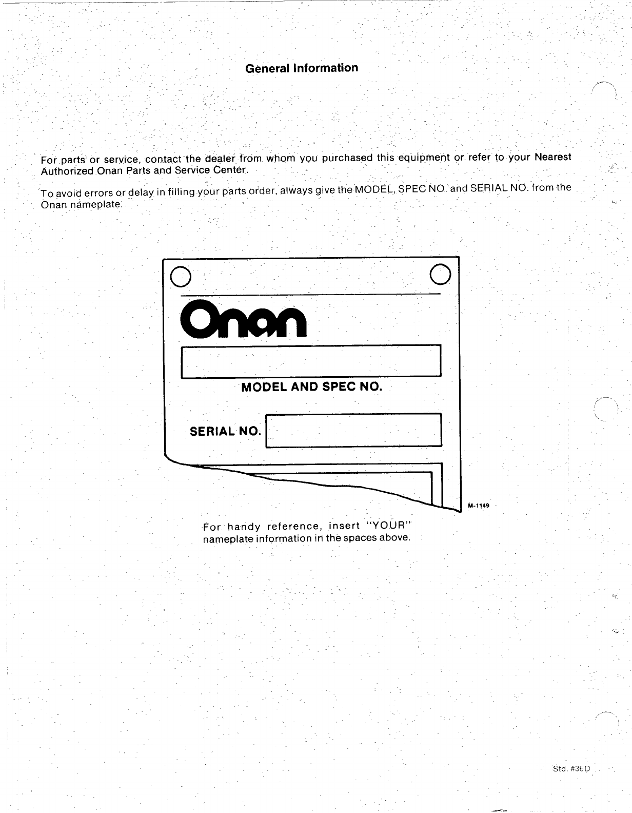
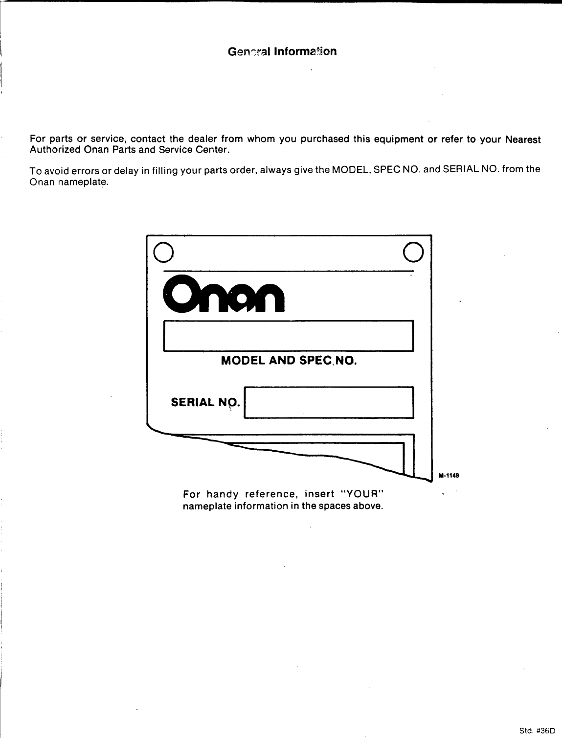
For parts or service, contact-the dealer frorn._whorn you purchased this equipment or. refer to your Nearest
,-
Authorized Onan Parts and Service Center.
To avoid errors or delay in”filling your parts order, always give the MODEL, ~PEC” NO. and SERIAL NO. -from the
Onan nameplate. ~...
00
MODEL AND SPEC NO.
SERIAL NO.
.=
,.-.
,,,’ ,
I.
M-1149
For handy reference, insert “YOUR”
nameplate information in the spaces above.
.,,.
..2
Std. #36D
—.
Index
Adapter, Clutch 46
Adapter, Exhaust (Flange Type) 49
Adapter, Governor Arm 26,34
Adapter, Oil Filter 36,41
Air Cleaner-Remote 45
Ammeter 34,35
Arm, Governor Control 25
Armature, Starter 21.37,38
Baffle, Breather Valve 4
Ball, Governor 11
Base, Oil 8
Base, Remote Oil Filter 36
Bearing, Camshaft 4
Bearing, Crankshaft 4
Block, Cylinder 4
Block, Terminal (4 Place) 43
Box, Breaker 19,20,42
Bracket, Governor Control 12,26
Bracket, Lifting 48
Brush, Ground-Starter 21,37,38
Cable, Choke 34.35
Cable, Spark Plug 19,44
Camshaft 11
Cap, Fuel Tank 33
Carburetor Components (Gasoline) 16,28,31,32
Carburetor, Gasoline 14,27
Clamp, Muffler 49
Coil, Ignition 19,44
Condenser, Ignition 20,42
Cover, Air-Cleaner 14,48
Cover, Breaker Box 20,42
/T Cover, Dust-Starter 21,38
Cover, Valve 4
Crankshaft 10
Drain, Oil Filter 41
Element, Air Cleaner 14
Extension, Governor Arm 35
Filter, Breather Tube 14,45
Filter, Oil 41,48
Flywheel 10
Gasket, Breaker Box 19,20,42
Gasket, Cylinder Head 4
Gasket, Exhaust Adapter 49
Gasket, Oil Base 8
Gasket, Valve Cover 4
Gauge, Oil Pressure 34,35
Gear, Camshaft 11
Gear, Crankshaft 10
Gear, Ring 10
Gearcase 7
Governor 12,25,26
Guard, Flywheel 10,48
Harness, Wiring 35
Head, Cylinder 4
Holder, Brush 21,38
Hose, Fuel 27
Hose, Vacuum 14,27
Housing, Air 18
Housing, Air Cleaner 14
Housing, Blower 18
Housing, Cylinder 18
Housing, Starter 21,38
Kit, Adapter -Remote Air Cleaner 45
Kit, Alternator Connector 23,24
Kit, Clutch 46
Kit, Fuel Tank 33
Kit, Gasket -Engine 4
Kit, Repair -Carburetor 16,28,31,32
Kit, Repair –Starter 21,38
Kit, Tuneup -Ignition 20,42
Lever, Choke 47
Lever, Throttle Control 34)35
Line, Fuel -Gasoline 33
Line, Oil -Flexible 34,35
Manifold, Exhaust 49
Manifold, Intake 14
Muffler, Exhaust 49
Numerical Index 50,51,52,53
Panel, Control 34,35
Pipe, Exhaust 49
Piston 6
Plate, Bearing -Rear 4
Plug, Spark 19,44
Pump, Fuel-Electric (Gasoline) 40
Pump, Fuel-Vacuum (Gasoline) 27,30
Pump, Oil 8
Regulator, Voltage 23,24
Relay, Start Solenoid 21,37,38
Ring, Piston 6
Rod, Connecting 6
Rod, Control-Governor 12,25
Seal, Oil 4,7
Seat, Valve 4
Sender, Oil Pressure (Electric) 48
Spring, Governor 12,25,26,34,35
Starter 21,38
Starter Components 21,37,38
Starter, Recoil 39
Stator 23,24,44
Strap, Fuel Tank 33
Switch, Ignition 34,35
Switch, Pressure-Oil 48
Tank, Fuel 33,48
Tappet, Valve 4
Tube, Air Intake 14,48
Tube, Breather 14,45
Tube, Oil 4
Tube, Vacuum Port 7,27
Valve, Exhaust 4
Valve, Intake 4
Valve, Shut-Off 33
Wrapper, Filter Element 48
1
Introduction
This cata~og applies to the Standard B43M-GA016 Engines. Parts are arranged in groups
of related items. Each illustrated part is identified bv areference number /-
corresponding to the same reference number in the parts ‘list for that group, Parts ~.
illustrations are typical. Using the MODEL and SPEC NO. from the nameplate, select the
Parts that apply to your engine. Unless otherwise mentioned in the description, parts
are in’cerch.angeable between model’s, Right and left sides are determined by facing the
blower end (front) of the engine.
WARNING
This engine is not designed or intended far use in any type of aircraft.
Use of this engjne in alrcra-ft may result in engine failure and cause
serious bodily Injury, death andlor property damage.
NOTICE !
Items referenced as optional indicate part is factory installed and ma
not be a ?7 licable to all models. Y
For field conversions additional par s
are usua yrequired. ,,,
,-
2

/“7,
c.
. .
3
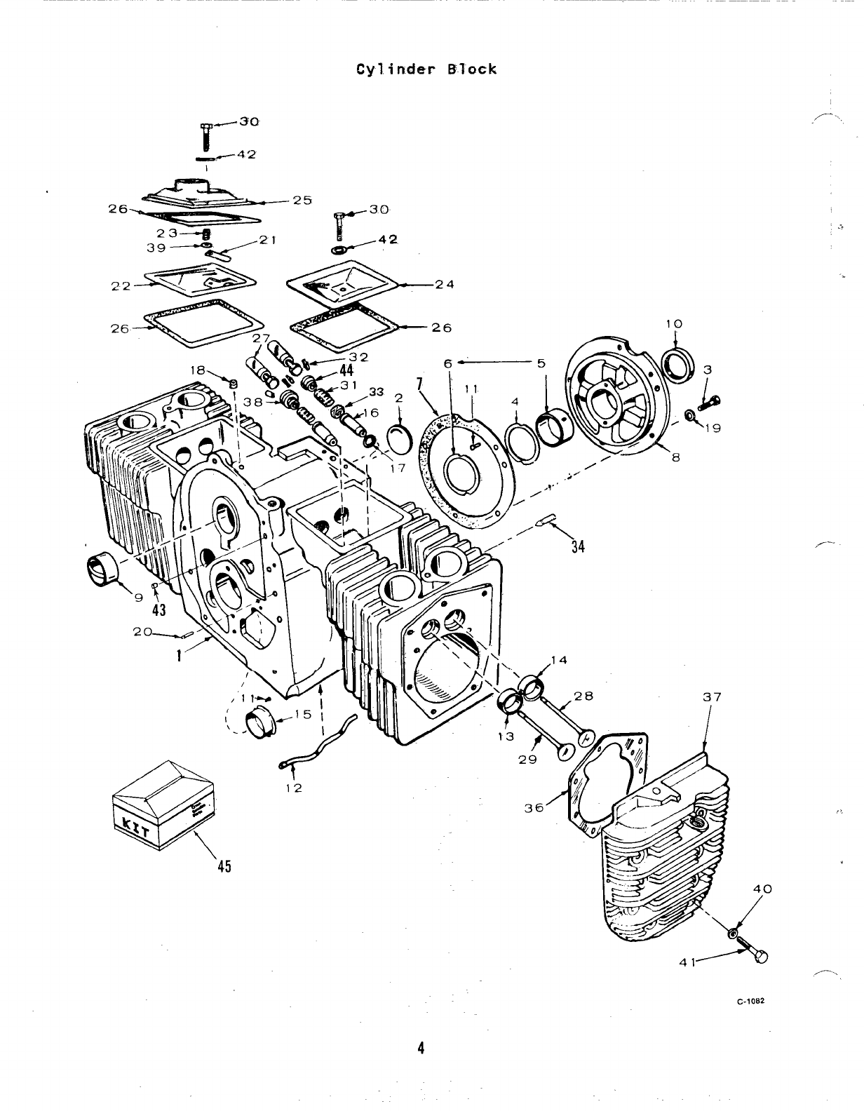
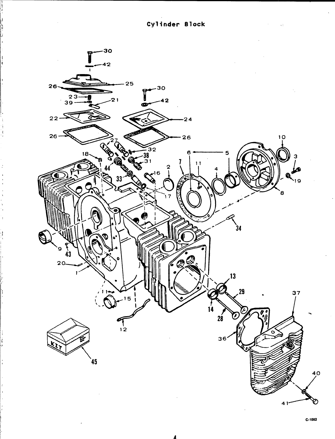
Cylinder Block
-30
r
_,/ 4‘2
1
.14
./’- ‘,
.-..
-.
’45
~,-
C.1082
,.>,
40
/
4
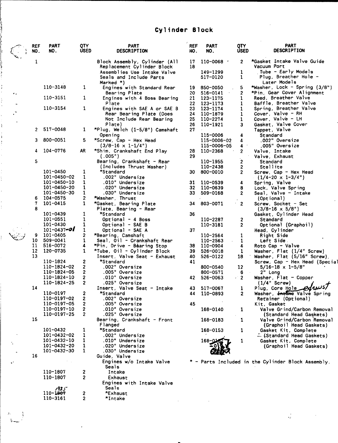
Cylinder Block
n, REF PART QTY
NO. NO. USED
PART
DESCRIPTION
Block Assembly, Cylinder (All
Replacement Cylinder Block
Assemblies Use Intake Valve
Seals and Include Parts
Marked *)
Engines with Standard Rear
Bearing Plate
Engines with 4Boss Bearing
Plate
Engines with SAE A or SAE B
Rear Bearing Plate (Does
Not Include Rear Bearing
Plate)
*Plug, Welch (1–5/8”) Camshaft
Opening
*Screw, Cap -Hex Head
(3/8-16 X1-1/4”)
*Shim, Crankshaft End Play
(.005”)
Bearing, Crankshaft -Rear
(Includes Thrust Washer)
*Standard
.002” Undersize
.010” Undersize
.020” Undersize
,030” Undersize
*Washer, Thrust
*Gasket, Bearing Plate
Plate, Bearing -Rear
*Standard
Optional -4Boss
Optional -SAE B
Optional -SAE A
*Bearing, Camshaft
Seal, Oil -Crankshaft Rear
*Pin, Drive -Bearing Stop
*Tube, Oil -Cylinder Block
Insert, Valve Seat -Exhaust
*Standard
.002” Oversize
.005” Oversize
.010” Oversize
.025” Oversize
Insert, Valve Seat –Intake
*Standard
.002” Oversize
.005” Oversize
.010” Oversize
.025” Oversize
Bearing, Crankshaft -Front
F1anged
*Standard
,002” Undersize
.010” Undersize
,020” Undersize
.030” Undersize
Guide, Valve
Engines w/o Intake Valve
Seals
Intake
Exhaust
Engines with Intake Valve
Seals
*Exhaust
*Intake
REF PART
NO. NO.
QTY PART
USED DESCRIPTION
2*Gasket Intake Valve Guide
Vacuum Port
Tube -Early Models
Plug, Breather Hole -
Later Models
*Washer, Lock -Spring (3/8”)
*Pin, Gear Cover Alignment
Reed, Breather Valve
Baffle, Breather Valve
Spring, Breather Valve
Cover, Valve -RH
Cover, Valve -LH
Gasket, Valve Cover
Tappet, Valve
Standard
,002” Oversize
.005” Oversize
Valve, Intake
Valve, Exhaust
Screw, Cap -Hex Head
(1/4-20 X1-3/4”)
Spring, Valve
Lock, Valve Spring
Seal, Valve -Intake
(Optional)
Screw, Socket –Set
(3/8-16 X5/8”)
Gasket, Cylinder Head
Standard
Optional (Graphoil)
Head, Cylinder
Right Side -Spec A
Left Side -Spec A
Left Side -Begin Spec B
Right Side -Begin Spec B
Roto Cap -Valve
Washer, Flat (1/4” Screw)
Washer, Flat (5/16” Screw)
Screw, Cap -Hex Head (Special)
5/16-18 X1-5/8”
2“ Long
Washer, Flat -Copper
(1/4” Screw)
Plug, Core Hole
Washer, Intake Valve Spring
Retainer (Optional)
Kit, Gasket
Valve Grind/Carbon Removal
(Standard Head Gaskets)
Valve Grind/Carbon Removal
(Graphoil Head Gaskets)
Gasket Kit, Complete
(Standard Head Gaskets)
Gasket Kit, Complete
(Graphoil Head Gaskets)
117 110-0068
18 149-1299
517-0120 1
1
110-3148 1
110-3151 1
110-3154 1
19
20
21
22
23
24
25
26
27
850-0050
516-0141
123-1175
123-1173
123-1174
110-1879
110-2274
110-1921
5
2
1
1
1
1
1
3
517-0048 1
BOO-0051 5
104-0776 AR
2
3
4
5
115-0006
115-0006-02
115-0006-05
110-2368
110-1955
800-0010
110-0539
110-0639
509-0168
4
4
4
28
29
30
2
2
.2
101-0450 1
101-0450-02 1
101-0450-10 1
101-0450-20 1
101-0450-30 1
104-0575 2
101-0415 1
31
32
33
4
8
2
34 803-0071 2
6
7
8
36
110-2287
110-3181
2
2
101-0439 1
101-0551 1
101-0430 1
101-0437 1
101-0405 2
509-0041 1
516-0072 4
120-0735 1
37
110-2564
110-2563
110-2561
110-2562
110-0904
526-0018
526-0122
800-0540
800-0571
526-0063
1
1
1
1
4
1
18
1:
11
12
13
38
39
40
41
110-1824 2
110-1824-02 2
110-1824-05 2
110-1824-10 2
110-1824-25 2
12
6
2
42
14 43
44
517-0067
110-0893
1
2
110-0197 2
110-0197-02 2
110-0197-05 2
110-0197-10 2
110-0197-25 2
45
168-0140
168-0183
168-0153
168-0182
1
15 1
101-0432 1
101-0432-02 1
101-0432-10 1
101-0432-20 1
101-0432-30 1
1
1
...
16
,.- *–parts Included in the Cylinder Block Assembly.
110-1807 2
110-1807 2
110-1807 2
110-3161 2
/-.
5
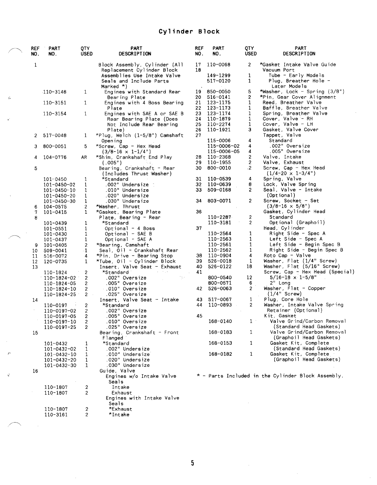
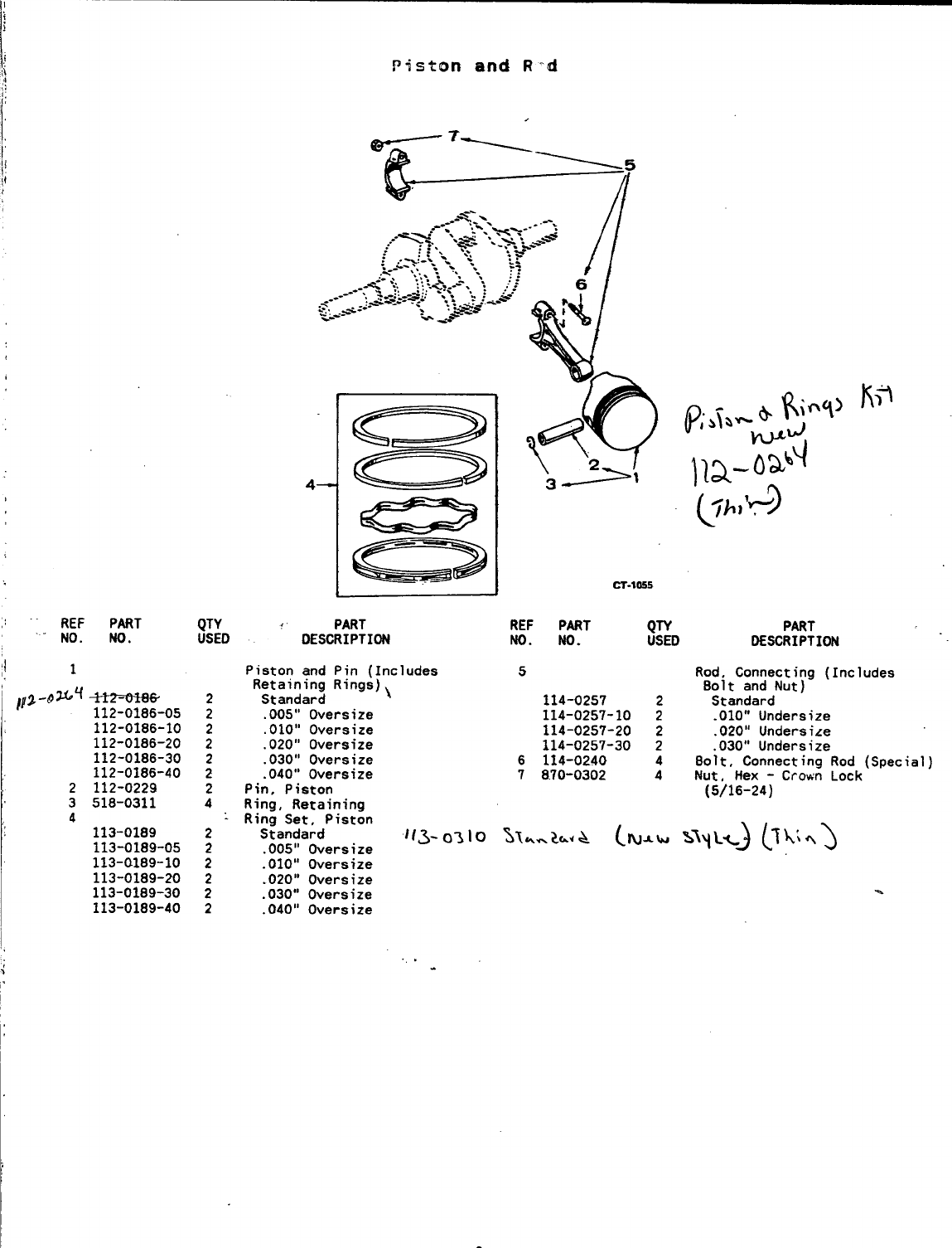
Piston and Rod
/1
CT-1055
REF PART
NO. NO.
.
1
112-0186
112-0186-05
112.-Olg6-lO
112-0186-20
112-0186’-30
112-0186-40
2112-0229
3518-0311
4
113-0189
113-0189-05
113-0189-10
113-0189-20
113-0189--30
113-0189-40
QTY
USED
2
2
2
2
2
2
2
4
2
2
2
2
2
2
PART
DESCRIPTION
Piston and Pin (Includes
Retaining Rings)
Standard
.005” Oversize
,010” Oversize
,020” Oversize
,030” Oversize
.040” Oversize
Pin, Piston
Ring, Retaining
Ring Set, Piston
Standard
.005” Oversize
.010” Oversize
.020” Oversize
,030” Oversize
,04~” Oversize
REF PART QTY
NO. NO. USED
5
-114-0300 2
114-0300-10 2-
114-0300-20 2
114-0300-30 2
6114-0240 4
7870-0302 4
.!
,-
PART
DESCRIPTION
Rod, Connecting (Includes
Bolt and Nut)
Standard
..010” Undersize
.020” Undersize
.030” Undersize
Bolt, Connecting Rod (Special)
N“ut, Hex -Crown Lock
(5/16-24)
\
!
1
I
,/— I
1
,
,.
.-.
6
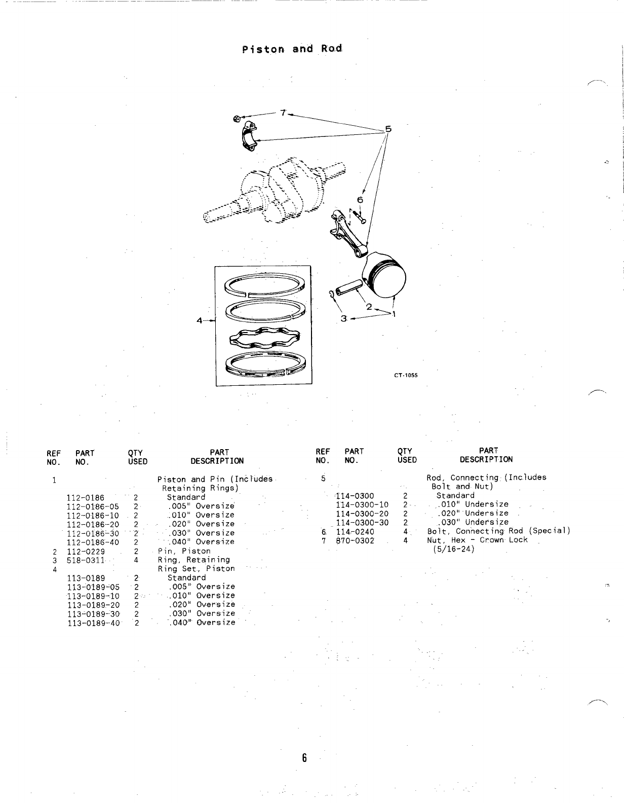
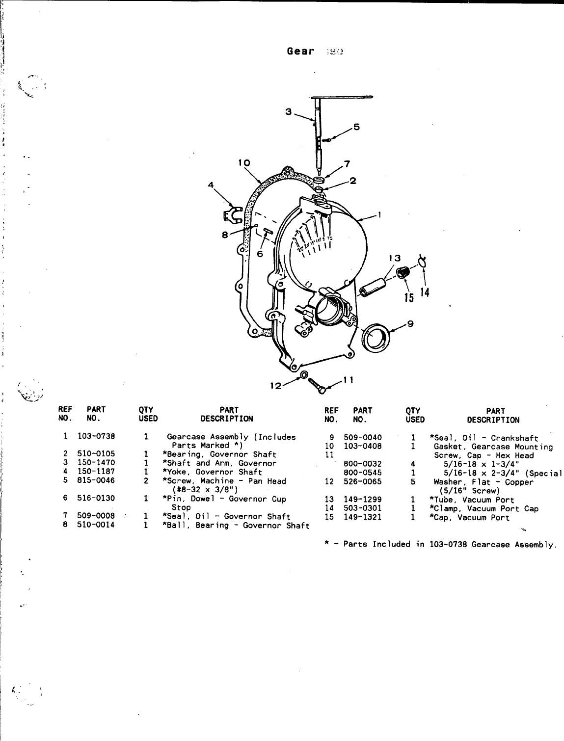
Gearcase
f
/2
/8 10
I
REF
NO. PART
NO. QTY PART
USED DESCRIPTION
REF PART
NO. NO.
QTY
USED
PART
DESCRIPTION
1103-0738 Gearcase Assembly (Includes
Parts Marked *)
*Bearing, Governor Shaft
*Shaft and Arm, Governor
*Yoke, Governor Shaft
*Screw, Machine -Pan Head
(#8-32 X3/8”)
*Pin, Dowel -Governor Cup
stop
*Seal, Oil -Governor Shaft
*Ball, Bearing -Governor Shaft
1:
11
509-0040
103-0408 *Seal, Oil -Crankshaft
Gasket, Gearcaae Mounting
Screw, Cap -Hex Head
5/16-18 X1-3/4”
5/16-18 x2-3/4” (Special)
Washer, Flat –Copper
(5/16” Screw)
*Tube, Vacuum Port
*Clamp, Vacuum Port Cap
*Cap, Vacuum Port
1
2510-0105
3150-1470
.. 4150-1187
5815-0046
1
1
1
2
800-0032
800-0545
526-0065
4
1
5
12
13
16
17
149-1299
503-0301
149-1321
1
1
1
6516-0130 1
,. 7509-0008
8510-0014 1
1
*–parts Included in 103-0738 Gearcase Assembly.
...
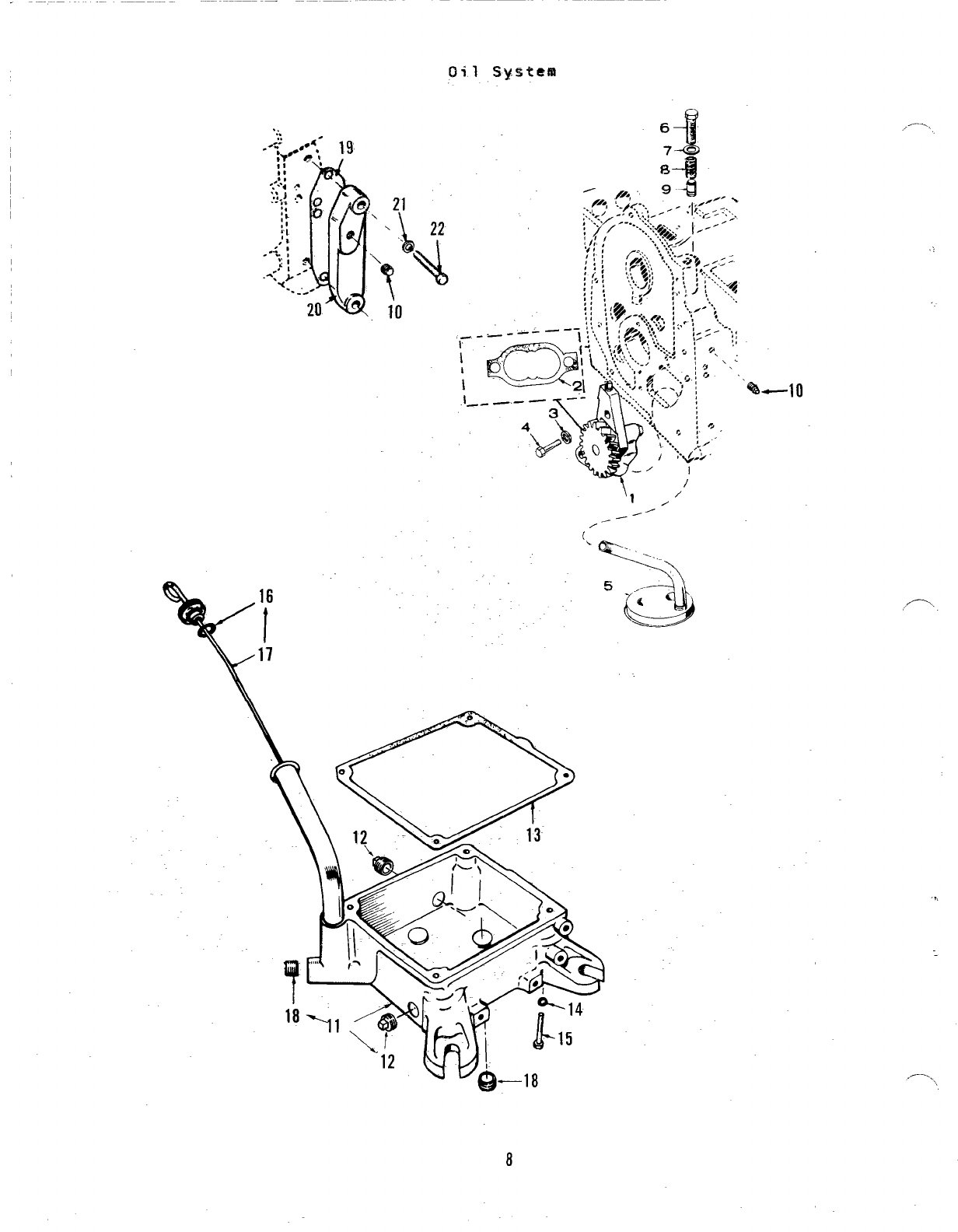
Oil System
-.
\
16
t
17
‘1 /’
--”
,/
(\
3..
‘w
<—
—.—
,-----
8
,—.
REF PART
NO. NO.
1120-0491
2120-0161
3850-0040
4800-0007
5120-0713
6801-0050
7526-0066
8120-0140
9120-0398
10 505-0057
11 102-0850
12 505-0056
QTY
USED
1
1
2
2
1
1
1
1
1
1
1
2
PART
DESCRIPTION
Oil System
Pump, Oil (Components Not
Sold Separately)
Gasket Kit, Oil Pump
Washer, Lock Spring (1/4”)
Screw, Cap -Hex Head
(1/4-20 X1“)
Cup, Intake -Oil Pump
Screw, Cap -Hex Head
(3/8-24 Xl“)
Washer, Flat -Copper
(3/8’( Screw)
Spring, Bypass Valve
Plunger, Bypass Valve
Plug, Pipe
Base, Oil
Plug, Pipe -Oil Drain (1/2”)
REF PART
NO. NO.
13 102-1200
14 850-0050
15 800-0056
16 123-1292
17 509-0142
t8 505-0937
19 122-0375
20 122-0438
21 S26-0065
22 800-0028
QTY
USED
1
4
4
1
1
2
1
1
2
2
—
PART
DESCRIPTION
Gasket, Oil Base
Washer, Lock -Spring
Screw, Cap -Hex Head
(3/8-16 X2-1/2”)
(3/8 “ )
Cap and Indicator; Oil Fill
Gasket, Oil Fill Cap (“O” Ring)
Plug, Pressure -Socket Head
(3/8”)
Gasket, Oil Filter Adapter
Cover, Oil Filter Pad -
Optional
Washer, Flat -Copper
(5/16” Screw)
Screw, Cap -Hex Head
(5/16-18 X1“)
,.,
,.
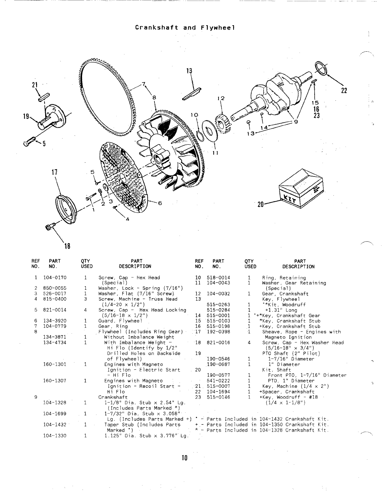
Crankshaft and Flywheel
,— .
’10
REF PART
NO. NO.
1104-0170
2850-0055
3526-0017
4815-0400
5821-0014
6134-3920
7104-0779
8
134-3871
134-4734
160-1301
160-1307
9
104-1328
104-1699
104--1432
104--1330
QTY
USED
1
;
3
4
1
1
1
1
1
1
1
1
1
1
\4
PART REF
DESCRIPTION NO.
Screw, Cap -Hex Head 10
(Special) 11
Washer, Lock -Spring (7/16”)
Washer, Flat (7/16” Screw). 12
Screw, Machine -Truss Head 13
(1/4-20 X1/2”)
Screw, Cap -Hex Head Locking
(5/16-18 X1/2”) 14
Guard, Flywheel 15
Gear, Ring 16
Flywheel (Includes Ring Gear) 17
Without Imbalance Weight
With Imbalance Weight – 18
Hi Flo (Identify by 1/2”
Drilled Holes on Backside 19
of Flywheel)
Engines with Magneto
Ignition -Electric Start 20
-Hi Flo
Engines with Magneto
Ignition -Recoil Start -21
Hi Flo 22
Crankshaft 23
1-1/8” Dia. Stub x2,54” Lg.
(Includes Parts Marked *)
PART
NO.
518-0014
104-0043
104-0032
515-0263
515-0284
515-0001
515-0103
515-0198
192-0398
821-0016
190-0546
190-0687
190-0577
541-0222
515-0007
104-1694
515-0146
QTY PART
USED DESCRIPTION
1Ring, Retaining
1Washer, Gear Retaining
(Special)
1Gear, Crankshaft
Key, Flywheel
1“*Kit, Woodruff
1+1.31” Long
1“+*Key, Crankshaft Gear
1*Key, Crankshaft Stub
1+Key, Crankshaft Stub
1Sheave, Rope -Engines with
Magneto Ignition
4Screw, Cap -Hex Washer Head
(5/16-18” X3/4”)
PTO Shaft (2” Pilot)
11-7/16” Diameter
11“ Diameter
Kit, Shaft
1Front PTCJ, 1-7/16” Diameter
1PTO, 1“ Diameter
1Key, Machine (1/4 x2“)
1+Spacer, Crankshaft
1+Key, Woodruff -#18
(1/4 X1-1/8”)
,-,
1:7/32” Oia. Stub x3.058i’
La. (Includes Parts Marked +) ‘-Parts Included in 104-1432 Crankshaft Kit
Ta~er’Stub (Includes Parts ‘+-parts Included in ~04-1350 Crankshaft Kit.
Marked “) *-parts Included in 104-1328 Crankshaft Kit.
1.125” Dia. Stub x3.776” Lg. ,-...,
10
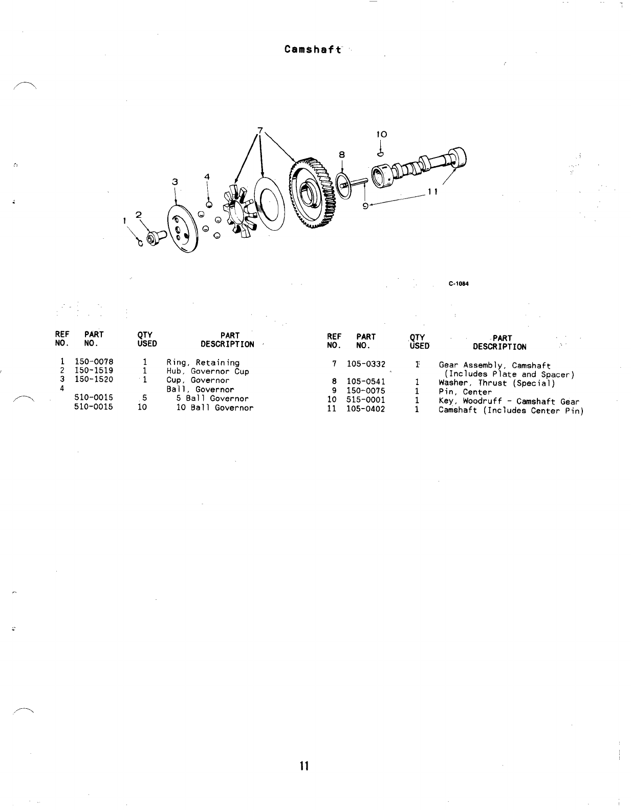
Camshaft
,,
C-1084
REF PART
NO. NO.
1150-0078
2150-1519
3150-1520
4
.- 510-0015
510-0015
QTY PART
USED DESCRIPTION REF PART ,QTY
NO. NO. USED
Ring, Retaining 7105-0332
:r
Hub, Governor Cup
1Cup, Governor 8105-0541 1
Ball, Governor 9150-0075 1
5Ball Governor 10 515-0001
1: 10 Ball Governor 11 105-0402 ;
PART
DESCRIPTION “
Gear Assembly, Camshaft
(Includes Plate and Spacer)
Washer, Thrust (Special)
Pin, Center
Key, Woodruff -Camshaft Gear
Camshaft (Includes Center Pin)
/-
11
“a
J
“%WH;3
lG --
.
~, \-
..;4
--=_.”. ....
I?EF PART QTY PART
NO. NO. USED DESCRIPTION
,—.! .
I
I
.,
6
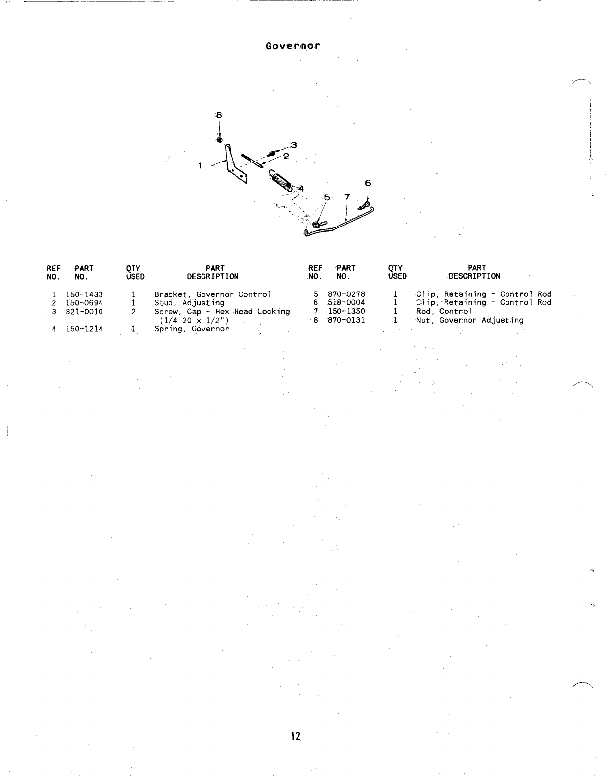
1150-1433 1Bracket, Governor Control
2150-0694 1Stud, Adjusting
3921-0010 2Screw, Cap -Hex Head Locking
(1/4-20 X1/2”)
4150-1214 1Governor
Spring, .,
,.Gti ;
REF ‘PART ~;:D PART
NO. NO. DESCRIPTION
5870-0278 1Clip, Retaining -“Control Rod
6.518-0004 1Clip, Retaining -Control Rod
7150-1350 Rod, Control
8870-0131 ;Nut, Governor Adjusting
,-,
12

13
Fuel” System
I
-’
,/’-..,.
-22
23
/24
14
Fuel System
/’>
,, \ REF PART
NO. NO.
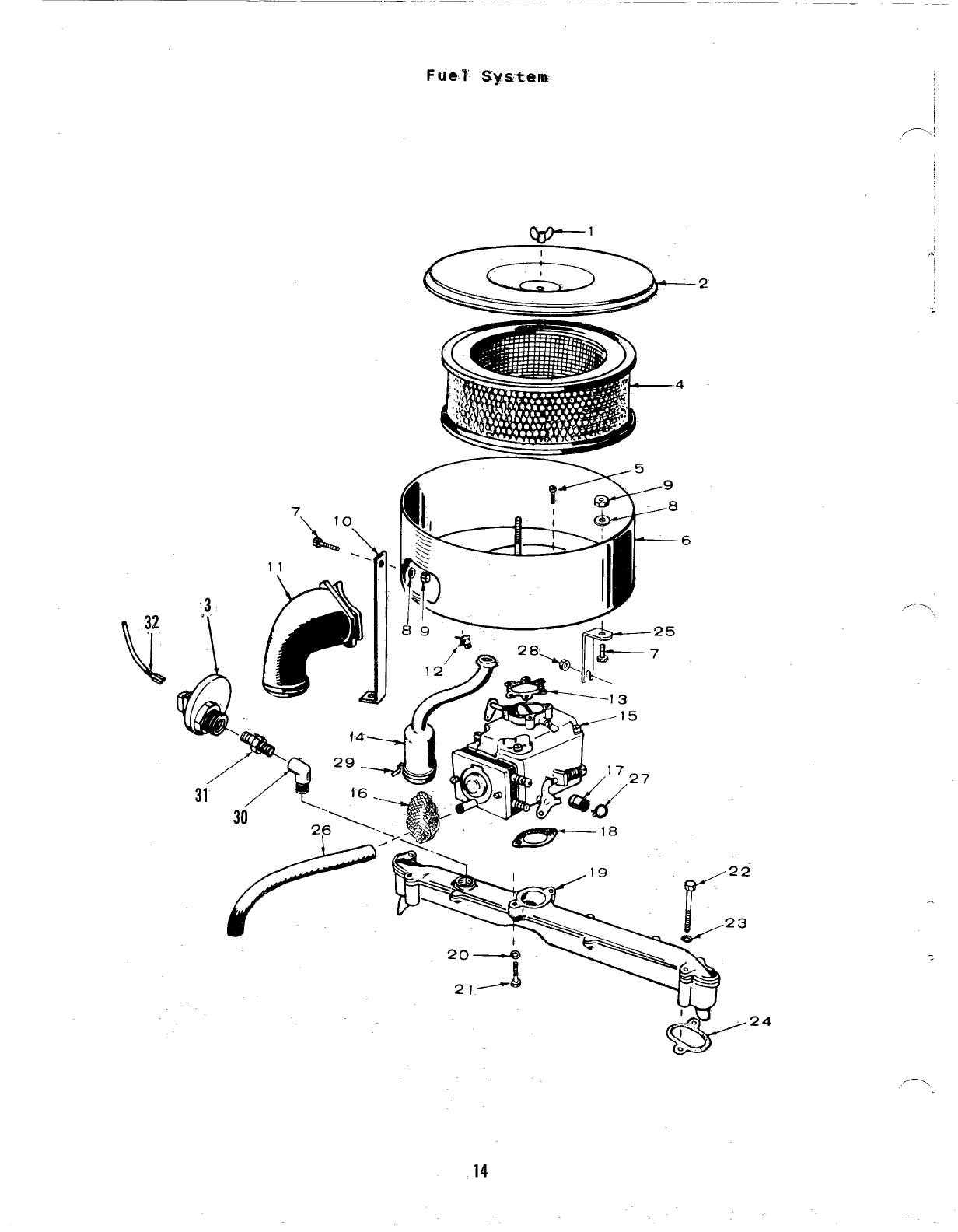
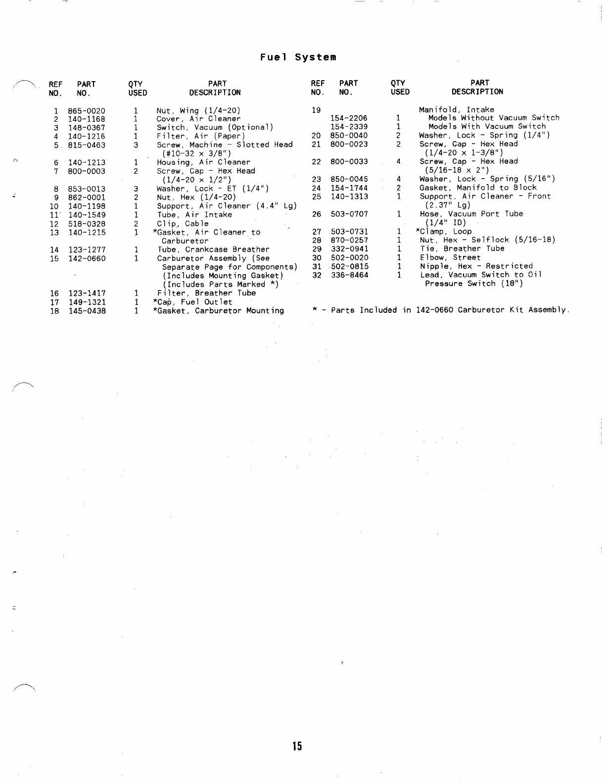
1865-0020
2140-1168
3148-0367
4140-1216
5815-0463
t> 6140-1213
7800-0003
8853-0013
.- 9862-0001
10 140-1198
11- 140-1549
12 518-0328
13 140-1215
14 123-1277
15 142-0660
16 123-1417
17 149-1321
18 145-0438
QTY PART
USED DESCRIPTION
:
1
1
3
1
2
3
2
1
1
2
1
1
1
1
i
Nut, Wing (1/4-20)
Cover, Air Cleaner
Switch, Vacuum (Optional)
Filter, Air (Paper)
Screw, Machine -Slotted Head
(#10-32 X3/8”)
Housing, Air Cleaner
Screw, Cap -Hex Head
(1/4-20 X1/2”)
Wssher, Lock -ET (1/4”)
Nut, Hex (1/4-20)
Support, Air Cleaner (4,4” Lg)
Tube, Air Intake
Clip, Cable
*Gasket, Air Cleaner to
Carburetor
Tube, Crankcase 8reather
Carburetor Assembly (See
Separate Page for Components)
(Includes Mounting Gasket)
(Includes Parts Marked *)
Filter, 8reather Tube
*Cap, Fuel Outlet
*Gasket, Carburetor Mounting
REF PART
NO. NO.
19 154-2206
154-2339
20 850-0040
21 800-0023
22 800-0033
23 850-0045
24 154-1744
25 140-1313
26 503-0707
27 503-0731
28 870-0257
29 332-0941
30 502-0020
31 502-0815
32 336-8464
QTY PART
USED DESCRIPTION
1
1
2
2
4
4
2
1
1
1
1
;
:
Manifold, Intake
Models Without Vacuum Switch
Models With Vacuum Switch
Washer, Lock -Spring (1/4”)
Screw, Cap -Hex Head
(1/4-20 X1-3/8”)
Screw, Cap -Hex Head
(5/16-18 X2“)
Washer, Lock- Spring (5/16”)
Gasket, Manifold to 810ck
Support, Air Cleaner -Front
(2.37” Lg)
Hose, Vac~um Port Tube
(1/4” ID)
*Clamp, Loop
Nut, Hex -Selflock (5/16-18)
Tie, Breather Tube
Elbow, Street
Nipple, Hex -Restricted
Lead, Vacuum Switch to Oil
Preseure Switch (18”)
*-parts Included in 142–0660 Carburetor Kit Assembly
Carburetor (With Knte ra.1 Fuel Pump)
(1~“2 -0650 ):
,.9.
Components
------- “o
.-
/’
1’
22
Y-
WI/“
21 17
I ,/
-‘r\,9 ~/1
,,.-.,,
8
16
,
(.,,
..
..
\’26 \
t5 6
18
16
P.
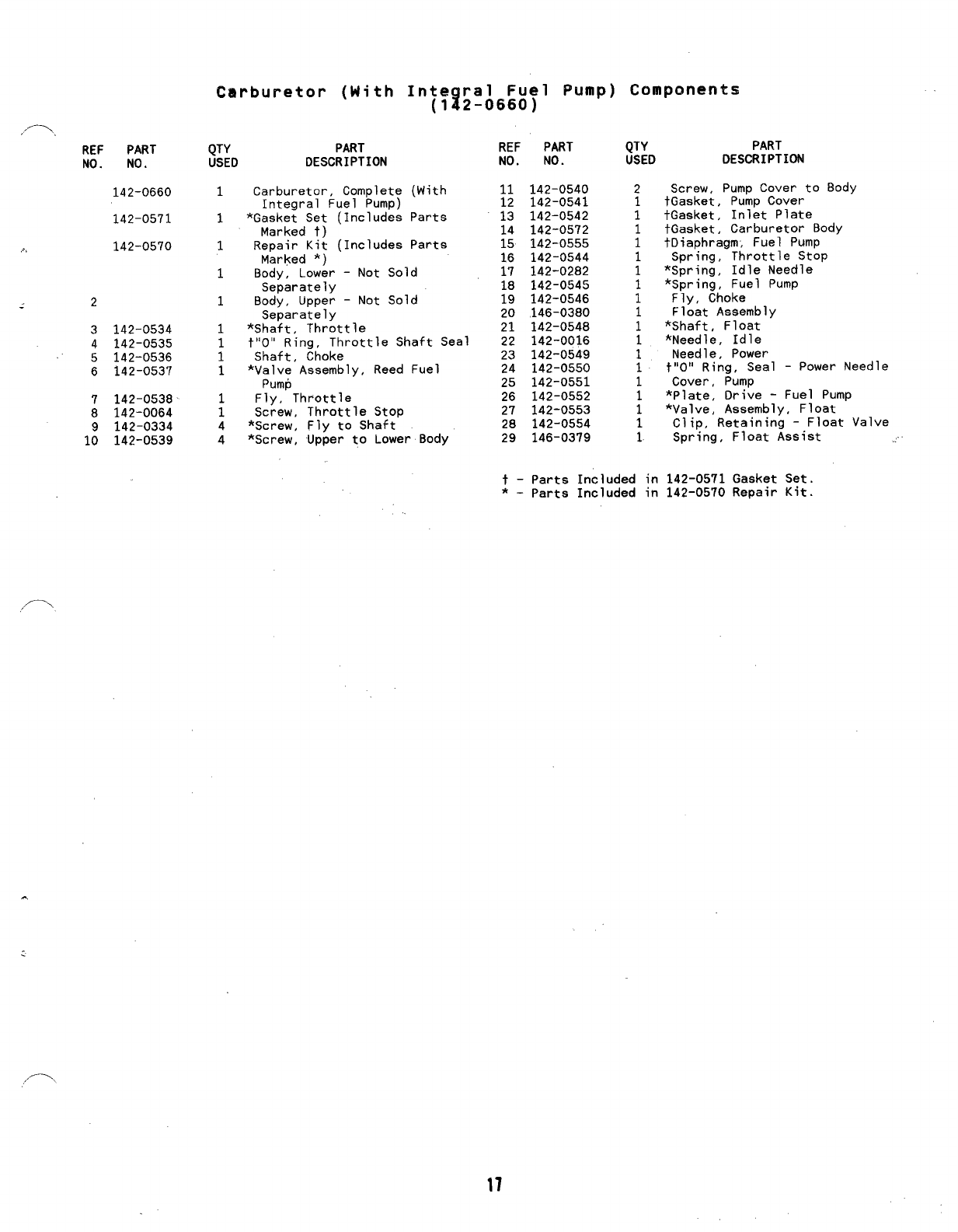
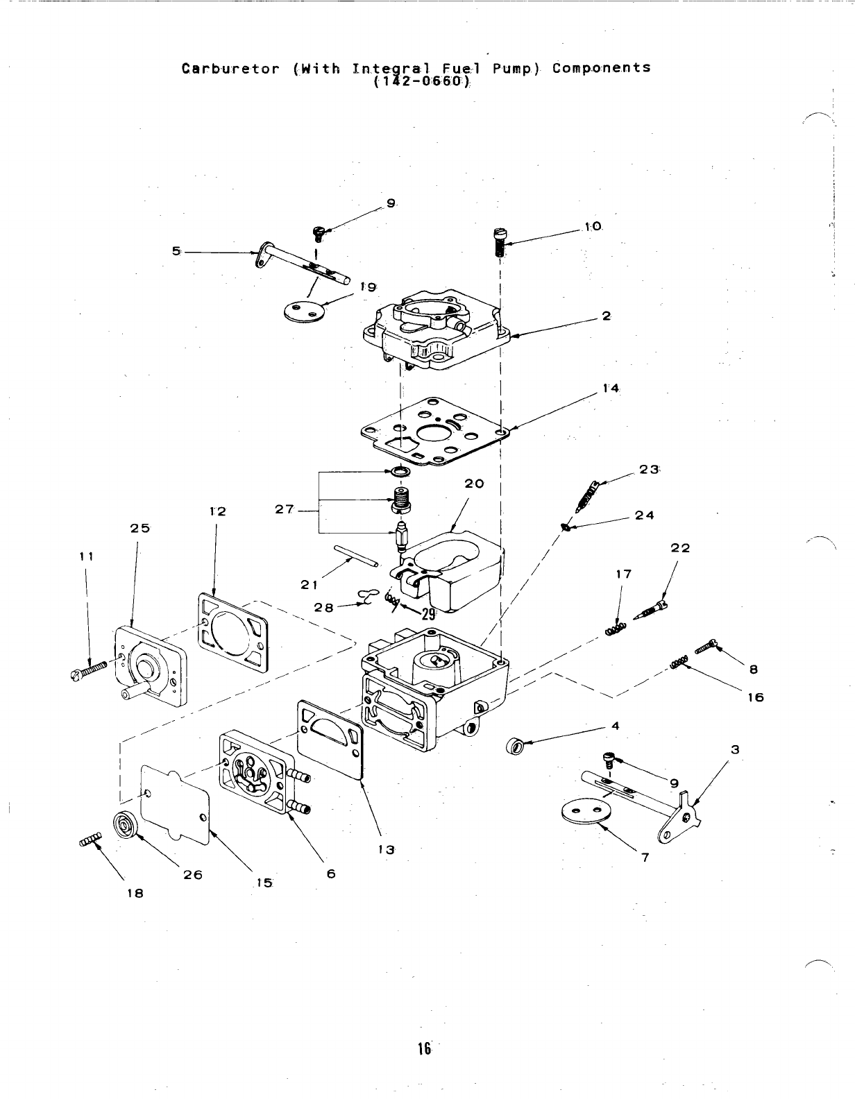
Carburetor (With
REF PART QTY PART
NO. NO. USED DESCRIPTION
2
3
4
5
6
7
8
1:
142-0534
142-0535
142-0536
142-0537
142-0538
142-0064
142-0334
142-0539
142-0660 1
142-0571 1
142-0570 1
1
1
1
1
1
1
;
4
4
Carburetor, Complete
Integral Fuel Pump)
*Gasket Set (Includes
Marked t)
Repair Kit (Includes
Marked *)
Integral Fuel Pump) Components
(142-0660)
(With
Parts
Parts
Body, Lower -Not Sold
Separately
Body, Upper -Not Sold
Separately
*Shaft, Throttle
t“O” Ring, Throttle Shaft Seal
Shaft, Choke
*Valve Assembly, Reed Fuel
Pump
Fly, Throttle
Screw, Throttle Stop
*Screw, Fly to Shaft
*Screw, Upper to Lower Body
REF PART
NO. NO.
11 142-0540
12 142-0541
13 142-0542
14 142-0572
15 142-0555
16 142-0544
17 142-0282
18 142-0545
19 142-0546
20 146-0380
21 142-0548
22 142-0016
23 142-0549
24 142-0550
25 142-0551
26 142-0552
27 142-0553
28 142-0554
29 146-0379
QTY PART
USED DESCRIPTION
Screw, Pump Cover to Body
tGasket, Pump Cover
tGasket, Inlet Plate
tGasket, Carburetor Body
+Diaphragm, Fuel Pump
Spring, Throttle Stop
*Spring, Idle Needle
*Spring, Fuel Pump
Fly, Choke
Float Assembly
*Shaft, Float
*Needle, Idle
Needle, Power
t“O” Ring, Seal -Power Needle
Cover, Pump
*Plate, Drive -Fuel Pump
*Valve, Assembly, Float
Clip, Retaining -Float Valve
Spring, Float Assist ..
..
t-Parts Included in 142-0571 Gasket Set.
*-parts Included in 142-0570 Repair Kit.
/’-.
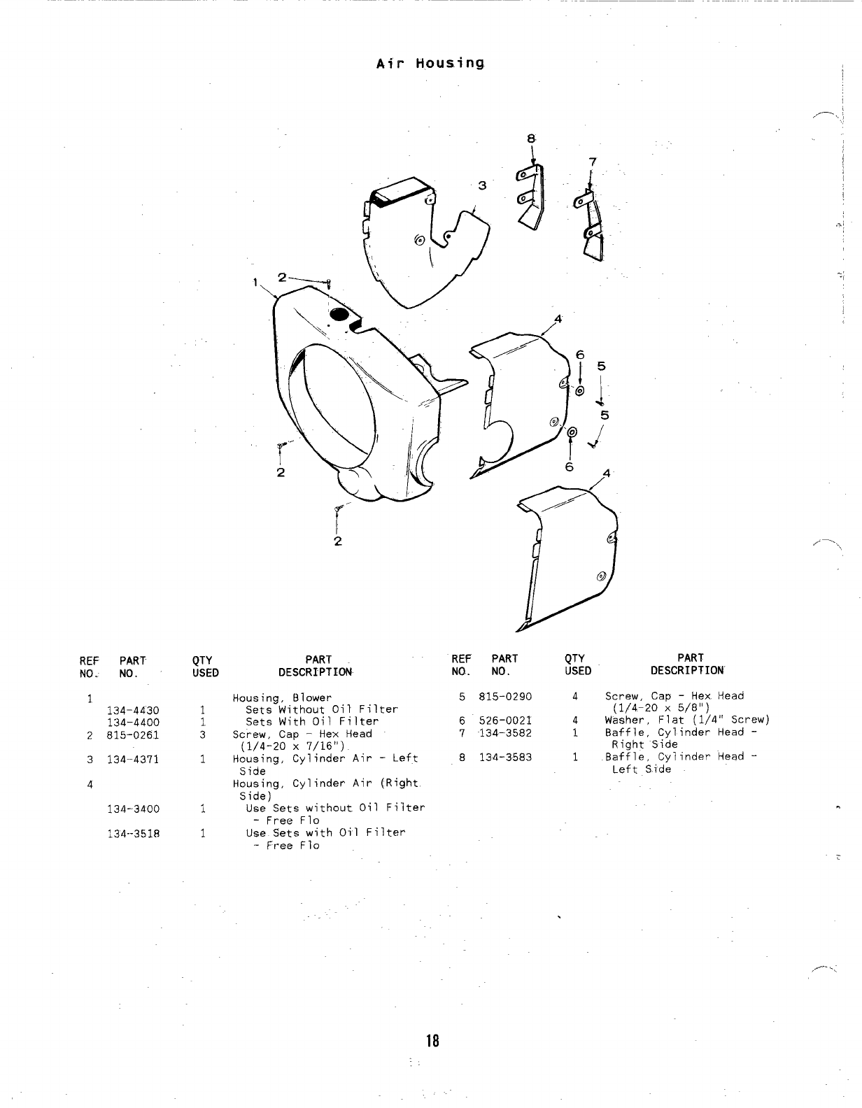
Air Housing
8
I
I
,.-, :
.,
REF PART
NO. NO.
1134-4430
134-4400
2815-0261
3134-4371
A
134-3400
134--3518
1.
QTY PART REF PART QTY
USED DESCRIPTION NO. NO. USED
Housing, Blower 5815-0290 4
1Sets Without Oil Filter
1Sets With Oil Filter 6526-0021 4
3Screw, Cap -Hex Head 7134-3582 1
(1/4-20 X7/16”)
1Housing, Cylinder Air -Left 8134-3583 1
Side
Housing, Cylinder Air (Right
Side)
1Use Sets without Oil Filter
-Free Flo
1Use Sets with Oil Filter
-Free Flo
.
18
/-..
PART
DESCRIPTION
Screw, Cap -Hex Head
(1/4-20 X5/8”)
Washer, Flat (1/4” Screw)
Baffle, Cylinder Head -
Right Side
Baffle, Cylinder Head -
Left S$de
.
,,--<,
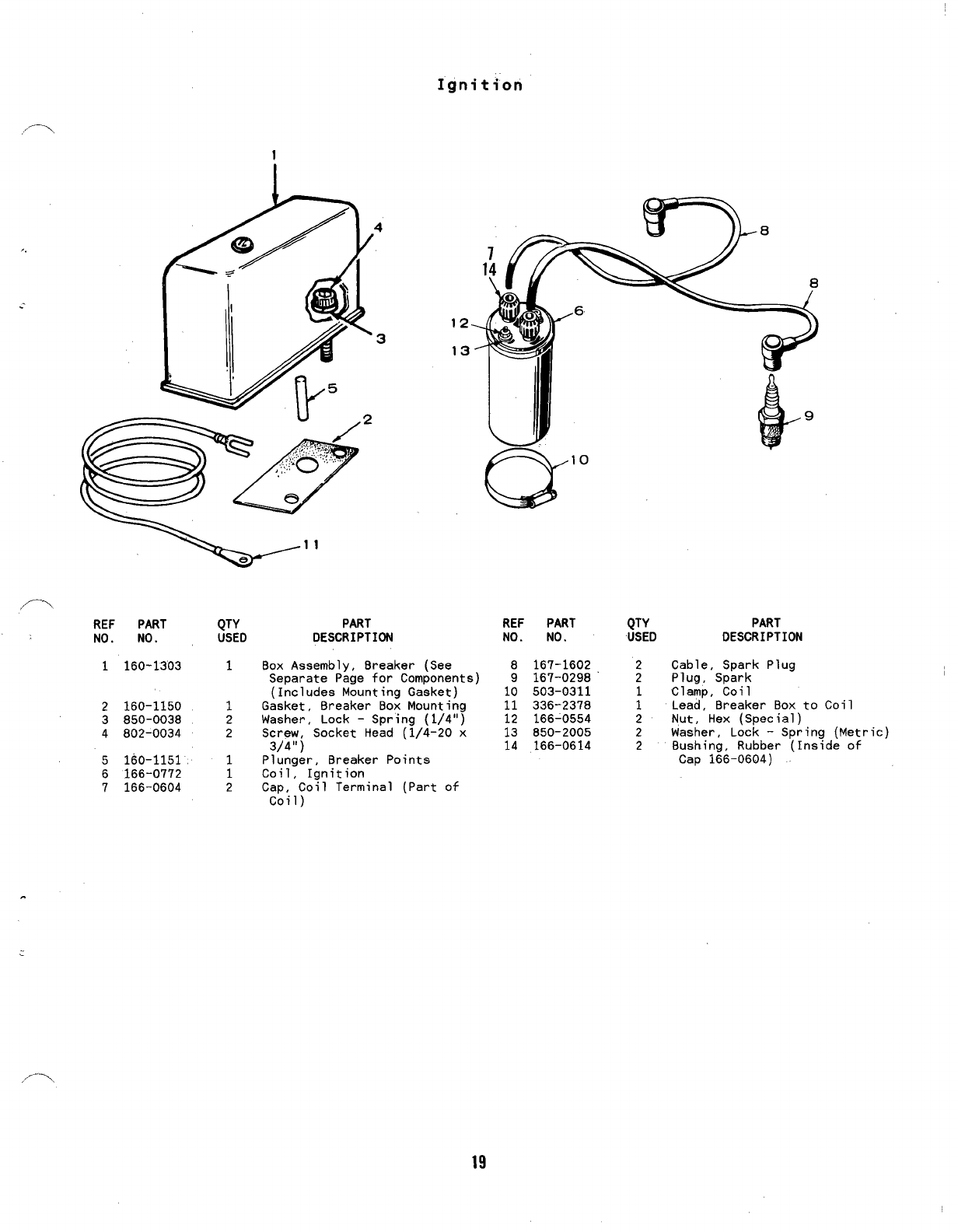
Ignition
1
I
REF PART
NO. NO.
1160-1303
2160-1150
3850-0038
4802-0034
5160-1151
6166-0772
7166-0604
QTY PART
USED DESCRIPTION
1Box Assembly, Breaker (See
Separate Page for Components)
(Includes Mounting Gasket)
1Gasket, Breaker Box Mounting
2Washer, Lock -Spring (1/4”)
2Screw, Socket Head (1/4-20 x
3/4”)
1Plunger, 8reaker Points
1Coil, Ignition
2Cap, Coil Terminal (Part of
Coil)
REF PART QTY PART
NO. NO. USED DESCRIPTION
8167-1602 2Cable, Spark Plug
9167-0298 2Plug, Spark
10 503-0311 Clamp, Coil
11 336-2378 :Lead, Breaker Box to
12 166-0554 2Nut, Hex [Soecial)
Coil
13 850-2005 2Washer, Lock -Sp~ing (Metric)
14 166-0614 2Bushing, Rubber (Inside of
Cap 166-0604)
19
.
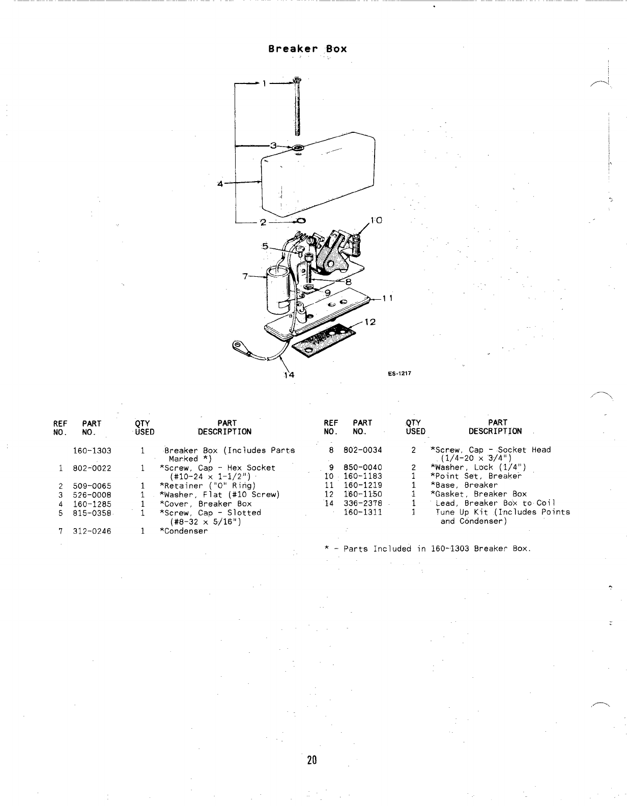
Breaker B-ox
REF PART
No. No.
160-1303
1802-0022
2509-0065
3526-0008
4160-1285
5815-0358
7312-0246
IrI
3,/
.-
.
11
I
,-,
?4 ES-1217
,,.-..,
REF PART QTY PART
NO. NO.. USED DESCRIPTION
Parts 8802-0034 2*Screw, Cap -Socket
(1/4-20 X‘3/4”)
Head
QTY PART
USED DESCRIPTION
1Breaker Box (Includes
Marked *) ‘
1*Screw, Cap -Hex Socket 9850-0040 2*Washer, Lock” (1)4”)
(#10-24 X1-1/2”) 10 160-1183 1*Point Set, 8reaker
1*Retainer (“O” Ritig) 11 160-12.19 1*8ase, Breaker
1*Washer, Flat (#10 Screw) 12 160-1150 1*Gasket, 8reaker Box
1*Cover, Breaker Box 14 336-2378 1
1
Lead, Breaker Box to Coil
*Screw, Cap -Slotted 160-1311 1Tune Up Kit (Includes Points
(#8-32 x’5j16”)
1
and Condenser)
*Condenser
*-Parts Included in 160-1303 Breaker Box.
20
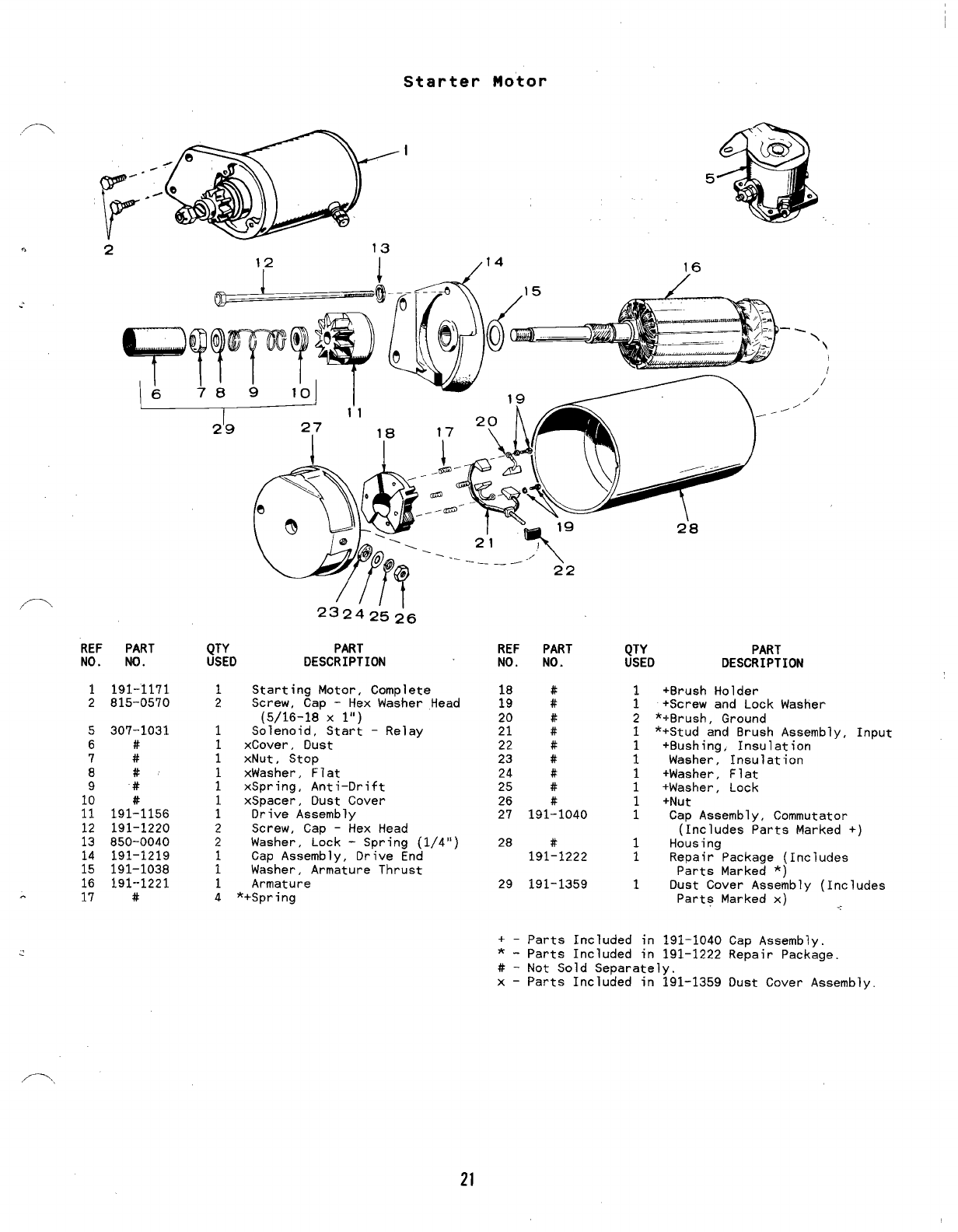
Starter Motor
/14
2“8
16
REF PART
NO. NO.
1191-1171
2815-0570
5
6
7
8
9
12
13
;2
16
17
307-1031
#
#
#
#
191:1156
191-1220
850-0040
191-1219
191-1038
191--1221
#
23242’5;6
QTY PART
USED DESCRIPTION
1
2
1
1
1
1
2
1
1
1
4
Starting Motor, Complete
Screw, Cap -Hex Washer Head
(5/16-18 Xl“)
Solenoid, Start -Relay
xCover, Dust
xNut, Stop
xWasher, Flat
xSpring, Anti-Drift
xSpacer, Dust Cover
Drive Assembly
Screw, Cap -Hex Head
Washer, Lock -Spring (1/4”)
Cap Assembly, Drive End
Washer, Armature Thrust
Armature
*+Spring
-\ \
/’
/
/
/
REF PART
NO. NO.
18
19 :
20 #
21 #
22 #
23 #
24 #
25 #
26 #
27 191-1040
28 #
191-1222
29 191-1359
QTY PART
USED DESCRIPTION
1
1
2
1
1
1
1
1
1
1
1
1
1
+Brush Holder
+Screw and Lock Washer
*+Brush, Ground
*+Stud and Brush Assembly, Input
+Bushing, Insulation
Washer, Insulation
+Washer, Flat
+Washer, Lock
+Nut
Cap Assembly, Commutator
(Includes Parts Marked +)
Housing
Repair Package (Includes
Parts Marked *)
Dust Cover Assembly (Includes
Parts Marked x) ~-,
+–parts Included in 191–1040 Cap Assembly.
*-Parts Included in 191-1222 Repair Package.
#-Not Sold Separately.
x–Parts Included in 191-1359 Dust Cover Assembly.
21
OPTIONAL EQUIPMENT SECTION
F\
This sact+ati contains illustrated parts listing of factory installed
options. for” these fndust~ial engines. Options may net be-applicable
to all models: for field conversions additional parts are usually
required. Optional parts listed in this section are in addition or in
place of those shown in the standard engine parts section.
I
: :,
I
22
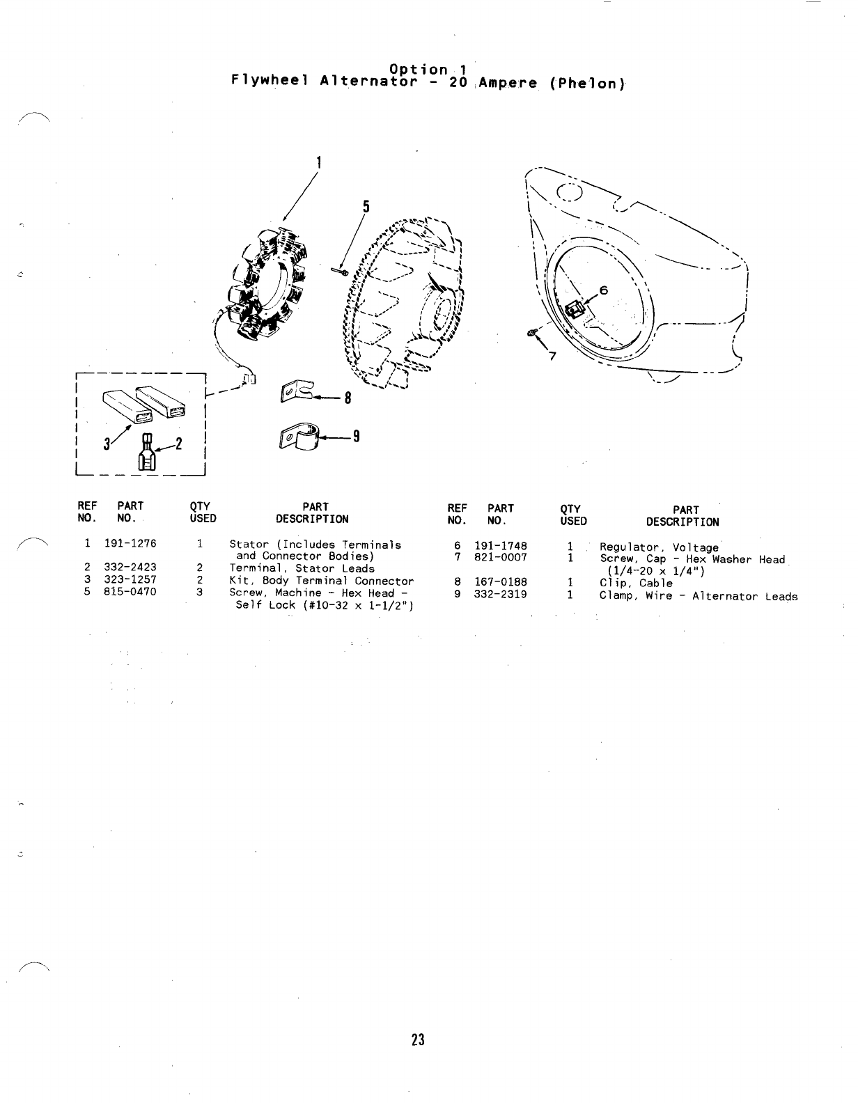
Option 1
Flywheel Alternator -20 ,Ampere (Phelon)
1
\
\\
REF PART QTY
NO. NO. USED
1191-1276 1
2332-2423 2
3323-1257 2
5815-0470 3
e’
PART REF PART
DESCRIPTION NO. NO. QTY
USED
Stator (Includes Terminals 6191-1748 1
and Connector Bodies) 7821-0007 1
Terminal, Stator Leads
Kit, Body Terminal Connector 8167-0188 1
Screw, Machine -Hex Head –9332-2319 1
Self Lock (#10-32 x1-1/2”)
PART
DESCRIPTION
Regulator, Voltage
Screw, Cap -Hex Washer Head
(1/4-20 X1/4”)
Clip, Cable
Clamp, Wire –Alternator Leads
23
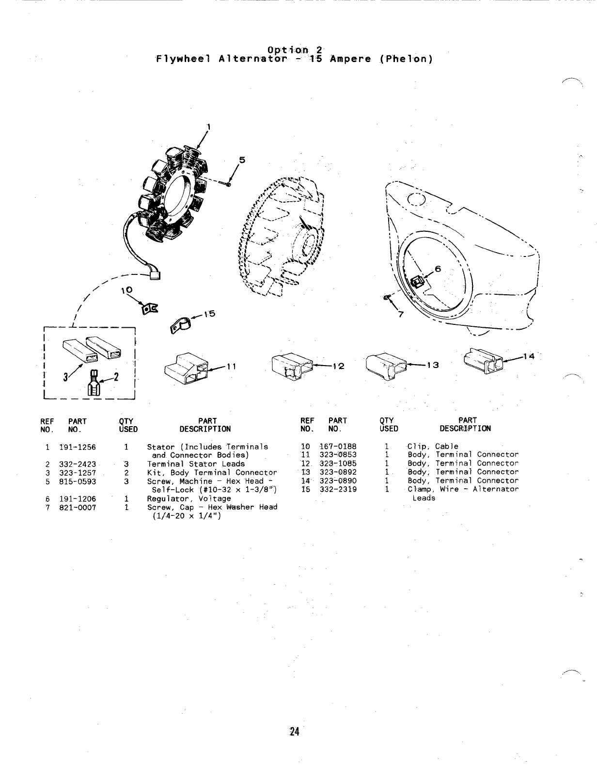
Op-ti.a.n 2
‘Flywheel Alternator --15 Ampere (P’helon)
;’
/
/
/
/
\
--
REF PART
NO. NO.
1191-1256
2332-2423
3323-1257
5815-0593
6191-1206
7821-0007
1
3
2
3
1
1
5
PART REF PART
DESCRIPTION NO. NO.
Stator (Includes Terminals 10 167-0188
and Connector Bodies) 11 323-0853
Terminal Stator Leads 12 323-1085
Kit, Body Terminal Connector 13 323-0892
Screw, Machine -Hex ’Head -14 323-0890
Self-Lock (#10-32 x1-3/8’”) 15 332-2319
Regulator, Voltage
Screw, Cap -Hex Washer Head
(1/4-20 X1/4”)
._,3 -14 ,_
Q
“N,.,.
QTY
USED
1Clip,
18ody ,
18ody ,
8ody ,
:8ody ,
1Clamp, Wire -Alternator
Leads
PART
DESCRIPTION
Cable
Terminal Connector
Terminal Connector
Terminal Connector
Terminal Connector
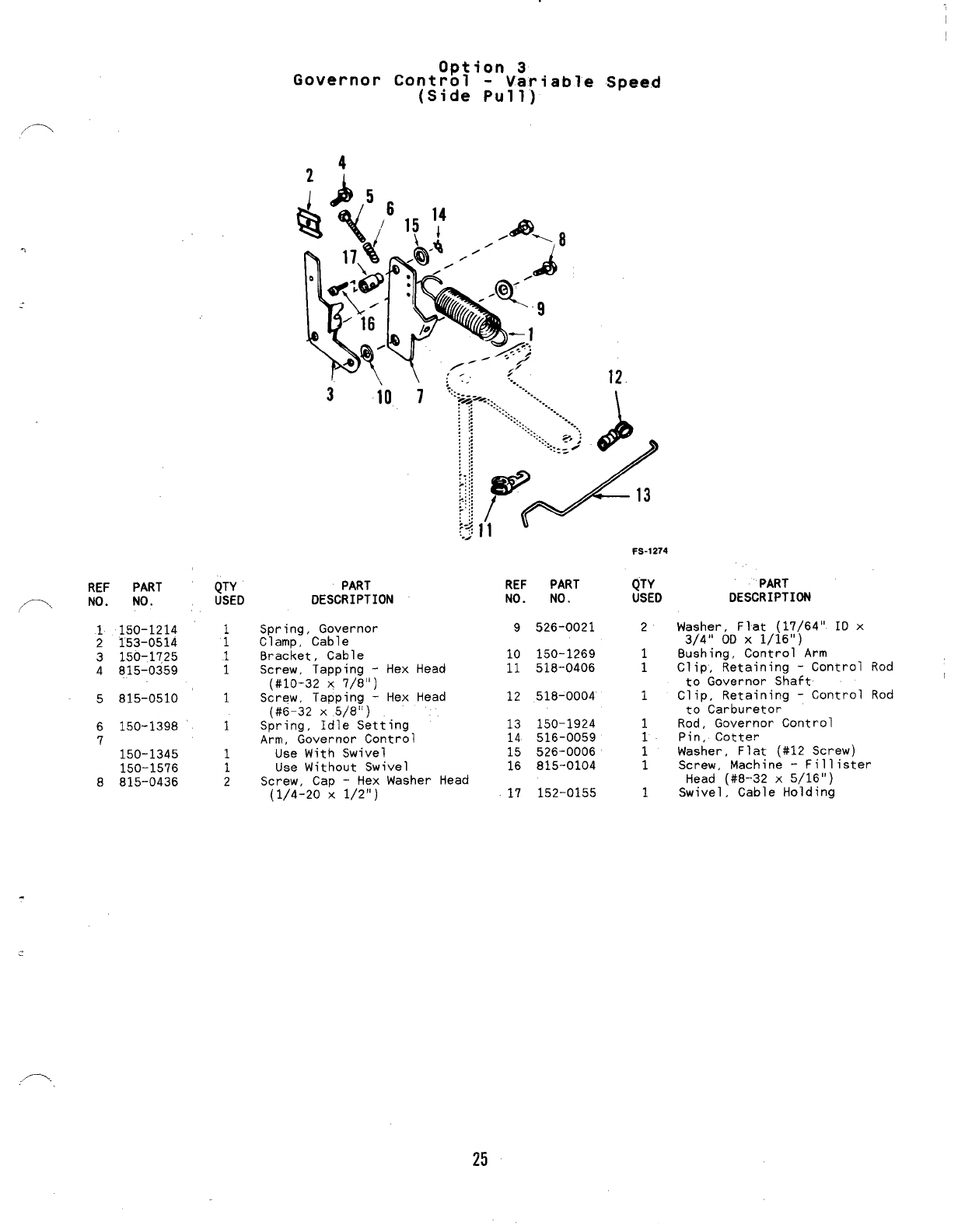
Option 3
Governor Control -Variable Speed
(Side Pull)
12.
REF PART
~,
,/ NO. NO.
1150-1214
2153-0514
3150-1725
4815-0359
5815-0510
6150-1398
7150-1345
150-1576
8815-0436
QTY
USED
:
;
1
1
1
1
2
310
PART
DESCRIPTION
7
REF PART
NO. NO.
9526-0021
Spring, Governor
Clamp, Cable
Bracket, Cable
Screw, Tapping -Hex Head
(#10-32 X7/8”)
Screw, Tapping -Hex Head
(#6-32 X5/8”)
Spring, Idle Setting
Arm, Governor Control
Use With Swivel
Use Without Swivel
Screw, Cap -Hex Washer Head
(1/4-20 X1/2”) 17 152-0155
10 150-1269
11 518-0406
12 518-0004
13 150-1924
14 516-0059
15 526-0006’
16 815-0104
FS-1274
QTY PART
USED DESCRIPTION
2Washer, Flat (17/64” ID x
3/4” OD X1/16”)
Bushing, Control Arm
;Clip, Retaining -Control Rod
to Governor Shaft
1Clip, Retaining -Control Rod
to Carburetor
1Rod, Governor Control
1Pin, Cotter
1Washer, Flat (#12 Screw)
1Screw, Machine -Fill ister
Head (#8-32 x5/16”)
1Swivel, Cable Holding
25
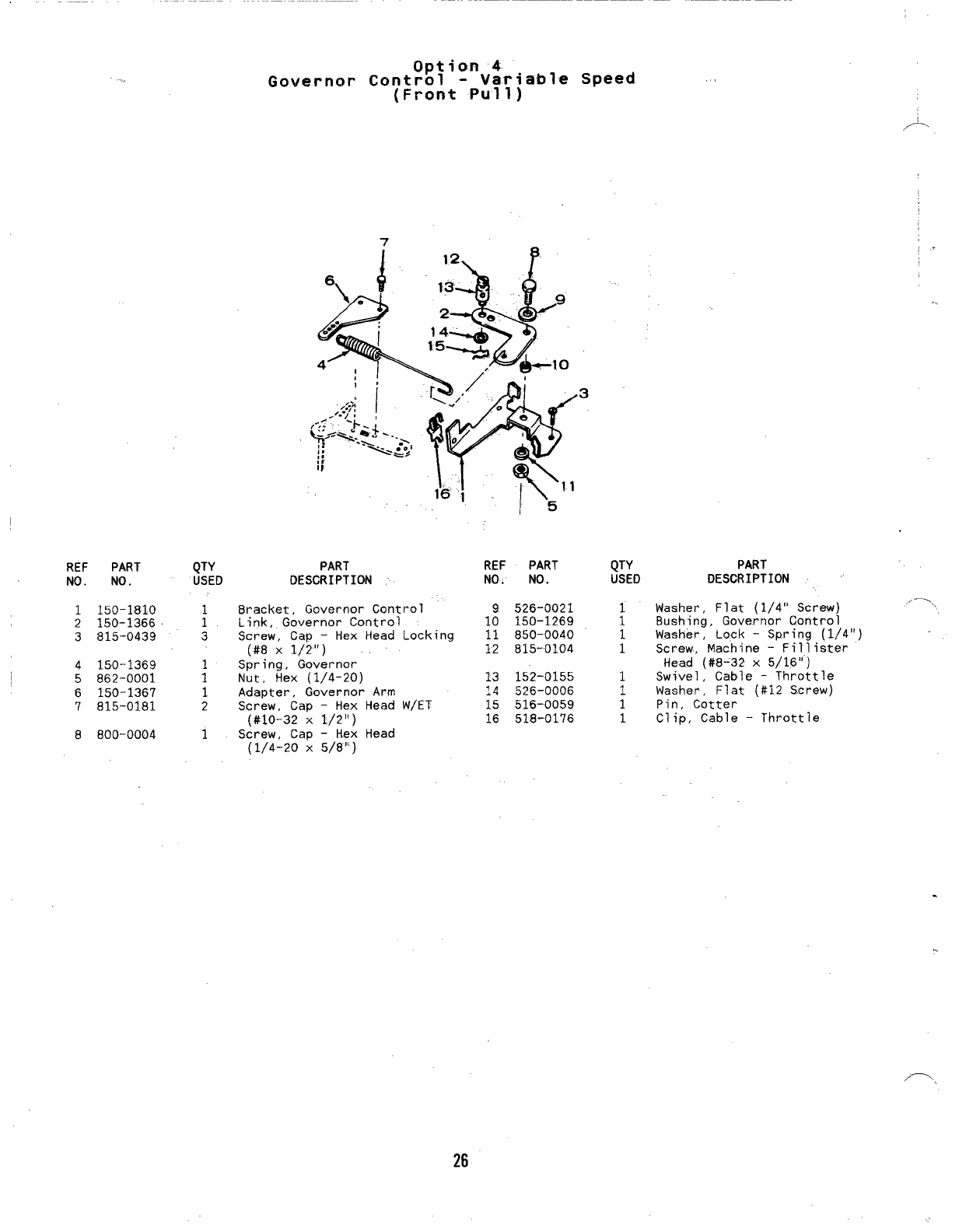
Option 4
., Governor Control -Variable Speed
(Front Pull)
7
REF PART
Nt). NO.
1150-1810
2150-1366
3815-0439
4150--1369
5862-0001
6150-1367
7815-0181
8800-0004
QTY
USED
1
1
3
i
1
2
1
PART
DESCRIPTION
Bracket, Governor Contro~
Link, Governor Control
Screw, Cap -Hex Head Locking
(#8 X1/2”)
Spring, Governor
Nut, Hex (1/4-20)
Adapter, Governor Arm
Screw, Cap -Hex Head W/ET
(#10-32 X1/2”)
Screw, Cap -Hex Head
(1/4-20 X5/8”)
REF PART
NO. NO.
9526-0021
10 150-1269
11 850-0040
12 815-0104
13 152-0155
~~ 5~6-ooo6
15 516-0059
16 518-0176
QTY
USED
:
;
1
1
1
1
,.
..
PART
DESCRIPTION
Washer, Flat (1/4” Screw) ..-
Bushing, Governor Control
Washer, Lock -Spring (1/4”)
Screw, Machine -Fillister
Head (#8-32 x5/16”)
Swivel, Cable -Throttle
Washer, Flat (#12 Screw)
Pin, Cotter
Clip, Cable -Throttle
.
!.
,--,
26
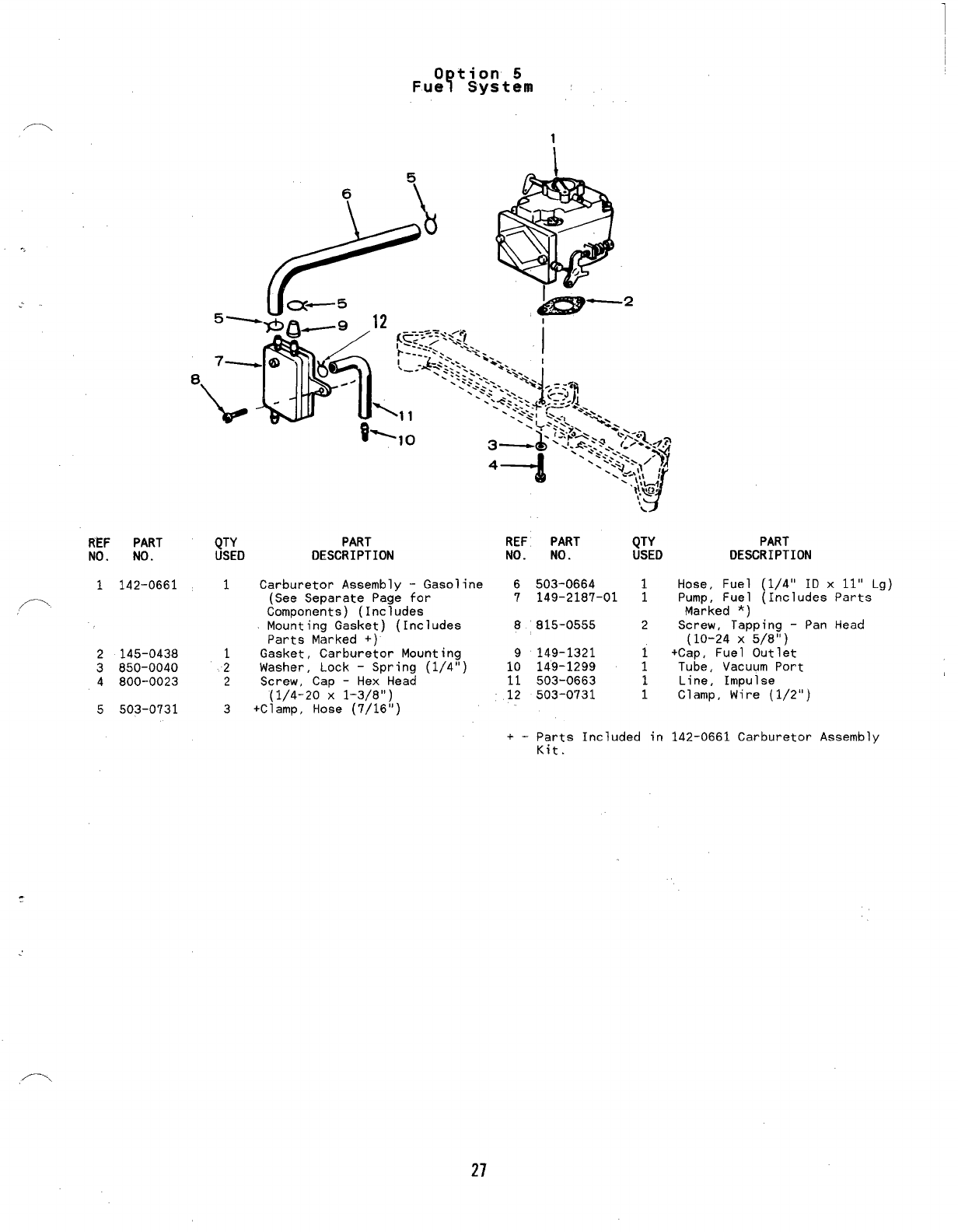
REF PART
NO. NO.
1142-0661
P.
2145-0438
3850-0040
4800-0023
5503-0731
0tion 5
Fue YSystem
1
QTY PART REF PART QTY
USED DESCRIPTION NO. NO. USED
PART
DESCRIPTION
1
1
2
2
3
Carburetor Assembly -Gasoline 6503-0664 1Hose, Fuel (1/4” ID x11” Lg)
(See Separate page for 7149-2187-01 1Pump, Fuel (Includes Parts
Components) (Inciudes
Mounting Gasket) (Includes
Parts Marked +)
Gasket, Carburetor Mounting
Washer, Lock -Spring (1/4”)
Screw, Cap -Hex Head
(1/4-20 X1-3/8”)
+Clamp, Hose (7/16”)
Marked *)
8815-0555 2Screw, Tapping -Pan Head
(10-24 X5/8”)
9149-1321 +Cap, Fuel Outlet
10 149-1299 ;Tube, Vacuum Port
11 503-0663 1Line, Impulse
12 503-0731 1Clamp, Wire (1/2”)
+-parts Included in 142–0661 carburetor Assembly
Kit.
/----
27
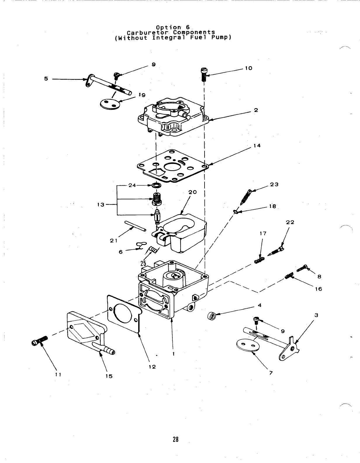
Option 6
Carburetor Components ,..
(Without Integral Fuel Pump)
,—.
13
10
L-— ““
,,—,
11 15. 6
28
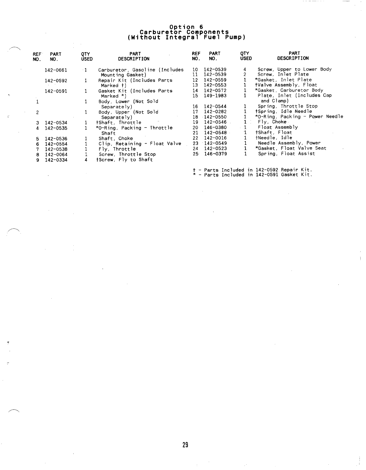
REF PART
NO. NO.
142-0661
142-0592
142-0591
1
2
..
3142-0534
4142-0535
5142-0536
6142-0554
‘1 142-0538
8142-0064
9142-0334
;TYD
1
1
1
1
1
1
1
1
;
1
4
Carbure!~~18;m$onents
(Without Integral Fuel Pump)
PART
DESCRIPTION
Carburetor, Gasoline (Includes
Mounting Gasket)
Repair Kit (Includes Parts
Marked t)
Gasket Kit (Includes Parts
Marked *)
Body, Lower (Not Sold
Separately)
Body, Upper (Not Sold
Separately)
tShaft, Throttle
*O-Ring, Packing -Throttle
Shaft
Shaft, Choke
Clip, Retaining -Float Valve
Fly, Throttle
Screw, Throttle Stop
tScrew, Fly to Shaft
REF PART
NO. NO.
10 142-0539
11 142-0539
12 142-0559
13 142-0553
14 142-0572
15 149-1983
16 142-0544
17 142-0282
18 142-0550
19 142-0546
20 146-0380
21 142-0548
22 142-0016
23 142-0549
24 142-0523
25 146-0379
QTY
USED
4
2
1
1
1
1
1
1
1
1
1
“1
1
1
t-Parts Included in
*–parts Included in
PART
DESCRIPTION
Screw, Upper to Lower Body
Screw, Inlet Plate
*Gasket, Inlet Plate
tValve Assembly, Float
*Gasket, Carburetor Body
Plate, Inlet (Includes Cap
and Clamp)
Spring, Throttle Stop
tSpring, Idle Needle
*O-Ring, Packing -Power Needle
Fly, Choke
Float Aesembly
tShaft, Float
tNeedle, Idle
Needle Assembly, Power
*Gasket, Float Valve Seat
Spring, Float Assist
142-0592 Repair Kit.
142-0591 Gasket Kit.
,-.
29
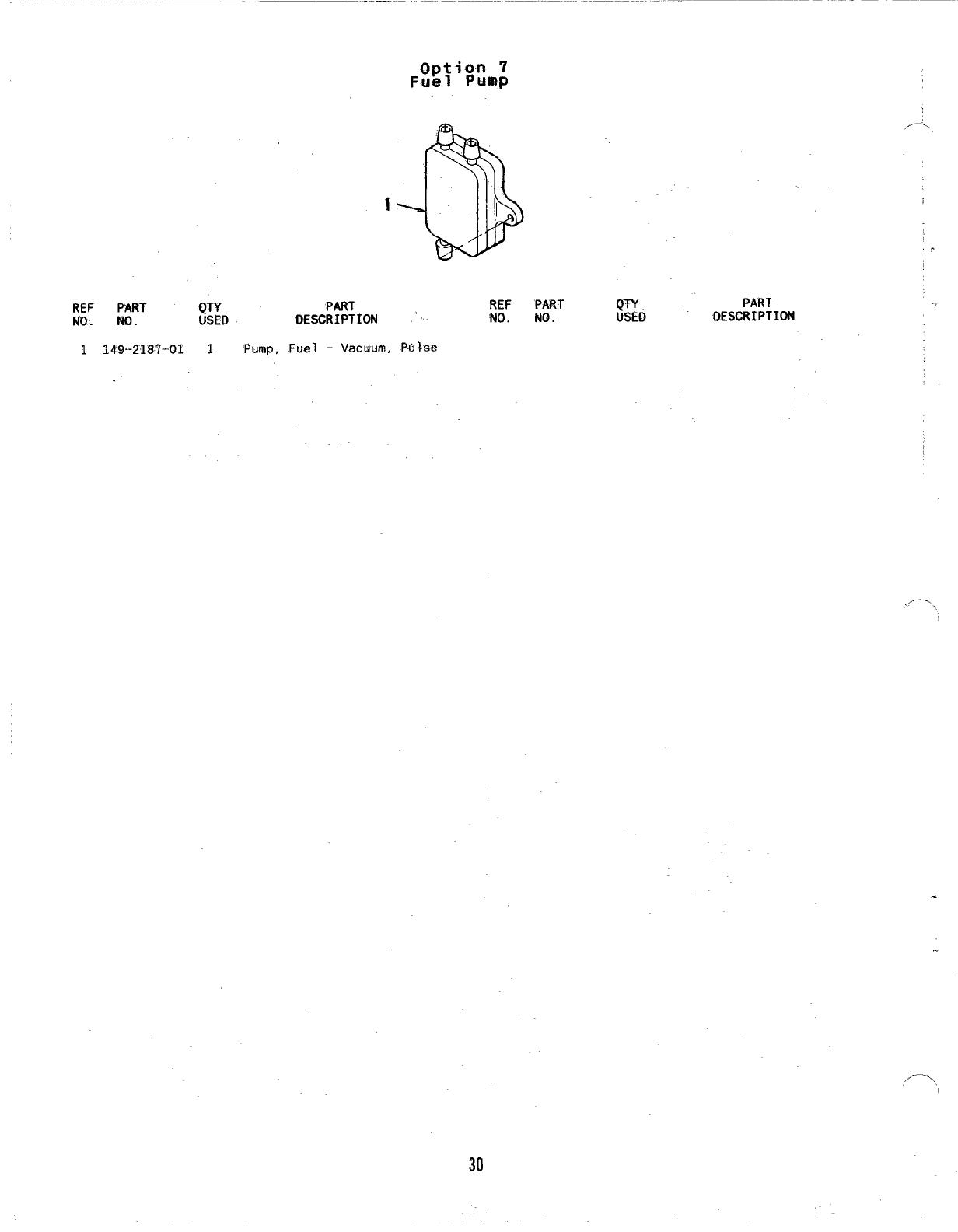
Option 7
Fuel PU,mP
1
REF PART QTY PART
No. MD. USED DESCRIPTION
1149-2187-01 1.Pump. Fuel -Vacuum, Ptilse
REF PART
NO. NO.
QTY PART
USED OEWRIPTION
/-,
.
,-,,
30
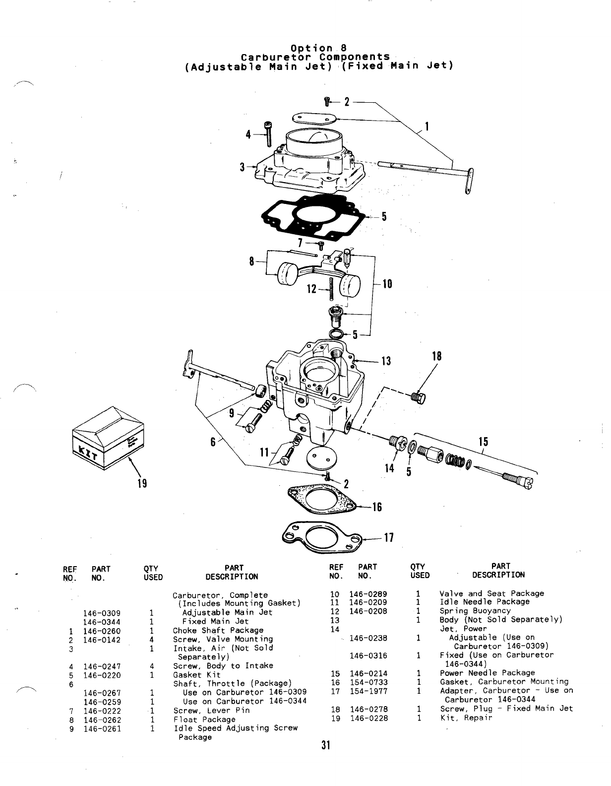
Option 8
Carburetor Components
(Adjustable Main Jet) (Fixed Main Jet)
4
8%’110
H
-J
f-.
i9
REF PART
.N07 NO.
PART
DESCRIPTION
QTY PART REF PART
USED DESCRIPTION NO. NO.
QTY
USED
Valve and Seat Package
Idle Needle Package
Spring Buoyancy
Body (Not Sold Separately)
Jet, Power
Adjustable (Use on
Carburetor 146-0309)
Fixed (Use on Carburetor
146-0344)
Power Needle Package
Gasket, Carburetor Mounting
Adapter, Carburetor -Use on
Carburetor 146-0344
Screw, Plug -Fixed Main Jet
Kit, Repair
Carburetor, Complete
(Includes Mounting Gasket)
Adjustable Main Jet
Fixed Main Jet
Choke Shaft Package
Screw, Valve Mounting
Intake, Air (Not Sold
Separately)
Screw, Body to Intake
Gasket Kit
Shaft, Throttle (Package)
Use on Carburetor 146-0309
Use on Carburetor 146-0344
Screw, Lever Pin
Float Package
Idle Speed Adjusting Screw
Package
10
11
12
13
14
146-0289
146-0209
146-0208
.. 146-0309
146-0344
1146-0260
2146-0142
3
1
1
1
4
1
146-0238 1
146-0316 1
4
1
4146-0247
5146-0220 15
16
17
146-0214
154-0733
154-1977
1
1
1
/’-\ 6
146-0267
146-0259
1
118
19 146-0278
146-0228
1
1
7146-0222
8146-0262
9146-0261
1
1
31
.
REF
NO.
PART
NO.
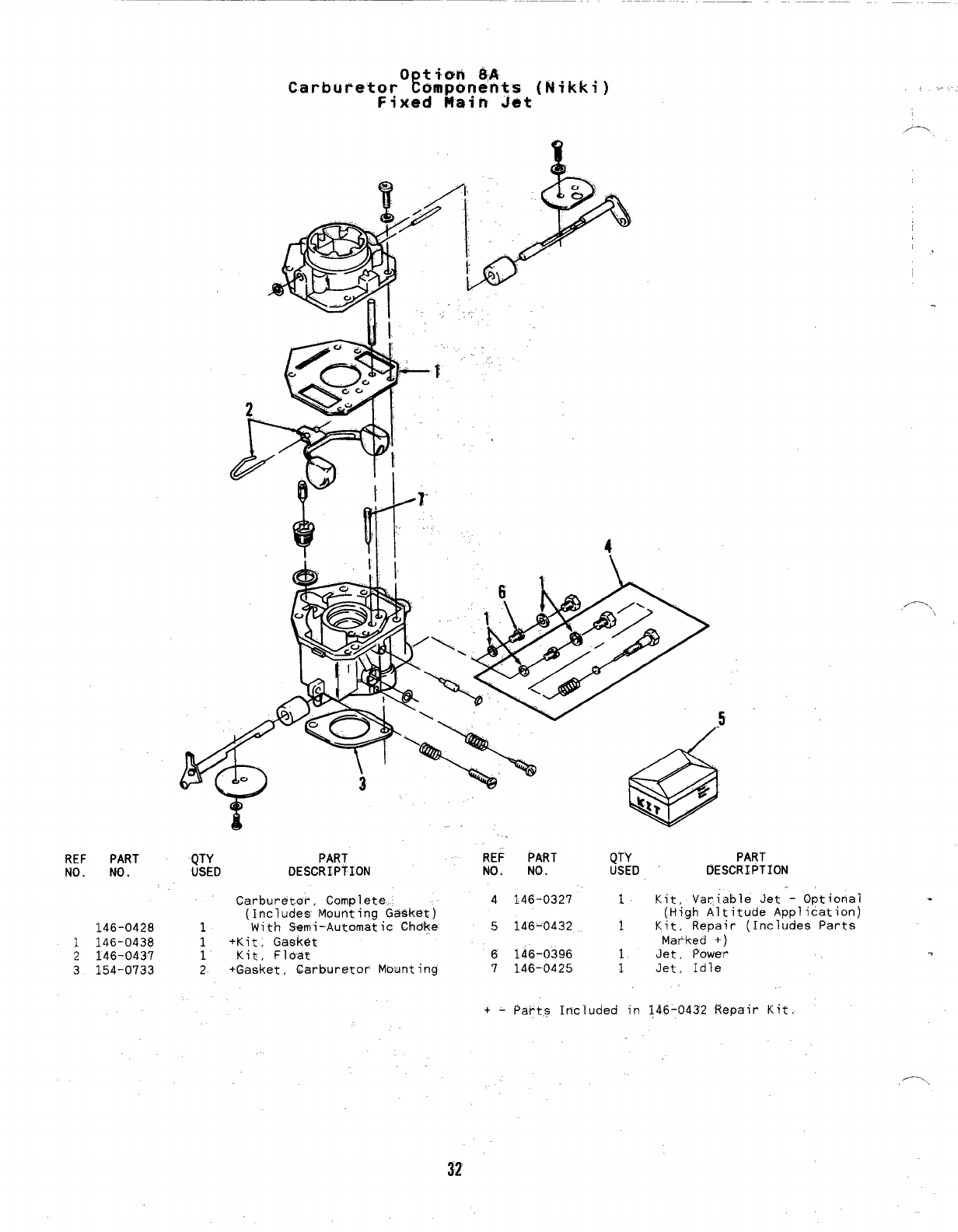
QTY PART REF PART QTY PART
USED DESCRIPTION NO. NO. USED DESCRIPTION
Carburet~r, Com~lete
(Includes Mounting Gasket)
146-0428 1With Semi-Automatic Choke
1146-0438 1+Kit, Gasket
2146-0437 1Kit, FIoat
3154-0733 2+Gasket, Carburetor Mounting
4146-0327 1Kit, Variable Jet -Optional
(High Altitude Application)
5146-0432 1Kit, Repair (Includes Parts
Marked +)
6146-0396 1Jet, Power
7146-0425 1Jet ,Idle
+-parts Included in 146-0432 Repair Kit,
,...,
.
.“-...,
32
10
a
1-
,/-
6
f
11-
REF PART
NO. NO.
159-0597
1159-0981
-. 2159-0596
3159-0595
4134-0599
.. 5501-0008
6159-0020
QTY
USED
1
1
2
2
1
;
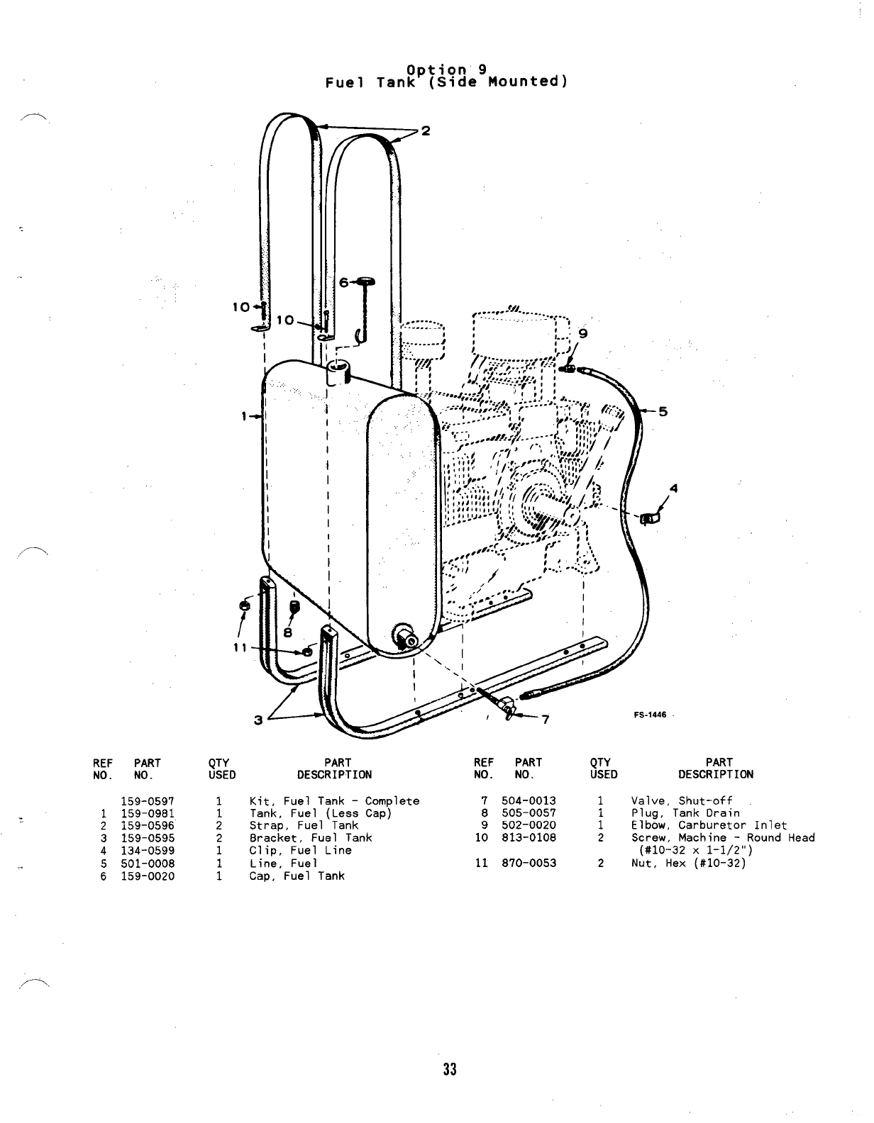
Option 9
Fuel Tank (Side Mounted)
II
II
II
I
II
I
II
II
I
I
I
PART
DESCRIPTION
.1
Kit, Fuel Tank –Complete
Tank, Fuel (Less Cap)
Strap, Fuel Tank
Bracket, Fuel Tank
Clip, Fuel Line
Line, Fuel
Cap, Fuel Tank
REF PART QTY PART
NO. NO. USED DESCRIPTION
7504-0013 1Valve, Shut-off
8505-0057 Plug, Tank Drain
9502-0020 iElbow, Carburetor Inlet
10 813-0108 2Screw, Machine -Round Head
(#10-32 X1-1/2”)
11 870-0053 2Nut, Hex (#10-32)
33
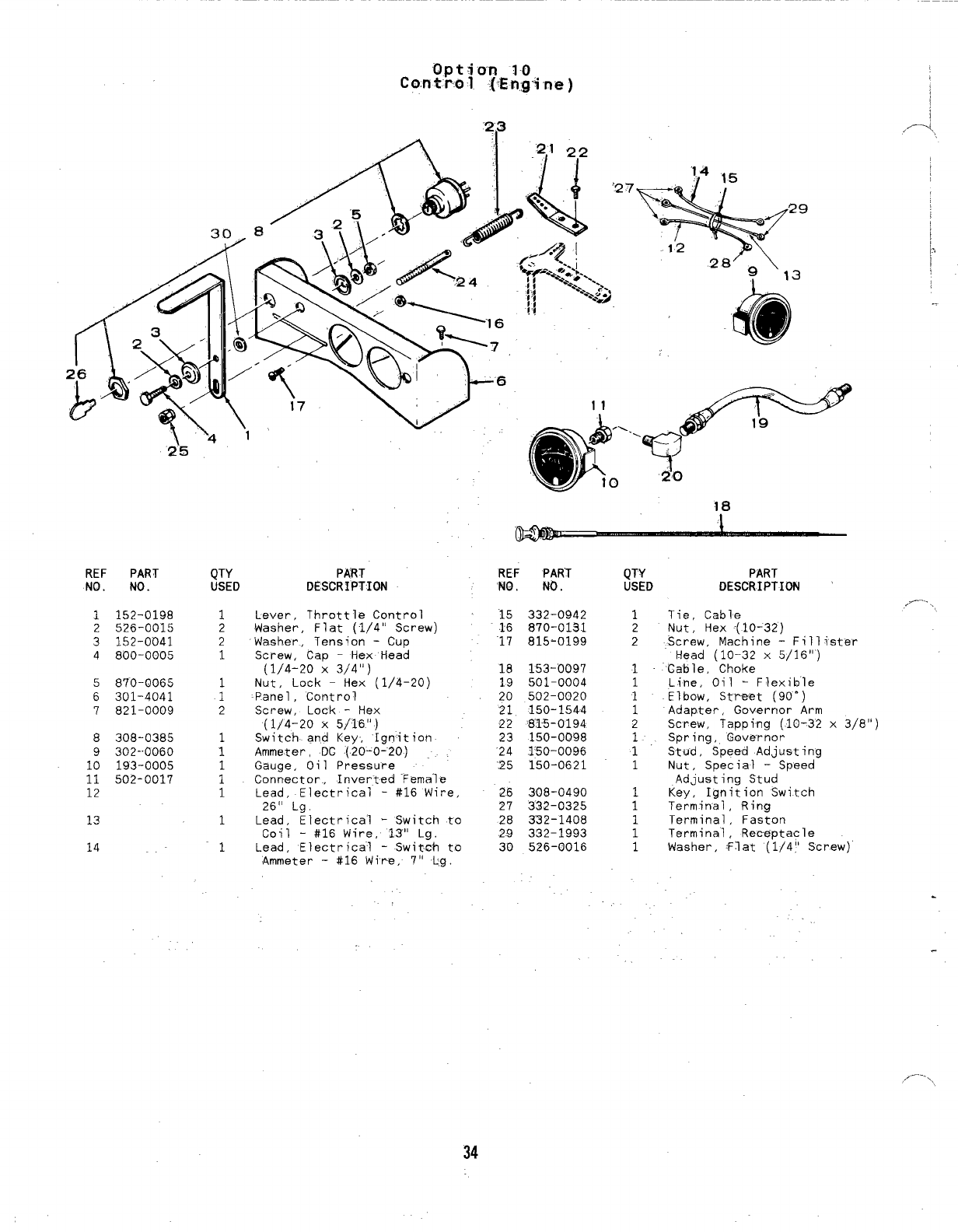
con tho 1
2’5
REF PART
NO. NO.
1152-0198
2526-0015
3152-0041
4800-0005
5870-0065
6301-4041
7821-0009
8308-0385
9302-0060
10 193-0005
11 502-0017
12
13
14
QTY
USED
1
2
2
1
1
1
2
1
1
1
1
1
1
1
PART
DESCRIPTION
Lever, Throttle Control
Washer, Flat (1/4” Screw)
Washer., Tension -Cup
Screw, Cap -Hex Head
(1/4-20 X3/4”)
Nut, Lock -Hex (1/4-20)
Panel ,Control
Screw, Lock -Hex
(1/4-20 X5/16”)
Switch. and Key, Ignition
Ammeter, DC (20-0-20)
Gauge, Oil Pressure
Connector, Inverted ‘Female
Lead, Electrical -#16 Wire,
26” Lg,
Lead, Electrical -Switch to
Coil -#16 Wire, 13” Lg.
Lead, Electrical -Switch to
Ammeter -#16 Wire, 7“ Lg.
REF PART
NO. NO.
15 332-0942
.16 870-013.1
’17 815-0199
18 153-0097
19 501-0004
20 502-0020
21 150-1544
22 ‘81-5-0194
23 150-0098
’24 150-0096
.25 150-0621
26 308-0490
?7 3“32-0325
28 332-1408
2.9 332-1993
30 526-0016
QTY PART
USED DESCRIPTION
1Tie, Cable
2Nut, Hex (10-32)
2Screw, Machine -Fill ister
Head (10-32 x5/16”)
1Cable, Choke
1Line, Oil -Flexible
1Elbow, Street (90”)
1Adapter, Governor Arm
2Screw, Tapping (10-32 x3/8”)
1. Spring, Governor
1’ Stud, Speed Adjusting
1Nut, Special -Speed
Adjusting Stud
1Key, Ignition Switch
1Terminal, Ring
1Terminal, Faston
1Terminal, Receptacle
1Washer, Flat (1/4)’ Screw)
.
/-.. .
34
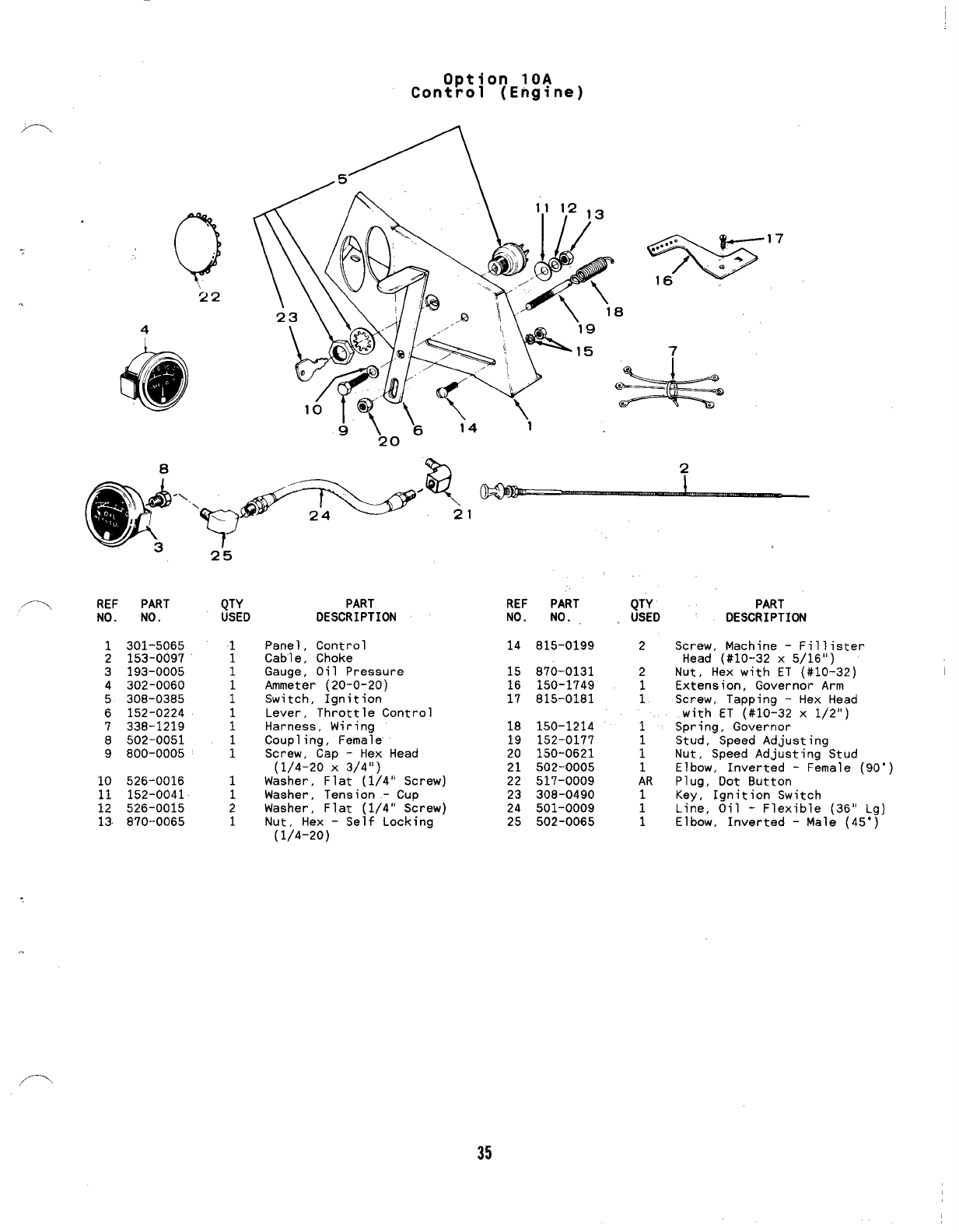
Option 10A
Control (Engine)
Q
,’
22
8
,-\ REF PART QTY
No. No. USED
1301-5065 1
2153-0097 1
3193-0005 1
4302-0060 1
5308-0385 1
6152-0224 1
7338-1219 1
8502-0051 1
9800-0005 1
10 526-0016 1
11 152-0041 1
12 526-0015 2
13 870-0065 1
PART
DESCRIPTION
Panel, Control
Cable, Choke
Gauge, Oil Pressure
Ammeter (20-0-20)
Switch, Ignition
Lever, Throttle Control
Harness, Wiring
Coupling, Female
Screw, Cap -Hex Head
(1/4-20 X3/4”)
Washer, Flat (1/4” Screw)
Washer, Tension -Cup
Washer, Flat (1/4” Screw)
Nut, Hex -Self Locking
(1/4-20)
REF PART
NO. NO.
14 815-0199
15 870-0131
16 150-1749
’17 815-0181
18 150-1214
19 152-0177
20 150-0621
21 502-0005
22 517-0009
23 308-0490
24 501-0009
25 502-0065
QTY
USED
2
2
1
1
1
1
1
1
AR
1
1
1
PART
DESCRIPTION
Straw, Machine –Fillister
Head (#10-32 x5/16”)
Nut, Hex with ET (#10-32)
Extension, Governor Arm
Screw, Tapping -Hex Head
with ET (#10–32 x1/2”)
Spring, Governor
Stud, Speed Adjusting
Nut, Speed Adjusting Stud
Elbow, Inverted -Female (90”)
Plug, Dot 8utton
Key, Ignition Switch
Line, Oil -Flexible (36” Lg)
Elbow, Inverted -Male (45”)
35
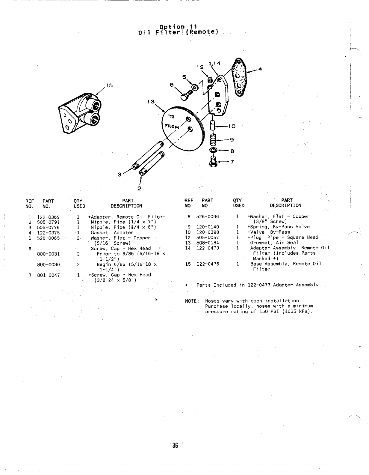
15
REF PART QTY
NO. NO. USED
1122-0369 1
2505-0791 1
3505-0776 1
4122-0375 1
5526-0065 2
6
800-0031 2
800-0030 2
7801-0047 1
/
.4 I
!
,.
-7
I
2,.
..
PART REF PART QTY PART
DESCRIPTION NO. NO. USED D~SCRIPTION
+Adapter, Remote Oil Filter
Nipple, Pipe (1/4 x7“)
Nipple, Pipe (1/4 x6“)
Gasket, Adapter
Washer, Flat -Copper
(5/16” Screw)
Screw, Cap -Hex Head
Prior to 6/86 (5/16-18 x
1-1/2”)
Begin 6/86 (5/16-18 x
1-1/4”)
+Screw. Cao -Hex Head
“(3/8L24 x5/8”)
8526-0066 1+Washer, Flat -Copper
(3/8” Screw)
9120-0140 1+Spring, By--Pass Valve
10 120-0398 1+Valve, By-Pass
12 505-0057 1+Plug, Pipe -Square Head
13 508-0184 1Grommet, Air Seal
14 122-0473 1Adapter Assembly, Remote Oil
Filter (Includes Par&s
Marked +)
15 122-0476 1Base Assembly, Remote Oil
Filter
+-parts Included in 122-0473 Adapter Assembly.
bNOTE; Hoses vary with each installation.
Purchase locally, hoses with aminimum
pressure rating of 150 PSI (1035 kPa).
36
, ....
/ .
,.--.,,
18
,,, =,
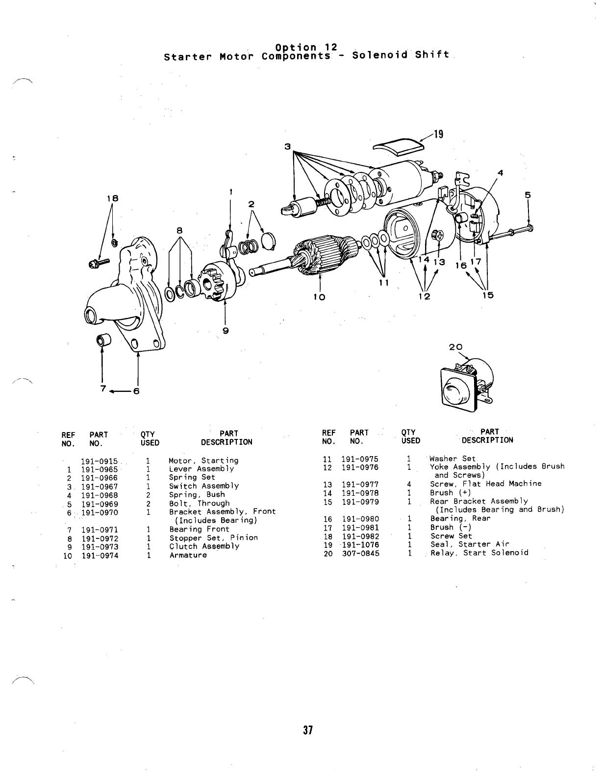
Option 12
starter Motor Components -Solenoid Shift
1
REF
NO.
3
20
1
2
3
4
5
6
7
8
1:
Ir
7—d
PART QTY
NO. USED
191-0915 1
191-0965 1
191-0966 1
191-0967 1
191-0968 2
191-0969 2
191-0970 1
191-0971 1
191-0972
191-0973 1
191-0974 1
PART
DESCRIPTION
Motor, Starting
Lever Assembly
Spring Set
Switch Assembly
Spring, Bush
Bolt, Through
Bracket Assembly, Front
(Includes Bearing)
Bearing Front
Stopper Set, Pinion
Clutch Assembly
Armature
REF PART
NO. NO.
11 191-0975
12 191-0976
13 191-0977
14 191-0978
15 191-0979
16 191-0980
17 191-0981
18 191-0982
19 -191-1076
20 307-0845
QTY PART
USED DESCRIPTION
1Washer Set
1Yoke Assembly (Includes Brush
and Screws)
4Screw, Flat Head Machine
1Brush (+)
1Rear Bracket Assembly
(Includes Bearing and Brush)
18earing, Rear
1Brush (-)
1Screw Set
1Seal, Starter Air
1Relay, Start Solenoid
,.
/-,
37
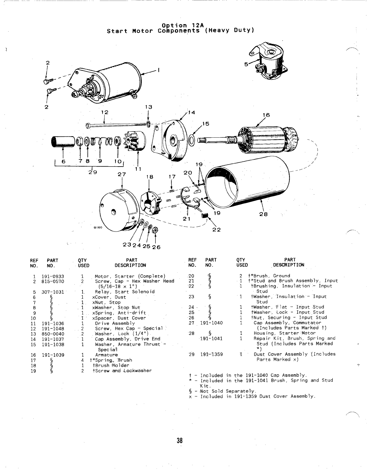
Option 12A
Start Motor Components {Heavy -Duty)
5
.-,
.
21;2
13
I/.14 146
‘\
/’
/
/
.
—
2’9
2’8
,,, , 23242’5~6
REF PART QTY PART
NO. NO. USED DESCRIPTION
REF PART
NO. NO.
QTY PART
USED DFSGRXPTION
20 ‘
21 !
22 s
1
2
5
6
7
8
9
10
191-’0933
815-0570 1
2Motor, Starter (Cnmplete)
Screw, Cap -Hex Washer Head
(’5/16-T8 Xl“)
Relay, Start Solenoid
xCover, Dust
xNut, Stop
xWasher, Stop Nut
xSpring, Anti-drift
xSpacer, Dust Cover
Drive Assembly
Screw, Hex Cap -Special
Washer, Lock (1/4”)
Cap Assembly, Drive End
Washer, Armature Thrust”-
Special
Armatu~e
t*Spring., ‘Brush
t8rush ~Holder
tScrew anti Loc.kwasher
2
1
1
+*Brush, Ground
t*Stud and Brush Assembly, Input
tBru,ehing, Insulation –Input
Stud
tWasher, ‘Insulation -Input
Stud
tWasher, ‘Flat -Input Stud
tWasher, Lock -Input Stud
tNut, Securing -Input Stud
Cap Assembly, Commutator
(Includes ’Parts Marked tj
Housing, Starter Motor
Repair Kit, Brush, Spring and
Stud (Includes Parts Marked
307-1031 1
24
25 :
26 4
27 191-1040
1
1
1
1
.11
1
11
12
191-1036
191-1048
850-0040
191-1037
191-1038
1
228 5
191-loal
1
1
2
1
1
1
4
1
2
15
16
17
18
19
*)
1Oust Cover Assembly
29 191-”1359 (Includes
191-1039
s
:
Parts Marked x)
t-Included in the 191-1040 Cap Assembly.
*-In~]uded in the 191–1041 8rush, SPrin9 and Stud
Kit,
$-Mot Sold Separately.
x–Included in 191-1359 Dust Cover Assembly.
38
REF PART
NO. NO.
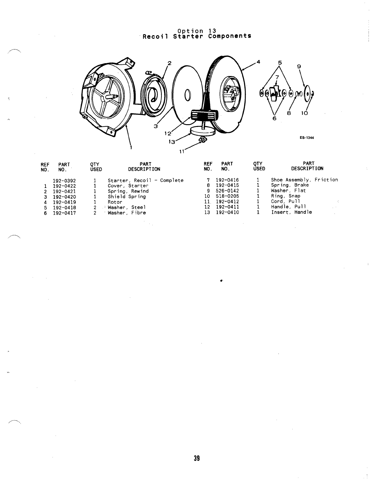
192-0392
1192-0422
2192-0421
3192-0420
4192-0419
5192-0418
6192-0417
Option 13
Recoil Starter Components
QTY PART
USED DESCRIPTION
1Starter, Recoil -Complete
1Cover, Starter
1Spring, Rewind
Shield Spring
;Rotor
2~Washer, Steel
2Washer, Fibre
REF PART
NO. NO.
7192-0416
8192-0415
9526-0142
10 518-0205
11, 192-0412
12 192-0411
13 192-0410
QTY
USED
1
1
1
1
1
1
1
6
ES-1344
PART
DESCRIPTION
Shoe Assembly, Friction
Spring, Brake
Washer, Flat
Ring, Snap
Cord, Pull
Handle, Pull
Insert, Handle
39
.—
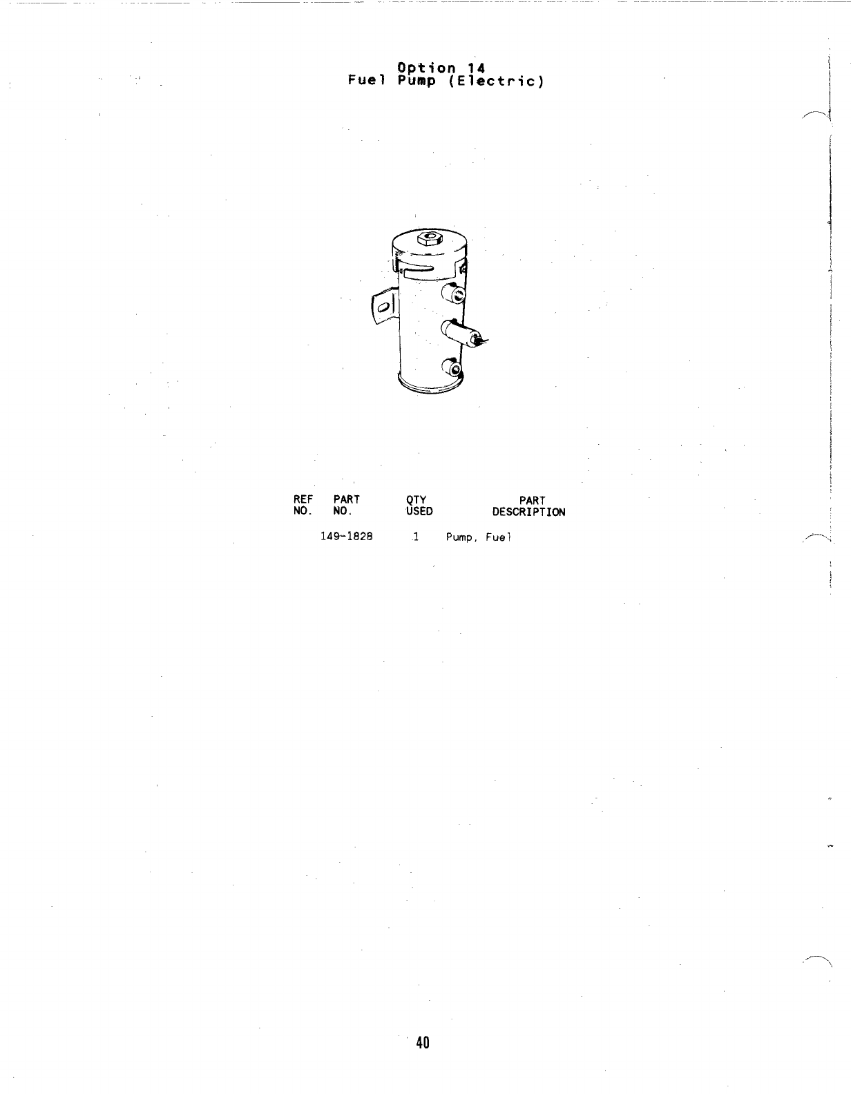
Option 14
Fuel Pump (Electric)
REF PART QTY PART
NO. NO. USED DESCRIPTION
149-1828 1Pump, Fuel
[
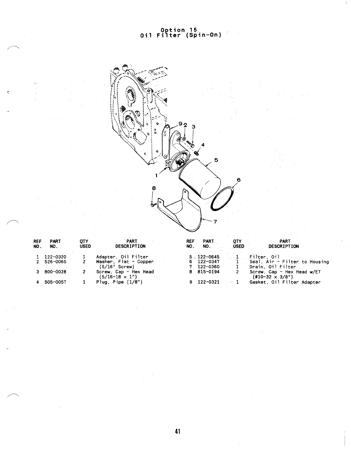
0tion 15
Y
Oil Fi ter (Spin-On)
!,,.
REF PART QTY
NO., NO. USED
1122-0320 1
2526-0065 2
3800-0028 2
4505-0057 1
‘PART
DESCRIPTION
Adapter, Oil Filter
Washer, Flat -Copper
(5/16” Screw)
Screw, Cap -Hex Head
(5/16-18 X1“)
Plug, Pipe (1/8”)
REF PART QTY
NO. NO. USED
5. 122-0645
6122-0347 i
7122-0360 1
8815-0194 2
9122-0321 ~~1
PART
DESCRIPTION
Filter, Oil
Seal, Air -Filter to Housing
Drain, Oil Filter
Screw, Cap -Hex Head w/ET
(#10-32 X3/8”)
Gasket, Oil Filter Adapter
41
--
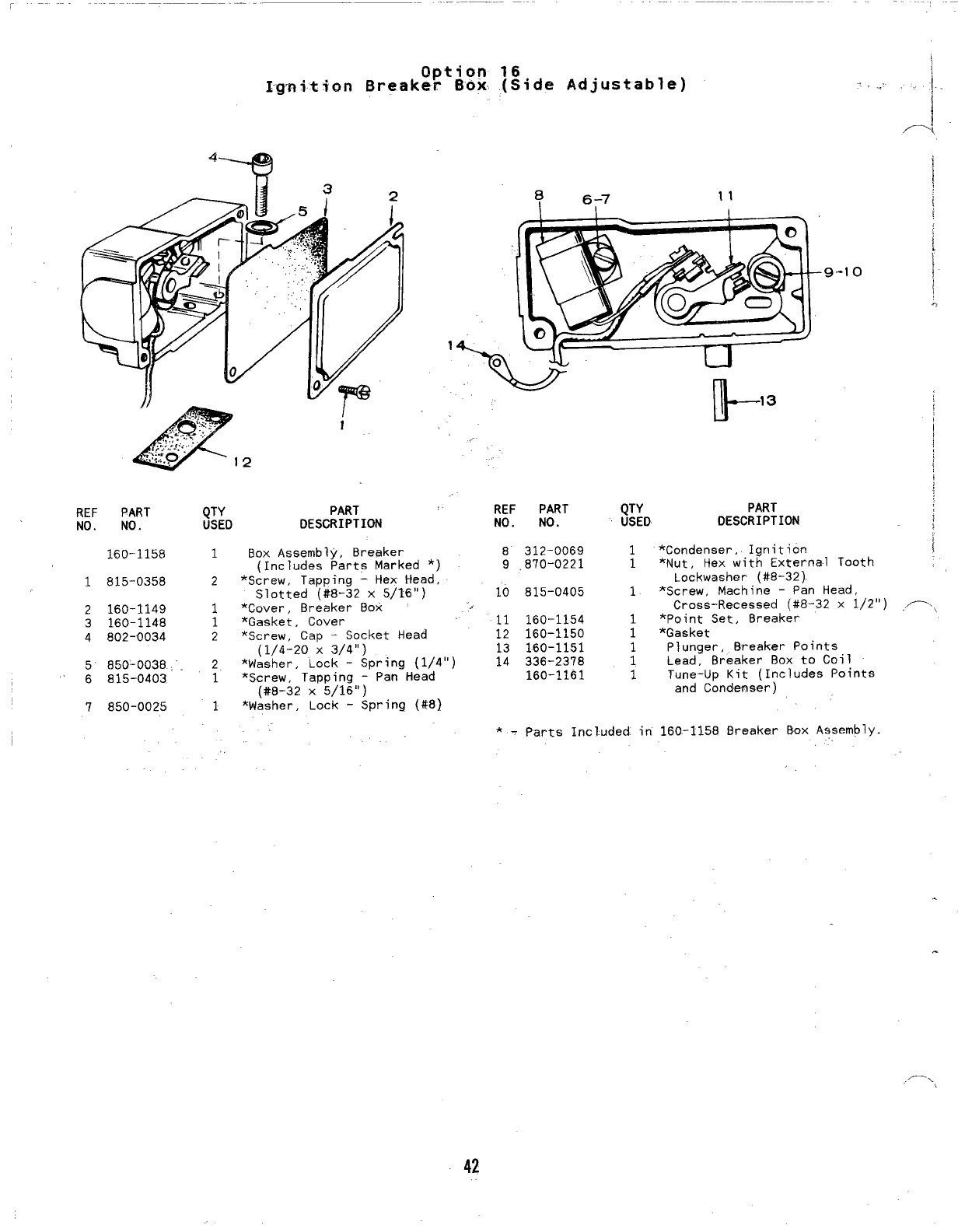
Option 16
Ignition Breaker Box (Side Adjustable) . ...
4*
REF PART
NO. ND.
160-1.158
1815-0358
2160-1149
3160-1148
4802-0034
5850-0038
6815-0403
7850-0025
a6-7 11
9-1o
l!l- 13
,.
QTY PART REF PART QTY PART
USED DESCRIPTION NO. NO. USED DESCRIPTION
1Box Assembly, Breaker 8312-0069 1*Condenser, Ignition
(Includes Parts Marked *) 9.870-0221 1*Nut, Hex with External Tooth
2*Screw, Tapping -Hex Head, Lockwashet” (#8-32)
Slotted (#8-32 x5/16”) 10 815-0405 1*Screw, Machine -Pan Head,
1*Cover, Breaker Box “. Cross-Recessed (#8-32 x1/2”)
1*Gasket, Cover 11 160-1154 1*Point Set, 8reaker
2*Screw, Cap -Socket Head 12 160-1150 1*Gasket
(1/4-20 X3/4”) 13 160-1151 1Plunger, 8reaker Points
2*Washer, Lock -Spring (1/4”) 14 336-2378 1
1
Lead, Breaker Box to Coil
*screw, Tapping -Pan Head 160-1161 1Tune-Up Kit (Includes Points
(#8-32 X5/16”)
1
and Condenser)
*Washer, Lock -Spring (#8)
*TParts Included. in 160-1158 Breaker Box A~sembly.
,,
,— ,,
42
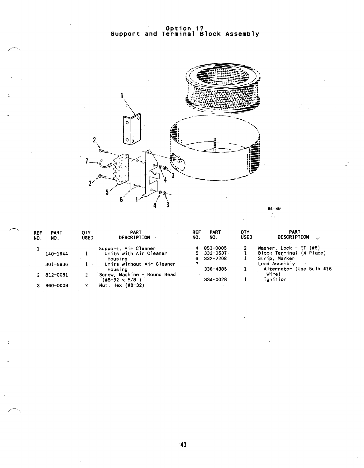
Option 17
Support and Terminal Block Assembly
ES-14S1
/-. REF PART
NO. NO.
1140-1644
301-5936
2812-0081
3860-0008
QTY PART
USED DESCRIPTION :
Support, Air Cleaner
1Units with Air Cleaner
Housing
1Units without Air Cleaner
Housing
2Screw, Machine -Round Head
(#8-32 X5/8”)
2Nut, Hex (#8-32)
REF PART
NO. NO.
4853-0005
5332-0537
6332-2208
7
336-4385
334-0028
QTY PART
USED DESCRIPTION ,.
2Washer, Lock -ET (#8)
1Block Terminal (,4 Place)
1Strip, Marker
Lead Assembly
1Alternator (Use Bulk #16
Wire)
1Ignition
43
..
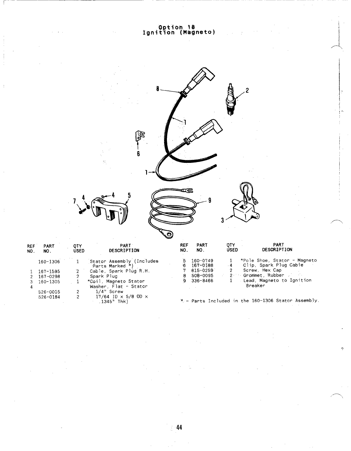
REF PART
NO. NO.
160-1306
1167-1595
2167-0298
3160-1305
4
526-0015
526-0184
T
o
6
QTY
USED
1
2
2
1
2
2
@
.’
9
e
PART R’EF PART
DESCRIPTION NO. NO.
Stator Assembly (Includes ~160-0749
Parts Marked *) .6 l~qk~~ss
Cable, Spark PIug R.H. 7815-0259
Spark Plug 8508-0095
*Coil, Magneto Stator 9336-8466
Washer, Flat -Stator
1/4” Screw
1$/64 ID X5/8 ~0 X
,1345” Thk)
3
QTY
USED
,,7.,
PART
DESCRIPTION
1*Pole Shoe, Stator -Magneto
-4 Clip, Spark Plug Cable
2Screw, Hex Cap
2Grommet, ‘Rubber
1Lead, Magneto to Ignition
Breaker
*–parts Included in the 160–1306 Stator A$sembly
44
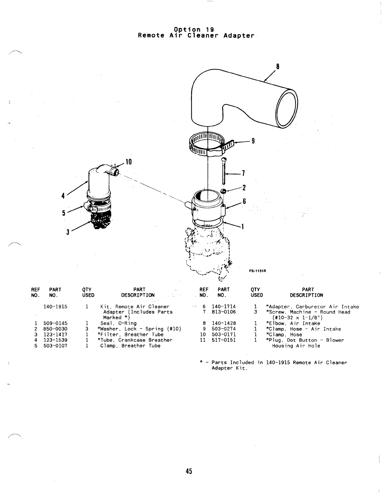
Option 19
Remote Air Cleaner Adapter
REF PART QTY
NO. NO. USED
PART
DESCRIPTION
140-1915 1Kit, Remote Air Cleaner
Adapter (Includes Parts
Marked *)
1509-0145 1Seal, O-Ring
2850-0030 3*Washer, Lock -Spring (#10)
3123-1417 1*Filter, Breather Tube
4123-1539 1*Tube, Crankcase Breather
5503-0107 1Clamp, Breather Tube
(3/
REF PART
NO. NO.
-6140-1714
7813-0106
8140-1428
9503-0274
10 503-0171
11 517-0151
9
.-
FS-1131R
QTY PART
USED DESCRIPTION
1*Adapter, Carburetor Air Intake
3*Screw, Machine -Round Head
(#10-32 X1-1/8’1)
1*Elbow, Air Intake
1*C]amp, Hose –Air Intake
1*Clamp, Hose
1*Pluq, Dot Button -
Ho~sing Air Hole
*-Parts Included in 140–1915 Remote Air
Adapter Kit.
Blower
Cleaner
45
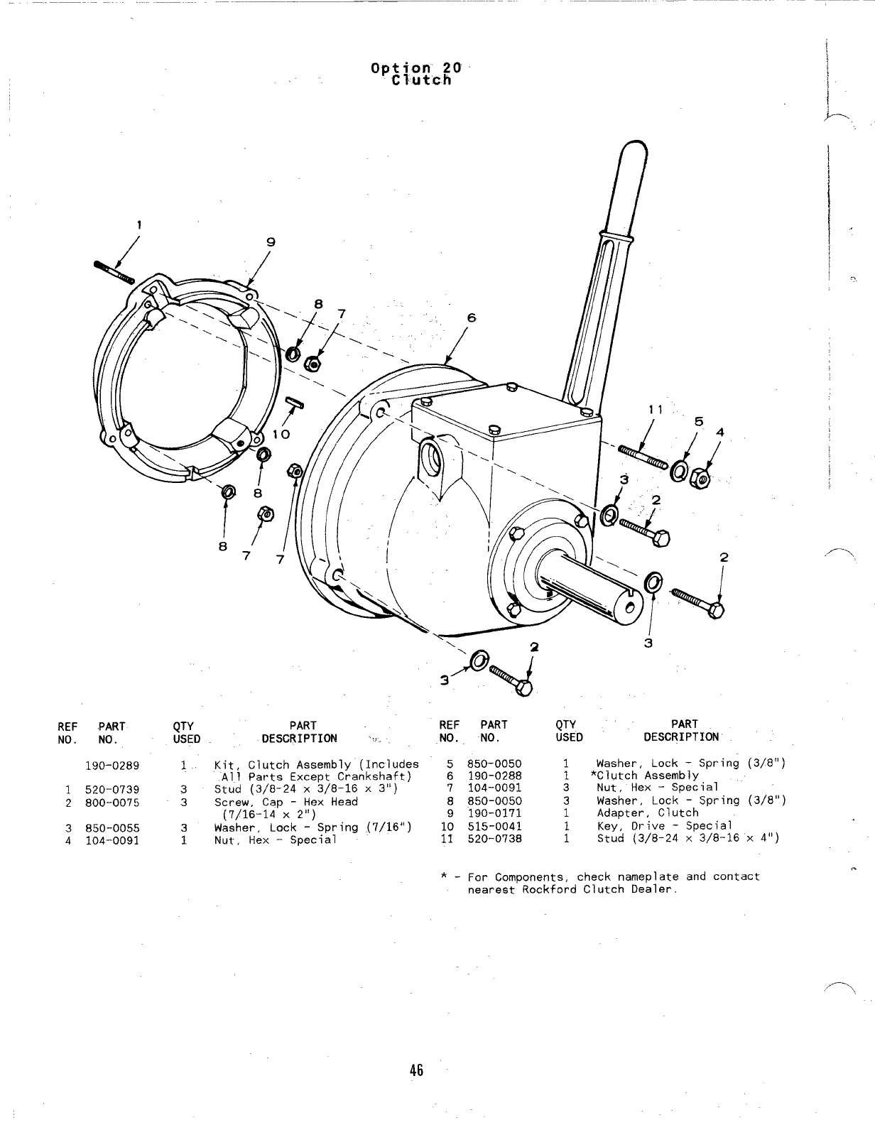
1
REF PART
NO. NO.
190-0289
1520-0739
2800-0075
3850-0055
4104-0091
1@/ill// /
QTY PART REF
USED DESCRIPTION :. NO.
\23
\-
1Kit, Clutch Assembly (Includes 5
All Parts Except Crankshaft) 6
3Stud (3/8-24 X3/8-16 X3“) 7
3Screw, Cap -Hex Head 8
(7/16-14 X2“) 9
3Washer, Lock -Spring (7/16”)
1Nut, Hex -Special i:
w
PART
NO.
850-0050
190-0288
104-0091
850-0050
190-0171
515-0041
520-0738
QTY PART
USEO DESCRIPTION
I
1Washer, Lock -Spring (3/8”)
1*Clutch Assembly
3Nut, Hex -Special
3Washer, Lock -Spring (3/8”)
1Adapter, Clutch
Key, Ot-ive -Special
;Stud (3/8-24 X3/8-16 X4“)
*. For Components, check nameplate and contact .
nearest Rockford Clutch Dealer.
,,.-. \
46
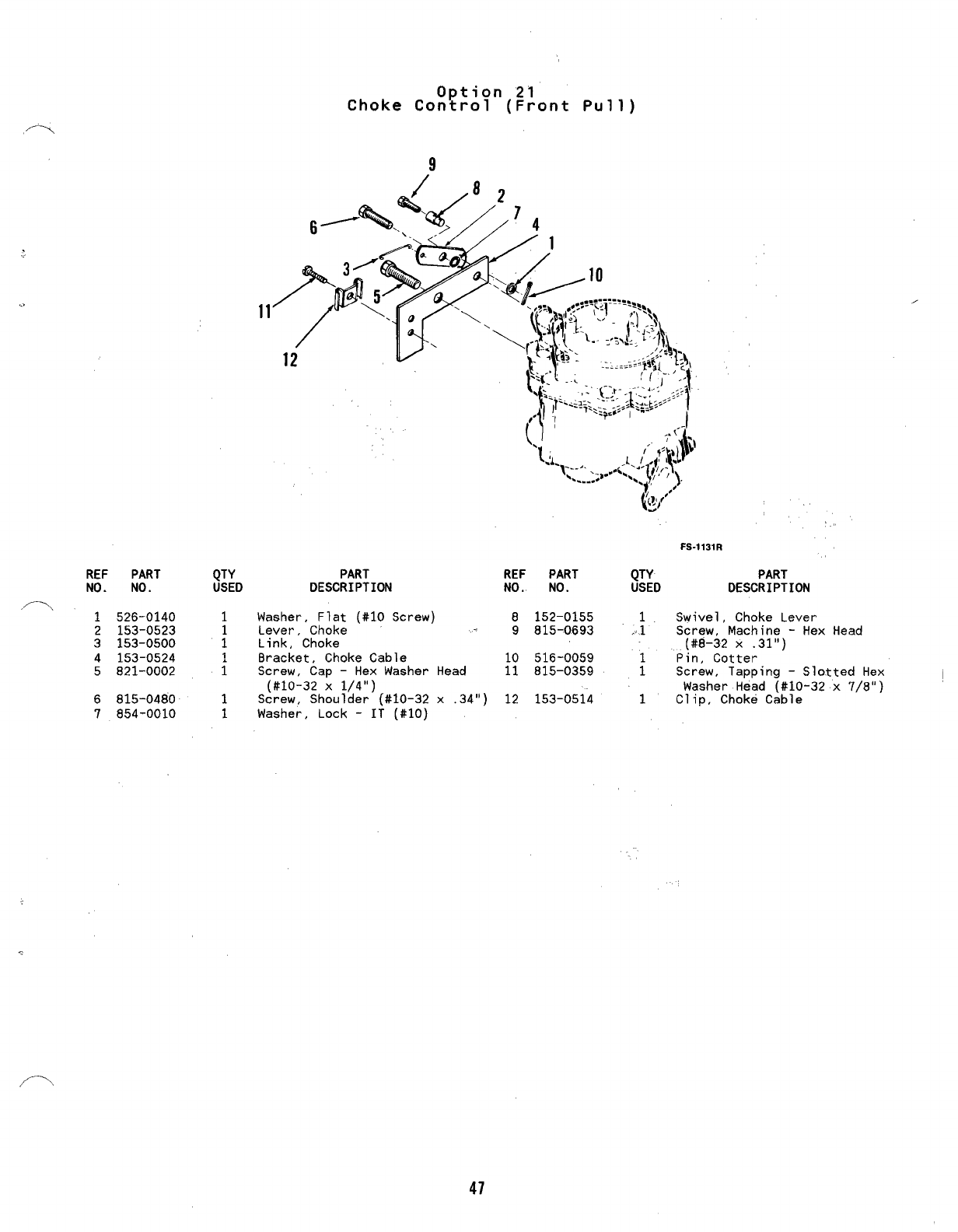
REF PART
NO. NO.
.- 1526-0140
2153-0523
3153-0500
4153-0524
5821-0002
6815-0480
7854-0010
QTY
USED
1
1
Option 21
Choke Control (Front Pull)
9
PART
DESCRIPTION
Washer, Flat (#10 Screw)
Lever, Choke
Link, Choke
Bracket, Choke Cable
Screw, Cap -Hex Washer Head
(#10-32 X1/4”)
Screw, Shoulder (#10-32 x.34”)
Washer, Lock -IT (#10)
‘,
FS-1131R
REF PART QTY PART
NO.. NO. USED DESCRIPTION
8152-0155 1Swivel, Choke Lever
9815-0693 .1 Screw, Machine -Hex Head
(#8-32 X.31”)
10 516-0059 Pin, Cotter
11 815-0359 ;Screw, Tapping -Slotted Hex
Washer Head (#10-32 x7/8”)
12 153-0514 1Clip, Choke Cable
/’-”.
47
~-
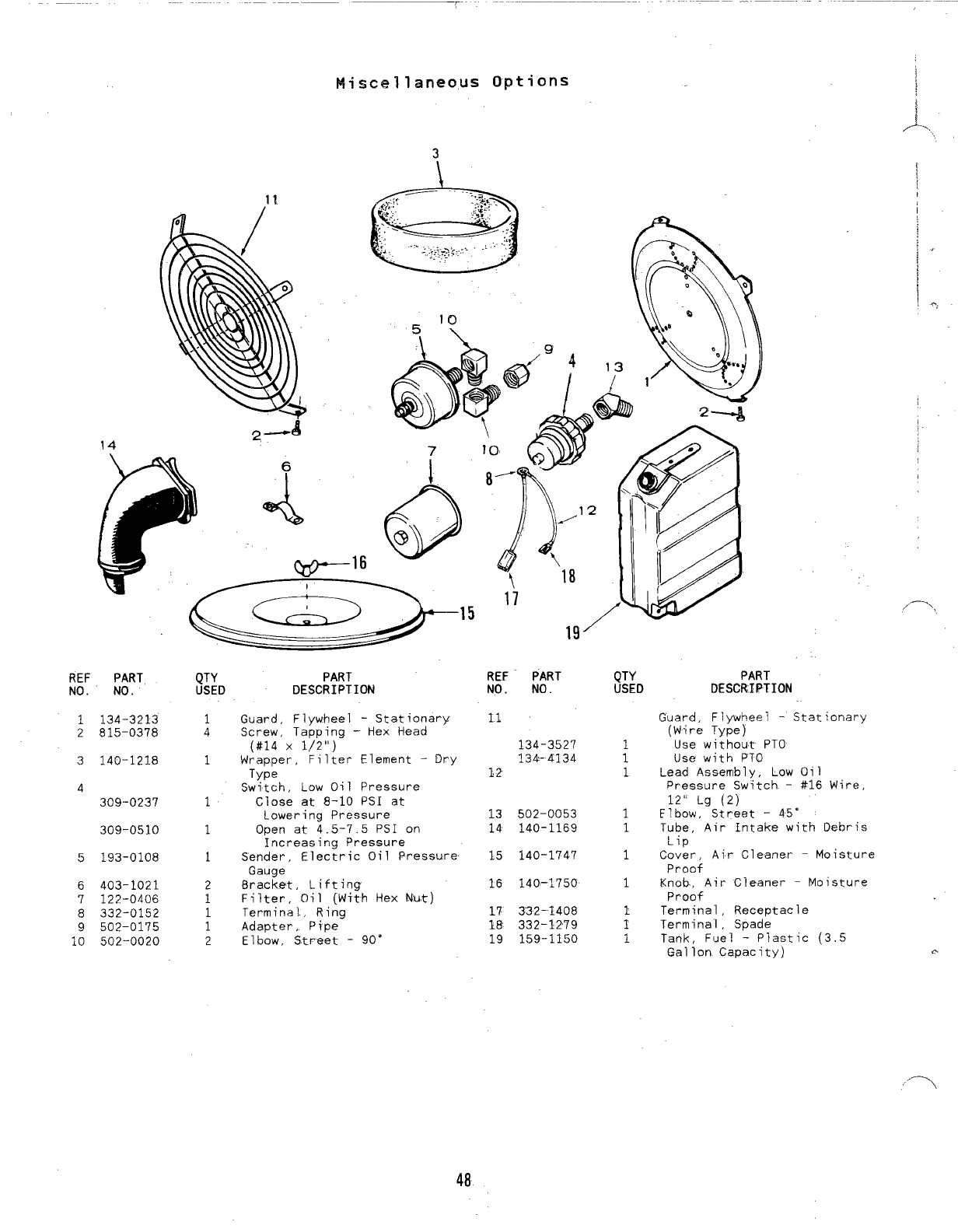
Miscellaneous Options ~
1?
—16
19’
REF PART
NO. NO.
1134-3213
2815-0378
3140-1218
4
309-0237
309-0510
5193-0108
6403-1021
7122-0406
8332-0152
9502-0175
10 502--0020
QTY
USED
1
4
1
1
1
1
2
1
1
1
2
PART
DESCRIPTION
Guard, Flywheel -Stationary
Screw, Tapping -Hex Head
(#14 x1/2”)
WrapDer, Filter Element -Dry
Type
Switch. Low Oil Pressure
Close at 8-10 PSI at
Lowering Pressure
Open at 4.5-7.5 PSI on
Increasing Pressure
Sender’, Electric Oil Pressure
Gauge
Bracket, Lifting
Filter, Oil (With Hex Nut)
Terminal., Ring
Adapter,. Pipe
Elbow, Street -90”
REF- PART
NO. NO.
134-3527
134’-4134
12
13 502-0053
14 140-1169
15 140-1747
16 140-1750
17 332-1408
18 332-1279
19 159-1150
QTY
USED
1
1
1
1
1
1
1
[
I
,/—\
PART
DESCRIPTION
Guard, Flywheel -Stationary
(Wire Type)
Use without PTO
Use with PTO
Lead Assembly, LCIWOil
Pressure Switch -#16 Wire,
12[’ Lg (2)
Elbow, Street -45’
Tube, Air Intake with Oebris
Lip
Cover, Air Cleaner -Moisture
Proaf
Knob., Air Cleaner -Moisture
Proof
Terminal, Receptacle
Termina’1, Spade
Tank, Fuel -Plastic (3.5
Gallon Capacity) e
48
,m.
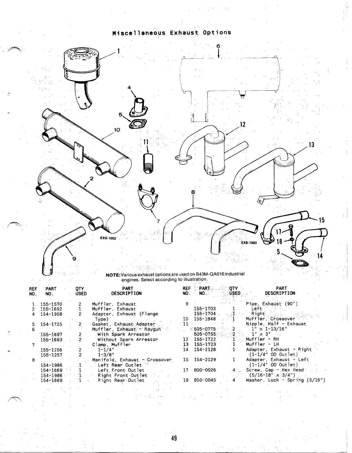
Miscellaneous Exhaust Options
REF PART QTY
NO. NO. USED
1155-1570 2
2155-1692 1
4154-1958 2
5154-1725 2
.6
155-1697 2
155-1693 2
7
.155-1256 ‘2
155-1257 2
8
154-1986
154-1669 ;
154-1986
154-1669 i
R’,
.,
~r
/’2
“A ,13
.. ,
NOTE:Variousexhaust optionsareused onB43M-GAO16 industrial
engines. Select according to illustration.
PART
DESCRIPTION
Muffler, Exhaust
Muffler, Exhaust
Adapter, Exhaust (Flange
Type )
“Gasket, Exhaust Adapter
Muffler, Exhaust- -Raygu’n”
With Spark Arrestor
Without Spark Arrestor
Clamp, Muffler
1-1/4”
1-3)8”
Manifold, Exhaust -Crossover
Left Rear Outlet -
Left Front Outlet
Right Front Outlet
Right Rear Outlet
REF “, PART :‘QTY
NO. NO. .U~ED,,
9155-1703
155-1704 .:
10 155-1848 ;1
11
:505-0775 -.2
505-0755 ‘. ‘2
12 155-1722 ‘1
13 155-1723 1
14 154-2128 1
15 154-2129 1
17 800-0026 4.
18 850-0045 4
PART
,’ DESCRIPTION
Pi~~itExhaust (90”)
Right ~
Muffler, Crossover ““
Nipple, Half -Exhaust
1“ X1-13/16”
~,, x~,1
Muffler ‘- RH
Muffler -LH
Adapter, Exhaust –Right
(1-1/4” 00 Outlet)
Adapter, Exhaust -Left
(lL1/4° OD Outlet)
Screw, Cap -Hex Head
(5/16-18” X3/4”)
Washer, Lock -Spring 5/16”
49
Part No. Page
332-2748 24
336-237% 22
336-2378 23
336-96’79 17
337-2229 28
337-2311 11
337-2311 31
338-1080 42
338-108T 42
338-1082 42
338-1931’ 41
338-1932 41
338-2031 41
357-0030 41
359-0034 42
370-4027 33
402-0549 11
402-0597 11
U03-15.23 5
403-1523 31
403-2218 11.
40-3-2280 11:
403--2280. 3-6
405-3332 36
405-3333 36
4’05-3334 36
405-3335 36
405-3405 36
405-3453 36
405-3611 36
405-3612 36
406-0566 36
406-0567 36
406-0568 36
501-0497 17
502-0002 15
502-0054 17
502-0313 15
502-0871 15
502-0923 17
502-0927-01 17
502-0928-01 17
502-0929-01 17
502-0932-01 .17
502-0933-01 17
502-0935 17
502-0965-01 17
503-0183 15
503-0183 17
503-1133’ 15
Part No.
503-1133
503-1190
503-1252
503-1336
503-1337
503-1345
503-1351
503-1365
504-0150
505-0110
505-0266
505-0274
508-0008
508-0071
508-0251
508-0253
508-0253
509-0008
509-0040
50.9-0041
509-0096
509”-0168
509-0196
509-0210
510-0013
510-0014
510-0015
510-0099
515-0001
515-0001
515-0227
516-0072
516-0130
516-0141
517-0048
517-0067
517-0129
517-0223
‘“518-0006
518-0014
518-0311
518-0387
518-0450
518-0452
518-0459
518-0466
525-0305
526-0002
526-0003
526-0008
.
Numerical Index
Page
17
17
15
15
15
15
15
17
17
11
11
17
36
36
41
39
41
13
13
5
11
5
28
5
13
13
8
39
~
9
~
.5
13
5
5
7
31
15
21
9
7
15
15
43
15
15
4-3
15
17
17
Part No.
526-0017
525-0018
526-0018
526-0018
526-0.018
526-0’018
526-0018
526-0030
526-0063
526-0065
526-0065
526-0066
526-0066
526-0122
526-0130
526-0240
526-0324
526-0325
526:1518
800-0002
800-0’004
800-0005
800-0007
800-0007
800-0010
800-0017
800-0017
8“00-0026
800-0026
8Q0-0028
800-003U
800’-0033
800-0033
-80Q-Q036
800-0046
800-0048
800-0051
800-0052
800-0052
800-0058
‘800-0540
800-0545
800-0571
800-0572
800-0730
800-0730
801-0049
801-0050
802-0034
802-0034
52
Page
9
5
15
17
28
33
39
36
7
12
73
5
7
5
35
11
11
11
36
36
35
33
7
33
5
15
17
33“
35
12
33
15.
17
33
5
31
39
24
39
11
5
13
5
5
33
35
7
7
22
23-
Part No,
802-1038
803-0071
812-0061
812-0061
812-0062
815-0046
815-0176
815-0181
815-0194
815-0194
8?5-0194
815-0194
815-0235
815-0261
815-0261
815-0261
815-0261
815-0261
/. .,
Page ‘,,
39
5
27
41
41
13
17
39 .
12-
28
39
41
28
15
17
22
27
31
815-0261 33
815-0,261 41
815-0290 ’28 :
815-0337 28
815-0337 39
815-0340 27 +>.
815-0358 23
815-0359 39 d
815-0359 41
815-Q370 17
815-0370 22
815-0370 27
815-0385 .42
815-0387 -41-
815-0388 41
815-0436 39
815-0499 33
815-0531 17
815-0550 41
8T5-0570-’ 25
815-0583 27
815-0584 39 .;
815-0587 .15
815-0587 17.
815-0590 15 *
815-0590 17
815-0591 15
815-0591 .17
815-0592 15
815-0610 15
815-0610 28 -<<
8-15-0647 17
2
Numerical Index
,.~~,
Part No.
815-0657
820-1077
821-0005
821-0009
821-0009
‘“~?-oolo.-
821-0010
821-0010
821-0014
821-0014
821-0014
821-0016
821-0016
821-0016
821-0029
821-0029
821-0029
821-0031
821-0031
821-0033
850-0020
850-0038
850-0038
,~ 850-0040
850-0040
850-0040
850-0040
850-0040
850-0040
850-0040
850-0045
850-0045
850-0045
850-0045
850-0050
850-0050
850-0050
850-0050
850-0055
850-2005
856-0006
856-0008
856-0008
856-0010
860-0005
862-0001
862-0001
862-0003
,—.> 862-0003
862-0015
Page
11
13
17
15
31
11
31
36
11
31
36
5
11
31
11
33
35
11
36
36
41
22
23
7
17
24
25
33
35
36
15
17
33
35
5
11
24
39
9
22
15
11
28
31
42
24
33
24
39
15
Part No. Page Part No. Page Part No. Page
862-0015 17
870-0131 21
870-0196 27
870-0221 17
870-0257 36
870-0302 7
870-0328 13
870-0421 15
870-0433-03 28
870-0437 36
870-1183 27
898-1193-03 28
53

-——-
.—
t’
/-’.,
\\
..
.—
—
—. .— .
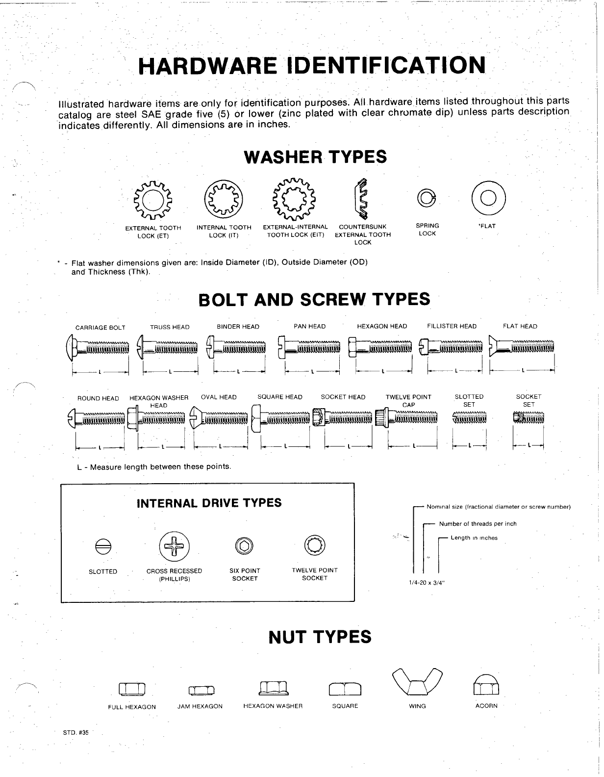
HARDWARE IDENTIFICATION
,-.,
.. . Illustrated hardware items are only for identification purposes. All hardware items listed throughout this parts
cataloa are steel SAE grade five (5) or lower (zinc plated with clear chromate dip) unless parts description
‘indica;es differently. Al~dimensionk “are in inches.
WASHER TYPES
..
@
COUNTERSUNK SPRING ‘FLAT
EXTERNAL TOOTH
LOCK (ET)
INTERNAL TOOTH EXTERNAL-INTERNAL
LOCK (IT) TOOTH LOCK (EIT) EXTERNAL TOOTH LOCK
LOCK
‘-Flat washer dimensions aiven are: Inside Diameter (ID), Outside Diameter (OD)
and Thickness (Thk). -
BOLT AND SCREW TYPES
FLAT HEAD
BINOER HEAD PAN HEAD FILLISTER HEAD
CARRIAGE BOLT TRUSS HEAD HEXAGON HEAD
I
ROUND HEAD HEXAGON WASHER OVAL HEAD SQUARE HEAD SOCKET HEAD TWELVE POINT SLOTTED SOCKET
CAP SET SET
r4 !
L-Measure length between these points
rNominal s!ze (fractional diameter or screw number)
INTERNAL DRIVE TYPES
-Number of threads per inch
orLength In rnches
SLOTTED CROSS RECESSED
(PHILLIPS)
SIX POINT
SOCKET
TWELVE POINT
SOCKET
..
1/4-20 X3/4$
NUT TYPES
B
ACORN
/---’\ Da Qm
FULL HEXAGON JAM HEXAGON HEXAGON WASHER SQUARE w
WING
STD. f#35

.&
.
.
...
1
!.
.
*-
II
Manua
Industrial
Engines
/
11-88 (Spec A)
Replaces
8-85
(Spec
A)
PitdiUSA
I
GenTral Information
For parts or service, contact the dealer from whom you purchased this equipment or refer to your Nearest
Authorized Onan Parts and Service Center.
To avoid errors or delay in filling your parts order, always give the MODEL, SPEC NO. and SERIAL NO. from the
Onan nameplate.
0
MODEL AND SPEC, NO.
SERIAL N~.
b
M-1149
For handy reference, insert “YOUR” .“
nameplate information in the spaces above.
I
Std.
#36D
i
Index
1:
,
,,
-.!
.Adapter, Carburetor 44
r’.!
“.., .Adapter, Exhaust (Flange Type) 48
Adapter, Governor Arm 24
Adapter, Oil Filter 12,35
Ammeter, DC 33.34
Arm, Governor Control 25
Armature,. Starter 20,36
Baffle, Breather Valve 4
.,. Ball, Governor 8
Base, Oil 12
-Bearing, Camshaft 4
.8earing, Crankshaft 4
Bearing, Sleeve 9
Block, Cylinder 4
Block, Terminal 42
Box, Breaker 18,19,41
Bracket, Governor Control 10,24
Bracket. Lifting 48
Brush, Ground-Starter 20,38
Cable, Choke 33,34
Cable, SDark Pluo 18.43 /Manifold. Exhaust 48
Camshaft’ 8-‘-”
Cap, Fuel Tank 32
3
Carburetor Components. Gasoline .28.37.38
Carburetor, Gasoline :14,28
Clamp, Muffler 48 ‘ .
clutch 31 . .
Coil, Ignition 18
Coil, Magneto Stator 43
Condenser 19
Cover, Air-Cleaner 14,46
Cover ,Breaker Box 19,41
Cover, Dust-Starter 20,36
Valve 4
‘~;~ ~;;;;;haft 9
Drain, Oil Filter 12
Elbow, Air Intake 44
Element, Air Cleaner 14
Filter, Air 14
Filter. Breather Tube 14.44
Filter, Fuel 39
Filter, Oil 12,46
Flywheel 9
Gasket ,Air Cleaner 14
Gasket, Breaker Box 19,41
Gasket, Cylinder Head 4
Gasket, Gearcase 7
Gasket, Oil Base 12
Gasket, Oil Filter Adapter 12
Gasket, Vaive Cover 4
Gauge, Oil Pressure 33,34
Gear, Camshaft 8
.Gear, Crankshaft 9
Gear, Ring 9
,- Gearcase 7
Governor 10
Guard, Flywheel 9,46
Guide, Valve 4
Harness, Wiring 34
Head, Cylinder 4
Holder, Brush 20,36
Hose: Fuel 14,26
Hous.].~g ,-.A_~r 11
.. Housing, Alr “CTea”n%r”’”””i4
-.
Housing, Blower 11
Housing, Clutch 46
Housing, Cylinder 11
Housing, Starter 20,36
Hub, Governor Cup 8
Ignition, Magneto 43
Kit, Adapter -Remote Air Cleaner 44
Kit, Alternator Connector 22,23
Kit. Fuel Tank 32
Kit, Gasket -Engine 4
Kit, Gasket -Oil Pump 12
Kit, Repair -Carburetor 16,28,37,38
Kit, Repair -Starter 20,36
Kit, Tuneup -Ignition 19
Lever, Choke 40
Lever, Throttle Control 34
Line, Fuel -Gasoline 32
Line, Oil 33.34
Manifold; Intake- 14
Muffler, Exhauat 48
Numerical Index 49,50,51,52
Panel ,Control 33,34
Pipe, Exhaust 48
Piston 6
Plate, Bearing -Rear 4
Plug, Spark 18,43
Point Set, Breaker 19,41
Pulley, Alternator Drive 46
Pump, Fuel -Vacuum (Gasoline) 16,28,30
Pump, Oil 12
Regulator, Voltage 22,23
Relay, Start Solenoid 20,36
Ring, Piston 6
Rod, :::;:::ing 6
Rod, 10
Seal ,Air Filter 12
Seal, Oil 4,7
Seat ,Valve 4
Shaft and Arm, Governor 7
Shaft. PTO 9-
Sheave, Rope 9
Spring, Governor 10,24,25,33,34
Spring, Valve 4
Starter Components 20,36 ‘
Stator 22,23,43
Strap, Fuel Tank 32
Switch, Ignition 33,34
Switch, Pressure -Oil 46
Tank, Fuel 32,46
Tappet, Valve 4
Tube, Air Intake 14,46
Tube, Breather 14,44
Tube, Oil 4
Tube, Vacuum Port 4,7
Valve, Exhaust 4
Valve, Intake 4
Valve, Shut-Off 32
Wrapper, Filter Element 46
1
~:ntroduct on
This catalog applies to the Standard B48M-GA018 Engines, Parts are arranged in grotips
of related items. Each illustrated tiart is id~ntified by areference number
corresponding to the same reference number in +he parts list for that group. Parts
illustrations are typical. Using the MODEL an,, SPEC NO. from the nareplate, select the
Parts that apply to your engine. Unless other~.lse mentioned in the tparts
are interchangeable between mode s. Right and left sides are determ
blower end (front) of the engine ng the
eicription,
ned by fac
WARNING
This en ine is not designed or intended for use in any type of aircraft.
Use of ?his engine in aircraft may result in engine failure and cause
serious bodily injury, death and/or property damage.
!’
,.,
,
.
I
NOTICE 1.
Items referenced as optional indicate part is factory installed and ma
not be a77 licable to all models. 1
For field conversions additional par s
are usua yrequired.
’45
C-1W2
4
Cylinder Block
PART
DEWIPTION
Intake Valve Guide
Port
-Early Modele
Breather Hole -
REF PART
NO. NO.
1
QTY PART
USEO DESCRIPTION REF PART
NO. NO.
Block Assembly, Cylinder (All
Replacement Cylinder Block
Assemblies Use Intake Valve
Seals and Include Parts
Marked *)
Engines with Standard Rear
Bearing Plate
Engines with 4Boss Bearing
Plate
Engines with SAE Aor SAE B
Rear Bearing Plate (Does
Not Include Rear Bearing
Plate)
*Plug, Welch (1-5/8”) Camshaft
Open ing
*Screw, Cap -Hex Head
(3/8-16 X1-1/4”)
110-0068 -
149-1299
517-0120
*Gasket
Vacuum
Tube
Plug
2
i
5
2
1
1
1
1
1
3
4
4
4
2
“2
2
2
4
8
2
2
;
1
1
4
1
18
12
6
2
1
2
1
1
1
1
Later Models
Washer, Lock -Spring (3/8”)
*Pin, Gear Cover Alignment
Reed, Breather Valve
Baffle, Breather Valve
Spring, Breather Valve
Cover, Valve -RH
Cover, Valve -LH
Gasket, Valve Cover
Tappet, Valve
Standard
.002” Oversize
.005” Oversize
Valve, Intake
Valve, Exhaust
Standard
Stellite
Screw, Cap -Hex Head
(1/4-20 X1-3/4”)
Spring, Valve
Lock, Valve Spring
Seal, Valve -Intake
(Optional)
Screw, Socket -Set
(3/8-16 X5/8”)
Gasket, Cylinder Head
Standard
Optional (Graphoil)
Head, Cylinder
Right Side
Left Side.
Roto Cap -Valve
Washer, Flat (1/4” Screw)
Washer, Flat (5/16” Screw).
Screw, Cap -Hex Head (Special)
5/16-18 X1-5/8” “
2“ Long
Washer, Flat -Copper
i$::zuc
Retai;er (Optional)
Kit, Gasket
Valve Grind/Carbon Removal
(Standard Head Gaqkets)
Valve Grind/Carbon Removal
(Graphoil Head Gaskets)
Gasket Kit, Complete
:{Standard Head Gaskets)
Gasket Kit, Complete
(Graphoil Head Gaskets)
110-3148
110-3151
110-3154
1
1
1
1
5
AR
1
1
1
1
1
2
1
1
1
1
1
2
1
4
1
2
2
2
2
2
:
2
2
2
1
:
:
2
2
2
2
19
20
21
850-0050
516-0141
123-1175
123-1173
123-1174
110-1879
110-2274
110-1921
22
23
24
25
26
27
2
3
4
5
517-0048
800-0051
104-0776
115-0006
115-0006-02
115-0006-05
110-2368
110-1955
110-2438
800-0010
*Shim, Crankshaft End Play
(.005”)
28
29
Bearing; Crankshaft -Rear
(Includes Thrust Washer)
*Standard
.002” Undersize
.010” Undersize
.020” Undersize
.030” Undersize
*Washer, Thrust
*Gasket, Bearing Plate
Plate, Bearing -Rear
*Standard
Optional -4Boss
Optional -SAE B
Optional -SAE A
*Bearing Camshaft
Seal, 0;1 -Crankshaft Rear
‘Pin, Drive -BAaring Stop
*Tube, Oil -Cylinder Block
Insert, Valve Seat -Exhaust
*Standard
.002” Oversize
.005” Oversize
.010” Oversize
.025” Oversize
Insert, Valve Seat -Intake
*Standard
.002” Oversize
.005” Oversize
.010” Oversize
.025” Oversize
Bearing, Crankshaft -Front
F1anged
*Standard
.002” Undersize
.010” Undersize
.020” Undersize
.030” Undersize
Guide, Valve
Engines w/o Intake Valve
Sea 1s
Intake
Exhaust
Engines with Intake Valve
Sea 1s
*Exhaust
*Intake
101-0450
101-0450-02
101-0450-10
101-0450-20
101-0450-30
104-0575
101-0415
30
110-0539
110-0639
509-0168
31
32
33
6
7
834
36
803-0071
101-0439
101-0551
101-0430
101-O437-OI
101-0405
509-0041
516-0072
120-0735
110-2287
110-3181
37
110-2564
110-2563
110-0904
526-0018
526-0122
38
39
40
41
110-1824
110-1824-02
110-1824-05
110-1824-10
110-1824-25
800-0540
800-0571
526-006342
14 43
44
517-0067
110-0893
110-0197
110-0197-02
110-0197-05
110-0197-10
110-0197-25
45
168-0140
168-0183
168-0153
15
101-0432
101-0432-02
101-0432-10
101-0432-20
101-0432-30 s
16B--o
16
*-Parts Included in the Cylinder Block Assembly.
110-1807
110-1807
/933-
11O-W
110-3161
Piston and R-d
REF PART QTY
NO. NO. USED
1
j~%”os~~e 2
112-0186-05 2
112-0186-10 2
112-0186-20 2
112-0186-30
112-0186-40
2112-0229
3518-0311
4
113-0189
113-0189-05
113-0189-10
113-0189-20
113-0189-30
113-0189-40
2
4
2
2
2
2
I
PART
DESCRIPTION
Piston and Pin (Includes
Retaining Rings)i
Standard
.005” Oversize
.010” Oversize
.020” Oversize
.030” Oversize
.040” Oversize
REF PART
No. No.
5
114-0257
114-0257-10
114-0257-20
114-0257-30
6114-0240
78.70-0302
QTY
USED PART
DESCRIPTION
Rod, Connecting (Includes
Bolt and Nut)
Standard
.010” Undersize
.020” Undersize
.030” Undersize
Bolt, Connecting Rod (Special)
Nut. Hex -Cretin Lock
Pin, Piston
Ring, Retaining
Ring Set, Piston
(5;16-24)
.010” Oversize
.020” Oversize
.030” Oversize
.040” Oversize
., ,
Gear ;:5(:
\
I
I
REF PART
NO. NO.
1103-0738
2510-0105
3150-1470
4150-1187
5815-0046
6516-0130
7509-0008
8510-0014
QTY P~T REF
USED PART
DESCRIPTION ::D
NO. NO.
1Gearcase Assembly (Includes
Parts Marked *)
1*8earing, Governor Shaft
1*Shaft and Arm, Governor
1*Yoke, Governor Shaft
2*Screw, Machine -Pan Head
(#8-32 X3/8”)
1*Pin, Dowel -Governor Cup
stop
1*Seal, Oil -Governor Shaft
1*8all ,8earing -Governor Shaft
PART
DESCRIPTION
9509-0040
10 103-0408 ;
11 800-0032 4
800-0545 1
12 526-0065 s
13 149-1299 1
14 503-0301 *Clamp, Vacuum Port Cap
15 149-1321 1*Cap, Vacuum Port
*Seal, Oil -Crankshaft
Gasket, Gearcase Mounting
Screw, Cap -Hex Head
5/16-18 X1-3/4”
5/16-18 x2-3/4” (Special)
Washer, Flat -Copper
(5/16” Screw)
*Tube, Vacuum Port
*-Parts Included in 103-0738 Gearcase
.
Assembly.
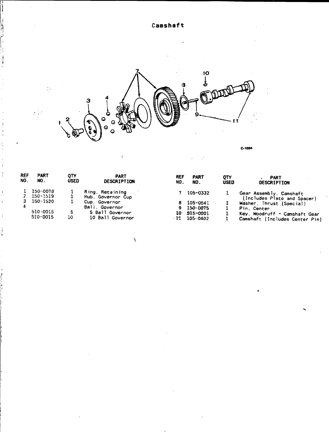
.
REF
w.
:
3
4
.
.. ,’
PART
m.
150-0078
150-1519
150--1520
510-001.5
510-0015
Camshaft
PART
DE=IPTI~
. .
REF Pmt m
No. No.. USED
Ring, Retaining 7105-0332 1
Hub, Governor Cup
Cup, Governor 8105-0541 1
Bali, hvernor 91*W5 :
5Ball Governor 10 .515-0001
10 Ball Governor 11 10s-0402 1
6ES$:;IW
Gear Assetily, Camshaft
(Includes Plate and Spacer)
Wastler, Thrust (Special)
Pin, Center
Key, Woodruff -Camshaft Gear
Camshaft (Includes Center Pin)
\.
.
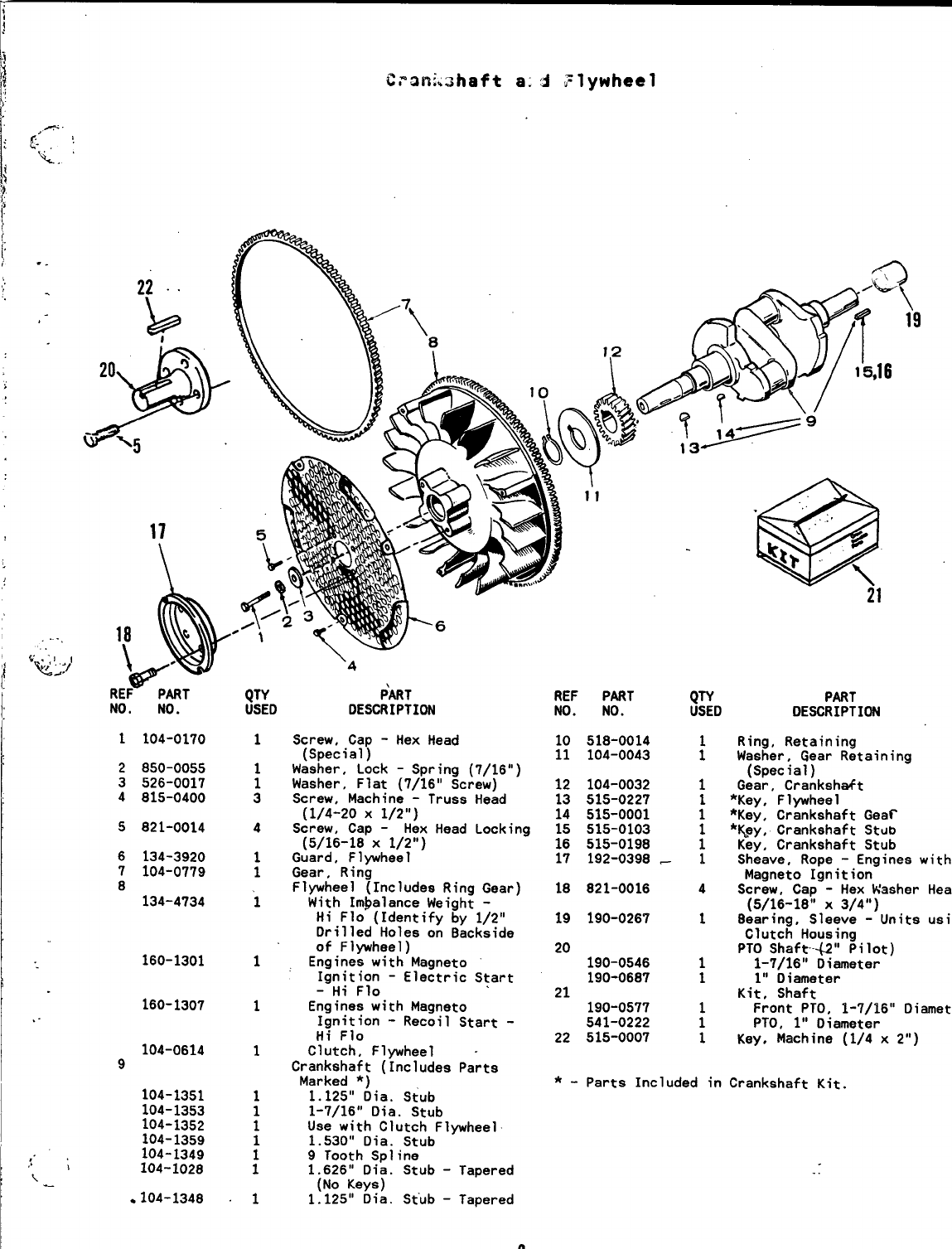
-@
.“.. :,
&
kt;. \
21
1.
1104-0170
2850-0055
3526-0017
4815-0400
5821-0014
6134-3920
7104-0779
8134-4734
160-1301
I
160-1307
104-0614
9
104-1351
104-1353
104-1352
104-1359
104-1349
104-1028
*104-1348
‘4
P~T
DESCRIPTIW
Screw, Cap -Hex Head
(Special)
Waeher, Lock -Spring (7/16”)
Washer, Flat (7/16” Screw)
Screw. Machine -Truss Head
(1/4-20 X1/2”)
Screw, Cap -Hex Head Locking
(5/16-18 X1/2”)
Guard, Flywheel
Gear, Ring
Flywheel (Includes Ring Gear)
With Imbalance Weight -
Hi Flo (Identify by 1/2”
Drilled Holes on 8ackside
of Flywheel)
Engines with Magneto
Ignition -Electric Start
-Hi Flo
Engines with Magneto
Ignition -Recoil Start -
Hi Flo
Clutch, Flywheel -
Crankshaft (Includes Parts
Marked *)
1.125” Dia. Stub
1-7/16” Dia. Stub
Uae with Clutch Fl~heel
1.530” Dia. Stub
9Tooth Spline
1.626” Dia. Stub -Tapered
(No Keys)
1.125” Dia. Stub -Tapered
9
REF P~T
NO. NO.
10 518-0014
11 104-0043
12 104-0032
13 515-0227
14 515-0001
15 515-0103
16 515-0198
17 192-0398 -
18 821-0016
19 190-0267
20 190-0546
190-0687
21 190-0577
541-0222
22 515-0007
QW PMT
USED DESCRIPTION
Ring, Retaining
:Washer, Gear Retaining
(Special)
1Gear, Cranksh&t
*Key, Fl~heel
;*Key, Crankshaft Gear
‘Key, Crankshaft stub
iKey, Crankshaft Stub
1Sheave, Rope -Engines with
Magneto Ignition
4Screw, Cap -Hex Washer
Head
(5/16-18;’ X3/4”)
18earing, Sleeve -Units
usin
Clutch Housing
PTO Shaft-a” Pilot)
11-7/16” Diameter
11“ Diameter
Kit, Shaft
Front PTO, 1-7/16”
Diameter
;PTO, 1“ Diameter
1Key, Machine (1/4 x2“)
*-Parts Included in Crankshaft Kit.
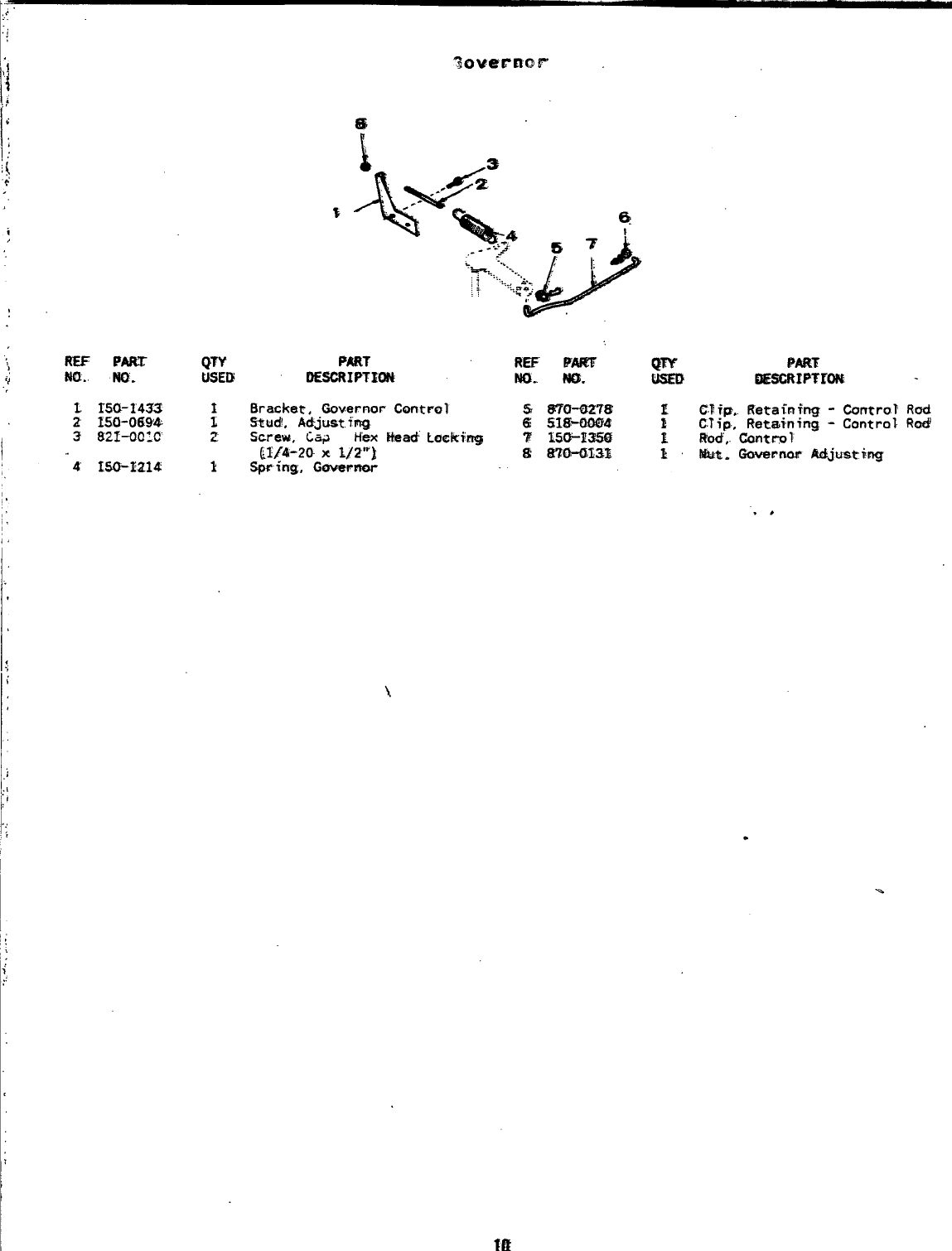
11’
QTY
USED
.,
.
I
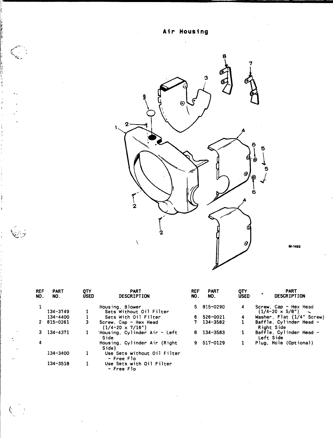
Air Housing
,.
/
,4
\M-1a
‘!
I
REF PART
NO. NO.
1134-3749
134-4400
2815-0261
3134-4371
4
134-3400
134-3518
PART
DESCRIPTION
Housing, Blower
Sets Without Oil Filter
Sets With Oil Filter
Screw, Cap -Hex Head
(1/4-20 X7/16”)
“Housinq, Cylinder Air -Left
Side - -
Housing, Cylinder Air (Right
Side)
Use”Sets without. Oil Filter
-Free Flo
Use Sets with Oil Filter
-Free Flo
REF PART j~D -PART
NO. NO. DESCRIPTION
5815-0290 4Screw, Cap -Hex Head
(1/4-20 X5/8”)
6526-0021 4Washer, Flat (1/4” ;crew)
7134-3582 1Baffle, Cylinder Head -
Right Side
8134-3583 1Baffle, Cylinder Head -
Left Side
9517-0129 1Plug, Hole (Optional)
,(, ..
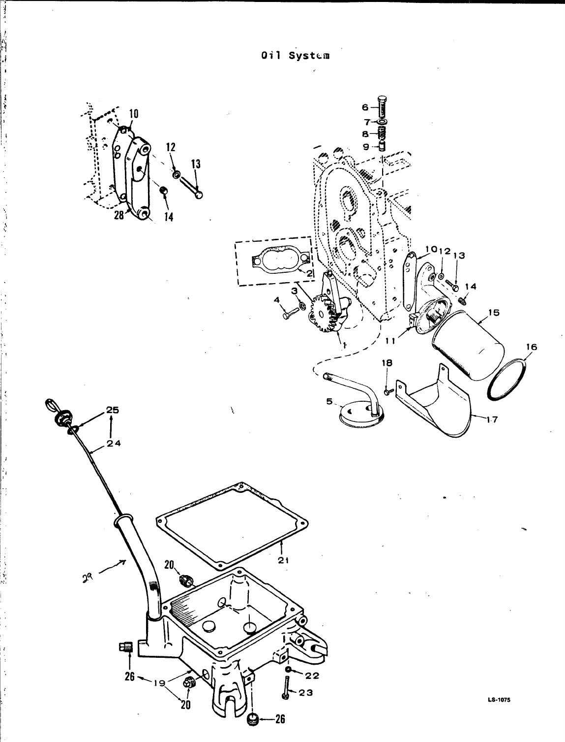
oil S-ystkm
‘,
,
J
I
.,
;
; ,,
,.,.
I
,,
‘,
1:
1,
1:
,;
1.
I
..
Y25
I
24
LS-1075
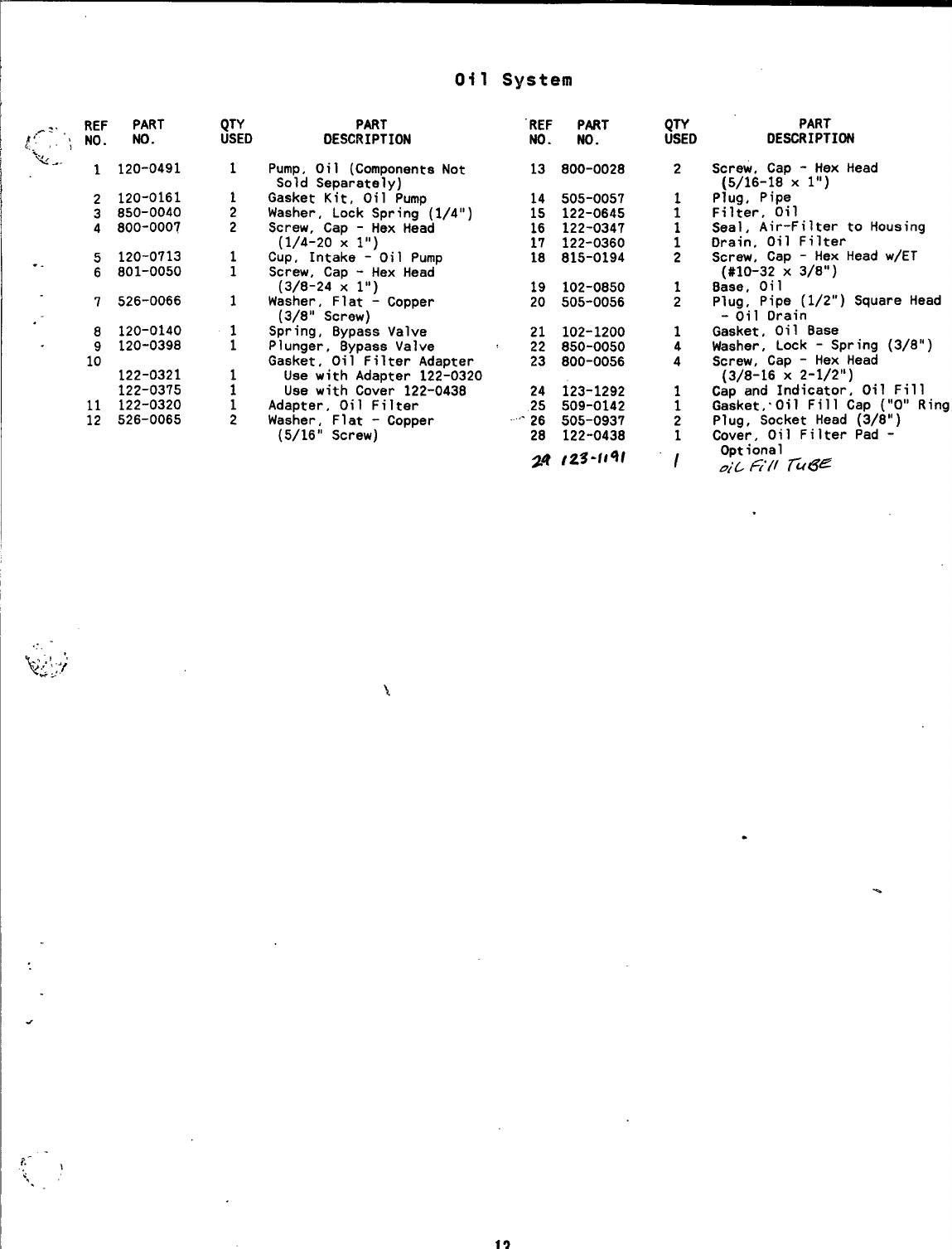
Oil System
REF PART
[’::: ‘\ NO. NO.
2120-0161
3850-0040
4800-0007
5120-0713
. . 6801-0050
7526-0066
.8120-0140
9120-0398
10 122-0321
122-0375
11 122-0320
12 526-0065
QTY
USED
1
1
2
2
1
1
1
1
1
;
1
2
PART
DESCRIPTION
Pump, Oil (Components Not
Sold Separately)
Gasket Kit, Oil Pump
Washer, Lock Spring (1/4”)
Screw, Cap -Hex Head
(1/4-20 X1“)
Cup, Intake -Oil Pump
Screw, Cap -Hex Head
(3/8-24 Xl“)
Washer, Flat -Copper
(3/8” Screw)
Spring, Bypass Valve
Plunger, Bypase Valve
Gasket, Oil Filter Adapter
Uee with Adapter 122-0320
Uaa with Cover 122-0438
Adapter, Oil Filter
Washer, Flat -Copper
(5/16” Screw)
“REF PART
No. No.
13 800-0028
14 505-0057
15 122-0645
16 122-0347
17 122-0360
18 815-0194
19 102-0850
20 505-0056
21 102-1200
22 850-0050
23 800-0056
24 123-1292
25 509-0142
2“26 505-0937
28 122-0438
24 /z3-li4/
QTY
USED
2
1
1
;
2
1
2
1
4
4
1
1
2
1
/
PART
DESCRIPTION
Screw, Cap -Hex Head
(5/16-18x l“)
Plug, Pipe
Filter, Oil
Seal, Air-Filter to Housing
Drain, Oil Filter
Screw, Cap -Hex Head w/ET
[#10-32 X3/8”)
Base, Oil
Plug, Pipe (1/2”) Square Head
-Oil Orain
Gasket, Oil Base
Waaher, Lock -Spring (3/8”)
Screw, Cap -Hex Head
(3/8-16 X2-1/2”)
Cap and Indicator, Oil Fill
Gasket,.Oil Fill Cap (“O” Ring)
Plug, Socket Head (3/8”)
Cover, Oil Fiiter Pad -
Optional
oiLGll ru6~
.
.
.
?.- -,
s,.’
13
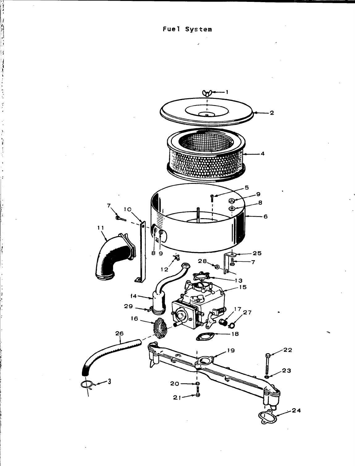
FueT System
1
2
4
6
&/3
\
.
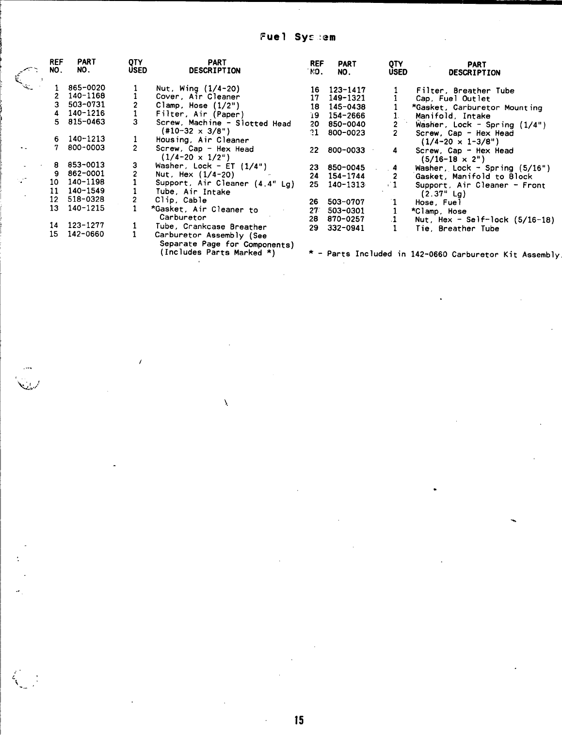
REF PART
-/: NO. NO.
..-
K.<, :
-- 1865-0020
2140-1168
3503-0731
4140-1216
5815-0463
6140-1213
. . 7800-0003
8853-0013
9862-0001
.“-10 140-1198
11 140-1549
12 518-0328
13 140-1215
14 123-1277
15 142-0660
QTY PART
USED DESCRIPTION
Nut, Wing (1/4-20)
;Cover, Air Cleaner
2Clamp, Hose (1/2”)
1Filter, Air (Paper)
3Screw, Machine -Slotted Head
(#10-32 X3/8”)
1Housing, Air Cleaner
2Screw, Cap -Hex Head
(1/4-20 X1/2”)
3Washer, Lock -ET (1/4”)
2Nut, Hex (1/4-20)
1SuPPort, Air Cleaner (4.4” Lg)
1Tube, Air Intake
2Clip, Cable
1*Gasket, Air Cleaner to
Carburetor
1Tube, Crankcase 8reather
1Carburetor Assembly (See
Separate Page for Components)
(Includes Parts Marked *)
REF PART
“h!O. NO.
16 123-1417
17 149-1321
18 145-0438
i9 154-2666
ZO 850-0040
?1 800-0023
22 800-0033
23 850-0045
24 154-1744
25 140-1313
26 503-0707
27’ 503-0301
28 870-0257
29 332-0941
4
1
1
.1
1
*-Parts Included in
PART
DESCRIPTION
Filter, Breather Tube
Cap, Fuel Outlet
*Gasket, Carburetor Mounting
Manifold, Intake
Washer, Lock -Spring (1/4”)
Screw, Cap -Hex Head
(1/4-20 X1-3/8”)
Screw, Cap -Hex Head
(5/16-18 X2“)
Washer, Lock -Spring (5/16”)
‘Gasket, Manifold to Block
Support, Air Cleaner -Front
(2.37” Lg)
Hose, Fuel
*Clamp, Hose
Nut, Hex -Self-lock (5/16-18)
Tie, Breather Tube
142-0660 Carburetor Kit Assembly.
....
~,;’
.
..
. .
i’
i’-4 ,
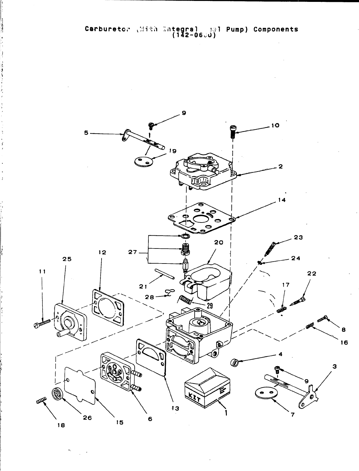
,
J
Carburetor;’ ,:jitil late ral !,>l Pump) Components
(l?2-06vO)
5/9
2
,
/’4
\\26” \\6 ‘3 v‘,
18 15
\w
7
I
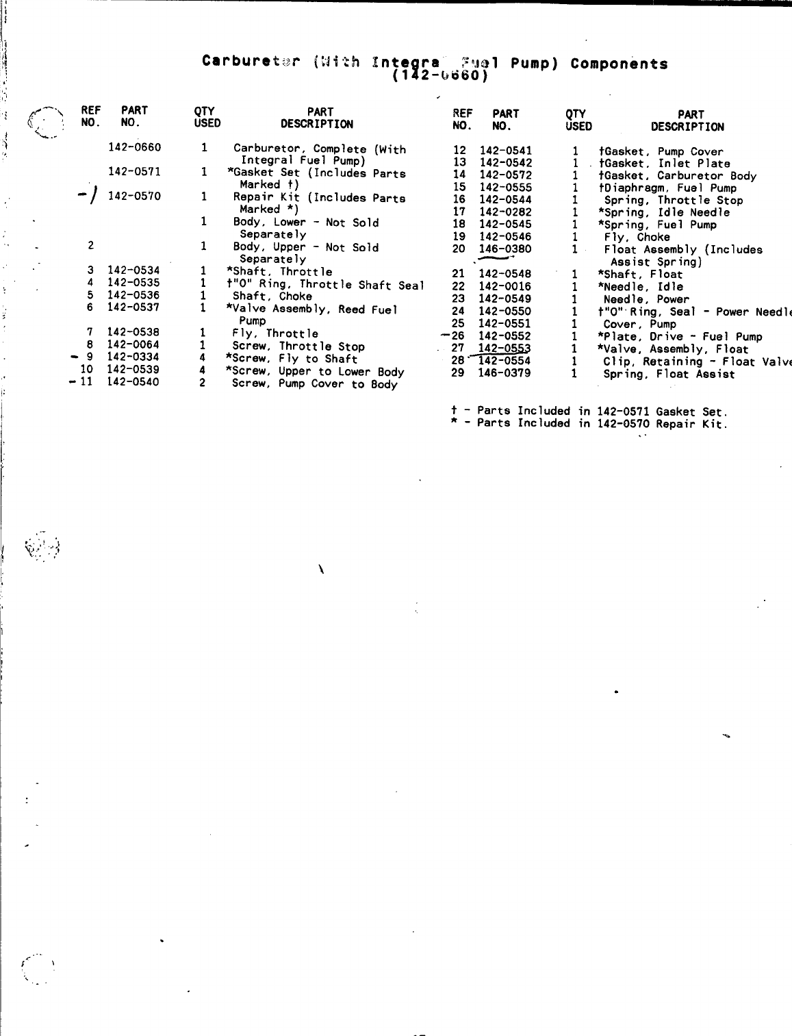
142-0571
-1 142-0570
2
3
4
5
6
142-0534
142-0535
142-0536
142-0537
142-0538
142-0064
142-0334
142-0539
142-0540
QTY PART
USED DESCRIPTION
Carburetor, Complete
Integral Fuel Pump)
*Gasket Set (Includes
Marked t)
Repair Kit (Includes
Marked *)
.
REF PART
No. No.
(With 12 142-0541
13 142-0542
Parts 14 142-0572
15 142-0555
Parts 16 142-0544
17 142-0282
Body, Lower -Not Sold 18 142-0545
Separately 19 142-0546
8ody, Upper -Not Sold 20 146-0380
Separately —-
*Shaft, Throttle 21 ‘142-0548
t“O” Ring, Throttle Shaft Seal 22 142-0016
Shaft, Choke 23 142-0549
*Valve Assembly, Reed Fuel 24 142-0550
Screw,
*Screw,
*Screw,
Screw,
Pump 25 142-0551
Fly, Throttle ’26 142-0552
Throttle Stop 27_142-05~
Fly to Shaft 28’ 142-0554
Upper to Lower Body 29 146-0379
Pump Cover to 8ody
t- Parts Included in
*-Parts Included in
PART
DE*RIPTION
fGasket, Pump Cover
tGasket, Inlet Plate
tGasket, Carburetor Body
tDiaphragm, Fuel Pump
Spring, Throttle Stop
*Spring, Idle Needle
*Spring, Fuel Pump
Fly, Choke
Float Assembly (Includes
Assist Spring)
*Shaft, Float
*Needle, Idle
Needle, Power
t*lot*Ring,seal - Power Needle
Cover, Pump
*Plate, Drive -Fuel Pump
*Valve, Assembly, Float
Clip, Retaining -Float Valve
Spring, Float Assist
142-0571 Gasket Set.
142-0570 Repair Kit.
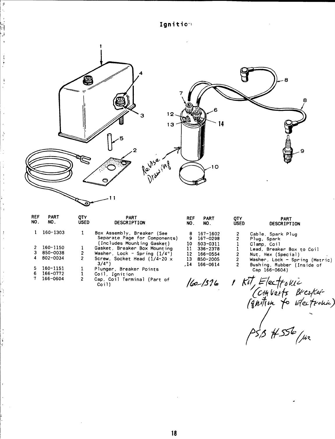
Ignitio’~
1
w“
REF PART QTY PART
NO. NO. USED DESCRIPTION
1160-1303 1Box Assembly, Breaker (See
Separate Page for Components)
(Includes Moun~ing Gasket)
2160-1150 1Gasket, Breaker Box Mounting
3850-0038 2Washer, Lock -Spring (1/4”)
4802-0034 2Screw, Socket Head (1/4-20 x
3/4”)
5160-1151 1Plunger, Breaker Points
6166-0772 1Coil. Ionition
7166-0604 2Cap, ”CoIl Terminal (Part of
Coil)
REF PART
NO. NO.
8167-1602
9167-0298
10 503-0311
11 336-2378
12 166-0554
13 850-2005
.14 166-0614
QTY
USED
:
;
2
2
2
PART
DESCRIPTION
Cable, Spark Plug
Plug, Spark
Clamp, Coil
Lead, Breaker Box to Coil
Nut, Hex (Special)
Washer, Lock -Spring (Metric)
Bushinq, Rubber [Inside of
Cap 166-0604) ‘
.
18
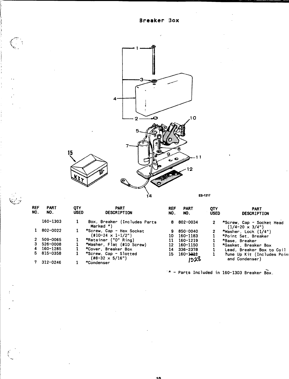
Breaker Box
“,
“~i;;;
REF PART OTY
r’<
11
$4 ES-1217
~RT REF
tiSED PART QTY
NO. NO. PART
DESCRIPTION NO. NO. USEO DESCRIPTION
1
2
3
4
5
7
160-1303 1Box, Breaker (Includes Parts 8
Marked *)
802-0022 1*Screw, Cap -Hex Socket 9
(#10-24 x1-1/2”) 10
509-0065 *Retainer (“O” Ring) 11
526-0008 iWasher, Flat (#10 Screw) 12
160-1285 1*Cover, 8reake~ 80X “14
815-0358 1*Screw, Cap -Slotted 15
(#8-32 X5/16”)
312-0246 1*Condenser
802-0034
850-0040
160-1183
160-1219
160-1150
336-2378
160-~
~~%%
2*Screw, Cap -Socket Head
(1/4-20 X3/4”)
2%asher, Lock (1/4”)
1*Point Set, 8reaker
*8ase, 8reaker
;*Gasket, 8reaker 80X
Lead, 8reaker 80X to Coil
;Tune Up Kit (Includes
Points
and Condenser)
*-Parts Included in 160-1303 8reaker 8%x
.
19
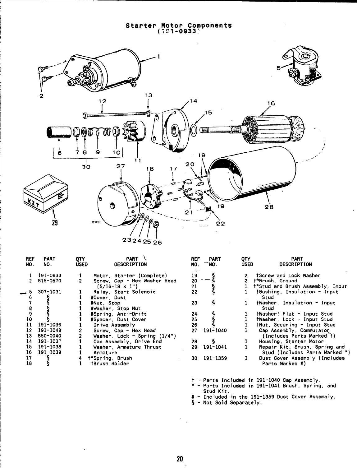
1,2 I/14 16
29
REF PART
NO. NO.
1191-0933
2815-0570
~—k------- ad> ““
5
_5 307-1031
6~
7
85
s
1: 5
11 191-1036
12 191-1048
13 850-0040
14 191-1037
15 191-1038
16 191-1039
17 5
18 s
‘“0 ~//17
QTY
USED
1Motor,
2Screw,
PART ‘c
DESCRIPTION
Starter (Complete)
Cap -Hex Washer Head
(5/16-18”x l“)
1Relay, Start Solenoid
1#Cover, Oust
1#Nut, Stop
1#Washer, Stop Nut
1#Spring, Anti-Drift
1#Spacer, Dust Cover
1Drive Assembly
2Screw, Cap -Hex Head
2Washer, Lock -Spring (1/4”)
1Cap Assembly, Orive End
1Washer, Armature Thrust
1Armature
4t*Spring, Brush
1tBrush Holder
.—- .-– $2
REF
NO.
19
20
21
22
23
24
25
26
27
28
29
30
t-
*-
#-
5-
PART
‘NO.
–i
5
s
s
5
5
5
191-1040
5
191-1041
191-1359
2’8
/
/
/
QTY PART
USED DESCRIPTION
2tScrew and Lock Washer
2t*8rush, Ground
1t*Stud and Brush Assembly, Input
1t8ushing, Insulation -Input
Stud
1tWasher, Insulation -Input
Stud
1tWashery Flat -Input Stud
1tWasher, Lock -Input Stud
1tNut, Securing -Input Stud
1Cap Assembly, Commutato~
(Includes Parts Marked t)
1Housing, Starter Motor
1ReDair Kit, 8rush, SDrina and
Stud (Includes Parts Ma~ked *)
1Oust Cover Assembly (Includes
Parta Marked #)
Parts Included in 191-1040 Cap Assembly.
Parts Included in 191-1041 Brush. Spring, and
Stud Kit.
Included in the 191-1359 Dust Cover Assembly.
Not Sold Separately.
m
OPTIONAL EQUIPMENT SECTION
,./:. .
?% >This section contains illustrated parts listin9 of faCtOrY installed
*...,.. options for these industrial engines. Options may not be applicable
to all models; for field conversions additional parts are usually
required. Optional parts listed in this section are in addition or in
place of those shown in the standard engine parts section.
.
.
21
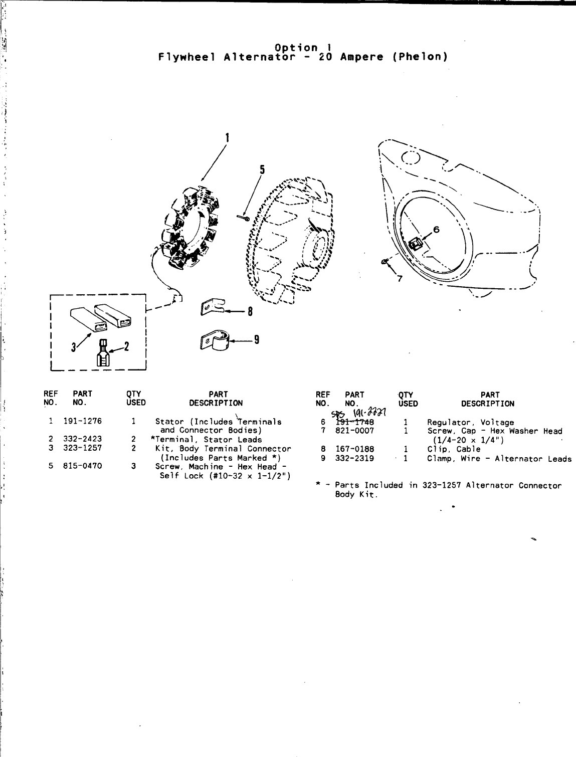
!,
Option 1
Flywheel Alternator -20 Ampere (Phelon)
1
/5
REF PART QTY PART REF
NO. NO. USED PART
DESCRIPTION NO. NO.
.
7
.191-1276 1Stator (Includes )Terminals
and Connector Bodies)
QTY
6ti$8 ‘~
7821-0007 1
2332-2423 2*Terminal ,Stator Leads
3323-1257 2Kit, ‘Body Terminal Connector 8167-0188 1
(Includes Parts Marked *) 9332-2319 1
5815-0470 3Screw, Machine -Hex Head -
Self Lock (#10-32 x1-1/2”)
PART
DESCRIPTION
Regulator, Voltage
Screw, Cap -Hex Washer Head
(1/4-20 X1/4”)
Clip, Cable
Clamp, Wire -Alternator Leads
*-Parts Included in 323-1257 Alternator Connector
8ody Kit. .
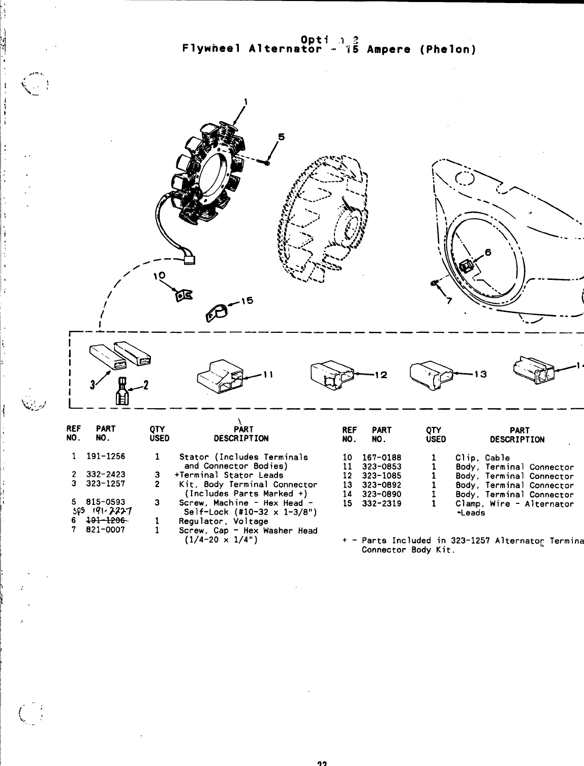
opt+ a2
Flywheel Alternator -15 Ampere (Phelon)
/--1
/’
/
I
r—-——”—————— —“———”———— —————————— ———1
REF PART QT~ ;kT REF PART QTY PART
NO. NO. USEO DESCRIPTION NO. NO. USEO DESCRIPTION
1191-1256 1Stator (Includes Terminals
and Connector Bodies)
2332-2423 3+Terminal Stator Leeds
3323-1257 2Kit, Body Terminal Connector
(Includes Parts Marked +)
5815-0593 3Screw, Mech ine -Hex Head -
SQ5 fql .>2>7 Sel f-Lock (#10-32 x1-3/8”)
6~1 Regu later, Voltage
7821-0007 1Screw, Cap -Hex Washer Head
(1/4-20 X1/4”)
10 167-0188 1Clip, Cable
11 323-0853 8ody, Terminal Connector
12 323-1085 ;Body, Terminal Connector
13 323-0892 Body, Terminal Connector
14 323-0890 :Body, Terminal Connector
15 332-2319 1Clamp, Wire -Alternator
“Leads
+- Parts Included in 323-1257 Alternato~ Terminal
Connector 8ody Kit.
23
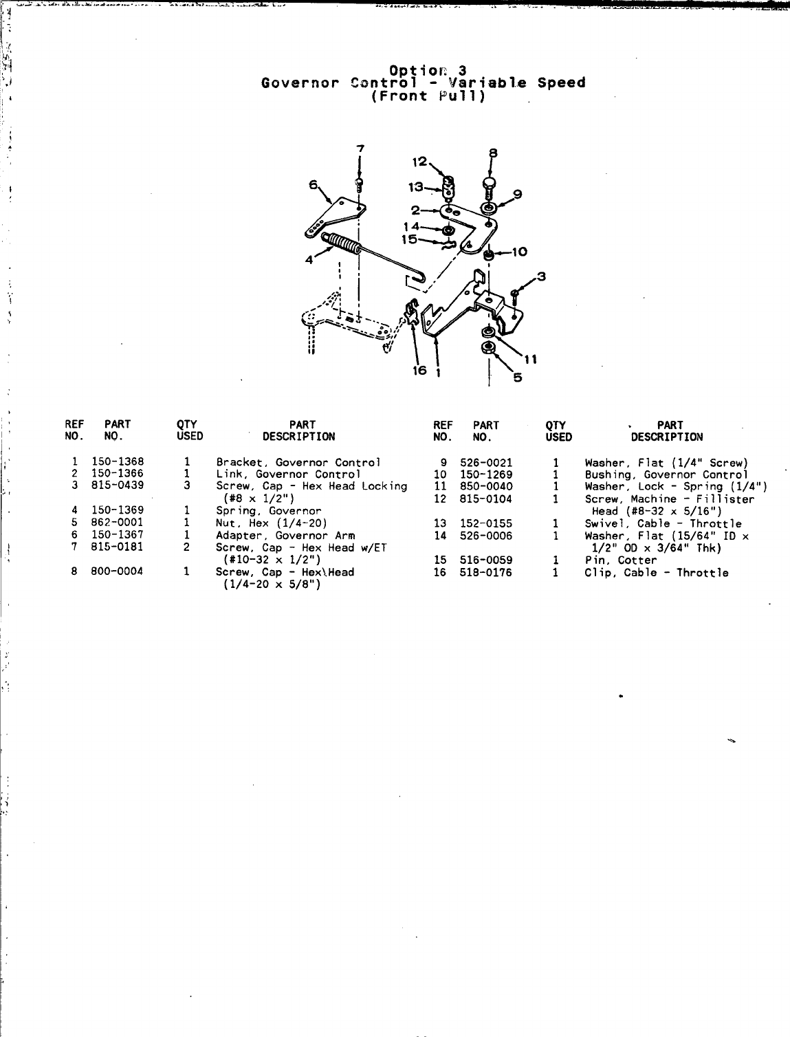
REF PART
NO. NO.
1150-1368
2150-1366
3815-0439
4150-1369
5862-0001
6150-1367
7815-0181
8800-0004
option 3
Governor Control -Variabl..e Speed
(Front Pull)
QTY PART REF PART
USED DESCRIPTION NO. NO.
Bracket, Governor Control
:Link, Governor Control 1:
3Screw, Cap -Hex Head Locking 11
(#8 X1/2”) 12
Spring, Governor
:Nut, Hex (1/4-20) 13
1Adapter, Governor Arm 14
2Screw, Cap -Hex Head w/ET
(#10-32 X1/2”) 15
1Screw, Cap -Hex~.Head 16
(1/4-20 X5/8”)
526-0021
150-1269
850-0040
815-0104
152-0155
526-0006
516-0059
51B-0176
QTY
USED
1
1
Washer, Flat (1/4” Screw)
Bushing, Governor Control
Washer, Lock -Spring (1/4”)
Screw, Machine -Fillister
Head (#B-32 x5/16”)
Swivel, Cable -Throttle
Washer, Flat (15/64” ID x
1/2” OD X3/64” Thk)
Pin, Cotter
Clip, Cable -Throttle
.
.
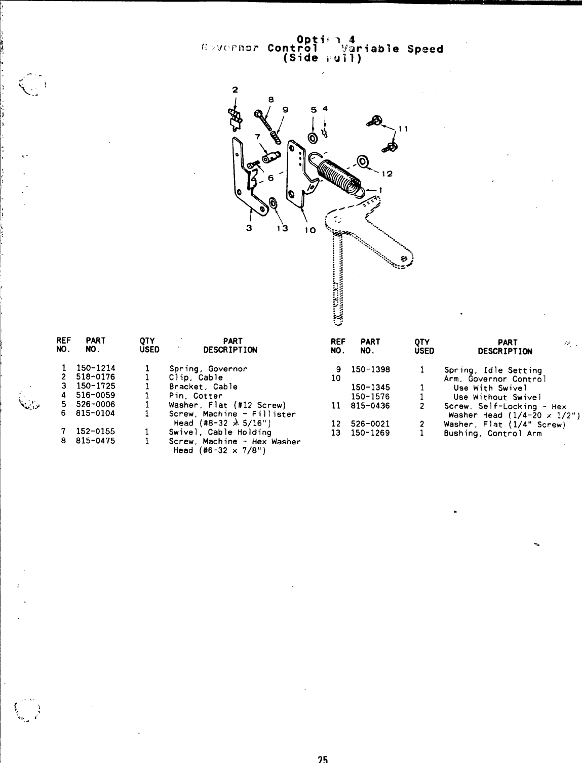
2
I8
REF PART
NO. NO.
1150-1214
2518-0176
3150-1725
4516-0059
5526-0006
6815-0104
7152-0155
8815-0475
QTY
USED
1
1
1
1
PART
DESCRIPTION
Spring, Governor
Clip, Cable
8racket, Cable
Pin, Cotter
Washer, Flat (#12 Screw)
Screw, Machine -Fill ister
Head (#8-32 ~.5/16”)
Swivel, Cable Holding
Screw, Machine -Hex Washer
Head (#6-32 x7/8”)
REF PART
NO. NO.
9150-1398
10 150-1345
150-1576
11 815-0436
12 526-0021
13 150-1269
,
QTY PART ,.-.
USED DESCRIPTION “’
1Spring, Idle Setting
Arm, Governor Control
1Use With Swivel
1Use Without Swivel
2Screw, Self-Locking -Hex
Washer Head (1/4-20 x1/2”)
2Washer, Flat (1/4” Screw)
18ushing, Control Arm
(.=”!
‘.> ,’
.-
25
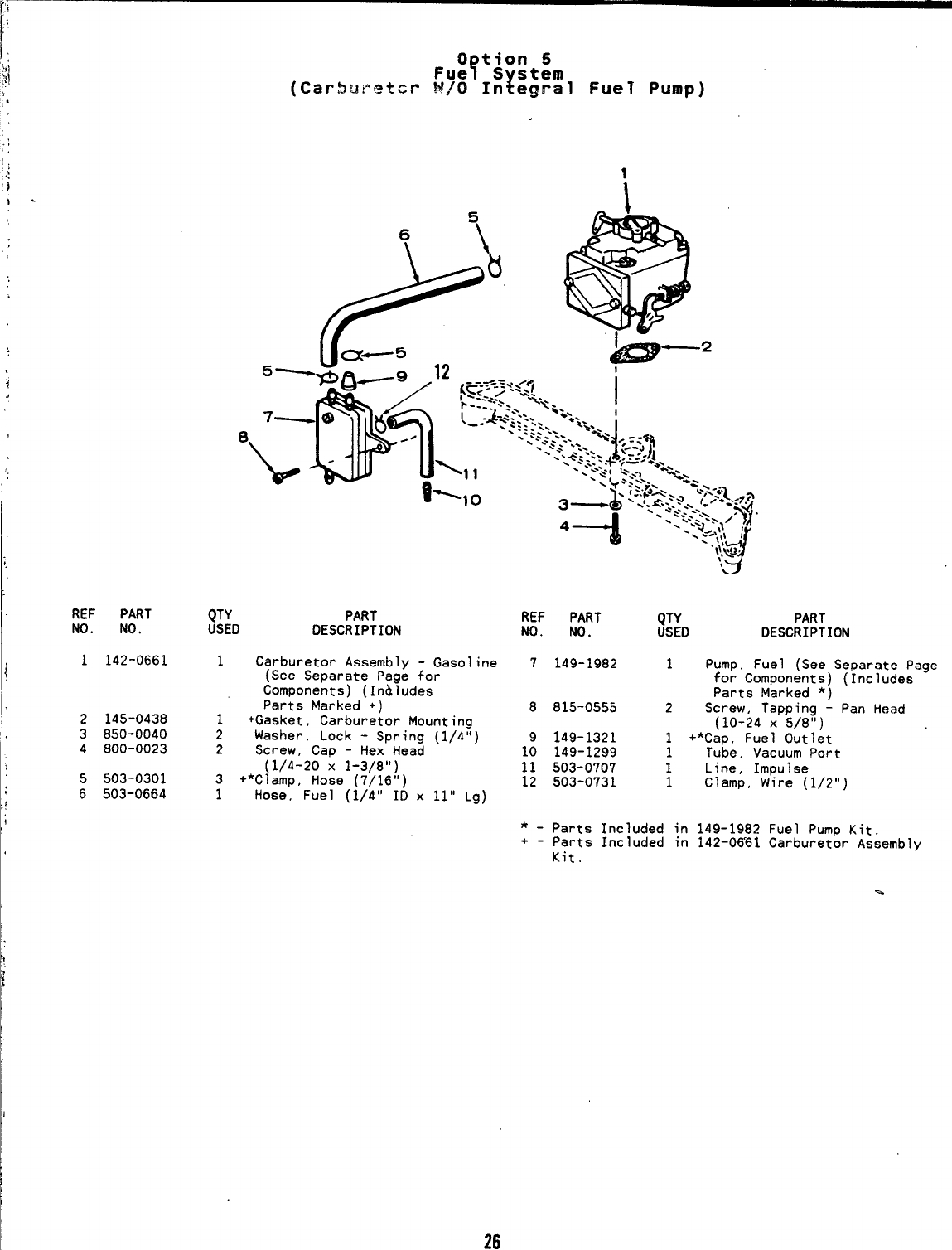
;
1
i
‘1
.
REF PART
NO. NO.
1142-0661
2145-0438
3850-0040
4800-0023
5503-0301
6503-0664
0tion 5
Fue ?Sstem
!(Carburetor !4/0 In egral FueT Pump)
j:D PART
DESCRIPTION
1Carburetor Assembly -Gasoline
(See Separate Page for
Components) (In&ludes
Parts Marked +)
1+Gasket, Carburetor Mounting
2Washer, Lock -Spring (1/4”)
2Screw, Cap -Hex Head
(1/4-20 X1-3/8”)
~+*Clamp, Hose (7/16”)
Hose, Fuel (1/4” ID x11” Lg)
REF PART QTY PART
NO. NO. USED DESCRIPTION
7149-1982 1Pump. Fuel (See Separate Page
for Components) (Includes
Parts Marked *)
8815-0555 2Screw, TaDDina -Pan Head
(10-24 xk/8fi)
9149-1321 1+*Cap, Fuel Outlet
10 149-1299 1Tube, Vacuum Port
11 503-0707 1
12 503-0731 1Line, Impulse
Clamp, Wire (1/2”)
*-Parts Included in
+-parts Included in
Kit.
149-1982 Fuel Pump Kit.
142-0~1 Carburetor Assembly
26

.
.
27
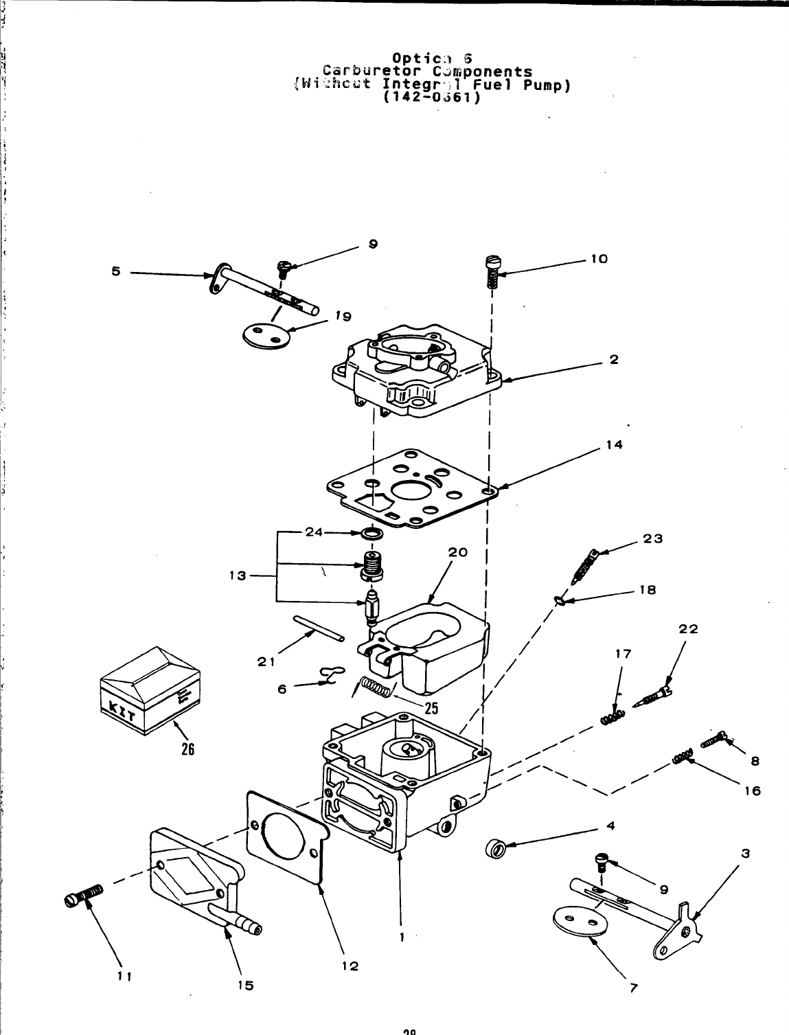
‘t
1:
i
I
I
)
Optic:l 6
Carburetor C~mponents
{Hi’:hcut Integr<l Fuel Pump)
(142-0661)
/9
19 I
/
0
T11
26
.23
15 ‘7
28
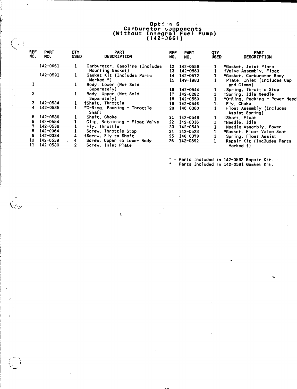
,.. .
[,;
*.. REF
NO. PART
NO.
142-0661
142-0591
1
2
3
4142-0534
142-0535
142-0536
142-0554
142-0538
142-0064
142-0334
142-0539
142-0539
Opti n6
Carburetor ~amponents
(Without Integral Fuel Pump)
(142-:2661)
QTY PART
USED DESCRIPTION
1Carburetor, Gasoline (Includes
Mounting Gasket)
1Gasket Kit (Includes Parts
Marked *)
1Body, Lower (Not Sold
Separately)
1Body, Upper (Not Sold
Separately)
1tShaft, Throttle
1*O-Ring, Packing -Throttle
Shaft
Shaft, Choke
:Clip, Retaining -Float Valve
Fly, Throttle
iScrew, Throttle Stop
4tScrew, Fly to Shaft
4Screw, Upper to Lower Body
2Screw, Inlet Plate
REF PART j;D PART
NO. NO. DESCRIPTION
12
13
14
15
16
17
18
19
20
21
22
23
24
25
26
142-0559
142-0553
142-0572
149-1983
142-0544
142-0282
142-0550
142-0546
146-0380
142-0548
142-0016
142-0549
142-0523
146-0379
142-0592
1
1
*Gasket, ,Inlet Plate
tValve ksembly, Float
*Gasket, Carburetor Body
Plate, Inlet (Includes Cap
and Clamp)
.Spring, Throttle Stop
tSpring, Idle Needle
*O-Ring, Packing -Power
Needle
Fly, Choke
Float Assembly (Includes
Assist Spring)
tShaft, Float
tNeedle, Idle
Needle Assembly, Power
*Gasket, Float Valve Seat
Spring, Float Assist
Repair Kit (Inc,ludes Parts
Marked t)
t- Parts Included in 142-0592 Repair Kit.
*-Parts Included in 142-0591 Gasket Kit.
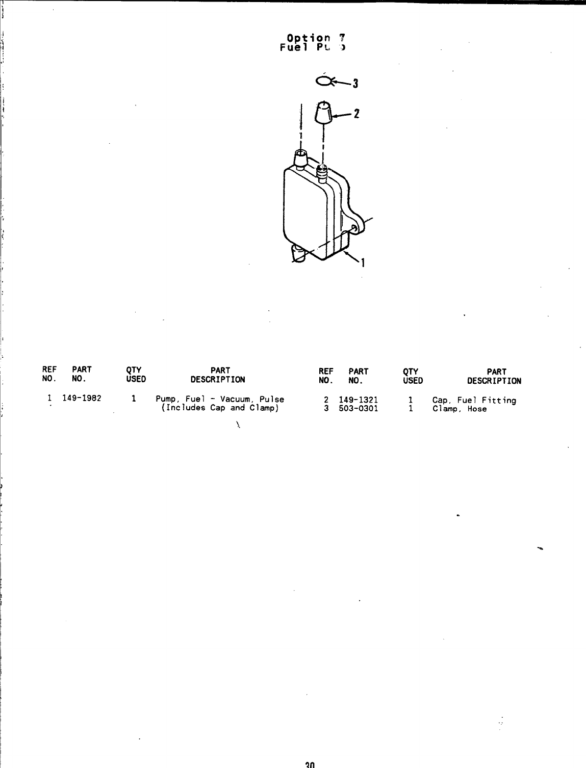
Option ?
Fuel PL J
I
II
REF PART QTY PART REF PART
NO. NO. USED DESCRIPTION QTY PART
NO. NO. USED DESCRIPTION
1149-1982 1Pump, Fuel -Vacuum, Pulse 2149-1321 1
(Includes Cap and Clamp) Cap, Fuel Fitting
3503-0301 1Clamp, Hose
),
I
1
I
I
1’
30
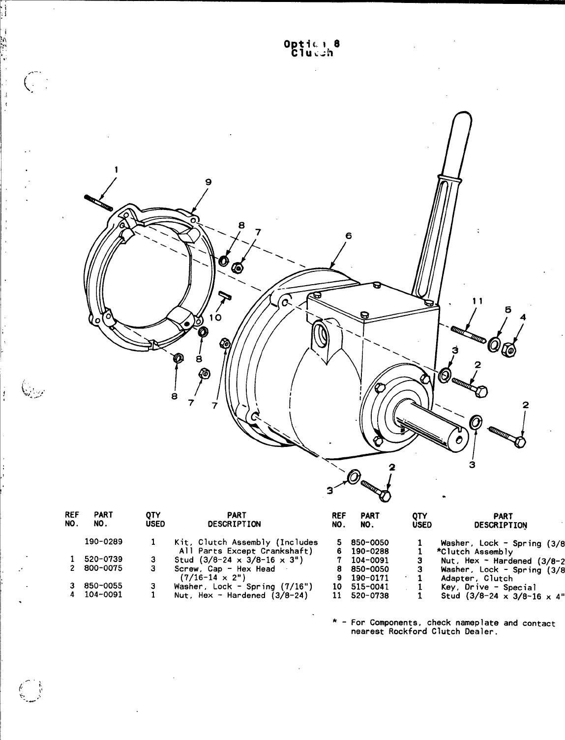
.
REF PART QTY PART
NO. NO. USED DESCRIPTION
190-0289 1Kit, Clutch Assembly (Includes
All Parts Except Crankshaft)
1520-0739 3Stud (3/8-24 X3/8-16 X3“)
2800-0075 3Screw, Cap -Hex Head
(7/16-14 X2“)
3850-0055 3Washer, Lock -Spring (7/16”)
4104-0091 1Nut, Hex -Hardened (3/8-24)
REF
NO.
*-
PART
NO.
850-0050
190-0288
104-0091
850-0050
190-0171
515-0041
520-0738
QTY PART
USED DESCRIPTION
1Washer, Lock -Spring
(3/8”)
1*Clutch Assembly
3Nut, Hex -Hardened (3/8-24)
Washer, Lock -Spring
(3/8”)
‘: Adapter, Clutch
Key, Drive -Special
;Stud (3/8-24 X3/8-16 X
4“)
For Components, check nameplate and contact
nearest Rockford Clutch Dealer.
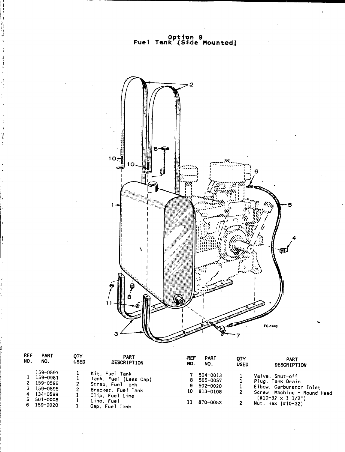
,’
‘,
i
REF PART
NO. NO.
159-0597
1159-0981
2159-0596
3159-0595
4134-0599
5501-0008
6159-0020
Fue 1
QTY PART
USED =CRIPTIW
1Kit, Fuel Tank
1Tank, Fuel (Less Cap)
2Strap, Fuel Tank
2Bracket, Fuel Tank
1Clip, Fuel Line
Line, Fuel
:Cap, Fuel Tank
REF PART QTY PART
NO. NO. USED DESCRIPTION
7504-0013 1Valve, Shut-off
8505-0057 Plug, Tank Drain
9502-0020 :Elbow, Carburetor Inlet
10 813-O1O8 2Screw, Machine -Round Head
11 870-0053 (#lo-3? x1-1/2”)
2Nut, Hex (#10-32)
II
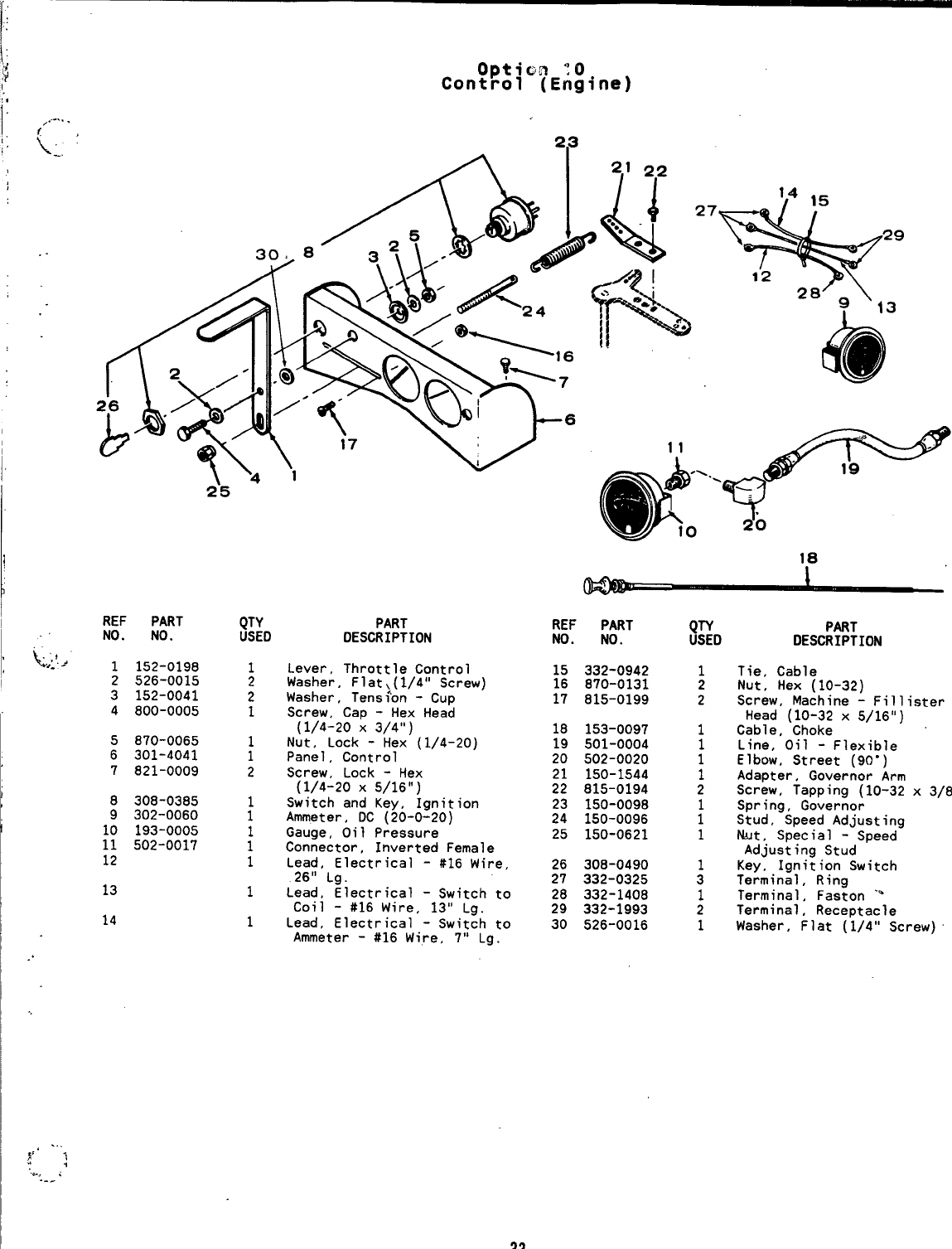
‘[‘
..
f
!’,
I
,.
{’
I
t
Option :0
Control (Engine)
REF PART
NO. NO.
1152-0198
2526-0015
3152-0041
4800-0005
5870-0065
6301-4041
7821-0009
8308-0385
9302-0060
10 193-0005
11 502-0017
12
13
14
2’5 ‘
PART
DESCRIPTION
Lever, Throttle Control
Washer, Flat,(l/4° Screw)
Washer, Tens$on -Cup
Screw, Cap -Hex Head
(1/4-20 X3/4”)
Nut, Lock -Hex (1/4-20)
Panel, Control
Screw, Lock -Hex
(1/4-20 X5/16”)
Switch and Key, Ignition
Ammeter, DC (20-0-20)
Gauge, Oil Pressure
Connector, Inverted Female
Lead, Electrical -#16 Wire,
26” Lg.
Lead, Electrical -Switch to
Coil -#16 Wire, 13” Lg.
Lead, Electrical -Switch to
Ammeter -#16 Wire, 7“ Lg.
2.3
27 ‘4 15
*
29
12 28[= \
I13
“-=..-
@’T
10 20
18
REF PART
NO. NO.
15 332-0942
16 870-0131
17 815-0199
18 153-0097
19 501-0004
20 502-0020
21 150-1544
22 815-0194
23 150-0098
24 150-0096
25 150-0621
26 308-0490
27 332-0325
28 332-1408
29 332-1993
30 526-0016
1
2
2
1
1
2
1
1
3
1
2
1
PART
DESCRIPTION
Tie, Cable
Nut, Hex (10-32)
Screw, Machine -Fillister
Head (10-32 x5/16”)
Cable, Choke
Line, Oil -Flexible
Elbow, Street (90”)
Adapter, Governor Arm
Screw, Tapping (10-32
Spring, Governor
Stud, Speed Adjusting
ht, Special -Speed
Adjusting Stud
Key, Ignition Switch
Terminal, Ring
Terminal, Faston ‘%
Terminal, Receptacle
X
3/8”)
Washer, Flat (1/4” Screw)
33
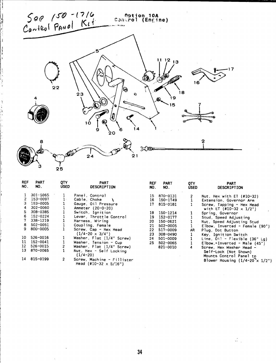
Q
;
22
4
@
23
920
7
“*
17
REF PART
No. No.
1301-5065
2153-0097
3193-0005
4302-0060
5308-0385
6152-0224
7338-1219
8502-0051
9800-0005
10 526-0016
11 152-0041
12 526-0015
13 870-0065
14 815-0199
2“5
QTY
USED
1
1
1
i
1
;
1
1
1
1
2
1
2
PART
DESCRIPTION
Panel, Control
Cable, Choke \
Gauge, Oil Pressure
Ammeter (20-0-20)
Switch, Ignition
Lever, Throttle Control
Harness, Wiring
Coupling, Female
Screw, Cap -Hex Head
(1/4-20 X3/4”)
Washer, Flat (1/4” Screw)
Washer, Tension -Cup
Washer, Flat (1/4” Screw)
Nut, Hex -Seif” Locking ‘
(1/4-20)
Screw, Machine -Fill ister
Head (#10-32 x5/16”)
REF PART
NO. NO.
15 870-0131
16 150-1749
17 815-0181
18 150-1214
19 152-0177
20 150-0621
21 502-0005
22 517-0009
23 308-0490
24 501-0009
25 502-0065
821-0010
QTY
USED
2
1
1
1
1
1
1
AR
i
1
4
PART
DESCRIPTION
Nut, Hex with ET (#10-32)
Extension, Governor Arm
Screw, Tapping -Hex Head
with ET (#10-32 x1/2”)
Spring, Governor
Stud, Speed Adjusting
Nut, Speed Adjusting Stud
Elbow, Inverted -Female (9o”)
Plug, Dot Button
Key, Ignition Switch
Line, Oil -Fiexible (36” Lg)
Elbow,-Inverted -Male (45”)
Screw, Hex Washer Head -
Self-Lock (Not Shown)
Mounts Control Panel to
Blower Housing (1/4-20*x 1/2”)
34
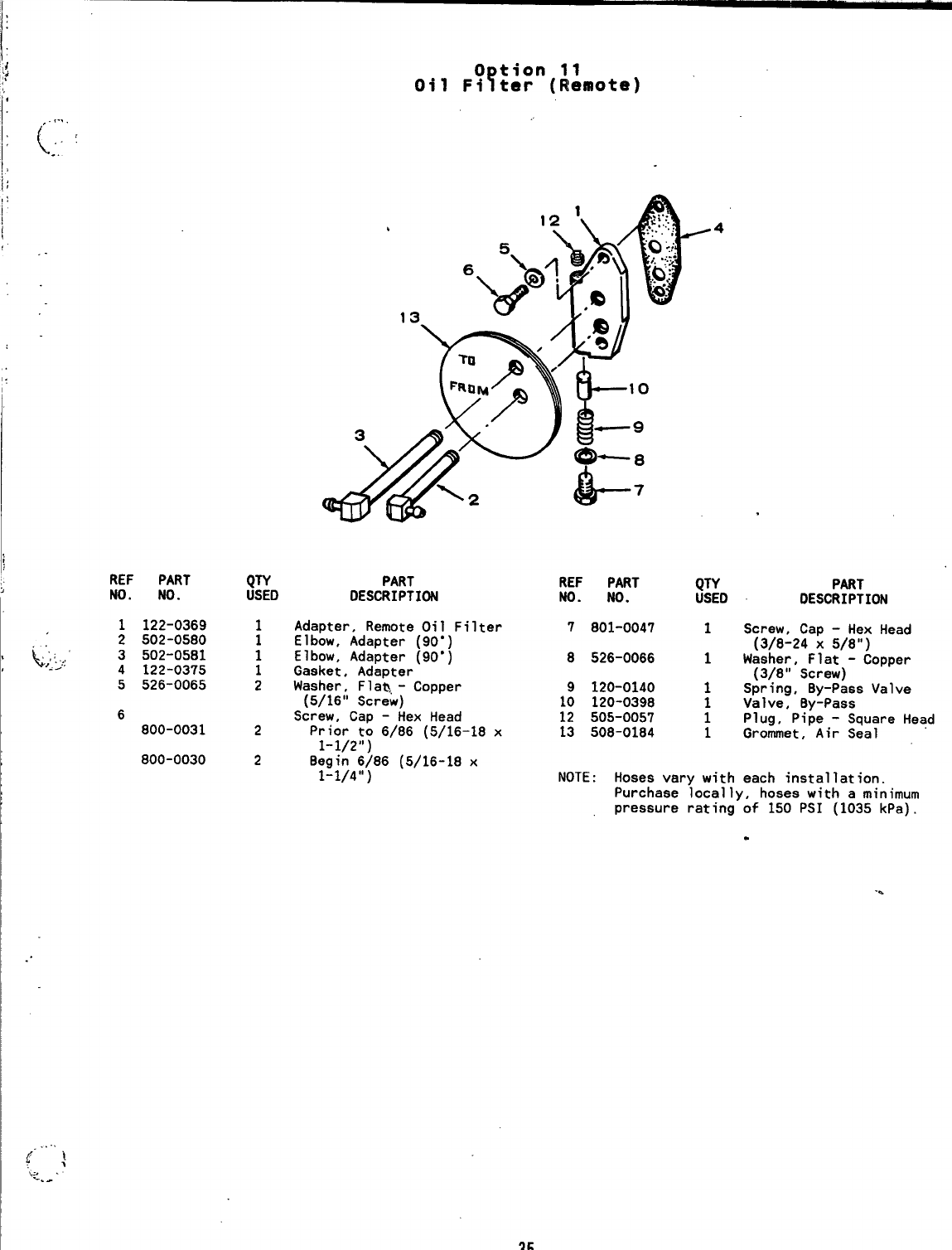
,. !..,
(’,.,
.
REF PART
NO. NO.
1122-0369
2502-0580
~:<>,; 3502-0581
4122-0375
5526-0065
6
800-0031
800-0030
3
QTY PART
USED DESCRIPTION
1Adapter, Remote Oil
Elbow, Adapter (90”,
;Elbow, Adapter [90”
1
2
2
REF PART
NO. NO.
Filter 7801-0047
8526-0066
Gasket, Adapter’
Washer, Fla&,- Copper 9120-0140
(5/16” Screw) 10 120-0398
Screw, Cap -Hex Head 12 505-0057
Prior to 6/86 (5/16-18 x13 508-0184
1-1/2”)
QTY
USED
1
1
1
1
1
1
PART
DESCRIPTION
Screw, Cap -Hex Head
(3/8-24 X5/8”)
Waeher, Flat -Copper
(3/8” Screw)
Spring, By-Pass Valve
Valve, By-Pass
Plug, Pipe -Square Head
Grommet, Air Seal
2Begin 6)86 (5/16-18 x
1-1/4”) NOTE :Hoses vary with each installation.
Purchase locally, hoses with aminimum
pressure rating of 150 PSI (1035 kPa).
.
35
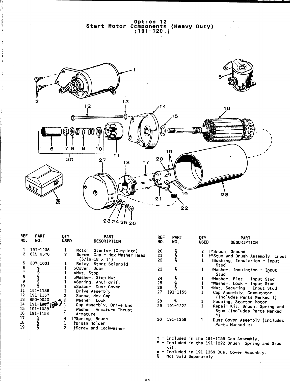
t:
Option 12
Start Motor Cemponent% (Heavy Duty)
i191-120 )
.
I
-/
F
--
2 13
1,2 I/14
5
16
2’8
23242’5~6
REF PART QTY PART
NO. NO. USED DESCRIPTION
1
2191-1205 1Motor, Starter (Complete)
815-0570 2Screw, Cap -Hex Washer Head
(5/16-18 Xl“)
307-1031 1Relay, Start Solenoid
s1xCover, Dust
5xNut, Stop
s;xWasher, Stop Nut
1xSpring, Anti-drift
!1xSpacer, Dust Cover
191-1156 1Drive Assembly
191-1157 2Screw, Hex Cap
Washer, Lock
::::0$ I*7 :Cap Assembly, Drive End
Washer, Armature Thrust
191-1154 1Armature
~t*Spring, 8rush
!t8rush Holder
s2?Screw and Lockwasher
REF PART
NO. NO.
23 s
28 s
29 191-1222
30 191-1359
QTY PART
USED DESCRIPTION
2
1
1
1
;
1
1
1
1
1
‘N \I
/’
/
/
/
t*8rush, Ground
t*Stud and Brush Assembly, Input
t8ushing, Insulation -Input
Stud
tWasher, Insulation -[~put
Stud
tWasher, Flat -Input Stud
tWasher, Lock -Input Stud
tNut, Securing -Input Stud
Cap Assembly, Comutator
(Includes Parts Marked t)
Housing, Starter Motor
Repair Kit, Brush, Spring and
Stud (Includes Parts Marked
*)
Dust Cover Assembly (Includes
Parts Marked x)
t - Included in the 191-1155 Cap Aesembly.
*-Included in the 191-1222 8rush, Spring and Stud
Kit.
x- Included in 191-1359 Dust Cover Assembly,
~-Not Sold Separately.
36
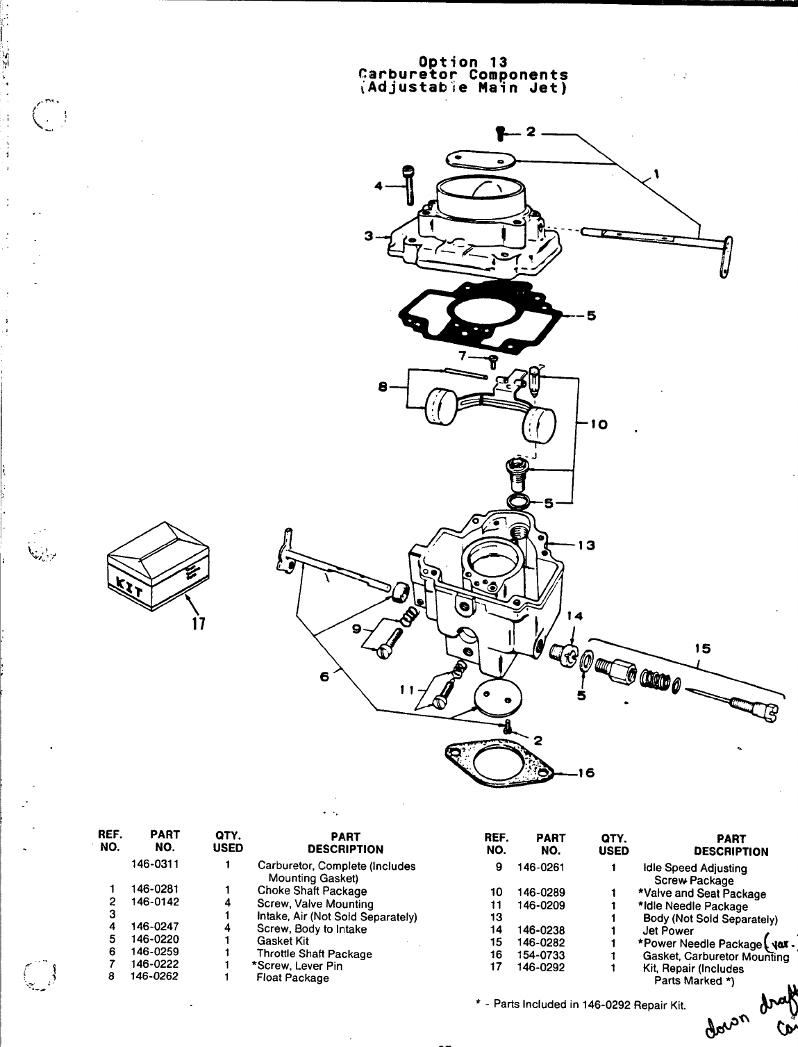
@
~l? d
\i7
REF. PART
NO. NO.
146-0311
1146-0281
2146-0142
3
4146-0247
5146-0220
6146-0259
7146-0222
8146-0262
QTY.
USED
1
1
4
1
4
1
1
1
1
Option 13
Carburetor Components
~Adjustab’ie Main Jet)
4
c‘L ., ,
H
-.
J
6
PART
DESCRIPTION
Carburetor, Complete (Includes
Mounting Gasket)
Choke Shati Package
Screw, Valve Mounting
Intake, Air (Not Sold Separately)
Screw, Bodytolntake
Gasket Kit
Throttle Shati Package
*Screw, Lever Pin
Float Package
-16 .
REF. PART PART
NO. NO. :SYD DESCRIPTION
9146-0261 1Idle Speed Adjusting
Screw Package
10 146-0289 1*Valveand Seat Package
11 146-0209 1●idle Needle Packaoe
13 1Body (Not Sold Se~arateiy)
14 146-0238 1Jet Power
15 146-0282 1L
‘
*Power Needle Package q~-je
16 154-0733 1Gasket, Carburetor Mounting
17 146-0292 1Kit, Repair(lnciudes
Parts Marked *)
*-Parts Included in 146-0292 Repair Kit.
n
w%
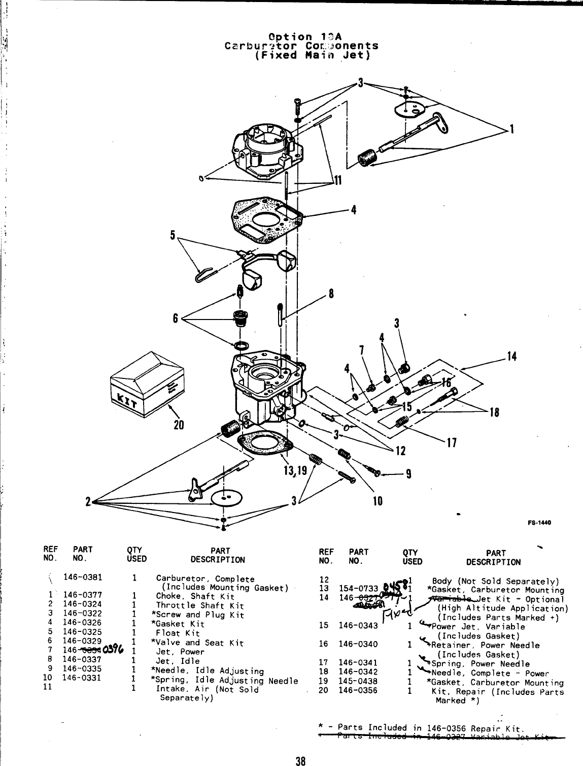
Option 13A
Carburetor Co~;:~onents
(Fixed Main Jet)
REF PART Q~ PART
NO. NO. USED DESCRIPTION
~146-0381 1Carburetor, Complete
(Includes Mounting Gasket)
1’ 146-0377 Choke, Shaft Kit
2146-0324 ;Throttle Shaft Kit
3146-0322 *Screw and Plug Kit
4146-0326 i*Gasket Kit
5146-0325 Float-Kit-
6146-0329 1*Valve and Seat Kit
7146~&96 1Jet, Power
8146-0337 1Jet, Idle
9146-0335 *Needle, Idle Adjusting
10 146-0331 ;*Spring, Idle Adjusting Needle
11 1Intake, Air (Not Sold
Separately)
REF PART ;~D
NO. NO.
15
.14
.
FS-lMO
PART %
DESCRIPTION
Body (Not Sold Separately)
‘~g-+~ ‘OPtional
*Gasket, Carburetor Mounting
-“~=?~u~;tAppl icat ion)
~@ (Includes Parts Marked +)
146-0343 1%power Jet, Variable
(Includes Gasket)
16 146-0340 1%Retainer, Power Needle
(Includes Gasket)
17 146-0341 1~Spring, Power Needle
18 146-0342 1~Needle, Complete -Power
19 145-0438 1*Gasket, Carburetor Mounting
20 146-0356 1Kit, Repair (Includes Parts
Marked *)
..
*_parts Included in 146-0356 Repair Kit. “.-
38
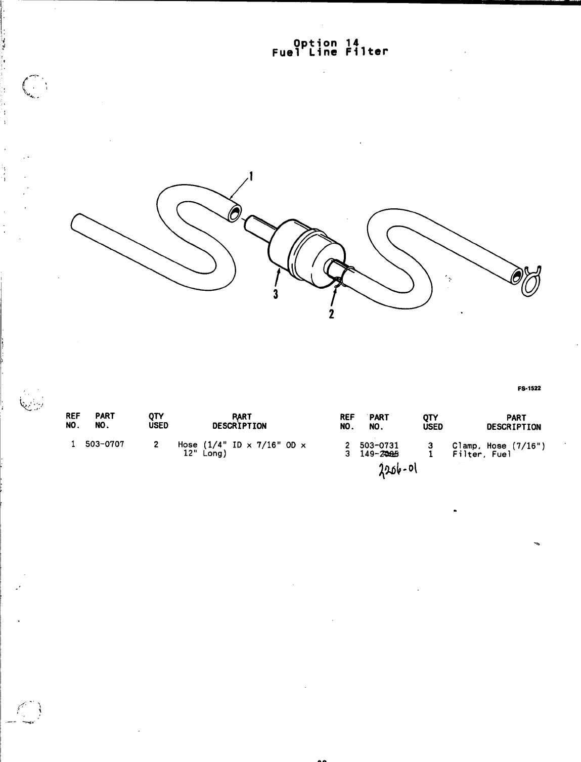
REF PART QW
NO. NO. ~E~cpp;loN
USED
Option 14
Fuel Line Filter
2.
FS-1522
REF PART Q~ PART
NO. NO. USED DESCRIPTION
1503-0707 2Hose (1/4” ID x7/16” OD x
12” Long) 2503-0731 3Clamp, Hose (7/16”)
3149-* Filter, Fuel
~~~.ol 1
—- -.
39
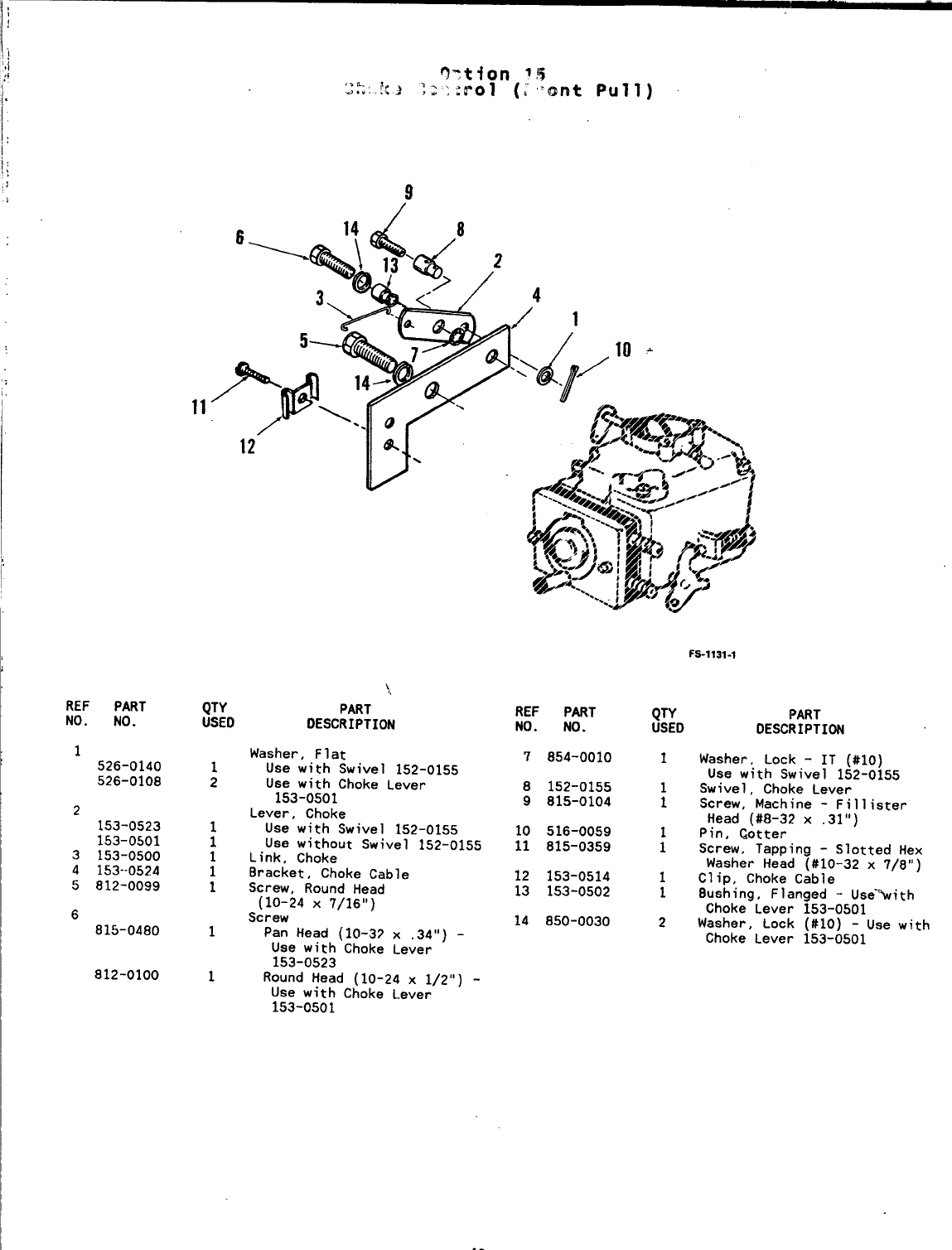
1’
,;
REF PART
NO. NO.
1526-0140
526-0108
2
153-0523
153-0501
3153-0500
4153--0524
5812-0099
6
815-0480
812-0100
QTY
USEO
1
2
1
1
:
1
1
1
),
PART
DESCRIPTION
Washer, Flat
Use with Swivel 152-0155
Use with Choke Lever
153-0501
Lever, Choke
Use with Swivel 152-0155
Use without Swivel 152-0155
Link, Choke
Bracket, Choke Cable
Screw, Round Head
(10-24 X7/16”)
Screw
Pan Head (10-37 x.34”) -
Use with Choke Lever
153-0523
Round Head (10-24 x1/2”) -
Use with Choke Lever
153-0501
REF PART
NO. NO.
7854-0010
8152-0155
9815-0104
10 516-0059
11 815-0359
12 153-0514
13 153-0502
14 850-0030
Fs-1131-I
QTY PART
USED DESCRIPTION
1Washer, Lock -IT (#10)
Use with Swivel 152-0155
1Swivel, Choke Lever
1Screw, Machine -Fill ister
Head (#8-32 x.31”)
1Pin, Cotter
1Screw, Tapping -Slotted Hex
Washer Head (#10-32 x7/8”)
1Clip, Choke Cable
1Bushing, Flanged -Use”%ith
Choke Lever 153-0501
2Washer, Lock (#10) -Use with
Choke Lever 153-0501
40
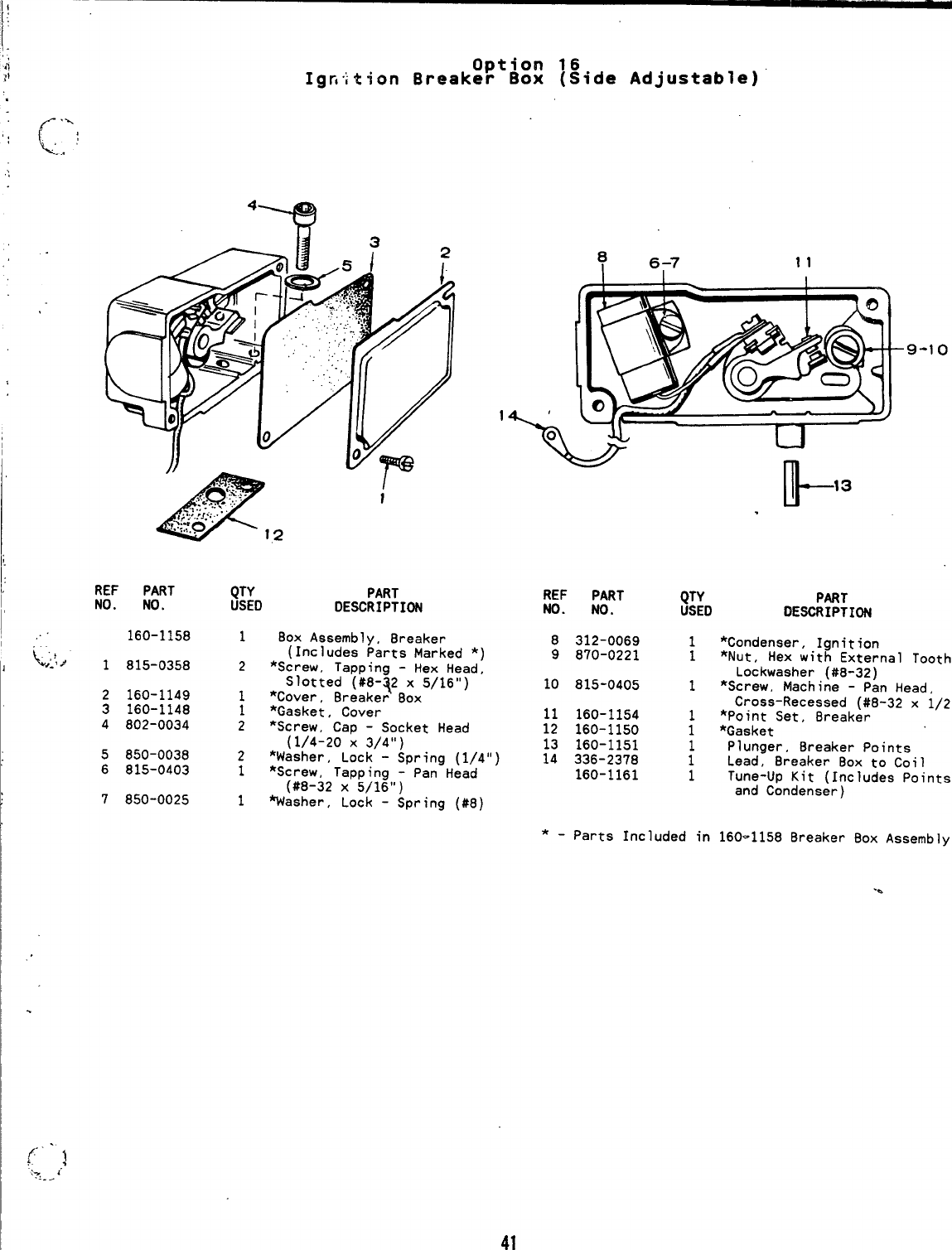
Option 16
Igfiition Breaker Box (Side Adjustable)
REF PART
NO. NO.
160-1158
1815-0358
2160-1149
3160-1148
4802-0034
5850-0038
6815-0403
7850-0025
1’
\o
QTY PART
USEO DESCRIPTION
180X Assembly, 8reaker
(Includes Parts Marked *)
2*screw, Tapping -Hex Head,
Slotted (#8-~2 x5/16”)
1*Cover, 8reaker 80X
1*Gasket, Cover
2*Screw, Cap -Socket Head
(1/4-20 X3/4”)
REF PART
NO. NO.
8312-0069
9870-0221
10 815-0405
11 160-1154
12 160-1150
13 160-1151
2*Washer, Lock”- Spring (1/4”) 14 336-2378
1*screw, Tapping -Pan Head
(#8-32 X5/16”) 160-1161
1Washer, Lock -Spring (#8)
k13
9-1o
QTY PART
USED DESCRIPTION
1*Condenser, Ignition
1*Nut, Hex with External Tooth
Lockwasher (#8-32)
1*Screw, Machine -Pan Head,
Cross-Recessed (#8-32 x
1/2”)
1*Point Set, Breaker
1*Gasket
Plunger, 8reaker Points
:Lead, Breaker Box to Coil
1Tune-Up Kit (Includes Points
and Condenser)
*-Parts Included in 160-1158 Breaker Box Assembly.
-a
41
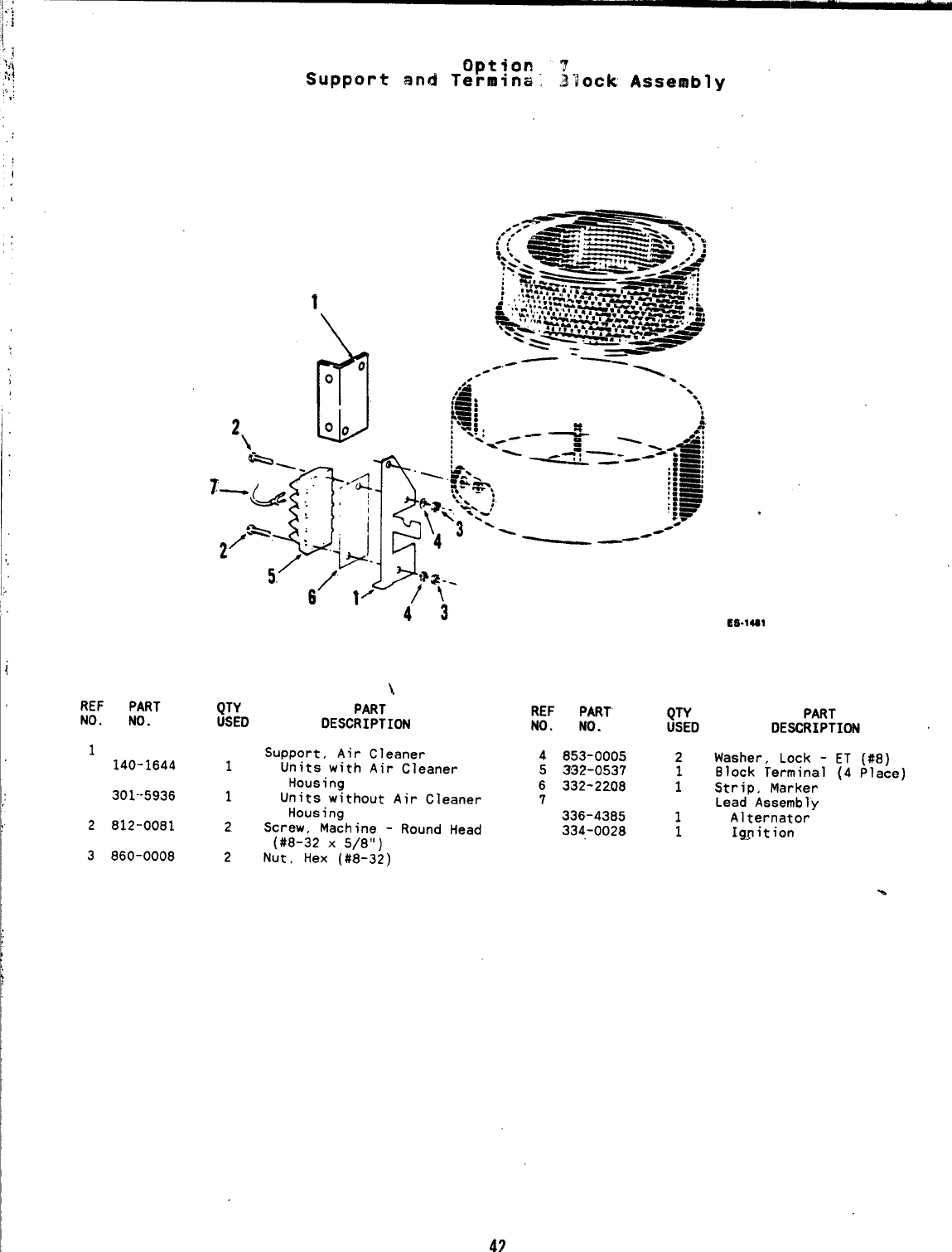
I;,
i
REF PART
NO. NO.
,
1
140-1644
301--5936
2812-0081
3860-0008
Option ?
Support and Termina, ~lock Assembly
\
QTY PART
USED DESCRIPTION
Support, Air Cleaner
1Units with Air Cleaner
Housing
1Units without Air Cleaner
Housing
2Screw, Machine -Round Head
(#8-32 X5/8”)
2Nut, Hex (#8-32)
REF PART
NO. NO.
4853-0005
5332-0537
6332-2208
7
336-4385
334-0028
.
Es.lal
QTY PART
USED DE~IPTION
2Washer, Lock -ET (#8)
Block Terminal (4 Place)
;Strip, Marker
Lead Assembly
1Alternator
1I~ition
42
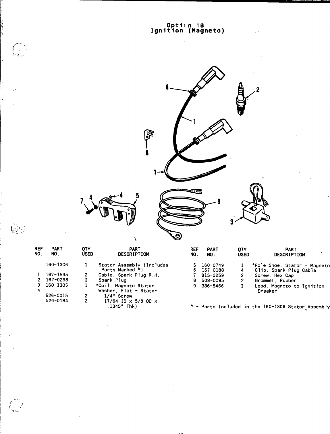
Opticn 18
Ignition (Magneto)
f“’
..
.,
;,,’
-. .
.-
1;;,;/,.;
W*
f--”.,
r:,
--,
REF PART
NO. NO.
160-1306
1167-1595
2167-0298
3160-1305
4526-0015
526-0184
r
o
6
1
8
$:0 PART REF PART
DESCRIPTION NO. NO.
.
&
e,
31°
$~D PART
DESCRIPTION
1Stator Assembly (Includes 5160-0749
Parts Marked *) 6167-0188
2Cable, Spark Plug R.H. 7815-0259
2Spark Plug 8508-0095
1*Coil, Magneto Stator 9336-8466
Washer, Flat -Stator
21/4” Screw
217/64 ID X5/8 OD X
.1345” Thk) *-Parts Included in the 160-1306 Stator~Assembly
1*Pole Shoe, Stator -Magneto
4Clip, Spark Plug Cable
2Screw, Hex Cap
2Grommet, Rubber
1Lead, Magneto to Ignition
Breaker
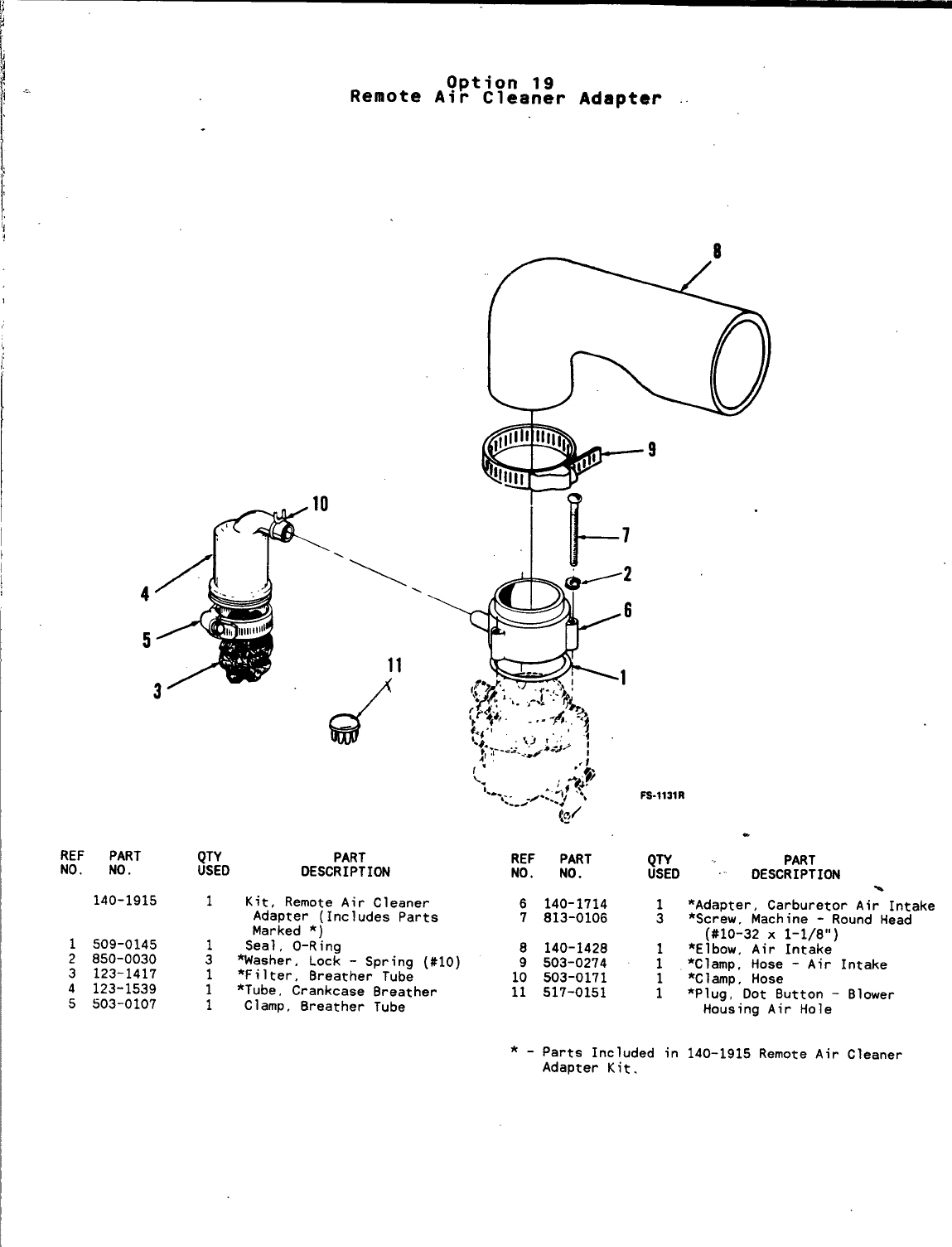
4
5
3
\
REF PART
NO. NO.
140-1915
1509-0145
2850-0030
3123-1417
4123-1539
5503-0107
Option 19
Remote Air Cleaner Adapter ..
\
.
QTY PART
USED DESCRIPTION
1Kit, Remote Air Cleaner
Adapter (Includes Parts
Marked *)
1Seal, O-Ring
3*Washer, Lock -Spring (#10)
1*Filter, Breather Tube
1*Tube, Crankcase Breather
1Clamp, Breather Tube
REF PART ;gD
NO. NO.
6140-1714 1
7813-0106 3
PART
DESCRIPTION \
*Adapter, Carburetor Air Intake
*Screw, Machine -Round Head
(#10-32 X1-1/8”)
*Elbow, Air Intake
8140-1428
9503-0274 :*Clamp, Hose -Air Intake
10 503-0171 1*Clamp, Hose
11 517-0151 1*Plug, Dot Button -
Housing Air Hole
*-parts Included in 140-1915 Remote Air
Adapter Kit.
Blower
Cleaner

.-
.
45
.
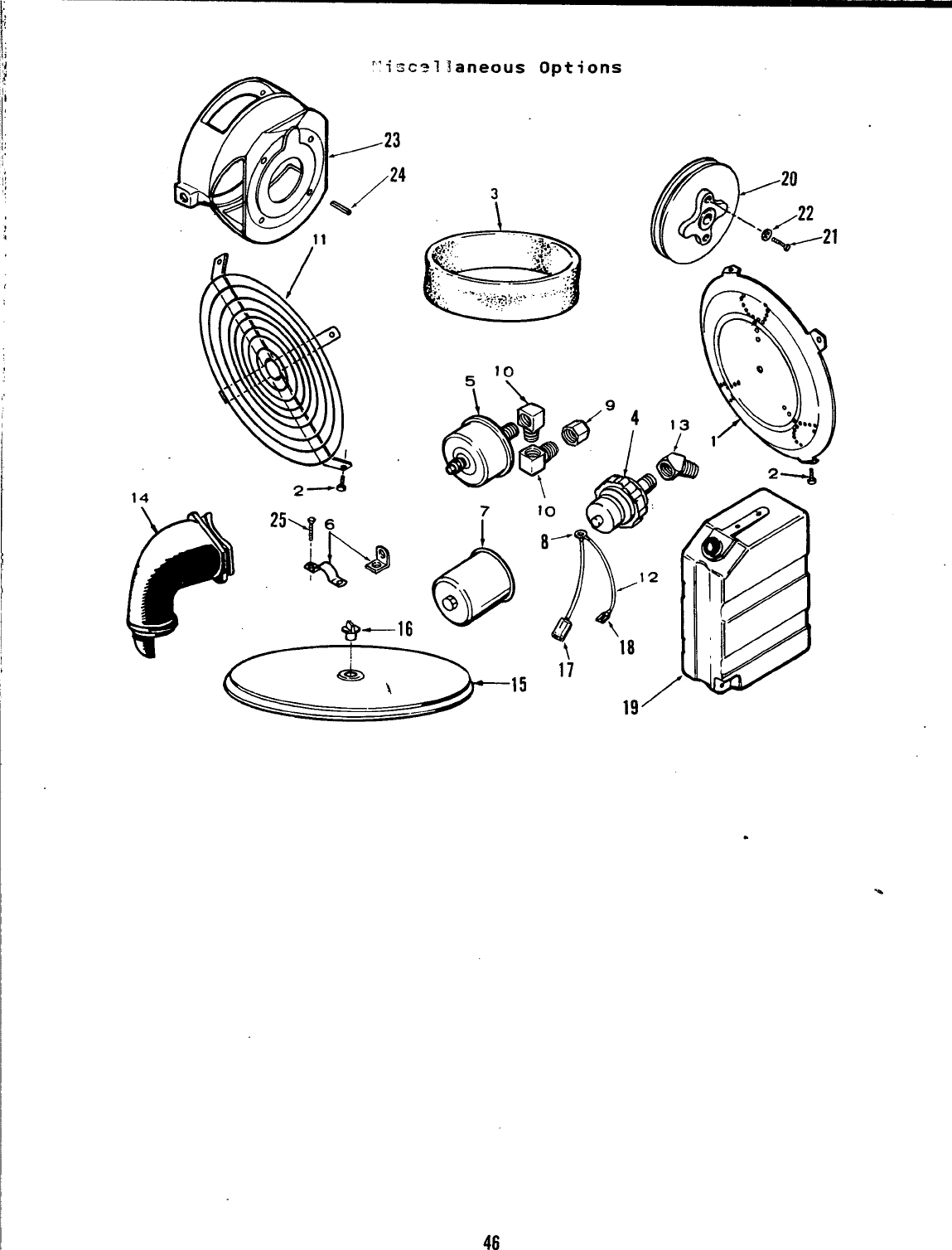
‘1
),
,.
14
“isca?laneous Options
@
20
e\/22
e‘@-21
*—J
.
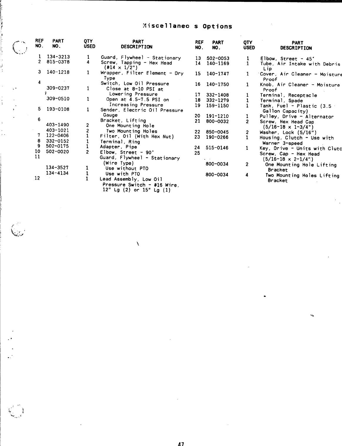
REF PART
c,:? ‘0” ‘0”
1134-3213
2815-0378
3140-1218
4
. . 309-0237
Y
309-0510
5
6
7
8
1:
11
193-0108
403-1490
403-1021
122-0406
332-0152
502-0175
502-0020
134-3527
134-4134
12
QTY
USED
1
4
1
1
1
1
2
:
;
2
1
:
Miscellaneo
PART
DESCRIPTION
Guard, Flywheel -Stationary
Screw, Tapping -Hex Head
(#14 x1/2”)
Wrapper, Filter Element -Dry
Type
Switch, Low Oil Pressure
Close at 8-10 PSI at
Lowering Pressure
Open at 4.5-7.5 PSI on
Increasing Pressure
Sender, Electric Oil Pressure
Gauge
8racket, Lifting
One Mounting Hole
Two Mounting Holes
Filter, Oil (With Hex Nut)
Terminal, Ring
Adapter, Pipe
Elbow, Street -90”
Guard, Flywheel -Stationary
(Wire Type)
Use without PTO
Use with PTO
Lead Assembly, Low Oil
Pressure Switch -#16 Wire,
12” Lg (2) or 15” Lg (1)
sOptions
REF PART
NO. NO.
13 502-0053
14 140-1169
15 140-1747
16 140-1750
17 332-1408
18 332-1279
19 159-1150
20 191-1210
21 800-0032
22 850-0045
23 190-0266
24 515-0146
25
800-0034
800-0034
QTY
USED
;
1
1
1
;
1
2
2
1
1
2
4
PART
DESCRIPTION
Elbow, Street -45”
Tube, Air Intake with Debris
Lip
Cover, Air Cleaner -Moisture
Proof
Knob, Air Cleaner -Moisture
Proof
Terminal, Receptacle
Terminal, Spade
Tank, Fuel -Plastic (3.5
Gallon Capacity)
Pulley, Drive -Alternator
Screw, Hex Head Cap
(5/16-18 X1-3/4”)
Washer, Lock (5/16”)
Housing, Clutch -Use with
Warner 3-speed
Key, Drive -Units with Clutch
Screw, Cap -Hex Head
(5/16-18 X2-1/4”.)
One Mounting Hole Lifting
Bracket
Two Mounting Holes Lifting
Bracket
-.
..
47
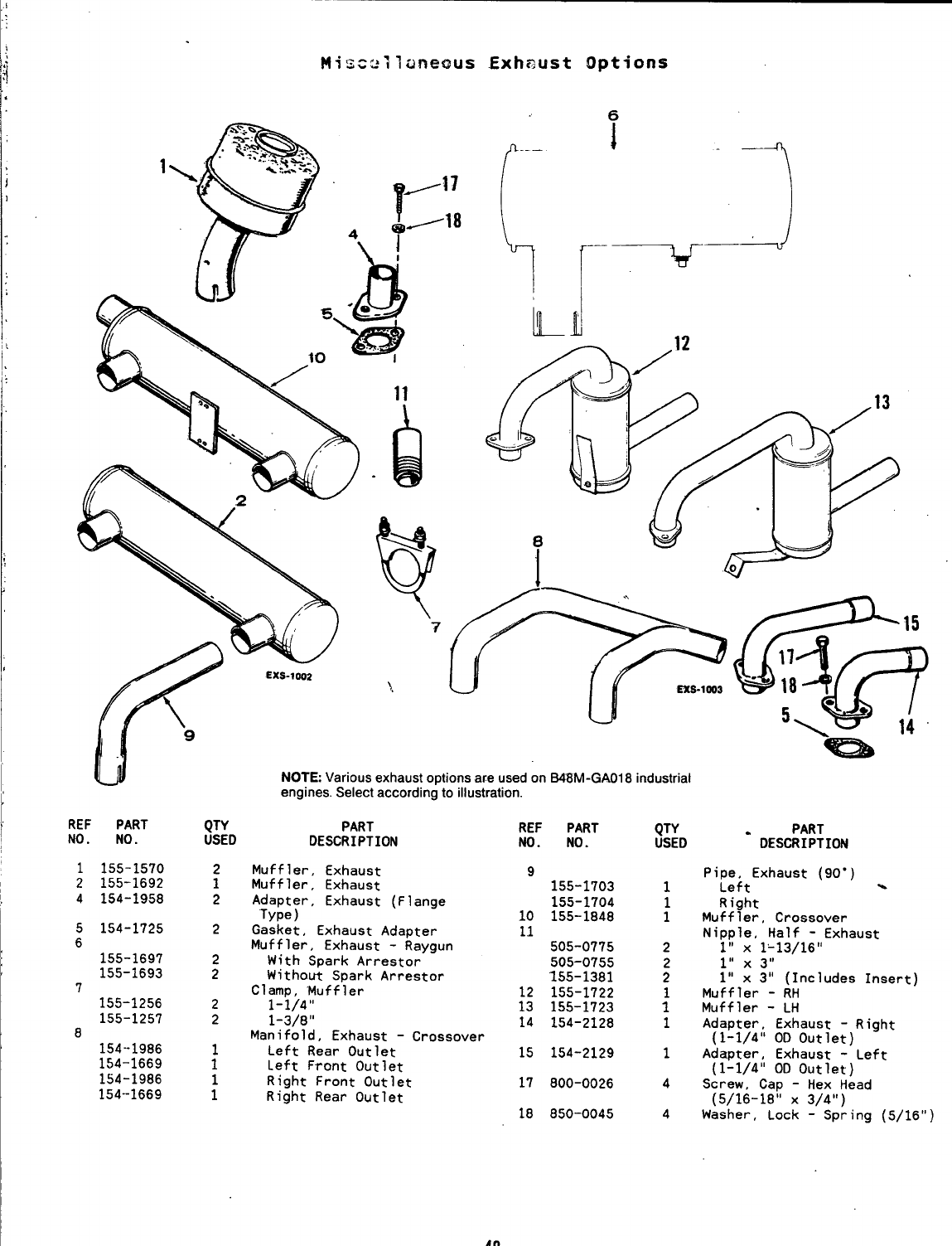
Mis=uilaneous Exhaust Options
6
-u
rExs-lm
\
.9
QTY
USED
2
1
2
2
;
2
2
;
:
‘- ‘-
NOTE: Various exhaust options are used on ~8M-GWl 8industrial
engines. Select according to illustration.
REF PART
NO. NO.
1155-1570
2155-1692
4154-1958
5154-1725
6
155-1697
155-1693
7
155-1256
155-1257
8
154-1986
154-1669
154-1986
154--1669
PART
DESCRIPTION
Muffler, Exhaust
Muffler, Exhaust
A~~~J~r, Exhaust (Flange
Gasket, Exhaust Adapter
Muffler, Exhaust -Raygun
With Spark Arrestor
Without Spark Arrestor
Clamp, ‘Muffler
1-1/4”
1-3/8”
Manifold, Exhaust -Crossover
Left Rear Outlet
Left Front Outlet
Right Front Outlet
Right Rear Outlet
REF PART
NO. NO. QTY
USED -DESC~$;ION
Pi~~ltExhaust (9o”) %
Right
Muffler, Crossover
Nipple, Half -Exhaust
1“ XlL13/16°
111 x 3!,
111 x all (Includes Insert)
Muffler -RH
Muffler -LH
Adapter, Exhaust -Right
(1-1/4” OD Outlet)
Adapter, Exhaust -Left
(1-1/4” OD Outlet)
Screw, Cap -Hex Head
(5/16-18” X3/4”)
Washer, Lock -Spring (5/16”)
9155-1703
155-1704
10 155-1848
11
505-0775
505-0755
155-1381
12 155-1722
13 155-1723
14 154-2128 1
15 154-2129 1
17 800-0026 4
18 850-0045 4
48
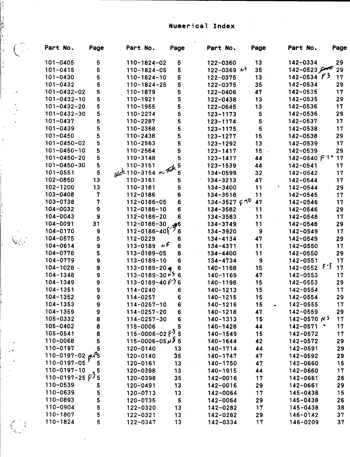
Numerical Index
.,.,,
(. Part No. Page
,.
101-0405 5
101-0415 5
101-0430 5
101-0432 5
. . 101-0432-02 5
101-0432-10 5
101-0432-20 5
101-0432-30 5
101-0437 5
101-0439 5
101-0450 5
101-0450-02 5
I
101-0450-10 5
101-0450-20 5
101-0450-30 5
101-0551 5
102-0850 13
102-1200 13
103-0408 7
103-0738 7
104-0032 9
104-0043 9
104-0091 31
104-0170 9
~,;:,: ‘104-0575 5
104-0614 9
104-0776 5
104-0779 9
104-1028 ~9
104-1348 9
104-1349 9
104-1351 9
104-1352 9
104-1353 9
104-1359 9
105-0332 8
105-0402 8
105-0541 8
110-0068 5
*110-0197 5
110-0197-02 Ja5
F
110-0197-05 5
110-0197-10 5
110-0197-25~~5
110-0539 5
110-0639 5
110-0893 5
110-0904 5
110-1807 5
,{. 110-1824
f: : 5
~.., .
---
Part No. Page
110-1824-02 5
110-1824-05 5
110-1824-10 5
110-1824-25 5
110-1879 5
110-1921 5
110-1955 5
110-2274 5
110-2287 5
110-2368 5
110-2438 5
110-2563 5
110-2564 5
0-3148
0-3151
0-3154 .Odi
110-3161 5
110-3181 5
112-0186 6
112-0186-05 6
112-0186-10 6
112-0186-20 6
112-0186-30 96
112-0186-40f’}6
112-0229 6
113-0189 N< 6
113-6189-05 6
113-0189-10 6
113-0189-20~ 6
113-0189-30P5 6
113-0189-40#? 6
114-0240 6
114-0257 6
114-0257-10 6
114-0257-20 6
114-0257-30 6
115-0006
115-0006-02~’~g
115-0006-05P$ 5
120-0140 13
20-0140 $5
20-0161 13
20-0398 13
20-0398 35
20-0491 13
20-0713 13
120-0735
122-0320
122-0321
122-0347
5
3
3“
3
Part No. Page
122-0360 13
122-0369 N+ 35
122-0375 13
122-0375 35
122-0406 47
122-0438 13
122-0645 13
123-1173 5
123-1174 5
123-1175 5
123-1277 15
123-1292 13
123-1417 15
23-1417 44
23-1539 44
34-0599 32
34-3213 47
34-3400 11
34-3518 11
134-3527 fq” 47
134-3582
134-3583
134-3749
134-3920
134-4134
134-4371
134-4400
134-4734
140-1168
140-1169
140-1198
140-1213
140-1215
140-1216
140-1218
140-1313
140-1428
140-1549
140-1644
140-1714
140-1747
140-1750
140-1915
142-0016
142-0016
142-0064
142-0064
142-0282
142-0282
142-0334
11
11
11
9
47
11
11
9
15
47
15
15
15
15
47
15
44
15
42
44
47
47
44
17
29
17
29
17
29
17
.
Part No. Page
142-0334 29
142-0523~ 29
142-0534 f3 17
142-0534 29
142-0535 17
142-0535 29
142-0536 17
142-0536 29
142-0537 17
142-0538 17
142-0538 29
142-0539 17
142-0539 29
142-0540~~” 17
142-0541 17
142-0542 17
142-0544 17
142-0544 29
142-0545 17
142-0546 17
142-0546 29
142-0548 17
142-0548 29
142-0549 17
142-0549 29
142-0550 17
142-0550 29
142-0551
142-0552 f-$ ~i
142-0553 17
142-0553 29
142-0554 17
142-0554 29
142-0555 17
142-0559 29
142-0570@5 17
142-0571 *17
142-0572 17
142-0572 29
142-0591 29
42-0592 29
42-0660 15
42-0660 17
42-0661 26
42-0661 29
45-0438 15
45-0438 26
45-0438 38
46-0142 37
46-0209 37
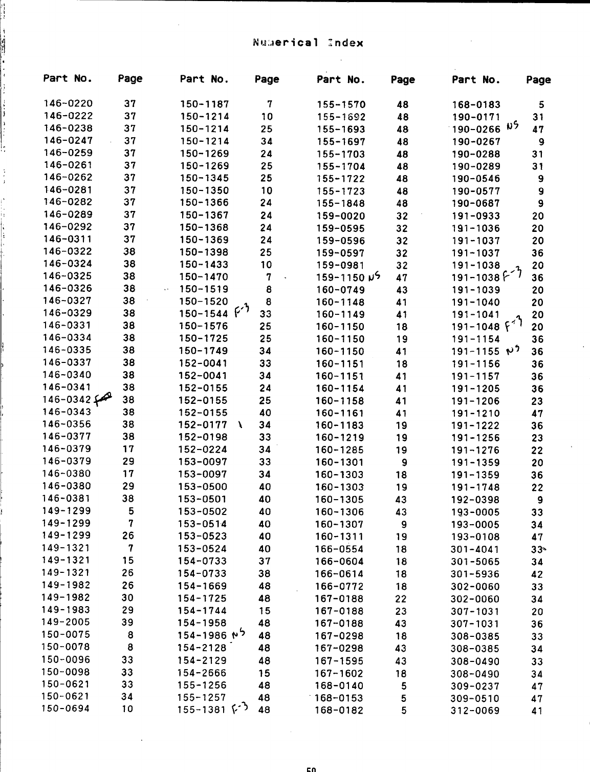
Part No.
146-0220
146-U222
146-0238
146-0247
146-0259
146-0261
146-0262
146-0281
146-0282
146-0289
146-0292
146-0311
146-0322
146-0324
146-0325
146-0326
146-0327
146-0329
146-0331
146-0334
146-0335
146-0337
146-0340
146-0341
146-0342~
146-0343
146-0356
146-0377
146-0379
146-0379
146-0380
146-0380
146-0381
149-1299
149-1299
149-1299
149-1321
149-1321
149-1321
149-1982
149-1982
149-1983
149-2005
150-0075
150-0078
150-0096
150-0098
150-0621
150-0621
150-0694
Page
37
37
37
37
37
37
37
37
37
37
37
37
38
38
38
38
38
38
38
38
38
38
38
38
38
38
38
38
17
29
17
29
38
5
7
26
7
15
26
26
30
29
39
8
8
33
33
33
34
10
Part No.
150-1187
150-1214
150-1214
150-1214
150-1269
150-1269
150-1345
150-1350
150-1366
150-1367
150-1368
150-1369
150-1398
150-1433
150-1470
150-1519
150-1520
150-1544 F’~
150-1576
150-1725
150-1749
152-0041
152-0041
152-0155
152-0155
152-0155
152-0177 \
152-0198
152-0224
153-0097
153-0097
153-0500
153-0501
153-0502
153-0514
153-0523
153-0524
154-0733
154-0733
154-1669
154-1725
154-1744
154-1958
154-1986 V$
154-2128-
154-2129
154-2666
155-1256
155-1257
155-1381 (~-~
Page
7
10
25
34
24
25
25
10
24
24
24
24
25
10
7
8
8
33
25
25
34
33
34
24
25
40
34
33
34
33
34
40
40
40
40
40
40
37
38
48
48
15
48
48
48
48
15
48
48
48
Part No. Page
155-1570 48
155-1692 48
155-1693 48
155-1697 48
155-1703 48
155-1704 48
155-1722 48
155-1723 48
155-1848 48
159-0020 32
159-0595 32
159-0596 32
159-0597 32
159-0981 32
159-1150U$ 47
160-0749
160-1148
160-1149
160-1150
160-1150
160-1150
160-1151
160-1151
160-1154
160-1158
160-1161
160-1183
160-1219
160-1285
160-1301
160-1303
160-1303
160-1305
160-1306
160-1307
160-1311
166-0554
166-0604
166-0614
166-0772
167-0188
167-0188
167-0188
167-0298
167-0298
167-1595
167-1602
168-0140
“168-0153
168-0182
50
43
41
41
18
19
41
18
41
41
41
41
19
19
19
9
18
19
43
43
9
19
18
18
18
18
22
23
43
18
43
43
18
5
5
5
Part No. Page
168-0183 5
190-0171 31
190-0266 ‘5 47
190-0267 9
190-0288 31
190-0289 31
190-0546 9
190-0577 9
190-0687 9
19?-0933 20
191-1036 20
191-1037 20
191-1037 36
::;-;::;P’~ ;:
191-1039 20
191-1040 20
;:;-;:::f’~ ::
191-1154 36
191-1155 Pq 36
191-1156
191-1157
191-1205
191-1206
191-1210
191-1222
191-1256
191-1276
191-1359
191-1359
191-1748
192-0398
193-0005
193-0005
193-0108
301-4041
301-5065
301-5936
302-0060
302-0060
307-1031
307-1031
308-0385
308-0385
308-0490
308-0490
309-0237
309-0510
312-0069
36
36
36
23
47
36
23
22
20
36
22
9
33
34
47
33’
34
42
33
34
20
36
33
34
33
34
47
47
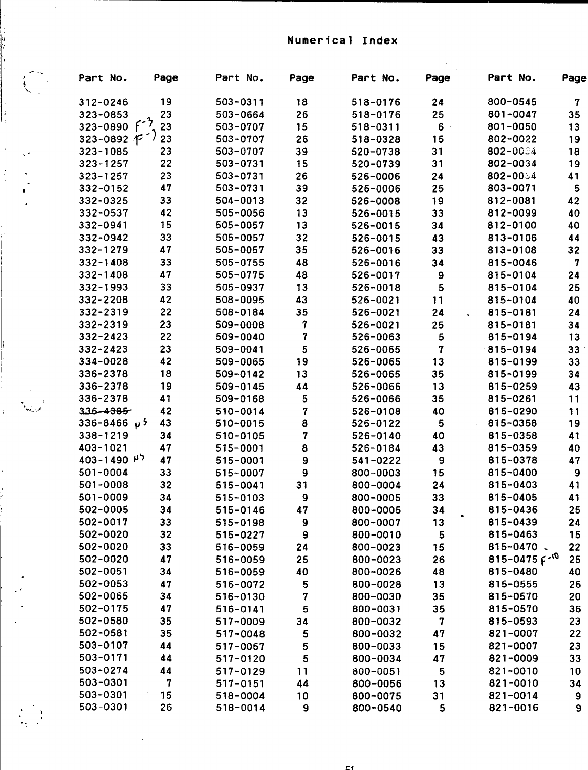
Numerical Index
I
I
A..
k..,‘Part No. Page
312-0246 19
323-0853 23
323-0890 f-~ 23
323-0892 ~“~23
. . 323-1085 23
323-1257 22
323-1257 23
1332-0152 47
332-0325 33
332-0537 42
332-0941 15
332-0942 33
332-1279 47
332-1408 33
332-1408 47
332-1993 33
332-2208 42
332-2319 22
332-2319 23
332-2423 22
332-2423 23
334-0028 42
336-2378 18
336-2378 19
?. t336-2378 41
+,: -’ 42
336-8466 P: 43
338-1219 34
403-1021 47
403-1490~~ 47
501-0004
501-0008
501-0009
502-0005
502-0017
502-0020
502-0020
502-0020
502-0051
502-0053
.502-0065
502-0175
502-0580
502-0581
503-0107
503-0171
503-0274
503-0301
503-0301
,, 503-0301
,’ ,
,..
33
32
34
34
33
32
33
47
34
47
34
47
35
35
44
44
44
7
15
26
Part No.
503-0311
503-0664
503-0707
503-0707
503-0707
503-0731
503-0731
503-0731
504-0013
505-0056
505-0057
505-0057
505-0057
505-0755
505-0775
505-0937
508-0095
508-0184
509-0008
509-0040
509-0041
509-0065
509-0142
509-0145
509-0168
510-0014
510-0015
510-0105
515-0001
515-0001
515-0007
515-0041
515-0103
515-0146
515-0198
515-0227
516-0059
516-0059
516-0059
516-0072
516-0130
516-0141
517-0009
517-0048
517-0067
517-0120
517-0129
517-0151
518-0004
518-0014
Page
18
26
15
26
39
15
26
39
32
13
13
32
35
48
48
13
43
35
7
7
5
19
13
44
5
7
8
7
8
9
9
31
9
47
9
9
24
25
40
5
7
5
34
5
5
5
11
44
10
9
Part No.
518-0176
518-0176
518-0311
518-0328
520-0738
520-0739
526-0006
526-0006
526-0008
526-0015
526-0015
526-0015
526-0016
526-0016
526-0017
526-0018
526-0021
526-0021
526-0021
526-0063
526-0065
526-0065
526-0065
526-0066
526-0066
526-0108
526-0122
526-0140
526-0184
541-0222
800-0003
800-0004
800-0005
800-0005
800-0007
800-0010
800-0023
800-0023
800-0026
800-0028
800-0030
800-0031
800-0032
800-0032
800-0033
800-0034
doo-oo51
800-0056
800-0075
800-0540
51
Page
24
25
6
15
31
31
24
25
19
33
34
43
33
34
9
5
11
24
25
5
7
13
35
13
35
40
5
40
43
9
15
24
33
34 .
13
5
15
26
48
13
35
35
7
47
15
47
5
13
31
5
Part No.
800-0545
801-0047
801-0050
802-0022
802-0GJ4
802-0034
802-0034
803-0071
812-0081
812-0099
812-0100
813-0106
813-0108
815-0046
815-0104
815-0104
815-0104
815-0181
815-0181
815-0194
815-0194
815-0199
815-0199
815-0259
815-0261
815-0290
815-0358
815-0358
815-0359
815-0378
815-0400
815-0403
815-0405
815-0436
815-0439
815-0463
Page
7
35
13
19
18
19
41
5
42
40
40
44
32
7
24
25
40
24
34
13
33
33
34
43
11
11
19
41
40
47
9
41
41
25
24
15
815-0470 .22
815-0475 f”!” 25
815-0480 40
815-0555 26
815-0570 20
815-0570 36
815-0593 23
821-0007 22
821-0007 23
821-0009 33
821-0010 10
821-0010 34
821-0014 9
821-0016 9
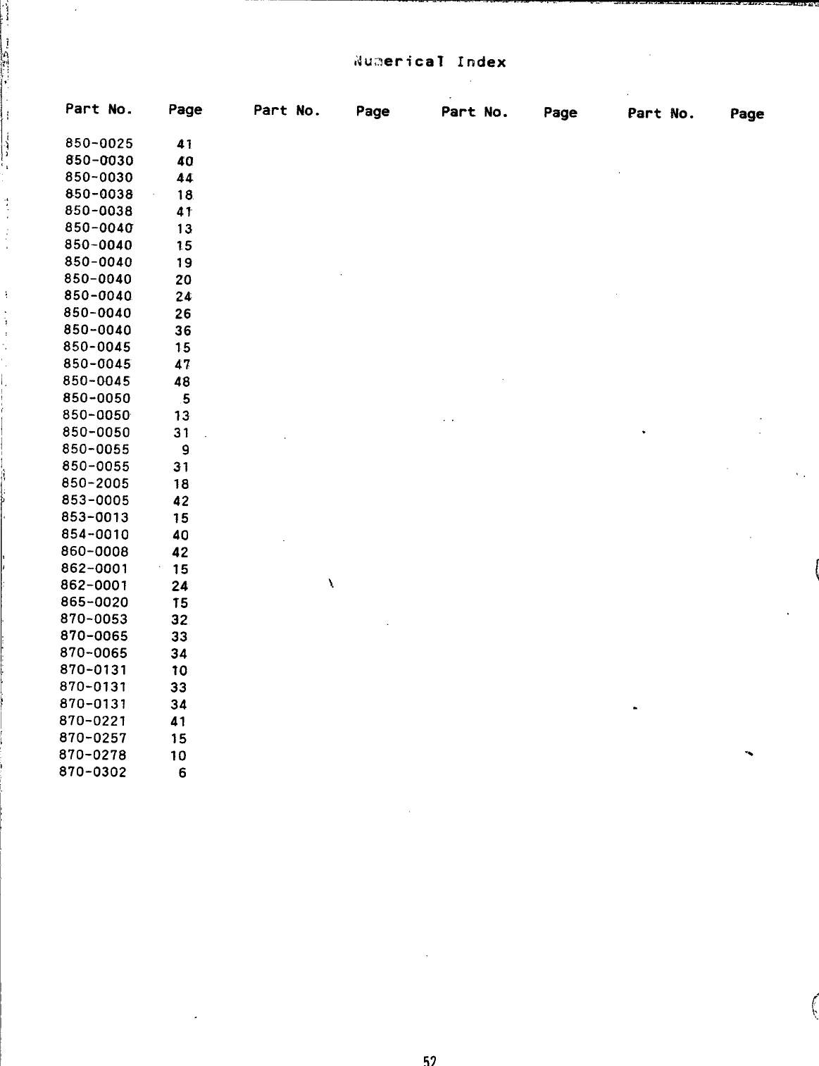
Part No.
850-0025
850-0030
850-0030
850-0038
850-0038
850-0040
850-0040
850-0040
850-0040
850-0040
850-0040
850-0040
850-0045
850-0045
i, 850-0045
850-0050
850-0050
850-0050
850-0055
850-0055
850-2005
853-0005
853-0013
854-0010
860-0008
862-0001
862-0001
865-0020
870-0053
870-0065
870-0065
870-0131
870-0131
870-0131
870-0221
870-0257
870-0278
870-0302
iiu,~ericaT Index
Page Part No. Page Part No. Page Part No.
41
60
44
18
4?
13
1.5
19
20
24
26
36
15
47
48
5
13
31
9
31
18
42
15
40
42
15
24
T5
32
33
34
?0
33
34
41
15
10
6
Page
.
52
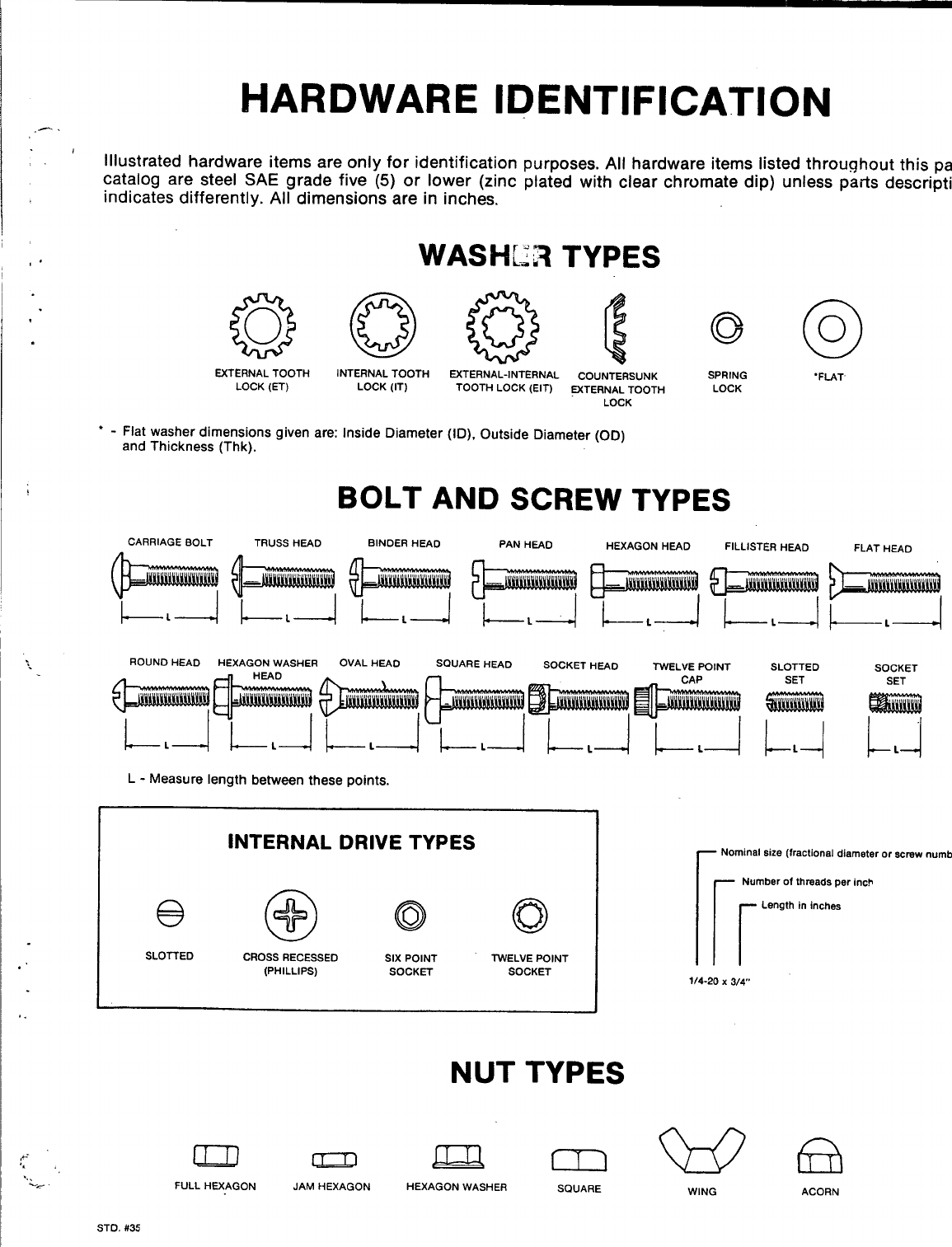
HARDWARE IDENTIFICATION
fIllustrated hardware items are only for identification purposes. All hardware items listed throughout this pa
catalog are steel SAE grade five (5) or lower (zinc plated with clear chromate dip) unless pads
description
indicates differently. All dimensions are in inches.
TYPES
EXTERNAL TOOTH INTERNAL TOOTH EXTERNAL-INTERNAL COUNTERSUNK SPRING
LOCK (ET) LOCK (IT) TOOTH LOCK (EIT) =TERNAL TOOTH LOCK
LOCK
‘-Flat washer dimensions given are: Inside Diameter (ID), Outside Diameter (OD)
and Thickness (Thk).
BOLT AND SCREW TYPES
o
0
“FLAT
CARRIAGE aOLT TRUSS HEAD alNDER HEAD PAN HEAD
mm
HEXAGON HEAD FILLISTER HEAD
~L~
ROUND HEAD HEXAGON WASHER OVAL HEAO SOUARE HEAD SOCKET HEAO TWELVE POINT SLOTTED
SET
L-Measure length between these points.
INTERNAL DRIVE TYPES
SLOTTED CROSa RECESSED SIX POINT TWELVE POINT
(PHILLIPS) SOCKET SOCKET
NUT TYPES
FULL HEXAGON JAM HEXAGON HEXAGON WASHER SQUARE
FLAT HEAD
SOCKET
SET
Ld
L
~Nominal size (fractionaldiameter or screw
numbe
Number of thmada per inch
[r
Length in inches
1/4-20 x3/4
WING ACORN
STD. #35

Onan Corporation Telephone: (61 2) 574-5000
.
●Paws
Manual
mwcma
Industrial
Engine
927-0253
6-86 (SPEC A-J)
‘* %
“T*9°
Repla;es 6-81 (Spe& A-J)
Printed in U.SA
MODEL IDENTIFICATION SAFETY PRECAUTIONS
To avoid errors or delay in filling your parts order, The following symbols are used in Onan manuals
always give the MODEL, SPEC NO. and SERIAL to alert users to the potentially dangerous condi-
NO. from the Onan nameplate. tions relating to maintenance of equipment and re- 9
placement of parts. Please read and observe.
For handy reference, insert your nameplate in-
formation in the spaces below.
~
MODEL AND SPEC NO.
@@@@
SERIAL NO.
DIGITAL CONTROL SOFTWARE VERSION lAcAuTION I
AND DATE (IF APPLICABLE)
PRODUCT
—. ,J
This symbol warns of immedi-
ate hazards which will result in
severe personal injury or death.
This symbol refers to ahazard
or unsafe practice which can re-
sult in severe personal injury or
death. -.-
This symbol refers to ahazard
or unsafe practice which can re-
sult in severe personal injury or
product or property damage.
SAFETY PRECAUTIONS
MM!!!!@
Service and repair of Onan equipment must be performed by trained, experienced personnel only. lm-
proper service orrepairmay result in propetiy damage, severe personal injury or death. Do not use thi
*
catalog as a guide to servicing your equipment. Read and follow the IMPORTANT SAFETY INSTRU
TIONS in the Service Manual appropriate for the equipment you are working on.
IAWAFINING I
Contact with USED ENGINE OILS has been identifiedbya United States federalagencyand some USA
state agencies as causing CANCER or REPRODUCTIVE TOXICITY When checking or changing engine
oils take all necessary precautions not to ingest, breathe the fumes or contact the used oil.
IAV4ARNING I
Contact with ASBESTOS has been identified by a United States federal agency and some USA state
agencies as causing CANCER or REPRODUCTIVE TOXICITY When handling engine gaskets take all
necessary precautions not to ingest, breathe or contact the dust from the gaskets! Useadequate ven-
tilation and wear protective gloves, masks and clothing!
E!miEEI
Contact with BENZINE and LEAD, found in gasoline, fuel additives and solvents has been identified )
by a United States federal agency and some USA state agencies as causing CANCER or REPRODUC-
17VE TOXICITY When checking, draining or adding gasoline and fuel additives or using solvents take ~
allnecessaryprecautions not to ingest, breathe the fumes or contact the liquids. Use adequate ventila-
tion and wear protective gloves, masks and protective clothing!
PSP-I a
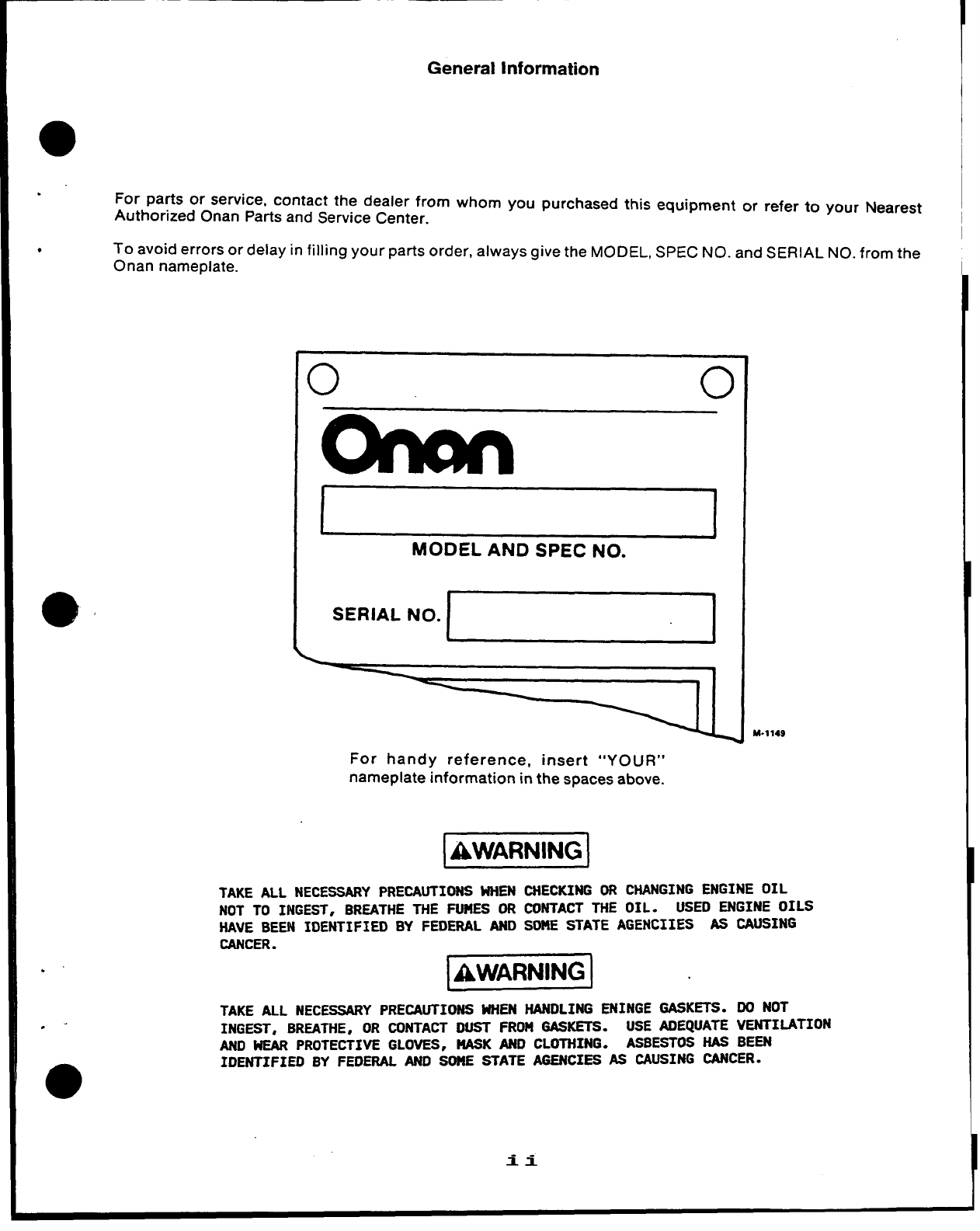
General Information
For parts or service, contact the dealer from whom you purchased this equipment or refer to your Nearest
Authorized Onan Parts and Service Center.
●To avoid errors or delay in filling your parts order, always give the MODEL, SPEC NO. and SERIAL NO. from the
Onan nameplate.
o0
SERIAL
MODEL AND SPEC NO.
N“*~
For handy reference, insert “YOUR”
nameplate information in the spaces above.
I
M-1149
@!!EN!w
TAKE ALL NECESSARY PRECAUTIONS WHEN CHECKING OR CHANGING ENGINE OIL
NOT TO INGEST, BREATHE THE FUMES OR CONTACT THE OIL. USED ENGINE OILS
HAVE BEEN IDENTIFIED BY FEDERAL AND SOME STATE AGENCIIES AS CAUSING
CANCER. 1
k!Yw!EJ
TAKE ALL NECESSARYPRECAUTIONS WHEN HANDLING ENINGE GASKETS. DO NOT
INGEST, BREATHE,OR CONTACT DUST FROM GASKETS. USE ADEQUATE VENTIMTION
AND WEAR PROTECTIVE GLOVES, NASK AND CLOTHING. ASBESTOS HAS BEEN
IDENTIFIED BY FEOERAL ANO SOME STATE AGENCIES AS CAUSING CANCER.
.
.-
0
ii
INDEX
. .
.
Adapter, Exhaust (Flange Type) 48
Arm and Shaft, Governor 6
Arm, Extension -Governor 48
Armature, Starter 16, 17,28,29
Baffle, Breather Tube 4
Base, Air Cleaner 4,48
Base, Oil 3
Bearing, Camshaft 4
Bearing, Crankshaft 4
Block, Cylinder 4
Box, Breaker 13, 14, 15,20,21
Bracket, Governor Control 15,38
Bracker, Ignition Coil 14,48
Brush, Ground-Starter 16,17,28,29
Cable, Spark Plug 13,14,48
Camshaft 6,48
Cap, Breather 4,48
Cap, Fuel Tank 35
Carburetor, Gasoline 12,30,32,34
Clamp, Coil 14,48
Clamp, Muffler 48
Coil, Ignition 13, 14
Cover, Air-Cleaner 10
Cover, Breaker Box 15,20,21
Cover, Valve 4
Crankshaft 7
Element, Air Cleaner 10
Filter, Fuel 37
Filter, Oil (Spin-On) 43
Filter, Oil (Cartridge Type) 43
Flywheel 7,22,23,24
Gasket, Breaker Box 13,14,15,20,21
Gasket, Cylinder Head 4
Gasket, Oil Base 3
Gasket, Valve Cover 4
Gear, Cam Shaft 6,48
Gear, Crankshaft 7
Gear, Ring 7,22,23,24,44
Gearcase 6,23,48
Governor 38
Guard, Flywheel 48
Guide, Valve 48
Head, Cylinder 4
Heater, Oil Base 48
Holder, Brush 16
Hose, Breather 10,48
Hose, Fuel 30,31,47
Housing, Blower 18,44
Housing, Cylinder 18
Line, Fuel—Gasoline 11, 30, 31, 35, 36
Line, Oil 3,39,43,48
Manifold, Exhaust 48
Manifold, intake 10
Muffler, Exhaust 10,48
Piston 8, 48
Plate, Bearing—Rear 4
Plug, Spark 13,14
Pump, Fuel—Manual 9, 10
Pump, Fuel—Vacuum Pulse 47
Pump, Oil 3
Regulator, Voltage 22,24,25,26,27
Ring, Piston 8
Rod, Connecting 8
Rod, Control 15
Seal, Air 43
Seal, Oil 4,6,48
Seat, Valve 4,48
Solenoid, Start 28,29, 48
Starter, Electric 16,17,28,29
Starter, Redi-Pull 45
Stator 22,23,24
Strap, Fuel Tank 35
Switch, Ignition 14,48
Switch, Pressure—Oil 48
Switch, Stop 13,39,48
Tank, Fuel 35
Tappet, Valve 4
Tube, Breather 4,10,37,48
Tube, Oil 4,43
Valve, Exhaust 4
Valve, Intake 4,48
Valve, Shut-Off 35
Wrapper, Air Cleaner Element 48
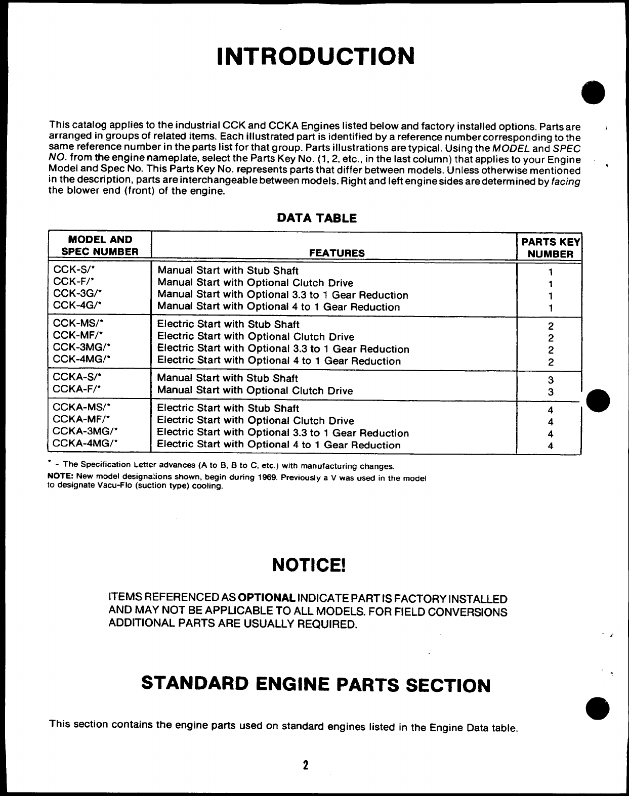
INTRODUCTION
This catalog applies to the industrial CCK and CCKA Engines listed below and factory installed options. Parts are +
arranged in groups of related items. Each illustrated part is identified by areference number corresponding to the
same reference number in the parts list for that group. Parts illustrations are typical. Using the MODEL and SPEC
NO. from the engine nameplate, select the Parts Key No. (1, 2, etc., in the last column) that applies to your Engine ,
Model and Spec No. This Parts Key No. represents parts that differ between models. Unless otherwise mentioned
in the description, parts are interchangeable between models. Riqht and left engine sides are determined by facing
the blower end (front) of the engine.
DATA TABLE
MODEL AND
SPEC NUMBER
CCK-S/*
CCK-F/*
ccK-3G/*
CC K-4G/*
CCK-MS/*
CCK-MF/*
ccK-3MG/*
ccK-4MG/*
CCKA-S/*
CCKA-F/*
CCKA-MW*
CCKA-MF/*
ccKA-3MG/*
ccKA-4MG/*
FEATURES
Manual Start with Stub Shaft
Manual Start with Optional Clutch Drive
Manual Start with Optional 3.3 to 1Gear Reduction
Manual Start with Optional 4to 1Gear Reduction
Electric Start with Stub Shaft
Electric Start with Optional Clutch Drive
Electric Start with Optional 3.3 to 1Gear Reduction
Electric Start with Optional 4to 1Gear Reduction
Manual Start with Stub Shaft
Manual Start with Optional Clutch Drive
Electric Start with Stub Shaft
Electric Start with Optional Clutch Drive
Electric Start with Optional 3.3 to 1Gear Reduction
Electric Start with Optional 4to 1Gear Reduction
●-The Specification Letter advances (A to B, Bto C, etc.) with manufacturing changes,
NOTE New model designations shown, begin during 1969. Previously aVwas used in the model
to designate Vacu-Flo (suction type) cooling.
NOTICE!
ITEMS REFERENCED AS OPTIONAL INDICATE PART IS FACTORY iNSTALLED
AND MAY NOT BE APPLICABLE TO ALL MODELS. FOR FIELD CONVERSIONS
ADDITIONAL PARTS ARE USUALLY REQUIRED.
STANDARD ENGINE PARTS SECTION
PARTS KEY
NUMBER
1
1
1
1
2
2
2
2
3
3
4●
4
4
This section contains the engine parts used on standard engines listed in the Engine Data table.
2
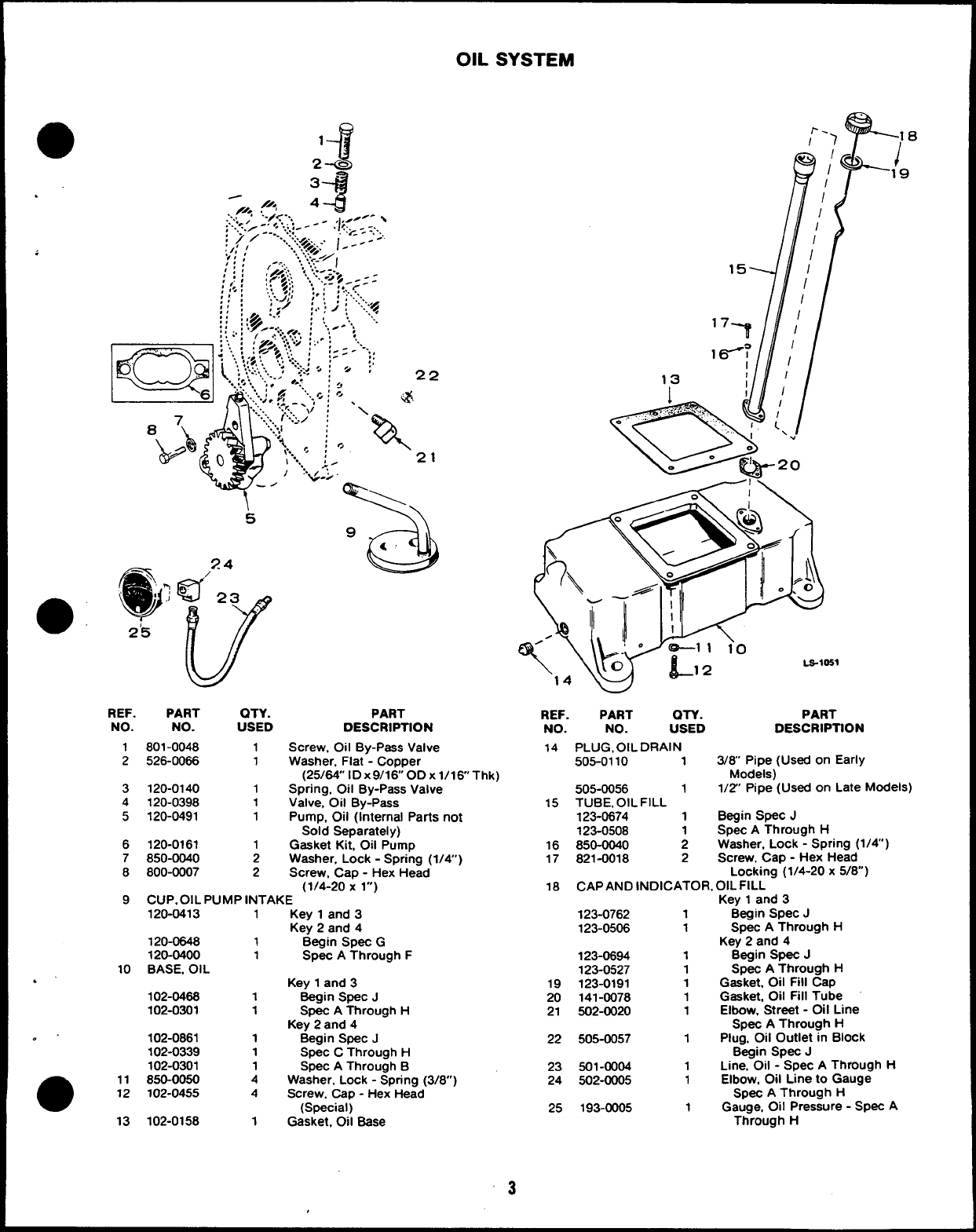
OIL SYSTEM
.
... -:;:.:;..’
.! z--
,:.:-
“.:./>.. .t.- -’
///< A- #
..,//< ,
,.+<.-,
;.’,.-..,
;)/---”.::
:,,,/ ....7<+: 1---
‘## :..‘,:.<.~/
,,, ,-.-,:, ., ‘... I
/:; :.gT!j;: . .... :-.
‘.,.‘..--< f$~ - : :
;(, ,:: A’
,,. , .,,!..,4,, ::, :!.:..<
!::
REF. PART QTY.
NO. NO. USED
1801-0048 1
2526-0086 1
3120-0140 1
4120-0398 1
5120-0491 1
6120-0161 1
7850-0040 2
8800-0007 2
15
J’/
‘7-? ~
q/
13 t/
PART
DESCRIPTION
Screw. Oil By-Pass Valve
Washer, Flat -Copper
(25/84” ID x9/16 OD Xl/16’’Thk)
Spring, Oil By-Pass Valve
Valve, Oil By-Pass
Pump, Oil (Internal Parts not
Sold Separatei y)
Gasket Kit, Oil Pump
Washer. Lock -Spring (1/4’)
Screw, Cap -Hex Head
(1/4-20 Xl“)
9CUP. OIL PUMP INTAKE
120-0413 1Key 1and 3
Key 2and 4
120-0648 1Begin Spec G
120-0400 1Spec AThrough F
10 BASE, OIL
.’ Key 1and 3
102-046s 1Begin Spec J
102-0301 1Spec AThrough H
Key 2and 4
. . 102-0861 1Begin SpeC J
102-0339 1Spec CThrough H
102-0301 1Spec AThrough B
●11 850-0050 4Washer, Lock -Spring (3/8”)
12 102-0455 4Screw. Cap -Hex Head
(Special)
13 102-0158 1Gasket, 011 Base
REF.
NO.
14
15
16
17
18
19
20
21
22
23
24
25
w
PART OTY. PART
NO. USED DESCRIPTION
PLUG, OIL DRAIN
505-0110 13/8 Pipe (Used on Early
Models)
505-0056 11/2 Pipe (Used on Late Models)
TUBE, OIL FILL
123-0674 1Begin Spec J
123-0508 1Spec AThrough H
850-0040 2Washer, Lock -Spring (1/4)
821-0018 2Screw, Cap -Hex Head
Locking (1/4-20 x5/8”)
CAP AND INDICATOR, OIL FILL
Key 1and 3
123-0762 1Begin Spec J
123-0506 1Spec AThrough H
Key 2and 4
123-0694 1Begin Spec J
123-0527 1Spec AThrough H
123-0191 1Gasket, Oil Fill Cap
141-0078 1Gasket, Oil Fill Tube
502-0020 1Elbow, Street -011 Line
Spec AThrough H
505-0057 1Plug, Oil Outlet in Block
Begin Spec J
501-0004 1Line, Oil -Spec AThrough H
502-0005 1Elbow, Oil L!ne to Gauge
Spec AThrough H
193-0005 1Gauge, 011 Pressure -Spec A
Through H
“3
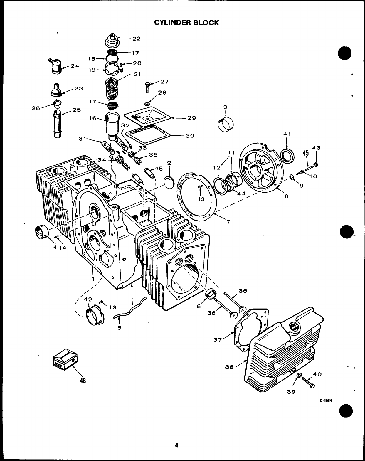
CYLINDER BLOCK
>
B-24
&
23
46
6!a-
22
17
18 20
19 21
“r’
27
28
.- /
C-1054
4
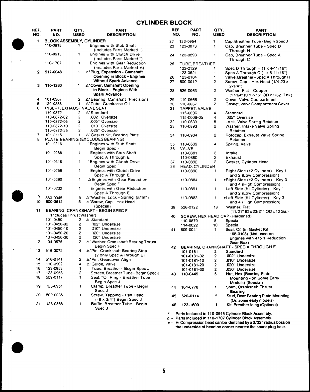
CYLINDER BLOCK
REF.
NO.
a
1
PART QTY. PART
NO. USED DESCRIPTION
BLOCK ASSEMBLY, CYLINDER
110-0915 1Engines with Stub Shaft
(Includes Parts Marked “)
110-0915 1Engines with Clutch Drive
(Includes Parts Marked “)
110-1707 1Engines with Gear Reduction
(Includes Parts Marked A)
517-0048 1A* Plug, Expansion -Camshaft
Opening in Block -Engines
Without Spark Advance
110-1263 1A* Cover, Camshaft Opening
in Block -Engines With
Spark Advance
101-0367 2A“Bearing, Camshaft (Preclslon)
120-0386 1A“Tube, Crankcase Oil
INSERT, EXHAUST VALVE SEAT
110-0872 2A“Standard
110-0872-02 2.002” Oversize
110-0872-05 2.005” Oversize
110-0872-10 2.010” Oversize
110-0872-25 2.025” Oversize
101-0115 1A“Gasket Kit. Bearing Plate
PLATE, BEARING (EXCLUDES BEARING)
101-0316 1“Engines with Stub Shaft
Begin Spec F
101-0258 1Engines with Stub Shaft
Soec AThrough E
101-0316 1“Engines with Clutch Drive
Begin Spec F
101-0258 1Engines with Clutch Drive
Spec AThrough E
101-0390 1AEnglnes with Gear Reduction
Begin Spec F
101-0232 1Er,glnes w!th Gear Reduction
Spec AThrough E
850-0045 5A“Vtiasher, Lock -SPrln9 (5/16’)
800-0512 5&“Screw, Cap -Hex Head
(Special)
BEARING, CRANKSHAFT -BEGIN SPEC F
(includes Thrust Wasner)
REF. PART al-y. PART
NO. NO. USED DESCRIPTION
Cap, BreatherTube -Begin Spec J
Cap, Breather Tube -Spec D
Through H
Cap, Breather Tube -Spec A
Through C
Spec DThrough H(1 x4-11/16’)
Spec AThrough C(1 x5-11/16’)
Valve, Breather -Spec AThrough H
Screw, Cap -Hex Head (1/4-20 x
2-1/4”)
Washer, Flat -Copper
(17/64” lDx7/16° ODx l/32’ Thk)
Cover, Valve Compartment
Gasket, Valve Compartment Cover
Standard
.005” Oversize
Lock, Valve Spring Retainer
Washer, Intake Valve Spring
Retainer
Rotocap, Exhaust Valve Spring
Retainer
Spring, Valve
Intake
Exhaust
Gasket, Cylinder Head
Right Side (#2 Cylinder) -Key I
and 2(Low Compression)
●Right Side (#2 Cylinder) -Key 3
and 4(High Compression)
Left Side (#l Cylinder) -Key 1
and 2(Low Compression)
●Left Side (#l Cylinder) -Key 3
and 4(High Com Dresslon)
Washer. Flat
22
23
123-0954 1
123-0073 1
123-0293 1
TUBE, BREATHER
123-0129 1
123-0521 1
123-0104 1
800-0012 2
52&O063 2
24
25
2
26
27
4“
3
28
4
5
6
29
30
31
110-0666 2
110-0667 2
TAPPET, VALVE
115-0006 4
115-0006-05 4
110-0639 8
110-0893 2
32
33
7
8
110-0904 2
34
35
36
110-0539 4
VALVE
110-0881 2
110-0880 2
110-0892 2
HEAD. CYLINDER
110-0890 1
110-0884 1
37
38
110-0891 1
99
10 110-0883 1
39 526-0122 18
11 (11/21’’ lDx23/21’’ ODxlOG).)
40 SCREW, HEX HEAD CAP (Hardened)
110-0879 8Specisl
114-0022 10 Special
41 509-0041 1Seal, Oil (in Gasket Kit
166-0103) (Not used on
Engines with 4to 1Reduction
Gear Box)
42 BEARING, CRANKSHAFT -SPEC ATHROUGH E
101-0181 2Standard
101-0181-02 2.002 Undersize
101-0181-10 2.010 Undersize
101-0181-20 2.020 Undersize
101-0181-30 2.030’ Undersize
43 110-0445 5Nut, Hex (Bearing Plate
Mounting -on Some Early
Models) (Special)
44 104-0776 1Shim, Crankshaft Thrust
Bearing
45 520-0114 5Stud, Rear Bearing Plate Mounting
(On some early models)
46 123-1600 1Kit, Breather Icing (Optional)
101-0450
101-0450-02
101-0450-10
101-0450-20
101-0450-30
104-0575
2
2
AStandard
002” Undersize
210’ Unders!ze
120” Undersize
)30” Undersze
A- Washer. Crankshaft Bearing Thrust
Begin Spec F
A“Ptn. Crankshaft Bearing Stop
(2 only Spec AThrough E)
A“Pln, Gearcover Align
A“Gulde. Valve
Tube, Breather -Begin Spec J
Screen. Breather Tube- Begin Spec J
Seal. ““O””Ring -Breather Tube
Begin Spec J
Clamp. Breather Tube -Begin
SPec J
Screw. Tapping -Pan Head
($z8x3/4”) Begin Spec J
Baffle. Breather Tube -Begin
Spec J
2
2
2
2
12
13 516-0072 4
14
15
16
17
18
516-0141
110-0902
123-0953
123-0958
509-0117
2
4
1
2
1
19 123-0951 1
20 809-0035
21 123-0865 1
●-Parts Included in 110-0915 Cylinder Block Assembly.
A- Parts Included in 110-1707 Cylinder Block Assembly.
●-Hi Compression head can be identified by a3132” radius boss on
the underside of head on comer neareat the spark plug hole.
5
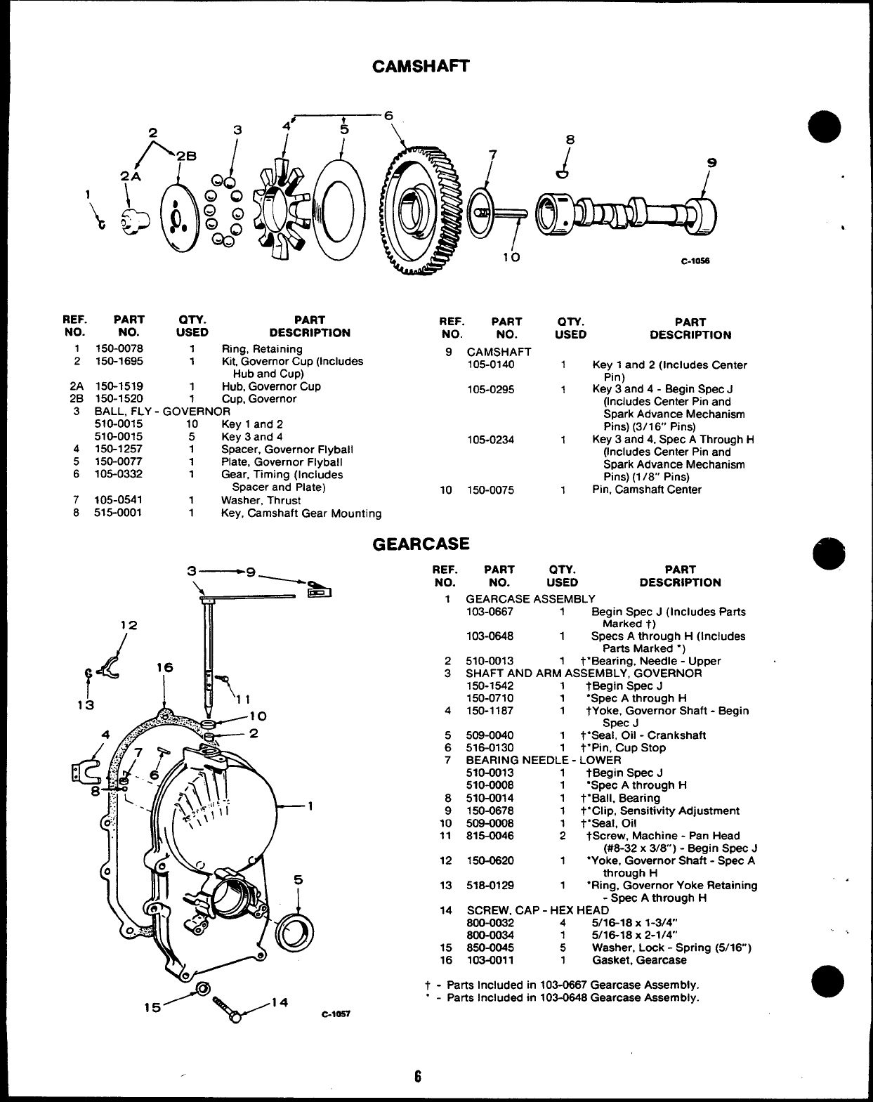
1
‘k
CAMSHAFT
234’
1k6\ e
10
0
J7
-●
c-loss
REF. PART OTY. PART
NO. REF.
NO. USED PART
DESCRIPTION NO. NO.
1150-0078 1Ring, Retaining
2150-1695 1Kit Governor Cup (Includes 9CAMSHAFT
105-0140
Hub and Cup)
2A 150-1519 1Hub, Governor Cup
2B 150-1520 1Cup, Governor 105-0295
3BALL, FLY -GOVERNOR
510-0015 10 Key 1and 2
510-0015 5Key 3and 4
4150-1257 1Spacer, Governor Flyball 105-0234
5150-0077 1Plate, Governor Flyball
6105-0332 1Gear, Timing (Includes
Spacer and Plate)
7105-0541 10 150-0075
1Washer, Thrust
8515-0001 1Key, Camshaft Gear Mounting
QTY. PART
USED DESCRIPTION
1Key 1and 2(Includes Center
Pin)
1Key 3and 4- Begin Spec J
(Includes Center Pin and
Spark Advance Mechanism
Pins) (3/1 6“ Pins)
1Key 3and 4, Spec AThrough H
(Includes Center Pin and
Spark Advance Mechanism
Pins) (1 /8” Pins)
1Pin, Camshaft Center
GEARCASE
3—9 ~REF. PART an. PART
\&NO. NO. USED DESCRIPTION
r
1GEARCASE ASSEMBLY
103-0667 1Begin Spec J(Includes Parts
12 Marked t)
d
103-0648 1Specs Athrough H(Includes
Parts Marked “)
r
16 2510-0013 1t“Bearing, Needle -Upper
&
T
3SHAFT AND ARM ASSEMBLY, GOVERNOR
150-1542 1tBegin Spec J
13 11 150-0710 1“Spec Athrough H
.,.‘+;:%.:>,, 10 4150-1187 1tYoke, Governor Shaft -Begin
4.,rn& 2
Spec J
5509-0040 1t“Seal, Oil -Crankshaft
6516-0130 1t“pin, Cup Stop
7BEARING NEEDLE -LOWER
510-0013 1tBegin Spec J
510-0008 1“Spec Athrough H
8510-0014 1t“Ball, Bearing
9150-0678 1t“Clip, Sensitivity Adjustment
10 509-0008 1t“seal, Oil
11 815-0046 2tScrew, Machine -Pan Head
(#6-32 x3/W) -Begin Spec J
12 150-0620 1“Yoke, Governor Shaft -Spec A
through H
T
13 518-0129 1‘Ring, Governor Yoke Retaining
-Screc Athrouah H
14 SCREW, CAP -HEX HEAD “
800-0032 45/16-18 X1-3/4’
800-0034 15/16-18 X2-1/4”
15 850-0045 5Washer, Lock -Spring (5/16)
16 103-0011 1Gasket, Gearcase
t - Parts Included in 103-0667 Gearcase Assembly.
“-Parts Included in 103-0648 Gearcase Assembly.
. ..
●
C-1OS7
,6
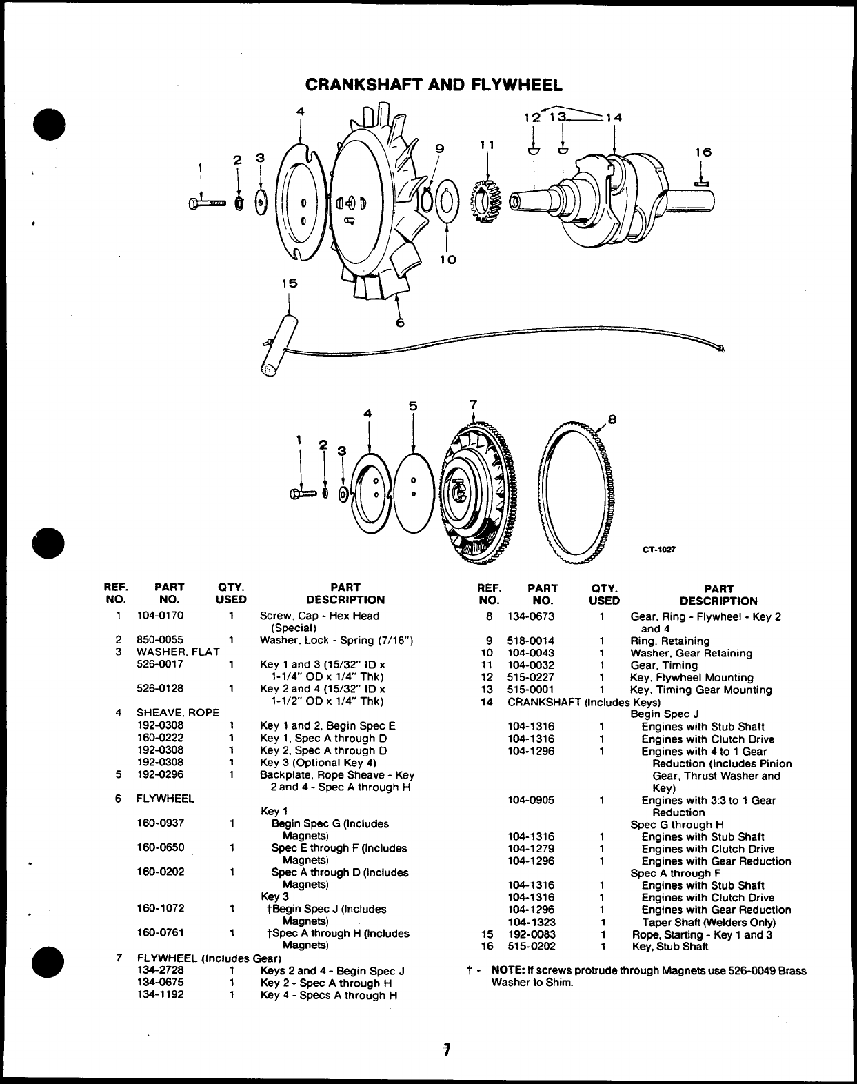
CRANKSHAFT AND FLYWHEEL
12_~14
1
A
*
@
REF. PART QTY.
NO. NO. USED
1104-0170 1
2850-0055 1
3WASHER, FLAT
526-0017 1
526-0128 1
4SHEAVE. ROPE
192-0308 1
160-0222 1
192-0308 1
192-0308 1
5192-0296 1
6FLYWHEEL
160-0937 1
160-0650 1
.160-0202 1
160-1072 1
.’
160-0761 1
5
4, 7
1
1*
JJ
PART
DESCRIPTION
Screw, Cap -Hex Head
(Special)
Washer. Lock -Spring (7/16)
Key 1and 3(15/32 ID x
1-1/4” OD X1/4” Thk)
Key 2and 4(15/32” ID x
1-1/2” OD X1/4” Thk)
Key 1and 2, Begin Spec E
Key 1. Spec Athrough D
Key 2. Spec Athrough D
Key 3(Optional Key 4)
Back plate, Rope Sheave -Key
2and 4- Spec Athrough H
Key 1
Beg:gpe.=y G(Includes
Spec Ethrough F(Includes
Magneta)
Spec Athrough D(Includes
Magnets)
Key 3
tBeg~g~~&; J(Includes
tSPec Athrough H(Includes
oMagnets)
7FLYWHEEL (Includes Gear)
134-2728 1Keys 2and 4- Begin Spec J
134-0675 1Key 2- Spec Athrough H
134-1192 1Key 4- Specs Athrough H
CT-1OS7
REF. PART QTY. PART
NO. NO. USED DESCRIPTION
8134-0673 1Gear, Ring -Flywheel -Key 2
and 4
9518-0014 1Ring, Retaining
10 104-0043 1Washer, Gear Retaining
11 104-0032 1Gear, Timing
12 515-0227 1Key, Flywheel Mounting
13 515-0001 1Key, Timing Gear Mounting
14 CRANKSHAFT (Includes Keys)
Begin Spec J
104-1316 1Engines with Stub Shaft
104-1316 1Engines with Clutch Drive
104-1296 1Engines with 4to 1Gear
Reduction (Includes Pinion
Gear, Thrust Washer and
Key)
104-0905 1Engines with 3:3 to 1Gear
Reduction
Spec Gthrough H
104-1316 1Engines with Stub Shaft
104-1279 1Engines with Clutch Drive
104-1296 1Engines with Gear Reduction
Spec Athrough F
104-1316 1Engines with Stub Shaft
104-1316 1Engines with Clutch Drive
104-1296 1Engines with Gear Reduction
104-1323 1Taper Shaft (Welders Only)
15 192-0083 1Rope, Starting -Key 1and 3
16 515-0202 1Key, Stub Shaft
t- NOTE If screws protrude through Magneta use 526-0049 Braas
Washer to Shim.
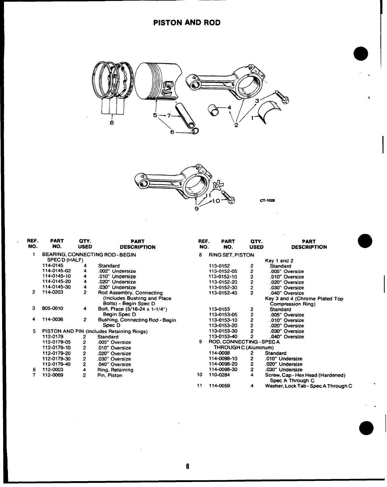
PISTON AND ROD
a
cl-loss
REF. PART QTY. PART
NO. NO. USED DESCRIPTION
1BEARING, CONNECTING ROD-BEGIN
SPEC D(HALF)
114-0145 “‘4 Standard
114-0145-02 4.002 Undersize
714-0145-10 4.010” Undersize
114-0145-20 4.020 Undersize
114-0145-30 4.030” Undersize
2114-0203 2Rod Assembly, Connecting
(Includes Bushing and Place
Bolts) -Begin Spec D
3805-0010 4Bolt, Place (5/18-24 x1-1/4”)
Begin Spec D
4114-0036 2Bushing, Connecting Rod -Begin
Spec D
5PISTON AND PIN (Includes Retaining Rings)
112-0179 2Standard
112-0179-05 2.005 Oversize
112-0179-10 2.010 Oversize
112-0179-20 2.020 Oversize
112-0179-30 2.030” Oversize
112-0179-40 2.040” Oversize
6112-0003 4Ring, Retaining
7112-0069 2Ptn, Piston
REF. PART aTY. PART
NO. NO. USED DESCRIPTION
8RING SET, PISTON Key 1and 2
113-0152 2Standard
113-0152-05 2.005” Oversize
113-0152-10 2.010” Oversize
113-0152-20 2.020” Oversize
113-0152-30 2.030 Oversize
113-0152-40 2.040” Oversize
Key 3and 4(Chrome Plated Top
Compression Ring)
113-0153 2Standard
113-0153-05 2.005” Oversize
113-0153-10 2.010 Oversize
113-0153-20 2.020” Oversize
113-0153-30 2.03& Oversize
113-0153-40 2.040” Oversize
9ROD, CONNECTING -SPECA
THROUGH C(Aluminum)
114-0098 2Standard
114-0098-10 2.010 Undersize
114-0098-20 2.02W Undersize
114-0098-30 2.030 Undersize
10 110-0284 4Screw, Cap -Hex Head (Hardened)
Spec AThrough C
11 114-0059 4Washer, Lock Tab -Spec AThrough C
.>
0
%
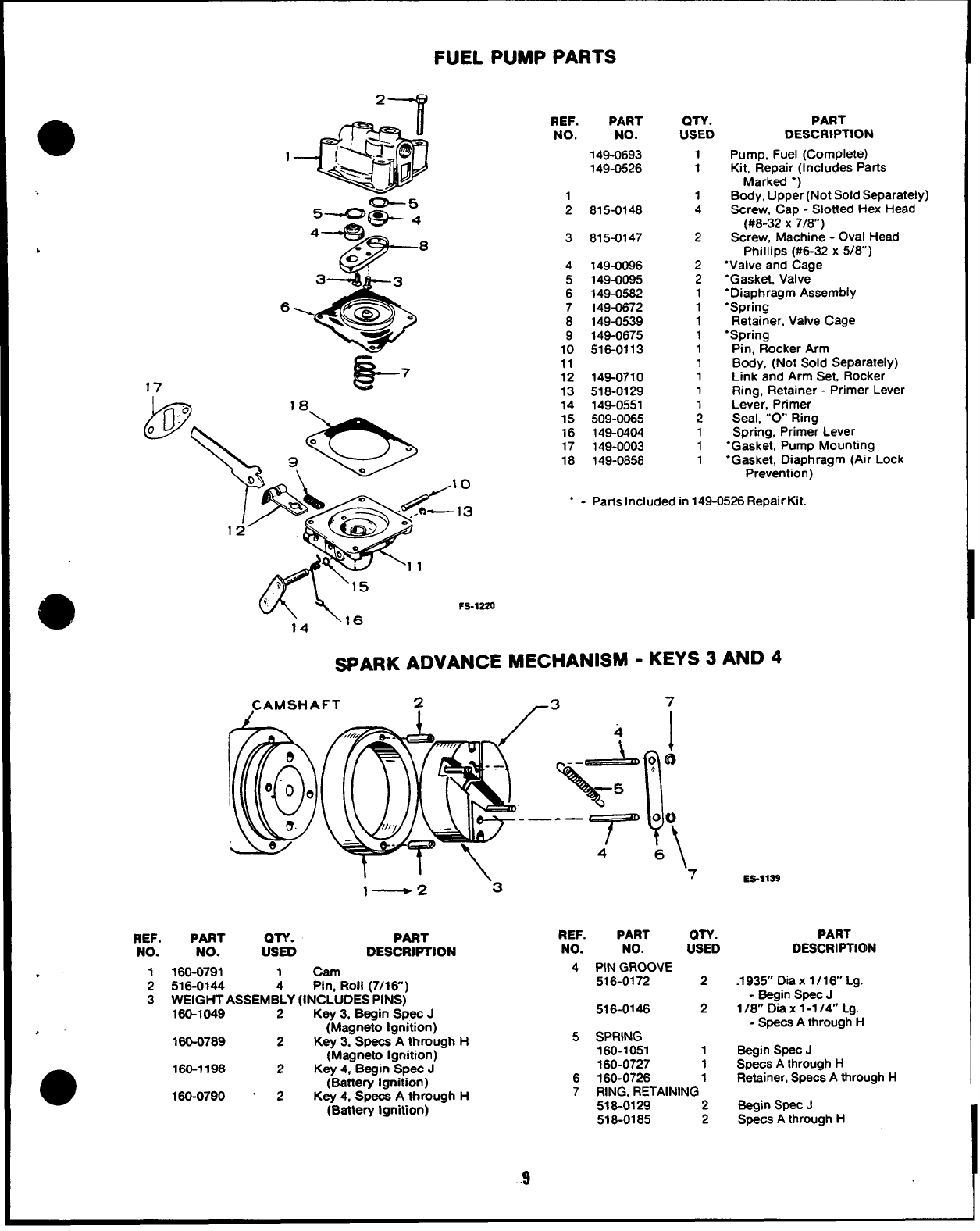
a
z
,
17 E?- 7
FUEL PUMP PARTS
REF.
.’ 1
2
3
.
REF.
No.
PART
NO.
149-0693
149-0526
1
2
3
4
5
6
7
8
9
10
11
12
13
14
15
16
17
18
815-0148
815-0147
149-0096
149-0095
149-0582
149-0872
149-0539
149-0675
516-0113
148-0710
518-0129
149-0551
508-0065
149-0404
149-0003
149-0858
QTY.
USED
1
1
1
4
2
2
2
1
1
1
1
1
1
1
1
1
1
1
1
PART
DESCRIPTION
Pump, Fuel (Complete)
Kit, Repair (Includes Parts
Marked “)
Body, Upper (Not Sold Separately)
Screw, Cap -Slotted Hex Head
(#8-32 X7/8)
Screw, Machine -Oval Head
Phillips (#6-32 x5/8)
“Valve and Cage
“Gasket, Valve
“Diaphragm Assembly
“Spring
Retainer, Valve Cage
‘Spring
Pin, Rocker Arm
Body, (Not Sold Separately)
Link and Arm Set, Rocker
Ring, Retainer -Primer Lever
Lever, Primer
Seal, “’O Ring
Spring, Primer Lever
‘Gasket, Pump Mounting
“Gasket, Diaphragm (Air Lock
Prevention)
“-Parts Included in 149-0526 Repair Kit.
w\,=
14
FS-12Z0
SPARK ADVANCE MECHANISM -KEYS 3AND 4
CAMSHAFT 2-3 7
ll\ ‘7
l— 2‘3 ES-llSS
PART PART
NO. :STD DESCRIPTION
160-0791 1Cam
516-0144 4Pin, Roll (7/l&’)
WEIGHT ASSEMBLY (INCLUDES PINS)
160-1049 2Key 3, Begin Spec J
(Magneto Ignition)
160-0789 2Key 3, Specs Athrough H
(Magneto Ignition)
160-1198 2Key 4, Begin Spec J
(Battery Ignition)
180-0790 -2Key 4, Specs Athrough H
(Battery Ignition)
REF. PART OTY.
NO. NO. USED
4PIN GROOVE
516-0172 2
516-0146 2
5SPRING
160-1051 1
180-0727 1
6160-0726 1
7RING, RETAINING
518-0129 2
518-0185 2
.9
PART
DESCRIPTKDN
.1935” Dia x 1/16” Lg.
-Begin Spec J
I/a Dia x1-7/4” Lg.
-Specs Athrough H
Begin Spec J
Specs Athrough H
Retainer, Specs Athrough H
Begin Spec J
Specs Athrough H
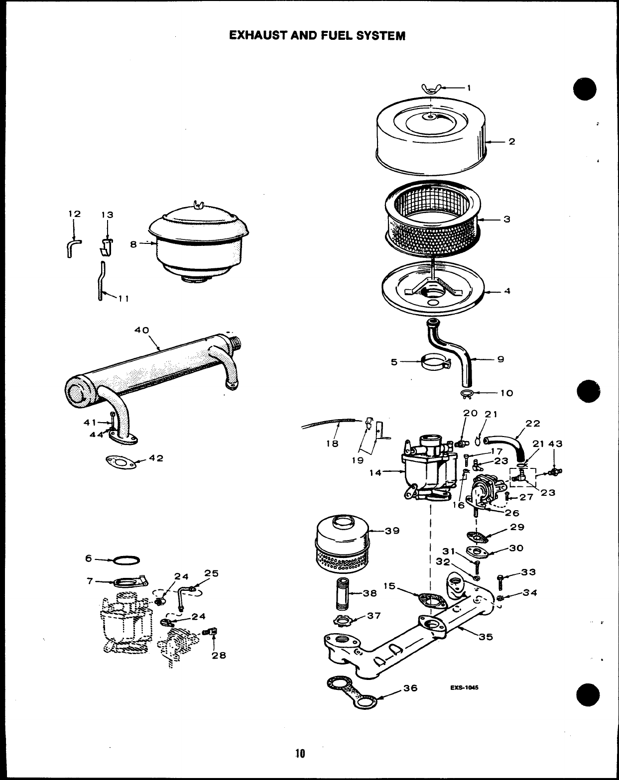
EXHAUST AND FUEL SYSTEM
13 —“”.
$~ 0-
/
u% 1
40 -.
,,, ,,, . . .. . .
-42
2
-“-7-via -
so
G---lo
20 21
// 22
/
18 r&d
J!q!qfp
21 43
19
14
I!#d 1
J?—
G36 EXS-1045
.:.
4
?’
,
●
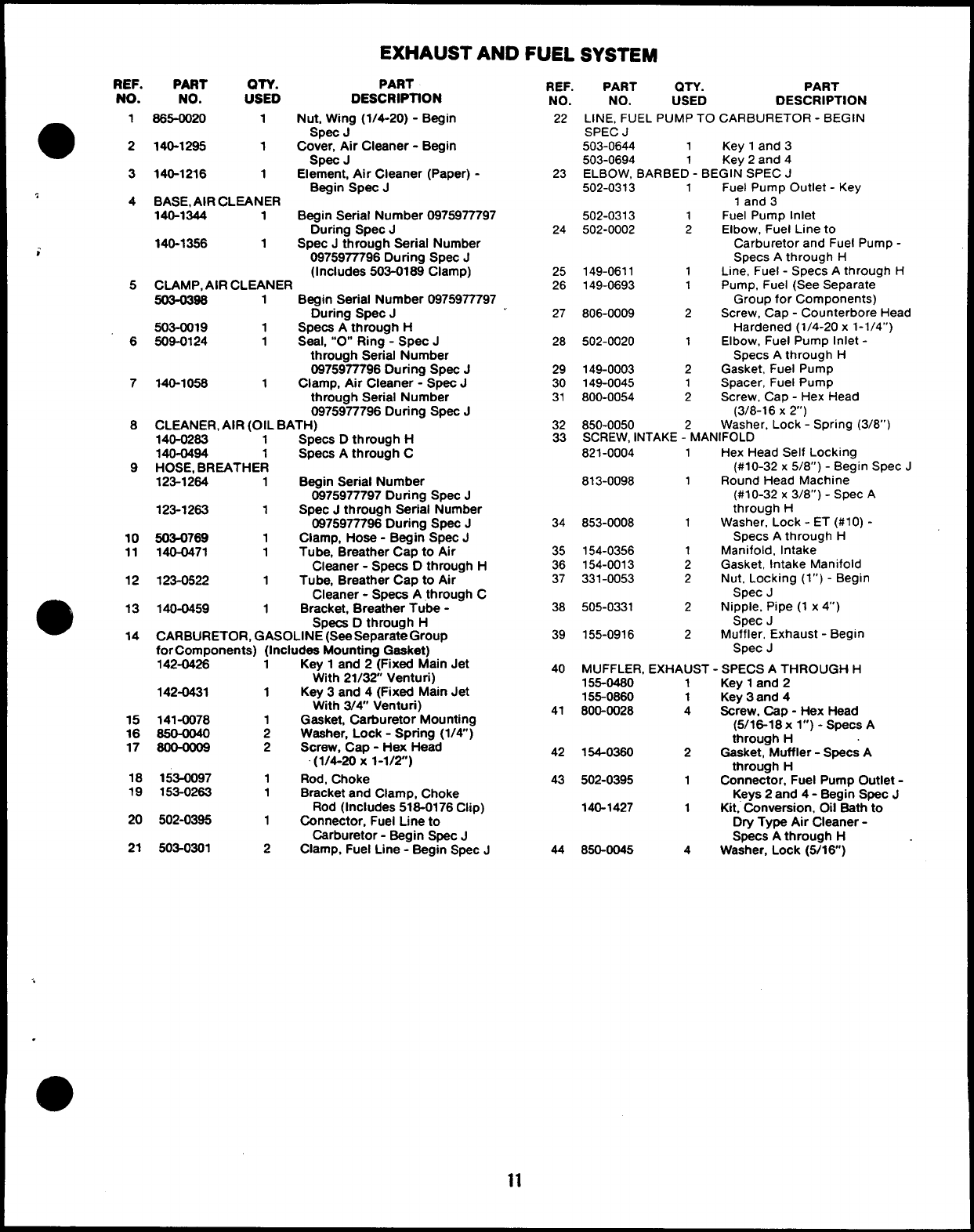
EXHAUST AND FUEL
REF.
NO.
1
2
3
4
;
5
6
7
8
9
10
11
12
14
PART QTY. PART
NO. USED DESCRIPTfON
865-0020 1Nut, Wh’ig (1/4-20)-Begin
Spec J
140-1295 1Cover, Air Cleaner -Begin
Spec J
140-1216 1Element, Ah Cleaner (Paper) -
Begin Spec J
BASE, AIR CLEANER
140-1344 1Begin Serial Number 0975977797
During Spec J
140-1356 1Spec Jthrough Serial Number
0975977796 During Spec J
(Includes 503-0189 Clamp)
CLAMP, AIR CLEANER
503-0396 1Begin Serial Number 0975977797
During Spec J
503-0019 1Specs Athrough H
509-0124 1Seal, “O” Ring -Spec J
through Serial Number
0975977796 During Spec J
140-1058 1Clamp, Air Cleaner -Spec J
through Serial Number
0975977796 During Spec J
CLEANER, AIR (OIL BATH)
140-0263 1Specs Dthrough H
140-0494 1Specs Athrough C
HOSE, BREATHER
123-1264 1Begin Serial Number
0975977797 During Spec J
123-1263 1Spec Jthrough Serial Number
0975977796 During Spec J
503-0769 1Clamp, Hose -Begin Spec J
140-0471 1Tube, Breather Cap to Air
Cleaner -Specs Dthrough H
123-0522 1Tube, Breather Cap to Air
Cleaner -Specs Athrough C
140-0459 1Bracket, Breather Tube -
Specs Dthrough H
CARBURETOR, GASOLINE (See Separate Group
for Components) (Includes Mounting Gasket)
142-04%
142-0431
15 141-0078
16 650-0040
17 8@OO09
18 153-0097
19 153-0263
20 502-0395
21 503-0301
iKey 1and 2-( Fixed Main Jet
1
1
2
2
1
1
1
2
With 21/32 Venturi)
Key 3and 4(Fixed Main Jet
With 3/~ Venturi)
Gasket, Carburetor Mounting
Washer, Lock -Spring (1/4)
Screw, Cap -Hex Head
(1/4-20x 1-1/2)
Rod, Choke
Bracket and Clamp, Choke
Rod (Includes 516-0176 Clip)
Connector, Fuel Line to
Carburetor -Begin Spec J
Clamp, Fuel Line -Begin Spec J
REF.
NO.
22
23
24
25
26
27
28
29
30
31
32
33
34
35
36
37
38
39
40
41
42
43
44
PART QTY. PART
NO. USED DESCRIPTION
LINE, FUEL PUMP TO CARBURETOR -BEGIN
SPEC J
503-0644 1Key 1and 3
503-0694 1Key 2and 4
ELBOW, BARBED -BEGIN SPEC J
502-0313 1Fuel Pump Outlet -Key
1and 3
502-0313 1Fuel Pump Inlet
502-0002 2Elbow, Fuel Line to
Carburetor and Fuel Pump -
Specs Athrough H
149-0611 1Line, Fuel -Specs Athrough H
149-0693 1Pump, Fuel (See Separate
Group for Components)
806-0009 2Screw, Cap -Counterbore Head
Hardened (1/4-20 x1-1/4”)
502-0020 1Elbow, Fuel Pump Inlet -
Specs Athrough H
149-0003 2Gasket, Fuel Pump
149-0045 1Spacer, Fuel Pump
800-0054 2Screw, Cap -Hex Head
(3/8-16 X2)
850-0050 Washer, Lock -Spring (3/8”)
SCREW, INTAKE -2MANIFOLD
821-0004 1Hex Head Self Locking
(#10-32 x5/8”) -Begin Spec J
813-0098 1Round Head Machine
(#10-32 x3/8”) -Spec A
through H
853-0008 1Washer, Lock -ET (#10) -
Specs Athrough H
154-0356 1Manifold, Intake
154-0013 2Gasket, Intake Manifold
331-0053 2Nut, Locking (l”) -Begin
Spec J
505-0331 2Nipple, Pipe (1 x4“)
Spec J
155-0916 2Muffler, Exhaust -Begin
Spec J
MUFFLER, EXHAUST -SPECS ATHROUGH H
155-0480 1Key 1and 2
155-0860 1Key 3and 4
800-0028 4Screw, Cap -Hex Head
(5/16-18 xl“) -Specs A
through H
154-0360 2Gasket, Muffler -Specs A
through H
502-0395 1Connector, Fuel Pump Outlet -
Keys 2and 4- Begin Spec J
140-1427 1Kit, Conversion, 011 Bath to
Dry Type Alr Cleaner-
Specs Athrough H
850-0045 4Washer, Lock (5/16)
..
.
11
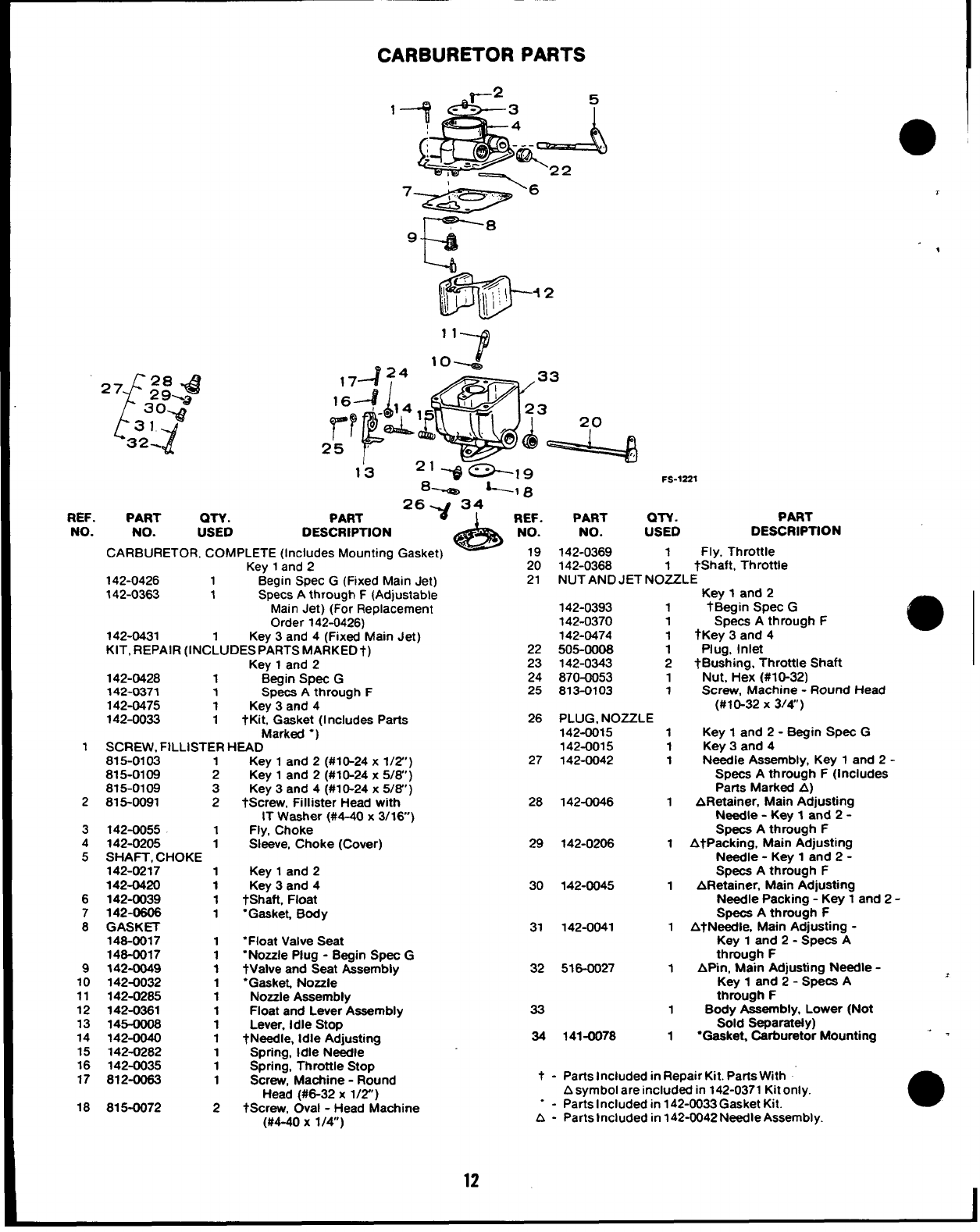
CARBURETOR PARTS
“72
‘f
27 28 .& ,7424 ‘omg
29%,,
3o.@ 1
16+- ,4
31
Y
32-
P
~r ~
25 8
13 FS-1221
‘-I 8
REF. PART QTY. PART 2t~34 REF.
A
PART QTY. PART
NO. NO. USED DESCRIPTION NO. NO. USED DESCRIPTION
CARBURETOR, COMPLETE (Includes Mounting Gasket) 19 142-0369 1Fly, Throttle
Key 1and 220 142-0368 1
142-0426 1Begin SPec G(Fixed Main Jet)
tShaft, Throttle
21 NUT AND JET NOZZLE
142-0363 1Specs Athrough F(Adjustable Key 1and 2
Main Jet) (For Replacement 142-0393 1tBegin Spec G
Order 142-0426) 142-0370 1Specs Athrough F
142-0431 Key 3and 4(Fixed Main Jet) 142-0474 1tKey 3and 4
KIT, REPAIR (lNC~UDESPARTSMARKED+) 22 505-0006 1Plug, Inlet
Key 1and 223 142-0343 2tBushing, Throttle Shaft
142-0428 1Begin Spec G24 870-0053 1Nut, Hex (#10-32)
142-0371 1Specs Athrough F25 813-0103 1Screw, Machine -Round Head
142-0475 1Key 3and 4(#10-32 X3/4”)
142-0033 1tKit, Gasket (1ncludes Parts 26 PLUG, NOZZLE
Marktxf “) 142-0015 1Key 1and 2- Begin Spec G
1SCREW. FtLLISTER HEAD 142-0015 1Key 3and 4
815-0103 1
815-0109 2
815-0109 3
2815-0091 2
3142-0055 1
4142-0205 1
5SHAFT, CHOKE
142-0217 1
142-0420 1
6142-0039 1
7142-0606 1
8GASKET
146-0017 1
146-0017 1
9142-0049 1
10 142-0032 1
11 142-0265 1
12 142-0361 1
13 145-oo06 1
14 142-0040 1
15 142-0282 1
16 142-0035 1
17 812-0063 1
18 815-0072 2
Key 1and 2(#10-24x 1/2”)
Key 1and 2(#10-24x 5/6”)
Key 3and 4(#1 O-24x 5/6”)
tscrew, Fillister Head with
IT Washer (#4-40 x3/16)
Fly, Choke
Sleeve, Choke (Cover)
Key 1and 2
Key 3and 4
&haft, Float
“Gasket, Body
“Float Valve Seat
“Nozzle Plug -Begin Spec G
tValve and Seat Aasemblv
27 142-0042 1N&die Assembly, Key 1and 2-
Specs Athrough F(Includes
Parts Marked A)
28 142-0046 1ARetainer, Main Adjusting
Needle -Key 1and 2-
Specs Athrough F
29 142-0206 1AtPacking, Main Adjusting
Needle -Key 1and 2-
Spaca Athrough F
30 142-0045 1ARetainer, Main Adjusting
Needle Packing -Key 1and 2-
Specs Athrough F
31 142-0041 1AtNeedle, Main Adjusting -
Key 1and 2- Specs A
through F
32 516-0027 1Af%n, Main Adjusting Needle -
“Gasket, Nozzle -
Nozzle Aaaembfy
Float and Lever Assembly 33
Lever, Idle Stop
tNeedle, Idle Adjusting 34
Spring, Idle Needle
Spring, Throttle Stop
Screw, Machine -Round t-
Head (#6-32 x1/2’)
tScrew, Oval -Head Machine --
(#4-40 x1/4) A-
9
Key 1and 2- Sp&a A
through F
1Body Assembly, Lower (Not
Sold Separately)
141-0078 1“Gasket, Carburetor Mounting ‘-
Parts Included in Repair Kit. Parts With
Asymbol are included in 142-0371 Kit only.
Parts Included in 142-0033 Gasket Kit. ●
Parts included in 142-0042 Needle Assembly.
12
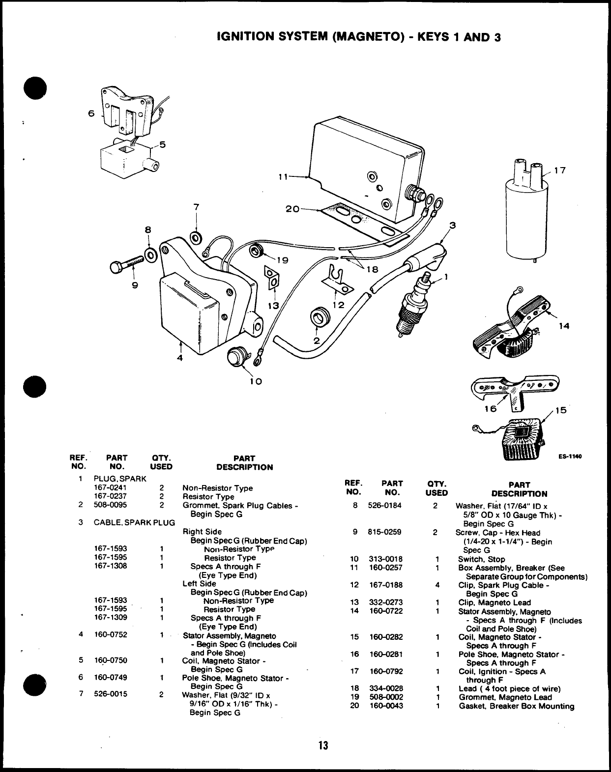
IGNITION SYSTEM (MAGNETO) -KEYS 1AND 3
6
17
14
1140
io
REF.
NO.
1
PART OTY.
NO. USED
PLUG, SPARK
167-0241 2
167-0237 2
508-0095 2
PART
DESCRIPTION
REF.
NO.
8
PART
NO.
526-0184
OTY.
USED PART
DESCRIPTION
Non-Resistor Type
Resistor Type
Grommet, Spark Plug Cables -
Begin Spec G
2
3
2
2
1
1
4
1
1
1
1
1
1
1
1
Washer, Flat (17/64” ID x
5/8 OD x 10 Gauge Thk) -
Begin SpeC G
Screw, Cap -Hex Head
(1/4-20 x1-1/4) -Begin
Spec G
Switch, Stop
Box Assembly, Breaker (See
Separate Group for Components)
Clip, Spark Plug Cable -
Begin Spec G
Clip, Magneto Lead
Stator Assembly, Magneto
-Specs Athrough F(Includes
Coil and Pole Shoe)
Coil, Magneto Stator -
Specs Athrough F
Pole Shoe, Magneto Stator -
Specs Athrough F
Coil, Ignition -Specs A
through F
Lead (4foot piece of wire)
Grommet, Magneto Lead
Gasket, Breaker Box Mounting
CABLE, SPARK PLUG
Right Side
Begin Spec G(Rubber End Cap)
Non-Resistor Type
Resistor Type
Specs Athrough F
(Eye Type End)
Left Side
Begin Spec G(Rubber End Cap)
Non-Resistor Type
Resistor Type
Specs Athrough F
(Eye Type End)
Stator Assembly, Magneto
-Begin Spec G(Includes Coil
and Pole Shoe)
Coil, Magneto Stator -
Begin SpeC G
Pole Shoe, Magneto Stator -
Begin Spec G
Washer, Flat (9/32” ID x
9/16 OD X1/16 Thk) -
Begin Spec G
9815-0259
167-1593 1
167-1595 1
167-1308 110
11 313-0018
160-0257
12 167-0188
167-1593 1
167-1595 1
167-1309 1
13
14 332-0273
160-0722
.
160-0752 1
4
5
15 160-0282
16
17
160-0281
16.0-0750 1
160-0749 1
526-0015 2
160-0792
e6
718
19
20
334-0028
508-0002
160-0043
13
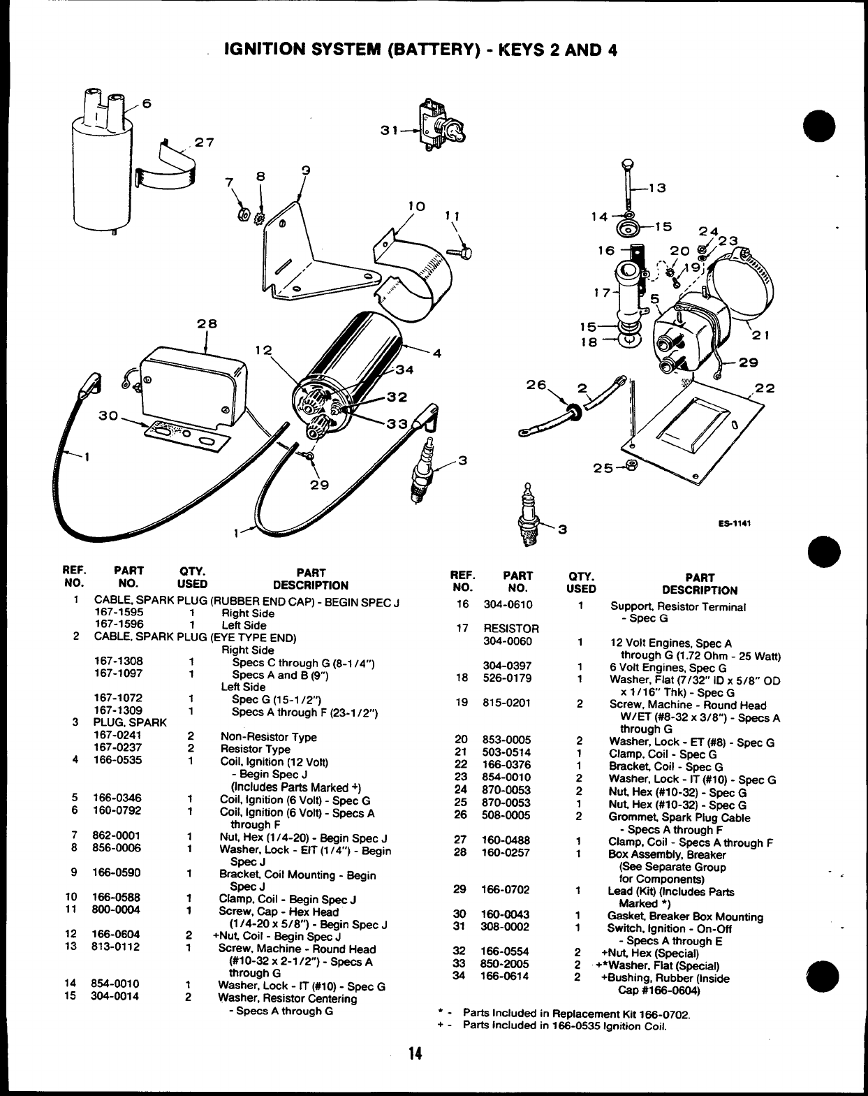
IGNITION SYSTEM (BATTERY) -KEYS 2AND 4
31
8?
&i!i
(i
/10 ,,
Q) /,
o.\ ==$)
?2> /‘“F
&,.
REF. PART QTY.
NO. PART
NO. USED DESCRIPTION
1CABLE, SPARK PLUG (RUBBER END CAP) -BEGIN SPEC J
167-1595 1Right Side
167-1596 1Left Side
2CABLE, SPARK PLUG (EYE TYPE END)
167-1308 1
167-1097 1
167-1072 1
167-1309 1
3PLUG, SPARK
167-0241 2
167-0237 2
4166-0535 1
5166-0346 1
6160-0792 1
7862-0001 1
8856-0006 1
9166-0590 1
10 166-0588 1
11 800-0004 1
12 166-0604 2
13 813-0112 1
14 854-0010
15 304-0014 ;
Right Side ‘
Spats Cthrough G(8-1 /4”)
Spats Aand B(9)
Left Side
Spat G(15-1 /2”)
Specs Athrough F(23-1 /2)
Non-Resistor Type
Resistor Type
Coil, Ignition (12 Volt)
-Begin Spec J
(Includes Parts Marked +)
Coil, Ignition (6 Volt) -Spat G
Coil, Ignition (6 Volt) -Spats A
through F
Nut, Hex (1/4-20) -Begin Spec J
Washer, Lock -EIT (1/4) -Begin
Spec J
Bracket, Coil Mounting -Bagin
Spec J
Clamp, Coil -Begin Spec J
Screw, Cap -Hex Head
(1/4-20 x5/8”) -Begin Spat J
+Nut, Coil -Begin Spec J
Screw, Machine -Round Head
(#10-32 X2-1 /2) -Specs A
through G
Washer, Lock -IT (#10) -Spec G
Washer, Resistor Centering
-Specs Athrough G
.3
REF,
NO.
16
17
IL
13
&
i3
PART
NO.
304-0610
RESISTOR
304-0060
304-0397
18 526-0179
19 815-0201
20 853-0005
21 503-0514
22 166-0376
23 854-0010
24 870-0063
25 870-0053
26 508-0005
27 160-0488
28 160-0257
29 166-0702
30 160-0043
31 308-0002
32 166-0554
33 850-2005
34 166-0614
QTY.
USED
1
1
1
1
2
2
1
1
2
2
1
2
1
1
1
1
1
ES-1141
PART
DESCRIPTION
Support, Resistor Terminal
-Spec G
12 Volt Engines, Spec A
through G(1.72 Ohm -25 Watt)
6Volt Engines, Spec G
Washer, Flat (7/32” ID x5/8” OD
xl/16 Thk)-Spec G
Screw, Machine -Round Head
W/ET (#8-32 X3/8”) -specs A
through G
Washer, Lock -ET (#8) -Spec G
Clamp, Coil -Spec G
Bracket, Coil -Spec G
Washer, Lock -IT (#10) -Spec G
Nut Hex (#10-32) -Spec G
Nut, Hex (#10-32) -Spec G
Grommet, Spark Plug Cable
-Specs Athrough F
Clamp, Coil -Specs Athrough F
BOXAssembly, Breaker
(sea Separate Group
for Components)
Lead (Kit) (Includes Parts
Marked ●)
Gaal@ Breaker Box Mounting
Switch, Ignition -On-Off
-Spats Athrough E
2+Nut, Hex (Special)
2+*Washer, Flat (Special)
2+Bushing, Rubbar (Inside
cap #166-0604j
‘-Parts Included in Replacement Kit 166-0702.
+-Parts Included in 1%-0535 Ignition Coil:
14
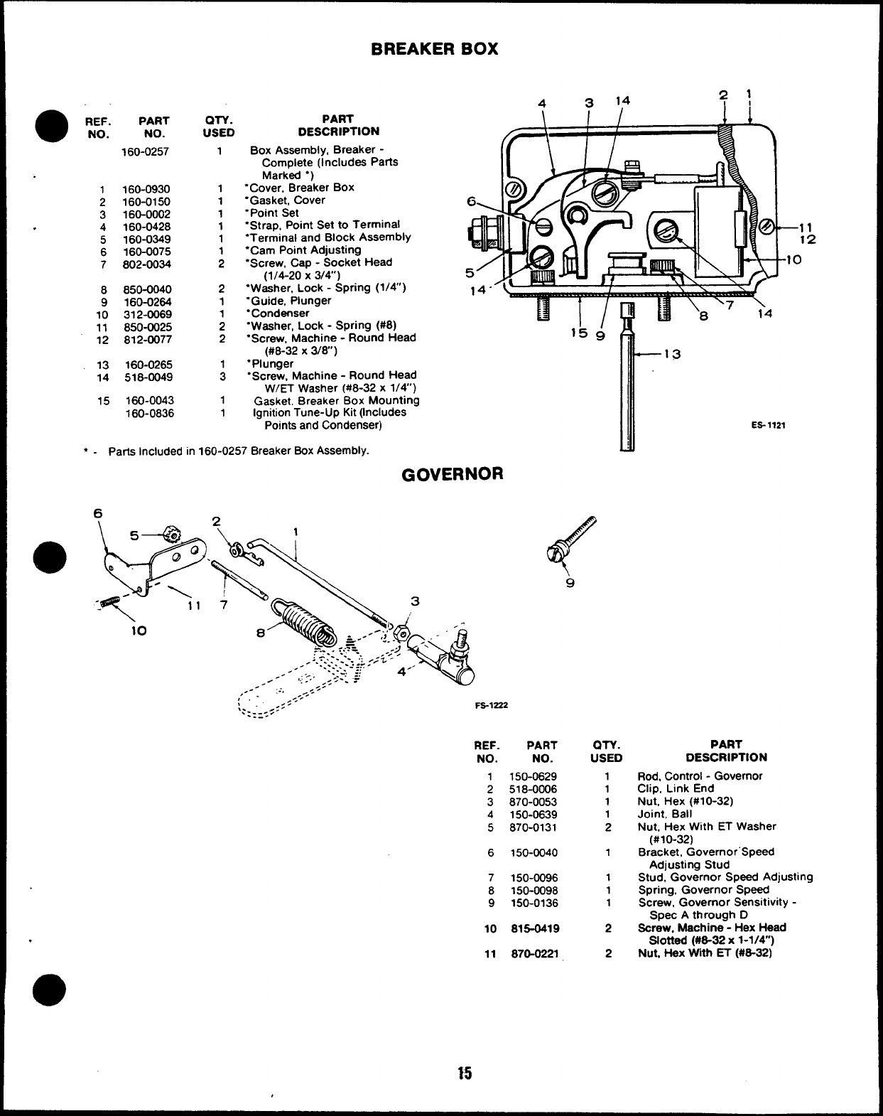
●REF.
NO.
1
2
3
.4
5
6
7
8
9
10
11
12
13
14
15
PART
NO.
160-0257
160-0930
160-0150
160-0002
160-0428
160-0349
160-0075
802-0034
850-0040
160-0264
312-0069
850-0025
812-0077
160-0265
518-0049
160-0043
160-0836
QTY.
USED
1
1
1
1
1
1
;
2
1
;
2
1
1
PART
DESCRIPTION
Box Assembly, Breaker -
Complete (Includes Parts
Marked “)
“Cover, Breaker BOX
“Gasket, Cover
“Point Set
“St rap, Point Set to Terminal
“Terminal and Block Assembly
“Cam Point Adjusting
“Screw, Cap -Socket Head
(1/4-20 X3/4)
“Washer, Lock -Spring (1/4)
“Guide, Plunger
“Condenser
“Washer, Lock -Spring (#8)
“Screw, Machine -Round Head
(#8-32 X3/8)
“Plunger
“Screw, Machine -Round Head
W/ET Washer (#8-32 x1/4)
Gasket. Breaker Box Mounting
Ignition Tune-Up Kit (Includes
4314
–11
12
0
15 &
Points and Condenser)
●-Parts included in 160-0257 Breaker Box Assembly.
GOVERNOR
9
,---
:’..-::.
\.
.: :=5. FS-1222
REF.
NO.
1
2
3
4
5
6
7
8
9
10
.11
PART
NO.
150-0629
518-0006
870-0053
150-0639
870-0131
150-0040
150-0096
150-0098
150-0136
816-0419
87G0221
(MY.
USED
1
1
1
1
2
1
1
1
1
2
2
—13
ES-1121
PART
DESCRIPTION
Rod, Control -Governor
Clip, Link End
Nut, Hex (#10-32)
Joint, Ball
Nut, Hex With ET Washer
(#10-32)
Bracket, Governor”Speed
Adjusting Stud
Stud, Governor Speed Adjusting
Spring, Governor Speed
Screw, Governor Sensitivity -
Spec Athrough D
Screw, Machine -Hex Head
Slotted (#8-32 x1-1/4”)
Nut, t+eX With ET (#6-32)
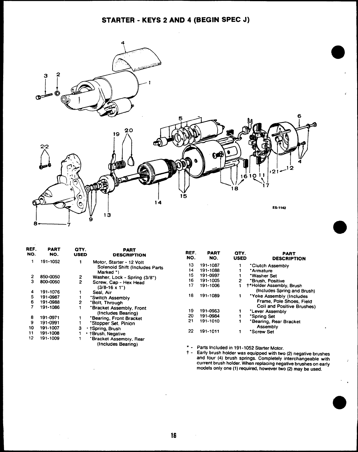
STARTER -KEYS 2AND 4(BEGIN SPEC J)
4
D..
.,,..:,
.~:
,.. , ,, ...
., ~,,
”.. .r ----
8— 7
REF. PART an. PART
NO. NO. USED DESCRIPTION
1191-1052 1Motor, Starter -12 Volt
2850-0050
3800-0050
4191-1076
5191-0987
6191-0988
7191-1086
8191-0971
9191-0991
10 191-1007
11 191-1008
12 191-1009
I15
14
REF. PART
NO. NO.
Solenoid Shift (Includes Parts 13
. .
Marked “)
2Washer, Lock -Spring (3/8)
2Screw, Cap -Hex Head
(3/8-16 Xl“)
1Seal, Air
1“Switch Assembly
2“Bolt, Through
1“Bracket Assembly, Front
(Includes Bearing)
1●Bearing, Front Bracket
1“Stopper Set, Pinion
3“tSPring, Brush
1“tBrush, Negative
1“Bracket Assemrx y, Rear
(Includes Bearing)
18
19
20
21
22
191-1087
191-1088
191-0997
191-1005
191-1006
191-1089
191-0963
191-0984
191-1010
191-1011
18 . .
ES%~42
OTY. PART
USED DESCRIPTION
1“Clutch Assembly
1“Armature
1“Washer Set
2‘Brush, Positive
1t●Holder Assembly, Brush
(Includes Spring and Brush)
1“Yoke Assembly (Includes
Frame, Pole Shoes, Field
coil and Positive Brushes)
1“Lever Assembly
1“Spring Set
1“Bearing, Rear Bracket
Assembly
1“Screw Set
Parta Included in 191-1052 Statier Motor.
Early brush holder was equipped with two (2) negative brushes
and four (4) brush springs. Completely interchangeable with
current brush holder. When replacing negative brushes on early -
models only one (1) required, however two (2) may be used.
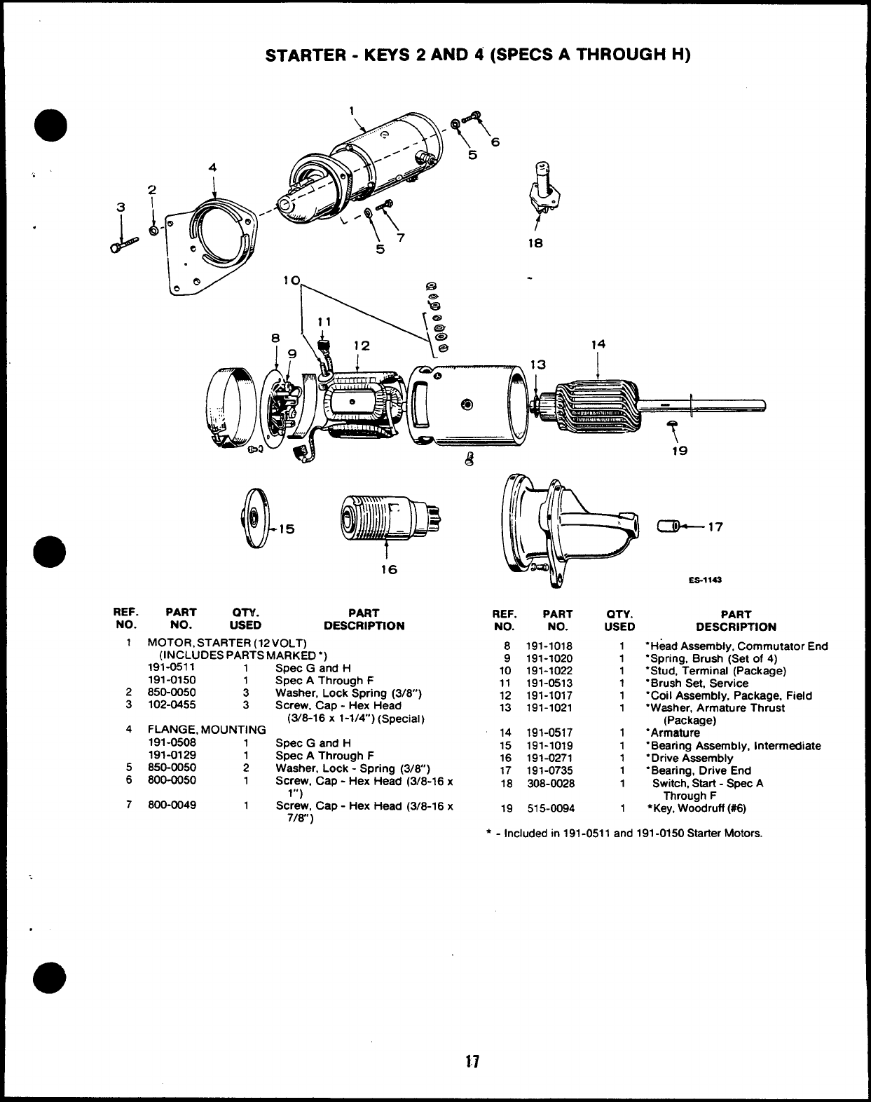
STARTER -KEYS 2AND 4(SPECS ATHROUGH H)
F
<
—.
18
14
!
.
REF. PART OTY. PART
NO. NO. USED DESCRIPTION
1MOTOR, STARTER (12 VOLT)
(INCLUDES PARTS MARKED “)
191-0511 1
191-0150
2850-0050 ;
3102-0455 3
4FLANGE, MOUNTING
191-0508 1
191-0129 1
5850-0050 2
6800-0050 1
7800-0049 1
Spec Gand H
Spec AThrough F
Washer, Lock Spring (3/8”)
Screw, Cap -Hex Head
(3/8-16 x1-1/4) (Special)
Spec Gand H
Spec AThrough F
Washer, Lock -Spring (3/6” )
Screw, Cap -Hex Head (3/8-16 x
1“)
Screw, Cap -Hex Head (3/8-16 x
7/w )
czk-17
ES-1 143
REF. PART QTY. PART
NO. NO. USED DESCRIPTION
8
9
10
11
12
13
14
15
16
17
18
19
191-1018
191-1020
191-1022
191-0513
191-1017
191-1021
191-0517
191-1019
191-0271
191-0735
308-0028
515-0094
1
1
1
1
1
1
1
1
1
1
1
1
“Head Assembly, Commutator End
‘Spring, Brush (Set of 4)
“Stud, Terminal (Package)
“Brush Set, Service
“Coil Assembly, Package, Field
“Washer, Armature Thrust
(Package)
“Armature
“Bearing Assembly, Intermediate
“Drive Assembly
“Bearing, Drive End
Switch, Start -Spec A
Through F
●Key, Woodruff (#6)
*-Included in 191-0511 and 191-0150 Starter Motors.
17
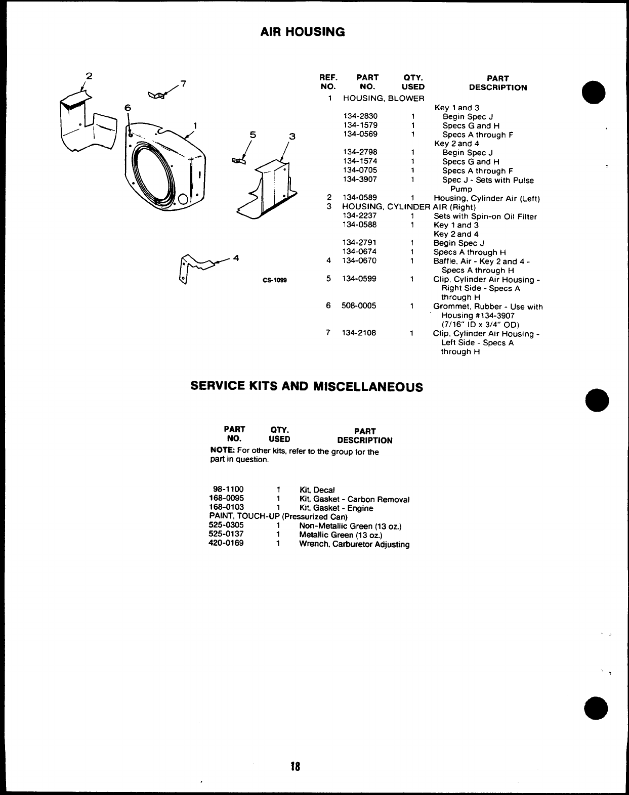
AIR HOUSING
2
6
““ 1’
%3/7
6
53
REF. PART QTY.
NO. NO. USED
1HOUSING, BLOWER
134-2830 1
134-1579 1
134-0569 1
Q$
J.
--
.134-2798 1
134-1574 1
134-0705 1
134-3907 1
PART
DESCRIPTION
Key 1and 3
Begin Spec J
Specs Gand H
Specs Athrough F
Key 2and 4
Begin Spec J
Specs Gand H
Specs Athrough F
Spec J-Sets with Pulse
Pump
2134-0589 1Housing, Cylinder Air (Left)
3HOUSING, CYLINDER AIR (Right)
134-2237
134-0588 1Sets wi;h Spin-on Oil Filter
1Key 1and 3
Key 2and 4
134-2791 1Begin Spec J
134-0674 1Specs Athrough H
4134-0670 1Baffle, Air -Key 2and 4-
Specs Athrough H
Ca-lass 5134-0599 1Clip, Cylinder Air Housing -
Right Side -Specs A
through H
6508-0005 1Grommet, Rubber -Use with
Housing #134-3907
(7/16” ID X3/4” OD)
7134-2108 1Clip, Cylinder Air Housing -
Left Side -Specs A
through H
SERVICE KITS AND MISCELLANEOUS
PART
NO. PART
:SYD DESCRIPTION
NOTE For other kita, refer to the group for the
part in question.
98-1100 1Kit, Decal
168-0095 1Kit, Gasket -Carbon Removal
168-0103 1Kit, Gasket -Engine
PAINT, TOUCH-UP (Pressurized Can)
525-0305 1Non-Metallic Green (13 oz.)
525-0137 1Metallic Green (13 oz.)
420-0169 1Wrench, Carburetor Adjusting
This section contains illustrated parts listing of factory installed options for these Industrial
Engines. Options may not be applicable to all models; for field conversions additional parts are
usually required. Some parts listed in the standard engine parts section for parts keys 3 and 4
are also applicable as optional parts for parts keys 1 and 2. Optional parts listed in this section
are in addition or in place of those shown in the standard engine parts section.
e
OPTIONAL EQUIPMENT PARTS SECTION
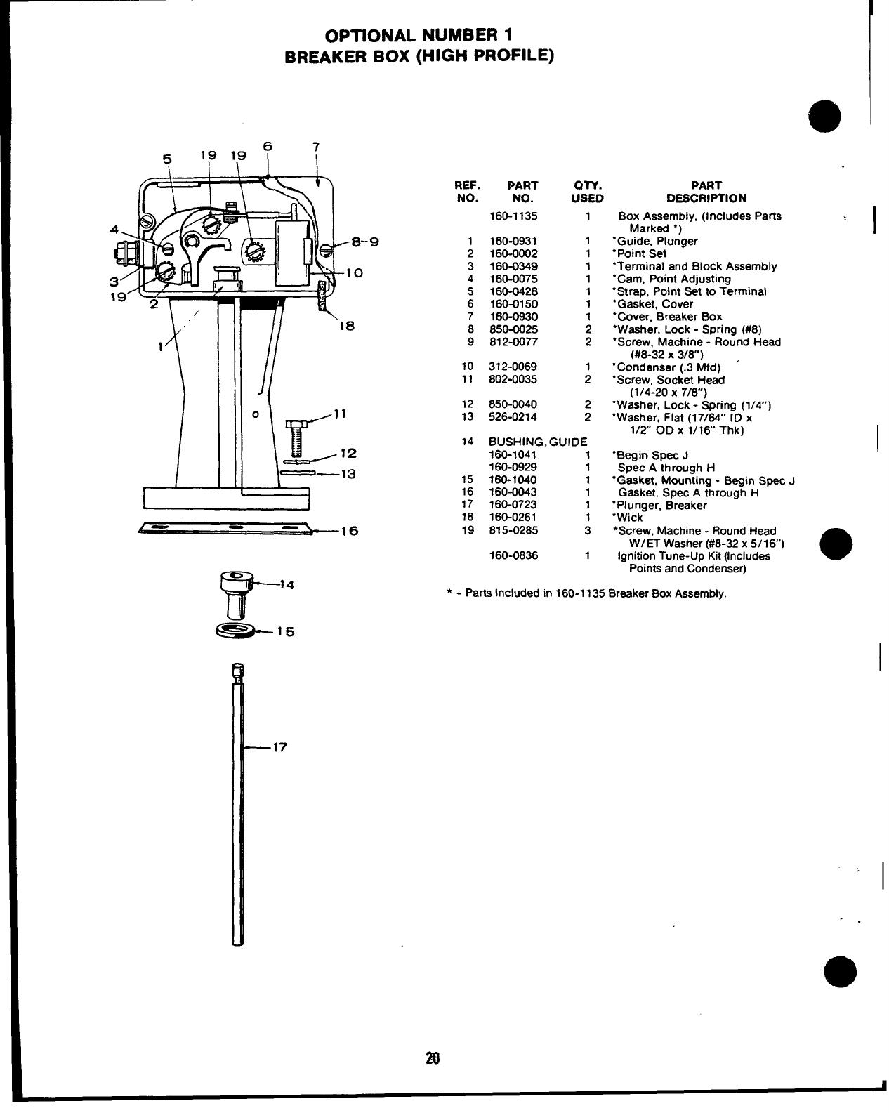
OPTIONAL NUMBER 1
BREAKER BOX (HIGH PROFILE)
REF.
NO.
;
3
4
5
6
7
8
9
10
11
12
13
Mm
NO.
160-1135
160-0931
160-0002
160-0349
160-0075
160-0428
160-0150
160-0930
850-0025
812-0077
312-0069
802-0035
850-0040
526-0214
OTY.
USED
1
1
1
1
1
1
1
1
2
2
1
2
2
2
14 BUSHING, GUIDE
160-1041 1
160-0929 1
15 160-1040 1
16 160-0043 1
17 160-0723 1
18 160-0261 1
19 815-0285 3
160-0836 1
PART
DESCRIPTION
Box Assembly, (Includes Parts
Marked “)
‘Guide, Plunger
“Point Set
‘Terminal and Block Assembly
“Cam, Point Adjusting
“Strap, Point Set to Terminal
“Gasket, Cover
“Cover, Breaker Box
“Washer, Lock -Spring (#8)
“Screw, Machine -Round Head
(#8-32 X3/6”)
“Condenser (.3 Mfd)
“Screw, Socket Head
(1/4-20 X7/8)
“Washer, Lock -Spring (1/4)
‘Washer, Flat (17/64” ID x
1/2 OD X1/16 Thk)
“Begin Spec J
Spec Athrough H
“Gasket, Mounting -Begin Spec J
Gasket, Spec Athrough H
“Plunger, Breaker
“Wick
*Screw, Machine -Round Head
W/ET Washer (#8-32 x5/16)
Ignition Tune-Up Kit (Includes a
Points and Condenser)
*-Parts Included in 160-1135 Breaker Box Assembly.
I
I
I
—17
I
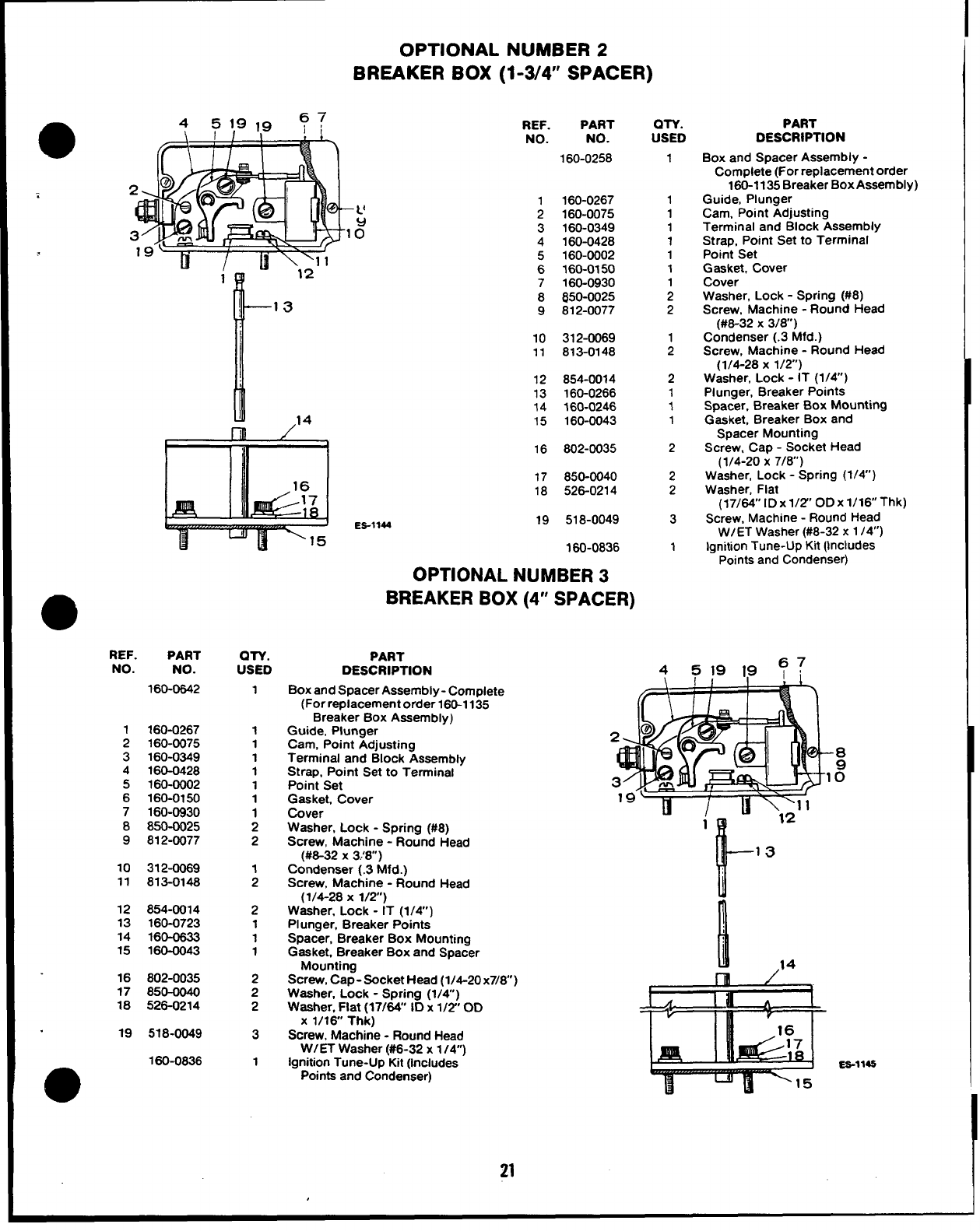
OPTIONAL NUMBER 2
BREAKER BOX (1-3/4’ SPACER)
m/“
REF. PART
NO. NO.
160-0258
1160-0267
2160-0075
3160-0349
4160-0428
5
6
7
8
9
10
11
12
13
14
15
160-0002
160-0150
160-0930
850-0025
812-0077
312-0069
813-0148
854-0014
160-0266
360-0246
160-0043
IIll /’
1II 116 802-0035
REF. PART
NO. NO.
160-0642
1
2
3
4
5
6
7
8
9
160-0267
160-0075
160-0349
160-0428
160-0002
160-0150
160-0930
850-0025
812-0077
10 3124069
11 813-0148
12 854-0014
13 160-0723
14 160-0633
15 160-0043
16 802-0035
17 850-0040
18 526-0214
19 518-0049
160-0836
m
QTY.
USED
1
1
1
1
1
1
1
1
2
2
;
2
1
1
1
2
2
2
3
1
17 850-0040
18 526-0214
ES-1144 19 518-0049
160-0836
OPTIONAL NUMBER 3
BREAKER BOX (4” SPACER)
PART
DESCRIPTION
Box and Spacer Assembly -Complete
(For replacement order 160-1135
Breaker Box Assembly)
Guide, Plunger
Cam, Point Adjusting
Terminal and Block Assembly
Strap, Point Set to Terminal
Point Set
Gasket, Cover
Cover
Washer, Lock -Stxina f#8)
Screw, Machine -“Ro;nd Head
(#8-32 X3!8”)
Condenser (.3 Mfd.)
Screw, Machine -Round Head
(1/4-28 X1/2”)
Washer, Lock -IT (1/4”)
PI unger, Breaker Points
Spacer, Breaker Box Mounting
Gasket, Breaker Box and Spacer
Mounting
Screw, Cap- Socket Head (1/4-20x7/8)
Washer, Lock -Spring (1/4)
Washer, Flat (17/64” ID x1/2” OD
X1/16 Thk)
Screw, Machine -Round Head
W/ET Washer (#6-32 x1/4”)
Ignition Tune-Up Kit (includes
Points and Condenser)
QTY.
USED
1
1
1
1
1
1
1
;
2
1
2
2
1
1
1
2
2
2
3
1
PART
DESCRIPTION
Box and Spacer Assembly -
Complete (For replacement order
160-1135 Breaker Box Assembly)
Guide, Plunger
Cam, Point Adjusting
Terminal and Block Assembly
Strap, Point Set to Terminal
Point Set
Gasket, Cover
Cover
Washer, Lock -Spring (#8)
Screw, Machine -Round Head
(#8-32 X3/8)
Condenser (.3 Mfd.)
Screw, Machine -Round Head
(1/4-28 X1/2”)
Washer, Lock -IT (1/4)
Plunger, Breaker Points
Spacer, Breaker Box Mounting
Gasket, Breaker Box and
Spacer Mounting
Screw, Cap -Socket Head
(1/4-20 X7/8)
Washer, Lock -Spring (1/4”)
Washer, Flat
(17/64’’ lDxl/2’’ ODx16Thk)k)
Screw, Machine -Round Head
W/ET Washer (#8-32 x 1/4”)
lanition Tune-Up Kit (Includes
-Points and Condenser)
451919 ?7
l--13
l.!
ES-114S
21
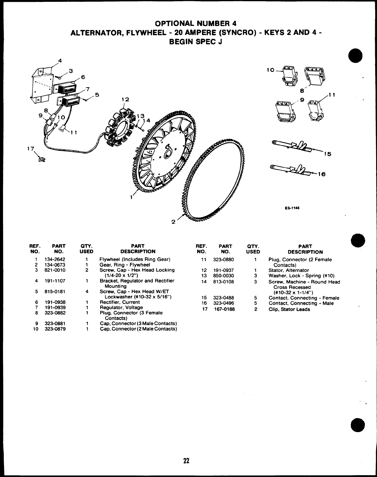
OPTIONAL NUMBER 4
ALTERNATOR, FLYWHEEL -20 AMPERE (SYNCRO) -KEYS 2AND 4-
BEGIN SPEC d
4
clii
---::. %/3 6
..---- :.
.7
..5
00‘%-’ 12
/
‘o%)B
8’
9
auf
Onm ‘no
&.-
-=2+5
==&-
REF. PART
NO. NO.
1134-2642
2134-0673
3821-0010
4191-1107
5815-0181
6191-0936
7191-0939
8323-0882
9323-0881
10 323-0879
QTY.
USED
1
1
2
1
4
1
1
1
1
1
PART
DESCRIPTION
Flywheel (Includes Ring Gear)
Gear, Ring -Flywheel
Screw, Cap -Hex Head Locking
(1/4-20 X1/2)
Bracket, Regulator and Rectifier
Mounting
Screw, Cap -Hex Head WET
Lockwaaher (#10-32x 5/16’)
Rectifier, Current
Regulator, Voltage
Plug, Connector (3 Female
Contacts)
Cap, Connector (3 Male Contacts)
Cap, Connector (2 Male Contacts)
22
REF.
NO.
11
12
13
14
15
16
17
PART
NO.
323-0880
191-0937
850-0030
813-0108
323-0488
323-0496
167-0186
on.
USED
1
A
3
5
5
2
ES-114S
PART
6
1
●✎
0
DESCRIPllON
Plug, Connector (2 Female
Contacts)
Stator, Alternator
Washer, Lock -Spring (#10)
Screw, Machine -Round Head
Cross Recessed
(#10-32 X1-1/4”)
Contact, Connecting -Female
Contact, Connecting -Male
Clip, Stator Leads
o
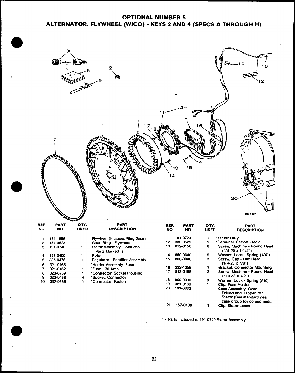
,
OPTIONAL NUMBER 5
ALTERNATOR, FLYWHEEL (WICO) -KEYS 2AND 4(SPECS ATHROUGH H)
1
I
.
2
REF. PART OTY.
NO. NO. USEID
1134-1895 1
2134-0673 1
3191-0740 1
4191-0400 1
5305-0478 1
6321-0165 1
7321-0162 1
8323-0759 1
9323-0468 4
10 332-0556 1
PART
DESCRIPTION
Flywheel (Includes Ring Gear)
Gear, Ring -Flywheel
Stator Assembly -Includes
Parts Marked “)
Rotor
Regulator -Rectifier Assembly
“Holder Assembly, Fuse
“Fuse -30 Amp.
“Connector, Socket Housing
“Socket, Connector
“Connector. Faston
REF. PART
NO. NO.
11 191-0724
12 332-0529
13 812-0156
14 850-0040
15 8oo-ooo6
16 332-1358
17 813-0108
18 850-0030
19 321-0169
20 103-0332
21 167-0188
20
‘N) -t
ES-1147
QN. PART “
USED DESCRIPTION
1‘Stator Unly
1“Terminal, Faston -Male
6Screw, Machine -Round Head
(1/4-20 X1-1/2’)
9Washer, Lock -Spring (1/4”)
3Screw, Cap -Hex Head
(1/4-20 x7/8)
1Bracket, Connactor Mounting
3Screw, Machine -Round Head
(#10-32 X1/2”)
3Washer, Lock -Spring (#10)
1Clip, Fuse Holder
1Case Assembly, Gear -
Drilled and Tapped for
Stator (See standard gear
case group for components)
1Clip, Stator Leads
.
“-patis Included in 191-0740 Stator Assembly,
23
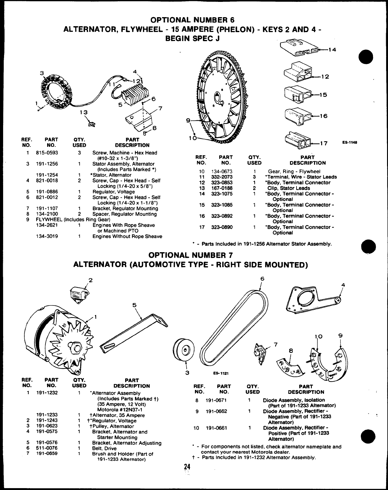
OPTIONAL NUMBER 6
ALTERNATOR, FLYWHEEL -15 AMPERE (PHELON) -KEYS 2AND 4-
BEGIN SPEC Jk=--” a
ES-114S
17
‘h
.
=
-..
<-... \17
REF. PART QTV. PART
NO. NO. USED DESCRIPTION
1
3
815-0593 3Screw, Machine -Hex Head
(#10-32 X1-3/8”)
191-1256 1Stator Assembly, Alternator
(Includes Parts Marked ●)
191-1254 ●Stator, Alternator
821-0018 ;Screw, Cap -Hex Head -Self
Locking (1/4-20x 5/8’)
191-0886 Regulator, Voltage
821-0012 1Screw, Cap -Hex Head -Self
Locking (1/4-20x 1-1 /8”)
191-1107 1Bracket, Regulator Mounting
134-2100 2Spacer, Regulator Mounting
FLYWHEEL (Includes Ring Gear)
134-2621 1Engines Wtth Rope Sheave
or Machined PTO
REF. PART
NO. NO. QTY. PART
USED DESCRIPTION
Gear, Ring -Flywheel
“Terminal, Wire -Stator Leads
●Body, Terminal Connector
Clip, StatorLeads
“Body, Terminal Connector -
Optional
“Body, Terminal Connector -
Optional
●Body, Terminal Connector -
Optional
●Body, Terminal Connector -
Optional
10 134-0673
11 332-2073
12 323-0853
13 167-0188
14 323-1075
4
5
6
15 323-1065 1
7
8
916 323-0892 1
17 323-0890 1
134-3019 1Engines Without Rope Sheave
●-Parts Included in
OPTIONAL NUMBER 7
ALTERNATOR (AUTOMOTIVE TYPE -RIGHT
191-1256 Alternator Stator Assembly.
SIDE MOUNTED)
6w4
ES- llZl
REF. PART QTV.
NO. NO. USED PART
DESCRIPTION REF. PART QTY. PART
NO. NO. USED DESCRWTION
8191-0671 1DMe Assembly, Isolation
(Part of 191-1233 Alternator)
9191-0662 1Dkxie Assembly, Rectiier -
Neoative (Pati of 191-1233 .,
a
1191-1232 1“Alternator Assembly
(Includes Parts Marked t)
(35 Ampere, 12 Volt)
Motorola #12 N37-1
191-1233 1tAlternator, 35 Ampere
2191-1243 1t“Regulator, Voltage
3191-0623 1_/Pulley, Alternator
4191-0575 1Bracket, Alternator and
Starter Mountina
Alt&nator)
10 191-0661 1Dkxfe Assembly, Rectifier -
Positive (part of 191-1233
Altamator)
5191-0576 1Bracket, Alternate; Adjusting
6511-0076 1Belt, Drive “-For components not listed, check alternator nameplate and
7191-0659 1Brush and Holder (Part of contact your nearest Motorola dealer.
191-1233 Alternator) t - Parts Included in 191-1232 Alternator Assembly.
24
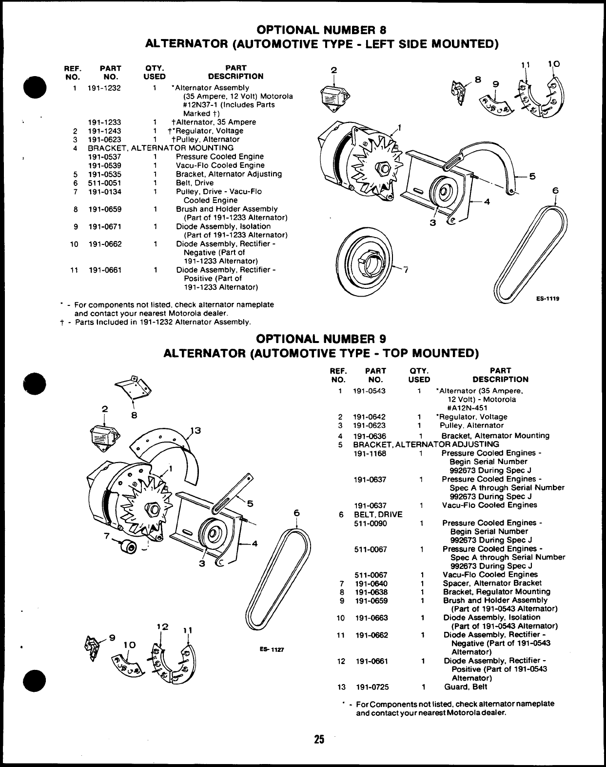
OPTIONAL NUMBER 8
ALTERNATOR (AUTOMOTIVE TYPE -LEFT SIDE MOUNTED)
REF. PART OTY. PART
NO. NO. USED DESCRIPTION
1191-1232 1‘Alternator Assembly
(35 Ampere, 12 Volt) Motorola
#12 N37-1 (Includes Parts
Marked t)
191-1233 1tAlternator, 35 Ampere
2191-1243 1t“Regulator, Voltage
3191-0623 1tPulley, Alternator
4BRACKET, ALTERNATOR MOUNTING
191-0537 1Pressure Cooled Engine
191-0539 1Vacu-Flo Cooled Engine
5191-0535 1Bracket, Alternator Adjusting
6511-0051 1Belt, Drive
7191-0134 1Pulley, Drive -Vacu-Flo
Cooled Engine
8191-0659 1Brush and Holder Assembly
(Part of 191-1233 Alternator)
9191-0671 1Diode Assembly, Isolation
(Part of 191-1233 Alternator)
10 191-0662 1Diode Assembly, Rectifier -
Negative (Parf of
191-1233 Alternator)
11 191-0661 1Diode Assembly, Rectifier -
Positive (Part of
191-1233 Alternator)
‘-For components not listed, check alternator nameplate
and contact your nearest Motorola dealer.
t - Parts Included in 191-1232 Alternator Assembly.
OPTIONAL NUMBER 9
ALTERNATOR (AUTOMOTIVE TYPE -TOP MOUNTED)
REF. PART QTY. PART
?>
.NO. NO. USED
.DESCRIPTION
.
. . 1191-0543 1“Alternator (35 Ampere,
\12 Volt) -Motorola
2#A12N-451
18 2191-0642 1‘Regulator, Voltage
3191-0623 1Pulley, Alternator
4191-0636 1Bracket, Alternator Mounting
5BRACKET, ALTERNATOR ADJUSTING
191-1168 1
191-0637
191-0637
6BELT, DRIVE
511-0090
511-0067
511-0067
7191-0640
8191-0638
9191-0659
10 191-0663
11 191-0662
ES- 11S7
12 191-0661
13 191-0725
1
1
1
1
1
1
1
1
1
1
1
1
Pressure Cooled Engines -
Begin Serial Number
992673 During Spec J
Pressure Cooled Engines -
Spec Athrough Serial Number
982673 During Spec J
Vacu-Flo Cooled Engines
Pressure Cooled Engines -
Begin Serial Number
992673 During Spec J
Pressure Cooled Engines -
Spec Athrough Serial Number
992673 During Spec J
Vacu-Flo Cooled Engines
Spacer, Alternator Bracket
Bracket, Regulator Mounting
Brush and Holder Assembly
(Part of 191-0643 Alternator)
Diode Assembly, Isolation
(Part of 191-0643 Alternator)
Diode Assembly, Rectifier -
Negative (Part of 191-0543
Alternator)
D&fe Assembly, Rectifier -
Positive (Pati of 191-0643
Alternator)
Guard, Belt
“-For Components not listed, check alternator nameplate
and contact your neareat Motorola dealer.
25

OPTIONAL NUMBER 10
GENERATOR (AUTOMOTIVE TYPE -6 VOLT)
417
12
@
. . -16
.
REF. PART OTY.
NO. NO. USED
1GENERATOR, 6VOLT
PART
DESCRIPTION
2
3
4
5
6
7
8
9
191-0308 1tBegin Spec F(Includes
Pulley, Excludes Regulator) -
Delco Remy # 1100055
191-0199 1“Specs Athrough E(Includes
Regulator. Excludes Pulley) -
Preatolite #GAS-41 75
191-0162 1Pulley, Generator -Specs
Athrough E
515-0105 1Key, Pulley -Specs A
through E
511-0051 Belt, Drive
BRACKET, GENE~ATOR MOUNTING
Begin Spec F
191-0279 1Pressure Cooled Engine
191-0304 1Vacu-Flo Cooled Engine
Spec E
191-0240 1Pressure Cooled Engine
191-0241 1Vacu-Flo Cooled Engine
BRACKET, GENERATOR MOUNTING -SPECS ATHROUGH D
191-0155 1Pressure Cooled Engine
191-0172 1Vacu-Fio Cooled Engine
191-0260 1Bracket, Adjusting -Begin Spec F
191-0239 1Bracket, Adjusting -Spec E
191-0156 1Bracket, Adjusting -Specs
Athrough O
@
/o,
e
0‘5
ES-1149
REF. PART
NO. NO.
10 191-0242
11 191-0157
12 191-0134
QTY. PART
USED DESCRIPTION
1Band, Generator Mounting -e
SPec E
1Band, Generator Mounting -
Spec Athrough D
1Pulley, Generator Drive -
Vacu-Flo Cooled Engine
13 BRACE, GENERATOR MOUNTING BRACKET -VACU-FLO
COOLED ENGINE
191-0305 1Begin Spec F
191-0158 1Specs Athrough D
14 302-1361 1Ammeter, Specs Athrough E
(Includes Mounting Clamp)
15 321-0094 1Fuse (5 Ampere) -Spec A
through E
16 191-0309 1tFlegulator, Voltage -Begin
Spec F
17 191-0382 1“Regulator, Voltage -Specs
Athrough E
t - For components check nameplate and contact your
nearest Delco-Remy dealer.
“-For components check nameplate and contact your
nearest Prestolite dealer.
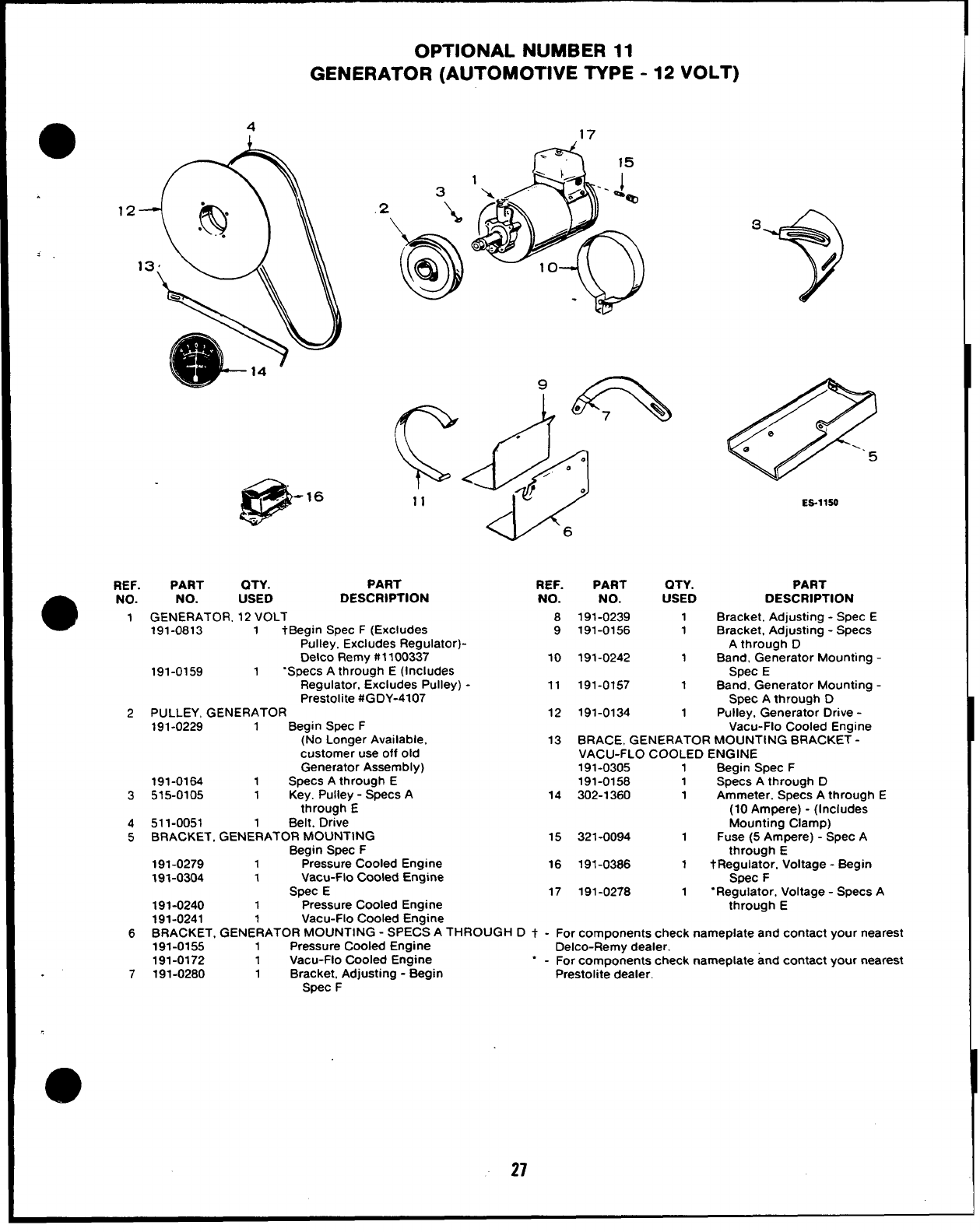
—— — —
OPTIONAL NUMBER 11
GENERATOR (AUTOMOTIVE TYPE -12 VOLT)
.
4
12
13
@
-16
.
3
11
REF. PART QTY. PART
a
NO. NO. USED DESCRIPTION
1GENERATOR, 12 VOLT
191-0813 1tBegin Spec F(Excludes
Pulley, Excludes Regulator)-
Delco Remy#1100337
191-0159 1“Specs Athrough E(Includes
Regulator, Excludes Pulley) -
Prestolite #GDY-4107
2PULLEY, GENERATOR
191-0229 1Begin Spec F
(No Longer Available,
customer use off old
Generator Assembly)
191-0164 1Specs Athrough E
3515-0105 1Key. Pulley -Specs A
through E
4511-0051 1Belt. Drive
5BRACKET, GENERATOR MOUNTING
Begin Spec F
191-0279 1Pressure Cooled Engine
191-0304 1Vacu+lo Cooled Engine
Spec E
191-0240 1Pressure Cooled Engine
‘6+?!)
d
.
do
0
/
?0
6
REF. PART
NO. NO.
8191-0239
9191-0156
10 191-0242
11 191-0157
12 191-0134
QTY.
USED
1
1
1
1
1
3
?
/
@
/e>
e
e=. 5
ES-llSO
PART
DESCRIPTION
Bracket, Adjusting -Spec E
Bracket, Adjusting -Specs
Athrough D
Band, Generator Mounting -
Spec E
Band, Generator Mounting -
Spec Athrough D
Pulley. Generator Drive -
Vacu-Flo Cooled Engine
13 BRACE, GENERATOR MOUNTING BRACKET -
VACU-FLO COOLED ENGINE
191-0305 1Begin Spec F
191-0158 1Specs Athrough D
14 302-1360 1Ammeter. Specs Athrough E
(10 Ampere) -(Includes
Mounting Clamp)
15 321-0094 1Fuse (5 Ampere) -Spec A
through E
16 191-0386 1tRegulator, Voltage -Begin
Spec F
17 191-0278 1“Regulator, Voltage -Specs A
through E
191-0241 1Vacu-Flo Cooled Engine
6BRACKET, GENERATOR MCIUNTING -SPECS ATHROUGH Dt - For components check nameplate and contact your nearest
191-0155 1Pressure Cooled Engine Delco-Remy dealer.
191-0172 1Vacu-Flo Cooled Engine
7191-0280 “-For components check nameplate and contact your nearest
1Bracket, Adjusting -Begin Prestolite dealer.
Spec F
27
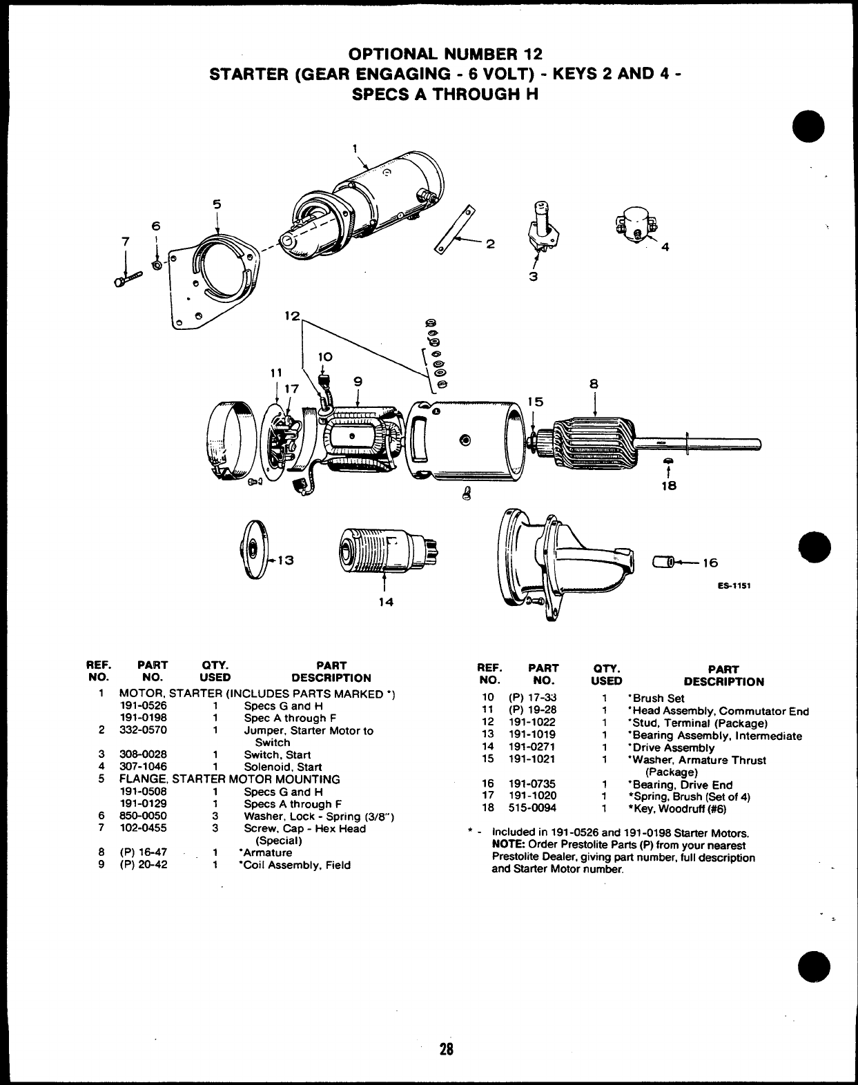
7
(3$@
OPTIONAL NUMBER 12
STARTER (GEAR ENGAGING -6 VOLT) -KEYS 2AND 4-
SPECS ATHROUGH H
.
5
6
I
A
~. 2&Q4
.t
3
0
.. .,.
,:.,,,
\, !,,
o
14
REF. PART QTY. PART
NO. NO. USED DESCRIPTION
1MOTOR, STARTER (INCLUDES PARTS MARKED “)
191-0526 1Specs Gand H
191-0198 1Spec Athrough F
2332-0570 1Jumper, Starter Motor to
Switch
3308-0028 1Switch, Start
4307-1046 Solenoid, Start
5FLANGE, START;R MOTOR MOUNTING
191-0508 1Specs Gand H
191-0128 1Specs Athrough F
6850-0050 3Washer, Lock -Spring (3/8)
7102-0455 3Screw, Cap -Hex Head
(Special)
8(P) 18-47 1“Armature
9(P) 20-42 1“Coil Assembly, Field
~16 a
ES-1151
REF. PART
NO. NO.
10 (P) 17-33
11 (P) 19-28
12 191-1022
13 191-1019
14 191-0271
15 191-1021
●✍
16 191-0735
17 191-1020
18 515-0094
OTY. PART
USED DESCRIPTION
1
1
1
1
1
1
1
1
1
“Brush Set
“Head Assembly, Commutator End
“Stud, Terminal (Package)
“Bearing Assembly, Intermediate
‘Drive Assembly
“Washer, Armature Thrust
(Package)
“Bearing, Drive End
*Spring, Brush (Set of 4)
●Key, Woodruff (#6)
Included in 191-0526 and 191-0198 Starter Motors.
NOTE Order Prestolite Parts (P) from your nearest
Prestoiite Dealer, giving part number, full description
and Starter Motor number.
28
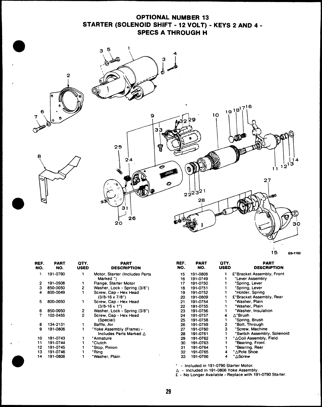
OPTIONAL NUMBER 13
STARTER (SOLENOID SHIFT -12 VOLT) -KEYS 2AND 4-
SPECS ATHROUGH H
35 1
\ \ A
REF.
NO.
2
1
2
3
4
5
6
7
8
9
10
~’ 11
12
13
e14
PART
NO.
191-0790
191-0508
850-0050
800-0049
800-0050
850-0050
102-0455
134-2131
191-0806
191-0743
191-0744
191-0745
191-0746
191-0806
.,716
10 ‘ml
QTY. PART REF. PART
USED DESCRIPTION NO. NO.
1
1
2
1
1
2
2
1
1
1
1
1
1
1
Motor, Starter (Includes Parts
Marked “)
Flange, Starter Motor
Washer. Lock -Spring (3/8”)
Screw, Cap -Hex Head
(3/8-16 X7/8)
Screw. Cap -Hex Head
(3/6-16 Xl“)
Washer, Lock -Spring (3/6”)
Screw, Cap -Hex Head
(Special)
Baffle, Air
“Yoke Assembly (Frame) -
Includes Parts Marked A
“Armature
“Clutch
“Stop, Pinion
“Ring
“Washer, Plain
15
16
17
18
19
20
21
22
23
24
25
26
27
28
29
30
31
32
33
191-0808
191-0749
191-0750
191-0751
191-0752
191-0809
191-0754
191-0755
191-0756
191-0757
191-0758
191-0759
191-0760
191-0761
191-0762
191-0763
191-0764
191-0765
191-0766
15 ES-11S2
am. PART
USED DESCRIPTION
1f“Bracket Assembly, Front
1“Lever Assembly
1‘Spring, Lever
1“Spring, Lever
1“Holder, Spring
1C“Bracket Assembly, Rear
1“Washer. Plain
1“Washer, Plain
1“Washer, Insulation
4A“Brush
“Spring, Brush
;“Bolt, Through
3“Screw, Machine
1“Switch Assembly. Solenoid
1“ACoii Assembly, Field
1“Bearing, Front
1“Bearing, Rear
4‘APole Shoe
4“AScrew
“-Included in 191-0790 Starter Motor.
A-Included in 191-0806 Yoke Assembly.
f - No Longer Available -Replace with 191-0790 Starter.
29
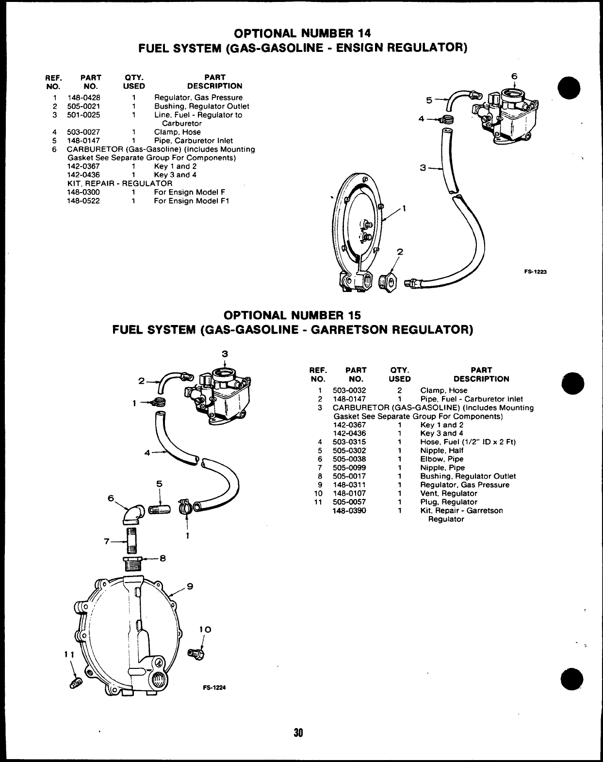
OPTIONAL NUMBER 14
FUEL SYSTEM (GAS-GASOLINE -ENSIGN REGULATOR)
REF. PART QTY.
NO. NO. USED
1148-0428 1
2505-0021 1
3501-0025 1
4503-0027 1
PART
DESCRIPTION
Regulator, Gas Pressure
Bushing, Regulator Outlet
Line, Fuel -Regulator to
Carburetor
Clamp, Hose
5148-0147 1Pipe, “Carburetor Inlet
6CARBURETOR (Gas-Gasoline) (Includes Mounting
Gasket See Separate Group For Components)
142-0367 1Kev 1and 2
142-0436 1Ke~ 3and 4
KIT, REPAIR -REGULATOR
148-0300 1For Ensign Model F
148-0522 1For Ensign Model F1
>
FS-1222
OPTIONAL NUMBER 15
FUEL SYSTEM (GAS-GASOLINE -GARRETSON REGULATOR)
3
1
REF.
NO.
1
2
3
4
5
6
7
8
9
10
11
PART QTY. PART
NO. USED DESCRIPTION
503-0032 2Clamp, Hose
148-0147 1Pipe, Fuel -Carburetor Inlet
CARBURETOR (GAS-GASOLINE) (Includes Mounting
Gasket See Separate Group For Components)
142-0367 1Key 1and 2
142-0436 1Key 3and 4
503-0315 1Hose, Fuel (1/2” ID x 2 Ft)
505-0302 1Nipple, Half
505-0038 1Elbow, Pipe
505-0099 1Nipple, Pipe
505-0017 1Bushing, Regulator Outlet
148-0311 1Regulator, Gas Pressure
148-0107 1Vent, Regulator
505-0057 1Plug, Regulator
148-0390 1Kit, Repair -Garretson
Regulator
10
d
. .,
FS-1224 a
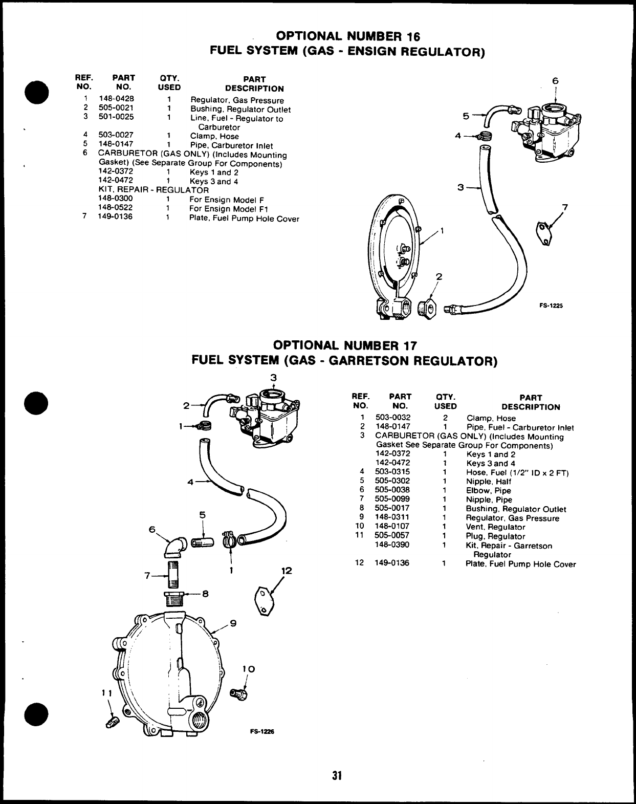
REF.
a
PART QTY.
NO. NO. USED
1148-0428 1
2505-0021 1
3501-0025 1
.4503-0027 1
5148-0147 1
OPTIONAL NUMBER 16
FUEL SYSTEM (GAS -ENSIGN REGULATOR)
PART
DESCRIPTION
Regulator, Gas Pressure
Bushing, Regulator Outlet
Line, Fuel -Regulator to
Carburetor
Clamp, Hose
pipe, Carburetor Inlet
6CARBURETOR (GAS ONLY) (Includes Mounting
Gasket) (See Separate Group For Components)
,142-0372 1Kevs 1and 9
--, ------ _
142-0472 1Keys 3and 4
KIT, REPAIR -REGULATOR
146-0300 1For Ensign Model F
148-0522 1For Ensign Model F1
7149-0136 1Plate, Fuel Pump Hole Cover
6
4
3--J\
OPTIONAL NUMBER 17
FUEL SYSTEM (GAS -GARRETSON REGULATOR)
3
h
1
13CARBURETOR (
Gas
A- REF. PART QTY. PART
NO. NO. USED DESCRIPTION
I503-0032 2Clamp, Hose
2148-0147 1Pipe, Fuel -Carburetor Inlet
GAS ONLY) (Includes Mounting
sket See Separate Group For Components)
142-0372 1Keys 1and 2
10
/
d
Fs-1225
4
5
6
7
8
9
10
11
12
142-0472
503-0315
505-0302
505-0038
505-0099
505-0017
146-0311
148-0107
505-0057
146-0390
149-0136
1
1
1
1
1
1
1
1
1
1
1
Keys 3and 4
Hose, Fuel (1/2” ID x2FT)
Nipple, Half
Elbow, Pipe
Nipple, Pipe
Bushing, Regulator Outlet
Regulator, Gas Pressure
Vent, Regulator
Plug, Regulator
Kit, Repair -Garretson
Regulator
Plate, Fuel Pump Hole Cover
31
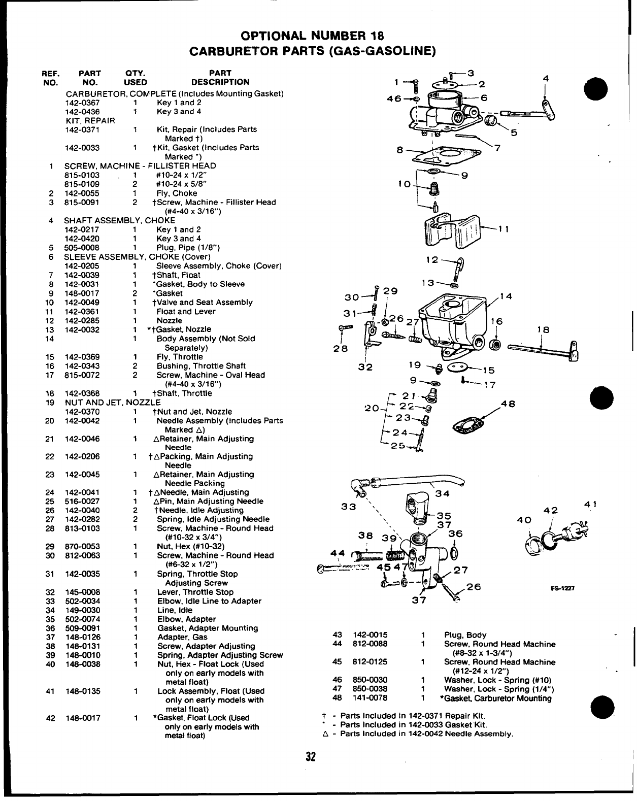
OPTIONAL NUMBER 18
CARBURETOR PARTS (GAS-GASOLINE)
REF.
NO.
1
2
3
4
5
6
7
8
9
10
11
12
13
14
15
16
17
18
19
20
21
22
23
24
25
26
27
28
29
30
31
32
E
35
36
37
38
39
40
41
42
PART QTY. PART
NO. USED DESCRIPTION
CARBURETOR, COMPLETE (Includes Mounting Gasket)
142-0367 1Key 1and 2
142-0436 1Key 3and 4
KIT, REPAIR
142-0371 1Kit, Repair (Includes Parts
Marked t)
142-0033 1tKit, Gasket (Includes Parts
Marked “)
SCREW, MACHINE -FILLISTER HEAD
815-0103 1#10-24 X1/2”
815-0109 2#10-24 X5/8”
142-0055 1Fly, Choke
815-0091 2tScrew, Machine -Fillister Head
(#4-40 x3/16)
SHAFT ASSEMBLY, CHOKE
142-0217 1Key 1and 2
142-0420 1Key 3and 4
505-0008 1Plug, Pipe (1/8)
SLEEVE ASSEMBLY, CHOKE (Cover)
142-0205 1Sleeve Assembly, Choke (Cover)
142-0039 1*Shaft, Float
142-0031 ‘Gasket, Body to Sleeve
148-0017 ;“Gasket
142-0049 1tValve and Seat Assembly
142-0361 1Float and Lever
142-0285 1Nozzle
142-0032 1*tGasket. Nozzle
1Body Assembly (Not Sold
Separately)
142-0369 1Fly, Throttle
142-0343 2Bushing, Throttle Shaft
815-0072 2Screw, Machine -Oval Head
(#4-40 X3/16”)
142-0368 1tShaft, Throttle
NUT AND JET, NOZZLE
142-0370
142-0042
142-0046
142-0206
142-0045
142-0041
516-0027
142-0040
142-0282
813-0103
870-0053
812-0063
142-0035
145-0008
502-0034
149-0030
502-0074
509-0081
148-0126
148-0131
148-0010
148-0038
148-0135
148-0017
1tNut and Jet. Nozzle
1
1
1
1
1
1
2
2
1
1
1
1
1
1
1
1
1
1
1
1
1
1
1
Needle Assembly (Includes Parts
Marked A)
ARetainer, Main Adjusting
Needle
tAp;$;~ Main Adjusting
ARetainer, Main Adjusting
Needle Packing
tANeedle, Main Adjusting
APin, Main Adjusting Needle
tNeedle, Idle Adjusting
Spring, Idle Adjusting Needle
Screw, Machine -Round Head
(#10-32 X3/4)
Nut, Hex (#10-32)
Screw, Machine -Round Head
(#6-32 X1/2”)
Spring, Throttle Stop
Adjusting Screw
Lever, Throttle Stop
Elbow, Idle Line to Adapter
Line, Idle
Elbow, Adapter
Gasket, Adapter Mounting
Adapter, Gas
Screw, Adapter Adjusting
Spring, Adapter Adjusting Screw
Nut, Hex -Float Lock (Used
only on early models with
metal float)
Lock Assembly, Float (Used
only on early models with
metal float)
*Gasket. Float Lock (Used
only on early models with
metal float)
,~
F.g-
34
33 “.\ ‘;
\35
‘. 37
41
42
40&
d
.’!
FS-1227
43 142-0015 1Plug, Body
44 812-0088 1Screw, Round Head Machine
(#6-32 X1-3/4”)
45 812-0125 1Screw, Round Head Machine
(#12-24 X1/2)
46 850-0030 1Washer, Lock -Scrrirm (#10)
47 850-0038 1Washer. Lock -Sprin~ (1/4;)
48 141-0078 1*GaskeL Carburetor Mounting
t-Parts Included in 142-0371 Repair Kit. a
.-Parts Included in 142-0033 Gasket Kit.
A-Parts Included in 142-0042 Needle Assembly.
32 I
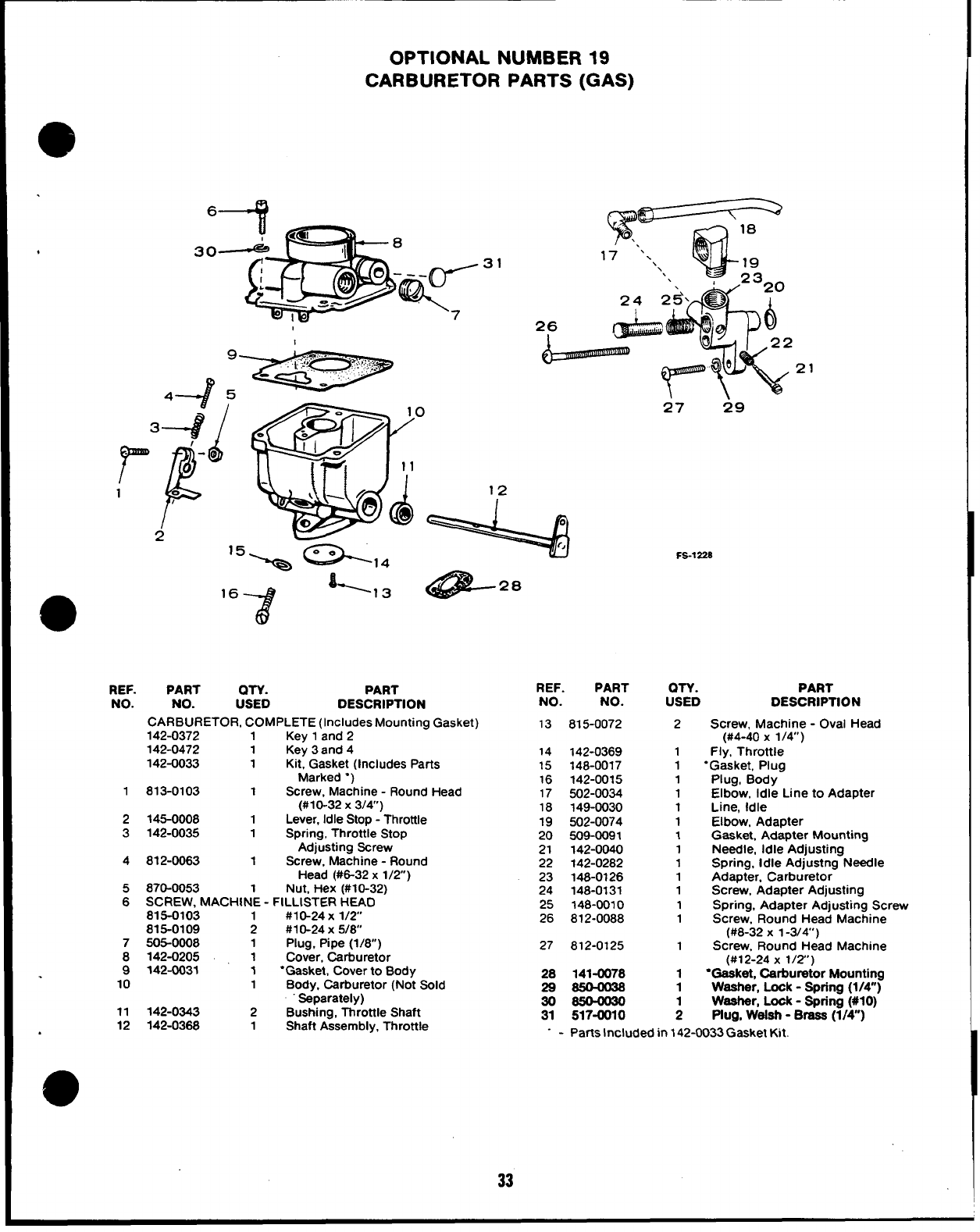
OPTIONAL NUMBER 19
CARBURETOR PARTS (GAS)
REF.
NO.
1
2
3
4
5
6
7
8
9
10
11
12
%r \---=
W
18
‘.
17 ‘. ‘\ 19
\\23
26
21
QTY. PART
USED DESCRIPTION
PART
NO.
CARBURETOR, COMPLETE (Includes Mounting Gasket)
142-0372 1Key 1and 2
142-0472 1Key 3and 4
142-0033 1Kit, Gasket (Includes Parts
Marked “)
813-0103 1Screw, Machine -Round Head
(#10-32 X3/4)
145-0008 1Lever, Idle Stop -Throttle
142-0035 1Spring, Throttle Stop
Adjusting Screw
812-0063 1Screw, Machine -Round
Head (#6-32 x1/2)
870-0053 Nut, Hex (#10-32)
SCREW, MACHIN’E -FILLISTER HEAD
815-0103 #10-24 X1/2
815-0109 ;#1 O-24X 5/8
505-0008 1Plug, Pipe (1/8)
142-0205 1Cover, Carburetor
142-CW31 1“Gasket, Cover to Body
1Body, Carburetor (Not Sold
Separately)
142-0343 2Bushing, Throttle Shaft
142-0368 1Shaft Assembly, Throttle
27 29
FS-1228
REF. PART OTY. PART
NO. NO. USED DESCRIPTION
13 815-0072 2Screw, Machine -Oval Head
(#4-40 x1/4”)
14 142-0369 1Fly, Throttle
15 148-0017 1“Gasket, Plug
16 142-0015 1Plug, Body
17 502-0034 1Elbow, Idle Line to Adapter
18 149-0030 1Line, Idle
19 502-0074 1Elbow, Adapter
20 509-0091 1Gasket, Adapter Mounting
21 142-0040 1Needle, Idle Adjusting
22 142-0282 1Spring, Idle Adjustng Needle
23 148-0126 1Adapter. Carburetor
24 148-0131 1Screw, Adapter Adjusting
25 ?48-0010 1Spring, Adapter Adjusting Screw
26 812-0088 1Screw, Round Head Machine
(#8-32 X1-3/4’)
27 812-0125 1Screw, Round Head Machine
(#12-24 X1/2’)
28 141-0078 1●Gaeket, Carburetor Mounting
29 S50—0@8 1Washer, Look -Spring (1/4”)
30 S504030 Weeher, Look -Spring (#IO)
31 517-0010 ;Plug, Weleh -Braaa (1/4”)
- - Parts Included in 142-0033 Gasket Kit.
33
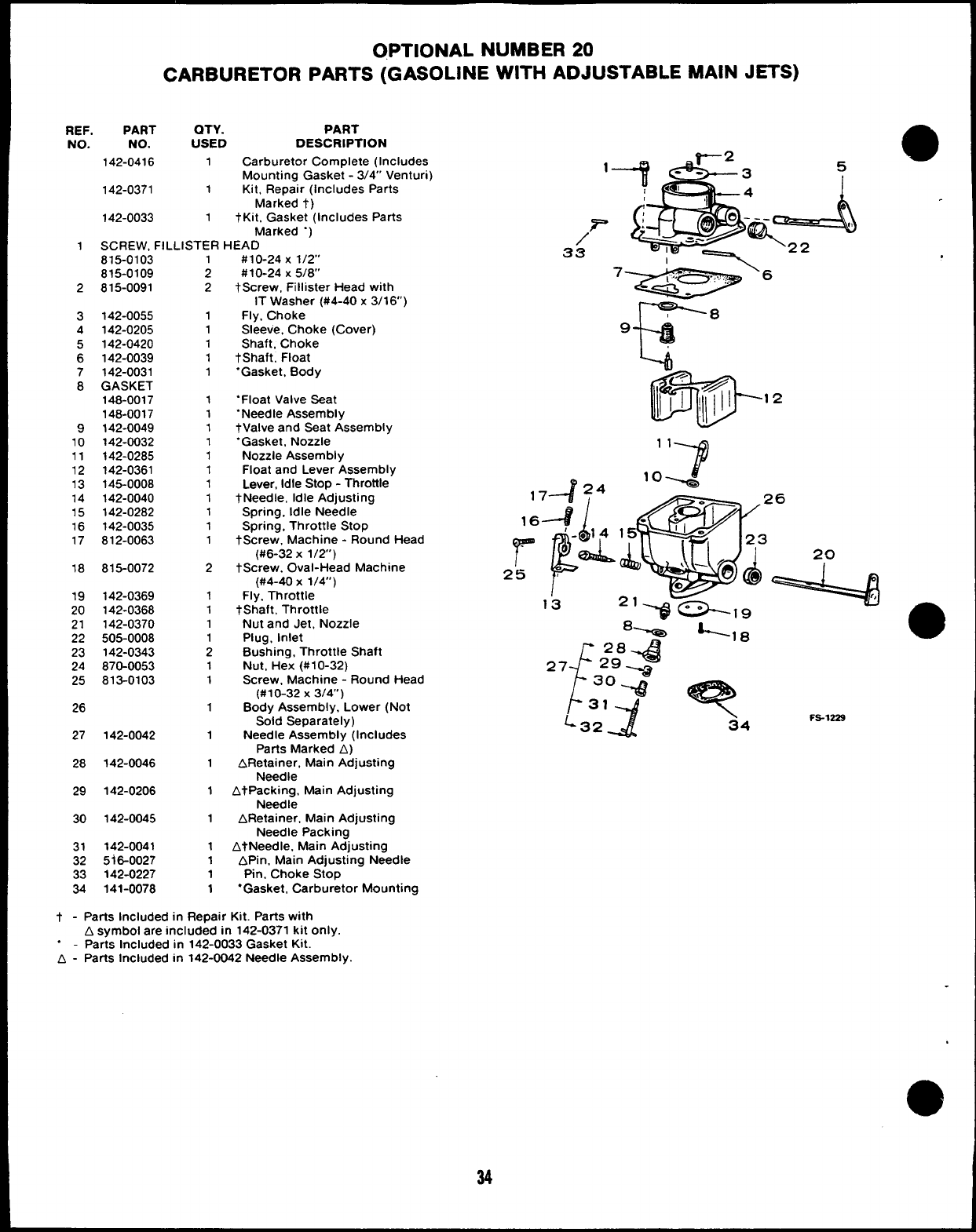
OPTIONAL NUMBER 20
CARBURETOR PARTS (GASOLINE WITH ADJUSTABLE MAIN JETS)
REF. PART QTY. PART
NO. NO. USED DESCRIPTION
142-0416 1Carburetor Complete (Includes
Mounting Gasket -3/4” Venturi)
142-0371 1Kit, Repair (Includes Parts
Marked t)
142-0033 1tKit, Gasket (Includes Parts
Marked “)
1SCREW, FILLISTER HEAD
815-0103
815-0109
2815-0091
3142-0055
4142-0205
5142-0420
6142-0039
7142-0031
8GASKET
148-0017
148-0017
9142-0049
10 142-0032
11 142-0285
12 142-0361
13 145-0008
14 142-0040
15 142-0282
16 142-0035
17 812-0063
18 815-0072
19 142-0369
20 142-0368
21 142-0370
22 505-0008
23 142-0343
24 870-0053
25 813-0103
26
27 142-0042
28 142-0046
29 142-0206
30 142-0045
31 142-0041
32 5i6-0027
33 142-0227
34 141-0078
;
2
1
1
1
1
1
1
1
1
1
1
1
1
1
1
1
1
2
1
1
1
1
2
1
1
1
1
1
1
1
1
1
1
1
#10-24 X1/2”
#10-24 X5/8”
tScrew, Fillister Head with
IT Washer (#4-40x 3/16’)
Fly, Choke
Sleeve, Choke (Cover)
Shaft, Choke
tShaft, Float
“Gasket, Body
“Float Valve Seat
“Needle Assembly
tValve and Seat Assembly
“Gasket, Nozzle
Nozzle Assembly
Float and Lever Assembly
Lever, Idle Stop -Throttle
tNeedle, Idle Adjusting
Spring, Idle Needle
Spring, Throttle Stop
tScrew, Machine -Round Head
(#6-32 X1/2)
tScrew. Oval-Head Machine
(#4-40 x1/4”)
Fly. Throttle
tShaft, Throttle
Nut and Jet, Nozzle
Plug, inlet
Bushing, Throttle Shaft
Nut, Hex (#10-32)
Screw, Machine -Round Head
(#10-32 X3/4”)
Body Assembly, Lower (Not
Sold Separately)
Needle Assembly (Includes
Parts Marked A)
ARetainer. Main Adjusting
Needle
AtPacking, Main Adjusting
Needle
ARetainer, Main Adjusting
Needle Packing
AtNeedle, Main Adjusting
APin, Main Adjusting Needle
Pin, Choke Stop
“Gasket, Carburetor Mounting
t - Parts Included in Repair Kit. Parts with
Asymbol are included in 142-0371 kit only.
.-Parts Included in 142-0033 Gasket Kit.
A-Parts Included in 142-0042 Needle Assembly.
34
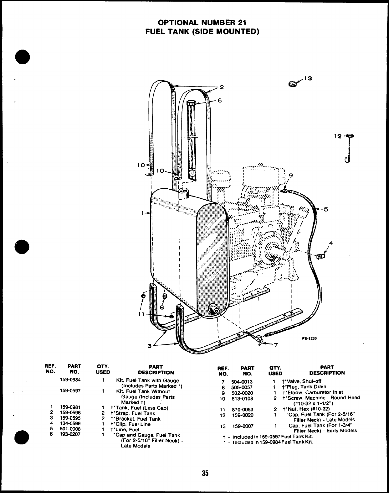
OPTIONAL NUMBER 21
FUEL TANK (SIDE MOUNTED)
REF. PART
NO. NO.
159-0964
159-0597
159-0981
;159-0596
3159-0595
4134-0599
5501-0006
m
6193-0207
r
,.:;,
......
......
......
......
:,::,
,....
.;..;
>.;,
q
,.:
10.
I
k-
Gi3”3
/’
-6
12
T
<41
1........- ,
e.---” ----: -.=..;...,
,........ .... , 1’
It, , . . 9
OTY. PART
USED DESCRIPTION
1Ktt, Fuel Tank with Gauge
(Includes Paris Marked “
1Kit. Fuel Tank Wtthout
Gauge (Includes Parts
Marked t)
1t“Tank, Fuel (Leas Cap)
2t“Strap. Fuel Tank
2t. Bracket, Fuel Tank
1t“Clip, Fuel Line
1t“Line, Fuel
4
REF. PART OTY. PART
NO. NO. USED DESCRIPTION
7504-0013 1t“Valve, Shut-off
8505-0057 1t“ptug, Tank Drain
9502-0020 1T“Elbow, Carburetor Inlet
10 813-0108 2t“Screw, Machine -Round Head
(#10-32 X1-1/2”)
11 870-0053 2t.Nut, Hex (#10-32)
12 159-0020 1tCap, Fuel Tank (For 2-5/16”
Filler Neck) -Late Models
13 159-0007 1Cap, Fuel Tank (For 1-3/4
1“Cap and Gauge, Fuel Tank Filler Neck) -Early Models
(For 2-5/16 Filler Neck) -t - Included in 159-0597 Fuel Tank Kit.
Late Models “-Included in 159-0964Fuel Tank Kk.
35
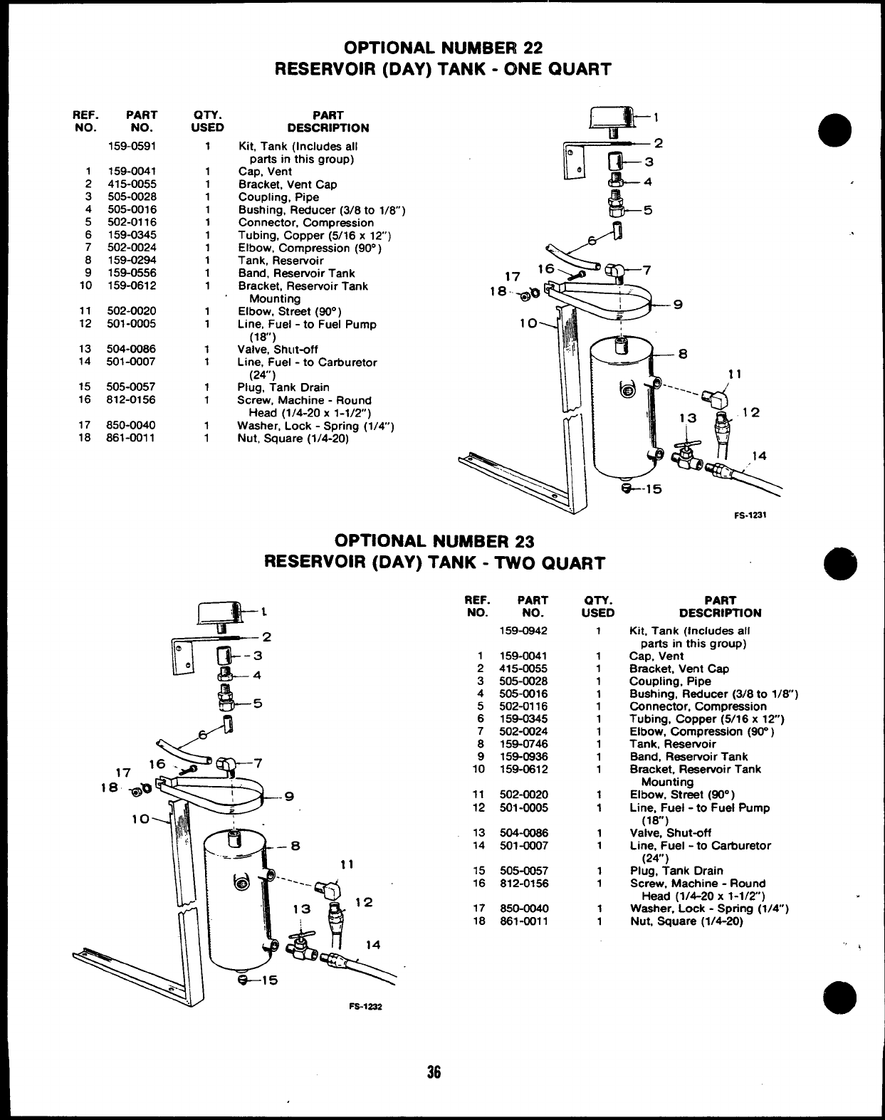
OPTIONAL NUMBER 22
RESERVOIR (DAY) TANK -ONE QUART
REF.
NO.
1
2
3
4
5
6
7
8
9
10
11
12
13
14
15
16
17
18
PART
NO.
159-0591
159-0041
415-0055
505-0028
505-0016
502-0116
159-0345
502-0024
159-0294
159-0556
159-0612
502-0020
501-0005
504-0086
501-0007
505-0057
812-0156
850-0040
861-0011
QTV.
USED
1
1
1
1
1
1
1
1
1
1
1
1
1
1
1
1
1
1
1
PART
DESCRIPTION m’
Kit, Tank (Includes all
parts in this group)
Cap, Vent
Bracket, Vent Cap
Coupling, Pipe
Bushing, Reducer (3/8 to 1/8)
Connector, Compression
Tubing, Copper (5/16 x12)
Elbow, Compression [90° )
Tank, Rese~oir ‘
Band, Reservoir Tank
Bracket, Reservoir Tank
Mounting
Elbow, Street (80° )
Line, Fuel -to Fuel Pump
(18”)
Valve. Shut-off
Line, Fuel -to Carburetor
(24”)
Plug, Tank Drain
Screw, Machine -Round
Head (1/4-20 x1-1/2) ~
Washer, Lock -Spring (1/4)
Nut, Square (1/4-20) r\
OPTIONAL NUMBER 23
RESERVOIR (DAY) TANK -TWO QUART
,.
3
–0
-—-
@‘----- ,“
\Q
13 12
&!
e-l 5%“
Fs-1232
REF. PART
NO. NO.
159-0942
1159-0041
2415-0055
3505-0028
4505-0016
5502-0116
6159-0345
7502-0024
8158-0746
9159-0936
10 159-0612
11 502-0020
12 501-0005
13 504-0086
14 501-0007
15 505-0057
16 812-0156
17 850-0040
18 881-0011
m-v.
USED
1
1
1
1
1
1
1
1
1
1
1
1
1
1
1
1
1
1
1
FS-1231
PART
DESCRIPTION
Kit, Tank (Includes all
parts in this group)
Cap, Vent
Bracket, Vent Cap
Coupling, Pipe
Bushing, Reducer (3/8 to 1/8)
Connector, Compression
Tubing, Copper (5/16 x12)
Elbow, Compression (90” )
Tank, Reservoir
Band, Reaewoir Tank
Bracket, Reservoir Tank
Mounting
Elbow, Street (90° )
Line, Fuel -to Fuel Pump
(18”)
Valve, Shut-off
Line, Fuel -to Carburetor
(24”)
Plug, Tank Orain
Screw, Machine -Round
Head (1/4-20 x1-1/2)
Washer, Lock -Spring (1/4”)
Nut, Square (1/4-20)
@
<
e
a
36
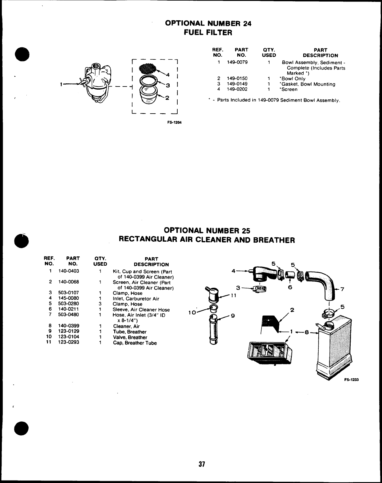
r——— — 1
I
:%
I
I
41
1;:3,
1—— -i
w
~I
1= 21
REF. PART
NO. NO.
1140-0403
2140-0068
3503-0107
4145-0080
5503-0280
6140-0211
7503-0480
8140-0399
9123-0129
10 123-0104
11 123-0293
OTY.
USED
1
1
1
1
3
1
1
1
1
1
1
OPTIONAL NUMBER 24
FUEL FILTER
REF. PART QTY. PART
NO. NO. USED DESCRIPTION
1149-0079 1Bowl Assembly, Sediment -
Complete (Includes Parts
Marked “)
2149-0150 1.Bowl Only
3149-0149 1“Gasket. Bowl Mounting
4149-0202 1.Screen
“-Parts Included in 149-0079 Sediment Bowl Assembly.
L——— -1
FS-1204
OPTIONAL NUMBER 25
RECTANGULAR AIR CLEANER AND BREATHER
PART
DESCRIPTION
Kit, Cup and Screen (part
of 140-0399 Air Cleaner)
Screen, Alr Cleaner (Part
of 140-0399 Air Cleaner)
Clamp, Hose
Inlet, Carburetor Air
Clamp, Hose
Sleeve, Air Cleaner Hose
Hose, Air Inlet (3/4” ID
x8-1/4”)
Cleaner, Air
Tube, Breather
Valve, Breather
Cap, Breather Tube
T$-
,.”--9
r’9
i
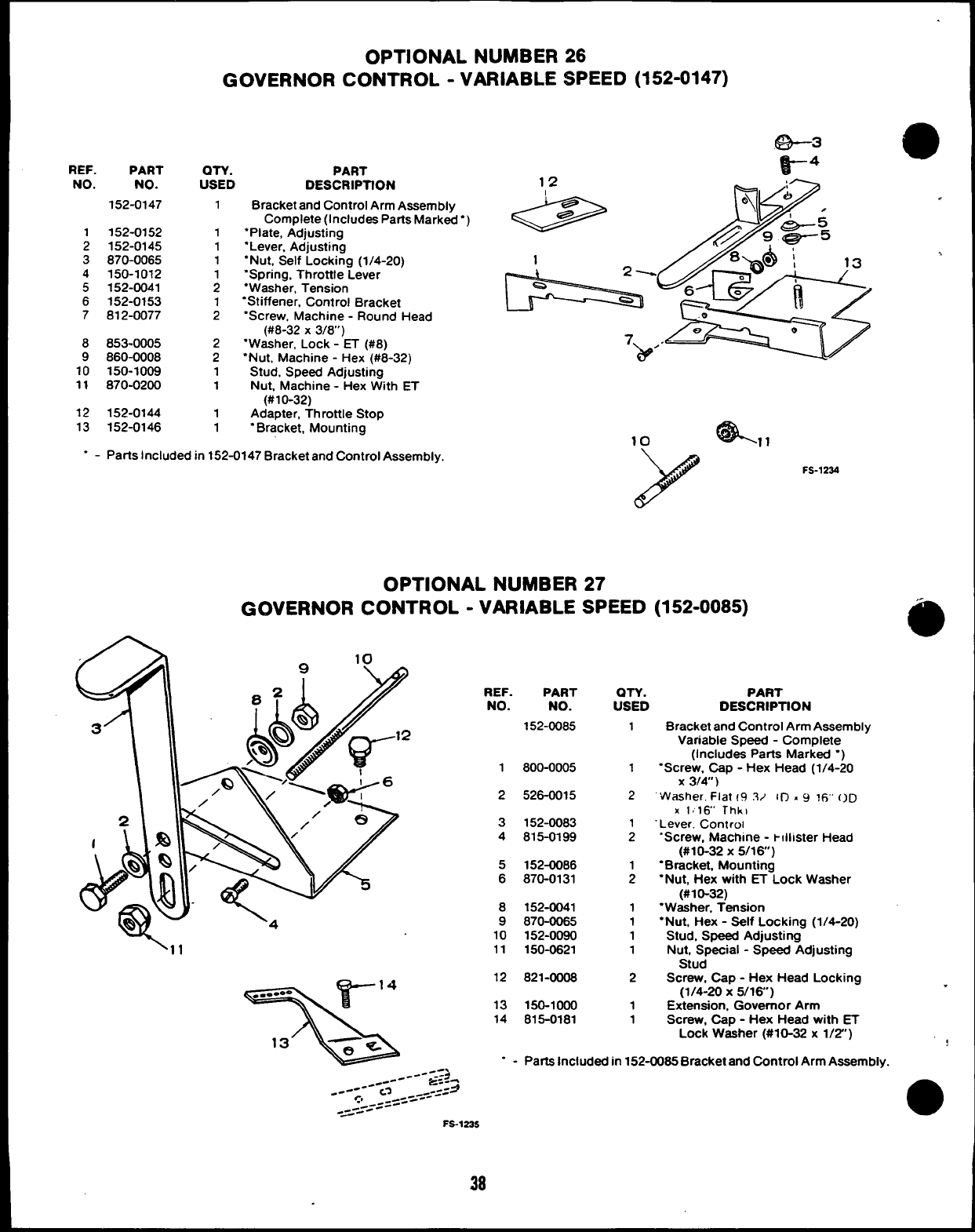
9
e
,
,.
9
.
OPTIONAL NUMBER 26
GOVERNOR CONTROL -VARIABLE SPEED (152-0147)
REF. PART
NO. NO.
152-0147
1152-0152
2152-0145
3870-0065
4150-1012
5152-0041
6152-0153
7612-0077
8853-0005
9860-0008
10 150-1009
11 870-0200
12 152-0144
13 152-0146
QTY. PART
USED DESCRIPTfON 12 A:-
Bracket and Control Arm Assembly
Complete (Includes Parts Marked”)
“Plate, Adjusting
“Lever, Adjusting
“Nut, Self Locking (1/4-20)
“Spring, Throttle Lever
“Washer, Tension
“Stiffener, Control Bracket
‘Screw, Machine -Round Head
(#8-32 X3/8”)
“Washer, Lock -ET (#8)
“Nut, Machine -Hex (#8-32)
Stud, Speed Adjusting
Nut, Machine -Hex W!th ET
(#10-32)
Adapter, Throttle Stop
“Bracket, Mounting
1
1
1
1
;
1
2
2
2
1
1
1
1
l--k==’”““8’
4!&,,
10
.-Parts Included in 152-0147 Bracket and Control Assembly.
FS-1234
OPTIONAL NUMBER 27
GOVERNOR CONTROL -VARIABLE SPEED (152-0085)
REF. PART
NO. NO. iTiD
1
PART
DESCRIPTtON
Bracket and Control Arm Assembly
Variable Speed -Complete
(Includes Parts Marked “)
‘Screw, Cap -Hex Head (1/4-20
x3/4’)
“Washer. Flat 19 3/ IIT .~Irj’ OD
X1,16’ Thk)
Lever. Controi
‘Screw, Machine -t!llister Head
(#10-32 X5/16)
“Bracket, Mounting
“Nut, Hex with ET Lock Washer
(#10-32)
“Washer, Tension
“Nut, Hex -Self Locking (1/4-20)
Stud, Speed Adjusting
Nut, Special -Speed Adjusting
Stud
Screw, Cap -Hex Head Locking
(1/4-20 x5/16)
Extension, Governor Arm
Screw. CaD -Hex Head with ET
152-0085
1800-0005 1
2526-0015 2
3
4152-0083
815-0199 ;
5
6152-0086
870-0131 ;
8
9
10
11
152-0041
870-0065
152-0090
150-0621
1
1
1
1
12 821-0008 2
r14
%
..-.0 -
13 ~s “-Parta Included in 152-0085 Bracket and Control Arm Assemblv.
13
14 150-1000
815-0181
1
1
Lock W&her (#10-32 x1/2”)
38
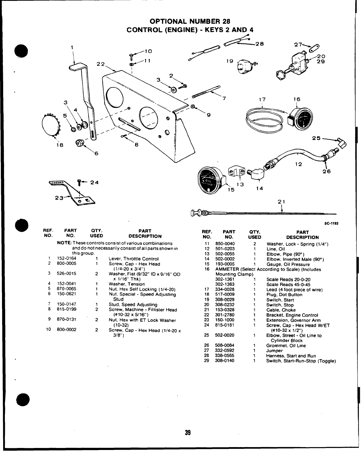
.
,
1
\
OPTIONAL NUMBER 28
CONTROL (ENGINE) -KEYS 2AND 4
./—2. 271A
?’ 10
/1 12-,.. ‘w
a/2 o
.>’ -n
\.. \.- ‘7 17 16
T
l’a v
o
6
x“
*REF.
NO.
1
2
3
4
5
6
7
8
9
10
PART QTY. PART
NO. REF.
USED PART QTY.
DESCRIPTION NO. NO. USED
NOTE. These controls consist of various combinations 11 850-0040 2
and do not necessarily consmt of all parts shown in 12 501-0203 1
this group. 13 502-0055 1
152-0164
800-0005
526-0015
152-0041
870-0065
150-0621
150-0147
815-0199
870-0131
800-0002
1Lever, Throttle Control 14 502-0002 1
1Screw. Cao -Hex Head 15 193-0005 1
2
1
1
1
2
2
SC-1193
PART
DESCRIPTION
Washer, Lock -Spring (1/4”)
Line, Oil
Elbow, Ptpe (90”)
Elbow, Inverted Male (90° )
Gauge, Oil Pressure
(1/4-20 x3/4”) 16 AMMETER (Select Accordina to Scale) (Includes
Washer, Flat (9/32’ ID x9/16’ OD
X1/16 Thk)
Washer, Tension
Nut, Hex Self Locking (1/4-20)
Nut. Special -Speed Adjusting
Stud
Stud, Speed Adjusting
Screw. Machine -Fillister Head
(#10-32 X5/16)
Nut, Hex with ET Lock Washer
(1O-32)
Screw, Cap -Hex Head (1/4-20 x
3/8’)
17
18
19
20
21
22
23
24
25
Mounting Clamp)
302-1361 1
302-1363 1
334-0028 1
517-0009 1
308-0029 1
308-0232 1
153-0328 1
301-2780 1
150-1000 1
815-0181 1
502-0020 1
,.-
Scale Reads 20-0-20
Scale Reads 45-O-45
Lead (4 foot piece of wire)
Plug, Dot Button
Switch, Start
Switch, Stop
Cable, Choke
Bracket, Engine Control
Extension, Governor Arm
Screw, Cap -Hex Head W/ET
(#10-32 X1/2)
Elbow. Street -Oil Line to
.
Cylinder Block
26 506-0064 1Grommet. Oil Line
27 332-0592 1Jumper
28 336-0565 1Harness, Start and Run
29 308-0140 1Switch, Start-Run-Stop (Toggle)
39
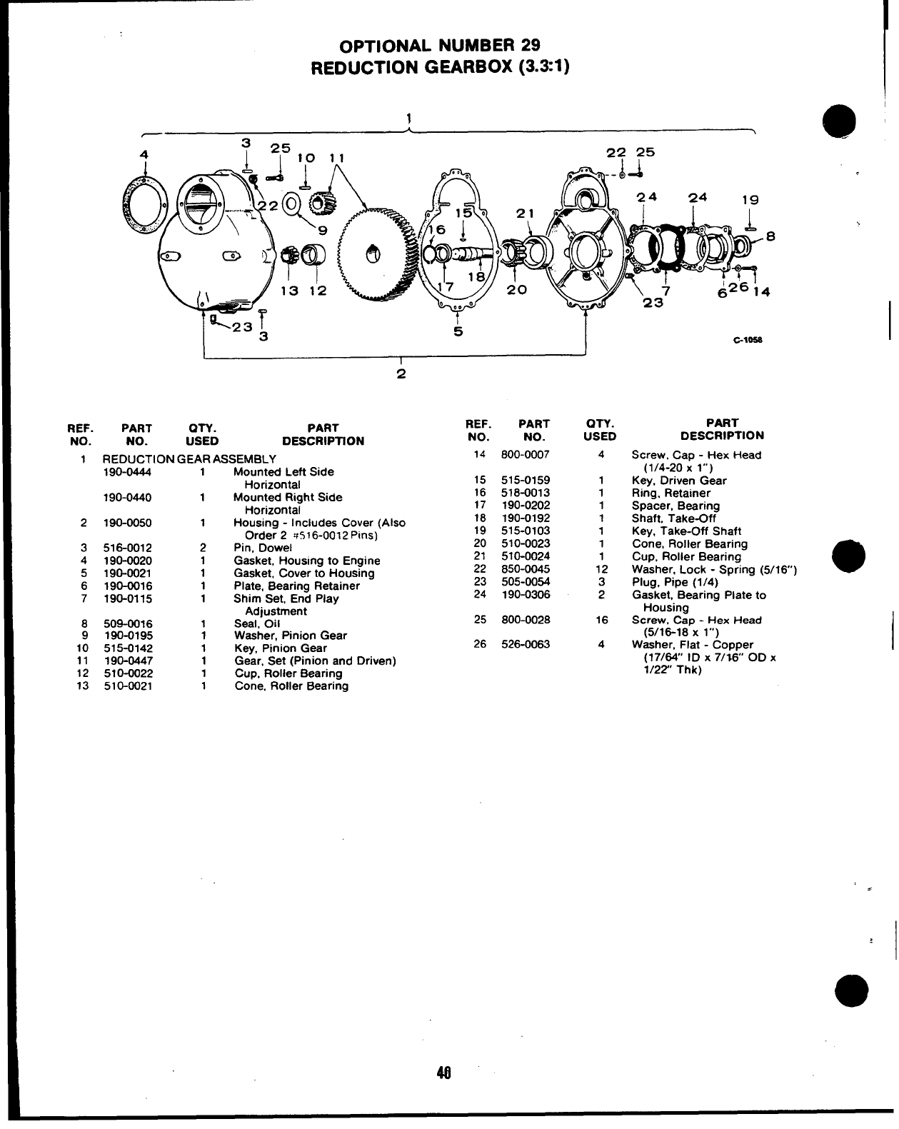
OPTIONAL NUMBER 29
REDUCTION GEARBOX (3.31)
1-1 @
3 25
4I10 11 22 25
I
C-1OS8
1J
I
2
REF. PART OTY. PART REF. PART
NO. NO. USED DESCRIPTION NO. NO.
QTY.
USED
4
1
1
1
1
1
1
1
12
3
2
16
4
PART
DESCRIPTION
Screw, Cap -Hex Head
(1/4-20 Xl“)
Key, Driven Gear
Ring. Retainer
Spacer, Bearing
Shaft, Take-Off
Key, Take-Off Shaft
Cone, Roller Bearing
Cup, Roller Bearing
Washer, Lock -Spring (5/16)
Plug, Pipe (1/4)
Gasket, Bearing Plate to
Housing
Screw, Cap -Hex Head
(5/16-18 Xl“)
Washer. Flat -Comer
1REDUCTION GEAR ASSEMBLY 14 800-0007
190-0444 1Mounted Left Side
Horizontal
Mounted Right Side
Horizontal
Housing -Includes Cover (Also
Order 2w516-0012 Pins)
Pin, Dowel
Gasket, Housing to Engine
Gasket, Cover to Housing
Plate, Bearing Retainer
Shim Set, End Play
Adjustment
Seal. Oil
Washer, Pinion Gear
Key, Pinion Gear
Gear, Set (Pinion and Driven)
Cup, Roller Bearing
Cone. Roller Bearing
15
16
17
18
19
20
21
515-0159
518-0013
190-0202
190-0192
515-0103
510-0023
510-0024
850-0045
505-0054
190-0306
190-0440 1
2190-0050 1
3
4
5
6
7
516-0012
190-0020
190-0021
190-0016
190-0115
2
1
1
1
1
22
23
24
25 800-0028
8
9
10
11
12
13
509-00J6
190-0195
515-0142
190-0447
510-0022
510-0021
1
1
1
1
1
1
26 526-0063
(17/&” ID X7/;6 OD X
1/22” Thk)
I
4
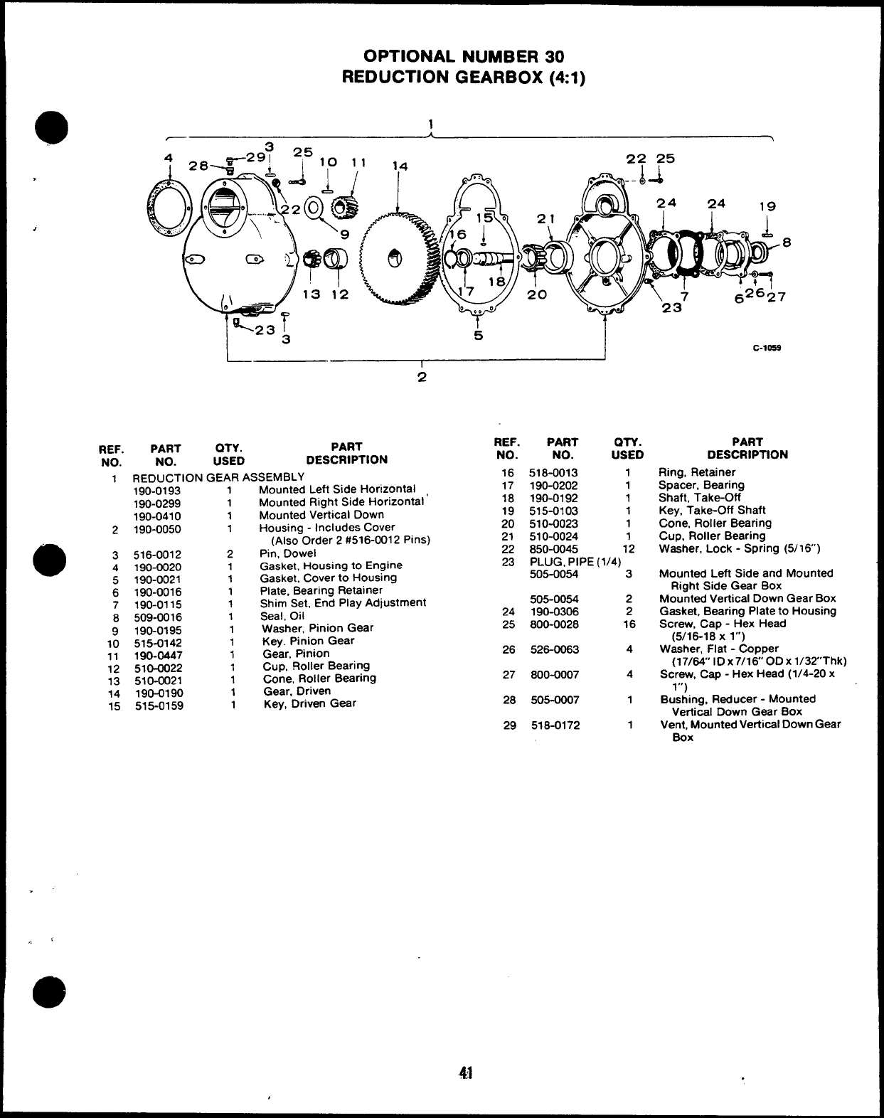
OPTIONAL NUMBER 30
REDUCTION GEARBOX (41)
—
.
,
L
-23 I
3k
I
2
REF. PART QTY. PART
NO. NO. USED DESCRIPTION
2
e3
4
5
-.
1REDUCTION GEAR ASSEMBLY
Mounted Left Side Horizontal
Mounted Right Side Horizontal’
Mounted Vertical Down
Housing -Includes Cover
(Also Order 2#516-0012 Pins)
Pin, Dowel
Gasket, Housing to Engine
Gasket. Cover to Housing
6
7
8
9
10
11
12
13
14
15
190-0193
190-0299
190-0410
190-0050
516-0012
190-0020
190-0021
190-0016
190-0115
509-0016
190-0195
515-0142
190-0447
510-0022
510-0021
190-0190
515-0159
1
1
1
1
2
1
1
1
1
1
1
1
1
1
1
1
1
REF. PART QTY.
NO. NO. USED
16
17
18
19
20
21
22
23
518-0013 1
190-0202 1
190-0192 1
515-0103 1
510-0023 1
510-0024 1
850-0045 12
PLUG, PIPE (1/4)
505-0054 3
Plate, Bearing Retainer
Shim Set, End Play Adjustment 505-0054 2
Seal, Oil 24 190-0306 2
Washer. Pinion Gear 25 800-0028 16
Key. Pinion Gear
Gear, Pinion 26 526-0063 4
Cup, FloIler Bearing
Cone, Roller Bearing 27 600-0007 4
Gear, Driven
Key, Driven Gear 28 505-0007 1
29 518-0172 1
c-loe9
PART
DESCRIPTION
Ring, Retainer
Spacer, Bearing
Shaft, Take-Off
Key, Take-Off Shaft
Cone, Roller Bearing
Cup, Roller Bearing
Washer, Lock -Spring (5/16’)
Mounted Left Side and Mounted
Right Side Gear Box
Mountad Vertical Down Gear Box
Gasket, Bearing Plate to Housing
Screw, Cap -Hex Head
(5/16-18 Xl“)
Washer, Flat -Copper
(17/64” ID x7/160D Xl/32Thk)
Screw, Cap -Hex Head (1/4-20 x
1“)
Bushing, Reducer -Mounted
Vertical Down Gear Box
Vent, Mounted Vefiical Down Gear
Box
41 .
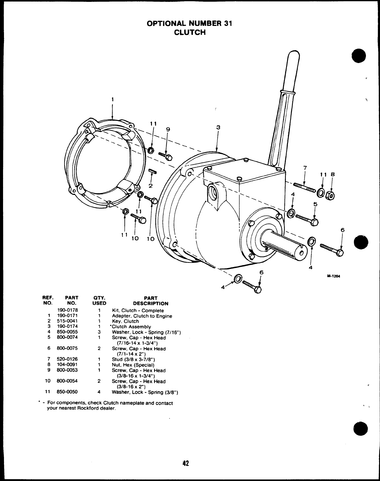
OPTIONAL NUMBER 31
CLUTCH
REF. PART
NO. NO.
190-0178
1190-0171
2515-0041
3190-0174
4850-0055
5800-0074
6800-0075
7520-0126
8104-0091
9800-0053
10 800-0054
11 850-0050
an.
USED
1
1
1
:
1
2
1
1
1
2
4
I Illllli ilf ///-\’
‘‘1’0 1’0
‘Q\
v
\I
*‘\
R, \\\
PART
DESCRIPTION
Kit, Clutch -Complete
Adapter, Clutch to Engine
Key, Clutch
“Clutch Assembly
Washer, Lock -Spring (7/16)
Screw, Cap -Hex Head
(7/16-14 x1-3/4)
Screw, Cap -Hex Head
(7/1-14 x2)
Stud (3/8 X3-7/8)
Nut, Hex (Special)
Screw, Cap -Hex Head
(3/8-16 X1-3/4”)
Screw, Cap -Hex Head
(3/8-16x2)
Washer, Lock -Spring (3/8)
-y- 6
P~
\
4
M.1204
.
‘,,
“-For components, check Clutch nameplate and contact
your nearest Rockford dealer.
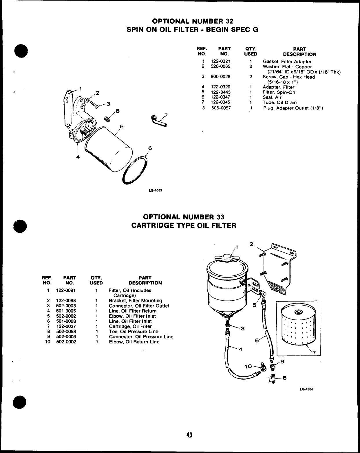
OPTIONAL NUMBER 32
SPIN ON OIL FILTER -BEGIN SPEC G
REF.
NO.
1
2
>
3
.
;
REF. PART
NO. NO.
1122-0091
2122-0088
3502-0003
4501-0005
5502-0002
6501-00Q8
7122-0037
8502-0058
9502-0003
10 502-0002
.’
.,“
o
QTY.
USED
1
1
1
1
1
1
1
1
1
1
4
5
6
7
8
PART
NO.
122-0321
526-0065
800-0028
122-0320
122-0445
122-0347
122-0345
505-0057
LS-1OSZ
OPTIONAL NUMBER 33
CARTRIDGE TYPE OIL FILTER
PART
DESCRIPTION
Filter, Oil (Includes
Cartridge)
Bracket, Filter Mounting
Connector, Oil Filter Outlet
Line, Oil Filter Return
Elbow, Oil Filter Inlet
Line, Oil Filter Inlet
Cartridge, Oil Filter
Tee, Oil Pressure Line
Connector, Oil Pressure Line
Elbow, Oil Return Line
43
on. PART
USED DESCRIPTION
1Gasket, Filter Adapter
2Washer, Flat -Copper
(21/64” lDx9/16 ODX l/16 Thk)
2Screw, Cap -Hex Head
(5/16-18 Xl“)
1Adapter, Filter
1Filter, Spin-On
1Seal, Air
1Tube, Oil Drain
1Plug, Adapter Outlet (1/8”)
LS-10!53
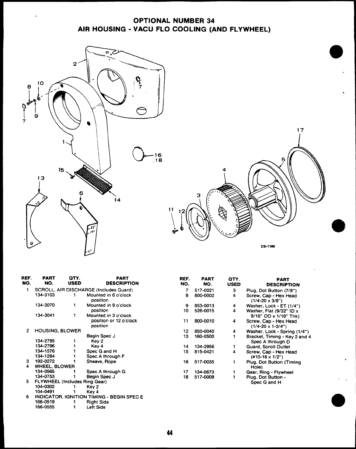
19
7
OPTIONAL NUMBER 34
AIR HOUSING -VACU FLO COOLING (AND FLYWHEEL)
1
13
(
.< 4
-.‘“
.0
G16
18
REF.
NO.
1
2
3
4
5
6
PART OTY. PART
NO. USED DESCRIPTION
SCROLL, AIR DISCHARGE (Includes Guard)
134-3103 1Mounted in 6o’clock
position
134-3070 1Mounted in 9o’clock
position
134-3041 1Mounted in 3o’clock
position or 12 o’clock
position
HOUSING, BLOWER Begin Spec J
134-2795 1Key 2
134-2796 1Key 4
134-1576 1Spec Gand H
134-1264 1Spec Athrough F
192-0272 1Sheave, Rope
WHEEL, BLOWER
134-0565 1Spec Athrough G
134-0753 1Begin Spec J
FLYWHEEL (Includes Ring Gear)
104-0302 1Key 2
104-0491 Key 4
INDICATOR, IGN;TION TIMING -BEGIN SPEC E
166-0519 1Right Side
166-0555 1Left Side
,
.
17
REF.
NO.
7
8
9
10
11
12
13
14
15
16
17
18
Ca-lloo
PART
NO.
517-0021
800-0002
853-0013
526-0015
800-0010
850-0040
160-0500
134-2956
815-0421
517-0035
134-0673
517-0009
QTY.
USED
3
4
4
4
4
4
1
1
4
1
1
1
PART
DESCRIPTION
Plug, Dot Button (7/6”)
Screw, Cap -Hex Head
(1/4-20 X3/8)
Washer, Lock -ET (1/4”)
Washer, Flat (9/32 ID x
9/16 OD X1/16 Thk)
Screw, Cap -Hex Head
(1/4-20 X1-3/4”)
Washer, Lock -Spring (1/4”)
Bracket, Timing -Key 2and 4
Spec Athrough D
Guard, Scroll Outlet
Screw, Cap -Hex Head
(#10-16x 1/2”)
Plug, Dot Button (Timing
Hole)
Gear, Ring -Flywheel
Plug, Dot Button -
Spec Gand H
.
.>
44
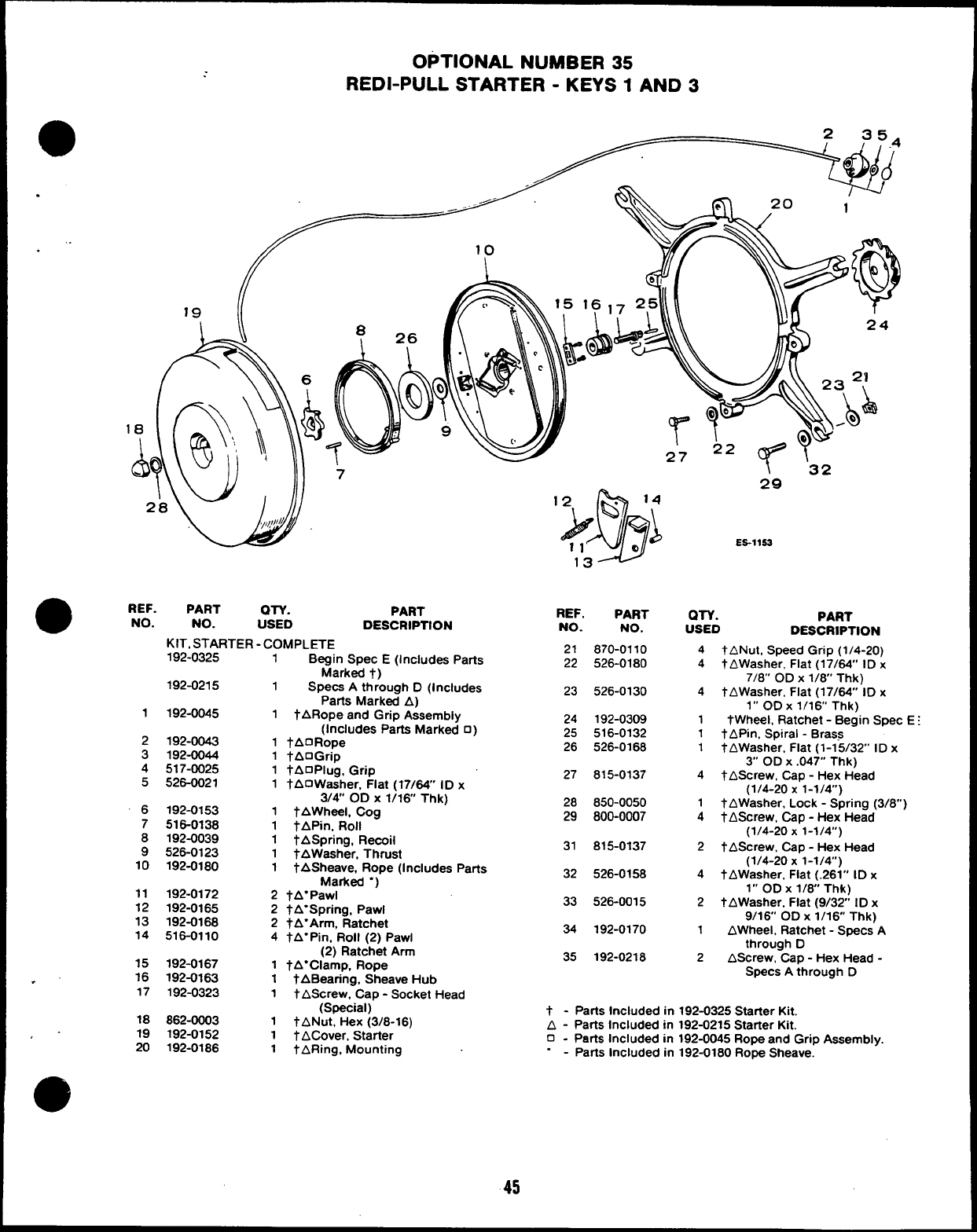
OPTIONAL NUMBER 35
REDI-PULL STARTER -KEYS 1AND 3
aREF. PART QTV.
NO. PART
NO. USED DESCRIPTION
KIT, STARTER -COMPLETE
1
2
3
4
5
6
7
8
9
10
11
12
13
14
15
.’ 16
17
18
,- 19
20
192-0325
192-0215
192-0045
192-0043
192-0044
517-0025
526-0021
192-0153
516-0138
192-0039
526-0123
192-0180
192-0172
192-0165
192-0168
516-0110
192-0167
192-0163
192-0323
862-0003
192-0152
192-0188
1Begin Spec E(Includes Parts
Marked t)
1Specs Athrough D(Includes
Parts Marked A)
1tARope and Grip Assembly
(Includes Parts Marked 0)
1fAORope
1tAOGrip
1tAOPlug, Grip
1tAOWasher, Fiat (17/64” ID x
3/4” OD X1/16 Thk)
1tAWheeL Cog
1TAPin, Roll
1tASpring, Recoil
1tAWasher, Thrust
1tASheave, Rope (Includes Parts
Marked “)
2tA”Pawl
2tA”Spring, Pawl
2tA”Arm, Ratchet
4tA”Pin, RoII (2) Pawl
(2) Ratchet Arm
1tA”Clamp, Rope
1tABearing, Sheave Hub
1tAScrew, Cap -Socket Head
(Special)
1tANut, Hex (3/8-16)
1tACover, Starter
1tARing, Mounting
REF. PART
NO. NO.
21 870-0110
22 526-0180
23 526-0130
24 192-0309
25 516-0132
26 526-0168
27 815-0137
28 850-0050
29 800-0007
31 815-0137
32 526-0158
33 526-0015
34 192-0170
35 192-0218
29
ES-llSS
QTY. PART
USED DESCRIPTION
4tANut, Speed Grip (1/4-20)
4tAWasher, Flat (17/64” ID x
7/8” OD X1/6” Thk)
4tAWasher, Flat (17/64” ID x
1“ ODx 1/16 Thk)
1tWheel, Ratchet -Begin Spec
1tAPin, Spiral -Brass
1tAWasher, Flat (1-15/32” ID x
3“ OD X.047” Thk)
4tAScrew, Cap -Hex Head
(1/4-20 X1-1/4)
1tAWasher, Lock -Spring (3/8”
4tAScrew, Cap -Hex Head
(1/4-20 X1-1/4”)
2tAScrew, Cap -Hex Head
(1/4-20 X1-1/4)
4tAWasher. Flat (.261” ID x
1“ OD X1/6” Thk)
2tAWasher, Flat (9/32 ID x
9/16 OD X1/16 Thk)
1AWheel, Ratchet -Specs A
through D
2AScrew, Cap -Hex Head -
Specs Athrough D
t-Parts Included in 192-0325 Starter Kit.
A-Parts Included in 192-0215 Starter Kit.
o-Parts Included in 192-0045 Rope and Grip Assembly.
.-Parts Included in 192-0180 Rope Sheave.
45
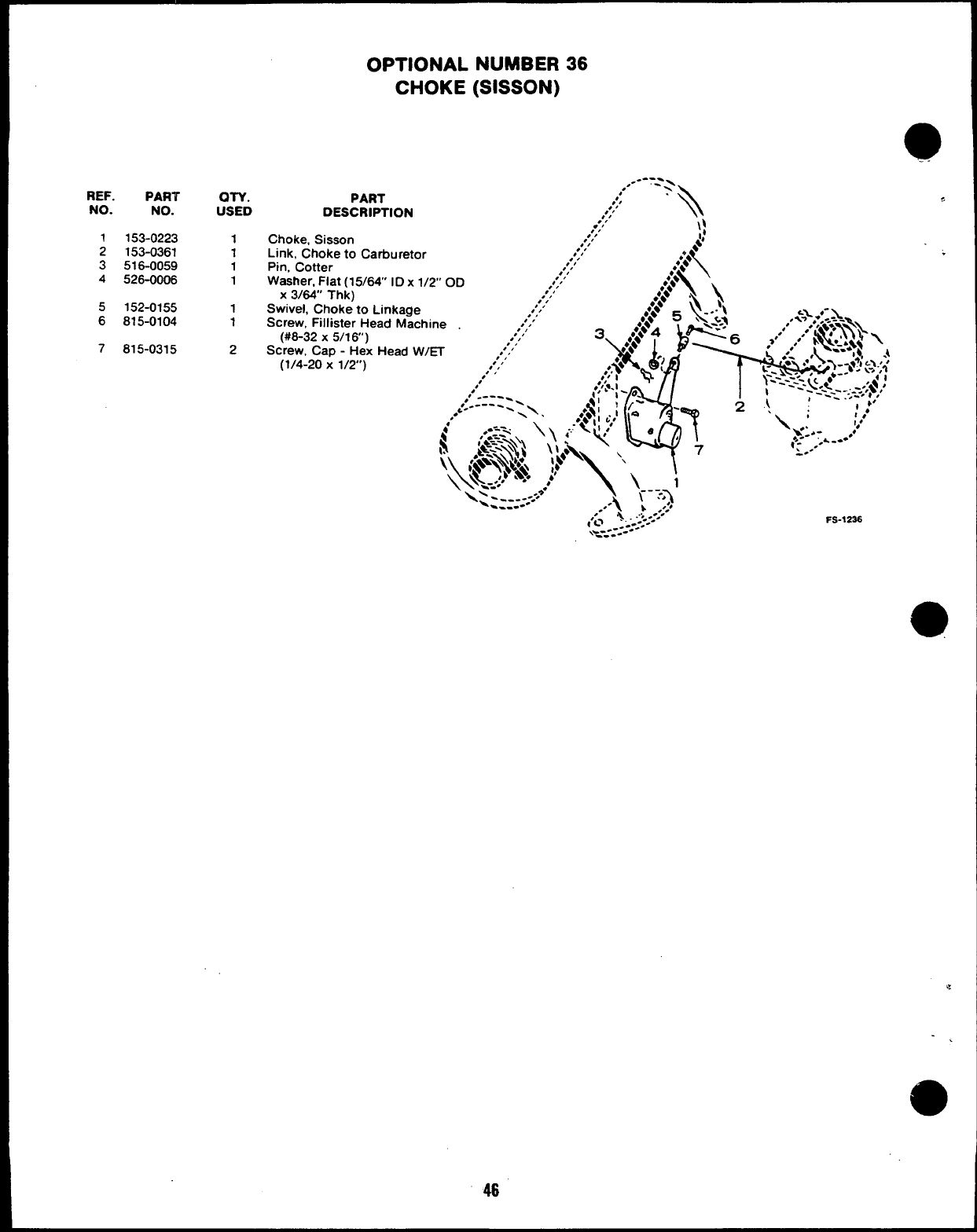
REF. PART
NO. NO.
1153-0223
2153-0361
3516-0059
4526-0006
5152-0155
6815-0104
7815-0315
OTY.
USED
1
1
1
1
1
1
2
OPTIONAL NUMBER 36
CHOKE (SISSON)
----
,.- -,-
PART ,
,,;/
DESCRIPTION ,’,’ ‘\
.“,‘\:
Choke, Sisson ,’/’
Link, Choke to Cafiuretor ,’/’ $
,’/’
\
●*;*
Pin, Cotter ,’/’
.,., .*A
Washer, Fiat (15/64
X3/64’ Thk) IDx
Swivel, Choke to Linkage
Screw, Fillister Head Machine
(#8-32 X5/1 6“)
Screw, Cap -Hex Head W/~
(1/4-20 X1/2’)
FS-1236
46
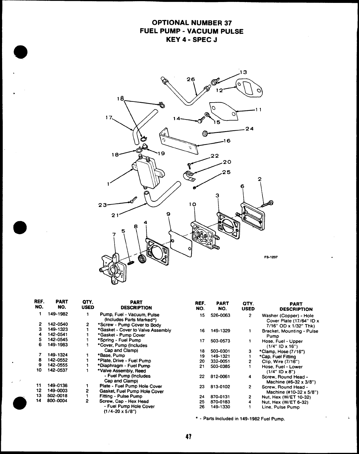
OPTIONAL NUMBER 37
FUEL PUMP -VACUUM PULSE
KEY 4- SPEC J
.13
Ck 26 A/~
wk;.–”
/22 20
/25
/
P
6
\\&
+
.
REF.
NO.
1
2
3
4
:
PART
NO.
149-1982
142-0540
149-1323
142-0541
142-0545
149-1983
QTY. PART
USED DESCRIPTION
1
REF.
NO.
15
PART
NO.
528-0063
QTY.
USED PART
DESCRIPTION
Washer (Copper) -Hole
Cover Plate (17/64” ID x
7/16’ OD X1/32 Thk)
Bracket, Mounting -Pulse
Pump
Hose, Fuel -Upper
(1/4” ID X16”)
●Clamp, Hose (7/ 16)
●Cap, Fuel Fitting
Clip, Wtre (7/16)
Hose, Fuel -Lower
(1/4” ID X8)
Screw, Round Head -
Machine (#6-32 x3/8)
Screw. Round Head -
Machine (#10-32 x5/8”)
Nut, Hex (W/ET 10-32)
Nut, Hex (W/ET 8-32)
Line. Pulse Pump
Pump, Fuel -Vacuum, Pulse
(Includes Parts Marked*)
●Screw -Pump Cover to Body
●Gasket -Cover to Valve Assembly
*Gasket -Pump Cover
●Spring -Fuel Pump
*Cover, Pump (Includes
Cap and Clamp)
‘Base, Pump
●Plate, Drive -Fuel Pump
*Olaphragm -Fuel Pump
●Valve Assembly, Reed
-Fuel Pump (Includes
Cap and Clamp)
Plate -Fuel Pump Hole Cover
Gasket Fuel Pump Hole Cover
Fting -Pulse Pump
Screw, Cap -Hex Head
-Fuel Pump Hole Cover
(1 /4-20X 5/8)
2
2
1
1
1
1
16 149-1329 1
503-0573
17 1
18
19
20
21
503-0301
149-1321
332-0051
503-0385
3
1
2
1
7
8
9
10
149-1324
142-0552
142-0555
142-0537
1
1
1
1
22 812-0061 4
11
12
13
14
149-0138
149-0003
502-0018
800-0004
23 813-0102 2
24
25
26
870-0131
870-0183
149-1330
2
4
1
●-Parts Included in 149-1982 Fuel Pump.
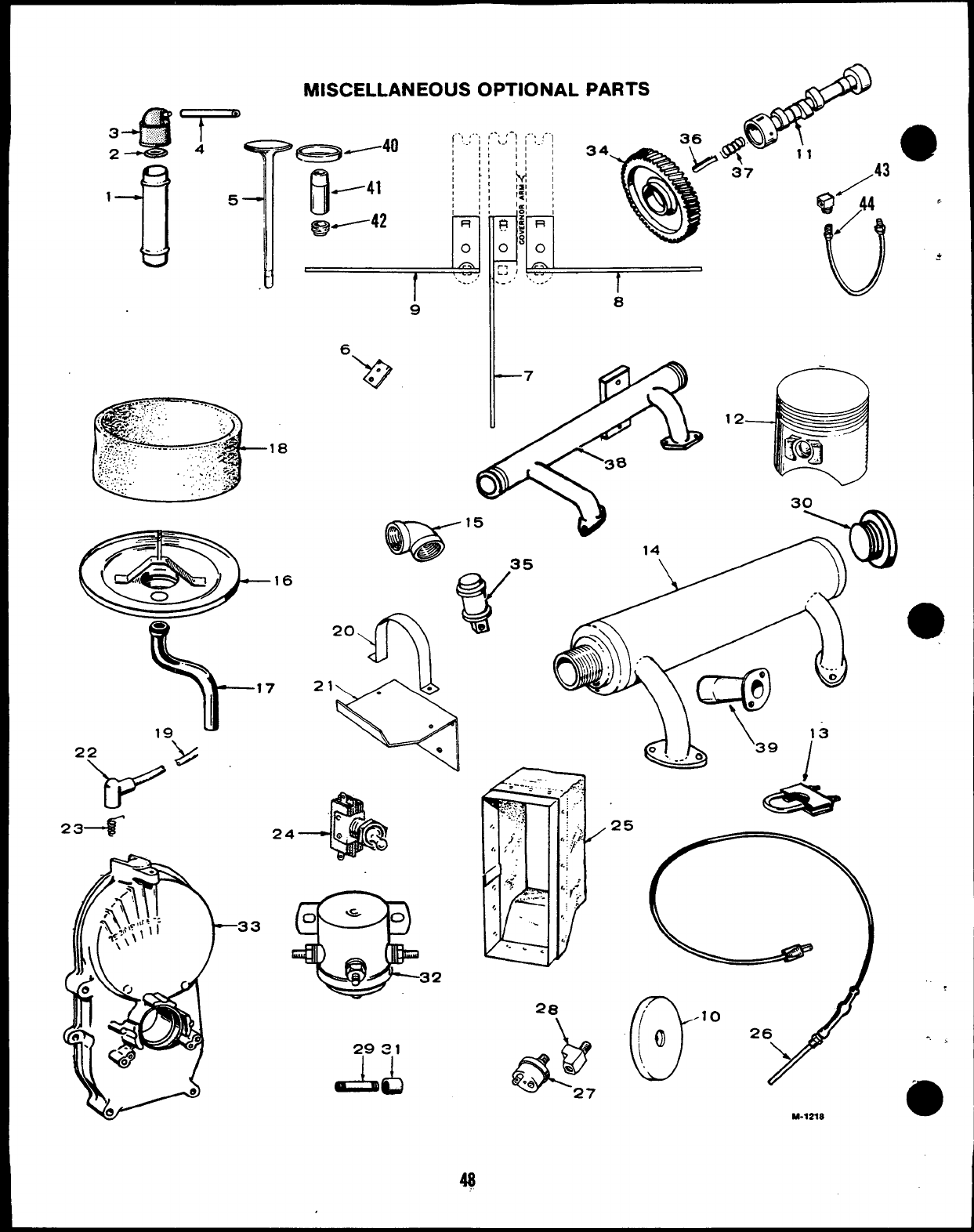
MISCELLANEOUS OPTIONAL PARTS
16
\
17
19,
234
29S1
AL)
.. -R
q’””11
!
oa
37
Qji43 ‘
u
*
8
(j’” 26~
M-72X8
,
-, >
MISCELLANEOUS OPTIONAL PARTS
aREF. PART
NO. NO.
1
.2
3
5
6
7
8
9
10
11
12
@
13
14
15
16
17
18
.’ 19
123-0810
123-0315
123-0787
123-0853
110-1037
150-0635
150-0755
150-0752
150-0790
134-2824
105-0238
(N-Y.
USED
1
1
1
1
2
1
1
1
1
1
1
PART
DESCRIPTION
Tube, Breather (1-9/1 6’
Diameter x4-7/8’ Long)-
Specs Athrough H
Valve. Breather (1-9/16’
Diameter) -Specs Athrough H
Cap, Breather Tube
(1-9/1 6Diameter) -Specs A
through I-1
Hose, Breather Cap Extension
(Use with 1-9/16’ Diameter
Cap) -Specs Athrough H
Valve, Intake -Chrome Cobalt
Arm, Extension -Governor
Arm (Rear Pull)
Arm, Extension -Governor
Arm (Front Pull)
Arm, Extension -Governor
Arm (Right Side Pull)
Arm, Extension -Governor
Arm (Left Side Pull)
Guard, Flywheel Capscrew
Camshaft -Key 4Without
Spark Advance Mechanism
PISTON AND PIN ASSEMBLY (Piston Has Round Holes
in Oil Ring Grooves and Top Groove is
9/32’ from top of Piston)
112-0170 2Standard Size
112-0170-05 2.005” Oversize
112-0170-10 2.010 Oversize
112-0170-20 2.020 Oversize
112-0170-30 2.030 Oversize
112-0170-40 2.040” Oversize
155-1239 2Clamp, Muffler (1-5/8”)
(Use With Ray Gun Muffler)
MUFFLER, EXHAUST Right Side Outlet
155-0510 13“ Diameter x15-7/8” Long
155-0859 13-1/2” Diameter x16-1/2”
Long
Left Side Outlet
155-0550 1 3 Diameter x15-7/8
Long
155-0859 13-1/2” Diameter x16-1/2”
Long
155-1660 23.24” Dia x6.3” Long
(Ray Gun)
155-1698 2Spark Arrestor (Ray Gun)
155-1253 13-1/2’ Dia x19-3/16 Long
(Crossover Left and Right
Outlet)
505-0041 1Elbow, Pipe -Exhaust
140-1348 1Base, Air Cleaner (Long
Mounting Tube for Higher
Elevation above Carburetor) -
Begin Spec J
123-1284 1Hose, Breather (Use with Tall
Air Cleaner Base) -Begin
Spec J
140-1218 1Wrapper -Air Cleaner Element
(Polyurethane) -Begin Spec J
CABLE, SPARK PLUG Right Side
167-1584 1Kit -Non-Resistor
Specs Athrough F
167-1330 117-1/2 Long -Eye Type
Terminal -Engine with
Top Mounted Coil -
Spec Athrough F
167-1460 117-3/4” Long -Rubber
— —
Covered Termmal -Engine
with Top Mounted Coil -
Spec Athrough F
49
REF. PART
NO. NO.
167-1343
167-1071
167-1315
20 160-0624
21 160-0625
22 166-0250
23 166-0253
24 308-0140
25 405-1059
26 102-0558
27 309-0237
28 502-0058
QTY.
USED
1
1
1
1
1
2
2
1
1
1
1
1
29 NIPPLE, OIL DRAIN
505-0342 1
505-0081 1
30 CAP, PIPE
505-0618 1
505-0329 1
1
1
1
1
1
1
1
1
1
1
1
2
2
2
2
1
1
PART
DESCRIPTION
Left Side
23-1/2” Long -Rubber
Covered Terminal -
Spec Athrough F
7-1 /4” Long -Eye Type
Terminal -Engine with Top
Mounted Coil -Spec A
through F
7-112” Long -Rubber
Covered Terminal -Engine
with Top Mounted Coil -
Spec Athrough F
Clamp, Coil -Top Mounted -
Specs Athrough F
Bracket, Coil -Top Mounted -
Spec Athrough F
Cover, Spark Plug Terminal -
Specs Athrough H
Spring, Contact -Spark Plug
Cover -Specs Athrough H
Switch, Ignition on-off -
Begin Spec F
Anti-Vibration Package -
Vacu-Flo Cooled Engines
Heater Assembly, Oil Base
Switch, Low Oil Pressure
(Also Asending Unit)
Tee. Low Oil Pressure
Switch
31 COUPLING, OIL DRAIN
505-0028
505-0014
32 307-0367
33 103-0387
34 105-0030
105-0150
105-0233
35 313-0018
36 105-0058
37 105-0059
38 154-1909
39 154-1757
40 110-1000
41 110-1827
42 509-0090
43 502-0020
44 501-0005
3/8 x5-1/2” (Early Models)
1/2 x5-1/2” (Late Models)
Use With Muffler 155-1253
(1-1/2”) -Spec J
Use With Exhaust Manifold
154-1909 (l-1 /4”) -Spec J
3/8” (Early Models)
1/2 (Late Models)
Solenoid, Start (12 Volt)
Gearcase (Includes Oil Seal) -
Manual Speed Controlled
Engines
Gear, Timing -Manual Speed
Controlled Engines
Key 1and 2
Key 3and 4(Includes Spark
Advance Mechanism Pins)
Switch, Push Button (Stop)
Plunger, Camshaft Thrust -
Manual Speed Controlled
Engines
Spring, Camshaft Plunger -
Manual Speed Controlled
Engines
Manifold -Exhaust -Crossover
Spec J
Adapter Assembly, Manifold
Use with 155-1660 Muffler
And 155-1698 Spark
Arrestor -Spec J
Insert, Intake (Stellite)
Guide, Intake Valve
Seal, Oil -Intake Valve
(Includes Ret Rings)
Elbow, Street -Oil Line
Line, 011
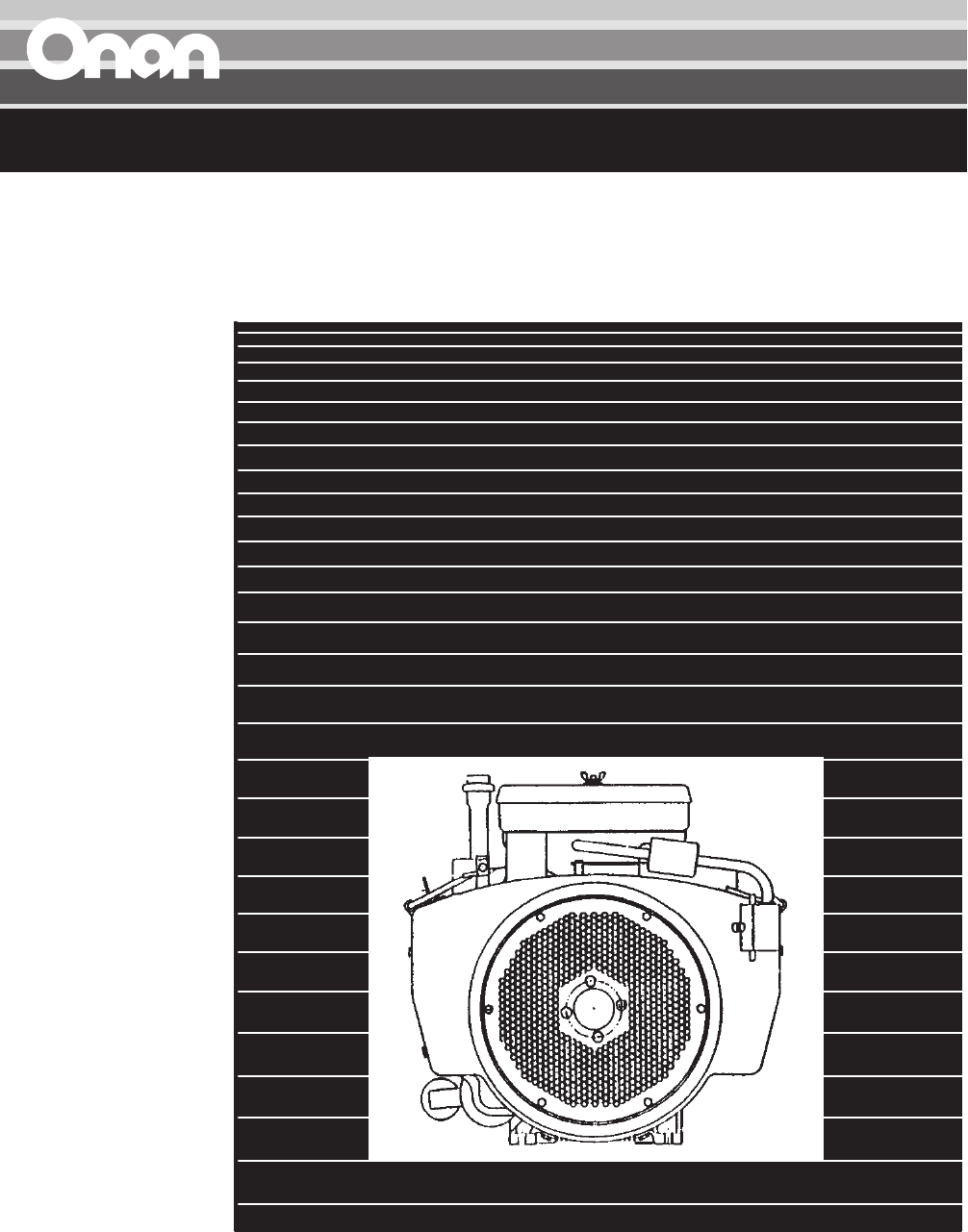
Engine
Parts Catalog
LX720
LX770
LX790
OL16
OL18
OL20
P216G
P218G
P220G
The following symbols are used in Onan manuals
to alert users to the potentially dangerous condi-
tions relating to maintenance of equipment and re-
placement of parts. Please read and observe.
This symbol warns of immedi-
ate hazards which will result in
severe personal injury or death.
This symbol refers to a hazard
or unsafe practice which can re-
sult in severe personal injury or
death.
This symbol refers to a hazard
or unsafe practice which can re-
sult in severe personal injury or
product or property damage.
To avoid errors or delay in filling your parts order,
always give the MODEL, SPEC NO. and SERIAL
NO. from the Onan nameplate.
For handy reference, insert your nameplate in-
formation in the spaces below.
MODEL AND SPEC NO.
SERIAL NO.
DIGITAL CONTROL SOFTWARE VERSION
AND DATE (IF APPLICABLE)
Contact with USED ENGINE OILS has been identified by a United States federal agency and some USA
state agencies as causing CANCER or REPRODUCTIVE TOXICITY. When checking or changing engine
oils take all necessary precautions not to ingest, breathe the fumes or contact the used oil.
Contact with ASBESTOS has been identified by a United States federal agency and some USA state
agencies as causing CANCER or REPRODUCTIVE TOXICITY. When handling engine gaskets take all
necessary precautions not to ingest, breathe or contact the dust from the gaskets! Use adequate ven-
tilation and wear protective gloves, masks and clothing!
Contact with BENZINE and LEAD, found in gasoline, fuel additives and solvents has been identified
by a United States federal agency and some USA state agencies as causing CANCER or REPRODUC-
TIVE TOXICITY. When checking, draining or adding gasoline and fuel additives or using solvents take
all necessary precautions not to ingest, breathe the fumes or contact the liquids. Use adequate ventila-
tion and wear protective gloves, masks and protective clothing!
PSP-1
Service and repair of Onan equipment must be performed by trained, experienced personnel only. Im-
proper service or repair may result in property damage, severe personal injury or death. Do not use this
catalog as a guide to servicing your equipment. Read and follow the IMPORTANT SAFETY INSTRUC-
TIONS in the Service Manual appropriate for the equipment you are working on.

1
Introduction
This parts manual applies to the standard Performer horizontal engine as listed in the Engine Data Table. Parts are
arranged in groups of related items and each illustrated part is identified by a reference number corresponding to the
same reference number in the parts list. Parts illustrations are typical. Throughout this manual, left and right sides are
determined by facing the oil cooler (front) end of the engine.
Using the MODEL and SPECIFICATION NUMBER from the nameplate, consult the SALES OPTION CODE TABLE
in the back of the book to identify factory installed parts that are unique to your engine (Note: The diagonal line (/) in the
model and specification number separates engine characteristics from the specification number/letter. The specifica-
tion number denotes customer requested features. The specification letter advances [A to B, B to C, etc] with major
manufacturing changes.)
Engine Data Table
MODEL RATING
P216G–I/* 16 Horse Power
P218G–I/* 18 Horse Power
P220G–I/* 20Horse Power
OL16/* 16 Horse Power
OL18/* 18 Horse Power
OL20/* 20 Horse Power
LX720/* 16 Horse Power
LX770/* 18 Horse Power
LX790/* 20 Horse Power
Index
2
Adapter, Air Intake – Carburetor, 39
Adapter, Arm – Governor, 43
Adapter, Cleaner – Remote Air, 39
Adapter, Clutch, 40
Adapter, Clutch – Electric, 40
Adapter, Exhaust, 53
Adapter, Filter – Oil, 47, 48
Adapter, Gas – LP, 29
Adapter, Governor Arm, 54
Adapter, Plate – Bearing, 7
Adapter, Pump – Hydraulic, 9
Alternator, 15
Arm Assy, Control – Governor, 43
Arm, Governor, 15
Baffle, Base – Oil, 51
Baffle, Tube – Breather, 9
Baffle, Valve – Breather, 7
Ball, Bearing – Governor Shaft, 15
Band, Cleaner – Air, 38
Base, Filter – Remote Oil, 48
Base, Oil, 51
Bearing, Camshaft, 7
Bearing, Crankshaft – Front, 7
Bearing, Crankshaft – Rear, 7
Bearing, Shaft – Governor, 15
Block, Cylinder, 7, 9
Bracket Assy, Choke, 35
Bracket, Adjust – Governor, 45
Bracket, Cable, 43
Bracket, Cable – Choke, 33, 34
Bracket, Choke, 35
Bracket, Control – Governor, 43
Bracket, Converter – LP, 31
Bracket, Filter – Remote Oil, 48
Bracket, Governor, 17
Bracket, Lifting, 45
Bracket, Line – Fuel, 17, 39
Bracket, Mounting – Regulator, 30
Bracket, Solenoid – Remote Choke, 35
Bracket, Solenoid – Two Speed Governor, 17
Bracket, Support – Muffler, 53
Bracket, Tube – Oil Fill, 46
Bushing, Arm – Control, 43
Bushing, Control – Governor, 17, 43
Bushing, Reducer – Natural Gas, 30
Cable, Governor, 17
Cable, Plug – Spark, 16
Camshaft, 10
Cap Assy, End – Starter, 21
Cap, Breather, 9
Cap, Fill – Oil, 46
Cap, Fitting – Fuel, 23
Cap, Limiter – Idle, 28
Cap, Port – Vacuum, 15
Cap, Solenoid – Starter, 19
Cap, Valve, 7
Capacitor, 37, 39
Carburetor Components, Gasoline, 26, 27
Carburetor Components, Gasoline – Auto Choke, 28
Carburetor, Components – LP Gas, 29
Carburetor, Gasoline, 25
Carburetor, LP, 32
Choke, Manual, 54
Choke, Remote, 35
Cleaner, Air, 37, 38
Cleaner, Air – Remote, 38
Clip, Cable – Choke, 33, 34
Clip, End – Rod, 25, 32, 45
Clip, Lock – Remote Choke, 35
Clip, Retaining – Control, 15
Clip, Retaining – Control Rod, 25, 32, 45
Clip, Wire, 16
Clip, Wire – Blower Housing, 45
Clip, Wire – Fuel Line, 25
Clutch Assy, Starter, 20
Codes, Sales (Definitions), 75
Coil, Ignition – Battery, 16
Components, Carburetor, 26
Components, Carburetor – Gasoline, 27
Components, Carburetor – Gasoline Auto Choke, 28
Components, Starter, 19, 20, 21
Connector, Line – Oil, 47
Connector, Male, 48
Connector, Male – Inverted, 29
Control, Choke – Front Pull, 34
Control, Choke – Rear Pull, 33
Control, Ignition, 15
Cover Assy, Starter, 21
Cover, Cleaner – Air, 37
Cover, Element – Air Cleaner, 37
Cover, Pad – Oil Filter, 47
Cover, Regulator – Voltage, 43
Cover, Tube – Exhaust, 53
Cover, Valve, 7
Crankshaft, 11
Cup, Governor, 10
Cup, Intake – Oil Pump, 51
Decal, Control Panel, 54
Deflector, Carburetor, 29
Drain, Filter – Oil, 47
Elbow, Adapter – LP, 29
Elbow, Brass – LP Carburetor Kit, 32
Elbow, Brass – LP Converter Kit, 31
Elbow, Brass – Natural Gas Regulator, 30
Elbow, Gas – LP, 29
Elbow, Inlet – Air, 38, 39
Elbow, Main Jet – LP Regulator, 29
Elbow, Male – Oil Hose, 48
Elbow, Street, 30
Elbow, Street – LOPKO, 48, 49
Elbow, Street – Oil Line, 47
Elbow, Street – Pressure Sender, 50
Index
3
Element, Cleaner – Air, 37
Exhaust System, 53
Filter, Fuel, 23
Filter, Oil, 47, 48
Filter, Oil – Remote, 48
Filter, Tube – Breather, 37, 39
Fitting, Barbed, 25
Flywheel, 13
Fuel System – Gasoline, 25
Fuel System – LP Gas, 29
Fuse, 30A Blade, 57, 58, 59
Fuse, 30A Cartridge, 58
Gasket, Adapter – Oil Filter, 47, 48
Gasket, Base – Oil, 51
Gasket, Carburetor – Gasoline, 25
Gasket, Carburetor – LP, 32
Gasket, Cleaner – Air, 29, 37
Gasket, Cover – Valve, 7
Gasket, Exhaust, 53
Gasket, Filter – Oil, 47
Gasket, Fitting – Hose, 37
Gasket, Head – Cylinder, 7
Gasket, Horn – Air, 29
Gasket, Manifold – Exhaust, 53
Gasket, Manifold – Gasoline Intake, 25
Gasket, Manifold – LP Intake, 32
Gasket, Mounting – Gearcase, 15
Gasket, Plate – Bearing, 7
Gasket, Plate – Ignition, 9
Gasket, Plug – Hex Head, 51
Gear, Camshaft, 10
Gear, Crankshaft, 11
Gear, Drive, 21
Gear, Ring, 13
Gearcase, 15
Governor, 43, 45
Governor, Speed – Two, 17
Grommet, Bracket – Fuel Line, 17
Grommet, Cleaner – Air, 32
Grommet, Cleaner – Remote Air, 39
Grommet, Seal – Air, 45, 48
Grommet, Support – Air Cleaner, 37
Grommet, Tube – Breather, 37
Guard, Stationary, 45
Guide, Valve, 7
Harness, Control, 54
Harness, Engine (Code 35AZ), 60
Harness, Engine (Code 35BB, 35BD, 35BH, 35CG), 55
Harness, Engine (Code 35BC, 35BZ, 35CC, 35CH, 35CJ,
35DB), 56, 58
Harness, Engine (Code 35BE), 57
Harness, Engine (Code 35BJ), 60
Harness, Engine (Code 35BK), 59
Harness, Interface (Code 35AW), 61
Harness, Interface (Code 47AW), 61
Harness, Wiring – LOPKO, 49
Head, Cylinder, 7
Holder, Brush, 20
Holder, Cartridge Fuse, 58
Hose, Breather, 25, 32, 39
Hose, Fuel, 23, 25, 29, 32
Hose, Inlet – Air, 32
Hose, Oil, 48
Housing, Blower, 43, 45
Housing, Cleaner – Air, 37
Housing, Cylinder – Air, 43
Hub, Cup – Governor, 10
Hub, Plate – Drive, 40
Ignition, Electric, 16
Indicator, Fill – Oil, 46
Insert, Seat – Valve, 7
Insulator, Module – Ignition, 15
Jet, Idle, 27, 28
Jet, Power, 26, 27, 28
Joint, Ball, 45
Key, Crankshaft, 11
Key, Flywheel, 13
Key, Gear – Crankshaft, 11
Key, Machine – PTO Shaft, 13
Key, Woodruff – Camshaft Gear, 10
Kit, Bracket – Mounting, 19
Kit, Brush – Starter, 19, 20
Kit, Bushing – Starter, 19, 20
Kit, Carburetor, 25
Kit, Carburetor – LP, 32
Kit, Cleaner – Air, 37
Kit, Clutch – Starter, 19
Kit, Converter – LP, 31
Kit, Float, 27, 28
Kit, Gasket, 28
Kit, Gasket – Oil Pump, 7
Kit, Hardware – Starter, 19, 20
Kit, Intake Manifold, 25
Kit, Lever – Choke, 27
Kit, Lever – Starter Shift, 19, 20
Kit, Repair – Gasoline Carburetor, 27
Kit, Repair – Starter, 21
Kit, Ring – Piston, 9
Kit, Screw and Plug, 28
Kit, Seal – Dust, 19
Kit, Shaft – Choke, 27
Kit, Shaft – Throttle, 27, 28
Kit, Solenoid – Starter, 19, 20
Kits, Gasket, 7, 62
Knob, Cleaner – Air, 37
Labels, 62
Lever, Choke, 34, 35
Lever, Control, 54
Lever, Governor, 45
Index
4
Line, Oil – Flex, 47
Line, Pulse, 23
Link, Choke, 34, 35
Link, Control – Governor, 43
Lock, Spring – Valve, 7
Manifold, Exhaust, 53
Manifold, Intake, 25, 32
Muffler, 53
Needle, Carburetor, 28
O–Ring, Carburetor – Gasoline, 25
O–Ring, Carburetor – LP, 29
O–Ring, Valve – Shutoff, 29
Paint, 62
Panel, Control, 54
Pin, Alignment – Gear Cover, 7
Pin, Center – Camshaft, 10
Pin, Cotter – Choke Lever, 34
Pin, Cotter – Governor, 43, 45
Pin, Cotter – Two Speed Governor, 17
Pin, Dowel – Governor Cup Stop, 15
Pin, Drive – Bearing Stop, 7
Pin, Piston, 9
Piston, 9
Plate, Bearing – Rear, 7
Plate, Cap – Starter, 21
Plate, Cover – Ignition Plunger, 9
Plate, Deflector – Air, 37
Plate, Support – Air Cleaner, 37
Plug, Black Nylon – Stationary Guard, 45
Plug, Cap, 34
Plug, Countersunk – Oil Pad Cover, 47
Plug, Dot Button – Blower Housing, 39
Plug, Hex Head – Oil Base, 51
Plug, Hole – Breather, 9
Plug, Hole – Core, 7
Plug, Spark, 16
Plug, Square Head – Adapter, 47
Plug, Square Head – Oil Base, 51
Plug, Welch – Camshaft, 7
Plunger, Valve – Bypass, 7, 48
Pre–Cleaner, Air, 38
Pulley, 41
Pulley, Drive – Alternator, 41
Pump, Fuel, 23
Pump, Fuel – Vacuum, 23
Pump, Oil, 7
Rectifier, Control Harness Silicon, 54
Rectifier, Engine Harness, 56
Rectifier, Silicon, 58
Reed, Valve – Breather, 7
Regulator, 15
Regulator, Converter – LP, 31
Regulator, Gas – LP, 29
Regulator, Gas – Natural, 30
Regulator, Voltage, 15
Retainer, Bolt – Starter, 21
Ring, Retaining – Camshaft, 10
Ring, Retaining – Crankshaft, 11
Ring, Retaining – Piston Pin, 9
Rod, Choke, 35
Rod, Connecting, 9
Rod, Control, 45
Rod, Control – Governor, 25, 32
Rod, Governor, 45
Rotor, Ignition, 16
Sales Code Definitions, 75
Sales Option Code Table, 74
Screen, Inlet – Air, 13
Screen, Tube – Breather, 9
Seal, Dust, 20, 21
Seal, O–Ring – Air Cleaner, 39
Seal, O–Ring – Breather Cap, 9
Seal, Oil – Crankshaft, 15
Seal, Oil – Crankshaft Rear, 7
Seal, Oil – Governor Shaft, 15
Seal, Tube – Oil Fill, 46
Seal, Valve – Intake, 7
Sealant, Thread, 62
Sender, Gauge – Oil Pressure, 50
Sender, Pressure – Oil, 50
Shaft, Governor, 15
Shaft, PTO, 13
Shim, End Play – Crankshaft, 7
Sleeve, Bearing, 11
Solenoid, 35
Solenoid, Cutoff – Fuel, 27
Solenoid, Governor – Two Speed, 17
Spacer, Cleaner – Air, 32
Spacer, LP Gas, 37
Spacer, Nylon – Air Cleaner, 37
Spacer, Stud – Air Cleaner, 37
Spring, Governor, 17, 43
Spring, Governor Return, 54
Spring, Needle – Power, 28
Spring, Rod – Governor, 25, 32
Spring, Setting – Idle, 43
Spring, Valve, 7
Spring, Valve – Breather, 7
Spring, Valve – Bypass, 7
Starter, 18
Starter, Inertia, 18
Starter, Shift – Solenoid, 18
Stator, 15
Strap, Mounting – Regulator, 30
Stud, Adjusting, 45
Stud, Cover – Gear, 15
Stud, Mounting, 7
Support, Cleaner – Air, 37
Support, Cover – Exhaust, 53
Support, Muffler, 53
Switch – LOPKO, 49
Index
5
Switch, Ignition, 54
Switch, LOPKO, 48, 49
Switch, Temperature – High, 41
Switch, Temperature – Oil, 51
Swivel, Lever – Choke, 17, 34, 45
Swivel, Lever – Throttle, 43
Swivel, Link, 35
Tappet, Valve – Standard, 7
Tube, Breather – Air Cleaner, 37
Tube, Breather – Crankcase, 37, 39
Tube, Breather – Cylinder Block, 9
Tube, Breather – LP Carburetor, 32
Tube, Exhaust, 53
Tube, Exhaust – Offset, 53
Tube, Fill – Oil, 46
Tube, Induction – Air, 38, 39
Tube, Intake – Air, 29, 37
Tube, Oil – Cylinder Block, 7
Tube, Port – Vacuum, 15
Valve, Breather, 9
Valve, Exhaust, 7
Valve, Intake, 7
Valve, Magnetic, 30
Valve, Shutoff – Fuel, 29
Valve, Shutoff – LP Converter, 31
Valve, Shutoff – Oil Base, 51
Vaporizer, Gas – LP, 29
Weight, Balance, 11
Wheel, Blower, 13
Wheel, Screen – Blower, 13
Wrapper, Element – Air Cleaner, 37
Yoke, Shaft – Governor, 15
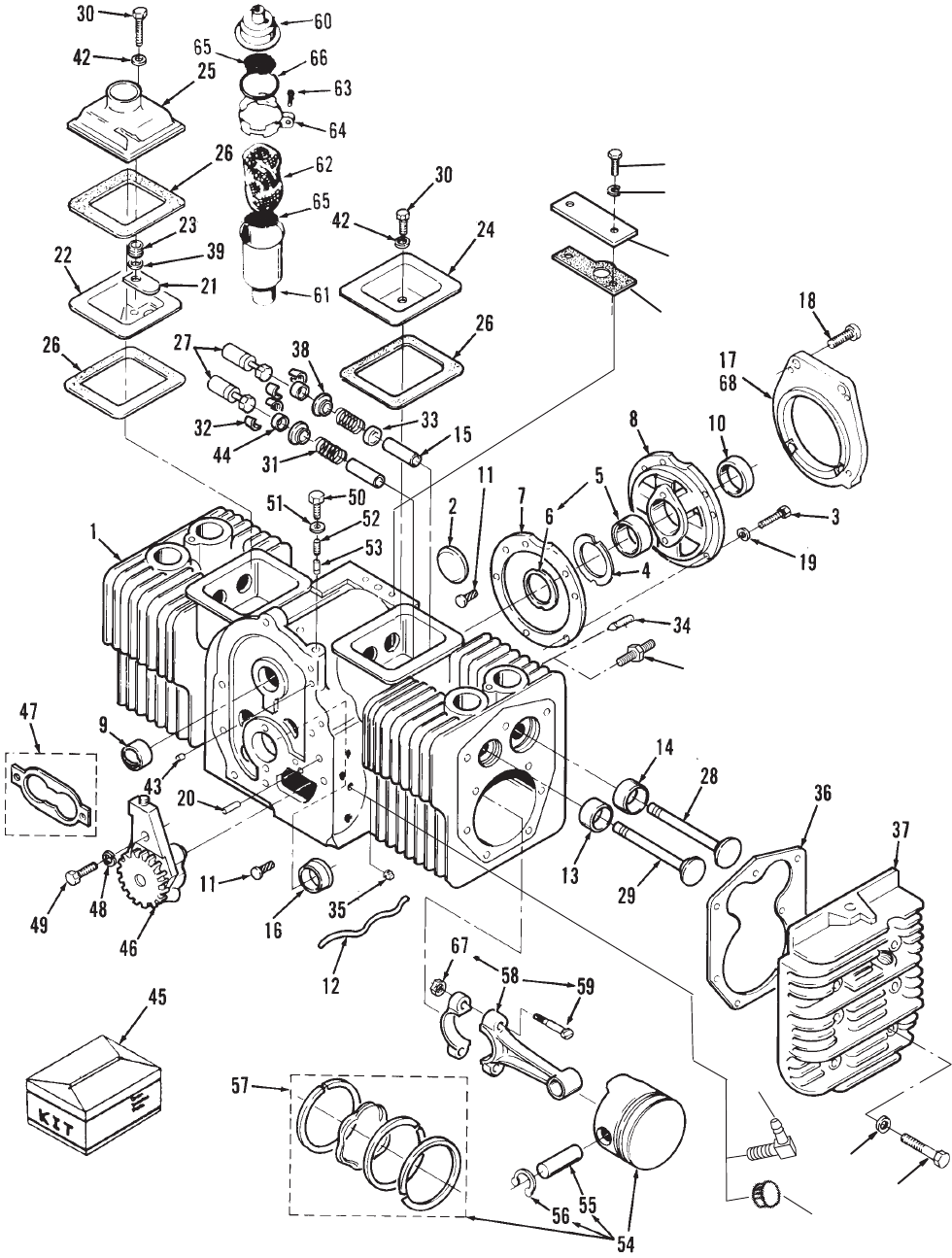
P216/18/20G
6
Cylinder Block
34A
40
41
69
70
71
72
73
74
P216/18/20G
7
Cylinder Block
REF PART QTY PART REF PART QTY PART
NO. NO. USED DESCRIPTION NO. NO. USED DESCRIPTION
1 1 Block, Cylinder (See Short
Block Catalog #932–0109)
2 517–0048–01 1 Plug, Camshaft Welch
Opening (1–5/8”)
3 800–0051 5 Screw, Hex Head Cap
(3/8–16 x 1–1/4”)
4 Shim, Crankshaft End Play
(Use as Required)
104–0776 1 .005”
104–0776–01 1 .003”
5 Bearing, Rear Crankshaft
(Includes Thrust Washer)
101–0804 1 Standard
101–0804–02 1 .002” Undersize
101–0804–10 1 .010” Undersize
101–0804–20 1 .020” Undersize
101–0804–30 1 .030” Undersize
6 104–0575 1 Washer, Thrust
7 101–0809 1 Gasket, Bearing Plate
8 Plate, Rear Bearing
101–0439–01 1 Cadmium Plated
Code 11AH,11AV
101–0551–01 1 4 Boss – Code 11AK
101–0437–01 1 SAE–A – Zinc Plated –
Code 11AP
9 101–0405 2 Bearing, Camshaft
10 509–0041 1 Seal, Crankshaft Rear Oil
11 516–0072 4 Pin, Bearing Stop Drive
12 120–1320 1 Tube, Oil
13 Insert, Exhaust Valve Seat
110–1824 2 Standard
110–1824–02 2 .002” Oversize
110–1824–05 2 .005” Oversize
110–1824–10 2 .010” Oversize
110–1824–25 2 .025” Oversize
14 Insert, Intake Valve Seat
110–0197 2 Standard
110–0197–02 2 .002” Oversize
110–0197–05 2 .005” Oversize
110–0197–10 2 .010” Oversize
110–0197–25 2 .025” Oversize
15 Guide, Valve
110–3527 2 Exhaust
110–3526 2 Intake
16 Bearing, Front Crankshaft
(Flanged)
101–0805 1 Standard
101–0805–02 1 .002” Undersize
101–0805–10 1 .010” Undersize
101–0805–20 1 .020” Undersize
101–0805–30 1 .030” Undersize
17 101–0761 1 Adapter, Bearing Plate
Code 11BH
18 Screw
815–0682 4 Socket Head (Special)
Code 11BH
800–0515 5 Cap, Hex Head (Special)
Code 11BF
800–0515 4 Cap, Hex Head (Special)
Code 11BE, 11AR
19 526–0402 5 Washer, Flat (.395 Screw)
20 516–0141 2 Pin, Gear Cover Alignment
21 123–1175 1 Reed, Breather Valve
Specs A, B
22 123–1173 1 Baffle, Breather Valve
Specs A, B
23 123–1174 1 Spring, Breather Valve
Specs A, B
24 110–1879–01 1 Cover, RH Valve – Spec A,B
25 110–3637–01 1 Cover, LH Valve – Begin
Spec C – Zinc–Plated
26 Gasket, Valve Cover
110–3709 3 Spec A, B
110–3709 2 Begin Spec C
27 115–0006 4 Tappet, Standard Valve
28 110–3479 2 Valve, Intake
29 110–3480 2 Valve, Exhaust
30 800–0010 2 Screw, Hex Head Cap
(1/4–20 x 1–3/4”)
31 110–3485 4 Spring, Valve
32 110–3511 8 Lock, Valve Spring
33 509–0289 2 Seal, Intake Valve
34 803–0071 2 Screw, Set Socket
(3/8–16 x 5/8”) (Use W/O
Remote Oil Filter)
34A 520–0820 2 Stud, Mounting
(3/8–16 x 1–11/16) (Use with
Remote Oil Filter)
35 505–0057 1 Plug, Pipe – Code 17CE
36 110–3181 2 Gasket, Cylinder Head
37 Head, Cylinder
110–3509 1 Right Side
110–3508 1 Left Side
38 110–3487 4 Washer, Valve Spring Retaining
39 526–0018 1 Washer, Flat (1/4” Screw)
40 526–0122 18 Washer, Flat (5/16” Screw)
41 800–0571 18 Screw, Hex Head Cap
(Special) 2.0” Long
42 526–0063 2 Washer, Copper Flat
(1/4” Screw)
43 517–0067 1 Plug, Core Hole (Specs A, B)
44 110–3510 4 Cap, Valve
45 Kit, Gasket
168–0187 1 Engine, Complete
168–0189 1 Valve Grind/Carbon Removal
46 120–0491 1 Pump, Oil (Components Not
Sold Separately)
47 120–0161 1 Gasket Kit, Oil Pump
48 740–1004 2 Washer, Flat (M6)
49 800–0007 2 Screw, Hex Head Cap
(1/4–20x1”)
50 801–0049 1 Screw, Hex Head Cap
(3/8–24 x 7/8”)
51 526–0066 1 Washer, Copper Flat
(3/8” Screw)
52 120–0140 1 Spring, Bypass Valve
53 120–0398 1 Plunger, Bypass Valve

P216/18/20G
8
Cylinder Block
34A
40
41
69
70
71
72
73
74
P216/18/20G
9
Cylinder Block
REF PART QTY PART REF PART QTY PART
NO. NO. USED DESCRIPTION NO. NO. USED DESCRIPTION
54 Piston (Includes Pin and
Retaining Rings)
112–0264 2 Standard
112–0264–05 2 .005” Oversize
112–0264–01 2 .010” Oversize
112–0264–02 2 .020” Oversize
112–0264–03 2 .030” Oversize
55 112–0229 2 Pin, Piston
56 518–0311 4 Ring, Retaining
57 Kit, Piston Ring
Specs A–C
113–0314 2 Standard
113–0314–05 2 .005” Oversize
113–0314–10 2 .010” Oversize
113–0314–20 2 .020” Oversize
113–0314–30 2 .030” Oversize
Begin Spec D
113–0310 2 Standard
113–0310–05 2 .005” Oversize
113–0310–01 2 .010” Oversize
113–0310–02 2 .020” Oversize
113–0310–03 2 .030” Oversize
58 Rod, Connecting (Includes
Bolt and Nut)
P216
114–0394 2 Standard
114–0394–10 2 .010” Undersize
114–0394–20 2 .020” Undersize
114–0394–30 2 .030” Undersize
P218, P220
114–0397 2 Standard
114–0397–10 2 .010” Undersize
114–0397–20 2 .020” Undersize
114–0397–30 2 .030” Undersize
59 114–0392 4 Bolt, Connecting Rod
(Special)
60 123–0954 1 Cap and Valve, Breather
Begin Spec C
61 123–0952 1 Tube, Breather – Begin Spec C
62 123–1871 1 Baffle, Breather Tube (Begin
Spec C)
63 809–0035 1 Screw, Round Head Tapping
(#8 x 3/4”) – Begin Spec C
64 123–0951 1 Clamp, Loop – Begin Spec C
65 123–0958 2 Screen, Breather Tube
Begin Spec C
66 509–0117 1 Seal, Breather Cap O–Ring
Begin Spec C
67 Nut
870–0302 4 Hex, Crown Lock
870–0533 4 Flange, Hex
68 Adapter, Hydraulic Pump
101–0766–01 1 Code 11BE
101–0766–02 1 Code 11BF
517–0120 1 Plug, Breather Hole – Begin
Spec C (Not Shown) (Use W/O
Fuel Pump)
69 160–1368 1 Gasket, Plate
70 160–1345–01 1 Plate, Ignition Plunger
Cover – Zinc Plated
71 740–1004 2 Washer, Flat (M6)
72 800–0004 2 Screw, Cap Hex Head
(1/4–20 x 5/8”)
73 502–1252 1 Elbow
74 517–0120 1 Plug, Breather Hole
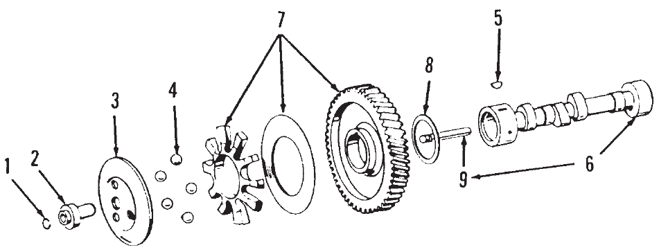
P216/18/20G
10
Camshaft
REF PART QTY PART REF PART QTY PART
NO. NO. USED DESCRIPTION NO. NO. USED DESCRIPTION
1 150–0078 1 Ring, Retaining
2 150–1519 1 Hub, Governor Cup
3 150–1520 1 Cup, Governor
4 Ball, Governor
510–0015 5 Codes 13BG, 13BM, 13BN,
13BP, 13BR, 13BS, 13BT,
13BV, 13BW 13CB, 13CE,
13CM,13CR, 13DB
510–0015 10 Code 13CH (Use with 13CF)
5 515–0001 1 Key, Camshaft Gear Woodruff
6 Camshaft (Includes Center Pin)
105–0637 1 P216, P218
P220
105–0639 1 All Specs Except 11212
105–0718 1 Spec 11212 Only
7 105–0700 1 Gear, Camshaft (Includes Gear,
Spacer and Plate)
8 105–0541 1 Washer, Special Thrust
9 150–0075 1 Pin, Center
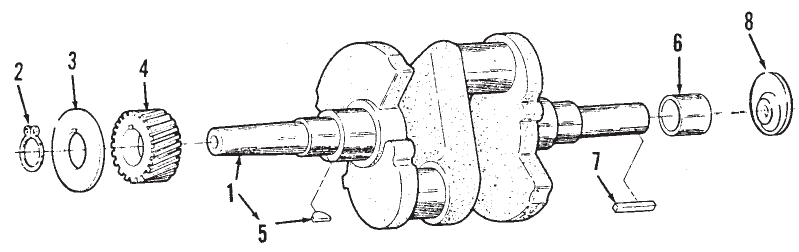
P216/18/20G
11
Crankshaft
REF PART QTY PART REF PART QTY PART
NO. NO. USED DESCRIPTION NO. NO. USED DESCRIPTION
1 Crankshaft
P216
104–1887 1 * Code 45BB
104–1332 1 * Code 45BC
104–1699 1 * Code 45BD,45BE,45BW
104–1331 1 * Code 45BF
104–1621 1 Code 45BG
104–1535 1 Code 45BH
104–1333 1 * Code 45BS
104–0901 1 Code 45BT
104–0900 1 Code 45BU
104–1432 1 * Code 45BZ
104–1330 1 * Code 45CA
P218, P220
104–1351 1 * Code 45BB
104–1443 1 * Code 45BC
104–1700 1 * Code 45BD,45BE
104–1348 1 * Code 45BF
104–1693 1 Code 45BG
104–1502 1 * Code 45BH
104–1735 1 Code 45BJ
104–1352 1 * Code 45BP
104–1349 1 * Code 45BS
104–1364 1 * Code 45BT
104–1167 1 Code 45BU
104–1575 1 Code 45BY
104–1354 1 * Code 45CA
104–0983–01 1 Code 45CC
104–1768 1 * Code 45CE
104–1787 1 Code 45EA
104–1871 1 Code 45ED
104–1873 1 Code 45EE
104–1939 1 Code 45EH
2 518–0014 1 Ring, Retaining
3 104–0043 1 Washer, Gear Retaining
Special
4 104–0032 1 Gear, Crankshaft
5 515–0001 1 Key, Crankshaft Gear
6 190–0267 1 Sleeve, Bearing – Code 45BP
7 Key
515–0198 1 Square (3/8 x 3/8 x 2–1/2”)
Code 45BW
515–0103 1 Woodruff (1/4 x 1/4 x 2”)
Code 45BC, 45BS, 45BT
515–0230 1 Square, Code 45BD, 45BW
(3/8 x 3/8 x 2”)
515–0263 1 Kit, Key – Code 45BC, 45BF,
45BH, 45BP, 45BS, 45BT,
45BZ, 45CA, 45CE
515–0146 1 Woodruff, #18 (1/4 x 1–1/8”)
Code 45BP
515–0301 1 Code 45CE
8 104–1712 1 Weight, Balance – Code 45BL
* Includes Keys.
P216/18/20G
12
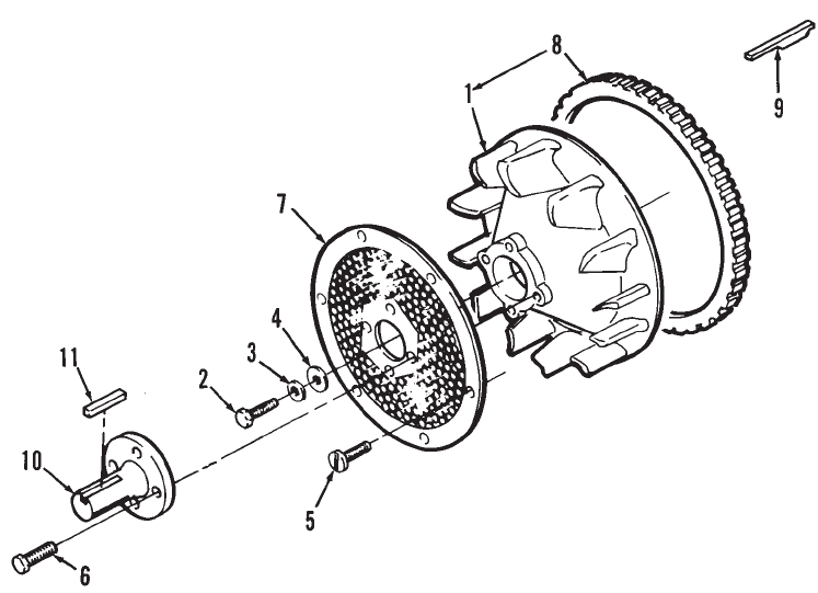
P216/18/20G
13
Blower Wheel With Screen
REF PART QTY PART REF PART QTY PART
NO. NO. USED DESCRIPTION NO. NO. USED DESCRIPTION
1 Flywheel (Includes Ring
Gear)
134–4633 1 Code 31AZ, 31BC, 23DJ,
23DC, 23EF, 31BD
134–4705 1 Code 23DD
2 104–0170 1 Screw, Hex Head Cap
(Special)
3 526–0356 1 Washer, Flat (7/16” Screw)
4 526–0017 1 Washer, Flat (7/16” Screw)
5 815–0687 6 Screw, Flange Lock Head
(#10–24 x 3/8”)
6 800–0030 4 Screw, Hex Head Cap
(5/16–18 x 1.25”) – OEM
Supplied On Code 23EL
7 134–4553–50 1 Screen, Air Inlet
Code 31AZ, 23DC, 23EF –
Painted
8 104–0779 1 Gear, Ring
9 515–0284 1 Key, Flywheel
10 190–0687 1 Shaft, PTO – 1” Diameter
11 515–0007 1 Key, Machine (1/4 x 2”)
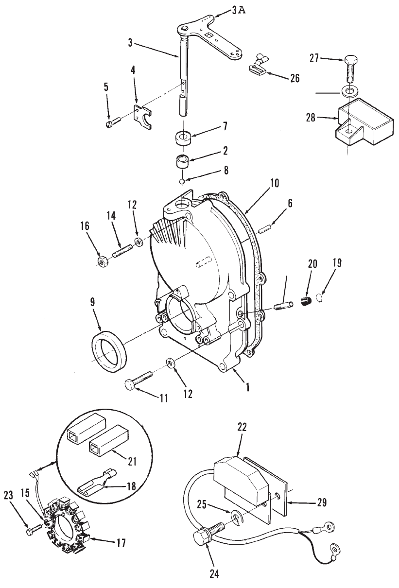
P216/18/20G
14
Gearcase, Ignition Control, Alternator
and Regulator
13
30
P216/18/20G
15
Gearcase, Ignition Control, Alternator
and Regulator
REF PART QTY PART REF PART QTY PART
NO. NO. USED DESCRIPTION NO. NO. USED DESCRIPTION
1 Gearcase (Kit) (Includes Parts
Marked*)
103–0791 1 W/Sleeve Bearing
103–0799 1 W/Needle Bearing
2 510–0105 1 *Bearing, Governor Shaft
3 *Shaft and Arm, Governor
150–1470–01 1 Case Hardened
150–1422 1 Code 31AZ, 31BD Begin
Spec C
3A 150–1007 1 Arm, Governor Spec A,B
4 150–1187 1 *Yoke, Governor Shaft
5 815–0046 2 *Screw, Pan Head Machine
(8–32 x 3/8”)
6 516–0130 1 *Pin, Governor Cup Dowel
Stop
7 509–0008 1 *Seal, Governor Shaft Oil
8 510–0014 1 *Ball, Governor Bearing
Shaft
9 509–0040 1 *Seal, Crankshaft Oil
10 103–0810 1 Gasket, Gearcase Mounting
11 114–0022 4 Screw, Hex Head Cap
(5/16–18 x 1–3/4”)
12 526–0065 5 Washer, Copper Flat
(5/16” Screw)
13 149–1299 1 *Tube, Vacuum Port (1.5” Long)
14 520–0933 1 Stud, Gear Cover
15 850–0030 3 Washer, Lock (#10) – Code
31AZ
16 862–0015 1 Nut, Hex (5/16–18)
17 Stator (Includes Terminals)
191–1276 1 Code 31BC (35A)
191–1456 1 Code 31AZ (20A)
18 332–2423 3 Terminal, Stator Leads
Code 31AZ,47AW – Use Qty. 2
19 503–0301 1 *Clamp, Vacuum Port Cap
20 149–1321 1 *Cap, Vacuum Port – Spec A,B
21 191–2104 2 Body, Terminal Connector
Kit (Includes Terminals)
Code 31AZ
22 Control, Ignition
166–0785 1 12 Volt
166–0800 1 24 Volt – Code 31BD
23 815–0172 3 Screw, Hex Head Machine
Self–Lock (#10–32 x 1”)
Code 31AZ,31BC
24 815–0340 2 Screw, Hex Washer Head
(10–32 x 3/8”)
25 854–0010 2 Washer, IT Lock (#10)
26 518–0637 1 Clip, Control Retaining
Rod To Governor Shaft
27 821–0015 1 Screw, Lock Head
(1/4–20 x 1/2”)
28 Regulator, Voltage
191–1847 1 35 Ampere – Code 31BC
191–2208 1 20 Ampere – Code 23DK,
31AZ, 23EH
29 166–0786 1 Insulator, Module Ignition
30 853–0013 1 Washer, ET Lock
* – Parts Included in Gearcase.
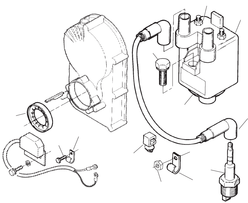
P216/18/20G
16
Electronic Ignition
1
2
3
4
5
6
7
8
9
10
11 2
REF PART QTY PART REF PART QTY PART
NO. NO. USED DESCRIPTION NO. NO. USED DESCRIPTION
1 Coil, Battery Ignition
(Includes Nuts)
166–0761 1 Spec A–G
166–0820 1 Begin Spec H
2 Clip, Wire (Attach To
Spark Plug Wire)
332–2904 1 Square
332–2650 1 Loop
3 166–0767 1 Rotor, Ignition
4 167–0272 2 Plug, Spark
5 Cable, Spark Plug
167–1615–01 1 9” Long
167–1615–04 1 18.5” Long
6 166–0770 1 Nut, Hex Flange (M4 Positive
Terminal)
7 518–0515 2 Clip, Wire
8 166–0771 1 Nut, Hex Flange (M5 Negative
Terminal)
9 815–0650 2 Screw, Hex Washer Head
(1/4–20 x 1”)
10 114–0022 2 Screw, Hex Head Cap
(5/16–18 x 1–3/4”)
11 870–0212 1 Nut, Self Lock
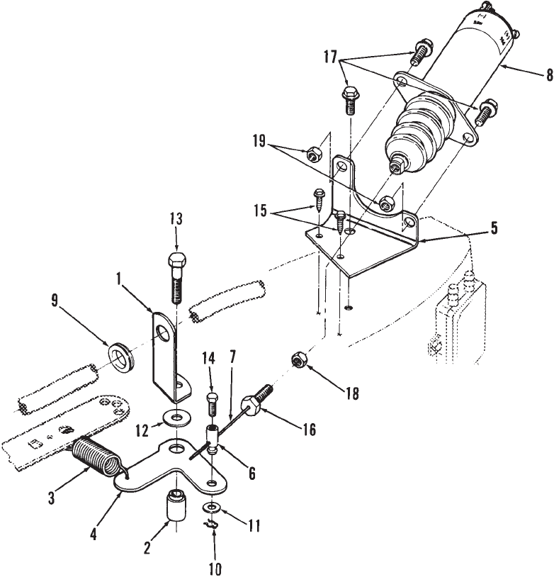
P216/18/20G
17
Two Speed Governor
REF PART QTY PART REF PART QTY PART
NO. NO. USED DESCRIPTION NO. NO. USED DESCRIPTION
1 149–2366 1 Bracket, Fuel Line
2 150–1727 1 Bushing, Governor Control
3 150–1740 1 Spring, Governor
4 150–2498 1 Bracket, Governor
5 150–2499 1 Bracket, Solenoid Mounting
6 153–0632 1 Swivel, Choke Lever
7 153–0678 1 Cable (Includes Bolt)
8 307–2758 1 Solenoid, 2 Speed Governor
9 508–0021 1 Grommet, Rubber
10 516–0059 1 Pin, Cotter
11 526–0006 1 Washer, Flat (#12 Screw)
12 526–0021 1 Washer, Flat (1/4” Screw)
13 114–0023 1 Screw, Hex Head Cap
(Special)
14 800–4072 1 Screw, Hex Head Machine
(M4)
15 815–0439 2 Screw, Hex Washer Head Cap
(#8–15 x 1/2”)
16 815–0800 1 Screw, Hex Head – Grade 5
(1/4–28 x 1”)
17 821–0010 3 Screw, Lock Head
(1/4–20 x 1/2”)
18 115–0025 1 Nut, Hex (1/4–28)
19 870–0212 2 Nut, Lock (1/4–20)
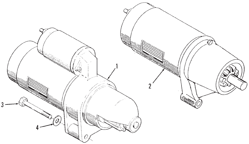
P216/18/20G
18
Starter
REF PART QTY PART REF PART QTY PART
NO. NO. USED DESCRIPTION NO. NO. USED DESCRIPTION
1 Starter, Solenoid Shift
(See Separate Page for
Components)
191–1949–04 1 Code 33AT, 33BF
191–1949–05 1 Code 33AS,33BA
191–1949–07 1 Code 33AW
2 191–1828 1 Starter, Inertia (Bendix)
Type (See Separate Page
For Components) – Code
33AV
3 800–0595 2 Screw, Cap Hex Head
(5/16–18 x 3–1/2”)
4 526–0122 2 Washer, Flat (5/16” Screw)
Inside Mounting Bolt
NOTE: Onan Part Number Stamped on the Starter
Nameplate for Identification.
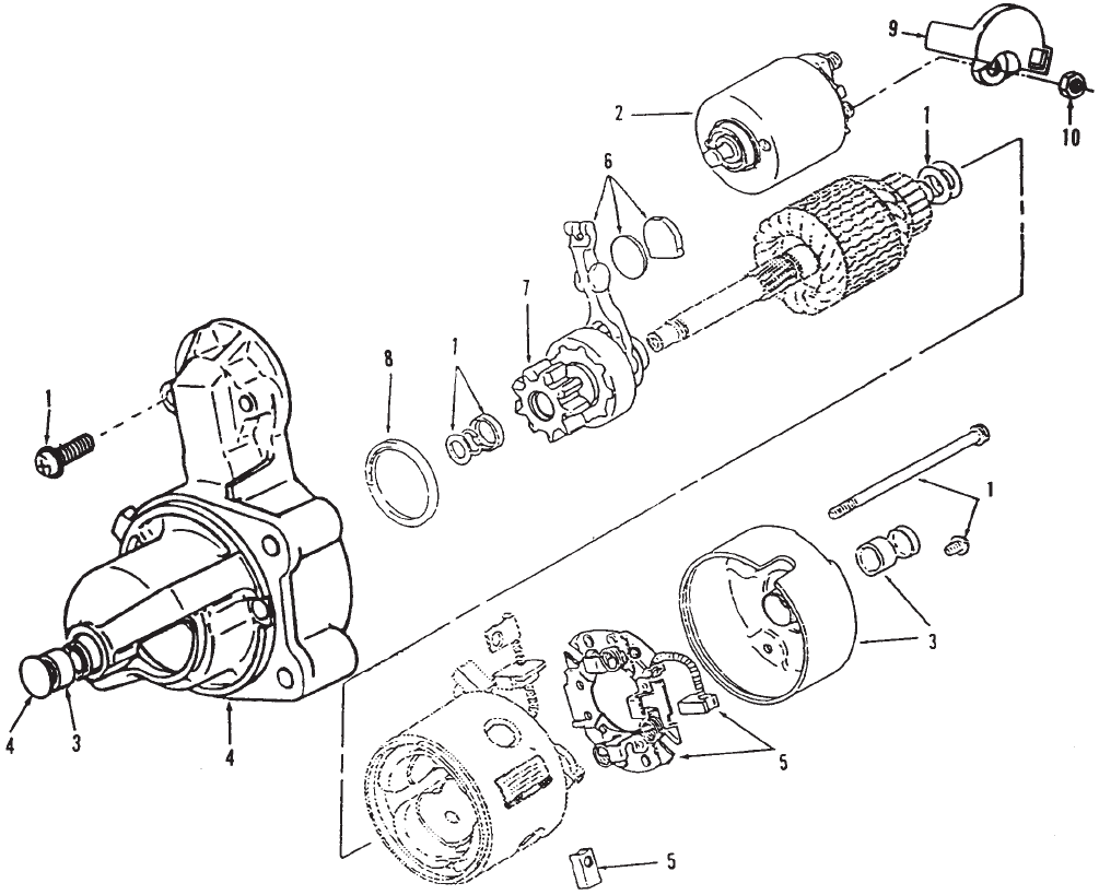
P216/18/20G
19
Starter Components
(191–1949–05 & 191–1949–07)
REF PART QTY PART REF PART QTY PART
NO. NO. USED DESCRIPTION NO. NO. USED DESCRIPTION
1 191–1954 1 Kit, Starter Hardware
(Includes (2) Solenoid
Mtg Screws, 2 Thru Bolts,
Armature Shims, Pinion Stop
Collar, Retaining Ring and
Solenoid Terminal Nuts)
2 191–1956 1 Kit, Starter Solenoid (Includes
Solenoid and Spring Plunger)
3 191–1931 1 Kit, Starter Bushing (Includes
Rear Cap with Bushing and
Front Bushing)
4 Kit, Mounting Bracket (Includes
Front Bracket, Front Bushing,
Dust Seal, Thrust Washer, Cap
Plug and OD Pinion Seal)
191–1950 1 Code 33AT, 33AW, 33BF
191–1952 1 Code 33AS, 33BA
5 191–1951 1 Kit, Starter Brush (Includes (2)
Negative and (2) Positive
Brushes and Brush Holder)
6 191–1766 1 Kit, Starter Shift Lever
(Includes Lever, Wear Plate,
Rubber Plug and Grease)
7 191–1953 1 Kit, Starter Clutch (Includes
Pinion Gear and Clutch
Assembly)
8 191–1955 1 Kit, Dust Seal (Includes ID, OD
Pinion Seals)
9 191–1947 1 Cap, Starter Solenoid
10 750–1006 1 Nut, Metric Hex (M8)
NOTE: Phantom Items Not For Sale, For Replacement
Order Complete Starter.
NOTE: Onan Part Number Stamped on the Starter
Nameplate for Identification.
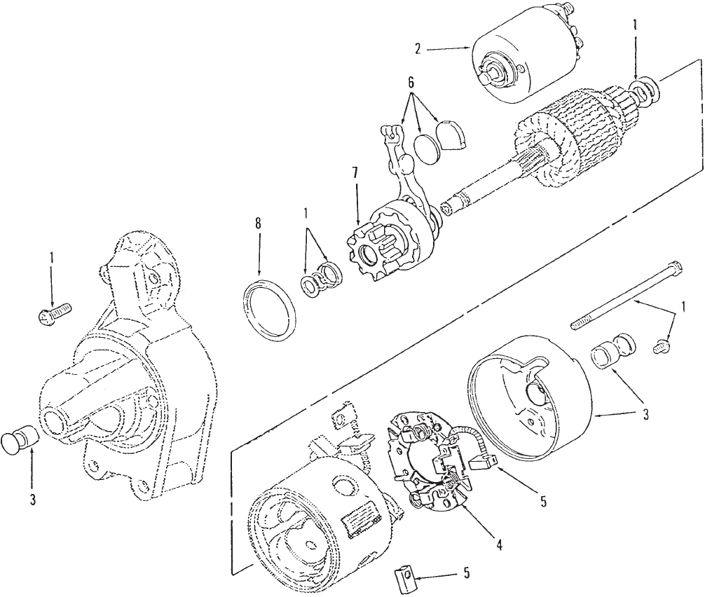
P216/18/20G
20
Starter Components
(191–1808–04 & 191–1808–05)
REF PART QTY PART REF PART QTY PART
NO. NO. USED DESCRIPTION NO. NO. USED DESCRIPTION
1 191–1954 1 Kit, Starter Hardware
(Includes (2) Solenoid Mtg
Screws, 2 Thru Bolts,
Armature Shims, Pinion Collar
and Retaining Ring)
2 191–1956 1 Kit, Starter Solenoid (Includes
Solenoid and Spring Plunger)
3 191–1931 1 Kit, Starter Bushing (Includes
Rear Cap with Bushing and
Front Bushing)
4 191–1764 1 Holder, Brush (Includes
Negative Brush)
5 191–1763 1 Kit, Starter Brush (Includes (2)
Negative and (1) Positive
Brushes)
6 191–1766 1 Kit, Starter Shift Lever
(Includes Lever, Wear Plate
and Rubber Plug)
7 191–1953 1 Clutch Assembly, Starter
(Includes Pinion Gear)
8 191–1955 1 Seal, Dust
NOTE: Phantom Items Not For Sale, For Replacement
Order Complete Starter.
NOTE: Onan Part Number Stamped on the Starter
Nameplate for Identification.
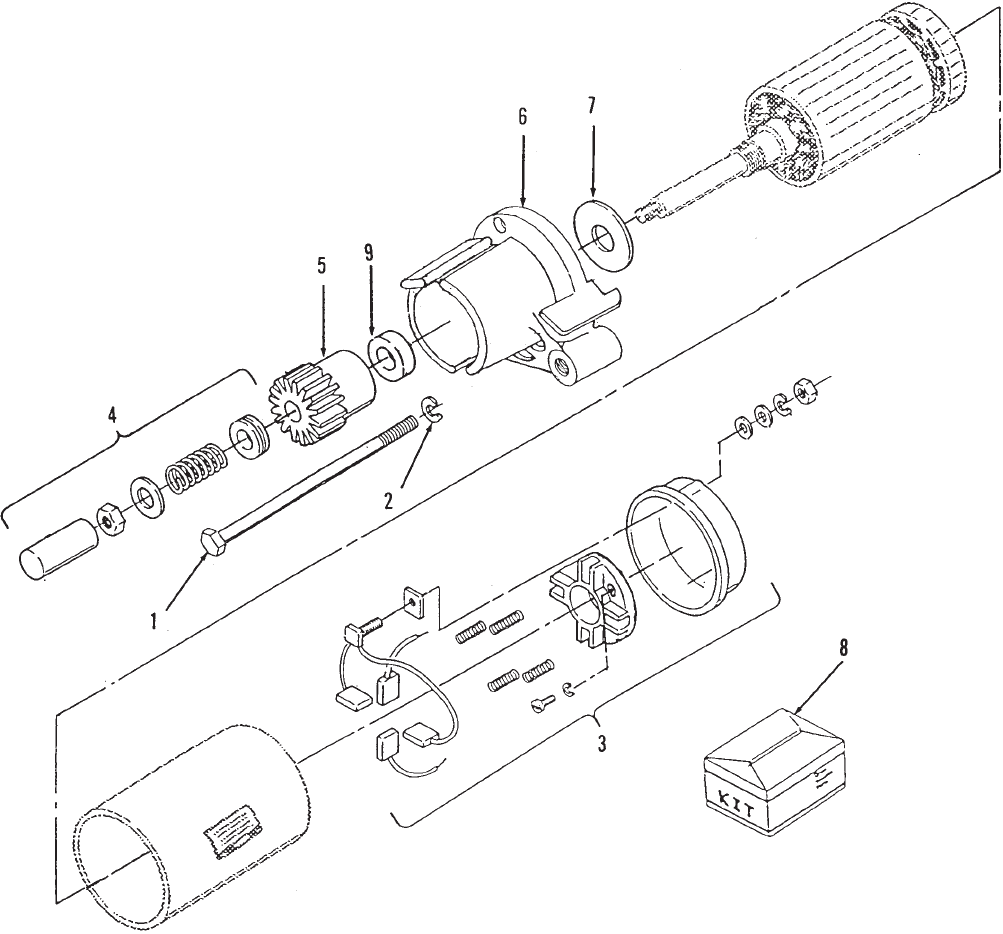
P216/18/20G
21
Starter Components
(191–1828)
REF PART QTY PART REF PART QTY PART
NO. NO. USED DESCRIPTION NO. NO. USED DESCRIPTION
1 191–1048 2 Bolt, Hex Head
2 870–0438 2 Retainer, Bolt
3 191–1532 1 Cap Assy, End (Includes
Cap, Brusholder, Springs,
Brushes, Terminal Hardware)
4 191–1359 1 Cover Assy (Includes Dust
Cover, Spring, Spacer, Nut and
Washer)
5 191–1156 1 Gear, Drive
6 191–1671 1 Plate, Front End Cap
7 191–1038 1 Washer, Thrust
8 191–1841 1 Kit, Repair (Includes Brush with
Stud, Springs and Brushes)
9 191–1534 1 Seal, Dust
NOTE: Phantom Items Not For Sale, For Replacement
Order Complete Starter.
NOTE: Onan Part Number Stamped on the Starter
Nameplate for Identification.
P216/18/20G
22
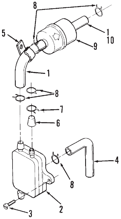
P216/18/20G
23
Fuel Pump and Filter
REF PART QTY PART REF PART QTY PART
NO. NO. USED DESCRIPTION NO. NO. USED DESCRIPTION
1 Hose (Cut to Length)
503–0707 1 12”, 9.5”
503–1016 1 8” (Code 13DA Only)
2 Pump, Fuel
Code 15AZ, 15BA, 15BL,
15BR
149–1982 1 Top or Bottom Inlet,
Top Outlet
149–2187–02 1 Top Inlet, Top Outlet
Code 15CY
149–2501–00 1 Top Inlet, Bottom Outlet
149–2501–01 1 Bottom Inlet, Bottom Outlet
3 815–0555 2 Screw, Pan Head Tapping
(10–24 x 5/8”) Code 15AZ,
15BA, 15BL, 15BM
4 Line, Pulse
503–0707 1 Cut to 7” Long (Code 13CD,
13CG, 15AZ, 15BA 15BL,
15BM)
503–1865–01 1 10–1/4” (Code 15CY)
5 518–0515 1 Clip, Wire – Code 15BZ, 15AZ,
15BL, 13CD, 13BJ
6 Cap, Fuel Fitting
149–1321 1 Code 13BJ, 13CG, 15AZ,
15BL
517–0165 1 Code15CM
7 503–0301 1 Clamp, Hose – Code 15AZ,
15BL, 13BJ
8 Clamp, Hose (1/2”)
503–0731 6 With Fuel Filter
503–0731 4 Without Fuel Filter
9 Filter, Fuel
149–2206–01 1 Code 15BZ
149–2206–01 1 Code 15BA, 15BL, 15BB,
15BZ, 15CM
10 Hose, Fuel
503–1199 1 21” (Code 13BJ)
503–0707 1 5–1/2” (Code 13DA, 15CM)
11 503–1593 1 Hose, Fuel (Out)
12 149–1308 3 Spring, Hose
13 149–2500 1 Bracket, Mounting
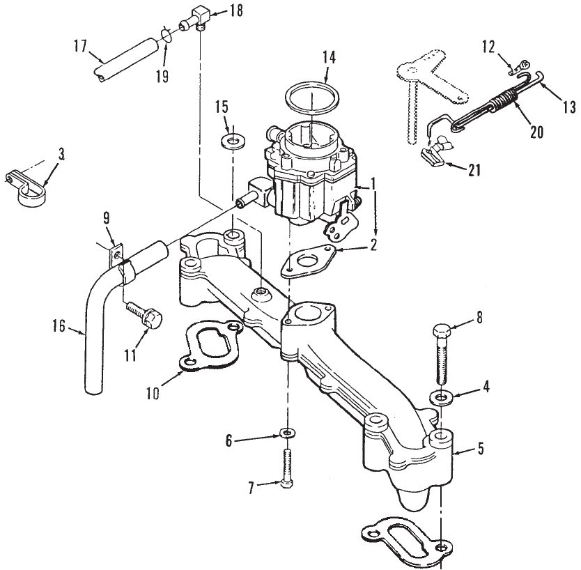
P216/18/20G
24
Fuel System
Gasoline
10
P216/18/20G
25
Fuel System
Gasoline
REF PART QTY PART REF PART QTY PART
NO. NO. USED DESCRIPTION NO. NO. USED DESCRIPTION
1 Kit, Carburetor (Includes
Mounting Gaskets) (See
Separate Page for
Components)
P216, P218
Spec A–F
146–0495 1 All Specs Except 11140
(Also Includes Elbow
and O–Ring)
146–0506 1 Spec 11140 Only (Does
Not Includes Gaskets)
146–0659 1 Begin Spec G
P220
Spec A–F
146–0496 1 All Specs Except 11212
(Also Includes Elbow
and O–Ring)
146–0613 1 Spec 11212 Only
Begin Spec G
146–0660 1 All Specs Except 11212
146–0661 1 Spec 11212 Only
2 154–0733 1 Gasket, Carburetor
3 332–1554 1 Clamp, Insulated (Fits 1/2”
Diameter Tube) – Code 23DZ
4 740–1006 4 Washer, Flat (M8) – Code 15BD,
15CB, 15CL
5 Kit, Intake Manifold (Includes
Carburetor Mounting Screws
and Washers)
541–0428 1 W/O Tapped Hole
541–0429 1 W/Tapped Hole
6 526–0122 2 Washer, Flat (5/16”)
7 Screw, Hex Head Cap
114–0022 2 (5/16–18 x 1–3/4”)
800–0193 2 (5/16–18 x 1–7/8”)
Floodlighter P218 –
Spec C
8 800–0033 4 Screw, Hex Head Cap
(5/16–18 x 2”)
9 518–0515 1 Clip, Fuel Line Wire
10 154–2495 2 Gasket, Manifold To Block
11 815–0474 1 Screw, Hex Washer Head
(1/4–14 x 1/2”)
12 518–0004 1 Clip, Retaining – Control Rod To
Carburetor (Use only with Old
Governor Rod)
13 Rod, Governor Control
150–2460 1 Zinc Plated – P216, P220
150–2364 1 P218
150–2593–02 1 P218 – Code 15CL/P216 –
Code 15BD,19BC
14 509–0145 1 O–Ring
15 526–0113 1 Washer, Flat (5/16” Screw)
16 Hose, Fuel
503–1548 1 17” Long – Code 15AZ,
15BR, 15BD
503–1577 1 30” Long – Code 15BL, 19AS
503–1443 1 15” Long – Code 15BD,15CL
17 Hose, Breather
503–1574 1 Code 19AU,19BA – Specs
A,B,C
503–1606–01 1 Code 19AS, 19AU, 19AW,
19BA – Begin Spec C –
3.25” Long
18 1 Fitting, Barbed
502–1038 1 Code 19AU, 19BA
502–0313 1 Code 19BC
19 Clamp, Hose
503–0731 2 1/2” Diameter – Code 19BA,
15CL, 15AZ
503–1133 1 .44” Diameter – Code 19AS,
19AW, 19AU, 19BA – Begin
Spec C
20 150–2550 1 Spring, Governor Rod
21 Clip, Rod End
518–0406 1 Old
518–0637 1 New
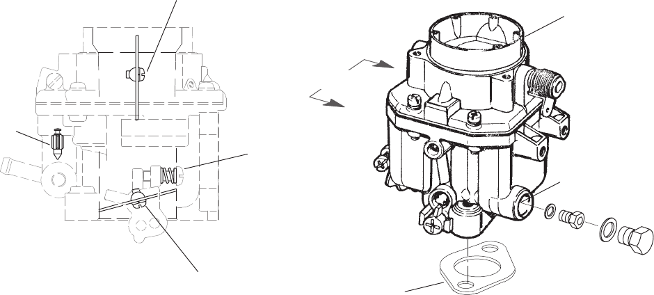
P216/18/20G
26
Carburetor Components
Gasoline
1
2
3
4
5
6
0.-1 )()
0.-1 )()
3
REF PART QTY PART REF PART QTY PART
NO. NO. USED DESCRIPTION NO. NO. USED DESCRIPTION
Kit, Carburetor (Includes
Mounting Gasket and
Carburetor)
146–0659 1 P216, P218
146–0660 1 P220
1 154–0733 1 Gasket, Carburetor Mounting
2 Carburetor (Includes Parts
Marked *)
146–0697 1 P216, P218
146–0698 1 P220
3 146–0338 4 *Screw, Valve Set
4 146–0331 1 *Spring, Adjustment Screw
5 146–0423 1 *Valve, Float
6 *Jet, Main Fuel (Altitude)
146–0652 1 P216, P218
146–0694 1 P220
146–0650 1 Package, Carburetor Repair
(Includes Air Horn Gasket
and Set Screws [M4 x 16mm],
Float Valve, Float Pin, Float
Assy, Main Plug Gasket and
O’Ring)
146–0649 1 Package, Accelerator Pump
Repair (Includes Diaphragm
Stopper Screw, O’Ring, Stop
Ring, Accelerator Pump Valve
Accelerator Diaphragm Spring
and Diaphragm Assy, Check
Valve Assy, Check Valve
Spring, Cover Set Screw
146–0502 1 Kit, Solenoid Valve Repair
(Includes Main Plug Gasket
and Solenoid Valve Assy
146–0657 1 Kit, Carburetor Repair (Includes
Mounting Gasket, Air Horn
Gasket and Set Screws
[M4 x 16mm], Float Valve,
Float Pin, Float Assy, Main
Plug Gasket and O’Ring)
146–0658 1 Kit, Carburetor Repair (Includes
Carburetor Mounting Gasket,
Diaphragm Stopper Screw,
O’Ring, Stop Ring, Accelerator
Pump Valve and Diaphragm
Assy, Accelerator Diaphragm
Spring, Check Valve Assy,
Check Valve Spring and Cover
Set Screws
* – Parts Included in Carburetor.
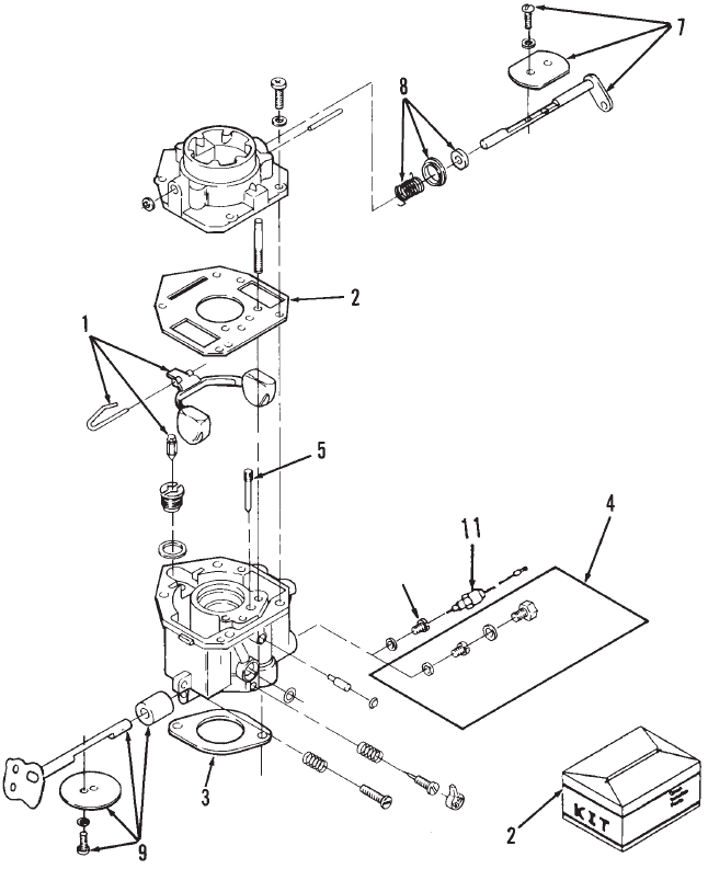
P216/18/20G
27
Carburetor Components
Gasoline
(Spec A–F)
6
REF PART QTY PART REF PART QTY PART
NO. NO. USED DESCRIPTION NO. NO. USED DESCRIPTION
Carburetor, Complete (Includes
Mounting Gasket)
146–0495 1 P216, P218
P220
146–0496 1 All Specs Except 11212
146–0613 1 Spec 11212
1 146–0437 1 Kit, Float (Includes Float, Pin
and Valve)
2 146–0500 1 Kit, Repair (Includes Screw and
Plug Package, Gasket
Package, Float Valve, Idle
Adjust Needle and Spring,
Mounting Gaskets, Idle Limit
Cap)
3 154–0733 2 Gasket, Carburetor
4 Jet, Fixed Power – Optional
(High Altitude Application)
146–0458 1 P216, P218
146–0347 1 P220
5 Jet, Idle
146–0425 1 P216, P218
146–0420 1 P220
6 Jet, Power
146–0396 1 P216, P218
146–0391 1 P220
7 146–0433 1 Kit, Choke Shaft (Includes
Choke Valve, Valve Set Screw
and Air Filter)
8 Kit, Choke Lever (Includes
Choke Lever Ring, Choke
Spring and Choke Collar)
146–0434 1 P216, P218
146–0435 1 P220
9 146–0503 1 Kit, Throttle Shaft (Includes
Valve Set Screw, Air Filter and
Throttle Valve)
11 146–0502 1 Solenoid, Fuel Cut–off
Code 15CJ
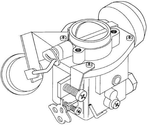
P216/18/20G
28
Carburetor Components
Gasoline
Auto Choke
REF PART QTY PART REF PART QTY PART
NO. NO. USED DESCRIPTION NO. NO. USED DESCRIPTION
146–0506 1 Carburetor, Complete
1 146–0425 1 Jet, Idle
2 146–0343 1 Jet, Power
3 146–0441 1 Cap, Idle Limiter
4 146–0341 1 Spring, Power Needle
5 146–0342 1 Needle, Complete Power
6 146–0498 1 Kit, Screw and Plug (Includes
Screws, Gaskets, Plugs and
Idle Adjust Spring)
8 146–0437 1 Kit, Float (Includes Float, Valve
and Pin)
7 146–0503 1 Kit, Throttle Shaft (Includes
Valve Set Screw, Throttle
Shaft, Air Filter and Throttle
Valve)
9 146–0499 1 Kit, Gasket (Includes Air Horn,
Gasket, Power Plug Gasket
(2) and O–Ring)
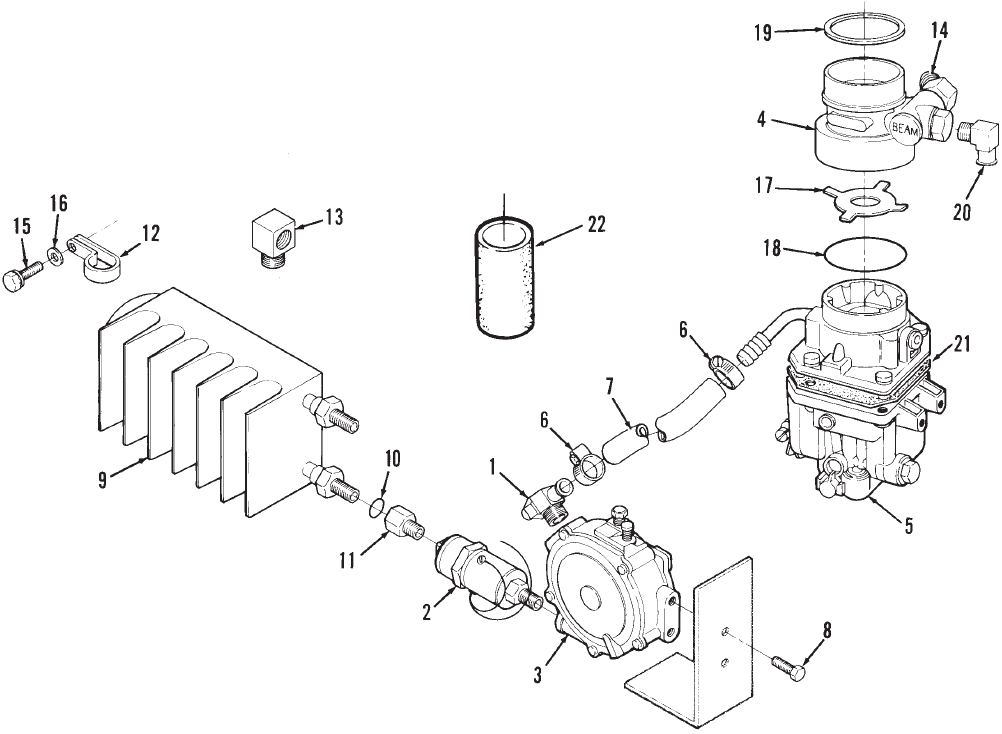
P216/18/20G
29
Fuel System
LP Gas
REF PART QTY PART REF PART QTY PART
NO. NO. USED DESCRIPTION NO. NO. USED DESCRIPTION
1 148–0907 1 Elbow, 90° Main Jet
2 307–2754 1 Valve, Fuel Shut–Off
3 Regulator, LP Gas
148–0909 1 Spec A–F
148–1025 1 Begin Spec G
4 Adapter, LP Gas
148–0918–01 1 LP Only
148–0908–01 1 Dual Fuel Carburetor
5 Carburetor, LP Gas (Includes
Gasket)
146–0495 1 Spec A–F
Begin Spec G
146–0678 1 P216, P218
146–0679 1 P220
6 503–0183 2 Clamp, Hose (7/8” Diameter)
7 503–1048 1 Hose, Fuel
8 821–0009 2 Screw, Hex Washer Head
Self–Locking (1/4–20 x 3/8”)
9 148–0914 1 Vaporizer, LP Gas
10 509–0035 2 O–Ring (1/2” ID)
11 502–0126 2 Connector, Inverted Male
12 332–1554 1 Clamp, Insulated (Fits 1/2”
Diameter Tube)
13 502–0054 1 Elbow, 90°
14 502–0575 1 Elbow, 45° – Dual Fuel Adapter
15 800–0011 2 Screw, Hex Washer Head
(1/4–20 x 2”)
16 526–0018 2 Washer, Flat (1/4” Screw)
17 148–0911 1 Deflector, Carburetor
18 509–0145 1 O–Ring (2” ID)
19 140–2279 1 Gasket, Air Cleaner – Dual
Fuel
20 502–0237 1 Elbow, Hose (Male ) 90° Dual
Fuel
21 146–0520 1 Gasket, Air Horn
22 503–1882–02 1 Tube, Air Intake
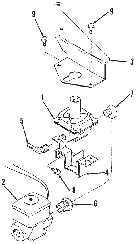
P216/18/20G
30
Natural Gas Regulator
REF PART QTY PART REF PART QTY PART
NO. NO. USED DESCRIPTION NO. NO. USED DESCRIPTION
1 Regulator, Natural Gas
148–0977 1 Spec A–F
148–1026 1 Begin Spec G
2 307–0312 1 Valve, Magnetic
3 148–0971 1 Bracket, Regulator Mounting
4 148–0972 1 Strap, Regulator Mounting
5 502–1145 1 Elbow, 90° Brass
6 502–0029–08 1 Bushing, Reducer (3/4 x 1/2”)
7 502–0133 1 Elbow, 90° Street
(1/2” NPT)
8 815–0293 1 Screw, Hex Washer Head
(1/4–20 x 3/4”)
9 821–0010 2 Screw, Hex Washer Head
(1/4–20 x 1/2”)
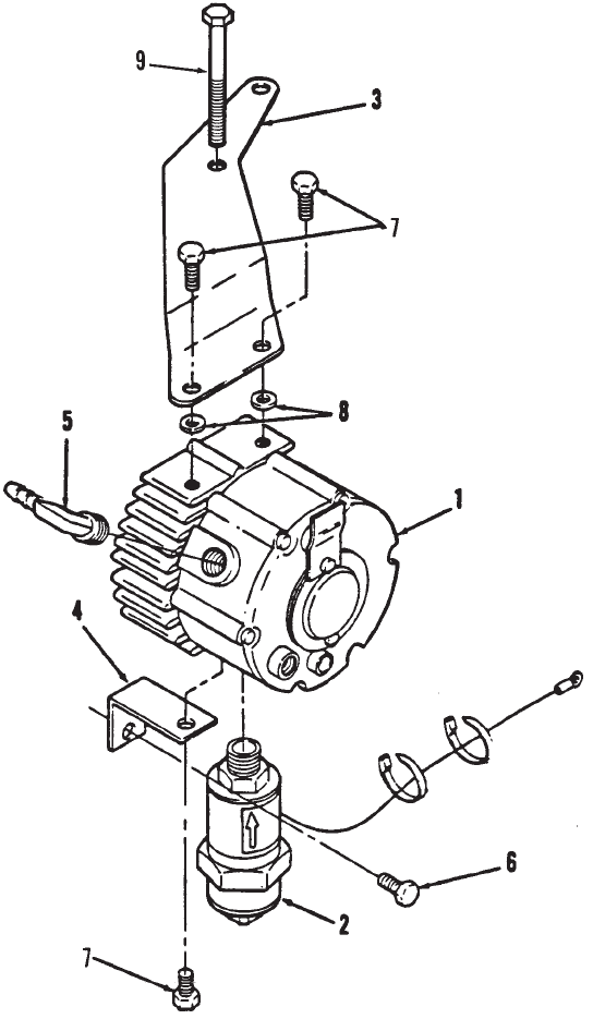
P216/18/20G
31
LP Converter Kit
REF PART QTY PART REF PART QTY PART
NO. NO. USED DESCRIPTION NO. NO. USED DESCRIPTION
1 148–0941 1 Regulator
2 307–2754 1 Valve, Shut Off
3 Bracket, Upper
148–0937–02 1 R.H. Mount
148–0942 1 L.H. Mount
4 Bracket, Lower
148–0938–02 1 R.H. Mount
148–0943 1 L.H. Mount
5 502–1145 1 Elbow, 90° Brass
(1/2” NPT – 3/8 Barb)
6 815–0293 1 Screw, Hex Washer Head
Thread Forming (1/4–20 x .75)
7 821–0018 3 Screw, Hex Head Cap
(1/4–20 x .625)
8 526–0018 2 Washer, Flat (1/4” Screw)
9 800–0034 2 Screw, Hex Head Cap
(5/16–18 x 2–1/4”)
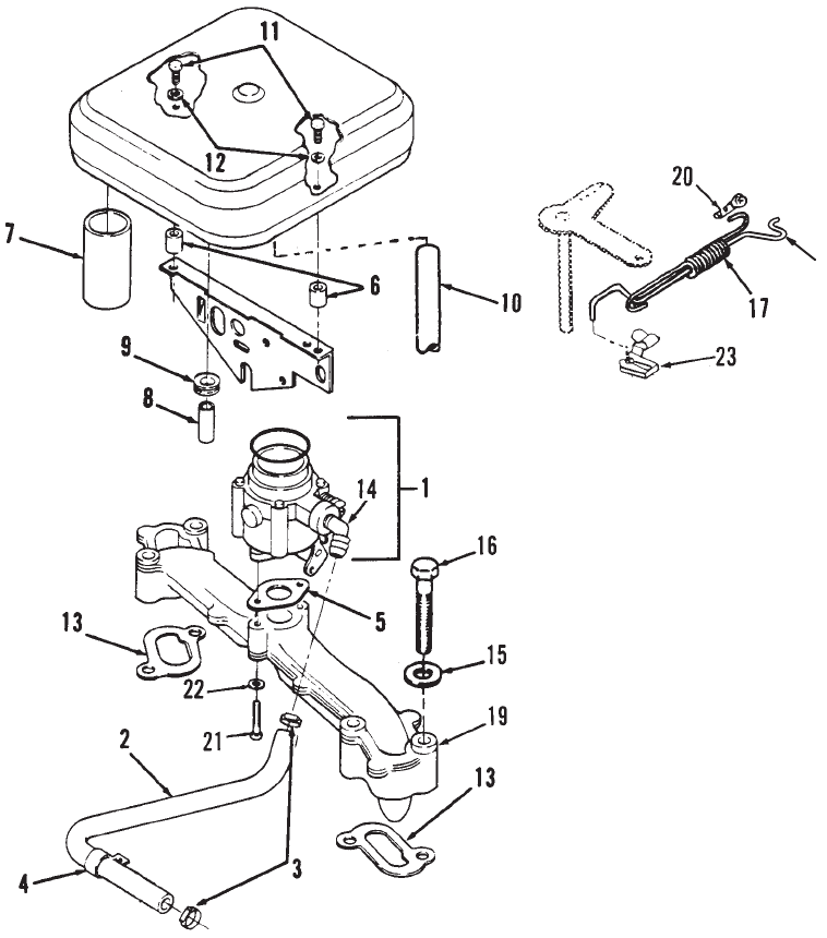
P216/18/20G
32
LP Carburetor Kit
18
REF PART QTY PART REF PART QTY PART
NO. NO. USED DESCRIPTION NO. NO. USED DESCRIPTION
1 Carburetor, LP
146–0562 1 Spec A–F
Begin Spec G
146–0678 1 P216
146–0679 1 P218/220
2 503–1798 1 Hose (3/8” I.D x 18” Long)
3 503–1133 2 Clamp, Hose
4 332–1356 1 Clamp, Loop
5 141–0281 1 Gasket, Carburetor
6 140–2722–01 2 Spacer, Air Cleaner
7 503–1882–02 1 Hose Air Inlet
8 123–1484–01 1 Tube, Copper Breather
9 508–0021 1 Grommet, Rubber
10 503–1606–02 1 Hose, Breather (3.75” Lg) –
Begin Spec C
11 821–0013 2 Screw, Hex Head Cap
(1/4–20 x 1)
12 526–0018 2 Washer, Flat (1/4” Screw)
13 154–2495 2 Gasket, Intake Manifold
14 502–1146 1 Elbow, 45° Brass
15 740–1006 4 Washer, Flat (M8)
16 800–0033 4 Screw, Hex Head Cap
(5/16–18 x 2”)
17 150–2550 1 Spring, Governor Rod
18 150–2593–02 1 Rod, Governor Control
19 541–0428 1 Manifold, Intake
20 518–0004 1 Clip, Control Rod Retaining
to Carburetor
21 800–0193 2 Screw, Hex Head Cap
(5/16–18 x 1–7/8”)
22 526–0397 2 Washer, Flat (.34” Screw)
23 Clip, Rod End
518–0406 1 Old
518–0637 1 New
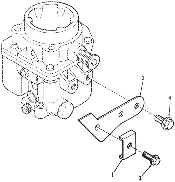
P216/18/20G
33
Choke Control
(Rear Pull)
REF PART QTY PART REF PART QTY PART
NO. NO. USED DESCRIPTION NO. NO. USED DESCRIPTION
1 153–0514 1 Clip, Choke Cable
2 153–0686–02 1 Bracket, Choke Cable
3 815–0359 1 Screw, Tapping Slotted Hex
Washer Head (#10–32 x 7/8”)
4 821–0004 2 Screw, Hex Washer Head Cap
(10–32 x 5/16”)
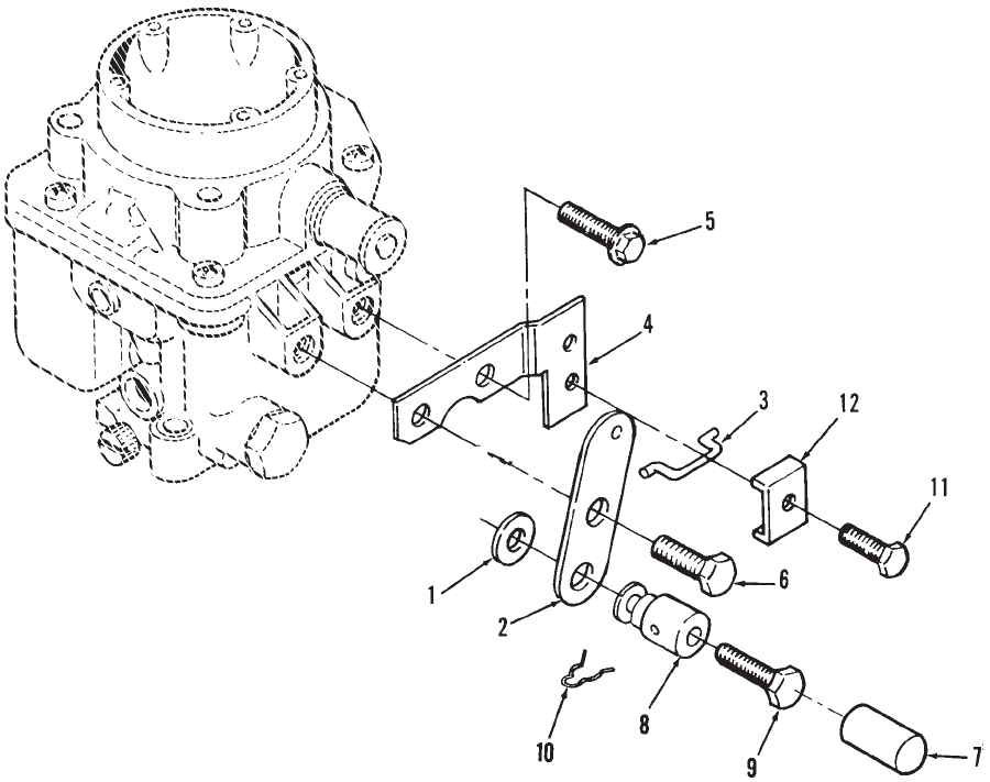
P216/18/20G
34
Choke Control
(Front Pull)
REF PART QTY PART REF PART QTY PART
NO. NO. USED DESCRIPTION NO. NO. USED DESCRIPTION
1 526–0140 1 Washer, Flat (#10 Screw)
2 153–0523 1 Lever, Choke
3 153–0500 1 Link, Choke
4 153–0524 1 Bracket, Choke Cable
5 821–0004 1 Screw, Hex Washer Cap
Head (#10–32 x 1/4”)
6 815–0820 1 Screw, Shoulder (#10–32 x .38”)
7 517–0177 1 Plug, Cap
8 152–0155 1 Swivel, Choke Lever
9 815–0693 1 Screw, Hex Head Machine
(#8–32 x .375”)
10 516–0059 1 Pin, Cotter
11 815–0359 1 Screw, Tapping Slotted
Hex Washer Head
(#10–32 x 7/8”)
12 153–0514 1 Clip, Choke Cable
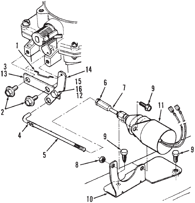
P216/18/20G
35
Remote Choke
Spec D
REF PART QTY PART REF PART QTY PART
NO. NO. USED DESCRIPTION NO. NO. USED DESCRIPTION
1 153–0500 1 Link, Choke
2 821–0004 2 Screw, Lk H (10–32 x 3/8)
3 153–0642 1 Bracket Assy, Choke (Includes
Parts Marked *)
4 518–0006 1 Clip, Lock
5 150–2478 1 Rod, Choke
6 870–0053 1 Nut, Hex Mach (10–32)
7 150–2481 1 Swivel, Link
8 870–0212 2 Nut, Self Lk (1/4–20)
9 815–0290 4 Screw, Hex Washer Head
Thread Form (1/4–20 x 5/8)
10 307–2751 1 Bracket, Solenoid
11 307–2750 1 Solenoid, 12 Volt
12 821–0010 2 Screw, Lock Head Flange
(1/4–20 x 1/2”)
13 150–2480 1 *Bracket, Choke
14 150–2531 1 *Lever, Choke
15 815–0820 1 *Screw, Pan Head Shoulder
(10–32)
16 870–0298 1 *Nut, Lock (10–32)
17 526–0008 1 *Washer, Flat (#10 Screw)
* – Parts Included in Choke Bracket Assy.
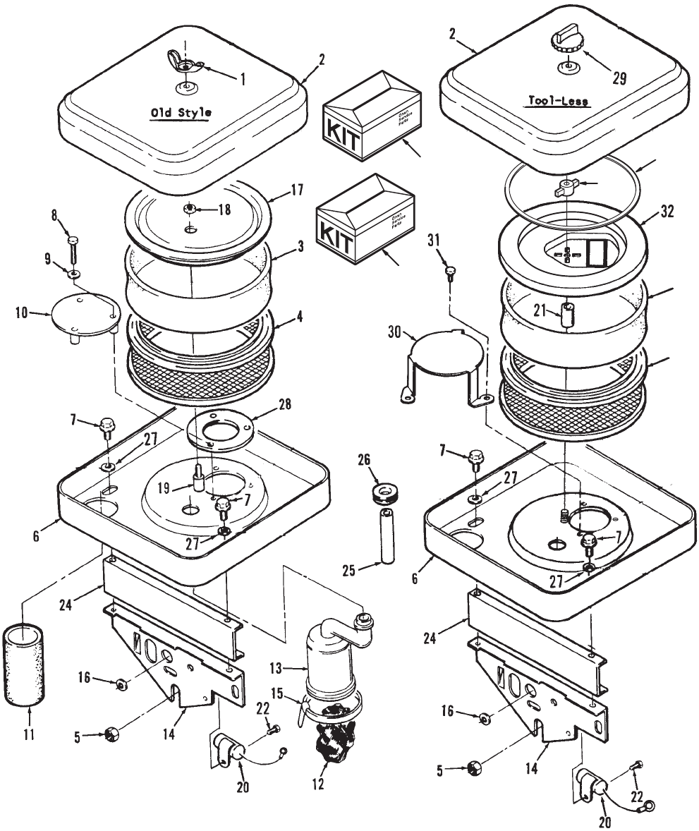
P216/18/20G
36
Air Cleaner
33
34
35
23
3
4
P216/18/20G
37
Air Cleaner
REF PART QTY PART REF PART QTY PART
NO. NO. USED DESCRIPTION NO. NO. USED DESCRIPTION
1 865–0020 1 Nut, Wing (1/4–20)
2 Cover, Air Cleaner
140–2005–50 1 Painted – Code 19AS, 19AW,
19BA (Standard Capacity)
140–2005–02 1 Chromed – Code 19BB
140–1913–50 1 Painted – Code 19AU (Hi
Capacity)
3 Wrapper, Air Cleaner Element
140–1496–01 1 Standard Svc and XSL
Code 19AS,19BA
140–1912–01 1 High Capacity – Code 19AU
4 Element, Air Cleaner
140–2628–01 1 Standard Capacity –
Code 19AS,19BA
140–2628–02 1 High Capacity – Code 19AU
5 870–0399 1 Nut, Hex Washer Head
Flanged (5/16–18)
6 Housing, Air Cleaner
140–2493–53 1 Code 19AS,19BA – Begin
Spec C – Use with Standard
Filter
140–2493–51 1 Code 19AS – Spec A,B – Use
with Standard Filter
140–2539–53 1 Code 19AU – Begin Spec C –
Use with High Capacity
Filter
140–2539–51 1 Code 19AU – Spec A,B – Use
with High Capacity Filter
7 Screw
815–0261 2 Hex Washer Head Tapping
(1/4–20 x 1/2”) Gasoline
800–0011 2 Hex Head Cap (1/4–20 x 2”)
LP
8 Screw, Hex Head Machine
815–0470 2 Gasoline Fuel
(#10–32 x1–1/2”)
815–0516 3 LP Gas – Dual Fuel Units
(#10–32 x 2–1/4”)
9 526–0234 3 Washer, Flat (#10 Screw)
10 145–0521 1 Plate, Air Deflector – Gasoline
11 Tube, Air Intake
140–2025–01 1 4.12” Long
503–1882–03 1 5.12” Long
503–1882–01 1 3.5” Long
12 123–1871 1 Filter, Breather Tube – Specs A
and B
13 123–1429 1 Tube, Crankcase Breather –
Specs A, B
14 140–2017–50 1 Support, Air Cleaner – Painted
15 503–1752 1 Clamp, Breather Tube – Spec
A and B
16 508–0001 1 Grommet, Rubber (1/2” Hole)
17 541–0459 1 Cover, Element
18 870–0365 1 Nut, Hex (1/4–20)
19 301–0458 1 Spacer, Air Cleaner Stud
20 312–0256 1 Capacitor (Placed Horizontal)
21 Spacer, Air Cleaner Stud
140–2536–01 1 1” Long – Standard
140–2536–02 1 2–3/4” Long – High Capacity
22 815–0178 1 Screw, Hex Washer Head
Thread Form (10–32 x 5/8”)
23 140–2786 1 Spacer, Nylon
24 140–2202–02 1 Spacer, LP Gas – Painted
(Early Systems)
25 123–1484–01 1 Tube, Breather (Copper)
LP Gas
26 508–0021 1 Grommet, Rubber (1/2” ID)
LP Gas
27 526–0018 2 Washer, Flat (1/4” Screw)
LP Gas
28 140–2278 1 Plate, Support – Dual Fuel
Units
140–2204 1 Gasket, Hose Fitting – Code
19BA – Not Shown
870–0346 1 Nut, 6 Point Self–Lock
(1/4–28) Code 19BA – Not
Shown
29 140–2761 1 Knob (1/4–20)
30 145–0614 1 Plate, Air Deflector, High
Capacity (Spec A–F)
Code 19AU
31 815–0463 3 Screw, Hex Washer Slotted
Head (#10–32 x 3/8”)
32 140–2942 1 Cover, Element
33 140–2789 1 Gasket, Air Cleaner
34 Kit, Air Cleaner
541–0457–01 1 Standard Capacity
High Capacity
541–0458–01 1 Spec A,B
541–0458–02 1 Begin Spec D
35 541–0459 1 Kit, Air Cleaner (Inner Cover)
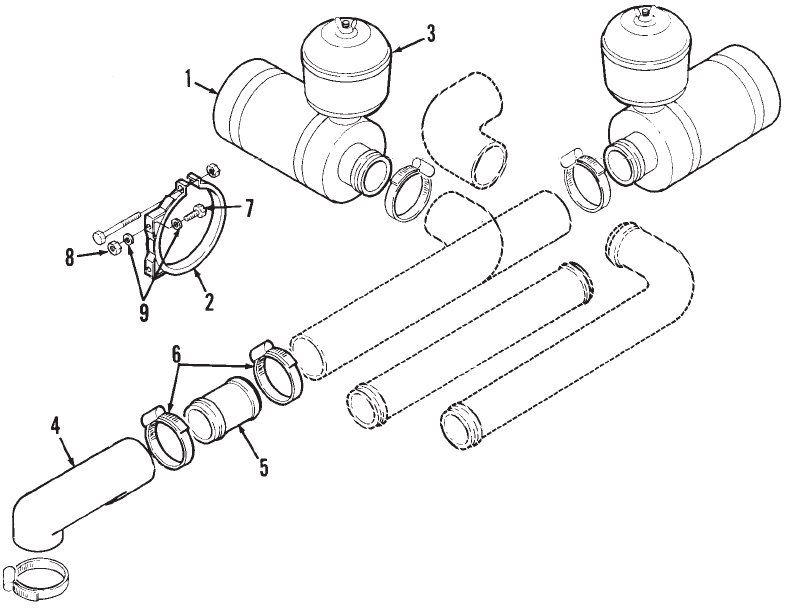
P216/18/20G
38
Remote Air Cleaner
REF PART QTY PART REF PART QTY PART
NO. NO. USED DESCRIPTION NO. NO. USED DESCRIPTION
1 140–0721 1 Cleaner, Air (Includes Element
#140–0765)
2 140–0722 2 Band, Air Cleaner
3 140–0723 1 Pre–Cleaner, Air
(Plastic)
4 140–1428 1 Elbow, Air Inlet
5 140–2173 1 Tube, Air Induction (Steel)
6 503–1141 4 Clamp, Hose (2–3/8” Dia.)
7 800–0004 4 Screw, Hex Head Cap
(1/4–20 x 5/8”)
8 870–0065 4 Nut, Self–Lock (1/4–20)
9 526–0018 8 Washer, Flat (1/4” Screw)
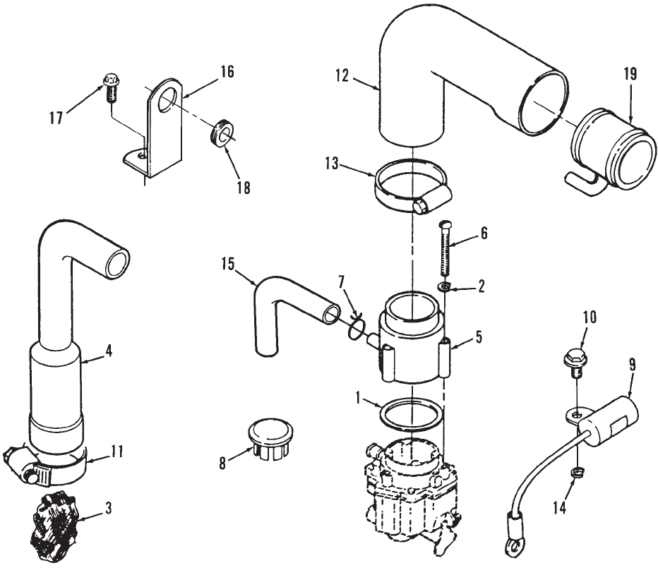
P216/18/20G
39
Remote Air Cleaner Adapter
REF PART QTY PART REF PART QTY PART
NO. NO. USED DESCRIPTION NO. NO. USED DESCRIPTION
1 509–0145 1 Seal, O–Ring
2 850–0030 3 Washer, Spring Lock (#10)
3 123–1871 1 Filter, Breather Tube – Spec A,B
4 123–1539 1 Tube, Crankcase Breather
Spec A,B
5 140–1714 1 Adapter, Carburetor Air Intake
6 813–0106 3 Screw, Round Head Machine
(#10–32 x 1–1/8”)
7 Clamp, Hose (11/16” Dia.)
503–0769 1 Spec A,B
503–0769 2 Begin Spec C
8 Plug, Dot Button – Blower
Housing Air Hole
517–0252 1 Unplated
517–0174 1 Tapered
9 312–0256 1 Capacitor
10 815–0389 1 Screw, Hex Washer Head
(1/4–20 x 3/8”)
11 503–0398 1 Clamp, Breather Tube
(1–5/8” Diameter)
12 140–1428 1 Elbow, Air Inlet
13 Clamp, Hose
503–1142 3 1.81–2.75” – P220 –
Code 19CK
503–1141 1 1.56 – 2.5” – Code 19AV
14 853–0013 1 Washer, ET Lock (1/4”)
15 503–1396 1 Hose, Breather
16 149–2242 1 Bracket, Fuel Line – P218,
P220 – Begin Spec C
17 815–0261 1 Screw, Hex Washer Head
(1/4–20 x 1/2”)
18 508–0021 1 Grommet, Rubber – P218, P220
– Begin Spec C
19 140–2668–01 1 Tube, Air Induction – P220 –
Code 19C
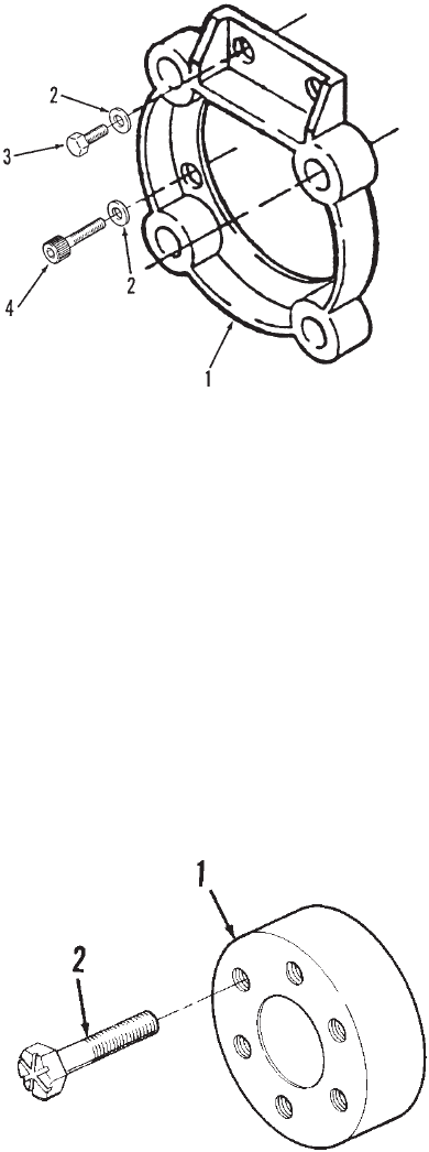
P216/18/20G
40
Clutch Adapter
REF PART QTY PART REF PART QTY PART
NO. NO. USED DESCRIPTION NO. NO. USED DESCRIPTION
1 190–0597 1 Adapter, Electric Clutch
2 526–0245 4 Washer, Flat (3/8” Screw)
3 800–0051 2 Screw, Hex Head Cap
(3/8–16 x 1–1/4”)
4 802–0073 2 Screw, Socket Head
(3/8–16 x 1–1/4”)
Drive Plate Hub
REF PART QTY PART
NO. NO. USED DESCRIPTION
1 104–1674 1 Hub, Drive Plate
2 805–0019 6 Bolt, Place – Grade 8
(3/8–16 x 1–7/16”)
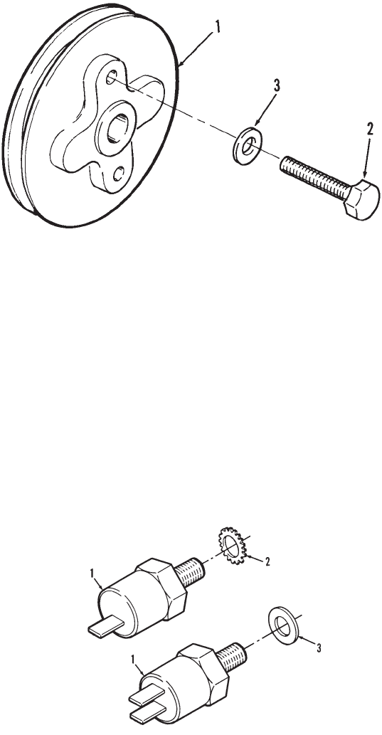
P216/18/20G
41
Pulley
(Single Groove)
REF PART QTY PART
NO. NO. USED DESCRIPTION
1 191–1210 1 Pulley, Alternator Drive
2 114–0022 4 Screw, Hex Head Ca-p
(5/16–18 x 1–3/4”)
3 740–1006 4 Washer, Flat (M8)
High Temperature Switch
Cut–Off
REF PART QTY PART REF PART QTY PART
NO. NO. USED DESCRIPTION NO. NO. USED DESCRIPTION
1 Switch, High Temperature
309–0559 1 1 Terminal
309–0592 1 2 Terminal
2 853–0013 1 Washer, ET Lock
(1/4”)
3 526–0021 1 Washer, Flat – 2 Terminal
Switch (1/4” Screw)
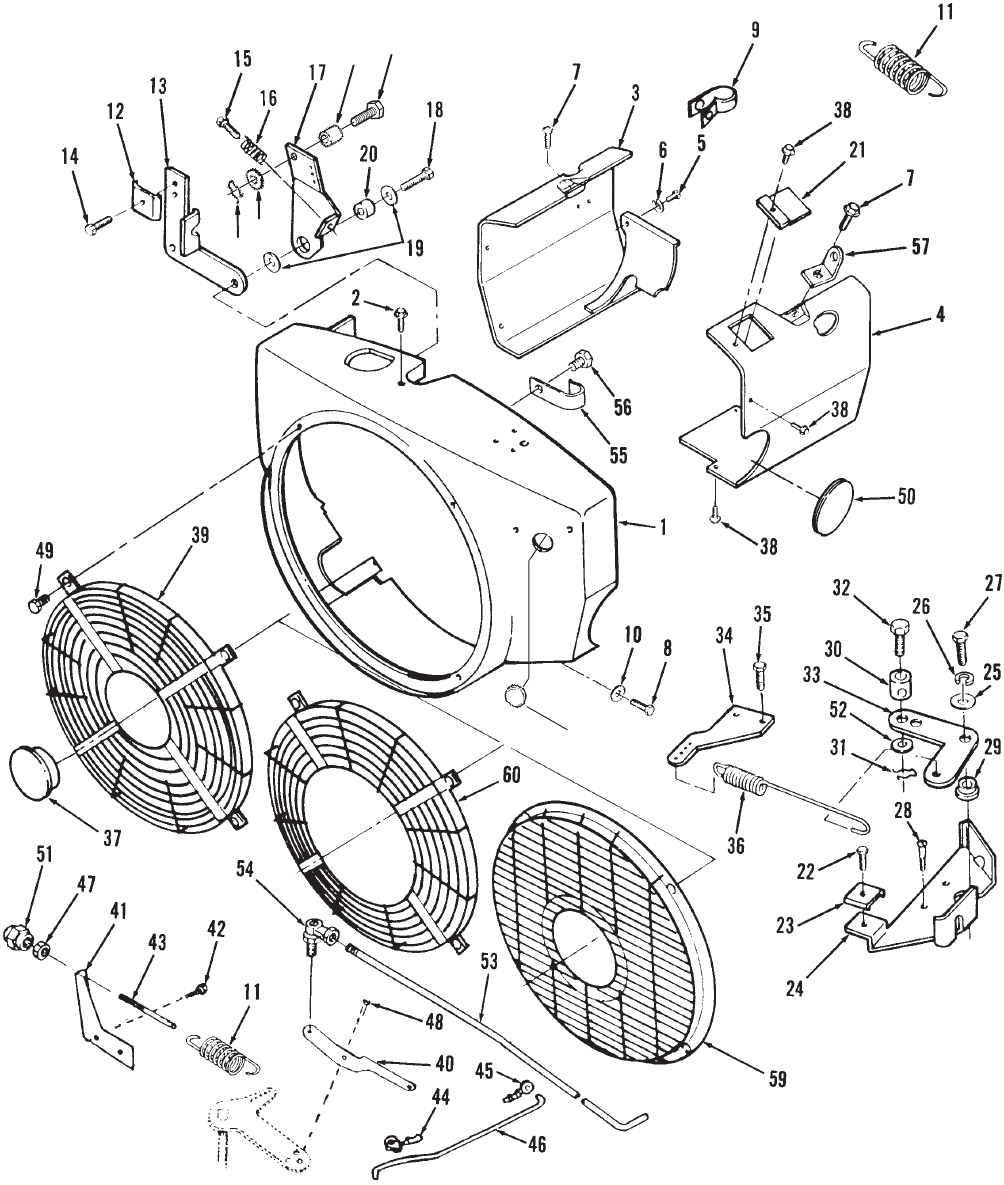
P216/18/20G
42
Blower Housing and Governor
61 62
6364
65
P216/18/20G
43
Blower Housing and Governor
REF PART QTY PART REF PART QTY PART
NO. NO. USED DESCRIPTION NO. NO. USED DESCRIPTION
1 Housing, Blower
134–5179–02 1 Standard – Used on all
Models Except ones with
the Following Codes:
134–5184–02 1 Code 13CK (Spec 10608)
134–5185–02 1 Code 17DA (W/Oil Cooler)
134–4902–02 1 Code 17BC (Spec 10876,
Floodlighter)(This Part To
Be Used With the Following
Not Illustrated Parts)
134–4907–02 1 Tray, Housing
134–4908–02 1 Housing, Transition (RH)
134–4909–02 1 Housing, Transition (LH)
134–4906–02 1 Backplate
2 815–0261 2 Screw, Hex Washer Tapping
Head (1/4–20 x 7/16”)
3 Housing, LH Cylinder Air
134–4615–50 1 Code 31AZ, 31BD, 31BC –
Painted
134–4610–50 1 Code 23DK – With 31AZ –
With Weld Nuts – Painted
134–4885–02 1 Floodlighter – Code 13CG
134–4956–50 1 Code 23EF – P218 – Painted
4 Housing, RH Cylinder Air
134–4798–50 1 Code 23DK – With 31AZ –
With Weld Nuts – Painted
134–4352 1 Floodlighter – Code 13CG
134–4824 1 Code 23DC
134–4796–50 1 Code 31AZ, 31BC, 31BD –
Painted
134–4957–50 1 Code 23EF – P218 – Painted
5 815–0290 2 Screw, Hex Washer Tapping
Head (1/4–20 x 5/8”)
6 526–0021 2 Washer, Flat (1/4” Screw)
7 821–0016 2 Screw, Hex Washer Cap
Head (5/16–18 x 3/4”)
8 Screw, Hex Washer Tapping
Head
815–0290 4 (1/4–20 x 5/8”)
815–0337 4 (1/4–20 x 3/4”) Units With
3 Quart Oil Base – Code
17CM
9 332–2319 1 Clamp, Alternator Wire
Leads (5/16” Diameter)
10 526–0018 4 Washer, Flat (1/4” Screw)
11 Spring, Governor
150–1214 1 5 Ball – Code 13BJ, 13CK
– Code 13CG, 13BF (Use
with Code 13CB)
150–1740 1 10 Ball – Code 13CH – P218
150–2550 1 5 Ball – Code 13CG (Use
with 13CC)
12 153–0514 1 Clamp, Cable – Code 13BJ,
13CK
13 Bracket, Cable
150–2345–02 1 Code 13BJ, 13CK
150–1725–01 1 Begin Spec D – Code 13BJ
14 815–0359 1 Screw, Hex Head Tapping
(#10–32 x 1/2”) – Code 13BJ
15 815–0510 1 Screw, Hex Head Tapping
(#6–32 x 5/8”) – Code 13BJ,
13CK
16 150–1398 1 Spring, Idle Setting –Code
13BJ, 13CK
17 Arm Assy, Governor Control
(Includes Spring and Screws)
Code 13BJ (Without Swivel)
150–2360 1 Spec A–C
150–1761 1 Spec D
150–2360 1 Code 13CK (Without Swivel)
150–2584 1 Code 13DA (With Swivel and
Pin)
150–1761–01 1 Code 13DD
18 Screw (1/4–20 x 1/2”)
821–0010 2 Lock Head
815–0436 2 Hex Washer Head
19 526–0021 2 Washer, Flat (1/4” Screw)
Code 13BJ, 13CD, 13CG
20 150–1269 1 Bushing, Control Arm –Code
13BJ, 13CK
21 134–3626–50 1 Cover, Voltage Regulator
Painted – Code 31BD, 23EF
22 815–0391 1 Screw, Hex Head Tapping
(#10–32 x 1/2”)
23 153–0514 1 Clamp, Throttle Cable
24 Bracket, Governor Control
Mounting – Zinc Plated
150–1726–01 1 All Specs Except 11215
150–2570 1 Spec 11215 Only
25 740–1004 1 Washer, Flat (M6)
26 850–0040 1 Washer, Spring Lock (1/4”)
27 800–0007 1 Screw, Hex Head Cap
(1/4–20 x 1”)
28 815–0439 3 Screw, Hex Washer Head
Tapping (8–15 x 1/2”)
29 150–1727 1 Bushing, Governor Control
30 152–0155 1 Swivel, Throttle Lever
31 516–0059 1 Pin, Cotter
32 815–0693 1 Screw, Hex Head Machine
33 Link, Governor Control
150–1366 1 All Specs Except 11215
150–2571 1 Spec 11215 Only
34 150–1754–01 1 Adapter, Governor Arm
(Zinc Plated)
35 815–0555 2 Screw, Hex Head Tapping
W/ET (#10–32 x 1/2”)
36 150–1755 1 Spring, Governor – Code 13BK,
39AG

P216/18/20G
44
Blower Housing and Governor
61 62
6364
65
P216/18/20G
45
Blower Housing and Governor
REF PART QTY PART REF PART QTY PART
NO. NO. USED DESCRIPTION NO. NO. USED DESCRIPTION
37 Plug, Black Nylon
517–0261 1 Code 23DE – 2” Dia.
517–0136 1 Code 13BJ,15BB,23DH –
(59/64” Dia.)
99–2393 1 Logo, Nameplate – Code 23DN
(2.475” Dia.)
99–2389 1 Logo, Nameplate (Wheelhorse)
Supplied by Onan
38 821–0008 4 Screw, Hex Washer Head Cap
(1/4–20 x 5/16”)
39 134–4560–50 1 Guard, Stationary – Painted
(See Illustration) Code 23DE
40 Lever, Governor – Code 13CC
150–2427–02 1 Zinc Plated
150–2408–02 1 Spec B – P216, P220
150–2388 1 Spec C – P218
150–2524–02 1 Zinc Plated – Code 13CY
Begin Spec H
Code 13CC
150–2688–02 1 Miller
150–2695–02 1 Lincoln, Hobart
150–2524–02 1 Code 13CY
41 150–2264 1 Bracket, Governor Adjust –
Code 13CG,13BJ, 13BF
42 821–0010 2 Screw, Lock Head
(1/4–20 x 1/2”) Code 13CG,
13BJ
43 150–0694 1 Stud, Adjusting – Code 13CG
44 518–0637 1 Clip, Rod End – Code 13CG
45 518–0004 1 Clip, Retaining – Control Rod
Code 13CG, 13CH
46 150–2460 1 Rod, Control – Code 13CG –
Zinc Plated
47 870–0131 1 Nut, Governor Adjusting Hex
(W/ET 10–32) – Code 13CG
48 Screw, Thread Cutting – Hex
Head W/ET
815–0194 2 10–32 x 3/8”
815–0181 2 10–32 x 1/2”
49 Screw
815–0575 4 Hex Washer Head
(1/4–20 x 3/8”)
815–0721 4 Pan Head Taptite (Special)
Code 23DN,13BJ,13CG,
13DA
50 508–0273 1 Grommet, Air Seal – Code 17CE
51 150–0621 1 Nut, Acorn Governor
Code 23DE, 23DC, 13CG
52 526–0006 1 Washer, Flat (#12 Screw)
Code 13BK, 13DA
53 150–0629 1 Rod, Governor – Code 13CH
54 150–0639 1 Joint, Ball – Code 13CH
55 518–0515 1 Clip, Wire – Code 13BJ, 13BK,
13CD, 13CG, 13DA
56 815–0474 1 Screw, Hex Washer Head
(1/4–14 x 1/2”) Code 13BJ,
13BK, 13CD, 13CG, 13DA
57 403–4202–02 2 Bracket Lifting
59 Guard, Stationary (See
Illustration)
134–4689 1 No Center Hole – Code 13BJ,
13CE, 23DE, 23DH, 23DN,
23ED, 23EJ, 23EK
134–4689–02 1 Center Hole Dia. 3.88”
Code 23DH, 23DN, 23ED,
13DA
60 134–4556–01 1 Guard, Stationary (See
llustration) – Code 23DH
61 153–0632 1 Swivel, Choke Lever
62 800–4072 1 Screw, (Special)
63 516–0059 1 Pin, Cotter
64 526–0006 1 Washer, Flat
65 517–0136 1 Plug
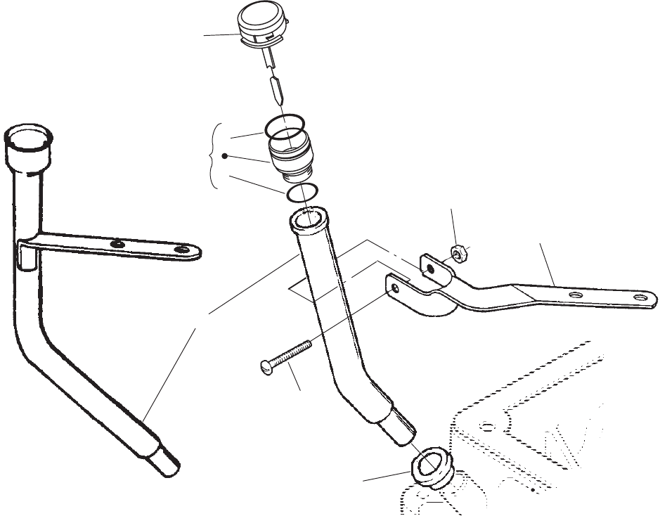
P216/18/20G
46
Oil Fill Tube and Bracket
1
2
5
8
7
9
6
4
3
REF PART QTY PART REF PART QTY PART
NO. NO. USED DESCRIPTION NO. NO. USED DESCRIPTION
1Cap and Indicator, Twist–On
123–1961 1 Code 17BC
Code 17BY
123–1851–01 1 Use with Code 17CM or
17DU
123–1637–01 1 Use with Code 17BW,
17CG or 17DK (Screw–In
Cap is 123–1637–00)
Code 17BZ
123–1880–01 1 Use with Code 17DA
Use with Code 17CG
123–1630–01 1 13.07” Indicator
123–1402–01 1 13.68” Indicator
123–1849–01 1 Use with Code 17CM
123–1402–01 1 Use with Code 17BW
Code 17CF
Use with Code 17DT
123–1754–01 1 17.57” Indicator
123–2119–01 1 16.90” Indicator
123–1754–01 1 Use with Code 17BW,
17CG or 17DK
123–1850–01 1 Use with Code 17CM
or 17DH
123–1860–01 1 Use with Code 17DA
123–1630–01 1 Code 17CH
123–2119–01 1 Code 17EA
2 123–2105 1 Adapter Assy, Oil Tube
(Includes O’Ring and Seal)
3 509–0304 1 O’Ring
4 509–0142 1 Seal
5 Tube, Oil Fill
With Welded Bracket
Code 17CF
123–1896–02 1 W/Straight Bracket
123–1896–04 1 W/T” Shaped Bracket
123–2117–02 1 W/“L” Shaped Bracket
W/O Welded Bracket
123–1685–50 1 Code 17BY
123–1718–50 1 Code 17BZ, 17CH
123–1729–50 1 Code 17CF
6 Screw
815–0576 1 Pan Head (#10 x 1–1/4”)
815–0760 1 Self–Tapping – Use with
Extended Tubes
7 509–0269 1 Seal, Oil Fill Tube
8 Bracket, Fill Tube
123–1865–51 1 Codes 17BZ, 17CH
123–1863–51 1 Code 17BY
9 870–0410 1 Nut, Speed (Type U)
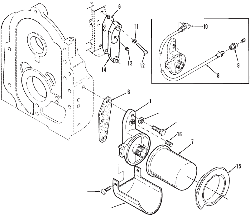
P216/18/20G
47
Oil Filter
3
4
2
5
REF PART QTY PART REF PART QTY PART
NO. NO. USED DESCRIPTION NO. NO. USED DESCRIPTION
1 122–0814 1 Adapter, Oil Filter (Includes
Screws)
2 815–0194 2 Screw, Hex Head ET Cap
(#10–32 x 3/8”)
3 526–0065 2 Washer, Copper Flat
(5/16” Screw)
4 800–0028 2 Screw, Hex Head Cap
(5/16–18 x 1”)
5 122–0360–50 1 Drain, Oil Filter (Painted)
6 122–0771 1 Gasket, Oil Filter Adapter
7 Filter, Oil
122–0645 1 With–Out Hex Nut
Code 17CD (3–1/2” Long)
122–0800 1 Without Hex Nut – Code
17CD,17DF (4–3/16” Long)
122–0469 1 With Hex Nut – Code 17CV
(4.64” Long)
122–0406 1 With Hex Nut – Code 17DG
(3.8” Long)
8 501–0008 1 Line, Flex Oil
9 502–0017 1 Connector
10 502–0020 1 Elbow, Street 90°
11 526–0065 2 Washer, Copper Flat
(5/16” Screw)
12 800–0028–01 2 Screw, Hex Head Cap
(5/16–18 x 1”)
13 505–0057 1 Plug, Countersunk (1/8”)
14 122–0438 1 Cover, Oil Filter Pad
Code 11AZ,17CE
15 122–0502 1 Gasket, Oil Filter (Code
17CD,17CV,17DF,17DG
16 505–1426 Plug, Countersunk (1/8”)
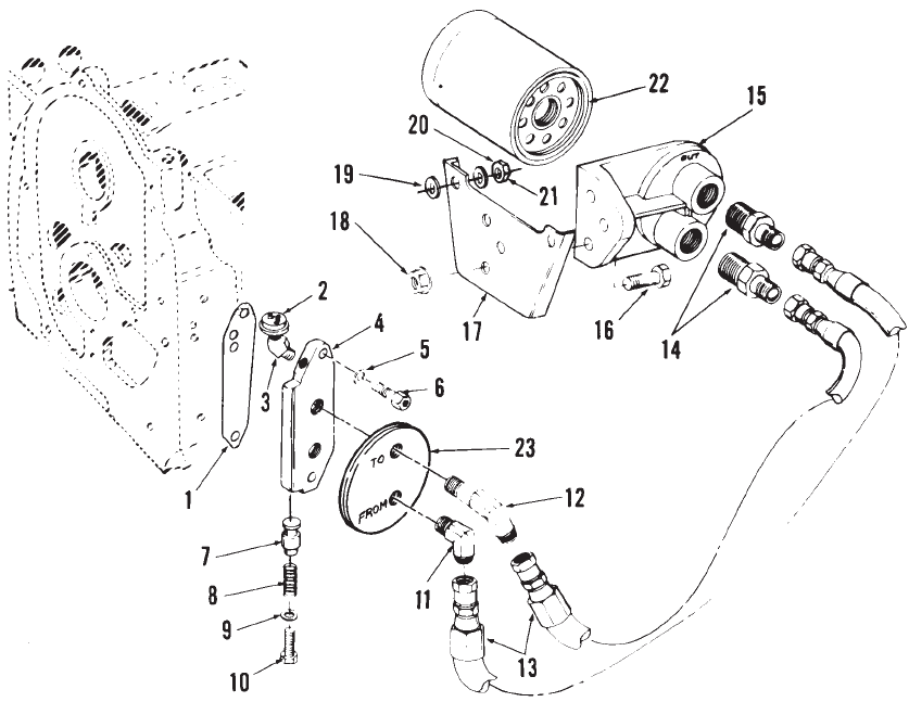
P216/18/20G
48
Remote Oil Filter
REF PART QTY PART REF PART QTY PART
NO. NO. USED DESCRIPTION NO. NO. USED DESCRIPTION
1 122–0771 1 Gasket, Oil Filter Adapter
2 Switch, LOPKO
309–0641–18 1 2 Terminal, Normally Open
Code 17CK,35AV
309–0546 1 1 Terminal, Normally Closed
Code 17AS,17CJ,35AU
3 Elbow, Street
502–0053 1 45° – Code 17AS, 17CJ
505–0049 1 90° – Code 17CK
4 122–0369 1 Adapter, Oil Filter
5 526–0065 2 Washer, Copper Flat
(5/16” Screw)
6 802–0056 2 Screw, Socket Head Cap
(5/16–18 x 1–1/4”)
7 120–0398 1 Plunger, Bypass
8 120–0140 1 Spring, Bypass Valve
9 526–0066 1 Washer, Flat (3/8” Screw)
10 801–0047 1 Screw, Hex Head Cap
(3/8–24” x 5/8”)
11 502–0805 1 Elbow, Male (From Filter) 90°
12 502–0806 1 Elbow, Male (To Filter) 90°
13 Hose, Oil
501–0498 2 Specs A, B – Code 17CJ
501–0440 2 Begin Spec C – Code 17CJ
14 502–0804 2 Connector, Male – Code 17CJ
15 122–0476 1 Base, Remote Oil Filter
Code 17CJ
16 800–0027 3 Screw, Hex Head Cap
(5/16–18 x 7/8”)
17 122–0559 1 Bracket, Remote Oil Filter
Code 17CJ
18 870–0257 3 Nut, Self–Lock (5/16–18”)
19 526–0030 2 Washer, Flat (3/8” Screw)
20 526–0174 2 Washer, Flat (13/32” ID x
25/32” OD x .1345 Thk)
21 862–0003 2 Nut, Hex (5/16–18”)
22 122–0469 1 Filter, Oil – Code 17CJ
23 Grommet, Air Seal
508–0249 1 W/Oil Line Holes
508–0273 1 W/O Oil Line Holes
505–0057 1 Plug, Square Head – Units
Without Lopko Switch
(Not Shown)
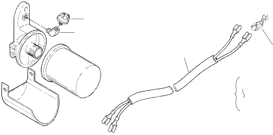
P216/18/20G
49
Low Oil Pressure
Cut–Off Switch
1
4
2
3
5
1
3
REF PART QTY PART REF PART QTY PART
NO. NO. USED DESCRIPTION NO. NO. USED DESCRIPTION
1 Switch, LOPKO
Spec A–D
309–0546 1 Code 35AU, 1 Terminal –
Normally Closed – 2.01”
Long
309–0641–18 1 Code 35AV, 2 Terminal –
Normally Open – 1.87”
Long
309–0558 1 Code 35BW, 2 Terminal –
One Terminal – Normally
Open, One Terminal –
Normally Closed and
Internally Grounded –
2” Long
309–0641–17 1 Code 35AH, 1 Terminal –
Normally Open 2.06”
Long
309–0583 1 Code 35BV, 3 Terminal –
One Terminal Normally
Open, One Terminal
Normally Closed with
External Common
Ground
Begin Spec E
309–0615 1 * Code 35AU, 1 Terminal –
Normally Closed – 2.01”
Long
309–0646–02 1 SCode 35AV, 2 Terminal –
Normally Open – 1.87”
Long
309–0646–03 1 + Code 35BW, 2 Terminal –
One Terminal – Normally
Open, One Terminal –
Normally Closed and
Internally Grounded –
2” Long
309–0646–01 1 Code 35AH, 1 Terminal –
Normally Open 2.06”
Long
309–0646–04 1 Code 35BV, 3 Terminal –
One Terminal Normally
Open, One Terminal
Normally Closed with
External Common
Ground
309–0661 1 Code 35DL
2 332–2301 2 +*STab, Faston
3 Harness, LOPKO
338–2211 1 Spec A–D
338–3183 1 +*SBegin Spec E
4 502–0053 1 Elbow, 45°Street (Spec A–D)
Code 17DF, 35AV, 35BW,
35AH, 35BV
5 Kit, LOPKO
541–0235 1 1 Terminal LOPKO (Includes
Parts Marked *)
2 Terminal LOPKO
541–0319 1 1 Open, 1 Closed (Includes
Parts Marked +)
541–0236 1 Both Open (Includes Parts
Marked S)
* – Parts Included in 1 Terminal LOPKO Kit.
+ – Parts Included in 2 Terminal (1 Open, 1 Closed) LOPKO
Kit.
S– Parts Included in 2 Terminal (Both Open) LOPKO Kit.
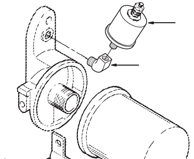
P216/18/20G
50
Oil Pressure Sender
1
2
REF PART QTY PART
NO. NO. USED DESCRIPTION
1 Sender, Oil Pressure Gauge
(40 P.S.I.)
193–0389 1 Spec A–D
309–0646–01 1 Begin Spec E
2 502–0053 1 Elbow, 45°Street
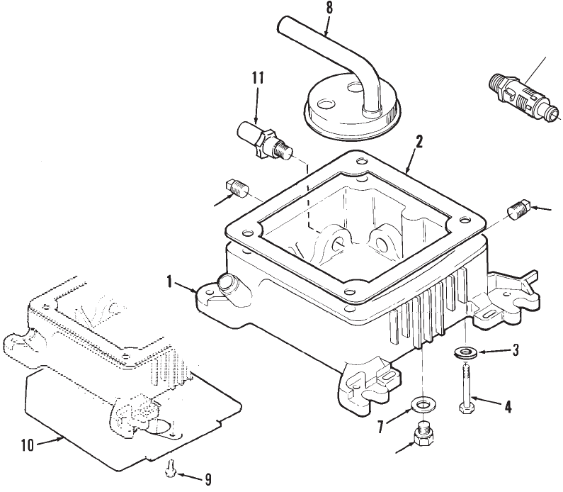
P216/18/20G
51
Oil Base
5
6
6
12
REF PART QTY PART REF PART QTY PART
NO. NO. USED DESCRIPTION NO. NO. USED DESCRIPTION
1 Base, Oil (Includes All Plugs
and Plug Gasket)
102–1325 1 1.75 Quart – Code 17BW,
17CG, 17DE, 17DK, 17DM,
17DT
102–1338 1 2.5 Quart – Multi Drain
Code 17CM, 17DH, 17DL,
17DU
102–1286 1 4 Quart – Code 17BC
102–1384 1 3 Quart – Code 17DA
2 102–1387 1 Gasket, Oil Base
3 526–0251 4 Washer, Flat (3/8” Screw)
4 Screw, Hex Head Cap
800–0061 4 (3/8–16 x 3–3/4”) Code
17BW, 17CG, 17DE, 17DK
800–0200–01 4 (3/8–16 x 5–3/4”) Code
17CM, 17DH, 17DL
800–0302 4 (3/8–16 x 5–1/2”) Code 17DA
800–0058 4 (3/8–16 x 3”) Code 17BC
5 Plug, Square Head (3/8”)
505–0110 2 Code 17BW, 17CG, 17CM,
17DA
505–0110 1 Code 17DE, 17DH, 17DM
505–1475 1 Code 17DK, 17DL
6 102–0938 1 Plug, Hex Head (Special) Code
17CM, 17DA, 17DE, 17DM
7 102–0743 1 Gasket, Hex Head Plug –
Code 17CM, 17DA, 17DE,
17DM
8 Cup, Oil Pump Intake
120–0713 1 Code 17BW, 17CG, 17DE,
17DK
120–1215 1 Code 17CM, 17DH, 17DL
120–1230 1 Code 17DA
123–1616 1 Code 17BC
9 815–0340 2 Screw, Hex Washer Head
(10–32 x 3/8”) – Code 23DV
10 134–3864–50 1 Baffle, Oil Base Code 23DV
11 309–0625 1 Switch, Oil Temperature – Open
345° – Code 17DE, 17DM
12 504–0186 1 Valve, Shutoff
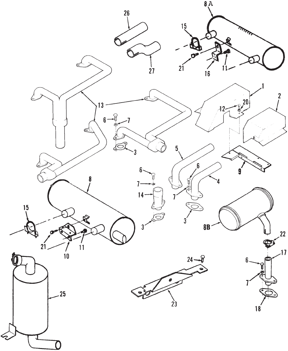
P216/18/20G
52
Exhaust System
P216/18/20G
53
Exhaust System
REF PART QTY PART REF PART QTY PART
NO. NO. USED DESCRIPTION NO. NO. USED DESCRIPTION
1 Cover, LH Exhaust Tube
134–4254–50 1 Code 21AW, 21BE, 21BH,
21BJ, 21BM – Painted
134–3891–50 1 Code 21CE, 21BB – Painted
134–4672–50 1 Code 21BF – Painted
2 134–4655–50 1 Cover, RH Exhaust Tube
Painted – Code 21BB, 21BE,
21BF, 21BH, 21BM, 21BW,
21CE
3 154–2746 2 Gasket, Exhaust
4 Adapter, RH Exhaust
154–2343–50 1 1–1/4” OD Outlet – Painted
Code 21AW, 21BE, 21BJ,
21BM
154–2128–50 1 1–1/4” OD Outlet – Painted
Code 21BB, 21BD, 21CE
154–2709 1 1.405” OD Outlet Code 21BF
5 Adapter, LH Exhaust
154–2344–50 1 1–1/4” OD Outlet – Painted
Code 21AW, 21BE, 21BJ,
21BM
154–2129–50 1 1–1/4” OD Outlet – Painted
Code 21BB, 21BD, 21CE
154–2710 1 1.405” OD Outlet Code 21BF
6 800–0026 4 Screw, Cap Hex Head
(5/16–18 x 3/4”)
7 Washer
850–0045 4 Lock 5/16” – Code 21BJ,
21BK, 21BW
740–1006 4 Flat (M8) – All Others
8 155–2320 1 Muffler, Exhaust – 16.55” Long
8A Muffler, Exhaust – 2 Inlets
Mounts Horizontal
155–2255 1 Rear, Center Exhaust –
15” Long
541–0379 1 End, Discharge Tube – (Kit)
16” Long – P216, P220
8B 155–2300 2 Muffler (Use in Pairs) – Use With
Adapter 154–2713
9 Support, Exhaust Cover
134–4983–50 1 Code 21BB – Painted
134–4445–50 1 Code 21BH,21BE – Painted
10 155–2329–50 1 Bracket, Muffler Support – Code
21BF, 21BM – Use with Muffler
155–2320 – Painted
11 Screw, Lock Head (3/8 x 3/4”)
821–0029 2 Code 21BF – Use with Muffler
– 155–2320
821–0029 1 Use with Muffler #155–2255,
155–2321
12 821–0009 2 Screw, Hex Washer Self–Lock
Head (1/4–20 x 3/8”) – Code
21BB, 21BE, 21BM, 21BH
13 Manifold, Exhaust
154–2178–50 1 Rear Right Down
154–2243–50 1 Rear Outlet
154–2613–50 1 Right Outlet
541–0377 1 Crossover – Code 21BG,
21BH, 21CA
14 154–1958–50 2 Adapter, Exhaust (Flange
Type) – Code 21AG (1.28” OD
Tapers to 1.13”OD, 4–1/2”
Long)
15 155–1257 2 Clamp, Muffler – (1–3/8” Dia)
16 155–2302–01 1 Support, Muffler – Use with
Muffler 155–2255, 155–2321
17 154–2713–50 2 Adapter, Exhaust Manifold –
Painted – (1.12” OD,
4–1/4” Long) Code 21AG,
21BZ
18 154–2746 2 Gasket, Exhaust Manifold
19 800–0512 4 Screw, Hex Head Cap
(5/16–18 x 1”)
20 850–0045 2 Washer, Lock – Code 21BH
(3/8”)
21 821–0014 1 Screw, Lock Head
(5/16–18 x 1/2”)
22 155–1256 2 Clamp, Muffler (1–1/8”)
23 155–2264–50 1 Bracket, Muffler Support –
Code 21BF – Painted
24 821–0008 2 Screw, Lock Head
(1/4–20 x 5/16”) Code 21BF
25 155–2521 1 Muffler, Exhaust – Single Inlet –
Mounts Vertically
26 154–2840 1 Tube, Exhaust – Straight Use
with Muffler Kit 541–0379
27 154–2841 1 Tube, Exhaust – Offset – Use
with Muffler Kit 541–0379
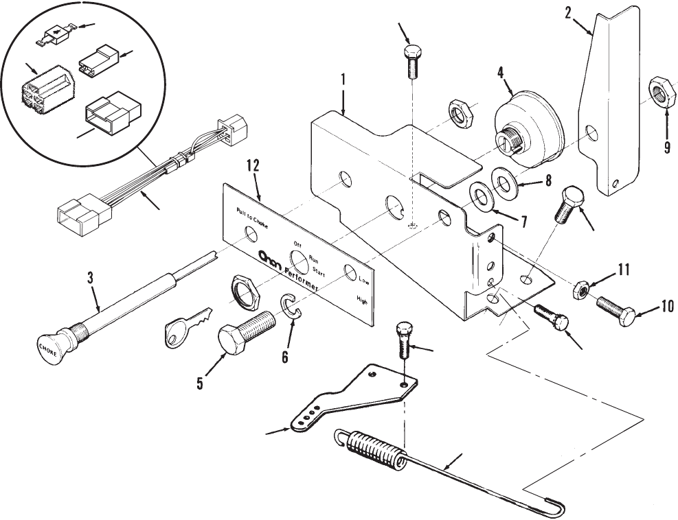
P216/18/20G
54
Control Panel
13
14
15
16
17
16
22
18
19
20
21
REF PART QTY PART REF PART QTY PART
NO. NO. USED DESCRIPTION NO. NO. USED DESCRIPTION
1 301–9964–51 1 Panel, Control
2 150–2184 1 Lever, Control
3 153–0606 1 Choke, Manual
4 308–0385 1 Switch, Ignition (Includes
Keys)
5 800–0050 1 Screw, Hex Head Cap
(3/8–16 x 1”)
6 851–0029 1 Washer, Lock (3/8”)
7 526–0029 1 Washer, Flat (3/8” Screw)
8 508–0284 1 Washer, Nylon Flat
(3/8” Screw)
9 870–0297 1 Nut, Lock (3/8–16)
10 815–0650 2 Screw, Hex Washer Head
(1/4–20 x 1”)
11 862–0001 2 Nut, Hex (1/4–20)
12 98–5735 1 Decal, Control Panel
13 150–1755 1 Spring, Governor Return
14 150–1754–01 1 Adapter, Governor Arm
Zinc Plated
15 815–0194 3 Screw, ET Hex Head Thread
Cutting (10–32 x 3/8”)
16 821–0009 2 Screw, Hex Washer Head
Self–Lock (1/4–20 x 3/8”)
17 Harness, Control
338–3689 1 With LOPKO (Includes Parts
Marked *)
338–3690 1 Without LOPKO (Includes
Tab Housing Connector and
5 Pin Connector Body)
18 323–0916 1 *Connector, Tab Housing
19 323–0987 1 *Body, Connector (5 Pin)
20 357–0030 1 *Rectifier, Silicon
21 323–1216 1 *Body, Connector (Single Pin)
22 815–0378 1 Screw, Hex Washer Head
(#14 x 1/2”)
* – Parts Included in Control Harness.
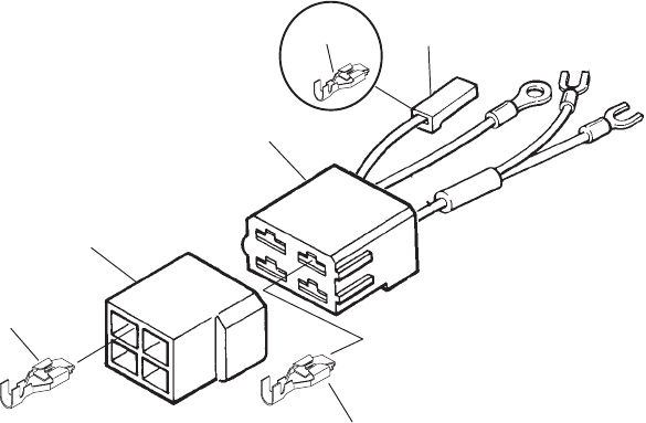
P216/18/20G
55
Engine Harness
(Code 35BB, 35BD, 35BH, 35CG)
67
8
1
2
3
45
6
9
,,
,
,
REF PART QTY PART REF PART QTY PART
NO. NO. USED DESCRIPTION NO. NO. USED DESCRIPTION
Harness, Engine
338–2390 1 W/O LOPKO (2 Wire, 4 Pin)
(Code 35BB, 35CG)
(Includes Parts Marked *)
With LOPKO (4 Wire, 4 Pin)
Spec A–D
Code 35BD
338–2075 1 14–15” LOPKO Leads
(Includes Parts
Marked *)
338–2162 1 24–25” LOPKO Leads
(Includes Parts
Marked +)
338–2075 1 Code 35BB, 35BH
(Includes Parts
Marked *)
Begin Spec E
Code 35BD
15–16” LOPKO Leads
(Includes Parts
Marked *)
338–3179 1 5” VR Lead
338–3358 1 14” VR Lead
25–26” LOPKO Leads
338–3181 1 11” VR Lead
(Includes Parts
Marked +)
338–3357 1 22” VR Lead
(Includes Parts
Marked S)
338–3179 1 Code 35BB, 35BH
(Includes Parts
Marked *)
1 332–2890 4 S+Terminal, Tab
2 323–1381 1 *S+Housing, 4–Way Receptacle
3 323–1216 1 S+Housing, Receptacle
4 332–2870–02 1 +Terminal, Receptacle (.25)
5 332–2870–01 3 STerminal, Receptacle (.25)
6 332–2715 AR *Terminal, Receptacle
(Qty 2,4,5)
7 332–0819 1 *Housing, Receptacle
8 323–1382 1 Housing, 4–Way Tab
9 Terminal, Tab
332–2301 4 20A Charging System
332–1503 1 35A Charging System
* – Parts Included in Harness 338–2390, 338–2075,
338–3179, 338–3358.
+ – Parts Included in Harness 338–2162, 338–3181.
S– Parts Included in Harness 338–3357.
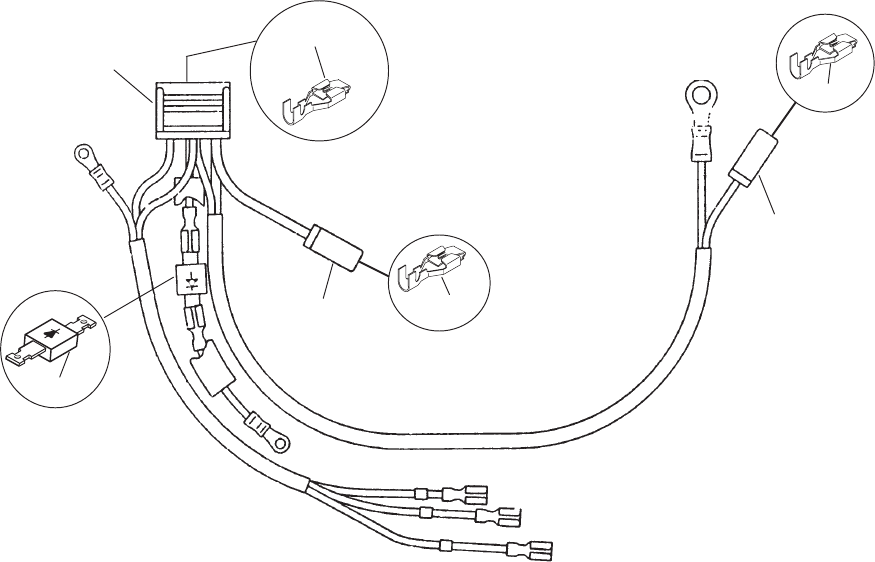
P216/18/20G
56
Engine Harness
(Code 35BC, 35BZ, 35CC, 35CH, 35CJ, 35DB)
1
2
3
456
7
8
1
7
,, ,
REF PART QTY PART REF PART QTY PART
NO. NO. USED DESCRIPTION NO. NO. USED DESCRIPTION
Harness, Engine
With LOPKO
Spec A–D (Code 35BC,
35BZ)
338–2104–02 1 W/O Rectifier (Includes
Parts Marked +)
338–2805 1 W/Rectifier (Includes
Parts Marked *)
Begin Spec E
338–3178–02 1 Code 35BC, 35BZ,
35CH (W/O Rectifier)
(Includes Parts
Marked +)
338–3186 1 Code 35BC, 35BZ,
35DB (W/Rectifier)
(Includes Parts
Marked *)
Without LOPKO
Spec A–D
338–2104–01 1 Code 35BL, 35CH,
35CJ (Includes Parts
Marked +)
338–2804–01 1 Code 35CC (Includes
Parts Marked S)
Begin Spec E
338–3178–01 Code 35BC, 35BZ
35CH, 35CJ (Includes
Parts Marked +)
338–3185–01 1 Code 35CC (Includes
Parts Marked S)
1 332–0819 2 +*SHousing, Receptacle
2 Housing, 6–Way Receptacle
323–1386 1 +SCode 35CC
323–0987 1 * Code 35BC, 35BZ
3 357–0030 1 *SRectifier, Silicon
4 332–2073 1 *Receptacle, Lock
5 332–3165 1 *Receptacle, Lock
6 332–3143 1 *Receptacle, Lock
7 332–2715 2 +*STerminal, Receptacle
8 332–2890 5 +STerminal, Receptacle
* – Parts Included in Harnesses 338–2805, 338–3186.
S– Parts Included in Harnesses 338–2804–01,
338–3185–01.
+ – Parts Included in Harnesses 338–2104–01,
338–2104–02, 338–3178–01, 338–3178–02.
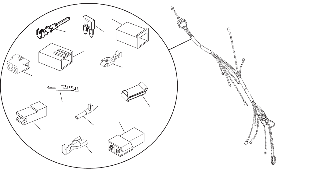
P216/18/20G
57
Engine Harness
(Code 35BE)
1
2
3
4
5
6
78
9
10
11
12
REF PART QTY PART REF PART QTY PART
NO. NO. USED DESCRIPTION NO. NO. USED DESCRIPTION
1Harness, Engine
Spec A–D
338–2216 1 W/30A Blade Fuse
(Includes Parts Marked +)
338–2843 1 W/O Fuse (Includes Parts
Marked #)
Spec E–G
338–3192 1 W/30A Blade Fuse
(Includes Parts Marked +)
338–3193 1 W/O Regulator Lead
(Includes Parts Marked #)
338–3194 1 W/Oil Temp Switch Lead
(Includes Parts Marked #)
338–3325 1 W/Ground Lead (Includes
Parts Marked S)
Begin Spec H
338–3551 1 W/30A Blade Fuse
(Includes Parts Marked +)
338–3552 1 W/O Fuse (Includes Parts
Marked #)
1 323–1200 *6 #S+Socket, Contact
2 323–1317 1 #S+Plug, Connector (6 Pl)
3 321–0291 1 +Fuse, 30A Blade
4 323–1424 1 +Cap, Connector
5 332–0819 1 +Housing, Receptacle Terminal
6 332–2715 1 +Terminal, Receptacle
7 332–2922 2 +Terminal, Receptacle
8 332–2923 1 +Clip, Connector
9 323–1216 *2 #SHousing, Receptacle
10 332–2870–01 *4 #STerminal, Receptacle (.25)
11 323–1679 2 SSocket, Contact
12 323–1697 1 SPlug (2 Cir)
* – Use As Needed.
+ – Parts Included in Harness 338–2216 and 338–3192.
#– Parts Included in Harness 338–2843, 338–3193,
338–3194 and 338–3552.
S– Parts Included in Harness 338–3325.
♦– Parts Included in Harness 338–3551.
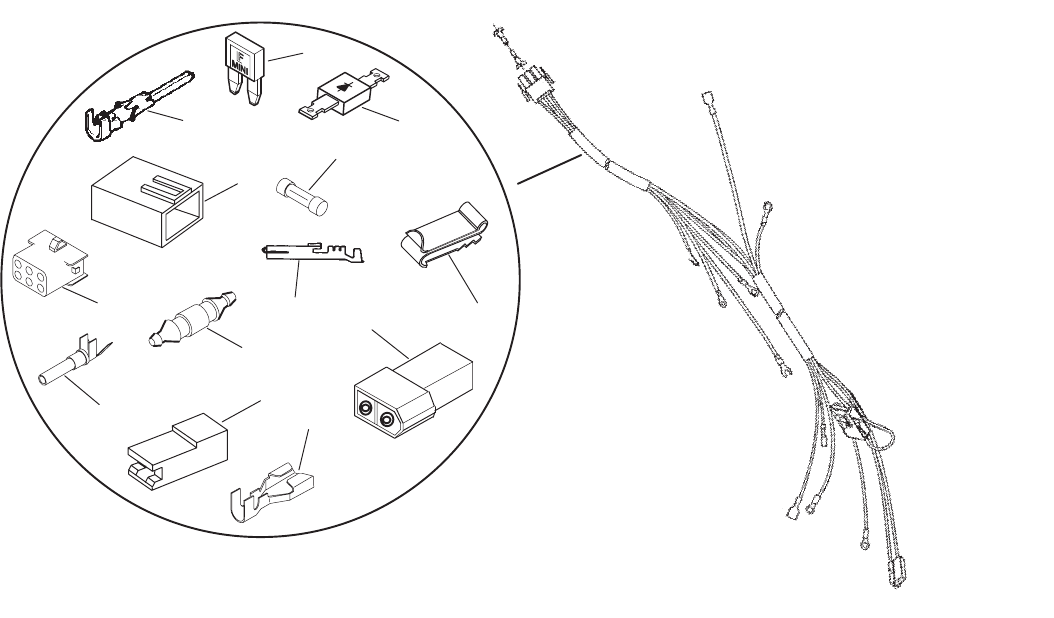
P216/18/20G
58
Engine Harness
(Code 35CL,35CV 35DD, 35DE, 35DJ)
,
9
10
11
12
13
14
1
2
34
5
6
78
REF PART QTY PART REF PART QTY PART
NO. NO. USED DESCRIPTION NO. NO. USED DESCRIPTION
Harness, Engine
Spec A–D
338–3086 1 Code 35CV (Includes
Parts Marked # and +)
338–2844 1 Code 35CL (Includes
Parts Marked #)
Spec E–G
Code 35CV
338–3195 1 13” Starter B+ Lead
(Includes Parts
Marked # and +)
338–3325 1 15” Starter B+ Lead
(Includes Parts
Marked # and +)
338–3421 1 Code 35DE (Includes
Parts Marked # and S)
338–3505 1 Code 35DJ (Includes
Parts Marked # and ~)
338–3420 1 Code 35DD (Includes
Parts Marked # and ∫)
Begin Spec H
Code 35DD
338–3556 1 W/O Grd Wire (Includes
Parts Marked # and ∫)
338–3642 1 W/Grd Wire (Includes
Parts Marked # and ∫)
Code 35DJ
338–3589 1 W/30A Blade Fuse
(Includes Parts
Marked # and ~)
338–3653 1 W/30A Cartridge Fuse
(Includes Parts
Marked # and ◊)
338–3653 1 Code 35DE (Includes
Parts Marked # and ◊)
1 323–1200 *6 #Socket, Contact
2 323–1317 1 #Plug, Connector (6 Pl)
3 323–1216 *2 #Housing, Receptacle
4 332–2870–01 *4 #Terminal, Receptacle (.25)
5 321–0291 1 ~Fuse, 30A Blade
6 323–1424 1 ~Cap, Connector
7 332–2922 2 ~Terminal, Receptacle
8 332–2923 1 ~Clip, Connector
9 323–1679 2 ◊~S+Socket, Contact
10 323–1697 1 ◊~S+Plug (2 Cir)
11 332–2870–02 2 ◊∫~STerminal, Receptacle (.25)
12 357–0030 1 ◊∫~SRectifier, Silicon
13 321–0362 1 ◊Holder, Fuse
14 321–0364 1 ◊Fuse, 30A Cartridge
* – Use As Needed.
+ – Parts Included in Harness 338–3086, 338–3195 and
338–3325.
# – Parts Included in All Harness Listed on This Page.
S– Parts Included in Harness 338–3421.
~ – Parts Included in Harness 338–3505 and 338–3589.
∫– Parts Included in Harness 338–3420, 338–3556 and
338–3642
◊– Parts Included in Harness 338–3653.
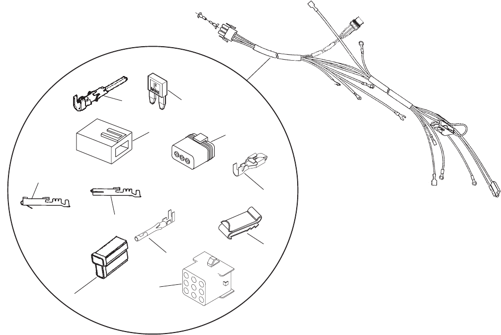
P216/18/20G
59
Engine Harness
(Code 35BK)
1
2
5
7
8
3
4
9
10
11
6
REF PART QTY PART REF PART QTY PART
NO. NO. USED DESCRIPTION NO. NO. USED DESCRIPTION
Harness, Engine
338–2175 1 Spec B (Includes Parts
Marked *)
338–2504 1 Spec C, D (Includes Parts
Marked +)
338–3191 Spec E–G (Includes Parts
Marked +)
338–3631 Begin Spec H (Includes Parts
Marked S)
1 323–1085 1 +S*Connector, Male
2 332–2073 1 +S*Terminal, Lock – Receptacle
3 323–1291 1 +S*Cap, Connector
4 323–1200 9 +*Socket, Contact
5 323–1424 1 *Cap, Connector
6 332–2922 2 *Terminal, Receptacle
7 332–2923 1 *Clip, Connector
8 321–0291 1 *Fuse, 30 Ampere
9 323–1199 9 Pin, Contact
10 332–3096–01 3 SSocket, Terminal
11 323–1774 1 SConnector, Sealed
* – Parts Included in Spec B Harness.
+ – Parts Included in Spec C–G Harnesses.
S– Parts Included in Spec H Harness.
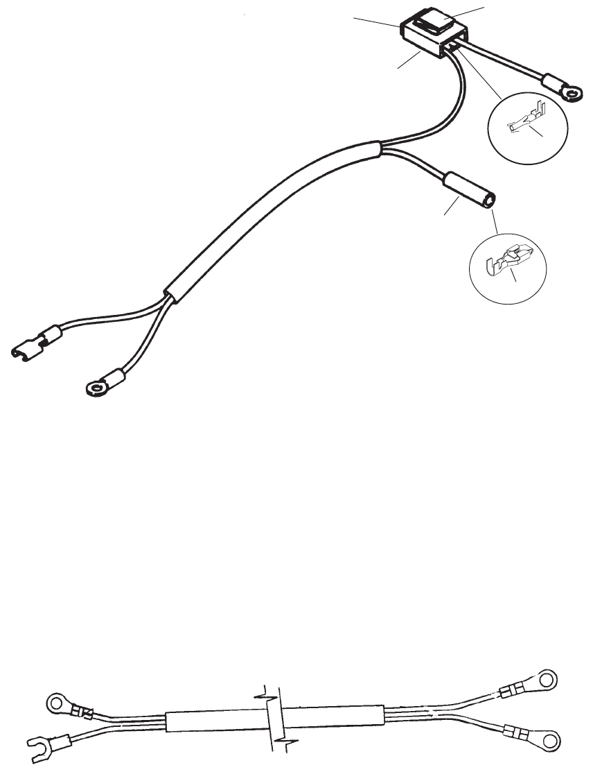
P216/18/20G
60
Engine Harness
(Code 35BJ)
1
2
3
4
5
6
REF PART QTY PART REF PART QTY PART
NO. NO. USED DESCRIPTION NO. NO. USED DESCRIPTION
338–2259 1 Harness, Engine
1 323–1296 1 Connector, Male
2 332–2073 1 Terminal, Receptacle Lock
3 323–1424 1 Cap, Connector
4 332–2922 2 Terminal, Receptacle
5 332–2923 1 Clip, Connector
6 321–0291 1 Fuse, 30A
Engine Harness
(Code 35AZ)
REF PART QTY PART
NO. NO. USED DESCRIPTION
338–2516 1 Harness, Engine
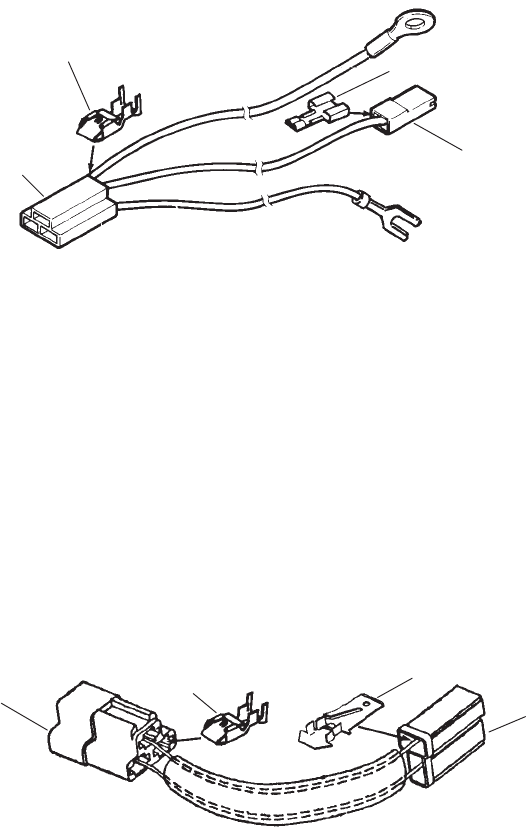
P216/18/20G
61
Interface Harness
(Code 35AW)
1
2
34
REF PART QTY PART REF PART QTY PART
NO. NO. USED DESCRIPTION NO. NO. USED DESCRIPTION
Harness, Interface (3 Pin)
338–2638 1 Spec A–D (Includes
Connectors)
338–3180 1 Begin Spec E (Includes
Connectors and Terminals)
1 323–1216 1 Connector, Body
2 323–1254 1 Connector, Body
3 332–2073 3 Terminal, Lock Receptacle
4 332–2423 1 Terminal, Recpetacle
Interface Harness
(Code 47AW)
12
34
REF PART QTY PART REF PART QTY PART
NO. NO. USED DESCRIPTION NO. NO. USED DESCRIPTION
338–2174 1 Harness, Wiring
1 323–1417 1 Body, Connector
2 323–0892 1 Body, Connector
3 332–2073 2 Terminal, Lock Receptacle
4 332–2238 2 Terminal, Tab
P216/18/20G
62
Labels, Paint, Thread Sealant and Gasket Kits
98–6802–01 3 Label, Performer – P216 (Red
and White)
Label, Model Ident
98–6802–01 2 P216
98–6802–02 2 P218
98–6802–03 2 P218
98–6664 1 Label, Air Cleaner –
Maintenance
Label, Periodic – Maintenance
98–5969–01 1 Standard Oil Base – No Oil
Filter
98–5969–02 1 Standard Oil Base – With
Oil Filter
98–5969–03 1 High Capacity Oil Base –
With Oil Filter
98–5969–04 1 Extra High Capacity Oil
Base with Oil Filter
518–0452 1 Sealant, Thread (50cc Bottle)
518–0347 1 Loctite, Bottle (250cc)
525–0305 1 Paint, Enamel Touch–Up Green
(Non–Metallic) 13 Ounce
Pressurized Can
525–0454 1 Paint, Enamel Touch–Up
Greige – 13 Ounce
Pressurized Can
525–0394 1 Paint, Enamel – Touch–Up –
Flat Black – 16 Ounce
Pressurized Can
525–0614 1 Paint, Enamel – Forest Green
3 oz. Pressurized Can
168–0189 1 Kit, Gasket – Carbon Removal
(Includes Parts Marked +)
110–3709 3 +Gasket, Valve Box
110–3181 2 +Gasket, Cylinder Head
154–2746 2 +Gasket, Exhaust Manifold
154–2495 2 +Gasket, Intake Manifold
509–0289 2 +Seal, Valve Stem
168–0187 1 Kit, Gasket – Complete Engine
(Includes Parts Marked #)
101–0809 1 #Gasket, Rear Bearing Plate
102–0743 1 #Gasket, Oil Drain
103–0810 1 #Gasket, Gearcase
110–3709 3 #Gasket, Valve Box
110–3181 2 #Gasket, Cylinder Head
120–0161 1 #Gasket Kit, Oil Pump
122–0771 1 #Gasket, Oil Filter Adapter
154–0733 1 #Gasket, Adapter to Carburetor
154–2495 2 #Gasket, Intake Manifold
154–2746 2 #Gasket, Exhaust Manifold
160–1368 1 #Gasket, Breaker Box
509–0008 1 #Seal, Oil (Governor Shaft)
509–0040 1 #Seal, Oil (Gearcase)
509–0041 1 #Seal, Oil (Bearing Plate)
509–0142 1 #O–Ring (Oil Fill Cap)
509–0145 1 #O–Ring (Air Cleaner to
Carburetor)
509–0289 2 #Seal, Valve Stem
102–1387 1 #Gasket, Oil Base
509–0269 1 #Seal, Fill Tube
+ – Parts Included in Carbon Removal Gasket Kit.
# – Parts Included in Complete Engine Gasket Kit.

63
Sales Option Code Table
SPEC NO.
SALES
OPTION
CODE
NUMBERS
10461
11AH
11AV
13BG
13BN
13BJ
13BV
15AZ
15BD
15BK
15BL
17BW
17BY
17CD
19AS
21AW
23DC
23DK
23DV
31AY
31AZ
33AT
35AU
35AW
45BB
47AG
10462
11AH
11AV
11BJ
13BG
13BJ
13BY
15BA
15BD
15BK
17BW
17BY
17CD
19AS
21AW
23DC
23DJ
31AY
31AZ
33AS
35AU
35AW
45BD
47AL
47AR
10463
11AH
11AV
13BG
13BJ
13BY
15BA
15BD
15BK
17BY
17CG
17CJ
19AU
21AW
23DC
23DJ
31AY
31AZ
33AT
35AU
35AW
45BD
47AL
47AR
10464
11AH
13BG
13BJ
13BY
15BA
15BD
15BK
17BW
17BY
17CE
19AS
21AW
23DC
23EL
31AY
31AZ
33AS
35AU
35AW
45BD
47AG
47AL
10478
11AH
11AV
11BH
13CB
13CC
13CG
15AZ
15BD
15BK
15BR
17BW
17BY
17CD
19AS
23DC
23DE
31AY
31AZ
33AT
35AV
35BD
45BG
45BV
47AB
10482
11AH
11AV
11BG
11BK
13BN
13BY
13CD
15AZ
15BD
15BJ
17CD
17CG
17CH
19AV
23DC
31AY
31BD
33AT
45BP
45BW
47AG
10488
11AK
11AV
13BJ
13BP
13BZ
15BD
15BK
15BL
17BY
17CD
17CG
19AV
21AW
23DC
31AY
31AZ
33AT
35AU
35BB
45BB
47AR
47BA
47BB
10498
11AH
11AV
13BK
13BM
13BY
15BD
15BJ
15BL
17BW
17BY
17CD
19AU
23DC
23DH
23DJ
31AY
31AZ
33AT
35AU
35BB
45BU
47AG
10501
11AH
11AV
13BK
13BN
13BW
15BD
15BJ
15BL
17BZ
17CD
17CG
19AS
21AZ
23DC
31AY
31AZ
33AT
45BH
47AG
10502
11AP
11BK
13CB
15BD
15BK
15BL
17BW
17BZ
17CD
19AS
23DC
31AY
31AZ
33AT
35AH
45BS
47AK
10509
11AH
11AU
13BN
13CG
15BD
15BK
15BL
17BW
17BZ
17CD
19AS
23DC
31AY
31BC
33AT
45BB
47AG
10518
11AH
11BG
13CB
13CC
13CG
15BD
15BK
15BL
17BW
17BZ
17CE
19AW
23DC
23DE
31AY
31AZ
33AT
35AV
35BC
45BH
47AG
10528
11AH
11AU
13BJ
13BM
13BV
15BB
15BD
15BK
17BW
17BY
17CE
19AW
23DC
31AY
31BD
33AT
45BB
47AB
SPEC NO.
SALES
OPTION
CODE
NUMBERS
10530
11AH
11AV
11BG
13BJ
13BN
13BV
13CC
13CG
15BD
15BK
15BL
17BZ
17CD
17CG
19AS
23DC
31AY
31AZ
33AT
35BC
45BB
45BW
47AA
47AG
10531
11AH
11AV
11BG
13BJ
13BN
13BV
15BD
15BK
15BL
17BZ
17CD
17CG
19AS
23DC
31AY
31AZ
33AT
35BC
35CH
45BE
45BW
10538
11AH
11AW
13BJ
13BV
13CR
15BD
15BJ
15BL
17BW
17BY
17CE
19AS
23DC
23DN
31AY
31AZ
33AT
35AU
35BK
45BB
47AR
10539
11AH
11AW
13BJ
13BV
13CR
15BD
15BJ
15BL
17BW
17BY
17CD
19BA
23DC
23DN
31AY
31AZ
33AT
35AU
35BK
45BB
47AR
10540
11AH
11AW
13BJ
13BV
13CR
15BD
15BJ
15BL
17BW
17BY
17CD
17CN
19BA
19BB
19BC
23DC
23DN
31AY
31AZ
33AT
35AU
35BK
35BL
45BB
47AR
10541
11AH
11AW
13BJ
13BV
13CR
15BD
15BJ
15BL
17BW
17BY
17CD
19AU
19BC
23DC
23DN
31AY
31AZ
33AT
35AU
35BK
45BB
47AR
10543
11AH
11AW
13BJ
13BN
13BZ
15BD
15BJ
15BL
17BW
17BY
17CD
19AU
23DC
31AY
31AZ
33AT
35BJ
45BB
47AR
10550
11AH
11AV
13BJ
13BM
13BY
15BA
15BD
15BJ
17BY
17CG
17CK
19AV
21AW
23DC
23DH
23DJ
23ED
31AY
31AZ
33AT
35AU
35BH
45BH
47AL
47AR
47BA
10551
11AR
11AV
13BJ
13BN
13BV
15BD
15BK
15BL
17BZ
17CD
17CG
19AS
23DC
31AY
31AZ
33AT
35BC
45BT
47AA
47AG
10552
11AP
11BE
11AV
13BJ
13BN
13BV
15BD
15BK
15BL
17BZ
17CD
17CG
19AS
23DC
31AY
31AZ
33AT
35BC
35CH
45BS
10556
11AW
11AV
11BG
11PP
13CB
13CC
13CG
15AZ
15BD
15BK
17BW
17CD
17CF
19AS
19BB
23DC
23DJ
23DN
31AY
31AZ
33A5
35AV
33AT
35AV
35BE
45BH
10557
11AH
11AV
11PP
13CF
13CG
13CH
15AZ
15BD
15BK
15BL
17BW
17CD
17CF
19AS
19BB
23DC
23DE
31AY
31AZ
33AT
35AV
35BE
45BH
10558
11AH
11AV
13CB
13CC
13CG
15BD
15BK
15BL
17BW
17CD
17CF
19AS
19BB
23DC
23DN
31AY
31AZ
33AT
35AV
35BE
45BH
47AG

64
Sales Option Code Table
SPEC NO.
SALES
OPTION
CODE
NUMBERS
10559
11AH
11AV
13BJ
13BN
13BZ
15BD
15BK
15BM
17BW
17BY
17CD
19AS
23DC
31AY
31AZ
33AT
35AU
35BB
45BB
10560
11AH
11AV
13BM
13CG
15BD
15BK
15BL
17BW
17BZ
17CD
19AS
23DC
23DE
31AY
31AZ
33AT
35AU
35BB
45BF
47AG
10561
11AH
11AV
13BK
13BP
13BV
15AZ
15BD
15BJ
15BK
15BL
17BW
17BY
17CD
19AS
21AW
23DC
31AY
31AZ
33AT
35AU
35BB
35BH
45BB
10562
11AH
11AV
13BJ
13BM
13BV
15BB
15BD
15BK
17BW
17BY
17CD
19AS
23DC
31AY
31BD
33AT
45BB
47AB
10563
11AH
11AV
11BG
13BN
13BV
13CD
15BD
15BK
15BL
17BZ
17CD
17CG
19AS
23DC
31AY
31AZ
33AT
35BC
35CK
45BB
45BW
47AA
10590
11AH
11AU
13BM
13BV
13CG
15BC
15BD
15BK
17BW
17BY
17CE
19AW
23DC
31AY
31AZ
33AT
45BB
47AB
10596
11AK
11AV
13BJ
13BN
13BV
15BD
15BJ
15BL
17BZ
17CD
17CG
19AV
23DC
31AY
31AZ
33AT
35AU
35BB
45BB
45BW
47AB
10601
11AH
11AV
13BR
13BV
13CD
15BD
15BK
15BL
17BZ
17CD
17CG
19AS
23DC
31AY
31AZ
33AT
35BC
35CK
45BB
45BW
10605
11AH
11AV
13BJ
13BN
13BV
15BD
15BK
15BL
17BZ
17CD
17CG
19AS
23DC
23DE
31AY
31AZ
33AT
35CH
45BE
45BW
10606
11AH
11AV
13BK
13BM
13BY
15BD
15BJ
15BL
17CD
17CF
17CM
19AS
23DC
23DH
23DJ
31AY
31AZ
33AS
35AU
35BH
45BU
47AG
10608
11AH
11AV
11BJ
13BG
13BY
13CK
15BD
15BK
15BL
17BY
17CD
17CG
19AS
21BF
23DC
23DJ
31AY
31AZ
33AV
35AU
35AW
45BD
10626
11AH
11AV
11BG
13BJ
13BN
13BV
15BD
15BK
15BL
17BZ
17CD
17CG
19AS
23DC
31AY
31AZ
33AT
35AU
35BC
45BE
45BW
47AA
10630
11AH
11AW
11BG
11PP
13CB
13CC
13CG
15AZ
15BD
15BK
15BR
17BW
17BY
17CD
19AS
23DC
23DE
31AY
31AZ
33AT
35AV
35BD
45BG
SPEC NO.
SALES
OPTION
CODE
NUMBERS
10632
11AH
11AV
13BJ
13BN
13BV
15BB
15BD
15BK
17BZ
17CD
17CG
19AS
23DC
31AY
31AZ
33AT
45BB
45BW
47AB
10640
11AR
11AV
13BN
13BV
13CD
15BB
15BD
15BK
17BW
17BY
17CD
19AV
23DC
23DE
31AY
31BC
33AT
35BC
39AG
47BS
47AA
47AR
10641
11AH
11AV
13BK
13BN
13BW
15BD
15BJ
15BL
17BZ
17CD
17CG
19AS
21BB
23DC
23DK
31AY
31AZ
33AT
35AU
35BH
45BH
47AG
10642
11AH
11AV
13BG
13BJ
13BY
15BA
15BD
15BK
17CF
17CJ
17CM
19AU
21AZ
23DC
23EL
31AY
31AZ
33AT
35AU
35AW
45BD
47AG
47AL
10643
11AH
11AV
13BJ
13BY
13CL
15BD
15BJ
15BM
17CD
17CF
19AV
23DC
23EL
31AY
31AZ
33AT
35AU
35BB
45BF
47AL
47AP
10645
11AH
11AU
13BS
13CG
15BA
15BD
15BK
17BW
17BZ
17CD
19AS
19AW
21AZ
23DC
23DE
23DN
31AY
31BC
33AT
35AU
35BB
45BB
10646
11AH
11AV
13BM
13CC
13CG
15BD
15BK
15BL
17BW
17BY
17CD
19AS
23DC
23DE
31AY
31AZ
33AT
35AV
35BB
45BF
47AG
10648
11AR
11AV
11BF
13BR
13BY
13CD
15BD
15BK
15BL
17BZ
17CD
17CG
19AS
23DC
23DE
31AY
31AZ
33AT
35BC
35CK
45BT
47AB
10649
11AH
11AV
13BJ
13BP
13BW
15BD
15BK
15BL
17BW
17BZ
17CD
19AV
21AG
23DC
23DK
31AY
31AZ
33AT
35AU
35BB
45BB
45BW
10662
11AH
11AV
13BM
13CC
13CG
15BD
15BK
15BL
17BY
17CD
17CM
19AS
23DC
23DE
31AY
31AZ
33AT
35AV
35BH
45BF
47AG
10666
11AH
11AV
13BJ
13BN
13BV
15BD
15BK
15BL
17CD
17CF
17CG
19AS
23DC
31AY
31BC
33AT
45BB
45BW
47AA
10667
11AH
11AV
11BG
13BJ
13BN
13BV
15BD
15BK
15BL
17BZ
17CD
17CM
19AS
23DC
31AY
31AZ
33AT
35AV
35BC
45BE
45BW
47AA
10670
11AP
11AV
11BE
13BJ
13BN
13BV
15BD
15BK
15BL
17BZ
17CD
17CG
19AS
23DC
31AY
31AZ
33AT
35BC
35CH
45BT

65
Sales Option Code Table
SPEC NO.
SALES
OPTION
CODE
NUMBERS
10671
11AH
11AV
13BJ
13BN
13BV
15BB
15BD
15BK
17BZ
17CD
17CG
19AS
23DC
31AY
31AZ
33AT
35AV
35BB
45BB
45BW
47AB
10674
11AP
11AV
13BM
13BV
13CD
15BA
15BD
15BK
17BW
17BY
17CD
19AS
21BM
23DC
31AY
31AZ
33AT
35AV
35BC
39AG
45BS
47AB
10675
11AH
11AV
13BJ
13BM
13BN
13BV
15BD
15BK
15BL
17BW
17BY
17BZ
17CD
19AS
23DC
23DN
31AY
31AZ
33AT
35AU
35BH
45BB
45BW
10676
11AH
11AY
13BJ
13BW
13CM
15AZ
15BD
15BJ
15BZ
17BW
17BY
17CD
19AS
21BG
21BH
23DC
31AY
31AZ
33AV
35AU
35BH
45AZ
45BB
45BL
47AL
47AS
10677
11AH
11AV
11BF
13BJ
13BP
13BV
15AZ
15BD
15BK
17BZ
17CG
17CV
19AV
21AW
23DC
31AY
31AZ
33AT
35AU
35BC
45BT
45EC
47AL
47AR
47BA
10678
11AH
11AV
13BM
13BV
13CD
15BD
15BK
15BL
17BZ
17CD
17CM
19AU
23DC
31AY
31AZ
33AT
35BC
39AG
45BE
45BW
47AB
10680
11AR
11AV
13BT
13BV
13CD
15BD
15BK
15BL
17BZ
17CD
17CG
19AS
23DC
23DE
31AY
31AZ
33AT
35BC
39AG
45BT
47AA
10685
11AH
11AV
13BJ
13BM
13BV
15BD
15BK
15BL
17BW
17BY
17CD
19AS
21BE
23DC
31AY
31AZ
33AT
35AV
35BC
39AG
45BB
45BW
47AB
10691
11AH
11AW
13BJ
13BS
13BZ
15BD
15BJ
15BL
17BW
17BY
17CE
19AS
23DC
23DN
31AY
31AZ
33AT
35AU
35BK
45BB
47AG
47AR
10692
11AH
11AW
13BJ
13BS
13BZ
15BD
15BJ
15BL
17BW
17BY
17CD
19BA
23DC
23DN
31AY
31AZ
33AT
35AU
35BK
45BB
47AG
47AR
10698
11AP
11AV
13BS
13BV
13CG
15BA
15BD
15BK
17BW
17BZ
17CD
19AS
23DC
23DE
31AY
31BC
33AT
35AV
35BB
45BS
47AA
10701
11AH
11AV
13BJ
13BR
13BV
15BD
15BK
15BL
17BZ
17CD
17CM
19AS
23DC
31AY
31AZ
33AT
35AV
35BB
45BB
45BW
10706
11AH
11AV
11PP
13CF
13CG
13CH
15BD
15BK
15BL
17CD
17CF
17CM
19AS
23DC
23DE
31AY
31AZ
33AT
35BB
45BH
47AG
SPEC NO.
SALES
OPTION
CODE
NUMBERS
10709
11AH
11AV
13BJ
13BN
13BV
15BD
15BJ
15BL
17CD
17CF
17CG
19AV
23DC
31AY
31AZ
33AT
35AU
35BB
45CC
10712
11AH
11AU
13BJ
13BS
13BV
15BB
15BD
15BK
17BW
17CE
17CF
19AW
23DC
31AY
31BD
33AT
45BB
47AB
10714
11AH
11AV
13BK
13BM
13BV
15BD
15BJ
15BL
17CD
17CF
17CG
19AS
21BM
23DC
31AY
31AZ
33AT
35AU
35BB
35BB
45BB
10720
11AH
11AW
13BJ
13BM
13BV
15BB
15BD
15BK
17BW
17BY
17CD
19AS
23DC
31AY
31BD
33AT
45BB
47AB
10721
11AH
11AW
13BJ
13BN
13BV
15BD
15BK
15BL
17BZ
17CD
17CG
19AS
23DC
31AY
31AZ
33AT
35BC
35CH
45BE
45BW
10722
11AH
11AW
13BJ
13BN
13BV
15BD
15BK
15BL
17BZ
17CD
17CG
19AS
23DC
31AY
31AZ
33AT
35BC
35CH
45BB
45BW
10725
11AR
11AW
13BJ
13BN
13BV
15BD
15BK
15BL
17BZ
17CD
17CG
19AS
23DC
31AY
31AZ
33AT
35BC
35CH
45BT
45EC
10729
11AH
11AV
13BJ
13BR
13BV
15BD
15BK
15BL
17CD
17CM
17CR
19AS
23DC
31AY
31AZ
33AT
35AV
35BB
45BB
45BW
47AB
10731
11AH
11AV
13BJ
13BM
13BV
15BD
15BK
15BL
17BZ
17CD
17CG
19AS
23DC
31AY
31BD
33AT
35AV
35BB
45BB
45BW
47AB
10734
11AH
11AV
13CB
13CC
13CG
15BD
15BK
15BL
17BW
17CD
17CF
19AS
19BB
23DC
23DN
31AY
31AZ
33AT
35AV
35BE
45BH
45BM
47AG
10735
11AH
11AV
11PP
13CF
13CG
13CH
15AZ
15BD
15BK
17BW
17CD
17CF
19AS
19BB
23DC
23DJ
23DN
31AY
31AZ
33AT
35AV
35BE
45BH
47AG
10736
11AH
11AV
13CB
13CC
13CG
15BD
15BK
15BL
17BW
17CD
17CF
19AS
19BB
23DC
23DN
31AY
31AZ
33AT
35AV
35BE
45BH
47AG
10740
11AH
11AV
13BM
13BU
13CD
15BD
15BK
15BL
17BW
17BY
17CD
19AU
21BJ
23DC
23DE
31AY
31AZ
33AT
35BC
39AG
45BB
45BW

66
Sales Option Code Table
SPEC NO.
SALES
OPTION
CODE
NUMBERS
10741
11AP
11AV
13BJ
13BM
13BV
15BD
15BK
15BL
17BW
17BZ
17CD
19AV
23DC
31AY
31AZ
33AT
35BC
45BT
47AG
10742
11AH
11AV
13BG
13BJ
13BV
15AZ
15BD
15BK
17BY
17CD
17CG
19AS
23DC
23DE
23DV
31AY
31AZ
33AT
45BC
47AG
10744
11AH
11AV
13BJ
13BN
13BV
15BB
15BD
15BK
17BZ
17CD
17CG
19AS
23DC
23DE
31AY
31AZ
33AT
35AV
35BB
45BB
45BW
10748
11AH
11AV
13BJ
13BM
13BV
15BB
15BD
15BK
17BZ
17CG
17CK
19AS
21BE
23DC
31AY
31BD
33AT
35AU
35BB
45BB
45BW
47AB
10753
11AR
11AU
13BJ
13BT
13BV
15BD
15BK
15BL
17BW
17BY
17CE
19AW
23DC
31AY
31AZ
33AT
35BC
45BT
47AB
10754
11AH
11AW
13CB
13CC
13CG
15AZ
15BD
15BK
15BR
17BW
17BY
17CD
19AS
23DC
23DN
31AY
31AZ
33AT
35AV
35BD
45BG
47AR
10756
11AH
11AV
13BR
13BV
13CG
15BK
15BL
15BU
17BZ
17CD
17CM
19AS
21BK
23DC
31AY
31AZ
33AT
35AV
35BB
45BB
45BW
10759
11AH
11AV
13CB
13CD
15BD
15BK
15BL
17BW
17CD
17CF
19AS
23DC
23DJ
23DN
31AY
31AZ
33AT
35AV
35BC
39AG
45BF
45BM
47AB
10760
11AH
11AV
13BJ
13BR
13BU
15BD
15BJ
15BL
17BW
17BY
17CD
19AS
21AG
23DC
31AY
31BC
33AT
35AV
35BC
45BB
47AB
10765
11AH
11AW
11PP
13CB
13CC
13CG
15AZ
15BD
15BK
15BR
17BW
17BY
17CD
19AS
23DC
23DJ
23DN
31AY
31BD
33AV
35AV
35BD
45BG
45BM
47AR
10769
11AH
11AW
13BJ
13BN
13BW
15BD
15BK
15BL
17BZ
17CD
17CG
19AS
23DC
23DK
31AY
31AZ
33AT
35AU
35BB
45BB
45BM
47AG
10775
11AH
11AW
11PP
13BJ
13BN
13BY
15BA
15BD
15BK
17BY
17CD
17CG
19AS
23DC
23DJ
31AY
31AZ
33AT
35AU
35AW
45BE
45BM
47AG
10776
11AH
11AW
11PP
13BJ
13BN
13BY
15BA
15BD
15BK
17BY
17CD
17CG
19AS
23DC
23DJ
31AY
31AZ
33AS
35AU
35AW
45BE
45BM
SPEC NO.
SALES
OPTION
CODE
NUMBERS
10777
11AH
11AZ
13BN
13BV
15BD
15BK
15BL
17CD
19AS
23DZ
31AY
31AZ
45BC
47AG
47AL
47AU
10779
11AH
11AW
13BJ
13BV
13CR
15BD
15BJ
15BL
17BW
17BY
17CD
19AS
23DC
23DN
31AY
31AZ
33AT
35AU
35BK
45BB
47AR
10780
11AH
11AW
13BJ
13BS
13BZ
15BD
15BJ
15BL
17BW
17BY
17CD
19AS
23DC
23DN
31AY
31AZ
33AT
35AU
35BK
45BB
47AG
47AR
10782
11AH
11AW
11PP
13BN
13BW
13CD
15BD
15BJ
15BL
17CG
17CH
17CV
19AV
23DC
31AY
31BD
33AT
35BA
45BM
45BN
45BP
10783
11AH
11AV
13BK
13BM
13BY
15BD
15BJ
15BL
17CD
17CF
17CM
19AU
23DC
23DH
23DJ
31AY
31AZ
33AS
35AU
35BH
45BU
47AG
10784
11AP
11BE
11AV
13BJ
13BT
13BV
15BD
15BK
15BL
17BZ
17CG
19AU
21BE
23DC
31AY
31BC
33AT
35BC
35CH
45BS
10788
11AH
11AW
13BM
13BV
13CD
15BD
15BK
15BL
17BW
17BY
17CD
19AS
23DC
31AY
31AZ
33AT
35BC
39AG
45BB
47AB
10790
11AH
11AV
11AW
11PP
13CB
13CD
15BD
15BK
15BL
17BW
17CD
17CF
19AS
23DC
23DJ
23DN
31AY
31AZ
33AT
35AV
35BC
39AG
45BF
45BM
10791
11AH
11AW
13BJ
13BN
13BU
15BD
15BK
15BL
17BW
17CD
17CF
19AV
23DC
31AY
31AZ
33AT
35AU
35BB
45BE
10796
11AH
11AW
13BJ
13BM
13BV
15BD
15BK
15BL
17BW
17BY
17CD
19AS
21BE
23DC
31AY
31AZ
33AT
35AU
35BB
45BB
45BW
10797
11AP
11BE
11AW
13BJ
13BM
13BV
15BD
15BK
15BL
17BW
17BY
17CD
19AU
21BE
23DC
23DE
31AY
31AZ
33AT
35BB
35CG
45BT
10808
11AH
11AV
13BJ
13BP
13BZ
15BA
15BD
15BJ
17CF
17CG
17CJ
19AV
21BB
23DC
23DK
31AY
31AZ
33AT
35AV
35BH
35BL
45AZ
45BJ
47AR
47BA
47BB
10815
11AH
11AW
13BJ
13BN
13BY
15BA
15BD
15BK
17BY
17CD
17CG
19AS
23DC
23DJ
31AY
31AZ
33AV
35AU
35AW
45BE
45BM

67
Sales Option Code Table
SPEC NO.
SALES
OPTION
CODE
NUMBERS
10816
11AH
11AV
13BJ
13BM
13BV
15BB
15BD
15BK
17BW
17BY
17CD
19AS
23DC
31AY
31BC
33AT
45BB
47AB
10821
11AH
11AP
11AW
11BE
13BJ
13BN
13BV
13CD
15BD
15BK
15BL
17BZ
17CD
17CG
19AS
23DC
23DE
31AY
31AZ
33AT
35AV
35BC
35CK
45BS
10830
11AP
11BE
11AW
13BJ
13BN
13BV
15BD
15BK
15BL
17BZ
17CD
17CG
19AS
23DC
31AY
31AZ
33AT
35BC
35CH
45BT
10832
11AH
11AV
11AW
11PP
13CB
13CC
13CG
15AZ
15BD
15BK
17BW
17CD
17CF
19AS
19BB
23DC
23DJ
23DN
23DV
31AY
31AZ
33AT
35AV
35BE
45BH
10844
11BE
11AW
13CB
13CG
15BD
15BK
15BL
17CD
17CF
17CG
19AS
21BM
23DC
23DJ
23DN
31AY
31AZ
33AT
35AV
35BC
45BS
47AR
47BA
47BB
10845
11AH
11AW
13BR
13CD
13CE
15BD
15BK
15BL
17BW
17BY
17CD
19AS
21BE
23DC
23DE
31AY
31AZ
33AT
35AV
35BC
35CK
45BB
45BW
10857
11AH
11AV
11PP
13CB
13CC
13CG
15AZ
15BD
15BK
17BY
17CD
17CM
17DL
19AS
19BB
23DC
23DJ
23DN
31AY
31AZ
33AT
35AV
35BD
35BH
45BF
10862
11AH
11AW
13BJ
13BM
13BV
15BD
15BJ
15BL
17BW
17BY
17CD
19AS
21BE
23DC
23DH
31AY
31AZ
33AT
35AU
35BB
45BC
45BW
47AR
10866
11AH
11AU
11PP
13CB
13CC
13CG
15AZ
15BD
15BK
17BW
17CD
17CF
19AS
23DC
23DJ
23DN
23DV
31AY
31AZ
33AV
35AV
35BF
34BH
47AR
10867
11AH
11AW
11BG
11PP
13CB
13CC
13CG
15AZ
15BD
15BK
15BR
17BW
17BY
17CD
19AS
23DC
23DJ
23DN
31AY
31AZ
33AT
35AV
35BD
45BG
47AR
47AZ
47BB
10868
11AH
11AV
11PP
13CF
13CG
13CH
15AZ
15BD
15BK
17BW
17CD
17CF
17DK
19AS
19BB
23DC
23DJ
23DN
23DV
23EH
23EK
31AY
31AZ
33AT
35AV
35BE
45BH
47AR
47AZ
47BB
10874
11AP
11BE
11AW
13BS
13CG
15BD
15BK
15BL
17BW
17BY
17CD
19AS
21BE
23DC
23DE
23DN
31AY
31AZ
33AT
35AV
35BB
45BU
10876
11AH
11AV
13CF
13CG
13CH
15BC
15BD
15BJ
17BC
17CD
19AS
23DD
31AY
31BD
35AU
35AZ
45CE
47AE
47AV
47AZ
SPEC NO.
SALES
OPTION
CODE
NUMBERS
10877
11AH
11AV
13BK
13BN
13BW
15BD
15BJ
15BL
17BZ
17CD
17CG
19AS
21BB
23DC
23DJ
23DK
31AY
31AZ
33AT
45BH
47AR
10882
11AH
11AV
13CB
13CC
13CG
15AZ
15BD
15BK
17BW
17CD
17CF
19AS
23DC
23DJ
23DN
31AY
31AZ
33AT
35AV
35BB
45BF
47AR
47BA
47BB
10888
11AH
11AU
13BJ
13BM
13BV
15BB
15BD
15BK
17BY
17CE
17CG
19AW
23DC
31AY
31BD
33AT
45BB
47AR
47AZ
47BB
47BD
47BF
10889
11AH
11AW
13BJ
13BM
13BV
15BB
15BD
15BK
17BY
17CD
17CG
19AS
23DC
31AY
31BD
33AT
45BB
47AR
47AZ
47BB
47BF
47BD
10896
11AH
11AU
13BJ
13BW
13CM
15AZ
15BD
15BJ
15BZ
17BW
17BY
17CD
19AS
21BH
23DC
23EL
31AY
31AZ
33AV
35AU
35BH
45BB
45BL
47AL
47AR
10897
11AH
11AW
13BR
13CD
13CE
15BD
15BK
15BL
17BW
17BY
17CD
19AU
21BM
23DC
23DE
31AY
31AZ
33AT
35AV
35BC
35CK
45BB
45BW
47AR
47AY
47BA
10898
11AH
11AW
11BE
13CB
13CG
15BD
15BK
15BL
17BZ
17CD
17CG
19AS
21BM
23DC
23DJ
23DN
31AY
31AZ
33AT
35AV
35BC
45BS
47AR
47BA
47BB
10904
11AH
11AV
11AW
13BJ
13BN
13BV
15AZ
15BD
15BK
17BW
17BY
17CD
19AS
21AW
23DC
23DK
23DV
31AY
31AZ
33AT
45BB
10905
11AH
11AV
11AW
13BG
13BJ
13BV
15AZ
15BD
15BK
17BY
17CD
17CG
19AS
23DC
23DE
23DJ
23DV
31AY
31AZ
33AT
45BC
10906
11AH
11AW
13BK
13BM
13BV
15BD
15BJ
15BL
17BW
17BZ
17CD
19AS
23DC
31AY
31BC
33AT
35AU
35BB
45BB
47AR
10907
11AH
11AV
11BG
13CF
13CG
13CH
15AZ
15BD
15BK
17BW
17CD
17CF
19AS
23DC
23DJ
23DN
31AY
31AZ
33AT
45BF
47AR
47BA
47BB
10911
11AH
11AU
13BM
13CG
15BD
15BK
15BL
17BW
17BY
17CE
19AW
21AG
23DC
23DN
31AT
31AY
31AZ
33AT
35AV
35BB
45BB
47AR
47BA
47BB
10920
11AH
11AV
13BS
13CG
15BC
15BD
15BK
17CF
17CK
17DA
19AV
23DC
23DE
23DJ
23DN
31AY
31AZ
33AT
45BD
47AR
47BA
47BB

68
Sales Option Code Table
SPEC NO.
SALES
OPTION
CODE
NUMBERS
10923
11AH
11AW
13CF
13CG
13CH
15BD
15BK
15BL
17CD
17CF
17CM
19AS
23DC
23DE
31AY
31AZ
33AT
35AV
35BC
45CE
47AR
10924
11AH
11AW
11BG
13CF
13CG
13CH
15AZ
15BD
15BK
15BL
15BZ
17CD
17CF
17CG
19AS
19BC
23DC
23FE
23DJ
23DN
31AY
31AZ
33AT
35AV
35BC
45CE
47AR
47AZ
47BB
47BF
10926
11AH
11AW
11BG
13BJ
13BM
13BV
15BD
15BK
15BL
17BZ
17CD
17CG
19AS
23DC
31AY
31AZ
33AT
35AU
35BB
45BB
45BW
47AR
10927
11AH
11AW
11BG
13BJ
13BM
13BV
15BD
15BK
15BL
17BZ
17CD
17CG
19AS
23DC
31AY
31BC
33AT
35AU
35BB
45BB
45BW
47AR
10930
11AH
11AW
11BG
13BJ
13BN
13BW
15AZ
15BD
15BK
15BZ
17BZ
17CD
17CG
19AS
23DC
31AY
31AZ
33AT
35AU
35BB
45CA
47AR
10931
11AK
11AW
11BG
13BG
13BJ
13BW
15AZ
15BD
15BK
15BZ
17BZ
17CD
17CG
19AS
23DC
23DK
31AY
31AZ
33AT
35AU
35BB
45BB
47AR
47AZ
47BB
47BF
10932
11AH
11AW
13BJ
13BP
13BW
15AZ
15BD
15BJ
15BZ
17CF
17CG
17CJ
19AV
23DC
23DK
31AY
31AZ
33AT
35AV
35BB
35BL
45BJ
47AR
47AZ
47BB
47BF
10933
11AH
11AW
11BG
13BG
13BJ
13BW
15AZ
15BD
15BK
15BZ
17BZ
17CD
17CG
19AS
23DC
31AY
31AZ
33AT
35AU
35BC
45BE
45BW
47AR
47AZ
47BB
47BF
10934
11AH
11AW
13BG
13BJ
13BW
15AZ
15BD
15BK
15BZ
17BY
17CD
17CG
19AS
23DC
23DJ
23ED
31AY
31AZ
33AS
35AU
35AW
45BD
47AR
47AZ
47BB
47BF
10935
11AH
11AW
13BG
13BJ
13BW
15AZ
15BD
15BK
15BZ
17BY
17CD
17CG
19AS
23DC
23DJ
23ED
31AY
31AZ
33AV
35AU
35AW
45BD
47AR
47AZ
47BB
10936
11AH
11AW
13BG
13BJ
13BW
15AZ
15BD
15BK
15BZ
17BY
17CD
17CG
19AS
23EF
31AY
31AZ
33AV
45BC
47AR
47AW
47AY
47AZ
47BB
47BF
10937
11AH
11AW
13CF
13CG
13CH
15AZ
15BD
15BK
15BZ
17CD
17CF
17CM
19AS
23DC
23DJ
23DN
31AY
31AZ
33AV
35AV
35BD
45BH
47AR
47AZ
47BB
47BF
10938
11AH
11AW
11BG
13CB
13CC
13CG
15AZ
15BD
15BK
15BZ
17BY
17CD
17CG
19AS
23DC
23DJ
23DN
31AY
31AZ
33AT
35AV
35BC
45BG
47AR
47AY
47AZ
47BF
SPEC NO.
SALES
OPTION
CODE
NUMBERS
10939
11AH
11AW
11BG
13CB
13CC
13CG
15AZ
15BD
15BK
15BZ
17BY
17CD
17CG
19AS
23DC
23DJ
23DN
31AY
31AZ
33AT
35AV
35BC
45BG
47AR
47AY
47AZ
47BF
10940
11AH
11AW
11BG
13BG
13BJ
13BW
15AZ
15BD
15BK
15BZ
17BZ
17CD
17CG
19AS
23DC
31AY
31AZ
33AT
35AU
35BC
45BB
47AR
47AZ
47BB
47BF
10941
11AH
11AW
11BG
13BG
13BJ
13BW
15AZ
15BD
15BK
15BZ
17BZ
17CD
17CG
19AS
23DC
31AY
31AZ
33AT
35AU
35BC
45BT
47AR
47AZ
47BB
47BF
10942
11AH
11AW
11BG
13BG
13BJ
13BW
15AZ
15BD
15BK
15BZ
17BZ
17CD
17CG
19AS
23DC
31AY
31AZ
33AT
35AU
35BC
45BU
47AR
47AZ
47BB
47BF
10943
11AH
11AW
11BG
13BG
13BJ
13BW
15AZ
15BD
15BK
15BZ
17BZ
17CD
17CG
19AS
23DC
31AY
31AZ
33AT
35AU
35BC
45BS
47AR
47AZ
47BB
47BF
10944
11AH
11AW
11BG
13BN
13BW
13CD
15AZ
15BD
15BJ
15BZ
17BZ
17CD
17CG
19AS
23DC
31AY
31AZ
33AT
45BP
47AR
47AZ
47BB
47BF
10945
11AR
11AV
11BF
13BR
13BY
13CD
15BB
15BD
15BK
15BL
17BZ
17CD
17CG
19AS
21BJ
23DC
23DJ
23DN
31AY
31AZ
33AT
35AV
35BC
35CK
45BT
10952
11AH
11AV
13BJ
13BP
13BV
15BD
15BJ
15BL
17BY
17CD
17CM
19AU
21AW
23DC
31AY
31AZ
33AT
35AU
35BH
45BB
10955
11AH
11AW
13BJ
13BY
13CR
15BD
15BJ
15BL
17BW
17BY
17CD
17CN
17DF
19BA
19BB
19BC
23DC
23DN
23EJ
31AY
31AZ
33AT
35BK
35BL
35BW
45BB
47AR
10956
11AH
11AW
13BJ
13BY
13CR
15BD
15BJ
15BL
17BW
17BY
17CD
19BA
23DC
23EJ
31AY
31AZ
33AT
35BK
35BL
35BW
45BB
47AR
10957
11AH
11AW
13BJ
13BS
13BY
15BD
15BJ
15BL
17BW
17BY
17CE
19AS
23DC
23EJ
31AY
31AZ
33AT
35BK
35BW
45BB
47AR
10958
11AH
11AW
13BJ
13BS
13BY
15BD
15BJ
15BL
17BW
17BY
17CD
17DF
19BA
23DC
23DN
23EJ
31AY
31AZ
33AT
35BK
35BW
45BB
47AR
10975
11AH
11AV
13BK
13BM
13BY
15BD
15BJ
15BL
17CD
17CF
17CM
19AU
23DC
23DJ
23DN
31AY
31AZ
33AS
35AU
35BH
45BU
47AR
47BA
47BB

69
Sales Option Code Table
SPEC NO.
SALES
OPTION
CODE
NUMBERS
10976
11AH
11AW
13BJ
13BP
13BY
13CR
15BD
15BJ
15BL
17BW
17BY
17CD
17DF
19AS
23DC
23DN
23EJ
31AY
31AZ
33AT
35BK
35BW
45BB
47AR
10982
11AH
11AW
13BJ
13BM
13BV
15BB
15BD
15BK
17BW
17BY
17CD
19AS
23DC
31AY
31BD
33AT
35AV
35BB
45BB
47AR
47BA
47BB
10994
11AH
11AW
13BR
13CD
13CE
15BD
15BK
15BL
17BW
17BY
17CD
19AU
21BE
23DC
23DE
31AY
31AZ
33AT
35AV
35BC
35CK
45BB
45BW
47AR
47AY
47AZ
47BA
11000
11AH
11AU
11PP
13CB
13CC
13CG
15AZ
15BD
15BK
17BY
17CD
17CF
17DH
19AS
19BB
23DC
23DJ
23DN
31AY
31AZ
33AT
35AV
35BD
45BF
47AR
47AZ
47BB
11003
11AH
11AW
13BJ
13BN
13BV
15BD
15BJ
15BL
17CF
17CV
17DA
19AU
21BB
23DC
31AY
31AZ
33AT
35AU
35BC
45BD
47AR
47BA
47BB
11004
11AH
11AV
11BE
13BM
13BV
13CD
15BD
15BK
15BL
17BY
17CD
17CG
19AS
21BZ
23DC
31AY
31AZ
33AT
35AV
35BC
35CK
45BS
47AR
47AZ
47BA
47BB
11006
11AP
11AV
13BN
13BV
13CD
15BD
15BK
15BL
17CD
17CF
17CG
19AV
21BB
23DC
23DN
31AY
31AZ
33AT
35BC
35CK
45BS
11007
11AH
11AW
11BG
13BJ
13BM
13BV
15BD
15BK
15BL
17BZ
17CD
17CG
19AS
21BH
23DC
31AY
31BC
33AT
35AU
35BD
35BH
45BC
11016
11AH
11AW
13BJ
13BM
13BV
15BD
15BK
15BL
17BY
17CD
17CG
19AS
21BE
23DC
31AY
31AZ
33AT
35AU
35BC
45BD
45BW
47AR
47AY
47BB
47BD
11017
11AR
11AV
13BR
13BY
13CD
15BD
15BK
15BL
17BZ
17CD
17CG
19AS
21BJ
23DC
23DJ
23DN
31AY
31AZ
33AT
35AV
35BC
35CK
45BT
47AR
47BA
47BD
11031
11AH
11AW
13BJ
13BN
13BV
15BD
15BK
15BL
17BZ
17CD
17CG
19AS
23DC
31AY
31AZ
33AT
35AU
35BC
45BB
45BW
47AR
47BA
47BB
11040
11AH
11AV
11BF
13BR
13BY
13CD
15BD
15BK
15BL
17BZ
17CD
17CG
19AS
21BZ
23DC
23DJ
23DN
31AY
31AZ
33AT
35AV
35BC
35CK
45BT
47AR
47BA
47BB
11051
11AH
11AW
13BN
13BV
13CD
15BD
15BK
15BL
17BZ
17CD
17CG
19AS
23DC
23DN
31AY
31AZ
33AT
35AV
35BC
35CK
45BB
47AR
47BA
47BB
SPEC NO.
SALES
OPTION
CODE
NUMBERS
11054
11AH
11AV
13BJ
13BW
13CM
15AZ
15BD
15BJ
15BZ
17BW
17BY
17CD
19AS
21BH
23DC
23EL
31AY
31AZ
33AT
35AU
35BZ
45BB
45BL
47AL
47AR
47BA
47BF
11056
11AW
11BF
13BJ
13BM
13BV
15BD
15BJ
15BL
17BZ
17CD
17CG
19AV
23DC
31AY
31AZ
33AT
35BC
45BT
47AR
11065
11AH
11AW
13BN
13BV
13CD
15BD
15BK
15BL
17BZ
17CD
17CG
19AS
21BW
23DC
23DN
31AY
31AZ
33AT
35AV
35BC
35CK
45BB
45BW
47AR
47BA
47BB
11069
11AH
11AW
13BS
13CG
15BC
15BD
15BK
15CJ
17CF
17CK
17DA
19AV
19CJ
23DC
23DE
23DJ
23DN
31AY
31AZ
33AT
45BD
45BW
47AR
47BA
47BB
11072
11AH
11AW
13BJ
13BN
13BV
15BD
15BJ
15BL
17BZ
17CD
17CG
19AS
21AW
23DC
31AY
31AZ
33AT
35BC
45BB
47AR
11075
11AH
11AW
13BJ
13BN
13BV
15BD
15BJ
15BL
17BY
17CD
17CG
19AS
23DC
23DN
31AY
31AZ
33AT
35CH
45EA
47AR
47BA
47BB
47BC
11076
11AH
11AV
13BK
13BN
13BW
15AZ
15BD
15BJ
17CF
17CG
17CV
19AS
21BB
23DC
23DJ
23DK
31AY
31AZ
33AT
45BH
47AR
47BA
47BB
11077
11AH
11AV
11PP
13CB
13CC
13CG
15AZ
15BD
15BK
17BW
17CD
17CF
17DK
19AS
23DC
23DJ
23DN
23DV
23EH
23EK
31AY
31AZ
33AT
35AV
35BE
45BH
47AR
47AZ
47BB
11081
11AH
11AV
11BJ
13BG
13BJ
13BY
15BA
15BD
15BK
17BW
17BY
17CD
19AS
21AW
23DC
23DJ
31AY
31AZ
33BA
33BB
35AU
35AW
45BD
47AL
47AR
47BA
11082
11AH
11AV
13BG
13BJ
13BY
15BA
15BD
15BK
17BY
17CG
17CJ
19AU
21AW
23DC
23DJ
31AY
31AZ
33AW
33BB
35AU
35AW
45BD
47AL
47AR
47BA
11083
11AH
11AW
11BG
11PP
13CG
13CC
13CG
15AZ
15BD
15BK
15BR
17BW
17BY
17CD
19AS
23DC
23DJ
23DN
31AY
31AZ
33AT
35AV
35BC
45BG
47AR
47AZ
47BB
11088
11AH
11AW
13BK
13BM
13BV
15BD
15BJ
15BL
17BY
17CD
17CG
19AS
21BE
23DC
31AY
31AZ
33AT
35AV
35BB
45CC
47AR
11089
11AH
11AW
11BG
13BJ
13BM
13BV
15BD
15BK
15BL
17BZ
17CD
17CG
19AS
21BE
23DC
23DJ
23DN
31AY
31BC
33AT
35BC
35CK
45BE
45BW
47AR
47BB
47BA
47BC

70
Sales Option Code Table
SPEC NO.
SALES
OPTION
CODE
NUMBERS
11090
11AH
11AV
11BG
13CB
13CC
13CG
15AZ
15BD
15BK
15BZ
17BW
17CD
17CF
19AS
23DC
23DJ
23DN
23DV
23EK
31AY
31AZ
33AT
35AV
35BE
45BH
47AR
47AZ
47BB
47BF
11091
11AH
11AW
13BJ
13BN
13BV
15BD
15BK
15BL
17BZ
17CD
17DA
19AS
23DC
31AY
31AZ
33AT
35AV
35BC
45BE
45BW
47AR
47BA
47BB
11093
11AH
11AV
13BJ
13BP
13BV
15BD
15BJ
15BL
17BY
17CD
17CM
19AU
21BK
23DC
31AY
31AZ
33AT
35AU
35BH
45BB
47AR
47BA
47BB
11100
11AH
11AW
11BG
11PP
13CB
13CC
13CG
15AZ
15BD
15BK
15BZ
17BW
17CD
17CF
19AS
23DC
23DJ
23DN
31AY
31AZ
33AT
35AV
35BB
45BG
47AR
47AZ
47BB
11105
11AH
11AW
13BG
13BJ
13BV
15BD
15BK
15BL
17BZ
17CD
17CG
19AS
21BE
23DC
31AY
31AZ
33AT
35CH
45BS
47AR
11106
11AH
11AV
13BJ
13BP
13BV
15AZ
15BD
15BJ
17BY
17CD
17CM
19AU
23DC
31AY
31AZ
33AT
35AU
35BH
45BB
47AR
47BA
47BB
11108
11AH
11AW
11BF
13BJ
13BM
13BV
15BD
15BJ
15BL
17BZ
17CD
17CG
19AV
21BW
23DC
31AY
31AZ
33AT
35CH
45BT
47AR
47BA
47BB
11110
11AH
11AV
11BF
13BK
13BM
13BY
15BD
15BJ
15BL
17CD
17CF
17CM
17DH
19AS
23DC
23DJ
23DN
23ED
31AY
31AZ
33BA
35AU
35BH
45BU
47AR
47AZ
47BB
11112
11AH
11AW
11BG
13BN
13BW
13CD
15AZ
15BD
15BJ
15BZ
17BZ
17CD
17CG
19AS
23DC
31AY
31BD
33AT3
5BC3
5CK
45BP
47AR
47AZ
47BB
47BF
11113
11AV
11BE
13BN
13BV
13CD
15BD
15BK
15BL
17CD
17CF
17CG
19AV
21BE
23DC
23DN
31AY
31AZ
33AT
35BC
35CK
45BS
47AR
47BA
47BB
11120
11AH
11AW
13BK
13BM
13BV
15BD
15BJ
15BL
17BY
17CD
17CG
19AS
21BE
23DC
31AY
31AZ
33AT
35AV
35BC
45CC
47AR
47BA
47BB
11121
11AH
11AW
13BM
13BV
13CD
15BD
15BK
15BL
17CD
17CF
17DA
19AS
21AG
23DC
23DN
31AY
31AZ
33AT
35AV
35CH
35CK
45BB
45BW
47AR
47BA
47BB
11122
11AH
11AW
13BN
13BV
13CD
15BD
15BK
15BL
17BZ
17CD
17CG
19AS
21CA
23DC
23DJ
23DN
31AY
31AZ
33AT
35AV
35BC
35CK
45BB
45BW
47AR
47AZ
SPEC NO.
SALES
OPTION
CODE
NUMBERS
11124
11AH
11AW
13BJ
13BN
13BV
15BD
15BJ
15BL
17BZ
17CG
17CV
19AS
21AW
23DC
31AY
31AZ
33AT
35CH
45BB
45BL
47AR
47BA
47BB
11126
11AH
11AW
11BG
13BJ
13BM
13BV
15BD
15BK
15BL
17BZ
17CD
17CG
19AS
21BE
23DC
23DJ
23DN
31AY
31BC
33AT
35AV
35BC
35CK
45BE
45BW
47AR
11127
11AH
11AW
11BG
11PP
13BJ
13BN
13BY
15BA
15BD
15BK
17BY
17CD
17CG
19AS
23DC
23DJ
31AY
31AZ
33BA
35AU
35AW
45BE
47AR
47BA
47BB
11128
11AH
11AW
13BG
13BJ
13BW
15AZ
15BD
15BK
15BZ
17BY
17CD
17CG
19AS
23DC
23DJ
23ED
31AY
31AZ
33BA
33BB
35AU
35AW
45BD
47AR
47AZ
47BB
47BF
11132
11AH
11AW
11PP
13CB
13CC
13CG
13CY
15AZ
15BD
15BK
15BR
17BW
17CF
17CD
19AS
23DC
23DJ
23DN
31AY
31AZ
33AT
35AV
35BD
45BF
47AR
47AZ
47BB
11134
11AH
11AW
13BN
13CG
15BB
15BD
15BK
17BZ
17CD
17DA
19AS
23DC
31AY
31AZ
33AT
35AV
35BC
45BE
45BW
47AR
47BA
47BB
47BF
11135
11AH
11AV
11PP
13CB
13CC
13CG
15AZ
15BD
15BK
17BW
17CD
17CF
17DK
19AS
19BB
23DC
23DJ
23DN
23DV
23EH
23EK
31AY
31AZ
33AT
35AV
35BE
45BH
47AR
47AZ
47BB
11137
11AH
11AV
13BK
13BS
13BV
15BD
15BJ
15BL
17BZ
17CD
17CG
19CK
21BE
23DC
23DH
31AY
31BC
33AT
35AU
35BC
45BD
47AR
47BA
47BB
11140
11AH
11AV
11PP
13CG
13CL
15ZA
15CL
17CD
17CF
17DE
17DM
19AS
19BB
23DC
23DJ
23DN
23DV
23EH
23EJ
31AY
31AZ
33AT
35AV
35BE
35CM
45BH
47AR
47AL
47AZ
11145
11AH
11AV
13BJ
13BN
13BV
15BD
15BK
15BL
17BZ
17CD
17CG
19AS
23DC
23DJ
23DN
31AY
31AZ
33AT
35CH
45BE
45BW
47AR
47BA
47BB
11147
11AH
11AW
13BK
13BM
13BU
15BD
15BJ
15BL
17BZ
17CD
17CG
19AS
21BH
23DC
23DJ
23DN
31AY
31AZ
33AW
35AV
35BC
45BB
47AR
47AZ
47BB
11149
11AH
11AV
13BJ
13BM
13BY
15BA
15BB
15BD
15BJ
15BK
17BY
17CG
17CK
19AV
21AW
23DC
23DH
23DJ
23DN
31AY
31AZ
33AT
35AU
35BH
45BB
47AL
47AR
47BA
11153
11AH
11AW
13BN
13BV
13CD
15BD
15BK
15BL
17BZ
17CD
17DA
19AS
21BW
23DC
23DN
31AY
31AZ
33AT
35AV
35BC
35CK
45BB
45BW
47AR
47AZ
47BB

71
Sales Option Code Table
SPEC NO.
SALES
OPTION
CODE
NUMBERS
11154
11AH
11AW
13BK
13BP
13BV
15BD
15BJ
15BL
17BY
17CD
17CG
19AV
21BE
23DC
31AY
31AZ
33AT
35AU
35BB
45CC
47AR
47BA
47BB
47BF
11156
11AH
11AW
13BP
13BV
13CD
15BD
15BK
15BL
17BZ
17CD
17CG
19AS
21BJ
23DC
23DJ
23DN
31AY
31AZ
33AT
35CH
35CK
45BB
47AR
47AZ
47BB
11159
11AH
11AW
13BN
13BV
13CD
15BD
15BK
15BL
17BZ
17CD
17CG
19AS
21BZ
23DC
31AY
31AZ
33AT
35AU
35CK
45BB
45BW
47AR
47BA
47BB
11160
11AH
11AW
11BG
11BK
11PP
13BJ
13BN
13BW
15BD
15BJ
15BL
17CG
17CH
17CV
19CJ
23DC
31AY
31BD
33AT
35BA
45BP
47AR
47AZ
47BB
11161
11AH
11AV
11BE
13BN
13BV
13CD
15BD
15BK
15BL
17CD
17CF
17CG
19AV
21BE
23DC
23DN
31AY
31AZ
33AT
35AV
35BC
35CK
45BS
47AR
47AZ
47BB
47BF
11162
11AH
11AV
13BK
13BP
13BV
15AZ
15BD
15BJ
17BW
17BY
17CD
19AU
21AW
23DC
31AY
31AZ
33AT
35AU
35BH
45BB
47AR
47AZ
47BB
47BF
11163
11AH
11AW
11BF
13BJ
13BM
13BV
15BD
15BK
15BL
17BZ
17CD
17CG
19AS
23DC
31AY
31BD
33AT
35AU
35BB
45BU
47AR
47AZ
47BB
47BF
11169
11AH
11AW
11BF
13BR
13BY
13CD
15BC
15BF
17BZ
17CD
17CG
19AS
21BZ
23DC
23DJ
23DN
31AY
31AZ
33AT
35AV
35BC
35CK
45BT
47AR
47AZ
47BB
11174
11AH
11AW
13BJ
13BN
13BV
15AZ
15BD
15BK
15BZ
17BZ
17DA
17DG
19AS
23DC
23DN
31AY
31AZ
33AW
35AV
35BC
35CK
45BB
45BW
47AR
47BF
11178
11AH
11AW
13BN
13BV
13CD
15BD
15BK
15BL
17BZ
17CD
17DA
19AS
21CA
23DC
23DN
31AY
31AZ
33AT
35AV
35BC
35CK
45BB
45BW
47AR
47AZ
47BB
11180
11AH
11AV
11PP
13CG
13CL
15BC
15BF
17CD
17CF
17DM
19AS
19BB
23DC
23DJ
23DV
23EH
23EJ
31AY
31AZ
33AT
35AV
35BE
35CM
45BH
47AL
47AR
47AZ
11182
11AH
11AV
13BM
13BU
13CD
15BD
15BK
15BL
17BW
17BY
17CD
19AU
21BJ
23DC
23DN
31AY
31AZ
33AT
35AV
35BC
35CK
45BB
45BW
47AR
47AZ
47BB
11186
11AH
11AW
13BJ
13BP
13BV
15BD
15BK
15BL
17BZ
17CD
17DA
19AS
23DC
23DN
31AY
31BC
33BA
35BW
45BB
47AR
47AZ
47BB
47BF
SPEC NO.
SALES
OPTION
CODE
NUMBERS
11190
11AH
11AW
11BF
13BF
13BN
13CE
15AZ
15BZ
15CK
15CR
17CF
17DA
17DF
19AS
23DC
23DJ
23DN
31AY
31BC
33AT
35BF
35CC
45BT
47AR
47AZ
47BB
47BF
11191
11AH
11AW
13BJ
13BN
13BV
15AZ
15BD
15BK
15BZ
17BZ
17CD
17CG
19AS
23DC
31AY
31AZ
33AT
35AV
35BC
45BB
45BW
47AR
47AZ
47BB
47BF
11192
11AH
11AW
13CB
13CC
13CG
15BC
15BF
17CD
17CF
17DK
19AS
23DC
23DJ
23DV
23EH
23EK
31AY
31AZ
33AT
33BB
35AV
35BE
45BH
47AR
47AZ
47BB
11193
11AH
11AW
13CF
13CG
13CH
15BC
15BF
17CD
15CF
17DK
19AS
19BB
23DC
23DJ
23DV
23EH
23DK
31AY
31AZ
33AT
33BB
35AV
35B3
45BH
47AR
47AZ
47BB
11198
11AH
11AW
11BG
11PP
13CB
13CG
13CY
15BD
15BK
15BR
17CD
17CF
17DK
19AS
23DJ
23DN
31AY
31AZ
33AT
35AV
35BD
45BF
47AR
47AZ
47BB
11199
11AH
11AW
11PP
13CB
13CC
13CG
15AZ
15BD
15BK
17BY
17CD
17DL
19AS
19BB
23DC
23DJ
23DN
31AY
31AZ
33AT
35AV
35BD
45BF
47AR
47AZ
47BB
11201
11AH
11AW
13BJ
13BN
13BV
15BD
15BK
15BL
17BZ
17CD
17CG
19AS
23DC
23DN
31AY
31AZ
33AT
35AV
35BB
45BB
45BW
47AR
47BA
47BB
11203
11AH
11AW
13BS
13CG
15BC
15BD
15BK
15CJ
17CF
17CK
17DA
19AV
23DC
23DJ
23DN
31AY
31AZ
33AT
45BD
45BW
47AR
47BA
47BB
11204
11AH
11AW
13BK
13BN
13BV
15AZ
15BD
15BK
17BY
17CD
17CG
19AS
21BH
23DC
31AY
31AZ
33AT
35AU
35BH
45BB
47AR
47BA
47BB
47BF
11206
11AH
11AW
13BJ
13BN
13BV
15BD
15BJ
15BL
17BZ
17CD
17CG
19AS
23DC
23DJ
23DN
31AY
31AZ
33AT
35CH
45BE
45BW
47AR
47BA
47BB
11208
11AH
11AW
13BJ
13BN
13BV
15AZ
15BD
15BK
15BZ
17BZ
17CD
17CG
19AS
23DC
31AY
31AZ
33AT
33CH
45BF
45BW
47AR
47AZ
47BB
47BF
11211
11AH
11AW
13BK
13BM
13BU
15BD
15BJ
15BL
17BZ
17CG
17DG
19AS
21BE
23DC
23DJ
23DN
31AY
31AZ
33AW
35AV
35BC
45BB
47AR
47AZ
47BB
11212
11AH
11AW
11BG
11BK
11PP
13BJ
13BN
13BW
15BJ
15BL
15CT
17CG
17CH
17CV
19CJ
23DC
31AY
31BD
33AT
35BA
45BP
47AR
47AZ
47BB

72
Sales Option Code Table
SPEC NO.
SALES
OPTION
CODE
NUMBERS
11213
11AH
11AW
11BG
13BR
13BV
13CD
15BD
15BK
15BL
17CD
17CF
17CG
19AS
23DC
23DN
31AY
31AZ
33AT
35AV
35BZ
35CK
45BF
47AR
47BA
47BB
47BF
11215
11AH
11AW
13BK
13BR
13BV
15BD
15BJ
15BM
15CM
17BY
17CG
17DF
19AS
23DC
23DJ
23DN
31AY
31AZ
33AW
35CJ
45BB
47AR
47AZ
47BB
47BF
11216
11AH
11AW
13BF
13BN
13CE
15AZ
15BZ
15CK
15CR
17CF
17DA
17DF
19AS
23DC
23DJ
23DN
31AY
31BC
33AT
35BV
35CC
45BB
47AR
47AZ
47BB
47BF
11218
11AH
11AW
13BR
13BV
13CD
15BD
15BK
15BL
17BZ
17CD
17CG
19AS
23DC
31AY
31AZ
33AT
35BC
35CK
45BB
47BW
47AL
47AR
47AZ
11220
11AH
11AW
11PP
13CB
13CG
13CY
15BD
15BK
15BR
17CD
17CF
17DK
19AS
23DC
23DJ
23DN
31AY
31AZ
33AT
35AV
35BD
45ED
47AR
47AZ
47BB
11224
11AH
11AW
13BJ
13BN
13BV
15AZ
15BD
15BJ
17BY
17CD
17CG
19AS
21BK
23DC
31AY
31AZ
33AT
35AU
35BH
45BB
47AR
47BA
47BB
47BF
11227
11AH
11AW
13BM
13BY
13DA
15BA
15BD
15BJ
17BY
17CG
17CK
19AV
21AW
23DC
23DJ
23ED
31AY
31AZ
33AT
35AU
35BH
45BH
47AL
47AR
47BA
11249
11AK
11AW
13BG
13BJ
13BW
15AZ
15BD
15BK
15BZ
17BZ
17CD
17CG
19AS
23DC
23DK
31AY
31AZ
33AV
35AU
35BB
45BB
47AR
47AZ
47BB
47BF
11251
11AH
11AW
13BJ
13BN
13BV
15AZ
15BD
15BK
15BZ
17BZ
17CD
17CG
19AS
23DC
31AY
31AZ
33AT
35CH
45BB
45BW
47AR
47AZ
47BB
47BF
11252
11AH
11AW
13BJ
13BN
13BV
15AZ
15BD
15BK
15BZ
17BZ
17CD
17CG
19AS
23DC
31AY
31AZ
33AT
35CH
45BE
45BW
47AR
47AZ
47BB
47BF
11253
11AH
11AW
13BJ
13BN
13BV
15AZ
15BD
15BK
15BZ
17BZ
17CD
17CG
19AS
23DC
31AY
31AZ
33AT
35CH
45BS
47AR
47AZ
47BB
47BF
11254
11AH
11AW
13BJ
13BN
13BV
15AZ
15BD
15BK
15BZ
17BZ
17CD
17CG
19AS
23DC
31AY
31AZ
33AT
35CH
45BU
47AR
47AZ
47BB
47BF
11255
11AH
11AW
13BJ
13BN
13BV
15AZ
15BD
15BK
15BZ
17BZ
17CD
17CG
19AS
23DC
31AY
31AZ
33AT
35CH
45BT
47AR
47AZ
47BB
47BF
SPEC NO.
SALES
OPTION
CODE
NUMBERS
11273
11AH
11AW
11PP
13CB
13CG
13CY
15BC
15BF
17CD
17CF
17DK
19AS
23DC
23DJ
23DN
31AY
31AZ
33AT
35AV
35BD
45BF
47AR
47AZ
47BB
11274
11AH
11AW
13BF
13BN
13CG
15BB
15BD
15BK
17BZ
17DA
17DG
19AS
23DC
31AY
31AZ
33AT
35AV
35CC
45BE
45BW
47AR
47AZ
47BB
47BF
11277
11AH
11AW
13CC
13CG
13DB
15BC
15BF
17CD
17CF
17DK
19AS
19BB
23DC
23DJ
23EH
23EK
31AY
31AZ
33AT
33BB
35AV
35BE
45BH
47AR
47AZ
47BB
11280
11AH
11AW
13CC
13CG
13DB
15AZ
15BD
15BK
17CD
17CF
17DT
19AS
23DC
23DJ
23EH
23EK
31AY
31AZ
33AT
33BB
35AV
35CV
45EE
47AR
47AZ
47BB
11281
11AH
11AW
13CC
13CG
13DB
15BC
15BF
17CD
17CF
17DT
19AS
23DC
23DJ
23EH
23EK
31AY
31AZ
33AT
33BB
35AV
35CV
45EE
47AR
47AZ
47BB
11291
11AH
11AW
13BN
13BV
13CD
15AZ
15BD
15BK
15BZ
17BZ
17CD
17CG
19AS
21BJ
23DC
23DN
31AY
31AZ
33AT
35AV
35BC
35CK
45BB
45BW
47AR
47AZ
47BB
47BF
11293
11AW
11BE
13BJ
13BN
13BV
15BD
15BK
15BL
17BZ
17CD
17CG
19AS
23DC
31AY
31BC
33AT
35AV
35BC
45BT
47AR
47BA
47BB
47BF
11300
11AH
11AV
13CF
13CG
13CH
15BC
15BD
15BJ
17BC
17CD
19AS
23DD
31AY
31BD
35AU
35AZ
45CE
47AE
47AZ
11302
11AH
11AW
13BJ
13BN
13BV
15AZ
15BD
15BK
15BZ
17BZ
17CD
17CG
19AS
23DC
31AY
31BC
33AT
35CH
45BS
47AR
47AZ
47BB
47BF
11305
11AH
11AW
13BN
13BV
13CD
15AZ
15BD
15BK
15BZ
17BZ
17CD
17CG
19AS
23DC
23DN
31AY
31AZ
33AT
35CJ
35CK
45BB
45BW
47AR
47AZ
47BB
47BF
11313
11AH
11AW
13BJ
13BM
13BV
15BB
15BD
15BK
17BZ
17CD
17DA
19AS
23DC
31AY
31AZ
33AT
35AU
35BC
45BB
47BW
47AR
47AZ
47BB
47BF
11337
11AH
11AW
13BJ
13BN
13BV
15AZ
15BD
15BK
15BZ
17BZ
17CD
17DA
19AS
21BJ
23DC
23DJ
23DN
31AY
31AZ
33AT
35AV
35BC
35CK
45BB
45BW
47AR
47AZ
47BB
47BF
11354
11AH
11AW
13BF
13BM
13BY
13CG
15AZ
15BD
17BY
17CD
17CG
19AS
21BJ
23DC
23DN
31AY
31AZ
33AT
35AV
35BC
45BB
47AR
47AZ
47BB
47BF

73
Sales Option Code Table
SPEC NO.
SALES
OPTION
CODE
NUMBERS
11359
11AH
11AW
13CC
13CG
13DB
15BD
15BK
15CY
17CD
17CF
17DT
19AS
23DC
23DJ
23EH
23EK
31AY
31AZ
33BF
35AV
35DE
35DF
45EE
47AR
47AZ
47BB
11383
AA1H
11AW
13BN
13BV
13CD
15AZ
15BD
15BK
15BZ
17BZ
17CD
17DA
19AS
21BJ
23DC
23DJ
23DN
31AY
31AZ
33AT
35AV
35BC
35CK
45BB
45BW
47AR
47AZ
47BB
47BF
11394
11AH
11AW
13CG
13CG
13CH
15BD
15BK
15CY
17CD
17CF
17DT
19AS
19BB
23DC
23DJ
23DV
23EH
23EK
31AY
31AZ
33BF
35AV
35DD
35DH
45BH
47AR
47AZ
47BB
11395
11AH
11AW
13CB
13CC
13CG
15BD
15BK
15CY
17CD
17CF
17DT
19AS
19BB
23DC
23DJ
23DV
23EH
23EK
31AY
31AZ
33BF
35AV
35DE
35DH
45BH
47AR
47AZ
47BB
11397
11AH
11AW
13BN
13BV
13CD
15AZ
15BD
15BK
15BZ
17BZ
17CD
17CG
19AS
21BZ
23DC
23DN
31AY
31AZ
33AT
35AV
35DB
45BB
45BW
47AR
47AZ
47BB
47BF
11401
11AW
11BE
13BF
13BN
13BV
13CG
15BC
15BF
17BZ
17CD
17CG
19AZ
23DC
31AY
31AZ
33AT
ETCH
45BS
47AR
47BA
47BB
47BF
11406
11AH
11AW
11PP
13CB
13CG
13CY
15BD
15BK
17CD
17CF
17DK
19AS
23DC
23DJ
23DN
23EH
31AY
31AZ
33AT
35AV
35BD
45BF
47AR
47AZ
47BB
11407
11AH
11AW
11PP
13CB
13CG
13CY
15BD
15BK
17CD
17CF
17DK
19AS
23DC
23DJ
23DN
23EH
31AY
31AZ
33AT
35AV
35BD
45ED
47AR
47AZ
47BB
11408
11AH
11AW
13CC
13CG
13DB
15AZ
15BD
15BK
17CD
17CF
17DT
19AS
23DC
23DJ
23EH
23EK
31AY
31AZ
33AT
33BB
35AV
35DC
45EE
47AR
47AZ
47BB
11409
11AH
11AW
13CC
13CG
13DB
15BC
15BF
17CD
17DF
17DT
19AS
23DC
23DJ
23EH
23EK
31AY
31AZ
33AT
33BB
35AV
35DC
45EE
47AR
47AZ
47BB
11410
11AH
11AW
13CF
13CG
13CH
15BC
15BF
17CD
17CF
17DT
19AS
19BB
23DC
23DJ
23EH
23EK
31AY
31AZ
33AT
33BB
35AV
35BE
47GH
47AR
47AZ
47BB
11411
11AH
11AW
13CC
13CG
13DB
15BC
15BF
17CD
17CF
17DT
19AS
19BB
23DC
23DJ
23EH
23EK
31AY
31AZ
33AT
33BB
35DC
45BH
47AR
47AZ
47BB
11413
11AH
11AW
11PP
13CB
13CC
13CG
15AZ
15BD
15BK
17BY
17CD
17DU
19AS
23EC
23DJ
23EN
23EH
31AY
31AZ
33AT
35AV
35BD
45BF
47AR
47AZ
47BB
SPEC NO.
SALES
OPTION
CODE
NUMBERS
11416
11AH
11AW
13CC
13CG
13DB
15AZ
15BD
15BK
17CD
17CF
17DT
19AS
23DC
23DJ
23EH
23EK
31AY
31AZ
33AT
33BB
35AV
35CF
45EE
47AR
47AZ
47BB
11417
11AH
11AW
13CF
13CG
13CH
15AZ
15BD
15BK
17CD
17CF
17DT
19AS
19BB
23DC
23DJ
23DV
23EH
23EK
31AY
31AZ
33AT
33BB
35AV
35BE
45BH
47AR
47AZ
47BB
11418
11AH
11AW
13CB
13CC
13CG
15AZ
15BD
15BK
17CD
17CF
17DT
19AS
19BB
23DC
23DJ
23DV
23EH
23EK
31AY
31AZ
33AT
33BB
35AV
35BE
45BH
47AR
47AZ
47BB
11421
11AH
11AW
11PP
13CB
13CG
13CY
15BD
15BK
15CY
17CD
17CF
17DK
19AS
23DC
23DJ
23DN
23EH
31AY
31AZ
33AT
35AV
35BD
45BF
47AR
47AZ
47BB
11422
11AH
11AW
11PP
13CB
13CG
13CY
15BC
15BF
17CD
17CF
17DK
19AS
23DC
23DJ
23DN
23EH
31AY
31AZ
33AT
35AV
35BD
45BF
47AR
47AZ
47BB
11423
11AH
11AW
11PP
13CB
13CG
13CY
15BD
15BK
15CY
17CD
17CF
19DK
19AS
23DC
23DJ
23DN
23EH
31AY
31AZ
33AT
35AV
35BD
45ED
47AR
47AZ
47BB
11432
11AH
11AW
13BP
13BZ
13DD
15AZ
15BD
15BJ
15BZ
17CD
17CF
17CG
19AS
21BJ
23DC
23DN
31AY
31AZ
33AT
45BW
45EA
47AR
47BA
47BB
47BF
11457
11AH
11AW
13BJ
13BN
13BV
15AZ
15BD
15BJ
17BY
17CD
17DK
19AS
21AW
23DC
23DK
23DV
31AY
31AZ
33AT
45BB
47AR
47BA
47BB
11458
11AH
11AW
13CC
13CG
13DB
15BC
15BF
17CD
17CF
17DT
19AS
23DC
23DJ
23EH
23EK
31AY
31AZ
33BF
35AV
35DC
35DF
45EE
47AR
47AZ
47BB
11459
11AH
11AW
13CF
13CG
13CH
15BC
15BF
17CD
17CF
17DT
19AS
19BB
23DC
23D
23EH
23EK
31AY
31AZ
33BF
35AV
35DD
35DH
45BH
47AR
47AZ
47BB
11460
11AH
11AW
13CC
13CG
13DB
15BC
15BF
17CD
17CF
17DT
19AS
19BB
23DC
23DJ
23EH
23EK
31AY
31AZ
33BF
35AV
35DE
35DH
45BH
47AR
47AZ
47BB
11485
11AH
11AW
13CC
13CG
13DB
15BD
15BK
15CY
17CD
17CF
17DT
19AS
23DC
23DJ
23EH
23EK
31AY
31AZ
33BF
35AV
35DF
35FJ
45EE
47AR
47AZ
47BB
11486
11AH
11AW
13CC
13CG
13DB
15BC
15BF
17CD
17CF
17DT
19AS
23DC
23DJ
23EH
23EK
31AY
31AZ
33BF
35AV
35DF
35DJ
45EE
47AR
47AZ
47BB

74
Sales Option Code Table
SPEC NO.
SALES
OPTION
CODE
NUMBERS
11496
11AH
11AW
13BN
13BV
13CD
17AZ
15BD
15BK
15BZ
17BZ
17CD
17CG
19AS
23DC
23DN
31AY
31AZ
33AT
35CJ
35CK
45BW
45EA
47AR
47AZ
47BB
47BF
11499
11AH
11AW
13CB
13CC
13CG
15BD
15BK
15CY
17CD
17CF
17DT
19AS
23DC
23DJ
23DV
23EH
23EK
31AY
31AZ
33BF
35AV
35DE
35DF
45BH
47AR
47AZ
47BB
11501
11AH
11AW
13CC
13CG
13DB
15BC
15BF
17CD
17CF
17DT
19AS
23DC
23DJ
23EH
23EK
31AY
31AZ
33BF
35AV
35D3
35DF
45BH
47AR
47AZ
47BB
11510
11AH
11AW
11PP
13CB
13CC
13CG
15AZ
15BD
15BK
17BY
17CD
17DU
19AS
23DC
23DJ
23DN
23EH
31AY
31AZ
33AT
35AV
35BD
45EE
47AR
47AZ
47BB
11519
11AH
11AW
13CC
13CG
13DB
15BD
15BK
15CY
17CD
17DT
17EA
19AS
21CT
23DC
23DJ
23EH
23EK
31AY
31AZ
33BF
35AV
35DF
35DJ
45EE
47AR
47AZ
47BB
11520
11AH
11AW
13CC
13CG
13DB
15BC
15BF
17CD
17DT
17EA
19AS
21CR
23DC
23DJ
23DN
23EH
31AY
31AZ
33BF
35AV
35DF
35DJ
45EE
47AR
47AZ
47BB
11546
11AH
11AW
13CF
13CG
13CH
15BD
15BK
15CY
17CD
17DT
17EA
19AS
21CR
23DC
23DJ
23EH
23EK
31AY
31AZ
33BF
35AV
35DD
35DF
45BH
47AR
47AZ
47BB
11551
11AH
11AW
13CB
13CC
13CG
15BD
15BK
15CY
17CD
17CF
17DT
19AS
21CR
23DC
23DJ
23DV
23EH
23EK
31AY
31AZ
33BF
35AV
35DF
35DJ
45BH
47AR
47AZ
47BB
11552
11AH
11AW
13CC
13CG
13DB
15BC
15BF
17CD
17CF
17DT
19AS
23DC
23DJ
23EH
23EK
31AY
31AZ
33BF
35AV
35DF
35DJ
45BH
47AR
47AZ
47BB
11561
11AH
11AW
13CF
13CG
13CH
15BC
15BF
17CD
17CF
17DT
19AS
21CR
23DC
23DJ
23DN
23EH
31AY
31AZ
33BF
35AV
35DD
35DH
45BH
47AR
47AZ
47BB
11568
11AH
11AW
13BN
13BV
13CD
15AZ
15BD
15BK
15BZ
17BZ
17CD
17CG
19AS
21BZ
23DC
23DN
31AY
31AY
33AT
35CJ
35CK
45BB
45BW
47AR
47AZ
47BB
47BF
11569
11AH
11AW
13BN
13BV
13CD
15AZ
15BD
15BK
15BZ
17BZ
17CD
17CG
19AS
21BZ
23DC
23DN
31AY
31AZ
33AT
35CJ
35CK
45BW
45EA
47AR
47AZ
47BB
47BF
11573
11AH
11AW
11BE
13BF
13BN
13BV
13CG
15AZ
15BD
15BZ
15CK
17BZ
17CD
17CG
19AS
21BJ
23DC
31AY
31AZ
33AT
35AV
35CH
45BT
47AR
47AZ
47BB
47BF
SPEC NO.
SALES
OPTION
CODE
NUMBERS
11592
11AH
11AW
13CB
13CC
13CG
15BD
15BK
15CY
17CD
17DT
17EA
19AS
21CR
23DC
23DJ
23DN
23DV
23EH
31AY
31AZ
33BF
35AV
35DF
35DJ
45EH
47AR
47AZ
47BB
11593
11AH
11AW
13CC
13CG
13DB
15BC
15BF
17CD
17DT
17EA
19AS
21CR
23DC
23DJ
23DN
23EH
31AY
31AZ
33BF
35AV
35DF
35DJ
45EH
47AR
47AZ
47BB
11602
11AH
11AW
11BF
13BF
13BN
13BZ
13CG
15AZ
15BD
15BJ
15BZ
17BZ
17CD
17CG
19AS
21BM
23DC
23DN
31AY
31AZ
33AT
35AV
35CH
45BT
47AR
47BA
47BB
47BF
11603
11AH
11AW
11BH
11PP
13CB
13CG
13CY
15BD
15BK
15CY
17CD
17CF
17DK
19AS
23DC
23DJ
23DN
23EH
31AY
31AZ
33AT
35AV
35BD
45ED
47AR
47AZ
47BB
11606
11AH
11AW
11BE
13BJ
13BN
13BV
15AZ
15BD
15BK
15BZ
17BZ
17CD
17CG
19AS
23DC
31AY
31BC
33AT
35CH
45BS
47AR
47AZ
47BB
47BF
11609
11AH
11AW
13BK
13BM
13BY
15BD
15BJ
15BL
17BZ
17CG
17CV
19AS
21BZ
23DC
23DN
31AY
31AZ
33AT
35AV
35BB
45BB
47AR
47BA
47BB
SALES CODES LISTED BELOW ARE SALES OPTION CODE NUMBERS THESE
CODES ARE USED ON P216, P218, P220
75
11AH Standard Bearing Plate
11AK 4 Boss 5.7 BC Bearing Plate
11AP SAE–A Bearing Plate
11AR SAE–B Bearing Plate
11AU Standard Block
11AV Premium Block – Plastic Thrust Washer
11AW Premium Block with Standard Thrust Washer
11AY Standard Block (Premium Head)
11AZ Hydraulic Lifters
11BB Premium Block (Deere) Standard Bearing Plate
11BE Adapter, Hydraulic Pump (SAE A)
11BF Adapter, Hydraulic Pump (SAE B)
11BG 6 Holes Rear of Block
11BH Adapter, Bearing Plate (7” Pilot)
11BJ Electric Clutch Adapter
11BK Single Groove Pulley
11PP Plastic Plugs (Inserted in Block)
13BF Governor, 2 Speed Solenoid
13BG Governor–3450 High Idle
13BJ Side Pull Governor
13BK Front Pull Governor
13BM 3850 High Idle
13BN 3600 High Idle
13BP 3300 High Idle
13BR 3200 High Idle
13BS 2800 High Idle
13BT 2600 High Idle
13BU 1100 Low Idle
13BV 1200 Low Idle
13BW 1300 Low Idle
13BY 1400 Low Idle
13BZ 1500 Low Idle
13CB 3780 High Idle
13CC Governor Arm Extension–Diameter .141 (Customer
Interface)
13CD No Governor Linkage
13CE 1800 Low Idle
13CF 1850 High Idle
13CG Fixed Speed Governor
13CH 10 Ball Governor
13CK Side Pull Governor with Blower Housing Cutout
13CL 3000 RPM High Idle
13CM 3400 RPM High Idle
13CR 3550 RPM High Idle
13CY Governor Arm Extension (Customer Interface)
13DA Governor, Side Pull–w/Swivel
13DB 3730 RPM High Idle
13DD Governor, Side Pull, .190 Hole
15AZ Fuel Pump–No Filter (Dual Inlet)
15BA Fuel Pump–Filter (Top Inlet)
15BB No Pump–Filter
15BC No Pump–No Filter
15BD Downdraft Carb–Manual Choke
15BF Carburetor, LP–Downdraft
15BJ Front Pull Choke
15BK Rear Pull Choke
15BL Fuel Pump with Filter (Dual Inlet)
15BM Fuel Pump – No Filter (Top Inlet)
15BR Fuel Pump – No Filter (Dual Inlet) 17” Line
15BU Downdraft Carb–Dual Fuel (Left)
15BZ 5” Fuel Line with Filter (Suck Side – Bottom)
15CB Down Carb–Manual Choke (Deere)
15CJ Fuel–Cutoff–Solenoid
15CK Remote Choke (Solenoid)
15CL Carb–Manifold–Auto Choke
15CM Fuel Line 5” – Filter (SUC Side Top)
15CY Pmp, Fuel–N/Filter–Carb Mounted
17AS Oil Filter–Remote
17BC Oil Base – 4 Quart
17BW Oil Base–Standard Capacity with Side Drain Only
17BY Oil Fill Tube & Indicator – Inner
17BZ Oil Fill Tube & Indicator – Outer
17CD Oil Filter (3.4” Long)
17CE No Oil Filter
17CF Oil Fill Tube & Indicator – Outer Extension
17CG Oil Base–Standard Capacity (Optional Drains)
17CH Oil Fill Tube & Indicator
17CJ Remote Oil Filter With Lines
17CK Remote Oil Filter Adapter Plate
17CM Oil Base 2.5 Quart (Die Cast)
17CN Chrome Oil Fill Tube & Indicator – Inner
17CR Oil Fill Tube & Indicator (Outer)
17CV Oil Filter–Hex Nut (4.6” Long)
17DA Oil Base–3 Quart (Sandcast)
17DE Oil Base – Standard Capacity with Temperature Switch
17DF Oil Filter (4.2” Long)
17DG Oil Filter with Hex Nut (3.8” Long)
17DH Oil Base – 2.5 Quart – Single Drain
17DK Oil Base – Standard Capacity
17DL Oil Base – 2.5 Quart – Single Drain
17DM Oil Base – Standard Capacity – Temperature Switch
17DT Base, Standard Oil–Side Drain–W/Valve
17DU Base, 2.5 Qt Oil–W/Valve
17EA Oil Fill & Indicator–Miller
19AS Air Cleaner – Standard Capacity
19AU Air Cleaner – High Capacity
19AV Remote Air Cleaner Adapter
19BA Air Cleaner–XSL with Reset Switch
19BB Air Cleaner Cover – Chrome
19BC Intake Manifold with Vacuum Top
19CJ Remote Air Cleaner Adapter with Elbow
19CK Elbow, Remote Air Cleaner–HAKO Only
19AS Air Cleaner, Standard Capacity
19AW Air Intake Sys–Standard Capacity
21AG Flanged, Exhaust Adapter 1.28 OD
21AW Exhaust Tube (7.5” Centers) with Covers
21AZ Exhaust Tubes (14” Centers) with Covers
21BB Exhaust Tubes (11.8” Centers) with Cover/Brackets
21BD Exhaust Tubes (11.8” Centers)
21BE Exhaust Tubes (7.5” Centers)
21BF Exhaust System with Covers and Brackets
21BG Adapter, Exhaust (1.5” OD)
21BH Exhaust Manifold – Left Rear Outlet with Covers
21BJ Exhaust Tubes (7.5” Centers)
21BK Exhaust Manifold – Right Rear – Outlet
21BM Exhaust Tubes with Covers and Support Brackets
(7.5” Centers)
21BW Exhaust Manifold–Right Rear–Down
21BZ Exhaust Adapter 1.125” OD
21CA Exhaust Manifold – Left Rear Outlet
21CC Exhaust Tubes with Covers and Support Brackets
(14” Centers)
SALES CODES LISTED BELOW ARE SALES OPTION CODE NUMBERS THESE
CODES ARE USED ON P216, P218, P220
76
21CD Exhaust Tubes (14” Centers)
21CE Exhaust Tube with Covers (11.8” Centers)
21CR Exhaust Studs
23DC Press Cooled Housing and Wheel
23DD Blower Wheel (Vacuflow)
23DE Stationary Guard – No PTO (Steel)
23DH Stationary Guard with PTO (Steel)
23DJ No Rotating Screen
23DK Cylinder Air Housings with Weld Nuts
23DN Stationary Guard (No PTO–Plastic) – Onan Logo
23DV Baffle, Oil Base Cooling
23DZ M Engine Components
23ED Stationary Guard with PTO (Plastic)
23EF Housing and Wheel Ingersoll (B)
23EH Inverted Volt Reg (Cyl Air Housing–Restricted)
23EJ Stationary Guard without P.T.O. – No Logo
23EK Stationary Guard – No P.T.O. (Miller)
23EL Screen – No Center Bolts
31AY Electronic Ignition
31AZ Alternator – 12V/20A
31BC Alternator – 12V/35A
31BD No Alternator
31BJ Alternator 12V (Deere) – 20 Ampere
33AS Starter Solenoid Shift (Down)
33AT Starter Solenoid Shift (Side) Standard
33AV Starter–Bendix
33AW Starter–Solenoid Shift (Side) Premium
33BA Solenoid Shift (Down) Premium
33BB No Starter Cap Kit
33BF Starter, Solenoid Shirt–Side W/Cap
35AH Low Oil Pressure Switch (1 Terminal/Normally Open)
35AU Low Oil Pressure Switch (1 Terminal/Normally Closed)
35AU Low Oil Pressure Switch (1 Terminal/Normally Open)
35AV Low Oil Pressure Switch (2 Terminal/Normally Open)
35AW 3 Pin Harness
35AZ Wiring Harness
35BA Oil Pressure Sender (40 PSI)
35BB 4 Pin Harness with Mating Connector
35BC 6 Pin Harness with Mating Connector
35BD 4 Pin Harness – Ext 10”
35BE 6 Pin Harness with LT Rear Interface
35BH 4 Pin Harness
35BJ 2 Wire Harness w/Inline Fuse
35BK 9 Pin Harness
35BL High Metal Temperature Switch (1 Terminal – Normally
Open)
35BV Low Oil Pressure Switch (3 Terminal – Normally Open/
Normally Closed Common Ground)
35BW Low Oil PressureSwitch (2 Terminal – Normally Open/
Normally Closed – Int. Ground)
35BZ 6 Pin Harness
35CC 6 Pin W/Diode & Mating Connector
35CG 4 Pin/2 Wire with Mating Connector
35CH 6 Pin/4 Wire with Mating Connector
35CJ 6 Pin/4 Wire Harness
35CK Control Panel
35CL 6 Pin Harness W/Lt Rear Interface
35CV 6 Pin Harness W/Lt Rear Intfl
35CM Oil Temperature Switch (1 Terminal – Normally Closed)
35DB Control Panel W/Harness
35DD Harness, 6 Pin Lt Rr Interface W/Diode
35DE Harness, 6 Pin Lt Rr Interface W/Diode
35DF Cable, Battery Pos. W/Slv
35DJ Harness, 6 Pin Lt Rr Interface W/Diode & Fuse
35DL Switch, Low Pressure–Sealed Connector
39AG Control Panel
45BB 1.12 Diameter St Shaft 3.95 to RFB
45BC 1.12 Diameter St Shaft 2.25 to RFB
45BD 1.44 Diameter St Shaft 3.77 to RFB
45BE 1.44 Diameter St Shaft 3.99 to RFB
45BF 1.12 Diameter TP Shaft 3.11 to RFB
45BG 1.12 Diameter TP Shaft 4.96 to RFB
45BH 1.12 Diameter TP Shaft 2.18 to RFB
45BJ 1.12 Diameter TP Shaft 2.55 to RFB
45BL Crankshaft–Balance Weight
45BP 1.50 Diameter St Shaft 2.74 to RFB
45BS Internal Splined 9 Tooth Crank
45BT Internal Splined 13 Tooth Crank
45BU Internal Splined 11 Tooth Crank
45BW Add Crankshaft Key
45BY 1.12 Diameter St Shaft 5.00 to RFB
45BZ 1.04 Diameter TP Shaft 3.63 to RFB
45CA 1.12 Diameter St Shaft 4.71 to RFB
45CC Crankshaft–No PTO (Stub)
45CE Crankshaft 1.63” TP Shaft x 2.24” RFB
45EA 1.12 Diameter St Shaft–4.71 to RFB
45ED 1.12 Dia Top Shaft 3.72 RFB
45EE CS–ST Shaft 1–14 UNS–2A SPL
45EH 1.12 Dia Top Shaft 2.68 to RFB
47AE Paint and Primer
47AL No Labels
47AR Finishing List
47AV Modification Kit
47AW Ingersoll B – Installation and Connection
47AY Loose Labels
47AZ Nameplate – Alternate Location
47BB Labels – P218, P220
47BF Maintenance Labels

Numerical Index
Part No. Page Part No. Page Part No. Page Part No. Page
77
098–5735, 54
098–5969–01, 62
098–5969–02, 62
098–5969–03, 62
098–5969–04, 62
098–6664, 62
098–6802–01, 62
098–6802–02, 62
098–6802–03, 62
101–0405, 7
101–0437–01, 7
101–0439–01, 7
101–0551–01, 7
101–0761, 7
101–0766–01, 9
101–0766–02, 9
101–0804, 7
101–0804–02, 7
101–0804–10, 7
101–0804–20, 7
101–0804–30, 7
101–0805, 7
101–0805–02, 7
101–0805–10, 7
101–0805–20, 7
101–0805–30, 7
101–0809, 7, 62
102–0743, 51, 62
102–0938, 51
102–1286, 51
102–1325, 51
102–1338, 51
102–1384, 51
102–1387, 51, 62
103–0791, 15
103–0799, 15
103–0810, 15, 62
104–0032, 11
104–0043, 11
104–0170, 13
104–0575, 7
104–0776, 7
104–0776–01, 7
104–0779, 13
104–0900, 11
104–0901, 11
104–0983–01, 11
104–1167, 11
104–1330, 11
104–1331, 11
104–1332, 11
104–1333, 11
104–1348, 11
104–1349, 11
104–1351, 11
104–1352, 11
104–1354, 11
104–1364, 11
104–1432, 11
104–1443, 11
104–1502, 11
104–1535, 11
104–1575, 11
104–1621, 11
104–1674, 40
104–1693, 11
104–1699, 11
104–1700, 11
104–1712, 11
104–1735, 11
104–1768, 11
104–1787, 11
104–1871, 11
104–1873, 11
104–1887, 11
104–1939, 11
105–0541, 10
105–0637, 10
105–0639, 10
105–0700, 10
105–0718, 10
110–0197, 7
110–0197–02, 7
110–0197–05, 7
110–0197–10, 7
110–0197–25, 7
110–1824, 7
110–1824–02, 7
110–1824–05, 7
110–1824–10, 7
110–1824–25, 7
110–1879–01, 7
110–3181, 7, 62
110–3479, 7
110–3480, 7
110–3485, 7
110–3487, 7
110–3508, 7
110–3509, 7
110–3510, 7
110–3511, 7
110–3526, 7
110–3527, 7
110–3637–01, 7
110–3709, 7, 62
112–0229, 9
112–0264, 9
112–0264–01, 9
112–0264–02, 9
112–0264–03, 9
112–0264–05, 9
113–0310, 9
113–0310–01, 9
113–0310–02, 9
113–0310–03, 9
113–0310–05, 9
113–0314, 9
113–0314–05, 9
113–0314–10, 9
113–0314–20, 9
113–0314–30, 9
114–0022, 15, 16, 25, 41
114–0023, 17
114–0392, 9
114–0394, 9
114–0394–10, 9
114–0394–20, 9
114–0394–30, 9
114–0397, 9
114–0397–10, 9
114–0397–20, 9
114–0397–30, 9
115–0006, 7
115–0025, 17
120–0140, 7, 48
120–0161, 7, 62
120–0398, 7, 48
120–0491, 7
120–0713, 51
120–1215, 51
120–1230, 51
120–1320, 7
122–0360–50, 47
122–0369, 48
122–0406, 47
122–0438, 47
122–0469, 47, 48
122–0476, 48
122–0502, 47
122–0559, 48
122–0645, 47
122–0771, 47, 48, 62
122–0800, 47
122–0814, 47
123–0951, 9
123–0952, 9
123–0954, 9
123–0958, 9
123–1173, 7
123–1174, 7

Numerical Index
Part No. Page Part No. Page Part No. Page Part No. Page
78
123–1175, 7
123–1402–01, 46
123–1429, 37
123–1484–01, 32, 37
123–1539, 39
123–1616, 51
123–1630–01, 46
123–1637, 46
123–1637–01, 46
123–1685–50, 46
123–1718–50, 46
123–1729–50, 46
123–1754–01, 46
123–1849–01, 46
123–1850–01, 46
123–1851–01, 46
123–1860–01, 46
123–1863–51, 46
123–1865–51, 46
123–1871, 9, 37, 39
123–1880–01, 46
123–1896–02, 46
123–1896–04, 46
123–1961, 46
123–2105, 46
123–2117–02, 46
123–2119–01, 46
134–3626–50, 43
134–3864–50, 51
134–3891–50, 53
134–4254–50, 53
134–4352, 43
134–4445–50, 53
134–4553–50, 13
134–4556–01, 45
134–4560–50, 45
134–4610–50, 43
134–4615–50, 43
134–4633, 13
134–4655–50, 53
134–4672–50, 53
134–4689, 45
134–4689–02, 45
134–4705, 13
134–4796–50, 43
134–4798–50, 43
134–4824, 43
134–4885–02, 43
134–4902–02, 43
134–4906–02, 43
134–4907–02, 43
134–4908–02, 43
134–4909–02, 43
134–4956–50, 43
134–4957–50, 43
134–4983–50, 53
134–5179–02, 43
134–5184–02, 43
134–5185–02, 43
140–0721, 38
140–0722, 38
140–0723, 38
140–1428, 38, 39
140–1496–01, 37
140–1714, 39
140–1912–01, 37
140–1913–50, 37
140–2005–02, 37
140–2005–50, 37
140–2017–50, 37
140–2025–01, 37
140–2173, 38
140–2202–02, 37
140–2204, 37
140–2278, 37
140–2279, 29
140–2493–51, 37
140–2493–53, 37
140–2536–01, 37
140–2536–02, 37
140–2539–51, 37
140–2539–53, 37
140–2628–01, 37
140–2628–02, 37
140–2668–01, 39
140–2722–01, 32
140–2761, 37
140–2786, 37
140–2789, 37
140–2942, 37
141–0281, 32
145–0521, 37
145–0614, 37
146–0331, 26
146–0338, 26
146–0341, 28
146–0342, 28
146–0343, 28
146–0347, 27
146–0391, 27
146–0396, 27
146–0420, 27
146–0423, 26
146–0425, 27, 28
146–0433, 27
146–0434, 27
146–0435, 27
146–0437, 27, 28
146–0441, 28
146–0458, 27
146–0495, 25, 27, 29
146–0496, 25, 27
146–0498, 28
146–0499, 28
146–0500, 27
146–0502, 26, 27
146–0503, 27, 28
146–0506, 25, 28
146–0520, 29
146–0562, 32
146–0613, 25, 27
146–0649, 26
146–0650, 26
146–0652, 26
146–0657, 26
146–0658, 26
146–0659, 25, 26
146–0660, 25, 26
146–0661, 25
146–0678, 29, 32
146–0679, 29, 32
146–0694, 26
146–0697, 26
146–0698, 26
148–0907, 29
148–0908–01, 29
148–0909, 29
148–0911, 29
148–0914, 29
148–0918–01, 29
148–0932–02, 31
148–0937–02, 31
148–0941, 31
148–0942, 31
148–0943, 31
148–0971, 30
148–0972, 30
148–0977, 30
148–1025, 29
148–1026, 30
149–1299, 15
149–1308, 23
149–1321, 15, 23
149–1982, 23
149–2187–02, 23
149–2206–01, 23
149–2242, 39
149–2366, 17
149–2500, 23
149–2501–00, 23

Numerical Index
Part No. Page Part No. Page Part No. Page Part No. Page
79
149–2501–01, 23
150–0075, 10
150–0078, 10
150–0621, 45
150–0629, 45
150–0639, 45
150–0694, 45
150–1007, 15
150–1187, 15
150–1214, 43
150–1269, 43
150–1366, 43
150–1398, 43
150–1422, 15
150–1470–01, 15
150–1519, 10
150–1520, 10
150–1725–01, 43
150–1726–01, 43
150–1727, 17, 43
150–1740, 17, 43
150–1754–01, 43, 54
150–1755, 43, 54
150–1761, 43
150–1761–01, 43
150–2184, 54
150–2264, 45
150–2345–02, 43
150–2360, 43
150–2364, 25
150–2388, 45
150–2408–02, 45
150–2427–02, 45
150–2460, 25, 45
150–2478, 35
150–2480, 35
150–2481, 35
150–2498, 17
150–2499, 17
150–2524–02, 45
150–2531, 35
150–2550, 25, 32, 43
150–2570, 43
150–2571, 43
150–2584, 43
150–2593–02, 25, 32
150–2688–02, 45
150–2695–02, 45
152–0155, 34, 43
153–0500, 34, 35
153–0514, 33, 34, 43
153–0523, 34
153–0524, 34
153–0606, 54
153–0632, 17, 45
153–0642, 35
153–0678, 17
153–0686–02, 33
154–0733, 25, 26, 27, 62
154–1958–50, 53
154–2128–50, 53
154–2129–50, 53
154–2178–50, 53
154–2243–50, 53
154–2343–50, 53
154–2344–50, 53
154–2495, 25, 32, 62
154–2613–50, 53
154–2709, 53
154–2710, 53
154–2713–50, 53
154–2746, 53, 62
154–2840, 53
154–2841, 53
155–1256, 53
155–1257, 53
155–2255, 53
155–2264–50, 53
155–2300, 53
155–2302–01, 53
155–2320, 53
155–2329–50, 53
155–2521, 53
160–1345–01, 9
160–1368, 9, 62
166–0761, 16
166–0767, 16
166–0770, 16
166–0771, 16
166–0785, 15
166–0786, 15
166–0800, 15
166–0820, 16
167–0272, 16
167–1615–01, 16
167–1615–04, 16
168–0187, 7, 62
168–0189, 7, 62
190–0267, 11
190–0597, 40
190–0687, 13
191–1038, 21
191–1048, 21
191–1156, 21
191–1210, 41
191–1276, 15
191–1359, 21
191–1456, 15
191–1532, 21
191–1534, 21
191–1671, 21
191–1763, 20
191–1764, 20
191–1766, 19, 20
191–1828, 18
191–1841, 21
191–1847, 15
191–1931, 19, 20
191–1947, 19
191–1949–04, 18
191–1949–05, 18
191–1949–07, 18
191–1950, 19
191–1951, 19
191–1952, 19
191–1953, 19, 20
191–1954, 19, 20
191–1955, 19, 20
191–1956, 19, 20
191–2104, 15
191–2208, 15
193–0389, 50
301–0458, 37
301–9964–51, 54
307–0312, 30
307–2750, 35
307–2751, 35
307–2754, 29, 31
307–2758, 17
308–0385, 54
309–0546, 48, 49
309–0558, 49
309–0559, 41
309–0583, 49
309–0592, 41
309–0615, 49
309–0625, 51
309–0641–17, 49
309–0641–18, 48, 49
309–0646–01, 49, 50
309–0646–02, 49
309–0646–03, 49
309–0646–04, 49
309–0661, 49
312–0256, 37, 39
321–0291, 57, 58, 59, 60
321–0362, 58
321–0364, 58
323–0892, 61
323–0916, 54

Numerical Index
Part No. Page Part No. Page Part No. Page Part No. Page
80
323–0987, 54, 56
323–1085, 59
323–1199, 59
323–1200, 57, 58, 59
323–1216, 54, 55, 57, 58,
61
323–1254, 61
323–1291, 59
323–1296, 60
323–1317, 57, 58
323–1381, 55
323–1382, 55
323–1386, 56
323–1417, 61
323–1424, 57, 58, 59, 60
323–1679, 57, 58
323–1697, 57, 58
323–1774, 59
332–0819, 55, 56, 57
332–1356, 32
332–1503, 55
332–1554, 25, 29
332–2073, 56, 59, 60, 61
332–2238, 61
332–2301, 49, 55
332–2319, 43
332–2423, 15, 61
332–2650, 16
332–2715, 55, 56, 57
332–2870–01, 55, 57, 58
332–2870–02, 55, 58
332–2890, 55, 56
332–2904, 16
332–2922, 57, 58, 59, 60
332–2923, 57, 58, 59, 60
332–3096–01, 59
332–3143, 56
332–3165, 56
338–2075, 55
338–2104–01, 56
338–2104–02, 56
338–2162, 55
338–2174, 61
338–2175, 59
338–2211, 49
338–2216, 57
338–2259, 60
338–2390, 55
338–2504, 59
338–2516, 60
338–2638, 61
338–2804–01, 56
338–2805, 56
338–2843, 57
338–2844, 58
338–3086, 58
338–3178–01, 56
338–3178–02, 56
338–3179, 55
338–3180, 61
338–3181, 55
338–3183, 49
338–3185–01, 56
338–3186, 56
338–3191, 59
338–3192, 57
338–3193, 57
338–3194, 57
338–3195, 58
338–3325, 57, 58
338–3357, 55
338–3358, 55
338–3420, 58
338–3421, 58
338–3505, 58
338–3551, 57
338–3552, 57
338–3556, 58
338–3589, 58
338–3631, 59
338–3642, 58
338–3653, 58
338–3689, 54
338–3690, 54
357–0030, 54, 56, 58
403–4202–02, 45
501–0008, 47
501–0440, 48
501–0498, 48
502–0017, 47
502–0020, 47
502–0029–08, 30
502–0053, 48, 49, 50
502–0054, 29
502–0126, 29
502–0133, 30
502–0237, 29
502–0313, 25
502–0575, 29
502–0804, 48
502–0806, 48
502–1038, 25
502–1145, 30, 31
502–1146, 32
502–1252, 9
503–0183, 29
503–0301, 15, 23
503–0398, 39
503–0707, 23
503–0731, 23, 25
503–0769, 39
503–1016, 23
503–1048, 29
503–1133, 25, 32
503–1141, 38, 39
503–1142, 39
503–1199, 23
503–1396, 39
503–1443, 25
503–1548, 25
503–1574, 25
503–1577, 25
503–1593, 23
503–1606–01, 25
503–1606–02, 32
503–1752, 37
503–1798, 32
503–1865–01, 23
503–1882–01, 32, 37
503–1882–02, 29
503–1882–03, 37
504–0186, 51
505–0049, 48
505–0057, 7, 47, 48
505–0110, 51
505–1426, 47
505–1475, 51
508–0001, 37
508–0021, 17, 32, 37, 39
508–0249, 48
508–0273, 45, 48
508–0284, 54
509–0008, 15, 62
509–0035, 29
509–0040, 15, 62
509–0041, 7, 62
509–0117, 9
509–0142, 46, 62
509–0145, 25, 29, 39, 62
509–0269, 46, 62
509–0289, 7, 62
509–0304, 46
510–0014, 15
510–0015, 10
510–0105, 15
515–0001, 10, 11
515–0007, 13
515–0103, 11
515–0146, 11
515–0198, 11

Numerical Index
Part No. Page Part No. Page Part No. Page Part No. Page
81
515–0230, 11
515–0263, 11
515–0284, 13
515–0301, 11
516–0059, 17, 34, 43, 45
516–0072, 7
516–0130, 15
516–0141, 7
517–0048–01, 7
517–0067, 7
517–0120, 9
517–0136, 45
517–0165, 23
517–0174, 39
517–0177, 34
517–0252, 39
517–0261, 45
518–0004, 25, 32, 45
518–0006, 35
518–0014, 11
518–0311, 9
518–0347, 62
518–0406, 25, 32
518–0452, 62
518–0515, 16, 23, 25, 45
518–0637, 15, 25, 32, 45
520–0820, 7
520–0933, 15
525–0305, 62
525–0394, 62
525–0454, 62
525–0614, 62
526–0006, 17, 45
526–0008, 35
526–0017, 13
526–0018, 7, 29, 31, 32,
37, 38, 43
526–0021, 17, 41, 43
526–0029, 54
526–0030, 48
526–0063, 7
526–0065, 15, 47, 48
526–0066, 7, 48
526–0113, 25
526–0122, 7, 18, 25
526–0140, 34
526–0174, 48
526–0234, 37
526–0245, 40
526–0251, 51
526–0356, 13
526–0397, 32
526–0402, 7
541–0235, 49
541–0236, 49
541–0319, 49
541–0377, 53
541–0379, 53
541–0428, 25, 32
541–0429, 25
541–0457–01, 37
541–0458–01, 37
541–0458–02, 37
541–0459, 37
740–1004, 7, 9, 43
740–1006, 25, 32, 41, 53
750–1006, 19
800–0004, 9, 38
800–0007, 7, 43
800–0010, 7
800–0011, 29, 37
800–0026, 53
800–0027, 48
800–0028, 47
800–0028–01, 47
800–0030, 13
800–0033, 25, 32
800–0034, 31
800–0050, 54
800–0051, 7, 40
800–0058, 51
800–0061, 51
800–0193, 25, 32
800–0200–01, 51
800–0302, 51
800–0512, 53
800–0515, 7
800–0571, 7
800–0595, 18
800–4072, 17, 45
801–0047, 48
801–0049, 7
802–0056, 48
802–0073, 40
802–0805, 48
803–0071, 7
805–0019, 40
809–0035, 9
813–0106, 39
815–0046, 15
815–0172, 15
815–0178, 37
815–0181, 45
815–0194, 45, 47, 54
815–0261, 37, 39, 43
815–0290, 35, 43
815–0293, 30, 31
815–0337, 43
815–0340, 15, 51
815–0359, 33, 34, 43
815–0378, 54
815–0389, 39
815–0391, 43
815–0436, 43
815–0439, 17, 43
815–0463, 37
815–0470, 37
815–0474, 25, 45
815–0510, 43
815–0516, 37
815–0555, 23, 43
815–0575, 45
815–0576, 46
815–0650, 16, 54
815–0682, 7
815–0687, 13
815–0693, 34, 43
815–0721, 45
815–0760, 46
815–0800, 17
815–0820, 34, 35
821–0004, 33, 34, 35
821–0008, 45, 53
821–0009, 29, 53, 54
821–0010, 17, 30, 35, 43,
45
821–0013, 32
821–0014, 53
821–0015, 15
821–0016, 43
821–0018, 31
821–0029, 53
850–0030, 15, 39
850–0040, 43
850–0045, 53
851–0029, 54
853–0013, 15, 39, 41
854–0010, 15
862–0001, 54
862–0003, 48
862–0015, 15
865–0020, 37
870–0053, 35
870–0065, 38
870–0131, 45
870–0212, 16, 17, 35
870–0257, 48
870–0297, 54
870–0298, 35
870–0302, 9

Numerical Index
Part No. Page Part No. Page Part No. Page Part No. Page
82
870–0346, 37
870–0365, 37
870–0399, 37
870–0410, 46
870–0438, 21
870–0533, 9
99–2389, 45
99–2393, 45

83
Onan Corporation
1400 73rd Avenue N.E.
Minneapolis, MN 55432
1-800-888-ONAN
612-574-5000 International Use
Telex: 275477
Fax: 612-574-8087
Onan is a registered trademark of Onan Corporation
Engine
Parts Catalog
LX990
OL24
P224G

The following symbols are used in Onan manuals
to alert users to the potentially dangerous condi-
tions
relating to maintenance of equipment and re
-
placement of parts. Please read and observe.
This symbol warns of immedi-
ate hazards which will result in
severe
personal injury or death.
This symbol refers to a hazard
or
unsafe practice which can re
-
sult
in severe personal injury or
death.
This symbol refers to a hazard
or
unsafe practice which can re
-
sult
in severe personal injury or
product
or property damage.
To avoid errors or delay in filling your parts order,
always
give the MODEL, SPEC NO. and SERIAL
NO. from the Onan nameplate.
For handy reference, insert your nameplate in-
formation in the spaces below.
MODEL AND SPEC NO.
SERIAL NO.
DIGITAL CONTROL SOFTW
ARE VERSION
AND DA
TE (IF APPLICABLE)
Contact
with USED ENGINE OILS has been identified by a United States federal agency and some USA
state
agencies as causing CANCER or REPRODUCTIVE T
OXICITY
. When checking or changing engine
oils take all necessary precautions not to ingest, breathe the fumes or contact the used oil.
Contact with ASBESTOS has been identified by a United States federal agency and some USA state
agencies as causing CANCER or REPRODUCTIVE TOXICITY. When handling engine gaskets take all
necessary
precautions not to ingest, breathe or contact the dust from the gaskets! Use adequate
ven
-
tilation and wear protective gloves, masks and clothing!
Contact with BENZINE and LEAD, found in gasoline, fuel additives and solvents has been identified
by
a United States federal agency and some USA state agencies as causing CANCER or REPRODUC
-
TIVE
T
OXICITY
. When checking, draining
or adding gasoline and fuel additives or using solvents take
all
necessary precautions not to ingest,
breathe the fumes or contact the liquids. Use adequate ventila
-
tion and wear protective gloves, masks and protective clothing!
PSP-1
Service
and repair of Onan equipment must be performed by trained, experienced personnel only
. Im
-
proper
service or
repair may result in property damage, severe personal injury or death. Do not use this
catalog as a guide to servicing your equipment. Read and follow the IMPORT
ANT SAFETY INSTRUC
-
TIONS in the Service Manual appropriate for the equipment you are working on.

1
Introduction
This parts manual applies to the Performer engine as listed in the Engine
Data T
able. Parts are arranged in groups of
related
items and
each illustrated part is identified by a reference number corresponding to the same reference num
-
ber
in the parts list. Parts illustrations are typical. Throughout this manual, right and left sides are
determined by facing
the
flywheel end (FRONT) of the Engine.
Using
the MODEL and SPECIFICA
TION NUMBER from the nameplate, consult the SALES OPTION CODE T
ABLE
in
the back of the book to identify factory installed parts that are unique to your engine. (Note: The diagonal line (/) in
the
model and specification number separates engine characteristics from
the specification number and letter
. The
specification
number denotes customer requested features. The specification letter advances (A to B, B to C,
etc.)
with
major manufacturing changes.)
Engine Data Table
Model Rating
P224G–I/* 24
Horsepower
OL24/*
24 Horsepower
LX990/*
24 Horsepower
Index
2
Adapter Assy
, Oil Fill,
14
Adapter
, Bearing Plate,
9
Adapter
, Clutch,
42
Adapter, Exhaust, 53
Adapter
, Governor Arm,
29
Adapter
, Hydraulic Pump,
9
Adapter
, Oil Filter
,
15
Adapter
, Oilcap,
14
Adapter
, Remote Air Cleaner
,
20
Arm Assy
, Governor Control,
29
Arm, Governor
,
17
Arm, Governor Control,
29
Ball, Governor
,
10
Ball, Governor Shaft Bearing,
17
Base, Oil,
13
Bearing, Camshaft,
7
Bearing, Connecting Rod Half,
7
Bearing, Cylinder Block Flanged Sleeve,
7
Bearing, Governor Shaft,
17
Bearing, Rear Crankshaft,
7
Block, Cylinder
,
7
Bracket Assembly, Governor
,
33
Bracket, Cable,
29
Bracket, Choke, 36
Bracket, Choke Cable (Front Pull),
34
Bracket, Choke Cable (Rear Pull),
35
Bracket, Coil Mounting,
51
Bracket, Fill T
ube,
14
Bracket, Fuel Line,
29
,
33
Bracket, Fuel T
ank,
43
Bracket, Governor
,
41
Bracket, Governor Adjust, 29
,
31
Bracket, Governor Control Mounting,
29
Bracket, Lifting,
29
Bracket, LP Converter Kit, 38
Bracket, Muffler
,
53
Bracket, Solenoid,
36
Bracket, T
wo Speed Governor
,
33
Bracket, T
wo Speed Governor Solenoid,
33
Bushing, Control Arm,
29
Bushing, Governor Control,
29
Bushing, Piston Pin,
7
Bushing, T
wo Speed Governor Control,
33
Cable Assy
, T
wo Speed Governor
,
33
Cable, Spark Plug,
51
Camshaft,
10
Cap, Breather
,
7
Cap, Exhaust V
alve,
7
Cap, Fuel Fitting,
54
Cap, Fuel T
ank,
43
Cap, Oil Fill,
14
Cap, Starter Solenoid,
39
,
40
Cap, V
acuum Port,
17
Capacitor
, Air Cleaner Adapter Mounted,
19
Capacitor
, Ignition Coil Bracket Mounted,
51
Capacitor
, Remote Air Cleaner Mounted,
20
Carburetor, Emissions, 25
Carburetor
, LP
,
26
Carburetor, LPG Emissions, 37
Carburetor
, Spec B Gasoline (Components),
23
Carburetor
, Spec C Gasoline (Components),
24
Carburetor
,Begin Spec G (Components),
25
Choke, Manual,
41
Clamp, Muf
fler
,
53
Cleaner
, Air
,
19
Cleaner
, Remote Air
,
21
Clip, Choke Cable,
34
Clip, Lock,
36
Clutch,
42
Coil, Battery Ignition,
51
Control, Ignition,
17
Converter
, LPG,
38
Cover
, Air Cleaner
,
19
Cover
, Air Cleaner Element,
19
Cover, Exhaust T
ube,
53
Cover
, Inner Air Cleaner
,
19
Cover
, V
alve Compartment,
7
Crankshaft, 11
Cup, Governor
,
10
Cup, Oil Pump Intake,
13
Decal, Control Panel,
41
Definitions, Sales Option Code,
62
Drain, Oil Filter
,
15
Elbow, Brass (LP), 26
Elbow
, Carburetor Inlet,
43
Elbow
, LOPKO Street,
45
Elbow, LP Converter Kit Brass, 38
Elbow
, Oil Filter Street,
15
Elbow
, Remote Air Cleaner Air Inlet,
20
,
21
Element, Air Cleaner
,
19
Element, Remote Air Cleaner
,
21
Exhaust System, 53
Filter
, Breather T
ube,
7
Filter
, Fuel,
54
Filter
, Oil,
15
Filter
, Remote Air Cleaner Breather T
ube,
20
Fitting, Barbed,
22
Flywheel,
12
Gasket, Bearing Plate,
7
Gasket, Carburetor
,
37
Gasket, Carburetor Mounting,
23
Gasket, Carburetor Mounting (Dual Fuel),
27
Gasket, Carburetor Mounting (LP),
26
Gasket, Carburetor Mounting (Spec B),
23
Gasket, Carburetor Mounting (Spec C),
24
Gasket, Cylinder Head, 7
Gasket, Exhaust Manifold,
53
Gasket, Intake Manifold,
37
Gasket, Oil Base, 13
Gasket, Oil Base Plug, 13
Index
3
Gasket, Oil Filter
,
15
Gasket, Oil Filter Adapter
,
15
Gasket, Plate,
9
Gasket, Valve Cover
,
7
Gear
, Camshaft,
10
Gear, Crankshaft, 11
Gear
, Flywheel Ring,
12
Gearcase, 17
Governor
, T
wo Speed,
33
Grommet, Rubber
,
19
,
31
Grommet, Two Speed Governor Fuel Line Bracket,
33
Guard, Stationary
,
31
Guide, Valve,
7
Harness, Control Panel Wiring,
41
Harness, Control Wiring,
50
Harness, Engine Wiring,
47
,
49
Harness, LOPKO Wiring, 48
Head, Cylinder
,
7
Hose, Air Cleaner Breather
,
19
Hose, Air Inlet (Dual Fuel),
27
Hose, Air Inlet (LP),
26
Hose, Breather
,
37
Hose, Breather (Gasoline),
22
Hose, Breather (LP),
26
Hose, Fuel (Dual Fuel),
27
Hose, Fuel (Gasoline),
22
Hose, Fuel Pump,
54
Hose, LP Fuel,
26
Hose, LPG, 37
Hose, Remote Air Cleaner Breather
,
20
Housing, Air Cleaner
,
19
Housing, Air Cylinder
,
29
Housing, Blower
,
29
Hub, Governor Cup,
10
Indicator
, Oil Fill,
14
Insert, V
alve Seat,
7
Insulator
, Ignition Module,
17
Jet, Idle (Dual Fuel),
27
Jet, Idle (Spec B),
23
Jet, Idle (Spec C),
24
Jet, Main Fuel High Altitude,
25
Jet, Power (Spec B), 23
Jet, Power (Spec C), 24
Joint, Ball,
31
,
36
Key
,
41
Key
, Blower Wheel Machine,
12
Key
, Camshaft Gear W
oodruf
f,
10
Key, Clutch Drive, 42
Key, Crankshaft Gear
,
11
Key, Crankshaft Woodruf
f,
11
Key
, Flywheel,
12
Kit , Front Pull Governor
,
29
Kit, 2 Speed, Solenoid Governor
,
33
Kit, 35 Amp Alternator
,
17
Kit, 4 Pin Harness Connector
,
47
Kit, 4 Wire, 6 Pin Wiring Harness,
47
Kit, 6 Pin Harness Connector
,
47
Kit, Air Cleaner
,
19
,
20
Kit, Alternator T
erminal,
17
Kit, Carburetor Repair (Begin Spec G),
25
Kit, Carburetor Repair (Spec B),
23
Kit, Carburetor Repair (Spec C),
24
Kit, Choke Lever (Spec B),
23
Kit, Choke Lever (Spec C), 24
Kit, Choke Shaft (Spec B),
23
Kit, Choke Shaft (Spec C),
24
Kit, Clutch,
42
Kit, Complete Engine Gasket,
7
Kit, Control Panel,
41
Kit, Cylinder Head Removal Gasket,
7
Kit, Electric Fuel Pump,
32
Kit, Exhaust Adapter
,
53
Kit, Exhaust Cover & Support,
53
Kit, Float (Spec B),
23
Kit, Float (Spec C),
24
Kit, Front /Rear Outlet Muf
fler
,
53
Kit, Front Pull Choke,
34
Kit, Fuel Cut–of
f Solenoid (Spec C),
24
Kit, Fuel T
ank,
43
Kit, Gasket, 55
Kit, Left Front Side or Right Rear Side Manifold,
53
Kit, Low Oil Pressure ,
45
Kit, LPG Conversion,
37
Kit, LPG Converter
,
38
Kit, Muf
fler
,
53
Kit, Oil Pump Gasket,
9
Kit, Piston Ring,
9
Kit, PT
O – 1” Shaft,
12
Kit, PT
O – 7” Pilot Adapter
,
9
Kit, PT
O Bearing Plate Adapter
,
9
Kit, PT
O Electric Clutch Adapter
,
42
Kit, PT
O Front Pulley
,
12
Kit, PT
O Spacer
,
12
Kit, Remote Choke,
36
Kit, Remote Elbow
,
21
Kit, Right Front Side or Left Rear Side Manifold,
53
Kit, Side Pull Governor ,
29
Kit, Starter Brush,
40
Kit, Starter Bushing,
40
Kit, Starter Cap,
39
Kit, Starter Clutch,
40
Kit, Starter Dust Seal,
40
Kit, Starter Hardware,
40
Kit, Starter Mounting Bracket,
40
Kit, Starter Shift Lever
,
40
Kit, Starter Solenoid,
40
Kit, Stationary Grill,
31
Kit, Throttle Shaft (Spec B),
23
Kit, Throttle Shaft (Spec C),
24
Knob, Air Cleaner
,
19
Index
4
Label, Blank Kit Number
,
17
Label, Blank Kit Number
,
9
,
12
,
19
,
20
,
21
,
38
,
41
,
47
Label, Kit Number (Emissions),
37
Labels,
55
Laber
, Blank Kit Number
,
31
Lever
, Choke (Front Pull),
34
Lever
, Choke (Remote),
36
Lever
, Control,
41
Lever, Governor
,
31
Line, Flex Oil,
15
Line, Fuel,
43
Line, Pulse,
54
Link, Choke (Front Pull),
34
Link, Choke (Remote),
36
Link, Governor Control,
29
Lock, V
alve Spring,
7
Manifold, Intake (Gasoline),
22
Manifold, Intake (LP),
26
Manifold, LH Exhaust,
53
Manifold, RH Exhaust,
53
Mixer
, LPG (Dual Fuel),
27
Muffler
,
53
O’Ring, Oil Fill Cap,
14
O–Ring, Oil Fill Adapter
,
14
Paint,
55
Panel Assy
, Control,
41
Panel, Control,
41
Pin, Bearing Stop,
7
Pin, Center
,
10
Pin, Choke Swivel Cotter (Front Pull),
34
Pin, Cotter
,
29
Pin, Cotter (T
wo Speed Governor),
33
Pin, Gearcase Alignment,
7
Pin, Governor Cup Stop Dowel,
17
Pin, Piston,
9
Piston,
9
Plate, Air Deflector
,
19
Plate, Ignition Plunger Cover
,
9
Plate, Rear Bearing,
7
Plug, Black Nylon Stationary Guard,
29
Plug, Blower Housing Hole,
31
Plug, Countersunk (LOPKO), 15
Plug, Cylinder Block Core Hole,
7
Plug, Cylinder Block Expansion,
7
Plug, Expansion,
17
,
25
Plug, Fuel T
ank Drain,
43
Plug, Governor Cap,
33
Plug, Hole,
20
Plug, Oil Base,
13
Plug, Spark,
51
Plunger, Bypass V
alve,
9
Precleaner
, Remote Air Cleaner
,
21
Pulley, Drive, 12
Pump, Fuel,
54
Pump, Oil,
9
Pump, V
acuum Fuel,
54
Rectifier, LOPKO, 50
Rectifier
, Silicon,
47
Regulator
, V
oltage,
17
,
29
Repair Kit, Solenoid V
alve,
25
Repair Package, Accelerator Pump,
25
Repair Package, Float and Gasket,
25
Ring, Camshaft Retaining,
10
Ring, Crankshaft Retaining,
11
Ring, Piston Retaining,
9
Rod, Choke,
36
Rod, Connecting,
9
Rod, Governor
,
31
Rod, Governor Control,
22
,
31
Rotator
, V
alve,
7
Rotor
, Ignition,
51
Sales Option Code Definitions,
62
Sales Option Code T
able,
56
Screen, Breather T
ube,
7
Seal, Breather Cap O’Ring,
7
Seal, Crankshaft Oil,
7
,
17
Seal, Governor Shaft Oil,
17
Seal, Intake V
alve,
7
Seal, Oil Fill Adapter
,
14
Seal, Oil Fill T
ube,
14
Seal, Remote Air Cleaner O’Ring,
20
Sealant, Thread,
55
Shaft, Governor
,
17
Shaft, PT
O, 12
Sheet, Instruction,
12
,
17
,
39
,
41
,
47
Shim, Crankshaft Thrust,
7
Shutof
f, LP Converter Kit Fuel Solenoid,
38
Solenoid, Fuel Cutof
f (Spec B), 23
Solenoid, Remote Choke,
36
Solenoid, T
wo Speed Governor
,
33
Spacer
, Air Cleaner
,
19
Spacer
, Air Cleaner (Gasoline),
19
Spacer
, Air Cleaner (LP),
26
Spacer
, Air Intake,
37
Spacer, Crankshaft, 11
Spacer
, PT
O, 12
Spring, Bypass V
alve,
9
Spring, Governor
,
29
Spring, Governor ,
41
Spring, Governor (Low Speed),
33
Spring, Governor Rod,
22
Spring, Idle Setting,
29
Spring, V
alve,
7
Starter
,
39
Starter (Components),
40
Stator
,
17
Stator
, Alternator
,
17
Strap, Fuel T
ank,
43
Support, Air Cleaner
,
19
Support, Exhaust Cover
,
53
Index
5
Switch, High T
emperature Cutof
f,
9
Switch, Ignition,
41
Switch, LOPKO, 45
Swivel, Choke Lever (Front Pull),
34
Swivel, Choke Lever (T
wo Speed),
33
Swivel, Throttle Lever
,
29
System, Gasoline Fuel,
22
System, LP Fuel,
26
T
able, Sales Option Code,
56
T
ank, Fuel,
43
T
appet, V
alve,
7
T
ube, Air Intake,
19
,
37
T
ube, Breather (Dual Fuel),
27
Tube, Crankcase Oil, 7
T
ube, Cylinder Block Breather
,
7
T
ube, Exhaust,
53
T
ube, Idle Feed (Dual Fuel),
27
T
ube, Oil Fill,
14
T
ube, Remote Air Cleaner Breather
,
20
T
ube, Remote Air Cleaner Induction,
21
T
ube, V
acuum Port,
17
V
alve, Breather
,
7
V
alve, Exhaust,
7
V
alve, Float,
25
V
alve, Intake,
7
V
alve, Shutof
f,
43
Wrapper
, Air Cleaner Element,
19
Y
oke, Governor Shaft,
17
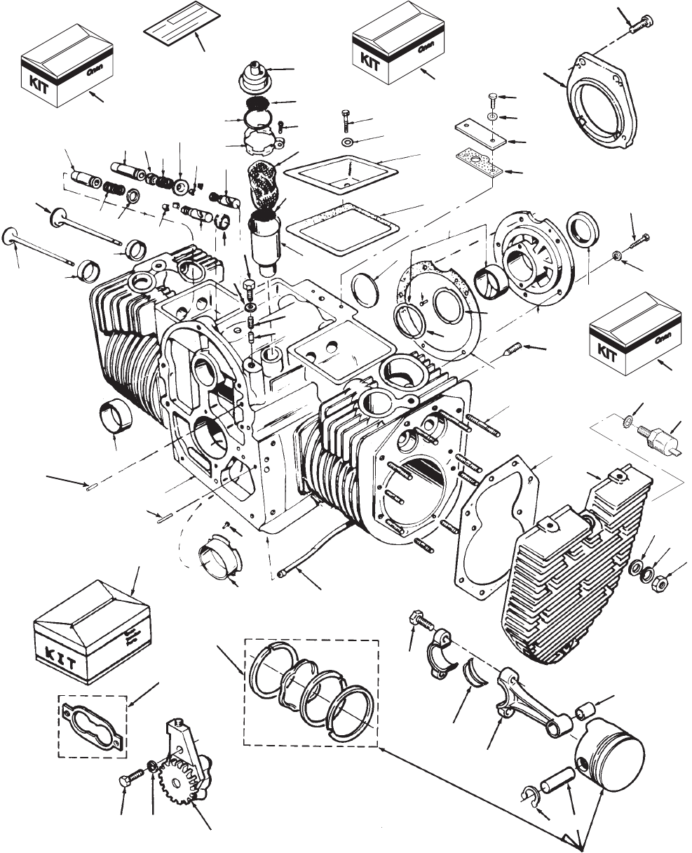
6
Cylinder Block
1
2
3
45
6
7
8
9
10
11
12
13
14
15
16
17
18
19
20
21
22
23 24
25
26 27 28 29
30
31
32
33
34
35
36
37
38
39
40
41
42
43
4445
46
47
48
49 50
51
52
53
54
55
56
57
58
59
60
61
68
69
72
73
74
75
27
26
33
28
18
63
65
66
67
62
64
70
71
,
29
76
77
7
Cylinder Block
REF PART QTY PART REF PART QTY PART
NO. NO. USED DESCRIPTION NO. NO. USED DESCRIPTION
1 1 Block,
Cylinder (See Short
Block Catalog #932–0109)
(Includes Parts Marked *)
2 123–0954 1
Cap and V
alve, Breather
3 123–0952 1 *T
ube, Breather
4 123–1417 1 Filter
, Breather T
ube
5 Cover
, V
alve Compartment
110–1624–01 2 Spec B,E
110–3616–02 1 Spec C,D
110–1624–01 1 Spec C,D
6 110–3575 2 Gasket, Valve Cover
7 517–0048–01 1 *
Plug, Expansion (Plated)
8 110–3604 2
Seal, Intake V
alve
9 110–2987 2 Gasket, Cylinder Head
10 110–3549 2
Head, Cylinder
11 809–0035 1 Screw
, Breather Clamp
(#8 x 3/4”)
12
Bearing, Rear Crankshaft
101–0804 1 * Standard
101–0804–02
1.002” Undersize
101–0804–10
1.010” Undersize
101–0804–20
1.020” Undersize
101–0804–30
1.030” Undersize
13 104–0575 2 *Washer
, Crankshaft Bearing
Thrust
14 101–0809 1 *
Gasket, Bearing Plate
15
Plate, Rear Bearing
101–0439–01 1 *
Code 1
1AH,11AW
101–0430–01 1
SAE–B – Code 1
1AR
101–0437–01 1
SAE–A – Code 1
1AP
101–0793–02 1
Begin Spec E
16 101–0405 2 *
Bearing, Camshaft
17 509–0041 1
Seal, Crankshaft Oil (Rear)
18 516–0072 4 *
Pin, Bearing Stop
19 800–0051–01 5 Screw
, Cap – Hex Head
(3/8–16 x 1–1/4”)
Loctite Patch
20 526–0063 2 Washer
, Flat – Copper
(1/4” Screw)
21 120–0680 1 *Tube, Crankcase Oil
22 V
alve, Intake
110–3569 2 Spec B,C
110–1718 2
Begin Spec E
23 Valve, Exhaust
110–3570 2 Spec B,C
110–1719 2
Begin Spec E
24
Insert, V
alve Seat – Exhaust
110–1716
2
* Standard
110–1716–02 2 .002” Oversize
110–1716–05 2 .005” Oversize
110–1716–10 2 .010” Oversize
110–1716–25 2 .025” Oversize
110–3655–25 2 .025” Oversize
25
Insert, V
alve Seat – Intake
(Zinc Plated)
110–3655 2 * Standard
110–3655–02 2 .002” Oversize
110–3655–05 2 .005” Oversize
110–3655–10 2 .010” Oversize
26 *
Guide, V
alve
110–3167 2 Exhaust
110–3168 2 Intake
27 110–0539 4
Spring, V
alve
28 Lock, V
alve Spring
110–3572 8 Spec B,C
110–0639 8 Spec E
29 115–0006 4 T
appet, V
alve
30 Rotator
, V
alve
110–0904 2 Spec B,C (Intake)
110–0904 4
Begin Spec E
31 800–0011 2 Screw
, Cap – Hex Head
(1/4–20 x 2”)
32 123–0951 1
Clamp, Loop – Breather T
ube
Cap
33 123–0958 2
Screen, Breather T
ube
34 509–0117 1
Seal, O–Ring – Breather Cap
35 Bearing,
Half – Connecting
Rod
114–0188 4 Standard
114–0188–02 4 .002” Undersize
114–0188–10 4
.010” Undersize
114–0188–20 4
.020” Undersize
114–0188–30 4
.030” Undersize
36 *
Stud, Cylinder Head Mounting
520–0919 8
3/8 x 2–19/32” (Install 4
Bottom Holes – RH, LH
Heads)
520–0876 4
3/8 x 2–3/4” (Install 2 T
op
Holes – RH, LH Heads)
520–0918 8
3/8 x 3” (Install 4 Middle
Holes – RH, LH Heads)
37
Bearing, Sleeve – Flanged
101–0805 1 * Standard
101–0805–02 1
.002” Undersize
101–0805–10 1
.010” Undersize
101–0805–20 1
.020” Undersize
101–0805–30 1
.030” Undersize
38 104–0776 AR *Shim,
Crankshaft Thrust (.005”)
39 516–0141 2 *Pin,
Gearcase Alignment
40 104–0091
20
Nut, Hex (Special)
41 114–0036 2
Bushing, Piston Pin
42 526–0402 5 Washer
, Flat (3/8”)
43 110–3571 2
Cap, V
alve – Exhaust (Spec
B and C only)
44 526–0250
20
Washer
, Flat – Heat T
reated
(3/8” Screw)
45 851–0029
24
Washer,
Compression
(Special)
46 517–0067 1 Plug,
Core Hole
47 Kit, Gasket
168–0190 1
Cylinder Head Removal
168–0191 1
Complete Engine
48 110–0893 2 Washer, Exhaust V
alve Spring
Retainer (Spec B and C only)
49 800–0007 2 Screw
, Cap – Hex Head
(1/4–20 x 1”)
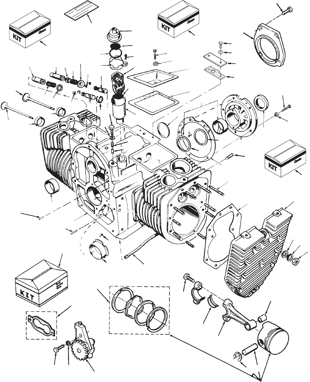
8
Cylinder Block
1
2
3
45
6
7
8
910
11
12
13
14
15
16
17
18
19
20
21
22
23 24
25
26 27 28 29
30
31
32
33
34
35
36
37
38
39
40
41
42
43
4445
46
47
48
49 50
51
52
53
54
55
56
57
58
59
60
61
68
69
72
73
74
75
27
26
33
28
18
63
65
66
67
62
64
70
71
,
29
9
Cylinder Block
REF PART QTY PART REF PART QTY PART
NO. NO. USED DESCRIPTION NO. NO. USED DESCRIPTION
50 Pump,
Oil (Components Not
Sold Separately)
120–0491 1 Spec B–D
120–1275–02 1
Begin Spec E
51 120–0161 1
Gasket Kit, Oil Pump
52 120–0140 1 Spring, Bypass Valve
53 120–0398 1 Plunger, Bypass Valve
54 801–0050 1 Screw
, Cap – Hex Head
(3/8–24 x 1”)
55 526–0066 1 Washer
, Flat – Copper
(3/8” Screw)
56
Ring, Retaining
518–0294 4 Spec B–D
112–0267 4
Begin Spec E
57
Kit, Ring – Piston
Spec B–D
113–0296 Standard
113–0296–05 2 .005” Oversize
113–0296–10 2 .010” Oversize
113–0296–20 2 .020” Oversize
113–0296–30 2 .030” Oversize
Begin Spec E
113–0311 2 Standard
113–0311–05 2 .005” Oversize
113–0311–01 2 .010” Oversize
113–0311–02 2 .020” Oversize
113–0311–03 2 .030” Oversize
58 114–0203 2
Rod, Connecting (Includes Bolt
and Bushing)
59 805–0010 4
Bolt, Connecting Rod
60
Piston & Ring Set (Includes Pin
and Retaining Rings)
112–0265 2 Standard
112–0265–05 2 .005” Oversize
112–0265–01 2 .010” Oversize
112–0265–02 2 .020” Oversize
112–0265–03 2 .030” Oversize
61
Pin, Piston
112–0069 2 Spec B–D
112–0268 2
Begin Spec E
62 740–1004 2 Washer
, Flat (1/4”)
63 803–0071 4 Screw
, Socket – Set
(3/8–16 x 5/8”)
64 541–0239 1
Kit, PT
O – 7” Pilot Adapter
Code 1
1BH (Includes Parts
Marked ~)
65 541–0344 1
Kit, PT
O Bearing Plate
Adapter
– SAE A – Code 1
1BE
(Includes
Parts Marked #)
66 541–0374 1
Kit, PT
O Bearing Plate
Adapter
– SAE B – Code 1
1BG
(Includes Parts Marked ^)
67 98–4240 1 ~^#
Label, Blank Kit Number
68 Adapter
, Hydraulic Pump
101–0766–01 1 #
Code 1
1BE
101–0766–02 1 ^
Code 1
1BF
, 1
1BG
69 Screw
, Cap – Hex Head
(3/8–16 x 1–3/4”)
800–0515 4 #
Code 1
1BE – SAE A
800–0515 5 ^
Code 1
1BF
, 1
1BG – SAE B
70 101–0761 1 ~Adapter
, Bearing Plate
71 815–0682 4 ~Screw, Hex Recessed
(3/8–16 x 1–1/4”)
72 160–1368 1 Gasket, Plate
73 160–1345–01 1
Plate, Ignition Plunger Cover
74 740–1004 2 Washer
, Flat (M6)
75 800–0004 2 Screw
, Hex Head Cap
(1/4–20 x 5/8”)
76 309–0559 1 Switch, Cut–Of
f – High
Temperature
77 853–0013 1 Washer,
Lock – Ext. T
ooth
(1/4”)
*
– Parts Included in the Cylinder Block.
#
– Parts included in PTO Bearing Plate Adapter Kit SAE A.
^
– Parts included in PTO Bearing Plate Adapter KIt SAE B.
~
– Parts included in PT
O – 7” Pilot Adapter Kit.
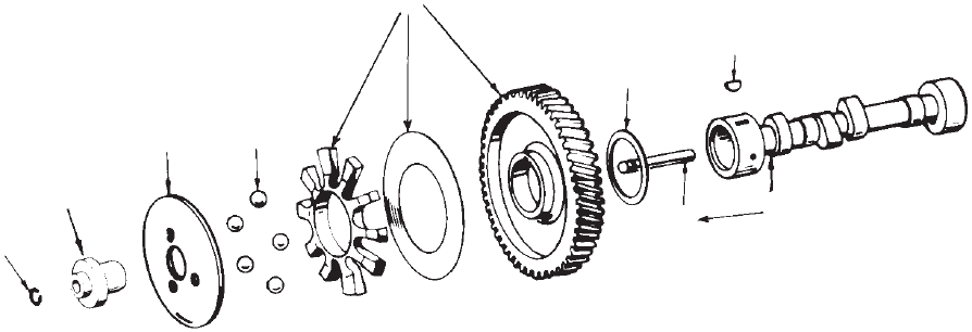
10
Camshaft
1
2
34
5
6
7
8
9
REF PART QTY PART REF PART QTY PART
NO. NO. USED DESCRIPTION NO. NO. USED DESCRIPTION
1 150–0078 1
Ring, Retaining
2 150–1519 1
Hub, Governor Cup
3 150–1520 1 Cup, Governor
4
Ball, Governor
510–0015 5
5 Ball Governor (Hi–Speed)
510–0015 10
10 Ball Governor – Code
13CH (Lo–Speed)
5 515–0001 1 Key,
W
oodruf
f – Camshaft Gear
6 Camshaft
105–0594 1 Specs B–G (Includes Center
Pin)
105–0676 1
Spec 1
1583H Only
7 105–0700 1 Gear,
Camshaft (Includes Gear
,
Spacer
and Plate)
8 105–0541 1 Washer
, Thrust – Special
9 150–0075 1
Pin, Center
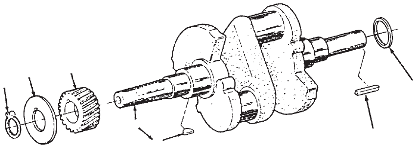
11
Crankshaft
1
234
5
6
7
REF PART QTY PART REF PART QTY PART
NO. NO. USED DESCRIPTION NO. NO. USED DESCRIPTION
1 Crankshaft (Includes Keys)
104–1340 1
Code 45BB
104–1698 1
Code 45BE
104–1314 1
Code 45BF
104–1311 1
Code 45BS
104–1310 1
Code 45BT
104–1500 1
Code 45BU
104–1786 1
Code 45BY
104–0864–01 1 +
Code 45CC
104–1698 1
Code 45BD
104–1831 1 +
Code 45EA
2 518–0014 1
Ring, Retaining
3 104–0043 1 Washer
, Gear Retaining –
Special
4 104–1808 1 Gear, Crankshaft
5 515–0001 1 Key, Crankshaft Gear
6 104–1694 1
Spacer – Code 45BE
7 Key
, W
oodruf
f – Crankshaft
Stub
515–0263 1
Kit, Flywheel Key
515–0103 1
(1/4 x 1/4 x 2”) Code
45BB,45BW
515–0146 1
(#18 x 1/4 x 1–1/8”)
515–0198 1
(3/8 x 3/8 x 2–1/2”)
Code 45BW
, 45BE
515–0230 1
(3/8 x 3/8 x 2”) Code 45BD
+ – Does Not Include Keys.
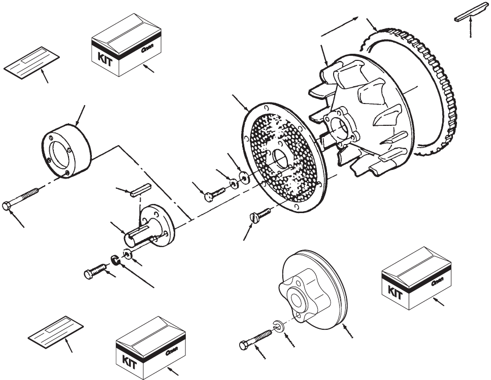
12
Blower Wheel With Screen
1
23
4
5
14
6
7
8
11
12
15
19
13
9
10
16
17 18
20
21
22 23
REF PART QTY PART REF PART QTY PART
NO. NO. USED DESCRIPTION NO. NO. USED DESCRIPTION
1 134–4680 1 Flywheel
(Includes Ring Gear)
2 104–0170 1 Screw
, Cap – Hex Head
3 526–0356 1 Washer
, Flat (7/16” Screw)
4 526–0017 1 Washer
, Flat (7/16” Screw)
5 815–0687 6 Screw
, Lock Head – Flange
6 134–4553–50 1
Screen, Air Inlet – Painted
7 104–0779 1 Gear
, Ring
8 515–0284 1 Key
, Flywheel (Special)
9 541–0222 1
Kit, PT
O – 1” Shaft
(Includes Parts Marked *)
10 98–4240 1 *
Label, Blank Kit Number
11 190–0687 1 *
Shaft, PT
O – 1” Diameter
12 515–0007 1 *Key
, Machine (1/4 x 2”)
13 850–0045 4 *Washer
, Lock (5/16”)
14 Screw,
Lock Head – Code
23DC
800–0030–01 4 * (5/16–18
x 1.25”)
821–0014 4 (5/16–18
x 1/2”) Begin Spec E
15 850–0045 4 *Washer,
Flat (5/16”)
16 541–0307 1 Kit,
PT
O Spacer (Includes Parts
Marked
#)
17 98–4240 1 #
Label, Blank Kit Number
18 190–0683 1 #Spacer
, PT
O
19 114–0022 2 Screw
, Cap – Hex Head
(5/16–18 x 1–3/4”)
20 190–0576 1
Kit, PT
O Front Pulley
(Code 45BN) (Includes Parts
Marked ^)
21 191–1210 1 ^Pulley, Drive (5–3/4” OD)
22 800–0548 2 ^Screw
, Hex Head Cap
(5/16–18 x 1–1/2”)
23 850–0045 2 ^Washer
, Lock (5/16)
24 E–256 1 ^
Sheet, Instruction (Not Shown)
*
– Parts included in PTO – 1” Shaft Kit.
#
– Parts included in PT
O Spacer Kit.
^ – Parts included in PTO Front Pulley Kit.
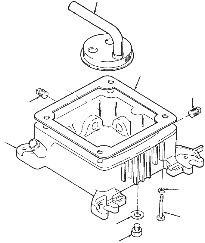
13
Oil Base
1
2
3
4
5
6
7
8
5
REF PART QTY PART REF PART QTY PART
NO. NO. USED DESCRIPTION NO. NO. USED DESCRIPTION
1 Base,
Oil (Includes All Plugs
and Plug Gasket)
102–1338 1
Spec B (Multidrain)
102–1384–02 1
Begin Spec C
2 102–1387 1 Gasket, Oil Base
3 526–0251 4 Washer
, Flat (3/8” Screw)
4 Screw
, Cap – Hex Head
800–0200–01 4
(3/8–16 x 5–3/4”) Spec B
800–0302–01 4
(3/8–16 x 5–1/2”) Begin
Spec C
5 Plug
505–0110 2
3/8 Pipe
505–0266 1
Pipe, Square – Countersunk
6
Plug, Hex Head – Special
505–1462 1
Metric (M22) Code 17DN
102–0938 1
Special (Code 17DA)
7 102–0743 1 Gasket, Hex Head Plug
8
Cup, Intake – Oil Pump
120–1215 1 Spec B
120–1230 1 Spec C
120–1272 1
Begin Spec E
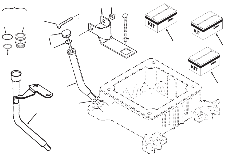
14
Oil Fill Tube
5
6
11
12
13
14
12
3
4
15
7
8
9
10
8thru 10
REF PART QTY PART REF PART QTY PART
NO. NO. USED DESCRIPTION NO. NO. USED DESCRIPTION
1 541–0433 1 Kit,
Inner Oil Fill T
ube
Code 17BY (Includes Parts
Marked #)
2 541–0434 1
Kit, Outer Oil Fill T
ube
Code 17BZ (Includes Parts
Marked ^)
3 541–0435 1
Kit, Outer T
all Oil Fill T
ube
Code 17CF ( Includes Parts
Marked *)
4
Cap and Indicator
, Oil Fill
(Includes O’Ring)
Code 17CF
123–1843 1 Spec B
123–1860 1 *
Begin Spec C
123–1860–01 1
Begin Spec H
123–1880 1 ^
Code 17BZ
123–1878 1 #
Code 17BY Begin Spec E
123–1880–01 1
Spec 1
1583H (Code 17BZ)
5 509–0142 1
O’Ring, Oil Fill Cap
6
Bracket, Fill T
ube
123–1897–51 1
Plated – Code 17CF
123–1867–51 1 ^
Painted – Code 17BZ
123–1869–51 1 # Painted
– Code 17BY – Begin
Spec E
7 123–2105 1 Adapter Assembly
, Oil Fill
(Begin
Spec H) (Includes Parts
Marked
@)
8 123–2091 1 @Adapter
, Oilcap
9 509–0142 1 @Seal
10 509–0304 1 @O–Ring
11 T
ube, Oil Fill
123–1718–50 1 ^ Outer
, Short – Painted –
Code 17BZ
123–1729–50 1 Outer
, T
all – Painted –
Code 17CF
123–1685–50 1 # Inner
, T
all – Painted –
Code 17BY – Begin Spec E
123–1869–51 1
Begin Spec H (Code 17BY)
12 509–0269 1 *^#
Seal, Oil Fill T
ube
13 Screw
815–0576 1
Pan Head (1–1/4” Long)
Code 17CF
815–0760 1 Hex W
asher Head – Thread
Cutting – Code 17BZ,17BY
14 870–0410 1
Nut, Speed (T
ype U) – Code
17CF
15 123–1969–51 1 *Tube,
Oil Fill – Painted (Includes
Bracket)
Code 17CF
# – Parts included in Inner Oil Fill T
ube Kit.
^ – Parts included in Outer Oil Fill T
ube Kit.
* – Parts included in Outer T
all Oil Fill Tube Kit.
@
– Parts included in Oil Fill Adapter Assembly
.
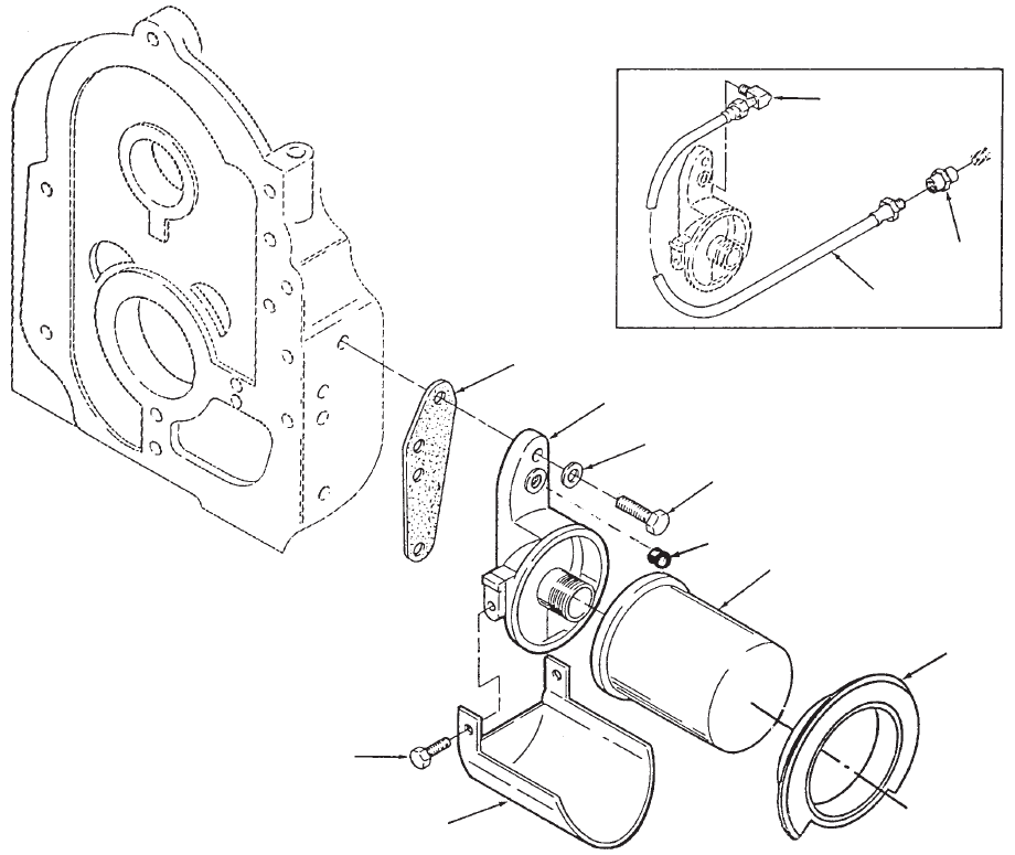
15
Oil Filter
1
2
3
4
5
6
7
8
9
10
11
12
REF PART QTY PART REF PART QTY PART
NO. NO. USED DESCRIPTION NO. NO. USED DESCRIPTION
1 122–0814 1 Adapter,
Oil Filter
2 526–0065 2 Washer
, Flat – Copper
(5/16” Screw)
3 800–0028–01 2 Screw
, Cap – Hex Head
(5/16–18 x 1”) Shakeproof
(Code 17DF)
4 122–0352–50 1
Drain, Oil Filter – Painted
5 815–0194 2 Screw
, Cap – Hex Head
W/ET (#10–32 x 3/8”)
6 122–0771 1
Gasket, Oil Filter Adapter
7 Filter
, Oil
122–0469 1
With Hex Nut – Code 17CV
122–0800 1
Without Hex Nut – Code
17CD 4.2” Long – Begin
Spec C Code 17DF
8 501–0008 1
Line, Flex
9 502–0017 1 Connector
10 502–0020 1 Elbow
, Street
11 505–1426 1
Plug, Countersunk (1/8”)
12 122–0502 1
Gasket, Oil Filter – Code 17CV
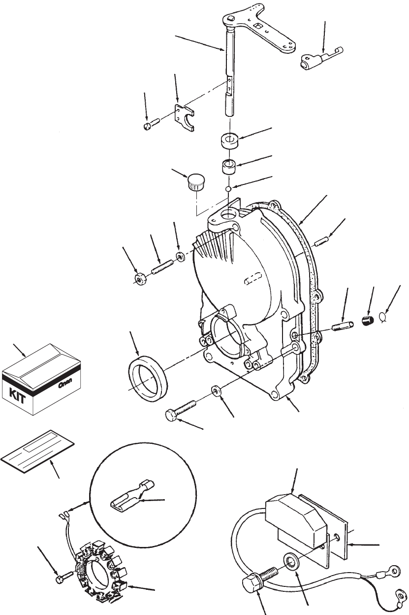
16
Gearcase
1
2
3
4
5
6
7
8
9
10
11 12
13
14
15
27
16
17
18
19
29
20 21
22
23
12
24
26
32
17
Gearcase
REF PART QTY PART REF PART QTY PART
NO. NO. USED DESCRIPTION NO. NO. USED DESCRIPTION
1 Gearcase Kit (Includes Parts
Marked *)
103–0791 1
All Specs Except 10913
103–0799 1
Spec 10913 only
2*
Bearing, Governor Shaft
510–0105 1
All Specs Except 10913 and
11583H
510–0013 1
Spec 10913 only
3
Shaft And Arm, Governor
150–1470–01 1
All Specs Except 10913 and
11583H
150–1422–01 1
Spec 10913 only
4 150–1187 1 *Yoke,
Governor
Shaft (All Specs
Except
1
1583H)
5 815–0046 2 *Screw
, Machine – Pan Head
(8–32x3/8”) (All Specs Except
11583H)
6 516–0130 1 *Pin,
Dowel –
Governor Cup Stop
(All Specs Except 11583H)
7 509–0008 1 *
Seal, Oil – Governor Shaft (All
Specs Except 1
1583H)
8 510–0014 1 *
Ball, Bearing – Governor Shaft
(All Specs Except 11583H)
9 509–0040 1 *
Seal, Oil – Crankshaft, Front
10 103–0810 1
Gasket, Gearcase Mounting
11 800–0032–01 4 Screw
, Cap – Hex Head
(5/16–18x1–3/4”)
12 526–0065 5 Washer
, Flat – Copper
(5/16” Screw)
13 149–1299 1 *T
ube, V
acuum Port (1.5” Long)
(Spec B only)
14 520–0933 1
Stud, Gear Cover
15 862–0015 1
Nut, Hex (5/16–18)
Stator (Includes T
erminals)
16 191–2104 1 T
erminal Kit, Alternator
(3 Leads)
17 503–0301 1
Clamp, V
acuum Port Cap
(Spec B only)
18 149–1321 1 Cap,
V
acuum Port
(Spec B only)
19 166–0785 1 Control,
Ignition
20 815–0340 2 Screw, Hex W
asher Head
(10–32x3/8”)
21 854–0010 2 Washer
, Lock – IT (#10)
22 518–0406 1 Clip,
Retaining – Control Rod T
o
Governor
Shaft
23 166–0786 1 Insulator
, Ignition Module
24 541–0259 1 Kit,
35
Amp Alternator (Includes
Parts
Marked +) Code 31BC
25 E–0327 1 +
Sheet, Instruction (Not Shown)
26 98–4240 1 +
Label, Blank Kit Number
27 191–1276 1 +Stator
, Alternator
191–1276 1
35 Ampere (Code 31BC)
191–1456 1
20 Ampere (Code 31AZ)
28 191–1847 1 +Regulator
, 35 Amp V
oltage
(Shown on Blower Housing
Page)
29 815–0659 3 +Screw
, Machine – Hex Head
Self–Lock (#10–32x1”)
30 821–0010 1 +Screw, Lock Head
(1/4–20 x1/2”) (Not Shown)
31 853–0013 1 +Washer, ET Lock (Not Shown)
32 517–0293 1 Plug, Expansion (Spec 11583H
Only)
*
– Parts included in Gearcase.
+ – Parts included in 35 Amp Alternator Kit.
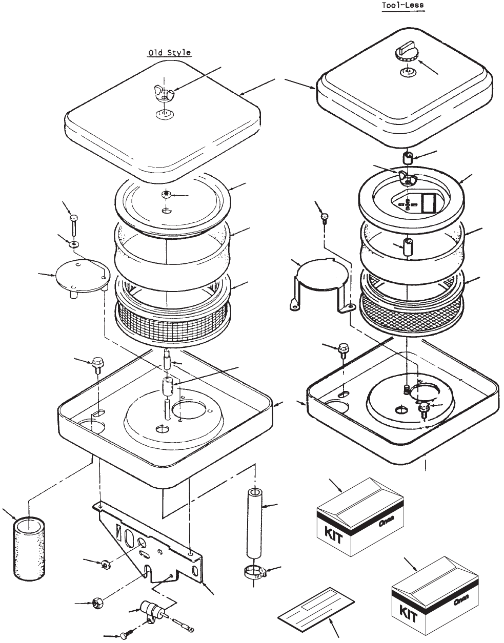
18
Air Cleaner
1
6
7
8
9
10
11
12
13
14
15
16
17
18
19
20
21
22
23
24
25
26
27
28
29
30
32
33
7
8
11
11
5
31
2
19
Air Cleaner
REF PART QTY PART REF PART QTY PART
NO. NO. USED DESCRIPTION NO. NO. USED DESCRIPTION
1 Kit,
Air Cleaner – Code 19AS
(Standard Capacity)
541–0457–01 1 Begin
Spec
B (Includes Parts
Marked *)
541–0457–02 1 Begin
Spec C (Includes Parts
Marked
#)
2
Kit, Air Cleaner – Code 19AU
(High Capacity)
541–0458–01 1 Begin
Spec
B (Includes Parts
Marked ~)
541–0458–02 1 Begin
Spec C (Includes Parts
Marked ^)
3 E–347a 1 ~*
Sheet, Instruction (Not Shown)
4 E–348b 1 ^#
Sheet, Instruction (Not Shown)
5 98–4240 1 ~^*#
Label, Blank Kit Number
6 Cover
, Air Cleaner
140–2005–50 1 *#
Code 19AS (Standard)
140–1913–50 1 ~^
Code 19AU,19CL (XSL)
140–2005–02 1
Code 19BB – Begin Spec C
(Chrome)
7 Wrapper
, Air Cleaner Element
140–1496–01 1 *#
Code 19AS
140–1912–01 1
Code 19AU,19CL
8
Element, Air Cleaner
140–2628–01 1 *#
Code 19AS – Standard
Capacity – Extended
Service
140–2628–02 1 ~^
Code 19AU,19CL – High
Capacity
9 870–0399 1 Nut, Hex W
asher Head
Flanged
(5/16–18) Code
19A
V
10 Housing,
Air Cleaner
140–2493–51 1 *
Code 19AS – Painted
140–2539–51 1 ~
Code 19AU – Painted
140–2493–53 1 #
Begin Spec C – Use with
Standard Filter
140–2539–53 1 ^
Begin Spec C – Use with
High Capacity Filter
11 815–0575 2 Screw
, T
apping – Hex W
asher
Head (1/4–20 x 3/8”)
12 815–0470 3 Screw
, Hex Head – Machine
(#10–32 x 1–1/2”)
13 526–0234 3 Washer
, Flat (#10 Screw)
14 145–0522 1
Plate, Air Deflector
15 T
ube, Air Intake
503–1882–01 1
3.5” Long
503–1882–02 1
4.12” Long
503–1882–03 1
5.12” Long
16 140–2191–50 1
Support, Air Cleaner
17 508–0021 1
Grommet, Rubber (3/4” Hole)
18 541–0459 1 Cover
, Element
19 870–0365 1
Nut, Hex (1/4–20)
20 301–0458 1 Spacer
, Air Cleaner Stud
21 520–0948 1
Stud – Code 19AU
22
Hose, Breather
503–1606–01 1 Old Style
503–1606–02 1 ^# Tool–Less
23 503–1133 1 ^#
Clamp, Hose
24 312–0256 1
Capacitor (Placed Horizontal)
25 815–0389 1 Screw,
Hex Head (1/4–20 x 3/8”)
26 Cover,
Inner – T
ool–Less
140–2794 1 Spec A–F
140–2942 1 ~^*#
Begin Spec G
27 Spacer
, Air Cleaner Stud
140–2536–01 1 *#
Extended Service Life &
Standard Capacity 1” Long
140–2536–02 1 ~^
High Capacity – 2.75” Long
28 140–2761 1 ~^*#
Knob, T
ool–Less
29 815–0463 3 ~^*#Screw
, Slotted – Hex W
asher
Head (10–32 x 3/8”)
30 865–0029 1
Nut, Wing
31 865–0020 1
Nut, Wing (1/4–20)
32 145–0614 1 ~^
Plate, Air Deflector – High
Capacity
33 140–2786 1 ~^*#Spacer, 1/2”LG – Standard and
High Capacity
* – Parts included in 541–0457–01 Air Cleaner Kit.
# – Parts included in 541–0457–02 Air Cleaner Kit.
~ – Parts included in 541–0458–01 Air Cleaner Kit.
^ – Parts included in 541–0458–02 Air Cleaner Kit.
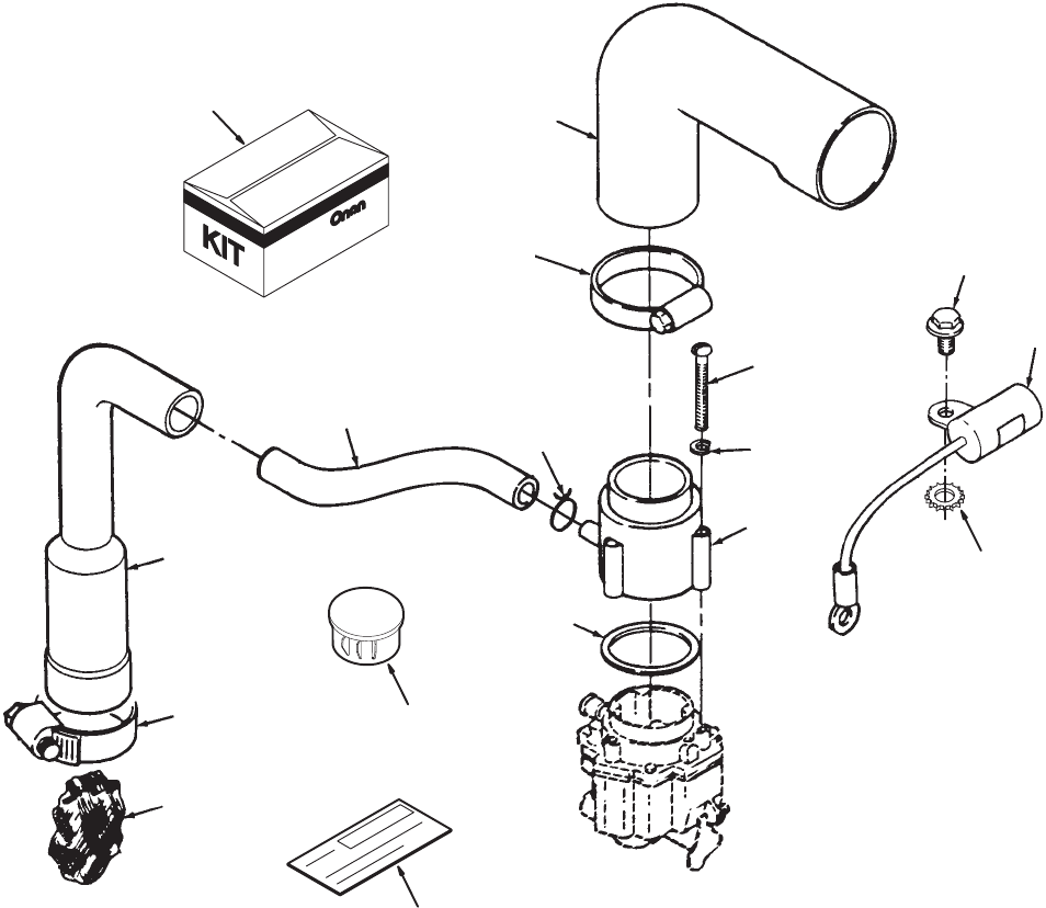
20
Remote Air Cleaner Adapter
1
3
11
12
6
7
9
13
14
15
16
17
5
4
2
8
10
REF PART QTY PART REF PART QTY PART
NO. NO. USED DESCRIPTION NO. NO. USED DESCRIPTION
1 541–0320 1 Kit,
Remote Adapter Air Cleaner
(Includes Parts Marked *)
Code 19A
V
2 509–0145 1 *
Seal, O–Ring
3 850–0030 3 *Washer
, Lock – Spring (#10)
4 503–1396 1 *
Hose, Breather
5 853–0013 1 *Washer
, Lock – External T
ooth
(1/4”)
6 140–1714 1 *Adapter
, Air Intake
7
813–0106 3 *Screw
, Machine – Round Head
(#10–32 x 1–1/8”)
8 517–0252–01 1 *
Plug, Hole
9
503–0171 2 *
Clamp, Hose (1
1/16” Dia.)
10 98–4240 1 *
Label, Blank Kit Number
11 123–1871 1 Filter
, Breather T
ube
12 123–1539 1 T
ube, Breather – Crankcase
13 312–0256 1 Capacitor
14 815–0178 1 Screw, Hex W
asher Head
Thread Form (10–32 x 5/8”)
15 503–0398 1
Clamp, Breather T
ube (1–5/8”
Diameter)
16 140–1428 1 Elbow
, Air Inlet
17 503–1141 1
Clamp, Hose (2–3/8” Diameter)
*
– Parts included in Air Cleaner Kit.
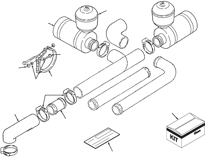
21
Remote Air Cleaner
7
8
2
9
3
10
11
12
6
4
1
5
REF PART QTY PART REF PART QTY PART
NO. NO. USED DESCRIPTION NO. NO. USED DESCRIPTION
1 541–0147 1 Kit,
Air Cleaner Remote Elbow
(Include Parts Marked *)
Code 19CJ
2 140–1428 1 *Elbow
, Air Inlet
3 503–1141 4 *
Clamp, Hose
(2–3/8 x 1/2” Band)
4 98–4240 1 *
Label, Blank Kit Number
5 140–0721 1 Cleaner
, Air (Includes Element)
6 140–2860 1
Element, Air Cleaner
7 140–0722 2
Band, Air Cleaner
8 140–0723 1 Precleaner
, Air Cleaner
(Plastic)
9 140–2173 1 T
ube, Air Induction (Steel)
10 800–0004 4 Screw
, Hex Head Cap
(1/4–20 x 5/8”)
11 870–0065 4
Nut, Self–Lock (1/4–20)
12 526–0018 8 Washer
, Flat (1/4” Screw)
*
– Parts included in Remote Elbow Kit.
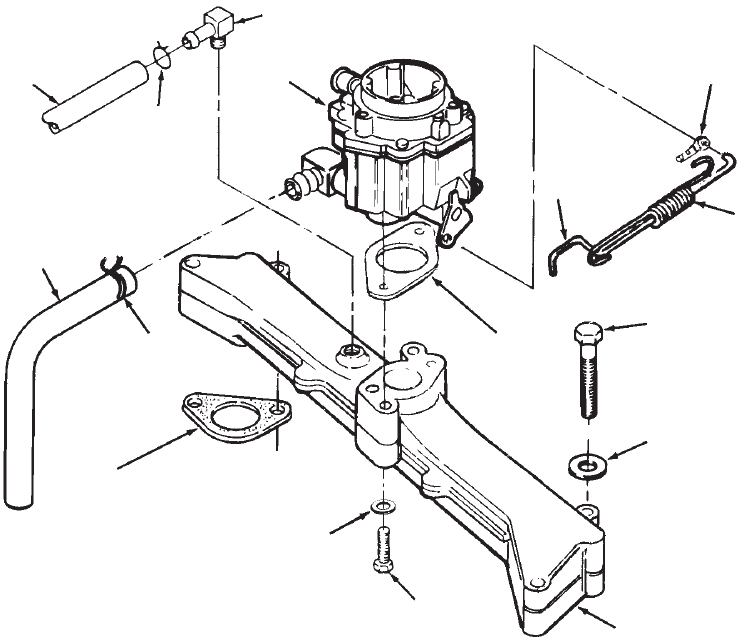
22
Fuel System
Gasoline
1
2
3
4
5
6
7
8
9
10
11
12
13
14
15
16
REF PART QTY PART REF PART QTY PART
NO. NO. USED DESCRIPTION NO. NO. USED DESCRIPTION
1 Carburetor,
Completd (Includes
Mounting Gasket, Elbow and
O–Ring) (See Separate Page
for Components)
146–0497 1 Spec B–F
146–0662 1 Begin Spec G (Emissions
Carbuetor) (Includes
Gasket Only)
2 154–0733 1
Gasket, Carburetor Mounting
3
Manifold, Intake
154–2873 1
Code 15BD
154–2749 1
Code 15CU
4 800–0035 2 Screw
, Cap – Hex Head
(5/16–18 x 2–1/2”)
5 Screw
, Cap – Hex Head
(3/8–16 x 3”)
800–0058 4
Spec B (3/8–16 x 3”)
800–0058 2
Begin Spec C (3/8–16 x 3”)
800–0036 2
Begin Spec C
(5/16–18 x 2–3/4”)
6 740–1006 2 Washer
, Flat (M8)
7 154–2219 2
Gasket, Intake Manifold
8 518–0004 1 Clip,
Retaining – Control Rod T
o
Carburetor
9 150–2553 1 Rod,
Governor Control
10
Hose, Fuel
503–1199 1
24” Long
503–1418 1
15” Long
11 503–1606–01 1
Hose, Rubber Breather
(3.25” Long)
12 502–1038 1
Fitting, Barbed – Code 19AU
13 503–0731 2
Clamp, Hose – (1/2” Diameter)
14 Washer
, Flat
526–0251 4 Spec B (3/8” Screw)
526–0251 2 Begin Spec C (3/8” Screw)
526–0122 2
Begin Spec C (5/16” Screw)
15 503–1133 1
Clamp, Hose – Breather
16 150–2409 1
Spring, Rod – Governor
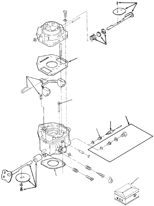
23
Carburetor Components
Nikki
Spec B
1
2
4
5
6
7
8
9
10
11 2
3
REF PART QTY PART REF PART QTY PART
NO. NO. USED DESCRIPTION NO. NO. USED DESCRIPTION
146–0431 1 Carburetor,
Complete (Includes
Mounting Gasket)
1 146–0437 1
Kit, Float (Includes Float, Pin
and V
alve)
2 146–0500 1 Kit,
Repair (Includes Screw And
Plug Package, Gasket
Package, Float V
alve, Idle
Adjust Needle and Spring,
Mounting Gaskets, Idle Limit
Cap)
3 154–0733 1
Gasket, Carburetor Mounting
4 146–0424 1
Jet, Power – Fixed – Optional
(High Altitude Application)
(Package) (Includes Float
V
alve, Idle Jet, Power Jet,
Idle Needle–Adjust, and
Power Jet Gasket)
5 146–0426 1
Jet, Idle
6 146–0501 1
Jet, Power – Fixed – Standard
7 146–0467 1
Solenoid, Fuel Cut–Of
f
(Includes Gasket)
8 146–0505 1
Kit, Throttle Shaft
9 146–0435 1
Kit, Choke Lever
10 146–0433 1
Kit, Choke Shaft
11 145–0438 1
Gasket, Carburetor Mounting
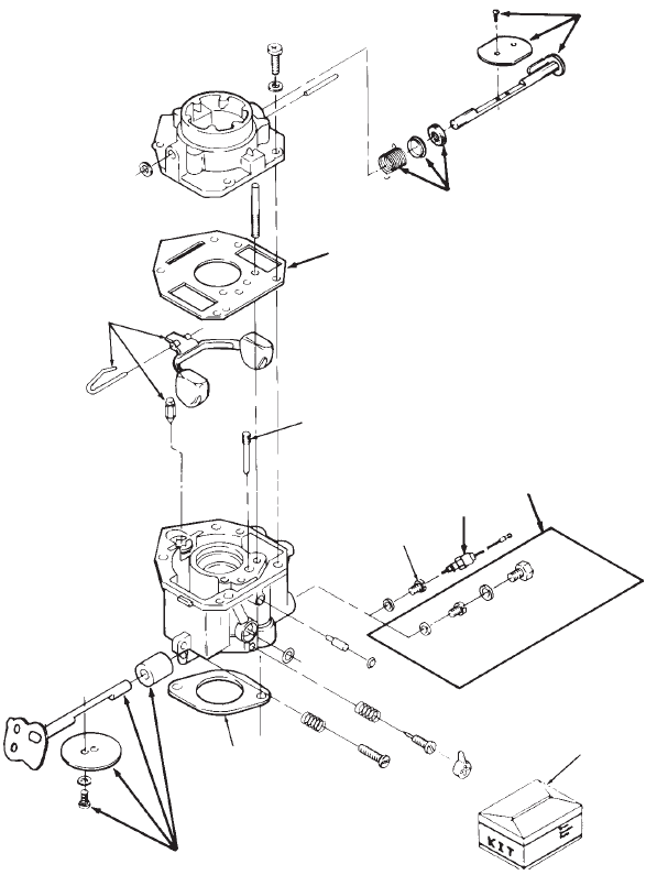
24
Carburetor Components
Nikki
Spec C
1
2
3
4
5
6
7
8
9
10
11
2
REF PART QTY PART REF PART QTY PART
NO. NO. USED DESCRIPTION NO. NO. USED DESCRIPTION
Carburetor,
Complete (Includes
Mounting Gasket)
146–0497 1
Begin Spec C
1 146–0437 1
Kit, Float (Includes Float, Pin
and V
alve)
2 146–0500 1
Kit, Repair (Includes Screw
And Plug Package, Gasket
Package, Float V
alve, Idle
Adjust Needle and Spring,
Mounting Gaskets, Idle Limit
Cap)
3 154–0733 1
Gasket, Carburetor Mounting
4 146–0424 1
Jet, Power – Fixed – Optional
(High Altitude Application)
(Package) (Includes Float
V
alve, Idle Jet, Power Jet,
Idle Needle–Adjust, and
Power Jet Gasket)
5 146–0426 1
Jet, Idle
6 146–0501 1
Jet, Power – Fixed – Standard
7 146–0502 1
Kit, Fuel Cut–Of
f Solenoid
(Includes Cut–Of
f Solenoid,
Crimp T
erminal, and Gasket)
8 146–0499 1
Gasket, Mounting
9 146–0433 1
Kit, Choke Shaft
10 146–0435 1
Kit, Choke Lever
11 146–0505 1
Kit, Throttle Shaft
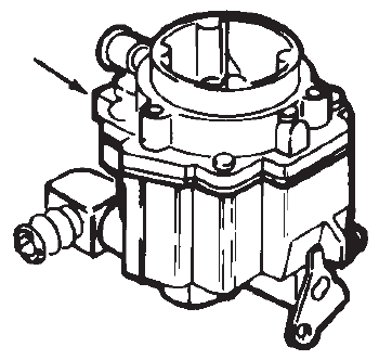
25
Carburetor Components
Begin Spec G
1
REF PART QTY PART REF PART QTY PART
NO. NO. USED DESCRIPTION NO. NO. USED DESCRIPTION
1 146–0662 1 Carburetor, Emissions
(Includes Parts Marked *)
2 146–0338 4 *Screw
, V
alve Set
3 146–0423 1 *V
alve, Float
4 146–0331 1 *
Spring, Adjustment Screw
5 146–0339 1 *
Plug, Expansion
6 146–0650 1 *
Repair Package, Float and
Gasket
7 146–0649 1 *
Repair Package, Accelerator
Pump
8 146–0502 1
Repair Kit, Solenoid V
alve
9 146–0657 1 *
Repair Kit, Float and Gasket
10 146–0658 1 *
Repair Kit, Accelerator Pump
11 146–0695 1 *
Jet, Main Fuel High Altitude
*
– Parts included in Emissions Carburetor
.
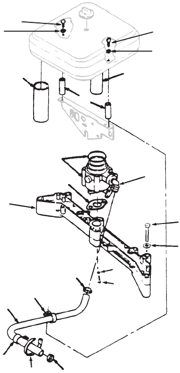
26
Fuel System
LP Carburetor
1
2
3
4
5
6
78
9
10
11
12
13
14
15
16
17
4
3
9
10
REF PART QTY PART REF PART QTY PART
NO. NO. USED DESCRIPTION NO. NO. USED DESCRIPTION
1 146–0562 1 Carburetor,
LP
2 503–1798–01 1
Hose, Fuel (3/8” ID x 27” Long)
3 503–1133 2
Clamp, Hose
4 332–1356 1
Clamp, Loop
5 141–0281 1
Gasket, Carburetor Mounting
6 140–2722–01 2 Spacer
, Air Cleaner
7 503–1882–03 1
Hose, Air Inlet
8 503–1606–03 1
Hose, Breather
9 821–0013 2 Screw
, Cap – Hex head
(1/4–20 x 1)
10 526–0018 2 Washer
, Flat (1/4” Screw)
11 502–1146 1 Elbow, Brass – 45°
(Included
with Carburetor)
12 Washer
, Flat (M8)
526–0251 4 Spec B (3/8” Screw)
526–0251 2 Begin Spec C (3/8” Screw)
526–0122 2
Begin Spec C (5/16” Screw)
13 Screw
, Cap – Hex Head
800–0058 4
Spec B (3/8–16 x 3”)
800–0058 2
Begin Spec C (3/8–16 x 3”)
800–0036 2
Begin Spec C
(5/16–18 x 2–3/4”)
14 154–2873 1
Manifold, Intake
15 800–0035 2 Screw
, Cap – Hex Head
(5/16–18 x 2–1/2”)
16 740–1006 2 Washer
, Flat
17 332–1794 1 T
ie, Cable (Self–Locking)
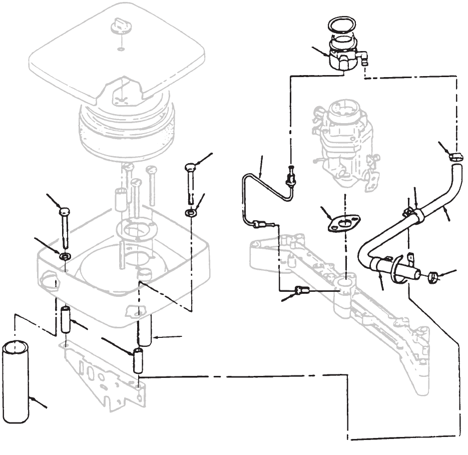
27
Fuel System
Dual Fuel
1
2
3
4
5
6
7
8
9
10
11
12
3
4
12
7
REF PART QTY PART REF PART QTY PART
NO. NO. USED DESCRIPTION NO. NO. USED DESCRIPTION
1 154–0733 1 Gasket,
Carburetor Mounting
2 140–2722–02 2 Spacer
, Air Cleaner
3 800–0011 2 Screw, Hex W
asher Head
(1/4–20 x 2”)
4 526–0018 2 Washer
, Flat (1/4” Screw)
5 503–1606–05 1 T
ube, Breather
6 503–1798–01 1
Hose, Fuel – 27” Long
7 503–1133 2
Clamp, Hose
8 503–1882–04 1
Hose, Air Inlet
9 148–0981–02 1 Mixer, LPG
10 148–0984–02 1
Jet, Idle
11 149–2385 1 T
ube, Idle Feed
12 332–1356 2
Clamp, Loop
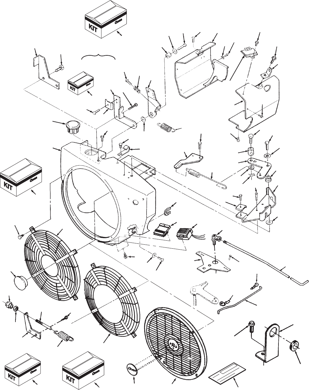
28
Blower Housing
1
2
3
4
56
8
12
13
14
15
17 18 19
20
21
22
23
25
26
27
28
29
30
31
32
33
34
35
36
37
38
39
40
41
42
43
44
45
46
47
48
65 66
12
41
41
66
66
21
45
6
20
45
43 43
41
7
9
(20
AMP)
(35 AMP)
(20 AMP)
(Begin Spec E)
(Spec A–D)
54
55
56
57
59
58
60
61
62
64 67 68
24
52
49
50
51
16
17 thru 19
63
10
11
53
29
Blower Housing
REF PART QTY PART REF PART QTY PART
NO. NO. USED DESCRIPTION NO. NO. USED DESCRIPTION
1 Housing,
Blower
134–4850 1
Without Oil Cooler (Spec B)
134–5001–50 1 Spec B–D
134–4986–02 1
Spec E–G (Painted)
Spec H
134–4986–02 1
With Control Panel
Code 39AG, 35CK,
and 35DB (With Harness)
134–5127–02 1
Without Control Panel
2
Housing, Cylinder Air – LH
134–4668–50 1
Without W
eld Nuts
134–4668–51 1
With W
eld Nuts
3
Housing, Cylinder Air – RH
134–4846–50 1
Without W
eld Nuts
134–4846–51 1
With W
eld Nuts
4 815–0290 2 Screw
, T
apping – Hex W
asher
Head (1/4–20 x 5/8”)
5 526–0021 2 Washer
, Flat (1/4” Screw)
6 821–0016 2 Screw
, Cap – Hex W
asher
Head (5/16–18 x 3/4”)
7 815–0337 3 Screw
, T
apping – Hex W
asher
Head (1/4–20 x 3/4”)
8 150–2264 1 Bracket, Governor Adjust
(Plated) Code 13CG
9 526–0018 4 Washer
, Flat (1/4” Screw)
10 541–0424 1
Kit, Fix Speed Governor
(Code 13CG) (Includes Parts
Marked ~)
11 541–0213 1
Kit, Side Pull Governor
(Code 13BJ) (Includes Parts
Marked ^)
12
Spring, Governor
150–1214 1 ~^
5 Ball Governor
150–1740 1
10 Ball Governor–Code
13CH
13 153–0514 1 ^
Clamp, Cable – Code 13BJ
14 150–1725–01 1 ^
Bracket, Governor Mounting
Code 13BJ
15 815–0359 1 ^Screw
, Tapping – Hex Head
(#10–32 x 1/2”) – Code 13BJ
16 Arm Assy
, Governor Control
150–1761 1 ^
Includes Parts Marked @
(Code 13CB)
150–2504–01 1 Includes
Parts Marked <
(Code
13BN)
17 Screw, Hex Head
815–0510 1 @ T
apping (#6–32 x 5/8”)
Code 13BJ
815–0563 1 <
Thread Form
(#6–32 x 1–3/8”)
Side Pull Governor –
V
ariable Speed
18 150–1398 1 <@
Spring, Idle Setting –
Code 13BJ
19
Arm, Governor Control (With–
out Swivel)
150–1576 1 @
Code 13BJ
150–1576–02 1 <
Code 13DD
20 815–0436 2 ^Screw,
Cap – Hex W
asher Head
(1/4–20
x 1/2”) – Code 13BJ
21 Washer
, Flat (1/4” Screw)
526–0021 2 ^
3/4” OD – Code 13BJ
526–0018 2
5/8” OD – Code 13CD,13BJ
22 150–1269 1 ^Bushing,
Governor Control Arm
23 150–0694 1 ~
Stud, Adjusting – Code 13CG
24 541–0191 1
Kit, Front Pull Governor
(Code 13BK) (Includes Parts
Marked #)
25 815–0391 1 #Screw
, Tapping – Hex Head
(#10–32 x 1/2”)
26 153–0514 1 #
Clamp, Throttle Cable
27 150–1726–01 1 #Bracket, Governor Control
Mounting – Zinc Plated
28 526–0021 1 Washer
, Flat (1/4” Screw)
29 850–0040 1 Washer
, Lock – Spring (1/4”)
30 800–0007 1 #Screw
, Cap – Hex Head
(1/4–20 x 1”)
31 815–0439 3 #Screw, Hex W
asher Head
T
apping (8–15 x 1/2”)
32 150–1727 1 #
Bushing, Governor Control
33 152–0155 1 #
Swivel, Throttle Lever
34 516–0059 1 #
Pin, Cotter
35 815–0693 1 #Screw
, Machine – Hex Head
(#8–32 x .318”)
36 150–1366 1 #
Link, Governor Control
37 150–1754–01 1 #Adapter, Governor Arm
38 815–0194 2 #Screw, Hex Head W/ET
(#10–32 x 1/2”)
39 150–1755 1 #
Spring, Governor
40 Plug, Black Nylon
517–0261 1
Code 23DE (57mm)
517–0136 1
Code 13BJ,13CD,15BB
(23.4mm)
41 821–0008 4 Screw,
Cap – Hex W
asher Head
(1/4–20
x 5/16”)
42 149–2242 1 Bracket,
Fuel Line – Begin
Spec
C
43 Regulator, Voltage
Spec A–D
191–2106 1
20 Ampere – Code 31AZ
Begin Spec E
191–2227 1
20 Ampere – Code 31AZ
191–1847 1
35 Ampere – Code 31BC
44 403–4202–02 2
Bracket, Lifting (Plated)
45 821–0010 5 ~Screw, Lock Head
(1/4–20 x1/2”)
46 518–0515 1
Clip, Wire – Code 13BJ,13BK
13CD (Spec B thru G only)
47 526–0006 1 #Washer
, Flat (#12 Screw)
Code 13BK
48 815–0474 1 Screw, Hex W
asher Head
(1/4–14 x 1/2”) – Code 13BJ
13BK,13CD – Code 13CG
(Spec B thru G only)

30
Blower Housing
1
2
3
4
56
8
12
13
14
15
17 18 19
20
21
22
23
25
26
27
28
29
30
31
32
33
34
35
36
37
38
39
40
41
42
43
44
45
46
47
48
65 66
12
41
41
66
66
21
45
6
20
45
43 43
41
7
9
(20
AMP)
(35 AMP)
(20 AMP)
(Begin Spec E)
(Spec A–D)
54
55
56
57
59
58
60
61
62
64 67 68
24
52
49
50
51
16
17 thru 19
63
10
11
53
31
Blower Housing
REF PART QTY PART REF PART QTY PART
NO. NO. USED DESCRIPTION NO. NO. USED DESCRIPTION
49 870–0131 1 ~Nut,
Hex – Governor Adjusting
(W/ET 10–32) – Code 13CG
50 150–0621 1 ~
Nut, Governor – Acorn,
51 815–0261 1 Screw, Hex W
asher Head
(1/4–20 x 1/2”)
52 150–2264 1 ~Bracket,
Governor
Adjust – Zinc
Plated
– Code 13CG
53 150–0639 1
Joint, Ball – Code 13CG
54 150–2364 1
Rod, Governor – Code 13CG
55 518–0406 1
Clip, Retaining – Control Rod
Code 13CG
56 815–0181 1 Screw
, Thread Cutting – Hex
Head W/ET (#10–32 x 1/2”)
57 150–2388 2 Lever
, Governor – Code 31AZ
Begin Spec C
58 150–2553 1
Rod, Governor Control (Zinc
Plated)
59 518–0004 1 Clip,
Retaining – Control Rod to
Carburetor
60 508–0021 1 Grommet,
Rubber
– Code 13BJ
61 508–0331 1 Grommet,
Rubber – 20, 35
Amp
Voltage
Regulator Harness –
Begin Spec E
62
Plug, Hole – Code 19A
V
517–0252 1 Plated
517–0174 1 Tapered
63 541–0296 1 Kit,
Stationary
Grill Without PT
O
Access
(Code 23DN)
(Includes Parts Marked *)
64 541–0369 1
Kit, Stationary Grill with PT
O
Access
(Code 23ED) (Includes
Parts Marked +)
65 Screw
815–0575 4 Hex W
asher Head
(1/4–20 x 3/8”)
815–0721 4
+*Pan Head – T
aptite (Special)
(10–32 x 1)
Code 23DN, 13CD
66
Guard, Stationary
134–4689 1
No Center Hole
134–4689–01 1
*Center Hole – 1” Dia.
134–4689–02 1
+Center Hole – 3.88” Dia.
67 99–2393 1 *
Nameplate, Logo
68 98–4240 1 *+#^
Label, Blank Kit Number
# – Parts included in Front Pull Governor Kit.
* – Parts included
in Stationary Grill Kit without PT
O Access.
+ – Parts included in Stationary Grill Kit with PT
O Access.
^ – Parts included in Side Pull Governor Kit.
@
– Parts included in 150–1761 Governor
Control Arm Assy
.
<
– Parts included in150–2504–01 Gov
. Control Arm Assy.
~ – Parts included in Fixed Speed Governor Kit.
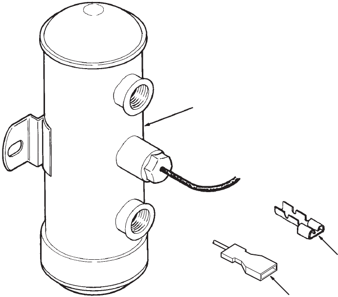
32
Remote Fuel Pump
(Electric)
2
3
1
REF PART QTY PART
NO. NO. USED DESCRIPTION
1 149–1828 1 Kit,
12 V
olt Electric Fuel Pump
(Includes Parts Marked *)
2 332–0529 1 *T
erminal, Crimp
3 332–1993 1 *Terminal
*
– Parts included in 12 V
olt Electric Fuel Pump Kit.
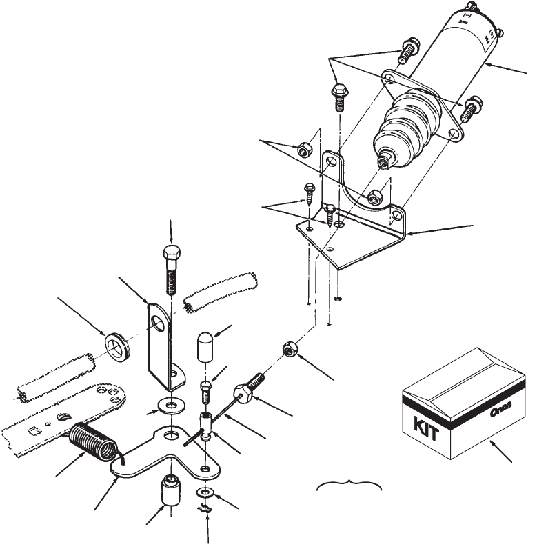
33
Two Speed Governor
(Code 13BF)
1
11
8
12
513
15
16
7
6
17
18
4
19
14
20
21
22
10
9
3
thru
38
2
REF PART QTY PART REF PART QTY PART
NO. NO. USED DESCRIPTION NO. NO. USED DESCRIPTION
1 541–0418 1 Kit,
2 Speed, 12 V
olt Solenoid
Governor (Code 13BF)
(Includes Parts Marked *)
2 150–2545 1 Bracket Assembly, Governor
(Includes Parts Marked #)
3 517–0177 1 #
Plug, Cap
4 800–4072 1 #*Screw
, Machine – Hex Head
(M4)
5 153–0632 1 #*Swivel, Choke Lever
6 526–0006 1 #*Washer
, Flat (#12 Screw)
7 516–0059 1 #*
Pin, Cotter
8 150–2498 1 #*Bracket, Governor
9 150–1740 1 *
Spring, Governor (Low Speed)
10 149–2242 1 *
Bracket, Fuel Line
11 150–1727 1 *
Bushing, Governor Control
12 150–2499 1 *
Bracket, Solenoid Mounting
13 153–0678 1 *Cable Assy (Includes Screw)
14 815–0800 1 *Screw
, Hex Head – Grade 5
(1/4–28 x 1”) (Included in
Cable Assy)
15 307–2758 1 *
Solenoid, Governor
16 508–0021 1 *
Grommet, Fuel Line Bracket
17 526–0021 1 *Washer
, Flat (1/4” Screw)
18 800–0007 1 *Screw
, Cap – Hex Head
(Special)
19 815–0439 2 *Screw,
Cap – Hex W
asher Head
(#8–15 x 1/2”)
20 821–0010 3 *Screw
, Lock Head
(1/4–20 x 1/2”)
21 115–0025 1 *
Nut, Hex (1/4–28)
22 870–0212 2 *
Nut, Lock (1/4–20)
23 E–350 1 *
Sheet, Instruction (Not Shown)
* – Parts included in 2 Speed, 12 V
olt
Solenoid Governor Kit.
# – Parts included in Governor Bracket Assemly.
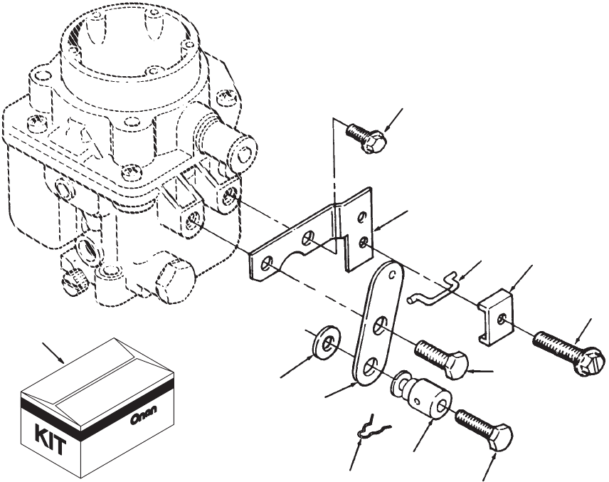
34
Choke Control
(Front Pull)
3
4
5
6
7
8
9
10
11
12
2
1
REF PART QTY PART REF PART QTY PART
NO. NO. USED DESCRIPTION NO. NO. USED DESCRIPTION
1 541–0190 1 Kit,
Front Pull Choke (Includes
Parts Marked *) Code 15BJ
2 526–0140 2 *Washer
, Flat (#10 Screw)
3 153–0523 1 *Lever, Choke
4 153–0500 1 *
Link, Choke
5 153–0524 1 *Bracket, Choke Cable
6 821–0004 1 *Screw, Cap – Hex W
asher
Head (#10–32 x 5/16”)
7 815–0820 1 *Screw
, Shoulder
(#10–32 x 3/8”)
8 152–0155 1 *Swivel, Choke Lever
9 815–0693 1 *Screw
, Machine – Hex Head
(#8–32 x.3/8”)
10 516–0059 1 *
Pin, Cotter
11 815–0359 1 *Screw
, T
apping – Slotted
Hex W
asher Head
(#10–32 x 7/8”)
12 153–0514 1 *
Clip, Choke Cable
*
– Parts included in Front Pull Choke Kit
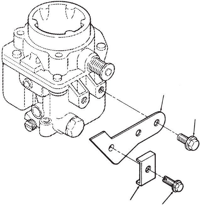
35
Choke Control
(Rear Pull)
1
2
34
REF PART QTY PART REF PART QTY PART
NO. NO. USED DESCRIPTION NO. NO. USED DESCRIPTION
1 821–0004 2 Screw, Cap – Hex Washer
Head (10–32x5/16”)
2 153–0686–02 1 Bracket, Choke Cable
3 153–0514 1
Clip, Choke Cable
4 815–0359 1 Screw
, T
apping – Slotted Hex
W
asher Head (#10–32 x 7/8”)
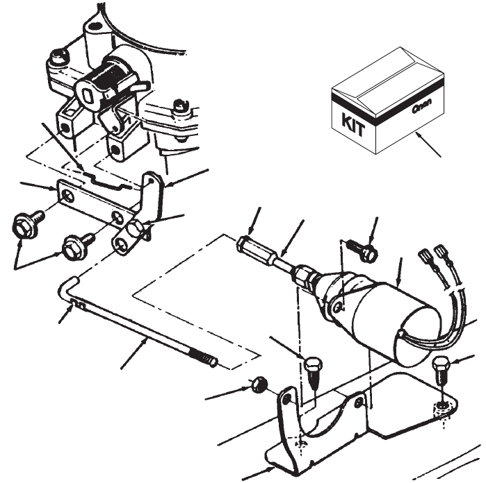
36
Remote Choke
Spec C
1
3
4
5
67
8
9
10
11
13
14
15
16
17 9
9
12
2
REF PART QTY PART REF PART QTY PART
NO. NO. USED DESCRIPTION NO. NO. USED DESCRIPTION
1 541–0412 1 Kit,
Remote Choke (Includes
Parts Marked +) Code 15CK
2 153–0500 1 +
Link, Choke
3 821–0004 2 +Screw
, Lk H (#10–32 x 3/8”)
4 518–0006 1 +Clip, Lock
5 150–2478 1 +
Rod, Choke
6 870–0053 1 +
Nut, Hex Mach (10–32)
7 150–2481 1 +
Joint, Ball
8 870–0212 2 +
Nut, Self Lk (1/4–20)
9 815–0290 4 +Screw, HWH THD Form
(1/4–20 x 5/8)
10 307–2751 1 +
Bracket, Solenoid
11 307–2750 1 +
Solenoid, 12 V
olt
12 153–0642 1 +Bracket Assy, Choke
(Includes Parts Marked *)
13 526–0008 2 *Washer
, Flat (#10 Screw)
14 150–2480 1 *Bracket, Choke
15 150–2531 1 *Lever, Choke
16 815–0480 1 *Screw
, Pan Head
Shoulder (#10–32)
17 870–0298 1 *
Nut, Lock (#10–32)
+
– Parts included in Remote Choke Kit.
* – Parts Included in Choke Bracket Assy.
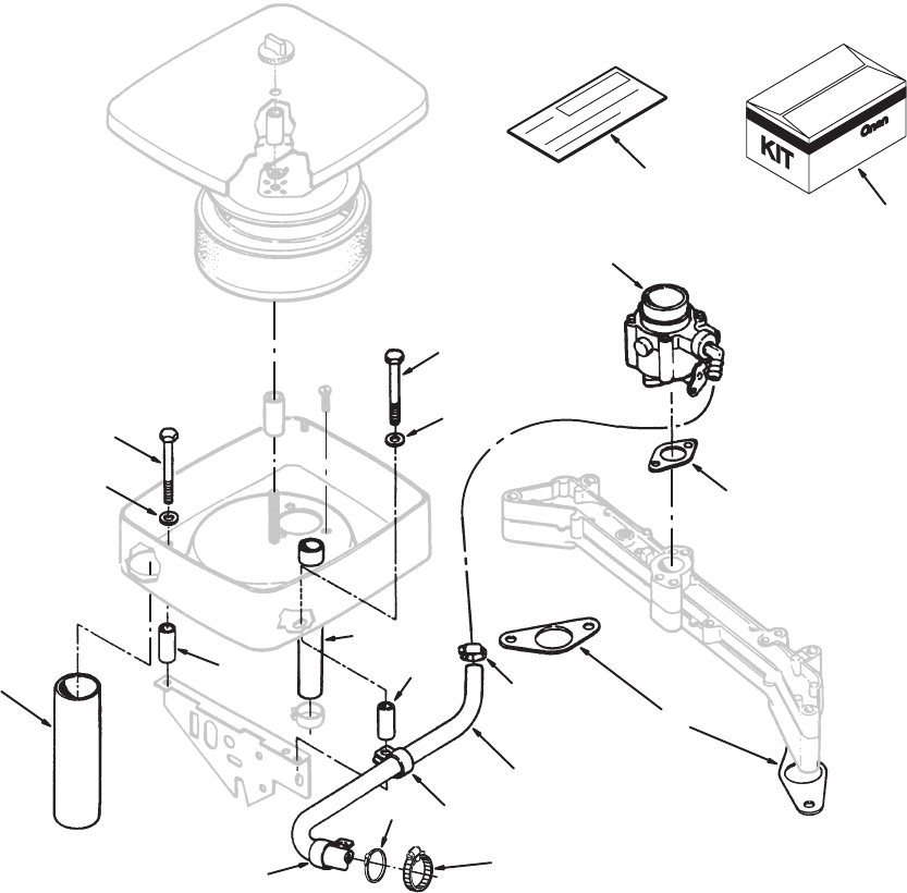
37
LPG Conversion Kit
1
3
4
5
6
11
13
14
16
17
18
19
20
22
4
13
16
20
22
REF PART QTY PART REF PART QTY PART
NO. NO. USED DESCRIPTION NO. NO. USED DESCRIPTION
1 541–0512 1 Kit, LPG Conversion (Includes
(Parts Marked *)
2 E–355 1 *
Sheet, Instruction (Not Shown)
3 98–7315–07 1 *
Label, Kit Number (Emission)
4 140–2722–01 2 *Spacer
, Air Intake
5 141–0281 1 *Gasket, Carburetor
6 146–0681 1 *Carburetor, LPG Emissions
7 148–0975 1 *Bracket, Upper (See LPG
Converter Kit page)
8 148–0976 1 *Bracket, Lower (See LPG
Converter Kit page)
9 148–1025 1 *Converter, LPG (See LPG
Converter Kit page)
10 149–1321 3 *
Cap, Fuel Fitting (Not Shown)
11 154–2219 2 *
Gasket, Intake Manifold
12 307–2754 1 *Shutof
f, Fuel Solenoid (See
LPG Converter Kit page)
13 332–1356 2 *
Clamp, Hose Mount
14 332–1794 3 *T
ie, Cable (Self–Locking)
15 502–1145 1 *Elbow
, 90 Degree (1/2 NPT x
3/8”
Hose) (See LPG Convert–
er
Kit page)
16 503–1133 2 *
Clamp, Hose
17 503–1606–03 1 *
Hose, Breather
18 503–1798–01 1 *Hose, LPG
19 503–1882–03 1 *T
ube, Air Intake
20 526–0018 4 *Washer
, Flat
21 815–0293 1 *Screw, Hex W
asher Head
Thread Forming (1/4–20 x
3/4”) (See LPG Converter Kit
page)
22 821–0013 2 *Screw
, Hex Head Cap
(1/4–20 x 1”)
23 821–0018 3 *Screw
, Hex Head Cap
(1/4–20 x 5/8”) (See LPG
Converter Kit page)
* – Parts included in LPG Conversion Kit.
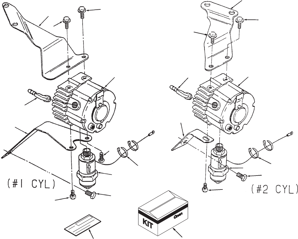
38
LPG Converter Kit
3
4
5
6
7
8
9
1
8
8
3
4
5
6
7
8
9
8
8
8
10
22
REF PART QTY PART REF PART QTY PART
NO. NO. USED DESCRIPTION NO. NO. USED DESCRIPTION
1 Kit, LPG Converter
541–0442 1
#1 Cylinder Mounting
(Includes Parts Marked *)
541–0443 1
#2 Cylinder Mounting
(Includes Parts Marked @)
2 148–1025 1 *@Converter, LPG
3 307–2754 1 *@
Shut Of
f, Fuel Solenoid
4 Bracket, Upper
148–0973 1 *
L.H. Mount (#1 Cyl)
148–0975 1 @
R.H. Mount (#2 Cyl)
5 Bracket, Lower
148–0974 1 *
L.H. Mount (#1 Cyl)
148–0976 1 @
R.H. Mount (#2 Cyl)
6 502–1145 1 *@Elbow
, 90
°Brass
(1/2”NPT
– 3/8 Barb)
7 815–0293 1 *@Screw, Hex W
asher Head
Thread Forming (1/4–20 x
3/4”)
8 Screw
, Hex Head Cap
(1/4–20 x 5/8”)
821–0018 4 *
#1 L.H. – Cylinder
821–0018 3 @
#2 R.H. – Cylinder
9 332–1794 2 *@T
ie, Cable
10 98–4240 1 *@
Label, Blank Kit Number
11 E–356 1 *@
Sheet, Instruction (Not Shown)
* – Parts included in #1 Cylinder Mounting Kit.
@ – Parts included in #2 Cylinder Mounting Kit.
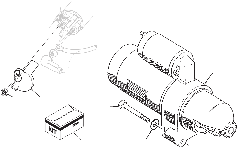
39
Starter
1
2
3
6
7
4
REF PART QTY PART REF PART QTY PART
NO. NO. USED DESCRIPTION NO. NO. USED DESCRIPTION
1 Starter
– Solenoid Shift
(See Separate Page for
Components)
191–1949–04 1
Code 33A
T
191–1949–07 1
Code 33A
W
2 526–0122 2 Washer
, Flat (5/16” Screw)
3 800–0595 2 Screw
, Cap Hex Head
(5/16”–18 x 3–1/2”)
4 541–0411 1
Kit, Starter Cap (Includes Parts
Marked *)
5 E–0342 1 *
Sheet, Instruction (Not Shown)
6 191–1947 1 *
Cap, Starter Solenoid
7 750–1006 1 *Nut, Hex
* – Parts included in Starter Cap Kit.
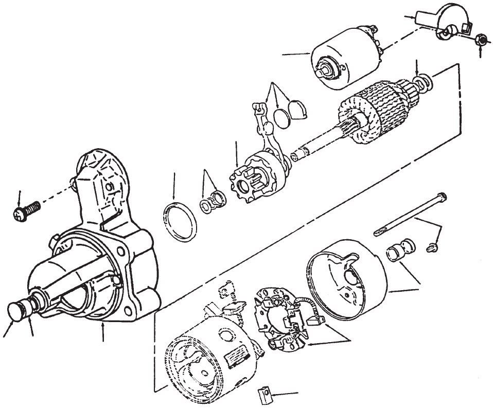
40
Starter Components
1
2
3
4
5
6
7
8
9
10
1
1
45
1
3
REF PART QTY PART REF PART QTY PART
NO. NO. USED DESCRIPTION NO. NO. USED DESCRIPTION
1 191–1954 1 Kit,
Hardware – Starter
(Includes (2) Solenoid
Mtg Screws, 2 Thru Bolts,
Armature Shims, Pinion Stop
Collar
, Retaining Ring and
Solenoid T
erminal Nuts)
2 191–1956 1
Kit, Solenoid – Starter
(Includes Solenoid and
Spring Plunger)
3 191–1931 1
Kit, Bushing – Starter
(Includes Rear Cap with
Bushing and Front Bushing)
4 191–1950 1
Kit, Mounting Bracket
(Includes Front Bracket,
Front Bushing, Dust Seal,
Thrust Washer
, Cap Plug and
OD Pinion Seal)
5 191–1951 1
Kit, Brush – Starter
(Includes (2) Negative and
(2) Positive Brushes and
Brush Holder)
6 191–1766 1
Kit, Shift Lever – Starter
(Includes Lever
, W
ear Plate,
Rubber Plug and Grease)
7 191–1953 1
Kit, Clutch – Starter (Includes
Pinion
Gear
, Clutch Assy & #8)
8 191–1955 1 Kit,
Dust Seal (Includes ID, OD
Pinion Seals)
9 191–1947 1
Cap, Starter Solenoid
10 750–1006 1
Nut, Hex – Metric (M8)
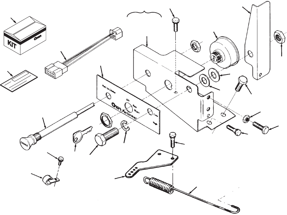
41
Control Panel
1
12
13
14
15
16
17
18
19
20
21
4
7
6
5
8
9
22
23
9
8
3
10
11
11 thru 21
24
REF PART QTY PART REF PART QTY PART
NO. NO. USED DESCRIPTION NO. NO. USED DESCRIPTION
1 Kit,
Control Panel (Includes
Parts Marked #) Code 35 DB
541–0240 1
Control Panel Kit With Oil
Pressure Switch
541–0194 1
Control Panel Kit Without Oil
Pressure Switch
2 E–0320 1 #
Sheet, Instruction (Not Shown)
3 98–4240 1 #
Label, Blank Kit Number
4 98–5735 1 #
Decal, Control Panel
5 #Bracket, Governor
150–1754 1 Non–Plated
150–1754–01 1
Zinc Plated
6 150–1755 1 #
Spring, Governor
71#
Harness, Control Panel Wiring
(See Separate Page for
Components)
338–2108 1 Units With Oil Pressure Switch
(4 Leads)
338–2109 1 Units With/Out Oil Pressure
Switch (2 Leads)
8 815–0194 2 #Screw
, Hex Head – Thread
Cutting W/ET – Panel
Mounting (#10–32 x 1/2”)
9 821–0009 2 #Screw, Hex W
asher Head
Self–Lock (1/4–20 x 3/8”)
10 301–9965 1 #Panel Assy
, Control (Includes
Parts Marked *)
11 301–9964–51 1 *
Panel, Control
12 150–2184 1 *Lever
, Control
13 153–0606 1 *
Choke, Manual
14 308–0385 1 *
Switch, Ignition (Includes
Keys)
15 800–0050 1 *Screw
, Cap – Hex Head
(3/8–16 x 1”)
16 851–0029 1 *Washer, Lock (3/8”)
17 526–0029 1 *Washer
, Flat (3/8” Screw)
18 508–0284 1 *Washer
, Flat – Nylon
(3/8” Screw)
19 870–0297 1 *
Nut, Lock (3/8–16)
20 815–0650 2 *Screw, Hex W
asher Head
(1/4–20 x 1”)
21 862–0001 2 *
Nut, Hex (1/4–20)
22 815–0474 1 Screw, Hex W
asher Head
(1/4–14
x 1/2”) (Spec B thru G
only)
23 518–0515 1 Clamp,
Cable (Spec B thru G
only)
24 308–0386 1 Key
# – Parts included in Control Panel Kit.
* – Parts included in Control Panel Assembly
.
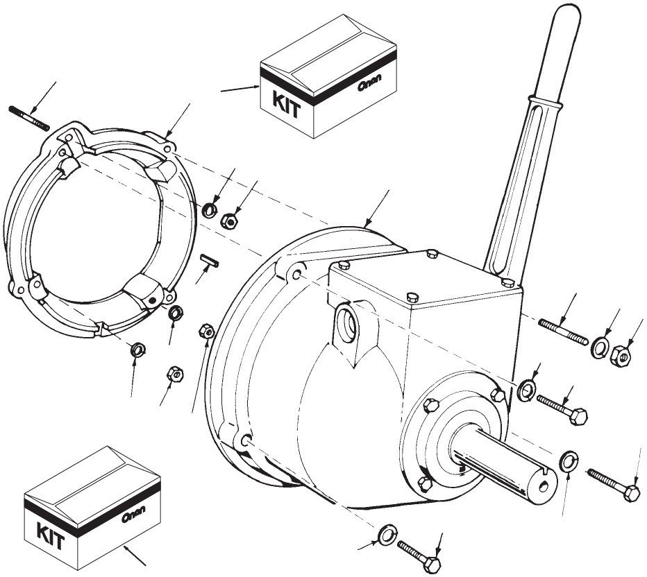
42
Clutch
1
2
3
4
6
7
8
9
10 11
2
2
3
3
5
7
7
8
8
12
,
13
REF PART QTY PART REF PART QTY PART
NO. NO. USED DESCRIPTION NO. NO. USED DESCRIPTION
1 520–0739 3 #
Stud (3/8–24 x 3/8–16 x 3”)
2 800–0075 3 #Screw
, Cap – Hex Head
(7/16–14 x 2”)
3 850–0055 3 #Washer
, Lock – Spring (7/16”)
4 104–0091 1 #
Nut, Hex – Hardened
5 850–0050 1 #Washer
, Lock – Spring (3/8”)
6 190–0288 1 #*Clutch
7 104–0091 4 #
Nut, Hex – Hardened
8 850–0050 3 #Washer
, Lock – Spring (3/8”)
9 190–0171 1 #Adapter
, Clutch
10 515–0041 1 #Key
, Drive – Special
11 520–0738 1 #
Stud (3/8–24 x 3/8–16 x 4”)
12 190–0597 1 Kit,
PT
O Electric Clutch Adapter
Code
45BA
13 190–0289 1 Kit, Clutch (Includes Parts
Marked #)
*–
For Components, check nameplate and contact
nearest Rockford Clutch Dealer
.
#
– Parts Included in Clutch Kit.
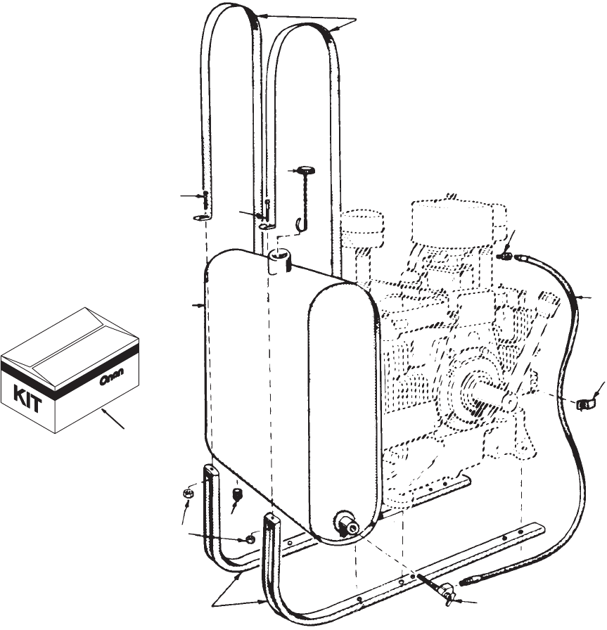
43
Fuel Tank
(Side Mounted)
1
2
3
4
5
6
7
8
9
10
11
10
12
REF PART QTY PART REF PART QTY PART
NO. NO. USED DESCRIPTION NO. NO. USED DESCRIPTION
1 159–0981 1 *Tank,
Fuel (Less Cap)
*
(3.75 Gallon)
2 159–0596 2 *
Strap, Fuel T
ank
3 159–0595 2 *
Bracket, Fuel T
ank
4 134–0599 1 *
Clip, Line – Fuel
5 501–0008 1 *
Line, Fuel
6 159–0020 1 *
Cap, Fuel T
ank
7 504–0013 1 *V
alve, Shut–of
f
8 505–0057 1 *
Plug, Drain – T
ank
9 505–0041 1 *Elbow
, 90
°
– Carburetor Inlet
10 813–0108 2 *Screw
, Machine – Round Head
(#10–32 x 1–1/2”)
11 870–0053 2 *
Nut, Hex (#10–32)
12 159–0597 1
Kit, Fuel T
ank (Side Mounting)
(Includes Parts Marked *)
*
– Parts included in Side Mounting Fuel T
ank Kit.
44
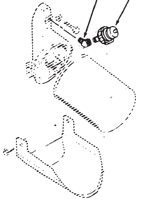
45
Low Oil Pressure
Cut–Off Switch
1
2
REF PART QTY PART REF PART QTY PART
NO. NO. USED DESCRIPTION NO. NO. USED DESCRIPTION
1 Switch, Low Oil Pressure
541–0235 1
Kit,1 T
erminal
Code 35AU
Normally
Closed 2.01”
Long
309–0546 1 Screw
On Connector
309–0615 1
Slip On Connector
Code 35AH
Normally
Open
– 2.06” Long
309–0641–17 1 Screw
On Connector
309–0646–01 1
Slip On Connector
541–0236 1
Kit, 2 T
erminal
Code 35A
V
Normally
Open
– 1.87” Long
309–0641–18 1 Screw
On Connector
309–0646–02 1
Slip On Connector
541–0319
Kit, 2 T
erminal
Code 35BW
One T
erminal Normally
Open
One T
erminal Normally
Closed
541–0436–02 Kit,
3 T
erminal – Code 35BV
–
Dual
Circuit to Open/Close
at 5 PSI
309–0583 1 Screw On Connector
309–0646–04 1
Slip On Connector
3 T
erminal – Code 35BV –
Dual Circuit to Open/Close
at 10 PSI
309–0609 1 Screw On Connector
309–0646–05 1
Slip On Connector
2 502–0053 1 Elbow
, 45
°
Street – Spec A–D
Code 35AH,35A
V
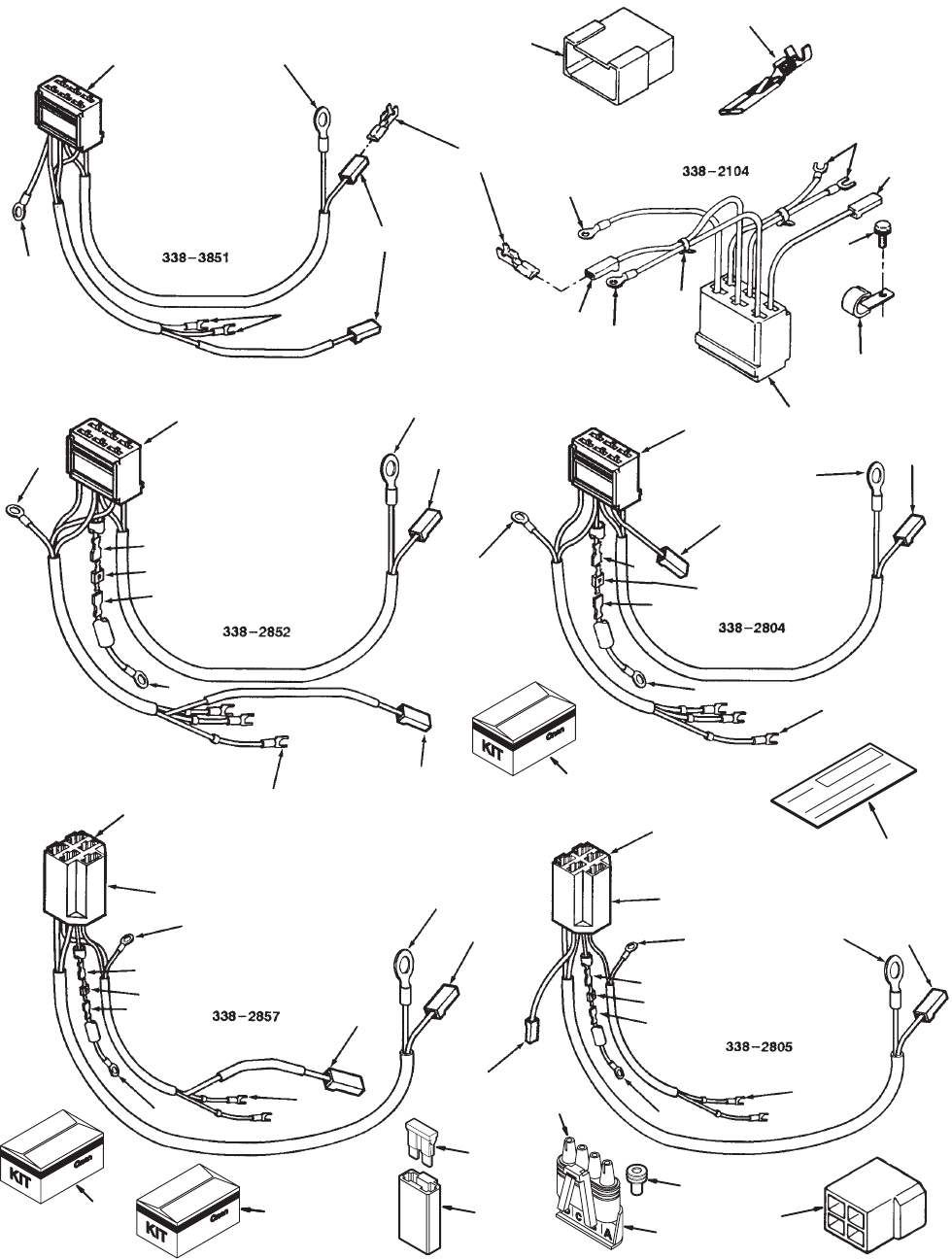
46
Wiring Harness
9
10
11
12
13
14
15
16
17
18
19
20
21
22
23
24
25
999
13
13 13
15
15
15
15
15
15
15
15
15
15
16
17
17
17
1
18
18
18
19
20
21
21
21
21
22
22
22
23
23
23
23
23
23
23
24
25
8
8
8
8
8
7
2
3
5
26
27
28 29
30
31
32
33
34
35
27
27
27
27 ,
,
178
28 29
,
,
178
28 29
,
,
178
28 29
,
,
178
28 29
,
,
178
28 29
,
,
,29
,28
,
33
,33
,
33
,
178
28 29
,
,
47
Wiring Harness
REF PART QTY PART REF PART QTY PART
NO. NO. USED DESCRIPTION NO. NO. USED DESCRIPTION
Harness,
Wiring – Engine
Units Without Pressure
Switch (4 Leads) Code
35CH,35CJ, 35CK (Prior
to Spec E)
338–2104–01 1 Screw On Connector
338–3178–01 1
Slip On Connector
Units With Pressure Switch
(6
Leads) Code 35BC,35BZ
(Prior
to Spec E)
338–2104–02 1 Screw On Connector
338–3178–02 1
Slip On Connector
6
Pin Connector
– 3 T
erminal
LOP
Switch – Code 35CC
(Prior to Spec E)
338–2804–02 1 Screw On Connector
338–3185–02 1
Slip On Connector
6
Pin Connector
– 2 T
erminal
LOP
Switch – Normally
Open Code 35CC (Prior to
Spec E)
338–2804–01 1 Screw On Connector
338–3185–01 1
Slip On Connector
6 Pin/6 Wire Code 35BC,
35BZ– to Relocate V
oltage
Regulator Begin Spec E
338–2851–02 1 Screw On Connector
338–3187–02 1
Slip On Connector
5
Pin Connector
– 2 T
erminal
LOP Switch (Normally
Open) Code 35CK (Prior to
Spec E)
338–2805 1 Screw On Connector
338–3186 1
Slip On Connector
6
Pin Connector
– 2 T
erminal
LOP
Switch Normally Open
Begin
Spec E – Code 35CC
338–2852–01 1 Screw
On Connector
338–3188–01 1
Slip On Connector
Pin Connector – 3 T
erminal
LOP
Switch – Begin Spec E
Code 35CC
338–2852–02 1 Screw On Connector
338–3188–02 1
Slip On Connector
6 Pin Connector – 4 Wire to
Relocate V
oltage Regulator
Begin
Spec E – Code 35CH,
35CJ,
35CK
338–2851–01 1 Screw On Connector
338–3187–01 1 #
Slip On Connector
338–3187–02 1 Use On Spec 1
1583H and
Spec 1
1590H
5
Pin Connector
– 2 T
erminal
Begin Spec E
With LOPKO Code 35CK
338–2857 1 Screw On Connector
338–3189 1
Slip On Connector
338–3376 1
Without LOPKO
Code 35DB
338–3616 1
Unit With Push On
T
erminals
T
o The LOP Switch
(Includes Parts Marked ^)
1 541–0175 1
Kit, 4 Pin Harness Connector
Code 35BB (Includes Parts
Marked *)
2 541–0195 1
Kit, 6 Pin Harness Connector
Code 35BC (Includes Parts
Marked +)
3 541–0437–02 1 Kit,
4
Wire, 6 Pin Wiring Harness
(Begin
Spec E) (Includes Parts
Marked
#)
4 E–364 1 #
Sheet, Instruction (Not Shown)
5 98–4240 1 #
Label, Blank Kit Number
6 E–0313 1 +*
Sheet, Instruction (Not Shown)
7 323–1382 1 *
Housing, T
ab (4–W
ay)
8 332–0819 2
Housing, Connector – Push On
9 323–1386 1
Housing, Receptacle – 6 W
ay
10 332–1567 2 #+*T
ie, Cable
11 518–0515 1 #
Clamp, Cable (1/2” Dia.) (Spec
B thru G only)
12 323–0916 1 #+Housing,
Connector – T
ab 6 Pin
13 Terminal
332–2301 6 #+* Used
with 20 Amp Charging
System – 18 to 14 Gauge
Wire
332–1503 2 #+*
Used with 35 Amp Charging
System
332–2890 5
Code 35CC
14 815–0474 1 Screw, Hex W
asher Head
(1/4–14
x 1/2”) (Spec B thru G
only)
15 332–0806 2 ^Terminal,
Ring (#8)
16 332–1303 5 T
erminal, Spade (#10)
17 332–2715 2 T
erminal, Receptacle
18 357–0030 1 Rectifier
, Silicon – Code 35CC
19 332–3165 1 Receptacle, Lock
20 332–3143 1 Receptacle, Lock
21 332–1048 1 T
erminal, Ring (.38)
22 332–2973 3 T
erminal, Spade (#8)
23 332–1993 2 T
erminal, Receptacle
24 323–0987 1 Body
, Connector – Code 35CK
25 332–2073 2 T
erminal
26 323–1451 1 ^Housing, Receptacle (4 RCPT)
27 332–2944 1 ^T
erminal, Ring (.312) Insulation
28 323–1216 2 ^Body
, Connector
29 332–2870–01 6 ^T
erminal, Receptacle (#.250)
30 321–0291 1 ^
Fuse, 30 AMP
31 323–1424 1 ^
Cap, Connector
32 332–2922 2 ^Terminal
33 357–0030 1 ^Rectifier
, Silicon
34 323–1576 4 ^
Seal, Cable (Gray)
35 323–1607 4 ^Contact, Socket
* – Parts included in 4 Pin Harness Connector Kit.
+
– Parts included in 6 Pin Harness Connector Kit.
#
– Parts Included in 4 Wire, 6 Pin Wiring Harness Kit.
^ – Parts included in 338–3616 Engine Wiring Harness.
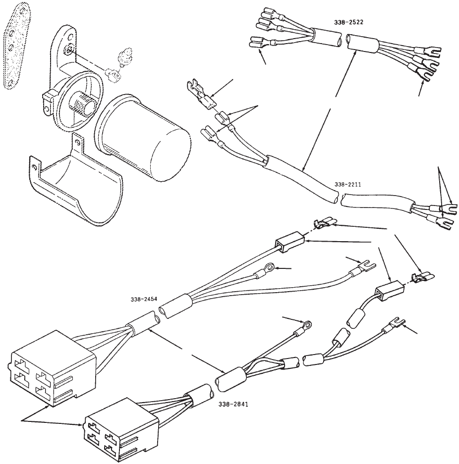
48
Wiring Harness
Lopko
1
2
3
45
6
7
8
1
2
3
3
3
7
REF PART QTY PART REF PART QTY PART
NO. NO. USED DESCRIPTION NO. NO. USED DESCRIPTION
1 Harness,
Wiring – Lopko
Code 35BY – 4 Pin, 3 Wire –
Ext. – Spec C
338–2454 1 Screw On Connector
338–3226–01 1
Slip On Connector
Code 35BG,35BV
338–2522 1 Screw On Connector
338–3332 1
Slip On Connector
Code 35BY – 4 Pin, 3 Wire –
Begin Spec E
338–2841 1 Screw On Connector
338–3182
Slip On Connector
2 332–2890 3 T
erminal, Receptacle
3T
erminal, Spade (#10)
332–2973 1
Code 35BY
332–1303 3
Code 35BV
4 332–0819 1
Housing, Connector – Push On
Code 35BY
5 332–2715 1 T
erminal, Receptacle – Code
35BY
6 332–2301 2 T
ab, Faston
7 332–0806 1 T
erminal, Ring (#8) Code 35BY
8 323–1381 1
Housing, Receptacle – 4 W
ay
Code 35BY
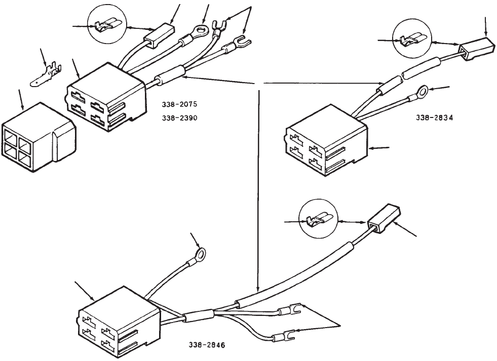
49
Wiring Harness
1
2
3
4
5
6
7
8
2
2
3
3
4
4
6
6
8
REF PART QTY PART REF PART QTY PART
NO. NO. USED DESCRIPTION NO. NO. USED DESCRIPTION
1 Harness,
Wiring – Engine
4 Wire, 4 Pin Connector –
Code 35BB,35BH
338–2075 1 Screw On Connector
338–3179 1
Slip On Connector
338–2390 1
2 Wire, 4 Pin Connector –
Code 35CG
Relocate V
oltage Regulator
Begin Spec E – Code
35BB,35BH
338–2846 1 Screw On Connector
338–3184 1
Slip On Connector
338–2834 1
Relocate V
oltage Regulator
Begin
Spec E – Code 35CG
2 332–0806 1 Terminal,
Ring(#8)
3T
erminal, Receptacle (.250)
332–2715 5
Code 35BB, 35BH
332–2715 3
Code 35CG
4 323–1381 1
Housing, Receptacle – 4 W
ay
5 323–1382 1
Housing, T
ab – 4 W
ay
6 332–0819 1
Housing, Receptacle
7T
erminal, T
ab
332–2301 4 20
Ampere Charging
System
332–1503 1
35 Ampere Charging System
8 332–2973 2 Terminal,
Spade (#8) Code
35BB,35BH
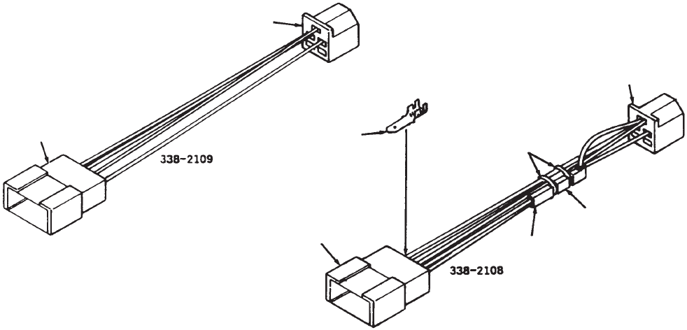
50
Wiring Harness
Control Panel
1
2
3
4
5
6
1
2
REF PART QTY PART REF PART QTY PART
NO. NO. USED DESCRIPTION NO. NO. USED DESCRIPTION
Harness,
Wiring – Control
Panel
338–2109 1
Without LOPKO
338–2108 1 Lopko
1 323–0916 1 Connector
2 323–0987 1 Body
, Connector
3 357–0030 1 Rectifier, LOPKO
4 323–1216 1 Body, Connector – LOPKO
5 332–0942 2 T
ie, Cable – LOPKO
6T
erminal, T
ab
332–2301 4 20
Ampere Charging
System
332–1503 2
35 Ampere Charging System
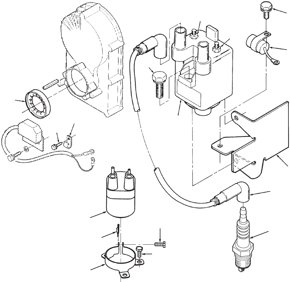
51
Ignition – Electronic
1
2
3
4
5
6
7
8
9
10
11
12
13
14
15
16
17
REF PART QTY PART REF PART QTY PART
NO. NO. USED DESCRIPTION NO. NO. USED DESCRIPTION
1 166–0761 1 Coil,
Battery Ignition (Includes
Nuts) (Spec B Thru G)
2 312–0256 1 Capacitor
3 166–0767 1 Rotor
, Ignition
4 167–0272 2
Plug, Spark
5 167–1602 1
Cable,Spark Plug
6 166–0770 1
Nut, Hex Flange (M4 Positive
Terminal)
7 518–0515 1
Clip, Wire (Spec B thru G only)
8 166–0771 1
Nut, Hex Flange (M5 Negative
Terminal)
9 114–0022 1 Screw
, Cap – Hex Head
(5/16–18 x 1–3/4”)
10 815–0650 2 Screw, Hex W
asher Head
(1/4–20 x 1”)
11 166–0787–01 1
Bracket, Coil Mounting (Spec B
Thru G)
12 815–0261 1 Screw, Hex W
asher Head
(1/4–20 x 1/2”)
13 166–0820 1
Coil, Battery Ignition (Begin
Spec H)
14 518–0574 1
Clip (Begin Spec H)
15 134–5130–02 1
Clamp, Coil Mounting (Begin
Spec H)
16 815–0261 3 Screw, Hex W
asher Head
Thread Forming
(1/4–20 x 1/2”)
17 821–0018 1 Screw, Hex Lock
(1/4–20 x 5/8”)
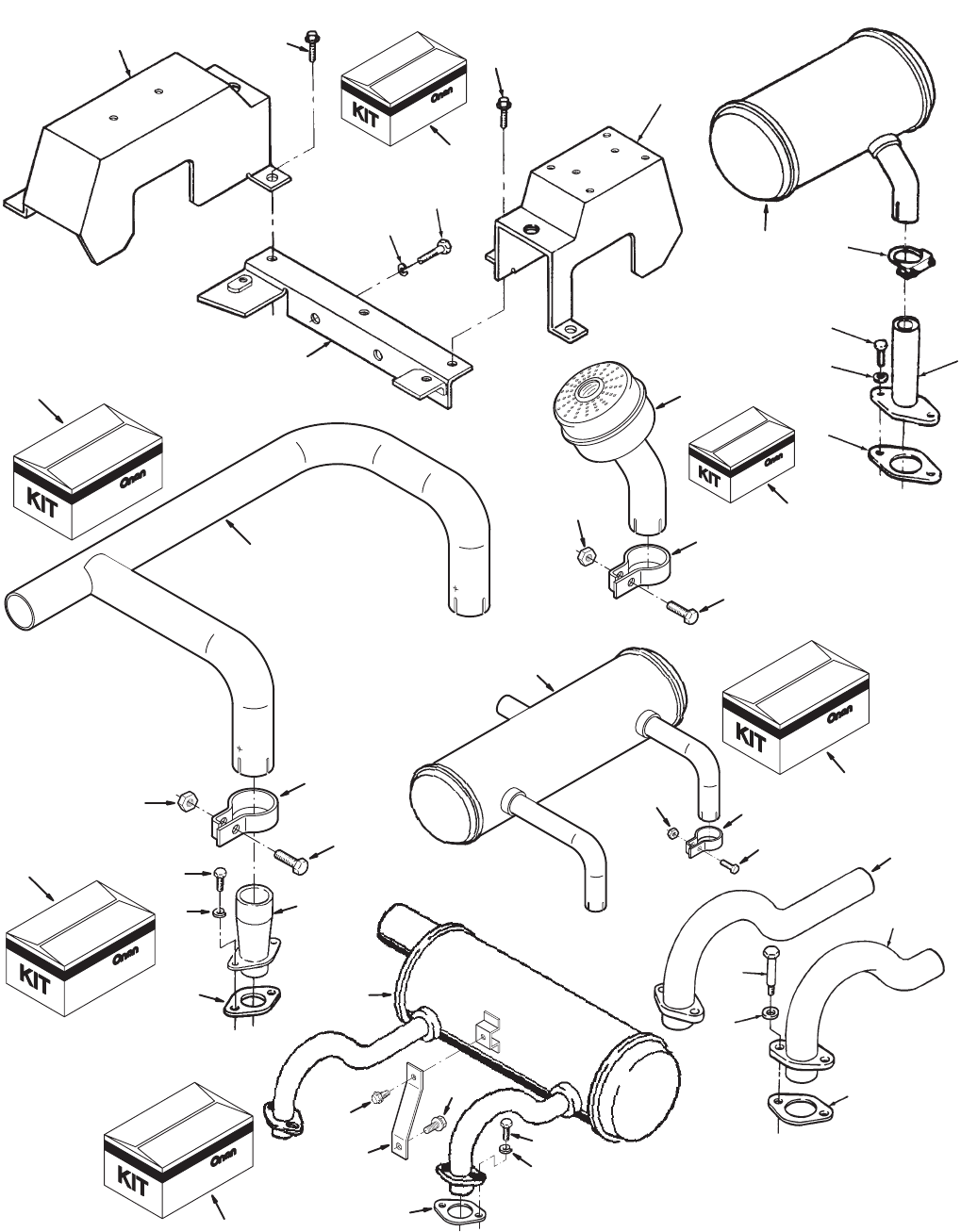
52
Exhaust System
67
8
2
3
4
3
5
2
1
10
11
12
13
14 14
2
3
5
16
17
26
27
28
29
30
31
32
33
34
35
,
,
,
,
5
18
19
20
21 22
23
24
25
36
37
38
39
40
41
42
43
45
44
9
15
,
53
Exhaust System
REF PART QTY PART REF PART QTY PART
NO. NO. USED DESCRIPTION NO. NO. USED DESCRIPTION
1 542–7129 1 Kit,
Exhaust Adapter (Includes
Parts Marked ~) Code 21BG
2 Screw
800–0512 4 ~
Cap, Hex Head (Special)
800–0512–01 4 Cap,
Hex Head (Spec
1
1583H)
802–0055 4 Socket
Head (5/16–18 x 1”)
Code 21CB
3 Washer
850–0045 4 ~
Lock (5/16”) Code 21AG,21BG
740–1006 4
Flat (M8) Code 21AZ,21CC
526–0022 4
Flat (5/16” Screw) Code 21CB
4 154–1484–50 2 ~Adapter,
Exhaust (Flange T
ype)
Code 21AG,21BG
5 154–2747 2 ~
Gasket, Exhaust Manifold
6 155–2534 2 Muffler
(Use in Pairs) – Use
With
Adapter
154–1484–50
7 155–1239 2
Clamp, Muf
fler (1–1/8” Dia.)
8 154–1484–50 2 Adapter
, Exhaust Manifold
4–1/4” Long
9 541–0419 1
Kit, Exhaust Cover & Support
(Includes Parts Marked ^)
Code 21CC
10 134–4656–50 1 ^Cover, Exhaust T
ube – RH
Code 21AZ,21BB – Painted
11 134–4678–50 1 ^Cover,
Exhaust T
ube – LH Code
21AZ,21CC
– Painted
12 134–4981–50 1 ^
Support, Exhaust Cover
13 850–0050 2 ^Washer, Lock (3/8”)
14 821–0008 2 ^Screw
, Lock Head – Flange
(1/4–20 x 5/16”)
15 800–0048 2 ^Screw
, Cap – Hex Head
(3/8–16 x 3/4”)
16 T
ube, Exhaust – RH – Painted
154–2263–50 1
Code 21AZ,21CC,21BD
154–2112–50 1
Code 21CB
17 T
ube, Exhaust – LH – Painted
154–2265–50 1
Code 21AZ,21CC,21BD
154–2113–50 1
Code 21CB
18
Kit, Muf
fler (Includes Parts
Marked #)
541–0315 1 Outlet, RH
514–0316 1
Outlet, LH)
19 #Muffler, Exhaust
155–2245–01 1
RH – Outlet (Not Shown)
155–2245–02 1
LH – Outlet (Shown)
20 154–2747 2 #
Gasket, Exhaust Manifold
21 155–2419–02 1 #Bracket, Muffler
22 800–0512 4 #Screw
, Hex Head Cap
(Special)
23 850–0045 4 #Washer
, Lock (5/16)
Code 21AG,21BG
24 821–0014 1 #Screw
, Lock Head Flange
(5/16–18 x 1/2”)
25 821–0029 1 #Screw
, Lock Head Flange
(3/8 x 3/4”)
26
542–71
19 1 Kit,
Right Front Side or Left Rear
Side
Manifold (Includes Parts
Marked *)
27 154–1610–50 1 *
Manifold, LH Exhaust
(Shown)
28 155–1219 2 *
Clamp, Muf
fler
29 805–0019 2 *Screw
, Hex Head Cap
(3/8–16 x 1 7/16”)
30 862–0003 2 *
Nut, Hex (3/8–16)
31 542–7120 1 Kit,
Left Front Side or Right Rear
Side
Manifold (Includes Parts
Marked +)
32 154–1609–50 1 +
Manifold, RH Exhaust
(Not Shown)
33 155–1219 2 +
Clamp, Muf
fler
34 805–0019 2 +Screw
, Hex Head Cap
(3/8–16 x 1 7/16”)
35 862–0003 2 +
Nut, Hex (3/8–16)
36 542–7101 1 Kit,
Pepper Pot Muf
fler (Includes
Parts
Marked @)
37 155–1216 2 @Muffler (Use With Exhaust
Adapter 1545–1484–50–
(Code 21BG)
38 155–1219 2 @
Clamp, Muf
fler
39 805–0019 2 @Screw
, Hex Head Cap
(3/8–16 x 1 7/16”)
40 862–0003 2 @
Nut, Hex (3/8–16)
41 542–7122 1 Kit,
Front or Rear Outlet Muf
fler
(Includes Parts Marked <)
42 155–1686 1 <Muffler, Exhaust (Use With
Exhaust Adapter
154–1484–50 (Code 21BG)
43 155–1219 2 <
Clamp, Muf
fler
44 805–0019 2 <Screw
, Hex Head Cap
(3/8–16 x 17/16)
45 862–0003 2 <
Nut, Hex (3/8–16)
~–
Parts included in Exhaust Adapter Kit.
^–
Parts included in Exhaust Cover & Support Kit.
#–
Parts included in RH and LH Outlet Muf
fler Kits.
*–
Parts included in Left Rear Crossover Manifold Kit.
+–
Parts included in Right Rear Crossover Manifold Kit.
@–
Parts included in Pepper Pot Muf
fler Kit.
<–
Parts included in Front or Rear Outlet Muf
fler Kit.
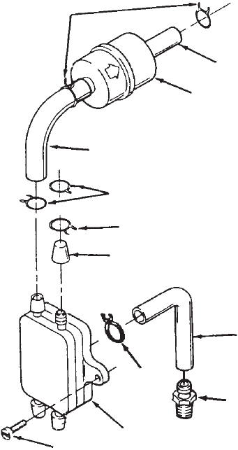
54
Fuel Pump
1
2
3
4
5
6
7
8
9
1
8
8
REF PART QTY PART REF PART QTY PART
NO. NO. USED DESCRIPTION NO. NO. USED DESCRIPTION
1 503–0707 1 Hose
2 Pump,
Fuel – V
acuum 2 Open
Ports
149–2187–02 1 All Codes Except 23DN
149–2187–01 1
Code 23DN
3 815–0555 2 Screw
, T
apping – Pan Head
(10–24 x 5/8”)
4 503–0707 1
Line, Pulse (Cut T
o 7” Long)
5 502–0395 1 Connector
, Hose – Fuel Pump
Vacuum
6 149–1321 1
Cap, Fuel Fitting
7 503–0301 1
Clamp, Hose
8 503–0731 6
Clamp, Hose (1/2”)
9 149–2206–01 1 Filter
, Fuel
55
Labels, Paint, Thread Sealant and Gasket Kits
REF PART QTY PART REF PART QTY PART
NO. NO. USED DESCRIPTION NO. NO. USED DESCRIPTION
518–0452 1 Sealant,
Thread (50cc Bottle)
518–0347 1
Loctite, Bottle (250cc)
Label, Performer 24 XSL
Red, White
98–6802–04 3
Code 19AS
98–6802–04 2
Code 19A
V
98–6664 1 Label,
Air Cleaner Maintenance
525–0394 1 Paint,
Enamel (T
ouch–Up) –
Flat Black, Pressurized Can
(16 oz.)
Label, Periodic Maintenance
98–5969–02 1
Standard Capacity Oil Base
98–5969–04 1 High Capacity Oil Base
98–5735 1
Decal, Control Panel
98–4024 2
Label, Head Bolt T
orque –
Begin Spec C
98–6266 1 Label,
Maintenance (Oil Check)
98–7193 1 Tag,
3 Y
ear W
arranty
98–7295 4
Label, Barcode
517–0165 1
Cap, Plug
168–0190 1
Kit, Gasket – Carbon Removal
(Includes Parts Marked *)
110–3575 3 *Gasket, V
alve Compartment
Cover
110–2987 2 *Gasket, Cylinder
154–2219 2 *
Gasket, Intake Manifold
154–2747 2 *Gasket, Exhaust Adapter
154–2746 2 *Gasket, Exhaust Adapter
154–2747 2 *
Gasket, Exhaust Manifold
110–3604 2 *
Seal, Oil – V
alve
168–0191 1
Kit, Gasket – Engine Complete
(Includes Parts Marked +)
101–0782 1 +
Gasket, Bearing Plate – 1/64”
102–1387 1 +Gasket, Oil Base
103–0810 1 +Gasket, Gear Cover
110–3575 3 +Gasket, Valve Box Cover
110–2987 2 +Gasket, Cylinder Head
120–0161 1 +
Gasket Kit, Oil Pump
122–0771 1 +
Gasket, Oil Filter Adapter to
Block
110–3604 2 +
Seal, Intake V
alve
509–0142 1 +
Seal, Oil Fill Cap O–Ring
102–0743 1 +Gasket, Oil Drain
509–0145 1 +
Seal, Air Cleaner O–Ring
154–0733 1 +
Gasket, Carburetor Flange
154–2219 2 +
Gasket, Intake Manifold
154–2747 2 +Gasket, Exhaust Adapter
160–1368 1 +Gasket, Breaker Box
509–0008 1 +
Seal, Governor Shaft
509–0040 1 +
Seal, Oil – Gear Cover
509–0041 1 +
Seal, Oil – Bearing Plate
509–0117 1 +
Seal, Breather Cap O–Ring
145–0438 1 +Gasket, Carburetor
154–2746 2 +Gasket, Exhaust Adapter
110–3604 2 +
Seal, Oil – V
alve
509–0269 1 +
Seal, Fill T
ube
*_
Parts Included in 168–0190 Gasket Kit.
+–
Parts Included in 168–0191 Gasket Kit

56
Sales Option Code Table
SPEC NO.
SALES
OPTION
CODE
NUMBERS
10684
11AH
11AW
13BJ
13BN
13BV
15BD
15BK
15BL
17CD
17CF
17DA
19AS
23DC
31AY
31AZ
33AT
35AU
35BB
45BB
45BW
47AL
47AR
47BA
47BB
10704
11AH
11AW
13BJ
13BP
13BW
15BD
15BK
15BL
17CD
17CF
17DA
19AS
23DC
31AY
31AZ
33AT
35AU
35BB
45BB
45BW
47AR
47AY
47BA
10705
11AH
11AW
13BG
13BK
13CE
15BD
15BK
15BL
17CD
17CF
17DA
19AS
21BG
23DC
31AY
31AZ
33AT
35AV
35BB
45BB
47AR
47BA
47BB
10707
11AH
11AW
13BJ
13BN
13BV
15BD
15BK
15BL
17CD
17CF
17DA
19AS
23DC
31AY
31AZ
33AT
35BC
45BB
45BW
47AR
10708
11AH
11AW
11BE
13BS
13BY
13CD
15BD
15BK
15BL
17CD
17CF
17DA
19AS
21BG
23DC
23DN
31AY
31AZ
33AT
35BC
39AG
45BS
47AR
47AZ
47BB
10710
11AH
11AW
13BJ
13BN
13BV
15BD
15BK
15BL
17CD
17CF
17DA
19AS
23DC
31AY
31AZ
33AT
35CH
45BB
45BW
47AR
47BA
47BB
10711
11AH
11AW
13BJ
13BM
13BV
15BA
15BD
15BK
17CD
17CF
17DA
19AS
23DC
31AY
31AZ
33AT
35AU
35BC
45BB
45BW
47AR
47BA
47BB
10713
11AH
11AW
13BJ
13BN
13BV
15BB
15BD
15BK
17CD
17CF
17DA
19AS
23DC
31AY
31AZ
33AT
35AV
35BB
45BB
45BW
47AR
47BA
47BB
10726
11AH
11AW
13BJ
13BN
13BV
15BD
15BK
15BL
17CD
17CF
17DA
19AS
23DC
31AY
31AZ
33AT
35CH
45BE
45BW
47AR
47AZ
47BB
47BF
10727
11AW
13BJ
13BN
13BV
15BD
15BK
15BL
17CD
17CF
17DA
19AS
23DC
31AY
31AZ
33AT
35CH
45BT
45EC
47AR
47AZ
47BB
47BF
10792
11AH
11AW
13BV
13CB
13CD
15BD
15BK
15BL
17CD
17CF
17DA
19AS
23DC
23DN
31AY
31AZ
33AT
35AV
35BC
39AG
45BF
45BM
47AR
47AZ
47BB
10803
11AH
11AW
13BJ
13BP
13BV
15BD
15BK
15BL
17CD
17CF
17DA
19AS
23DC
31AY
31AZ
33AT
35CG
45BB
47AR
47BA
47BB
SPEC NO.
SALES
OPTION
CODE
NUMBERS
10813
11AH
11AW
11BG
13BJ
13BN
13BW
15BD
15BK
15BL
17CF
17DA
17DF
19AS
23DC
31AY
31AZ
33AT
35AU
35BH
35BL
45BY
47AR
47BA
47BB
10814
11AH
11AW
13BK
13BP
15BD
15BJ
15BL
15BV
17CD
17CF
17DA
19AU
21BR
23DC
31AY
31AZ
33AT
35AU
35BB
45BB
47AR
47AZ
47BB
47BF
10825
11AH
11AW
13BJ
13BN
13BV
15BD
15BK
15BL
17CD
17CF
17DA
19AS
23DC
31AY
31BC
33AT
35AV
35BC
45BB
45BW
47AR
47BA
47BB
10828
11AH
11AW
13BM
13BV
13CD
15BD
15BK
15BL
17CD
17CF
17DA
19AV
23DC
31AY
31AZ
33AT
35BC
39AG
45BB
47AR
10829
11AW
11BE
13BR
13CG
15BD
15BK
15BL
17CD
17CF
17DA
19AS
23DC
31AY
31AZ
33AT
35AV
35BB
45BT
47AR
47BA
47BB
10833
11AH
11AW
13BJ
13BN
13BU
15BD
15BJ
15BL
17CF
17DA
17DF
19AV
23DC
31AY
31AZ
33AT
35AU
35BC
45BD
47AR
47BA
47BB
10834
11AH
11AW
13BJ
13BM
13BV
15BD
15BJ
15BL
17CD
17CF
17DA
19AV
23DC
31AY
31AZ
33AT
35AU
35BB
45BB
47AR
47BA
47BB
10835
11AR
11AW
13BJ
13BN
13BV
15BD
15BK
15BL
17CD
17CF
17DA
19AS
23DC
31AY
31AZ
33AT
35BC
45BT
47AR
10836
11AW
11BE
13BJ
13BM
13BV
15BD
15BK
15BL
17CD
17CF
17DA
19AV
23DC
31AY
31AZ
33AT
35CH
45BT
47AR
47BA
47BB
10837
11AH
11AW
13BM
13BV
13CD
15BD
15BK
15BL
17CD
17CF
17DA
19AU
23DC
23DE
31AY
31AZ
33AT
35BC
39AG
45BB
47AR
47AZ
47BB
10838
11AW
11BE
13BM
13BV
13CD
15BB
15BD
15BK
17CD
17CF
17DA
19AS
23DC
23DE
31AY
31AZ
33AT
35BC
39AG
45BT
47AR
47AZ
47BB
10839
11AH
11AW
13BJ
13BN
13BV
15BD
15BJ
15BL
17CD
17CF
17DA
19AU
23DC
31AY
31AZ
33AT
35AH
35BY
45BB
47AR
47BA
47BB
10841
11AH
11AW
13BJ
13BM
13BU
15BD
15BK
15BL
17CD
17CF
17DA
19AU
23DC
31AY
31AZ
33AT
35AV
35BC
45BD
47AR
47BA
47BB

57
Sales Option Code Table
SPEC NO.
SALES
OPTION
CODE
NUMBERS
10842
11AH
11AW
13BJ
13BZ
13CB
15BD
15BK
15BL
17BZ
17DA
17DF
19AS
21CB
23DC
31AY
31BD
33AT
45BB
45BW
47AR
47BA
47BB
10843
11AH
11AW
13BJ
13BM
13BV
15BD
15BJ
15BL
17CD
17CF
17DA
19AU
23DC
31AY
31AZ
33AT
35AV
35BC
45BT
47AR
47BA
47BB
10847
11AH
11AW
13BM
13BV
13CD
15BD
15BK
15BL
17CD
17CF
17DA
19AS
23DC
31AY
31AZ
33AT
35BC
39AG
45BB
47AR
47BA
47BB
10875
11AH
11AW
13BG
13BJ
13BZ
15BD
15BJ
15BM
15CM
17CF
17CV
17DA
19CJ
21CC
23DC
23DJ
23DK
31AY
31AZ
33AT
35AU
35BC
35BL
45BE
47AR
47BA
47BB
10890
11AH
11AW
13BJ
13BM
13BV
15BB
15BD
15BK
17CF
17DA
17DF
19AS
23DC
31AY
31BD
33AT
45BB
47AR
47AZ
47BB
47BF
10909
11AH
11AW
13BJ
13BN
13BV
15BD
15BK
15BL
17CF
17DA
17DF
19AV
23DC
31AY
31AZ
33AT
35AU
35BB
45BE
47AR
47BA
47BB
10912
11AH
11AW
13BJ
13BM
13BV
15BD
15BK
15BL
17CD
17CF
17DA
19AU
23DC
23DN
31AY
31AZ
33AT
35AV
35BC
39AG
45BE
47AR
47AZ
47BB
10913
11AH
11AW
11BG
13CG
13CH
13CS
15AZ
15BD
15BK
17CF
17DA
17DF
19AS
23DC
23DN
31AY
31AZ
33AT
35AV
35BH
45BF
47AR
47AZ
47BB
10922
11AH
11AW
13BJ
13BW
13CM
15AZ
15BD
15BK
17BZ
17DA
17DF
19AS
21BG
23DC
31AY
31AZ
33AT
35CH
45BB
45BW
47AR
47BA
47BB
10925
11AH
11AW
13BM
13BV
13CD
15BD
15BK
15BL
17CD
17CF
17DA
19AU
23DC
23DJ
23DN
31AY
31AZ
33AT
35BC
39AG
45BB
47AR
47BA
47BE
10966
11AH
11AW
13BJ
13BY
13CR
15BD
15BJ
15BL
17CF
17DF
17DN
19AU
23DC
31AY
31AZ
33AT
35AH
35BL
35BY
45BB
47AR
47BA
10967
11AH
11AW
13BR
13CD
13CE
15BD
15BK
15BL
17CD
17CF
17DA
19AU
21AZ
23DC
23DN
31AY
31AZ
33AT
35AV
35BC
39AG
45BB
45BW
47AR
47AZ
47BB
10983
11AH
11AW
13BJ
13BM
13BZ
15BB
15BD
15BK
17CD
17CF
17DA
19AS
23DC
31AY
31AZ
33AT
35AV
35BB
45BB
47AR
47BA
47BB
SPEC NO.
SALES
OPTION
CODE
NUMBERS
10987
11AH
11AW
11BE
13BP
13CG
15BD
15BK
15BL
17CF
17DA
17DF
19AS
23DC
23DN
31AY
31AZ
33AT
35AV
35BB
45BU
47AR
47BA
47BB
10999
11AH
11AW
13BG
13BJ
13BZ
15AZ
15BD
15BJ
15BZ
17CF
17CV
17DN
19AU
23DC
23DJ
23EJ
31AY
31AZ
33AT
35AV
35BZ
45BD
47AL
47AR
47BA
11014
11AW
11BE
13BG
13BJ
13BV
15BD
15BK
15BL
17CF
17CV
17DA
19AS
21BG
23DC
31AY
31AZ
33AT
35AU
35BC
45BT
47AR
47BA
47BB
11015
11AH
11AW
13BJ
13BS
13BY
15BD
15BJ
15BL
17CD
17CF
17DA
19AU
23DC
31AY
31AZ
33AT
35AH
35BL
35BY
45BB
47AR
11021
11AH
11AW
13BM
13BV
13CD
15BD
15BK
15BL
17CF
17DA
17DF
19AU
23DC
31AY
31AZ
33AT
35BC
35BV
35CK
45BB
47AR
47AZ
47BB
11022
11AH
11AW
13BK
13BN
13BV
15BD
15BK
15BL
17CF
17DA
17DF
19AS
23DC
31AY
31AZ
33AT
45BE
47AR
47BA
47BB
11025
11AH
11AW
13BJ
13BM
13BV
15BD
15BK
15BL
17CD
17CF
17DA
19AS
23DC
31AY
31AZ
33AT
35AV
35BC
45BE
45BW
47AR
47BA
47BB
11029
11AH
11AW
13BJ
13BN
13BV
15BD
15BJ
15BL
17CD
17CF
17DA
19AS
23DC
23DJ
23DN
31AY
31BC
33AT
35AV
35BC
45BB
45BW
47AR
47BA
47BB
11041
11AH
11AW
13BJ
13BM
13BV
15BD
15BK
15BL
17CD
17CF
17DA
19AS
23DC
31AY
31BD
33AT
45BB
47AR
47BA
47BB
11043
11AH
11AW
13BM
13BV
13CD
15BD
15BK
15BL
17CF
17DA
17DF
19AV
23DC
23DJ
23DN
31AY
31AZ
33AT
35BC
35CK
45BB
47AR
47AZ
47BB
11050
11AW
13BJ
13BM
13BV
15BB
15BD
15BK
17CD
17CF
17DA
19AS
23DC
23ED
31AY
31AZ
33AT
35AV
35BC
45BT
45EC
47AR
47BA
47BB
11057
11AH
11AW
11BE
13BM
13BV
13CD
15BD
15BK
15BL
17CD
17CF
17DA
19AS
23DC
23DN
31AY
31AZ
33AT
35BC
39AG
45BS
47AR
47AZ
47BB
11066
11AH
11AW
13BJ
13BN
13BV
15BD
15BK
15BL
17CD
17CF
17DA
19AS
23DC
23DJ
23DN
31AY
31AZ
33AT
35BG
35BV
35CH
45BB
45BW
47AR
47BA
47BB

58
Sales Option Code Table
SPEC NO.
SALES
OPTION
CODE
NUMBERS
11070
11AH
11AW
13BJ
13BM
13BV
15BD
15BK
15BL
17CD
17CF
17DA
19AS
23DC
31AY
31AZ
33AT
35AV
35BC
45BB
47AR
47BA
47BB
11071
11AH
11AW
11BE
13BJ
13BM
13BV
15BD
15BK
15BL
17CD
17CF
17DA
19AS
23DC
31AY
31AZ
33AT
35AV
35BC
45BS
47AR
47BA
47BB
11087
11AH
11AW
13BJ
13BN
13BV
15BD
15BK
15BL
17CD
17CF
17DA
19AS
23DC
31AY
31AZ
33AT
35AV
35BC
45BB
45BW
47AR
47BA
47BB
11092
11AH
11AW
13BJ
13BN
13BV
15BD
15BK
15BL
17CD
17CF
17DA
19AS
23DC
23DN
31AY
31AZ
33AT
35AV
35BC
45BE
45BW
47AR
47BA
47BE
11109
11AH
11AW
13BN
13CG
15BB
15BD
15BK
17CF
17DA
17DF
19AS
23DC
31AY
31AZ
33AT
35AV
35BC
45BE
45BW
47AR
47BA
47BB
11111
11AH
11AW
11BE
13BS
13CG
15BD
15BK
15BL
17CF
17DA
17DF
19AS
21BG
23DC
31AY
31BC
33AT
35BV
35CC
45BS
47AR
47BA
47BB
11115
11AH
11AW
13BN
13BV
13CD
15BD
15BK
15BL
17CF
17DA
17DF
19AU
23DC
31AY
31AZ
33AT
35AV
35BZ
35CK
45BB
47AR
47AZ
47BB
11116
11AH
11AW
13BJ
13BN
13BV
15BD
15BK
15BL
17CF
17DA
17DF
19AS
23DC
23DJ
23DN
31AY
31AZ
33AT
35BV
35CC
45BB
45BW
47AR
47BA
47BB
11117
11AH
11AW
13BM
13BV
13CD
15BD
15BK
15BL
17CF
17DA
17DF
19AS
21BG
23DC
31AY
31AZ
33AT
35AV
35BC
35CK
45BE
45BW
47AR
47AZ
47BB
11119
11AH
11AW
11PP
13CB
13CG
15AZ
15BD
15BK
17CF
17DF
17DN
19AS
19BB
23DC
23DJ
23ED
31AY
31AZ
33AT
35AV
35BH
45BF
47AR
47AZ
47BE
11125
11AH
11AW
13BJ
13BN
13BV
15BD
15BK
15BL
17CF
17DA
17DF
19AS
21BG
23DC
31AY
31AZ
33AT
35CH
45BE
45BW
47AR
47BA
47BE
47BF
11133
11AH
11AW
13BN
13BV
13CD
15BD
15BK
15BL
17CF
17DA
17DF
19AS
21BG
23DC
23DJ
23DN
31AY
31AZ
33AT
35AV
35BC
35CK
45BB
45BW
47AR
47AZ
47BB
11138
11AH
11AW
13BJ
13BM
13BV
15BD
15BK
15BL
17CF
17DA
17DF
19AS
23DC
31AY
31BC
33AT
35AV
35BC
45BE
45BW
47AR
47BA
47BB
SPEC NO.
SALES
OPTION
CODE
NUMBERS
11146
11AH
11AW
13BK
13BM
13BU
15BD
15BJ
15BL
17BZ
17DA
17DF
19AS
23DC
23DJ
23DN
31AY
31AZ
33AW
35AV
35BC
45BB
47AR
47AZ
47BB
11150
11AH
11AW
13BJ
13BN
13BV
15BB
15BD
15BK
17CF
17DA
17DF
19AS
23DC
23DJ
23DN
31AY
31AZ
33AT
35BV
35CC
45BB
45BW
47AR
47AY
47BA
47BG
11151
11AH
11AW
13BN
13CG
15BD
15BJ
15BL
17CF
17DA
17DF
19AS
23DC
23DJ
23ED
31AY
31AZ
33AT
35AV
35BC
45CC
47AR
47AZ
47BB
47BF
11155
11AH
11AW
11BE
13BG
13BJ
13BV
15BD
15BK
15BL
17CF
17CV
17DA
19AV
21BG
23DC
31AY
31AZ
33AT
35AU
35BC
45BT
47AR
47BA
47BB
11157
11AH
11AW
13BP
13CG
15BD
15BK
15BL
17BZ
17DA
17DF
19AS
21BG
23DC
23DJ
23DN
31AY
31AZ
33AT
35CH
45BB
47AR
47BA
47BB
11158
11AH
11AW
11BF
13BJ
13BM
13BV
15BB
15BD
15BK
17CF
17DA
17DF
19AS
23DC
23ED
31AY
31AZ
33AT
35CH
45BT
47AR
47BA
47BB
11166
11AH
11AW
13BP
13CG
15BD
15BK
15BL
17BZ
17DA
17DF
19AS
21BG
23DC
23DJ
23DN
31AY
31AZ
33AT
35CH
45BE
47AR
47BA
47BB
11167
11AH
11AW
11BG
13BM
13BV
13CD
15BD
15BK
15BL
17CF
17DA
17DF
19AU
23DC
31AY
31AZ
33AT
35BC
35BV
35CK
45BB
47AR
47BB
47BH
11168
11AH
11AW
13BJ
13BN
13BV
15BD
15BK
15BL
17BZ
17CD
17DA
19AV
23DC
31AY
31AZ
33AT
35AU
35BH
45BB
45BW
47AR
47BA
47BB
47BF
11175
11AH
11AW
11BF
13BN
13BV
13CD
15AZ
15BD
15BK
15BZ
17CF
17DA
17DF
19AS
21BG
23DC
23DN
31AY
31AZ
33AT
35AV
35BC
35CK
45BT
47AR
47AZ
47BB
47BF
11181
11AH
11AW
13BM
13BV
13CD
15BD
15BK
15BL
17CF
17DA
17DF
19AV
23DC
23DJ
23DN
31AY
31AZ
33AW
35AV
35BC
35CK
45BB
47AR
47AZ
47BB
11183
11AH
11AW
13BJ
13BZ
13CB
15BD
15BJ
15BM
15CM
17CF
17CV
17DA
19CJ
21CC
23DC
23DJ
23DK
31AY
31AZ
33AT
35AU
35BC
35BL
45BE
47AR
47BA
47BB
11184
11AH
11AW
13BJ
13BN
13BV
15BB
15BD
15BK
17CF
17DA
17DF
19AS
23DC
23DJ
23DN
31AY
31AZ
33AT
35AV
35BC
45BB
45BW
47AR
47AY
47BA
47BG

59
Sales Option Code Table
SPEC NO.
SALES
OPTION
CODE
NUMBERS
11185
11AH
11AW
13BJ
13BN
13BV
15BD
15BK
15BL
17CF
17DA
17DF
19CL
21BG
23DC
23DN
31AY
31BC
33AW
35AU
35BZ
45BB
45BW
47AR
47BA
47BB
47BF
11189
11AH
11AW
11BF
13BN
13CG
15AZ
15BD
15BK
15BZ
17CF
17DA
17DF
19AS
23DC
23DJ
23DN
31AY
31BC
33AT
35BV
35CC
45BT
47AR
47AZ
47BB
47BF
11190
11AH
11AW
11BF
13BF
13BN
13CE
15AZ
15BZ
15CK
15CR
17CF
17DA
17DF
19AS
23DC
23DJ
23DN
31AY
31BC
33AT
35BV
35CC
45BT
47AR
47AZ
47BB
47BF
11194
11AH
11AW
13BN
13BV
13CD
15BD
15BK
15BL
17BY
17DA
17DF
19AS
21BG
23DC
23DN
31AY
31AZ
33AT
35CJ
35CK
45EA
47AR
47AZ
47BB
47BF
11196
11AH
11AW
13BK
13BM
13BV
15BD
15BJ
15BL
17CF
17DA
17DF
19AS
23DC
31AY
31BC
33AT
35AU
35BB
45BB
45BW
47AR
47BA
47BB
47BF
11200
11AH
11AW
13BJ
13BN
13BV
15BD
15BK
15BL
17CF
17DA
17DF
19AS
23DC
23DJ
23DN
31AY
31AZ
33AT
35AV
35BC
45BB
45BW
47AR
47AY
47BA
47BG
11202
11AH
11AW
13BJ
13BP
13BV
15BA
15BD
15BK
17BY
17CK
17DA
19AS
23DC
23DJ
23DN
31AY
31AZ
33AT
33BB
35AU
35BC
45BE
47AR
47BA
47BB
47BF
11205
11AH
11AW
13BJ
13BN
13BV
15BC
15BF
17CF
17DA
17DF
19AS
23DC
23DJ
23DN
31AY
31AZ
33AT
35BV
35CC
45BB
45BW
47AR
47BA
47BB
11210
11AH
11AW
13BK
13BM
13BU
15BD
15BJ
15BL
17BZ
17CV
17DA
19AS
23DC
23DJ
23DN
31AY
31AZ
33AW
35AV
35BC
45BB
47AR
47AZ
47BB
11214
11AH
11AW
11BG
13CB
13CG
15AZ
15BD
15BK
17CF
17DA
17DF
19AS
23DC
23DJ
23DN
31AY
31AZ
33AT
35AV
35BH
45BF
47AR
47AZ
47BB
11216
11AH
11AW
13BF
13BN
13CE
15AZ
15BZ
15CK
15CR
17CF
17DA
17DF
19AS
23DC
23DJ
23DN
31AY
31BC
33AT
35BV
35CC
45BB
47AR
47AZ
47BB
47BF
11219
11AH
11AW
11BG
13BM
13BV
13CD
15BD
15BK
15BL
17CF
17DA
17DF
19AU
23DC
31AY
31AZ
33AT
35BC
35BV
35CK
45BB
47AL
47AR
47BH
11222
11AH
11AW
13BJ
13BN
13BV
15AZ
15BD
15BK
15BZ
17CF
17DA
17DF
19AS
23DC
31AY
31AZ
33AT
35AV
35BC
45BB
45BW
47AR
47AZ
47BB
47BF
SPEC NO.
SALES
OPTION
CODE
NUMBERS
11223
11AH
11AW
11BK
13BG
13BJ
13BV
15BD
15BL
15CK
17BZ
17CV
17DA
19AS
23DC
31AY
31BC
33AW
35AU
35BC
45BB
47AR
47BA
47BB
47BF
11225
11AH
11AW
13BJ
13BM
13BV
15BD
15BK
15BL
17CF
17DA
17DF
19AS
23DC
23DJ
23DN
31AY
31BC
33AT
35AV
35BC
35CK
45BE
45BW
47AR
47AZ
47BB
11228
11AH
11AW
13BJ
13BN
13BV
15BK
15BL
15CU
17CF
17DA
17DF
19AS
23DC
23DJ
23DN
31AY
31AZ
33AT
35BV
35CC
45BB
45BW
47AR
47BA
47BB
11229
11AH
11AW
13BJ
13BZ
13CB
15AZ
15BD
15BK
15BZ
17BZ
17DA
17DF
19AS
21CB
23DC
31AY
31BD
33AT
45BB
45BW
47AR
47BA
47BB
11256
11AH
11AW
13BJ
13BN
13BV
15AZ
15BD
15BK
15BZ
17CF
17DA
17DF
19AS
23DC
31AY
31AZ
33AT
35CH
45BB
45BW
47AR
47AZ
47BB
47BF
11257
11AH
11AW
13BJ
13BN
13BV
15AZ
15BD
15BK
15BZ
17CF
17DA
17DF
19AS
23DC
31AY
31AZ
33AT
35CH
45BE
45BW
47AR
47AZ
47BB
47BF
11258
11AH
11AW
13BJ
13BN
13BV
15AZ
15BD
15BK
15BZ
17CF
17DA
17DF
19AS
23DC
31AY
31AZ
33AT
35CH
45BS
47AR
47AZ
47BB
47BF
11259
11AH
11AW
13BJ
13BN
13BV
15AZ
15BD
15BK
15BZ
17CF
17DA
17DF
19AS
23DC
31AY
31AZ
33AT
35CH
45BU
47AR
47AZ
47BB
47BF
11260
11AH
11AW
13BJ
13BN
13BV
15AZ
15BD
15BK
15BZ
17CF
17DA
17DF
19AS
23DC
31AY
31AZ
33AT
35CH
45BT
47AR
47AZ
47BB
47BF
11275
11AH
11AW
13BF
13BN
13CG
15BB
15BD
15BK
17CF
17CV
17DA
19AS
23DC
31AY
31AZ
33AT
35AV
35CC
45BE
45BW
47AR
47BA
47BB
11278
11AH
11AW
13BJ
13BZ
13CB
15AZ
15BD
15BK
15BZ
17CF
17DA
17DF
19AS
23DC
31AY
31BD
33AT
45BB
45BW
47AR
47BA
47BB
11289
11AH
11AW
13BG
13BJ
13BZ
15AZ
15BD
15BJ
15BZ
17CF
17CV
17DN
19AU
23DC
23DJ
23EJ
31AY
31AZ
33AT
35AV
35CT
45BD
45AL
47AR
47BA
11292
11AH
11AW
13BN
13BV
13CD
15AZ
15BD
15BK
15BZ
17CF
17DA
17DF
19AS
23DC
23DN
31AY
31AZ
33AT
35AV
35BC
35CK
45BB
45BW
47AR
47AZ
47BB
47BF

60
Sales Option Code Table
SPEC NO.
SALES
OPTION
CODE
NUMBERS
11295
11AH
11AW
13BZ
13CB
13DD
15AZ
15BD
15BK
15BZ
17CF
17DA
17DF
19AS
23DC
23DN
31AY
31BD
33AT
45BB
45BW
47AR
47BA
47BB
11306
11AH
11AW
13BN
13BV
13CD
15AZ
15BD
15BK
15BZ
17CF
17DA
17DF
19AS
23DC
23DN
31AY
31AZ
33AT
35CJ
35CK
45BE
45BW
47AR
47AZ
47BB
47BF
11314
11AH
11AW
11BH
13BF
13BV
13CB
13CG
15AZ
15BD
15BK
17CF
17DA
17DF
19AS
23DC
23DJ
23DN
31AY
31AZ
33AT
35BV
35CC
45BF
47AR
47AZ
47BB
47BF
11318
11AH
11AW
11BE
13BG
13BJ
13BV
15BD
15BK
15BL
17CF
17CV
17DA
19AV
21BG
23DC
31AY
31BC
33AT
35AV
35BC
45BT
47AR
47BA
47BB
11331
11AH
11AW
13BJ
13BN
13DG
15BB
15BD
15BK
17CF
17CV
17DA
19AS
23DC
31AY
31AZ
33AT
35AV
35CC
45BE
45BW
47AR
47BA
47BB
11338
11AH
11AW
13BJ
13BN
13BV
15AZ
15BD
15BK
15BZ
17CF
17DA
17DF
19AS
23DC
23DJ
23DN
31AY
31AZ
33AT
35AV
35BC
35CK
45BB
45BW
47AR
47AZ
47BB
47BF
11363
11AH
11AW
13BN
13BV
13CD
15AZ
15BD
15BK
15BZ
17CF
17DA
17DF
19AV
23DC
23DJ
23DN
31AY
31AZ
33AT
35AV
35BZ
35CK
45BE
45BW
47AR
47AZ
47BB
47BF
11367
11AH
11AW
13BN
13BV
13CG
15BC
15BD
15BK
15BZ
17CF
17CK
17DA
19AU
23DC
31AY
31AZ
33AT
35BC
45BE
45BW
47AR
47AZ
47BB
11384
11AH
11AW
13BN
13BV
13CD
15AZ
15BD
15BK
15BZ
17CF
17DA
17DF
19AS
23DC
23DJ
23DN
31AY
31AZ
33AT
35AV
35BC
35CK
45BB
45BW
47AR
47AZ
47BB
47BF
11398
11AH
11AW
13BN
13BV
13CD
15AZ
15BD
15BK
15BZ
17CF
17DA
17DF
19AS
21BG
23DC
23DN
31AY
31AZ
33AT
35AV
35DB
45BB
45BW
47AR
47AZ
47BB
47BF
11431
11AH
11AW
13BJ
13BN
13BV
15BB
15BK
15BU
17BZ
17DA
17DF
19AS
21BG
23DC
23DJ
23DN
31AY
31AZ
33AT
35AV
35BC
45BE
45BW
47AR
47BA
47BB
47BF
11434
11AH
11AW
13BP
13BZ
13DD
15AZ
15BD
15BJ
15BZ
17CF
17DA
17DF
19AS
23DC
23DN
31AY
31BD
33AT
45BB
45BW
47AR
47BA
47BB
11436
11AH
11AW
13BK
13BM
13BU
15BD
15BJ
15BL
17BZ
17CV
17DA
19AS
23DC
23DJ
23DN
31AY
31BC
33AW
35AV
35BC
45BB
47AR
47AZ
47BB
SPEC NO.
SALES
OPTION
CODE
NUMBERS
11468
11AH
11AW
13BF
13BZ
13CG
15AZ
15BD
15BZ
15CK
17CV
17DZ
19AU
23DC
23DJ
23EJ
31AY
31AZ
33AT
35AV
35CT
45BD
47AL
47AR
47AZ
11469
11AH
11AW
13BN
13BV
13CD
15BA
15BD
15BK
15BZ
17CF
17DA
17DF
19AS
23DC
31AY
31AZ
33AT
35DB
45BE
45BW
47AR
47AZ
47BB
47BF
11471
11AH
11AW
11BF
13BM
13BV
13CD
15BD
15BK
15BL
17CF
17DA
17DF
19AS
23DC
31AY
31AZ
33AW
33AV
35DB
45BT
47AR
47AZ
47BB
47BF
11480
11AH
11AW
13BM
13CG
15BC
15BD
15BK
17BZ
17CV
17DA
19AV
23DC
23DJ
23ED
31AY
31AZ
33AT
35AV
35BB
45BF
47AR
47AZ
47BB
47BF
11481
11AH
11AW
13BM
13BV
13CD
15AZ
15BD
15BK
15BZ
17CF
17CV
17DA
21BG
19AS
23DC
23DN
31AY
31AZ
33AT
35AV
35DB
45BB
45BW
47AR
47AZ
47BB
47BF
11487
11AH
11AW
11BG
13CB
13CG
15BF
17CF
17DA
17DF
19AS
23DC
23DJ
23DN
31AY
31AZ
33AT
35AV
35BH
45BF
47AR
47AZ
47BB
11490
11AH
11AW
11BE
13BG
13BJ
13BV
15BD
15BK
15BL
17CF
17CV
17DA
19AV
21BG
23DC
31AY
31BC
33AT
35BV
35CC
45BT
47AR
47BA
47BB
11493
11AH
11AW
13BN
13BV
13CD
15AZ
15BD
15BK
15BZ
17CF
17DA
17DF
19AS
23DC
23DN
31AY
31AZ
33AT
35DJ
35CK
45BW
45EA
47AR
47AZ
47BB
47BF
11495
11AH
11AW
13BJ
13BW
13CM
15AZ
15BD
15BK
15BZ
17BZ
17DF
17DZ
19AS
23DC
31AY
31AZ
33AT
35CH
45BB
45BW
47AR
47BA
47BB
11570
11AH
11AW
13BN
13BV
13CD
15AZ
15BD
15BK
15BZ
17CF
17DA
17DF
19AS
21BG
23DC
23DN
31AY
31AZ
33AT
35CJ
35CK
45BW
45EA
47AR
47AZ
47BB
47BF
11582
11AH
11AW
13BJ
13BN
13BV
15AZ
15BD
15BK
15BZ
17CF
17DA
17DF
19AS
23DC
31AY
31AZ
33AT
35CH
45BW
45EA
47AR
47AZ
47BB
47BF
11583
11AH
11AW
13CD
13CE
13GJ
15BF
17BZ
17DA
17DF
19AU
21BG
23DC
23DN
31AY
31BC
33AW
35AV
35BC
45BE
47AR
47AZ
47BB
11590
11AH
11AW
13BF
13BN
13CG
15AZ
15BD
15BZ
15CK
17BZ
17CV
17DA
19AS
23DC
23DJ
23DN
31AY
31BD
33AT
35AV
35CH
45BE
47AR
47AZ
47BB
47BF

61
Sales Option Code Table
SPEC NO.
SALES
OPTION
CODE
NUMBERS
11607
11AH
11AW
13BM
13BV
13CD
15BD
15BK
15BL
17BY
17DA
17DF
19AS
23DC
23DJ
23DN
31AY
31AZ
33AT
35AV
35DB
45BD
45BW
47AR
47AZ
47BB
47BF
11613
11AH
11AW
13BM
13BV
13CD
15BD
15BK
15BL
17BY
17DA
17DF
19AU
23DC
23DN
31AY
31AZ
33AT
35AV
35DB
45BE
47AR
47AZ
47BB
47BF

62
SALES OPTION CODE DEFINITIONS
LISTED BELOW ARE SALES OPTION CODE NUMBERS USED ON P224G
11AH
Standard Bearing Plate
11AW
Premium Block with Standard Thrust
Washer
11BE Adapter, Hydraulic Pump (SAE A)
11BF Adapter, Hydraulic Pump (SAE B)
11BG 6 Holes Rear of Block
11BH Adapter
, Bearing Plate (7” Pilot)
11BK Pulley
, Single Groove
13BF Governor
, 2–Speed Solenoid
13BG
Governor–3450 High Idle
13BJ
Side Pull Governor
13BK
Front Pull Governor
13BM
3850 High Idle
13BN
3600 High Idle
13BP
3300 High Idle
13BR
3200 High Idle
13BS
2800 High Idle
13BU 1
100 Low Idle
13BV
1200 Low Idle
13BW
1300 Low Idle
13BY
1400 Low Idle
13BZ
1500 Low Idle
13CB
3780 High Idle
13CD
No Governor Linkage
13CE
1800 Low Idle
13CG
Fixed Speed Governor
13CH
10 Ball Governor
13CM
3400 RPM High Idle
13CR
3550 RPM High Idle
13CS
1850 High Idle
13DD Governor
, Side Pull, .190 Hole
13DG
1950 Low Idle
13GJ
Delete Governor
15AZ
Fuel Pump–No Filter (Dual Inlet)
15BA
Fuel Pump–Filter (T
op Inlet)
15BB
No Pump–Filter
15BC
No Pump, No Filter
15BD
Downdraft Carb–Manual Choke
15BF
Carb–LPG Downdraft
15BJ
Front Pull Choke
15BK
Rear Pull Choke
15BL
Fuel Pump with Filter (Dual Inlet)
15BM
Fuel Pump – No Filter (T
op Inlet)
15BV Fuel Line (Hard) Assy
15BZ
5” Fuel Line with Filter (Suck Side –
Bottom)
15CK
Choke, Remote (Solenoid
)
15CM
Fuel Line 5” – Filter (SUC Side T
op)
15CR
Carb–Downdraft Dual Fuel
15CU
Carb–Downdraft–Manual Choke Intake Manf
w/Plug–Special
17BY
Oil Fill & Indicator – Inner
17BZ
Oil Fill T
ube & Indicator – Outer
17CD
Oil Filter (3.4” Long)
17CF
Oil Fill T
ube & Indicator – Outer Extension
17CG
Base, Oil–Std Cap (Opt Drains)
17CK
Plate, Oil–Remote Filter Adapter
17CV
Oil Filter–Hex Nut (4.6” Long)
17DA Oil Base–3 Quart (Sandcast)
17DF
Oil Filter (4.2” Long)
17DN
Oil Base, Single Drain – 3 Quart
17DZ
Base, Oil – 3 Quart – Side Drain – Steel Plug
19AS
Air Cleaner – Standard Capacity
19AU
Air Cleaner – High Capacity
19AV
Remote Air Cleaner Adapter
19BB
Air Cleaner Cover – Chrome
19CJ
Remote Air Cleaner Adapter with Elbow
19CL
Air Cleaner – High Capacity
21AZ Exhaust Tubes (14” Centers) with Covers
21BG Exhaust Adapter (1.5” OD)
21BR Exhaust System (Steiner)
21CB Exhaust T
ubes (13.24” Centers)
21CC Exhaust T
ubes with Covers and Support
Brackets (14” Centers)
23DC
Blower Wheel
23DE
Stationary Guard – No PT
O (Steel)
23DJ
No Rotating Screen
23DK
Cylinder Air Housings with W
eld Nuts
23DN
Stationary Guard (No PT
O–Plastic) –
Onan Logo
23ED
Stationary Guard with PT
O (Plastic)
23EJ
Stationary Guard without P
.T
.O. – No Logo
31AY
Electronic Ignition
31AZ
Alternator – 12V/20A
31BC
Alternator – 12V/35A
31BD
No Alternator
33AT
Starter Solenoid Shift (Side) Standard
33AW
Starter–Solenoid Shift (Side) Premium
33BB
No Starter Cap Kit
35AH Low
Oil Pressure Switch (1 T
erminal/Normally Open)
35AU Low Oil Pressure Switch (1 Terminal/Normally
Closed)
35AV Low
Oil Pressure Switch (2 T
erminal/Normally Open)
35BB 4
Pin Harness with Mating Connector
35BC
6 Pin Harness with Mating Connector
35BG
Harness, 3 Wire – Leads
35BH 4 Pin Harness
35BL
High Metal T
emperature Switch (1 T
erminal –
Normally Open)
35BV Low Oil Pressure Switch (3 T
erminal – Normally
Open/Normally Closed Common Ground)
35BY
Harness, 4 Pin – 3 Wire
35BZ 6 Pin Harness
35CC
6 Pin with Diode and Mating Connector
35CG
4 Pin/2 Wire with Mating Connector
35CH
6 Pin/4 Wire with Mating Connector
35CJ
6 Pin/4 Wire Harness
35CK
Control Panel
35CT 4 Pin Harness–w/Metri–Pack
35DB
Control Panel
39AG
Control Panel
45AL
Generator Adapter–YK
45BB
1.12 Diameter Straight Shaft 3.95 to RFB
45BD
1.44 Diameter Straight Shaft 3.77 to RFB
45BE
1.44 Diameter Straight Shaft 3.99 to RFB
45BF
1.12 Diameter T
apered Shaft 3.1
1 to RFB
45BM
6 Holes–Rear of Block
45BS
Internal Splined 9 T
ooth Crank
45BT
Internal Splined 13 T
ooth Crank
45BU
Internal Splined 1
1 T
ooth Crank
45BW Crankshaft Key

63
SALES OPTION CODE DEFINITIONS (cont’d)
LISTED BELOW ARE SALES OPTION CODE NUMBERS USED ON P224G
45BY
1.12 Diameter Straight Shaft 5.00 to RFB
45CC Crankshaft–No PTO (Stub)
45EA
1.12 Diameter Straight Shaft 4.71 to RFB
45EC Adapter
, Pump (SAE–B)
47AL
No Labels
47AR
Finishing List
47AY
Loose Labels
47AZ
Nameplate – Alternate Location
47BA
Nameplate – Standard Location
47BB
Labels – P224
47BE
Labels – P224
47BF
Maintenance Labels
47BG
Maintenance Labels
47BH
Nameplate Location

Numerical Index
Part No. Page
Part No. Page Part No. Page Part No. Page
64
098–4024,
55
098–4240,
9
,
12
,
17
,
19,
20
,
21
,
31
,
38
,
41
,
47
098–5735,
41
,
55
098–5969–02,
55
098–5969–04,
55
098–6266,
55
098–6664,
55
098–6802–04,
55
098–7193,
55
098–7295,
55
098–7315–07,
37
099–2393,
31
101–0405,
7
101–0430–01,
7
101–0437–01,
7
101–0439–01,
7
101–0761,
9
101–0766–01,
9
101–0766–02,
9
101–0782,
55
101–0793–02,
7
101–0804,
7
101–0804–02,
7
101–0804–10,
7
101–0804–20,
7
101–0804–30,
7
101–0805,
7
101–0805–02,
7
101–0805–10,
7
101–0805–20,
7
101–0805–30,
7
101–0809,
7
102–0743,
13
,
55
102–0938,
13
102–1338,
13
102–1384–02,
13
102–1387,
13
,
55
103–0791,
17
103–0799,
17
103–0810,
17
,
55
104–0043,
11
104–0091,
7
,
42
104–0170,
12
104–0575,
7
104–0776,
7
104–0779,
12
104–0864–01,
11
104–1310,
11
104–131
1,
11
104–1314,
11
104–1340,
11
104–1500,
11
104–1694,
11
104–1698,
11
104–1786,
11
104–1808,
11
104–1831,
11
105–0541,
10
105–0594,
10
105–0676,
10
105–0700,
10
1
10–0539,
7
1
10–0639,
7
1
10–0893,
7
1
10–0904,
7
1
10–1624–01,
7
1
10–1716,
7
1
10–1716–02,
7
1
10–1716–05,
7
1
10–1716–10,
7
1
10–1716–25,
7
1
10–1718,
7
1
10–1719,
7
1
10–2987,
7
,
55
1
10–3167,
7
1
10–3168,
7
1
10–3549,
7
1
10–3569,
7
1
10–3570,
7
1
10–3571,
7
1
10–3572,
7
1
10–3575,
7
,
55
1
10–3604,
7
,
55
1
10–3616–02,
7
1
10–3655,
7
1
10–3655–02,
7
1
10–3655–05,
7
1
10–3655–10,
7
1
10–3655–25,
7
1
12–0069,
9
1
12–0265,
9
1
12–0265–01,
9
1
12–0265–02,
9
1
12–0265–03,
9
1
12–0265–05,
9
1
12–0267,
9
1
12–0268,
9
1
13–0296,
9
1
13–0296–05,
9
1
13–0296–10,
9
1
13–0296–20,
9
1
13–0296–30,
9
113–031
1,
9
113–031
1–01,
9
113–031
1–02,
9
113–031
1–03,
9
113–031
1–05,
9
1
14–0022,
12
,
51
1
14–0036,
7
1
14–0188,
7
1
14–0188–02,
7
1
14–0188–10,
7
1
14–0188–20,
7
1
14–0188–30,
7
1
14–0203,
9
1
15–0006,
7
1
15–0025,
33
120–0140,
9
120–0161,
9
,
55
120–0398,
9
120–0491,
9
120–0680,
7
120–1215,
13
120–1230,
13
120–1272,
13
120–1275–02,
9
122–0352–50,
15
122–0469,
15
122–0502,
15
122–0771,
15
,
55
122–0800,
15
122–0814,
15
123–0951,
7
123–0952,
7
123–0954,
7
123–0958,
7
123–1417,
7
123–1539,
20
123–1685–50,
14
123–1718–50,
14
123–1729–50,
14
123–1843,
14
123–1860,
14
123–1860–01,
14
123–1867–51,
14
123–1869–51,
14
123–1871,
20
123–1878,
14
123–1880,
14
123–1880–01,
14
123–1897–51,
14
123–1969–51,
14
123–2091,
14
123–2105,
14
134–0599,
43
134–4553–50,
12
134–4656–50,
53
134–4668–50,
29
134–4668–51,
29

Numerical Index
Part No. Page
Part No. Page Part No. Page Part No. Page
65
134–4678–50,
53
134–4680,
12
134–4689,
31
134–4689–01,
31
134–4689–02,
31
134–4846–50,
29
134–4846–51,
29
134–4850,
29
134–4981–50,
53
134–4986–02,
29
134–5001–50,
29
134–5127–02,
29
134–5130–02,
51
140–0721,
21
140–0722,
21
140–0723,
21
140–1428,
20
,
21
140–1496–01,
19
140–1714,
20
140–1912–01,
19
140–1913–50,
19
140–2005–02,
19
140–2005–50,
19
140–2173,
21
140–2191–50,
19
140–2493–51,
19
140–2493–53,
19
140–2536–01,
19
140–2536–02,
19
140–2539–51,
19
140–2539–53,
19
140–2628–01,
19
140–2628–02,
19
140–2722–01,
26
,
37
140–2722–02,
27
140–2761,
19
140–2786,
19
140–2794,
19
140–2860,
21
140–2942,
19
141–0281,
26
,
37
145–0438,
23
,
55
145–0522,
19
145–0614,
19
146–0331,
25
146–0338,
25
146–0339,
25
146–0423,
25
146–0424,
23
,
24
146–0426,
23
,
24
146–0431,
23
146–0433,
23
,
24
146–0435,
23
,
24
146–0437,
23
,
24
146–0467,
23
146–0497,
22
,
24
146–0499,
24
146–0500,
23
,
24
146–0501,
23
,
24
146–0502,
24
146–0505,
23
,
24
146–0562,
26
146–0649,
25
146–0650,
25
146–0657,
25
146–0658,
25
146–0662,
22
,
25
146–0681,
37
146–0695,
25
148–0941,
38
148–0973,
38
148–0974,
38
148–0975,
37
,
38
148–0976,
37
,
38
148–0981–02,
27
148–0984–02,
27
148–1025,
37
149–1299,
17
149–1321,
17
,
37
,
54
149–1828,
32
149–2187–01,
54
149–2187–02,
54
149–2206–01,
54
149–2242,
29
,
33
149–2385,
27
150–0075,
10
150–0078,
10
150–0621,
31
150–0639,
31
150–0694,
29
150–1
187,
17
150–1214,
29
150–1269,
29
150–1366,
29
150–1398,
29
150–1422–01,
17
150–1470–01,
17
150–1519,
10
150–1520,
10
150–1576,
29
150–1576–02,
29
150–1725–01,
29
150–1726–01,
29
150–1727,
29
,
33
150–1740,
29
,
33
150–1754,
41
150–1754–01,
29
,
41
150–1755,
29
,
41
150–1761,
29
150–2184,
41
150–2264,
29
,
31
150–2364,
31
150–2388,
31
150–2409,
22
150–2478,
36
150–2480,
36
150–2481,
36
150–2498,
33
150–2499,
33
150–2504–01,
29
150–2531,
36
150–2545,
33
150–2553,
22
,
31
152–0155,
29
,
34
153–0500,
34
,
36
153–0514,
29
,
34
,
35
153–0523,
34
153–0524,
34
153–0606,
41
153–0632,
33
153–0642,
36
153–0678,
33
153–0686–02,
35
154–0733,
22
,
23
,
24
,
27,
55
154–1484–50,
53
154–1609–50,
53
154–1610–50,
53
154–21
12–50,
53
154–21
13–50,
53
154–2219,
22
,
37
,
55
154–2263–50,
53
154–2265–50,
53
154–2746,
55
154–2747,
53
,
55
154–2749,
22
154–2873,
22
,
26
155–1216,
53
155–1219,
53
155–1239,
53
155–1686,
53
155–2245–01,
53
155–2245–02,
53
155–2419–02,
53
155–2534,
53
159–0020,
43
159–0595,
43
159–0596,
43
159–0597,
43
159–0981,
43

Numerical Index
Part No. Page
Part No. Page Part No. Page Part No. Page
66
160–1345–01,
9
160–1368,
9
,
55
166–0761,
51
166–0767,
51
166–0770,
51
166–0771,
51
166–0785,
17
166–0786,
17
166–0787–01,
51
166–0820,
51
167–0272,
51
167–1602,
51
168–0190,
7
,
55
168–0191,
7
,
55
190–0171,
42
190–0288,
42
190–0289,
42
190–0576,
12
190–0597,
42
190–0683,
12
190–0687,
12
191–1210,
12
191–1276,
17
191–1456,
17
191–1766,
40
191–1847,
17
,
29
191–1931,
40
191–1947,
39
,
40
191–1949–04,
39
191–1949–07,
39
191–1950,
40
191–1951,
40
191–1953,
40
191–1954,
40
191–1955,
40
191–1956,
40
191–2104,
17
191–2106,
29
191–2227,
29
301–0458,
19
301–9964–51,
41
307–2750,
36
307–2751,
36
307–2754,
37
,
38
307–2758,
33
308–0385,
41
308–0386,
41
309–0546,
45
309–0559,
9
309–0583,
45
309–0609,
45
309–0615,
45
309–0641–17,
45
309–0641–18,
45
309–0646–01,
45
309–0646–02,
45
309–0646–04,
45
309–0646–05,
45
312–0256,
19
,
20
,
51
321–0291,
47
323–0916,
47
,
50
323–0987,
47
,
50
323–1216,
47
,
50
323–1381,
48
,
49
323–1382,
47
,
49
323–1386,
47
323–1424,
47
323–1451,
47
323–1576,
47
323–1607,
47
332–0529,
32
332–0806,
47
,
48
,
49
332–0819,
47
,
48
,
49
332–0942,
50
332–1048,
47
332–1303,
47
,
48
332–1356,
26
,
27
,
37
332–1503,
47
,
49
,
50
332–1567,
47
332–1794,
26
,
37
,
38
332–1993,
32
,
47
332–2073,
47
332–2301,
47
,
48
,
49
,
50
332–2715,
47
,
48
,
49
332–2870–01,
47
332–2890,
47
,
48
332–2922,
47
332–2944,
47
332–2973,
47
,
48
,
49
332–3143,
47
332–3165,
47
338–2075,
49
338–2104–01,
47
338–2104–02,
47
338–2108,
41
,
50
338–2109,
41
,
50
338–2390,
49
338–2454,
48
338–2522,
48
338–2804–01,
47
338–2804–02,
47
338–2805,
47
338–2834,
49
338–2841,
48
338–2846,
49
338–2851–01,
47
338–2851–02,
47
338–2852–01,
47
338–2852–02,
47
338–2857,
47
338–3178–01,
47
338–3178–02,
47
338–3179,
49
338–3182,
48
338–3184,
49
338–3185–01,
47
338–3185–02,
47
338–3186,
47
338–3187–01,
47
338–3187–02,
47
338–3188–01,
47
338–3188–02,
47
338–3189,
47
338–3226–01,
48
338–3332,
48
338–3376,
47
338–3616,
47
357–0030,
47
,
50
403–4202–02,
29
501–0008,
15
,
43
502–0017,
15
502–0020,
15
502–0053,
45
502–0395,
54
502–1038,
22
502–1
145,
37
,
38
502–1
146,
26
503–0171,
20
503–0301,
17
,
54
503–0398,
20
503–0707,
54
503–0731,
22
,
54
503–1
133,
19
,
22
,
26
,
27,
37
503–1
141,
20
,
21
503–1
199,
22
503–1396,
20
503–1418,
22
503–1606–01,
19
,
22
503–1606–02,
19
503–1606–03,
26
,
37
503–1606–05,
27
503–1798–01,
26
,
27
,
37
503–1882–01,
19
503–1882–02,
19
503–1882–03,
19
,
26
,
37
503–1882–04,
27
504–0013,
43
505–0041,
43
505–0057,
43

Numerical Index
Part No. Page
Part No. Page Part No. Page Part No. Page
67
505–01
10,
13
505–0266,
13
505–1426,
15
505–1462,
13
508–0021,
19
,
31
,
33
508–0284,
41
508–0331,
31
509–0008,
17
,
55
509–0040,
17
,
55
509–0041,
7
,
55
509–01
17,
7
,
55
509–0142,
14
,
55
509–0145,
20
,
55
509–0269,
14
,
55
509–0304,
14
510–0013,
17
510–0014,
17
510–0015,
10
510–0105,
17
515–0001,
10
,
11
515–0007,
12
515–0041,
42
515–0103,
11
515–0146,
11
515–0198,
11
515–0230,
11
515–0263,
11
515–0284,
12
516–0059,
29
,
33
,
34
516–0072,
7
516–0130,
17
516–0141,
7
517–0048–01,
7
517–0067,
7
517–0136,
29
517–0165,
55
517–0174,
31
517–0177,
33
517–0252,
31
517–0252–01,
20
517–0261,
29
517–0293,
17
518–0004,
22
,
31
518–0006,
36
518–0014,
11
518–0294,
9
518–0347,
55
518–0406,
17
,
31
518–0452,
55
518–0515,
29
,
41
,
47
,
51
518–0574,
51
520–0738,
42
520–0739,
42
520–0876,
7
520–0918,
7
520–0919,
7
520–0933,
17
520–0948,
19
525–0394,
55
526–0006,
29
,
33
526–0008,
36
526–0017,
12
526–0018,
21
,
26
,
27
,
29,
37
526–0021,
29
,
33
526–0022,
53
526–0029,
41
526–0063,
7
526–0065,
15
,
17
526–0066,
9
526–0122,
22
,
26
,
39
526–0140,
34
526–0234,
19
526–0250,
7
526–0251,
13
,
22
,
26
526–0356,
12
526–0402,
7
541–0147,
21
541–0175,
47
541–0190,
34
541–0191,
29
541–0194,
41
541–0195,
47
541–0213,
29
541–0222,
12
541–0235,
45
541–0236,
45
541–0239,
9
541–0240,
41
541–0259,
17
541–0296,
31
541–0307,
12
541–0319,
45
541–0320,
20
541–0344,
9
541–0369,
31
541–0374,
9
541–041
1,
39
541–0412,
36
541–0418,
33
541–0419,
53
541–0424,
29
541–0433,
14
541–0434,
14
541–0435,
14
541–0436–02,
45
541–0437–02,
47
541–0442,
38
541–0443,
38
541–0457–01,
19
541–0457–02,
19
541–0458–01,
19
541–0458–02,
19
541–0459,
19
541–0512,
37
542–7101,
53
542–71
19,
53
542–7120,
53
542–7122,
53
542–7129,
53
740–1004,
9
740–1006,
22
,
26
,
53
750–1006,
39
,
40
800–0004,
9
,
21
800–0007,
7
,
29
,
33
800–001
1,
7
,
27
800–0028–01,
15
800–0030–01,
12
800–0032–01,
17
800–0035,
22
,
26
800–0036,
22
,
26
800–0048,
53
800–0050,
41
800–0051–01,
7
800–0058,
22
,
26
800–0075,
42
800–0200–01,
13
800–0302–01,
13
800–0512,
53
800–0512–01,
53
800–0515,
9
800–0595,
39
800–4072,
33
801–0050,
9
802–0055,
53
803–0071,
9
805–0010,
9
805–0019,
53
809–0035,
7
813–0106,
20
813–0108,
43
815–0046,
17
815–0178,
20
815–0181,
31
815–0194,
15
,
29
,
41
815–0261,
31
,
51
815–0290,
29
,
36
815–0293,
37
,
38
815–0337,
29
815–0340,
17

Numerical Index
Part No. Page
Part No. Page Part No. Page Part No. Page
68
815–0359,
29
,
34
,
35
815–0389,
19
815–0391,
29
815–0436,
29
815–0439,
29
,
33
815–0463,
19
815–0470,
19
815–0474,
29
,
41
,
47
815–0480,
36
815–0510,
29
815–0555,
54
815–0563,
29
815–0575,
19
,
31
815–0576,
14
815–0650,
41
,
51
815–0659,
17
815–0682,
9
815–0687,
12
815–0693,
29
,
34
815–0721,
31
815–0760,
14
815–0800,
33
815–0820,
34
821–0004,
34
,
35
,
36
821–0008,
29
,
53
821–0009,
41
821–0010,
17
,
29
,
33
821–0013,
26
,
37
821–0014,
12
821–0016,
29
821–0018,
37
,
38
,
51
850–0030,
20
850–0040,
29
850–0045,
12
,
53
850–0050,
42
,
53
850–0055,
42
851–0029,
7
,
41
853–0013,
9
,
17
,
20
854–0010,
17
862–0001,
41
862–0003,
53
862–0015,
17
865–0020,
19
865–0029,
19
870–0053,
36
,
43
870–0065,
21
870–0131,
31
870–0212,
33
,
36
870–0297,
41
870–0298,
36
870–0365,
19
870–0399,
19
870–0410,
14
98–4240,
12

69
Onan Corporation
1400 73rd A
venue N.E.
Minneapolis, MN 55432
1-800-888-ONAN
612-574-5000 International Use
T
elex: 275477
Fax: 612-574-8087
Onan
is a registered trademark of Onan Corporation
