965 0500 Onan BGD NHD (spec H, J K, L M) Mobile Generator Servicve Manual (11 1995)
User Manual: 965-0500 Onan BGD NHD (spec H, J-K, L-M) Mobile Generator Servicve manual (11-1995)
Open the PDF directly: View PDF ![]() .
.
Page Count: 108 [warning: Documents this large are best viewed by clicking the View PDF Link!]
Caution: This document contains mixed page sizes (8.5 x 11 or 11 x
17), which may affect printing. Please adjust your printer settings
according to the size of each page you wish to print.
Service Manual
Model BGD and NHD Generator Sets,
Beginning Spec H
Printed in U.S.A. 11-95
965-0500

Safety Precautions
Thoroughly read the OPERATOR’S MANUAL before
operating the genset. Safe operation and top perfor-
mance can be obtained only with proper operation
and maintenance.
The following symbols in this Manual alert you to poten-
tial hazards to the operator, service person and equip-
ment.
Alerts you to an immediate hazard
which will result in severe personal injury or death.
Alerts you to a hazard or unsafe prac-
tice which can result in severe personal injury or
death.
Alerts you to a hazard or unsafe prac-
tice which can result in personal injury or equipment
damage.
Electricity, fuel, exhaust, moving parts and batteries
present hazards which can result in severe personal inju-
ry or death.
GENERAL PRECAUTIONS
•Keep ABC fire extinguishers handy.
•Make sure all fasteners are secure and torqued
properly.
•Keep the genset and its compartment clean. Ex-
cess oil and oily rags can catch fire. Dirt and gear
stowed in the compartment can restrict cooling air.
•Before working on the genset, disconnect the nega-
tive (-) battery cable at the battery to prevent start-
ing.
•Use caution when making adjustments while the
genset is running—hot, moving or electrically live
parts can cause severe personal injury or death.
•Used engine oil has been identified by some state
and federal agencies as causing cancer or repro-
ductive toxicity. Do not ingest, inhale, or contact
used oil or its vapors.
•Benzene and lead in some gasolines have been
identified by some state and federal agencies as
causing cancer or reproductive toxicity. Do not to in-
gest, inhale or contact gasoline or its vapors.
•Do not work on the genset when mentally or physi-
cally fatigued or after consuming alcohol or drugs.
•Carefully follow all applicable local, state and feder-
al codes.
GENERATOR VOLTAGE IS DEADLY!
•Generator output connections must be made by a
qualified electrician in accordance with applicable
codes.
•The genset must not be connected to the public util-
ity or any other source of electrical power. Connec-
tion could lead to electrocution of utility workers,
damage to equipment and fire. An approved switch-
ing device must be used to prevent interconnec-
tions.
•Use caution when working on live electrical equip-
ment. Remove jewelry, make sure clothing and
shoes are dry and stand on a dry wooden platform
on the ground or floor.
FUEL IS FLAMMABLE AND EXPLOSIVE
•Keep flames, cigarettes, sparks, pilot lights, electri-
cal arc-producing equipment and switches and all
other sources of ignition well away from areas
where fuel fumes are present and areas sharing
ventilation.
•Fuel lines must be secured, free of leaks and sepa-
rated or shielded from electrical wiring.
•Use approved non-conductive flexible fuel hose for
fuel connections at the genset.
ENGINE EXHAUST IS DEADLY!
•Learn the symptoms of carbon monoxide poisoning
in this Manual.
•Never sleep in the vehicle while the genset is run-
ning unless the vehicle has a working carbon mon-
oxide detector.
•The exhaust system must be installed in accor-
dance with the genset Installation Manual.
•Do not use engine cooling air to heat the vehicle in-
terior.
•Make sure there is ample fresh air when operating
the genset in a confined area.
MOVING PARTS CAN CAUSE SEVERE PERSONAL
INJURY OR DEATH
•Do not wear loose clothing or jewelry near moving
parts such as PTO shafts, fans, belts and pulleys.
•Keep hands away from moving parts.
•Keep guards in place over fans, belts, pulleys, etc.
BATTERY GAS IS EXPLOSIVE
•WEAR SAFETY GLASSES and DO NOT SMOKE
while servicing batteries.
•When disconnecting or reconnecting battery
cables, always disconnect the negative (-) battery
cable first and reconnect it last to reduce arcing.
Redistribution or publication of this document,
by any means, is strictly prohibited.

1
Table of Contents
SAFETY PRECAUTIONS Inside Front Cover. . . . . . . . . . . . . . . . . . . . . . . . . . . . . . . . . . . . .
INTRODUCTION 3. . . . . . . . . . . . . . . . . . . . . . . . . . . . . . . . . . . . . . . . . . . . . . . . . . . . . . . . . . . .
SPECIFICATIONS 5. . . . . . . . . . . . . . . . . . . . . . . . . . . . . . . . . . . . . . . . . . . . . . . . . . . . . . . . . . .
TOLERANCES AND CLEARANCES 7. . . . . . . . . . . . . . . . . . . . . . . . . . . . . . . . . . . . . . . . . .
ASSEMBLY TORQUES 9. . . . . . . . . . . . . . . . . . . . . . . . . . . . . . . . . . . . . . . . . . . . . . . . . . . . . .
PREPARATIONS 10. . . . . . . . . . . . . . . . . . . . . . . . . . . . . . . . . . . . . . . . . . . . . . . . . . . . . . . . . . .
Troubleshooting 10. . . . . . . . . . . . . . . . . . . . . . . . . . . . . . . . . . . . . . . . . . . . . . . . . . . . . . . .
Safety 10. . . . . . . . . . . . . . . . . . . . . . . . . . . . . . . . . . . . . . . . . . . . . . . . . . . . . . . . . . . . . . . . .
Special Tools 11. . . . . . . . . . . . . . . . . . . . . . . . . . . . . . . . . . . . . . . . . . . . . . . . . . . . . . . . . . . .
Removing the Genset 11. . . . . . . . . . . . . . . . . . . . . . . . . . . . . . . . . . . . . . . . . . . . . . . . . . . .
ENGINE SUBSYSTEMS 14. . . . . . . . . . . . . . . . . . . . . . . . . . . . . . . . . . . . . . . . . . . . . . . . . . . .
Cylinder Compression Test 14. . . . . . . . . . . . . . . . . . . . . . . . . . . . . . . . . . . . . . . . . . . . . . .
Valve Clearance (Lash) Adjustment 14. . . . . . . . . . . . . . . . . . . . . . . . . . . . . . . . . . . . . . .
Exhaust System 15. . . . . . . . . . . . . . . . . . . . . . . . . . . . . . . . . . . . . . . . . . . . . . . . . . . . . . . .
Engine Cooling System 17. . . . . . . . . . . . . . . . . . . . . . . . . . . . . . . . . . . . . . . . . . . . . . . . . .
PMG 18. . . . . . . . . . . . . . . . . . . . . . . . . . . . . . . . . . . . . . . . . . . . . . . . . . . . . . . . . . . . . . . . . .
Ignition System 19. . . . . . . . . . . . . . . . . . . . . . . . . . . . . . . . . . . . . . . . . . . . . . . . . . . . . . . . .
Crankcase Breather Assembly 22. . . . . . . . . . . . . . . . . . . . . . . . . . . . . . . . . . . . . . . . . . .
Lubrication System 23. . . . . . . . . . . . . . . . . . . . . . . . . . . . . . . . . . . . . . . . . . . . . . . . . . . . .
Fuel System 24. . . . . . . . . . . . . . . . . . . . . . . . . . . . . . . . . . . . . . . . . . . . . . . . . . . . . . . . . . .
Electric Starter 41. . . . . . . . . . . . . . . . . . . . . . . . . . . . . . . . . . . . . . . . . . . . . . . . . . . . . . . . .
ENGINE CONTROL 44. . . . . . . . . . . . . . . . . . . . . . . . . . . . . . . . . . . . . . . . . . . . . . . . . . . . . . . .
Control System (Beginning Spec J) 44. . . . . . . . . . . . . . . . . . . . . . . . . . . . . . . . . . . . . . .
Control System (Spec H Only) 46. . . . . . . . . . . . . . . . . . . . . . . . . . . . . . . . . . . . . . . . . . . .
GENERATOR 49. . . . . . . . . . . . . . . . . . . . . . . . . . . . . . . . . . . . . . . . . . . . . . . . . . . . . . . . . . . . . .
Basic Generator Operation 50. . . . . . . . . . . . . . . . . . . . . . . . . . . . . . . . . . . . . . . . . . . . . . .
Servicing Brushes and Slip Rings 51. . . . . . . . . . . . . . . . . . . . . . . . . . . . . . . . . . . . . . . . .
Removing/Remounting Generator 52. . . . . . . . . . . . . . . . . . . . . . . . . . . . . . . . . . . . . . . . .
Generator Assembly/Disassembly 53. . . . . . . . . . . . . . . . . . . . . . . . . . . . . . . . . . . . . . . .
Testing the Generator 55. . . . . . . . . . . . . . . . . . . . . . . . . . . . . . . . . . . . . . . . . . . . . . . . . . .
Testing For Field Voltage 58. . . . . . . . . . . . . . . . . . . . . . . . . . . . . . . . . . . . . . . . . . . . . . . .
Testing 1-Ph Voltage Regulators 58. . . . . . . . . . . . . . . . . . . . . . . . . . . . . . . . . . . . . . . . . .
Generator Reconnections 58. . . . . . . . . . . . . . . . . . . . . . . . . . . . . . . . . . . . . . . . . . . . . . . .
Redistribution or publication of this document,
by any means, is strictly prohibited.

2
ENGINE BLOCK ASSEMBLY 62. . . . . . . . . . . . . . . . . . . . . . . . . . . . . . . . . . . . . . . . . . . . . . . .
Cylinder Heads 62. . . . . . . . . . . . . . . . . . . . . . . . . . . . . . . . . . . . . . . . . . . . . . . . . . . . . . . . .
Valve System 63. . . . . . . . . . . . . . . . . . . . . . . . . . . . . . . . . . . . . . . . . . . . . . . . . . . . . . . . . .
Gear Cover 67. . . . . . . . . . . . . . . . . . . . . . . . . . . . . . . . . . . . . . . . . . . . . . . . . . . . . . . . . . . .
Governor Cup 68. . . . . . . . . . . . . . . . . . . . . . . . . . . . . . . . . . . . . . . . . . . . . . . . . . . . . . . . . .
Timing Gears and Camshaft 69. . . . . . . . . . . . . . . . . . . . . . . . . . . . . . . . . . . . . . . . . . . . . .
Oil Pump Assembly 70. . . . . . . . . . . . . . . . . . . . . . . . . . . . . . . . . . . . . . . . . . . . . . . . . . . . .
Piston Assembly 71. . . . . . . . . . . . . . . . . . . . . . . . . . . . . . . . . . . . . . . . . . . . . . . . . . . . . . . .
Crankshaft 75. . . . . . . . . . . . . . . . . . . . . . . . . . . . . . . . . . . . . . . . . . . . . . . . . . . . . . . . . . . . .
Bearings 76. . . . . . . . . . . . . . . . . . . . . . . . . . . . . . . . . . . . . . . . . . . . . . . . . . . . . . . . . . . . . . .
Oil Seals 77. . . . . . . . . . . . . . . . . . . . . . . . . . . . . . . . . . . . . . . . . . . . . . . . . . . . . . . . . . . . . . .
Engine Block 78. . . . . . . . . . . . . . . . . . . . . . . . . . . . . . . . . . . . . . . . . . . . . . . . . . . . . . . . . . .
SERVICE CHECKLIST 80. . . . . . . . . . . . . . . . . . . . . . . . . . . . . . . . . . . . . . . . . . . . . . . . . . . . . .
TROUBLESHOOTING 81. . . . . . . . . . . . . . . . . . . . . . . . . . . . . . . . . . . . . . . . . . . . . . . . . . . . . .
The Engine Does Not Crank 81. . . . . . . . . . . . . . . . . . . . . . . . . . . . . . . . . . . . . . . . . . . . .
The Engine Cranks But Does Not Start 84. . . . . . . . . . . . . . . . . . . . . . . . . . . . . . . . . . . .
The Engine Stops When the Start Switch Is Released (Beginning Spec J) 87. . . . .
The Engine Stops When the Start Switch Is Released (Spec H Only) 88. . . . . . . . .
The Engine Misfires or Backfires 90. . . . . . . . . . . . . . . . . . . . . . . . . . . . . . . . . . . . . . . . .
The Engine Lacks Power 91. . . . . . . . . . . . . . . . . . . . . . . . . . . . . . . . . . . . . . . . . . . . . . . .
The Engine Hunts 92. . . . . . . . . . . . . . . . . . . . . . . . . . . . . . . . . . . . . . . . . . . . . . . . . . . . . .
The Engine Overheats 93. . . . . . . . . . . . . . . . . . . . . . . . . . . . . . . . . . . . . . . . . . . . . . . . . .
The Engine Has High Oil Consumption 93. . . . . . . . . . . . . . . . . . . . . . . . . . . . . . . . . . . .
The Genset Runs But There Is No Output Voltage 94. . . . . . . . . . . . . . . . . . . . . . . . . .
The Output Voltage Is Too High or Too Low 95. . . . . . . . . . . . . . . . . . . . . . . . . . . . . . . .
The Generator Is Noisy 96. . . . . . . . . . . . . . . . . . . . . . . . . . . . . . . . . . . . . . . . . . . . . . . . .
The Generator Overheats 96. . . . . . . . . . . . . . . . . . . . . . . . . . . . . . . . . . . . . . . . . . . . . . .
The Phases Are Unbalanced (3-Phase Gensets) 97. . . . . . . . . . . . . . . . . . . . . . . . . . .
The Genset Does Not Charge the Battery 98. . . . . . . . . . . . . . . . . . . . . . . . . . . . . . . . .
WIRING DIAGRAMS 99. . . . . . . . . . . . . . . . . . . . . . . . . . . . . . . . . . . . . . . . . . . . . . . . . . . . . . . .
Single-Phase 60 Hertz Gensets (Beginning Spec J) 99. . . . . . . . . . . . . . . . . . . . . . . . .
Single-Phase 50 Hertz Gensets (Beginning Spec J) 100. . . . . . . . . . . . . . . . . . . . . . . .
Three-Phase Gensets (Beginning Spec J) 101. . . . . . . . . . . . . . . . . . . . . . . . . . . . . . . .
Single-Phase Gasoline-Fueled Gensets (Spec H Only) 102. . . . . . . . . . . . . . . . . . . . .
Single-Phase LPG-Fueled Gensets (Spec H Only) 103. . . . . . . . . . . . . . . . . . . . . . . . .
Three-Phase Gensets (Spec H Only) 104. . . . . . . . . . . . . . . . . . . . . . . . . . . . . . . . . . . . .
Redistribution or publication of this document,
by any means, is strictly prohibited.
Redistribution or publication of this document,
by any means, is strictly prohibited.
3
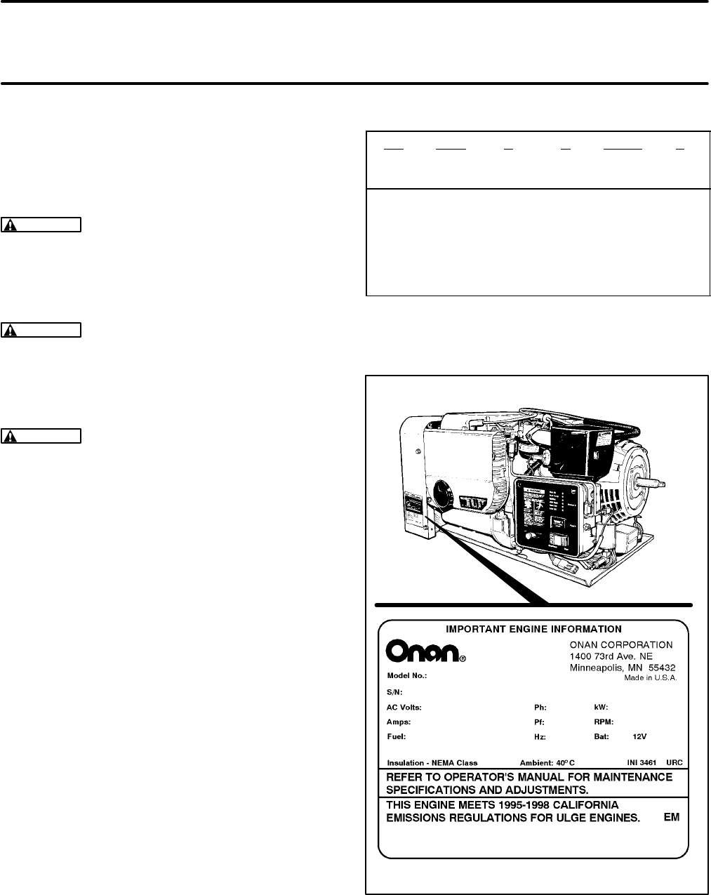
Introduction
This is the service manual for the Series BGD and
NHD generator sets (gensets) for commercial ve-
hicles. Read and carefully observe all of the instruc-
tions and precautions in this manual. Figure 2 illus-
trates a typical genset.
WARNING
Improper service or parts replace-
ment can lead to severe personal injury or death
and to damage to equipment and property. Ser-
vice personnel must be qualified to perform
electrical and mechanical service.
WARNING
Unauthorized modifications or re-
placement of fuel, exhaust, air intake or speed
control system components that affect engine
emissions are prohibited by law in the State of
California.
WARNING
LPG (liquified petroleum gas) is
flammable and explosive and can cause as-
phyxiation. NFPA 58, Section 1.6 requires all
persons handling LPG to be trained in proper
handling and operating procedures.
See the Operator’s Manual for instructions concern-
ing operation, maintenance and storage and for rec-
ommendations concerning engine lubricating oil
and fuel.
See the Installation Manual for important recom-
mendations concerning the installation and for a list
of the installation codes and standards for safety
which may be applicable.
See the Parts Manual for parts identification num-
bers and required quantities and for exploded views
of the genset subassemblies. Genuine Onan re-
placement parts are recommended for best results.
When contacting Onan for parts, service or product
information, be ready to provide the model number
and the serial number, both of which appear on the
genset nameplate. See Table 1 for the significance
of each character of the model number and Figure 1
for how the model and serial numbers are displayed
on the nameplate.
TABLE 1. MODEL NUMBER
6.5 NHD F B 30502 L
||||||
123456
1. Rated Power in Kilowatts
2. Genset Family
3. Starting Method Code
4. Voltage and Frequency Code
5. Options and Special Features Code
6. Spec Letter designating modifications
SN5980U1G2RA 980 cc
6.5NHDFB30502L
A953123456
FIGURE 1. TYPICAL NAMEPLATE
Redistribution or publication of this document,
by any means, is strictly prohibited.
Redistribution or publication of this document,
by any means, is strictly prohibited.

4
WARNING
EXHAUST GAS IS DEADLY!
All engine exhaust contains contain carbon monoxide, an odorless, colorless, poisonous gas that
can cause unconsciousness and death. Symptoms of carbon monoxide poisoning include:
•
Dizziness
•
Nausea
•
Headache
•
Vomiting
•
Weakness and Sleepiness
•
Inability to Think Coherently
IF YOU EXPERIENCE ANY OF THESE SYMPTOMS, GET INTO FRESH AIR IMMEDIATELY. If symp-
toms persist, seek medical attention. Shut down the genset and do not operate it until it has been
inspected and repaired.
Never sleep in the vehicle while the genset is running unless the vehicle has a working carbon mon-
oxide detector. The exhaust system must be installed in accordance with the genset Installation
Manual. Make sure there is ample fresh air when operating the genset in a confined area.
THE EXHAUST
OUTLET
FLANGE IS
ACCESSIBLE
THROUGH THE
WARM AIR
DISCHARGE
OPENING
BATTERY
CABLE
CONNECTIONS
(HIDDEN)
WARM
AIR DISCHARGE
CONTROL
PANEL
COOLING
AIR
AIR
CLEANER
REMOTE START
ENABLE SWITCH
CONNECTOR
BLOWER
HOUSING
SPARK PLUG
(HIDDEN)
SPARK
PLUG CARBURETOR AND
GOVERNOR ADJUSTMENTS
OIL
FILTER
GASOLINE
FUEL PUMP
CONTROL
FUSE F1
REMOTE CONTROL
CONNECTOR PLUG
LINE
CIRCUIT
BREAKERS
AC
VOLTAGE
REGULATOR
(1-PHASE)
FIGURE 2. TYPICAL GENSET
Redistribution or publication of this document,
by any means, is strictly prohibited.
Redistribution or publication of this document,
by any means, is strictly prohibited.

5
Specifications
GASOLINE MODELS
BGD NHD
GENERATOR: 4-Pole Revolving Field, Self-Excited, Electronically Regulated
Power (watts) 4500 4000 6500 5000
Frequency (Hertz) 60 50 60 50
120/240 Volt Single-Phase Output Current
(amperes @ 1.0 PF) 37.5/18.8 33.3/16.6 54/57 41.7/20.8
120/240 Volt Three-Phase Output Current
(amperes @ 1.0 PF) 21.7/10.8 - 31.3/15.6 -
220/380 Volt Three-Phase Output Current
(amperes @ 1.0 PF) - 10.5/6.1 - 13.1/7.6
Speed (RPM) 1800 1500 1800 1500
FUEL CONSUMPTION:
No load gph (l/h)
Half load gph (l/h)
Full load gph (l/h)
0.3 (1.1)
0.5 (1.9)
0.8 (3.0)
0.3 (1.1)
0.5 (1.9)
0.8 (3.0)
0.4 (1.5)
0.7 (2.6)
1.3 (4.9)
0.4 (1.5)
0.7 (2.6)
1.0 (3.8)
ENGINE: 2-Cylinder Opposed, 4-Cycle, Spark-Ignited, Side-Valve, Air Cooled
Bore 3.250 inch (83 mm) 3.563 inch (90 mm)
Stroke 2.875 inch (73 mm) 3.000 inch (76 mm)
Displacement 48 inch3 (782 cc) 60 inch3 (980 cc)
Compression Ratio 7.0 : 1 7.0 : 1
Min. Cylinder Compression Test Pressure 75 psi (517 kPa) 75 psi (517 kPa)
Oil Capacity (with filter)* 3.5 quart (3.3 l) 3.5 quart (3.3 l)
Intake Valve Clearance (Cold) 0.005 inch (0.13 mm) 0.005 inch (0.13 mm)
Exhaust Valve Clearance (Cold) 0.013 inch (0.33 mm) 0.013 inch (0.33 mm)
Spark Plug Gap 0.025 inch (0.64 mm) 0.025 inch (0.64 mm)
Spark Plug Tightening Torque 8 lbs-ft (10 N-m) 8 lbs-ft (10 N-m)
Ignition Timing (Beginning Spec L) 12° BTDC non-adjustable 12° BTDC non-adjustable
Ignition Timing (Prior to Spec L) 14°-18°BTDC non-adjustable 14°-18° BTDC non-adjustable
Max. Fuel Supply Pressure at Carburetor 6 psi (41 kPa) 6 psi (41 kPa)
Max. Fuel Pump Lift 3 feet (0.9 m) 3 feet (0.9 m)
Fuel Fitting 5/16 inch OD Hose Barb 5/16 inch OD Hose Barb
Exhaust Tailpipe Requirements 1-3/8 inch ID, 18 Ga Steel Tubing 1-3/8 inch ID, 18 Ga Steel Tubing
CONTROL AND CRANKING SYSTEM: 12 VDC
Nominal Battery Voltage 12 volts 12 volts
Minimum Battery Cold Cranking Capacity:
Above/Below Freezing 360/450 amperes 360/450 amperes
Nominal Regulated-Voltage Battery
Charging Output 10 amperes 10 amperes
Control Fuse F1 (Beginning Spec J) 10 amperes mini-bayonet 10 amperes mini-bayonet
Control Fuse F1 (Spec H only) 5 amperes slow-blow 5 amperes slow-blow
Ignition/Choke F2 (Spec H only) 10 amperes mini-bayonet 10 amperes mini-bayonet
* -See
Periodic Maintenance
for oil filling instructions.
Redistribution or publication of this document,
by any means, is strictly prohibited.
Redistribution or publication of this document,
by any means, is strictly prohibited.

6
LPG MODELS
BGD NHD
GENERATOR: 4-Pole Revolving Field, Self-Excited, Electronically Regulated
Power (watts) 4500 4000 6300 5000
Frequency (Hertz) 60 50 60 50
120/240 Volt Single-Phase Output Current
(amperes @ 1.0 PF) 37.5/18.8 33.3/16.6 52.5/26.3 41.7/20.8
120/240 Volt Three-Phase Output Current
(amperes @ 1.0 PF) 21.7/10.8 - 30.3/15.2 -
220/380 Volt Three-Phase Output Current
(amperes @ 1.0 PF) - 10.5/6.1 - 13.1/7.6
Speed (RPM) 1800 1500 1800 1500
FUEL CONSUMPTION:
No load lbs/h (kg/h)
Half load lbs/h (kg/h
Full load lbs/h (kg/h
1.8 (0.8)
3.1 (1.4)
4.4 (2.0)
1.5 (0.7)
2.6 (1.2)
4.0 (1.8)
2.2 (1.0)
3.8 (1.7)
6.6 (3.0)
2.0 (0.9)
3.5 (1.6)
5.1 (2.3)
ENGINE: 2-Cylinder Opposed, 4-Cycle, Spark-Ignited, Side-Valve, Air Cooled
Bore 3.250 inch (83 mm) 3.563 inch (90 mm)
Stroke 2.875 inch (73 mm) 3.000 inch (76 mm)
Displacement 48 inch3 (782 cc) 60 inch3 (980 cc)
Compression Ratio 7.0 : 1 7.0 : 1
Min. Cylinder Compression Test Pressure 75 psi (517 kPa) 75 psi (517 kPa)
Oil Capacity (with filter)* 3.5 quarts (3.3 l) 3.5 quarts (3.3 l)
Intake Valve Clearance (Cold) 0.005 inch (0.13 mm) 0.005 inch (0.13 mm)
Exhaust Valve Clearance (Cold) 0.013 inch (0.33 mm) 0.013 inch (0.33 mm)
Spark Plug Gap 0.025 inch (0.64 mm) 0.025 inch (0.64 mm)
Spark Plug Tightening Torque 8 lbs-ft (10 N-m) 8 lbs-ft (10 N-m)
Ignition Timing (Beginning Spec L) 12° BTDC non-adjustable 12° BTDC non-adjustable
Ignition Timing (Prior to Spec L) 14°-18°BTDC non-adjustable 14°-18° BTDC non-adjustable
LPG Vapor Supply Pressure Range
(Vapor-Withdrawal Only) 9 to 13 inch (229 to 330 mm)
W.C. (water column) 9 to 13 inch (229 to 330 mm)
W.C. (water column)
LPG Connection for Vapor Withdrawal 3/4 inch NPT Tapping 3/4 inch NPT Tapping
LPG Connection for Liquid Withdrawal 1/4 inch NPTF Tapping 1/4 inch NPTF Tapping
Exhaust Tailpipe Requirements 1-3/8 inch ID, 18 Ga Steel Tubing 1-3/8 inch ID, 18 Ga Steel Tubing
CONTROL AND CRANKING SYSTEM: 12 VDC
Nominal Battery Voltage 12 volts 12 volts
Minimum Battery Cold Cranking Capacity:
Above/Below Freezing 360/450 amperes 360/450 amperes
Nominal Regulated-Voltage Battery
Charging Output 10 amperes 10 amperes
Control Fuse F1 (Beginning Spec J) 10 amperes mini-bayonet 10 amperes mini-bayonet
Control Fuse F1 (Spec H only) 5 amperes slow-blow 5 amperes slow-blow
Ignition/Choke F2 (Spec H only) 10 amperes mini-bayonet 10 amperes mini-bayonet
* -See
Periodic Maintenance
for oil filling instructions.
Redistribution or publication of this document,
by any means, is strictly prohibited.
Redistribution or publication of this document,
by any means, is strictly prohibited.

7
Tolerances and Clearances
All dimensional tolerances and clearances are in inches
(millimeters) unless otherwise indicated MODEL BDG MODEL NHD
Cylinder Bore (Standard Size)* 3.2490-3.2500
(82.52-82.55) 3.5625-3.5635
(90.49-90.51)
Cylinder Taper (maximum) 0.005
(0.13) 0.003
(0.08)
Cylinder Out of Round (maximum) 0.003
(0.08) 0.003
(0.08)
Clearance in Cylinder 0.0033-0.0053
(0.084-0.135) 0.0070-0.0090
(0.178-0.229)
Ring Gap 0.010-0.020
(0.25-0.50) 0.010-0.020
(0.25-0.50)
#1 (Top) Piston Ring Groove Width 0.0602-0.0612
(1.53-1.55) 0.0602-0.0612
(0.25-0.50)
#2 Piston Ring Groove Width 0.0602-0.0612
(1.53-1.55) 0.0602-0.0612
(1.53-1.55)
#3 Piston Ring Groove Width 0.1193-0.1203
(3.03-3.06) 0.1193-0.1203
(3.03-3.06)
#1 (Top) Piston Ring Groove Width Prior to Spec F 0.080-0.081
(2.03-2.06) 0.080-0.081
(2.03-2.06)
#2 Piston Ring Groove Width Prior to Spec F 0.080-0.081
(2.03-2.06) 0.080-0.081
(2.03-2.06)
#3 Piston Ring Groove Width Prior to Spec F 0.188-0.189
(4.78-4.80) 0.188-0.189
(4.78-4.80)
#1 (Top) Piston Ring Side Clearance 0.003-0.008
(0.076-0.203) 0.002-0.008
(0.051-0.203)
Piston Pin Diameter 0.6875-0.6877
(17.46-17.47) 0.7500-0.7502
(19.05-19.06)
Piston Pin Fit in Rod 0.0002-0.007
(0.005-0.018) 0.0002-0.0008
(0.005-0.020)
Connecting Rod Side Clearance 0.002-0.016
(0.051-0.406) 0.002-0.016
(0.051-0.406)
Connecting Rod Bearing Clearance 0.0020-0.0033
(0.051-0.084) 0.002-0.0033
(0.051-0.084)
Crankshaft Main Bearing Journal Diameter 1.9992-2.0000
(50.780-50.800) 1.9992-2.0000
(50.780-50.800)
Crankshaft Rod Journal Bearing Diameter 1.6252-1.6260
(41.280-41.300) 1.6252-1.6260
(41.280-41.300)
Crankshaft Main Bearing Diameter 2.0024-2.0034
(50.860-50.886) 2.0015-2.0040
(50.838-50.902)
Crankshaft Main Bearing Clearance 0.0024-0.0042
(0.061-0.107) 0.0024-0.0042
(0.061-0.107)
Crankshaft End Play 0.006-0.012
(0.15-0.30) 0.006-0.012
(0.15-0.30)
* - The bore is 0.005 inch oversize if the engine serial number has suffix “E”.
Redistribution or publication of this document,
by any means, is strictly prohibited.
Redistribution or publication of this document,
by any means, is strictly prohibited.

8
All dimensional tolerances and clearances are in inches
(millimeters) unless otherwise indicated MODEL BDG MODEL NHD
Camshaft Journal Diameter 1.3740-1.3745
(34.90-34.91) 1.3740-1.3745
(34.90-34.91)
Camshaft Bearing Diameter 1.376-1.377
(34.95-34.97) 1.376-1.377
(34.95-34.97)
Camshaft Bearing Clearance 0.0015-0.0030
(0.038-0.076) 0.0015-0.0030
(0.038-0.076)
Camshaft End Play 0.011-0.048
(0.28-1.2) 0.011-0.048
(0.28-1.2)
Valve Spring Free Length 1.600
(40.64) 1.662
(42.21)
Valve Spring Compressed Length (Valve Closed) 1.346
(34.19) 1.375
(34.92)
Valve Spring Tension Open 55 lbs
(25 kg) 71 lbs
(32 kg)
Valve Spring Tension Closed 25 lbs
(11 kg) 38 lbs
(17 kg)
Valve Face Angle 44°44°
Valve Seat Angle 45°45°
Valve Stem Diameter (Intake) 0.2795-0.2800
(7.099-7.112) 0.3425-0.3430
(8.700-8.712)
Valve Stem Diameter (Exhaust) 0.2780-0.2785
(7.061-7.074) 0.3410-0.3420
(8.661-8.687)
Intake Valve Guide Diameter 0.2810-0.280
(7.137-7.163) 0.344-0.346
(8.74-8.79)
Exhaust Valve Guide Diameter 0.2805-0.2815
(7.125-7.150) 0.344-0.346
(8.74-8.79)
Valve Stem Clearance (Intake) 0.0010-0.0025
(0.025-0.064) 0.0010-0.0025
(0.025-0.064)
Valve Stem Clearance (Exhaust) 0.0020-0.0035
(0.051-0.089) 0.0025-0.0040
(0.064-0.102)
Valve Lifter Diameter 0.74575-0.7480
(18.987-18.999) 0.7475-0.7480
(18.987-18.999)
Valve Lifter Bore Diameter 0.7500-0.7515
(19.050-19.088) 0.7500-0.7515
(19.050-19.088)
Valve Lifter To Block Clearance 0.0020-0.0040
(0.051-0.102) 0.0020-0.0040
(0.051-0.102)
Intake Valve Seat Diameter (Outside) 1.470-1.471
(37.34-37.36) 1.569-1.570
(39.85-39.88)
Exhaust Valve Seat Diameter (Outside) 1.192-1.193
(30.28-30.30) 1.255-1.256
(31.88-31.90)
Valve Seat Bore Diameter (Intake) 1.4395-1.4405
(36.563-36.588) 1.5645-1.5655
(39.738-39.764)
Valve Seat Bore Diameter (Exhaust) 1.189-1.190
(30.20-30.23) 1.2510-1.2520
(31.775-31.801)
Redistribution or publication of this document,
by any means, is strictly prohibited.
Redistribution or publication of this document,
by any means, is strictly prohibited.

9
Assembly Torques
Bolt torques are in lbs-ft (N-m)* MODEL BGD MODEL NHD
Cylinder Head Bolts (Cold) 15-17 (20-23) 15-17 (20-23)
Connecting Rod Bolts 12-14 (16-19) 27-29 (37-39)
Rear Bearing Plate Bolts 25-27 (34-37) 25-27 (34-37)
Flywheel Mounting Nut 50-55 (68-75) 50-55 (68-75)
Oil Base Bolts 18-23 (24-31) 18-23 (24-31)
Gearcase Cover Bolts 8-10 (11-14) 8-10 (11-14)
Spark Plug 8 (10) 8 (10)
Exhaust Manifold Bolts 9-11 (12-15) 20-23 (27-31)
Intake Manifold Bolts 6-10 (8-14) 15 (20)
Rotor Through-Bolt 45-55 (61-75) 45-55 (61-75)
Starter Mounting Bolts 30-33 (41-45) 30-33 (41-45)
Stator Clamp Screws 10-12 (11-16) 10-12 (11-16)
Adapter-Engine Mounting Bolts 25-27 (34-37) 25-27 (34-37)
Adapter-Generator Mounting Bolts 25 (34) 25 (34)
Rear Vibration Isolators
Center Bolt
Flange to Drip Tray Screws
30-33 (41-45)
10-12 (11-16) 30-33 (41-45)
10-12 (11-16)
Front Vibration Isolators
Center Bolt
Flange to Oil Base Screws
28-32 (38-43)
19-22 (26-30) 28-32 (38-43)
19-22 (26-30)
* - Use engine oil as a lubricant for all threads EXCEPT for spark plug and rotor through-bolt threads.
Redistribution or publication of this document,
by any means, is strictly prohibited.
Redistribution or publication of this document,
by any means, is strictly prohibited.

10
Preparations
TROUBLESHOOTING
See
Troubleshooting
to determine the probable
cause of the problem before removing the genset
for service.
SAFETY
There are hazards in servicing gensets. Study
Safe-
ty Precautions
and become familiar with the haz-
ards listed in Table 2. Note the following safeguards
and ways of avoiding hazards:
•
Use personal protection:
Wear appropriate
protective safety equipment, such as:
Safety shoes
Gloves
Safety glasses
Hard hats
Do not wear rings or jewelry and do not wear
loose clothing that might get caught on equip-
ment.
•
Reduce the hazard:
A safe, orderly workshop
area and well-maintained equipment reduce
the hazard potential. Keep guards and shields
in place on machinery and maintain equipment
in good working condition. Store flammable liq-
uids in approved containers; away from fire,
flame, spark, pilot light, switches, arc-produc-
ing equipment and other ignition sources. Keep
the workshop clean and well-lighted and pro-
vide adequate ventilation.
•
Develop safe work habits:
Unsafe actions
cause accidents with tools and machines. Be
familiar with the equipment and know how to
use it safely. Use the correct tool for the job and
check its condition before starting. Comply with
the warnings in this manual and take special
precautions when working around electrical
equipment. Do not work alone if possible and
take no risks.
•
Be prepared for an accident:
Keep fire extin-
guishers and safety equipment nearby. Agen-
cies such as the Red Cross and public safety
departments offer courses in first aid, CPR and
fire control. Take advantage of this information
to be ready to respond to an accident. Learn to
be safety-conscious and make safety proce-
dures part of the work routine.
TABLE 2. HAZARDS AND THEIR SOURCES
Fire and
Explosion
•Leaking or spilled fuel
•Hydrogen gas from battery
•Oily rags improperly stored
•Flammable liquids improperly
stored
Burns
•Hot exhaust pipes
•Hot engine and generator sur-
faces
•Electrical shorts
Poisonous
Gas •Operating genset where ex-
haust gases can accumulate
Electrical
Shock (AC)
•Improper generator connec-
tions
•Faulty wiring
•Working in damp conditions
•Jewelry touching electrical
components
Rotating
Machinery •Fan guards not in place
Slippery
Surfaces •Leaking or spilled oil
Heavy
Objects •Removing genset from vehicle
•Removing heavy components
Redistribution or publication of this document,
by any means, is strictly prohibited.
Redistribution or publication of this document,
by any means, is strictly prohibited.

11
SPECIAL TOOLS
The tools listed below are necessary for servicing
the genset. See the Onan Tool Catalog.
Engine Tools
Torque wrench: 0-75 lbs-ft (0-100 N-m)
Hole gauge: 0.300-0.400 inch (5-10 mm)
Outside micrometer set: 0-4 inch (0-100 mm)
Telescoping gauge set: up to 4 inch (100 mm)
Feeler gauge
Plasti-Gage bearing clearance guide
Spark plug gap gauge
Oil pressure gauge: 0-30 psi (0-200 kPa)
Fuel pressure gauge (for gasoline): 0-10 psi
(0-75 kPa)
Manometer (for LPG): 14 inch (350 mm) WC
Inclined Manometer (for LPG): 1 inch (25 mm)
WC range with 0.01 inch (0.1 mm) WC divisions
Cylinder compression tester
Flywheel puller
Crankshaft gear puller ring, bolts and puller
(or special shoulder bolts and flywheel puller)
Snap ring pliers
Combination main and cam bearing remover
Combination main and cam bearing driver
Oil seal loader and driver
Cylinder ridge reamer
Piston ring spreader
Piston groove cleaner
Piston ring compressor
Cylinder hone
Valve spring compressor
Valve lock replacer
Valve seat cutter kit
Valve guide driver
Slide hammer
Lead or dead-blow hammer
Generator and Control Tools
Rotor removal tool (headless bolt)
Commutator stone
Battery hydrometer
Frequency meter
Digital multi-meter: AC and DC Voltage, Ohms
and Diode Check
Load test panel and leads
Voltage Regulator Testor and Adaptor (1-Ph)
Rotor and Stator Testor and Adaptor
REMOVING THE GENSET
Some service procedures will require that the gen-
set be removed from the vehicle. The genset is nor-
mally mounted in a special compartment on the ve-
hicle floor. Because installations vary, it is not pos-
sible to describe a specific removal procedure. Con-
tact the vehicle manufacturer or installer if the best
way to remove the genset is not obvious.
Disconnections at the Genset
1. First disconnect the negative (-) battery cable
from the battery
and then disconnect the bat-
tery cables from the genset.
WARNING
Sparks and high current could
cause fire and other damage to the battery,
battery cables and vehicle if the loose ends
of cables connected to the battery touch.
Always disconnect the negative (-) battery
cable from the battery before disconnecting
the battery cables from the genset.
2. Disconnect the remote control wiring harness
connector at the genset.
3. Disconnect the generator output wiring and
conduit from the power distribution panel or box
on the vehicle. Tag all wires to make reconnec-
tions easier.
4. Disconnect the exhaust tailpipe from the outlet
of the muffler and then remove the muffler. See
EXHAUST SYSTEM under
Engine Subsys-
tems
.
5. Disconnect couplings, adapters, hydraulic
lines and other power takeoff attachments on
gensets so equipped.
Redistribution or publication of this document,
by any means, is strictly prohibited.
Redistribution or publication of this document,
by any means, is strictly prohibited.

12
6. Disconnect the fuel line from the genset. Follow
the applicable instructions depending on the
fuel.
WARNING
Gasoline and LPG (liquified pe-
troleum gas) are flammable and explosive
and can cause severe personal injury or
death. Do not smoke if you smell gas or gas-
oline or are near fuel tanks or fuel-burning
equipment or are in an area sharing ventila-
tion with such equipment. Keep flames,
sparks, pilot lights, electrical arcs and arc-
producing equipment and all other sources
of ignition well away.
Gasoline Fueled Gensets:
Disconnect the
fuel line from the genset and securely plug the
end of the fuel line to prevent leakage or an ac-
cumulation of explosive gasoline vapor.
LPG Fueled Gensets:
Close the fuel shutoff
valve(s) at the LPG container(s) and move the
vehicle outside and away from below-grade
spaces where LPG could accumulate. To purge
the fuel line and genset as much as possible,
run the genset (if it starts) until it runs out of fuel
with the LPG valve(s) closed.
WARNING
LPG is flammable and explo-
sive and can cause asphyxiation. NFPA 58,
Section 1.6 requires all persons handling
LPG to be trained in proper handling and
operating procedures.
LPG “sinks” when it escapes into the air
and can accumulate in explosive con-
centrations. Before disconnecting the LPG
fuel line, close the fuel shutoff valve(s) at
the LPG container(s) and move the vehicle
outside and away from pits or basements or
other below-grade spaces where LPG could
accumulate.
For LPG liquid-withdrawal systems
(see Figure
28 on Page 35) press the regulator priming but-
ton while cranking for 10 seconds to purge
some of the remaining LPG. Then loosen the
threaded flexible fuel supply hose connector at
the fuel filter on the genset just enough to hear
gas escaping. Unthread the connector when no
more gas is heard escaping. Finally, cap the
end of the fuel supply hose with a 1/4 inch
NPTF pipe cap to prevent fuel from escaping if
someone inadvertently opens the shutoff
valve(s) at the LPG container(s).
WARNING
Large volumes of LPG can be
released in the process of disconnecting a
liquid-withdrawal type of LPG supply sys-
tem. Before disconnecting LPG fuel con-
nections, make sure the the fuel shutoff
valve(s) at the LPG container(s) are closed
and that the vehicle is outside and away
from pits or basements or other below-
grade spaces where LPG could accumu-
late.
For LPG vapor-withdrawal gensets
(see Figure
32 on Page 38) disconnect the gas supply hose
at the carburetor and the fuel solenoid shutoff
valve leads at the control box on the genset. If
the pressure regulator/solenoid valve assem-
bly is also to be removed, cap the end of the fuel
supply line with a threaded pipe cap to prevent
fuel from escaping if someone inadvertently
opens the shutoff valve(s).
Redistribution or publication of this document,
by any means, is strictly prohibited.
Redistribution or publication of this document,
by any means, is strictly prohibited.
13
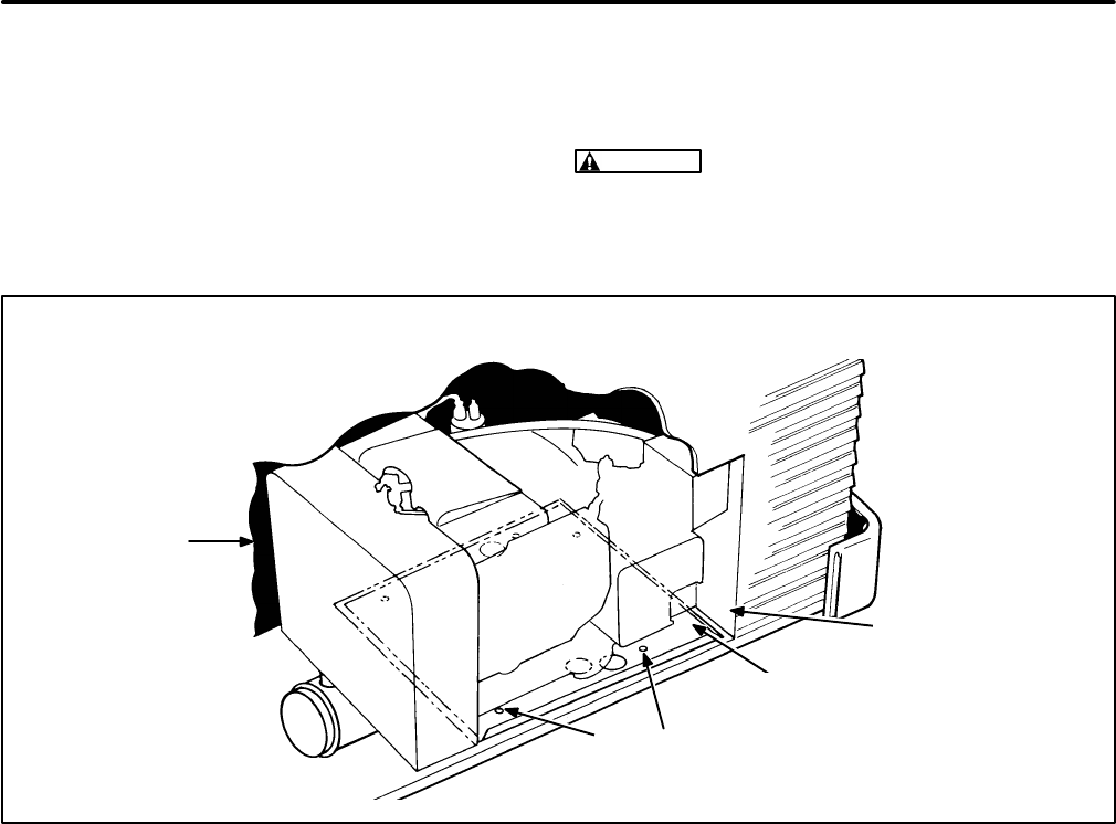
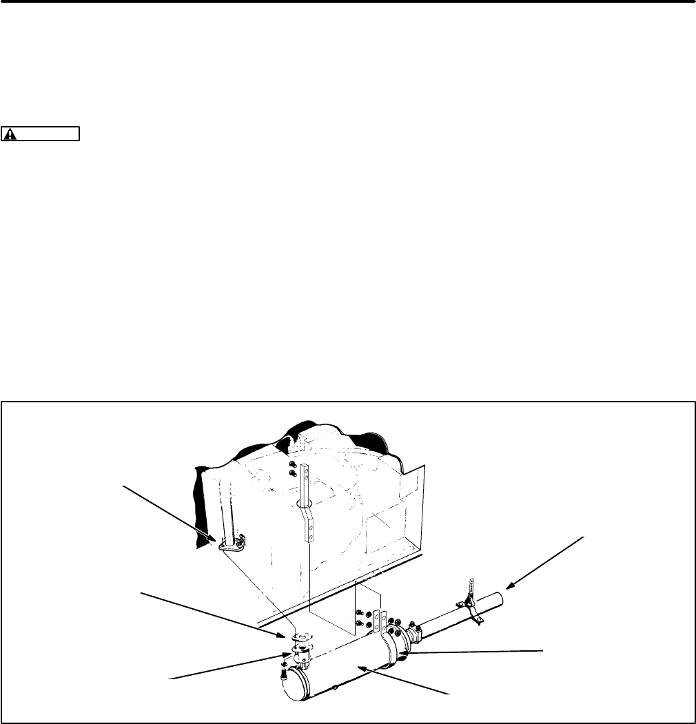
Removal of the Genset from the Vehicle
See Figure 3. When the genset has been discon-
nected from the electrical, exhaust and fuel sys-
tems, examine its mounting bolts and support mem-
bers. The genset drip tray is normally bolted to the
vehicle framework. Make sure that the genset is
firmly supported before loosening any mounting
bolts or support members. A fork lift is recom-
mended to lift or move the genset.
WARNING
Gensets are heavy and can cause
severe personal injury if dropped during remov-
al. Use adequate lifting devices. Keep hands
and feet clear while lifting.
BARRIER
MOUNTING
HOLES
COMPARTMENT
FLOOR
DOOR
FIGURE 3. TYPICAL FLOOR-MOUNTED GENSET
Redistribution or publication of this document,
by any means, is strictly prohibited.
Redistribution or publication of this document,
by any means, is strictly prohibited.
14
Engine Subsystems
These engine subsystems or service procedures do
not require removal of the cylinder heads, gearcase
or main bearings for access and may be serviceable
without removing the genset from the vehicle.
CYLINDER COMPRESSION TEST
Examining the spark plugs and testing cylinder
compression can tell much about the condition of
the valves, piston rings and cylinders. Test cylinder
compression as follows:
1. Start the genset and let it warm up.
2. Stop the genset and remove and inspect the
spark plugs. See IGNITION SYSTEM in this
section.
3. Insert the compression gauge nozzle into one
of the spark plug holes, hold the throttle open
and crank the engine. Note the pressure indi-
cated by the gauge.
4. Repeat the test on the other cylinder.
5. Refer to
Engine Block Assembly
if cylinder
compression test pressures do not meet
Speci-
fications.
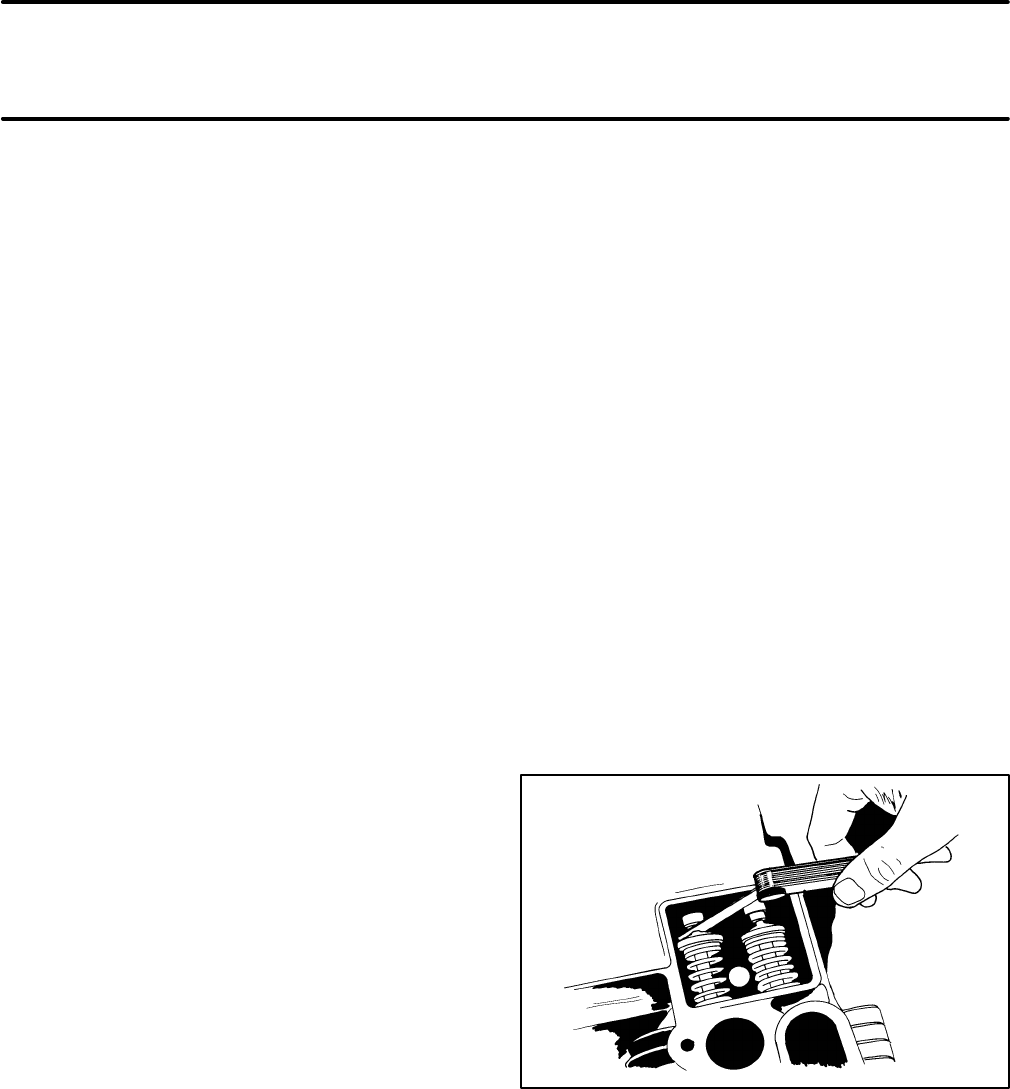
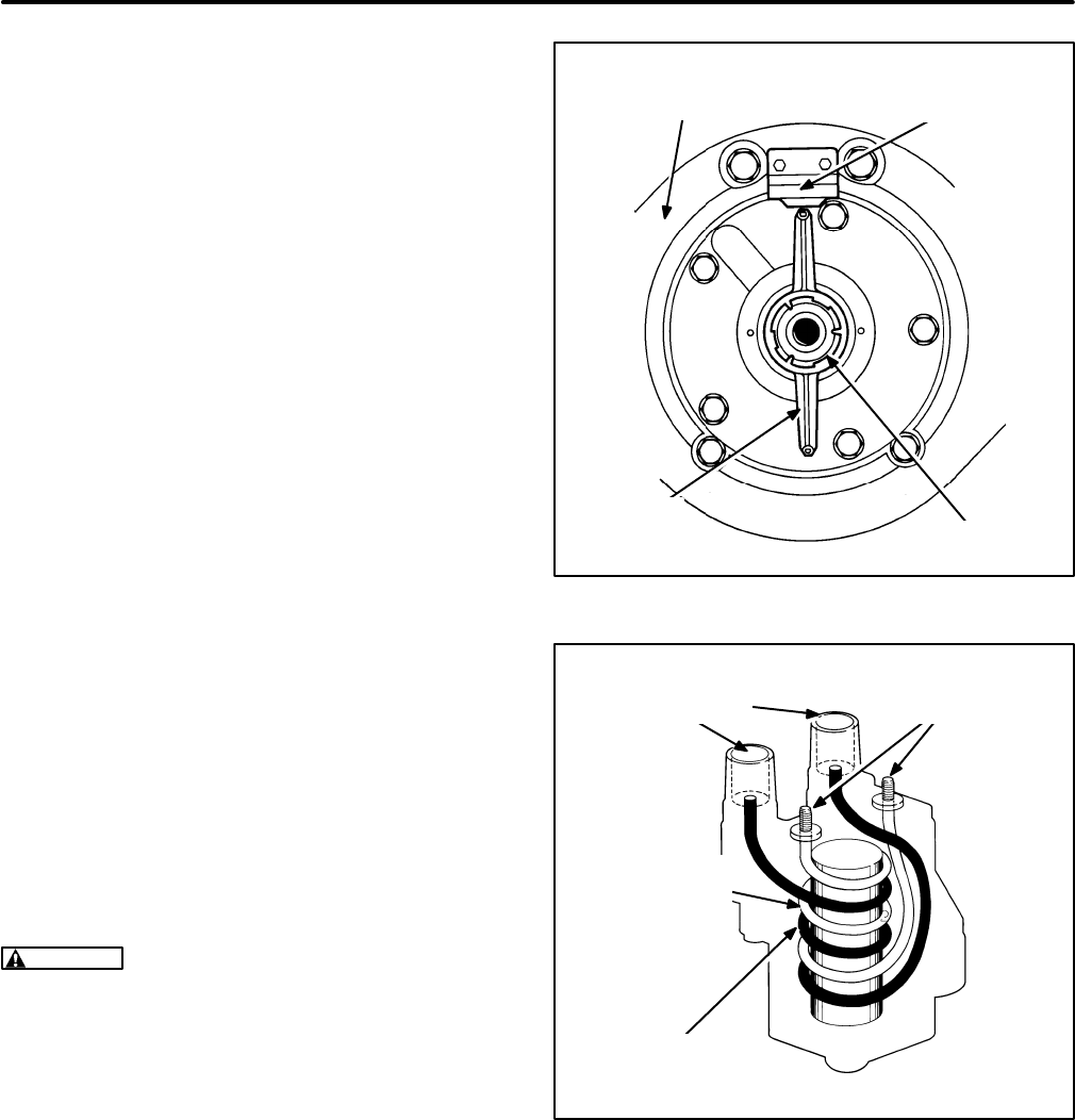
VALVE CLEARANCE (LASH)
ADJUSTMENT
See Figure 4. The engine is equipped with adjust-
able valve tappets. Adjust the valve clearance only
when the engine is at ambient temperature:
1. Remove all parts that block access to the valve
tappets.
2. Remove the spark plugs, to make turning the
engine easier.
3. Place a socket wrench on the flywheel caps-
crew and rotate the crankshaft in a clockwise
direction until the left intake valve (viewed from
flywheel end) opens and closes. Continue turn-
ing the crankshaft until the TC mark on the fly-
wheel is lined up with the TC mark on the gear
cover. This should place the left piston at the
top of its compression stroke. Verify that the left
intake and exhaust valves are closed and that
there is no pressure on the valve lifters.
4. See
Specifications
for valve clearance. When
taking the clearance measurement, the feeler
gauge should just pass between the valve stem
and valve tappet.
5. To correct the valve clearance, turn the adjust-
ing screw as needed. The screw is self-locking.
6. To adjust the valves on the right cylinder, turn
the engine one complete revolution until the TC
mark on the flywheel lines up again with the TC
mark on the gear cover and then follow the
same procedure as for the left cylinder.
7. Replace all parts removed. Tighten all screws
securely. Torque the manifold bolts according
to
Assembly Torques
.
FIGURE 4. ADJUSTING VALVE CLEARANCE
(LASH)
Redistribution or publication of this document,
by any means, is strictly prohibited.
Redistribution or publication of this document,
by any means, is strictly prohibited.
15
EXHAUST SYSTEM
See Figure 5. The exhaust system consists of the
manifold, muffler, tailpipe and hardware for assem-
bling and mounting the components.
WARNING
Exhaust gas is deadly. The exhaust
system must not leak and must discharge all en-
gine exhaust away from the vehicle.
Liability for injury, death, damage and warranty
expense due to the use of an unapproved muf-
fler or due to modifications becomes the re-
sponsibility of the person installing the unap-
proved muffler or performing the modifications.
Use Onan approved exhaust system parts.
Muffler
Replacement mufflers are available as kits that in-
clude all necessary hardware and gaskets. Follow
the instructions in the kits exactly.
To remove the muffler remove the tail pipe, the muf-
fler support strap screws and the inlet flange bolts
and pull the muffler away.
Always reassemble with new muffler flange gas-
kets.
Tailpipe
The tailpipe is not supplied by Onan. If it is neces-
sary to replace the tailpipe, use 1-3/8 inch I.D., 18
rigid steel tubing and 1-3/8 inch U-bolt muffler
clamps and shock-mount hangers. Important safety
warnings and information and instructions regard-
ing the routing and termination of the tailpipe are in-
cluded in the Installation Manual. The tailpipe must
be mounted in such a way that it is protected from
damage or dislocation and be terminated in such a
way that exhaust gases will not recirculate back into
the vehicle.
FLANGE AT EXIT OF
EXHAUST MANIFOLD
FLANGE-TO-MUFFLER
CONNECTOR AND CLAMP
TAILPIPE AND HANGER
(SUPPLIED BY OTHERS)
MUFFLER
FLANGE
GASKET
MUFFLER
SUPPORT STRAP
FIGURE 5. TYPICAL MUFFLER INSTALLATION
Redistribution or publication of this document,
by any means, is strictly prohibited.
Redistribution or publication of this document,
by any means, is strictly prohibited.
16
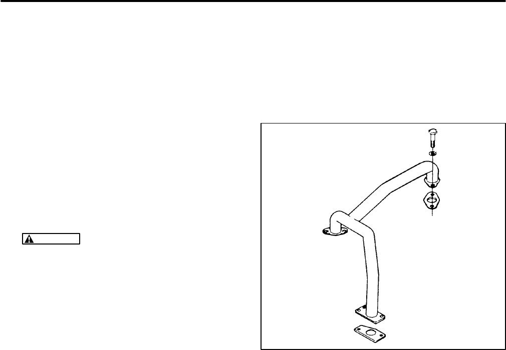
Exhaust Manifold
See Figure 6. To remove the exhaust manifold it will
first be necessary to remove the muffler and then re-
move the genset from the vehicle. See
Prepara-
tions
.
1. Remove the cooling system noise shield, fan
guard and scroll (Figure 7) to provide access to
the exhaust manifold.
2. Remove the screw that secures the exhaust
manifold outlet flange to the support bracket.
3. If this is a LPG genset equipped for liquid with-
drawal, disconnect the fuel vaporizer (the tub-
ing wrapped around the manifold) at both ends
and remove the pressure regulator.
WARNING
Bending the fuel vaporizer tub-
ing can weaken it to the point that it can
crack allowing LPG under high pressure to
escape, resulting in possible severe per-
sonal injury or death.
Large volumes of LPG can be released in
the process of disconnecting a liquid-with-
drawal type of LPG supply system. See
Preparations (Page 12) for the proper pro-
cedures and precautions.
4. Remove the four exhaust manifold bolts. Lift off
the exhaust manifold and the two manifold gas-
kets.
Reassembly is the reverse of disassembly. Always
use new manifold gaskets when reassembling and
torque the manifold bolts according to
Assembly
Torques.
FIGURE 6. EXHAUST MANIFOLD
Redistribution or publication of this document,
by any means, is strictly prohibited.
Redistribution or publication of this document,
by any means, is strictly prohibited.
17
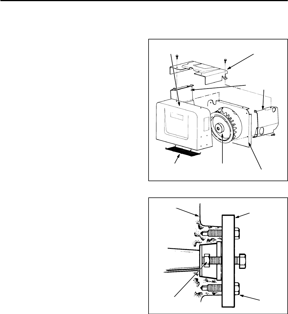
ENGINE COOLING SYSTEM
See Figure 7. These are air-cooled gensets. The
engine flywheel is also a centrifugal blower that
draws cooling air across the fins on the engine cylin-
ders and heads and discharges the warm air down-
wards through the discharge grill.
Disassembly:
1. Remove the muffler (see EXHAUST SYS-
TEM).
2. Remove the capscrews that secure the noise
shield and lift off the noise shield.
3. Remove the three nuts along the lower edge of
the blower scroll that hold the discharge grill to
the scroll.
4. Remove the capscrews that fasten the blower
scroll to the backplate and pull away the scroll.
5. Remove the screws that fasten the cylinder
shrouds to the back plate and cylinder heads
and lift them off.
6. Loosen the flywheel capscrew and back it out
several turns. See Figure 8.
7. Attach the puller tool to the flywheel. The tool
has two jack screws that fit into the holes
tapped in the flywheel.
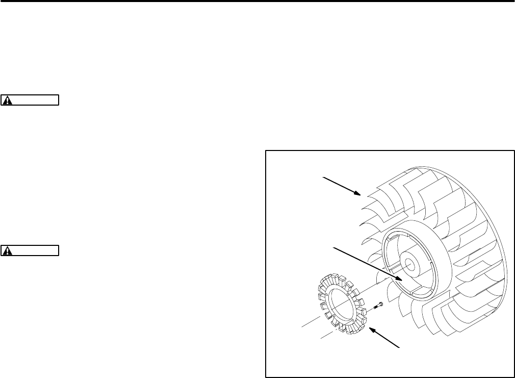
8. Tighten the puller center screw until the fly-
wheel comes loose. Remove the puller, fly-
wheel center screw and washer. Remove the
flywheel carefully so as not to damage the
PMG. Inspect the flywheel and replace it if any
air vanes are missing or magnets are loose or
missing (Figure 9).
9. Remove the lead from the low oil pressure cut-
off switch.
10. Remove the exhaust manifold (see EXHAUST
SYSTEM).
11. Remove the capscrews that hold the backplate
to the engine. Lift off the backplate.
12. Use a brush or low pressure compressed air to
remove accumulated dust on the engine cool-
ing fins.
CYLINDER
SHROUDS
BLOWER
SCROLL NOISE
SHIELD
DISCHARGE
GRILL BACKPLATE
FLYWHEEL
-BLOWER
FIGURE 7. COOLING SYSTEM
FLYWHEEL
CAPSCREW
FLYWHEEL FLYWHEEL
PULLER
JACK
SCREW
FIGURE 8. FLYWHEEL REMOVAL
Redistribution or publication of this document,
by any means, is strictly prohibited.
Redistribution or publication of this document,
by any means, is strictly prohibited.
18
Reassembly:
Reassembly is the reverse of disas-
sembly. When installing the flywheel, align its key-
way with the woodruff key on the crankshaft. Use
non-hardening sealer on the flywheel capscrew
threads and torque to 50-55 lbs-ft (68-75 N-m).
CAUTION
The engine will overheat and can be
damaged if it is operated without all the cooling
system components in place.
See the Installation Manual regarding the minimum
free area required for the air inlet to the compart-
ment or enclosure and the minimum clearance re-
quired at the discharge opening. The engine will
overheat if the inlet and outlet openings are too
small or are obstructed or if dust has accumulated
on the cooling fins.
WARNING
Discharge air from the engine can
include deadly exhaust gas. Therefore, do not
use engine discharge air to heat the interior of
the vehicle.
PMG
See Figure 9. Beginning Spec J, the genset is
equipped with a PMG (permanent magnet genera-
tor). The PMG consists of a multi-pole stator bolted
to the engine gear case, concentric with the crank-
shaft, and six rotating permanent magnets mounted
in the flywheel. The stator leads exit around the bot-
tom right-side of the engine and terminate in con-
nector J8/P8 in the vicinity of the starter motor. PMG
output is regulated by battery charging voltage reg-
ulator VR2. Output from the PMG recharges the
cranking battery and provides the signal for the en-
gine control board (A1) to disconnect the starter and
to continue operation when the START switch (S1)
is released.
FLYWHEEL
PERMANENT
MAGNETS
STATOR
FIGURE 9. PMG (BEGINNING SPEC J)
Redistribution or publication of this document,
by any means, is strictly prohibited.
Redistribution or publication of this document,
by any means, is strictly prohibited.
19
IGNITION SYSTEM
These gensets are equipped with an electronic igni-
tion system consisting of a rotor, module, coil, ca-
pacitor, spark plugs and associated wiring. Energy
for ignition is supplied by the 12 volt cranking bat-
tery.
Rotor
See Figure 10. The ignition rotor is keyed to the en-
gine crankshaft. The ends have opposite magnetic
polarity (north and south). One pole switches on the
ignition module and the other pole switches it off,
once each revolution of the crankshaft. The rotor
should not normally require replacement.
Module
The ignition module is secured and grounded to the
generator-engine adaptor by two cap screws. It is
an electronic switch in the primary circuit of the igni-
tion coil. See
Wiring Diagrams
for the appropriate
wiring diagram. It is switched on and off once each
revolution by the rotor. The module contains no ser-
viceable parts and should not normally require re-
placement.
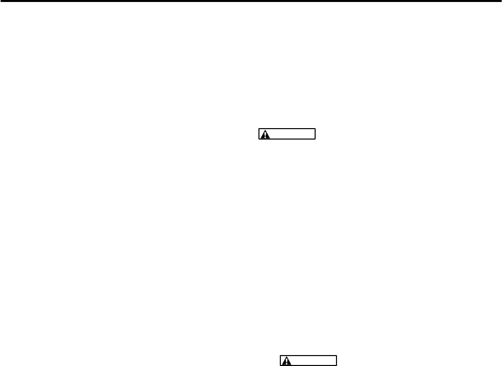
Coil
See Figure 11. The ignition coil is a transformer that
fires the spark plugs at roughly 20,000 volts each
revolution when the ignition module opens the pri-
mary circuit causing the coil field to collapse.
CAUTION
The leads connected at the low volt-
age terminals of the ignition coil (Figure 11)
should not be routed so as to pass between the
high voltage terminal posts. Otherwise, false
signals can be induced in the low voltage wires,
leading to erratic operation.
IGNITION
MODULE
IGNITION
ROTOR CRANKSHAFT
ENGINE-GENERATOR
ADAPTOR
FIGURE 10. IGNITION ROTOR AND MODULE
LOW VOLTAGE
TERMINALS
SECONDARY
WINDING
PRIMARY
WINDING
HIGH VOLTAGE
TERMINALS
FIGURE 11. IGNITION COIL
Redistribution or publication of this document,
by any means, is strictly prohibited.
Redistribution or publication of this document,
by any means, is strictly prohibited.
20
Capacitor
The ignition capacitor is secured and grounded to
the top of the generator-engine adaptor by one cap
screw. The pig tail is connected to the positive (+)
low voltage terminal of the ignition coil.
Spark Plugs
The genset has two spark plugs. The spark plugs
must be in good condition and have the proper gap
for top engine performance. See
Specifications.
To prevent crossthreading a spark plug, always
thread it in by hand until it seats. Then tighten the
spark plug according to
Assembly Torques.
Alterna-
tively, if the spark plug is being reused, turn it with a
wrench an additional 1/4 turn. If the spark plug is
new, turn it an additional 3/8 to 1/2 turn.
If the engine misses or performance otherwise dete-
riorates, remove and examine the spark plugs for
signs of the following problems:
Light tan, gray or reddish deposits -
Normal
One spark plug fouled -
Broken spark plug cable,
low cylinder compression
Soot fouled -
Wrong spark plug heat range (too
cold), duty cycle too short for engine to reach normal
operating temperature
Fuel fouled -
Wrong spark plug heat range (too
cold), faulty choke operation, overly rich fuel mix-
ture, dirty air filter
Oil fouled -
Malfunctioning crankcase breather,
worn rings, worn valve guides or seals
Burned Or Overheated -
Leaking intake manifold
gaskets, lean fuel mixture
Worn -
Spark plug service life used up.
Quick Ignition Test
If the engine misfires, test the ignition system as fol-
lows to quickly determine if the problem is in the igni-
tion system. First recheck, clean and tighten the
connections at the ignition coil terminals. See
Wir-
ing Diagrams
for the proper connections at the “-”
and “+” terminals.
WARNING
Gasoline and LPG are flammable
and explosive and can cause severe personal
injury or death. Park the vehicle in a well-venti-
lated area, leave the generator compartment
door open for several minutes and make sure
you cannot smell gas or gasoline vapors before
conducting this test. Have an ABC rated fire ex-
tinguisher handy.
1. Park the vehicle in a well-ventilated area, leave
the generator compartment door open for sev-
eral minutes and make sure you cannot smell
gas or gasoline vapors before conducting this
test.
2. Remove one of the spark plugs.
3. Reconnect the spark plug cable and lay the
spark plug on bare engine metal to ground it.
WARNING
HIGH VOLTAGE. To prevent
electric shock do not touch the spark plug
or wire during this test.
4. Crank the engine and observe the spark. A
strong, consistent spark indicates that the igni-
tion system is probably functioning properly
and that the problem is elsewhere. See
Trou-
bleshooting
. Service the ignition system as re-
quired if the spark is weak or inconsistent.
Spark Plug Cable Resistance Tests
Remove both spark plug cables and check resist-
ance across the ends with an ohmmeter. Replace a
cable if resistance is not between 3,000 and 15,000
ohms.
Redistribution or publication of this document,
by any means, is strictly prohibited.
Redistribution or publication of this document,
by any means, is strictly prohibited.
21
Ignition Module Test
1. Remove both spark plugs and the cooling dis-
charge grill (Figure 7) so that the engine can be
turned by hand.
2. Connect the positive (+) side of a voltmeter to
the negative (-) terminal of the ignition coil
(larger of the two screw terminals) and the neg-
ative (-) side of the voltmeter to engine ground.
3. Remove all leads from the positive (+) terminal
of the coil.
4. Use a jumper to connect the red lead of the igni-
tion module (the one just removed from the coil)
to the battery positive terminal.
5. Rotate the flywheel clockwise by hand. Re-
place the ignition module if voltage does not
jump from approximately 1 volt to approximate-
ly 12 volts, and then back again, each revolu-
tion.
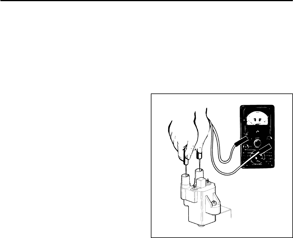
Ignition Coil Test
1. Remove all wires attached to the ignition coil.
2. Remove the coil from the engine.
3. Inspect the terminals for corrosion, looseness,
cracks or other damage. Look for carbon run-
ners around the high tension terminals: these
indicate electrical leakage. Replace a dam-
aged or leaking coil.
4. Clean the outside of the coil with a cloth damp-
ened in parts cleaning solvent.
5. Measure primary coil resistance (across the
positive [+] and negative [-] terminals). Replace
the ignition coil if primary resistance is not be-
tween 3 and 5 ohms.
6. Measure secondary coil resistance (across the
spark plug cable terminals). Replace the igni-
tion coil if secondary resistance is not between
10,000 and 40,000 ohms. See Figure 12.
FIGURE 12. TESTING THE IGNITION COIL
Redistribution or publication of this document,
by any means, is strictly prohibited.
Redistribution or publication of this document,
by any means, is strictly prohibited.
22
CRANKCASE BREATHER ASSEMBLY
See Figure 13. The crankcase breather is a reed
valve assembly that opens to discharge crankcase
vapors on the piston down-stroke and closes on the
up-stroke, resulting in a negative pressure in the
crankcase when the engine is running. The crank-
case vapors (blowby gases, gasoline vapors, mois-
ture, air) are routed to the carburetor for burning in
the cylinders. A dirty or sticking valve can cause oil
leaks, high oil consumption, rough idle, reduced en-
gine power and sludge formation within the engine.
Disassembly:
The breather assembly is serviced
by disassembling it and cleaning all the parts in
parts cleaning solvent. The assembly comes apart
when the capscrew is unscrewed.
WARNING
Most parts cleaning solvents are
flammable and corrosive and can cause severe
burns and inflammation. Use only as recom-
mended by the manufacturer.
Reassembly:
Reassemble using a new gasket.
Replace the reed valve if it does not lie flat across
the discharge orifice. Torque the cover capscrew to
12-24 lbs-in (1.3-2.6 N-m).
CAUTION
Over-tightening the capscrew can
distort the cover allowing dirt and air to enter the
engine.
BREATHER
HOSE
CAPSCREW
FLAT
WASHER
FLAT
WASHER
SPRING
REED
VALVE
PACK
GASKET
HOSE
CLAMP
VALVE
COVER
BREATHER
BAFFLE
FIGURE 13. CRANKCASE BREATHER ASSEMBLY
Redistribution or publication of this document,
by any means, is strictly prohibited.
Redistribution or publication of this document,
by any means, is strictly prohibited.
23
LUBRICATION SYSTEM
Drain the oil before removing the oil base. Always
use a new gasket when replacing the oil base.
An oil pump (See OIL PUMP under
Engine Block
Assembly
) provides a constant flow of oil to the en-
gine parts and a full-flow, spin-on filter keeps the oil
clean. The oil collects in the oil base where it is
picked up by the oil pump pick-up cup. An oil by-
pass valve is used to control oil pressure.
Oil pressure should be at least 13 psi (90 kPa) for
Model BGD gensets and at least 20 psi (138 kPa) for
Model NHD gensets when the engine is at normal
operating temperature. If pressure drops below this
value at governed speed, inspect the oil system for
faulty components.
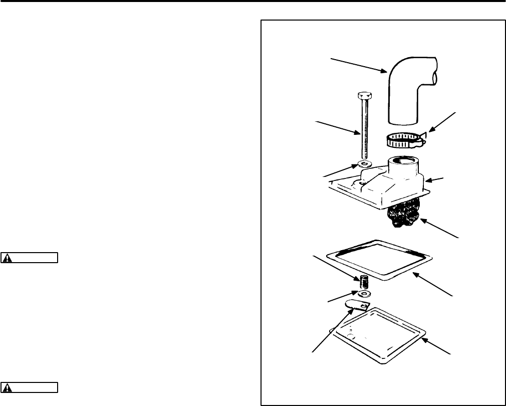
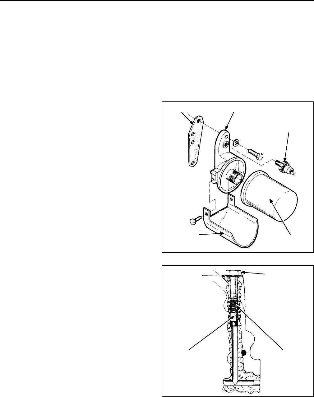
Oil Filter And Adapter
1. Open the oil drain valve and drain the crank-
case oil.
2. Remove the filter by turning it counterclockwise
with a filter wrench.
3. Loosen the two capscrews that secure the
adapter to the engine block and remove the
adapter and gasket. The low oil pressure cutoff
switch is installed in a threaded hole in the filter
adapter. See Figure 14.
To reassemble the oil filter and adapter, perform
these steps in reverse order. Install a new adapter
gasket so that the two small oil holes are aligned
with the oil holes in the block. This gasket should
be installed dry. Coat the threads of each caps-
crew with non-hardening sealer and torque to speci-
fications.
Oil Bypass Valve
The bypass valve is located to the right and behind
the gear cover (Figure 15). It controls oil pressure by
allowing excess oil to flow back to the crankcase. It
is non-adjustable and normally needs no mainte-
nance. If it is suspected that it is the cause of high or
low oil pressure, inspect it as follows:
1. Remove the 3/8 capscrew behind the gear cov-
er and under the governor arm.
2. Remove the spring and plunger with a magnet-
ic tool and clean them.
3. Replace the plunger if its diameter is not 0.3105
to 0.3125 inch (7.89 to 7.94 mm).
4. Replace the spring if its free length is not
approximately 1 inch (25.4 mm) or if it takes
other than 2.4-2.8 pounds (10.7-12.5 N) to
compress it 0.5 inch (12.7 mm).
5. Check the bore and valve seat and clean away
any debris.
GASKET ADAPTER LOW OIL
PRESSURE
CUTOUT
SWITCH
OIL FILTER
DRIP
SHIELD
FIGURE 14. OIL FILTER AND ADAPTER
FLAT
WASHER
SPRINGVALVE
HEX CAP
SCREW
FIGURE 15. OIL BYPASS VALVE
Redistribution or publication of this document,
by any means, is strictly prohibited.
Redistribution or publication of this document,
by any means, is strictly prohibited.
24
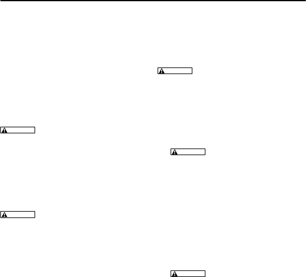
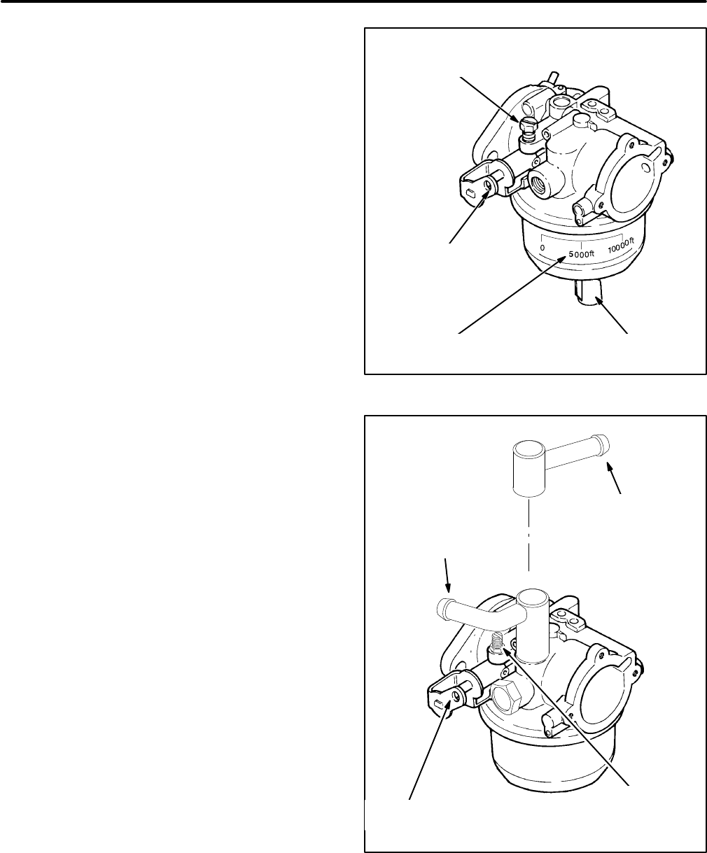
FUEL SYSTEM
The carburetor mixes air and fuel in the correct pro-
portion for good performance. The governor oper-
ates the throttle to maintain a nearly constant en-
gine speed (frequency) as the load varies. Figure 16
is representative of most of the fuel system parts.
LPG (liquified petroleum gas) systems do not use
an air preheater or choke and have different fuel
connections. See Automatic Choke, Fuel Pump and
LPG System Components in this section for details
of the other parts of the fuel system.
WARNING
Gasoline and LPG are flammable
and explosive and can cause severe personal
injury or death. Do not smoke if you smell gas or
gasoline vapors or are near fuel tanks or fuel-
burning equipment or are in an area sharing
ventilation with such equipment. Keep flames,
sparks, pilot flames, electrical arcs and
switches and other sources of ignition well
away.
WARNING
LPG is flammable and explosive
and can cause asphyxiation. NFPA 58, Section
1.6 requires all persons handling LPG to be
trained in proper handling and operating proce-
dures.
Air Cleaner Assembly
Disassembly:
1. Remove the crankcase breather hose and air
preheater hose (gasoline gensets only) from
the air cleaner housing.
2. Remove the air cleaner housing center caps-
crew and lift off the housing and air filter.
3. Remove the three capscrews that secure the
air cleaner adapter to the carburetor and lift off
the adapter. (One of the screws is inside the
throat of the adapter.)
4. For LPG gensets (Spec H only), disconnect the
leads at Relay K5 or remove the relay and
bracket from the air cleaner adapter.
Reassembly:
Reassembly is the reverse of disas-
sembly. Use a new gasket between the adapter and
the carburetor.
CAUTION
Take care not to cross-thread the in-
side adapter mounting screw.
Carburetor And Intake Manifold Assembly
Disassembly:
1. Remove the air cleaner assembly.
2. Disconnect the fuel line and governor rod from
the carburetor.
WARNING
Large volumes of LPG can be
released in the process of disconnecting a
liquid-withdrawal type of LPG supply sys-
tem. See Preparations (Page 12) for the
proper procedures and precautions.
3. Remove the intake manifold capscrews, the
carburetor air preheater (gasoline gensets
only) and the carburetor and intake manifold as
an assembly. On LPG gensets equipped for
liquid withdrawal, if will first be necessary to
disconnect the fuel vaporizer (the tube
wrapped around the exhaust manifold) at both
ends, remove the pressure regulator, discon-
nect the vaporizer line from its support bracket
and rotate the vaporizer line out of the way.
WARNING
Bending the fuel vaporizer tub-
ing can weaken it to the point that it can
crack allowing LPG under high pressure to
escape, resulting in possible severe per-
sonal injury or death.
4. Remove the two intake manifold gaskets and
cover the intake ports to prevent loose parts
from accidentally entering the ports.
5. Unbolt the carburetor from the intake manifold.
Reassembly:
Reassembly is the reverse of disas-
sembly. Use new gaskets between the intake man-
ifold and the engine and between the intake man-
ifold and the carburetor. Do not use sealer on the
gaskets. Tighten all fasteners according to
Assem-
bly Torques
.
Redistribution or publication of this document,
by any means, is strictly prohibited.
Redistribution or publication of this document,
by any means, is strictly prohibited.
25
DETAIL OF
GOVERNOR ROD/THROTTLE
LEVER CONNECTION
(gasoline)
CRANKCASE
BREATHER
HOSE AND CLIP
AIR
CLEANER
HOUSING
AIR
CLEANER
ADAPTOR
AIR
FILTER
ELEMENT
GOVERNOR
ROD
INTAKE
MANIFOLD
AIR PREHEATER AND HOSE
(gasoline gensets only)
GASOLINE FUEL INLET
(The fuel line from a remote or mounted pump
is connected here through an elbow fitting)
ADAPTOR/CARBURETOR
GASKET
MANIFOLD
GASKETS
O-RING
(Slip the O-ring over the end of the
preheater hose and insert it into the
collar)
GASOLINE
CARBURETOR/CHOKE
ASSEMBLY
MANIFOLD
GASKET
FIGURE 16. TYPICAL FUEL SYSTEM
Redistribution or publication of this document,
by any means, is strictly prohibited.
Redistribution or publication of this document,
by any means, is strictly prohibited.
26
Governor and Carburetor Adjustments
Careful adjustments of the carburetor and governor
are essential for top performance. Perform all nec-
essary engine and generator maintenance and re-
pairs before making these adjustments.
These adjustments require the use of meters to
measure voltage, frequency and amperage and a
stepped load bank of at least 8 kW, where a portion
of at least 600 watts is variable. Digital meters are
recommended. Accuracy should be at least 0.3 per-
cent for frequency measurement and 0.5 percent for
voltage measurement.
It is recommended that the genset be disconnected
from the AC service panel of the vehicle. If the gen-
set is not disconnected, disconnect or unplug all
voltage and frequency sensitive devices throughout
the vehicle to protect them from the variations in fre-
quency and voltage that occur during these adjust-
ments.
WARNING
Disconnect or unplug all voltage
and frequency sensitive devices such as TVs,
VCRs, computers and other solid-state elec-
tronic devices before making governor and car-
buretor adjustments. Typically, some internal
circuits are powered when these types of de-
vices are plugged in, even if the device has been
switched “OFF”. These circuits can be dam-
aged by variations in voltage and frequency.
Consequential damage to TVs, VCRs, comput-
ers and other voltage and frequency sensitive
devices as a result of failing to observe this pre-
caution is not covered under the Onan warranty
policy.
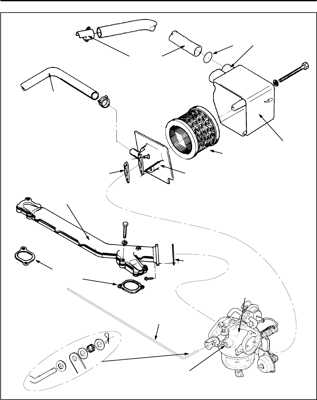
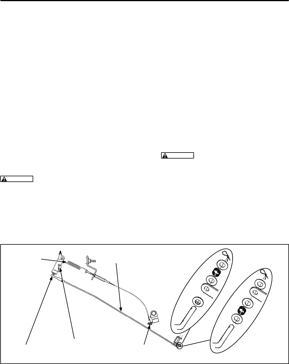
Governor Rod Length Adjustment:
The length of
the governor rod (Figure 17) must be checked and
adjusted as follows before other adjustments are at-
tempted:
1. Loosen the lock nut at the ball joint end of the
governor rod and unsnap the socket from the
ball.
2. Push the governor rod gently towards the car-
buretor (full-throttle position). While keeping it
there, turn the socket, as necessary, to length-
en or shorten the rod so that the ball and socket
line up.
CAUTION
Too much pressure on the rod
can result in a faulty adjustment of the rod
length.
3. Snap the socket back over the ball.
4. Tighten the lock nut while holding the socket
square with the axis of the ball. Also, the leg at
the throttle end of the rod must be kept level.
5. Gently rotate the governor arm and check for
binding. If necessary, loosen the locknut and
repeat Step 4 until the linkage moves smoothly.
Binding can cause erratic governor action.
DETAIL: GASOLINE
AND LPG VAPOR
WITHDRAWAL
GENSETS
GOVERNOR
SENSITIVITY
ADJUSTING SCREW
(DROOP)
BALL AND
SOCKET
GOVERNOR
SPRING GOVERNOR
ROD
GOVERNOR SPEED
ADJUSTING SCREW DETAIL: LPG LIQUID
WITHDRAWAL
GENSETS
FIGURE 17. GOVERNOR ROD
Redistribution or publication of this document,
by any means, is strictly prohibited.
Redistribution or publication of this document,
by any means, is strictly prohibited.
27
Note: The following groups of adjustments must be
performed in sequence. They apply to gensets BE-
GINNING SPEC L. For gensets PRIOR TO SPEC L, see
Page 29.
Idle Speed Stop Adjustment:
The frequency
specifications for 60 Hz gensets are followed in pa-
rentheses by the specifications for 50 Hz gensets.
1. Start the genset and let it warm up for ten min-
utes under 1/2 to 3/4 rated load. (On vapor with-
drawal type LPG gensets it might be necessary
to first adjust the supply pressure as instructed
under LPG System Components to get the gen-
set to start.)
2. Disconnect the load (check for zero amps). Pull
the governor rod so that the tang on the throttle
lever bears against the idle speed stop screw.
Adjust the screw to obtain 54-56 Hz (44-46 Hz).
(On LPG carburetors the stop screw has a lock-
nut.)
Frequency Adjustments:
The frequency specifi-
cations for 60 Hz gensets are followed in paren-
theses by the specifications for 50 Hz gensets.
1. Set the altitude adjust knob (gasoline only) on
the carburetor to your altitude.
2. Disconnect all loads (check for zero amps).
Then check no-load frequency. If necessary,
turn the governor speed adjusting screw to ob-
tain a no-load frequency of 62-63 Hz (51.5-52.5
Hz).
3. Check output voltage. See
Generator
if output
voltage cannot be adjusted to within 10 percent
of rated voltage (Table 3).
4. See
Troubleshooting
if the engine runs roughly.
ALTITUDE
SCALE
IDLE SPEED
STOP SCREW
ALTITUDE
ADJUST KNOB
THROTTLE
LEVER
FIGURE 18. GASOLINE CARBURETOR
(BEGINNING SPEC L)
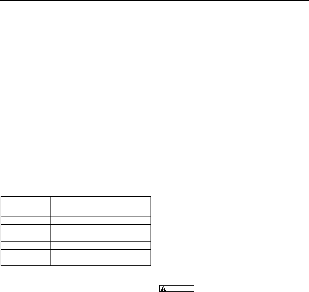
IDLE SPEED
STOP SCREW
AND LOCKNUT
THROTTLE
LEVER
FUEL INLET
LIQUID-WITHDRAWAL
FUEL INLET
VAPOR-WITHDRAWAL
FIGURE 19. LPG CARBURETOR
(BEGINNING SPEC L)
Redistribution or publication of this document,
by any means, is strictly prohibited.
Redistribution or publication of this document,
by any means, is strictly prohibited.
28
Droop Adjustments:
The frequency specifications
for 60 Hz gensets are followed in parentheses by
the specifications for 50 Hz gensets.
1. Connect rated load.
A. Load (watts) is the product of volts (V) and
amps (A).
For Single-phase Output:
Load (watts) = V x A
For Three-phase Output:
Load (watts) = 1.73 x V x A*
* average of the three phases
(A 1.0 power factor, obtainable with a re-
sistance load bank, is assumed. True rated
output might not be obtained if appliances
are used as part of the load.)
B. See
Generator
if output voltage cannot be
adjusted to within 10 percent of rated volt-
age (Table 3).
TABLE 3. VOLTAGE SPECIFICATION
RATED
OUTPUT
VOLTAGE
MAXIMUM
NO-LOAD
VOLTAGE
MINIMUM
FULL-LOAD
VOLTAGE
120V, 1PH 132 112
120/240V, 1PH 264 224
120/240V, 3PH 252 236
220/380V, 3PH 417 364
127/220V, 3PH 232 202
277/480V, 3PH 504 440
2. Check and adjust droop.
A. If droop (from no-load frequency) is more
than 3 Hz (3.5 Hz) for Model BGD or 4 Hz
(3.5 Hz) for Model NHD, turn the governor
sensitivity adjusting screw (Figure 17) one
turn counterclockwise. Disconnect the
load and, if necessary, readjust the gover-
nor speed adjusting screw to return to
62-63 Hz (51.5-52.5 Hz) no-load frequen-
cy. Check droop again and repeat the ad-
justments, if necessary.
B. If droop (from no-load frequency) is less
than 2 Hz (2 Hz) for Model BGD or 3 Hz
(2 Hz) for Model NHD, turn the governor
sensitivity adjusting screw (Figure 17) one
turn clockwise. Disconnect the load and, if
necessary, readjust the governor speed
adjusting screw to return to 62-63 Hz
(51.5-52.5 Hz) no-load frequency. Check
droop again and repeat the adjustments, if
necessary.
3. Check governor response under 1/4, 1/2 and
3/4 rated loads. See
Troubleshooting
if hunting
is unacceptable.
Carburetor Replacement
(Beginning Spec L)
Other than turning the altitude adjust knob shown in
Figure 18, which changes the main fuel mixture
within a limited range (gasoline carburetors only),
fuel mixture adjustments should not be attempted
on gasoline or LPG carburetors. Nor should the car-
buretor be overhauled. Instead, a malfunctioning
carburetor should be replaced. Before replacing a
carburetor, however, make certain 1) that all other
necessary engine and generator adjustments and
repairs have been performed and 2) that the carbu-
retor is actually malfunctioning, by carefully follow-
ing the troubleshooting procedures in
Troubleshoot-
ing
.
LPG carburetors are usually not the cause of prob-
lems. Make certain all other possible causes of the
problem have been eliminated before replacing an
LPG carburetor.
WARNING
Unauthorized modifications or re-
placement of fuel, exhaust, air intake or speed
control system components that affect engine
emissions are prohibited by law in the State of
California.
See the instructions on how to remove and replace
the carburetor under the subheadings AIR CLEAN-
ER ASSEMBLY and CARBURETOR AND INTAKE
MANIFOLD ASSEMBLY in this section.
Redistribution or publication of this document,
by any means, is strictly prohibited.
Redistribution or publication of this document,
by any means, is strictly prohibited.
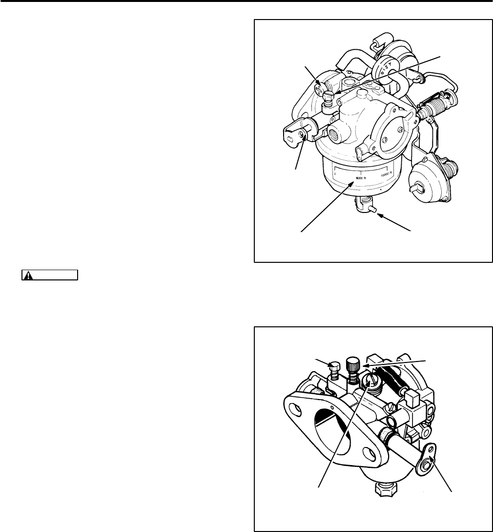
29
Note: The following groups of adjustments must be
performed in sequence. They apply to gensets
PRIOR TO SPEC L only. For gensets BEGINNING
SPEC L, see Page 27.
Idle Speed Stop Adjustment:
The frequency
specifications for 60 Hz gensets are followed in pa-
rentheses by the specifications for 50 Hz gensets.
1. If the carburetor has been overhauled, gently
turn the idle and main fuel mixture screws in by
hand until they seat.
For Gasoline Gensets:
Turn the idle mixture
screw out 1 turn and the main fuel mixture
screw out 1-1/4 turns so that the engine will
start and run.
For LPG Gensets:
Turn the idle mixture screw
out 1-1/4 turns and the main fuel mixture screw
out 2-1/2 turns so that the engine will start and
run.
CAUTION
Forcing a mixture adjusting
screw in tight will score the needle and seat.
Turn it lightly by hand only.
2. Start the genset and let it warm up for ten min-
utes under 1/2 to 3/4 rated load. (On vapor with-
drawal type LPG gensets it might be necessary
to first adjust the demand regulator and supply
pressure as instructed under LPG System
Components to get the genset to start.)
3. Disconnect the load (check for zero amps). Pull
the governor rod so that the tang on the throttle
lever bears against the idle speed stop screw.
Adjust the screw to obtain 54-56 Hz (44-46 Hz).
Idle Mixture and Frequency Adjustments:
The
frequency specifications for 60 Hz gensets are fol-
lowed in parentheses by the specifications for 50 Hz
gensets.
1. Disconnect all loads (check for zero amps).
Then check no-load frequency. If necessary,
turn the governor speed adjusting screw to ob-
tain a no-load frequency of 62-63 Hz (51.5-52.5
Hz).
ALTITUDE
SCALE
IDLE
MIXTURE
ADJUSTING
SCREW CAP
IDLE
SPEED
STOP
SCREW
MAIN FUEL MIXTURE
ADJUSTING SCREW CAP
THROTTLE
LEVER
FIGURE 20. GASOLINE CARBURETOR
(PRIOR TO SPEC L)
IDLE SPEED
STOP SCREW
THROTTLE
LEVER
MAIN FUEL MIXTURE
ADJUSTING SCREW
IDLE
MIXTURE
ADJUSTING
SCREW
FIGURE 21. LPG CARBURETOR
(PRIOR TO SPEC L)
Redistribution or publication of this document,
by any means, is strictly prohibited.
Redistribution or publication of this document,
by any means, is strictly prohibited.

30
2. Turn the idle mixture adjusting screw clockwise
until the frequency drops and then counter-
clockwise until it drops again. Adjust it to obtain
the highest possible stable frequency. Some
“wander” is normal. For closer adjustments,
use a CO meter to adjust to 6-8% CO (gasoline)
or 4-6% CO (LPG). See
Troubleshooting
if the
engine runs roughly.
3. Push the adjustment limiter cap on over the
mixture screw head such that it will allow equal
adjustment in either direction.
4. If no-load frequency has changed because of
idle mixture adjustment, repeat Step 1.
5. Check output voltage. See
Generator
if output
voltage cannot be adjusted to within 10 percent
of rated voltage (Table 4).
Main Fuel Mixture and Droop Adjustments:
The
frequency specifications for 60 Hz gensets are fol-
lowed in parentheses by the specifications for 50 Hz
gensets.
1. Connect rated load.
A. Load (watts) is the product of volts (V) and
amps (A).
For Single-phase Output:
Load (watts) = V x A
For Three-phase Output:
Load (watts) = 1.73 x V x A*
* average of the three phases
(A 1.0 power factor, obtainable with a re-
sistance load bank, is assumed. True rated
output might not be obtained if appliances
are used as part of the load.)
B. See
Generator
if output voltage cannot be
adjusted to within 10 percent of rated volt-
age (Table 4).
TABLE 4. VOLTAGE SPECIFICATION
RATED
OUTPUT
VOLTAGE
MAXIMUM
NO-LOAD
VOLTAGE
MINIMUM
FULL-LOAD
VOLTAGE
120V, 1PH 132 112
120/240V, 1PH 264 224
120/240V, 3PH 252 236
220/380V, 3PH 417 364
127/220V, 3PH 232 202
277/480V, 3PH 504 440
2. Turn the main fuel mixture adjusting screw
clockwise until the frequency drops and then
counterclockwise until it drops again. Adjust it
to obtain the highest possible stable frequency.
For closer adjustments, use a CO meter to ad-
just to 6-8% CO (gasoline) or 2-4% CO (LPG).
See
Troubleshooting
if the engine runs roughly.
3. Push the adjustment limiter cap on over the
mixture screw head such that the cap pointer
indicates the current altitude.
4. Disconnect the load and readjust the governor
speed adjusting screw to return no-load fre-
quency to 62-63 Hz (51.5-52.5 Hz).
5. Check and adjust droop.
A. If droop (from no-load frequency) is more
than 3 Hz (3.5 Hz) for Model BGD or 4 Hz
(3.5 Hz) for Model NHD, turn the governor
sensitivity adjusting screw (Figure 17) one
turn counterclockwise. Disconnect the
load and, if necessary, readjust the gover-
nor speed adjusting screw to return to
62-63 Hz (51.5-52.5 Hz) no-load frequen-
cy. Check droop again and repeat the ad-
justments, if necessary.
B. If droop (from no-load frequency) is less
than 2 Hz (2 Hz) for Model BGD or 3 Hz
(2 Hz) for Model NHD, turn the governor
sensitivity adjusting screw (Figure 17) one
turn clockwise. Disconnect the load and, if
necessary, readjust the governor speed
adjusting screw to return to 62-63 Hz
(51.5-52.5 Hz) no-load frequency. Check
droop again and repeat the adjustments, if
necessary.
6. Check governor response under 1/4, 1/2 and
3/4 rated loads. See
Troubleshooting
if hunting
is unacceptable.
Redistribution or publication of this document,
by any means, is strictly prohibited.
Redistribution or publication of this document,
by any means, is strictly prohibited.

31
Carburetor Overhaul (Prior to Spec L)
(See Page 28 for Spec L and Later)
See Figures 22 and 23. Carburetor problems not
corrected by mixture or float adjustments are often
caused by gummed-up fuel passages or worn inter-
nal parts. The most effective remedy is to replace or
overhaul the carburetor. Overhauling a carburetor
consists of complete disassembly, thorough clean-
ing and replacement of worn parts. Repair kits are
available for gasoline carburetors that include new
gaskets and float assembly parts.
Disassembly:
Carefully note how the carburetor
parts fit together as the carburetor is being disas-
sembled so that it will be easier to reassemble.
Read and understand these instructions before
starting.
1. Remove the air cleaner adapter and the auto-
matic choke assembly (gasoline carburetors).
2. Remove the throttle and choke plate retaining
screws, then remove the plates. Pull out the
throttle and choke shafts, being careful not to
damage the Teflon coating applied to the
shafts.
3. Remove the main and idle mixture screw as-
semblies.
4. Separate the lower section of the carburetor
(float bowl) from the body of the carburetor.
5. Carefully note the position of the float assembly
parts, then remove the hinge pin, float and
needle valve (gasoline carburetors).
Cleaning and Repair:
1. Soak all metal components not replaced by the
repair kit in carburetor cleaner. Do not soak any
rubber or plastic parts. Follow the cleaner
manufacturer’s recommendations.
WARNING
Most parts cleaning solvents
are flammable and corrosive and can cause
severe burns and inflammation. Use only as
recommended by the manufacturer.
2. Clean all carbon from the carburetor bore, es-
pecially where the throttle and choke plates
seat. Be careful not to plug the idle or main fuel
ports.
3. Blow out all passages with compressed air. Do
not use wire or other objects for cleaning that
might increase the size of critical passages.
CHOKE
PLATE
THROTTLE
SHAFT
FUEL
INLET
NEEDLE
VALVE
FLOAT
BOWL
CHOKE
SHAFT
THROTTLE
PLATE
FLOAT
MAIN FUEL
MIXTURE
ADJUSTING
ASSEMBLY
FIGURE 22. GASOLINE CARBURETOR
(PRIOR TO SPEC L)
THROTTLE
SHAFT
BOWL
THROTTLE
PLATE
BOWL
GASKET
FIGURE 23. LPG CARBURETOR
(PRIOR TO SPEC L)
Redistribution or publication of this document,
by any means, is strictly prohibited.
Redistribution or publication of this document,
by any means, is strictly prohibited.
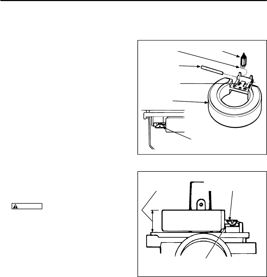
32
Reassembly:
1. Slide in the throttle shaft and install the throttle
plate using new screws, if they are furnished in
the repair kit. Before tightening the screws, the
plate must be centered in the bore. To do this,
back off the throttle stop screw as necessary
and completely close the throttle lever. Seat the
plate by gently tapping it with a small screwdriv-
er, then tighten the screws. Install the choke
shaft and plate in the same manner.
2. See Figure 24. Turn the carburetor upside
down and install the new needle valve, float,
float hinge pin and fuel bowl gasket in the repair
kit. Make sure the wire clip properly engages
the groove around the end of the needle valve
and loops around the metal tang of the float.
(The clip pulls down on the needle valve when
the float level drops, breaking the needle loose
if it is stuck.) Check to see that the float moves
freely without binding.
3. See Figure 25. Check float level as shown while
the carburetor is still upside down. Measure the
height above the bowl gasket flange on the side
opposite the hinge. Make sure the full weight of
the float is resting on the needle valve. Remove
the float and bend the metal tang to adjust the
height.
CAUTION
Remove the float before bend-
ing the tang so as not to damage the soft
nose of the needle valve.
4. Install the float bowl and the main mixture
screw assembly.
5. Install the idle and main fuel mixture screws.
Turn them lightly by hand until they seat. Then:
For Gasoline Gensets:
Turn the idle mixture
screw out 1 turn and the main fuel mixture
screw out 1-1/4 turns so that the engine will
start and run.
For LPG Gensets:
Turn the idle mixture screw
out 1-1/4 turns and the main fuel mixture screw
out 2-1/2 turns so that the engine will start and
run.
FLOAT
NEEDLE VALVEWIRE CLIP
METAL TANG
FLOAT HINGE PIN
RETAINING SCREW
FLOAT
HINGE PIN
FIGURE 24. FLOAT INSTALLATION (GASOLINE)
BEND METAL TANG TO
ADJUST FLOAT HEIGHT
0.59-0.63 INCH
(15-16 mm )
THE FULL WEIGHT OF THE FLOAT MUST
REST ON THE NEEDLE VALVE WHILE
MEASURING FLOAT HEIGHT
FIGURE 25. FLOAT LEVEL (GASOLINE)
Redistribution or publication of this document,
by any means, is strictly prohibited.
Redistribution or publication of this document,
by any means, is strictly prohibited.

33
Automatic Choke (Gasoline Sets)
See Figure 26.The automatic choke is operated by
a bi-metal/heater assembly and a vacuum breaker
assembly. Replace faulty choke components and
reassemble as shown. Adjust the choke breaker as-
sembly each time it is assembled to the carburetor,
as follows:
1. Apply a vacuum of at least 4 inches (100 mm)
of mercury to fully pull in the choke breaker arm.
2. Insert a 0.337 inch (8.6 mm) drill rod between
the choke plate and the carburetor throat.
3. If necessary, bend the link at the point shown
until the lip of the choke plate just touches the
drill rod. Use two pliers to bend the link.
VACUUM
SUSTAIN VALVE
ASSEMBLY
CARBURETOR
CHOKE
SHAFT
ASSEMBLY
IF NECESSARY, BEND THIS LINK
AT THIS POINT WHEN ADJUSTING
THE CHOKE BREAKER ASSEMBLY.
BI-METAL / HEATER
ASSEMBLY
CHOKE
PLATE
CHOKE
BREAKER
ASSEMBLY
GAUGE THE DISTANCE BETWEEN THE CHOKE
PLATE AND THE CARBURETOR THROAT WITH A
0.337 INCH (8.6 mm) DRILL ROD WHEN ADJUSTING
THE CHOKE BREAKER ASSEMBLY
Make sure
this hose is not kinked
(may cause engine to
flood) and does not in-
terfere with the choke
shaft assembly.
CAUTION
FIGURE 26. CHOKE ASSEMBLY
Redistribution or publication of this document,
by any means, is strictly prohibited.
Redistribution or publication of this document,
by any means, is strictly prohibited.
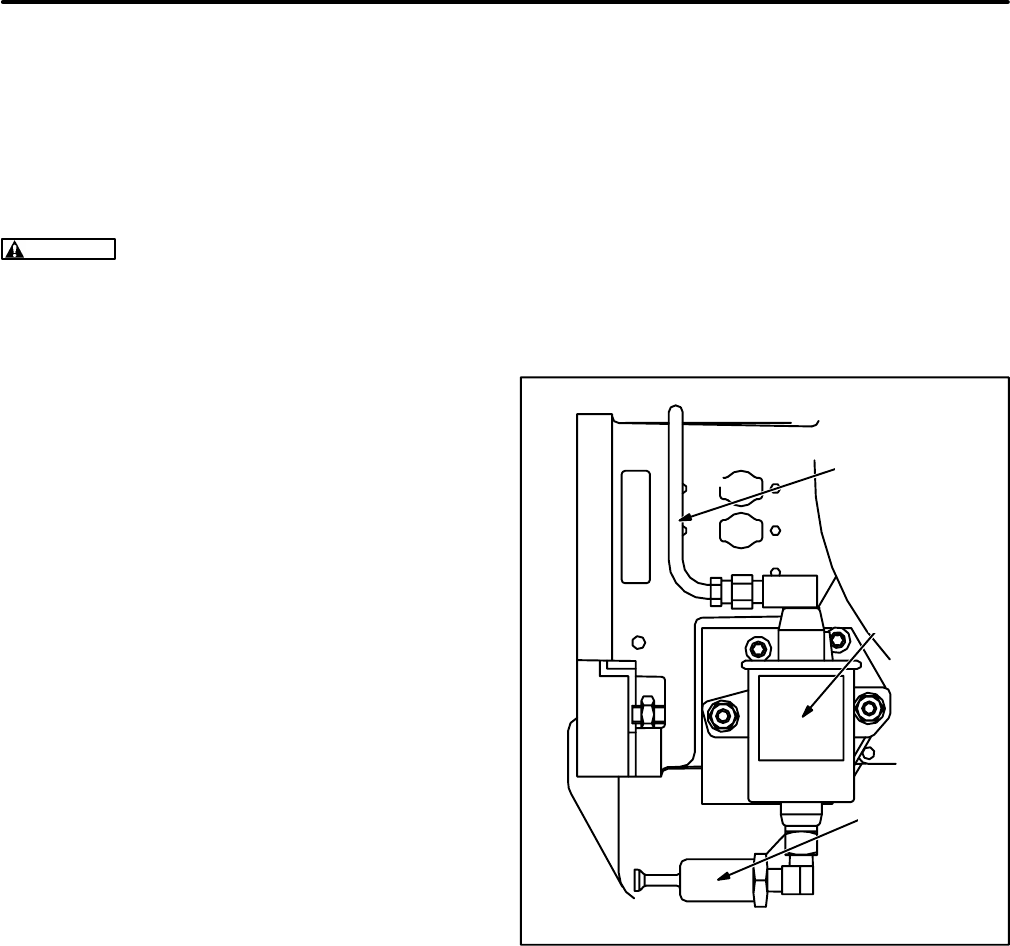
34
Fuel Pump (Gasoline Gensets)
See Figure 27. The fuel pump might be mounted on
the genset or at a remote location on the vehicle.
The pump delivers fuel to the carburetor at 3.5-5 psi
(24-35 kPa) and has a lift capacity (suction) of 3 feet
(0.9 meters).
WARNING
Do not substitute an automotive fuel
pump for the standard pump removed from the
genset. Other pumps can cause carburetor
flooding because of the high pressures they de-
velop. Carburetor flooding can cause poor per-
formance and engine damage and lead to pos-
sible fire and severe personal injury or death.
Fuel pressure at the carburetor fitting must not
exceed 6 psi (41 kPa) under any operating con-
dition.
Fuel Pressure Test:
1. Disconnect the fuel line at the outlet of the fuel
pump and connect a pressure gauge at the
pump outlet. A gauge calibrated for 0-15 psi
(0-100 kPa) is recommended. Do not tee into
the fuel line. This is a static pressure test.
2. Push the Start/Stop switch to START and hold
it there for several seconds until the fuel pres-
sure stabilizes. Fuel pressure should stabilize
between 3.5 and 6 psi (24 and 41 kPa).
3. Repeat the test with the vehicle engine running.
A fuel pressure greater than 6 psi (41 kPa) is not
acceptable. Find out why the pressure is high. If it is
high when the vehicle engine is not running, check
to see that the proper Onan supplied pump is being
used. If it is high when the vehicle engine is running,
a separate fuel pickup tube in the fuel tank, or equiv-
alent means, will be required.
If the fuel pressure is less than 3.5 psi (24 kPa),
check for fuel restrictions in the system. The pump
will have to be relocated closer to the fuel tank if it is
located more than 3 feet (0.9 meters) above the end
of the fuel pickup tube in the fuel tank. If the pump is
defective, replace it with the appropriate Onan
pump. The pump is not serviceable.
See the Installation Manual for important recom-
mendations regarding the fuel supply system.
FUEL
PUMP
FUEL
FILTER
FUEL LINE TO
CARBURETOR
FIGURE 27. MOUNTED FUEL PUMP
Redistribution or publication of this document,
by any means, is strictly prohibited.
Redistribution or publication of this document,
by any means, is strictly prohibited.

35
LPG System—Liquid Withdrawal
See Figure 28. For liquid withdrawal systems the
LPG container(s) must be equipped to withdraw
LPG as a liquid. See the Installation Manual for im-
portant recommendations regarding the installation
of a LPG liquid withdrawal type of fuel supply sys-
tem.
WARNING
LPG is flammable and explosive
and can cause asphyxiation. NFPA 58, Section
1.6 requires all persons handling LPG to be
trained in proper handling and operating proce-
dures.
It is important to understand that the fuel filter, sole-
noid shutoff valve, vaporizer and demand regulator
handle LPG liquid at the same pressure as in the
LPG container. Depending on ambient tempera-
ture, LPG container pressure can exceed 200 psi
(1379 kPa). Therefore, discharge or leakage from
LPG liquid-containing components can result in the
escape of large volumes of flammable and explo-
sive gas.
Purging the LPG System:
It is imperative that the
LPG system be purged before disconnecting fuel
system components.
WARNING
Large volumes of LPG can be re-
leased in the process of disconnecting a liquid-
withdrawal type of LPG supply system. See
Preparations (Page 12) for the proper proce-
dures and precautions.
LPG FILTER AND FUEL
SUPPLY CONNECTION
LPG VAPORIZER
COILS LPG FUEL SHUTOFF
SOLENOID
TWO-STAGE LPG
PRESSURE REGULATOR LPG FITTING AND HOSE
TO CARBURETOR
EXHAUST MANIFOLD
WITH BAFFLE
PRIMING
BUTTON
ONE OF TWO REGULATOR
MOUNTING SCREWS
FIGURE 28. LPG SYSTEM COMPONENTS FOR LIQUID WITHDRAWAL
Redistribution or publication of this document,
by any means, is strictly prohibited.
Redistribution or publication of this document,
by any means, is strictly prohibited.
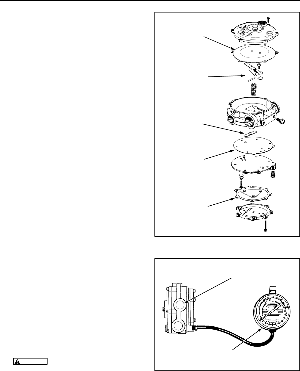
36
Demand Regulator:
See Figure 29. The two-stage
demand regulator delivers vaporized LPG to the
carburetor. The primary stage receives LPG vapor
(and liquid) at LPG container pressure and reduces
it to approximately 1.5 psi (10.3 kPa). The secon-
dary stage is a demand regulator that delivers LPG
vapor at the rate demanded by the carburetor.
The regulator should require little attention if the
genset is operated regularly. Most regulator mal-
function is due to:
•Hardened diaphragms and valve seats. The
pressure regulator in a genset that has been
operated and then stored for a long time might
require replacement because diaphragms,
gaskets and valve seats tend to shrink and
harden over time.
•Fuel impurities and oils dissolved in the liquid
LPG. Impurities can form granules that become
embedded in the secondary valve seat causing
it to leak and oils can clog passages inside the
regulator. The results could be hard starting, er-
ratic idling and poor load acceptance.
Testing the Demand Regulator:
Use compressed
air and a pressure gauge to test the regulator as fol-
lows:
1. Connect a pressure gauge to the test port on
the back of the regulator.
2. Connect a source of compressed air (at least
80 psi [550 kPa]) to the inlet opening and open
the air pressure valve.
3. If the primary valve is sound, the gauge will indi-
cate approximately 1.5 psi (10.3 kPa) and the
pressure will remain constant. Fluctuating
pressure indicates a leaking primary valve
seat.
4. Close the air pressure valve and observe the
pressure gauge. The pressure should remain
constant. If the pressure drops, the secondary
valve seat is leaking.
5. Disassemble and clean the regulator assembly
if it does not pass either test. Replace the regu-
lator if it still does not pass either test.
WARNING
Most parts cleaning solvents
are flammable and corrosive and can cause
severe burns and inflammation. Use only as
recommended by the manufacturer.
SECONDARY
DIAPHRAGM
PRIMARY
DIAPHRAGM
PRIMARY
GASKET
PRIMARY
VALVE
SECONDARY
VALVE
FIGURE 29. DEMAND REGULATOR ASSEMBLY
THE GAUGE SHOULD INDICATE APPROXIMATELY
1.5 PSI (10.3 KPA) AND HOLD STEADY
CONNECT THE INLET TO A
SOURCE OF COMPRESSED AIR
FIGURE 30. TESTING THE DEMAND REGULATOR
(LIQUID-WITHDRAWAL SYSTEM)
Redistribution or publication of this document,
by any means, is strictly prohibited.
Redistribution or publication of this document,
by any means, is strictly prohibited.

37
Fuel Filter:
See Figure 31. The fuel filter removes
rust and scale and other solid particles from the LPG
liquid to keep them from embedding in the valve
seats of the shutoff valve and pressure regulator
and causing them to leak. A magnet traps iron and
rust particles and a filter element traps non-magnet-
ic particles.
Disassembling and Cleaning the Fuel Filter:
1. Purge the LPG system as instructed on Page
12 before beginning disassembly.
2. Remove the four capscrews and lock washers
that hold the filter bowl to the filter body.
3. Separate the filter bowl from the filter body and
discard the O-ring seal.
4. Remove the nut and washer from the center
stud and pull out the filter element.
5. Wash the filter element in kerosene to remove
the particles it has collected. Blow it dry with low
pressure (30 psi / 207 kPa) compressed air. Re-
place the filter element if damaged.
6. Wipe the magnet clean of the particles it has
collected.
7. Install a clean filter element using two new gas-
kets and securely tighten the center stud nut.
8. Place a new O-ring in the filter bowl sealing
groove.
9. Align the reference mark on the filter bowl with
the reference mark on the filter body and torque
the capscrews to 65 lbs-in (7.2 N-m). Check for
and fix leaks at the filter when connections have
been made to the fuel supply system. The fuel
filter operates at fuel supply tank pressure.
Fuel Vaporizer:
The fuel vaporizer consists of sev-
eral wraps of tubing around the exhaust manifold.
Exhaust heat vaporizes the LPG liquid. The vaporiz-
er is not removable from the exhaust manifold.
WARNING
Bending the fuel vaporizer tubing
could weaken it to the point that it could crack
allowing fuel under high pressure to escape,
which could result in severe personal injury or
death.
Fuel Shutoff Solenoid Valve:
Test the fuel sole-
noid by disconnecting its long lead and jumpering it
directly to the battery positive (+) terminal on the
genset. Replace the solenoid if it does not “click”
open when it is powered.
FILTER
ELEMENT
GASKET
O-RING
SEAL
FILTER
BODY
MAGNET
FILTER
BOWL
GASKET
FIGURE 31. LPG FUEL FILTER
(LIQUID WITHDRAWAL SYSTEM)
Redistribution or publication of this document,
by any means, is strictly prohibited.
Redistribution or publication of this document,
by any means, is strictly prohibited.
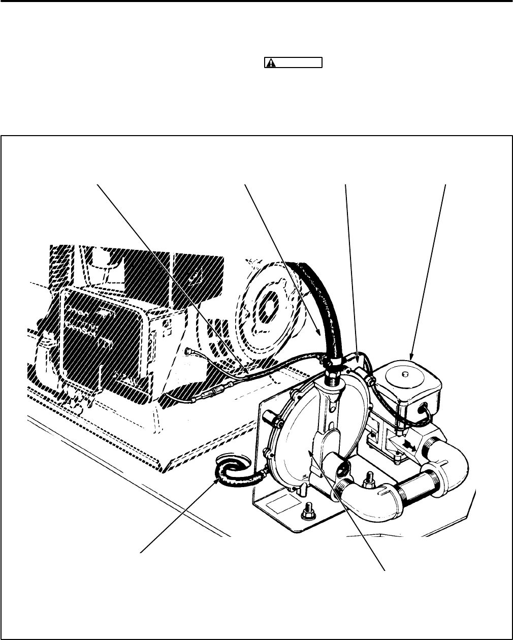
38
LPG System—Vapor Withdrawal
See the Installation Manual for important recom-
mendations regarding the installation of an LPG va-
por withdrawal type of fuel supply system. Gensets
equipped for vapor withdrawal of LPG must be
equipped with a fuel shutoff solenoid valve and de-
mand regulator. These are available as a kit for
mounting near the genset. See Figure 32.
WARNING
LPG is flammable and explosive
and can cause asphyxiation. NFPA 58, Section
1.6 requires all persons handling LPG to be
trained in proper handling and operating proce-
dures.
GAS SUPPLY HOSE TO
THE CARBURETOR INLET
DEMAND REGULATOR
(The regulator must be mounted such that
the diaphragm is in a vertical plane, as
shown, to maintain calibrated gas pressure.)
MOUNTING
BRACKET
VENT/PRESSURE-BALANCE HOSE
(Must extend outside the genset compartment to
prevent accumulation of LPG in compartment in the
event the diaphragm leaks and to prevent erratic fuel
delivery because of pressure fluctuations cause by
the cooling air flow through the compartment.)
SOLENOID PIGTAIL
CONNECTIONS AT THE GENSET FUEL SHUTOFF
SOLENOID VALVE
FIGURE 32. LPG SYSTEM COMPONENTS FOR VAPOR WITHDRAWAL
Redistribution or publication of this document,
by any means, is strictly prohibited.
Redistribution or publication of this document,
by any means, is strictly prohibited.

39
LPG Supply Pressure:
LPG supply pressure must
be maintained at 9-13 inches (229-330 mm) water
column (WC) under all conditions. Adjust the supply
pressure as follows:
1. Close the gas shutoff valve(s) at the LPG con-
tainer(s).
2. Remove the 1/8 inch pipe plug from the regula-
tor test port (Figure 33) and connect a manom-
eter calibrated in inches or mm WC having a
scale range of at least 14 inches (350 mm).
3. Open the LPG container shutoff valve and try
starting the genset.
4. While the genset is running, check the manom-
eter and adjust the LPG supply pressure regu-
lator to obtain 11 inches (279 mm) WC. (If there
is a secondary pressure regulator in the supply
line, adjust the secondary regulator instead of
the primary regulator at the LPG container.)
5. If the genset will not start, jumper the fuel sole-
noid to the battery cable connections on the
genset so that it stays open (the regulator will
keep gas from flowing)and then check and ad-
just the LPG supply pressure.
6. If the genset is operable, check LPG supply
pressure under full load. If it drops below the
minimum required pressure, either the LPG
container is too small to provide the rate of va-
porization necessary or it is less than half full or
the supply line is too restrictive.
7. Disconnect any jumpers which may have been
used to energize the fuel solenoid and thread
in and tighten the pressure test port plug unless
tests are going to be continued.
Fuel Shutoff Solenoid Valve:
Replace the fuel so-
lenoid if it fails to open (as indicated by the absence
of gas pressure on the manometer scale in the pre-
vious test) when it is jumpered across the the bat-
tery cable connections at the genset.
Demand Regulator Lock-Off Pressure Test:
Lock-off pressure is determined as follows by pres-
surizing the back (vent) side of the regulator dia-
phragm to simulate carburetor venturi vacuum:
1. Continue with the test setup for adjusting LPG
supply pressure shown in Figure 33. If the regu-
lator is being tested on the bench, connect it to
a source of air pressure regulated to 11 inches
(280 mm) WC.
CAUTION
If this is a bench test of the regu-
lator, make sure the diaphragm is in a verti-
cal plane (see Figure 32), otherwise the
weight of the diaphragm will cause erro-
neous readings of lock-off pressure.
2. “T” in two hoses to the end of the hose con-
nected to the regulator vent fitting (3/8 inch
I. D.). Use one hose to provide the test pres-
sure and the other to measure pressure by con-
necting it to an inclined manometer calibrated
with 0.01 inch or 0.1 mm divisions and having
a range of at least 1 inch (25 mm).
3. Disconnect the hose to the carburetor and at-
tach a soap bubble to the regulator outlet hose
fitting. While reading the pressure indicated by
the inclined manometer and watching the soap
bubble, blow lightly into the hose being used to
pressurize the regulator. Regulator lock-off
pressure is the minimum pressure that will
cause gas to flow through the regulator, as indi-
cated by the expanding soap bubble. (At first
the soap bubble may expand due to diaphragm
movement but will stop expanding if gas or air
is not flowing through the regulator.)
For Gensets Beginning Spec L:
Replace the
demand regulator if the lock-off pressure does
not fall between 0.15 and 0.25 inch WC (3.8
and 6.4 mm WC).
WARNING
Unauthorized modifications or
replacement of fuel, exhaust, air intake or
speed control system components that af-
fect engine emissions are prohibited by law
in the State of California.
Redistribution or publication of this document,
by any means, is strictly prohibited.
Redistribution or publication of this document,
by any means, is strictly prohibited.
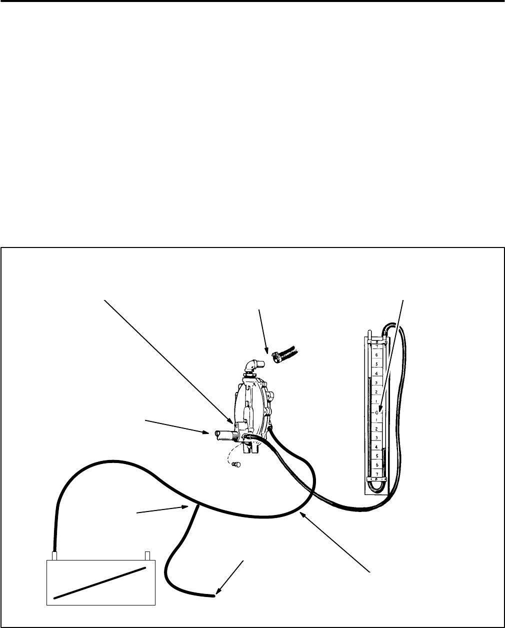
40
For Gensets Prior to Spec L:
Adjust lock-off
pressure as follows:
•If the lock-off pressure is greater than 0.25
inches (6.4 mm) WC, remove the locking
screw and back out the adjusting screw
(counterclockwise) until the lock-off pres-
sure falls between 0.15 and 0.25 inch WC
(3.8 and 6.4 mm WC). Set the locking
screw and test lock-off pressure again. Re-
peat the procedure if necessary.
•If the lock-off pressure is less than 0.15
inch (3.8 mm) WC, remove the locking
screw and turn in the adjusting screw
(clockwise) until the lock-off pressure falls
between 0.15 and 0.25 inch WC (3.8 and
6.4 mm WC). Set the locking screw and
test lock-off pressure again. Repeat the
procedure if necessary.
•Replace the demand regulator if it contin-
ues to leak after lock-off pressure adjust-
ments have been attempted.
4. If the genset is mounted in a compartment,
make sure the vent/pressure-balance hose is
routed properly to the outside.
5. Reconnect the hose to the carburetor, discon-
nect any jumpers which may have been used
to energize the fuel solenoid and thread in and
tighten the pressure test port plug.
6. For gensets prior to Spec L, adjust fuel mixture
as instructed under Governor and Carburetor
Adjustments in this section.
LPG OUTLET TO
CARBURETOR
(Place soap bubble on
end of hose fitting)
MANOMETER
(Connected to LPG supply
pressure test port)
LOCK-OFF ADJUSTING SCREW
(Beginning Spec L, this screw is
not accessible for adjustments)
INCLINED
MANOMETER
HOSE “T” FOR
TESTING
for test
PRESSURE
VENT/PRESSURE-BALANCE HOSE
(See Figure 32 for a view of the vent hose
fitting when it is located on the other side.)
LPG INLET
(11 inch WC pressure)
FIGURE 33. LPG SUPPLY PRESSURE AND REGULATOR LOCK-OFF PRESSURE
Redistribution or publication of this document,
by any means, is strictly prohibited.
Redistribution or publication of this document,
by any means, is strictly prohibited.
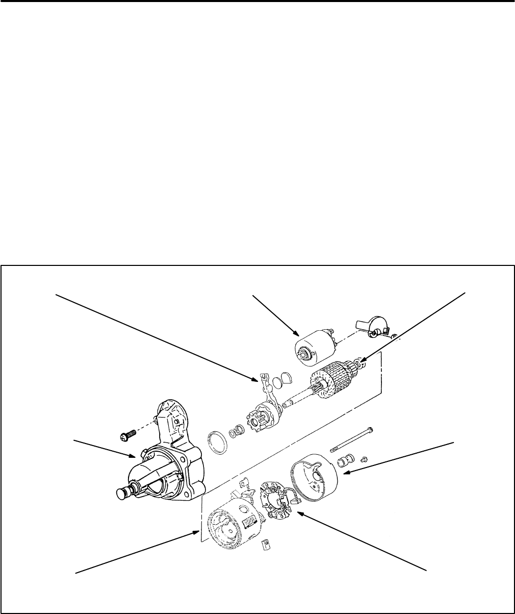
41
ELECTRIC STARTER
Starter motor parts replacement kits are available
for Spec J gensets. Starter motor assembles for
Spec H gensets do not have any replaceable or ser-
viceable parts, requiring that the entire starter motor
assembly be replaced if it does not work.
Starter Removal and Replacement
To remove the starter for service or replacement:
1. Disconnect the negative (-) cable from the
starting battery.
2. Disconnect all wires and cables from the motor
terminals.
3. Remove the two starter mounting bolts and re-
move the starter.
Replacement is the reverse of removal. Torque the
mounting bolts to specifications.
Starter Assembly and Disassembly
(Beginning Spec J)
See Figure 34. Remove the starter from the genset.
Remove the solenoid before disassembling the mo-
tor and remount if after assembling the motor. When
mounting the solenoid make sure the plunger is
hooked by the shift fork. The drive housing, motor
frame and end bell are separable after the motor
through bolts have been removed. Before loosening
the through bolts, however, scratch register lines on
the drive housing, motor frame and end bell so that
these parts can be easily reassembled the same
way relative to each other. While removing the end
bell, be prepared to catch the brush springs, which
tend to spring loose.
END BELL
BRUSH
ASSEMBLY
SOLENOIDSHIFT FORK ARMATURE
PINION DRIVE
HOUSING
MOTOR
FRAME
FIGURE 34. SOLENOID SHIFT STARTER (BEGINNING SPEC J)
Redistribution or publication of this document,
by any means, is strictly prohibited.
Redistribution or publication of this document,
by any means, is strictly prohibited.
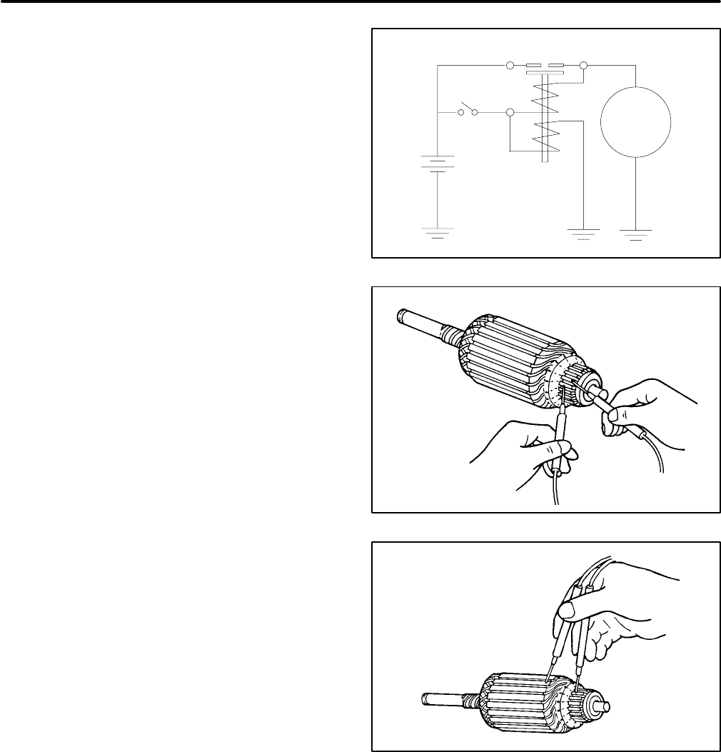
42
Solenoid
Refer to Figure 35. Before replacing the solenoid,
confirm that it is the cause of the starter not working
by removing it from the starter assembly and con-
ducting the following tests.
1. Connect 6 volt battery positive (+) to solenoid
terminal S and battery negative (-) to solenoid
terminal M. The plunger should pull in and hold
in strongly. If it does not, replace the solenoid.
2. Connect 6 volt battery positive (+) to solenoid
terminal S and battery negative (-) to the body
of the solenoid. Push the plunger in and release
it. The plunger should stay in. If it does not, re-
place the solenoid.
3. Connect 12 volt battery positive (+) to solenoid
terminal M and battery negative (-) to the sole-
noid body (reversed from normal polarity).
Push the plunger in and release it. The plunger
should push back out immediately. If it does
not, replace the solenoid.
Armature
Winding Integrity:
Refer to Figure 36. Use an ohm-
meter to check for electrical continuity between
pairs of commutator segments all the way around
the commutator. Make sure each segment is
checked. Replace the armature if a winding is open
(high resistance) at any segment.
Winding Insulation:
Refer to Figure 37. Use an
ohmmeter to check for winding insulation break-
down between the windings and the rotor lamina-
tions. Replace the armature if the ohmmeter does
not indicate high resistance on its highest scale be-
tween any commutator segment and the rotor lami-
nations.
MOTOR
SOLENOID
BM
S
+
-
FIGURE 35. SOLENOID-MOTOR CIRCUITS
FIGURE 36. CHECKING WINDING INTEGRITY
FIGURE 37. CHECKING WINDING INSULATION
Redistribution or publication of this document,
by any means, is strictly prohibited.
Redistribution or publication of this document,
by any means, is strictly prohibited.
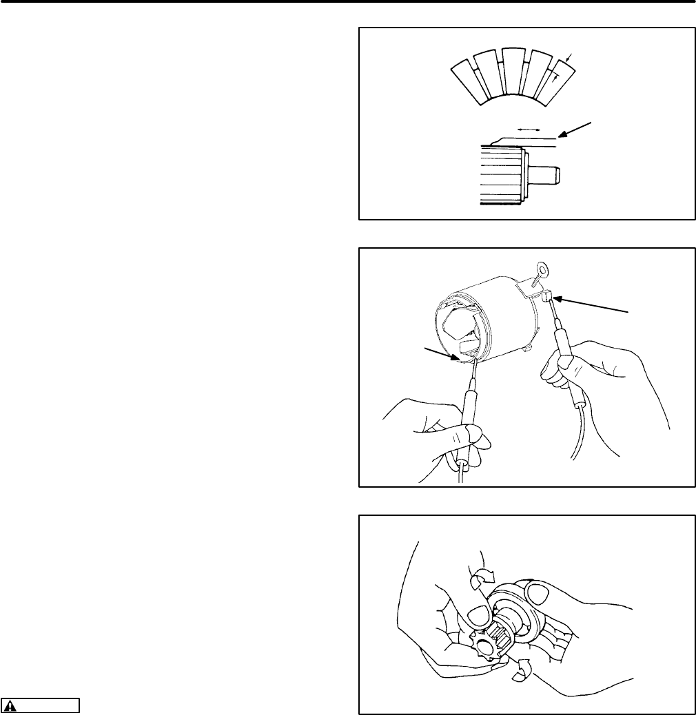
43
Commutator:
Clean the commutator surface with
sandpaper. Measure the diameter at several loca-
tions around the commutator. Turn the commutator
in a lathe if it is not round or has deep pits. Replace
the armature if it is necessary to turn the diameter of
the commutator to less than 1-1/16 inch (27 mm).
Using a hacksaw blade, undercut the mica between
the commutator segments by 1/32 inch and chamfer
the edges of the segments slightly. See Figure 38.
Brush Assembly
Replace the motor frame and brush assembly if any
brush is less than 0.43 inch (11 mm) long.
Motor Frame and Stator
Refer to Figure 39. Two of the four brushes are con-
nected directly to the stator windings, one to each
pair of windings. The other ends of the two pairs of
stator windings are crimped to the motor frame
(grounded). To check the integrity of each winding
pair, use an ohmmeter to check for continuity be-
tween its brush and the motor frame. Replace the
motor frame if either winding pair is open (high re-
sistance). (This test will not detect if a single winding
of a pair is open. If the windings look burnt or smell
bad, it is recommended that the motor frame be re-
placed.)
Pinion
Refer to Figure 40. Replace the pinion assembly if
the pinion teeth and armature shaft splines are worn
or damaged. Check the over-running clutch by ro-
tating the pinion clockwise and counterclockwise.
Replace the pinion assembly if it does not turn
smoothly counterclockwise or lock clockwise.
WARNING
Do not clean the pinion overrunning
clutch with any kind of cleaning solution, other-
wise it may be damaged.
MICA
UNDERCUT
SAW
BLADE
FIGURE 38. COMMUTATOR MICA UNDERCUT
BRUSH
MOTOR
FRAME
FIGURE 39. CHECKING MOTOR FRAME WINDINGS
FIGURE 40. CHECKING OPERATION OF THE PIN-
ION OVER-RUNNING CLUTCH
Redistribution or publication of this document,
by any means, is strictly prohibited.
Redistribution or publication of this document,
by any means, is strictly prohibited.
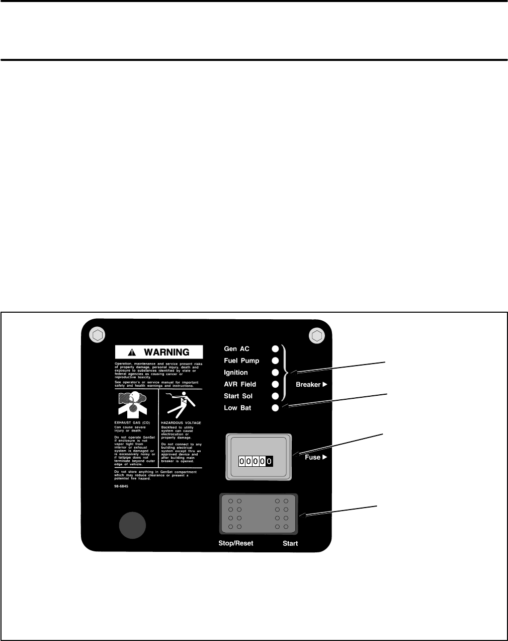
44
Engine Control
The engine control system provides a means to
start, run and stop the engine, automatically disen-
gage the starter, recharge the battery, automatically
shut down the genset in the event of low oil pressure
and start, stop and monitor the genset from the cab
or other location.
CONTROL SYSTEM (BEGINNING SPEC J)
See
Wiring Diagrams
for the appropriate schematic
and connection diagrams.
Control Components
The control system consists of the following compo-
nents:
Control Panel:
See Figure 41. The Start-Stop/Re-
set switch, hour meter and indicator lights are
mounted on the control panel. Control board A1 and
start relay K5 are mounted on the back of the control
panel. Only start relay K5 is separable from the con-
trol panel assembly for replacement.
Start-Stop/Reset Switch (S1):
This is a momen-
tary-contact type switch mounted as an integral part
of the control panel.
Fuse (F1):
This is a 10 amp mini-bayonet type fuse
mounted on the side of the control box to protect
printed circuit board A1 from overcurrent.
Start Relay (K5):
The starter solenoid (K6) is ener-
gized by the control board (A1) through this relay. It
is mounted in a socket on the back of the control
panel.
GREEN
LEDS
RED
LED
HOUR
METER
STOP/RESET-START
SWITCH
Cranking:
•Gen AC LED (green) will be OFF
•Fuel Pump LED (green) will be ON
•Ignition LED (green) will be ON
•AVR Field LED (green) will be ON
•Start Sol LED (green) will be ON
•Low Bat LED (red) MAY flash ON
Genset started and running:
•Gen AC LED (green) will be ON
•Fuel Pump LED (green) will be ON
•Ignition LED (green) will be ON
•AVR Field LED (green) will be OFF
•Start Sol LED (green) will be OFF
•Low Bat LED (red) will be OFF
FIGURE 41. CONTROL PANEL (BEGINNING SPEC J)
Redistribution or publication of this document,
by any means, is strictly prohibited.
Redistribution or publication of this document,
by any means, is strictly prohibited.

45
Starter Solenoid (K6):
The starter solenoid is part
of the starter motor assembly. It engages the starter
pinion and connects the starter motor to the battery
for cranking.
Hour Meter:
The hour meter is mounted as an inte-
gral part of the control panel. It is not resettable.
Ignition Coil T1:
The ignition coil provides spark for
igniting the fuel.
Gasoline Fuel Pump (E2):
The fuel pump lifts gas-
oline from the supply tank and delivers it under pres-
sure to the carburetor. A fuel shutoff solenoid may
also have been connected in parallel to the fuel
pump by the customer to prevent fuel spillage in the
event the vehicle rolls over.
LPG Shutoff Solenoid (FS):
The LPG shutoff sole-
noid closes against fuel supply pressure when it is
de-energized.
Choke Heater H1:
The choke heater opens the
choke to the full-open run position (gasoline gen-
sets only).
Low Oil Pressure Cutout Switch (S2):
This switch
opens in the event engine lubricating oil pressure
drops below 5 psi (34 kPa) to de-energize the run
relay and shutdown the genset.
PMG:
The PMG provides power for recharging the
cranking battery (through VR2) during operation of
the genset and a signal for the control board (A1) for
start disconnect. See
Engine Subsystems
for de-
tails.
Battery Charging Regulator (VR2):
The battery
charging regulator recharges the battery while the
genset is running. It is connected to the PMG. The
regulator limits output to 14.2 volts and 10 amps.
Remote Control (A2, A3—Optional):
The remote
control is an optional accessory that enables the
genset to be operated from a remote location.
Sequence Of Operation
See
Wiring Diagrams
for the appropriate wiring
schematic while working through the following de-
scription.
1. Holding Start-Stop switch S1 at Start causes:
Start Relay K5 to energize starter motor sole-
noid K6 to crank the engine. (Green light)
Fuel Pump E1 or Fuel Solenoid FS to pump
fuel or open to allow fuel to flow. (Green light)
Ignition Coil T1 to provide ignition spark. The
engine should start. (Green light)
Battery Current to build up the generator field
(through AC voltage regulator VR1) for fast
build-up of generator output voltage. (Green
light)
Choke Heater H1 to start opening the choke to
the full-open running position.
2. Low oil pressure cutout switch S2 should close
as soon as the engine starts up. It must close
before the genset can continue to run.
3. PMG output builds up right away and provides
a signal for the control board to disconnect the
starter even if the Start switch is still being held
in the start position.
4. The genset will continue to run when Start-Stop
switch S1 is released. The green Generator AC
light should come on.
5. The red Low Battery light will probably come on
during cranking, but should go off during opera-
tion.
6. Momentarily pushing Start-Stop switch S1 to
Stop deactivates the ignition and fuel systems
to cause the genset to shut down.
Troubleshooting
The indicator lights on the control panel should be
used in conjunction with
Troubleshooting
to narrow
the search for the problem. If, for example, the Fuel
Pump or Ignition light is on but it has been deter-
mined that there is no fuel or no ignition spark, the
problem is not in the control board but in the rest of
the circuit.
Redistribution or publication of this document,
by any means, is strictly prohibited.
Redistribution or publication of this document,
by any means, is strictly prohibited.
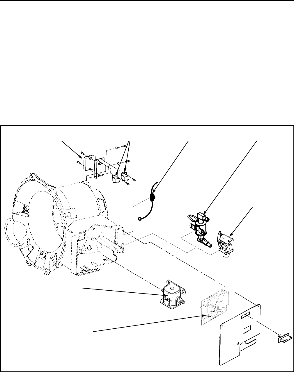
46
CONTROL SYSTEM (SPEC H ONLY)
See Figure 42 and
Wiring Diagrams
. The control
system consists of the following components:
Printed Circuit Board (A1):
The printed circuit
board includes the relays (K2, K3 and K4), switch
(S1) and circuits necessary to start, run and stop the
genset, automatically disconnect the starter, shut-
down the genset in the event of low oil pressure and
connect to a remote control circuit. It is mounted on
the back of the control panel.
Start-Stop Switch (S1):
This is a rocker switch
mounted on the printed circuit board to start and
stop the genset. The switch returns to the center
(run) position when released. It is not separately re-
placeable.
Fuse (F1):
This is a 5 amp fuse to protect printed cir-
cuit board A1 from overcurrent. It is removable from
the front of the control panel. Spare fuses are inside
the fuse holder.
Fuse (F2):
This is a 10 amp fuse to protect the igni-
tion and choke heater circuits.
Start Solenoid (K1):
The start solenoid closes the
battery to the starter motor during cranking, han-
dling up to 300 amps. It includes the battery B+ ter-
minal which is readily accessible from the front for
connecting the positive (+) battery cable.
BATTERY CHARGING VOLTAGE
REGULATOR (VR2)* RELAYS
(K5 AND K6)* FUEL PUMP (E2)
(GASOLINE)
FUEL
SOLENOID (E2)
AND FILTER
(LPG LIQUID
WITHDRAWAL)
CONTROL BOARD (A1)
WITH FUSE (F1) AND
START-STOP SWITCH (S1)
START SOLENOID
(K1)
FUSE
(F2)
CIRCUIT BREAKER (CB4)*
LOCATED INSIDE BOX
(NOT SHOWN)
* - VR2, K5, K6 AND CB4 ARE MOUNTED ON THE OUT-
PUT VOLTAGE REGULATOR (VR1) BRACKET ON
3-PHASE GENSETS
FIGURE 42. TYPICAL CONTROL COMPONENTS (SPEC H ONLY)
Redistribution or publication of this document,
by any means, is strictly prohibited.
Redistribution or publication of this document,
by any means, is strictly prohibited.

47
Stop Relay (K5):
This relay latches the control to
prevent the genset from restarting when the Start-
Stop switch is momentarily pushed to STOP and
then released.
Ignition Relay (K6):
This relay closes to energize
the ignition and choke heater circuits. It is not pro-
vided on LPG gensets.
Gasoline Fuel Pump (E2):
The fuel pump lifts gas-
oline from the supply tank and delivers it under pres-
sure to the carburetor.
LPG Shutoff Solenoid (FS):
The LPG shutoff sole-
noid closes against fuel supply pressure when it is
de-energized.
Battery Charging Regulator (VR2):
The battery
charging regulator recharges the battery while the
genset is running. It is connected to generator termi-
nals B1 and B2 which provide power to the regulator
at 19-21 VAC. The regulator limits output to 10
amps.
Low Oil Pressure Cutout Switch (S2):
This switch
opens in the event engine lubricating oil pressure
drops below 5 psi (34 kPa) to de-energize the run
relay and shutdown the genset.
Battery Charging Circuit Breaker (CB4):
This is a
thermal-type, automatic-reset circuit breaker to pro-
tect the charging circuit. On 1-phase gensets it is lo-
cated inside the control box and is tied to the leads
from battery charging regulator VR2. On 3-phase
gensets it is mounted on the bracket for output volt-
age regulator VR1.
Remote Control (A2, A3—Optional):
The remote
control is an optional accessory that enables the
genset to be operated from a remote location. The
deluxe control includes a running time meter and
battery condition meter.
Sequence Of Operation
See
Wiring Diagrams
for the appropriate wiring
schematic while working through the following de-
scription.
1. Holding Start-Stop switch S1 at Start causes
relay K4 on control board A1 to pull in, causing
the following components to be energized by
the battery:
Start Solenoid K1 - The engine should crank.
Fuel Pump E1 or Fuel Solenoid FS - The
electric fuel pump should start pumping gaso-
line or the LPG fuel solenoid should open.
Relay K5 - Relay K5 opens to energize run
relay K3.
Relay K6 - Relay K6 closes to energize the
ignition (T1) and choke heater (H1) circuits.
The engine should start.
Generator Field - Battery current energizes
the generator field (through AC voltage regula-
tor VR1) for fast build-up of generator output
voltage.
2. Low oil pressure cutout switch S2 should close
as soon as the engine starts up. It must be
closed before run relay K3 can be energized
and must stay closed to keep the engine run-
ning.
3. Start disconnect relay K2 on control board A1
pulls in as soon as generator voltage builds up.
It causes start relay K4 to drop out, disconnects
the field from the battery and causes run relay
K3 to pull in. When K4 drops out, it cause K1
to drop out, disconnecting the starter. When K3
pulls in, it keeps the fuel and ignition circuits ac-
tive so that the genset will continue to run.
4. The genset will continue to run when Start-Stop
switch S1 is released and returns to its center
(run) position. If the switch is held in after the
genset has started, relay K2 will still cause the
starter to be disconnected.
5. Momentarily pushing Start-Stop switch S1 to
Stop causes run relay K3 to drop out, causing
the ignition and fuel circuits to deactivate, shut-
ting down the genset. Relay K5 also drops out,
closing its contacts to keep relay K3 out, pre-
venting the genset from restarting if it has not
stopped before S1 is released.
Redistribution or publication of this document,
by any means, is strictly prohibited.
Redistribution or publication of this document,
by any means, is strictly prohibited.
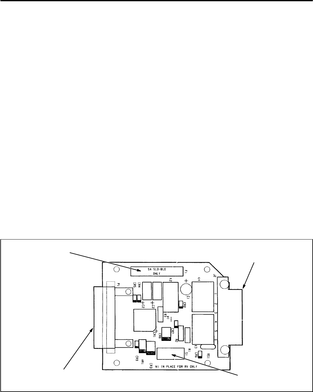
48
Testing Control Board A1 (Spec H Only)
Confirm that control board A1 (Figure 43) is faulty
before replacing it. Use a DC voltmeter and an ohm-
meter to perform the following tests:
1. Disconnect the negative (-) battery cable.
2. Remove the control panel and separate control
board A1 from it by removing the four mounting
screws.
3. With an ohmmeter check for good electrical
contact between each pin and jack of connector
P1-J1. To test a connection, touch one meter
probe to the back of the pin, which is bare. Dis-
connect the fast-on connector on the other end
of the lead connected to the J1 jack and touch
the other meter probe to the connector.
Reconnect the lead before checking the next
connection to minimize the possibility of mak-
ing wrong reconnections.
Replace the connector jack/lead assembly if
the jacks are corroded or there is measurable
resistance (greater than zero ohms) at any con-
nection.
4. Reconnect the battery and try to start and run
the genset.
5. If the engine does not crank, disconnect the
fast-on connector on the end of the connector
PI-J1 lead marked K1-S/J1-9. Measure volt-
age between the connector on the end of the
lead and a good engine ground while pressing
the panel start switch. If the voltmeter indicates
zero volts, check fuse F1 on the control board.
If it is good, replace control board A1. If the volt-
meter indicates at least 9 volts, the problem is
not in the control board. Go to
Troubleshooting.
6. If the engine cranks but does not start, discon-
nect the fast-on connectors on the ends of the
connector P1-J1 leads marked J6/J1-6 and
E2/J1-12. Measure voltage between the con-
nector on the end of each lead and a good en-
gine ground while pressing the panel start
switch. Replace control board A1 if the voltme-
ter indicates zero volts at either connector. If the
voltmeter indicates at least 9 volts at both con-
nectors, the problem is not in the control board.
Go to
Troubleshooting.
7. If the engine starts but stops when the panel
start switch is released, the problem could be
low oil pressure, a faulty low oil pressure cutoff
switch or no generator output voltage. Go to
Troubleshooting.
Replace control board A1 if
oil pressure, switch and generator are normal.
FUSE
F1 CONNECTOR P2-J2 FOR
REMOTE CONTROL
CONNECTIONS
START-STOP
SWITCH S1
CONNECTOR P1-J1 FOR
BATTERY, GENERATOR AND
CONTROL CONNECTIONS
FIGURE 43. CONTROL BOARD A1 (SPEC H ONLY)
Redistribution or publication of this document,
by any means, is strictly prohibited.
Redistribution or publication of this document,
by any means, is strictly prohibited.
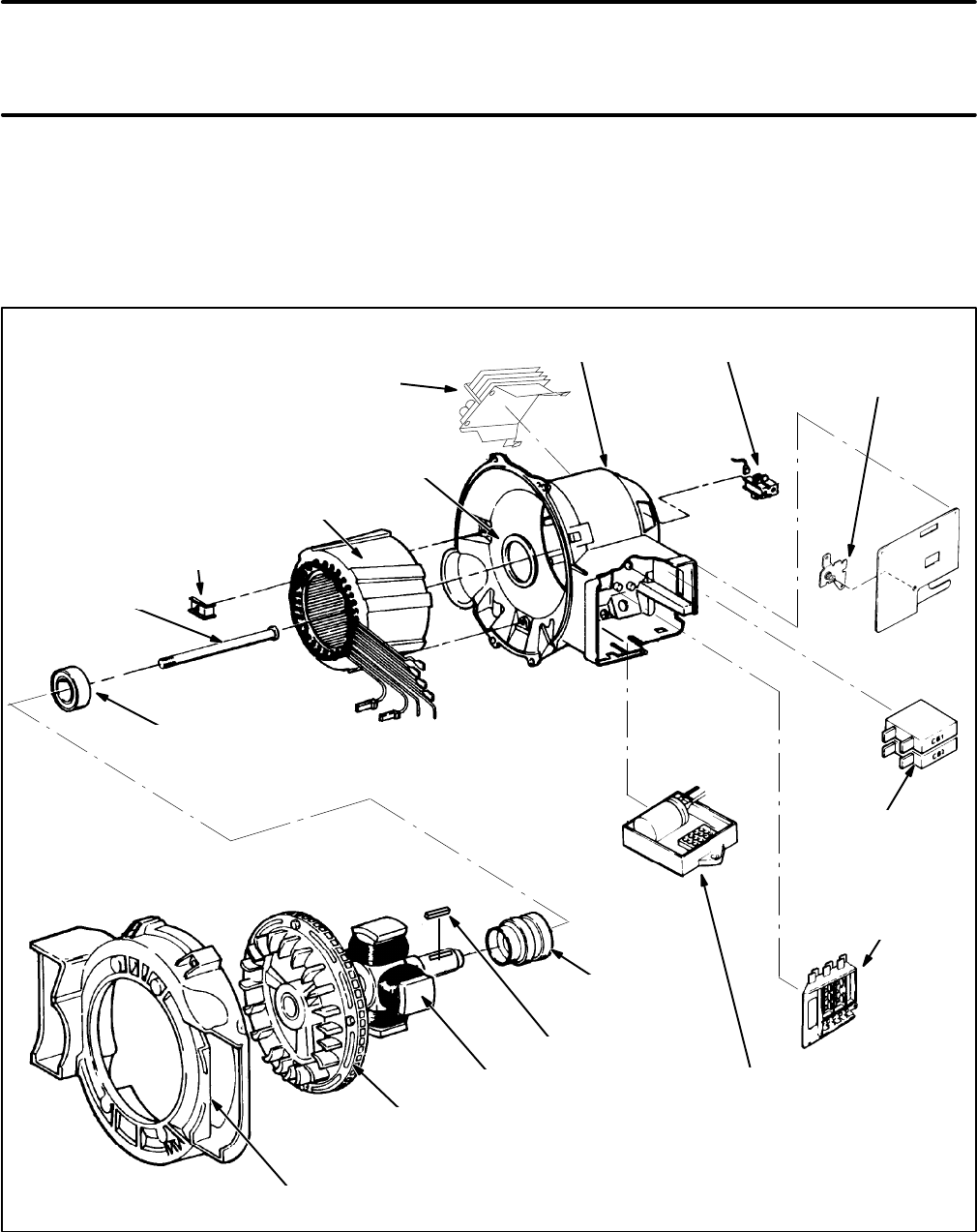
49
Generator
These are 4-pole, revolving-field generators with
slip rings and electronic voltage regulators. Single-
phase generators have quadrature windings and
three-phase generators main winding taps for field
excitation. Spec H generators have auxiliary wind-
ings for battery charging. The generator rotor and
engine crankshaft have a tapered coupling secured
by the rotor through-bolt. The other end of the rotor
is supported in a sealed, pre-lubricated ball bearing
assembly. The cooling blower wheel and starter ring
gear are part of the rotor assembly. See Figure 44.
ROTOR END
BEARING
STATOR
CLAMP
STATOR
O-RING
BRUSH BLOCK
ASSEMBLY
TERMINAL
BOARD TB1
SLIP
RINGS
ENGINE-TO-GENERATOR
ADAPTER HOUSING
ROTOR SPEC H 1-PH VOLTAGE REGULATOR
SPEC J 1-PH VOLTAGE REGULATOR IS
MOUNTED ON THE DRIP PAN (FIGURE 2)
SPEC J 1 PH, 50 HZ HAS AN ISOLATION
TRANSFORMER FOR VOLTAGE REFERENCE
MOUNTED AT THIS LOCATION
COOLING BLOWER
WHEEL AND STARTER
RING GEAR
GENERATOR
HOUSING
ROTOR
THROUGH-BOLT
THREE-PHASE VOLTAGE REGULATOR WITH
VOLTAGE ADJUSTING POTENTIOMETER
(A STEP-DOWN VOLTAGE REFERENCE
TRANSFORMER IS MOUNTED ON THE DRIP
PAN BEGINNING SPEC J)
SINGLE-PHASE
VOLTAGE
ADJUSTING
POTENTIOMETER
LINE CIRCUIT
BREAKERS
(CB1, CB2, CB3)
KEY
FIGURE 44. GENERATOR COMPONENTS
Redistribution or publication of this document,
by any means, is strictly prohibited.
Redistribution or publication of this document,
by any means, is strictly prohibited.
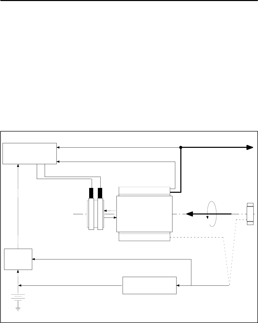
50
BASIC GENERATOR OPERATION
Refer to Figure 45 and to
Wiring Diagrams
while
working through the following description of opera-
tion:
1. Voltage regulator VR1 supplies DC power to
the main rotor (field) windings through the
brushes and slip rings. A rotating, four-pole
magnetic field is thereby established that in-
duces AC in the stator windings. Quadrature
windings are provided for single-phase genera-
tors to power the voltage regulator. The main
windings provide power for the voltage regula-
tor on three-phase generators.
2. While the governor matches engine output to
the load, maintaining a constant speed (fre-
quency), the voltage regulator senses output
voltage and adjusts field current to maintain a
constant output voltage.
3. During startup, the voltage regulator is pow-
ered by the battery for fast generator voltage
buildup. Control board A1 disconnects the volt-
age regulator from the battery at the same time
that it disconnects the starter. See
Engine Con-
trol
.
4. Beginning Spec J, a PMG on the other end of
the engine crankshaft from the generator sup-
plies power for charging the battery through
voltage regulator VR2. Spec H gensets have
separate generator stator windings for charg-
ing the battery through voltage regulator VR2.
The battery charging output signal is also used
for start disconnect. See
Engine Control
.
+-
FIELD FLASHING
OUTPUT VOLTAGE SIGNAL*** AC POWER OUTPUT
AC POWER FOR REGULATOR(1-PH)
START DISCONNECT SIGNAL
BATTERY CHARGING CURRENT
MAIN STATOR (G1)
MAIN ROTOR
(FIELD)
CHARGING VOLTAGE
REGULATOR (VR2)
ENGINE
CONTROL
(A1)
AC OUTPUT VOLTAGE
REGULATOR (VR1)
DC FIELD POWER
BRUSHES AND
SLIP RINGS
ROTATING
MECHANICAL
POWER INPUT
OF ENGINE PMG*
CURRENT DURING CRANKING
B1/B2 WINDINGS**
*** - BEGINNING SPEC J, 1-PH 50 HZ AND 3-PH USE VOLTAGE REFERENCE TRANSFORMER T2.
* - BEGINNING SPEC J
** - SPEC H ONLY
AC POWER FOR REGULATOR (3-PH)
FIGURE 45. SCHEMATIC OF GENERATOR OPERATION
Redistribution or publication of this document,
by any means, is strictly prohibited.
Redistribution or publication of this document,
by any means, is strictly prohibited.
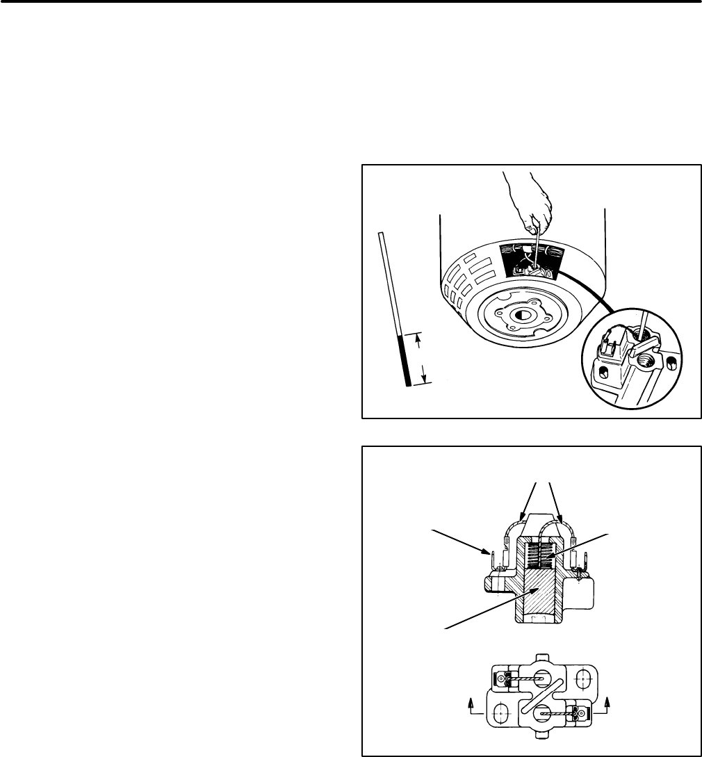
51
SERVICING BRUSHES AND SLIP RINGS
Remove the air cleaner and the brush block cover
and inspect for burned brushes and grooved or
pitted slip rings and any other damage. (Turn the ro-
tor with a 3/8 inch allen wrench to be able to inspect
all the way around the slip rings.)
If everything looks good, check brush wear with a
piece of wire marked off as shown in Figure 46. Re-
place the brushes and brush springs if the wire can
be inserted more than 1 inch (25 mm) into the hole in
the brush holder. (Make sure the wire rests on top of
the brush and not on part of the brush spring.)
If the slip rings are grooved or pitted it might be pos-
sible to clean them up with a commutator stone. If
the slip rings are worn and need to be replaced, see
Removing and Replacing the Slip Ring Assembly
under GENERATOR ASSEMBLY/DISASSEMBLY
in this section.
To replace the brushes or to clean up the slip rings:
1. Disconnect the leads marked F1 and F2 from
the brush block terminals.
2. Remove the brush block mounting screws and
lift out the brush block assembly.
3. If the slip rings need to be cleaned up, insulate
the ends of leads F1 and F2, disconnect all
leads from the positive (+) terminal of the igni-
tion coil to keep the engine from starting, hold
the commutator stone lightly against the slip
rings and crank the engine for 3 to 6 seconds.
Check the slip rings and repeat the procedure
as necessary until the pits and groves have
been removed.
4. Replace the brushes and brush springs with
new parts. Connect each brush pigtail to the
terminal on its side of the insulating divide (Fig-
ure 47).
5. Remount the brush block. Center the brushes
on the slip rings before tightening the mounting
screws.
6. Reconnect the lead marked F1 to the outboard
brush terminal and the lead marked F2 to the in-
board brush terminal and secure the cover and
air cleaner.
1 IN. (25 mm)
FIGURE 46. CHECKING BRUSH WEAR
BRUSH
SPRING
BRUSH
LEAD
TERMINALS
BRUSH
PIG TAILS
FIGURE 47. BRUSH BLOCK ASSEMBLY
Redistribution or publication of this document,
by any means, is strictly prohibited.
Redistribution or publication of this document,
by any means, is strictly prohibited.
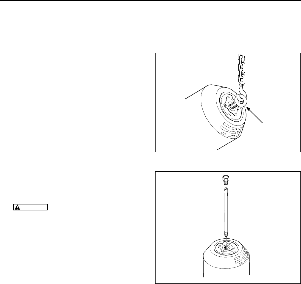
52
REMOVING/REMOUNTING GENERATOR
Removing the Generator from the Genset
1. Drain the engine oil while the genset is
mounted in the vehicle. (Oil will spill out when
the genset is tipped up on end to remove the
generator unless the oil has been drained.)
2. Remove the genset from the vehicle and place
it on a sturdy work bench. See
Preparing for
Service
.
3. Remove the blower housing so that the genset
can be rested flat on the blower wheel. See EN-
GINE COOLING SYSTEM in
Engine Subsys-
tems
for instructions.
4. Disconnect the fuel line at the carburetor.
5. Disconnect the leads at the low oil pressure cut
off switch and B+ terminal of the ignition coil.
6. Use a 3/8 inch allen wrench and rubber mallet
to remove the rotor through-bolt.
7. Thread a 9/16-12 eyebolt into the end of the ro-
tor and tip the genset up with a hoist until it rests
squarely on the blower wheel. See Figure 48.
CAUTION
Do not lift the genset with the
eyebolt. The weight of the genset could
cause the tapered crankshaft-rotor fit to
break loose, leading to generator damage.
8. Disconnect the ground strap from the drip tray,
remove the four vibration isolator center-bolts
(for reassembly, note the locations of the large
flat washers) and pull the tray away.
9. Remove the four bolts, nuts and lock washers
that secure the generator housing to the gen-
set.
10. Remove the eyebolt and insert the rotor remov-
al rod (headless bolt, Figure 49) and thread it in
with a screwdriver until it bottoms. Thread in
and tighten a 9/16-12x1-3/4 bolt against the rod
until the rotor breaks loose from the crankshaft.
EYEBOLT
(9/16-12)
FIGURE 48. GENERATOR LIFT
FIGURE 49. ROTOR REMOVAL TOOL
Redistribution or publication of this document,
by any means, is strictly prohibited.
Redistribution or publication of this document,
by any means, is strictly prohibited.
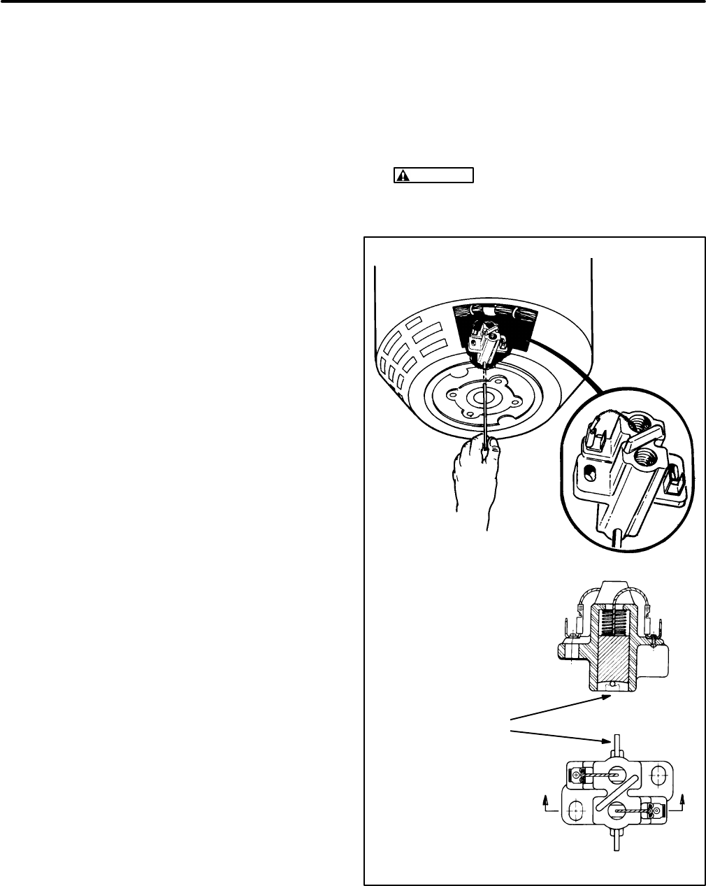
53
Remounting the Generator on the Genset
Essentially, remounting is the reverse of removal.
Note the following:
1. First reassemble the generator housing, stator
and rotor as instructed, if they have been taken
apart.
2. It is recommended that the rotor removal tool
be threaded into the crankshaft to guide the ro-
tor into the crankshaft as the assembly is low-
ered, using an eyebolt (Figure 48) and hoist.
3. The lock washers go under the bolt heads of the
generator mounting bolts.
4. Locate the large flat washers at the locations
noted when disassembling the vibration isola-
tors (Step 8 under Removal).
5. Torque the generator housing, rotor through-
bolt and vibration isolator center-bolts to
As-
sembly Torques
.
6. Make sure to secure the ground strap to the drip
tray using one EIT (external and internal
toothed) lock washer on each side of the strap
terminal for a good electrical connection.
7. Reconnect or reassemble all other parts that
were disconnected or removed. Do not forget
to refill the crankcase with the appropriate
grade of engine oil after the genset has
been re-installed in the vehicle. See the Op-
erator’s Manual for engine oil recommenda-
tions.
GENERATOR ASSEMBLY/DISASSEMBLY
Removing the Rotor from the Generator
1. Remove the generator from the genset, as
instructed under Removing the Generator from
the genset.
2. To keep from damaging the brushes and to
keep them from interfering when inserting the
rotor, either:
A. Remove the brush block assembly by dis-
connecting the leads marked F1 and F2
from the brush block terminals and then re-
moving the two mounting screws.
B. Insert a stiff wire into the small hole in the
end of the stator housing to hold the
brushes up and out of the way (Figure 50).
To do this, first pull both brush pigtails to lift
the brushes off the slip rings.
3. Turn the generator over onto its bearing end
and withdraw the rotor straight up. It may be
necessary to have an assistant hold down the
generator housing.
CAUTION
Be careful not to nick the stator
windings with the rotor while withdrawing
the rotor.
INSERT A RETAINING WIRE
TO KEEP THE BRUSHES OUT
OF THE WAY WHEN
ASSEMBLING AND
DISASSEMBLING THE
GENERATOR
RETAINING
WIRE
FIGURE 50. BRUSH BLOCK ASSEMBLY
Redistribution or publication of this document,
by any means, is strictly prohibited.
Redistribution or publication of this document,
by any means, is strictly prohibited.
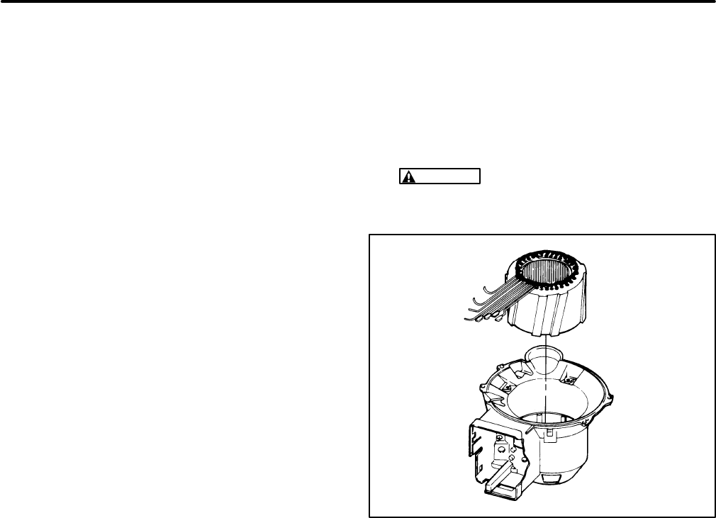
54
Re-installing the Rotor in the Generator
It is recommended that the rotor be re-installed in
the generator first and then that the entire generator
be mounted on the genset as instructed under Re-
mounting the Generator on the genset.
Re-installation of the rotor is the reverse of removal.
Note the following:
1. Replace the slip ring assembly, rotor bearing
and stator, if necessary.
2. Make sure the brush block assembly has been
removed or that the wire is holding both
brushes up and out of the way.
3. Make sure the rubber O-ring is in place in the
bearing bore and then carefully lower the rotor
into the generator. The rotor bearing should fit
snugly into the bearing bore.
4. Install the brush block assembly if it was re-
moved. If it was left in place, pull the brush pig
tails and remove the retaining wire. If neces-
sary, loosen the brush block mounting screws,
align the brush block so that the brushes are
centered on the slip rings and retighten the
mounting screws.
5. Connect the lead marked F1 to the outboard
brush terminal and the lead marked F2 to the in-
board brush terminal and snap the cover on.
Removing the Stator from the Generator
See Figure 51. To remove the stator from the gener-
ator housing:
1. Upend the generator as shown.
2. Remove the rotor as instructed under Remov-
ing the Rotor from the Generator.
3. Disconnect all the stator leads and pull them
from the control box.
4. Remove the three stator clamps.
5. Lift the stator straight up and out of the housing.
CAUTION
Careless handling of the stator
can damage the insulation on the stator
windings.
FIGURE 51. REMOVING THE STATOR
Re-installing the Stator in the Generator
Re-installing the stator is the reverse of removal.
Make sure the stator leads line up with the exit hole
in the housing while lowering the stator into the
housing. Connect the leads according to the ap-
propriate connection diagram in Figure 59, 60 or 61.
Redistribution or publication of this document,
by any means, is strictly prohibited.
Redistribution or publication of this document,
by any means, is strictly prohibited.
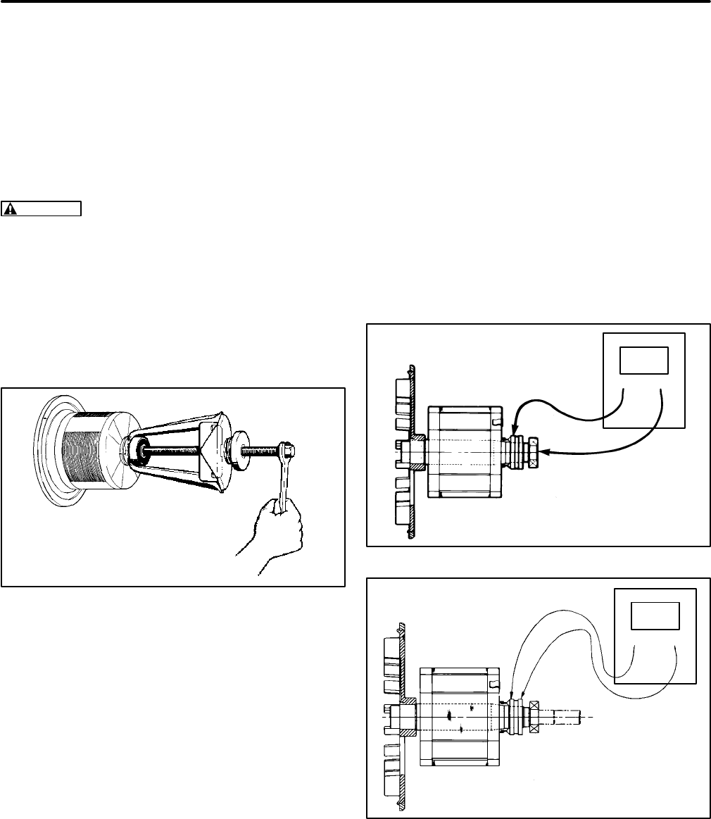
55
Removing and Replacing the Rotor
Bearing
Use a gear puller to remove the bearing from the ro-
tor shaft if it or the slip ring assembly is to be re-
placed, otherwise leave it in place. See Figure 52. If
the bearing is to be reused, make sure the fingers of
the gear puller bear on the inner race of the bearing
only.
CAUTION
The bearing will be damaged and
become unusable if force is applied to the outer
race either when pulling it off or pressing it on.
Replace the bearing as follows:
1. Replace the slip ring assembly first, if neces-
sary.
2. Press the bearing on with a press, making sure
to bear down on the inner race only.
FIGURE 52. BEARING REMOVAL
Removing and Replacing the Slip Ring
Assembly
Unsolder the two rotor leads from the slip ring as-
sembly and pull the slip ring assembly off with a gear
puller. Tape the key to the shaft to keep from loosing
it if a new assembly is not going to be installed right
away.
Press on a new slip ring assembly with a press,
making sure the key is in place and the assembly is
aligned with the key. Solder the two rotor leads to the
solder terminals on the slip ring assembly.
TESTING THE GENERATOR
Testing the Rotor
It is possible to test the rotor without removing it from
the generator by removing the brush block assem-
bly.
Testing for a Grounded Winding:
A digital ohm-
meter is recommended for this test. Select the high-
est resistance scale on the meter and touch one test
probe to the rotor shaft and the other to either slip
ring as shown in Figure 53. Replace the rotor as-
sembly if the meter does not indicate an open circuit
to ground (the same high resistance as when the
meter probes are separated by an air gap).
FIGURE 53. ROTOR INSULATION RESISTANCE
FIGURE 54. ROTOR WINDING RESISTANCE
Redistribution or publication of this document,
by any means, is strictly prohibited.
Redistribution or publication of this document,
by any means, is strictly prohibited.
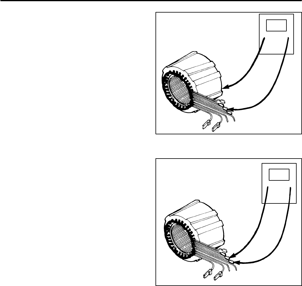
56
Testing Winding Resistance:
A digital ohmmeter
is recommended for measuring rotor winding resist-
ance. Select the best scale for measuring a 20 to 25
ohm value. Touch the test probes to the slip rings as
shown in Figure 54.
If the meter indicates a high resistance, first check
the connection between the slip rings and the rotor
leads and resolder if necessary. Replace the rotor
assembly if the connections are good but the wind-
ing does not meet the resistance specification in
Table 5 or 6, as appropriate.
Testing the Stator
These tests can be done by disconnecting all the Tx
winding leads from terminal block TB1 and the Bx
and Qx winding leads from their connectors. Single-
phase generators have winding lead pairs T1-T2,
T3-T4 and Q1-Q2. Three-phase generators have
lead pairs T1-T4, T2-T5, T3-6, T7-T10, T8-T11 and
T9-T12. Spec H generators also have lead pair
B1-B2. Alternatively, a plug-in tester is available for
conducting stator winding tests.
Testing for a Grounded Winding:
A digital ohm-
meter is recommended for this test. Select the high-
est scale on the meter. Test each lead as shown in
Figure 55. Replace the stator assembly if any read-
ing is low indicating a breakdown in the winding in-
sulation.
Testing Winding Resistance:
A digital ohmmeter
can be used to determine if a stator winding is open,
as shown in Figure 56. A Wheatstone (Kelvin)
bridge should be used to measure stator winding re-
sistance. Replace the stator assembly if any wind-
ing is open or does not meet the resistance specifi-
cation in Table 5 or 6, as appropriate.
FIGURE 55. STATOR INSULATION RESISTANCE
FIGURE 56. STATOR WINDING CONTINUITY
Redistribution or publication of this document,
by any means, is strictly prohibited.
Redistribution or publication of this document,
by any means, is strictly prohibited.

57
Checking Open-Circuit Output Voltage:
Alterna-
tively, check the open-circuit output voltage (VAC) of
each stator winding as follows:
1. If necessary, service the brushes, slip rings and
rotor and adjust for rated frequency.
2. Disconnect leads F1 and F2 from the brush
block terminals.
3. Connect brush block terminal B- (inboard) to
the negative (-) battery terminal on the genset.
4. Connect brush block terminal B+ (outboard) to
the positive (+) battery terminal on the genset
(K1-B+). This jumper should have a 10 amp
fuse and switch.
5. Measure the output across each lead pair while
running the genset.
Replace the stator assembly if any winding does not
meet the output specification in Table 5 or 6, as ap-
propriate.
TABLE 5. SINGLE-PHASE GENERATOR STATOR SPECIFICATIONS
WINDING RESISTANCES* (OHMS)
FREQUENCY
(Hz) LEAD PAIRS
T1-T2, T3-T4 LEAD PAIR
B1-B2
LEAD PAIR
Q1-Q2
(SPEC H ONLY) ROTOR
WINDING
60 0.327 0.058 2.089 22.5
50 0.502 0.112 2.873 22.5
OPEN-CIRCUIT WINDING VOLTAGE (VAC) WHEN FIELD VOLTAGE IS 12 VDC
FREQUENCY
(Hz) LEAD PAIRS
T1-T2, T3-T4 LEAD PAIR
B1-B2
LEAD PAIR
Q1-Q2
(SPEC H ONLY) ROTOR
WINDING
60 49 7 58 -
50 49 7 58 -
* - These values are approximate, plus or minus 10 percent at 68° F (20° C).
TABLE 6. THREE-PHASE GENERATOR STATOR SPECIFICATIONS
WINDING RESISTANCES* (OHMS)
FREQUENCY
(Hz)
LEAD PAIRS
T1-T4, T2-T5, T3-T6,
T7-T10, T8-T11,
T9-T12
LEAD PAIR
B1-B2
LEAD PAIR
Q1-Q2
(SPEC H ONLY)
ROTOR
WINDING
60 1.089 0.101 - 24.78
50 1.625 0.114 - 24.78
60** 0.716 0.101 - 24.78
OPEN-CIRCUIT WINDING VOLTAGE (VAC) WHEN FIELD VOLTAGE IS 12 VDC
FREQUENCY
(Hz)
LEAD PAIRS
T1-T4, T2-T5, T3-T6,
T7-T10, T8-T11,
T9-T12
LEAD PAIR
B1-B2
LEAD PAIR
Q1-Q2
(SPEC H ONLY)
ROTOR
WINDING
60 60 7 65 -
50 60 7 65 -
60** 60 7 65 -
* - These values are approximate, plus or minus 10 percent at 68° F (20° C).
** - 120/240 DELTA
Redistribution or publication of this document,
by any means, is strictly prohibited.
Redistribution or publication of this document,
by any means, is strictly prohibited.
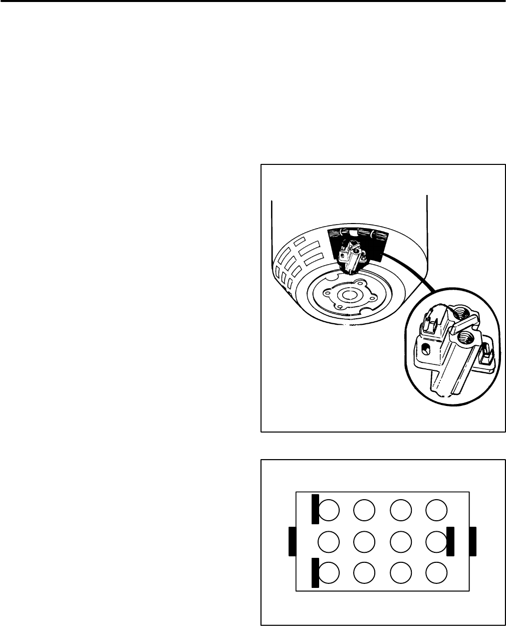
58
TESTING FOR FIELD VOLTAGE
To check the field voltage, remove the brush block
cover and connect a DC voltmeter to the brush block
terminals. See Figure 57. Connect the positive lead
to the B+ (outboard) terminal and the negative lead
to the B- (inboard) terminal.
Start the genset and allow it to stabilize. Measure
the field voltage with no load applied and then with
full load applied. Both readings should fall between
25 and 100 volts DC and be stable at constant load.
If field voltage fluctuates at constant load, a possible
governor or voltage regulator problem exists. See
Troubleshooting.
TESTING 1-PH VOLTAGE REGULATORS
See Figure 58. Confirm that the voltage regulator
(VR1) is faulty before replacing it. Use the tester
available or a meter with a diode checking function
(Fluke Model 73 Multimeter, for example) to perform
the following tests:
1. Disconnect the negative (-) battery cable.
2. Remove the generator control box cover.
3. Disengage the wiring connector and remove
the voltage regulator.
4. With the meter on “Diode Check”, test between
connector terminal pairs 5-9, 7-9, 10-9, 11-9,
12-9, 10-5, 5-11, 5-12 and 5-3. It is important
that the positive lead of the meter be con-
nected to the first terminal of each pair. Re-
place the voltage regulator if any reading indi-
cates “short” or “open”, except for pair 10-5,
which should indicate “open”.
A good reading is approximately 0.5, which is
the voltage drop across a diode. “Short” is indi-
cated by zero or a number very nearly zero. Me-
ters of different type may indicate “open” differ-
ently. Read the meter instructions. If in doubt,
compare readings with a regulator of the same
part number known to be good.
GENERATOR RECONNECTIONS
When it is necessary to reconnect a generator, re-
move the control panel and reconnect the leads at
terminal block TB1 and circuit breakers CB1, CB2
and CB3 as shown in the appropriate diagram in
Figure 59, 60 or 61. It should be noted that other
leads are also connected to terminal block TB1 in
the control box and that they should be reconnected
as marked, if inadvertently disconnected.
FIGURE 57. BRUSH BLOCK ASSEMBLY
1
2
3
4
5
6
7
8
9
10
11
12
FIGURE 58. VOLTAGE REGULATOR TERMINALS
(1-PHASE GENSETS)
Redistribution or publication of this document,
by any means, is strictly prohibited.
Redistribution or publication of this document,
by any means, is strictly prohibited.
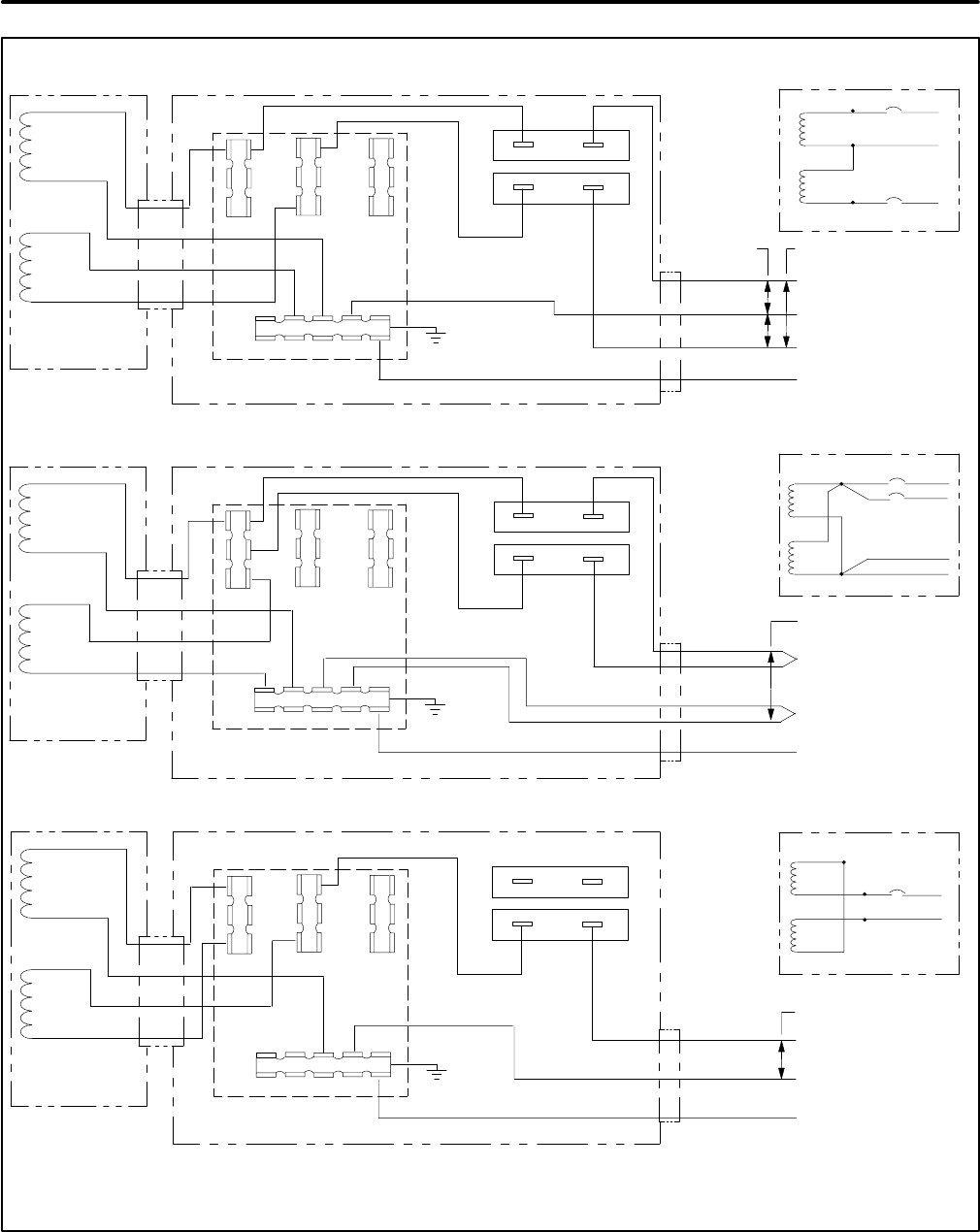
59
T1
T2
T3
T4
L0
L1 L2 L3
TB1
CB1
CB2
GREEN (GND)
WHITE (NEUTRAL)
BLACK (CB2-LOAD)
BLACK (CB1-LOAD)
3-WIRE 60 HZ 120 / 240 VAC
110-120 VAC 220-240 VAC
CONTROL BOX
GENERATOR
2-WIRE 60 HZ 120 VAC
T1
T2
T3
T4
L0
L1 L2 L3
TB1
CB1
CB2
GREEN (GND)
WHITE *
BLACK (CB2-LOAD)
BLACK (CB1-LOAD)
110-120 VAC
CONTROL BOX
GENERATOR
T1
T2
T3
T4
L0
L1 L2 L3
TB1
CB1
CB2
GREEN (GND)
WHITE (NEUTRAL)
BLACK (CB2-LOAD)
220-240 VAC
CONTROL BOX
GENERATOR
2-WIRE 60 HZ 240 VAC
WHITE (NEUTRAL)
**
* - INSTALLER MUST PROVIDE A NO.12 AWG TYPE XLPE CONDUCTOR (125 C) AND INSULATED FEMALE 1/4 INCH FASTON CONNECTOR.
** - REMOVE AND DISCARD BOTH LEADS CONNECTED TO CB1. LEAVE CB1 IN PLACE TO KEEP THE OPENING COVERED.
**
T1
T2
T3
T4
L1
L0
L2
T1
T2
T3
T4
L1
L0
T1
T2
T3
T4
L1
L0
L2
FIGURE 59. SINGLE-PHASE (4-LEAD) 60 Hz GENERATOR RECONNECTIONS
Redistribution or publication of this document,
by any means, is strictly prohibited.
Redistribution or publication of this document,
by any means, is strictly prohibited.
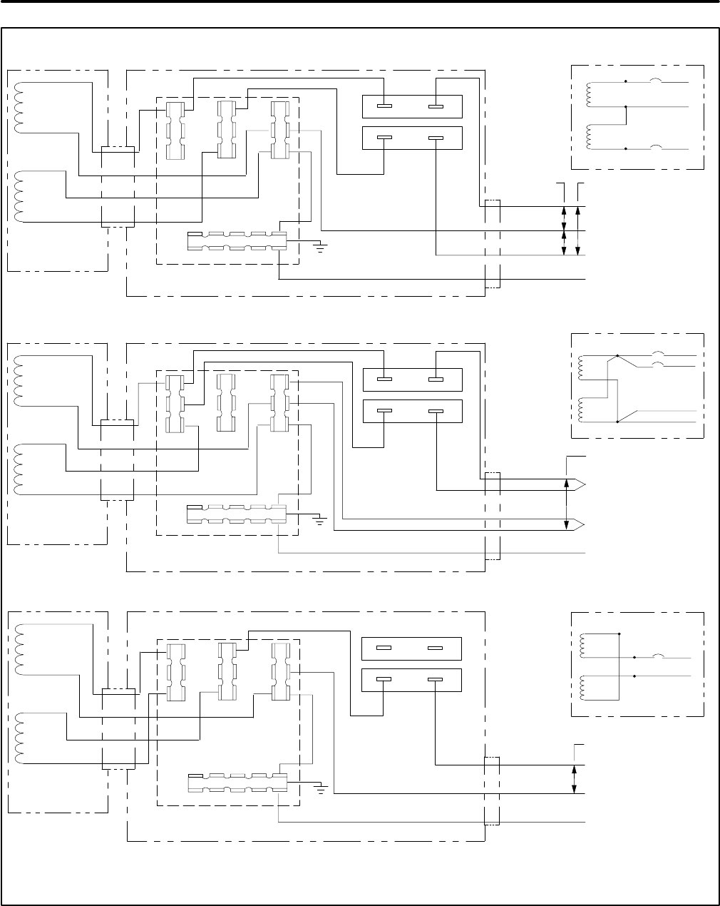
60
T1
T2
T3
T4
L0
L1 L2 L3
TB1
CB1
CB2
GREEN (GND)
WHITE (NEUTRAL)
BLACK (CB2-LOAD)
BLACK (CB1-LOAD)
3-WIRE 50 HZ (110-120) / (220-240) VAC
110-120 VAC 220-240 VAC
CONTROL BOX
GENERATOR
2-WIRE 50 HZ 110-120 VAC
T1
T2
T3
T4
L0
L1 L2 L3
TB1
CB1
CB2
GREEN (GND)
WHITE *
BLACK (CB2-LOAD)
BLACK (CB1-LOAD)
110-120 VAC
CONTROL BOX
GENERATOR
T1
T2
T3
T4
L0
L1 L2 L3
TB1
CB1
CB2
GREEN (GND)
WHITE (NEUTRAL)
BLACK (CB2-LOAD)
220-240 VAC
CONTROL BOX
GENERATOR
2-WIRE 50HZ 220-240 VAC
WHITE (NEUTRAL)
**
* - INSTALLER MUST PROVIDE A NO.12 AWG TYPE XLPE CONDUCTOR (125 C) AND INSULATED FEMALE 1/4 INCH FASTON CONNECTOR.
** - REMOVE AND DISCARD BOTH LEADS CONNECTED TO CB1. LEAVE CB1 IN PLACE TO KEEP THE OPENING COVERED.
**
T1
T2
T3
T4
L1
L3
L2
T1
T2
T3
T4
L1
L3
T1
T2
T3
T4
L1
L3
L2
W2***
W2***
W2***
*** - REMOVE JUMPER W2 FOR ISOLATED NEUTRAL.
FIGURE 60. SINGLE-PHASE (4-LEAD) 50 Hz GENERATOR RECONNECTIONS
Redistribution or publication of this document,
by any means, is strictly prohibited.
Redistribution or publication of this document,
by any means, is strictly prohibited.
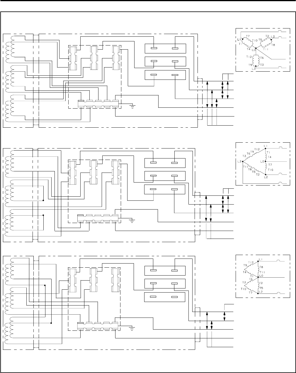
61
T6 T12
T1
T4
L0
L1 L2 L3
CB1
CB2
GREEN (GND)
WHITE (NEUTRAL)
BLK/YEL (CB2-LOAD)
BLACK (CB1-LOAD)
3-PHASE , 4-WIRE WYE, 60HZ (120-139) / (208-240) VAC AND 50 HZ (110-127) / (190-220) VAC
LINE-TO-NEUTRAL
LINE-TO-LINE
CONTROL BOX
GENERATOR
CB3
BLACK (CB3-LOAD)
T7
T10
T2
T5
T8
T11
T3
T6
T9
T12
T1
T7
T2
T8
T3
T9
T4T10T5T11
T12
T1
T4
L0
L1 L2 L3
CB1
CB2
GREEN (GND)
WHITE (NEUTRAL)
BLK/YEL (CB2-LOAD)
BLACK (CB1-LOAD)
3-PHASE , 4-WIRE DELTA, 60 HZ 120 / 240 VAC AND 50 HZ (110-120) / (220-240) VAC
LINE-TO-NEUTRAL
CONTROL BOX
GENERATOR
CB3
BLACK (CB3-LOAD)
T7
T10
T2
T5
T8
T11
T3
T6
T9
T12
T1
T2 T3
T4T7
T11T10
T9
T6
T5
T8
T12
T1
T4
L0
L1 L2 L3
TB1
CB1
CB2
GREEN (GND)
WHITE (NEUTRAL)
BLK/YEL (CB2-LOAD)
BLACK (CB1-LOAD)
1-PHASE, 3-WIRE DOUBLE-DELTA, 60 HZ 120 / 240 VAC AND 50 HZ (110-120) / (220-240) VAC
LINE-TO-NEUTRAL
CONTROL BOX
GENERATOR
CB3
T7
T10
T2
T5
T8
T11
T3
T6
T9
T12
T7
T9
T5
T4
T3
T10
T8
T6
T11 T2 T1
* - USE A DOUBLE-END MALE 1/4 INCH FASTON CONNECTOR TO CONNECT THE GENERATOR LEADS.
** - REMOVE AND DISCARD BOTH LEADS CONNECTED TO CB3. LEAVE CB3 IN PLACE TO KEEP THE OPENING COVERED.
*
TB1
TB1
*
*
*
**
**
LINE-TO-LINE
LINE-TO-LINE
FIGURE 61. THREE-PHASE (12-LEAD) GENERATOR RECONNECTIONS
Redistribution or publication of this document,
by any means, is strictly prohibited.
Redistribution or publication of this document,
by any means, is strictly prohibited.
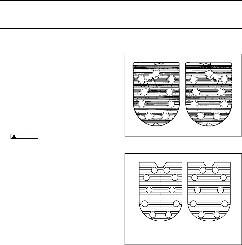
62
Engine Block Assembly
Performing major service on the engine block as-
sembly requires that the genset be removed from
the vehicle. See
Preparations
. The control, genera-
tor and all engine subsystems must also be re-
moved for complete access to the block assembly.
Refer to the previous sections for disassembly and
removal procedures.
CYLINDER HEADS
See Figures 62 and 63. Remove and clean the cylin-
der heads as follows when poor engine perfor-
mance is noticed:
1. Remove the cylinder head bolts by using a 1/2
inch socket wrench. Lift off the cylinder head.
CAUTION
The heads may warp if they are
removed while hot. Wait until the engine has
cooled before removing the heads.
2. After removing the heads, clean out all carbon
deposits. Be careful not to damage the outer
sealing edges where the gaskets fit. The heads
are made of aluminum and can be damaged by
careless handling.
3. It is a good idea to also remove the valves and
clean carbon deposits from the valves and the
intake and exhaust ports. See VALVE SYS-
TEM.
4. Use new head gaskets and clean both the
heads and the cylinder block thoroughly where
the gaskets rest.
5. Place the heads in position and torque the head
bolts in steps of 5 lbs-ft (7 N-m) in the numbered
sequence shown in Figure 62 or 63 up to the
specified torque of 15-17 lbs-ft (20-23 N-m).
6. Retorque the head bolts before the engine has
run a total of 25 hours.
12
33
12
44
5566
77
8899
FIGURE 62. MODEL BGD CYLINDER HEAD BOLT
TORQUE SEQUENCE
1
2
34
56
78
910
12
34
56
78
910
LEFT SIDE* RIGHT SIDE*
* THE OIL FILTER SIDE IS THE RIGHT SIDE
FIGURE 63. MODEL NHD CYLINDER HEAD BOLT
TORQUE SEQUENCE
Redistribution or publication of this document,
by any means, is strictly prohibited.
Redistribution or publication of this document,
by any means, is strictly prohibited.
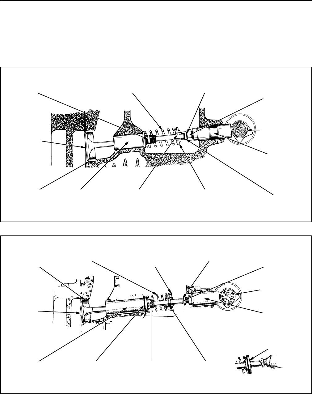
63
VALVE SYSTEM
See Figures 64 and 65 for the valve system layouts
of the respective engines. This engines have a “side
valve” type of valve system layout. A properly func-
tioning valve system is essential for top engine per-
formance.
See VALVE CLEARANCE (LASH) ADJUSTMENT
under
Engine Subsystems
for instructions on how to
adjust valve clearance.
VALVE SEAT
INSERT
TAPPET
VALVE CAP
VALVE SPRING
RETAINER
RETAINER
LOCK
VALVE ADJUSTING
NUT
VALVE CLEARANCEVALVE SPRINGVALVE STEM SEAL
VALVE
CAMSHAFT
VALVE
GUIDE
FIGURE 64. MODEL BGD VALVE SYSTEM
VALVE SEAT
INSERT
VALVE
VALVE
GUIDE RUBBER
GASKET VALVE STEM
SEAL (OPTIONAL) RETAINER
LOCK
TAPPET
CAMSHAFT
VALVE ADJUSTING
NUT
VALVE CLEARANCE
VALVE SPRING
RETAINER
VALVE SPRING
EXHAUST VALVE
ROTATOR
FIGURE 65. MODEL NHD VALVE SYSTEM
Redistribution or publication of this document,
by any means, is strictly prohibited.
Redistribution or publication of this document,
by any means, is strictly prohibited.
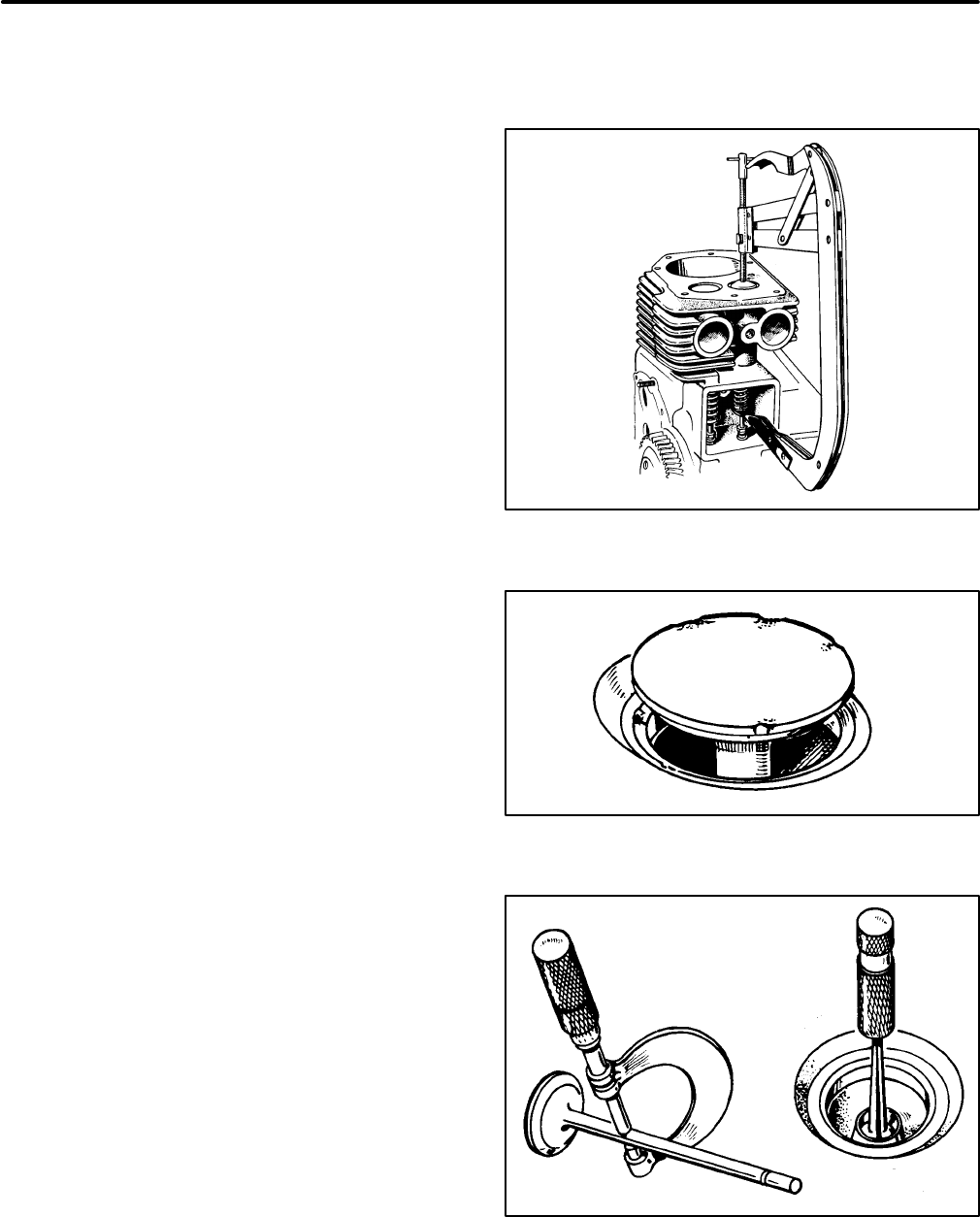
64
Inspecting the Valve System
The valve system is accessible by removing the cyl-
inder heads and the valve covers on top of the en-
gine. Use a valve spring compressor (Figure 66) to
remove and replace the valves from the cylinder
block. Make sure to first plug the breather hole in the
Number 1 cylinder valve box (opposite oil filter side)
to prevent the valve keepers from falling into the
crankcase.
Valve Face:
Check the valve face for evidence of
burning, warping, out-of-roundness and carbon de-
posits (Figure 67).
Burning and pitting are caused by the valve failing to
seat tightly. This condition is often caused by hard
carbon particles on the seat. It may also be caused
by weak valve springs, insufficient tappet clear-
ance, valve warpage and misalignment.
Warping occurs chiefly in the upper stem, because it
is exposed to intense heat. Out-of-roundness re-
sults from warping, when the seat is pounded by a
valve whose head is not in line with the stem. If a
valve face is burned or warped, or the stem is worn,
install a new valve.
Excess clearance in the intake guide admits air and
oil into the combustion chamber, upsetting carbure-
tion, increasing oil consumption and making heavy
carbon deposits. Carbon prevents heat dissipation.
Clean metal is a good heat conductor, but carbon in-
sulates and retains heat. This increases combus-
tion chamber temperatures, causing warping and
burning.
Unburned carbon residue gums valve stems, caus-
ing them to stick in the guide. Deposits of hard car-
bon with sharp points projecting become white-hot,
causing pre-ignition and “pinging”.
Valve Stems and Guides:
Check valve stems and
guides for wear (Figure 68). Use a hole gauge to
measure the valve guide bore diameter. When valve
clearance with the stem exceeds the original clear-
ance by 0.002 inch (0.05 mm), replace either the
valve or guide or both, as necessary. Always regrind
the seat to make it concentric with the newly
installed guide.
Valve Stem Seal:
A valve stem seal is used on the
intake valve guides. This seal must be replaced
each time the valve is removed.
FIGURE 66. VALVE SPRING COMPRESSOR
FIGURE 67. BURNED VALVE FACE
FIGURE 68. VALVE STEM AND VALVE GUIDE BORE
DIAMETERS
Redistribution or publication of this document,
by any means, is strictly prohibited.
Redistribution or publication of this document,
by any means, is strictly prohibited.
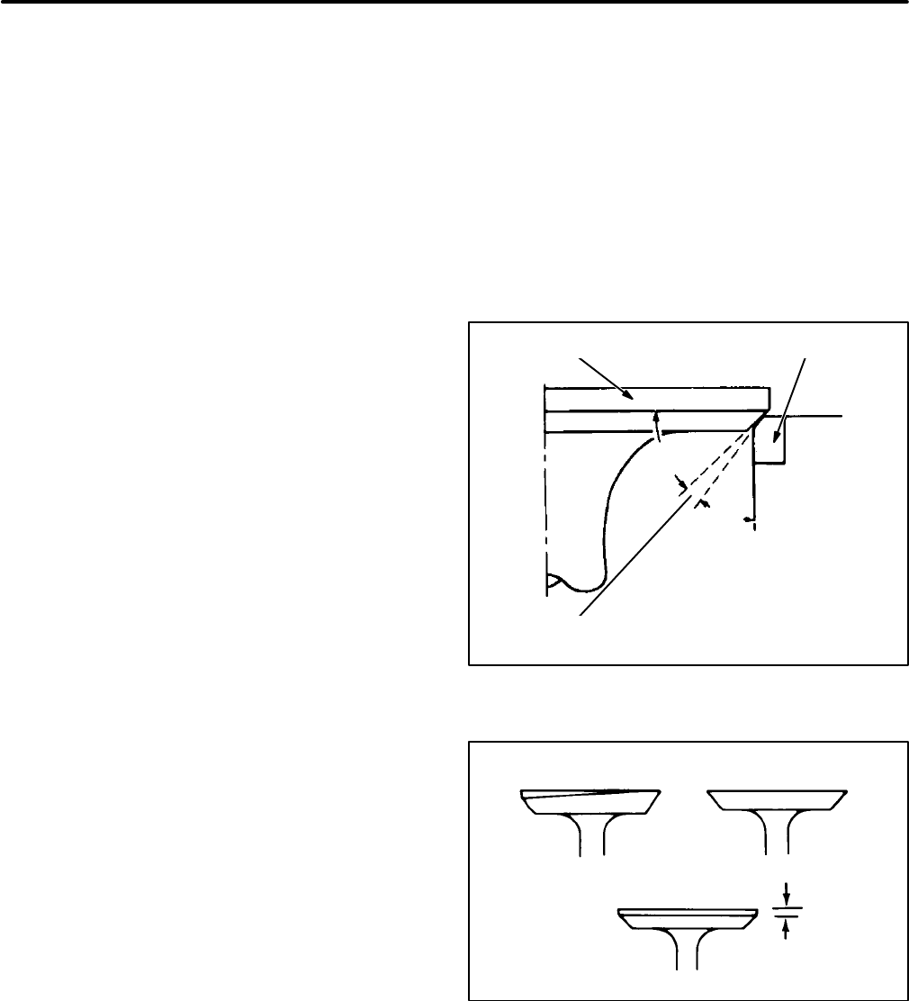
65
Springs:
Check the valve springs for free-height,
squareness, end wear and tension. If the spring
ends are worn, check the valve spring retainer for
wear. Check for height and squareness by placing
the spring on a flat surface next to a square. Rotate
the spring against the square edge to measure its
distortion. Check the spring tension at the installed
height in both the valve open and closed positions,
using a valve spring tester. Replace a weak, broken,
worn or distorted spring.
Reconditioning Valves and Valve Seats
See Figure 69. The interference angle method of
valve seating is used on these engines. The valve
face angle is 44 degrees. The valve seat angle is 45
degrees. This 1-degree interference angle results in
a sharp seating surface between the valve and the
top of the valve seat.
The valves must not be hand lapped, because the
sharp contact between the valve and the seat will be
destroyed. This is especially important where
chrome cobalt faced valves and seats are used.
Valve faces must be finished to 44 degrees, in a ma-
chine.
Each valve must have a minimum of 1/32 inch
(0.8 mm) margin (Figure 70). If the valve has less
margin than this it will heat up excessively. It will re-
tain this heat during the compression stroke and
pre-ignite the mixture, causing loss of power and
economy. This valve is also susceptible to warping
and breakage.
Not all valves can be reconditioned. A badly warped
valve must be replaced, because the amount of
grinding required to make it seat correctly removes
its margin. To make a valve gas-tight, remove all pit-
ting from the valve face and seat. Deeply pitted or
cut valves must be replaced, because grinding re-
moves the margin.
Grind or cut the valve seats at 45 degrees. The seat
band should be 1/32-3/64 inch (0.79-1.2 mm) wide.
Remove only enough material to ensure proper
valve seating. If a valve seat is cracked or loose or
does not have enough material left to seat the valve
properly, replace the entire block assembly.
Check each valve for a tight seat. Make several
marks at regular intervals across the valve face us-
ing machinist’s bluing. The marks should rub off uni-
formly when the valve is rotated a quarter-turn
against the seat, indicating even contact all the way
around. The line of contact should be at the center of
the valve face.
44°
45°
VALVE HEAD SEAT
INTERFERENCE
ANGLE
FIGURE 69. VALVE INTERFERENCE ANGLE
WARPED VALVE KNIFE EDGE
GOOD MARGIN
0.30 INCH (.8 mm)
MINIMUM
FIGURE 70. VALVE MARGIN
Redistribution or publication of this document,
by any means, is strictly prohibited.
Redistribution or publication of this document,
by any means, is strictly prohibited.

66
Replacing the Valve Guides
Worn valve stem guides can be replaced from in-
side the valve chamber. The smaller diameter of the
tapered valve guides must face toward the valve
head.
Removal:
1. Before removing the valve guides, use an elec-
tric drill with a wire brush to remove carbon and
other foreign material from the top surface of
the guides. Failure to do this may result in dam-
age to the guide bores.
2. Drive the guides out with a hammer and a valve
guide driver.
CAUTION
Driving out the old valve guides
can damage the tappet bores. Be careful not
to strike the bores with the driver.
Installation:
1. Run a small polishing rod with crocus cloth
through the valve guide holes, to clean out car-
bon and other foreign materials.
2. Place a new gasket on the intake valve guide
and coat the outer edge of each new guide with
anhydrous lanolin (available at the drugstore).
3. Place the guide, notch up, in the cylinder block
and press it in until the shoulder of the guide
rests against the cylinder block (Figure 71).
5/8 in
(16 mm)
2-3/8 in
(60 mm)
4-3/4 in
(121 mm)
1-1/4 in
(32 mm) 7 in
(178 mm)
5/16-18 HEX, NUT
(2 REQUIRED)
5/16-18
THREADED
ROD
5/16 FLAT
WASHER
(2 REQUIRED)
NUT ROD PLATE
VALVE
GUIDE
WASHER
WASHER
NUT
FIGURE 71. SUGGESTED TOOL FOR INSTALLING
THE VALVE GUIDES
Redistribution or publication of this document,
by any means, is strictly prohibited.
Redistribution or publication of this document,
by any means, is strictly prohibited.
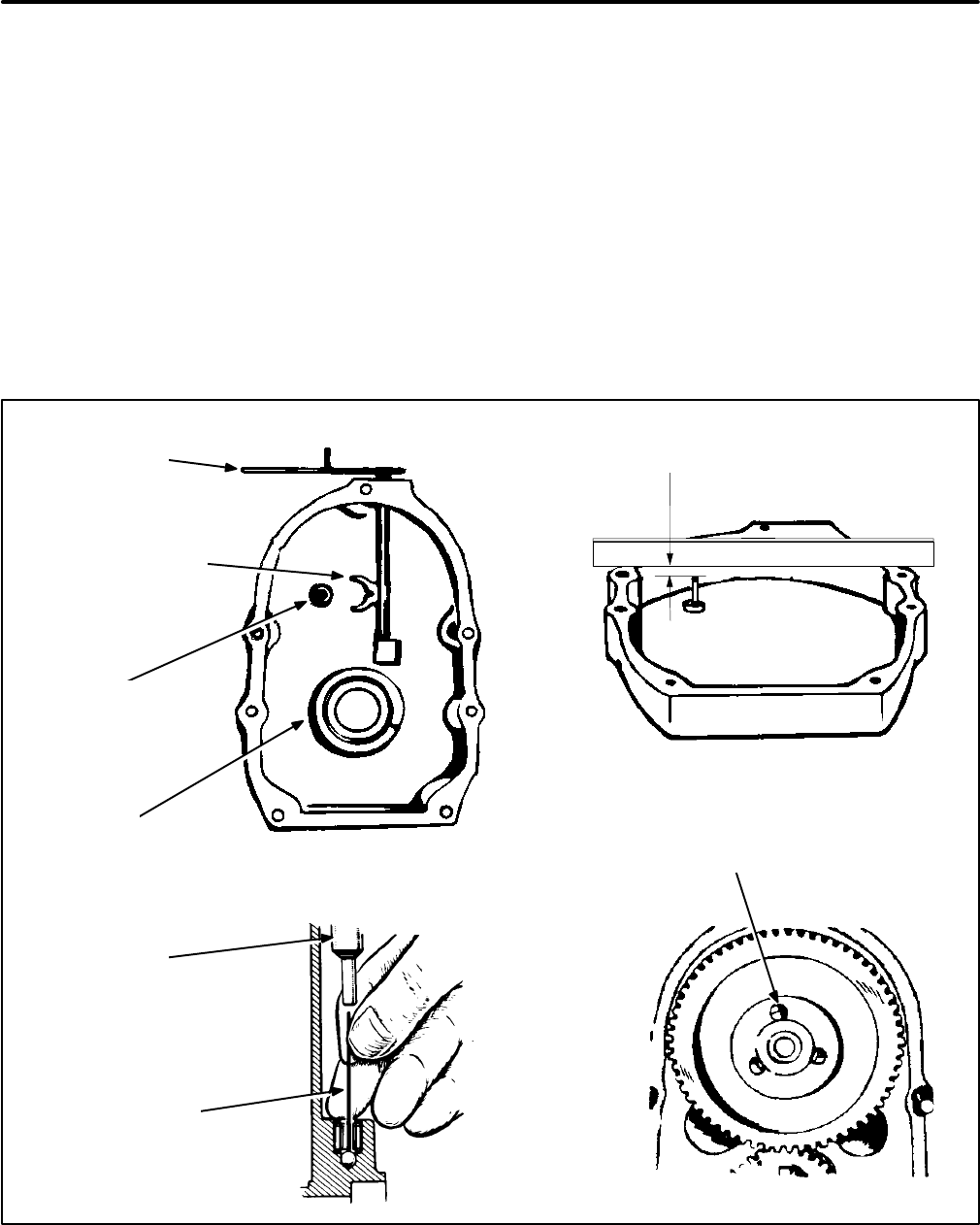
67
GEAR COVER
Removal
See Figure 72. Remove the flywheel, flywheel key
and the gear cover mounting screws. See ENGINE
COOLING SYSTEM under
Engine Subsystems
.
Gently tap the gear cover with a leather or plastic
mallet to loosen it.
Installation
1. When installing the gear cover, make sure that
the pin in the gear cover engages the hole with
the nylon grommet in the governor cup. See
OIL SEALS in this section for replacing the gear
cover oil seal.
2. Turn the governor cup so the hole with the ny-
lon grommet is at the three o’clock position.
Use a small amount of grease to help hold the
cup in position. The rounded side of the gover-
nor yoke must ride against the governor cup.
3. Turn the governor arm and shaft clockwise as
far as possible and hold it in this position until
the gear cover is installed flush against the
crankcase. Be careful not to damage the gear
cover oil seal.
ROLL
PIN
GOVERNOR
ARM
GOVERNOR SHAFT
YOKE WITH SMOOTH
SIDE TOWARD CUP
OIL
SEAL
IF FEELER WILL
ENTER HOLE 1/2 IN.
(13 mm) BALL HAS
FALLEN OUT
GOVERNOR
SHAFT
ROTATE THE GOVERNOR CUP SO
THAT THE ROLL PIN FITS INTO THE
HOLE WITH THE GROMMET
TOP OF ROLL PIN
3/4 IN (19.0 mm)
FIGURE 72. GEAR COVER ASSEMBLY
Redistribution or publication of this document,
by any means, is strictly prohibited.
Redistribution or publication of this document,
by any means, is strictly prohibited.
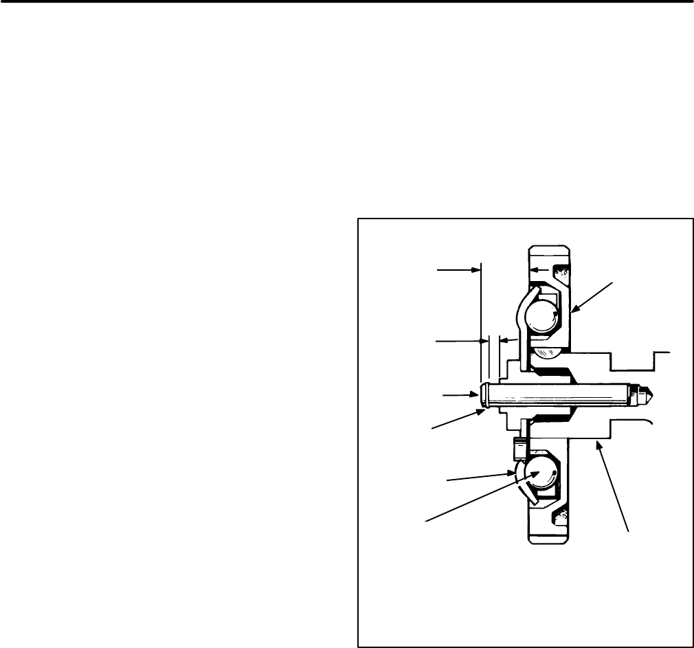
68
GOVERNOR CUP
Removal
1. Remove the gear cover. See GEAR COVER.
2. Remove the snap ring from the camshaft cen-
ter pin (Figure 73).
3. Slide the governor cup off, making certain to
catch the flyballs. Replace any flyball that is
grooved or has a flat spot.
4. Examine the ball spacer. If the arms of the ball
spacer are worn or otherwise damaged, re-
move the spacer by splitting it with a chisel. Use
a press to install a new spacer on the camshaft
gear.
5. The governor cup must spin freely on the cam-
shaft center pin without excessive looseness or
wobble. If the race surface of the cup is grooved
or rough, replace it with a new one.
Installation
The governor cup and flyballs are easily installed
when the camshaft assembly is removed from the
engine. If necessary, the engine may be tilted up to
install the cup and flyballs.
1. Put the flyballs between the spacer arms and
install the cup on the center pin.
2. Lock the cup in place with the snap ring.
Camshaft Center Pin Installation
1. The camshaft center pin extends 3/4 inch
(19 mm) from the end of the camshaft. This dis-
tance provides 7/32 inch (5.5 mm) travel for the
governor cup, as shown. Measure this distance
while holding the cup against the flyballs. If the
distance is less, the engine may race, especial-
ly at no load.
2. Remove the center pin and press in a new pin
the specified amount. Do not hammer the new
pin into place, or it will be damaged. The cam-
shaft center pin cannot be pulled outward or re-
moved without damage. If the center pin ex-
tends too far, the cup will not hold the flyballs
properly.
WHEN THE GOVERNOR IS PROPERLY ASSEMBLED
THE DIMENSIONS SHOWN ON DRAWING WILL BE AS
INDICATED
3/4 in
(19 mm)
7/32 in
(5.5 mm)
CENTER
PIN
SNAP
RING
GOVERNOR
CUP
GOVERNOR
FLYBALL
CAMSHAFT
GEAR
CAMSHAFT
FIGURE 73. GOVERNOR CUP
Redistribution or publication of this document,
by any means, is strictly prohibited.
Redistribution or publication of this document,
by any means, is strictly prohibited.
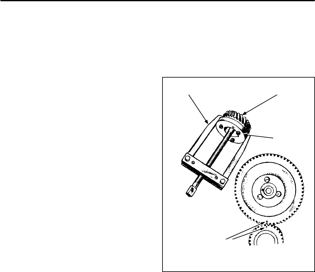
69
TIMING GEARS AND CAMSHAFT
If either timing gear needs replacement, both gears
should be replaced. Also, the camshaft and its gear
are replaceable only as an assembly. See Fig-
ure 74.
Removal
1. Remove the valve tappets so that the camshaft
can be withdrawn.
2. Remove the snap ring and retainer washer in
front of the crankshaft timing gear.
3. Withdraw the camshaft/timing gear assembly.
4. Remove the oil pump.
5. Bolt the gear pulling ring to the crankshaft tim-
ing gear using two Grade 8, 1/4-20x1 inch bolts
(lesser grade bolts will snap off) and remove
the gear with a gear puller as shown. Alterna-
tively, special shoulder bolts are available for
use with the flywheel puller to remove the
crankshaft gear.
Installation
1. Service the crankshaft as necessary and rein-
stall it. See CRANKSHAFT in this section.
2. Preheat the crankshaft timing gear in an oven
to 325° F (168° C).
3. Make sure the key is in place in the crankshaft
and then tap the gear down to the shoulder on
the crankshaft.
4. Install the camshaft assembly. Make sure the
thrust washer is in place between the back of
the timing gear and the block and that the “0”
marks on the timing gears line up as shown in
Figure 74.
5. Install the oil pump assembly.
6. Install the retainer washer and snap ring in front
of the crankshaft timing gear.
CRANKSHAFT
GEAR
GEAR
PULLER
GEAR
PULLER
RING
ALIGN THESE MARKS
WHEN REASSEMBLING
THE TIMING GEARS
FIGURE 74. TIMING GEAR REMOVAL
AND INSTALLATION
Redistribution or publication of this document,
by any means, is strictly prohibited.
Redistribution or publication of this document,
by any means, is strictly prohibited.

70
OIL PUMP ASSEMBLY
The oil pump is mounted on the front of the crank-
case behind the gear cover and is driven by the
crankshaft gear. The inlet pipe and screen assem-
bly is attached to the pump body. A discharge pas-
sage in the pump cover is aligned with a passage
drilled in the crankcase that leads to the front main
bearing via the oil filter. A circumferential groove in
the front main bearing allows oil to cross over to a
drilled passage that leads to the front camshaft
bearing. A copper colored crossover tube carries oil
to the rear main bearing. The connecting rod jour-
nals are lubricated through drilled passages from
the main journals. The oil overflow from the bypass
valve lubricates the camshaft drive gears.
Replace the oil pump if the crossover tube is tight
and the oil bypass valve is functioning properly but
the oil pressure is below specification. The gasket
and pick-up cup are the only individually replace-
able parts. Oil the pump generously when reassem-
bling it so that it will prime faster when the engine is
first started.
OIL PUMPOIL PICKUP SCREEN
FIGURE 75. OIL PUMP ASSEMBLY
Redistribution or publication of this document,
by any means, is strictly prohibited.
Redistribution or publication of this document,
by any means, is strictly prohibited.
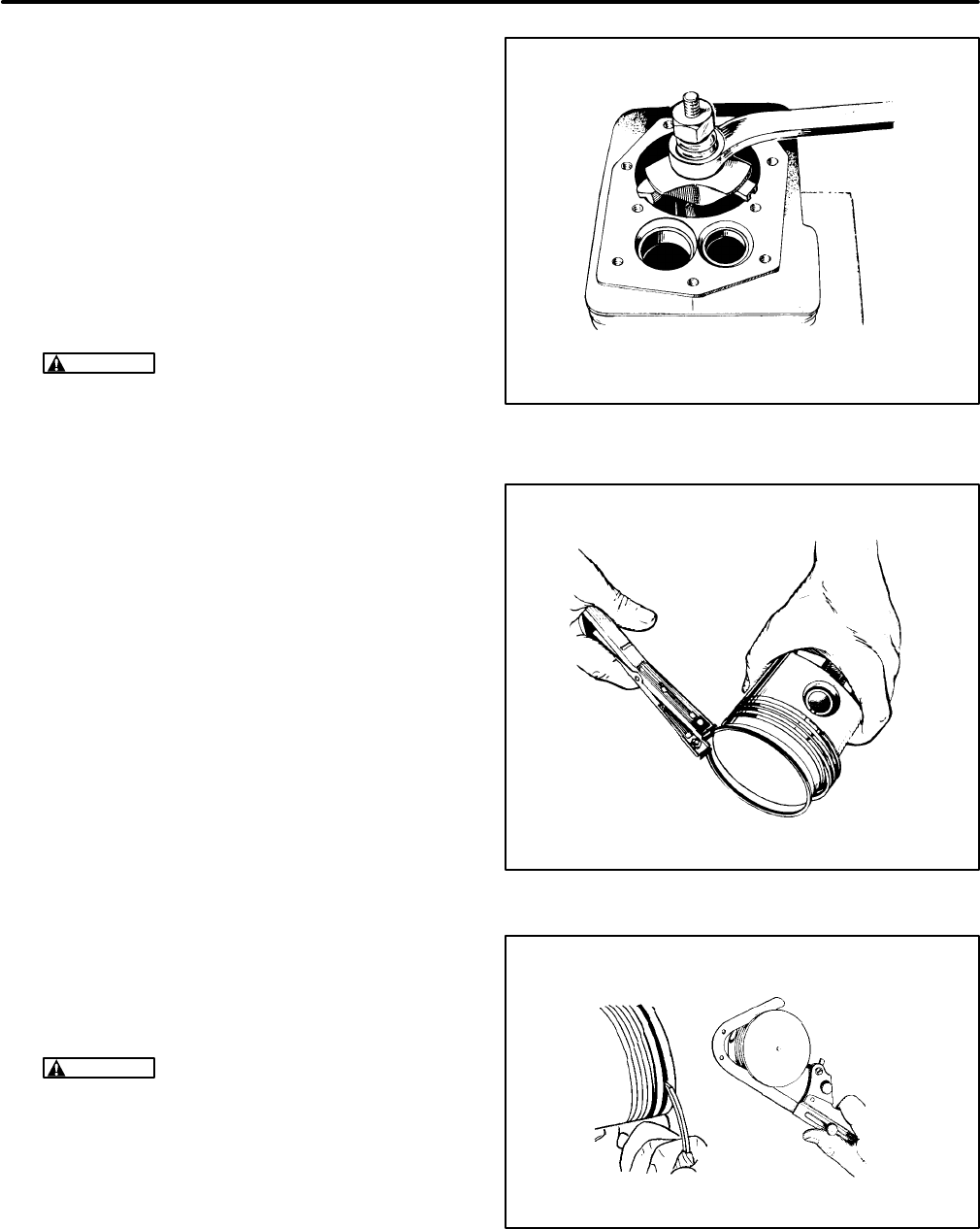
71
PISTON ASSEMBLY
The piston assembly consists of the piston, rings
and connecting rod assembly. After removal from
the engine, all parts must be carefully inspected for
damage and wear before they are replaced.
Removal and Disassembly
1. Remove the ridge at the top of the cylinder with
a ridge reamer before attempting to remove the
piston (Figure 76).
CAUTION
Improper use of a ridge reamer
can damage the cylinder bore. Use this tool
with extreme care.
2. Turn the crankshaft until a piston is at the bot-
tom of its stroke.
3. Remove the bearing caps from the connecting
rods and push the rods and pistons out the top
of the cylinders. Be careful not to scratch the
crankpin or the cylinder wall when removing
these parts.
4. Mark each piston, rod and bearing cap so that
they can be reassembled together in the same
cylinder.
5. The pistons are fitted with two compression
rings and one oil control ring. Remove these
rings from the piston using a piston ring spread-
er (Figure 77).
6. Remove the piston pin retainer from each side
and push the pin out.
7. Remove dirt and deposits from the piston sur-
faces with an approved cleaning solvent. Clean
the piston ring grooves with a groove cleaner,
or with the end of a piston ring filed to a sharp
point (Figure 78). Take care not to remove met-
al from the sides of the grooves.
CAUTION
Using a caustic cleaning sol-
vent or wire brush for cleaning pistons will
cause piston damage. Use only parts clean-
ing solvent for this job.
When cleaning the connecting rods in solvent,
make certain to include the rod bore. Blow out
all passages with low-pressure compressed
air.
FIGURE 76. CYLINDER RIDGE REAMER
FIGURE 77. PISTON RING SPREADER
FIGURE 78. PISTON RING GROVE CLEANER
Redistribution or publication of this document,
by any means, is strictly prohibited.
Redistribution or publication of this document,
by any means, is strictly prohibited.
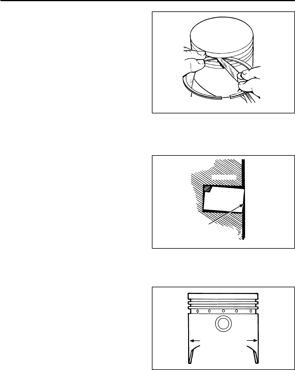
72
Piston and Connecting Rod Inspection
Piston Inspection:
Inspect the pistons for fractures
at the ring lands, skirts and pin bosses. Check for
wear at the ring lands, using a new ring and feeler
gauge (Figure 79). Replace the piston if the side
clearance of the top compression ring is 0.008 inch
(0.20 mm) or more.
Improper ring width or excessive ring side clearance
can result in ring breakage. New rings in worn ring
grooves do not make adequate contact with the cyl-
inder wall (Figure 80).
Replace pistons showing signs of scuffing, scoring,
worn ring lands, fractures or damage from pre-igni-
tion.
Connecting Rod Inspection:
Replace connecting
rod bolts and nuts having damaged threads. Re-
place connecting rods with deep nicks, signs of frac-
tures, scored bores or bores out of round more than
0.002 inch (0.05 mm).
Use a new piston pin to check the connecting rod for
wear. A push-fit clearance is required; this varies
from engine to engine. If a new piston pin falls
through a dry rod pin bore as a result of its own
weight, replace the rod or bushing, as required.
Piston Pin Inspection:
Replace piston pins that
are cracked, scored, or out of round more than
0.002 inch (0.05 mm).
Bearing Inspection:
Inspect bearings for burrs,
breaks, pitting and wear. Replace bearing inserts
which are scored, have their overlay wiped out,
show fatigue failure, or are badly scratched. If the
bearings appear to be serviceable, check them for
proper clearance.
Piston Clearance
Correct piston tolerances must be maintained. Use
a micrometer to measure the piston diameter at the
point shown in Figure 81. When the cylinder bore is
measured (see CYLINDER BLOCK), subtract the
piston diameter from the cylinder bore diameter to
obtain the piston-to-cylinder wall clearance. See
Tolerances and Clearances
.
FIGURE 79. CHECKING RING LAND
PISTON
PISTON
RING
IMPROPER
RING
CONTACT
CYLINDER
WALL
FIGURE 80. NEW RING IN WORN RING GROVE
MEASURE
DIAMETER HERE
FIGURE 81. MEASURING PISTON DIAMETER
Redistribution or publication of this document,
by any means, is strictly prohibited.
Redistribution or publication of this document,
by any means, is strictly prohibited.
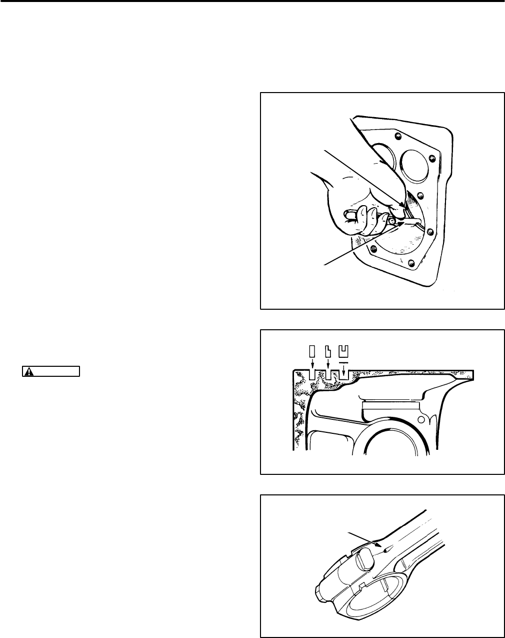
73
Piston Ring Gap
Before installing new rings on the piston, check the
ring gap by placing each ring squarely in its cylinder,
at a position corresponding to the bottom of its travel
(Figure 82). The gap should be 0.010-0.020 inch
(0.25-0.50 mm).
Do not file the ring ends to increase the end gap. If
the ring end gap does not meet the specifications,
check the correctness of ring and bore sizes. A cyl-
inder bore that is 0.001 inch (0.03 mm) undersize
will reduce the end gap 0.003 (0.08 m).
Rings that are 0.010, 0.020, 0.030 and 0.040 inch
(0.25, 0.51, 0.76 and 1.02 mm) oversize should be
used on corresponding oversize pistons.
Piston Assembly
1. Lubricate all parts with clean engine oil.
2. Line up the piston and connecting rod and in-
sert the piston pin. The piston pin is a full-float-
ing type kept in place by a lock ring on each
side. Push the lock rings in by thumb pressure
or pry them in with a small screwdriver. Make
sure they are properly seated.
CAUTION
Wear safety glasses and hold
your thumb over the lock ring to keep it from
flying out and getting lost or causing per-
sonal injury.
3. Refer to Figure 83. Use a piston ring spreader
to install the piston rings to prevent twisting or
excessive expansion. Follow the instructions in
the ring kit exactly. Note which ring goes in
which groove and which side of the ring is “up”.
Also note that the oil control ring is an assem-
bly.
Piston Installation
1. The crankshaft must be in place and should
have been serviced already if crankshaft ser-
vice was required. See CRANKSHAFT.
2. Turn the crankshaft to position the Number 1
rod bearing journal (side opposite oil filter side)
at the bottom of its stroke.
3. Lubricate the Number 1 piston assembly and
cylinder with engine oil. Compress the rings
with a ring compressor as shown in Figure 85.
Install the bearing insert in the piston rod.
4. Position the piston and rod assembly in the cyl-
inder block with the connecting rod oil hole up
(Figure 84).
FEELER
GAGE
PISTON RING IN
CYLINDER BORE
FIGURE 82. CHECKING RING GAP
FIGURE 83. PISTON RINGS
OIL HOLE
UP
FIGURE 84. CONNECTING ROD OIL HOLE
Redistribution or publication of this document,
by any means, is strictly prohibited.
Redistribution or publication of this document,
by any means, is strictly prohibited.
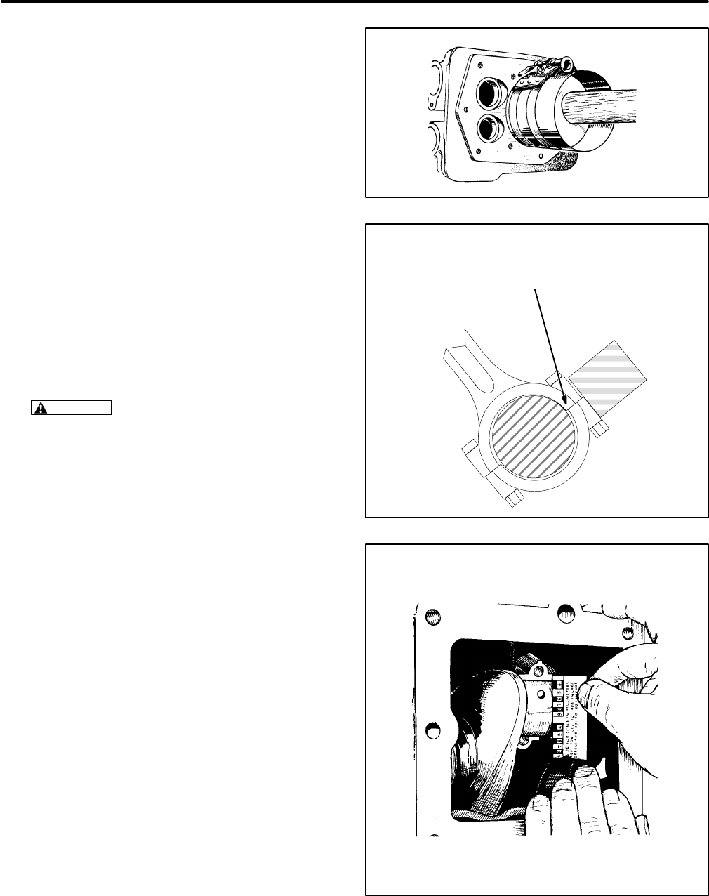
74
5. Tap the piston into the bore with the handle end
of the hammer until the connecting rod is
seated on the crankshaft journal (Figure 85). If
the crankshaft has been reground and/or new
rods are being installed, check the bearing
clearance with Plasti-gage as instructed below
under Rod Bearing Clearance.
6. Install the rod bearing cap as follows:
A. Lubricate the cap bolts with engine oil and
torque to 5 lbs-ft (7 N-m).
B. Strike the cap/rod joint using a hardwood
block and a leather or plastic mallet to re-
move any misalignment (Figure 86).
C. Torque the cap bolts to 14 lbs-ft (19 N-m).
Recheck the torque on each bolt after both
bolts have been torqued.
CAUTION
Failure to align the rod and cap
can result in high engine oil temperature
and failure of the rod.
7. Install the other piston assembly and crank the
engine by hand to see that all bearings are free.
Connecting Rod Bearing Clearance
1. Wipe all parts clean of oil and grease.
2. Select Plasti-gage that corresponds to the con-
necting rod bearing clearance specification
(0.0020-0.0033 inch [0.051-0.084 mm]). Place
the piece of Plasti-gage across the full width of
the bearing cap, about 1/4 inch (6 mm) off-cen-
ter (Figure 87).
3. Install the rod bearing caps as instructed in
Step 6 of Piston Installation above. Make sure
not rotate the crankshaft or the Plasti-gage will
smear.
4. Remove the bearing cap, leaving the Plasti-
gage on the part it sticks to. Check the widest
part of the flattened Plasti-gage with the gradu-
ations on the envelope to determine the bear-
ing clearance.
FIGURE 85. INSERTING PISTON
Torque the cap bolts to 5 lbs-ft (7 N-m), remove any
misalignment by striking the cap/rod joint using a
hardwood block and a leather or plastic mallet and
then torque the cap bolts to specification
FIGURE 86. ALIGNING CONNECTING ROD CAP
FIGURE 87. USING PLASTI-GAGE
Redistribution or publication of this document,
by any means, is strictly prohibited.
Redistribution or publication of this document,
by any means, is strictly prohibited.
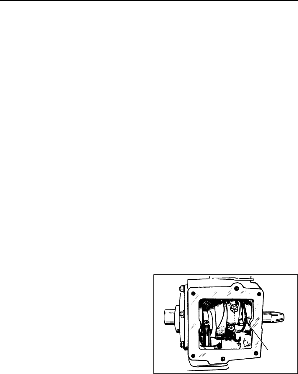
75
CRANKSHAFT
Removal
1. Remove the piston/rod assemblies if they have
not already been removed.
2. Remove the gear cover and crankshaft timing
gear. See GEAR COVER and TIMING GEARS
in this section.
3. Loosen the rear bearing plate screws and re-
move the bearing plate, gasket, thrust washer
and shims. See BEARINGS in this section.
4. Turn the crankshaft so the crankthrow is
aligned with the notch in the rear opening of the
crankcase and carefully slide the crankshaft
out.
Inspection
Inspect the rod and main bearing journals. If they
are worn or scored and cannot be smoothed by pol-
ishing, either the journals should be reground to the
next undersize, or the crankshaft should be re-
placed.
Clean out the drilled oil passages in the crankshaft.
Installation
1. Lubricate the front and rear main bearings with
engine oil.
2. Use oil or gear lubricant to hold the front thrust
washer in place against the engine block (see
Figure 90). The flat side of the thrust washer
goes against the block.
3. Position the crankshaft so that the crank throw
is aligned with the notch at the rear of the crank-
case and install the crankshaft. Make sure the
front thrust washer did not slip out of place dur-
ing installation.
4. Place the oil seal loader on the oil seal guide
and driver and insert it into the rear bearing
plate. Remove the seal guide and driver leaving
the loader in the bearing plate. The loader pre-
vents the seal from being cut on the crankshaft
keyway during installation of the rear bearing
plate.
5. Use oil or gear lubricant to hold the shim(s) and
rear thrust washer in position on the rear bear-
ing plate (see Figure 89). The shim goes
against the bearing plate and the flat surface of
the thrust washer goes against the shim.
6. Place the bearing plate gasket in position on
the block, making sure the oil hole on the back
of the block is exposed.
7. Install the rear bearing plate and fasten with two
nuts (or capscrews) tightened to the specified
torque. Make sure the rear thrust washer and
shim(s) did not slip out of place during installa-
tion. The crankshaft should turn freely by hand.
Crankshaft Endplay
See Figure 88. After tightening two rear bearing
plate nuts (or capscrews) to the specified torque,
check the crankshaft endplay at the point shown us-
ing a feeler gauge.
1. Lightly tap the front of the crankshaft with a
plastic-faced hammer to take up the endplay.
The endplay should be 0.006-0.012 inch
(0.15-0.30 mm).
2. If necessary, remove the rear bearing end plate
and add or remove shims.
3. Install the end plate and tighten all nuts (or
capscrews) to the specified torque.
4. Make sure the shim and thrust washer are in
place and recheck crankshaft endplay. Verify
that the crankshaft turns freely without binding.
REAR FRONT
MEASURE
ENDPLAY
HERE
FIGURE 88. CHECKING CRANKSHAFT ENDPLAY
Redistribution or publication of this document,
by any means, is strictly prohibited.
Redistribution or publication of this document,
by any means, is strictly prohibited.
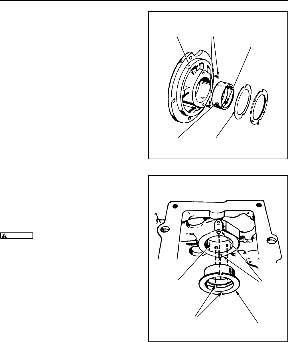
76
BEARINGS
To replace the crankshaft and camshaft bearings,
the engine must be completely disassembled. Use
the special drivers available to drive out the old
bearings and drive in the new. Support the engine
casting so as not to cause distortion or damage to
the bore or casting.
Crankshaft Bearings
Crankshaft bearings are available in standard size,
0.002, 0.010, 0.020 or 0.030 inch undersize.
When installing either the front or rear main bearing,
always align the oil hole(s) in the bearing with the oil
hole(s) in the bearing bore. The oil passage must be
at least 1/2 open.
Rear Bearing:
Use the special driver available to
drive in the rear main bearing. Push the bearing into
the bearing plate from the inner side to the depth al-
lowed by the flange on the driver. See Figure 89.
Front Bearing:
Use Loctite brand Bearing Mount or
equivalent when installing the front bearing. Use the
towelette furnished with the bearing kit to clean the
outside of the bearing and the bearing bore in the
block. Apply the Loctite to the mating surfaces of the
bearing and bearing bore. Allow three to four min-
utes for drying.
WARNING
Breathing the vapor from the towe-
lette provided with the Loctite, or prolonged
contact with skin, can be harmful. Be sure the
work area is well ventilated.
Use the special driver available to drive in the front
bearing. Push the bearing in to the depth allowed by
the flange on the driver. Wipe off any excess Loctite
and allow one hour for hardening at room tempera-
ture. See Figure 90.
Engines shipped from the factory have separate
thrust washers and main bearings for both front and
rear of engine. The front bearing replacement part is
a one-piece bearing (with attached thrust washer),
as shown. Do not add an additional thrust washer to
this front bearing.
REAR BEARING
END PLATE
SHIM
ALIGN BEARING OIL
HOLES WITH OIL
HOLES IN BEARING
BORE
BEARING THRUST
WASHER
LOCK
PINS
FIGURE 89. REAR CRANKSHAFT BEARING
NOTE: DO NOT ADD ADDITIONAL THRUST
WASHERS WHEN REPLACING THE FRONT BEARING
FRONT MAIN
BEARING
FRONT MAIN
BEARING
BORE
LOCK
PINS
ALIGN BEARING NOTCHES
WITH LOCK PINS AND
MATCH OIL HOLES
FIGURE 90. FRONT CRANKSHAFT BEARING
Redistribution or publication of this document,
by any means, is strictly prohibited.
Redistribution or publication of this document,
by any means, is strictly prohibited.
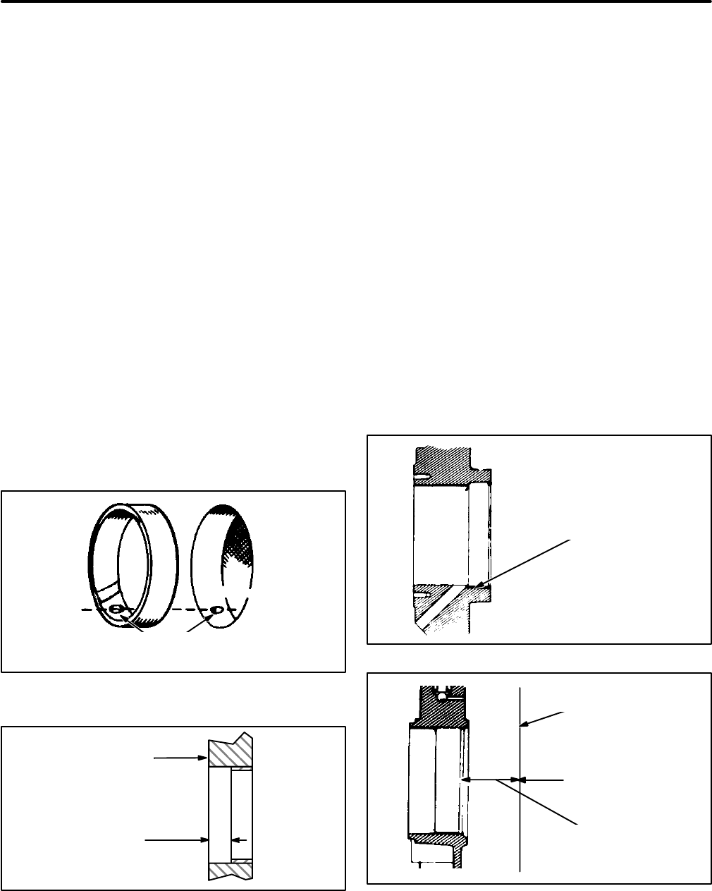
77
Camshaft Bearings
It should be noted that identical bearings are used
for replacing the front and rear camshaft bearings
and that they may look different from the old bear-
ings.
1. Clean the outside of each bearing and the bear-
ing bore in the block and coat the outside of the
bearing with Loctite brand Bearing Mount or
equivalent just before pressing it into its bore.
2. Press the front bearing in so that the oil hole in
the bearing lines up with the oil hole in the bore
(Figure 91).
3. Press the rear bearing in so that it is positioned
1/2 inch (12.7 mm) from the outside edge of the
bore. There is no oil hole in the rear bore with
which to line up the hole in the bearing (Fig-
ure 92).
4 Coat the bearing surfaces with engine oil after
installation.
ALIGN THE HOLE IN THE BEARING
WITH THE HOLE IN THE BEARING BORE
FIGURE 91. FRONT CAMSHAFT BEARING
1/2 inch
(12.7 mm)
OUTSIDE
OF BLOCK
FIGURE 92. REAR CAMSHAFT BEARING
OIL SEALS
Remove the rear bearing plate to replace the rear oil
seal (Figure 93) and the gear cover to replace the
front oil seal (Figure 94). Use an oil seal remover to
pry out the oil seals. Clean the bores of all old seal-
ing compound before installing the new seals.
Use an oil seal guide and driver to drive the rear seal
into the rear bearing plate until it bottoms against the
shoulder of the plate.
Drive the front oil seal into the gear cover until it is
0.95-0.99 inch (24.1-25.1 mm) from the mounting
face of the cover.
Place a light coating of grease on the lips of the
seals before installing the rear bearing plate and
gear cover. This provides initial lubrication until en-
gine oil reaches the seal. Refer to CRANKSHAFT
for the rear bearing plate installation procedure. Re-
fer to GEAR COVER for the gear cover installation
procedure.
DRIVE THE OIL SEAL
TO THE SHOULDER
OF THE PLATE BORE
FIGURE 93. REAR CRANKSHAFT OIL SEAL
0.95-0.99 inch
(24.1-25.1 mm)
DRIVE THE OIL SEAL
THUS FAR INTO THE
GEAR COVER BORE
MOUNTING FACE
OF GEAR COVER
FIGURE 94. FRONT (GEARCASE) CRANKSHAFT
OIL SEAL
Redistribution or publication of this document,
by any means, is strictly prohibited.
Redistribution or publication of this document,
by any means, is strictly prohibited.
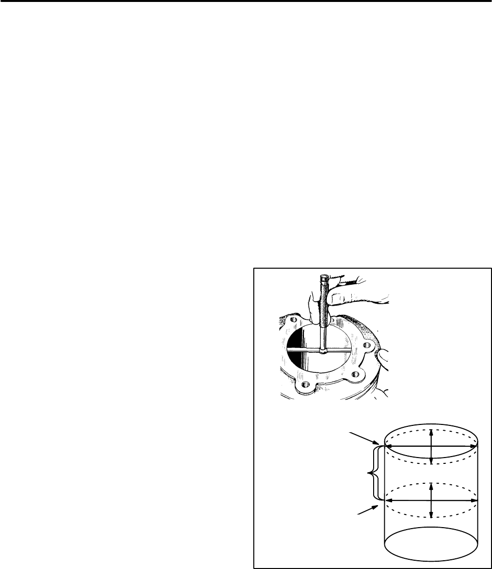
78
ENGINE BLOCK
The engine block is the main support for all other ba-
sic engine parts and subassemblies.
Cleaning
After removing the pistons, crankshaft, cylinder
heads, etc., inspect the block for cracks and ex-
treme wear. If it is still serviceable, prepare it for
cleaning as follows:
1. Scrape all old gasket material from the block.
Remove oil bypass to allow cleaning solution to
contact inside of oil passages.
2. Remove grease and scale from the cylinder
block by agitating in a bath of commercial
cleaning solution or hot soapy washing solu-
tion.
3. Rinse the block in clean hot water to remove
cleaning solution.
Inspecting the Block
When rebuilding the engine, thoroughly inspect the
block for any condition that would make it unfit for
further use. This inspection must be made after all
parts have been removed and the block has been
thoroughly cleaned and dried.
1. Make a thorough check for cracks. Minute
cracks may be detected by coating the sus-
pected area with a mixture of 25 percent kero-
sene and 75 percent light motor oil. Wipe the
part dry and immediately apply a coating of zinc
oxide (white lead) dissolved in wood alcohol. If
cracks are present, the white coating will be-
come discolored at the defective area. (Re-
move this coating after the test and before reas-
sembly.) Always replace a cracked cylinder
block.
2. Inspect all machined surfaces and threaded
holes. Carefully remove any nicks or burrs from
machined surfaces. Clean out tapped holes
and clean up any damaged threads.
3. Check the top of the block for flatness with a
straight-edge and a feeler gauge.
Inspecting the Cylinder Bores
Inspect the cylinder bores for scuffing, scratches,
wear and scoring. If these conditions exist, the cylin-
ders must be rebored and honed for the next over-
size piston.
If the cylinder bores look good and there are no scuff
marks, check the bores for wear and out-of-round-
ness as follows:
1. Check cylinder bore for taper, out-of-round-
ness and wear with a cylinder bore gauge, tele-
scope gauge or inside micrometer. These mea-
surements should be taken at four places: the
top and bottom of piston ring travel, and parallel
and perpendicular to the axis of the crankshaft.
See Figure 95.
A
B
C
D
RING WEAR
AREA
TOP OF RING
TRAVEL
BOTTOM OF
RING
TRAVEL
FIGURE 95. MEASURING CYLINDER BORE
Redistribution or publication of this document,
by any means, is strictly prohibited.
Redistribution or publication of this document,
by any means, is strictly prohibited.
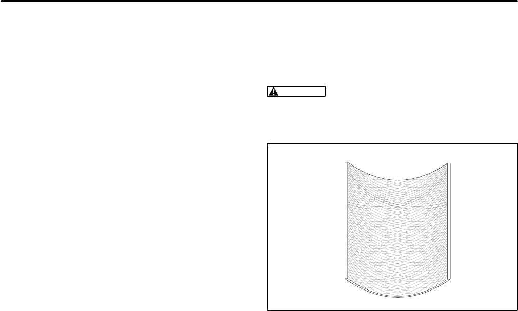
79
2. Record the measurements taken at the top and
bottom of the piston travel as follows:
A. Measure and record as A the cylinder bore
diameter (parallel to crankshaft) near the
top of cylinder bore where the greatest
amount of wear occurs.
B. Measure and record as B the cylinder bore
diameter (parallel to crankshaft) at the bot-
tom of piston travel.
C. Measure and record as C the cylinder bore
diameter (perpendicular to crankshaft)
near the top of cylinder bore where the
greatest amount of wear occurs.
D. Measure and record as D the cylinder bore
diameter (perpendicular to crankshaft) at
the bottom of piston travel.
E. Reading A subtracted from reading B and
reading C subtracted from reading D indi-
cates the cylinder taper.
F. Reading A compared to reading C and
reading B compared to reading D indicates
whether or not the cylinder is out-of-round.
If the out-of-round exceeds 0.003 inch
(0.08 mm), the cylinders must be rebored
and honed to the next oversize. A reboring
machine is used when changing to over-
size pistons. The following repair data de-
scribes the honing procedure.
Machining the Cylinder Bores
The available oversize pistons and rings will fit with
the required clearance in cylinders machined to the
matching oversize (standard bore plus 0.005,
0.010, 0.020, 0.030 and 0.040 inch). There is no
need to adjust or to “fit” pistons and rings. Piston and
ring size should be checked as described below to
confirm that they are correct for the standard bore
oversize. Boring and honing must be accurate and
remove just enough metal for the smallest oversize
possible. The finish hone should leave a 20 to 40 mi-
cro-inch crosshatch finish having an included angle
of 20 to 25 degrees. The crosshatch finish is neces-
sary for fast piston ring break-in. See Figure 96.
Clean the cylinder bore with hot, soapy water and a
brush after machining. A clean white rag will not soil
when the cylinder bore is clean. Dry the bores and
coat them with oil.
CAUTION
Do not use gasoline or commercial
cleaning solvents to clean the cylinder bores af-
ter honing—they do not remove abrasives.
FIGURE 96. PROPER HONE CROSSHATCH
IN CYLINDER BORE
Deglazing the Cylinder Bores
Deglaze the cylinder bores for fast piston ring break-
in if the bores look good and there is not enough
wear, taper and out-of-roundness to warrant ma-
chining. Deglazing should not increase the bore di-
ameter, permitting the use of the original pistons (if
they are good) with new rings. To deglaze the cylin-
der bores:
1. Wipe the cylinder bores with a clean cloth that
has been dipped in light engine oil.
2. Use a brush-type deglazing tool with coated
bristle tips.
3. Drive the tool with a slow-speed drill. Move the
tool up and down in the cylinder bores fast
enough to obtain the crosshatch pattern shown
(Figure 96). Ten to twelve strokes should be
sufficient.
4. Clean the cylinder bore with hot, soapy water
and a brush after deglazing. A clean white rag
will not soil when the cylinder bore is clean. Dry
the bores and coat them with oil.
Redistribution or publication of this document,
by any means, is strictly prohibited.
Redistribution or publication of this document,
by any means, is strictly prohibited.
80
Service Checklist
After servicing, inspect and test the installation to
confirm that the genset will operate as intended.
Check each of the areas described below before
putting the genset into service.
Mounting
Examine all mounting bolts and supporting mem-
bers to verify that the genset is properly mounted.
All fasteners should be tightened securely to pre-
vent them from working loose when subjected to
vibration.
Lubrication
If the engine oil was drained, refill as instructed in
the Operator’s Manual.
Wiring
Verify that all wiring connections are tight and
installed properly. Check each of these connec-
tions:
•Load wires
•Control wires
•Ground straps
•Battery cables
Initial Start Adjustments
Perform governor and carburetor adjustments ac-
cording to
Engine Subsystems
if they have not been
done already.
Output Check
Apply a full load to make sure the genset can pro-
duce its full rated output. Use a load test panel to ap-
ply a progressively greater load until full load is
reached.
Exhaust System
While the genset is running inspect the entire ex-
haust system, including the exhaust manifold, muf-
fler and exhaust pipe. Look and listen for leaks at all
connections, welds, gaskets and joints. Also make
sure the exhaust pipe is not overheating adjacent
materials or equipment. Do not run the genset until
all exhaust leaks have been repaired.
WARNING
Exhaust gas is deadly. The exhaust
system must not leak and must discharge all ex-
haust away from the vehicle. Do not run the gen-
set until the exhaust leaks have been repaired.
Fuel System
While the genset is running, inspect the fuel supply
lines, return lines, filters and fittings for leaks. Check
flexible sections for cuts, cracks and abrasions and
make sure they are not rubbing against anything
that could cause leakage. Repair all fuel leaks im-
mediately.
WARNING
Gasoline and LPG are flammable
and explosive. Leaking fuel could lead to fire
and to severe personal injury or death. Repair
fuel leaks immediately.
Control
Stop and start the genset several times at the con-
trol panel on the genset and at the remote control
board (if provided) to verify that they work properly.
Mechanical
Stop the genset and inspect it for leaking gaskets,
loose fasteners, damaged components and inter-
ference with other equipment. Repair as necessary.
Inspect the generator compartment and verify that
there are no breaks or openings in the vapor-proof
wall that separates the compartment from the ve-
hicle interior. Seal openings as necessary. Make
sure that all soundproofing material is in place.
Redistribution or publication of this document,
by any means, is strictly prohibited.
Redistribution or publication of this document,
by any means, is strictly prohibited.

81
Troubleshooting
Regular maintenance can prevent many of the
problems listed below. Removing and cleaning the
cylinder heads every 500 hours is especially impor-
tant for gasoline models. Before considering major
engine service because of abnormal performance,
refer to
Periodic Maintenance
in the Operator’s
Manual for instructions on how to clean the cylinder
heads using Onan “4C”.
These troubleshooting charts are designed to help
you think through genset problems. To save time
troubleshooting, read the entire manual ahead of
time to understand the genset. Try to think through
problems. Go over what was done during the last
service call. The problem could be as simple as an
empty fuel tank, closed fuel shutoff valve, loose
wire, blown fuse or tripped circuit breaker.
THE ENGINE DOES NOT CRANK
There are hazards present in troubleshooting that can cause equipment damage,
severe personal injury or death. Troubleshooting must be performed by qualified persons who
know about the hazards of fuel, electricity and machinery. Read Safety Precautions inside the
front cover and observe all instructions and precautions in this manual.
WARNING
Possible Cause Corrective Action
1. The remote enable switch (if
supplied) is OFF.Turn the key switch ON. If necessary, verify that the switch works
and that the customer connected it according to the appropriate
wiring diagram in
Wiring Diagrams
.
2. Control fuse F1 on the side
of the control box has blown.
(Beginning Spec J)
Check for and repair ground faults in the choke heater (H1), fuel
pump/solenoid (E2/FS), ignition coil (T1) and remote control con-
nector (P2-5 and P2-6) circuits. See
Wiring Diagrams
.
Replace
the fuse with a 10 amp slow-blow mini-bayonet type.
3. Control board fuse F1 has
blown. (Spec H Only) Check for and repair ground faults in the starter relay (K1), fuel
pump/solenoid (E2/FS) and relay K5/K6 circuits. See
Wiring Dia-
grams
.
Replace the fuse with an Onan supplied fuse only.
4. The remote control circuit (if
provided) is faulty. Try starting with the local Start switch. If the engine cranks, find
and repair the fault in the remote control circuit.
5. The local Start switch circuit
is faulty. Try starting with the remote Start switch (if provided). If the en-
gine cranks, replace control board A1 (Spec H only) or the control
panel assembly (Beginning Spec J).
Redistribution or publication of this document,
by any means, is strictly prohibited.
Redistribution or publication of this document,
by any means, is strictly prohibited.

82
THE ENGINE DOES NOT CRANK (CONTINUED)
There are hazards present in troubleshooting that can cause equipment damage,
severe personal injury or death. Troubleshooting must be performed by qualified persons who
know about the hazards of fuel, electricity and machinery. Read Safety Precautions inside the
front cover and observe all instructions and precautions in this manual.
WARNING
Possible Cause Corrective Action
6. Cranking voltage is too low
to crank the engine. a. Clean and tighten or replace the battery cable connectors and
cables at the battery and the genset. See the Installation Manual
to verify that the battery cable sizes are adequate.
b. Recharge or replace the battery. Specific gravity for a fully
charged battery is approximately 1.260 at 80°F (27°C).
c. If the genset is in standby service, install a battery charger.
d. Once the genset has been started, troubleshoot the battery
charging circuit according to THE GENERATOR DOES NOT
CHARGE THE BATTERY. Beginning Spec J, if the Low Bat indi-
cator stays on during operation, recheck all of the above steps.
Beginning Spec J
7. The starter motor assem-
bly is malfunctioning or not
connected properly.
Check and tighten connections at starter solenoid terminals S
and M and push and hold in the Start switch.
If the Start Sol indicator does not light, go to Step 8.
If the Start Sol indicator on the control panel lights, measure
voltage at solenoid terminal M.
If there is at least 9 VDC but the motor does not function
properly, service or replace the motor assembly.
If there is not at least 9 VDC, replace the solenoid. See
ELECTRIC STARTER in
Engine Subsystems.
8. Control A1 or start relay K5
are faulty or not properly
connected.
Remove the control panel and check for B+ at relay K5 terminal
30. (K5 is mounted in a socket on the back of the panel.)
If there is no voltage, reconnect wiring as necessary. See
Wiring Diagrams
.
If there is B+ at terminal 30, remove the relay from its socket
and apply battery voltage across coil terminals 85 and 86.
If the coil does not function or if there is no electrical con-
tinuity between terminals 30 and 87 when the relay is
energized, replace the relay.
If the relay is good, replace the control panel assembly.
Redistribution or publication of this document,
by any means, is strictly prohibited.
Redistribution or publication of this document,
by any means, is strictly prohibited.

83
THE ENGINE DOES NOT CRANK (CONTINUED)
There are hazards present in troubleshooting that can cause equipment damage,
severe personal injury or death. Troubleshooting must be performed by qualified persons who
know about the hazards of fuel, electricity and machinery. Read Safety Precautions inside the
front cover and observe all instructions and precautions in this manual.
WARNING
Possible Cause Corrective Action
Spec H Only
9. Control board A1 or start
relay K1 is faulty. Remove the control panel. Push the Start-Stop switch to Start
and measure voltage at start solenoid terminal S.
If there is not at least 9 VDC, see TESTING CONTROL
BOARD A1 in
Engine Control
. Replace parts or reconnect
leads as necessary.
If there is at least 9 volts at terminal S, push the Start-Stop
switch to Start again and measure voltage at the motor ter-
minal on the start solenoid. If there is no voltage at the motor
terminal, replace relay K1.
10. The cable between start
relay K1 and the starter
motor is loose, damaged or
missing.
Service as necessary.
11. The starter motor is mal-
functioning. Push the Start-Stop switch to Start and measure voltage at the
starter motor terminal. If there is at least 9 VDC but the motor
does not function, replace the starter motor. See ELECTRIC
STARTER in
Engine Subsystems.
Redistribution or publication of this document,
by any means, is strictly prohibited.
Redistribution or publication of this document,
by any means, is strictly prohibited.

84
THE ENGINE CRANKS BUT DOES NOT START
There are hazards present in troubleshooting that can cause equipment damage,
severe personal injury or death. Troubleshooting must be performed by qualified persons who
know about the hazards of fuel, electricity and machinery. Read Safety Precautions inside the
front cover and observe all instructions and precautions in this manual.
WARNING
Possible Cause Corrective Action
1. Fuse F2 on the side of the
control box has blown.
(Spec H, Gasoline only)
Check for and repair ground faults in the choke heater (H1) and
ignition coil (T1) circuits. See
Wiring Diagrams
.
Replace the fuse
with a 10 amp slow-blow mini-bayonet type.
2. The fuel supply shutoff
valve is closed or the fuel
tank is empty.
Service as necessary.
3. Cranking voltage is too low
to reach require cranking
speed.
a. Clean and tighten or replace the battery cable connectors and
cables at the battery and the genset. See Installation Manual to
verify that the battery cable sizes are adequate.
b. Recharge or replace the battery. Specific gravity for a fully
charged battery is approximately 1.260 at 80°F (27°C).
c. If the genset is in standby service, install a battery charger.
d. Once the genset has started, troubleshoot the battery charging
circuit according to THE GENERATOR DOES NOT CHARGE
THE BATTERY.
4. Low engine temperature is
causing too low a cranking
speed for starting.
Replace the engine oil if it is not of the recommended viscosity
for the ambient temperature. See the Operator’s Manual.
5. The ignition system is weak
or has poor connections or
the control is faulty. (Begin-
ning Spec J)
a. If the Ignition indicator lights when the Start switch is held in,
check and tighten the connections at the + and - terminals of the
ignition coil (T1). Do the Quick Ignition Test under IGNITION
SYSTEM in
Engine Subsystems
. If the spark is weak or there is
no spark at all, service the ignition system as necessary.
b. If the Ignition indicator does not light, replace the control assem-
bly.
Redistribution or publication of this document,
by any means, is strictly prohibited.
Redistribution or publication of this document,
by any means, is strictly prohibited.

85
THE ENGINE CRANKS BUT DOES NOT START (CONTINUED)
There are hazards present in troubleshooting that can cause equipment damage,
severe personal injury or death. Troubleshooting must be performed by qualified persons who
know about the hazards of fuel, electricity and machinery. Read Safety Precautions inside the
front cover and observe all instructions and precautions in this manual.
WARNING
Possible Cause Corrective Action
6. The ignition system is weak
or has poor connections.
(Spec H Only)
Do the Quick Ignition Test under IGNITION SYSTEM in
Engine
Subsystems
.
If there is only a weak spark, service the ignition system as
necessary.
If there is no spark, hold in the Start switch and measure the
voltage at the positive (+) terminal on the ignition coil.
If there is at least 9 VDC, service the ignition system as
necessary.
If there is not at least 9 VDC, go to Step 7 or 8, as ap-
propriate.
7. Control board A1 is faulty.
(Spec H, LPG) If there is not at least 9 VDC at the ignition coil during cranking
(Step 6), see TESTING CONTROL BOARD A1 in
Engine Con-
trol
. Replace parts or reconnect leads as necessary.
8. Relay K6 or control A1 is
faulty. (Spec H, Gasoline) If there is not at least 9 VDC at the ignition coil during cranking
(Step 6), remove the lead at terminal 85 on relay K6. Hold in the
Start switch and measure the voltage at the end of the lead just
disconnected.
If there is at least 9 VDC, verify that all the leads at relay K6
are connected according to the appropriate connection dia-
gram in
Wiring Diagrams
. If they are, replace relay K6.
If there is not at least 9 VDC at the end of the lead marked
K6-85, check all the connections back to control board A1
and see TESTING CONTROL BOARD A1 in
Engine Con-
trol.
Replace parts or reconnect leads as necessary.
9. The choke is not closing
properly in colder weather. Service as instructed in FUEL SYSTEM in
Engine Subsystems.
(Gasoline carburetors only.)
10. The engine is not getting
fuel because the fuel sole-
noid is not opening, the fuel
pump is not pumping or the
control is faulty. (Beginning
Spec J)
If the Fuel Pump indicator lights during cranking but you cannot
hear or feel the solenoid open or the pump vibrate, test the fuel
solenoid or pump according to FUEL SYSTEM in
Engine Sub-
systems
. If the Fuel Pump indicator does not light during crank-
ing, replace the control board assembly.
Redistribution or publication of this document,
by any means, is strictly prohibited.
Redistribution or publication of this document,
by any means, is strictly prohibited.

86
THE ENGINE CRANKS BUT DOES NOT START (CONTINUED)
There are hazards present in troubleshooting that can cause equipment damage,
severe personal injury or death. Troubleshooting must be performed by qualified persons who
know about the hazards of fuel, electricity and machinery. Read Safety Precautions inside the
front cover and observe all instructions and precautions in this manual.
WARNING
Possible Cause Corrective Action
11. The engine is not getting
fuel because the fuel sole-
noid is not opening, the fuel
pump is not pumping or the
control is faulty. (Spec H
Only)
If you cannot hear or feel the solenoid open or the pump vibrate,
disconnect the lead to the fuel pump and/or solenoid and and
measure voltage at the end of the lead during cranking.
If there is at least 9 VDC, test the fuel solenoid or pump ac-
cording to FUEL SYSTEM in
Engine Subsystems
.
If there is not at least 9 VDC, see TESTING CONTROL
BOARD A1 in
Engine Control
.
12. The engine is not getting
fuel because the fuel pump
and/or fuel solenoid is not
installed properly.
a. Verify that the LPG fuel solenoid and gasoline fuel pump are con-
nected properly, especially where the customer has mounted the
fuel pump remote from the genset and added a fuel tank shutoff
solenoid. The remote pump and solenoid must be connected to
the genset using insulated conductors of at least 16 AWG, have
adequate bonding paths to the negative (-) terminal of the battery
and have corrosion-free connections.
b. Verify that the fuel pump (gasoline gensets only) is not more than
3 feet (.9 M) in elevation above the pickup tube in the fuel supply
tank. If it is, relocate the fuel pump according to the instructions
in the Installation Manual.
13. The fuel mixture screws are
not adjusted properly. (Prior
to SPEC L only)
Adjust as instructed in FUEL SYSTEM in
Engine Subsystems
.
14. The LPG demand regulator
is malfunctioning. Test and adjust (prior to SPEC L only) and/or replace as
instructed in FUEL SYSTEM in
Engine Subsystems
.
15. The engine is worn or mal-
functioning mechanically. Do the CYLINDER COMPRESSION TEST in
Engine Subsys-
tems
and service as necessary.
Redistribution or publication of this document,
by any means, is strictly prohibited.
Redistribution or publication of this document,
by any means, is strictly prohibited.

87
THE ENGINE STOPS WHEN THE START SWITCH IS RELEASED
(BEGINNING SPEC J)
There are hazards present in troubleshooting that can cause equipment damage,
severe personal injury or death. Troubleshooting must be performed by qualified persons who
know about the hazards of fuel, electricity and machinery. Read Safety Precautions inside the
front cover and observe all instructions and precautions in this manual.
WARNING
Possible Cause Corrective Action
Go to Step 1 if the engine stops when the Start switch is released but the starter disengages normally
when the Start switch is held in. The problem is probably low oil pressure or a faulty pressure sender.
Go to Step 2 if the starter does not disengage when the Start switch is held in. The problem is prob-
ably in the PMG or its connections.
1. The engine oil pressure is
low or the cutout switch is
faulty. (The starter disen-
gages normally when the
Start switch is held in.)
a. Check engine oil level and fill as necessary. Go to the next step
if the engine still does not continue to run when the start switch
is released.
b. Bypass low oil pressure cutout switch S2 by disconnecting the
lead to it and grounding it. (For access, remove the cylinder head
shroud on the oil filter side.) Start the genset.
If oil pressure is at least 12 psi, replace low oil pressure cut-
out switch S2.
If oil pressure is less than 12 psi, service the engine accord-
ing to LUBRICATION SYSTEM in
Engine Block Assembly
.
2. The PMG is faulty or not
connected properly. (The
starter does not disengage
when the Start switch is
held in.)
a. Disconnect connector J8/P8 in the wiring harness in the vicinity
of the ignition coil and connect an ohmmeter to check PMG stator
winding continuity. Replace the PMG stator if the windings are
open (normal winding resistance is approximately 0.13 ohms).
See PMG in
Engine Subsystems
.
b. If winding continuity is good, connect an AC volt meter to the
PMG stator leads, start the engine, hold in the Start switch and
immediately pull off the wire connector at starter solenoid termi-
nal S to disengage the starter. Replace the flywheel assembly
(Figure 9) if the output is less than 29 VAC.
Redistribution or publication of this document,
by any means, is strictly prohibited.
Redistribution or publication of this document,
by any means, is strictly prohibited.

88
THE ENGINE STOPS WHEN THE START SWITCH IS RELEASED
(SPEC H ONLY)
There are hazards present in troubleshooting that can cause equipment damage,
severe personal injury or death. Troubleshooting must be performed by qualified persons who
know about the hazards of fuel, electricity and machinery. Read Safety Precautions inside the
front cover and observe all instructions and precautions in this manual.
WARNING
Possible Cause Corrective Action
In normal operation, run relay K3 on control board A1 must remain powered in order to keep the
genset running when the start switch is released. See
Wiring Diagrams
. Three things must occur to
keep run relay K3 powered: 1) engine oil pressure must be sufficient to close low oil pressure cutout
switch S2, 2) stop relay K5 must open and 3) output from generator winding B1-B2 must be sufficient
to pull in start disconnect relay K2 on control board A1.
To isolate the problem, plug a test lamp or voltmeter into a convenient power receptacle on the
vehicle. Start the genset and keep it running by holding in the Start switch and go to NORMAL OUT-
PUT VOLTAGE or NO (LOW) OUTPUT VOLTAGE, as appropriate.
Normal Output Voltage
1. The engine oil level is low. Check engine oil level and fill as necessary.
2. The engine oil pressure is
low or the cutout switch is
faulty.
Bypass low oil pressure cutout switch S2 by disconnecting con-
trol board A1 connector lead J1-5 / J5 from connector J5 and
grounding it and start the genset. If bypassing switch S2 allows
the engine to continue running, remove the pressure switch (for
access, remove the cylinder shroud on the oil filter side), install
an oil pressure gauge and run the genset.
If oil pressure is at least 12 psi, replace low oil pressure cut-
out switch S2.
If oil pressure is less than 12 psi, service the engine accord-
ing to LUBRICATION SYSTEM in
Engine Block Assembly
.
3. Stop Relay K5 is faulty. Disconnect stop relay K5 by disconnecting engine control board
A1 connector lead J1-10 / CR6 from CR6 (inside the control box)
and start the genset. If disconnecting relay K5 allows the engine
to continue running, check wiring in the stop relay K5 circuit
against the appropriate wiring diagram in
Wiring Diagrams
. If the
wiring is good, replace relay K5.
Redistribution or publication of this document,
by any means, is strictly prohibited.
Redistribution or publication of this document,
by any means, is strictly prohibited.

89
THE ENGINE STOPS WHEN THE START SWITCH IS RELEASED
(SPEC H ONLY) (CONTINUED)
There are hazards present in troubleshooting that can cause equipment damage,
severe personal injury or death. Troubleshooting must be performed by qualified persons who
know about the hazards of fuel, electricity and machinery. Read Safety Precautions inside the
front cover and observe all instructions and precautions in this manual.
WARNING
Possible Cause Corrective Action
4. Winding B1-B2 is faulty. Isolate the B1-B2 winding lead pair (orange striped leads) by dis-
connecting connectors J7 and J8 (inside the control box) and the
two leads at the AC terminals on battery charging voltage regula-
tor VR2 (mounted on a bracket on the generator) and test the
winding as instructed under TESTING THE GENERATOR in
Generator
. If the B1-B2 winding is faulty, replace the entire stator
assembly.
5. Control Board A1 is faulty. Check the control board connector according to TESTING CON-
TROL BOARD A1 in
Engine Control
and replace control board
A1 if cleaning the connector does not help.
No (Low) Output Voltage
6. Field voltage is low. Measure field voltage while cranking the engine. See TESTING
FOR FIELD VOLTAGE in
Generator
. If there is at least 9 VDC
across the brush block terminals, test and service or replace the
brushes, slip rings, rotor and stator according to SERVICING
THE BRUSHES AND SLIP RINGS and TESTING THE GEN-
ERATOR in
Generator
.
7. Control Board A1 is faulty. Measure voltage between output voltage regulator VR1 connec-
tor pin 7 (connector J9 on 3-phase gensets) and ground while
cranking the engine. If there is less than 9 VDC, check the control
board connector according to TESTING CONTROL BOARD A1
in
Engine Control
and replace engine control board A1 if cleaning
the connector does not help.
Redistribution or publication of this document,
by any means, is strictly prohibited.
Redistribution or publication of this document,
by any means, is strictly prohibited.

90
THE ENGINE STOPS WHEN THE START SWITCH IS RELEASED
(SPEC H ONLY) (CONTINUED)
There are hazards present in troubleshooting that can cause equipment damage,
severe personal injury or death. Troubleshooting must be performed by qualified persons who
know about the hazards of fuel, electricity and machinery. Read Safety Precautions inside the
front cover and observe all instructions and precautions in this manual.
WARNING
Possible Cause Corrective Action
8. Voltage Regulator VR1 is
faulty. Measure voltage between VR1 connector pin 9 (connector J10
on 3-phase gensets) and ground while cranking the engine.
If there is less than 9 VDC, replace output voltage regulator
VR1.
If there is at least 9 VDC, measure resistance between VR1
connector pin 10 (connector J11 on 3-phase gensets) and
ground. Replace output voltage regulator VR1 if there is
measurable resistance (greater than zero).
9. Generator output too low. See OUTPUT VOLTAGE IS TOO HIGH OR TOO LOW
THE ENGINE MISFIRES OR BACKFIRES
There are hazards present in troubleshooting that can cause equipment damage,
severe personal injury or death. Troubleshooting must be performed by qualified persons who
know about the hazards of fuel, electricity and machinery. Read Safety Precautions inside the
front cover and observe all instructions and precautions in this manual.
WARNING
Possible Cause Corrective Action
1. The ignition system if faulty. Service the ignition system as necessary according to IGNITION
SYSTEM in
Engine Subsystems.
2. The fuel mixture is too lean. a. Adjust fuel mixture (prior to Spec L only) according to FUEL SYS-
TEM in
Engine Subsystems.
b. Check for and repair a vacuum leak.
c. Overhaul (prior to Spec L only) or replace the carburetor accord-
ing to FUEL SYSTEM in
Engine Subsystems.
Redistribution or publication of this document,
by any means, is strictly prohibited.
Redistribution or publication of this document,
by any means, is strictly prohibited.

91
THE ENGINE MISFIRES OR BACKFIRES (CONTINUED)
There are hazards present in troubleshooting that can cause equipment damage,
severe personal injury or death. Troubleshooting must be performed by qualified persons who
know about the hazards of fuel, electricity and machinery. Read Safety Precautions inside the
front cover and observe all instructions and precautions in this manual.
WARNING
Possible Cause Corrective Action
3. The fuel (gasoline) is con-
taminated. Connect the genset to a container of fuel of known quality and run
the genset under various loads. Replace the contents of the fuel
supply tank if there is a noticeable improvement in performance.
4. The engine is malfunction-
ing mechanically. Service as necessary according to
Engine Block Assembly
.
THE ENGINE LACKS POWER
There are hazards present in troubleshooting that can cause equipment damage,
severe personal injury or death. Troubleshooting must be performed by qualified persons who
know about the hazards of fuel, electricity and machinery. Read Safety Precautions inside the
front cover and observe all instructions and precautions in this manual.
WARNING
Possible Cause Corrective Action
1. There is carbon build-up in
the cylinder heads. Remove the heads and clean using Onan “4C” according the Op-
erator’s Manual.
2. The ignition system is faulty. Service the ignition system as necessary according to IGNITION
SYSTEM in
Engine Subsystems.
3. Fuel mixture and governor
adjustments are incorrect. a. Adjust according to Governor and Carburetor Adjustments under
FUEL SYSTEM in
Engine Subsystems.
b. Check for and repair a vacuum leak.
c. Overhaul (prior to Spec L only) or replace the carburetor accord-
ing to FUEL SYSTEM in
Engine Subsystems.
4. The gasoline fuel pump is
not installed properly. Verify that the fuel pump is not more than 3 feet (.9 m) in elevation
above the pickup tube in the fuel supply tank. If it is, relocate the
fuel pump according to the instructions in the Installation Manual.
5. The fuel filter(s) is clogged. Replace clogged gasoline filters and clean out LPG filters and
regulators. See LPG System—Liquid Withdrawal under FUEL
SYSTEM in
Engine Subsystems.
Redistribution or publication of this document,
by any means, is strictly prohibited.
Redistribution or publication of this document,
by any means, is strictly prohibited.

92
THE ENGINE LACKS POWER (CONTINUED)
There are hazards present in troubleshooting that can cause equipment damage,
severe personal injury or death. Troubleshooting must be performed by qualified persons who
know about the hazards of fuel, electricity and machinery. Read Safety Precautions inside the
front cover and observe all instructions and precautions in this manual.
WARNING
Possible Cause Corrective Action
6. The fuel (gasoline) is con-
taminated. Connect the genset to a container of known fuel quality and run
the genset under various loads. Replace the contents of the fuel
supply tank if there is a noticeable improvement in performance.
7. The engine air filter element
is dirty. Replace the air filter element.
8. The exhaust system is re-
stricted. Service as necessary.
9. The valve adjustment is in-
correct. Adjust according to Adjusting Valve Clearance (Lash) under
VALVE SYSTEM in
Engine Block Assembly
.
10. The engine is worn or mal-
functioning mechanically. Do the CYLINDER COMPRESSION TEST in
Engine Subsys-
tems
and service as necessary according to
Engine Block As-
sembly
.
THE ENGINE HUNTS
There are hazards present in troubleshooting that can cause equipment damage,
severe personal injury or death. Troubleshooting must be performed by qualified persons who
know about the hazards of fuel, electricity and machinery. Read Safety Precautions inside the
front cover and observe all instructions and precautions in this manual.
WARNING
Possible Cause Corrective Action
1. Fuel mixture (prior to Spec L
only) and governor adjust-
ments are incorrect.
Adjust according to Governor and Carburetor Adjustments under
FUEL SYSTEM in
Engine Subsystems.
2. The governor spring is
weak. Replace the spring.
3. The governor mechanism is
worn. Service as necessary according to GEAR COVER and GOVER-
NOR CUP in
Engine Block Assembly
.
Redistribution or publication of this document,
by any means, is strictly prohibited.
Redistribution or publication of this document,
by any means, is strictly prohibited.

93
THE ENGINE OVERHEATS
There are hazards present in troubleshooting that can cause equipment damage,
severe personal injury or death. Troubleshooting must be performed by qualified persons who
know about the hazards of fuel, electricity and machinery. Read Safety Precautions inside the
front cover and observe all instructions and precautions in this manual.
WARNING
Possible Cause Corrective Action
1. The fuel mixture is too lean. Adjust according to Governor and Carburetor Adjustments under
FUEL SYSTEM in
Engine Subsystems
(prior to Spec L only).
2. The engine cooling fins are
oily and dirty. Clean as necessary.
3. The installation restricts
cooling air. Verify that the installation is in accordance with the Installation
Manual.
THE ENGINE HAS HIGH OIL CONSUMPTION
There are hazards present in troubleshooting that can cause equipment damage,
severe personal injury or death. Troubleshooting must be performed by qualified persons who
know about the hazards of fuel, electricity and machinery. Read Safety Precautions inside the
front cover and observe all instructions and precautions in this manual.
WARNING
Possible Cause Corrective Action
1. The oil is diluted or has too
light a viscosity. Replace the oil in the crankcase with oil of correct viscosity. See
the Operator’s Manual for engine oil recommendations.
2. The crankcase breather
valve is dirty or defective. Service or replace the breather valve according to CRANKCASE
BREATHER ASSEMBLY in
Engine Subsystems
.
3. There are oil leaks. Service as necessary.
4. The oil bypass valve is
faulty. Service as necessary according to LUBRICATION SYSTEM in
Engine Block Assembly
.
5. The engine is worn or mal-
functioning mechanically. Do the CYLINDER COMPRESSION TEST in
Engine Subsys-
tems
and service as necessary according to
Engine Block As-
sembly
.
Redistribution or publication of this document,
by any means, is strictly prohibited.
Redistribution or publication of this document,
by any means, is strictly prohibited.

94
THE GENSET RUNS BUT THERE IS NO OUTPUT VOLTAGE
There are hazards present in troubleshooting that can cause equipment damage,
severe personal injury or death. Troubleshooting must be performed by qualified persons who
know about the hazards of fuel, electricity and machinery. Read Safety Precautions inside the
front cover and observe all instructions and precautions in this manual.
WARNING
Possible Cause Corrective Action
1. The line circuit breakers are
OFF or have TRIPPED.
(Beginning Spec J the Gen
AC indicator light will be on
if generator output volt-
age—ahead of the circuit
breakers—is normal.)
Find out why the circuit breakers were turned OFF, make sure it
is safe to reconnect power, and then throw the circuit breaker ON.
If the circuit breakers have tripped, shut down the genset and ser-
vice as necessary to clear the short circuit or ground fault that
caused tripping and then RESET the circuit breakers and restart
the genset.
2. A line circuit breaker is
faulty. Shut down the genset, make sure the power output lines from the
genset have been disconnected from all other sources of power,
attempt to RESET the circuit breaker and throw it ON and check
for electrical continuity across its terminals. Replace the circuit
breaker if there is measurable resistance.
3. The generator is connected
wrong. Remove the control panel and verify that all generator connec-
tions are according to the appropriate connection diagram in
Generator.
4. A main stator winding is
open. (Beginning Spec J, if
the Gen AC indicator light is
not on, there is a problem in
the generator or voltage
regulator.)
Test and service according to TESTING THE GENERATOR in
Generator
.
5. The quadrature winding of
the stator is open (single-
phase gensets only).
Test and service according to TESTING THE GENERATOR in
Generator
.
6. Voltage regulator VR1 is
faulty. Test and service according to TESTING THE VOLTAGE REG-
ULATOR in
Generator
.
Redistribution or publication of this document,
by any means, is strictly prohibited.
Redistribution or publication of this document,
by any means, is strictly prohibited.

95
THE OUTPUT VOLTAGE IS TOO HIGH OR TOO LOW
There are hazards present in troubleshooting that can cause equipment damage,
severe personal injury or death. Troubleshooting must be performed by qualified persons who
know about the hazards of fuel, electricity and machinery. Read Safety Precautions inside the
front cover and observe all instructions and precautions in this manual.
WARNING
Possible Cause Corrective Action
1. Voltage has been adjusted
incorrectly. Adjust the voltage as required. For single-phase gensets, the ad-
justing rheostat is on the control panel (inside the control box on
Spec J) and for three-phase gensets on the voltage regulator.
2. Frequency has been ad-
justed incorrectly. Adjust according to Governor and Carburetor Adjustments under
FUEL SYSTEM in
Engine Subsystems.
3. The brushes are not making
good contact with the slip
rings.
Service as necessary according to SERVICING THE BRUSHES
AND SLIP RINGS in
Generator
.
4. The generator is connected
wrong. Remove the control panel and verify that all generator connec-
tions are according to the appropriate connection diagram in
Generator
.
5. The rotor winding is shorted. Test and service according to TESTING THE GENERATOR in
Generator
.
6. A main stator winding is
shorted or grounded. Test and service according to TESTING THE GENERATOR in
Generator
.
7. Voltage regulator VR1 is
faulty. Test and service according to TESTING THE VOLTAGE REG-
ULATOR in
Generator
.
Redistribution or publication of this document,
by any means, is strictly prohibited.
Redistribution or publication of this document,
by any means, is strictly prohibited.

96
THE GENERATOR IS NOISY
There are hazards present in troubleshooting that can cause equipment damage,
severe personal injury or death. Troubleshooting must be performed by qualified persons who
know about the hazards of fuel, electricity and machinery. Read Safety Precautions inside the
front cover and observe all instructions and precautions in this manual.
WARNING
Possible Cause Corrective Action
1. The brush block is loose. Tighten the mounting screws as necessary.
2. The generator bearing is
worn. Replace according to ASSEMBLING AND DISASSEMBLING
THE GENERATOR in
Generator
.
3. The rotor and crankshaft are
misaligned. Service according to ASSEMBLING AND DISASSEMBLING
THE GENERATOR in
Generator
.
THE GENERATOR OVERHEATS
There are hazards present in troubleshooting that can cause equipment damage,
severe personal injury or death. Troubleshooting must be performed by qualified persons who
know about the hazards of fuel, electricity and machinery. Read Safety Precautions inside the
front cover and observe all instructions and precautions in this manual.
WARNING
Possible Cause Corrective Action
1. The vent openings in the
stator are restricted with oil
and dirt.
Clean as necessary.
2. The generator windings are
covered with oil and dirt. Clean as necessary.
3. A rotor or stator winding is
shorted or grounded. Test and service according to TESTING THE GENERATOR in
Generator
.
4. Voltage regulator VR1 is
faulty. Test and service according to TESTING THE VOLTAGE REG-
ULATOR in
Generator
.
Redistribution or publication of this document,
by any means, is strictly prohibited.
Redistribution or publication of this document,
by any means, is strictly prohibited.

97
THE PHASES ARE UNBALANCED (3-PHASE GENSETS)
There are hazards present in troubleshooting that can cause equipment damage,
severe personal injury or death. Troubleshooting must be performed by qualified persons who
know about the hazards of fuel, electricity and machinery. Read Safety Precautions inside the
front cover and observe all instructions and precautions in this manual.
WARNING
Possible Cause Corrective Action
1. The connected loads are
distributed unevenly among
the phases.
Shut down the genset and redistribute the loads so that there is
a difference of less than 10 percent between phases.
2. Improper connections have
been made at terminal block
TB1 or the power output cir-
cuit breakers CB1, CB2
and/or CB3.
Shut down the genset and reconnect according to the appropri-
ate connection diagram in
Generator.
3. A main stator winding is
shorted or grounded. Test and service according to TESTING THE GENERATOR in
Generator
.
4. A load has a ground fault or
short circuit. Service the faulty equipment as necessary.
Redistribution or publication of this document,
by any means, is strictly prohibited.
Redistribution or publication of this document,
by any means, is strictly prohibited.

98
THE GENSET DOES NOT CHARGE THE BATTERY
There are hazards present in troubleshooting that can cause equipment damage,
severe personal injury or death. Troubleshooting must be performed by qualified persons who
know about the hazards of fuel, electricity and machinery. Read Safety Precautions inside the
front cover and observe all instructions and precautions in this manual.
WARNING
Possible Cause Corrective Action
1. Circuit breaker CB4 is faulty
(Spec H only). Check for continuity across the terminals. Replace if resistance
is greater than zero ohms.
2. PMG leads J8-1 and J8-2
(beginning Spec J) or Gen-
erator winding leads B1 and
B2 (Spec H only), battery
charging voltage regulator
VR2 and circuit breaker
CB4 (Spec H only) are not
connected properly.
Remove the control panel and verify that all generator connec-
tions are according to the appropriate connection diagram in
Generator.
3. Battery charging voltage
regulator VR2 is faulty. Disconnect the lead at terminal B+ on voltage regulator VR2 and
measure voltage (VDC) while the genset is running. If all wiring
corrections are correct, replace voltage regulator VR2 if output
is less than 12 VDC.
Redistribution or publication of this document,
by any means, is strictly prohibited.
Redistribution or publication of this document,
by any means, is strictly prohibited.
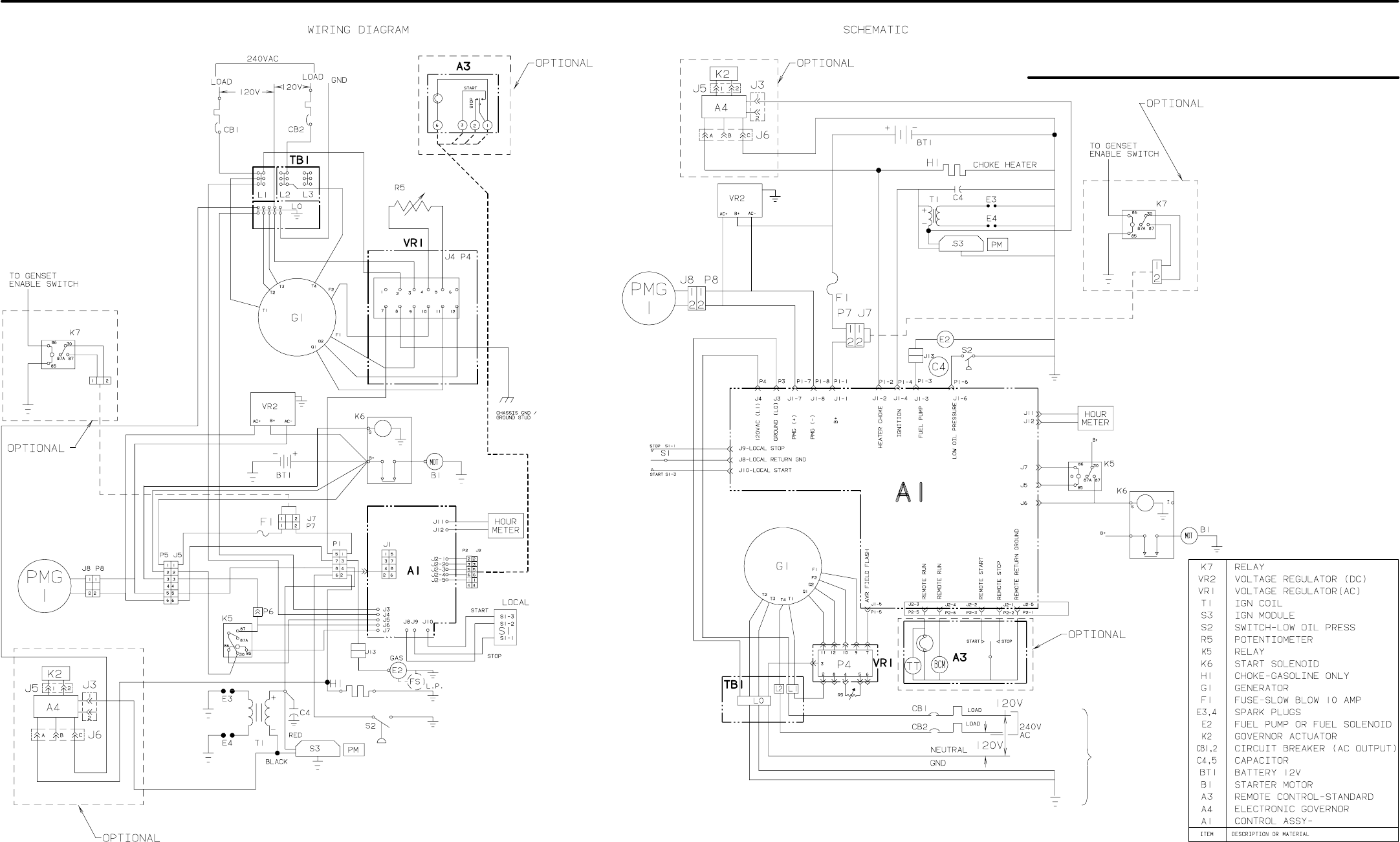
99
Wiring Diagrams
SINGLE-PHASE 60 HERTZ GENSETS (BEGINNING SPEC J) 611-1227
NOTES:
1. THE ENABLE SWITCH IS CUSTOMER
PROVIDED. USE 16 GA CU WIRE
FOR CONNECTIONS.
2. SEE THE SECTION TITLED
GENERA-
TOR
FOR GENERATOR RECONNEC-
TIONS.
SEE NOTE 2
SEE NOTE 1
SEE NOTE 1
Redistribution or publication of this document,
by any means, is strictly prohibited.
Redistribution or publication of this document,
by any means, is strictly prohibited.
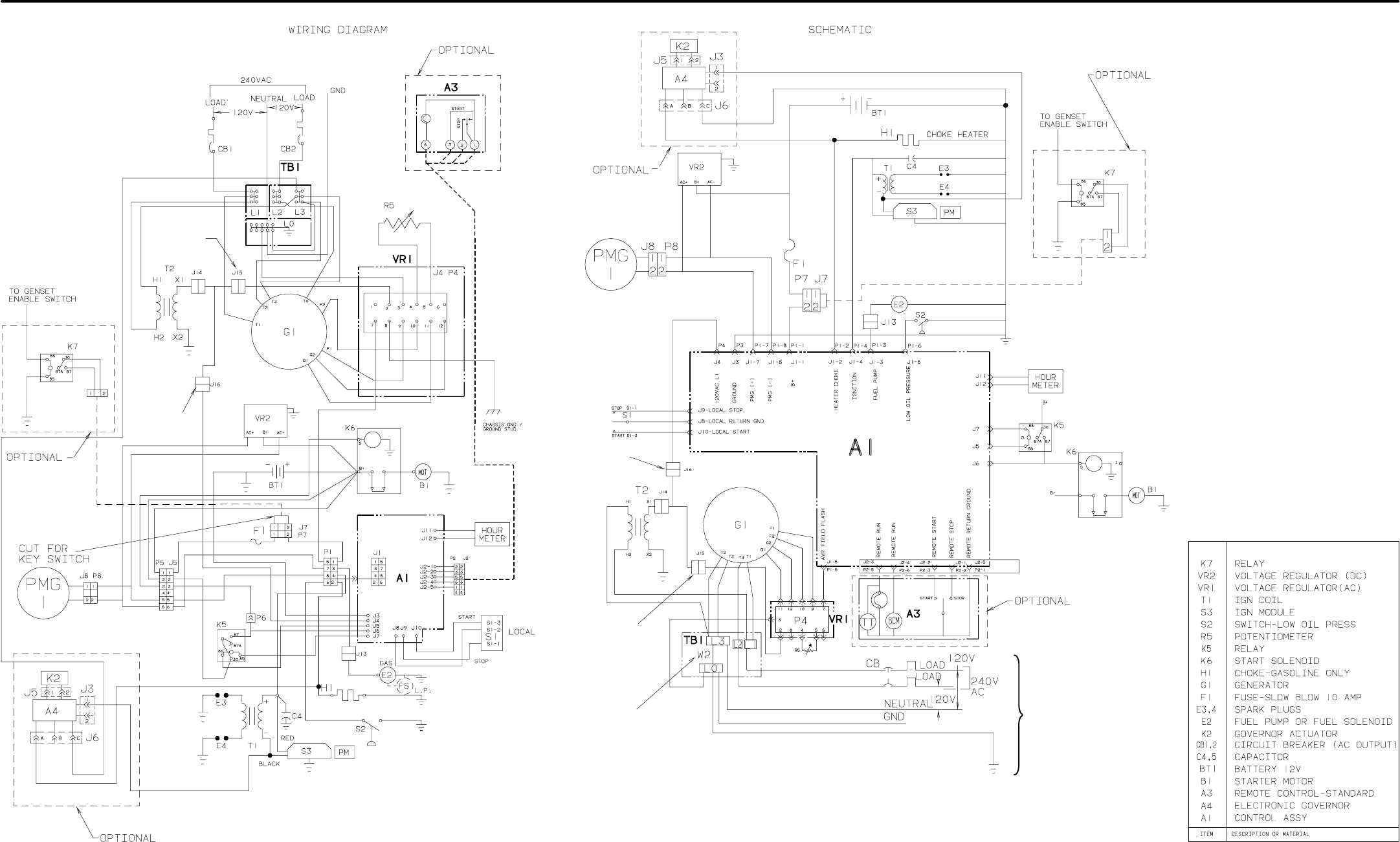
100
SINGLE-PHASE 50 HERTZ GENSETS (BEGINNING SPEC J) 611-1234
NOTES:
1. THE ENABLE SWITCH IS CUS-
TOMER PROVIDED. USE 16 GA CU
WIRE FOR CONNECTIONS.
2. SEE THE SECTION TITLED
GEN-
ERATOR
FOR GENERATOR RE-
CONNECTIONS.
3. FOR ISOLATED NEUTRAL RE-
MOVE JUMPER W2 BETWEEN
TB1-L3 AND TB1-L0.
4. LEAD L1-J4 CONNECTS TO J16.
5. LEAD L1 P4-2 CONNECTS TO J15.
T2 TRANSFORMER-VOLTAGE REF.
SEE NOTE 4
SEE NOTE 5
SEE NOTE 5
SEE NOTE 4
SEE NOTE 3 SEE NOTE 2
SEE NOTE 1
SEE NOTE 1
Redistribution or publication of this document,
by any means, is strictly prohibited.
Redistribution or publication of this document,
by any means, is strictly prohibited.
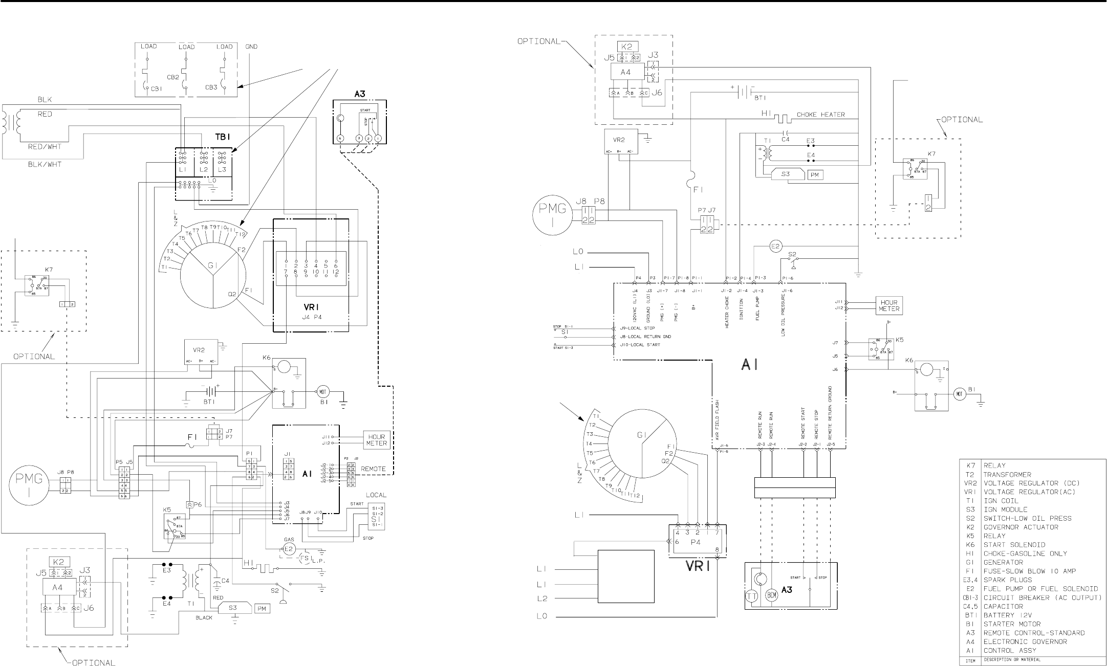
101
THREE-PHASE GENSETS (BEGINNING SPEC J) 611-1232
WIRING SCHEMATIC
SEE SECTION TITLED
GENERATOR
FOR GENERATOR CONNECTIONS
T2
P2
J2
T2
SEE SECTION TITLED
GENERATOR
FOR GENERATOR CONNECTIONS
54 1236
54 1236
TO THE CUSTOMER PROVIDED REMOTE
ENABLE SWITCH. USE 16 AWG CU WIRE.
TO REMOTE
ENABLE SWITCH.
Redistribution or publication of this document,
by any means, is strictly prohibited.
Redistribution or publication of this document,
by any means, is strictly prohibited.
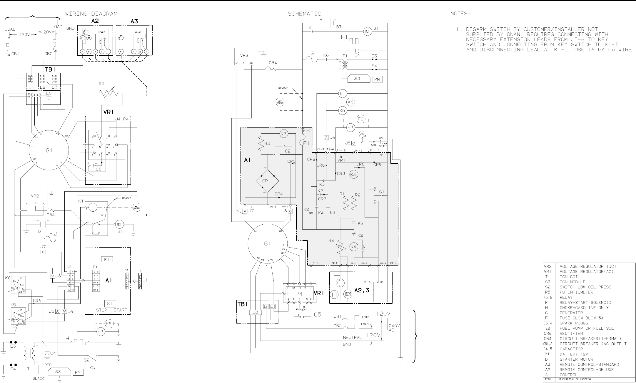
102
SINGLE-PHASE GASOLINE-FUELED GENSETS (SPEC H ONLY)
2. THE COMPONENTS ON CONTROL BOARD A1 (SHADED AREA) ARE NOT
SEPARATELY REPLACEABLE, EXCEPT FOR FUSE F1, AND ARE SHOWN FOR
REFERENCE ONLY.
3. SEE THE SECTION TITLED
GENERATOR
FOR GENERATOR RECONNEC-
TIONS.
611-1215
SEE NOTE 3
SEE NOTE 3
SEE NOTE 2
SEE NOTE 1
SEE NOTE 1
Redistribution or publication of this document,
by any means, is strictly prohibited.
Redistribution or publication of this document,
by any means, is strictly prohibited.
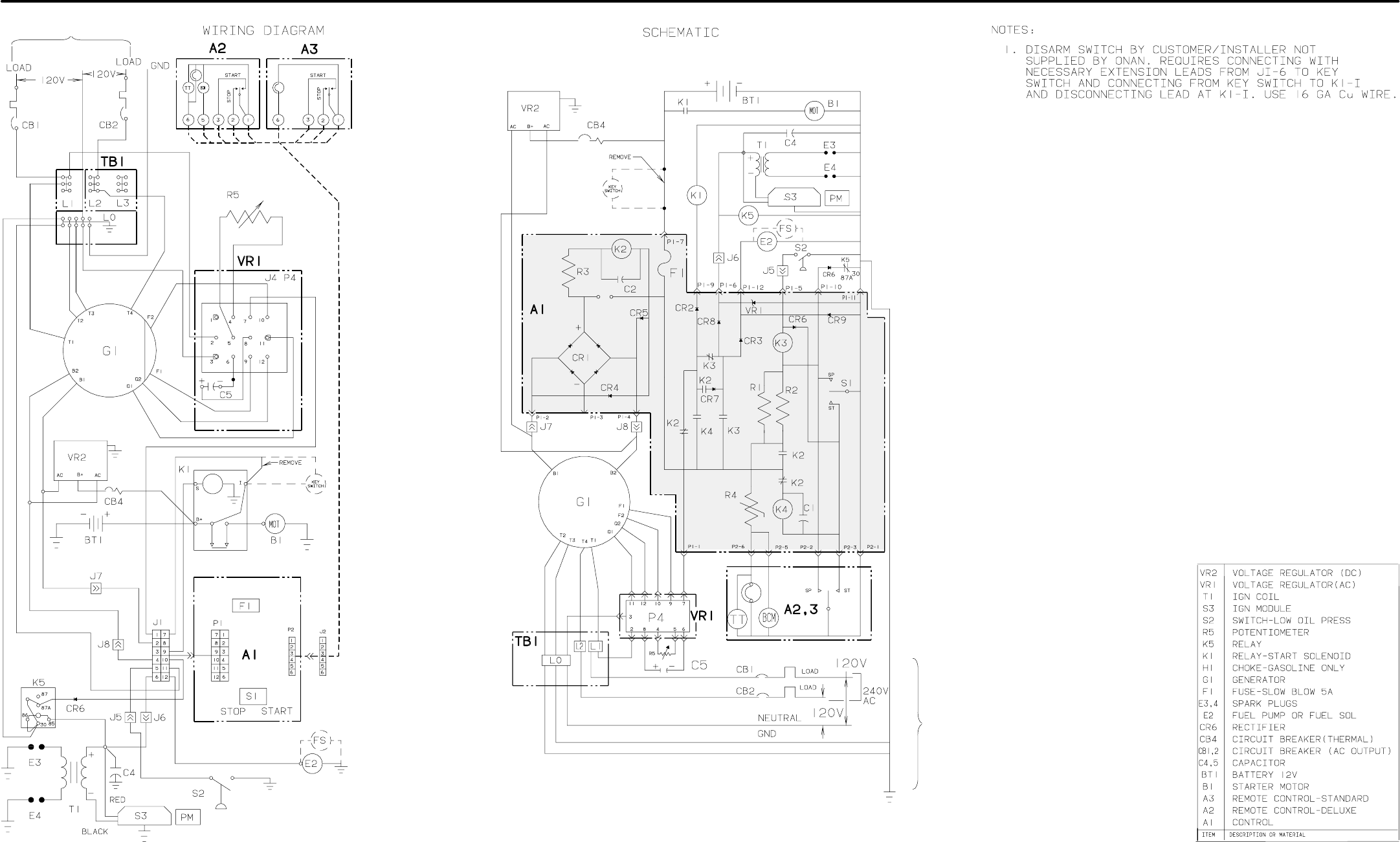
103
SINGLE-PHASE LPG-FUELED GENSETS (SPEC H ONLY) 611-1210
2. THE COMPONENTS ON CONTROL BOARD A1 (SHADED AREA) ARE NOT
SEPARATELY REPLACEABLE, EXCEPT FOR FUSE F1, AND ARE SHOWN FOR
REFERENCE ONLY.
3. SEE THE SECTION TITLED
GENERATOR
FOR GENERATOR RECONNEC-
TIONS.
SEE NOTE 3
SEE NOTE 3
SEE NOTE 2
SEE NOTE 1
SEE NOTE 1
Redistribution or publication of this document,
by any means, is strictly prohibited.
Redistribution or publication of this document,
by any means, is strictly prohibited.
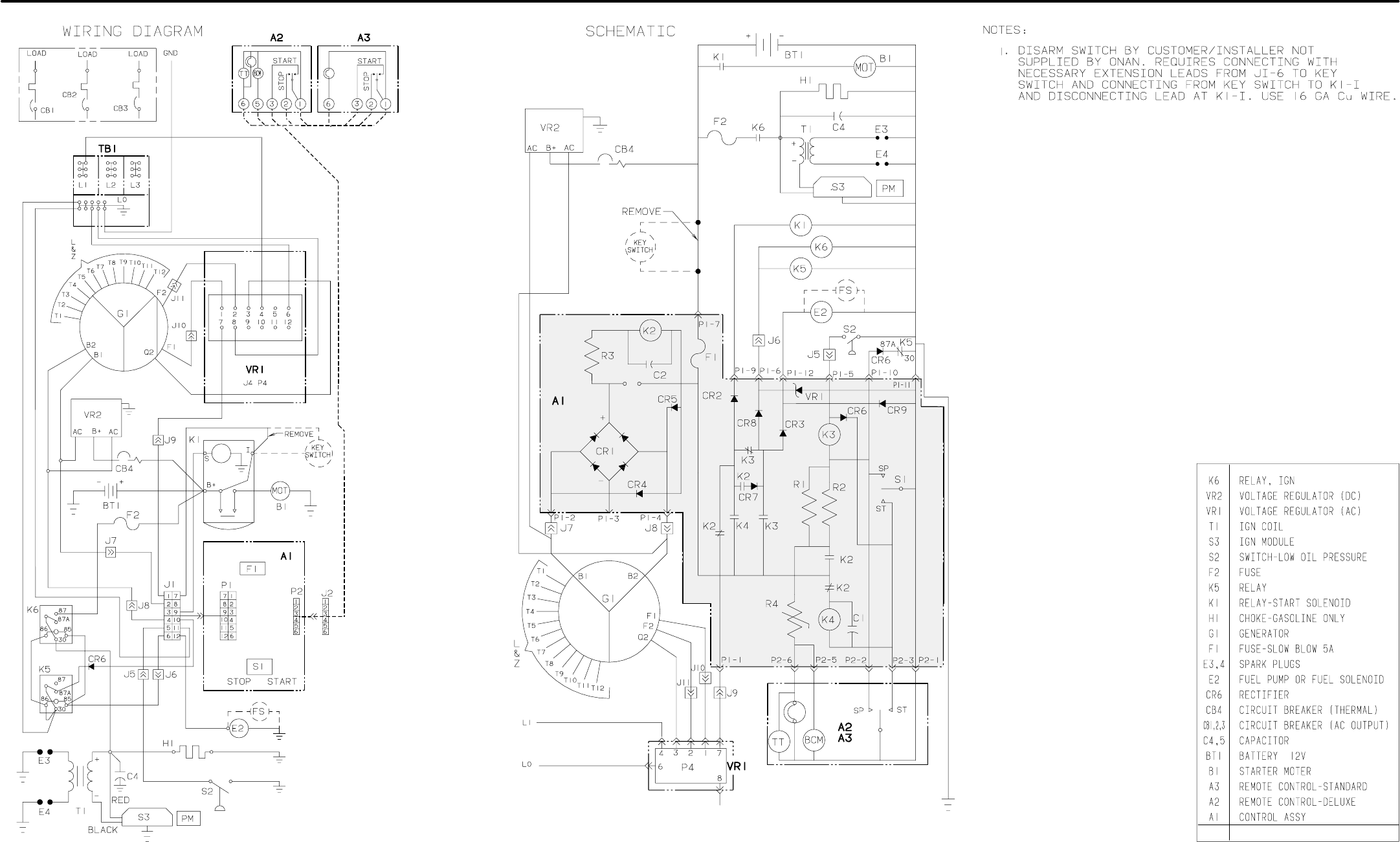
104
THREE-PHASE GENSETS (SPEC H ONLY) 611-1224ITEM DESCRIPTION
2. THE COMPONENTS ON CONTROL BOARD A1 (SHADED AREA) ARE
NOT SEPARATELY REPLACEABLE, EXCEPT FOR FUSE F1, AND ARE
SHOWN FOR REFERENCE ONLY.
3. SEE THE SECTION TITLED
GENERATOR
FOR GENERATOR RECON-
NECTIONS.
SEE NOTE 3
SEE NOTE 3
SEE NOTE 2
SEE NOTE 1
SEE NOTE 1
Redistribution or publication of this document,
by any means, is strictly prohibited.
Redistribution or publication of this document,
by any means, is strictly prohibited.

Cummins Power Generation
1400 73rd Avenue N.E.
Minneapolis, MN 55432
763-574-5000
Fax: 763-528-7229
Cummins and Onan are registered trademarks of Cummins Inc.
Redistribution or publication of this document,
by any means, is strictly prohibited.
Redistribution or publication of this document,
by any means, is strictly prohibited.
