965 0528 Onan BGE (spec F K) NHE E Genset Service Manual (09 1994) 1060 Supplement M) (11 1995)
User Manual: 965-0528 Onan BGE (spec F-K) NHE (spec E-K) Genset Service manual (09-1994) 965-1060 Supplement (spec M) (11-1995)
Open the PDF directly: View PDF ![]() .
.
Page Count: 161 [warning: Documents this large are best viewed by clicking the View PDF Link!]
- Cover
- Supplements
- Appendix B. Later Wiring Diagrams
- Table of Contents
- 1. Introduction
- 2. Specifications
- 3. Dimensions and Clearances
- 4. Torque Specifications
- 5. Preparing to Service
- 6. Engine - Primary Systems
- 7. Control
- 8. Generator
- 9. Engine - Block Assembly
- 10. Service Checklist
- Appendix A. Troubleshooting Charts
- Appendix B. Spec J and K Diagrams

Caution: This document contains mixed page sizes (8.5 x 11 or 11 x
17), which may affect printing. Please adjust your printer settings
according to the size of each page you wish to print.
Redistribution or publication of this document
by any means, is strictly prohibited.
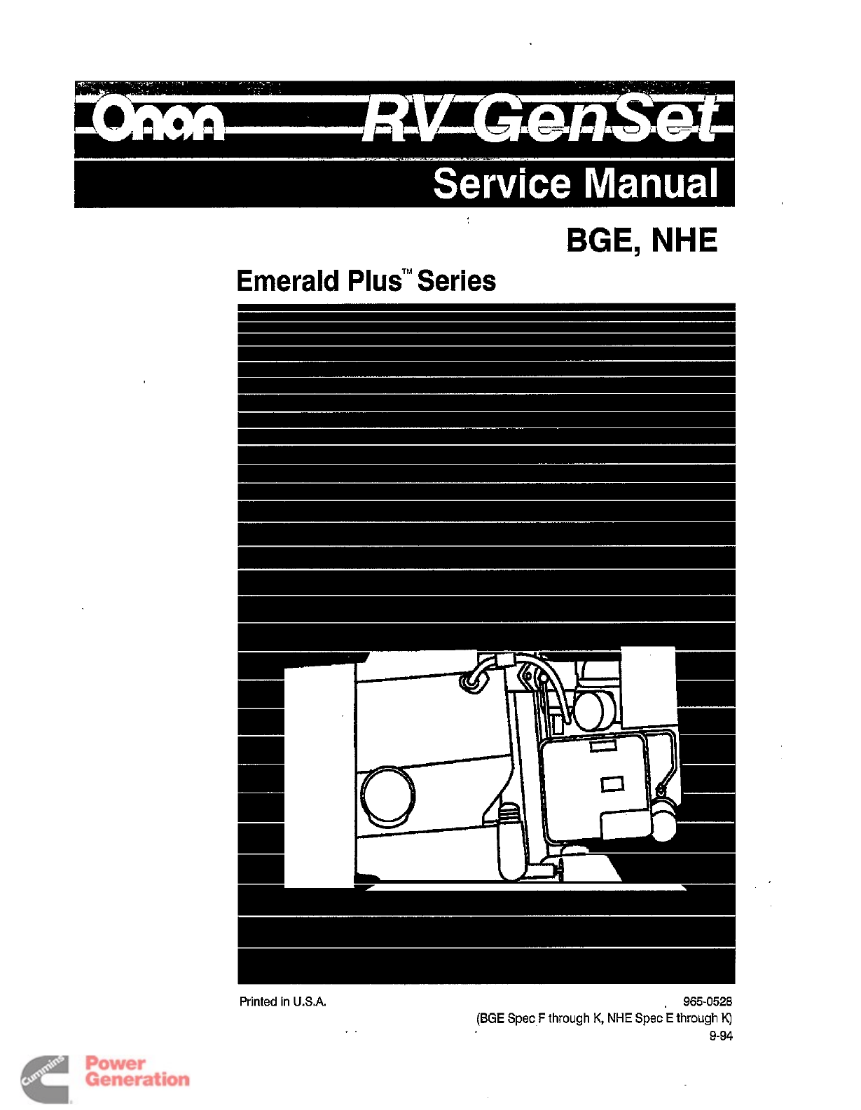
BGE,
NHE
Emerald
Plus'"
Series
,
965-0528
(BGE
Spec
F
through
K,
NHE
Spec
E
through
K)
9-94
.I
Redistribution or publication of this document
by any means, is strictly prohibited.
The engine exhaust from this product
contains chemicals known
to
the State
of
California
to
cause cancer, birth
defects or other reproductive harm.
Redistribution or publication of this document
by any means, is strictly prohibited.
,
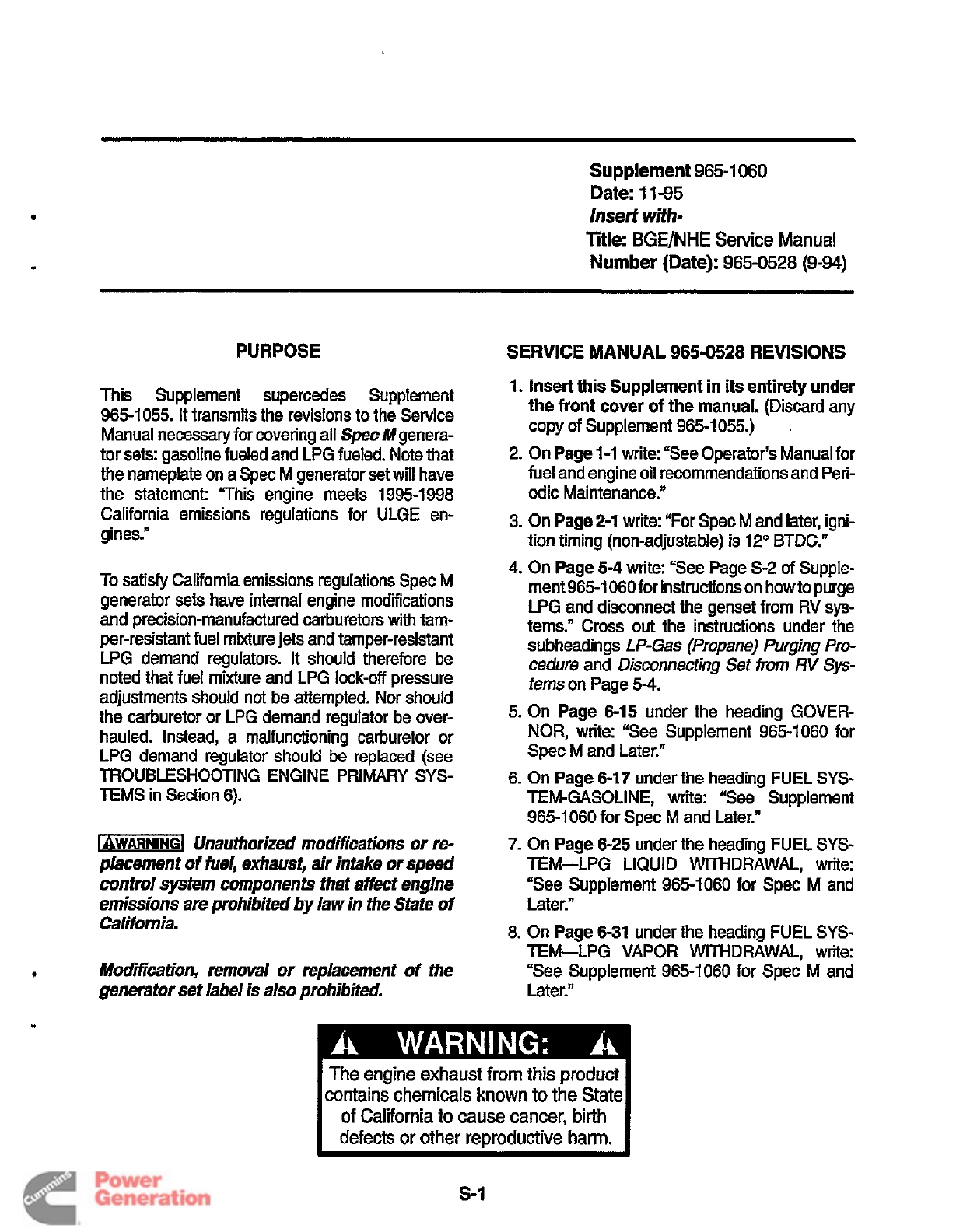
PURPOSE
This Supplement supercedes Supplement
965-1055. It transmits the revisions to the Service
Manual necessary for covering all Spec Mgenera-
tor sets: gasoline fueled and LPG fueled. Note that
the nameplate on a Spec
M
generator set will have
the statement: “This engine meets 1995-1 998
California emissions regulations for ULGE en-
gines.”
To satisfy California emissions regulations Spec M
generator sets have internal engine modifications
and precision-manufactured carburetors with tam-
per-resistant fuel mixture jets and tamper-resistant
LPG demand regulators. It should therefore be
noted that fuel mixture and LPG
lock-off
pressure
adjustments should not be attempted. Nor should
the carburetor or LPG demand regulator be over-
hauled. Instead, a malfunctioning carburetor or
LPG demand regulator should be replaced (see
TEMS in Section 6).
TROUBLESHOOTING ENGINE PRIMARY
SYS-
LgWAR”G1
Unauthorized modifications or
re-
placement
of
fuel, exhaust, air intake or
speed
control system wmponenis that affecf engine
emissions are prohibited by law in the State
of
California.
9
Modification, removal
or
replacement
of
the
generator set label is also prohibited,
Supplement
965-1
060
Date:
1
1-95
Insert
with-
Title:
BGE/NHE
Service
Manual
Number (Date):
965-0528 (9-94)
SERVICE MANUAL
965-0528
REVISIONS
1.
Insert this Supplement in its entirety under
the
front
cover
of
the manual.
(Discard any
copy of Supplement 965-1
055.)
2.
On
Page 1-1
wriie: “See Operator’s Manual for
fuel and engine oil recommendations and Peri-
odic Maintenance.”
3.
On
Page 2-1
write: “For Spec
M
and later, igni-
tion timing (nonadjustable)
is
12” BTDC.”
4.
On
Page
5-4
write: “See Page
S-2
of Supple-
ment 965-1 060 for instructions on how to purge
LPG and disconnect the genset from RV
sys-
tems.” Cross
out
the instructions under
the
subheadings
L
P-Gas
(Propane) Purging Pro-
cedure
and
Disconnecting Set from
RV
Sys-
tems
on Page
5-4.
5.
On
Page 6-15
under the heading GOVER-
NOR,
write: “See Supplement 965-1 060 for
Spec M and Later.”
6.
On
Page 6-17
under the heading FUEL
SYS-
TEM-GASOLINE, write:
“See
Supplement
965-1060 for
Spec
M and Later.”
7.
On
Page 6-25
under the heading FUEL SYS-
TEM-LPG LIQUID
WITHDRAWAL,
write:
“See Supplement 965-1060 for Spec M and
Later.”
8.
On
Page 6-31
under the heading FUEL
SYS-
TEM-LPG VAPOR WITHDRAWAL, write:
“See Supplement 965-1060 for Spec M and
Later.”
.
I
The engine exhaust from this product
contains chemicals known to the State
of
California to cause cancer, birth
I
defects or other reproductive harm.
s-I
Redistribution or publication of this document
by any means, is strictly prohibited.
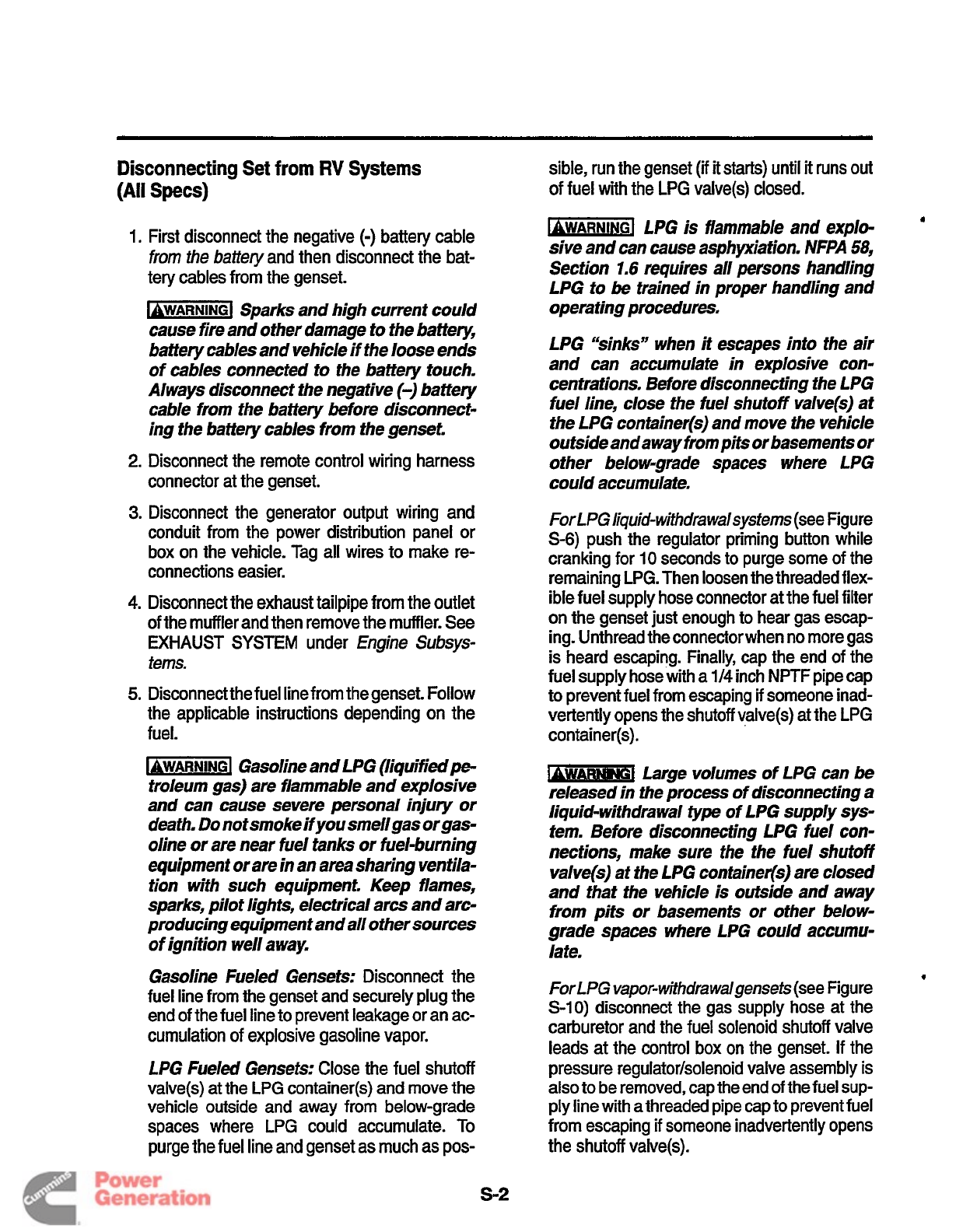
Disconnecting Set
from
RV
Systems
(All
Specs)
1.
First disconnect the negative
(-)
battery cable
from
the
baitery
and then disconnect the bat-
tery cables from the genset.
LQWAR”G1
Sparks and high current could
cause fire and other damage to the battery,
battery cables and vehicle if the loose ends
of cables connected to the battery touch.
Always disconnect the negative
(-)
battery
cable from the battery before disconnect-
ing the battery cables from the genset.
2.
Disconnect the remote control wiring harness
connector at the genset.
3.
Disconnect the generator output wiring and
conduit from the power distribution panel
or
box on the vehicle. Tag all wires to make re-
connections easier.
4.
Disconnect the exhaust tailpipe from the outlet
of the muffler and then remove the muffler. See
EXHAUST
SYSTEM
under
Engine
Subsys-
tems.
5.
Disconnect the fuel line from thegenset. Follow
the applicable instructions depending on the
fuel.
[QWARNINGI
Gasoline and LPG (liguifiedpe-
troleum gas) are flammable and explosive
and can cause severe personal injury or
death.
Do
not smoke if
you
smellgas orgas-
oline or are near fuel tanks or fuel-burning
equipment or are
in
an area sharing ventila-
tion with such equipment. Keep flames,
sparks, pilot lights, electrical arcs and arc-
producing equipment and all other sources
of
ignition well away.
Gasoline Fueled Gensets:
Disconnect the
fuel line from the genset and securely plug the
end of the fuel line to prevent leakage
or
an ac-
cumulation of explosive gasoline vapor.
f
PG Fueled Gensets:
Close the fuel shutoff
valve(s)
at
the LPG container(s) and move the
vehicle outside and away from below-grade
spaces where LPG could accumulate.
To
purge the fuel line and genset as much as pos-
sible, run the genset
(ii
it
starts) until
it
runs
out
of fuel with the LPG valve(s) closed.
k-j
LPG is flammable and explo-
a
sive and can cause asphyxiation. NFPA 58,
Section
1.6
requires all persons handling
LPG to
be
trained in proper handling and
operating procedures.
LPG “sinks” when it escapes into the air
and can accumulate in explosive con-
centrations. Before disconnecting the LPG
fuel line, close the fuel shutoff valve(s) at
the LPG container(s) and move the vehicle
outside and away from pi& or basements or
other below-grade spaces where LPG
could accumulate.
For
LPG
li9uid-wifhdrawalsyste~s
(see Figure
S-6)
push the regulator priming button while
cranking for
10
seconds to purge some of the
remaining LPG. Then loosen the threaded flex-
ible fuel supply hose connector at the fuel filter
on the genset just enough to hear gas escap-
ing. Unthread the connectorwhen no more gas
is heard escaping. Finally, cap the end of the
fuel supply hosewith a
1/4
inch
NFTF
pipe cap
to prevent fuel from escaping
if
someone inad-
vertently opens the shutoff valve(s) at the LPG
container(s).
Large volumes
of
LPG
can
be
released in the process of disconnecting a
liquid-withdrawal type of LPG supply sys-
tem. Before disconnecting LPG fuel con-
nections, make sure the the fuel shutoff
valve@) at the LPG container(s) are closed
and that the vehicle is outside and away
from pits or basements or other below-
grade spaces where LPG could accumu-
late.
ForLPG
vapor-withdrawalgensets
(see Figure
S-IO)
disconnect the gas supply hose
at
the
carburetor and the fuel solenoid shutoff valve
leads
at
the control box on the genset. If the
pressure regulator/solenoid valve assembly
is
also to be removed, cap the end
of
the fuel sup-
ply line with athreaded pipe cap to prevent fuel
from escaping
if
someone inadvertently opens
the
shutoff
valve(s).
9
s-2
Redistribution or publication of this document
by any means, is strictly prohibited.
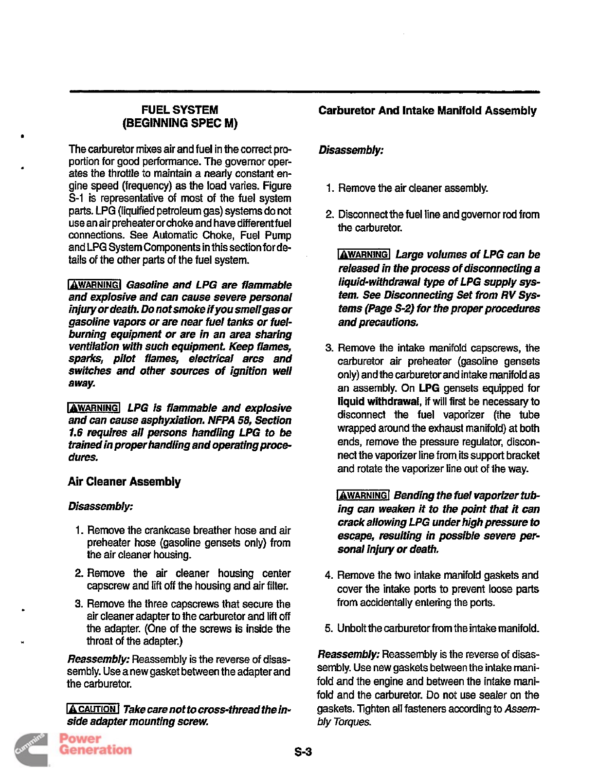
FUEL SYSTEM
(BEGINNING
SPEC
M)
The carburetor mixes air and fuel in the correct pro-
portion for good performance. The governor oper-
ates the throttle to maintain a nearly constant en-
gine speed (frequency) as the load vanes. Figure
S-1
is representative of most of the fuel system
parts.
LPG
(liquified petroleum gas) systemsdo not
use an air preheater or choke and have different fuel
connections. See Automatic Choke, Fuel Pump
and
LPG
System Components
in
this section for de-
tails of the other parts of the fuel system.
1QWAR"GI
Gasoline and LPG are flammable
and explosive and can cause severe personal
injury or death.
Do
not smoke if
you
smellgas or
gasoline vapors or are near fuel tanks or fuel-
burning equipment or are in an area sharing
ventilation with such equipment. Keep flames,
sparks, pilot flames, electrical arcs and
switches and other sources of ignition well
away.
b-1
LPG is flammable and explosive
and can cause asphyxiation. NFPA
58,
Section
1.6
requires all
persons
handling LPG to
be
trained in proper handling and operating
proce-
dum.
Air Cleaner
Assembly
Disassembly:
1.
Remove the crankcase breather hose and
air
preheater hose (gasoline gensets only) from
the air cleaner housing.
2.
Remove the air cleaner housing center
capscrew and
lift
off
the housing and air filter.
3.
Remove the three capscrews that secure the
air cleaner adapter to the carburetor and
lift
off
the adapter. (One of the screws is inside the
throat of the adapter.)
Reassembly:
Reassembly is the reverse of disas-
sembly. Use a new gasket between the adapter and
the carburetor.
-1
Take care not to cross-thread the
in-
side adapter mounting screw.
Carburetor
And
Intake
Manifold
Assembly
Disassembly:
1.
Remove the
air
cleaner assembly.
2.
Disconnect the fuel line and governor rod from
the carburetor.
Large volumes of LPG can
be
released in the process
of
disconnecting a
liquid-withdrawal
fype
of
LPG supply sys-
tem.
See
Disconnecting Set from
RV
Sys-
tems (Page
S-2)
for the proper procedures
and precautions.
3.
Remove the intake manifold capscrews, the
carburetor air preheater (gasoline gensets
only) and the carburetor and intake manifold as
an
assembly. On
LPG
gensets equipped for
liquid
withdrawal,
if
will
first
be necessary to
disconnect the fuel vaporizer (the tube
wrapped around the exhaust manifold)
at
both
ends, remove the pressure regulator, discon-
nect the vaporizer line from.its support bracket
and rotate the vaporizer line
out
of the way.
-1
Bending the fuel vaporizer tu&
ing can weaken
it
to the point that
it
can
crack allowing LPG under high pressure
to
escape, resulting in possible sever?? per-
sonal injury or death.
4.
Remove the two intake manifold gaskets and
cover the intake
ports
to prevent loose parts
from accidentally entering the ports.
5.
Unbolt the carburetorfrom the intake manifold.
Reassembly:
Reassembly is the reverse
of
disas-
sembly. Use new gaskets between the intake mani-
fold and the engine and between the intake mani-
fold and the carburetor.
Do
not use sealer on the
gaskets. Tighten all fasteners according to
Assem-
bly
Torques.
s-3
Redistribution or publication of this document
by any means, is strictly prohibited.
O-RING
(Slip
the O-ring over the end
of
the
HOSE
AND
CUP
is
connected here through an
elbow
fitting)
FIGURE
$1.
TYPICAL
FUEL
SYSTEM
S-4
Redistribution or publication of this document
by any means, is strictly prohibited.
Governor and Carburetor Adjustments
Careful adjustments of the carburetor and governor
are essential for top performance. Perform
all
nec-
essary engine and generator maintenance and re-
pairs before making these adjustments.
These adjustments require the use of meters to
measure voltage, frequency and amperage and
a
stepped load bank of at least
8
kW, where
a
portion
of at least
600
watts is variable. Digital meters are
recommended. Accuracy should be at least
0.3
per-
cent
for
frequency. measurement and
0.5
percent
for voltage measurement.
It is recommended that the genset be disconnected
from the
AC
service panel
of
the vehicle. If the gen-
set is not disconnected, disconnect or unplug
all
voltage and frequency sensitive devices throughout
the vehicle to protect them from thevariations in fre-
quency and voltage that occur during these adjust-
ments.
b-1
Disconnect or unplug all voltage
and fwuency sensitive devices such as
W’s,
VCR’s,
computers and other solid-state elec-
tronic devices befom making governor and car-
buretor adjustments. Typicallly, some internal
cimujts
are
powered when these
types
of
de-
vicesarepluggedin, even if the device has
been
switched
““OFF”,
These circuits can
be
dam-
aged by variations in voltage and frequency.
Consequential damage to
W’s,
VCR’s,
comput-
ers and other voltage and frequency sensitive
devices
as
a
result of failing to observe thispre-
caution is
nof
covered under the
Onan
warranty
policy.
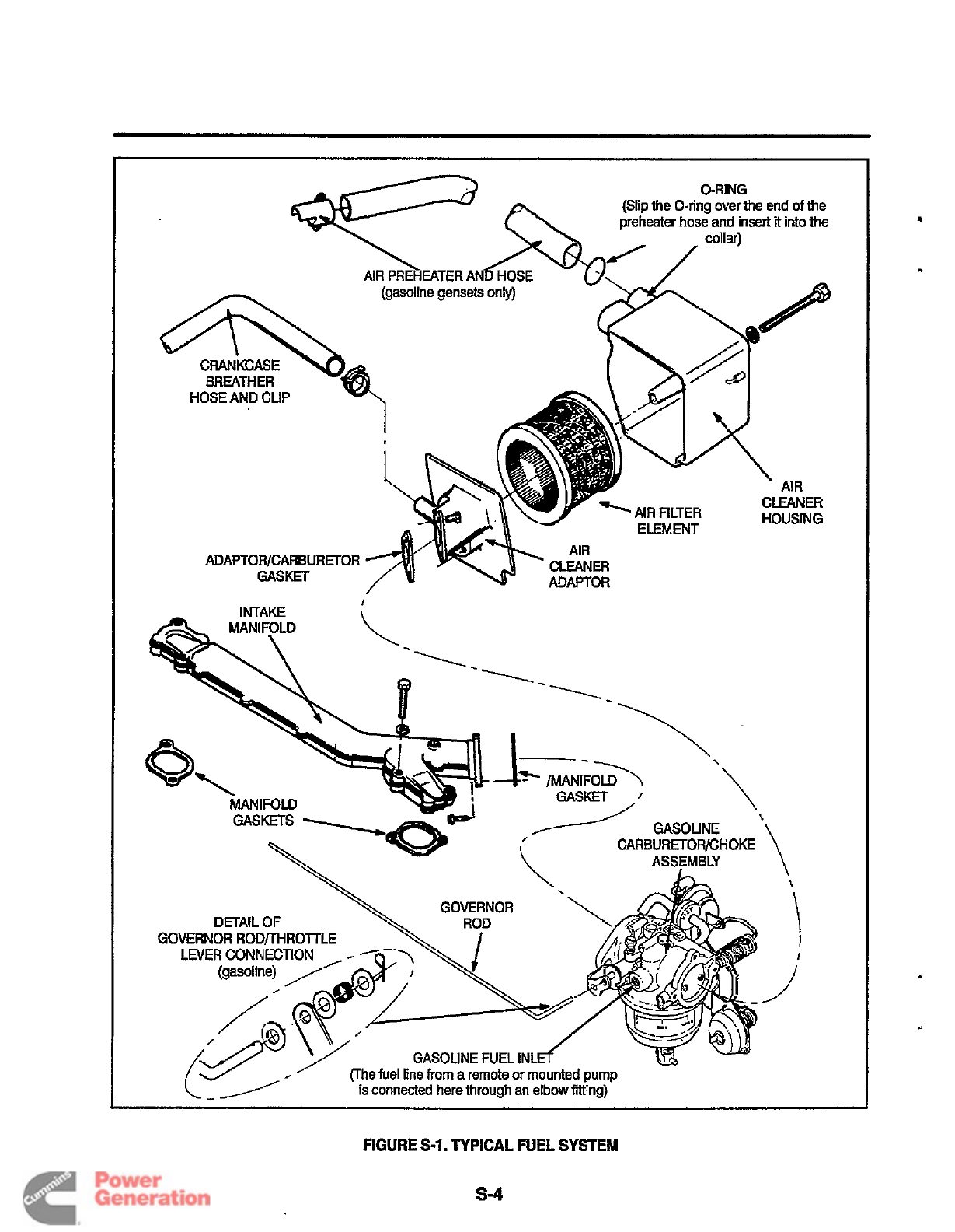
Governor Rod Length AdjustrnenlThe
length of
the governor rod (Figure
S-2)
must be checked and
adjusted as follows before other adjustments are at-
tempted:
1.
Loosen the lock nut
at
the ball joint end of the
governor
rod
and unsnap the socket from the
ball.
2.
Push the governor rod gently towards the car-
buretor (full-throttle position). While keeping
it
there,
turn
the socket, as necessary, to
lengthen
or
shorten the
rod
so
that the ball and
socket line up.
-1
Too
much pressure
on
the rod
can result in
a
faulty adjustment
of
the
rod
length.
3.
Snap the socket back over the ball.
4.
Tighten the lock
nut
while holding the socket
square with the
axis
of the ball. Also, the leg at
the throttle end of the
rod
must be kept level.
5.
Gently rotate the governor arm and check for
.
binding. If necessary, loosen the locknut and
repeat Step
4
until the linkage moves smoothly.
Binding
can
cause erratic governor action.
FIGURE
S-2.
GOVERNOR
ROD
s-5
Redistribution or publication of this document
by any means, is strictly prohibited.
Note:
The
following
groups
of
adjustments
must
be
performed
in
sequence.
Idle
Speed Stop
Adjustment: The frequency
specifications for 60 Hz gensets are followed in pa-
rentheses by the specifications for
50
Hz gensets.
1. Start the genset and
let
it
warm up for ten min-
utes under 1/2 to
3/4
rated load. (On vapor
withdrawal type
LPG
gensets
it
might be nec-
essary to first adjust the supply pressure as
in-
structed under
LPG
System Components to
get the genset to start.)
2. Disconnect the load (check for zero amps). Pull
the governor rod
so
that the tang on the throttle
lever bears against the idle speed stop screw.
Adjust the screw to obtain 54-56 Hz (44-46 Hz).
(On
LPG
carburetors the stop screw has a lock-
nut.)
Frequency Adjustments: The frequency specifi-
cations for 60 Hz gensets are followed in parenthe-
ses by the specifications for
50
Hz gensets.
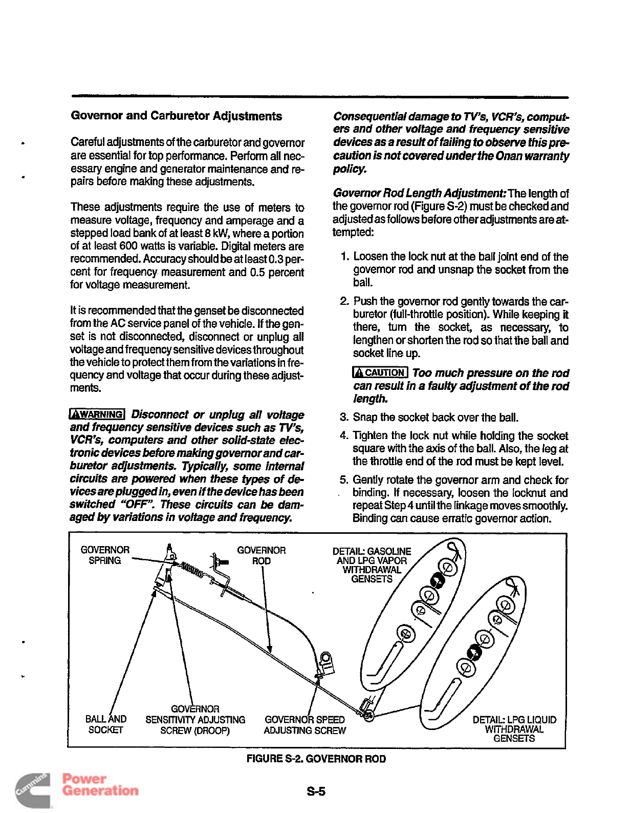
1.
Set the altitude adjust
knob
(gasoline only) on
the carburetor to your altitude.
2.
Disconnect all loads (check for zero amps).
Then check no-load frequency. If necessary,
turn the governor speed adjusting screw
to
obtain
a
no-load frequency of 62-63
Hz
3.
Check output voltage. See
Generatorif
output
voltage cannot be adjusted to within 10 percent
of rated voltage (Table S-1).
4.
See
Troubeshoofing
if
the engine runs roughly.
.
(51.5-52.5
Hz).
IDLE SPEED
ST_OP
SCREW
ALTITU
4
E
SCALE A\L)ITUDE
ADJUST
KNOB
FIGURE
S-3.
GASOLINE
CARBURETOR
F\
I
FUEL INLET
I
VAPOR-WITHDRAWAL
FUEL INLET
I
LIQUID-WITHDRAWAL
I
THRO~
LNER
STOP SCREW
AND LOCKNUT
FIGURE
S-4.
LPG
CARBURETOR
S-6
Redistribution or publication of this document
by any means, is strictly prohibited.
Droop
AdjustmenkxThe frequency specifications
for 60 Hz gensets are followed
in
parentheses by
the specifications for
50
Hz gensets.
1.
Connect rated load.
amps
(A).
Load (watts)
=
V
x
A
(A
1
.O
power factor, obtainable with
a
re-
sistance load bank, is assumed. True
rated output might not be obtained
if
appli-
ances are used as part of the load.)
B. See
Generator
if output voltage cannot be
adjusted to within
10
percent of rated volt-
age (Table S-1).
A.
Load (watts) is the product of volts
(V)
and
TABLE
$1.
VOLTAGE SPECIFICATION
I
OUTPUT NO-LOAD
I
FULL-LOAD
I
VOLTAGE
I
VOLTAGE VOLTAGE
I
120V,lPH
I
132
I
112
I
120/240V, 1PH
I
264
I
224
I
2.
Check and adjust droop.
A. If droop (from no-load frequency) is more
than
3
Hz (3.5 Hz) for Model BGE or 4 Hz
(3.5
Hz) for Model NHE, turn the governor
sensitivity adjusting screw (Figure S-2)
one turn counterclockwise. Disconnect
the load and,
if
necessary, readjust the
governor speed adjusting screw to return
to 62-63 Hz (51.5-52.5 Hz) no-load fre-
quency. Checkdroop again and repeat the
adjustments,
if
necessary.
B.
If droop (from no-load frequency)
is
less
than
2
Hz
(2
Hz) for Model BGD or 3 Hz
(2
Hz) for Model NHD, turn the governor
sensitivity adjusting screw (Figure S-2)
one turn clockwise. Disconnect the load
and,
if
necessary, readjust the governor
speed adjusting screw to return to 62-63
Hz
(51.5-52.5
Hz)
no-load frequency.
Check droop again and repeat the adjust-
ments,
if
necessary.
3. Check governor response under 1/4,1/2 and
314 rated loads. See
Troubleshootingif
hunting
is unacceptable.
Carburetor Replacement
Other than turning the altitude adjust knob shown
in
Figure S-3, which changes the main fuel mixture
within
a
limited range (gasoline carburetors only),
fuel mixture adjustments should not be attempted
on
gasoline or LPG carburetors. Nor should the car-
buretor be overhauled. Instead, a malfunctioning
carburetor should be replaced. Before replacing
a
carburetor, however, make certain
1)
that all other
necessary engine and generator adjustments and
repairs have been performed and
2)
that the carbu-
retor is actually malfunctioning, by carefully follow-
ing the troubleshooting procedures in
Trouble-
shooting.
L
PG carburetors are usually
not
the cause
of
prob-
lems. Make certain all otherpossible causes
of
the
problem have been eliminated before replacing
an
LPG
cahuretofi
-1
Unauthorized modifications or
re-
placement
of
fuel, exhaust, air intake
or
speed
control system components that affect engine
emissions are prohibited by law in the State
of
California.
See the instructions on how to remove and replace
the carburetor under the subheadings AIR CLEAN-
ER ASSEMBLY and CARBURETOR AND INTAKE
MANIFOLD ASSEMBLY in this section.
s-7
Redistribution or publication of this document
by any means, is strictly prohibited.
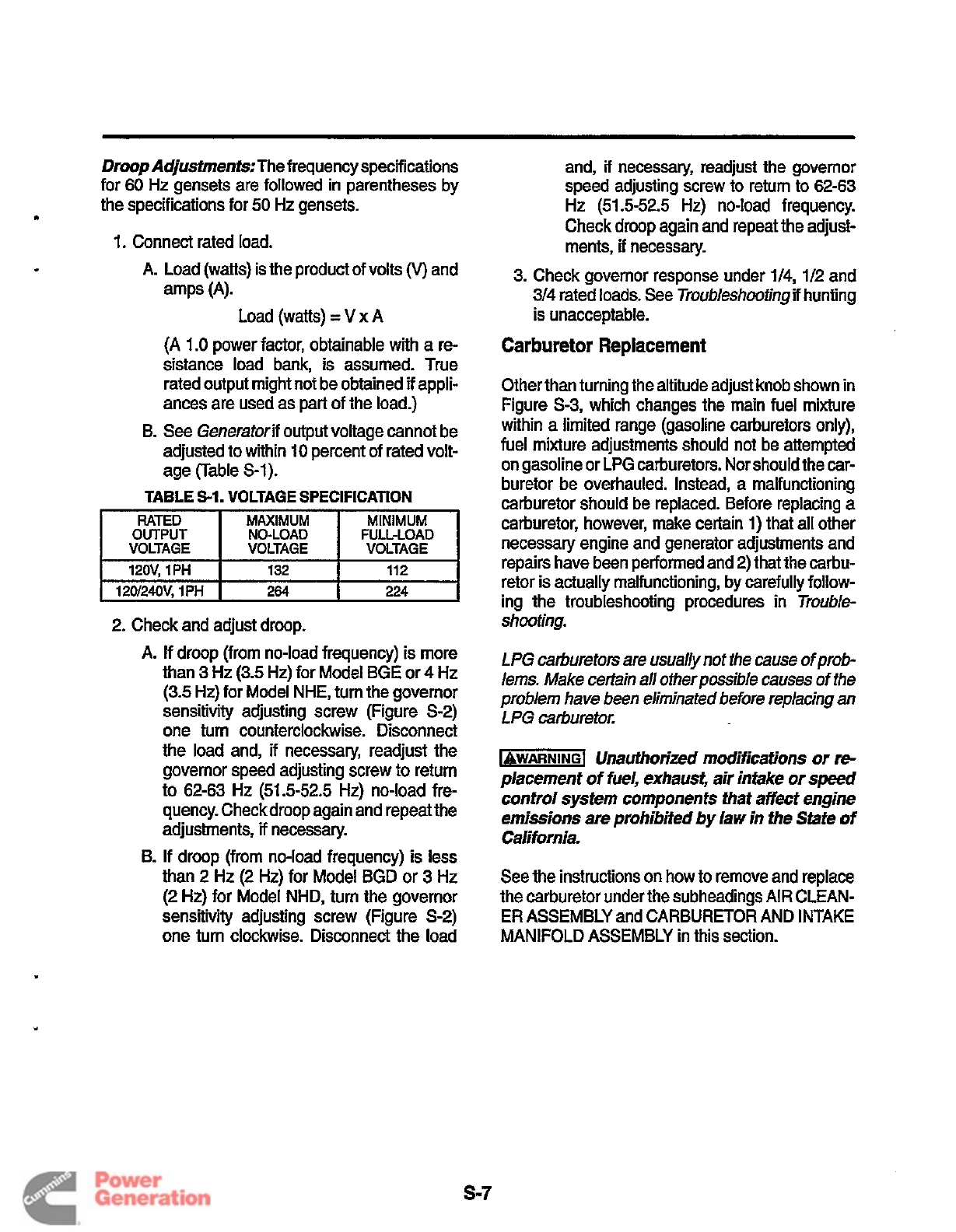
Automatic
Choke
(Gasoline
Sets)
1.
Apply a vacuum of at least
100
mm
(4
inches)
of mercury to fully pull in the choke breaker
arm.
.
2.
Insert a
8.6
mm
(0.337
inch) drill rod between
the choke plate and the carburetor throat.
See Figure S-5.The automatic choke is operated by
a
bi-metalheater assembly and a vacuum breaker
assembly. Replace faulty choke components and
reassemble as shown. Adjust the choke breaker as-
sembly each time
it
is assembled to the carburetor,
as
follows:
3.
If necessary, bend the link
at
the point shown
until the
lip
of
the choke plate just touches the
drill rod. Use
two
pliers to bend the link.
FIGURE
S-5.
CHOKE
ASSEMBLY
S-8
Redistribution or publication of this document
by any means, is strictly prohibited.
Fuel Pump (Gasoline Gensets)
The fuel pump delivers fuel to the carburetor at
3.5-5
psi (24-35 kPa) and has
a
lift
capacity (suc-
tion) of
3
feet
(0.9
meters).
wj
Do
not substitute an automotive
fuel pump for the standard pump removed from
the genset. Other pumps can cause carburetor
flooding because of the high pressures theyde-
velop. Carburetor flooding
can
cause poor per-
formance and engine damage and lead to pos-
sible fire and severe personal
injury
or death.
Fuel pressure at the carburetor fitting must not
exceed 6psi
(41
kPa) under any operating con-
dition.
Fuel
Pressure
Test:
1.
Disconnect the fuel line at the outlet of the fuel
pump and connect a pressure gauge
at
the
pump outlet.
A
gauge calibrated for
0-15
psi
(0-100
kPa) is recommended.
Do
not tee into
the fuel line. This is a static pressure test.
2.
Push the Start/Stop switch to
START
and hold
it
there for several seconds until the
fuel
pres-
sure stabilizes. Fuel pressure should stabilize
between
3.5
and
6
psi (24 and 41 kPa).
3. Repeat the test with the vehicle engine run-
ning.
A
fuel pressure greater than
6
psi
(41
kPa)
is
not
acceptable.
Find
out
why the pressure is high.
If
it
is
high when the vehicle engine is not running, check
to see that the proper Onan supplied pump is being
used. If it is high when the vehicle engine is running,
a separate fuel pickup tube in the fuel tank, or
equivalent means, will be required.
If the fuel pressure is less than
3.5
psi
(24
kPa),
check for fuel restrictions
in
the system. The pump
will have to be relocated closer to the fuel tank
if
it
is
located more than
3
feet
(0.9
meters) above the end
of the fuel pickup tube in the fuel tank. If the pump is
defective, replace
it
with
the
appropriate Onan
pump. The pump is not serviceable.
See the Installation Manual for important recom-
mendations regarding the fuel supply system.
s-9
Redistribution or publication of this document
by any means, is strictly prohibited.
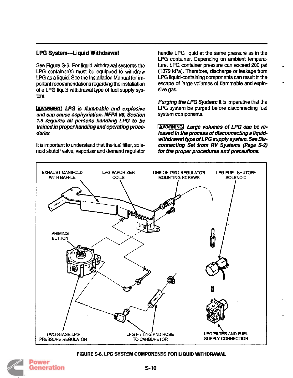
LPG
System-Liquid Withdrawal
See Figure
S-6.
For liquid withdrawal systems the
LPG
container($ must be equipped to withdraw
LPG
as a liquid. See the Installation Manual for im-
portant recommendations regarding the installation
of
a
LPG liquid withdrawal type of fuel supply sys-
tem.
lgWAR”G1
LPG is flammable and explosive
and can cause asphyxiation. NFPA
58,
Section
7.6
requires all persons handling LPG to
be
trained in proper handling and operating proce-
dures.
It is important to understand that the fuel filter, sole-
handle
LPG
liquid at the same pressure as in the
LPG container. Depending on ambient tempera-
ture,
LPG
container pressure
can
exceed
200
psi
(1379
kPa). Therefore, discharge
or
leakage from
LPG liquid-containing components
can
result in the
escape of large volumes of flammable and explo-
sive gas.
*
.
Purging fhe LPG System:
It
is imperative that the
LPG system be purged before disconnecting fuel
system components.
b-1
Large volumes
of
LPG can
be
re-
leased in the process
of
disconnecting a liquid-
withdrawal
type
of LPG supply system.
See
Dis-
connecting Set from
RV
Systems (Page
S-2)
noid shutoff valve, vaporizer and demand regulator
for the proper procedures
and
precautions.
EXHAUST MANIFOLD LPG VAPORIZER
ONE
OF
TWO
REGULATOR LPG FUEL SHUTOFF
WITH
BAFFLE COILS
MOUNTING
SCREWS
SOLENOID
TWO-STAGE LPG
LPG
FII~NG’AND
HOSE
LPG FIL
1
R
AND FUEL
PRESSURE REGULATOR
TO
CARBURETOR SUPPLY
CONNECTION
FIGURE
S-6.
LPG
SYSTEM
COMPONENTS
FOR
LIQUID WITHDRAWAL
s-I
0
Redistribution or publication of this document
by any means, is strictly prohibited.
.
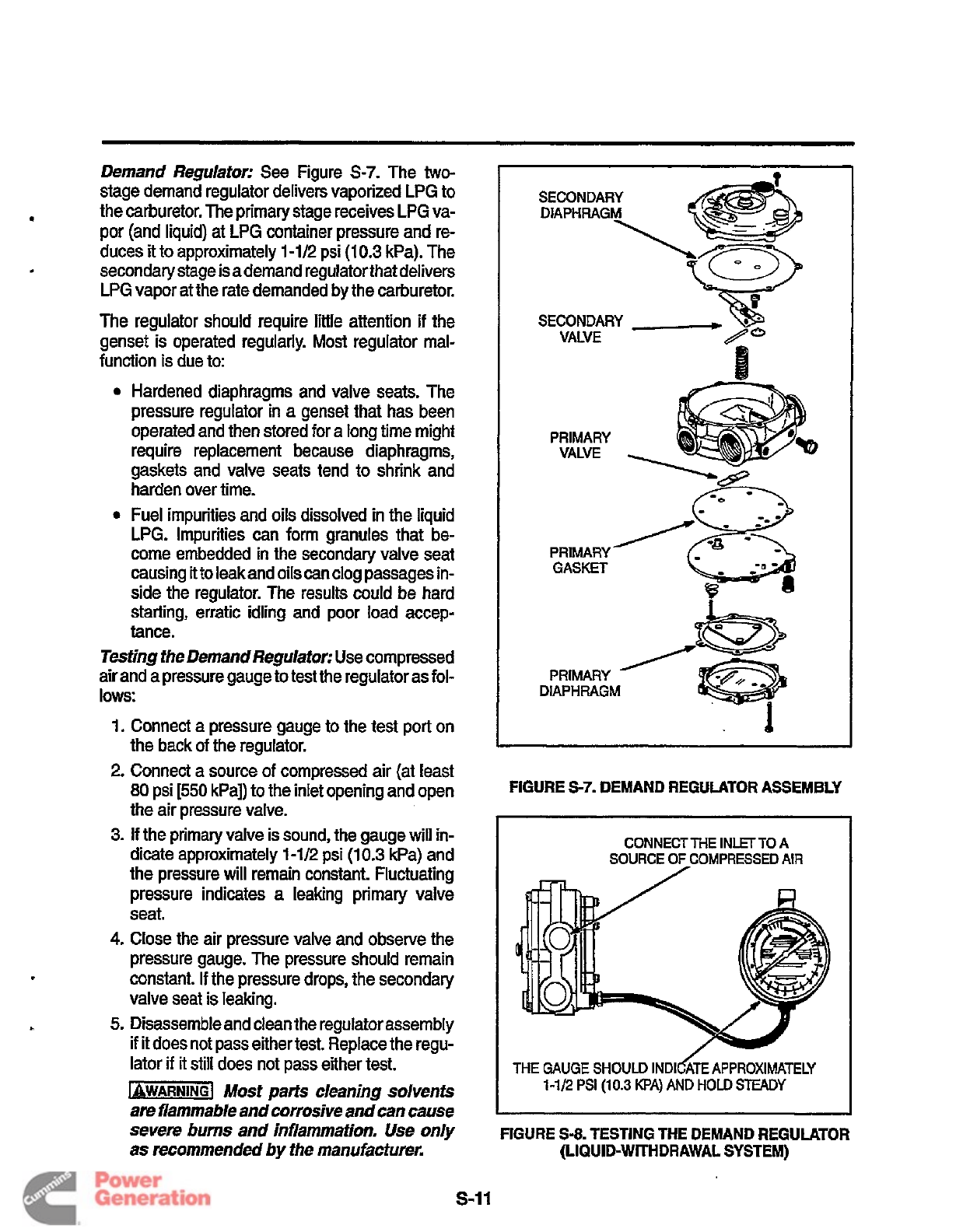
Demand Regulafor: See Figure
S-7.
The
two-
stage demand regulator delivers vaporized LPG to
the carburetor. The primary stage receives LPG va-
por (and liquid) at LPG container pressure and re-
duces
it
to approximately
1-1/2
psi
(10.3
kPa). The
secondary stage is a demand regulator that delivers
LPG vapor at the rate demanded by the carburetor.
The regulator should require little attention if the
genset is operated regularly.
Most
regulator mal-
function is due to:
Hardened diaphragms and valve seats. The
pressure regulator in
a
genset that has been
operated and then stored for a long time might
require replacement because diaphragms,
gaskets and valve seats tend to shrink and
harden over time.
Fuel impurities and oils dissolved
in
the liquid
LPG. Impurities can form granules that be-
come embedded in the secondary valve seat
causing it to leak and oils can clog passages in-
side the regulator. The results could be hard
starting, erratic idling and poor load accep-
tance.
Tesfing the Demand Regulator: Use compressed
air and a pressure gauge to test the regulator as fol-
lows:
1.
Connect a pressure gauge
to
the test port on
the back of the regulator.
2.
Connect a source
of
compressed air (at least
80
psi
[550
kPa]) to the inlet opening and open
the air pressure valve.
3.
If
the primary valve is sound, the gauge will
in-
dicate approximately
1
-1/2
psi
(1
0.3
kPa) and
the pressure will remain constant. Fluctuating
pressure indicates a leaking primary valve
seat.
4.
Close the air pressure valve and observe the
pressure gauge. The pressure should remain
constant. If the pressure drops, the secondary
valve seat is leaking.
5.
Disassemble and clean the regulator assembly
if
it
does not pass eithertest. Replace the regu-
lator
if
it
still does not pass either test.
IaWARNINGl
Most parts cleaning solvents
are flammable and corrosive and can cause
severe burns and inflammafion.
Use
only
as recommended by the manufacturer.
SECONDARY
.
VALVE
PRIMARY
VALVE
PRIMARY
DIAPHRAGM
FIGURE
S-7.
DEMAND REGULATOR ASSEMBLY
CONNECT ME INLET
TO
A
SOURCE
OF
COMPRESSED
AIR
/-
THE
GAUGE
SHOULD
INDICATE
APPROXIMATELY
1-1/2
PSI
(10.3
KPA)
AND
HOLD
STEADY
FIGURE
S-8.
TESTING THE DEMAND REGULATOR
(LIQUID-WITHDRAWAL SYSTEM)
s-11
Redistribution or publication of this document
by any means, is strictly prohibited.
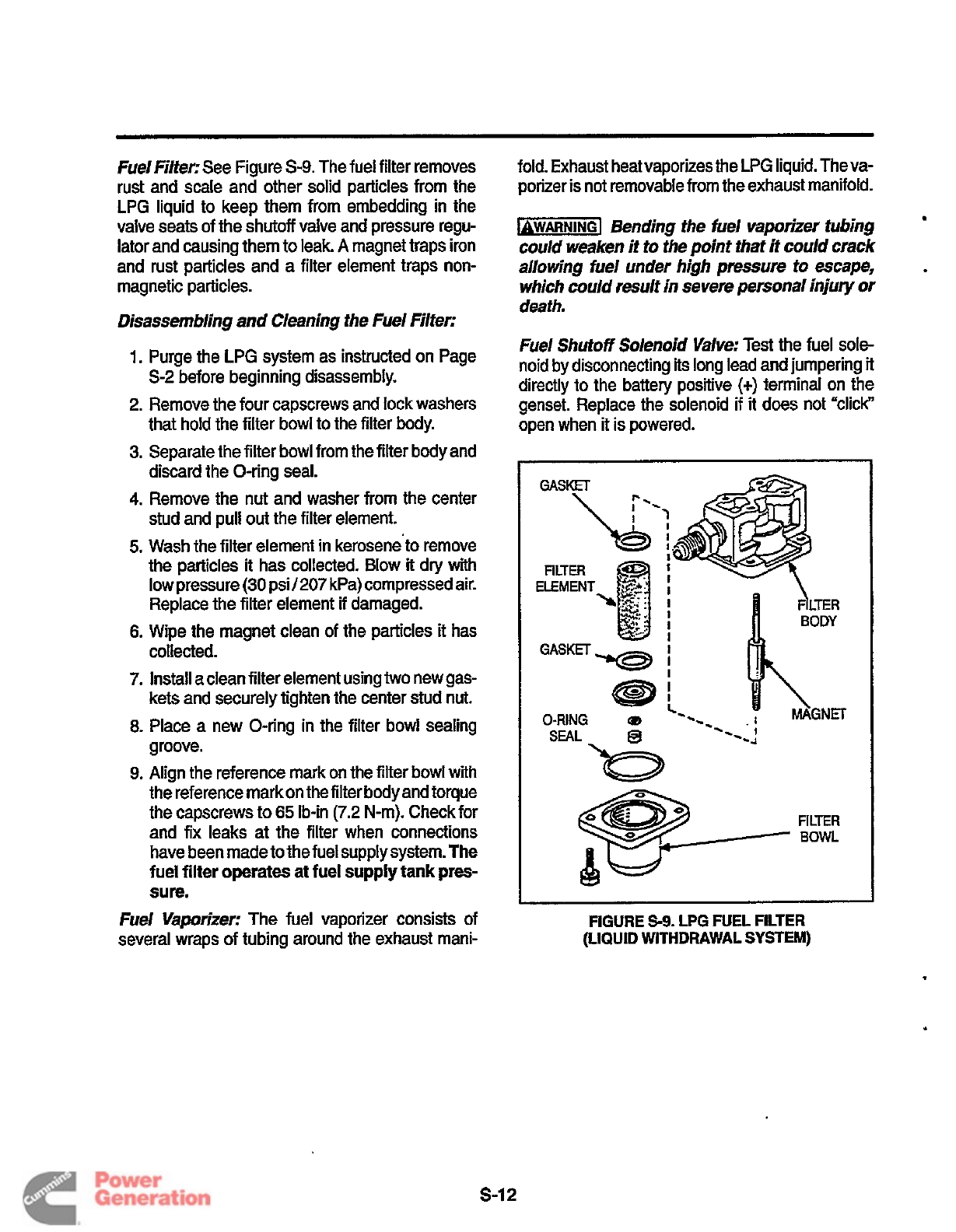
Fuel Filter; See Figure
S-9.
The fuel filter removes
rust and scale and other solid particles from the
LPG
liquid to keep them from embedding in the
valve seats of the shutoff valve and pressure regu-
lator and causing them to leak.
A
magnet traps iron
and rust particles and
a
filter element traps non-
magnetic particles.
Disassembling and Cleaning the Fuel Filter;
1.
Purge the LPG system as instructed on Page
S-2 before beginning disassembly.
2. Remove the four capscrews and lock washers
that hold the filter bowl to the filter body.
3.
Separate the filter bowl from the filter body and
discard the O-ring seal.
4.
Remove the nut and washer from the center
stud and pull out the filter element.
5.
Wash the filter element in keroseneto remove
the particles
it
has collected. Blow
it
dry with
low pressure
(30
psi/207 kPa) compressed air.
Replace the filter element if damaged.
6.
Wipe the magnet clean of the particles
it
has
collected.
7.
Install a clean filter element using
two
new gas-
kets and securely tighten the center stud nut.
8.
Place
a
new O-ring
in
the filter bowl sealing
groove.
9.
Align the reference mark on the filter bowl with
the reference markon the filter body and torque
the capscrews to
65
Ib-in (7.2 N-m). Check for
and fix leaks
at
the filter when connections
have been made to the fuel supply system.
The
fuel
filter
operates at
fuel
supply
tank
pres-
sure.
Fuel Vaporizer; The fuel vaporizer consists
of
several wraps of tubing around the exhaust mani-
fold. Exhaust heat vaporizes the LPG liquid. The va-
porizer is not removable from the exhaust manifold.
b-1
Bending the fuel Vaporizer tubing
could weaken it to the point that
it
could crack
allowing fuel under high pressure to escape,
which could result in severe personal injury
or
death.
Fuel
Shutoff
Solenoid Valve: Test the fuel sole-
noid by disconnecting
its
long lead and jumpering
it
directly to the battery positive
(+)
terminal on the
genset. Replace the solenoid if it does not "click"
open when
it
is powered.
GASKET
\
r--
O-RING
(D
FIGURE
$9.
LPG FUEL FILTER
(LIQUID WITHDRAWAL SYSTEM)
.
s-12
Redistribution or publication of this document
by any means, is strictly prohibited.
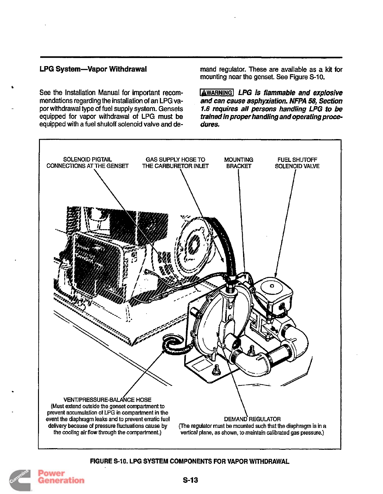
LPG
System-Vapor
Withdrawal
rnand regulator. These are available as a
kit
for
mounting near the genset. See Figure
S-10.
b
See the Installation Manual for important recom-
mendations regarding the installation of an
LPG
va-
por withdrawal type
of
fuel
supply system. Gensets
equipped
for
vapor withdrawal
of
LPG
must
be
equipped with a
fuel
shutoff solenoid valve and de-
1-1
LPG
is
flammable
and
explosive
and
can
cause
asphpiafion.
NFPA
58,
&don
1.6
requires
a//
persons
handhg
LPG
to
be
~rain~j~~fo~r~an~/jng
andoperafingproce-
dum.
.
SOLENOID PIGTAIL GAS SUPPLY HOSE TO MOUNTING FUEL SHUTOFF
\
VENTPRESSURE-BALA~CE
HOSE
(Must extend outside the genset compartment to
prevent accumulation
of
LPG
in Compartment in the
event the diaphragm
leaks
and to prevent erratic fuel
delivery because
of
pressure fluctuations cause
by
the cooling
airflow
through the compartment.)
DEMAND REGULATOR
(The regulator must
be
mounted
such
that
the diaphragm
is
in
vertical
plane,
as
shown,
to maintain calibrated
gas
pressure.
FIGURE
S-10.
LPG
SYSTEM
COMPONENTS
FOR
VAPOR
WITHDRAWAL
S-I
3
Redistribution or publication of this document
by any means, is strictly prohibited.
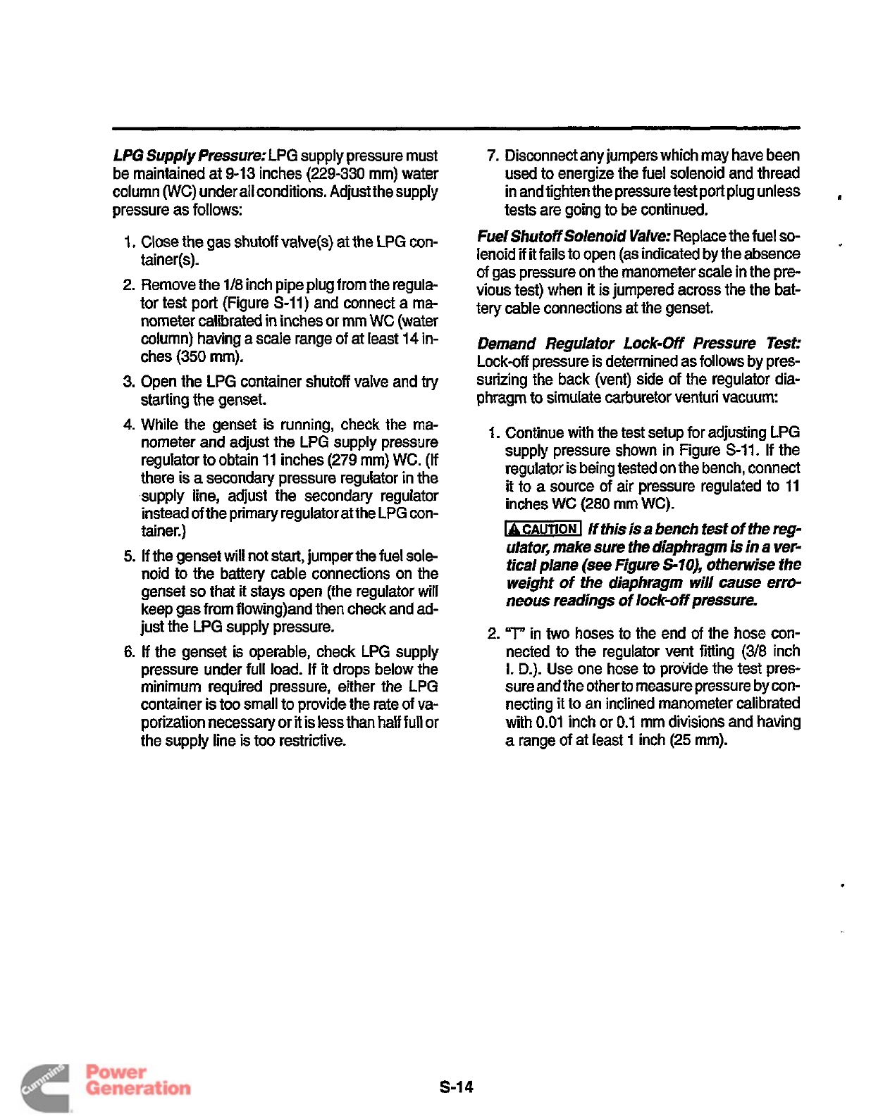
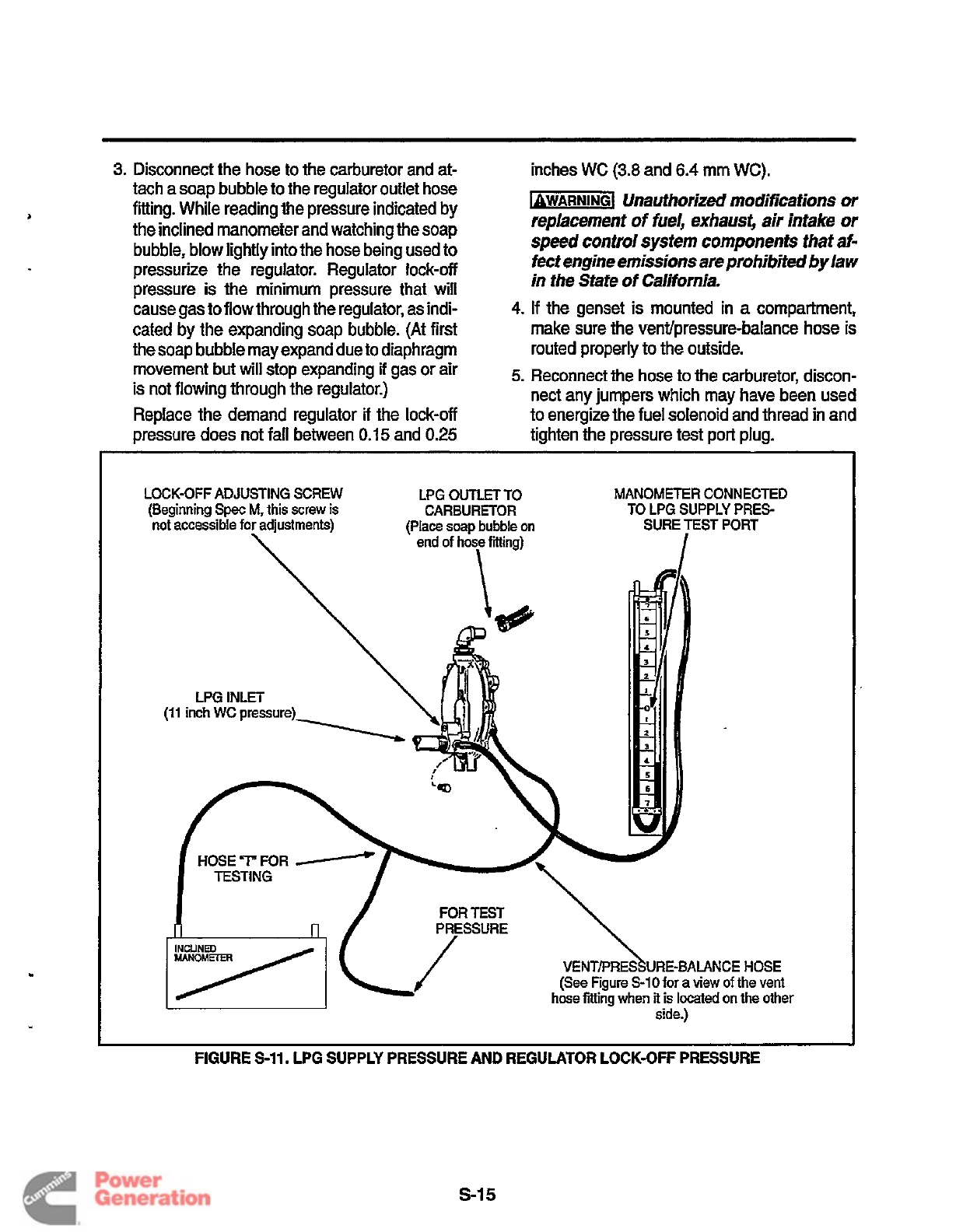
LPG Supply Pressure: LPG supply pressure must
be maintained at
9-13
inches
(229-330
mm) water
column
(WC)
under all conditions. Adjust the supply
pressure as follows:
1.
Close the gas shutoff valve(s)
at
the
LPG
con-
tainer(s).
2.
Remove the
1/8
inch pipe plug from the regula-
tor test port (Figure S-11) and connect a ma-
nometer calibrated
in
inches or mrn
WC
(water
column) having a scale range of
at
least
14
in-
ches
(350
mm).
3.
Open the LPG container shutoff valve and
try
starting the genset.
4.
While the genset is running, check the ma-
nometer and adjust the LPG supply pressure
regulator to obtain
11
inches
(279
mm) WC. (If
there is
a
secondary pressure regulator
in
the
supply line, adjust the secondary regulator
instead of the primary regulator at the LPG con-
tainer.)
5.
If the genset will not start, jumper
the
fuel
sole-
noid to the battery cable connections
on
the
genset
so
that
it
stays open (the regulator
will
keep gas from f1owing)and then check and ad-
just the LPG supply pressure.
6.
If the genset
is
operable, check LPG supply
pressure under full load.
If
it
drops below the
minimum required pressure, either the LPG
container is too small to provide the rate of va-
porization necessary or
it
is
less than half
full
or
the supply line is
too
restrictive.
7.
Disconnect any jumpers which may have been
used to energize the fuel solenoid and thread
in
and tighten the pressure test port plug unless
tests are going to be continued.
Fuel Shutoff Solenoid Valve: Replace the fuel
so-
lenoid
if
it
fails to open (as indicated by the absence
of gas pressure on the manometer scale
in
the pre-
vious test) when
it
is jumpered across the the bat-
tery cable connections
at
the genset.
,
Demand Regulator
Lock-Off
Pressure Test:
Lock-off pressure is determined as follows by pres-
surizing the back (vent) side of the regulator dia-
phragm
to
simulate carburetor venturi vacuum:
1.
Continue with the test setup for adjusting LPG
supply pressure shown in Figure
S-11.
If the
regulator is being tested on the bench, connect
it
to
a
source of air pressure regulated to
11
inches
WC
(280
mm
WC).
b-1
If
this is a bench test
of
fhe reg-
ulator, make
sure
the diaphragm is in a ver-
tical plane
(see
Figure
S-IO),
otherwise
the
weight
of
the diaphragm
will
cause erro-
neous
readings
of
lock-off
pmsure.
2.
'T'
in
two
hoses to the end of the hose con-
nected to the regulator vent fitting
(3/8
inch
I.
D.).
Use one hose
to
provide the test pres-
sure and the other to measure pressure by con-
necting it to an inclined manometer calibrated
with
0.01
inch or
0.1
mm divisions and having
a
range of at least
1
inch
(25
mm).
.
s-14
Redistribution or publication of this document
by any means, is strictly prohibited.
3.
Disconnect the hose to the carburetor and
at-
inches
WC
(3.8
and
6.4
mm
WC).
*
.
tach a soap bubble to the regulator outlet hose
fitting. While reading the pressure indicated by
the inclined manometer and watching the soap
bubble,
blow
lightly into the hose being used to
pressurize the regulator. Regulator lock-off
Dressure is the minimum Dressure that
will
-1
Unauthorized modifications or
replacement
of
fuel, exhaust, air intake
or
speed
control system components that
af-
fect
engine emissions are prohibited bylaw
in the
State
of
California.
cause gas to flowthrough the regulator, as indi-
cated by the expanding soap bubble. (At first
the soap bubble may expand due to diaphragm
movement
but
will stop expanding
if
gas or air
is not flowing through the regulator.)
Replace the demand regulator
if
the lock-off
pressure does not fall between
0.15
and
0.25
4.
If
the genset is mounted in
a
compartment,
make sure the ventlpressure-balance hose
is
routed properly to the outside.
5.
Reconnect the hose to the carburetor, discon-
nect any jumpers which may have been used
to energize the fuel solenoid and thread in and
tighten the pressure test port plug.
LOCK-OFF ADJUSTING SCREW LPG
OUTLET
TO
MANOMETER CONNECTED
(Beginning
Spec
M,
this
screw
is
CARBURETOR
not accessible
for
adjustments)
TO
LPG SUPPLY PRES-
SURE TEST PORT
LPG INLET
(11
inch
WC
pressure)
-BALANCE HOSE
r
a
view
of
the vent
FIGURE
S-11.
LPG SUPPLY PRESSURE
AND
REGULATOR LOCK-OFF PRESSURE
s-I
5
Redistribution or publication of this document
by any means, is strictly prohibited.

Redistribution or publication of this document
by any means, is strictly prohibited.

S-1
Supplement 9651065
Date: 197
Insert with
Title: BGE/NHE Service Manual
Number (Date): 9650528 (994)
PURPOSE
This Supplement is used in addition to Supplement
965-1060. It transmits the revisions to the Service
Manual necessary for covering all changes made
since Supplement 965-1060 was issued.
SERVICE MANUAL 965-0528 REVISIONS
1. Insert this Supplement in its entirety under
the front cover of the manual. (Do
not
discard
Supplement 965-1060.)
2. On Page 2-2 replace Figure 2-1 with Figure S-1
on Page S-2 of this supplement.
The engine exhaust from this product
contains chemicals known to the State
of California to cause cancer, birth
defects or other reproductive harm.
!!
Redistribution or publication of this document
by any means, is strictly prohibited.
S-2
BGE/NHE
(LPG)
BGE/NHE
(Gasoline)
REMOTE START CABLE
CONNECTION
REMOTE START CABLE
CONNECTION
FIGURE S-1. TYPICAL EMERALD GENERATOR SETS
Redistribution or publication of this document
by any means, is strictly prohibited.

S-3
3. On Page 7-5 replace Figure 7-3a with Figure
on Page of this supplement.
Redistribution or publication of this document
by any means, is strictly prohibited.
Supplement
965-1 069
Date:
11-98
lnserl
with-
Title:
BGE/NHE
Service
Manual
Number (Date):
965-0528
(9-94)
PURPOSE
This Supplement transmits the revisions to the Service Manual necessary to cover changes beginning with
Spec
N
gensets. Gensets beginning with Spec
N
have a sealed-type remote control connector and single,
16-pin connector on the genset control board.
SERVICE
MANUAL
965-0528
REVISIONS
5.
Insert attached
Page A-11
after Appendix A
1.
Do
not discard Supplement
965-1060,
which covers changes beginning with
2.
Look
for statement “BGE Spec
F
through
K,
NHE Spec
E
through
K”
on the front cover.
Strike out the
“K”
in both places and write in
“P’
in both places.
3. On
Page
6-14,
Step
6,
change“12.6 and 15.4k
ohms” to “12.6kand 15.4k ohms.”
spec
M.
Page A-1
0.
6.
Replace
Page
B-1
(Appendix
B)
with the
attached
PageB-1
and
add
the attached
Pages
B-8
through
B-11.
7.
On
Page
ii
(Table
of
Contents), change the
Heading
“Appendix
B
SPEC
J
and
K DIA-
GRAMS”,
to
“Appendix
6.
Later Wiring Dia-
grams”.
8.
On
Page
ii
under
Appendix
B.
Later Wiring
4. On
Page A-1
(Appendix A) write:
“Prior
to
Spec
N:
In lieu
of
testing the connec-
tor pins with a meter, use control board tester
No.
420-0572 and the appropriate adapter har-
Diagrams
add the entries:
“Beginning Spec
N:
ness to determine whether a control board
needs
to
be replaced. Follow Instruction Sheet
G220
packaged with the tester.”
“Beginning Spec
N:
See Page
A-11
.”
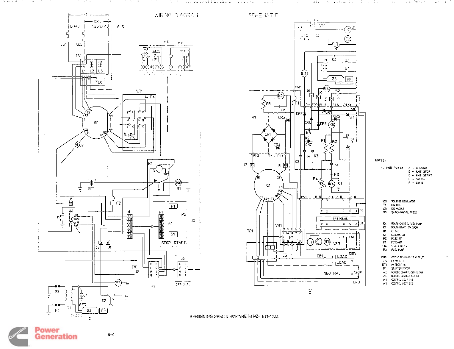
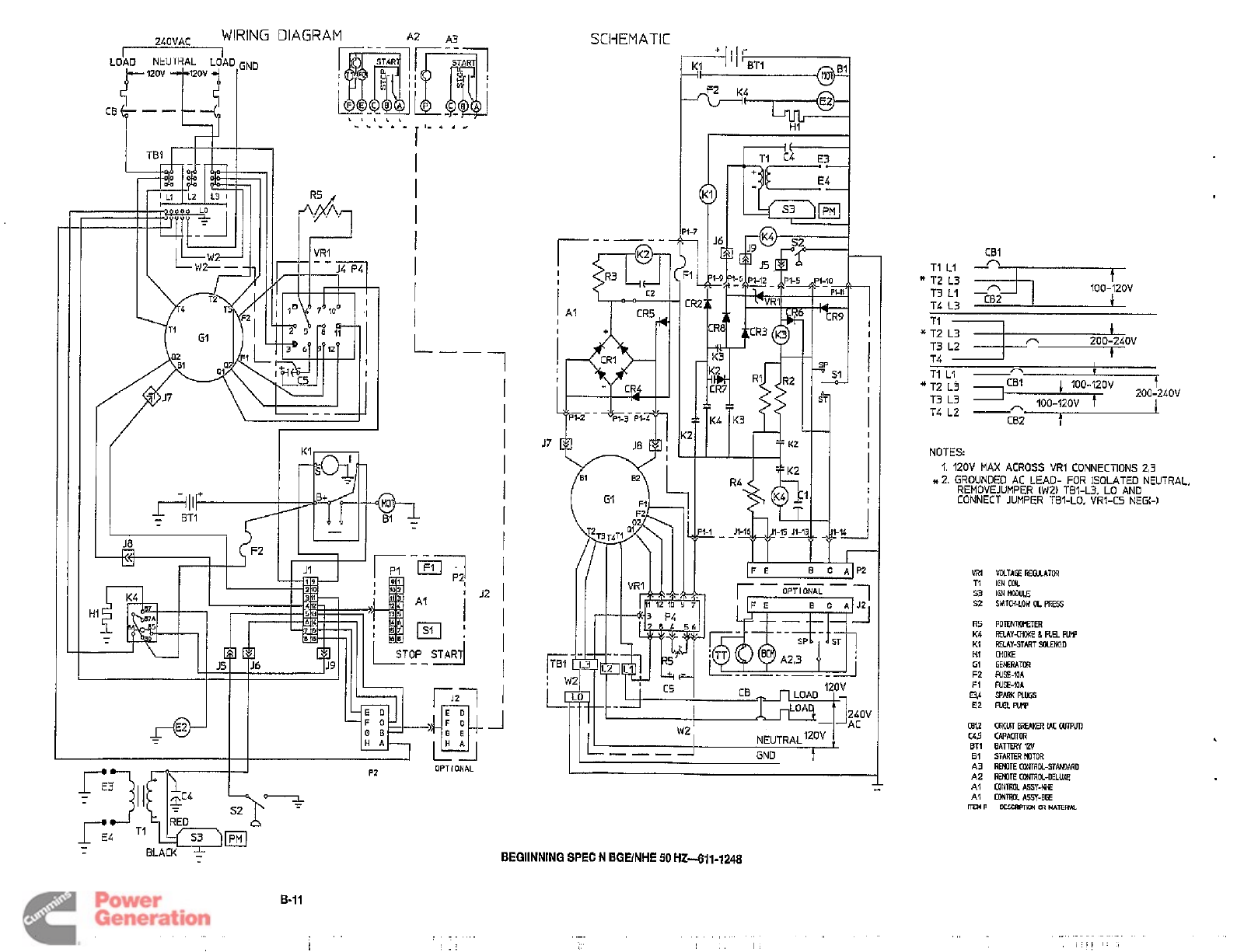
BGENHE, 60 HZ (611-1244).
.
.
.
. .
.
.B-8
BGE/NHE, 60 Hz,
LP
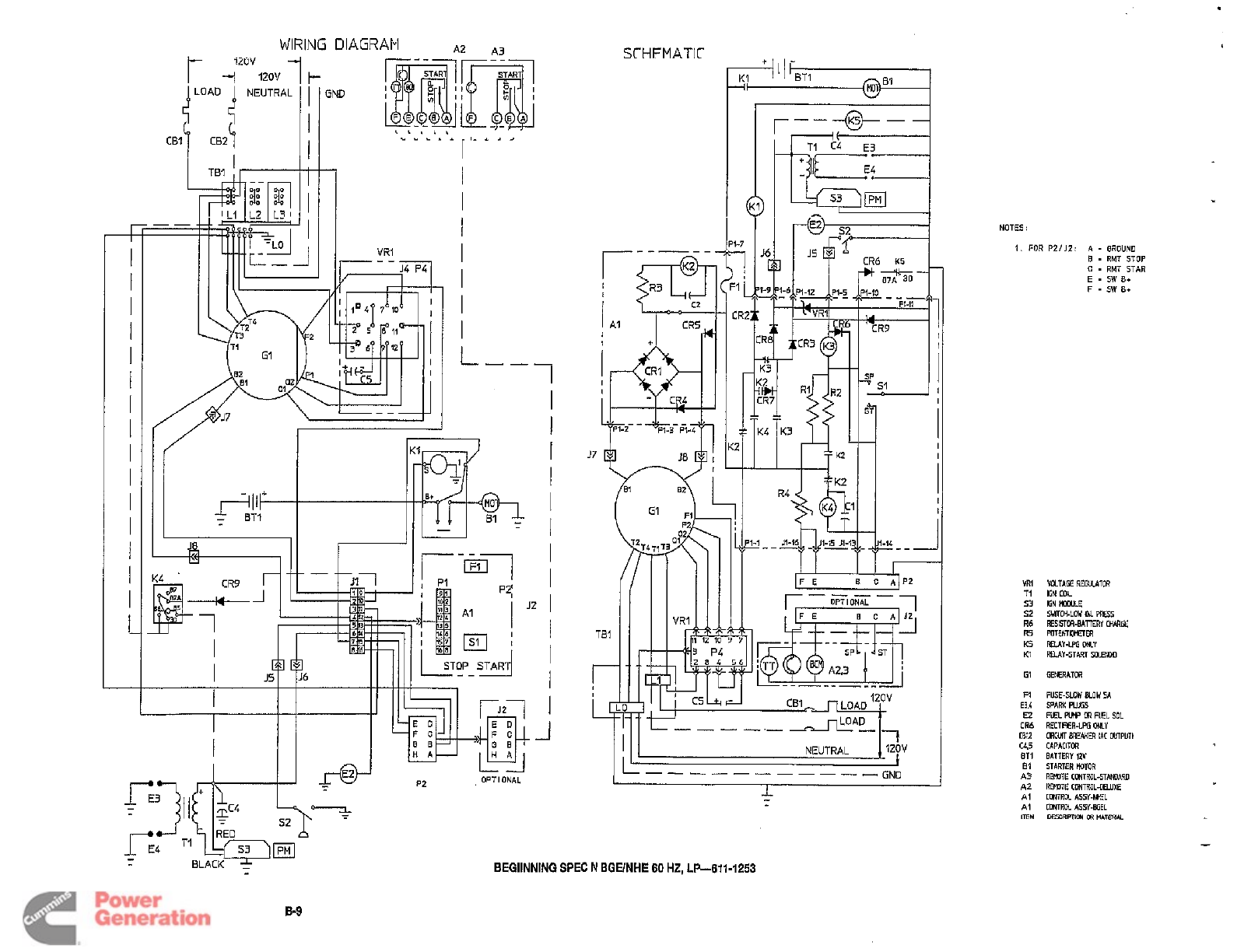
(611-1253)
. .
.
.
.
B-9
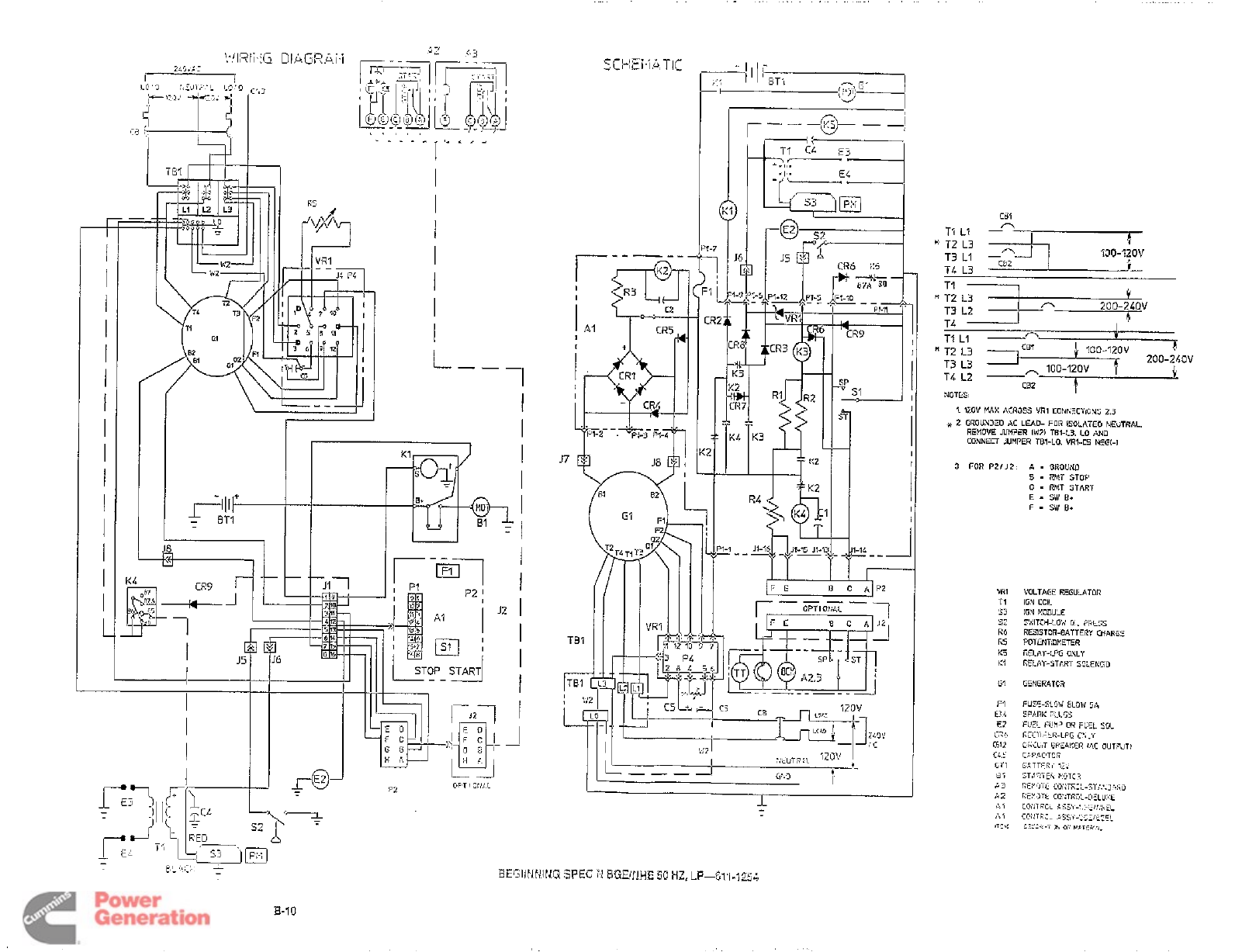
BGE/NHE,
50
Hz,
LP
(611-1254).
.
.
.
.
B-10
BGE/NHE,
50
HZ (611-1248).
.
. .
.
.
.Ell’’
Page
1
of
1
with attachments
A-1
1,
B-1
and
B-8
through
B-11
Redistribution or publication of this document
by any means, is strictly prohibited.

Redistribution or publication of this document
by any means, is strictly prohibited.
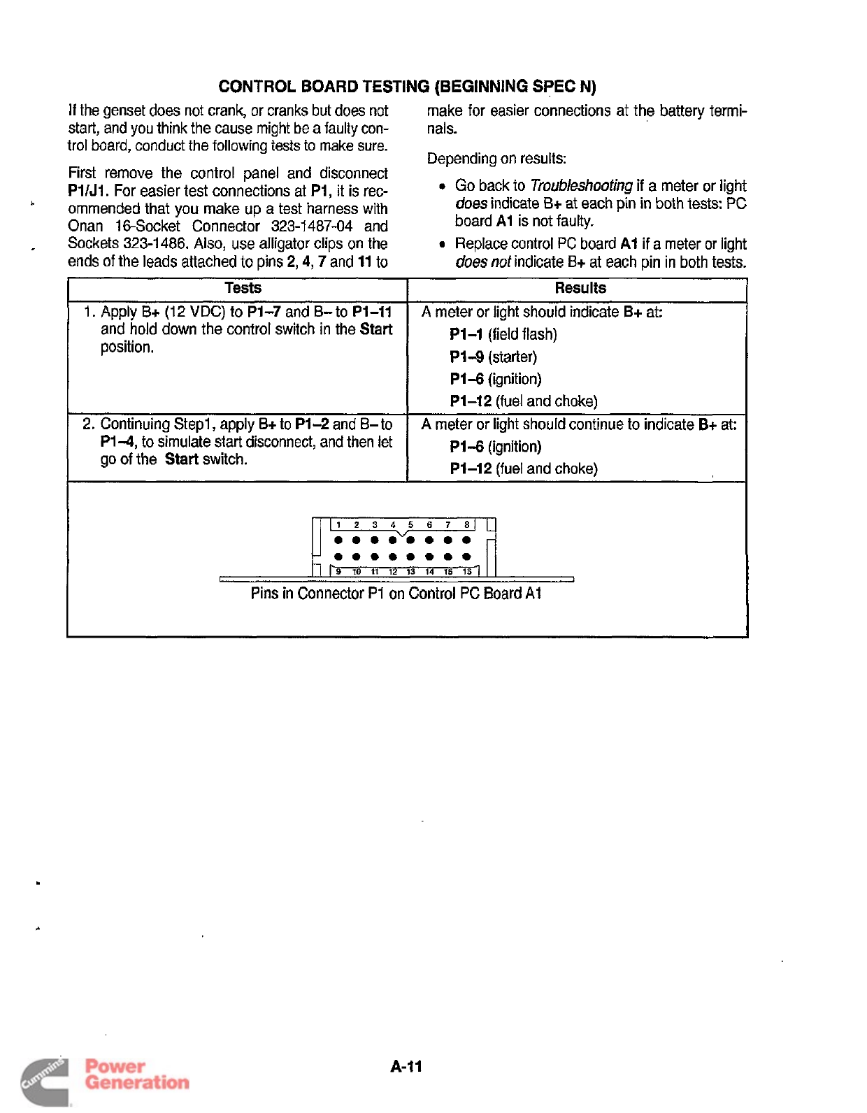
CONTROL
BOARD
TESTING (BEGINNING SPEC N)
Tests
1.
Apply
B+
(12
VDC)
to
P1-7
and
B-
to
P1-11
and hold down the control switch in the Start
position.
2.
Continuing Step1
,
apply
B+
to
Pl-2
and
B-
to
If
the genset does not crank, or cranks but does not
start, and
you
think the cause might be a faulty con-
trol board, conduct the following tests
to
make sure.
First remove the control panel and disconnect
PIIJI.
For easier test connections at
Pi,
it is rec-
ommended that
you
make up a test harness with
Onan 16-Socket Connector 323-1 487-04 and
Sockets 323-1486. Also, use alligator clips on the
ends
of
the leads attached to pins
2,4,7
and
11
to
'
.
Results
A meter or light should indicate
B+
at:
P1-1
(field flash)
PI4
(starter)
P1-6
(ignition)
Pl-12
(fuel and choke)
A
meter or light should continue to indicate
B+
at:
make for easier connections at the battery termi-
nals.
Depending on results:
0
Go
back to
Troubleshoofing
if
a meter or light
does
indicate
B+
at
each
pin
in
both tests:
PC
board
AI
is not faulty.
0
Replace control PC board
AI
if
a
meter or light
does
not
indicate
B+
at each pin in both tests.
P1-4,
to simulate start disconnect, and then let
go of the
Start
switch.
P1-6
(ignition)
P1-12
(fuel and choke)
11
2
3
4
5
6 7
81
...."....
-
r9
11
12
13
14
15
161
-
-
00000000
-
.
A-11
Redistribution or publication of this document
by any means, is strictly prohibited.

,
Redistribution or publication of this document
by any means, is strictly prohibited.
Appendix
B.
Later Wiring Diagrams
V
WIRING DIAGRAM DRAWING No. PAGE No.
Beginning Spec
J:
.
BGElNHE 60 HZ
611-1206 B-2
BGE/NHE
50
Hz
61 1-1 207
B-3
BGE
60
Hz,
100
V
611-1208
B-4
Beginning Spec
K:
BGE/NHE
60
Hz
611-1220
B-5
BGUNHE
50
Hz
61
1
-1
22
1
B-6
BGE 60 Hz,
100
V
61 1-1 222
B-7
Beginning Spec
N:
(sealed remote connector)
BGUNHE
60
Hz 61
1-1 244
B-8
BGE/NHE
60
Hz,
LP
61 1-1 253
B-9
BGElNHE
50
Hz,
LP
61 1-1 254 B-1 0
B-1
Redistribution or publication of this document
by any means, is strictly prohibited.
I
VR1
I
I
I
I
L
-
-
-1
I
I
NOTES:
1.
FOR
PZIJZ:
A
-
QROUND
0
-
KMT
STOP
C
-
RMT
START
E
.
sw
01
F
-
5W
61
VRl
VDLTAGE
CEWTOtl
T1
IGN
CCiL
53
EN
fiW).€
52
SUKH-LOW
OC
PES
Redistribution or publication of this document
by any means, is strictly prohibited.
WIRING
DIAGRAM
A2
A3
4
I
I
I
I
I
I
I
I
I
I
I
I
I
I
I
L
-
f/
I
I
s-
A
'
I
I
I
I
I
I
I
L---
I
I
I
OPT
I
ONAL
P2
Sr
HFMATIC
TBI
r
4
NOTES
:
1.
FOR
P2/JZ:
A
-
OROUNO
E
-
RMT
STOP
C
-
RMT
STAR
E
-
SW
Bt
F
-
SW
Bt
m1
TI
53
92
R6
R5
K5
K1
GI
F1
E3.4
E2
CR6
CL.5
ET1
€11
A3
A2
AI
AI
cniz
ITEM
VaTAQ
REWTOa
IGN
CCU
IGN
WE
Shmi-LOW
al
ms
ti€S!STM(-BATlERY
MaRE
w1ENTmw
RBAYIp(i MY
wY-sraRT
SOLENMO
GEMATOR
FUSE-SLOW
BLOW
5A
SPARK
PLUGS
FEL
FWF
OR
FUEL
SOL
FECTRER-LPG
ONLY
CIRCUT
BREAKER
!At
WTPUTl
CAPACITW
BATTERY
1ZV
STARIER
REMOTE
CONTROL-STAMARD
MOTOR
REMOTE
CONTAOL.OELUXE
CONTROL
ASSY-MEL
CONTROL
ASSY-BGEL
DESCRFTKN
CR
MAlWU
BEGllNNlNG
SPEC
N
BOUNHE
60
HZ.
LP-611-1253
Redistribution or publication of this document
by any means, is strictly prohibited.
-f
I
I
I
I
I
I
I
I
I
I
I
I
I
I
I
L
r-PI
I
I
I
I
I
I
I
I
I
I
I
I
L--,
I
I
I
I
'
I'
ZO'I
iC
CEil
T3
L1
700-IfOV
TL
L3
'''
T2
L3
T3
L2
T4
TI
L1
-
T&
L2
-
1
200-ZLOV
I
I
n
CBI
100-12ov
4
ZOO-2LOV
*
T3
T2
L3
L3
IIl
*
100-120V
f
C82
NOTES
1
IZOV
MAX
ACROSS
CRI
COEIhXTIGNS
2.3
!
2.
GROUNJEO
AC
LEAD-
FOR
ISOLATED NEUTRAL.
REMOVE
JUMPER
IW21
TB1-L3. LO AND
CONNECT
JUMPER
TBl-LO. VRI-C5
NEGI-I
3
FOR
P2lJZ A
-
QROUND
8
-
AHT
STOP
C
-
RMT START
E-SWB+
F-SWE+
VRl
TI
53
s:
R6
R§
t:5
t:1
GI
F1
E3
4
E2
CRb
Ch12
CL
E
Oil
611
A3
r;2
91
AI
,is%!
WLTAGE REGULATOR
IEW
COIL
IGN
NODULE
WTCH-LOV
0.
PRE55
RESISTOR-BATTERY
CHARS:
PDTENTlSMETER
RELAY-LPG
ONLY
RELAY-STCRT
S%ENC;D
GENERATCR
FUSSLOW
BLOW
5A
SPARK
FLLGS
FUEL
FLIP?
OX
FUEL
SOL
I;
ECiI=IER-LPG
C:
I-'(
ClKUT
FREAKEff
I4C
OUTPUT)
C"FilClT0f
Redistribution or publication of this document
by any means, is strictly prohibited.
I I
/
\
I---
\
I
/
I
I
I
I
I
I
I
L--
1
I
I
I
I
I
I
I
I
I
I
I
I
I
SCHEMATIC
'
I
-4
II
I..
P1-11
Tsl
,
q!
I
BEGllNNlNG
SPEC
N BGHNHE
50
HZ411-1248
CBI
I
~-
A
TIII
-
f
200-24OV
100-120v
TL L2
-
CB2
E
NOTES
1.
12OV
MAX
ACROSS
VRI CONNECTIONS 2,3
it
2.
GROUNDED AC LEAD- FOR ISOLATED NEUTRAL,
REMOVEJUMPER (WZ) TBI-L3. LO AND
CONNECT JUMPER TBI-LO. VRI-C5 NEGM
TI
IGN
CML
53
IGIlHOWLE
s2
SWITW-LOW
a
ffiEss
R5
FOTENTWTER
K4
RBAY.CHOKELFUELWW
KI
RMY-START
SoLENoiO
HI
CHOKE
El
GEWTffl
F2
FUSE-XIA
F1
FUSE-XIA
E3,b
SPARK
PLffiS
E2
FMW
CBU
CRCW
BRum
(AC
0UIpun
(45
CAPACITOR
ET1
BATTERY
1ZV
E1
STARTER
WTOR
A3
REHDTE
CONIRK-STAMARO
A2
REHDTE
CGVRCi-OELUXE
AI
CMrmUASSY-BE
AI
comtxfisy~
IXMP
OESCWTKU~LUTERN
.
..
.I
.
,
,
.
.
.
.
.
..
-
.
,,,
I
:t!
'
,
Redistribution or publication of this document
by any means, is strictly prohibited.

Redistribution or publication of this document
by any means, is strictly prohibited.
Supplement
965-1
075
Date:
02-01
hserf
with-
Title:
BGE,
NHE
Service
Manual
Number
(Date):
965-0528 (9-94)
This
supplement transmits
the
following
corrections
to
the service manual:
1.
On
Page
6-14
under
Direct Testing Coil With
Ohmmeter:
step
6,
change
"12.6
and
15.4
k
ohms"
to:
34.0
to
41.6
k
ohms
at
68°F
(20°C)
Refer
to
the
page
6-1
4
of
your
manual
and
write
"Refer
to
Supplement"
on
it.
Page
1
of
1
Redistribution or publication of this document
by any means, is strictly prohibited.

Redistribution or publication of this document
by any means, is strictly prohibited.
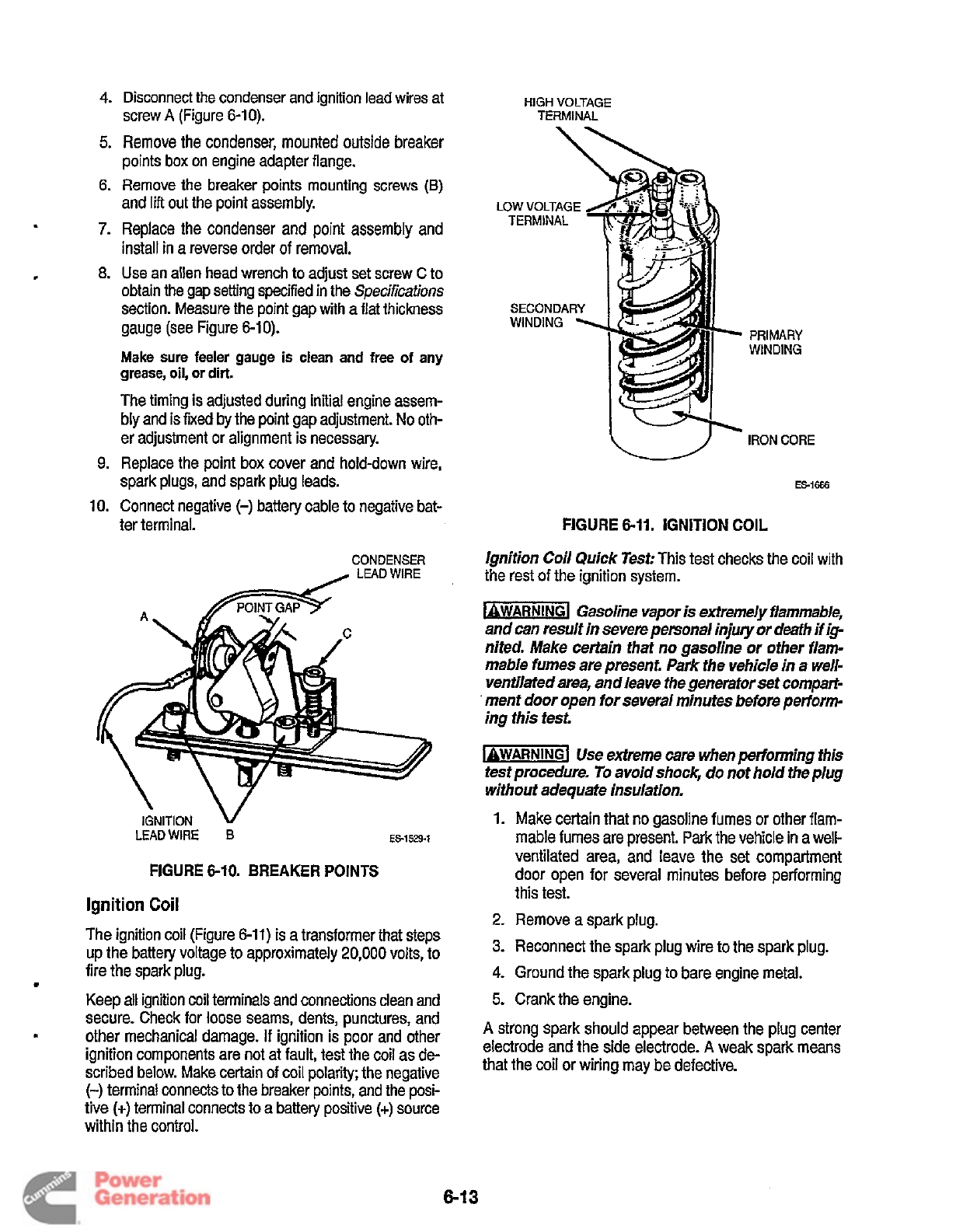
4.
Disconnect the condenser and ignition lead wires at
screw
A
(Figure
6-1
0).
HIGH
VOLTAGE
TERMINAL
c
5.
Remove the condenser, mounted outside breaker
points box on engine adapter flange.
6.
Remove the breaker points mounting screws
(B)
and
lift
out the point assembly.
7.
Replace the condenser and point assembly and
install in a reverse order
of
removal.
8.
Use an allen head wrench to adjust set screw
C
to
obtain
the
gap setting specified in the
Specifications
section. Measure the point gap with a flat thickness
gauge (see Figure
6-1
0).
Make sure feeler gauge
is
clean and
free
of
any
grease,
oil,
or
dirt.
The timing is adjusted during initial engine assem-
bly and is
fixed
by the point gap adjustment.
No
oth-
er adjustment or alignment is necessary.
9.
Replace the point box cover and hold-down wire,
spark plugs, and spark plug leads.
LOW
VOLTAGE
SECONDARY
PRIMARY
WINDING
IRON CORE
ES-1666
10.
Connect negative
(-)
battery cable to negative bat-
ter terminal. FIGURE
6-11.
IGNITION
COIL
CONDENSER
Ignition Coil Quick Test:
This test checks the coil with
the rest of the ignition system.
bWAR”Gl
Gasoline vapor
is
extremely flammable,
and can result in severe personal injury or death if ip
nited. Make certain that no gasoline or other flam-
mable fumes are present. Park the vehicle in a well-
ventilated area, and leave the generator set wmpart-
’
ment door open for several minutes before petiorm-
ing this test.
-1
Use extreme
care
when petionning this
test procedure.
To
avoid shock-, do not hold the plug
without adequate insulation.
IGINITION
V
LEADWIRE
B
1.
Make certain that no gasoline fumes or other flam-
mable fumes are present.
Park
the vehicle in a well-
ES-1529-1
ventilated area, and leave the set compartment
door open for several minutes before performing
this test.
FIGURE
6-10,
BREAKER
POINTS
Ignition
Coil
The ignition coil (Figure
6-11)
is a transformer that steps
up the battery voltage
to
approximately
20,000
volts, to
2.
Remove
a
spark
plug.
3.
Reconnect the spark plug wire to the spark plug.
fire the spark plug.
e
4.
Ground the spark plug to bare engine metal.
KeeD
all
ignition
coil
terminals and connections clean and
5.
Crank the engine.
-
A
strong spark should appear between the plug center
that the coil or wiring may be defective.
secure. Check for loose seams, dents, punctures, and
other mechanical damage.
If
ignition is poor and other
ignition components are not at fault, test the coil as de-
scribed below. Make certain of coil Dolaritv: the neaative
and
the
side
electrode.
A
weak
spark
(-)
terminal connects to the breake; pointi;and thiposi-
tive
(t)
terminal connects to a battery positive
(t)
source
within the control.
813
Redistribution or publication of this document
by any means, is strictly prohibited.
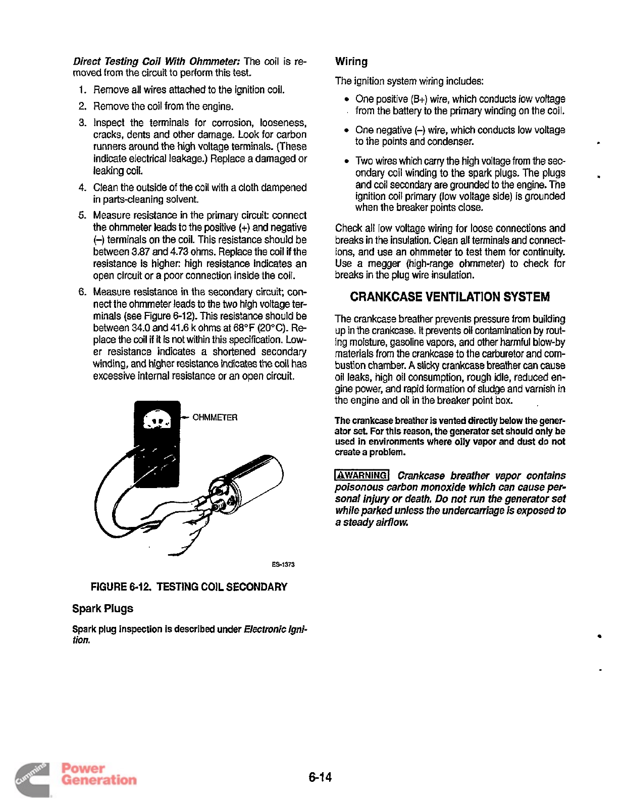
Direct Testing Coil Wth Ohmmeter:
The coil is re-
moved from the circuit to perform this test.
1.
Remove all wires attached
to
the ignition coil.
2.
Remove the coil from the engine.
3. Inspect the terminals for corrosion, looseness,
cracks, dents and other damage. Look for carbon
runners around the high voltage terminals. (These
indicate electrical leakage.) Replace a damaged or
leaking coil.
4.
Clean the outside of the coil with a cloth dampened
in parts-cleaning solvent.
5.
Measure resistance in the primary circuit: connect
the ohmmeter leads to the positive
(+)
and negative
(-)
terminals
on
the coil. This resistance should be
between 3.87 and
4.73
ohms. Replace the coil
if
the
resistance is higher: high resistance indicates an
open circuit or a poor connection inside the coil.
6.
Measure resistance
in
the secondary circuit; con-
nect the ohmmeter leads to the
two
high voltage ter-
minals (see Figure 6-12). This resistance should be
between 34.0 and 41.6 k ohms at 68°F (20°C).
Re
place the coil
if
it
is not within this specification. Low-
er resistance indicates a shortened secondary
winding, and higher resistance indicates the coil has
excessive internal resistance or an open circuit.
E51373
'2
FIGURE
6-12.
TESTING
COIL
SECONDARY
Wiring
The ignition system wiring includes:
One positive
(B+)
wire, which conducts
low
voltage
.
from the battery to the primary winding on the coil.
One negative
(-)
wire, which conducts
low
voltage
to the points and condenser.
Two wires which carry the high voltage from
the
sec-
ondary coil winding to the spark plugs. The plugs
and coil secondary are grounded to the engine. The
ignition coil primary
(low
voltage side) is grounded
when the breaker points close.
Check all
low
voltage wiring for loose connections and
breaks in the insulation. Clean all terminals and connect-
ions, and use an ohmmeter
to
test them for continuity.
Use a megger (high-range ohmmeter) to check for
breaks in the plug wire insulation.
CRANKCASE VENTILATION SYSTEM
.
The crankcase breather prevents pressure from building
up in the crankcase.
It
prevents oil contamination by rout-
ing moisture, gasoline vapors, and other harmful blow-by
materials from the crankcase to the carburetor and com-
bustion chamber.
A
sticky
crankcase breather can cause
oil
leaks, high oil consumption, rough idle, reduced en-
gine power, and rapid formation of sludge and varnish in
the engine and oil in
the
breaker point box.
The crankcase breather
is
vented directly below the gener-
ator set.
For
this reason, the generator set should
only
be
used in environments where oily vapor and dust do not
create a problem.
1-1
Crankcase breather
vapor
contains
poisonous carbon monoxide which can cause per-
sonal injury or death.
Do
not run the generator set
while parked unless the undercarriage
is
exposed to
a steady
airflow
,
Spark
Plugs
Spark plug inspection
is
described under
Electronic
Igni-
tion.
6-1
4
Redistribution or publication of this document
by any means, is strictly prohibited.
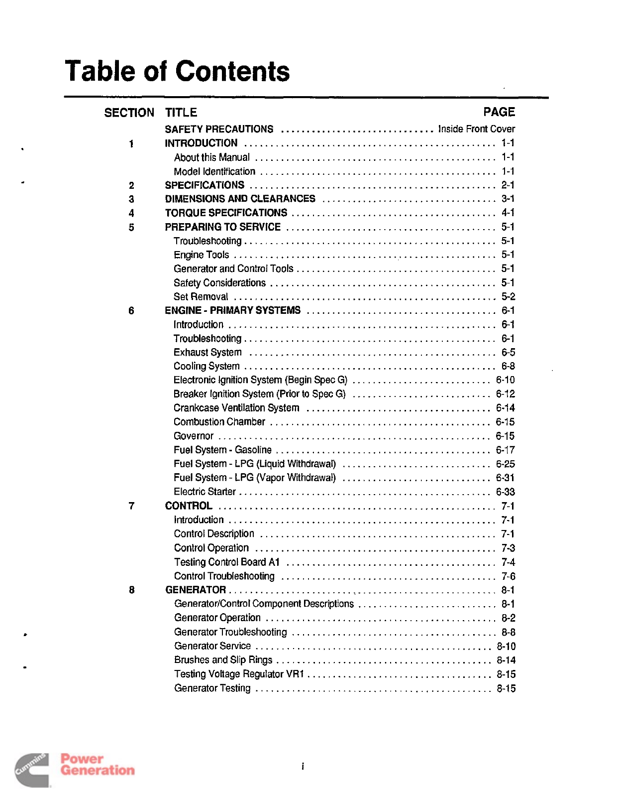
Table
of
Contents
6
7
8
SECTION
TITLE
PAGE
SAFETY PRECAUTIONS
..............................
Inside Front Cover
1
INTRODUCTION
.................................................
1-1
About this Manual
...............................................
1-1
Model Identification
..............................................
1-1
2
SPECIFICATIONS
................................................
2-1
3
DIMENSIONS AND CLEARANCES
..................................
3-1
4
TORQUE SPECIFICATIONS
........................................
4-1
5
PREPARING
TO
SERVICE
.........................................
5-1
Troubleshooting
.................................................
5-1
Engine
Tools
....................................................
5-1
Generator and Control Tools
.......................................
5-1
Safety Considerations
............................................
5-1
Set Removal
...................................................
5-2
Introduction
....................................................
6-1
Troubleshooting
.................................................
6-1
Exhaustsystem
................................................
6-5
Cooling System
.................................................
6-8
Electronic Ignition System (Begin Spec G)
...........................
6-10
Breaker Ignition
System
{Prior
to
Spec G)
...........................
6-12
Crankcase Ventilation System
....................................
6-14
Combustion Chamber
...........................................
6-15
Governor
.....................................................
6-15
Fuel System
-
Gasoline
..........................................
6-17
Fuel System
-
LPG (Liquid Withdrawal)
.............................
6-25
Fuel System
-
LPG (Vapor Withdrawal)
.............................
6-31
Electric Starter
.................................................
6-33
Introduction
....................................................
7-1
Control Description
..............................................
7-1
Testing Control Board
AI
.........................................
7-4
Control Troubleshooting
..........................................
7-6
GeneratorEontrol Component Descriptions
...........................
8-1
Generator Operation
.............................................
8-2
Generator Troubleshooting
........................................
8-8
Generator Service
..............................................
8-10
Brushes and Slip Rings
..........................................
8-14
Testing Voltage Regulator
VR1
....................................
8-15
Generator Testing
..............................................
8-15
ENGINE
-
PRIMARY SYSTEMS
.....................................
6-1
CONTROL
......................................................
7-1
Control Operation
...............................................
7-3
GENERATOR
....................................................
8-1
i
Redistribution or publication of this document
by any means, is strictly prohibited.
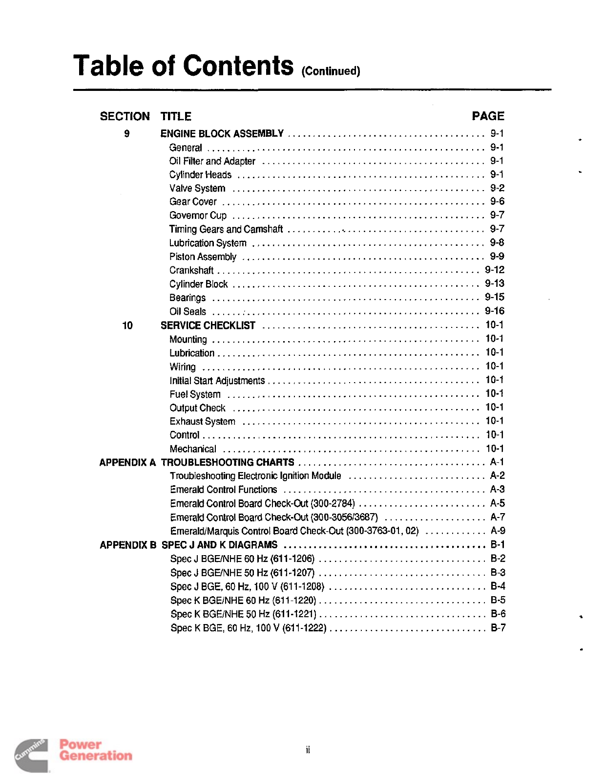
Table
of
Contents
(Continued)
~~ ~
SECTION TITLE PAGE
9
ENGINE BLOCK ASSEMBLY
.......................................
9-1
General
.......................................................
9-1
Oil Filter and Adapter
............................................
9-1
CylinderHeads
.................................................
9-1
Valvesystem
..................................................
9-2
Gear Cover
....................................................
9-6
GovemorCup
..................................................
9-7
Timing Gears and Camshaft
........................................
9-7
Lubrication System
..............................................
9-8
Piston Assembly
................................................
9-9
Crankshaft
....................................................
9-12
Cylinder Block
.................................................
9-13
Bearings
.....................................................
9-15
Oil Seals
......
:
..............................................
9-16
10
SERVICE CHECKLIST
...........................................
10-1
Mounting
.....................................................
10-1
Lubrication
....................................................
10-1
Wiring
.......................................................
10-1
Initial Start Adjustments
..........................................
10-1
Fuel System
..................................................
10-1
Output Check
.................................................
10-1
Exhaust System
...............................................
10-1
Control
.......................................................
10-1
Mechanical
...................................................
10-1
APPENDIX
A
TROUBLESHOOTING CHARTS
.....................................
A-1
Troubleshooting Electronic Ignition Module
...........................
A-2
Emerald Control Functions
........................................
A-3
Emerald Control Board Check-Out (300-2784)
.........................
A-5
Emerald Control
Board
Check-Out (300-305613667)
....................
A-7
Emerald/Marquis Control Board Check-Out (300-3763-01,
02)
............
A-9
APPENDIX
B
SPEC
J
AND K DIAGRAMS
........................................
B-1
Spec
J
BGElNHE 60
Hz
(611-1206)
.................................
8-2
Spec
J
BGElNHE
50
Hz
(61 1-1207)
.................................
B-3
Spec
J
BGE,
60
Hz,
100
V
(611-1208)
...............................
8-4
Spec
K
BGElNHE 60
Hz
(61 1-1220)
.................................
B-5
Spec
K
BGElNHE
50
Hz (61 1-1221)
.................................
B-6
Spec
K
BGE,
60
Hz, 100
V
(61 1-1222)
...............................
B-7
ii
Redistribution or publication of this document
by any means, is strictly prohibited.
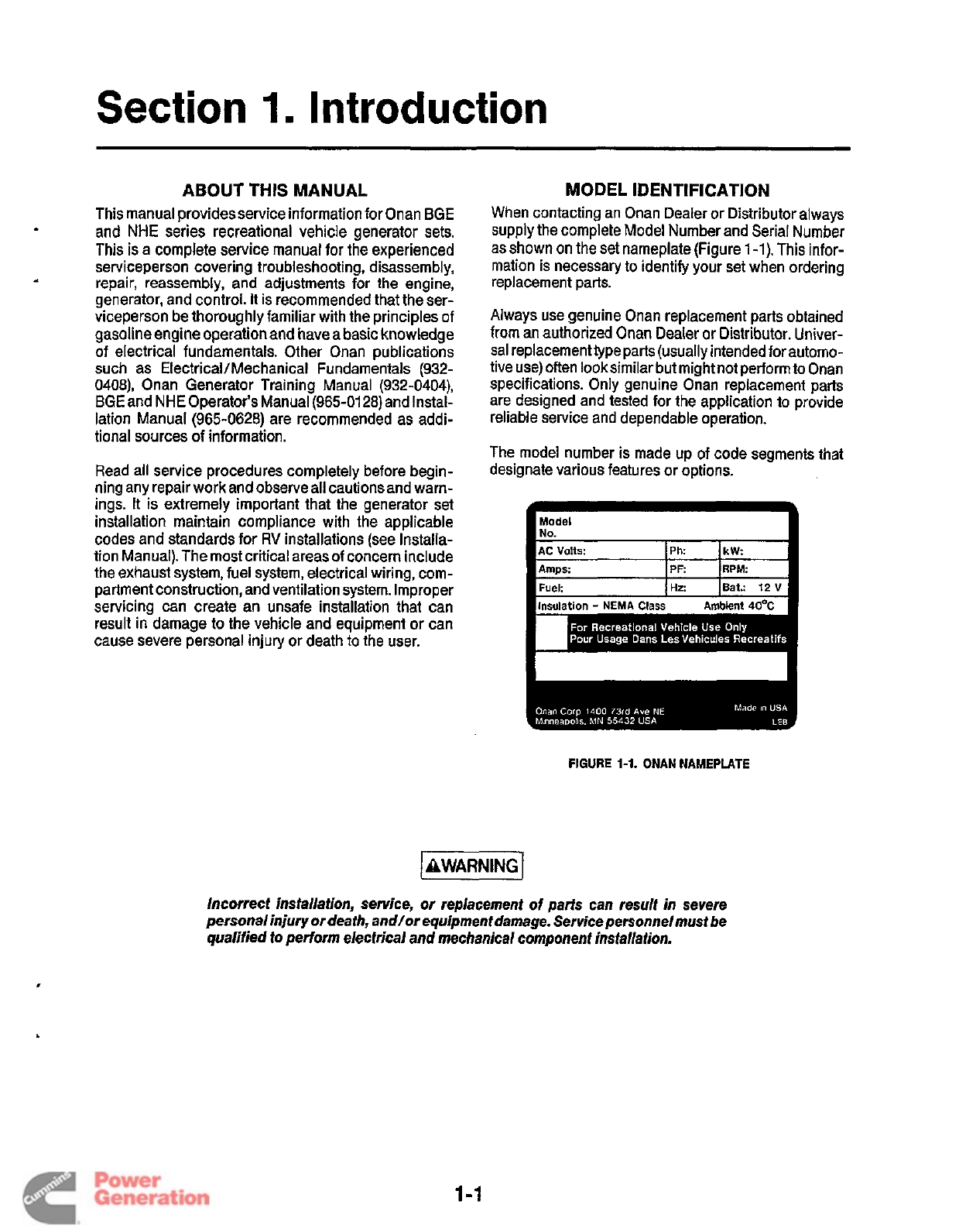
Section
1
Introduction
ABOUT THIS MANUAL
This manual providesservice information for Onan
BGE
and
NHE
series recreational vehicle generator sets.
This
is
a complete service manual for the experienced
serviceperson covering troubleshooting, disassembly,
repair, reassembly, and adjustments
for
the engine,
generator, and control.
It
is recommended that the ser-
viceperson be thoroughly familiar with the principles of
gasoline engine operation and have a basic knowledge
of electrical fundamentals. Other Onan publications
such as ElectricaVMechanicaI Fundamentals (932-
0408),
Onan Generator Training Manual (932-0404),
BGE and NHE Operator’s Manual (965-01 28) and Instal-
lation Manual (965-0628) are recommended as addi-
tional sources
of
information.
Read all service procedures completely before begin-
ning any repair work and observe all cautions and warn-
ings. It is extremely important that the generator set
installation maintain compliance with the applicable
codes and standards
for
RV
installations (see Installa-
tion Manual). The most critical areas of concern include
the exhaust system, fuel system, electrical wiring, com-
partment construction, and ventilation system. Improper
servicing can create an unsafe installation that can
result in damage to the vehicle and equipment or can
cause severe personal injury or death to the user.
MOD EL
I
DENTI FlCATlON
When contacting an Onan Dealer or Distributor always
supply the complete Model Number and Serial Number
as shown on the set nameplate (Figure
1-1).
This infor-
mation is necessary to identify your set when ordering
replacement parts.
Always use genuine Onan replacement parts obtained
from an authorized Onan Dealer or Distributor. Univer-
sal replacementtype parts (usually intended for automo-
tive use) often looksimilar but might not perform to Onan
specifications. Only genuine Onan replacement parts
are designed and tested for the application to provide
reliable service and dependable operation.
The model number is made up of code segments that
designate various features or options.
FIGURE
1-1.
ONAN NAMEPLATE
Incorrect installation, service, or replacement of parts can result in severe
personal injury or death, and/or equipment damage. Service personnel must be
qualified
to
perform electrical and mechanical component insfallation.
1-1
Redistribution or publication of this document
by any means, is strictly prohibited.
Section
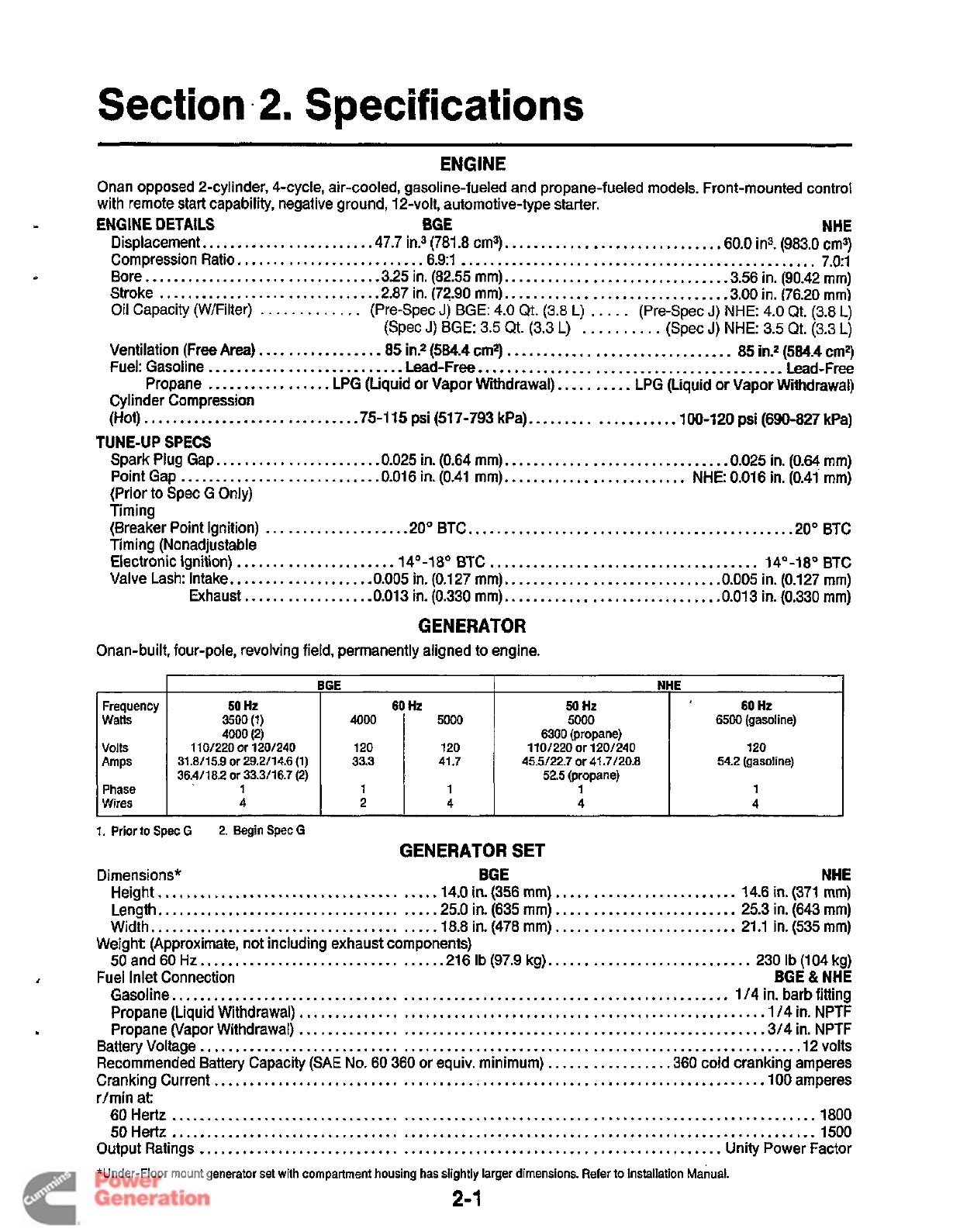
.2.
Specifications
Frequency
Watts
Volts
Amps
Phase
Wires
Onan opposed 2-cylinder, 4-cycle, air-cooled, gasoline-fueled and propane-fueled models. Front-mounted control
with remote start capability, negative ground, 12-volt, automotive-type starter.
ENGINE
DETAILS
BGE
NHE
Displacement..
.....................
.47.7
in?
(781.8
cm3).
............................
.60.0
ins.
(983.0
cm3)
Compression Ratio.
........................
.6.9:1
.................................................
7.0:l
Bore..
..............................
.3.25
in. (82.55 mm).
.............................
-3.56
in. (90.42
mm)
Stroke
..............................
.2.87
in.
(72.90
mm).
.............................
.3.00
in.
(76.20
mm)
Oil
Capacity (WIFilter)
.............
(Pre-Spec
J)
BGE:
4.0
Qt.
(3.8
L)
.....
(Pre-Spec
J)
NHE:
4.0
Qt.
(3.8
L)
(Spec
J)
BGE:
3.5
Qt.
(3.3
L)
..........
(Spec
J)
NHE:
3.5
Qt.
(3.3
L)
Ventilation (Free Area).
...............
-85
in.*
(584.4
cm2)
...............................
85
in?
(584.4
cm2)
Fuel: Gasoline
...........................
Lead-Free
..........................................
Lead-Free
Propane
.................
LPG (Liquid or Vapor Withdrawal).
.........
LPG (Liquid or Vapor Withdrawal)
Cylinder Compression
(Hot).
............................
.75-115
psi
(517-793
kPa).
..................
.100-120
psi
(690-827
kPa)
BGE
NHE
50
Hz
60
Hz
50
Hz
60
Hz
3500
(1)
4000
5000
5000 6500
(gasoline)
4000(2) 6300
(propane)
31.8115.9
or
29.2114.6 (1) 33.3 41.7 45.5122.7 or 41.7120.8 54.2
(gasoline)
36.4118.2 or 33.3116.7 (2) 52.5
(propane)
1
101220 or 1201240 120 120 1101220or1201240 120
1 1 1 1 1
4
2
4 4 4
TUNE-UP SPECS
Spark Plug Gap..
....................
.0.025
in.
(0.64
mm).
.............................
.0.025
in.
(0.64
mm)
Point Gap
...........................
.0.016
in.
(0.41
mm).
........................
NHE:
0.016
in.
(0.41
mm)
(Prior to Spec G Only)
Timing
(Breaker Point Ignition)
...................
.20°
BTC..
..........................................
.20°
BTC
Timing (Nonadjustable
Electronic Ignition)
.....................
.14'-18O
BTC
.....................................
14'-18'
BTC
Valve Lash: Intake..
.................
.0.005
in.
(0.127
mm).
............................
.0.005
in.
(0.127
mm)
Exhaust..
...............
.0.013
in.
(0.330
mm).
............................
.0.013
in.
(0.330
mm)
GENERATOR
Onan-built, four-pole, revolving field, permanently aligned
to
engine.
Dimensions"
BGE NHE
Height..
....................................
.14.0
in.
(356
mm)
.........................
14.6
in.
(371
mm)
Length,.
....................................
,25.0
in.
(635
mm)
.........................
25.3
in.
(643
mm)
Width..
.....................................
.18.8
in.
(478
mm)
.........................
21.1
in.
(535
mm)
50
and
60
Hr..
...............................
.216
Ib
(97.9
kg).
...........................
230
Ib
(104
kg)
BGE
&
NHE
Gasoline..
...........................................................................
114
in. barb fitting
Propane
(Liquid
Withdrawal)
...............................................................
.1/4
in.
NPTF
Propane (Vapor Withdrawal)
...............................................................
.3/4
in. NPTF
Battery Voltage
..................................................................................
.12
volts
Recommended Battery Capacity (SAE
No. 60
360
or equiv. minimum)
................
.360
cold cranking amperes
Cranking Current
...........................................................................
.lo0
amperes
r/min at:
60
Hertz
.........................................................................................
1800
50
Hertz
.........................................................................................
1500
Output Ratings
........................................................................
Unity Power Factor
*Under-Floor mount generator set with compartment housing has slightly larger dimensions. Refer to Installation Manual.
Weight (Approximate, not including exhaust components)
Fuel Inlet Connection
2-1
Redistribution or publication of this document
by any means, is strictly prohibited.
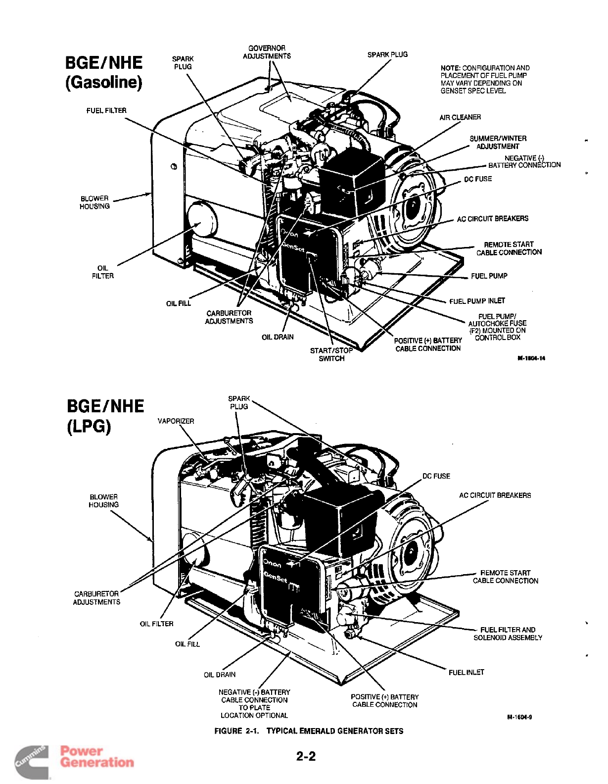
BGE/NHE
SPARK
PLUG
GOVERNOR
ADJUSTMENTS
I\
SPARK PLUG
/
NOTE: CONFIGURATION AND
PLACEMENT
OF
FUEL PUMP
MAY
VARY
DEPENDING ON
GENSET SPEC LEVEL
\
(Gasoline)
I
t
FUEL FILTER
\
BLOWER
/
iOUSING
OIL
/
FILTER
BGE/NHE
SUMMER1 WINTER
ADJUSTMENT
REMOTE START
CABLE CONNECTION
ADJUSTMENTS
-7ik
OCFUSE
1
AC CIRCUIT BREAKERS
0
1
,"
Y
FUELPUMP
FUELPUMP INLET
SWlTCH
M.1sm-14
HOUSING
REMOTE START
ABLE CONNECTION
FUEL FILTER AND
SOLENOID ASSEMBLY
NEGATIVE (-[BATTERY
CABLE CONNECTION
TO
PLATE
POSITIVE
(+)
BATTERY
CABLE CONNECTION
TlON
-.
-
LOCATION OPTIONAL
FIGURE
2-1.
TYPICAL
EMERALD
GENERATOR
SETS
M-1604-9
2-2
Redistribution or publication of this document
by any means, is strictly prohibited.
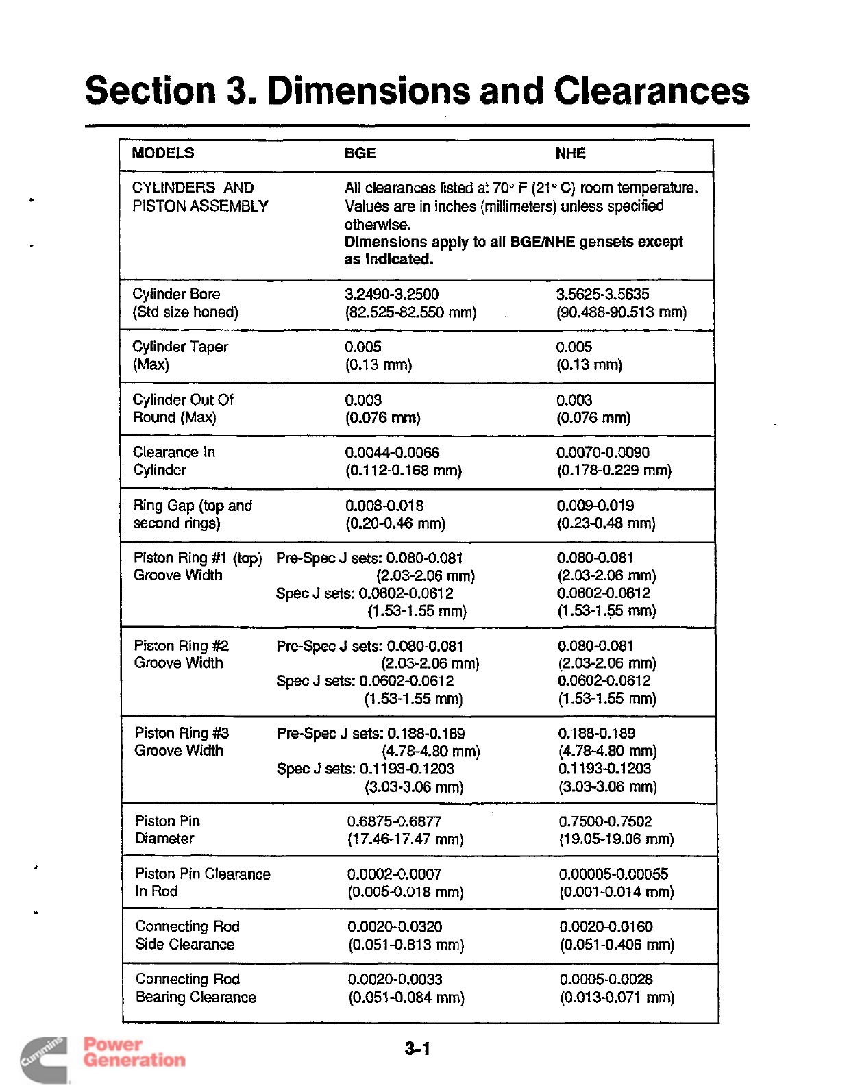
Section
3.
Dimensions
and
Clearances
MODELS
BGE
NHE
CYLINDERS
AND
PISTON
ASSEMBLY
All
clearances listed at
70"
F
(21
O
C)
room temperature.
Values
are
in
inches (millimeters) unless specified
otherwise.
Dimensions
apply
to
all
BGE/NHE
gensets
except
as indlcated.
Cylinder Bore
3.2490-3.2500 3.5625-3.5635
(Std size honed)
(82.525-82.550
mm)
(90.488-90.513
mm)
Cylinder Taper
(Ma)
0.005
(0.13
mm)
0.005
(0.13
mm)
Cylinder
Out
Of
Round
(Max)
0.003
(0.076
mm)
0.003
(0.076
mm)
Clearance
In
Cylinder
0.0044-0.0066
0.0070-0.0090
(0.1
12-0.1 68
mm)
(0.1 78-0.229
mm)
Ring Gap (top and
second rings)
(0.20-0.46
mm)
0.008-0.01
8
0.009-0.01 9
(0.23-0.48
mm)
Piston Ring
#1
(top) Pre-Spec
J
sets:
0.080-0.081 0.080-0.081
Groove Width
(2.03-2.06
mm)
(2.03-2.06
mm)
0.0602-0.061
2
(1.53-1
35
mm)
Spec
J
sets:
0.0602-0.061
2
(1
53-1.55
mm)
Piston Ring
#2
Pre-Spec
J
sets:
0.080-0.081 0.080-0.081
Groove Width
(2.03-206
mm)
(2.03-2.06
mm)
0.0602-0.061
2
(1
53-1.55
mm)
Spec
J
sets:
0.0602-0.061 2
(1
53-1.55
mm)
Piston Ring
#3
0.1
884.1 89
Groove Width
(4.78-4.80
mm)
(4.78-4.80
mm)
0.1
193-0.1 203
(3.03-3.06
mm)
(3.03-3.06
mm)
Pre-Spec
J
sets:
0.1
88-0.1 89
Spec
J
sets:
0.1 193-0.1 203
Piston Pin
Diameter
0.6875-0.6877 0.7500-0.7502
(1 7.46-1 7.47
mm)
(1
9.05-1 9.06
mm)
Piston Pin Clearance
0.0002-0.0007
0.00005-0.00055
In
Rod
(0.005-0.01
8
mm)
(0.001
-0.01
4
mm)
Connecting Rod
Side Clearance
0.0020-0.0320 0.0020-0.01 60
(0.051
-0.81
3
mm)
(0.051 -0.406
mm)
Connecting Rod
0.0020-0.0033 0.0005-0.0028
Bearing Clearance
(0.051
-0.084
mm)
(0.01
3-0.071
mm)
3-
1
Redistribution or publication of this document
by any means, is strictly prohibited.
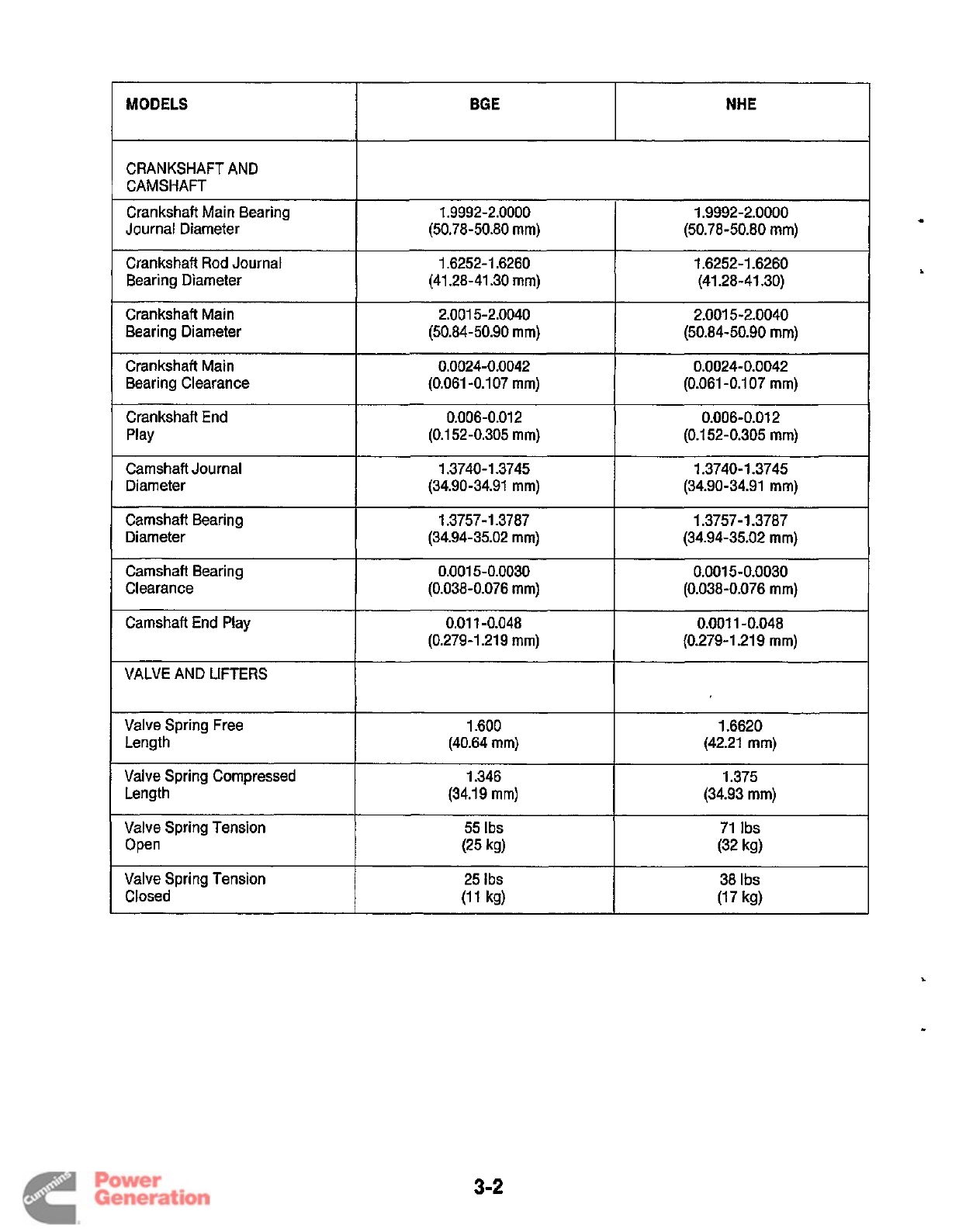
MODELS
I
BGE
I
NHE
CRANKSHAFT AND
CAMSHAFT
Journal Diameter
crankshaft Main Bearing
Crankshaft Rod Journal
Bearing Diameter
1.9992-2.0000 1.9992-2.0000
(50.78-50.80
mm)
(50.78-50.80
mm)
1.6252-1.6260 1.6252-1.6260
(41.28-41.30
mm)
(41.28-41.30)
Crankshaft Main
Bearing Diameter
2.001 5-2.0040 2.001 5-2.0040
(50.84-50.90
mm)
(50.84-50.90
mm)
Crankshaft Main
Bearing Clearance
0.0024-0.0042 0.0024-0.0042
(0.061 -0.1 07
mm)
(0.061 -0.1 07
mm)
Crankshaft End
Play
Diameter
Camshaft Journal
Camshaft Bearing
Diameter
3-2
0.006-0.01
2
0.006-0.01 2
(0.1 52-0.305
mm)
(0.1 52-0.305
mm)
(34.90-34.91
mm)
(34.90-34.91
mm)
(34.94-35.02
mm)
(34.94-35.02
mm)
1.3740-1 -3745 1.3740-1.3745
1.3757-1.3787 1.3757-1.3787
Camshaft Bearing
Clearance
Camshaft End Play
VALVE AND LIFTERS
Valve Spring Free
Length
Valve Spring Compressed
Length
0.001 5-0.0030 0.001 5-0.0030
(0.038-0.076
mm)
(0.038-0.076
mm)
(0.279-1.219
mm)
(0.279-1.21 9
mm)
0.01
1-0.048 0.001 1-0.048
1.6620
1.600
(40.64
mm)
(42.21
mm)
1.346 1.375
(34.19
mm)
(34.93
mm)
Valve Spring Tension
Open
Valve Spring Tension
Closed
55
Ibs
71
Ibs
25
Ibs
38
Ibs
(25
kg)
(32
kg)
(11
kg)
(17
kg)
Redistribution or publication of this document
by any means, is strictly prohibited.
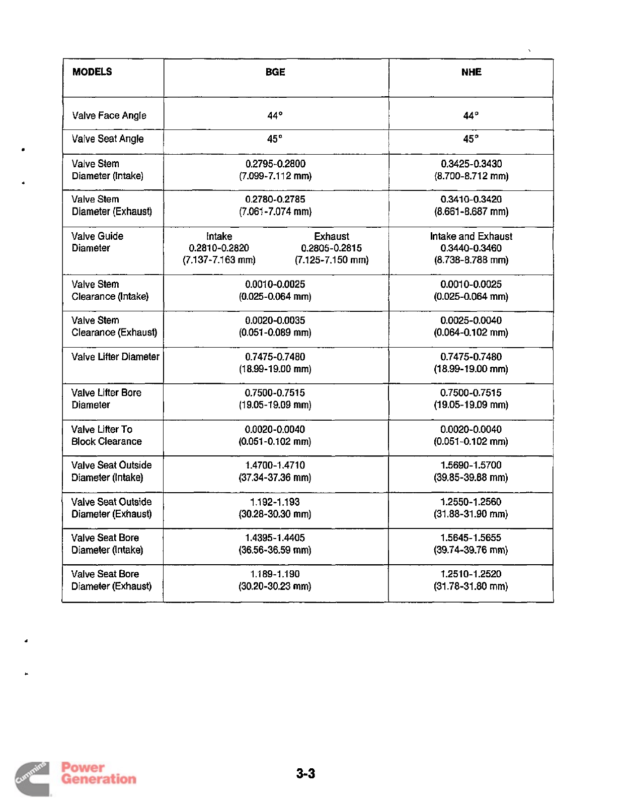
MODELS BGE
Valve Face Angle
44O
Valve Seat Angle
45
Valve Stem
0.2795-0.2800
Diameter (Intake)
(7.099-7.1 12
mm)
NHE
44
O
45O
0.3425-0.3430
(8.700-8.71 2
mm)
Valve Guide
Diameter
Valve Stem
Diameter (Exhaust)
Intake Exhaust
(7.137-7.163
mm)
(7.125-7.1
50
mm)
0.281 0-0.2820 0.2805-0.2815
0.2780-0.2785 0.341 0-0.3420
(7.061 -7.074
mm)
(8.661 -8.687
mm)
Intake and Exhaust
(8.738-8.788
mm)
0.3440-0.3460
Valve Stem
Clearance (Intake)
0.001 0-0.0025 0.001 0-0.0025
(0.025-0.064
mm)
(0.025-0.064
mm)
Valve Stem
Clearance (Exhaust)
Valve Lifter Diameter
Valve Lifter Bore
Diameter
Valve Lifter
To
Block Clearance
~
0.0020-0.0035 0.0025-0.0040
(0.051 -0.089
mm)
(0.064-0.102
mm)
0.7475-0.7480 0.7475-0.7480
(1
8.99-1 9.00
mm)
(18.99-1 9.00
mm)
(19.05-1 9.09
mm)
0.7500-0.751
5
0.7500-0.751
5
(1
9.05-1 9.09
mm)
0.0020-0.0040 0.0020-0.0040
(0.051
-0.102
mm)
(0.051
-0.1 02
mm)
Valve Seat Outside
Diameter (Intake)
I
I
I
I
1.4700-1.471
0
1.5690-1.5700
(37.34-37.36
mm)
(39.85-39.88
mm)
3-3
Valve Seat Outside
Diameter (Exhaust)
Valve Seat Bore
Diameter (Intake)
Valve Seat Bore
Diameter (Exhaust)
1.1
92-1.1 93 1.2550-1.2560
(30.28-30.30
mm)
(31.88-31.90
mm)
1.4395-1.4405 1.5645-1 S655
(36.56-36.59
mm)
(39.74-39.76
mm)
1.1
89-1.1 90 1.251 0-1.2520
(30.20-30.23
mm)
(31.78-31.80
mm)
Redistribution or publication of this document
by any means, is strictly prohibited.

Redistribution or publication of this document
by any means, is strictly prohibited.
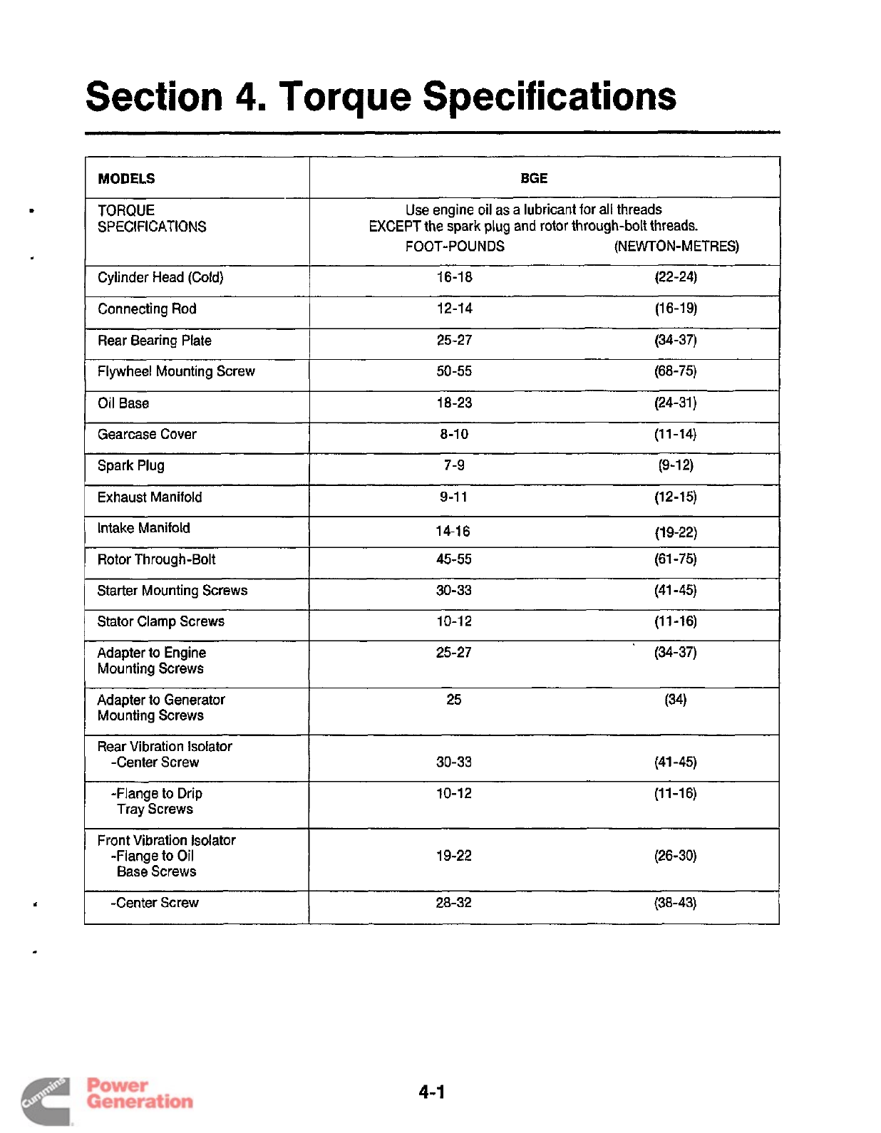
Section
4.
Torque
Specifications
Connecting Rod
Rear Bearing Plate
MODELS
BGE
I
12-14 (16-19)
25-27 (34-37)
TORQUE
SPECIFICATIONS
Oil Base
Use engine oil as a lubricant for all threads
EXCEPT the spark plug and rotor through-bolt threads.
FOOT-POUNDS (NEWTON-METRES)
18-23 (24-31)
Cylinder Head (Cold) 16-18 (22-24)
I
Gearcase Cover
Spark Plug
8-1
0
(11-14)
7-9
(9-1
2)
50-55 (68-75)
I
Flywheel Mounting Screw
Exhaust Manifold
Intake Manifold
9-1 1 (12-15)
14-1
6
(1 9-22)
Rotor Through-Bolt 45-55 (61
-75)
Adapter to Engine
Mounting Screws
Starter Mounting Screws
25-27 (34-37)
30-33 (41 -45)
_______
Stator Clamp Screws 10-12 (11-16)
Adapter to Generator
Mounting Screws 25 (34)
Rear Vibration Isolator
-Center Screw 30-33 (41 -45)
-Flange to Drip
Tray Screws 10-12
(1
1
-1 6)
Front Vibration Isolator
-Flange to
Oil
Base Screws 19-22 (26-30)
-Center Screw 28-32 (38-43)
4-1
Redistribution or publication of this document
by any means, is strictly prohibited.
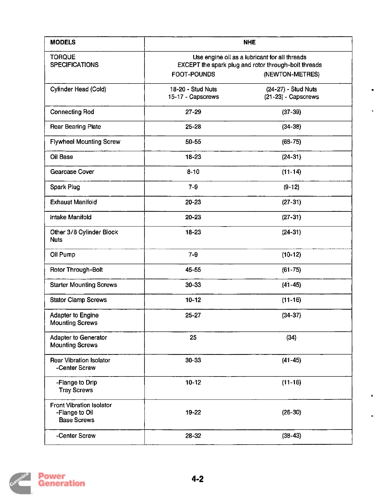
I
MODELS
Gearcase Cover
Spark Plug
NHE
8-1
0
(11-14)
7-9 (9-12)
Use engine
oil
as a lubricant for all threads
EXCEPT the spark plug and rotor through-bolt threads
FOOT-POUNDS (NEWTON-METRES)
Starter Mounting Screws
TORQUE
SPECIFICATIONS
30-33 (4i -45)
18-20
-
Stud Nuts
15-1
7
-
Capscrews
Adapter to Generator
Mounting Screws
Rear Vibration Isolator
-Center Screw
-Flange to Drip
Tray Screws
Front Vibration Isolator
-Flange to Oil
Base Screws
(24-27)
-
Stud Nuts
(21 -23)
-
Capscrews
25 (34)
30-33 (41 -45)
10-12
(1
1
-1
6)
19-22 (26-30)
Cylinder Head (Cold)
I
Connecting Rod
27-29 (37-39)
I
Rear Bearing Plate
25-28 (34-38)
1
Flywheel Mounting Screw
50-55 (68-75)
I
OilBase
18-23 (24-31)
I
Exhaust Manifold
20-23 (27-31)
I
Intake Manifold
I
20-23 (27-31)
Other
318
Cylinder Block
I
Nuts
18-23 (24-31)
7-9
(1
0-1 2)
I
Rotor Through-Bolt
45-55 (61 -75)
I
Stator clamp screws
10-12
(1
1
-1
6)
25-27 (34-37)
Adapter to Engine
Mounting Screws
I
-Center Screw
28-32 (38-43)
4-2
Redistribution or publication of this document
by any means, is strictly prohibited.
Section
5.
Preparing
to
Service
TROUBLESHOOTING
Most service procedures require that the genset be
removed from the vehicle. Because genset installations
vary, removal procedures vary.
If
removal is a problem,
contact the vehicle manufacturer or genset installer for
assistance. Many procedures require that the outer
sheet metal cover assemblies of the generator set be
removed. This section covers this procedure.
c
GENERATOR AND CONTROL TOOLS
Lead or dead-blow hammer
Battery hydrometer
VOM multi-tester
Frequency meter
Armature growler
Load test panel
Jumper wires
The main service areas are covered in these manual
sections: catalog (publication #900-0019).
Many of these tools are available through the Onan tool
Section
6
-
Engine
-
Primary Systems
0
Section
7
-
Control System
0
Section
8
-
Generator
0
Section 9
-
Engine Block Assembly
SAFETY
CONSIDERATIONS
Be totally aware of generator set hazards. Study the
safety precautions on the inside front cover of this man-
ual, and know the hazards listed in Table 5-1. Approach
Troubleshooting charts in each section providefixesfor
common malfunctions. death.
the job in a safety conscious manner, to avoid injury and
ENGINE
TOOLS
Torque wrench
(0-175
ft-lbs
0-240
Nom)
Feeler gauge
Pressure gauge
Spark plug gap gauge
Cylinder compression tester
Carburetor adjustment wrench
Points adjustment tool
Flywheel puller
Snap ring pliers
Gear puller with puller ring
Cylinder ridge reamer
Combination main and cam bearing remover
Combination main and cam bearing driver
Oil seal loader and driver
Piston ring compressor
Piston ring spreader
Cylinder hone
Valve seat cutter
Valve spring compressor
Valve lock replacer
Valve seat driver
Valve guide driver
Slide hammer
Piston groove cleaner
Outside micrometer set
(0
to
4
in.)
Telescoping gauge set (1
/2
in. to
6
in.)
Hole gauge
(0.300
in. to
0.400
in.)
Plasti-Gage bearing clearance guide
Standard Torx screwdriver
~
M
:r
4
Safeguards
to
Avoid Hazards
0
Use personal protection: Wear protective safety
equipment, such as:
-Safety shoes
-Gloves
-Safety glasses
-Hard hats
-Ear plugs
Do
not wear rings, jewelry, o'r loose clothing: these
might get caught on equipment or conduct electricity.
0
Reduce the hazard:
A
safe, orderly work area and
well-maintained equipment reduce hazard. Leave
all guards and shields in place on machinery, and
maintain equipment in top condition. Store flamma-
ble liquids in approved containers, away from fire,
flame, spark, pilot light, arc-producing equipment
and other ignition sources. Keep the work area
clean, well-lighted, and well-ventilated. Keep fire
extinguishers and safety equipment nearby, and be
prepared for an emergency.
Develop safe
work
habits: Unsafe practices cause
accidents. Be familiar with your tools and machines,
to use them safely. Use the right tool for the job, and
check its condition before starting. Follow all warn-
ings in this manual, and take extra precautions
when working around electrical equipment. Avoid
working alone, and take
no
risks.
0
Be prepared
for
a potential accident: The Red
Cross and public safety departments offer courses
in first aid,
CPR,
and fire control. Use this informa-
tion to be ready for an accident.
Be
safety-
conscious, and make safety procedures part of the
work routine.
5-1
Redistribution or publication of this document
by any means, is strictly prohibited.
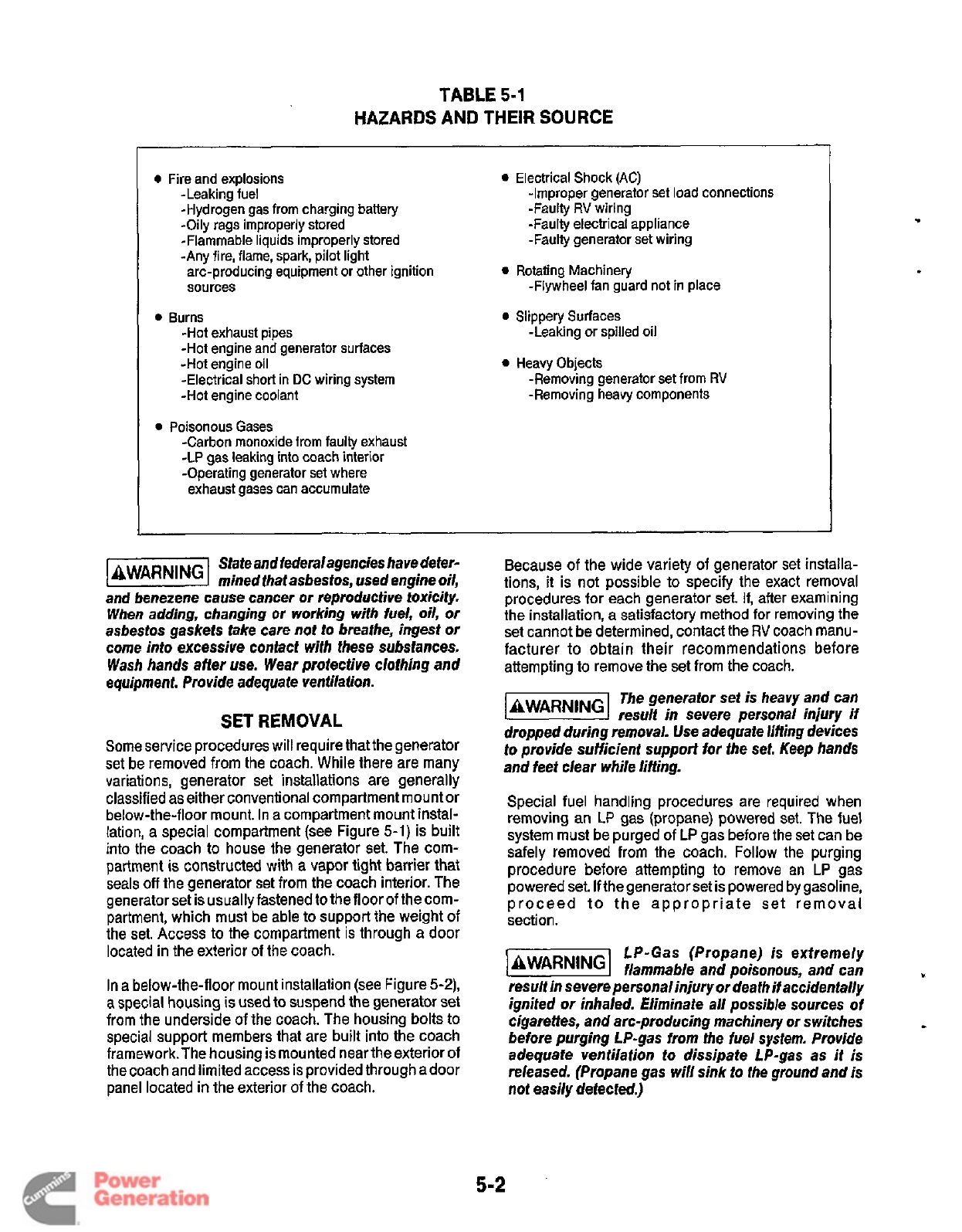
TABLE
5-1
HAZARDS AND THEIR SOURCE
0
Fire and explosions
-Leaking fuel
-Hydrogen gas
from
charging battery
-Oily rags improperly stored
-Flammable liquids improperly stored
-Any fire, flame, spark, pilot light
arc-producing equipment
or
other ignition
sources
0
Burns
-Hot
exhaust pipes
-Hot engine and generator surfaces
-Hot engine oil
-Electrical short in
DC
wiring system
-Hot engine coolant
-Carbon monoxide from faulty exhaust
-LP gas leaking into coach interior
-Operating generator set where
exhaust gases can accumulate
0
Poisonous Gases
0
Electrical Shock
(AC)
-Improper generator
set
load connections
-Faulty
RV
wiring
-Faulty electrical appliance
-Faulty generator set wiring
-Flywheel fan guard not in place
-Leaking or spilled oil
-Removing generator set from
RV
-Removing heavy components
0
Rotating Machinery
0
Slippery Surfaces
0
Heavy Objects
State and federalagencies have defer-
-
mined fhaf asbestos, used engine oil,
and benezene cause cancer or reproductive toxicity.
When adding, changing or working with iuel,
oil,
or
asbestos gaskets fake care not to breathe, ingest or
come into excessive contact with these substances.
Wash hands after use. Wear profective clothing and
equipment. Provide adequate venfilaiion.
SET
REMOVAL
Some service procedures will require that the generator
set be removed from the coach. While there are many
variations, generator set installations are generally
classified as either conventional compartment mount or
below-the-floor mount. In a compartment mount instal-
lation, a special compartment (see Figure
5-1)
is built
into the coach to house the generator set. The com-
partment
is
constructed with a vapor
tight
barrier that
seals
off
the generator set from the coach interior. The
generator set is usually fastened to the floor of the com-
partment, which must be able to support the weight of
the set. Access to the compartment is through a door
located in the exterior of the coach.
In a below-the-floor mount installation (see Figure
5-2),
a
special housing is used to suspend the generator set
from the underside of the coach. The housing bolts to
special support members that are built into the coach
framework.The housing is mounted near the exterior
of
the coach and limited access is provided through adoor
panel located in the exterior of the coach.
Because of the wide variety of generator set installa-
tions, it is not possible to specify the exact removal
procedures for each generator set.
If,
after examining
the installation, a satisfactory method
for
removing the
set cannot be determined, contact the
RV
coach manu-
facturer
to
obtain their recommendations before
attempting to remove the set from the coach.
The
generator set is heavy and can
lZEi@%l
result in severe personal injury
if
dropped during removal. Use adequate lifting devices
to
provide sufficienf support for fhe set. Keep hands
and feet clear while lifting.
Special fuel handling procedures are required when
removing an
LP
gas (propane) powered set. The iuel
system must be purged of
LP
gas before the set can be
safely removed from the coach. Follow the purging
procedure before attempting to remove an
LP
gas
powered set. If the generator set is powered by gasoline,
proceed to the appropriate set removal
section.
LP-Gas (Propane) is extremely
1-1
flammable and poisonous, and can
result in severe personalinjury or deafh
if
accidentally
ignited or inhaled. Eliminate all possible sources of
cigarettes, and arc-producing machinery or switches
before purging LP-gas from the fuel system. Provide
adequafe ventilation to dissipate LP-gas as it is
released. (Propane gas will sink
to
the ground and is
not
easily detected.)
n
.
5-2
Redistribution or publication of this document
by any means, is strictly prohibited.
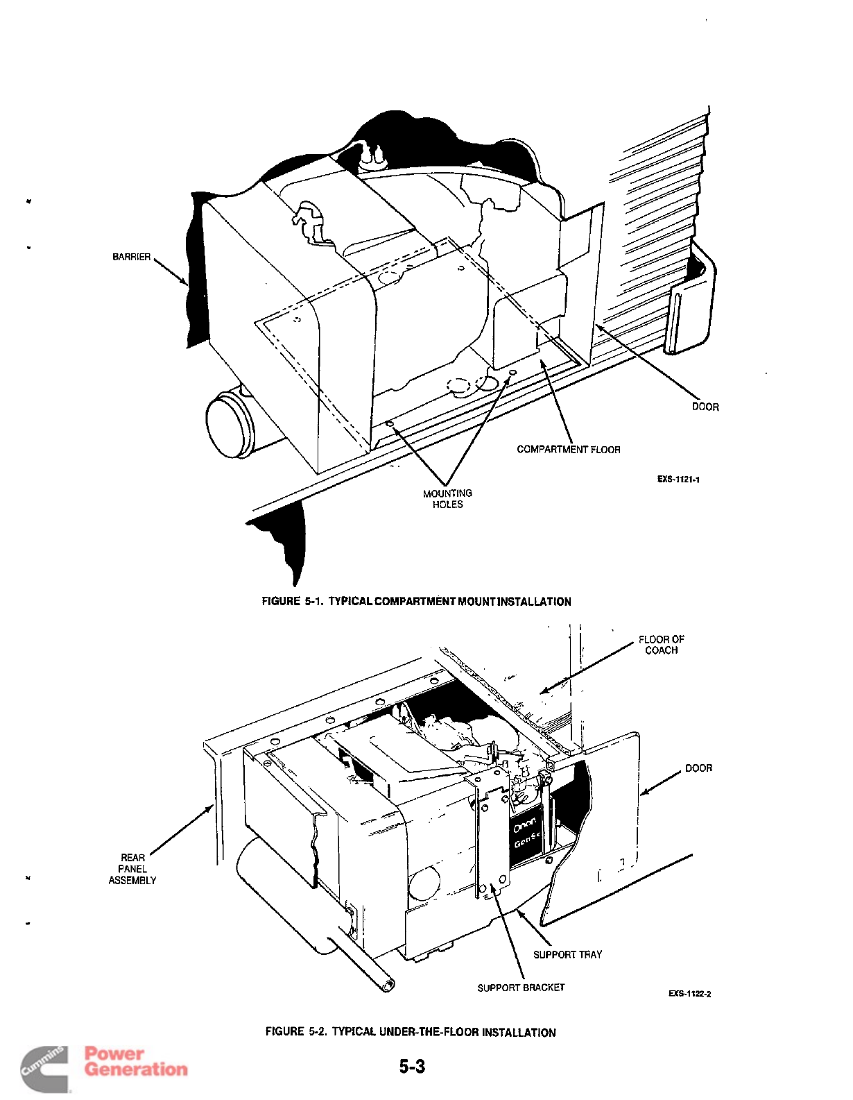
BARRIER
FIGURE
5-1.
TYPICALCOMPARTMENT MOUNT INSTALLATION
REAR
PANEL
ASSEMBLY
ws-1122-2
FIGURE
5-2.
TYPICAL UNDER-THE-FLOOR INSTALLATION
5-3
Redistribution or publication of this document
by any means, is strictly prohibited.
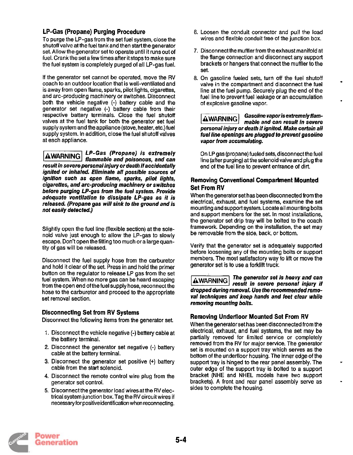
LP-Gas (Propane) Purging Procedure
To purge the LP-gas from the set fuel system, close the
shutoff valve atthe fuel tankand then startthegenerator
set. Allow the generator set to operate until
it
runs out of
fuel. Crank the set a few times after it stops to make sure
the fuel system is completely purged of all LP-gas fuel.
If the generator set cannot be operated, move the
RV
coach to an outdoor location that is well-ventilated and
is away from open flame, sparks, pilot lights, cigarettes,
and arc-producing machinery or switches. Disconnect
both the vehicle negative
(-)
battery cable and the
generator set negative
(-)
battery cable from their
respective battery terminals. Close the fuel shutoff
valves at the fuel tank for both the generator set fuel
supply system and the appliance (stove, heater, etc.)fuel
supply system.
In
addition, close the fuel shutoff valves
at each appliance.
LP-Gas (Propane)
is
extremely
k@@%l
flammable and poisonous, and can
result in severe personal injury or death
if
accidentally
ignited or inhaled. Eliminate all possible sources
of
ignition such as open flame, sparks, pilot lights,
cigarettes, and arc-producing machinery or switches
before purging LP-gas from the fuel system. Provide
adequate ventilation to dissipate LP-gas as it
is
released. (Propane gas will sink
to
the ground and is
not easily detected.)
Slightly open the fuel line (flexible section) at the sole-
noid valve just enough to allow the LP-gas to slowly
escape. Don’t open the fitting too much or a largequan-
tity of gas will be released.
Disconnect the fuel supply hose from the carburetor
and hold it clear
of
the set. Press in and hold the primer
button on the regulator
to
release LP gas from the set
fuel system. When no more gas can be heard escaping
from the open end of the fuel supply hose, reconnect the
hose to the carburetor and proceed to the appropriate
set removal section.
Disconnecting Set from
RV
Systems
Disconnect the following items from the generator set.
1.
2.
3.
4.
5.
Disconnect the vehicle negative
(-)
battery cable at
the battery terminal.
Disconnect the generator set negative
(-)
battery
cable at the battery terminal.
Disconnect the generator set positive
(+)
battery
cable from the start solenoid.
Disconnect the remote control wire plug from the
generator set control.
Disconnect thegenerator load wiresat the RVelec-
trical system junction box. Tag the
RV
circuit wires if
necessary for positive identification when reconnecting.
Loosen the conduit connector and pull the load
wires and flexible conduit free of the junction box.
Disconnect the muffler from the exhaust manifold at
the flange connection and disconnect any support
brackets or hangers that connect the muffler to the
set.
On gasoline fueled sets, turn
off
the fuel shutoff
valve in the compartment and disconnect the fuel
line at the fuel pump. Securely plug the end of the
fuel line to prevent fuel leakage or an accumulation
of explosive gasoline vapor.
Gasoline vapor is extremely flam-
@!!%!%I
mable and can result in severe
personal injury or death iiignited. Make certain all
fuel line openings are plugged to prevent gasoline
vapor from accumulating.
*
On LP gas (propane) fueled sets, disconnect the fuel
line (after purging) at the solenoid valve and plug the
end
of
the fuel line to prevent entrance of dirt.
Removing Conventional Compartment Mounted
Set From
RV
When the generatorset has been disconnected from the
electrical, exhaust, and fuel systems, examine the set
mounting and support system. Locate all mounting bolts
and support members for the set. In most installations,
the generator set drip tray will be bolted to the coach
framework. Depending on the installation, the set may
be removable from the side, back, or bottom.
Verify that the generator set is adequately supported
before loosening any of the mounting bolts or support
members. The most satisfactory way to lift or move the
generator set
is
to
use a forklift truck.
The generator sef is heavy and can
l2EEEl
result in severe personal injury if
dropped during removal. Use the recommended remo-
val techniques and keep hands and feet clear while
removing mounting bolts.
Removing Underfloor Mounted Set From
RV
When the generatorset has been disconnected from the
electrical, exhaust, and fuel systems, the set may be
partially removed for limited service or completely
removed from the
RV
for major service. The generator
set is mounted on a support tray which serves as the
bottom
of
the underfloor housing. The inner edge of the
support tray is hinged to the rear panel assembly. The
outer edge of the support tray is bolted
to
a support
bracket (NHE and NHEL models have two support
brackets).
A
front and rear panel assembly serve as
sides to complete the housing.
Y
f
5-4
Redistribution or publication of this document
by any means, is strictly prohibited.
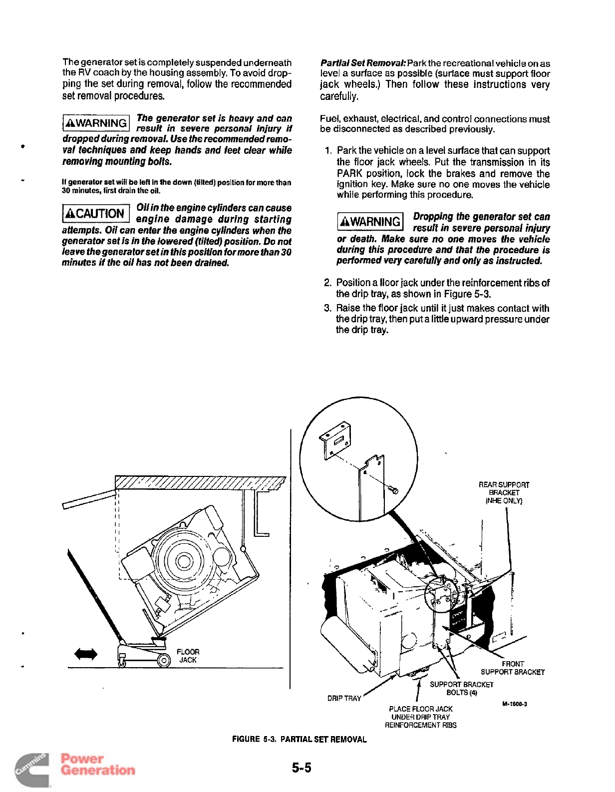
The generator set is completely suspended underneath
the
RV
coach by the housing assembly.
To
avoid drop-
ping the set during removal, follow the recommended
set
removal
procedures.
The generator set is heavy and can
result in sewere personal injury
if
dropped during removal. Use the recommended remo-
val techniques and keep hands and feet clear while
removing mounting bolts.
If
generator
set
will
be lefl in the down (lilted) position for
more
than
30
minutes,
first
drain the oil.
Oilin the engine cylinders can cause
engine damage during starting
attempts. Oil can enter the engine cylinders when the
generator set is in the lowered (tilted) position.
Do
not
leave thegenerator set in this position formore than 30
minutes
H
the oil has not been drained.
Partialset
RemovakPark
the recreational vehicle on as
level a surface as possible (surface must support floor
jack wheels.) Then follow these instructions very
carefully.
Fuel, exhaust, electrical, and control connections must
be disconnected as described previously.
1.
Park the vehicle on a level surface that can support
the floor jack wheels. Put the transmission
in
its
PARK position,
lock
the brakes and remove the
ignition key. Make sure no one moves the vehicle
while performing this procedure.
Dropping the generator set can
l3!E@El
result in severe personal injury
or
death. Make sure no one moves the vehicle
during this procedure and that the procedure is
performed very carefully and only as instructed.
2.
Position a floor jack under the reinforcement ribs
of
the drip tray, as shown in Figure 5-3.
3.
Raise the floor jack until
it
just makes contact with
the drip tray, then put a little upward pressure under
the drip tray.
SOLTS(4)
M-1600-3
DRIP
TRAY
PLACE
FLOOR
JACK
UNDER
DRIP
TRAY
REINFORCEMENT
RIBS
FIGURE
5-3.
PARTIAL SET
REMOVAL
5-5
Redistribution or publication of this document
by any means, is strictly prohibited.
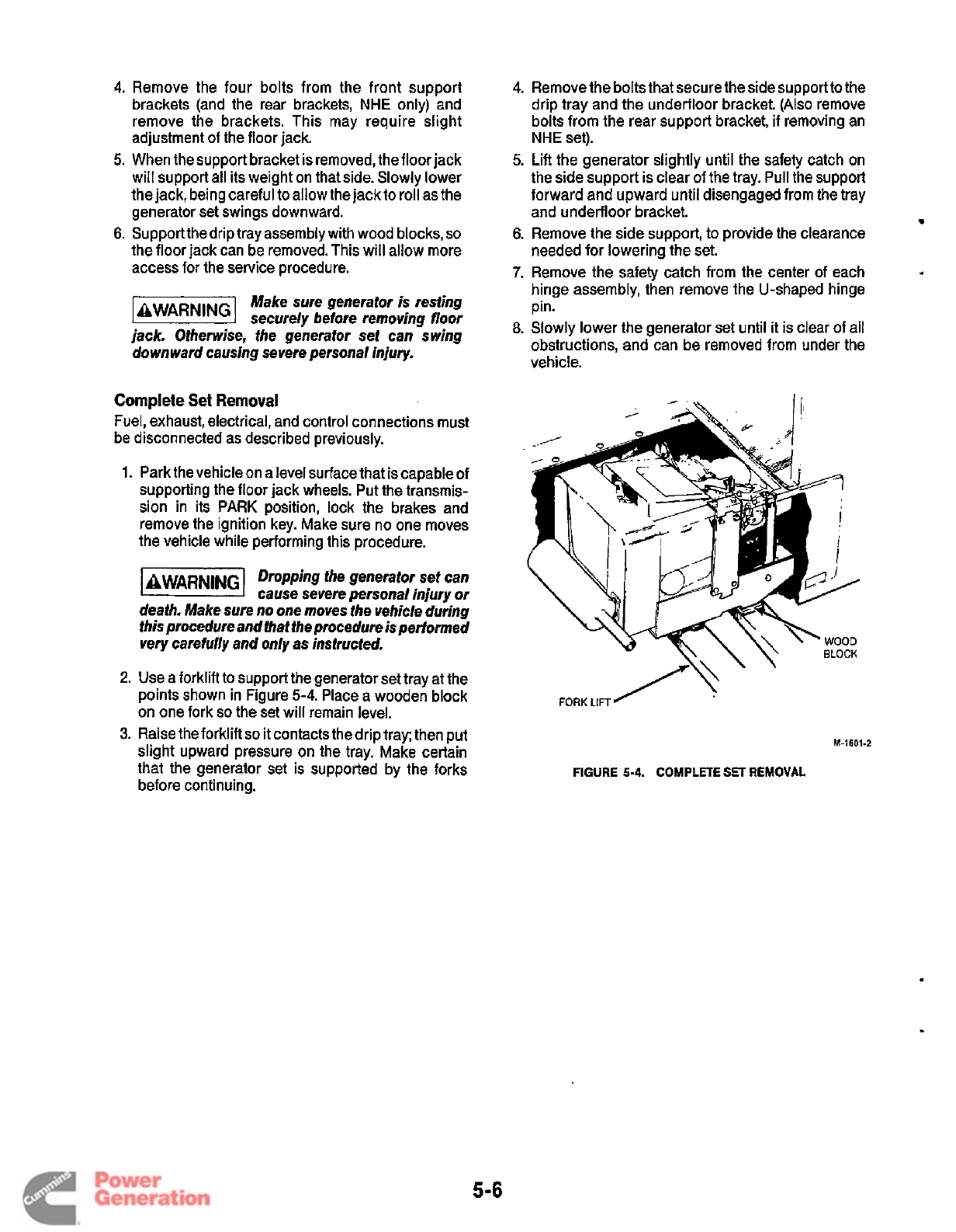
4.
Remove the four bolts from the front support
brackets (and the rear brackets,
NHE
only) and
remove the brackets. This may require slight
adjustment of the floor jack.
5.
When the support bracket is removed, the floor jack
will support all its weight on that side. Slowly lower
the jack, being careful to allow the jack to roll as the
generator set swings downward.
6.
Supportthe drip tray assembly with wood blocks,
so
the floor jack can be removed. This will allow more
access for the service procedure.
Make sure generator
is
resting
securely before removing
floor
jack. Otherwise, fhe generator set can swing
downward causing severe personal injury.
Complete Set Removal
Fuel, exhaust, electrical, and control connections must
be disconnected as described previously.
1.
Park the vehicle on a level surface that is capable of
supporting the floor jack wheels. Put the transmis-
sion in its PARK position, lock the brakes and
remove the ignition key. Make sure no one moves
the vehicle while performing this procedure.
-1
Dropping the generator set can
cause severe personal injury
or
deaih. Make sure no one moves the vehicle during
this procedure and that the procedure
is
performed
very carefully and only
as
instructed.
2.
Use a forklift to support the generator set tray at the
points shown in Figure
5-4.
Place a wooden block
on one fork
so
the set will remain level.
3.
Raise the forklift
so
it contacts the drip tray; then put
slight upward pressure on the tray. Make certain
that the generator set is supported by the forks
before continuing.
4.
Remove the bolts that secure the side supportto the
drip tray and the underfloor bracket. (Also remove
bolts from the rear support bracket,
if
removing an
NHE
set).
5.
Lift the generator slightly until the safety catch on
the side support is clear of the tray. Pull the support
forward and upward until disengaged from the tray
and underfloor bracket.
6.
Remove the side support, to provide the clearance
needed for lowering the set.
7.
Remove the safety catch from the center
of
each
hinge assembly, then remove the U-shaped hinge
pin.
8.
Slowly lower the generator set until it is clear
of
all
obstructions, and can be removed from under the
vehicle.
*
/\'
'
FORK
LIFT'
M-1601-2
FIGURE
5-4.
COMPLETE SET REMOVAL
.
5-6
Redistribution or publication of this document
by any means, is strictly prohibited.
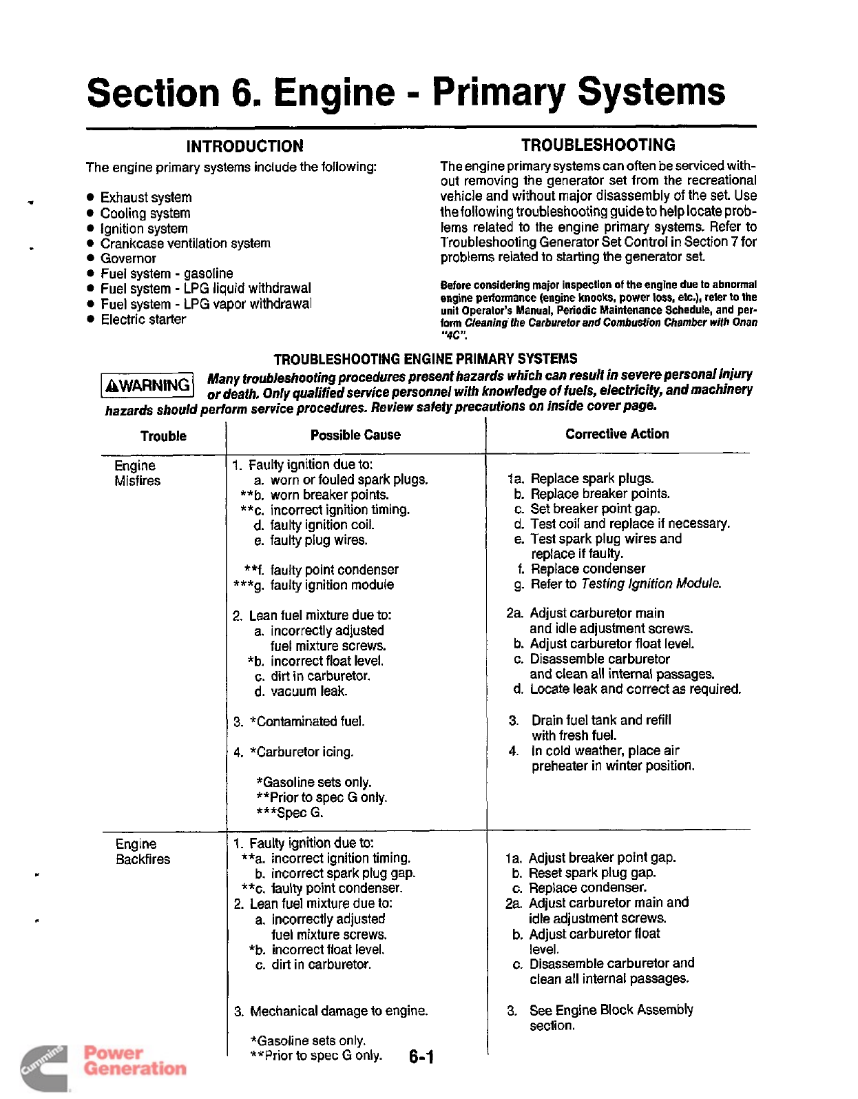
Section
6.
Engine
-
Primary
Systems
INTRODUCTION TROUBLESHOOTING
The engine primary systems include the following:
Exhaust system
Cooling system
Ignition system
0
Crankcase ventilation system
Governor
0
Fuel system
-
gasoline
Fuel system
-
LPG liquid withdrawal
0
Fuel system
-
LPG vapor withdrawal
Electric starter
The engine primary systems can often be serviced with-
out removing the generator set from the recreational
vehicle and without major disassembly of the set. Use
the following troubleshooting guide to
help
locate prob-
lems related to the engine primary systems. Refer to
Troubleshooting Generator Set Control in Section
7
for
problems related to starting the generator set.
Before considering major inspection
of
the
engine due
to
abnormal
engine performance (engine knocks, power
loss,
etc.), reler
to
the
unit
Operator’s Manual, Periodic Maintenance Schedule,
and
per-
form Cleaning ihe Carburetor
and
Combustion Chamber
with
Onan
“4C?
TROUBLESHOOTING
ENGINE
PRIMARY SYSTEMS
71
Many troubleshooting procedures present hazards which can result in severe personal injury
or death. Only qualified service personnel with knowledge
of
fuels, elecfricify, and machinery
hazards should perform service procedures. Review safety precautions
on
inside cover page.
Trouble
Engine
Misfires
Engine
Backfires
Possible Cause
1.
Faulty ignition due to:
a. worn or fouled spark plugs.
**b. worn breaker points.
**c. incorrect ignition timing.
d.
faulty ignition coil.
e. faulty plug wires.
**f. faulty point condenser
***g.
faulty ignition module
2. Lean fuel mixture due to:
a. incorrectly adjusted
fuel mixture screws.
*b. incorrect float level.
c.
dirt in carburetor.
d. vacuum leak.
3.
*Contaminated fuel.
4.
*Carburetor icing.
*Gasoline sets only.
**Prior to spec G only.
***Spec
G.
1.
Faulty ignition due to:
**a. incorrect ignition timing.
b. incorrect spark plug gap.
**c. faulty point condenser.
2.
Lean fuel mixture due to:
a. incorrectly adjusted
fuel mixture screws.
*b. incorrect float level.
c. dirt in carburetor.
3.
Mechanical damage to engine.
6-1
*Gasoline sets only.
**Prior to spec
G
only.
Corrective
Action
la. Replace spark plugs.
b. Replace breaker points.
c. Set breaker point gap.
d. Test coil and replace
if
necessary.
e. Test spark plug wires and
replace if faulty.
f.
Replace condenser
g.
Refer to
Testing Ignition
Module.
2a. Adjust carburetor main
and idle adjustment screws.
b. Adjust carburetor float level.
c. Disassemble carburetor
and clean all internal passages.
d.
Locate leak and correct as required.
3.
Drain fuel tank and refill
with fresh fuel.
4.
In cold weather, place air
preheater in winter position.
1
a. Adjust breaker point gap.
b.
Reset spark plug gap.
c. Replace condenser.
2a. Adjust carburetor main and
idle adjustment screws.
b. Adjust carburetor float
level.
c. Disassemble carburetor and
clean all internal passages.
3.
See Engine Block Assembly
section.
Redistribution or publication of this document
by any means, is strictly prohibited.
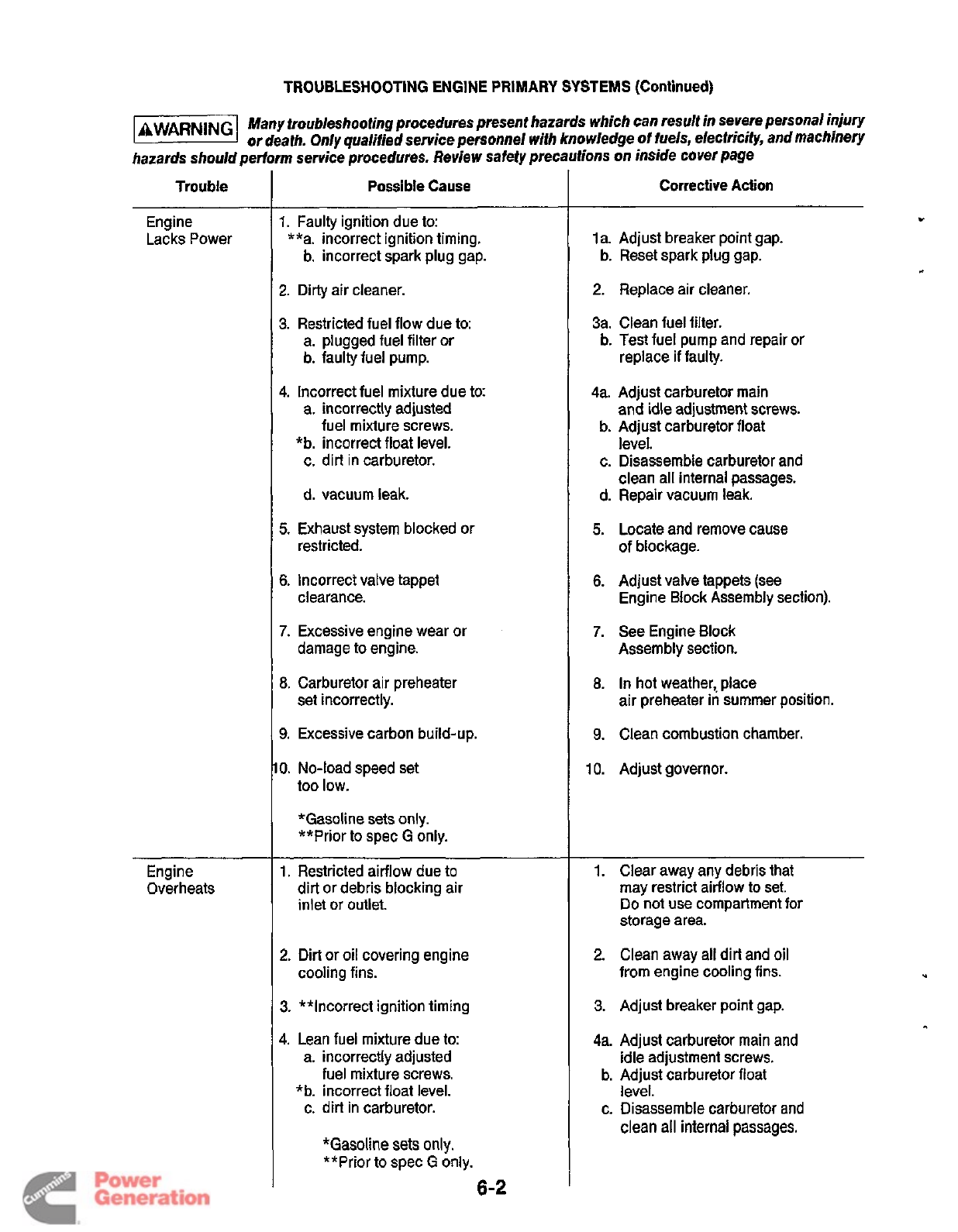
TROUBLESHOOTING ENGINE PRIMARY SYSTEMS (Continued)
[-I
Many troubleshooting procedures present hazards which can result in severe personal injury
or death. Only qualified service personnel with knowledge
of
fuels, electricity, and machinery
hazards should perform service procedures. Review safety precautions on inside cover page
Trouble
~~
Engine
Lacks Power
Engine
Overheats
Possible Cause
1.
Faulty ignition due to:
**a. incorrect ignition timing.
b. incorrect spark plug gap.
2.
Dirty air cleaner.
3.
Restricted fuel flow due to:
a. plugged fuel filter or
b. faulty fuel pump.
4.
Incorrect fuel mixture due to:
a. incorrectly adjusted
fuel mixture screws.
*b. incorrect float level.
c. dirt in carburetor.
d. vacuum leak.
5.
Exhaust system blocked or
restricted.
6.
Incorrect valve tappet
clearance.
7.
Excessive engine wear or
damage to engine.
8.
Carburetor air preheater
set incorrectly.
9.
Excessive carbon build-up.
0.
No-load speed set
too low.
*Gasoline sets only.
**Prior to spec
G
only.
1.
Restricted airflow due to
dirt or debris blocking air
inlet
or
outlet
2.
Dirt or oil covering engine
3. **Incorrect ignition timing
4.
Lean fuel mixture due
to:
a. incorrectly adjusted
fuel mixture screws.
*b. incorrect float level.
c. dirt in carburetor.
cooling fins.
*Gasoline
sets
only.
**Prior to spec
G
only.
Corrective Action
la. Adjust breaker point gap.
b. Reset spark plug gap.
2.
Replace air cleaner.
3a. Clean fuel filter.
replace
if
faulty.
b. Test fuel pump and repair or
4a. Adjust carburetor main
and idle adjustment screws.
b.
Adjust carburetor float
level.
c.
Disassemble carburetor and
clean all internal passages.
d. Repair vacuum leak.
5.
Locate and remove cause
of
blockage.
6.
Adjust valve tappets (see
Engine Block Assembly section).
7.
See Engine Block
Assembly section.
8.
In hot weather,, place
air preheater in summer position.
9.
Clean combustion chamber.
10. Adjust governor.
1.
Clear away any debris that
may restrict airflow
to
set.
Do
not use compartment for
storage area.
2.
Clean away all dirt and
oil
from engine cooling fins.
3. Adjust breaker point gap.
4a. Adjust carburetor main and
idle adjustment screws.
b. Adjust carburetor float
level.
c. Disassemble carburetor and
clean all internal passages.
Redistribution or publication of this document
by any means, is strictly prohibited.
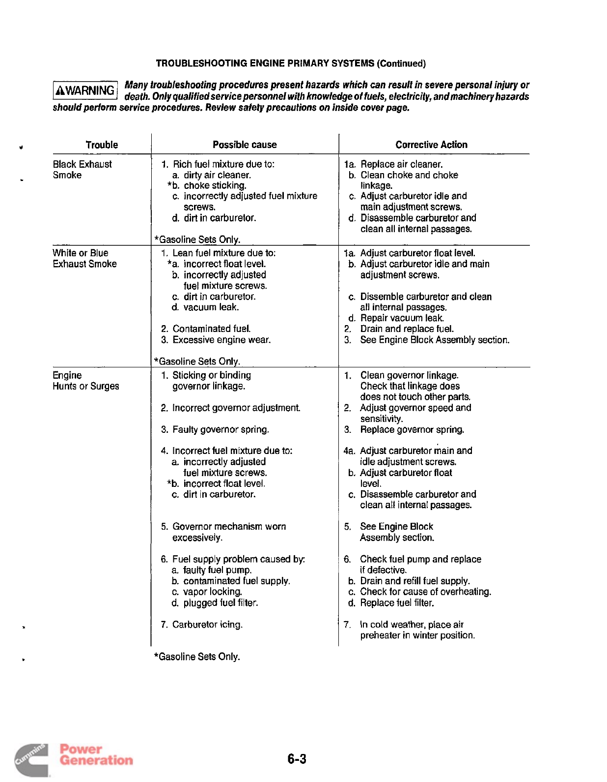
TROUBLESHOOTING ENGINE PRIMARY SYSTEMS
(Continued)
Many troubleshooting procedures present hazards which can result in severe personal injury or
death. Only qualified service personnel with knowledge
of
fuels, electricity, andmachinery hazards
should perform service procedures. Review safety precautions on inside cover page.
*
Trouble
Black Exhaust
Smoke
White or Blue
Exhaust Smoke
Engine
Hunts
or
Surges
Possible cause
1.
Rich fuel mixture due to:
a. dirty air cleaner.
c. incorrectly adjusted fuel mixture
d. dirt in carburetor.
*b. choke sticking.
screws.
“Gasoline Sets Only.
1.
Lean fuel mixture due to:
*a. incorrect float level.
b. incorrectly adjusted
fuel mixture screws.
c. dirt in carburetor.
d. vacuum leak.
2.
Contaminated fuel.
3.
Excessive engine wear.
rGasoline Sets Only.
1.
Sticking or binding
governor linkage.
2.
Incorrect governor adjustment.
3.
Faulty governor spring.
4.
Incorrect fuel mixture due to:
a. incorrectly adjusted
fuel mixture screws.
*b. incorrect float level.
c. dirt in carburetor.
5.
Governor mechanism worn
excessively.
6.
Fuel supply problem caused by
a. faulty fuel pump.
b.
contaminated fuel supply.
c. vapor locking.
d. plugged fuel filter.
7.
Carburetor icing.
‘Gasoline Sets Only.
Corrective Action
la. Replace air cleaner.
b. Clean choke and choke
linkage.
c. Adjust carburetor idle and
main adjustment screws.
d. Disassemble carburetor and
clean all internal passages.
la. Adjust carburetor float level.
b.
Adjust carburetor idle and main
adjustment screws.
c. Dissemble carburetor and clean
all internal passages.
d. Repair vacuum leak.
2.
Drain and replace fuel.
3.
See Engine Block Assembly section.
1.
Clean governor linkage.
Check that linkage does
does not touch other parts.
2.
Adjust governor speed and
sensitivity.
3.
Replace governor spring.
4a. Adjust carburetor main and
idle adjustment screws.
b.
Adjust carburetor float
level.
c. Disassemble carburetor and
clean all internal passages.
5.
See Engine Block
Assembly section.
6.
Check fuel pump and replace
if defective.
b. Drain and refill fuel supply.
c. Check for cause of overheating.
d. Replace fuel filter.
7.
In cold weather, place air
preheater in winter position.
6-3
Redistribution or publication of this document
by any means, is strictly prohibited.
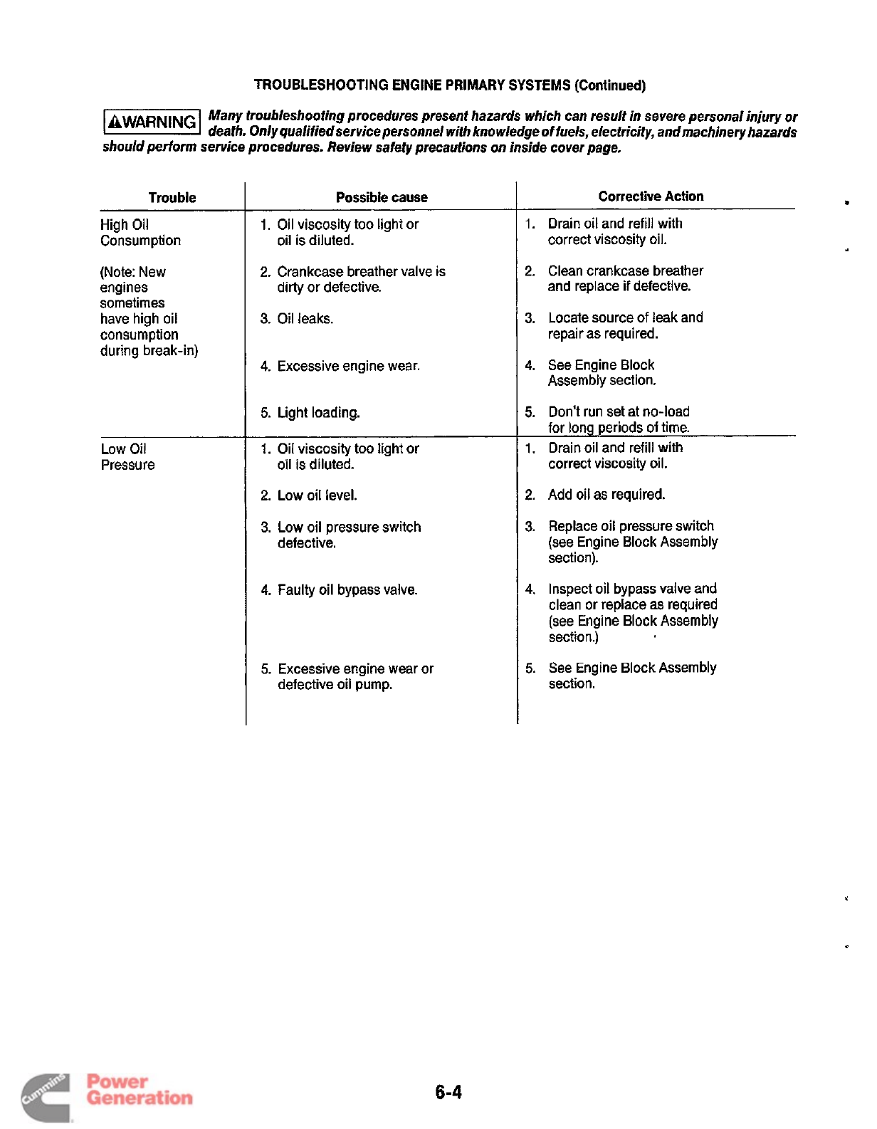
TROUBLESHOOTING ENGINE PRIMARY
SYSTEMS
(Continued)
Many troubleshooting procedures present hazards which can result in severe personal injury
or
death. Only qualified service personnel with knowledge of fuels, electricity, andmachinery hazards
should perform service procedures. Review safety precautions on inside cover page.
Trouble
High Oil
Consumption
(Note: New
engines
sometimes
have high oil
consumption
during break-in)
Low Oil
Pressure
Possible cause
1.
Oil viscosity too light or
2.
Crankcase breather valve is
oil is diluted.
dirty or defective.
3.
Oil leaks.
4.
Excessive engine wear.
5.
Light loading.
1.
Oil viscosity too light or
oil is diluted.
2. Low
oil
level.
3.
Low
oil pressure switch
defective.
4.
Faulty oil bypass valve.
5.
Excessive engine wear or
defective
oil
pump.
Corrective
Action
8
1.
Drain oil and refill with
correct viscosity oil.
2.
Clean crankcase breather
and replace
if
defective.
3.
Locate source of leak and
repair as required.
4.
See Engine Block
Assembly section.
5.
Don’t run set at no-load
for long periods
of
time.
1.
Drain oil and refill with
correct viscosity oil.
2.
Add
oil
as required.
3.
Replace oil pressure switch
(see Engine Block Assembly
section).
4.
Inspect
oil
bypass valve and
clean or replace as required
(see Engine Block Assembly
section.)
5.
See Engine Block Assembly
section.
6-4
Redistribution or publication of this document
by any means, is strictly prohibited.
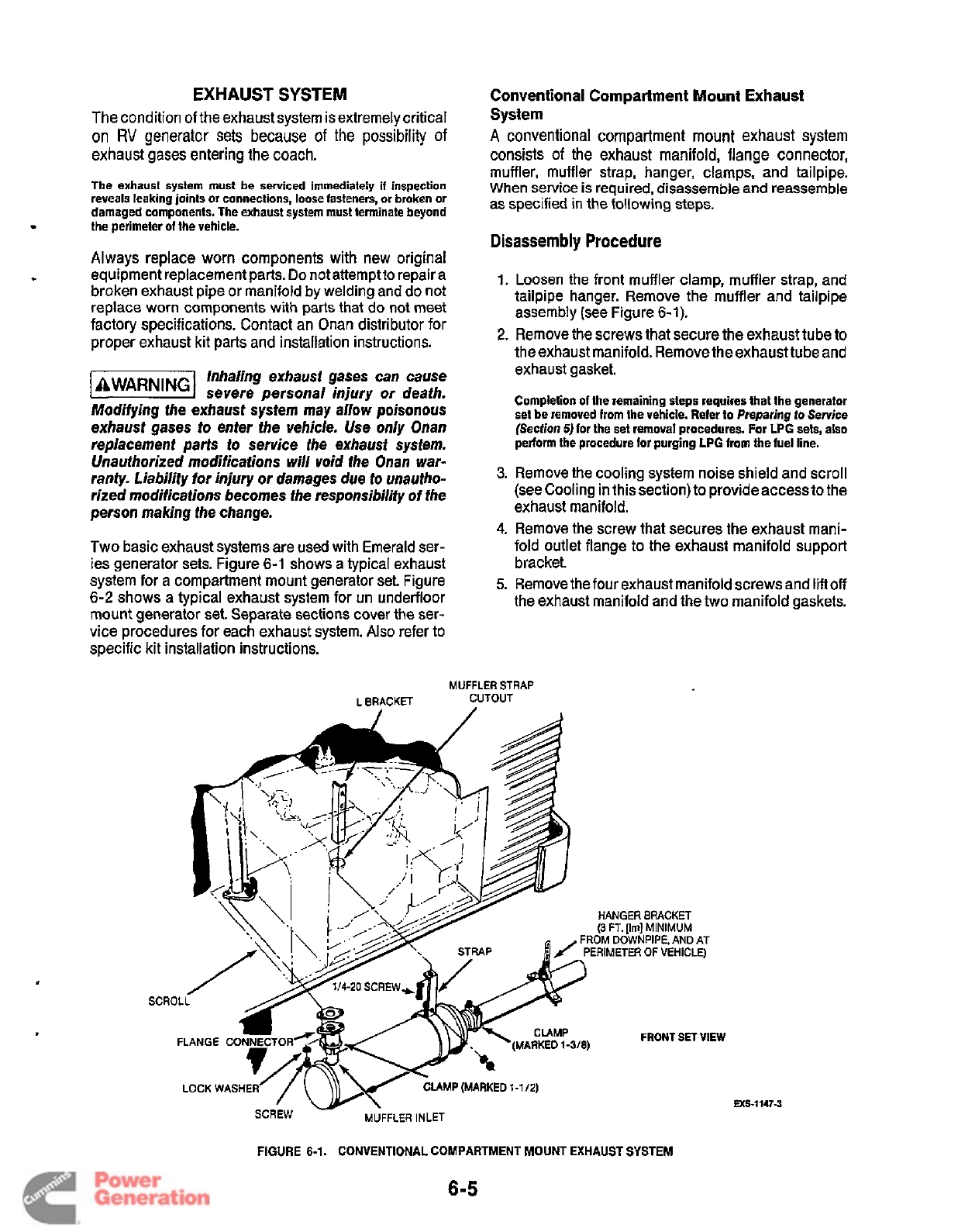
EXHAUST
SYSTEM
The condition of the exhaust system is extremely critical
on
RV
generator sets
because
of
the
possibility
of
exhaust gases entering the coach.
The exhaust
system
must be serviced immediately
if
inspection
reveals leaking joints
or
connections, loose fasteners, or broken
or
damaged components. The exhaust system must terminate beyond
*
the perimeter
of
the vehicle.
Always replace worn components with new original
equipment replacement parts.
Do
not attempt to repair a
broken exhaust pipe or manifold by welding and do not
replace worn components with parts that do
not
meet
factory specifications. Contact an Onan distributor for
proper exhaust kit parts and installation instructions.
Inhaling exhaust gases can cause
lAWAR"Gl
severe personal injury or death.
Modifying the exhaust system
may
allow poisonous
exhaust gases
to
enter the vehicle. Use only Onan
replacement parts
to
service the exhaust system.
Unauthorized modifications will
void
the Onan war-
ranty. Liability for injury
or
damages due
to
unautho-
rized modifications becomes the responsibility of the
person making the change.
w
Two basic exhaust systems are used with Emerald ser-
ies generator sets. Figure
6-1
shows a typical exhaust
system for a compartment mount generator set. Figure
6-2
shows a typical exhaust system for un underfloor
mount generator set. Separate sections cover the ser-
vice procedures for each exhaust system.
Also
refer to
specific kit installation instructions.
Conventional Compartment Mount Exhaust
System
A
conventional compartment mount exhaust system
consists of the exhaust manifold, flange connector,
muffler, muffler strap, hanger, clamps, and tailpipe.
When service is required, disassemble and reassemble
as specified in the following
steps.
Disassembly
Procedure
1.
Loosen the front muffler clamp, muffler strap, and
tailpipe hanger. Remove the muffler and tailpipe
assembly (see Figure
6-1).
2.
Remove the screws that secure the exhaust tube to
the exhaust manifold. Remove the exhaust tube and
exhaust gasket.
Completion of the remaining steps requires that the generator
set be removed from the vehicle. Refer
to
Preparing
to Service
(Section
5)
for the set removal procedures.
For
LPG sets, also
perform the procedure for purging
LPG
from
the fuel line.
3.
Remove the cooling system noise shield and scroll
(see Cooling in this section) to provideaccess to the
exhaust manifold.
4.
Remove the screw that secures the exhaust mani-
fold outlet flange to the exhaust manifold support
bracket.
5.
Remove the four exhaust manifold screws and liftoff
the exhaust manifold and the two manifold gaskets.
MUFFLER
STRAP
L
BRACKET CUTOUT
sc
FRONT SET
VIEW
LOCK
WASHER
MP
(MARKED
1-1/2)
MUFFLER
INLET
SCREW
-
MS-1147-3
FIGURE
6-1.
CONVENTIONAL COMPARTMENT MOUNT
EXHAUST
SYSTEM
6-5
Redistribution or publication of this document
by any means, is strictly prohibited.
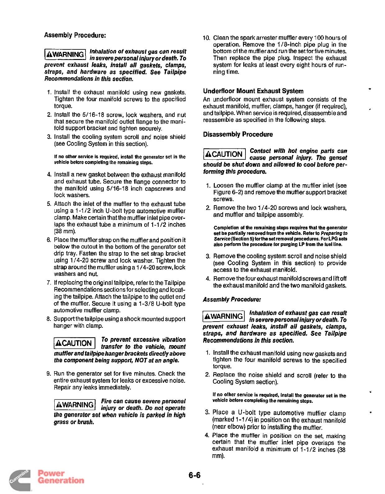
Assembly Procedure:
10.
Clean the spark arrester muffler every
100
hours of
operation. Remove the 1/8-inch pipe plug in the
bottom of the mufflerand run the set forfive minutes.
Then replace the pipe plug. Inspect the exhaust
system for leaks at least every eight hours of run-
ning time.
Inhalation of exhaust gas can result
in severe personal injury or death. To
prevent exhaust leaks, install all gaskets, clamps,
straps, and hardware as specified. See Tailpipe
Recommendations in this section.
1.
2.
3.
4.
5.
6.
7.
8.
9.
Install the exhaust manifold using new gaskets.
Tighten the four manifold screws to the specified
torque.
Install the 5/16-18 screw, lock washers, and nut
that secure the manifold outlet flange to the mani-
fold support bracket and tighten securely.
Install the cooling system scroll and noise shield
(see Cooling System in this section).
If
no other service is required, install the generator set in the
vehicle before completing the remaining steps.
Install a new gasket between the exhaust manifold
and exhaust tube. Secure the flange connector to
the manifold using 5/16-18 inch capscrews and
lock washers.
Attach the inlet of the muffler to the exhaust tube
using a
1-1
12 inch U-bolt type automotive muffler
clamp. Make certain that the muffler inlet pipe over-
laps the exhaust tube a minimum of 1-1
/2
inches
(38 mm).
Place the muffler strap on the muffler and position
it
below the cutout in the bottom
of
the generator set
drip tray. Fasten the strap to the set strap bracket
using 1/4-20 screw and lock washer. Tighten the
strap around the muffler using a
1
/4-20screw, lock
washers and nut.
If
replacing the original tailpipe, refer to the Tailpipe
Recommendations sections for selecting and locat-
ing the tailpipe. Attach the tailpipe to the outlet end
of
the muffler. Secure
it
using a 1 -3/8 U-bolt type
automotive muffler clamp.
Supportthe tailpipe using a shock mounted support
hanger with clamp.
To
prevent excessive vibration
-1
transfer to the vehicle, mount
muffler and tailpipe hanger brackets directly above
fhe component being support, NOT at an angle.
Run the generator set for five minutes. Check the
entire exhaust system for leaks
or
excessive noise.
Repair any leaks immediately.
Fire can cause severe personal
lAWAR"Gl
injury or death.
Do
not operate
the generator set when vehicle
is
parked
in
high
grass or brush.
6-6
Underfloor Mount Exhaust System
An underfloor mount exhaust system consists of the
exhaust manifold, muffler; clamps, hanger (if required),
and tailpipe. When service is required, disassemble and
reassemble as specified in the following steps.
*
Disassembly Procedure
Contact with hot engine parts can
cause personal injury. The genset
should be shut down
and
allowed
lo
cool
before per-
forming this procedure.
1.
Loosen the muffler clamp at the muffler inlet (see
Figure 6-2) and remove the muffler support bracket
screws.
2. Remove the two 1 /4-20 screws and lock washers,
and muffler and tailpipe assembly.
Completion
of
the remaining steps requires that the generator
set be partially removed from the vehicle. Refer
to
Preparing
to
Service(Section 5)fortheset removal procedures. For
LPG
sels
also perform
the
procedure
for
purging
LP
from the fuel line.
3. Remove the cooling system scroll and noise shield
(see Cooling System in this section) to provide
access to the exhaust manifold.
4.
Remove the four exhaust manifold screwsand liftoff
the exhaust manifold and the two manifold gaskets.
Assembly Procedure:
Inhalation
of
exhaust gas can result
lAWAR"G1
in severepersonalinjury or death.
To
prevent exhaust leaks, install all gaskets, Clamps,
straps, and hardware as specified. See Tailpipe
Recommendations in this section.
1.
Install the exhaust manifold using new gaskets and
tighten the four manifold screws to the specified
torque.
2.
Replace the noise shield and scroll (refer
to
the
Cooling System section).
u
If
no other service is required, install the generator set in the
vehicle before completing the remaining steps.
3.
Place a U-bolt type automotive muffler clamp
(marked 1-1
14)
in position
on
the exhaust manifold
(near elbow) prior
to
installing the muffler.
4. Place the muffler in position on the set, making
certain that the muffler inlet pipe overlaps the
exhaust manifold a minimum of 1-1/2 inches
(38
mm).
1
Redistribution or publication of this document
by any means, is strictly prohibited.
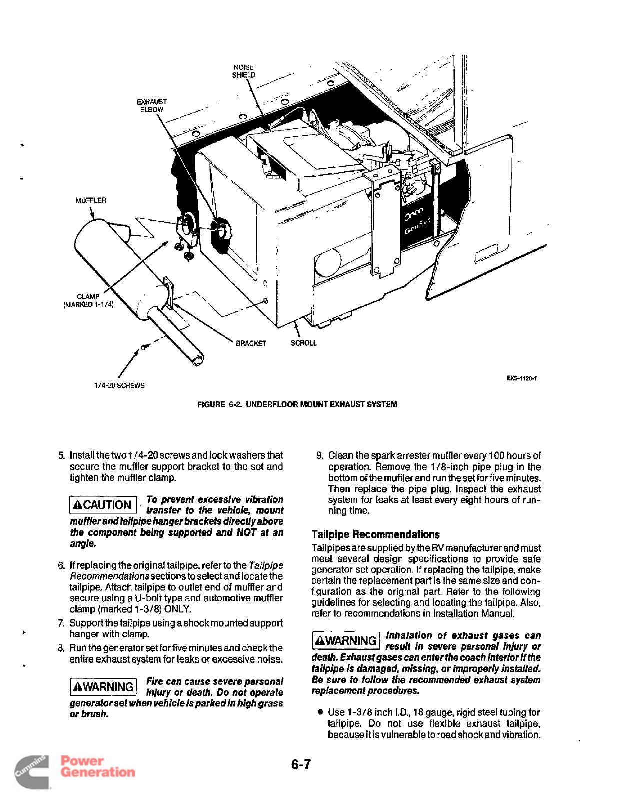
Exs1120-1
1/4-20
SCREWS
FIGURE
6-2.
UNDERFLOOR MOUNT EXHAUST SYSTEM
5.
Install the two
1
/4-20
screws and lock washers that
secure the muffler support bracket to the set and
tighten the muffler clamp.
To
prevent excessive vibration
B'
transfer
to
the vehicle, mount
muffler and tailpipe hanger brackets directly above
the component being supported and
NOT
at an
angle.
6.
If
replacing the original tailpipe, refer to the
Tailpipe
Recommendationssections to select and locate the
tailpipe. Attach tailpipe to outlet end of muffler and
secure using a U-bolt type and automotive muffler
clamp (marked
1
-3/8)
ONLY.
7.
Support the tailpipe using ashock mounted support
8. Run the generator set for five minutes and check the
entire exhaust system for leaks
or
excessive noise.
fire can cause severe personal
injury or death.
Do
not operate
generator set when vehicle is parked in high grass
or brush.
t
hanger with clamp.
9.
Clean the spark arrester muffler every
100
hours of
operation. Remove the 1/8-inch pipe plug in the
bottom ofthe muffler and run theset for five minutes.
Then replace the pipe plug. Inspect the exhaust
system for leaks at least every eight hours of run-
ning time.
Tailpipe Recommendations
Tailpipes are supplied by the
RV
manufacturer and must
meet several design specifications to provide safe
generator set operation.
If
replacing the tailpipe, make
certain the replacement part is the same size and con-
figuration as the original part.
Refer
to the following
guidelines for selecting and locating the tailpipe.
Also,
refer to recommendations in Installation Manual.
Inhalation
of
exhaust gases can
liEEESl
result in severe personal injury or
death. Exhaust gases can enter the coach interior
if
the
tailpipe is damaged, missing, or improperly installed.
Be sure to follow the recommended exhaust system
replacement procedures.
0
Use 1-318 inch
ID.,
18 gauge, rigid steel tubing for
tailpipe.
Do
not use flexible exhaust tailpipe,
because
it
isvulnerable to road shock and vibration.
6-7
Redistribution or publication of this document
by any means, is strictly prohibited.
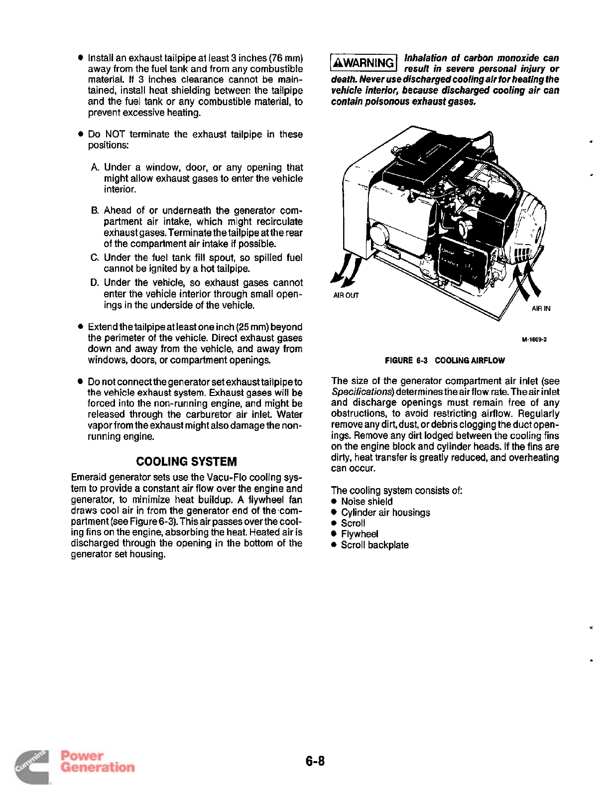
Install an exhaust tailpipe at least 3 inches (76 mm)
away from the fuel tank and from any combustible
material.
If
3
inches clearance cannot be main-
tained, install heat shielding between the tailpipe
and the fuel tank or any combustible material, to
prevent excessive heating.
0
Do
NOT terminate the exhaust tailpipe in these
positions:
Inhalation
of
carbon monoxide can
lEEiEI
result in severe personal injury
or
death. Never use dischargedcooling air for heating the
vehicle interior, because discharged cooling air can
contain poisonous exhaust gases.
A.
Under a window, door, or any opening that
might allow exhaust gases to enter the vehicle
interior.
B.
Ahead of or underneath the generator com-
partment air intake, which might recirculate
exhaust gases. Terminate the tailpipe at the rear
of the compartment air intake if possible.
C. Under the fuel tank fill spout,
so
spilled fuel
cannot be ignited by a hot tailpipe.
D.
Under the vehicle,
so
exhaust gases cannot
enter the vehicle interior through small open-
ings in the underside of the vehicle.
0
Extend the tailpipe at least one inch
(25
mm) beyond
the perimeter of the vehicle. Direct exhaust gases
down and away from the vehicle, and away from
windows, doors, or compartment openings.
Do
not connect the generator set exhaust tailpipe to
the vehicle exhaust system. Exhaust gases will be
forced into the non-running engine, and might be
released through the carburetor air inlet. Water
vapor from the exhaust might also damage the non-
running engine.
COOLING
SYSTEM
Emerald generator sets use the Vacu-Flo cooling sys-
tem to provide a constant air flow over the engine and
generator, to minimize heat buildup.
A
flywheel fan
draws cool air in from the generator end of thecom-
partment (see Figure 6-3). This air passesover the cool-
ing fins on the engine, absorbing the heat. Heated air is
discharged through the opening in the bottom of the
generator set housing.
v
A'R"
Y-1609-2
FIGURE
6-3
COOLING AIRFLOW
The size of the generator compartment air inlet (see
Specifications)
determines the air flow rate. The air inlet
and discharge openings must remain free
of
any
obstructions, to avoid restricting airflow. Regularly
remove any dirt, dust, or debris clogging the duct open-
ings. Remove any dirt lodged between the cooling fins
on the engine block and cylinder heads. If the fins are
dirty, heat transfer is greatly reduced, and overheating
can occur.
The cooling system consists of:
0
Noise shield
Cylinder air housings
0
Scroll
Flywheel
0
Scroll backplate
6-8
Redistribution or publication of this document
by any means, is strictly prohibited.
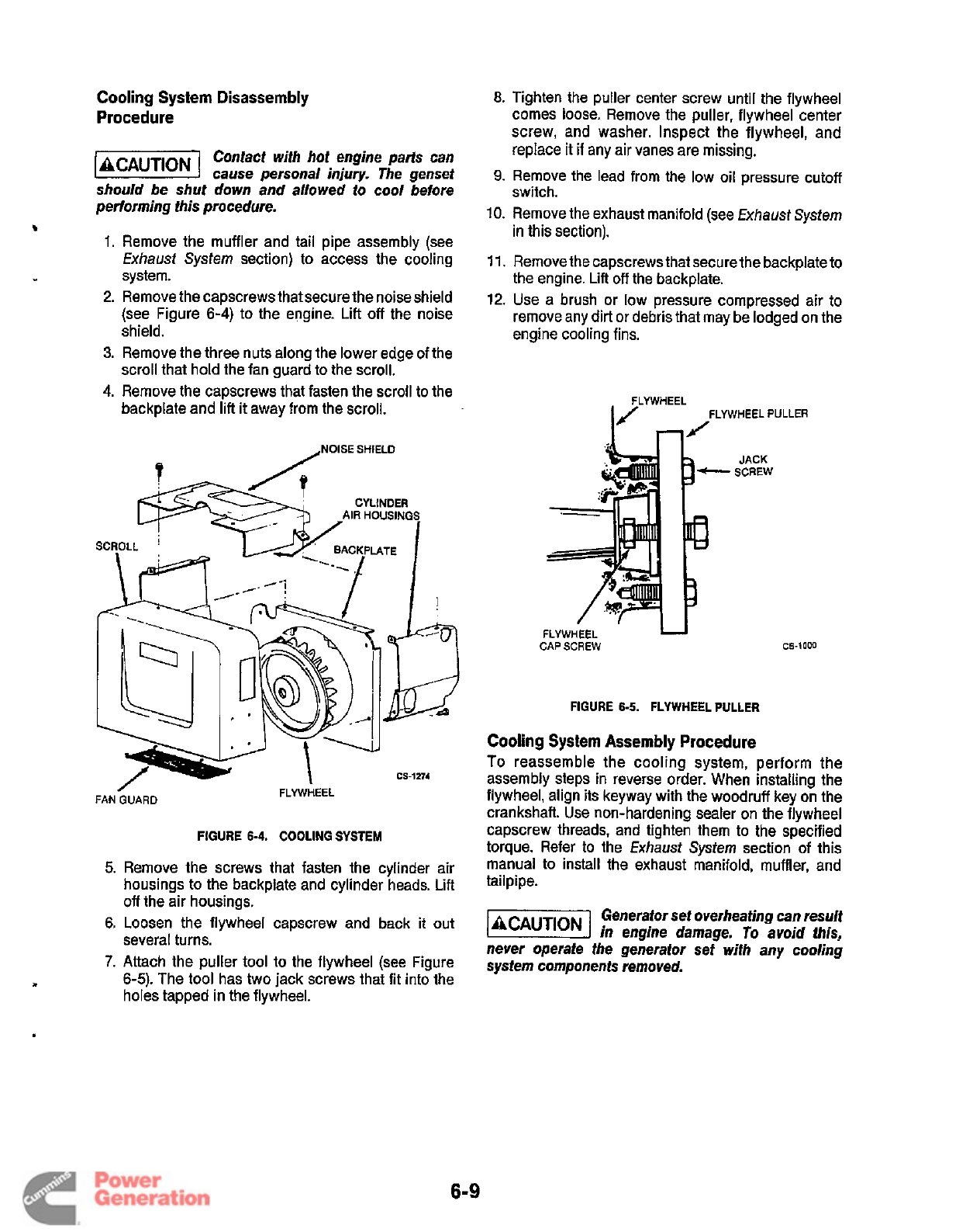
Cooling
System Disassembly
Procedure
Contact with hot engine parts can
liEE@l
cause
personal injury- The genset
should be shut down and allowed to cool before
performing this procedure.
b
1.
Remove the muffler and tail pipe assembly (see
Exhaust
System
section) to access the cooling
system.
2. Remove the capscrews that secure the noise shield
(see Figure
6-4)
to the engine. Lift off the noise
shield.
3.
Remove the three nuts along the lower edge of the
scroll that hold the fan guard to the scroll.
4.
Remove the capscrews that fasten the scroll to the
backplate and lift
it
away from the scroll.
,NOISE
SHIELD
CYLINDER
AIR
HOUSINGS
I
SCROLL
/
FAN
GUARD
FLYWHEEL
FIGURE
6-4.
COOLING
SYSTEM
k
I
cs-1274
5.
Remove the screws that fasten the cylinder air
housings to the backplate and cylinder heads.
Lift
off
the air housings.
6.
Loosen the flywheel capscrew and back
it
out
several turns.
7.
Attach the puller tool to the flywheel (see Figure
6-5).
The tool has two jack screws that fit into the
holes tapped in the flywheel.
8.
Tighten the puller center screw until the flywheel
comes loose. Remove the puller, flywheel center
screw, and washer. Inspect the flywheel, and
replace it
if
any
air
vanes are missing.
9.
Remove the lead from the low oil pressure cutoff
switch.
10. Remove the exhaust manifold (see
Exhaust
System
in this section).
11.
Remove the capscrews that secure the backplate to
the engine. Lift off the backplate.
12. Use a brush or low pressure compressed air to
remove any dirt or debris that may be lodged on the
engine cooling fins.
FLYWHEEL
PULLER
FLYWHEEL
U
CAP
SCREW
JACK
SCREW
cs-1000
FIGURE
6-5.
FLYWHEEL PULLER
Cooling
System
Assembly
Procedure
To
reassemble the cooling system, perform the
assembly steps in reverse order. When installing the
flywheel, align its keyway with the woodruff key on the
crankshaft. Use non-hardening sealer on the flywheel
capscrew threads, and tighten them to the specified
torque. Refer to the
Exhaust
System
section of this
manual to install the exhaust manifold, muffler, and
tailpipe.
Generator set overheating can result
-1
in engine damage.
To
avoid this,
never operate the generator set with any cooring
system components removed.
6-9
Redistribution or publication of this document
by any means, is strictly prohibited.
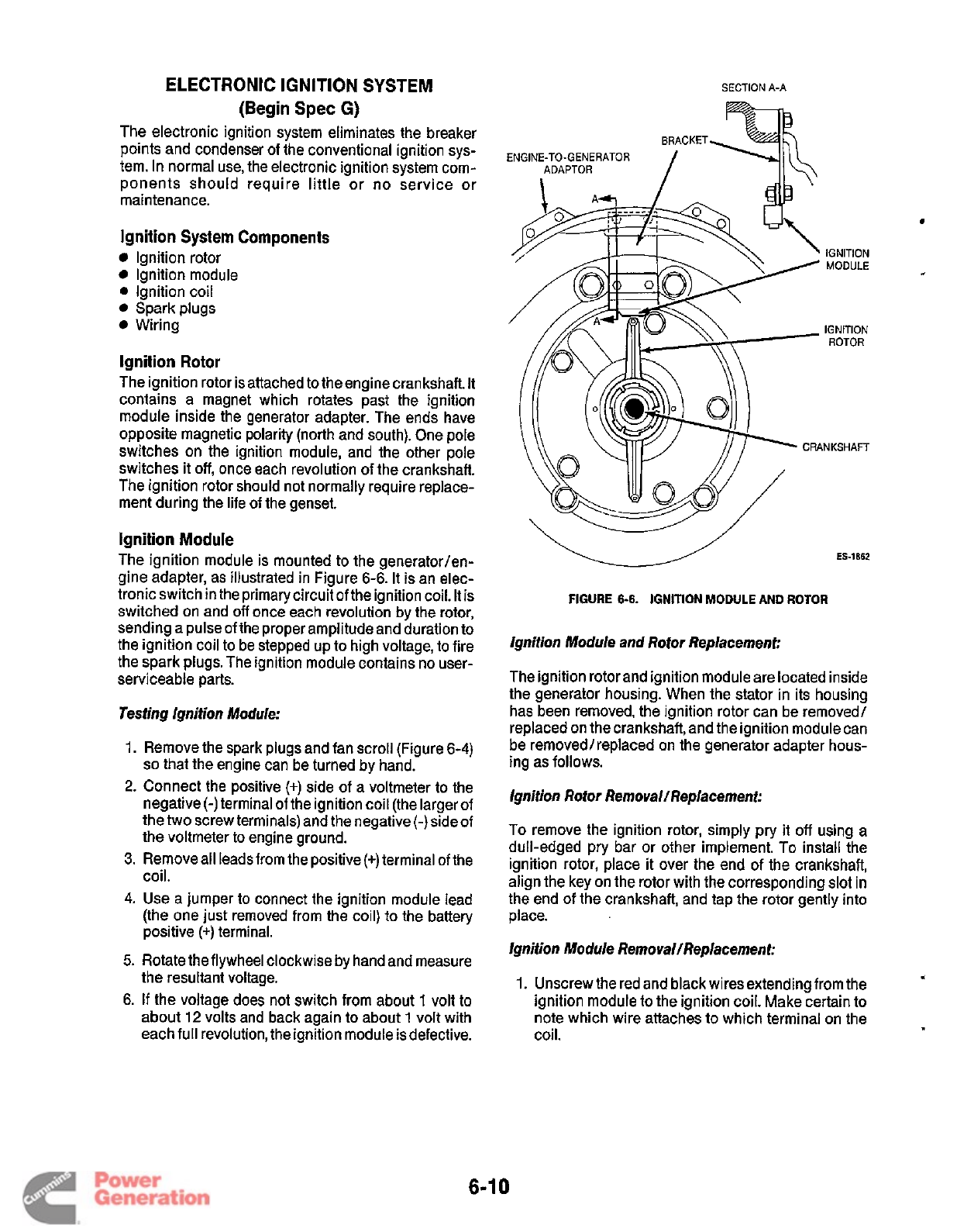
ELECTRONIC
IGNITION
SYSTEM
(Begin
Spec
G)
The electronic ignition system eliminates the breaker
points and condenser of the conventional ignition sys-
tem. In normal use, the electronic ignition system com-
ponents should require little or no service or
maintenance.
Ignition System Components
Ignition rotor
Ignition module
0
Ignition coil
Sparkplugs
Wiring
Ignition
Rotor
The ignition rotor is attached to the engine crankshaft. It
contains a magnet which rotates past the ignition
module inside the generator adapter. The ends have
opposite magnetic polarity (north and south). One pole
switches on the ignition module, and the other pole
switches it
off,
once each revolution
of
the crankshaft.
The ignition rotor should not normally require replace-
ment during the life of the genset.
Ignition
Module
The ignition module is mounted to the generator/en-
gine adapter, as illustrated in Figure
6-6.
It is an elec-
tronic switch in the primary circuit of the ignition coil. It is
switched on and
off
once each revolution by the rotor,
sending a pulse of the proper amplitude and duration to
the ignition coil to be stepped up
to
high voltage, to fire
the spark plugs. The ignition module contains no user-
serviceable parts.
Testing Ignition Module:
1.
2.
3.
4.
5.
6.
Remove the spark plugs and fan scroll (Figure 6-4)
so
that the engine can be turned by hand.
Connect the positive
(+)
side of a voltmeter to the
negative
(-)
terminal of the ignition coil (the larger
of
the two screw terminals) and the negative (-)side of
the voltmeter to engine ground.
Remove all leadsfrom the positive
(+)
terminal of the
coil.
Use a jumper to connect the ignition module lead
(the one just removed from the coil) to the battery
positive
(+)
terminal.
Rotate the flywheel clockwise by hand and measure
the resultant voltage.
If
the voltage does not switch from about
1
volt
to
about
12
volts and back again to about
1
volt with
each full revolution, the ignition module is defective.
SECTION
A-A
v
ES-1862
FIGURE
6-6.
IGNITION
MODULE
AND
ROTOR
Ignition Module and Rotor Replacement:
The ignition rotor and ignition module are located inside
the generator housing. When the stator in its housing
has been removed, the ignition rotor can be removed/
replaced on the crankshaft, and the ignition module can
be removed/replaced on the generator adapter hous-
ing as follows.
Ignition Rotor Removal/Replacement:
To remove the ignition rotor, simply pry it
off
using a
dull-edged pry bar or other implement.
To
install the
ignition rotor, place it over the end of the crankshaft,
align the key on the rotor with the corresponding slot in
the end of the crankshaft, and tap the rotor gently into
place.
Ignition Module Removal/Replacement:
1.
Unscrew the red and black wiresextending from the
ignition module to the ignition coil. Make certain to
note which wire attaches to which terminal on the
coil.
.(
6-1
0
Redistribution or publication of this document
by any means, is strictly prohibited.
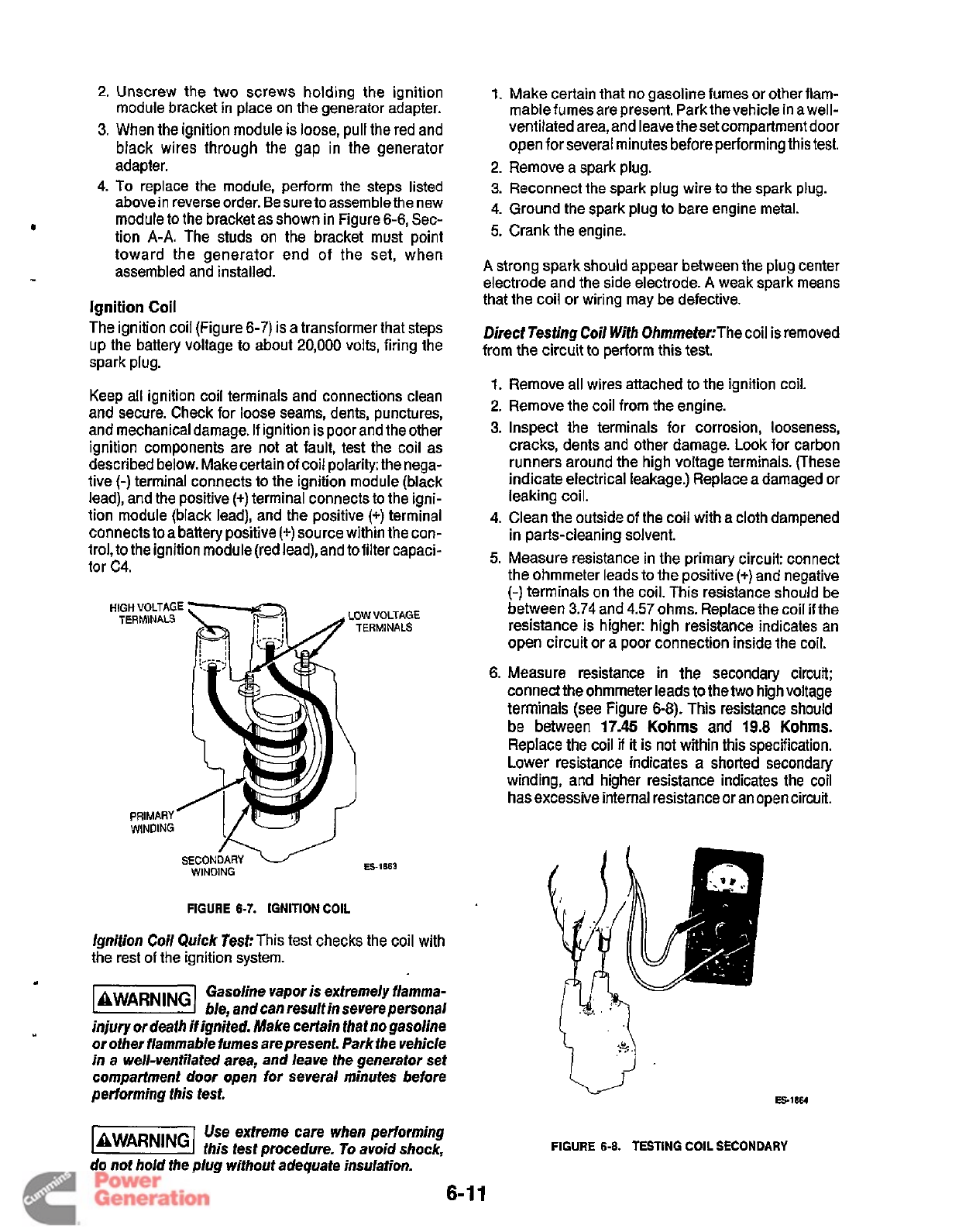
2.
Unscrew the two screws holding the ignition
module bracket in place on the generator adapter.
3.
When the ignition module is loose, pull the red and
black wires through the gap in the generator
adapter.
4.
To
replace the module, perform the steps listed
above in reverse order. Be sure to assemble the new
module to the bracket as shown in Figure
6-6,
Sec-
tion
A-A.
The studs on the bracket must point
toward the generator end
of
the set, when
assembled and installed.
Ignition
Coil
The ignition coil (Figure
6-7)
is a transformer that steps
up the battery voltage to about
20,000
volts, firing the
spark plug.
Keep all ignition coil terminals and connections clean
and secure. Check for loose seams, dents, punctures,
and mechanical damage.
If
ignition is poor and the other
ignition components are not at fault, test the coil as
described below. Make certain of coil polarity: the nega-
tive
(-)
terminal connects to the ignition module (black
lead), and the positive (+)terminal connects to the igni-
tion module (black lead), and the positive
(+)
terminal
connects to a battery positive
(+)
source within the con-
trol, to the ignition module (red lead), and to filter capaci-
tor C4.
ES-1863
WINDING
FIGURE
6-7.
IGNITION
COIL
Ignition Coil Quick Test:
This test checks the coil with
the rest
of
the ignition system.
Gasoline vapor is extremely flamma-
IBWAR"GJ
ble, and can result in severe personal
injury
or
death
if
ignited. Make certain that no gasoline
or other flammable fumes are present. Park the vehicle
in a well-ventilated area, and leave the generator set
compartment door open for several minutes before
performing this test.
-
Use extreme care when performing
this test procedure.
To
avoid shock,
do not hold the plug without adequate insulation.
6-
1.
Make certain that no gasoline fumes or other flam-
mablefumes are present. Park thevehicle in a well-
ventilated area, and leave the set compartment door
open
for
several minutes before performing this test.
2.
Remove a spark plug.
3.
Reconnect the spark plug wire to the spark plug.
4.
Ground the spark plug
to
bare engine metal.
5.
Crank the engine.
A
strong spark should appear between the plug center
electrode and the side electrode.
A
weak spark means
that the coil or wiring may be defective.
Direct Testing Coil With OhmmetecThe
coil is removed
from the circuit to perform this test.
1.
Remove all wires attached to the ignition coil.
2.
Remove the coil from the engine.
3.
Inspect the terminals for corrosion, looseness,
cracks, dents and other damage.
Look
for carbon
runners around the high voltage terminals. (These
indicate electrical leakage.) Replace a damaged or
leaking coil.
4.
Clean the outside of the coil with a cloth dampened
in parts-cleaning solvent.
5.
Measure resistance in the primary circuit: connect
the ohmmeter leads to the positive
(+)
and negative
(-)
terminals on the coil. This resistance should be
between
3.74
and
4.57
ohms. Replace the coil
if
the
resistance is higher: high resistance indicates an
open circuit or a poor connection inside the coil.
6.
Measure resistance in
the
secondary circuit;
connect the ohmmeter leads to the two high voltage
terminals (see Figure
6-8).
This resistance should
be between
17.45
Kohms
and
19.8
Kohms.
Replace the coil
if
it
is
not within this specification.
Lower resistance indicates a shorted secondary
winding, and higher resistance indicates the coil
has excessive internal resistance
or
an open circuit.
Es-1864
FIGURE
6-8.
TESTING
COIL
SECONDARY
11
Redistribution or publication of this document
by any means, is strictly prohibited.
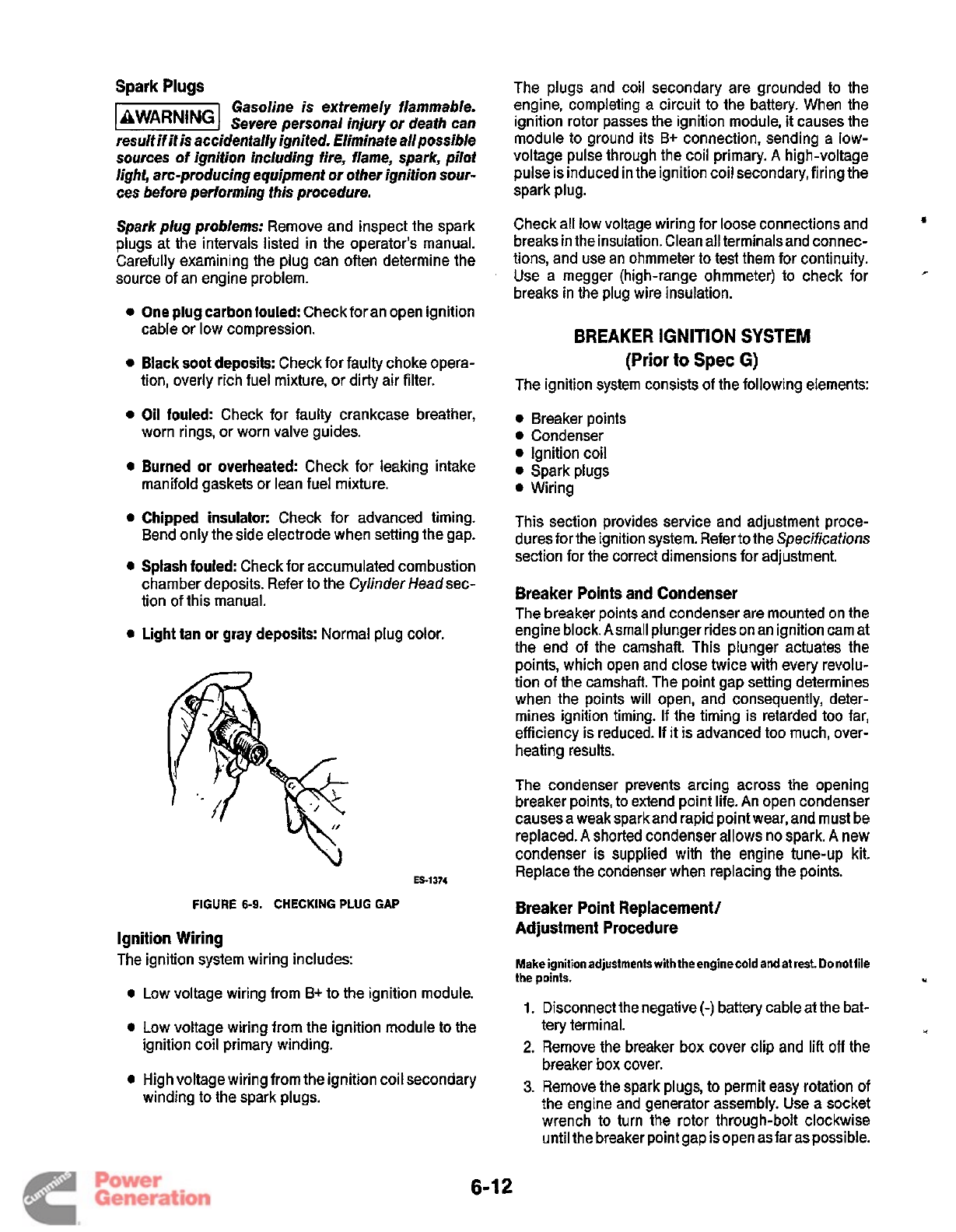
Spark Plugs
Gasoline is extremely flammable.
IaWARNlNGI
Severe personal injury or death can
result
if
it
is
accidentally ignited. Eliminate all possible
sources of ignition including fire, flame, spark, pilot
light, arc-producing equipment
or
other ignition
sour-
ces before performing this procedure.
Spark plug problems:
Remove and inspect the spark
plugs at the intervals listed in the operator's manual.
Carefully examining the plug can often determine the
source of an engine problem.
One plug carbonfouled:
Check foran open ignition
cable or low compression.
Black soot deposits:
Check for faulty choke opera-
tion, overly rich fuel mixture, or dirty air filter.
Oil
fouled:
Check for faulty crankcase breather,
worn rings, or worn valve guides.
Burned
or
overheated:
Check for leaking intake
manifold gaskets
or
lean fuel mixture.
Chipped insulator:
Check for advanced timing.
Bend only the side electrode when setting the gap.
Splash fouled:
Check for accumulated combustion
chamber deposits. Refer to the Cyhder Headsec-
tion of this manual.
Light tan
or
gray deposits:
Normal plug color.
E51374
\
FIGURE
6-9.
CHECKING PLUG
GAP
Ignition Wiring
The ignition system wiring includes:
Low voltage wiring from B+ to the ignition module.
Low voltage wiring from the ignition module to the
ignition coil primary winding.
High voltage wiring from the ignition coil secondary
winding to the spark plugs.
The plugs and coil secondary are grounded to the
engine, completing a circuit to the battery. When the
ignition rotor passes the ignition module, it causes the
module to ground its B+ connection, sending a low-
voltage pulse through the coil primary.
A
high-voltage
pulse is induced in the ignition coil secondary, firing the
spark plug.
Check all low voltage wiring for loose connections and
breaks in the insulation. Clean all terminalsand connec-
tions, and use an ohmmeter to test them for continuity.
Use a megger (high-range ohmmeter) to check for
breaks in the plug wire insulation.
S
*
BREAKER
IGNITION
SYSTEM
(Prior
to
Spec
G)
The ignition system consists
of
the following elements:
0
Breaker points
0
Condenser
0
Ignition coil
0
Spark plugs
0
Wiring
This section provides service and adjustment proce-
duresfor the ignition system. Refer to the Specificafions
section for the correct dimensions for adjustment.
Breaker Points and Condenser
The breaker points and condenser are mounted on the
engine block. Asmall plunger rides on an ignition cam at
the end of the camshaft. This plunger actuates the
points, which open and close twice with every revolu-
tion of the camshaft. The point gap setting determines
when the points will open, and consequently, deter-
mines ignition timing.
If
the timing is retarded too far,
efficiency is reduced. If
it
is advanced too much, over-
heating results.
The condenser prevents arcing across the opening
breaker points, to extend point life. An open condenser
causes a weak spark and rapid point wear, and must be
replaced.
A
shorted condenser allows no spark.
A
new
condenser is supplied with the engine tune-up kit.
Replace the condenser when replacing the points.
Breaker Point Replacement/
Adjustment Procedure
Make ignitionadjustments with theenginecold andat rest. Donotiile
the points.
I
Disconnect the negative
(-)
battery cable at the bat-
tery terminal.
Remove the breaker box cover clip and
lift
off
the
breaker box cover.
Remove the spark plugs, to permit easy rotation of
the engine and generator assembly. Use a socket
wrench to turn the rotor through-bolt clockwise
until the breaker point gap is open as far as possible.
6-1
2
Redistribution or publication of this document
by any means, is strictly prohibited.
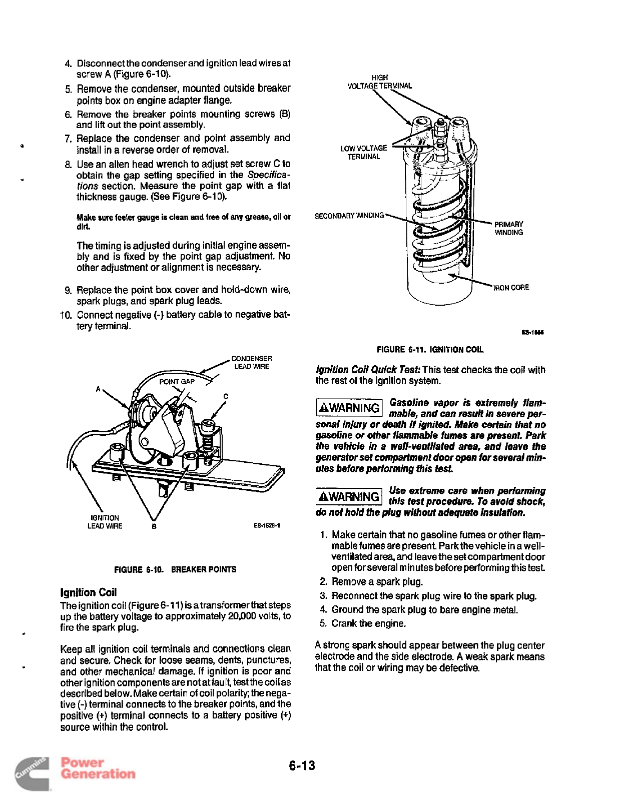
4.
5.
6.
7.
8.
9.
10.
Disconnect the condenser and ignition lead wires at
Remove
the
condenser, mounted outside breaker
points box on engine adapter flange.
Remove the breaker points mounting screws
(B)
and
lift
out the point assembly.
Replace the condenser and point assembly and
install in a reverse order
of
removal.
Use an allen head wrench to adjust set screw
C
to
obtain the gap setting specified in the
Specifica-
tions
section. Measure the point gap with a flat
thickness gauge.
(See
Figure 6-1
0).
Make sure feeler gauge
is
clean
and
free
of
any
grease,
oil
or
The timing is adjusted during initial engine assem-
bly and is fixed by the point gap adjustment.
No
other adjustment or alignment is necessary.
spark plugs, and spark plug leads.
Connect negative
(-)
battery cable to negative bat-
tery terminal.
screw
A
(Figure
6-10).
HIGH
VOLTAGE TERMINAL
SECONDARY WINDING
dirt.
PRIMARY
WIND IN G
Replace the point box cover and hold-down wire,
IRON
CORE
ES-lWI
FIGURE 6-11. IGNITION
COIL
CONDENSER
LEAD
WIRE
Ignition Coil Quick Test:
This test checks the coil with
the rest of the ignition system.
POINT GAP
IGiTlON
V
LEAD
WIRE
B
ES-1529-1
FIGURE 6-10.
BREAKER
POINTS
Ignition
Coil
The ignition coil (Figure 6-1
1)
is
a
transformer that steps
up the battery voltage to approximately
20,000
volts, to
Keep all ignition coil terminals and connections clean
and secure. Check for loose seams, dents, punctures,
and other mechanical damage.
If
ignition is poor and
other ignition components are not at fault, test the coil as
described below. Make certain of coil polarity; the nega-
tive
(-)
terminal connects to the breaker points, and the
positive
(+)
terminal connects to a battery positive
(+)
source within the control.
c
fire the spark plug.
Gasoline vapor
is
extremely flam-
mable, and can result in severe
per-
sonal injury or deafh if ignited. Make certain that no
gasoline or other flammable fumes are present. Park
the vehicle in a well-ventilated area, and leave the
generator set compartment door open for several min-
utes before performing this test.
Use extreme care when performing
LBWARNING?
this test procedure. To avoid shock,
do not hold the plug without adequate insulation.
1.
Make certain that no gasoline fumes or other flam-
mable fumes are present. Park the vehicle in a well-
ventilated area, and leave the set compartment door
open for several minutes before performing this test.
2.
Remove
a
spark plug.
3.
Reconnect the spark plug wire
to
the spark plug.
4.
Ground the spark plug to bare engine metal.
5.
Crank the engine.
A
strong spark should appear between the plug center
electrode and the side electrode.
A
weak spark means
that the coil or wiring may be defective.
6-1
3
Redistribution or publication of this document
by any means, is strictly prohibited.
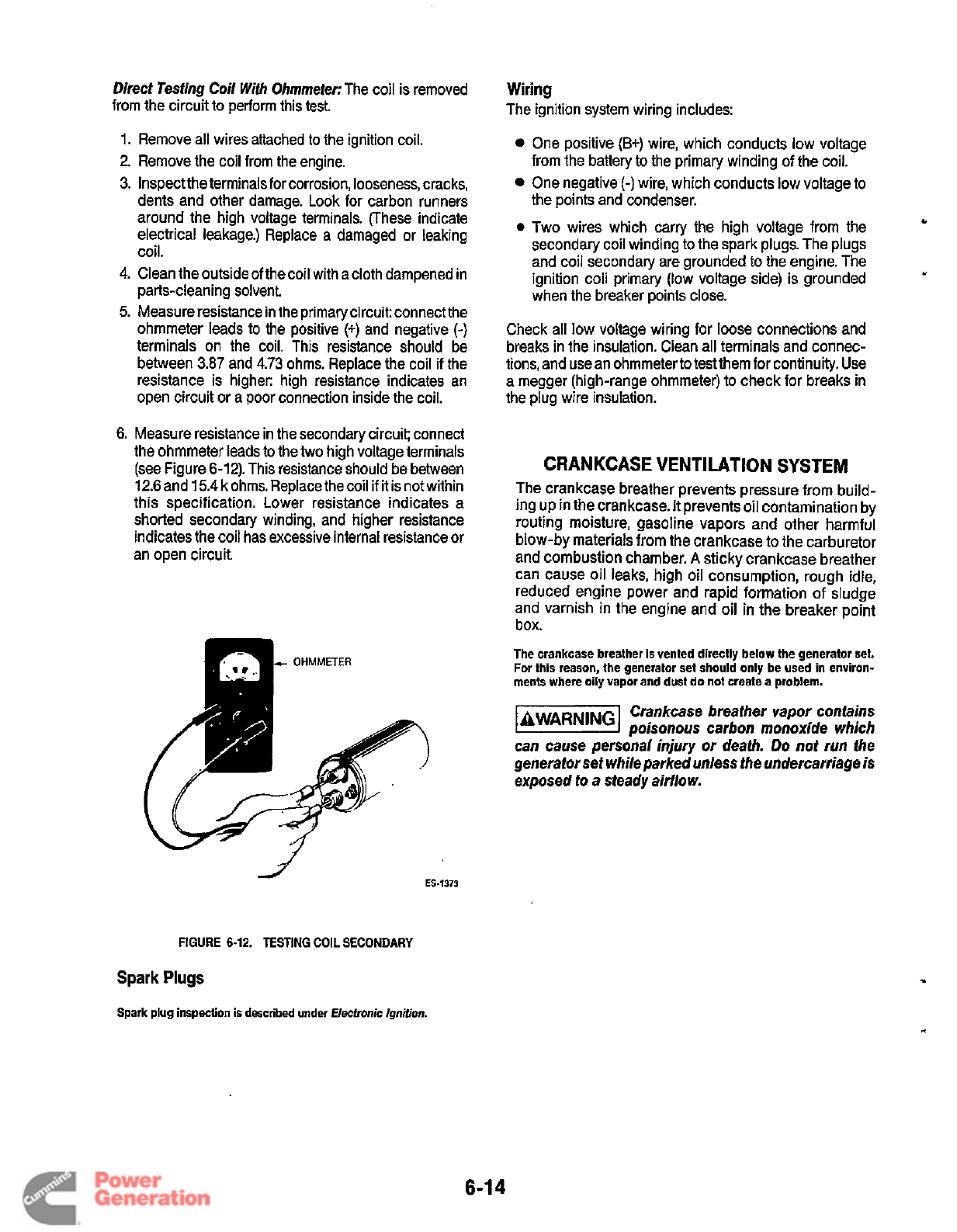
Direct Tesfing Coil
With
Ohmmefer:
The coil is removed
from the circuit to perform this test.
1.
Remove all wires attached to the ignition coil.
2.
Remove the coil from the engine.
3.
Inspect the terminals for corrosion, looseness, cracks,
dents and other damage. Look for carbon runners
around the high voltage terminals. (These indicate
electrical leakage.) Replace a damaged or leaking
coil.
4.
Clean the outside of the coil with a cloth dampened in
parts-cleaning solvent
5.
Measure resistance in the primary circuit: connect the
ohmmeter leads to the positive
(+)
and negative
(-)
terminals on the coil. This resistance should be
between
3.87
and
4.73
ohms. Replace the coil if the
resistance is higher: high resistance indicates an
open circuit or a poor connection inside the coil.
6.
Measure resistance in the secondary circuit; connect
the ohmmeter leads to the
two
high voltage terminals
(see Figure
6-12).
This resistance should be between
12.6
and
15.4
k
ohms. Replace the coil if it is not within
this specification. Lower resistance indicates a
shorted secondary winding, and higher resistance
indicates the coil has excessive internal resistance or
an open circuit
+
OHMMETER
ES-1373
FIGURE
6-12.
TESTING
COIL
SECONDARY
Spark
Plugs
Spark plug inspection
is
described under Electronic Ignition.
Wiring
The ignition system wiring includes:
One positive
(B+)
wire, which conducts low voltage
from the battery
to
the primary winding
of
the coil.
One negative
(-)
wire, which conducts low voltage to
the points and condenser.
0
Two wires which carry the high voltage from the
secondary coil winding to the spark plugs. The plugs
and coil secondary are grounded to the engine. The
ignition coil primary (low voltage side) is grounded
when the breaker points close.
Check all low voltage wiring for loose connections and
breaks in the insulation. Clean all terminals and connec-
tions, and use an ohmmeter to test them for continuity. Use
a megger (high-range ohmmeter) to check for breaks in
the plug wire insulation.
*
CRANKCASE VENTILATION
SYSTEM
The crankcase breather prevents pressure from build-
ing up in the crankcase. It preventsoil contamination by
routing moisture, gasoline vapors and other harmful
blow-by materials from the crankcase
to
the carburetor
and combustion chamber.
A
sticky crankcase breather
can cause oil leaks, high
oil
consumption, rough idle,
reduced engine power and rapid formation of sludge
and varnish in the engine and oil in the breaker point
box.
The crankcase breather
is
vented directly below the generator set.
For
this reason, the generator set should only be used in environ-
ments where
oily
vapor and dust do not create a problem.
Crankcase breather vapor contains
poisonous carbon monoxide which
can cause personal injury or death.
Do
not run the
generator set while parked unless fhe undercarriage is
exposed
fo
a steady airflow.
6-1
4
Redistribution or publication of this document
by any means, is strictly prohibited.
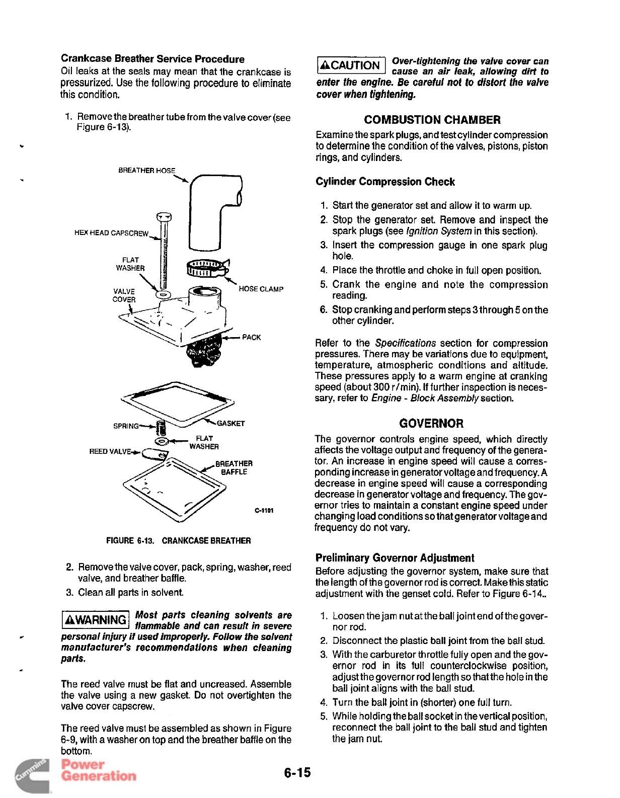
c
Crankcase Breather Service Procedure
Oil leaks at the seals may mean that the crankcase is
pressurized. Use the following procedure
to
eliminate
this condition.
cover
when
fighfening.
1.
Remove the breather tube from the valve cover (see
71
Over-tightening the valve cover can
cause an air leak, allowing dirf to
enter the engine. Be careful
not
to
dist0f-f
the
valve
COMBUSTION CHAMBER
Examine the spark plugs, and test cylinder compression
to determine the condition of the valves, pistons, piston
rings, and cylinders.
Figure 6-13).
BREATHER HOSE
\f--7
Cylinder Compression Check
HEX HEAD
FLAT
WASHER
VALVE
COVER
/
ip
fl
-"OSECLAMP
\
._
-
/i
1.
Start the generator set and allow
it
to warm up.
2.
Stop the generator set. Remove and inspect the
spark plugs (see Ignition
System
in this section).
3.
Insert the compression gauge in one spark plug
hole.
4.
Place the throttle and choke in full open position.
5.
Crank the engine and note the compression
6.
Stop cranking and perform steps
3
through
5
on the
reading.
other cylinder.
PACK
Refer to the Specifications section for compression
pressures. There may be variations due to equipment,
temperature, atmospheric conditions and altitude.
These pressures apply to
a
warm engine at cranking
speed (about
300
r/min). If further inspection is neces-
sary, refer to Engine
-
Block
Assembly section.
GOVERNOR
The governor controls engine speed, which directly
affects the voltage output and frequency
of
the genera-
tor. An increase in engine speed will cause a corres-
ponding increase in generator voltage and frequency. A
decrease in engine speed will cause a corresponding
decrease in generator voltage and frequency. The gov-
ernor tries to maintain a constant engine speed under
changing load conditions
so
that generator voltageand
frequency do not vary.
Preliminary Governor Adjustment
the length of the governor rod is correct. Make this static
adjustment with the genset cold. Refer to Figure
6-14..
REED VALVE*
c-1101
FIGURE
6-13.
CRANKCASE
BREATHER
2-
Remove the valve cover, pack,springr washer* reed Before adjusting the governor system, make Sure that
valve, and breather baffle.
3.
Clean all parts in solvent.
Most
parts cleaning solvents are
kiEiEl
flammable and can result
in
severe
personal injury if used improperly. Follow the solvent
manufacturer's recommendations
when
cleaning
parts.
The reed valve must be flat and uncreased. Assemble
the valve using a new gasket.
Do
not overtighten the
valve cover capscrew.
*
il
The reed valve must be assembled as shown in Figure
6-9,
with a washer on top and the breather baffle on the
bottom.
1.
Loosen the jam nut
at
the ball joint end of the gover-
2.
Disconnect the plastic ball joint from the ball stud.
3. With the carburetor throttle fully open and the gov-
ernor rod in its full counterclockwise position,
adjust the governor rod length
so
that the hole in the
ball joint aligns with the ball stud.
nor rod.
4.
Turn the ball joint in (shorter) one full turn.
5.
While holding the ball socket in the vertical position,
reconnect the ball joint to the ball stud and tighten
the jam nut.
6-1
5
Redistribution or publication of this document
by any means, is strictly prohibited.
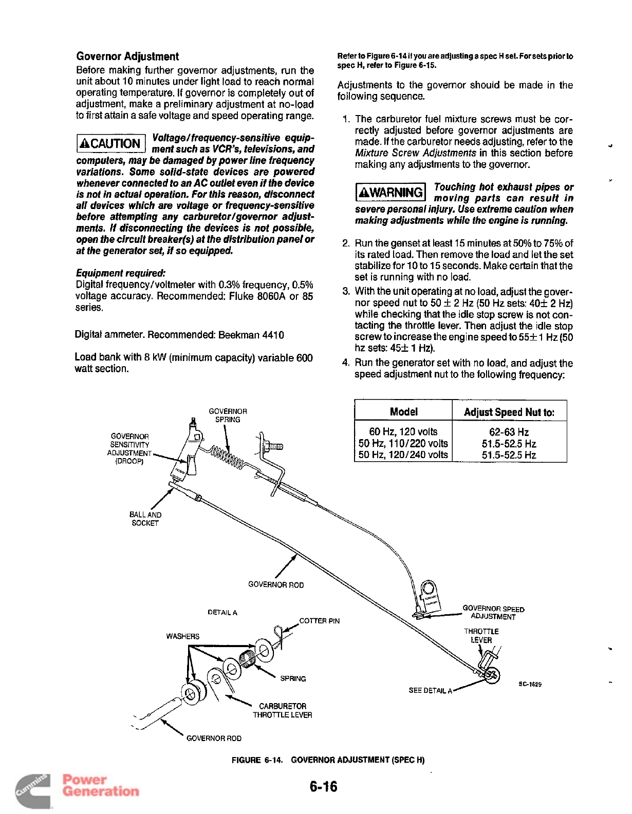
Governor
Adjustment
Before making further governor adjustments, run the
unit about 10 minutes under light load to reach normal
operating temperature.
If
governor is completely out of
adjustment, make a preliminary adjustment at no-load
to first attain a safe voltage and speed operating range.
Voltage/frequency-sensitive
equip-
@%@!I
ment such as
VCR's,
televisions, and
computers, may be damaged by power line frequency
variations. Some solid-state devices are powered
whenever connected to an
AC
outlet even if the device
is not in actual operation.
For
this reason, disconnect
all devices which are voltage or frequency-sensitive
before attempting any carburetor/governor adjust-
ments. If disconnecting the devices is not possible,
open the circuit breaker@) at the distribution panel or
at the generator set, if
so
equipped.
Equipment required:
Digital frequency/voltmeter with
0.3%
frequency,
0.5%
voltage accuracy. Recommended: Fluke 8060A or 85
series.
Digital ammeter. Recommended: Beekman 441
0
Load bank with
8
kW (minimum capacity) variable 600
watt section.
GOVERNOR
A
SP,FZING
I
n
Refer
to
Figure 6-14if
you
areadjusting
a
spec H set. For sets prior to
spec
H,
refer
to
Figure 6-15.
Adjustments to the governor should be made in the
following sequence.
1.
The carburetor fuel mixture screws must be cor-
rectly adjusted before governor adjustments are
made.
If
the carburetor needs adjusting, refer to the
Mixture
Screw
Adjustments
in this section before
making any adjustments to the governor.
rl
w
Touching hot exhaust pipes or
l3HESl
moving parts can result in
severe personal injury. Use extreme caution when
making adjustments while the engine is running.
2. Run the genset at least
15
minutes at
50%
to
75%
of
its rated load. Then remove the load and let the set
stabilize for
10
to 15 seconds. Make certain that the
set is running with no load.
3.
With the unit operating at no load, adjust the gover-
nor speed nut to
50
f
2 Hz (50 Hz sets:
40+
2
Hz)
while checking that the idle stop screw is not con-
tacting the throttle lever. Then adjust the idle stop
screw to increase the engine speed to
55f
1 Hz
(50
hz sets:
45f
1
Hz).
4.
Run the generator set with no load, and adjust the
speed adjustment nut to the following frequency:
50
Hz,
11
0/220 volts 51.5-52.5 HZ
BALL
AND
SOCKET
WASHERS
GOVERNOR
ROD
DETAIL A
COTTER
PIN
n
w
GOVERNOR SPEED
THROTTLE
SC-1629
GOVERNOR
ROD
\
FIGURE 6-14. GOVERNOR ADJUSTMENT
(SPEC
H)
6-1
6
Redistribution or publication of this document
by any means, is strictly prohibited.
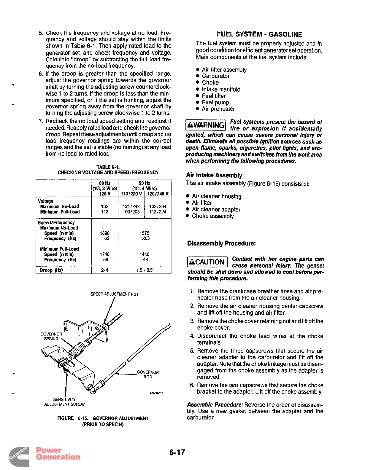
Check the frequency and voltage
at
no load. Fre-
quency and voltage should stay within the limits
shown in Table
6-1.
Then apply rated load to the
generator set, and check frequency and voltage.
Calculate "droop" by subtracting the full-load fre-
quency from the no-load frequency.
If the droop is greater than the specified range,
adjust the governor spring towards the governor
shaft by turning the adjusting screw counterclock-
wise
1
to
2
turns.
If
the droop is less than the min-
imum specified, or if the set is hunting, adjust the
governor spring away from the governor shaft by
turning the adjusting screw clockwise
1
to
2
turns.
Recheck the no load speed setting and readjust if
needed. Reapply rated load and check thegovernor
droop. Repeat theseadjustments until droop and no
load frequency readings are within the correct
ranges and the set is stable (no hunting) at any load
from no load to rated load.
TABLE
6-1.
CHECKING VOLTAGE AND SPEEDlFREQUENCY
(10,2-Wire)
Voltage
Maximum No-Load
Minimum Full-Load
112
SpeedlFrequency
Maximum No-Load
Speed (rlmin)
Frequency (Hz)
Minimum Full-Load
Speed (r/min)
Frequency (Hz)
1890
63
1740
58
1575
52.5
1440
48
I
Droop (Hz)
I
2-4
I
1.5
-
3.5
FUEL
SYSTEM
-
GASOLINE
The fuel system must be properly adjusted and in
good condition for efficient generator set operation.
Main components of the fuel system include:
0
Air filter assembly
0
Carburetor
Choke
0
Intake manifold
Fuel filter
0
Fuel pump
0
Air preheater
Fuel systems present the hazard of
leWAR"G1
fire
or
explosion if accidentally
ignited, which can cause severe personal injury
or
death. Eliminate all possible ignition sources such as
open flame, sparks, cigarettes, pilot lights, and arc-
producing machinery and switches from the workarea
when performing the following procedures.
Air Intake Assembly
The air intake assembly (Figure
6-1
6)
consists
of:
Air cleaner housing
Air filter
Air cleaner adapter
Choke assembly
Disassembly Procedure:
Contact with hot engine parts can
cause personal injury. The genset
should be shut down and allowed to cool before per-
forming this procedure.
1.
Remove the crankcase breather hose and air pre-
heater hose from the air cleaner housing.
2.
Remove the air cleaner housing center capscrew
and lift
off
the housing and air filter.
3.
Remove the chokecover retaining nut and liftoff the
choke cover.
4.
Disconnect the choke lead wires at the choke
terminals.
5.
Remove the three capscrews that secure the air
cleaner adapter to the carburetor and
lift
off
the
adapter. Note thatthe choke linkage must be disen-
gaged from the choke assembly as the adapter is
removed.
6.
Remove the two capscrews that secure the choke
bracket
to
the adapter. Lift
off
the choke assembly.
Assemble Procedure:
Reverse the order of disassem-
bly.
Use a new gasket between the adapter and the
SPEED
ADJUSTMENT NUT
FS-1613
SENSITIVITY
ADJUSTMENT
SCREW
FIGURE
6-15.
GOVERNOR ADJUSTMENT
carburetor.
(PRIOR
TO
SPEC
H)
6-1
7
Redistribution or publication of this document
by any means, is strictly prohibited.
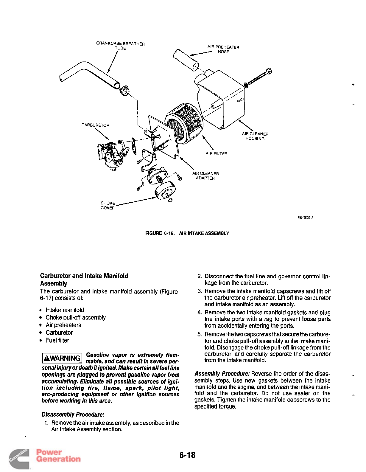
AIR PREHEATER
CRANKCASE BREATHER
/
HOSE
CARBURETOR
'\
\
AW
AIR FILTER
n
AIR
CLEANER
ADAPTER
CHOKE
COVER
FS-1609-3
FIGURE
6-16.
AIR INTAKE ASSEMBLY
Carburetor and Intake Manifold
Assembly
The carburetor and intake manifold assembly (Figure
6-1
7)
consists of:
0
Intake manifold
Choke pull-off assembly
Air preheaters
Carburetor
Fuel
filter
Gasoline vapor is extremely flam-
mable, and can result in severe per-
sonalinjury or death
if
ignited. Make certain all fuelline
openings are plugged
fo
prevent gasoline vapor from
accumulating. Eliminate all possible sources
of
igni-
tion including fire, flame, spark, pilot light,
arc-producing equipment or other ignition sources
before working in fhis area.
Disassembly Procedure:
1.
Remove theair intakeassembly, asdescribed in the
Air Intake Assembly section.
2.
Disconnect the fuel line and governor control lin-
kage from the carburetor.
3.
Remove the intake manifold capscrews and lift
off
the carburetor air preheater. Lift
off
the carburetor
and intake manifold as an assembly.
4.
Remove the
two
intake manifold gaskets and plug
the intake ports with
a
rag to prevent loose parts
from accidentally entering the ports.
5.
Removethetwo capscrews that secure the carbure-
tor and choke pull-off assembly to the intake mani-
fold. Disengage the choke pull-off linkage from the
carburetor, and carefully separate the carburetor
from the intake manifold.
Assembly Procedure:
Reverse the order
of
the disas-
.
sembly steps. Use new gaskets between the intake
manifold and the engine, and between the intake mani-
fold and the carburetor.
Do
not use sealer on the
..
gaskets. Tighten the intake manifold capscrews to the
specified torque.
6-1
8
Redistribution or publication of this document
by any means, is strictly prohibited.
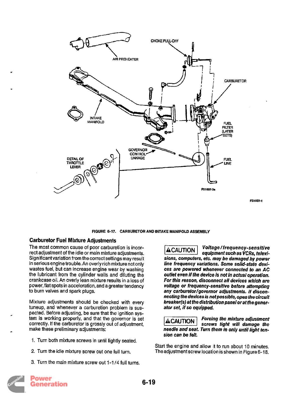
URETOR
DETAIL
Of
FIGURE
6-17.
CARBURETOR
AND
INTAKE
MANIFOLD
ASSEMBLY
Carburetor Fuel Mixture Adjustments
The most common cause
of
poor carburetion
is
incor-
rect adjustment of the idle or main mixture adjustments.
Significant variation from the correct settings may result
in serious engine trouble. An overly rich mixture not only
wastes fuel, but can increase engine wear by washing
the lubricant from the cylinder walls and diluting the
crankcase
oil.
An overly lean mixture results in a loss of
power, flat spots in acceleration, and a greater tendency
to burn valves and spark plugs.
Mixture adjustments
should
be checked with every
tuneup, and whenever a carburetion problem is sus-
pected. Before adjusting, be sure that the ignition
sys-
tem is working properly, and that the governor is set
correctly.
If
the carburetor is grossly out of adjustment,
c
4
make these preliminary adjustments:
1.
Turn both mixture screws in until lightly seated.
2.
Turn the idle mixture screw out one full turn.
Voltage/ frequenc y-sensitive
equipment such as
VCRs,
televi-
sions, computers, etc. may be damaged by power
line frequency variations. Some solid-state devi-
ces are powered whenever connected to an
AC
ouflet even if the device is not in actual operation.
For
this reason, disconnect all devices which are
voltage or frequency-sensitive before attempting
any carburetor/governor adjustments. If discon-
necting the devices
is
not possible, open the circuit
breaker@) at the distribution panelor at the gener-
ator set, if
so
equipped.
Forcing the mixture adjustment
screws tight will damage the
needle and seat.
Turn
them in only until light ten-
sion can be felt.
Start the engine and allow it to run about
10
minutes.
Theadjustment screw location
is
shown in Figure
6-1
8.
3.
Turn the main mixture screw out
1-1
/4
full turns.
6-1
9
Redistribution or publication of this document
by any means, is strictly prohibited.
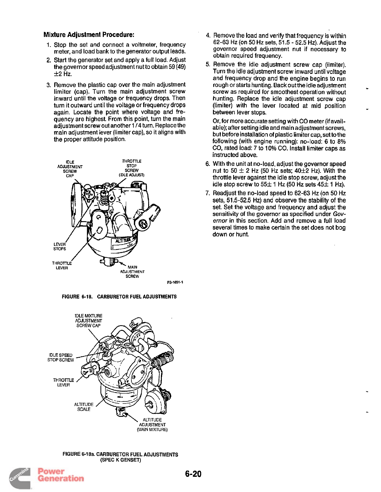
Mixture Adjustment Procedure:
1.
Stop the set and connect a voltmeter, frequency
meter, and load bank to the generator output leads.
2.
Start the generator set and apply a full load. Adjust
the governor speed adjustment nut
to
obtain
59 (49)
f2
Hz.
3.
Remove the plastic cap over the main adjustment
limiter (cap). Turn the main adjustment screw
inward until the voltage or frequency drops. Then
turn
it
outward until the voltage or frequency drops
again. Locate the point where voltage and fre-
quency are highest. From this point, turn the main
adjustment screw out another
1
/4
turn. Replace the
main adjustment lever (limiter cap),
so
it aligns with
the proper attitude position.
IDLE THROTTLE
ADJUSTMENT STOP
SCREW SCREW
CAP (IDLE ADJUST)
LE
ST
THROTTLE LEVER
’
-MAIN
ADJUSTMENT
SCREW
FS-1691-1
FIGURE
6-18.
CARBURETOR FUEL ADJUSTMENTS
IDLE MIXTURE
-
IDLE
SPEED
STOP SCREW
THROTTLE
LEVER
4.
Remove the load and verify that frequency is within
62-63 Hz (on
50
Hz sets,
51.5
-
52.5
Hz). Adjust the
governor speed adjustment nut
if
necessary to
obtain required frequency.
5.
Remove the idle adjustment screw cap (limiter).
Turn the idle adjustment screw inward until voltage
and frequency drop and the engine begins to run
rough or starts hunting. Back outthe idle adjustment
screw as required for smoothest operation without
hunting. Replace the idle adjustment screw cap
(limiter) with the lever located at mid position
between lever stops.
Or, for more accuratesetting with
CO
meter (if avail-
able); after setting idle and main adjustment screws,
but before installation
of
plastic limiter cap, set to the
following (with engine running): no-load: 6 to
8%
CO,
rated load:
7
to
10%
CO.
Install limiter caps as
instructed above.
6. With the unit at no-load, adjust the governor speed
nut to
50
f
2 Hz
(50
Hz sets;
40f2
Hz). With the
throttle lever against the idle stop screw, adjust the
idle stop screw to
55f
1
Hz
(50
Hz sets
45+
1
Hz).
7.
Readjust the no-load speed to 62-63 Hz (on
50
Hz
sets, 51.5-52.5 Hz) and observe the stability
of
the
set. Set the voltage and frequency and adjust the
sensitivity
of
the governor as specified under
Gov-
ernor
in this section. Add and remove a full load
several times to make certain the set does not bog
down
or
hunt.
Y
”
-
\
ALTITUDE
ADJUSTMENT
(MAIN MIXTURE)
FIGURE
6-18a.
CARBURETOR FUEL ADJUSTMENTS
(SPEC
K
GENSET)
6-20
Redistribution or publication of this document
by any means, is strictly prohibited.
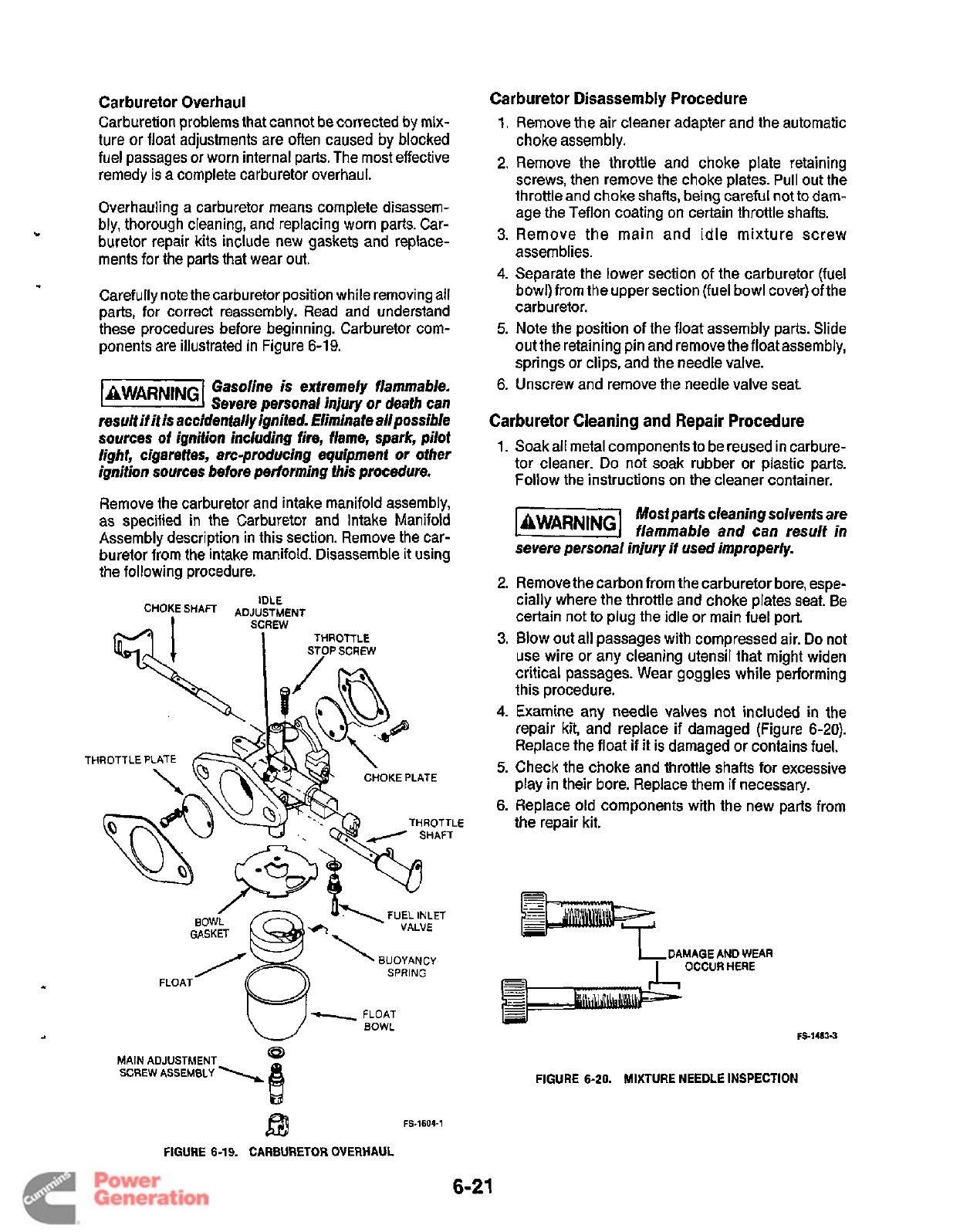
t
Carburetor Overhaul
Carburetion problems that cannot be corrected by mix-
ture or float adjustments are often caused by blocked
fuel passages
or
worn internal parts. The most effective
remedy is a complete carburetor overhaul.
Overhauling a carburetor means complete disassem-
bly, thorough cleaning, and replacing worn parts. Car-
buretor repair kits include new gaskets and replace-
ments for the parts that wear out.
Carefully note the carburetor position while removing all
parts, for correct reassembly. Read and understand
these procedures before beginning. Carburetor com-
ponents are illustrated in Figure 6-19.
Gasoline is extremely flammable.
@@%@
Severe personal injury
or
death can
result if it is accidentally ignited. Eliminate allpossible
sources
of
ignition including fire, flame, spark, pilot
light, cigarettes, arc-producing equipment
or
other
ignition
sources
before performing this procedure.
Remove the carburetor and intake manifold assembly,
as specified in the Carburetor and Intake Manifold
Assembly description in this section. Remove the car-
buretor from the intake manifold. Disassemble
it
using
the following procedure.
IDLE
CHOKE
SHAFT ADJUPTIAENT
THROTTLE
s!
~
STOPSCREW
THROTTLE
PLATE
\v
CHOKE
PLATE
x
THROTTLE
3
/
SHAFT
FUEL
INLET
VALVE
/
GASKET
BUOYANCY
SPRING
FLOAT
@
FS-1604-1
B
MAIN
ADJUSTMENT
SCREW
ASSEMBLY
\
B
FIGURE
6-19.
CARBURETOR
OVERHAUL
Carburetor Disassembly Procedure
1.
Remove the air cleaner adapter and the automatic
choke assembly.
2.
Remove the throttle and choke plate retaining
screws, then remove the choke plates. Pull out the
throttle and choke shafts, being careful
not to
dam-
age the Teflon coating on certain throttle shafts.
3.
Remove the main and idle mixture screw
assemblies.
4.
Separate the lower section of the carburetor (fuel
bowl) from the upper section (fuel bowl cover)
of
the
carburetor.
5.
Note the position of the float assembly parts. Slide
out the retaining pin and remove the floatassembly,
springs or clips, and the needle valve.
6. Unscrew and remove the needle valve seat
Carburetor Cleaning and Repair Procedure
1.
Soak all metal components to be reused in carbure-
tor cleaner. Do not soak rubber or plastic parts.
Follow the instructions on the cleaner container.
Mostparts
cleaningsoluents
are
jaWAR"G1
flammable and can result
in
severe personal injury
if
used improperly.
2.
Remove the carbon from the carburetor bore, espe-
cially where the throttle and choke plates seat. Be
certain not to plug the idle or main fuel port.
3.
Blow out all passages with compressed air.
Do
not
use wire or any cleaning utensil that might widen
critical passages. Wear goggles while performing
this procedure.
4.
Examine any needle valves not included in the
repair kit, and replace
if
damaged (Figure
6-20).
Replace the float if it is damaged or contains fuel.
5.
Check the choke and throttle shafts for excessive
play in their bore. Replace them
if
necessary.
6.
Replace old components with the new parts from
the repair kit.
IDAMAGE
AND
WEAR
I
OCCURHERE
FIGURE
6-20.
MIXTURE
NEEDLE
INSPECTION
6-21
Redistribution or publication of this document
by any means, is strictly prohibited.
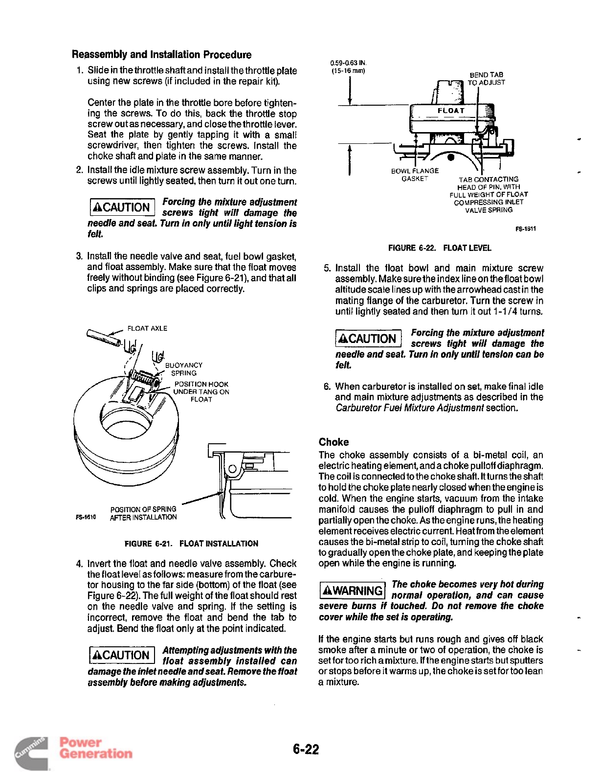
Reassembly and Installation Procedure
1.
Slide in the throttle shaftand install the throttle plate
using new screws (if included in the repair kit).
Center the plate in the throttle bore before tighten-
ing the screws.
To
do this, back the throttle stop
screw out as necessary, and close the throttle lever.
Seat the plate by gently tapping
it
with a small
screwdriver, then tighten the screws. Install the
choke shaft and plate in the same manner.
2.
Install the idle mixture screw assembly. Turn in the
screws until lightly seated, then turn it out one turn.
Forcing the mixture adjustment
screws tight will damage the
needle and seat. Turn in only until light tension is
felt.
3.
Install the needle valve and seat, fuel bowl gasket,
and float assembly. Make sure that the float moves
freely without binding (see Figure 6-21), and that all
clips and springs are placed correctly.
SlTlON
HOOK
DER TANG
ON
POSITION
OF
SPRING
FS-1610
AFTER INSTALLATION
FIGURE
6-21.
FLOAT INSTALLATION
4.
Invert the float and needle valve assembly. Check
the float level as follows: measure from the carbure-
tor housing
to
the far side (bottom)
of
the float (see
Figure 6-22). The full weight of the float should rest
on the needle valve and spring. If the setting is
incorrect, remove the float and bend the tab to
adjust. Bend the float only at the point indicated.
Attempting adjustments with the
float assembly installed can
damage the inlet needle andseaf. Remove the float
assembly before making adjustments.
0.59-0.63
IN.
(15-16
mm)
t
BEND TAB
if7
TO(DJUST
..
-
BOWL
--qY
FLANGE
~~
GASKET
TAB
C~NTACTING
HEAD
OF
PIN.
WITH
FULL WEIGHT
OF
FLOAT
COMPRESSING INLET
VALVE
SPRING
FS-1611
FIGURE
6-22.
FLOAT LEVEL
5.
Install the float bowl and main mixture screw
assembly. Make sure the index line on thefloat bowl
altitude scale lines up with the arrowhead cast in the
mating flange
of
the carburetor. Turn the screw in
until lightly seated and then turn
it
out
1-1
/4
turns.
Forcing the mixture adjustment
screws tight will damage the
needle and seat. Turn in only until tension can be
felt.
6.
When carburetor is installed on set, make final idle
and main mixture adjustments as described in the
Carburetor
Fuel Mixture Adjustment
section.
Choke
The choke assembly consists of a bi-metal coil, an
electric heating element, and a choke pulloff diaphragm.
The coil is connected to the choke shaft.
It
turns the shaft
to hold the choke plate nearly closed when the engine is
cold. When the engine starts, vacuum from the intake
manifold causes the pulloff diaphragm to pull in and
partially open the choke.
As
the engine runs, the heating
element receives electric current. Heatfrom theelement
causes the bi-metal strip to coil, turning the choke shaft
to
gradually open the choke plate, and keeping the plate
open while the engine is running.
The choke becomes very hot during
(BWARNINGI
normal operation, and can cause
severe burns
if
touched.
Do
not remove the choke
cover while the set is operating.
-
If the engine starts but runs rough and gives
off
black
smoke after a minute or two of operation, the choke is
setfortoo richamixture. Iftheengine starts but sputters
or stops before
it
warms up, the choke is set for
too
lean
a mixture.
-
6-22
Redistribution or publication of this document
by any means, is strictly prohibited.
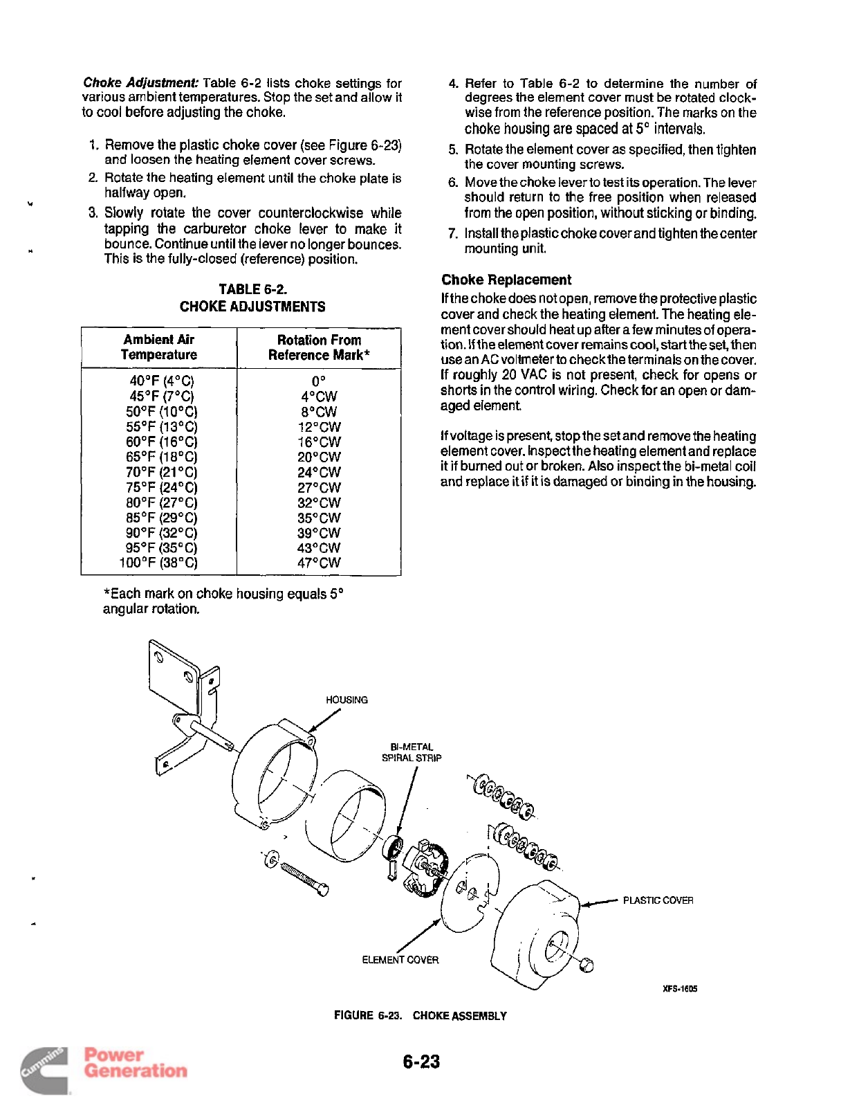
Choke
Adjustment:
Table
6-2
lists choke settings for
various ambient temperatures. Stop the set and allow
it
to cool before adjusting the choke.
1.
Remove the plastic choke cover (see Figure 6-23)
and loosen the heating element cover screws.
2.
Rotate the heating element until the choke plate is
halfway open.
3.
Slowly rotate the cover counterclockwise while
tapping the carburetor choke lever to make it
bounce. Continue until the lever no longer bounces.
This is the fully-closed (reference) position.
TABLE
6-2.
CHOKE ADJUSTMENTS
Ambient Air
Temperature
40°F (4°C)
45OF (7°C)
50°F (10°C)
55°F (13°C)
60°F (16°C)
65°F (18°C)
70°F (21 "C)
75°F (24°C)
80°F (27°C)
85°F (29°C)
90°F (32°C)
95°F
(35°C)
100°F (38°C)
Rotation From
Reference Mark*
0"
4OCW
8"CW
12"CW
16"CW
2O"CW
24"CW
27"CW
32"CW
35"CW
39"CW
43"CW
47"CW
*Each mark on choke housing equals
5"
angular rotation.
4.
Refer
to
Table
6-2
to
determine the number
of
degrees the element cover must be rotated clock-
wise from the reference position. The marks on the
choke
housing
are
spaced
at
5"
intervals.
5.
Rotate the element cover as specified, then tighten
the cover mounting screws.
6.
Move the choke lever to test its operation. The lever
should return to the free position when released
from the open position, without sticking or binding.
7. Install the plastic choke cover and tighten the center
mounting unit.
Choke
Replacement
If
the choke does not open, remove the protective plastic
cover and check the heating element. The heating ele-
ment cover should heat up after afew minutes of opera-
tion.
If
the element cover remains cool, start the set, then
use an AC voltmeter to check the terminals on the cover.
If
roughly 20 VAC is not present, check for opens or
shorts in the control wiring. Check for an open or dam-
aged element.
If
voltage is present, stop the set and remove the heating
element cover. Inspect the heating element and replace
it
if
burned out or broken. Also inspect the bi-metal coil
and replace
it
if
it
is damaged or binding
in
the housing.
PLASTIC
COVER
XFS-1605
FIGURE
6-23.
CHOKE
ASSEMBLY
6-23
Redistribution or publication of this document
by any means, is strictly prohibited.
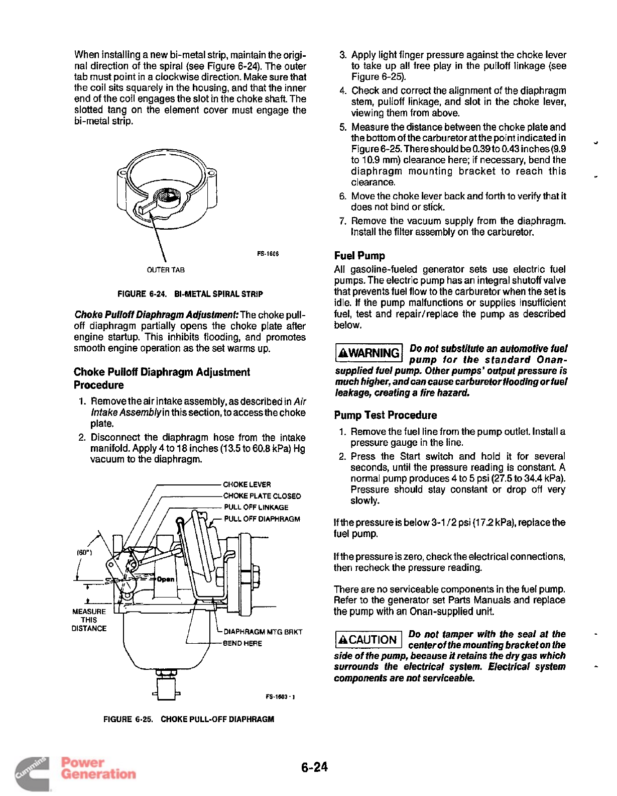
When installing a new bi-metal strip, maintain the origi-
nal direction of the spiral (see Figure 6-24). The outer
tab must point in a clockwise direction. Make sure that
the coil sits squarely in the housing, and that the inner
end of the coil engages the slot in the choke shaft. The
slotted tang on the element cover must engage the
bi-metal strip.
FS-1606
\
OUTER
TAB
FIGURE 6-24. BI-METAL SPIRAL
STRIP
Choke
Pulloff
Diaphragm Adjustment:
The choke pull-
off diaphragm partially opens the choke plate after
engine startup. This inhibits flooding, and promotes
smooth engine operation as the set warms up.
Choke Pulloff Diaphragm Adjustment
Procedure
1.
Remove the air intake assembly, as described in
Air
lnfake Assembly
in this section, to accessthe choke
plate.
2. Disconnect the diaphragm hose from the intake
manifold. Apply 4 to 18 inches (13.5 to 60.8 kPa) Hg
vacuum to the diaphragm.
PULL
OFF
LINKAGE
PULL
OFF
DIAPHRAGM
DIAPHRAGM
MTG
BRKT
BEND
HERE
DISTANCE
/
1
3.
Apply light finger pressure against the choke lever
to take up all free play in the pulloff linkage (see
Figure 6-25).
4. Check and correct the alignment
of
the diaphragm
stem, pulloff linkage, and slot in the choke lever,
viewing them from above.
5.
Measure the distance between the choke plate and
the bottom of the carburetor at the point indicated in
Figure 6-25. There should be 0.39 to 0.43 inches (9.9
to 10.9 mm) clearance here; if necessary, bend the
diaphragm mounting bracket to reach this
clearance.
6. Move the choke lever back and forth to verify that
it
does not bind or stick.
7.
Remove the vacuum supply from the diaphragm.
Install the filter assembly on the carburetor.
c)
Fuel Pump
All
gasoline-fueled generator sets use electric fuel
pumps. The electric pump has an integral shutoff valve
that preventsfuel flow to the carburetor when the set is
idle.
If
the pump malfunctions or supplies insufficient
fuel, test and repair/replace the pump as described
below.
-1
Do
not substitute an automotive fuel
pump for the standard Onan-
supplied fuel pump. Other pumps’ output pressure
is
much higher, and can cause carburetortooding
or
fuel
leakage, creating a fire hazard.
Pump Test Procedure
1. Remove the fuel line from the pump outlet. Install a
pressure gauge in the line.
2.
Press the Start switch and hold
it
for several
seconds, until the pressure reading
is
constant.
A
normal pump produces 4 to
5
psi (27.5 to 34.4 kPa).
Pressure should stay constant or drop off very
slowly.
If
the pressure is below 3-1 12 psi
(1
7.2
kPa), replace the
fuel pump.
If
the pressure is zero, check the electrical connections,
then recheck the pressure reading.
There are no serviceable components in the fuel pump.
Refer to the generator set Parts Manuals and replace
the pump with an Onan-supplied unit.
Do
not tamper with the seal at the
center of the mounting bracket on the
side of the pump, because
it
retains the
dry
gas which
surrounds the electrical system. Electrical system
components are not serviceable.
L
FIGURE 6-25. CHOKE PULL-OFF DIAPHRAGM
6-24
Redistribution or publication of this document
by any means, is strictly prohibited.
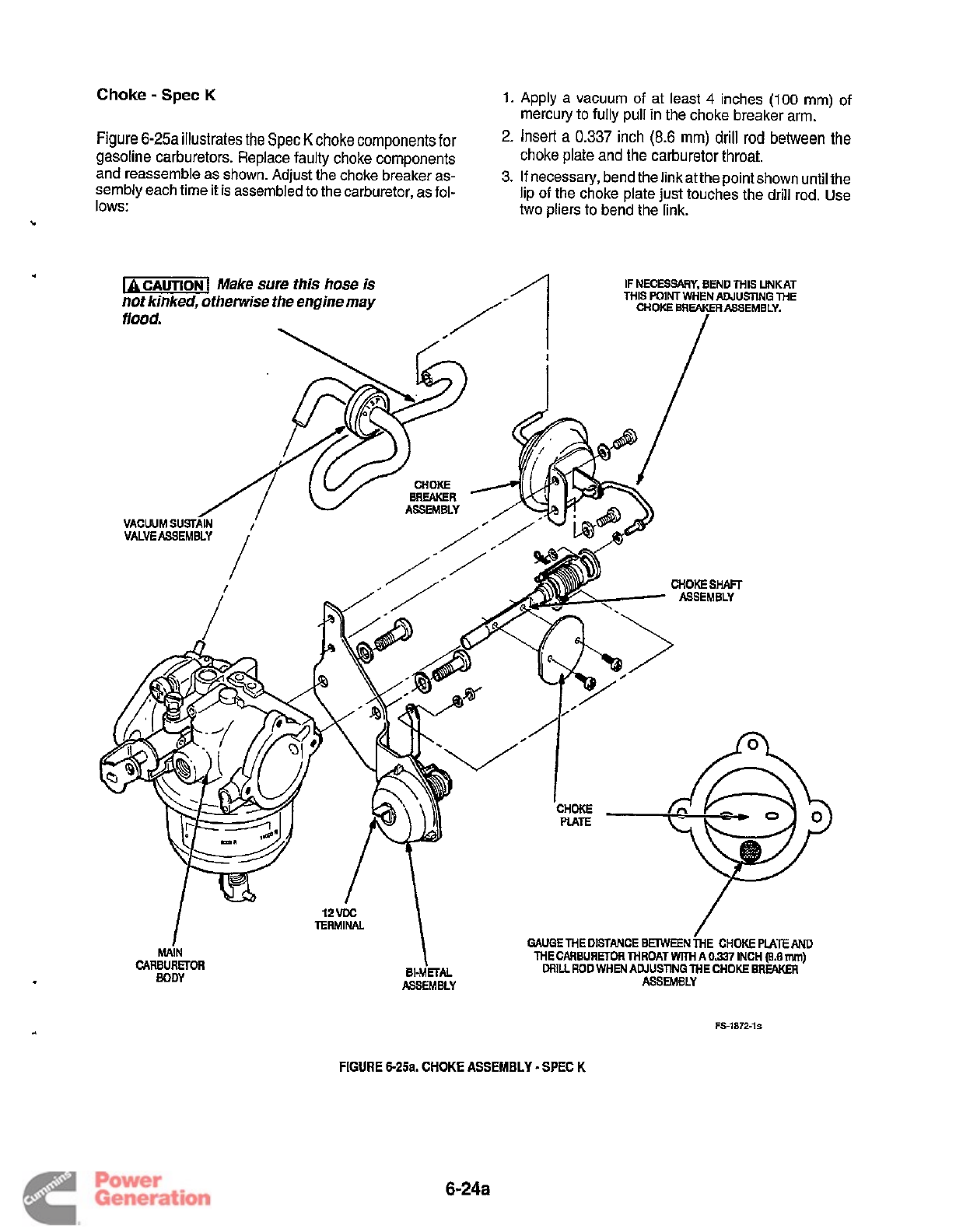
Choke
-
Spec
K
1.
Apply
a vacuum
of
at least
4
inches
(100
rnm)
of
mercury to fully pull in the choke breaker arm.
Figure
6-25a illustrates the Spec
K
choke
components
for
gasoline carburetors. Replace faulty choke components
and reassemble as shown. Adjust the choke breaker
as-
sembly each time it is assembled to the carburetor, as
fol-
lows:
2.
Insert
a
inch
(8.6
mm)
drill
rod
the
choke plate and the carburetor throat.
3.
If
necessary, bend the linkat the point shown until the
lip
of
the choke plate just touches the drill rod. Use
two pliers
to
bend the link.
FIGURE
625a. CHOKE
ASSEMBLY
-
SPEC
K
FS-1872-1s
6-24a
Redistribution or publication of this document
by any means, is strictly prohibited.
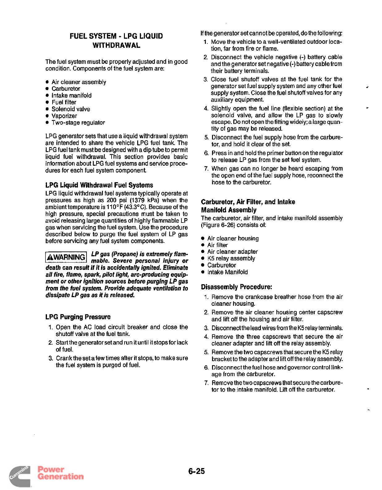
FUEL SYSTEM
-
LPG LIQUID
WITHDRAWAL
The fuel system must be properly adjusted and in good
condition. Components of the fuel system are:
0
Air cleaner assembly
0
Carburetor
0
Intake manifold
0
Fuel filter
0
Solenoid valve
0
Vaporizer
0
Two-stage regulator
LPG generator sets that use a liquid withdrawal system
are intended
to
share the vehicle LPG fuel tank. The
LPG fuel tank must be designed with adip tube
to
permit
liquid fuel withdrawal. This section provides basic
information about LPG fuel systems and service proce-
dures for each fuel system component
LPG Liquid Withdrawal Fuel Systems
LPG liquid withdrawal fuel systems typically operate at
pressures as high as
200
psi (1379 kPa) when the
ambient temperature is 11OOF (43.3"C). Because
of
the
high pressure, special precautions must be taken to
avoid releasing large quantities of highly flammable LP
gas when servicing the fuel system. Use the procedure
described below to purge the fuel system of LP gas
before servicing any fuel system components.
LP gas (Propane) is extremely flam-
l&i@EW
mable. Severe personal injury
or
death can result if it
is
accidentally ignited. fliminafe
all fire, flame, spark, pilot light, arc-producing equip-
ment
or
other ignition sources before purging L P gas
from the fuel system. Provide adequate ventilation to
dissipate LP gas as it is released.
LPG Purging Pressure
1.
Open the
AC
load circuit breaker and close the
2.
Start the generator set and run
it
until it stopsfor lack
3. Crank the set a few times after
it
stops,
to
make sure
shutoff valve at the fuel tank.
of fuel.
the fuel system is purged of fuel.
If
the generator set cannot be operated, do the following:
1.
Move the vehicle to a well-ventilated outdoor loca-
tion, far from fire or flame.
2.
Disconnect the vehicle negative
(-)
battery cable
and the generator set negative
(-)
battery cable from
their battery terminals.
3.
Close fuel shutoff valves at the fuel tank for the
generator set fuel supply system and any other fuel
supply system. Close the fuel shutoff valves for any
auxiliary equipment.
4. Slightly open the fuel line (flexible section) at the
solenoid valve, and allow the LP gas
to
slowly
escape.
Do
not open the fitting widely; a large quan-
tity
of
gas may be released.
5.
Disconnect the fuel supply hose from the carbure-
tor, and hold
it
clear of the set.
6.
Press in and hold the primer button on the regulator
to release LP gas from the set fuel system.
7.
When gas can no longer be heard escaping from
the open end of the fuel supply hose, reconnect the
hose to the carburetor.
J
Carburetor, Air Filter, and Intake
Manifold Assembly
The carburetor, air filter, and intake manifold assembly
(Figure
6-26)
consists of:
Air
cleaner housing
0
Air filter
0
Air
cleaner adapter
0
K5
relay assembly
Carburetor
0
Intake Manifold
Disassembly Procedure:
1.
Remove the crankcase breather hose from the air
2.
Remove the air cleaner housing center capscrew
3.
Disconnect the lead wires from the
K5
relay terminals.
4. Remove the three capscrews that secure the air
cleaner adapter and
lift
off the relay assembly.
5.
Remove the two capscrews that secure the
K5
relay
bracket to the adapter and liftoff the relay assembly.
6.
Disconnect the fuel hose and governor control link-
age from the carburetor.
7.
Remove the two capscrews that secure the carbure-
tor to the intake manifold. Lift off the carburetor.
cleaner housing.
and lift
off
the housing and air filter.
-
6-25
Redistribution or publication of this document
by any means, is strictly prohibited.
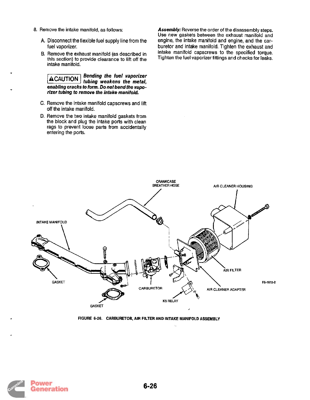
,
8.
Remove the intake manifold, as follows:
Assembly:
Reverse the order
of
the disassembly steps.
Use new gaskets between the exhaust manifold and
engine, the intake manifold and engine, and the car-
buretor
and
intake manifold. Tighten the exhaust
and
intake manifold capscrews
to
the specified torque.
Tighten the fuel vaporizer fittings and checks for leaks.
A.
Disconnect the
flexible
fuel
supply
line
from the
fuel vaporizer.
B.
Remove
the exhaust
(as
described
in
this section)
to
provide
clearance
to
lift
off
the
intake manifold.
Bending the
fuel
vaporizer
f-1
tubing weakens the metal,
enabling cracks
io
form.
Do
not bend the vapo-
rizer tubing to remove the intake manifold.
C.
Remove the intake manifold capscrews and
lift
off
the intake manifold.
D.
Remove the two intake manifold gaskets from
the block and plug the intake ports with clean
rags to prevent loose parts from accidentally
entering the ports.
CRANKCASE
BREATHER HOSE
n
/
AIR
CLEANER HOUSING
I
FS-1612-2
AIR
CLEANER ADAPTER
GASKET
/--
K5
RELAY
GASKET
J
FIGURE
6-26.
CARBURETOR,
AIR
FILTER AND INTAKE MANIFOLD ASSEMBLY
6-26
Redistribution or publication of this document
by any means, is strictly prohibited.
Carburetor Mixture Screw Adjustments
Vo/tage/irequency-sensitive
lacAunoNI
equipment such as
VCRs,
televisions,
computers, etc. may be damaged by power line fre-
quency variations. Some solid-state devices are
powered whenever connected to an
AC
output even
if
the device
is
not in actual operation.
For
this reason,
disconnect a// devices that are voltage
or
irequency-
sensitive before attempting any carburetor/governor
adjustments. If disconnecting the devices
is
notpossi-
ble, open the circuit breaker@) at the distribution panel
or
at the generator set,
if
so
equipped.
LPG
carburetors have three adjustment screws:
0
The throttle stop screw sets the width of the throttle
plate opening when the throttle is pulled back to the
closed position.
0
The idle adjustment screw controls the fuel mixture
when the set is operating at no load.
0
The main adjustment screw controls the fuel mix-
ture when the set is operating at full load.
No
other adjustments are necessary with an
LPG
car-
buretor, because there are no float
or
choke adjust-
ments.
Do
not make these adjustments until the ignition system,
governor, and other fuel system components have been
checked for correct operation.
If
the carburetor is
grossly out of adjustment, turn the mixture screws in
until they are lightly seated, then turn the main adjust-
ment screw out
2-1
/2
(+
1
14)
turns and the idle adjust-
ment screw out
1
(*
114)
turn. This provides a rough
preliminary adjustment.
forcing the mixture adjustment
screws tight will damage the needle
and seat. Turn in
only
until light tension can be felt.
Start the engine and allow itto run for
10
minutesat light
load. Figure
6-27
illustrates the location of the adjust-
ment screws.
IDLE
ADJUSTMENT
SCREW
THROTTLE
STOP
/
SCREW
MAIN
ADJUSTMENT
SCREW
Adjustment Procedure:
1.
Stop the set and connect a voltmeter, frequency
meter, and load bank to the generator output leads.
2.
Start the generator set and apply a full load. Adjust
the governor speed adjustment nut,
if
necessary, to
obtain
59
(49)
*
2
Hz.
3.
Turn the main adjustment screw inward until the
voltage or frequency drops, then outward until the
voltage or frequency drops again. Set the main
adjustment screw at the point where thevoltageand
frequency are highest.
"
4.
Remove the load. Adjust the governor speed
adjustment nut
if
necessary, to obtain
62
(51.5)
f
1
Hz.
5.
Turn the idleadjustment screw inward until thevolt-
age and frequency drop and the engine begins to
run rough or starts hunting. Back out the idle
adjustment screw until the engine runs smoothly
without hunting.
w
Or for a more accurate setting with CO meter
(if
available), after setting idle and main adjustment
screws, but before installation of plastic limiter cap,
setto the following (with engine running); no-load:
6
to
8%
CO,
rated load:
7
to
10%
CO.
Install limiter
caps as instructed above.
6.
With unit at no-load, adjust governor speed nut to
50
5
2
Hz
(50
Hz sets:
40
t-
2
Hz). With the throttle lever
against the idle stop screw, adjust the stop screw to
55
f
1
Hz
(50
Hz
sets:
45f.
1
Hz).
7.
Readjust no-load speed to
62
(51.5)
f
1
Hz and
observe the stability
of
the set. Set the voltage and
frequency and adjust the sensitivity of the governor
as specified in the Governor section. Add and
remove a half-load several times, to make certain
the set does not bog down or hunt.
Carburetor Overhaul
Carburetor problems that cannot be corrected by mix-
ture adjustments may be caused by dirt in fuel passages,
or
by worn internal parts. Normally, the carburetor
should seldom require cleaning, because
LP
gas vapo-
rizes completely before reaching the carburetor, leaving
no residue. However, a bad fuel supply or fuel filter may
let dirt or oil through to the carburetor. This may mean
that the carburetor should be cleaned to restore satis-
factory operation.
Overhauling the carburetor involves its complete disas-
sembly, thorough cleaning, and replacement
of
worn
parts. Carburetor repair kits are available that supply
new gaskets and replacement parts for the components
subject to wear.
Note the position
of
all
components while removing
them, for correct reassembly. See Figure
6-28
for com-
ponent designations.
L.
FS-1601
FIGURE
6-27.
MIXTURE
SCREW
ADJUSTMENTS
6-27
Redistribution or publication of this document
by any means, is strictly prohibited.
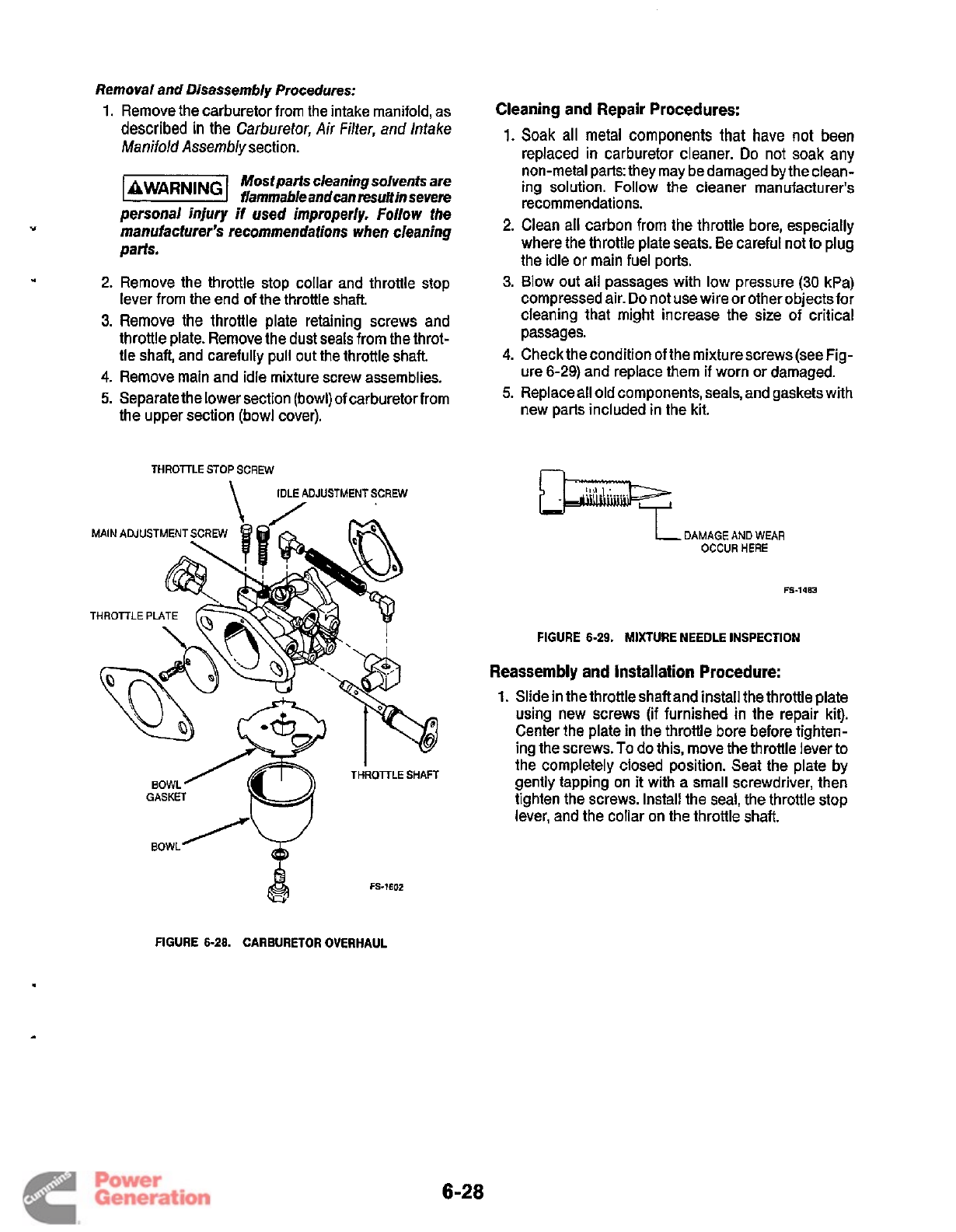
Removal and Disassembly Procedures:
1.
Remove the carburetor from the intake manifold, as
described
in
the
Carburetor,
Air
Filter, and Intake
Manifold Assembly
section.
Mostparts cleaning solvents are
f/ammab/eandcanresuMin severe
personal injury
if
used improperly. Follow the
manufacturer's recommendations when cleaning
parts.
2.
Remove the throttle stop collar and throttle stop
lever from the end
of
the throttle shaft.
3.
Remove the throttle plate retaining screws and
throttle plate. Remove the dust seals from the throt-
tle shaft, and carefully pull out the throttle shaft.
4.
Remove main and idle mixture screw assemblies.
5.
Separate the lower section (bowl) of carburetor from
the upper section (bowl cover).
THROTTLE
STOP
SCREW
\
IDLE
ADJUSTMENTSCREW
I
THROITLE
SHAFT
BOWL
GASKET
BOWL
'V
Cleaning
and
Repair
Procedures:
1.
Soak all metal components that have not been
replaced in carburetor cleaner.
Do
not soak any
non-metal parts: they may bedamaged by the clean-
ing solution. Follow the cleaner manufacturer's
recommendations.
2.
Clean all carbon from the throttle bore, especially
where the throttle plate seats. Be careful not
to
plug
the idle or main fuel ports.
3.
Blow out all passages with low pressure
(30
kPa)
compressed air.
Do
not use wire or otherobjectsfor
cleaning that might increase the size of critical
passages.
4.
Check the condition of the mixturescrews(see Fig-
ure
6-29)
and replace them
if
worn or damaged.
5.
Replace all old components, seals, and gaskets with
new parts included in the kit.
1
DAMAGE
AND
WEAR
OCCUR
HERE
FS-1483
FIGURE
6-29.
MIXTURE
NEEDLE
INSPECTION
Reassembly
and
installation
Procedure:
1.
Slide in the throttle shaft and install the throttle plate
using new screws
(if
furnished in the repair kit).
Center the plate in the throttle bore before tighten-
ing the screws.
To
do this, move the throttle lever to
the completely closed position. Seat the plate by
gently tapping on
it
with a small screwdriver, then
tighten the screws. Install the seal, the throttle stop
lever, and the collar on the throttle shaft.
Q
FS-1602
FIGURE
6-28.
CARBURETOR OVERHAUL
6-28
Redistribution or publication of this document
by any means, is strictly prohibited.
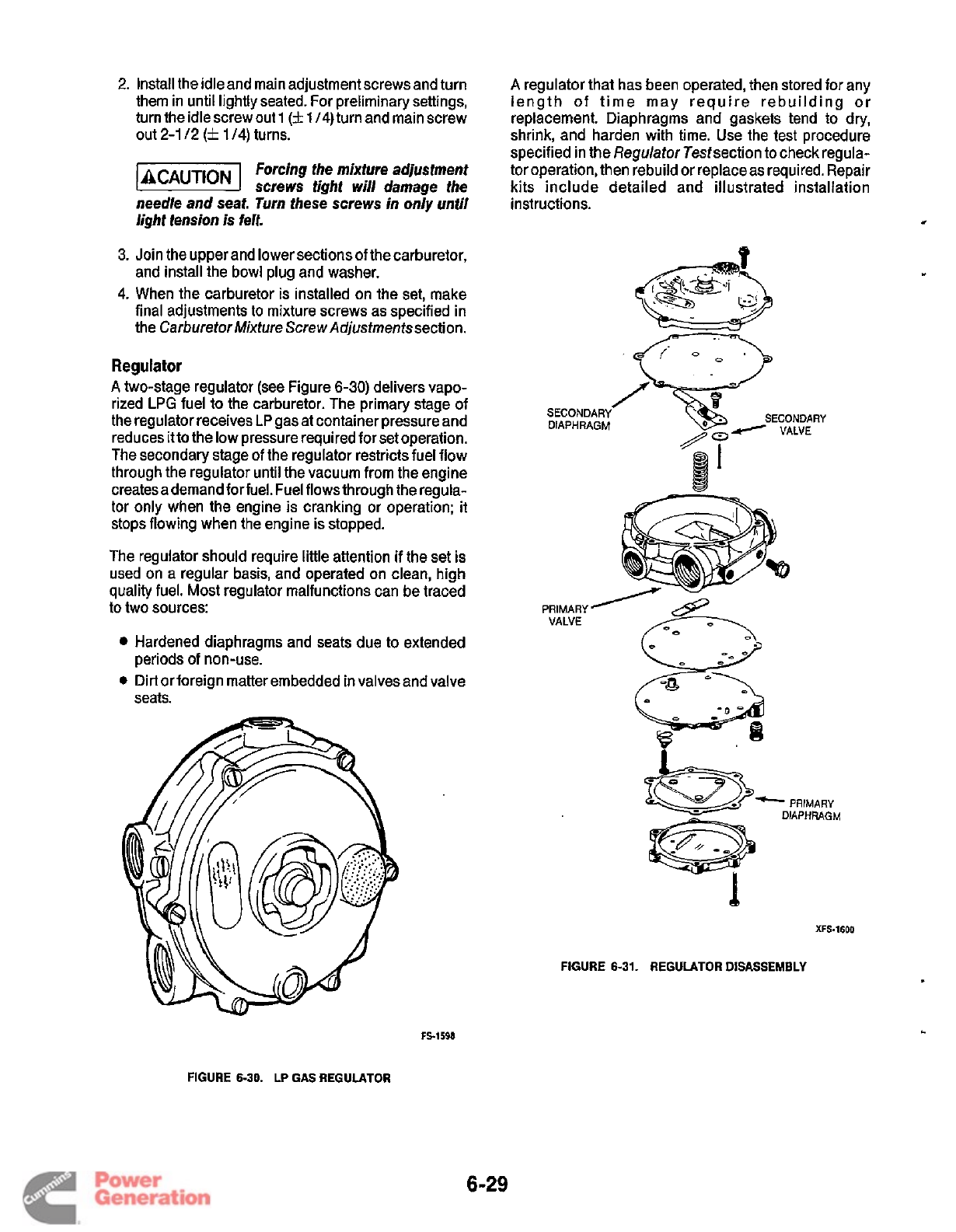
2.
Install the idleand main adjustment screws and turn
them in until lightly seated. For preliminary settings,
turn the idlescrew out
1
(k
1
/4)
turn and main screw
out
2-1
12
(2
1
/4)
turns.
Forcing the
mixfure
adjusfmenf
screws fight
will
damage the
needle and seat. Turn fhese screws in only unfil
lighf tension
is
felt.
3.
Join the upper and lower sections of the carburetor,
and install the bowl plug and washer.
4.
When the carburetor is installed
on
the set, make
final adjustments
to
mixture screws
as
specified in
the Carburetor Mixture Screw Adjustmentssection.
Regulator
A
two-stage regulator (see Figure
6-30)
delivers vapo-
rized
LPG
fuel
to
the carburetor. The primary stage
of
the regulator receives
LP
gas at container pressure and
reduces itto the low pressure required for set operation.
The secondary stage of the regulator restricts fuel flow
through the regulator until the vacuum from the engine
creates a demand for fuel. Fuel flows through the regula-
tor only when the engine is cranking or operation; it
stops flowing when the engine is stopped.
The regulator should require little attention if the set is
used on a regular basis, and operated on clean, high
quality fuel. Most regulator malfunctions can be traced
to two sources:
Hardened diaphragms and seats due to extended
0
Dirt or foreign matter embedded in valves and valve
periods
of
non-use.
seats.
A
regulator that has been operated, then stored for any
length
of
time may require rebuilding or
replacement. Diaphragms and gaskets tend to dry,
shrink, and harden with time. Use the test procedure
specified in the Regulator Testsection to check regula-
tor operation, then rebuild or replace as required. Repair
kits include detailed and illustrated installation
instructions.
*
1
XFS-1600
FIGURE 6-31. REGULATOR DISASSEMBLY
FS-1598
FIGURE 6-30.
LP
GAS REGULATOR
6-29
Redistribution or publication of this document
by any means, is strictly prohibited.
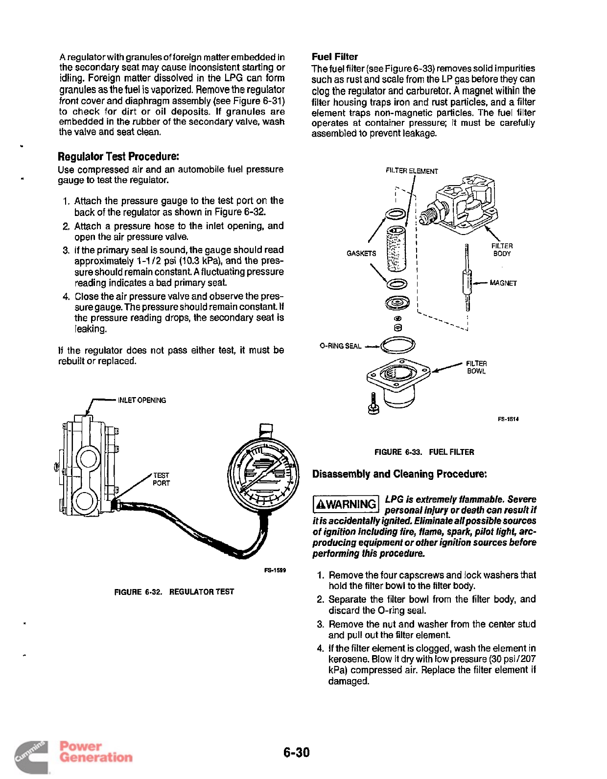
A
regulator with granules of foreign matter embedded in
the secondary seat may cause inconsistent starting or
idling. Foreign matter dissolved in the
LPG
can form
granules
as
the
fuel
is
vaporized.
Remove
the
regulator
front cover and diaphragm assembly (see Figure 6-31)
to check
for
dirt or oil deposits.
If
granules are
embedded in the rubber of the secondary valve, wash
the valve and seat clean.
Regulator Test Procedure:
Use compressed air and an automobile fuel pressure
gauge
to
test the regulator.
1. Attach the pressure gauge
to
the test port on the
back
of
the regulator as shown in Figure 6-32.
2. Attach a pressure hose to the inlet opening, and
open the air pressure valve.
3.
If the primary seal is sound, the gauge should read
approximately
1-1
/2
psi
(10.3
kPa), and the pres-
sure should remain constant.
A
fluctuating pressure
reading indicates a bad primary seat
4.
Close the air pressure valve and observe the pres-
suregauge. The pressureshould remain constant.
If
the pressure reading drops, the secondary seat is
leaking.
If
the regulator does not pass either test,
it
must be
rebuilt or replaced.
INLETOPENING
FS-1599
FIGURE
6-32.
REGULATOR
TEST
Fuel Filter
The fuel filter (see Figure
6-33)
removes solid impurities
such as rust and scale from the
LP
gas before they can
clog the regulator
and
carburetor.
A
magnet within the
filter housing traps iron and rust particles, and a filter
element traps nonmagnetic particles. The fuel filter
operates at container pressure;
it
must be carefully
assembled
to
prevent leakage.
FILTER ELEMENT
0
O-RING
SEAL
-c
FIGURE
6-33.
FUEL FILTER
Disassembly
and
Cleaning Procedure:
LPG
is extremely flammable. Severe
personal injury
or
death can result if
it is accidentally ignited. Eliminate allpossible sources
of
ignition including fire, flame, spark, pilot light, arc-
producing equipment or other ignition sources before
performing this procedure.
1.
Remove the four capscrews and lock washers that
hold the filter bowl to the filter body.
2.
Separate the filter bowl from the filter body, and
discard the O-ring seal.
3. Remove the nut and washer from the center stud
and pull out the filter element.
4.
If
the filter element
is
clogged, wash the element in
kerosene. Blow
it
dry with low pressure (30 psi1207
kPa) compressed air. Replace the filter element if
damaged.
6-30
Redistribution or publication of this document
by any means, is strictly prohibited.
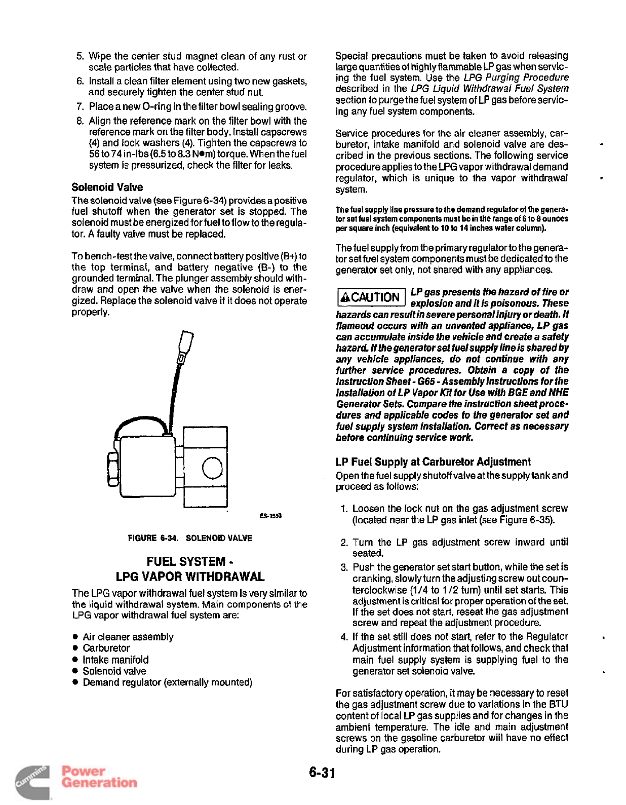
5.
Wipe the center stud magnet clean of any rust or
6.
Install a clean filter element using two new gaskets,
7.
Place a new O-ring in the filter bowl sealing groove.
8.
Align the reference mark on the filter bowl with the
reference mark on the filter body. Install capscrews
(4)
and lock washers (4). Tighten the capscrews to
56 to74 in-lbs(6.5 to
8.3
Nom) torque. When the fuel
system
is
pressurized, check the filter for leaks.
scale particles that have collected.
and securely tighten the center stud nut.
Solenoid Valve
The solenoid valve (see Figure
6-34)
provides a positive
fuel shutoff when the generator set is stopped. The
solenoid must be energized for fuel
to
flow to the regula-
tor.
A
faulty valve must be replaced.
To bench-test the valve, connect battery positive (E+)
to
the top terminal, and battery negative
(B-)
to the
grounded terminal. The plunger assembly should with-
draw and open the valve when the solenoid is ener-
gized. Replace the solenoid valve if it does not operate
properly.
ES-1553
FIGURE
6-34.
SOLENOID
VALVE
FUEL SYSTEM
-
LPG VAPOR WITHDRAWAL
The LPG vapor withdrawal fuel system is very similar to
the liquid withdrawal system. Main components of the
LPG vapor withdrawal fuel system are:
0
Air cleaner assembly
0
Carburetor
Intake manifold
Solenoid valve
Demand regulator (externally mounted)
Special precautions must be taken to avoid releasing
large quantities of highly flammable LP gas when servic-
ing the fuel system. Use the
LPG Purging Procedure
described in the
LPG
Liquid
Withdrawal
Fuel
System
section to purge the fuel system of LP gas before servic-
ing any fuel system components.
Service procedures for the air cleaner assembly, car-
buretor, intake manifold and solenoid valve are des-
cribed in the previous sections. The following service
procedure applies to the LPG vapor withdrawal demand
regulator, which is unique to the vapor withdrawal
system.
The fuel supply line pressure
to
the demand regulator
01
the genera-
tor set
fuel
system components must be in the range
of
6
to
8
ounces
per square inch (equivalent to
10
to
14
inches water column).
The fuel supply from the primary regulatorto the genera-
tor setfuel system components must be dedicated to the
generator set only, not shared with any appliances.
LP
gas presents fhe hazard of fire or
explosion and
if
is poisonous. These
hazards can result in severe personal
injury
or death. If
flameout occurs with an unvenfed appliance,
LP
gas
can accumulate inside the vehicle and create
a
safety
hazard.
/f
the generator sef fuelsupply line is shared by
any vehicle appliances, do not continue with any
furfher service procedures. Obtain a copy of the
lnstrucfion Sheet
-
665
-Assembly Instructions for the
Installation of
LP
Vapor Kif
tor
Use with
BGE
and
NHE
Generator Sets. Compare the instruction sheet proce-
dures and applicable codes
to
the generafor set and
fuel supply system installation. Correct as necessary
before continuing service
work.
4
LP
Fuel Supply at Carburetor Adjustment
Open the fuel supply shutoff valveatthesupplytankand
proceed as follows:
1.
Loosen the lock nut on the gas adjustment screw
(located near the LP gas inlet (see Figure 6-35).
2.
Turn the LP gas adjustment screw inward until
seated.
3.
Push the generator set start button, while the set is
cranking, slowly turn the adjusting screw out coun-
terclockwise
(1/4
to
1
/2
turn) until set starts. This
adjustment is critical for proper operation
of
the set.
If
the set does not
start,
reseat the gas adjustment
screw and repeat the adjustment procedure.
4.
If
the set still does not start, refer to the Regulator
Adjustment information that follows, and check that
main fuel supply system is supplying fuel to the
generator set solenoid valve.
For
satisfactory operation,
it
may be necessary to reset
the gas adjustment screw due to variations in the BTU
content of local LP gas supplies and for changes in the
ambient temperature. The idle and main adjustment
screws on the gasoline carburetor will have no effect
during LP gas operation.
6-3
1
Redistribution or publication of this document
by any means, is strictly prohibited.
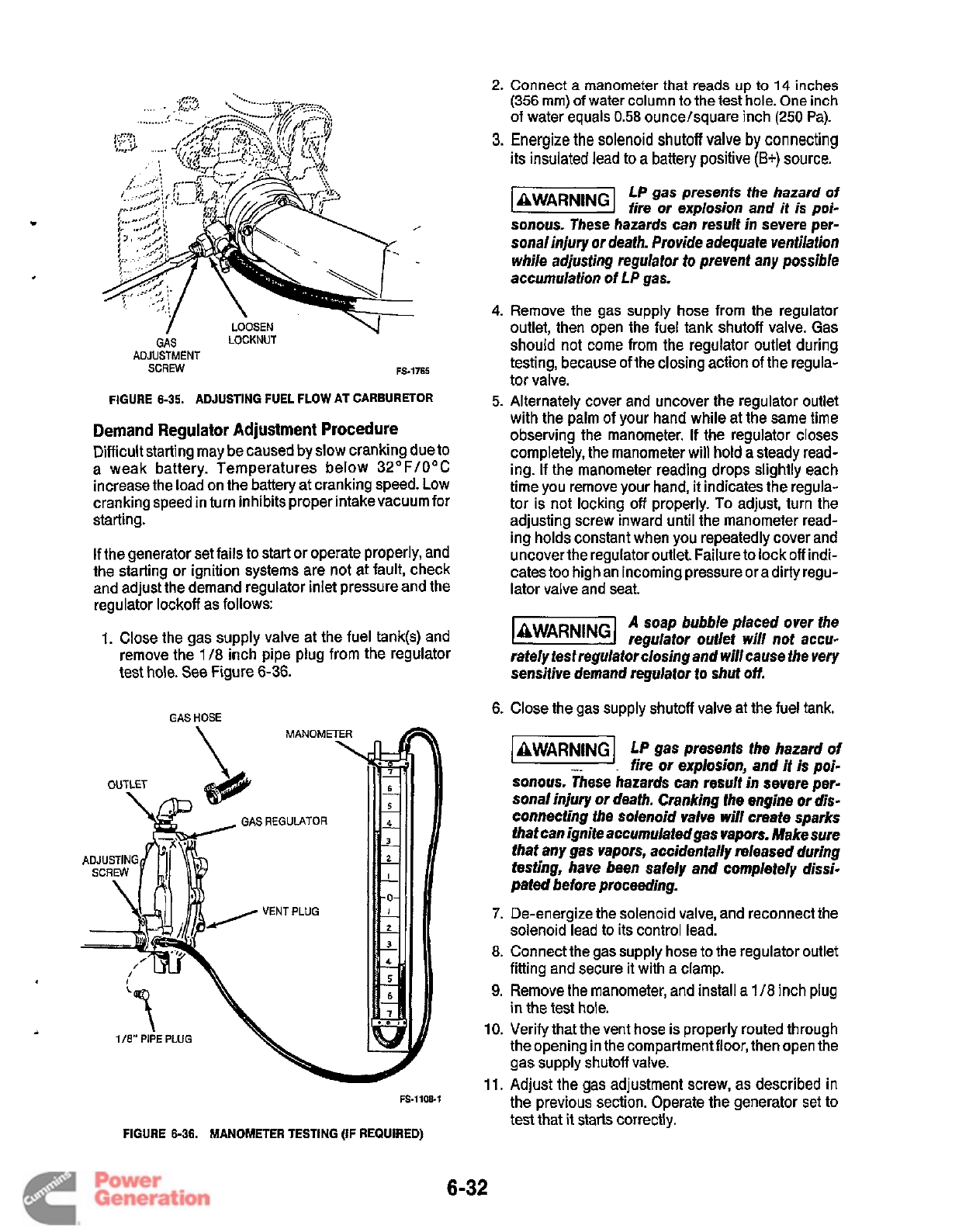
2.
Connect
a
manometer
that
reads
up
to
14
inches
(356
mm)
of
water column to the test hole. One inch
of
water equals
0.58
ounce/square inch (250 Pa).
3.
Energize the
solenoid
shutoff
valve
by
connecting
its insulated lead to
a
battery
positive
(B+)
source.
c
LOOSEN
LOCKNUT
/
GAS
ADJUSTMENT
SCREW
FS-1765
ADJUSTING FUEL FLOW AT CARBURETOR
FIGURE
6-35.
Demand Regulator Adjustment Procedure
Difficult starting may be caused by slow cranking due to
a weak battery. Temperatures below 32OF/OoC
increase the load on the battery at cranking speed. Low
cranking speed in turn inhibits proper intakevacuum for
starting.
If the generator set fails to start or operate properly, and
the starting or ignition systems are not at fault, check
and adjust the demand regulator inlet pressure and the
regulator lockoff as follows:
1.
Close the gas supply valve at the fuel tank(s) and
remove the
1
/8
inch pipe plug from the regulator
test hole. See Figure
6-36.
GAS
HOSE
FS-1108.1
FIGURE
6-36.
MANOMETER TESTING
(IF
REQUIRED)
LP
gas presents
the
hazard of
fire or exp/osion and
it
is
poi-
*WARN"
sonous. These hazards can result in severe per-
sonal injury or death. Provide adequate ventilation
while adjusting regulator to prevent any possible
accumulation of LP gas.
4.
Remove the gas supply hose from the regulator
outlet, then open the fuel tank shutoff valve. Gas
should not come from the regulator outlet during
testing, because of the closing action
of
the regula-
tor valve.
5.
Alternately cover and uncover the regulator outlet
with the palm of your hand while at the same time
observing the manometer. If the regulator closes
completely, the manometer will hold a steady read-
ing.
If
the manometer reading drops slightly each
time you remove your hand, it indicates the regula-
tor is not locking off properly.
To
adjust, turn the
adjusting screw inward until the manometer read-
ing holds constant when you repeatedly cover and
uncover the regulator outlet. Failure to lock off indi-
cates too high an incoming pressure or a dirty regu-
lator valve and seat.
A soap bubble placed over the
laWARNlNGl
regulator outlet will not accu-
rately test regulator closing and will cause the very
sensitive demand regulator
to
shut
off.
6.
Close the gas supply shutoff valve at the fuel tank.
AWARNlNG
LP
gas presents the hazard of
fire or explosion, and
it
is
poi-
sonous. These hazards can result in severe per-
sonal injuty or death. Cranking the engine
or
dis-
connecting the solenoid valve will create sparks
that can ignite accumulatedgas vapors. Make sure
that any gas vapors, accidentally released during
testing, have been safely and completely dissi-
pated before proceeding.
7.
De-energize the solenoid valve, and reconnect the
solenoid lead to its control lead.
8.
Connect the gas supply hose to the regulator outlet
fitting and secure it with a clamp.
9.
Remove the manometer, and install
a
1
/8
inch plug
in the test hole.
10.
Verify that the vent hose is properly routed through
the opening in the compartmentfloor, then open the
gas supply shutoff valve.
11.
Adjust the gas adjustment screw, as described in
the previous section. Operate the generator set to
test that
it
starts correctly.
6-32
Redistribution or publication of this document
by any means, is strictly prohibited.
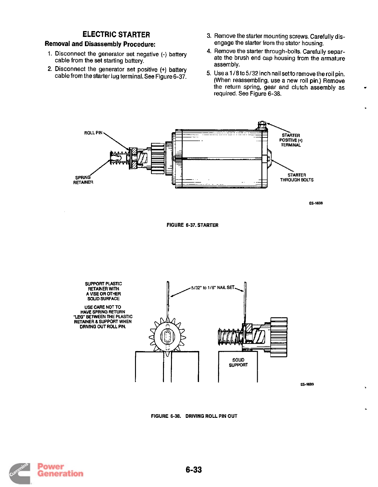
ELECTRIC
STARTER
Removal and Disassembly Procedure:
1.
Disconnect the generator set negative
(-)
battery
cable from the set starting battery.
cable from the starter lug terminal. See Figure 6-37.
3.
Remove the starter mounting screws. Carefully dis-
engage the starter from the stator housing.
4.
Remove the starter through-bolts. Carefully separ-
ate the brush end cap housing from the armature
assembly.
(When reassembling, use a new roll pin.) Remove
the return spring, gear and clutch assembly as
required. See Figure 6-38.
2'
Disconnect
the
generator
set
positive
('1
5.
Uses
1
/8to
5/32 inch nail setto remove the roll pin.
FIGURE
6-37.
STARTER
SUPPORT
PLASTIC
RETAINER
WH
A
VlSE
OR
OTHER
SOUD
SURFACE
USE
CARE NOT
TO
HAM
SPRING
RETURN
RETAlNER
a
SUPPORT
WHEN
DRMNG
OUT
ROU
PIN.
"LEO"
BETWEEN
THE
Pusnc
to
1
ES-1609
.)
FIGURE
6-38.
DRIVING ROLL
PIN
OUT
6-33
Redistribution or publication of this document
by any means, is strictly prohibited.
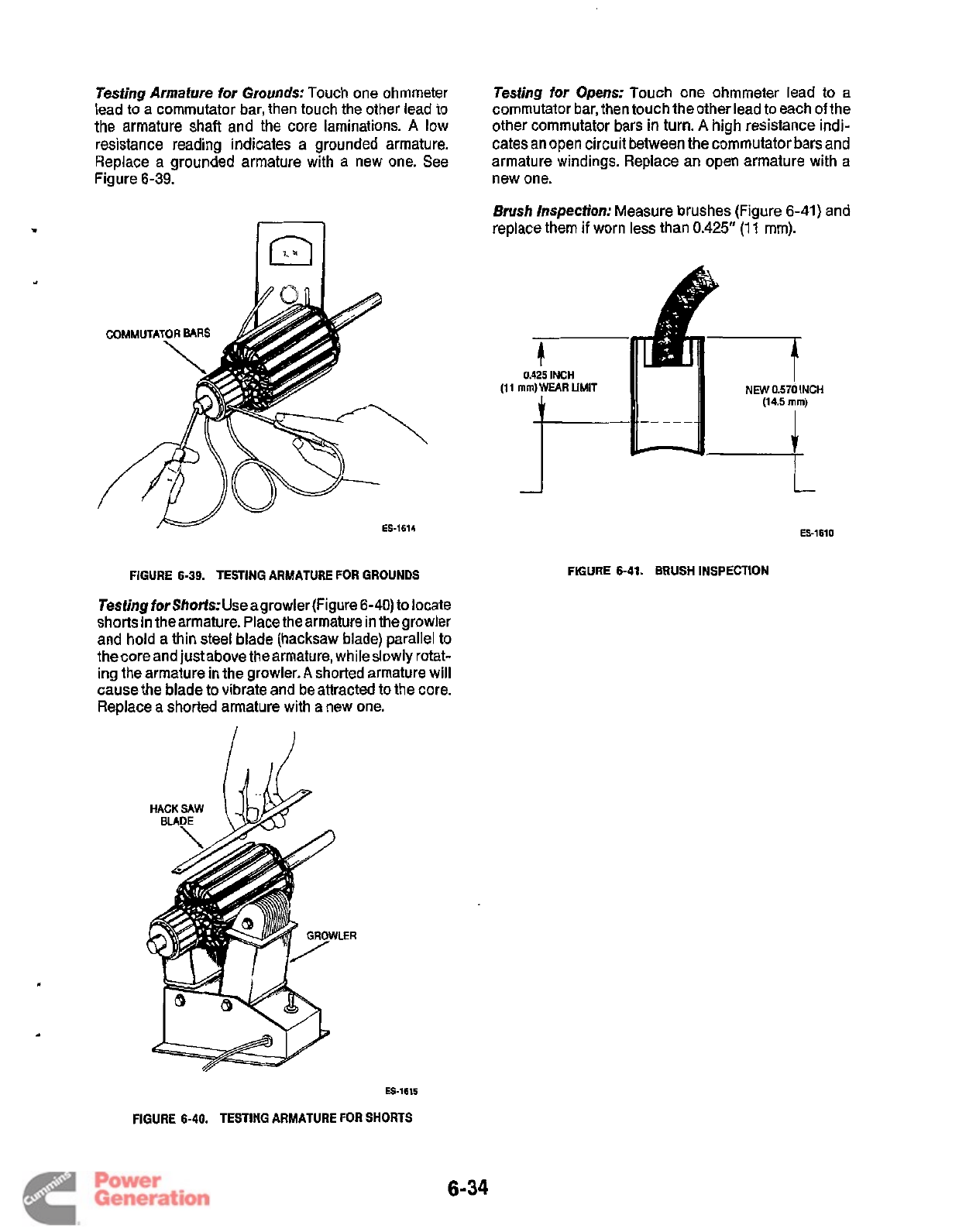
Testing Armature
for
Grounds: Touch one ohmmeter
lead
to
a commutator bar, then touch the other lead to
the armature shaft and the core laminations.
A
low
resistance reading indicates a grounded armature.
Replace a grounded armature with a new one. See
Figure 6-39.
ES-1614
FIGURE
6-39.
TESTING ARMATURE FOR GROUNDS
Testing forShortsAJsea growler(Figure 6-4O)to locate
shorts in thearmature. Place thearmature in the growler
and hold a thin steel blade (hacksaw blade) parallel to
the core and just above thearmature, whileslowly rotat-
ing the armature
in
the growler.
A
shorted armature will
cause the blade to vibrate and be attracted to the core.
Replace a shorted armature with a new one.
LER
Testing for Opens: Touch one ohmmeter lead to
a
commutator bar, then touch the other lead to each
of
the
other commutator bars in turn.
A
high resistance indi-
cates an open circuit between the commutator bars and
armature windings. Replace an open armature with a
new one.
Brush
Inspection: Measure brushes (Figure 6-41) and
replace them
if
worn less than
0.425"
(1
1
mm).
b
0.425
INCH
mm)
WEAR
LIMIT
11
11
NEW0.57d
INCH
A
(14.5
mm)
t-
ES-1610
FIGURE
6-41.
BRUSH INSPECTION
ES-1615
FIGURE
6-40.
TESTING ARMATURE FOR SHORTS
6-34
Redistribution or publication of this document
by any means, is strictly prohibited.
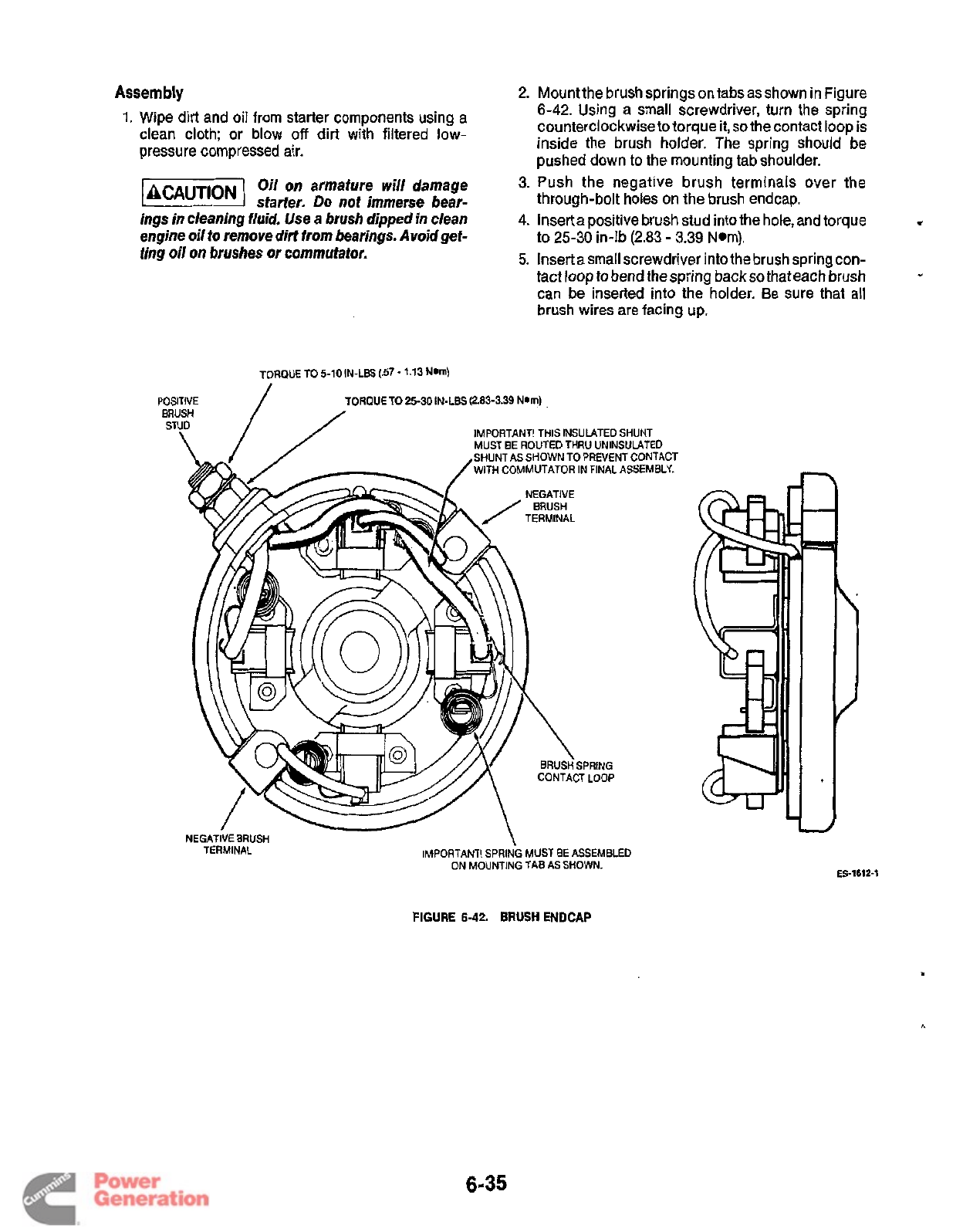
Assembly
1.
Wipe dirt and oil from starter components using a
clean cloth; or blow
off
dirt with filtered low-
pressure compressed air.
Oil on armature will damage
starter.
Do
not immerse bear-
ings in cleaning fluid.
Use
a brush dipped in clean
engine oil
to
remove dirt from bearings. Avoid gef-
fing oil on brushes or commutator.
2.
Mountthe brush springs on tabsasshown in Figure
6-42.
Using a small screwdriver, turn the spring
counterclockwise to torque it,
so
the contact loop is
inside the brush holder. The spring should be
pushed down
to
the mounting tab shoulder.
3.
Push the negative brush terminals over the
through-bolt holes on the brush endcap.
4.
lnserta positive brush stud intothe hole, and torque
to
25-30
in-lb
(2.83
-
3.39
Nom).
5.
Insert asmall screwdriver into the brush spring con-
tact loop to bend the spring back
so
that each brush
can be inserted into the holder. Be sure that all
brush wires are facing up.
1
w
TORQUE TO 5-10 IN-LBS (.57
-
1.13
Nam)
ORQUE TO
25-30
IN-LBS (2.83-3.39 NDm)
IMPORTANT! THIS INSULATED SHUNT
MUST BE ROUTED THRU UNINSULATED
SHUNT AS SHOWN TO PREVENT CONTACT
WITH COMMUTATOR IN FINAL ASSEMBLY.
CONTACT LOOP
IMPORTANT! SPRING MUST BE ASSEMBLED
ON MOUNTING TAB
AS
SHOWN.
NEGATIVE BRUSH
TERMINAL
ES-1612-1
FIGURE
6-42.
BRUSH
ENDCAP
6-35
Redistribution or publication of this document
by any means, is strictly prohibited.
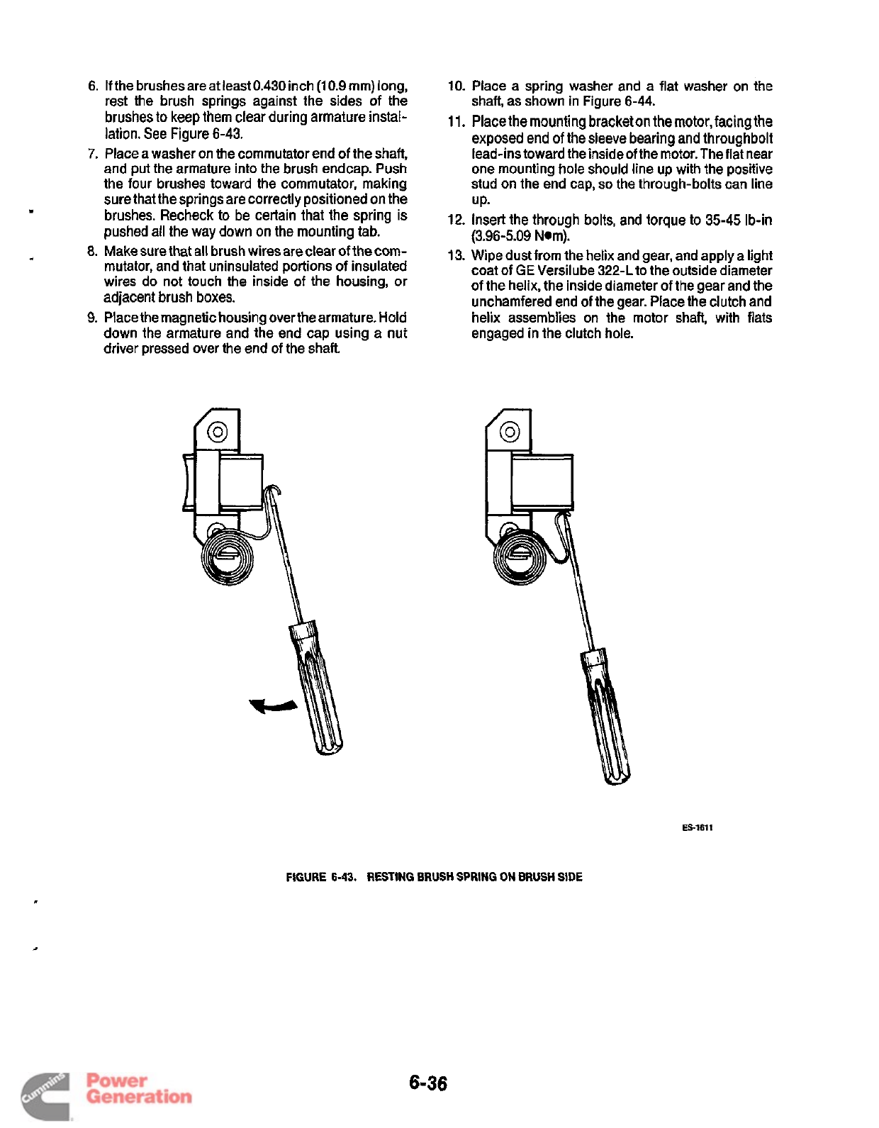
6.
If the brushes are at least
0.430
inch
(1
0.9
mm) long,
rest the brush springs against the sides of the
brushes to keep them clear during armature instal-
lation. See Figure
6-43.
7.
Place a washer on the commutator end of the shaft,
and put the armature into the brush endcap. Push
the four brushes toward the commutator, making
sure that the springsare correctly positioned on the
brushes. Recheck to be certain that the spring
is
pushed all the way down
on
the mounting tab.
8.
Make sure that all brush wires are clear of the com-
mutator, and that uninsulated portions
of
insulated
wires do not touch the inside of the housing, or
adjacent brush boxes.
9.
Place the magnetic housing over the armature.
Hold
down the armature and the end cap using a nut
driver pressed over the end
of
the shaft.
10.
Place a spring washer and a flat washer on the
shaft, as shown in Figure
6-44.
11.
Place the mounting bracket on the motor, facing the
exposed end
of
the sleeve bearing and throughbolt
lead-ins toward the inside of the motor. The flat near
one mounting hole should line up with the positive
stud on the end cap,
so
the through-bolts can line
UP-
12.
Insert the through bolts, and torque
to
35-45
Ib-in
(3.96-5.09
Nom).
13.
Wipe dust from the helix and gear, and apply a light
coat of
GE
Versilube
322-L
to
the outside diameter
of
the helix, the inside diameter of the gear and the
unchamfered end of the gear. Place the clutch and
helix assemblies on the motor shaft, with flats
engaged in the clutch hole.
ES-1611
FIGURE
6-43.
RESTING BRUSH
SPRING
ON
BRUSH
SIDE
6-36
Redistribution or publication of this document
by any means, is strictly prohibited.
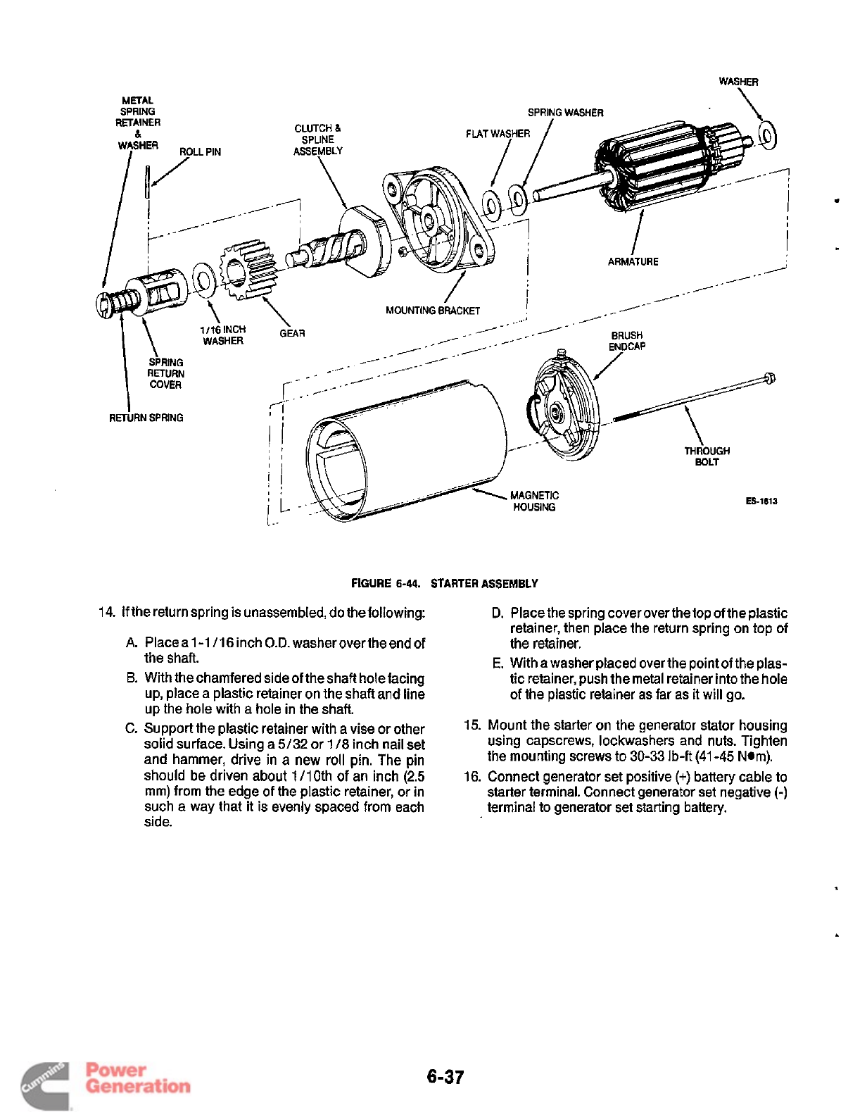
.
ES-1613
FIGURE
6-44.
STARTER ASSEMBLY
14.
If
the return spring is unassembled, do the following:
D.
Place the spring cover over the
top
of the plastic
A.
B.
C.
Place a 1-1
/I6
inch
O.D.
washer over the end of
the shaft.
With thechamfered sideof theshafl hole facing
up, place a plastic retainer on the shaft and line
up the hole with a hole in the shaft.
Support the plastic retainer with a vise or other
solid surface. Using a
5/32
or
118
inch nail set
and hammer, drive in a new
roll
pin. The pin
should be driven about 1110th
of
an inch
(2.5
mm) from the edge
of
the plastic retainer, or in
such a way that
it
is evenly spaced from each
side.
retainer, then place the return spring on top of
the retainer.
E.
With a washer placed over the point
of
the plas-
tic retainer, push the metal retainer into the hole
of the plastic retainer as far as it
will
go.
15.
Mount the starter on the generator stator housing
using capscrews, lockwashers and nuts. Tighten
the mounting screws to
30-33
Ib-ft (41
-45
Nom).
16.
Connect generator set positive
(+)
battery cable to
starter terminal. Connect generator set negative
(-)
terminal to generator set starting battery.
6-37
Redistribution or publication of this document
by any means, is strictly prohibited.
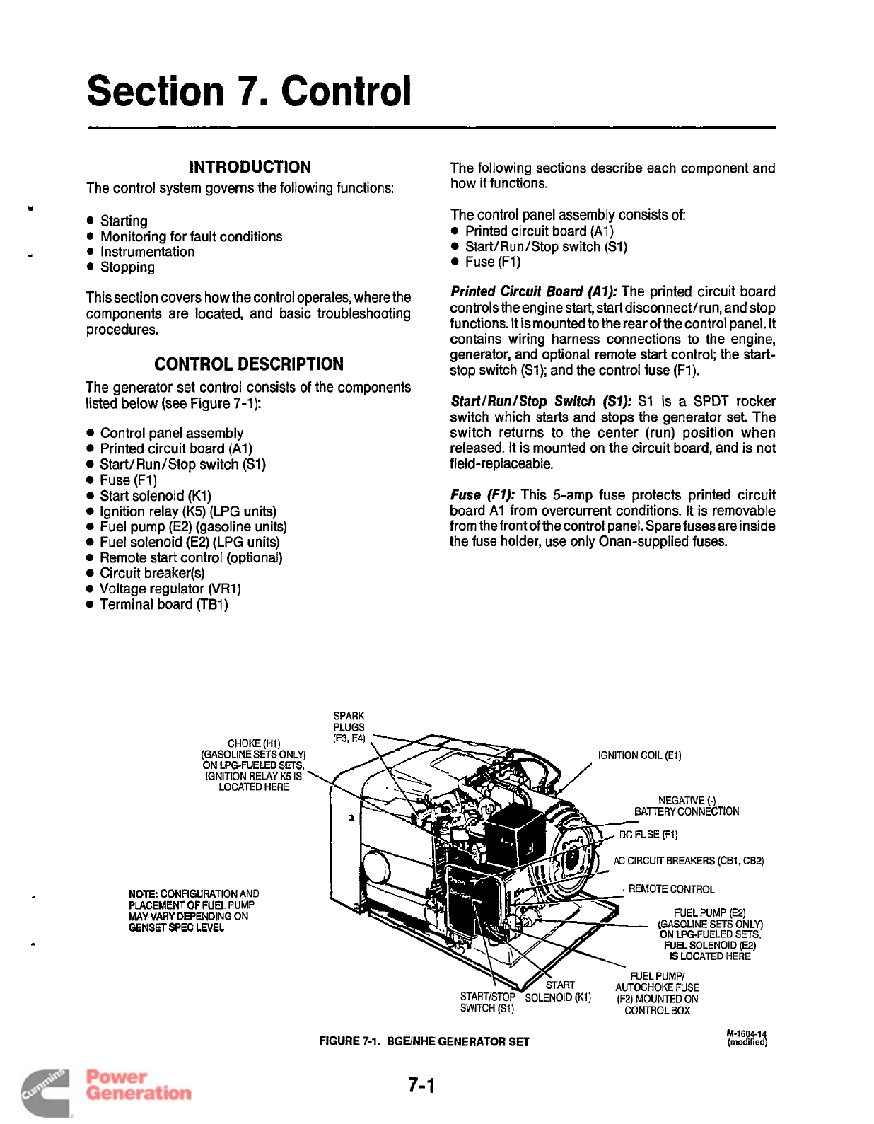
Section
7.
Control
INTRODUCTION
The control system governs the following functions:
Starting
Monitoring for fault conditions
4
0
Instrumentation
Stopping
1
This section covers how the control operates, where the
components are located, and basic troubleshooting
procedures.
CONTROL
DESCRIPTION
The generator set control consists of the components
listed below
(see
Figure
7-1):
0
0
0
0
0
0
0
0
0
0
0
0
Control panel assembly
Printed circuit board
(Al)
Start/Run/Stop switch
(Sl)
Fuse (FI)
Start solenoid
(Kl)
Ignition relay
(K5)
(LPG units)
Fuel pump
(E2)
(gasoline units)
Fuel solenoid
(E2)
(LPG units)
Remote start control (optional)
Circuit breaker(s)
Voltage regulator
(VR1)
Terminal board (TBl)
CHOKE (Hl)
(GASOLINE
SETS
ONLY)
IGNITION RELAY K5
IS
LOCATED HERE
ON LPG-FUELED
SETS,
NOTE CONFIGURATION AND
PLACEMENT
OF
FUEL PUMP
MAY VARY DEPENDING
ON
GENSET SPEC LEVEL
The following sections describe each component and
how
it
functions.
The control panel assembly consists
of:
0
Printed circuit board (Al)
Start/Run/Stop switch
(Sl)
0
Fuse(F1)
Printed Circuit Board
(AI):
The printed circuit board
controls the engine start, startdisconnect/run, and stop
functions.
It
is mounted to the rear of the control panel. It
contains wiring harness connections to the engine,
generator, and optional remote start control; the start-
stop switch
(Sl);
and the control fuse (Fl).
Start/Run/Stop Switch
(SI):
S1
is
a
SPDT
rocker
switch which starts and stops the generator set. The
switch returns to the center (run) position when
released. It is mounted on the circuit board, and is not
field-replaceable.
fuse
(FI):
This 5-amp fuse protects printed circuit
board
A1
from overcurrent conditions.
It
is removable
from the front of the control panel. Spare fuses are inside
the fuse holder, use only Onan-supplied fuses.
SPARK
PLUGS
I
IGNITION COIL (El)
NEGATIVE
(-)
BATTERY CONNECTION
C CIRCUIT BREAKERS (CB1,
CB2)
REMOTE CONTROL
FUEL PUMP
(E2)
-
(GASOLINE
SETS
ONLY)
ON LPG-FUELED
SETS,
FUEL SOLENOID
(E)
IS
LOCATED HERE
y!
START AUTOCHOKE FUEL PUMP/ FUSE
START/STOP SOLENOID
(K1)
(F2) MOUNTED ON
SWITCH (Sl) CONTROL
BOX
M-1604-14
FIGURE
7-1.
BGUNHE
GENERATOR
SET
(modified)
7-
1
Redistribution or publication of this document
by any means, is strictly prohibited.
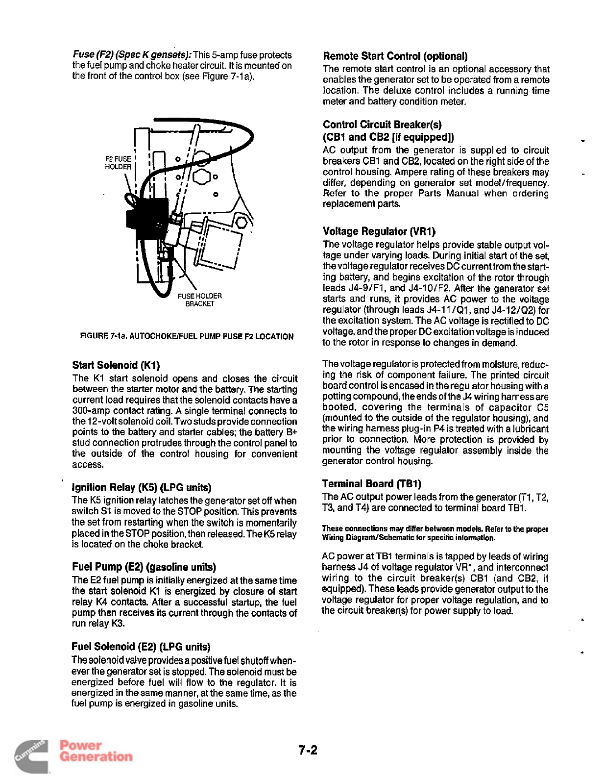
Fuse
(F2)
(Spec Kgensets):This 5-amp fuse protects
the fuel pump and choke heater circuit.
It
is mounted
on
the front of the control box (see Figure 7-1 a).
F2
FU
HOLD
BRACKET
FIGURE 7-la. AUTOCHOKWFUEL PUMP FUSE F2 LOCATION
Start Solenoid (KI)
The K1 start solenoid opens and closes the circuit
between the starter motor and the battery. The starting
current load requires that the solenoid contacts have a
300-amp contact rating.
A
single terminal connects to
the 12-volt solenoid coil.Two studs provide connection
points to the battery and starter cables; the battery B+
stud connection protrudes through the control panel to
the outside of the control housing for convenient
access.
Ignition Relay (K5) (LPG units)
The K5 ignition relay latches the generator set
off
when
switch S1 is moved to the STOP position. This prevents
the set from restarting when the switch is momentarily
placed in the STOP position, then released. The K5 relay
is located on the choke bracket.
Fuel Pump
(E2)
(gasoline units)
The
E2
fuel pump is initially energized at the same time
the start solenoid K1 is energized
by
closure of start
relay K4 contacts. After a successful startup, the fuel
pump then receives its current through the contacts of
run relay K3.
Fuel Solenoid (E2) (LPG units)
The solenoidvalve providesa positive fuel shutoff when-
ever the generator set is stopped. The solenoid must be
energized before fuel will flow to the regulator. It is
energized in the same manner, at the same time, as the
fuel pump is energized in gasoline units.
Remote Start Control (optional)
The remote start control is an optional accessory that
enables the generator set to be operated from a remote
location. The deluxe control includes a running time
meter and battery condition meter.
Control Circuit Breaker(s)
(CB1
and
CB2
[if
equipped])
AC output from the generator is supplied
to
circuit
breakers CB1 and CB2, located on the right side of the
control housing. Ampere rating of these breakers may
differ, depending on generator set modeVfrequency.
Refer to the proper Parts Manual when ordering
replacement parts.
.
Voltage Regulator (VR1)
The voltage regulator helps provide stable output vol-
tage under varying loads. During initial start of the set,
thevoltage regulator receives DC currentfrom thestart-
ing battery, and begins excitation of the rotor through
leads J4-9/FIl and J4-101F2. After the generator set
starts and runs,
it
provides AC power to the voltage
regulator (through leads J4-11 /Q1, and J4-12/Q2) for
the excitation system. The AC voltage is rectified to
DC
voltage, and the proper DC excitation voltage is induced
to the rotor in response to changes in demand.
Thevoltage regulator is protected from moisture, reduc-
ing the risk of component failure. The printed circuit
board control is encased in the regulator housing with a
potting compound, the ends
of
the 54 wiring harnessare
booted, covering the terminals of capacitor C5
(mounted to the outside of the regulator housing), and
the wiring harness plug-in P4 is treated with a lubricant
prior to connection. More protection
is
provided by
mounting the voltage regulator assembly inside the
generator control housing.
Terminal Board UBI)
The AC output power leads from the generator (Tl, T2,
T3, and T4) are connected to terminal board TB1.
These connections may differ between models. Refer
to
the proper
Wiring Diagram/Schematic
for
specific information.
AC power at TB1 terminals is tapped by leads of wiring
harness J4 of voltage regulator
VR1,
and interconnect
wiring to the circuit breaker(s) CB1 (and CB2,
if
equipped). These leads provide generator output to the
voltage regulator for proper voltage regulation, and
to
the circuit breaker(s) for power supply to load.
1
7-2
Redistribution or publication of this document
by any means, is strictly prohibited.
CONTROL
OPERATION
The schematic diagram shown in Figure 7-2 is intended
as
an
illustration of the circuit description. However,
when troubleshooting, always refer to the wiring dia-
gram that corresponds to the model and spec numbers
of
the generator set.
m
Starting
Placing the Start/Run/Stop switch in the Start position
connects battery ground
(B-)
to the K4 start relay. This
energizes K4, which closes the normally open
(N.O.)
contacts that connect battery positive
(B+)
to the
following:
0
N.C.
contacts of
K2
generator relay
Generator voltage regulator
Ignition coil (Tl)
0
Fuel pump or solenoid valve (E2)
0
Start solenoid (Kl)
Connecting
B+
produces the following control re-
sponses:
Flashes the field, to ensure that there is adequate
residual magnetism to induce voltage buildup.
Energizes the ignition coil (Tl),
so
it
can begin pro-
ducing a spark when ignition module S3 is activated
(prior to Spec G, breaker point ignition is used.)
Energizes the start solenoid (Kl), which closes its
N.O.
contacts in the starter motor circuit.
(Gasoline units) Energizes the fuel pump (E2), which
begins pumping fuel to the carburetor.
(LPG units) Energizes the fuel solenoid (E2), which
allows LPG to flow to the vaporizer and the
regulator.
Energizes the stop latch (ignition) relay (K5) to open
its contacts to ground, which allows run relay K3 to
be energized through closure of oil pressure switch
S2 after engine startup.
Starter
Lockout-Run
When start-stop switch
S1
is released and returns to the
center
(run)
position,
the enginecontinues to
run.
Relays
K2
(generator relay),
K3
(run
relay),
and
K5
(ignition
relay [LPG sets only]) are energized while relays
K1
(start solenoid) and K4 (start relay) are de-energized.
Energizing
K2
opens a set of contacts to de-energize
K4, and closes another set
of
contacts to connect
B+
to
the generator start disconnect/run relay (k3). Energiz-
ing K3 closes a set
of
contacts which provides an alter-
nate
B+
circuit to
T1
ignition coil and El fuel pump/fuel
solenoid.
De-energizing K4 opens contacts which de-energize
the
K1
start solenoid. De-energizing
K1
disconnects
B+
from the starter motor, which stops cranking.
Opening these
K4
contacts at this time has no effect on
engine operation, because they are in parallel with the
closed K3 contacts which connect
B+
to the ignition coil
and the fuel pumplfuel solenoid.
When start-stop switch S1 is released and returns to the
center (run) position, the engine continues to run.
Relays K2 (generator relay), K3 (run relay), and K5 (igni-
tion relay ([LPG sets only]) are energized while relays K2
(start solenoid) and K4 start relay) are de-energized.
Stopping
Moving start-stop switch S1 to the STOP position
grounds resistors R1 and R2 to de-energize run relay
K3. This opens its contacts to disconnect
B+
from igni-
tion coil TI, fuel pump/fuel solenoid E2, and (on LPG
sets) ignition relay
K5.
De-energizing
K5
allows its N.C.
contacts to close to ground.This prevents K3 from being
energized, and prevents the set from restarting when
switch S1
is
released from the STOP position.
Without ignition orfue1,theengine stops. Asthegenera-
tor output voltage drops, generator relay K2 also de-
energizes. All components return to their de-energized
position following set shutdown.
Closing the K1 start solenoid contacts connects
B+
to
the starter motor. This energizes the starter motor,
which begins
to
crank the engine to initiate starting.
7-3
Redistribution or publication of this document
by any means, is strictly prohibited.
TESTING
CONTROL
BOARD
AI
Confirm that control board
A1
is faulty before replacing
it.
Use a
DC
voltmeter and an ohmmeter to perform the
following tests.
VR1
T1
S3
52
R6
R5
K5
1.
Disconnect the negative
(-)
battery cable.
2.
Remove the control box cover (Figure 7-3) and
separate it from control board
A1
by removing the
four screws on the back of the board.
3. With an ohmmeter, check for electrical continuity
across each Pl/Jl and P3/J3 connector on the
control board (Figures 7-2 and
7-4).
Replace the
socket portion
of
each connector that has a measu-
rable resistance (greater than zero ohms) or has
begun to corrode.
4.
Reconnect the battery and try to start and run the
set.
5.
If
the engine does not crank, measure voltage at
connector
P1-2
while pressing the panel start
switch (the negative
(-)
test probe
of
the voltmeter
should be grounded at connector P1-8).
If
the volt-
meter indicates zero volts, and if fuse F1 is good,
replace control board
Al.
If
the voltmeter indicates
at least
9
volts, the problem is not with the control
board.
Go
back to the
Troubleshooting Guide.
6.
If
the engine cranks, but does not start, measure
voltage at connectors P3-3 and P3-6 while the
engine is cran king (the negative
(-)
test probe of the
voltmeter should be grounded at connector
P1-8).
Replace control board
A1
if the voltmeter indicates
zero volts at either connector. If the voltmeter indi-
cates at least
9
volts at both connectors, the prob-
lem is not with the control board.
Go
back to the
Troubleshooting Guide.
7.
If
the engine starts, but stops when the Start switch
is released, the problem could be with the
low
oil
pressure switch or generator (no voltage).
Go
back
to the
Troubleshooting Guide.
Replace control
board
A1
if the oil pressure switch and generator
are functioning properly.
8.
Reassemble the control board and cover.
Voltage Regulator
Ignition Coil
Ignition Module
Switch-Low Oil Pressure
Resistor-Battery Charge
Potentiometer
Relav-LPG Onlv
I'
'.r
r:'
HI
G1
F1
E34
E2
CR9
CB1,2
I
Item
1
DescriDtion
of
Material
I
Choke-Gasoline Only
Generator
Fuse-Slow Blow 5A
Spark Plugs
Fuel Pump or Fuel Solenoid
Rectifier-LPG Only
Circuit Breaker (AC Output)
A1
I
K1
I
Relav-Start Solenoid
I
Control Assy
-
BGElBGEL
~4.5
I
Capacitor
BT1
I
Battery
-
12V
E1
I
Starter Motor
A3
I
Remote Control-Standard
61
1-1
190
A2
AI
I
Remote Control
-
Deluxe
I
Control
ASSY
-
NHEINHEL
7-4
Redistribution or publication of this document
by any means, is strictly prohibited.
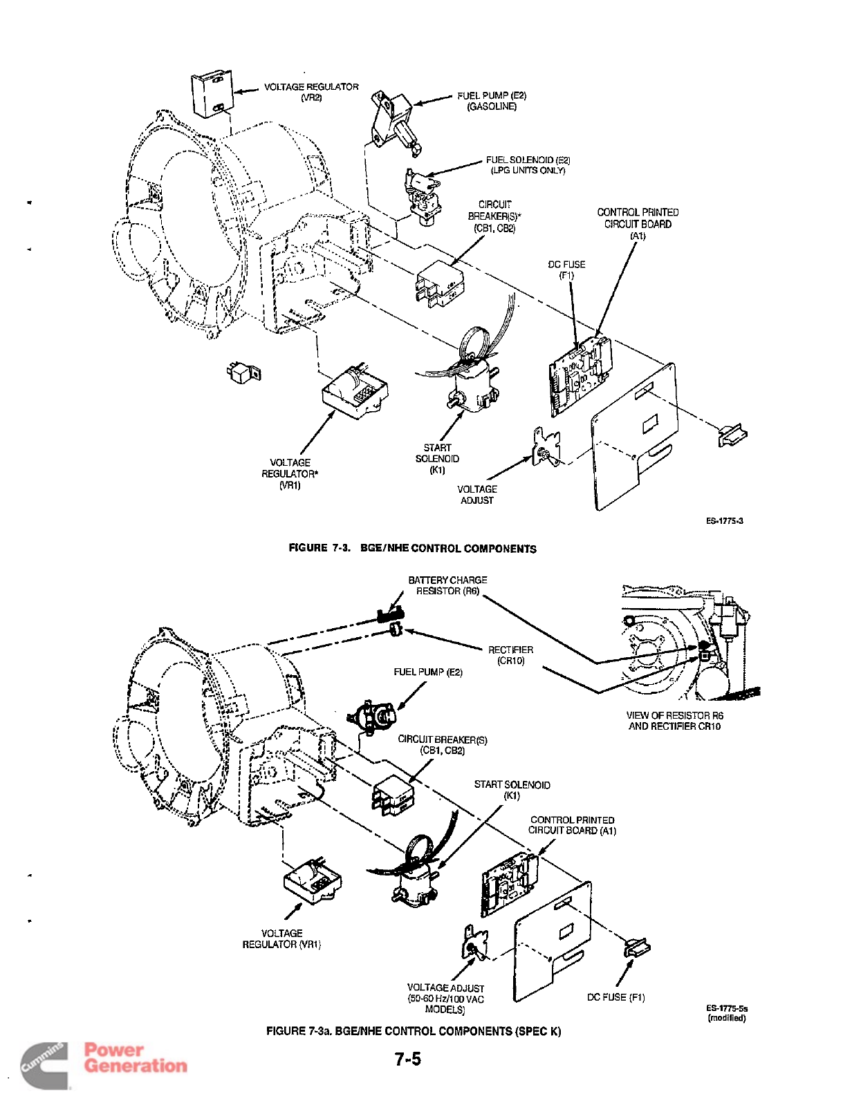
8
ES-1775-3
FIGURE
7-3.
BGElNHE CONTROL COMPONENTS
FIGURE 7-3a. BGE/NHE CONTROL COMPONENTS (SPEC
K)
7-5
Redistribution or publication of this document
by any means, is strictly prohibited.
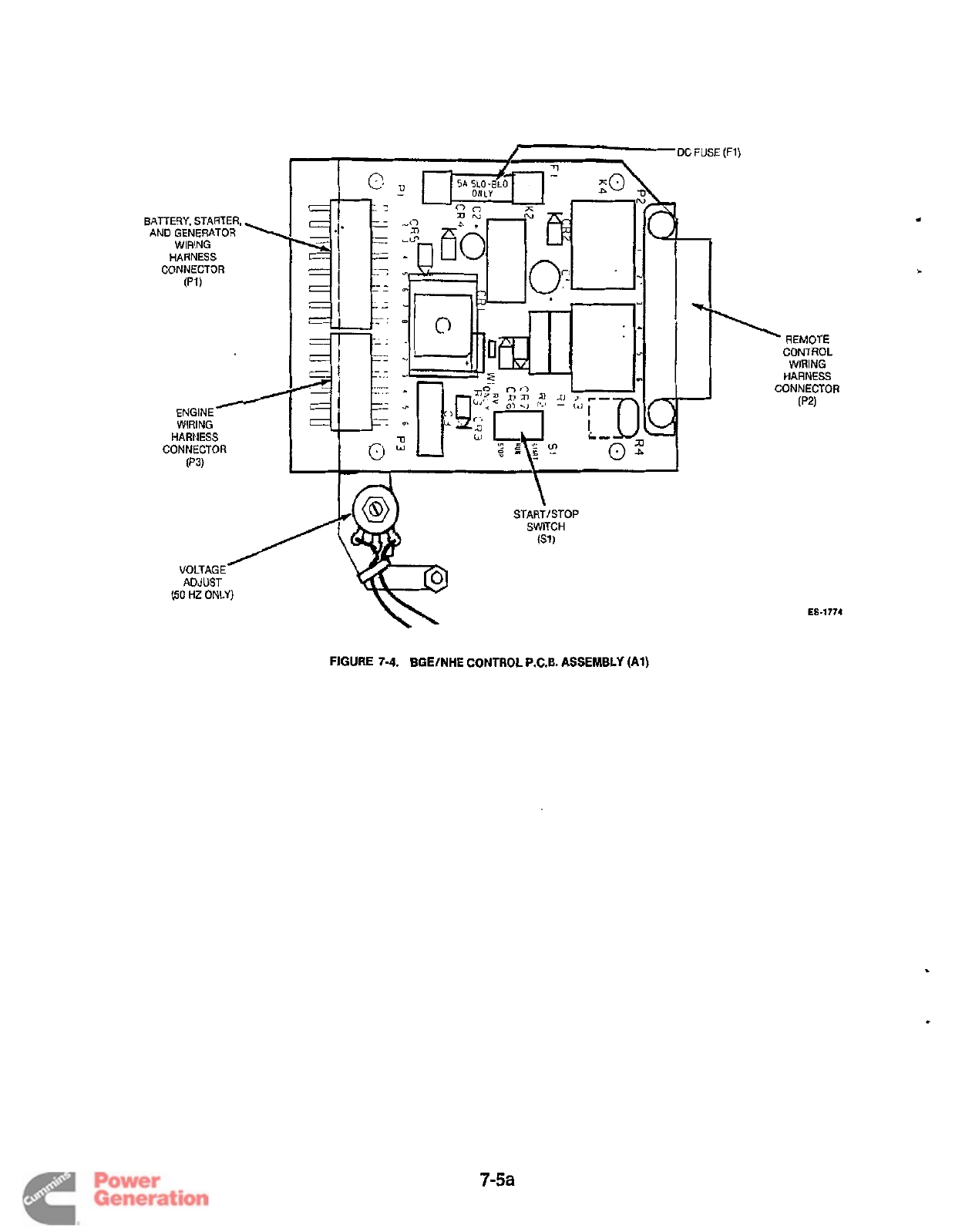
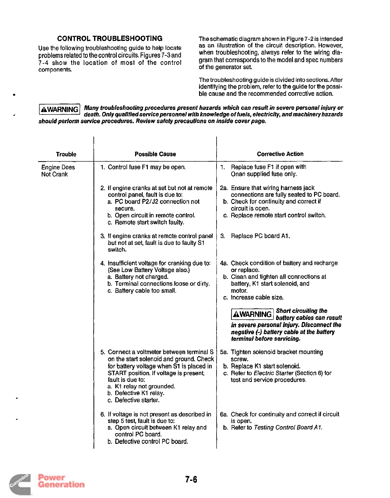
CONTROL
TROUBLESHOOTING
Theschematic diagram shown in Figure
7-2
is intended
Use the following troubleshooting guide
to
help
locate
problemsrelated
to
the control circuits. Figures
7-3
and
7-4
show
the location
of
most
of
the
control
components.
of
the generator set.
as an illustration of the circuit description. However,
when troubleshooting, always refer to the wiring dia-
gram that correspondsto the model
and
spec numbers
The troubleshooting guide is divided into sections. After
identifying the problem, refer to the guide for the possi-
ble cause and the recommended corrective action.
Many troubleshooting procedures presenf hazards which can result in severe personal injury or
death. Only qualifiedservice personnel with knowledge of fuels, elecfricity, andmachineryhazards
should periorm service procedures. Review safety precautions on inside cover page.
Trouble
I
Possible Cause Corrective Action
Engine Does
Not Crank
1.
Control fuse
F1
may be open.
2.
If
engine cranks at set but not at remote
control panel, fault is due to:
a. PC board
P2/J2
connection not
b. Open circuit in remote control.
c. Remote start switch faulty.
secure.
3.
If
engine cranks
at
remote control panel
but not at set, fault is due to faulty
S1
switch.
4.
Insufficient voltage for cranking
due
to:
(See
Low
Battery Voltage also.)
a. Battery not charged.
b. Terminal connections loose or dirty.
c. Battery cable too small.
5.
Connect a voltmeter between terminal
S
on the start solenoid and ground. Check
for battery voltage when S1 is placed in
START position.
If
voltage
is
present,
fault
is
due
to:
a.
K1
relay not grounded.
b. Defective
K1
relay.
c. Defective starter.
6.
If
voltage is not present as described in
step
5
test, fault is due to:
a. Open circuit between
K1
relay and
b.
Defective control
PC
board.
control PC board.
1.
Replace fuse
F1
if
open with
Onan supplied fuse only.
2a. Ensure that wiring harness jack
connections are fully seated to PC board.
circuit is open.
b. Check for continuity and correct
if
c. Replace remote start control switch.
3.
Replace
PC
board Al.
4a.
Check condition of battery and recharge
or replace.
battery,
Kl
start solenoid, and
motor.
b. Clean and tighten all connections at
c. Increase cable size.
Short circuiting the
@@@%I
batterv cables can result
in severe personal injiry, Disconnect the
negative
(-1
battery cable at fhe battery
terminal before servicing.
5a.
Tighten solenoid bracket mounting
screw.
test and service procedures.
b.
Replace
K1
start solenoid.
c. Refer to Nectric
Starter
(Section 6) for
6a. Check for continuity and correct if circuit
is open.
b.
Refer to Testing Control
Board
A
7.
7-6
Redistribution or publication of this document
by any means, is strictly prohibited.
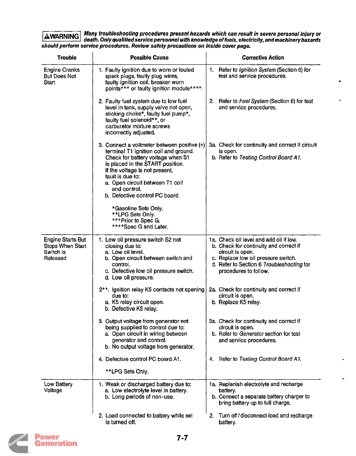
Many troubleshooting procedures present hazards which can result in severe personal injury or
@@!@%I
death. On/y qualified service personnel with knowledge
of
fuels, electricity, andmachinery hazards
should perform service procedures. Review safety precautions on inside cover page.
Trouble
Engine Cranks
But Does Not
Start
Engine Starts But
Stops When Start
Switch is
Released
Low Battery
Voltage
Possible
Cause
1. Faulty ignition due to worn or fouled
spark plugs, faulty plug wires,
faulty ignition coil, breaker worn
points***
or
faulty ignition module****.
2.
Faulty fuel system due to low fuel
level in tank, supply valve not open,
sticking choke*, faulty fuel pump*,
faulty fuel solenoid**,
or
carburetor mixture screws
incorrectly adjusted.
3.
Connect a voltmeter between positive
(+]
terminal
Ti
ignition coil and ground.
Check for battery voltage when
S1
is placed in the START position.
If the voltage is not present,
fault is due to:
a. Open circuit between
T1
coil
and control.
b.
Defective control
PC
board.
*Gasoline Sets Only.
**LPG
Sets Only.
***Prior to Spec
G.
****Spec
G
and Later.
1.
Low oil pressure switch
S2
not
closing due to:
a.
Low
oil level.
b. Open circuit between switch and
control.
c.
Defective
low
oil pressure switch.
d. Low oil pressure.
2**.
lgnition relay
K5
contacts not opening
due to:
a.
K5
relay circuit open.
b.
Defective
K5
relay.
3.
Output voltage from generator not
being supplied to control due to:
a. Open circuit in wiring between
b.
No
output voltage from generator.
generator and control.
4.
Defective control
PC
board
A1
.
**LPG Sets Only.
1.
Weak
or
discharged battery due to:
a. Low electrolyte level in battery.
b. Long periods of non-use.
2.
Load connected to battery while set
is turned
off.
Corrective Action
1. Refer to
lgnition System
(Section
6)
for
test and service procedures.
2.
Refer to
Fuel System
(Section
6)
for test
and service procedures.
3a. Check for continuity and correct
if
circuit
is open.
b. Refer to
Testing
Control
Board
A
7.
la. Check
oil
level and add oil if low.
b. Check for continuity and correct
if
c. Replace low oil pressure switch.
d.
Refer
to
Section
6
Troubleshooting
for
circuit is open.
procedures to follow.
2a. Check for continuity and correct
if
circuit is open.
b.
Replace
K5
relay.
3a. Check for continuity and correct
if
b. Refer to
Generator
section for test
circuit
is
open.
and service procedures.
4.
Refer
to
Testing
Control
Board
A
1.
c
la. Replenish electrolyte and recharge
battery.
bring battery up to full charge.
2.
Turn
off
/disconnect load and recharge
battery.
b. Connect a separate battery charger to
7-7
Redistribution or publication of this document
by any means, is strictly prohibited.
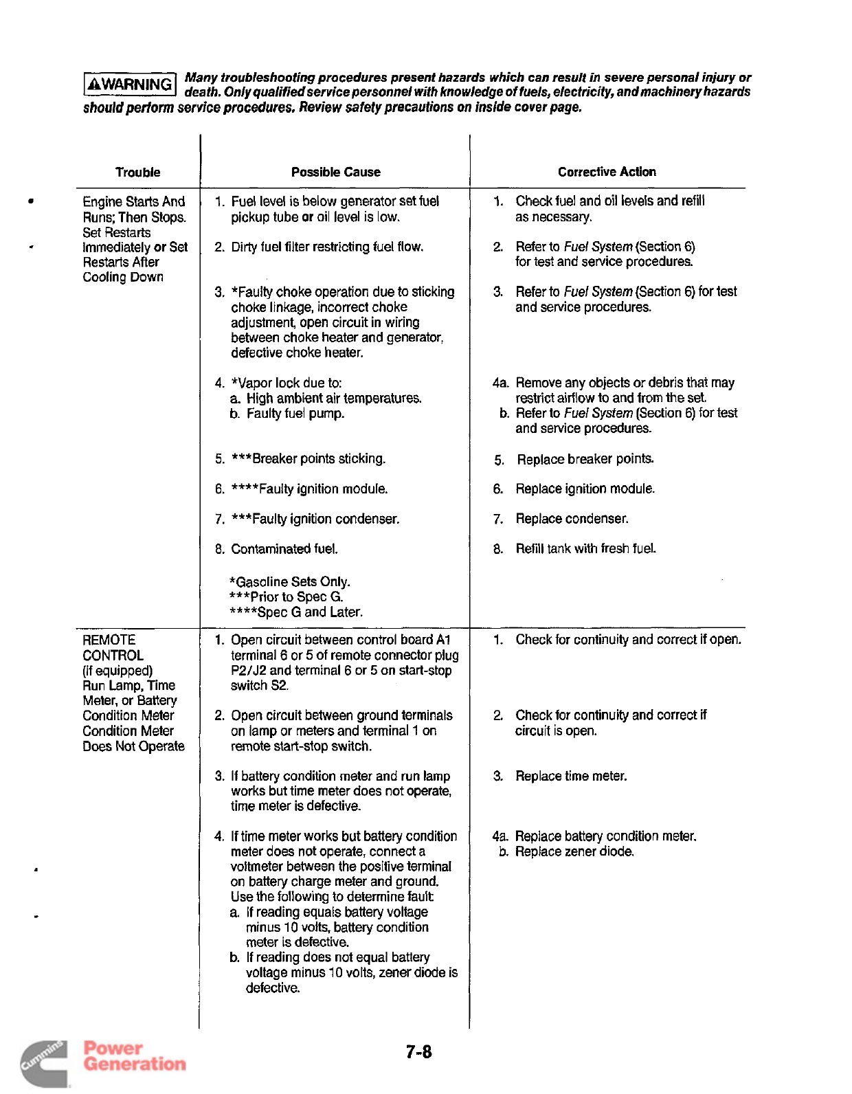
Many troubleshooting procedures present hazards which can result in severe personal injury or
deafh. Only qualifiedservice personnel
wifh
knowledge
of
fuels, electricity, andmachineryhazards
should
perform service procedures. Review safety precautions
on
inside cover page.
Trouble
Engine Starts And
.
Immediately
or
Set
Runs; Then Stops.
Set Restarts
Restarts After
Cooling Down
REMOTE
CONTROL
(if equipped)
Run Lamp, Time
Meter, or Battery
Condition Meter
Condition Meter
Does Not Operate
Possible Cause
1.
Fuel level
is
below generator set fuel
pickup tube
or
oil level
is
low.
2.
Dirty fuel filter restricting fuel
flow.
3.
"Faulty choke operation due
to
sticking
choke linkage, incorrect choke
adjustment, open circuit in wiring
between choke heater and generator,
defective choke heater.
4.
*Vapor lock due to:
a.
High ambient air temperatures.
b. Faulty fuel pump.
5.
***Breaker points sticking.
6.
****Faulty ignition module.
7.
***Faulty ignition condenser.
8.
Contaminated fuel.
*Gasoline Sets Only.
***Prior to Spec
G.
****Spec
G
and Later.
1.
Open circuit between control board A1
terminal
6
or
5
of remote connector plug
P2/J2
and terminal
6
or
5
on start-stop
switch
S2.
2.
Open circuit between ground terminals
on lamp or meters and terminal 1 on
remote start-stop switch.
3.
If battery condition meter and run lamp
works but time meter does not operate,
time meter is defective.
4.
If time meter works but battery condition
meter does not operate, connect a
voltmeter between the positive terminal
on battery charge meter and ground.
Use the following
to
determine
fault
a. If reading equals battery voltage
minus
10
volts, battery condition
meter is defective.
b.
If reading does not equal battery
voltage minus 10 volts, zener diode is
defective.
Corrective Action
1.
Check fuel and oil levels and refill
as necessary.
2.
Refer to
Fuel
System (Section
6)
for test and service procedures.
3.
Refer to
he/
System (Section
6)
for test
and service procedures.
4a. Remove any objects or debris that may
restrict airflow to and from the set
b. Refer to
Fuel
System (Section
6)
for test
and service procedures.
5.
Replace breaker points.
6.
Replace ignition module.
7.
Replace condenser.
8.
Refill
tank
with fresh fuel.
-
1. Check for continuity and correct if open.
2.
Check for continuity and correct if
circuit is open.
3.
Replace time meter.
4a.
Replace battery condition meter.
b. Replace zener diode.
7-8
Redistribution or publication of this document
by any means, is strictly prohibited.
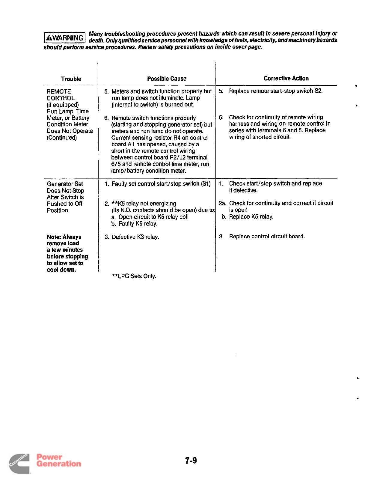
Many troubleshooting procedures present hazards which can result in severe personal injury
or
death. Only qualified service personnel with knowledge of fuels, electricity, and machinery hazards
should perform service procedures. Review safety precautions on inside cover page.
Trouble
REMOTE
CONTROL
(if
equipped)
Run Lamp, Time
Meter, or Battery
Condition Meter
Does Not Operate
(Continued)
Generator Set
Does
Not
Stop
After Switch is
Pushed to
Off
Position
Note: Always
remove load
a
few minutes
before stopping
to allow set to
cool down.
Possible Cause
5.
Meters and switch function properly but
run lamp does not illuminate. Lamp
(internal to switch) is burned out.
6.
Remote switch functions properly
(starting and stopping generator set) but
meters and run lamp do not operate.
Current sensing resistor
R4
on control
board
Ai
has opened, caused by a
short in the remote control wiring
between control board
P2/J2
terminal
6/5
and remote control time meter, run
lamplbattery condition meter.
1.
Faulty set control start/stop switch
(Sl)
2.
**K5
relay not energizing
(its
N.O.
contacts should be open) due
tc
a. Open circuit to
K5
relay coil
b.
Faulty
K5
relay.
3.
Defective
K3
relay.
Corrective Action
s
5.
Replace remote start-stop switch
S2.
6.
Check for continuity of remote wiring
harness and wiring on remote control in
series with terminals
6
and
5.
Replace
wiring of shorted circuit.
1.
Check start/stop switch and replace
if
defective.
2a.
Check for continuity and correct if circuit
is open
b.
Replace
K5
relay.
3.
Replace control circuit board.
**LPG Sets Only.
7-9
Redistribution or publication of this document
by any means, is strictly prohibited.
Section
8.
Generator
GENERATORKONTROL
COMPONENT DESCRIPTIONS
The generator and its control components consist
of
the
following: (Refer to Figure 8-1.)
*
0
0
0
0
0
0
0
0
Control Printed Circuit Board
(Al)"
Brushes
Rotor
Stator and Housing
Terminal Board (TB1)
Voltage Regulator (VR1)
Circuit Breaker(s) (CB1, and CB2 if equipped)
Wiring Harness to Load(s)
*Refer to Section
7,
Control, for further information.
Control Printed
Circuit
Board (Al)
Initial excitation voltage to the generator rotor is supplied by
the generator set starting battery BT1. During cranking of
the engine, DC voltage of the battery is supplied through
N.C. contacts of generator relay
K2
(on control board
Al),
through the voltage regulator
VRl
,
to the brushes and slip
rings of the rotor. Upon successful engine start and genera-
tor voltage build-up, generator relay
K2
becomes ener-
gized, which 0penstheN.C. contacts in the battery
B+
circuit
to the voltage regulator and closes
a
set of
N.O.
contacts in
the start disconnect/run relay K3 circuit of board Al. This
circuit keeps relay K3 energized while the set is in operation.
If
relay
K2
becomes de-energized, the set will shut down.
Brushes
DC excitation voltage is induced through the brushes and
rotor slip rings
to
the rotor windings. The brush block
assembly consists of asingle brush block with
two
brushes.
The brush block mounts inside the generator housing,
directly over the rotor slip rings, and can be accessed by
removing the small plate at the rear of the housing.
Rotor
The 4-pole rotor provides the rotating magnetic field that is
required for generating an
AC
voltage potential in the stator
windings. The DC current required for field excitation is
supplied through twoslip rings that mount on the rotor shaft
The inner end
of
the rotor is connected directly tothe engine
crankshaft using a tapered seatishaft coupling and
through-bolt The outer end of the rotor
is
supported
by
a
single bearing that is pressed onto the rotor shaft The
bearing fits inside the generator housing.
Cooling airflow for the generator is provided by a centrifugal
fan that mounts on the inner end of the rotor shaft. The fan
also serves as a mount for the starter ring gear.
Stator and Housing
During generator set operation, AC current is produced in
the windings
of
the stator.
All
stator winding
leads
are routed
into the generator set control housing compartment, for
control component connection as follows:
0
Leads T1, T2, T3, and 14 to Terminal Board TB1, for
supplying power to load.
0
Leads B1 and B2 to Control Board All wiring harness
J1
,
for supplying power to generator relay
K2.
0
Leads
Q1
and
Q2
to
Voltage Regulator
VR1,
wiring
harness J4, for excitation voltage
of
rotor. (AC voltage
from stator is rectified to DC voltage in VRI.)
The stator mounts inside the generator housing and is held
in position with clamps and capscrews.
A
series
of
air intake
openings in the end of the housing allow cool air to be
drawn inside the housing for generator cooling. The hous-
ing also provides a mounting point for the engine starter,
rear rotor bearing, exciter brush block, control components,
and fuel pump or solenoid
(LPG).
The complete stator and
housing assembly bolts to the engine-to-generator adapter.
Terminal Board (TBl)
The AC output power leads from the generator
(Tl,
T2, T3,
and T4) are connected to terminal board TBl at terminals
L1
-LO
(connection configuration
is
model dependent, refer
to
proper Wiring Diagram/Schematic for further informa-
tion). AC power at TBl terminalsistapped by leads
of
wiring
harness J4 of voltage regulator
VRl,
and interconnect wir-
ing
to
the circuit breaker(s) CB1 (and CB2, if equipped).
These leads provide generator output to the voltage regula-
tor for proper voltage regulation, and tothe circuit breaker(s)
for power supply to load.
9
8-1
Redistribution or publication of this document
by any means, is strictly prohibited.

Voltage Regulator (VR1)
The voltage regulator helps to provide stable generator
output voltage under varying load conditions. During
initial start of the generator set, the voltage regulator
receives DC current from the set starting battery, and
begins excitation of the rotor (through leads J4-9/F1,
and J4-1 O/F2). After the generator set starts and runs, it
provides AC power to the voltage regulator (through
leads J4-11 /Q1, and J4-12/Q2). The AC voltage is recti-
fied to DC voltage, and the proper DCexcitation voltage
is induced to the rotor in response to changes in load
demand.
The voltage regulator design reduces the risk of com-
ponent failure by not allowing moisture to contact/inter-
fere with its operation, by; the printed circuit board con-
trol being encased in the regulator housing with a
potting compound, the booted ends of the J4 wiring
harness covering the terminals of capacitor C5 (mounted
to the outside of the regulator housing), and the wiring
harness plug-in P4 being treated with a lubricant prior
to connection. Further protection is provided by mount-
ing the voltage regulator assembly inside the generator
control housing.
Control Circuit Breaker(s)
(CB1, and CB2
if
equipped)
The output power from the generator set is supplied to
the control circuit breaker(s), located on side of the
control right housing. The ampere rating of the circuit
breaker@) may differ, depending on generator set
model/frequency. Be sure to refer to proper Parts Man-
ual when ordering any replacement parts.
Wiring Harness to Load@)
A separate wiring harness is provided for connecting
the generator set to the
RV
electrical system.
All
lead
wires are stranded copper wire to withstand vibration.
The lead wires must be protected with flexible conduit
from the generator set control housing to the
RV
swit-
ching/disconnect device, which must be provided by
the RV manufacturer. The lead wires exit the control
housing behind the fuel pump/solenoid. The load con-
ductors are black, the neutral conductors are white, and
the ground conductor is green.
GENERATOR OPERATION
Generator operation involves all control components
previously described. The wiring diagrams/schematics
examples shown in Figures 8-2,8-3,8-4, and 8-5 reflect
representative generator set models, and are intended
for reference only. Always refer to the specific wiring
diagram/schematic that corresponds to the specific
generator set when troubleshooting problems.
When the start-stop switch is placed in the STARTposi-
tion, the rotating field (rotor) is momentarily connected
to battery positive
(B+)
to provide adequate residual
magnetism for voltage build-up. As the engine starts
and speed increases, the rotating field induces avoltage
build-up in the stator windings.
A
portion of the AC
current generated in the stator windings is provided to
the voltage regulator
(VR1)
by the quadrature windings
(01,
(22). The ACvoltage is rectified to DC by the voltage
regulator. The DC current is supplied to the rotating field
windings to create the strong magnetic field required for
generating the rated current. The AC voltage build-up
stabilizes at approximately 128 volts when the engine
reaches governed speed.
To prevent an excessive voltage drop when a load is
applied to the generator, a method for regulating the AC
output voltage is required. The voltage regulator allows
the generator to provide a stable AC output voltage
under varying load conditions through wire taps from
voltage regulatorVR1 wire harness J4-2 and -3 that are
connected to terminal board
TB1.
These leads sense
voltage changes of the load on the generator.
During operation, adding load increases the current
flow through terminal board TB1 and the sensing leads
to the regulator. The circuitry of the voltage regulator
will then adjust the DC excitation voltage to the rotating
field to a higher level, offsetting the voltage drop that
would normally occur when a load is applied. In the
same manner, decreasing the load reduces the DC field
current to offset the voltage rise that would normally
occur when a load is removed. Continuously adjusting
the field current as the load changes
is
how voltage
regulation is achieved.
Efficient generator set performance relieson effectivevolt-
age regulation and maintaining proper frequency
(engine speed). Load changes on the generator output
can cause engine speed to decrease or increase signif-
icantly.
If
the governor does not maintain proper engine
speed, too much of a burden can be imposed on the
voltage regulator to provide proper current to load.
Review the information in
Section
6,
Engine
Primary
Systemsfor governor troubleshooting and adjustments.
P
8-2
Redistribution or publication of this document
by any means, is strictly prohibited.
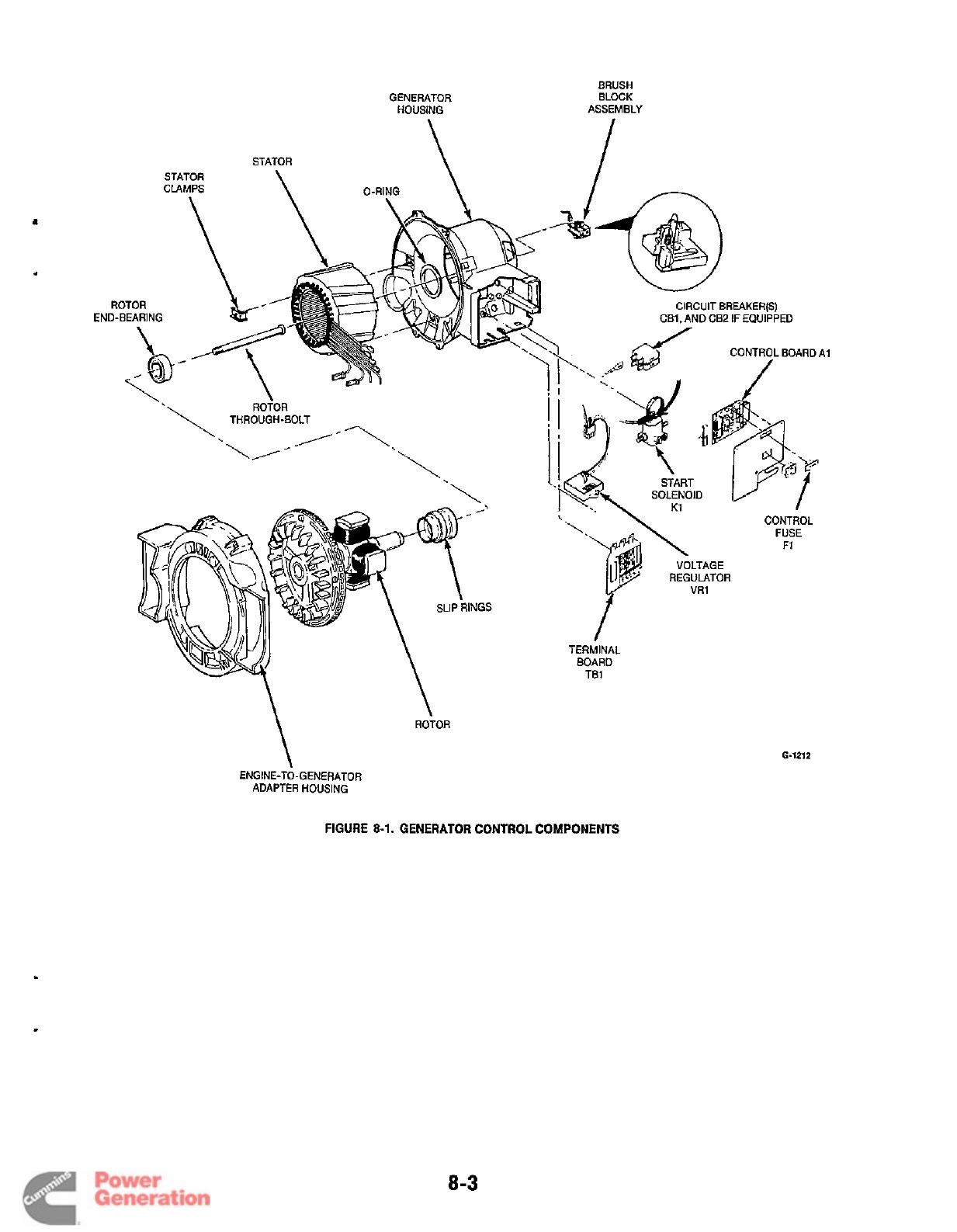
GENERATOR
HOUSING
STATOR
\
I
STATOR
CLAMPS
ROTOR
END-BEARING
ROTOR
\
ENGINE-TO-GENERATOR
ADAPTER HOUSING
6-1212
FIGURE
8-1.
GENERATOR CONTROL COMPONENTS
8-3
Redistribution or publication of this document
by any means, is strictly prohibited.
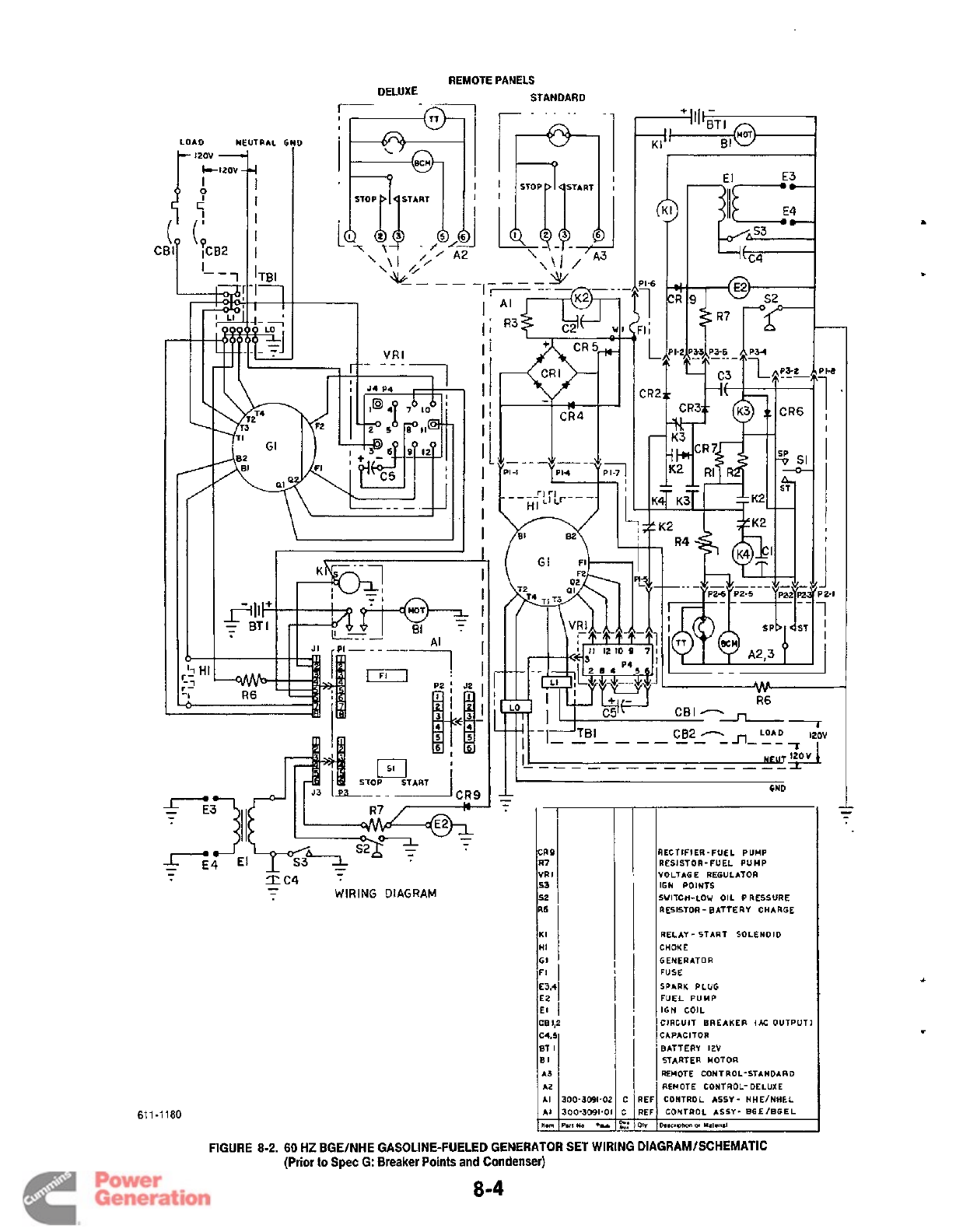
REMOTE PANELS
STANDARD
DELUXE
--
LOAD NEUTRAL
f
-
IZOV
-+
i
I
I
I
1
-1
JfM
=
BTI
-
WIRING
DIAGRAM
-
611
-1
180
\\I
/
I
I1
Ij
I
II
I
I!
I
I
I
I
I
El
IECTIFI ER
-
FUEL PUMP
RESISTOR-FUEL PUMP
IOLTAG E REGULATOR
IGN
POINTS
SWITCH-LOW OIL PRESSURE
RESISTOR
-
BATTERY CHARGE
RELAY- START SOLENOID
CHOKE
GENERATOR
FUSE
SPARK PLUG
FUEL PUMP
IGN COIL
CIRCUIT BREAKER
IAC
OUTPUT1
CAPACITOR
BATTERY
12V
STARTER MOTOR
REMOTE CONTROL-STANDARD
REMOTE CONTROL- DELUXE
CONTROL ASSY- HHE/NHF.L
CONTROL ASSY- EGE/BGEL
D.scwlm
w
U.I.IUI
-
T’
J
I
I
I
‘2-1
1
I
I
J
FIGURE
8-2.
60
HZ BGE/NHE GASOLINE-FUELED GENERATOR SET WIRING DlAGRAMlSCHEMATIC
(Prior
to
Spec G: Breaker Points and Condenser)
8-4
Redistribution or publication of this document
by any means, is strictly prohibited.
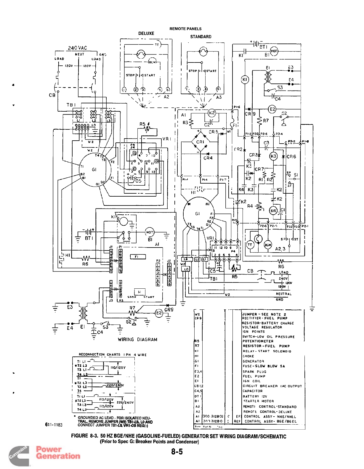
REMOTE PANELS
DELUXE STANDARD
RS
R7
KI
HI
GI
FI
€3.4
€2
El
CE
1.2
c4.5
PT
I
El
A3
AC
AI
AI
111.81.
I
I--------+
300
~12802
30-13128-0,
1:um
N,
.*.#
RECONNECTION CHARTS
I
PH
4
WIRE
*T2
L3
___
--
-
C
GROUNDED AC
LEAD
-
FOR
ISOLATED NEU-
TRAL, REMOVE JUMPER
(W2
TB1
L3
LO AND
61
1-1
183
CONNECT
JUMPER
m-Lo.
3mc~
N'EG(-)
EF CONTROL
ASSY-
HHE/NHEL
rT
C
REF CONTROL
ASSY-
EGEIEGEL
GND
-.
-
__
JUMPER -SEE NOTE
2
RECTIFIER- FUEL PUMP
RESISTOR-BATTERY CHARGE
VOLTAGE
REGULATOR
IGN
POINTS
SWITCH-LOW
OIL
PRESSURE
POTENTIOMETER
RESISTOR -FUEL PUMP
RELAY
-
START
SOLENOID
CHOKE
GENERA109
FUSE-SLOW BLOW
SA
SPARK
PLUG
FUEL PUMP
IGN COIL
CIRCUIT BREAKER IAC OUTPUT
CAPACITOR
RATT
E
RY
12V
STARTER
MOTOR
REHOTt
CONTROL-STANDARD
RENOTt
CONTROL- JELUXE
FIGURE
8-3.
50
HZ BGElNHE (GASOLINE-FUELED) GENERATOR
SET
WIRING DlAGRAMlSCHEMATlC
(Prior
to
Spec
G:
Breaker
Points
and Condenser)
8-5
Redistribution or publication of this document
by any means, is strictly prohibited.
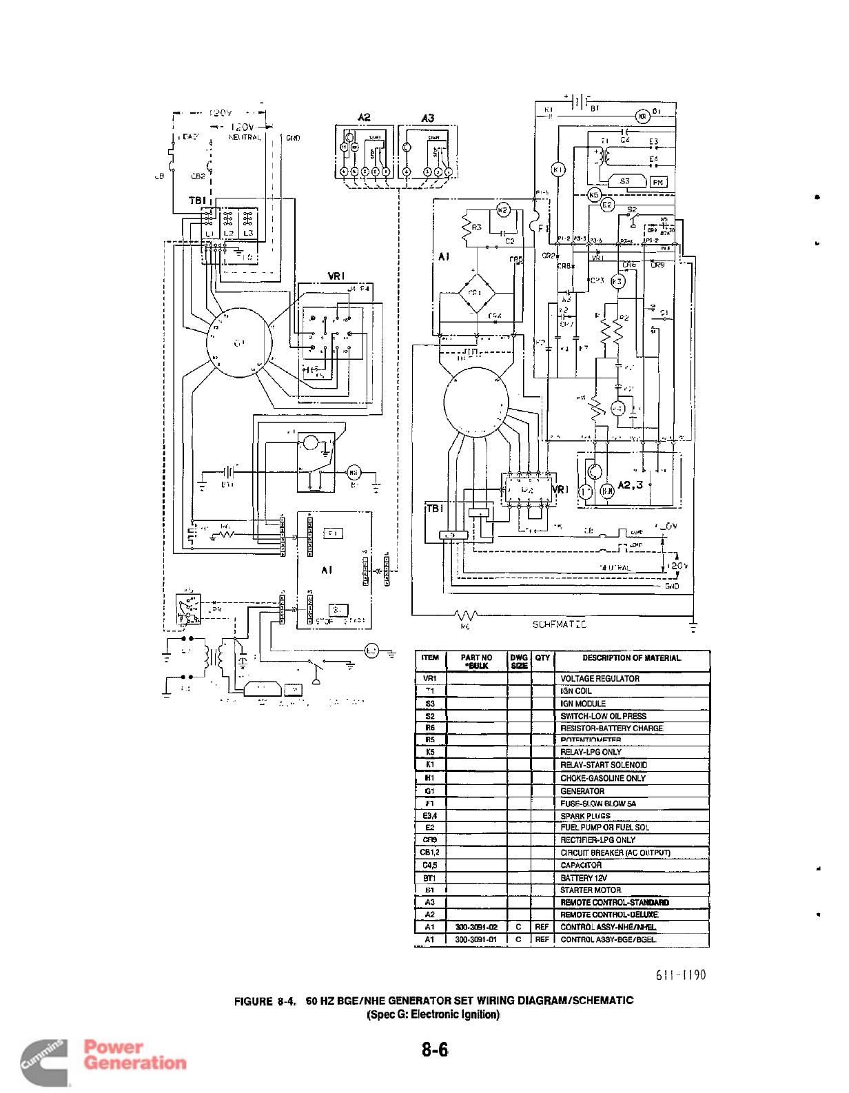
A2
51
53
52
R6
R5
I
I
I
I
I
I
I
I
I
I
I
I
I
I
I
I
I
I
I
I
I
I
!
IGN COIL
IGN MODULE
SWITCH-LOW
OIL
PRESS
RESISTOR-BATTERY CHARGE
POTFNTIOMFGR
r.Y
,.hn
A
-
...
.....
.;,
-
-
;,
,
..
,
.. ..
K5
K1
H1
GI
F1
ITEM
PARTNO
DWG
QTY
DESCRIPTION
OF
MATERIAL
VR1
1
1
VOLTAGE REGULATOR
'BULK
SIZE
RELAY-LPG ONLY
REMY-START SOLENOID
CHOKE-GASOLINE ONLY
GENERATOR
FIIRF-SI
nw
RI
nw
SA
A3
A2
AI
300-3091-02
REMOTE CONTROL-STANDARD
REMOTE CONTROL-DELUXE
C
REF
CONTRO-ASSY-NhEINHEL
I
1 1
STARTERMOTOR
I
~~
A1
1
300-3091-01
I
C
I
REF
I
CONTROLASSY-EGEIBGU
61
I
-I
I90
FIGURE
8-4.
60
HZ BGEINHE GENERATOR SET WIRING DlAGRAMlSCHEMATlC
(Spec
G Electronic Ignition)
8
-6
Redistribution or publication of this document
by any means, is strictly prohibited.
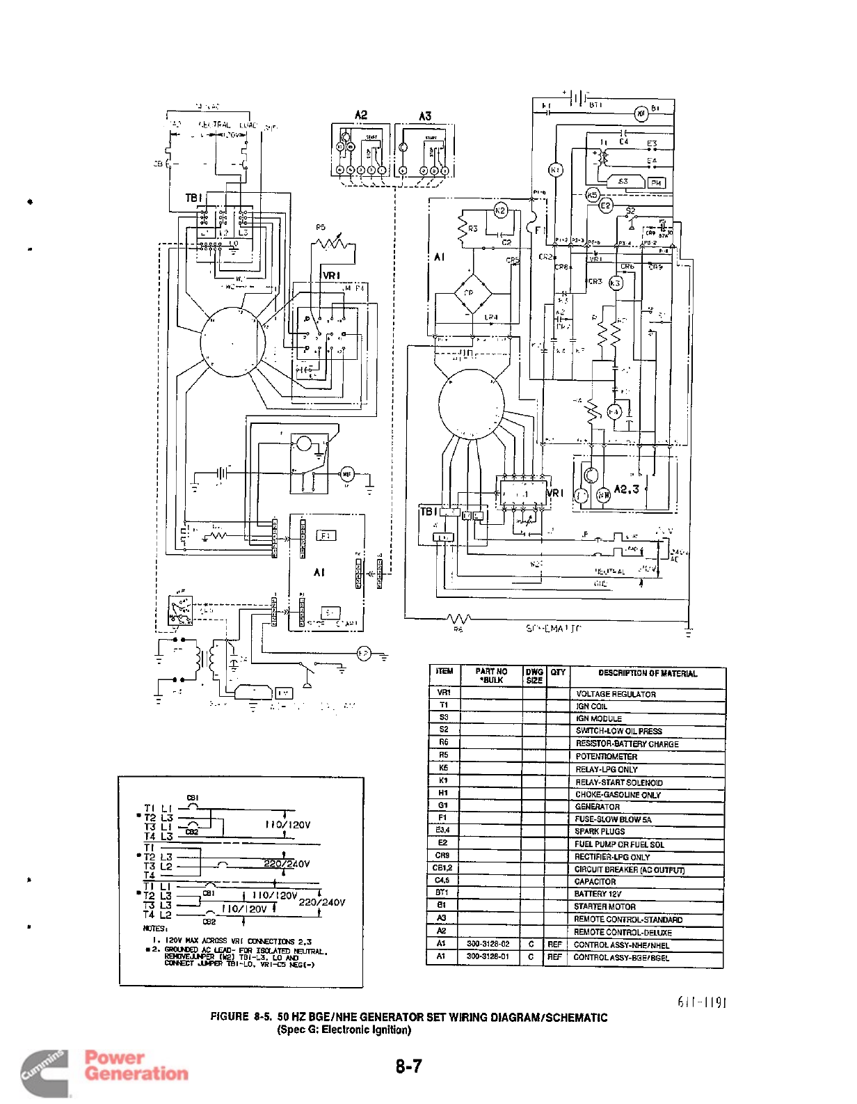
I
I
I
I
I
I
I
I
I
I
I
I
I
I
I
I
8
I
I
I
I
I
I
I
I
I
I
I
I
I
I
I
I
I
I
I
I
I
I
I
I
I
I I
I
I
I
I
I
I
I
I
I
I
I
I
I
C31
TI
LI
.
I
I
T3
L2
A
2201240V
I
I
611-1191
FIGURE
8-5. 50
HZ
BGElNHE GENERATOR
SET
WIRING DIAGRAM/SCHEMATIC
(Spec
G:
Electronic Ignition)
8-7
Redistribution or publication of this document
by any means, is strictly prohibited.
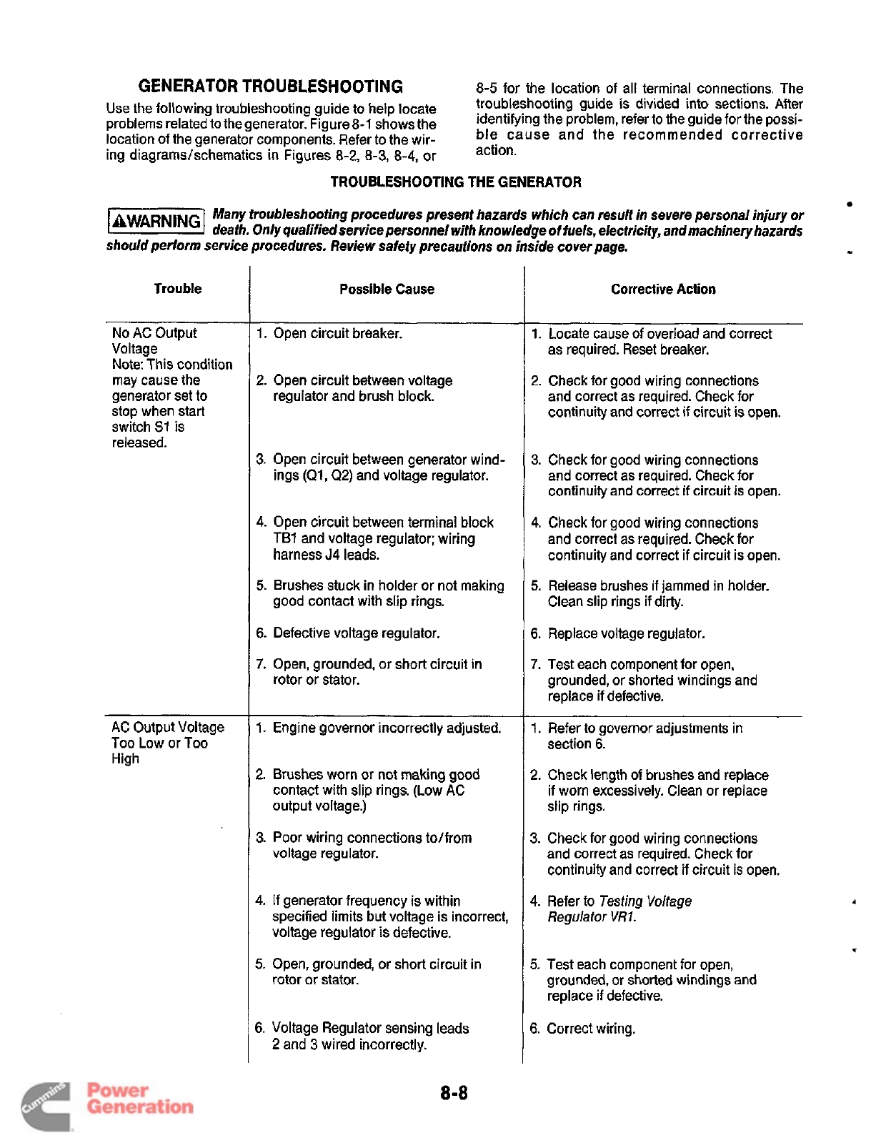
GENERATOR TROUBLESHOOTING
Use
the
following
troubleshooting
guide to
help
locate
location of the generator components. Refer to the wir-
ing diagrams/schematics
in
Figures
8-2,
8-3,
8-4, or
8-5 for the location of all terminal connections. The
troubleshooting guide is divided into sections. After
ble cause and the recommended corrective
action.
problems related tothe generator. Figure 8-1 shows the identifying the problem,
refer
to
the
guide
for
the POssi-
TROUBLESHOOTING THE GENERATOR
Many troubleshoofing procedures present hazards which can resulf in severe personal injury
or
laWAR"Gl
death. Only qualified service personnel with knowledge of fuels, electricity, and machinery hazards
should perform service procedures. Review safety precautions on inside cover page.
I
Trouble
No
AC Output
Voltage
Note: This condition
may cause the
generator set to
stop when start
switch S1 is
released.
AC Output Voltage
Too
Low or
Too
High
Possible Cause
1.
Open circuit breaker.
2.
Open circuit between voltage
regulator and brush block.
3.
Open circuit between generator wind-
ings
(Ql,
Q2)
and voltage regulator.
4.
Open circuit between terminal block
TBl
and voltage regulator; wiring
harness
J4
leads.
5.
Brushes stuck in holder or not making
good contact with slip rings.
6.
Defective voltage regulator.
7.
Open, grounded, or short circuit in
rotor or stator.
1.
Engine governor incorrectly adjusted.
2.
Brushes worn
or
not making good
contact with slip rings. (Low
AC
output voltage.)
3.
Poor wiring connections to/from
voltage regulator.
4.
If generator frequency is within
specified limits but voltage is incorrect,
voltage regulator is defective.
rotor or stator.
5.
Open, grounded, or short circuit in
6.
Voltage Regulator sensing leads
2
and
3
wired incorrectly.
Corrective Action
1.
Locate cause of overload and correct
as required. Reset breaker.
2.
Check for good wiring connections
and correct as required. Check for
continuity and correct if circuit is open.
3.
Check for good wiring connections
and correct as required. Check for
continuity and correct
if
circuit is open.
4.
Check for good wiring connections
and correct
as
required. Check for
continuity and correct if circuit is open.
5.
Release brushes
if
jammed in holder.
Clean slip rings if dirty.
6.
Replace voltage regulator.
7.
Test each component for open,
grounded, or shorted windings and
replace
if
defective.
section
6.
1.
Refer to governor adjustments in
2.
Check length
of
brushes and replace
if worn excessively. Clean or replace
slip rings.
3.
Check for good wiring connections
and correct as required. Check for
continuity and correct if circuit is open.
4.
Refer to Testing Voltage
Regulator
VRI.
5.
Test each component for open,
grounded, or shorted windings and
replace if defective.
6.
Correct wiring.
8-8
Redistribution or publication of this document
by any means, is strictly prohibited.
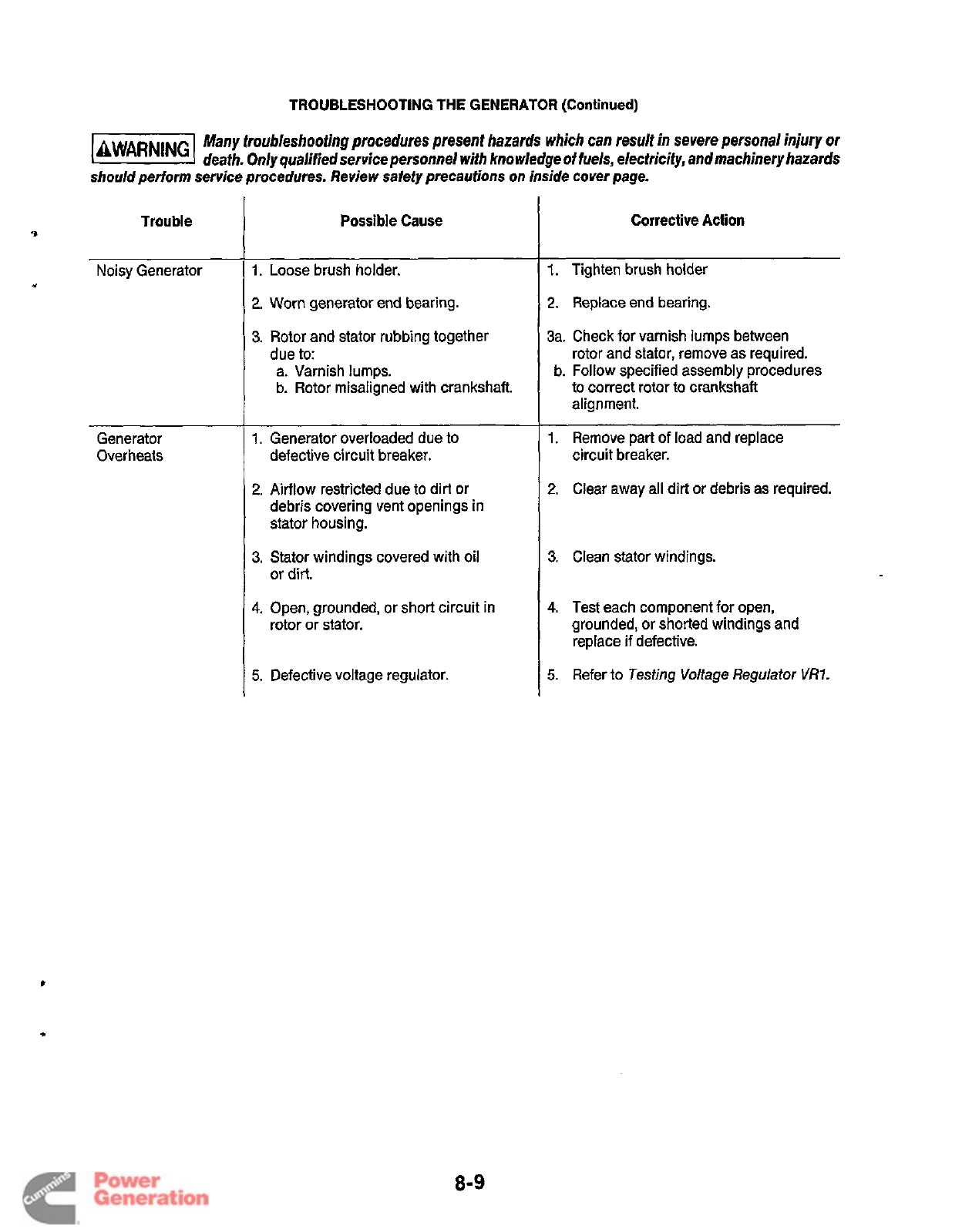
TROUBLESHOOTING
THE
GENERATOR (Continued)
Many troubleshooting procedures present hazards which can result in severe personal
injury
or
k@k%l
death. Only qualifiedservice personnel
with
knowledge
of
fuels, electricity, andmachinery hazards
should perform service procedures. Review
safety
precautions on inside cover page.
Trouble
9
Noisy Generator
*
Generator
Overheats
Possible Cause
1.
Loose brush holder.
2.
Worn generator end bearing.
3.
Rotor and stator rubbing together
due to:
a. Varnish lumps.
b. Rotor misaligned with crankshaft.
1.
Generator overloaded due to
defective circuit breaker.
2.
Airflow restricted due to dirt or
debris covering vent openings in
stator housing.
3.
Stator windings covered with oil
or dirt.
4.
Open, grounded, or short circuit in
rotor or stator.
5.
Defective voltage regulator.
Corrective Action
1.
Tighten brush holder
2.
Replace end bearing.
3a. Check for varnish lumps between
rotor and stator, remove as required.
b. Follow specified assembly procedures
to correct rotor to crankshaft
alignment.
1.
Remove
part
of load and replace
circuit breaker.
2.
Clear away all dirt or debris as required.
3.
Clean stator windings.
4.
Test each component for open,
grounded, or shorted windings and
replace if defective.
5.
Refer to
Testing Voltage Regulator
VRI.
8-9
Redistribution or publication of this document
by any means, is strictly prohibited.
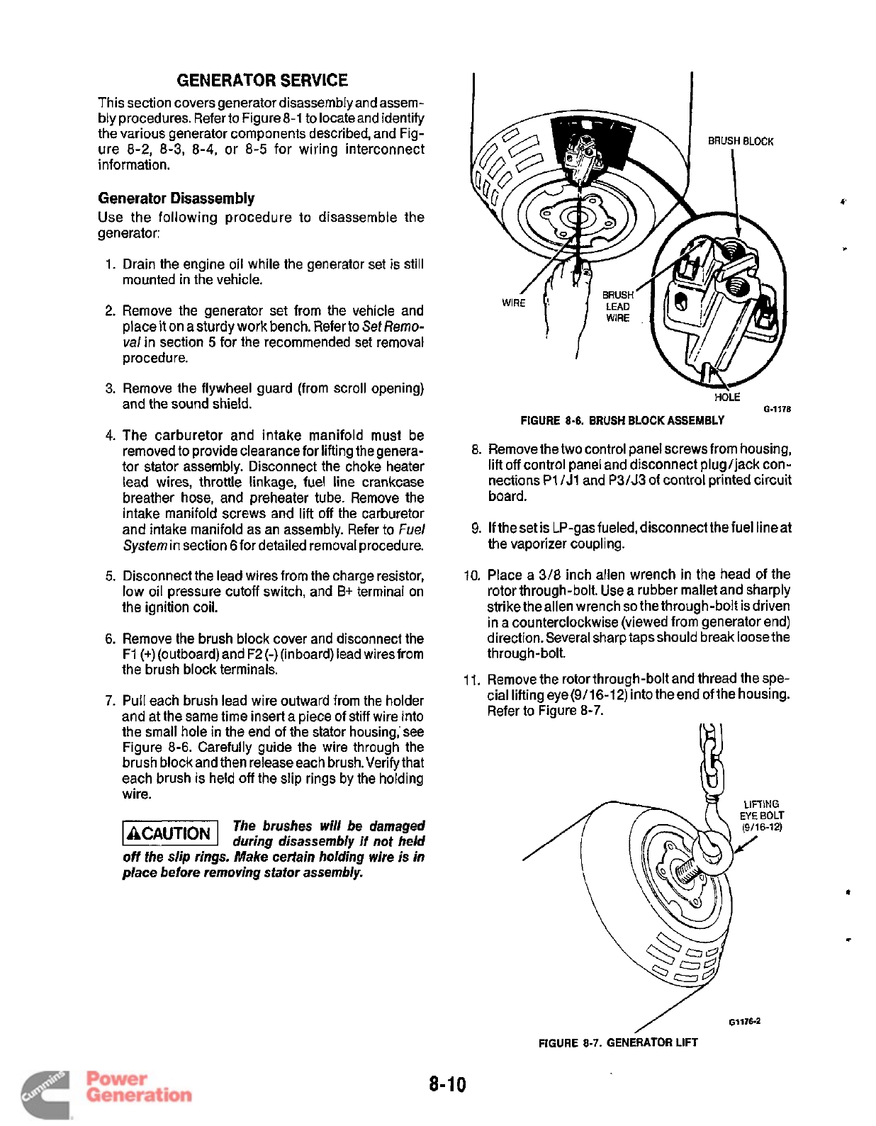
GENERATOR SERVICE
This section covers generator disassembly and assem-
bly procedures. Refer to Figure 8-1 to locate and identify
the various generator components described, and Fig-
ure 8-2, 8-3, 8-4, or 8-5 for wiring interconnect
information.
Generator Disassembly
Use the following procedure to disassemble the
generator:
1.
2.
3.
4.
5.
6.
7.
Drain the engine oil while the generator set is still
mounted in the vehicle.
Remove the generator set from the vehicle and
place it
on
a sturdy work bench. Refer to
Set
Remo-
val
in section
5
for the recommended set removal
procedure.
Remove the flywheel guard (from scroll opening)
and the sound shield.
The carburetor and intake manifold must be
removed to provide clearance for lifting the genera-
tor stator assembly. Disconnect the choke heater
lead wires, throttle linkage, fuel line crankcase
breather hose, and preheater tube. Remove the
intake manifold screws and lift
off
the carburetor
and intake manifold as an assembly. Refer to
Fuel
System in section 6for detailed removal procedure.
Disconnect the lead wires from the charge resistor,
low oil pressure cutoff switch, and
B+
terminal on
the ignition coil.
Remove the brush block cover and disconnect the
F1 (+)(outboard) and F2
(-)
(inboard) lead wiresfrom
the brush block terminals.
Pull each brush lead wire outward from the holder
and at the same time insert a piece of stiff wire into
the small hole in the end of the stator housing,'see
Figure 8-6. Carefully guide the wire through the
brush block and then release each brush.Verify that
each brush is held off the slip rings by the holding
wire.
The brushes will be damaged
during disassembly
if
not held
off
the slip rings. Make certain holding wire is in
place before removing stator assembly.
8.
9.
10.
11.
HOLE
6-1178
FIGURE
8-6.
BRUSH
BLOCK
ASSEMBLY
Remove the two control panel screws from housing,
lift
off
control panel and disconnect plug/jack con-
nections
P1
/J1
and
P3/J3
of control printed circuit
board.
If
the set
is
LP-gas fueled, disconnect the fuel line at
the vaporizer coupling.
Place a
3/8
inch allen wrench in the head of the
rotor through-bolt. Use a rubber mallet and sharply
strike theallen wrench
so
the through-bolt is driven
in a counterclockwise (viewed from generator end)
direction. Several sharp tapsshould break loose the
through-bolt.
Remove the rotor through-bolt and thread the spe-
cial liftingeye(9/16-12)into theendofthe housing.
Refer to Figure 8-7.
01176-2
/
FIGURE
8-7.
GENERATOR LIFT
8-1 0
Redistribution or publication of this document
by any means, is strictly prohibited.
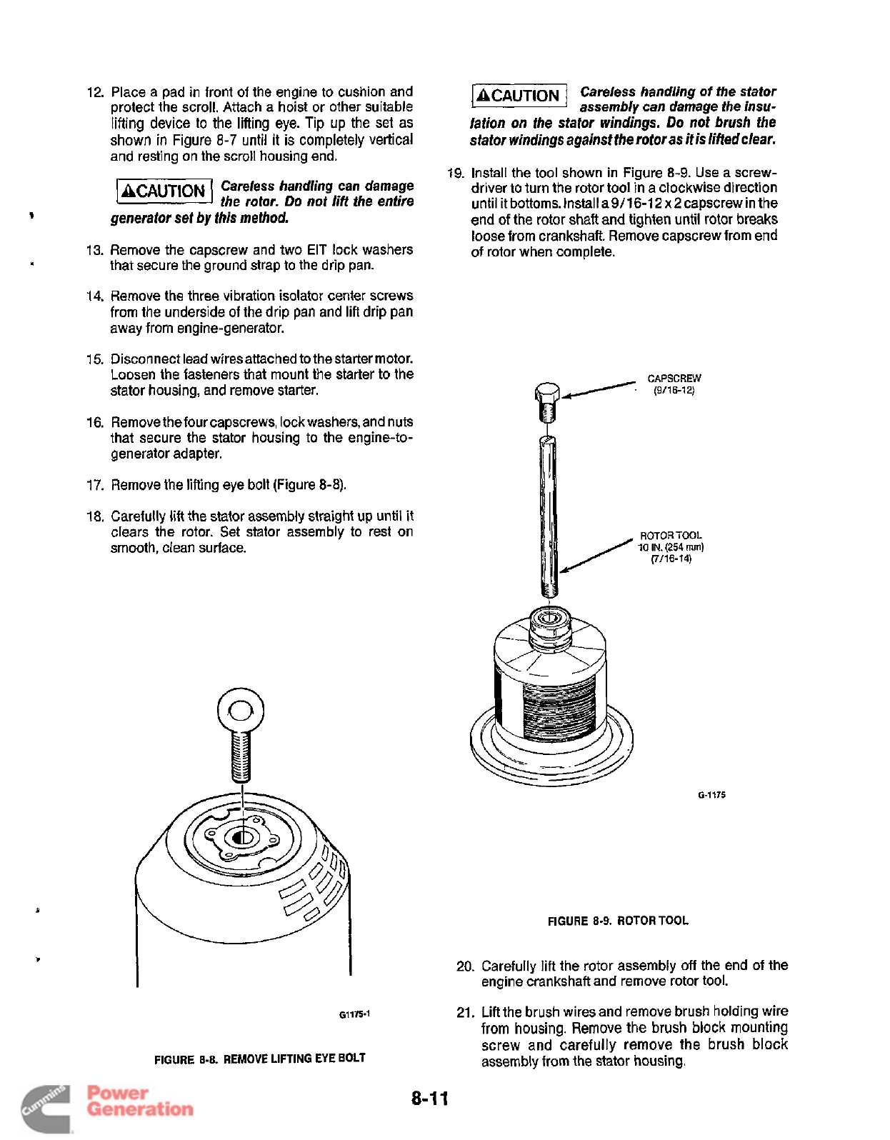
12. Place a pad in front
of
the engine to cushion and
protect the scroll. Attach a hoist or other suitable
lifting device
to
the lifting eye. Tip
up
the set as
shown in Figure
8-7
until it
is
completely vertical
and resting on the scroll housing end.
7)
Careless handling can damage
the
rotor.
Do
not lift the entire
generator set
by
this method.
13.
Remove the capscrew and two EIT lock washers
that secure the ground strap to the drip pan.
14.
Remove the three vibration isolator center screws
from the underside of the drip
pan
and lift drip pan
away from engine-generator.
15.
Disconnect lead wiresattached to thestarter motor.
Loosen the fasteners that mount the starter to the
stator housing, and remove starter.
v
.
16.
Remove thefourcapscrews, lock washers, and nuts
that secure the stator housing to the engine-to-
generator adapter.
17.
Remove the lifting eye bolt (Figure
8-8).
18.
Carefully
lift
the stator assembly straight
up
until
it
clears the rotor. Set stator assembly to rest on
smooth, clean surface.
ACAUT~ON
Careless handling
of
the stator
assembly can damage the insu-
lation on the stator
windings.
Do
not
brush the
stator
windings
againstthe rotor as
it
is
liftedclear.
19. Install the tool shown in Figure 8-9. Use a screw-
driver to turn the rotor tool in a clockwise direction
until
it
bottoms. Install a
911
6-1
2
x
2
capscrew in the
end
of
the
rotor
shait and tighten until
rotor
breaks
loose from crankshaft. Remove capscrew from end
of
rotor when complete.
/
ROTOR
TOOL
10
IN.
(254
rnm)
(7/16-14)
6-1175
FIGURE
8-9.
ROTOR
TOOL
20. Carefully lift the rotor assembly
off
the end
of
the
engine crankshaft and remove rotor tool.
21.
Lift the brush wires and remove brush holding wire
from
housing. Remove
the
brush block mounting
screw and carefully remove the brush block
assembly from the stator housing.
61175.1
FIGURE
8-8.
REMOVE
LIFTING EYE BOLT
8-1
1
Redistribution or publication of this document
by any means, is strictly prohibited.
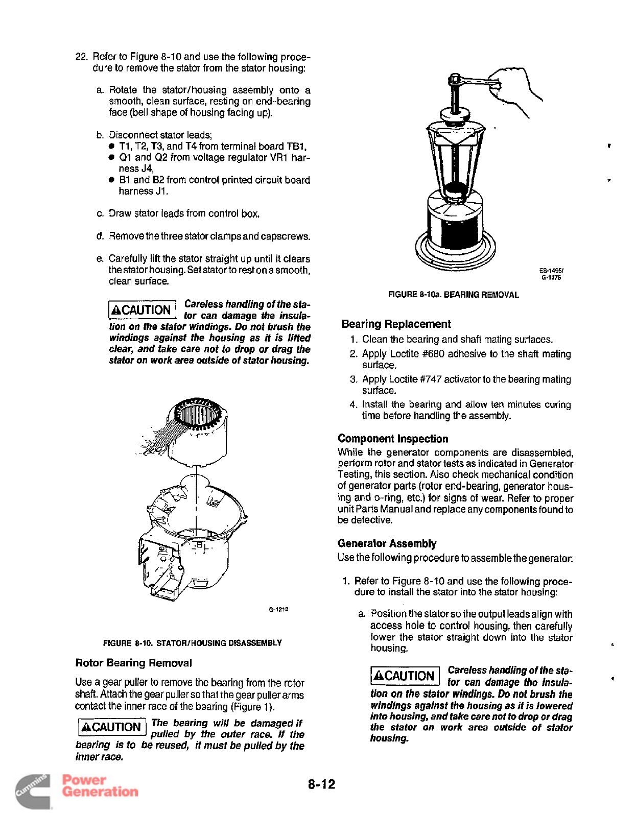
22.
Refer to Figure 8-10 and use the following proce-
dure to remove the stator from the stator housing:
a. Rotate the stator/housing assembly onto a
smooth, clean surface, resting on end-bearing
face (bell shape of housing facing up).
b. Disconnect stator leads;
T1,
T2,
T3, and
T4
from terminal board TB1,
Q1 and
Q2
from voltage regulator VR1 har-
B1 and
82
from control printed circuit board
ness
J4,
harness
J1.
c. Draw stator leads from control box.
d. Remove the three stator clamps and capscrews.
e. Carefully
lift
the stator straight up until
it
clears
the stator housing. Set stator
to
rest on asmooth,
clean surface.
FIGURE
8-loa.
BEARING REMOVAL
Careless handling
of
the sfa-
-1
for can damage the insula-
tion
on
the stator windings.
Do
not brush fhe
windings against the housing as it is lifted
clear, and take care not to drop or drag the
sfator
on
work area outside
of
stator housing.
6-1213
FIGURE
8-10.
STATORlHOUSlNG
DISASSEMBLY
Rotor
Bearing Removal
Use a gear puller to remove the bearing from the rotor
shaft. Attach the gear puller
so
that the gear puller arms
contact the inner race of the bearing (Figure
1).
The bearing will be damaged if
pulled by the outer race. If the
bearing is to be reused,
it
must be pulled by the
inner race.
EM4951
61175
Bearing Replacement
1.
Clean the bearing and shaft mating surfaces.
2.
Apply Loctite #680 adhesive to the shaft mating
3.
Apply Loctite
#747
activator to the bearing mating
4.
Install the bearing and allow ten minutes curing
surface.
surface.
time before handling the assembly.
Component Inspection
While the generator components are disassembled,
perform rotor and stator tests as indicated in Generator
Testing, this section. Also check mechanical condition
of
generator parts (rotor end-bearing, generator
hous-
ing and O-ring, etc.)
for
signs of wear. Refer to proper
unit Parts Manual and replace any components found to
be defective.
Generator Assembly
Use the following procedure to assemble the generator:
1.
Refer to Figure 8-10 and use the following proce-
dure
to
install the stator into the stator housing:
a. Position the stator
so
the output leadsalign with
access hole
to
control housing, then carefully
lower the stator straight down into the stator
housing.
I
Careless handling
of
the sta-
@%!!@I
tor can damage the insula-
tion
on
the stator windings.
Do
not
brush
the
windings against the housing as it is lowered
into housing, and take care not to drop
or
drag
the sfafor on work area outside
of
sfator
housing.
#
8-1
2
Redistribution or publication of this document
by any means, is strictly prohibited.
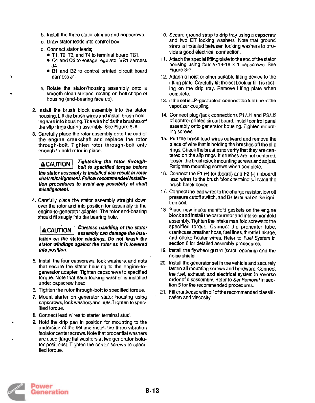
b. Install the three stator clamps and capscrews.
c. Draw stator leads into control box.
d. Connect stator leads;
T1
,
T2, T3, and T4 to terminal board TB1,
Q1
and
Q2
to
voltage regulator
VR1
harness
0
B1
and
B2
to
control printed circuit board
J4.
harness
J1.
e. Rotate the stator/housing assembly onto a
smooth clean surface, resting on bell shape of
Iiousing (end-bearing face up).
2.
Install the brush block assembly into the stator
housing. Lift the brush wiyes and install brush hold-
ing wire into housing. The wire holds the brushes
off
the slip rings during assembly. See Figure
8-6.
3.
Carefully place the rotor assembly onto the end of
the engine crankshaft and replace the rotor
through-bolt. Tighten rotor through-bolt only
enough to hold rotor in place.
Tightening the rotor through-
-
bolt to specified torque before
the stator assembly is installed can result in rotor
shaff misalignment. Follow recommended installa-
tion procedures to avoid any possiblity of shaft
misalignment.
4.
Carefully
place
the stator assembly straight down
over the rotor and into position for assembly
to
the
engine-to-generator adapter. The rotor end-bearing
should fit snugly into the bearing
hole.
Careless handling of the stator
assembly can damage fhe insu-
lation
on
fhe sfator windings.
Do
not
brush
the
stator windings against the rotor as it
is
lowered
into position.
5.
Install the four capscrews, lock washers, and nuts
that secure the stator housing to the engine-to-
generator adapter. Tighten capscrews to specified
torque. Note that each locking washer is installed
under capscrew head.
6.
Tighten the rotor through-bolt to specified torque.
7.
Mount starter on generator stator housing using
capscrews, lock washers and nuts. Tighten to spec-
ified torque.
.
8.
Connect lead wires to starter terminal stud.
9.
Hold the drip pan in position for mounting to the
underside of the set and install the three vibration
isolator center screws. Note that proper flat washers
are used (large flat washers at two generator isola-
tor positions). Tighten the center screws to speci-
fied torque.
10.
Secure ground strap to drip tray using
a
capscrew
and two
EIT
locking washers. Note that ground
strap
is
installed
between
locking washers
to
pro-
vide
a
good electrical connection.
11,
Attach the special lifting plateto the end of the stator
housing using four
5/16-18
x
1
capscrews. See
Figure
8-7.
12.
Attach a hoist or other suitable lifting device to the
lifting plate. Carefully tilt the set back until it
is
rest-
ing on the drip tray. Remove lifting plate when
complete.
13.
If the set is LP-gas fueled, connect the fuel line at the
vaporizer coupling.
14.
Connect plugljack connections
Pl/Jl
and P3/J3
of control printed circuit board. Install control panel
assembly onto generator housing. Tighten mount-
ing screws.
15.
Pull
the brush lead wires outward and remove the
piece of wire that is holding the brushes off the slip
rings. Check the brushes to verify that they are cen-
tered on the slip rings.
If
brushes are not centered,
loosen the brush block mounting screws and adjust.
Retighten mounting screws when complete.
16.
Connect the
F1
(+)
(outboard) and
F2
(-)
(inboard)
lead wires to the brush block terminals. Install the
brush block cover.
17.
Connect the lead wires to the charge resistor, low oil
pressure cutoff switch, and
B+
terminal on the igni-
tion coil.
18.
Place new intake manifold gaskets on the engine
block and install the carburetor and intake manifold
assembly. Tighten the intake manifold screws to the
specified torque. Connect the preheater tube,
crankcase breather hose, fuel lines, throttle linkage,
and choke heater wires. Refer to
Fuel
System in
section
6
for detailed assembly procedures.
19.
Install the flywheel guard (scroll opening) and the
noise shield.
20.
Install the generator set in the vehicle and securely
fasten all mounting screws and hardware. Connect
the fuel, exhaust, and electrical system in reverse
order of disassembly. Refer to
Set
Removal
in sec-
tion
5
for the recommended procedures.
21.
Fill crankcase with oil of the recommended classifi-
cation and viscosity.
8-1
3
Redistribution or publication of this document
by any means, is strictly prohibited.
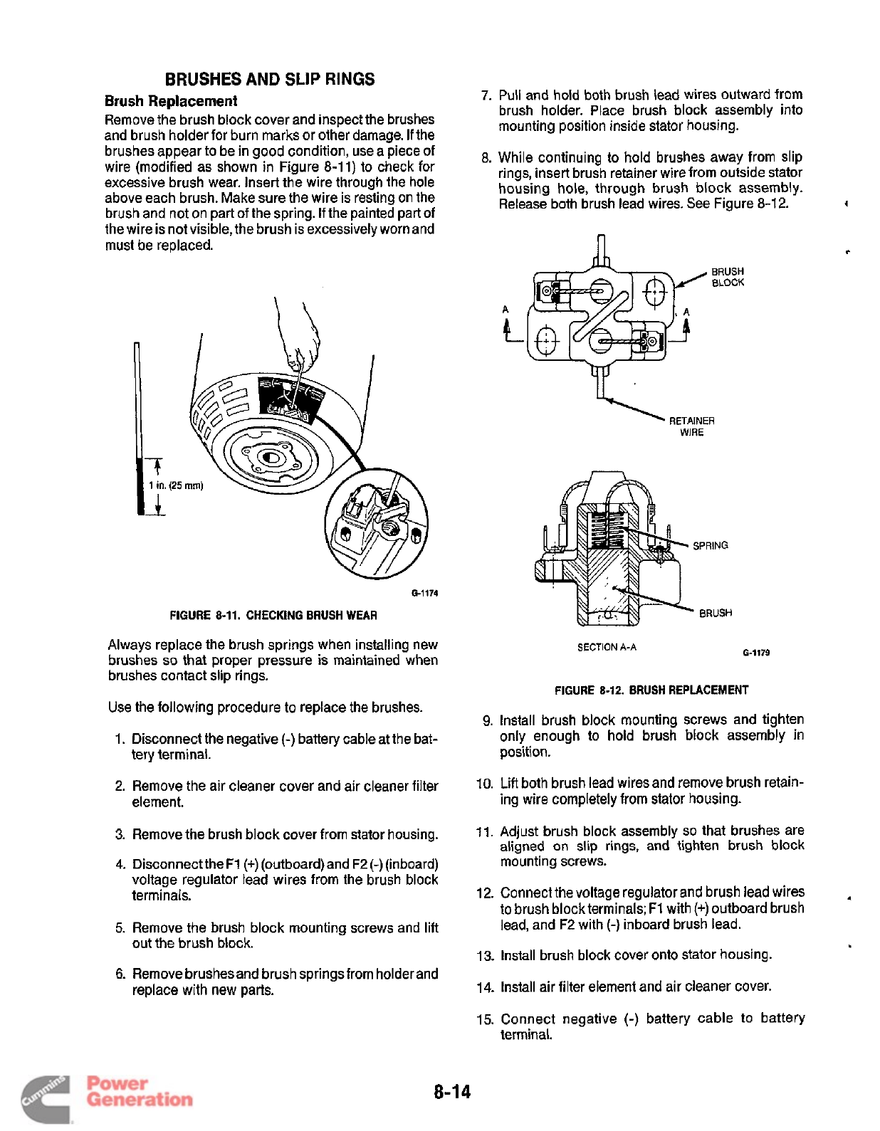
BRUSHES
AND
SLIP
RINGS
Brush
Replacement
Remove the brush block cover and inspect the brushes
and brush holder for burn marks or other damage.
If
the
brushes appear to be in good condition, use a piece of
wire (modified as shown in Figure 8-11) to check for
excessive brush wear. Insert the wire through the hole
above each brush. Make sure the wire is resting on the
brush and not on part of the spring. If the painted part of
the wire is not visible, the brush is excessively worn and
must be replaced.
-
-T
6.1174
FIGURE 8-11. CHECKING BRUSH
WEAR
Always replace the brush springs when installing new
brushes
so
that proper pressure is maintained when
brushes contact slip rings.
Use the following procedure to replace the brushes.
1.
Disconnect the negative
(-)
battery cable at the bat-
tery terminal.
2.
Remove the air cleaner cover and air cleaner filter
element.
3.
Remove the brush block cover from stator housing.
4.
Disconnect the F1
(+)
(outboard) and F2
(-)
(inboard)
voltage regulator lead wires from the brush block
terminals.
5.
Remove the brush block mounting screws and
lift
out the brush block.
6.
Remove brushesand brush springs from holder and
replace with new parts.
7.
Pull and hold both brush lead wires outward from
brush holder. Place brush block assembly into
mounting position inside stator housing.
8. While continuing to hold brushes away from slip
rings, insert brush retainer wire from outside stator
housing hole, through brush block assembly.
Release both brush lead wires. See Figure 8-1
2.
n
A
BRUSH
BLOCK
SPRING
-
BRUSH
G-1179
SECTION
A-A
FIGURE 8-12. BRUSH REPLACEMENT
9.
Install brush block mounting screws and tighten
only enough to hold brush block assembly in
position.
10. Lift both brush lead wires and remove brush retain-
ing wire completely from stator housing.
11.
Adjust brush block assembly
so
that brushes are
aligned on slip rings, and tighten brush block
mounting screws.
12.
Connect the voltage regulator and brush lead wires
to brush block terminals;
F1
with (+)outboard brush
lead, and
F2
with
(-)
inboard brush lead.
13.
Install brush block cover onto stator housing.
L
14.
Install air filter element and air cleaner cover.
15.
Connect negative
(-)
battery cable to battery
terminal.
8-1
4
Redistribution or publication of this document
by any means, is strictly prohibited.
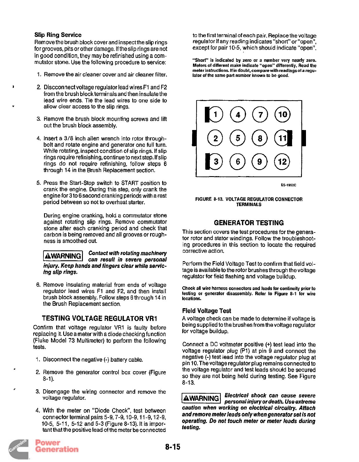
Slip
Ring
Service
Remove the brush block cover and inspecttheslip rings
for grooves, pitsor other damage.
If
theslip rings are not
in
good condition, they may be refinished using
a
com-
mutator stone. Use the following procedure to service:
1.
Remove the air cleaner cover and air cleaner filter.
2.
Discconnect voltage regulator lead wires
F1
and
F2
from the brush block terminals and then insulate the
lead wire ends. Tie the lead wires
to
one side
to
allow clear access to the slip rings.
3.
Remove the brush block mounting screws and lift
out the brush block assembly.
4.
Insert a
3/8
inch allen wrench into rotor through-
bolt and rotate engine and generator one full turn.
While rotating, inspect condition of slip rings. If slip
rings require refinishing, continue to next step. If slip
rings do not require refinishing, follow steps
6
through
14
in the Brush Replacement section.
5.
Press the Start-Stop switch to START position
to
crank the engine. During this step, only crank the
engine for
3
to
6
second cranking periods with a rest
period between
so
not to overheat starter.
During engine cranking, hold a commutator stone
against rotating slip rings. Remove commutator
stone after each cranking period and check that
carbon is being removed and all grooves or rough-
ness is smoothed out.
Contact wifh rotating machinery
I
AWARNING
can result in severe personal
injury. Keep hands and fingers clear while servic-
ing slip rings.
6.
Remove insulating material from ends of voltage
regulator lead wires
F1
and F2, and then install
brush block assembly. Follow steps
6
through
14
in
the Brush Replacement section.
TESTING VOLTAGE REGULATOR VR1
Confirm that voltage regulator VR1 is faulty before
replacing it. Usea meter with a diode checking function
(Fluke Model
73
Multimeter) to perform the following
tests.
1.
Disconnect the negative
(-)
battery cable.
6
2. Remove the generator control box cover (Figure
8-1).
*
3.
Disengage the wiring connector and remove the
voltage regulator.
4.
With the meter on “Diode Check”, test between
connector terminal pairs
5-9,7-9,lO-9,ll-9,12-9,
10-5, 5-11, 5-12
and
5-3
(Figure
8-13).
It is impor-
tant that the positive lead of the meter be connected
to the first terminal of each pair. Replace the voltage
regulator
if
any reading indicates “short” or “open“,
except for pair
10-5,
which should indicate “open”.
“Short”
is indicated
by
zero or a number very nearly zero.
Meters
of
different make indicate “open” differently. Read the
meter instructions.
If
in doubt, compare with readingsof a regu-
lator of the same part number known to be good.
1
I
ES-1952C
FIGURE
8-13.
VOLTAGE REGULATOR CONNECTOR
TERMINALS
GENERATOR TESTING
This section covers the test procedures for the genera-
tor rotor and stator windings. Follow the troubleshoot-
ing procedures in this section
to
locate the required
corrective action.
Perform the Field Voltage Test to confirm that field vol-
tage is available to the rotor brushes through the voltage
regulator for field flashing and voltage buildup.
Check all wire harness connectors and leads for continuity prior to
testing or generator disassembly. Refer to Figure
8-1
for wire
locations.
Field
Voltage
Test
A
voltage check can be made to determine
if
voltage is
being supplied to the brushes from thevoltage regulator
for voltage buildup.
Connect a
DC
voltmeter positive
(+)
test lead into the
voltage regulator plug
(Pl)
at pin
9
and connect the
negative
(-)
test lead into the voltage regulator plug at
pin
10.
Thevoltage regulator plug remains connected to
the voltage regulator and test leads should be secured
so
they are not being held during testing. See Figure
8-1 3.
Electrical shock can cause severe
laWAR”Gl
personalinjury or death. Use extreme
caution when working on electrical circuitry. Affach
and remove meter leads only when generator set
is
nof
operating.
Do
not touch meter or meter leads during
testing.
8-1
5
Redistribution or publication of this document
by any means, is strictly prohibited.
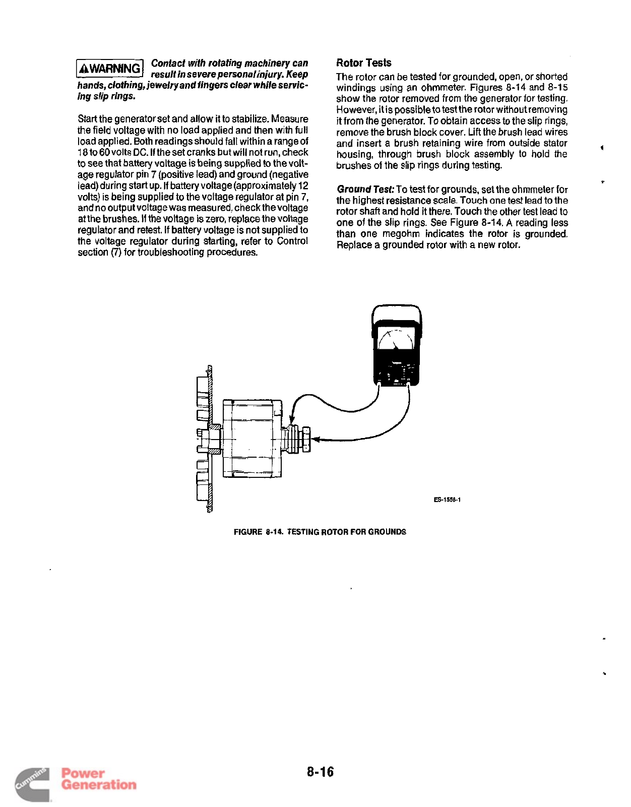
Contact with rotating machinery can
@&@@I
result in severe personal injury. Keep
hands,
clothing,
jewelry and fingers clear while servic-
ing slip rings.
Start the generator set and allow it to stabilize. Measure
the field voltage with no load applied and then with full
load applied. Both readings should fall within a range of
18
to60 volts
DC.
If
the set cranks but will not run, check
to see that battery voltage is being supplied to the volt-
age regulator pin
7
(positive lead) and ground (negative
lead) during start up.
If
battery voltage (approximately
12
volts) is being supplied to the voltage regulator at pin
7,
and no output voltage was measured, check thevoltage
at the brushes.
If
the voltage is zero, replace the voltage
regulator and retest. If battery voltage is not supplied
to
the voltage regulator during starting, refer to Control
section
(7)
for troubleshooting procedures.
Rotor
Tests
The rotor can be tested for grounded, open, or shorted
windings using an ohmmeter. Figures
8-14
and
8-15
show the rotor removed from the generator for testing.
However, it is possible to test the rotor without removing
it
from the generator. To obtain access to the
slip
rings,
remove the brush block cover. Lift the brush lead wires
housing, through brush block assembly to hold the
brushes
of
the slip rings during testing.
Ground
Test:
To test for grounds, set the ohmmeter for
the highest resistance scale. Touch one test lead
to
the
rotor shaft and hold it there. Touch the other test lead to
one of the slip rings. See Figure
8-14.
A
reading less
than one megohm indicates the rotor is grounded.
Replace
a
grounded rotor with a new rotor.
and insert a brush retaining wire from outside stator
4
1
ES-1558-1
FIGURE
8-14.
TESTING ROTOR
FOR
GROUNDS
8-16
Redistribution or publication of this document
by any means, is strictly prohibited.
Open
or
Shorted
Windings
Test:To
test for open wind-
ings, set the ohmmeter for the highest resistance scale.
Place test leads on the slip rings as shown in Figure
8-1
5.
Ohmmetershould indicatecontinuity between slip
rings. A high resistance reading indicates a poor con-
nection or an open winding. Check the connection
between the slip rings and rotor lead wires. Replace
rotor
if
the rotor winding is open.
To test for shorted windings,
set
the ohmmeter for the
lowest scale. Place the test leads on the slip rings as
20.25 to 24.75 ohms at 77' F (25"
C).
Replace a rotor
with shorted windings with a new rotor.
b
.l
shown in Figure 8-15. Resistance reading should be
ES-1558-2
Stator
Tests
The stator can be tested for grounded or open windings
using an ohmmeter. Testing for shorted windings
requires
a
digital-type ohmmeter that can
read
to
within
0.01 ohms.
Figures 8-1
6
and 8-1
7
show the stator removed from the
generator for testing. However,
it
is possible to test the
stator without disassembling the generator. Remove the
control panel
to
obtain access to the specified lead
wires during testing.
Ground
Test:To
test for grounds, disconnect the follow-
ing stator leads:
0
Stator leads T1 and
T3
from TB1
0
Stator lead B1 from A1 /P1-1
0
Stator lead Q1 from
VR1
/J4-11
Insulate or position the lead wire ends
so
they are not
touching the generator set housing or other compo-
nents within control. Set the ohmmeter for the highest
resistance scale and then connect one test lead to the
generator housing. Touch the other test lead (see Figure
8-16)
to the listed generator leads individually.
A
read-
ing less than one megohm indicates a ground. Replace
a grounded stator with a new stator.
FIGURE
8-15.
TESTING
ROTOR FOR
OPENS
OR SHORTS
TEST
LEADS
T1.
T3.
B1
and
Q1
FOR GROUNDS
6-1214
FIGURE
8-16.
TESTING STATOR
FOR
GROUNDS
8-1
7
Redistribution or publication of this document
by any means, is strictly prohibited.
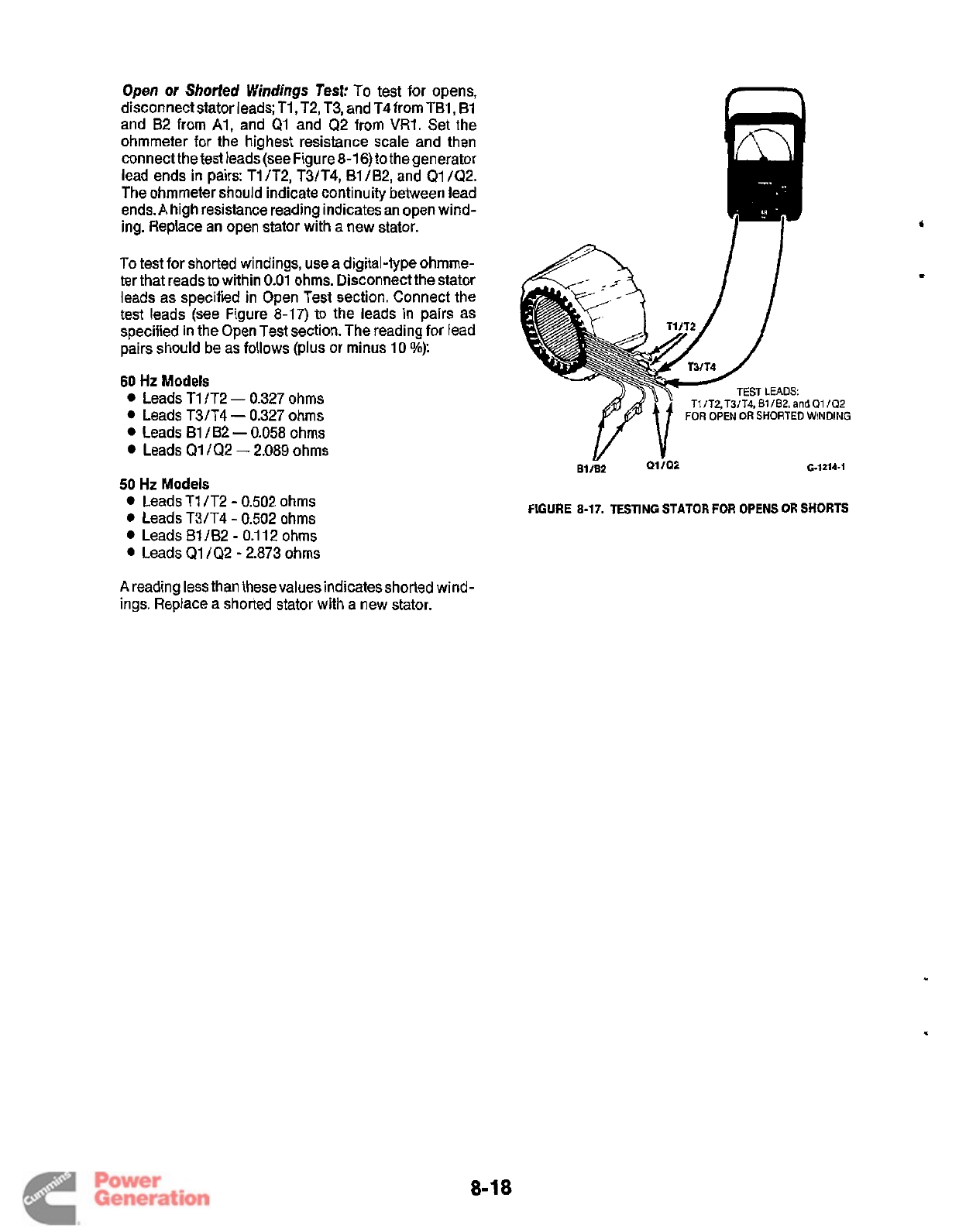
Open
or
Shorted Windings Test:
To test for opens,
disconnect stator leads; TI, T2, T3, and T4from TBl, B1
and B2 from Al, and Q1 and Q2 from
VR1.
Set the
ohmmeter for the highest resistance scale and then
connect the test leads (see Figure 8-1
6)
to the generator
lead ends in pairs: T1 /T2, T3/T4, B1 /B2, and
Q1
/Q2.
The ohmmeter should indicate continuity between lead
ends. A high resistance reading indicates an open wind-
ing. Replace an open stator with a new stator.
n
To test for shorted windings, use a digital-type ohmme-
ter that reads to within 0.01 ohms. Disconnect the stator
leads as specified in Open Test section. Connect the
test leads
(see
Figure
8-17)
to the leads in pairs as
specified in the Open Test section. The reading for lead
pairs should be as follows (plus or minus 10
%):
60
Hz
Models
Leads
T1
/T2
-
0.327 ohms
Leads
T3/T4
-
0.327 ohms
Leads B1
/B2
-
0.058 ohms
Leads Q1 /Q2
-
2.089 ohms
TEST
LEADS:
T3/T4,
E1
IB2,
and
01
I02
6-1214-1
50
Hz
Models
Leads T1 /T2
-
0.502 ohms
Leads T3/T4
-
0.502 ohms
Leads B1/B2
-
0.1
12
ohms
Leads
Q1
/Q2
-
2.873 ohms
FIGURE
8-17.
TESTING
STATOR
FOR
OPENS
OR
SHORTS
A
reading less than thesevalues indicatesshorted wind-
ings. Replace a shorted stator with a new stator.
8-18
Redistribution or publication of this document
by any means, is strictly prohibited.
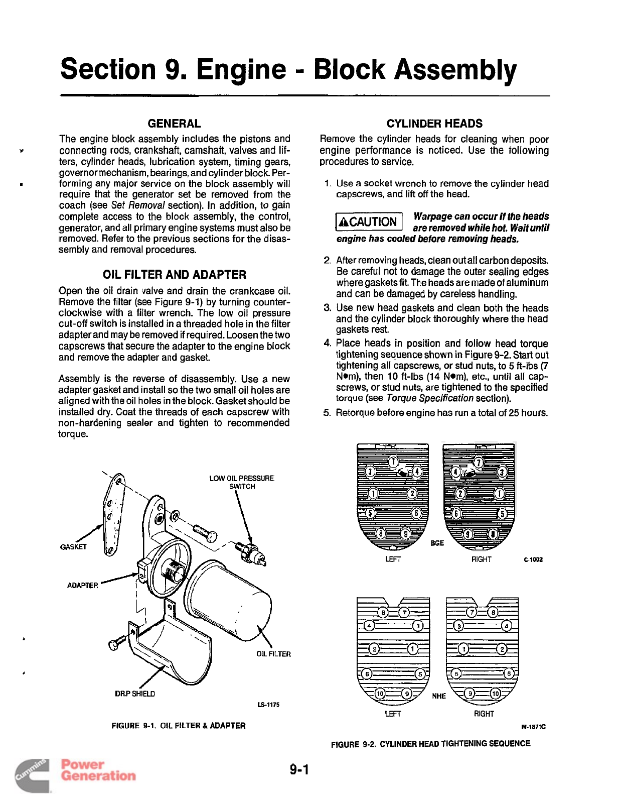
Section
9.
Engine
=
Block
Assembly
GENERAL
The engine block assembly includes the pistons and
connecting
rods,
crankshaft, camshaft, valves and
lif-
ters, cylinder heads, lubrication system, timing gears,
governor mechanism, bearings, and cylinder block. Per-
forming any major service on the block assembly will
require that the generator set be removed from the
coach (see
Set
Removal section). In addition,
to
gain
complete access to the block assembly, the control,
generator, and all primary engine systems must also be
removed. Refer to the previous sections for the disas-
sembly and removal procedures.
V
I
OIL
FILTER AND ADAPTER
Open the oil drain valve and drain the crankcase oil.
Remove the filter (see Figure
9-1)
by turning counter-
clockwise with a filter wrench. The low oil pressure
cut-off switch is installed in a threaded hole in the filter
adapter and may be removed if required. Loosen the two
capscrews that secure the adapter to the engine block
and remove the adapter and gasket.
Assembly is the reverse of disassembly. Use
a
new
adapter gasket and install
so
the two small oil holes are
aligned with theoil holes in the block. Gasket should be
installed
dry.
Coat the threads of each capscrew with
non-hardening sealer and tighten to recommended
torque.
LOW
OIL
PRESSURE
DRIP
SHIELD
LS-1175
CYLINDER
HEADS
Remove the cylinder heads
for
cleaning when poor
engine performance is noticed. Use the following
procedures to service.
1.
Use a socket wrench
to
remove the cylinder head
capscrews, and
lift
off
the head.
Warpage
can
occur
if
the heads
@@%!I
are removed while hot. Waif until
engine has cooled before removing heads.
2.
After removing heads, clean outall carbon deposits.
Be careful not
to
damage the outer sealing edges
where gasketsfit. The heads are made of aluminum
and can be damaged by careless handling.
3.
Use new head gaskets and clean both the heads
and the cylinder block thoroughly where the head
gaskets rest.
4.
Place heads in position and follow head torque
tightening sequence shown in Figure
9-2.
Start out
tightening all capscrews,
or
stud nuts, to
5
ft-lbs
(7
Nom), then
10
ft-lbs
(14
Nom), etc., until all cap-
screws, or stud nuts, are tightened to the specified
torque (see
Torque
Specification
section).
5.
Retorque before engine has run a total of
25
hours.
LEFT
RIGHT
C-1002
LEFT
RIGHT
FIGURE
9-1.
OIL FILTER &ADAPTER
M-1871C
FIGURE
9-2.
CYLINDER HEAD TIGHTENING SEQUENCE
9-1
Redistribution or publication of this document
by any means, is strictly prohibited.
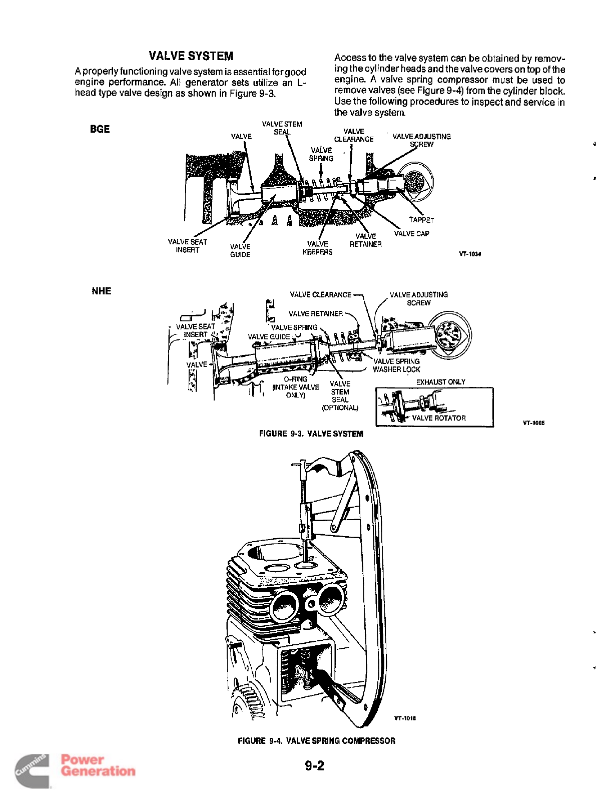
VALVE
SYSTEM
engine performance. All generator sets utilize an
L-
head type valve design as shown in Figure
9-3.
Access to the valve system can be obtained by remov-
engine.
A
valve spring compressor must be used to
remove valves (see Figure
9-4)
from the cylinder block.
Use the following procedures to inspect and service in
the valve system.
A
properlyfunctioning valve system is essential forgood ing the cylinder heads and thevalvecoverson top ofthe
VALVE
STEM
BGE
KEEPERS
VT-1034
NHE
VALVE
CLEARANCE
VALVE
ADJUSTING
A
.I
7
/
SCREW
VALVE
RETAINER
FIGURE
9-3.
VALVE SYSTEM
VT
-1
D18
VT-1005
FIGURE
9-4.
VALVE
SPRING
COMPRESSOR
9-2
Redistribution or publication of this document
by any means, is strictly prohibited.
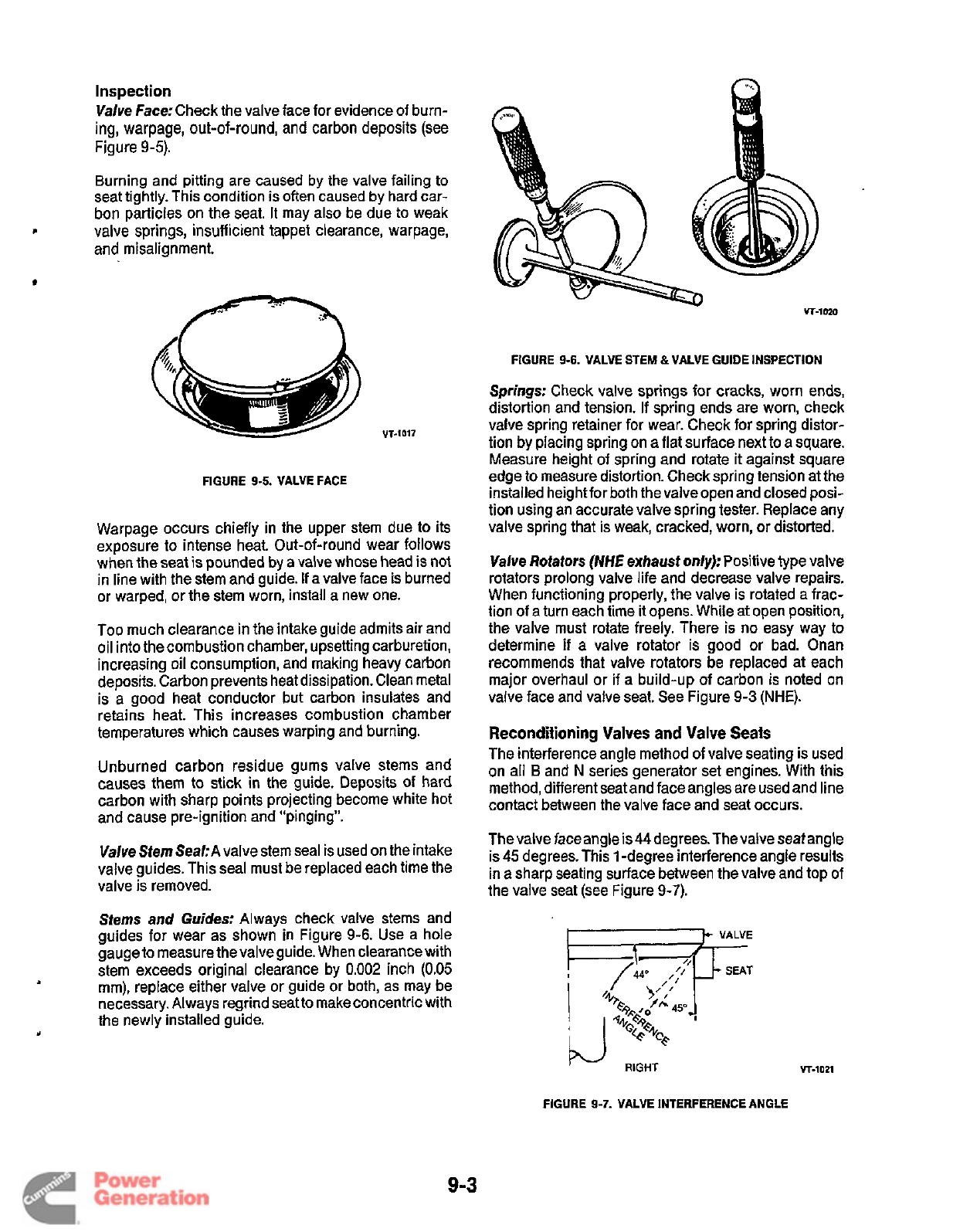
Inspection
Valve Face:
Check the valve face for evidence of burn-
ing,
warpage, out-of-round, and carbon deposits (see
Figure
9-5).
Burning and pitting are caused by the valve failing to
seat tightly. This condition is often caused by hard car-
bon
particles on the seat. It may also be due to weak
and misalignment.
L
valve springs, insufficient tappet clearance, warpage,
FIGURE
9-5.
VALVE FACE
Warpage occurs chiefly in the upper stem due to its
exposure to intense heat. Out-of-round wear follows
when the seat
is
pounded
by
a valve whose head is not
in line with the stem and guide.
If
a valve face is burned
or warped, or the stem worn, install a new one.
Too much clearance in the intake guide admits air and
oil into the combustion chamber, upsetting carburetion,
increasing oil consumption, and making heavy carbon
deposits. Carbon prevents heat dissipation. Clean metal
is a good heat conductor but carbon insulates and
retains heat. This increases combustion chamber
temperatures which causes warping and burning.
Unburned carbon residue gums valve stems and
causes them to stick in the guide. Deposits
of
hard
carbon with sharp points projecting become white
hot
and cause pre-ignition and "pinging".
Valve Stem Seal:
A
valve stem seal is used on the intake
valve guides. This seal must be replaced each time the
valve is removed.
Stems
and
Guides:
Always check valve stems and
guides for wear as shown in Figure
9-6.
Use a hole
gauge to measure the valve guide. When clearance with
stem exceeds original clearance by
0.002
inch
(0.05
mm), replace either valve or guide or both, as may be
necessary. Always regrind seat to make concentric with
the newly installed guide.
FIGURE
9-6.
VALVE STEM &VALVE GUIDE INSPECTION
Springs:
Check valve springs for cracks, worn ends,
distortion and tension. If spring ends are worn, check
valve spring retainer for wear. Check for spring distor-
tion by placing spring on a flat surface next to a square.
Measure height of spring and rotate
it
against square
edge to measure distortion. Check spring tension at the
installed heightfor both the valve open and closed posi-
tion using an accurate valve spring tester. Replace any
valve spring that is weak, cracked, worn, or distorted.
Valve Rotators
(NHE
exhaust
only):
Positive type valve
rotators prolong valve life and decrease valve repairs.
When functioning properly, the valve is rotated a frac-
tion of
a
turn each time
it
opens. While at open position,
the valve must rotate freely. There is no easy way
to
determine
if
a valve rotator is good or bad. Onan
recommends that valve rotators be replaced at each
major overhaul or if a build-up of carbon is noted on
valve face and valve seat. See Figure
9-3
(NHE).
Reconditioning
Valves and Valve
Seats
The interference angle method of valve seating is used
on all
B
and
N
series generator set engines. With this
method, different seat and face angles are used and line
contact between the valve face and seat occurs.
The valve faceangle
is
44degrees.Thevalve
seat
angle
is
45
degrees. This
1
-degree interference angle results
in a sharp seating surface between the valve and top of
the valve seat (see Figure
9-7).
RIGHT
VT-lOZl
FIGURE
9-7.
VALVE INTERFERENCE ANGLE
9-3
Redistribution or publication of this document
by any means, is strictly prohibited.
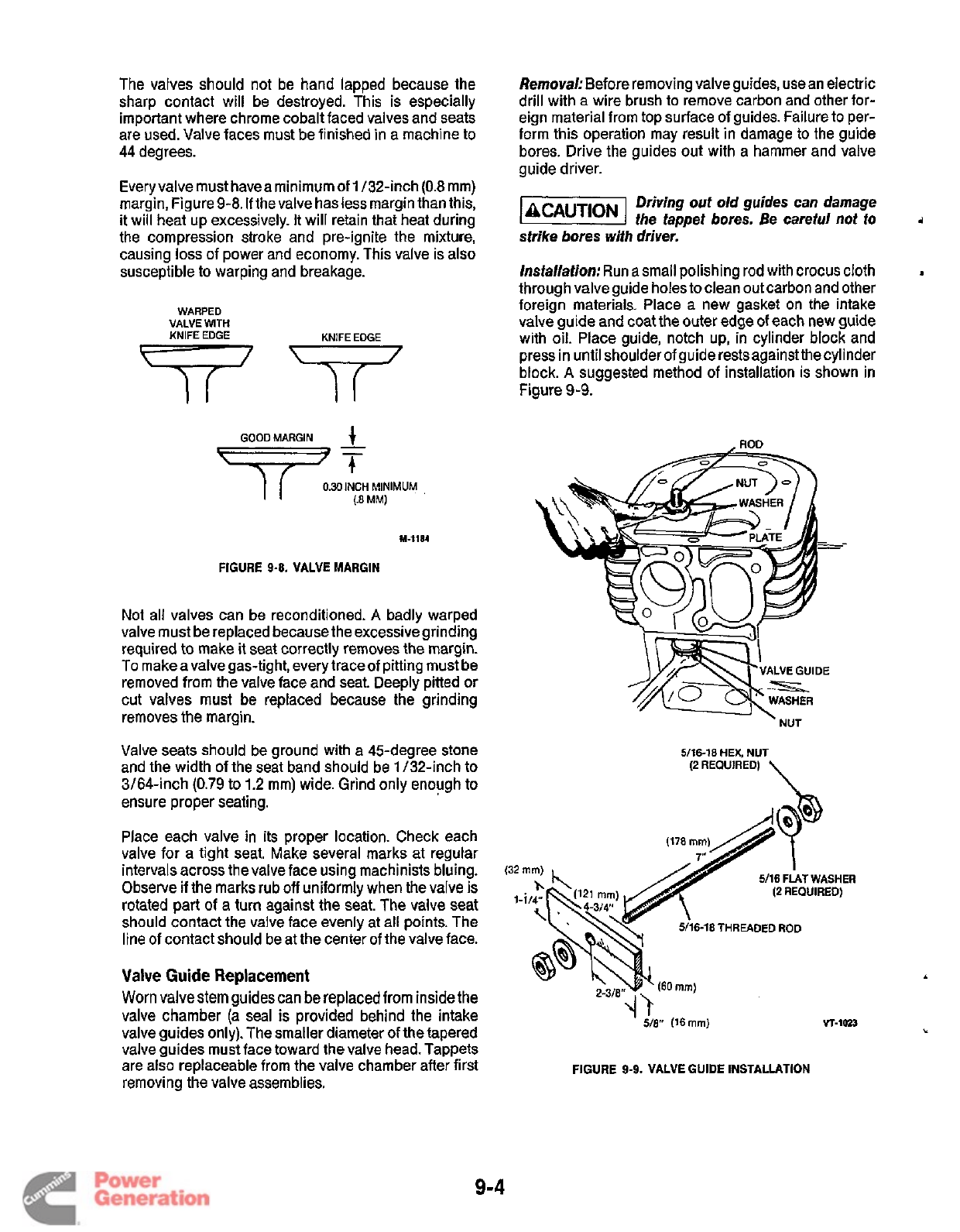
The valves should not be hand lapped because the
sharp contact will be destroyed. This is especially
important where chrome cobalt faced valves and seats
are used. Valve faces must be finished in a machine to
44 degrees.
Every valve must haveaminimum of
1
/32-inch
(0.8
mm)
margin, Figure
9-8.
If
the valve has less margin than this,
it will heat up excessively.
It
will retain that heat during
the compression stroke and pre-ignite the mixture,
causing loss of power and economy. This valve is also
susceptible to warping and breakage.
WARPED
VALVE
WITH
KNIFE
EDGE
GOODMARGIN
I
I
0.30lNCH
MINIMUM
,
(.a
MM)
FIGURE
9-8.
VALVE MARGIN
Not all valves can be reconditioned.
A
badly warped
valve must be replaced because the excessivegrinding
required to make
it
seat correctly removes the margin.
To make a valve gas-tight, every trace of pitting must be
removed from the valve face and seat. Deeply pitted or
cut valves must be replaced because the grinding
removes the margin.
Valve seats should be ground with a 45-degree stone
and the width of the seat band should be
1
/32-inch to
3/64-inch
(0.79
to
1.2
mm) wide. Grind only enough to
ensure proper seating.
Place each valve in its proper location. Check each
valve for a tight seat. Make several marks at regular
intervals across the valve face using machinists bluing.
Observe if the marks rub
off
uniformly when the valve is
rotated part
of
a turn against the seat. The valve seat
should contact the valve face evenly at all points. The
line of contact should be at the center of the valve face.
Valve
Guide
Replacement
Worn valve stem guides can
be
replaced from inside the
valve chamber
(a
seal
is
provided behind the intake
valve guides only). The smaller diameter of the tapered
valve guides must face toward the valve head. Tappets
are also replaceable from the valve chamber after first
removing the valve assemblies.
Removal:
Before removing valve guides, use an electric
drill with
a
wire brush to remove carbon and other for-
eign material from top surface of guides. Failure to per-
form this operation may result in damage to the guide
bores. Drive the guides out with a hammer and valve
guide driver.
Driving out old guides can damage
the tappet bores. Be careful not to
i
strike bores
wifh
driver.
Installation:
Run a small polishing rod with crocus cloth
through valve guide holes to clean out carbon and other
foreign materials. Place a new gasket on the intake
valve guide and coat the outer edge
of
each new guide
with oil. Place guide, notch up, in cylinder block and
press in until shoulder of guide rests againstthe cylinder
block.
A
suggested method of installation is shown in
Figure
9-9.
a
ROD
5/16-18
HEX,
NUT
(2
REQUIRED)
\
FIGURE
9-9.
VALVE GUIDE INSTALLATION
9-4
Redistribution or publication of this document
by any means, is strictly prohibited.
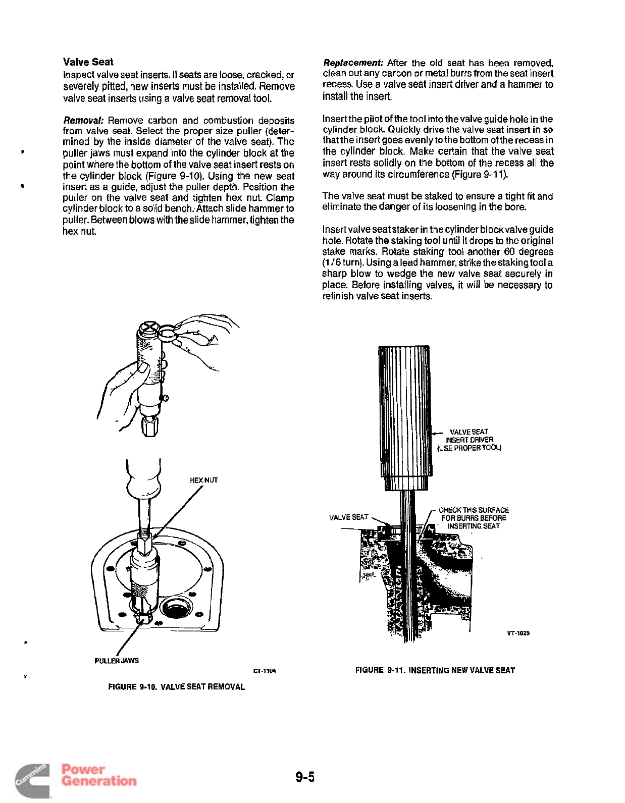
Valve Seat
Inspect valve seat inserts.
If
seats are loose, cracked, or
severely pitted,
new
inserts
must
be
installed. Remove
valve seat inserts using a valve seat removal
tool.
Removal:
Remove carbon and combustion deposits
from valve seat. Select the proper size puller (deter-
mined by the inside diameter of the valve seat). The
point where the bottom
of
the valve seat insert rests on
the cylinder block (Figure 9-10). Using the new seat
puller on the valve seat and tighten hex nut. Clamp
cylinder block to a solid bench..Attach slide hammer to
puller. Between blows with the slide hammer, tighten the
hex nut.
B
puller jaws must expand into the cylinder block at the
insert as a guide, adjust the puller depth. Position the
Replacement:
After the old seat has been removed,
clean out any carbon or metal burrs from the seat insert
recess. Use a valve seat insert driver and a hammer to
install
the insert.
Insert the pilot of the tool into thevalve guide hole in the
cylinder block. Quickly drive the valve seat insert in
so
that the insert goes evenly to the bottom of the recess in
the cylinder block. Make certain that the valve seat
insert rests solidly on the bottom
of
the recess all the
way around its circumference (Figure 9-1 1).
The valve seat must be staked to ensure a tight fit and
eliminate the danger of its loosening in the bore.
Insert valve seat staker in the cylinder block valve guide
hole. Rotate the staking tool until it drops to the original
stake marks. Rotate staking
tool
another
60
degrees
(1
/6
turn). Using a lead hammer, strike the staking tool a
sharp blow to wedge the new valve seat securely
in
place. Before installing valves,
it
will be necessary
to
refinish valve seat inserts.
PULLERJAWS
CT-1104
FIGURE 9-10. VALVE
SEAT
REMOVAL
VALVE
-
INSERT
DRIVER
(USE
PROPER TOOL)
CHECK
THIS
SURFACE
FOR
BURRS
BEFORE
Y
T-1025
FIGURE 9-11. INSERTING NEW VALVE
SEAT
9-5
Redistribution or publication of this document
by any means, is strictly prohibited.
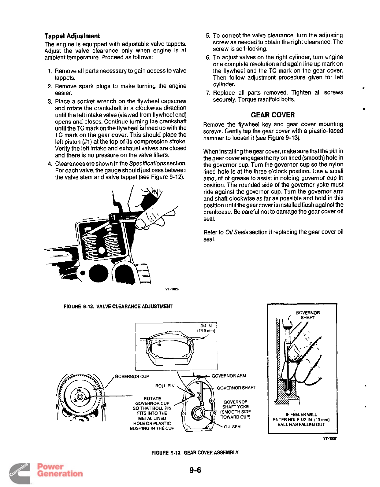
Tappet Adjustment
The engine is equipped with adjustable valve tappets.
Adjust the valve clearance only when engine is at
ambient temperature. Proceed as follows:
1.
Remove all parts necessary to gain access to valve
tappets.
2.
Remove spark plugs to make turning the engine
easier.
3.
Place a socket wrench on the flywheel capscrew
and rotate the crankshaft in a clockwise direction
until the left intake valve (viewed from flywheel end)
opens and closes. Continue turning the crankshaft
until the TC mark on the flywheel is lined up with the
TC mark on the gear cover. This should place the
left piston
(#1)
at the top of its compression stroke.
Verify the left intake and exhaust valves are closed
and there is no pressure on the valve lifters.
4.
Clearances are shown in the Specificationssection.
For each valve, the gauge should just pass between
the valve stem and valve tappet (see Figure
9-12).
Vr-1026
FIGURE 9-12. VALVE CLEARANCE ADJUSTMENT
5.
To correct the valve clearance, turn the adjusting
screw as needed to obtain the right clearance. The
screw is self-locking.
6.
To
adjust valves on the right cylinder, turn engine
one complete revolution and again line up mark on
the flywheel and the TC mark on the gear cover.
Then follow adjustment procedure given for left
cylinder.
7.
Replace all parts removed. Tighten all screws
securely. Torque manifold bolts.
GEAR
COVER
Remove the flywheel key and gear cover mounting
screws. Gently tap the gear cover with a plastic-faced
hammer to loosen
it
(see Figure
9-1
3).
*
When installing thegear cover, make sure that the pin in
the gear cover engages the nylon lined (smooth) hole in
the governor cup. Turn the governor cup
so
the nylon
lined hole is at the three o’clock position. Use a
small
amount of grease to assist in holding governor cup in
position. The rounded side
of
the governor yoke must
ride against the governor cup. Turn the governor arm
and shaft clockwise as far as possible and hold in this
position until the gear cover is installed flush against the
crankcase. Be careful not to damage the gear cover oil
seal.
Refer to
Oil
Seals section if replacing the gear cover oil
seal.
OVERNOR ARM
GOVERNOR
SHAFT
GOVERNOR CUP
SO
THAT ROLL PIN
FITS INTO THE
.
METAL LINED
HOLE
OR
PLASTIC
BUSHING IN
THE
CUP
GOVERNOR
IF FEELER WILL
ENTER HOLE
1/2
IN.
(13
mm)
BALL HAS FALLEN OUT
VT-1027
FIGURE
9-13.
GEAR
COVER
ASSEMBLY
9-6
Redistribution or publication of this document
by any means, is strictly prohibited.
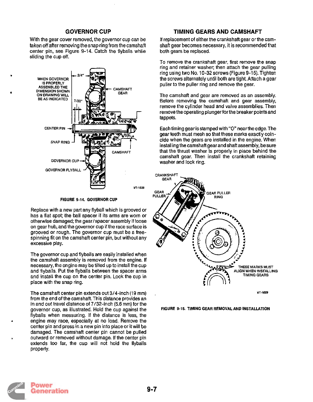
GOVERNOR
CUP
With the gear cover removed, the governor cup can be
taken
off
after
removing the snap ring from the camshaft
center pin, see Figure
9-14.
Catch the flyballs while
sliding the cup
off.
WHEN
GOVERNOR
IS
PROPERLY
ASSEMBLED
THE
DIMENSION
SHOWN
ON
DRAWING
WILL
BE
AS
INDICATED
GOVERNOR
CUP
GOVERNOR
FLYBALL
I
VT-1028
FIGURE
9-14.
GOVERNOR CUP
Replace with a new part any flyball which is grooved or
has a flat spot; the ball spacer if its arms are worn or
otherwise damaged; the gear/spacer assembly if loose
on gear hub, and the governor cup
if
the race surface is
grooved or rough. The governor cup must be
a
free-
spinning fit on the camshaft center pin, but without any
excessive play.
The governor cup and flyballs are easily installed when
the camshaft assembly is removed from the engine. If
necessary, the engine may be tilted up to install the cup
and flyballs. Put the flyballs between the spacer arms
and install the cup on the center pin. Lock the cup in
place with the snap ring.
TIMING GEARS AND CAMSHAFT
If
replacement of either the crankshaft gear or the cam-
shaft gear
becomes
necessary,
it
is
recommended
that
both gears be replaced.
To
remove the crankshaft gear, first remove the snap
ring and retainer washer; then attach the gear pulling
ring using two
No.
10-32
screws (Figure
9-15).
Tighten
the screws alternately until both are tight. Attach a gear
puller
to
the puller ring and remove the gear.
The camshaft and gear are removed as an assembly.
Before removing the camshaft and gear assembly,
remove the cylinder head and valve assemblies. Then
remove the operating plunger for the breaker points and
tappets.
Each timing gear is stamped with
“0
near the edge. The
gear teeth must mesh
so
that these marks exactly coin-
cide when the gears are installed in the engine. When
installing the camshaft gear and shaft assembly, besure
that the thrust washer is properly in place behind the
camshaft gear. Then install the crankshaft retaining
washer and lock ring.
CRANKSHAFT
GEAR
PULLER
THESE
MARKS
MUST
TIMING
GEARS
WHEN
INSTALLING
The camshaft center pin extends out 3/4-inch
(19
mm)
.
vr-1019
from the end of the camshaft. This distance provides an
in and out travel distance of 7/32-inch
(5.6
mm) for the
flyballs when measuring. If the distance is less, the
engine may race, especially at no load. Remove the
center pin and press in a new pin into place or
it
will be
damaged. The camshaft center pin cannot be pulled
outward or removed without damage.
If
the center pin
extends
too
far, the cup will not hold the flyballs
properly.
governor cup, as illustrated. Hold the cup against the
FIGURE
9-15.
TIMING GEAR REMOVAL AND INSTALLATION
4
Y
9-7
Redistribution or publication of this document
by any means, is strictly prohibited.
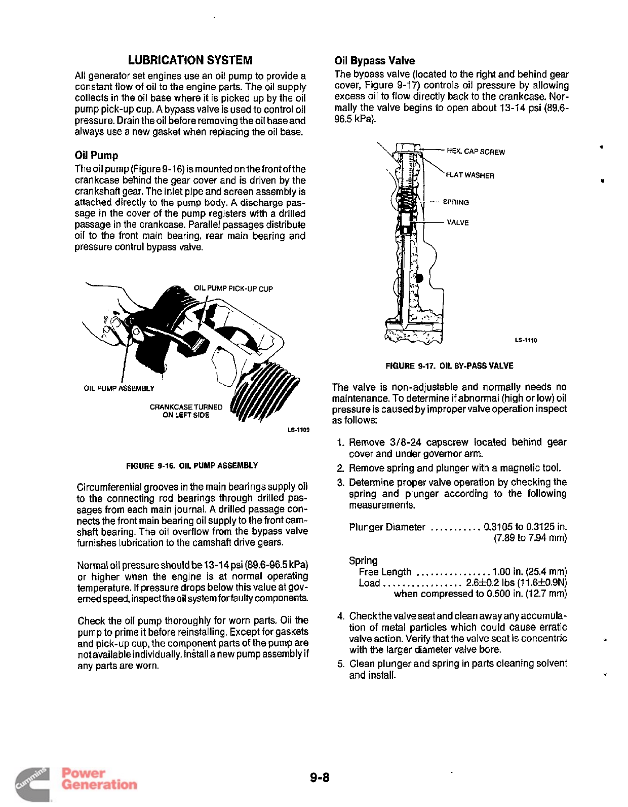
LUBRICATION
SYSTEM
All
generator set engines use an oil pump to provide a
constant flow of oil to the engine parts. The oil supply
collects in the oil base where
it
is picked up by the oil
pump pick-up cup.
A
bypass valve
is
used to control oil
pressure. Drain the oil before removing the
oil
baseand
always use a new gasket when replacing the oil base.
Oil
Pump
Theoil pump(Figure9-16) is mounted on thefrontofthe
crankcase behind the gear cover and is driven by the
crankshaft gear. The inlet pipe and screen assembly is
attached directly to the pump body.
A
discharge pas-
sage in the cover of the pump registers with
a
drilled
passage in the crankcase. Parallel passages distribute
oil to the front main bearing, rear main bearing and
pressure control bypass valve.
UMP
PICK-UP
CUP
CRANKCASE
TURNED
ON LEFT SIDE
LS-1109
FIGURE
9-16.
OIL PUMP ASSEMBLY
Circumferential grooves in the main bearings supply
oil
to the connecting rod bearings through drilled pas-
sages from each main journal.
A
drilled passage con-
nects the front main bearing oil supply to the front carn-
shaft bearing. The oil overflow from the bypass valve
furnishes lubrication to the camshaft drive gears.
Normal
oil
pressure
should
be
13-1
4
psi
(89.6-96.5
kPa)
or higher when the engine is at normal operating
temperature.
If
pressure drops below this value at gov-
erned speed, inspect the oil system for faulty components.
Check the oil pump thoroughly for worn parts. Oil the
pump to prime it before reinstalling. Except for gaskets
and pick-up cup, the component parts of the pump are
not available individually. Install a new pump assembly if
any parts are worn.
Oil
Bypass
Valve
The bypass valve (located to the right and behind gear
cover, Figure 9-17) controls oil pressure by allowing
excess oil to flow directly back to the crankcase. Nor-
mally the valve begins to open about 13-14 psi (89.6-
96.5 kPa).
HEX.
CAP
SCREW
LS-1110
FIGURE
9-17.
OIL BY-PASS VALVE
The valve is non-adjustable and normally needs no
maintenance.
To
determine
if
abnormal (high or low) oil
pressure is caused by improper valve operation inspect
as follows:
1.
Remove
3/8-24
capscrew located behind gear
2. Remove spring and plunger with a magnetic tool.
3.
Determine proper valve operation by checking the
spring and plunger according to the following
measurements.
cover and under governor arm.
Plunger Diameter
.
.
.
.
.
. .
.
.
.
.
0.3105 to
0.3125
in.
(7.89 to 7.94 mm)
Spring
Free Length
. . .
.
.
.
. .
. .
.
. .
.
.
.
1.00 in. (25.4 mm)
Load..
. . . . . .
.
.
.
. . .
.
. .
2.6f0.2 Ibs (11.6f0.9N)
when compressed to
0.500
in. (12.7 mm)
4. Check the valve seat and clean away any accumula-
tion of metal particles which could cause erratic
valve action. Verify that the valve seat is concentric
with the larger diameter valve bore.
5.
Clean plunger and spring in parts cleaning solvent
and
install.
Y
I
9-8
Redistribution or publication of this document
by any means, is strictly prohibited.
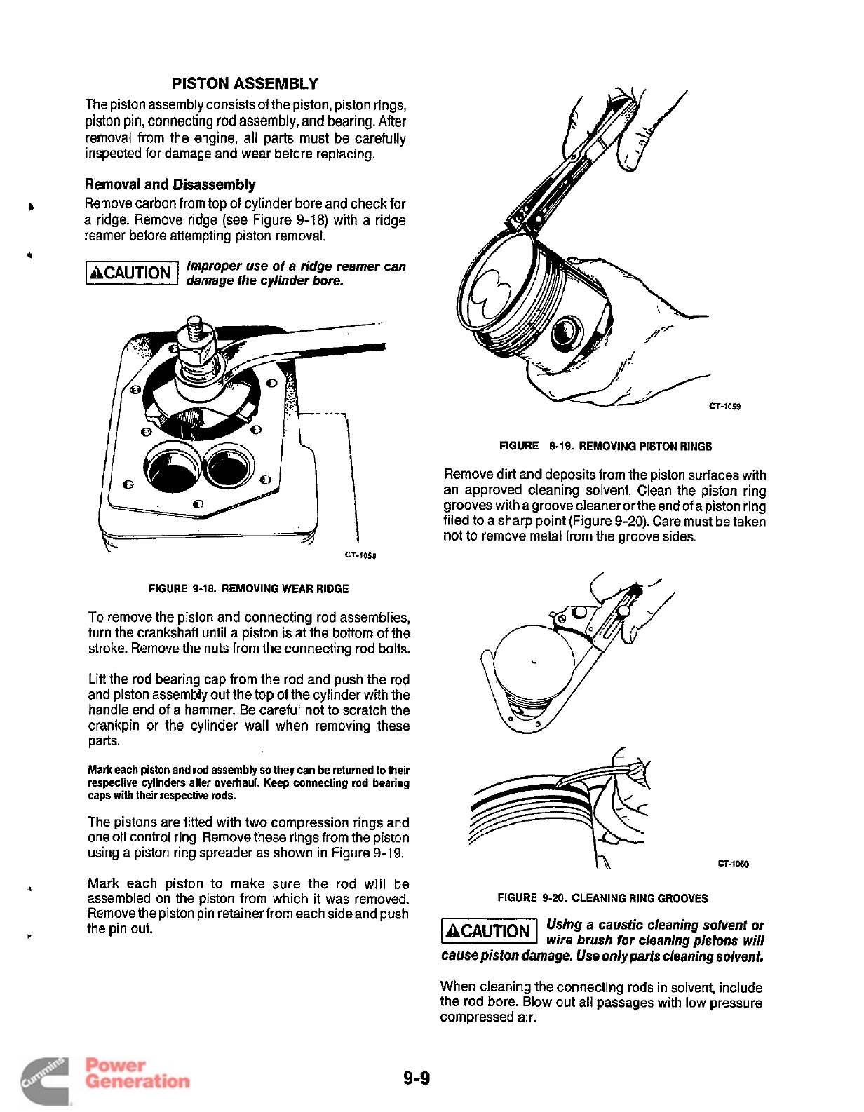
PISTON
ASSEMBLY
The piston assembly consists of the piston, piston rings,
piston
pin,
connecting
rod
assembly,
and bearing. After
removal from the engine, all parts must be carefully
inspected for damage and wear before replacing.
Removal
and
Disassembly
Remove carbon from top
of
cylinder bore and check for
a ridge. Remove ridge (see Figure
9-18)
with
a
ridge
reamer before attempting piston removal.
Improper use
of
a ridge reamer can
damage the cylinder bore.
B
4
FIGURE
9-19.
REMOVING
PISTON
RINGS
FIGURE
9-18.
REMOVING WEAR RIDGE
To remove the piston and connecting rod assemblies,
turn the crankshaft until
a
piston
is
at the bottom of the
stroke. Remove the nuts from the connecting rod bolts.
Lift the rod bearing cap from the rod and push the rod
and piston assembly out the top of the cylinder with the
handle end
of
a hammer. Be careful not to scratch the
crankpin or the cylinder wall when removing these
parts.
Mark each piston and rod assembly
so
they can be returned
to
their
respective cylinders after overhaul. Keep connecting rod bearing
caps with their respective rods.
The pistons are fitted with two compression rings and
one oil control ring. Remove these rings from the piston
using a piston ring spreader as shown in Figure 9-1
9.
Mark each piston
to
make sure the rod will be
assembled on the piston from which it was removed.
Remove the piston pin retainer from each side and push
the pin out.
-1059
Remove dirt and deposits from the piston surfaces with
an approved cleaning solvent. Clean the piston ring
grooves with a groove cleaner or the end of a piston ring
filed to a sharp point (Figure
9-20).
Care must be taken
not to remove metal from the groove sides.
&
Y
h
CT-1wO
FIGURE
9-20.
CLEANING RING GROOVES
1-1
Using a caustic cleaning solvent
or
wire brush
for
cleaning pistons will
cause piston damage.
Use
only parts cleaning solvent.
When cleaning the connecting rods in solvent, include
the rod bore. Blow out all passages with low pressure
compressed air.
9
-9
Redistribution or publication of this document
by any means, is strictly prohibited.
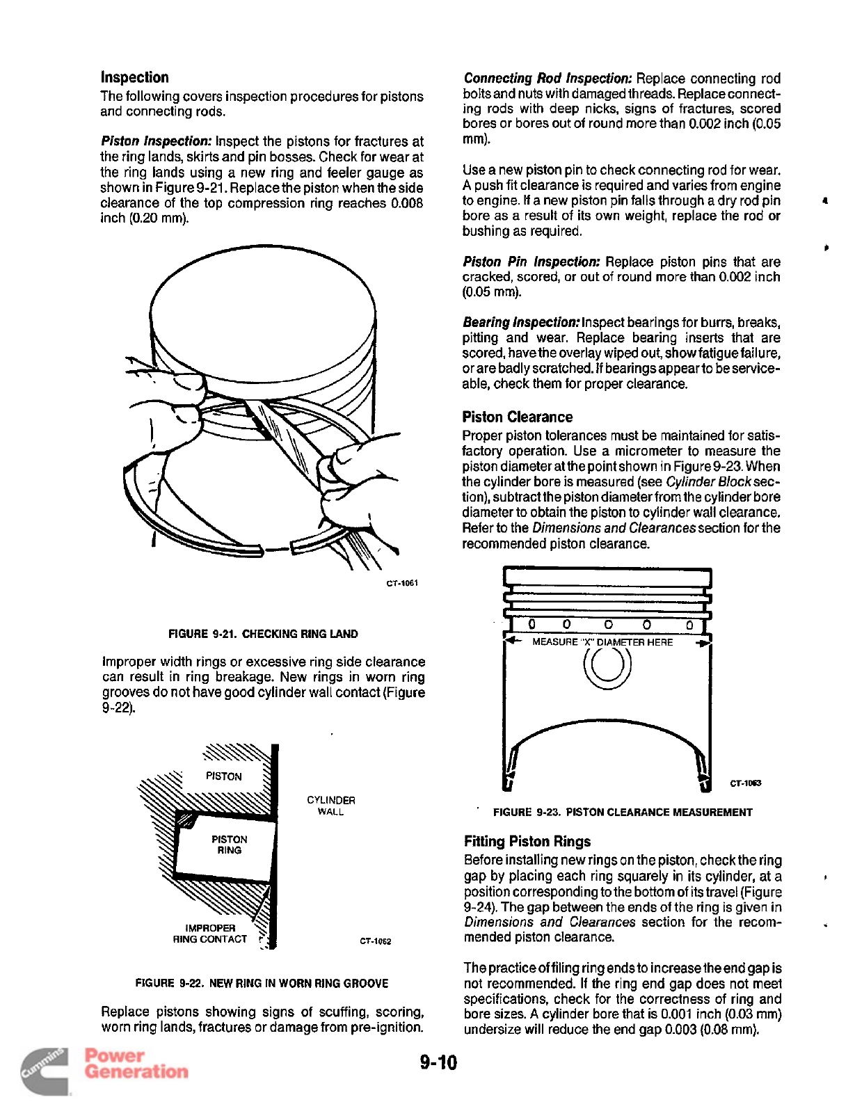
Inspection
The following covers inspection procedures for pistons
and connecting rods.
Piston Inspection: Inspect the pistons for fractures at
the ring lands, skirts and pin bosses. Check for wear at
the ring lands using a new ring and feeler gauge as
shown in Figure9-21. Replace the piston when the side
clearance of the top compression ring reaches
0.008
inch
(0.20
mm).
CT-1061
FIGURE
9-21.
CHECKING
RING
LAND
Improper width rings or excessive ring side clearance
can result in ring breakage. New rings in worn ring
grooves do not have good cylinder wall contact (Figure
9-22).
CYLINDER
WALL
CT-1062
FIGURE
9-22.
NEW
RING
IN
WORN
RING GROOVE
Replace pistons showing signs of scuffing, scoring,
worn ring lands, fractures or damage from pre-ignition.
9-
Connecting
Rod
Inspection: Replace connecting rod
bolts and nuts with damaged threads. Replace connect-
ing rods with deep nicks, signs of fractures, scored
bores or bores out of round more than
0.002
inch
(0.05
mm).
Use a new piston pin to check connecting rod for wear.
A
push fit clearance is required and varies from engine
bore as a result
of
its own weight, replace the rod or
bushing as required.
Pisfon
Pin
Inspection: Replace piston pins that are
cracked, scored, or out of round more than
0.002
inch
(0.05
mm).
to engine. If a new piston pin falls through a dry rod pin
1
c
Bearing Inspection:lnspect bearings for burrs, breaks,
pitting and wear. Replace bearing inserts that are
scored, have the overlay wiped out, show fatigue failure,
or are badly scratched.
If
bearings appear to be service-
able, check them for proper clearance.
Piston Clearance
Proper piston tolerances must be maintained for satis-
factory operation. Use a micrometer to measure the
piston diameter at the point shown in Figure 9-23. When
the cylinder bore is measured (see Cylinder Blocksec-
tion), subtractthe piston diameter from the cylinder bore
diameter to obtain the piston to cylinder wall clearance.
Refer to the Dimensions and Clearances section for the
recommended piston clearance.
..
'A
MEASURE"X' DIAMETER HERE
+
.
FIGURE
9-23.
PISTON
CLEARANCE
MEASUREMENT
Fitting Piston Rings
Before installing new rings on the piston, check the ring
gap by placing each ring squarely in
its
cylinder, at a
position corresponding to the bottom
of
its travel (Figure
9-24).
The gap between the ends of the ring is given in
Dimensions
and
Clearances section for the recom-
mended piston clearance.
L
<
The practice of filing ring ends to increase the end gap is
not recommended. If the ring end gap does not meet
specifications, check for the correctness of ring and
bore sizes.
A
cylinder bore that is
0.001
inch
(0.03
mm)
undersize will reduce the end gap
0.003
(0.08
mm).
Redistribution or publication of this document
by any means, is strictly prohibited.
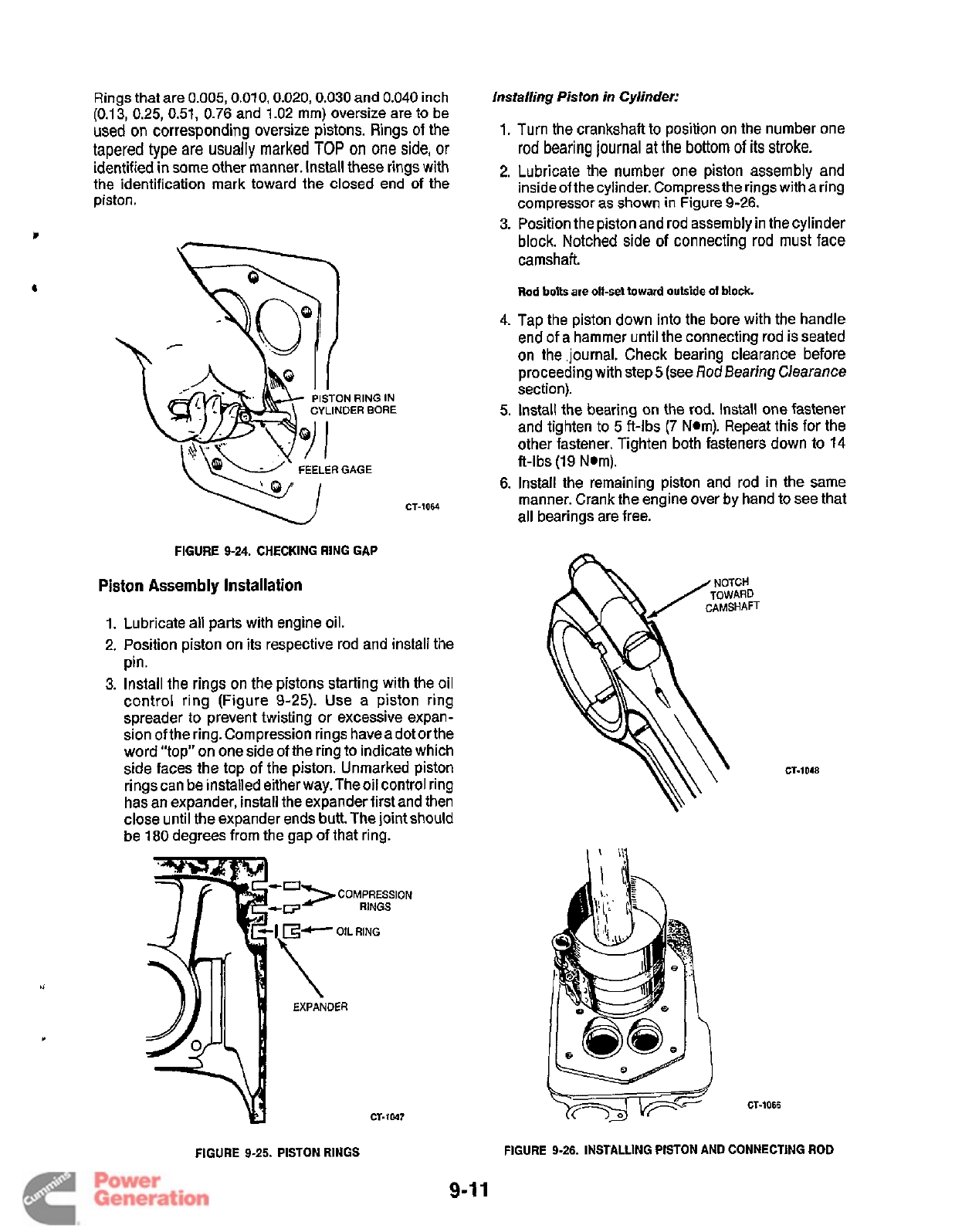
Rings
that
are
0.005,0.010,0.020,0.030
and
0.040
inch
(0.1
3,
0.25,
0.51,
0.76 and 1.02 mm) oversize are to be
used on corresponding oversize pistons. Rings
of
the
tapered type are usually marked
TOP
on
one side,
or
identified in some other manner. Install these rings with
the identification mark toward the closed end of the
piston.
c
&
CT-1064
FIGURE 9-24. CHECKING RING GAP
Piston
Assembly
Installation
1.
Lubricate all parts with engine oil.
2.
Position piston on its respective rod and install the
pin.
3.
Install the rings on the pistons starting with the oil
control ring (Figure
9-25).
Use a piston ring
spreader
to
prevent twisting or excessive expan-
sion of the ring. Compression rings have a dot or the
word “top” on one side of the ring
to
indicate which
side faces the top of the piston. Unmarked piston
rings can be installed either way. The oil control ring
has an expander, install the expander first and then
close until the expander ends butt. The joint should
be
180
degrees from the gap of that ring.
CT-1047
Installing Piston
in
Cylinder:
1.
Turn the crankshaft to position on the number one
rod bearing journal
at
the bottom
of
its stroke.
2.
Lubricate the number one piston assembly and
insideof the cylinder. Compress the rings with a ring
compressor as shown in Figure
9-26.
3.
Position the piston and rod assembly in the cylinder
block. Notched side of connecting rod must face
camshaft.
Rod
bolts
are
off-set
toward
outside
of
block.
4.
Tap the piston down into the bore with the handle
end of a hammer until the connecting rod
is
seated
on the .journal. Check bearing clearance before
proceeding with step
5
(see
Rod
Bearing Clearance
section).
5.
Install the bearing on the rod. Install one fastener
and tighten
to
5 ft-lbs
(7 Nom). Repeat this for the
other fastener. Tighten both fasteners down to
14
ft-lbs
(19
Nom).
6. Install the remaining piston and rod in the same
manner. Crank the engine over by hand
to
see that
all bearings are free.
he
CT-1066
CT-1048
FIGURE 9-25. PISTON
RINGS
FIGURE 9-26. INSTALLING PISTON AND CONNECTING
ROD
9-1
1
Redistribution or publication of this document
by any means, is strictly prohibited.
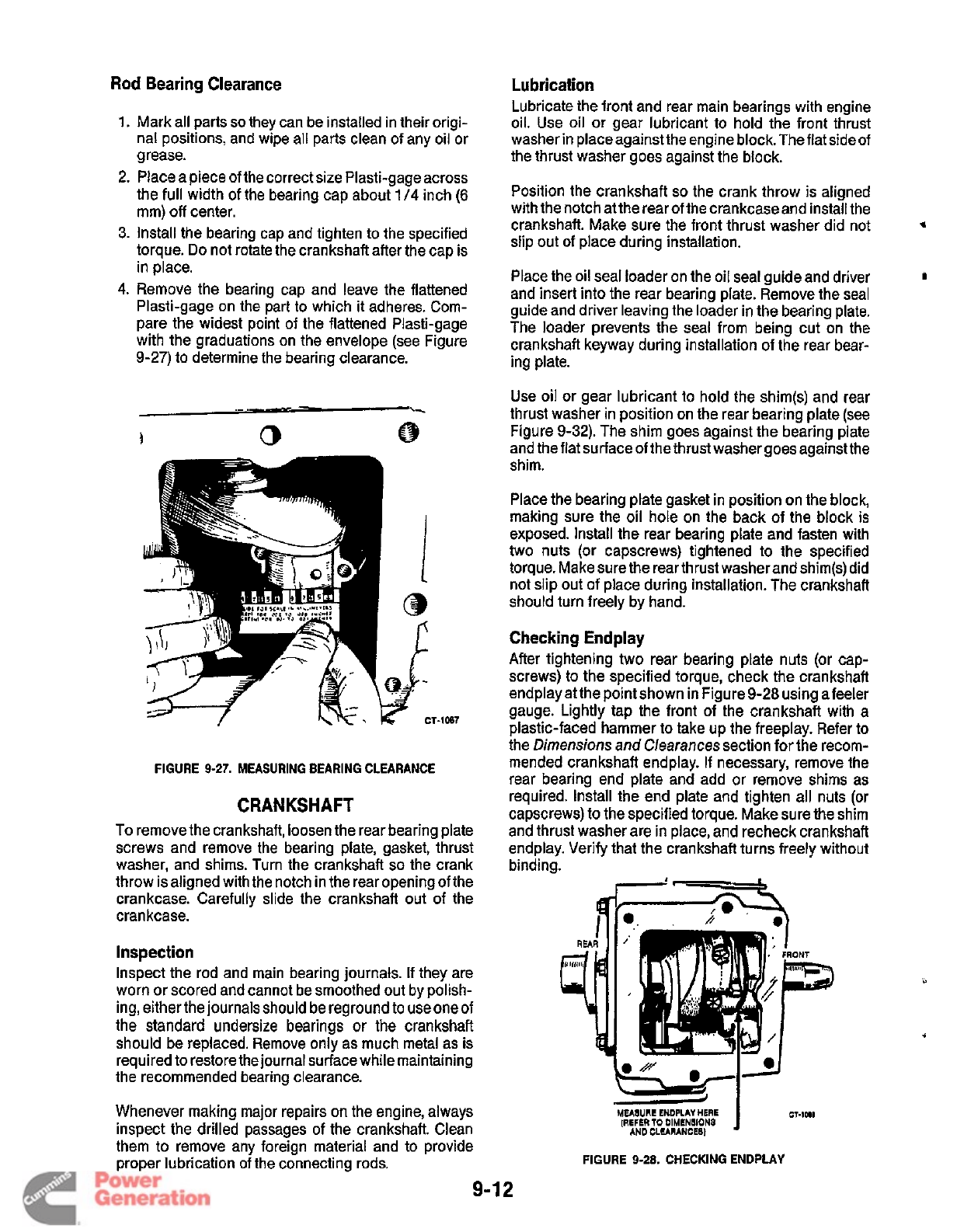
Rod
Bearing
Clearance
Lubrication
Lubricate the front and rear main bearings with engine
oil. Use oil or gear lubricant to hold the front thrust
washer in place against the engine block. The flat side of
the thrust washer goes against the block.
Mark all parts
so
they can be installed in their origi-
nal positions, and wipe all parts dean of any oil or
grease.
Place a piece of the correct size Plasti-gage across
the full width of the bearing cap about
1
/4
inch
(6
mm)
off
center.
Install the bearing cap and tighten
to
the specified
torque.
Do
not rotate the crankshaft after the cap is
in place.
Remove the bearing cap and leave the flattened
Plasti-gage on the part
to
which
it
adheres. Com-
pare the widest point of the flattened Plasti-gage
with the graduations on the envelope (see Figure
9-27) to determine the bearing clearance.
-1
OB7
FIGURE
9-27.
MEASURING
BEARING
CLEARANCE
CRANKSHAFT
To remove the crankshaft, loosen the rear bearing plate
screws and remove the bearing plate, gasket, thrust
washer, and shims. Turn the crankshaft
so
the crank
throw is aligned with the notch in the rear opening of the
crankcase. Carefully slide the crankshaft out of the
crankcase.
inspection
Inspect the rod and main bearing journals.
If
they are
worn or scored and cannot be smoothed out by polish-
ing, either the journals should be reground to use oneof
the standard undersize bearings
or
the crankshaft
should be replaced. Remove only as much metal as is
required to restore the journal surface while maintaining
the recommended bearing clearance.
Whenever making major repairs on the engine, always
inspect the drilled passages of the crankshaft. Clean
them
to
remove any foreign material and to provide
proper lubrication of the connecting rods.
Position the crankshaft
so
the crank throw is aligned
with the notch at the rear of the crankcase and install the
crankshaft. Make sure the front thrust washer did not
slip out of place during installation.
and insert into the rear bearing plate. Remove the seal
guide and driver leaving the loader in the bearing plate.
The loader prevents the seal from being cut on the
crankshaft keyway during installation of the rear bear-
ing plate.
1
Place the oil seal loader on the oil seal guide and driver
b
Use oil or gear lubricant to hold the shim(s) and rear
thrust washer in position on the rear bearing plate (see
Figure 9-32). The shim goes against the bearing plate
and the flat surface of the thrust washer goes against the
shim.
Place the bearing plate gasket in position on the block,
making sure the oil hole on the back of the block
is
exposed. Install the rear bearing plate and fasten with
two nuts (or capscrews) tightened to the specified
torque. Make sure the rear thrust washer and shim(s) did
not slip out of place during installation. The crankshaft
should turn freely by hand.
Checking
Endpiay
After tightening two rear bearing plate nuts (or cap-
screws) to the specified torque, check the crankshaft
endplay at the point shown in Figure 9-28 using a feeler
gauge. Lightly tap the front of the crankshaft with a
plastic-faced hammer to take up the freeplay. Refer to
the Dimensions
and
Clearances section for the recom-
mended crankshaft endplay.
If
necessary, remove the
rear bearing end plate and add or remove shims as
required. Install the end plate and tighten all nuts (or
capscrews) to the specified torque. Make sure the shim
and thrust washer are in place, and recheck crankshaft
endplay. Verify that the crankshaft turns freely without
binding.
MEAIUAE
ENDPLAY HERE
CT-IO((
(REFER
TO
DIMINIIONB
1
AND CLEARANGEE)
FIGURE
9-28.
CHECKING ENDPLAV
9-1
2
Redistribution or publication of this document
by any means, is strictly prohibited.
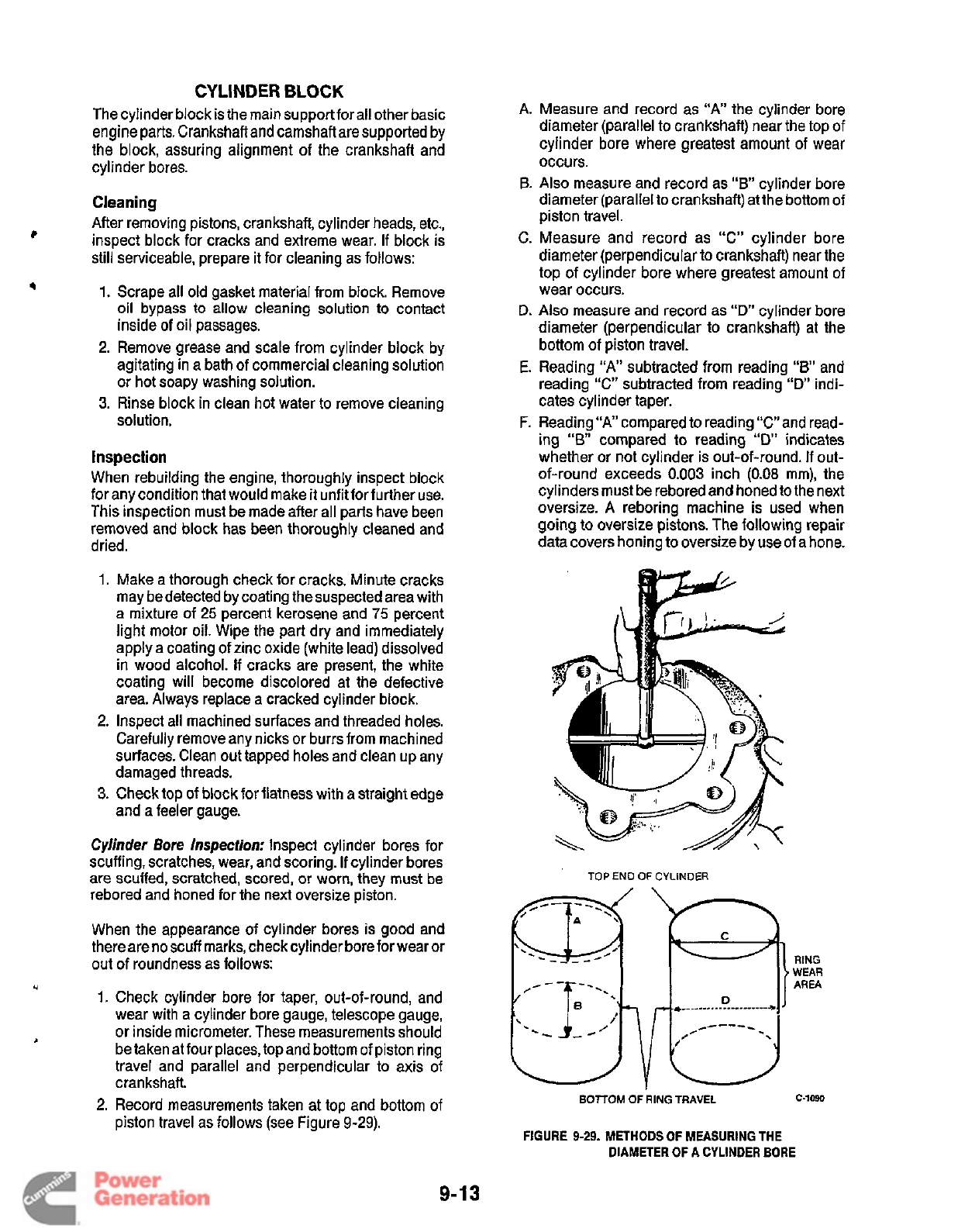
CYLINDER
BLOCK
The cylinder block
is
the main support for all other basic
engine parts. Crankshaft and camshaft are supported
by
the block, assuring alignment of the crankshaft and
cylinder bores.
Cleaning
After removing pistons, crankshaft, cylinder heads, etc.,
inspect block for cracks and extreme wear.
If
block is
still serviceable, prepare it for cleaning as follows:
1.
Scrape all old gasket material from block. Remove
oil bypass
to
allow cleaning solution to contact
inside
of
oil passages.
2. Remove grease and scale from cylinder block by
agitating in a bath of commercial cleaning solution
or hot soapy washing solution.
3.
Rinse block in clean hot water to remove cleaning
solution.
?
4
Inspection
When rebuilding the engine, thoroughly inspect block
for any condition that would make it unfit for further use.
This inspection must be made after all parts have been
removed and block has been thoroughly cleaned and
dried.
A.
Measure and record as
“A”
the cylinder bore
diameter (parallel to crankshaft) near the top of
cylinder bore where greatest amount of wear
occurs.
6.
Also
measure and record as
“B’
cylinder bore
diameter (parallel to crankshaft) atthe bottom of
piston travel.
C.
Measure and record as “C” cylinder bore
diameter (perpendicular to crankshaft) near the
top of cylinder bore where greatest amount of
wear occurs.
D.
Also
measure and record as
“D”
cylinder bore
diameter (perpendicular to crankshaft) at the
bottom of piston travel.
E.
Reading
“A”
subtracted from reading
“BI
and
reading
“C“
subtracted from reading
“D”
indi-
cates cylinder taper.
F.
Reading
“A”
compared to reading “C”and read-
ing
“6
compared to reading
“D’
indicates
whether or not cylinder is out-of-round.
If
out-
of-round exceeds
0.003
inch
(0.08
mm), the
cylinders must be rebored and honed to the next
oversize.
A
reboring machine is used when
going
to
oversize pistons. The following repair
data covers honing to oversize by use
of
a hone.
1.
Make
a
thorough check for cracks. Minute cracks
may be detected by coating the suspected area with
a mixture
of
25
percent kerosene and
75
percent
light motor oil. Wipe the part dry and immediately
apply a coating of zinc oxide (white lead) dissolved
in wood alcohol.
If
cracks are present, the white
coating will become discolored at the defective
area. Always replace a cracked cylinder block.
2. Inspect all machined surfaces and threaded holes.
Carefully remove any nicks or burrs from machined
surfaces. Clean out tapped holes and clean up any
damaged threads.
3.
Check top
of
block for flatness with
a
straight edge
and a feeler gauge.
Cylinder Bore Inspection:
Inspect cylinder bores for
scuffing, scratches, wear, and scoring.
If
cylinder bores
are scuffed, scratched, scored, or worn, they must be
rebored and honed for the next oversize piston.
When the appearance of cylinder bores is good and
thereareno scuff marks, checkcylinder boreforwear
or
out of roundness as follows:
1.
Check cylinder bore for taper, out-of-round, and
wear with a cylinder bore gauge, telescope gauge,
or inside micrometer. These measurements should
betaken
at
four places, top and bottom of piston ring
travel and parallel and perpendicular to axis
of
cranks haft.
2.
Record measurements taken at top and bottom of
piston travel as follows (see Figure 9-29).
U
I
TOP
END
OF
CYLINDER
RING
WEAR
AREA
BOlTOM
OF
RING
TRAVEL
c-1090
FIGURE
9-29.
METHODS OF MEASURING THE
DIAMETER OF A CYLINDER
BORE
9-1
3
Redistribution or publication of this document
by any means, is strictly prohibited.
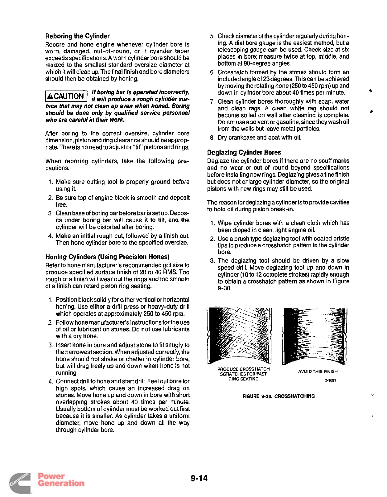
Reboring the Cylinder
Rebore and hone engine whenever cylinder bore is
worn, damaged, out-of-round, or if cylinder taper
exceeds specifications.
A
worn cylinder bore should be
resized to the smallest standard oversize diameter at
which it will clean up. The final finish and bore diameters
should then be obtained by honing.
If boring bar
is
operated incorrectly,
1-1
it will produce a rough cylinder sur-
face that may not clean up even when honed. Boring
should be done only by qualified service personnel
who are careful in their work.
After boring to the correct oversize, cylinder bore
dimension, piston and ring clearance should be approp-
riate. There is no need
to
adjust or “fit” pistons and rings.
When reboring cylinders, take the following pre-
cautions:
Make sure cutting tool is properly ground before
using it.
Be sure top of engine block is smooth and deposit
free.
Clean base of boring bar before bar is set up. Depos-
its under boring bar will cause
it
to
tilt,
and the
cylinder will be distorted after boring.
Make an initial rough cut, followed by a finish cut.
Then hone cylinder bore to the specified oversize.
5.
Check diameter of the cylinder regularly during hon-
ing.
A
dial bore gauge is the easiest method, but a
telescoping gauge can be used. Check size at six
places in bore; measure twice at top, middle, and
bottom at 90-degree angles.
6.
Crosshatch formed by the stones should form an
included angle of 23degrees. This can be achieved
by moving the rotating hone
(250
to
450
rpm) up and
7.
Clean cylinder bores thoroughly with soap, water
and clean rags.
A
clean white rag should not
become soiled on wall after cleaning is complete.
Do
not useasolvent or gasoline, since they wash oil
from the walls but leave metal particles.
down in cylinder bore about
40
times per minute.
9
#
8.
Dry
crankcase and coat with oil.
Deglazing Cylinder Bores
Deglaze the cylinder bores
if
there are no scuff marks
and no wear or out of round beyond specifications
before installing new rings. Deglazing givesafinefinish
but does not enlarge cylinder diameter,
so
the original
pistons with new rings may still be used.
The reason for deglazing a cylinder is
to
provide cavities
to hold oil during piston break-in.
1.
Wipe cylinder bores with a clean cloth which has
been dipped in clean, light engine oil.
2. Use a brush type deglazing tool with coated bristle
tips to produce a crosshatch pattern in the cylinder
bore.
3. The deglazing tool should be driven by a slow
speed drill. Move deglazing tool up and down in
cylinder
(10
to
12
complete strokes) rapidly enough
to obtain a crosshatch pattern as shown in Figure
Honing Cylinders (Using Precision Hones)
Refer
to
hone manufacturer’s recommended grit size to
produce specified surface finish of
20
to
40
RMS.
Too
rough of a finish will wear out the rings and too smooth
of a finish can retard piston ring seating. 9-30.
1.
Position blocksolidly for either vertical or horizontal
which operates at approximately
250
to
450
rpm.
2. Follow hone manufacturer’s instructions for the use
of oil or lubricant on stones. Do not use lubricants
with a dry hone.
3. Insert hone in bore and adjust stone to fit snugly to
the narrowest section. When adjusted correctly, the
hone should not shake or chatter
in
cylinder bore,
honing. Use either a drill press or heavy-duty drill
...
.
but will drag freely up and down when hone is not
running.
SCRATCHES
FOR
FAST
PRODUCE
CROSS
HATCH
AVOID
THIS
FINISH
c-1091
RING
SEATING
4.
Connect drill to honeand start drill. Feel out borefor
high spots, which cause an increased drag on
overlapping strokes about
40
times per minute.
Usually bottom of cylinder must be worked out first
because it is smaller.
As
cylinder takes a uniform
diameter, move hone up and down all the way
through cylinder bore.
stones. Move hone up and down in bore with short
FIGURE
9-30.
CROSSHATCHING
9-1
4
Redistribution or publication of this document
by any means, is strictly prohibited.
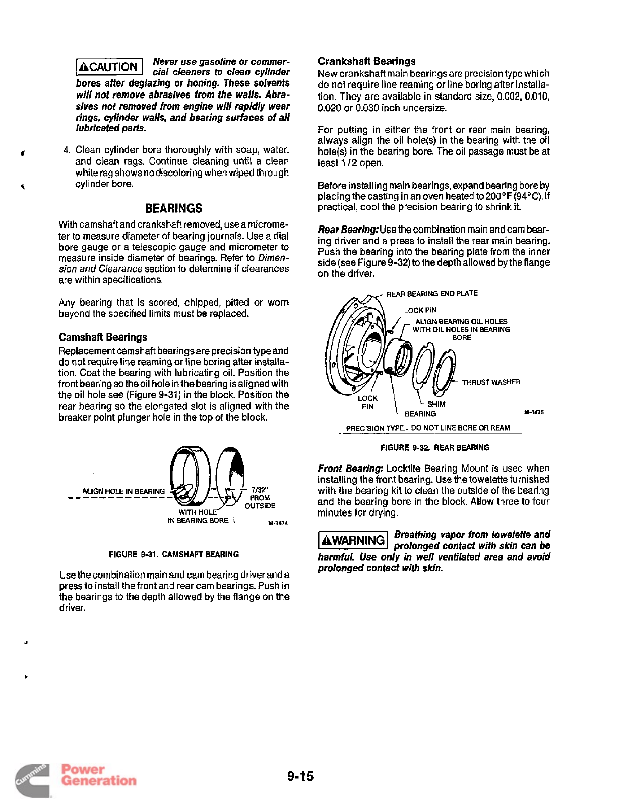
4,
Never
use
gasoline or commer-
cial cleaners
io
clean cylinder
bores after deglazing
or
honing. These solvents
will not remove abrasives from the walls.
Abra-
sives not removed from engine will rapidly wear
rings, cylinder walls, and bearing surfaces
of
all
lubricated pa&.
Clean cylinder bore thoroughly with soap, water,
and clean rags. Continue cleaning until a clean
white rag shows no discoloring when wiped through
cylinder bore.
BEARINGS
With camshaft and crankshaft removed, usea microme-
ter to measure diameter of bearing journals. Use a dial
bore gauge or a telescopic gauge and micrometer to
measure inside diameter of bearings. Refer to Dimen-
sion and Clearance section to determine if clearances
are within specifications.
Any bearing that is scored, chipped, pitted or worn
beyond the specified limits must be replaced.
Camshaft
Bearings
Replacement camshaft bearings are precision type and
do not require line reaming or line boring after installa-
tion. Coat the bearing with lubricating oil. Position the
front bearing
so
the oil hole in the bearing isaligned with
the oil hole see (Figure
9-31)
in the block. Position the
rear bearing
so
the elongated slot is aligned with the
breaker point plunger hole in the top
of
the block.
IN
BEARING
BORE
I
M-1474
FIGURE
9-31.
CAMSHAFT
BEARING
Use the combination main and cam bearing driver and a
press to install the front and rear cam bearings. Push in
the bearings to the depth allowed by the flange on the
driver.
Crankshaft Bearings
New crankshaft main bearings are precision type which
do
not
require
line
reaming or line boring after installa-
tion. They are available in standard size,
0.002,
0,010,
0.020
or
0.030
inch undersize.
For putting in either the front
or
rear main bearing,
always align the oil hole@) in the bearing with the oil
hole(s) in the bearing bore. The oil passage must be at
least
112
open.
Before installing main bearings, expand bearing bore by
placing the casting in an oven heated to 2OO0F(94"C).
If
practical,
cool
the precision bearing to shrink it.
Rear Bearing:Use
the combination main and cam bear-
ing driver and a press to install the rear main bearing.
Push the bearing into the bearing plate from the inner
side (see Figure9-32) to the depth allowed by the flange
on the driver.
REAR
BEARING
END
PLATE
&
ALIGN BEARING OIL
HOLES
WITH
OIL
HOLES
IN
BEARING
THRUST
WASHER
1
I,.
BEARING
PRECISION
TYPE
-
DO
NOT
LINE
BORE
OR
REAM
M-I415
FIGURE
9-32.
REAR
BEARING
Front Bearing:
Locktite Bearing Mount is used when
installing the front bearing. Use the towelette furnished
with the bearing kit to clean the outside of the bearing
and the bearing bore in the block. Allow three to four
minutes for drying.
Breathing vapor
from
towelette and
k&@%l
prolonged contact wifh skin can be
harmful. Use only
in
well ventilated area and avoid
prolonged confact wiih skin.
9-1
5
Redistribution or publication of this document
by any means, is strictly prohibited.
Apply the Locktite Bearing Mount to the mating surfaces
of the bearing and bearing bore. Use the combination
main
and
cam
bearing
driver
and
a
press
to
instal1
the
front bearing. Push the bearing
in
to the depth allowed
by the flange
on
driver. Wipe
off
any excess Locktite and
allow one hour for hardening at room temperature.
OIL
SEALS
R~~~~~
the
rear
bearing plate
to
the
rear
oil
seal. Remove the gear cover to replace the front oil seal.
Use an
oil
seal removed to pry out the front
or
rear oil
seal,
Engines shipped from the factory have separate thrust washers and
main bearings for both front and rear of engine. Front bearing
replacement part is one piece bearing (with attached thrust washer)
as shown in Figure 9-33.
Do
not add an additional thrust washer to
this front bearing.
FRONT
MAIN BEARING
BORE
NOTE:
DO
NOT ADD ADDITIONAL
THRUST WASHER WHEN
REPLACING FRONT BEARING
ALIGN BEARING
NOTCHES WITH
LOCK PINS AND
MATCH OIL HOLES
FRONT
MAIN BEARING
PRECISION TYPE
DO NOT LINE BORE
OR
REAM
OR
BORE
M-1476
FIGURE
9-33.
FRONT BEARING
Use an oil seal guide and driver to press or drive the rear
seal into the rear bearing plate until it bottoms against
the shoulder of the plate (see Figure 9-34). Press
or
drive the front seal into the gear cover until it is 0.97
f
0.02
inch (24.6
k
0.5
mm) from the mounting face of the
cover.
Lubricate the lips
of
the replacement seal with a light
coating of grease before installing the rear bearing plate
or gear cover. This provides initial lubrication until
engine oil reaches the seal. Refer to the
Crankshaft
section for the rear bearing plate installation proce-
dures. Refer to the
Gear Cover
section for the gear cover
installation procedures.
USE GREASE IN
SPACE BETWEEN
SEALS TO IMPROVE
MOUNTING FACE
OF
GEAR
COVER
0.97
f
0.02
INCH
(24.6
f
0.5
mm)
GEAR
COVER
OIL
SEAL
THIS
SURFACE SHOULD BE
CLEANED
OF
ALL OLD SEALING
COMPOUND BEFORE
INSTALLING SEAL
i
GEAR
COVER
OIL
SEAL
THIS SURFACE SHOULD BE
CLEANED OF ALL OLD
SEALING COMPOUND
BEFORE INSTALLING
SEAL
REAR BEARING PLATE
OIL SEAL
DRIVE
OR
PRESS OIL
SEAL
TO
SHOULDER
OF THE PLATE BORE
m-1477
FIGURE 9-34.
OIL
SEALS
9-1
6
Redistribution or publication of this document
by any means, is strictly prohibited.
Section
IO.
Service Checklist
After servicing, inspect and test the complete installa-
tion to confirm that the generator set will operate prop-
erly and will pull full rated load. Check each of the
4
following areas before putting the set into service.
.(
MOUNTING
Examine all mounting bolts and supporting members to
verify that the generator set is properly mounted.
All
fasteners should be tightened securely to prevent them
from working loose when subjected to vibration.
LUBRICATION
If
the engine
oil
was drained,fill thecrankcase with oil of
the recommended classification and viscositv. Refer to
the appropriate operator’s manual
recommendations and procedures.
WIRING
Verify that all wiring connections
secure. Check each of the following:
0
Load Wires
0
Control Wires
Ground Strap
Battery Cables
for the specific
are correct and
INITIAL START ADJUSTMENTS
Adjust the carburetor idle and main adjustment screws
as specified in the Fuel System section.
1-1
Before attempting any carburetor/
governoradjustments, disconnect all
devices which are voltage or frequency sensitive.
Some solid-state devices, such as TV’s or VCR’s, are
powered whenever connected to an
AC
outlet even if
the device
is
not in actual operation.
If
disconnecfing
the devices
is
not possible, open the circuit breaker(s)
at the distribution panelor at the genset,
if
so
equipped.
Failure to heed this advisory may result in consequen-
tial damage to voltage/frequency sensitive equipment
such as VCR’s,
TV’s,
computers, etc. Repairheplace-
ment
of
damaged devices is not covered under Onan
warranty policy.
Start the set and immediately adjust the governor speed
adjustment nut to obtain
a
safe no-load operating
sounds or vibrations. When the choke is completely
open, adjust the carburetor and governor as specified in
the Fuel System section.
d
speed. With no load applied, listen for any unusual
FUEL
SYSTEM
With the generator set operating, inspectthe fuel supply
lines, filters, and fittings for leaks. Check any flexible
sections for cuts, cracks and abrasions and make sure
they are not rubbing against anything that could cause
breakage.
Leaking fuel will create a fire hazard
which can result in severe personal
injury or death if ignited by
a
spark, flame,
or
other
ignition source. If leaks are detected, correct
immediately.
OUTPUT CHECK
Applyafull load to makesurethesetwill produceitsfull
rated output. Use a load test panel to apply a progres-
sively greater load until full load is reached.
EXHAUST SYSTEM
With the generator set operating, inspect the entire
exhaust system including the exhaust manifold, muffler,
and exhaust pipe. Visually and audibly check for leaks
at all connections, welds, gaskets, and joints and also
make sure exhaust pipes are not heating surrounding
areas excessively.
If
leaks are detected, correct
immediately.
‘
1-1
Inhalation
of
exhaust gases can
result in severe personal injury or
death. Inspect exhaust system audibly and visually for
leaks daily. Repair leaks immediately.
CONTROL
Stop and start the generator set several times at the set
control and remote control (if equipped) to verify the
control functions properly.
MECHANICAL
Stop the generator set and inspect
for
leaking gaskets,
loose fasteners, damaged components, or interference
problems. Repair as required. Inspect the generator set
compartment and verify there are no breaks
or
openings
in the vapor-proof wall that separates the compartment
from the vehicle interior. Seal openings as required.
Make sure all soundproofing material is in place.
10-1
Redistribution or publication of this document
by any means, is strictly prohibited.

IAWARNING
I
EXHAUST
GAS
IS
DEADLY!
Exhaust gases contain carbon monoxide, an odorless and colorless gas. Carbon
monoxide is poisonous and can cause unconsciousness and death. Symptoms
of
carbon monoxide poisoning can include:
Dizziness
0
Nausea
0
Muscular Twitching
Headache
0
Vomiting
Weakness and Sleepiness
0
Throbbing in Temples
Inability
to
Think Coherently
IF
YOU
OR ANYONE ELSE EXPERIENCE ANY OF THESE SYMPTOMS, GET
OUT
INTO THE FRESH AIR IMMEDIATELY. If symptoms persist, seek medical atten-
tion. Shut down the unit and do not operate until it has been inspected and
repaired.
Never sleep in vehicle with the generator set running unless the vehicle interior is
equipped with an operating carbon monoxide detector. Proiecfion against carbon
monoxide inhalation also includes proper exhaust system installation and visual
and audible inspection
of
the complete exhaust system at
the
start
of
each
generator set operation.
1
-RV
10-2
Redistribution or publication of this document
by any means, is strictly prohibited.

Appendix
A.
Troubleshooting Charts
These pages
form
an appendix to the service manual. This information was prepared by the Onan Service
Training Department in the
form
of
simplified guides to troubleshooting
a
variety of the circuit boards used on
the
BGElNHE
generator sets. while this information
is
accurate, make
sure
to
follow
the complete procedures
outlined
in
the appropriate service manual sections for reasons
of
safety and product integrity.
R
Q
A-2:
“Troubleshooting Electronic Ignition Module”
A-3,
A-4:
“EmeraldTM Control Functions”
0
A-5,
A-6:
“Emerald Control Board Checkout (300-2784)“
A-7,
A-8: “Emerald Control Board Checkout (300-3056/3687)”
0
A-9,
A-1
0:
“Emerald Control Board Checkout (300-3763-01,
-02)”
A-I
Redistribution or publication of this document
by any means, is strictly prohibited.
Troubleshooting Electronic
Ignition
Module
Models: PerformerTM, Emerald
PlusTM,
MarquisTM,
Ensignm
Test
1
Test
-
Ignition
-
Module
Ignition
-
__
Test
2
Trigger
Ring
I
Module
Test
Light
1.
2.
3.
4.
5.
I
AWARNING
I
Check wiring:
red
lead to positive
(+);
black lead
to
negative
e).
Connect a DC powered test light from
the negative
(-)
coil
terminal
to
ground.
Turn
the ignition switch on and crank
the engine over. Does the test light
flash, bright then dim?
Yes
-
The
module is
ok;
do net
replace the module.
No
-
Go
to Test
2.
Note:
If
the primary winding of the
ignition coil is open, the light will not
come
on.
Connect the
test
light from the
positive
(+)
coil terminal to ground.
Turn the ignition switch to the on
position. Does the light come on?
Yes
-
Crank the engine over. Does
the light
stay
on
while
cranking?
Yes
-
Replace the module and the
trigger ring as
a
set if the coil
tests good.
No
-
It
is not a module problem.
Check the wiring and
connections to the coil and
the ignition switch, then retest
the module.
___~
Use extreme caution when working
on
operating equipment Operating equipment presents hazards
of
electrocution,
bums, fire and explosion, asphyxiation, and entanglement with rotating parts.
Review
Important Safety instructions in
Operator’s Manual.
Performer, Emerald Plus, Marquis, Ensign
are
trademarks
of
Onan Corporation
@
1991
Onan
Corporation
A-2
900-0261
Redistribution or publication of this document
by any means, is strictly prohibited.
Emerald'"
Control Functions
(AI
Control
Board
38013056/3687)
Use
exlreme
cautlon
when
woMng on
generator
sets
presents
hazards
ofelec-
opntlng
generator sets. Operating
4
Sequence
of
Events:
Battery
+
@os)
at
PI-6,
Battery
-
(neg)
at
P1-8.
Operator pushes
start
button
at
AI.
B+
from PI-2 to start solenoid
(S
terminal).
Solenoid contacts close send
B+
to
starter.
*
FUEL
PUMP
ET1
BATTERY
Es2Mn2c
Sequence
of
Events:
Operator pushes
start
button on
AI.
Safeties are bypassed.
B+
from
P3-3
to
ignition coil.
Breaker points open/close
path
to
ground.
High voltage jumps spark plug
gap.
B+ supplied to
fuel
pump
from
PI-2.
b
1
AWARNING
I
Engine Cranking
Start
Mode
Ignition
Start
Mode
E3
SPARK
PLUG
IGNVON
COIL
-
S
-
trucufion,
bums,
tlre
and exploslon,
as-
I
phyxlatlon, and entanglement
with
rvtat-
lng
parts.
Review
Important
Safe'ety
In-
structions
In
Operator's Manual.
A-3
Redistribution or publication of this document
by any means, is strictly prohibited.
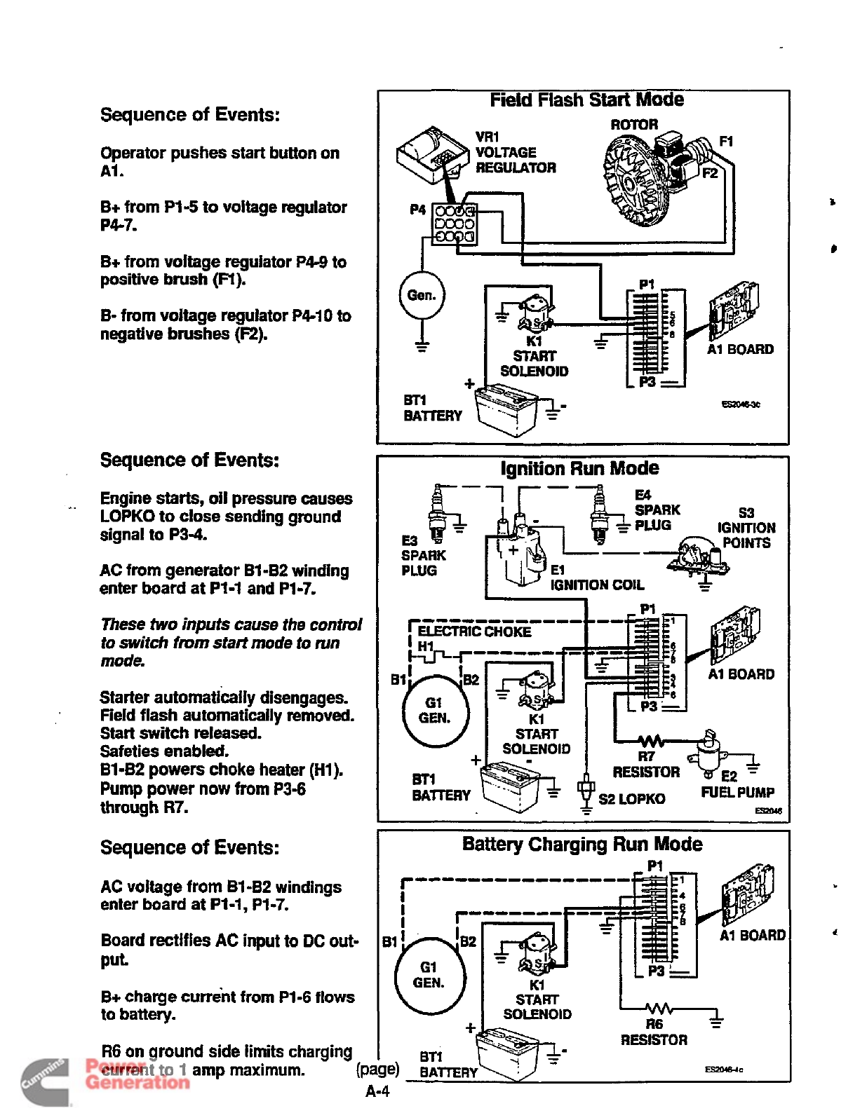
Sequence
of
Events:
Operator pushes start button on
AI.
B+
from
P1-5
to voltage regulator
P4-7.
B+
from voltage regulator
P4-9
to
positive
brush
(Fl).
B-
from
voltage regulator P4-10 to
negative
brushes
(F2).
Sequence
of
Events:
I.
Engine
starts,
oil
pressure causes
LOPKO
to
close sending ground
signal to
P3-4.
AC from generator B1
-B2
winding
enter board at P1-1 and P1-7.
These
two inputs cause the
contra1
tu
switch
from
staH
mode
to
run
mode.
Starter automatically disengages.
Field flash automatically removed.
Start switch released.
Safeties enabled.
Bl-B2
powers choke heater
(Hl).
Pump
power now
from
P3-6
through
R7.
FiHKFlaXStart
Mode
.-
I,
Kl
A1
BOARD
m
I
lgn%ion Run
Mode
E3
SPARK
PLUG
I
w
IGNITION
COIL
-
Sequence
of
Events:
AC voltage from B1-82 windings
enter board at PI
-1,
PI
-7.
Board
rectifies
AC
input to
DC
out-
B+
charge current from
P1-6
flows
to
battery.
R6
on ground side limits charging
Put
Battery
Charging
Run
Mode
I
current
to
1
amp maximum.
A-4
Redistribution or publication of this document
by any means, is strictly prohibited.
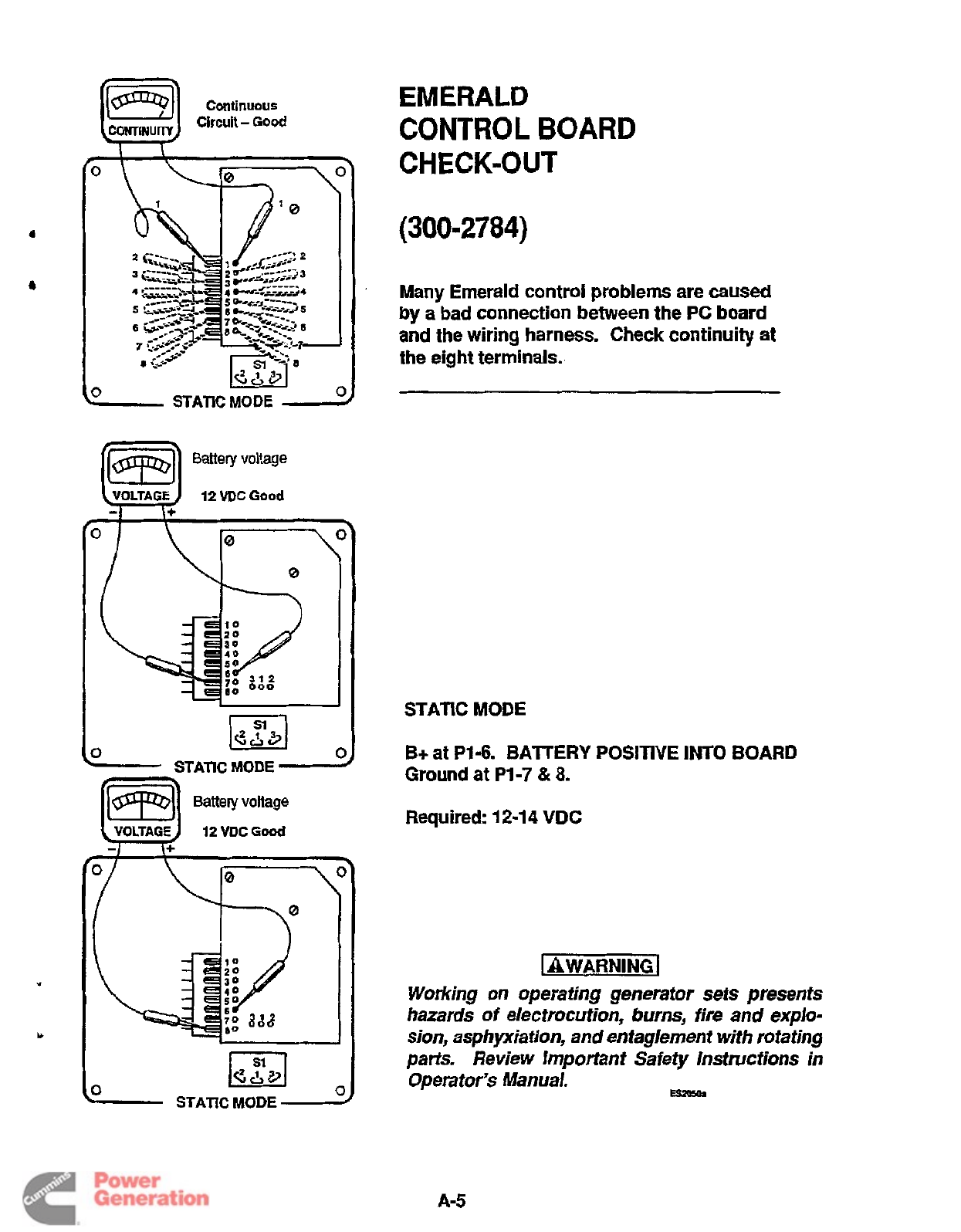
Conlinuous
Circuit -
Good
COHTlNUlTY
1
3
V
-
STATICMODE
-
Battery voltage
(E)
12
VDC
Good
40
10
Oo0
3
STATIC
MODE
-
Battery voltage
5
STATIC
MODE
EMERALD
CONTROL
BOARD
CHECK-OUT
(300-2784)
Many Emerald control
problems
are caused
by
a
bad connection between
the
PC
board
and
the wiring harness. Check
continuity
at
the eight terminals.
STATIC MODE
B+
at
P1-6.
BAlTERY POSITIVE
INTO
BOARD
Ground at
P1-7
&
8.
Required:
12-1
4
VDC
[
AWARNING
1
Working on operating generator sets presents
hazards
of
electrocution, burns, fire and explo-
sion, asphyxiation, and entaglement with rotating
pa& Review Important Safety Instructions in
Operator's Manual.
Es1050r
A-5
Redistribution or publication of this document
by any means, is strictly prohibited.
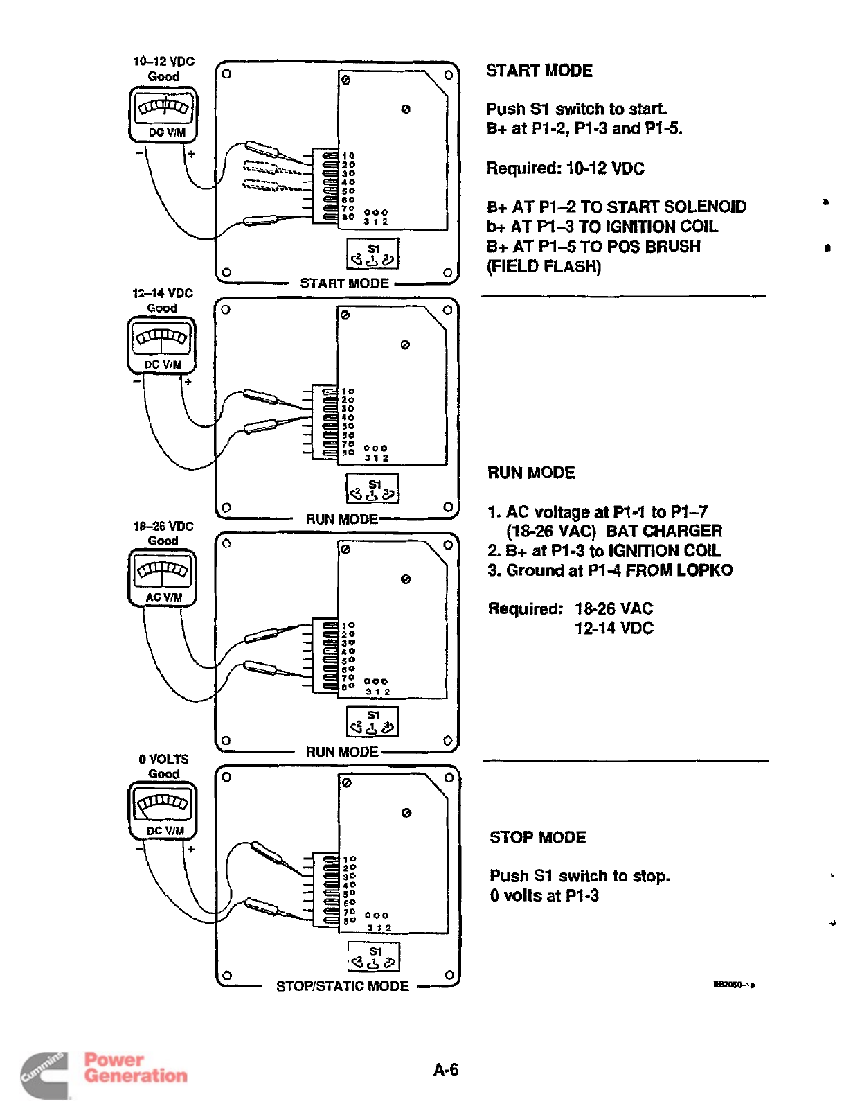
START
MODE
I
I
(BZJ
le
STOP/STATIC
MODE
Push
SI
switch
to
start.
B+ at P1-2, P1-3 and P1-5.
Required: 10-12
VDC
B+
AT P1-2
TO
START
SOLENOID
B+
AT P1-5
TO
POS
BRUSH
b+
AT
PI3
TO
IGNITION
COIL
(FIELD
FLASH)
RUN
MODE
1. AC
voltage at
P1-1
to
P1-7
2.
B+
at
P1-3
to
IGNITION
COIL
3.
Ground
at
P1-4 FROM
LOPKO
(18-26 VAC) BAT CHARGER
Required:
18-26 VAC
12-1
4
VDC
STOP MODE
Push
SI
switch to stop.
0
volts
at PI-3
A-6
Redistribution or publication of this document
by any means, is strictly prohibited.
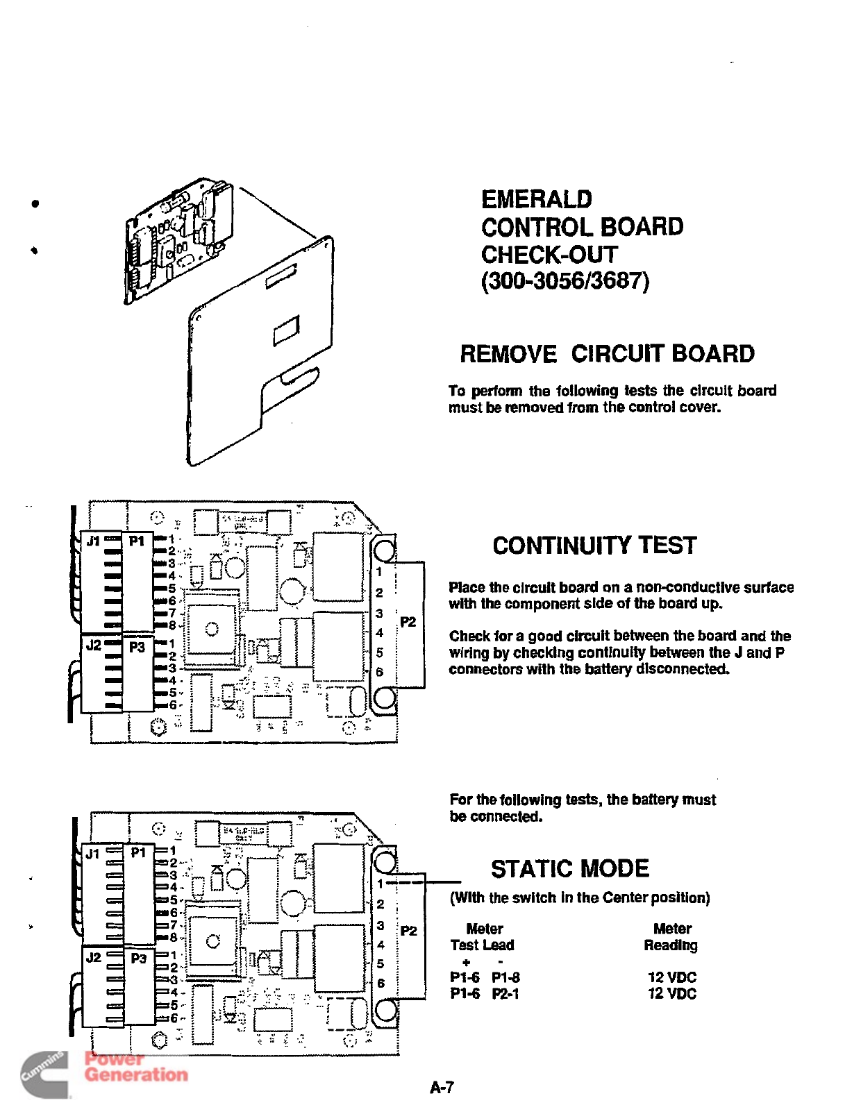
0
..
EMERALD
CONTROL
BOARD
CHECK-OUT
(300-305613687)
REMOVE
CIRCUIT
BOARD
To
perform
the following tests the circuit board
must
be
removed
from the control cover.
CONTINUITY
TEST
Place the circuit board on a non-conductive surface
with the component
side
of the board up.
Check for a
good
clrcuit between the board and the
wiring by checking contlnuity between the
J
and
P
connectors
with
the battery disconnected.
For the following tests, the battery must
be
connected.
STATIC
MODE
in
the Center position)
Meter
Reading
12
VDC
12
VDC
A-7
Redistribution or publication of this document
by any means, is strictly prohibited.
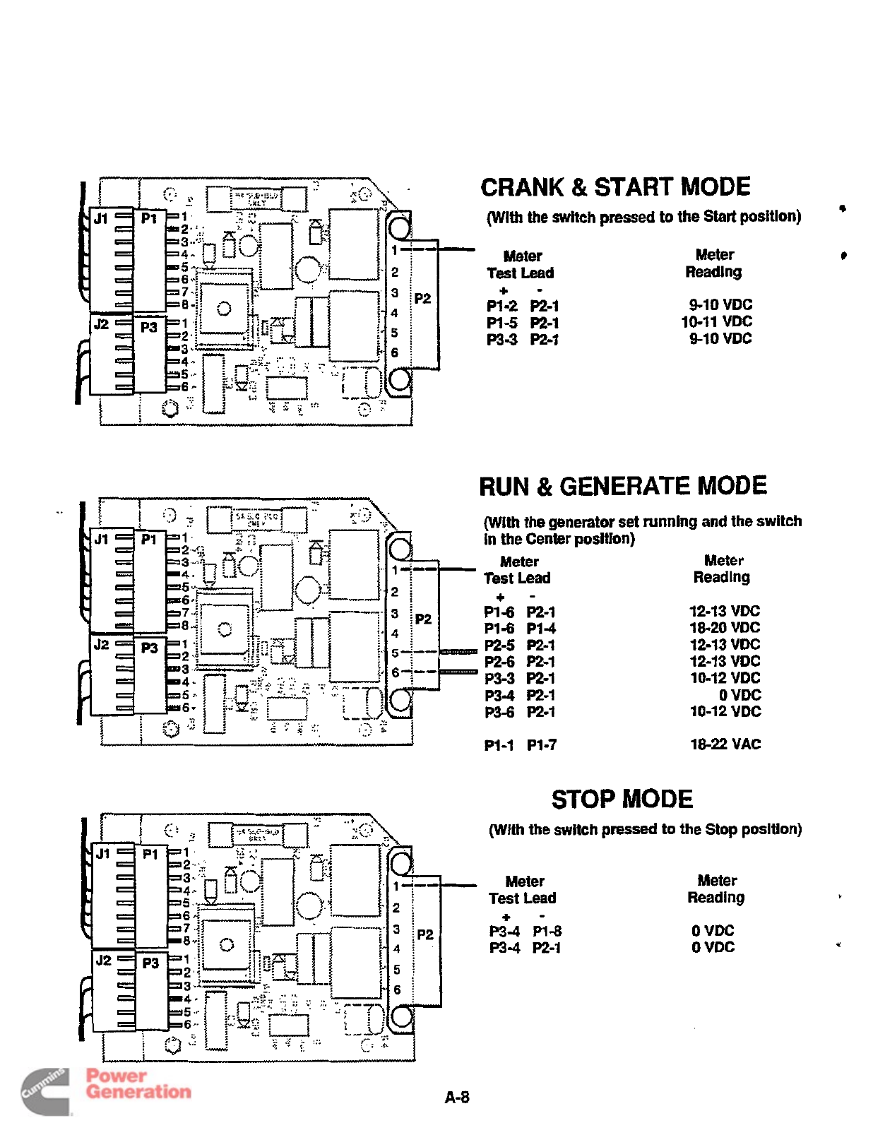
6
CRANK
&
START MODE
(Wlth
the switch pressed
to
the
Start
position)
Meter
Test
Lead
P1-2 P2-1
P1-5 P2-1
P3-3
P2-1
+-
Meter
9-10 VDC
10-11 VDC
9-10 VDC
RUN
&
GENERATE
MODE
(With
the
generator
set
running and the switch
In
the Center position)
Meter Meter
Test Lead Reading
P1-6 P1-4 18-20 VDC
+-
Pl-6 P2-1 12-13 VDC
P2-5
P2-1 12-13 VDC
P2-6
P2-1 12-1
3
VDC
P3-3 P2-1 10-12 VDC
P3-6 P2-1 10-12 VDC
P3-4 P2-1
0
VDC
P1-1 P1-7 18-22 VAC
STOP
MODE
(With
the
switch pressed
to
the Stop position)
Meter
Test Lead
P3-4
P1-8
P3-4
P2-1
+-
Meter
Reading
0
VDC
0
VDC
Redistribution or publication of this document
by any means, is strictly prohibited.
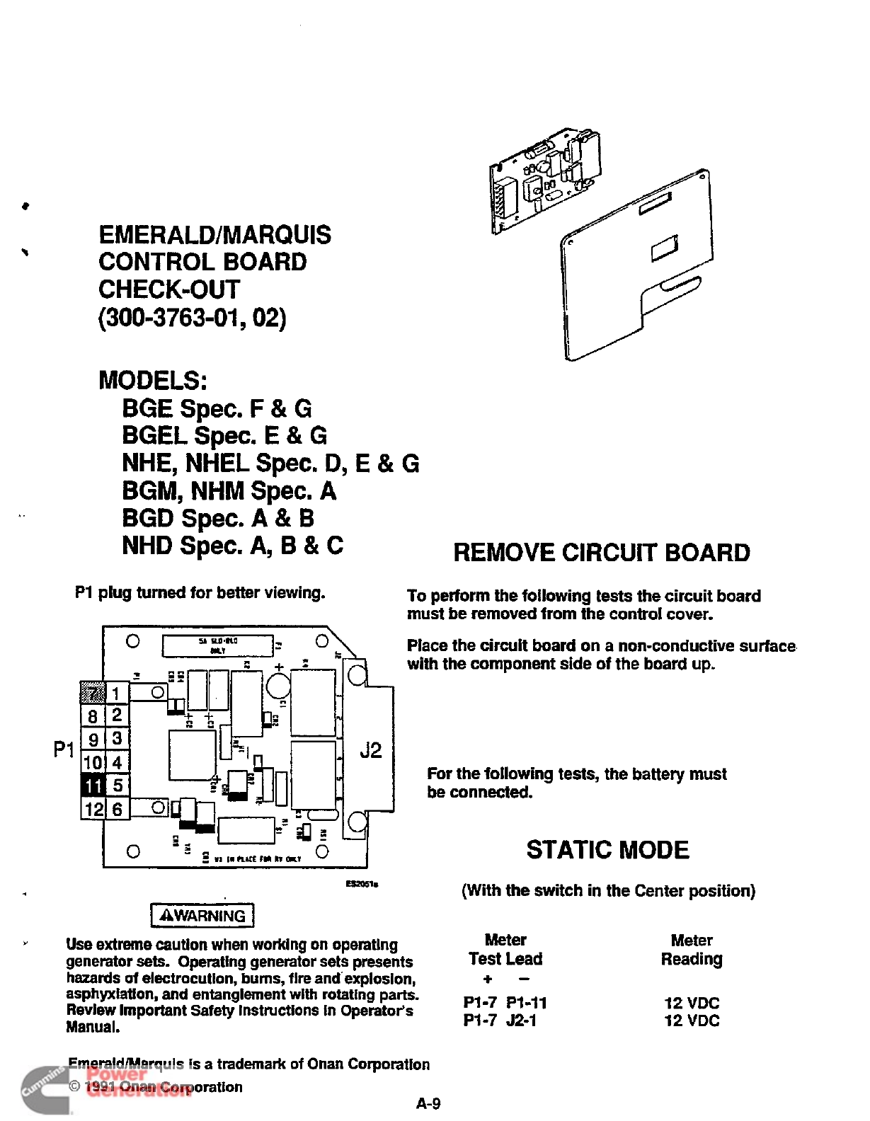
P1
EMERALDIMARQUIS
CONTROL
BOARD
CHECK=OUT
(300-3763-01
,
02)
MODELS:
BGE
Spec.
F
&
G
BGEL
Spec.
E
&
G
NHE, NHEL
Spec.
D,
E
&
G
BGM,
NHM
Spec.
A
BGD Spec.
A
&
B
NHD
Spec.
A,
B
&
C
REMOVE
CIRCUIT
BOARD
PI
plug
turned
for better viewing. To perform the
following
tests the circuit board
must be removed from
the
control cover.
I
AWARNING
I
Place the circuit board
on
a non-conductive surface
with the component side
of
the board
up.
For the
following
tests, the battery
must
be connected.
STATIC
MODE
(With
the
switch
in
the Center position)
*
Use extreme caution when worklng on operating Meter
generator
sets.
Operating generator sets presents
asphyxiatlon,
and
entanglement
with
rotating
parts.
Review Important Safety Instructions In Operator's
Manual.
Test
Lead
hazards
of
electrocution, bums, fire and-explosion,
+-
PI-7 PI-11
PI-7
J2-1
EmeraldMarquis
is
a trademark
of
Onan Corporation
0
1991
Onan Corporation
A-9
Meter
Reading
12
VDC
12 VDC
Redistribution or publication of this document
by any means, is strictly prohibited.
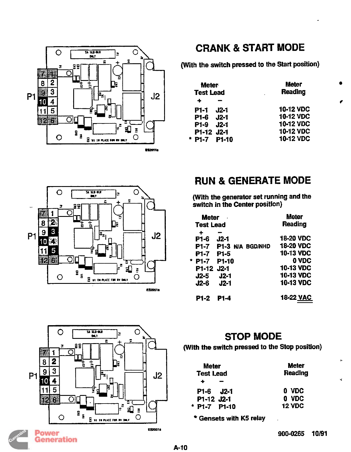
CRANK
&
START
MODE
PI-7 PI-3
NIA
BGDNHD
18-20
VDC
PI-7 PI-5 10-1
3
VDC
PI
...
P1
(With
the
switch
pressed
to the
Start
position)
Meter. Meter
Test
Lead
Reading
-
+
PI-1 52-1
PI4 52-1
PI-9 J2-1
P1-12 J2-I
*
PI-7
PI-IO
10-12 VDC
10-1 2 VDC
10-1
2 VDC
10-12
VDC
10-12
VDC
L
RUN
tk
GENERATE
MODE
(With the generator set running and the
switch in the Center position)
Meter
.
Test
Lead
Meter
Reading
18-22
VAC
-
PI-2 PI4
I
STOP
MODE
(With the switch
pressed
to
the
Stop position)
Meter Meter
Test
Lead
Reading
L
-
+
*
0
VDC
0
VDC
12
VDC
PI
-6
52-1
PI
-1
2
J2-1
*
P1-7 PI-IO
PI
Gensets
with
K5
relay
900-0265 10191
Redistribution or publication of this document
by any means, is strictly prohibited.
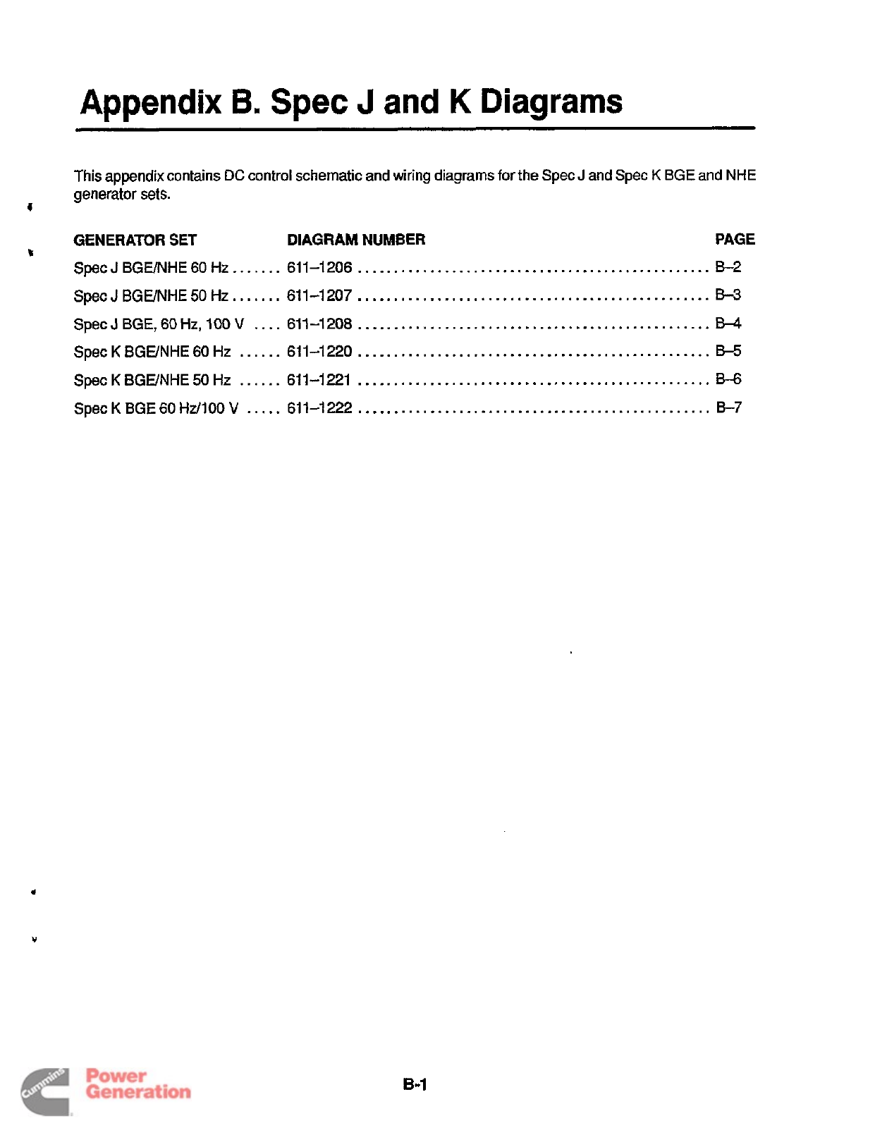
Appendix
6.
Spec
J
and
K
Diagrams
This
appendix contains
DC
control schematic and wiring diagrams
for
the
Spec
J
and
Spec
K
BGE
and NHE
generator
sets.
c
GENERATOR
SET
DIAGRAM
NUMBER
PAGE
h
Spec
J
BGE/NHE 60 HZ
.......
611-1206
.................................................
52
Spec
J
BGUNHE
50
Hz
.......
611-1207
.................................................
53
Spec
J
BGE,
60
Hz,
100
V
....
611-1208
.................................................
E34
Spec
K
BGUNHE 60
Hz
......
611-1220
.................................................
E-5
Spec
K
BGUNHE
50
HZ
......
611-1221
.................................................
B-6
Spec
K
BGE
60
Hd100
V
.....
611-1222
.................................................
57
Redistribution or publication of this document
by any means, is strictly prohibited.

Redistribution or publication of this document
by any means, is strictly prohibited.
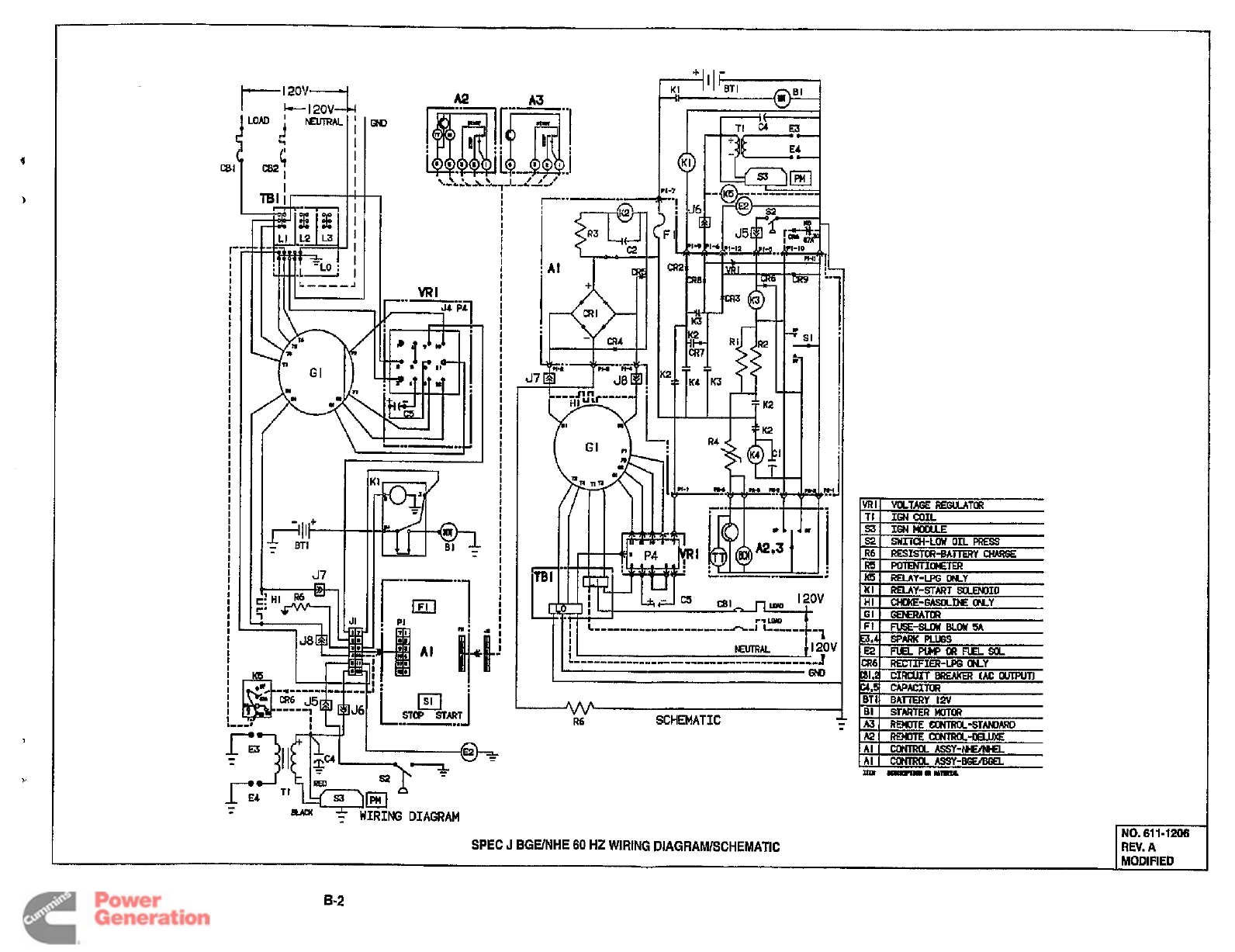
I'
I
I
I
I
i
I
I
I
I
I
I
I
I
I
I
c
R6
SCHEMATIC
SPEC
J
BGUNHE
60
HZ
WIRING
DlAGRAMlSCHEMATlC
I
MODIFIED
8-2
Redistribution or publication of this document
by any means, is strictly prohibited.
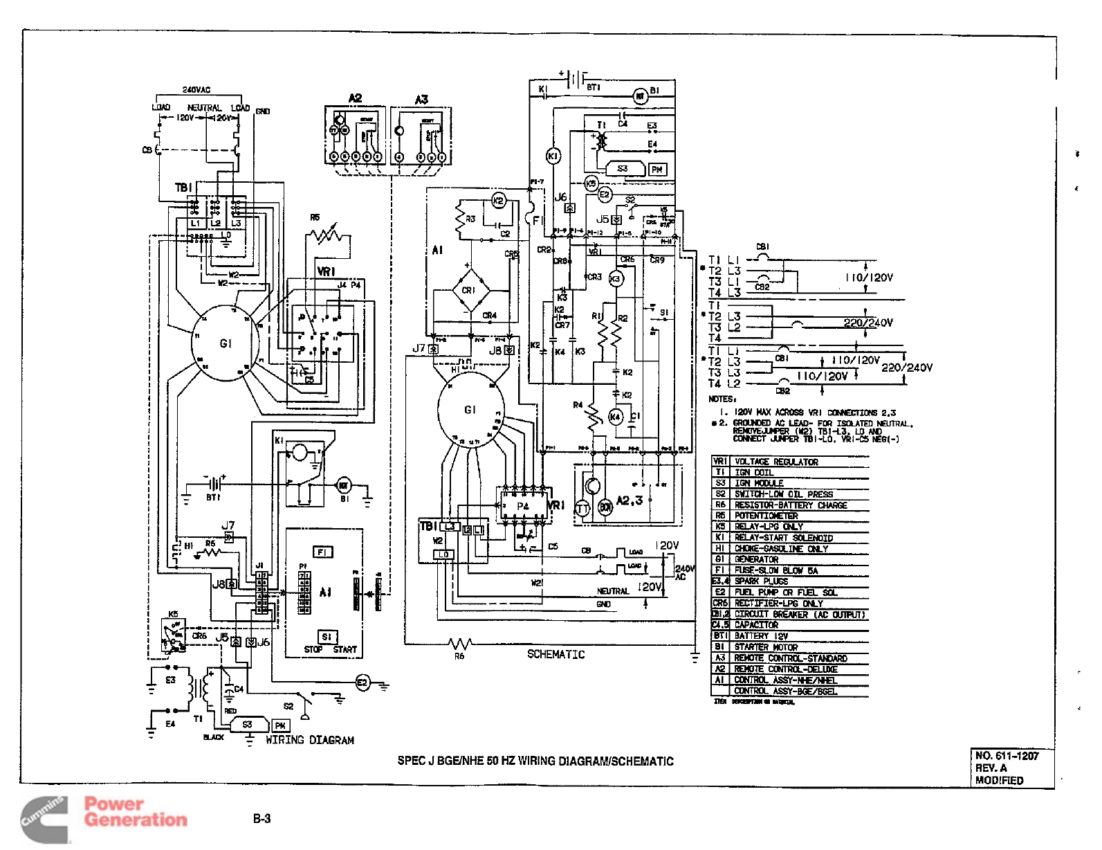
I
I
I
I
I
I
I
I
I
I
I
1
I
I
I
I
t
"
'I'-Tm
WIRING
DIAGRAM
I10/120V
*T2
L3
T4
L3
--
F
I
R6
SCHEMATIC
SPEC
J
BGE/NHE
50
HZ
WIRING
DIAGRAWSCHEMATIC
I
MODIFIED
B-3
Redistribution or publication of this document
by any means, is strictly prohibited.
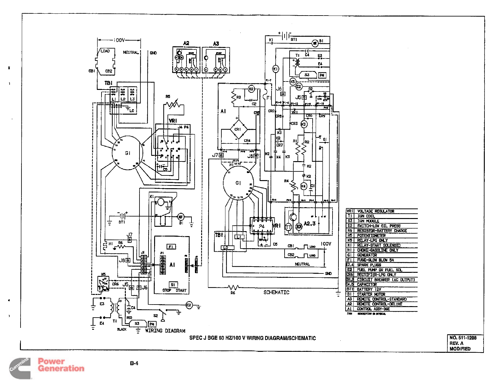
I'
I
I
I
I
I
I
I
I
I
I
I
I
I
t
I
I
I
I
I
I
I
I
-
-
SPEC
J
BGE
60
HUlOO
V
WIRING
DIAGRAM/SCHEMATIC
I
NO.
611-1208
REV.
A
MOblFlED
8-4
Redistribution or publication of this document
by any means, is strictly prohibited.
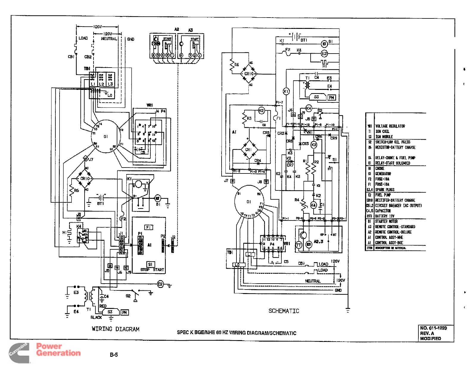
I
I
I
I
I
jWMj
.1
-Mi
CBl'i
c821
c
!
I
4-
-
cRIO+
E2
I
61
GWIATOR
F2
FUSE-IY
FI
I
FUSE-IOA
SCHEMATIC
SPEC
K
BGUNHE
60
HZ
WIRING DlAGRAMlSCHEMATlC
WIRING
DIAGRAM
I
MODIFIED
B-5
Redistribution or publication of this document
by any means, is strictly prohibited.
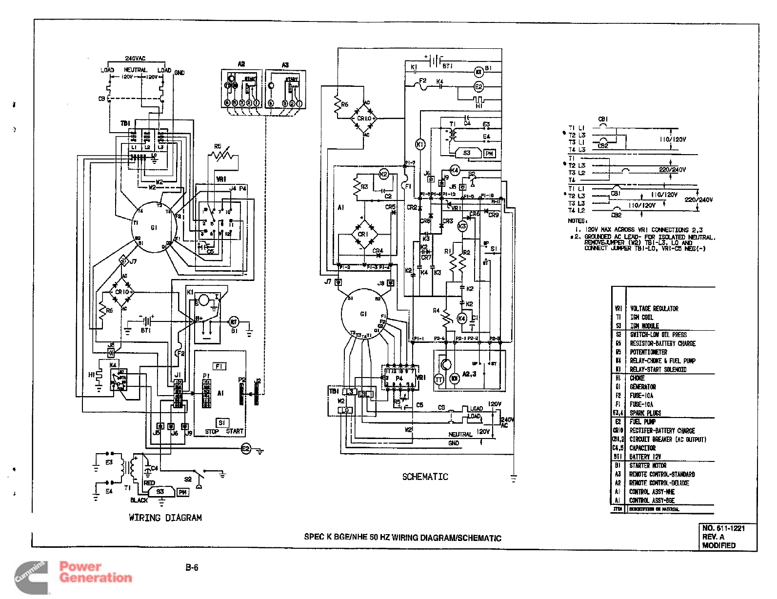
%
-
CRLO+
I
L..i
SCHEMATIC
CBI
TI
LI
-*--
I
7
I10/12OV
T2
L3
TI
12
L3
T3L2
T4
1
t
I
I
~
In
220/240V
m:
YRI
VKlA6EG€GuUToR
II
TI
IMCOIL
s31
IfflrrmuE
s2
I
!#ITCH-LW
OIL
PRESS
SPEC
K
BGUNHE
50
HZ WIRING DlAGRAMlSCHEMATlC
I
MODIFIED
8-6
Redistribution or publication of this document
by any means, is strictly prohibited.
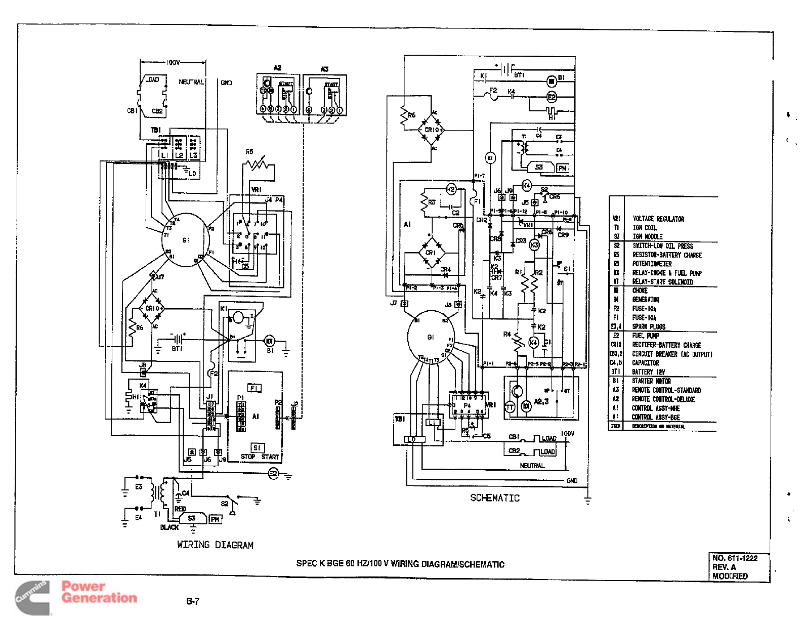
1
YRI
s3
R6
K4
KI
HI
61
R
FI
ri
52
~5
I-’OoV1
VOLTAGEREGUATOR
IGNlMwLE
RESISTOR-BATIERY
ClURE€
RElAY-cHMIELFuELpulp
RELAY-START
SOLMOID
CHOKE
GEIERATWl
NSE-IOA
FUSE-IOA
IGN
COIL
WITCH-LOU
on
PIES
PorrmIOwErm
w
XI0
Bl,2
4,6
1
RECTIFIR-BATTERY
CMEE
CIRCUIT BREAKER
UC
WPUTI
CAPACITOR
A2
A3
-
cRIO+
%
WIRING
DIAGRAM
SPEC
K
BGE
60
HUlOO
V
WIRING
DIAGRAWSCHEMATIC
IT1
I
BATTERY
12V
BI
I
STRTERllPTlR
mAL
GH1
SCHEMATIC
NO.
6111222
MODIFIED
6-7
Redistribution or publication of this document
by any means, is strictly prohibited.

Redistribution or publication of this document
by any means, is strictly prohibited.
Page 1 of 4
Instruction Sheet
C351e 6−2000
Installation of Control Board Replacement
Kit 300-3950
PURPOSE OF KIT
These instructions describe the removal and re-
placement of the Control Circuit board used on the
following generators.
BGE Spec F and G. . . . . . . . . . . . . .
BGEL Spec E and G. . . . . . . . . . . . .
NHE, NHEL Spec D, E and G. . . . . . . .
BGM, NHM Spec A only. . . . . . . .
BGD Spec A and B. . . . . . . . . . . . . .
NHD Spec A, B and C. . . . . . . . . . . . . .
SAFETY PRECAUTIONS
Read these instructions completely and become fa-
miliar with safety warnings, cautions, and proce-
dures before starting the installation.
Always disconnect a battery charger
from its AC source before disconnecting the battery
cables. Otherwise, disconnecting the cables can re-
sult in voltage spikes high enough to damage the DC
control circuits of the set.
Accidental starting of the generator set
while working on it can cause severe personal injury
or death. Prevent accidental starting by disconnect-
ing the starting battery cables (negative [−] first).
KIT PARTS
Prior to installation, verify receipt of the proper parts
from the table below.
Part Description QTY.
Splice, Window; 22−16 6
Screw, Pan Head; 6−32 x .38 4
Harness, Wire, PCB 1
PCB, Control Assembly 1
BGM/NHM MOUNTING CONSIDERATIONS
If installing the kit on a BGM/NHM (Marquis) gener-
ator set, note the following change:
The lead marked J1-12-E2 MUST be connected
to K5, pin 85 instead of the marked connection.
Disregard the wire routing labels in this
instance only.
Consult Figure 3 (J1 diagram) for more information.
This note applies only to technicians installing the
Control Board kit on the BGM/NHM (Marquis) gen-
sets.
Incorrect installation, service, or parts
replacement can result in severe personal injury,
death, and/or equipment damage. Service personnel
must be qualified to perform electrical and mechani-
cal installions and service.
INSTALLATION
Tools Required
•Wire stripping and splicing tool
•Torx screwdriver kit
•Needle-nose pliers
•Conventional screwdriver kit
Procedure
1. Disconnect the generator set starting battery
cables (negative [−] cable first) to prevent the
genset from starting.
2. Turn off and disconnect battery charger (if
equipped).
3. Pull the genset fuse from the control panel and
set it aside. Disconnect the remote cable, if
present.
4. Remove the two screws from the top of the con-
trol panel. Pull the panel down and away from
the control box.

C351e
Page 2 of 4
5. Pull connectors J1 and J3 off the edge of the
Control Circuit board. Remove the wires from
the control panel wire retainer (Figure 1).
6. Remove the four screws securing the circuit
board to the control panel and pull the board off
the panel. Discard the old board and screws.
7. Mount the new circuit board from the kit onto
the control panel using the no. 6 screws in the
kit.
CONTROL PANEL
ATTACHMENT
SCREWS
J1
CONNECTOR
J3
CONNECTOR
GENSET
MAIN FUSE
BATTERY
POSITIVE (+)
CONNECTION
FIGURE 1: CONTROL PANEL ASSEMBLY
(EARLIER VERSION w/J1 and J3 CONNECTORS)
Build New Connector
1. Cut connectors J1 and J3 from the wires ex-
tending into the generator set control. Clip
wires as close to the connector as possible.
Make sure the routing labels on the wires
remain intact.
If the routing labels are missing, refer to Figure
3 and Table 1, and refer to the wiring diagram/
schematic for the genset.
2. Using the stripping/splicing tool, crimp the 6
splices to the wires extending from the new J1
connector supplied in the kit. Insert the wires
one-by-one into the connectors, then crimp the
connectors firmly onto the wires using the splic-
ing tool.
Wiring
Wires on the new connector are labeled for con-
necting wires in the control box. Connect the wires
one at a time. Do not cut away or obscure the la-
bels on the wires, wherever possible.
1. Attach the new connector J1 to the wires in the
control box as follows:
A. Using the stripping/splicing tool, strip 1/4
inch off one of the wires from the control
box.
B. Insert the end of the wire into one of the
wire splice connectors.
C. Crimp the connector firmly onto the wire
using the splicing tool.
D. Repeat this step for each of the wires at-
tached to new J1 connector.
NOTE: Wire J1−3 is not used. Use a tie wrap to
coil and secure this wire, or remove the wire.
When installing on a Marquis
(Models BGM and NHM) be sure to connect
J1-12 to K5, pin 85. Connecting this lead to
E2 as marked, will short out the control
board, and the genset will not run.
2. Remove the remaining non-terminated wires
one at a time, replacing them with new wires
from J1.
3. Connect the five push-on terminals from con-
nector J1 to the designated connectors inside
the genset using the needle-nose pliers (Table
1).
4. The terminal marked K1−s may have two
wires. Clip the wire tie holding them together to
connect the new K1−S. Secure the terminal
with a new wire tie.
5. Plug new J1 connector onto the control board.
6. Tuck all wires neatly back into the control box. if
possible, pull the wires back into the control
box from the rear of the box.
7. Four of the wires connecting to new J1 pass
through the front of the control box. Clip these
wires to the retainer located on the lower, inside
edge of the control board to secure them in
place (Figure 2).
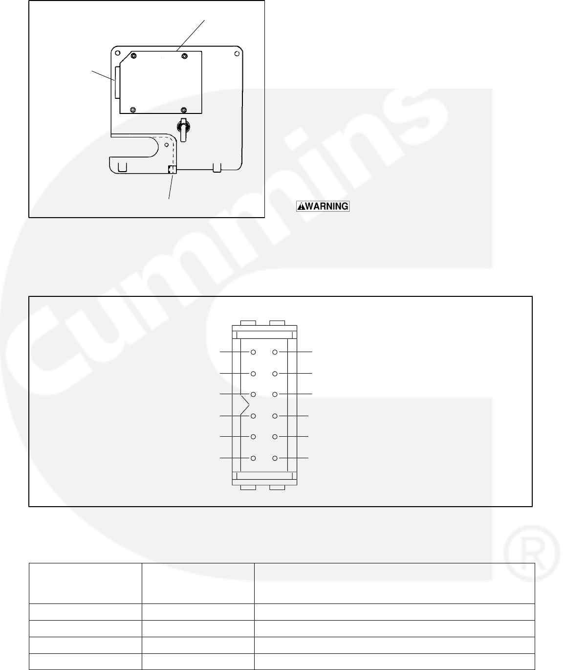
C351e
Page 3 of 4
P2 BOARD
CONNECTOR:
ATTACH NEW
J1 HERE
CONTROL
BOARD
WIRE RETAINER
FIGURE 2: BACK OF CONTROL PANEL
(REPLACEMENT PANEL)
Reassemble
1. Position the control panel on front of the control
box. Reattach the control panel using the two
screws removed in Step 4.
2. Connect the positive (+) battery cable to the
terminal at the front of the control box.
3. Connect the negative (−) battery cable to the
terminal on the generator set.
4. Reconnect the battery charger (if equipped).
5. Install the main fuse in the control panel.
6. Start and test the genset according to the ap-
propriate operator’s manual.
Electrical shock can cause severe per-
sonal injury or death. Do not touch electrical wiring
or components during testing. Disconnect electrical
power by removing starting battery negative (−)
cable before handling electrical wiring or compo-
nents.
7
8
9
10
11
12
1
2
3
4
5
6
ROUTE LEAD TO:
J1
− K1−1 (B+ POWER TO BOARD)
− NOT USED
− K1−S
− BGE/NHE−NOT USED BGEL/NHEL−CR6
ALL OTHERS−CR8
− GROUND (L0)
− E2 OR R7 (K5 ON BGM/NHM)
J4−7 (TO VR1) −
B1 (FROM GENERATOR −
R6 (NOT USED) −
B2 (FROM GENERATOR −
S2 (LOPKO) −
E1 (IGNITION COIL) −
ROUTE LEAD TO:
FIGURE 3. J1 PIN CONNECTIONS
TABLE 1. LABELS ON HARNESS LEADS
New Wire Labels
Near Connector J1
Original Wire Labels
Furthest From
Connector
Component Connection
J1−1 J1−5J4−7 (to VR1)
J1−2 J1−1 B1
J1−3 J1−4Not used on 3951 board; R6 on 3950 board
J1−4 J1−7 B2

C351e
Page 4 of 4
J1−5J3−4S2 (LOPKO)
New Wire Labels
Near Connector J1
Original Wire Labels
Furthest From
Connector
Component Connection
J1−6 J3−3E1 (Ignition coil +)
J1−7 J1−6 K1−1
J1−8−−− Not used
J1−9 J1−2L1−S (May be piggybacked to CR9−E2 or K6−85)
J1−10 J3−2BGE/NHE − Not used; BGEL/NHEL − CR6;
BGM/NHM and BGD/NHD − CR8
J1−11 J1−8GND (L0)
J1−12 J3−6BGM/NHM − K5−85; Models with R7 resistor − R7;
All others − Pump E2

Curnrnins Power Generation
1400 73rd
Avenue
N.E.
Minneapolis,
MN
55432
763-574-5000
Fax:
763-574-8087
Cummins and Onan are registered trademarks
of
Cummins Inc.
Redistribution or publication of this document
by any means, is strictly prohibited.
