965 0531B Onan BGM NHM Marquis Series RV Genset Service Manual (02 1991)
User Manual: 965-0531B Onan BGM NHM Marquis series RV Genset Service manual (02-1991)
Open the PDF directly: View PDF ![]() .
.
Page Count: 136 [warning: Documents this large are best viewed by clicking the View PDF Link!]
- Cover
- Table of Contents
- Safety Precautions
- 1. Introduction
- 2. General Specifications
- 3. Dimensions and Clearances
- 4. Torque Specifications
- 5. Preparing for Service
- 6. Engine - Primary Systems
- 7. Control System
- 8. Generator
- 9. Engine Block Assembly
- 10. Service Checklist
- A. Troubleshooting Guides
- B. Wiring Diagrams
Caution: This document contains mixed page sizes (8.5 x 11 or 11 x
17), which may affect printing. Please adjust your printer settings
according to the size of each page you wish to print.
Printed in U.S.A. 965−0531B
BGM, NHM

Table of Contents
i
SECTION TITLE PAGE
SAFETY PRECAUTIONS iii. . . . . . . . . . . . . . . . . . . . . . . . . . . . . . . . . . . . . . . . . . .
1 INTRODUCTION 1-1. . . . . . . . . . . . . . . . . . . . . . . . . . . . . . . . . . . . . . . . . . . . . . . . . .
2 GENERAL SPECIFICATIONS 2-1. . . . . . . . . . . . . . . . . . . . . . . . . . . . . . . . . . . . . .
3 DIMENSIONS AND CLEARANCES 3-1. . . . . . . . . . . . . . . . . . . . . . . . . . . . . . . . .
4 TORQUE SPECIFICATIONS 4-1. . . . . . . . . . . . . . . . . . . . . . . . . . . . . . . . . . . . . . .
5 PREPARING FOR SERVICE 5-1. . . . . . . . . . . . . . . . . . . . . . . . . . . . . . . . . . . . . . .
Troubleshooting 5-1. . . . . . . . . . . . . . . . . . . . . . . . . . . . . . . . . . . . . . . . . . . . . . . . .
Safety 5-1. . . . . . . . . . . . . . . . . . . . . . . . . . . . . . . . . . . . . . . . . . . . . . . . . . . . . . . . . .
Special Tools 5-2. . . . . . . . . . . . . . . . . . . . . . . . . . . . . . . . . . . . . . . . . . . . . . . . . . . .
Removing the Genset 5-2. . . . . . . . . . . . . . . . . . . . . . . . . . . . . . . . . . . . . . . . . . . .
6 ENGINE - PRIMARY SYSTEMS 6-1. . . . . . . . . . . . . . . . . . . . . . . . . . . . . . . . . . . .
Troubleshooting Engine Primary Systems 6-1. . . . . . . . . . . . . . . . . . . . . . . . . . .
Exhaust System 6-6. . . . . . . . . . . . . . . . . . . . . . . . . . . . . . . . . . . . . . . . . . . . . . . . .
Cooling System 6-7. . . . . . . . . . . . . . . . . . . . . . . . . . . . . . . . . . . . . . . . . . . . . . . . .
Ignition System 6-10. . . . . . . . . . . . . . . . . . . . . . . . . . . . . . . . . . . . . . . . . . . . . . . . .
Cylinder Compression Test 6-13. . . . . . . . . . . . . . . . . . . . . . . . . . . . . . . . . . . . . .
Crankcase Breather Assembly 6-13. . . . . . . . . . . . . . . . . . . . . . . . . . . . . . . . . . .
Governor and Carburetor Adjustments 6-14. . . . . . . . . . . . . . . . . . . . . . . . . . . .
Fuel System 6-20. . . . . . . . . . . . . . . . . . . . . . . . . . . . . . . . . . . . . . . . . . . . . . . . . . .
Electric Starter 6-36. . . . . . . . . . . . . . . . . . . . . . . . . . . . . . . . . . . . . . . . . . . . . . . . .
7 CONTROL 7-1. . . . . . . . . . . . . . . . . . . . . . . . . . . . . . . . . . . . . . . . . . . . . . . . . . . . . . .
Introduction 7-1. . . . . . . . . . . . . . . . . . . . . . . . . . . . . . . . . . . . . . . . . . . . . . . . . . . . .
Control Description (Mechanical Governor Gensets) 7-2. . . . . . . . . . . . . . . . .
Control Operation 7-3. . . . . . . . . . . . . . . . . . . . . . . . . . . . . . . . . . . . . . . . . . . . . . .
Control Description (Electronic Governor Gensets) 7-8. . . . . . . . . . . . . . . . . . .
Control Operation 7-10. . . . . . . . . . . . . . . . . . . . . . . . . . . . . . . . . . . . . . . . . . . . . .
Control Troubleshooting 7-15. . . . . . . . . . . . . . . . . . . . . . . . . . . . . . . . . . . . . . . . .
The engine exhaust from this product
contains chemicals known to the State
of California to cause cancer, birth
defects or other reproductive harm.
!!
Redistribution or publication of this document,
by any means, is strictly prohibited.

ii
SECTION TITLE PAGE
8 GENERATOR 8-1. . . . . . . . . . . . . . . . . . . . . . . . . . . . . . . . . . . . . . . . . . . . . . . . . . . . .
Generator/Control Component Descriptions 8-1. . . . . . . . . . . . . . . . . . . . . . . . .
Generator Operation 8-3. . . . . . . . . . . . . . . . . . . . . . . . . . . . . . . . . . . . . . . . . . . . .
Generator Troubleshooting 8-5. . . . . . . . . . . . . . . . . . . . . . . . . . . . . . . . . . . . . . .
Generator Service 8-8. . . . . . . . . . . . . . . . . . . . . . . . . . . . . . . . . . . . . . . . . . . . . . .
Brushes and Slip Rings 8-13. . . . . . . . . . . . . . . . . . . . . . . . . . . . . . . . . . . . . . . . . .
Generator Testing 8-15. . . . . . . . . . . . . . . . . . . . . . . . . . . . . . . . . . . . . . . . . . . . . .
9 ENGINE BLOCK ASSEMBLY 9-1. . . . . . . . . . . . . . . . . . . . . . . . . . . . . . . . . . . . . .
General 9-1. . . . . . . . . . . . . . . . . . . . . . . . . . . . . . . . . . . . . . . . . . . . . . . . . . . . . . . .
Oil Filter and Adapter 9-1. . . . . . . . . . . . . . . . . . . . . . . . . . . . . . . . . . . . . . . . . . . .
Cylinder Heads 9-1. . . . . . . . . . . . . . . . . . . . . . . . . . . . . . . . . . . . . . . . . . . . . . . . . .
Valve System 9-4. . . . . . . . . . . . . . . . . . . . . . . . . . . . . . . . . . . . . . . . . . . . . . . . . . .
Gear Cover 9-9. . . . . . . . . . . . . . . . . . . . . . . . . . . . . . . . . . . . . . . . . . . . . . . . . . . . .
Governor Cup (Mechanical) 9-10. . . . . . . . . . . . . . . . . . . . . . . . . . . . . . . . . . . . . .
Timing Gears and Camshaft 9-10. . . . . . . . . . . . . . . . . . . . . . . . . . . . . . . . . . . . .
Lubrication System 9-11. . . . . . . . . . . . . . . . . . . . . . . . . . . . . . . . . . . . . . . . . . . . .
Piston Assembly 9-13. . . . . . . . . . . . . . . . . . . . . . . . . . . . . . . . . . . . . . . . . . . . . . . .
Crankshaft 9-17. . . . . . . . . . . . . . . . . . . . . . . . . . . . . . . . . . . . . . . . . . . . . . . . . . . . .
Cylinder Block 9-18. . . . . . . . . . . . . . . . . . . . . . . . . . . . . . . . . . . . . . . . . . . . . . . . . .
Bearings 9-21. . . . . . . . . . . . . . . . . . . . . . . . . . . . . . . . . . . . . . . . . . . . . . . . . . . . . .
Oil Seals 9-22. . . . . . . . . . . . . . . . . . . . . . . . . . . . . . . . . . . . . . . . . . . . . . . . . . . . . .
10 SERVICE CHECKLIST 10-1. . . . . . . . . . . . . . . . . . . . . . . . . . . . . . . . . . . . . . . . . . . .
Mounting 10-1. . . . . . . . . . . . . . . . . . . . . . . . . . . . . . . . . . . . . . . . . . . . . . . . . . . . . .
Lubrication 10-1. . . . . . . . . . . . . . . . . . . . . . . . . . . . . . . . . . . . . . . . . . . . . . . . . . . . .
Wiring 10-1. . . . . . . . . . . . . . . . . . . . . . . . . . . . . . . . . . . . . . . . . . . . . . . . . . . . . . . . .
Initial Start and Adjustments 10-1. . . . . . . . . . . . . . . . . . . . . . . . . . . . . . . . . . . . .
Output Check 10-1. . . . . . . . . . . . . . . . . . . . . . . . . . . . . . . . . . . . . . . . . . . . . . . . . .
Exhaust System 10-1. . . . . . . . . . . . . . . . . . . . . . . . . . . . . . . . . . . . . . . . . . . . . . . .
Fuel System 10-1. . . . . . . . . . . . . . . . . . . . . . . . . . . . . . . . . . . . . . . . . . . . . . . . . . .
Control 10-2. . . . . . . . . . . . . . . . . . . . . . . . . . . . . . . . . . . . . . . . . . . . . . . . . . . . . . . .
Mechanical 10-2. . . . . . . . . . . . . . . . . . . . . . . . . . . . . . . . . . . . . . . . . . . . . . . . . . . .
Appendix A TROUBLESHOOTING CHARTS A-1. . . . . . . . . . . . . . . . . . . . . . . . . . . . . . . . . . .
Appendix B WIRING DIAGRAMS B-1. . . . . . . . . . . . . . . . . . . . . . . . . . . . . . . . . . . . . . . . . . . . .
Redistribution or publication of this document,
by any means, is strictly prohibited.

iii
Safety Precautions
Thoroughly read the INSTALLATION MANUAL
before installing the genset. Safe operation and
top performance can be obtained only with
proper operation and maintenance.
The following symbols in this Manual alert you to
potential hazards to the operator, service person
and equipment.
Alerts you to an immediate hazard
which will result in severe personal injury or
death.
WARNING
Alerts you to a hazard or unsafe
practice which can result in severe personal in-
jury or death.
CAUTION
Alerts you to a hazard or unsafe
practice which can result in personal injury or
equipment damage.
Electricity, fuel, exhaust, moving parts and batteries
present hazards which can result in severe person-
al injury or death.
GENERAL PRECAUTIONS
•Keep ABC fire extinguishers handy.
•Make sure all fasteners are secure and torqued
properly.
•Keep the genset and its compartment clean.
Excess oil and oily rags can catch fire. Dirt and
gear stowed in the compartment can restrict
cooling air.
•Before working on the genset, disconnect the
negative (-) battery cable at the battery to pre-
vent starting.
•Use caution when making adjustments while
the genset is running—hot, moving or electri-
cally live parts can cause severe personal inju-
ry or death.
•Used engine oil has been identified by some
state and federal agencies as causing cancer
or reproductive toxicity. Do not ingest, inhale,
or contact used oil or its vapors.
•Benzene and lead in some gasolines have
been identified by some state and federal
agencies as causing cancer or reproductive
toxicity. Do not ingest, inhale or contact gaso-
line or its vapors.
•Do not work on the genset when mentally or
physically fatigued or after consuming alcohol
or drugs.
•Carefully follow all applicable local, state and
federal codes.
GENERATOR VOLTAGE IS DEADLY!
•Generator output connections must be made
by a qualified electrician in accordance with ap-
plicable codes.
•The genset must not be connected to the public
utility or any other source of electrical power.
Connection could lead to electrocution of utility
workers, damage to equipment and fire. An ap-
proved switching device must be used to pre-
vent interconnections.
•Use caution when working on live electrical
equipment. Remove jewelry, make sure cloth-
ing and shoes are dry and stand on a dry wood-
en platform on the ground or floor.
FUEL IS FLAMMABLE AND EXPLOSIVE
•Keep flames, cigarettes, sparks, pilot lights,
electrical arc-producing equipment and
switches and all other sources of ignition well
away from areas where fuel fumes are present
and areas sharing ventilation.
•Fuel lines must be secured, free of leaks and
separated or shielded from electrical wiring.
•Use approved non-conductive flexible fuel
hose for fuel connections at the genset.
Redistribution or publication of this document,
by any means, is strictly prohibited.
iv
ENGINE EXHAUST IS DEADLY!
•Learn the symptoms of carbon monoxide poi-
soning in this Manual.
•Never sleep in the vehicle while the genset is
running unless the vehicle has a working car-
bon monoxide detector.
•The exhaust system must be installed in accor-
dance with the genset Installation Manual.
•Do not use engine cooling air to heat the ve-
hicle interior.
•Make sure there is ample fresh air when oper-
ating the genset in a confined area.
MOVING PARTS CAN CAUSE SEVERE
PERSONAL INJURY OR DEATH
•Do not wear loose clothing or jewelry near mov-
ing parts such as PTO shafts, fans, belts and
pulleys.
•Keep hands away from moving parts.
•Keep guards in place over fans, belts, pulleys,
etc.
BATTERY GAS IS EXPLOSIVE
•Wear safety glasses and do not smoke while
servicing batteries.
•When disconnecting or reconnecting battery
cables, always disconnect the negative (-) bat-
tery cable first and reconnect it last to reduce
arcing.
MBL-1
Redistribution or publication of this document,
by any means, is strictly prohibited.
Section 1. Introduction
1-1
This is the service manual for the Series BGM and
NHM generator sets (gensets). Read and carefully
observe all of the instructions and precautions in
this manual.
WARNING
Improper service or parts replace-
ment can lead to severe personal injury or death
and to damage to equipment and property. Ser-
vice personnel must be qualified to perform
electrical and mechanical service.
WARNING
Unauthorized modifications or re-
placement of fuel, exhaust, air intake or speed
control system components that affect engine
emissions are prohibited by law in the State of
California.
WARNING
LPG (liquified petroleum gas) is
flammable and explosive and can cause as-
phyxiation. NFPA 58, Section 1.6 requires all
persons handling LPG to be trained in proper
handling and operating procedures.
See the Operator’s Manual for instructions con-
cerning operation, maintenance and storage and
for recommendations concerning engine lubricat-
ing oil and fuel.
See the Installation Manual for important recom-
mendations concerning the installation and for a list
of the installation codes and standards for safety
which may be applicable.
See the Parts Manual for parts identification num-
bers and required quantities and for exploded views
of the genset subassemblies. Genuine Onan re-
placement parts are recommended for best results.
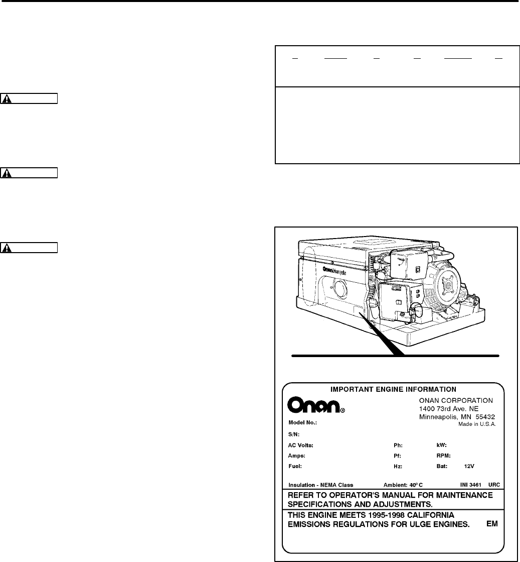
When contacting Onan for parts, service or product
information, be ready to provide the model number
and the serial number, both of which appear on the
genset nameplate. See Table 1-1 for the signifi-
cance of each character of the model number and
Figure 1-1 for how the model and serial numbers
are displayed on the nameplate.
TABLE 1-1. MODEL NUMBER
7 NHM F A 26105 G
||||||
123456
1. Rated Power in Kilowatts
2. Genset Family
3. Starting Method Code
4. Voltage and Frequency Code
5. Options and Special Features Code
6. Spec Letter designating modifications
SN5980U1G2RA 980 cc
A953123456
NAMEPLATE WITH TYPICAL MODEL AND
SERIAL NUMBER DATA
7NHM-FA/26105G
FIGURE 1-1. TYPICAL NAMEPLATE
Redistribution or publication of this document,
by any means, is strictly prohibited.

Section 2. General Specifications
2-1
GASOLINE MODELS BGM NHM
GENERATOR: 4-Pole Revolving Field, Self-Excited, Electronically Regulated, 1-Phase
Power (watts) 5500 6800
Frequency (Hertz) 60 60
Voltage 120 120
Current (amperes) 45.8 56.7
Speed (RPM) 1800 1800
FUEL CONSUMPTION:
No load gph (l/h)
Half load gph (l/h)
Full load gph (l/h)
0.4 (1.5)
0.7 (2.6)
1.0 (3.8)
0.4 (1.5)
0.7 (2.6)
1.3 (4.9)
ENGINE: 2-Cylinder Opposed, 4-Cycle, Spark-Ignited, Side-Valve, Air Cooled
Bore 3.250 inch (83 mm) 3.563 inch (90 mm)
Stroke 2.875 inch (73 mm) 3.000 inch (76 mm)
Displacement 48 inch3 (782 cc) 60 inch3 (980 cc)
Compression Ratio 7.0 : 1 7.0 : 1
Min Cylinder Compression Test Pressure 75 psi (517 kPa) 75 psi (517 kPa)
Oil Capacity (with filter)* 3.5 quart (3.3 l) 3.5 quart (3.3 l)
Intake Valve Clearance (Cold) 0.005 inch (0.13 mm) 0.005 inch (0.13 mm)
Exhaust Valve Clearance (Cold) 0.013 inch (0.33 mm) 0.013 inch (0.33 mm)
Spark Plug Gap 0.025 inch (0.64 mm) 0.025 inch (0.64 mm)
Spark Plug Tightening Torque 8 lbs-ft (10 N-m) 8 lbs-ft (10 N-m)
Ignition Timing (Begin Spec F) 12° BTDC non-adjustable 12° BTDC non-adjustable
Ignition Timing (Prior to Spec F) 14°-18°BTDC non-adjustable 14°-18°BTDC non-adjustable
Maximum Fuel Supply
Pressure at Carburetor 6 psi (41 kPa) 6 psi (41 kPa)
Maximum Fuel Pump Lift 3 feet (0.9 m) 3 feet (0.9 m)
Fuel Fitting 1/4 inch OD Hose Barb 1/4 inch OD Hose Barb
Exhaust Tailpipe Requirements 1-3/8 inch ID 18 Ga Steel Tubing 1-3/8 inch ID 18 Ga Steel Tubing
CONTROL AND CRANKING SYSTEM: 12 VDC
Nominal Battery Voltage 12 volts
Minimum Battery Cold
Cranking Capacity: Above/Below Freezing 360/450 amperes
Fuse F1 (Control Board, Spec A only) 5 amperes slow-blow
Fuse F2 (Fuel, Spec A only) 5 amperes slow-blow
Fuse F1 (Control Board,
Begin Spec B) 10 amperes
Fuse F2 (Choke/Fuel, Begin Spec D) 10 amperes mini-bayonet
* -See
Periodic Maintenance
for oil filling instructions.
Redistribution or publication of this document,
by any means, is strictly prohibited.

2-2
LPG MODELS NHM
GENERATOR: 4-Pole Revolving Field, Self-Excited, Electronically Regulated, 1-Phase
Power (watts) 6500
Frequency (Hertz) 60
Voltage 120
Current (amperes) 54.2
Speed (RPM) 1800
FUEL CONSUMPTION (HR):
No load lbs (kg) / gp (lp)
Half load lbs (kg) / gp (lp)
Full load lbs (kg) / gp (lp)
2.1 (.95) / .50 (1.9)
4.1 (1.86) / 1.0 (3.7)
6.6 (3) / 1.6 (5.9)
ENGINE: 2-Cylinder Opposed, 4-Cycle, Spark-Ignited, Side-Valve, Air Cooled
Bore 3.563 inch (90 mm)
Stroke 3.000 inch (76 mm)
Displacement 60 inch3 (980 cc)
Compression Ratio 7.0 : 1
Min Cylinder Compression Test Pressure 75 psi (517 kPa)
Oil Capacity (with filter)* 3.5 quart (3.3 l)
Intake Valve Clearance (Cold) 0.005 inch (0.13 mm)
Exhaust Valve Clearance (Cold) 0.013 inch (0.33 mm)
Spark Plug Gap 0.025 inch (0.64 mm)
Spark Plug Tightening Torque 8 lbs-ft (10 N-m)
Ignition Timing (Begin Spec F) 12° BTDC non-adjustable
Ignition Timing (Prior to Spec F) 14°-18°BTDC non-adjustable
LPG Vapor Supply Pressure Range
(Vapor-Withdrawal Only) 9 to 13 inch (229 to 330 mm) W. C. (water column)
LPG Connection for Vapor Withdrawal 3/4 inch NPT Tapping
LPG Connection for Liquid Withdrawal 1/4 inch NPTF Tapping
Exhaust Tailpipe Requirements 1-3/8 inch ID 18 Ga Steel Tubing
CONTROL AND CRANKING SYSTEM: 12 VDC
Nominal Battery Voltage 12 volts
Minimum Battery Cold Cranking
Capacity: Above/Below Freezing 360/450 amperes
Fuse F1 (Control Board) 10 amperes
* -See
Periodic Maintenance
for oil filling instructions.
Redistribution or publication of this document,
by any means, is strictly prohibited.

Section 3. Dimensions and Clearances
3-1
MODELS BGM NHM
CYLINDERS AND All clearances listed at 70° F (21°C) room temperature.
PISTON ASSEMBLY Values are in inches (millimeters) unless specified
otherwise. Dimensions apply to Specs A, B and C
gensets except as indicated.
Cylinder Bore 3.2490-3.2500 3.5625-3.5635
(Std size honed) (82.525-82.550 mm) (90.488-90.513 mm)
Cylinder Taper 0.005 0.005
(Max) (0.13 mm) (0.13 mm)
Cylinder Out Of 0.003 0.003
Round (Max) (0.076 mm) (0.076 mm)
Clearance In 0.0044-0.0066 0.0070-0.0090
Cylinder (0.112-0.168 mm) (0.178-0.229 mm)
Ring Gap (top and 0.008-0.018 0.009-0.019
second rings) (0.20-0.46 mm) (0.23-0.48 mm)
Piston Ring #1 (top) Spec A, B sets: 0.080-0.081 0.080-0.081
Groove Width (2.03-2.06 mm) (2.03-2.06 mm)
Spec C sets: 0.0602-0.0612 0.0602-0.0612
(1.53-1.55 mm) (1.53-1.55 mm)
Piston Ring #2 Spec A, B sets: 0.080-0.081 0.080-0.081
Groove Width (2.03-2.06 mm) (2.03-2.06 mm)
Spec C sets: 0.0602-0.0612 0.0602-0.0612
(1.53-1.55 mm) (1.53-1.55 mm)
Piston Ring #3 Spec A, B sets: 0.188-0.189 0.188-0.189
Groove Width (4.78-4.80 mm) (4.78-4.80 mm)
Spec C sets: 0.1193-0.1203 0.1193-0.1203
(3.03-3.06 mm) (3.03-3.06 mm)
Piston Pin 0.6875-0.6877 0.7500-0.7502
Diameter (17.46-17.47 mm) (19.05-19.06 mm)
Piston Pin Clearance 0.0002-0.0007 0.00005-0.00055
In Rod (0.005-0.018 mm) (0.001-0.014 mm)
Connecting Rod 0.0020-0.032 0.0020-0.0160
Side Clearance (0.051-0.813 mm) (0.051-0.406 mm)
Connecting Rod 0.0020-0.0033 0.0005-0.0028
Bearing Clearance (0.051-0.084 mm) (0.013-0.071 mm)
Redistribution or publication of this document,
by any means, is strictly prohibited.

3-2
MODELS BGM NHM
CRANKSHAFT AND
CAMSHAFT
Crankshaft Main Bearing 1.9992-2.0000 1.9992-2.0000
Journal Diameter (50.780-50.800 mm) (50.780-50.800 mm)
Crankshaft Rod Journal 1.6252-1.6260 1.6252-1.6260
Bearing Diameter (41.280-41.300 mm) (41.280-41.300 mm)
Crankshaft Main 2.0024-2.0034 2.0024-2.0034
Bearing Diameter (50.860-50.886 mm) (50.860-50.886 mm)
Crankshaft Main 0.0024-0.0042 0.0025-0.0038
Bearing Clearance (0.064-0.107 mm) (0.064-0.097 mm)
Crankshaft End 0.006-0.012 0.005-0.009
Play (0.15-0.30 mm) (0.13-0.23 mm)
Camshaft Journal 1.3740-1.3745 1.3740-1.3745
Diameter (34.900-34.912 mm) (34.900-34.912 mm)
Camshaft Bearing 1.376-1.377 1.376-1.377
Diameter (34.950-34.976 mm) (34.950-34.976 mm)
Camshaft Bearing 0.0015-0.0030 0.0015-0.0030
Clearance (0.038-0.076 mm) (0.038-0.076 mm)
Camshaft End Play 0.0110-0.0480 .0.0030-0.0120
(0.280-1.22 mm) (0.076-0.305 mm)
VALVE AND LIFTERS
Valve Spring Free 1.600 1.6620
Length (approx.) (40.640 mm) (42.214 mm)
Valve Spring Compressed 1.3750 1.3750
Length (Valve Closed) (34.925 mm) (34.925 mm)
Valve Spring Tension 71-79 lbs 71-79 lbs
Open (9.8-10.9 N) (9.8-10.9 N)
Valve Spring Tension 38-42 lbs 38-42 lbs
Closed (5.3-5.8 N) (5.3-5.8 N)
Redistribution or publication of this document,
by any means, is strictly prohibited.

3-3
MODELS BGM NHM
Valve Face Angle 44o44o
Valve Seat Angle 45o45o
Valve Stem 0.2795-0.2800 0.3425-0.3430
Diameter (Intake) (7.0993-7.1120 mm) (8.700-8.712 mm)
Valve Stem 0.2780-0.2785 0.3410-0.3415
Diameter (Exhaust) (7.0612-7.0739 mm) (8.661-8.674 mm)
Valve Guide Intake Exhaust Intake and Exhaust
Inside Diameter 0.2810-0.2820 0.2805-0.2815 0.344-0.346
(7.1374-7.0739 mm) (7.1200-7.1501 mm) (8.738-8.788 mm)
Valve Stem 0.0010-0.0025 0.0010-0.0025
Clearance (Intake) (0.025-0.064 mm) (0.025-0.064 mm)
Valve Stem 0.0020-0.0035 0.0025-0.0050
Clearance (Exhaust) (0.0508-0.0889 mm) (0.064-0.127 mm)
Valve Lifter 0.7475-0.7480 0.7475-0.7480
Diameter (18.987-18.999 mm) (18.987-18.999 mm)
Valve Lifter Bore 0.7500-0.7515 0.7500-0.7515
Diameter (19.050-19.088 mm) (19.050-19.088 mm)
Valve Lifter To 0.0020-0.0040 0.0020-0.0040
Block Clearance (0.0508-0.1016 mm) (0.0508-0.1016 mm)
Valve Seat 1.4425-1.4435 1.5690-1.5700
Diameter (Intake) (36.6395-36.6649 mm) (39.738-39.764 mm)
Valve Seat 1.192-1.193 1.2550-1.2560
Diameter (Exhaust) (30.28-30.30 mm) (31.877-31.902 mm)
Valve Seat Bore 1.4395-1.4405 1.5645-1.5655
Diameter (Intake) (36.563-36.589 mm) (39.738-39.764 mm)
Valve Seat Bore 1.189-1.190 1.2510-1.2520
Diameter (Exhaust) 30.20-30.23 mm) (31.775-31.801 mm)
Redistribution or publication of this document,
by any means, is strictly prohibited.

Section 4. Torque Specifications
4-1
MODEL BGM
TORQUE Use engine oil as a lubricant for all threads
SPECIFICATIONS EXCEPT the spark plug and rotor through-bolt threads
FOOT-POUNDS NEWTON-METERS
Cylinder Head Bolts (cold) 14-16 19-22
Connecting Rod Bolts 12-14 16-19
Rear Bearing Plate 25-27 34-37
Flywheel Mounting Screw 50-55 68-75
Oil Base 20-24 27-33
Gearcase Cover 10-12 14-16
Spark Plug 7-9 9-12
Exhaust Manifold 9-11 12-15
Intake Manifold 6-10 8-14
Rotor Through-Bolt 45-55 61-75
Starter Mounting Screws 30-33 41-45
Stator Clamp Screws 10-12 11-16
Adapter to Engine 25-27 34-37
Mounting Screws
Adapter to Generator 25 34
Mounting Screws
Rear Vibration Isolator
Center Screw 30-33 41-45
Flange to Drip Tray Screws 10-12 14-16
Front Vibration Isolator
Flange to Oil Base Screws 19-22 26-30
Center Screw 28-32 38-43
Vibration Isolators
Center Screw 30-33 ft-lbs 41-45
Flange to Drip Tray Screws 10-12 ft-lbs 14-16
Voltage Regulator
Mounting Bracket Screws 7-8 ft-lbs 9-11
Regulator Attachment Screws 5-6 ft-lbs 7-8
Start Solenoid Attachment Screws 5-6 ft-lbs 7-8
Redistribution or publication of this document,
by any means, is strictly prohibited.

4-2
MODEL NHM
TORQUE Use engine oil as a lubricant for all threads
SPECIFICATIONS EXCEPT the spark plug and rotor through-bolt threads.
FOOT-POUNDS NEWTON-METERS
Cylinder Head Nuts (cold) 14 19
(with compression washers)
Cylinder Head Nuts (cold) 17 23
(without compression washers)
Connecting Rod 27-29 37-39
Rear Bearing Plate 25-28 34-38
Flywheel Mounting Screw 50-55 68-75
Starting Mounting Bracket to 20-24 27-33
Oil Base Screws
Gearcase Cover 10-12 14-16
Spark Plug 7-9 9-12
Exhaust Manifold 20-23 27-31
Intake Manifold 14-16 19-22
Rotor Through-Bolt 45-55 61-75
Starter Mounting Screws 30-33 41-45
Stator Clamp Screws 10-12 14-16
Adapter to Engine 25-27 34-37
Mounting Screws
Adapter to Generator 25 34
Mounting Screws
Rear Vibration Isolator
Center Screw 30-33 41-45
Flange to Drip Tray Screws 10-12 14-16
Front Vibration Isolator
Flange to Oil Base Screws 19-22 26-30
Center Screw 28-32 38-43
Vibration Isolators
Center Screw 30-33 ft-lbs 41-45
Flange to Drip Tray Screws 10-12 ft-lbs 14-16
Voltage Regulator
Mounting Bracket Screws 7-8 ft-lbs 9-11
Regulator Attachment Screws 5-6 ft-lbs 7-8
Start Solenoid Attachment Screws 5-6 ft-lbs 7-8
Redistribution or publication of this document,
by any means, is strictly prohibited.

Section 5. Preparing for Service
5-1
TROUBLESHOOTING
See
Troubleshooting
to determine the probable
cause of the problem before removing the genset
for service.
SAFETY
There are hazards in servicing gensets. Study
Safety Precautions
and become familiar with the
hazards listed in Table 5-2. Note the following safe-
guards and ways of avoiding hazards:
•
Use personal protection:
Wear appropriate
protective safety equipment, such as:
Safety shoes
Gloves
Safety glasses
Hard hats
Do not wear rings or jewelry and do not wear
loose clothing that might get caught in equip-
ment.
•
Reduce the hazard:
A safe, orderly workshop
area and well-maintained equipment reduce
the hazard potential. Keep guards and shields
in place on machinery and maintain equipment
in good working condition. Store flammable liq-
uids in approved containers; away from fire,
flame, spark, pilot light, switches, arc-produc-
ing equipment and other ignition sources. Keep
the workshop clean and well-lighted and pro-
vide adequate ventilation.
•
Develop safe work habits:
Unsafe actions
cause accidents with tools and machines. Be
familiar with the equipment and know how to
use it safely. Use the correct tool for the job and
check its condition before starting. Comply with
the warnings in this manual and take special
precautions when working around electrical
equipment. Do not work alone if possible and
take no risks.
•
Be prepared for an accident:
Keep fire extin-
guishers and safety equipment nearby. Agen-
cies such as the Red Cross and public safety
departments offer courses in first aid, CPR and
fire control. Take advantage of this information
to be ready to respond to an accident. Learn to
be safety-conscious and make safety proce-
dures part of the work routine.
TABLE 5-2. HAZARDS AND THEIR SOURCES
Fire and
Explosion
•Leaking or spilled fuel
•Hydrogen gas from battery
•Oily rags improperly stored
•Flammable liquids improperly
stored
Burns
•Hot exhaust pipes
•Hot engine and generator sur-
faces
•Electrical shorts
Poisonous
Gas •Operating genset where ex-
haust gases can accumulate
Electrical
Shock (AC)
•Improper generator connec-
tions
•Faulty wiring
•Working in damp conditions
•Jewelry touching electrical
components
Rotating
Machinery •Fan guards not in place
Slippery
Surfaces •Leaking or spilled oil
Heavy
Objects •Removing genset from vehicle
•Removing heavy components
Redistribution or publication of this document,
by any means, is strictly prohibited.

5-2
SPECIAL TOOLS
The tools listed below are necessary for servicing
the genset. See the Onan Tool Catalog.
Engine Tools
Torque wrench: 0-75 lbs-ft (0-100 N-m)
Hole gauge: 0.300-0.400 inch (5-10 mm)
Outside micrometer set: 0-4 inch (0-100 mm)
Telescoping gauge set: up to 4 inch (100 mm)
Feeler gauge
Plasti-Gage bearing clearance guide
Spark plug gap gauge
Oil pressure gauge: 0-30 psi (0-200 kPa)
Fuel pressure gauge (for gasoline): 0-10 psi
(0-75 kPa)
Manometer (for LPG): 14 inch (350 mm) WC
Inclined Manometer (for LPG): 1 inch (25 mm)
WC range with 0.01 inch (0.2 mm) WC di-
visions
Cylinder compression tester
Flywheel puller
Crankshaft gear puller ring, bolts and puller
(or special shoulder bolts and flywheel
puller)
Snap ring pliers
Combination main and cam bearing remover
Combination main and cam bearing driver
Oil seal loader and driver
Cylinder ridge reamer
Piston ring spreader
Piston groove cleaner
Piston ring compressor
Cylinder hone
Valve spring compressor
Valve lock replacer
Valve seat cutter kit
Valve guide driver
Slide hammer
Lead or dead-blow hammer
Generator and Control Tools
Rotor removal tool (headless bolt)
Battery hydrometer
Frequency meter
Digital multi-meter: AC and DC Voltage, Ohms
and Diode Check
Load test panel and leads
Voltage Regulator Testor and Adaptor (1-Ph)
Rotor and Stator Testor and Adaptor
REMOVING THE GENSET
Some service procedures will require that the gen-
set be removed from the vehicle. The genset is nor-
mally mounted in a special compartment on the ve-
hicle floor. Because installations vary, it is not pos-
sible to describe a specific removal procedure.
Contact the vehicle manufacturer or installer if the
best way to remove the genset is not obvious.
Disconnections at the Genset
1. First disconnect the negative (-) battery cable
from the battery
and then disconnect the bat-
tery cables from the genset.
WARNING
Sparks and high current could
cause fire and other damage to the battery,
battery cables and vehicle if the loose ends
of cables connected to the battery touch.
Always disconnect the negative (-) battery
cable from the battery before disconnect-
ing the battery cables from the genset.
2. Disconnect the remote control wiring harness
connector at the genset.
3. Disconnect the generator output wiring and
conduit from the power distribution panel or
box on the vehicle. Tag all wires to make recon-
nections easier.
Redistribution or publication of this document,
by any means, is strictly prohibited.
5-3
4. Disconnect the exhaust tailpipe from the outlet
of the muffler. See EXHAUST SYSTEM under
Section 6. Engine-Primary Systems.
5. Disconnect the fuel supply line from the genset.
Follow the applicable instructions depending
on the fuel.
WARNING
Gasoline and LPG (liquified pe-
troleum gas) are flammable and explosive
and can cause severe personal injury or
death. Do not smoke if you smell gas or gas-
oline or are near fuel tanks or fuel-burning
equipment or are in an area sharing ventila-
tion with such equipment. Keep flames,
sparks, pilot lights, electrical arcs and arc-
producing equipment and all other sources
of ignition well away.
Gasoline Fueled Gensets:
Disconnect the
fuel line from the genset and securely plug the
end of the fuel line to prevent leakage or an ac-
cumulation of explosive gasoline vapor.
LPG Fueled Gensets:
Close the fuel shutoff
valve(s) at the LPG container(s) and move the
vehicle outside and away from below-grade
spaces where LPG could accumulate. To
purge the fuel line and genset as much as pos-
sible, run the genset (if it starts) until it runs out
of fuel with the LPG valve(s) closed. Also see
the specific additional instructions which follow
for purging liquid-withdrawal and vapor-with-
drawal systems and for capping off the gas
supply line.
WARNING
LPG is flammable and explo-
sive and can cause asphyxiation. NFPA 58,
Section 1.6 requires all persons handling
LPG to be trained in proper handling and
operating procedures.
LPG “sinks” when it escapes into the air
and can accumulate in explosive con-
centrations. Before disconnecting the LPG
fuel line, close the fuel shutoff valve(s) at
the LPG container(s) and move the vehicle
outside and away from pits or basements or
other below-grade spaces where LPG
could accumulate.
Purging LPG Liquid-Withdrawal Systems:
Purge the supply line further by loosening the
threaded supply connection at the LPG filter on
the genset just enough to hear gas escaping.
Unthread the connector when no more gas is
heard escaping. To purge the LPG trapped be-
tween the solenoid and regulator, loosen the
flexible hose connector at the fuel solenoid just
enough to hear gas escaping, and then retigh-
ten. Finally, cap the end of the fuel supply hose
or pipe with a 1/4 inch NPTF pipe cap to pre-
vent fuel from escaping if someone inadver-
tently opens the shutoff valve(s) at the LPG
container(s).
WARNING
Large volumes of LPG can be
released in the process of disconnecting a
liquid-withdrawal type of LPG supply sys-
tem. Before disconnecting LPG fuel con-
nections, make sure the the fuel shutoff
valve(s) at the LPG container(s) are closed
and that the vehicle is outside and away
from pits or basements or other below-
grade spaces where LPG could accumu-
late.
Purging LPG Vapor-Withdrawal Systems:
Dis-
connect the gas supply hose at the carburetor
and the fuel solenoid shutoff valve leads at the
control box on the genset. If the pressure regu-
lator/solenoid valve assembly is also to be re-
moved, cap the end of the fuel supply line with
a threaded pipe cap to prevent fuel from escap-
ing if someone inadvertently opens the shutoff
valve(s).
Redistribution or publication of this document,
by any means, is strictly prohibited.
5-4
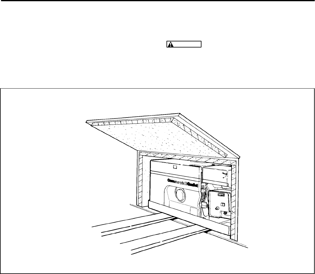
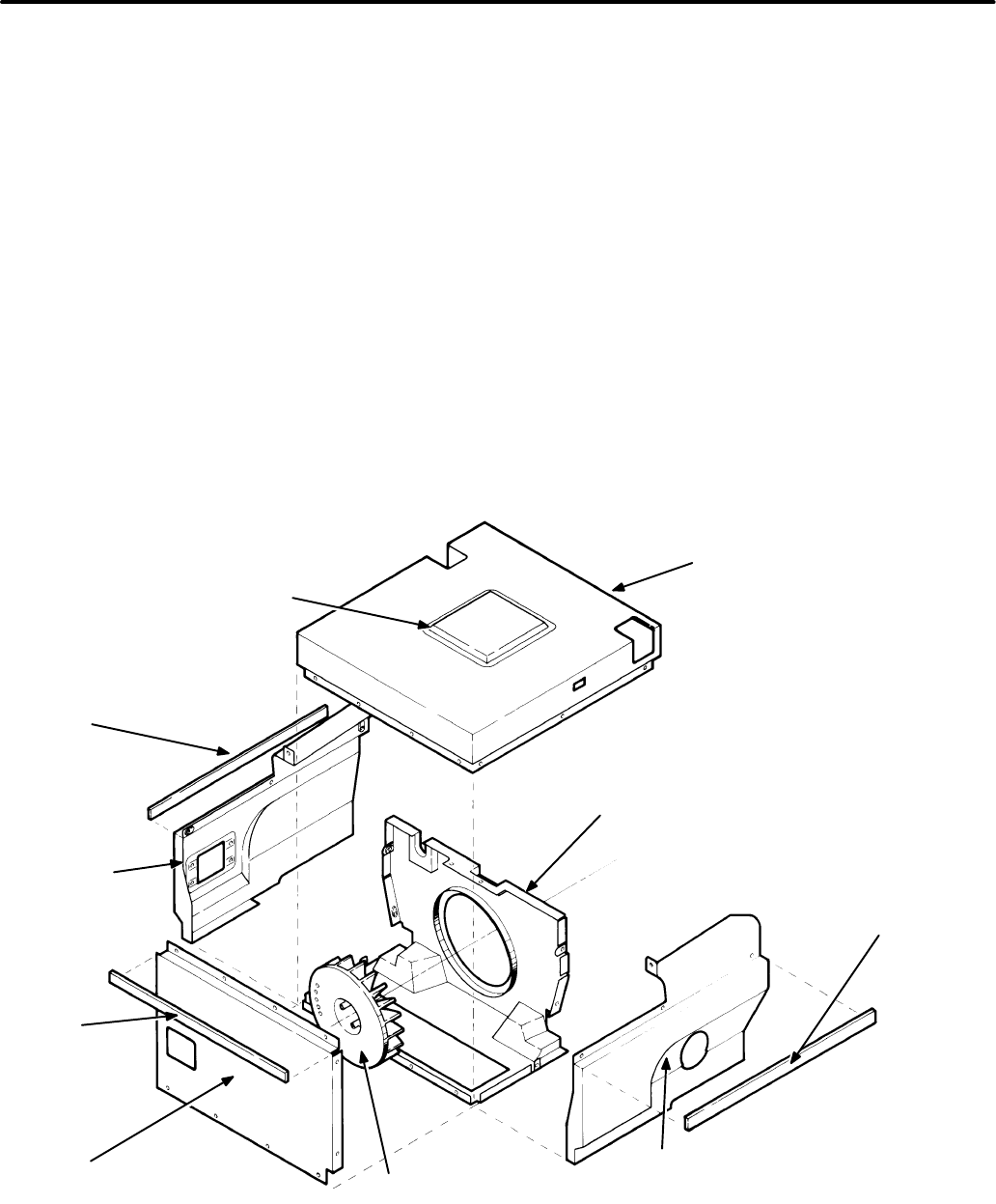
Removal of the Genset from the Vehicle
See Figure 5-2. When the genset has been discon-
nected from the electrical, exhaust and fuel sys-
tems, examine its mounting bolts and support mem-
bers. The genset drip tray is normally bolted to the
vehicle framework. Make sure that the genset is
firmly supported before loosening any mounting
bolts or support members. A fork lift is recom-
mended to lift or move the genset.
WARNING
Gensets are heavy and can cause
severe personal injury if dropped. Use a forklift
or other suitable means to handle the genset
while removing or installing it. Keep hands and
feet clear incase the genset is dropped.
FIGURE 5-2. SET REMOVAL
Redistribution or publication of this document,
by any means, is strictly prohibited.
Section 6. Engine − Primary Systems
6-1
The engine primary systems and service proce-
dures covered in this section do not require removal
of the cylinder heads, gearcase or rear bearing
plate for access. It may be possible to perform some
of these procedures without removing the genset
from the vehicle.
TROUBLESHOOTING ENGINE PRIMARY
SYSTEMS
Regular maintenance can prevent many of the
problems listed below. Removing and cleaning the
cylinder heads every 500 hours is especially impor-
tant for gasoline models. Before considering major
engine service because of abnormal performance,
refer to
Periodic Maintenance
in the Operator’s
Manual for instructions on how to clean the cylinder
heads using Onan “4C”.
The following troubleshooting tables are designed
to help you think through genset problems. To save
time troubleshooting, read the entire manual ahead
of time to understand the genset. Try to think
through problems. Go over what was done during
the last service call. The problem could be as simple
as an empty fuel tank, closed fuel shutoff valve,
loose wire, blown fuse or tripped circuit breaker.
See
Section 7.
Control System
and
Section 8.
Gen-
erator
for control and generator troubleshooting
tables.
Many troubleshooting procedures present hazards which can result in severe personal
injury or death. Only qualified service personnel with knowledge of fuel, electricity, and machinery
hazards should perform service procedures. Review safety precautions on inside cover page.
Trouble Possible Cause Corrective Action
Engine 1.Faulty ignition due to: 1a. Replace spark plugs.
Misfires a.worn or fouled spark plugs. 1b. Test coil and replace if necessary.
b.faulty ignition coil. 1c. Test spark plug wires and replace
c. faulty plug wires. if faulty.
2.Lean fuel mixture due to: 2a. Adjust carburetor main
a.incorrectly adjusted and idle adjustment screws.1
fuel mixture screws.12b. Adjust carburetor float level.1
b.incorrect float level.1, 22c. Disassemble carburetor and clean all
c. dirt in carburetor. internal passages.1 Replace fuel filter.
d.vacuum leak. 2d. Locate leak and correct as required.
e.altitude setting. 2e. Reset altitude adjust knob on carburetor.
3.Contaminated fuel.23.Drain fuel tank and refill with fresh fuel.
4.Carburetor icing.24.Place air preheater in winter position.
Engine 1.Faulty ignition due to 1.Reset spark plug gap.
Backfires incorrect spark plug gap.
2.Lean fuel mixture due to: 2a. Adjust carburetor main and idle
a.incorrectly adjusted fuel mixture screws.1
adjustment screws.12b. Adjust carburetor float level.1
b.incorrect float level.1, 22c. Disassemble carburetor and clean
c. dirt in carburetor. all internal passages.1
3.Mechanical damage to engine. 3.See
Engine Block Assembly
section.
1 - Prior to Spec F only
2 - Gasoline models only
WARNING
Redistribution or publication of this document,
by any means, is strictly prohibited.
6-2
Trouble Possible Cause Corrective Action
Engine 1.Faulty ignition due to incorrect 1. Reset spark plug gap.
Lacks spark plug gap.
Power 2.Dirty air cleaner. 2. Replace air cleaner.
3.Restricted fuel flow due to: 3a. Replace fuel filter.
a.Plugged fuel filter. 3b. Test fuel pump and repair or replace
b.Faulty fuel pump. if faulty.
4.Incorrect fuel mixture due to: 4a. Adjust carburetor main and idle
a.incorrectly adjusted fuel adjustment screws.1
mixture screws.14b. Adjust carburetor float level.1
b.incorrect float level.1, 24c. Disassemble carburetor and clean all
c. dirt in carburetor. internal passages.1 Replace fuel filter.
d.vacuum leak. 4d. Repair vacuum leak.
e.altitude setting. 4e. Reset altitude adjust knob on carburetor.
5.Exhaust system blocked or 5. Locate and remove cause of blockage.
restricted.
6.Incorrect valve tappet clearance. 6. Adjust valve tappets (see
Engine Block
Assembly
section).
7.Excessive engine wear or 7. See
Engine Block Assembly
section.
damage to engine.
8.Carburetor air preheater set 8. In hot weather, place air preheater in
incorrectly.2summer position.
9.Combustion chamber deposits. 9. Clean combustion chamber.
10.(Spec A sets) No-load speed 10. Adjust (mechanical) governor.
set too low: excessive
governor droop.
11.Contaminants in LPG regulator. 11. Clean LPG regulator.
(liquid-withdrawal systems)
1 - Prior to Spec F only
2 - Gasoline models only
TROUBLESHOOTING ENGINE PRIMARY SYSTEMS
Many troubleshooting procedures present hazards which can result in severe personal
injury or death. Only qualified service personnel with knowledge of fuel, electricity, and machinery
hazards should perform service procedures. Review safety precautions on inside cover page.
WARNING
Redistribution or publication of this document,
by any means, is strictly prohibited.

6-3
Trouble Possible Cause Corrective Action
Engine 1.Restricted airflow due to: 1.a. Clear away debris. Do not use genset
Overheats a.debris blocking air inlet or outlet. compartment for storage.
b.improper installation b. See the Installation Manual.
2.Dirt or oil covering engine 2.Clean away all dirt and oil from engine
cooling fins. cooling fins.
3.Lean fuel mixture due to: 3.a. Adjust carburetor main and idle
a.incorrectly adjusted fuel adjustment screws.1
mixture screws.13.b. Adjust carburetor float level.1
b.incorrect float level.1, 2c. Disassemble carburetor and clean all
c. dirt in carburetor. internal passages.1 Replace fuel filter.
d.vacuum leak. d.Repair vacuum leak.
Black 1.Rich fuel mixture due to: 1a. Adjust carburetor float level.1
Exhaust a.incorrect float level 1b. Replace carburetor float.1
Smoke b. faulty carburetor float.1, 2
White or 1.Lean fuel mixture due to: 1a. Adjust carburetor float level.1
Blue a.incorrect float level.1, 21b. Adjust carburetor idle and main
Exhaust b.incorrectly adjusted fuel adjustment screws.1
Smoke mixture screws.11c. Disassemble carburetor and clean
c. dirt in carburetor all internal passages.1
d.vacuum leak 1d. Repair vacuum leak.
2.Contaminated fuel.22.Drain and replace fuel.
3.Excessive engine wear 3.See
Engine Block Assembly
section.
1 - Prior to Spec F only
2 - Gasoline models only
TROUBLESHOOTING ENGINE PRIMARY SYSTEMS
Many troubleshooting procedures present hazards which can result in severe personal
injury or death. Only qualified service personnel with knowledge of fuel, electricity, and machinery
hazards should perform service procedures. Review safety precautions on inside cover page.
WARNING
Redistribution or publication of this document,
by any means, is strictly prohibited.

6-4
Trouble Possible Cause Corrective Action
Engine 1.Sticking or binding 1.Clean governor linkage (remove dirt or
Surges (mechanical) governor linkage. ice buildup). Check that linkage
does not touch other parts.
2.Incorrect (mechanical) governor 2.Adjust governor speed and
adjustment. sensitivity.
3.Faulty (mechanical) governor 3.Replace governor spring.
spring.
4.Incorrect fuel mixture due to: 4a. Adjust carburetor main and
a.incorrectly adjusted idle adjustment screws.1
fuel mixture screws.14b. Adjust carburetor float level.1
* b.incorrect float level.1, 24c. Disassemble carburetor and
c. dirt in carburetor clean all internal passages.1
d.ignition misfires 4d. Check connections, see
Ignition
section.
5.Intermittent electrical 5. Check battery and ignition connections.
connections.
6.Governor mechanism worn 6.See
Engine Block
excessively.
Assembly
section.
7.Fuel supply problem caused by: 7a. Check fuel pump and replace
a.Faulty fuel pump.2if defective.
b.Contaminated fuel supply.27b. Drain and refill fuel supply
c. Vapor locking.27c. Check for cause of overheating
d.Plugged fuel filter 7d. Replace fuel filter.
8.Carburetor icing.28.In cold weather, place air
preheater in winter position.
1 - Prior to Spec F only
2 - Gasoline models only
TROUBLESHOOTING ENGINE PRIMARY SYSTEMS
Many troubleshooting procedures present hazards which can result in severe personal
injury or death. Only qualified service personnel with knowledge of fuel, electricity, and machinery
hazards should perform service procedures. Review safety precautions on inside cover page.
WARNING
Redistribution or publication of this document,
by any means, is strictly prohibited.

6-5
Trouble Possible Cause Corrective Action
High Oil 1.Oil viscosity is too light . 1.Drain and refill with oil suitable for
Consumption the ambient temperature.
(Note: New
engines 2. Crankcase breather valve is 2.Clean crankcase breather
sometimes dirty or faulty. and replace if defective.
consume oil
during break-in) 3.Oil leaks. 3.Locate source of leak and
repair as required.
4.Excessive engine wear. 4. See
Engine Block Assembly
section.
5.Light loading. 5.Don’t run set at no-load
for long periods of time.
Low Oil 1.Oil viscosity is too light. 1.Drain and refill with oil suitable for
Pressure the ambient temperature.
2.Oil dilution due to: 2.a. Adjust choke.
a.faulty choke b. Replace spark plugs
b.fouled spark plug c. Adjust fuel mixture1, 2
c. rich fuel mixture
3.Low oil level. 3. Add oil as required.
4.Low oil pressure switch 4.Replace oil pressure switch
defective. (see
Engine Block Assembly
section).
5.Faulty oil bypass valve. 5.Inspect oil bypass valve and
clean or replace as required
(see
Engine Block Assembly
section).
6.Excessive engine wear or 6.See
Engine Block Assembly
section.
faulty oil pump.
1 - Prior to Spec F only
2 - Gasoline models only
TROUBLESHOOTING ENGINE PRIMARY SYSTEMS
Many troubleshooting procedures present hazards which can result in severe personal
injury or death. Only qualified service personnel with knowledge of fuel, electricity, and machinery
hazards should perform service procedures. Review safety precautions on inside cover page.
WARNING
Redistribution or publication of this document,
by any means, is strictly prohibited.
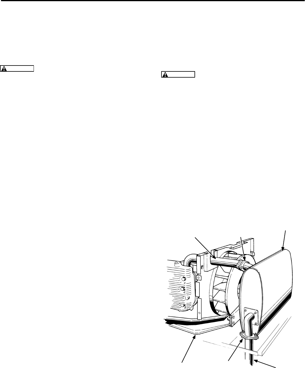
6-6
EXHAUST SYSTEM
See Figure 6-3. The exhaust system consists of the
exhaust manifold, muffler, tailpipe adapter and tail-
pipe. The muffler is mounted inside the genset
housing. The tailpipe is supplied by the customer.
WARNING
Exhaust gas is deadly. The exhaust
system must not leak and must discharge all en-
gine exhaust away from the vehicle.
Liability for injury, death, damage and warranty
expense due to the use of an unapproved muf-
fler or due to modifications becomes the re-
sponsibility of the person installing the unap-
proved muffler or performing the modifications.
Use Onan approved exhaust system parts.
Repair the exhaust system before running the gen-
set if there is damage or leaks. Do not try to weld a
broken or leaky tailpipe, muffler or manifold.
Tailpipe
If it is necessary to replace the tailpipe, use 1-3/8
inch I. D. 18 gauge steel tubing. Because the tail-
pipe is connected rigidly to the engine (via the muf-
fler) and the engine is mounted on vibration isola-
tors, flexible shock-mount hangers must be used to
support the tailpipe. Important safety warnings and
instructions regarding the routing and termination of
the tailpipe are included in the Installation Manual.
Muffler
It will probably be necessary to remove the genset
from the vehicle.
See
Section 5. Preparing to Ser-
vice.
Remove the top panel (see COOLING SYSTEM in
this section). Then remove the two flange bolts of
the joint between the manifold and the muffler and
the four mounting bracket screws on the ends of the
muffler and withdraw the muffler.
When installing the muffler make sure the self-
aligning joint between the manifold and the muffler
lines up properly for a leak-free joint before tighten-
ing the bracket mounting screws.
Exhaust Manifold
To remove the exhaust manifold first remove the
muffler. On gensets equipped for liquid-withdrawal
of LPG, disconnect both ends of the LPG vaporizer
tubing clamped to the manifold. Remove the four
exhaust manifold bolts and then the manifold and
gaskets. Be sure to cover the openings in the block
to prevent loose parts and dirt from entering the en-
gine.
WARNING
Bending the fuel vaporizer tubing
can weaken it to the point that it can crack allow-
ing LPG under high pressure to escape, result-
ing in possible severe personal injury or death.
Large volumes of LPG can be released in the
process of disconnecting a liquid-withdrawal
type of LPG supply system. See Section 5. Pre-
paring to Service for proper procedures and
precautions.
When installing an exhaust manifold, always use
new gaskets and torque the manifold bolts accord-
ing to
Section 4. Torque Specifications.
If the man-
ifold has an LPG vaporizer tube clamped to it, con-
nect the tubing ends before tightening the manifold
bolts. Also, if necessary, loosen the tubing clamps
to make the tubing connections easier and then re-
tighten the clamps.
EXHAUST
MANIFOLD
MUFFLER ATTACHMENT
FLANGES
MUFFLER
TAILPIPE
BOTTOM−EXIT
TAILPIPE ADAPTER
MUFFLER
SUPPORT
FIGURE 6-3. EXHAUST SYSTEM
Redistribution or publication of this document,
by any means, is strictly prohibited.
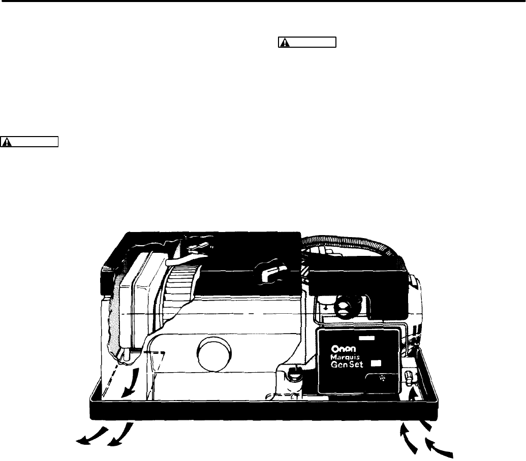
6-7
COOLING SYSTEM
See Figure 6-4. These are air-cooled gensets. The
engine flywheel is also a centrifugal blower that
draws cooling air across the fins on the engine cylin-
ders and heads and discharges the warm air down-
wards through the discharge grill.
WARNING
Do not run the generator set without
all the covers in place. Contact with the rotating
flywheel can result in severe personal injury or
death.
WARNING
Discharge air from the engine can
include deadly exhaust gas. Therefore, do not
use engine discharge air to heat the interior of
the vehicle.
See the Installation Manual regarding the minimum
free area required for the air inlet to the compart-
ment or enclosure and the minimum clearance re-
quired at the discharge opening. The engine will
overheat if the inlet and outlet openings are too
small or are obstructed or if dust has accumulated
on the cooling fins.
AIR
OUTLET BOTTOM
AIR INLET
FIGURE 6-4. COOLING AIR FLOW
Redistribution or publication of this document,
by any means, is strictly prohibited.
6-8
Cooling System Panel Removal
1. Disconnect the starting battery, negative (-)
cable first, to prevent accidental starting.
2. Pry off the trim strips (if any) around the three
sides of the top panel and remove the exposed
Torx screws and the two screws on top. See
Figure 6-5. Through the spark plug access
opening, unhook the left-side (oil filter side)
spark plug lead from the top panel and remove
the panel.
3. Remove the left and right side panels. Five re-
maining Torx screws and two capscrews at the
top of the cylinder heads secure each.
4. Remove the end panel which is secured by four
remaining screws along its bottom edge.
Cooling System Disassembly for Engine
Block Service:
1. Remove the cooling system panels, muffler
and exhaust manifold (see
EXHAUST SYS-
TEM in this section).
2. Remove the flywheel. See Flywheel Removal.
3. Disconnect the lead connected at the low oil
pressure cutoff switch (next to the oil filter).
4. Remove the four capscrews that secure the in-
ner bulkhead to the engine and remove it.
5. Thoroughly clean the engine cooling fins.
TOP PANEL
LEFT
SIDE PANEL
FLYWHEEL
RIGHT
SIDE PANEL
TRIM
STRIP*
INNER
BULKHEAD
TRIM
STRIP*
TRIM
STRIP*
* SPEC A ONLY
END
PANEL
GOVERNOR
ACCESS COVER*
FIGURE 6-5. COOLING SYSTEM
Redistribution or publication of this document,
by any means, is strictly prohibited.
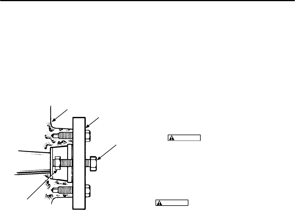
6-9
Flywheel Removal
1. Loosen the flywheel capscrew and back it out
several turns. See Figure 6-6.
2. Attach the puller tool to the flywheel. The tool
has two jack screws that fit into the holes
tapped in the flywheel. Tighten the puller center
screw until the flywheel comes loose. Remove
the puller, flywheel center screw and washer.
Inspect the flywheel and replace it if any air
vanes are missing.
FLYWHEEL
FLYWHEEL
PULLER
JACK SCREW
FLYWHEEL
CAP SCREW
FIGURE 6-6. FLYWHEEL PULLER
Cooling System Reassembly
Reassembly is the reverse of disassembly.
1. Make sure the woodruff key is in place when
installing the flywheel. Use non-hardening
sealer on the flywheel capscrew threads and
tighten according to
Section 4. Torque Specifi-
cations.
2. Make sure the pieces of insulation used to seal
the openings in the inner bulkhead where the
two muffler support brackets and the exhaust
manifold pass through are in place.
3. Make sure the lead to the low oil pressure
switch has been reconnected.
CAUTION
Running the set without the low
oil pressure cutoff switch connected can
lead to serious engine damage in the event
of low oil pressure.
4. Make sure the spark plug cable (oil filter side)
has been rehooked by the clip inside the top
panel to prevent it from interfering with the gov-
ernor rod and causing erratic operation.
CAUTION
The engine will overheat and can be
damaged if it is operated without all the cooling
system components in place.
Redistribution or publication of this document,
by any means, is strictly prohibited.
6-10
IGNITION SYSTEM
These gensets are equipped with an electronic igni-
tion system consisting of a rotor, module, coil, ca-
pacitor, spark plugs and associated wiring. Energy
for ignition is supplied by the 12 volt cranking bat-
tery.
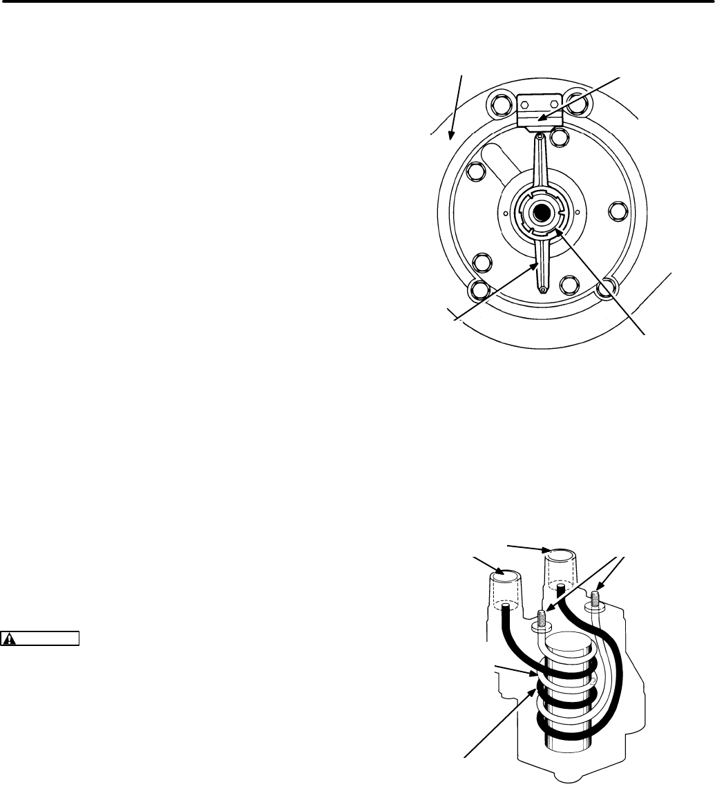
Rotor
See Figure 6-7. The ignition rotor is keyed to the en-
gine crankshaft. The ends have opposite magnetic
polarity (north and south). One pole switches on the
ignition module and the other pole switches it off,
once each revolution of the crankshaft. The rotor
should not normally require replacement.
Module
The ignition module is secured and grounded to the
generator-engine adaptor by two cap screws. It is
an electronic switch in the primary circuit of the igni-
tion coil. See
Appendix B. Wiring Diagrams
for the
appropriate wiring diagram. It is switched on and off
once each revolution by the rotor. The module con-
tains no serviceable parts and should not normally
require replacement.
Coil
See Figure 6-8. The ignition coil is a transformer
that fires the spark plugs at roughly 20,000 volts
each revolution when the ignition module opens the
primary circuit causing the coil field to collapse.
CAUTION
The leads connected at the low volt-
age terminals of the ignition coil (Figure 6-8)
should not be routed so as to pass between the
high voltage terminal posts. Otherwise, false
signals can be induced in the low voltage wires,
leading to erratic operation.
Capacitor
The ignition capacitor is secured and grounded to
the top of the generator-engine adaptor by one cap
screw. The pig tail is connected to the positive (+)
low voltage terminal of the ignition coil.
IGNITION
MODULE
IGNITION
ROTOR CRANKSHAFT
ENGINE-GENERATOR
ADAPTOR
FIGURE 6-7. IGNITION ROTOR AND MODULE
LOW VOLTAGE
TERMINALS
SECONDARY
WINDING
PRIMARY
WINDING
HIGH VOLTAGE
TERMINALS
FIGURE 6-8. IGNITION COIL
Redistribution or publication of this document,
by any means, is strictly prohibited.
6-11
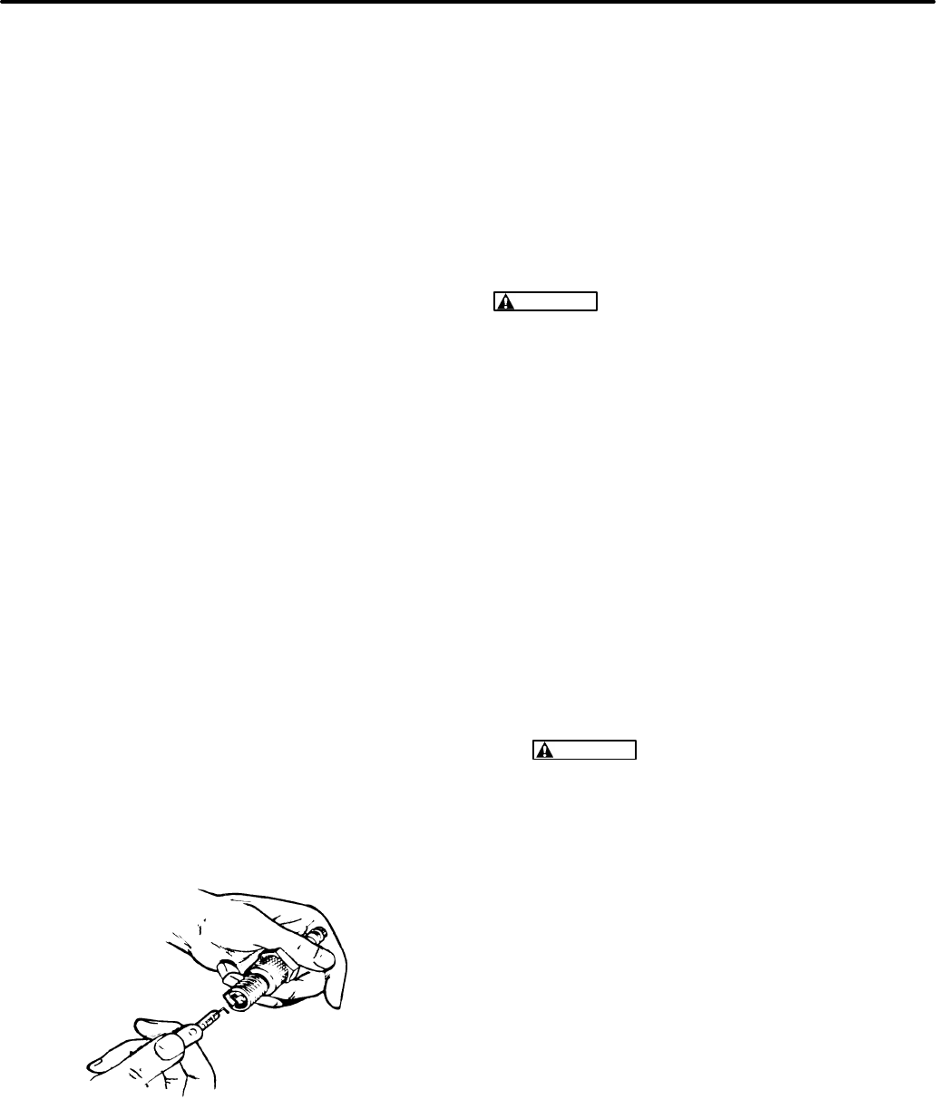
Spark Plugs
The genset has two spark plugs. The spark plugs
must be in good condition and have the proper gap
for top engine performance. See Figure 6-9 and
Section 2. General Specifications.
To prevent crossthreading a spark plug, always
thread it in by hand until it seats. Then tighten the
spark plug according to
Section 4. Torque Specifi-
cations.
Alternatively, turn it with a wrench an addi-
tional 1/4 turn.
If the engine misses or performance otherwise de-
teriorates, remove and examine the spark plugs for
signs of the following problems:
Light tan, gray or reddish deposits -
Normal
One spark plug fouled -
Broken spark plug cable,
low cylinder compression
Soot fouled -
Wrong spark plug heat range (too
cold), duty cycle too short for engine to reach nor-
mal operating temperature
Fuel fouled -
Wrong spark plug heat range (too
cold), faulty choke operation, overly rich fuel mix-
ture, dirty air filter
Oil fouled -
Malfunctioning crankcase breather,
worn rings, worn valve guides or seals
Burned Or Overheated -
Leaking intake manifold
gaskets, lean fuel mixture
Worn -
Spark plug service life used up.
FIGURE 6-9. CHECKING SPARK PLUG GAP
Quick Ignition Test
If the engine misfires, test the ignition system as fol-
lows to quickly determine if the problem is in the
ignition system. First recheck, clean and tighten the
connections at the ignition coil terminals. See
Ap-
pendix B. Wiring Diagrams
for the proper connec-
tions at the “-” and “+” terminals.
WARNING
Gasoline and LPG are flammable
and explosive and can cause severe personal
injury or death. Park the vehicle in a well-venti-
lated area, leave the generator compartment
door open for several minutes and make sure
you cannot smell gas or gasoline vapors before
conducting this test. Have an ABC rated fire ex-
tinguisher handy.
1. Park the vehicle in a well-ventilated area, leave
the generator compartment door open for sev-
eral minutes and make sure you cannot smell
gas or gasoline vapors before conducting this
test.
2. Remove one of the spark plugs.
3. Reconnect the spark plug cable and lay the
spark plug on bare engine metal to ground it.
WARNING
HIGH VOLTAGE. To prevent
electric shock do not touch the spark plug
or wire during this test.
4. Crank the engine and observe the spark. A
strong, consistent spark indicates that the igni-
tion system is probably functioning properly
and that the problem is elsewhere. See
Trou-
bleshooting
. Service the ignition system as re-
quired if the spark is weak or inconsistent.
Spark Plug Cable Resistance Test
Remove both spark plug cables and check resist-
ance across the ends with an ohmmeter. Replace a
cable if resistance is not between 3,000 and 15,000
ohms.
Redistribution or publication of this document,
by any means, is strictly prohibited.
6-12
Ignition Module Test
1. Remove both spark plug cables from the igni-
tion coil so that the engine cannot start when
the crankshaft is manually rotated.
WARNING
Severe personal injury or death
can result if the engine starts while manual-
ly rotating the crankshaft. To prevent start-
ing during this test, remove both spark plug
cables from the ignition coil.
2. Connect the positive (+) side of a voltmeter to
the negative (-) terminal of the ignition coil
(larger of the two screw terminals) and the neg-
ative (-) side of the voltmeter to engine ground.
3. Remove all leads from the positive (+) terminal
of the coil.
4. Use a jumper to connect the red lead of the igni-
tion module (the one just removed from the
coil) to the battery positive (+) terminal.
5. Rotate the engine clockwise using a socket
head wrench (either a 3/8 inch Allen or Torx) on
the generator through bolt. Replace the ignition
module if voltage does not jump from approxi-
mately 1 volt to approximately 12 volts, and
then back again, each revolution.
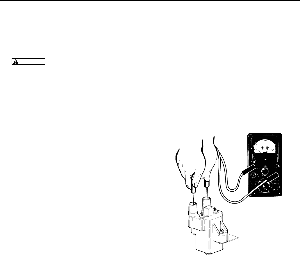
Ignition Coil Test
1. Remove all wires attached to the ignition coil.
2. Remove the coil from the engine.
3. Inspect the terminals for corrosion, looseness,
cracks or other damage. Look for carbon run-
ners around the high tension terminals: these
indicate electrical leakage. Replace a dam-
aged or leaking coil.
4. Clean the outside of the coil with a cloth damp-
ened in parts cleaning solvent.
5. Measure primary coil resistance (across the
positive [+] and negative [-] terminals). Replace
the ignition coil if primary resistance is not be-
tween 3 and 5 ohms.
6. Measure secondary coil resistance (across the
spark plug cable terminals). Replace the igni-
tion coil if secondary resistance is not between
14,000 and 30,000 ohms. See Figure 6-10.
FIGURE 6-10. TESTING THE IGNITION COIL
Redistribution or publication of this document,
by any means, is strictly prohibited.
6-13
CYLINDER COMPRESSION TEST
Examining the spark plugs and testing cylinder
compression can tell much about the condition of
the valves, piston rings and cylinders. Test cylinder
compression as follows:
1. Start the genset and let it warm up.
2. Stop the genset and remove and inspect the
spark plugs. See IGNITION SYSTEM in this
section.
3. Insert the compression gauge nozzle into one
of the spark plug holes, hold the throttle open
and crank the engine. Note the pressure indi-
cated by the gauge.
4. Repeat the test on the other cylinder.
5. Refer to
Section 9. Engine Block Assembly
if
cylinder compression test pressures do not
meet
Specifications.
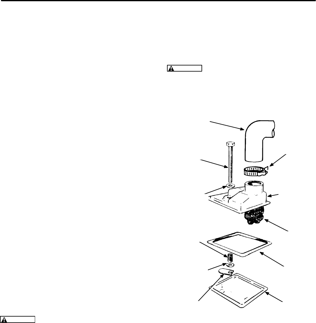
CRANKCASE BREATHER ASSEMBLY
See Figure 6-11. The crankcase breather is a reed
valve assembly that opens to discharge crankcase
vapors on the piston down-stroke and closes on the
up-stroke, resulting in a negative pressure in the
crankcase when the engine is running. The crank-
case vapors (blowby gases, gasoline vapors, mois-
ture, air) are routed to the carburetor for burning in
the cylinders. A dirty or sticking valve can cause oil
leaks, high oil consumption, rough idle, reduced en-
gine power and sludge formation within the engine.
Disassembly:
The breather assembly is serviced
by disassembling it and cleaning all the parts in
parts cleaning solvent. The assembly comes apart
when the capscrew is unscrewed.
WARNING
Most parts cleaning solvents are
flammable and corrosive and can cause severe
burns and inflammation. Use only as recom-
mended by the manufacturer.
Reassembly:
Reassemble using a new gasket.
Replace the reed valve if it does not lie flat across
the discharge orifice. Torque the cover capscrew to
12-24 lbs-in (1.3-2.6 N-m).
CAUTION
Over-tightening the capscrew can
distort the cover allowing dirt to enter the en-
gine.
BREATHER
HOSE
CAPSCREW
FLAT
WASHER
FLAT
WASHER
SPRING
REED
VALVE
PACK
GASKET
HOSE
CLAMP
VALVE
COVER
BREATHER
BAFFLE
FIGURE 6-11. CRANKCASE BREATHER ASSEM-
BLY
Redistribution or publication of this document,
by any means, is strictly prohibited.
6-14
GOVERNOR AND CARBURETOR
ADJUSTMENTS
The governor operates the throttle to maintain a
nearly constant engine speed (frequency) as the
electrical load on the genset varies. Careful adjust-
ments of the carburetor and governor are essential
for top performance. Perform all necessary engine
and generator maintenance and repairs before
making these adjustments.
Governor and carburetor adjustments should be
done together. They require the use of meters to
measure voltage, frequency and amperage and a
stepped load bank of at least 8 kW, where a portion
of at least 600 watts is variable. Digital meters are
recommended. Accuracy should be at least 0.3 per-
cent for frequency measurement and 0.5 percent
for voltage measurement.
Beginning Spec F, carburetor fuel mixture adjust-
ing screws are not accessible. Other than turning
the altitude adjust knob to compensate for altitude
on gasoline carburetors, fuel mixture adjustments
should not be attempted.
WARNING
Unauthorized modifications or re-
placement of fuel, exhaust, air intake or speed
control system components that affect engine
emissions are prohibited by law in the State of
California.
WARNING
Disconnect or unplug all voltage
and frequency sensitive devices such as TVs,
VCRs, computers and other solid-state elec-
tronic devices before making governor and car-
buretor adjustments. Typically, some internal
circuits are powered when these types of de-
vices are plugged in, even if the device has been
switched “OFF”. These circuits can be dam-
aged by variations in voltage and frequency that
occur during these tests.
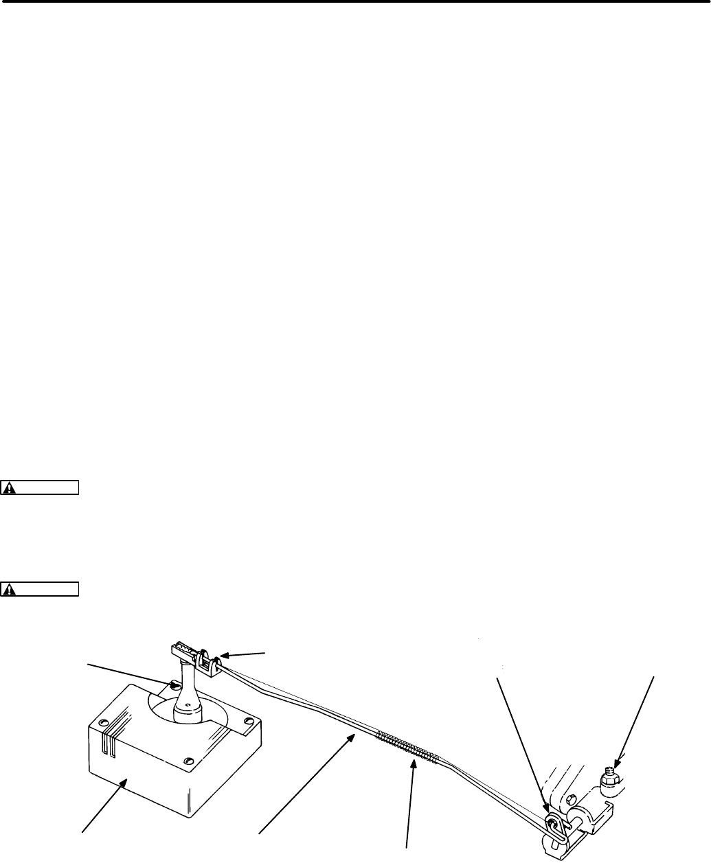
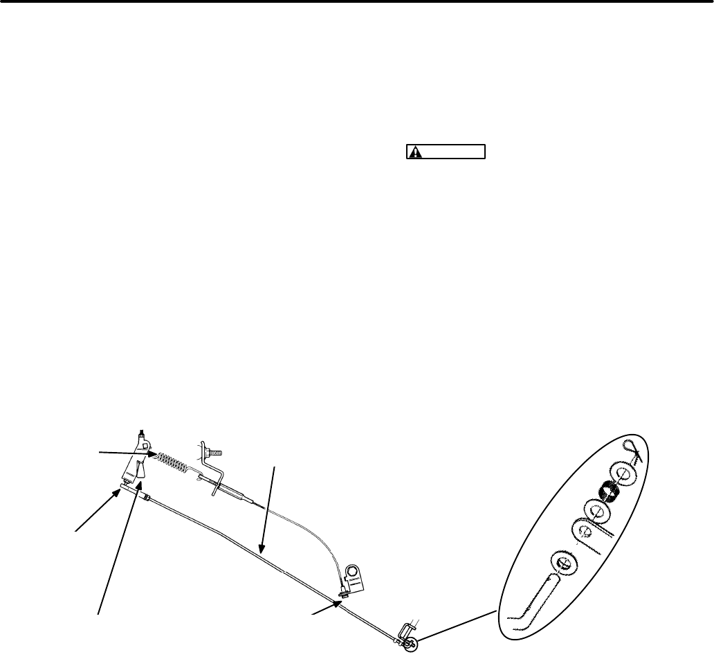
Electronic Governor
Electronic governor speed and sensitivity set points
are not adjustable.
The governor actuator and link-
age (Figure 6-12) are accessible by removing the
top panel. The governor controller is mounted on
the base pan (Figure 7-5).
Disconnecting the Governor Rod:
Remove the
top panel (see COOLING SYSTEM in this section)
for access to the governor rod. Unhook the gover-
nor rod and spring from the governor actuator arm
first. Use both hands so as not to bend the actuator
arm. Then unhook the rod and spring from the
throttle.
Reconnecting the Governor Rod:
Before recon-
necting the governor rod, check to see if the paint
seal on the throttle stop screw on the carburetor has
not been broken. If it has been broken, readjust the
throttle stop screw as follows:
1. Disconnect the governor rod from the actuator
arm if it has not already been removed.
GOVERNOR
ROD SPRING
GOVERNOR
ACTUATOR
THROTTLE LEVER
(On Carburetor)
PLASTIC CLIP THROTTLE
STOP SCREW
ACTUATOR
LEVER
FIGURE 6-12. ELECTRONIC GOVERNOR LINKAGE
Redistribution or publication of this document,
by any means, is strictly prohibited.
6-15
2. Loosen the throttle stop screw locknut and
back the screw out away from the tang on the
throttle lever, while gently rotating the throttle
lever counterclockwise as far as if will go.
3. While gently holding the throttle lever counter-
clockwise as far as it will go, turn the stop screw
in until it just touches the tang. Then turn the
screw an additional 1/8-1/4 turn (clockwise)
and set and seal the locknut.
If the throttle stop screw adjustment is okay, recon-
nect the governor rod as follows:
1. Insert the rod in the spring such that the shorter
hook wire is on the throttle side.
2. Hook the rod and spring into the grommet in the
throttle lever. (The spring should pull on one
side and the rod push on the other side of the
grommet when fully assembled.)
3. Pull the governor rod towards the plastic clip on
the end of the actuator lever as far as the
throttle stop screw permits. Leave the actuator
lever in its fully counterclockwise (rest) posi-
tion. Snap the dogleg on the end of the rod into
the slot in the clip that most closely lines up with
it. Use both hands so as not to bend the actua-
tor lever.
4. Hook the spring into the slot in the end of the
actuator lever. When assembled, the spring
hook wires should not wrap around the gover-
nor rod.
5. Move the actuator back and forth through its full
movement to make certain there is no sticking
or binding.
6. After installing the top panel, hook the spark
plug cable with the clip inside the panel to keep
it from interfering with the governor rod.
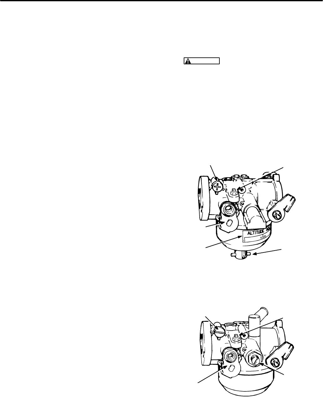
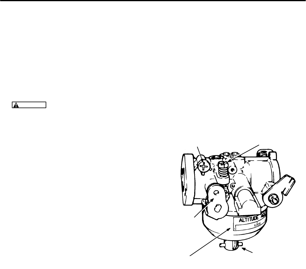
Idle Fuel Mixture Adjustment:
These instructions
do not apply to Spec F and later gensets.
1. If the carburetor has been overhauled, gently
turn the idle and main fuel mixture screws in by
hand until they seat.
For Gasoline Gensets:
Turn the idle mixture
screw out 1 turn and the main fuel mixture
screw out 1-3/8 turns so that the engine will
start and run.
For LPG Gensets:
Turn the idle mixture screw
out 1-1/4 turns and the main fuel mixture screw
out 2-1/2 turns so that the engine will start and
run.
CAUTION
Forcing a mixture adjusting
screw in tight will score the needle and seat.
Turn it lightly by hand only.
2. Start the genset and let it warm up for ten min-
utes under 1/2 to 3/4 rated load. (On vapor
withdrawal type LPG gensets it might be nec-
essary first to adjust the demand regulator and
supply pressure to get the genset to start. See
LPG System—Vapor Withdrawal.)
IDLE MIXTURE
ADJUSTING SCREW CAP
IDLE SPEED
STOP
SCREW
THROTTLE
LEVER MAIN FUEL
MIXTURE
ADJUSTING
SCREW CAP
ALTITUDE
SCALE
FIGURE 6-13. GASOLINE CARBURETOR
IDLE MIXTURE
ADJUSTING SCREW
IDLE SPEED
STOP
SCREW
THROTTLE
LEVER
MAIN FUEL
MIXTURE
ADJUSTING
SCREW
FIGURE 6-14. LPG CARBURETOR
Redistribution or publication of this document,
by any means, is strictly prohibited.

6-16
3. Disconnect the load (check for zero amps).
Turn the idle mixture adjusting screw clockwise
until the engine begins to stumble. Then,
counting the number of turns, turn the screw
counterclockwise until it begins to stumble
again. Set the screw halfway in between. For
closer adjustments, use a CO meter to adjust
to 6-8% CO (gasoline) or 4-6% CO (LPG). See
Troubleshooting
if the engine runs roughly.
4. Push the adjustment limiter cap on over the
mixture screw head such that it will allow equal
adjustment in either direction (gasoline carbu-
retors).
Main Fuel Mixture Adjustment:
These instruc-
tions do not apply to Spec F and later gensets.
1. Connect rated load.
A. Load (watts) is the product of volts (V) and
amps (A). Load (watts) = V x A
(A 1.0 power factor, obtainable with a re-
sistance load bank, is assumed. True
rated output might not be obtained if ap-
pliances are used as part of the load.)
B. See
Section 8. Generator
if output voltage
cannot be adjusted to within 10 percent of
rated voltage (Table 6-3).
2. Turn the main fuel mixture adjusting screw
clockwise until the engine begins to stumble.
Then, counting the number of turns, turn the
screw counterclockwise until it begins to
stumble again. Set the screw halfway in be-
tween. For closer adjustments, use a CO meter
to adjust to 6-8% CO (gasoline) or 2-4% CO
(LPG). See
Troubleshooting
if the engine runs
roughly.
3. Push the adjustment limiter cap on over the
mixture screw head such that the cap pointer
indicates the current altitude (gasoline carbu-
retors).
TABLE 6-3. VOLTAGE SPECIFICATION
RATED
OUTPUT
VOLTAGE
MAXIMUM
NO-LOAD
VOLTAGE
MINIMUM
FULL-LOAD
VOLTAGE
120V, 1PH 126 114
Redistribution or publication of this document,
by any means, is strictly prohibited.
6-17
Mechanical Governor (Spec A Only)
Mechanical governor speed and sensitivity set
points are adjustable.
The following adjustments
must be made in the sequence that they appear.
Governor Rod Length Adjustment:
The length of
the governor rod (Figure 6-15) must be checked
and adjusted as follows before other adjustments
are attempted:
1. To access the governor linkage remove access
cover or the top panel (Figure 6-5).
2. Loosen the lock nut at the ball joint end of the
governor rod and unsnap the socket from the
ball.
3. Push the governor rod gently towards the car-
buretor (full-throttle position). While keeping it
there, turn the socket, as necessary, to length-
en or shorten the rod so that the ball and socket
line up.
CAUTION
Too much pressure on the rod
can result in a faulty adjustment of the rod
length.
4. Snap the socket back over the ball.
5. Tighten the lock nut while holding the socket
square with the axis of the ball. Also, the leg at
the throttle end of the rod must be kept level.
6. Gently rotate the governor arm and check for
binding. If necessary, loosen the locknut and
repeat Step 5 until the linkage moves smoothly.
Binding can cause erratic governor action.
CONNECTION
DETAIL
GOVERNOR
SENSITIVITY ADJUSTING
SCREW (DROOP)
BALL AND
SOCKET
GOVERNOR
SPRING GOVERNOR
ROD
GOVERNOR
SPEED ADJUSTING
SCREW
FIGURE 6-15. MECHANICAL GOVERNOR (SPEC A ONLY)
Redistribution or publication of this document,
by any means, is strictly prohibited.
6-18
Note: The following groups of adjustments must be
performed in sequence.
Idle Speed Stop Adjustment (Spec A only):
1. If the carburetor has been overhauled, gently
turn the idle and main fuel mixture screws in by
hand until they seat (Figure 6-16).
Turn the idle mixture screw out 1 turn and the
main fuel mixture screw out 1-3/8 turns so that
the engine will start and run.
CAUTION
Forcing a mixture adjusting
screw in tight will score the needle and seat.
Turn it lightly by hand only.
2. Start the genset and let it warm up for ten min-
utes under 1/2 to 3/4 rated load.
3. Disconnect the load (check for zero amps). Pull
the governor rod so that the tang on the throttle
lever bears against the idle speed stop screw.
Adjust the screw to obtain 54-56 Hz.
Idle Mixture and Frequency Adjustments
(Spec A only):
1. Disconnect all loads (check for zero amps).
Then check no-load frequency. If necessary,
turn the governor speed adjusting screw (Fig-
ure 6-15) to obtain a no-load frequency of
62-63 Hz.
2. Turn the idle mixture adjusting screw clockwise
until the engine begins to stumble. Then,
counting the number of turns, turn the screw
counterclockwise until it begins to stumble
again. Set the screw halfway in between. For
closer adjustments, use a CO meter to adjust
to 6-8% CO. See
Troubleshooting
if the engine
runs roughly.
3. Push the adjustment limiter cap on over the
mixture screw head such that it will allow equal
adjustment in either direction (gasoline carbu-
retors).
4. If no-load frequency has changed because of
idle mixture adjustment, repeat Step 1.
5. Check output voltage. See
Section 8. Genera-
tor
if output voltage cannot be adjusted to with-
in 10 percent of rated voltage (Table 6-3 on
Page 6-16).
IDLE MIXTURE
ADJUSTING SCREW CAP
IDLE SPEED
STOP SCREW
THROTTLE
LEVER
MAIN FUEL MIXTURE
ADJUSTING SCREW CAP
ALTITUDE
SCALE
FIGURE 6-16. CARBURETOR (SPEC A ONLY)
Redistribution or publication of this document,
by any means, is strictly prohibited.

6-19
Main Fuel Mixture and Droop Adjustments
(Spec A only):
1. Connect rated load.
A. Load (watts) is the product of volts (V) and
amps (A). Load (watts) = V x A
B. (A 1.0 power factor, obtainable with a re-
sistance load bank, is assumed. True
rated output might not be obtained if ap-
pliances are used as part of the load.)
C. See
Section 8. Generator
if output voltage
cannot be adjusted to within 10 percent of
rated voltage (Table 6-3 on Page 6-16).
2. Turn the main fuel mixture adjusting screw
clockwise until the engine begins to stumble.
Then, counting the number of turns, turn the
screw counterclockwise until it begins to
stumble again. Set the screw halfway in be-
tween. For closer adjustments, use a CO meter
to adjust to 6-8% CO. See
Troubleshooting
if
the engine runs roughly.
3. Push the adjustment limiter cap on over the
mixture screw head such that the cap pointer
indicates the current altitude (gasoline carbu-
retors).
4. Disconnect the load and readjust the governor
speed adjusting screw to return no-load fre-
quency to 62-63 Hz.
5. Check and adjust droop.
A. If droop (from no-load frequency) is more
than 3 Hz for Model BGM or 4 Hz for Model
NHM, turn the governor sensitivity adjust-
ing screw (Figure 6-15) one turn counter-
clockwise. Disconnect the load and, if nec-
essary, readjust the governor speed ad-
justing screw to return to 62-63 Hz no-load
frequency. Check droop again and repeat
the adjustments, if necessary.
B. If droop (from no-load frequency) is less
than 2 Hz for Model BGM or 3 Hz for Model
NHM, turn the governor sensitivity adjust-
ing screw (Figure 6-15) one turn clock-
wise. Disconnect the load and, if neces-
sary, readjust the governor speed adjust-
ing screw to return to 62-63 Hz no-load fre-
quency. Check droop again and repeat the
adjustments, if necessary.
6. Check governor response under 1/4, 1/2 and
3/4 rated loads. See
Troubleshooting
if hunting
is unacceptable.
Redistribution or publication of this document,
by any means, is strictly prohibited.

6-20
FUEL SYSTEM
The carburetor mixes air and fuel in the correct pro-
portion for good performance. The governor oper-
ates the throttle to maintain a nearly constant en-
gine speed (frequency) as the load varies. Figure
6-17 is representative of most of the fuel system
parts beginning Spec B. LPG (liquified petroleum
gas) systems do not use an air preheater or choke
and have different fuel connections. See Choke As-
sembly, Fuel Pump and LPG System (Liquid With-
drawal and Vapor Withdrawal) in this section for oth-
er details which may be applicable.
See GOVERNOR AND CARBURETOR ADJUST-
MENTS in this section for carburetor adjustments.
WARNING
Gasoline and LPG are flammable
and explosive and can cause severe personal
injury or death. Do not smoke if you smell gas or
gasoline vapors or are near fuel tanks or fuel-
burning equipment or are in an area sharing
ventilation with such equipment. Keep flames,
sparks, pilot flames, electrical arcs and
switches and other sources of ignition well
away.
WARNING
LPG is flammable and explosive
and can cause asphyxiation. NFPA 58, Section
1.6 requires all persons handling LPG to be
trained in proper handling and operating proce-
dures.
Air Cleaner Assembly
Disassembly:
1. Remove the crankcase breather hose and air
preheater hose (gasoline gensets only) from
the air cleaner housing.
2. Remove the air cleaner housing center caps-
crew and lift off the housing and air filter.
3. Prior to Spec D gasoline and Spec F LPG, re-
move the choke cover retaining nut and cover
and disconnect the leads connected at the ter-
minals.
4. Remove the three capscrews that secure the
air cleaner adapter to the carburetor and lift off
the adapter. (One of the screws is inside the
throat of the adapter.)
Prior to Spec D gasoline and Spec F LPG, the
choke linkage must be disengaged from the
choke as the air cleaner adapter is being re-
moved. See Figure 6-18.
5. Beginning Spec D gasoline, disconnect the
leads at Relay K4 or remove the relay and
bracket from the air cleaner adapter.
Reassembly:
Reassembly is the reverse of disas-
sembly. Use a new gasket between the adapter and
the carburetor.
CAUTION
Make sure you use the right screws
to mount the adapter on the carburetor. The
screw inside the throat will interfere with the
choke shaft if it is too long or tightened too tight.
Take care also not to cross thread it.
Carburetor And Intake Manifold Assembly
Disassembly:
1. Remove the top panel (see COOLING SYS-
TEM in this section).
2. Remove the air cleaner assembly.
3. Disconnect the fuel line and governor rod from
the carburetor (see GOVERNOR AND CAR-
BURETOR ADJUSTMENTS in this section).
4. Remove the intake manifold capscrews, the
carburetor air preheater (gasoline gensets
only) and the carburetor and intake manifold as
an assembly.
Prior to Spec D gasoline and Spec F LPG, disen-
gage the choke pulloff linkage from the carbure-
tor. See Figure 6-19.
5. Remove the two intake manifold gaskets and
cover the intake ports to prevent loose parts
and dirt from entering the engine.
6. Unbolt the carburetor from the intake manifold.
Reassembly:
Reassembly is the reverse of disas-
sembly. Use new gaskets between the intake man-
ifold and the engine and between the intake man-
ifold and the carburetor. Do not use sealer on the
gaskets. Tighten all fasteners according to
Section
4. Torque Specifications
.
Redistribution or publication of this document,
by any means, is strictly prohibited.
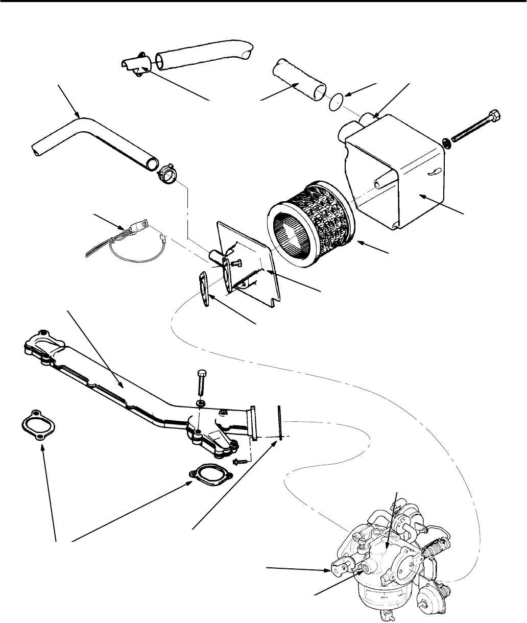
6-21
CRANKCASE
BREATHER
HOSE AND CLIP
AIR
CLEANER
HOUSING
AIR
CLEANER
ADAPTOR
AIR
FILTER
ELEMENT
THROTTLE
LEVER
AIR PREHEATER AND HOSE
(gasoline gensets only)
GASOLINE
FUEL INLET
ADAPTOR TO
CARBURETOR
GASKET
MANIFOLD
GASKETS
O-RING
(Slip the O-ring over the end of the
preheater hose and insert it into the
collar)
GASOLINE
CARBURETOR/CHOKE
ASSEMBLY
MANIFOLD
GASKET
RELAY K4 BOLTS TO
REAR OF AIR
CLEANER ADAPTER
INTAKE
MANIFOLD
FIGURE 6-17. TYPICAL FUEL SYSTEM (BEGINNING SPEC D GASOLINE)
Redistribution or publication of this document,
by any means, is strictly prohibited.
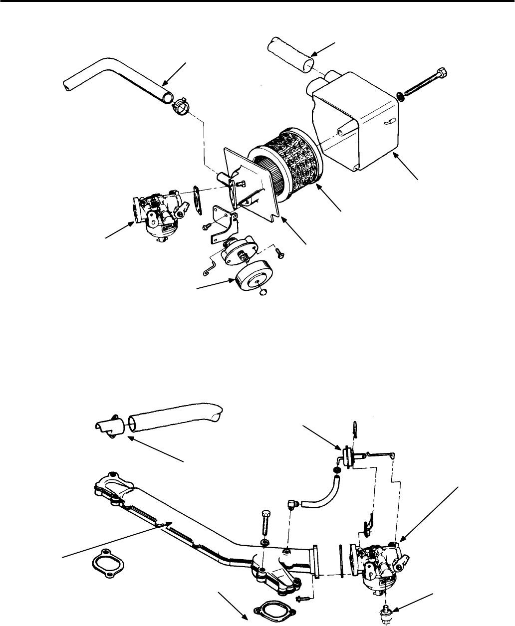
6-22
CRANKCASE
BREATHER TUBE
AIR PREHEATER HOSE
(gasoline only)
AIR FILTER
AIR CLEANER
HOUSING
AIR CLEANER
ADAPTER
CHOKE
COVER
CARBURETOR
FIGURE 6-18. AIR INTAKE ASSEMBLY (PRIOR TO SPEC D GASOLINE AND SPEC F LPG)
AIR
PREHEATER
INTAKE
MANIFOLD
CARBURETOR
GOVERNOR
ROD FUEL
FILTER
CHOKE
PULLOFF
FIGURE 6-19. CARBURETOR AND INTAKE MANIFOLD (PRIOR TO SPEC D GASOLINE AND SPEC F LPG)
Redistribution or publication of this document,
by any means, is strictly prohibited.

6-23
Carburetor Replacement
(Beginning Spec F)
Beginning Spec F, the gasoline or LPG carburetor
should not be overhauled. Instead, a malfunction-
ing carburetor should be replaced. Before replacing
a carburetor, however, make certain 1) that all other
necessary engine and generator adjustments and
repairs have been performed and 2) that the carbu-
retor is actually malfunctioning, by carefully follow-
ing the troubleshooting procedures in
Trouble-
shooting
.
LPG carburetors are usually not the cause of prob-
lems. Make certain all other possible causes of the
problem have been eliminated before replacing an
LPG carburetor.
WARNING
Unauthorized modifications or re-
placement of fuel, exhaust, air intake or speed
control system components that affect engine
emissions are prohibited by law in the State of
California.
Redistribution or publication of this document,
by any means, is strictly prohibited.
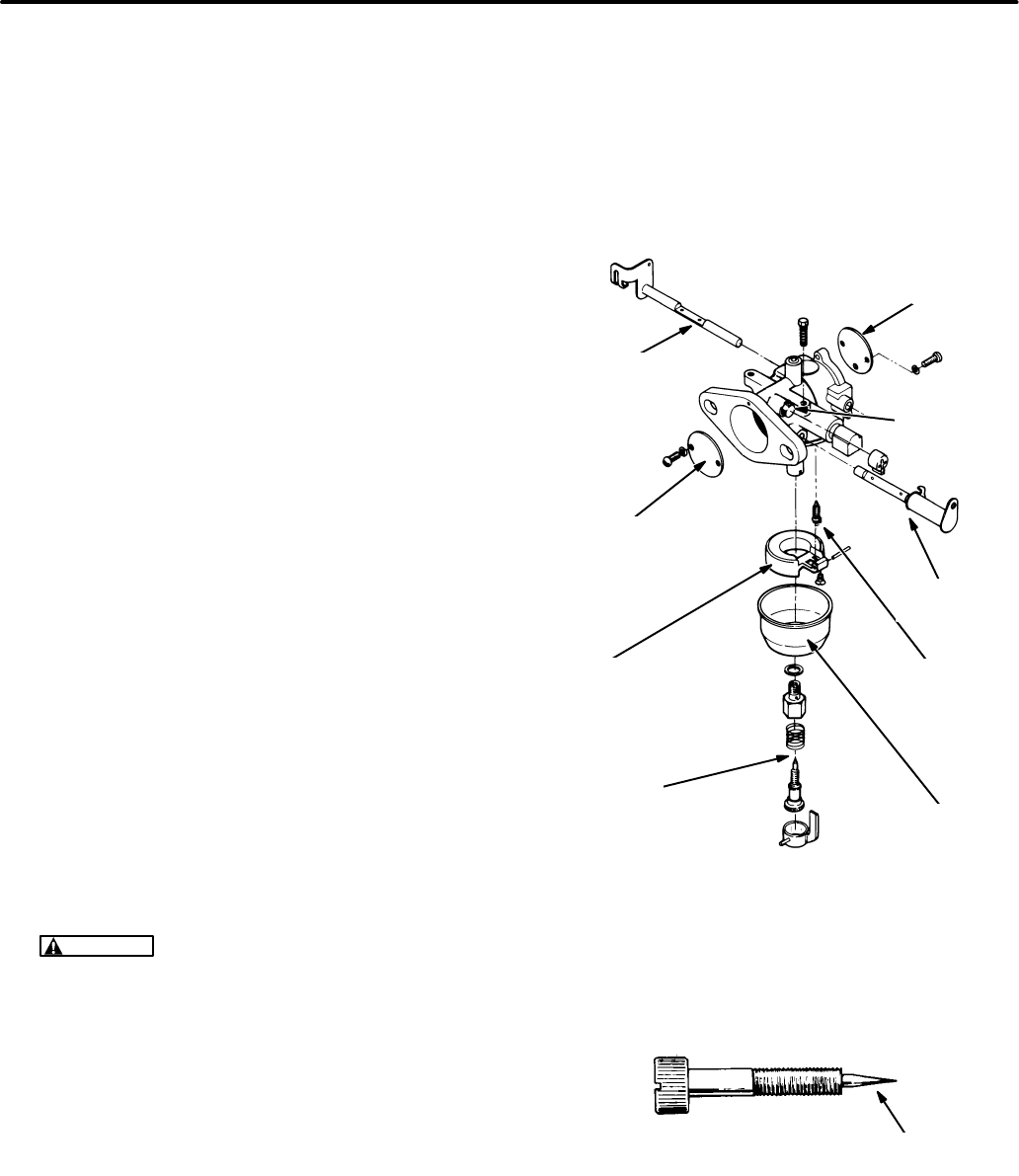
6-24
Gasoline Carburetor Overhaul
(Prior to Spec F)
See Figure 6-20. Carburetor problems not cor-
rected by mixture or float adjustments are often
caused by gummed-up fuel passages or worn inter-
nal parts. The most effective remedy is to replace or
overhaul the carburetor. Overhauling a carburetor
consists of complete disassembly, thorough clean-
ing and replacement of worn parts. Repair kits are
available for gasoline carburetors that include new
gaskets and float assembly parts.
Disassembly:
Carefully note how the carburetor
parts fit together as the carburetor is being disas-
sembled so that it will be easier to reassemble.
Read and understand these instructions before
starting.
1. Remove the air cleaner adapter and the auto-
matic choke assembly (gasoline carburetors).
2. Remove the main and idle mixture screw as-
semblies.
3. Separate the lower section of the carburetor
(float bowl) from the body of the carburetor.
4. Carefully note the position of the float assembly
parts, then remove the hinge pin, float and
needle valve.
Cleaning and Inspection:
1. Soak all metal components not replaced by the
repair kit in carburetor cleaner. Do not soak any
rubber or plastic parts. Follow the cleaner
manufacturer’s recommendations.
WARNING
Most parts cleaning solvents
are flammable and corrosive and can cause
severe burns and inflammation. Use only
as recommended by the manufacturer.
2. Clean all carbon from the carburetor bore, es-
pecially where the throttle and choke plates
seat. Be careful not to plug the idle or main fuel
ports.
3. Blow out all passages with compressed air. Do
not use wire or other objects for cleaning that
might increase the size of critical passages.
4. Replace the fuel mixture screws if they are
scored (Figure 6-21).
5. Replace the carburetor if either the choke or
the throttle sticks after cleaning. It is usually not
necessary to disassemble the throttle or choke.
CHOKE
PLATE
THROTTLE
SHAFT
FUEL
INLET
NEEDLE
VALVE
FLOAT
BOWL
CHOKE
SHAFT
THROTTLE
PLATE
FLOAT
MAIN FUEL
MIXTURE
ADJUSTING
ASSEMBLY
IDLE FUEL
MIXTURE
SCREW
FIGURE 6-20. GASOLINE CARBURETOR
CHECK FOR
SCORING HERE
FIGURE 6-21. TYPICAL FUEL MIXTURE SCREW
Redistribution or publication of this document,
by any means, is strictly prohibited.
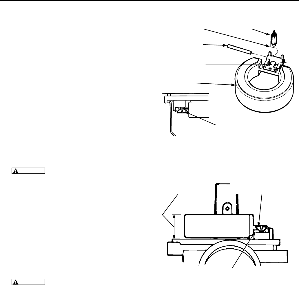
6-25
Reassembly:
1. See Figure 6-22. Turn the carburetor upside
down and install the new needle valve, float,
float hinge pin and fuel bowl gasket in the repair
kit. Make sure the wire clip properly engages
the groove around the end of the needle valve
and loops around the metal tang of the float.
(The clip pulls down on the needle valve when
the float level drops, breaking the needle loose
if it is stuck.) Check to see that the float moves
freely without binding.
2. See Figure 6-23. Check the float level as
shown while the carburetor is still upside down.
Measure the height above the bowl gasket
flange on the side opposite the hinge. Make
sure the full weight of the float is resting on the
needle valve. Remove the float and bend the
metal tang to adjust the height.
CAUTION
Remove the float before bend-
ing the tang so as not to damage the soft
nose of the needle valve.
3. Install the float bowl and the main mixture
screw assembly.
4. Install the idle and main fuel mixture screws.
Turn them lightly by hand until they seat. Then
turn the idle mixture screw out 1 turn and the
main fuel mixture screw out 1-3/8 turns so that
the engine will start and run.
5. If it is necessary to reassemble the throttle or
choke, secure the plate screws such that they
will not loosen.
CAUTION
Loose throttle or choke plate
screws can get drawn into the engine and
cause serious engine damage.
FLOAT
NEEDLE VALVEWIRE CLIP
METAL TANG
FLOAT HINGE PIN
RETAINING SCREW
FLOAT
HINGE PIN
FIGURE 6-22. FLOAT INSTALLATION (GASOLINE)
BEND METAL TANG TO
ADJUST FLOAT HEIGHT
0.59-0.63 INCH
(15-16 mm )
THE FULL WEIGHT OF THE FLOAT MUST
REST ON THE NEEDLE VALVE WHILE
MEASURING FLOAT HEIGHT
FIGURE 6-23. FLOAT LEVEL (GASOLINE)
Redistribution or publication of this document,
by any means, is strictly prohibited.
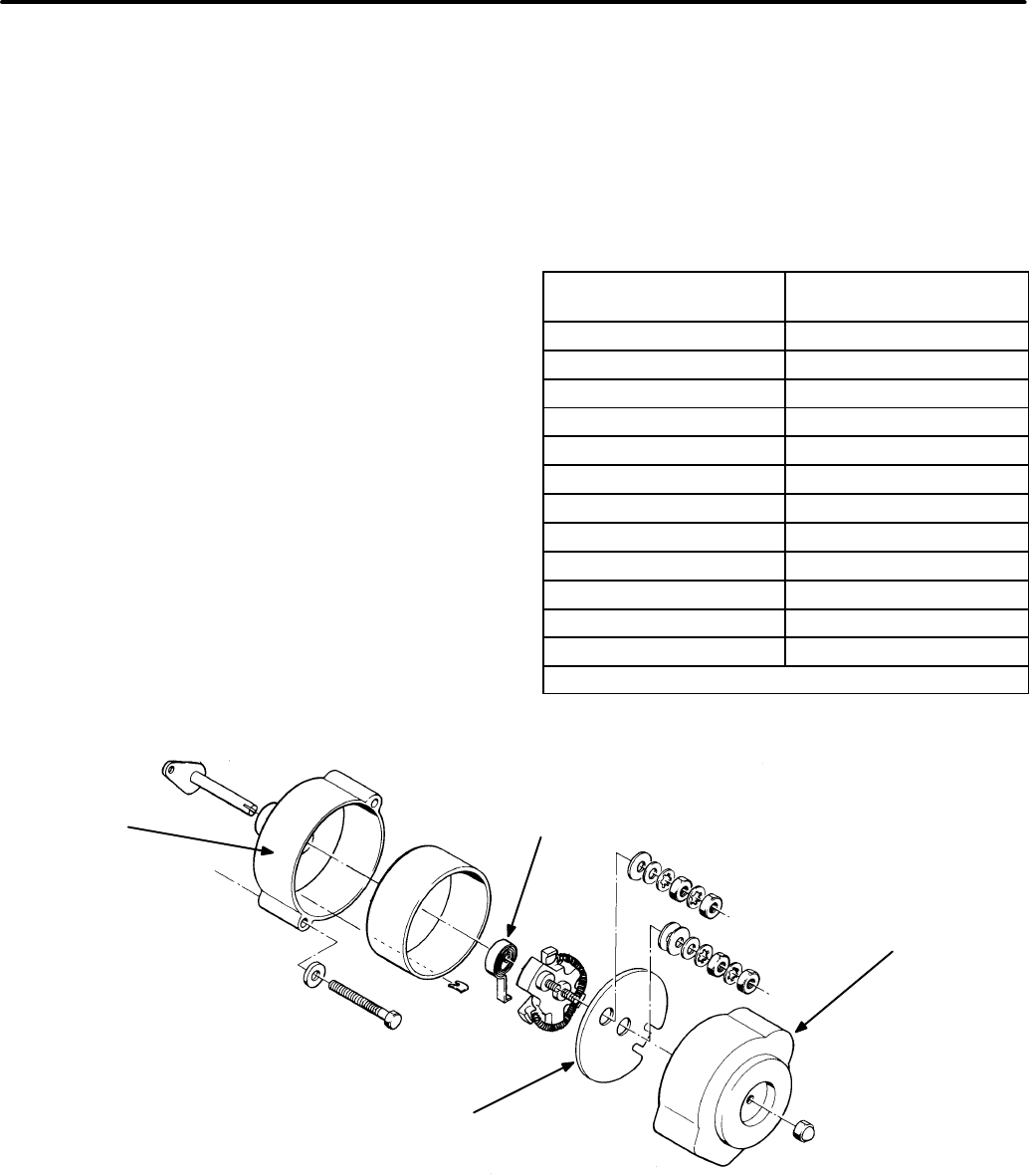
6-26
Choke Assembly
(Prior to Spec D Gasoline and Spec F LPG*)
Choke Settings:
Table 6-2 lists choke settings for
various ambient temperatures. Stop the set and let
it cool before adjusting the choke.
1. Remove the plastic choke cover (see Figure
6-24) and loosen the heating element cover
screws.
2. Rotate the heating element until the choke
plate is halfway open.
3. Slowly rotate the cover counter clockwise while
tapping the carburetor choke lever to make it
bounce. Continue until the lever no longer
bounces. This is the fully-closed (reference)
position.
4. Refer to Table 6-4 to determine the number of
degrees the element cover must be rotated
clockwise from the reference position. The
marks on the choke housing are spaced at 5°
intervals.
5. Rotate the element cover as specified, then
tighten the cover mounting screws.
6. Move the choke lever to test its operation. The
lever should return to the free position when re-
leased from the open position, without sticking
or binding.
7. Install the plastic choke cover and tighten the
center mounting unit.
TABLE 6-4. CHOKE SETTINGS
Ambient Air
Temperature Rotation from
Reference Mark*
40°F(4°C) 0°
45°F(7°C) 4°CW
50°F(10°C) 8°CW
60°F(16°C) 16°CW
65°F(18°C) 20°CW
70°F(21°C) 24°CW
75°F(24°C) 27°CW
80°F(32°C) 32°CW
85°F(29°C) 35°CW
90°F(32°C) 39°CW
95°F(35°C) 43°CW
100°F(38°C) 47°CW
* Each mark on choke housing equals 5°
HOUSING
BI−METAL
SPIRAL STRIP
PLASTIC
COVER
ELEMENT
COVER
FIGURE 6-24. CHOKE ASSEMBLY (SPEC A GASOLINE AND UP TO SPEC E LPG)
* Beginning Spec F, LPG models do not incorporate a choke.
Redistribution or publication of this document,
by any means, is strictly prohibited.
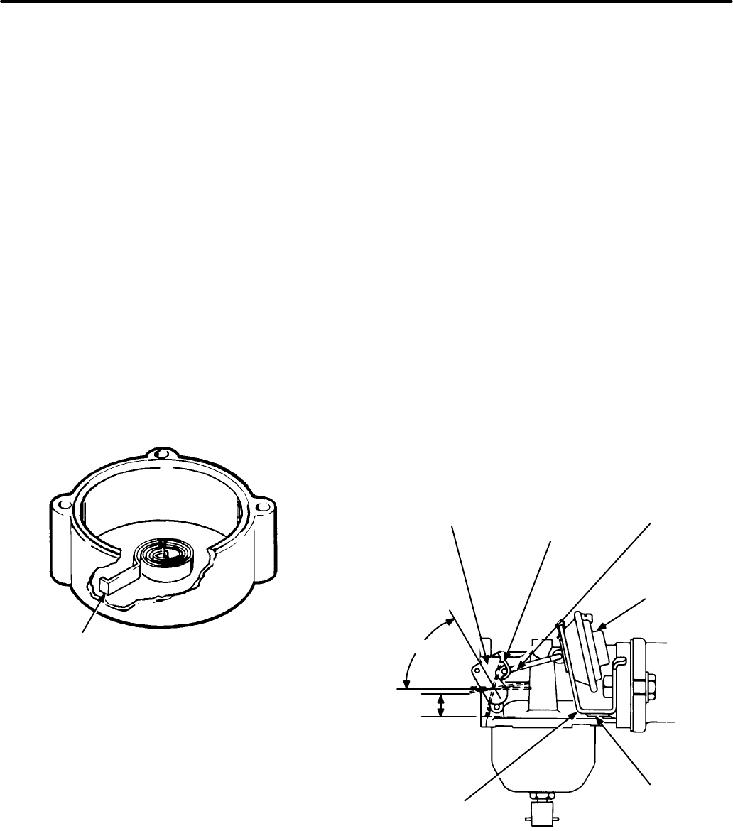
6-27
Choke Replacement:
If the choke does not open,
remove the protective plastic cover and check the
heating element. The heating element cover should
heat up after a few minutes of operation. If the ele-
ment cover remains cool, start the set, then use an
AC voltmeter to check the terminals on the cover. If
roughly 20 VAC is not present, check for opens or
shorts in the control wiring.
If voltage is present, stop the set and remove the
heating element cover. Inspect the heating element
and replace it if burned out or broken. Also inspect
the bi-metal coil and replace it if it is damaged or
binding in the housing.
When installing a new bi-metal strip, maintain the
original direction of the spiral (see Figure 6-25). The
outer tab must point in a clockwise direction. Make
sure that the coil sets squarely in the housing, and
that the inner end of the coil engages the slot in the
choke shaft. The slotted tang on the element cover
must engage the bi-metal strip.
OUTER TAB
FIGURE 6-25. BI-METAL COIL
Choke Pulloff Diaphragm Adjustment:
The
choke pulloff diaphragm partially opens the choke
plate after engine startup. This inhibits flooding, and
promotes smooth engine operation as the set
warms up.
1. Remove the air cleaner assembly as described
in Air Cleaner Assembly in this section, to ac-
cess the choke plate.
2. Disconnect the diaphragm hose from the in-
take manifold. Apply 4-18 inch (13.5-60.8 kPa)
Hg vacuum to the diaphragm.
3. Apply light finger pressure against the choke
lever to take up all free play in the pulloff linkage
(see Figure 6-26).
4. Check and correct the alignment of the dia-
phragm stem, pulloff linkage, and slot in the
choke lever, viewing them from above.
5. Measure the distance between the choke plate
and the bottom of the carburetor at the point in-
dicated in Figure 6-26. There should be
0.39-0.43 inch (9.9-10.9 mm) clearance here;
if necessary, bend the diaphragm mounting
bracket to reach this clearance.
6. Move the choke lever back and forth to verify
that it does not bind or stick.
7. Remove the vacuum supply from the dia-
phragm. Install the filter assembly on the car-
buretor.
CHOKE
LEVER
CHOKE
PLATE
CLOSED
PULL OFF
LINKAGE
PULL OFF
DIAPHRAGM
MEASURE
THIS
DISTANCE
DIAPHRAGM
MOUNTING
BRACKET
BEND
HERE
(60°)
FIGURE 6-26. CHOKE PULLOFF DIAPHRAGM
Redistribution or publication of this document,
by any means, is strictly prohibited.
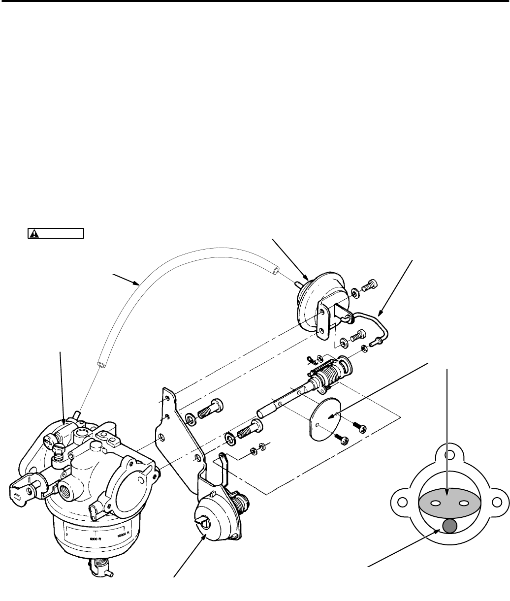
6-28
Choke Assembly
(Beginning Spec D Gasoline)
See Figure 6-27. The choke is operated automati-
cally by a 12 VDC heater/bi-metal assembly and a
vacuum break, both of which are mounted on the
side of the carburetor by a bracket. Reassemble the
choke components as shown.
The choke bi-metal/heater assembly is adjusted at
the factory. If the factory settings have been dis-
turbed, loosen the three bezel ring screws at the
base of the assembly and rotate the body counter-
clockwise for a richer setting and clockwise for a
leaner setting and retighten the screws.
The choke plate opening should be checked with a
gauge each time the vacuum break is remounted.
Check and readjust the opening as follows:
1. Apply a vacuum of at least 4 inches (100 mm)
mercury to fully pull in the vacuum break arm.
2. Insert a 0.337 inch (8.6 mm) drill rod between
the choke plate and the carburetor throat.
3. Bend the link at the point shown, if necessary,
until the lip of the choke plate just touches the
drill rod. Use two pliers to bend the link.
CHOKE
PLATE
GAUGE THE OPENING OF THE CHOKE PLATE
IN THE CARBURETOR THROAT WITH A
0.337 INCH (8.6 mm) DRILL ROD AS SHOWN
IF NECESSARY, BEND THIS LINK AT
THIS POINT WHEN ADJUSTING THE
OPENING OF THE CHOKE PLATE
CARBURETOR
VACUUM BREAK
BI−METAL/HEATER
ASSEMBLY
KINKS IN THIS VACUUM
HOSE CAN CAUSE HARD
STARTING AND IDLING
CAUTION
FIGURE 6-27. CHOKE ASSEMBLY (BEGINNING SPEC D GASOLINE)
Redistribution or publication of this document,
by any means, is strictly prohibited.

6-29
Fuel Pump (Gasoline Gensets)
If a problem in fuel delivery is indicated (see TROU-
BLESHOOTING in this section), test fuel pump
pressure as follows:
1. Disconnect the fuel line at the outlet of the fuel
pump and connect a pressure gauge at the
pump outlet. A gauge calibrated for 0-15 psi
(0-100 kPa) is recommended. Do not tee into
the fuel line. This is a static pressure test.
2. Push the Start/Stop switch to START and hold
it there for several seconds until the fuel pres-
sure stabilizes. Fuel pressure should stabilize
between 3.5 and 6 psi (24 and 41 kPa).
3. Repeat the test with the vehicle engine run-
ning.
A fuel pressure greater than 6 psi (41 kPa) is not
acceptable. Find out why the pressure is high. If it is
high when the vehicle engine is not running, check
to see that the proper Onan supplied pump is being
used. If it is high when the vehicle engine is running,
a separate fuel pickup tube in the fuel tank, or equiv-
alent means, will be required.
If the fuel pressure is less than 3.5 psi (24 kPa),
check for fuel restrictions in the system. If the pump
is defective, replace it with the appropriate Onan
pump. The pump is not serviceable.
CAUTION
Tampering with the seal at the cen-
ter of the mounting bracket on the side of the
pump can cause the dry gas which surrounds
the electrical components to leak, leading to
pump failure. The pump is not serviceable.
WARNING
Do not substitute an automotive
fuel pump for the standard pump removed from
the genset. Other pumps can cause carburetor
flooding because of the high pressures they de-
velop. Carburetor flooding can cause poor per-
formance and engine damage and lead to pos-
sible fire and severe personal injury or death.
Fuel pressure at the carburetor fitting must not
exceed 6 psi (41 kPa) under any operating con-
dition.
Redistribution or publication of this document,
by any means, is strictly prohibited.
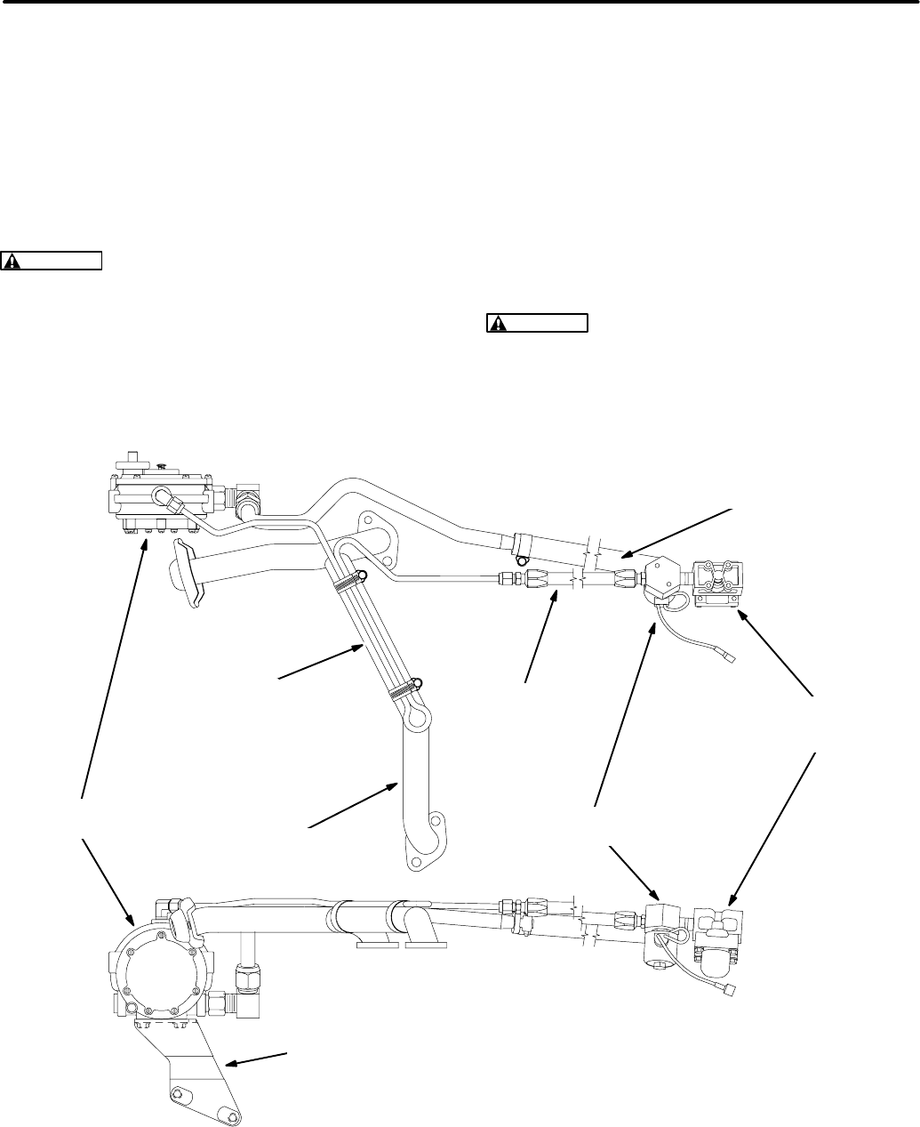
6-30
LPG System—Liquid Withdrawal
See Figure 6-28. For liquid withdrawal systems the
LPG container(s) must be equipped to withdraw
LPG as a liquid. See the Installation Manual for im-
portant recommendations regarding the installation
of a LPG liquid withdrawal type of fuel supply sys-
tem.
WARNING
LPG is flammable and explosive
and can cause asphyxiation. NFPA 58, Section
1.6 requires all persons handling LPG to be
trained in proper handling and operating proce-
dures.
It is important to understand that the fuel filter, sole-
noid shutoff valve, vaporizer and demand regulator
handle LPG liquid at the same pressure as in the
LPG container. Depending on ambient tempera-
ture, LPG container pressure can exceed 200 psi
(1379 kPa). Therefore, discharge or leakage from
LPG liquid-containing components can result in the
escape of large volumes of flammable and explo-
sive gas.
Purging the LPG System:
It is imperative that the
LPG system be purged before disconnecting fuel
system components.
WARNING
Large volumes of LPG can be re-
leased in the process of disconnecting a liquid-
withdrawal type of LPG supply system. See the
instructions in
Section 5. Preparing to Service
for proper procedures and precautions when
disconnecting LPG fuel lines.
TOP VIEW
SIDE VIEW
EXHAUST
MANIFOLD
LPG
VAPORIZATION
TUBE LPG FILTER
(Note Direction
of Arrows)
LPG
REGULATOR LPG SHUTOFF
SOLENOID
FLEXIBLE
HIGH
PRESSURE
LPG HOSE
FLEXIBLE LOW PRESSURE
LPG HOSE TO CARBURETOR
REGULATOR
MOUNTING
BRACKET
FIGURE 6-28. LPG SYSTEM COMPONENTS FOR LIQUID WITHDRAWAL
Redistribution or publication of this document,
by any means, is strictly prohibited.
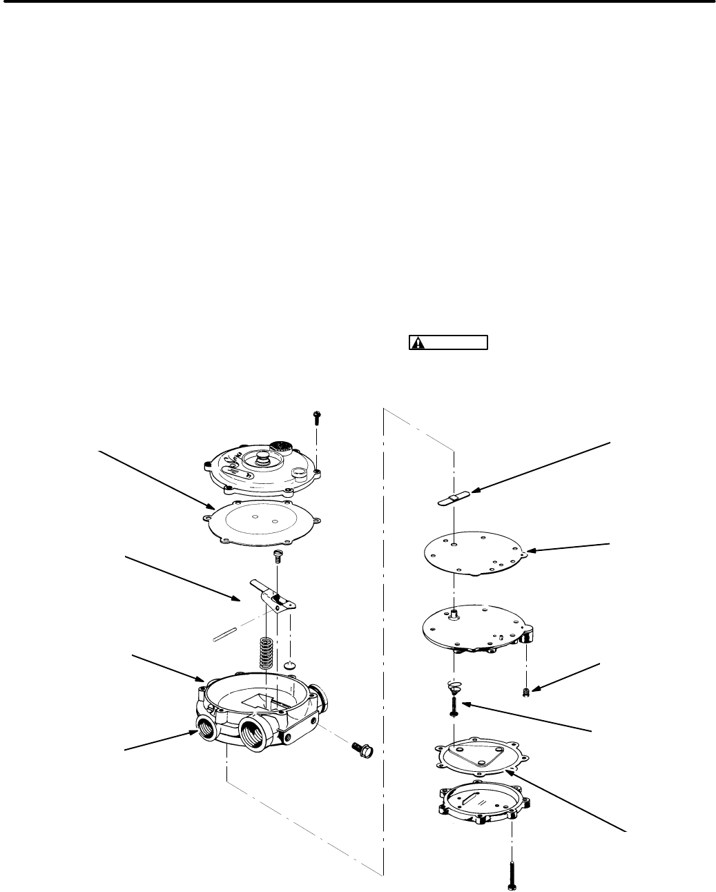
6-31
Demand Regulator:
See Figure 6-29. The two-
stage demand regulator delivers vaporized LPG to
the carburetor. The primary stage receives LPG va-
por (and liquid) at LPG container pressure and re-
duces it to approximately 1.5 psi (10.3 kPa). The
secondary stage delivers LPG vapor at the rate de-
manded by the carburetor.
The regulator should require little attention if the
genset is operated regularly. Most problems are
due to:
•
Hardened Diaphragms, Gaskets and Valve
Seats:
Diaphragms, gaskets and valve seats
tend to shrink and harden when a genset is
stored for long periods of time and may need to
be replaced.
•
Impurities and Dissolved Oils in Liquid LPG:
Impurities can embed on valve seats causing
them to leak and oils can clog regulator pas-
sages, resulting in hard starting, erratic idling
and poor load acceptance.
Primary Pressure Test:
1. Connect a pressure gauge to the primary pres-
sure test port and a source of compressed air
(at least 80 psi [550 kPa]) to the inlet port.
2. The gauge should indicate approximately 1.5
psi (10.3 kPa) and hold steady when the test
pressure valve is opened. The pressure should
not drop off when the test pressure valve is
closed.
3. Disassemble and clean and retest the regula-
tor if it cannot hold the proper pressure. Re-
place it if it still does not function properly.
WARNING
Parts cleaning solvents are
flammable and corrosive and can cause
burns and inflammation. Follow the
manufacturer’s instructions.
SECONDARY
DIAPHRAGM PRIMARY
VALVE1
SECONDARY
VALVE
COMPONENTS
PRIMARY VALVE
PLUNGER AND
SPRING1
PRIMARY
PRESSURE
TEST PORT
PLUG
PRIMARY
DIAPHRAGM
1- Beginning Spec F, the primary valve
plunger serves also as the primary valve.
The separate part labeled “PRIMARY
VALVE” is no longer provided.
2- Make sure the smallest hole in the gas-
ket lines up with the small hole for the test
port. Flip the gasket over if necessary.
PRIMARY
GASKET2
INLET PORT
(Beginning Spec F)
INLET PORT
(Prior to Spec F)
FIGURE 6-29. DEMAND REGULATOR ASSEMBLY
Redistribution or publication of this document,
by any means, is strictly prohibited.
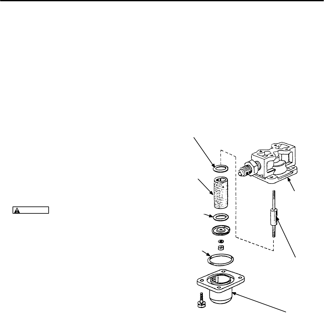
6-32
Fuel Filter:
See Figure 6-30. The fuel filter removes
rust and scale and other solid particles from the
LPG liquid to keep them from embedding in the
valve seats of the shutoff valve and pressure regu-
lator and causing them to leak. A magnet traps iron
and rust particles and a filter element traps non-
magnetic particles.
Disassembling and Cleaning the Fuel Filter:
1. Purge the LPG system as instructed in
Section
5. Preparing to Service.
2. Remove the four capscrews and lock washers
that hold the filter bowl to the filter body.
3. Separate the filter bowl from the filter body and
discard the O-ring seal.
4. Remove the nut and washer from the center
stud and pull out the filter element.
5. Wash the filter element in solvent to remove the
particles it has collected. Blow it dry with low
pressure (30 psi / 207 kPa) compressed air.
Replace the filter element if damaged.
WARNING
Parts cleaning solvents are
flammable and corrosive and can cause
burns and inflammation. Follow the
manufacturer’s instructions.
6. Wipe the magnet clean of the particles it has
collected.
7. Install a clean filter element using two new gas-
kets and securely tighten the center stud nut.
8. Place a new O-ring in the filter bowl sealing
groove.
9. Align the reference mark on the filter bowl with
the reference mark on the filter body and torque
the capscrews to 65 lbs-in (7.2 N-m). Check for
and fix leaks at the filter when connections
have been made to the fuel supply system. The
fuel filter operates at fuel supply tank pres-
sure.
Fuel Vaporizer:
The fuel vaporizer consists of tub-
ing clamped to the exhaust manifold. See EX-
HAUST SYSTEM in this section for removal.
Fuel Shutoff Solenoid Valve:
Test the fuel sole-
noid by disconnecting its long lead and jumpering it
directly to the battery positive (+) terminal on the
genset. Replace the solenoid if it does not “click”
open when it is powered.
FILTER
ELEMENT
GASKET
O-RING
SEAL
FILTER
BODY
MAGNET
FILTER
BOWL
GASKET
FIGURE 6-30. LPG FUEL FILTER
(LIQUID WITHDRAWAL SYSTEM)
Redistribution or publication of this document,
by any means, is strictly prohibited.
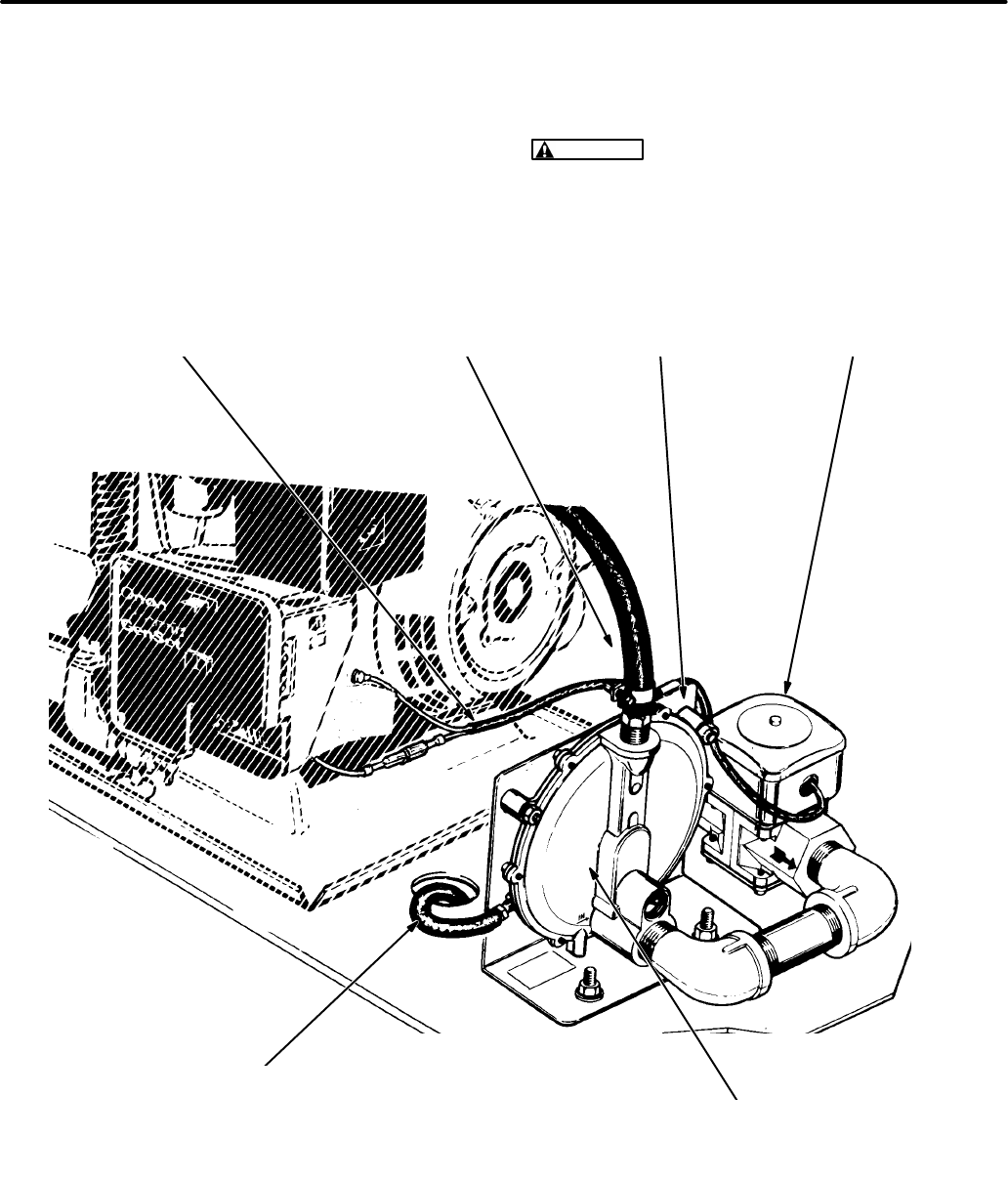
6-33
LPG System—Vapor Withdrawal
See the Installation Manual for important recom-
mendations regarding the installation of an LPG va-
por withdrawal type of fuel supply system. Gensets
equipped for vapor withdrawal of LPG must be
equipped with a fuel shutoff solenoid valve and de-
mand regulator. These are available as a kit for
mounting near the genset. See Figure 6-31.
WARNING
LPG is flammable and explosive
and can cause asphyxiation. NFPA 58, Section
1.6 requires all persons handling LPG to be
trained in proper handling and operating proce-
dures.
GAS SUPPLY HOSE TO
THE CARBURETOR INLET
DEMAND REGULATOR
(The regulator must be mounted such that
the diaphragm is in a vertical plane, as
shown, to maintain calibrated gas pressure.)
MOUNTING
BRACKET
VENT/PRESSURE-BALANCE HOSE
(Must extend outside the genset compartment to
prevent accumulation of LPG in compartment in the
event the diaphragm leaks and to prevent erratic fuel
delivery because of pressure fluctuations cause by
the cooling air flow through the compartment.)
SOLENOID PIGTAIL
CONNECTIONS AT THE GENSET FUEL SHUTOFF
SOLENOID VALVE
FIGURE 6-31. LPG SYSTEM COMPONENTS FOR VAPOR WITHDRAWAL
Redistribution or publication of this document,
by any means, is strictly prohibited.

6-34
LPG Supply Pressure:
LPG supply pressure must
be maintained at 9-13 inches (229-330 mm) water
column (WC) under all conditions. Adjust the supply
pressure as follows:
1. Close the gas shutoff valve(s) at the LPG con-
tainer(s).
2. Remove the 1/8 inch pipe plug from the regula-
tor test port (Figure 6-32) and connect a ma-
nometer calibrated in inches or mm WC having
a scale range of at least 14 inches (350 mm).
3. Open the LPG container shutoff valve and try
starting the genset.
4. While the genset is running, check the manom-
eter and adjust the LPG supply pressure regu-
lator to obtain 11 inches (279 mm) WC. (If there
is a secondary pressure regulator in the supply
line, adjust the secondary regulator instead of
the primary regulator at the LPG container.)
5. If the genset will not start, jumper the fuel sole-
noid to the battery cable connections on the
genset so that it stays open (the regulator will
keep gas from flowing)and then check and ad-
just the LPG supply pressure.
6. If the genset is operable, check LPG supply
pressure under full load. If it drops below the
minimum required pressure, either the LPG
container is too small to provide the rate of va-
porization necessary or it is less than half full or
the supply line is too restrictive.
7. Disconnect any jumpers which may have been
used to energize the fuel solenoid and thread
in and tighten the pressure test port plug unless
tests are going to be continued.
Fuel Shutoff Solenoid Valve:
Replace the fuel so-
lenoid if it fails to open (as indicated by the absence
of gas pressure on the manometer scale in the pre-
vious test) when it is jumpered across the the bat-
tery cable connections at the genset.
Demand Regulator Lock-Off Pressure Test:
Lock-off pressure is determined as follows by pres-
surizing the back (vent) side of the regulator dia-
phragm to simulate carburetor venturi vacuum:
1. Continue with the test setup for adjusting LPG
supply pressure shown in Figure 6-32. If the
regulator is being tested on the bench, connect
it to a source of air pressure regulated to 11
inches (280 mm) WC.
CAUTION
If this is a bench test of the reg-
ulator, make sure the diaphragm is in a ver-
tical plane (see Figure 6-31), otherwise the
weight of the diaphragm will cause erro-
neous readings of lock-off pressure.
2. “T” in two hoses to the end of the hose con-
nected to the regulator vent fitting
(3/8 inch I. D.). Use one hose to provide the
test pressure and the other to measure pres-
sure by connecting it to an inclined manometer
calibrated with 0.01 inch or 0.2 mm WC divi-
sions and having a range of at least 1 inch
(25 mm) WC.
3. Disconnect the hose to the carburetor and at-
tach a soap bubble to the regulator outlet hose
fitting. While reading the pressure indicated by
the inclined manometer and watching the soap
bubble, blow lightly into the hose being used to
pressurize the regulator. Regulator lock-off
pressure is the minimum pressure that will
cause gas to flow through the regulator, as indi-
cated by the expanding soap bubble. (At first
the soap bubble may expand due to diaphragm
movement but will stop expanding if gas or air
is not flowing through the regulator.)
For Gensets Beginning Spec F:
Replace the
demand regulator if the lock-off pressure does
not fall between 0.15 and 0.25 inch WC (3.8
and 6.4 mm WC).
WARNING
Unauthorized modifications or
replacement of fuel, exhaust, air intake or
speed control system components that af-
fect engine emissions are prohibited by law
in the State of California.
Redistribution or publication of this document,
by any means, is strictly prohibited.
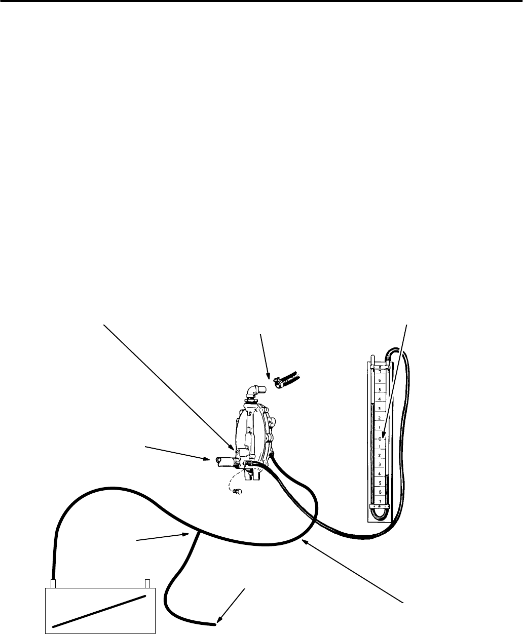
6-35
For Gensets Prior to Spec F:
Adjust lock-off
pressure as follows:
•If the lock-off pressure is greater than
0.25 inches (6.4 mm) WC, remove the
locking screw and back out the adjusting
screw (counterclockwise) until the lock-off
pressure falls between 0.15 and 0.25 inch
WC (3.8 and 6.4 mm WC). Set the locking
screw and test lock-off pressure again.
Repeat the procedure if necessary.
•If the lock-off pressure is less than
0.15 inch (3.8 mm) WC, remove the lock-
ing screw and turn in the adjusting screw
(clockwise) until the lock-off pressure falls
between 0.15 and 0.25 inch WC (3.8 and
6.4 mm WC). Set the locking screw and
test lock-off pressure again. Repeat the
procedure if necessary.
•Replace the demand regulator if it contin-
ues to leak after lock-off pressure adjust-
ments have been attempted.
4. If the genset is mounted in a compartment,
make sure the vent/pressure-balance hose is
routed properly to the outside.
5. Reconnect the hose to the carburetor, discon-
nect any jumpers which may have been used
to energize the fuel solenoid and thread in and
tighten the pressure test port plug.
6. For gensets prior to Spec F, adjust fuel mixture
as instructed under GOVERNOR AND CAR-
BURETOR ADJUSTMENTS in this section.
LPG OUTLET TO
CARBURETOR
(Place soap bubble on
end of hose fitting)
MANOMETER
(Connected to LPG supply
pressure test port)
LOCK-OFF ADJUSTING SCREW
(Beginning Spec F, this screw is
not accessible for adjustments)
INCLINED
MANOMETER
HOSE “T” FOR
TESTING
TEST
PRESSURE
VENT/PRESSURE-BALANCE HOSE
(See Figure 6-31 for a view of the vent hose
fitting when it is located on the other side.)
LPG INLET
(11 inch WC pressure)
FIGURE 6-32. LPG SUPPLY PRESSURE AND REGULATOR LOCK-OFF PRESSURE
Redistribution or publication of this document,
by any means, is strictly prohibited.
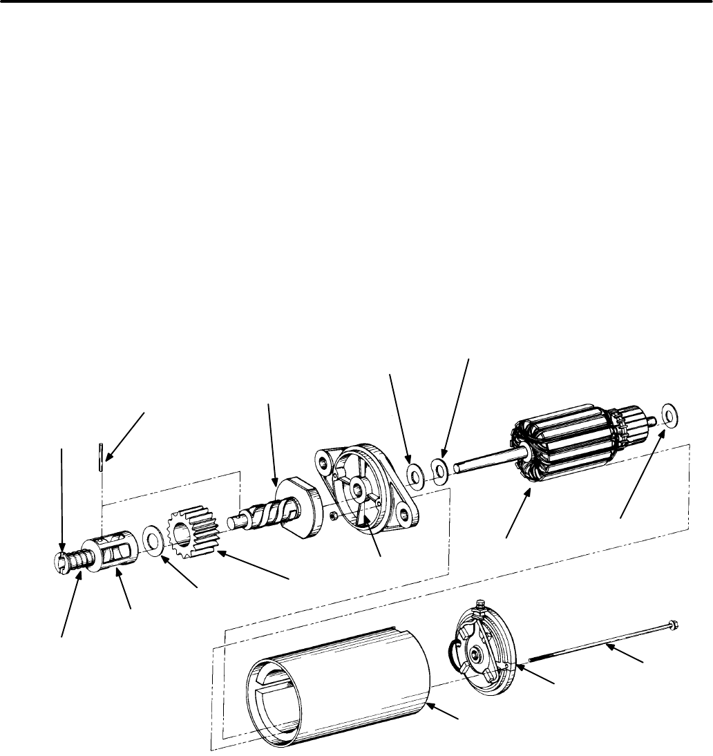
6-36
ELECTRIC STARTER
Starter Removal and Replacement
To remove the starter for service or replacement:
1. Disconnect the negative (-) cable from the
starting battery.
2. Disconnect the cable at the motor terminal.
3. Remove the two starter mounting bolts and re-
move the starter.
Replacement is the reverse of removal. Torque the
mounting bolts to specifications.
Starter Disassembly
Motor Disassembly:
See Figure 6-33. Remove
the starter from the genset. The drive housing, mo-
tor frame and end bell are separable after the motor
through bolts have been removed. Before loosen-
ing the through bolts, however, scratch register
lines on the drive housing, motor frame and end bell
so that these parts can be easily reassembled the
same way relative to each other. While removing
the end bell, be prepared to catch the brush springs,
which tend to spring loose.
METAL SPRING
RETAINER &
WASHER
ROLL
PIN
CLUTCH & SPLINE
ASSEMBLY
FLAT
WASHER
SPRING
WASHER
WASHER
ARMATURE
BRUSH
ENDCAP
THROUGH
BOLT
MAGNETIC
HOUSING
MOUNTING
BRACKET
GEAR
1/16 INCH
WASHER
SPRING
RETURN
COVER
RETURN
SPRING
FIGURE 6-33. STARTER ASSEMBLY
Redistribution or publication of this document,
by any means, is strictly prohibited.
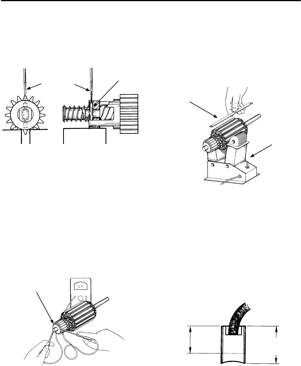
6-37
Removing the Roll Pin:
Remove the return spring,
gear and clutch assembly if necessary by driving
out the roll pin. Use a 1/8 to 5/32 inch nail set (Figure
6-34). Always use a new roll pin when reassembling
the drive assembly.
ROLL
PIN
5/32−1/8
inch NAIL
SET
SUPPORT PLASTIC RETAINER WITH A VISE OR OTHER
SOLID SURFACE. USE CARE NOT TO HAVE SPRING
RETURN "LEG" BETWEEN THE PLASTIC RETAINER
AND SUPPORT WHEN DRIVING OUT ROLL PIN
FIGURE 6-34. REMOVING ROLL PIN
Testing and Inspecting the Starter
Testing Armature for Grounds:
Touch one ohm-
meter lead to a commutator bar, then touch the oth-
er lead to the armature shaft and the core lamina-
tions (Figure 6-35). A low resistance reading indi-
cates a grounded armature. Replace a grounded
armature with a new one.
COMMUTATOR
BARS
FIGURE 6-35. TESTING ARMATURE FOR
GROUNDS
Testing Armature for Shorts:
Use a growler (Fig-
ure 6-36) to locate shorts in the armature. Place the
armature in the growler and hold a thin steel blade
(hacksaw blade) parallel to the core and just above
the armature, while slowly rotating the armature in
the growler. A shorted armature will cause the blade
to vibrate and be attracted to the core. Replace a
shorted armature with a new one.
HACKSAW BLADE
GROWLER
FIGURE 6-36. TESTING ARMATURE FOR SHORTS
Testing Armature for Opens:
Touch one ohmme-
ter lead to a commutator bar, then touch the other
lead to each of the other commutator bars in turn. A
high resistance indicates an open circuit between
the commutator bars and armature windings. Re-
place an open armature with a new one.
Brush Inspection:
Measure brushes (Figure 6-37)
and replace them if worn to less than 0.425 inch
(11 mm).
0.425 INCH (11 mm)
WEAR LIMIT
NEW
0.570 INCH
(14.5 mm)
FIGURE 6-37. BRUSH INSPECTION
Redistribution or publication of this document,
by any means, is strictly prohibited.
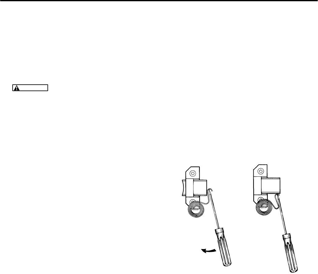
6-38
Starter Assembly
Use this procedure to return the electric starter as-
sembly to service.
1. Wipe dirt and oil from starter components using
a clean cloth; or blow off dirt with filtered low-
pressure compressed air.
CAUTION
Oil on armature will damage
starter. Do not immerse bearings in clean-
ing fluid. Use a brush dipped in clean en-
gine oil to remove dirt from bearings. Avoid
getting oil on brushes or commutator.
2. Mount the brush springs on tabs as shown in
Figure 6-39. Using a small screwdriver, turn the
spring counterclockwise to torque it, so the
contact loop is inside the brush holder. The
spring should be pushed down to the mounting
tab shoulder.
3. Push the negative brush terminals over the
through-bolt holes on the brush endcap.
4. Insert a positive brush stud into the hole, and
torque to 25-30 in-lb (2.83-3.39 N-m).
5. Insert a small screwdriver into the brush spring
contact loop to bend the spring back so that
each brush can be inserted into the holder. Be
sure that all brush wires are facing up.
6. If the brushes are at least 0.430 inch (10.9 mm)
long, rest the brush springs against the sides of
the brushes to keep them clear during arma-
ture installation. See Figure 6-38.
7. Place a washer on the commutator end of the
shaft, and put the armature into the brush end-
cap. Push the four brushes toward the commu-
tator, making sure that the springs are correctly
positioned on the brushes. Recheck to be cer-
tain that the spring is pushed all the way down
on the mounting tab.
8. Make sure that all brush wires are clear of the
commutator, and that uninsulated portions of
insulated wires do not touch the inside of the
housing, or adjacent brush boxes.
9. Place the magnetic housing over the armature.
Hold down the armature and the end cap using
a nut driver pressed over the end of the shaft.
10. Place a spring washer and a flat washer on the
shaft, as shown in Figure 6-33.
FIGURE 6-38. RESTING BRUSH SPRING ON SIDE
OF BRUSH
Redistribution or publication of this document,
by any means, is strictly prohibited.
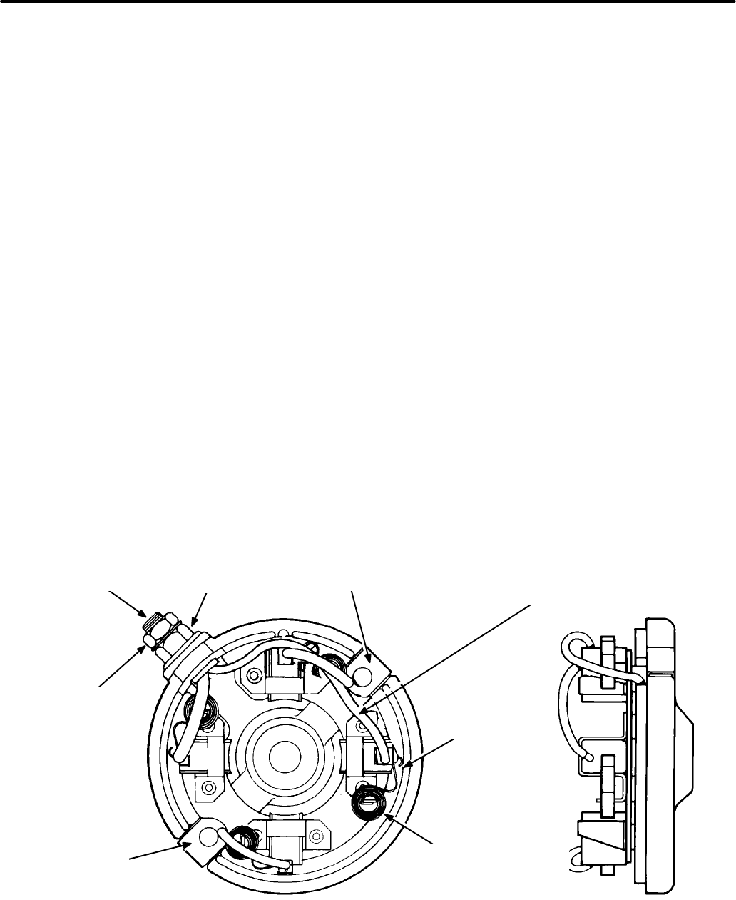
6-39
11. Place the mounting bracket on the motor, fac-
ing the exposed end of the sleeve bearing and
through-bolt lead-ins toward the inside of the
motor. The flat near one mounting hole should
line up with the positive stud on the end cap, so
the through-bolts can line up.
12. Insert the through-bolts, and torque to
35-45 lbs-in (3.96-5.09 N-m).
13. Wipe dust from the helix and gear, and apply a
light coat of GE Versilube 322-L to the outside
diameter of the helix, the inside diameter of the
gear and the unchamfered end of the gear.
Place the clutch and helix assemblies on the
motor shaft, with flats engaged in the clutch
hole.
14. If the return spring is unassembled, do the fol-
lowing:
A. Place a 1-1/16 inch O.D. washer over the
end of the shaft.
B. With the chamfered side of the shaft hole
facing up, place a plastic retainer on the
shaft and line up the hole with a hole in the
shaft.
C. Support the plastic retainer with a vise or
other solid surface. Using a 5/32 or
1/8 inch nail set and hammer, drive in a
new roll pin. The pin should be driven
about 1/10th of an inch (2.5 mm) from the
edge of the plastic retainer, or in such a
way that it is evenly spaced from each
side.
D. Place the spring cover over the top of the
plastic retainer, then place the return
spring on top of the retainer.
E. With a washer placed over the point of the
plastic retainer, push the metal retainer
into the hole of the plastic retainer as far as
it will go.
15. Mount the starter on the generator stator hous-
ing using capscrews, lockwashers and nuts.
Tighten the mounting screws to 30-33 lbs-ft
(41-45 N-m).
16. Reconnect the starter cable and battery.
TORQUE TO
5−10 LBS−IN
(.57−1.13 N−M)
IMPORTANT! THIS INSULATED SHUNT MUST
BE ROUTED THROUGH UNINSULATED
SHUNT AS SHOWN TO PREVENT CONTACT
WITH COMMUTATOR IN FINAL ASSEMBLY.
NEGATIVE
BRUSH
TERMINAL
NEGATIVE
BRUSH
TERMINAL
POSITIVE
BRUSH
STUD
BRUSH SPRING
CONTACT LOOP
IMPORTANT! SPRING
MUST BE ASSEMBLED ON
MOUNTING TAB AS
SHOWN.
TORQUE TO
25−30 LBS−IN
(2.83−3.39 N−M)
FIGURE 6-39. BRUSH END CAP
Redistribution or publication of this document,
by any means, is strictly prohibited.
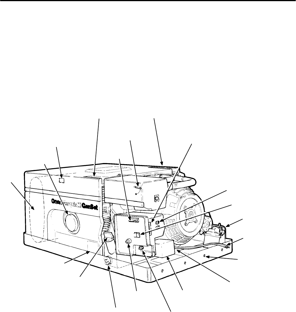
Section 7. Control System
7-1
INTRODUCTION
The control system governs the following functions:
•Starting
•Monitoring for fault conditions
•Instrumentation
•Stopping
•Engine speed governing (electronic
governor sets only)
FIGURE 7-1. BGM/NHM GENERATOR SET (MECHANICAL-GOVERNOR VERSION)
SPARK PLUGS (TOP ACCESS
TO FRONT AND REAR PLUG)
REMOTE CONTROL
CONNECTION (A1; P2/J2)
AC CIRCUIT BREAKERS
START/STOP SWITCH
FUEL INLET
0.25 INCH (6.35 mm)
HOSE
NEGATIVE (−) BATTERY
CABLE CONNECTION
(1 OF 4): LOCATION
OPTIONAL
AC OUTPUT LEADS
60 INCHES (1.5 M)
LONG
0.50 INCH
FLEXIBLE
CONDUIT
CONNECTION
VOLTAGE
REGULATOR
POSITIVE (+)
BATTERY
CONNECTION
FUEL PUMP
FUSE (F2)
OIL DRAIN KNOB
(3/8 INCH SQUARE
DRIVE)
OIL FILL AND CHECK
NAMEPLATE
MUFFLER
OIL
FILTER
GOVERNOR
SENSITIVITY
ADJUSTMENT ACCESS
FUSE
(F1)
SUMMER/WINTER
ADJUSTMENT
M-1801s
Redistribution or publication of this document,
by any means, is strictly prohibited.

7-2
CONTROL DESCRIPTION
(Mechanical governor gensets)
The generator set control consists of the compo-
nents listed below (see Figure 7-1):
•Control panel assembly
•Printed circuit board (A1)
•Start/Run/Stop switch (S1)
•Fuse (F1)
•Fuse (F2)
•Start solenoid (K1)
•Stop latch relay (K5)
•Fuel valve solenoid (E4)
•Fuel pump (E3)
•Remote start control
•Circuit breaker(s)
•Voltage regulator (VR1)
•Terminal board (TB1)
Control Panel Assembly
The control panel assembly consists of:
•Printed circuit board (A1)
•Start/Run/Stop switch (S1)
•Fuse (F1)
•Fuse (F2)
Printed Circuit Board (A1):
The printed circuit
board controls the engine start, start disconnect/
run, and stop functions. It is mounted at the rear of
the control panel. It contains wiring harness con-
nections to the engine, generator, and remote start
control; the start-stop switch (S1); and the control
fuse (F1).
Start/Run/Stop Switch (S1):
S1 is a SPDT rocker
switch which starts and stops the generator set. The
switch returns to the center (run) position when re-
leased. It is mounted on the circuit board, and is not
field-replaceable.
Fuse (F1):
This slow-blow 5-amp fuse protects
printed circuit board A1 from overcurrent condi-
tions. It is removable from the front of the control
panel. Spare fuses are inside the fuse holder; use
only Onan-supplied 5-amp fuses.
Fuse (F2):
This slow-blow 5-amp fuse protects the
fuel pump circuit from overcurrent conditions. It is
removable from the front of the control panel. Spare
fuses are inside the F1 fuse holder; use only Onan-
supplied fuses.
Start Solenoid (K1)
The K1 start solenoid opens and closes the circuit
between the starter motor and the battery. The
starting current load requires that the solenoid con-
tacts have a 300-amp contact rating. A single termi-
nal connects to the 12-volt solenoid coil. Two studs
provide connection points to the battery and starter
cables; the battery B+ stud connection protrudes
through the control panel to the outside of the con-
trol housing for convenient access.
Stop Latch Relay (K5)
The K5 stop latch relay latches the generator set off
when switch S1 is moved to the STOP position. This
prevents the set from restarting when the switch is
momentarily placed in the STOP position, then re-
leased. The K5 relay is located inside the control
box.
Fuel Pump (E3), Fuel Valve Solenoid (E4)
The E3 fuel pump is initially energized (through
CR9) at the same time the start solenoid K1 is ener-
gized, by closure of start relay K4 contacts. After the
set is started, fuel pump relay K6 is deactivated and
the fuel pump then receives its current through a
separate connection. Fuel pump power is rectified
to DC by CR10. CR9 then serves as a blocking
diode to prevent current flow to start solenoid K1
and fuel pump relay K6.
Fuel valve solenoid E4 parallels fuel pump E3; it
serves as a safety measure by blocking fuel flow
when the fuel pump is not activated.
Remote Start Control
The remote start control enables the generator set
to be operated from a remote location. The deluxe
control includes a running time meter and battery
condition meter.
Circuit Breakers (CB1 and CB2)
AC output from the generator is supplied to circuit
breakers CB1 and CB2, located on the right side of
the control housing.
Redistribution or publication of this document,
by any means, is strictly prohibited.

7-3
Voltage Regulator (VR1)
The voltage regulator helps provide stable output
voltage under varying loads. During initial start of
the set, the voltage regulator receives DC current
from the starting battery, and begins excitation of
the rotor through leads J4-9/F1, and J4-10/F2. After
the generator set starts and runs, it provides AC
power to the voltage regulator through leads
J4-11/Q1, and J4-12/Q2 for the excitation system.
The AC voltage is rectified to DC voltage, and the
proper DC excitation voltage is conducted to the ro-
tor in proportion to changes in demand. Reference
voltage is J4-2/L1 to J4-3/L0.
The voltage regulator is protected from moisture
and other contamination, reducing the risk of com-
ponent failure. The capacitor and the printed circuit
board are encased in the regulator housing with a
potting compound. The wiring harness plug-in P4 is
treated with a lubricant prior to connection.
Terminal Board (TB1)
The AC output power leads from the generator (T1,
T2, T3, and T4) are connected to terminal board
TB1 at terminals L1 - L0.
AC power at TB1 terminals is tapped by leads of wir-
ing harness J4 of voltage regulator VR1, and inter-
connect wiring to circuit breakers CB1 and CB2.
These leads provide generator output to the voltage
regulator for proper voltage regulation, and to the
circuit breakers for power supply to load.
CONTROL OPERATION
The schematic diagram shown in Figure 7-2 is in-
tended as an illustration of the circuit description.
However, when troubleshooting, always refer to the
wiring diagram that corresponds to the model and
spec numbers of the generator set.
Redistribution or publication of this document,
by any means, is strictly prohibited.
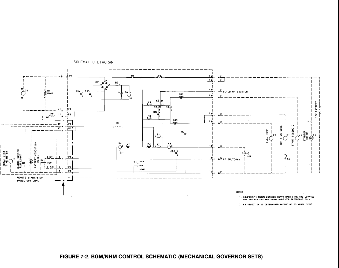
7-4
PIN CALLOUTS FOR THE REMOTE CONNECTIONS
BEGINNING SPEC G ARE DIFFERENT, REFER TO
SECTION 11 FOR CORRECT WIRING DIAGRAM
Redistribution or publication of this document,
by any means, is strictly prohibited.

7-5
Starting
Placing the Start/Run/Stop switch in the Start posi-
tion connects battery ground (B-) to the K4 start
relay. This energizes K4, which closes the normally
open (N. O.) contacts that connect battery positive
(B+) to the following:
•N.C. contacts of K2 generator relay
•Generator voltage regulator
•Ignition coil (T1)
•Fuel pump relay (K6)
•Start solenoid (K1)
Connecting B+ produces the following control re-
sponses:
•Flashes the field, to make sure that there is ad-
equate residual magnetism to induce voltage
buildup.
•Energizes the ignition coil (T1), so it can begin
producing a spark when ignition module S3 is
activated.
•Energizes the fuel pump relay (K6), which con-
nects B+ to the fuel pump and fuel solenoid.
•Energizes the start solenoid (K1), which closes
its N.O. contacts in the starter motor circuit.
•Energizes the solenoid fuel valve (E4), allow-
ing fuel to the carburetor.
•Energizes the fuel pump (E3), which begins
pumping fuel to the carburetor.
•Energizes the stop latch relay (K5) to open its
contacts to ground, which allows run relay K3
to be energized through closure of oil pressure
switch S2 after engine startup.
Closing the K1 start solenoid contacts connects B+
to the starter motor. This energizes the starter mo-
tor, which begins to crank the engine to initiate start-
ing.
Starter Lockout-Run
When the engine starts, the low oil pressure switch
(S2) closes to connect battery ground to the run
relay (K3). As the engine comes up to speed, AC
output voltage from the generator energizes the
generator relay (K2). This AC voltage activates the
choke heater element through a separate connec-
tion, opening the choke and powering the fuel pump
and fuel solenoid.
Energizing K2 opens a set of contacts to de-ener-
gize K4, and closes another set of contacts to con-
nect B+ to the generator start disconnect/run relay
(K3). Energizing K3 closes a set of contacts which
provides an alternate B+ circuit to T1 ignition coil
and S3 ignition module.
De-energizing K4 opens contacts which de-ener-
gize K1 start solenoid and K6 fuel pump relay. De-
energizing K1 disconnects B+ from the starter mo-
tor, which stops cranking. De-energizing K6 closes
contacts which connect E3 and E4 directly to gener-
ator power, rectified by CR10.
Opening these K4 contacts at this time has no effect
on engine operation, because they are in parallel
with the closed K3 contacts which connect B+ to the
ignition coil.
When start-stop switch S1 is released and returns
to center (run) position, the engine continues to run.
Relays K2 (generator relay), K3 (run relay), and K5
(stop latch relay) are energized while relays K1
(start solenoid), K4 (start relay) and K6 (fuel pump
relay) are de-energized.
Stopping
Moving start-stop switch S1 to the STOP position
grounds resistors R1 and R2 to de-energize run
relay K3. This opens its contacts to disconnect B+
from ignition coil T1, and stop latch relay K5. De-en-
ergizing K5 allows its N.C. contacts to close to
ground. This prevents K3 from being energized,
and prevents the set from restarting when switch S1
is released from the STOP position.
Without ignition, the engine stops. As the generator
output voltage drops, generator relay K2 also deen-
ergizes. All components return to their de-ener-
gized position following set shutdown.
Redistribution or publication of this document,
by any means, is strictly prohibited.
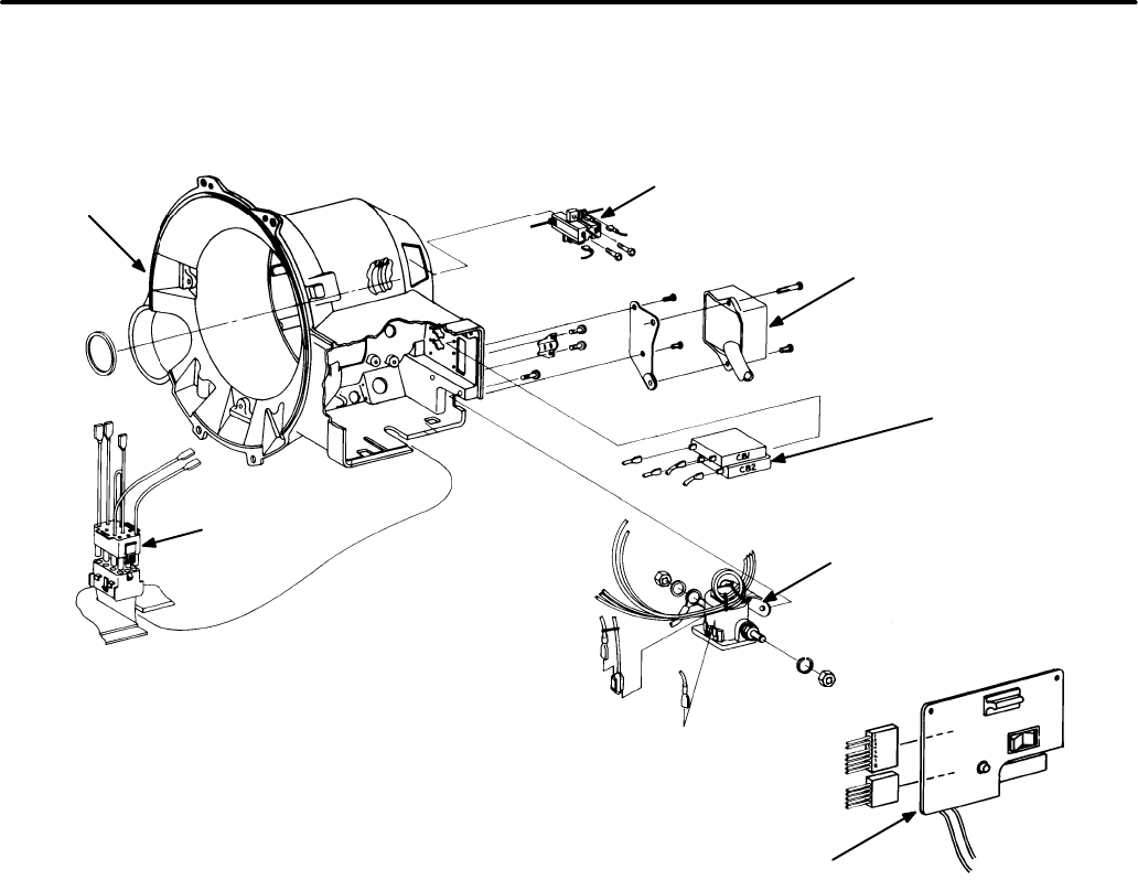
7-6
FIGURE 7-3. BGM/NHM CONTROL COMPONENTS
(MECHANICAL-GOVERNOR GENSETS ONLY)
G1212-5
J3
STATOR
HOUSING
J1
CONTROL PANEL
ASSEMBLY
BRUSH BLOCK
ASSEMBLY
VOLTAGE
REGULATOR
ASSEMBLY
MAGNETIC
CIRCUIT
BREAKERS
START SOLENOID RELAY
REGULATOR
HARNESS
Redistribution or publication of this document,
by any means, is strictly prohibited.
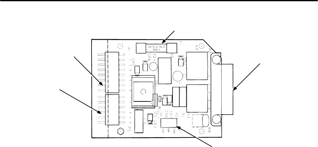
7-7
BATTERY, STARTER AND
GENERATOR WIRING
HARNESS CONNECTOR (P1)
ENGINE WIRING HARNESS
CONNECTOR (P3)
FUSE
F1
START/STOP
SWITCH (S1)
REMOTE CONTROL
WIRING HARNESS
CONNECTOR (P2)
FIGURE 7-4. BGM/NHM CONTROL PCB ASSEMBLY (A1)
(MECHANICAL-GOVERNOR GENSET ONLY)
Redistribution or publication of this document,
by any means, is strictly prohibited.
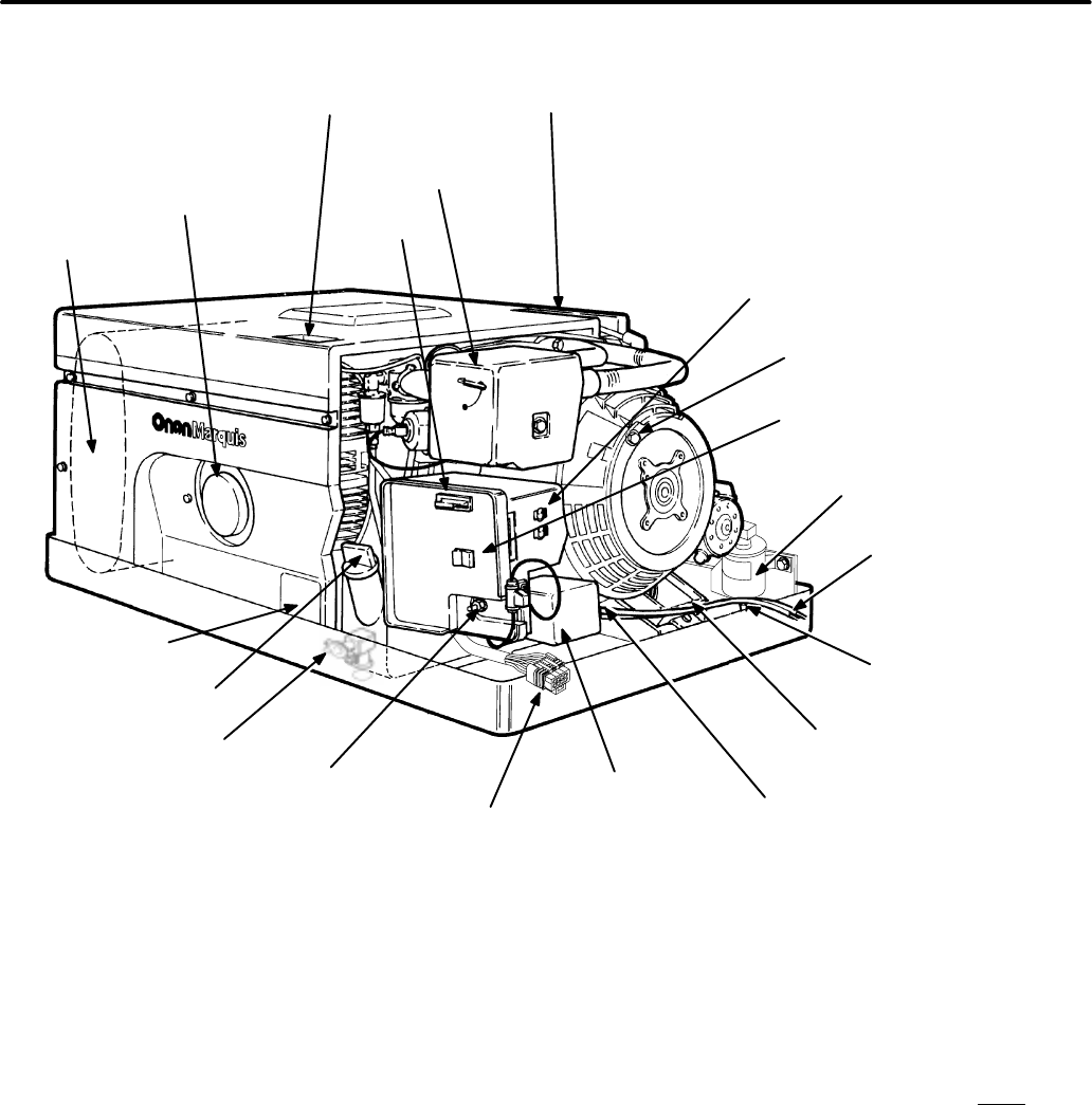
7-8
FIGURE 7-5. BGM/NHM GENERATOR SET (ELECTRONIC-GOVERNOR VERSION)
(SPEC G GENSET SHOWN)
SPARK PLUGS (TOP ACCESS
TO FRONT AND REAR PLUG)
REMOTE CABLE
CONNECTOR
AC CIRCUIT
BREAKERS
START/STOP
SWITCH
FUEL INLET
.25 INCH HOSE (GASOLINE)
.25 INCH NPTF (LPG)
AC OUTPUT LEADS
60 INCHES (1.5 M)
LONG
.50 INCH FLEXIBLE
CONDUIT CONNECTION
VOLTAGE
REGULATOR
POSITIVE (+) BATTERY
CONNECTION
OIL DRAIN VALVE
OIL FILL AND
CHECK
NAMEPLATE
MUFFLER
OIL FILTER
FUSE
SUMMER/WINTER
ADJUSTMENT
NEGATIVE (-) BATTERY
CABLE CONNECTION
GOVERNOR
CONTROLLER
FUEL PUMP (FUEL SOLENOID,
LPG GENSETS)
CONTROL DESCRIPTION
(Electronic governor gensets)
The generator set control consists of the compo-
nents listed below (see Figure 7-5):
•Control panel assembly
•Printed circuit board (A1)
•Start/Run/Stop switch (S1)
•Fuse (F1)
•Start solenoid (K1)
•Fuel pump (E3) and fuel valve solenoid
•Remote start control (optional)
•Circuit breaker(s) CB1 and CB2
•Voltage regulator (VR1)
•Terminal board (TB1)
•Governor controller board (A4)
•Fuel pump/autochoke fuse (F2) (Spec D)
•Fuel pump/autochoke relay (K4) (Spec D)
These components are described below. The des-
ignations in these descriptions refer only to the
control board schematic in Figure 7-7; they do
not necessarily correlate with the designations
in any other schematic or wiring diagram.
Control Panel Assembly
The control panel assembly consists of:
•Printed circuit board (A1)
•Start/Run/Stop switch (S1)
•Fuse (F1)
Redistribution or publication of this document,
by any means, is strictly prohibited.

7-9
Printed Circuit Board (A1):
The printed circuit
board controls the engine start, run, and stop func-
tions. It is mounted behind the control panel. It in-
cludes the following parts:
•Wiring harness connections to the engine,
generator, governor control board and
remote start control
•Start-stop switch (S1);
•Control fuse (F1)
•Relays K1, K2 and K3 (see schematic)
The printed circuit board is not repairable.
Start/Run/Stop Switch (S1):
S1 is a SPDT rocker
switch, mounted on the circuit board, which starts
and stops the generator set. The switch returns to
the center (run) position when released.
Fuse (F1):
This slow-blow 10-amp fuse protects cir-
cuit board A1 from overcurrent conditions. It is re-
movable from the front of the control panel. Spare
fuses are inside the fuse holder; use only Onan-
supplied 10-amp fuses.
Start Solenoid (K1)
Start solenoid K1 opens and closes the circuit be-
tween the starter motor and the battery. Two termi-
nals provide connection points to the battery and
starter cables; the battery B+ connection protrudes
through the control panel to the outside of the con-
trol housing for convenient access.
Fuel Pump (E3)
Fuel pump E3 is energized at the same time that
start solenoid K1 is energized. (Spec D gensets: E3
is activated through K4 contacts.) See
Appendix B.
Wiring Diagrams.
Remote Start Control (A1;P2/J2) (optional)
The optional remote start control enables the user
to start and stop the set from a remote location. The
deluxe control includes a running time meter and
battery condition meter.
Circuit Breakers (CB1 and CB2)
The set AC output is supplied for operator use
through circuit breakers CB1 and CB2, located on
the right side of the control housing.
Voltage Regulator (VR1)
The voltage regulator helps stabilize output voltage
under varying loads by providing DC excitation volt-
age to the generator rotor. AC voltage is rectified to
DC voltage, and the proper DC excitation voltage is
conducted to the rotor in proportion to changes in
demand.
Terminal Board (TB1)
AC output power leads T1, T2, T3, and T4 from the
generator are connected to terminal board TB1 at
terminals L1 - L0. Wiring harness J4 connects TB1
to voltage regulator VR1 and circuit breakers CB1
and CB2.
(Spec D gensets)
Fuel Pump/Autochoke Relay and Fuse
(K4 and F2)
Relay K4 opens and closes the circuit that powers
fuel pump E3 and autochoke K1. A connection to
control assembly A1 energizes K4. K4 is located on
the rear of the air cleaner adapter.
Redistribution or publication of this document,
by any means, is strictly prohibited.
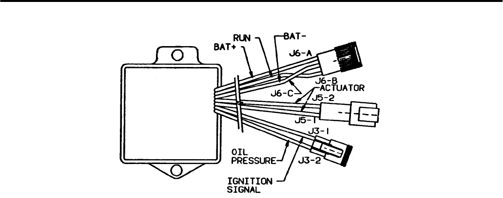
7-10
FIGURE 7-6. GOVERNOR CONTROLLER BOARD A4
151-0702A
Governor Controller Board (A4)
Governor controller board A4 is located on the gen-
set mounting tray. It accepts inputs from the elec-
tronic ignition module and the oil pressure sensor.
B+ and ground connections power the board. See
Figure 7-6.
Governor controller board A4 outputs a DC voltage
that drives the governor actuator, which in turn
moves the carburetor throttle to maintain an engine
speed of 1800 RPM. The inputs from the ignition
module and the oil pressure sensor can signal the
governor controller board to shut the engine off un-
der the following adverse conditions:
•If power (B+) is lost to the controller
•If genset speed goes beyond 2700 RPM
•If oil pressure switch S2 closes
•If the signal from the ignition module stops
•If genset speed goes below 1760 RPM for 30
seconds
Under all these circumstances, governor controller
board A4 shuts down the genset. The governor con-
troller board is a non-serviceable component.
CONTROL OPERATION
The schematic diagram shown in Figure 7-7 is in-
tended as an illustration of the circuit description.
Also see
Appendix B. Wiring Diagrams.
Redistribution or publication of this document,
by any means, is strictly prohibited.
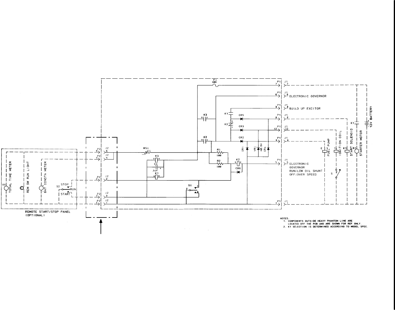
7-11
PIN CALLOUTS FOR THE REMOTE CONNECTIONS
BEGINNING SPEC G ARE DIFFERENT, REFER TO
SECTION 11 FOR CORRECT WIRING DIAGRAM
FIGURE 7-7. BGM/NHM CONTROL SCHEMATIC (ELECTRONIC GOVERNOR SETS) (PRIOR TO SPEC G)
Redistribution or publication of this document,
by any means, is strictly prohibited.

7-12
Starting
Moving the Start/Run/Stop switch to the Start posi-
tion connects battery ground (B-) to relays A1-K3
and A1-K1. Normally-open contacts on A1-K3
close, connecting B+ to the following:
•Governor control board A4
•Relay K4
•Ignition coil T1
•Start solenoid K1(through N.C. contacts
of A1-K2 relay
•Relay K2 (through resistors R1 and R2)
Normally-open contacts on relay K1 close,
connecting B+ to the following:
•Voltage regulator VR1 (to build-up exciter)
NOTE: Pre-Spec D generator sets have fuel pumps
that are powered directly rather than through K4 con-
tacts. Otherwise their control functions are identical
to those described here.
The following control responses take place:
•Governor control board A4 moves the throttle
to an open position after a 1-second delay.
•K4 relay contacts close to provide power to fuel
pump E3 and fuel pump solenoid E4.
•The field is flashed to provide residual magne-
tism to induce voltage buildup. J1-3 is ener-
gized.
•Ignition coil T1 is energized, to begin producing
sparks when ignition module S3 is activated.
•Start solenoid K1 is energized, connecting B+
to the starter motor, which cranks the engine for
starting.
•Solenoid fuel valve E4 (see Figure 8-3) is
opened, releasing fuel to the carburetor.
•Fuel pump E3 begins pumping fuel to the car-
buretor.
When governor control board A4 determines that
the generator reaches 1150 RPM, it connects
ground to relay A1-K2. A1-K2 contacts open, which
opens the exciter circuit after initial start and closes
another circuit to the fuel pump and ignition coil after
K3 is de-energized.
Starter Lockout-Run
When the engine cranks, the low oil pressure switch
is bypassed until the engine reaches operating
speed. Normally, with the engine running, the
switch is open. When the Start/Run/Stop switch is
released and returns to center (Run) position, the
engine continues to run. A1-K3 is de-energized,
opening the B+ line to the field exciter, governor
control board, start solenoid, fuel pump and fuel
valve solenoid. At the same time, A1-K2 is ener-
gized, and A1-K2 contacts open which block the
start solenoid from being activated while the set is
running. Another set of K2 contacts close to contin-
ue to provide power to the fuel pump, fuel valve so-
lenoid, ignition coil and governor controller.
(On electronic-governor generator sets, the engine
can be started and run, even if the lead to the low oil
pressure switch is disconnected or missing, as long
as this lead is not grounded.)
Off the control board, bridge rectifier CR10 receives
AC voltage through generator leads B1/B2, and
provides DC voltage through battery charge resis-
tor R1 to charge the starting battery. On pre-Spec D
gensets, the B1/B2 connection is paralleled to pow-
er the choke heater element, opening the choke. On
Spec D sets, the autochoke is powered directly by
B+ voltage.
Stopping
Moving start-stop switch S1 to the STOP position
grounds resistors A1-R1 and A1-R2. The governor
actuator responds by closing the throttle, cutting off
fuel to the engine. Relay A1-K2 is de-energized,
disconnecting the B+ line from the fuel pump and
ignition coil.
Without ignition, the engine stops. All components
return to their de-energized position following set
shutdown.
Redistribution or publication of this document,
by any means, is strictly prohibited.
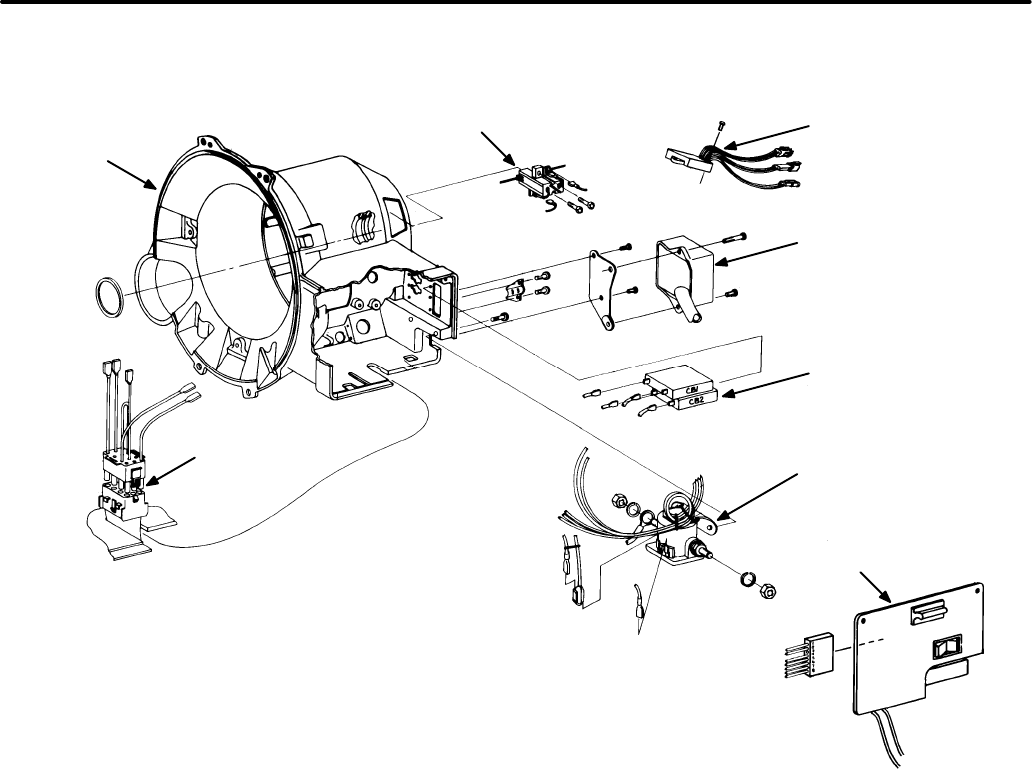
7-13
FIGURE 7-8. BGM/NHM CONTROL COMPONENTS
(ELECTRONIC-GOVERNOR GENSETS ONLY)
G1212-4
GOVERNOR
CONTROLLER
ASSEMBLY (A4)
VOLTAGE
REGULATOR
ASSEMBLY
(VR1)
BRUSH
BLOCK
ASSEMBLY
STATOR
HOUSING
REGULATOR
HARNESS
MAGNETIC
CIRCUIT
BREAKERS
(CB1, CB2)
CONTROL PANEL
ASSEMBLY
START
SOLENOID
RELAY
Redistribution or publication of this document,
by any means, is strictly prohibited.
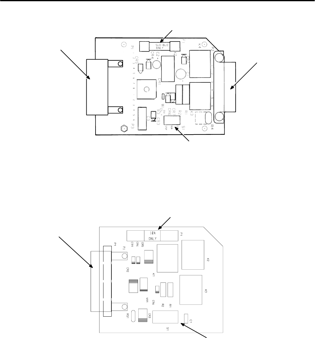
7-14
(PRIOR TO SPEC G)
BATTERY, STARTER, ENGINE
AND GENERATOR WIRING
HARNESS CONNECTOR (P1)
FUSE (F1)
START/STOP
SWITCH (S1)
REMOTE CONTROL
WIRING HARNESS
CONNECTOR (P2)
(BEGINNING SPEC G)
BATTERY, STARTER, ENGINE
AND GENERATOR WIRING
HARNESS CONNECTOR (P1)
FUSE (F1)
START/STOP
SWITCH (S1)
FIGURE 7-9. BGM/NHM CONTROL PCB ASSEMBLY (A1) (BEGINNING SPEC G)
Redistribution or publication of this document,
by any means, is strictly prohibited.
7-15
Trouble Possible Cause Corrective Action
Engine Does 1.Control fuse F1 is blown. 1. Replace fuse F1 (see
Section 2. General
Not Crank
Specifications
). If it blows again, look for a
loose or pinched wire inside and outside con-
trol box. If wiring is good, see
Appendix B. Wir-
ing Diagrams
and disconnect all DC loads
from the control board. Reconnect one at a
time. Press the Start Switch after each con-
nection. Replace the component that causes
the fuse to blow. Recommended order: fuel
solenoid or pump (E3, E4), ignition coil (T1)
ignition capacitor (C4), start solenoid coil (K1)
relay (K4, K5 and K6, depending on Spec)
Replace control board A1 if fuse still blows.
2.If engine cranks at set but not at 2a. Ensure that wiring harness jack
remote control panel, fault is connections are fully seated to PC board.
due to:
a.PC board P2/J2 connection not 2b. Check for continuity and correct if circuit
secure. is open.
b.Open circuit in remote control. 2c. Replace remote start control switch.
c. Remote start switch faulty.
3.If engine cranks at remote 3.Replace PC board A1.
control panel but not at set, fault
is due to faulty S1 switch.
4.Insufficient voltage for cranking 4a. Check condition of battery and recharge
due to: or replace.
(See Low Battery Voltage also.) 4b. Clean and tighten all connections at
a.Battery not charged. battery, K1 start solenoid, and starter
b.Terminal connections loose motor.
or dirty.
Use the following troubleshooting guide to help lo-
cate problems related to the control circuits. Fig-
ures 7-1 and 7-5 show the location of most of the
control components. Refer to the appropriate wir-
ing diagram/schematic in Section 8 for the location
of all terminal connections.
The troubleshooting guide is divided into sections.
After identifying the problem, refer to the guide for
the possible cause and the recommended correc-
tive action.
Many of the components listed in the following pro-
cedures are not present on the newer, electronic
governor Marquis gensets. Follow only the proce-
dures that apply to the particular genset being ser-
viced.
CONTROL TROUBLESHOOTING
Many troubleshooting procedures present hazards which can result in severe personal
injury or death. Only qualified service personnel with knowledge of fuels, electricity, and machinery
hazards should perform service procedures. Review safety precautions on inside cover page.
WARNING
Redistribution or publication of this document,
by any means, is strictly prohibited.

7-16
Trouble Possible Cause Corrective Action
Engine Does 5.Connect a voltmeter between 5a. Tighten solenoid bracket mounting
Not Crank terminal S on the start solenoid screw.
and ground. Check for battery 5b. Replace K1 start solenoid.
voltage when S1 is placed in 5c. Refer to
Electric Starter
(Section 6) for
START position. If voltage is test and service procedures.
present, fault is due to:
a.K1 start solenoid not grounded.
b.Defective K1 start solenoid.
c. Defective starter.
6.If voltage is not present as 6a. Check for continuity and correct if circuit
described in step 5 test, fault is open.
is due to: 6b. Replace control PC board.
a.Open circuit between K1 relay
and control PC board.
b.Defective control PC board.
7.B+ fuse (F1) is open. 7.Replace fuse.
Engine Cranks 1.Faulty ignition due to worn or 1.Refer to
Ignition System
(Section 6) for
But Does Not fouled spark plugs, faulty plug test and service procedures.
Start wires, faulty ignition coil or
control module.
2.Faulty fuel system due to low 2. Refer to
Fuel System
(Section 6) for test
fuel level in tank, supply valve and service procedures.
not open, sticking choke, faulty
fuel pump/fuel solenoid, or
carburetor mixture screws
incorrectly adjusted.
3.Bad relay K4 and/or fuse F2 3.Replace relay and/or fuse.
4.Connect a voltmeter between 4. a. Check for continuity and correct if
positive (+) terminal E1 ignition circuit is open.
coil and ground. Check for bat- 4.b. Test/replace control PC board.
tery voltage when S1 is placed
in START position. If voltage
not present, fault due to:
a.Open E1 coil-to-control circuit.
b.Defective control PC board.
Many troubleshooting procedures present hazards which can result in severe
personal injury or death. Only qualified service personnel with knowledge of fuels, elec-
tricity, and machinery hazards should perform service procedures. Review safety pre-
cautions on inside cover page.
WARNING
Redistribution or publication of this document,
by any means, is strictly prohibited.

7-17
Trouble Possible Cause Corrective Action
Engine Cranks 5.Governor controller board not 5.Verify that throttle goes wide open after1
But Does Not operating properly (electronic second of cranking. If so, problem is not
Start governor sets) governor controller. Check electrical
connections to actuator, governor control,
ignition. If board is defective, replace.
Engine Starts 1.Low oil pressure switch S2 not 1a. Check oil level and add oil if low.
But Stops opening due to: 1b. Check for continuity, correct if circuit is
When Start a.Low oil level. open.
Switch is b.Open circuit between switch 1c. Replace low oil pressure switch.
Released and governor controller. 1d. Refer to Section 6,
Troubleshooting
, for
c. Defective low oil pressure procedures to follow.
switch.
d.Low oil pressure.
2.(Spec A sets only) 2a. Check for continuity and correct if
Ignition relay K5 contacts not circuit is open.
opening due to: 2b. Replace K5 relay.
a.K5 relay circuit open.
b.Defective K5 relay.
3.Output voltage from generator 3a. Check for continuity and correct if
not being supplied to control circuit is open.
due to: 3b. Refer to
Generator
section for test
a.Open circuit in wiring between and service procedures.
generator and control.
b.No output voltage from
generator.
4.Defective control PC board A1. 4.Replace PC board A1.
Low Battery 1. Weak or discharged battery 1a. Replenish electrolyte and recharge
Voltage due to: battery.
a.Low electrolyte level in battery. 1b. Connect a separate battery charger to
b.Long periods of non-use. bring battery up to full charge.
c. Improperly wired battery. 1c. Reconnect and check battery con-
nection.
2.Load connected to battery while 2.Turn off/disconnect load and recharge
set is turned off. battery.
Many troubleshooting procedures present hazards which can result in severe
personal injury or death. Only qualified service personnel with knowledge of fuels, elec-
tricity, and machinery hazards should perform service procedures. Review safety pre-
cautions on inside cover page.
WARNING
Redistribution or publication of this document,
by any means, is strictly prohibited.

7-18
Trouble Possible Cause Corrective Action
Engine Starts 1.Fuel level is below generator set 1.Check fuel and oil levels and refill
And Runs; fuel pickup tube or oil level as necessary.
Then Stops. is low.
Set Restarts
Immediately or 2.Dirty fuel filter restricting 2.Clean fuel filter. Refer to Fuel
Set Restarts fuel flow. System (Section 6) for test and
After Cooling service procedures.
Down 3.Faulty ignition module. 3.Replace ignition module.
4.Contaminated fuel. 4.Refill tank with fresh fuel.
REMOTE 1. Open circuit between control 1.Check for continuity and correct if
CONTROL board A1 and terminal 6 or 5 circuit is open.
(if equipped) of remote terminal 6 or 5 on
connector plug P2/J2 and
Run Lamp, start-stop switch S2.
Time Meter, or
Battery Con- 2.Open circuit between ground 2.Check for continuity and correct if
dition Meter terminals on lamp or meters circuit is open.
Does Not and terminal 1 on remote
Operate start-stop switch.
3.If battery condition meter and 3.Replace time meter.
run lamp work but time meter
does not operate, time meter
is defective.
4.If time meter works but battery 4a. Replace battery condition meter.
condition meter does not operate, 4b. Replace zener diode.
connect a voltmeter between the
positive terminal on battery
charge meter and ground. Use
the following to determine fault:
a.If reading equals battery
voltage minus 10 volts, battery
condition meter is defective.
b.If reading does not equal
battery voltage minus 10 volts,
zener diode is defective.
Many troubleshooting procedures present hazards which can result in severe
personal injury or death. Only qualified service personnel with knowledge of fuels, elec-
tricity, and machinery hazards should perform service procedures. Review safety pre-
cautions on inside cover page.
WARNING
Redistribution or publication of this document,
by any means, is strictly prohibited.

7-19
Trouble Possible Cause Corrective Action
REMOTE 5. Meters and switch function 5.Replace remote start-stop switch S2.
CONTROL properly but run lamp does not
(if equipped) illuminate. Lamp (internal to
Run Lamp, switch) is burned out.
Time Meter, or
Battery Con- 6.If remote switch functions OK 6.Check for continuity of remote wiring
dition Meter (starting and stopping genset) harness and wiring on remote control in
Does Not but meters and run lamp do not series with terminals 6 and 5. Replace
Operate operate, current sensing resistor wiring of control circuit.
R4 on control board A1 has
opened, caused by a short in the
remote control wiring between
control board P2/J2 terminal 6/5
and remote control time meter,
run lamp/battery condition meter.
Generator Set 1.Faulty set control start/stop 1. Check start/stop switch and replace
Does Not Stop switch (S1) if defective.
After Switch Is
Pushed to Off 2.(Spec A sets only) 2.a. Check for continuity and correct if circuit
K5 relay not energizing due to: is open.
Always a.Open circuit to K5 relay coil. 2.b. Replace K5 relay.
remove load b. Faulty K5 relay.
a few minutes
before stop-
ping to allow
set to cool
down.
Many troubleshooting procedures present hazards which can result in severe
personal injury or death. Only qualified service personnel with knowledge of fuels, elec-
tricity, and machinery hazards should perform service procedures. Review safety pre-
cautions on inside cover page.
WARNING
Redistribution or publication of this document,
by any means, is strictly prohibited.

7-20
TESTING CONTROL BOARD A1
Confirm that control board A1 is faulty before re-
placing it. Use a DC voltmeter and an ohmmeter to
perform the following tests.
1. Disconnect the negative (-) battery cable.
2. Remove the control box cover (Figures 7-1 and
7-5) and separate it from control board A1 by
removing the four screws on the back of the
board.
3. With an ohmmeter, check for electrical continu-
ity across each P1/J1 and P3/J3 connector on
the control board (Figures 7-2 and 7-6). Re-
place the socket portion of each connector that
has a measurable resistance (greater than
zero ohms) or has begun to corrode.
4. Reconnect the battery and try to start and run
the set.
5. If the engine does not crank, measure voltage
at connector P1-2 while pressing the panel
start switch (the negative (-) test probe of the
voltmeter should be grounded at connector
P1-8). If the voltmeter indicates zero volts, re-
place control board A1. If the voltmeter indi-
cates at least 9 volts, the problem is not with the
control board. Go back to the
Troubleshooting
Guide
.
6. If the engine cranks, but does not start, mea-
sure voltage at connectors P3-3 and P3-6 while
the engine is cranking (the negative (-) test
probe of the voltmeter should be grounded at
connector P1-8). Replace control board A1 if
the voltmeter indicates zero volts at either con-
nector. If the voltmeter indicates at least 9 volts
at both connectors, the problem is not with the
control board. Go back to the
Troubleshooting
Guide
.
7. If the engine starts, but stops when the Start
switch is released, the problem could be with
the low oil pressure switch or generator (no
voltage). Go back to the
Troubleshooting
Guide.
Replace control board A1 if the oil pres-
sure switch and generator are functioning
properly.
8. Reassemble the control board and cover.
Redistribution or publication of this document,
by any means, is strictly prohibited.

Section 8. Generator
8-1
GENERATOR/CONTROL COMPONENT
DESCRIPTIONS
The generator and its control components consist
of the following elements (see Figure 8-1):
•Control printed circuit board (A1)
•Brushes
•Rotor
•Stator and housing
•Terminal board (TB1)
•Voltage regulator (VR1)
•Circuit breakers (CB1/CB2)
•Wiring harness to load
The ignition module and rotor are mounted inside
the generator; for this reason, their removal/re-
placement are described in this section.
Control Printed Circuit Board (A1)
(Mechanical-governor generator sets)
The starting battery supplies initial excitation volt-
age to the generator rotor. While the engine cranks,
battery DC voltage is supplied through the N.C.
contacts of generator relay K2 (on control board
A1), through voltage regulator VR1, to the brushes
and slip rings of the rotor. When the engine starts
and generator voltage builds up, generator relay K2
is energized, opening the N.C. contacts in the bat-
tery B+ circuit to the voltage regulator and closing a
set of N. O. contacts in the start disconnect/ run
relay K3 circuit of board A1. This circuit keeps relay
K3 energized while the set is in operation. If relay K2
becomes de-energized, the set shuts down.
Control Printed Circuit Board (A1)
(Electronic-governor generator sets)
Moving the Start/Run/Stop switch to the Start posi-
tion connects battery ground (B-) to relay K3. Nor-
mally-open contacts on K3 close, connecting B+ to
governor control board A4 (see Section 7), fuel
pump E2, ignition coil E1, start solenoid K1, N.C.
contacts of K2 relay, voltage regulator VR1 (to build-
up exciter), and relay K2 (through resistors R1 and
R2). The field (rotor) is flashed through the N.C.
contacts of K2 . Ignition coil E1 is energized. Start
solenoid K1, solenoid fuel valve E3 and fuel pump
E2 are activated. After initial start, K2 on the control
board is activated, opening the exciter circuit and
closing another circuit to the governor control
board, fuel pump and ignition coil after K3 is de-en-
ergized. Governor control board A4 is energized,
which moves the throttle to an open position.
Brushes
DC excitation voltage is induced through the
brushes and rotor slip rings to the rotor windings.
The brush block assembly consists of a single
brush block with two brushes. The brush block
mounts directly over the rotor slip rings inside the
generator housing, and may be accessed by re-
moving the small plate at the rear of the housing.
Rotor
The 4-pole rotor provides the rotating magnetic field
that is required to generate an AC voltage potential
in the stator windings. The DC current required for
field excitation is supplied through two slip rings on
the rotor shaft.
The engine end of the rotor is connected directly to
the engine crankshaft with a tapered seat/shaft cou-
pling and through-bolt. The outer end of the rotor is
supported by a single bearing that is pressed onto
the rotor shaft. The bearing slip-fits inside the gen-
erator housing.
Cooling airflow for the generator is provided by a
centrifugal fan that mounts on the inner end of the
rotor shaft. The fan also serves as a mount for the
starter ring gear.
Redistribution or publication of this document,
by any means, is strictly prohibited.

8-2
Stator and Housing
During genset operation, AC current is produced in
the windings of the stator. Stator winding leads are
routed into the set control housing compartment, for
control component connection as follows:
•Leads T1, T2, T3 and T4 to terminal board TB1.
•(Mechanical-governor sets) Leads B1 and B2
to control board A1, to rectifier CR10, to the
electric choke, and for battery charging, where
applicable.
•(Electronic-governor sets) Leads B1 and B2 to
rectifier CR10, to the electric choke, and for
battery charging through R1.
•Leads Q1 and Q2 to voltage regulator VR1, wir-
ing harness J4, for excitation of rotor. (AC volt-
age from stator is rectified to DC voltage in
VR1).
The stator mounts inside the generator housing and
is held in position with clamps and capscrews. A se-
ries of air intake openings in the end of the housing
allow cool air to be drawn inside the housing for gen-
erator cooling. The housing also provides a mount-
ing for the engine starter, rear rotor bearing, exciter
brush block, control components, and fuel pump.
The complete stator and housing assembly bolts to
the engine-to-generator adapter.
Terminal Board (TB1)
The AC output power leads from the generator (T1,
T2, T3, and T4) are connected to terminal board
TB1 at terminals L1 - L0.
AC power at TB1 terminals is tapped by leads of wir-
ing harness J4 of voltage regulator VR1, and inter-
connect wiring to circuit breakers CB1 and CB2.
These leads provide generator output to the voltage
regulator for proper voltage regulation, and to the
circuit breakers for power supply to load.
Voltage Regulator (VR1)
The voltage regulator helps provide stable output
voltage under varying loads. During initial start of
the set, the voltage regulator receives DC current
from the starting battery, and begins excitation of
the rotor through leads J4-9/F1, and J4-10/F2. After
the genset starts and runs, it provides AC power to
the voltage regulator through leads J4-11/Q1, and
J4-12/Q2 for the excitation system. The AC voltage
is rectified to DC voltage, and the proper DC excita-
tion voltage is conducted to the rotor in proportion to
changes in demand. Reference voltage is J4-2/L1
to J4-3/L0.
The voltage regulator is protected from moisture
and other contamination, reducing the risk of com-
ponent failure. The capacitor and the printed circuit
board are encased in the regulator housing with a
potting compound. The wiring harness plug-in P4 is
treated with a lubricant prior to connection.
Circuit Breakers (CB1,CB2)
AC output from the generator is supplied to circuit
breakers CB1 and CB2, located on the right side of
the control housing. Ampere rating of these break-
ers may differ, depending on the set model/frequen-
cy. Refer to the proper Parts Manual when ordering
replacement parts.
Wiring Harness to Load
A wiring harness is provided to connect the genset
to the electrical system. All leads are stranded cop-
per wire, to withstand vibration. The leads must be
protected with flexible conduit from the set control
housing to the switching/disconnect device, which
must be provided by the vehicle manufacturer. Load
conductors are black, neutral conductors are white,
and the ground conductor is green.
Redistribution or publication of this document,
by any means, is strictly prohibited.

8-3
GENERATOR OPERATION
Refer to
Appendix B. Wiring Diagrams
while review-
ing this text. Always refer to the wiring diagram/
schematic that corresponds to the specific genset
when troubleshooting problems.
When the start-stop switch is moved to START, the
rotating field (rotor) is momentarily connected to
battery positive (B+) to provide magnetism for volt-
age build-up. As the engine starts and speed in-
creases, the rotating field induces an AC voltage in
the stator windings. AC voltage from the quadrature
winding (Q1, Q2) is rectified for field excitation volt-
age. AC voltage output stabilizes at approximately
128 volts when the engine reaches governed
speed.
Voltage regulator VR1 enables the generator to pro-
vide a stable AC output voltage under varying load
conditions. Leads from VR1 wire harness J4-2
and -3 are connected to terminal board TB1: these
leads sense voltage changes of the load on the gen-
erator.
The sensing leads provide reference voltage to the
voltage regulator, depending on load. The voltage
regulator increases DC excitation voltage to the ro-
tating field proportionate to the load, continuously
adjusting the field current as the load changes.
Efficient set performance depends on voltage and
frequency (engine speed) regulation. On the me-
chanical governor generator set, output load
changes can significantly decrease or increase en-
gine speed. If the governor does not maintain prop-
er engine speed, too large a burden may be im-
posed on the voltage regulator for proper current to
be supplied to the load. Governor adjustment and
troubleshooting is discussed in Section 6 of this
manual.
Redistribution or publication of this document,
by any means, is strictly prohibited.
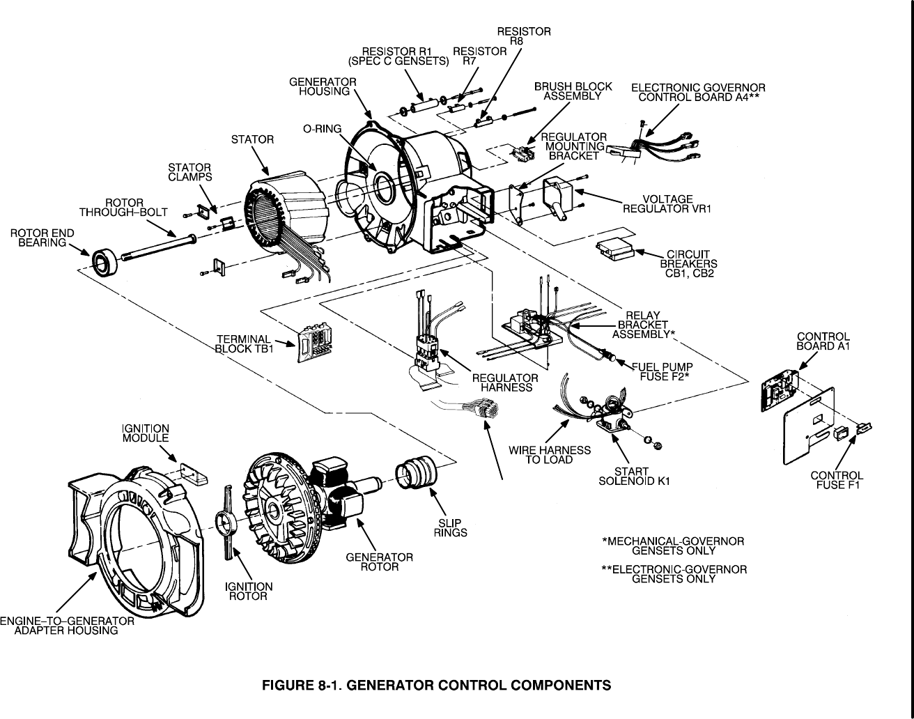
8-4
(1) PRIOR TO SPEC G
(1)
(2) BEGINNING SPEC G
(1)
(1)
(1)
REMOTE
CONNECTOR (2)
Redistribution or publication of this document,
by any means, is strictly prohibited.
8-5
Trouble Possible Cause Corrective Action
No AC Output 1.Open circuit breaker. 1. Locate cause of overload and correct
Voltage as required. Reset breaker.
Note: This
condition may
cause the 2.Open circuit between voltage 2.Check for good wiring connections
generator set regulator and brush block. and correct as required. Check for
to stop when continuity and correct if circuit is open.
start switch S1
is released. 3. Open circuit between generator 3.Check for good wiring connections
windings (Q1, Q2) and voltage and correct as required. Check for
regulator. continuity and correct if circuit is open.
4.Open circuit between terminal 4.Check for good wiring connections
block TB1 and voltage regulator; and correct as required. Check for
wiring harness J4 leads. continuity and correct if circuit is open.
5.Brushes stuck in holder or not 5.If there are 12 or more volts
making good contact with slip on the brush block while cranking,
rings. then release brushes if jammed
in holder, and clean slip rings
if dirty. If not, the problem is in the
control or wiring harness.
6.Defective voltage regulator. 6.Replace voltage regulator.
7.Open, grounded, or short circuit 7.Test each component for open,
in rotor or stator. grounded, or shorted windings and
replace if defective.
GENERATOR TROUBLESHOOTING
This troubleshooting guide provides solutions to many common generator problems. Figure 8-1 shows the
location of the generator components. Refer to the wiring diagrams/schematics in Section 11 to locate termi-
nal connections. If these suggestions do not help, contact an authorized Onan service representative.
Many troubleshooting procedures present hazards which can result in severe
personal injury or death. Only qualified service personnel with knowledge of fuels, elec-
tricity, and machinery hazards should perform service procedures. Review safety pre-
cautions on inside cover page.
WARNING
Redistribution or publication of this document,
by any means, is strictly prohibited.

8-6
Many troubleshooting procedures present hazards which can result in severe
personal injury or death. Only qualified service personnel with knowledge of fuels, elec-
tricity, and machinery hazards should perform service procedures. Review safety pre-
cautions on inside cover page.
Trouble Possible Cause Corrective Action
AC Output 1. Engine governor (mechanical) 1.Refer to governor adjustments in
Voltage Too out of adjustment. Section 6.
Low or Too
High 2.Brushes worn or not making good 2.Check length of brushes and replace
contact with slip rings. (Low or if worn excessively. Clean or replace
intermittent AC output voltage.) slip rings.
3.Poor wiring connections to/from 3. Check for good wiring connections
voltage regulator. and correct as required. Check for
continuity and correct if circuit is open.
4.If generator frequency is within 4. Replace voltage regulator.
specified limits but voltage is incor-
rect, voltage regulator is defective.
5.Open, grounded, or short circuit in 5.Test each component for open,
rotor or stator. grounded, or shorted windings and
replace if defective.
Noisy 1. Loose brush holder. 1.Tighten brush holder.
generator 2.Worn generator end bearing. 2.Replace end bearing.
3.Rotor and stator rubbing together 3a. Check for varnish lumps between
due to: rotor and stator, remove as required.
a.Varnish lumps. 3b. Follow specified assembly procedures
b.Rotor misaligned with crankshaft. to correct rotor to crankshaft
alignment.
WARNING
Redistribution or publication of this document,
by any means, is strictly prohibited.

8-7
Many troubleshooting procedures present hazards which can result in severe
personal injury or death. Only qualified service personnel with knowledge of fuels, elec-
tricity, and machinery hazards should perform service procedures. Review safety pre-
cautions on inside cover page.
Trouble Possible Cause Corrective Action
Generator 1.Generator overloaded due to 1. Remove part of load and replace
Overheats defective circuit breaker. circuit breaker.
2.Airflow restricted due to dirt or 2.Clear away all dirt or debris as required.
debris covering vent openings in
stator housing.
3.Stator windings covered with oil 3.Clean stator windings.
or dirt.
4.Open, grounded, or short circuit in 4.Test each component for open,
rotor or stator. grounded, or shorted windings and
replace if defective.
5.Defective voltage regulator. 5.Replace voltage regulator.
WARNING
Redistribution or publication of this document,
by any means, is strictly prohibited.
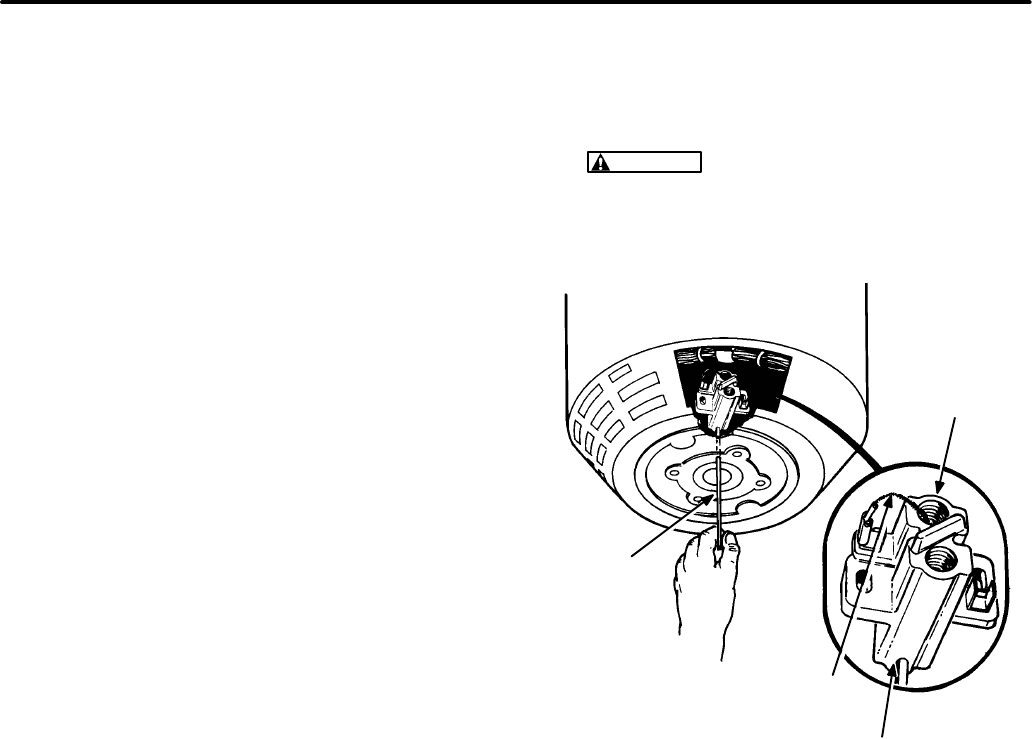
8-8
GENERATOR SERVICE
This section describes generator disassembly/as-
sembly procedures. Refer to Figure 8-1 to locate
and identify the various generator components and
Appendix B. Wiring Diagrams.
Generator Disassembly Procedure
1. After allowing the engine to cool, drain the en-
gine oil while the genset is mounted in the ve-
hicle.
2. Remove the set from the vehicle and place it on
a sturdy work bench. Refer to Section 5 of this
manual for set removal procedures.
3. Remove the top cover from the generator set.
4. Remove the carburetor and intake manifold to
provide clearance to lift the generator stator as-
sembly. Disconnect the following parts:
•choke heater lead wires
•throttle linkage
(mechanical governor: at carburetor)
(electronic governor: at actuator clip)
•fuel line
•crankcase breather hose
•air preheater tube
Remove the intake manifold screws, and lift off
the carburetor and intake manifold as an as-
sembly. Refer to the
Fuel System
description in
Section 6 for detailed removal procedures and
important safety instructions.
5. Disconnect the leads to the charge resistor, the
low oil pressure cut off switch, and the B+ termi-
nal on the ignition coil.
6. Remove the brush block cover and disconnect
the F1 (+) (outboard) and F2 (-) (inboard) lead
wires from the brush block terminals.
7. Pull each brush outward from the holder, and at
the same time insert a piece of stiff wire into the
small hole in the end of the stator housing (see
Figure 8-2). Carefully guide the wire through
the brush block, then release each brush.
Verify that each brush is held off the slip rings
by the wire.
CAUTION
The brushes will be damaged
during disassembly if not held off the slip
rings. Make certain wire is in place before
removing stator assembly.
G1178s
FIGURE 8-2. BRUSH BLOCK ASSEMBLY
BRUSH BLOCK
HOLE
BRUSH
LEAD
WIRE
WIRE
8. Remove the two control panel screws from the
housing, lift off the control panel and discon-
nect plug/jack connections P1/J1 and P3/J3 of
the control printed circuit board.
9. Place a 3/8 inch allen wrench in the head of the
rotor through-bolt. Use a rubber mallet and
sharply strike the allen wrench so the through-
bolt is driven in a counterclockwise (viewed
from generator end) direction. Several sharp
taps should break loose the generator.
Redistribution or publication of this document,
by any means, is strictly prohibited.
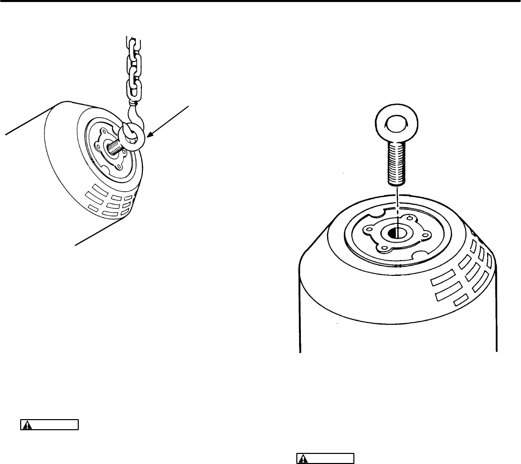
8-9
FIGURE 8-3. GENERATOR LIFT
G1176-2
LIFTING EYE
BOLT (9/16−12)
10. Remove the rotor through-bolt and thread the
special lifting eye (9/16-12) into the end of the
housing. Refer to Figure 8-3.
11. Place a pad or cushion in front of the engine to
protect the scroll. Attach a hoist or other lifting
device to the lifting eye. Tip up the set until it is
completely vertical and resting on the scroll.
Remove the lifting plate when finished.
CAUTION
Careless handling can damage
the rotor. Do not lift the entire generator set
by this method.
12. Remove the capscrew and two EIT lock wash-
ers that hold the ground strap to the drip pan.
13. Remove the vibration-isolator center screws
from the underside of the drip pan, and lift the
drip pan away from the set.
14. Disconnect the lead wires attached to the start-
er motor. Loosen the fasteners that mount the
starter to the stator housing, and remove the
starter.
15. Remove the four capscrews, lock washers,
and nuts that secure the stator housing to the
engine-to-generator adapter.
16. Remove the lifting eye bolt (Figure 8-4).
FIGURE 8-4. REMOVAL OF LIFTING EYE BOLT
G1175-1
17. Carefully lift the stator assembly straight up un-
til it clears the rotor. Set stator assembly to rest
on smooth, clean surface.
CAUTION
Careless handling of the stator
can damage the insulation on the stator
windings. Do not brush the windings
against the housing as it is lifted clear.
18. Install the tool shown in Figure 8-5. Use a
screwdriver to turn the rotor tool in a clockwise
direction until it bottoms. Install a capscrew in
the end of the rotor shaft and tighten until rotor
breaks loose from crankshaft. Remove caps-
crew from end of rotor when complete.
Redistribution or publication of this document,
by any means, is strictly prohibited.
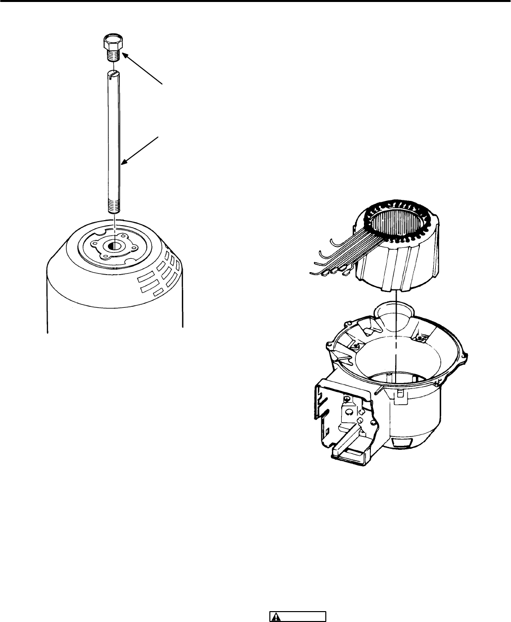
8-10
FIGURE 8-5. ROTOR TOOL
G1175
CAPSCREW
(9/16−12)
ROTOR TOOL
10 IN. (254 mm)
(7/16−14)
19. Carefully lift the rotor assembly off the end of
the engine crankshaft and remove rotor tool.
20. Lift the brush wires and remove brush holding
wire from housing. Remove the brush block
mounting screw and carefully remove the
brush block assembly from the stator housing.
21. Remove the stator from the stator housing as
follows (see Figure 8-6):
A. Rotate the stator/housing assembly onto a
smooth, clean surface, resting on end-
bearing face (bell shape of housing facing
up).
B. Disconnect stator leads:
•T1, T2, T3, and T4 from terminal board
TB1
•Q1, Q2, F1 and F2 from voltage regulator
VR1 harness J4
•B1 and B2 from control printed circuit
board harness J1
C. Pull the stator leads from the control box.
D. Remove the three stator clamps and caps-
crews.
E. Carefully lift the stator straight up until it
clears the stator housing. Set the stator
down on a smooth, clean surface.
FIGURE 8-6. STATOR/HOUSING DISASSEMBLY
G1213s
Rotor Bearing Removal
Use a gear puller to remove the bearing from the ro-
tor shaft. Attach the gear puller so that the gear pull-
er arms contact the inner race of the bearing (Figure
8-7).
CAUTION
The bearing will be damaged if
pulled by the outer race. If the bearing is to be
reused, it must be pulled by the inner race.
Redistribution or publication of this document,
by any means, is strictly prohibited.
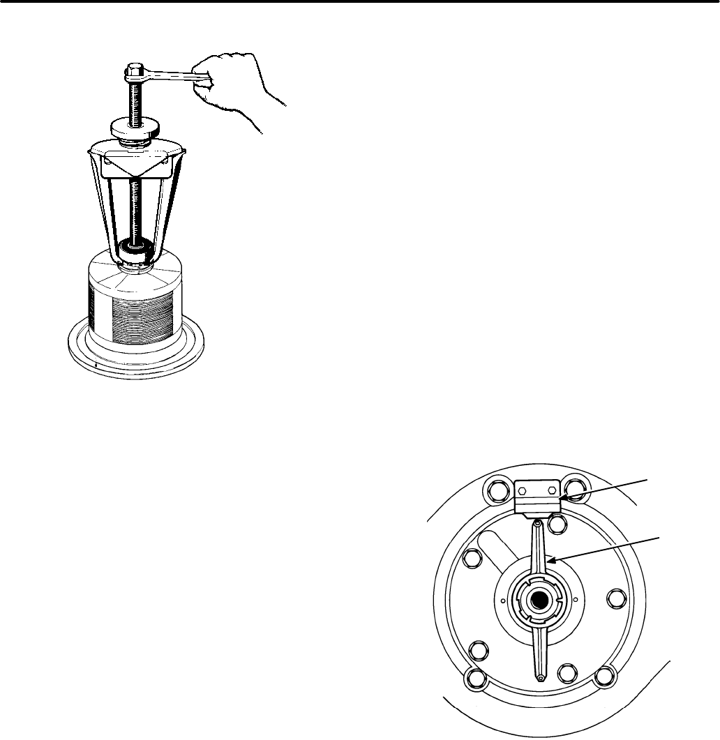
8-11
ES−1495/
G−1175
FIGURE 8-7. ROTOR BEARING REMOVAL
Rotor Bearing Replacement
1. Clean the bearing and shaft mating surfaces.
2. Apply Loctite #680 adhesive to the shaft mating
surface.
3. Apply Loctite #747 activator to the bearing mat-
ing surface.
4. Install the bearing and allow ten minutes curing
time before handling the assembly.
Ignition Components
The ignition rotor and ignition module are located in-
side the generator. When the stator in its housing
has been removed, the ignition rotor can be re-
moved/replaced on the crankshaft, and the ignition
module can be removed/replaced on the generator
adapter housing as follows (see Figure 8-8).
Ignition Rotor Removal/Replacement
To remove the ignition rotor, simply pry it off using a
dull-edged pry bar or other implement. To install the
ignition rotor, place it over the end of the crankshaft,
line the key on the rotor up with the corresponding
slot in the end of the crankshaft, and tap the rotor
gently into place.
Ignition Module Removal/Replacement
1. Unscrew the red and black wires extending
from the ignition module to the ignition coil.
Make certain to note which wire attaches to
which terminal on the coil.
2. Unscrew the two screws holding the ignition
module in place on the generator adapter.
3. When the ignition module is loose, pull the red
and black wires through the gap in the genera-
tor adapter.
To replace the module, perform the steps listed
above in reverse order.
FIGURE 8-8. IGNITION COMPONENTS
IGNITION
MODULE
IGNITION
ROTOR
ES-1862s
Redistribution or publication of this document,
by any means, is strictly prohibited.
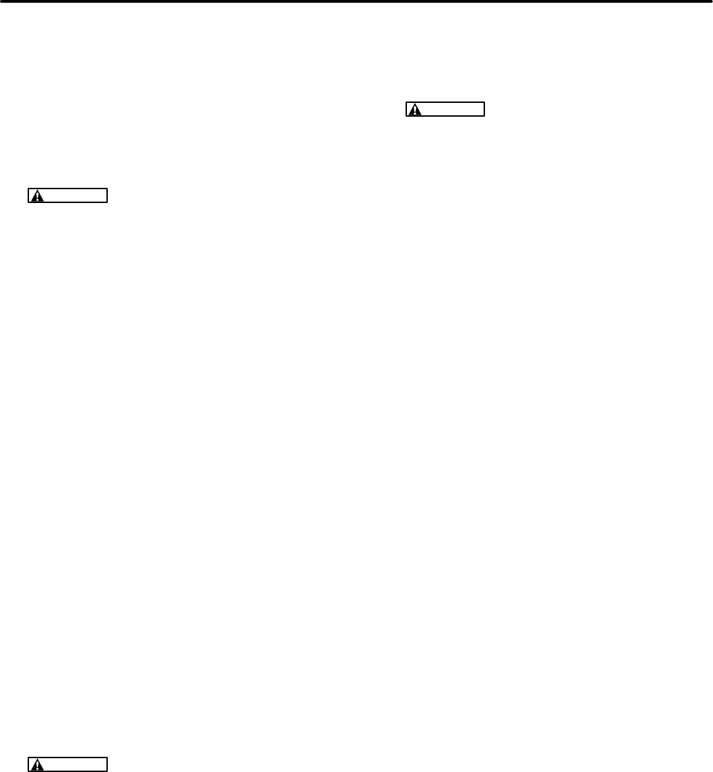
8-12
Generator Assembly Procedure
1. Install the stator in its housing as follows (see
Figure 8-6):
A. Position the stator so the output leads
align with the access hole to control hous-
ing. Carefully lower the stator straight
down into the stator housing.
CAUTION
Careless handling of the stator
can damage the insulation on the stator
windings. Do not brush the windings
against the housing as it is lowered into
housing, and take care not to drop or drag
the stator on work area outside of stator
housing.
B. Install the three stator clamps and caps-
crews.
C. Pull the stator leads into control box.
D. Connect stator leads;
•T1, T2, T3 and T4 to terminal board TB1
•Q1, Q2, F1 and F2 to voltage regulator
VR1 harness J4
•B1 and B2 to control printed circuit board
harness J1
E. Rotate the stator/housing assembly onto a
smooth, clean surface, resting on the bell
shape of the housing (end bearing face
up).
2. Install the brush block assembly in the stator
housing. Lift the brush wires and install the
brush holding wire in the housing. The wire
holds the brushes off the slip rings during as-
sembly (see Figure 8-10).
3. Carefully place the rotor assembly on the end
of the engine crankshaft, and replace the rotor
through-bolt. Tighten the rotor through-bolt
only enough to hold the rotor in place.
CAUTION
Tightening the rotor through-
bolt to the specified torque before the sta-
tor assembly is installed can result in rotor
shaft misalignment. Follow the recom-
mended installation procedures to avoid
any possibility of shaft misalignment.
4. Carefully place the stator assembly straight
down over the rotor and into position for as-
sembly to the engine-to-generator adapter.
The rotor end-bearing should fit snugly into the
bearing bore hole.
CAUTION
Careless handling of the stator
can result in damage to the stator windings.
Do not brush the stator windings against
the rotor as it is lowered into position.
5. Install the four nuts, locking washers, and
capscrews that secure the stator housing to the
engine-to-generator adapter. Tighten the cap
screws to the specified torque. Note that each
locking washer is installed under the capscrew
head.
6. Tighten the rotor through-bolt to the specified
torque.
7. Mount the starter on the generator stator hous-
ing using capscrews, lock washers and nuts.
Tighten to the specified torque.
8. Connect the leads to the starter terminal stud.
9. Hold the drip pan in position to mount to the un-
derside of the set, and install the vibration-iso-
lator center screws. Note that proper flat wash-
ers are used (large flat washers at each isolator
position). Tighten the center screws to the spe-
cified torque.
10. Secure the ground strap to the drip tray using a
capscrew and two EIT locking washers. Note
that the ground strap is installed between the
locking washers to ensure a good electrical
connection.
11. Attach the lifting bolt (Figure 8-3) to the end of
the stator housing.
12. Attach a hoist or other lifting device to the lifting
bolt. Carefully tilt the set back until it rests on
the drip tray. Remove the lifting bolt when com-
plete.
13. Connect plug/jack connections P1/J1 and
P3/J3 of the control printed circuit board. Install
the control panel assembly on generator hous-
ing. Tighten the mounting screws.
14. Pull the brush leads outward and remove the
wire holding the brushes off the slip rings. Make
certain that the brushes are centered on the
slip rings. If the brushes are not centered, loos-
en the brush block mounting screws and ad-
just. Retighten the mounting screws when
complete.
Redistribution or publication of this document,
by any means, is strictly prohibited.
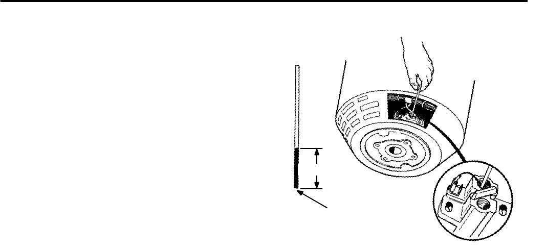
8-13
15. Connect the B+ lead to the outboard brush ter-
minal and the B- lead to the inboard brush ter-
minal. Install the brush block cover and tighten
the cover mounting screws.
16. Connect the leads to the charge resistor, low oil
pressure cut-off switch, and ignition coil B+ ter-
minal.
17. Place new intake manifold gaskets on the en-
gine block, and install the carburetor and intake
manifold assembly. Tighten the intake manifold
screws to the specified torque. Connect the
preheater tube, crankcase breather hose, fuel
lines, throttle linkage, and choke heater wires
(gasoline units). Refer to Fuel System (Section
6) for detailed assembly procedures.
18. Install the top cover on the generator set.
19. Install the set in the vehicle and securely fasten
all mounting screws and hardware. Connect
the fuel, exhaust, and electrical systems in re-
verse order of disassembly. Refer to the Set
Removal section for more information.
20. Fill crankcase with oil of the recommended
classification and viscosity.
BRUSHES AND SLIP RINGS
Brush Inspection
Remove the brush block cover and inspect the
brushes and brush holder for burns or other dam-
age. If the brushes appear to be in good condition,
use a piece of wire (marked as shown in Figure 8-9)
to check for excessive brush wear. Insert the wire
through the hole above each brush. Make sure the
wire is resting on the brush and not on part of the
spring. If the painted part of the wire is not visible,
the brush is excessively worn and must be re-
placed.
FIGURE 8-9. CHECKING BRUSH WEAR
G1174s
1 IN. (25 mm)
PAINTED OR
MARKED SECTION
OF WIRE
Always replace the brush springs when installing
new brushes to ensure that proper tension is main-
tained.
Brush Replacement Procedure
1. Disconnect the negative (-) battery cable at the
battery terminal.
2. Remove the air cleaner cover and air cleaner
filter element.
3. Remove the brush block cover from the stator
housing.
4. Disconnect the F1 (+) (outboard) and F2 (-) (in-
board) lead wires from the brush block termi-
nals.
5. Remove the brush block mounting screws and
lift out the brush block.
6. Remove brushes and brush springs from hold-
er and replace with new parts.
7. Pull and hold both brush lead wires outward
from brush holder. Place brush block assembly
into mounting position inside stator housing.
Redistribution or publication of this document,
by any means, is strictly prohibited.
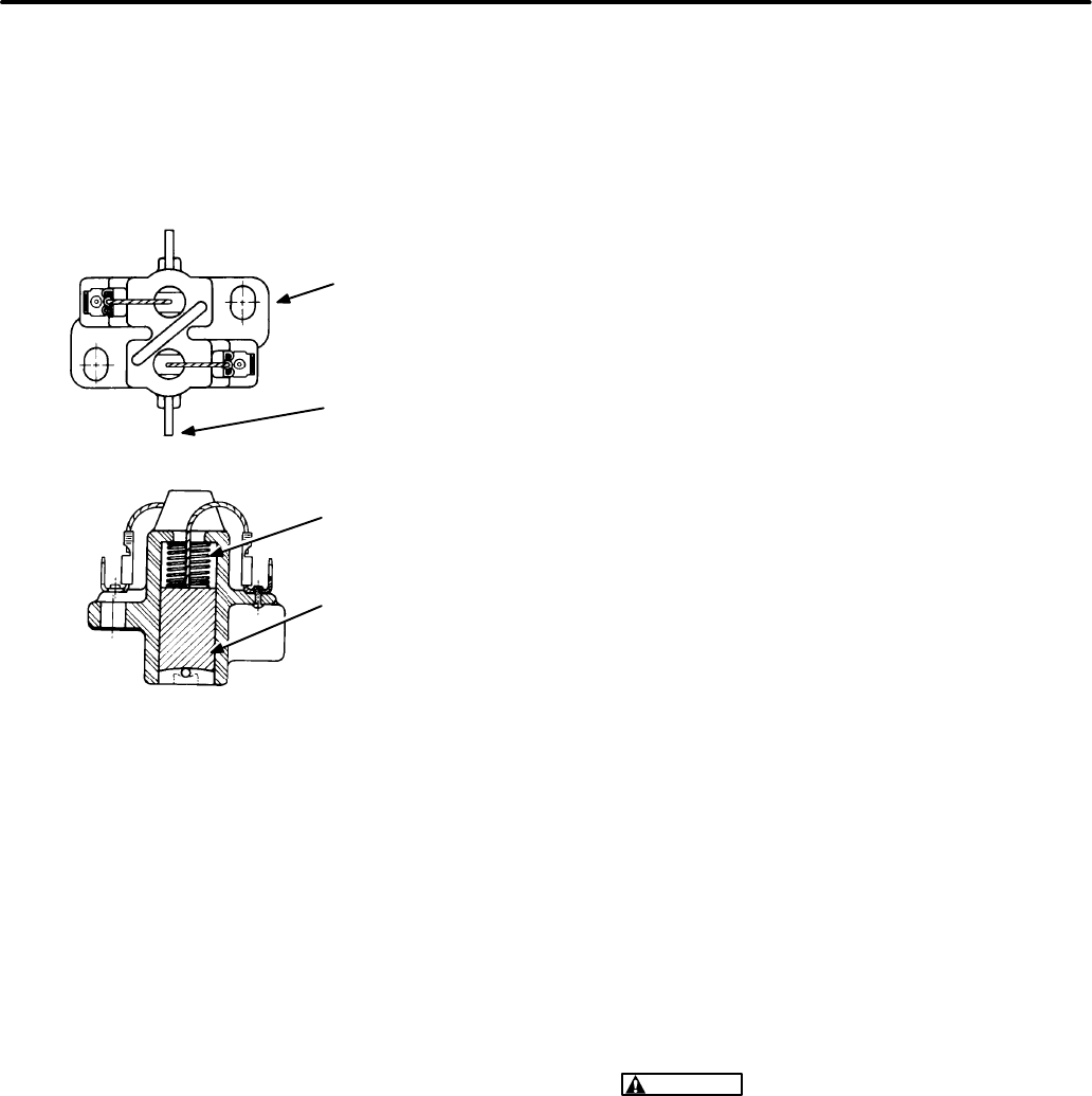
8-14
8. While continuing to hold the brushes away from
slip rings, insert the brush retainer wire from
outside stator housing hole, through brush
block assembly. Release both brush lead
wires. See Figure 8-10.
FIGURE 8-10. BRUSH REPLACEMENT
BRUSH
BLOCK
RETAINER
WIRE
BRUSH
G-1179s
SPRING
9. Install brush block mounting screws and tight-
en only enough to hold brush block assembly in
position.
10. Lift both brush lead wires and remove brush re-
taining wire completely from stator housing.
11. Adjust brush block assembly so that brushes
are aligned on slip rings, and tighten brush
block mounting screws. Do not overtighten, or
the plastic will crack.
12. Connect the voltage regulator and brush lead
wires to brush block terminals; F1 with (+) out-
board brush lead, and F2 with (-) inboard brush
lead.
13. Install brush block cover onto stator housing.
14. Install air filter element and air cleaner cover.
15. Connect negative (-) battery cable to battery
terminal.
Slip Ring Inspection and Maintenance
Remove the brush block cover and inspect the slip
rings for grooves, pits, or other damage. If the slip
rings are not in good condition, they may be refin-
ished using a commutator stone. A shiny brown/
black surface is normal, with one or two areas with
exposed brass.
Slip Ring Service Procedure
1. Remove the air cleaner cover and air cleaner
filter.
2. Disconnect the lead wires from the brush block
terminals and then insulate the lead wire ends.
Tie the lead wires to one side to allow clear ac-
cess to the slip rings.
3. Remove the brush block mounting screws and
lift out the brush block assembly.
4. Insert a 3/8 inch allen wrench into the rotor
through-bolt and rotate the engine and genera-
tor one full turn. While rotating, inspect condi-
tion of slip rings. If the slip rings need refinish-
ing, continue to next step. If slip rings do not
need refinishing, follow steps 9 through 14 in
the Brush Replacement section.
5. Move the Start-Stop switch to START position
to crank the engine. During this step, crank the
engine for 3 to 6 second cranking periods with a
rest period between, so the starter will not over-
heat.
During engine cranking, hold a commutator
stone (Onan tool 420-0259) against rotating
slip rings. Remove the commutator stone after
each cranking period and check that carbon is
being removed and all roughness and grooves
are smoothed out.
WARNING
Contact with rotating machin-
ery can cause severe personal injury. Keep
hands, fingers, clothing and jewelry clear
while servicing slip rings.
6. Remove insulating material from ends of volt-
age regulator lead wires F1 and F2, and then
install brush block assembly. Follow steps 6
through 14 in the Brush Replacement section.
Redistribution or publication of this document,
by any means, is strictly prohibited.
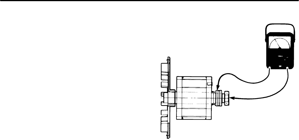
8-15
GENERATOR TESTING
This section describes test procedures for checking
field voltage, rotor, and stator.
Field Voltage Test
To check the field voltage, remove the brush block
cover and connect a DC voltmeter to the brush
block terminals. Connect the positive lead to the B+
(outboard) terminal and the negative lead to the B-
(inboard) terminal.
Start the genset and allow it to stabilize. Measure
the field voltage with no load applied and then with
full load applied. Both readings should fall between
18 and 60 volts DC, and be stable at constant load.
If field voltage fluctuates at constant load, refer to
Troubleshooting in this section; a possible governor
or voltage regulator problem exists.
Stop the genset, remove the test leads and replace
the brush block cover when the test is complete.
Rotor Test
The rotor may be tested for grounded, open, or
shorted windings using an ohmmeter. Figures 8-11
and 8-12 show the rotor removed from the genera-
tor for testing. However, it is possible to test the rotor
without removing it from the generator. To obtain ac-
cess to the slip rings, remove the brush block cover.
Lift the brush lead wires and insert a brush retaining
wire from outside stator housing, through brush
block assembly to hold the brushes off the slip rings
during testing.
FIGURE 8-11. TESTING ROTOR FOR GROUNDS
ES1558s-1
Ground Test:
To test for grounds, set the ohmme-
ter to the highest resistance scale. Touch one test
prod to the rotor shaft and hold it there. Touch the
other test prod to one of the slip rings (Figure 8-11).
A reading less than one megohm indicates that the
rotor is grounded. Replace a grounded rotor with a
new rotor.
Open Or Shorted Windings Test:
To test for open
windings, set the ohmmeter for the highest resist-
ance scale. Place test prods on the slip rings as
shown in Figure 8-12. The ohmmeter should indi-
cate continuity between slip rings. A high resistance
reading indicates a poor connection or an open
winding. Check the connection between the slip
rings and rotor lead wires. Replace the rotor if the
rotor winding is open.
To test for shorted windings, set the ohmmeter for
the lowest scale. Place the test prods on the slip
rings as shown in Figure 8-12. Resistance reading
should be 20.25 to 24.75 ohms at 77° F (25° C). Re-
place a rotor with shorted windings with a new rotor.
Redistribution or publication of this document,
by any means, is strictly prohibited.
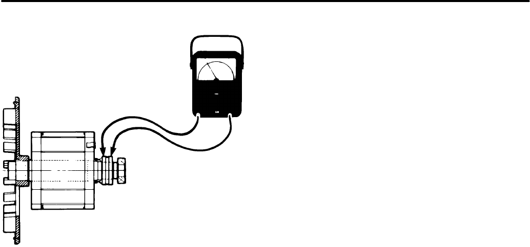
8-16
FIGURE 8-12. TESTING ROTOR FOR OPENS
OR SHORTS
ES1558s-2
Stator Test
The stator may be tested for grounded or open
windings by using an ohmmeter. Testing for shorted
windings requires a digital ohmmeter that can read
to within 0.01 ohms.
Figures 8-13 and 8-14 show the stator removed
from the generator for testing. However, it may be
tested without removing it from the generator. Re-
move the control panel to obtain access to the spe-
cified lead wires during testing.
Ground Test:
To test for grounds, disconnect the
transformer and stator leads listed below:
•Stator leads T1 and T3 from TB1
•Stator lead B1 from A1/P1-1
•Stator lead Q1 from VR1/J4-11
Insulate or position the lead wire ends so they do not
touch the set housing or other components within
the control. Set the ohmmeter to its highest resist-
ance scale, then connect one test prod to the gener-
ator housing. Touch the other test prod (see Figure
8-13) to the listed leads individually. A reading less
than one megohm indicates a ground. Replace a
grounded stator with a new stator.
Open or Shorted Windings Test:
To test for
opens, disconnect the following leads:
•Stator leads T1, T2, T3 and T4 from TB1
•Stator leads B1 and B2 from A1
•Stator leads Q1 and Q2 from VR1
Set the ohmmeter to the highest resistance scale.
Connect the test prods (see Figure 8-14) to the gen-
erator lead ends in pairs: T1/T2, T3/T4, B1/B2, and
Q1/Q2. The ohmmeter should indicate continuity
between lead ends. A high resistance reading indi-
cates an open winding. Replace an open stator with
a new stator.
To test for shorted windings, use a digital ohmmeter
that reads to within 0.01 ohms. Disconnect the sta-
tor leads as specified in the Open Test section. Con-
nect the test prods (see Figure 8-14) to the leads in
pairs as specified in the Open Test section. The
readings for lead pairs should be as follows (plus or
minus 10%):
Leads T1/T2: 0.327 ohms
Leads T3/T4: 0.327 ohms
Leads B1/B2: 0.058 ohms
Leads Q1/Q2: 2.089 ohms
A reading less than these values indicates shorted
windings. Replace a shorted stator with a new sta-
tor.
Redistribution or publication of this document,
by any means, is strictly prohibited.
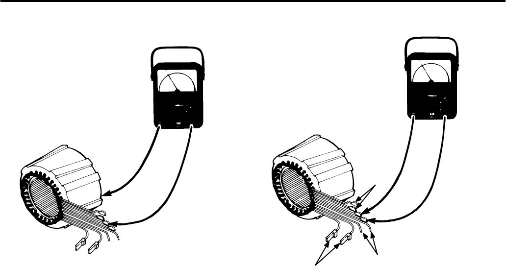
8-17
FIGURE 8-13. TESTING STATOR FOR GROUNDS
G1214s
TEST LEADS: T1, T3, B1
AND Q1 FOR GROUNDS
FIGURE 8-14. TESTING STATOR FOR
OPENS OR SHORTS
G1214s-1
TEST LEADS: T1/T2,
T3/T4, B1/B2, AND Q1/Q2
FOR OPEN OR SHORTED
WINDINGS
T1/T2
T3/T4
B1/B2
Q1/Q2
Redistribution or publication of this document,
by any means, is strictly prohibited.
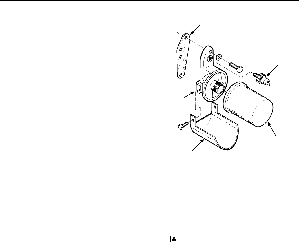
Section 9. Engine Block Assembly
9-1
GENERAL
The engine block assembly includes:
•Pistons and connecting rods
•Crankshaft
•Camshaft
•Valves and lifters
•Cylinder heads
•Lubrication system
•Timing gears
•Governor mechanism (mechanical)
•Bearings
•Cylinder block
Performing major service on the block assembly re-
quires that the genset be removed from the vehicle
(see
Set Removal
section). The control, generator,
electronic governor actuator, and all primary engine
systems must also be removed for complete access
to the block assembly. Refer to the previous sec-
tions for disassembly and removal procedures.
OIL FILTER AND ADAPTER
Disassembly Procedure
1. After allowing the engine to cool, open the oil
drain valve and drain the crankcase oil.
2. Remove the filter (see Figure 9-1) by turning it
counterclockwise with Onan filter wrench
420-0550.
3. Loosen the two capscrews that secure the
adapter to the engine block and remove the
adapter and gasket. The low oil pressure cutoff
switch is installed in a threaded hole in the filter
adapter.
Assembly Procedure
To assemble the oil filter and adapter, perform these
steps in reverse order. Install a new adapter gasket
so that the two small oil holes are aligned with the oil
holes in the block. This gasket should be installed
dry. Coat the threads of each capscrew with non-
hardening sealer, and tighten to the recommended
torque.
FIGURE 9-1. OIL FILTER AND ADAPTER
(BGM SHOWN)
LS1175s
GASKET
ADAPTER
DRIP SHIELD
OIL FILTER
LOW OIL
PRESSURE
SWITCH
CYLINDER HEADS
Removal/Cleaning Procedure
1. Remove the cylinder head capscrews or nuts
by using a 1/2 inch socket wrench. Lift off the
cylinder head.
CAUTION
The heads may warp if they are
removed while hot. Also, contact with hot
parts may cause burns to skin. Wait until
the engine has cooled before removing the
heads.
2. After removing the heads, clean out all carbon
deposits. Be careful not to damage the outer
sealing edges where the gaskets fit. The heads
are made of aluminum, and may be damaged
by careless handling.
Assembly Procedure (BGM)
1. Use new head gaskets, and clean both the
heads and the cylinder block thoroughly where
the gaskets rest.
2. Place the heads in position, and follow the
head torque tightening sequence shown in Fig-
ure 9-2. Start by tightening all bolts to 5 ft-lbs (7
N•m), then 10 ft-lbs (14 N•m), etc., until all
Redistribution or publication of this document,
by any means, is strictly prohibited.
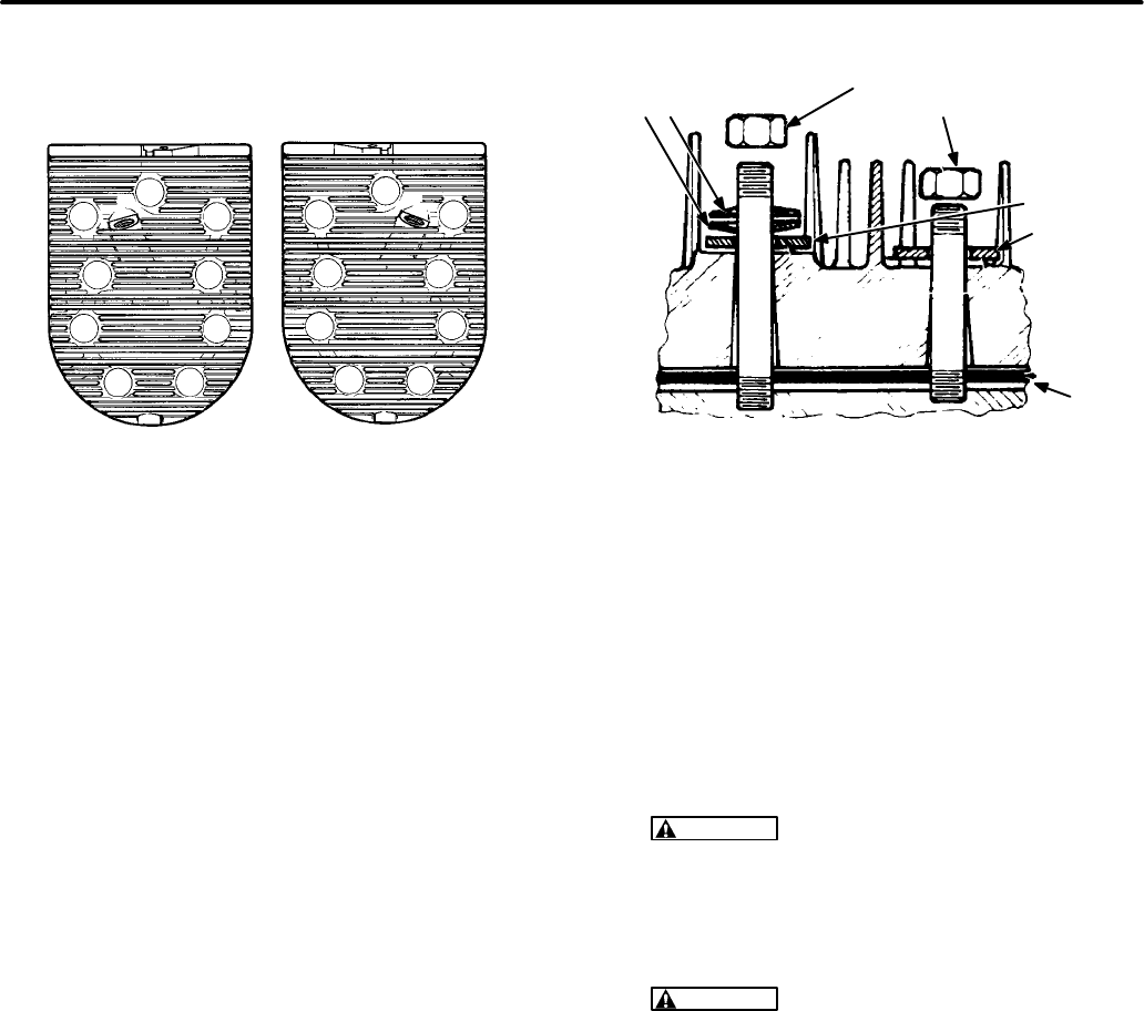
9-2
bolts or stud nuts are tightened to the specified
torque (see
Torque Specification
section).
FIGURE 9-2. BGM CYLINDER HEAD TIGHTENING
SEQUENCE
C1002s
12
3
4
56
7
89
12
34
56
89
7
LEFT* RIGHT*
* AS VIEWED FROM FRONT OF ENGINE
Assembly Procedure (NHM)
1. Use new head gaskets, and clean both the
heads and the cylinder block thoroughly where
the gaskets rest.
2. Place a head gasket on the cylinder head and
align the stud holes in the gasket with the stud
holes in the cylinder head. While holding the
gasket against the cylinder head, carefully
install the cylinder head on the engine. Do not
attempt to slide the gasket over the studs with-
out the cylinder head behind it or the gasket
may tear.
3. install a flat washer, two compression washers,
and nut on each of the top six studs (see Figure
9-3 for correct sequence). When properly
installed, only the outside edges of the com-
pression washers will be in contact with each
other. Install a flat washer and nut on each of
the four bottom studs.
FIGURE 9-3. NHM CYLINDER HEAD WITH
COMPRESSION WASHERS
M1918s
HEAT TREATED
NUTS
COMPRESSION
WASHERS
HEAD
HARDENED
WASHERS
HEAD
GASKET
BLOCK
6 LONG
STUDS/HEAD
4 SHORT
STUDS/HEAD
4. Follow the head torque tightening sequence
shown in Figure 9-4 for the NHM. Start by tight-
ening all bolts to 5 ft-lbs (7 N•m), then 10 ft-lbs
(14 N•m), etc., until all bolts or stud nuts are
tightened to the specified torque (see
Torque
Specification
section). Recheck all nuts for cor-
rect torque.
CAUTION
Too much torque will flatten the
compression washers and could result in
engine damage.
5. Recheck torque before engine has run a total of
50 hours.
CAUTION
Do not torque or remove heads
when they are hot. Warpage may occur. The
gasket surface must be below 100
°
F before
removal. At temperatures above 100
°
F, the
gasket will become gummy and difficult to
remove from the surface of the block and
cylinder head.
Redistribution or publication of this document,
by any means, is strictly prohibited.
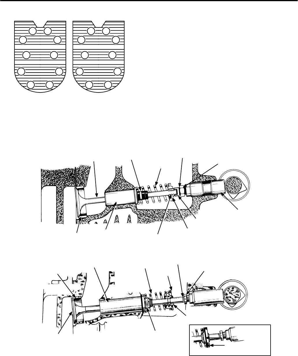
9-3
FIGURE 9-4. NHM CYLINDER HEAD
TIGHTENING SEQUENCE
1
2
34
56
78
910
12
34
56
78
910
LEFT* RIGHT*
M1871c
* AS VIEWED FROM FRONT OF ENGINE
FIGURE 9-5. VALVE SYSTEM
VT1005s
VT1034s
BGM VALVE
VALVE STEM
SEAL (INTAKE
ONLY)
SPRING
CLEARANCE ADJUSTING
SCREW
TAPPET
CAP
RETAINER
KEEPERS
GUIDE
VALVE SEAT
INSERT
NHM
VALVE SEAT
INSERT
GUIDE SPRING
RETAINER
CLEARANCE
ADJUSTING SCREW
SPRING
WASHER LOCK
VALVE STEM
SEAL (INTAKE
ONLY)
VALVE
VALVE ROTATOR
(EXHAUST ONLY)
(NOTE: ON LPG NHM, VALVE
ROTATORS ARE PRESENT ON
BOTH INTAKE AND EXHAUST)
Redistribution or publication of this document,
by any means, is strictly prohibited.
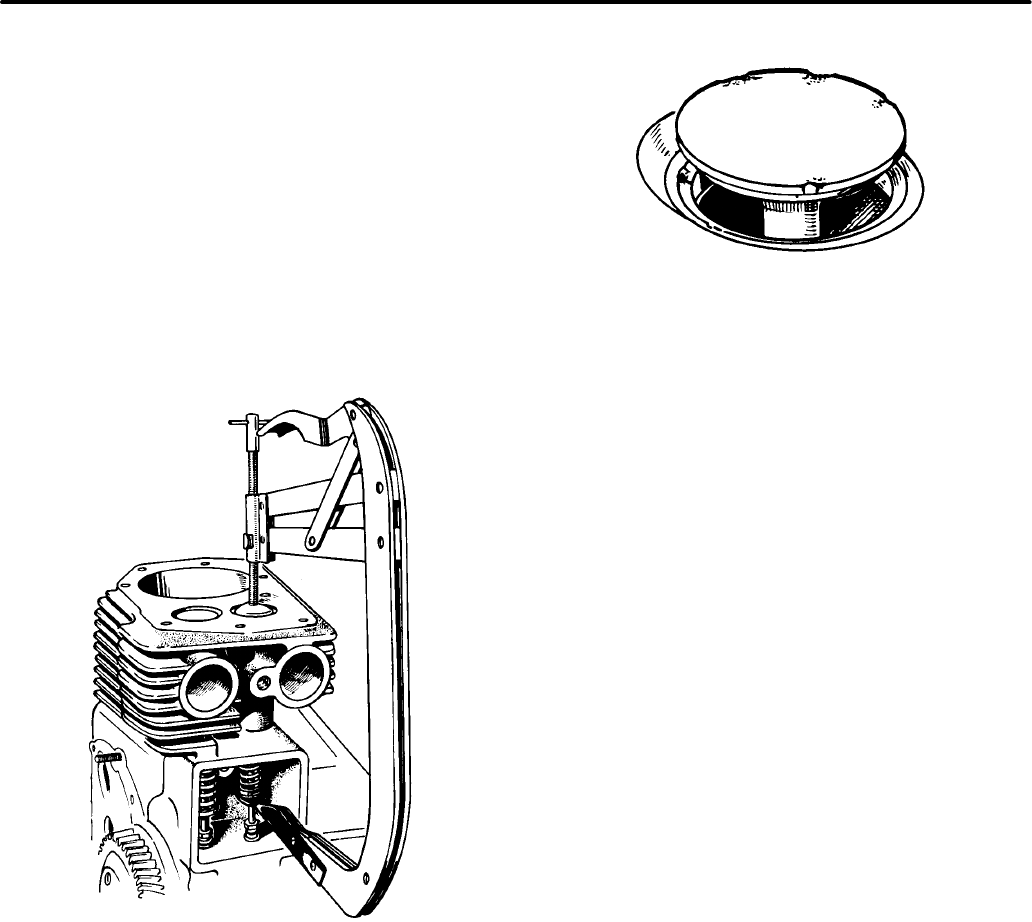
9-4
VALVE SYSTEM
A properly functioning valve system is essential for
the engine to perform well. Onan gensets use an L-
head valve design, as shown in Figure 9-5. The
valve system may be accessed by removing the cyl-
inder heads and valve covers on top of the engine. A
valve spring compressor must be used to remove
the valves (see Figure 9-6) from the cylinder block.
Use the procedures described below to inspect and
service the valve system.
FIGURE 9-6. VALVE SPRING COMPRESSOR
VT1018s
Valve Inspection Procedure
Valve Face:
Check the valve face for evidence of
burning, warping, out-of-round, and carbon depos-
its (see Figure 9-7).
FIGURE 9-7. VALVE FACE
VT1017s
Burning and pitting are caused by the valve failing to
seat tightly. This condition is often caused by hard
carbon particles on the seat. It may also be caused
by weak valve springs, insufficient tappet clear-
ance, valve warpage, and misalignment.
Warping occurs chiefly in the upper stem, because
it is exposed to intense heat. Out-of-round wear re-
sults from warping, when the seat is pounded by a
valve whose head is not in line with the stem and
guide. If a valve face is burned or warped, or the
stem is worn, install a new valve.
Excess clearance in the intake guide admits air and
oil into the combustion chamber, upsetting carbure-
tion, increasing oil consumption, and making heavy
carbon deposits. Carbon prevents heat dissipation.
Clean metal is a good heat conductor, but carbon in-
sulates and retains heat. This increases combus-
tion chamber temperatures, causing warping and
burning. Unburned carbon residue gums valve
stems, causing them to stick in the guide.
Valve Stem Seal:
A valve stem seal is used on the
intake valve guides. This seal must be replaced
each time the valve is removed.
Stems and Guides:
Check valve stems and guides
for wear, as shown in Figure 9-8. Use a hole gauge
to measure the valve guide. When valve clearance
with the stem exceeds the original clearance by
0.002 inch (0.05 mm), replace either the valve or
guide or both, as necessary. Regrind the seat if nec-
essary, to make it concentric with the newly installed
guide.
Redistribution or publication of this document,
by any means, is strictly prohibited.
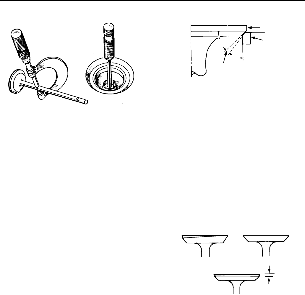
9-5
FIGURE 9-8. VALVE STEM AND
VALVE GUIDE INSPECTION
VT1020s
Springs:
Check the valve springs for cracks, worn
ends, distortion and tension. If the spring ends are
worn, check the valve spring retainer for wear.
Check for spring distortion by placing each spring
on a flat surface next to a square. Measure the
height of the spring and rotate it against the square
edge to measure its distortion. Check the spring
tension at the installed height in both the valve open
and closed positions, using a valve spring tester.
Replace any valve spring that is weak, cracked,
worn, or distorted.
Reconditioning Valves and Valve Seats
The interference angle method of valve seating is
used on all B and N series genset engines. This
method uses different seat and face angles, and
line contact is made between the valve face and
seat.
The valve face angle is 44 degrees. The valve seat
angle is 45 degrees. This 1-degree interference
angle results in a sharp seating surface between
the valve and the top of the valve seat (see Figure
9-9).
FIGURE 9-9. VALVE INTERFERENCE ANGLE
VT1021s
VALVE
SEAT
44°
1°INTERFERENCE
ANGLE
45°
RIGHT
The valves must not be hand lapped, because the
sharp contact between the valve and the seat will be
destroyed. This is especially important where
chrome cobalt faced valves and seats are used.
Valve faces must be finished to 44 degrees, in a ma-
chine.
Each valve must have a minimum of 1/32 inch (0.8
mm) margin (see Figure 9-10). If the valve has less
margin than this, it will heat up excessively. It will re-
tain this heat during the compression stroke, and
pre-ignite the mixture, causing loss of power and
economy. This valve is also susceptible to warping
and breakage.
0.30 INCH
MINIMUM (0.8 mm)
M1184s
WARPED VALVE WITH
KNIFE EDGE KNIFE EDGE
GOOD MARGIN
FIGURE 9-10. VALVE MARGIN
Not all valves can be reconditioned. A badly warped
valve must be replaced, because the amount of
grinding required to make it seat correctly removes
its margin. To make a valve gas-tight, remove all pit-
ting from the valve face and seat. Deeply pitted or
Redistribution or publication of this document,
by any means, is strictly prohibited.
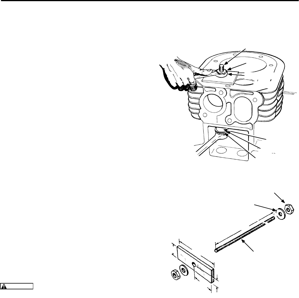
9-6
cut valves must be replaced, because grinding re-
moves the margin.
Grind valve seats with a 45-degree stone. The width
of the seat band should be 1/32 inch to 3/64 inch
(0.79 to 1.2 mm) wide. Grind only enough to be sure
of proper valve seating.
Place each valve in its proper location. Check each
valve for a tight seat. Make several marks at regular
intervals across the valve face using machinist’s
bluing. Observe if the marks rub off uniformly when
the valve is rotated part of a turn against the seat.
The valve seat should contact the valve face evenly
at all points. The line of contact should be at the cen-
ter of the valve face.
Valve Guides
Worn valve stem guides can be replaced from in-
side the valve chamber. The smaller diameter of the
tapered valve guides must face toward the valve
head.
Tappets are also replaceable from the valve cham-
ber, after the valve assemblies are removed first.
Valve Guide Removal Procedure
1. Before removing the valve guides, use an elec-
tric drill with a wire brush to remove carbon and
other foreign material from the top surface of
the guides. Failure to do this may result in dam-
age to the guide bores.
2. Drive the guides out with a hammer and a valve
guide driver. Wear goggles while performing
this procedure.
CAUTION
Driving out the old valve guides can
damage the tappet bores. Be careful not to
strike the bores with the driver.
Valve Guide Installation Procedure
1. Run a small polishing rod with crocus cloth
through the valve guide holes, to clean out car-
bon and other foreign materials.
2. Coat the outer edge of each new guide with oil.
3. Place the guide, notch up, in the cylinder block,
and press it in until the shoulder of the guide
rests against the cylinder block.
A suggested method of installation is shown in Fig-
ure 9-11.
FIGURE 9-11. VALVE GUIDE INSTALLATION
VT1023s
NUT
WASHER
PLATE
VALVE
GUIDE
WASHER
NUT
ROD
VT1023
(178 mm)
7 IN.
(121 mm)
4−3/4 IN.
(32 mm)
1−1/4 IN.
(60 mm)
5/8 IN. (16 mm)
2−3/8"
5/16−18 THREADED
ROD
5/16 IN. FLAT WASHER
(2 REQUIRED)
5/16−18 HEX. NUT (2 REQUIRED)
Valve Seats
Inspect the valve seat inserts. If the seats are loose,
cracked, or severely pitted, new (oversize) inserts
must be installed. Remove valve seat inserts using
a valve seat removal tool.
Redistribution or publication of this document,
by any means, is strictly prohibited.
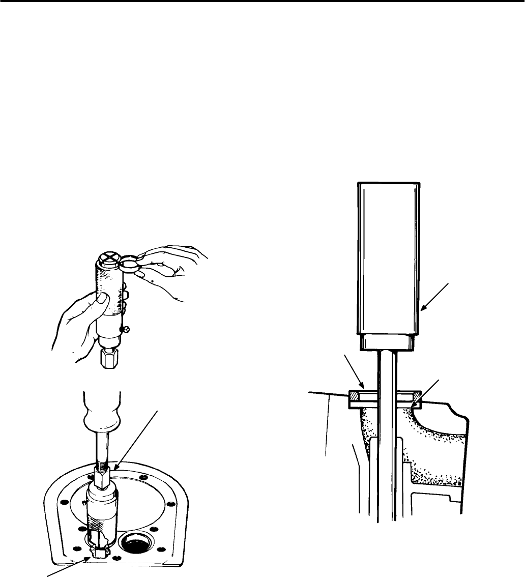
9-7
Valve Seat Removal Procedure
1. Remove carbon and combustion deposits from
the valve seat.
2. Select the proper size puller (determined by the
inside diameter of the valve seat). The puller
jaws must expand into the cylinder block at the
point where the bottom of the valve seat insert
rests on the cylinder block (Figure 9-12).
3. Using the new seat insert as a guide, adjust the
puller depth. Position the puller on the valve
seat and tighten its hex nut. Clamp the cylinder
block to a solid bench. Attach a slide hammer to
the puller. Between blows with the slide ham-
mer, tighten the hex nut.
FIGURE 9-12. VALVE SEAT REMOVAL
VT1056c
HEX NUT
PULLER JAWS
Valve Seat Installation Procedure
1. After the old seat has been removed, clean out
carbon and metal burrs from the seat insert re-
cess. Use a valve seat insert driver and a ham-
mer to install the insert.
2. Insert the pilot of the driver into the valve guide
hole in the cylinder block. Quickly drive the
valve seat insert in, so that the insert goes
evenly to the bottom of the recess in the cylin-
der block. Make certain that the valve seat in-
sert rests solidly on the bottom of the recess all
the way around its circumference (Figure
9-13).
FIGURE 9-13. INSERTING NEW VALVE SEAT
VT1025s
VALVE SEAT
INSERT DRIVER
(USE PROPER
TOOL)
CHECK THIS
SURFACE FOR
BURRS BEFORE
INSERTING SEAT
VALVE SEAT
3. Insert a valve seat staker into the cylinder block
valve guide hole. Rotate the staking tool until it
drops to the original stake marks. Rotate the
staking tool another 60° (1/6 turn). Using a lead
hammer, strike the staking tool a sharp blow to
wedge the new valve seat securely in place.
The valve seat must be staked to ensure a tight
fit and eliminate the danger of its loosening in
Redistribution or publication of this document,
by any means, is strictly prohibited.

9-8
the bore. Before installing the valves, refinish
the valve seat inserts.
Valve Tappets
The engine is equipped with adjustable valve tap-
pets. Adjust the valve clearance only when the en-
gine is at ambient temperature.
Tappet Adjustment Procedure
1. Remove all parts that block access to the valve
tappets.
2. Remove the spark plugs, to make turning the
engine easier.
3. Place a socket wrench on the flywheel caps-
crew, and rotate the crankshaft in a clockwise
direction until the left intake valve (viewed from
flywheel end) opens and closes. Continue turn-
ing the crankshaft until the TDC mark on the fly-
wheel is lined up with the TDC mark on the gear
cover. This should place the left piston (#1) at
the top of its compression stroke. Verify that the
left intake and exhaust valves are closed and
that there is no pressure on the valve lifters.
4. Clearances are listed in the Dimensions and
Clearances section. For each valve, the gauge
should just pass between the valve stem and
valve tappet (see Figure 9-14).
FIGURE 9-14. VALVE CLEARANCE
ADJUSTMENT
VT1026s
5. To correct the valve clearance, turn the adjust-
ing screw as needed. The screw is self-locking.
6. To adjust the valves on the right cylinder, turn
the engine one complete revolution, and line up
the mark on the flywheel and the TDC mark on
the gear cover again. Then follow the adjust-
ment procedure given for the left cylinder.
7. Replace all parts removed. Use new gaskets
on valve covers. Tighten all screws securely.
Torque manifold bolts.
Redistribution or publication of this document,
by any means, is strictly prohibited.
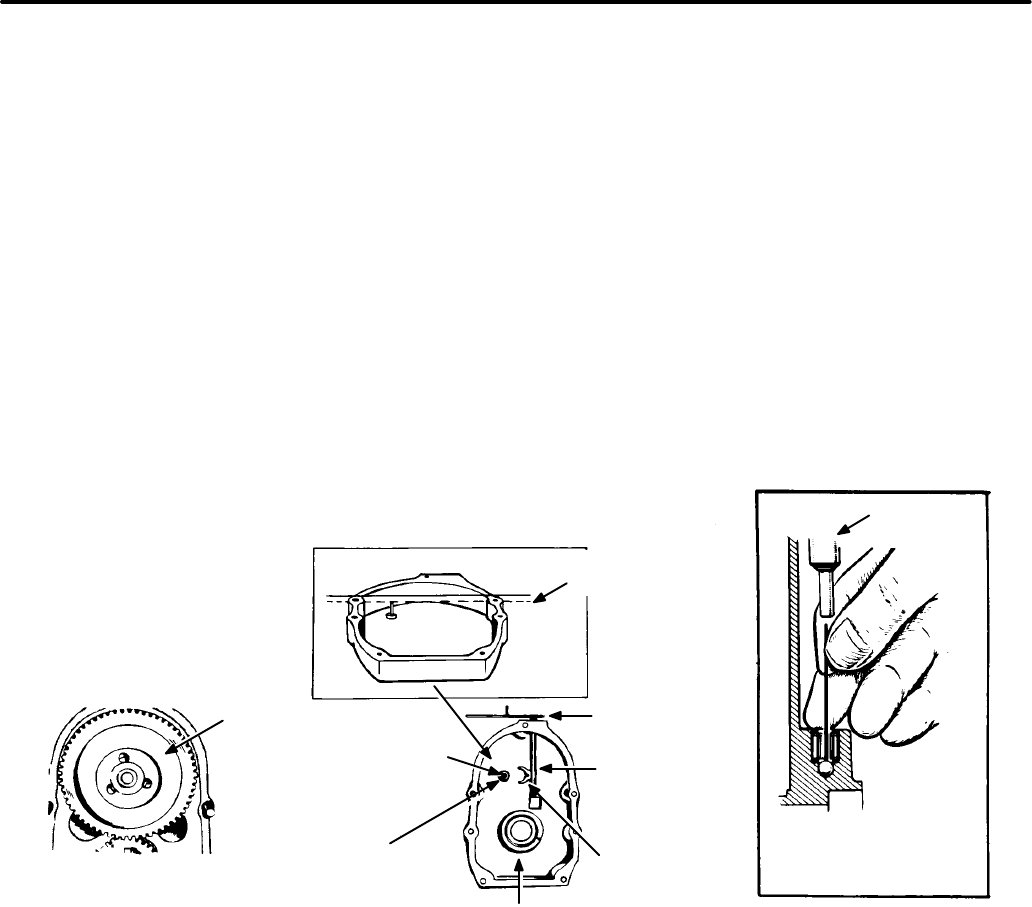
9-9
GEAR COVER
Gear Cover Removal Procedure
1. Remove the flywheel key and gear cover
mounting screws.
2. Gently tap the gear cover with a plastic-faced
hammer to loosen it (see Figure 9-15).
Gear Cover Installation Procedure
(Mechanical governor gensets)
NOTE: Electronic governor gensets have no gover-
nor arm, shaft, etc. to consider when performing this
step.
1. Use new gaskets and apply thread sealant to
the bolts when installing the gear cover. Make
sure that the pin in the gear cover engages the
nylon-lined (smooth) hole in the governor cup.
See Figure 9-15.
2. Turn the governor cup so the nylon-lined hole is
at the three o’clock position. Use a small
amount of grease to help hold the cup in posi-
tion. The rounded side of the governor yoke
must ride against the governor cup.
3. Turn the governor arm and shaft clockwise as
far as possible, and hold in this position until the
gear cover is installed flush against the crank-
case. Be careful not to damage the gear cover
oil seal.
Refer to the Oil Seals section if replacing the gear
cover oil seal.
FIGURE 9-15. GEAR COVER ASSEMBLY
VT1027s
3/4 IN.
(19.0 mm)
GOVERNOR
CUP
ROLL PIN
ROTATE GOVERNOR
CUP SO THAT ROLL
PIN FITS INTO THE
METAL LINED HOLE
OR PLASTIC BUSHING
IN THE CUP
GOVERNOR
SHAFT YOKE
(SMOOTH SIDE
TOWARD CUP)
GOVERNOR
SHAFT
GOVERNOR
ARM
OIL SEAL
GOVERNOR
SHAFT
IF FEELER WILL ENTER
HOLE 1/2 IN. (13 mm)
BALL HAS FALLEN OUT
Redistribution or publication of this document,
by any means, is strictly prohibited.
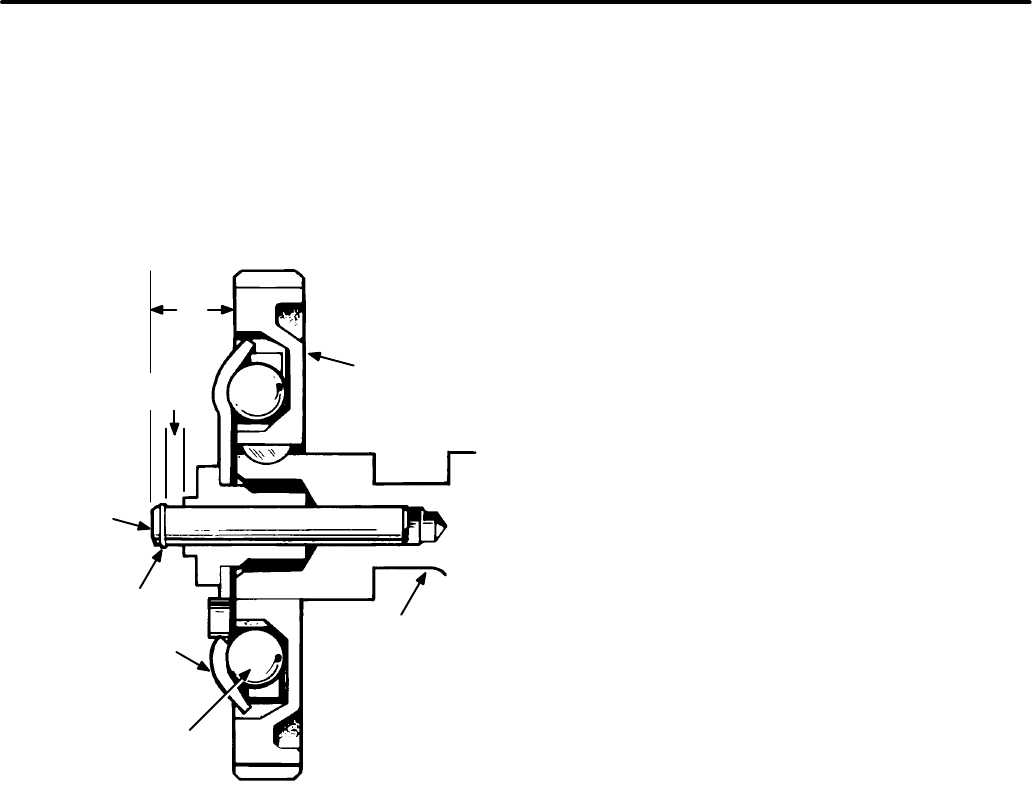
9-10
GOVERNOR CUP (MECHANICAL)
Governor Cup Removal Procedure
1. Remove the gear cover, as described above.
2. Remove the snap ring from the camshaft cen-
ter pin (see Figure 9-16).
3/4 IN.
(19.05
mm)
FIGURE 9-16. GOVERNOR CUP
VT1028s
CAMSHAFT
GEAR
CAMSHAFT
GOVERNOR
FLYBALL
SNAP RING
CENTER
PIN
WHEN GOVERNOR IS PROPERLY
ASSEMBLED, DIMENSIONS SHOWN ON
THIS DRAWING WILL BE AS INDICATED
GOVERNOR
CUP
7/32 IN.
(5.55 mm)
3. Slide the governor cup off, making certain to
catch the flyballs. Replace any flyball that is
grooved or has a flat spot.
4. Examine the ball spacer. If the arms of the ball
spacer are worn or otherwise damaged, re-
move the spacer by splitting it with a chisel. Use
a press to install a new spacer on the camshaft
gear.
5. The governor cup must spin freely on the cam-
shaft center pin without excessive looseness or
wobble. If the race surface of the cup is
grooved or rough, replace it with a new one.
Governor Cup Installation Procedure
The governor cup and flyballs are easily installed
when the camshaft assembly is removed from the
engine. If necessary, the engine may be tilted up to
install the cup and flyballs.
1. Put the flyballs between the spacer arms and
install the cup on the center pin.
2. Lock the cup in place with the snap ring.
Camshaft Center Pin Installation Procedure
1. The camshaft center pin extends 3/4 inch (19
mm) from the end of the camshaft. This dis-
tance provides 7/32 inch (5.6 mm) travel for the
governor cup, as illustrated in Figure 9-16.
Measure this distance while holding the cup
against the flyballs. If the distance is less, the
engine may race, especially at no load.
2. Remove the center pin and press in a new pin
the specified amount. Do not hammer the new
pin into place, or it will be damaged. The cam-
shaft center pin cannot be pulled outward or re-
moved without damage. If the center pin ex-
tends too far, the cup will not hold the flyballs
properly.
TIMING GEARS AND CAMSHAFT
If either the crankshaft gear or the camshaft gear
needs replacement, both gears should be replaced.
Timing Gear Removal Procedure
1. Remove the snap ring and retainer washer.
2. Attach the gear pulling ring using two 10-32
screws (Figure 9-17). Tighten the screws alter-
nately, until both are tight.
Redistribution or publication of this document,
by any means, is strictly prohibited.
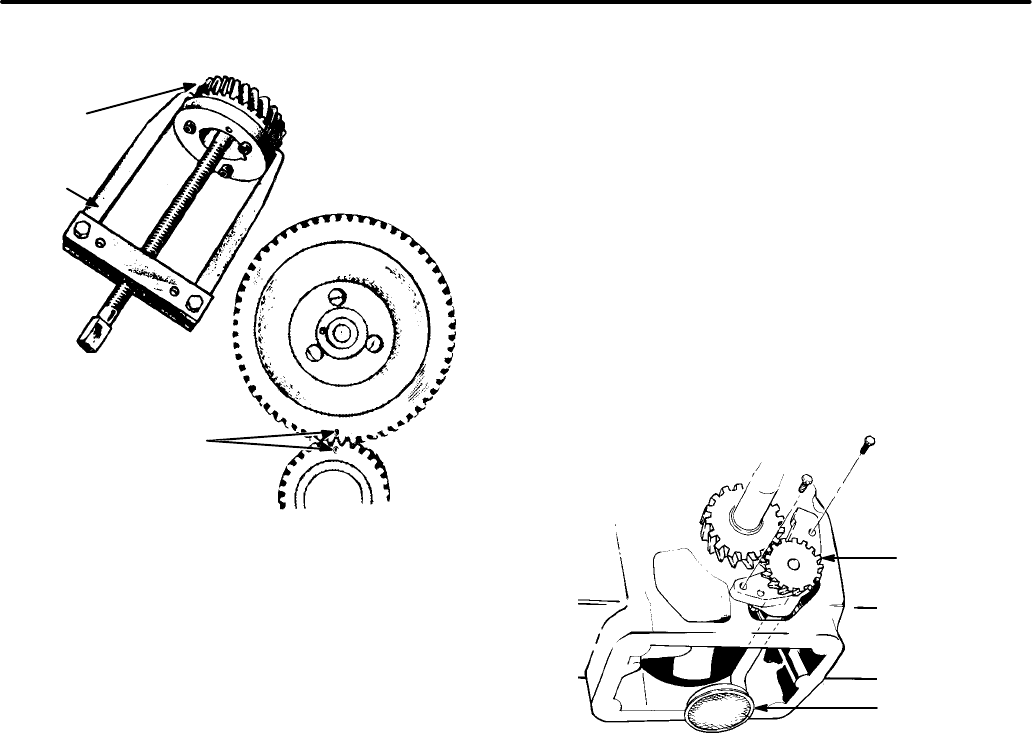
9-11
FIGURE 9-17. TIMING GEAR REMOVAL AND
INSTALLATION
VT1029s
CRANKSHAFT
GEAR
GEAR
PULLER
GEAR PULLER
RING
THESE MARKS
MUST ALIGN
WHEN
INSTALLING
TIMING GEARS
3. Attach a gear puller to the puller ring and re-
move the crankshaft gear.
The camshaft and gear are removed as an assem-
bly.
4. Before removing the camshaft and gear as-
sembly, remove the cylinder head and valve
assemblies, then remove the actuating plunger
for the breaker points and tappets.
Timing Gear Installation
Each timing gear is stamped with ”O” near its edge.
The gear teeth must mesh so that these marks ex-
actly coincide when the gears are installed in the
engine. When installing the camshaft gear and
shaft assembly, be sure that the thrust washer is
properly in place behind the camshaft gear. Then
install the crankshaft retaining washer and lock ring.
LUBRICATION SYSTEM
All genset engines use an oil pump to provide a
constant flow of oil to the engine parts. The oil sup-
ply collects in the oil base, where it is picked up by
the oil pump pickup cup. A bypass valve controls oil
pressure. Drain the oil before removing the oil base,
and always use a new gasket when replacing the oil
base.
Oil Pump
The oil pump (Figure 9-18) is mounted on the front
of the crankcase behind the gear cover. It is driven
by the crankshaft gear. The inlet pipe and screen
assembly is attached to the pump body. A discharge
passage in the pump cover is aligned with a pas-
sage drilled in the crankcase. Other passages dis-
tribute oil to the front main bearing, rear main bear-
ing and pressure control bypass valve.
FIGURE 9-18. OIL PUMP ASSEMBLY
OIL PUMP
ASSEMBLY
OIL PUMP
PICKUP
CUP
Circumferential grooves in the main bearings sup-
ply oil to the connecting rod bearings through pas-
sages from each main journal. A passage connects
the front main bearing oil supply to the front cam-
shaft bearing. The oil overflow from the bypass
valve lubricates the camshaft drive gears.
Normal oil pressure should be no less than 13.5 psi
(93 kPa) for the BGM, or 21 psi (144.8 kPa) for the
NHM, when the engine is at normal operating tem-
perature. If pressure drops below this value at gov-
erned speed, inspect the oil system for faulty com-
ponents.
Check the oil pump thoroughly for worn parts. Oil
the pump to prime it before reinstalling it. Except for
the gaskets and pick-up cup, the component parts
of the pump are not individually available. Install a
new pump assembly if any parts are worn.
Redistribution or publication of this document,
by any means, is strictly prohibited.
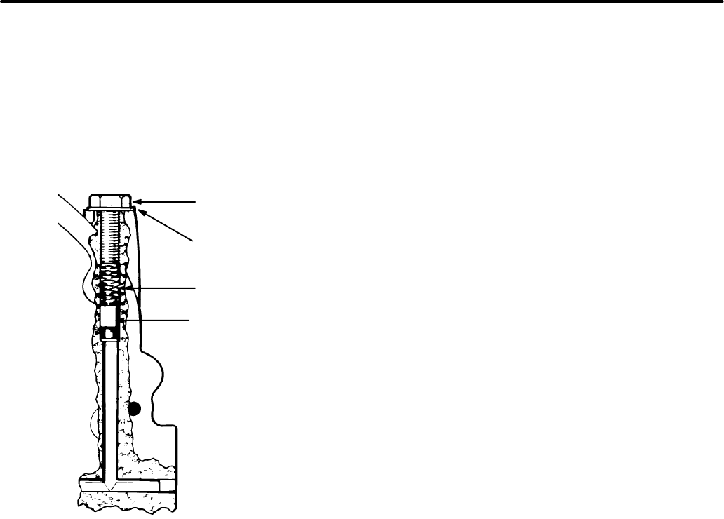
9-12
Oil Bypass Valve
The bypass valve (located to the right and behind
the gear cover, Figure 9-19), controls oil pressure
by allowing excess oil to flow directly back to the
crankcase. Normally the valve begins to open at
roughly 13-14 psi on BGM gensets, or 19-21 psi on
NHM gensets.
HEX. CAP
SCREW
FLAT
WASHER
SPRING
FIGURE 9-19. OIL BYPASS VALVE
VALVE
Oil Bypass Valve Test
The bypass valve is non-adjustable, and normally
needs no maintenance. To determine if abnormal
(high or low) oil pressure is caused by improper
valve operation, inspect as follows:
1. Remove the 3/8-24 x 7/8 in. (BGM) or 3/8-24 x
1 in. (NHM) capscrew behind the gear cover
and under the governor arm.
2. Remove the spring and plunger with a magnet-
ic tool.
3. Determine the proper valve operation by
checking the spring and plunger against the
measurements listed below:
Plunger Diameter....................0.3105 to 0.3125 in.
(7.89 to 7.94 mm)
Spring
Free Length.........................1.00 in. (25.4 mm)
Load............................2.6+0.2 lbs (11.6+0.9N)
when compressed to 0.500 in. (12.7 mm)
4. Check the valve seat, and clean away any ac-
cumulation of metal particles which could
cause erratic valve action. Verify that the valve
seat is concentric with the larger diameter
valve bore.
5. Clean the plunger and spring in parts cleaning
solvent, and reinstall.
Redistribution or publication of this document,
by any means, is strictly prohibited.
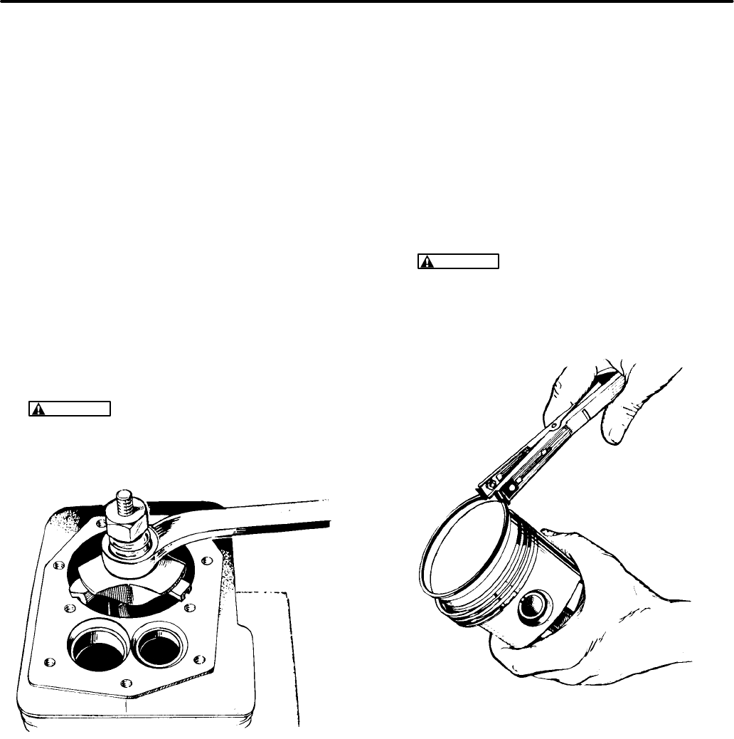
9-13
PISTON ASSEMBLY
The piston assembly consists of:
•Piston
•Piston rings
•Piston pin
•Connecting rod assembly and bearing
After removal from the engine, all parts must be
carefully inspected for damage and wear before
they are replaced.
Piston Removal and Disassembly Procedure
1. Remove carbon from the top of cylinder bore,
and check for a ridge. Remove this ridge (see
Figure 9-20) with a ridge reamer before at-
tempting piston removal.
CAUTION
Improper use of a ridge reamer
can damage the cylinder bore. Use this tool
with extreme care.
FIGURE 9-20. REMOVING WEAR RIDGE
CT1058s
2. Turn the crankshaft until a piston is at the bot-
tom of its stroke. Remove the nuts from the
connecting rod bolts.
3. Lift the rod bearing cap from the rod, and push
the rod and piston assembly out the top of the
cylinder with the handle end of a hammer. Be
careful not to scratch the crankpin or the cylin-
der wall when removing these parts.
4. Mark each piston and rod assembly so they
can be returned to their respective cylinders af-
ter overhaul. Keep the connecting rod bearing
caps with their respective rods.
5. The pistons are fitted with two compression
rings and one oil control ring. Remove these
rings from the piston using a piston ring spread-
er, as shown in Figure 9-21.
WARNING
Piston rings can fly off the
spreader, causing severe eye injury. Wear
eye protection while performing piston ring
removal procedure.
FIGURE 9-21. REMOVING PISTON RINGS
CT1059s
6. Mark each piston’s orientation to make sure the
rod is assembled on the piston from which it
was removed. Remove the piston pin retainer
from each side, and push the pin out.
7. Remove dirt and deposits from the piston sur-
faces with an approved cleaning solvent. Clean
the piston ring grooves with a groove cleaner,
or with the end of a piston ring filed to a sharp
Redistribution or publication of this document,
by any means, is strictly prohibited.
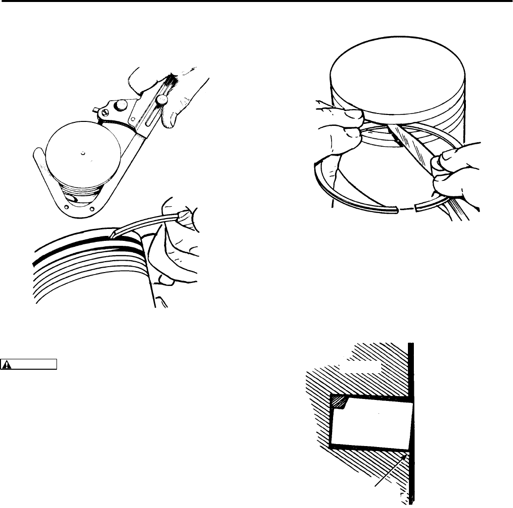
9-14
point (Figure 9-22). Take care not to remove
metal from the groove sides.
FIGURE 9-22. CLEANING RING GROOVES
CT1060s
CAUTION
Using a caustic cleaning solvent or
wire brush for cleaning pistons will cause pis-
ton damage. Use only parts cleaning solvent for
this job. Make certain to follow the solvent
manufacturer’s instructions.
When cleaning the connecting rods in solvent,
make certain to include the rod bore.
Piston and Connecting Rod Inspection Procedure
Piston Inspection:
Inspect the pistons for frac-
tures at the ring lands, skirts and pin bosses. Check
for wear at the ring lands, using a new ring and feel-
er gauge, as shown in Figure 9-23. Replace the pis-
ton if the side clearance of the top compression ring
is as much as 0.008 inch (0.20 mm).
FIGURE 9-23. CHECKING RING LAND
CT1061s
Improper ring width or excessive ring side clear-
ance can result in ring breakage. New rings in worn
ring grooves do not make adequate contact with the
cylinder wall (Figure 9-24).
FIGURE 9-24. NEW RING IN
WORN RING GROOVE
CT1062s
PISTON
PISTON
RING
IMPROPER
RING
CONTACT
CYLINDER
WALL
Redistribution or publication of this document,
by any means, is strictly prohibited.

9-15
FIGURE 9-25. PISTON CLEARANCE
MEASUREMENT
CT1063s
MEASURE "X"
DIAMETER HERE
Replace pistons showing signs of scuffing, scoring,
worn ring lands, fractures or damage from pre-igni-
tion.
Connecting Rod Inspection:
Replace connecting
rod bolts and nuts with damaged threads. Replace
connecting rods with deep nicks, signs of fractures,
scored bores or bores out of round more than 0.002
inch (0.05 mm).
Use a new piston pin to check the connecting rod for
wear. A push-fit clearance is required; this varies
from engine to engine. If a new piston pin falls
through a dry rod pin bore as a result of its own
weight, replace the rod or bushing, as required.
Piston Pin Inspection:
Replace piston pins that
are cracked, scored, or out of round more than
0.002 inch (0.05 mm).
Bearing Inspection:
Inspect bearings for burrs,
breaks, pitting and wear. Replace bearing inserts
which are scored, have their overlay wiped out,
show fatigue failure, or are badly scratched. If the
bearings appear to be serviceable, check them for
proper clearance.
Piston Clearance
Correct piston tolerances must be maintained. Use
a micrometer to measure the piston diameter at the
point shown in Figure 9-25. When the cylinder bore
is measured (see Cylinder Block section), subtract
the piston diameter from the cylinder bore diameter
to obtain the piston-to-cylinder wall clearance. Re-
fer to the Dimensions and Clearances section for
the recommended piston clearance.
Fitting Piston Rings
Before installing new rings on the piston, check the
ring gap by placing each ring squarely in its cylinder,
at a position corresponding to the bottom of its trav-
el (Figure 9-26). The gap between the ends of the
ring is given in the
Dimensions and Clearances
sec-
tion of this manual.
FIGURE 9-26. CHECKING RING GAP
CT1064s
PISTON RING IN
CYLINDER
BORE
FEELER
GAUGE
Do not file the ring ends to increase the end gap. If
the ring end gap does not meet the specifications,
check the correctness of ring and bore sizes. A cyl-
inder bore that is 0.001 inch (0.03 mm) undersize
will reduce the end gap 0.003 (0.08 m).
Rings that are 0.010, 0.020, 0.030 and 0.040 inch
(0.25, 0.51, 0.76 and 1.02 mm) oversize should be
used on corresponding oversize pistons. Tapered
piston rings are usually marked TOP on one side, or
identified in some other manner. Install these rings
with the identification mark toward the closed end of
the piston.
Piston Assembly Procedure
1. Lubricate all parts with clean engine oil.
Redistribution or publication of this document,
by any means, is strictly prohibited.
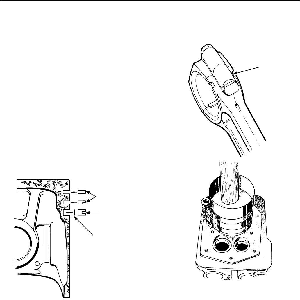
9-16
2. Position the piston on the connecting rod.
Install the piston pin. The piston pin is a full-
floating type, and must be kept in place (in the
piston) with two lock rings, one at each side.
Install the lock rings and ensure they are prop-
erly in place before installing the piston and
connecting rod in the engine.
3. Install the rings on the piston beginning with the
oil control ring (Figure 9-27). Use a piston ring
spreader to prevent twisting or excessive ex-
pansion of the ring. Compression rings are
marked with a dot or the word ”top” on one side
of the ring to indicate which side faces the top of
the piston. Unmarked piston rings can be
installed either way. The oil control ring has an
expander. Install the expander first, then close
until the expander ends butt together. Locate
the expander gap 180 degrees from the ring
gap. Make certain that the piston ring gaps are
not aligned with one another.
FIGURE 9-27. PISTON RINGS
CT1047s
COMPRESSION
RINGS
OIL
RING
EXPANDER
Piston Installation Procedure
1. Turn the crankshaft to position the #1 rod bear-
ing journal at the bottom of its stroke.
2. Lubricate the #1 piston assembly and the in-
side of the cylinder. Compress the rings with a
ring compressor as shown in Figure 9-28.
Install the bearing insert in rod.
FIGURE 9-28. INSTALLING PISTON
AND CONNECTING ROD
CT1048s
CT1066s
NOTCH
TOWARD
CAMSHAFT
3. Position the piston and rod assembly in the cyl-
inder block with the connecting rod oil hole to-
ward the camshaft.
4. Tap the piston down into the bore with the han-
dle end of the hammer until the connecting rod
is seated on the journal. Check the bearing
clearance before proceeding to step 5 (see
Rod Bearing Clearance section).
Redistribution or publication of this document,
by any means, is strictly prohibited.
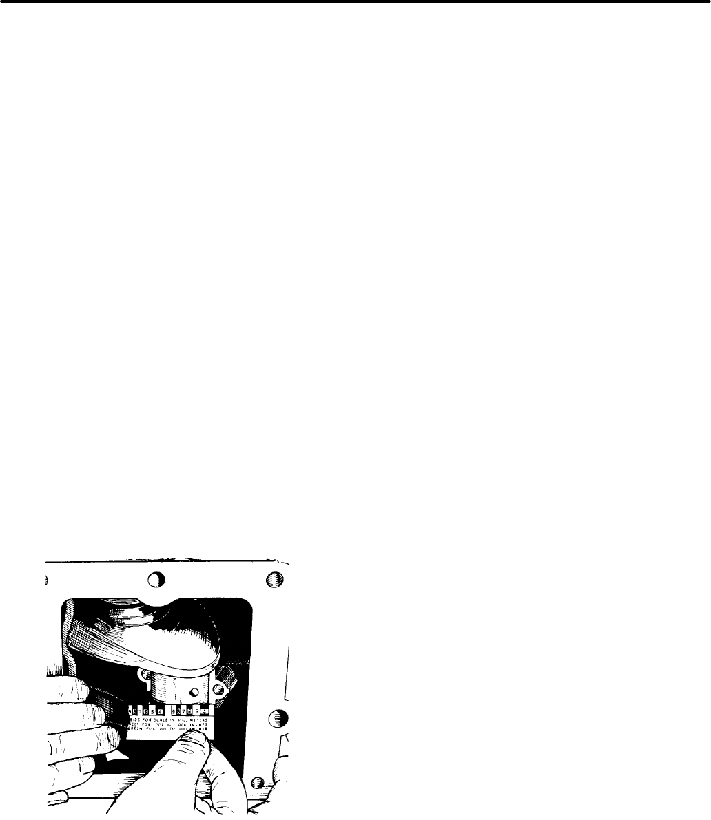
9-17
5. Install the bearing cap on the rod. Install one
fastener and tighten to 5 ft-lbs (7 N•m). Repeat
this for the other fastener. Tighten both fasten-
ers to 14 ft-lbs (19 N•m).
6. Install the remaining piston and rod in the same
way. Crank the engine by hand, to see that all
bearings are free.
Rod Bearing Clearance Procedure
1. Mark all parts so they can be installed in their
original positions, and wipe all parts clean of oil
and grease.
2. Place a piece of the correct size Plasti-gage
across the full width of the bearing cap, about
1/4 inch (6 mm) off-center.
3. Install the bearing cap, and tighten to the speci-
fied torque. Do not rotate the crankshaft after
the cap is in place.
4. Remove the bearing cap and leave the flat-
tened Plasti-gage on the part to which it ad-
heres. Compare the widest point of the flat-
tened Plasti-gage with the graduations on the
envelope (see Figure 9-29) to determine the
bearing clearance.
FIGURE 9-29. MEASURING BEARING
CLEARANCE
CT1067s
CRANKSHAFT
Crankshaft Removal Procedure
1. Loosen the rear bearing plate screws and re-
move the bearing plate, gasket, thrust washer,
and shims.
2. Turn the crankshaft so the crankthrow is
aligned with the notch in the rear opening of the
crankcase.
3. Carefully slide the crankshaft out of the crank-
case.
Crankshaft Inspection
Inspect the rod and main bearing journals. If they
are worn or scored, and cannot be smoothed by pol-
ishing, either the journals should be reground to fit
one of the standard undersize bearings, or the
crankshaft should be replaced. Remove only
enough metal to restore the journal surface while
maintaining the correct bearing clearance.
When making major repairs on the engine, always
inspect the drilled passages of the crankshaft.
Clean them to remove any foreign material and to
ensure lubrication of the connecting rods.
Crankshaft Installation Procedure
1. Lubricate the front and rear main bearings with
engine oil.
2. Use oil or gear lubricant to hold the front thrust
washer in place against the engine block. The
flat side of the thrust washer goes against the
block.
3. Position the crankshaft so that the crank throw
is aligned with the notch at the rear of the crank-
case, and install the crankshaft. Make sure the
front thrust washer did not slip out of place dur-
ing installation.
4. Place the oil seal loader on the oil seal guide
and driver, and insert into the rear bearing
plate. Remove the seal guide and driver leav-
ing the loader in the bearing plate. The loader
prevents the seal from being cut on the crank-
shaft keyway during installation of the rear
bearing plate.
5. Use oil or gear lubricant to hold the shim(s) and
rear thrust washer in position on the rear bear-
ing plate (see Figure 9-34). The shim goes
Redistribution or publication of this document,
by any means, is strictly prohibited.
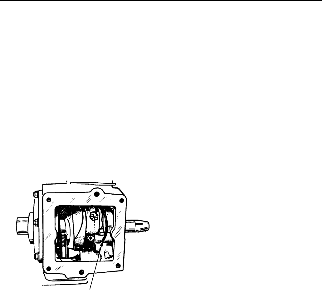
9-18
against the bearing plate, and the flat surface of
the thrust washer goes against the shim.
6. Place the new bearing plate gasket in position
on the block, making sure the oil hole on the
back of the block is exposed.
7. Install the rear bearing plate and fasten with
two nuts (or capscrews) tightened to the speci-
fied torque. Make sure the rear thrust washer
and shim(s) did not slip out of place during
installation. The crankshaft should turn freely
by hand.
Endplay Checking Procedure
After tightening two rear bearing plate nuts (or caps-
crews) to the specified torque, check the crankshaft
endplay at the point shown in Figure 9-30, using a
feeler gauge.
FIGURE 9-30. CHECKING ENDPLAY
CT1068s
MEASURE ENDPLAY HERE
(REFER TO DIMENSIONS
AND CLEARANCES)
FRONT
REAR
1. Lightly tap the front of the crankshaft with a
plastic-faced hammer to take up the freeplay.
Refer to the Dimensions and Clearances sec-
tion for the recommended crankshaft endplay.
2. If necessary, remove the rear bearing end plate
and add or remove shims as required.
3. Install the end plate, and tighten all nuts (or
capscrews) to the specified torque.
4. Make sure the shim and thrust washer are in
place, and recheck crankshaft endplay. Verify
that the crankshaft turns freely without binding.
CYLINDER BLOCK
The cylinder block is the main support for all other
primary engine parts. The crankshaft and camshaft
are supported by the cylinder block, assuring align-
ment of the crankshaft and cylinder bores.
Cylinder Block Cleaning
After removing the pistons, crankshaft, cylinder
heads, etc., inspect the block for cracks and ex-
treme wear. If it is still serviceable, prepare it for
cleaning as follows:
1. Carefully scrape all old gasket material from
the block. Remove oil bypass to allow cleaning
solution to contact inside of oil passages.
2. Remove grease and scale from the cylinder
block by agitating in a bath of commercial
cleaning solution or hot soapy washing solu-
tion.
3. Rinse the block in clean hot water to remove
cleaning solution.
Cylinder Block Inspection
When rebuilding the engine, thoroughly inspect the
block for any condition that would make it unfit for
further use. This inspection must be made after all
parts have been removed, and the block has been
thoroughly cleaned and dried.
1. Make a thorough check for cracks. Minute
cracks may be detected by coating the sus-
pected area with a mixture of 25 percent kero-
sene and 75 percent light motor oil. Wipe the
part dry and immediately apply a coating of zinc
oxide (white lead) dissolved in wood alcohol. If
cracks are present, the white coating will be-
come discolored at the defective area. (Re-
move this coating after the test, and before
reassembly.) Always replace a cracked cylin-
der block.
2. Inspect all machined surfaces and threaded
holes. Carefully remove any nicks or burrs from
machined surfaces. Clean out tapped holes
and clean up any damaged threads.
3. Check the top of the block for flatness with a
straight-edge and a feeler gauge.
Redistribution or publication of this document,
by any means, is strictly prohibited.
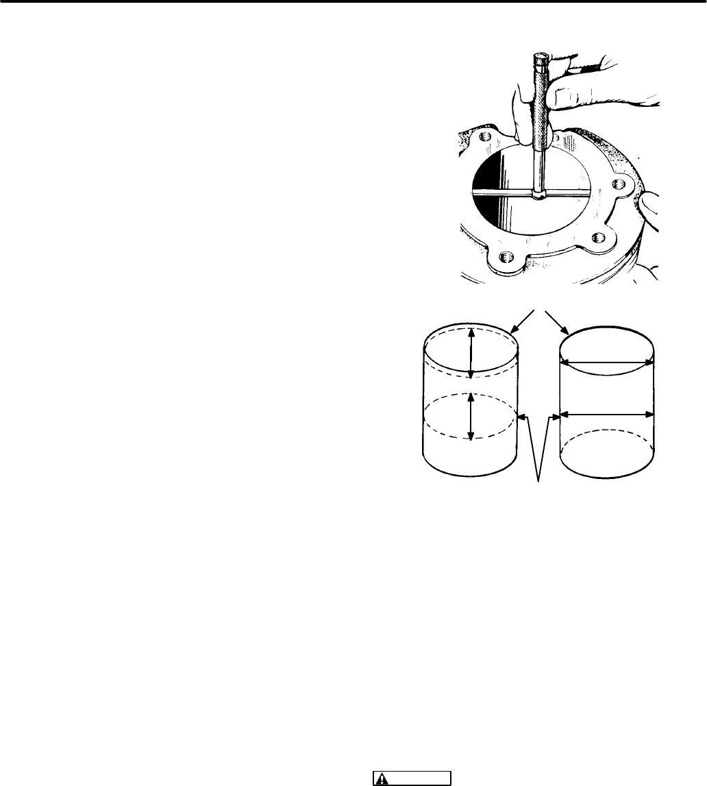
9-19
Cylinder Bore Inspection:
Inspect the cylinder
bores for scuffing, scratches, wear, and scoring. If
these conditions exist, they must be rebored and
honed for the next oversize piston.
When the appearance of cylinder bores is accept-
able and there are no scuff marks, check the bores
for wear or out-of-roundness as follows:
1. Check cylinder bore for taper, out-of-round,
and wear with a cylinder bore gauge, telescope
gauge, or inside micrometer. These measure-
ments should be taken at four places: the top
and bottom of piston ring travel, and parallel
and perpendicular to the axis of the crankshaft.
2. Record the measurements taken at the top and
bottom of the piston travel as follows (see Fig-
ure 9-31).
A. Measure and record as “A” the cylinder
bore diameter (parallel to crankshaft) near
the top of cylinder bore where the greatest
amount of wear occurs.
B. Measure and record as “B” the cylinder
bore diameter (parallel to crankshaft) at
the bottom of piston travel.
C. Measure and record as “C” the cylinder
bore diameter (perpendicular to crank-
shaft) near the top of cylinder bore where
the greatest amount of wear occurs.
D. Measure and record as “D” the cylinder
bore diameter (perpendicular to crank-
shaft) at the bottom of piston travel.
E. Reading “A” subtracted from reading “B”
and reading “C” subtracted from reading
“D” indicates the cylinder taper.
F. Reading “A” compared to reading “C” and
reading “B” compared to reading “D” indi-
cates whether or not the cylinder is out-of-
round. If the out-of-round exceeds 0.003
inches (0.08 mm), the cylinders must be
rebored and honed to the next oversize. A
reboring machine is used when changing
to oversize pistons. The following repair
data describes the boring and honing pro-
cedure.
FIGURE 9-31. METHODS OF MEASURING
THE DIAMETER OF A CYLINDER BORE
TOP END OF CYLINDER
C1090s
BOTTOM OF RING TRAVEL
A
B
C
D
RING
WEAR
AREA
Reboring the Cylinder
Rebore and hone the engine whenever the cylinder
bore is worn, damaged, out-of-round, or if the cylin-
der taper exceeds specifications. A worn cylinder
bore should be resized to the smallest standard
oversize diameter at which it can be cleaned up.
The final finish and bore diameters should then be
obtained by honing.
CAUTION
Operating the boring bar incorrectly
can produce a rough cylinder surface that may
not be repairable, even by honing. Make certain
that only an experienced technician performs
this job.
After boring to the correct oversize, there should be
no need to adjust or ”fit” pistons and rings; cylinder
Redistribution or publication of this document,
by any means, is strictly prohibited.

9-20
bore dimension and piston and ring clearance
should be correct.
WARNING
Metalworking techniques can en-
danger eyes and hands. Make certain to wear
goggles when performing these procedures.
When reboring cylinders, take these precautions:
1. Make sure the cutting tool is properly ground.
2. Be sure that the top of the engine block is
smooth and free of deposits.
3. Clean the base of the boring bar before the bar
is set up. Deposits under the boring bar will
cause it to tilt, causing the cylinder to be dis-
torted after boring.
4. Make an initial rough cut, followed by a finish
cut. Then hone the cylinder bore to the speci-
fied oversize.
Honing Cylinders Using Precision Hones
Refer to the hone manufacturer’s recommended
grit size to produce the specified surface finish of 20
to 40 RMS. Too rough a finish will wear out the pis-
ton rings, and too smooth a finish can retard piston
ring seating.
1. Position the block solidly for either vertical or
horizontal honing. Use either a drill press or a
heavy-duty drill which operates at approxi-
mately 250 to 450 rpm.
2. Follow the hone manufacturer’s instructions for
the use of oil or lubricant on the stones. Do not
use lubricants with a dry hone.
3. Insert the hone in the bore, and adjust the stone
to fit snugly to the narrowest section. When ad-
justed correctly, the hone should not shake or
chatter in the cylinder bore, but will drag freely
up and down when hone is not running.
4. Connect the drill to the hone and start the drill.
Note that high spots in the bore cause an in-
creased drag on the stones. Move the hone up
and down in bore with short overlapping
strokes, about 40 times per minute. Usually the
bottom of the cylinder must be honed first, be-
cause it is smaller. As the cylinder takes a uni-
form diameter, move the hone up and down
through the length of the cylinder bore.
5. Check the diameter of the cylinder regularly
during honing, at six places in the bore; mea-
sure twice at top, middle, and bottom at 90-de-
gree angles. A dial bore gauge is the easiest
method, but a telescoping gauge can be used.
6. The crosshatch formed by the stones should
form an included angle of 23 degrees. This can
be achieved by moving the rotating hone (250
to 450 rpm) up and down in the cylinder bore
roughly 40 times per minute.
7. Clean the cylinder bores thoroughly with soap,
water and clean rags. A clean white rag should
not become soiled on the cylinder wall after
cleaning is complete.
Do not use gasoline or other solvents to clean
the cylinder walls. Solvents wash oil from the
walls, but leave metal particles.
8. Dry the crankcase and coat it with oil.
Deglazing Cylinder Bores
Deglazing the cylinder bore provides cavities to
hold oil during piston ring break-in. Deglazing pro-
duces a good finish, but does not enlarge the cylin-
der diameter, so the original pistons with new rings
may still be used. Deglaze the cylinder bores if there
are no scuff marks and no wear or out-of-round be-
yond specifications before installing new rings.
1. Wipe cylinder bores with a clean cloth which
has been soaked in light engine oil.
2. Use a brush-type deglazing tool with coated
bristle tips to produce a crosshatch pattern in
the cylinder bore.
3. The deglazing tool should be driven by a slow-
speed drill. Move the deglazing tool up and
down in the cylinder (10 to 12 complete
strokes) rapidly enough to obtain a crosshatch
pattern, as shown in Figure 9-32.
Redistribution or publication of this document,
by any means, is strictly prohibited.
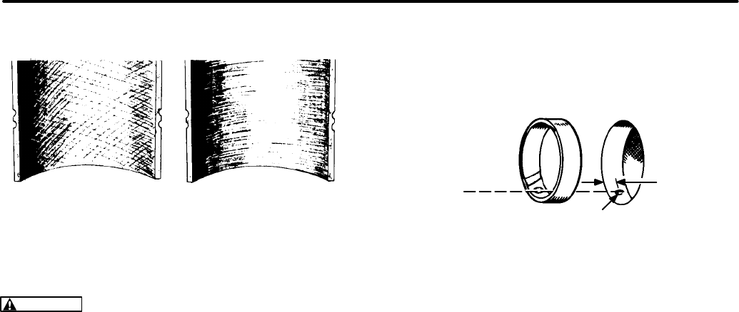
9-21
FIGURE 9-32. CROSSHATCHING
PRODUCE CROSS HATCH
SCRATCHES FOR FAST
RING SEATING C1091s
AVOID THIS
FINISH
CAUTION
Abrasives not removed from the en-
gine will rapidly wear the rings, cylinder walls,
and bearing surfaces of all lubricated parts. For
this reason, do not use gasoline or commercial
solvents to clean the cylinder bores after de-
glazing or honing. These solvents cannot re-
move abrasives from the cylinder walls.
4. Clean the cylinder bore thoroughly with soap,
water, and clean rags, until a clean white rag
shows no discoloring when wiped through the
cylinder bore.
BEARINGS
To remove the camshaft or crankshaft bearings, the
engine must be completely disassembled. Drive out
the bearings by using a combination main and cam
bearing removal tool, and a press. Support the cast-
ing to avoid distorting or damaging the bearing
bores.
Camshaft Bearing Replacement Procedure
Precision replacement camshaft bearings do not
require line reaming or line boring after installation.
1. Coat the bearing with lubricating oil.
2. Position the front bearing so that the oil hole in
the bearing is aligned with the oil hole (see Fig-
ure 9-33) in the block.
FIGURE 9-33. CAMSHAFT BEARING
M1474s
7/32"
(5.55 mm)
FROM
OUTSIDE
WITH HOLE
IN BEARING
BORE
ALIGN
HOLE IN
BEARING
3. Position the rear bearing so that the elongated
slot is aligned with the breaker point plunger
hole in the top of the block.
4. Use the combination main and cam bearing
driver with a press to install the front and rear
cam bearings. Push in the bearings to the
depth allowed by the flange on the driver.
Crankshaft Bearings
Precision replacement crankshaft main bearings do
not require line reaming or line boring after installa-
tion. They are available in standard size, 0.002,
0.010, 0.020 or 0.030 inch undersize.
When installing either the front or rear main bearing,
always align the oil hole(s) in the bearing with the oil
hole(s) in the bearing bore. The oil passage must be
at least half open.
Rear Bearing:
Use the combination main and cam
bearing driver and a press to install the rear main
bearing. Push the bearing into the bearing plate
from the inner side (see Figure 9-34) to the depth al-
lowed by the flange on the driver.
Redistribution or publication of this document,
by any means, is strictly prohibited.
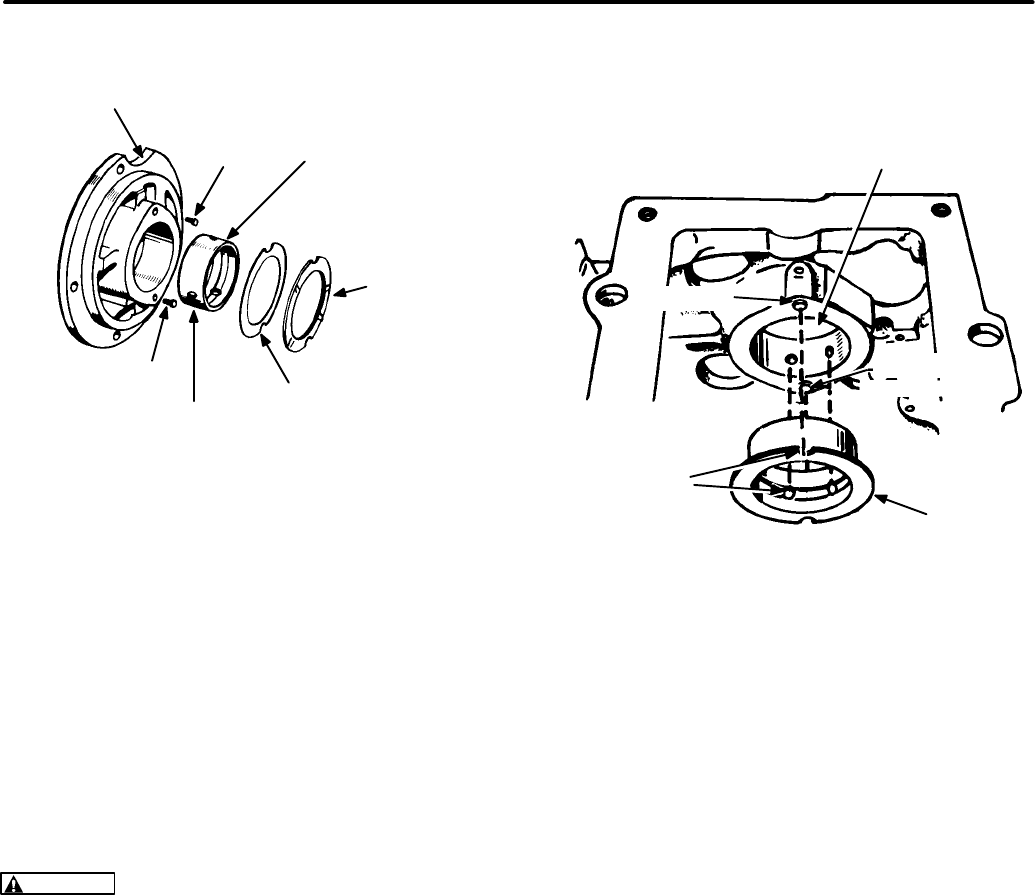
9-22
FIGURE 9-34. REAR BEARING
M1475s
REAR BEARING
END PLATE
LOCK
PIN
ALIGN BEARING
OIL HOLES WITH
OIL HOLES IN
BEARING BORE
THRUST
WASHER
SHIM
BEARING
LOCK
PIN
PRECISION TYPE− DO NOT
LINE BORE OR REAM
Front Bearing:
Loctite brand Bearing Mount is
used when installing the front bearing. Use the to-
welette furnished with the bearing kit to clean the
outside of the bearing and the bearing bore in the
block. Apply the Loctite to the mating surfaces of the
bearing and bearing bore. Allow three to four min-
utes for drying.
WARNING
Breathing the vapor from the towe-
lette provided with the Loctite, or prolonged
contact with skin, can be harmful. Be sure the
area is well-ventilated.
Use the combination main and cam bearing driver
and a press to install the front bearing. Push the
bearing in to the depth allowed by the flange on the
driver. Wipe off any excess Loctite, and allow one
hour for hardening at room temperature.
Engines shipped from the factory have separate
thrust washers and main bearings for both front and
rear of engine. The front bearing replacement part
is a one-piece bearing (with attached thrust wash-
er), as shown in Figure 9-35. Do not add an addi-
tional thrust washer to this front bearing.
FIGURE 9-35. FRONT BEARING
M1476s
NOTE: DO NOT ADD
ADDITIONAL THRUST
WASHER WHEN REPLACING
FRONT BEARING FRONT MAIN
BEARING BORE
FRONT
MAIN
BEARING
PRECISION
TYPE: DO NOT
LINE BORE OR
REAM OR
BORE
ALIGN BEARING
NOTCHES WITH
LOCK PINS AND
MATCH OIL HOLES
LOCK PIN
LOCK PIN
OIL SEALS
Oil Seal Replacement Procedure
Remove the rear bearing plate to replace the rear oil
seal. Remove the gear cover to replace the front oil
seal. Use an oil seal remover to pry out the front or
rear oil seal.
Use an oil seal guide and driver to press or drive the
rear seal into the rear bearing plate until it bottoms
against the shoulder of the plate (see Figure 9-36).
Press or drive the front oil seal into the gear cover
until it is 0.97 ± 0.02 inch (24.6 ± 0.5 mm) from the
mounting face of the cover.
Place a light coating of grease on the lips of the re-
placement seal before installing the rear bearing
plate or gear cover. This provides initial lubrication
until engine oil reaches the seal. Refer to the Crank-
shaft section for the rear bearing plate installation
procedures. Refer to the Gear Cover section for the
gear cover installation procedures.
Redistribution or publication of this document,
by any means, is strictly prohibited.
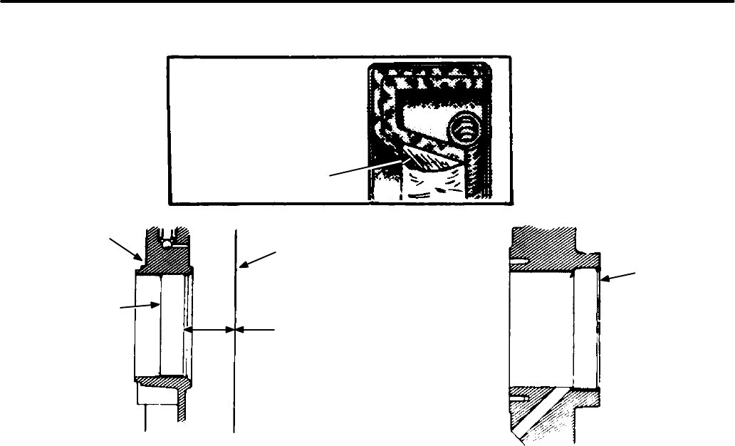
9-23
FIGURE 9-36. OIL SEALS
M1477s
USE GREASE IN
SPACE BETWEEN
SEALS TO
IMPROVE SEAL
THIS SURFACE
SHOULD BE
CLEANED OF
ALL OLD
SEALING
COMPOUND
BEFORE
INSTALLING
SEAL
DRIVE OR
PRESS OIL SEAL
TO SHOULDER
OF THE PLATE
BORE
REAR BEARING PLATE
OIL SEAL
THIS SURFACE
SHOULD BE CLEANED
OF ALL OLD SEALING
COMPOUND BEFORE
INSTALLING SEAL
0.97 ± 0.02 INCH
(24.6 ± 0.5 mm)
MOUNTING
FACE OF
GEAR COVER
GEAR
COVER
OIL
SEAL
GEAR COVER OIL SEAL
Redistribution or publication of this document,
by any means, is strictly prohibited.

Section 10. Service Checklist
10-1
After servicing, inspect and test the installation to
confirm that the generator set will operate to its
rated capacity. Check each of the areas described
below before putting the set into service.
MOUNTING
Examine all mounting bolts and supporting mem-
bers to verify that the generator set is properly
mounted. All fasteners should be tightened secure-
ly, to prevent them from working loose when sub-
jected to vibration.
LUBRICATION
If the engine oil was drained, fill the crankcase with
oil of the recommended classification and viscosity.
Refer to the appropriate operators’ manual for the
specific recommendations and procedures.
WIRING
Verify that all wiring connections are tight and
installed properly. Make certain that wires do not
run over hot, sharp or rough surfaces and are not
kinked or worn. Check each of these connections:
•Load wires
•Control wires
•Ground strap
•Battery cables
INITIAL START ADJUSTMENTS
Gasoline sets: Before starting the genset, check
that the idle and main mixture adjustment screw lim-
iter caps are in the correct position. If the limiter
caps are missing, adjust the idle and main mixture
screws, and reinstall the limiter caps. For instruc-
tions, see the Fuel System section of this manual.
Mechanical-governor sets: Start the set, then im-
mediately adjust the governor speed for a safe no-
load operating speed (mechanical governor gen-
sets). With no load applied, listen for unusual
sounds or vibrations. Warm up the genset for at
least 15 minutes at 50% to 75% of rated load and
check that the choke is completely open. Adjust
governor (mechanical governor gensets) as speci-
fied in the Governor section of this manual.
CAUTION
Voltage/frequency-sensitive equip-
ment such as VCRs, televisions, computers,
etc. may be damaged by power line frequency
variations. Some solid-state devices are pow-
ered whenever connected to an AC outlet even
if the device is not in actual operation. For this
reason, disconnect all devices which are volt-
age- or frequency-sensitive before attempting
any carburetor/governor adjustments. If dis-
connecting the devices is not possible, open
the circuit breaker(s) at the distribution panel or
at the generator set, if so equipped.
OUTPUT CHECK
Apply a full load to make sure the set can produce its
full rated output. Use a load test panel to apply a
progressively greater load until full load is reached.
Redistribution or publication of this document,
by any means, is strictly prohibited.

10-2
EXHAUST SYSTEM
With the generator set operating, inspect the entire
exhaust system, including the exhaust manifold,
muffler, and exhaust pipe. Make certain that the ex-
haust pipe terminates beyond the perimeter of the
coach. Visually and audibly check for leaks at all
connections, welds, gaskets, and joints. Also make
sure that exhaust pipes do not heat surrounding
areas excessively. If leaks are detected, correct im-
mediately.
WARNING
Inhalation of exhaust gases can re-
sult in severe personal injury or death. Inspect
exhaust system audibly and visually for leaks
daily. Shut off the engine and repair leaks imme-
diately.
FUEL SYSTEM
With the generator set operating, inspect the fuel
supply lines, return lines, filters, and fittings for
leaks. Check any flexible sections for cuts, cracks
and abrasions and make sure they are not rubbing
against anything that could cause breakage.
WARNING
Leaking fuel creates a fire hazard
which might result in severe personal injury or
death if fire, flame, spark, pilot light, cigarettes,
arc-producing equipment or other ignition
sources are present. If fuel leaks are detected,
shut off the generator set and correct immedi-
ately.
CONTROL
Stop and start the generator set several times at the
set control and remote control to verify that it func-
tions properly.
MECHANICAL
Stop the generator set and inspect it for leaking gas-
kets, loose fasteners, damaged components, or in-
terference problems. Repair as required. Inspect
the generator set compartment and verify that there
are no breaks or openings in the vapor-proof wall
that separates the compartment from the vehicle in-
terior. Seal openings as required. Make sure that all
soundproofing material is in place.
Redistribution or publication of this document,
by any means, is strictly prohibited.
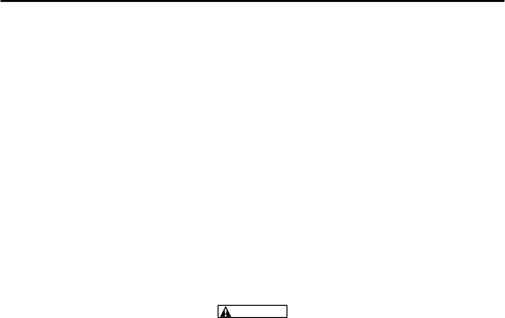
Appendix A. Troubleshooting Guides
A-1
The following pages contain simplified troubleshooting procedures for these Marquis electronic components:
Subject Page
Emerald/Marquis Control Boards 300-3763-01 and 300-3763-02 A-2, A-3. . . . . . . . . .
Performer/Emerald Plus/Marquis/Ensign Electronic Ignition Module A-4. . . . . . . .
Marquis Control Board Check-Out A-5, A-6. . . . . . . . . . . . . . . . . . . . . . . . . . . . . . . . . . . . .
Use a volt-ohmmeter and a test light with these procedures to test Marquis control circuit boards for proper
functioning.
Two Onan product support bulletins are also reprinted in this supplement, as follows:
Subject Page
“Set Dies When Switch Released” (PSB #563) A-7. . . . . . . . . . . . . . . . . . . . . . . . . .
“Rotor/Stator Check” (PSB #564) A-8. . . . . . . . . . . . . . . . . . . . . . . . . . . . . . . . . . . . . .
WARNING
The steps described in this appendix are intended as quick reference guides, rather than
complete procedures. Consult the appropriate sections of this manual before using the
procedures found in this Appendix.
Incorrect service or parts replacement can result in severe personal injury, death, and/or
equipment damage. Service personnel must be qualified to perform electrical and/or me-
chanical service.
Redistribution or publication of this document,
by any means, is strictly prohibited.
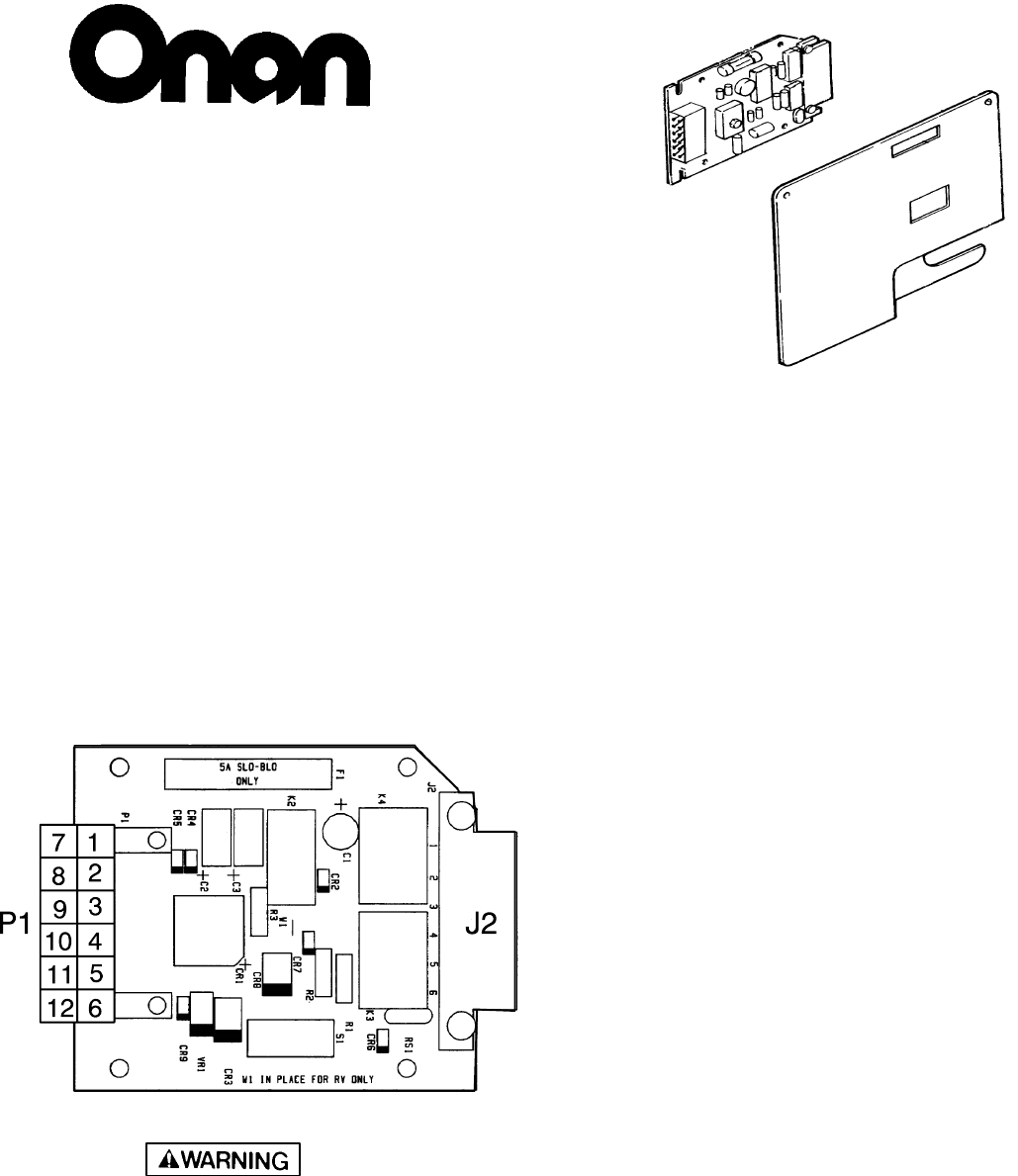
EMERALD/MARQUIS
CONTROL BOARD
CHECK-OUT
(300-3763-01, 02)
MODELS:
BGE Spec. F & G
BGEL Spec. E & G
NHE, NHEL Spec. D, E & G
BGM, NHM Spec. A
BGD Spec. A & B
NHD Spec. A, B & C REMOVE CIRCUIT BOARD
To perform the following tests the circuit board
must be removed from the control cover.
Place the circuit board on a non-conductive surface
with the component side of the board up.
P1 plug turned for better viewing.
For the following tests, the battery must
be connected.
STATIC MODE
(With the switch in the Center position)
Meter
Test Lead
+ -
Meter
Reading
P1-7 P1-11
P1-7 J2-1 12 VDC
12 VDC
Use extreme caution when working on operating
generator sets. Operating generator sets presents
hazards of electrocution, burns, fire and explosion,
asphyxiation, and entanglement with rotating parts.
Review Important Safety Instructions in Operator’s
Manual.
Emerald/Marquis is a trademark of Onan Corporation
ES2051s
A-2
Redistribution or publication of this document,
by any means, is strictly prohibited.
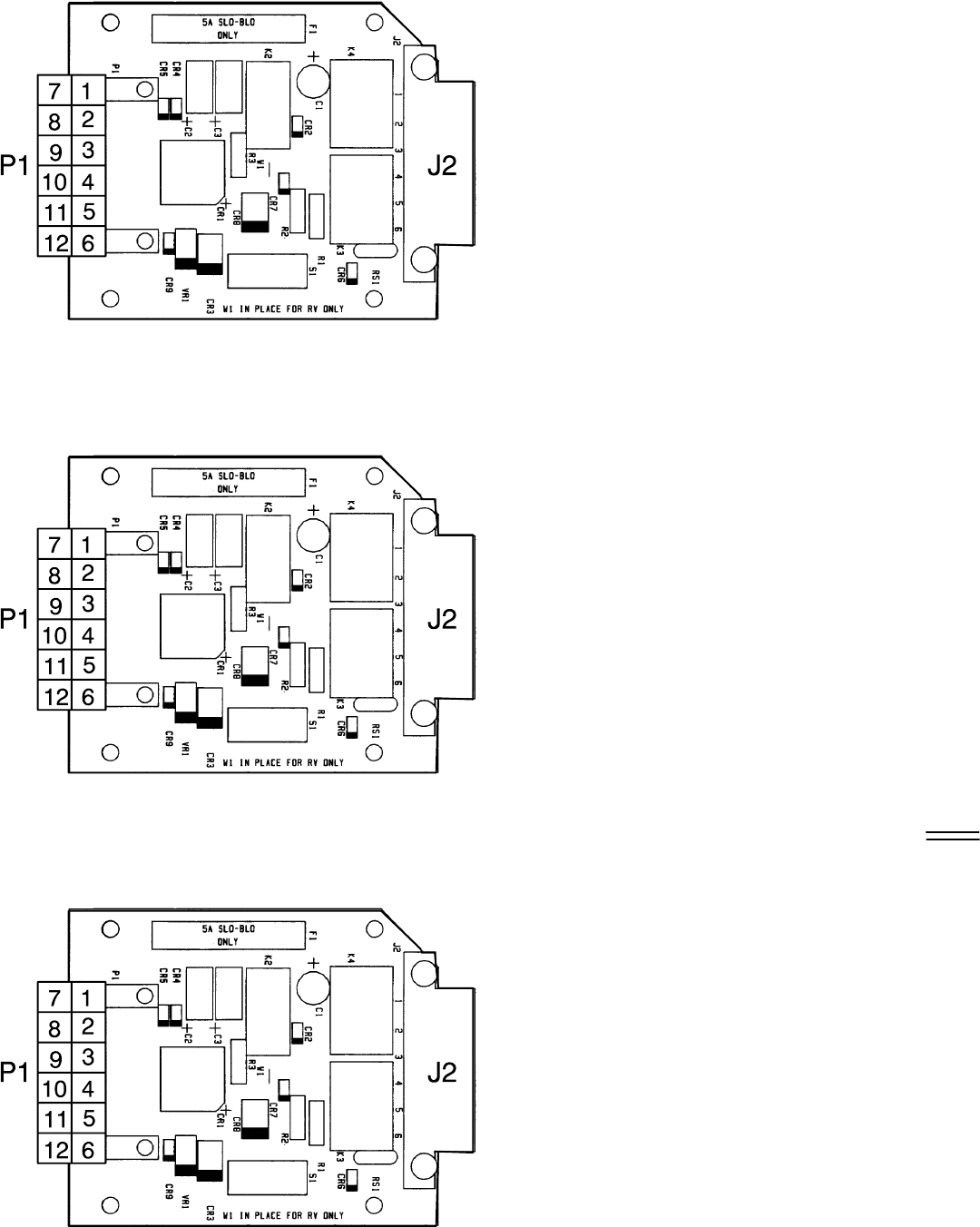
STOP MODE
(With the switch pressed to the Stop position)
Meter
Test Lead
+ -
Meter
Reading
P1-6 J2-1
P1-12 J2-1
* P1-7 P1-10
0 VDC
0 VDC
12 VDC
CRANK & START MODE
(With the switch pressed to the Start position)
Meter
Test Lead
+ -
Meter
Reading
RUN & GENERATE MODE
(With the generator set running and the
switch in the Center position)
Meter
Test Lead
+ -
Meter
Reading
P1-1 J2-1
P1-6 J2-1
P1-9 J2-1
P1-12 J2-1
* P1-7 P1-10
10-12 VDC
10-12 VDC
10-12 VDC
10-12 VDC
10-12 VDC
P1-6 J2-1
P1-7 P1-3 N/A BGD/NHD
P1-7 P1-5
* P1-7 P1-10
P1-12 J2-1
J2-5 J2-1
J2-6 J2-1
P1-2 P1-4
18-20 VDC
18-20 VDC
10-13 VDC
0 VDC
10-13 VDC
10-13 VDC
10-13 VDC
18-22 VAC
* Gensets with K5 relay
10/91
ES2051s
ES2051s
ES2051s A-3
Redistribution or publication of this document,
by any means, is strictly prohibited.
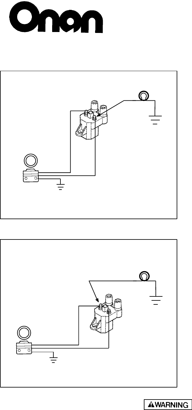
1. Check wiring: red lead to positive (+);
black lead to negative (-).
2. Connect a DC powered test light from
the negative (-) coil terminal to
ground.
3. Turn the ignition switch on and crank
the engine over. Does the test light
flash, bright then dim?
Yes - The module is ok; do not
replace the module.
No - Go to Test 2.
Note: If the primary winding of the
ignition coil is open, the light will not
come on.
4. Connect the test light from the posi-
tive (+) coil terminal to ground.
5. Turn the ignition switch to the on
position. Does the light come on?
Yes - Crank the engine over. Does
the light stay on while
cranking?
Yes - Replace the module and the
trigger ring as a set if the coil
tests good.
No - It is not a module problem.
Check the wiring and
connections to the coil and
the ignition switch, then retest
the module.
+
-
Trigger
Ring
Ignition
Module
Test
Light
Ignition
Coil
Test 1
Test 2
+
-
Test
Light
Ignition
Coil
Ignition
Module
Trigger
Ring
Troubleshooting Electronic
Ignition Module
Use extreme caution when working on operating equipment. Operating equipment presents hazards of electrocution,
burns, fire and explosion, asphyxiation, and entanglement with rotating parts. Review Important Safety Instructions in
Operator’s Manual.
1991 Onan Corporation
2/91
Models: Performer, Emerald Plus,
Marquis, Ensign
Performer, Emerald Plus, Marquis, Ensign are trademarks of Onan Corporation
A-4
Redistribution or publication of this document,
by any means, is strictly prohibited.
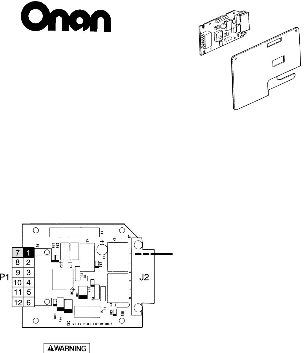
MARQUIS
CONTROL BOARD
CHECK-OUT
(300-3764)
MODEL:
BGM/NHM
(Beginning Spec. B)
REMOVE CIRCUIT BOARD
To perform the following tests the circuit board
must be removed from the control cover.
Place the circuit board on a non-conductive surface
with the component side of the board up.
For the following tests, the battery must be con-
nected and in a fully charged state.
P1 plug turned for better viewing.
STATIC MODE
Meter
Test Lead
+ -
(With the switch in the Center position
and the unit not running)
Meter
Reading
P1-7 P1-1 12-13 VDC. . . . . . . . . . . .
P1-7 J2-1 12-13 VDC. . . . . . . . . . . . .
Use extreme caution when working on operating
generator sets. Operating generator sets presents
hazards of electrocution, burns, fire and explosion,
asphyxiation, and entanglement with rotating parts.
Review Important Safety Instructions in Operator’s
Manual.
1992 Onan Corporation
Marquis is a trademark of Onan Corporation
ES2051s
A-5 900-0266
Note: Care must be taken not to touch more
than one P1 pin at a time with a meter lead.
* All readings +/- 5%. Note that the coating
on the P1 pins may have to be scraped off to
get a good meter reading.
Fuse
*
Redistribution or publication of this document,
by any means, is strictly prohibited.
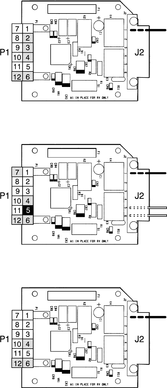
STOP MODE
(With the set running, then the switch
pressed to the Stop position)
Meter
Test Lead
+ -
Meter
Reading
P1-4 J2-1 10-12 then 0 VDC. . . . . . . . .
P1-6 J2-1 11-13 then 0 VDC. . . . . . . . . .
P1-12 J2-1 10-12 then 0 VDC. . . . . . . . . .
CRANK & START MODE
(With the switch pressed and held
to the Start position)
Meter
Test Lead
+ -
Meter
Reading
RUN & GENERATE MODE
(With the generator set running and the
switch in the Center position)
Meter
Test Lead
+ -
Meter
Reading
P1-2 J2-1 8-9 then 0 VDC. . . . . . . . . .
P1-3 J2-1 9-10 then 0 VDC. . . . . . . . . .
P1-4 J2-1 8-9 then 10-12 VDC. . . . . . . . . .
P1-6 J2-1 9-10 then 11-13 VDC. . . . . . . . . .
P1-12 J2-1 8-9 then 10-12 VDC. . . . . . . . . .
P1-4 J2-1 10-12 VDC. . . . . . . . . .
P1-6 J2-1 11-13 VDC. . . . . . . . . .
P1-12 J2-1 10-12 VDC. . . . . . . . . .
P1-7 P1-5 11-13 VDC. . . . . . . . .
J2-5 J2-1 11-13 VDC. . . . . . . . .
J2-6 J2-1 11-13 VDC. . . . . . . . .
6/92
ES2051s
ES2051s
ES2051s
A-6
900-0266
Fuse
*
*
*
Fuse
Fuse
Redistribution or publication of this document,
by any means, is strictly prohibited.
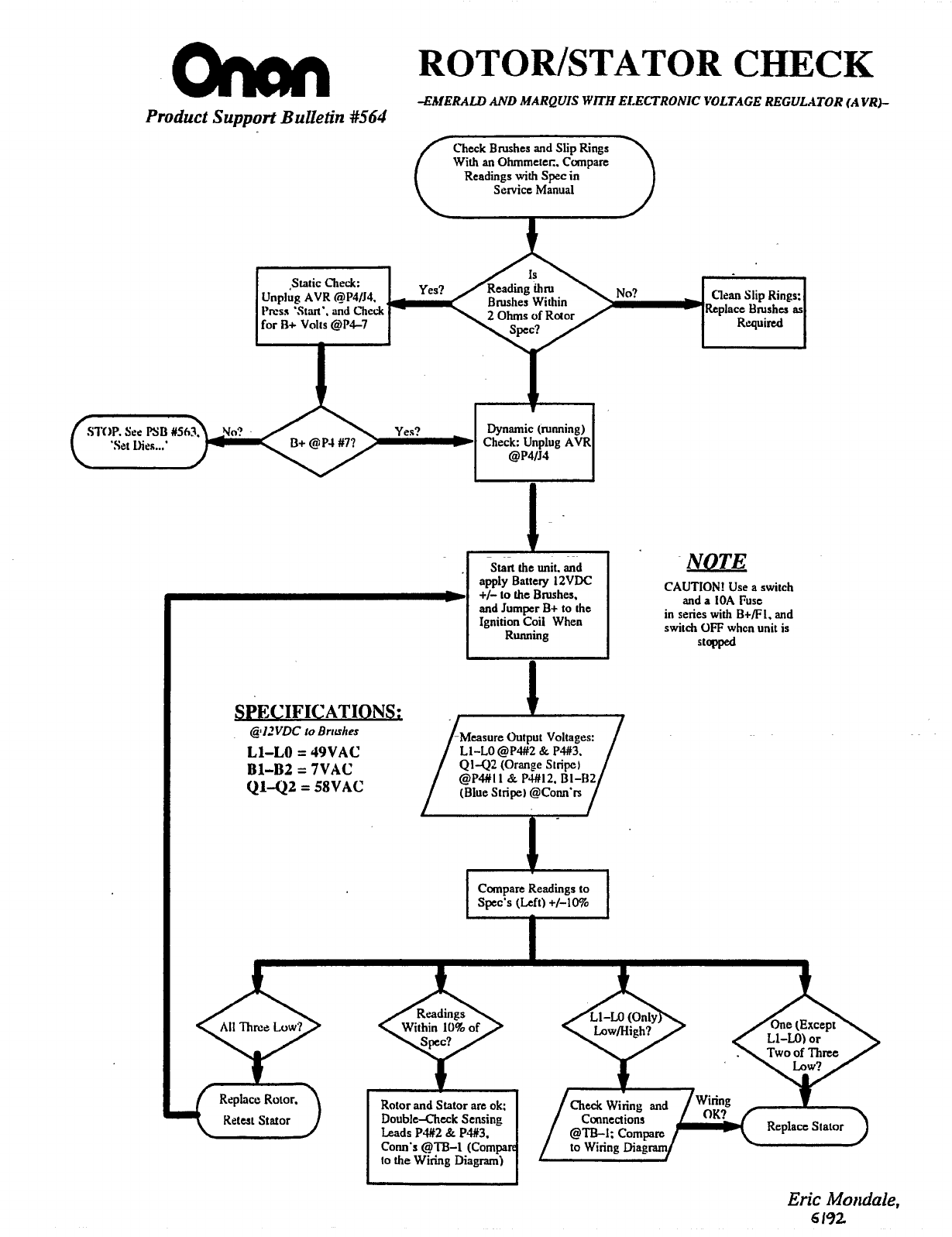
ROTOWSTATOR
CHECK
4MERALL)
AND
MARQUIS
WITH
ELECTRONIC VOLTAGE REGULATOR
(A
VR)-
Product
Support
Bulletin
#564
With
an
Ohrnrnetec.
Compare
Service
Manual
Readings
with
Spec
in
I
Unpig
AVR
@~4/~4,
,
Brushes Within
NO?
Clean Slip Rings:
Static
C7lrck:
Replace bushes
as
l'rcss
'Start'.
and
Check
2
Ohms of Rotor
for
R+
Volts
@P4-7
Yes?
Rquired
1
Dynamic (running)
Check: Unplug AVR
aP4IJ.1
~~
Start
the
unit. and
awly
Battery
IZVJX
NOTE
CAUTION!
Use
a switch
and
a
IOA
Fuse
in
series with
B+/FI.
and
switch
OFF
whcn
unit
is
and Jumper
B+
to the
Ignition Coil When
Running
SPECIFICATIONS;
@I2VDC
IO
Brushes
L1-LO
=
J9VAC
Bl-B2
=
7VAC
vi42
=
SVAC
Q142
(Orange
Stripcl
(Blue Stripe) @COM'IX
@P#I
I
&
PU12.
B1-H2
Compare Readings
to
Spec's (Left)
+/-lo%
Rotor and
Stator
are ok:
DoubleXhcck
Sensing
Leads
P#Z
&
P#3.
COM'S
@TB-1
(Compa
to
the
Wiring
Diagram)
I
Eric
Moiuiale,
6
192
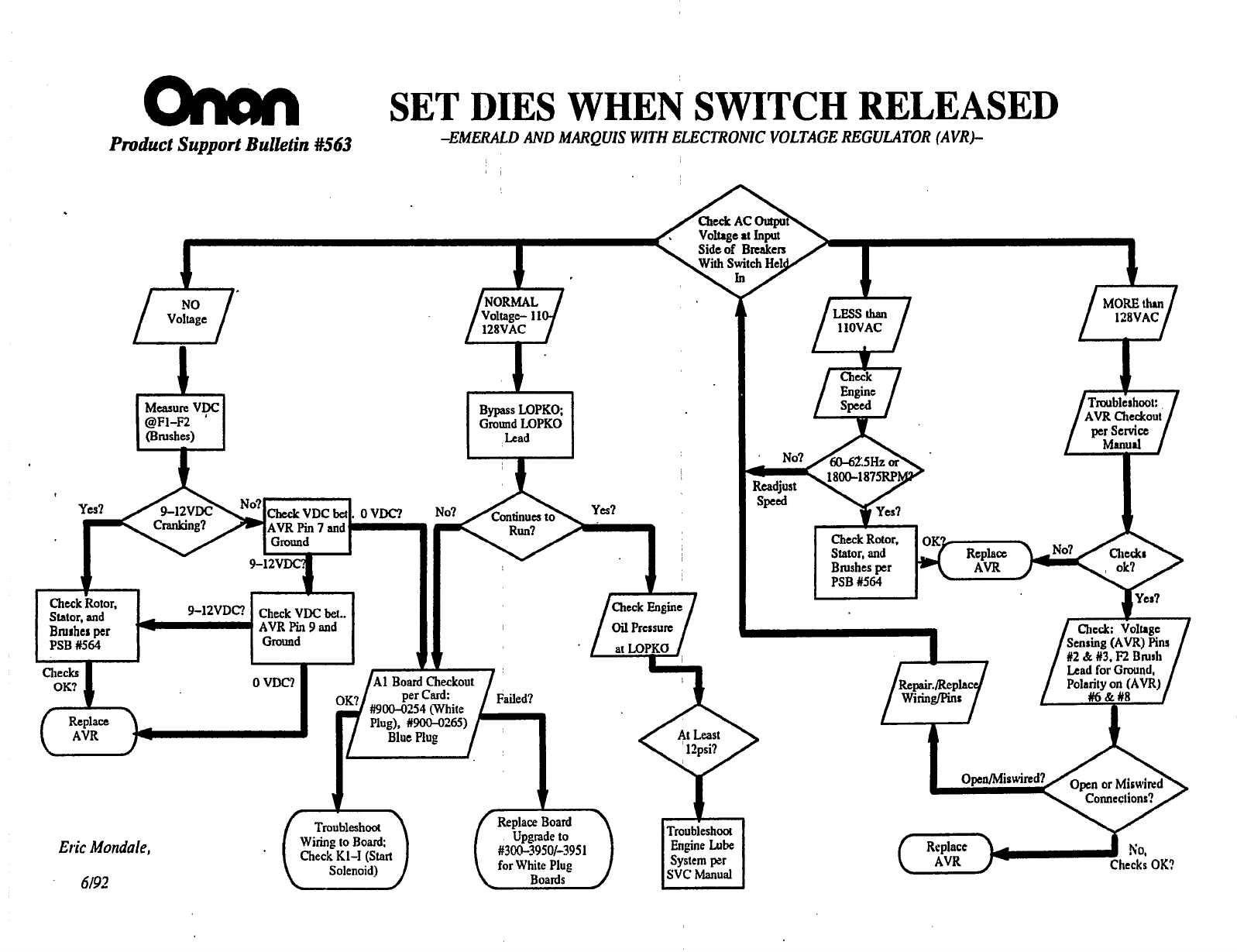
SET
DIES
WHEN
SWITCH
RELEASED
-EMERALD
AND
MARQUIS
WITH
ELECTRONIC VOLTAGE REGULATOR (AVRk
Pmduct
Support
Bulktin
4643
,-,
Voltage
Measure
V?C
4
(Brushes)
eF1-R
t
Bypass
LOPKO
Ground
LOPKO
Lead
I
I
Lead
for
Grouod,
Eric
Mondale,
6/92

Appendix B. Wiring Diagrams
B-1
WIRING DIAGRAM DRAWING
No. PAGE
No.
Spec A 611-1186 B-2
Specs B and C (Begin Electronic Governor) 611-1196 B-3
Begin Spec D (Battery Powered Choke Heater for Gasoline) 611-1219 B-4
Begin Spec D (10 Amp Battery Charging) 611-1233 B-5
Begin Spec G (LP, No Battery Charging) 611-1250 B-6
Begin Spec G (Gasoline, No Battery Charging) 611-1240 B-7
Begin Spec G (10 Amp Battery Charging) 611-1251 B-8
Redistribution or publication of this document,
by any means, is strictly prohibited.
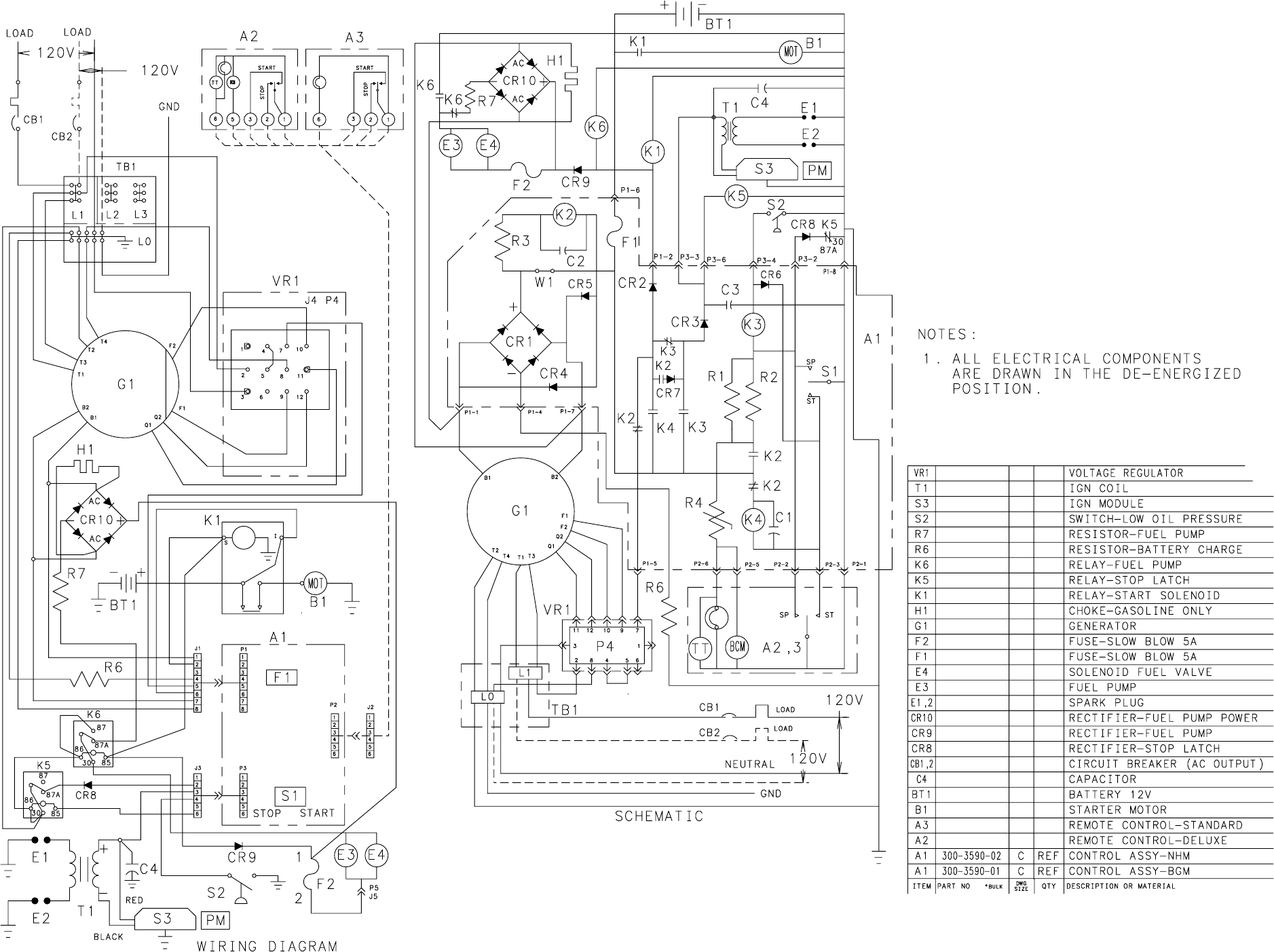
B-2
611−1186
Redistribution or publication of this document,
by any means, is strictly prohibited.
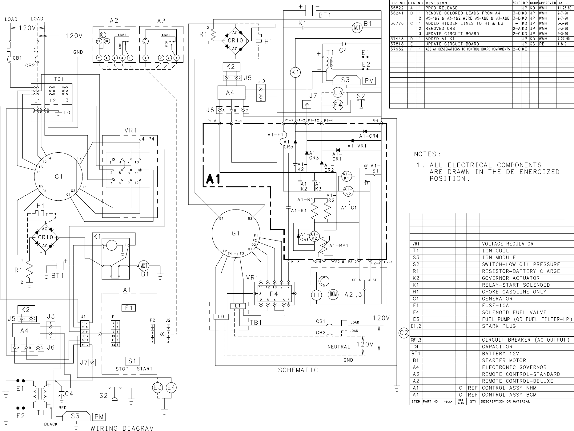
B-3
611−1196
Redistribution or publication of this document,
by any means, is strictly prohibited.
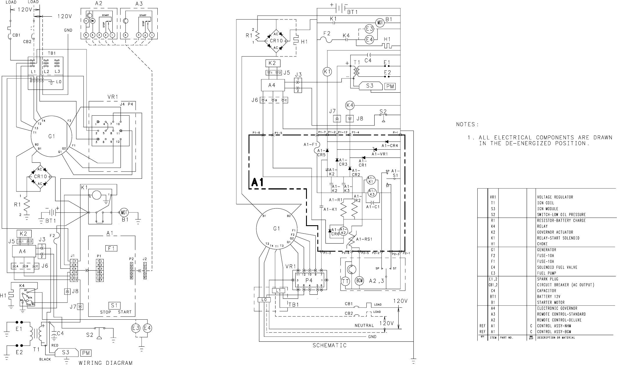
B-4
611−1219
Redistribution or publication of this document,
by any means, is strictly prohibited.
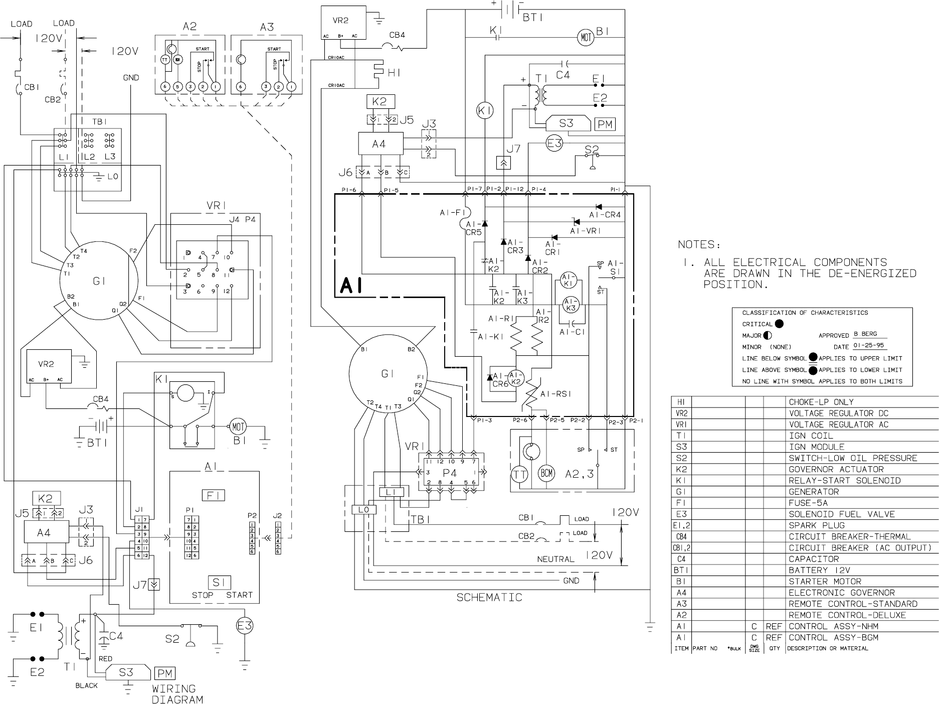
B-5
611−1233
Redistribution or publication of this document,
by any means, is strictly prohibited.
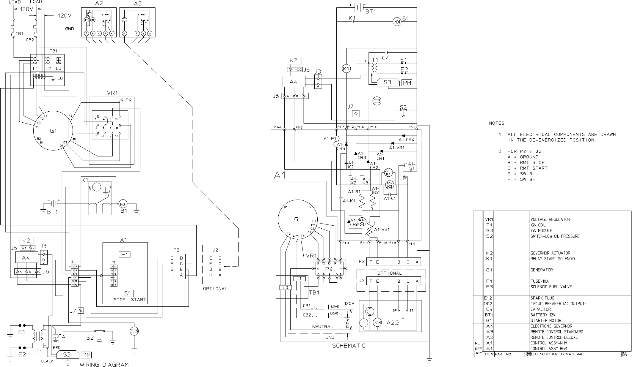
B-6
611−1250
Redistribution or publication of this document,
by any means, is strictly prohibited.
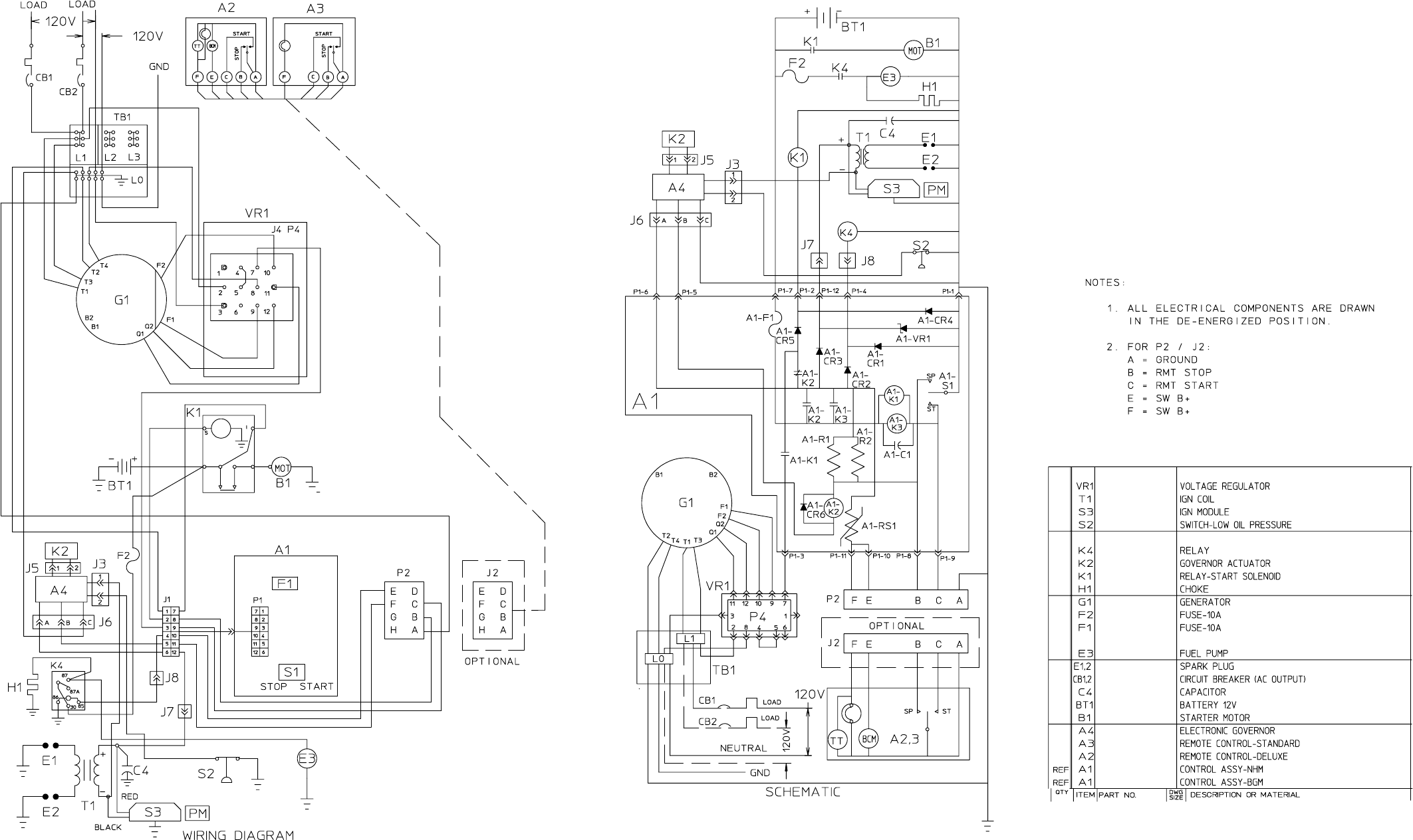
B-7
611−1240
Redistribution or publication of this document,
by any means, is strictly prohibited.
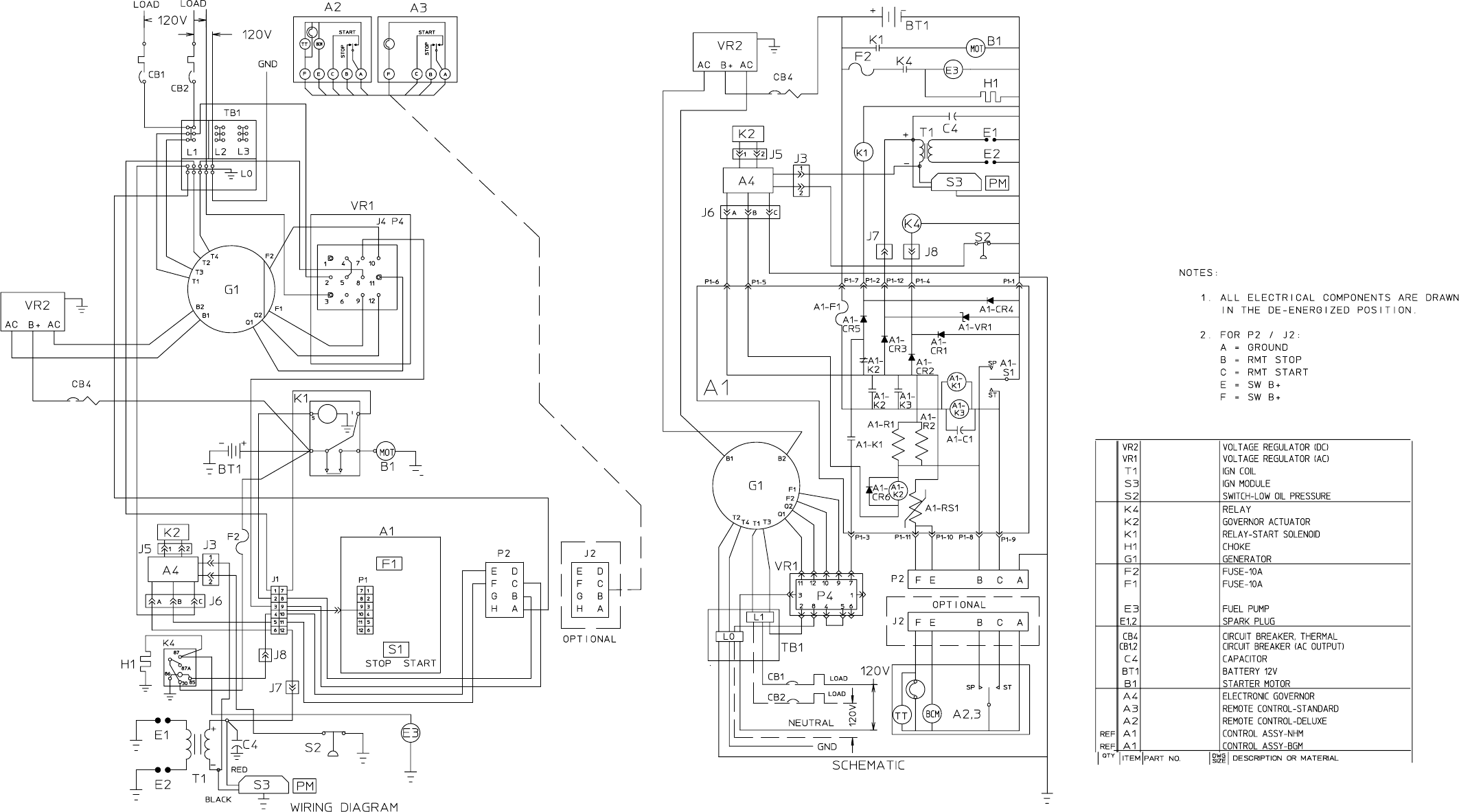
B-8
611−1251
Redistribution or publication of this document,
by any means, is strictly prohibited.

Cummins Power Generation
1400 73rd Avenue N.E.
Minneapolis, MN 55432
763-574-5000
Fax: 763-528-7229
Cummins and Onan are registered trademarks of Cummins Inc.
Redistribution or publication of this document,
by any means, is strictly prohibited.
