965 0601C Onan GHAB (spec A) Genset Installation Manual (03 2003)
User Manual: 965-0601C Onan GHAB (spec A) Genset Installation manual (03-2003)
Open the PDF directly: View PDF ![]() .
.
Page Count: 47
Installation Manual
GHAB
Printed in U. S. A. 965-0601C
3-2003
Redistribution or publication of this document,
by any means, is strictly prohibited.

i
Supplement 965-1079
Date: 2-2004
Insert with-
Title: GHAB Installation Manual
Number: 965-0601C
PURPOSE
This publication adds supplementary information to the following page of
the GHAB Installation Manual.
Page 3-4: Revised conversion procedure to include brass elbow.
SUPPLEMENT USE
Replace page 3−3/3−4 with the attached.
Please keep this supplement with the Installation Manual (965-0601C).
Redistribution or publication of this document,
by any means, is strictly prohibited.
ii
Redistribution or publication of this document,
by any means, is strictly prohibited.
3-3
NATURAL GAS FUEL SYSTEM
The genset requires an adequate fuel supply to op-
erate correctly at full load. The length of the fuel sup-
ply pipe from the gas service entrance to the genset
must be known to determine the correct fuel pipe
size. Refer to Table 3-1 to find the fuel supply re-
quirement for your genset. Pipe must be minimum
of schedule 40 subject to the authority having juris-
diction.
Natural Gas Supply Line Size
The genset requires up to 240,000 BTU/hr (240 cu-
bic feet/hr) delivered to the genset inlet at 11 inches
(28 mm) WC, nominal. If the meter serves other gas
appliances such as a furnace, water heater, or
stove, you must consult with the local natural gas
utility to determine whether the natural gas meter is
adequate.
It is important to consider other loads operated from
the fuel supply pipe. Other loads, such as space
heating and water heating equipment, must also be
determined to correctly size the fuel pipe. Use the
total load requirement of the fuel supply line to de-
termine the size of the fuel supply pipe. Use
Table 3-1 to determine the correct pipe size. (typi-
cally, 1 ft3/hr =1000 BTU/hr, )
When the fuel delivery value falls between two col-
umns, use the larger value.
GENSET SHUTOFF
VALVE GAS METER
FIGURE 3-2. TYPICAL NATURAL GAS INSTALLATION
TABLE 3-1. NATURAL GAS PIPE CAPACITY—CUBIC FEET OF GAS PER HOUR
Maximum pipe capacity in cubic feet per hour of 0.60 specific gravity natural gas with
a pressure drop of 0.5 inches (1.27 mm) WC over the length
NOMINAL IRON
PIPE SIZE
LENGTH OF PIPE IN FEET
PIPE SIZE
(INCHES) 10 20 30 40 50 60 70 80 90 100 125 150 175 200
3/4 360 250 200 170 151 138 125 118 110 103 93 84 77 72
1680 465 375 320 285 260 240 220 205 195 175 160 145 135
1-1/4 1400 950 770 660 580 530 490 460 430 400 360 325 300 280
Redistribution or publication of this document,
by any means, is strictly prohibited.
3-4
LP VAPOR FUEL SYSTEM
WARNING
Fuel leaks can lead to explosive ac-
cumulations of gas. Natural gas rises and can
accumulate under overhanging hoods and in-
side housings and buildings. LP Vapor sinks air
and can accumulate inside housings, base-
ments and other below-grade spaces. Prevent
gas leaks and the accumulation of gaseous fuel
in the event of a leak.
NFPA Standard No. 58 requires all persons han-
dling and operating LP Vapor to be trained in
proper handling and operating procedures.
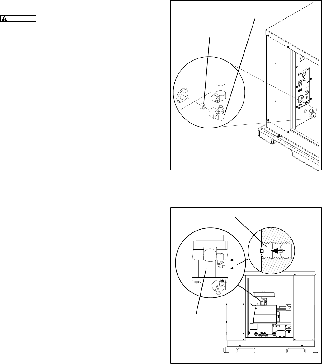
Converting from Natural Gas to LP Vapor
The genset leaves the factory set up for natural gas.
The genset must be converted to use LP Vapor.
Conversion on early production units involves in-
serting an orifice into the brass elbow (See Figure
3-3). Later production units use a replacement el-
bow with a smaller ID, and is marked with a red dot
on the elbow. All conversions require adjusting the
carburetor (See Figure 3-4). The genset is shipped
with a kit containing the orifice for conversion.
A genset purchased to use Natural Gas or LP Vapor
can not be converted to use LP Liquid, and one that
is purchased to use LP Liquid can not be converted
to use Natural Gas or LP Vapor.
Conversion Procedure (Natural Gas to LP Va-
por):
1. Remove access panel on the control side of the
genset. Lift handle up and out, then turn count-
er-clockwise, swing the access panel down,
and lift out.
2. Remove the elbow following the regulator in
the fuel line (Figure 3-3).
3a. For early production units, insert the orifice into
the elbow (smaller end into the elbow first) and
reinstall the elbow.
3b. For later production units, install the replace-
ment elbow from the conversion kit that has
been marked with a red dot.
4. Turn the carburetor (mixer) idle screw from all
the way in (original factory setting) out so that
the top of screw is flush with the body of the car-
buretor. See Figure 3-4.
5. Replace the access panel. Set it in the bottom
of the opening, swing it up, turn the latch clock-
wise, and fold up to secure the panel.
ELBOW
ORIFICE OR NEW ELBOW
FOR LP VAPOR
ORIFICE (EARLY
PRODUCTION ONLY)
FIGURE 3-3. NATURAL GAS TO LP VAPOR
CONVERSION
CARBURETOR
(MIXER)
ADJUSTMENT SCREW
FIGURE 3-4. CARBURETOR ADJUSTMENT
Redistribution or publication of this document,
by any means, is strictly prohibited.

-
The engine exhaust from this product
contains chemicals known to the State
of California to cause cancer, birth
defects or other reproductive harm.
!!
Redistribution or publication of this document,
by any means, is strictly prohibited.

i
Table of Contents
TITLE PAGE
SAFETY PRECAUTIONS II. . . . . . . . . . . . . . . . . . . . . . . . . . . . . . . . . . . . . . . . . . . . . . . . . . . .
1. INTRODUCTION 1-1. . . . . . . . . . . . . . . . . . . . . . . . . . . . . . . . . . . . . . . . . . . . . . . . . . . . . . . . .
About this Manual 1-1. . . . . . . . . . . . . . . . . . . . . . . . . . . . . . . . . . . . . . . . . . . . . . . . . . . . . .
Pre-Installation Considerations 1-1. . . . . . . . . . . . . . . . . . . . . . . . . . . . . . . . . . . . . . . . . . .
Installation Overview 1-3. . . . . . . . . . . . . . . . . . . . . . . . . . . . . . . . . . . . . . . . . . . . . . . . . . . .
Installation Codes and Safety Recomendations 1-3. . . . . . . . . . . . . . . . . . . . . . . . . . . . .
2. STEP-BY-STEP INSTALLATION OUTLINE 2-1. . . . . . . . . . . . . . . . . . . . . . . . . . . . . . . . .
Introduction 2-1. . . . . . . . . . . . . . . . . . . . . . . . . . . . . . . . . . . . . . . . . . . . . . . . . . . . . . . . . . . .
Locating the Site 2-1. . . . . . . . . . . . . . . . . . . . . . . . . . . . . . . . . . . . . . . . . . . . . . . . . . . . . . . .
Genset Clearances 2-2. . . . . . . . . . . . . . . . . . . . . . . . . . . . . . . . . . . . . . . . . . . . . . . . . . . . .
Preparing the Site 2-3. . . . . . . . . . . . . . . . . . . . . . . . . . . . . . . . . . . . . . . . . . . . . . . . . . . . . .
Moving the Genset 2-4. . . . . . . . . . . . . . . . . . . . . . . . . . . . . . . . . . . . . . . . . . . . . . . . . . . . . .
Placing the Genset 2-5. . . . . . . . . . . . . . . . . . . . . . . . . . . . . . . . . . . . . . . . . . . . . . . . . . . . . .
Connecting the Genset 2-6. . . . . . . . . . . . . . . . . . . . . . . . . . . . . . . . . . . . . . . . . . . . . . . . . .
3. MECHANICAL 3-1. . . . . . . . . . . . . . . . . . . . . . . . . . . . . . . . . . . . . . . . . . . . . . . . . . . . . . . . . . .
Location 3-1. . . . . . . . . . . . . . . . . . . . . . . . . . . . . . . . . . . . . . . . . . . . . . . . . . . . . . . . . . . . . . .
Access and Mounting 3-1. . . . . . . . . . . . . . . . . . . . . . . . . . . . . . . . . . . . . . . . . . . . . . . . . . .
Engine Exhaust 3-2. . . . . . . . . . . . . . . . . . . . . . . . . . . . . . . . . . . . . . . . . . . . . . . . . . . . . . . . .
Fuel System 3-2. . . . . . . . . . . . . . . . . . . . . . . . . . . . . . . . . . . . . . . . . . . . . . . . . . . . . . . . . . .
Natural Gas Fuel System 3-3. . . . . . . . . . . . . . . . . . . . . . . . . . . . . . . . . . . . . . . . . . . . . . . .
LP Vapor Fuel System 3-4. . . . . . . . . . . . . . . . . . . . . . . . . . . . . . . . . . . . . . . . . . . . . . . . . . .
LP Liquid Fuel System 3-7. . . . . . . . . . . . . . . . . . . . . . . . . . . . . . . . . . . . . . . . . . . . . . . . . .
4. ELECTRICAL CONNECTIONS 4-1. . . . . . . . . . . . . . . . . . . . . . . . . . . . . . . . . . . . . . . . . . . .
Conduit 4-1. . . . . . . . . . . . . . . . . . . . . . . . . . . . . . . . . . . . . . . . . . . . . . . . . . . . . . . . . . . . . . . .
Control and Power Connections 4-1. . . . . . . . . . . . . . . . . . . . . . . . . . . . . . . . . . . . . . . . . .
Grounding 4-3. . . . . . . . . . . . . . . . . . . . . . . . . . . . . . . . . . . . . . . . . . . . . . . . . . . . . . . . . . . . .
Transfer Switch 4-4. . . . . . . . . . . . . . . . . . . . . . . . . . . . . . . . . . . . . . . . . . . . . . . . . . . . . . . . .
Battery 4-8. . . . . . . . . . . . . . . . . . . . . . . . . . . . . . . . . . . . . . . . . . . . . . . . . . . . . . . . . . . . . . . .
5. INSTALLATION REVIEW AND STARTUP 5-1. . . . . . . . . . . . . . . . . . . . . . . . . . . . . . . . . . .
Installation Review 5-1. . . . . . . . . . . . . . . . . . . . . . . . . . . . . . . . . . . . . . . . . . . . . . . . . . . . . .
Startup 5-1. . . . . . . . . . . . . . . . . . . . . . . . . . . . . . . . . . . . . . . . . . . . . . . . . . . . . . . . . . . . . . . .
6. SPECIFICATIONS 6-1. . . . . . . . . . . . . . . . . . . . . . . . . . . . . . . . . . . . . . . . . . . . . . . . . . . . . . . .
7. DRAWINGS 7-1. . . . . . . . . . . . . . . . . . . . . . . . . . . . . . . . . . . . . . . . . . . . . . . . . . . . . . . . . . . . .
GHAB Genset Outline Drawing 7-1. . . . . . . . . . . . . . . . . . . . . . . . . . . . . . . . . . . . . . . . . . .
GHAB Wiring Diagram 7-2. . . . . . . . . . . . . . . . . . . . . . . . . . . . . . . . . . . . . . . . . . . . . . . . . .
RSZ Transfer Switch Drawings 7-3. . . . . . . . . . . . . . . . . . . . . . . . . . . . . . . . . . . . . . . . . . .
Redistribution or publication of this document,
by any means, is strictly prohibited.

ii
Safety Precautions
Thoroughly read the OPERATOR’S MANUAL
before operating the genset. Safe operation and
top performance can be obtained only when
equipment is operated and maintained proper-
ly.
The following symbols in this manual alert you to
potential hazards to the operator, service person
and equipment.
alerts you to an immediate hazard
which will result in severe personal injury or
death.
WARNING
alerts you to a hazard or unsafe
practice which can result in severe personal in-
jury or death.
CAUTION
alerts you to a hazard or unsafe
practice which can result in personal injury or
equipment damage.
Electricity, fuel, exhaust, batteries and moving parts
present hazards which can result in severe person-
al injury or death.
GENERAL PRECAUTIONS
•Keep ABC fire extinguishers handy.
•Make sure all fasteners are secure and torqued
properly.
•Keep the genset and its compartment clean.
Excess oil and oily rags can catch fire. Dirt and
gear stowed in the compartment can restrict
cooling air.
•Before working on the genset, disconnect the
negative (–) battery cable at the battery to pre-
vent starting.
•Use caution when making adjustments while
the genset is running—hot, moving or electri-
cally live parts can cause severe personal inju-
ry or death.
•Used engine oil has been identified by some
state and federal agencies as causing cancer
or reproductive toxicity. Do not ingest, inhale,
or contact used oil or its vapors.
•Do not work on the genset when mentally or
physically fatigued or after consuming alcohol
or drugs.
•Carefully follow all applicable local, state and
federal codes.
GENERATOR VOLTAGE IS DEADLY!
•Generator output connections must be made
by a qualified electrician in accordance with ap-
plicable codes.
•The genset must not be connected to the public
utility or any other source of electrical power.
Connection could lead to electrocution of utility
workers and damage to equipment. An ap-
proved switching device must be used to pre-
vent interconnections.
•Use caution when working on live electrical
equipment. Remove jewelry, make sure cloth-
ing and shoes are dry and stand on a dry wood-
en platform.
FUEL IS FLAMMABLE AND EXPLOSIVE
•Keep flames, cigarettes, sparks, pilot lights,
electrical arc-producing equipment and
switches and all other sources of ignition well
away from areas where fuel fumes are present
and areas sharing ventilation.
•Fuel lines must be secured, free of leaks and
separated or shielded from electrical wiring.
•Leaks can lead to explosive accumulations of
gas. Natural gas rises when released and can
accumulate under hoods and inside housings
and buildings. LPG sinks when released and
can accumulate inside housings and base-
ments and other below-grade spaces. Prevent
leaks and the accumulation of gas.
Redistribution or publication of this document,
by any means, is strictly prohibited.
iii
ENGINE EXHAUST IS DEADLY!
•Learn the symptoms of carbon monoxide poi-
soning in this manual.
•The exhaust system must be installed in accor-
dance with the genset Installation Manual.
•Do not use engine cooling air to heat a room or
compartment.
•Make sure there is ample fresh air when oper-
ating the genset in a confined area.
BATTERY GAS IS EXPLOSIVE
•Wear safety glasses and do not smoke while
servicing batteries.
•When disconnecting the battery cables, always
check for a battery charger and disconnect it
first then disconnect the negative (–) battery
cable.
•When reconnecting battery cables, always re-
connect the negative (–) battery cable after the
positive (+) cable, then rereconnect the battery
charger to reduce arcing.
MOVING PARTS CAN CAUSE SEVERE
PERSONAL INJURY OR DEATH
•Do not wear loose clothing or jewelry near mov-
ing parts such as fans.
•Keep hands away from moving parts.
•Keep guards in place over fans.
HS-1
Redistribution or publication of this document,
by any means, is strictly prohibited.
iv
THIS PAGE LEFT INTENTIONALLY BLANK
Redistribution or publication of this document,
by any means, is strictly prohibited.

1-1
1. Introduction
ABOUT THIS MANUAL
This manual is a guide for the installation of the Se-
ries GHAB generator sets (gensets). The
Step-by-
Step Installation Outline
section provides an over-
view of the basic installation steps. The
Mechanical
and
Electrical Connections
sections cover most as-
pects of the installation procedures. The
Installation
Review and
Startup
section covers the steps nec-
essary to place the genset in service.
Specifications
tabulates features of the genset important for instal-
lation, operation and maintenance. Refer to the
model-specific Outline Drawing, Specification Bul-
letin and Data Sheet for more information.
This manual covers two specs of GHAB gensets:
•GHAB/101, Natural Gas
•GHAB/101, LP Vapor (requires conversion)
•GHAB/102, LP Liquid Withdrawal
See the Operator’s Manual for operation and main-
tenance and refer to the Service Manual for service
procedures.
PRE-INSTALLATION CONSIDERATIONS
The exhaust from this genset contains carbon mon-
oxide. Do not install this genset inside a building or
where exhaust can be drawn into or accumulate in
an inhabitable area.
Consider the following factors to determine whether
the location is suitable for the genset installation.
•Install on compacted ground leveled with a lay-
er of sand or pea gravel.
•Place near electric service to house.
•Place near fuel source.
•Orient so that prevailing winds carry exhaust
away from occupied areas.
•Before installing, call for local utilities to mark
the location of buried utility services (electric,
gas, telephone, etc.).
•For natural gas installations, verify that the ex-
isting meter supplies gas at adequate pressure
and flow rate. At full load, the genset alone re-
quires 239,000 BTU/hr. If you use natural gas
for any other purpose, you must consider the
total of the genset and household use. For ex-
ample, a typical installation at a residence with
other gas appliances would need a
420,000 BTU meter.
Redistribution or publication of this document,
by any means, is strictly prohibited.
1-2
•Provide adequate fresh air for the engine. Al-
low sufficient air flow for cooling and ventila-
tion. Figure 1-1 shows airflow patterns through
the genset.
CAUTION
Do not locate the genset in a
confined area such as in a three-sided
niche of a building. Insufficient air flow
through the genset housing can cause the
genset to overheat and shut down resulting
in a loss of standby electrical power.
•Locate away from noise sensitive areas such
as bedrooms, living room windows, and neigh-
bors.
•Secure from vandalism, flooding, and vehicu-
lar traffic.
•Locate away from possible obstructions to ven-
tilation caused by snow drifts, plant growth,
lawn clippings, falling leaves, etc. FIGURE 1–1. GENSET AIRFLOW
Redistribution or publication of this document,
by any means, is strictly prohibited.
1-3
INSTALLATION OVERVIEW
Proper application and installation are essential for
reliability and safety.
Installation:
The proper installation of the genset
and all the other equipment included in the standby
power system requires the skill of qualified person-
nel such as electricians, mechanics and plumbers.
Call an authorized Cummins/Onan dealer or distrib-
utor if questions remain.
Reliability and Safety:
It is essential for reliability
and safety that these instructions be followed close-
ly and that the standby system, as a whole, com-
plies with all applicable codes at the time it is placed
in service.
WARNING
Improper application or installation
can result in severe personal injury or death and
property damage. Installation must be made by
qualified electrical and mechanical technicians.
The standby power system must comply with all
applicable codes.
IMPORTANT NOTICE: Depending on the location
of the genset and its use, it may be necessary to ob-
tain an air quality emissions permit before installa-
tion begins. Check with the local pollution control or
air quality authority.
INSTALLATION CODES AND SAFETY
RECOMMENDATIONS
The following list of Installation Codes and Safety
Recommendations applies to the installation and
operation of standby gensets. This list is for refer-
ence only and not intended to be inclusive of all ap-
plicable codes and standards. The address of each
agency is listed so that copies of the codes may be
obtained for reference. Installation codes and rec-
ommendations are subject to change, and may vary
by location or over time. The genset installer bears
sole responsibility for following all applicable local
codes and regulations.
This manual contains information that is subject to
change. For this reason, use only the installation
manual supplied with the genset for the installation.
WARNING
Incorrect installation, service, or re-
placement of parts can result in severe personal
injury, death and/or equipment damage. Ser-
vice personnel must be qualified to perform
electrical and/or mechanical component instal-
lation.
TABLE 1-1. INSTALLATION CODES AND SAFETY RECOMMENDATIONS
NFPA 70 National Electric Code
NFPA 37 Installation and Use of Stationary Combustion
Engines and Gas Turbines
NFPA 54 National Fuel Gas Code
NFPA 58 Storage and Handling of Liquefied Petroleum
Gases
National Fire Protection Association,
470 Atlantic Avenue
Boston, MA 02210
CSA Electrical Bulletin
CSA C22.2 No. 100
CSA C22.2 No. 14
Canadian Standards Association,
Housing and Construction Materials Section
178 Rexdale Blvd.
Rexdale, Ontario, Canada M9W 1R3
California Administrative Code - Title 25 Chapter 3 State of California
Documents Section
P.O. Box 1015
North Highlands, CA 95660
Underwriters Laboratories
UL2200 Stationary Engine Generator Assemblies Underwriters Laboratories, Inc.
3333 Pfingsten Road
Northbrook, IL 60062-2096
Redistribution or publication of this document,
by any means, is strictly prohibited.
1-4
THIS PAGE LEFT INTENTIONALLY BLANK
Redistribution or publication of this document,
by any means, is strictly prohibited.
2-1
2. Step–by–Step Installation Outline
INTRODUCTION
This section is a step-by-step overview of a typical
installation. This section includes:
•Locating the site
•Genset Clearances
•Preparing the site
•Moving the genset
•Placing the genset
•Connecting the genset
Review this section, then refer to the detailed in-
structions that are given in the following sections for
specific procedures and important safety precau-
tions before starting the installation. The installer is
responsible for complying with all applicable instal-
lation codes and safety requirements.
LOCATING THE SITE
These gensets are housed in a weather-protective
enclosure for installation out-of-doors.
Choose a site close to the electric service and fuel
supply lines (Natural Gas) or tanks (LP Vapor and
LP Liquid). Figure 2-1 shows a typical natural gas
installation. The main distribution, transfer switch
and sub-panels are inside the house.
ELECTRIC
DISCONNECT
GAS
METER GAS
SHUTOFF
VALVE
ELECTRIC
METER
MAIN
DISTRIBUTION
PANEL
TRANSFER
SWITCH
SUB-PANEL
UNDERGROUND
GAS SERVICE
UNDERGROUND
ELECTRIC SERVICE
FIGURE 2-1. TYPICAL GENSET SITE
Redistribution or publication of this document,
by any means, is strictly prohibited.
2-2
GENSET CLEARANCES
The genset must be a minimum of 3 ft (915 mm)
from combustible material (NFPA 37). Leave at
least 3 ft (915 mm) all around the genset enclosure
for access to the inside (NEC Art. 110-26a, Art.
110-26b). The genset must be at least 5 ft
(1524 mm) from any opening (window, door, vent,
etc.) in the wall, and the exhaust must not be able to
accumulate in any occupied area (See Figure 2-2).
5 FT (1524 MM) MIN
TO ANY OPENING
FIGURE 2-2. GENSET CLEARANCES
Redistribution or publication of this document,
by any means, is strictly prohibited.
2-3
PREPARING THE SITE
If the site is not on level ground prepare an area
large enough to easily hold the genset so that it can
be mounted level. If you add fill to the site, be sure to
tamp the ground until it is firm and stabilized.
Prepare a site at least 45 in by 34 in (1143 mm by
864 mm) on firm ground. Sites on inclines require
more area. Add a layer of sand or pea gravel deep
enough so that you can level the genset. See Fig-
ure 2-3.
Install the rigid fuel line, manual fuel shut-off valve,
electrical disconnect, (See
Mechanical and Electri-
cal
section for details) and the waterproof electrical
conduit to the site (See
Mechanical
section for de-
tails).
FIGURE 2-3. LEVELING THE GENSET
Redistribution or publication of this document,
by any means, is strictly prohibited.
2-4
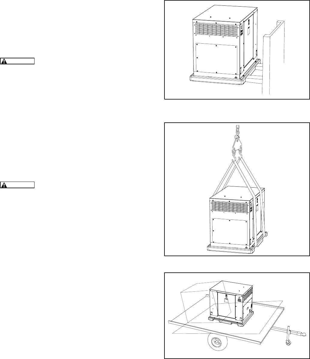
MOVING THE GENSET
The genset is heavy [600 lbs (272 kg)], and must be
handled with care. Carefully raise the genset with a
forklift or crane. Make sure the unit is stable before
moving it into position for installation. See Fig-
ures 2-4 and 2-5.
WARNING
The genset weighs 600 lb. (272 kg).
Dropping the genset can cause severe personal
injury or death. Keep feet and hands clear when
lifting the genset.
Use a fork lift truck to move the genset to the site you
prepared. The genset base has fork lift channels.
Orient the genset so that the access opening for the
control is opposite from the building and exhaust is
pointed away from windows, doors, vents, and hab-
itable areas.
The genset can be transported and moved to the
site in a small tilt-bed trailer. At the site, the genset
can be carefully slid from the trailer to the ground
when the bed is tilted. See Figure 2-6
CAUTION
The genset is shipped with oil in the
crankcase. Do not tip the genset on its side.
FIGURE 2-4. MOVING THE GENSET INTO
POSITION
FIGURE 2-5. LIFTING STRAPS
FIGURE 2-6. TILT-BED TRAILER
Redistribution or publication of this document,
by any means, is strictly prohibited.
2-5
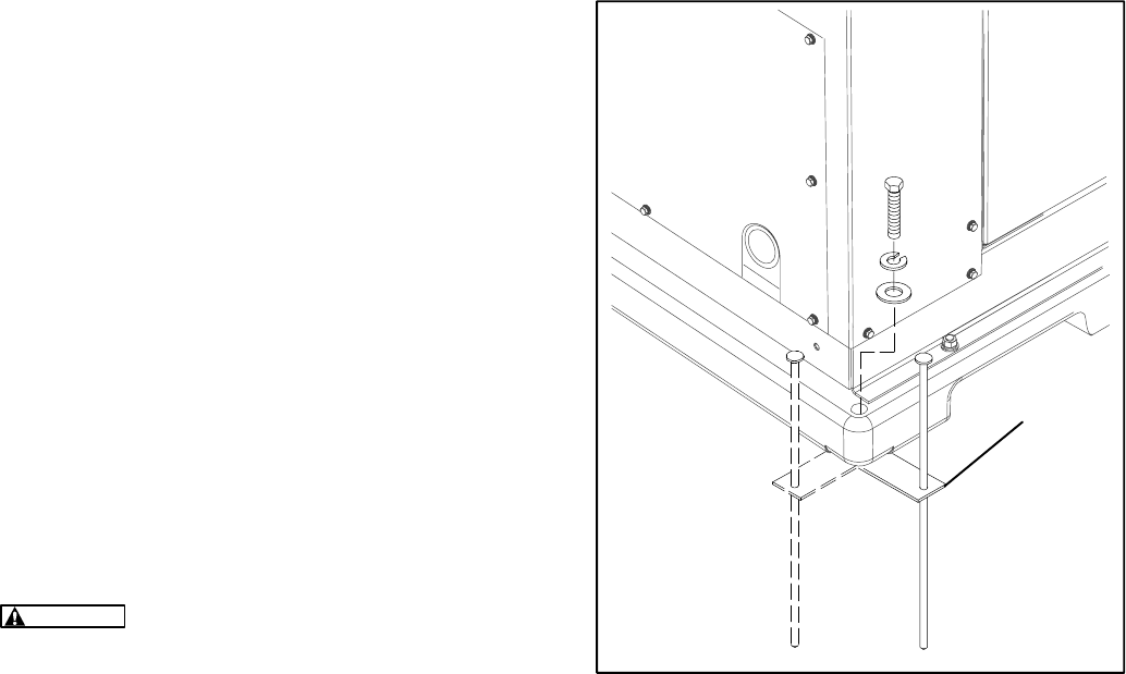
PLACING THE GENSET
Remove the plastic bag covering the genset and
collect loose shipped items, such as the Operator’s
Manual.
While the genset is raised, install the tabs to the four
corners of the base. Use the cap screws and wash-
ers supplied to secure the tabs to the base. The tabs
have weld-nuts on the bottom. The tabs can be
turned 90 degrees. See Figure 2-7.
Place the genset in position at the prepared site on
the ground. Pound the four spikes into the ground to
fix the genset in place. Do not pound the spikes into
any wires or pipes.
WARNING
Pounding the spikes into electric,
gas, or telephone service lines can result in se-
vere personal injury or death. Observe the util-
ity company markings.
MOUNTING
TAB
FIGURE 2-7. CORNER TABS
Redistribution or publication of this document,
by any means, is strictly prohibited.
2-6
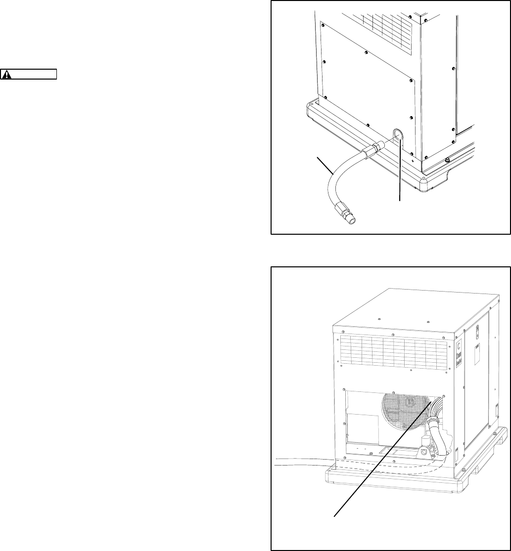
CONNECTING THE GENSET
Fuel Lines
WARNING
Fuel presents the hazard of fire or
explosion that can result in severe personal in-
jury or death. Do not smoke or allow any flame,
spark, pilot light, or other ignition sources near
fuel or in the installation area. Read the impor-
tant safety precautions in the
Fuel System
sec-
tion.
Connect the flexible fuel line included (See
Fuel
System
in Section 3) between the 3/4 NPT fitting on
the genset and the fuel supply line. See Figure 2-8.
Electrical Lines
Thread the flexible liquid-tight conduits through the
electrical stub-up area in the skid base and connect
the clamp on the conduit to the bottom of the genset
control box. The control has two holes for conduit on
its bottom. See Figure 2-9.
The outline drawing, Figure 7-1, shows alternate
conduit access areas on the sides of the enclosure.
Use these areas for entry into the enclosure when
underground access is not practical. The installer is
responsible for complying with all local codes.
Route the wires from the transfer switch, battery
charger, and battery pad heater through the conduit
and connect the wires to the mating terminals on
TB1 in the genset control box.
Refer to each of the sections in this manual for de-
tailed installation instructions and for important
safety precautions. Always follow the procedures in
the
Initial Start and Checks
section when the instal-
lation is complete.
FLEXIBLE
FUEL LINE
GENSET
FUEL FITTING
FIGURE 2-8. FUEL CONNECTION
CONTROL BOX
FIGURE 2-9. ELECTRICAL CONNECTION
Redistribution or publication of this document,
by any means, is strictly prohibited.
3-1
3. Mechanical
LOCATION
These gensets are designed for installation out-of-
doors in its weather-protective enclosure.
Factors to consider when deciding where to locate
the genset include:
•Proximity of genset, transfer switch, loads and
fuel supply lines (Natural Gas) or tanks (LPG).
•Access for maintenance and service.
•Security from vandalism, flooding and vehicu-
lar traffic.
•Noise levels and proximity of property lines.
•Safe dispersal of engine exhaust and cooling
air away from buildings, habitable areas, and
people.
•Possible obstructions to ventilation caused by
snowdrifts, plant growth, lawn clippings, falling
leaves, etc.
•See
Locating the Site
in Section 2.
ACCESS AND MOUNTING
The genset requires 3 ft (915 mm) minimum access
space on all sides for servicing. See Figure 3-1.
3 FT (915 MM) MIN
(ALL SIDES)
3 FT (915 MM) MIN
(ALL SIDES)
FIGURE 3-1. GENSET ACCESS FOR MAINTENANCE
Redistribution or publication of this document,
by any means, is strictly prohibited.
3-2
ENGINE EXHAUST
The exhaust system of this genset was designed for
this engine and is complete. Do not modify or add to
the exhaust system of this genset.
WARNING
EXHAUST GAS IS DEADLY! The ex-
haust system must terminate away from build-
ing vents, windows and doors and sheltered
spaces that may not have ample fresh air ven-
tilation.
Do not use genset discharge air or engine exhaust
for heating a room or enclosed space.
WARNING
Engine discharge air and exhaust
carry carbon monoxide gas (odorless and invis-
ible) which can cause asphyxiation and death.
Never use engine discharge air or exhaust for
heating a room or enclosed space.
FUEL SYSTEM
WARNING
Fuel systems must be installed by
qualified service technicians. Improper installa-
tion presents hazards of fire and improper op-
eration, resulting in severe personal injury or
property damage.
Gensets can be equipped to operate on:
•GHAB/101, Natural Gas
•GHAB/101, LP Vapor (requires conversion)
•GHAB.102, LP Liquid
The genset identification plate has been marked to
indicate the fuel type to connect to the genset.
WARNING
Gaseous fuels are flammable and
explosive and can cause severe personal injury
or death. Do not smoke if you smell gas or are
near fuel tanks or fuel-burning equipment or are
in an area sharing ventilation with such equip-
ment. Keep flames, sparks, pilot lights, electri-
cal arcs and arc-producing equipment and all
other sources of ignition well away. Keep a type
ABC fire extinguisher handy.
Install a dry-type fuel filter (fuel strainer) ahead of
the service pressure regulator to protect the sensi-
tive pressure regulating components and orifices
downstream from rust, scale and other solid sub-
stances carried along in the gas stream.
In all fuel system installations, cleanliness is of the
upmost importance. Make every effort to prevent
entrance of moisture, dirt, excess thread sealant, or
contaminants of any kind. Clean all fuel system
components before installing.
The section of flexible fuel hose supplied with the
genset must be used between the engine’s fuel sys-
tem and fuel supply line to protect the fuel system
from damage caused by vibration, expansion and
contraction. The fuel hose must be installed accord-
ing to all applicable codes and standards.
Gaseous-fuel supply system design, materials,
components, fabrication, assembly, installation,
testing, inspection, operation and maintenance
must comply with the applicable codes. See NFPA
Standards No. 37, No. 54 and No. 58.
Most codes require a manual shutoff valve ahead of
a flexible fuel hose. The genset has an electric (bat-
tery-powered) shutoff valve included between the
fuel supply and the carburetor. The manual valve
should be of the indicating type. The electric valve
should be wired so that the valve is closed when the
genset is off.
Until the genset is connected, cap the fuel line stub-
up at the genset to prevent dirt from entering and
gas discharging if the gas supply shutoff valve is
opened inadvertently.
See the
Specifications
section for Natural Gas/LP
Vapor fuel inlet size.
Redistribution or publication of this document,
by any means, is strictly prohibited.

3-3
NATURAL GAS FUEL SYSTEM
The genset requires an adequate fuel supply to op-
erate correctly at full load. The length of the fuel sup-
ply pipe from the gas service entrance to the genset
must be known to determine the correct fuel pipe
size. Refer to Table 3-1 to find the fuel supply re-
quirement for your genset. Pipe must be minimum
of schedule 40 subject to the authority having juris-
diction.
Natural Gas Supply Line Size
The genset requires up to 240,000 BTU/hr (240 cu-
bic feet/hr) delivered to the genset inlet at 11 inches
(28 mm) WC, nominal. If the meter serves other gas
appliances such as a furnace, water heater, or
stove, you must consult with the local natural gas
utility to determine whether the natural gas meter is
adequate.
It is important to consider other loads operated from
the fuel supply pipe. Other loads, such as space
heating and water heating equipment, must also be
determined to correctly size the fuel pipe. Use the
total load requirement of the fuel supply line to de-
termine the size of the fuel supply pipe. Use
Table 3-1 to determine the correct pipe size. (typi-
cally, 1 ft3/hr =1000 BTU/hr, )
When the fuel delivery value falls between two col-
umns, use the larger value.
GENSET SHUTOFF
VALVE GAS METER
FIGURE 3-2. TYPICAL NATURAL GAS INSTALLATION
TABLE 3-1. NATURAL GAS PIPE CAPACITY—CUBIC FEET OF GAS PER HOUR
Maximum pipe capacity in cubic feet per hour of 0.60 specific gravity natural gas with
a pressure drop of 0.5 inches (1.27 mm) WC over the length
NOMINAL IRON
PIPE SIZE
LENGTH OF PIPE IN FEET
PIPE SIZE
(INCHES) 10 20 30 40 50 60 70 80 90 100 125 150 175 200
3/4 360 250 200 170 151 138 125 118 110 103 93 84 77 72
1680 465 375 320 285 260 240 220 205 195 175 160 145 135
1-1/4 1400 950 770 660 580 530 490 460 430 400 360 325 300 280
Redistribution or publication of this document,
by any means, is strictly prohibited.
3-4
LP VAPOR FUEL SYSTEM
WARNING
Fuel leaks can lead to explosive ac-
cumulations of gas. Natural gas rises and can
accumulate under overhanging hoods and in-
side housings and buildings. LP Vapor sinks air
and can accumulate inside housings, base-
ments and other below-grade spaces. Prevent
gas leaks and the accumulation of gaseous fuel
in the event of a leak.
NFPA Standard No. 58 requires all persons han-
dling and operating LP Vapor to be trained in
proper handling and operating procedures.
Converting from Natural Gas to LP Vapor
The genset leaves the factory set up for natural gas.
The genset must be converted to use LP Vapor.
Conversion involves inserting an orifice into the
brass elbow (See Figure 3-3) and adjusting the car-
buretor (See Figure 3-4). The genset is shipped
with a kit containing the orifice for conversion.
A genset purchased to use Natural Gas or LP Vapor
can not be converted to use LP Liquid, and one that
is purchased to use LP Liquid can not be converted
to use Natural Gas or LP Vapor.
Conversion Procedure (Natural Gas to LP Va-
por):
1. Remove access panel on the control side of the
genset. Lift handle up and out, then turn count-
er-clockwise, swing the access panel down,
and lift out.
2. Remove the elbow following the regulator in
the fuel line (Figure 3-3).
3. Insert the orifice into the elbow (smaller end
into the elbow first) and reinstall the elbow.
4. Turn the carburetor (mixer) idle screw from all
the way in (original factory setting) out so that
the top of screw is flush with the body of the car-
buretor. See Figure 3-4.
5. Replace access panel. Set it in the bottom of
the opening, swing it up, turn the latch clock-
wise, and fold up to secure the panel.
ELBOW
ORIFICE FOR LP VAPOR
ORIFICE
FIGURE 3-3. NATURAL GAS TO LP VAPOR
CONVERSION
CARBURETOR
(MIXER)
ADJUSTMENT SCREW
FIGURE 3-4. CARBURETOR ADJUSTMENT
Redistribution or publication of this document,
by any means, is strictly prohibited.

3-5
Fuel Pressure
WARNING
High gas supply pressure can cause
gas leaks which can lead to fire and severe per-
sonal injury or death. Gas supply pressure must
be adjusted to Specifications by qualified per-
sonnel.
The gas pressure regulators in each line provide
constant gas pressure at the gas mixer under vary-
ing load conditions. There are pressure test ports
on both sides of the regulator for measuring supply
and regulated fuel pressures (natural gas or LP Va-
por systems). When measuring supply pressure,
the most accurate reading would be on the input
side of the solenoid valve.
See the
Specifications
section for fuel pressure lim-
its and fuel consumption. Size the fuel line so that
LP Vapor and natural gas systems have no more
than 2” WC of drop from no load to full load.
For LP Liquid, the maximum permissible fuel supply
pressure is 300 psi (2,070 kPa) under any operating
condition.
LP Vapor Fuel Supply Line Size
Fuel line size depends on the amount of fuel need-
ed to run the genset at full load at the distance the
fuel must be moved. The genset requires 85.0 ft3/hr
of LP Vapor at full load delivered to the genset inlet
at 11 inches (280 mm) water column gas pressure.
Figure 3-5 shows a typical LP Vapor installation and
Table 3-2 lists fuel capacity for given distances and
pipe size.
GENSET
SHUTOFF
VALVE SECONDARY
REGULATOR
PRIMARY
REGULATOR
PROPANE
TANK
FIGURE 3-5. TYPICAL LP VAPOR INSTALLATION
TABLE 3-2. LP VAPOR PIPE CAPACITY—CUBIC FEET OF GAS PER HOUR
Maximum pipe capacity in cubic feet per hour of LP vapor with a pressure drop of 0.5 inches (1.27 mm) WC over the length
NOMINAL IRON
PIPE SIZE
LENGTH OF PIPE IN FEET
PIPE SIZE
(INCHES) 10 20 30 40 50 60 70 80 90 100 125 150
3/4 227 157 126 107 95 87 78 74 69 65 58 53
1428 293 236 201 179 164 151 138 129 123 110 101
1-1/4 882 598 485 416 365 333 308 289 207 252 230 204
1-1/2 1323 920 743 624 567 570 472 434 409 390 346 315
22488 1732 1386 1197 1058 958 882 819 768 724 642 598
Redistribution or publication of this document,
by any means, is strictly prohibited.

3-6
Recommended Fuel
Use clean, fresh HD-5 grade liquified petroleum gas
or equivalent product consisting of at least 90 per-
cent propane. Commercial liquified petroleum gas
fuels may contain more than 2.5 percent butane
which can result in poor fuel vaporization and low
tank pressure resulting in poor engine starting in
low ambient temperatures (below 32°F (0°C).
Satisfactory performance requires that the LP Va-
por (vapor-withdrawal models only) be supplied at a
pressure within the range of 7-15 in (178-381 mm)
WC (water column).
WARNING
High LP supply pressure (vapor
withdrawal models only) can cause gas leaks
which can lead to fire and severe personal inju-
ry or death. LP Vapor supply pressure must be
adjusted to Specifications by qualified person-
nel.
WARNING
LP gas presents the hazard of fire or
explosion that can cause severe personal injury
or death. Do not permit any flame, spark, arc-
producing equipment, switch, pilot light, ciga-
rette, or other ignition source near the fuel sys-
tem. Keep an ABC type fire extinguisher nearby.
LP Vapor Fuel Tank Size
If the genset operates on LP Vapor, you must supply
an LP tank for the fuel supply. To assist in the proper
selection of the fuel tank, follow the guidelines be-
low.
LP tanks are sized by the number of gallons of
water they can hold, not the amount of fuel they
hold.
LP tanks are generally filled to only 80% of their
water capacity.
Low ambient temperatures affect the amount
of fuel available from the LP tank.
Approximately 60% of the fuel (in gallons) filled
in the tank can be effectively used.
LP tanks must be fitted with a pressure reduc-
ing regulator before connection to the genset to
prevent fuel system damage.
LP tanks must be located at least 10 ft (3048
mm) from any source of combustion (including
the genset).
TABLE 3-3. REQUIRED LP TANK SIZE IN GALLONS (LITERS) FOR
INDICATED TEMPERATURES WHEN KEPT AT LEAST HALF FULL
LOWEST AVERAGE WINTER TEMPERATURE
WITHDRAWAL RATE 32°F(0°C) 20°F(–7°C) 10°F(–12°C) 0°F(–18°C) –10°F(–23°C) –20°F(–29°C) –30°F(–34C)
100 cfh (250,000 BTU/hr)
[2.8 m3/hr (264 MJ/hr)] 250
(945) 250
(945) 250
(945) 400
(1515) 500
(1890) 1000
(3785) 1500
(5675)
150 cfh (375,000 BTU/hr)
[4.2 m3/hr (395.6 MJ/hr)] 300
(1135) 400
(1515) 500
(1890) 500
(1890) 1000
(3785) 1500
(5675) 2500
(9640)
200 cfh (500,000 BTU/hr)
[5.7 m3/hr (527.5 MJ/hr)] 400
(1515) 500
(1890) 750
(2840) 1000
(3785) 1200
(4540)
2000
(7570) 3500
(13250)
300 cfh (750,000 BTU/hr)
[8.5 m3/hr (791.2 MJ/hr)] 750
(2840) 1000
(3785) 1500
(5675) 2000
(7570) 2500
(9460) 4000
(15140) 5000
(18925)
Redistribution or publication of this document,
by any means, is strictly prohibited.

3-7
Testing Fuel System for Leaks
Before operating the set, test the LP fuel system for
leaks. Energize the fuel solenoid from a separate
12-volt DC source before testing the fuel system.
Testing must conform to procedures listed in
NFPA-58, or to the UL recommended test proce-
dure, as follows:
After assembly and before initial operation, all fuel
system connections, hose valves, regulators, and
fittings must be tested and proven free of leaks us-
ing a soap-and-water (or equivalent) solution while
the system is under gas or air pressure of at least
1.5 times the supply pressure or 3 psi (20.7 kPa)
minimum.
Other approved methods of detecting leaks can be
used if appropriate. DO NOT make this test with a
flame.
WARNING
LP fuel presents the hazard of ex-
plosion or fire which can result in severe per-
sonal injury or death. Do not smoke or allow any
flame, spark, pilot light, arc-producing equip-
ment, switch, or other ignition sources around
fuel or fuel components.
LP LIQUID FUEL SYSTEM
Fuel System Provisions
Satisfactory performance requires that the LP Liq-
uid (liquid-withdrawal models only) be supplied at a
pressure within the range of 30 to 300 psi (20.7 to
2070 kPa). The genset requires 2.41 gal/hr (9.1 l/
hr) of LP Liquid at full load.
NFPA 58, Storage and Handling of LIquefied Petro-
leum Gasses, prohibits LP liquid from entering build-
ing walls.
TABLE 3-4. LP LIQUID PIPE CAPACITY
Based on pressure drop of 1 psi (6.9 kPa)
LIQUID
PETROLEUM
LIQUID
PETROLEUM
PIPE LENGTH - FEET (M)
PETROLEUM
FLOW
CFH
PETROLEUM
FLOW
GPH
1/4 Inch
Schedule 3/8 Inch
Schedule 1/2 Inch
Schedule 3/4 Inch
Schedule
CFH
(M3/HR)
GPH
(LITER/HR.) 40 80 40 80 40 80 40 80
360 (10.2) 10 (38) 729
(222) 416
(127)
540 (15.3) 15 (57) 324
(98) 185
(56)
720 (20.4) 20 (76) 182
(55) 104
(32) 825
(251) 521
(159)
1440 (40.8) 40 (152) 46
(14) 26
(8) 205
(62) 129
(39) 745
(227) 504
(154)
2160 (61.1) 60 (227) 20
(6.1) 11
(3.4) 92
(28) 58
(18) 331
(101) 224
(68)
2880 (81.5) 80 (303) 11
(3.4) 6
(1.8) 51
(16) 32
(10) 187
(57) 127
(39) 735
(224) 537
(164)
3600 (101.9) 100 (378) 7
(2.1) 4
(1.2) 33
(10) 21
(6.4) 119
(36) 81
(25) 470
(143) 343
(105)
Redistribution or publication of this document,
by any means, is strictly prohibited.
3-8
THIS PAGE LEFT INTENTIONALLY BLANK
Redistribution or publication of this document,
by any means, is strictly prohibited.
4-1
4. Electrical Connections
WARNING
Electrical connections must be
installed by qualified electricians. Improper
installation presents hazards of electrical
shock and improper operation, resulting in se-
vere personal injury or property damage.
To prevent injury due to accidental start-up, do not
connect the battery cables to the battery until the
installation has been completed and it is time to
start the set. See
Installation Review and Startup,
Section 5.
WARNING
Automatic startup of the genset
while performing maintenance or service can
cause severe personal injury or death. Push the
control switch to Off and disconnect the nega-
tive (–) battery cable from the battery to keep the
genset from starting up while working on it.
CONDUIT
Stranded conductors and flexible conduit must be
used for connections to take up movement of the
genset. The control panel has two access holes for
flexible conduit: one hole is 1/2 in dia the other is 1 in
dia. Refer to the outline drawing, Figure 7-1, for the
location of these holes in the control panel and for
the location of two other areas on the sides of the
enclosure for alternate access.
The larger conduit hole is intended for power output
wires and the optional battery pad heater wires. The
smaller conduit hole is intended for the remote start
signal wires, optional battery charger wires, equip-
ment ground wire, and the remote light wire. See
Table 4-1. for a complete list of all wires including
optional wires. All external connections except the
common or equipment ground are made to the low-
er terminals of TB1.
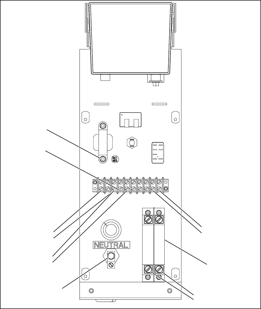
CONTROL AND POWER CONNECTIONS
Remove the access panel from the end of the gen-
set, and the cover from the back of the the control
panel. Figure 2-9 shows the location of the control
panel.
Connect the AC power output conductors to the bot-
tom terminals of the circuit breaker and the neutral
to the lug on the back of the control assembly. Fig-
ure 4-1 shows the back of the control with the cover
removed.
Figure 4-1 also shows connection points for the
transfer switch, battery charger, equipment ground
and optional battery pad heater.
The National Electrical Code (NFPA No. 70) should
be used as a guide for all AC wiring connections.
WARNING
Keep fuel lines physically sepa-
rated from electrical wiring. Wire and fuel line
contact can cause severe personal injury or
death.
WARNING
Faulty grounding can lead to fire
and electrocution, resulting in severe personal
injury or death. The genset must be grounded in
accordance with the applicable codes.
TABLE 4-1. WIRE CONNECTIONS AT THE GENSET
WIRE TERMINAL IN GENSET
AC Output Circuit Breaker
L1 and L2
AC Neutral Neutral Lug
Battery Charger
Negative TB1-3 (GND)
Battery Charger
Positive TB1-1
Transfer Switch
(Remote) TB1-3 and TB1-5
Battery Pad Heater TB1-9 (Black) and
TB1-10 (White)
Remote Light TB1-4
Common Ground Lug above terminal strip
Redistribution or publication of this document,
by any means, is strictly prohibited.
4-2
AC OUTPUT
L2
L1
BATTERY CHARGER
TB1–1 +
TB1–3 – (GND)
AC NEUTRAL
BATTERY PAD HEATER
TB1–10
TB1–9
TRANSFER SWITCH
TB1–3 REMOTE GND
TB1–5 REMOTE START
TB1
L1 L2
1 2 3 4 5 6 7 8 9 10
REMOTE LIGHT
TB1–4
MAIN OUTPUT
CIRCUIT BREAKER
COMMON GROUND
FIGURE 4-1. ELECTRICAL CONNECTIONS ON THE BACK OF THE CONTROL ASSEMBLY
Redistribution or publication of this document,
by any means, is strictly prohibited.
4-3
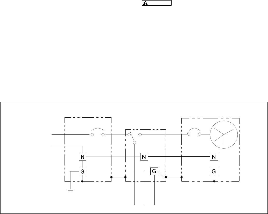
GROUNDING
The generator set, power supply wiring, and all con-
nected electrical equipment must be bonded to a
common grounding point in accordance with appli-
cable codes or standards. Do not provide an addi-
tional ground for the genset alone.
The genset ground terminal (TB1-3) is connected to
the common ground on the control panel. Figure 4-2
illustrates typical system grounding for a 2-pole au-
tomatic transfer switch (ATS). Note that the genera-
tor neutral is connected to the ATS and is NOT
bonded to ground at the generator.
WARNING
Contact with electrical equipment
can result in severe personal injury or death. It
is extremely important that bonding and equip-
ment grounding be properly done. All metallic
parts that could become energized under ab-
normal conditions must be properly grounded.
Typical requirements for bonding and grounding
are given in the National Electrical Code. All con-
nections, wire sizes, etc. must conform to the re-
quirements of the electrical codes in effect at the
installation site.
2-POLE AUTOMATIC
TRANSFER SWITCH
GENERATOR SETSERVICE ENTRANCE
2 WIRES & GROUND
TO LOAD
1∅
N
TO UTILITY
SERVICE
FIGURE 4-2. TYPICAL SYSTEM GROUNDING ONE-LINE DIAGRAM
Redistribution or publication of this document,
by any means, is strictly prohibited.
4-4
TRANSFER SWITCH
An approved device must be used to prevent the
genset and utility from being interconnected. Fig-
ures 4-2 and 4-3 show the control, line, load and
utility connections to the transfer switch.
Refer to the manufacturer’s transfer switch installa-
tion manual for important safety precautions and
installation instructions.
WARNING
Interconnecting the genset and the
public utility (or any other power source) can
lead to the electrocution of personnel working
on the utility lines, damage to equipment and
fire. An approved switching device must be
used to prevent interconnections.
WARNING
Contact with electrical equipment
can result in severe personal injury or death. It
is extremely important that bonding and equip-
ment grounding be done properly done. All met-
al parts that could become energized under nor-
mal conditions must be properly grounded
The transfer switch can be connected to a partial
load equal to the capacity of the genset or to the en-
tire load. Refer to Figure 4-3 for a diagram of a par-
tial load (60 amp) connection and to Figure 4-4 for a
diagram of an entire load (200 amp) connection. If
the transfer switch is connected to the entire load,
the load on the genset must be managed so that the
capacity of the genset is not exceeded. See
Power-
ing Equipment
in the Operator’s Manual for genset
loading details.
Figures 4-5 shows the Onan RST Transfer Switch
to genset control connections, and Figure 4-6
shows the power connections at the RST Transfer
Switch. Use the National Electrical Code (NFPA No.
70) as a guide for all AC wiring connections.
RS 12000 GENSET
NORMAL STANDBY
60 AMP RST
TRANSFER PANEL
60 AMP
SUB–PANEL
60
AMP
TO STANDBY LOADS
METER
MAIN SERVICE
ENTRANCE PANEL
200
AMP
60
FIGURE 4-3. TRANSFER SWITCH WITH 60 AMP LOAD
Redistribution or publication of this document,
by any means, is strictly prohibited.

4-5
RS 12000 GENSET
NORMAL STANDBY
200 AMP RST
TRANSFER PANEL
200 AMP
MAIN DISTRIBUTION
PANEL
TO ALL LOADS
200
AMP
200 AMP OVER CURRENT
PROTECTION DEVICE
METER
UTILITY SOURCE
FIGURE 4-4. TRANSFER SWITCH WITH 200 AMP LOAD
Redistribution or publication of this document,
by any means, is strictly prohibited.
4-6
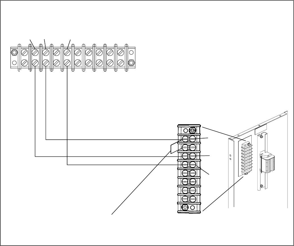
GND
TB2-1
B+
TB2-3
RMT
START
TB2-4
RST TRANSFER SWITCH
TB2
GHAB GENSET
TB1
GND
TB1-3 RMT START
TB1-5
B+
TB1-2
TB2-1
TB1–1
JUMPER
TB2-1 TO TB2–2
FIGURE 4-5. RST TRANSFER SWITCH CONTROL CONNECTIONS
Redistribution or publication of this document,
by any means, is strictly prohibited.
4-7
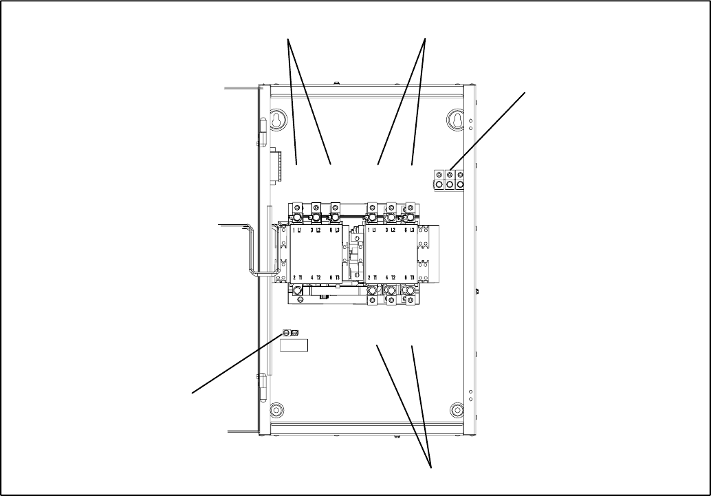
A B C
EMERGENCY
POWER SOURCE
LOAD
NORMAL
POWER SOURCE
NEUTRAL BAR
T1 T2 T3
L1 L2 L3 L1 L2 L3
A B CA B C
GND TERMINAL
FIGURE 4-6. RTS GENSET LINE CONNECTIONS
Redistribution or publication of this document,
by any means, is strictly prohibited.

4-8
BATTERY
The genset has a 12 VDC, negative-ground control
and engine cranking system. The engine is
equipped with an automatic, 18-amp nominal bat-
tery charging circuit. A remote battery charger can
be connected to the genset to keep the battery
charged. The battery must be installed in the battery
tray and secured to the tray with the strap. See Fig-
ure 4-7. The genset requires a 12 volt BCI Group 26
battery [8.2L x 6.8W x 8.1H inches (208 x 173 x
205 mm) to the top of the terminals].
Battery Capacity
See
Specifications
for minimum battery require-
ments.
WARNING
Arcing can ignite the explosive hy-
drogen gas given off by the battery, causing se-
vere personal injury. The battery compartment
must be ventilated and must isolate the battery
from spark-producing equipment.
Battery Cables
To prevent injury due to accidental start-up, do not
connect the battery cables to the battery until the
installation has been completed and it is time to
start the set. See
Installation Review and Startup.
WARNING
Electric sparks can ignite gaseous
fuel and cause severe personal injury or death.
Optional battery heater
Use the optional thermostatically controlled heater
for the battery for more reliable starting in ambient
temperatures down to –20° F (–28.8° C). The heat-
er fits in the battery tray and must be connected to
external AC power. The installer is responsible for
complying with all local electrical codes. See Fig-
ure 4-1 and Table 4-1 for wiring details.
BATTERY
STRAP
FIGURE 4-7. BATTERY INSTALLATION
Redistribution or publication of this document,
by any means, is strictly prohibited.
5-1
5. Installation Review and Startup
INSTALLATION REVIEW
Before starting the genset inspect the installation
and check off (√) each of the following questions if it
can be answered “YES”. If a question cannot be
checked off, review the appropriate section in the
manual.
[ ] Is there access to the control switch for starting
and stopping the genset?
[ ] Is there access to the circuit breaker and con-
trol fuses for resetting or replacement?
[ ] Is there access to the engine oil drain for drain-
ing engine oil?
[ ] Are the cooling air inlet and outlet openings
free of obstructions?
[ ] Have the AC output connections been made
properly?
[ ] Has an approved transfer switch been installed
to prevent connecting the genset to the utility?
[ ] Has a properly sized battery been installed?
[ ] Are all fuel connections tight?
[ ] Is fuel supply pressure correct?
[ ] Are electrical and fuel lines properly sepa-
rated?
[ ] Does engine exhaust disperse away from
buildings?
STARTUP
When all installation requirements have been met,
connect the battery cables to the battery, positive
(+) cable first.
WARNING
Batteries give off explosive gases
that can cause severe personal injury. Do not
smoke near batteries. Keep flames, sparks, pi-
lot lights, electrical arcs and arc-producing
equipment, switches, and all other ignition
sources well away.
Do not disconnect the battery cables while the
genset is cranking or running: the arcing can ig-
nite the explosive battery gases.
Read through the Operator’s Manual and perform
the maintenance and pre-start checks instructed.
The genset is shipped from the factory with the
proper level of engine oil, but should be checked be-
fore the genset is started. Start and operate the
genset, following all the instructions and precau-
tions in the Operator’s Manual.
WARNING
EXHAUST GAS IS DEADLY! Do not
operate the genset indoors.
Check for fuel and exhaust leaks and unusual
noises while the genset is running under full and in-
termediate loads. To calculate electrical loads see
Operation
in the Operator’s Manual. Do not place
the genset in service until all leaks have been fixed
and operation is satisfactory.
Before leaving the site, if the genset is ready to
be placed in service, set the control switch to
the AUTO position to provide automatic stand-
by power.
Redistribution or publication of this document,
by any means, is strictly prohibited.
5-2
THIS PAGE LEFT INTENTIONALLY BLANK
Redistribution or publication of this document,
by any means, is strictly prohibited.

6-1
6. Specifications
GENERATOR:
MODEL: Natural Gas LP Vapor LP Liquid
Rated Power 10 kW 11 kW 10 kW
Frequency 60 Hertz
Voltage 120/240 volts
Circuit Breaker Rating 2-Pole, 50 amperes
Speed 3600 RPM
FUEL CONSUMPTION:
No-load
Half-load
Full-load
84,000 BTU/hr
124,000 BTU/hr
190,000 BTU/hr
37.0 ft.3/hr
54.0 ft.3/hr
80.0 ft.3/hr
1.01 gal/hr (3.6 l/hr)
1.50 gal/hr (4.4 l/hr)
2.20 gal/hr (9.1 l/hr)
Natural Gas Supply Pressure 7-15“ WC (water column)
(178-381 mm) WC
LP Supply Pressure (vapor) 7-15” WC (water column)
(178-381 mm) WC
LP Supply Pressure (liquid) 30–300 psi
(207–2070 kPA)
Gas Supply Connection 3/4 inch NPT 3/4 inch NPT 1/4 inch NPT
ENGINE: Onan Performer P224, 1,000 cc. High Motor Starting Reserve
Bore 3.653 inch (90 mm)
Stroke 3.000 inch (76 mm)
Displacement 60 inch3 (980 cc)
Compression Ratio 7.0 : 1
Minimum Cylinder Compression Test
Pressure 75 psi (517 kPa)
Oil Capacity (with filter)* 3.5 quart (3.3 liter)
Intake Valve Clearance (Cold) 0.005 inch (0.13 mm)
Exhaust Valve Clearance (Cold) 0.013 inch (0.33 mm)
Spark Plug Gap 0.025 inch (0.64 mm)
Spark Plug Tightening Torque 8 lb-for (10 N-m)
Ignition Timing (electronic ignition) 20° BTDC (non-adjustable)
CRANKING SYSTEM:
Nominal Battery Voltage (BCI, GP 26) 12 volts
Battery Cranking Capacity 530 CCA @ 0° F (–17° C)
Nominal Battery Charging Output 18 amperes
Fuse F1 (control B+ input circuit) 20 amperes
ENCLOSURE:
Control Features Lighted Run/OFF Auto Switch, Running Time Meter, 50 Amp UL Listed Circuit
Breaker, DC Control Fuse. Large User Connection Area
Enclosure Features Sound Attenuated Drip-Proof Design, less than 70 dBA at 23 ft. (7M), Easy Service
Access, Internal Starting Battery Tray and Tie-Down, Heavy Duty Exterior High
performance Fluoropolymer Finish Coat System
Exhaust Silencer Fully Enclosed Exhaust Silencer, Insulated Heat Shield, Ultra-Low Noise
Installation Features Pre-Mounted UV Resistant Plastic Installation Base, Convenient Electrical and Gas
Supply Connections, Ground Anchor System for Base Included
Unit Dimensions 45 in (1143 mm) Length, 34 inch (864 mm) Width, 39 inch (986 mm) Height (Includ-
ing installation base)
Weight 600 Pounds (272) kg)
Sound Level at Full Load Less than 70 dBA at 23 ft. (7 m)
* See
Periodic Maintenance
for oil filling instructions.
Redistribution or publication of this document,
by any means, is strictly prohibited.
6-2
THIS PAGE LEFT INTENTIONALLY BLANK
Redistribution or publication of this document,
by any means, is strictly prohibited.
7-1
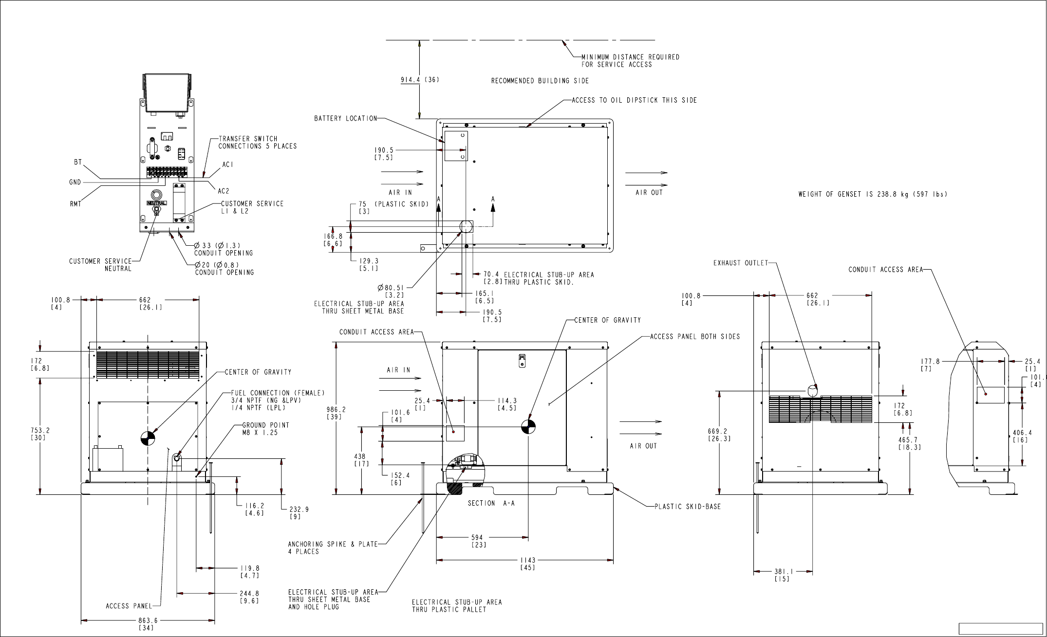
ProE0500_3294 rev.B
FIGURE 7-1. GHAB OUTLINE DRAWING
Redistribution or publication of this document,
by any means, is strictly prohibited.
7-2
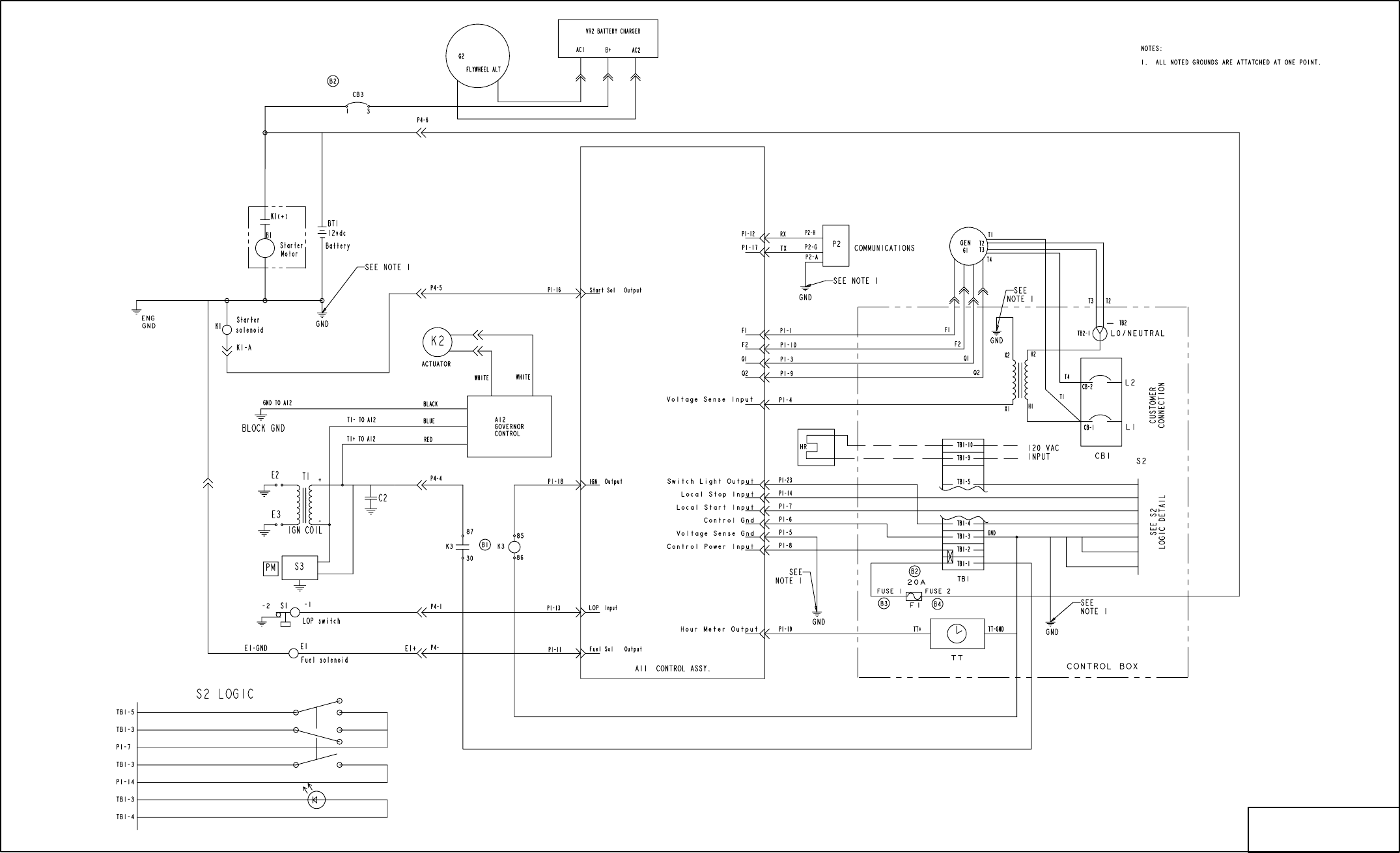
No. 6111270 sh 1 of 1
Rev. B Sys: ProE
Modified 699
FIGURE 7-2. GHAB WIRING DIAGRAM
Redistribution or publication of this document,
by any means, is strictly prohibited.
7-3
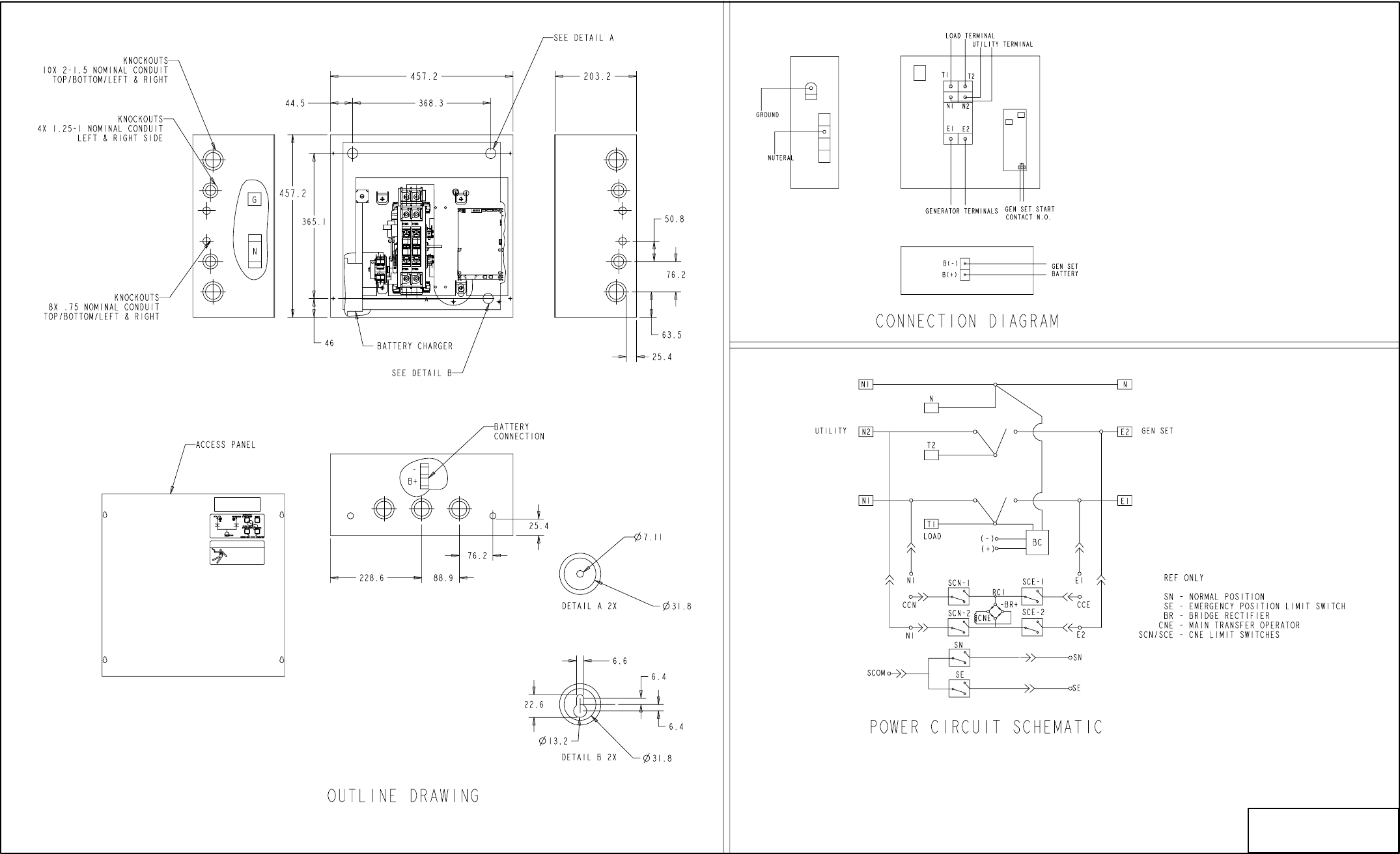
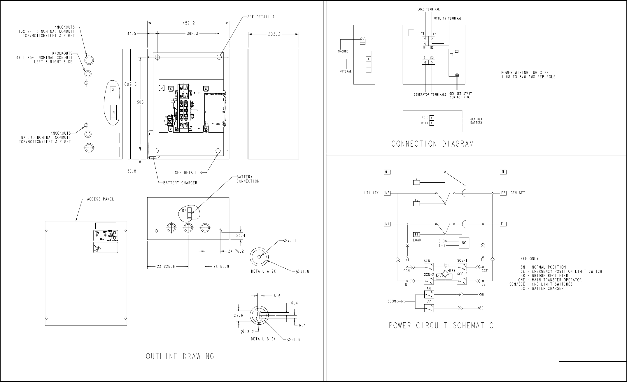
No. 3064692 Sh 2 of 2
Rev. B Sys: ProE
Modified 601
FIGURE 7-3. RSZ 100-AMP NEMA-1 TRANSFER SWITCH
Redistribution or publication of this document,
by any means, is strictly prohibited.
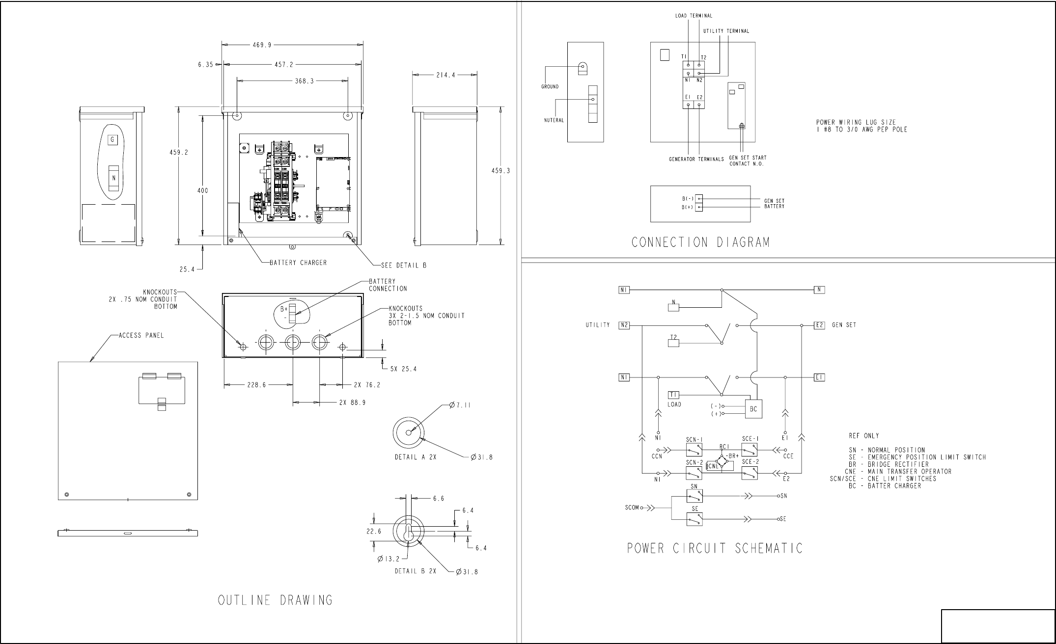
7-4
No. 3064693 Sh 2 of 2
Rev. A Sys: ProE
Modified 501
FIGURE 7-4. RSZ 200 AMP NEMA-1 TRANSFER SWITCH
Redistribution or publication of this document,
by any means, is strictly prohibited.
7-5
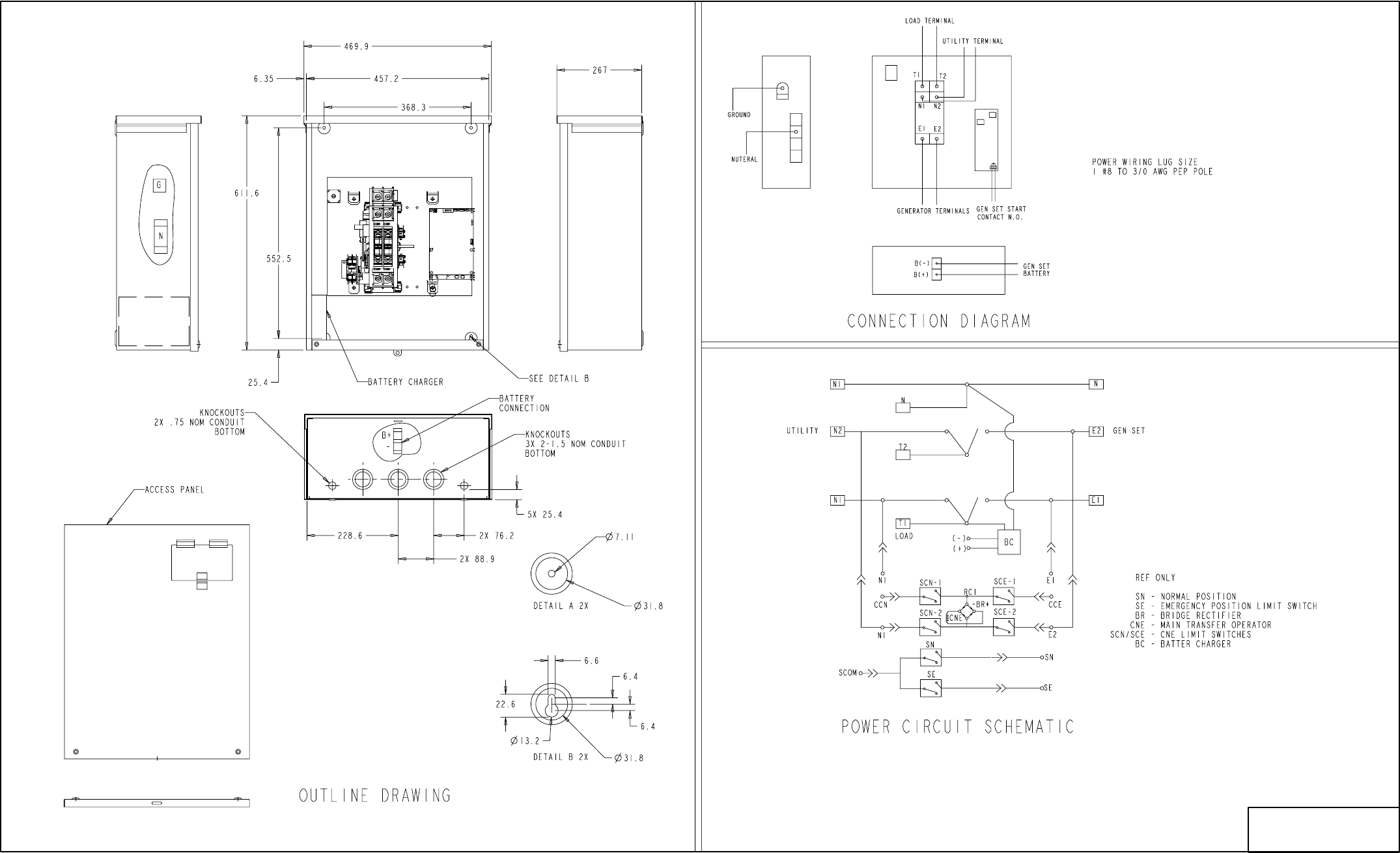
No. 3064694 Sh 2 of 2
Rev. A Sys: ProE
Modified 501
FIGURE 7-5. RSZ 100-AMP NEMA-3R TRANSFER SWITCH
Redistribution or publication of this document,
by any means, is strictly prohibited.
7-6
No. 3064695 Sh 2 of 2
Rev. A Sys: ProE
Modified 501
FIGURE 7-6. RSZ 200 AMP NEMA-3R TRANSFER SWITCH
Redistribution or publication of this document,
by any means, is strictly prohibited.

Cummins Power Generation
1400 73rd Avenue N.E.
Minneapolis, MN 55432
1-800-888-6626
763-574-5000 International Use
Fax: 763-528-7229
Cummins is a registered trademark of Cummins Inc.
Redistribution or publication of this document,
by any means, is strictly prohibited.
