967 0604 Onan GNAA GNAB GNAC Genset (w PCC 1301 Power Command) Install Manual (12 2005)
User Manual: 967-0604 Onan GNAA GNAB GNAC Genset (w-PCC-1301 PowerCommand) Install manual (12-2005)
Open the PDF directly: View PDF ![]() .
.
Page Count: 38
GenSet Model
GNAA, GNAB, GNAC
Printed in U.S.A. 967-0604 12-2005
Installation Manual
with PowerCommand Control
PCC1301
Redistribution or publication of this document,
by any means, is strictly prohibited.

i
Table of Contents
SECTION TITLE PAGE
IMPORTANT SAFETY INSTRUCTIONS iii. . . . . . . . . . . . . . . . . . . . . . . . . . . . . . .
1 INTRODUCTION
About this Manual 1-1. . . . . . . . . . . . . . . . . . . . . . . . . . . . . . . . . . . . . . . . . . . . . .
Installation Overview 1-1. . . . . . . . . . . . . . . . . . . . . . . . . . . . . . . . . . . . . . . . . . . .
2 SPECIFICATIONS 2-1. . . . . . . . . . . . . . . . . . . . . . . . . . . . . . . . . . . . . . . . . . . . . . . .
3 MOUNTING THE GENERATOR SET
General 3-1. . . . . . . . . . . . . . . . . . . . . . . . . . . . . . . . . . . . . . . . . . . . . . . . . . . . . . .
Location 3-1. . . . . . . . . . . . . . . . . . . . . . . . . . . . . . . . . . . . . . . . . . . . . . . . . . . . . . .
Mounting 3-3. . . . . . . . . . . . . . . . . . . . . . . . . . . . . . . . . . . . . . . . . . . . . . . . . . . . . .
Access to Set 3-3. . . . . . . . . . . . . . . . . . . . . . . . . . . . . . . . . . . . . . . . . . . . . . . . . .
4 MECHANICAL CONNECTIONS
General 4-1. . . . . . . . . . . . . . . . . . . . . . . . . . . . . . . . . . . . . . . . . . . . . . . . . . . . . . .
Fuel System 4-1. . . . . . . . . . . . . . . . . . . . . . . . . . . . . . . . . . . . . . . . . . . . . . . . . . .
Exhaust System 4-3. . . . . . . . . . . . . . . . . . . . . . . . . . . . . . . . . . . . . . . . . . . . . . . .
Ventilation and Cooling 4-5. . . . . . . . . . . . . . . . . . . . . . . . . . . . . . . . . . . . . . . . . .
5 DC CONTROL WIRING
Control Wiring 5-1. . . . . . . . . . . . . . . . . . . . . . . . . . . . . . . . . . . . . . . . . . . . . . . . . .
TB1 Remote Monitor/Control Connections 5-2. . . . . . . . . . . . . . . . . . . . . . . . .
Switched B+ 5-2. . . . . . . . . . . . . . . . . . . . . . . . . . . . . . . . . . . . . . . . . . . . . . . . . . .
Universal Annunciator 5-2. . . . . . . . . . . . . . . . . . . . . . . . . . . . . . . . . . . . . . . . . . .
I/O Module 5-3. . . . . . . . . . . . . . . . . . . . . . . . . . . . . . . . . . . . . . . . . . . . . . . . . . . . .
Run Relays (K10, K11) 5-3. . . . . . . . . . . . . . . . . . . . . . . . . . . . . . . . . . . . . . . . . .
Batteries 5-4. . . . . . . . . . . . . . . . . . . . . . . . . . . . . . . . . . . . . . . . . . . . . . . . . . . . . . .
The engine exhaust from this product
contains chemicals known to the State
of California to cause cancer, birth
defects or other reproductive harm.
!!
Redistribution or publication of this document,
by any means, is strictly prohibited.
ii
SECTION TITLE PAGE
6 AC ELECTRICAL CONNECTIONS
General 6-1. . . . . . . . . . . . . . . . . . . . . . . . . . . . . . . . . . . . . . . . . . . . . . . . . . . . . . .
Transfer Switch 6-2. . . . . . . . . . . . . . . . . . . . . . . . . . . . . . . . . . . . . . . . . . . . . . . . .
AC Wiring 6-3. . . . . . . . . . . . . . . . . . . . . . . . . . . . . . . . . . . . . . . . . . . . . . . . . . . . .
Control Heater (Optional) 6-6. . . . . . . . . . . . . . . . . . . . . . . . . . . . . . . . . . . . . . . .
Coolant Heater (Optional) 6-6. . . . . . . . . . . . . . . . . . . . . . . . . . . . . . . . . . . . . . . .
Generator Heater (Optional) 6-6. . . . . . . . . . . . . . . . . . . . . . . . . . . . . . . . . . . . .
7 PRESTART PREPARATION
General 7-1. . . . . . . . . . . . . . . . . . . . . . . . . . . . . . . . . . . . . . . . . . . . . . . . . . . . . . .
InPower Service Tool General Information 7-1. . . . . . . . . . . . . . . . . . . . . . . . .
Electrical System 7-1. . . . . . . . . . . . . . . . . . . . . . . . . . . . . . . . . . . . . . . . . . . . . . .
PCC Options Prestart Checks 7-2. . . . . . . . . . . . . . . . . . . . . . . . . . . . . . . . . . . .
Screen Adjust Menu 7-2. . . . . . . . . . . . . . . . . . . . . . . . . . . . . . . . . . . . . . . . . . . .
Starting 7-4. . . . . . . . . . . . . . . . . . . . . . . . . . . . . . . . . . . . . . . . . . . . . . . . . . . . . . . .
8 INSTALLATION CHECKLIST
General 8-1. . . . . . . . . . . . . . . . . . . . . . . . . . . . . . . . . . . . . . . . . . . . . . . . . . . . . . .
Generator Set Support 8-1. . . . . . . . . . . . . . . . . . . . . . . . . . . . . . . . . . . . . . . . . .
Cooling Air Flow 8-1. . . . . . . . . . . . . . . . . . . . . . . . . . . . . . . . . . . . . . . . . . . . . . . .
Fuel System 8-1. . . . . . . . . . . . . . . . . . . . . . . . . . . . . . . . . . . . . . . . . . . . . . . . . . .
Exhaust System 8-2. . . . . . . . . . . . . . . . . . . . . . . . . . . . . . . . . . . . . . . . . . . . . . . .
AC and DC Wiring 8-2. . . . . . . . . . . . . . . . . . . . . . . . . . . . . . . . . . . . . . . . . . . . . .
Generator Set Prestart 8-2. . . . . . . . . . . . . . . . . . . . . . . . . . . . . . . . . . . . . . . . . .
9 WIRING DIAGRAMS
Customer Connection Diagram 9-1. . . . . . . . . . . . . . . . . . . . . . . . . . . . . . . . . . .
Redistribution or publication of this document,
by any means, is strictly prohibited.

MS-4
iii
IMPORTANT SAFETY INSTRUCTIONS
SAVE THESE INSTRUCTIONS – This manual contains
important instructions that should be followed during
installation and maintenance of the generator and batter-
ies.
Before operating the generator set (genset), read the
Operator’s Manual and become familiar with it and the
equipment. Safe and efficient operation can be
achieved only if the equipment is properly operated
and maintained. Many accidents are caused by failure
to follow fundamental rules and precautions.
The following symbols, found throughout this manual,
alert you to potentially dangerous conditions to the oper-
ator, service personnel, or the equipment.
This symbol warns of immediate
hazards which will result in severe personal in-
jury or death.
WARNING This symbol refers to a hazard or un-
safe practice which can result in severe person-
al injury or death.
CAUTION This symbol refers to a hazard or un-
safe practice which can result in personal injury
or product or property damage.
FUEL AND FUMES ARE FLAMMABLE
Fire, explosion, and personal injury or death can result
from improper practices.
•DO NOT fill fuel tanks while engine is running, un-
less tanks are outside the engine compartment.
Fuel contact with hot engine or exhaust is a potential
fire hazard.
•DO NOT permit any flame, cigarette, pilot light,
spark, arcing equipment, or other ignition source
near the generator set or fuel tank.
•Fuel lines must be adequately secured and free of
leaks. Fuel connection at the engine should be
made with an approved flexible line. Do not use
copper piping on flexible lines as copper will be-
come brittle if continuously vibrated or repeatedly
bent.
•Natural gas is lighter than air, and will tend to gather
under hoods. Propane is heavier than air, and will
tend to gather in sumps or low areas. NFPA code re-
quires all persons handling propane to be trained
and qualified.
•Be sure all fuel supplies have a positive shutoff
valve.
•Be sure battery area has been well-ventilated prior
to servicing near it. Lead-acid batteries emit a highly
explosive hydrogen gas that can be ignited by arc-
ing, sparking, smoking, etc.
EXHAUST GASES ARE DEADLY
•Provide an adequate exhaust system to properly
expel discharged gases away from enclosed or
sheltered areas and areas where individuals are
likely to congregate. Visually and audibly inspect
the exhaust daily for leaks per the maintenance
schedule. Make sure that exhaust manifolds are se-
cured and not warped. Do not use exhaust gases to
heat a compartment.
•Be sure the unit is well ventilated.
•Engine exhaust and some of its constituents are
known to the state of California to cause cancer,
birth defects, and other reproductive harm.
MOVING PARTS CAN CAUSE SEVERE
PERSONAL INJURY OR DEATH
•Keep your hands, clothing, and jewelry away from
moving parts.
•Before starting work on the generator set, discon-
nect battery charger from its AC source, then dis-
connect starting batteries, negative (-) cable first.
This will prevent accidental starting.
•Make sure that fasteners on the generator set are
secure. Tighten supports and clamps, keep guards
in position over fans, drive belts, etc.
•Do not wear loose clothing or jewelry in the vicinity of
moving parts, or while working on electrical equip-
ment. Loose clothing and jewelry can become
caught in moving parts. Jewelry can short out elec-
trical contacts and cause shock or burning.
•If adjustment must be made while the unit is run-
ning, use extreme caution around hot manifolds,
moving parts, etc.
Redistribution or publication of this document,
by any means, is strictly prohibited.
iv
ELECTRICAL SHOCK CAN CAUSE
SEVERE PERSONAL INJURY OR DEATH
•Remove electric power before removing protective
shields or touching electrical equipment. Use rub-
ber insulative mats placed on dry wood platforms
over floors that are metal or concrete when around
electrical equipment. Do not wear damp clothing
(particularly wet shoes) or allow skin surface to be
damp when handling electrical equipment.
•Use extreme caution when working on electrical
components. High voltages can cause injury or
death. DO NOT tamper with interlocks.
•Follow all applicable state and local electrical
codes. Have all electrical installations performed by
a qualified licensed electrician. Tag and lock open
switches to avoid accidental closure.
•DO NOT CONNECT GENERATOR SET DIRECT-
LY TO ANY BUILDING ELECTRICAL SYSTEM.
Hazardous voltages can flow from the generator set
into the utility line. This creates a potential for elec-
trocution or property damage. Connect only
through an approved isolation switch or an ap-
proved paralleling device.
GENERAL SAFETY PRECAUTIONS
•Coolants under pressure have a higher boiling point
than water. DO NOT open a radiator or heat ex-
changer pressure cap while the engine is running.
Allow the generator set to cool and bleed the system
pressure first.
•Benzene and lead, found in some gasoline, have
been identified by some state and federal agencies
as causing cancer or reproductive toxicity. When
checking, draining or adding gasoline, take care not
to ingest, breathe the fumes, or contact gasoline.
•Used engine oils have been identified by some state
or federal agencies as causing cancer or reproduc-
tive toxicity. When checking or changing engine oil,
take care not to ingest, breathe the fumes, or con-
tact used oil.
•Keep multi-class ABC fire extinguishers handy.
Class A fires involve ordinary combustible materials
such as wood and cloth; Class B fires, combustible
and flammable liquid fuels and gaseous fuels; Class
C fires, live electrical equipment. (ref. NFPA No. 10).
•Make sure that rags are not left on or near the en-
gine.
•Make sure generator set is mounted in a manner to
prevent combustible materials from accumulating
under the unit.
•Remove all unnecessary grease and oil from the
unit. Accumulated grease and oil can cause over-
heating and engine damage which present a poten-
tial fire hazard.
•Keep the generator set and the surrounding area
clean and free from obstructions. Remove any de-
bris from the set and keep the floor clean and dry.
•Do not work on this equipment when mentally or
physically fatigued, or after consuming any alcohol
or drug that makes the operation of equipment un-
safe.
•Substances in exhaust gases have been identified
by some state or federal agencies as causing can-
cer or reproductive toxicity. Take care not to breath
or ingest or come into contact with exhaust gases.
•Do not store any flammable liquids, such as fuel,
cleaners, oil, etc., near the generator set. A fire or
explosion could result.
•Wear hearing protection when going near an oper-
ating generator set.
•To prevent serious burns, avoid contact with hot
metal parts such as radiator, turbo charger and ex-
haust system.
KEEP THIS MANUAL NEAR THE GENSET FOR EASY REFERENCE
Redistribution or publication of this document,
by any means, is strictly prohibited.

1-1
1. Introduction
ABOUT THIS MANUAL
This manual provides installation instructions for
the generator set models listed on the front cover.
This includes the following information:
Mounting Recommendations - for fastening
generator set to base and space requirements
for normal operation and service.
Mechanical and Electrical Connections -
covers most aspects of the generator set instal-
lation.
Prestart – checklist of items or procedures
needed to prepare generator set for operation.
Initial Startup – test complete system to en-
sure proper installation, satisfactory perfor-
mance, and safe operation. Refer to Operators
Manual for troubleshooting information.
Installation Checklist – reference checks
upon completion of installation.
This manual DOES NOT provide application infor-
mation for selecting a generator set or designing the
complete installation. If it is necessary to design the
various integrated systems (fuel, exhaust, cooling,
etc.), additional information is required. Review
standard installation practices. For engineering
data specific to the generator set, refer to the Speci-
fication and Data Sheets. For application informa-
tion, refer to Application Manual T-030, “Liquid
Cooled Generator Sets”.
INSTALLATION OVERVIEW
These installation recommendations apply to typi-
cal installations with standard model generator
sets. Whenever possible, these recommendations
also cover factory designed options or modifica-
tions. However, because of the many variables in
any installation, it is not possible to provide specific
recommendations for every situation. If there are
any questions not answered by this manual, contact
your nearest Cummins Power Generation distribu-
tor for assistance.
Application and Installation
A power system must be carefully planned and cor-
rectly installed for proper operation. This involves
two essential elements: application and installa-
tion.
Application (as it applies to generator set installa-
tions) refers to the design of the complete power
system that usually includes power distribution
equipment, transfer switches, ventilation equip-
ment, mounting pads, and cooling, exhaust, and
fuel systems. Each component must be correctly
designed so the complete system will function as in-
tended. Application and design is an engineering
function generally done by specifying engineers or
other trained specialists. Specifying engineers or
other trained specialists are responsible for the de-
sign of the complete power system and for selecting
the materials and products required.
Installation refers to the actual set-up and assem-
bly of the power system. The installers set up and
connect the various components of the system as
specified in the system design plan. The complexity
of the system normally requires the special skills of
qualified electricians, plumbers, sheetmetal work-
ers, etc. to complete the various segments of the
installation. This is necessary so all components
are assembled using standard methods and prac-
tices.
Redistribution or publication of this document,
by any means, is strictly prohibited.
1-2
Safety Considerations
The generator set has been carefully designed to
provide safe and efficient service when properly
installed, maintained, and operated. However, the
overall safety and reliability of the complete system
is dependent on many factors outside the control of
the generator set manufacturer. To avoid possible
safety hazards, make all mechanical and electrical
connections to the generator set exactly as speci-
fied in this manual. All systems external to the gen-
erator (fuel, exhaust, electrical, etc.) must comply
with all applicable codes. Make certain all required
inspections and tests have been completed and all
code requirements have been satisfied before certi-
fying the installation is complete and ready for ser-
vice.
Standby Heating Devices
In accordance with NFPA 110, Cummins Power
Generation recommends installing standby gener-
ator sets (life safety systems) equipped with engine
jacket water coolant heaters in locations where the
minimum ambient temperature is above 40°F
(4°C). NFPA also requires that the engine be
heated as necessary to maintain the water jacket
temperature determined by the manufacturer for
cold start and load acceptance for the type of sys-
tem. Although most Cummins Power Generation
generator sets will start in temperatures down to
–25°F (–32°C) when equipped with engine jacket
water coolant heaters, it might take more than 10
seconds to warm the engine before a load can be
applied when ambient temperatures are below
40°F (4°C).
On generator sets equipped with a graphic display,
the Low Coolant Temperature (Code 203) mes-
sage, in conjunction with illumination of the Warning
LED, is provided to meet the requirements of NFPA
110. The engine cold sensing logic initiates a warn-
ing when the engine jacket water coolant tempera-
ture falls below 70°F (21°C). In applications where
the ambient temperature falls below 40°F (4°C), a
cold engine may be indicated even though the cool-
ant heaters are connected and operating correctly.
Under these conditions, although the generator set
may start, it may not be able to accept load within 10
seconds. When this condition occurs, check the
coolant heaters for proper operation. If the coolant
heaters are operating properly, other precautions
may be necessary to warm the engine before apply-
ing a load.
Product Modifications
Agency certified products purchased from Cum-
mins Power Generation comply only with those
specific requirements and as noted on company
product specification sheets. Subsequent modifica-
tions must meet commonly accepted engineering
practices and/or local and national codes and stan-
dards. Product modifications must be submitted to
the local authority having jurisdiction for approval.
Copyright2005 Cummins Power Generation. All rights reserved.
Cummins and PowerCommand are registered trademarks of Cummins Inc.
Redistribution or publication of this document,
by any means, is strictly prohibited.

2-1
2. Specifications
MODEL
GNAA GNAB GNAC
GENERATOR: Single-Bearing, 4-Pole Rotating Field, Brushless, Electronically Regulated
60 Hz LPG* Power Output Rating
60 Hz NG* Power Output Rating
7.0 kW
6.0 kW
11.5 kW
10.0 kW
16.0 kW
14.0 kW
50 Hz LPG* Power Output Rating
50 Hz NG* Power Output Rating
6.5 kW
4.7 kW
9.0 kW
7.8 kW
12.5 kW
10.9 kW
FULL LOAD FUEL CONSUMPTION:
60 Hz LPG*
60 Hz NG*
45 cfh
95 cfh
70 cfh
144 cfh
87 cfh
206 cfh
50 Hz LPG*
50 Hz NG*
33 cfh
75 cfh
50 cfh
111 cfh
67 cfh
157 cfh
ENGINE: Electronically Governed, 4-Stroke Cycle Spark-Ignited, Water Cooled
Number of Cylinders 2 3 4
Bore 86 mm (3.38 inch) 86 mm (3.38 inch) 86 mm (3.38 inch)
Stroke 80 mm (3.15 inch) 80 mm (3.15 inch) 80 mm (3.15 inch)
Displacement 0.93 liter (56.75 in3)1.40 liter (85.13 in3)1.86 liter (113.50 in3)
Compression Ratio 9.5:1 9.5:1 9.5:1
Firing Order 1-2 1-2-3 1-3-4-2
Coolant Capacity 6.4 liter (6.8 quart) 7.1 liter (7.5 quart) 7.6 liter (8.0 quart)
Engine Oil Capacity** 3.4 liter (3.6 quart) 4.5 liter (4.7 quart) 5.6 liter (5.9 quart)
Ignition Timing—LPG* 10° BTDC
Ignition Timing—NG* 20° BTDC
Rotation Clockwise (looking at radiator end)
Valve Lash Hydraulic tappets
Spark Gap 0.021 inch (0.53 mm)
Spark Plug Torque 28 lb-ft (40 N-m)
Gas Supply Pressure—LPG* and NG* 5.5-13.6 Inches Water Column (1.4-3.4 kPa)
Fuel Supply Connection 3/4 inch NPT female
Maximum Exhaust Back Pressure 15 inch (381 mm) WC (Water Column)
BATTERIES:***
Nominal Battery Voltage 12 volts
Minimum CCA (Cold Cranking Amps) 525 amps
Charging Alternator Output 45 amps
INSTALLATION SPECIFICATIONS:
See the appropriate Specification Bulletin and Outline Drawing for minimum cooling air flow; fuel, exhaust and
electrical connection points; overall dimensions; weight; etc.
* LPG (liquified petroleum gas), NG (natural gas)
** Includes Oil Filter
*** A battery mounted in the built-in battery rack in the skid base must be of a type with barbed vent hose fittings for its cells. The vent lines
must be routed away from the generator end bell (air inlet) to prevent battery gasses from entering the generator and causing corrosion.
Redistribution or publication of this document,
by any means, is strictly prohibited.
2-2
THIS PAGE LEFT INTENTIONALLY BLANK
Redistribution or publication of this document,
by any means, is strictly prohibited.
3-1
3. Mounting the Generator Set
GENERAL
Generator set installations must be engineered so
the generator set will function properly under the ex-
pected load conditions. Use these instructions as a
general guide only. Follow the instructions of the
consulting engineer when locating or installing any
components. The complete installation must com-
ply with all local and state building codes, fire ordi-
nances, and other applicable regulations. A typical
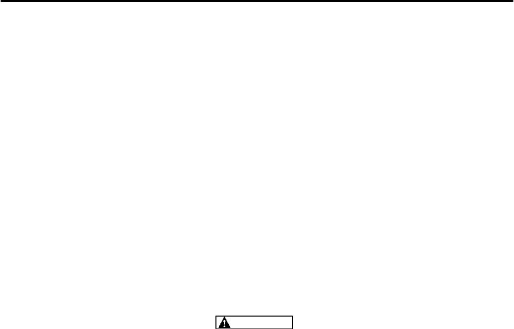
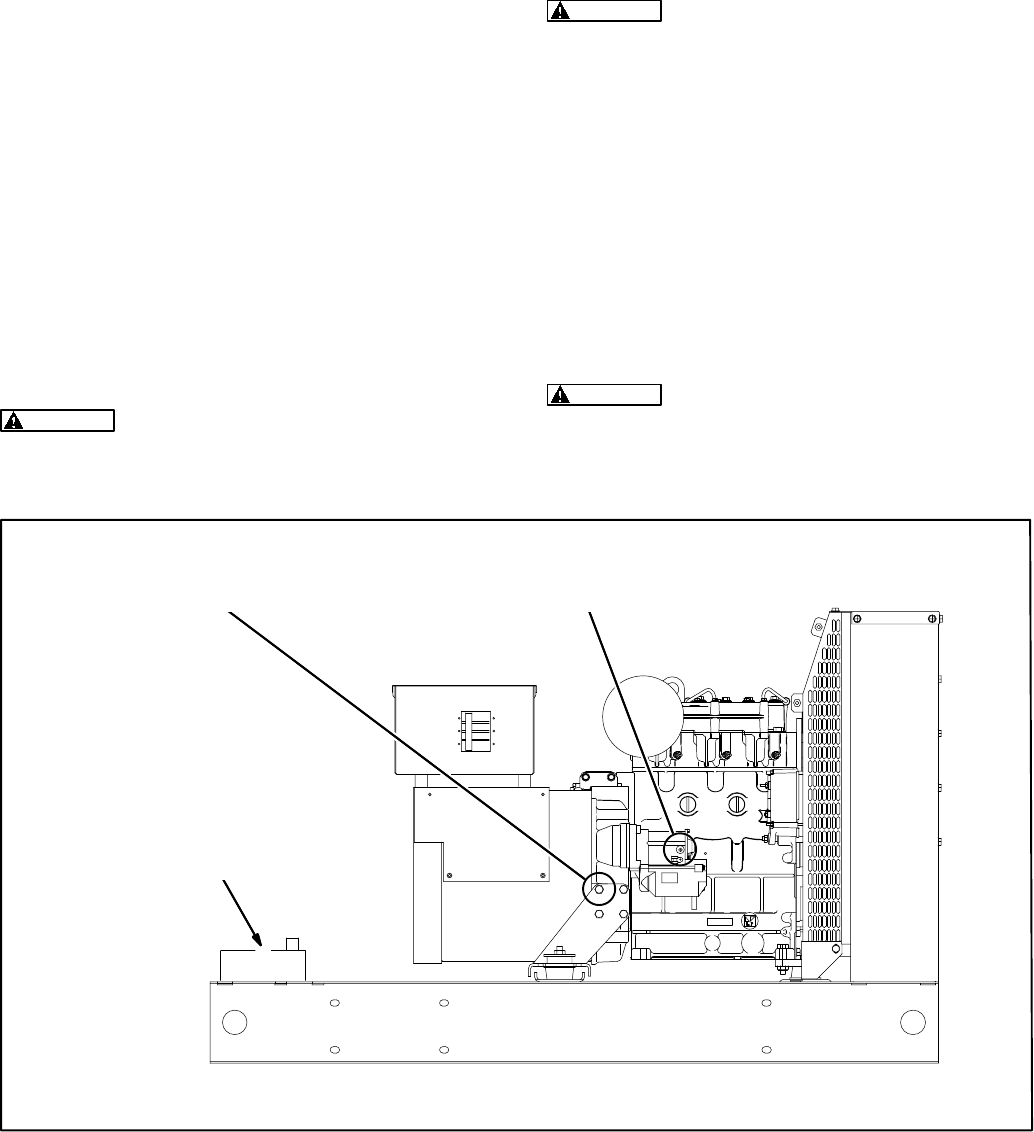
generator set installation is shown in Figure 3-1.
Requirements to be considered prior to installation:
•Level mounting surface
•Adequate cooling air
•Adequate fresh induction air
•Discharge of generator set air
•Non-combustible mounting surface
•Discharge of exhaust gases
•Electrical connections
•Accessibility for operation and servicing
•Noise levels
•Vibration isolation
LOCATION
Generator set location is decided mainly by related
systems such as ventilation, wiring, fuel, and ex-
haust. The set should be located as near as pos-
sible to the main power service entrance. Exhaust
must not be able to enter or accumulate around in-
habited areas.
Provide a location away from extreme ambient tem-
peratures and protect the generator set from ad-
verse weather conditions. An optional housing is
available for outdoor operation.
WARNING
INCORRECT INSTALLATION, SERVICE OR PARTS REPLACEMENT CAN RESULT IN SEVERE
PERSONAL INJURY, DEATH, AND/OR EQUIPMENT DAMAGE. SERVICE PERSONNEL MUST
BE TRAINED AND EXPERIENCED TO PERFORM ELECTRICAL AND MECHANICAL COM-
PONENT INSTALLATION.
IMPORTANT
DEPENDING ON YOUR LOCATION AND INTENDED USE, FEDERAL, STATE OR LOCAL LAWS
AND REGULATIONS MAY REQUIRE YOU TO OBTAIN AN AIR QUALITY EMISSIONS PERMIT
BEFORE BEGINNING INSTALLATION OF YOUR GENSET. BE SURE TO CONSULT LOCAL
POLLUTION CONTROL OR AIR QUALITY AUTHORITIES BEFORE COMPLETING YOUR
CONSTRUCTION PLANS.
Redistribution or publication of this document,
by any means, is strictly prohibited.
3-2
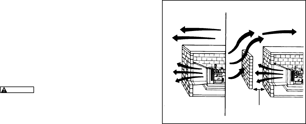
COOLING AIR INLET MUST BE AT LEAST 1-1/2 TIMES LARGER
THAN RADIATOR DUCT OUTLET AREA ON RADIATOR-COOLED
MODELS.
FLOW OF COOLING AIR AND HEATED AIR MAY BE
CONTROLLED BY AUTOMATICALLY OPERATED LOUVRES.
IMPORTANT!
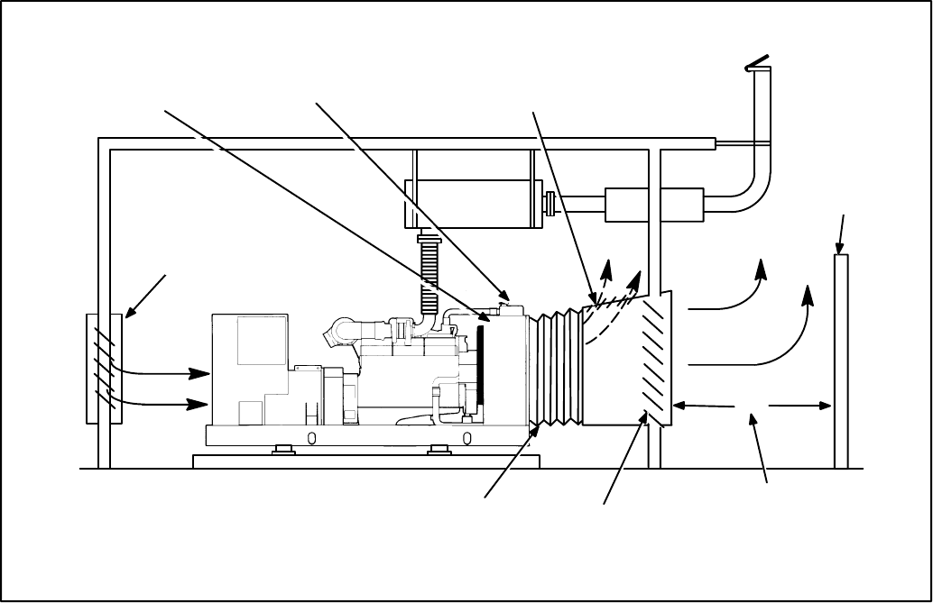
FLEXIBLE
BELLOWS
AC POWER WIRING
AIR
IN
CONCRETE
BASE
CONTROL
SWEEPING
ELBOW
MUFFLER
THIMBLE
FLEXIBLE SECTION
DC
WIRING
COOLING
AIR
IN
AIR OUT
FIGURE 3-1. TYPICAL GENERATOR SET INSTALLATION
Redistribution or publication of this document,
by any means, is strictly prohibited.
3-3
MOUNTING
Generator sets are mounted on a steel skid that pro-
vides proper support. The engine-generator as-
sembly is isolated from the skid frame by rubber
mounts that provide adequate vibration isolation for
normal installations. Where required by building
codes or special isolation needs, generator sets
may be mounted on rubber pads or mechanical
spring isolators. The use of unapproved isolators
may result in harmful resonances and may void the
genset warranty.
Mount the generator set on a substantial and level
base such as a concrete pad. A non-combustible
material must be used for the pad.
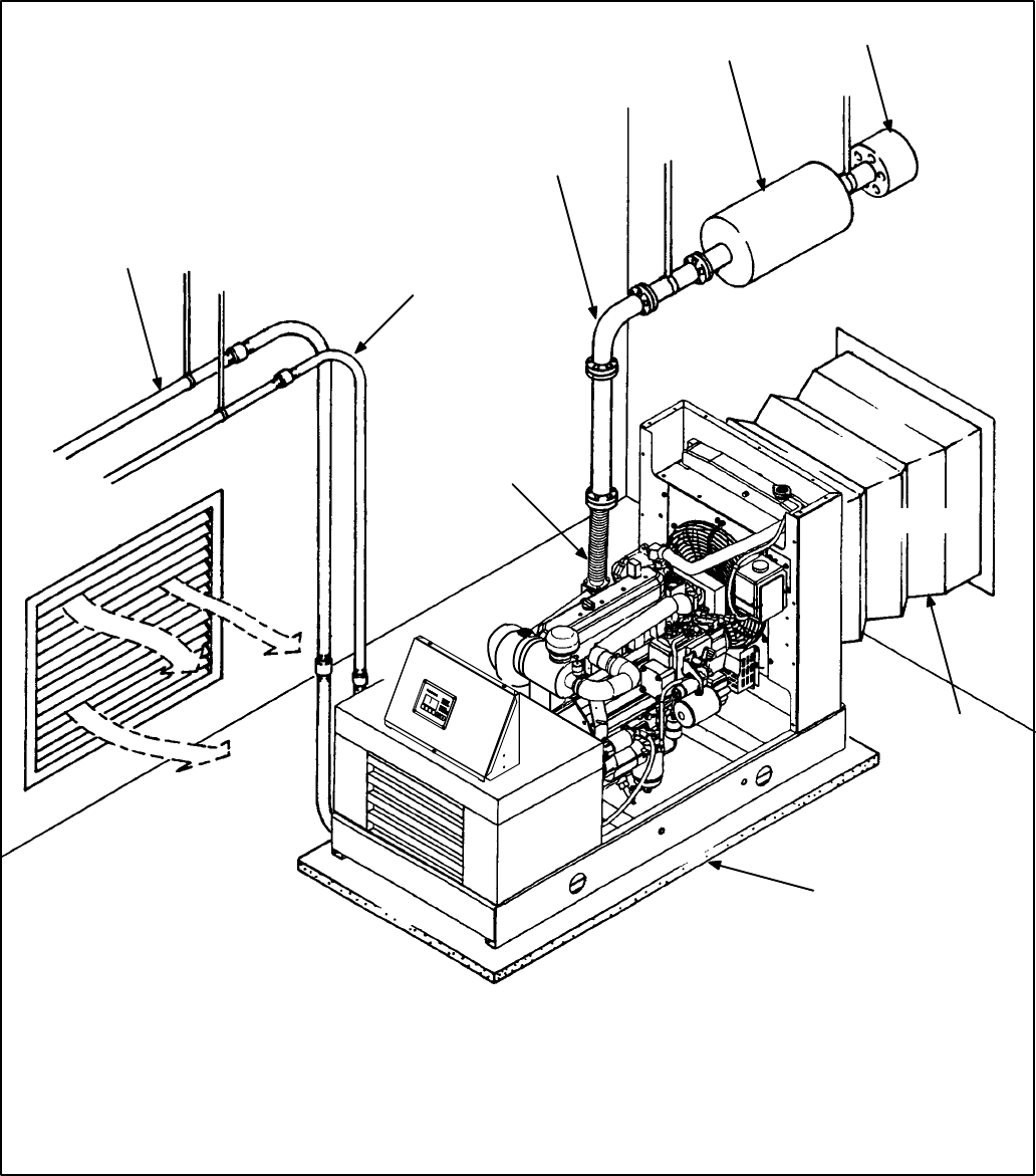
Use 5/8 inch or 16 mm anchored mounting bolts to
secure the skid or vibration isolators to the base
(Figure 3-2). The 1-1/2 x 6 inch pipe inserted over
the mounting bolts allows minor adjustment of the
bolts to align them to the holes in the subbase or
vibration isolator.
The skid mounting bolt hole locations are shown on
the generator set Outline Drawing referenced in the
Data Sheet.
ACCESS TO SET
Generally, at least 1 meter (3 feet) of clearance
should be provided on all sides of the generator set
for maintenance and service access. (Increase
clearance by width of door if optional housing is
used.) A raised foundation or slab of 150 mm (6
inches) or more above floor level will make servic-
ing easier.
Lighting should be adequate for operation, mainte-
nance and service operations and should be con-
nected on the load side of the transfer switch so that
it is available at all times.
FLAT WASHER
MOUNTING
BOLT
12 IN.
(305 mm)
MOUNTING
BASE
1-1/2 x 6 INCH
PIPE
SKID OR VIBRATION
ISOLATOR FLANGE
HEX NUT
CONCRETE
FIGURE 3-2. BOLT DIAGRAM
Redistribution or publication of this document,
by any means, is strictly prohibited.
3-4
THIS PAGE LEFT INTENTIONALLY BLANK
Redistribution or publication of this document,
by any means, is strictly prohibited.
4-1
4. Mechanical Connections
GENERAL
The generator set mechanical system installation
includes connecting the fuel, exhaust, ventilation
and cooling systems. Before starting any type of
fuel installation, all pertinent state and local codes
must be complied with and the installation must be
inspected before the unit is put in service.
All pipe threaded fuel system fittings, including con-
tainer fittings, must be assembled using a pipe joint
sealing compound designed for use with LPG/NG.
FUEL SYSTEM
Gensets can be equipped to operate on:
•LPG (vapor or liquid withdrawal)
•NG (natural gas) or
•Combination (NG/LPG)
In all fuel system installations, cleanliness is of the
upmost importance. Make every effort to prevent
entrance of moisture, dirt or contaminants of any
kind. Clean all fuel system components before
installing.
Fuel Lines – Routing
A flexible fuel hose(s) or section of flexible fuel
hose(s) must be used between the engine’s fuel
system and fuel supply line to protect the fuel sys-
tem from damage caused by vibration, expansion
and contraction.
WARNING Fuel leaks create fire and explosion
hazards which can result in severe personal in-
jury or death. Always use flexible tubing be-
tween engine and fuel supply to avoid line fail-
ure and leaks due to vibration. The fuel system
must meet applicable codes.
Installation of the fuel hose must be done according
to all applicable codes and standards, and installa-
tion recommendations provided by the manufactur-
er. The flexible hose used must be approved by the
hose manufacture for use with the genset fuel type
and product application.
Support fuel lines to restrain movement and prevent
chaffing or contact with sharp edges, electrical wir-
ing and hot exhaust parts.
WARNING Sparks and hot surfaces can ignite
fuel, leading to severe personal injury or death.
Do not route fuel lines near electrical wiring or
hot exhaust parts.
Fuel lines must be routed and secured to maintain a
2 inch (51 mm) minimum clearance from electrical
wiring and hot exhaust parts.
Natural Gas/LPG Vapor/LPG Liquid Fuel
System
WARNING Gaseous fuels are flammable and
explosive and can cause severe personal injury
or death. Do not smoke if you smell gas or are
near fuel tanks or fuel-burning equipment or are
in an area sharing ventilation with such equip-
ment. Keep flames, sparks, pilot lights, electri-
cal arcs and arc-producing equipment and all
other sources of ignition well away from genset
and areas sharing ventilation. Keep a type ABC
fire extinguisher handy.
NFPA Standard No. 58 requires all persons han-
dling and operating LPG to be trained in proper
handling and operating procedures.
Gaseous-fuel supply system design, materials,
components, fabrication, assembly, installation,
testing, inspection, operation and maintenance
must comply with the applicable codes. See NFPA
Standards No. 37, No. 54 and No. 58.
Redistribution or publication of this document,
by any means, is strictly prohibited.
4-2
Most codes require both manual and electric (bat-
tery-powered) shutoff valves ahead of the flexible
fuel hose(s). The manual valve should be of the in-
dicating type. The electric valve should be wired so
that the valve is closed when the genset is off.
Install a dry-type fuel filter ahead of the service
pressure regulator to protect the sensitive pressure
regulating components and orifices downstream
from rust, scale and other solid substances carried
along in the gas stream.
See Specifications section for natural gas/LPG fuel
inlet size. The recommendations in Application
Manual T-030, should be followed in regard to fuel
supply system pipe sizes, manual shutoff valves,
fuel filters and gas pressure regulators.
Fuel Pressure
WARNING High gas supply pressure can cause
gas leaks which can lead to fire and severe per-
sonal injury or death. Gas supply pressure must
be adjusted to Specifications by qualified per-
sonnel.
The gas pressure regulators in each line provide
constant gas pressure at the gas mixer under vary-
ing load conditions. A pressure test port is provided
on the regulator for measuring supply fuel pres-
sures (NG or LPG systems). When measuring sup-
ply pressure, the most accurate reading would be
on the input side of the solenoid valve.
Fuel supply pressure: The minimum pressure re-
fers to supply pressure under rated load (maximum
gas flow).
For LPG (vapor withdrawal) and NG, the maximum
permissible fuel supply pressure is 13.6 inches WC
(3.4 kPa) and the minimum permissible is 5.5 inch-
es WC (1.4 kPa).
For LPG (liquid withdrawal), the maximum permis-
sible fuel supply pressure is 312 psi (2,153 kPa) un-
der any operating condition.
WARNING Gaseous fuel leaks into an inade-
quately ventilated space can lead to explosive
accumulations of gas. Natural gas rises when
released into the air and can accumulate under
overhanging hoods and inside housings and
buildings. LPG sinks when released into the air
and can accumulate inside housings, base-
ments and other below-grade spaces. Precau-
tions must be taken to prevent gas leaks and the
accumulation of gaseous fuel in the event of a
leak.
Check Gas Leaks and Correct
All fuel-system connections, including the container
with associated valves and fittings, must be tested
for leaks with a soap and water solution or equiva-
lent, while the system is under pressure. LP gas
pressure should not be less than 90 psi (621 kPa) at
the inlet of the primary regulator for this test.
Redistribution or publication of this document,
by any means, is strictly prohibited.
4-3
EXHAUST SYSTEM
WARNING Inhalation of exhaust gases can re-
sult in severe personal injury or death. Do not
use exhaust heat to warm a room, compartment
or storage area.
Pipe exhaust gases to the outside of any enclosure.
Locate the exhaust outlets away from any air inlets
to avoid gases re-entering the enclosure. Exhaust
installations are subject to various detrimental con-
ditions such as extreme heat, infrequent operation
and light loads. Regularly inspect the exhaust sys-
tem both visually and audibly to see that the entire
system remains fume tight and safe for operation.
WARNING Inhalation of exhaust gases can re-
sult in severe personal injury or death. Use ex-
treme care during installation to provide a tight
exhaust system. Terminate exhaust pipe away
from enclosed or sheltered areas, windows,
doors and vents.
For indoor installation, the exhaust system must
use sealed joint type fittings, (for example NPT fit-
tings) to provide a tighter exhaust system. Use of
slip type fittings (secured with a muffler clamp) may
allow leakage of exhaust gases into the building.
WARNING Inhalation of exhaust gases can re-
sult in severe personal injury or death. Use ex-
treme care during installation to provide a tight
exhaust system. Use NPT or equivalent type fit-
tings for all indoor installations.
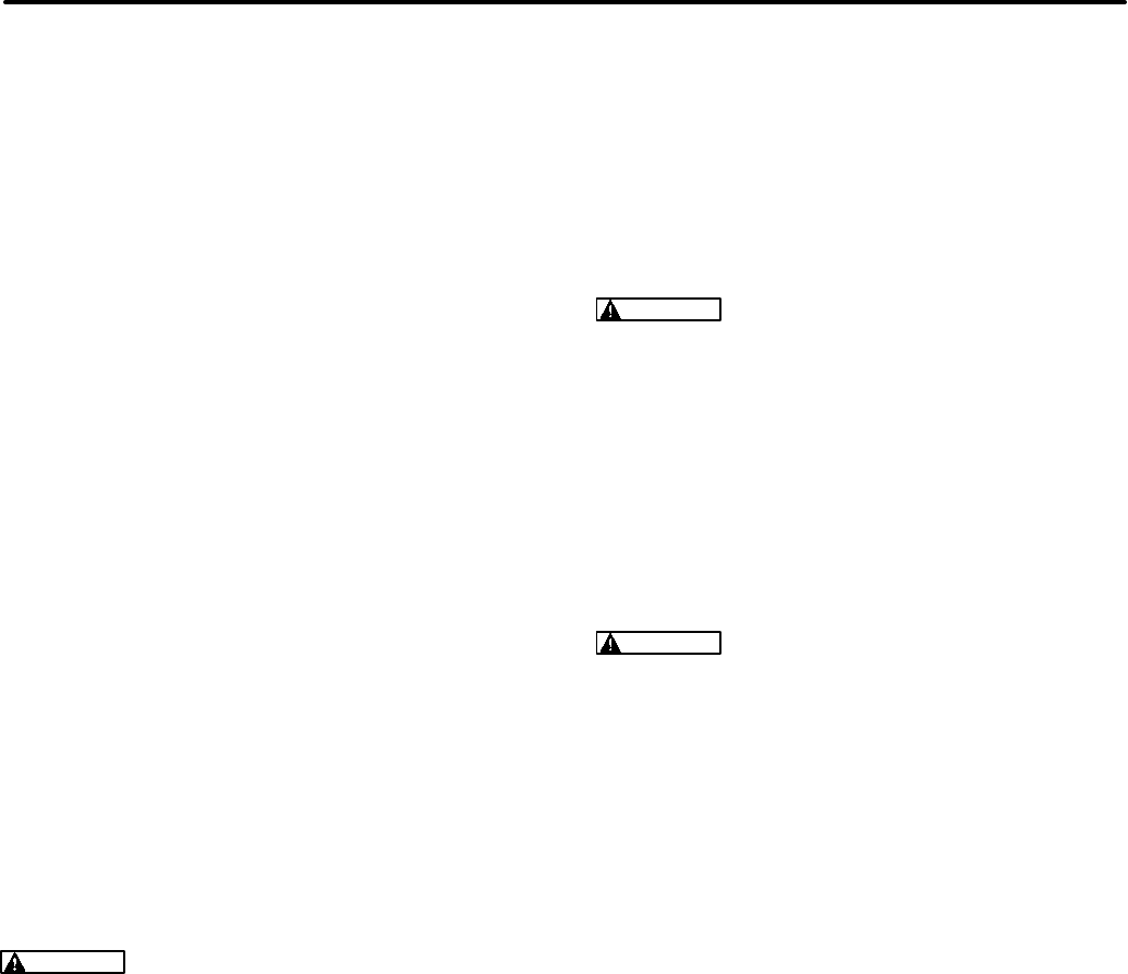
Use an approved thimble (Figure 4-1) where ex-
haust pipes pass through wall or partitions. Insu-
lated wall/roof thimbles are used where exhaust
pipes pass through a combustible roof or wall. This
includes structures, such as wood framing or insu-
lated steel decking, etc. Uninsulated wall/roof
thimbles are used where exhaust pipes pass
through a non-combustible wall or roof, such as
concrete. Refer to NFPA 37, Section 6-3. “Station-
ary Combustion Engines and Gas Turbines” for ac-
cepted design practices. Build according to the
code requirements in effect at the installation site.
WARNING Hot exhaust pipes can start a fire
and cause severe injury or death if improperly
routed through walls. Use an approved thimble
where exhaust pipes pass through walls or
partitions.
Rain caps are available for the discharge end of ver-
tical exhaust pipes. The rain cap clamps onto the
end of the pipe and opens due to exhaust discharge
force from the generator set. When the generator
set is stopped, the rain cap automatically closes,
protecting the exhaust system from rain, snow, etc.
Use a section of flexible exhaust pipe between the
engine and remainder of exhaust system. Support
exhaust system to prevent weight from being ap-
plied to engine exhaust outlet.
CAUTION Weight applied to the engine man-
ifold can result in damage. Support the muffler
and exhaust piping so no weight or stress is ap-
plied to engine exhaust.
The exhaust system design should meet local code
requirements.
Liability for injury, death, damage, and warranty ex-
pense due to use of unapproved mufflers or modifi-
cations to the exhaust system becomes the respon-
sibility of the person installing the unapproved muf-
fler or performing the modification. Contact a Cum-
mins Power Generation distributor for approved ex-
haust system parts.
Redistribution or publication of this document,
by any means, is strictly prohibited.
4-4
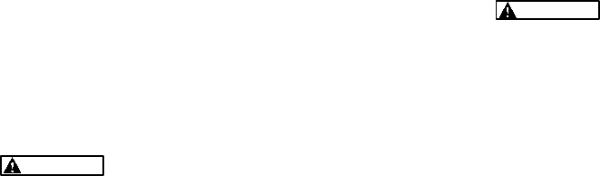
Avoid sharp bends by using sweeping, long radius
elbows and provide adequate support for muffler
and tailpipe. Pitch a horizontal run of exhaust pipe
DOWNWARD (away from engine) to allow any
moisture condensation to drain away from the en-
gine. If an exhaust pipe must be turned upward,
install a condensation trap at the point where the
rise begins (Figure 4-2).
Shield or insulate exhaust lines if there is danger of
personal contact. Allow at least 12 inches (305 mm)
of clearance if the pipes pass close to a combustible
wall or partition. Before installing insulation on ex-
haust system components, check the exhaust sys-
tem for leaks while operating the genset under full
load and correct all leaks.
WARNING Exhaust pipes are very hot and they
can cause severe personal injury or death from
direct contact or from fire hazard. Shield or in-
sulate exhaust pipes if there is danger of per-
sonal contact or when routed through walls or
near other combustible materials.
DRIP CAP
RAIN CAP
ROOF
WALL OR PARTITION
HORIZONTAL
VERTICAL
9 INCH
(230 mm)
HOLES IN
END OF INNER
SLEEVE
9 INCH
(230 mm)
FIGURE 4-1. MOUNTING EXHAUST THIMBLE
AVOID
SHARP
BENDS
IF EXHAUST LINE MUST BE
PITCHED UPWARD, CONSTRUCT
A TRAP AT POINT OF RISE
DRAIN CONDENSATION
TRAP PERIODICALLY
VALVE HANDLE SHOWN
IN OPEN POSITION
FIGURE 4-2. CONDENSATION TRAP
Redistribution or publication of this document,
by any means, is strictly prohibited.
4-5
VENTILATION AND COOLING
Generator sets dissipate heat and fumes that must
be removed by proper cooling and ventilation.
Generator sets in factory-mounted housings for
outdoor installation are designed for proper cooling
and ventilation.
Indoor installations require careful design with re-
spect to cooling and ventilation. In an indoor instal-
lation, all radiator cooling air must be discharged to
the out-of-doors. Duct adapter kits are available.
WARNING Engine or radiator cooling air may
carry deadly carbon monoxide gas which can
cause asphyxiation and death. All engine or ra-
diator cooling air must be discharged to the out-
of-doors. Do not use it for heating a room or
compartment.
Vents and Ducts
For indoor installations, locate vents so incoming air
passes through the immediate area of the installa-
tion before exhausting. Install the air outlet higher
than the air inlet to allow for convection air move-
ment.
Size the vents and ducts so they are large enough to
allow the required flow rate of air. The ”free area” of
ducts must be as large as the exposed area of the
radiator. Refer to the genset Data Sheet for the air-
flow requirements and allowed airflow restriction.
Wind will restrict free airflow if it blows directly into
the air outlet vent. Locate the outlet vent so the ef-
fects of wind are eliminated. See Figure 4-3.
Dampers
Dampers or louvres protect the generator set and
equipment room from the outside environment.
Their operation of opening and closing should be
controlled by operation of the generator set.
Designers should be aware that the generator set
room operating temperature will be very close to the
outdoor temperature, and either not route water pip-
ing through the generator set room, or protect it
from freezing.
A thermostatically controlled recirculating damper
in the radiator discharge duct may be used to re-
duce the volume of cold air drawn into the generator
room.
PREVAILING WINDS PREVAILING WINDS
NOT LESS THAN
HEIGHT OF OPENING
FIGURE 4-3. WIND BARRIER
Redistribution or publication of this document,
by any means, is strictly prohibited.
4-6
Radiator Set Requirements
Louvers and screens over air inlet and outlet open-
ings restrict air flow and vary widely in performance.
A louver assembly with narrow vanes, for example,
tends to be more restrictive than one with wide
vanes. The effective open area specified by the lou-
ver or screen manufacturer should be used.
Radiator set cooling air is drawn past the control
end of the set by a pusher fan that blows air through
the radiator. Locate the air inlet to the rear of the set.
Make the inlet vent opening 1-1/2 times larger than
the radiator area.
Locate the cooling air outlet directly in front of the ra-
diator and as close as possible. The outlet opening
must be at least as large as the radiator area.
Length and shape of the air outlet duct should offer
minimum restriction to airflow.
Attach a canvas or sheet metal duct to the air outlet
opening using screws and nuts so duct can be re-
moved for maintenance purposes. The duct pre-
vents recirculation of heated air. Before installing
the duct, remove the radiator core guard.
Remote Radiator Cooling (Optional) substitutes
a remote mounted radiator and an electrically driv-
en fan in place of genset mounted components. Re-
moval of the radiator and the fan from the genset re-
duces noise levels without forcing dependence on a
continuous cooling water supply (necessary with
heat exchanger cooling). The remote radiator
installation must be completely protected against
freezing.
Remote radiator plumbing will vary with installation.
Follow recommendations given in Application
Manual T-030. See product Data Sheet for friction
head and static head limits.
Before filling cooling system, make sure all hard-
ware is tight. This includes hose clamps, capscrews,
fittings and connections. Use flexible coolant lines
with heat exchanger or remote mounted radiator.
COOL
AIR
INLET
AIR
DAMPER
HOT
AIR
WIND/
NOISE
BARRIER
D
ENGINE-DRIVEN
FAN
DISTANCE SHOULD
NOT BE LESS THAN
HEIGHT OF RADIATOR
THERMOSTATICALLY
CONTROLLED
RECIRCULATING DAMPER
FLEXIBLE DUCT
CONNECTOR
RADIATOR
OUTLET AIR
DAMPER
FIGURE 4-4. TYPICAL RADIATOR SET INSTALLATION
Redistribution or publication of this document,
by any means, is strictly prohibited.
5-1
5. DC Control Wiring
CONTROL WIRING
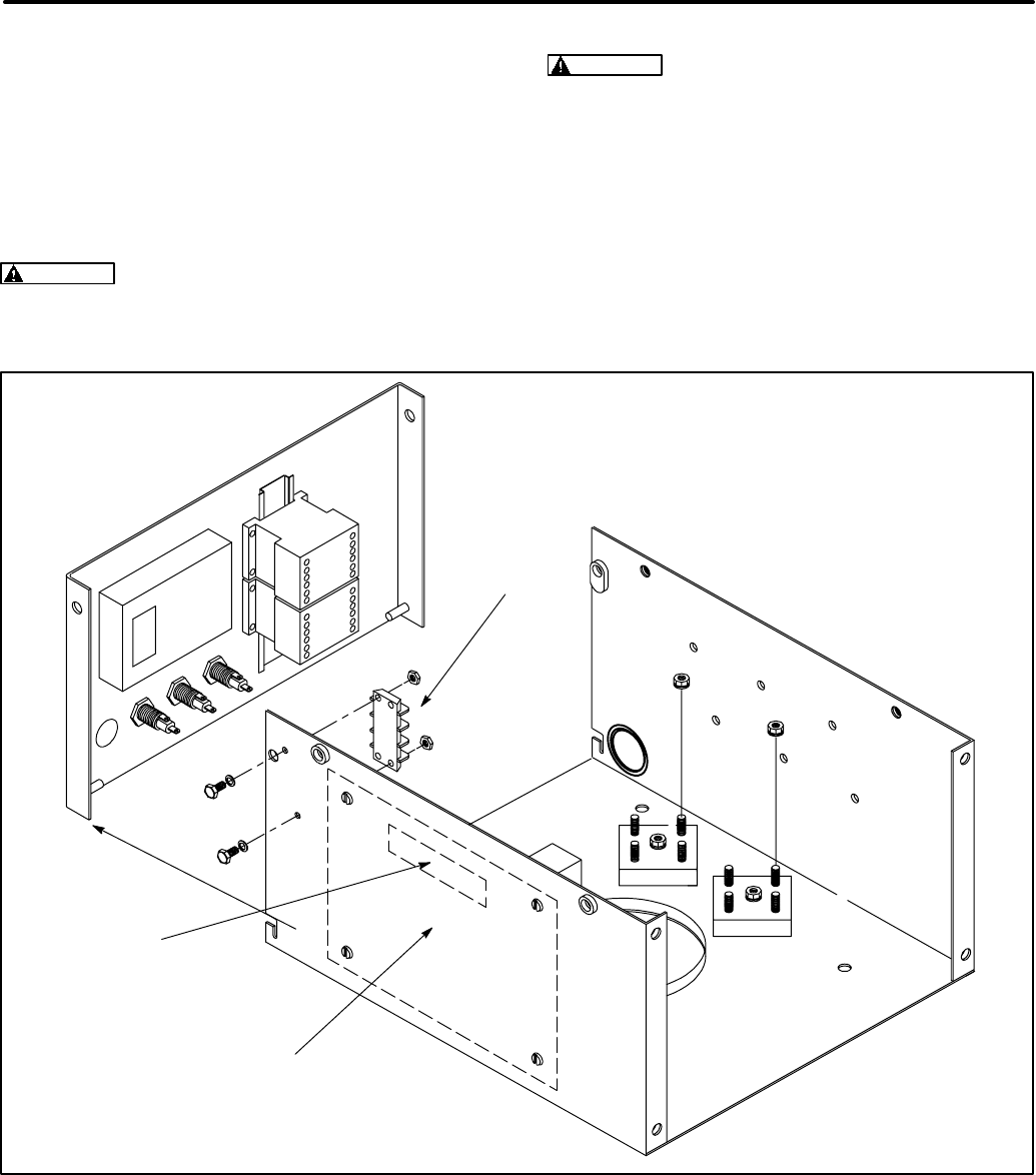
The generator set control box contains connection
points for remote control and monitor options.
These connection points are located inside of the
control box (Figure 5-1).
Use flexible conduit for all wiring connections to the
generator set.
CAUTION Stranded copper wire must be used
for all customer connections to the control pan-
el. Solid copper wire may break due to genset
vibration.
WARNING HAZARDOUS VOLTAGE Touching
uninsulated high voltage parts inside the con-
trol box can result in severe personal injury or
death. Control wire installation must be done
with care to avoid touching uninsulated live
parts.
Stand on a clean dry wooden platform or clean
rubber insulating mat, make sure your clothing
and shoes are dry, remove jewelry and use tools
with insulated handles.
TB1
TB 26
BASE
BOARD
FIGURE 5-1. CONTROL BOX
Redistribution or publication of this document,
by any means, is strictly prohibited.

5-2
TB1 REMOTE MONITOR/CONTROL
CONNECTIONS
Customer monitor/control connections are at-
tached to terminal block TB1 (Figure 5-1). Optional
equipment, such as sensing devices used to moni-
tor genset operation, remote start/stop switches,
etc. are attached to TB1. Refer to Customer Con-
nections diagram in Section 9.
Available options will vary between PCC1301 control
models (PCC with or without display).
TB1 Wiring
CAUTION Always run control circuit wiring in
a separate metal conduit from AC power cables
to avoid inducing currents that could cause
problems within the control.
Digital Connections: Connection points, other
than relayed outputs and network are considered
digital connections to terminal strip TB1. The type/
gauge wire to use for these connections are:
•Less than 1000 feet (305m), use 20 gauge
stranded copper wire.
•1000 to 2000 feet (305 to 610m), use 18 gauge
stranded copper wire.
Relay Connections: Due to the wide variety of de-
vices that can be attached to the relay outputs of
TB1, the electrical contractor must determine the
gauge of the stranded copper wire that is used at
this installation site.
TB1 Customer Inputs
Refer to Page 9-1 for typical connections to TB1.
Remote Start: When the control is in Auto/Remote
mode, grounding this input initiates the engine
cranking and start sequence. This circuit must be
opened to permit resetting a shutdown condition
with the Reset input. (The remote stop is actually
the removal of the remote start signal to the control.)
Remote Emergency Stop: Opening this input
causes an immediate shutdown. Emergency stop
must be reset at the front panel.
Customer Fault Inputs 1 and 2: Grounding any
one of these inputs activates the corresponding
warning or shutdown sequence.
External sensing equipment must be connected to
the designated digital input.
The nature of the fault is an optional customer
selection. Example inputs: Low Coolant Level, Low
Fuel Pressure, Ground Fault, etc.
Each of the two fault functions can be programmed
as follows:
•Status, Warning or Shutdown. Default = Warn-
ing.
•Enter a brief description of the event (up to 32
characters).
The InPower service tool or access to the Setup Sub-
menus is required to modify the customer fault in-
puts. Contact an authorized service center for assis-
tance.
TB1 Customer Outputs
Refer to Page 9-1 for typical connections to TB1.
Customer Outputs 1 and 2: One set of normally
open (NO) contacts, rated for 2 amps at 30 VDC for
each of the two output signals. The relays can be
used to control small devices and indicator lamps.
The nature of the customer output signal (contacts
closed) is an optional customer selection. Example
outputs: Genset running (event), common warning,
common shutdown, etc. (Refer to Operator’s manu-
al for warning and shutdown code listing and the
Service manual for event code listing.)
Each relay can be independently programmed to
energize by entering a code number (0 through 255,
default = 0) for the desired event.
The InPower service tool or access to the Setup Sub-
menus is required to modify the customer outputs.
Contact an authorized service center for assistance.
Ready To Load Signal (Generator Set Running):
B+ signal out when the generator set has reached
90 percent of rated speed and voltage.
SWITCHED B+
Switched B+ (T26) has six terminals located in the
control box and is fused at 20 amps.
UNIVERSAL ANNUNCIATOR
The optional universal annunciator (300-5929) pro-
vides for remote monitoring of the power system.
Refer to its operators manual for connections.
Redistribution or publication of this document,
by any means, is strictly prohibited.
5-3
I/O MODULE
The optional I/O module provides additional cus-
tomer inputs and outputs for control and monitoring
of the power system. Up to sixteen relay outputs
and twelve discrete analog inputs are available
when the control contains both the Base I/O Mod-
ule (AUX101) and the Expansion I/O Module
(AUX102). Refer to Instruction Sheet C693 for I/O
module configuration/wiring information.
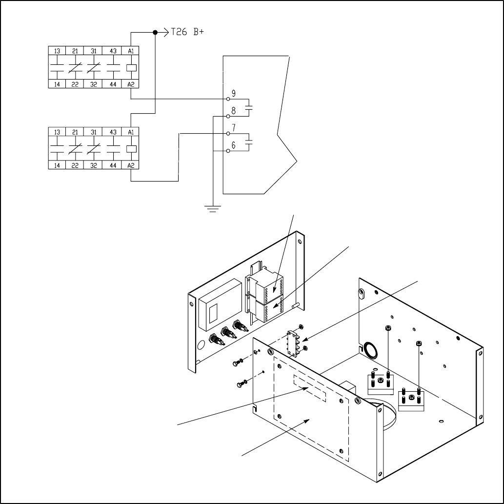
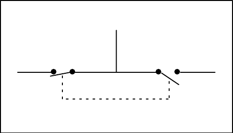
RUN RELAYS (K10, K11)
The optional run relays (Figure 5-2) are mounted in-
side the control box. They are used to control auxil-
iary equipment such as fans, pumps and motorized
air dampers. The run relays are energized when the
generator set control receives a start signal.
The contacts are rated:
•20 amps resistive @ 30VDC
•15 amps inductive @ 30VDC
BASE BOARD
K10
K11
TB1
K10
K11
T26 (SW B+)
TB1
BASE
BOARD
FIGURE 5-2. OPTIONAL RUN RELAYS (K10, K11)
Redistribution or publication of this document,
by any means, is strictly prohibited.
5-4
BATTERIES
The generator set has a 12 VDC, negative-ground
control and starting system. See Figure 5-3 for bat-
tery cable connections and Specifications for mini-
mum battery requirements.
The engine is equipped with a 45 amp battery
charging alternator to supply the control loads and
restore cranking current. Emergency standby ap-
plications will require a battery charger powered by
the normal AC power supply. Check the local codes
for emergency standby requirements.
The generator set is provided with battery cables
and the skid-base has a built-in battery rack.
WARNING Accidental starting can cause se-
vere personal injury or death. Push the control
panel switch to OFF before connecting the bat-
tery cables.
WARNING Arcing can ignite battery gases and
cause severe personal injury and can cause
voltage spikes that can damage generator set
control circuits. To reduce arcing:
Always disconnect a battery charger from its
AC source before disconnecting the battery
cables.
Always disconnect the negative (–) cable first
and reconnect it last. (This prevents arcing if the
tool on the positive terminal touches grounded
metal.)
CAUTION The battery must be of a type with
barbed vent hose fittings for its cells. The vent
lines must be routed away from the generator
end bell (air inlet) to prevent battery gases from
entering the generator and causing corrosion.
SEALED TYPE BATTERY TO
PREVENT GASES FROM EN-
TERING GENERATOR AND
CAUSING CORROSION
NEGATIVE (–) CABLE
CONNECTION
POSITIVE (+) CABLE CONNECTION
(STARTER SOLENOID TERMINAL)
FIGURE 5-3. BATTERY CONNECTIONS
Redistribution or publication of this document,
by any means, is strictly prohibited.
6-1
6. AC Electrical Connections
GENERAL
This section provides the procedure that is used to
connect the AC electrical system of the genset.
Before making any AC electrical connections, make
certain the generator set cannot be accidentally
started. Place the control panel run switch in the
OFF position. Turn off or remove AC power from the
battery charger and then remove the negative (–)
battery cable from the set starting battery.
WARNING Ignition of explosive battery gases
can cause severe personal injury or death. Arc-
ing at battery terminals, light switch or other
equipment, flame, pilot lights and sparks can ig-
nite battery gas. Do not smoke, or switch
trouble light ON or OFF near battery. Discharge
static electricity from body before touching bat-
teries by first touching a grounded metal sur-
face.
Ventilate battery area before working on or near
battery—Wear goggles—Stop genset and dis-
connect charger before disconnecting battery
cables—Disconnect negative (–) cable first and
reconnect last.
CAUTION Disconnect battery charger from AC
source before disconnecting battery cables.
Otherwise, disconnecting cables can result in
voltage spikes damaging to DC control circuits
of the set.
WARNING Accidental starting of the generator
set can cause severe personal injury or death.
Prevent accidental starting by disconnecting
the negative (–) cable from the battery terminal.
WARNING Each of the operations described in
this section should be done only by persons
trained and experienced in electrical mainte-
nance. Improper procedures may result in prop-
erty damage, bodily injury or death.
Connecting the genset AC electrical system in-
volves:
•Installation of transfer switch
•Generator output voltage selection
•Load cable connection
•Standard and optional AC equipment connec-
tions (e.g., control box heater, coolant heater,
etc.).
Local regulations often require that wiring connec-
tions be made by a licensed electrician, and that the
installation be inspected and approved before op-
eration. All connections, wire sizes, materials used,
etc. must conform to the requirements of electrical
codes in effect at the installation site.
WARNING Improper wiring can cause a fire or
electrical hazard, resulting in severe personal
injury or death and/or property and equipment
damage.
Before starting the genset, check to make sure that
all electrical connections are secure, and that all
wiring is complete. Replace and secure any access
panels that have been removed during installation.
Check that the load cables from the genset are
properly connected.
WARNING Backfeed to utility system can
cause electrocution or property damage. Do not
connect to any building electrical system ex-
cept through an approved device and after
building main switch is opened.
Redistribution or publication of this document,
by any means, is strictly prohibited.
6-2
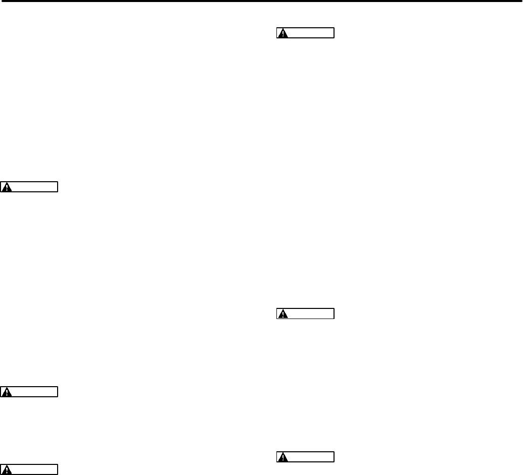
TRANSFER SWITCH
If the installation is for standby service, a transfer
switch must be used for switching the load from the
normal power source to the genset (see Figure 6-1).
Follow the installation instructions provided with the
transfer switch when connecting the load and con-
trol wiring.
LOAD
GENSET
NORMAL
SOURCE
FIGURE 6-1. TYPICAL LOAD TRANSFER
FUNCTION
Redistribution or publication of this document,
by any means, is strictly prohibited.

6-3
AC WIRING
Generator Voltage Connections
The available generator output voltages and maxi-
mum current ratings are specified on the generator
set nameplate. Line-to-neutral voltage is always the
lower voltage shown and line-to-line voltage is the
higher rating.
These generators can be configured to the name-
plate voltages as shown on the Reconnection Dia-
gram decal, attached to the backside of the control
box cover. Many of the voltages listed will require
reconfiguration of the generator output leads on the
connection terminal block. This reconfiguration
must only be done by service personnel that are
trained and experienced to perform electrical instal-
lation. The generator set was adjusted to produce a
specified voltage during production verification test-
ing prior to shipment. The installer must always
check the stator lead terminal block connections
and perform any necessary reconnect to obtain the
voltage required.
Some generator sets are capable of producing a
wide range of voltages and connection configura-
tions, others have specific limited capabilities. Re-
fer to wiring diagram and generator voltages (from
the nameplate) when reviewing the voltage connec-
tion information and use the wiring diagram sup-
plied with your generator set when actually perform-
ing load connections.
CAUTION Reconfiguring generator sets to
higher voltages can exceed the voltage capabil-
ity of the specific generator windings and dam-
age the generator and also decrease line cur-
rent, rendering line circuit breakers too large.
Consult with your distributor before performing
reconnection for a different voltage.
CAUTION Reconfiguring generator sets to
lower voltages can reduce generator set rat-
ings, and also increase line current, rendering
line circuit breakers too small. Consult with
your distributor before performing reconnec-
tion for a different voltage.
Redistribution or publication of this document,
by any means, is strictly prohibited.
6-4
Load Connections
Flexible conduit and stranded conductors must be
used for connections to take up movement of the
generator set.
All loads are connected to the generator by bolting
stranded load wires to the appropriate terminals on
the generator reconnection terminal block or circuit
breaker lugs. The terminals are marked U, V, W and
N to indicate the line and neutral connections. (Ref-
erence: U, V, and W correspond with L1, L2 and L3;
and N with L0 respectively).
Load Balancing
When connecting loads to the generator set, bal-
ance the loads so the current flow from each line ter-
minal (L1, L2 and L3) is about the same. This is es-
pecially important if both single phase and three
phase loads are connected. Any combination of
single phase and three phase loading can be used
as long as each line current is about the same, with-
in 10 percent of median value and no line current ex-
ceeds the nameplate rating of the generator. Check
the current flow from each line after connections by
observing the control panel ammeter.
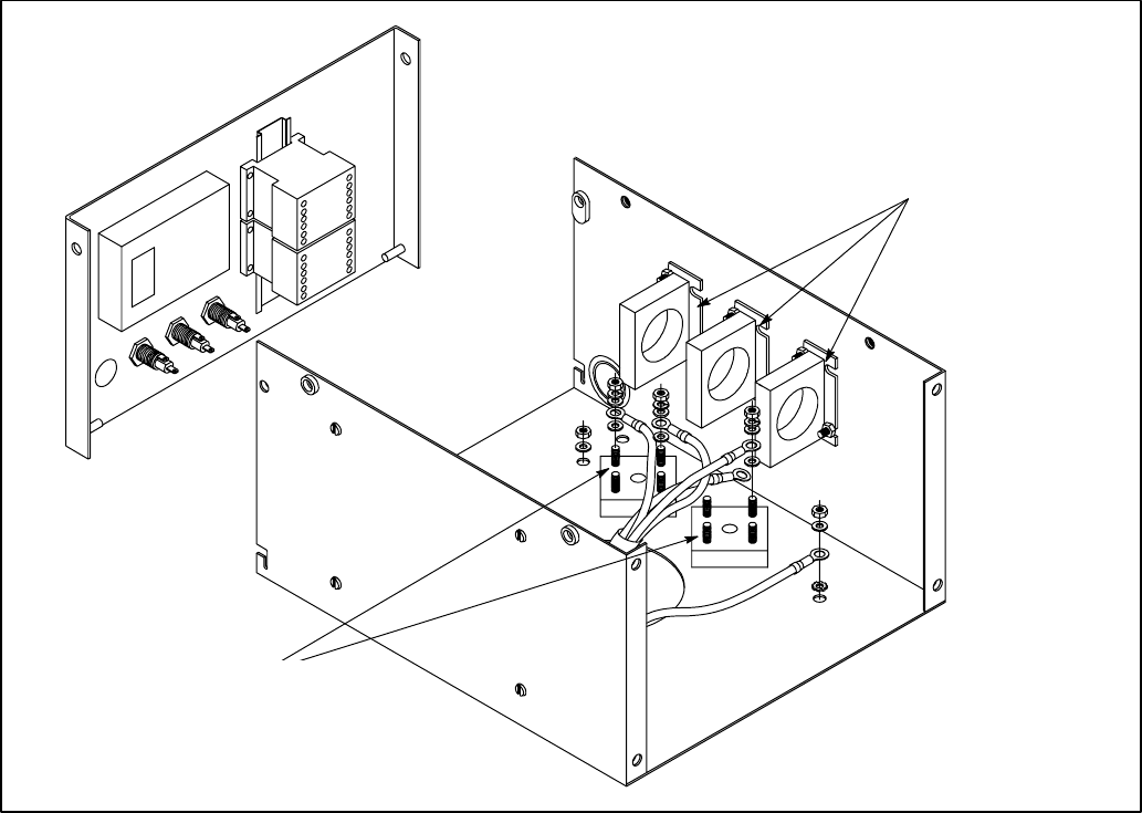
Current Transformers (Optional)
The optional current transformers (CTs) are used to
display genset load in kVA and alternator amper-
age. Refer to the Reconnection Diagram for routing
leads through the CTs.
AC TERMINALS
CURRENT
TRANSFORMERS
FIGURE 6-2. AC OUTPUT BOX
Redistribution or publication of this document,
by any means, is strictly prohibited.
6-5
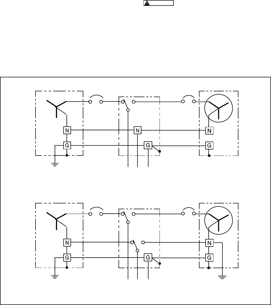
Grounding
The following is a brief description of system and
equipment grounding of permanently installed AC
generators within a facility wiring system. It is impor-
tant to follow the requirements of the local electrical
code.
Figure 6-3 illustrates typical system grounding for a
3-pole and a 4-pole automatic transfer switch
(ATS). In the 3-pole ATS, note that the generator
neutral is connected to the ATS and is NOT bonded
to ground at the generator. In the 4-pole ATS sys-
tem, a grounding electrode conductor and a bond-
ing jumper are used to connect the generator neu-
tral to ground.
Make sure the genset is grounded to earth in one
location only. Use the ground lug provided in the
power output box.
WARNING Electric current can cause severe
personal injury or death. Bonding and ground-
ing must be done properly. All metallic parts
that could become energized under abnormal
conditions must be properly grounded.
Typical requirements for bonding and grounding
are given in the National Electrical Code, Article
250. All connections, wire sizes, etc. must conform
to the requirements of the electrical codes in effect
at the installation site.
4-POLE ATS
GENERATOR SET
SERVICE ENTRANCE
LOAD
3-POLE ATS
GENERATOR SET
SERVICE ENTRANCE
LOAD
THREE-PHASE, FOUR-WIRE UTILITY, THREE-POLE ATS
THREE-PHASE, FOUR-WIRE UTILITY, FOUR-POLE ATS
FIGURE 6-3. TYPICAL SYSTEM GROUNDING ONE-LINE DIAGRAMS
Redistribution or publication of this document,
by any means, is strictly prohibited.
6-6
CONTROL HEATER (OPTIONAL)
A control heater (Figure 5-4) provides a means of
humidity / temperature control of the control box in-
terior. It protects the components when the genera-
tor set is subjected to varying ambient air conditions
during extended periods of non-use.
The heater is equipped with a power cord that termi-
nates with a 120V or 240V NEMA plug.
COOLANT HEATER (OPTIONAL)
A coolant heater is used to keep the engine coolant
warm when the engine is shut down. It heats and cir-
culates the coolant within the engine. This reduces
startup time and lessens engine wear caused by
cold starts. It is electrically operated and thermo-
statically controlled.
WARNING The coolant heater must not be op-
erated while the cooling system is empty or
damage to the heater will occur.
The heater is equipped with a power cord that termi-
nates with a 120V or 240V NEMA plug.
Connect the heater to a source of power that will be
on during the time the generator set is not running.
Be sure the voltage rating is correct for the heater
element rating.
GENERATOR HEATER (OPTIONAL)
A generator heater is used to help keep the genera-
tor free of condensation when the generator set is
not running. During cool and humid conditions, con-
densation may form within a generator, creating
flashing and shock hazards.
WARNING Water or moisture inside a genera-
tor increases the possibility of flashing and
electrical shock, which can cause equipment
damage and severe personal injury or death. Do
not use a generator which is not dry inside and
out.
The heater is equipped with a power cord that termi-
nates with a 120V NEMA plug.
Connect the heater to a source of power that will be
on during the time the generator set is not running.
Redistribution or publication of this document,
by any means, is strictly prohibited.
7-1
7. Prestart Preparation
GENERAL
Before attempting the initial start of the generator
set, be sure to complete the Installation Checklist in
Section 8.
INPOWER SERVICE TOOL
GENERAL INFORMATION
InPower is a PC based service tool for the Power-
Command 1301 Control (PCC). Use InPower to:
•Make adjustments to the controls trims and set-
tings.
•Perform diagnostics and monitoring.
•Create a capture file of the controls trims and
settings.
•Update control calibrations (InPower PRO ver-
sion).
Refer to INPOWER User’s Guide for specifics.
InPower Adjust Mode
The adjustment feature allows you to make adjust-
ments to genset parameters, calibrations and set-
tings. There are several groups of adjustment pa-
rameters; note that not all gensets will have the
same adjustments available.
InPower Capture File Description
InPower provides a method of extracting (captur-
ing) a device’s parameter values. Capturing saves
device information in a file that is identified with a
.CAP extension.
Capture files are used to store a copy of the gen-
set’s parameter values. During genset installation,
it is suggested that a capture file be made before
and after changes are made to the genset operating
parameters. This information can be a very useful
when troubleshooting the genset (determine if pa-
rameters/settings have been modified after installa-
tion) and when replacement of the Base board is
necessary. The capture file can be used as a tem-
plate to write the previous settings to the new Base
board software.
ELECTRICAL SYSTEM
Verify all electrical connections are secure and all
wiring is complete and inspected. Replace and se-
cure any access panels that may have been re-
moved during installation.
Battery Connections
WARNING Accidental starting of the generator
set can cause severe personal injury or death.
Make sure that the PCC is in the OFF mode be-
fore connecting the battery cables.
Starting the unit requires a 12 volt battery. Connect
positive battery cable before connecting negative
battery cable to prevent arcing.
Service the batteries as necessary. If an automatic
transfer switch is installed without a built-in charge
circuit, connect a separate battery charger. Proper
selection and maintenance of batteries and battery
chargers is essential for system reliability.
WARNING Ignition of explosive battery gases
can cause severe personal injury or death. Al-
ways connect negative (–) battery cable last to
prevent arcing.
WARNING Ventilate battery area before work-
ing on or near battery. Arcing at battery termi-
nals, light switch or other equipment, flame, pi-
lot lights and sparks can ignite battery gas. Do
not smoke, or switch trouble light ON or OFF
near battery. Discharge static electricity from
body before touching batteries by first touching
a grounded metal surface.
Redistribution or publication of this document,
by any means, is strictly prohibited.

7-2
PCC OPTIONS PRESTART CHECKS
All generator set configuration options are set at the
factory except for site related options, (e.g., Start/
Stop Time Delays, Cycle Crank, Customer Fault 1
and 2, etc.
If the PCC graphical display option is not provided,
the InPower service tool will be required to adjust all
site related options.
Adjustment of these options are divided into two
categories within the menu driven system. These
two categories are Setup and Screen Adjust.
The Setup menus are intended for qualified service
personnel only and require a password to modify
these submenus (refer to Service manual). The
Screen Adjust menu is intended for service person-
nel and site personnel.
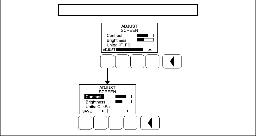
SCREEN ADJUST MENU
Figure 7-1 shows a block representation of the
Screen Adjust menu. The Screen Adjust menu is
displayed when the (3) button is pressed in the first
Service Menu.
From any of the Operator menus, simultaneously
press the and selection buttons for two sec-
onds to display the first Service menu.
Adjusting Values/Parameters
1. Press the ADJUST selection button to select
the first parameter or value to be changed.
2. Press the + or – selection buttons to adjust val-
ues or select parameters.
3. Press the arrow selection button to navi-
gate to the next or previous adjustable value or
parameter.
4. After adjusting values/selecting parameters,
press the SAVE button to save your settings.
NOTE: If the Previous Menu button is
pressed before pressing the SAVE but-
ton, the changes are not saved.
5. Press the button to return to the Service
Menu.
Screen Adjust Menu
This menu allows for adjusting the screen’s contrast
and brightness and for selecting the units of mea-
surement (SAE or SI) to be displayed.
•Contrast and Brightness: Press the + or –
selection buttons to adjust the screen’s con-
trast and brightness. Changing the bright-
ness setting also affects the brightness of the
LEDs on the control panel.
•Units: Press the + or – selection buttons to
select SAE (_F, PSI) or SI (C, kPa) units of
measurement to be displayed.
Redistribution or publication of this document,
by any means, is strictly prohibited.
7-3
SCREEN ADJUST MENU
FIGURE 7-1. SCREEN ADJUST MENU
Redistribution or publication of this document,
by any means, is strictly prohibited.
7-4
STARTING
Refer to the generator set Operator’s manual for im-
portant safety precautions and recommended pro-
cedures for starting the genset and verifying proper
operation. Start the generator set and verify all en-
gine and generator menus are displaying the cor-
rect values.
Redistribution or publication of this document,
by any means, is strictly prohibited.

8-1
8. Installation Checklist
GENERAL
jGenerator set wattage capacity is sufficient to handle maximum anticipated load.
jAt least 3 feet of clearance (or greater for housing door) is provided around entire generator set for servic-
ing and ventilation.
jGenerator set is located in an area not subject to flooding.
jAll operating personnel have read and are familiar with Operator’s Manual.
jAll operators have been thoroughly briefed on preventive maintenance procedures.
jAll operators have read and understand all Important Safety Instructions in Operator’s Manual.
GENERATOR SET SUPPORT
jFloor, roof or earth on which the generator set rests is strong enough and will not allow shifting or move-
ment. Observe local codes on soil bearing capacity due to freezing and thawing.
jGenerator set is properly supported and retained to approved base.
jSupporting base is large enough and is of non-combustible material – extends 6-inches all around set.
COOLING AIR FLOW
jGenerator set air inlet is faced into direction of strongest, prevailing winds.
jAir inlet openings are unrestricted and at least 1–1/2 times larger than air outlet area.
jCooling air outlet is on downwind side of building (if not, wind barrier is constructed).
jProper ducting material (sheet metal, canvas) is used between radiator and air outlet.
FUEL SYSTEM
jFuel tanks meet or exceed all Local, State or National codes.
jFuel lines are properly installed, supported and protected against damage.
jApproved flexible fuel line is installed between main fuel supply line and generator set’s fuel system, near
the generator set, to protect the fuel system from damage caused by vibration, expansion and contrac-
tion.
jFuel supply line shutoff valves are installed to prevent fuel flow in case of leaks.
jNo fuel leaks are found in supply line or engine fuel system.
Redistribution or publication of this document,
by any means, is strictly prohibited.
8-2
EXHAUST SYSTEM
jOperators are thoroughly briefed on the dangers of carbon monoxide gas.
jAreas around set are well ventilated. No possibility of exhaust fumes entering building doors, windows, or
intake fans.
jExhaust gases are piped safely outside and away from building.
jThe correct length of approved rigid pipe is connected to the generator set flexible pipe using approved
securing methods with no weight resting on engine exhaust components. There are no bends in flex sec-
tion.
jCondensation drain is provided in lowest section of exhaust piping.
jExhaust piping is insulated to guard against burns to personnel.
jExhaust piping passing through walls or ceilings have approved fire-proof materials and are in com-
pliance with all codes.
jExhaust piping is large enough in diameter to prevent excessive back pressure on engine.
AC AND DC WIRING
jWire sizes, insulation, conduits and connection methods all meet applicable codes.
jAC and DC wires are separated in their own conduit to prevent electrical induction.
jAll load, line and generator connections are proper and correct.
jFlexible conduit between generator set and building or surrounding structure.
GENERATOR SET PRESTART
jGenerator set engine is properly serviced with oil and coolant.
jBatteries are properly installed, serviced and charged.
jBattery charger and engine coolant heater are connected and operational.
jAll generator set covers and safety shields are installed properly.
jAll fuel and coolant shutoff valves are operational.
jCreated control capture file of the generator’s set parameter values before and after modifications.
Redistribution or publication of this document,
by any means, is strictly prohibited.
9-1
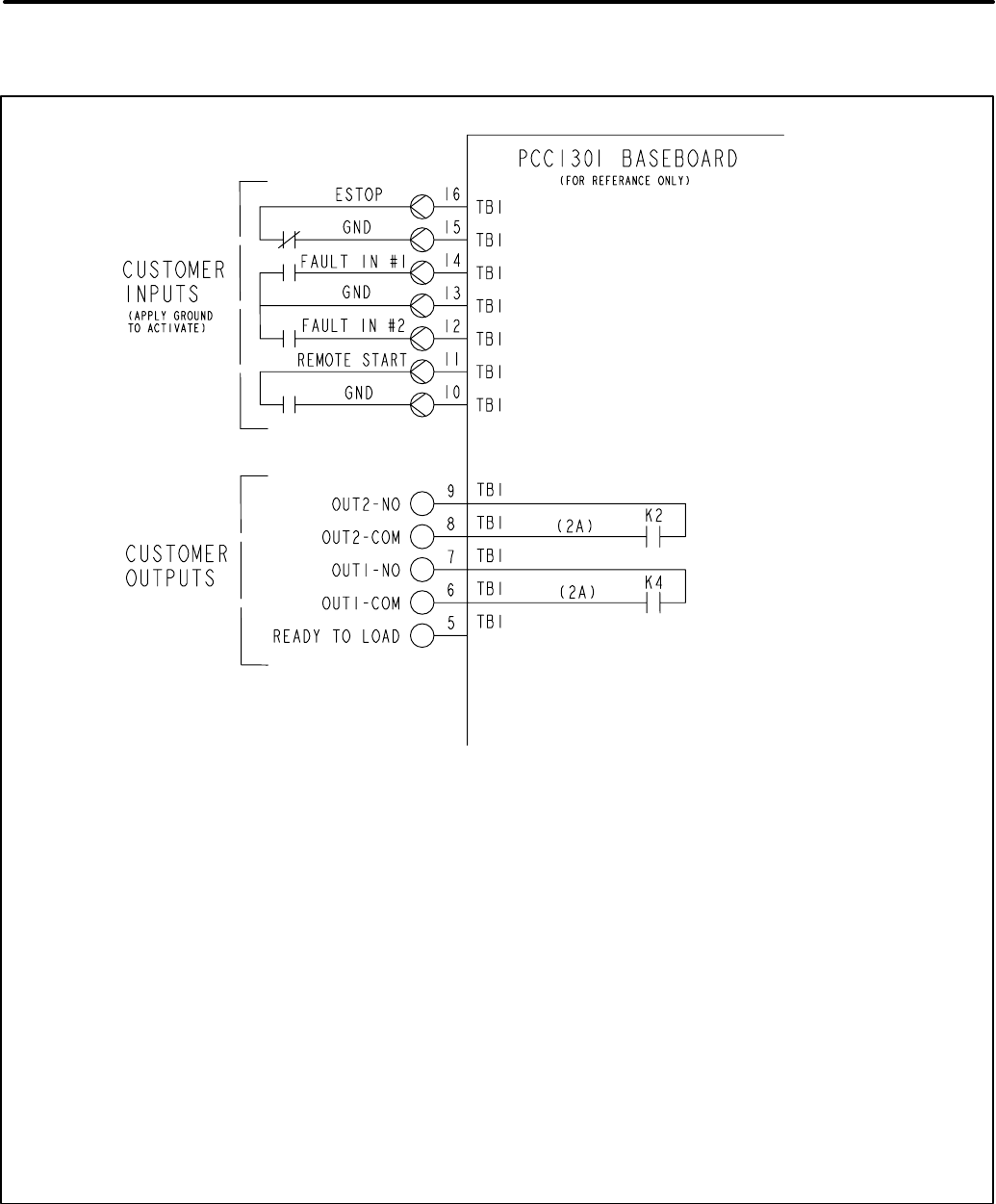
9. Wiring Diagrams
NOTES:
1. TORQUE TERMINALS TO 4.4 IN/LBS (0.5 Nm).
2. WIRE SIZE, 30–AWG (0.14–2.5MM) (TB1).
3. WIRE TYPE, USE 60°C RATED MINIMUM. COPPER WIRE (TB1).
4. TERMINAL SCREWS ARE SLOTTED (0.6MN).
5. USE FLAT–BLADED SCREWDRIVER WITH 2.5MN BLADE.
6. STRIP WIRE LENGTH TO 6.0MN.
7. FAULT IN #1 USED FOR OPTIONAL LOW COOLANT LEVEL.
8. FAULT IN #2 USED FOR OPTIONAL LOW FUEL PRESSURE.
CUSTOMER CONNECTION DIAGRAM
Redistribution or publication of this document,
by any means, is strictly prohibited.
9-2
THIS PAGE LEFT INTENTIONALLY BLANK
Redistribution or publication of this document,
by any means, is strictly prohibited.

Cummins Power Generation
1400 73rd Avenue N.E.
Minneapolis, MN 55432
1-800-888-6626
763-574-5000 International Use
Fax: 763-528-7229
Cummins is a registered trademark of Cummins Inc.
Redistribution or publication of this document,
by any means, is strictly prohibited.
