974 0220 Onan RJC (spec A AC) Genset Parts Manual (03 1990)
User Manual: 974-0220 Onan RJC (spec A-AC) Genset Parts manual (03-1990)
Open the PDF directly: View PDF ![]() .
.
Page Count: 83
a
*
.Parts
Manual
RJE
GenSet
.
Replaces-6:81 (Spec A-AL)
Printed in U.S.A.
SAFETY PRECAUTIONS
The following symbols are used in Onan manuals to alert
users to the potentially dangerous conditions relating to
maintenance of the equipment and replacement of parts.
Please read and observe.
~This symbol warns of immediate
hazards which will result in severe
persona/ injury or death.
EEEimEl
This symbol refers to ahazard or
unsafe practice which can result
in severe personal injury or death.
MODEL IDENTIFICATION
To avoid errors or delay in filling your parts order, always ●
give the MODEL, SPEC NO., and SERIAL NO. from the
Onan nameplate. .
For handy reference, insert your nameplate information ,
in the spaces below
.
MODEL AND SPEC NO. .-
SERIAL NO.
IEziEl This symbol reiem to ahazard or
unsafe practice which can result
in personal injury or product or property damage.
PRODUCT SAFETY PRECAUTIONS
IAWARNINGI
Contact with USED ENGINE OILS has been identified by aUnitad States federal agency and
some USA state agencies as causing CANCER or REPRODUCTIVE TOXICITY When checking or
changing engine oils take all necessary precautions not to ingest, breathe the fumes or contact
the used oil.
“
Contact with ASBESTOS has been identified by aUnited States federal agency and some USA
state agencies as causing CANCER or REPRODUCTIVE TOXICIN. When handling engine
gaskets take all necessary precautions not to ingest, breathe or contact the dust from the
gasketsl Use adequate ventilation and wear protective gloves, masks and clothing!
lAwARhiINGl
LI
Contact with BENZINE and LEAD, found in gasoline;fuel additives and solvents has been ‘
identified by aUnited States federal agency and some USA agencies as causing CANCER or
REPRODUCTIVE TOXICITY When checking, draining or adding gasoline and fuel additives, or
using solvents take all necessary precautions not to ingest, breathe the fumes, or contact the
#
liquids. Use adequate ventilation and wear protective gloves, masks and clothingl
I
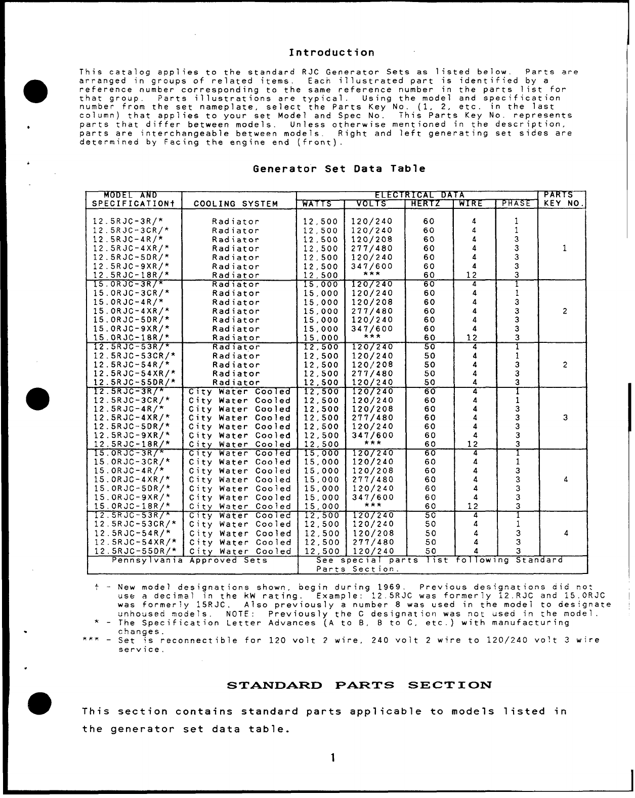
Introduction
This catalog applies to the standard RJC Generator Sets as listed below. Parts are
●arranged in groups of related items. Eacn illustrated part is identified by a
reference number corresponding to the same reference number in the parts list for
that group. Parts illustrations are typical. Using the model and specification
number from the set nameplate, select the Parts Key No. (1, 2, etc. in the last
column) that applies to your set Model and Spec No. This Parts Key No. represents
●parts that differ between models. Unless otherwise mentioned in the description,
parts are interchangeable between models. Right and left generating set sides are
determined by Facing the engine end (front).
.
●
✎
Generator Set Data Table
MODEL AND tLtCTRICAL DATA PARTS
Specification COOLING SYSTEM WATTS VOLTS RE PHASt KEY NO.
12.5RJC-3R/* Radiator 12,500 120/240 60 41
12.5RJC-3CR/* Radiator 12,500 120/240 60 4 1
12.5RJC-4R/* Radiator 12,s00 120/208 60 43
12.5RJC-4XR/* Radiator 12,500 277/480 60 4 3 1
12.5RJC-5DR/* Radiator 12,500 120/240 60 4 3
12.5RJC-9XR/* Radiator 12,s00 347/600 60
12.5RJC-18R/* 3
Radiator 12,500 *** 60 1; 3
15.oRJc-3R/* Radiator 15,000 120/240 60 4
15.oRJc-3cR/* Radiator 15,000 120/240 60 41
15.oRJc-4R/* Radiator 15,000 120/208 60 4
15.oRJc-4xR/* 3
Radiator 15,000 277/480 60 4
15.oRJc-5oR/* 32
Radiator 1s,000 120/240 60 4 3
ls.oRJc-9xR/* Radiator 15,000 347/600 60 4 3
15.oRJc-18R/* Radiator 15,000 *** 60 12 3
12.5RJC-53R/* Radiator 12,500 120/240 50 4
12.5RJC-53CR/* Radiator 12,500 120/240 50 4 1
12.5RJC-54R/* Radiator 12,500 120/208 50 4 3 2
12.5RJC-54XR/* Radiator 12,500 277/480 50 4
12.5RJC-550R/* 3
Radiator 12,500 120/240 50 4 3
12.5RJC-3R/* C!ty Water Cooled 12,500 120/240 60 4
12.5RJC-3CR/* C?ty Water Cooled 12,500 120/240 60 4
12.5RJC-4R/* 1
City Water Cooled 12,500 120/208 60 4
12.5RJC-4XR/* City Water Cooled 3
12,500 277/480 60 43 3
12.5RJC-5DR/* City Water Cooled 12,500 120/2.40 60 4 3
12.5RJC-9XR)* City Water Cooled 12,500 347/600 60 4 3
12.5RJC-18R/* City Water Cooled 12,500 *** 60 12 3
15.ORJC-3R/* City Water Cooled 15,000 120/240 60 41
15.oRJc-3cR/* City Water Cooled 15,000 120/240 60 41
15.oRJc-4R/* City Water Cooled 15,000 120/208 60 4 3
15.oRJc-4xR/* C~ty Water Cooled 15,000 277/480 60 43A
15.oRJc-5DR/~ City Water Cooled 15,000 120/240 60 4 3
15.oRJc-9xR/* City Water Cooled 15,000 347/600 60 43
15.ORJC-18R/* City Water Cooled 15,000 *** 60 12 3
12.5RJC-53R/* City Water Cooled 12,500 120/240 50 b
12.5RJC-53CR/* City Water Cooled 12,500 120/240 50 41
12.5RJC-54R/* City Water Cooled 12,500 120/208 50 4 3 4
12.5RJC-54XR/* City Water Cooled 12,500 277/480 50 43
12,5RJC-550R/* City Water Cooled 12,500 120/240 50 43
Pennsylvania Approved Sets See special parts 1st fol lowing Standard
Parts Section.
New model designations shown, begin during 1969. Previous designations aid rot
use adecimal in the KW rating. Example: 12.5RJC was for,merly 12.RJC and 15.ORJC
was formerly 15RJC. Also previously anumber 8was used in the model to designate
unhoused motiels. NOTE :Previously the Cdesignation was no~ ~sed in the model.
The Specification Letter Advances (A to B, Bto C, etc.) with manufacturing
changes.
*** -Set is reconnectable for 120 volt ?wire, 240 volt 2wire to 120/240 volt 3wire
service.
.
STANDARD PARTS SECTION
mThis section contains standard parts applicable to models listed in
the generator set data table.
1
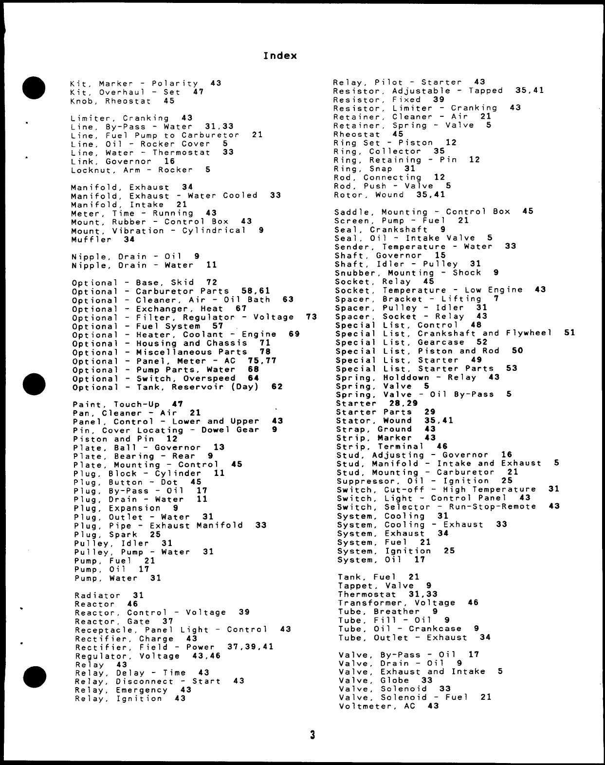
Index
Adapter, Engine to Generator 35,41
Adapter, Filter -Oil 17
Adapter, Hose -Water Inlet 33
Ammeter, Charge 43
Arm, Governor 15
Arm, Rocker -Exhaust and
Baffle, Air -Generators
Baffle, Distributor -Fue
Bail, Bowl -Fuel Pump 2’
Ball, Arm -Rocker 5
Ball, Fly -Governor 13
Band, Tank -Fuel 21
Base, Oil 9
Intake 5
35
Bearing Half, Rod -Connect
Bearing, Ball 31
Bearing, Rotor 35
Bearings, Precision 9
Bell, End 35,41
Block, Cylinder 9
Block, Terminal -3and 4P
Blower, Generator 35
Bolt, Carriage 11
Bolt, Head -Cvlinder 5
5
ng 12
ace 43
Bolt, Place -Connecting Rod 12
Bowl, Pump -Fuel 21
Box, Control 43
Box, output -Control 45
Brace, Bracket -Lifting 7
Bracket, Adjustment -Governor 16
Bracket, Intake Cup -Oil Pump 17
Bracket, Lifting 7
Bracket, Mounting -Control 43
Bracket, Mounting -Relay 43
Bracket, Mounting -Ignition Coil 25
Bracket, Output Box --Control 45
Bracket, Panel Stop -Control 43
Bracket, Pulley -Idler 31
Bracket, Temperature Relay -Low
Engine 45
Breaker, Circuit -Voltage Regulator
Bulb,. Light -Signal and Panel 43
Bushing, Pin -Piston 12
Bushing, Spacing 7,9
Cable, Battery 28
Cable, Battery -Jumper 28
Cable, Plug -Spark 25
Camshaft 13
Cap and Indicator, Oil 9
Cap, Radiator 31
Cap, Stem -Valve 5
Cap, Tank -Fuel 21
Cap, Tube -Breather 9
Carburetor Parts, Gasoline 22,23
Carburetor, Gasoline 21
Choke, Electric 18
Choke, Magnetic -Thermo 18
Coil, Ignition 25
Condenser 45
Condenser, Coil -Ignition 25
Connector, Inlet -Fuel Pump 21
Control 43,45
Control ,Temperature 24
Coupling, Drain -Water 11
Coupling, Tube -Exhaust 34
Cover, Cleaner -Air 21
Cover, Output Box -Control 45
Cover, Rocker 5
Cover, Thermostat 33
Crankshaft 14
cup, Intake -Oil Pump
Cushion, Vibration 7
45
Distributor 25,27
Distributor, Parts 27
Duct, Heater -Air 24
Elbow, Inlet -Fuel Pump 21
Elbow, Inlet -Carl
Elbow, Sender -Oi
Element, Cleaner -
Elbow, Outlet -Wa
Exciter, Generator
Fan, Generator 41
Fan; Radiator 31
Filter,
Filter,
Flange,
Flywhee
Gasket,
Gasket,
Gasket ,
Gasket,
Gasket,
Gasket .
Gasket;
Gasket ,
Gasket,
Gasket,
Gasket,
Gasket,
Gasket,
Gasket,
Gasket,
Gasket,
Gasket,
Gasket,
Gasket,
Gasket,
Gasket.
ureter 21
Gauge 17
Air 21
er
37,:;
Oil 17
Tube -Breather 9
Mounting -Starter 28
14
Adapter -Carburetor 21
Adapter -Oil Filter 17
Backplate -Gearcase 15
Base -Oil 9
Cap -Oil Fill Tube 9
Carburetor -Gasoline 21
Cleaner -Air 21
Cover -Gearcase 15
Cover -Rocker 5
Cover -Thermostat 33
Head 5
Manifold -Exhaust 33,34
Manifold -Intake 21
Mounting -Fuel Pump 21
Neck -Tank Filler 21
Outlet -Exhaust 34
Plate -Breather 25
Plate -Rear Bearing 9
Pump -Oil 17
Pump -Water 31
Tube -Oil Fill 9
Gauge: Pressure -Oil 43
Gauge, Temperature -Water 43
Gear, Distributor Drive -Camshaft
Gearcase 15
Generator 35,41
Governor 16
Grommet, Rubber 35,39,43
Guard, Flywheel 14
Guide, Rod -Push 5
Guide, Valve 5
Handle, Panel -Upper Control 45
Harness, Wiring –Engine to Control
Harness, Wiring -Voltage Regulator
Circuit Breaker 43
Harness, Wiring -Voltage Regulator
Exciter Stator 46
Head, Cylinder 5
Heater, Air –Carburetor 24
Hose, Drain -Oil 9
Hose, Inlet -Water 33
Hose, Radiator 31
Housing, Pump -Water 31
13
43
to
to
Housing, Water Outlet -Cylinder Head
Hub, Flywheel 14
Insert, Seat -Valve 5
Joint, Ball -Governor 16
Jumper, Board -Terminal 43
Key, Blower -Generator 35
Key, Gear -Camshaft 13
Kit, Decal -Plant 47
Kit, Gasket -Plant 47
.
31 .
.
Q
2
Index
aKit, Marker -Polarity 43
Kit, Overhaul –Set 47
Knob, Rheostat 45
Limiter,
.Cranking 43
Line, By-Pass -Water 31,33
Line, Fuel Pump to Carburetor
Line, Oil -Rocker Cover 5
Line, Water -Thermostat 33
.Link, Governor 16
Locknut, Arm -Rocker 5
Manifold. Exhaust 34
21
Manifold; Exhaust -Water Cooled 33
Manifold, Intake 21
Meter, Time -Running 43
Mount, Rubber -Control Box 43
Mount, Vibration -Cylindrical 9
Muffler 34
Nipple, Drain -Oil 9
Nipple, Drain -Water 11
Optional
Optional
Optional
Optional
Optional
Optional
Optional
Optional
Optional
Optional
Optional
Optional
Optional
-Base, Skid 72
-Carburetor Parts 58,61
-Cleaner, Air -Oil Bath 63
-Exchanger, Heat 67
-Filter, Regulato~ -Voltage 73
-Fuel System 57
-Heater, Coolant -“ Engine 69
-Housing and Chassis 71
-Miscellaneous Parts 78
-Panel, Meter -AC 75,77
-Pump Parts, Water 68
-Switch, Overspeed 64
-Tank, Reservoir (Day) 62
Paint, Touch-Up 47
Pan. Cleaner -Air 21
Panel ,Control -Lower and Upper 43
Pin. Cover Locatina -Dowel Gear 9
Piston and Pin “l2-
Plate, Ball -Governor 13
Plate, Bearing -Rear 9
Plate, Mounting -Control 45
Plug, Block -Cylinder 11
Plug, Button -Dot 45
Plug, By-Pass -Oil 17
Plug, Drain -Water 11
Plug, Expansion 9
Plug, Outlet -Water 31
Plug, Pipe -Exhaust Manifold
Plug, Spark 25
Pulley, Idler 31
Pulley, Pump -Water 31
Pump, Fuel 21
Pump, Oil 17
Pump, Water 31
Radiator 31
Reactor 46
33
.Reactor, Control -V01ta9e 39
Reactor, Gate 37
Receptacle, Panel Light -Control
Rectifier, Charge 43
.Rectifier, Field -Power 37,39,41
Reaulator, Voltaqe 43,46
●Reiay 43
Relay, Delay -Time 43
Relay, Disconnect -Start 43
Relay, Emergency 43
Relay, Ignition 43
43
Relay, Pilot -Starter 43
Resistor, Adjustable -Tapped 35,41
Resistor, Fixed 39
Resistor, Limiter -Cranking 43
Retainer, Cleaner -Air 21
Retainer, Spring -Valve 5
Rheostat 45
Ring Set -Piston 12
Ring, Collector 35
Ring, Retaining -Pin 12
Ring, Snap 31
Rod, Connecting 12
Rod, Push -Valve 5
Rotor, Wound 35,41
Saddle, Mounting -Control Box 45
Screen, Pump -Fuel 21
Seal ,Crankshaft 9
Seal ,Oil -Intake Valve 5
Sender, Temperature -Water 33
Shaft, Governor 15
Shaft, Idler -Pulley 31
Snubber, Mounting -Shock 9
Socket, Relay 45
Socket ,Temperature -Low Engine 43
Spacer, Bracket -Lifting 7
Spacer, Pulley -Idler 31
Spacer, Socket -Relay 43
Special List, Control 48
Special List, Crankshaft and Flywheel
Special List, Gearcase 52
Special List, Piston and Rod 50
Special List, Starter 49
Special List, Starter Parts 53
SDrina, Holddown -Relay 43
Sprin~, Valve 5
Spring, Valve -0
Starter 28,29
Starter Parts 29
Stator, Wound 35,
Strap, Ground 43
Strip, Marker 43
Strio, Terminal J
.-
1By-Pass 5
41
6
Governor 16
Stud”, Adjusting -
Stud, Manifold -Intake and Exhaust 5
Stud ,Mounting –Carburetor 21
Suppressor, Oil -Ignition 25
Switch, Cut-off -High Temperature 31
Switch, Light -Control Panel 43
Switch, Selector -Run-Stop-Remote 43
Svstem. Coolina 31
S~stem~ Coolin~ -Exhaust 33
System, Exhaust 34
System. Fuel 21
System, Ignition 25
System, Oil 17
Tank. Fuel 21
Tappet, Valve 9
Thermostat 31,33
Transformer, Voltage 46
Tube, Breather 9
Tube, Fill -Oil 9
Tube, Oil -Crankcase 9
Tube, Outlet -Exhaust 34
Valve, By-Pass -Oil 17
Valve, Drain -Oil 9
Valve, Exhaust and Intake 5
Valve, Globe 33
Valve, Solenoid 33
Valve, Solenoid -Fuel 21
Voltmeter, AC 43
51
3
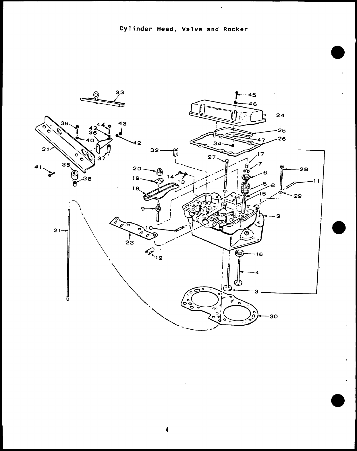
Cylinder Head, Valve and Rocker
(5) V&45
21
w> 8 —28
\1< 116
\,\q~~~
0°0 .,l!: ~
ee
o
,,,
,
d/,J; ,
-“ie,,,, .,, J30
.
.
.
Cylinder Head, Valve and Rocker
I
aREF PART
NO. NO.
.
1
110-1343
.110-1416
110-2879
110-1483
2
110-1347
110-1399
110-1432
110-1626
110-1482
4
5
6
7
8
9
:?
12
13
14
110-1218
110-1286
110-1219
110-1221
110-1220
110-0858
509-0090
115-0152
520-0338
520-0608
110-1312
850-0030
15
110-1501
110-1501-01
110-1501
110-1501-01
.110-1392
110-1392-01
QTY PART
uSED DESCRIPTION
Head Assembly, Cylinder
(Includes Parts Marked x)
Key 1and 2
2Gasoline Sets (Includes
Parts Marked t)
2Gas &Gas-Gasoline Sets
(Includes Parts Marked *)
Key 3and 4
2Gasoline Sets -City
Water Cooled -Without
Heat Exchanger (Includes
Parts Marked 1)
2Gas-Gasoline Sets -With
Heat Exchanger -Without
Heat Exchanger -City
Water Cooled (Includes
Parts Marked 7)
xHead, Cylinder (Includes
Parts Marked xx)
2tGasoline Sets -Standard
2*Gas &Gas-Gasoline Sets
2@Gas &Gas-Gasoline Sets -
City Water Cooled -
Without Heat Exchanger
2#Gasoline Sets -With Heat
Exchanger -City Water
Coo 1ed
21Gas-Gasoline Sets With Heat
Exchanger -Without Heat
Exchanger -City Water
Coo 1ed
xValve, Intake
4f~# Gasoline Sets
4*@~ Gas &Gas-Gasoline Sets
4xValve, Exhaust
8xSpring, Valve
xRetainer, Valve Spring
1: xLock, Valve Spring Retainer
4xSeal, Oil -Intake Valve -
Includes Retainer Rings
8xStud, Rocker Arm
4xStud, Intake Manifold
8xStud, Exhaust Manifold
2x8affle, Fuel Distributor
4xWasher, Lock (#10 Meal)
4xScrew, Round Head -Machine
(#10-32 X3/16”)
xxGuide, Valve
I:::e &Exhaust Gasoline
8t~# Standard
8.001” Oversize
Intake, Gas &Gas–Gasoline
Sets
4*@n Standard
4.001” Oversize -Exhaust,
Gas &Gas-Gasoline Sets
4*@q Standard
4.001” Oversize
.
5
REF PART
NO. NO.
16
110-1214
110-1214-02
110-1214-05
110-1214-10
110-1214-25
110-1287
110-1287-02
110-1287-05
110-1287-10
110-1287-25
110-1215
110-1215-02
110-1215-05
110-1215-10
110-1215-25
17 110-0859
18 115-0128
115-0129
19 115-0127
20 115-0150
21 115-0154
23 115-0196
24 115-0134
115-0179
25 120-0628
120-0626
26 115-0130
27 110-1225
28 800-0501
29 526-0174
30 110-1211
QTY PART
USED DESCRIPTION
xxInsert, Valve Seat
Intake, Gasoline
4t~# Standard
4.002” Oversize
4.005” Oversize
4.010” Oversize
4.025” Oversize
Sets
Intake, Gas &Gas-Gasoline
Sets
4*@l Standard
4.002” Oversize
4.005” Oversize
4.010” Oversize
4.025” Oversize
Exhaust
4Standard -All Sets
4.002” Oversize
4.005” Oversize
4.010” Oversize
4.025” Oversize
8Cap, Valve Stem
Arm, Rocker
4Exhaust
4Intake
88all, Rocker Arm
8Locknut, Rocker Arm
8Rod, Valve Push (Steel)
2Guide, Push Rod
Cover, Rocker
2Gasoline Sets (Includes
Parts Marked **)
2Gas &Gas-Gasoline Sets
(Includes Parts Marked tt)
Line, Oil -Rocker Cover
2** Gasoline Sets Only
2tt Gas &Gas-Gasoline Sets
2Gasket, Rocker Cover
8olt, Cylinder Head (Special)
;! Screw. Hex Head -Cvlinder
Head
14 Washer
(.406
.1345
2Gasket
Special) -
Flat -Cylinder Head
IO X.781 OD X
Thk)
Head
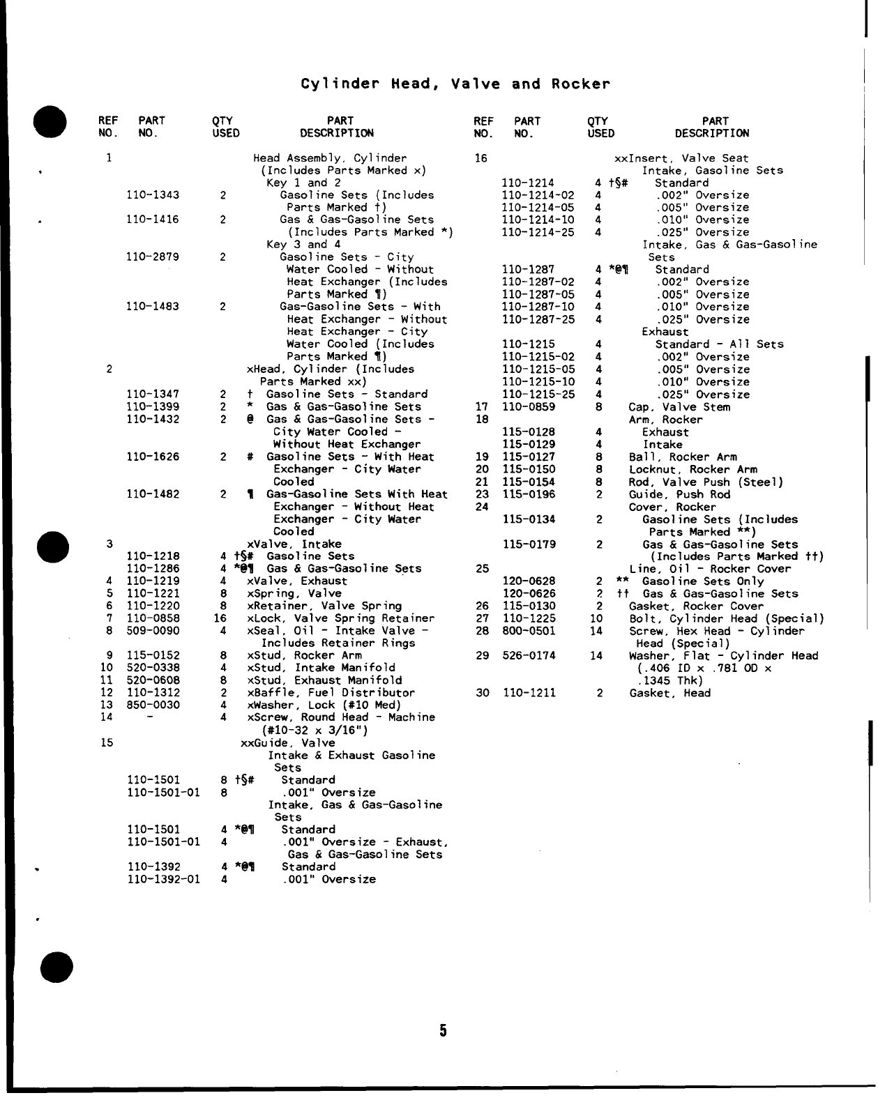
Cylinder Head, Valve and Rocker
21- \\
\
*45
23 L“’
\\ “-’12 1’
\q
1
~k
4
~oe ‘“ ~,
01 —3
,,1...
0
‘.!1!’ ~
0°0 !,! ,,
.me ill, I‘,
\
&
-“i-,, .-; 30
---
.
●
.
.
●
6
aREF PART
NO. NO.
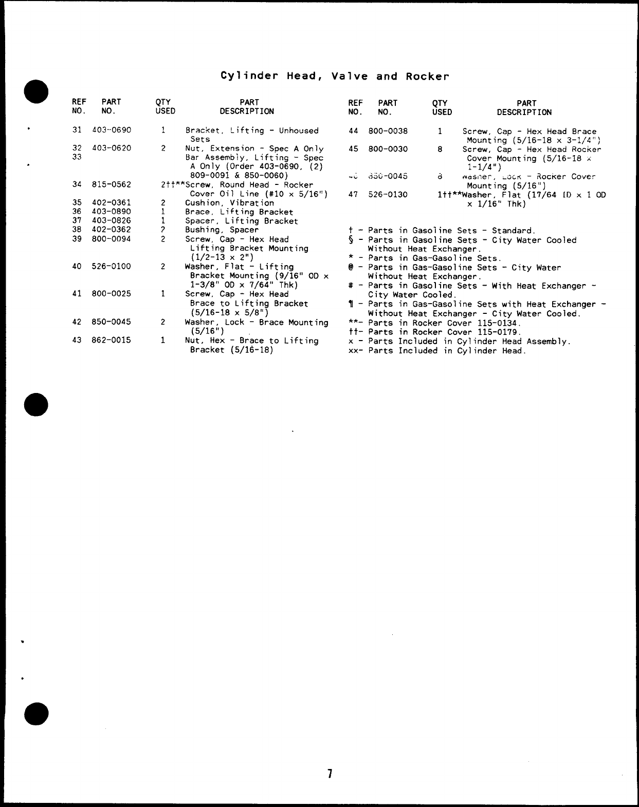
.31 403-0690
32 403-0620
33
.
34 815-0562
35 402-0361
36 403-0890
37 403-0826
38 402-0362
39 800-0094
40 526-0100
41 800-0025
42 850-0045
43 862-0015
Cylinder Head,
QTY PART
USED DESCRIPTION
1Bracket, Lifting -Unhoused
Sets
2Nut, Extension -Spec AOnly
Bar Assembly, Lifting -Spec
AOnly (Order 403-0690, (2)
809-0091 &850-0060)
2tt**Screw, Round Head -Rocker
2
~
1
?
2
2
1
2
1
Cover Oil Line (#10 x5/16”
Cushion, Vibration
Brace, Lifting Bracket
Spacer, Lifting Bracket
Bushing, Spacer
Screw, Cap -Hex Head
Lifting Bracket Mounting
(1/2-13 X2“)
Washer. Flat -Liftina
Bracket Mounting i9/~6° OD x
1-3/8” OD X7/64” Thk)
Screw, Cap -Hex Head
Brace to Lifting Bracket
(5/16-18 X5/8”)
Washer, Lock -Brace Mounting
[5/16”)
Nut”, Hex -Brace to Lifting
Bracket (5/16-lB)
Valve and Rocker
REF PART QTY PART
NO. NO. USED DESCRIPTION
44 800-0038 1Screw, Cap -Hex Head Brace
Mounting (5/16-18 x3–1114”)
45 800-0030 8Screw, Cap -Hex Head Rocker
Cover Mounting (5/16-18 A
1-1/4”)
-. .33G-0045 &m+sner, .OC.~ –3ocker Cover
Mounting (5/16”)
47 526-0130 ltt**Washer, Flat (17/64 [1) x 1 OD
X1/16” Thk)
t - Parts in Gasoline Sets -Standard.
$-Parts in Gasoline Sets -City Water Cooled
Without Heat Exchanger.
*-parts in Gas-Gasoline Sets.
@-Parts in Gas-Gasoline Sets -City Water
Without Heat Exchanger.
#-Parts in Gasoline Sets -With Heat Exchanger -
City Water Cooled.
I-Parts in Gas-Gasoline Sets with Heat Exchanger -
Without Heat Exchanaer -Citv Water Cooled.
**- parts jn Rocker Cov;r 115-01i4
tt- Parts in Rocker Cover
x-Parts Included in Cy”
xx- Parts Included in Cy
115-0179.
inder Head Assemb
inder Head. Y.
,
.
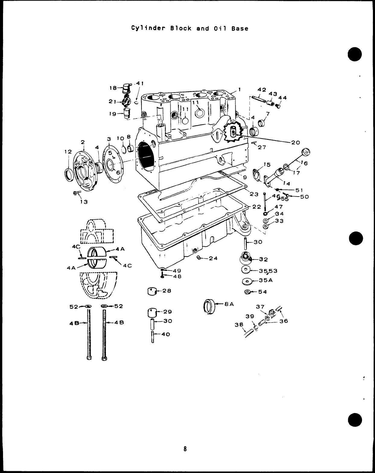
Cylinder Block and Oil Base
-52
r
-“B
0--2”
-35,53
@-35A
*54
,
.
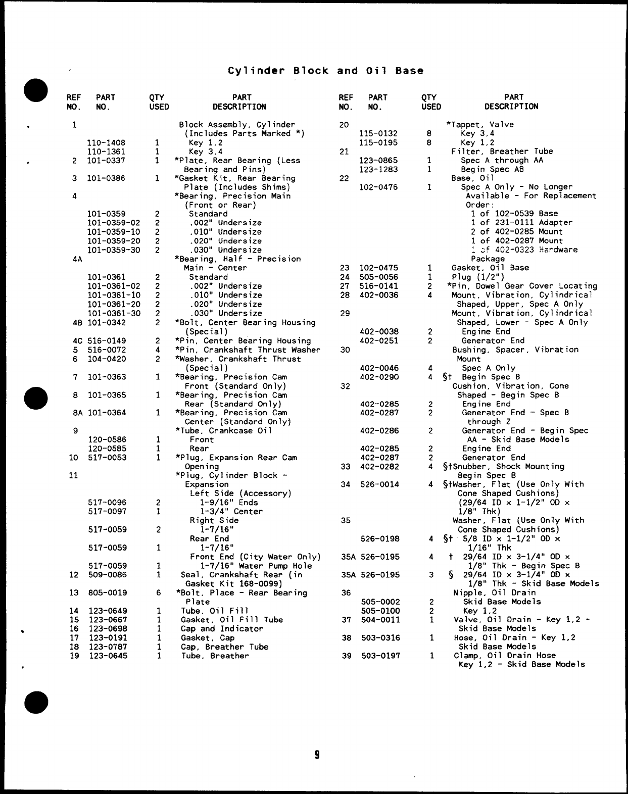
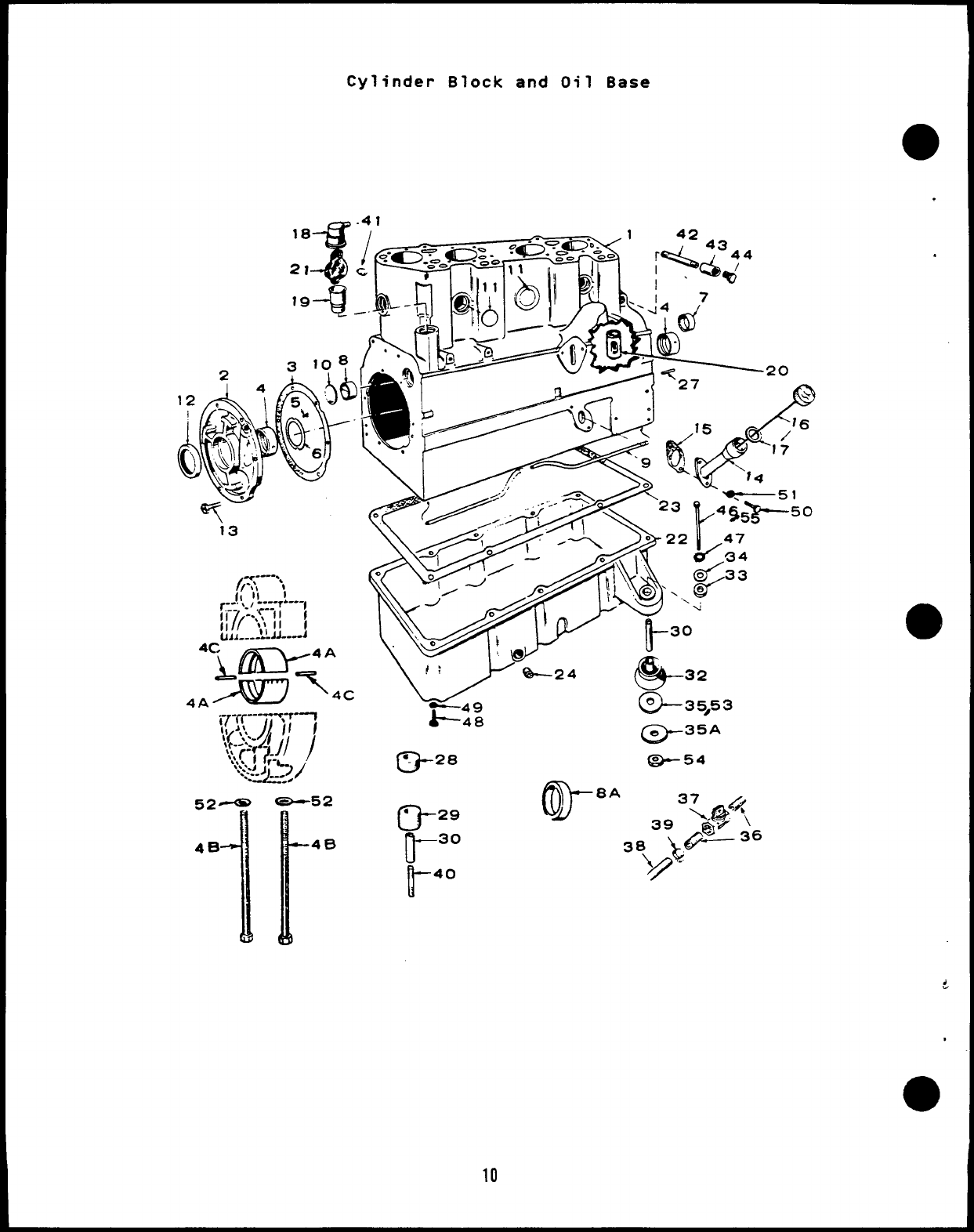
Cylinder Block and Oil Base
●REF PART
NO. NO. QTY
USED
PART
DESCRIPTION
REF PART
NO. NO. QTY PART
USED DESCRIPTION
*Tappet, Valve
8Key 3,4
8Key 1,2
Filter, 8reather Tube
1Spec Athrough AA
18egin Spec A8
8ase, Oil
1Spec AOnly -No Longer
Available -For Replacement
Order:
1of 102-0539 8ase
1of 231-0111 Adapter
2of 402-0285 Mount
1of 402-0287 Mount
.~f 402-0323 Hardware
Package
1Gasket, Oil 8ase
1Plug (1/2”)
2*Pin, Dowel Gear Cover Locating
4Mount, Vibration, Cylindrical
Shaped, Upper, Spec AOnly
Mount, Vibration, Cylindrical
Shaped, Lower -Spec AOnly
2Engine End
2Generator End
8ushing, Spacer, Vibration
Mount
4Spec AOnly
4Sf 8egin Spec 8
Cushion, Vibration, Cone
Shaped -Begin Spec B
2Engine End
2Generator End -Spec B
through Z
2Generator End -Begin Spec
AA -Skid 8ase Models
2Engine End
2Generator End
4StSnubber, Shock Mounting
Begin Spec B
4StWasher, Flat (Use Only With
Cone Shaped Cushions)
(29/64 ID X1-1/2” 00 X
1/8” Thk)
Washer, Flat (Use Only With
Cone Shaped Cushions)
4St 5/8 ID X1-1/2” OD X
1/16” Thk
4t29/64 ID X3-1/4” 00 X
1/8” Thk -Begin Spec 8
3~29/64 IDx3-1/4° OD X
1/8” Thk -Skid Base Models
Nipple, Oil Drain
2Skid Base Models
2Key 1,2
1Valve, Oil Drain -Key 1,2 -
Skid Base Models
1Hose, Oil Drain -Key 1,2
Skid Base Models
1Clamp, Oil Drain Hose
.Block Assembly, Cylinder
(Includes Parts Marked *)
Key 1,2
Key 3,4
*Plate, Rear 8earing (Less
Bearing and Pins)
*Gasket Kit, Rear Bearing
Plate (Includes Shims)
*Bearing, Precision Main
(Front or Rear)
Standard
.002” Undersize
.010” Undersize
.020” Undersize
.030” Undersize
*8earing, Half -Precision
Main -Center
Standard
.002” Undersize
.010” Undersize
.020” Undersize
.030” Undersize
*Bolt, Center Bearing Housing
(Special)
*Pin, Center Bearing Housing
*Pin, Crankshaft Thrust Washer
washer, Crankshaft Thrust
(Special)
*Bearing, Precision Cam
Front (Standard Only)
*Bearing, Precision Cam
Rear (Standard Only)
*Bearing, Precision Cam
Center (Standard Only]
*Tube, Crankcase Oil
Front
Rear
*Plug, Expansion Rear Cam
Open ing
*Plug, Cylinder Block -
Expansion
Left Side (Accessory)
1-9/16” Ends
1-3/4” Center
Right Side
1-7/16”
Rear End
1-7/16”
Front End (City Water Only)
1-7/16” Water Pump Hole
Seal, Crankshaft Rear (in
Gasket Kit 168-0099)
*Bolt, Place -Rear Bearing
Plate
Tube, Oil Fill
Gasket, Oil Fill Tube
Cap and Indicator
Gasket, Cap
Cap, Breather Tube
Tube, Breather
20 115-0132
115-0195
21 123-0865
123-1283
22 102-0476
.1
110-1408
110-1361
.2101-0337
3101-0386 1
4
101-0359
101-0359-02
101-0359-10
101-0359-20
101-0359-30
4A
101-0361
101-0361-02
101-0361-10
101-0361-20
101-0361-30
48 101-0342
4C 516-0149
5516-0072
6104-0420
2
2
2
:
23
24
27
2B
29
102-0475
505-0056
516-0141
402-0036
2
2
2
2
2
2402-0038
402-0251
2
4
230
402-0046
402-0290
7101-0363 132
a8101-0365
8A 101-0364
1402-0285
402-0287
1
402-0286
9120-05B6
120-0585
517-0053
1
1
1402-0285
402-0287
402-0282
10
11 33
34 526-0014
517-0096
517-0097 2
135
517-0059 2526-0198
517-0059 135A 526-0195
517-0059
509-0086 1
1
12 35A 526-0195
13 805-0019 636
505-0002
505-0100
37 504-0011
14
.::
17
18
19
.
123-0649
123-0667
123-0698
123-0191
123-0787
123-0645
38 503-0316
39 503-0197 Key”l,2 -Skid 8ase Models
9
Cylinder Block and Oil Base
-52
I
48 0-
●29
11- 30
u- 40
10
.
.
aREF PART
NO. NO.
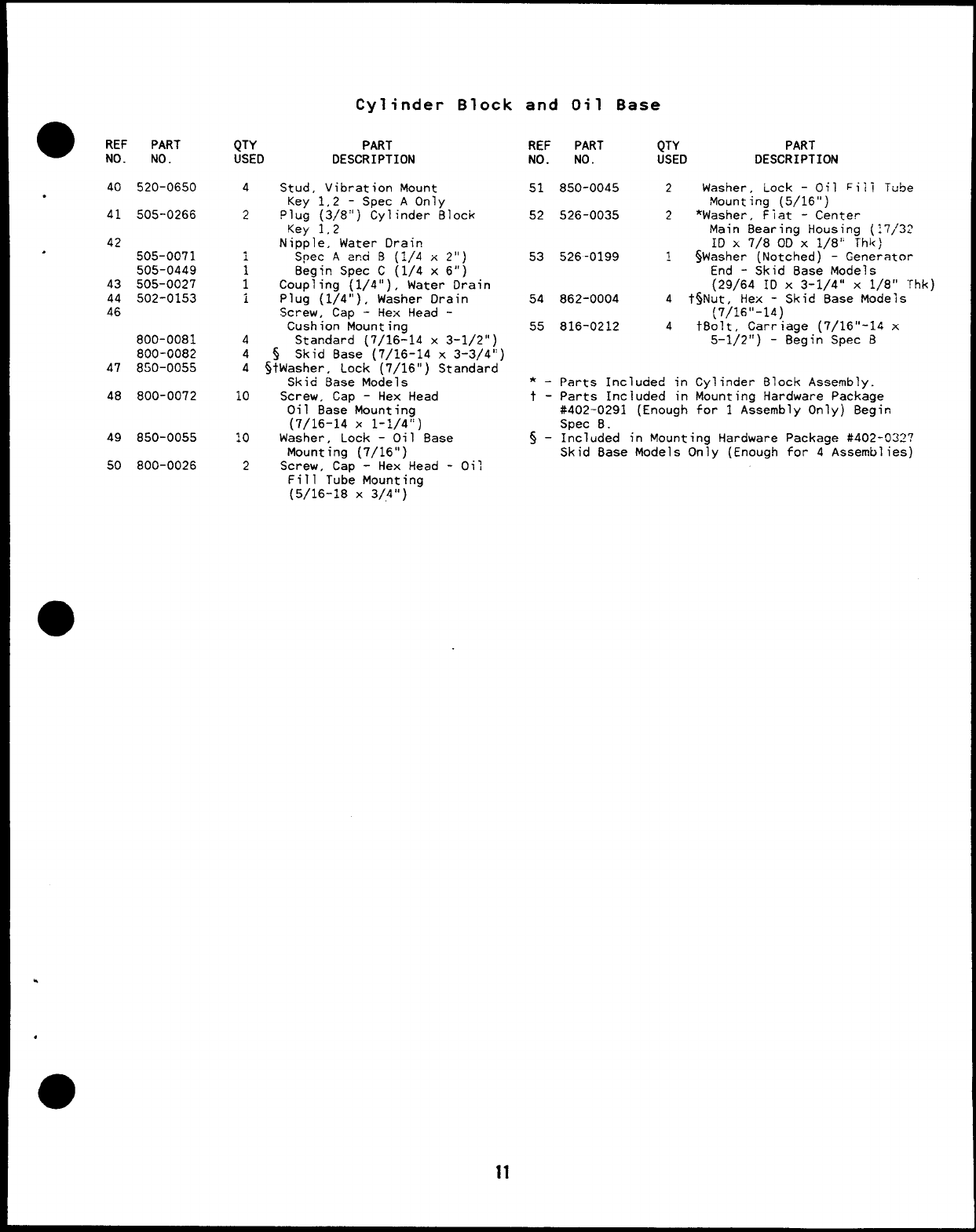
40
.
41
42
.
43
44
46
47
48
520-0650
505-0266
505-0071
505-0449
505-0027
502-0153
800-0081
800-0082
850-oo55
800-0072
49 850-0055
50 800-0026
Cylinder
QTY PART
USED DESCRIPTION
4Stud, Vibration Mount
Key 1,2 -Spec AOnly
Block
2plug (3/8”) Cylinder Block
Key 1,2
Nipple, Water Drain
Spec Ama !3 (1/4 x2“)
iBegin Spec C(1/4 x6“)
1Coupling (1/4”), Water Drain
iPlug (1/4”), Washer Drain
Screw, Cap -Hex Head -
Cushion Mounting
4Standard (7/16-14 x3-1/2”)
4 $ Skid Base (7/16-14 x3-3/4n)
4$tWasher. Lock [7/16”) Standard
Skici ~ase MOdeis ‘
10 Screw, Cap -Hex Head
Oil Base Mounting
(7/16-14 X1-1/4”)
10 Washer, Lock –Oil Base
Mounting (7/16”)
2Screw, Cap -Hex Head -
Fill Tube Mounting
(5/16-18 X3/3”)
Oil
11
and Oil Base
REF
NO.
51
52
53
54
55
*_
t-
5-
PART QTY PART
NO. USED DESCRIPTION
850-0045 2Washer, Lock -Oil Fiii Tube
Mounting (5/16”)
526-0035 2*Washer, Fiat -Center
Main 8earing Housing (17/32
ID x7/8 00 X1/8” Thk)
526-0199 ~$Washer (Notched) -Generator
End -Skid Base Models
(29/64 ID X3-1/4” X1/8” “rhk)
862-0004 4t%Nut, Hex -Skid Base Models
816-0212 4
Parts Included in
Parts Included in
#402-0291 (Enough
Spec 8.
(7/16’’- 14)
tBolt. Carriaae [7/16’’-14 x
5-1/2”) -B;gi; Spec 8
Cylinder Block Assembly.
Mounting Hardware Package
for 1Assembly Only) 8egin
Included in Mounting Hardware Package #402-022?
Skid Base Models Only (Enough for 4Assemblies)
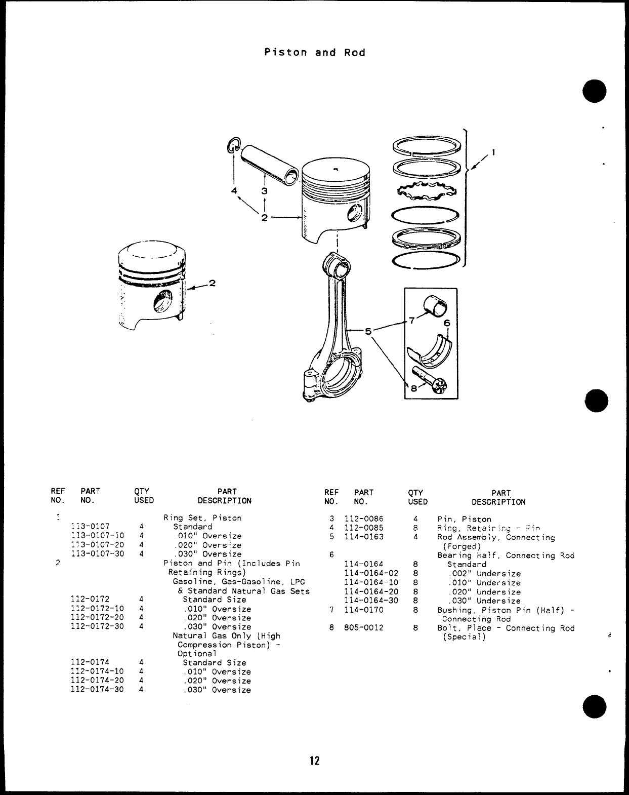
Piston and Rod
QTY
USED
L
4
4
4
4
4
4
4
4
4
4
4
Illiu I1
PART
DESCRIPTION
Ring Set, Piston
Standard
.O1O:’ Oversize
.020” Oversize
,030” Oversize
Piston and Pin (Includes Pin
Retaining Rings)
Gasoline, Gas-Gasoline, LPG
&Standard Natural Gas Sets
Standard Size
.010” Oversize
.020” Oversize
.030” Oversize
Natural Gas Only (High
Compression Piston) -
Optional
Standard Size
.010” Oversize
.020” Oversize
.030” Oversize
12
REF PART
NO. NO.
3112-0086
4112-0085
5114-0163
6
114-0164
114-0164-02
114-0164-10
114-0164-20
114-0164-30
7114-0170
8805-0012
QTY
USED
6
8
4
8
8
8
8
8
8
8
1
/’ .
REF PART
NO. NO.
113-0107
113-0107-10
;;3-0107-20
li3-0107-30
2
112-0i72
112-0172-10
112-0172-20
112-0172-30
112-0174
112-0174-10
112-0174-20
112-0174-30
PART
DESCRIPTION
Pin, Piston
Ricg, ?,etairir~ –‘T’~
Rod Assembly, Connecting
(Forged)
8earing half, Connecting Rod
Standard
.002” Undersize
.010” Undersize
.020” Undersize
.030” Undersize
8ushing, Piston Pin (Half) -
Connecting Rod
8olt, Place -Connecting Rod
(Special) 5-
,
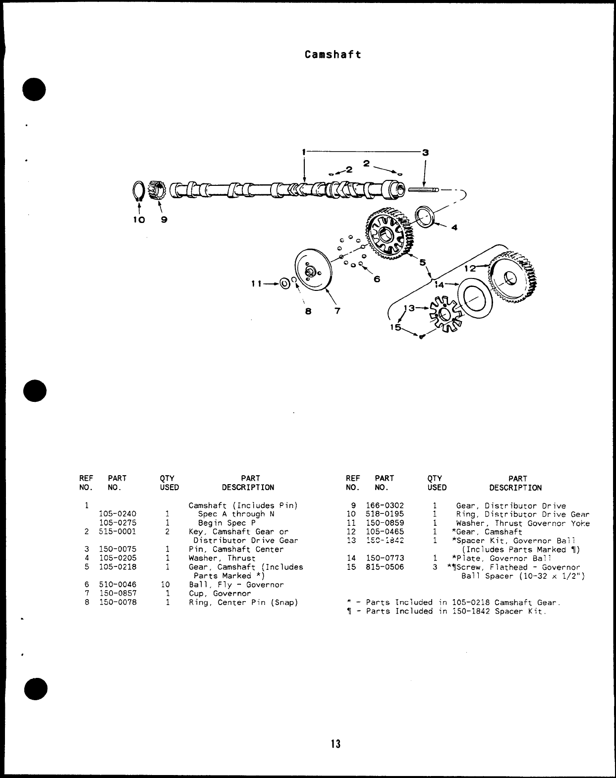
Camshaft
●
.
.
REF PART
NO. NO.
1105–0240
105-0275
2515-0001
3150-0075
4105-0205
5105-0218
6510-0046
7150-0857
8150-0078
QTY
USED
1
1
i
10
1
1
PART
DESCRIPTION
Camshaft (includes Pin)
Spec Athrough N
Begin Spec P
Key, Camshaft Gear or
Distributor Drive Gear
Pin, Camshaft Center
Washer, Thrust
Gear, Camshaft (Includes
Parts Marked *)
Ball, Fly -Governor
Cup, Governor
Ring, Center Pin (Snap)
REF PART
NO. NO.
9166-0302
10 518-0195
11 150-0859
14 150-0773
15 815-0506
QTY PART
USED DESCRIPTION
1Gear, Distributor Drive
~Ring, Distributor Drive Gear
1Washer, Thrust Governor Yoke
1*Gear, Camshaft
~*Spacer Kit, Governor Ba;i
(Includes Parts Marked 11)
1*Plate, Governor 8al!
3*!lScrew, Flathead -Governor
Ball Spacer (10-32 x1/2”)
*-Parts Included in 105-0218 Camshaft Gear.
11 -Parts Included in 150-1842 Spacer Kit.
.
.
13
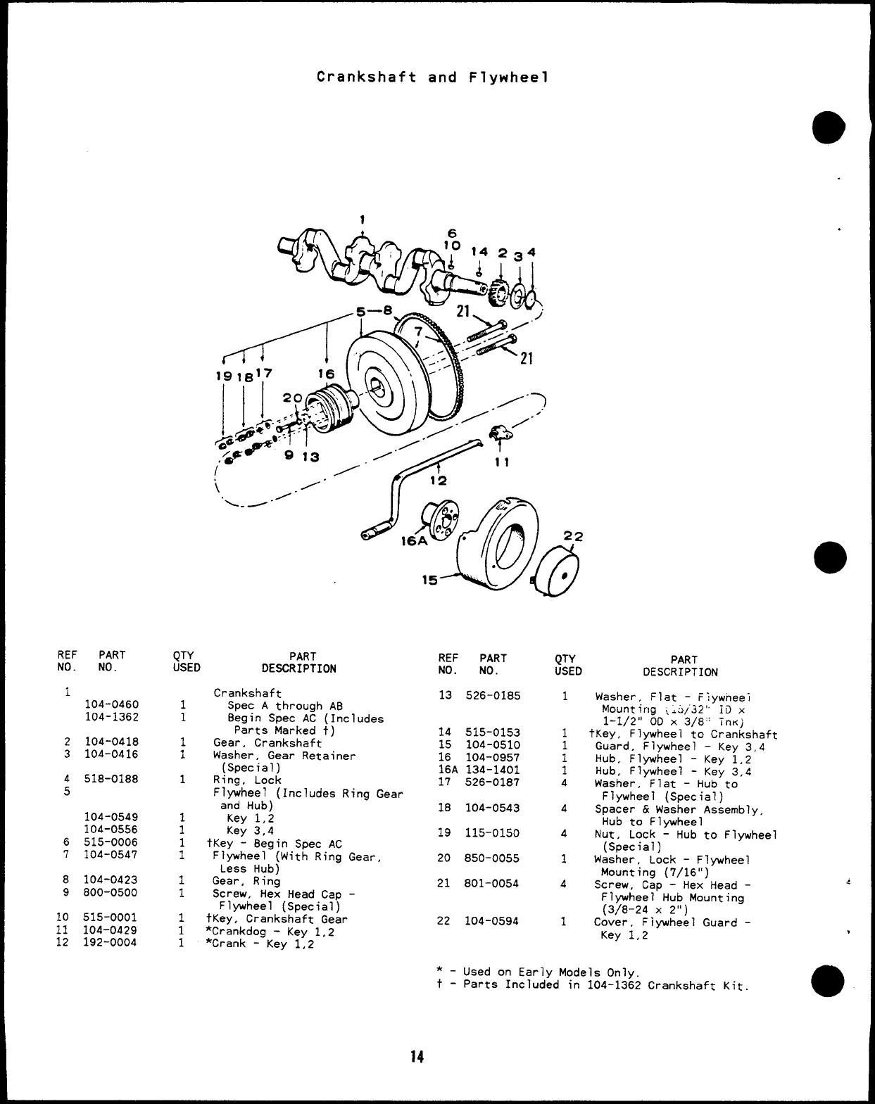
Crankshaft and Flywheel
REF PART
NO. NO. QTY PART
USED DESCRIPTION REF
NO.
13
PART
NO.
526-0185
515-0153
104-0510
104-0957
134-1401
526-0187
104-0543
115-0150
850-0055
801-0054
104-0594
QTY
USED
1
PART
DESCRIPTION
1104-0460
104-1362
Crankshaft
Spec Athrough AB
Begin Spec AC (Includes
Parts Marked t)
Gear, Crankshaft
Washer, Gear Retainer
(Special)
Ring, Lock
Flywheel (Includes Rina Gear
Washer, Flat -Flywneei
Mounting ~;3/.32° 10 x
1-1/2” OD X3/8” TnKj
~Key, Flywheel to Crankshaft
Guard, Flywheel -Key 3,4
Hub, Flywheel -Key 1,2
Hub, Flywheel -Key 3,4
Washer, Flat -Hub to
Flywheel (Special)
Spacer &Washer Assembly,
Hub to Flywheel
Nut, Lock -Hub to Flywheel
(Special)
Washer, Lock -Flywheel
Mounting (7/16”)
Screw, Cap -Hex Head -
1
1
;
1
1
1
;
1
1
1
1
1
14
;:
16A
17
1
1
1
1
4
2
3104-0418
104-0416
518-0188
and Hub)
Key 1,2
Key 3,4
tKey -8egin Spec AC
Flywheel (With Ring
Less Hub)
Gear, Ring
Screw, Hex Head Car)
Gear,
18 4
104-0549
104-0556
515-0006
104-0547
19 A
6
720 1
8
9104-0423
800-0500 21 4
Flywheel” Hub Mounting
(3/8-24 X2“)
Cover, Fiywheel Guard -
Flywheel (Special’)
tKey, Crankshaft Gear
‘Crankdog -Key 1,2
*Crank -Key 1,2
10
11
12
515-0001
104-0429
192-0004
22 1
Key 1,2 ,
*_
t-
14
Used on Early Models Onlv
Parts Included in 104-1362 Crankshaft Kit
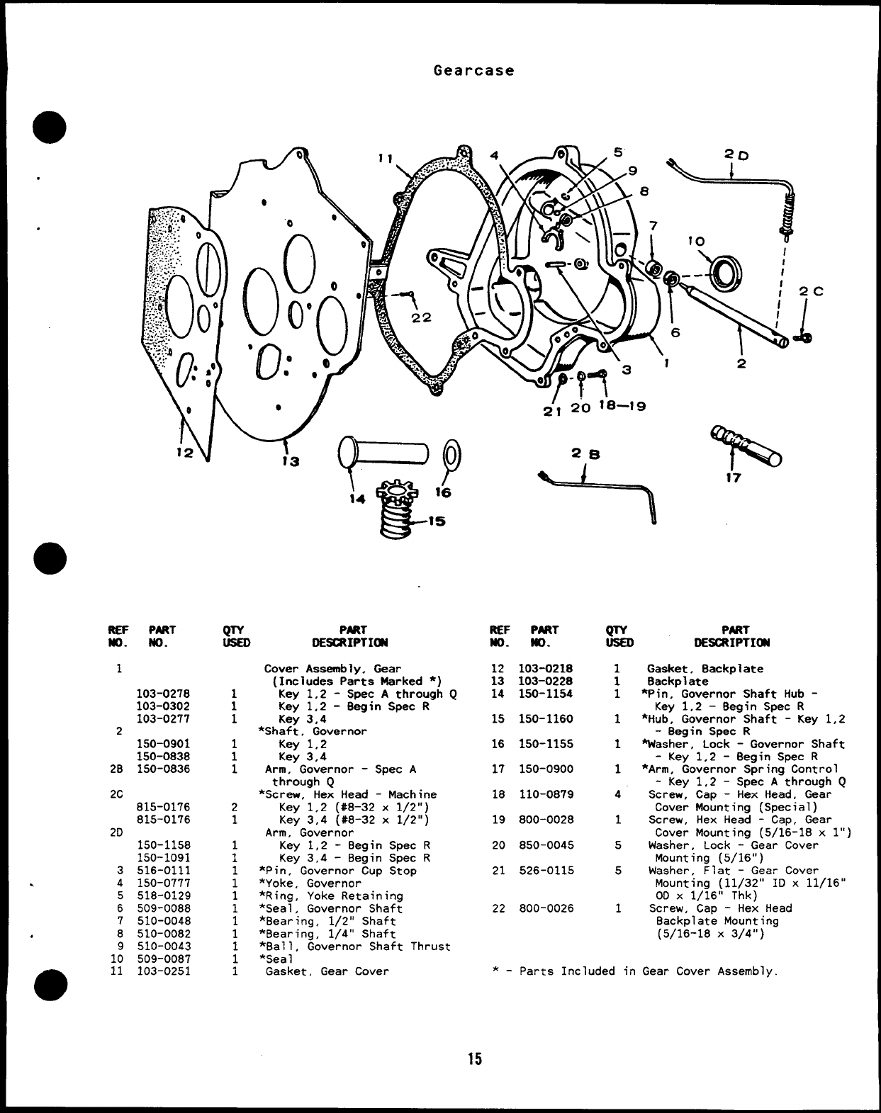
Gearcase
-A o
.
J-’- I2
REP PART
No. No.
1
103-0278
103-0302
103-0277
z150-0901
150-0838
2B 150-0836
2C 815-0176
815-0176
2D 150-1158
150-1091
3516-0111
.4150-0777
5518-0129
6509-0088
7510-0048
,8510-0082
9510-0043
10 509-0087
m11 103-0251
QTY PMT
DE=IPTIa
1
1
1
2
1
~’1 2’o 1-8-19
2B
I?%
Cover Assembly, Gear
(Includes Parts Marked *)
Key 1,2 -Spec Athrough Q
Key 1,2 -8egin Spec R
Key 3,4
*Shaft, Governor
Key 1,2
Key 3,4
Arm, Governor -Spec A
through Q
*Screw, Hex Head -Machine
Key 1,2 (#8-32 x1/2”)
Key 3,4 (#8-32 x1/2”)
Arm, Governor
Key 1,2 -8egin Spec R
Key 3,4 -Begin Spec R
*Pin, Governor CurI Stop
1*Yoke, Governor
1*Ring, Yoke Retaining
1*Seal, Governor Shaft
1*Bearing, 1/2” Shaft
1*Bearing, 1/4” Shaft
*Ball, Governor Shaft
;*Sea 1
1Gasket, Gear Cover
Thrust
REF P8JZT
No. No.
12 103-0218
13 103-0228
14 150-1154
15 150-1160
16 150-1155
17 150-0900
18 110-0879
19 800-0028
20 850-0045
21 526-0115
22 800-0026
QTY
1
1
1
1
1
1
4
1
5
5
1
PART
IIE=IPTION
Gasket, Backplate
Backplate
*Pin, Governor Shaft Hub -
Key 1.2 –Begin Spec R
*Hub, Governor Shaft -Key 1,2
-8egin Spec R
Washer, Lock -Governor Shaft
-Key 1,2 -Begin Spec R
*Arm, Governor Spring Control
-Key 1,2 -Spec Athrough Q
Screw, Cap -Hex Head, Gear
Cover Mounting (Special)
Screw, Hex Head -Cap, Gear
Cover Mounting (5/16-18 x1“)
Washer, Lock -Gear Cover
Mounting (5/16”)
Washer, Flat -Gear Cover
Mounting (11/32” ID x11/16”
OD X1/16” Thk)
Screw, Cap -Hex Head
Backplate Mounting
(5/16-18 X3/4”)
*-Parts Included in Gear Cover Assembly.
15
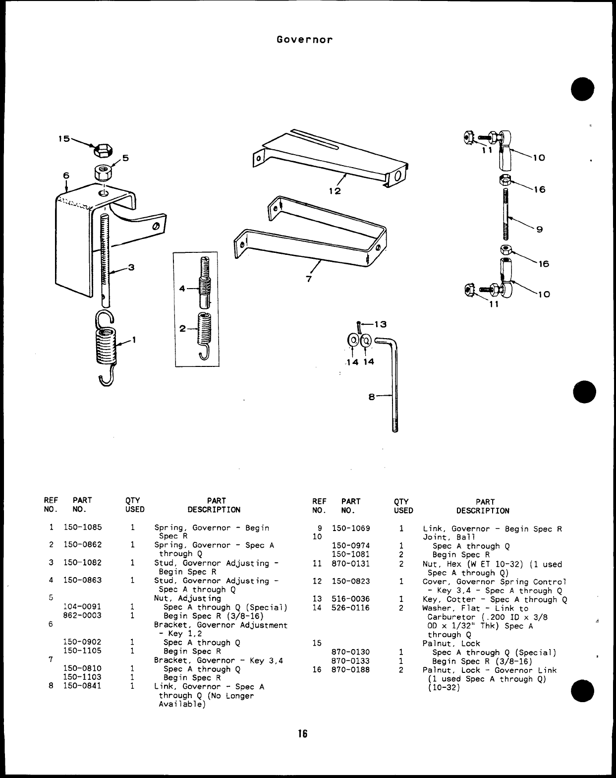
Governor
REF PART
NO. NO.
1150-1085
2150-0862
3150-1082
4150-0863
~
:04-0091
862-0003
6
150-0902
150-1105
7
150-0810
150-1103
8150-0841
QTY
USEO
1
1
1
1
1
1
1
1
1
1
1
PART
DESCRIPTION
.-
7
Spring, Governor -8egin
Spec R
Spring, Governor -Spec A
through Q
Stud, Governor Adjusting -
Begin Spec R
Stud, Governor Adjusting -
Spec Athrough Q
Nut, Adjusting
Spec Athrough Q(Special)
Begin Spec R(3/8-16)
Bracket, Governor Adjustment
-Key 1,2
Spec Athrough Q
Begin Spec R
Bracket, Governor -Key 3,4
Spec Athrough Q
8egin Spec R
Link, Governor -Spec A
through Q(No Longer
Available)
~–13
??
Q. ‘Q —
.14 14
4
8
REF PART
NO. NO.
9150-1069
10 150-0974
150-1081
11 870-0131
12 150-0823
13 516-0036
14 526-0116
15
870-0130
870-0133
16 870-0188
QTY
USED
1
1
2
2
1
1
2
;
2
%16
l-’
9
\,6
Q=@K
%10
11
,
PART
DESCRIPTION
Link, Governor -Begin Spec R
Joint, Ball
Spec Athrough Q
Begin Spec R
Nut, Hex (W ET 10-32) (1 used
Spec Athrough Q)
Cover, Governor Spring Control
-Key 3,4 -Spec Athrough Q
Key, Cotter -Spec Athrough Q
Washer, Flat -Link to
Carburetor (.200 10 x 3/8
OD x1/32” Thk) Spec A~
through Q
Palnut, Lock
Spec Athrough Q(Special)
Begin Spec R(3/8-16) *
Palnut, Lock -Governor Link
16
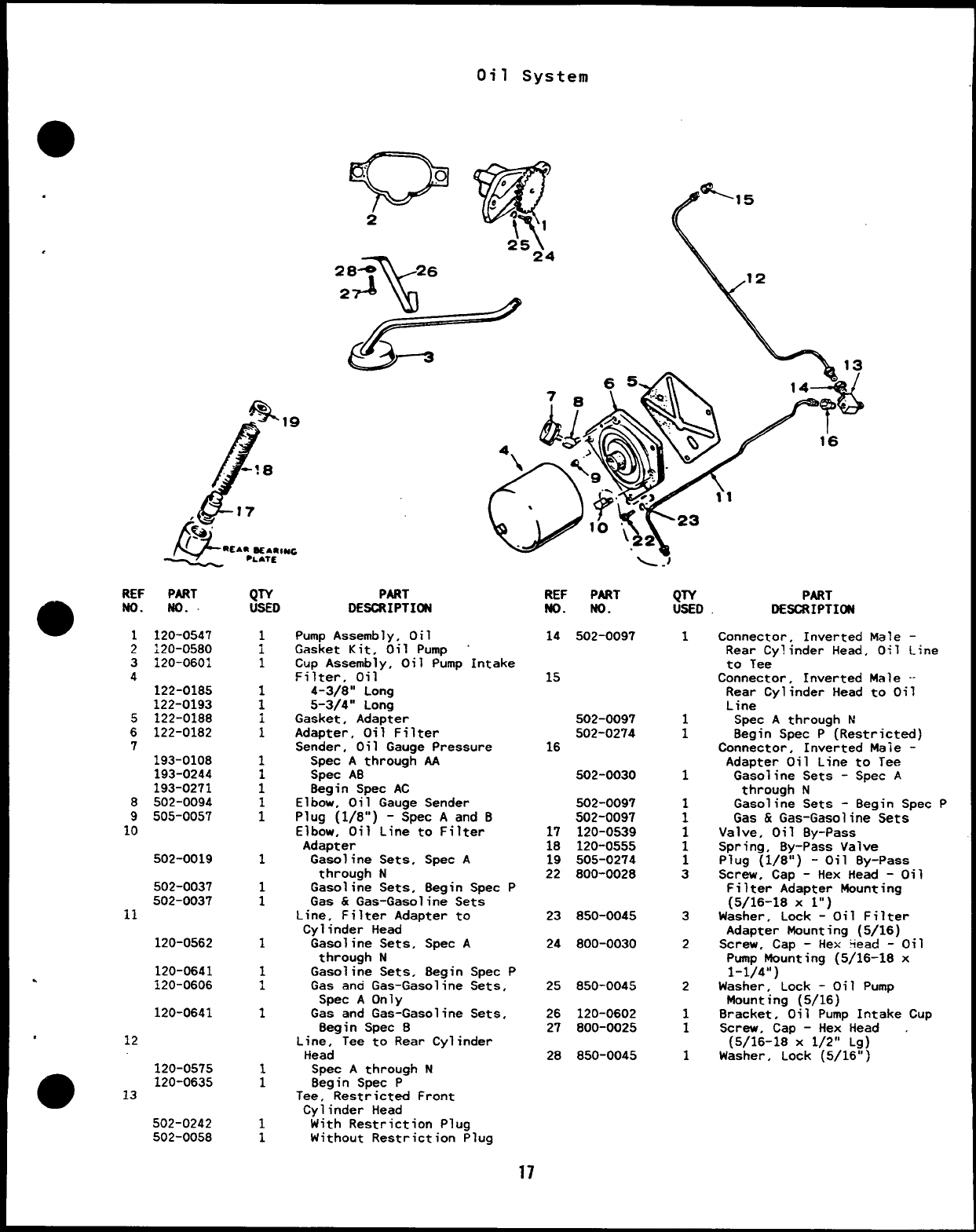
Oil System
REF PART
a
No. NO.
1120-0547
2
3
4
5
6
7
120-0580
120-0601
122-0185
122-0193
122-0188
122-0182
193-0108
193-0244
193-0271
502-0094
505-0057
502-0019
502-0037
502-0037
11
120-0562
120-0641
●120-0606
120-0641
*12
120-0575
m
120-0635
13
502-0242
502-0058
\
24
-. .
(&
1
i
1
;i
1
1
1
1
i
1
1
1
1
1
1
1
1
1
1
1
PART
DESCRIPTI~
Pump Assembly, Oil
Gasket Kit, Oil Pump “
Cup Assembly, Oil Pump Intake
Filter, Oil
4-3/8” Long
5-3/4” Long
Gasket, Adapter
Adapter, Oil Filter
Sender, Oil Gauge Pressure
Spec Athrough AA
Spec AB
8egin Spec AC
Elbow, Oil Gauge Sender
Plug (1/8”) -Spec Aand B
Elbow, Oil Line to Filter
Adapter
Gasoline Sets, Spec A
through N
Gasoline Sets, 8egin Spec P
Gas &Gas-Gasoline Sets
Line, Filter Adapter to
Cylinder Head
Gasoline Sets, Spec A
through N
Gasoline Sets. 8egin Spec P
Gas and Gas-Gasoline Sets,
Spec AOnly
Gas and Gas-Gasoline Sets,
Begin Spec 8
Line, Tee to Rear Cylinder
tiead
Spec Athrough N
Begin Spec P
Tee, Restricted Front
Cylinder Head
With Restriction Plug
Without Restriction Plug
\.)
REF PART
NO. NO.
14 502-0097
15
502-0097
502-0274
16
502-0030
502-009’7
502-0097
17 120-0539
18 120-0555
19 505-0274
22 800-0028
23 850-0045
24 800-0030
25 850-0045
26 120-0602
27 800-0025
28 850-0045
CJT&
1
1
1
1
:
1
1
1
3
3
2
2
1
1
1
PART
DESCRIPTI~
Connector, Inverted Male -
Rear Cylinder Head, Oil Line
to Tee
Connector, Inverted Male --
Rear Cylinder Head to Oil
Line
Spec Athrough N
Begin Spec P(Restricted)
Connector, Inverted Male -
Adapter Oil Line to Tee
Gasoline Sets -Spec A
through N
Gasoline Sets -8egin Spec P
Gas &Gas-Gasoline Sets
Valve, Oil 8y-Pass
Spring, By-Pass Valve
Plug (1/8”) -Oil By-Pass
Screw, Cap -Hex Head -Oil
Filter Adapter Mounting
(5/16-18 X1“)
Washer, Lock -Oil Filter
Adapter Mounting (5/16)
Screw, Cap -Hex %ead -Oil
Pump Mounting (5/16-18 x
1-1/4”)
Washer, Lock -Oil Pump
Mounting (5/16)
Sracket, Oil Pump Intake Cup
Screw, Cap -Hex Head .
(5/16-18 X1/2” Lg)
Washer, Lock (5/16”)
17
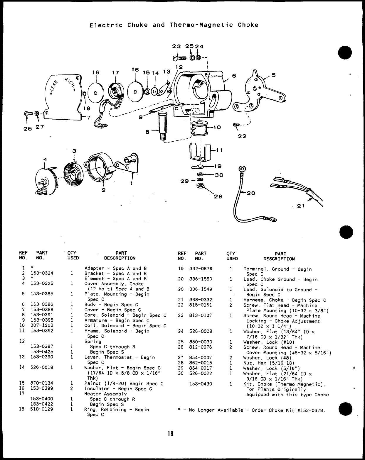
Electric Choke and Thermo-Magnetic Choke
T---:)
22
L-- —1
2‘28
.
REF PART
NO. :::D
1
1
1
1
1
1
1
1
1
1
1
1
1
1
2
1
:
PART
DESCRIPTION REF PART
NO. NO.
19 332-0876
20 336-1550
20 336-1549
QTY
USED
1
1
1
1
2
1
1
1
2
2
:
1
1
PART
DESCRIPTION
Terminal, Ground -Begin
Spec C
Lead, Choke Ground –Begin
Spec C
Lead, Solenoid to Ground -
Begin Spec C
Harness, Choke -Begin Spec
No.
*
153-0324
*
153–0325
1
2
3
4
Adapter -Spec Aand 8
Bracket -Spec Aand B
Element -Spec Aand B
Cover Assembly, Choke
(12 Volt) Spec Aand B
Plate, Mounting -Begin
Spec C
Body -Begin Spec C
Cover -Begin Spec C
Core, Solenoid -Begin Spec C
Armature -Begin Spec C
Coil, Solenoid -Begin Spec C
Frame, Solenoid -Begin
Spec C
Spring
Spec Cthrough R
8egin Spec S
Lever, Thermostat -Begin
Spec C
Washer, Flat -Begin Spec C
(17/64 ID X5/8 00 X1/16”
Thk)
Palnut (1/4-20) Begin Spec C
Insulator -Begin Spec C
Heater Assembly
Spec Cthrough R
Begin Spec S
Ring, Retaining -Begin
Spec C
5153-0385
21 338-0332
22 815-0161 c
6
7
8
9
10
11
153-0386
153-0389
153-0391
153-0395
307-1203
153-0392
Screw, Flat Head -Machine
Plate Mountina (10-32 x3/8”)
23 813-0107 Screw, Round H;ad -Machine ‘
Locking -Choke Adjustment
(10-32 X1-1/4”)
24 526-0008 Washer, Flat “(13~64° ID x
7/16 OD X1/32” Thk)
Washer, Lock (#IO)
Screw, Round Head -Machine
Cover Mounting (#8-32 x5/16”)
Washer, Lock (#8)
Nut, Hex (5/16-18)
Washer, Lock (5/16”)
Washer, Flat (21/64 ID x
9/16 OD X1/16” Thk)
Kit, Choke (Thermo Magnetic),
For Plants Oriainallv
12 25 850-0030
26 812-0076
:53-0387
153-0425
153-039013
14
27 854-0007
28 862-0015
29 854-0017
30 526-0022
526-0018
15
16
17
870-0134
153-0399 153-0430
equipped with {his t~pe Choke
153-0400
1.53-0422
518-012918 *_No Longer Available -Order Choke Kit #153–0378
18
Fuel System
,,17’
$iiiE
41
lib
.w-12
,
a
20
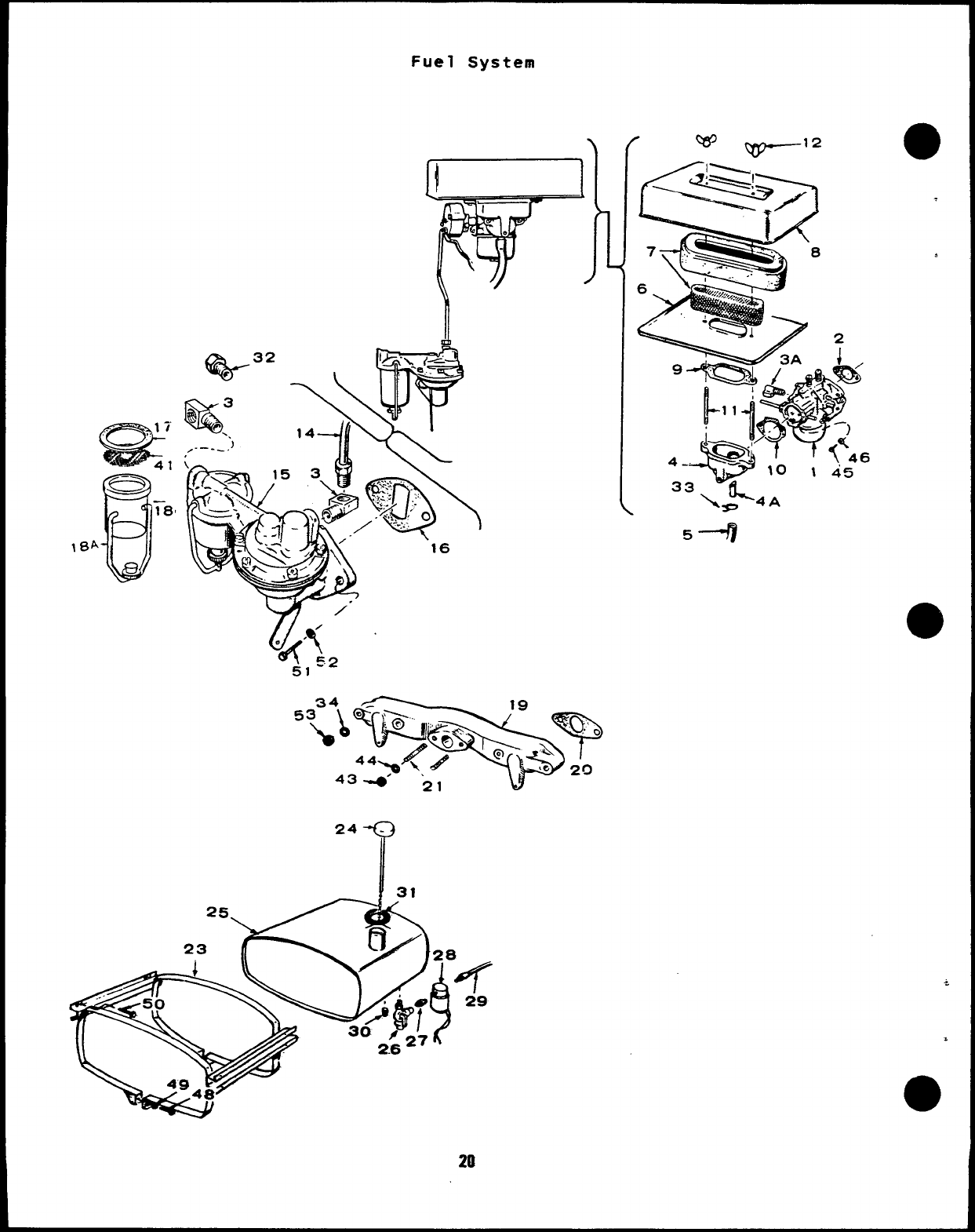
Fuel System
●REF PART
NO. NO.
1
141-0758
.141-0876
2
3
3A
4
4A
5
6
7
8
9
10
11
●12
14
15
141-0281
502-000?
502-0065
140-0647
140-0933
123-0732
503-0416
140-0595
140-0636
140-0594
140-0584
140-0585
140-0921
520-0621
865-0020
159-0744
149-1016
149-1099
149-1787
16 149-0792
17 149-0517
18 149-0116
149-1168
;84 :49-1oo6
149--1169
19 154-0749
20 154-0733
21 520-0526
23 15’+0640
24 159-0642
QTY PART
USED DESCRIPTION
*Carburetor, Gasoline
(Includes Mounting Gasket)
1(Includes Parts Marked **)
Spec AThrough Q
(For Carburetor Breakdown
See 141-0759)
1Begin Spec R(Includes
Parts Marked t) (For
Carburetor Breakdown
See 141-0685)
1Gasket, Carburetor
2Elbow, Fuel Pump Inlet and
Outlet
1Elbow, Carburetor Inlet
Adapter, Air Cleaner
(Includes Tube)
1Spec Athrough Q
1** Begin Spec R
1Tube, Nylon
1
.Hose, Breather to Air Cleaner
Adapter (7/16 IO x12”)
7Pan, Air Cleaner
iElement &Retainer, Air
Cleaner
1Cover, Air Cleaner
1**Gasket, Air Cleaner
Gasket, Adapter to Carburetor
1Spec Athrough Q
1** Begin Spec R
2Stud, Air Cleaner
2Nut, Wing -Air Cleaner
(1/4-20)
Line, Pump to Carburetor
1Spec Aand B
1Spec Cthrough Q“
~** Begin Spec R
1Pump, Fuel (Includes Mounting
Gasket) (includes Parts
Marked $)
1 $ Gasket, Fuel Pump Mounting
1Gasket. Fuei Pump Bowl
#Bowl, Fuel Pump (Glass)
7
.Soec Athrouqh T(2-3/8”)
REF
NO.
25
26
27
28
29
30
31
32
33
34
41
43
44
45
46
48
49
50
51
52
1Begin Spec Ax (1-5/8’;) -53
#Bail, Fuel Pump Bowl Retaining
,Spec Athrough T(2-3/8”)
iBegin Spec AA (1--5/8”)
1Manifold, Intake
2**+ Gasket, Intake Manifold *_
2Stud, Carburetor Mounting
7
ABand, Tank -Housed Sets -
Key 1,2 !:
1Cap Assembly -Housed Sets -~-
Key 1,2 **.
.
a
PART
NO.
159-0639
504-0004
502-0082
307-0565
501-0015
505-0057
159-0751
502-0003
503-0171
526-0065
149-0463
868-0002
854-0017
813-0108
850-0030
812-0168
850-0040
821-0010
800-0027
149-1307
1:0-0445
149-1048
QTY
USED
1
1
1
1
1
1
1
1
2
4
1
2
2
2
2
2
2
8
2
2
4
1
PART
DESCRIPTION
Tank, Fuel -Housed Sets -
Key 1,2
Valve, Shut-off –Housed Sets
-Key 1,2
Nipple, Hex -Brass Pipe -
Key 1,2 –Housed Sets
Valve, Fuel Solenoid (12 Volt)
Housed Sets -Key 1,2
Line, (16”) -Housed Sets -
Key 1;2 ‘
Plug (1/8”) -Shut Off Vaive
-Housed Sets -Key 1,2
Gasket, Tank Filler-Neck -
Key 1,2 -Floused Sets
Connector, Pump Inlet -
Housed Sets with Mounted
Tank -Key 1,2 -Housed Sets
Clamp, Breather Hose
Washer, Flat (Copper) Intake
Manifold Mounting (21/64” ID
X9/16” 00 X1/16” Thk)
Screen, Fuel Pump
Nut, Hex -Carburetor
Mounting (5/16--24)
Washer, Lock (IT) -Carburetor
Mounting (5/16”)
Screw, Round Head -Machine
Air Cleaner Adapter Mounting
(10-32 x1-1/2”)
Washer, Lock -Air Cleaner
Adapter Mounting (#IO)
Screw, Round Head -Machine --
Fuel Tank Mounting Bracket
(1/4-20 X3-1/2”)
Washer, Lock -Fuel Tank
Mounting 8racket (1/4”)
Screw, Hex Washer Head -Self
Locking -Fuel Tank Mounting
(1/4-20 X1/2”)
Screw, Cap -Hex Head -Fuel
Pump Mounting (5/16-18 x7/8”)
Washer, Copper -Fuel !%mp
Mounting
INut ,Hex -Intake MtiT.. .
ticl~:?.: ~;.,j>cb’.::>
Repair Kit, Fuel Pump
See Separate Group for Components and Service
Kits.
Measure for Correct Size When Ordering.
Parts Included in 149-1787 Fuel Pump.
Parts Included in 141-0876 Carburetor Kit.
Parts Included in 141-0758 Carburetor Kit.
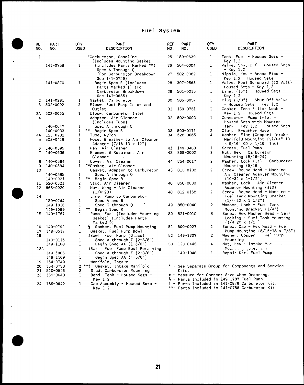
Carburetor Parts (Gasoline)
Spec Athrough Q
REF PART
NO. NO.
141-O’159
:43-0241
143-0201
141-0281
1
.143-0202
2143-0234
-1
., 143-0204
4143-0235
.5 143-0237
6123-0207
;.43-0315
4+/17 15
q-
21
3
_,19 18-@
m
-—
R’”
11
&a7’
QTY PART
USEO DESCRIPTION
Carburetor
1Gasoline
iRepair Kit, Carburetor
(Includes Parts Marked **)
1** Gasket Kit, Carburetor
(includes Parts Marked *)
1Gasket, Carburetor Flange
(Illustrated in Fuel
System Group)
1Valve, Throttle
,Shaft and Lever, Throttle
iValve, Choke
1**Needle, Idle Jet and High
Speed Adjustment
1**Nozzle
Shaft, Choke
1Spec Aand 8(No Longer
Available)
1Spec Cthrough Q
REF PART
NO. NO.
7143-0208
8143-0015
9~43-0209
10 143-0105
11 143-0210
12 143-0077
13 141-0703
14 143-0341
15 143-0213
16 812-0014
17 143-0110
18 143-0214
19 143-0112
20 143-0114
21 143-0215
QTY PART
USED DESCRIPTION
1Screw and Gasket, Bowl
*Gasket, Fuel Inlet Valve
;*Gasket
~Float and Lever
1Bowl
i*Gasket. Bowl Ring
1**Pin. Float
**Valve, Fuel inlet
:Screw, Idle Adjustment
4**Screw, Round liead -Machine
(#3-48 x3/16)
1Plug, Expansion
1Spring, Throttle Adjustment
Spring, Idle Adjustment
;Spring, High Speed Adjustment
1Screw, Throttle Adjustment
*-parts Included in Gasket Kit 143-0201.
**– parts Included in Repair Kit 143-0241.
●
☛
●
✚
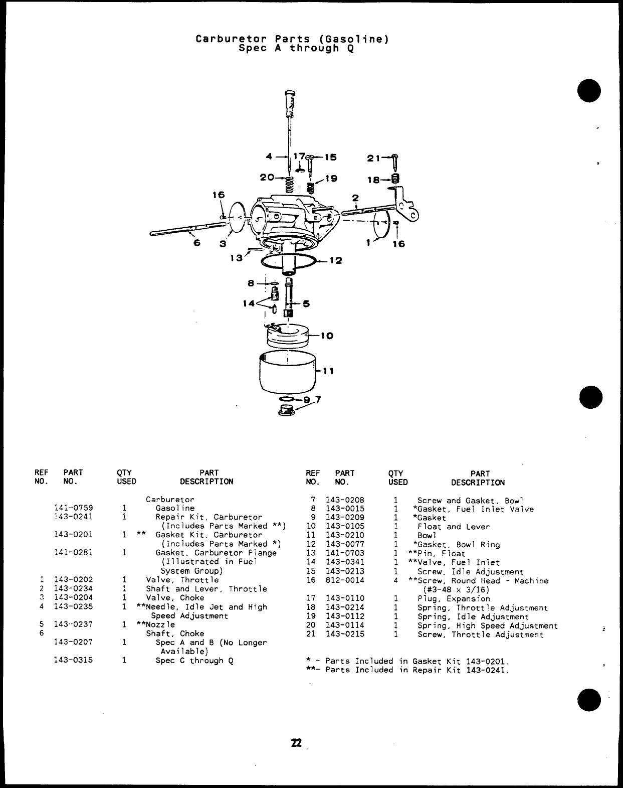
Carburetor Parts (Gasoline)
Begin Spec R
a
.
e
REF PART
No. MO.
141-0685
141-0747
141-0748
141-0281
141.-0708
141-0860
141-0698
141-0793
141-0705
141-0661
141-0798
141-0703
141-0702
QTY
USED
,
1
1
1
:
-i
1
1
10
<
3
Q
>“0”
32
g304
,J
PART
DESCRIPTIffl
Carburetor, Gasoiine
Repair Kit (Includes
Marked *)
Gasket Kit (Includes
29 ‘“ 6q-10
Marked +} -
r
Parts
Parts
*+Gasket, Carburetor Flange
Bowl, Fuei
Plate, Choke
Screw and Washer, Choke and
Throttle Plate Mounting
‘late. Throttle
*Retainer, Seal
*+Seal, Rubber
*Valve x.?t Assembly, Fuel
*Shaft, Float
Float Assembly
REF PART
No. No.
11 141-0701
12 141-0700
13 141-0711
14 141-0713
15 141-0710
16 141-00j7
17 141-0712
18 141-0679
22 141-0735
29 141-0799
30 141-0811
QN PART
USED DESCRIPTION
~*+Gasket. Bowl tu ~c~y
Screw, Throttle Stop
iSpring, Throttle stGp
1Needle, Idle AdJusting
1Spring, Idle Needle
1*+Washer, Main Jet Assemb~y
1Jet Assembly, Main
(Adjustable)
1Shaft, Choke -Flectric
1Shaft and Lever Throttle
3*Spring, Float
i+Washer, Fuel Valve Seat
*-parts Included in Repair Kit ~41-t)747.
+-Parts Included in Gasket Kit 141-0748.
23
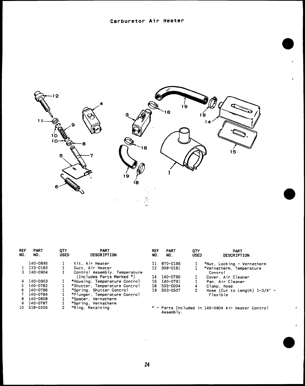
Carburetor Air Heater
,
REF PART
NO. NO.
140-0895
1133-0183
3140-0904
4140-0903
5140-0782
6140-0786
7140-0784
8140-0808
9140-0787
10 518-0205
QTY PART
USED DESCRIPTION
.1
1
1
1
1
2
18 .
e..
,.
,.
?.-
Kit, Air Heater
Duct, Air Heater
Control Assembly, Temperature
(Includes Parts Marked *)
*Housing, Temperature Control
*Shutter, Temperature Control
*Spring, Shutter Control
*Plunger, Temperature Control
*Spacer, Vernatherm
*Spring, Vernatherm
*Ring, Retaining
REF PART
NO. NO.
11 870-0195
12 309-0181
14 140-0790
15 140-0791
18 503-0004
19 503-0507
QTY PART
USED DESCRIPTION
*Nut, Locking -Vernatherm
;*Vernatherm, Temperature
Control
1Cover, Air Cleaner
1Pan, Air Cleaner
4Clamp, Hose
2Hose (Cut to Length) 1-3/4” -
Flexible
*-Parts Included in 140-0904 Air Heater Control ~
Assembly.
.
●
24
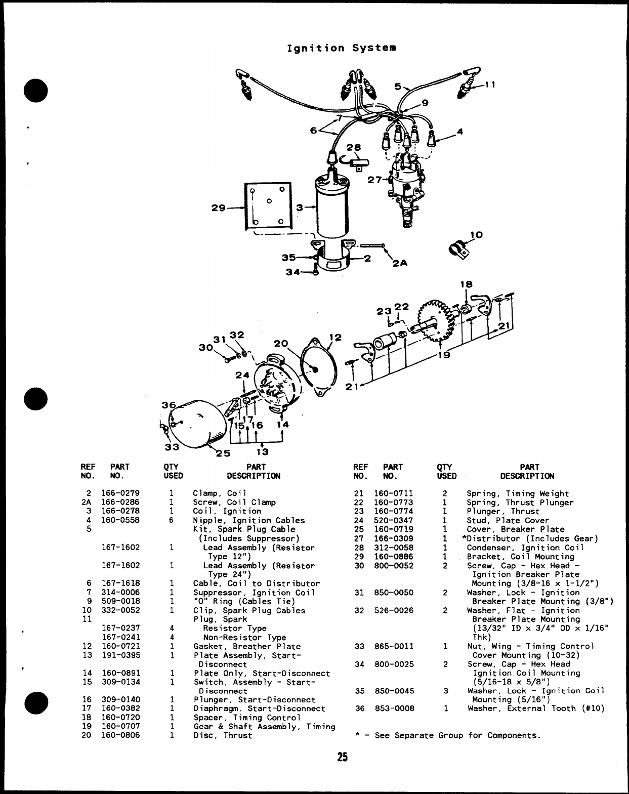
Ignition System
.
,
REF PART
NO. NO.
2166-0279
2A 166-0286
3166-0278
4160-0558
5
167-1602
167-1602
6
7
9
10
11
.
12
13
167-1618
314-0006
509-0018
332-0052
167-0237
167-0241
160-0721
191-0395
,14 160-0891
15 309-0134
16 309-0140
17 160-0382
18 160-0720
19 160-0707
20 160-0806
29-
QTY
USED
1
1
1
6
1
1
1
1
1
1
4
4
1
1
1
1
1
i
:
PART
DESCRIPTI(M
clamp, coil
Screw, Coil Clamp
Coil, Ignition
Nipple, Ignition Cables
Kit, Spark Plug Cable
(Includes Suppressor)
Lead Assembly (Resistor
Type 12”)
Lead Assembly (Resistor
Type 24”)
Cable, Coil to Distributor
Suppressor, Ignition Coil
“O” Ring (Cables Tie)
Clip, Spark Plug Cables
Plug, Spark
Resistor Type
Non-Resistor Type
Gasket, 8reather Plate
Plate Assembly, Start-
Disconnect
Plate Only, Start-Disconnect
Switch, Assembly -Start-
Disconnect
Plunger, Start-Disconnect
Diaphragm, Start-Disconnect
Spacer, Timing Control
Gear &Shaft Assembly, Timing
Disc, Thrust
.11
18
hl’-
W.0
-- “
23~2 .-~.’
L-1 -’ 2,
s.”
*
.0 --
~/-
T
19
21
REF PART
No. No.
21 160-0711
22 160-0773
23 160-0774
24 520-0347
25 160-0719
27 166-0309
28 312-0058
29 160-0886
30 800-0052
31 850-0050
QTY PART
USED DESCRIPTION
2Spring, Timing Weight
1Spring, Thrust Plunger
1Plunger, Thrust
1Stud, Plate Cover
1Cover, Breaker Plate
1*Distributor (Includes Gear:
Condenser, Ignition Coil
;Bracket, Coil Mounting
2Screw, Cap -Hex Head -
Ignition 8reaker Plate
Mounting (3/8-16 x1-1/2”
2Washer, Lock -Ianition
32 526-0026
33 865-0011
34 800-0025
35 850-0045
36 853-0008
8reaker Plate M;unting (3/8”)
2Washer, Flat -Ignition
8reaker Plate Mounting
(13/32” ID X3/4” OD X1/16”
Thk)
1Nut, Wing -Timing Control
Cover Mounting (10-32)
2Screw, Cap -Hex Head
Ignition Coil Mounting
(5/16-18 X5/8”)
3Washer, Lock –Ignition Coi’
Mounting (5/16”)
1Washer, External Tooth (#10’
*_ see Separate Group for COmPonents-
25
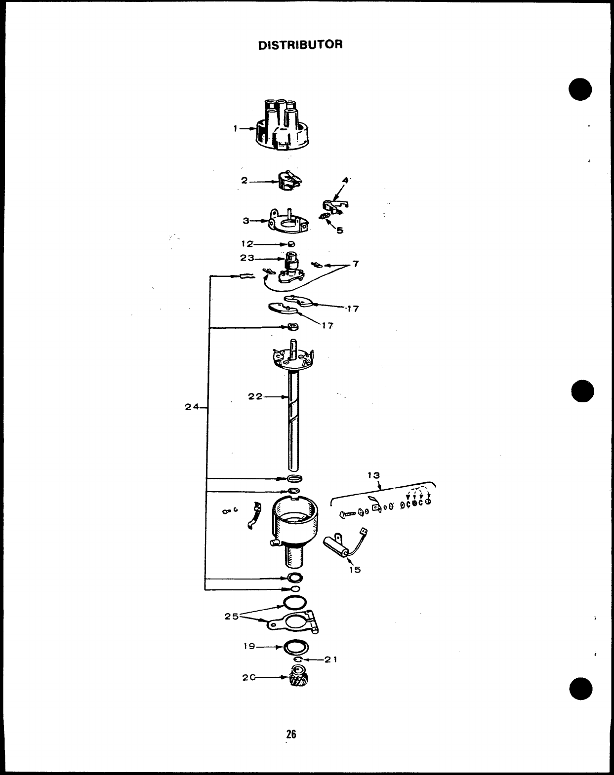
DISTRIBUTOR
-45
-.
1f- 1-
“>
*-%$ /$
3--Q%t
13 .
2’+3
26
.
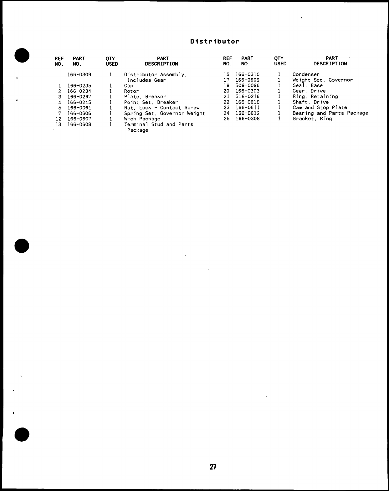
Distributor
●REF PART QTY PART
NO. NO. USED DESCRIPTION
166-0309 1Distributor Assembly,
.Includes Gear
1166-0235 Cap
2166-0234 :Rotor
3166-0297 1Plate, Breaker
,4166-0245 1Point Set, Breaker
REF PART QTY
NO. NO. USED
15 166-0310 1
17 166-0609 1
19 509-0096 1
20 166-0303 1
21 518-0216
22 166-0610 ;
PART
DESCRIPTION
Condenser
Weight Set, Governor
Seal, Base
Gear, Drive
Ring, Retaining
Shaft, Drive
5166-0061 1Nut, Lock -Contact Screw 23 166-0611 1Cam and Stop Plate
7166-0606 1Spring Set, Governor Weight 24 166-0612 1
12 166-0607
Bearing and Parts Package
Wick Package 25 166-0308 1
13 166-0608
Bracket, Ring
;?erminai Stud and Parts
Package
27
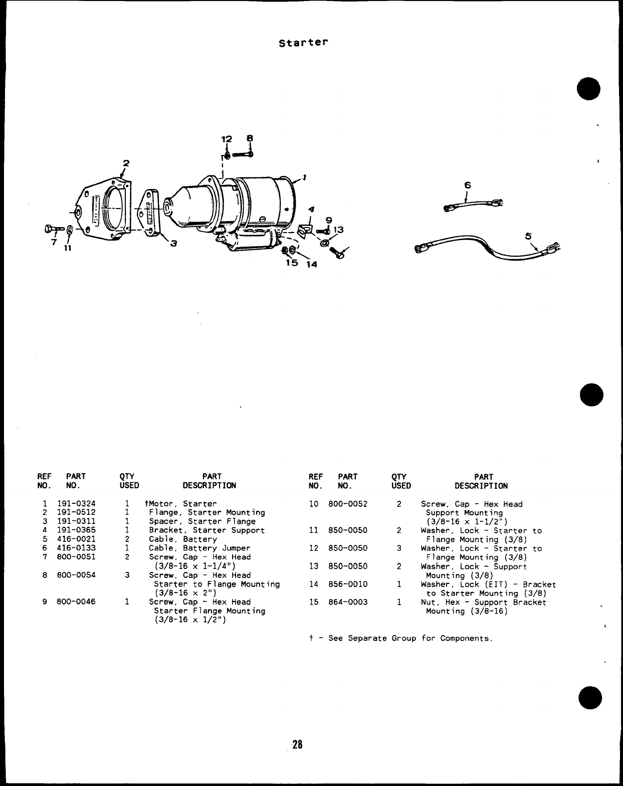
Starter
“il
15 14 -
eL===
REF PART
NO. NO.
1191-0324
2191-0512
3191-0311
4191-0365
5416-0021
6416-0133
7800-0051
8800-0054
9800-0046
QTY
USEO
1
1
;
2
1
2
3
1
PART
DESCRIPTION
tMotor, Starter
Flange, Starter Mounting
Spacer, Starter Flange
Bracket, Starter Support
Cable, Battery
Cable, Battery Jumper
Screw, Cap -Hex Head
(3/8-16 X1-1/4”)
Screw, Cap -Hex Head
Starter to Flange Mounting
(3/8-16 X2“)
Screw, Cap -Hex Head
Starter Flange Mounting
(3/6-16 x1/2”)
REF
NO.
10
11
12
13
14
15
t-
PART QTY PART
NO. USEO DESCRIPTION
800-0052 2Screw, Cap -Hex Head
Support Mounting
(3/8-16 X1-1/2”)
850-0050 2Washer, Lock -Starter to
Flange Mounting (3/8)
850-0050 3Washer, Lock -Starter to
Flange Mounting (3/8)
850-0050 2Washer, Lock -Support
Mounting (3/8)
856-0010 1Washer, Lock (EIT) -Bracket
to Starter Mounting (3/8)
864-0003 1Nut, Hex -Support Bracket
Mounting (3/8-16)
See Separate Group for Components.
28
*
*
13
7ii!)
14
6
1
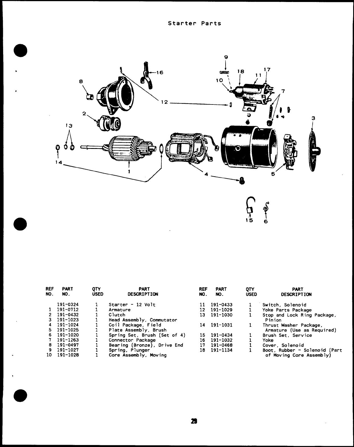
Starter Parts
9
~16
\I11 ‘1’
REF PART
NO. NO.
1
2
3
4
5
6
7
8
.1:
191-0324
191-0712
191-0432
191-1023
191-1024
191-1025
191-1020
191-1263
191-0497
191-1027
191-1028
PART
DESCRIPTION
Starter -12 Volt
Armature
Clutch
Head Assembly, Commutator
Coil Packaae, Field
Plate Asse;bly, Brush
Spring Set, Brush (Set of 4)
Connector Package
Bearing (Bronze), Drive End
Spring, Plunger
Core Assembly, Moving
REF PART
No. No.
11 191-0433
12 191-1029
13 191-1030
14 191-1031
15 191-0434
16 191-1032
17 191-0468
18 191-1134
F
1“5
QTY
USED
1
1
1
1
1
1
:
f6
PART
DES&IPTION
Switch, Solenoid
Yoke Parts Package
Stop and Lock Ring Package,
Pinion
Thrust Washer Package,
Armature (Use as Required)
Brush Set, Service
Yoke
Cover, Solenoid
Boot, Rubber -Solenoid (Part
of Moving Core Assembly)
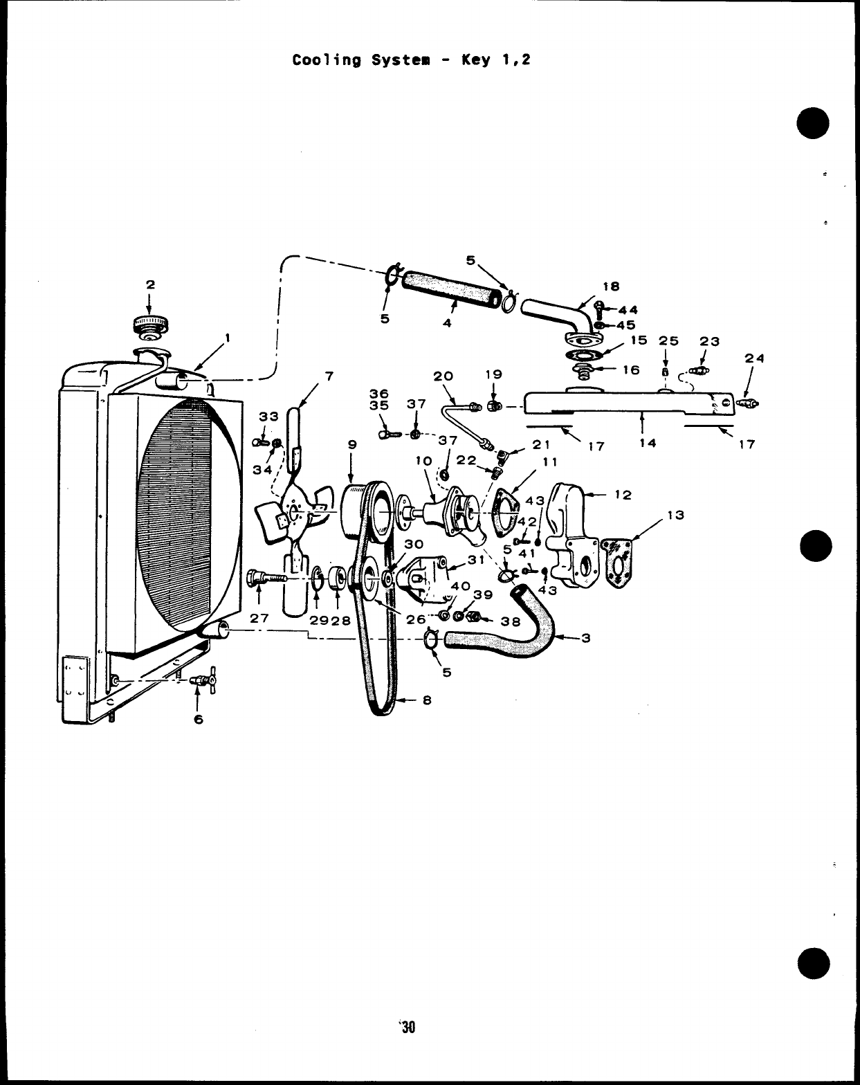
Cooling System -Key 1,2
I
I
1i
H
I
“-’--iiiiiii~fL
54U+45
-o- ,15
-. ...
34; W1
es-’
20 19 ~16
&aQ14D~-.
36 )/
35 3,7 ,–- ~r3cc@
\
17
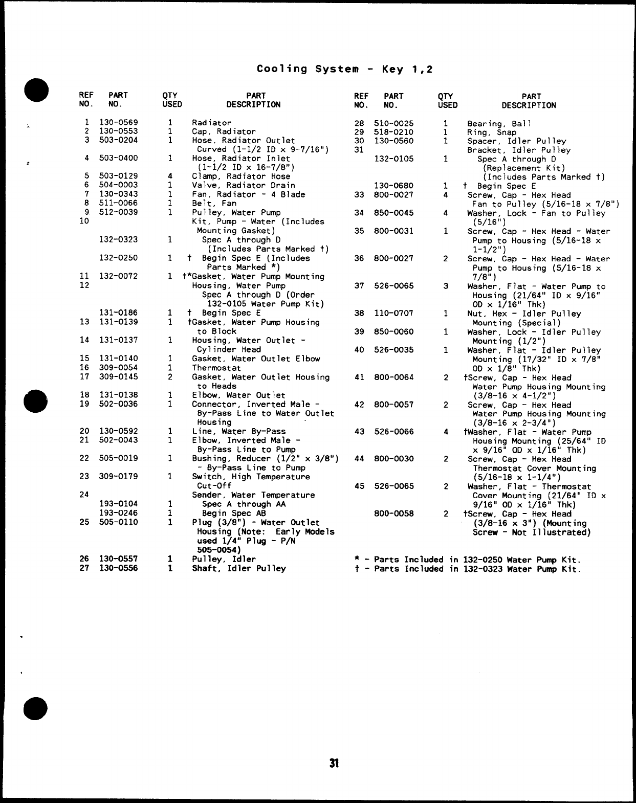
Cooling System -Key 1,2
●REF PART
NO. NO.
1130-0569
2130-0553
3503-0204
4.503-0400
,
5503-0129
6504-0003
7130-0343
8511-0066
9. 512-0039
10
132-0323
132-0250
11 132-0072
12
131-0186
13 131-0139
14 131-0137
15 131-0140
16 309-0054
17 309-0145
918 131-0138
19 502-0036
20 130-0592
21 502-0043
22 505-0019
23 309-0179
24
193-0104
193-0246
25 505-0110
26 130-0557
27 130-05S6
QTY PART
USED DESCRIPTION
Radiator
Cap, Radiator
Hose, Radiator Outlet
Curved (1-1/2 ID x9-7/16”)
Hose, Radiator Inlet
(1-1/2 ID X16-7/8”)
Clamp, Radiator Hose
Valve, Radiator Drain
Fan, Radiator -4Blade
Belt, Fan
Pulley, Water Pump
Kit, Pump –Water (Includes
Mounting Gasket)
Spec Athrough D
(Includes Parts Marked t)
t8egin Spec E(Includes
Parts Marked *)
t*Gasket, Water Pump Mounting
Housing, Water Pump
Spec Athrough D(Order
132-0105 Water Pump Kit)
t8egin Spec E
tGasket, Water Pump Housing
to Block
Housing, Water Outlet -
Cylinder Head
Gasket, Water Outlet Elbow
Thermostat
Gasket, Water Outlet Housing
to Heads
Elbow, Water Outlet
Connector, Inverted Male -
8y-Pass Line to Water Outlet
Housing
Line, Water By-Pass
Elbow, Inverted Male -
By-Pass Line to Pump
Bushing, Reducer (1/2” x3/8”)
-By-Pass Line to Pump
Switch, High Temperature
cut-off
Sender, Water Temperature
Spec Athrough AA
Begin Spec AB
Plug (3/8”) -Water Outlet
Housing (Note: Early Models
used 1/4” Plug -P/N
505-0054)
Pulley, Idler
Shaft, Idler Pulley
REF PART
NO. NO.
28 510-0025
29 518-0210
30 130-0560
31 132-0105
130-0680
33 800-0027
34 850-0045
35 800-0031
36 800-0027
37 526-0065
38 110-0707
39 850-0060
40 526-0035
41 800-0064
42 800-0057
43 526-0066
44 800-0030
45 526-0065
800-0058
QTY PART
USED DESCRIPTION
;
1
1
1
4
4
1
2
3
1
1
1
2
2
4
2
2
2
Bearing, 8all
Ring, Snap
Spacer, Idler Pulley
Bracket, Idler Pulley
Spec Athrough D
(Replacement Kit)
(Includes Parts Marked t)
tBegin Spec E
Screw, Cap -Hex Head
Fan to Pulley (5/16-18 x7/8”)
Washer, Lock LFan to Pulley
(5/16”)
Screw, Cap -Hex Head -Water
Pump to Housing (5/16-lB x
1-1/2”)
Screw, Cap -Hex Head -Water
Pump to Housing (5/16-18 x
7/8” )
Washer, Flat -Water Pump to
Housing (21/64” ID x9/16”
00 X1/16” Thk)
Nut, Hex -Idler Pulley
Mounting (Special)
Washer, Lock -Idler Pulley
Mounting (1/2”)
Washer, Flat -Idler Pulley
Mounting (17/32” ID x7/8”
OD X1/8” Thk)
tScrew, Cap -Hex Head
Water Pump Housing Mounting
(3/8-16 X4-1/2”)
Screw, Cap -Hex Head
Water Pump Housing Mounting
(3/B-16 x2-3/4”)
tWasher, Flat -Water Pump
Housing Mounting (25/64” ID
X9/16” OD X1/16” Thk)
Screw, Cap -Hex Head
Thermostat Cover Mounting
(5/16-18 X1-1/4”)
Washer, Flat -Thermostat
Cover Mounting (21/64” ID x
9/16” OD X1/16” Thk)
tScrew, Cap -Hex Head
(3/8-16 x3”) (Mounting
Screw -Not Illustrated)
*-Parts Included in 132-0250 Water Pump Kit.
t- Parts Included in 132-0323 Water Pump Kit.
.
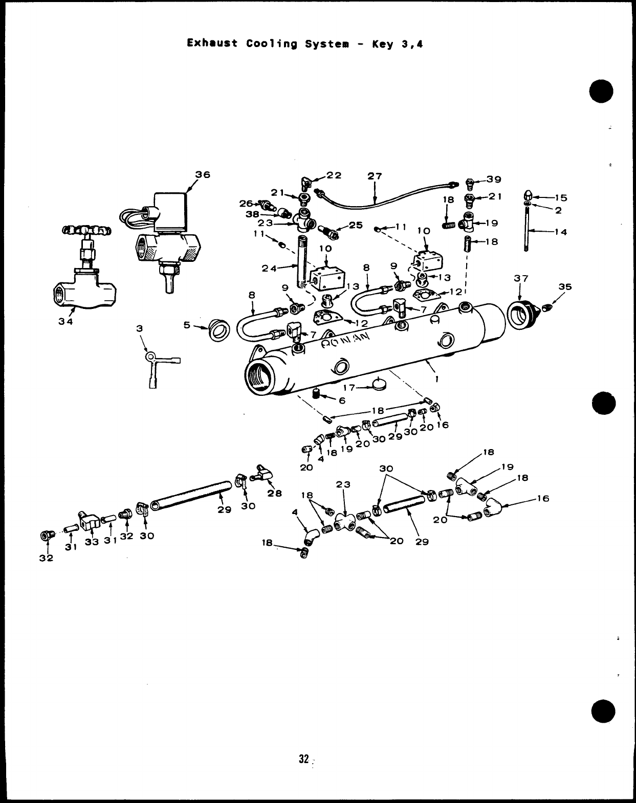
Exhaust Cooling System -Key 3,4
&
0—
—
34
36
35%
\@
.:6==%
Ttip==’?’T
t’
e-7’33313230
32
4!!L==$.. ‘
32,
Exhaust Cooling System -Key 3,4
0REF PART
NO. NO.
1154-2124
.
2526-0022
a3504-0020
4505-0376
5154-1057
6
505-0110
505-0266
7
502-0074
502-0074
8130-0510
9
10
11
12
13
14
●15
16
502-0103
309-0160
505-0274
309-0145
309-0130
520-0143
869-0002
505-0039
17 517-0041
517-0059
18
505-0101
505-0101
19 505-0060
20
505-0135
505-0135
QTY PART
USED DESCRIPTION
1Manifold Assembly, Exhaust -
Water Cooled (Includes Parts
Marked *)
4Washer, Flat (21/64” ID x
9/16” 00 X1/16” Thk)
1Key, Valve (Used on Early
Style Valve) (No Longer
Available)
1Elbow, Pipe (45”)
4Gasket, Exhaust Manifold
Plug, Pipe (3/8”) Exhaust
Manifold
Square Head (80ttom Mounted)
:*Countersunk Head (Top
Mounted) -Set With Heat
Exchanger
Elbow, Inverted Male
(Manifold Water Line Inlet)
2Sets Without Heat Exchanger
1Sets With Heat Exchanger
2Line, Water -Thermostat
Cover to Manifold
2Connector, Inverted Male -
Thermostat Cover Outlet
2Cover, Thermostat
2Plug, Pipe (1/8”) Countersunk
-Thermostat Cover
2Gasket, Thermostat Cover
2Thermostat
4Stud, Thermostat Cover
Mounting
4Nut, Acorn (5/16-24)
Thermostat Cover
1E~i ;:~t (3/8” x1“”) -
*Plug, Exhaust Manifold
4Expansion (1-1/8” 00)
1Welch (1-7/16” 00)
Nipple, Close -Pipe
(3/8” Xl“)
5Sets Without Water Jacket
Heater
7Sets With Water Jacket
Heater
2Tee, Pipe (3/8”) Water Inlet
and Exhaust Manifold
Nipple, Half -Pipe (3/8” x
1-1/2”) -Water Inlet
3Sets Without Water Jacket
Heater
4Sets With Water Jacket
Heater
REF PART
No. No.
21
505-0016
505-0016
22 502-0037
23 505-0475
505-0475
24 505-0224
25 309-0178
26
193-0104
193-0246
27
130-0633
130-0813
28 502-0237
29 503-0394
503-0478
30 503-0183
31 130-0533
32 502-0239
33 502-0247
34 504-0019
35 502-0080
36 307-0833
37 505-0402
38 309-0081
39 502-0097
QTY
USED
2
1
1
1
2
1
1
1
1
1
1
1
1
1
2
2
2
1
1
1
1
1
1
1
PART
DESCRIPTION
Bushing, Reduce -Pipe -
8y-Pass Line
Sets Without Heat Exchanger
Sets With Heat Exchanger
Elbow, 8rass -By-Pass Line
Cross, Pipe (3/8”)
Sets Without Water Jacket
Heater (Water By-Pass Line)
Sets With Water Jacket
Heater (Water 8y-Pass Line
and Water Inlet)
Nipple, Pipe (3/8” x4-1/2”)
Switch, High Water Temperature
(Not Used on Pennsylvania
Approved Sets)
Sender, Water Temperature
Spec Athrough AA
Begin Spec A8
Line, Water By-Pass
Sets Without Heat Exchanger
Sets With Heat Exchanger
Elbow, 8rass -Water Inlet
(Used on Early Models)
Hose, Water Inlet
Used With Brass Fittings
(1/2” X9-5/8”)
Used With Pipe Fittings
(3/4” x9“)
Clamp, Water Inlet Hose
Adapter, Water Inlet Hose
(Used on Early Models)
Nut, Inverted (Brass) Water
Inlet (Used on Early Models)
Tee, Male 8ranch (8rass)
Water Inlet (Used on Early
Mode 1s )
Valve, Globe
Plug, Square Head (8raes)
(1/8”) Used on Early Models
Valve, Solenoid
Plug, Pipe -Square Head
(1-1/2”) Begin Spec 8
Extension, Pipe
Connector, Braes -By-Pass
Line
*-Parts Included in 154-2124 Exhaust Manifold
Assembly.
.
33
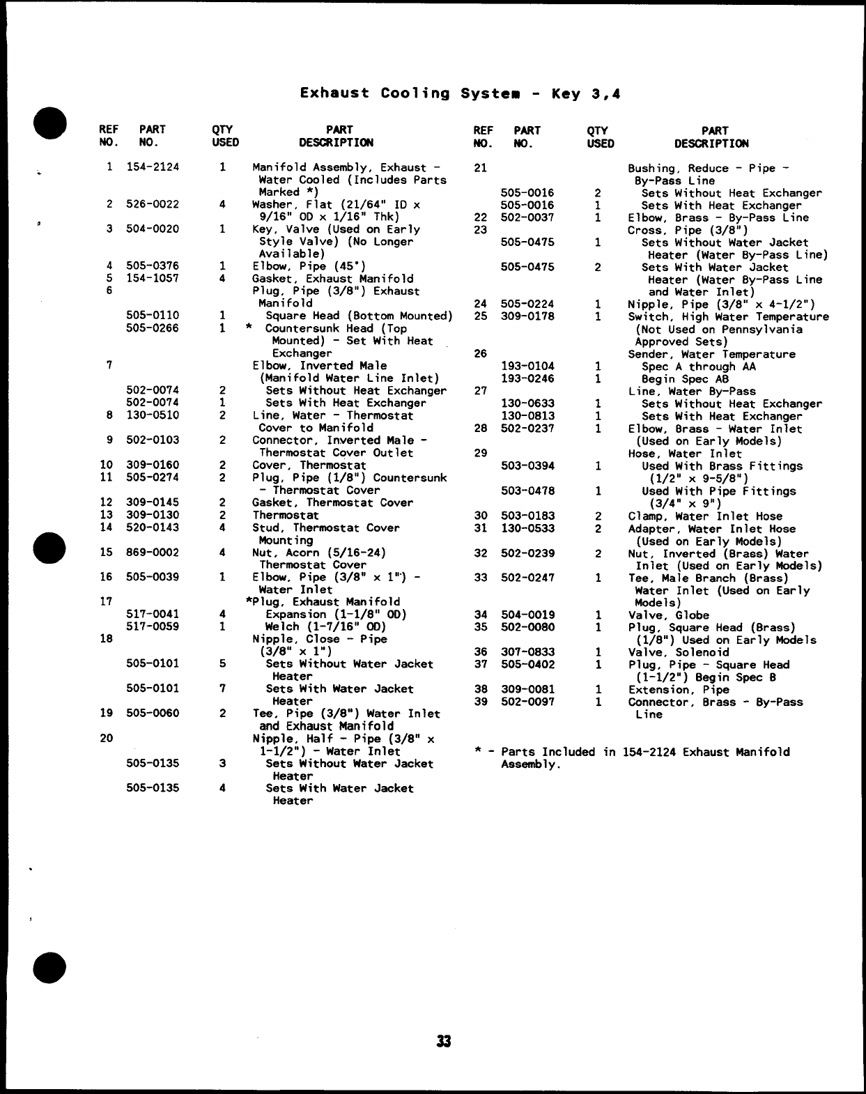
Exhaust System
REF PART
No. No.
1154-0714
2154-1057
3155-0456
4155-0493
6154-0738
7155-0806
12 110-0445
13 800-0052
QTY
USED
1
4
1
1
1
1
8
2
t
12
-c
o
15
0
PART REF PART QTY
DESCRIPTION NO. NO. USED
Manifold, Exhaust -Key 1,2 14 850-0050 2
Gasket, Exhaust Manifold
Muffler 15 154-1665 4
Tube, Exhaust -Flexible
Gasket, Exhaust Outlet 16 505-0032 1
Tube, Exhaust Outlet
Nut, Hex -Exhaust Manifold
Mounting (Special)
Screw, Cap -Hex Head -
Exhaust Tube Mounting
(3/8-16 X1-1/2”)
PART
DESCRIPTION
Washer, Lock -Exhaust Tube
Mounting (3/8)
Locktabs -Exhaust Manifold
Mounting
Coupling (1-1/2”) -Use With
Exhaust Tube #155-0493
r
34
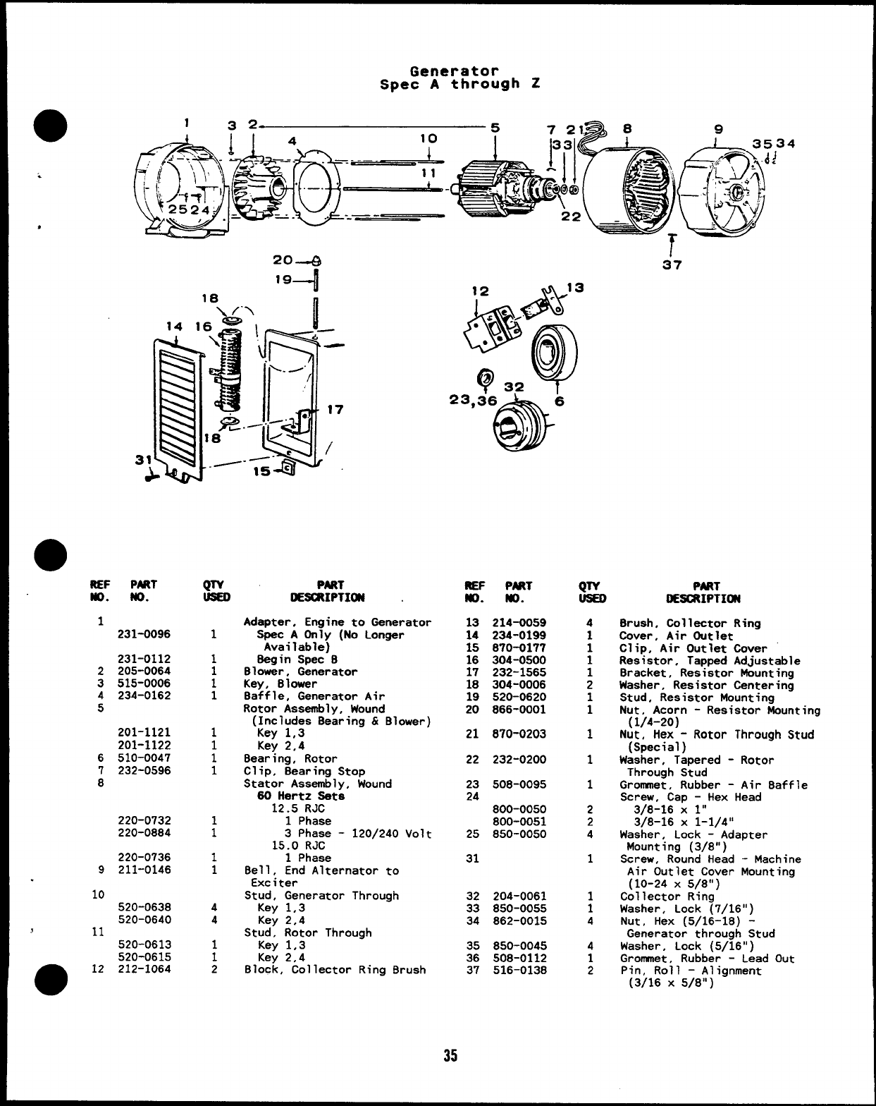
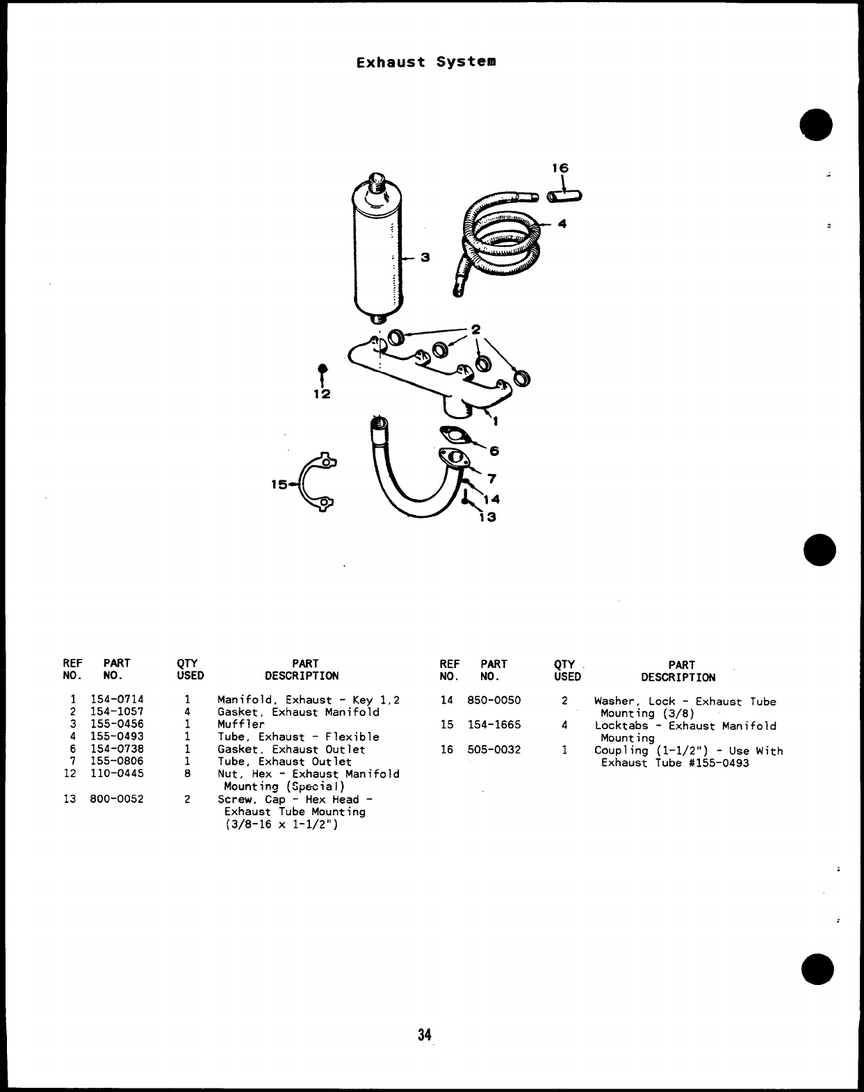
Generator
Spec Athrough Z
14
31 [
&
20+
19d
10 n
II
,6’4”’, _
wJ-
\~.5
L.-’ /
,**”--;”l ●17
e/
----- 75”4
34
J
k
12 13
&
@
.0
“j-’” ‘
Q
c1
Q2)” 32
REF PmT
w. No.
1
231-0096
231-0112
2205-0064
3515-0006
4234-0162
5
201-1121
201-1122
6510-0047
7232-0596
8
220-0732
220-0884
220-0736
9211-0146
10 520-0638
520-0640
11
520-0613
520-0615
12 212-1064
QTY
1
1
1
1
1
1
1
1
1
:
1
1
4
4
1
1
2
PART
IE=IPTI~ .
Adapter. Engine to Generator
Spec AOnly (No Longer
Available)
Begin Spec B
Blower, Generator
Key, Blower
Baffle, Generator Air
REF P~T
No. m.
13 214-0059
14 234-0199
15 870-0177
16 304-0500
17 232-1565
18 304-0006
19 520-0620
Rotor Assembly, Wound 20 866-0001
[Includes Bearina &Blower)
‘Key 1,3
Key 2,4
Bearing, Rotor
Clip, Bearing Stop
Stator Assembly, Wound
60 Hertz Sets
12.5 RJC
1Phase
3Phase -120/240
15.0 RJC
1Phase
Bell, End Alternator to
Exciter
Stud, Generator Through
Key 1,3
Key 2.4
Stud, Rotor Through
Key 1,3
–,
volt
Key 2,4
Block, Collector Ring Brush
21 870-0203
22 232-0200
23 508-0095
24 800-0050
800-0051
25 850-0050
31
32 204-0061
33 850-0055
34 862-0015
35 850-0045
36 508-0112
37 516-0138
37
QTY
4
1
1
1
1
2
:
1
1
1
2
2
4
1
1
1
4
4
1
2
PART
ESCRIPTI~
Brush, Collector Ring
Cover, Air Outlet
Clip, Air Outlet Cover
Resistor, Tapped Adjustable
Bracket, Resistor Nounting
Washer, Resistor Centering
Stud, Resistor Mounting
Nut, Acorn -Resistor Mountina
(1/4-20) .
Nut. Hex -Rotor Throuah Stud
(Special)
Washer, Tapered -Rotor
Through Stud
Grommet, Rubber -Air Baffle
Screw, Cap -Hex Head
3/8-16 X1“
3/8-16 X1-1/4”
Washer, Lock -Adapter
Mounting (3/8”)
Screw, Round Head -Machine
Air Outlet Cover Mounting
(10-24 x5/8”)
Collector Ring
Washer, Lock (7/16”)
Nut, Hex (5/16-lB) -
Generator through Stud
Washer, Lock (5/16”)
Grommet, Rubber -Lead Out
Pin, Roll -Alignment
(3/16 X5/8”)
35
Generator Exciter
Spec AThrough Z
34
w
!
->
“./
OPPOSITE SIDE
w,
4
11
1
I
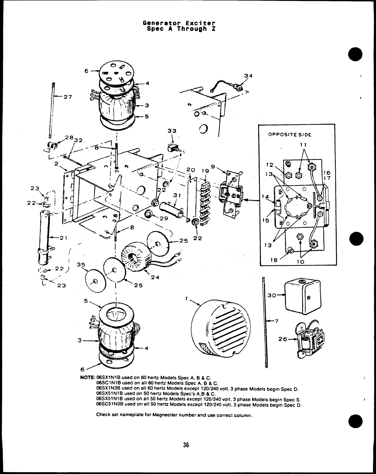
NOTE: 06SX1N1B used on 60 hertz Models Spec A. B&C.
06SC1N1 Bused on all 60 hertz Models S*C A. B & C.
06SX1 N3B used on all 60 hertz Models except 120/240 volt, 3phase Models begin Spec D.
06SX51 N1 Bused on 50 herlz Models Spec’s A,B &C.
06SX51 N1 Bused on all 50 hertz Models except 120/240 volt, 3phase Models begin Spec S.
06SC51 N3B used on all 50 hertz Models except 120/240 volt, 3phase Models begin Spec D
Check set nameplate for Magneciter number and use correct column.
a
i
36
●Generator Exciter
Spec AThrough Z
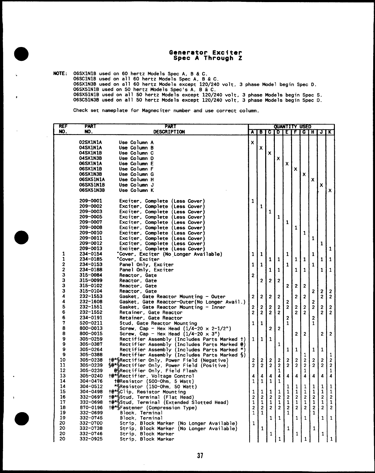
.NOTE :06SX1N1B used on 60 hertz Models Spec A, B & C.
06SC1N1B used on all 60 hertz Models Spec A, B & C.
06SX1N3B used on all 60 hertz Models except 1201240 volt, 3phase Model begin Spec D.
06SX51N1B used on 50 hertz Models Spec’s A, B & C.
06SX51N1B used on all 50 hertz Models except 120/240 volt, 3phase Models begin Spec S.
06SC51N3B used on all 50 hertz Models except 120/240 volt, 3phase Models begin Spec D.
Check set nameplate for Magneciter number and use correct column.
REF ART PAW
No. LDESCRIPTION
1
1
2
2
3
3
3
3
4
4
5
6
6
7
B
8
9
9
9
1:
11
12
13
14
14
15
16
17
18
19
19
20
20
20
20
02SX1N1A
04SX1N1A
04SX1N1B
04SX1N3B
06SX1N1A
06SX1N1B
06SX1N3B
06SX51N1A
06SX51N1B
06SX51N3B
209-0001
209-0002
209-0003
209-0005
209-0007
209-OOOB
209-0010
209-0011
209-0012
209-0013
234-0154
234-0185
234-0153
234-0188
315-0084
315-0099
315-0102
315-0104
232-1553
232-1608
232-1551
232-1552
234-0191
520-0211
800-0013
800-0015
305-0259
305-0387
305-0264
305-038B
305-0238
305-0239
305-0239
305-0240
304-0476
304-0512
304-0498
332-0697
332-0698
870-0196
332-0699
332-0745
332-0700
332-0738
332-0746
332-0925
Use Column A
Use Column B
Use Column C
Use Column O
Use Column E
Use Column F
Use Column G
Use Column H
Use Column J
Use Column K
Exciter, Complete (Less Cover)
Exciter, Complete (Less Cover)
Exciter, Complete (Less Cover)
Exciter, Complete (Less Cover)
Exciter, Complete (Less Cover)
Exciter, Complete (Less Cover)
Exciter, Ccmplete (Less Cover)
Exciter, Complete (Less Cover)
Exciter, Complete (Less Cover)
Exciter, Complete (Less Cover)
“Cover. Exciter (No,Longer Available)
“Cover, Exciter
Panel Only, Exciter
Panel Only, Exciter
Reactor. Gate
Reactor, Gate
Reactor, Gate
Reactor, Gate
Gasket, Gate Reactor Mounting -Outer
Gasket, Gate Reactor-Outer(No Longer Avail.)
Gasket, Gate Reactor Mounting -Inner
Retainer, Gate Reactor
Retainer, Gate Reactor
Stud, Gate Reactor Mounting
Screw, Cap -Hex Head (1/4-20 x2-1/2”)
Screw, Cap -Hex Head (1/4-20 x3“)
Rectifier Assembly (Includes Parts Marked t)
Rectifier Assembly (Includee Parts Marked @)
Rectifier Assemblv (Includes Parts Marked *)
Rectifier Assembl~ (Includes Parts Marked Sj
t@*SRectifier Only, Power Field (Negative)
~@*~Rectifier Only, Power Field (Positive)
@sRectifier Only, Field Flash
t@*$Rectifier, Voltage Control
t@Resistor (500-Ohm, 5Watt)
*~Resistor (150-Ohm, 50 Watt)
t@*$Clip, Resistor Mounting
t@*$Stud, Terminal (Flat Head)
t@*$tud, Terminal (Extended Slotted Head)
t@*SFastener (Compression Type)
Block, Terminal
Block, Terminal
Strip, Block Marker (No Longer Available)
Strip, Block Marker (No Longer Available)
Strip, 810ck Marker
Strip, Block Marker
37
~
(
1
1
1
2
2
2
2
1
1
2
2
4
1
1
2
1
2
1
1
—
~
K
1
1
1
2
2
2
2
1
1
2
2
4
1
1
2
1
2
1
1
r
,
(
1
1
1
2
2
2
2
2
1
2
2
4
1
1
2
1
2
1
1
—
m
~
K
1
1
1
2
2
2
2
2
1
2
2
1
4
1
1
2
1
2
1
1
~
(
1
1
1
2
2
2
2
1
1
2
2
4
1
1
2
1
2
1
1
—
r
r
K
1
1
1
2
2
2
2
2
1
2
2
4
1
1
2
1
2
1
1
—
9
~
K
1
1
1
2
2
2
2
2
1
2
2
1
4
1
1
2
1
2
1
1
~
K
1
1
1
2
2
2
2
1
1
2
2
4
1
1
2
1
2
1
1
~
K
1
1
1
2
2
2
2
2
1
2
2
4
1
1
2
1
2
1
1
[
(
1
1
1
2
2
2
2
2
1
2
2
1
4
1
1
2
1
2
1
1
Generator Exciter
Spec AThrough Z
6
4
3
5
I33
w,
4
NOTE: 06 SX1NIB used on 60 hertz Models Wec A. B & C
OPPOSITE SIDE
11
al
_J9 ~
10 e
–7
26
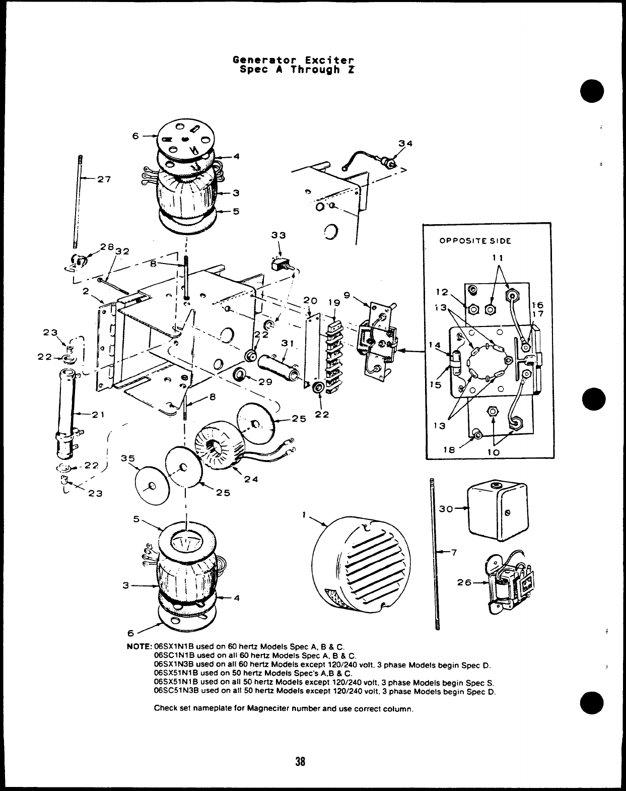
06 SC1N1B used on all 60 hertz Mode;s Spec A, B & C.
06SX1 N3B used on all 60 hertz Models except 120/240 volt. 3phase Models begin Spec D.
06SX51 N1 Bused on 50 hertz Models Spec’s A,B &C.
06SX51 N1 Bused on all 50 hertz Models except 120/240 volt, 3phase Models begin Spec S.
06SC51 N3B used on all 50 hertz Models except 120/240 volt, 3phase Models begin Spec D
Check set nameplate for Magneciter number and use correct column. a
38
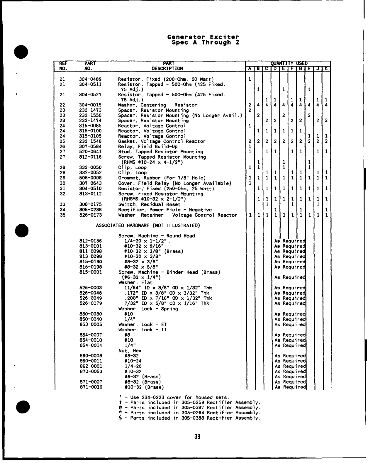
Generator Exciter
Spec AThrough Z
ltEf PART PART
NO. No. DESCRIPTION
21
21
21
22
23
23
23
24
;:
;:
27
27
28
28
29
30
31
32
33
34
35
304-0489
304-0511
304-0527
304-0015
232-1473
232-1550
232-1474
315-0085
315-0100
315-0105
232-1548
307-0584
520-0641
812-0116
332-0050
332-0052
508-0008
307-0643
304-0510
813-0112
306-0175
305-0238
526-0173
Resistor, Fixed (200-Ohm, 50 Watt)
Resistor, Tapped -500-Ohm (425 Fixed,
75 AdJ.)
Resistor, Tapped -500-Ohm (425 Fixed,
75 Adj.)
Washer, Centering -Resistor
Spacer, Resistor Mounting
Spacer, Resistor Mounting (No Longer Avail.)
Spacer, Resistor Mounting
Reactor. Voltage Control
Reactor, Voltage Control
Reactor, Voltage Control
Gasket, Voltage Control Reactor
Relay, Field 8uild-Up
Stud, Tapped Resistor Mounting
Screw, Tapped Resistor Mounting
(RHMS #10-24 X4-1/2”)
Clip, Loop
Clip, Loop
Gronmnet, Rubber (For 7/8” Hole)
Cover, Field Relay (No Longer Available)
Resistor; Fixed (250-Ohm, 25 Watt)
Screw, Fixed Resistor Mounting
(RHSMS #10-32 X2-1/2”)
Switch, Residual Reset
Rectifier, Power Field -Negative
Washer, Retainer -Voltage Control Reactor
Associate HARDWARE (NOT ILLUSTRATE)
812-0156
813-0101
811-0098
813-0098
815-0190
815-0198
815-0001
526-0003
526-0048
526-0049
526-0179
850-0030
850-0040
853-0005
854-0007
854-0010
854-0014
860-0008
860-0011
862-0001
870-0053
871-0007
871-0010
Screw, Machine -Round Head
1/4-20 X1-1/2” .
#10-32 X9/16”
#10-32 x3/8” (8rass)
#10-32 X3/8”
#8-32 X3/8”
S8-32 X5/8”
Screw, Machine -8inder Head (Brass)
(#6-32 X1/41’)
Washer, Flat
11/64” ID X3/8” 00 X1/32” Thk
.172” IO X3/8” 00 X1/32” Thk
.200” ID X7/16” 00 X1/32” Thk
7/32” 10 X5/8” 00 X1/16” Thk
Washer, Lock -Spring
#lo
1/4”
Washer, Lock -ET
Washer, Lock -IT
#8
#lo
1/4 “
Nut, Hex
#8-32
#10-24
1/4-20
#10-32
#6-32 (Brass)
#8-32 (Brass)
#10-32 (8rass)
“-Use 234-0223 cover for housed sets.
t - Parts included in 305-0259 Rectifier
@-Parts included in 305-0387 Rectifier
*-parts included in 305-0264 Rectifier
~-Parts included in 305-0388 Rectifier
Assembly.
Assembly.
Assembly.
Assembly.
T
q
1
4
2
1
2
1
1
1
1
1
1
R
T
~
1
$
2
1
2
1
1
1
1
1
1
1
ui
a
~
1
4
2
1
2
1
1
1
1
1
1
1
e
As Require
As Require
As Require
As Require
As Require
As Require
As Require
As Require
As Require
As Require
As Require
As Require
As Require
As Require
As Require
As Require
As Require
As Require
As Require
As Require
As Require
As Require
As Require
~
1
4
2
1
2
1
1
1
1
1
1
r
.
I
i
)
1
>
1
1
1
1
1
1
1
39
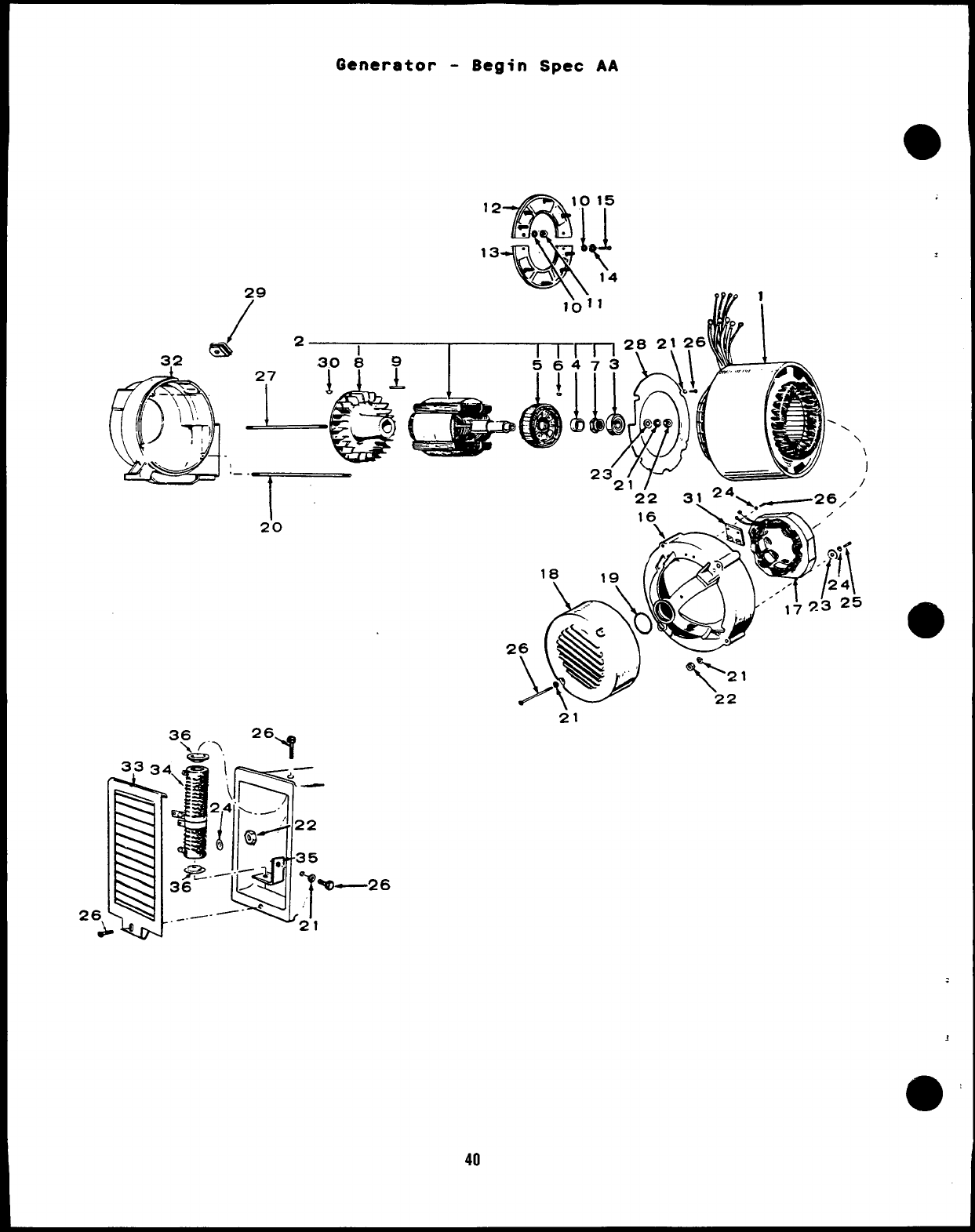
Generator -Begin Spec AA
m
12 -lfT+l
1015
&
●
13 “+\
/~ 14
I
I
20
40
22 .
3, Z4, .~-26/’
21
;
3
a’
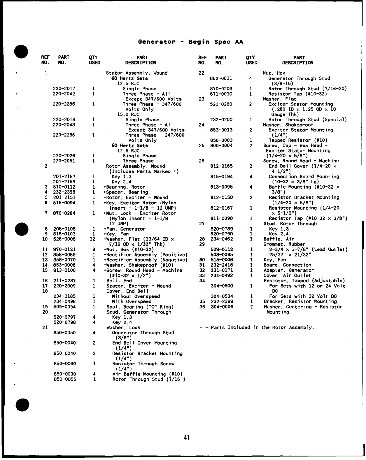
Generator -Begin Spec AA
●REF PART QTY PART
USED DESCRIPTION REF
No.
22
PART
No. QTY
USED
4
1
1
2
1
2
1
2
2
4
4
2
1
1
1
1
1
1
1
1
1
1
1
1
1
1
2
PART
DESCRIPTION
No. No.
Stator Assembly, Wound
60 Hertz Sets
12.5 RJC
Single Phase
Three Phase -All
Except 347/600 Volts
Three Phase -347/600
Volts Only
15.0 RJC
Single Phase
Three Phase -All
Except 347/600 Volts
Three Phase -347/600
Volts Only
50 Hartz Sets
12.5 RJC
Single Phase
Three Phase
Rotor Assembly, Wound
(Includes Parts Marked +)
Key 1,3
Key 2,4
+Bearing, Rotor
+Spacer, Bearing
+Rotor, Exciter -Wound
+Key, Exciter Rotor (Nylon
Insert -1-1/8 -12 UNP)
+Nut, Lock -Exciter Rotor
(Nylon Insert -1-1/8 -
12 UNP)
+Fan, Generator
+Key, Fan
+Washer, Flat (13/64 ID x
7/16 (Xl X1/32” Thk) “
+Nut, Hex (*1O-32)
+Rectifier Assembly (Positive)
+Rectifier Assembly (Negative)
+Washer, Shakeproof (*1O)
+Screw, Round Head -Machine
(#10-32 X1/2”)
Bell, End
Stator, Exciter -Wound
Cover, End Bell
Without Overspeed
With Dverspeed
Seal, Bearing (“O” Ring)
Stud, Generator Through
Key 1,3
Key 2,4
Washer, Lock
Generator Throuah Stud
Nut, Hex
Generator Through Stud
(3/8-16)
Rotor Through Stud (7/16-20)
Resistor Tap (#10-32)
Washer, Flat
Exciter Stator Mounting
(.280 IDx1.25ODX1O
Gauge Thk)
Rotor Through Stud (Special)
Washer, Shakeproof
Exciter Stator Mountina
862-0011
220-2017
J220-2042 i
1
:
1
:
1
1
1
1
1
1
1
1
1;
B
1
1
4
4
1
1
1
1
1
4
4
4
2
2
1
4
1
870-0203
871-0010
23
220-2285 526-0260
220-2018
220-2043 232-0200
24
25
26
853-0013
220-2286 856-0003
800-0004 Screw, Cap -Hex Head 2
Exciter Stator Mounting
(1/4-20 X5/B”)
Screw, Round Head -Machine
End Bell Cover (1/4-20 x
4-1/2”)
Connection Board Mounting
(10-32 X3/8” Lg)
Baffle Mounting (#10-32 x
3/8” )
Resistor Bracket Mounting
(1/4-20 X5/8”)
Resistor Mounting (1/4-20
X5-1/2”)
Resistor Tap (#10-32 x3/B”)
Stud, Rotor Through
220-2026
220-2051
2812-0165
201-2157
201-2158
3510-0112
4232-2398
5201-2151
6515-0094
815-0194
813-0098
812-0150
812-0167
7870-0284
811-0098
27
205-0105
515-0103
526-OOOB
520-0789
520-0790
234-0462
Key 1,3
Key 2,4
Baffle, Air
Grcmmet, Rubber
2-3/4 X1-7/8”
25/32” X21/32”
Key, Fan
8oard, Connection
10 28
29
11
12
13
870-0131
358-0069
358-0070
853-0008
813-0100
508-0112
508-0095
515-0006
232-2418
231-0171
234-0492
Lead Outlet)
:
32
33
34
14
15 Adapter, Generator
Cover, Air Outlet
Resistor, Tapped (Adjustable)
For Sets with 12 or 24 Volt
DC
For Sets with 32 Volt DC
Bracket, Resistor Mounting
Washer, Centering -Resistor
16
17
18
211-0237
220-2009 304-0500
234-0185
234-049B
509-0094
520-0797
520-0798
850-0050
850-0040
304-0534
232-2399
304-0006
35
36
19
20 Mounting -
21 +- Parts Included in the Rotor Assembly.
(3/8”) -
End Bell Cover Mountina
(1/4”)
Resistor 8racket Mounting
(1/4”)
Resistor Through Screw
(1/4”)
Air Baffle Mounting (#10)
Rotor Through Stud (7/16”)
850-0040
850-0040
850-0030
850-0055
.
41
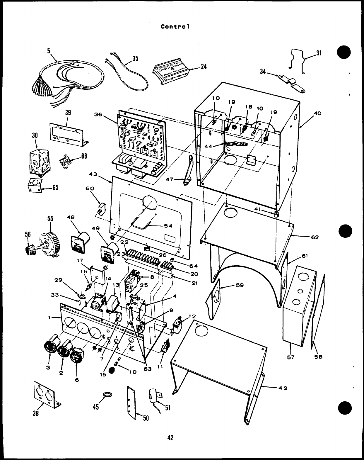
39
&
30 .
\Q
43\
I/
w3’
58
a
42
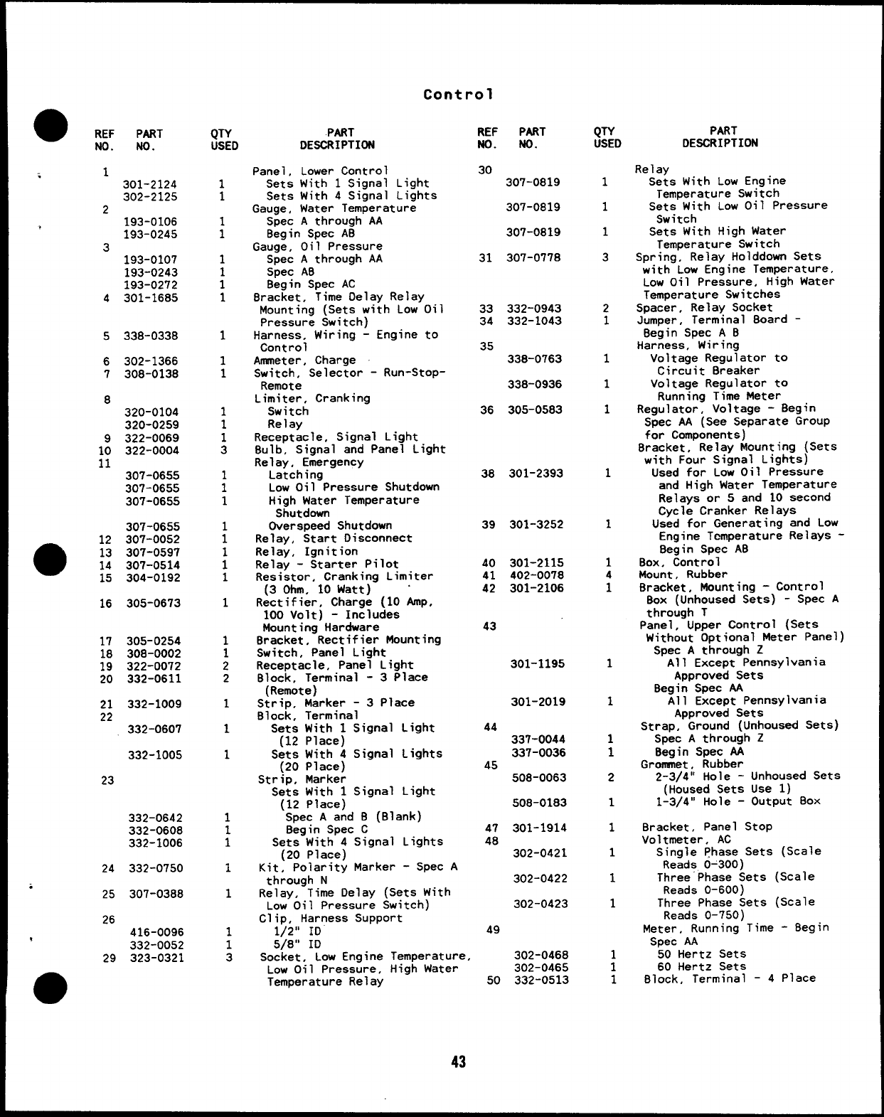
Control
aREF PART
No. No. QTY
USED
1
1
;
1
1
1
1
1
1
1
1
1
1
3
;
1
:
1
1
1
1
1
1
2
2
1
1
1
1
1
1
1
1
1
1
3
PART
DESCRIPTION
Pane 1, Lower Control
Sets With 1Signal Light
Sets With 4Signal Lights
Gauge, Water Temperature
Spec Athrough AA
Begin Spec AB
Gauge, Oil Pressure
Spec Athrough AA
Spec AB
Begin Spec AC
Bracket, Time Delay Relay
Mounting (Sets with Low Oil
Pressure Switch)
Harness, Wiring -Engine to
Control
Ammeter, Charge
Switch, Selector -Run-Stop-
Remote
Limiter, Cranking
Switch
Re 1ay
Receptacle, Signal Light
Bulb, Signal and Panel Light
Relay, Emergency
Latching
Low Oil Pressure Shutdown
High Water Temperature
Shutdown
Overspeed Shutdown
Relay, Start Disconnect
Relay, Ignition
Relay -Starter Pilot
Resistor, Cranking Limiter
(3 Ohm, 10 Watt) “
Rectifier, Charge (10 Amp,
100 volt) -Includes
Mounting Hardware
Bracket, Rectifier Mounting
Switch, Panel Light
Receptacle, Panel Light
Block, Terminal -3Place
(Remote)
Strip, Marker -3Place
Block, Terminal
Sets With 1Signal Light
(12 Place)
Sets With 4Signal Lights
(20 Place)
Strip, Marker
Sets With 1Signal Light
(12 Place)
Spec Aand B(Blank)
Begin Spec C
Sets With 4Signal Lights
(20 Place)
Kit, Polarity Marker -Spec A
through N
Relay, Time Delay (Sets With
Low Oil Pressure Switch)
Clio. Harness s.UDDOrt
REF PART
No. No. QTY
USED
1
1
1
3
2
1
1
1
1
1
1
1
4
1
1
1
1
1
2
1
1
1
1
1
:
1
PART
DESCRIPTION
Re 1ay
Sets With Low Engine
Temperature Switch
Sets With Low Oil Pressure
Switch
Sets With High Water
Temperature Switch
Spring, Relay Holddown Sets
with Low Engine Temperature,
LOW Oil Pressure, High Water
Temperature Switches
Spacer, Relay Socket
Jumper, Terminal Board -
Begin Spec A B
Harness, Wiring
Voltage Regulator to
Circuit Breaker
Voltage Regulator to
Running Time Meter
Regulator, Voltage -Begin
Spec AA (See Separate Group
for Components)
Bracket, Relay Mounting (Sets
with Four Signal Lights)
Used for Low Oil Pressure
and High Water Temperature
Relays or 5and 10 second
Cycle Cranker Relays
Used for Generating and Low
Engine Temperature Relays -
Begin Spec AB
Box, Control
Mount, Rubber
Bracket. Mounting -Control
Box (Unhoused Sets) -Spec A
through T
Panel, Upper Control (Sets
Without Optional Meter Panel)
Spec Athrough Z
All Except Pennsylvania
Approved Sets
Begin Spec AA
All Except Pennsylvania
Approved Sets
Strap, Ground (Unhoused Sets)
Spec Athrough Z
Begin Spec AA
Grommet, Rubber
2-3/4” Hole -Unhoused Sets
(Housed Sets Use 1)
1-3/4” Hole -Output BOX
Bracket, Panel Stop
Voltmeter, AC
Single Phase Sets (Scale
Reads 0-300)
Three Phase Sets (Scale
Reads 0-600)
Three Phase Sets (Scale
Reads 0-750)
Meter, Running Time -Begin
Spec AA
50 Hertz Sets
60 Hertz Sets
Block, Terminal -4Place
30 307-0819
307-0819
<1301-2124
302-2125
2193-0106
193-0245
3193-0107
193-0243
193-0272
4301-1685
307-0B19
31 307-0778
33 332-0943
34 332-1043
5338-033B 35 338-0763
6
7302-1366
30B-0138 338-0936
B36 305-05B3
320-0104
320-0259
322-0069
322-0004
1:
11 38 301-2393
307-0655
307-0655
307-0655
39 301-3252
307-0655
307-0052
307-0597
307-0514
304-0192
@
12
13
14
15
40 301-2115
41 402-0078
42 301-2106
16 305-0673
43
17 305-0254
lB 30B-0002
19 322-0072
20 332-0611 301-1195
301-2019
21 332-1009
22 332-0607 44
337-0044
337-0036
45
508-0063
332-1005
23
508-0183
332-0642
332-060B
332-1006 47 301-1914
4B 302-0421
24 332-0750 302-0422
i25 307-03BB 302-0423
26
t416-0096
332-0052
29 323-0321
,..
1/2” ID ““
5/8” ID
Socket, Low Engine
Low Oil Pressure,
Temperature Relay
49
Temperature, 302-0468
High Water 302-0465
50 332-0513
43
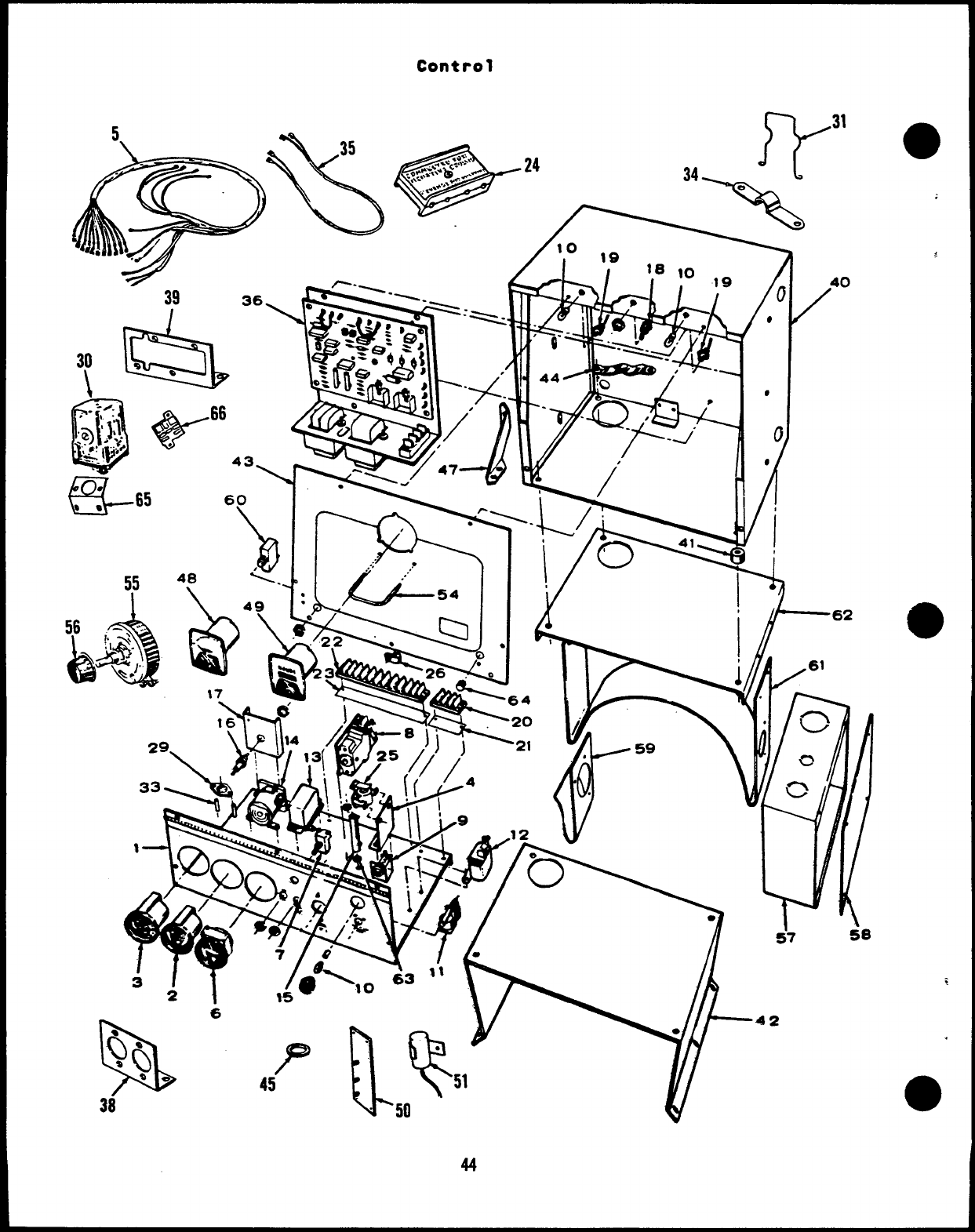
Control
55
‘1
43\
2i
40
/
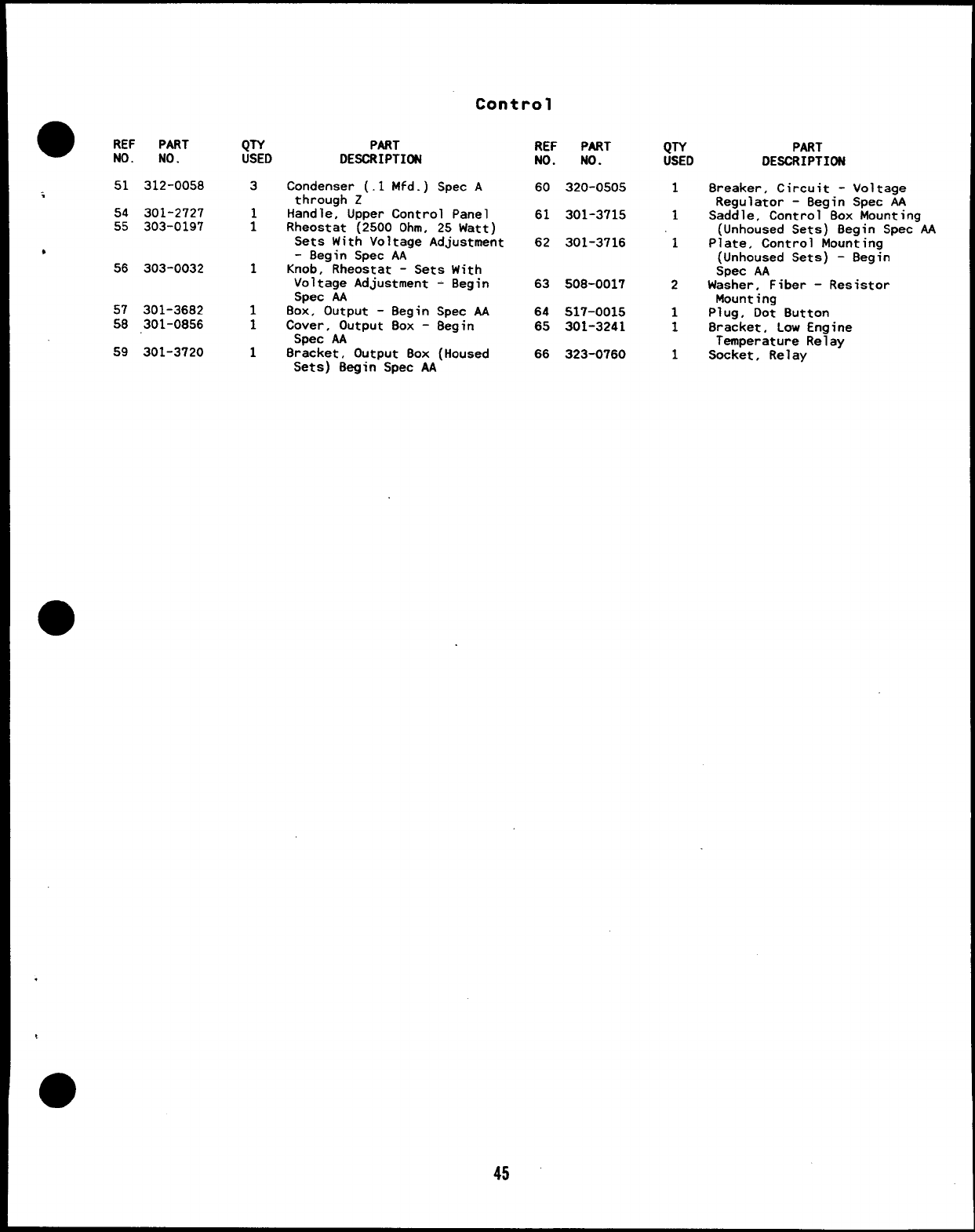
●REF PART
NO. NO.
51 312-0058
i
54 301-2727
55 303-0197
*
56 303-0032
57 301-3682
58 301-0856
59 301-3720
QTY PART
USED DESCRIPTION
3Condenser (.1 Mfd.)
throuah z
Control
REF PART
NO. NO.
Spec A60 320-0505
Handle; Upper Control Panel
:61 301-3715
Rheostat (2500 Ohm, 25 Watt)
Sets With Voltage Adjustment 62 301-3716
-Begin Spec AA
1Knob, Rheostat -Sets With
Voltage Adjustment -Begin 63 508-0017
Spec AA
1Box, Output -Begin Spec AA 64 517-0015
1Cover, Output Box -Begin 65 301-3241
Spec AA
18racket, Output Box (Housed 66 323-0760
Sets) Begin Spec AA
QTY PART
USED DESCRIPTION
18reaker, Circuit -
Requlator -Beqin
Voltage
Spec AA
1Saddle, Control-Box kounting
(Unhoused Sets) Begin Spec AA
1Plate, Control Mounting
(Unhoused Sets) -Begin
Spec AA
2Washer, Fiber -Resistor
Mounting
1Plug, Dot Button
1Bracket, Low Engine
Temperature Relay
1Socket, Relay
45
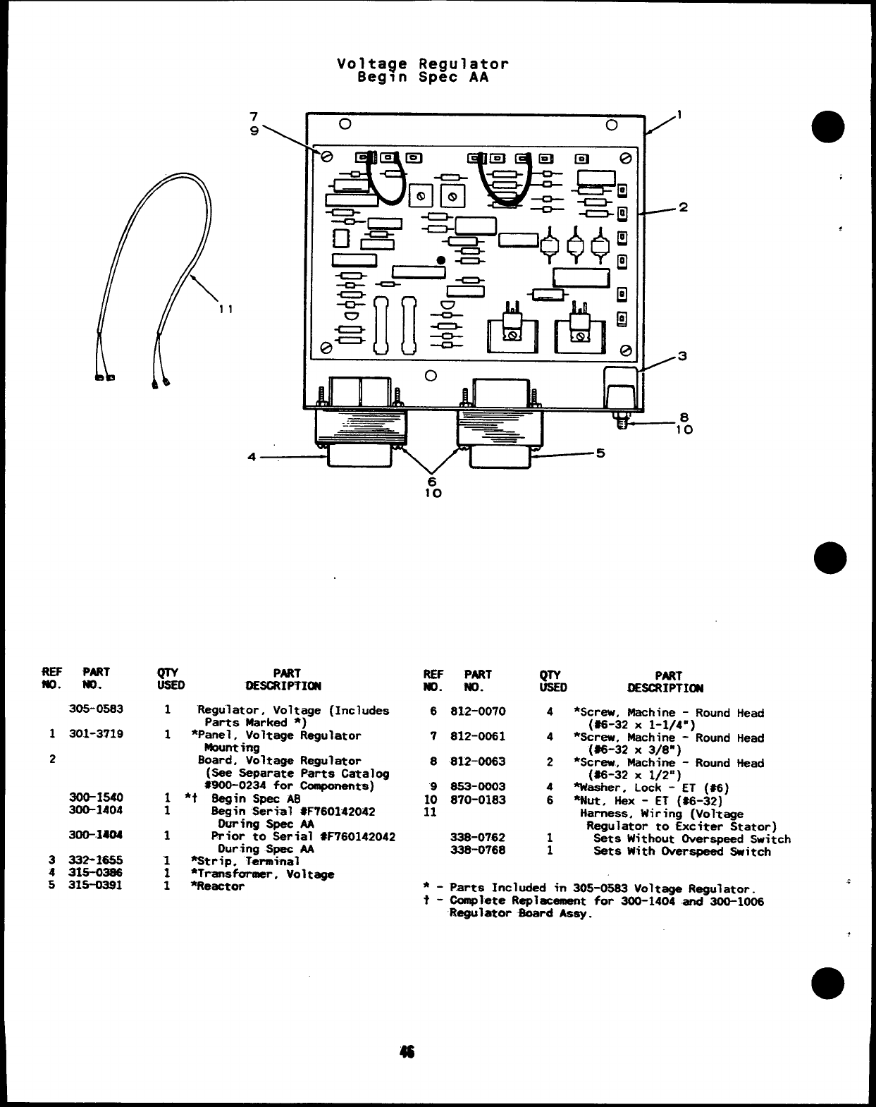
ftEF PART
tm. m.
30s-0583
1301-3719
2
300-1s40
300-1404
300-1404
3332-166s
431s-0386
531s-0391
Volta$e Regulator
Begin Spec AA
o1
0●
II :1111~ Iru-11
ilk u
4
180
45
wPART
USED DESCRIPTIm
1“Reguletor, Voltage (Includes
Parts Marked *)
1*Panel, Voltage Regulator
Mount img
Board, Voltage Regulator
(See separate=~~~og
:900-0234 for
1*t Begin Spec AB
1Begin Serial ~F760142042
Ouring Spec M
1Prior to Serial #F760142042
During Spat AA
“1 %trip. Terminal
1●Transfommr. Voltage
1*Reactor
160
REf
No.
6
7
8
1:
11
*_
t-
46
PART QTV PART
No. USED DESCRIPTI~
812-0070 4*Screw, Machine -Round Head
(#6-32 X1-1/4”)
812-0061 4*Screw. Machine -Round Head
(#6-32 X3/8’)
812-0063 2*Screw, Machine -Round Head
(S6-32 X1/2”)
BS3-0003 4%esher, Lock -ET (#6)
870-0183 6%Jt, Hex -ET (#6-32)
Harness, Wiring (Voltage
Regulator to Exciter Stator)
338-0762 1Sets Without Overspead Switch
338-0768 1Sets With Dverspaed switch
Parts Included in 30S-0583 Voltage Regulator. ;
Complete Replacement for 300-1404 end 3OD-1OO6
Regulator 9oerd Asey.
Service Kits and Miscellaneous
●REF PART QTY PART
NO. NO. USED DESCRIPTION REF PART QTY PART
NO. NO. USED DESCRIPTION
98-1807 1Decal Kit, Plant
168-0099 1Touch-Up Paint (Pressurized
Gasket Kit, Plant Can )
Overhaul Kit, Set 525-0137
522-0211 1Spec Athrough QSilver Green (13 oz.)
525-0305 ;Non-metallic Green (13 oz.)
522-0236 18egin Spec R
d
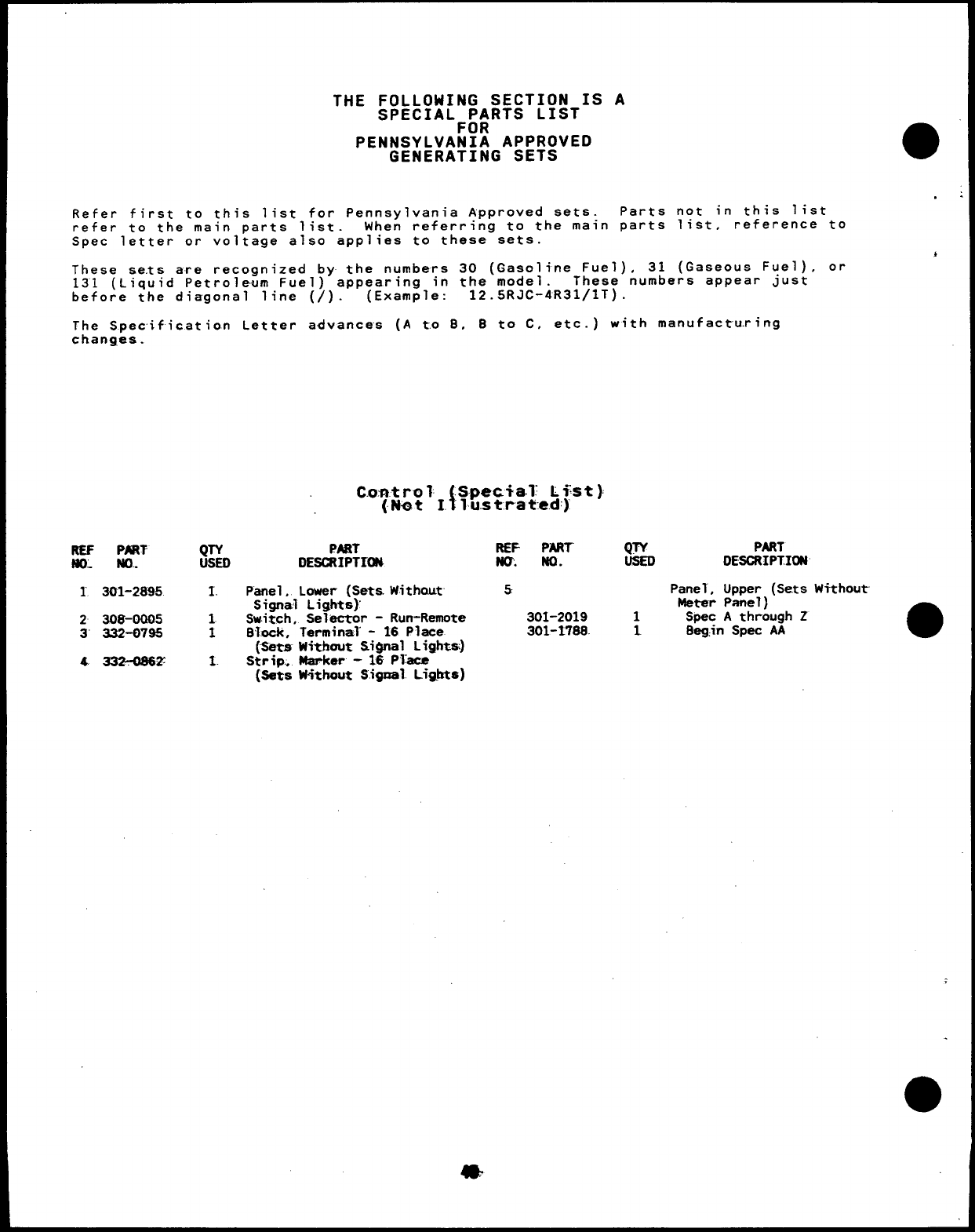
THE FOLLOWING SECTION IS A
SPECIALF~:RTS LIST
PENNSYLVANIA APPROVED
GENERATING SETS
Refer first to this list for Pennsylvania Approved sets. Parts not in this list
refer to the main parts list. When referring to the main parts list, reference to
Spec letter or voltage also applies to these sets.
These sets are recognized by the numbers 30 (Gasoline Fuel), 31 (Gaseous Fyel). or
131 (Liquid Petroleum Fuel) appearing in the model. These numbers appear Just
before the diagonal line (/). (Example: 12.5RJC-4R31/lT) .
The Specification Letter advances (A t.o B, Bto C, etc.) with manufactu.rirtg
changes.
C.o.ntro ?{.Spec+al: Li%t)
(Nat I. ’lu.strated)
REF PnRT QTY PART REF PART
ND: m.. usED DESCRIPTION N@. No.
1301-2895 I. Panel, Lower (Sets. Without 5
Signal Lights)
2308-0005 1Switch, Selector -Run-Remote 301-2019
3“ 332-0795 IBTock, Terminal -16 Place 301-1788.
(Sets Without Signal Lights)
4. 332?D86Z 1. Strip., Marker -16 Plkce
(Sets W’ithout Sigual Li@ts)
QTY PART
DESCRIPTION
Panel, Upper (Sets Without-
Metar Panel)
1Spec Athrough Z
1. Bag,in Spec AA a
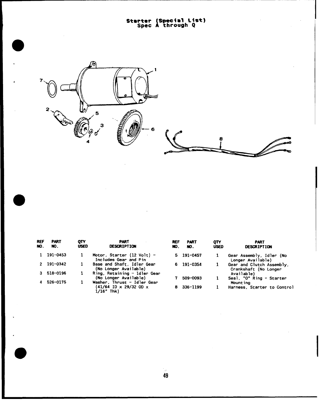
.
Stme: Speciml List)
ithrough Q
●
REF PART QTY PART
No. No. USED DESCt?IPTIffl
1191-0453 1Wotor, Starter (12 Volt) -
Includes Gear and Pin
2191-0342 1Base and Shaft, Idler Gear
(No Longer Available)
3518-0196 1Ring, Retaining -Idler Gear
(No Longer Available)
4526-0175 1Washer, Thrust -Idler Gear
(41/64 ID X29/32 OD X
1/16” Thk)
REF PRRT QTY PART
ND. w. USED DESCJtIPTIffl
5191-0457 1Gear Assembly, Idler (No
Longer Available)
6191-0354 1Gear and Clutch Assembly,
Crankshaft (No Longer
Available)
7509-0093 1Seal, “O” Ring -Starter
Mounting
8336-1199 1Harness, Starter to Control
49
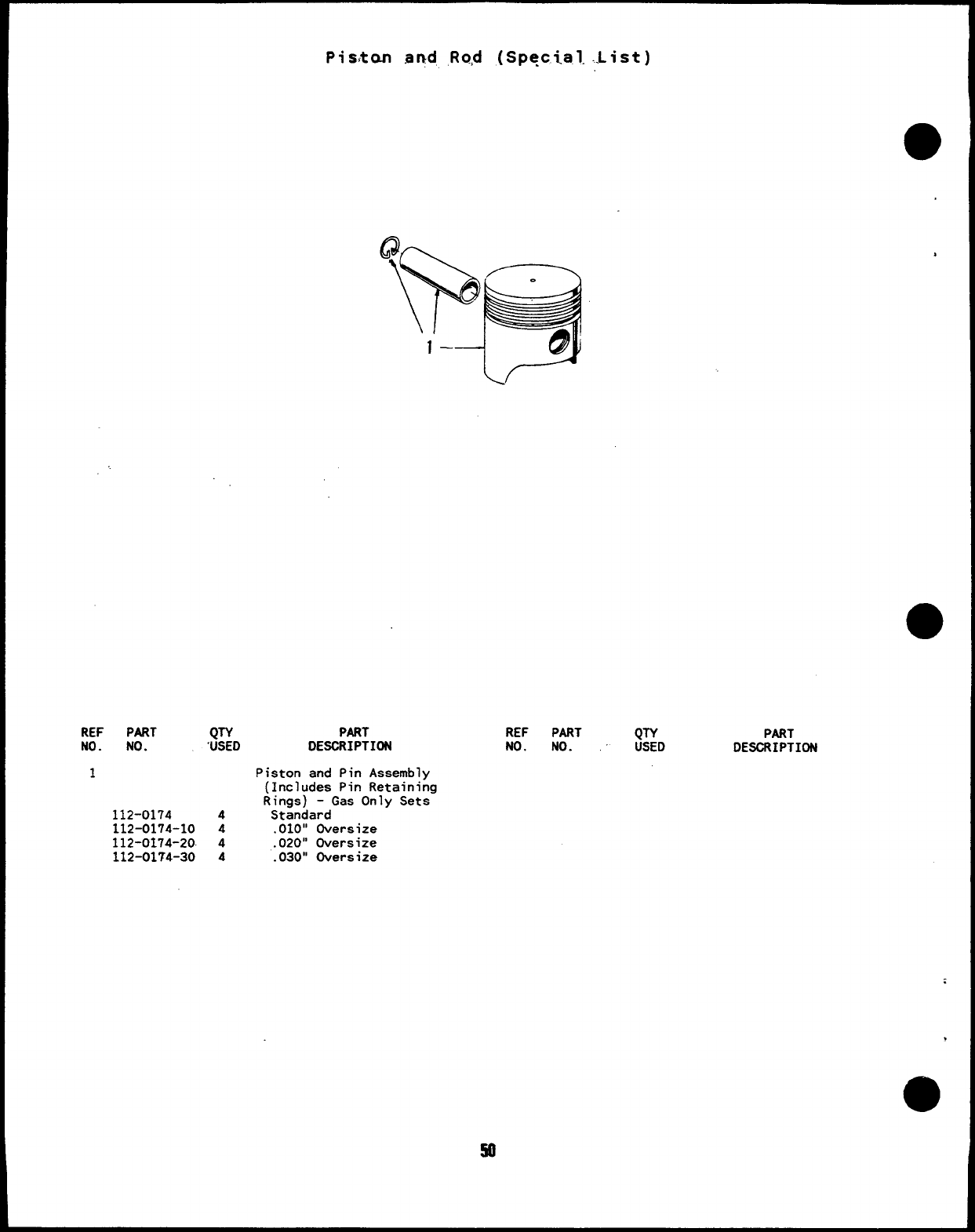
Pisito.n aqd, ,Rqd (Special. ..List)
REF PART QTY
NO. NO. “USED PART
DESCRIPTION
1Piston and Pin Assembly
(Includes Pin Retaining
Rings) -Gas Only Sets
112-0174 4Standard
112-0174-10 4.010” Oversize
112-0174-20. 4.020” Oversize
112-01?4-30 4.030” Oversize
REF PART QTY
No. No. USED PART
DESCRIPTION
.
so
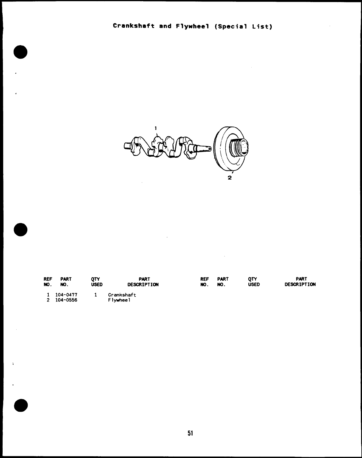
Crankshaft and Flywheel (Special List)
REF PART QTY PART
ND. ND. USED DESCRIPTION
1104-0477 1Crankshaft
2104-0556 Flywheel
;
.
51
REF PART QTY PART
ND. ND. USED DESCRIPTION
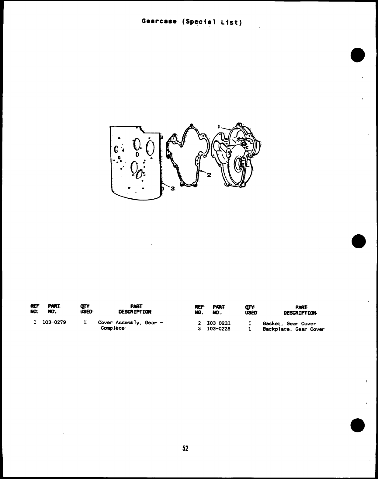
Gearcase (Special List)
REE PART g& PART
m. MO. DEscftwnm$
2103-0231 1Gasket, Gear Cover
3103-f1228 1ffacicplate, Gear Ccwer
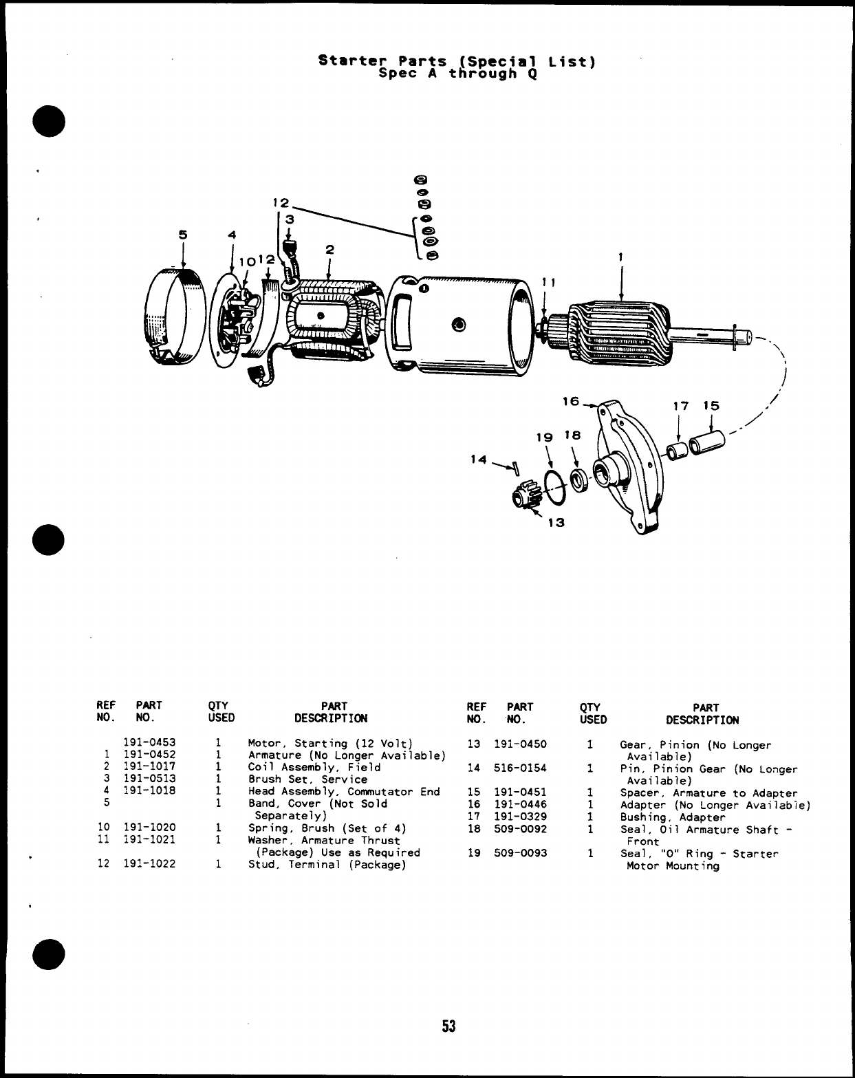
●
REF
NO.
Starter Parts (Special List)
Spec Athrough Q
a
e
5
b
,..,..
,,,,,
,,,.,
.,.
I!!.
PART
No.
191-0453
1191-0452
2191-1017
3191-0513
4191-1018
5
10 191-1020
11 191-1021
.12 191-1022
w,/”
/
/-
14
-. \\
,/
PART
DESCRIPTI@l
Motor, Starting (12 Volt)
Armature (No Longer Available)
Coil Assembly, Field
Brush Set, Service
Head Assembly, Commutator End
Band, Cover (Not Sold
Separately)
Spring, Brush (Set of 4)
Washer, Armature Thrust
(Package) Use as Required
Stud, Terminal (Package)
REF PART
No. “NO.
13 191-0450
14 516-0154
15 191-0451
16 191-0446
17 191-0329
18 509-0092
19 509-0093
QTY
USED
1
1
.
1
i
1
1
PART
DESCRIPTION
Gear, Pinion (No Longer
Available)
Pin, Pinion Gear (No Longer
Available)
Spacer, Armature to Adapter
Adapter (No Longer Availabie)
Bushing, Adapter
Seal, Oil Armature Shaft -
Front
Sea 1, “O” Ring -Starter
Motor Mounting
53
I
OPTIONAL PARTS SECTION
@
This section contains illustrated parts listing of factory instal
b
options for the generator sets. Options may not be applicable to
ed
all
models; for field conversions additional parts are usually required.
Optional parts listed in this section are in addition or in place of
those shown in the standard parts section.
.
55
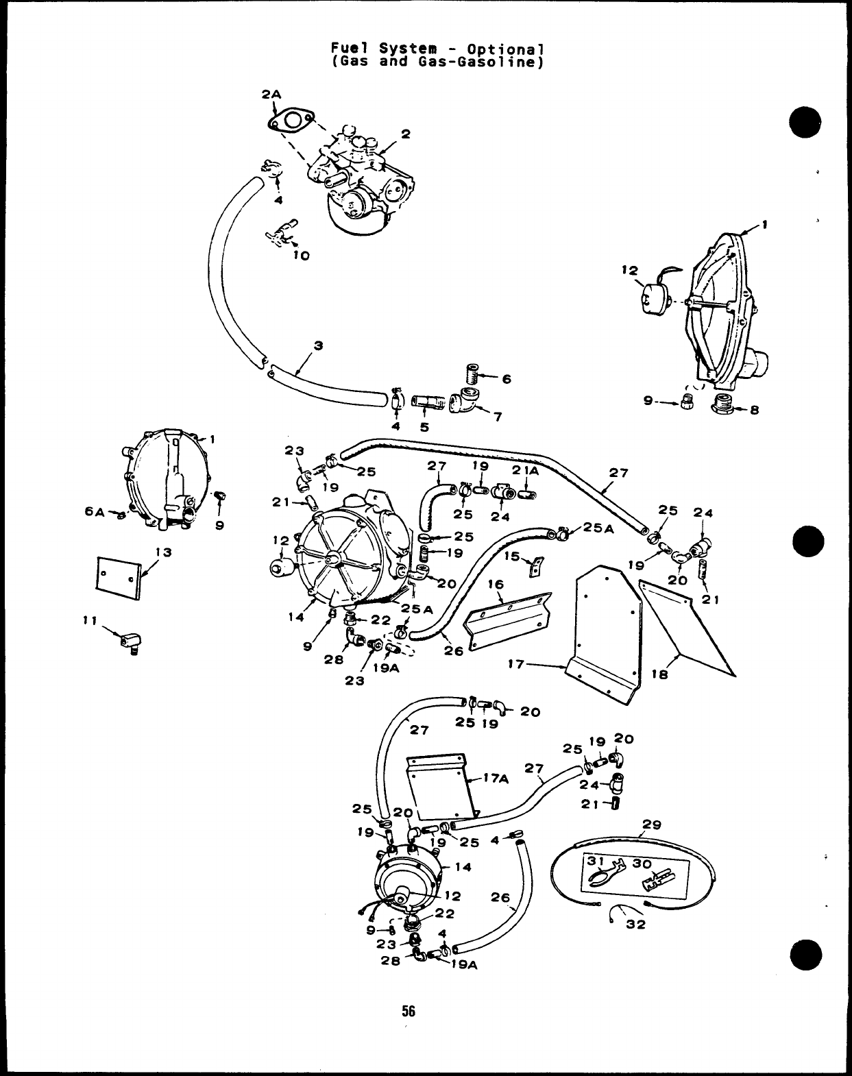
6A
Fuel System -Optional
(Gas and Gas-Gasoline)
2A
12 6
\..
‘-–’$3@-8
45
A- 19 ?0
==\\_J
M2’”29
Q+
●
.
.
m
56
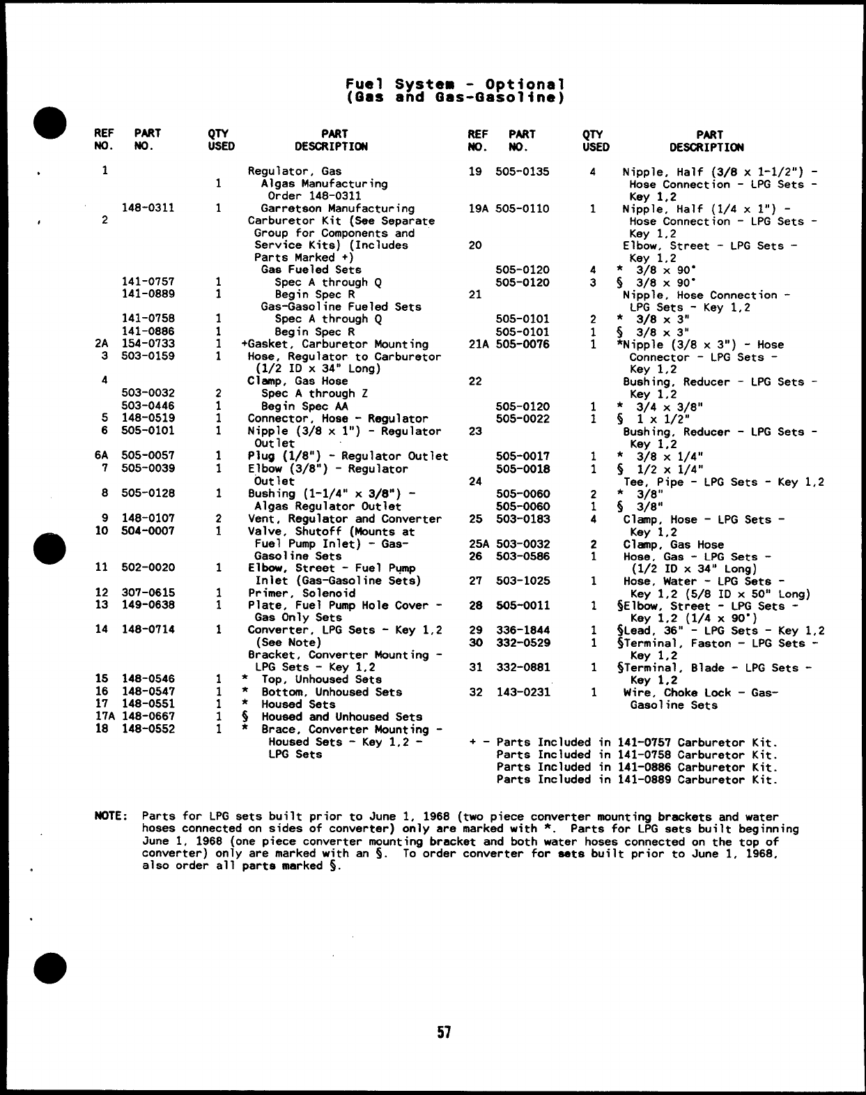
Fuel System -Optional
(Qas and Gas-Gasoline)
aREF PART
No. No.
.
.1
148-0311
#2
141-0757
141-0889
141-0758
141-0886
2A 154-0733
3503-0159
4
503-0032
503-0446
5148-0519
6505-0101
6A 505-0057
7505-0039
8505-0128
9148-0107
9
10 504-0007
11 502-0020
12 307-0615
13 149-0638
14 148-0714
1S 148-0546
16 148-0547
17 148-0551
17A 148-0667
18 148-0552
QTY PART
USED DESCRIPTI~
1
1
1
1
1
1
1
1
2
1
1
1
1
1
1
2
1
1
1
1
1
1
1
1
1
1
Regulator, Gas
Algas Manufacturing
Order 148-0311
Garretson Manufacturing
Carburetor Kit (See Separate
Group for Components and
Service Kits) (Includes
Parts Marked +)
Gas Fueled Sets
Spec Athrough Q
8egin Spec R
Gas-Gasoline Fueled Sets
Spec Athrough Q
8egin Spec R
+Gasket, Carburetor Mounting
Hose, Regulator to Carburetor
(1/2 IDx34° Long)
Clamp, Gas Hose
Spec Athrough Z
8egin Spec AA
Connector, Hose -Regulator
Nipple (3/8 xl“) -Regulator
Outlet
Plug (1/8”) -Regulator Outlet
Elbow (3/8”) -Regulator
Outlet
8ushing (1-1/4” x3/8”) -
Algas Regulator Outlet
Vent, Regulator and Converter
Valve, Shutoff (Mounts at
Fuel Pump Inlet) -Gas-
Gasoline Sets
Elbow, Street -Fuel Pump
Inlet (Gas-Gasoline Sets)
Primer, Solenoid
Plate, Fuel Pump Hole Cover -
Gas Only Sets
Converter, LPG Sets -Key 1,2
(See Note)
8racket, Converter Mounting -
LPG Sets -Key 1,2
*Top, Unhoused Sets
*Bottom, Unhoused Sets
*Housed Sets
sHoused and Unhoused Sets
*Brace, Converter Mounting -
Housed Sets -Key 1,2 -
LPG Sets
REF PART
ND. No.
19 505-0135
19A 505-0110
20
505-0120
505-0120
21
505-0101
505-0101
21A 505-0076
22
505-0120
505-0022
23
505-0017
505-0018
24 505-0060
505-0060
25 503-0183
25A 503-0032
26 503-0586
27 503-1025
28 505-0011
29 336-1844
30 332-0529
31 332-0881
32 143-0231
QTY PART
USED DESCRIPTIffl
4
1
4
3
2
1
1
1
1
i
2
1
4
2
1
1
1
1
1
1
1
Nipple, Half (3/8 x1-1/2”) -
Hose Connection -LPG Sets -
Key 1,2
Nipple, Half (1/4 xl“) -
Hose Connection -LPG Sets -
Key 1,2
Elbow, Street -LPG Sets -
Key 1,2
*3/8 X90”
!j 3/8x 90”
Nipple, Hose Connection -
LPG Sets -Key 1,2
*3/8 X3“
~3/8x3°
*Nipple (3/8 x3“) -Hose
Connector -LPG Sets -
Key 1,2
8ushing, Reducer -LPG Sets -
Key 1,2
*3/4 X3/8”
s8u:h;n;/2°
,Reducer -LPG Sets -
Key 1,2
*3/8 X1/4”
s1/2 x1/4”
Tee, Pipe -LPG Sets -Key 1,2
*3/811
~3/8”
Clamp, Hose -LPG Sets -
Key 1,2
Clamp, Gas Hose
Hose, Gas -LPG Sets -
(1/2 ID x34” Long)
Hose, Water -LPG Sets -
Key 1,2 (5/8 ID x50” Long)
~Elbow, Street -LPG Sets -
Key 1,2 (1/4 x90”)
~Lead, 36” -LPG Sets -Key 1,2
6Terminal. Faston -LPG Sets -
Key 1,2”
$Terminal, Blade -LPG Sets -
Kev 1,2
Wire, Choke Lock -Gas-
Gasoline Sets
+-parts Included in 141-0757 carburetor Kit.
Parts Included in 141-0758 Carburetor Kit.
Parts Included in 141-0886 Carburetor Kit.
Parts Included in 141-0889 Carburetor Kit.
NOTE :Parts for LPG sets built prior to June 1, 196B (two piece converter mounting brackets and water
hoses connected on sides of converter) only are marked with *. Parts for LPG sets built beginning
June 1, 196B (one piece converter mounting bracket and both water hoses connected on the top of
converter) only are marked with an ~. To order converter for sets built prior to June 1, 1968,
,also order all parts marked ~.
57
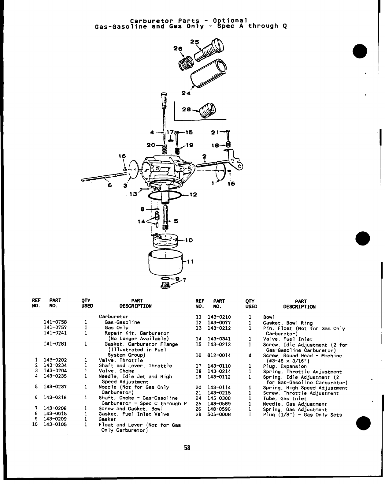
REF PART
ND. ND.
141-0758
141-0757
141-0241
141-0281
1143-0202
2143-0234
3143-0204
4143-0235
5143-0237
6143-0316
7143-0208
8143-0015
9143-0209
10 143-0105
Carburetor Parts -0tional
Gas-Gasollne and Gas Only -Rpec Athrough Q
16
!
QTY
USED
1
1
1
1
i
1
1
1
1
1
1
1
1
20 *
-15 21 7
/19 18-E
w
8+
4-
14 5
i,
PART REF PART
DESORIPTIDN ND. No.
Carburetor 11 143-0210
Gas-Gasoline 12 143-0077
Gas Only 13 143-0212
Repair Kit, Carburetor
(No Longer Available) 14 143-0341
Gasket, Carburetor Flange 15 143-0213
(Illustrated in Fuel
System GrouD) 16 812-0014
Valve, Throttle’
Shaft and Lever, Throttle
Valve, Choke
Needle, Idle Jet and High
Speed Adjustment
Nozzle (Not for Gas Only
Carburetor)
Shaft, Choke -Gas-Gasoline
Carburetor -Spec Cthrough
Screw and Gasket, 80W1
Gasket, Fuel Inlet Valve
Gasket
Float and Lever (Not for Gas
17 143-0110
18 143-0214
19 143-0112
20 143-0114
21 143-0215
24 145-0308
P25 146-0589
26 148-0590
28 505-0008
Only Carburetor)
58
‘1
QTV
USED
:
1
1
1
4
1
1
1
1
1
1
1
1
1
PART
DE80RIPTIDN
80W1
Gasket, 80W1 Ring
Pin, Float (Not for Gas Only
Carburetor)
Valve, Fuel Inlet
Screw, Idle Adjustment (2 for
Gas-Gasoline Carburetor)
Screw, Round Head -Machine
(#3-48 X3/16”)
Plug, Expansion
Spring, Throttle Adjustment
Spring, Idle Adjustment (2
for Gas-Gasoline Carburetor) ,
Spring, High Speed Adjustment
Screw, Throttle Adjustment
Tube, Gas Inlet
Needle, Gas Adjustment
Spring, Gas Adjustment
Plug (1/8”) -Gas Only Sets
o
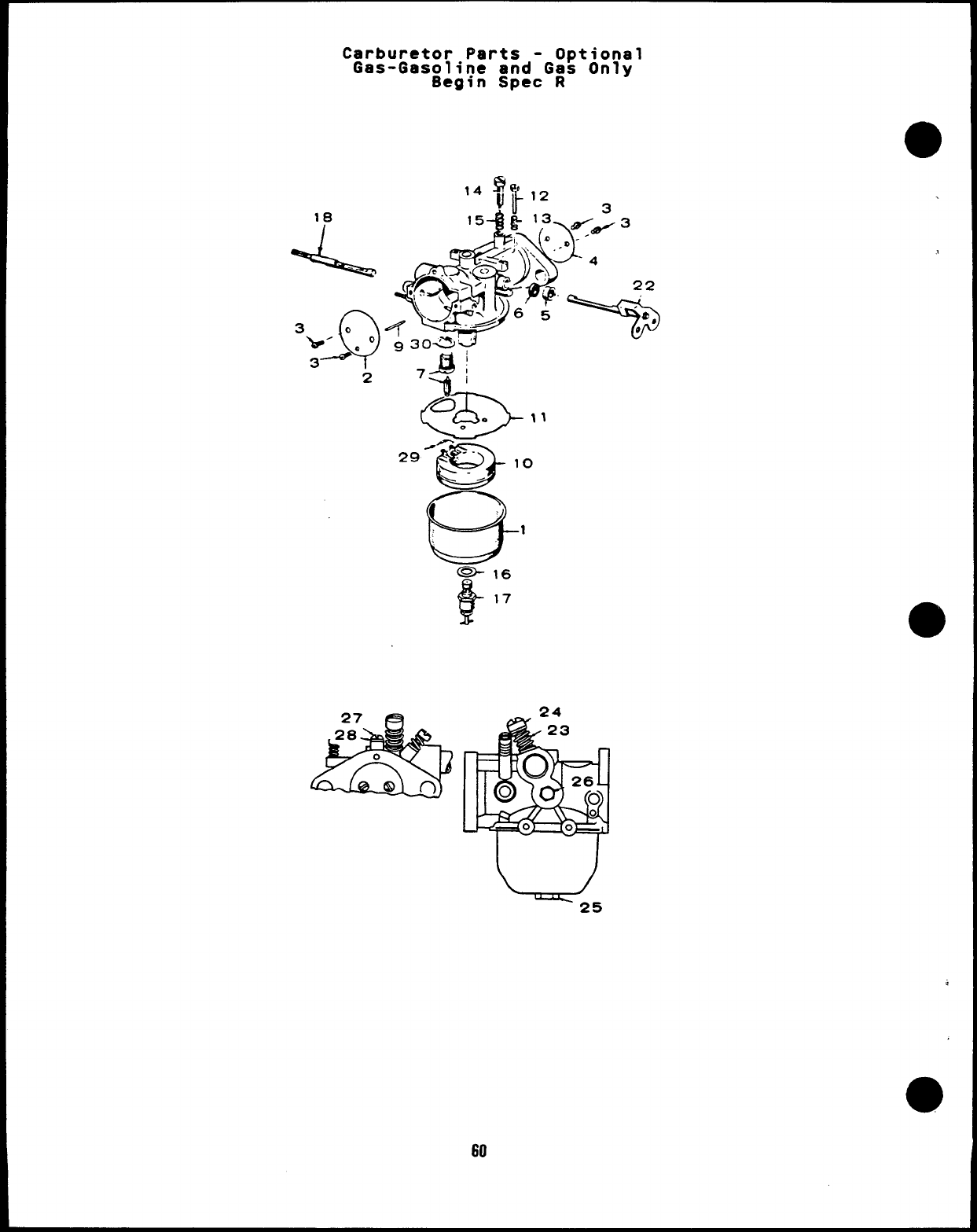
Carburetor Parts -Optional
Gas-Gasoline and Gas Only
Begin Spec R
18
3Q
b’O.”
3- 2
27
&
24
20
0
on
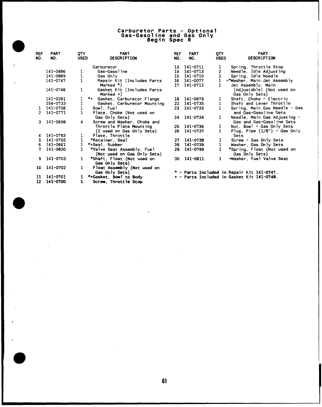
Carburetor Parts -Optional
Gas-Gasoline and Gas Onlv I
Begin SPeC R-”-
●REF PART
NO. NO. QTY PART
USED DESCRIPTION REF PART
NO. NO. QTY PART
USED DESCRIPTION
141-0886
141-0889
Carburetor
Gas-Gasoline
Gas Only
Repair Kit (Includes Parts
Marked *)
Gasket Kit (Includes Parts
Marked +)
*+ Gasket, Carburetor Flange
Gasket, Carburetor Mounting
Bowl, Fuel
Plate, Choke (Not used on
Gas Only Sets)
Screw and Washer, Choke and
Throttle Plate Mounting
(2 used on Gas Only Sets)
Plate, Throttle
*Retainer, Seal
*+Seal, Rubber
*Valve Seat Assembly, Fuel
(Not used on Gas Only Sets)
*Shaft, Float (Not used on
Gas Only Sets)
Float Assembly. (Not used on
Gas Only Sets)
*+Gasket, BOW1 to 8ody
screw, Throttle Stop
13 141-0711
14 141-0713
15 141-0710
16 141-0077
17 141-0712
1
2
2
1+
1
Spring, Throttle Stop
Needle, Idle Adjusting
Spring, Idle Needle
Washer, Main Jet Assembly
Jet Assembly, Main
(Adjustable) (Not used on
Gas Only Sets)
Shaft, Choke -Electric
Shaft and Lever Throttle
Spring, Main Gas Needle -Gas
and Gas-Gasoline Sets
Needle, Main Gas Adjusting -
Gas and Gas-Gasoline Sets
Nut, Bowl -Gas Only Sets
Plug, Pipe (1/8”) -Gas Only
Sets
Screw -Gas Only Sets
Washer, Gas Only Sets
*Spring, Float (Not used on
Gas Only Sets)
+Washer, Fuel Valve Seat
141-0747
141-0748 1
141-0281
154-0733
1141-0708
2141-0771
1
118 141-0679
22 141-0735
23 141-0733
1
1
11
124 141-0734 1
3141-0698 4
25 141-0736
26 141-0737 1
1
4
5
6
7
141-0793
141-0705
141-0661
141-0830
1
1
1
1
27 141-0738
28 141-0739
29 141-0799
1
1
1
9141-0703 1
1
30 141-0811 1
10 141-0702 *-Parts Included in Repair Kit 141-0747.
+-parts Included in Gasket Kit 141-0748.
11
12 141-0701
141-0700
61
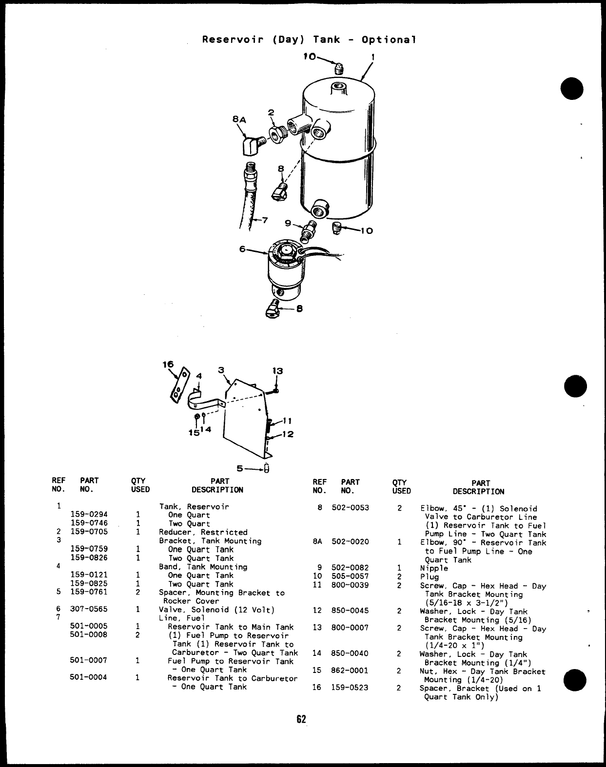
Reservoir (Day) Tank -Optional
REF PART
No. No.
1159-0294
159-0746
2159-0705
3
159-0759
159-0826
4
159-0121
159-0825
5159-0761
6307-0565
7501-0005
501-0008
501-0007
501-0004
QTY
USED
1
;
1
1
;
2
1
1
2
1
1
‘% 1
A.,
F%
5—G
PART
DESCRIPTION
Tank, Reservoir
One Quart
Two Quart
Reducer, Restricted
Bracket, Tank Mounting
One Quart Tank
Two Quart Tank
Band, Tank Mounting
One Quart Tank
Two Quart Tank
Spacer, Mounting Bracket to
Rocker Cover
Valve, Solenoid (12 Volt)
Line, Fuel
Reservoir Tank to Main Tank
(1) Fuel Pump to Reservoir
Tank (1) Reservoir Tank to
Carburetor -Two Quart Tank
Fuel Pump to Reservoir Tank
-One Quart Tank
Reservoir Tank to Carburetor
-One Quart Tank
REF PART
NO. NO.
8502-0053
8A 502-0020
9502-0082
10 505-0057
11 800-0039
12 850-0045
13 800-0007
14 850-0040
15 862-0001
16 159-0523
QTY
USED
2
1
1
2
2
2
2
2
2
2
PART
DESCRIPTION
Elbow, 45” -(1) Solenoid
Valve to Carburetor Line
(1) Reservoir Tank to Fuel
Pump Line -Two Quart Tank
Elbow, 90” -Reservoir Tank
to Fuel Pump Line -One
Quart Tank
Nipple
Plug
Screw, Cap -Hex Head -Day
Tank 8racket Mounting
(5/16-18 X3-1/2”)
Washer, Lock -Day Tank
Bracket Mounting (5/16)
Screw, Cap -Hex Head -Oay
Tank Bracket Mounting
(1/4-20 X1“ )
Washer, Lock -Day Tank
Bracket Mounting (1/4”)
Nut, Hex -Day Tank 8racket
Mounting (1/4-20)
Spacer, Bracket [Used on 1
Quart Tank Only)
62
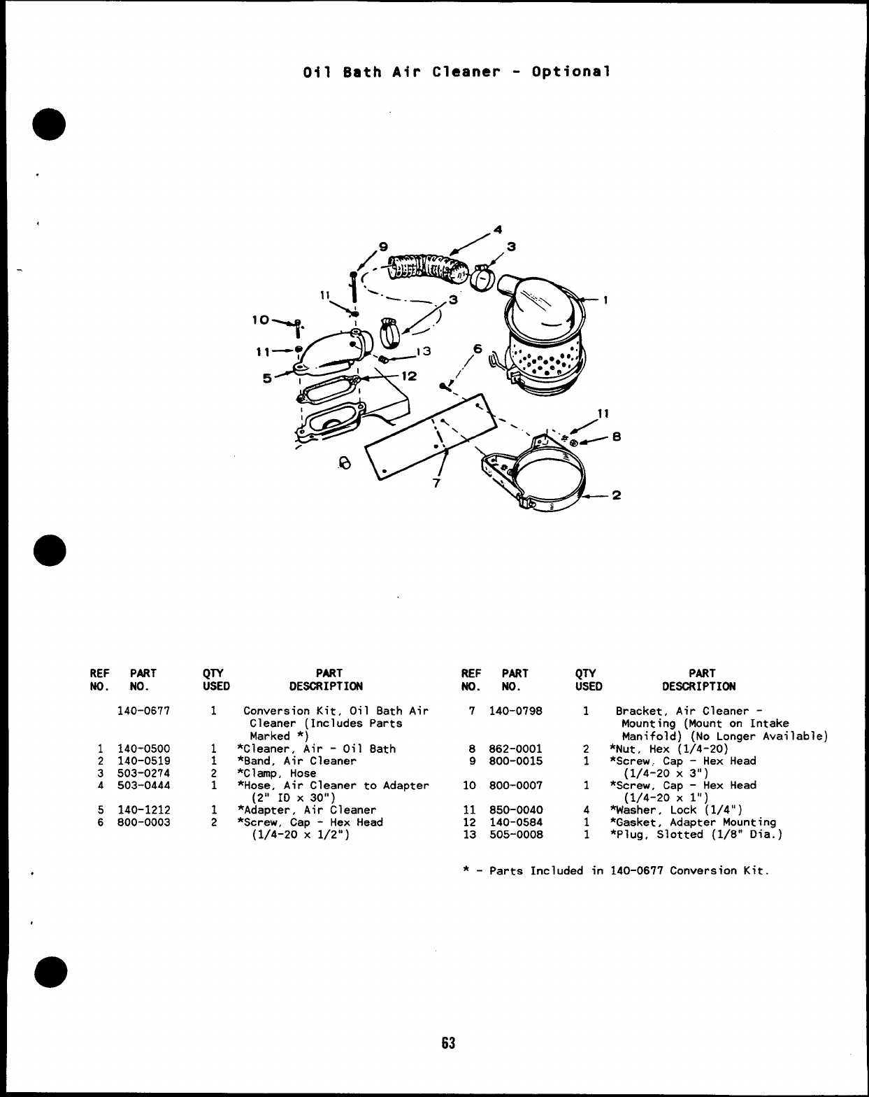
041 Bath Air Cleaner -Optional
a
.
.
REF PART
NO. NO.
140-0677
1140-0500
2140-0519
3503-0274
4503-0444
5140-1212
6800-0003
QTY PART
USED DESCRIPTION
1
1
1
2
1
1
2
Conversion Kit, Oil Bath Air
Cleaner (Includes Parts
Marked *)
*Cleaner, Air -Oil Bath
*Band, Air Cleaner
*ClamP, Hose
*Hose”, Air Cleaner to Adapter
(2” 10 x 30”)
*Adapter, Air Cleaner
*Screw, Cap -Hex Head
(1/4-20 X1/2”)
REF PART
ND. ND.
7140-0798
8862-0001
9800-0015
10 800-0007
11 850-0040
12 140-0584
13 505-0008
QTY
USED
1
2
1
1
4
1
1
*-parts Included in
63
PART
DESCi?IPTION
Bracket, Air Cleaner -
Mounting (Mount on Intake
Manifold) (No Longer Available)
*Nut, Hex (1/4-20)
*Screw, Cap -Hex Head
(1/4-20 X3“)
*Screw, Cap -Hex Head
(1/4-20 X1“ )
washer, Lock (1/4”)
*Gasket, Adapter Mounting
*Plug, Slotted (1/8” Dia.)
140-0677 Conversion Kit.
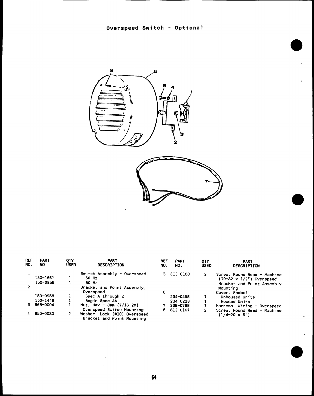
REF PART
ND. NO.
:50-1661
150-0956
2
150-0958
150-1446
3868-0004
4850-0030
QTY
USED
1
1
Overspeed Switch -Optional
8.6
I
PART
DESCRIPTION
Switch Assembly -Overspeed
50 Hz
60 HZ
Bracket and Point Assembly,
Overspeed
Spec Athrough Z
Begin Spec AA
Nut, Hex -Jam (7/16-20)
Overspeed Switch Mounting
Washer, Lock (#IO) Overspeed
Bracket and Point Mounting
REF PART
NO. NO.
3813-0100
6234-0498
234-0223
7338-0768
8812-0167
QTY PART
USED DESCRIPTION
2Screw, Round Head -Machine
(10-32 x1/2”) Overspeed
Bracket and Point Assembly
Mounting
Cover, Endbell
1Unhoused Units
1Housed Units
1Harness, Wiring -Overspeed
2Screw. Round Head -Machine
(1/4-20 X6“) .
64
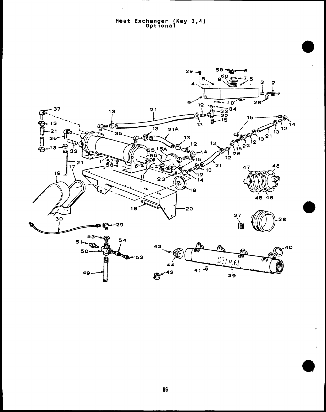
Heat Exchanger {Key 3,4)
Optlona
.
4
‘-21 A7 48
66
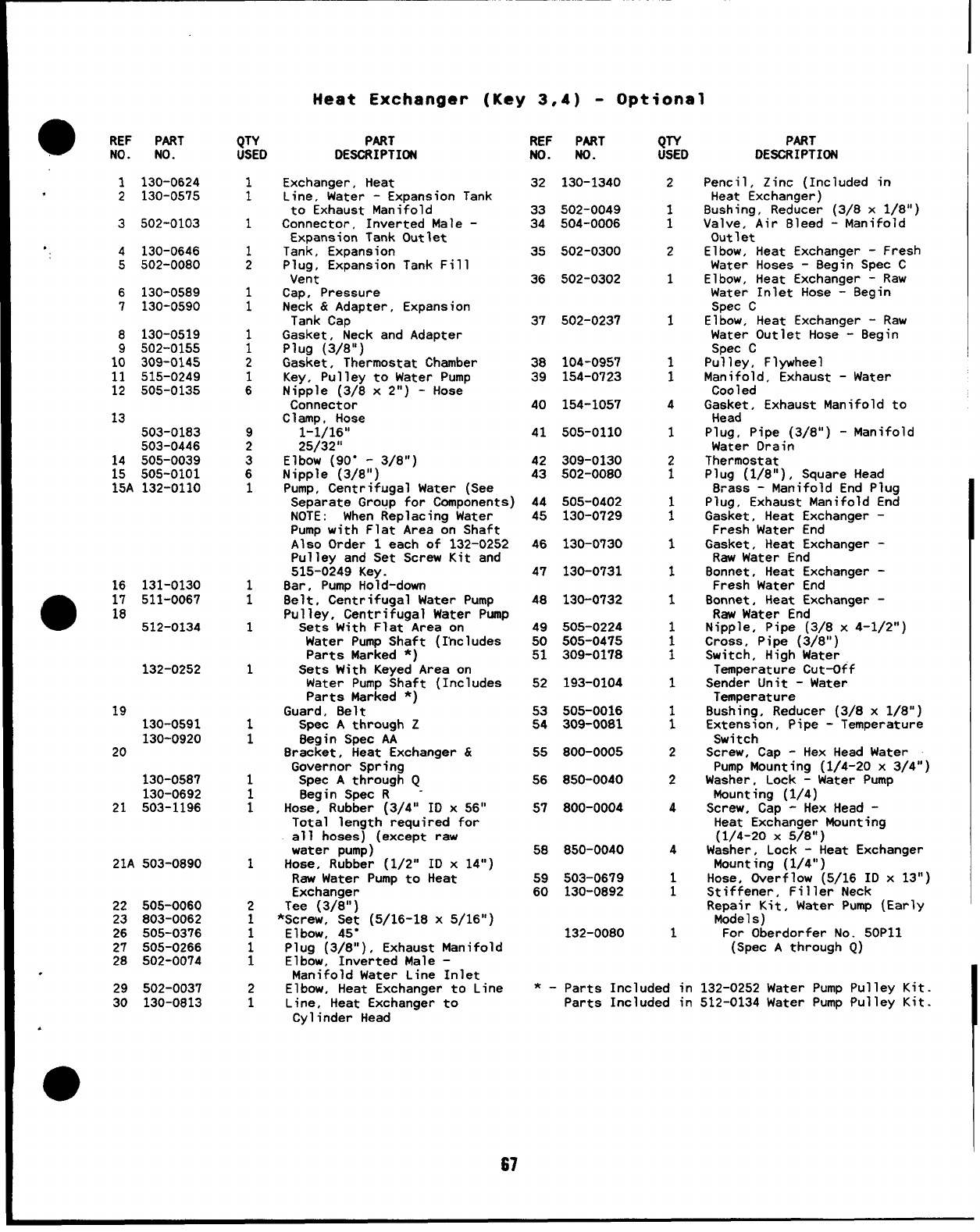
I
Heat Exchanger (Key 3,4) -Optional
@REF PART
No. No. PART
DESCRIPTION
QTY PART
USED DESCRIPTIffl REF
Ho. PART
No. QTY
USED
1130-0624
2130-0575 1
1
1
1
2
1
1
1
1
2
1
6
9
2
;1
1
1
1
1
1
1
1
;
1
2
1
1
1
1
2
1
Exchanger, Heat
Line, Water -Expansion Tank
to Exhaust Manifold
Connector, Inverted Male -
Expansion Tank Outlet
Tank, Expansion
Plug, Expansion Tank Fill
Vent
Cap, Pressure
Neck &Adapter, Expansion
Tank Cap
Gasket, Neck and Adapter
Plug (3/8”)
Gasket, Thermostat Chamber
Key, Pulley to Water Pump
Nipple (3/8 x2“) -Hose
Connector
Clamp, Hose
1-1/16”
25/32”
Elbow (90” -3/8”)
Nipple (3/8”)
Pump, Centrifugal Water (See
Separate Group for Components)
NOTE :When Replacing Water
Pump with Flat Area on Shaft
Also Order 1each of 132-0252
Pulley and Set Screw Kit and
515-0249 Key.
8ar, Pump Hold-down
Belt, Centrifugal Water Pump
Pulley, Centrifugal Water Pump
Sets With Flat Area on
Water Pump Shaft (Includes
Parts Marked *)
Sets With Keyed Area on
Water Pump Shaft (Includes
Parts Marked *)
Guard, 8elt
Spec Athrough Z
Begin Spec AA
Bracket, Heat Exchanger &
Governor Spring
Spec Athrough Q
Begin Spec R-
Hose, Rubber (3/4” ID x56”
Total length required for
all hoses) (except raw
water pump)
Hose, Rubber (1/2” ID x14”)
Raw Water Pump to Heat
Exchanger
Tee (3/8”)
*Screw, Set (5/16-18 x5/16”)
Elbow, 45”
Plug (3/8”), Exhaust Manifold
Elbow, Inverted Male -
Manifold Water Line Inlet
Elbow, Heat Exchanger to Line
Line, Heat Exchanger to
Cylinder Head
32 130-1340 2
1
1
2
1
1
1
1
4
1
2
1
:
1
1
1
1
:
1
1
1
2
2
4
4
1
1
1
Pent i
Heat Zinc (Included in
Exchanger)
Bushina, Reducer [3/8 x1/8”)502-0049
504-0006
33
34
35
3502-0103 Valve,-Air Bleed ~Manifold “
Out 1et
Elbow, Heat Exchanger -Fresh
Water Hoses -Begin Spec C
Elbow, Heat Exchanger -Raw
Water Inlet Hose -Begin
Spec C
Elbow, Heat Exchanger -Raw
Water Outlet Hose -Begin
Spec C
Pulley, Flywheel
Manifold, Exhaust -Water
Coo 1ed
Gasket, Exhaust Manifold to
Head
Plug, Pipe (3/8”) -Manifold
Water Drain
Thermostat
Plug (1/8”), Square Head
Brass -Manifold End Plug
Plug, Exhaust Manifold End
Gasket, Heat Exchanger -
Fresh Water End
Gasket, Heat Exchanger -
Raw Water End
Bonnet, Heat Exchanger -
Fresh Water End
Bonnet, Heat Exchanger -
Raw Water End
Nipple, Pipe (3/8 x4-1/2”)
Cross, Pipe (3/8”)
Switch, High Water
Temperature Cut-Off
Sender Unit -Water
Temperature
Bushing, Reducer (3/8 x1/8”)
Extension, Pipe -Temperature
Switch
Screw, Cap -Hex Head Water
Pump Mounting (1/4-20 x3/4”)
Washer, Lock -Water Pump
Mounting (1/4)
Screw, Cap -Hex Head -
Heat Exchanger Mounting
(1/4-20 X5/8”)
Washer, Lock -Heat Exchanger
Mounting (1/4”)
Hose, Overflow (5/16 ID x13”)
Stiffener, Filler Neck
Repair Kit, Water Pump (Early
Models)
For Oberdorfer No. 50P11
(Spec Athrough Q)
4130-0646
5502-0080 502-0300
502-0302
36
6130-0589
7130-0590
37 502-0237
8130-0519
9502-0155
10 309-0145
11 515-0249
12 505-0135
38
39 104-0957
154-0723
40 154-1057
13 503-0183
503-0446 505-011041
14 505-0039
15 505-0101
15A 132-0110
309-0130
502-0080
44
45
505-0402
130-0729
46 130-0730
47 130-0731
16 131-0130
a
17 511-0067
18 512-0134
48 130-0732
49
50
51
505-0224
505-0475
309-0178
132-0252 52 193-0104
19 130-0591
130-0920
20
53
54 505-0016
309-0081
55 800-0005
130-0587
130-0692
21 503-1196
56 850-0040
57 800-0004
58 850-0040
21A 503-0890 59
60 503-0679
130-0892
22 505-0060
23 803-0062
26 505-0376
27 505-0266
28 502-0074
132-0080
n132-0252 Water Pump Pulley Kit.
n512-0134 Water Pump Pulley Kit.
29 502-0037
30 130-0813
*-Parts Included
Parts Included
d
67
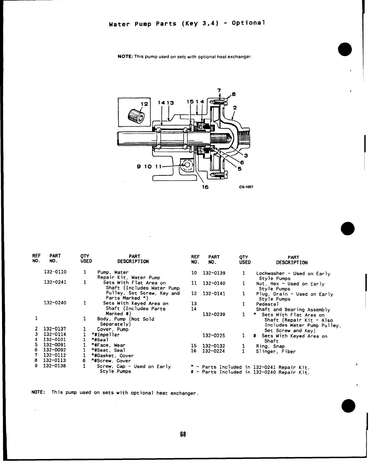
REF PART
No. No.
132-0110
132-0241
132-0240
1
2
3
4
5
6
7
8
9
132-0137
132-0114
132-0101
132-0091
132-0092
132-0112
132-0113
132-0138
(JTY
USED
1
1
1
1
1
1
1
1
1
1
6
1
Water Pump Parts (Key 3,4) -Optional
NOTE:This pump used onsets with optional heat exchanger.
.
~1413 l,!?&8
9‘o:’+@@.!.z
PART
DESCRIPTION
16 CS-1057
Pump, Water
Repair Kit, Water Pump
Sets With Flat Area on
Shaft (Includes Water Pump
pulley, Set Screw, Key and
Parts Marked *)
Sets With Keyed Area on
Shaft (Includes Parts
Marked #)
Body, Pump (Not Sold
Separately)
Cover, Pump
*#Impeller
*#Seal
*#Face, Wear
*#Seat, Seal
*#Gaaket, Cover
*#Screw, Cover
Screw, Cap -Used on Earlv
Style Pumps
REF
NO.
10
11
12
13
14
;:
*-
#-
NOTE :This pump used on sets with optional heat exchanger.
PART
NO.
132-0139
132-0140
132-0141
132-0239
132-0225
132-0132
132-0224
QTY
USED
1
1
1
1
1
1
;
Parts Included in
Parts Included in
PART
DESCRIPTION
Lockwasher -Used on Early
Style Pumps
Nut, Hex -Used on Early
Style Pumps
Plug, Drain -Used on Early
Style Pumps
Pedestal
Shaft and Bearing Assembly
*Sets With Flat Area on
Shaft (Repair Kit -Also
Includes Water Pump Pulley,
Set Screw and Key)
#Sets With Keyed Area on
Shaft
Ring, Snap
Slinger, Fiber
132-0241 Repair Kit.
132-0240 Repair Kit.
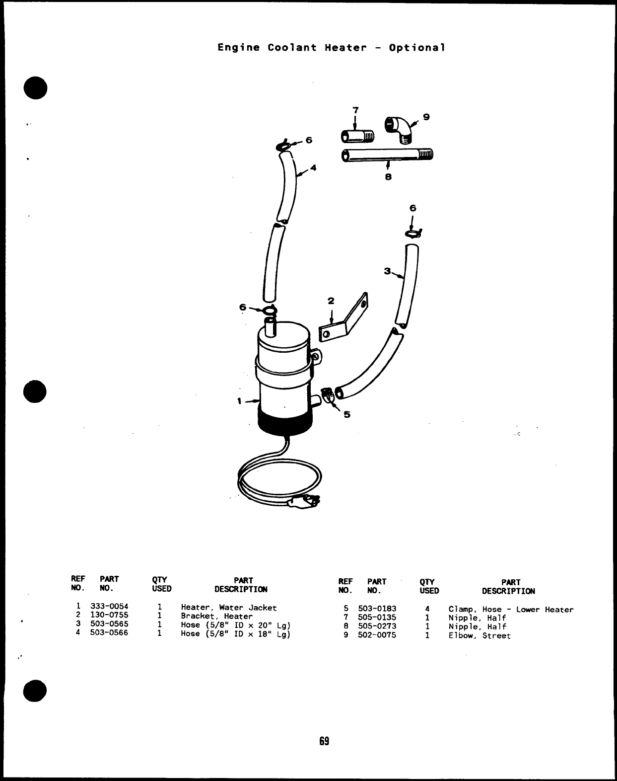
Engine Coolant Heater -Optional
o
,
,
7
// 6
u
/7 L
REF PART QTY PART
No. No. USED DESCRIPTI~
1333-0054 Heater, Water Jacket
2130-0755 :Bracket, Heater
3503-0565 1Hose (5/8” ID x20” Lg)
4503-0566 1Hose (5/8” ID x18” Lg)
.
..
●
69
REF PART QTY PART
No. No. USED DESCRIPTION
5503-0183 4Clamp, Hose -Lower Heater
7505-0135 1Nipple, Half
8505-0273 Nipple, Half
9502-0075 :Elbow, Street
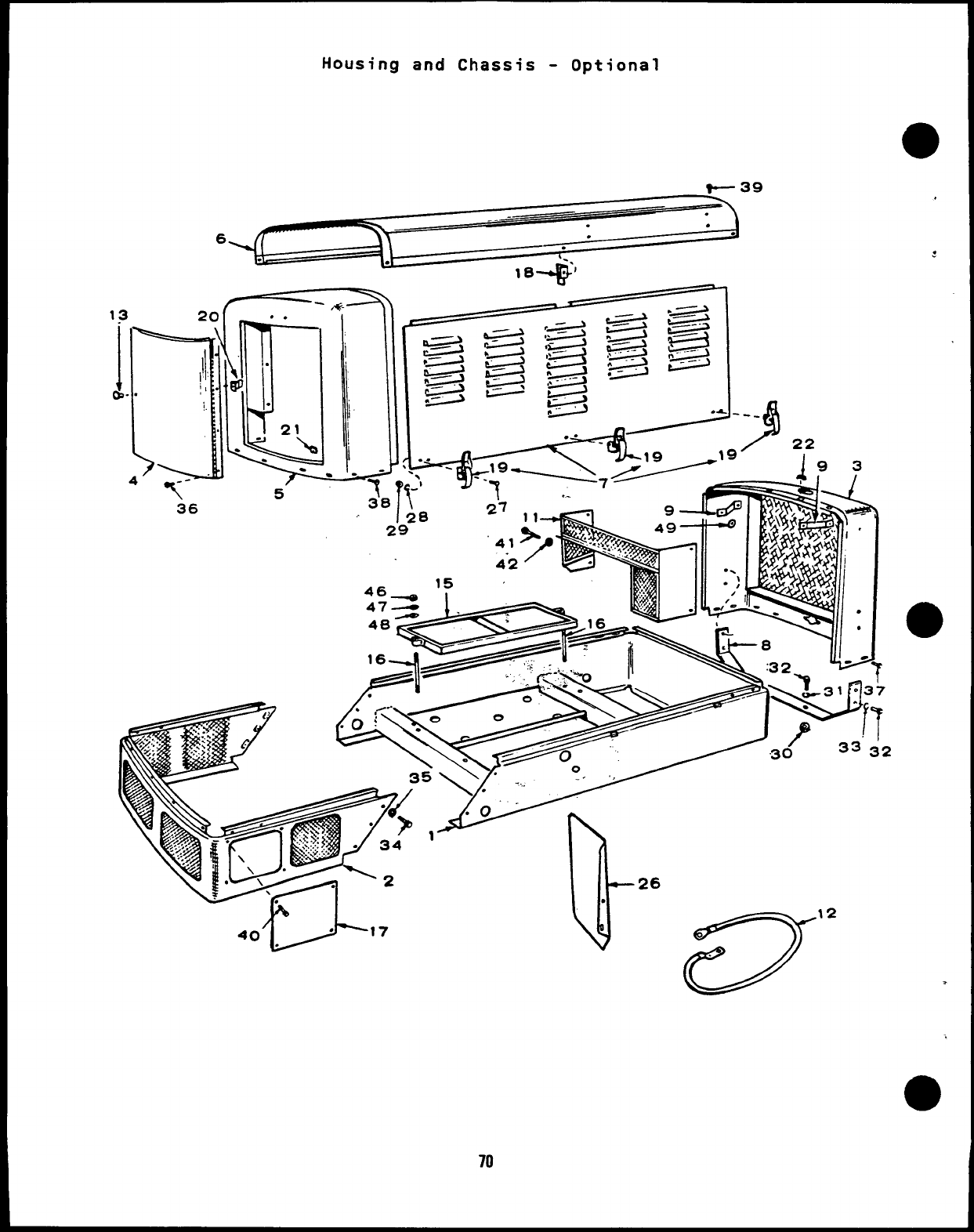
Housing and Chassis -Optional
-1. >“
J-’ k26
.s12
.
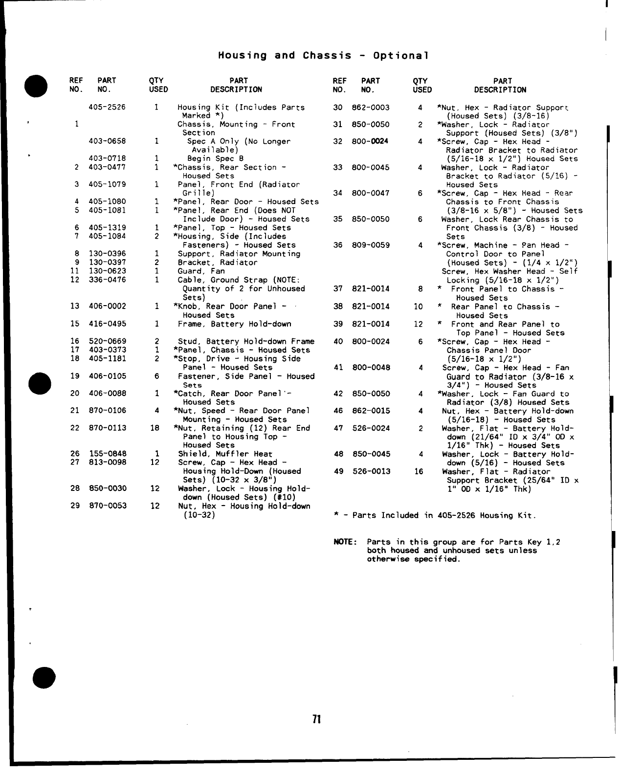
I
I
Housing and Chassis -Optional
●REF PART
NO. NO. QTY PART
USED DESCRIPTION REF PART
NO. NO.
30 862-0003
31 850-0050
32 800-0024
33 800-0045
34 800-0047
35 850-0050
36 809-0059
37 821-0014
38 821-0014
39 821-0014
40 800-0024
41 800-0048
42 850-0050
46 862-0015
47 526-0024
48 850-0045
49 526-0013
QTY
USED
4
2
4
4
6
6
4
8
10
12
6
4
4
4
2
4
16
PART
DESCRIPTION
405-2526 1
1
;
1
1
1
1
2
1
2
1
1
1
1
2
1
2
6
1
4
18
1
12
12
12
Housing Kit (Includes Parts
Marked *)
Chassis, Mounting -Front
Section
Spec AOnly (No Longer
Available)
8egin Spec 8
*Chassis, Rear Section -
Housed Sets
Panel, Front End (Radiator
Grille)
*Panel, Rear Door -Housed Sets
*Panel, Rear End (Does NOT
Include Door) -Housed Sets
*Panel ,Top -Housed Sets
*Housing, Side (Includes
Fasteners) -Housed Sets
Support, Radiator Mounting
8racket, Radiator
Guard, Fan
Cable, Ground Strap (NOTE:
Quantity of 2for Unhoused
Sets)
*Knob, Rear Door Panel -
Housed Sets
Frame, 8attery Hold-down
Stud, Battery Hold-down Frame
*Panel, Chassis -Housed Sets
*Stop, Drive -Housing Side
Panel -Housed Sets
Fastener, Side Panel -Housed
Sets
*Catch, Rear Door Panel ‘-
Housed Sets
*Nut, Speed -Rear Door Panel
Mounting -Housed Sets
*Nut, Retaining (12) Rear End
Panel to Housing Top -
Housed Sets
Shield, Muffler Heat
Screw, Cap -Hex Head -
Housing Hold-Down (Housed
Sets) (10-32 x3/8”)
Washer, Lock -Housing Hold-
down (Housed Sets) (#IO)
Nut, Hex -Housinq Hold-down
*Nut. Hex -Radiator Support
(Housed Sets) (3/8-16)
*Washer, Lock -Radiator
Support (Housed Sets) (3/8”]
“Screw. Cap -Hex Head -
Radiator 8racket to Radiator
(5/16-18 x1/2”) Housed Sets
Washer, Lock -Radiator
Bracket to Radiator (5/16) -
Housed Sets
*Screw, Cap -Hex Head -Rear
Chassis to Front Chassis
(3/8-16 x5/8”) -Housed Sets
Washer, Lock Rear Chassis to
Front Chassis (3/8) -Housed
Sets
*Screw, Machine -Pan Head -
Control Door to Panel
(Housed Sets) -(1/4 x1/2”)
Screw, Hex Washer Head -Self
Locking (5/16-18 x1/2”)
*Front Panel to Chassis -
Housed Sets
*Rear Panel to Chassis -
Housed Sets
*Front and Rear Panel to
Top Panel -Housed Sets
*Screw, Cap -Hex Head -
Chassis Panel Door
(5/16-18 X1/21’)
Screw, Cap -Hex Head -Fan
Guard to Radiator (3/8-16 x
3/4”) -Housed Sets
*Washer, Lock -Fan Guard to
Radiator (3/8) Housed Sets
Nut, Hex -Battery Hold-down
(5/16-18) -Housed Sets
Washer, Flat -8attery Hold-
down (21/64” ID x3/4” OD x
1/16” Thk) -Housed Sets
Washer, Lock -8attery Hold-
down (5/16) -Housed Sets
Washer, Flat -Radiator
Sumort Bracket (25/64” ID x
,1
403-0658
●403-0718
2403-0477
3405-1079
4405-1080
5405-1081
6405-1319
7405-1084
8130-0396
9130-0397
11 130-0623
12 336-0476
13 406-0002
15 416-0495
16
17
18
520-0669
403-0373
405-1181
019
20
406-0105
406-0088
870-0106
870-011322
26 155-0848
27 813-0098
28 850-0030
29 810-0053
l’;&l x1/16” Thk)“
(10-32) -
71
*-parts Included in 405-2526 Housing Kit
NOTE :Parts in this group are for Parts Key 1,2
both housed and unhoused sets unless
otherwise specified.
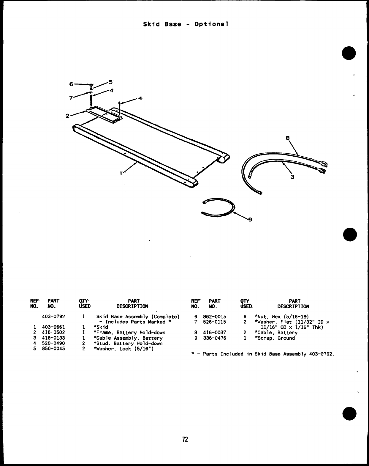
Skid Base -Optional
/
1
.
a
REF. PART- QTY’ PART
m.. No. usED DESCRIPTION
403-0792 1
1403-0661 1
2416-0502 1
3416-0133 1
4520-0490 2
5850-0045 2
Skid Base Assembly (C’bmplete)
-Includes Parts Marked *
%Skid
*Frame, Battery Hold-down
*Cable Assembly, Battery
*Stud, Battery Hold-down
Washer, Lock (5/16”)
REF PART QTY PART
No. No. USED DESCRIPTION
6862-0015 6*Nut, Hex (5/16-18)
7526-0115 2Washer, Flat (11/32” ID x
11/16” 00 X1/16” Thk)
8416-003? 2*Cable, Battery
9336-0476 1*Strap, Ground
*-Parts Included in Skid Base Assembly 403-0792.
.
12
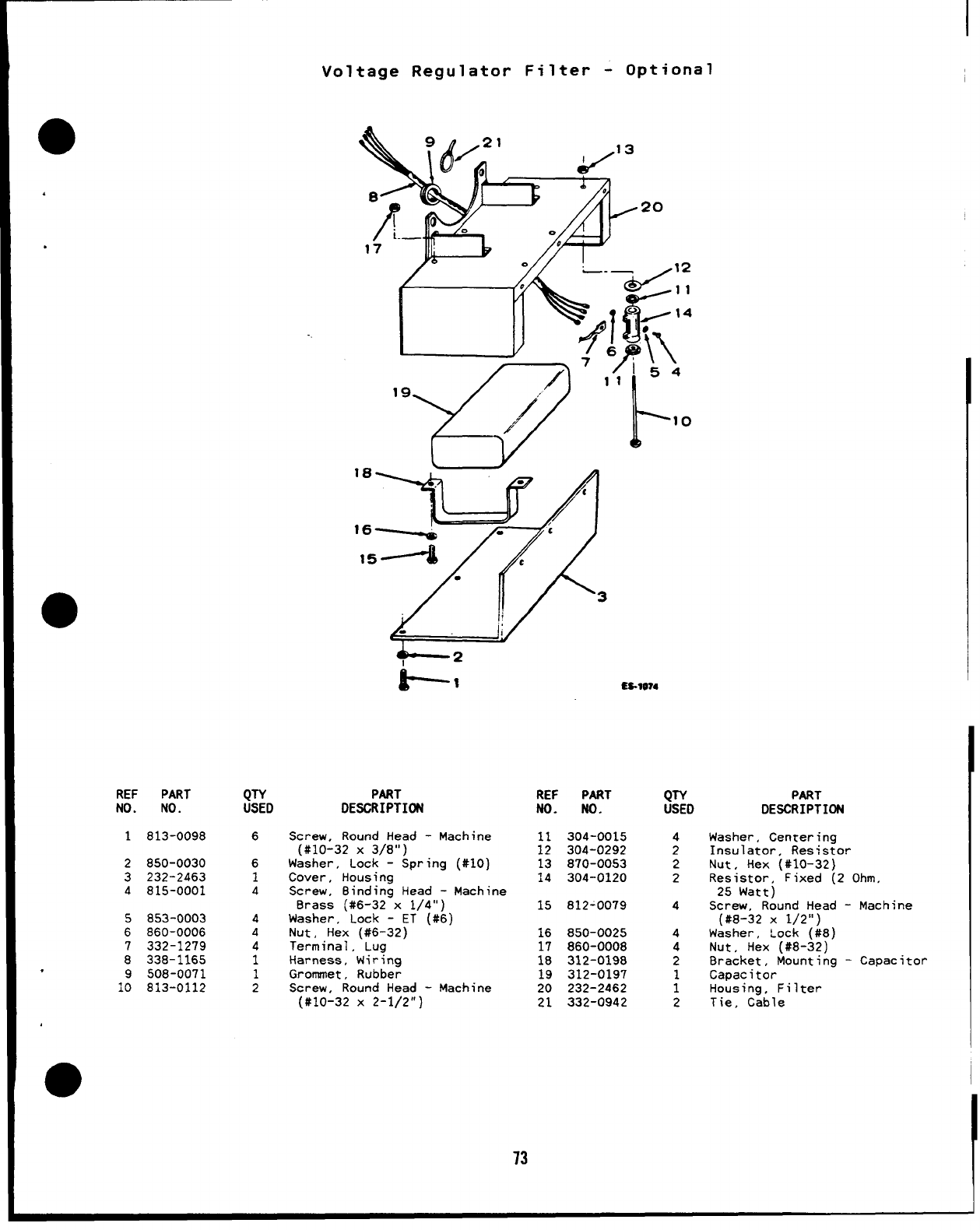
I
Voltage Regulator Filter -Optional
●
REF PART
NO. NO.
1813-0098
2850-0030
3232-2463
4815-0001
5853-0003
6860-0006
7332-1279
8338-1165
,9508-0071
10 813-0112
QTY
USED
6
6
1
4
4
4
4
1
1
2
2
1
4
0
1
1
PART
DESCRIPTION
Screw, Round Head -Machine
(#10-32 X3/8”)
Washer, Lock -Spring (#IO)
Cover, Housing
Screw, Binding Head -Machine
Brass (#6-32 x1/4”)
Washer, Lock -ET (#6)
Nut, Hex (#6-32)
Terminal, Lug
Harness, Wiring
Grommet, Rubber
Screw, Round Head -Machine
(#10-32 X2-1/2”)
ES.1O?4
..- . ..- .
;;
13
14
15
16
17
18
19
20
21
304-0015
304-0292
870-0053
304-0120
812-0079
850-0025
860-0008
312-0198
312-0197
232-2462
332-0942
4
2
2
2
4
4
4
2
1
1
2
. . . . ... . , ----
Washer, Centering
Insulator, Resistor
Nut, Hex (#10-32)
Resistor, Fixed (2 Ohm,
25 Watt)
Screw, Round Head -Machine
(#8-32 X1/2”)
Washer, Lock (#8)
Nut, Hex (#8-32)
Bracket, Mounting -Capacitor
Capacitor
Housing, Filter
Tie, Cable
13
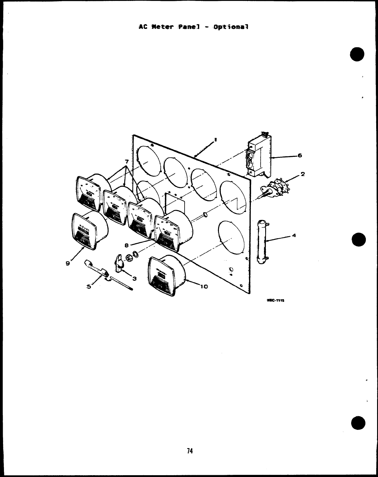
.AC 14e.ter ,?a.mal --.uptbsial
a
.
●
74
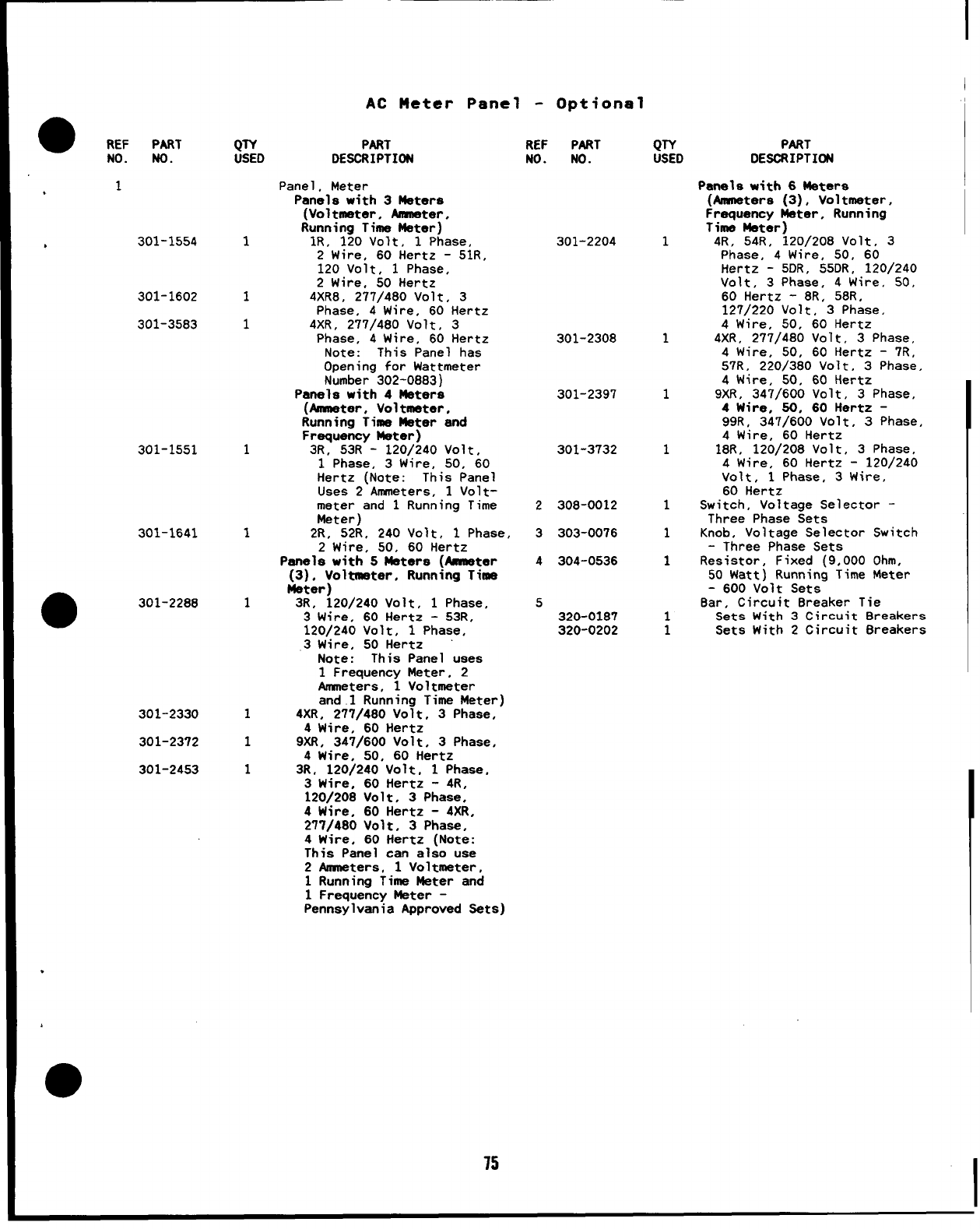
I
I
AC Meter Panel -Optional
●REF PART
NO. NO.
,1
,301-1554
301-1602
301-3583
301-1551
301-1641
●301-2288
301-2330
301-23’/2
301-2453
QTY
USED
1
1
1
1
1
1
1
1
1
PART
DESCRIPTION
Panel, Meter
Panels with 3Meters
(Voltmeter, Ammeter,
Running Time Meter)
lR, 120 Volt, 1Phase,
2Wire, 60 Hertz -51R,
120 Volt, 1Phase,
2Wire, 50 Hertz
4XR8, 277/480 Volt, 3
Phase, 4Wire, 60 Hertz
4XR, 277/480 Volt, 3
Phase, 4Wire, 60 Hertz
Note: This Panel has
Opening for Wattmeter
Number 302-0883)
Panels with 4Maters
(Amneter, Voltmeter,
Running Time Meter and
Frequency Meter)
3R, 53R -120/240 Volt,
1Phase, 3Wire, 50, 60
Hertz (Note: This Panel
Uses 2Ammeters, 1Volt-
meter and 1Running Time
Meter)
2R, 52R, 240 Volt, 1Phase,
2Wire, 50, 60 Hertz
Panela with 5Meters (Anmeter
(3), Voltmeter, Running Time
Water)
3R, 120/240 Volt, 1Phase,
3Wire, 60 Hertz -53R,
120/240 Volt, 1Phase,
3Wire, 50 Hertz
Note: This Panel uses
1Frequency Meter, 2
Anneters, 1Voltmeter
and.1 Running Time Meter)
4XR, 277/480 Volt, 3Phase,
4Wire, 60 Hertz
9XR, 347/600 Volt, 3Phase,
4Wire, 50, 60 Hertz
3R, 120/240 Volt, 1Phase.
3Wire, 60 Hertz -4R,
120/208 Volt. 3Phase,
4Wire, 60 Hertz -4XR.
277/480 Volt, 3Phase,
4Wire, 60 Hertz (Note:
This Panel can also use
2Anmsters, 1Voltmeter.
1Running Time Meter and
1Frequency Water -
Pennsylvania Approved Sets)
REF PART
NO. NO.
301-2204
301-2308
301-2397
301-3732
2308-0012
3303-0076
4304-0536
5320-0187
320-0202
QTY
USED
1
1
1
1
1
1
1
1
1
PART
OESORIPTION
Panels with 6Meters
(Anmneters (3), Voltmeter,
Frequency Meter, Running
Time Mater)
4R, 54R, 120/208 Volt, 3
Phase, 4Wire, 50, 60
Hertz -5DR, 55DR, 120/240
Volt, 3Phase, 4Wire. 50,
60 Hertz -8R, 58R,
127/220 Volt, 3Phase,
4Wire, 50, 60 Hertz
4XR, 277/480 Volt, 3Phase,
4Wire, 50, 60 Hertz -7R,
57R, 220/380 Volt, 3Phase,
4Wire, 50, 60 Hertz
9XR, 347/600 Volt, 3Phase,
4Wire, 50, 60 Hertz -
99R, 347/600 Volt, 3Phase,
4Wire, 60 Hertz
18R, 120/208 Volt, 3Phase,
4Wire, 60 Hertz -120/240
Volt, 1Phase, 3Wire,
60 Hertz
Switch, Voltage Selector -
Three Phase Sets
Knob, Voltage Selector Switch
-Three Phase Sets
Resistor, Fixed (9,000 Ohm,
50 Watt) Running Time Meter
-600 Volt Sets
8ar, Circuit 8reaker Tie
Sets With 3Circuit Breakers
Sets With 2Circuit 8reakers
.
75
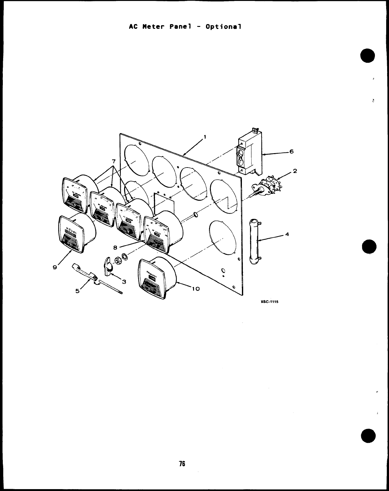
AC Meter Panel -Optional
XSC-1115
-.
a
76
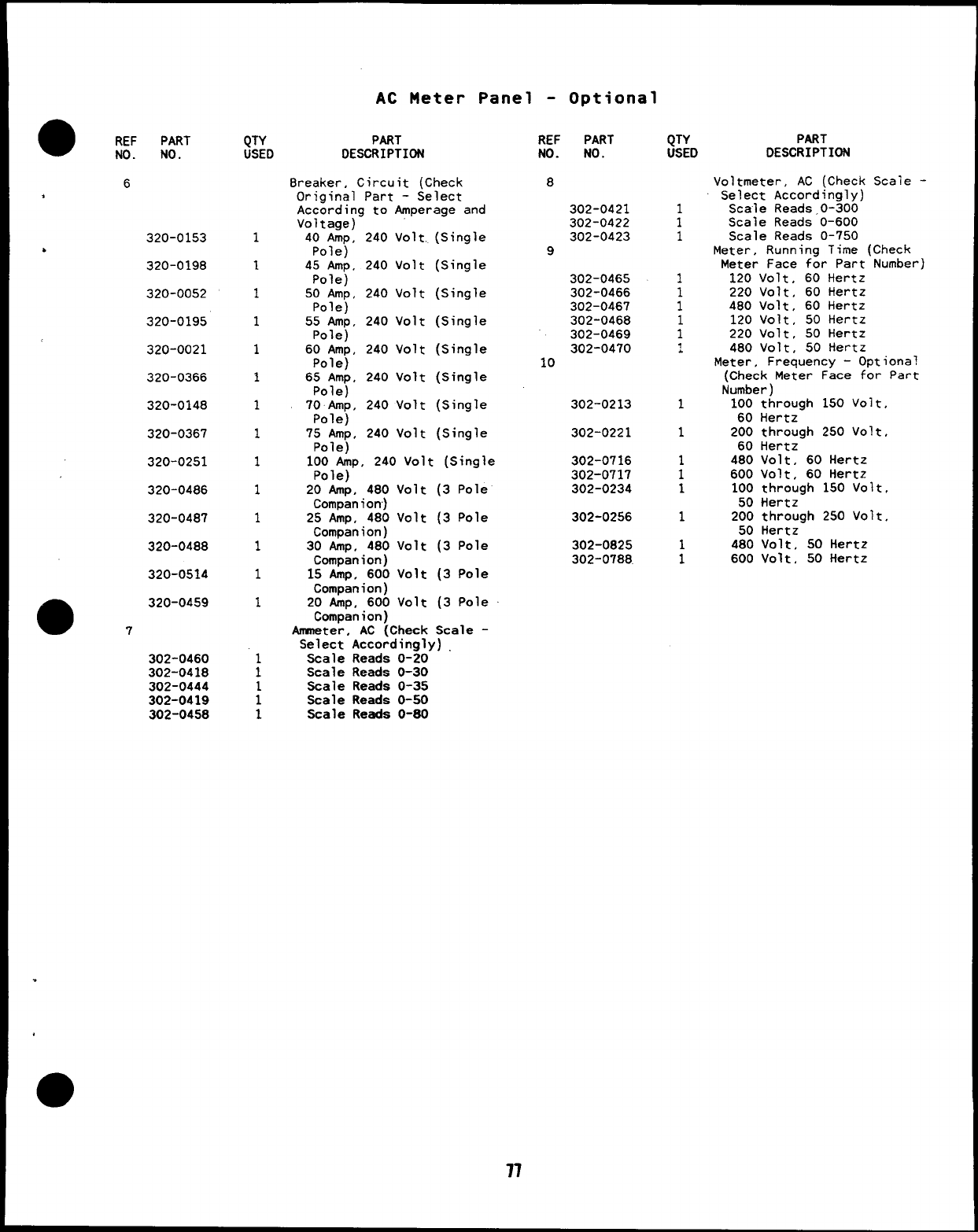
AC Meter Panel -Optional
REF PART
NO. NO.
6
,
320-0153
b320-0198
320-0052
320-0195
320-0021
320-0366
320-0148
320-0367
320-0251
320-0486
320-0487
320-0488
320-0514
●320-0459
7
302-0460
302-0418
302-0444
302-0419
302-0458
QTY
USED
1
1
1
1
1
1
1
1
1
1
1
1
1
1
1
1
1
1
PART
DESCRIPTION
8reaker, Circuit (Check
Original Part -Select
According to Amperage and
Voltage)
40 Amp, 240 Volt. (Single
Pole)
45 Amp, 240 Volt (Single
Pole)
50 Amp, 240 Volt (Single
Pole)
55 Amp, 240 Volt (Single
Pole)
60 Amp, 240 Volt (Single
Pole)
65 Amp, 240 Volt (Sin~le
Polej
70 Amp, 240 Volt
Pole)
75 Amp, 240 Volt
Pole)
100 Amp, 240 Volt
Pole)
20 Amp, 480 Volt
Companion)
25 Amp, 480 Volt
ComDanion)
Single
Single
(Single
3Pole
3Pole
30 tip, 480 Volt (3 Pole
Companion)
15 Amp, 600 Volt (3 Pole
Companion)
20 Amp, 600 Volt (3 Pole
Companion)
Anwneter, AC (Check Scale -
Select Accordingly)
Scale Reads 0-20
Scale Reads 0-30
Scale Reads O-35
Scale Reads 0-50
Scale Reads 0-80
REF PART
NO. NO.
8
302-0421
302-0422
302-0423
9
302-0465
302-0466
302-0467
302-0468
302-0469
302-0470
10
302-0213
302-0221
302-0716
302-0717
302-0234
302-0256
302-0825
302-0788.
77
QTY
USED
1
1
1
1
1
1
1
1
‘1
.
1
1
;
1
1
:
PART
DESCRIPTION
Voltmeter, AC (Check
Select Accordingly)
Scale Reads,O-300
Scale Reads 0-600
Scale Reads 0-750
Scaie -
Meter, Running Time (Check
Meter Face for Part Number)
120 Volt, 60 Hertz
220 Volt, 60 Hertz
480 Volt, 60 Hertz
120 Volt, 50 Hertz
220 Volt, 50 Hertz
480 Volt, 50 Hertz
Meter, Frequency -Optional
(Check Meter Face for Part
Number )
100 through 150 Volt,
60 Hertz
200 through 250 Volt,
60 Hertz
480 Volt, 60 Hertz
600 Volt, 60 Hertz
100 through 150 Volt,
50 Hertz
200 through 250 Volt,
50 Hertz
480 Volt, 50 Hertz
600 Volt, 50 Hertz
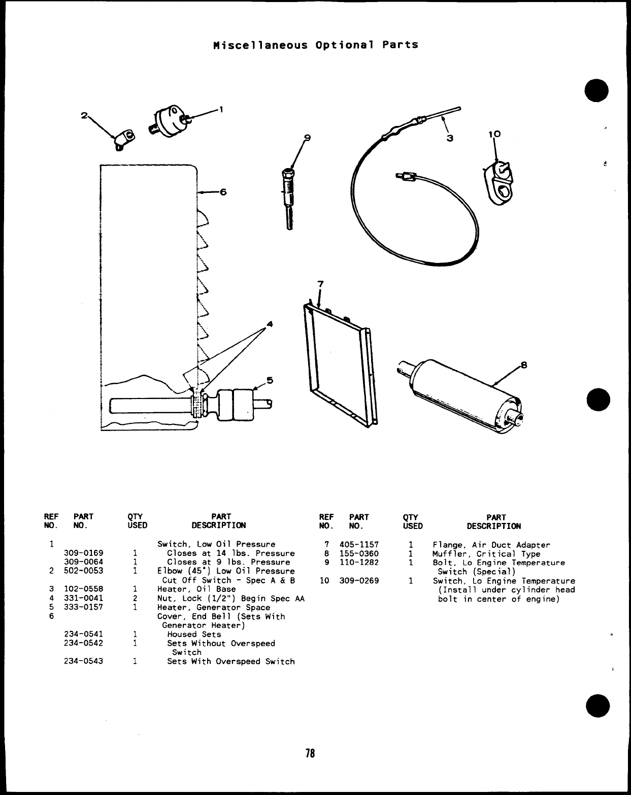
Miscellaneous
REF PART
NO. NO.
,
L309-0169
309-0064
2502-0053
3102-0558
4331-0041
5333-0157
6
234-0541
234-0542
234-0543
QTY
USED
1
;
1
2
1
1
1
1
PART
DESCRIPTICM
Optional Parts
7
W
....
-...
=...
..!~. 4
-.
Switch, Low Oil Pressure
Closes at 14 lbs. Pressure
Closes at 9lbs. Pressure
Elbow (45”) Low Oil Pressure
Cut Off Switch -Spec A & B
Heater, Oil Base
Nut, Lock (1/2”) Begin Spec AA
Heater, Generator Space
Cover, End Bell (Sets With
Generator Heater)
Housed Sets
Sets Without Overspeed
Switch
Sets With Overspeed Switch
REF PART QTY
ND. No. USED
7405-1157
8155-0360 :
9110-1282 1
10 309-0269 1
..
$
PART
DESCRIPTION
Flange, Air Duct Adapter
Muffler, Critical Type
8olt, Lo Engine Temperature
Switch (Special)
Switch, Lo Engine Temperature
(Install under cylinder head
bolt in center of engine)
78
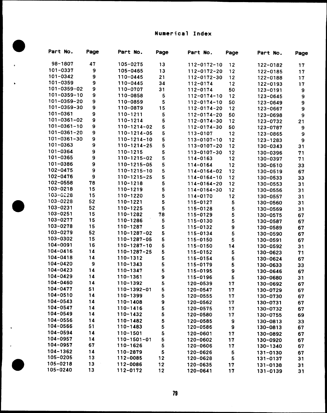
Numerical Index
●Part No.
d98-1807
101-0337
101-0342
>101-0359
101-0359-02
101-0359-10
1OI-O359-2O
101-0359-30
101-0361
101-0361-02
101-0361-10
101-0361-20
101-0361-30
101-0363
101-0364
101-0365
101-0386
102-0475
102-0476
102-0558
103-0218
103-0:28
m103-0228
103-0231
103-0251
103-0277
103-0278
103-0279
103-0302
104-0091
104-0416
104-0418
104-0420
104-0423
104-0429
104-0460
104-0477
104-0510
104-0543
104-0547
104-0549
104-0556
.104-0566
104-0594
104-0957
104-0957
104-1362
●105-0205
105-0218
105-0240
Page
47
9
9
9
9
9
9
9
9
9
9
9
9
9
9
9
9
9
9
78
15
15
52
52
15
15
15
52
15
16
14
14
9
14
14
14
51
14
14
14
14
14
51
14
14
67
14
13
13
13
Part No. Page
105-0275
105-0465
110-0445
110-0445
110-0707
110-0858
110-0859
110-0879
110-1211
110-1214
110-1214-02
110-1214-05
110-1214-10
110-1214-25
110-1215
110-1215-02
110-1215-05
110-1215-10
110-1215-25
110-1218
110-1219
110-1220
110-1221
110-1225
110-1282
110-1286
110-1287
110-1287-02
110-1287-05
110-1287-10
110-1287-25
110-1312
110-1343
110-1347
110-1361
110-1392
110-1392-01
110-1399
110-1408
11o-
11o-
11o-
11o-
11o-
11o-
416
432
482
483
501
501-01
110-1626
110-2879
112-0085
112-0086
112-0172
13
13
21
34
31
5
5
15
5
5
5
5
5
5
5
5
5
5
5
5
5
5
5
5
78
5
5
5
5
5
5
5
5
5
9
5
5
5
9
5
5
5
5
5
5
5
5
12
12
12
Part No. Page
112-0172-10
112-0172-20
112-0172-30
112-0174
112-0174
112-0174-10
112-0174-10
112-0174-20
112-0174-20
112-0174-30
112-0174-30
113-0107
113-0107-10
113-0107-20
113-0107-30
114-0163
114-0164
114-0164-02
114-0164-10
114-0164-20
114-0164-30
114-0170
115-0127
115-0128
115-0129
115-0130
115-0132
115-0134
115-0150
115-0150
115-0152
115-0154
115-0179
115-0195
115-0196
120-0539
120-0547
120-0555
120-0562
120-0575
120-0580
120-0585
120-0586
120-0601
120-0602
120-0606
120-0626
120-0628
120-0635
120-0641
12
12
12
12
50
12
50
12
50
12
50
12
12
12
12
12
12
12
12
12
12
12
5
5
5
5
9
5
5
14
5
5
5
9
5
17
17
17
17
17
17
9
9
17
17
17
5
5
17
17
Part No.
122-0182
22-0185
22-0188
22-0193
23-0191
23-0645
23-0649
23-0667
23-0698
23-0732
23-0787
23-0865
123-1283
130-0343
130-0396
130-0397
130-0510
130-0519
130-0533
130-0553
130-0556
130-0557
130-0560
130-0569
130-0575
130-0587
130-0589
130-0590
130-0591
130-0592
130-0623
130-0624
130-0633
130-0646
130-0680
130-0692
130-0729
130-0730
130-0731
130-0732
130-0755
130-0813
130-0813
130-0892
130-0920
130-1340
131-0130
131-0137
131-0138
131-0139
Page
17
17
17
17
9
9
9
9
9
21
9
9
9
31
71
71
33
67
33
31
31
31
31
31
67
67
67
67
67
31
71
67
33
67
31
67
67
67
67
67
69
33
67
67
67
67
67
31
31
31
19
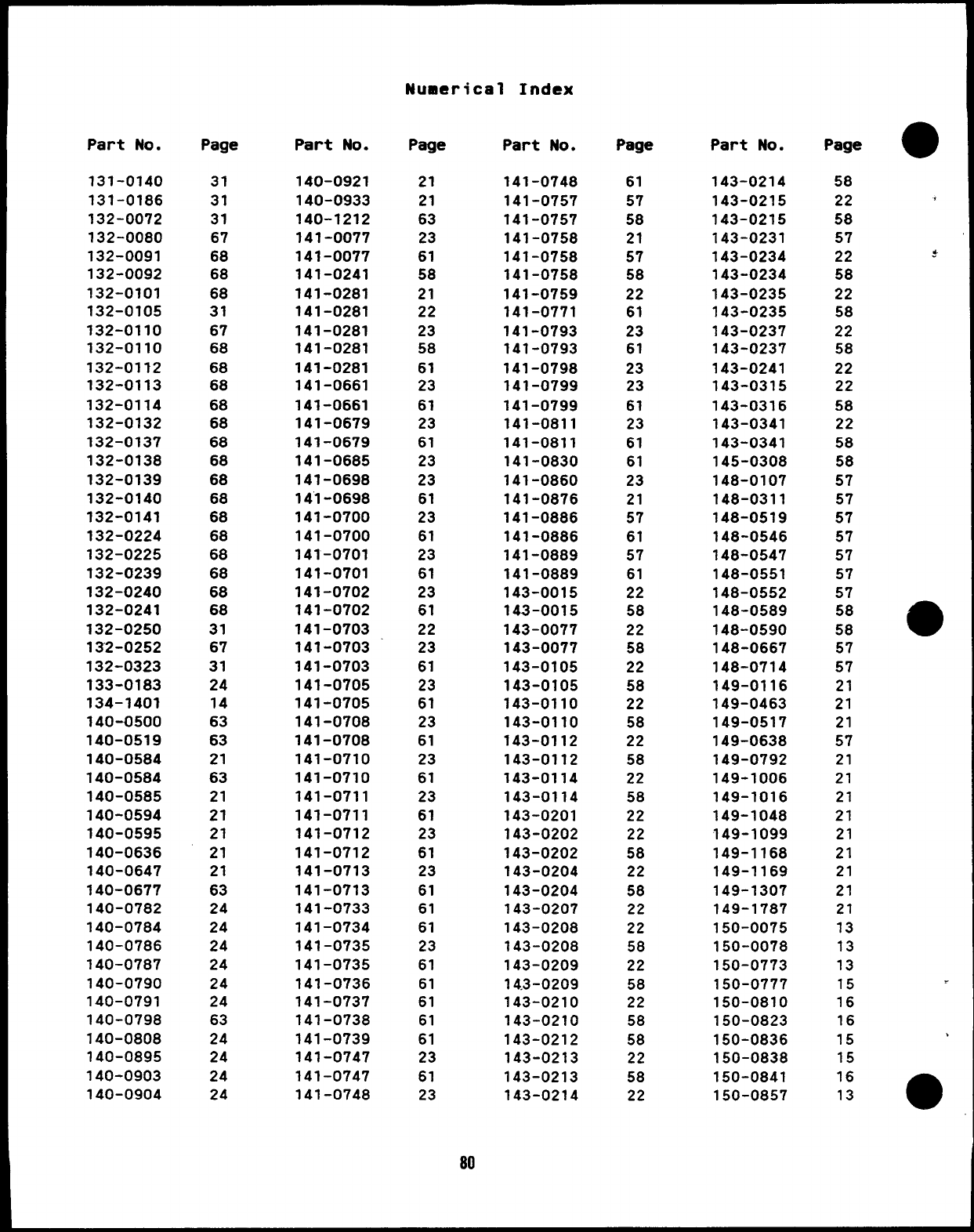
Numerical Index
Part No.
131-0140
131-0186
132-0072
132-0080
132-0091
132-0092
132-0101
32-0105
32-0110
32-0110
32-0112
32-0113
32-0114
32-0132
32-0137
32-0138
32-0139
32-0140
32-0141
32-0224
32-0225
32-0239
32-0240
32-0241
132-0250
132-0252
132-0323
133-0183
134-1401
40-0500
40-0519
40-0584
40-0584
40-0585
40-0594
40-0595
40-0636
40-0647
40-0677
40-0782
40-0784
40-0786
40-0787
40-0790
40-0791
40-0798
40-0808
40-0895
40-0903
40-0904
Page
31
31
31
67
68
68
68
31
67
68
68
68
68
68
68
68
68
68
68
68
68
68
68
68
31
67
31
24
14
63
63
21
63
21
21
21
21
21
63
24
24
24
24
24
24
63
24
24
24
24
Part No.
140-0921
140-0933
140-1212
141-0077
141-0077
141-0241
141-0281
141-0281
141-0281
141-0281
141-0281
141-0661
141-0661
141-0679
141-0679
141-0685
141-0698
14’1-0698
141-0700
141-0700
141-0701
141-0701
141-0702
141-0702
141-0703
141-0703
141-0703
141-0705
141-0705
141-0708
141-0708
141-0710
141-0710
141-0711
141-0711
141-0712
141-0712
141-0713
141-0713
141-0733
141-0734
141-0735
141-0735
141-0736
141-0737
141-0738
141-0739
141-0747
141-0747
141-0748
Page
21
21
63
23
61
58
21
22
23
58
61
23
61
23
61
23
23
61
23
61
23
61
23
61
22
23
61
23
61
23
61
23
61
23
61
23
61
23
61
61
61
23
61
61
61
61
61
23
61
23
80
Part No.
141-0748
141-0757
141-0757
141-0758
141-0758
141-0758
141-0759
141-0771
141-0793
141-0793
141-0798
141-0799
141-0799
141-0811
141-0811
141-0830
141-0860
141-0876
141-0886
141-0886
141-0889
141-0889
143-0015
143-0015
143-0077
143-0077
143-0105
143-0105
143-0110
143-0110
143-0112
143-0112
143-0114
143-0114
143-0201
143-0202
143-0202
143-0204
143-0204
143-0207
143-0208
143-0208
143-0209
14.3-0209
143-0210
143-0210
143-0212
143-0213
143-0213
143-0214
Page
61
57
58
21
57
58
22
61
23
61
23
23
61
23
61
61
23
21
57
61
57
61
22
58
22
58
22
58
22
58
22
58
22
58
22
22
58
22
58
22
22
58
22
58
22
58
58
22
58
22
Part No.
143-0214
143-0215
143-0215
143-0231
143-0234
143-0234
143-0235
143-0235
143-0237
143-0237
143-0241
143-0315
143-0316
143-0341
143-0341
145-0308
148-0107
148-0311
148-0519
148-0546
148-0547
148-0551
148-0552
148-0589
148-0590
148-0667
148-0714
149-0116
149-0463
149-0517
149-0638
149-0792
149-1006
149-1016
149-1048
149-1099
149-1168
149-1169
149-1307
149-1787
50-0075
50-0078
50-0773
50-0777
50-0810
50-0823
50-0836
50-0838
50-0841
50-0857
Page
58
22
58
57
22
58
22
58
22
58
22
22
58
22
58
58
57
57
57
57
57
57
57
58
58
57
57
21
21
21
57
21
21
21
21
21
21
21
21
21
3
3
3
5
6
6
5
5
6
3
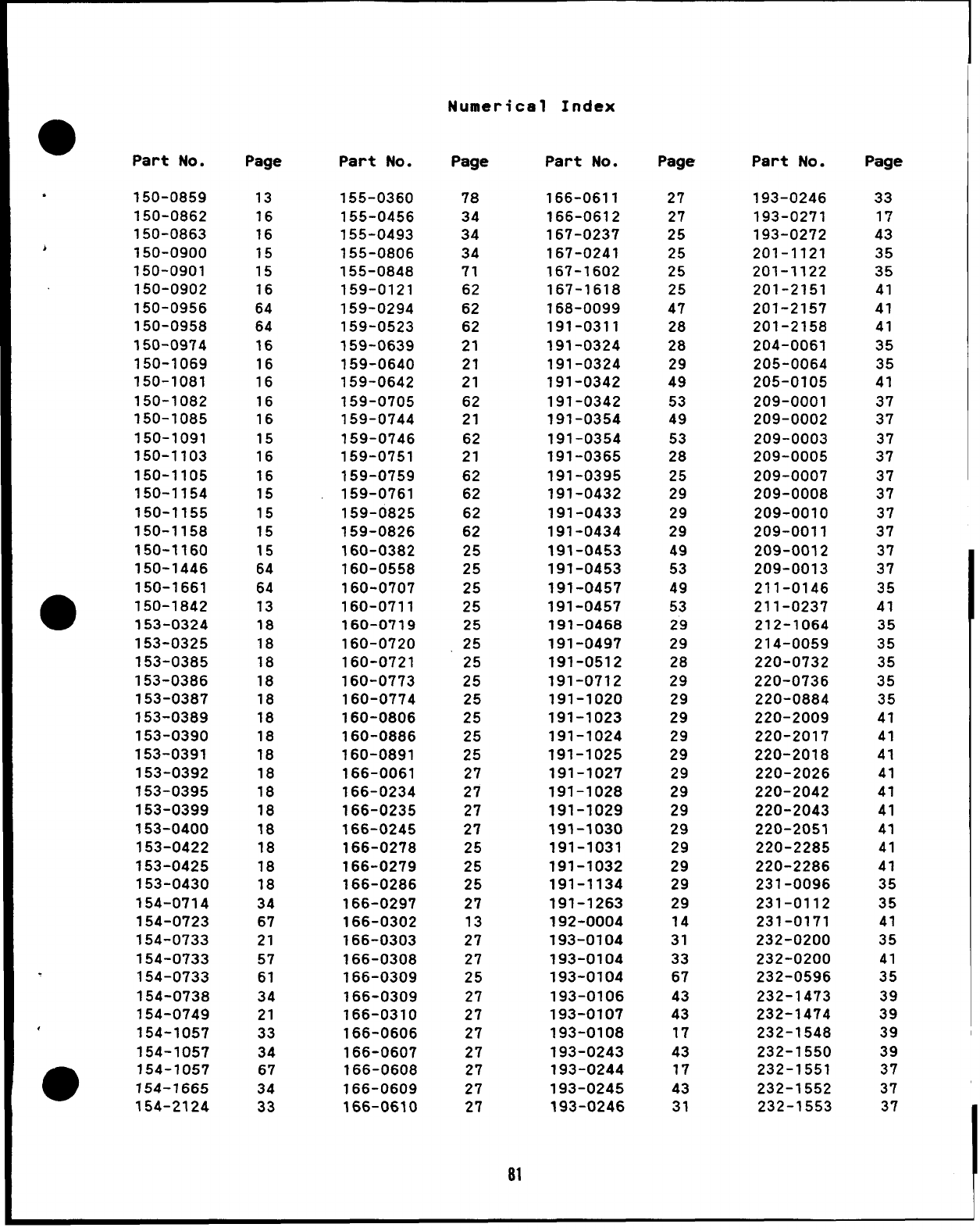
Numerical Index
ePart No.
●150-0859
150-0862
150-0863
h150-0900
150-0901
150-0902
50-0956
50-0958
50-0974
50-1069
50-1081
50-1082
50-1085
50-1091
50-1103
50-1105
50-1154
50-1155
50-1158
50-1160
50-1446
50-1661
50-1842
●153-0324
153-0325
153-0385
153-0386
153-0387
153-0389
153-0390
153-0391
153-0392
153-0395
153-0399
153-0400
153-0422
153-0425
153-0430
154-0714
154-0723
154-0733
154-0733
154-0733
154-0738
154-0749
154-1057
154-1057
e154-1057
154-1665
154-2124
Page
13
16
16
15
15
16
64
64
16
16
16
16
16
15
16
16
15
15
15
15
64
64
13
18
18
18
18
18
18
18
18
18
18
18
18
18
18
18
34
67
21
57
61
34
21
33
34
67
34
33
Part No.
155-0360
155-0456
155-0493
155-0806
155-0848
159-0121
159-0294
159-0523
159-0639
159-0640
159-0642
159-0705
159-0744
159-0746
159-0751
159-0759
159-0761
59-0825
59-0826
60-0382
60-0558
60-0707
60-0711
60-0719
60-0720
60-0721
60-0773
60-0774
60-0806
160-0886
160-0891
166-0061
166-0234
166-0235
166-0245
166-0278
166-0279
166-0286
166-0297
166-0302
166-0303
166-0308
166-0309
166-0309
166-0310
166-0606
166-0607
166-0608
166-0609
166-0610
Page
78
34
34
34
71
62
62
62
21
21
21
62
21
62
21
62
62
62
62
25
25
25
25
25
25
25
25
25
25
25
25
27
27
27
27
25
25
25
27
13
27
27
25
27
27
27
27
27
27
27
Part No.
166-0611
166-0612
167-0237
167-0241
167-1602
167-1618
168-0099
191-0311
191-0324
191-0324
191-0342
191-0342
191-0354
191-0354
191-0365
191-0395
191-0432
191-0433
191-0434
191-0453
191-0453
191-0457
191-0457
191-0468
191-0497
191-0512
191-0712
191-1020
91-1023
91-1024
91-1025
91-1027
91-1028
91-1029
191-1030
191-1031
191-1032
191-1134
191-1263
192-0004
193-0104
193-0104
193-0104
193-0106
193-0107
193-0108
193-0243
193-0244
193-0245
193-0246
Page
27
27
25
25
25
25
47
28
28
29
49
53
49
53
28
25
29
29
29
49
53
49
53
29
29
28
29
29
29
29
29
29
29
29
29
29
29
29
29
14
31
33
67
43
43
17
43
17
43
31
Part No.
193-0246
193-0271
193-0272
201-1121
201-1122
201-2151
201-2157
201-2158
204-0061
205-0064
205-0105
209-0001
209-0002
209-0003
209-0005
209-0007
209-0008
209-0010
209-0011
209-0012
209-0013
211-0146
211-0237
212-1064
214-0059
220-0732
220-0736
220-0884
220-2009
220-2017
220-2018
220-2026
220-2042
220-2043
220-2051
220-2285
220-2286
231-0096
231-0112
231-0171
232-0200
232-0200
232-0596
232-1473
232-1474
232-1548
232-1550
232-1551
232-1552
232-1553
Page
33
17
43
35
35
41
41
41
35
35
41
37
37
37
37
37
37
37
37
37
37
35
41
35
35
35
35
35
41
41
41
41
41
41
41
41
41
35
35
41
35
41
35
39
39
39
39
37
37
37
81
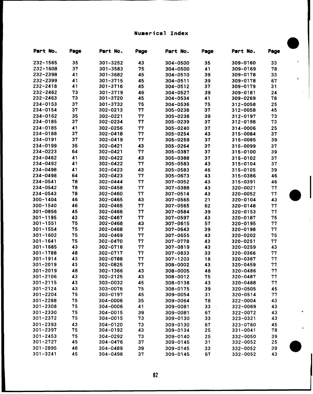
Numerical Index
Part No.
232-1565
232-1608
232-2398
232-2399
232-2418
232-2462
232-2463
234-0153
234-0154
234-0162
234-0185
234-0185
234-0188
234-0191
234-0199
234-0223
234-0462
234-0492
234-0498
234-0498
234-0541
234-0542
234-0543
300-1404
300-1540
301-0856
301-1195
301-1551
301-1554
301-1602
301-1641
301-1685
301-1788
301-1914
301-2019
301-2019
301-2106
301-2115
301-2124
301-2204
301-2288
301-2308
301-2330
301-2372
301-2393
301-2397
301-2453
301-2727
301-2895
301-3241
Page
35
37
41
41
41
73
73
37
37
35
37
41
37
37
35
64
41
41
41
64
78
78
78
46
46
45
43
75
75
75
75
43
48
43
43
48
43
43
43
75
75
75
75
75
43
75
75
45
48
45
Part No.
301-3252
301-3583
301-3682
301-3715
301-3716
301-3719
301-3720
301-3732
302-0213
302-0221
302-0234
302-0256
302-0418
302-0419
302-0421
302-0421
302-0422
302-0422
302-0423
302-0423
302-0444
302-0458
302-0460
302-0465
302-0465
302-0466
302-0467
302-0468
302-0468
302-0469
302-0470
302-0716
302-0717
302-0788
302-0825
302-1366
302-2125
303-0032
303-0076
303-0197
304-0006
304-0006
304-0015
304-0015
304-0120
304-0192
304-0292
304-0476
304-0489
304-0498
Page
43
75
45
45
45
46
45
75
77
77
77
77
77
77
43
77
43
77
43
77
77
77
77
43
77
77
77
43
77
77
77
77
77
77
77
43
43
45
75
45
35
41
39
73
73
43
73
37
39
37
Part No.
304-0500
304-0500
304-0510
304-0511
304-0512
304-0527
304-0534
304-0536
305-0238
305-0238
305-0239
305-0240
305-0254
305-0259
305-0264
305-0387
305-0388
305-0583
305-0583
305-0673
307-0052
307-0388
307-0514
307-0565
307-0565
307-0584
307-0597
307-0615
307-0643
307-0655
307-0778
307-0819
307-0833
307-1203
308-0002
308-0005
308-0012
308-0138
308-0175
309-0054
309-0064
309-0081
309-0081
309-0130
309-0130
309-0134
309-0140
309-0145
309-0145
309-0145
Page
35
41
39
39
37
39
41
75
37
39
37
37
43
37
37
37
37
43
46
43
43
43
43
21
62
39
43
57
39
43
43
43
33
18
43
48
75
43
39
31
78
33
67
33
67
25
25
31
33
67
Part No.
309-0160
309-0169
309-0178
309-0178
309-0179
309-0181
309-0269
312-0058
312-0058
312-0197
312-0198
314-0006
315-0084
315-0085
315-0099
315-0100
315-0102
315-0104
315-0105
315-0386
315-0391
320-0021
320-0052
320-0104
320-0148
320-0153
320-0187
320-0195
320-0198
320-0202
320-0251
320-0259
320-0366
320-0367
320-0459
320-0486
320-0487
320-0488
320-0505
320-0514
322-0004
322-0069
322-0072
323-0321
323-0760
331-0041
332-0050
332-0052
332-0052
332-0052
33 ‘
78
33
67 4
31
24
78
25
45
73
73
25
37
39
37
39
37
37
39
46
46
77
77
43 a
77
77
75
77
77
75
77
43
77
77
77
77
77
77
45
77
43
43
43 .
43
45
78
39
25
39 m
43
82

Numerical Index
@Part No.
332-0513
332-0529
332-0607
332-0608
332-0611
332-0642
332-0697
332-0698
332-0699
332-0700
332-0738
332-0745
332-0746
332-0750
332-0795
332-0862
332-0876
332-0881
332-0925
332-0942
332-0943
332-1005
332-1006
a332-1009
332-1043
332-1279
332-1655
333-0054
333-0157
336-0476
336-0476
336-1199
336-1199
336-1549
336-1550
336-1844
337-0036
337-0044
338-0332
338-0338
338-0762
338-0763
338-0768
●338-0768
338-0936
338-1165
358-0069
358-0070
●402-0036
402-0038
Page
43
57
43
43
43
43
37
37
37
37
37
37
37
43
48
48
18
57
37
73
43
43
43
43
43
73
46
69
78
71
72
49
53
18
18
57
43
43
18
43
46
43
46
64
43
73
41
41
9
9
Part No.
402-0046
402-0078
402-0251
402-0282
402-0285
402-0286
402-0287
402-0290
402-0361
402-0362
403-0373
403-0477
403-0620
403-0658
403-0661
403-0690
403-0718
403-0792
403-0826
403-0890
405-1079
405-1080
405-1081
405-1084
405-1157
405-1181
405-1319
405-2526
406-0002
406-0088
406-0105
416-0021
416-0037
416-0096
416-0133
416-0133
416-0495
416-0502
501-0004
501-0005
501-0007
501-0008
501-0015
502-0002
502-0003
502-0019
502-0020
502-0020
502-0030
502-0036
Page
9
43
9
9
9
9
9
9
7
7
71
71
7
71
72
7
71
72
“7
7
71
71
71
71
78
71
71
71
71
71
71
28
72
43
28
72
71
72
62
62
62
62
21
21
21
17
57
62
17
31
Part No.
502-0037
502-0037
502-0037
502-0043
502-0049
502-0053
502-0053
502-0058
502-0065
502-0074
502-0074
502-0075
502-0080
502-0080
502-0082
502-0082
502-0094
502-0097
502-0097
502-0103
502-0103
502-0153
502-0155
502-0237
502-0237
502-0239
502-0242
502-0247
502-0274
502-0300
502-0302
503-0004
503-0032
503-0129
503-0159
503-0171
503-0183
503-0183
503-0183
503-0183
503-0197
503-0204
503-0274
503-0285
503-0316
503-0394
503-0400
503-0416
503-0444
503-0446
Page
17
33
67
31
67
62
78
17
21
33
67
69
33
67
21
62
17
17
33
33
67
11
67
33
67
33
17
33
17
67
67
24
57
31
57
21
33
57
67
69
9
31
63
67
9
33
31
21
63
57
Part No.
503-0446
503-0463
503-0478
503-0507
503-0565
503-0566
503-0586
503-0679
503-1025
504-0003
504-0004
504-0006
504-0007
504-0011
504-0019
504-0020
505-0002
505-0008
505-0008
505-0011
505-0016
505-0016
505-0017
505-0018
505-0019
505-0022
505-0027
505-0032
505-0039
505-0039
505-0039
505-0056
505-0057
505-0057
505-0057
505-0057
505-0060
505-0060
505-0060
505-0071
505-0076
505-0100
505-0101
505-0101
505-0101
505-0110
505-0110
505-0110
505-0110
505-0120
Page
67
67
33
24
69
69
57
67
57
31
21
67
57
9
33
33
9
58
63
57
33
67
57
57
31
57
11
34
33
57
67
9
17
21
57
62
33
57
67
11
57
9
33
57
67
31
33
57
67
57
83
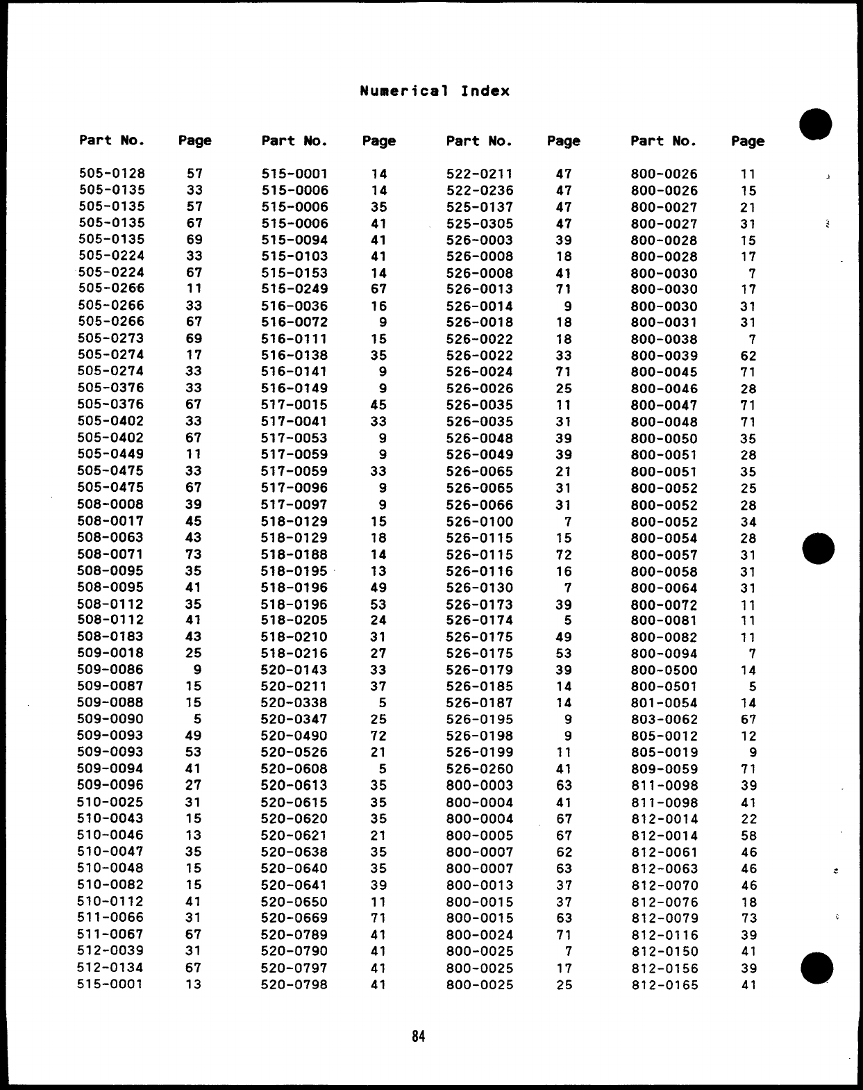
Numerical Index
Part No.
505-0128
505-0135
505-0135
505-0135
505-0135
505-0224
505-0224
505-0266
505-0266
505-0266
505-0273
505-0274
505-0274
505-0376
505-0376
505-0402
505-0402
505-0449
505-0475
505-0475
508-0008
508-0017
508-0063
508-0071
508-0095
508-0095
508-0112
508-0112
508-0183
509-0018
509-0086
509-0087
509-0088
509-0090
509-0093
509-0093
509-0094
509-0096
510-0025
510-0043
510-0046
510-0047
510-0048
510-0082
510-0112
511-0066
511-0067
512-0039
512-0134
515-0001
Page
57
33
57
67
69
33
67
11
33
67
69
17
33
33
67
33
67
11
33
67
39
45
43
73
35
41
35
41
43
25
9
15
15
5
49
53
41
27
31
15
13
35
15
15
41
31
67
31
67
13
Part No.
515-0001
515-0006
515-0006
515-0006
515-0094
515-0103
515-0153
515-0249
516-0036
516-0072
516-0111
516-0138
516-0141
516-0149
517-0015
517-0041
517-0053
517-0059
517-0059
517-0096
517-0097
518-0129
518-0129
518-0188
518-0195
518-0196
518-0196
518-0205
518-0210
518-0216
520-0143
520-0211
520-0338
520-0347
520-0490
520-0526
520-0608
520-0613
520-0615
520-0620
520-0621
520-0638
520-0640
520-0641
520-0650
520-0669
520-0789
520-0790
520-0797
520-0798
Page
14
14
35
41
41
41
14
67
16
9
15
35
9
9
45
33
9
9
33
9
9
15
18
14
13
49
53
24
31
27
33
37
5
25
72
21
5
35
35
35
21
35
35
39
11
71
41
41
41
41
Part No.
522-0211
522-0236
525-0137
525-0305
526-0003
526-0008
526-0008
526-0013
526-0014
526-0018
526-0022
526-0022
526-0024
526-0026
526-0035
526-0035
526-0048
526-0049
526-0065
526-0065
526-0066
526-0100
526-0115
526-0115
526-0116
526-0130
526-0173
526-0174
526-0175
526-0175
526-0179
526-0185
526-0187
526-0195
526-0198
526-0199
526-0260
800-0003
800-0004
800-0004
800-0005
800-0007
800-0007
800-0013
800-0015
800-0015
800-0024
800-0025
800-0025
800-0025
Page
47
47
47
47
39
18
41
71
9
18
18
33
71
25
11
31
39
39
21
31
31
7
15
72
16
7
39
5
49
53
39
14
14
9
9
11
41
63
41
67
67
62
63
37
37
63
71
7
17
25
Part No.
800-0026
800-0026
800-0027
800-0027
800-0028
800-0028
800-0030
800-0030
800-0030
800-0031
800-0038
800-0039
800-0045
800-0046
800-0047
800-0048
800-0050
800-0051
800-0051
800-0052
800-0052
800-0052
800-0054
800-0057
800-0058
800-0064
800-0072
800-0081
800-0082
800-0094
800-0500
800-0501
801-0054
803-0062
805-0012
805-0019
809-0059
811-0098
811-0098
812-0014
812-0014
812-0061
812-0063
812-0070
812-0076
812-0079
812-0116
812-0150
812-0156
812-0165
Page
11
15
21
31
15
17
7
17
31
31
7
62
71
28
71
71
35
28
35
25
28
34
28
31
31
31
11
11
11
7
14
5
14
67
12
9
71
39
41
22
58
46
46
46
18
73
39
41
39
41
84
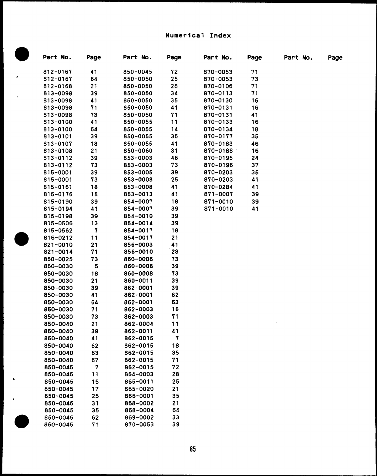
Numerical Index
●Part No.
812-0167
A812-0167
812-0168
813-0098
>813-0098
813-0098
813-0098
813-0100
813-0100
813-0101
813-0107
813-0108
813-0112
813-0112
815-0001
815-0001
815-0161
815-0176
815-0190
815-0194
815-0198
815-0506
●815-0562
816-0212
821-0010
821-0014
850-0025
850-0030
850-0030
850-0030
850-0030
850-0030
850-0030
850-0030
850-0030
850-0040
850-0040
850-0040
850-0040
850-0040
850-0040
850-0045
850-0045
●850-0045
850-0045
850-0045
*850-0045
850-0045
●850-0045
850-0045
Page
41
64
21
39
41
71
73
41
64
39
18
21
39
73
39
73
18
15
39
41
39
13
7
11
21
71
73
5
18
21
39
41
64
71
73
21
39
41
62
63
67
7
11
15
17
25
31
35
62
71
Part No.
850-0045
850-0050
850-0050
850-0050
850-0050
850-0050
850-0050
850-0055
850-0055
850-0055
850-0055
850-0060
853-0003
853-0003
853-0005
853-0008
853-0008
853-0013
854-0007
854-0007
854-0010
854-0014
854-0017
854-0017
856-0003
856-0010
860-0006
860-0008
860-0008
860-0011
862-0001
862-0001
862-0001
862-0003
862-0003
862-0004
862-0011
862-0015
862-0015
862-0015
862-0015
862-0015
864-0003
865-0011
865-0020
866-0001
868-0002
868-0004
869-0002
870-0053
Page
72
25
28
34
35
41
71
11
14
35
41
31
46
73
39
25
41
41
18
39
39
39
18
21
41
28
73
39
73
39
39
62
63
16
71
11
41
7
18
35
71
72
28
25
21
35
21
64
33
39
85
Part No.
870-0053
870-0053
870-0106
870-0113
870-0130
870-0131
870-0131
870-0133
870-0134
870-0177
870-0183
870-0188
870-0195
870-0196
870-0203
870-0203
870-0284
871-0007
871-0010
871-0010
Page
71
73
71
71
16
16
41
16
18
35
46
16
24
37
35
41
41
39
39
41
Part No. Page
