995 T2 HD Education Guide_JAN17_ 2007 Edge T 2
User Manual: 2007 Edge
Open the PDF directly: View PDF ![]() .
.
Page Count: 32
What you need to know about January 2017
Price: $19.99
Wheel Alignment on
Heavy-Duty Trucks

Contents
What is Proper Wheel Alignment? . . . . . . . . . . . . . . . . . . . . . . . . . . . . . . . . . 3
Alignment Angles and Effects . . . . . . . . . . . . . . . . . . . . . . . . . . . . . . . . . . . 4
Tire Wear Due to Improper Toe Settings . . . . . . . . . . . . . . . . . . . . . . . . . . . . . . . . . . . . . . . . 4
Tire Wear Due to Improper Camber Settings . . . . . . . . . . . . . . . . . . . . . . . . . . . . . . . . . . . . . . 5
Caster: A Factor in Vehicle Handling . . . . . . . . . . . . . . . . . . . . . . . . . . . . . . . . . . . . . . . . . . 5
Tandem Axle Angles. . . . . . . . . . . . . . . . . . . . . . . . . . . . . . . . . . . . . . . . . . . . . . . . . . 6
Tandem Scrub Angle . . . . . . . . . . . . . . . . . . . . . . . . . . . . . . . . . . . . . . . . . . . . . . . . . 6
Alignment Angles Affect Rolling Resistance and Fuel Consumption . . . . . . . . . . . . . . . . . . . . . . . . . . . 7
Geometric Centerline Alignment . . . . . . . . . . . . . . . . . . . . . . . . . . . . . . . . . . . . . . . . . . . . 7
Frame Centerline Alignment . . . . . . . . . . . . . . . . . . . . . . . . . . . . . . . . . . . . . . . . . . . . . . 8
Separation . . . . . . . . . . . . . . . . . . . . . . . . . . . . . . . . . . . . . . . . . . . . . . . . . . . . . . 8
WinAlign® HD Software . . . . . . . . . . . . . . . . . . . . . . . . . . . . . . . . . . . . . . . . . . . . . . . . 9
HD Procedure Database . . . . . . . . . . . . . . . . . . . . . . . . . . . . . . . . . . . . . . . . . . . . . . . 10
Vehicle Specifi cations . . . . . . . . . . . . . . . . . . . . . . . . . . . . . . . . . . . . . . . . . . . . . . . . 11
Compensation Control Screen . . . . . . . . . . . . . . . . . . . . . . . . . . . . . . . . . . . . . . . . . . . . 11
Roll Compensation . . . . . . . . . . . . . . . . . . . . . . . . . . . . . . . . . . . . . . . . . . . . . . . . . 12
Precise Measurement Display . . . . . . . . . . . . . . . . . . . . . . . . . . . . . . . . . . . . . . . . . . . . 12
Automatic calculation . . . . . . . . . . . . . . . . . . . . . . . . . . . . . . . . . . . . . . . . . . . . . . . . 13
Frame Offset . . . . . . . . . . . . . . . . . . . . . . . . . . . . . . . . . . . . . . . . . . . . . . . . . . . . 14
Print Any Screen . . . . . . . . . . . . . . . . . . . . . . . . . . . . . . . . . . . . . . . . . . . . . . . . . . 14
Total Alignment . . . . . . . . . . . . . . . . . . . . . . . . . . . . . . . . . . . . . . . . . . . . . . . . . . . 15
6 Sensor Alignment vs. 4 Sensor Alignment . . . . . . . . . . . . . . . . . . . . . . . . . . . . . . . . . . . . . 16
Recognizing Factors That Can “Fool” the Alignment Technician . . . . . . . . . . . . . . . . 17
Compensation for Runout . . . . . . . . . . . . . . . . . . . . . . . . . . . . . . . . . . . . . . . . . . . . . . 17
Identifi es and Corrects for Offset. . . . . . . . . . . . . . . . . . . . . . . . . . . . . . . . . . . . . . . . . . . 17
Wheel Balance and Its Effect on Tire Wear . . . . . . . . . . . . . . . . . . . . . . . . . . . 17
Irregular Tire Wear Guide (Steer Tires) . . . . . . . . . . . . . . . . . . . . . . . . . . . . . . 19
Diagnostic from the Printout . . . . . . . . . . . . . . . . . . . . . . . . . . . . . . . . . . . 20
Troubleshooting Guide . . . . . . . . . . . . . . . . . . . . . . . . . . . . . . . . . . . . . . 21
Power Steering Troubleshooting Guide . . . . . . . . . . . . . . . . . . . . . . . . . . . . . 24
Facility Factors . . . . . . . . . . . . . . . . . . . . . . . . . . . . . . . . . . . . . . . . . . 25
How Much Space is Required?. . . . . . . . . . . . . . . . . . . . . . . . . . . . . . . . . . . . . . . . . . . . 25
Is a Pit Rack Needed? . . . . . . . . . . . . . . . . . . . . . . . . . . . . . . . . . . . . . . . . . . . . . . . . 25
Alignment Training. . . . . . . . . . . . . . . . . . . . . . . . . . . . . . . . . . . . . . . . . . . . . . . . . . 25
Truck/Bus/Trailer Alignment Procedures . . . . . . . . . . . . . . . . . . . . . . . . . . . . 26
Truck & Bus Axle Confi gurations . . . . . . . . . . . . . . . . . . . . . . . . . . . . . . . . . 26
Trailer Axle Confi gurations . . . . . . . . . . . . . . . . . . . . . . . . . . . . . . . . . . . . 27
Glossary . . . . . . . . . . . . . . . . . . . . . . . . . . . . . . . . . . . . . . . . . . . . . . 28
2

Proper Wheel Alignment 3
Education Guide: Wheel Alignment on Heavy Duty Trucks
What is Proper Wheel Alignment?
Wheel alignment is the process of positioning the wheels and suspension of a vehicle to Original Equipment
Manufacturer specifi cations. The goal is to meet or exceed the expected tire life, vehicle handling, ride quality
and performance characteristics intended by the vehicle manufacturer.
The primary wheel alignment angles specified for class 8 vehicles are:
%
Camber
%
Caster
%
Total toe
%
Thrust angle
%
Tandem scrub angle
How Can Wheel Alignment Benefi t Your Operation?
The number one and number two operating expenses in over-the-road transportation are fuel and tires
respectively. Both are typically perceived as hard to control. Routine wheel alignment is the most effective way
to control tire costs and can impact fuel costs as well.
Problems created by misalignment:
%
Excessive tire wear
%
Increased fuel consumption caused by increased rolling resistance
%
Unsafe vehicle handling characteristics
%
Driver fatigue and driver retention
%
Premature suspension component wear
Between 70 and 80 percent of heavy duty vehicles on the road today are misaligned!
The transportation industry, as a whole, fi nds that outsourcing timely, accurate alignment service performed
by qualifi ed technicians is diffi cult to manage. As a result alignment is mostly addressed after the damage
has been done. Simply making alignment part of a vehicle or fl eet preventive maintenance program allows
operators to easily get a handle on this perceived uncontrollable expense.
Hunter recommends a minimum of two to three alignments per year or every
50,000 to 60,000 miles as part of the average vehicle’s preventive maintenance program.
Alignment service is a natural fi t for service facilities currently repairing suspensions. Technicians performing
repairs on heavy duty suspensions are in effect alignment technicians. The only required equipment is the
precision measuring system.
Alignment Angles and Effects
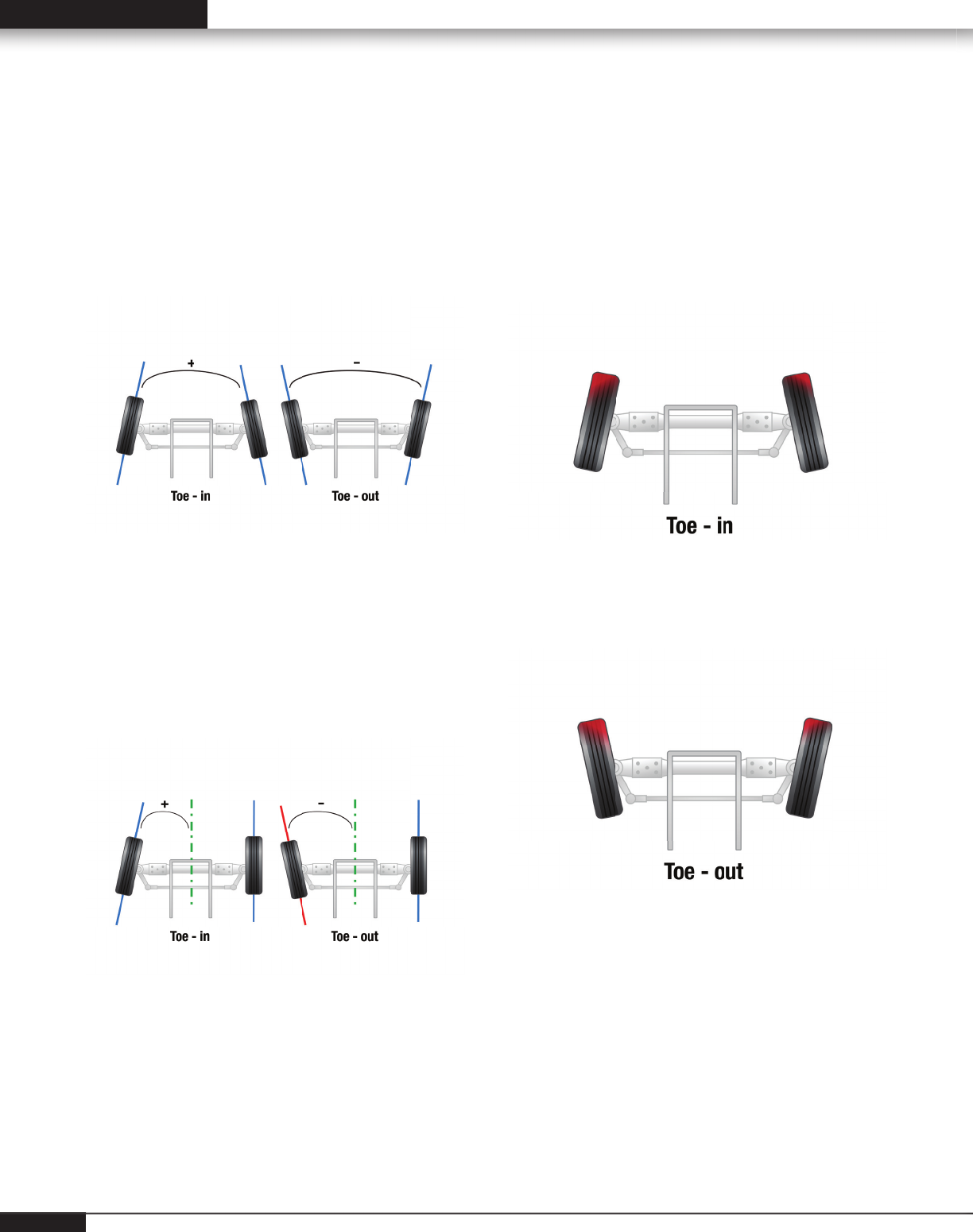
Tire Wear Due to Improper Toe Settings
Total Toe is one of the most critical alignment
setting for tire wear It is measured in degrees, and
displayed in inches, millimeters or degrees.
Total Toe is the angle formed by the intersection
of two lines drawn through the rotational axis of left
and right wheels of a given axle. Toe-in is when the
horizontal lines intersect in front of the vehicle; Toe-
out is when the horizontal lines intersect behind the
wheels.
Individual Toe is the angle drawn by a line drawn
through a plane of one wheel referenced to the
geometric centerline (reference axle) or the thrust
line (non-reference axles) of the vehicle. Individual
toe is used to compute steer ahead, total toe, thrust
angle and tandem scrub angle.
Results of excessive toe is wear on the leading
edge of the tire.
Excessive toe-in wears the outside of the tire.
Excessive toe-out wears the inside of the tire.
4
Alignment Angles and Effects 5
Education Guide: Wheel Alignment on Heavy Duty Trucks
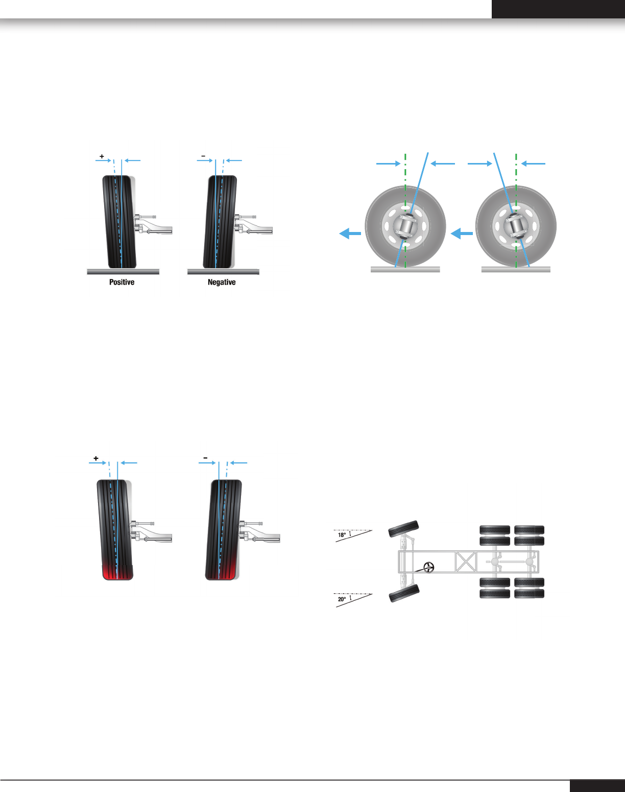
Tire Wear Due to Improper
Camber Settings
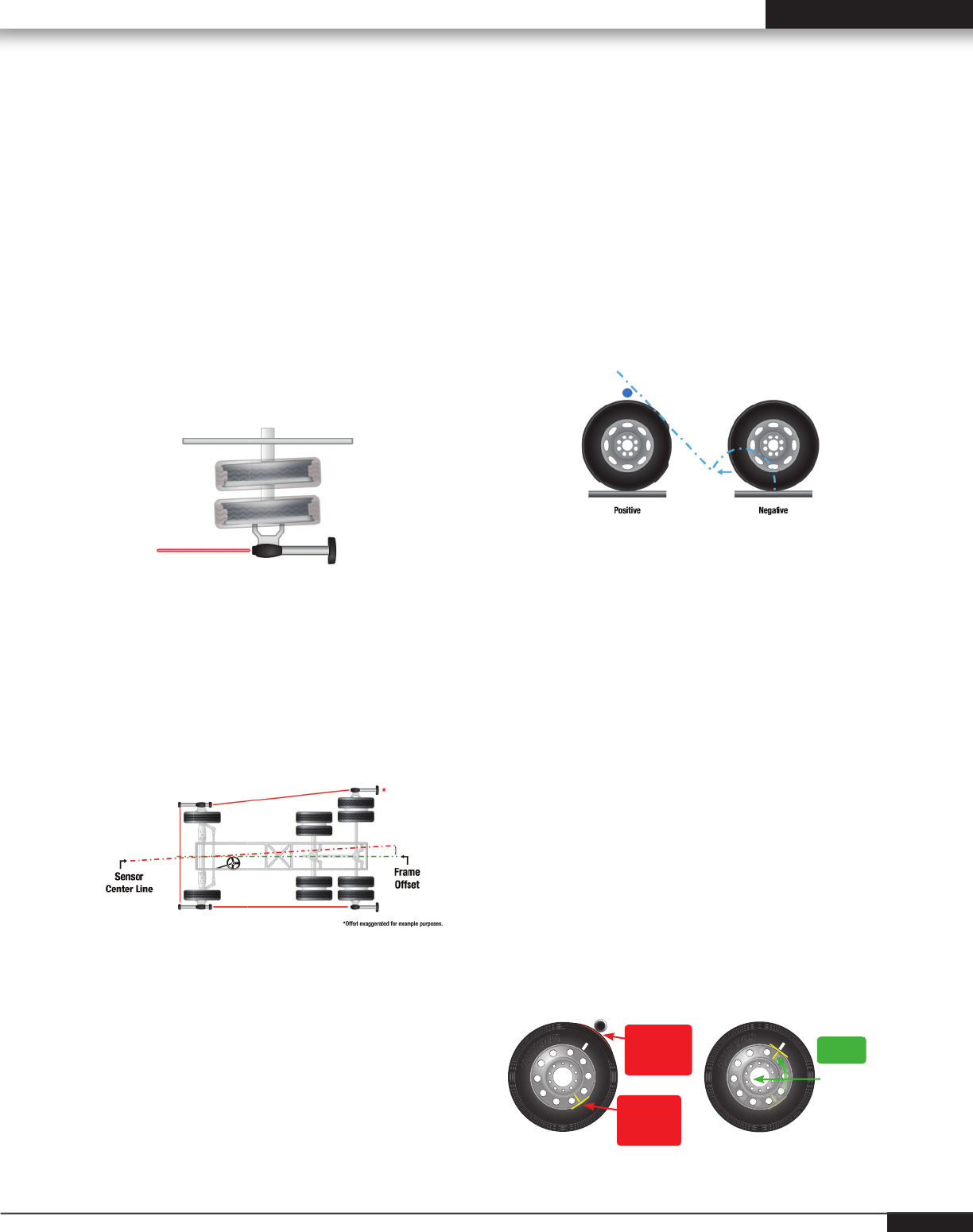
Camber is the angle formed by the inward or
outward tilt of the wheel referenced to a vertical
line. This angle is measured in degrees. Camber
is positive when the wheel is tilted outward at the
top and is negative when the wheel is tilted inward
at the top. A pull may be generated if left and right
front camber angles differ by more than 0.50°.
Tire wear from excessive camber: Wear from
positive camber is on the outside shoulder of the
tire; with negative camber, wear is on the inside
shoulder.
Caster: A Factor in Vehicle
Handling
Positive Negative
Caster is the forward or rearward tilt of the steering
axis in reference to a vertical line. The angle is
measured in degrees. Caster is positive when the
top of the steering axis is tilted rearward and is
negative when the tilt is forward. Caster doesn’t
effect tire wear directly. Caster is responsible for
directional stability and returnability. Excessive
caster may cause front wheel shimmy and excessive
steering effort. A pull may be generated if left and
right front caster differ by more than 0.50°.
Turning Angle is the difference in the angles of
the front wheels in a turn. This measurement is
an aid in diagnosing steering component problems
and irregular tire wear. Improper turning angle may
cause scuffi ng, leading to excessive tire wear.
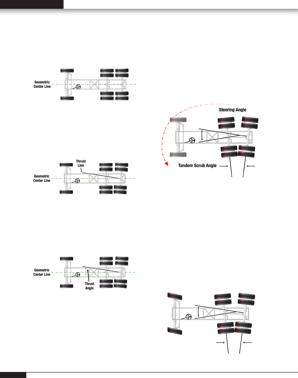
Tandem Axle Angles
Geometric centerline is used as a reference
from which to compute individual toe for the rear
reference axle.
Thrust line is the bisector of the total toe angle of
an axle. It represents the direction the axle “points”
compared to the centerline of the vehicle.
Thrust angle is the angle formed by the geometric
centerline and the thrust line of an axle
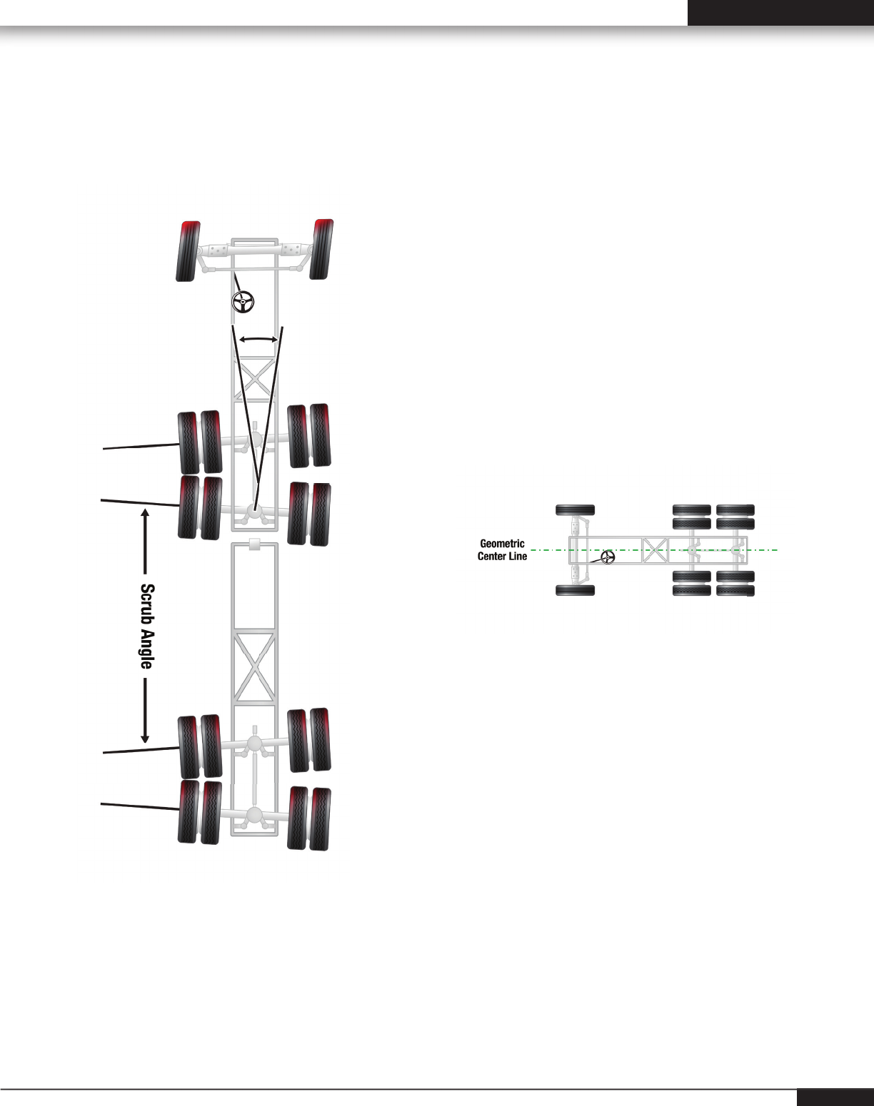
Tandem Scrub Angle
Tandem scrub angle is the angle formed by the
two thrust lines of a tandem axle vehicle. In the
diagram below, misalignment causes the tandem
axles to steer the rear of the truck. In this example,
the rear of the truck is being steered to the left.
The steer axle must be turned to offset the “push”
of the axles and keep the vehicle moving straight
ahead. This causes every tire on the vehicle to
scrub.
Tire Wear from Tandem Scrub occurs at the
leading edge of the steer tires, in a pattern called
“inside/outside” wear.
For example, on the front axle of this vehicle, wear
would occur on the outside of the left steer tire and
on the inside of the right steer tire. Tire wear would
occur on all drive axle tires.
Tandem Scrub Angle
Steering Angle
6
Alignment Angles and Effects 7
Education Guide: Wheel Alignment on Heavy Duty Trucks
Trailer Alignment and Tire Wear
The same conditions that cause tandem scrub on
tractors also apply to tractor-trailer combinations.
Misaligned trailer axles cause tandem scrub,
resulting in rapid wear on all tires.
If the trailer doesn’t track correctly, it may cause
handling problems, use excessive lane space and
affect fuel economy.
Alignment Angles Affect
Rolling Resistance and Fuel
Consumption
While the effects of misalignment show clearly in tire
wear, the effects on fuel consumption are less easy
to quantify. Fuel consumption is affected by many
factors.
However, it is obvious that misalignment must
increase rolling resistance – and rolling resistance is
a major cause of fuel consumption
Geometric Centerline Alignment
Geometric Centerline Alignment can be used as
a reference from which to compute individual toe
angles.
The Geometric Centerline of a vehicle is established
by placing a line from the midpoint of the front axle
and the midpoint of the rear-most axle.
The Geometric Centerline is not based on frame
rails or cross member reference points.
The alignment system will establish the Geometric
Centerline.
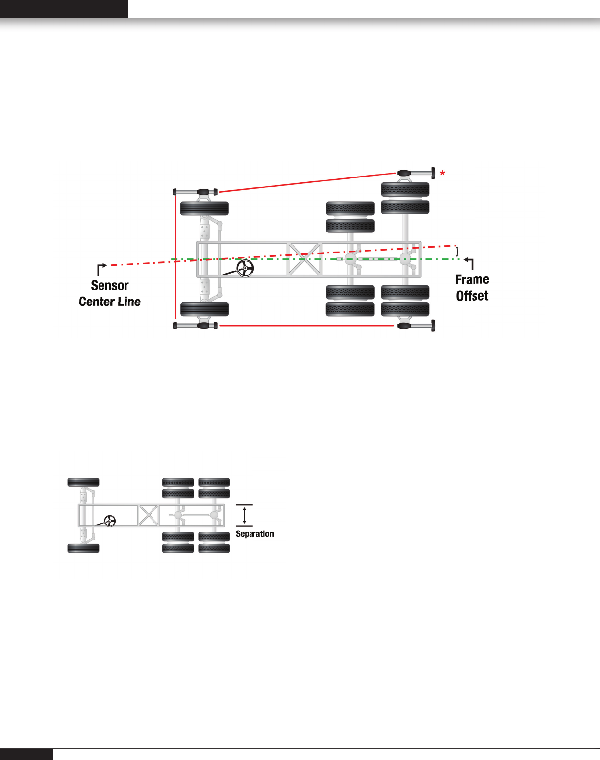
Frame Centerline Alignment
Frame offset angle is the angle of the frame referenced centerline to the geometric (sensor) centerline. This
angle is calculated by the aligner when frame offset measurements are entered into the aligner. Frame offset
measurements may be selected and measured by selecting"make Additional Measurements".
Separation
Separation is the distance between the reference axle adjustment points. This distance may be measured
and entered into the aligner before adjusting thrust angle to allow the aligner to calculate how much the axle
must be moved at the adjustment point.
8
Alignment Angles and Effects 9
Education Guide: Wheel Alignment on Heavy Duty Trucks
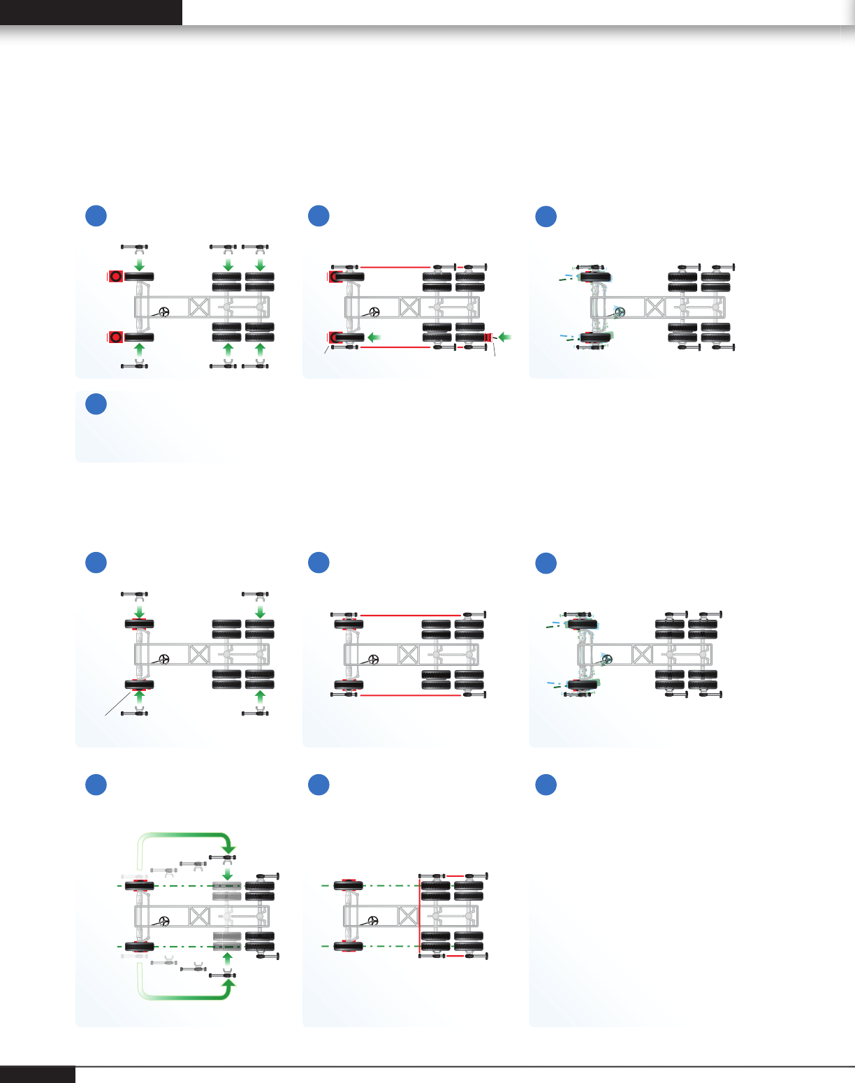
Total Alignment
In the total alignment procedure, every axle on
the vehicle is measured and the axles are set
parallel – so all the wheels roll in the same direction,
minimizing rolling resistance.
1. Electronic sensors are mounted on the
steer axle and on the tandem drive axles (the
reference axle). The sensors are compensated
for runout by rolling the vehicle forward
approximately 22 inches.
2. The rear reference axle is adjusted to correct
thrust angle. The goal is to reduce thrust angle to
0.00° ± 0.04°.
3. The next drive axle is then aligned to the
reference drive axle. The goal is to reduce
tandem scrub angle to 0.00° ± 0.04°.
4. The steer axle is aligned to the rear reference
axle.
For other vehicle confi gurations, similar procedures
are followed, aligning all axles to a reference axle.
37 pre-programmed procedures are built in to
this system’s software.
Diagnose tire wear and handling problems.
Start adjustments if needed.
Measure Caster
Measure Caster
6 Sensors - Time: Approx. 3 minutes
Jacking Comp.
Mount Sensors
4 Sensors - Time: Approx. 12 minutes
Mount Sensors
Jacking Comp.Move front sensors
to middle drive axle
Roll Compensation
Truck Pusher
Turnplate
Turnplate
Front axle Rear axle
Front axle Middle axle
Middle axle
1
4
23
1
4
23
5 6 Diagnose tire wear and
handling problems.
Restart entire process
if adjustments if needed.
6 Sensor Alignment vs. 4 Sensor Alignment
10
Advantages of Computerized Alignment 11
Education Guide: Wheel Alignment on Heavy Duty Trucks
Advantages of Computerized Alignment
WinAlign® HD Software
HD Procedure Database
WinAlign® HD software supports more than 60 customized truck, trailer and bus alignment procedures as
well as passenger car and light truck alignment.
37 pre-programmed procedures
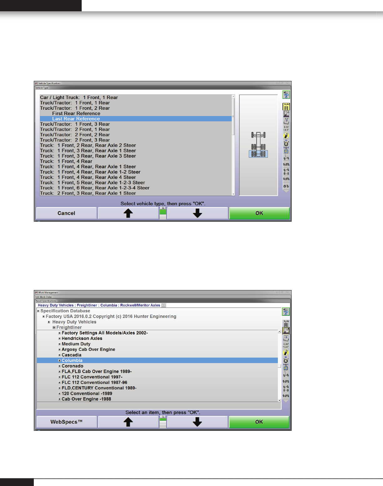
Specifi cation Database
A customized HD specifi cation database supports most vehicle manufacturers by simply scrolling to the
specifi c model being aligned.
12
Alignment Angles and Effects 13
Education Guide: Wheel Alignment on Heavy Duty Trucks
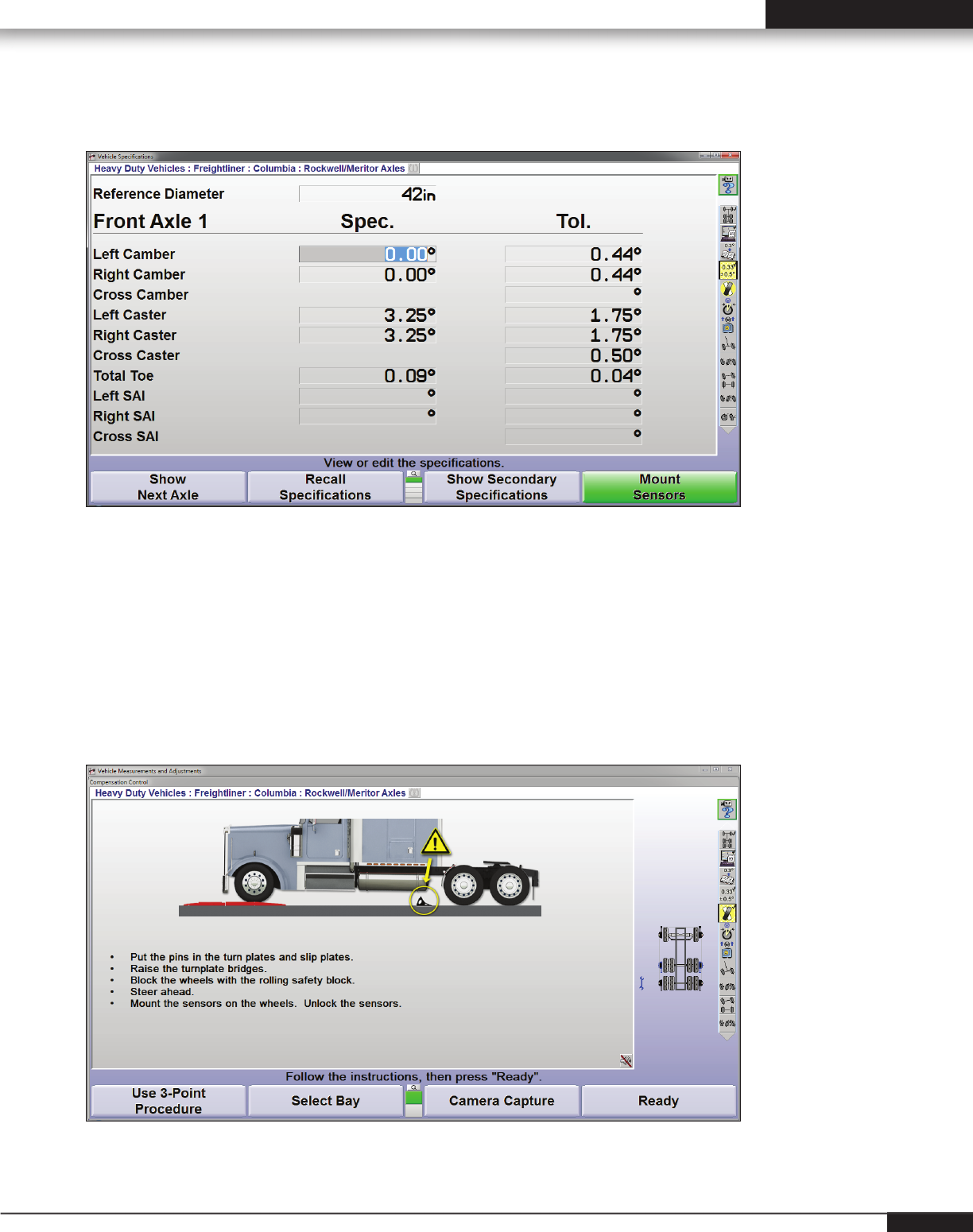
Vehicle Specifi cations
The “Vehicle Specifi cations” primary screen displays the alignment specifi cations for the vehicle chosen.
The technician may be asked to enter a reference diameter. He can measure the front tire diameter and enter
that value in “Reference Diameter.”
When activated, ExpressAlign® tool bar (visible in top, right hand corner of aligner screen) automatically
shows the customized alignment path for the vehicle selected. ExpressAlign allows movement in procedure
by using the mouse and selecting the respective icon relative to sensor location.
Compensation Control Screen
Hunter's premium six sensor alignment system measures 3 axles at one time.
Roll Compensation
Roll the vehicle forward and the sensors are compensated.
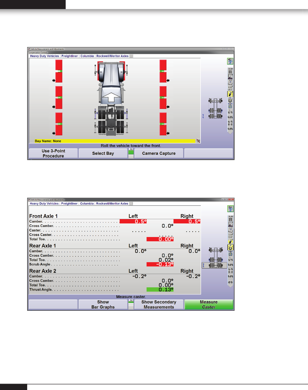
Precise Measurement Display
Measuring all three axles at one time offers the advantage quickly diagnosing tire wear related to tandem
scrub and excessive total toe.
Measurements are compared with the manufacturer's specifi cation and results are shown on the vehicle
measurement display screen.
Easy-to-read color coding identifi es in- and out- of-specifi cation measurements.
14
Alignment Angles and Effects 15
Education Guide: Wheel Alignment on Heavy Duty Trucks
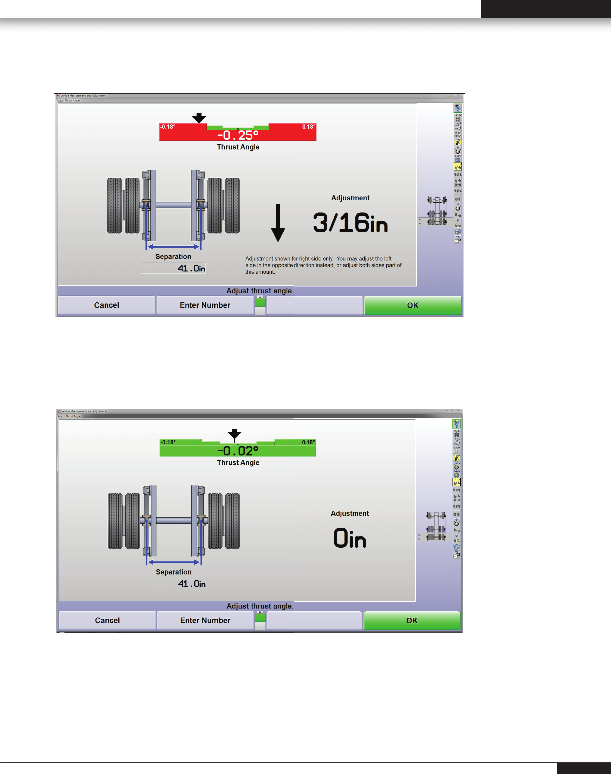
Automatic calculation
WinAlignHD automatically calculates the correction required. As the adjustment is made, the arrow moves
across the bar graph target guiding the technician.
When the adjustment comes within specifi cation the bar graph changes from red to green.
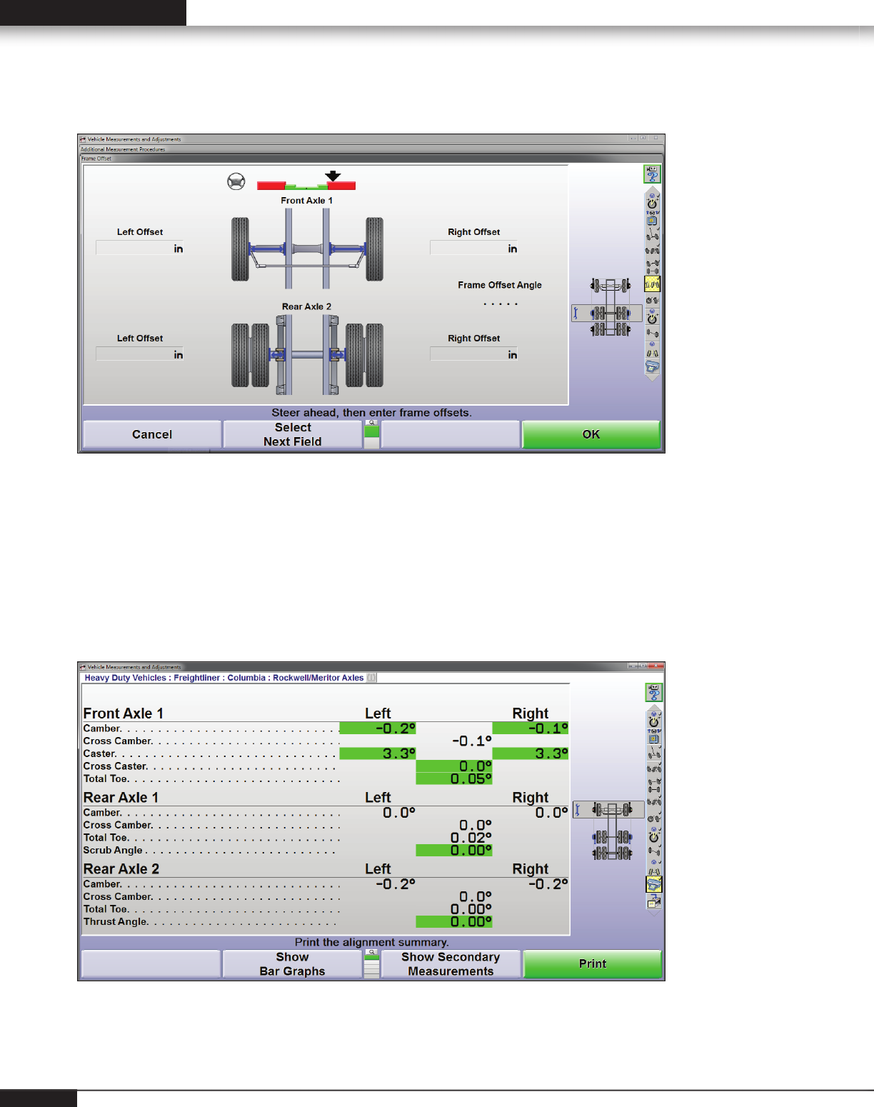
Frame Offset
WinAlignHD allows frame offset measurements to be input and displays frame offset angle, recalculating thrust
angle from the geometric centerline of the frame.
Print Any Screen
WinAlignHD allows the user to print any screen for records or to show the vehicle owner the need for
service. Before and after alignment measurement screens can be printed to show any out-of-spec condition.
Screens can be printed anytime as a guide for the technician.
16
Alignment Angles and Effects 17
Education Guide: Wheel Alignment on Heavy Duty Trucks
Recognizing Factors
That Can “Fool”
the Alignment
Technician
A computerized alignment system should have the
capacity to recognize several factors that can affect
alignment.
Compensation for Runout
Runout, due to bent or distorted rims, is common
on heavy duty trucks and trailers. The aligner
electronically compensates each sensor and
correctly measures where the axle points.
Identifi es and Corrects for Offset
Axle offset on heavy duty trucks and trailers is due
(for example) to mismatched rims. The aligner allows
the technician to measure the distances and input
those measurements, which automatically corrects
for offset.
Wheel Balance and
Its Effect on Tire
Wear & Vibration
When aligning the wheels don’t forget about the
importance of proper balance. Maximizing tire wear
requires proper balance in addition to alignment.
When the wheel is put in motion, centrifugal
force acts on the heavy spot, causing the rotating
assembly to pull away from its axis.
The resulting force causes the wheel to “hop.”
This causes vibration and increased tread wear in
the form of “cupping.
Road Force
Hunter’s ForceMatch HD balancer quickly measures
runout (eccentricity) of a tire and wheel assembly.
The roller measures the entire contact patch of
the tire, detecting if the assembly is out of round.
Match-mounting the high spot on a tire to the low
spot on a rim makes the assembly roll as smoothly
as possible.
Dataset
Arms locate
LOW SPOT
on Rim
ForceMatch
Roller locates
HIGH SPOT
on tire
RUNOUT
minimized
18
Alignment Angles and Effects 19
Education Guide: Wheel Alignment on Heavy Duty Trucks
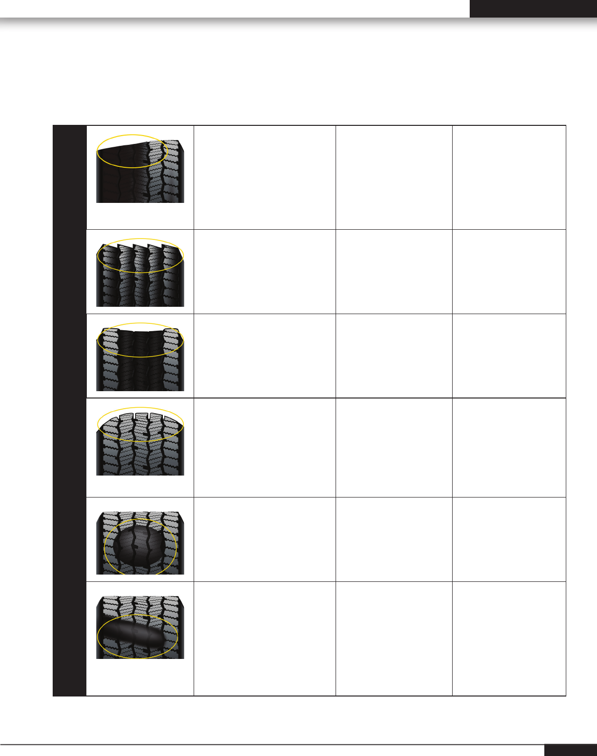
Irregular Tire Wear Guide (Steer Tires)
Description
Appearance
Possible Cause
Solution
Full shoulder
Excessive wear extended
across the entire shoulder rib
to a major tread groove.
Excessive camber angle
is the primary cause.
Measure and align
all wheels. If wear is
severe, rotate tires.
Sawtoothed /
Feathered
Tread ribs worn so that one
side is higher, resulting in
step-offs across the tread.
Scrubbing due to
incorrect toe angles,
front and/or rear
defective suspension or
steering components.
Replace worn parts,
align vehicle, and if
wear patterns are
severe, rotate tires.
Over Inflation
Excessive wear in the center
of the tread – when properly
inflated, appears to cup when
viewed across the tread face.
Over-inflation expands
the tire forcing more
wear in the center of
the tread.
Keep tires properly
inflated.
Under Inflation
Tread is worn unevenly
toward the edges of
the tire - when properly
inflated the tire appears
round when viewed across
the tread face.
Under-inflation
causes the tire to
collapse, forcing more
wear on the edges of
the tread.
Keep tires properly
inflated.
Cupping / Dished
out areas
Localized patches of fast
wear creating a scalloped
appearance.
A result of moderate
to sever assembly out
of balance condition.
Diagnose imbalance
condition. Tires
should be rotated
to drive axle.
Diagonal
Localized flat spots
across the tread often
repeating around the tread
circumference.
Runout and/or
out of balance in
conjunction with a
slow rate of wear.
Can also be caused
by a loose wheel
bearing.
Mount as outside
drive dual with
change in rotation
of tire.
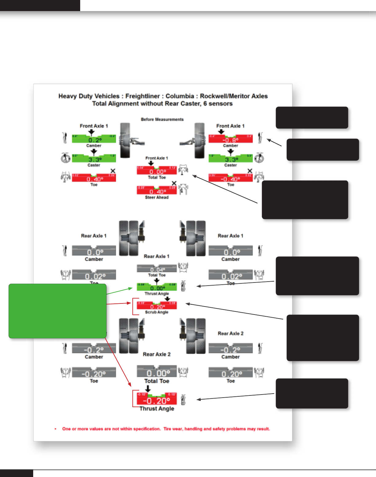
Diagnostic from the Printout
Measuring a multi-axle truck using six sensors in less than 4 minutes offers amazing possibilities for
diagnosing premature tire wear and vehicle handling conditions.
Negative camber may
cause tire wear
Incorrect front total toe
may cause premature tire
wear and/or reduction in
directional stability
Thrust angle measurement
of 0.00 indicates what the
scrub angle will be after the
reference axle is adjusted
Center axle is pointed
to the right of the
rear reference axle.
This scrub angle will
cause a pull to the right.
Reference axle Thrust
angle indicates axle is
pointed left of center
Cross camber may
cause pull to left
As the thrust angle arrow moves
toward center (to the right), the
scrub angle arrow will move
toward center (to the left).
Adjusting thrust angle to zero will
result in a zero scrub angle.
20

Alignment Angles and Effects 21
Education Guide: Wheel Alignment on Heavy Duty Trucks
Troubleshooting Guide
Symptom
Possible Cause
Pull Left/Right Uneven tire pressure / uneven tread wear / mismatched tires
Uneven camber Uneven caster
Brake drag Suspension/frame sag
Unbalanced power assist Bent spindle
Worn suspension components (front/rear) Excessive tandem scrub
Centerline
Steering Error
Incorrect front toe
Rear wheel misalignment
Excessive steering and suspension play
Excessive gearbox play
Gearbox loose at the frame
Shimmy Excessive positive caster
Wheel imbalance
Defective suspension and steering components
Excessive wheel and tire runout (lateral)
Worn tires
Under inflation
Steering gear loose
Excessively loose wheel bearings
Ply separation or blister
Improperly torqued lug nuts
Vibration Wheel imbalance
Excessive wheel and tire runout (axial)
Drum imbalance
Drive shaft imbalance
Defective u-joints
Defective wheel bearings
Improper tire inflation Drivetrain misalignment
Defective shock or shock mounting
Defective tire

Troubleshooting Guide (continued)
Symptom
Possible Cause
Noise (abnormal) Defective wheel bearing
Overinflation
Coarse tread pattern
Incorrect alignment (all wheels) Incorrect turning angle
Loose or rubbing suspension or steering component
Driveline misalignment
Hard Steering Low air pressure
Steering gear binding
Steering lubricant low
Excessive positive caster
Defective power steering belt
Power steering fluid level low
Power steering pressure low
Steering and suspension component dry or binding
Loose Steering Excessively loose wheel bearings
Worn steering and suspension components
Steering gear assembly loose on mounting
Excessive internal wear in steering gear
Loose or worn steering shaft coupling Steering gear mis-adjusted
Excessive Road
Shock
Excessive positive caster
Low air pressure
Worn tires Wrong type tire
Wrong shocks Worn shocks
Springs worn or sagged
Braking Instability Brakes incorrectly adjusted
Contaminated brake linings
Defective suspension components
Incorrect alignment
Excessive negative caster
Uneven or low tire pressure
22

Alignment Angles and Effects 23
Education Guide: Wheel Alignment on Heavy Duty Trucks
Troubleshooting Guide (continued)
Symptom
Possible Cause
Wander/Instability Incorrect alignment
Worn tires
Low air pressure
Mismatched tires
Worn suspension and steering components
Worn or loose steering gear Mis-adjusted steering gear
Excessively loose wheel bearings
Squeal/Scuff on
Turns
Worn tires
Low tire pressure Incorrect turning angle
Poor driving habits
Worn suspension or steering components
Excessive Body
Sway
Worn shocks or mountings
Broken or sagging springs
Uneven vehicle load
Uneven tire pressure

Symptom Possible Cause
Insufficient Assist Low fluid Incorrect fluid
Loose/worn belt Defective pump
Restricted fluid passages
Mechanical bind
Vehicle Pulls Inoperative control valve
Mis-adjusted control valve
Fluid Leaks Loose hose connection
Defective hose Damaged seals
Fluid level too high
Excessive Noise Low fluid level
Loose/worn belt
Defective pump
Restricted fluid passages
Defective relief valve
Poor Returnability Steering column misalignment
Yoke plug too tight
Valve assembly binding
Contaminated fluid Defective u-joints
Power Steering Troubleshooting Guide
24

Alignment Angles and Effects 25
Education Guide: Wheel Alignment on Heavy Duty Trucks
How Much Space is Required?
Wheel alignment for heavy duty vehicles is not
space intensive.
The alignment console is usually mounted on a
mobile cabinet that can be rolled to the vehicle.
Overall dimensions of a console with a 19” monitor
and truck & bus sensors mounted are 65” high by
33” deep by 72” wide.
Space for the console and the vehicle, and working
room for the technician is all that is required.
Is a Pit Rack Needed?
A pit rack has defi nite advantages in providing room
underneath a vehicle for inspection, alignment and
suspension repairs.
However the only equipment needed for toe, scrub
and thrust angle (the most important adjustments
to be made) are the alignment system, turning
angle gauges (standard equipment with the Hunter
system) and a jack for lifting the vehicle during the
procedure.
Facility Factors
Technicians and Training
Finding an Alignment Technician
Most experienced heavy duty technicians can learn
alignment quickly, especially with the help of a
computerized system and on-site training.
Alignment Training
Hunter Engineering Company routinely offers
heavy-duty truck alignment courses. These courses
provide extensive hands-on experience with
equipment and vehicles.
On-site training is offered at the time of equipment
installation, with retraining available when new
technicians are hired.
Training in Alignment
Merchandising
Surprisingly, many experienced people in the
trucking industry have only a minimal understanding
of wheel alignment and its effects on tire wear, fuel
consumption and vehicle handling. Because of this,
the technician or service manager may need help in
merchandising alignment service.
Hands-on training in alignment merchandising
should be as much a part of the equipment
”package” as operations training. See your local
Hunter representative for details.
Pamphlets and brochures can be used at the shop
location and in working with fl eet management.
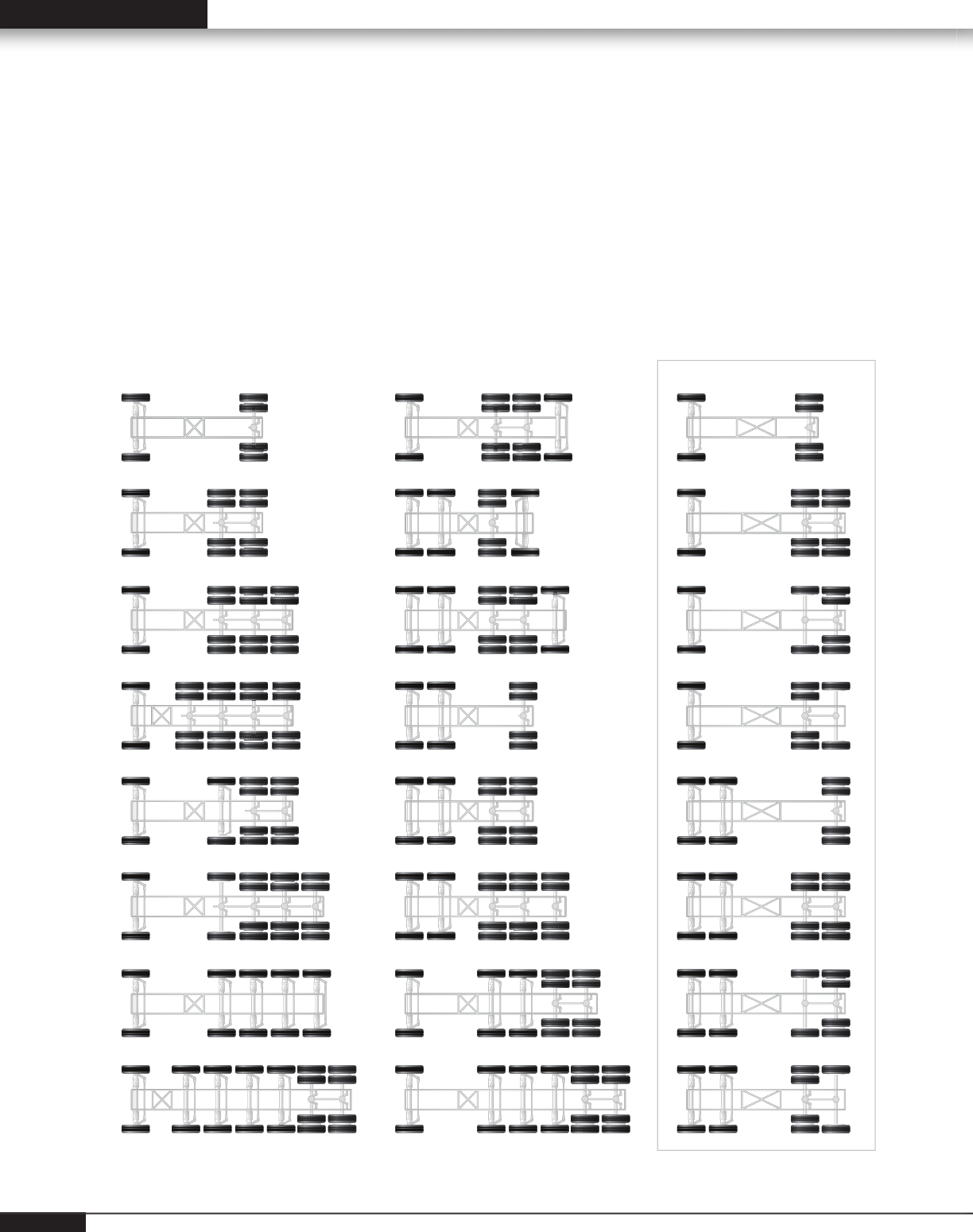
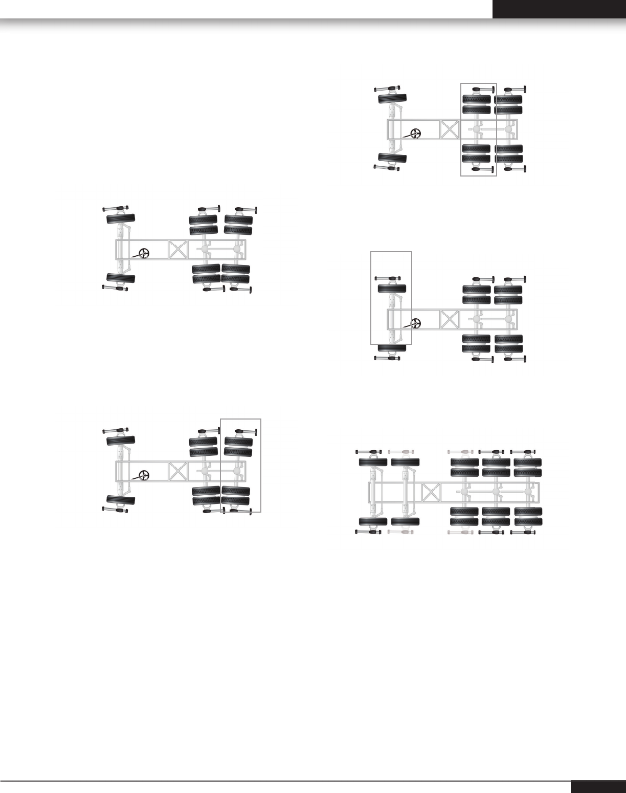
Truck/Bus/Trailer Alignment Procedures
Truck & Bus Axle Configurations
To properly align heavy-duty trucks, buses and trailers, it is
necessary to fi rst determine the axle confi guration. WinAlign
15.0 software offers more than 50 confi gurations of trucks,
tractors and trailers. The correct alignment process is
automatically loaded based on the chosen confi guration.
Hunter’s DSP760 sensors offer the advantage of measuring
and adjusting a trailer while still attached to the truck / trailer.
Twin steer vehicle confi gurations guide the technician through
the adjustment process, including establishing parallelism
between the steer axles.
Truck Bus Axle Configurations
Trucks Buses
26
Alignment Angles and Effects 27
Education Guide: Wheel Alignment on Heavy Duty Trucks
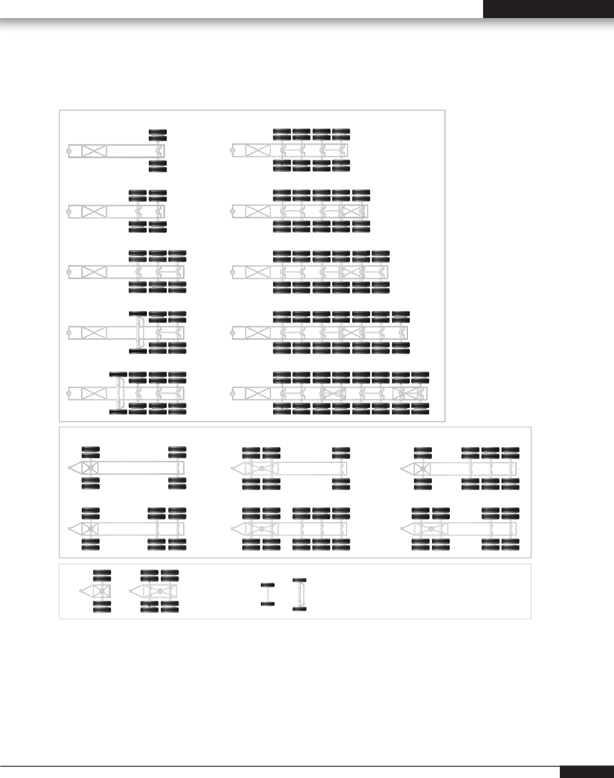
Trailer Axle Configurations
Truck Bus Axle Configurations
Semi-Trailers
Full Trailers
Dollies Cars / Light Truck

A
Ackerman Principle: An alignment principle based
on vehicle tread width and wheelbase upon which
turning angle is computed.
Ackerman Arm: A steering component, which
provides interconnection between the outer tie rod
and spindle.
Alignment: The process of measuring and
adjusting the position of all wheels attached to a
common chassis.
Angle: Two intersecting lines that are not parallel.
Arc: Any part of a circle or a curved line.
Axial Play: Vertical movement of the wheel and tire
assembly when inspecting a kingpin.
B
Balance: This term is used to describe having
equal weight distribution about the circumference of
a wheel and tire assembly.
Bead: A wire steel coil forming an anchor for
individual plies and rim attachment of a tire.
Bellows: A rubber type seal, which is folded to
allow for a telescopic action. Normally referred to as
a bellows boot.
Bias Belted: A bias ply tire that has reinforcing
strips or belts under the tread section.
Bias Ply: A tire constructed of alternate plies, which
intersect the tire centerline at approximately 35
degrees.
Body Roll: The leaning of the vehicle body while
cornering.
Braking Control: Vehicle stability related to the
reaction under all stopping conditions.
Bushing: A component made of metal or rubber-
type material, used to isolate interconnected moving
parts.
C
Cam Bolt: A bolt and eccentric assembly which,
when rotated, will force components to change
position.
Camber: The inward or outward tilt of the wheel.
Camber Roll: A change in camber brought about
by suspension changes while cornering.
Caster: The forward or rearward tilt of the steering
axis.
Center Bolt: A bolt that provides centering and
attachment of an axle and spring assembly.
Centerline Steering: A centered steering wheel
while the vehicle is traveling a straight ahead course.
Chassis: All major assemblies on a vehicle
including suspension, steering, drivetrain, and
frame. Everything, except the body.
Circumference: The total distance around a circle.
Concentric: Two or more components sharing a
common center.
Conicity: A tire irregularity, which causes the tire to
take the shape of a cone when infl ated and loaded.
This may generate a lateral force.
Contact Area: The total amount of tread surface
that contacts the road.
Cornering: The ease at which a vehicle travels a
curved path.
Cross Tube Assembly: Two tie rods and a tube,
which transfers the turning effort to the opposite
side of the vehicle.
Curb Weight: The overall weight of a vehicle, less
passengers, luggage, or load.
D
Degree: A unit of measurement to describe an
angle.
Glossary
28

Alignment Angles and Effects 29
Education Guide: Wheel Alignment on Heavy Duty Trucks
Dial Indicator: An instrument used to measure
and display linear displacement. Measurement is
displayed on a dial face and the scale is commonly
graduated in thousandths.
Directional Stability: The tendency for a vehicle to
maintain a directed path.
Drag Link: A tube or rod used for interconnection
between
Pitman Arm and tie-rod assemblies.
Dynamic Balance: This normally refers to the
balance condition of a wheel and tire assembly in
motion.
F
Foot Pound: A unit of measurement used to
describe torque force.
Frame Angle: The angle formed by a horizontal line
and a line drawn parallel to the frame.
G
Geometric Centerline: A line drawn between the
midpoint of the front axle and the midpoint of the
rear axle.
H
Horizontal: Parallel or level with the plane of the
horizon.
Hub: The assembly that houses the bearings about
which the wheel and tire assembly rotates.
Hydraulic Pump: A power driven device generating
constant volume and pressure.
I
Included Angle: The sum of the angles, camber
and SAI.
Independent Suspension: A suspension system
that provides an isolated mounting for each wheel to
the chassis.
Individual Toe: The angle formed by a horizontal
line drawn through the plane of one wheel versus a
centerline.
Intersect: The crossing point of two lines.
Jounce Travel: A suspension moving up through its
travel.
K
Kinetic Balance: The balance condition of a
rotating wheel related to force generated in a
vertical plane.
King Pin: A pin used to attach a spindle to an axle.
L
Lateral Run-out: Side-to-side movement with a
rotating wheel or tire.
Lead: A slight tendency for a vehicle to move away
from its directed course.
Linkage: A series of rods or levers used to transmit
motion or force.
Load Range: A system used to describe the service
or weight limitations of a tire.
M
Memory Steer: A condition where the wheels,
rather than returning to straight ahead, tend to
remember and seek a previous position.
Millimeter: A unit of linear measurement. One
millimeter is equivalent to 0.039 inches.
Minute: A unit of measurement used to describe
an angle. One minute is equivalent to 1/60 of one
degree.
O
Offset: The lateral displacement of a wheel or axle
in respect to a centerline.
Oscillate: A back and forth motion at a specifi c
frequency.

Out-of-Round: A wheel and tire irregularity in
which one or both are not concentric with its axis of
rotation.
Overinfl ation: Infl ation pressure beyond that which
is recommended.
Oversteer: A characteristic in which a vehicle has a
tendency to turn sharper than the driver intends.
P
Parallelogram Steering Linkage: A steering
linkage design where if all pivot points were
connected by lines, these lines would be parallel.
Perpendicular: Being at right angles.
Pitman Arm: A steering component that provides
interconnection between the steering gear sector
shaft and the steering linkage.
Ply Rating: A method of rating tire strength. Not
necessarily indicative of the actual number of plies
used.
Power Steering: A steering system that
incorporates hydraulics to assist in the steering of
the wheels.
Pre-load: A predetermined amount of load or force
applied during assembly to prevent unwanted play
during actual operation.
Pull: The tendency for a vehicle to steer away from
its directed course.
R
Radial Play: Any lateral movement of the wheel
and tire assembly when inspecting a ball-joint or
kingpin.
Radial Ply Tire: A tire construction type with
alternating plies 90 degrees to the tire bead.
Radius: The distance from the center to the outer
edge of a circle.
Rear Axle Departure Offset: The amount in
inches from the midpoint of the steer axle (or
kingpin on a trailer), where the projected thrustline
intersects.
Rebound: A suspension moving down through its
travel.
Recirculating Ball Steering Gear: A steering
gear design that is made up of a worm shaft, ball
nut, and two recirculating ball circuits.
Returnability: The tendency of the front wheels to
return to a straight ahead position.
Road Crown: The slope of a road from its center.
Road Feel: Necessary feedback transmitted from the
road surface up to the steering wheel.
Road Isolation: The ability of a vehicle to better
separate road irregularities from the driver and
passengers.
Road Shock: An excessive amount of force
transmitted from the road surface up to the steering
wheel.
S
Scrub Radius: The radius formed at the road
surface between the wheel centerline and steering
axis.
Semi-Integral Power Assist: A power assist
system using a hydraulic pump and a power cylinder
in conjunction with the steering gear.
Setback: The angle formed between a centerline
and a line perpendicular to the front axle.
Shim: Thin material of fi ber or metallic makeup
used to take up clearance between two parts.
Shimmy: A violent shake or oscillation of the front
wheels transmitted up to the steering wheel.
Shock Absorber: A suspension component used
to dampen spring oscillation.
Solid Axle Suspension: A suspension system
consisting of one steel or aluminum I-beam
extended the width of the vehicle.
Short Long Arm (SLA): An independent
suspension design incorporating unequal length
control arms.
30

Alignment Angles and Effects 31
Education Guide: Wheel Alignment on Heavy Duty Trucks
Spindle: A component on which a wheel and tire
assembly rotates.
Stability: The tendency of a vehicle to maintain a
directed course.
Stabilizer: A steel bar used to minimize body roll.
Steering Axis Inclination: The angle formed by
an imaginary line drawn through the steering axis
versus vertical.
Steering Gear: A mechanical device used to
convert the rotary motion at the steering wheel to a
lateral motion.
Steering Shaft: A tube or rod, which interconnects
the steering wheel to a lateral motion.
Strut: Any support used between two parts.
Suspension: An assembly used to support weight,
absorb and dampen shock, help maintain tire
contact and proper wheel to chassis relationship.
Suspension Height: The specifi ed distance
between one or more points on a vehicle to the road
surface.
T
Tandem Lateral Offset: When the geometric
centerline does not cross the midpoint of all axles.
Tandem Scrub Angle: The angle formed by the
intersection of horizontal lines drawn through each
rear axle when total toe and the offset is zero.
Thrust Angle: The angle formed by thrustline and
geometric centerline.
Thrustline: A bisector of rear total toe.
Tie Rod Assembly: The outer most assemblies on
a parallelogram steering linkage. These assemblies
are attached to the drag link and Ackerman Arms.
Tie Rod End: The ball and socket assembly of a tie
rod.
Tie Rod Sleeve: A threaded tube that provides
connection and adjustment of a tie rod assembly.
Tire Force Variation: A tire irregularity, in which
there is a difference in radial stiffness about the
circumference of the tire.
Toe: The comparison of a horizontal line drawn
through both wheels of the same axle.
Turning Angle: The difference in the turning angle
of the front wheels in a turn.
Torsion Bar: A spring steel bar used in place of a
coil spring.
Tracking: The interrelated paths taken by the front
and rear wheels.
Treadwidth: The dimension as measured between
the centerlines of the wheels on the same axle.
Treadwear Indicators: Ridges molded between
the ribs of the tread that visibly indicate a worn tire.
U
Under Infl ation: Air pressure below that which is
s p e c i fi e d .
Understeer: A characteristic in which a vehicle has
a tendency to turn less than the driver intends.
V
Vertical: Being exactly upright or plumb.
Vibration: To constantly oscillate at a specifi c
frequency.
W
Waddle: The lateral movement of a vehicle, usually
caused by some type of tire or wheel imperfection.
Wander: The tendency of a vehicle to drift to either
side of its directed course.
Wheelbase: The dimension as measured between
the center of the front and rear axles.

Form 995-T-2, 01/17
Supersedes form 995-T-2, 09/06
0117EH
Copyright © 2017, Hunter Engineering Company
www.hunter.com
