A Novel Route Selection And Resource Allocation Approach To Improve The Efficiency Of Manual Material Handling System In 200 Mm Materia
User Manual:
Open the PDF directly: View PDF ![]() .
.
Page Count: 14
IEEE TRANSACTIONS ON AUTOMATION SCIENCE AND ENGINEERING, VOL. 13, NO. 4, OCTOBER 2016 1567
A Novel Route Selection and Resource Allocation
Approach to Improve the Efficiency of Manual
Material Handling System in 200-mm
Wafer Fabs for Industry 3.5
Chen-Fu Chien, Member, IEEE, Che-Wei Chou, and Hui-Chun Yu
Abstract—Motivated by realistic needs to enhance the
productivity for 200-mm wafer fabs, this paper aims to propose a
novel approach for manual material handling system (MMHS) to
mimic functionalities of the automated material handling system
in the advanced fabs without intensive capital investment to
deliver the wafer lots manually and systematically. In particular,
a mathematical model is developed to optimize the routing plan
with two objectives that minimize the total traveling distance in
all routes or minimize the number of manpower needed in all
routes. Furthermore, a route planning approach is proposed to
utilize the routes that reduce the technician traveling distance
and transportation time for implementation. Also, a manpower
loading index was developed for evaluating the number of needed
technicians in the proposed MMHS. To estimate the validity of the
proposed MMHS, we developed a simulation environment based
on empirical data with different transportation requirement
scenarios for comparison. The results have shown practical
viability of the proposed approach.
Note to Practitioners—As advanced manufacturing strategies
such as Industry 4.0 are proposed for smart production, 200-mm
wafer fabs cannot be equipped with fully automation facilities
such as the automated material handling system to enhance
overall productivity. To address the needs in real settings,
a disruptive innovation manual material handling system was
developed, on the basis of existing 200-mm fab facility, to
organize the technicians to mimic the setting of a virtual material
handling system manually to enhance productivity. Indeed, the
developed solution has been implemented in this case company,
in which the results have validated the proposed approach that
can be a hybrid between the existing Industry 3.0 and to-be
Industry 4.0.
Index Terms—Fab economics, Industry 3.5, manpower allo-
cation, manual material handling system (MMHS), productivity,
route planning.
Manuscript received April 30, 2016; accepted June 11, 2016. Date of
publication July 19, 2016; date of current version October 4, 2016. This
paper was recommended for publication by Associate Editor M. Liu and
Editor H. Ding upon evaluation of the reviewers’ comments. This work
was supported in part by the Ministry of Science and Technology, R.O.C.
under Grant NSC 102-2221-E-007-057-MY3, Grant NSC 103-2622-E-007-
002-TM1, Grant NSC 102-2622-E-007-013, and Grant MOST 103-2218-E-
007-023, in part by the Toward World Class University Project within the
Ministry of Education under Grant 105N536CE1, and in part by Taiwan
Semiconductor Manufacturing Company under Grant 102A0287JC.
The authors are with the NTHU-TSMC Center for Manufacturing Excel-
lence, Department of Industrial Engineering and Engineering Manage-
ment, National Tsing Hua University, Hsinchu 30013, Taiwan (e-mail:
cfchien@mx.nthu.edu.tw).
Color versions of one or more of the figures in this paper are available
online at http://ieeexplore.ieee.org.
Digital Object Identifier 10.1109/TASE.2016.2583659
I. INTRODUCTION
SEMICONDUCTOR fabrication facilities (fabs) are the
most capital-intensive and complex manufacturing plants
that consists of lengthy re-entrant processes including clean-
ing, oxidation, deposition, metallization, lithography, etching,
ion implantation, photoresist strip, inspection, and measure-
ment [1]. The wafers pass through approximately several
hundred processing steps for wafer fabrication, in which opera-
tional efficiency and productivity enhancement via maximizing
the throughput and yield, while minimizing cycle time, are
critical for maintaining competitive advantages [2], [3].
Automation in modern fabs enables efficient material han-
dling between resources to reduce cycle time and manufactur-
ing cost [4]. In particular, the advanced 300-mm fabs rely on
automated material handling system (AMHS) to manage the
wafer transportation in fabs [5], [6]. Furthermore, Germany
has proposed a manufacturing strategy, Industry 4.0 [7], for
smart factory via cyber-physical systems and decentralized
decisions within a smart and networked platform. However,
most existing 200-mm fabs that find it difficult or cost effective
to install AMHS employ technicians maneuvering the trolleys
for moving the wafer lots [8].
Motivated by realistic needs to empower 200-mm wafer
fabs, this paper aims to propose a disruptive innovation via
manual material handling system (MMHS) that mimics the
AMHS functionalities by technicians and reduces the trolley
accidents effectively. However, since the technicians may
decide by themselves the wafer lots and the corresponding
transportation route, some lots may be delayed causing cycle
time increase, while serious trolley accidents happen causing
injuries and yield loss. It is important to determine the
standard operating procedures and manage the transportation
routes for the technicians to avoid these issues. In particular,
a mathematical model is developed to optimize the routing
plan with two objectives that minimize the total traveling
distance in all routes or minimize the number of manpower
needed in all routes. Furthermore, a route planning approach
is also proposed to utilize the routes that reduce the technician
traveling distance and transportation time in a short time for
implementation. Also, a manpower loading evaluation model
is developed for determining the appropriate number of tech-
nicians for the MMHS. In order to estimate the validity of the
proposed MMHS approach, a simulation model was developed
1545-5955 © 2016 IEEE. Personal use is permitted, but republication/redistribution requires IEEE permission.
See http://www.ieee.org/publications_standards/publications/rights/index.html for more information.
1568 IEEE TRANSACTIONS ON AUTOMATION SCIENCE AND ENGINEERING, VOL. 13, NO. 4, OCTOBER 2016
based on empirical data collected in the largest 200-mm fab
in a leading semiconductor manufacturing company in Taiwan
for comparison under different scenarios. The results have
shown practical viability of the proposed approach. Indeed,
the proposed MMHS has been employed in the case study.
Indeed, the proposed approach can be Industry 3.5, namely,
a hybrid approach between the existing Industry 3.0 and the
to-be Industry 4.0 platform.
The remainder of this paper is organized as follows.
Section II reviews related approaches for material handling for
semiconductor manufacturing. Section III describes the pro-
posed approaches for route planning and manpower evaluation.
Section IV estimates the validity of the proposed approach
with simulation and scenario analyses. Section V discusses
the implementation of this approach. Section VI concludes this
paper with a discussion of contributions and future research
directions.
II. LITERATURE REVIEW
The wafers pass through hundreds of production steps of re-
entrant processing flows in the fab, in which material handling
of the wafers is critical to enhance productivity. Thus, AMHS
is effectively employed in advanced fabs to enable efficient
delivery of the wafer lots [5], [6]. In particular, the facility
design and material handling system design are two major
designs that will influence the fab productivity [5]. Many
studies have addressed the design of the AMHS. For example,
Peters and Yang [9] proposed a network flow formulation
to integrate the layout and material handling system design
for both spine and perimeter layout configurations. More-
over, Ting and Tanchoco [10] proposed two rectilinear layout
configurations, the unidirectional loop and bidirectional loop
layout, which connected the tools to stockers to minimize the
total loaded travel distances in fabs.
Indeed, the spine unidirectional configuration has no inter-
section and the involved traffic management, vehicle routing,
and dispatching decisions are simple [11]. Therefore, the spine
configuration is a general layout of the AMHS with a loop in
one direction.
Similar to a general tandem configuration, segmented flow
configuration design consists of one or more mutual zones
that are nonoverlapping segments with a single vehicle serving
each segment [12]. Indeed, the segmented flow configuration
design has higher efficiency than conventional systems by
eliminating the congestion and blocking of vehicles [13].
However, the segmented flow configuration design requires
additional transfer stations [14]. Hsieh et al. [15] proposed
a segmented configuration design for AMHS which used a
dual-track bidirectional loop design to eliminate congestion
and blocking to reduce the cycle time and increase stocker
utilization.
Yu and Egbelu [16] developed a partitioning algorithm
that grouped the workstations into a number of single-vehicle
zones based on variable path routing for nonoverlapping
tandem configuration while minimizing the number of vehicles
and satisfying the total workload. In addition, meta-heuristic
approaches were employed to deal with the partitioning
problem of the tandem configuration design [17], [18].
Aarab et al. [19] developed a hierarchical classification
approach to group the workstations based on a similarity
coefficient considering the flows and the distances between
workstations.
Vehicle fleet sizing problem for determining the number
of vehicles is critical for achieving the performance and
minimizing the vehicle cost for AMHS. A number of studies
have developed mathematical programming models [20]–[22],
queuing models [23]–[25], or simulation models [26]–[28] to
solve the vehicle fleet sizing problem. Furthermore, multiload
vehicles were proposed to picks up additional wafer lots while
transferring a previously assigned load, indicating better per-
formance than single-load vehicles via simulation [29], [30].
Hung and Liu [31] modified previous single-load vehicle
studies and proposed a model to estimate the number of
multiload vehicles needed to improve the system performance.
However, a complicated material handling control system is
required to employ multiload vehicles [14].
The material handling control systems [12], [14] were
developed to fulfill transportation demands and avoid traffic
conflicts among the vehicles with the following functions:
1) vehicle dispatching rule to select a vehicle to execute a
transportation demand;
2) vehicle scheduling to dispatch the vehicles for trans-
portation demands under certain constraints such as
capacity and priority;
3) vehicle routing to find a suitable path for a pickup or
delivery of a dispatched wafer lot.
It is difficult to schedule the vehicles over a long horizon
in a fab with high arraival stochasticity. In order to quickly
respond to transporation requests, heuristic dispatching rules
are employed to reduce cycle time, wafer waiting time, and
delivery time, as well as to improve throughput, vechicle
utilization, and machine utilization [32], [33]. A number of
studies have been done to address route planning that decides
the route for a vehicle to picks up the working pieces and the
visiting sequence with the most efficient resource utilization
and the minimum traveling distance and cost [34]–[36].
In conventional unidirectional (CU) route planning, Sinriech
and Tanchoco [37] proposed the optimal single-loop route
planning based on integer programming in an automated
guided vehicle system. While the vehicles ran with the same
direction path and uniform speed, the material handling system
would not congest with the optimal single-loop route. How-
ever, the automated guided vehicle system may not be suitable
for a large-scale material handling system with great number
of vehicles and stations [34]. Asef-Vaziri et al. [38] developed
an optimal unidirectional loop route to serve manufacturing
cells in an automated guided vehicle system, in which the
vehicle transported working piece following the assigned loop
route including corresponding pickup and delivery stations.
In AMHS, the material flow is influenced by routing strate-
gies such as static routing [39] and dynamic routing [40], [41].
In particular, Kim et al. [39] proposed a simple blocking
prevention method for a path-based AMHS based on swap-
ping the load assignments between retrieval vehicles on the
same path. The simulation showed that their approach could
improve productivity under various vehicle dispatching rules.
CHIEN et al.: NOVEL ROUTE SELECTION AND RESOURCE ALLOCATION APPROACH TO IMPROVE THE EFFICIENCY OF MMHS 1569
Fig. 1. Illustration of MMHS configuration in a 200-mm fab.
Bartlett et al. [40] proposed a congestion-aware dynamic
routing approach to efficiently reroute vehicles as congestion
status changes such as vehicle breakdowns and thus reduced
the frequency of heavy congestion. Lau and Woo [41] devel-
oped an agent-based dynamic routing strategy for a loop-
based network including the generation of feasible routes,
reconfiguration of system parameters, and management of fault
situations that can generate good routes in terms of cycle time,
utilization, and ability to balance network loading.
However, the present problem addressed material han-
dling in 200-mm fabs that cannot install the AMHS and
in which the technicians maneuver the trolleys to carry
the wafer lots dynamically. There is a need to deter-
mine manpower allocation and route planning. For example,
Faaland and Schmitt [42] developed a cost-based heuristic to
determine the manpower and machines needed in the assembly
workshop. Süer et al. [43] focused on the cell loading and
product sequencing problems and proposed a three-phase
methodology to allocate manpower to the operation cells.
Guyon et al. [44] proposed an approach to simultaneously
assign a work pattern to each operator and form a feasible
schedule to solve the employee scheduling and production
scheduling problems. Chien et al. [45] employed genetic
algorithm and response surface methodology to determine the
operator–machine assignment under different product mix to
minimize machine interference time and labor cost in the IC
final testing facility.
Indeed, there is no study to address related issues for the
MMHS problem for 200-mm wafer fabs in real settings.
Therefore, a mathematical model and an analytical model
were developed in this paper to address the routing plan and
manpower evaluation.
III. METHODOLOGY
A. Problem Description
Focusing on real needs in the largest 200-mm fab in a
leading semiconductor company in Taiwan that consists of two
production lines equipped with tools in six production bays:
diffusion (DIF), chemical vapor deposition, physical vapor
deposition, etching (ETH), photo lithography (PHO), and ion
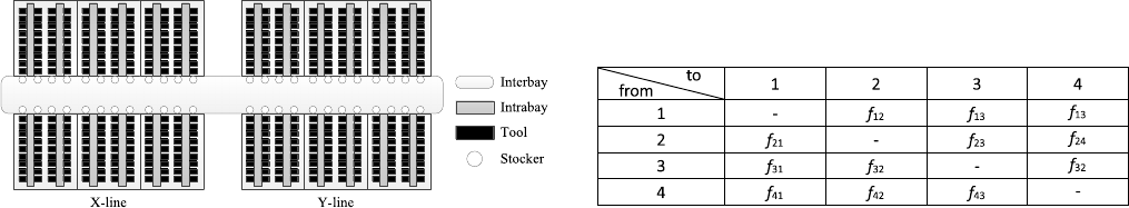
implant (IMP). The proposed MMHS has a loop layout that
connects twin fab tools with a length of more than 200 m as
shown in Fig. 1. Although the X-line and Y-line can be treated
as independent production lines, they can back up each other
to enhance overall productivity. Therefore, it is inevitable to
have cross-line transportation of the wafer lots.
TABLE I
FROM–TOFLOW TABLE
The wafer material handling system is a single-loop interbay
design to deliver the wafer lots manually by technicians.
A number of stockers are located among the production bays
to store temporary wafer lots before they are transported.
A stocker has 32 temporary racks to store the output wafers
from tools and the input wafers waiting for next processing
tool. The wafer lot was first placed onto a stocker by techni-
cian. Each stocker is regarded as an entry (or exit) point to
(from) an intrabay.
The trolleys used in the MMHS are multiload trolleys
that can store up to 12 wafer lots. According to the pri-
ority information provided by the manufacturing execution
system (MES), the technicians load the wafer lots from the
beginning stockers to the terminal stockers in the unidirec-
tional loop configuration following the interbay design of the
AMHS. Then, another technician in charge of the correspond-
ing production bay will move the wafer lots from stockers
to the tools within the production bay following the intrabay
design of the AMHS.
The from–to flow table was employed to denote the wafer
lot that moved among stockers. fij denotes the number of
wafer lots that are expected in the planning period to be moved
from stocker ito stocker j,wherei= j. An example of four
stockers in the material handling system is illustrated. Given
the number of technicians, Table I extracts the from–to flows
indicating the relationships among stockers, which illustrates
the demands via CU transportation.
The efficiency of the MMHS is difficult to evaluate through
the number of technicians and from–to flow table. Therefore,
when the technicians cannot fulfill the transport demand, the
conventional approach will add technicians to resolve the
shortage problem, yet will increase the manpower cost.
It is difficult to control and manage the MMHS system.
Since there are many stockers, numerous multiload trolleys,
and cross-line transportation in the 200-mm fab, the route
planning is complicated. The transportation control system of
MMHS is not similar to AMHS which could receive all the
transportation requests and assign vehicles immediately by the
computational control system. In addition, the technicians are
not automatic vehicles. They could not execute the compli-
cated routing plan accurately. The technician tends to have his
or her discretion for transporting the wafer lots and thus may
cause traffic accidents and wafer damages. Hence, it is very
important to develop a simple and highly efficient routing plan
to meet the transportation request in MMHS.
This paper focused on the interbay design of the MMHS
to assign the route and allocate the corresponding stockers
to the technicians to improve the efficiency and reduce the

1570 IEEE TRANSACTIONS ON AUTOMATION SCIENCE AND ENGINEERING, VOL. 13, NO. 4, OCTOBER 2016
average transportation time of the MMHS. Based on domain
knowledge, three indices including efficiency (E), minimal
number of manpower needed (G), and average transportation
time (TT) were used to evaluate the MMHS performance and
thus derive the optimal solution. In particular, the efficiency
is calculated by dividing the total transportation demand (F)
by the total traveling distance (D) in the planning period as
follows:
E=F
D(1)
where Fdenotes the total transportation demand, which is the
sum of all wafer lots from stocker ito stocker j, i.e., F=
ijfij.Dindicates the total traveling distance, which is
the sum of all trolley’s traveling distance, i.e., D=gdg,
where dgrepresents the traveling distance by technician (g).
That is, the more wafer lots are transported per distance, the
more efficient the MMHS is.
The manpower needed is the minimal technicians required
to fulfill transportation demand while keeping the MMHS
uncongested. The average transportation time is the sum of
the average waiting time on the stocker (ws) and the average
transportation time on the trolley (wt). The waiting time begins
from the wafer lot put on stocker until the wafer lots are
loaded onto the transportation trolleys. The transportation time
on the trolley is from the time the wafer lots are loaded
onto the trolleys to the time they arrive at the terminal stocker.
The transportation time is regarded as the service level of
the MMHS.
B. Mathematical Model
Before further discussion, the notations used below are
summarized as follows.
Indices:
i,j,p,qIndex of stockers, i,j,p,q=1,2,...,N.
sIndex of beginning stockers, s=1,2,...,N.
rIndex of routes, r=1,2,...,R.
Parameters:
fij Number of wafer lots expected to be moved from
stocker ito stocker jin the planning period,
where i= j.
λrTrolley’s traveling frequency in route rin the
planning period.
vijr Wafer transported from stocker ito stocker jin
route r.
tsi Transportation time from beginning stocker sto
stocker i.
dsi Distance between stocker sand stocker i.
vTransportation velocity of a trolley.
Lir Number of wafer lots on a trolley while it stops
at an intermediate stocker iin route r.
ArTotal trip time of trolley in route r.
tl Loading time from beginning stocker to trolley.
tu Unloading time from trolley to destination stocker.
LDrTotal wafer loading time by technician in route r.
ULDrTotal wafer unloading time by technician in
route r.
OT Operation time for transportation technician.
drTotal trip distance of all trolleys based on route r.
cTrolley capacity.
MLarge positive number.
Decision Variables:
grNumber of trolleys needed in route r.
xir =1,if trolley picks up wafer from stocker iin route r
0,otherwise
xsr =1,if trolley stops at stocker sin route r
0,otherwise.
The mathematical programming formulation of the MMHS
routing problem is described as follows:
Objective function
Min
R
r=1
dr(2)
or
Min
R
r=1
gr(3)
subject to
dr≥2dsiλr−M(1−xir)∀r,s,i=s+1,...,N
(4)
Lir ≥
i−1
p=s
N
q=i+1
vpqr +
N
q=i+1
i−1
p=s
vqpr
−M(1−xir)∀r,s,i=s+1,...,N−1(5)
R
r=1
vijr =fij ∀i,j(6)
N
i=s+1
xir ≤(N−s)xsr ∀r,s(7)
λr≤Mxsr ∀r,s(8)
N
j=1
vijr +
N
j=1
vjir ≤Mxir ∀r,s(9)
j−1
p=s
N
q=j
vpqr ≤cλr∀r,s,j=s+1,...,N(10)
j−1
p=s
N
q=j
vqpr ≤cλr∀r,s,j=s+1,...,N(11)
Ar≥2λrmax
i{tsixir}−M(1−xir)
∀r,s,i=s+1,...,N(12)
LDr=tl
N
i=1
N
j=1
vijr ∀r(13)
ULDr=tu
N
i=1
N
j=1
vijr ∀r(14)
gr≥(Ar+LDr+ULDr)/OT ∀r(15)
xir ∈{0,1}∀i,r(16)
CHIEN et al.: NOVEL ROUTE SELECTION AND RESOURCE ALLOCATION APPROACH TO IMPROVE THE EFFICIENCY OF MMHS 1571
xsr ∈{0,1}∀s,r(17)
gr≥0,and integer ∀r(18)
λr≥0,and integer ∀r(19)
where
E=N
i=1N
j=1fij
R
r=1dr
(20)
G=
R
r=1
gr.(21)
Objective function (2) is used to minimize the total traveling
distance in all routes. Alternatively, objective function (3)
arms to minimize the number of manpower needed in all
routes. Constraint (4) specifies the total trip distance drbased
on route r.dris obtained by multiplying two (for round
trip), the distance between the beginning stocker sand the
end stocker iof the route r, and its service frequency λr
together. The large positive number Mand the 0–1 variable
xir in constraint (4) ensure that dris the maximum of the
distance dsi between stocker sand all stockers iin the
route r. If a route ris not formed, i.e., all xir =0,
the large positive number Mwill make dr=0. Constraint
(5) defines Lir that is determined by the wafer lots pickup
at a previous stocker pand alight at a subsequent stocker q,
i.e., Lir is the total wafer lots (vpqr and vqpr)servedbythe
round trip of the route rbetween stocker pand stocker q.
Constraint (6) denotes the transportation demand fij between
stockers iand jwhich must be fulfilled by all wafer lots
vijr served by all routes. Constraints (7) and (8) obtain route
r. All trolley trips based on route rstart from a beginning
stocker s,wherexsr =1, i.e., the trolley stops at stocker s,
and load and unload wafer lots. If xsr =0, route rcannot
be formed while trolley does not stop at stocker s,i.e.,all
xir in constraint (7) and the trip frequency λrin constraint
(8) are equal to zero. Constraint (9) ensures that no wafer
lot can load or unload at stocker i, if route rdoes not stop
at stocker i. Constraints (10) and (11) are capacity limitation
constraints that denote total wafer lots served by a one-way
trip of route rwhich must be accommodated by the trolley
capacity of the corresponding trips. Constraint (12) defines the
total trip time of trolley Arin route rwhich is restricted by
multiplying its traveling frequency λrand its running time of
round trip between the beginning stocker sand ending stocker
i(maxi{tsixir }), i.e., considering the running time by maximal
distance of a round trip. Constraints (13) and (14) denote
the total wafer loading and unloading time by technician
in route r. Constraint (15) determines the minimum number
of trolley needed, gr, in route r. For each route r,the
number of trolley required is the sum of total trolley traveling
time, loading time, and unloading time, divided by operation
time of transportation technician. Constraints (16) and (17)
define the binary variables of decision variables xir and xsr.
Constraint (18) obtains decision variable gras a nonnegative
real number. Constraint (19) denotes the trolley’s traveling
frequency λras a nonnegative real number. Constraint (20)
obtains the efficiency of a MMHS system which is cal-
culated by dividing the total transportation demand by the
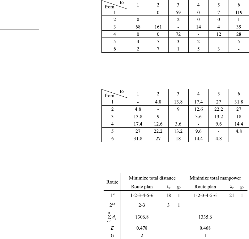
TABLE II
FROM–TOFLOW TABLE OF THE SMALL-SCALE NUMERICAL EXAMPLE
TABLE III
DISTANCE BETWEEN EACH STOCKER OF THE
SMALL-SCALE NUMERICAL EXAMPLE
TABLE IV
RESULT OF THE SMALL-SCALE NUMERICAL EXAMPLE
total traveling distance. Constraint (21) indicates the minimal
manpower needed which is the sum of number of trolleys that
maneuvered by technicians in route r.
To validate the mathematical model, a small-scale numerical
example was demonstrated. In this case, there are six stock-
ers in the MMHS. The transportation demand of MMHS is
shown in Table II, and the distance between each stocker is
listed in Table III. The transportation velocity of a trolley (v)
was set at 0.56 m/s. The operational time for loading (tl)and
unloading (tu) of wafer lots from stockers was set as 10 s. The
capacity limitation of trolley is 12 wafer lots. In this paper, the
small-scale test problem was solved through the mathematical
model by using LINGO software.
First, we considered objective function (2) to minimize
the total traveling distance in all routes that were subject
to constraints (4)–(21). Then, LINGO was used to generate
the optimal solution to the mathematical model. Second, we
alternatively considered objective function (3) to minimize
the manpower needed in all routes that were also subject to
constraints (4)–(21). Table IV illustrates an optimal route plan
that includes the manpower needed, total traveling distance,
and the efficiency of the MMHS system.
1572 IEEE TRANSACTIONS ON AUTOMATION SCIENCE AND ENGINEERING, VOL. 13, NO. 4, OCTOBER 2016
In Table IV, there are two routes allocated to two tech-
nicians for minimizing total traveling distance, 1306.8 m,
in objective function (2). One technician transported wafer
lots in round trip with first route (1-2-3-4-5-6) that stops at
each stocker. The other technician transported wafer lots only
between stocker #2 and stocker #3 with the second route (2-3).
Alternatively, one route was allocated to one technician
for minimizing total manpower in objective function (3).
The technician was assigned to the route (1-2-3-4-5-6) to
transport wafer lots with total traveling distance in MMHS.
In conclusion, the optimal route plan was determined by the
objective function. The proposed mathematical model can
address the present MMHS problem.
However, the proposed mathematical model may not be able
to generate the optimal route plan in real settings because
of computational limitations. Indeed, the MMHS problem in
200-mm fab is a complex and large-scale problem. It takes
much computational time to solve the mathematical model
in MMHS. It is not efficient in semiconductor manufacturing
environment. Furthermore, the mathematical model that is
formulated with different objectives could solve the MMHS
problem to minimize the total traveling distance in all routes
or minimize the manpower needed in all routes. However, it
is crucial to simultaneously consider multiple and conflicting
objectives to optimize the route plan and manpower allocation
in real MMHS settings. Therefore, this paper proposed an
analytical model to solve the MMHS problem in real setting.
C. Proposed Analytical Model
This paper proposes a route planning approach to deter-
mine the routes and to allocate the corresponding number of
technicians simultaneously. Two types of transportation flows
are considered: forward transportation (FWDT) and backward
transportation (BWDT). A technician starts the FWDT by
moving forward in a loop configuration to transport the wafer
lots from the left-side stocker to the right-side stocker. When
a technician reaches the end of the lane, he or she starts
the BWDT that rolls over to deliver the wafer lots from the
right-side stocker to the left-side stocker. The BWDT needs to
confirm all the transportation demands to be fulfilled, while the
demands arise from left-side stockers to right-side stockers.
The path flow (pij)is the total number of wafer lots
that pass along the corridor between stocker iand the next
stocker jin the planning period, that is
pij =
p≤i
q≥j
fpq ∀i,j,p,q=1,2,...,N;i= j(22)
where fpq is the wafer lots needed to be transported from
stocker pto stocker q,andNdenotes the total number of
stockers. While fpq is given in this paper, the path flow is not
only a metric to measure the congestion of the MMHS, but is
also regarded as a consequence of routing decision.
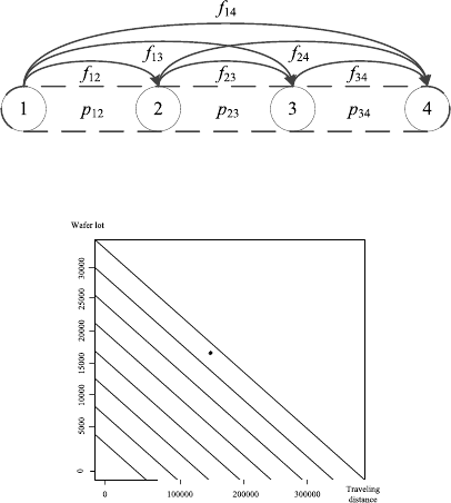
Fig. 2 shows an example of path flows. A technician
carries wafer lots from stocker 1 which consists of different
destination stockers. The path flow p12 is the accumulated
number of wafer lots that transport from stocker 1 to stocker 2,
which is equal to f12 +f13 +f14 based on (22). When the
Fig. 2. Illustration of path flow.
Fig. 3. Illustration of the manpower work loading of the MMHS.
technician passes through stocker 2, he or she unloads ( f12)
and loads wafer lots ( f23 +f24)to next stocker. Then, the
path flow p23 is f13 +f14 +f23 +f24. Finally, before arriving
at stocker 4, the path flow p34 is f14 +f24 +f34,wherethe
wafer lots are delivered to stocker 4.
This paper also evaluates the manpower workload for people
productivity by considering two indices: the traveling distance
and the number of wafer lots for transportation in the planning
period. This evaluation assumes that each technician follows a
repetitive working procedure of first loading the wafers from
the stockers, then transporting the wafer lots by trolleys, and
finally unloading the wafer lots to stockers. Fig. 3 illustrates
manpower workload, where the x-axis represents the total
traveling distance by all technicians and the y-axis stands for
the total number of wafer lots the technicians transported. Each
line represents the cumulative transportation capacity as each
additional technician is added. The dot shows the workload
of the technicians. When the dot is located on the diagonal
line, denoting a specific number of technicians, they are all
working at full capacity. The manpower workload is evaluated
by the transported wafer lots and the corresponding traveling
distance. The optimal number of needed technicians can thus
be derived. As shown in Fig. 3, the minimal manpower needed
to satisfy the transportation requirements is eight technicians
in the MMHS.
Based on the transportation requirements from a given
from–to flow table, the manpower can be determined for
the MMHS. In addition, this paper develops a novel route
planning (NRP) approach to design the routes to be assigned to
each of the corresponding technicians that satisfied technician
workload limitation with high transportation efficiency and
good service without congestion.
Following the route planning in Fig. 4, the ranges of routes
can be generated, in which the technicians have been assigned
a distinct route that defined the corresponding beginning and
ending stockers. While the route is assigned with a wide range,
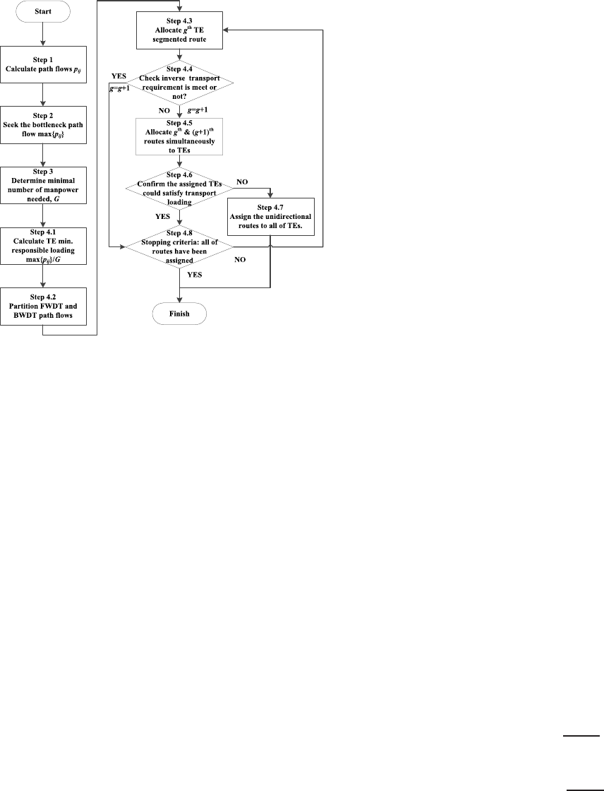
CHIEN et al.: NOVEL ROUTE SELECTION AND RESOURCE ALLOCATION APPROACH TO IMPROVE THE EFFICIENCY OF MMHS 1573
Fig. 4. Proposed route planning procedures.
the technicians can load and unload wafer lots from more
stockers, which confirms that wafer lots could be delivered in
a reasonable waiting time. On the other hand, the technicians
that were assigned a route with a narrow range can move
more wafer lots contributing to the increase in the frequency
of round trip. That is, the technicians with a wide route could
cover all stockers fulfilling transportation demand. The tech-
nicians with a narrow route can transport more lots to increase
efficiency. Hence, the MMHS efficiency can be improved. The
proposed route planning procedures are as follows.
Step 1) Calculate the path flow pij for stocker iand the next
stocker jbased on (22). According to the from–to
table, the transportation flow can be specified for
each demand. The overall transportation flow can
be derived by computing the path flow of FWDT
and BWDT. Note that pij can be converted into
pi,i+1in FWDT and pi,i−1in BWDT.
Step 2) Identify the bottleneck path flow, max{pij}, that
contains the maximal accumulated wafer lots from
stocker ito next stocker j. Indeed, stocker iis the
earliest stocker to be blocked when using CU route
planning in which technicians traverse from the first
left-side stocker to the last right-side stocker.
Step 3) Determine the total number of technicians
needed (G)using the manpower loading evaluation
approach based on the from–to flow table without
considering route planning, i.e., all technicians
transport in the same unidirectional loop routes.
First, calculate the minimal traveling frequency
(λ) based on trolley capacity (c)considering the
bottleneck path as follows:
λ=max
i,j{pij}/c.(23)
Note that the technician is at least loaded λ−1 times with full
loads plus one more load with (0, full] load, so that Stocker i
will not be congested. Then, the total traveling distance (D)
is determined by multiplying two (for round trip), the distance
between the first stocker and the end stocker (d1,N), and its
minimal traveling frequency (λ) together as follows:
D=2d1,Nλ. (24)
Then, compute the total traveling distance and obtain all
transportation flows from the from–to flow table to derive the
total workload of the technicians in the MMHS. Finally, derive
the total manpower workload and thus determine the minimal
number of needed technicians based on their loading including
traveling distance and transportation flows. In addition, the
slope that formed by the dot and the origin in Fig. 3 is
derived by total taking wafer lots (ijfij) divided by total
traveling distance (D). The slope denotes the efficiency which
measures the transportation efficiency, i.e., an assigned flow
route, where the shorter the traveling distance is, the more the
efficiency is.
Furthermore, the following procedures are employed to
assign the route to the technician, respectively.
Step 4.1) Calculate the minimal responsible loading for each
technician, i.e., max{pij}/G. That is, each techni-
cian needs to transport at least max{pij}/Gwafer
lots from stocker i; otherwise, stocker iwill be
blocked and congested.
Step 4.2) Path flows of both FWDT and BWDT are parti-
tioned by dividing with the minimal responsible
loading. After splitting the path flows of the stock-
ers, the overall traffic flow in the MMHS can be
estimated, in which the minimal required wafer lots
for the stockers to be transported are managed to
avoid congestion.
Step 4.3) Determine the route for each technician based on
the corresponding transportation flow of techni-
cian g,(G−g/G)·max{pij}. In FWDT, the route
of technician gstarts at stocker i,wherethepath
flow is greater than (G−g/G)·max{pij}, and ends
at stocker Nof the loop configuration. Thus, the
initial stocker and the end stocker for FWDT and
BWDT are derived as follows:
FWDT:min i|pij ≥G−g
G·max{pij},N
(25)
BWDT:max i|pij ≥G−g
G·max{pij},1.
(26)
Note that the gth technician was assigned to be in
charge of the boundary stocker at the end of the
configuration. It is designed to let the technician
load as many wafer lots as possible, while the
trolley still has empty space in one trip. Hence,
the gth technician can improve utilization and
share the transportation loading of other (G−g)
technicians.
1574 IEEE TRANSACTIONS ON AUTOMATION SCIENCE AND ENGINEERING, VOL. 13, NO. 4, OCTOBER 2016
Step 4.4) Ensure (G−g) technicians can handle the trans-
portation flows of inverse transportation, i.e., when
the first assigned is FWDT, the inverse trans-
portation is BWDT. While the gth technician has
been assigned a route, his traveling distance can
be reduced by reducing the transportation scope.
Thus, the other (G−g) technicians need to trans-
port the wafer lots in the inverse transportation that
the gth technician has not covered. Go to Step 4.8
and check the other technicians that have been
assigned routes; otherwise, continue to Step 4.5 to
assign the next route allocation for the (g+1)th
technician.
Step 4.5) Assign the gth and (g+1)th technicians to take
charge of the routes according to (25) and (26),
respectively, where g=g+1. If the gth technician
cannot fulfill the transportation demands with the
corresponding gth route in both FWDT and BWDT
flows, the inverse transportation will be congested
while using the gth route and the other unassigned
routes. Thus, we need to assign both the gth and
(g+1)th technicians to satisfy the transportation
requirements.
Step 4.6) Confirm that the assigned gth technician, the
(g+1)th technician, and the other unassigned tech-
nicians can satisfy the transportation requirements.
Ifnot,gotoStep4.7.Otherwise,gotoStep4.8.
As the gth and (g+1)th technicians are assigned
to the corresponding routes in Step 4.5, confirm
that the gth technician can back up transportation
requirements for the (g+1)th technician who is in
charge of the inverse transportation, respectively.
That is, the gth technician should be able to carry
out twice the required transportation in the range of
his corresponding route that substitutes the (g+1)th
transportation flow. Also, the inverse transportation
should be checked at the same time. The gth route
and (g+1)th route are determined to ensure that
the transportation system will not be congested,
since the gth and (g+1)th technicians may share
the loading of other technicians. Therefore, the
other technicians who were not given assigned
routes can still transport the wafer lots in the same
unidirectional route.
Step 4.7) If the assigned technicians, gth and (g+1)th,
cannot satisfy the transportation requirements, the
transportation system will be congested. Therefore,
the unassigned technicians are all allocated to
unidirectional routes to transport the wafer lots.
Step 4.8) Stop the route planning, if all routes have been
assigned. Otherwise, return to Step 4.3.
IV. SIMULATION AND RESULTS
Given the complex and lengthy processing steps in the fabs,
simulation has been widely used for analyzing the AMHS for
semiconductor manufacturing [27], [46], [47]. A simulation
model of the proposed MMHS was developed with eM-Plant
based on empirical data collected in a 200-mm twin fab in a
leading semiconductor manufacturing company in Taiwan to
test the feasibility and estimate the validity of the proposed
approach under different transportation requirement scenarios.
The tradeoff among the performance indices are also illustrated
in scenario analyses.
A. Simulation Assumptions
The proposed MMHS was employed for the largest
200-mm twin fab with two production lines in this empirical
study. The material handling system consisted of 42 stockers,
and the transportation requirements were obtained from real
settings. For confidentiality issues, the data and transportation
flow of the MMHS were transformed without loss of generality
for validation. The settings are designed as follows.
1) The transportation velocity of a trolley (v)was set
at 0.56 m/s.
2) The operational time for loading (tl) and unloading (tu)
of wafer lots from stockers was set at 10 s.
3) The wafer lot output time was exponentially distributed.
4) The capacity limitation of stocker was 32 wafer lots.
5) The capacity limitation of trolley c=12 wafer lots.
6) The trolley dispatch rule of the MMHS was set as the
first come first serve (FCFS).
7) The wafer lot dispatch rule of the MMHS was designed
as a weighted priority index (WP
m)considering lot
priority (LP
m), remaining queue time index (QIm),
waiting time on the stocker (WI
m), and transportation
distance index (DIm)of wafer lots, that is
WP
m=ym(α1LP
m+α2QIm+α3WI
m+α4DIm)
(27)
where there are mwafer lots on the stocker, and α1,α2,
α3,andα4denote the weight parameters, α1+α2+α3+
α4=1, that were determined by the preference of the
domain expert. LP
mrepresents the production priority
of wafer lot, scoring from 0 to 1, which is determined
by the production planner. QImis determined by the
remaining queue time (RQm)divided by its processing
limited queue time (LQm),i.e.,QIm=RQm/LQm.
WI
mis equal to the maximum waiting time of wafer lots
on the stocker (maxm{WT
m})subtracted from its waiting
time (WT
m)and divided by maxm{WT
m}, i.e., WI
m=
(maxm{WT
m}−WT
m/maxm{WT
m}).DImdefines the
transportation distance of the wafer lot (TD
m)divided
by the maximum transportation distance of wafer lots
on the stocker, i.e., DIm=TD
m/maxm{TD
m}.ym
is the Boolean binary that controls the priority index.
If the queue time (QTm)of the wafer lot longer
than its processing limited queue time, ym=0;
otherwise, ym=1.
While the trolley stopped at a stocker, the technician
checked the priority information of the wafer lot from the MES
and then transports the wafer lots according to their priorities
determined by the dispatch rule to satisfy multiple objectives.
Note that the wafer lot with smaller priority index indicates
higher priority. The technicians load and unload the wafer lots
CHIEN et al.: NOVEL ROUTE SELECTION AND RESOURCE ALLOCATION APPROACH TO IMPROVE THE EFFICIENCY OF MMHS 1575
TABLE V
SIMULATION SCENARIO
from the stockers and use trolleys to move them in a clockwise
direction.
The wafer lots whose processing from the tools in the
production bay is completed will be moved to the preassigned
stocker until they are ready to be transported by technicians
for the next process. If the storage racks of the stockers
are full, the stockers will not be available until technicians
transport previously loaded wafer lots to their destination
stockers. Meanwhile, the completed wafer lots will remain
inside the tools if they cannot be moved to next location. The
transportation will not be affected during the meal time in the
simulation since other technicians can back up.
B. Experimental Design
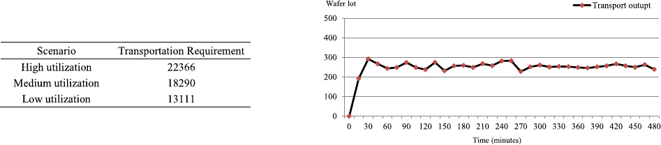
To validate the proposed route planning approach, three
scenarios of different utilization levels, i.e., high, medium,
and low, were examined with historical data in 200-mm
fab as shown in Table V. Six route planning approaches
were employed to compare the performances of the
proposed MMHS.
Hung and Liu [31] proposed an analytical model (AM) by
modifying the vehicle fleet size estimation model [20] to esti-
mate the multiload vehicle requirement in an automated guided
vehicle system for minimizing empty vehicle travel time
(see the Appendix). Thus, the AM approach can determine
the manpower needed and assign the technician to transport
wafer lots in the same direction in the 200-m fab.
The present approach (PS) assigns the technicians to trans-
port wafer lots according to their corresponding production
bay. For example, the technicians who are in charge of PHO
production bay carry wafer lots from the stockers located in
PHO production bay to its destination stockers (Fig. 1), i.e., the
technician’s route is assigned to only take the wafer lots from
his or her corresponding production bay and transport them to
the destination stocker in the loop configuration layout.
The CU approach computes the manpower needed by using
the manpower loading evaluation approach which is proposed
in this paper. However, the technician’s route planning follows
the CU path. i.e., CU approach assigns every technician to
transport wafer lots in one direction in the loop configuration
layout of the MMHS.
To comprehensively compare the route planning methods
in this paper, we also ran Dijkstra’s algorithm [48] which
is used to solve the shortest path (SP) problem. We applied
AM and CU approaches to determine the manpower needed
and assigned the technicians to follow Dijkstra’s algorithm for
generating route plan that is named as AM-SP and CU-SP,
respectively. When the technicians picks up wafer lots based
on weighted priority index (WPm), the system will calculate
the shortest path by Dijkstra’s algorithm. Then, the technician
Fig. 5. Partial transport output of the MMHS.
follows this request to move to the destination. In addition,
while wafer lots are loaded and unloaded, the route plan will
be updated depending on transported wafer lots that are loaded
on a trolley.
The proposed NRP approach determines the needed man-
power and allocates technicians who follow routes to transport
wafer lots. To reduce the randomness of the simulation model,
we ran ten replications for each scenario. The pilot run was
designed to reach a steady state. Therefore, only after a steady
state was reached, the warm-up period could be determined.
As shown in Fig. 5, a transient period was for 60 min and
then the data collection began and lasted for 10 days.
C. Route Planning
To demonstrate the proposed route planning approach, the
medium utilization scenario of the MMHS is used for the
following Illustration.
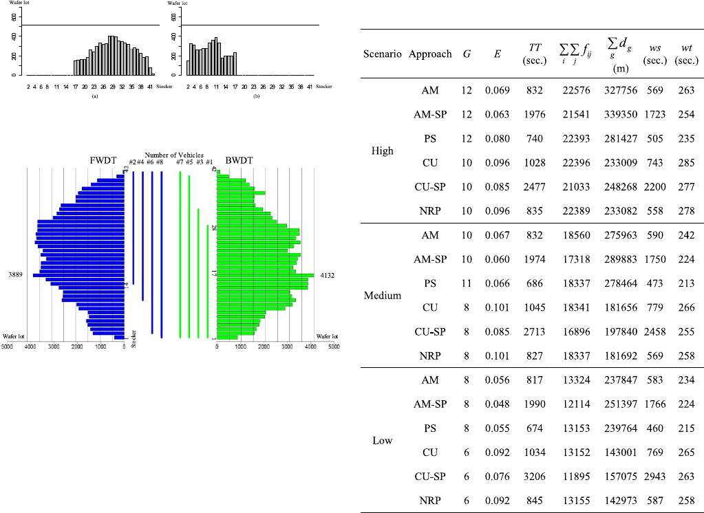
First, in Step 1, the path flows based on the given from–to
flow table were calculated for FWDT and BWDT, respectively.
In Step 2, max{pij}=4132 was specified, which was between
the 17th stocker and the 16th stocker in the BWDT mode.
In Step 3, the minimal traveling frequency,
λ=4132/12=345, was computed based on the
bottleneck path flow and the trolley capacity. Also, the total
traveling distance, D=2d1,Nλ=161 561, was determined.
Then, we evaluated manpower workload based on traveling
distance and transporting wafer lots. Fig. 3 shows the
transformed working hour into the number of loaded wafer
lots and the distance moved, respectively. Thus, the minimal
manpower needed for the MMHS was derived to be eight
technicians.
Second, the routes were designed as follows. In Step 4.1,
the calculated max{ pij}/Gwas 517 wafer lots, which was
equal to the minimal responsible loading. In Step 4.2, both
FWDT and BWDT were partitioned by dividing the path
flows from the minimal responsible loading of 517 wafer
lots. In Step 4.3, we assigned the first technician with the
first route {28,1} traveling in the BWDT mode using (26).
In Step 4.4, we checked whether seven technicians can
meet the transportation requirements at inverse transporta-
tion, FWDT. However, FWDT still had to be done by eight
technicians. Thus, we needed to simultaneously allocate the
first and second technicians to take charge of the respective
BWDT {28,1} and FWDT routes {14,42} in Step 4.5. As the
first technician had transported the wafer lots between the 28th
stocker and the first stocker, the second technician transported
1576 IEEE TRANSACTIONS ON AUTOMATION SCIENCE AND ENGINEERING, VOL. 13, NO. 4, OCTOBER 2016
Fig. 6. Path flow chart of Step 4.6 for the medium utilization scenario.
Fig. 7. Route planning result of medium utilization in the MMHS.
wafer lots between the 14th stocker and the 42nd stocker.
To guarantee the assigned technicians fulfilling the minimal
required wafer lots, we need to check, in Step 4.6, whether
the assigned first and the second routes met the transportation
requirements in the BWDT and FWDT modes simultaneously.
For the BWDT mode, seven technicians were needed
to transport wafer lots in the range of {42,28}, yet eight
technicians were required to reach the bottleneck stocker of
the range {17,1}. However, the second technician had been
assigned to be responsible for the range of {14,42}in the
FWDT mode. Thus, it was necessary to confirm whether the
first technician could transport two-eighths of the original
transportation requirements in the bottleneck stocker of the
range {17,1}, and the other unassigned six technicians could
deliver the remaining six-eighths of the transportation require-
ments in the BWDT mode. The path flows were recalculated
based on the two-eighths transportation requirements of the
from–to flow table in the range of {17,1}. We found that
the first technician could meet the transportation flow under
his minimal responsible loading, i.e., 517 wafer lots. For
the FWDT mode, the checking procedure is the same with
different ranges, respectively. Fig. 6 shows the path flow chart
of the two-eighths requirements. That is, it was confirmed
that the assigned first and second routes could satisfy the
transportation requirement in Step 4.6. The route planning
procedures stopped after all of the technicians were assigned
in Step 4.8.
That is, as shown in Fig. 7, the route planning of the eight
routes in the MMHS is as follows: #1:{28,1}, #2:{14,42},
#3:{32,1}, #4:{10,42}, #5:{40,1}, #6:{2,42}, #7:{42,1},and
#8:{1,42}.
Thus, the range of the routes was narrowed down con-
tributing to the increase in the frequency of round trip.
TABLE VI
SIMULATION RESULTS OF THREE SCENARIOS
The technicians moved the wafer lots on the stockers with
higher transportation frequency in their corresponding routes.
Consequently, the efficiency of the MMHS and the trans-
portation time are improved with this proposed route planning
approach.
D. Simulation Results
Six approaches were compared in the simulation model
developed for the real setting MMHS problem under three
scenarios. Table VI lists the comparison results with three
measures, i.e., the efficiency (E), the manpower needed (G),
and the average transportation time (TT), in which each result
denotes the average of ten replications.
As shown in Table VI, the number of technicians determined
by the proposed manpower loading approach was fewer than
those derived from PS and AM approaches. Also, the results
are all significantly different from the two approaches, PS and
NRP, at the level α=0.05 in each scenario. Furthermore,
the efficiency comparisons showed 20.7%, 53.3%, and 67.7%
improvement rates for the high, medium, and low utilization
scenarios, respectively, showing that the proposed NRP was
more efficient than the PS approach.
In addition, the AM approach overestimates the manpower
needed because of assuming that each time an empty trolley
could load all wafer lots equal to its fully loading capacity
with the same destination stocker. Alternatively, the technician
CHIEN et al.: NOVEL ROUTE SELECTION AND RESOURCE ALLOCATION APPROACH TO IMPROVE THE EFFICIENCY OF MMHS 1577
may load wafer lots from different stockers and often
have different destination stockers. In practice, the trolley
may not be fully loaded during every trip because of the
wafer lot output rate. Therefore, the AM approach has a
long traveling distance that deteriorates the transportation
efficiency.
Compared with the average transportation time, AM-SP and
CU-SP have shorter transportation times on the trolley due
to application of the shortest path for route plan. However,
the traffic congestion happened in MMHS, which resulted
in a long transportation time on the stocker. The wafer lots
were queued on the stockers. The efficiency was worse than
that obtained using other approaches. Indeed, AM-SP and
CU-SP cannot fulfill the transportation demand of three sce-
narios even if the transport manpower is the same for AM and
CU approaches, respectively.
Furthermore, the NRP approach had a shorter transportation
time than the CU approach, implying that the waiting time
on the stocker was reduced. Note that the NRP and CU
approaches have used the same manpower loading evaluation
approach except routing planning. The NRP approach con-
siders the route planning that designed shorter empty trip for
transportation of trolley, and thus the technician could visit the
stockers and pick the corresponding wafer lots up as early as
possible to reduce the wafer waiting time on stockers. Note
that the transportation time of the PS was shorter than that
of others. However, its efficiency was significantly worse than
that of others at the level α=0.05.
Therefore, both the NRP and CU approaches were more
efficient than the PS, AM, AM-SP, and CU-SP approaches.
The NRP approach reduced the transportation time signifi-
cantly compared with the CU approach. Indeed, the proposed
NRP approach assigns the efficiency routes to the technicians
reducing the transportation time with the best performance
among other approaches.
V. DISCUSSION
The developed solution has been implemented in this case
company. The results have shown practical viability of the
proposed approach and performance indices to enhance the
efficiency of the proposed MMHS and improve the overall
fab productivity. In particular, each work shift can save two
transport technicians in MMHS, i.e., 16% people productivity
improvement, while the average transportation time is still
keep at the same service level. Meanwhile, the efficiency is
also improved by at least 20% subject to the transportation
demands.
A number of studies have investigated the control strategies
for AMHS. However, few studies have addressed similar
control strategies for MMHS in real settings. While the pro-
posed MMHS mimics AMHS, this paper developed effective
approach and performance indices to determine the routes and
allocate the corresponding manpower needed. The proposed
approach provides an adaptive and flexible control policy for
efficiently maintaining transportation performance of MMHS
in the real setting of 200-mm fab.
While AMHS was constrained in 200-mm fabs due to fab
configuration, the proposed approach provides an adaptive and
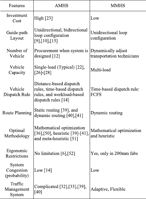
TABLE VII
COMPARISON OF AMHS AND MMHS
flexible manpower allocation and route planning to empower
the proposed MMHS. Table VII addresses the differences in
features between AMHS and MMHS.
An AMHS spends a significant share of a 300-mm fab
investment cost, U.S. $2–3 billion, as much as 3%–5% of the
total fab cost [23], [49]. Alternatively, the proposed MMHS
requires only labor cost for transportation and associated
variable cost which are much lower than the capital investment
of AMHS.
The AMHS should not be a bottleneck in wafer manufac-
turing fab, and thus AMHS design is critical for constraints
and assumptions. The minimum number of vehicles has to be
determined while AMHS is designed [12] considering different
scenarios. However, a fab configuration, capacity portfolio,
and product mix are often change as semiconductor manu-
facturing technologies migrate, causing difficult adjustments
of the constructed AMHS. Alternatively, the proposed MMHS
can adjust the needed manpower and the corresponding routing
flexibly in light of the transportation demands considering
production plan and product mix change.
The vehicle capacity is single load in AMHS [22]–[28].
However, the proposed MMHS employs multiload trolley
to picks up additional lots while transferring a previously
assigned wafer lot to improve system performance [29]–[31].
The AMHS in a 300-mm fab generally employs unidirectional
loop configuration [9], while some AMHS studies [10], [15]
1578 IEEE TRANSACTIONS ON AUTOMATION SCIENCE AND ENGINEERING, VOL. 13, NO. 4, OCTOBER 2016
designed bidirectional loop configuration to eliminate conges-
tion and blocking.
Vehicle dispatch rules help AMHS and MMHS control
vehicles when a vehicle picks up wafer lots, a vehicle reaches
its destination stocker, and a vheicle unloads wafer lots.
Depending on the objective of dispatch rules, three types of
dispatch rules were addressed in AMHS [14].
1) Distance-based dispatch rules based on traveling dis-
tances or time, including shortest travel time first rule
and nearest vehicle first rule.
2) Workload-based dispatch rules considered queue sizes
of wafer lots in the stockers. There rules include maxi-
mum outgoing queue size rule and minimum remaining
outgoing queue space rule.
3) Time-based dispatch rules depended on waiting time of
wafer lots, such as the FCFS rule.
In MMHS, the time-based dispatch rule, FCFS, was applied.
While a trolley stops at a stocker, the technician will follow
a weighted priority index (WP
m)which determines the wafer
lot priority to load. The technician usually takes several wafer
lots onto the trolley due to multiload trolley design.
There are two types of routing strategies in AMHS such
as static routing [39] and dynamic routing [40], [41]. The
static route planning employs static strategies such as shortest
distance, least utilization, random assignment, round robin,
and CU algorithms for route planning. The dynamic route
planning needs to change periodically to fulfill the trans-
portation demands. The proposed MMHS has a central lane
designed for multiload trolley transferring wafer lots in a
200-mm fab. The designed routing can be adjusted dynami-
cally in light of new demands by using the proposed approach.
In general, the optimization methodologies of AMHS rout-
ing problem are classified into three catagories: mathemati-
cal optimization, heuristic, and meta-heuristic. Mathematical
optimization approaches search optimal routing plan based
on objective functions, such as transportation cost, vehicle
cost, balancing of routes, and wait time [36], [50]. Heuristics
are problem-specific approaches that take advantage of the
problem properties to derive the routing plan [39], [40].
Meta-heuristics are general heuristic schemes that can be
applied to many complicated and large-scale routing problems
in AMHS [51]. In this paper, a mathematical model that
is formulated with different objectives, minimizing the total
traveling distance in all routes or minimizing the manpower
needed in all routes, was addressed to solve the MMHS
routing problem. However, this model cannot generate the
optimal route plan because of computational limitations with
real settings. And it is also crucial to simultaneously consider
multiple and conflicting objectives to optimize the route plan
and manpower allocation. Therefore, this paper also devel-
oped a novel heuristic approach to provide an efficient route
planning.
AMHS traffic management is complicated due to large-
scale stockers and vehicles used in fab [32], [33], [39], [40].
It is a very important task to prevent the traffic congestion
and keep the wafer transportation efficient. In this paper, we
provided an NRP approach to manage all trolley’s routes with
high efficiency. Besides, this routing plan is also adaptive and
flexible, which was validated through a simulation model and
really implemented on MMHS system in a 200-mm fab based
on transportation request.
VI. CONCLUSION
To empower existing 200-mm fabs, this paper developed
a novel MMHS approach as an illustration of Industry 3.5
as a hybrid strategy between the existing manufacturing for
Industry 3.0 and to-be Industry 4.0. In particular, a mathe-
matical model was constructed to address the MMHS routing
problem that was formulated with two objectives to minimize
the total traveling distance in all routes or minimize the
manpower needed in all routes. Since it cannot generate the
optimal route plan because of computational limitations in
real settings, it is crucial to simultaneously consider multiple
conflicting objectives to optimize the route plan and manpower
allocation. This paper also developed a novel approach for
route planning that considers the path flows of segmented
configuration to obtain the route planning in light of trans-
portation requirements and a data-driven from–to flow table
and determines the manpower needed for the corresponding
routes. Empirical data collected in the largest 200-mm fab of
a leading semiconductor manufacturing company in Taiwan
were used for validation. The results have shown that the
proposed approach has fairly good performance than others
under different transportation scenarios, showing practical
viability of the developed solution. The proposed approach
can dynamically adjust both the manpower needed and the
routes in light of the change of production system to improve
the efficiency and reduce the transportation time to enhance
overall productivity of the fab. Indeed, the proposed approach
has been implemented in this company.
Further research can be done to integrate the interbay
and intrabay configurations of the MMHS while considering
extra factors such as fab capacity, product mix, and various
layout configurations. Furthermore, since most of the existing
manufacturing facilities cannot easily adopt advanced manu-
facturing strategies such as Industry 4.0 platform, the proposed
hybrid approach, i.e., Industry 3.5, should be extended to
other industries that do not have fully automated systems
for handling the materials to empower existing facilities to
address the needs for smart production. Future research can
be done to examine human–machine collaborations between
humans, trolleys, and robotics with the information collected
by multimode sensors and mobile devices in advanced man-
ufacturing systems. In addition, AMs and big data analytics
can be employed to structure the present problem to generate
the optimal solutions, provide alternative estimates, and derive
empirical rules to enhance the overall effectiveness of MMHS
in real settings.
APPENDIX
The integer linear programming model [20], [31] for esti-
mating the minimal number of multiload vehicles needed is
as follows:
Objective function
min Te=
n
i=1
n
j=1
tijxij (A1)

CHIEN et al.: NOVEL ROUTE SELECTION AND RESOURCE ALLOCATION APPROACH TO IMPROVE THE EFFICIENCY OF MMHS 1579
subject to
n
j=1
xij =
n
j=1
fij/c,∀i(A2)
n
j=1
xji =
n
j=1
fij/c,∀i(A3)
xii ≤⎡
⎢
⎢
⎢⎛
⎝
n
j=1
fji/c
⎞
⎠·⎛
⎝
n
j=1
fji/c/
n
k=1
n
l=1
fkl/c
⎞
⎠⎤
⎥
⎥
⎥
,∀i
(A4)
xij ≥0,and integer ∀i,j(A5)
where
Tt=
n
i=1
n
j=1fij/ctij (A6)
Tl=(tl +tu)
n
i=1
n
j=1
fij (A7)
G=Tt+Tl+Te
Ta.(A8)
Objective function (A1) aims to minimize the total empty
travel time (Te)that aggregates total empty trips from the
ith stocker to the jth stocker (xij)multiplied by its traveling
time (tij), where the vehicle can load with the maximal
capacity (c). Constraint (A2) guarantees that the total num-
ber of empty trips departing from the ith stocker is equal
to the number of multiload of wafer lots delivered there.
Constraint (A3) denotes that the total number of empty trips
terminating at the ith stocker is equal to the total number of
multiload of wafer lots loaded from there. Constraint (A4)
indicates that the number of empty trips depart from the ith
stocker and stop there itself (xii).xii should not be more than
the number of multiload of wafer lots delivered at the ith
stocker multiplied by the fraction of multiload of wafer lots
loaded from the same stocker. Therefore, at most xii-loaded
trips ending at the ith stocker will again start as loaded from
the same stocker. Constraint (A5) defines the positive integer
variable of decision variable xij. Constraint (A6) denotes that
the total vehicle traveling time (Tt)is equal to summation the
traveling time of all loaded trips from the ith stocker to the
jth stocker. Constraint (A7) represents the total loading and
unloading time (Tl), i.e., the summation of accessing wafer
lots loading time (tl) and unloading time (tu). Consequently,
constraint (A8) derives the total vehicles needed (G)during
the planning period, where Tais the total vehicle effective
time.
REFERENCES
[1] C.-F. Chien and C.-H. Chen, “Using genetic algorithms (GA) and a
coloured timed Petri net (CTPN) for modelling the optimization-based
schedule generator of a generic production scheduling system,” Int. J.
Prod. Res., vol. 45, no. 8, pp. 1763–1789, 2007.
[2] C.-F. Chien, Y.-J. Chen, and J.-T. Peng, “Manufacturing intelligence
for semiconductor demand forecast based on technology diffusion and
product life cycle,” Int. J. Prod. Econ., vol. 128, no. 2, pp. 496–509,
2010.
[3] C.-F. Chien, C.-Y. Hsu, and C.-W. Hsiao, “Manufacturing intelligence to
forecast and reduce semiconductor cycle time,” J. Intell. Manuf., vol. 23,
no. 6, pp. 2281–2294, 2012.
[4] R.L.Francis,L.F.McGinnis,Jr.,andJ.A.White,Facility Layout
and Location: An Analytical Approach. Englewood Cliffs, NJ, USA:
Prentice-Hall, 1992.
[5] G. K. Agrawal and S. S. Heragu, “A survey of automated material han-
dling systems in 300-mm SemiconductorFabs,” IEEE Trans. Semicond.
Manuf., vol. 19, no. 1, pp. 112–120, Feb. 2006.
[6] J. R. Montoya-Torres, “A literature survey on the design approaches and
operational issues of automated wafer-transport systems for wafer fabs,”
Prod. Planning Control, Manage. Oper., vol. 17, no. 7, pp. 648–663,
2006.
[7] H. Kagermann, W. Wahlster, and J. Helbig, Recommendations
for Implementing the Strategic Initiative Industrie 4.0: Final
Report of the Industrie 4.0 Working Group. Berlin, Germany:
Federal Ministry of Education and Research, 2013.
[8] W. C. Chen, N. Chiou, J. Y. Lu, J. Yeh, and J. Kuan, “Manual material
handling system,” in Proc. Int. Symp. Semicond. Manuf., 2008, pp. 152–
154.
[9] B. A. Peters and T. Yang, “Integrated facility layout and material
handling system design in semiconductor fabrication facilities,” IEEE
Trans. Semicond. Manuf., vol. 10, no. 3, pp. 360–369, Aug. 1997.
[10] J.-H. Ting and J. M. A. Tanchoco, “Optimal bidirectional spine layout
for overhead material handling systems,” IEEE Trans. Semicond. Manuf.,
vol. 14, no. 1, pp. 57–64, Feb. 2001.
[11] A. Asef-Vaziri and G. Laporte, “Loop based facility planning and
material handling,” Eur. J. Oper. Res., vol. 164, no. 1, pp. 1–11, 2005.
[12] I. F. A. Vis, “Survey of research in the design and control of automated
guided vehicle systems,” Eur. J. Oper. Res., vol. 170, no. 3, pp. 677–709,
2006.
[13] D. Sinriech and J. M. A. Tanchoco, “An introduction to the segmented
flow approach for discrete material flow systems,” Int. J. Prod. Res.,
vol. 33, no. 12, pp. 3381–3410, 1995.
[14] T. Le-Anh and M. B. M. De Koster, “A review of design and control of
automated guided vehicle systems,” Eur. J. Oper. Res., vol. 171, no. 1,
pp. 1–23, 2006.
[15] C.-H. Hsieh, C. Cho, T. Yang, and T.-J. Chang, “Simulation study for
a proposed segmented automated material handling system design for
300-mm semiconductor fabs,” Simul. Model. Pract. Theory, vol. 29,
pp. 18–31, Dec. 2012.
[16] W. Yu and P. J. Egbelu, “Design of a variable path tandem layout
for automated guided vehicle systems,” J. Manuf. Syst., vol. 20, no. 5,
pp. 305–319, 2001.
[17] G. Laporte, R. Z. Farahani, and E. Miandoabchi, “Designing an efficient
method for tandem AGV network design problem using tabu search,”
Appl. Math. Comput., vol. 183, no. 2, pp. 1410–1421, 2006.
[18] T. Y. ElMekkawy and S. Liu, “A new memetic algorithm for optimizing
the partitioning problem of tandem AGV systems,” Int. J. Prod. Econ.,
vol. 118, no. 2, pp. 508–520, 2009.
[19] A. Aarab, H. Chetto, and L. Radouane, “Flow path design for AGV
systems,” Stud. Inform. Control, vol. 8, no. 2, pp. 97–106, 1999.
[20] S. Rajotia, K. Shanker, and J. L. Batra, “Determination of optimal AGV
fleet size for an FMS,” Int. J. Prod. Res., vol. 36, no. 5, pp. 1177–1198,
1998.
[21] P. J. Egbelu, “Concurrent specification of unit load sizes and automated
guided vehicle fleet size in manufacturing system,” Int. J. Prod. Econ.,
vol. 29, no. 1, pp. 49–64, 1993.
[22] Y.-M. Tu, C.-W. Lu, and A. H. I. Lee, “AMHS capacity determination
model for wafer fabrication based on production performance optimiza-
tion,” Int. J. Prod. Res., vol. 51, no. 18, pp. 5520–5535, 2013.
[23] D. Nazzal and L. F. McGinnis, “Analytical approach to estimating
AMHS performance in 300 mm fabs,” Int. J. Prod. Res., vol. 45, no. 3,
pp. 571–590, 2007.
[24] D. Nazzal and L. F. McGinnis, “Expected response times for closed-
loop multivehicle AMHS,” IEEE Trans. Autom. Sci. Eng., vol. 4, no. 4,
pp. 533–542, Oct. 2007.
[25] D. Nazzal, “A closed queueing network approach to analyzing multi-
vehicle material handling systems,” IIE Trans., vol. 43, no. 10,
pp. 721–738, 2011.
[26] J. T. Lin, F. K. Wang, and C. J. Yang, “The performance of the number
of vehicles in a dynamic connecting transport AMHS,” Int. J. Prod. Res.,
vol. 43, no. 11, pp. 2263–2276, 2005.
[27] C.-J. Huang, K.-H. Chang, and J. T. Lin, “Optimal vehicle allocation for
an automated materials handling system using simulation optimisation,”
Int. J. Prod. Res., vol. 50, no. 20, pp. 5734–5746, 2012.

1580 IEEE TRANSACTIONS ON AUTOMATION SCIENCE AND ENGINEERING, VOL. 13, NO. 4, OCTOBER 2016
[28] K.-H. Chang, Y.-H. Huang, and S.-P. Yang, “Vehicle fleet sizing for
automated material handling systems to minimize cost subject to time
constraints,” IIE Trans., vol. 46, no. 3, pp. 301–312, 2014.
[29] Ü. Bilge and J. M. A. Tanchoco, “AGV systems with multi-load carriers:
Basic issues and potential benefits,” J. Manuf. Syst., vol. 16, no. 3,
pp. 159–174, 1997.
[30] J. R. Van der Meer and R. de Koster, “Using multiple load vehicles
for internal transport with batch arrivals of loads,” in New Trends
in Distribution Logistics. Berlin, Germany: Springer-Verlag, 1999,
pp. 197–214.
[31] P.-C. Hung and F.-H. Liu, “Estimation of the fleet size for a multi-load
automated guided vehicle system,” Proc. Nat. Sci. Council, Phys. Sci.
Eng., vol. 25, no. 4, pp. 244–253, 2001.
[32] J. T. Lin, F.-K. Wang, and P.-Y. Yen, “Simulation analysis of dispatching
rules for an automated interbay material handling system in wafer fab,”
Int. J. Prod. Res., vol. 39, no. 6, pp. 1221–1238, 2001.
[33] S. C. Sarin, A. Varadarajan, and L. Wang, “A survey of dispatching rules
for operational control in wafer fabrication,” Prod. Planning Control,
Manage. Oper., vol. 22, no. 1, pp. 4–24, 2011.
[34] L. Qiu, W.-J. Hsu, S.-Y. Huang, and H. Wang, “Scheduling and routing
algorithms for AGVs: A survey,” Int. J. Prod. Res., vol. 40, no. 3,
pp. 745–760, 2002.
[35] M. Saravanan and G. S. Kumar, “Different approaches for the loop
layout problems: A review,” Int. J. Adv. Manuf. Technol., vol. 69,
nos. 9–12, pp. 2513–2529, 2013.
[36] H. Fazlollahtabar and M. Saidi-Mehrabad, “Methodologies to optimize
automated guided vehicle scheduling and routing problems: A review
study,” J. Intell. Robot. Syst., vol. 77, no. 3, pp. 525–545, 2015.
[37] D. Sinriech and J. M. A. Tanchoco, “Impact of empty vehicle flow on
performance of single-loop AGV systems,” Int. J. Prod. Res., vol. 30,
no. 10, pp. 2237–2252, 1992.
[38] A. Asef-Vaziri, G. Laporte, and R. Ortiz, “Exact and heuristic procedures
for the material handling circular flow path design problem,” Eur. J.
Oper. Res., vol. 176, no. 2, pp. 707–726, 2007.
[39] B.-I. Kim, J. Shin, and J. Chae, “Simple blocking prevention for bay type
path-based automated material handling systems,” Int. J. Adv. Manuf.
Technol., vol. 44, nos. 7–8, pp. 809–816, 2009.
[40] K. Bartlett, J. Lee, S. Ahmed, G. Nemhauser, J. Sokol, and B. Na,
“Congestion-aware dynamic routing in automated material handling
systems,” Comput. Ind. Eng., vol. 70, pp. 176–182, Apr. 2014.
[41] H. Y. K. Lau and S. O. Woo, “An agent-based dynamic routing strategy
for automated material handling systems,” Int. J. Comput. Integr. Manuf.,
vol. 21, no. 3, pp. 269–288, 2008.
[42] B. Faaland and T. Schmitt, “Cost-based scheduling of workers and
equipment in a fabrication and assembly shop,” Oper. Res., vol. 41,
no. 2, pp. 253–268, 1993.
[43] G. A. Süer, J. Cosner, and A. Patten, “Models for cell loading and
product sequencing in labor-intensive cells,” Comput. Ind. Eng., vol. 56,
no. 1, pp. 97–105, 2009.
[44] O. Guyon, P. Lemaire, É. Pinson, and D. Rivreau, “Cut generation for
an integrated employee timetabling and production scheduling problem,”
Eur. J. Oper. Res., vol. 201, no. 2, pp. 557–567, 2010.
[45] C.-F. Chien, J.-N. Zheng, and Y.-J. Lin, “Determining the operator-
machine assignment for machine interference problem and an empirical
study in semiconductor test facility,” J. Intell. Manuf., vol. 25, no. 5,
pp. 899–911, 2014.
[46] G. T. Mackulak and P. Savory, “A simulation-based experiment for
comparing AMHS performance in a semiconductor fabrication facility,”
IEEE Trans. Semicond. Manuf., vol. 14, no. 3, pp. 273–280, Aug. 2001.
[47] N. Govind, T. M. Roeder, and L. W. Schruben, “A simulation-based
closed queueing network approximation of semiconductor automated
material handling systems,” IEEE Trans. Semicond. Manuf., vol. 24,
no. 1, pp. 5–13, Feb. 2011.
[48] E. W. Dijkstra, “A note on two problems in connexion with graphs,”
Numer. Math., vol. 1, no. 1, pp. 269–271, Dec. 1959.
[49] J. T. Lin, F. K. Wang, and Y. M. Chang, “A hybrid push/pull-dispatching
rule for a photobay in a 300 mm wafer fab,” Robot. Comput.-Integr.
Manuf., vol. 22, no. 1, pp. 47–55, 2006.
[50] A. Asef-Vaziri, N. G. Hall, and R. George, “The significance of
deterministic empty vehicle trips in the design of a unidirectional loop
flow path,” Comput. Oper. Res., vol. 35, no. 5, pp. 1546–1561, 2008.
[51] W. Qin, J. Zhang, and Y. Sun, “Multiple-objective scheduling for inter-
bay AMHS by using genetic-programming-based composite dispatching
rules generator,” Comput. Ind., vol. 64, no. 6, pp. 694–707, 2013.
[52] M.-J. J. Wang, H.-C. Chung, and H.-C. Wu, “The evaluation of manual
FOUP handling in 300-mm wafer fab,” IEEE Trans. Semicond. Manuf.,
vol. 16, no. 3, pp. 551–554, Aug. 2003.
Chen-Fu Chien (M’03) received the B.S. degree
(Phi Tao Phi Hons.) in industrial engineering and
electrical engineering from National Tsing Hua Uni-
versity (NTHU), Hsinchu, Taiwan in 1990, and
the M.S. degree in industrial engineering and the
Ph.D. degree in operations research and decision
sciences from the University of Wisconsin–Madison,
Madison, WI, USA, in 1994 and 1996, respectively.
He was a Fulbright Scholar with the University
of California at Berkeley, Berkeley, CA, USA, from
2002 to 2003. He received the PCMPCL Training at
the Harvard Business School, Boston, MA, USA, in 2007. From 2005 to 2008,
he was on-leave as the Deputy Director of the Industrial Engineering Division
at Taiwan Semiconductor Manufacturing Company (TSMC), Hsinchu. He is
currently a Tsing Hua Chair Professor with NTHU. He is also the Director
of the NTHU–TSMC Center for Manufacturing Excellence and the Princi-
pal Investigator for the Semiconductor Technologies Empowerment Partners
(STEP) Consortium, Ministry of Science and Technology, Taiwan. He has
received 20 invention patents on semiconductor manufacturing and published
4 books, more than 140 journal papers, and 12 case studies with the Harvard
Business School. His current research interests include decision analysis,
big data analytics, modeling and analysis for semiconductor manufacturing,
manufacturing strategy, and manufacturing intelligence.
Dr. Chien received the National Quality Award, the Distinguished Research
Awards and Tier 1 Principal Investigator (Top 3%) from NSC, the Distin-
guished University-Industry Collaborative Research Award from the Ministry
of Education, the University Industrial Contribution Awards from the Ministry
of Economic Affairs, the Distinguished University-Industry Collaborative
Research Award, the Distinguished Young Faculty Research Award from
NTHU, the Distinguished Young Industrial Engineer Award, the Best IE
Paper Award, the IE Award from the Chinese Institute of Industrial Engi-
neering, the Best Engineering Paper Award and Distinguished Engineering
Professor by the Chinese Institute of Engineers in Taiwan, the 2011 Best
Paper Award of the IEEE TRANSACTIONS ON AUTOMATION SCIENCE AND
ENGINEERING, and the 2015 Best Paper Award of the IEEE TRANSACTIONS
ON SEMICONDUCTOR MANUFACTURING. He is an Area Editor of the
Flexible Services and Manufacturing Journal, an Editorial Board Member
of Computers and Industrial Engineering, an Associate Editor of the Jour-
nal of Intelligent Manufacturing, and an Advisory Board Member of OR
Spectrum. He has been invited to give keynote speech in various confer-
ences, including APIEMS, C&IE, IEEM, and IML, and leading universities
worldwide.
Che-Wei Chou is currently pursuing the
Ph.D. degree with the Department of Industrial
Engineering and Engineering Management, National
Tsing Hua University, Hsinchu, Taiwan.
He has published papers in the IEEE
TRANSACTIONS ON AUTOMATION SCIENCE AND
ENGINEERING and the Journal of Management
and System. His current research interests include
production planning and scheduling, modeling
and analysis for manufacturing, intelligent
manufacturing, and decision analysis.
Hui-Chun Yu received the Ph.D. degree in statis-
tics from National Cheng Kung University, Tainan,
Taiwan, in 2011.
He was a Research Fellow with the NTHU TSMC
Center for Manufacturing Excellence, NTHU,
Hsinchu, Taiwan. He is currently a Senior Data Sci-
entist with TSMC, Hsinchu. He has published papers
in the International Journal of Computational Intel-
ligence Systems and the Journal of Intelligent Man-
ufacturing. His current research interests include
data mining, tool health, modeling and analysis for
manufacturing, and intelligent manufacturing.
