5963_6615E_07.14.05 A_83732B A 83732B
User Manual: A_83732B
Open the PDF directly: View PDF ![]() .
.
Page Count: 8
Specifications describe the instrument’s
warranted performance over the 0° to
55°C temperature range unless other-
wise noted.
Supplemental Characteristics are intended
to provide information useful in estimat-
ing instrument capability in your appli-
cation by describing typical, but not war-
ranted, performance. Note: Supplemental
characteristics are indicated by italic type.
Agilent 83711B and 83712B
Synthesized CW Generators
Agilent 83731B and 83732B
Synthesized Signal Generators
Data Sheet
10 MHz to 20 GHz
1 to 20 GHz
2
Frequency
Range:
Synthesized CW generators
83711B, 1.0 to 20 GHz
83712B, 10 MHz to 20 GHz
Synthesized signal generators
83731B, 1.0 to 20 GHz
83732B, 10 MHz to 20 GHz
Resolution: 1 kHz (1 Hz with Option 1E8)
Stability (with high-stability timebase, Option 1E5)
Aging rate:
<1.5 x 10⁻⁹/day after 24-hour warm up
Temperature effects:
<1 x 10⁻⁷ over 0 to 55° C, nominally <1.4 x 10⁻⁹/° C
Line voltage effects:
<5 x 10⁻¹⁰ for 10% change in line voltage
Stability (without high-stability timebase)
Aging rate:
<1.0 x 10⁻⁸/day after 72 hours at 25° C ± 10° C
Temperature effects:
<5 x 10⁻⁶ over 0 to 55° C referenced to 25° C
Stability (with external 10 MHz reference):
Same as external reference.
Frequency switching time
<50 ms to within 1 kHz for any frequency step
<35 ms to within 1 kHz for <1 GHz steps not across the
10 GHz band switch point
RF Output
Maximum leveled output power:
Frequency Standard with Option 1E1
0.01 to 1 GHz +13 dBm +13 dBm
1 to 18 GHz +11 dBm +10 dBm
18 to 20 GHz +10 dBm + 8 dBm
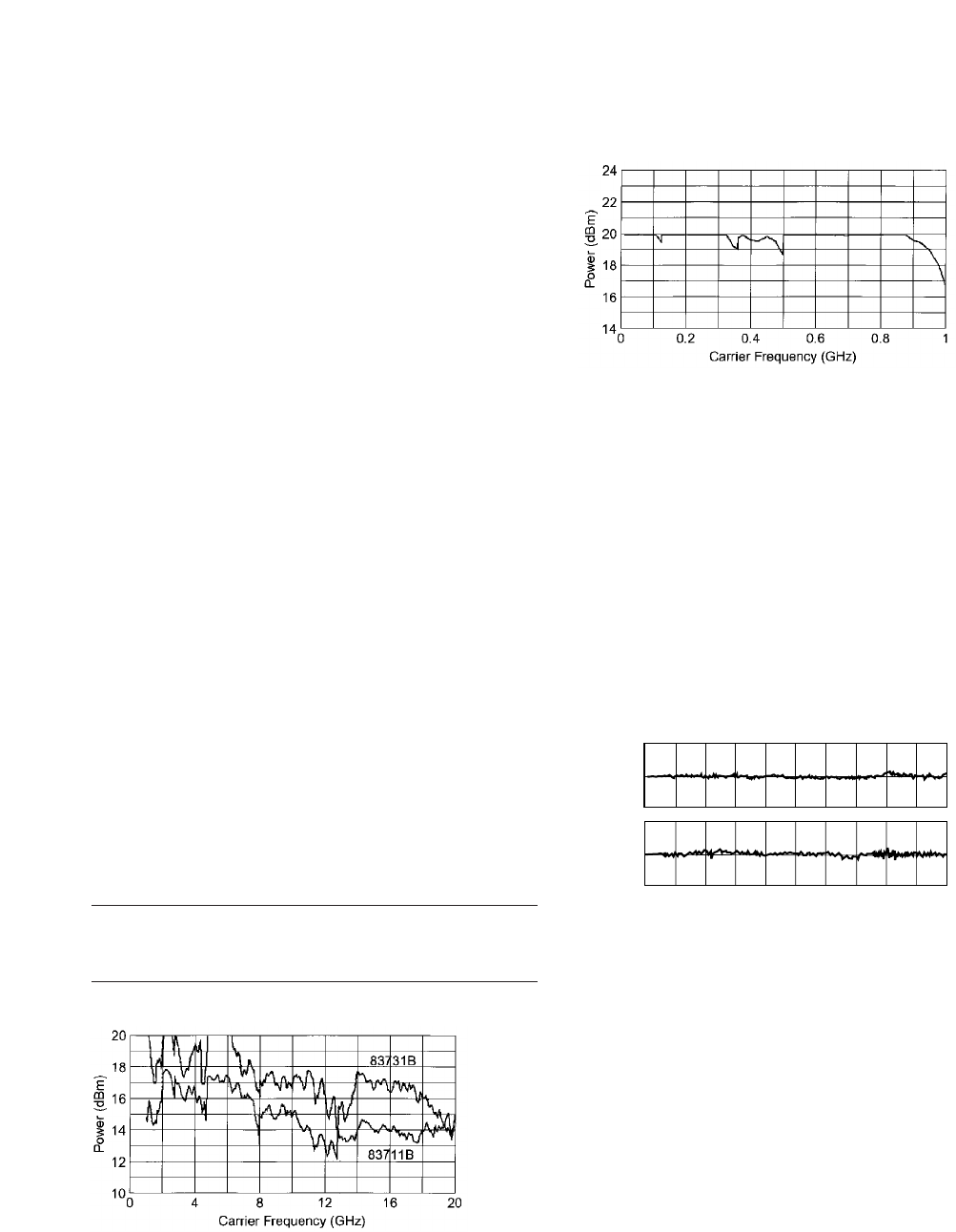
Typical maximum available output power from 1 to 20 GHz,
at 25°C with output step attenuator (Option 1E1) installed
Typical maximum available output power from 0.01 to
1 GHz at 25°C
Minimum leveled output power: –4 dBm
with Option 1E1, –110 dBm
Display resolution: 0.01 dB
Accuracy (–4 dBm1to maximum specified leveled output
power2):
10 MHz to 50 MHz, ±1.3 dB
50 MHz to 20 GHz, ±1.0 dB
Accuracy (over all power levels2):
10 MHz to 50 MHz, ±2.3 dB (power ≥–90 dBm)
50 MHz to 20 GHz, ±2.0 dB (power ≥–90 dBm)
10 MHz to 20 GHz, ±2.5 dB (power < –90 dBm)
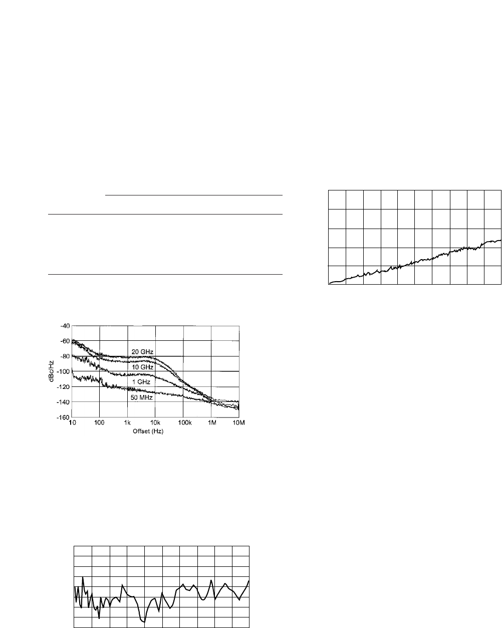
Typical output level accuracy and flatness at +10
and –85 dBm
Flatness:
±0.5 dB2(power ≥–90 dBm)
±0.7 dB2(power < –90 dBm)
Level switching time: <17 ms
(without step attenuator range change)
Attenuator range changes occur at:
83711B, 83712B
–1 dBm, –11 dBm, –21 dBm, etc.
83731B, 83732B
–4 dBm, –14 dBm, –24 dBm, etc.
–10 dBm, –20 dBm, –30 dBm, etc. (linear AM)
Output SWR: <2.0 : 1 nominal
10.5
Output Level (dBm)
Carrier Frequency (GHz)
10.0
9.5
-84.5
-85.0
-86.5 048121620
1. –10 dBm (linear AM)
2. The use of type-N RF connectors above 18.0 GHz degrades specification typically
by 0.2 dB.
3
User Flatness (Level) Correction
Number of points: 2 to 401 points/table
Number of tables: up to 4
Entry modes: power meter, GPIB
Spectral Purity
SSB phase noise (dBc/Hz, CW mode):
Offsets
Carrier Freq. 100 Hz 1 kHz 10 kHz 100 kHz
0.5 to <1 GHz –78 –92 –103 –115
1 to <2 GHz –73 –83 –92 –107
2 to <5 GHz –70 –78 –83 –100
5 to <10 GHz –69 –78 –82 –100
10 to 20 GHz –65 –73 –76 –100
Phase noise decreases 6 dB/octave below 500 MHz and
reaches a floor of <–140 dBc/Hz.
Typical single-sideband phase noise at 50 MHz, 1 GHz,
10 GHz, and 20 GHz, 25°C, CW mode. Offsets less than
100 Hz require the high-stability timebase, Option 1E5.
Harmonics:
83711B/83712B, <–50 dBc (at levels < +6 dBm)
83731B/83732B, <–55 dBc (at levels < +6 dBm)
Typical 2nd harmonic levels measured at output power
of +6 dBm
Nonharmonic spurious (≥3 kHz): <–60 dBc (includes
power supply and frequency synthesis spurious)
Nonharmonic spurious (<3 kHz): <–50 dBc
Subharmonics: none
Residual FM:
At 1 GHz, in 50 Hz to 15 kHz bandwidth: < 15 Hz Residual
FM decreases 6 dB per octave below 1 GHz.
Typical residual FM measured in 50 Hz to 15 kHz bandwidth,
CW mode, with high-stability timebase, Option 1E5
AM noise floor (at 0 dBm and offsets greater than
5 MHz from carrier):
0.01 to 1 GHz, <–140 dBm/Hz
1 to 20 GHz, <–150 dBm/Hz
–50
Harmonic (dBc)
Carrier Frequency (GHz)
–55
–60
–65
–70
–75
–80
–85
–900246810
Carrier Frequency (GHz)
250
RMS Deviation (Hz)
200
150
100
50
0048121620
4
Agilent 83731B and 83732B
Modulation Specifications
Pulse Modulation1
MHz GHz
Carrier <25 25 to 64 to 128 to 500 to 1 to
Frequency <64 <128 <500 <1000 20
Minimum <1 µs <100 ns <25 ns
Pulse width Typically <10 ns
Rise/Fall Time <500 ns <350 ns <50 ns <35 ns <15 ns <10 ns
Video <2 mV peak-to-peak at 0 dBm <20 mV
Feedthrough peak-to-
peak
at 0 dBm
Pulse Width ±150 ns ±15 ns ±5 ns
Compression
Pulse Delay <1 µsec <200 ns <125 ns <100 ns
(Video outto RF out)
On/off ratio: >80 dB
Typical pulse modulation on/off ratio at +8 dBm
Maximum pulse repetition frequency: >3 MHz
Minimum pulse duty cycle: no restrictions on duty cycle
Pulse level accuracy: ±1.0 dB (relative to CW)
Pulse overshoot: <10 %
Input impedance: 50Ωnominal; TTL drive levels
Maximum leveled output power in pulse mode: –0.5 dB
(relative to CW)
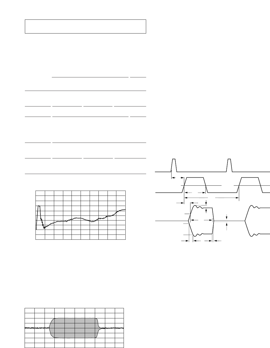
Typical pulse modulation envelope illustrates the fast rise
and fall times, excellent flatness, and pulse fidelity of the
83731B/83732B.
Internal Pulse Source
Pulse source modes: free-run, triggered with delay, doublet,
and gated. Triggered with delay, doublet, and gated require
external trigger source.
Pulse repetition frequency: 3 Hz to >3 MHz
Pulse repetition interval (PRI):300 ns to 419 ms
Pulse width (Tw):25 ns to 419 ms
Variable pulse delay
Free-run mode (Td): ±419 ms
Triggered with delay and doublet modes (Td):
225 ns to 419 ms with ±25 ns jitter
Pulse width/delay/PRI resolution: 25 ns
Pulse delay (video to RF, Tm):
1 to 20 GHz, <20 ns nominal
All pulse modulation specifications and supplemental
characteristics apply during use of internal pulse source.
Tdvideo delay (variable) TmRF delay TrRF pulse rise time
Twvideo pulse width (variable) Trf RF pulse width Vor overshoot and ringing
Tppulse period (variable) TfRF pulse fall time Vfvideo feedthrough
Carrier Frequency (GHz)
75
On/Off Ratio (dB)
85
95
105
115
125 0 4 8 121620
Timebase = 10.0 ns/div
Carrier Frequency = 10.0 GHz
Risetime = 4.9 ns
Falltime = 2.05 ns
Sync
Output
Video
Output
Td
50% 50%
TwTp
Tm
50%
RF Pulse
Output
10%
vor
T
rf
vf
90%
T
rTf
1. CW power will be present for up to 10 ms when changing frequency or
power level.
This page shows modulation specifications that are available only for
the 83731B and 83732B, and not for the 83711B and 83712B.
5
Frequency Modulation
Rates: 1 kHz to 1 MHz
Flatness: ±2 dB
Frequency Maximum Deviation2Modulation Index
2 to 20 GHz 10 MHz peak >300
1 to <2 GHz 5 MHz peak >150
500 MHz to <1 GHz 2.5 MHz peak >75
256 to <500 MHz 1.25 MHz peak >37
The modulation index and maximum deviation decrease
by a factor of 2 for each octave below 256 MHz.
FM sensitivity:
Frequency Seven ranges, selectable
1 to 20 GHz 10, 5, 3, 1, 0.3, 0.1, 0.03 MHz/V pk
256 MHz to <1 GHz 2500, 1250, 750, 250, 75, 25, 7.5 kHz/V pk
64 to <256 MHz 625, 312, 187, 62.5, 18.7, 6.25, 1.87 kHz/V pk
16 to <64 MHz 156, 78.1, 46.8, 15.6, 4.68, 1.56, 0.468 kHz/V pk
10 to <16 MHz 78.1, 39.0, 23.4, 7.81, 2.34, 0.871, 0.234 kHz/V pk
FM sensitivity accuracy: ±10% at 100 kHz
Incidental AM: <5%
FM input impedance: 600Ωnominal
Harmonic distortion: <1% (1 MHz peak deviation
at 100 kHz rate)
Option 800 Phase Modulation
Sensitivity:
Two ranges, selectable
Low Range High Range
Frequency
1 to 20 GHz 1 rad/V pk 50 rad/V pk
256 MHz to <1 GHz 0.25 rad/V pk 12.5 rad/V pk
64 to <256 MHz .0625 rad/V pk 3.12 rad/V pk
16 to <64 MHz 0.0156 rad/V pk 0.781 rad/V pk
10 to <16 MHz 0.00781 rad/V pk 0.39 rad/V pk
Accuracy ±5% (at 1 kHz) ±10% (at 100 Hz)
Flatness DC to 100 kHz: ±1 dB DC to 30 kHz: ±2 dB
Bandwidth >1 MHz (3 dB) usable to 1 MHz
at low deviations
Input Impedance 600 ohms nominal 600 ohms nominal
Maximum deviation:2
Frequency Low Range High Range
2 to 20 GHz 4 rad 200 ra
1 to <2 GHz 2 rad 100 rad
500 to <1 GHz 1 rad 50 rad
256 to <500 MHz 0.5 rad 25 rad
The maximum deviation decreases by a factor of 2 for each
octave below 256 MHz.
Linear Amplitude Modulation
Sensitivity:
Two ranges, selectable: 30%/Vpk and 100%/Vpk
Sensitivity accuracy:
(1 kHz) ±8% of value ±2%, (15 to 35°C)
Maximum Depth: 90%
Bandwidth: (3 dB, 30% depth) DC to >100 kHz
Incidental phase modulation: (30% depth) <0.4 radians peak
Maximum carrier level in linear AM mode (relative to CW):
With no modulation input <1 GHz 1 to 4 GHz >4 GHz
0 dB –4.5 dB –1.0 dB
With modulation degrades up to 6 dB depending on depth
Logarithmic Amplitude
Modulation (Scan Modulation)
Maximum depth: > 60 dB
Sensitivity: –10 dB/V; (0 to +6V for 0 to –60 dBc)
Step response (50 dB change in level):
< 1 GHz, < 10 µs rise time, < 20 µs fall time
1 to 20 GHz, < 5 µs rise and fall times
Input impedance: 5000Ωnominal
Maximum leveled output power in log AM mode
(relative to CW):
<1 GHz 1 to 4 GHz >4 GHz
0 dB –4.5 dB –1.0 dB
Typical log AM error (deviation from desired depth) at
25°C for carrier frequencies between 1.0 and 20 GHz
Simultaneous Modulations
Full AM bandwidth and depth is available at any pulse rate
or width. FM/FM is completely independent of AM and
pulse modulation.
2. With sine wave modulation only.
–5.00
5.00
Error (dB)
0
Log AM Error 10 GHz
Log AM Error 4-20 GHz
Log AM Error 1-4 GHz
Peak Power Level = 0 dBm
Desired Log AM Depth (attenuation) in dB
5 1015202530354045505560
This page shows modulation specifications that are available only for
the 83731B and 83732B, and not for the 83711B and 83712B.
6
Option 1E2: Internal
Modulation Generator
Available in 83731B and 83732B models only.
Specifications for internal modulation are same as
base instrument, unless noted below.
Waveforms
Sine wave: 0.5 Hz to 1 MHz rates
Ramp, square, triangle: 0.5 Hz to 100 kHz rates
Uniform noise, Gaussian noise
Rate accuracy: < ± .01%
Internal scan modulation
Rate: 0.5 Hz to 20 kHz
Rate Resolution: 0.5 Hz (3 digits displayed)
Depth resolution: 0.01 dB
Internal linear AM
Rate: 0.5 Hz to 100 kHz
Rate Resolution: 0.5 Hz (3 digits displayed)
Depth resolution: 0.1%
Internal FM
Rate: 1 kHz to 1 MHz
Rate Resolution: 0.5 Hz (3 digits displayed)
Deviation resolution: 0.01 Hz
Flatness: ±2 dB (1 to 500 kHz)
Internal phase modulation (with Option 800 only)
Rate: 0.5 Hz to 1 MHz
Rate Resolution: 0.5 Hz (3 digits displayed)
Deviation resolution: 0.01 rad
Bandwidth: 700 kHz (3 dB) on low range
General
Noise figure meter compatibility
Agilent 8370 sources are fully compatible with and
can be controlled by the 8970B noise figure meter
through Special Function 41.5.
Programming
These instruments are fully compatible with
the Standard Commands for Programmable
Instruments (SCPI). SCPI complies with IEEE
488.2-1987.
In addition, these instruments will emulate most
applicable Agilent 8673 commands, providing gen-
eral compatibility with ATE systems which include
8673 series signal generators.
Environmental
Operating temperature range: 0° to 55°C
EMC: complies with CISPR Pub. 11/1990, Class A,
and Mil-Std-461C, Part 2, Methods CE03, CS01, CS02,
RE02, RS03
Power requirements
Power: 90 to 132V, 48 to 440 Hz; 198 to 264V,
48 to 66 Hz; 260 VA maximum
Physical dimensions
Net weight: <16 kg (35 lb) Shipping: <23 kg (49 lb)
Size: 498 mm D x 426 mm W x 133 mm H
(19.6in x 16.8in x 5.2in)
Transit case available by ordering Agilent part
number 9211-2655.
Front Panel Connectors
83731B/83732B front panel
RF output
Type-N precision, or 3.5 mm precision (Option 1E9).
Nominal impedance is 50 ohms.
ALC in
Used for external leveling with either a power meter
or a positive- or negative-polarity diode detector.
AM in (83731B/83732B only)
Accepts input signal for external linear AM or log
AM. Nominal impedance is 5k ohms.
FM/FM in (83731B/83732B only)
Accepts input signal for external FM or phase
modulation (Option 800 only). Nominal impedance
is 600 ohms.
Pulse/trigger gate in (83731B/83732B only)
Accepts input signal for external pulse modulation.
Also accepts external trigger pulse input for inter-
nal pulse modulation. TTL-level compatible, nomi-
nal impedance is 50 ohms.
Pulse video out (83731B/83732B only)
Outputs a signal that follows the RF output in all
pulse modes. TTL-level compatible, nominal source
impedance is 50 ohms.
Pulse sync out (83731B/83732B only)
Outputs a synchronizing pulse, nominally 50 ns
width, during internal and triggered pulse modula-
tion. TTL-level compatible, nominal source imped-
ance is 50 ohms.
7
Rear Panel Connectors
83731B/83732B rear panel
10 MHz input
Accepts a 10 MHz ±100 Hz, 0 to 10 dBm, exter-
nal reference signal for operation from an
external high stability timebase. Nominal input
impedance is 50Ω.
10 MHz output
Outputs the 10 MHz reference signal, nominally
+3 dBm, for use as an external reference signal.
Nominal source impedance is 50Ω.
0.5V/GHz output
Supplies a voltage proportional to output fre-
quency for use with mm-wave frequency multi-
pliers, including the Agilent 83550 Series
Millimeter Wave Source Modules.
AM output (Option 1E2 only)
Provides a sample of the modulating signal
from the internal AM generator or external AM
input.
FM/FM output (Option 1E2 only)
Provides a sample of the modulating signal
from the internal FM/FFM generator or exter-
nal FM/FFM input.
8370 SERIES
GENERATOR
Ordering Information:
Products Frequency range
83711B 1 to 20 GHz synthesized CW generator
83712B 0.01 to 20 GHz synthesized CW generator
83731B 1 to 20 GHz synthesized signal generator
83732B 0.01 to 20 GHz synthesized signal generator
Options
To add options to a product, use the following ordering scheme:
Model: 837xxB (x = 11, 12, 31 or 32)
Model Options: 837xxB-opt#1
837xxB-opt#2
837xxB-1E1 Adds 110 dB output step attenuator
837xxB-1E2 Adds internal modulation generator (83731B/32B only)
837xxB-1E5 Adds high-stability timebas
837xxB-1E8 1 Hz frequency resolution
837xxB-1E9 3.5 mm RF output connector
837xxB-800 Analog phase modulation (83731B/32B only)
837xxB-0B2 Extra operating manual
837xxB-0BV Service documentation, component level
837xxB-0BW Service documentation, assembly level
837xxB-1CM Rack mount kit (Part number 5062-3977)
837xxB-1CP Rack mount and handle kit (Part number 5062-3983)
837xxB-1CR Rack slide kit (Part number 1494-0059)
Warranty and Service
For warranty and service of 5 years, please order 60 months
of R-51B (quantity = 60). Standard warranty is 36 months.
R-51B Return-to-Agilent warranty and service plan
Calibration1
For 3 years, order 36 months of the appropriate calibration plan shown below.
For 5 years, specify 60 months.
R-50C-001 Standard calibration
R-50C-002 Standards compliant calibration
1. Options not available in all countries.

Agilent Technologies’ Test and
Measurement Support, Services, and
Assistance
Agilent Technologies aims to maximize
the value you receive, while minimizing
your risk and problems. We strive to
ensure that you get the test and meas-
urement capabilities you paid for and
obtain the support you need. Our exten-
sive support resources and services can
help you choose the right Agilent prod-
ucts for your applications and apply
them successfully. Every instrument and
system we sell has a global warranty.
Two concepts underlie Agilent’s overall
support policy: “Our Promise” and “Your
Advantage.”
Our Promise
Our Promise means your Agilent test
and measurement equipment will meet
its advertised performance and function-
ality. When you are choosing new
equipment, we will help you with prod-
uct information, including realistic per-
formance specifications and practical
recommendations from experienced test
engineers. When you use Agilent equip-
ment, we can verify that it works prop-
erly, help with product operation, and
provide basic measurement assistance
for the use of specified capabilities, at
no extra cost upon request. Many self-
help tools are available.
Your Advantage
Your Advantage means that Agilent
offers a wide range of additional expert
test and measurement services, which
you can purchase according to your
unique technical and business needs.
Solve problems efficiently and gain a
competitive edge by contracting with us
for calibration, extra-cost upgrades, out-
of-warranty repairs, and on-site educa-
tion and training, as well as design, sys-
tem integration, project management,
and other professional engineering serv-
ices. Experienced Agilent engineers and
technicians worldwide can help you
maximize your productivity, optimize the
return on investment of your Agilent
instruments and systems, and obtain
dependable measurement accuracy for
the life of those products.
By internet, phone, or fax, get assis-
tance with all your test and measure-
ment needs.
Online assistance:
www.agilent.com/find/assist
Phone or Fax
United States:
(tel) 1 800 452 4844
Canada:
(tel) 1 877 894 4414
(fax) (905) 282 6495
China:
(tel) 800 810 0189
(fax) 1 0800 650 0121
Europe:
(tel) (31 20) 547 2323
(fax) (31 20) 547 2390
Latin America:
(tel) (305) 269 7500
(fax) (305) 269 7599
Japan:
(tel) (81) 426 56 7832
(fax) (81) 426 56 7840
Korea:
(tel) (82 2) 2004 5004
(fax) (82 2) 2004 5115
Taiwan:
(tel) 080 004 7866
(fax) (886 2) 2545 6723
Other Asia Pacific Countries:
(tel) (65) 375 8100
(fax) (65) 836 0252
Email: tm_asia@agilent.com
www.agilent.com/find/emailupdates
Get the latest information on the
products and applications you select.
Product specifications and descriptions
in this document subject to change
without notice.
© Agilent Technologies, Inc. 2002, 2005
Printed in USA, July 14, 2005
5963-6615E
