AA Enhanced Quadrature Encoder Pulse (e QEP) Module Reference Guide
AA%20Enhanced%20Quadrature%20Encoder%20Pulse%20(eQEP)%20Module%20Reference%20Guide
User Manual:
Open the PDF directly: View PDF ![]() .
.
Page Count: 44
- TMS320x280x, 2801x, 2804x Enhanced Quadrature Encoder Pulse (eQEP) Module
- Table of Contents
- Preface
- 1 Introduction
- 2 Description
- 3 Quadrature Decoder Unit (QDU)
- 4 Position Counter and Control Unit (PCCU)
- 5 eQEP Edge Capture Unit
- 6 eQEP Watchdog
- 7 Unit Timer Base
- 8 eQEP Interrupt Structure
- 9 eQEP Registers
- Appendix A Revision History

TMS320x280x, 2801x, 2804x Enhanced
Quadrature Encoder Pulse (eQEP) Module
Reference Guide
Literature Number: SPRU790D
November 2004–Revised December 2008


Preface ....................................................................................................................................... 6
1 Introduction ........................................................................................................................ 9
2 Description ....................................................................................................................... 11
2.1 EQEP Inputs ............................................................................................................ 12
2.2 Functional Description ................................................................................................. 12
2.3 eQEP Memory Map .................................................................................................... 13
3 Quadrature Decoder Unit (QDU) .......................................................................................... 15
3.1 Position Counter Input Modes ........................................................................................ 15
3.2 eQEP Input Polarity Selection ........................................................................................ 18
3.3 Position-Compare Sync Output ...................................................................................... 18
4 Position Counter and Control Unit (PCCU) ........................................................................... 18
4.1 Position Counter Operating Modes .................................................................................. 18
4.2 Position Counter Latch ................................................................................................ 21
4.3 Position Counter Initialization ........................................................................................ 23
4.4 eQEP Position-compare Unit ......................................................................................... 23
5 eQEP Edge Capture Unit .................................................................................................... 25
6 eQEP Watchdog ................................................................................................................ 28
7 Unit Timer Base ................................................................................................................. 28
8 eQEP Interrupt Structure .................................................................................................... 29
9 eQEP Registers ................................................................................................................. 29
Appendix A Revision History ...................................................................................................... 43
3
SPRU790D–November 2004–Revised December 2008 Table of Contents
Submit Documentation Feedback
Copyright © 2004–2008, Texas Instruments Incorporated

www.ti.com
List of Figures
1 Optical Encoder Disk ....................................................................................................... 9
2 QEP Encoder Output Signal for Forward/Reverse Movement ...................................................... 10
3 Index Pulse Example ..................................................................................................... 10
4 Functional Block Diagram of the eQEP Peripheral ................................................................... 13
5 Functional Block Diagram of Decoder Unit ............................................................................ 15
6 Quadrature Decoder State Machine .................................................................................... 16
7 Quadrature-clock and Direction Decoding ............................................................................. 17
8 Position Counter Reset by Index Pulse for 1000 Line Encoder (QPOSMAX = 3999 or 0xF9F)................ 19
9 Position Counter Underflow/Overflow (QPOSMAX = 4) ............................................................. 20
10 Software Index Marker for 1000-line Encoder (QEPCTL[IEL] = 1) ................................................. 22
11 Strobe Event Latch (QEPCTL[SEL] = 1) ............................................................................... 22
12 eQEP Position-compare Unit ............................................................................................ 23
13 eQEP Position-compare Event Generation Points.................................................................... 24
14 eQEP Position-compare Sync Output Pulse Stretcher ............................................................... 24
15 eQEP Edge Capture Unit................................................................................................. 26
16 Unit Position Event for Low Speed Measurement (QCAPCTL[UPPS] = 0010) ................................... 26
17 eQEP Edge Capture Unit - Timing Details ............................................................................. 27
18 eQEP Watchdog Timer ................................................................................................... 28
19 eQEP Unit Time Base .................................................................................................... 28
20 EQEP Interrupt Generation .............................................................................................. 29
21 QEP Decoder Control (QDECCTL) Register .......................................................................... 29
22 eQEP Control (QEPCTL) Register ...................................................................................... 30
23 eQEP Position-compare Control (QPOSCTL) Register .............................................................. 32
24 eQEP Capture Control (QCAPCTL) Register.......................................................................... 33
25 eQEP Position Counter (QPOSCNT) Register ........................................................................ 33
26 eQEP Position Counter Initialization (QPOSINIT) Register.......................................................... 33
27 eQEP Maximum Position Count Register (QPOSMAX) Register................................................... 34
28 eQEP Position-compare (QPOSCMP) Register....................................................................... 34
29 eQEP Index Position Latch (QPOSILAT) Register.................................................................... 34
30 eQEP Strobe Position Latch (QPOSSLAT) Register ................................................................. 34
31 eQEP Position Counter Latch (QPOSLAT) Register ................................................................. 35
32 eQEP Unit Timer (QUTMR) Register ................................................................................... 35
33 eQEP Register Unit Period (QUPRD) Register ....................................................................... 35
34 eQEP Watchdog Timer (QWDTMR) Register ......................................................................... 35
35 eQEP Watchdog Period (QWDPRD) Register ........................................................................ 36
36 eQEP Interrupt Enable (QEINT) Register .............................................................................. 36
37 eQEP Interrupt Flag (QFLG) Register .................................................................................. 37
38 eQEP Interrupt Clear (QCLR) Register................................................................................. 38
39 eQEP Interrupt Force (QFRC) Register ................................................................................ 39
40 eQEP Status (QEPSTS) Register....................................................................................... 40
41 eQEP Capture Timer (QCTMR) Register .............................................................................. 41
42 eQEP Capture Period (QCPRD) Register.............................................................................. 41
43 eQEP Capture Timer Latch (QCTMRLAT) Register .................................................................. 41
44 eQEP Capture Period Latch (QCPRDLAT) Register ................................................................. 42
4List of Figures SPRU790D–November 2004–Revised December 2008
Submit Documentation Feedback
Copyright © 2004–2008, Texas Instruments Incorporated

www.ti.com
List of Tables
1 EQEP Memory Map ...................................................................................................... 13
2 Quadrature Decoder Truth Table ....................................................................................... 16
3 eQEP Decoder Control (QDECCTL) Register Field Descriptions .................................................. 29
4 eQEP Control (QEPCTL) Register Field Descriptions................................................................ 31
5 eQEP Position-compare Control (QPOSCTL) Register Field Descriptions........................................ 32
6 eQEP Capture Control (QCAPCTL) Register Field Descriptions ................................................... 33
7 eQEP Position Counter (QPOSCNT) Register Field Descriptions.................................................. 33
8 eQEP Position Counter Initialization (QPOSINIT) Register Field Descriptions ................................... 34
9 eQEP Maximum Position Count (QPOSMAX) Register Field Descriptions ....................................... 34
10 eQEP Position-compare (QPOSCMP) Register Field Descriptions ................................................ 34
11 eQEP Index Position Latch(QPOSILAT) Register Field Descriptions .............................................. 34
12 eQEP Strobe Position Latch (QPOSSLAT) Register Field Descriptions........................................... 35
13 eQEP Position Counter Latch (QPOSLAT) Register Field Descriptions ........................................... 35
14 eQEP Unit Timer (QUTMR) Register Field Descriptions............................................................. 35
15 eQEP Unit Period (QUPRD) Register Field Descriptions ............................................................ 35
16 eQEP Watchdog Timer (QWDTMR) Register Field Descriptions................................................... 36
17 eQEP Watchdog Period (QWDPRD) Register Field Description ................................................... 36
18 eQEP Interrupt Enable(QEINT) Register Field Descriptions ........................................................ 36
19 eQEP Interrupt Flag (QFLG) Register Field Descriptions............................................................ 37
20 eQEP Interrupt Clear (QCLR) Register Field Descriptions .......................................................... 38
21 eQEP Interrupt Force (QFRC) Register Field Descriptions.......................................................... 39
22 eQEP Status (QEPSTS) Register Field Descriptions ................................................................ 40
23 eQEP Capture Timer (QCTMR) Register Field Descriptions ........................................................ 41
24 eQEP Capture Period Register (QCPRD) Register Field Descriptions ............................................ 41
25 eQEP Capture Timer Latch (QCTMRLAT) Register Field Descriptions............................................ 41
26 eQEP Capture Period Latch (QCPRDLAT) Register Field Descriptions........................................... 42
27 Changes for Revision D .................................................................................................. 43
5
SPRU790D–November 2004–Revised December 2008 List of Tables
Submit Documentation Feedback
Copyright © 2004–2008, Texas Instruments Incorporated

Preface
SPRU790D–November 2004–Revised December 2008
Read This First
This reference guide describes the enhanced quadrature encoder pulse (eQEP) module .
About This Manual
The eQEP module described in this reference guide is a Type 0 eQEP. See the TMS320x28xx, 28xxx
DSP Peripheral Reference Guide (SPRU566) for a list of all devices with a module of the same type to
determine the differences between types and for a list of device-specific differences within a type.
Notational Conventions
This document uses the following conventions.
• Hexadecimal numbers are shown with the suffix h or with a leading 0x. For example, the following
number is 40 hexadecimal (decimal 64): 40h or 0x40.
• Registers in this document are shown in figures and described in tables.
– Each register figure shows a rectangle divided into fields that represent the fields of the register.
Each field is labeled with its bit name, its beginning and ending bit numbers above, and its
read/write properties below. A legend explains the notation used for the properties.
– Reserved bits in a register figure designate a bit that is used for future device expansion.
Related Documentation From Texas Instruments
The following books describe the TMS320x280x and related support tools that are available on the TI
website:
Data Manuals—
SPRS174 — TMS320F2810, TMS320F2811, TMS320F2812, TMS320C2810, TMS320C2811,
TMS320C2812 Digital Signal Processors Data Manual contains the electrical and timing
specifications for these devices, as well as signal descriptions and pinouts for all of the available
packages.
SPRS230 — TMS320F2809, F2808, F2806, F2802, F2801, C2802, C2801, and F2801x DSPs Data
Manual contains the pinout, signal descriptions, as well as electrical and timing specifications for
the F280x devices.
SPRS257 — TMS320R2811, TMS320R2812 Digital Signal Processors Data Manual contains the
electrical and timing specifications for these devices, as well as signal descriptions and pinouts for
all of the available packages.
SPRS357 — TMS320F28044 Digital Signal Processor Data Manual contains the pinout, signal
descriptions, as well as electrical and timing specifications for the F28044 device.
SPRS439 — TMS320F28335, TMS320F28334, TMS320F28332, TMS320F28235, TMS320F28234,
TMS320F28232 Digital Signal Controllers (DSCs) Data Manual contains the pinout, signal
descriptions, as well as electrical and timing specifications for the F2833x/F2823x devices.
SPRS516 — TMS320C28346, TMS320C28345, TMS320C28344, TMS320C28343, TMS320C28342,
TMS320C28341 Delfino Microcontrollers Data Manual. This document contains the pinout,
signal descriptions, as well as electrical and timing specifications for the C2834x devices.
CPU User's Guides—
6Preface SPRU790D–November 2004–Revised December 2008
Submit Documentation Feedback
Copyright © 2004–2008, Texas Instruments Incorporated

www.ti.com
Related Documentation From Texas Instruments
SPRU430 — TMS320C28x CPU and Instruction Set Reference Guide describes the central processing
unit (CPU) and the assembly language instructions of the TMS320C28x fixed-point digital signal
processors (DSPs). It also describes emulation features available on these DSPs.
SPRUEO2 — TMS320C28x Floating Point Unit and Instruction Set Reference Guide describes the
floating-point unit and includes the instructions for the FPU.
Peripheral Guides—
SPRU566 — TMS320x28xx, 28xxx DSP Peripheral Reference Guide describes the peripheral
reference guides of the 28x digital signal processors (DSPs).
SPRUFB0 — TMS320x2833x, 2823x System Control and Interrupts Reference Guide describes the
various interrupts and system control features of the 2833x and 2823x digital signal controllers
(DSCs).
SPRU712 — TMS320x280x, 2801x, 2804x System Control and Interrupts Reference Guide describes
the various interrupts and system control features of the 280x digital signal processors (DSPs).
SPRU812 — TMS320x2833x, 2823x Analog-to-Digital Converter (ADC) Reference Guide describes
how to configure and use the on-chip ADC module, which is a 12-bit pipelined ADC.
SPRU716 — TMS320x280x, 2801x, 2804x Analog-to-Digital Converter (ADC) Reference Guide
describes how to configure and use the on-chip ADC module, which is a 12-bit pipelined ADC.
SPRU949 — TMS320x2833x, 2823x DSC External Interface (XINTF) Reference Guide describes the
XINTF, which is a nonmultiplexed asynchronous bus, as it is used on the 2833x and 2823x devices.
SPRU963 — TMS320x2833x, 2823x Boot ROM Reference Guide describes the purpose and features of
the bootloader (factory-programmed boot-loading software) and provides examples of code. It also
describes other contents of the device on-chip boot ROM and identifies where all of the information
is located within that memory.
SPRU722 — TMS320x280x, 2801x, 2804x Boot ROM Reference Guide describes the purpose and
features of the bootloader (factory-programmed boot-loading software). It also describes other
contents of the device on-chip boot ROM and identifies where all of the information is located within
that memory.
SPRUFB7 — TMS320x2833x, 2823x Multichannel Buffered Serial Port (McBSP) Reference Guide
describes the McBSP available on the 2833x and 2823x devices. The McBSPs allow direct
interface between a DSP and other devices in a system.
SPRUFB8 — TMS320x2833x, 2823x Direct Memory Access (DMA) Module Reference Guide
describes the DMA on the 2833x and 2823x devices.
SPRU791 — TMS320x28xx, 28xxx Enhanced Pulse Width Modulator (ePWM) Module Reference
Guide describes the main areas of the enhanced pulse width modulator that include digital motor
control, switch mode power supply control, UPS (uninterruptible power supplies), and other forms of
power conversion.
SPRU924 — TMS320x28xx, 28xxx High-Resolution Pulse Width Modulator (HRPWM) describes the
operation of the high-resolution extension to the pulse width modulator (HRPWM).
SPRU807 — TMS320x28xx, 28xxx Enhanced Capture (eCAP) Module Reference Guide describes the
enhanced capture module. It includes the module description and registers.
SPRUFG4 — TMS320x2833x, 2823x Enhanced Capture (eCAP) Module Reference Guide describes
the enhanced capture module. It includes the module description and registers.
SPRU790 — TMS320x28xx, 28xxx Enhanced Quadrature Encoder Pulse (eQEP) Reference Guide
describes the eQEP module, which is used for interfacing with a linear or rotary incremental
encoder to get position, direction, and speed information from a rotating machine in high
performance motion and position control systems. It includes the module description and registers.
7
SPRU790D–November 2004–Revised December 2008 Read This First
Submit Documentation Feedback
Copyright © 2004–2008, Texas Instruments Incorporated

Related Documentation From Texas Instruments
www.ti.com
SPRU074 — TMS320x28xx, 28xxx Enhanced Controller Area Network (eCAN) Reference Guide
describes the eCAN that uses established protocol to communicate serially with other controllers in
electrically noisy environments.
SPRU051 — TMS320x28xx, 28xxx Serial Communication Interface (SCI) Reference Guide describes
the SCI, which is a two-wire asynchronous serial port, commonly known as a UART. The SCI
modules support digital communications between the CPU and other asynchronous peripherals that
use the standard non-return-to-zero (NRZ) format.
SPRU059 — TMS320x28xx, 28xxx Serial Peripheral Interface (SPI) Reference Guide describes the
SPI - a high-speed synchronous serial input/output (I/O) port - that allows a serial bit stream of
programmed length (one to sixteen bits) to be shifted into and out of the device at a programmed
bit-transfer rate.
SPRU721 — TMS320x28xx, 28xxx Inter-Integrated Circuit (I2C) Reference Guide describes the
features and operation of the inter-integrated circuit (I2C) module.
Tools Guides—
SPRU513 — TMS320C28x Assembly Language Tools v5.0.0 User's Guide describes the assembly
language tools (assembler and other tools used to develop assembly language code), assembler
directives, macros, common object file format, and symbolic debugging directives for the
TMS320C28x device.
SPRU514 — TMS320C28x Optimizing C/C++ Compiler v5.0.0 User's Guide describes the
TMS320C28x™ C/C++ compiler. This compiler accepts ANSI standard C/C++ source code and
produces TMS320 DSP assembly language source code for the TMS320C28x device.
SPRU608 — TMS320C28x Instruction Set Simulator Technical Overview describes the simulator,
available within the Code Composer Studio for TMS320C2000 IDE, that simulates the instruction
set of the C28x™ core.
SPRU625— TMS320C28x DSP/BIOS 5.32 Application Programming Interface (API) Reference
Guide describes development using DSP/BIOS.
8Read This First SPRU790D–November 2004–Revised December 2008
Submit Documentation Feedback
Copyright © 2004–2008, Texas Instruments Incorporated

QEPA
QEPB
QEPI
Reference Guide
SPRU790D–November 2004–Revised December 2008
Enhanced QEP (eQEP) Module
The enhanced quadrature encoder pulse (eQEP) module is used for direct interface with a linear or rotary
incremental encoder to get position, direction, and speed information from a rotating machine for use in a
high-performance motion and position-control system.
This reference guide is applicable for the eQEP found on the TMS320x280x family of processors. This
includes all Flash-based, ROM-based, and RAM-based devices within the 280x family.
1 Introduction
A single track of slots patterns the periphery of an incremental encoder disk, as shown in Figure 1. These
slots create an alternating pattern of dark and light lines. The disk count is defined as the number of
dark/light line pairs that occur per revolution (lines per revolution). As a rule, a second track is added to
generate a signal that occurs once per revolution (index signal: QEPI), which can be used to indicate an
absolute position. Encoder manufacturers identify the index pulse using different terms such as index,
marker, home position, and zero reference
Figure 1. Optical Encoder Disk
To derive direction information, the lines on the disk are read out by two different photo-elements that
"look" at the disk pattern with a mechanical shift of 1/4 the pitch of a line pair between them. This shift is
realized with a reticle or mask that restricts the view of the photo-element to the desired part of the disk
lines. As the disk rotates, the two photo-elements generate signals that are shifted 90° out of phase from
each other. These are commonly called the quadrature QEPA and QEPB signals. The clockwise direction
for most encoders is defined as the QEPA channel going positive before the QEPB channel and vise
versa as shown in Figure 2.
9
SPRU790D–November 2004–Revised December 2008 Enhanced QEP (eQEP) Module
Submit Documentation Feedback
Copyright © 2004–2008, Texas Instruments Incorporated
T0
0 1 2 3 4 5 6 7 N−6 N−5 N−4 N−3 N−2 N−1 0
QEPA
QEPB
QEPI
Clockwise shaft rotation/forward movement
Anti-clockwise shaft rotation/reverse movement
0 N−1 N−2 N−3 N−4 N−5 N−6 N−7 6 5 4 3 2 1 0 N−1 N−2
QEPA
QEPB
QEPI
T0
Legend: N = lines per revolution
T0
0.25T0 ±0.1T0
0.5T0 ±0.1T0
T0 ±0.5T0
QEPA
QEPB
QEPI
(gated to
A and B)
QEPI
(gated to A)
QEPI
(ungated)
Introduction
www.ti.com
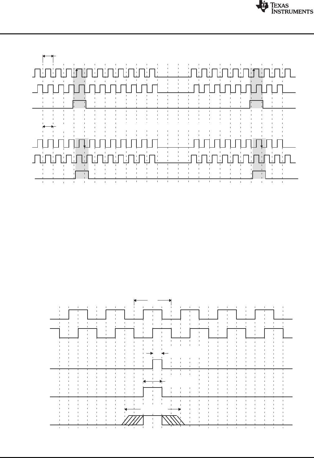
Figure 2. QEP Encoder Output Signal for Forward/Reverse Movement
The encoder wheel typically makes one revolution for every revolution of the motor or the wheel may be at
a geared rotation ratio with respect to the motor. Therefore, the frequency of the digital signal coming from
the QEPA and QEPB outputs varies proportionally with the velocity of the motor. For example, a 2000-line
encoder directly coupled to a motor running at 5000 revolutions per minute (rpm) results in a frequency of
166.6 KHz, so by measuring the frequency of either the QEPA or QEPB output, the processor can
determine the velocity of the motor.
Quadrature encoders from different manufacturers come with two forms of index pulse (gated index pulse
or ungated index pulse) as shown in Figure 3. A nonstandard form of index pulse is ungated. In the
ungated configuration, the index edges are not necessarily coincident with A and B signals. The gated
index pulse is aligned to any of the four quadrature edges and width of the index pulse and can be equal
to a quarter, half, or full period of the quadrature signal.
Figure 3. Index Pulse Example
10 Enhanced QEP (eQEP) Module SPRU790D–November 2004–Revised December 2008
Submit Documentation Feedback
Copyright © 2004–2008, Texas Instruments Incorporated

v(k)[x(k)*x(k*1)
T+DX
T
v(k)[X
t(k)*t(k*1)+X
DT
www.ti.com
Description
Some typical applications of shaft encoders include robotics and even computer input in the form of a
mouse. Inside your mouse you can see where the mouse ball spins a pair of axles (a left/right, and an
up/down axle). These axles are connected to optical shaft encoders that effectively tell the computer how
fast and in what direction the mouse is moving.
General Issues: Estimating velocity from a digital position sensor is a cost-effective strategy in motor
control. Two different first order approximations for velocity may be written as:
(1)
(2)
where
v(k): Velocity at time instant k
x(k): Position at time instant k
x(k-1): Position at time instant k-1
T: Fixed unit time or inverse of velocity calculation rate
ΔX: Incremental position movement in unit time
t(k): Time instant "k"
t(k-1): Time instant "k-1"
X: Fixed unit position
ΔT: Incremental time elapsed for unit position movement.
Equation 1 is the conventional approach to velocity estimation and it requires a time base to provide unit
time event for velocity calculation. Unit time is basically the inverse of the velocity calculation rate.
The encoder count (position) is read once during each unit time event. The quantity [x(k) - x(k-1)] is
formed by subtracting the previous reading from the current reading. Then the velocity estimate is
computed by multiplying by the known constant 1/T (where T is the constant time between unit time
events and is known in advance).
Estimation based on Equation 1 has an inherent accuracy limit directly related to the resolution of the
position sensor and the unit time period T. For example, consider a 500-line per revolution quadrature
encoder with a velocity calculation rate of 400 Hz. When used for position the quadrature encoder gives a
four-fold increase in resolution, in this case, 2000 counts per revolution. The minimum rotation that can be
detected is therefore 0.0005 revolutions, which gives a velocity resolution of 12 rpm when sampled at 400
Hz. While this resolution may be satisfactory at moderate or high speeds, e.g. 1% error at 1200 rpm, it
would clearly prove inadequate at low speeds. In fact, at speeds below 12 rpm, the speed estimate would
erroneously be zero much of the time.
At low speed, Equation 2 provides a more accurate approach. It requires a position sensor that outputs a
fixed interval pulse train, such as the aforementioned quadrature encoder. The width of each pulse is
defined by motor speed for a given sensor resolution. Equation 2 can be used to calculate motor speed by
measuring the elapsed time between successive quadrature pulse edges. However, this method suffers
from the opposite limitation, as does Equation 1. A combination of relatively large motor speeds and high
sensor resolution makes the time interval ΔT small, and thus more greatly influenced by the timer
resolution. This can introduce considerable error into high-speed estimates.
For systems with a large speed range (that is, speed estimation is needed at both low and high speeds),
one approach is to use Equation 2 at low speed and have the DSP software switch over to Equation 1
when the motor speed rises above some specified threshold.
2 Description
This section provides the eQEP inputs, memory map, and functional description.
11
SPRU790D–November 2004–Revised December 2008 Enhanced QEP (eQEP) Module
Submit Documentation Feedback
Copyright © 2004–2008, Texas Instruments Incorporated

Description
www.ti.com
2.1 EQEP Inputs
The eQEP inputs include two pins for quadrature-clock mode or direction-count mode, an index (or 0
marker), and a strobe input.
•QEPA/XCLK and QEPB/XDIR
These two pins can be used in quadrature-clock mode or direction-count mode.
–Quadrature-clock Mode
The eQEP encoders provide two square wave signals (A and B) 90 electrical degrees out of phase
whose phase relationship is used to determine the direction of rotation of the input shaft and
number of eQEP pulses from the index position to derive the relative position information. For
forward or clockwise rotation, QEPA signal leads QEPB signal and vice versa. The quadrature
decoder uses these two inputs to generate quadrature-clock and direction signals.
–Direction-count Mode
In direction-count mode, direction and clock signals are provided directly from the external source.
Some position encoders have this type of output instead of quadrature output. The QEPA pin
provides the clock input and the QEPB pin provides the direction input.
•eQEPI: Index or Zero Marker
The eQEP encoder uses an index signal to assign an absolute start position from which position
information is incrementally encoded using quadrature pulses. This pin is connected to the index
output of the eQEP encoder to optionally reset the position counter for each revolution. This signal can
be used to initialize or latch the position counter on the occurrence of a desired event on the index pin.
• QEPS: Strobe Input
This general-purpose strobe signal can initialize or latch the position counter on the occurrence of a
desired event on the strobe pin. This signal is typically connected to a sensor or limit switch to notify
that the motor has reached a defined position.
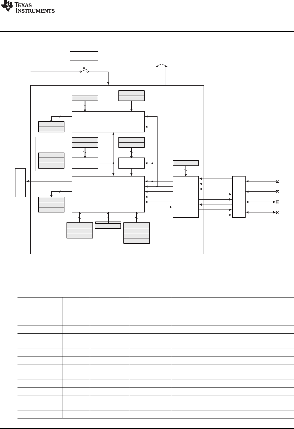
2.2 Functional Description
The eQEP peripheral contains the following major functional units (as shown in Figure 4):
• Programmable input qualification for each pin (part of the GPIO MUX)
• Quadrature decoder unit (QDU)
• Position counter and control unit for position measurement (PCCU)
• Quadrature edge-capture unit for low-speed measurement (QCAP)
• Unit time base for speed/frequency measurement (UTIME)
• Watchdog timer for detecting stalls (QWDOG)
12 Enhanced QEP (eQEP) Module SPRU790D–November 2004–Revised December 2008
Submit Documentation Feedback
Copyright © 2004–2008, Texas Instruments Incorporated
QWDTMR
QWDPRD
16
QWDOG
UTIME
QUPRD
QUTMR
32
UTOUT
WDTOUT
Quadrature
capture unit
(QCAP)
QCPRDLAT
QCTMRLAT
16
QFLG
QEPSTS
QEPCTL
Registers
used by
multiple units
QCLK
QDIR
QI
QS
PHE
PCSOUT
Quadrature
decoder
(QDU)
QDECCTL
16
Position counter/
control unit
(PCCU)
QPOSLAT
QPOSSLAT
32
QPOSILAT
EQEPxAIN
EQEPxBIN
EQEPxIIN
EQEPxIOUT
EQEPxIOE
EQEPxSIN
EQEPxSOUT
EQEPxSOE
GPIO
MUX
EQEPxA/XCLK
EQEPxB/XDIR
EQEPxS
EQEPxI
QPOSCMP QEINT
QFRC
32
QCLR
QPOSCTL
1632
QPOSCNT
QPOSMAX
QPOSINIT
PIE EQEPxINT
Enhanced QEP (eQEP) peripheral
System
control registers
QCTMR
QCPRD
1616
QCAPCTL
EQEPxENCLK
SYSCLKOUT
Data bus
To CPU
www.ti.com
Description
Figure 4. Functional Block Diagram of the eQEP Peripheral
2.3 eQEP Memory Map
Table 1 lists the registers with their memory locations, sizes, and reset values.
Table 1. EQEP Memory Map
Size(x16)/
Name Offset #shadow Reset Register Description
QPOSCNT 0x00 2/0 0x00000000 eQEP Position Counter
QPOSINIT 0x02 2/0 0x00000000 eQEP Initialization Position Count
QPOSMAX 0x04 2/0 0x00000000 eQEP Maximum Position Count
QPOSCMP 0x06 2/1 0x00000000 eQEP Position-compare
QPOSILAT 0x08 2/0 0x00000000 eQEP Index Position Latch
QPOSSLAT 0x0A 2/0 0x00000000 eQEP Strobe Position Latch
QPOSLAT 0x0C 2/0 0x00000000 eQEP Position Latch
QUTMR 0x0E 2/0 0x00000000 QEP Unit Timer
QUPRD 0x10 2/0 0x00000000 eQEP Unit Period Register
QWDTMR 0x12 1/0 0x0000 eQEP Watchdog Timer
QWDPRD 0x13 1/0 0x0000 eQEP Watchdog Period Register
QDECCTL 0x14 1/0 0x0000 eQEP Decoder Control Register
QEPCTL 0x15 1/0 0x0000 eQEP Control Register
QCAPCTL 0x16 1/0 0x0000 eQEP Capture Control Register
13
SPRU790D–November 2004–Revised December 2008 Enhanced QEP (eQEP) Module
Submit Documentation Feedback
Copyright © 2004–2008, Texas Instruments Incorporated

Description
www.ti.com
Table 1. EQEP Memory Map (continued)
Size(x16)/
Name Offset #shadow Reset Register Description
QPOSCTL 0x17 1/0 0x00000 eQEP Position-compare Control Register
QEINT 0x18 1/0 0x0000 eQEP Interrupt Enable Register
QFLG 0x19 1/0 0x0000 eQEP Interrupt Flag Register
QCLR 0x1A 1/0 0x0000 eQEP Interrupt Clear Register
QFRC 0x1B 1/0 0x0000 eQEP Interrupt Force Register
QEPSTS 0x1C 1/0 0x0000 eQEP Status Register
QCTMR 0x1D 1/0 0x0000 eQEP Capture Timer
QCPRD 0x1E 1/0 0x0000 eQEP Capture Period Register
QCTMRLAT 0x1F 1/0 0x0000 eQEP Capture Timer Latch
QCPRDLAT 0x20 1/0 0x0000 eQEP Capture Period Latch
reserved 0x21 31/0
to
0x3F
14 Enhanced QEP (eQEP) Module SPRU790D–November 2004–Revised December 2008
Submit Documentation Feedback
Copyright © 2004–2008, Texas Instruments Incorporated
0
1
1
0
QA
QB
1
1
0
0
QDECCTL:QBP
Quadrature
decoder
00
01
10
11
iCLK
xCLK
xCLK
xCLK
01
11
10
00 iDIR
xDIR
1
0
QDECCTL:QSRC
2
QFLG:PHE
PHE
QDECCTL:QAP
x1
x2 x1, x2
QDECCTL:XCR
0
1
1
0
QDECCTL:QIP
QDECCTL:IGATE
QCLK
QDIR
QI
1
0
QDECCTL:QSP
0
1
QDECCTL:SPSEL
QDECCTL:SPSEL
1
0
QDECCTL:SOEN
QS
PCSOUT
EQEPxIOE
EQEPxSOE
EQEPxIOUT
EQEPxSOUT
EQEPxSIN
EQEPxIIN
EQEPxBIN
EQEPxAIN
QDECCTL:SWAP
QEPSTS:QDF
EQEPA
EQEPB
www.ti.com
Quadrature Decoder Unit (QDU)
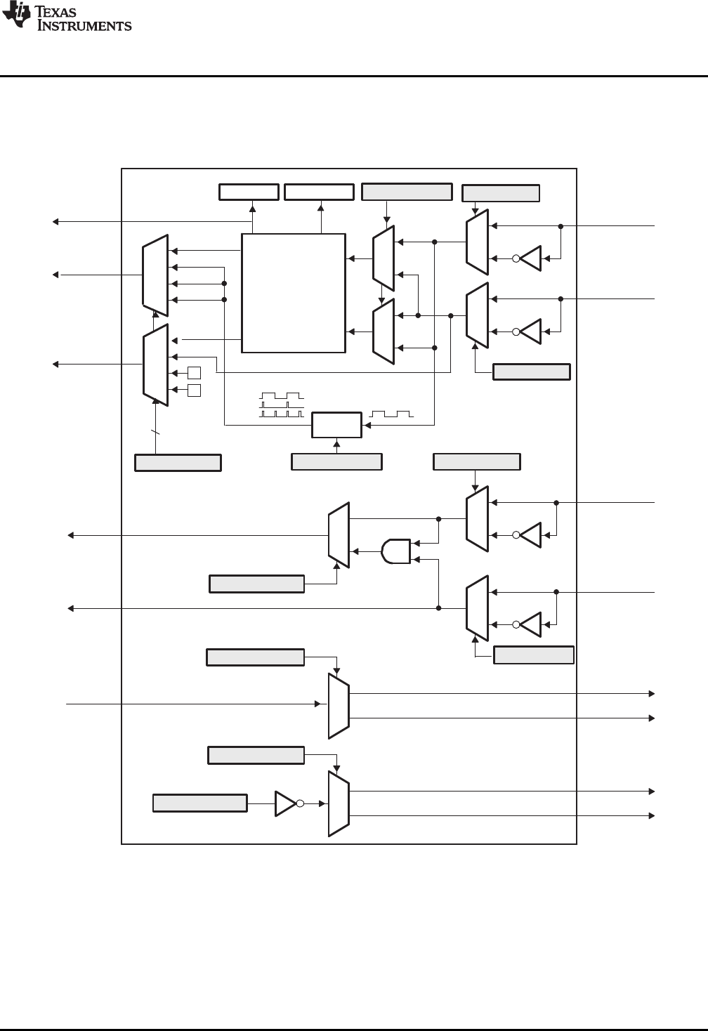
3 Quadrature Decoder Unit (QDU)
Figure 5 shows a functional block diagram of the QDU.
Figure 5. Functional Block Diagram of Decoder Unit
3.1 Position Counter Input Modes
Clock and direction input to position counter is selected using QDECCTL[QSRC] bits, based on interface
input requirement as follows:
• Quadrature-count mode
• Direction-count mode
• UP-count mode
• DOWN-count mode
15
SPRU790D–November 2004–Revised December 2008 Enhanced QEP (eQEP) Module
Submit Documentation Feedback
Copyright © 2004–2008, Texas Instruments Incorporated
(00)
(10)
(11)
(01)
(A,B)=
QEPA
QEPB
eQEP signals
10
01
00 11
Increment
counter
Decrement
counter
Decrement
counter
Increment
counter
Decrement
counter
Decrement
counter
Increment
counter
Increment
counter
Quadrature Decoder Unit (QDU)
www.ti.com
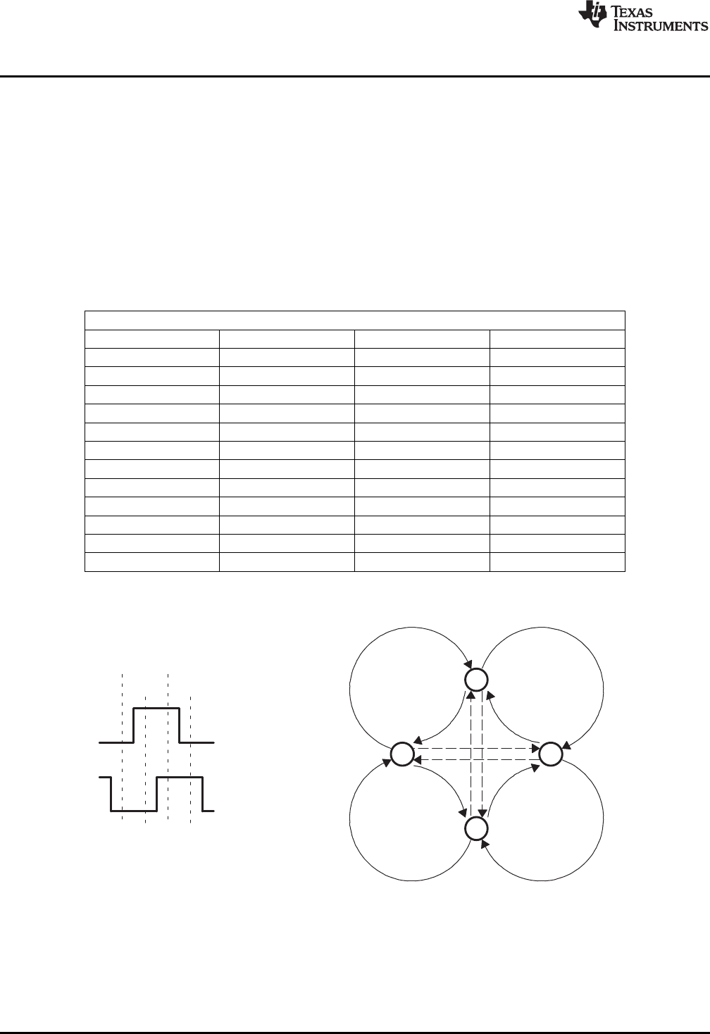
3.1.1 Quadrature Count Mode
The quadrature decoder generates the direction and clock to the position counter in quadrature count
mode.
Direction Decoding— The direction decoding logic of the eQEP circuit determines which one of the
sequences (QEPA, QEPB) is the leading sequence and accordingly updates the direction
information in QEPSTS[QDF] bit. Table 2 and Figure 6 show the direction decoding logic in truth
table and state machine form. Both edges of the QEPA and QEPB signals are sensed to generate
count pulses for the position counter. Therefore, the frequency of the clock generated by the eQEP
logic is four times that of each input sequence. Figure 7 shows the direction decoding and clock
generation from the eQEP input signals.
Table 2. Quadrature Decoder Truth Table
.
Previous Edge Present Edge QDIR QPOSCNT
QA↑QB↑UP Increment
QB↓DOWN Decrement
QA↓TOGGLE Increment or Decrement
QA↓QB↓UP Increment
QB↑DOWN Decrement
QA↑TOGGLE Increment or Decrement
QB↑QA↑DOWN Increment
QA↓UP Decrement
QB↓TOGGLE Increment or Decrement
QB↓QA↓DOWN Increment
QA↑UP Decrement
QB↑TOGGLE Increment or Decrement
Figure 6. Quadrature Decoder State Machine
16 Enhanced QEP (eQEP) Module SPRU790D–November 2004–Revised December 2008
Submit Documentation Feedback
Copyright © 2004–2008, Texas Instruments Incorporated
+1 +1 +1+1 +1+1+1 −1 −1 −1−1 −1−1−1−1 −1−1 −1 +1+1+1
−1 −1 −1 −1 −1 −1 −1 +1 +1 +1 +1 +1 +1 +1+1+1+1 +1 −1−1−1
QA
QB
QCLK
QDIR
QPOSCNT
QA
QB
QCLK
QDIR
QPOSCNT
www.ti.com
Quadrature Decoder Unit (QDU)
Figure 7. Quadrature-clock and Direction Decoding
Phase Error Flag— In normal operating conditions, quadrature inputs QEPA and QEPB will be 90
degrees out of phase. The phase error flag (PHE) is set in the QFLG register when edge transition
is detected simultaneously on the QEPA and QEPB signals to optionally generate interrupts. State
transitions marked by dashed lines in Figure 6 are invalid transitions that generate a phase error.
Count Multiplication— The eQEP position counter provides 4x times the resolution of an input clock by
generating a quadrature-clock (QCLK) on the rising/falling edges of both eQEP input clocks (QEPA
and QEPB) as shown in Figure 7 .
Reverse Count— In normal quadrature count operation, QEPA input is fed to the QA input of the
quadrature decoder and the QEPB input is fed to the QB input of the quadrature decoder. Reverse
counting is enabled by setting the SWAP bit in the QDECCTL register. This will swap the input to
the quadrature decoder thereby reversing the counting direction.
3.1.2 Direction-count Mode
Some position encoders provide direction and clock outputs, instead of quadrature outputs. In such cases,
direction-count mode can be used. QEPA input will provide the clock for position counter and the QEPB
input will have the direction information. The position counter is incremented on every rising edge of a
QEPA input when the direction input is high and decremented when the direction input is low.
3.1.3 Up-Count Mode
The counter direction signal is hard-wired for up count and the position counter is used to measure the
frequency of the QEPA input. Setting of the QDECCTL[XCR] bit enables clock generation to the position
counter on both edges of the QEPA input, thereby increasing the measurement resolution by 2x factor.
17
SPRU790D–November 2004–Revised December 2008 Enhanced QEP (eQEP) Module
Submit Documentation Feedback
Copyright © 2004–2008, Texas Instruments Incorporated

Position Counter and Control Unit (PCCU)
www.ti.com
3.1.4 Down-Count Mode
The counter direction signal is hardwired for a down count and the position counter is used to measure the
frequency of the QEPA input. Setting of the QDECCTL[XCR] bit enables clock generation to the position
counter on both edges of a QEPA input, thereby increasing the measurement resolution by 2x factor.
3.2 eQEP Input Polarity Selection
Each eQEP input can be inverted using QDECCTL[8:5] control bits. As an example, setting of
QDECCTL[QIP] bit will invert the index input.
3.3 Position-Compare Sync Output
The enhanced eQEP peripheral includes a position-compare unit that is used to generate the
position-compare sync signal on compare match between the position counter register (QPOSCNT) and
the position-compare register (QPOSCMP). This sync signal can be output using an index pin or strobe
pin of the EQEP peripheral.
Setting the QDECCTL[SOEN] bit enables the position-compare sync output and the QDECCTL[SPSEL] bit
selects either an eQEP index pin or an eQEP strobe pin.
4 Position Counter and Control Unit (PCCU)
The position counter and control unit provides two configuration registers (QEPCTL and QPOSCTL) for
setting up position counter operational modes, position counter initialization/latch modes and
position-compare logic for sync signal generation.
4.1 Position Counter Operating Modes
Position counter data may be captured in different manners. In some systems, the position counter is
accumulated continuously for multiple revolutions and the position counter value provides the position
information with respect to the known reference. An example of this is the quadrature encoder mounted on
the motor controlling the print head in the printer. Here the position counter is reset by moving the print
head to the home position and then position counter provides absolute position information with respect to
home position.
In other systems, the position counter is reset on every revolution using index pulse and position counter
provides rotor angle with respect to index pulse position.
Position counter can be configured to operate in following four modes
• Position Counter Reset on Index Event
• Position Counter Reset on Maximum Position
• Position Counter Reset on the first Index Event
• Position Counter Reset on Unit Time Out Event (Frequency Measurement)
In all the above operating modes, position counter is reset to 0 on overflow and to QPOSMAX register
value on underflow. Overflow occurs when the position counter counts up after QPOSMAX value.
Underflow occurs when position counter counts down after "0". Interrupt flag is set to indicate
overflow/underflow in QFLG register.
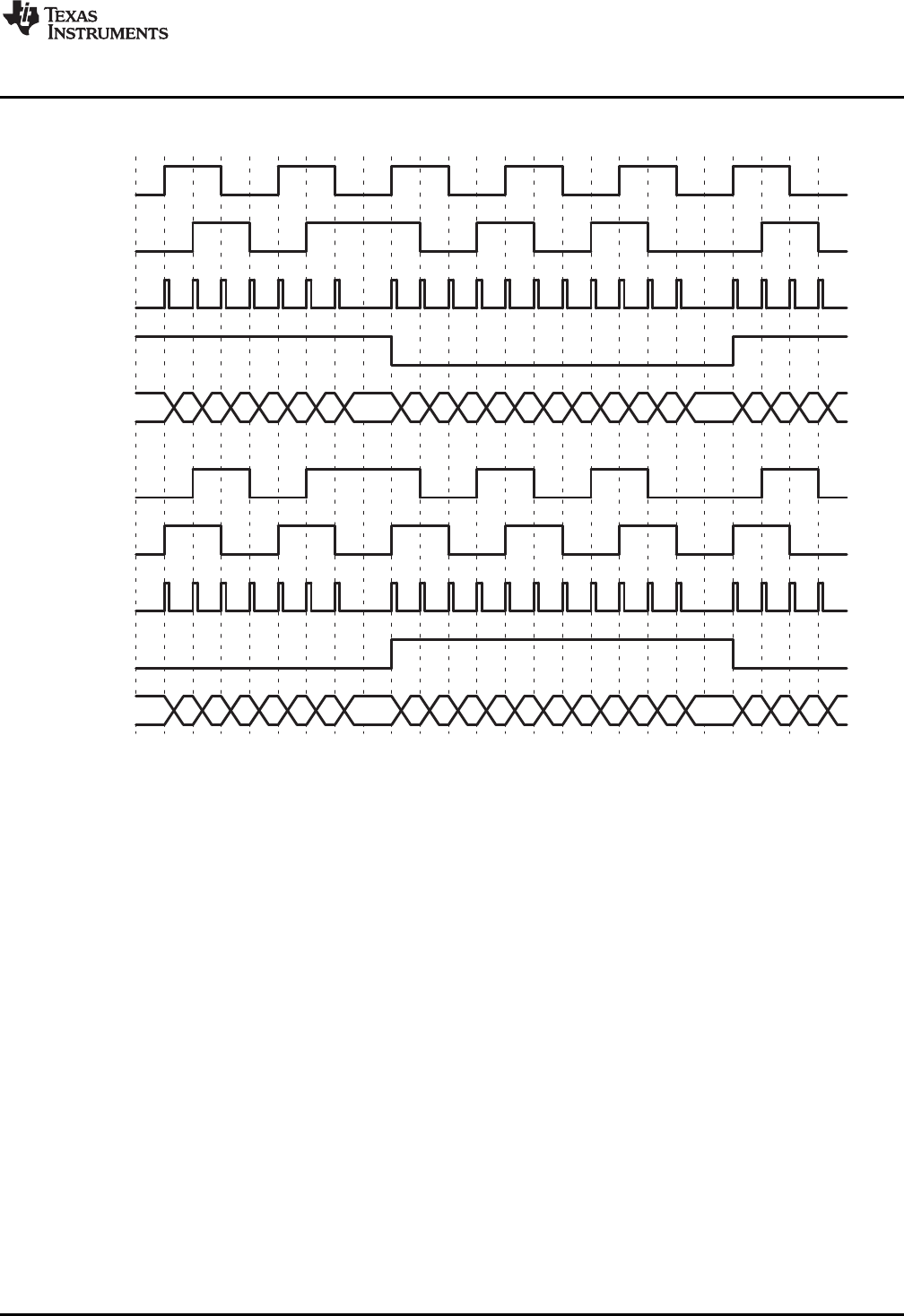
4.1.1 Position Counter Reset on Index Event (QEPCTL[PCRM]=00)
If the index event occurs during the forward movement, then position counter is reset to 0 on the next
eQEP clock. If the index event occurs during the reverse movement, then the position counter is reset to
the value in the QPOSMAX register on the next eQEP clock.
First index marker is defined as the quadrature edge following the first index edge. The eQEP peripheral
records the occurrence of the first index marker (QEPSTS[FIMF]) and direction on the first index event
marker (QEPSTS[FIDF]) in QEPSTS registers, it also remembers the quadrature edge on the first index
marker so that same relative quadrature transition is used for index event reset operation.
18 Enhanced QEP (eQEP) Module SPRU790D–November 2004–Revised December 2008
Submit Documentation Feedback
Copyright © 2004–2008, Texas Instruments Incorporated
F9D
F9E
0
F9F
321 4 3 12
F9D
F9E
F9F
0
F9B
F9C F9A
F97
F98
F99
QA
QB
QCLK
QEPSTS:QDF
QPOSCNT F9C 4 5
F9F 0
QI
Index interrupt/
index event
marker
QPOSILAT
QEPSTS:QDLF
www.ti.com
Position Counter and Control Unit (PCCU)
For example, if the first reset operation occurs on the falling edge of QEPB during the forward direction,
then all the subsequent reset must be aligned with the falling edge of QEPB for the forward rotation and
on the rising edge of QEPB for the reverse rotation as shown in Figure 8.
The position-counter value is latched to the QPOSILAT register and direction information is recorded in
the QEPSTS[QDLF] bit on every index event marker. The position-counter error flag (QEPSTS[PCEF])
and error interrupt flag (QFLG[PCE]) are set if the latched value is not equal to 0 or QPOSMAX. The
position-counter error flag (QEPSTS[PCEF]) is updated on every index event marker and an interrupt flag
(QFLG[PCE]) will be set on error that can be cleared only through software.
The index event latch configuration QEPCTL[IEL] bits are ignored in this mode and position counter error
flag/interrupt flag are generated only in index event reset mode.
Figure 8. Position Counter Reset by Index Pulse for 1000 Line Encoder (QPOSMAX = 3999 or 0xF9F)
4.1.2 Position Counter Reset on Maximum Position (QEPCTL[PCRM]=01)
If the position counter is equal to QPOSMAX, then the position counter is reset to 0 on the next eQEP
clock for forward movement and position counter overflow flag is set. If the position counter is equal to
ZERO, then the position counter is reset to QPOSMAX on the next QEP clock for reverse movement and
position counter underflow flag is set. Figure 9shows the position counter reset operation in this mode.
First index marker is defined as the quadrature edge following the first index edge. The eQEP peripheral
records the occurrence of the first index marker (QEPSTS[FIMF]) and direction on the first index event
marker (QEPSTS[FIDF]) in the QEPSTS registers; it also remembers the quadrature edge on the first
index marker so that the same relative quadrature transition is used for the software index marker
(QEPCTL[IEL]=11).
19
SPRU790D–November 2004–Revised December 2008 Enhanced QEP (eQEP) Module
Submit Documentation Feedback
Copyright © 2004–2008, Texas Instruments Incorporated
QA
QB
QCLK
QDIR
QPOSCNT
OV/UF
QA
QB
QCLK
QDIR
QPOSCNT
OV/UF
1 2 3 4 0 1 2 1 0 4 3 2 1 0 4 3 2 1 2 3 4 0
1 0 4 3 2 1 0 1 2 3 4 0 1 2 3 4 0 1 0 4 3
Position Counter and Control Unit (PCCU)
www.ti.com
Figure 9. Position Counter Underflow/Overflow (QPOSMAX = 4)
4.1.3 Position Counter Reset on the First Index Event (QEPCTL[PCRM] = 10)
If the index event occurs during forward movement, then the position counter is reset to 0 on the next
eQEP clock. If the index event occurs during the reverse movement, then the position counter is reset to
the value in the QPOSMAX register on the next eQEP clock. Note that this is done only on the first
occurrence and subsequently the position counter value is not reset on an index event; rather, it is reset
based on maximum position as described in Section Section 4.1.2.
First index marker is defined as the quadrature edge following the first index edge. The eQEP peripheral
records the occurrence of the first index marker (QEPSTS[FIMF]) and direction on the first index event
marker (QEPSTS[FIDF]) in QEPSTS registers, it also remembers the quadrature edge on the first index
marker so that same relative quadrature transition is used for software index marker (QEPCTL[IEL]=11).
4.1.4 Position Counter Reset on Unit Time out Event (QEPCTL[PCRM] = 11)
In this mode, the QPOSCNT value is latched to the QPOSLAT register and then the QPOSCNT is reset
(to 0 or QPOSMAX, depending on the direction mode selected by QDECCTL[QSRC] bits on a unit time
event). This is useful for frequency measurement.
20 Enhanced QEP (eQEP) Module SPRU790D–November 2004–Revised December 2008
Submit Documentation Feedback
Copyright © 2004–2008, Texas Instruments Incorporated

www.ti.com
Position Counter and Control Unit (PCCU)
4.2 Position Counter Latch
The eQEP index and strobe input can be configured to latch the position counter (QPOSCNT) into
QPOSILAT and QPOSSLAT, respectively, on occurrence of a definite event on these pins.
4.2.1 Index Event Latch
In some applications, it may not be desirable to reset the position counter on every index event and
instead it may be required to operate the position counter in full 32-bit mode (QEPCTL[PCRM] = 01 and
QEPCTL[PCRM] = 10 modes).
In such cases, the eQEP position counter can be configured to latch on the following events and direction
information is recorded in the QEPSTS[QDLF] bit on every index event marker.
• Latch on Rising edge (QEPCTL[IEL]=01)
• Latch on Falling edge (QEPCTL[IEL]=10)
• Latch on Index Event Marker (QEPCTL[IEL]=11)
This is particularly useful as an error checking mechanism to check if the position counter accumulated
the correct number of counts between index events. As an example, the 1000-line encoder must count
4000 times when moving in the same direction between the index events.
The index event latch interrupt flag (QFLG[IEL]) is set when the position counter is latched to the
QPOSILAT register. The index event latch configuration bits (QEPCTZ[IEL]) are ignored when
QEPCTL[PCRM] = 00.
Latch on Rising Edge (QEPCTL[IEL]=01)— The position counter value (QPOSCNT) is latched to the
QPOSILAT register on every rising edge of an index input.
Latch on Falling Edge (QEPCTL[IEL] = 10)— The position counter value (QPOSCNT) is latched to the
QPOSILAT register on every falling edge of index input.
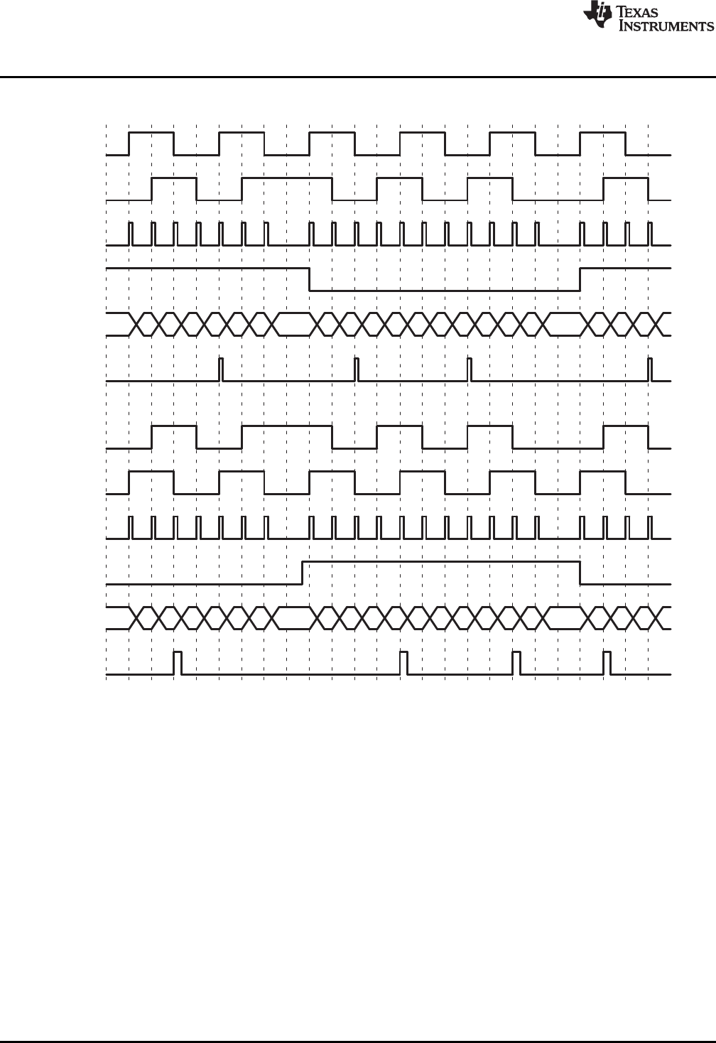
Latch on Index Event Marker/Software Index Marker (QEPCTL[IEL] = 11— The first index marker is
defined as the quadrature edge following the first index edge. The eQEP peripheral records the
occurrence of the first index marker (QEPSTS[FIMF]) and direction on the first index event marker
(QEPSTS[FIDF]) in the QEPSTS registers. It also remembers the quadrature edge on the first
index marker so that same relative quadrature transition is used for latching the position counter
(QEPCTL[IEL]=11).
Figure 10 shows the position counter latch using an index event marker.
21
SPRU790D–November 2004–Revised December 2008 Enhanced QEP (eQEP) Module
Submit Documentation Feedback
Copyright © 2004–2008, Texas Instruments Incorporated
F9C
F9D
F9E
F9F
FA0
FA1
FA2
FA3
FA4
FA5
FA4
FA3
FA2
FA1
FA0
F9F
F9E
F9D
F9C
F9B
F9A
F99
F98
F97
F9F 0
QA
QB
QI
QCLK
QEPSTS:QDF
QPOSCNT
Index interrupt/
index event
marker
QPOSILAT
QEPSTS:QDLF
F9C
F9D
F9E
F9F
FA0
FA1
FA2
FA3
FA4
FA5
FA4
FA3
FA2
FA1
FA0
F9F
F9E
F9D
F9C
F9B
F9A
F99
F98
F97
F9F F9F
QA
QB
QS
QCLK
QEPST:QDF
QPOSCNT
QIPOSSLAT
Position Counter and Control Unit (PCCU)
www.ti.com
Figure 10. Software Index Marker for 1000-line Encoder (QEPCTL[IEL] = 1)
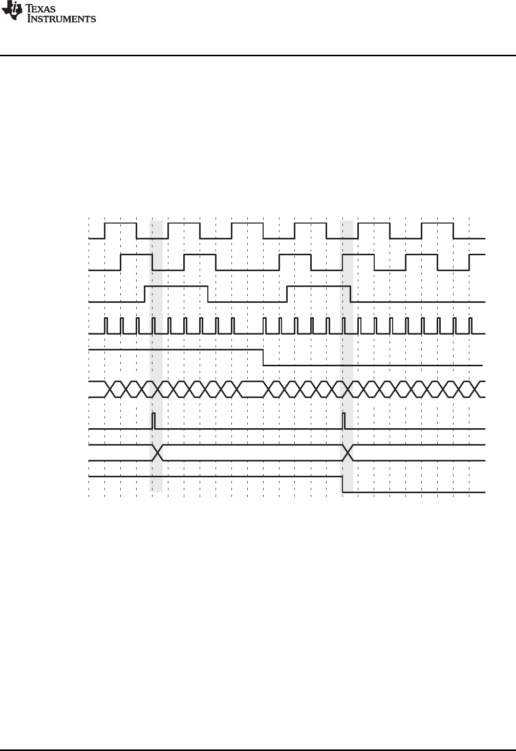
4.2.2 Strobe Event Latch
The position-counter value is latched to the QPOSSLAT register on the rising edge of the strobe input by
clearing the QEPCTL[SEL] bit.
If the QEPCTL[SEL] bit is set, then the position counter value is latched to the QPOSSLAT register on the
rising edge of the strobe input for forward direction and on the falling edge of the strobe input for reverse
direction as shown in Figure 11.
The strobe event latch interrupt flag (QFLG[SEL) is set when the position counter is latched to the
QPOSSLAT register.
Figure 11. Strobe Event Latch (QEPCTL[SEL] = 1)
22 Enhanced QEP (eQEP) Module SPRU790D–November 2004–Revised December 2008
Submit Documentation Feedback
Copyright © 2004–2008, Texas Instruments Incorporated
QPOSCTL:PCSPW
8
Pulse
stretcher
QFLG:PCM
QPOSCNT
32
QPOSCMP QFLG:PCR
32
QPOSCTL:PCSHDW
QPOSCTL:PCLOAD
0
1
QPOSCTL:PCPOL
PCSOUT
PCEVENT
www.ti.com
Position Counter and Control Unit (PCCU)
4.3 Position Counter Initialization
The position counter can be initialized using following events:
• Index event
• Strobe event
• Software initialization
Index Event Initialization (IEI)— The QEPI index input can be used to trigger the initialization of the
position counter at the rising or falling edge of the index input. If the QEPCTL[IEI] bits are 10, then
the position counter (QPOSCNT) is initialized with a value in the QPOSINIT register on the rising
edge of index input. Conversely, if the QEPCTL[IEI] bits are 11, initialization will be on the falling
edge of the index input.
Strobe Event Initialization (SEI)— If the QEPCTL[SEI] bits are 10, then the position counter is initialized
with a value in the QPOSINIT register on the rising edge of strobe input.
If QEPCTL[SEL] bits are 11, then the position counter is initialized with a value in the QPOSINIT
register on the rising edge of strobe input for forward direction and on the falling edge of strobe
input for reverse direction.
Software Initialization (SWI)— The position counter can be initialized in software by writing a 1 to the
QEPCTL[SWI] bit. This bit is not automatically cleared. While the bit is still set, if a 1 is written to it
again, the position counter will be re-initialized.
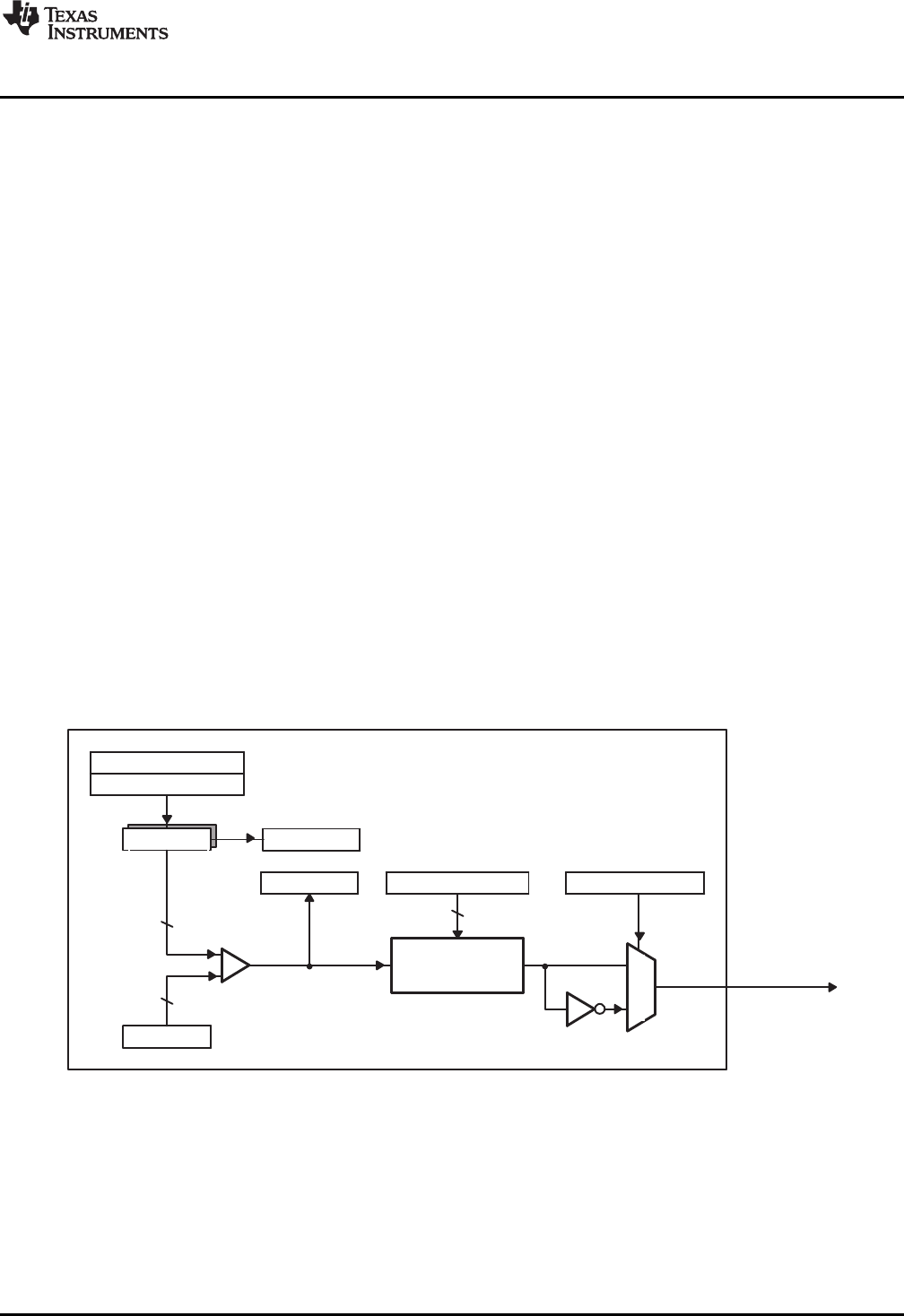
4.4 eQEP Position-compare Unit
The eQEP peripheral includes a position-compare unit that is used to generate a sync output and/or
interrupt on a position-compare match. Figure 12 shows a diagram. The position-compare (QPOSCMP)
register is shadowed and shadow mode can be enabled or disabled using the QPOSCTL[PSSHDW] bit. If
the shadow mode is not enabled, the CPU writes directly to the active position compare register.
Figure 12. eQEP Position-compare Unit
In shadow mode, you can configure the position-compare unit (QPOSCTL[PCLOAD]) to load the shadow
register value into the active register on the following events and to generate the position-compare ready
(QFLG[PCR]) interrupt after loading.
• Load on compare match
• Load on position-counter zero event
The position-compare match (QFLG[PCM]) is set when the position-counter value (QPOSCNT) matches
with the active position-compare register (QPOSCMP) and the position-compare sync output of the
programmable pulse width is generated on compare match to trigger an external device.
23
SPRU790D–November 2004–Revised December 2008 Enhanced QEP (eQEP) Module
Submit Documentation Feedback
Copyright © 2004–2008, Texas Instruments Incorporated

POSCMP=2
0
1
2
3
4
3
2
1
0
1
2
3
4
3
2
1
0
eQEP counter
PCEVNT
PCSOUT (active HIGH)
PCSOUT (active LOW)
PCSPW
DIR
QPOSCMP
QPOSCNT
PCSOUT (active HIGH)
PCSPW PCSPW PCSPW
PCEVNT
Position Counter and Control Unit (PCCU)
www.ti.com
For example, if QPOSCMP = 2, the position-compare unit generates a position-compare event on 1 to 2
transitions of the eQEP position counter for forward counting direction and on 3 to 2 transitions of the
eQEP position counter for reverse counting direction (see Figure 13).
Figure 23 shows the layout of the eQEP Position-Compare Control Register (QPOSCTL) and Table 5
describes the QPOSCTL bit fields.
Figure 13. eQEP Position-compare Event Generation Points
The pulse stretcher logic in the position-compare unit generates a programmable position-compare sync
pulse output on the position-compare match. In the event of a new position-compare match while a
previous position-compare pulse is still active, then the pulse stretcher generates a pulse of specified
duration from the new position-compare event as shown in Figure 14.
Figure 14. eQEP Position-compare Sync Output Pulse Stretcher
24 Enhanced QEP (eQEP) Module SPRU790D–November 2004–Revised December 2008
Submit Documentation Feedback
Copyright © 2004–2008, Texas Instruments Incorporated

v(k)+X
t(k)*t(k*1)+X
DT
www.ti.com
eQEP Edge Capture Unit
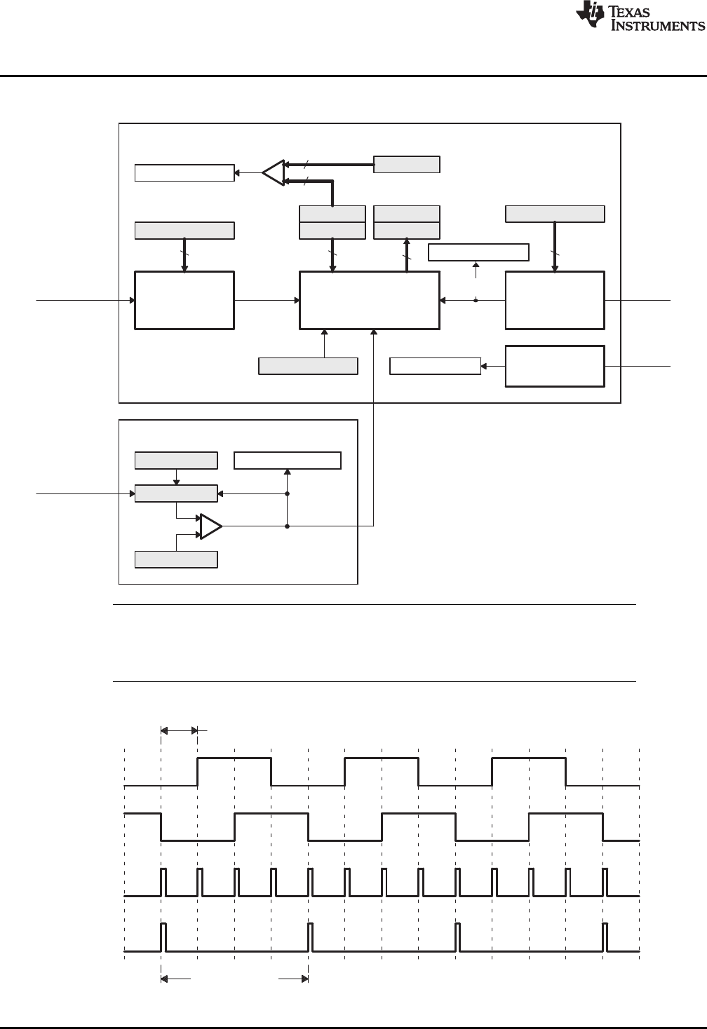
5 eQEP Edge Capture Unit
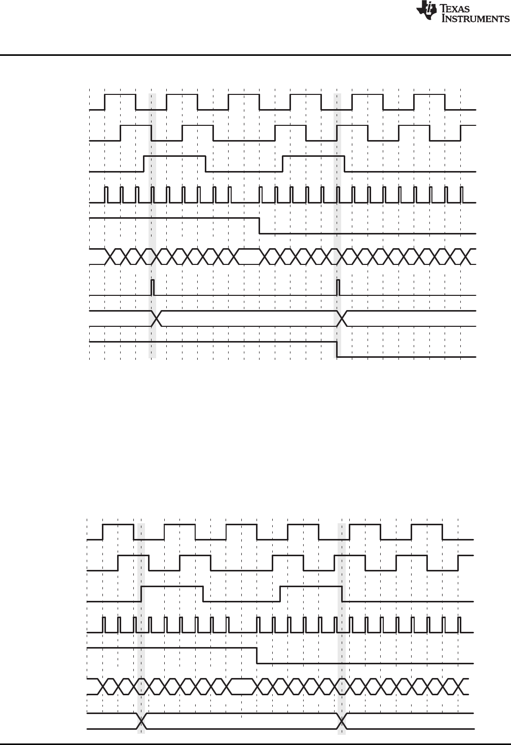
The eQEP peripheral includes an integrated edge capture unit to measure the elapsed time between the
unit position events as shown in Figure 15. This feature is typically used for low speed measurement using
the following equation:
(3)
where,
• X - Unit position is defined by integer multiple of quadrature edges (see Figure 16)
•ΔT - Elapsed time between unit position events
• v(k) - Velocity at time instant "k"
The eQEP capture timer (QCTMR) runs from prescaled SYSCLKOUT and the prescaler is programmed
by the QCAPCTL[CCPS] bits. The capture timer (QCTMR) value is latched into the capture period register
(QCPRD) on every unit position event and then the capture timer is reset, a flag is set in
QEPSTS:UPEVNT to indicate that new value is latched into the QCPRD register. Software can check this
status flag before reading the period register for low speed measurement and clear the flag by writing 1.
Time measurement (ΔT) between unit position events will be correct if the following conditions are met:
• No more than 65,535 counts have occurred between unit position events.
• No direction change between unit position events.
The capture unit sets the eQEP overflow error flag (QEPSTS[COEF]) in the event of capture timer
overflow between unit position events. If a direction change occurs between the unit position events, then
an error flag is set in the status register (QEPSTS[CDEF]).
Capture Timer (QCTMR) and Capture period register (QCPRD) can be configured to latch on following
events.
• CPU read of QPOSCNT register
• Unit time-out event
If the QEPCTL[QCLM] bit is cleared, then the capture timer and capture period values are latched into the
QCTMRLAT and QCPRDLAT registers, respectively, when the CPU reads the position counter
(QPOSCNT).
If the QEPCTL[QCLM] bit is set, then the position counter, capture timer, and capture period values are
latched into the QPOSLAT, QCTMRLAT and QCPRDLAT registers, respectively, on unit time out.
Figure 17 shows the capture unit operation along with the position counter.
25
SPRU790D–November 2004–Revised December 2008 Enhanced QEP (eQEP) Module
Submit Documentation Feedback
Copyright © 2004–2008, Texas Instruments Incorporated
QCAPCTL:CEN
Capture timer
control unit
(CTCU)
QCPRD
QCTMR QCTMRLAT
QCPRDLAT
16 16
3-bit binary
divider
x1, 1/2, 1/4...,
1/128
CAPCLK
QCAPCTL:CCPS
3
SYSCLKOUT
16
0xFFFF
16
QEPSTS:COEF
x1, 1/2, 1/4...,
1/2048
4-bit binary
divider QCLK
Rising/falling
edge detect
QDIR
QEPSTS:CDEF
QEPCTL:UTE
QUTMR
QUPRD
SYSCLKOUT
QFLG:UTO
UTIME
4
QCAPCTL:UPPS
UTOUT
QEPSTS:UPEVNT
UPEVNT
X=N x P
P
QA
QB
QCLK
UPEVNT
eQEP Edge Capture Unit
www.ti.com
Figure 15. eQEP Edge Capture Unit
NOTE: The QCAPCTL[UPPS] prescaler should not be modified dynamically (such as switching the
unit event prescaler from QCLK/4 to QCLK/8). Doing so may result in undefined behavior.
The QCAPCTL[CPPS] prescaler can be modified dynamically (such as switching CAPCLK
prescaling mode from SYSCLK/4 to SYSCLK/8) only after the capture unit is disabled.
Figure 16. Unit Position Event for Low Speed Measurement (QCAPCTL[UPPS] = 0010)
A N - Number of quadrature periods selected using QCAPCTL[UPPS] bits
26 Enhanced QEP (eQEP) Module SPRU790D–November 2004–Revised December 2008
Submit Documentation Feedback
Copyright © 2004–2008, Texas Instruments Incorporated

∆X
x(k−1)
∆T
t(k)
t(k−1)
T
QEPA
QEPB
QCLK
QPOSCNT
UPEVNT
QCTMR
UTOUT
x(k)
v(k)+x(k)*x(k*1)
T+
DX
Tor
www.ti.com
eQEP Edge Capture Unit
Figure 17. eQEP Edge Capture Unit - Timing Details
Velocity Calculation Equations:
(4)
where
v(k): Velocity at time instant k
x(k): Position at time instant k
x(k-1): Position at time instant k-1
T: Fixed unit time or inverse of velocity calculation rate
ΔX: Incremental position movement in unit time
X: Fixed unit position
ΔT: Incremental time elapsed for unit position movement
t(k): Time instant "k"
t(k-1): Time instant "k-1"
Unit time (T) and unit period(X) are configured using the QUPRD and QCAPCTL[UPPS] registers.
Incremental position output and incremental time output is available in the QPOSLAT and QCPRDLAT
registers.
27
SPRU790D–November 2004–Revised December 2008 Enhanced QEP (eQEP) Module
Submit Documentation Feedback
Copyright © 2004–2008, Texas Instruments Incorporated
QFLG:WTOQWDPRD
16
QWDTMR
16
QEPCTL:WDE
QWDOG
RESET
SYSCLKOUT
/64
SYSCLKOUT
QCLK WDTOUT
QFLG:UTOQUPRD
32
QUTMR
32
QEPCTL:UTE
UTIME
SYSCLKOUT
UTOUT
eQEP Watchdog
www.ti.com
Parameter Relevant Register to Configure or Read the Information
T Unit Period Register (QUPRD)
ΔX Incremental Position = QPOSLAT(k) - QPOSLAT(K-1)
X Fixed unit position defined by sensor resolution and ZCAPCTL[UPPS] bits
ΔT Capture Period Latch (QCPRDLAT)
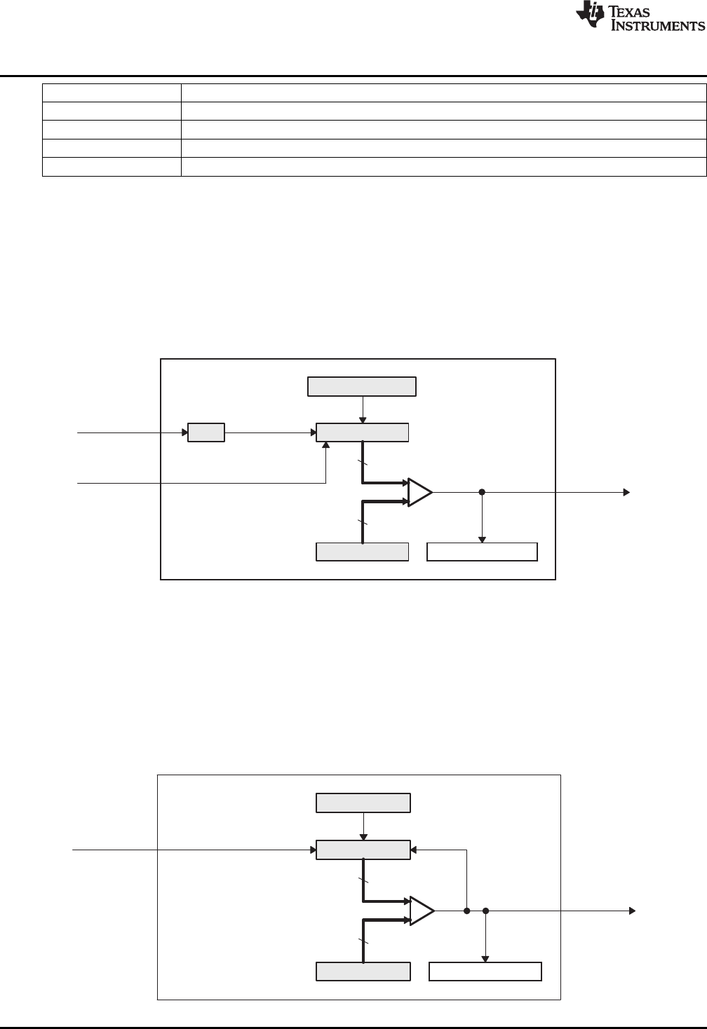
6 eQEP Watchdog
The eQEP peripheral contains a 16-bit watchdog timer that monitors the quadrature-clock to indicate
proper operation of the motion-control system. The eQEP watchdog timer is clocked from
SYSCLKOUT/64 and the quadrate clock event (pulse) resets the watchdog timer. If no quadrature-clock
event is detected until a period match (QWDPRD = QWDTMR), then the watchdog timer will time out and
the watchdog interrupt flag will be set (QFLG[WTO]). The time-out value is programmable through the
watchdog period register (QWDPRD).
Figure 18. eQEP Watchdog Timer
7 Unit Timer Base
The eQEP peripheral includes a 32-bit timer (QUTMR) that is clocked by SYSCLKOUT to generate
periodic interrupts for velocity calculations. The unit time out interrupt is set (QFLG[UTO]) when the unit
timer (QUTMR) matches the unit period register (QUPRD).
The eQEP peripheral can be configured to latch the position counter, capture timer, and capture period
values on a unit time out event so that latched values are used for velocity calculation as described in
Section Section 5.
Figure 19. eQEP Unit Time Base
28 Enhanced QEP (eQEP) Module SPRU790D–November 2004–Revised December 2008
Submit Documentation Feedback
Copyright © 2004–2008, Texas Instruments Incorporated
Clr
Set
Latch
QFRC:PCE
PCE
QCLR:PCE
QFLG:PCE
QEINT:PCE
QCLR:UTO
QFRC:UTO
QEINT:UTO
set
Latch
clr
UTO
QFLG:UTO
0
1
0
Pulse
generator
when
input=1
QFLG:INT
Latch
Set Clr QCLR:INT
EQEPxINT
www.ti.com
eQEP Interrupt Structure
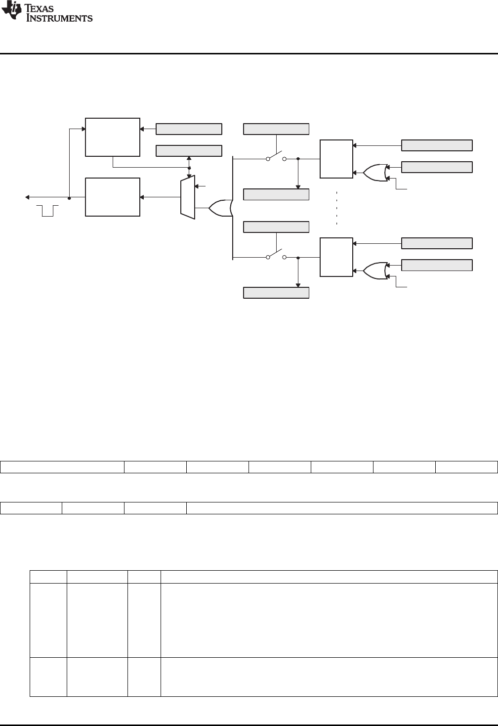
8 eQEP Interrupt Structure
Figure 20 shows how the interrupt mechanism works in the EQEP module.
Figure 20. EQEP Interrupt Generation
Eleven interrupt events (PCE, PHE, QDC, WTO, PCU, PCO, PCR, PCM, SEL, IEL and UTO) can be
generated. The interrupt control register (QEINT) is used to enable/disable individual interrupt event
sources. The interrupt flag register (QFLG) indicates if any interrupt event has been latched and contains
the global interrupt flag bit (INT). An interrupt pulse is generated only to the PIE if any of the interrupt
events is enabled, the flag bit is 1 and the INT flag bit is 0. The interrupt service routine will need to clear
the global interrupt flag bit and the serviced event, via the interrupt clear register (QCLR), before any other
interrupt pulses are generated. You can force an interrupt event by way of the interrupt force register
(QFRC), which is useful for test purposes.
9 eQEP Registers
Figure 21. QEP Decoder Control (QDECCTL) Register
15 14 13 12 11 10 9 8
QSRC SOEN SPSEL XCR SWAP IGATE QAP
R/W-0 R/W-0 R/W-0 R/W-0 R/W-0 R/W-0 R/W-0
7654 0
QBP QIP QSP Reserved
R/W-0 R/W-0 R/W-0 R-0
LEGEND: R/W = Read/Write; R = Read only; -n= value after reset
Table 3. eQEP Decoder Control (QDECCTL) Register Field Descriptions
Bits Name Value Description
15-14 QSRC Position-counter source selection
00 Quadrature count mode (QCLK = iCLK, QDIR = iDIR)
01 Direction-count mode (QCLK = xCLK, QDIR = xDIR)
10 UP count mode for frequency measurement (QCLK = xCLK, QDIR = 1)
11 DOWN count mode for frequency measurement
(QCLK = xCLK, QDIR = 0)
13 SOEN Sync output-enable
0 Disable position-compare sync output
1 Enable position-compare sync output
29
SPRU790D–November 2004–Revised December 2008 Enhanced QEP (eQEP) Module
Submit Documentation Feedback
Copyright © 2004–2008, Texas Instruments Incorporated

eQEP Registers
www.ti.com
Table 3. eQEP Decoder Control (QDECCTL) Register Field Descriptions (continued)
Bits Name Value Description
12 SPSEL Sync output pin selection
0 Index pin is used for sync output
1 Strobe pin is used for sync output
11 XCR External clock rate
0 2x resolution: Count the rising/falling edge
1 1x resolution: Count the rising edge only
10 SWAP Swap quadrature clock inputs. This swaps the input to the quadrature decoder, reversing the
counting direction.
0 Quadrature-clock inputs are not swapped
1 Quadrature-clock inputs are swapped
9 IGATE Index pulse gating option
0 Disable gating of Index pulse
1 Gate the index pin with strobe
8 QAP QEPA input polarity
0 No effect
1 Negates QEPA input
7 QBP QEPB input polarity
0 No effect
1 Negates QEPB input
6 QIP QEPI input polarity
0 No effect
1 Negates QEPI input
5 QSP QEPS input polarity
0 No effect
1 Negates QEPS input
4-0 Reserved Always write as 0
Figure 22. eQEP Control (QEPCTL) Register
15 14 13 12 11 10 9 8 7 6 5 4 3 2 1 0
FREE, SOFT PCRM SEI IEI SWI SEL IEL QPEN QCLM UTE WDE
R/W-0 R/W-0 R/W-0 R/W-0 R/W-0 R/W-0 R/W-0 R/W-0 R/W-0 R/W-0 R/W-0
LEGEND: R/W = Read/Write; R = Read only; -n= value after reset
30 Enhanced QEP (eQEP) Module SPRU790D–November 2004–Revised December 2008
Submit Documentation Feedback
Copyright © 2004–2008, Texas Instruments Incorporated

www.ti.com
eQEP Registers
Table 4. eQEP Control (QEPCTL) Register Field Descriptions
Bits Name Value Description
15-14 FREE, Emulation Control Bits
SOFT QPOSCNT behavior
00 Position counter stops immediately on emulation suspend
01 Position counter continues to count until the rollover
1x Position counter is unaffected by emulation suspend
QWDTMR behavior
00 Watchdog counter stops immediately
01 Watchdog counter counts until WD period match roll over
1x Watchdog counter is unaffected by emulation suspend
QUTMR behavior
00 Unit timer stops immediately
01 Unit timer counts until period rollover
1x Unit timer is unaffected by emulation suspend
QCTMR behavior
00 Capture Timer stops immediately
01 Capture Timer counts until next unit period event
1x Capture Timer is unaffected by emulation suspend
13-12 PCRM Position counter reset mode
00 Position counter reset on an index event
01 Position counter reset on the maximum position
10 Position counter reset on the first index event
11 Position counter reset on a unit time event
11-10 SEI Strobe event initialization of position counter
00 Does nothing (action disabled)
01 Does nothing (action disabled)
10 Initializes the position counter on rising edge of the QEPS signal
11 Clockwise Direction:
Initializes the position counter on the rising edge of QEPS strobe
Counter Clockwise Direction:
Initializes the position counter on the falling edge of QEPS strobe
9-8 IEI Index event initialization of position counter
00 Do nothing (action disabled)
01 Do nothing (action disabled)
10 Initializes the position counter on the rising edge of the QEPI signal (QPOSCNT =
QPOSINIT)
11 Initializes the position counter on the falling edge of QEPI signal (QPOSCNT = QPOSINIT)
7 SWI Software initialization of position counter
0 Do nothing (action disabled)
1 Initialize position counter (QPOSCNT=QPOSINIT). This bit is not cleared automatically
6 SEL Strobe event latch of position counter
0 The position counter is latched on the rising edge of QEPS strobe (QPOSSLAT =
POSCCNT). Latching on the falling edge can be done by inverting the strobe input using the
QSP bit in the QDECCTL register.
1 Clockwise Direction:
Position counter is latched on rising edge of QEPS strobe
Counter Clockwise Direction:
Position counter is latched on falling edge of QEPS strobe
5-4 IEL Index event latch of position counter (software index marker)
00 Reserved
01 Latches position counter on rising edge of the index signal
10 Latches position counter on falling edge of the index signal
11 Software index marker. Latches the position counter and quadrature direction flag on index
event marker. The position counter is latched to the QPOSILAT register and the direction flag
is latched in the QEPSTS[QDLF] bit. This mode is useful for software index marking.
31
SPRU790D–November 2004–Revised December 2008 Enhanced QEP (eQEP) Module
Submit Documentation Feedback
Copyright © 2004–2008, Texas Instruments Incorporated

eQEP Registers
www.ti.com
Table 4. eQEP Control (QEPCTL) Register Field Descriptions (continued)
Bits Name Value Description
3 QPEN Quadrature position counter enable/software reset
0 Reset the eQEP peripheral internal operating flags/read-only registers. Control/configuration
registers are not disturbed by a software reset.
1 eQEP position counter is enabled
2 QCLM eQEP capture latch mode
0 Latch on position counter read by CPU. Capture timer and capture period values are latched
into QCTMRLAT and QCPRDLAT registers when CPU reads the QPOSCNT register.
1 Latch on unit time out. Position counter, capture timer and capture period values are latched
into QPOSLAT, QCTMRLAT and QCPRDLAT registers on unit time out.
1 UTE eQEP unit timer enable
0 Disable eQEP unit timer
1 Enable unit timer
0 WDE eQEP watchdog enable
0 Disable the eQEP watchdog timer
1 Enable the eQEP watchdog timer
Figure 23. eQEP Position-compare Control (QPOSCTL) Register
15 14 13 12 11 8
PCSHDW PCLOAD PCPOL PCE PCSPW
R/W-0 R/W-0 R/W-0 R/W-0 R/W-0
7 0
PCSPW
R/W-0
LEGEND: R/W = Read/Write; R = Read only; -n= value after reset
Table 5. eQEP Position-compare Control (QPOSCTL) Register Field Descriptions
Bit Name Description
15 PCSHDW Position-compare shadow enable
0 Shadow disabled, load Immediate
1 Shadow enabled
14 PCLOAD Position-compare shadow load mode
0 Load on QPOSCNT = 0
1 Load when QPOSCNT = QPOSCMP
13 PCPOL Polarity of sync output
0 Active HIGH pulse output
1 Active LOW pulse output
12 PCE Position-compare enable/disable
0 Disable position compare unit
1 Enable position compare unit
11-0 PCSPW Select-position-compare sync output pulse width
0x000 1 * 4 * SYSCLKOUT cycles
0x001 2 * 4 * SYSCLKOUT cycles
0xFFF 4096 * 4 * SYSCLKOUT cycles
32 Enhanced QEP (eQEP) Module SPRU790D–November 2004–Revised December 2008
Submit Documentation Feedback
Copyright © 2004–2008, Texas Instruments Incorporated

www.ti.com
eQEP Registers
Figure 24. eQEP Capture Control (QCAPCTL) Register
15 14 7 6 4 3 0
CEN Reserved CCPS UPPS
R/W-0 R-0 R/W-0 R/W-0
LEGEND: R/W = Read/Write; R = Read only; -n= value after reset
Table 6. eQEP Capture Control (QCAPCTL) Register Field Descriptions
Bits Name Description
15 CEN Enable eQEP capture
0 eQEP capture unit is disabled
1 eQEP capture unit is enabled
14-7 Reserved Always write as 0
6-4 CCPS eQEP capture timer clock prescaler
000 CAPCLK = SYSCLKOUT/1
001 CAPCLK = SYSCLKOUT/2
010 CAPCLK = SYSCLKOUT/4
011 CAPCLK = SYSCLKOUT/8
100 CAPCLK = SYSCLKOUT/16
101 CAPCLK = SYSCLKOUT/32
110 CAPCLK = SYSCLKOUT/64
111 CAPCLK = SYSCLKOUT/128
3-0 UPPS Unit position event prescaler
0000 UPEVNT = QCLK/1
0001 UPEVNT = QCLK/2
0010 UPEVNT = QCLK/4
0011 UPEVNT = QCLK/8
0100 UPEVNT = QCLK/16
0101 UPEVNT = QCLK/32
0110 UPEVNT = QCLK/64
0111 UPEVNT = QCLK/128
1000 UPEVNT = QCLK/256
1001 UPEVNT = QCLK/512
1010 UPEVNT = QCLK/1024
1011 UPEVNT = QCLK/2048
11xx Reserved
Figure 25. eQEP Position Counter (QPOSCNT) Register
31 0
QPOSCNT
R/W-0
LEGEND: R/W = Read/Write; R = Read only; -n= value after reset
Table 7. eQEP Position Counter (QPOSCNT) Register Field Descriptions
Bits Name Description
31-0 QPOSCNT This 32-bit position counter register counts up/down on every eQEP pulse based on direction
input. This counter acts as a position integrator whose count value is proportional to position
from a give reference point.
Figure 26. eQEP Position Counter Initialization (QPOSINIT) Register
31 0
QPOSINIT
R/W-0
LEGEND: R/W = Read/Write; R = Read only; -n= value after reset
33
SPRU790D–November 2004–Revised December 2008 Enhanced QEP (eQEP) Module
Submit Documentation Feedback
Copyright © 2004–2008, Texas Instruments Incorporated

eQEP Registers
www.ti.com
Table 8. eQEP Position Counter Initialization (QPOSINIT) Register Field Descriptions
Bits Name Description
31-0 QPOSINIT This register contains the position value that is used to initialize the position counter based on
external strobe or index event. The position counter can be initialized through software.
Figure 27. eQEP Maximum Position Count Register (QPOSMAX) Register
31 0
QPOSMAX
R/W-0
LEGEND: R/W = Read/Write; R = Read only; -n= value after reset
Table 9. eQEP Maximum Position Count (QPOSMAX) Register Field Descriptions
Bits Name Description
31-0 QPOSMAX This register contains the maximum position counter value.
Figure 28. eQEP Position-compare (QPOSCMP) Register
31 0
QPOSCMP
R/W-0
LEGEND: R/W = Read/Write; R = Read only; -n= value after reset
Table 10. eQEP Position-compare (QPOSCMP) Register Field Descriptions
Bits Name Description
31-0 QPOSCMP The position-compare value in this register is compared with the position counter (QPOSCNT) to
generate sync output and/or interrupt on compare match.
Figure 29. eQEP Index Position Latch (QPOSILAT) Register
31 0
QPOSILAT
R-0
LEGEND: R/W = Read/Write; R = Read only; -n= value after reset
Table 11. eQEP Index Position Latch(QPOSILAT) Register Field Descriptions
Bits Name Description
31-0 QPOSILAT The position-counter value is latched into this register on an index event as defined by the
QEPCTL[IEL] bits.
Figure 30. eQEP Strobe Position Latch (QPOSSLAT) Register
31 0
QPOSSLAT
R-0
LEGEND: R/W = Read/Write; R = Read only; -n= value after reset
34 Enhanced QEP (eQEP) Module SPRU790D–November 2004–Revised December 2008
Submit Documentation Feedback
Copyright © 2004–2008, Texas Instruments Incorporated

www.ti.com
eQEP Registers
Table 12. eQEP Strobe Position Latch (QPOSSLAT) Register Field Descriptions
Bits Name Description
31-0 QPOSSLAT The position-counter value is latched into this register on strobe event as defined by the
QEPCTL[SEL] bits.
Figure 31. eQEP Position Counter Latch (QPOSLAT) Register
31 0
QPOSLAT
R-0
LEGEND: R/W = Read/Write; R = Read only; -n= value after reset
Table 13. eQEP Position Counter Latch (QPOSLAT) Register Field Descriptions
Bits Name Description
31-0 QPOSLAT The position-counter value is latched into this register on unit time out event.
Figure 32. eQEP Unit Timer (QUTMR) Register
31 0
QUTMR
R/W-0
LEGEND: R/W = Read/Write; R = Read only; -n= value after reset
Table 14. eQEP Unit Timer (QUTMR) Register Field Descriptions
Bits Name Description
31-0 QUTMR This register acts as time base for unit time event generation. When this timer value matches
with unit time period value, unit time event is generated.
Figure 33. eQEP Register Unit Period (QUPRD) Register
31 0
QUPRD
R/W-0
LEGEND: R/W = Read/Write; R = Read only; -n= value after reset
Table 15. eQEP Unit Period (QUPRD) Register Field Descriptions
Bits Name Description
31-0 QUPRD This register contains the period count for unit timer to generate periodic unit time events to latch
the eQEP position information at periodic interval and optionally to generate interrupt.
Figure 34. eQEP Watchdog Timer (QWDTMR) Register
15 0
QWDTMR
R/W-0
LEGEND: R/W = Read/Write; R = Read only; -n= value after reset
35
SPRU790D–November 2004–Revised December 2008 Enhanced QEP (eQEP) Module
Submit Documentation Feedback
Copyright © 2004–2008, Texas Instruments Incorporated

eQEP Registers
www.ti.com
Table 16. eQEP Watchdog Timer (QWDTMR) Register Field Descriptions
Bits Name Description
15-0 QWDTMR This register acts as time base for watch dog to detect motor stalls. When this timer value
matches with watch dog period value, watch dog timeout interrupt is generated. This register is
reset upon edge transition in quadrature-clock indicating the motion.
Figure 35. eQEP Watchdog Period (QWDPRD) Register
15 0
QWDPRD
R/W-0
LEGEND: R/W = Read/Write; R = Read only; -n= value after reset
Table 17. eQEP Watchdog Period (QWDPRD) Register Field Description
Bits Name Value Description
15-0 QWDPRD This register contains the time-out count for the eQEP peripheral watch dog timer.
When the watchdog timer value matches the watchdog period value, a watchdog
timeout interrupt is generated.
Figure 36. eQEP Interrupt Enable (QEINT) Register
15 12 11 10 9 8
Reserved UTO IEL SEL PCM
R-0 R/W-0 R/W-0 R/W-0 R/W-0
76543210
PCR PCO PCU WTO QDC QPE PCE Reserved
R/W-0 R/W-0 R/W-0 R/W-0 R/W-0 R/W-0 R/W-0 R-0
LEGEND: R/W = Read/Write; R = Read only; -n= value after reset
Table 18. eQEP Interrupt Enable(QEINT) Register Field Descriptions
Bits Name Value Description
15-12 Reserved 0 Always write as 0
11 UTO Unit time out interrupt enable
0 Interrupt is disabled
1 Interrupt is enabled
10 IEL Index event latch interrupt enable
0 Interrupt is disabled
1 Interrupt is enabled
9 SEL Strobe event latch interrupt enable
0 Interrupt is disabled
1 Interrupt is enabled
8 PCM Position-compare match interrupt enable
0 Interrupt is disabled
1 Interrupt is enabled
7 PCR Position-compare ready interrupt enable
0 Interrupt is disabled
1 Interrupt is enabled
6 PCO Position counter overflow interrupt enable
0 Interrupt is disabled
1 Interrupt is enabled
36 Enhanced QEP (eQEP) Module SPRU790D–November 2004–Revised December 2008
Submit Documentation Feedback
Copyright © 2004–2008, Texas Instruments Incorporated

www.ti.com
eQEP Registers
Table 18. eQEP Interrupt Enable(QEINT) Register Field Descriptions (continued)
Bits Name Value Description
5 PCU Position counter underflow interrupt enable
0 Interrupt is disabled
1 Interrupt is enabled
4 WTO Watchdog time out interrupt enable
0 Interrupt is disabled
1 Interrupt is enabled
3 QDC Quadrature direction change interrupt enable
0 Interrupt is disabled
1 Interrupt is enabled
2 QPE Quadrature phase error interrupt enable
0 Interrupt is disabled
1 Interrupt is enabled
1 PCE Position counter error interrupt enable
0 Interrupt is disabled
1 Interrupt is enabled
0 Reserved Reserved
Figure 37. eQEP Interrupt Flag (QFLG) Register
15 12 11 10 9 8
Reserved UTO IEL SEL PCM
R-0 R-0 R-0 R-0 R-0
76543210
PCR PCO PCU WTO QDC PHE PCE INT
R-0 R-0 R-0 R-0 R-0 R-0 R-0 R-0
LEGEND: R/W = Read/Write; R = Read only; -n= value after reset
Table 19. eQEP Interrupt Flag (QFLG) Register Field Descriptions
Bits Name Value Description
15- Reserved Always write as 0
12
11 UTO Unit time out interrupt flag
0 No interrupt generated
1 Set by eQEP unit timer period match
10 IEL Index event latch interrupt flag
0 No interrupt generated
1 This bit is set after latching the QPOSCNT to QPOSILAT
9 SEL Strobe event latch interrupt flag
0 No interrupt generated
1 This bit is set after latching the QPOSCNT to QPOSSLAT
8 PCM eQEP compare match event interrupt flag
0 No interrupt generated
1 This bit is set on position-compare match
7 PCR Position-compare ready interrupt flag
0 No interrupt generated
1 This bit is set after transferring the shadow register value to the active position compare register.
6 PCO Position counter overflow interrupt flag
0 No interrupt generated
37
SPRU790D–November 2004–Revised December 2008 Enhanced QEP (eQEP) Module
Submit Documentation Feedback
Copyright © 2004–2008, Texas Instruments Incorporated

eQEP Registers
www.ti.com
Table 19. eQEP Interrupt Flag (QFLG) Register Field Descriptions (continued)
Bits Name Value Description
1 This bit is set on position counter overflow.
5 PCU Position counter underflow interrupt flag
0 No interrupt generated
1 This bit is set on position counter underflow.
4 WTO Watchdog timeout interrupt flag
0 No interrupt generated
1 Set by watch dog timeout
3 QDC Quadrature direction change interrupt flag
0 No interrupt generated
1 This bit is set during change of direction
2 PHE Quadrature phase error interrupt flag
0 No interrupt generated
1 Set on simultaneous transition of QEPA and QEPB
1 PCE Position counter error interrupt flag
0 No interrupt generated
1 Position counter error
0 INT Global interrupt status flag
0 No interrupt generated
1 Interrupt was generated
Figure 38. eQEP Interrupt Clear (QCLR) Register
15 12 11 10 9 8
Reserved UTO IEL SEL PCM
R-0 R/W-0 R/W-0 R/W-0 R/W-0
76543210
PCR PCO PCU WTO QDC PHE PCE INT
R/W-0 R/W-0 R/W-0 R/W-0 R/W-0 R/W-0 R/W-0 R/W-0
LEGEND: R/W = Read/Write; R = Read only; -n= value after reset
Table 20. eQEP Interrupt Clear (QCLR) Register Field Descriptions
Bit Field Value Description
15-12 Reserved Always write as 0s
11 UTO Clear unit time out interrupt flag
0 No effect
1 Clears the interrupt flag
10 IEL Clear index event latch interrupt flag
0 No effect
1 Clears the interrupt flag
9 SEL Clear strobe event latch interrupt flag
0 No effect
1 Clears the interrupt flag
8 PCM Clear eQEP compare match event interrupt flag
0 No effect
1 Clears the interrupt flag
7 PCR Clear position-compare ready interrupt flag
0 No effect
1 Clears the interrupt flag
38 Enhanced QEP (eQEP) Module SPRU790D–November 2004–Revised December 2008
Submit Documentation Feedback
Copyright © 2004–2008, Texas Instruments Incorporated

www.ti.com
eQEP Registers
Table 20. eQEP Interrupt Clear (QCLR) Register Field Descriptions (continued)
Bit Field Value Description
6 PCO Clear position counter overflow interrupt flag
0 No effect
1 Clears the interrupt flag
5 PCU Clear position counter underflow interrupt flag
0 No effect
1 Clears the interrupt flag
4 WTO Clear watchdog timeout interrupt flag
0 No effect
1 Clears the interrupt flag
3 QDC Clear quadrature direction change interrupt flag
0 No effect
1 Clears the interrupt flag
2 PHE Clear quadrature phase error interrupt flag
0 No effect
1 Clears the interrupt flag
1 PCE Clear position counter error interrupt flag
0 No effect
1 Clears the interrupt flag
0 INT Global interrupt clear flag
0 No effect
1 Clears the interrupt flag and enables further interrupts to be generated if an event flags is set to 1.
Figure 39. eQEP Interrupt Force (QFRC) Register
15 12 11 10 9 8
Reserved UTO IEL SEL PCM
R-0 R/W-0 R/W-0 R/W-0 R/W-0
76543210
PCR PCO PCU WTO QDC PHE PCE Reserved
R/W-0 R/W-0 R/W-0 R/W-0 R/W-0 R/W-0 R/W-0 R-0
LEGEND: R/W = Read/Write; R = Read only; -n= value after reset
Table 21. eQEP Interrupt Force (QFRC) Register Field Descriptions
Bit Field Value Description
15-12 Reserved Always write as 0s
11 UTO Force unit time out interrupt
0 No effect
1 Force the interrupt
10 IEL Force index event latch interrupt
0 No effect
1 Force the interrupt
9 SEL Force strobe event latch interrupt
0 No effect
1 Force the interrupt
8 PCM Force position-compare match interrupt
0 No effect
1 Force the interrupt
39
SPRU790D–November 2004–Revised December 2008 Enhanced QEP (eQEP) Module
Submit Documentation Feedback
Copyright © 2004–2008, Texas Instruments Incorporated

eQEP Registers
www.ti.com
Table 21. eQEP Interrupt Force (QFRC) Register Field Descriptions (continued)
Bit Field Value Description
7 PCR Force position-compare ready interrupt
0 No effect
1 Force the interrupt
6 PCO Force position counter overflow interrupt
0 No effect
1 Force the interrupt
5 PCU Force position counter underflow interrupt
0 No effect
1 Force the interrupt
4 WTO Force watchdog time out interrupt
0 No effect
1 Force the interrupt
3 QDC Force quadrature direction change interrupt
0 No effect
1 Force the interrupt
2 PHE Force quadrature phase error interrupt
0 No effect
1 Force the interrupt
1 PCE Force position counter error interrupt
0 No effect
1 Force the interrupt
0 Reserved 0 1 Always write as 0
Figure 40. eQEP Status (QEPSTS) Register
15 8
Reserved
R-0
76543210
UPEVNT FIDF QDF QDLF COEF CDEF FIMF PCEF
R-1 R-0 R-0 R-0 R/W-1 R/W-1 R/W-1 R-0
LEGEND: R/W = Read/Write; R = Read only; -n= value after reset
Table 22. eQEP Status (QEPSTS) Register Field Descriptions
Bit Field Value Description
15-8 Reserved Always write as 0
7 UPEVNT Unit position event flag
0 No unit position event detected
1 Unit position event detected. Write 1 to clear.
6 FDF Direction on the first index marker
Status of the direction is latched on the first index event marker.
0 Counter-clockwise rotation (or reverse movement) on the first index event
1 Clockwise rotation (or forward movement) on the first index event
5 QDF Quadrature direction flag
0 Counter-clockwise rotation (or reverse movement)
1 Clockwise rotation (or forward movement)
40 Enhanced QEP (eQEP) Module SPRU790D–November 2004–Revised December 2008
Submit Documentation Feedback
Copyright © 2004–2008, Texas Instruments Incorporated

www.ti.com
eQEP Registers
Table 22. eQEP Status (QEPSTS) Register Field Descriptions (continued)
Bit Field Value Description
4 QDLF eQEP direction latch flag
Status of direction is latched on every index event marker.
0 Counter-clockwise rotation (or reverse movement) on index event marker
1 Clockwise rotation (or forward movement) on index event marker
3 COEF Capture overflow error flag
0 Sticky bit, cleared by writing 1
1 Overflow occurred in eQEP Capture timer (QEPCTMR)
2 CDEF Capture direction error flag
0 Sticky bit, cleared by writing 1
1 Direction change occurred between the capture position event.
1 FIMF First index marker flag
0 Sticky bit, cleared by writing 1
1 Set by first occurrence of index pulse
0 PCEF Position counter error flag. This bit is not sticky and it is updated for every index event.
0 No error occurred during the last index transition.
1 Position counter error
Figure 41. eQEP Capture Timer (QCTMR) Register
15 0
QCTMR
R/W
LEGEND: R/W = Read/Write; R = Read only; -n= value after reset
Table 23. eQEP Capture Timer (QCTMR) Register Field Descriptions
Bits Name Description
15-0 QCTMR This register provides time base for edge capture unit.
Figure 42. eQEP Capture Period (QCPRD) Register
15 0
QCPRD
R/W
LEGEND: R/W = Read/Write; R = Read only; -n= value after reset
Table 24. eQEP Capture Period Register (QCPRD) Register Field Descriptions
Bits Name Description
15-0 QCPRD This register holds the period count value between the last successive eQEP position events
Figure 43. eQEP Capture Timer Latch (QCTMRLAT) Register
15 0
QCTMRLAT
R
LEGEND: R/W = Read/Write; R = Read only; -n= value after reset
Table 25. eQEP Capture Timer Latch (QCTMRLAT) Register Field Descriptions
Bits Name Description
15-0 QCTMRLAT The eQEP capture timer value can be latched into this register on two events viz., unit timeout
event, reading the eQEP position counter.
41
SPRU790D–November 2004–Revised December 2008 Enhanced QEP (eQEP) Module
Submit Documentation Feedback
Copyright © 2004–2008, Texas Instruments Incorporated

eQEP Registers
www.ti.com
Figure 44. eQEP Capture Period Latch (QCPRDLAT) Register
15 0
QCPRDLAT
R/W
LEGEND: R/W = Read/Write; R = Read only; -n= value after reset
Table 26. eQEP Capture Period Latch (QCPRDLAT) Register Field Descriptions
Bits Name Description
15-0 QCPRDLAT eQEP capture period value can be latched into this register on two events viz., unit timeout
event, reading the eQEP position counter.
42 Enhanced QEP (eQEP) Module SPRU790D–November 2004–Revised December 2008
Submit Documentation Feedback
Copyright © 2004–2008, Texas Instruments Incorporated

www.ti.com
Appendix A Revision History
The changes shown below were made in this revision.
Table 27. Changes for Revision D
Location Additions, Deletions, Modifications
Section 4.3 Modified description of Software Initialization (SWI)
Table 4 Modified the description for bit 7 of the eQEP Control Register
43
SPRU790D–November 2004–Revised December 2008 Revision History
Submit Documentation Feedback
Copyright © 2004–2008, Texas Instruments Incorporated

IMPORTANT NOTICE
Texas Instruments Incorporated and its subsidiaries (TI) reserve the right to make corrections, modifications, enhancements, improvements,
and other changes to its products and services at any time and to discontinue any product or service without notice. Customers should
obtain the latest relevant information before placing orders and should verify that such information is current and complete. All products are
sold subject to TI’s terms and conditions of sale supplied at the time of order acknowledgment.
TI warrants performance of its hardware products to the specifications applicable at the time of sale in accordance with TI’s standard
warranty. Testing and other quality control techniques are used to the extent TI deems necessary to support this warranty. Except where
mandated by government requirements, testing of all parameters of each product is not necessarily performed.
TI assumes no liability for applications assistance or customer product design. Customers are responsible for their products and
applications using TI components. To minimize the risks associated with customer products and applications, customers should provide
adequate design and operating safeguards.
TI does not warrant or represent that any license, either express or implied, is granted under any TI patent right, copyright, mask work right,
or other TI intellectual property right relating to any combination, machine, or process in which TI products or services are used. Information
published by TI regarding third-party products or services does not constitute a license from TI to use such products or services or a
warranty or endorsement thereof. Use of such information may require a license from a third party under the patents or other intellectual
property of the third party, or a license from TI under the patents or other intellectual property of TI.
Reproduction of TI information in TI data books or data sheets is permissible only if reproduction is without alteration and is accompanied
by all associated warranties, conditions, limitations, and notices. Reproduction of this information with alteration is an unfair and deceptive
business practice. TI is not responsible or liable for such altered documentation. Information of third parties may be subject to additional
restrictions.
Resale of TI products or services with statements different from or beyond the parameters stated by TI for that product or service voids all
express and any implied warranties for the associated TI product or service and is an unfair and deceptive business practice. TI is not
responsible or liable for any such statements.
TI products are not authorized for use in safety-critical applications (such as life support) where a failure of the TI product would reasonably
be expected to cause severe personal injury or death, unless officers of the parties have executed an agreement specifically governing
such use. Buyers represent that they have all necessary expertise in the safety and regulatory ramifications of their applications, and
acknowledge and agree that they are solely responsible for all legal, regulatory and safety-related requirements concerning their products
and any use of TI products in such safety-critical applications, notwithstanding any applications-related information or support that may be
provided by TI. Further, Buyers must fully indemnify TI and its representatives against any damages arising out of the use of TI products in
such safety-critical applications.
TI products are neither designed nor intended for use in military/aerospace applications or environments unless the TI products are
specifically designated by TI as military-grade or "enhanced plastic." Only products designated by TI as military-grade meet military
specifications. Buyers acknowledge and agree that any such use of TI products which TI has not designated as military-grade is solely at
the Buyer's risk, and that they are solely responsible for compliance with all legal and regulatory requirements in connection with such use.
TI products are neither designed nor intended for use in automotive applications or environments unless the specific TI products are
designated by TI as compliant with ISO/TS 16949 requirements. Buyers acknowledge and agree that, if they use any non-designated
products in automotive applications, TI will not be responsible for any failure to meet such requirements.
Following are URLs where you can obtain information on other Texas Instruments products and application solutions:
Products Applications
Amplifiers amplifier.ti.com Audio www.ti.com/audio
Data Converters dataconverter.ti.com Automotive www.ti.com/automotive
DLP® Products www.dlp.com Communications and www.ti.com/communications
Telecom
DSP dsp.ti.com Computers and www.ti.com/computers
Peripherals
Clocks and Timers www.ti.com/clocks Consumer Electronics www.ti.com/consumer-apps
Interface interface.ti.com Energy www.ti.com/energy
Logic logic.ti.com Industrial www.ti.com/industrial
Power Mgmt power.ti.com Medical www.ti.com/medical
Microcontrollers microcontroller.ti.com Security www.ti.com/security
RFID www.ti-rfid.com Space, Avionics & www.ti.com/space-avionics-defense
Defense
RF/IF and ZigBee® Solutions www.ti.com/lprf Video and Imaging www.ti.com/video
Wireless www.ti.com/wireless-apps
Mailing Address: Texas Instruments, Post Office Box 655303, Dallas, Texas 75265
Copyright © 2010, Texas Instruments Incorporated
