AC F053C MC_X11Usr Man Apr82 MC X11Usr
AC-F053C-MC_X11UsrManApr82 AC-F053C-MC_X11UsrManApr82
User Manual: AC-F053C-MC_X11UsrManApr82
Open the PDF directly: View PDF ![]() .
.
Page Count: 142 [warning: Documents this large are best viewed by clicking the View PDF Link!]
- 001
- 002
- 003
- 004
- 005
- 006
- 007
- 008
- 009
- 010
- 011
- 012
- 013
- 014
- 015
- 016
- 017
- 018
- 019
- 020
- 021
- 022
- 023
- 024
- 025
- 026
- 027
- 028
- 029
- 030
- 031
- 032
- 033
- 034
- 035
- 036
- 037
- 038
- 039
- 040
- 041
- 042
- 043
- 044
- 045
- 046
- 047
- 048
- 049
- 050
- 051
- 052
- 053
- 054
- 055
- 056
- 057
- 058
- 059
- 060
- 061
- 062
- 063
- 064
- 065
- 066
- 067
- 068
- 069
- 070
- 071
- 072
- 073
- 074
- 075
- 076
- 077
- 078
- 079
- 080
- 081
- 082
- 083
- 084
- 085
- 086
- 087
- 088
- 089
- 090
- 091
- 092
- 093
- 094
- 095
- 096
- 097
- 098
- 099
- 100
- 101
- 102
- 103
- 104
- 105
- 106
- 107
- 108
- 109
- 110
- 111
- 112
- 113
- 114
- 115
- 116
- 117
- 118
- 119
- 120
- 121
- 122
- 123
- 124
- 125
- 126
- 127
- 128
- 129
- 130
- 131
- 132
- 133
- 134
- 135
- 136
- 137
- 138
- 139
- 140
- 141
- 142
Page
1
IDENTIFICATION
--------------
'PRODUCT
CODE:
AC-F053C-MC
PRODUCT
NAME:
CXQUACO
DEC/XII
USER'S
MANUAL
PRODUCT
DATE:
APRIL
1982
MAINTAINER:
DEC/XII
Support
Group
AUTHOR:
D.
Butenhof
THE
INFORMATION
IN THIS
DOCUMENT
IS
SUBJECT
TO
CHANGE
WITHOUT
NOTICE
AND
SHOULD
NOT
BE
CONSTRUED
AS
A
COMMITMENT
BY
DIGITAL
EQUIPMENT
CORPORATION. DIGITAL
EQUIPMENT
CORPORATION
ASSUMES
NO
RESPONSIBILITY
FOR
ANY
ERRORS
THAT
MAY
APPEAR
IN THIS
MANUAL.
THE
SOFTWARE
DESCRIBED IN THIS
DOCUMENT
IS
FURNISHED
TO
THE
PURCHASER
UNDER
A LICENSE
FOR
USE
ON
A SINGLE
COMPUTER
SYSTEM
AND
CAN
BE
COPIED (WITH INCLUSION
OF
DIGITALS
COPYRIGHT
NOTICE)
ONLY
FOR
.USE
IN
SUCH
SYSTEM,
EXCEPT
AS
MAY
OTHERWISE
BE
PROVIDED IN WRITING
BY
DIGITAL.
DIGITAL
EQUIPMENT
CORPORATION
ASSUMES
NO
RESPONSIBILITY
FOR
THE
USE
OR
RELIABILITY
OF
ITS
SOFTWARE
ON
EQUIPMENT
THAT
IS
NOT
SUPPLIED
BY
DIGITAL.
COPYRIGHT
(C)
1973,1982
DIGITAL
EQUIPMENT
CORPORATION
~6
Page
2
PREFACE.
. • • . • . • • • . . • • . . • • • . • . . • • • • • . • • • • . . • . • • . . . . . • • . • • • . • 5
CHAPTER
1..................................................
6
1.1
DEC/XII
SYSTEM
EXERCISER
MONITOR
..••••.••..••••••••
7
1.1.1
System
Exerciser
Programs.....................
7
1.1.2
New
DEC/XII
Monitor
•••.•.•••.••••.....•..•••••
7
1.1.3
New
DEC/XII
RTE
Programs
•••••••••••..••.••••••
7
1 • 2
REFERENCE
DOCUMENTS................................
9
CHAPTER
2..................................................
10
2.0
DEC/XII
SYSTEM
OVERVIEW
•••••••••••••.••••••••••••••
12
2.1
Option/Device
Modules
••••••••••••••••••••••••••••••
14
2.1.1
Background
Module
(BKMOD)
•••••••••••••••••••••
14
2.1.2
Special
Background
Module
(SBKMOD)
••••••••••.•
15
2.1.3
Non-Restartable
Background
Module
(NBKMOD)
••.•
16
2.1.4
I/O
Module
(IOMOD)
•.••••.•••.•..•.....••••••••
16
2.1.5
I/O
Module
Restricted
(IOMODR)
........••.•••.•
16
2.1.6
I/O
Module
Extended
(IOMODX)
..•.......•..•••.•
16
2.1.7
I/O
Module
Partially
Restricted
(IOMOD?)
..••.•
17
2.2
DEC/XII
Monitors
.•••.••••......•...........•.••••.•
17
2.2.1
System
Initialization
....•................•...
18
2.2.2
Operator
Interfacing
......................•...
19
2.2.3
Option
Module
Control
.........................
22
2.2.3.1
Priority
Scheduling
......................
22
2.2.3.2
Module
Communications
....................
23
2.2.4
Memory
Usage
Control
..........................
30
2.2.4.1
Memory
Options
Control
...................
30
2.2.4.2
Write
Buffer
Control
.............•.......
31
2.2.4.3
Exerciser
Relocation
.................•...
34
2.2.4.4
Memory-Worst-Case-Pattern
Generation
.....
36
2.2.5
Trap
Processlng
...•.......................•...
36
2.3
Configurator/Linker
Program
.....................•..
38
2.3.1
The
Configuration
Process
.....................
39
2.3.2
The
Linking
Process
......................••...
39
2.4
DEC/XII
Distribution
...............................
39
CHAPTER
3..................................................
40
3 . 1
GENERAL
I
NFORMAT
I
ON
. . . . . . . . . . . . • . . . . . . . . . . . . . . • . . . . 42
3 . 2
EXERC
I
SER
BU
I
LD
PROCEDURES.........................
42
3.2.1
Procedural
Guide
...•..........................
42
3.2.2
Pre-Build
Planning
................•...........
43
3.2.3
Build
Requirements
............................
46
3.2.3.1
Required
Hardware
...•....................
46
3.2.3.2
Required
Software
........................
47
3.2.3.3
Required
Documentation
...................
48
3.2.4
Configurator/Linker
Programs..................
48
3.2.4.1
Load
and
Start
Procedures................
52
3.2.4.1.1
Loading
Via
Absolute
Loader
.........
52
3.2.4.1.2
Loading
Via
XXDP+
Monitor
...........
52
3.2.4.1.3
Starting
Procedures
.................
52
3.2.4.2
Operating
Procedures
.....................
53
3.2.4.2.1
Configure
,Mode Commands
.............
58
3.2.4.2.2
Linking
Process
Command
........•....
65
3.2.4.2.3
I/O
Control
Commands
....•...•...••..
69
3.2.4.2.4
General
Utility
Command
.....•....•..
76
3.2.4.2.5
Command
Error
Messages
..•.....••..•.
78
3s2.5
Generating
A
Run-Time
Exerciser
Module
••.••...
82
3.2.5.1
The
Configuration
Table
(C-Table)
•••••..•
82
76
Page
3
3.2.5.2
The
Linking
Process
(LINK Command)
•••••••
83
3.2.3.3
The
Run-Time
Exerciser
(RTE)
•••••••••••••
85
3.3
RUN-TIME
EXERCISER
PROCEDURES
•.••••••••••••••••••••
85
3.3.1
Hardware
And
Software
Requirements
••••••••••••
85
3.3.2
Load
And
Start
Procedures
.•
·•••••••••••••••••••
86
3.3.2.1
Load/Start
Via
Absolute
Loader
••••••••.••
87
3.3.2.2
Loading
Via
XXDP+
Monitor
••••••••••••••••
87
3.3.2.3
Starting
Via
XXDP+
Monitor
•••••.•••.••••.
89
3e3e3
Operating
Procedures
••.•••••••••••••.•••••••••
89
3.3.3.1
Switch
Register
Options
••••••••••••••••••
90
3.3.3.2
Keyboard
Commands........................
93
3.3.3.2.1
Keyboard
Character
Usage
••••••••••••
93
3.3.3.2.2
Keyboard
Error
Messages
.....•••••.••
94
3.3.3.2.3
Keyboard
Command
Analysis
..•••••••••
96
3.3.3.3
Operator
Modifications...................
131
3.3.3.3.1
Monitor
Modifications
••..•.••••••••.
131
3.3.3.3.2
Option
Module
Modifications
.••.••.•.
131
3.3.3.4
Message
Print-Outs
•..•••.••..•....•••••••
133
3.3.3.4.1
Normal
Run-Time
Messages
•...•.•.•••.
133
3.3.3.4.2
RTE
Run-Time
-Error
Messages.........
136
3.3.3.4.3
Debug
Recommendations
..•.•..•...•...
142
APPEND
I X
A.................................................
145
76
Page
4
PREFACE
Scope
and
Purpose
The
'material
in
this
manual
is
arranged
to
initially
provide
the
reader
with
an
introduction
to
the
new DEC/XII
System
Exerciser.
This
is
followed
by
an
overview
of
the
system
and
procedural
information
pertaining
to
both
the
loading
and
control
of
the
software,
in
relation
to
the
generation
of
user-designed
Run-Time
Exerciser
(RTE)
programs.
The
manual
concludes
with
separate
detailed
procedures
for
both
loading
and
controlling
the
user-designed
programs.
The
information
is
formally
arranged
as
follows:
Chapter
1
provides
an
introduction
to
the
new DEC/XII
monitor
in
regard
to
general
improvements
in
both
design
and
functionality.
Chapter
2
provides
an
overview
of
the
entire
DEC/XII
system,
defining
the
various
software
elements.
Chapter
3
provides
the
user
with
all
of
the
procedural
information
required
to
load,
start,
and
operate
the
DEC/XII
RTE
build
programs
and
the
resultant
user-designed
RTE
modules.
APPENDIX
A
provides
the
user
with
a
sample
build
pre-build
planning
through
the
actual
build
under
Configurator/Linker
program.
from
the
76
Page
5
CHAPTER
1
INTRODUCTION
1.1
DEC/XII
SYSTEM
EXERCISER
MONITOR
1.1.1
System
Exerciser
Programs
1.1.2
New
DEC/XII
Monitor
1. 1.
3
New
DEC/XII
RTE
Programs
1.2
REFERENCE
DOCuMENTS
76
Page
6
1.1
DEC/XII
SYSTEM
EXERCISER
MONITOR
Run-Time
Exerciser
(RTE)
programs
provide
confidence
and
reliability
testing
for
PDP-II
hardware
by
generally
providing
for
the
detection,
as
opposed
to
the
isolation,
of
a
wide
range
of
hardware
problems.
There
are
three
classes
of
exerciser
program:
subsystem
exercisers,
unit
exercisers,
and
system
interaction
exercisers.
System
interaction
exercisers
are
the
most
complex,
and
the
main
concern
of
thlS
manual,
since
they
are
both
designed
and
generated
using
DEC/XII
software.
1.1.1
System
Exerciser
Programs
System
interaction
exerciser
programs
drive
associated
systems
at
maXImum
activity
rates
in
order
to
provoke
noise,
timing,
and
logical
interaction
failures.
The
programs
exercise
systems
hardware
at
the
limits
of
design
in
order
to
ensure
reliability.
Such
programs
require
a
high
degree
of
parameterization
and
operator
interaction
and
are
generally
large
in
both
size
and
scope
although
problem
isolation
and
fault
resolution
only
occur
at
a
subsystem
level.
stress
provided
by
this
class
of
exerciser
to
normal
customer
usage,
makes
these
programs
prototype
acceptance
testing,
(2)
customer
and
(3)
preventive
and
corrective
field
The
system
activity
program,
as
opposed
ideally
suited
for
(I)
installation
testing,
maintenance
usage.
1.1.2
New
DEC/XII
Monitor
The
new
DEC/XII
Monitor-is
a
modularized
program
which
incorporates
both
structured
design
and
programming
techniques.
The
nature
of
this
design
enhances
maintainability
by
providing
extensive
documentation,
at
a
modular
level,
as
an
inherent
by-product
of
structured
programming
and
simplification
of
flow
as
a
by-product
of
top-down
implementation.
As
a
result,
the
new DEC/XII
software
lends
itself
more
readily
to
the
support
of
future
hardware
options
and/or
enhancements.
1.1.3
New
DEC/XII
RTE
Programs
Run-time
system
exerciser
programs,
created
software,
are
a
combination
of
user
selected
and
exerciser
option
modules.
Enhancements
to
the
final
programs
improve
both
the
operation
in
the
following
areas.
Operator/user
interface
via
the
new
DEC/XII
DEC/XII
monitor
modules
the
monitor
portions
of
and
control
of
the
RTEs
76
Page
7
System
interactions
Management
of
memory
Error
reporting
and
recovery
Operator/User
Interface
The
operator/user
interface
has
been
improved
to
provide:
1.
Increased
Console
Interaction:
Many
of
the
keyboard
commands
and
control
characters
may
now
be
entered
dynamically
as
well
as
statically,
i.e.,
in
Busy
Mode
(BSY»
as
well
as
Command
Mode
(CMD».
2.
Increased
Operator
Control:
An
expanded
set
of
keyboard
commands
and
control
characters
now
provides
increased
report
generation
capabilities
(e.g.,
summaries
of
module
header
information),
access
to
user
specified
locations,
and
expanded
editing
abilities.
System
Interactions
Improved
system
interaction
and,
as
a
by-product,
increased
throughput
has
been
achieved
as
follows:
1.
By
asynchronous-parallel
processing
of:
Keyboard
input
and
command
decoding:
where
interrupt
servicing,
and
decoding,
will
occur
as
fast
as
the
operator
can
enter
the
input.
Message
dequeuing
and
terminal
output:
where
processing
and
printout
will
occur
as
fast
as
the
terminal
device
can
accept
the
data.
Job
scheduling
and
multiprogramming:
where
option
and
monitor
module
processes
are
serviced
on
a
First-In
First-Out
(FIFO)
basis.
2.
By
an
increased
degree
of
mUltiprogramming:
Made
possible
by
minimizing
the
amount
of
overhead
required
to
service
the
option
modules
(Control
Queue)
and
console
device
(Type
Queue),
thus
increasing
the
amount
of
CPU
time
available
to
run
option
modules.
Management
of
Memory
Memory
management
has
been
improved
in
the
following
areas:
1.
Advanced
Memory
Utilization:
Through
the
use
of
optional
keyboard
commands,
the
operator
may
initiate
a
systematic
relocation
of
the
exerciser
program
through
all
of
memory.
Page
8
Through
the
use
of
optional
bit
settings
in
the
Software
Switch
Register,
the
operator
may
inititate
sequential
movement
of
the
exerciser
program
through
memory.
2.
Write
Buffer
Control:
Rotation
of
the
write
buffer,
through
the
l24K
bank
of
memory
in
which
the
exerciser
currently
resides,
is
both
continous
and
contiguous.
Periodically,
worst-case
UNIBUS
data
patterns
are
written
into
all
of
the
memory
space
not
currently
occupied
by
the
exerciser
program.
Error
Reporting
and
Recovery
Error
reporting
and
recovery
have
been
improved
in
the
following
ways:
A
run
summary
now
lists
both
hard
and
soft
errors
occurring
within
a
module.
If
a
system
error
is
caused
by
an
option
module,
the
name
of
the
module
is
now
listed
along
with
the
offset
value
of
the
Program
Counter.
1.2
REFERENCE
DOCUMENTS
The
following
reference
documents
are
currently
available:
DEC/XII USER'S
MANUAL
(MD-ZZ-CXQUA)
DEC/XII
CROSS
REFERENCE
MANUAL
(MD-ZZ-CXQUB)
XXDP+
USER'S
MANUAL
(MD-ZZ-CHQUS)
DEC/XII
REFERENCE
CARD
76
CHAPTER
2
GENERAL
DESCRIPTION
2.
DEC/XII
SYSTEM
OVERVIEW
2.1
Option/Device
Modules
2.1.1
2.1.2
2.1.3
2 • 1 • 4
2.1.5
2.1.6
2.1.7
2.2
2.2.1
2 . 2 . 2
2.2.3
2.2.3.1
2.2.3.2
2.2.4
2.2.4.1
2.2.4.2
2.2.4.3
2.2.4.4
2 . 2 .
2.3
2.3.1
Background
Module
(BKMOD)
Non-Restartable
Background
Module
(NBKMOD)
Special
Background
Module
(SBKMOO)
I/O
Module
(rOMOD)
I/O
Module
Restricted
(IOMOOR)
I/O
Module
Extended
(IOMOOX)
I/O
Module
Partially
Restricted
(IOMODP)
DEC/XII
Monitors
System
Initialization
Operator
Interfacing
Option
Module
Control
Priority
Scheduli~g
Module
Communications
Memory
Usage
Control
Memory
Options
Control
Write
Buffer
Control
Exerciser
Relocation
Memory-Worst
Case
Pattern
Generation
Trap
processing
Configurator/Linker
Program
The
Configuration
Process
Page
9

76
Page
10
2.3.2
The
Linking
Process
2.4
DEC/XII
Distribution
76
Page
11
2.0
DEC/XII
SYSTEM
OVERVIEW
DEC/XII
system
software
1S
used
to
create
independent
Run-Time
Exerciser
(RTE)
programs
from
monitor
and
device/option
modules
that
are
selected
by
the
user
from
the
DEC/XII
CROSS
REFERENCE
MANUAL.
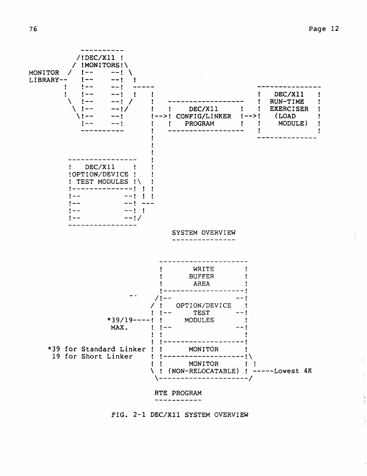
In
Figure
2-1,
an
overview
of
the
basic
DEC/XII
system
is
depicted,
along
with
a
general
representation
of
the
layout
of
a
typical
RTE
program.
The
DEC/XII
system
consists
of
three
fundamental
parts:
DEC/XII
Monitor
Library
DEC/XII
Device/Option
Test
Modules
DEC/XII
Configurator/Linker
Programs
From
these
the
user
selects
a
particular
monitor,
required
test
modules,
and
an
applicable
configurator/linker
program
in
order
to
generate
an
RTE
program
for
a
particular
hardware
system.
Once
the
RTE
program
is
linked,
it
may
be
independently
loaded
via
a
standard
ABS
loader
or
an
XXDP+
Monitor,
depending
on
whether
the
load
module
is
contained
on
paper
tape
or
on a
non-paper
tape
medium,
respectively.
Whenever
an
RTE
program
is
loaded
into
memory,
an
unrelocatable
portion
of
the
monitor
always
resides
in
the
lowest
4K
of
memory. The
area
directly
above
may
then
contain
a maximum
of
39
test
modules
plus
the
remaining
portion
of
the
monitor
(if
the
standard
linker
is
used)
or
19
test
modules
plus
the
remaining
portion
of
the
monitor
(if
the
short
linker
is
used).
In
either
case,
the
remaining
free
memory
area
satisfies
the
need
for
write
buffer
space
and
monitor/test
module
relocation.
76
MONITOR
LIBRARY--
/IDEC/XII
!
/
!MONITORS!\
/
!--
--I
\
!--
--I
!--
--I
!--
\
!--
\
!--
\!--
1--
--I
--I
/
--II
--1
--!
!
DEC/XII
!
!OPTION/DEVICE
!
! TEST
MODULES
!\
!--------------!
!--
--I
1
!--
!--
!--
--I
---
--I
!
--II
DEC/XII
!
-->!
CONFIG/LINKER
!-->
PROGRAM
SYSTEM
OVERVIEW
WRITE
BUFFER
AREA
!-------------------!
/!--
--I
/!
OPTION/DEVICE !
!--
TEST
--I
*39/19----!
MODULES
MAX.
,--
--I
!
-------------------!
*39
for
Standard
Linker
MONITOR!
19
for
Short
Linker
-------------------!\
MONITOR
! !
DEC/XII
RUN-TIME
EXERCISER
(LOAD
MODULE)
Page
12
\ (NON-RELOCATABLE)!
-----Lowest
4K
\---------------------/
RTE
PROGRAM
FIG.
2-1
DEC/XII
SYSTEM
OVERVIEW
76
Page
13
2.1
Option/Device
Modules
Each
option/de~ice
module
is
a
program,
that
is
dedicated
to
the
testing
of
a
single
option
or
device-controller
within
the
confines
of
a
system
configuration.
Thus,
unlike
a
stand-alone
diagnostic
program
that
is
used
to
isolate
a
static
problem
within
an
individual
device,
a
system
exerciser
module
is
used
to
isolate
an
individual
device
only
as
it
relates
to
a
system
problem.
In
fact,
prior
to
running
a
collective
group
of
exerciser
modules
for
a
given
system,
it
is
preswued
that
stand-alone
diagnostics
have
been
individually,
and
successfully,
run
for
each
device.
Each
option/device
module
communicates
with
its
resident
monitor
via
software
hooks
that
are
contained
in
both
the
body
of
each
module
and
a
module's
header-statement.
In
addition,
there
are
seven
basic
types
into
which
all
modules
are
grouped.
With
this
arrangement
(interfacing
with
the
monitor
by
type)
a
module
may
gain
access
to
those
support
and/or
utility
routines
that
the
monitor
provides
and
the
module
requires.
The
following
subsections
describe
the
seven
basic
module
types
currently
available
and
the
purpose
of
each.
2.1.1
Background
Module
(BKMOD)
The BKMOD-type
only
runs-in
a
background
mode
(i.e.~
via
non-interrupt
driven
devices)
and
at
the
lowest
module
run-time
priority.
A
module
of
this
type
is
used
to
exercise
non-interrupt
hardware
options
or
functions.
Examples
of
BKMon
usage
are:
Exercising
a
floating
point
hardware
option.
(Module
FPA)
Testing
the
basic
PDP-ll
Instruction
Set.
In
addition,
all
modules
of
this
type
are
run
separately
and
consecutively.
When
relocation
occurs,
a
pointer
to
the
next
module
to
be
run
ensures
that
although
all
the
modules
may
not
be
run
in
each
bank,
they
will
be
run
consecutively.
NOTE
When
the
"RUN"
command
is
entered
or
after
relocation'
BKMODS
will
do
a 1
iteration
pass
by
taking
on
the
identity
of
a
TMPIO
(Temporary
rOMOD).
This
is
done
to
insure
BKMODs
are
run
in
a
high
I/O
activity
system.
76
Page
14
2.1.2
Special
Background
Module
(SBKMOO)
, The SBKMOD-type-module
only
runs
in
a
background
mode
and
is
the
first
type
of
module
to
be
run
(i.e.,
before
any
resident
NBKMOD).
Once
this
module
is
initially
run,
it
will,
following
every
relocation,
be
run
once
again.
The
latter
allows
the
special
function
of
this
module
type
(i.e.,
to
set-up
a
special
system
condition)
to
be
initially
executed
when
the
exerciser
is
relocated
to
another
memory
bank.
Examples
of
SB~~OD
usage
are:
To
set-up
the
run-time
sequencing
of
other
resident
modules
or
peripheral
devices.
To
switch
the
DT03
Buss
Switch
before
the
other
modules
are
run.
2.1.3
Non-Restartable
Background
Module
(NBKMOO)
The NBKMOD-type-module
only
runs
in
a
background
mode,
is
the
second
type
of
module
to
be
run,
and
is
non-restartable.
Once
this
type
of
module
has
been
initially
run
successfully,
it
is
never
run
again;
unless,
of
course,
an
exercise
is
both
aborted
and
restarted.
Examples
of
NBKMOD
usage
are:
Checking
system
timing
before
other
modules
are
run.
Checking
system
parity
before
other
modules
are
run.
2.1.4
I/O
Module
(lOMOD)
The IOMOD-type-module
only
runs
in
Input/Output
mode
(i.e.,
via
interrupt-driven
devices),
depending
on
expected
interrupts
in
order
to
run
continuously.
These
modules
generally
service
buffer-driven
devices
(i.e.,
devices
that
do
not
generate
NPRs
or
contain
word-count
registers).
This
type
of
module
can
be
relocated
without
restriction.
Examples
of
IOMOD
usage
are:
For
exercising
TA-11
Cassettes,
and
floppy
disks.
For
exercising
a
paper
tape
reader/punch
or
a
line
printer.
Exercising
a
floating
point
hardware
option
(module
FPB)
2.1.5
I/O
Module
Restricted
(IOMOOR)
The IOMODR-type-module
is
an
rOMOD
that
cannot
be
relocated,
due
to
hardware
restrictions,
and
is
only
run
in
the
lowest
bank
of
memory.
76
Page
15
\n
example
of
IOMODR
usage
is:
the
exercising
of
a
UNIBUS
Tester.
2~1.6
r/o
Module
Extended
(IOMODX)
The
rOMODX-type-module
is
an
rOMOD
with
extended
capabilities
that
serVlces
NPR
devices.
The
capabilities
of
this
module
type
include:
use
of
a
monitor
supplied
write
buffer,
the
ability
to
change
the
size
of
read
and
write
buffers,
the
ability
to
access
a
monitor's
check
data
utility
routine,
and
the
ability
to
convert
16-bit
addresses
to
18-bit
addresses
or
IS-bit
addresses
to
22-bit
addresses.
Examples
of
IOMODX
usage
are:
Exercising
the
RKll
Controller
and
up
to
8
drives
(types
RK02-RK05).
Exercising
the
RPII
high
and
low
density
disk
drives.
2.1.7
I/O
Module
Partially
Restricted
(IOMODP)
The
IOMODP-type-module
is
an
IOMODX
that
is
partially
relocatable.
rhis
means
that
due
to
hardware
restrictions
the
module
is
only
relocated
to
certain
fixed
boundaries'
(e.g.,
32K).,
2.2
DEC/XII
Monitors
Since
there
are
several
DEC/XII
monitor
programs
that
are
available
to
the
user,
the
selectfon
of
an
appropriate
monitor
depends
on
the
configuration
of
the
hardware
system
to
be
tested.
However,
the
monitor
programs
are
not
separate
entities.
A
desired
monitor
must
be
constructed,
via
the
configurator/linker
process;
from
pre-assembled
monitor
modules
that
are
contained
in
a
DEC/XII
Monitor
Library.
Therefore,
to
provide
for
both
convenient
selection
and
adaptation
to
the
configurator/linker
process"
DEC/XII
monitor
programs
are
classified
by
type
and
named
(i.e.,
A,B,C,
etc.)
as
described
in
the
DEC/XII
CROSS
REFERENCE
MANUAL.
Such
monitor
classification
in
the
reference
manual
not
only
allows
the
user
to
apply
an
appropriate
monitor
program
to
a
given
hardware
configuration,
but
to
select
a
monitor
that
most
nearly
meets
the
needs
of
the
hardware
system
in
relation
to
(1)
the
functional
requirements
of
the
resultant
RTE
and
(2)
the
more
efficient
use
of
assigned
monitor
space.
Moreover,
in
the
same
manner
that
the
linking
of
the
basic
software
components
of
an
RTE
program
(monitor
and
option
modules)
depends
on
the
total
configuration
of
the
hardware
system,
the
linking
of
the
basic
software
components
of
the
monitor
portion
of
the
RTE
76
Page
16
{pre-assembled
monitor
modules}
depends
on
the
type
of
processor
to
be
serviced
and
its
available
options.
Finally,
since
in
all
probability
additional
monitors
will
be
designed,
the
following
material
is
not
intended
to
describe
monitor
concepts
in
terms
of
specific
monitor
differences
but
rather
in
terms
of
common
functionality.
Monitor
Operations
Basically,
the
monitor
portion
of
an
RTE
program
is
responsible
for
starting
the
RTE
(via
Initialization)~
establishing
operator
communications
(via
Command
Decoding)~
establishing
communications
with
its
resident
option
modules
(via
Trap
Interpretation):
providing
for
option
module
control
(via
Queue
Priority
Servicing);
and
providing
for
memory
usage
control
(via
RTE
Relocation
and
Write
Buffer
Rotation).
2.2.1
System
Initialization
When
an
RTE
program
is
loaded,
the
monitor
portion
of
the
program
provides
for
the
initialization
of
certain
software
and
hardware
components
of
the
system
via
the
execution
of
two
routines:
the
Start-Up
and
Initialization
routines.
Start-up
Routine
This
routine
sets-up
required
software
components
of
the
determines
the
operating
environment
by
performing
functions:
monitor
and
the
following
Set-up
the
Power
Failure
Vector.
Set-up
the
software
and
hardware
trap
handlers.
Set-up
the
Software
Switch
Register
(SWR)
and
certain
Status
Indicator
Words
(for
option
status).
Size
and
Poll
the
system
to
determine:
(a)
Processor
type
(11/70,
11/60,
etc.)
(b)
Processor
Options
(KT,
CACHE,
etc.).
(c)
Memory
size
(size
of
RTE
is
in
Loc.
Zero).
(d)
If
good
parity
must
be
written
in
memory
76
Page
17
(only
if
PARITY
or
ECC
option).
(e)
Software
environment
(APT, ACT/SLIDE/XXDP+)
Output
RTE
identity
message.
Output
System
Size
message.
Output
Keyboard
Prompt
(CMD».
Initialization
Routine
This
routine
Initializes
certain
software
and
hardware
components
(and
starts
the
monitor
running)
as
follows:
Initialize
both
the
Control
and
Type
Queues.
Initialize
error
logging
function
(if
available).
Initialize
the
option
module
servicing
mechanisms
(i.e.,
set-up
the
various
pointers
and
flags).
Enable
the
keyboard
for
operator
input.
2.2.2
Operator
Interfacing
Once
an
RTE
program
is
Initialized,
the
fact
that
the
monitor
portion
of
the
program
is
running
(and
the
keyboard
enabled
for
command
input)
is
indicated
by
the
printing
of
the
Command
Mode
(CMD»
prompt.
Thus,
at
this
point
the
monitor
is
available
to
provide
service
to
the
more
than
twenty
keyboard
commands
available
to
the
user.
Some
of
the
commands
(such
as
module
start,
option
disable/re-enable
commands,
and
the
module
parameter
modification
command)
are
restricted
to
entry
in
Command
Mode
only.
The
remaining
commands,
that
are
generally
related
to
the
deselection/reselection
of
modules
and
the
disposition
of
printout
data,
may
be
entered
in
either
the
Command
Mode
or
(following
a
module
start
command)
the
Run
Mode
(BSY».
In
any
case,
as
the
operator
enters
a command
format,
each
character
is
stored
in
the
Keyboard
Input
Buffer
until
a
Carriage
Return
(CR)
is
both
entered
and
recognized
by
the
Monitor.
When
this
occurs,
the
Monitor
(via
its
Task
Scheduler)
dispatches
control
to
its
Keyboard
Input
Processing
Routine
to
execute
the
following
5
monitor
modules:
The
Process
Command
Routine
(CMDPRC)
The Copy
Command
Routine
(CMDCPY)
The
Decode
Command
Routine
(CMDDEC)
76
Page
18
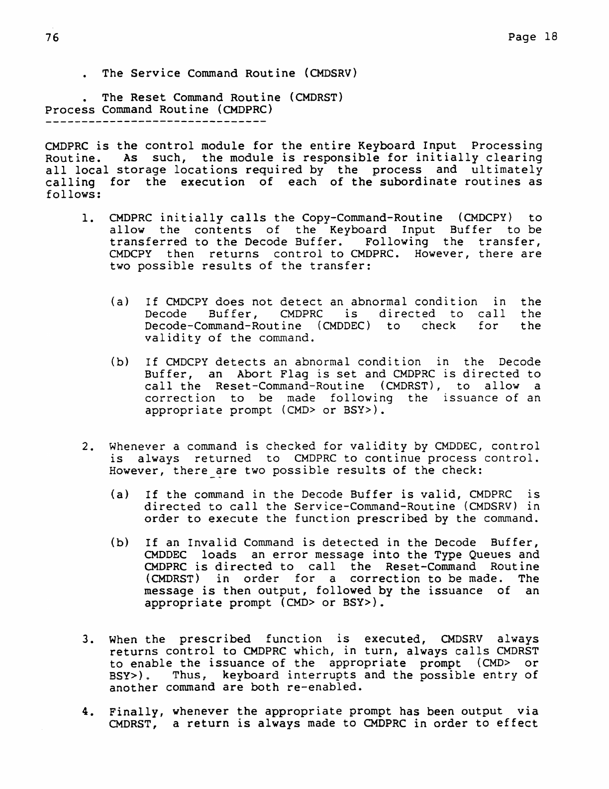
The
Service
Command
Routine
(CMDSRV)
The
Reset
Command
Routine
(CMDRST)
Process
Command
Routine
(CMDPRC)
CMDPRC
is
the
control
module
for
the
entire
Keyboard
Input
Processing
Routine.
As
such,
the
module
is
responsible
for
initially
clearing
all
local
storage
locations
required
by
the
process
and
ultimately
calling
for
the
execution
of
each
of
the
subordinate
routines
as
follows:
1.
CMDPRC
initially
calls
the
Copy-Command-Routine
(CMDCPY)
to
allow
the
contents
of
the
Keyboard
Input
Buffer
to
be
transferred
to
the
Decode
Buffer.
Following
the
transfer,
CMDCPY
then
returns
control
to
CMDPRC.
However,
there
are
two
possible
results
of
the
transfer:
(a)
If
CMDCPY
does
not
detect
an
abnormal
condition
in
Decode
Buffer,
CMDPRC
is
directed
to
call
Decode-Command-Routine
(CMDDEC)
to
check
for
validity
of
the
command.
the
the
the
(b)
If
CMDCPY
detects
an
abnormal
condition
in
the
Decode
Buffer,
an
Abort
Flag
is
set
and
CMDPRC
is
directed
to
call
the
Reset-Command-Routine
(CMDRST),
to
allow
a
correction
to
be
made
following
the
issuance
of
an
appropriate
prompt
(CMD>
or
BSY».
2.
Whenever a command
is
checked
for
validity
by
CMDDEC,
control
is
always
returned
to
CMDPRC
to
continue
process
control.
However,
there_~re
two
possible
results
of
the
check:
(a)
If
the
command
in
the
Decode
Buffer
is
valid,
CMDPRC
is
directed
to
call
the
Service-Command-Routine
(CMDSRV)
in
order
to
execute
the
function
prescribed
by
the
command.
(b)
If
an
Invalid
Command
is
detected
in
the
Decode
Buffer,
CMDDEC
loads
an
error
message
into
the
Type
Queues
and
CMDPRC
is
directed
to
call
the
Reset-Command
Routine
(CMDRST)
in
order
for
a
correction
to
be
made. The
message
is
then
output,
followed
by
the
issuance
of
an
appropriate
prompt
(CMD>
or
BSY».
3.
When
the
prescribed
function
is
executed,
CMDSRV
always
returns
control
to
CMDPRC
which,
in
turn,
always
calls
CMDRST
to
enable
the
issuance
of
the
appropriate
prompt
(CMD>
or
BSY»~
Thus,
keyboard
interrupts
and
the
possible
entry
of
another
command
are
both
re-enabled.
4.
Finally,
whenever
the
appropriate
prompt
has
been
output
via
CMDRST,
a
return
is
always
made
to
CMDPRC
in
order
to
effect
76
Page
19
a
return
to
the
Task
Scheduler.
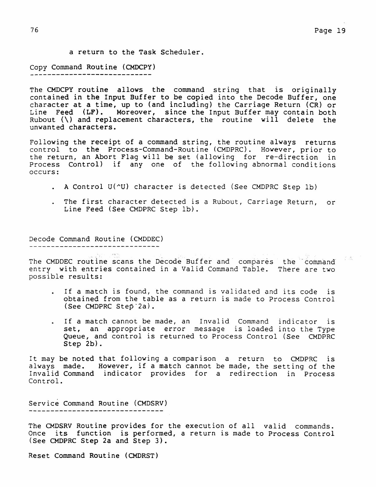
Copy
Command
Routine
(CMDCPY)
The
CMDCPY
routine
allows
the
command
string
that
is
originally
contained
in
the
Input
Buffer
to
be
copied
into
the
Decode
Buffer,
one
character
at
a
time,
up
to
(and
including)
the
Carriage
Return
(CR)
or
Line
Feed
(LF).
Moreover,
since
the
Input
Buffer
may
contain
both
Rubout
(\)
and
replacement
characters,
the
routine
will
delete
the
unwanted
characters.
Following
the
receipt
of
a command
string,
the
routine
always
returns
control
to
the
Process-Command-Routine
(CMDPRC).
However,
prior
to
the
return,
an
Abort
Flag
will
be
set
(allowing
for
re-direction
in
Process
Control)
if
anyone
of
the
following
abnormal
conditions
occurs:
A
Control
U(AU)
character
is
detected
(See
CMDPRC
Step
lb)
The
first
character
detected
is
a
Rubout,
Carriage
Return,
or
Line
Feed
(See
CMDPRC
Step
lb).
Decode
Command
Routine
«(MDDEC)
The
CMDDEC
rouiine
scans
the
D~cod~
Buffer
and
compar~s
entry
with
entries
contained
in
a
Valid
Command
Table.
possible
results:
the
'command
There
are
two
If
a
match
is
found,
the
command
is
validated
and
its
code
is
obtained
from
the
table
as
a
return
is
made
to
Process
Control
(See
CMDPRC
Step-2a).
If
a
match
cannot
be
made,
an
Invalid
Command
indicator
is
set,
an
appropriate
error
message
is
loaded
into
the
Type
Queue,
and
control
is
returned
to
Process
Control
(See
CMDPRC
Step
2b).
It
may
be
noted
that
following
a
comparison
a
return
to
CMDPRC
is
always
made.
However,
if
a
match
cannot
be
made,
the
setting
of
the
Invalid
Command
indicator
provides
for
a
redirection
in
Process
Control.
Service
Command
Routine
(CMDSRV)
The
CMDSRV
Routine
provides
for
the
execution
of
all
valid
commands.
Once
its
function
is
performed,
a
return
is
made
to
Process
Control
(See
CMDPRC
Step
2a
and
Step
3).
Reset
Command
Routine
(CMDRST)
76
Page
20
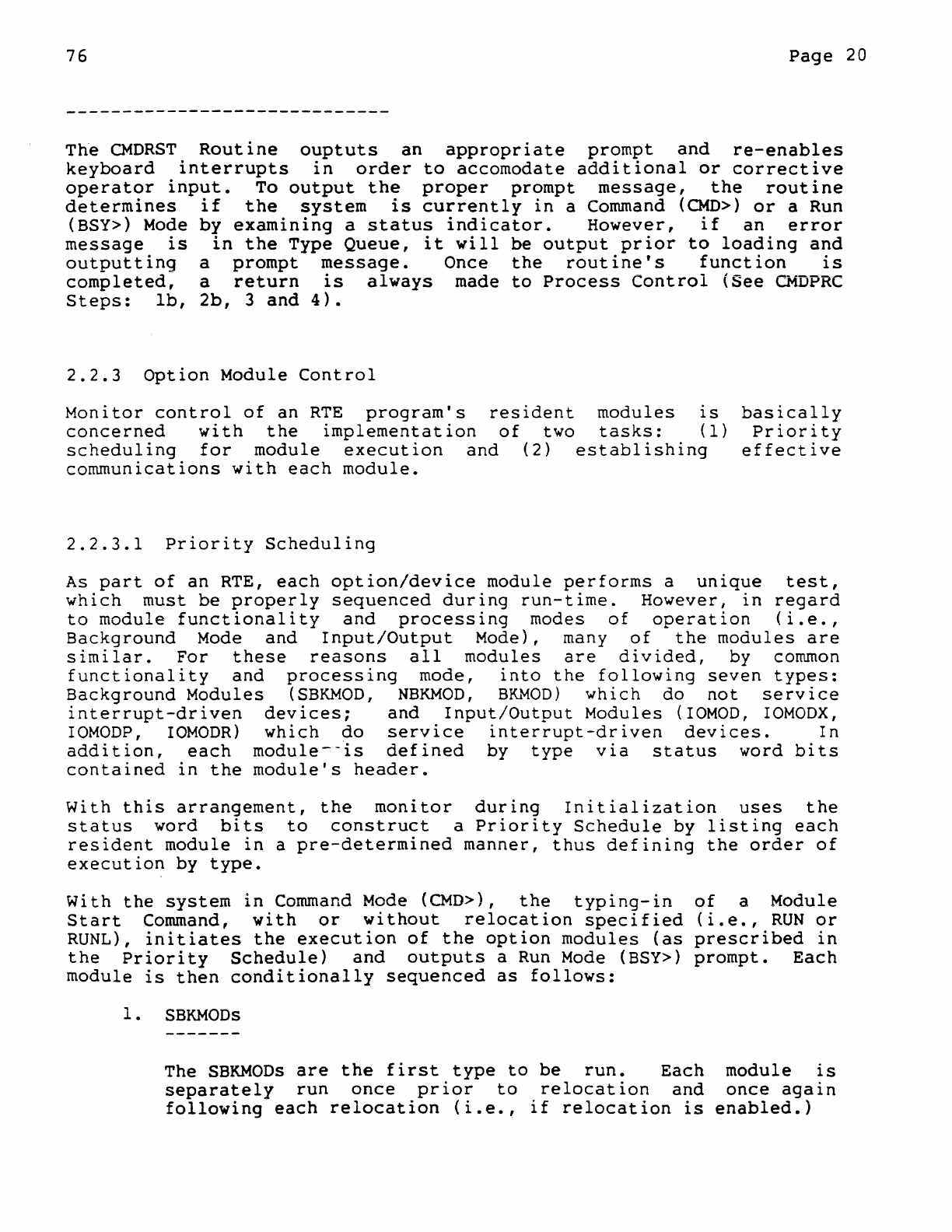
Th·e
CMDRST
Routine
o~Ptuts
an
appropriate
prompt
and
re-enables
keyboard
interrupts
1n
order
to
accomodate
additional
or
corrective
operator
input.
To
output
the
proper
prompt
message,
the
routine
determines
if
the
system
is
currently
in
a Command
(CMD»
or
a Run
(BSY»
Mode
by
examining
a
status
indicator.
However,
if
an
error
message
is
in
the
Type
Queue,
it
will
be
output
prior
to
loading
and
outputting
a
prompt
message.
Once
the
routine's
function
is
completed,
a
return
is
always
made
to
Process
Control
(See
CMDPRC
Steps:
lb,
2b,
3
and
4).
2.2.3
Option
Module
Control
Monitor
control
of
an
RTE
program's
resident
modules
is
basically
Priority
effective
concerned
with
the
implementation
of
two
tasks:
(1)
scheduling
for
module
execution
and
(2)
establishing
communications
with
each
module.
2.2.3.1
Priority
Scheduling
As
part
of
an
RTE,
each
option/device
module
performs
a
unique
test,
which
must
be
properly
sequenced
during
run-time.
However,
in
regard
to
module
functionality
and
processing
modes
of
operation
(i.e.,
Background
Mode
and
Input/Output
Mode), many
of
the
modules
are
similar.
For
these
reasons
all
modules
are
divided,
by common
functionality
and
processing
mode,
into
the
following
seven
types:
Background
Modules
(SBKMOD,
NBKMOD,
B~~OD)
which
do
not
service
interrupt-driven
devices:
and
Input/Output
Modules
(rOMOD,
IOMODX,
IOMODP,
rOMODR)
which
do
service
interrupt-driven
devices.
In
addition,
each
module--is
defined
by
type
via
status
word
bits
contained
in
the
module's
header.
With
this
arrangement,
the
monitor
during
Initialization
uses
the
status
word
bits
to
construct
a
Priority
Schedule
by
listing
each
resident
module
in
a
pre-determined
manner,
thus
defining
the
order
of
execution
by
type.
With
the
system
in
Command
Mode
(CMD»,
the
typing-in
Start
Command,
with
or
without
relocation
specified
RUNL),
initiates
the
execution
of
the
option
modules
(as
the
Priority
Schedule)
and
outputs
a Run
Mode
(BSY»
module
is
then
conditionally
sequenced
as
follows:
1.
SBKMODs
of
a
Module
(i.e.,
RUN
or
prescribed
in
prompt.
Each
The
SBKMODs
are
the
first
type
to
be
run.
Each
module
is
separately
run
once
prior
to
relocation
and
once
again
following
each
relocation
(i.e.,
if
relocation
is
enabled.)
76
Page
21
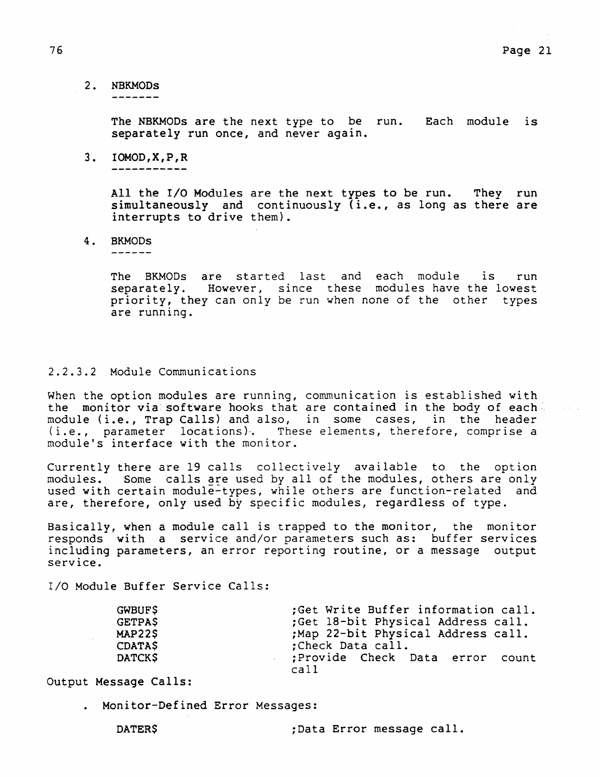
2.
NBKMODs
The
NBKMODs
are
the
next
type
to
be
run.
separately
run
once,
and
never
again.
Each
module
is
3 •
IOMOD
, X , P , R
All
the
I/O
Modules
are
the
next
types
to
be
run.
They
run
simultaneously
and
continuously
(i.e.,
as
long
as
there
are
interrupts
to
drive
them).
4.
BKMODs
The
BKMODs
are
started
last
and
each
module
is
run
separately.
However,
since
these
modules
have
the
lowest
priority,
they
can
only
be
run
when
none
of
the
other
types
are
running.
2.2.3.2
Module
Communications
When
the
option
modules
are
running,
co~munication
is
established
with
the
monitor
via
software
hooks
that
are
contained
in
the
body
of
each".
module
(i.e.,
Trap
Calls)
and
also,
in
some
cases,
in
the
header
(i.e.,
parameter
locations)-.
These
elements,
therefore,
comprise
a
module's
interface
with
the
monitor.
Currently
there
are
19
calls
collectively
available
to
the
option
modules.
Some
calls
are
used
by
all
of
the
modules,
others
are
only
used
with
certain
module~types,
while
others
are
function-related
and
are,
therefore,
only
used
by
specific
modules,
regardless
of
type.
Basically,
when a
module
call
is
trapped
to
the
monitor,
the
monitor
responds
with
a
service
and/or
parameters
such
as:
buffer
services
including
parameters,
an
error
reporting
routine,
or
a
message
output
service.
I/O
Module
Buffer
Service
Calls:
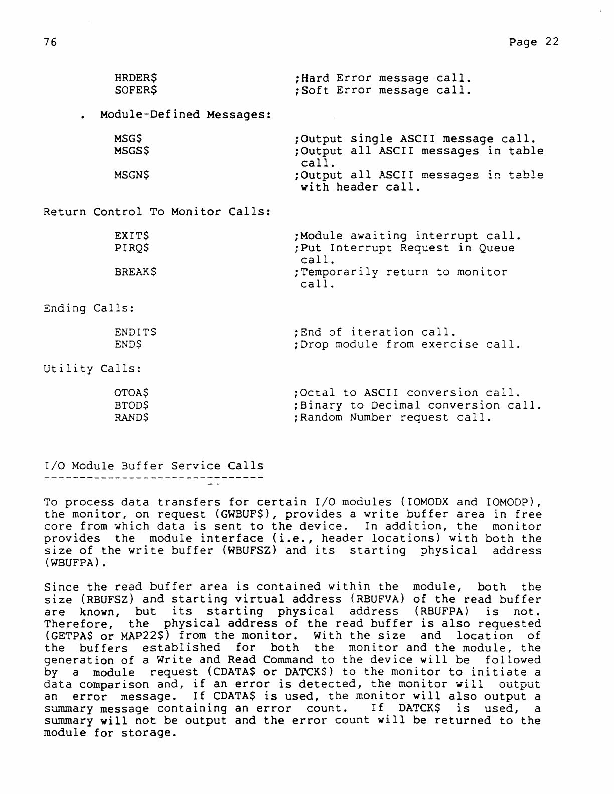
GWBUFS
GETPA$
MAP22S
CDATAS
DATCKS
Output
Message
Calls:
;Get
Write
Buffer
information
call.
;Get
IS-bit
Physical
Address
call.
;Map
22-bit
Physical
Address
call.
;Check
Data
call.
;Provide
Check
Data
error
count
call
Monitor-Defined
Error
Messages:
DATER$
;Data
Error
message
call.
76
HRDER$
SOFER$
Module-Defined
Messages:
MSG$
MSGS$
MSGN$
Return
Control
To
Monitor
Calls:
EXIT$
PIRQS
BREAK$
Ending
Calls:
ENDITS
ENDS
Utility
Calls:
OTOA$
BTOD$
RANDS
I/O
Module
Buffer
Service
Calls
;Hard
Error
message
call.
;Soft
Error
message
call.
Page
22
;Output
single
ASCII
message
call.
;Output
all
ASCII
messages
in
table
call.
;Output
all
ASCII
messages
in
table
with
header
call.
;Module
awaltlng
interrupt
call.
;Put
Interrupt
Request
in
Queue
call.
;Temporarily
return
to
monitor
call.
;End
of
iteration
call.
;Drop
module
from
exercise
call.
;Octal
to
ASCII
conversion
call.
;Binary
to
Decimal
conversion
call.
;Random Number
request
call.
To
process
data
transfers
for
certain
I/O
modules
(IOMODX
and
IOMODP),
the
monitor,
on
request
(GWBUF$),
provides
a
write
buffer
area
in
free
core
from
which
data
is
sent
to
the
device.
In
addition,
the
monitor
provides
the
module
interface
<i.e.,
header
locations}
with
both
the
size
of
the
write
buffer
(WBUFSZ)
and
its
starting
physical
address
(WBUFPA)
.
Since
the
read
buffer
area
is
contained
within
the
module,
both
the
size
(RBUFSZ)
and
starting
virtual
address
(RBUFVA)
of
the
read
buffer
are
known,
but
its
starting
physical
address
(RBUFPA)
is
not.
Therefore,
the
physical
address
of
the
read
buffer
is
also
requested
(GETPA$
or
MAP22$)
from
the
monitor.
With
the
size
and
location
of
the
buffers
established
for
both
the
monitor
and
the
module,
the
generation
of
a
write
and
Read
Command
to
the
device
will
be
followed
by a
module
request
(CDATA$
or
DATCK$)
to
the
monitor
to
initiate
a
data
comparison
and,
if
an
error
is
detected,
the
monitor
will
output
an
error
message.
If
CDATA$
is
used,
the
monitor
will
also
output
a
summary
message
containing
an
error
count.
If
DATCK$
is
used,
a
summary
will
not
be
output
and
the
error
count
will
be
returned
to
the
module
for
storage.
76
Page
23
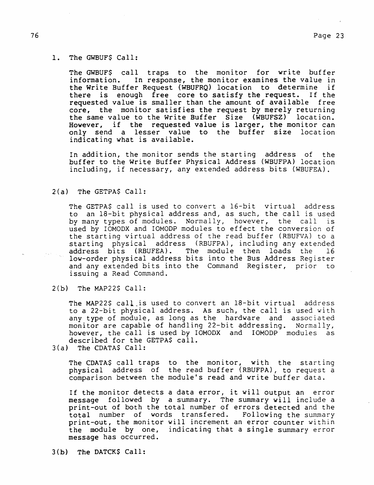
1.
The
GWBUF$
Call:
The
GWBUF$
call
traps
to
the
monitor
for
write
buffer
information.
In
response,
the
monitor
examines
the
value
in
the
Write
Buffer
Request
(WBUFRQ)
location
to
determine
if
there
is
enough
free
core
to
satisfy
the
request.
If
the
requested
value
is
smaller
than
the
amount
of
available
free
core,
the
monitor
satisfies
the
request
by
merely
returning
the
same
value
to
the
Write
Buffer
Size
(WBUFSZ)
location.
However,
if
~ne
requested
value
is
larger,
the
monitor
can
only
send
a
lesser
value
to
the
buffer
size
location
indicating
what
is
available.
In
addition,
the
monitor
sends
the
starting
address
of
the
buffer
to
the
Write
Buffer
Physical
Address
(WBUFPA)
location
including,
if
necessary,
any
extended
address
bits
(WBUFEA).
2(a)
The
GETPA$
Call:
The
GETPA$
call
is
used
to
convert
a
16-bit
virtual
address
to
an
l8-bit
physical
address
and,
as
such,
the
call
is
used
by
many
types
of
modules.
Normally,
however,
the
call
is
used
by
IOMODX
and
IOMODP
modules
to
effect
the
conversion
of
the
starting
virtual
address
of
the
read
buffer
(RBUFVA)
to
a
starting
physical
address
(RBUFPA),
including
any
extended
address
bits
(RBUFEA). The
module
then
loads
the
16
low-order
physical
address
bits
into
the
Bus
Address
Register
and
any
extended
bits
into
the
Command
Register,
prior
to
issuing
a Read Command.
2(b)
The
MAP22$
Call:
The
MAP22$
call_is
used
to
convert
an
18-bit
virtual
address
to
a
22-bit
physical
address.
As
such,
the
call
is
used
with
any
type
of
module,
as
long
as
the
hardware
and
associated
monitor
are
capable
of
handling
22-bit
addressing.
Normally,
however,
the
call
is
used
by
rOMODX
and
IOMODP
modules
as
described
for
the
GETPA$
call.
3(a)
The
CDATA$
Call:
The
CDATA$
call
traps
to
the
monitor,
with
the
starting
physical
address
of
the
read
buffer
(RBUFPA),
to
request
a
comparison
between
the
module's
read
and
write
buffer
data.
If
the
monitor
detects
a
data
error,
it
will
output
an
error
message
followed
by
a summary. The summary
will
include
a
print-out
of
both
the
total
number
of
errors
detected
and
the
total
number
of
words
transfered.
Following
the
summary
print-out,
the
monitor
will
increment
an
error
counter
within
the
module
by
one,
indicating
that
a
single
summary
error
message
has
occurred.
3(b)
The
DATeKS
Call:
76
Page
24
The
DATCK$
call
performs
the
same
function
as
the
CDATA$
call
with
the
following
exceptions:
If
the
monitor
detects
a
data
error,
only
an
error
message
will
be
output.
However,
the
total
number
of
errors
and
words
transfered
will
be
delivered
to
the
body
of
the
module
and
the
error
counter
will
be
incremented,
as
previously
described.
Output
Message
Calls
There
are
six
output
message
calls:
Three
(DATER$,
HRDER$,
SOFER$)
are
used
to
request
predefined
error
reports
from
the
monitor
while
the
remaining
three
(MSG$,
MSGS$,
MSGN$)
are
used
to
request
user-defined
messages
from
the
module
defining
certain
normal
operating
conditions
and/or
error
statistics
(e.g.,
TOO
MANY
WRITE
ERRORS).
The
monitor-defined
error
messages
are:
1.
The
DATER$
Call:
The
DATER$
call
traps
to
the
monitor
to
request
an
error
report
when a
data
buffer
comparison
error
has
been
internally
detected
within
a
module
(e.g.,
IOMOD,
IOMODR).
This
is
in
contrast
to
the
data
comparison
that
is
externally
performed
by
the
monitor
for
IOMODX
and
IOMODP
modules
(refer
to
the
CDATA$
and
DATCK$
calls
under
I/O
Module
Buffer
Service).
In
any
case
when
the
error
message
is
output,
the
monitor
will
increment
the
module's
soft
error
counters
by
one
to
indicat~_that
the
error
message
has
occurred.
2.
The
HRDER$
Call:
The
HRDER$
call
traps
to
the
monitor
to
request
the
output
of
a
standard
error
message
when
an
unrecoverable
Hard
Error
(e.g.,
non-existent
memory)
is
detected
by a
module.
As
such,
the
call
can
be
used
by
any
module
type.
In
addition,
certain
modules
will
pass
a comment
(i.e.,
a
cause
of
error
statement)
to
the
monitor
for
outputting
with
the
message.
Moreover,
an
extended
form
of
the
call
can
also
pass
the
address
of
a
table
containing
statistical
error
information
(e.g.,
contents
of
all
of
a
device's
registers)
for
outputting.
The
monitor
will
increment
the
module's
Hard
Error
Counts.
3.
The
SOFER$
call
traps
to
the
monitor,
to
request
the
output
of
a
standard
error
message,
when a
recoverable
Soft
Error
(e.g.,
data
late)
is
detected
by a
module.
As
such,
the
call
can
be
used
by
any
type
module.
With
the
exception
of
the
appearance
of
the
word
"SOFT"
as
a
replacement
for
the
word
"HARD",
basic
and
extended
message
formatting
for
the
call
is
76
Page
25
identical
to
the
formatting
outputted
for
an
HRDER$
call.
The
monitor
will
increment
the
module's
Soft
Error
Counts.
The
module-defined
messages
are:
Ie The
MSG$
Call
The
MSG$
call
traps
to
the
monitor
to
request
the
output
of
a
single
ASCII
message.
An
address
is
also
passed
to
the
monitor
to
define
the
location
of
the
message.
2.
The
MSGS$
Call
The
MSGS$
call
traps
to
the
monitor
to
request
the
output
of
a
table
of
ASCII
messages.
An
address
is
included
to
define
the
location
of
the
table.
3.
The
MSGN$
Call:
monitor
to
request
the
output
of
An
address
is
included
to
define
In
addition,
however,
this
call
a
complete
header
message
(i.e.,
etc.).
The
MSGN$
call
traps
to
the
a
table
of
ASCII
messages.
the
location
of
the
table.
elicits
the
output
of
modulename,
PC
contents,
Return
Control
To
Monitor
Calls
The
three
return-control-to-rnonitor
calls
are
used
to
provide
for
a
more
efficient
use
of
exerciser
run-time
in
regard
to
module
scheduling,
the
execution
of
interrupt
service
routines,
and
the
processing
of
module
requests.
1.
The
EXIT$
Call:
The
EXIT$
call
is
used
to
return
control
to
the
monitor
when
a module
is
awaiting
an
interrupt.
As
such,
the
call
is
only
used
with
a
module
that
is
dedicated
to
servIcIng
an
interrupt-driven
device
(normally,
but
not
necessarily,
an
I/O
Module).
In
any
case,
by
relinquishing
control
to
the
monitor
during
the
wait
period,
the
monitor
allows
module
scheduling
to
continue.
2.
The
PIRQ$
Call:
The
PIRQ
call
is
trapped
to
the
monitor
to
request
that
the
execution
of
an
interrupt
service
routine,
contained
within
an
I/O
Module,
be
deferred
to
a
lower
priority.
This
is
done
to
defer
the
execution
of
a
non-critical
routine,
such
as
a
routine
which
error-chec.ks
registers
that
are
not
subject
to
immediate
change.
This
is
in
direct
opposition
to
the
priority
required
for
the
execution
of
a
critical
routine,
such
as
a
routine
that
must
service
the
contents
of
a
communications
buffer.
76
Page
26
When
PIRQ$
is
executed,
the
monitor
stores
the
Interrupt
Request
in
a FIFO
queue
at
the
lowest
priority
(i.e.,
PRO)
and
does
an
RTI
to
return
to
the
processing
operation
that
was
being
performed
prior
to
the
generation
of
the
interrupt
request.
However,
the
latter
statement
should
not
be
misconstrued.
It
does
not
imply
a
direct
return
to
the
scheduling
of
the
Background
Modules
(i.e.,
BKMODs)
since
all
I/O
interrupt
requests
in
the
queue,
regardless
of
their
relative
module
priority,
must
be
serviced
before
a
BKMOD
can
be
run.
3.
The
BREAK$
Call:
The
BREAK$
call
is
used
to
transfer
temporary
control
to
the
monitor
while
a
module
awaits
the
occurrence
of
an
asynchronous
event
(e.g.,
the
setting
of
a
DONE
or
READY
bit)
before
proceeding.
As
such,
the
call
is
normally
but
not
necessarily
used
with
I/O
Modules.
When
the
BREAKS
call
is
executed,
the
monitor
checks
the
queues
for
pending
I/O
interrupt
requests.
When
all
previous
requests
have
been
serviced,
the
monitor
returns
control
to
the
module;
specifically,
to
the
instruction
directly
following
the
BREAKS
call.
Ending
Calls
There
are
two
ending
calls:
one
is
used
to
indicate
the
successful
completion
of
a
module's
test
procedure(s)
prior
to
a
restart
while
the
other
is
used
by
all
modules.
1.
The
ENDITS
Call:
The
ENDIT$
calt-is
trapped
to
inform
the
monitor
that
an
iteration
point
has
been
reached.
The
monitor
responds
by
incrementing
an
Iteration
Counter
in
the
module's
header
by
one
and
comparing
the
resultant
count
with
an
Iteration
Constant
that
is
also
contained
in
the
module's
header.
If
the
values
are
equal,
the
monitor
will
output
an
END
OF
PASS
message
and
restart
the
module.
However,
if
the
values
are
not
equal,
the
monitor
will
resume
module
operation
by
executing
the
instruction
that
directly
follows
the
ENDITS
call.
2.
The
END$
Call:
The
END$
call
is
used
to
inform
the
monitor
that
a
fatal
error
has
been
detected
(e.g.,
device
is
off-line).
The
monitor
responds
by
stopping
the
module,
via
the
setting
of
Bit
13
in
the
module's
status
word,
and
outputting
a
module-dropped
message.
Thus,
the
setting
of
Bit
13
prevents
the
module
from
running
for
the
duration
of
the
exercise.
However,
if
the
error
is
detected
in
an
I/O
MOQule,
interrupt
lines
are
also
disabled
prior
to
the
generation
of
the
call.
76
Page
27
Utility
Calls
There
are
three
utility
calls
currently
available:
one
will
convert
an
octal
number
to
ASCII
characters,
another
will
convert
a
binary
n~~ber
to
its
decimal
ASCII
equivalent,
while
the
third
generates
a
random
number.
The
calls
may
be
used
by
any
type
of
module.
1.
The
OTOA$
Call:
The
OTOA$
call
traps
to
the
monitor
to
request
the
conversion
of
an
octal
number
(max.
16
bits>
to
equivalent
ASCII
characters
(max.
6
characters).
When
the
call
is
issued,
the
module
provides
the
monitor
with
both
the
module
location
of
the
number
to
be
converted
and
the
module
location
of
the
starting
address
to
which
the
result
will
be
directed.
As
an
example
of
usage:
the
call
may
be
issued
prior
to
the
issuance
of
an
MSG$
call
to
define
the
ASCII
message.
2.
The
BTOD$
Call:
The
BTOD$
call
traps
to
the
monitor
to
request
the
conversion
of
a
binary
number
(max. 16
bits)
to
decimally
equivalent
ASCII
characters
(max.
5
characters).
When
the
call
is
issued,
the
module
provides
the
monitor
with
both
the
module
location
of
the
number
to
be
converted
and
the
module
location
of
the
starting
address
to
which
the
result
will
be
directed.
As
an
example
of
usage:
the
call
may
be
issued
prior
to
the
issuance
of
an
MSG$
call
to
define
the
ASCII
message.
3.
The
RAND$
Call:
The
RAND$
call
traps
to
the
monitor
to
request
the
generation
of
a new
random
number
(max.
16
bits).
Once
the
number
is
generated,
it
is
directed
to
a
random
nlliuber
location
in
the
module's
header.
As
an
example
of
usage:
a new
random
number
may
be
used
to
alter
the
sector
address
for
a
disk,
thus
allowing
random
instead
of
contiguous
SEEKs
to
occur.
2.2.4
Memory
Usage
Control
When
the
RTE
is
running,
one
of
the
monitor's
is
to
exercise
an
efficient
control
of
includes:
major
memory
responsibilities
resources.
This
Control
of
the
available
memory
hardware
options
(i.e.,
KT,
CACHE,
PARITY, ECC,
etc.)
76
Page
28
The
sizing
and
designation
of
write
buffer
space
for
requesting
modules
within
a
pre-defined
write
buffer
area.
Control
over
the
relocation
of
the
moveable
portion
of
both
the
RTE
and
the
monitor
(i.e.,
if
the
option
is
enabled).
The
generation
of
memory-worst-case
patterns
in
free
core
for
a more
comprehensive
exercise
of
available
memory
resources.
2e2e4el
Memory
Options
Control
The
monitor
is
responsible
for
establishing
control
over
all
memory
hardware
options
that
may
be
available
to
the
system.
This
includes:
(1)
Memory Management
(KT):
(2)
Parity
Memory,
ECC,
and
Cache
Memory:
and
(3)
the
22-Bit
Addressing
option.
Memory Management
(KT)
Control
Initially,
the
monitor
determines
if
a
KT
unit
is
available.
is,
the
following
control
functions
will
be
performed:
If
it
The
KT
may
be
turned
On
or
Off
via
keyboard
command.
All
Page
Address
Registers
(PARs)
and
Descriptor
Registers
(PDRs)
will
be
set
up.
Page
If
a
CDATA$
or
DATCK$
call
is
trapped
to
the
monitor,
the
processor
will
be
switched
from
KERNEL
to
USER
Mode.
Parity,
ECC,
and
Cache
Memory
Control
Monitor
control
of
Parity,
ECC,
and
Cache
Memory
consists
of
turning
these
options
On
or
Off
via
keyboard
commands
and
accommodating
associated
error
traps.
However,
in
regard
to
parity
Memory
and
the
ECC
option,
common
On/Off
commands
are
currently
in
use.
Thus,
turning
Parity
Memory
On
will
also
turn
the
ECC
option
On,
if
it
is
available.
22-Bit
Addressing
Control
Monitor
control
of
22-Bit
Addressing
consists
of
turning
the
option
On
or
Off
via
keyboard
command
and
loading
the
Mapping
Registers.
Initiation
of
the
latter
provides
pointers
to
the
write
buffer
area.
76
Page
29
2.2.4.2
Write
Buffer
Control
certain
DEC/XII
test
modules
(i.e.,
IOMODX,
rOMODP)
have
the
ability
to
request
that
the
monitor
provide
write
buffer
space
for
the
transfer
of
output
data
to
an
associated
device.
In
this
regard,
monitor
control
of
the
write
buffer
area
concerns
(1)
the
designation
of
such
space
on
request
and
(2)
the
"rotation"
of
write
buffer
spaces
(via
the
RTON
Command)
during
successive
requests,
to
provide
a
device
with
more
comprehensive
testing
in
relation
to
its
ability
to
access
all
of
free
core.
Write
Buffer
Area
For
systems
having
only
128K
of
memory
or
less,
all
of
the
memory
space
not
currently
occupied
by
the
RTE
is
defined
as
the
write
buffer
area
from
which
write
buffer
space
is
assigned.
However,
for
system~
greater
than
128K
which
require
22-bit
addressing,
memory
IS
divided
into
contiguous
segments
consisting
of
the
124K
locations.
The
write
buffer
area
is
then
limited
to
that
124K
segment
of
memory
in
which
the
moveable
portion
of
the
RTE
currently
resides.
Segmentation
is
necessary
due
to
hardware
addressing
restrictions
in
which
the
UNIBUS
Mapping
Registers,
fully
loaded,
can
only
accommodate
a
maXImum
addressing
range
of
124K
locations.
In
Figure
2-2,
three
examples
of
segmentation
depict
the
relationships
existent
between
the
current
location
of
the
RTE
and
the
location
and
limits
of
the
write
buffer
area:
In
example
2a,
the
limits
of
the
write
buffer
area
are
shown when
the
moveable
portion
of
the
RTE
is
in
the
lowest
124K
segment.
Note
that
the
RTE
is
not
relocated
within
the
segment
and,
if
it
were,
the
limits
of
the
write
buffer
would
remain
the
same.
In
example
2b,
the
limits
of
the
write
buffer
area
are
shown when
the
moveable
portion
of
the
RTE
is
relocated
to
another
124K
segment.
Note
that
if
the
RTE
is
again
relocated
but
remains
within
the
segment,
the
limits
of
the
write
buffer
will
remain
the
same.
In
example
2c,
the
limits
of
the
write
buffer
area
are
shown when
the
moveable
portion
of
the
RTE
has
been
relocated
to
straddle
the
boundary
of
a 124K
segment.
Note,
in
this
instance,
that
the
lower
limit
of
the
write
buffer
area
starts
at
the
base
of
the
moveable
portion
of
the
RTE
and
ends
124K
locations
above
the
base.
Write
Buffer
Rotation
Briefly,
write
buffer
rotation
(if
enabled)
allows
an
initial
write
~uffer
assignment
to
be
made from a
pre-defined
starting
position:
that
is,
the
first
free
location
above
the
top
of
the
moveable
portion
of
the
RTE.
Subsequently,
assignments
are
advanced
through
the
write
buffer
area
until
the
top
of
the
area
is
reached,
whereupon
the
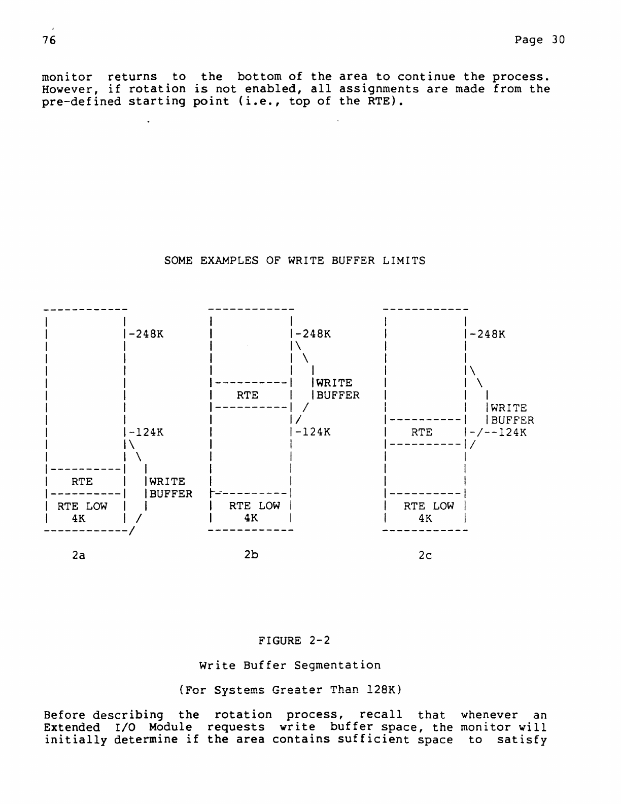
76
Page
30
monitor
returns
to
the
bottom
of
the
area
to
continue
the
process.
However,
if
rotation
is
not
enabled,
all
assignments
are
made from
the
pre-defined
starting
point
(i.e.,
top
of
the
RTE).
SOME
EXAMPLES
OF
WRITE
BUFFER
LIMITS
------------
------------
------------
I
1 -248K
-248K -248K
1 \
I \
1 I \
1
----------
IWRITE
\
I
RTE
I
BUFFER
1
I
----------
/
IWRITE
1 /
----------
I
BUFFER
1 -124K
-124K
RTE
-/--124K
1 \
----------
/
I \
1----------
1
I
RTE
IWRITE
1----------
I
BUFFER
r..:----------I
----------
I
RTE
LOW
I I
RTE
LOW
I
RTE
LOW
1
4K
/ I
4K
I
4K
------------/
------------
------------
2a
2b
2c
FIGURE
2-2
Write
Buffer
Segmentation
(For
Systems
Greater
Than 128K)
Before
describing
the
rotation
process,
recall
that
whenever
an
Extended
I/O
Module
requests
write
buffer
space,
the
monitor
will
initially
determine
if
the
area
contains
sufficient
space
to
satisfy
76
Page
31
the
request.
Once
this
determination
is
made,
the
monitor
either
grants
the
requesting
module
the
desired
buffer
size
or
provides
the
module
with
whatever
space
is
available.
The
monitor
then
delivers
the
start
address
of
the
assigned
buffer
space
to
the
module.
To accommodate
such
requests,
and
also
the
requirements
of
both
the
Exerciser
Relocation
option
and
the
Write
Buffer
Rotation
option,
the
monitor
uses
a
write
buffer
area
as
the
first
free
location
above
the
moveable
portion
of
the
RTE,
thus
defining
a
start
address
which
equates
with
the
base
address
of
the
write
buffer
area
(i.e.,
the
top
of
the
RTE).
This
is
accomplished
via
pointer
initialization
which
occurs
under
two
conditions:
(1)
prior
to
the
issuance
of
an
initial
request
and
(2)
following
any
relocation
of
the
RTE.
Moreover,
since
the
pointer
can
only
be
advanced
when
Write
Buffer
Rotation
is
enabled,
all
subsequent
requests,
made
with
rotation
disabled,
will
effectively
use
the
base
address
of
the
area
as
a
start
address.
In
any
case,
with
the
initial
start
address
appropriately
defined
and
rotation
enabled,
the
pointer
will
be
advanced
to
define
the
first
free
location
above
the
top
of
the
first
requested
buffer
space.
At
this
point,
if
sufficient
core
is
available,
the
pointer
will
assume
an
address-value
which
equates
with
the
requested
buffer
size
plus
one.
Otherwise,
the
pointer
will
assume
an
address
which
equates
with
available
space.
In
this
manner,
every
subsequent
request
will
advance
the
pointer
through
the
buffer
area
until
the
top
of
the
area
is
reached,
whereupon
the
pointer
will
be
returned
to
the
bottom
of
the
write
buffer
area,
where
the
advancement
process
will
continue.
However,
as
shown
in
Figure
2-2,
depending
on
relocation,
the
bottom
of
the
buffer
area
may
again
be
at
the
top
df
the
RTE
(Examples
2a
and
2c)
or
below
the
RTE
(Example
2b).
If
the
latter
is
true,
advancement
will
continue
until
the
last
free
location,
at
the
bottom
of
the
moveable
portion
of
the
RTE,
is
eventually
reached.
At
this
point,
since
the
RTE
itself
cannot
~e
used
as
write
buffer
space,
the
address
pointer
will
skip
to
th~-top
of
the
RTE
and
the
rotation
process
will
continue.
2.2.4.3
Exerciser
Relocation
Before
describing
the
Relocation
Process,
recall
that
when
an
RTE
program
is
loaded
into
memory
the
program
is
effectively
divided
into
two
sections:
(1)
a
fixed
monitor
portion
which
must
reside
1n
the
lowest
4K
of
memory
and
is
not
relocatable
and
(2)
a
moveable
portion,
consisting
of
the
remainder
of
the
monitor
and
all
of
the
test
modules,
which
initially
resides
above
the
fixed
portion
and
can
be
continuously
relocated
through
the
remainder
of
memory
(See
Figure
1-1).
In
addition,
continuous
relocatio'n
is
only
possible
if:
(1)
the
system
contains
a Memory Management (KT)
unit,
(2)
the
KT
unit
is
enabled
via
the
KTON
Command,
and
(3)
the
Relocation
Process
is
not
locked
out
(i.e.,
the
RTE
is
started
by a
RUN
Command
as
opposed
to
a
RUNL.
76
Page
32
Relocation
Process
The
Relocation
Process
is
a
monitor
controlled
option
which
allows
the
moveable
portion
of
the
RTE
to
be
continuously
relocated
through
main
memory
via
a
series
of
relocation
operations
to
provide
for
a
complete
test
of
all
available
core
(the
lowest
4K
excepted).
During
the
process,
each
new
relocation
operation
is
initiated
by
the
monitor
when
all
of
the
liO
type
modules
have
completed
a
-single
pass
or
when
any
BKMOD
(if
no
I/O
modules
exist)
has
completed
a
pass.
However,
since
the
modules
have
varying
run-times,
some
of
the
modules
will
have
completed
a
pass
and
restarted.
Therefore,
all
of
the
modules
will
be
stopped
at
their
next
iteration
point,
at
which
point
they
will
be
restarted
when
relocation
is
completed.
When
a
relocation
operation
is
completed,
a
RELOCATED
TO
XXXXXX
message
is
output,
indicating
the
new
physical
start
address
(XXXXXX)
of
the
RTE.
However,
there
are
two
separate
types
of
relocation
operations
that
may
sequence
during
a
Relocation
Process:
Constant
Relocation
operations
or
Random
Relocation
operations.
Moreover,
by
setting
a
bit
(SW08
=
1)
in
the
RTE's
Software
Switch
Register,
the
execution
of
the
series
of
random
relocation
operations
may
be
disabled.
If
both
types
of
relocation
are
permitted
(SW08
=
0),
constant
relocation
operations
will
first
cycle
the
RTE·
completely
through
memory,
but
only
once.
The
Relocation
Process
will
then
be
continuously
effected
by
random
relocation
operations
until
the
program
is
stopped
and
restarted.
However,
if
Random
Relocation
is
disabled
(SWOB
=
1),
constant
relocation
operations
will
run
continuously.
Constant
Relocation
Ope~dtions
Starting
at
a
base
address
defined
by
the
user,
or
the
original
base
address
defined
by
default,
the
moveable
portion
of
the
RTE
is
advanced
to
a
new
base
address
via
an
incremental
constant
(normally
4K).
In
this
manner,
constant
relocations
occur
until
an
upper
limit
of
memory
is
eventually
reached
that
can
accomodate
the
program.
The
monitor
then
returns
the
RTE
to
its
original
base
address
and
the
cycle
is
completed.
At
this
point,
if
Random
Relocation
is
enabled,
the
process
will
never
be
re-cycled
until
the
program
is
stopped.
Otherwise,
it
will
recycle
continuously.
Random
Relocation
Operations
Following
the
completion
of
a
series
of
constant
relocation
operations
which
return
the
RTE
to
its
original
base
address,
the
Relocation
Process
may
be
re-initiated
by
a
series
of
random
relocation
operations.
During
Random
Relocation,
the
moveable
portion
of
the
RTE
is
relocated
76
Page
33
to
randomly
selected
areas
of
memory,
via
random
number
generation,
until
a
pre-defined
number
of
relocations
(determined
by
total
memory
size)
has
occurred.
At
this
point,
the
next
relocation
will
return
the
RTE
to
the
lowest
possible
address
(the
original
base
address).
The
next
relocation
will
then
direct
the
RTE
to
the
highest
possible
address
that
can
accow~odate
the
program,
which
completes
the
cycle.
The
entire
process
is
then
continuously
repeated
until
the
program
is
stopped.
2.2.4.4
Memory-Worst-Case-Pattern
Generation
As
previously
stated,
all
of
the
memory
space
not
currently
occupied
by
the
RTE
is
defined
as
free
core
and
as
such
serves
as
the
write
buffer
area.
With
this
consideration,
when a
Module
Start
Command
(i.ee;
RUN
or
RUNL)
is
entered
f a memory
worst-case
pattern
is
automatically
written
into
the
free
core
area
in
order
to
intensify
UNIBUS
activity
during
I/O
data
transfers.
However,
if
relocation
of
the
RTE
is
enabled,
during
each
successive
relocation
increasing
portions
of
the
worst-case
pattern
are
overlaid.
Therefore,
whenever
the
RTE
is
eventually
relocated
to
lowest
memory,
the
worst-case
pattern
is
completely
re-written.
2.2.5'
Trap
Processing
Trap
processing
by
the
monitor
is
concerned
with
the
handling
of
both
software
and
hardware
traps.
Software
traps
are
used
to
provide
access
to
special
handling
routines
via
a
Trap
Instruction
when
an
option/device
module
requires
external
services
that
the
monitor
provides
such
as
buffer
services
or
error
reporting
services
(refer
to
Module
Communications
-2.2.3.2).
Hardware
traps
are
used
to
provide
access
to
special
handling
routines
following
the
execution
of
an
instruction
when
an
internal
error
condition
is
detected
by
the
cpu.
Thus,
hardware
traps
are
caused
by
internal
failures
as
opposed
to
external
failures
occuring
within
a
device.
Software
Traps
When
a
module
issues
a
trap
call
(e.g.,
GWBUF$,
GETPA$,
etc.),
the
trap
instruction
is
vectored
via
Location
34(TRAP
instruction}
to
the
monitor's
Trap
Service
routine.
The
trap
code
is
identified
and
the
module's
register
contents
and
offset
PC
address
are
saved.
The
monitor
then
dispatches
to
the
appropriate
routine(s)
where,
depending
on
both
the
type
of
call
and
the
complexity
of
the
requested
service,
one
or
more
of
the
following
operations
will
occur:
The
request
is
executed
and
control
is
returned
to
the
requesting
module
(e.g.,
OTOA$,
RANDS,
etc).
The
request
is
executed
and/or
an
entry
is
provided
76
Page
34
to
the
Type
Queue
(e.g.,
CDATA$,
DATER$,
MSG$,
etc.).
An
entry
is
provided
to
the
Control
Queue
for
subsequent
service
(e.g.,
PIRQ$,
BREAKS,
etc.).
The
request
is
executed
and
control
is
returned
to
the
monitor's
Priority
Scheduler
routine
(e.g.,
END$;
EXIT$)e
Hardware
Traps
Hardware
trap
handling
concerns
the·
processing
of
internally
produced
errors
associated
with
the
CPU
and
memory
options
that
are
classified
as
follows:
(1)
System
Errors;
(2)
Parity
Errors
(main
or
cache
memory)
and
ECC
Errors;
(3)
Memory Management (KT)
Errors.
1.
System
Errors:
When
a Bus
Error
(e.g.,
non-existent
memory,
odd
address,
etc.)
is
trapped
through
location
04
or
a
Reserved
Instruction
Error
(i.e.,
an
illegal
instruction)
is
trapped
through
location
10,
the
monitor
saves
the
contents
of
the
updated
PC,
PSW,
and
SP.
The
monitor
then
initializes
the
system
and
outputs
a
System
Error
message.
However,
at
this
point
any
or
all
of
the
following
may
occur:
If
error
logging
is
available
to
the
CPU,
it
1S
performed.
If
an
optioQ~odule
is
responsible
for
four
system
errors,
it
is
dropped.
If
the
entire
RTE
program
has
accumulated
excessive
system
errors,
the
run
is
terminated
and
the
system
is
returned
to
Command Mode
(CMD».
With
the
exception
of
the
latter
possibility
(i.e.,
return
to
CMD»,
following
the
processing
of
a
system
error
the
RTE
is
restarted
as
follows:
All
modules
that
have
completed
an
End-Of-Pass
will
be
re-initiated
from
the
beginning
(i.e.,
RESTART
address)
while
the
remaining
modules
will
be
re-initiated
from
a
pre-defined
location
(i.e.,
START
address).
2.
Parity
Errors
and
Ece
Double-Bit
Errors:
If
a Memory
Parity
Error,
a
Cache
Parity
Error,
or
an
ECC
Memory
Double-Bit
Error
is
trapped
through
location
114,
the
system
is
initialized
and
the
contents
of
the
appropriate
registers
are
output,
along
with
an
appropriate
error
message.
However,
if
ten
of
these
errors
occur,
the
run
is
terminated
and
the
system
is
returned
to
CMD>
mode.
Otherwise,
the
RTE
is
restarted
as
previously
described.
76
Page
35
3.
Memory Management (KT)
Errors:
If
a
KT
Error
is
trapped
through
location
250,
the
system
is
initialized
and
the
contents
of
the
available
general
registers
(SRO
and
SR2,
SRl
and
SR3)
are
output,
along
with
an
appropriate
error
message.
HOwever,
if
a
KT
error
occurs,
the
run
is
terminated
and
the
system
is
returned
to
CMD>
mode.
2.3
Configurator/Linker
Program
The DEC/XII
configurator/linker
program
is
used
to
create
Run-Time
Exerciser
(RTE)
programs.
The
initial
implementation
of
a
configuration
process
(via
construction
of
a
Configuration
Table)
is
followed
by
the
implementation
of
a
linking
process
(via
execution
of
a
LINK
Command),
which
results
in
the
creation
of
an
individualized
RTE
module.
A
user
specified
monitor
and
user
specified
test
modules
are
selected,
entered
in
the
Configuration
Table
(C-Table),
and
linked
by
command
to
derive
an
RTE
module.
2.3.1
The
Configuration
Process
The
configuration
process
facilitates
the
execution
of
the
linking
process,
by
providing
an
accessible
area
for
required
monitor
and
test
module
information.
Following
the
loading
of
a
configurator/linker
program,
the
user
implements
the
configuration
process
by
initiating
a
Configure
Mode
of
operation
and
constructing
a
Configuration
Table
(C-Table).
During
construction,
the
name
of
the
desired
monitor
is
entered
in
the
table.
The name
of
each
desired
test
module
is
then
separately
entered
along
with
certain
associated
parameters,
such
as
device
and
vector
addresses
and
priority
t~vels.
The
C-Table
will
accommodate
a maximum
of
40,
II-word
entries
(i.e.,
1
monitor
entry
and
39
test
module
entries).
When
the
construction
of
the
C-Table
is
completed,
the
information
required
for
the
linking
process
is
available
and
the
user
provides
for
an
exit
to
the
Non-Configure
Mode
of
operation
to
initiate
the
link.
2.3.2
The
Linking
Process
With
the
construction
of
the
C-Table
completed,
the
user
initiates
the
linking
process
via
the
formatting
and
execution
of
a
Link
Command.
Basically,
the
linking
process
effects
the
building
of
an
RTE
by
examining
the
C-Table
and
selecting,
or
informing
the
user
to
select
(i.e.,
if
the
input
medium
is
paper
tape),
the
appropriate
monitor
modules
(from
the
monitor
library)
and
the
appropriate
test
module
input.
However
as
each
module
is
selected,
it
is
individually
processed
and
output,
a
block
at
a
time,
as
a
portion
of
the
RTE.
In
76
Page
36
this
manner,
the
RTE
is
created
as
a
single
executable
binary
file.
2.4
DEC/XII
Distribution
DEC/XII
software
is
packaged
for
usage
over
a
wide
media
range.
Therefore,
the
elements
of
a
software
package
are
associated
with
a
narticu1a
r
m~diurn
uia
~
MAT~~r
nAsinnator
(alnhanumer;~
~nne)
~hat
is
..t" ...
_...-
-
..".
..
.....
..........
..."
...
......
~
'-
..
~
• •
..,
....
t:'
A
......
,
......
'""
""'"
'"
'-'A
'-
•
~
-
both
listed
and
described
in
the
DEC/XII
CROSS
REFERENCE
MANUAL.
76
3.1
3.2
3.2.1
3.2.2
3.2.3
3.2.3.1
3.2.3.2
3.2.3.3
3.2.4
3.2.4.1
3.2.4.1.1
3.2.4.1.2
3.2.4.1.3
3.2.4.2
3.2.4.2.1
3.2.4.2.2
3.2.4.2.3
3.2.4.2.4
3.2.4.2.5
3.2.5
3.2.5.1
3.2.5.2
3.2.5.3
CHAPTER
3
USER'S SECTION
GENERAL
I
NFORMA
T I
ON
EXERCISER
BUILD
PROCEDURES
Procedural
Guide
Pre-Build
Planning
Build
Requirements
Required
Hardware
Required
Software
Required
Documentation
Configurator/Linker
Programs
Load
and
Start
Procedures
Loading
Via
Absolute
Loader
Loading
Via
XXDP+
Monitor
Starting
Prucedures
Operating
Procedures
Configure
Mode
Commands
Linking
Process
Command
I/O
Control
Commands
General
Utility
Command
Command
Error
Messages
Generating
a Run-Time,
Exerciser
Module
The
Configuration
Table
(C-Table)
The
Linking
Process
(LINK Command)
The
Run-Time
Exerciser
(RTE)
Page
37
76
3.3
3.3.1
3.3.2
3.3.2.1
3.3.2.2
3.3.2.3
3.3.3
3.3.3.1
3.3.3.2
3.3.3.2.1
3.3.3.2.2
3.3.3.2.3
3.3.3.3
3.3.3.3.1
3.3.3.3.2
3.3.3.4
3.3.3.4.1
3.3.3.4.2
3.3.4
Page
38
EXERCISER
RUN
PROCEDURES
Hardware
and
Software
Requirements
Load
and
Start
Procedures
Load/Start
Via
ABS
Loader
Loading
Via
XXDP+
Monitor
Starting
Via
XXDP+
Monitor
Operating
Procedures
Switch
Register
Options
Keyboard
Commands
Keyboard
Character
Usage
Keyboard
Error
Messages
Keyboard
Command
Analysis
Operator
Modifications
Monitor
Modifications
Option
Module
Modifications
Message
Print~outs
Normal
Run-Time
Messages
Run-Time
Error
Messages
Debug
Recommendations
76
Page
39
1.1
GENERAL
INFORMATION
This
chapter
provides
all
of
the
reference
and
procedural
the
user
needs
to
(I)
load,
start,
and
run
Configurator/Linker
program
and
(2)
effectively
create
exerciser
(RTE)
module
for
a
specified
device.
information
a DEC/XII
a
run-time
To
accomplish
the
above,
the
user
must
have
an
adequate
knowledge
of
the
PDP-II
system
for
which
the
RTE
module
~is
intended
(i.e.,
processor
type,
core
size,
device
and
vector
addresses,
priority
levels,
etc.).
Such
information
is
necessary
prior
to
initiating
the
configuration
process
in
order
to
both
determine
and
specify
which
device/option
modules
and
monitor
program
are
needed
to
satisfy
device
test
requirements.
3.2
EXERCISER
BUILD
PROCEDURES
The
following
material
initially
provides
a
procedural
guide
(with
a
ore-build
check
list)
to
the
use
of
the
build
information
contained
in
this
section.
The
build
information
first
defines
the
hardware,
software,
and
reference
documentation
required
to
successfully
construct
a
run-time
exerciser
program
to
user
specifications.
This
is
followed
by
descriptions
of
load,
start,
and
run
procedures
as
they
relate
to
the
DEC/Xll
Configurator/Linker
program
and
those
PDP-li
levices
currently
available.
The
section
concludes
with
a
description
of
the
keyboard
commands
and
their
procedural
application
to
the
configuration
process.
3.2.1
Procedural
Guide
In
order
to
successfuTly
construct
an
RTE
program,
a
carefully
evaluated
pre-build
planning
phase
must
be
initiated
that
is
followed
by a
systematic
application
of
the
exerciser
build
procedures
that
are
described
in
this
section~
In
this
regard
and
as
an
aid
to
software,
the
following
material
the
planning
and
building
subsection-by-subsection
guide
procedures
as
they
are
contained
the
inexperienced
user
of
DEC/Xll
provides
both
a
step-by-step
guide
to
of
an
RTE
program
and
a
to
the
systematic
use
of
the
build
in
this
section.
Step
Orie:
Initiate
a
Pre-Build
Plan
In
the
pre-build
planning
phase,
major
elements
of
the
hardware
configuration
to
be
tested
are
cross-referenced
with
appropriate
DEC/XII
software
elements
{i.e.,
monitor
and
test
modules}
in
order
to
prepare
a
formal
listing
of
build
requirements.
This
is
done
prior
to
selecting,
loading,
starting,
and
running
the
configurator/linker
76
Page
40
program.
For
details:
refer
to
PRE-BUILD
PLANNING
and
BUILD
REQUIREMENTS,
subsections
3.2.2
and
3.2.3.
Step
Two:
Build
a
Configuration
Table
(C-Table)
This
step
is
entered
with
the
configurator/linker
program
running
and
its
repetoire
of
run-time
commands
available
to
the
user.
Under
these
conditions
and
to
facilitate
the
next
step
in
the
build
(i.e.,
the
RTE
linking
process),
the
name
of
the
monitor,
each
test
module,
and
certain
parameters
that
have
all
been
derived
from
pre-build
notations
are
entered
in
the
Configuration
Table
(C-Table).
For
details:
refer
to
OPERATING
PROCEDURES,
CONFIGURE
MODE
COMMANDS,
and
THE
CONFIGURATION
TABLE
(C-TABLE);
subsections
3.2.4.2,
3.2.4.2.1
and
3.2.5.1.
Step
Three:
Initiate
The
Linking
Process
In
this,
the
last
step
of
the
build,
the
Link
Command
is
formatted
and
executed
to
create
an
RTE
file
named
by
the
user.
For
details:
refer
to
OPERATING
PROCEDURES,
LINKING
PROCESS
COMMAND,
and
THE
LINKING
PROCESS
(LINK
COMMAND),
subsections
3.2.4.2,
3.2.4.2.2
and
3.2.5.2.
3.2.2
Pre-Build
Planning
Pre-build
planning
consists
of
a
careful
determination
of
the
elements
required
to
properly
test
a
given
hardware
system.
This
involves
noting
all
of
the
major
hardware
components,
options,
and
required
parameters
and
cross-referencing
these
elements
(via
the
DEC/XII
CROSS
REFERENCE
MANUAL)
to
derive
a
list
that
will
associate
the
appropriate
software
with
the
hardware
configuration.
An
example
of
such
a
list
is
shown
in
Figure
3-1.
Notice
in
figure
3-1
that
a
particular
monitor
(C)
has
been
derived
for
a
given
processor
(PDP-11/34)
and
its
options
while
specific
test
modules
have
been
derived
<CPA,
FBB,
etc.)
for
both
the
processor
and
its
associated
devices.
In
addition,
both
default
and
specified
parameters
(DVA,
VCT,
etc.)
are
listed.
With
these
considerations,
the
planning
phase
may
be
implemented
as
follows:
Step
1:
Determine
and
note
the
major
hardware
components
and
options
of
the
system,
such
as:
The
processor
type
and
available
options
(e.g.,
KT,
CACHE,
etc.).
76
The
associated
device(s)
and
available
options
(e.g.,
DUAL
PORTS,
etc.).
Page
41
In
addition,
note
the
device
addresses
(OVA),
vectors
(VCT),
priority
levels
(BRI,
BR2),
and
the
counts
required
to
define
the
numbers
of
devices
(DVC).
Step
2:
Cross-referencing
the
DEC/XII
CROSS
REFERENCE
MANUAL
with
the
information
gathered
in
the
previous
step,
implement
the
following:
3tep
Determine
the
types
of
modules)
required
to
configuration
and
formally
modulenarnes.
software
(monitor
accommodate
the
list
the
monitor
and
test
hardware
type
and
Next,
formally
list
the
parameters
(default
or
specified)
for
and
associated
with
each
modulename,
as
follows:
(a)
DVA
(Device
Address)
(b)
veT
(Vector
Address)
(c)
BRI
(Buss
Request
Level
I)
(d)
BR2
(Buss
Request
Level
2 )
(
e)
DVC
(Device
Count)
( f ) SR1-SR4
(Software
Switch
Register
1-4)
3:
Implement
the
configurator/linker
SHEET
1
of
1
phase.
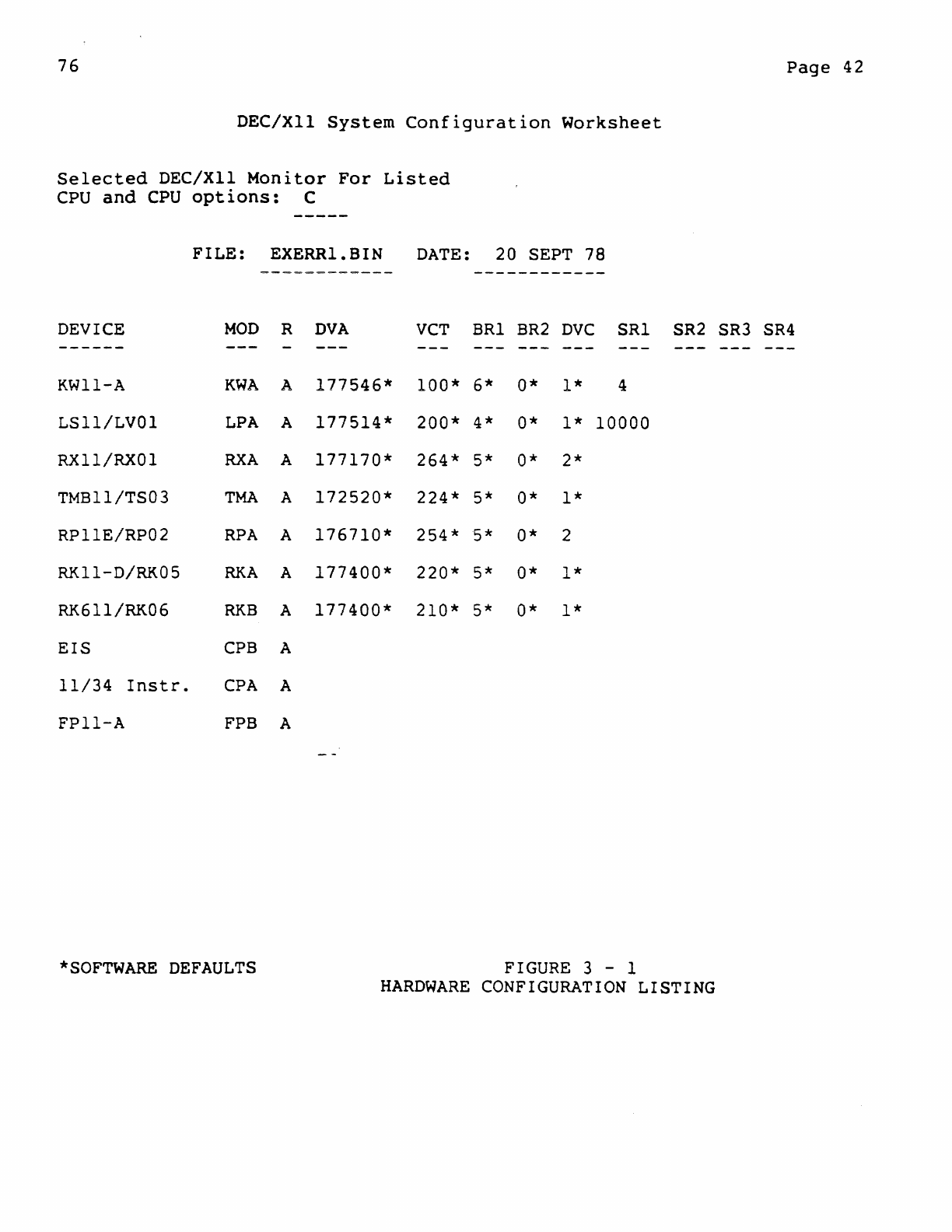
76
DEC/XII
System
Configuration
Worksheet
Selected
DEC/XII
Monitor
For
Listed
CPU
and
CPU
options:
C
FILE:
EXERRI.BIN
DATE:
20
SEPT
78
DEVICE
MOD
R
DVA
VCT
BRI
BR2
DVC
SRI
------
KWI1-A
KWA
A
177546*
100*
6*
0*
1*
4
LSll/LVOI
LPA
A
177514*
200*
4*
0*
1*
10000
RXll/RX01
RXA
A
177170*
264*
5*
0*
2*
TMB11/TS03
TMA
A
172520*
224*
5*
0*
1*
RP11E/RP02
RPA
A
176710*
254*
5*
0*
2
RK11-D/RK05
RKA
A
177400*
220*
5*
0*
1*
RK611/RK06
RKB
A
177400*
210*
5*
0*
1*
EIS
CPB
A
11/34
Instr.
CPA
A
FPI1-A
FPB A
SR2
*SOFTWARE
DEFAULTS
FIGURE 3 - 1
HARDWARE
CONFIGURATION
LISTING
Page
42
SR3 SR4
76
Page
43
3.2.3
Build
Requirements
DEC/XII
programs
are
not
self-loading.
Therefore,
loading
depends
on
the
medium
employed
(i.e.,
paper
tape
or
non-paper
tape).
A DEC/XII
program
is
loaded
from a
paper
tape
device
via
a
Paper
Tape
Loader
(ABS)
program,
and
from
a
non-paper
tape
device
via
an
associated
XXDP+
Monitor
program,
both
of
which
are
previously
loaded
by
the
manual
insertion
of
a
bootstrap
program
or
the
availability
of
a
ROM
bootstrap
option.
It
must
be
noted~
however,
that
the
configuratorilinker
program
is
available
only
on
XXDP+
media,
and
not
on
paper
tape.
with
these
considerations,
the
documentation
are
required
to
module.
3.2.3.1
Required
Hardware
following
construct
hardware,
software,
and
a
run-time
exerciser
load
The
following
information
lists
hardware
requirements
for
the
DEC/XlI
Configuration
Program.
These
requirements
are
related
to
the
basic
differences
encountered
in
the
use
of
PDP-II
systems.
:ommon
Hardware
Requirements
PDP-II
Processor
Minimum memory
capacity
of
16K
Console
device
j~.g.,
ASR33,35; VT05;
etc.)
ROM
bootstrap
Loader
(e.g.,
BM792,
MRlI, M9301,
etc.)
A
ROM
bootstrap
loader
is
not
required.
However,
the
availability
of
this
option
facilitates
the
loading
of
an
XXDP+
Monitor
Program.
XXDP+
Requirements*
Dectape
System:
~
Tell
Dectape
Controller
and
a
TU56
Dual
Dectape
Transport.
Disk
System:
*Note:
media.
An
RKII
Controller
and
an
RK05
Disk
Drive.
These
examples
offer
only
a
partial
listing
of
supported
For
a
complete
listing
refer
to
current
XXDP+
documentation.
76
Page
44
Floppy
Disk
System:
An
RXII
Controller
and
RXOI
Disk
Drives.
Magtape
Systems:
A TMII
Magtape
Controller
and
two
(2)
TUID
Magtape
Drives.
If
2
drives
are
not
available,
the
run-time
exerciser
must
be
directed
to
another
medium.
3.2.3.2
Required
Software
The
version
of
the
DEC/XIl
software
package
to
be
used
will
depend
on
the
hardware
system
employed.
For
example:
if
the
run-time
exerciser
is
to
be
built
from
paper
tape,
there
will
be
separate
tapes
for
each
of
the
desired
test
modules
and
the
monitor
library.
However,
if
an
XXDP+
medium
is
used,
the
DEC/XII
software
will
reside
on
the
media
employed
<i.e.,
Dectape,
Disk,
etc.),
with
each
option
module
and
the
monitor
library
having
a
unique
filename
(i.e.,
.OBJ
and
.LIB
extensions,
respectively).
But,
since
the
configurator/linker
program
is
available
only
on
XXDP+
media,
and
not
paper
tape,
the
DEC/XII
software
requirements
for
building
an
RTE
file
will
be
as
follows:
A
device-associated
XXDP+
monitor
program
DEC/XIII
Configurator/Linker
Program
on
XXDP+
medium
DEC/XII
Monitor
Library
and
option
modules
on
paper
tape
or
XXDP+
medium
3.2.3.3
Required
Documentation
Documentation
requirements
are
related
to
the
reference
material
required
to
(1)
select
the
desired
device/option
and
monitor
modules
and
(2)
acquire
the
boot,
load,
and
start
procedures
for
the
applicable
paper
tape
or
non-paper
tape
device.
These
requirements
are
as
follows:
The DEC/XII
Cross
Reference
Manual
(MD-ZZ-CXQUB)
The
PDP-II
Paper
Tape
Software
User's
Manual
The
XXDP+
User's
Manual
/
3.2.4
Configurator/Linker
Program
The
object
of
the
configurator
program
is
to
link
a
user
specified
monitor
with
user
specified
option
modules,
thereby
creating
a
76
Page
45
run-time
exerciser
(RTE)
module
having
a
user
defined
.BIN
or
.BIC
extension.
User
selected
device/option
modules
are
relocatable-object-modules
with
a .OBJ
extension
that
cannot
be
run
independently.
Therefore,
they
must
be
linked
to
a
monitor
that
is
extracted
from a
library
having
a
.LIB
Extension
under
the
direction
of
the
Configurator/Linker
program
to
derive
an
RTE
program
for
the
testing
of
a
specified
system.
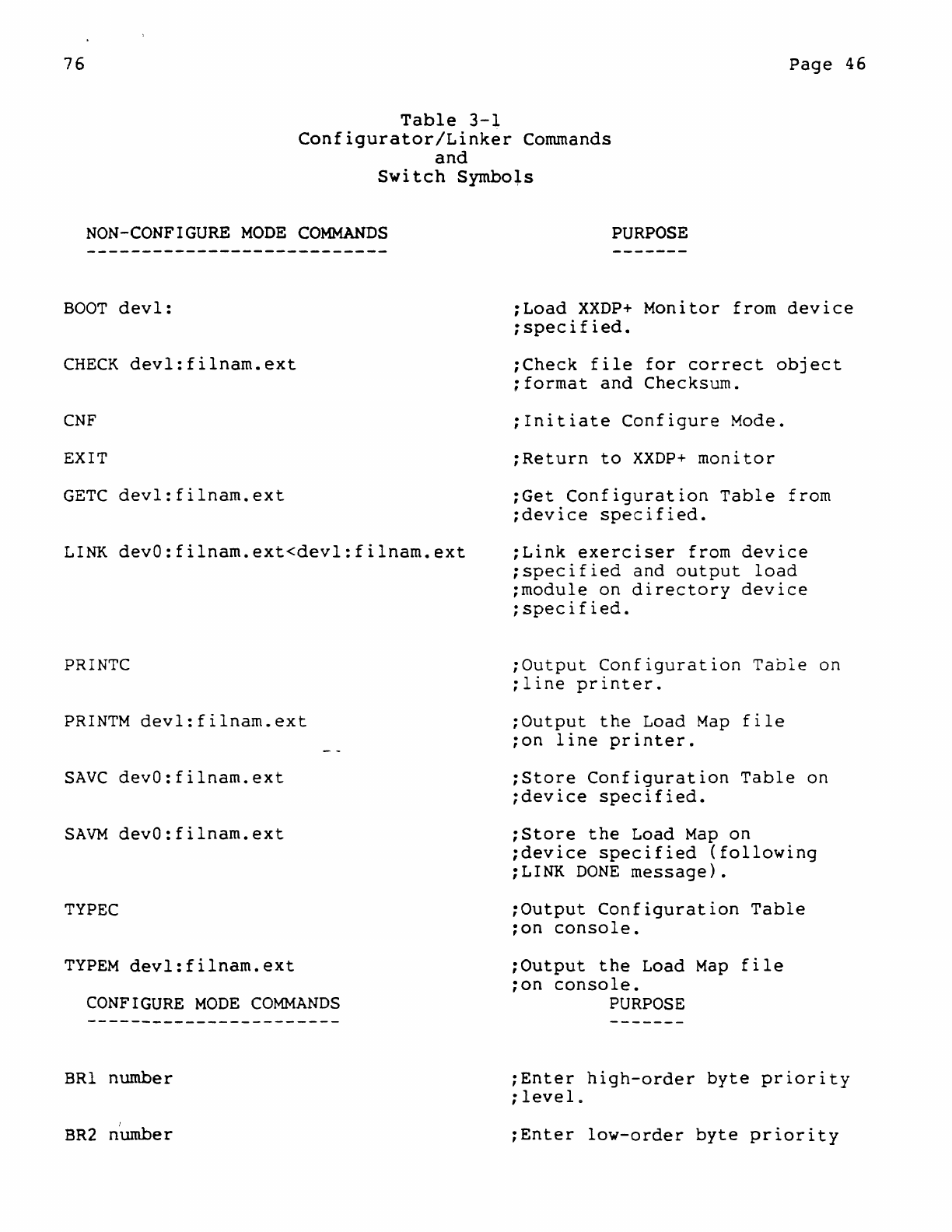
76
Page
46
Table
3-1
Configurator/Linker
Commands
and
Switch
Symbols
NON-CONFIGURE
MODE
COMMANDS
BOOT
dev1:
CHECK
devl:filnam.ext
CNF
EXIT
GETC
devl:filnarn.ext
LINK
devO:filnam.ext<devl:filnam.ext
PRINTC
PRINTM
devl:filnam.ext
SAVC
devO:filnam.ext
SAVM
devO:filnam.ext
TYPEC
TYPEM
devl:filnam.ext
CONFIGURE
MODE
COMMANDS
BRI
number
BR2
nUmber
PURPOSE
iLoad
XXDP+
Monitor
from
device
ispecified.
iCheck
file
for
correct
object
:format
and
Checksum.
:Initiate
Configure
Mode.
:Return
to
XXDP+
monitor
iGet
Configuration
Table
from
:device
specified.
iLink
exerciser
from
device
:specified
and
output
load
:module
on
directory
device
:specified.
;Output
Configuration
Table
on
;line
printer.
:Output
the
Load
Map
file
ion
line
printer.
:Store
Configuration
Table
on
;device
specified.
:Store
the
Load
Map
on
;device
specified
(following
iLINK
DONE
message).
;Output
Configuration
Table
ion
console.
iOutput
the
Load
Map
file
ion
console.
PURPOSE
:Enter
high-order
byte
priority
;levele
:Enter
low-order
byte
priority
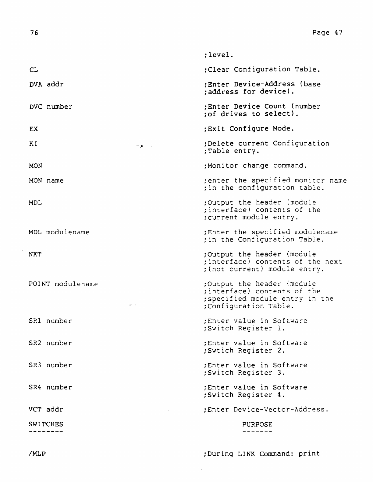
76
CL
DVA
addr
DVC
number
EX
KI
MaN
MaN
name
MDL
MDL
modulenarne
NXT
POINT
modulename
SRI number
SR2
number
SR3
number
SR4
number
veT
addr
SWITCHES
/MLP
Page
47
;level.
;Clear
Configuration
Table.
;Enter
Device-Address
(base
;address
for
device).
;Enter
Device
Count
(number
;of
drives
to
select).
:Exit
Configure
Mode.
:Delete
current
Configuration
;Table
entry.
:Monitor
change
command.
;enter
the
specified
monitor
name
;in
the
configuration
tab~e.
;Output
the
header
(module
;interface)
contents
of
the
;current
module
entry.
;Enter
the
specified
modulename
;in
the
Configuration
Table.
:Output
the
header
(module
;interface)
contents
of
the
next
;(not
current)
module
entry.
;Output
the
header
(module
;interface)
contents
of
the
;specified
module
entry
in
the
;Configuration
Table.
;Enter
value
in
Software
;Switch
Register
1.
;Enter
value
in
Software
;Swtich
Register
2.
;Enter
value
in
Software
;Switch
Register
3.
;Enter
value
in
Software
;Switch
Register
4.
;Enter
Device-Vector-Address.
PURPOSE
:During
LINK
Command:
print
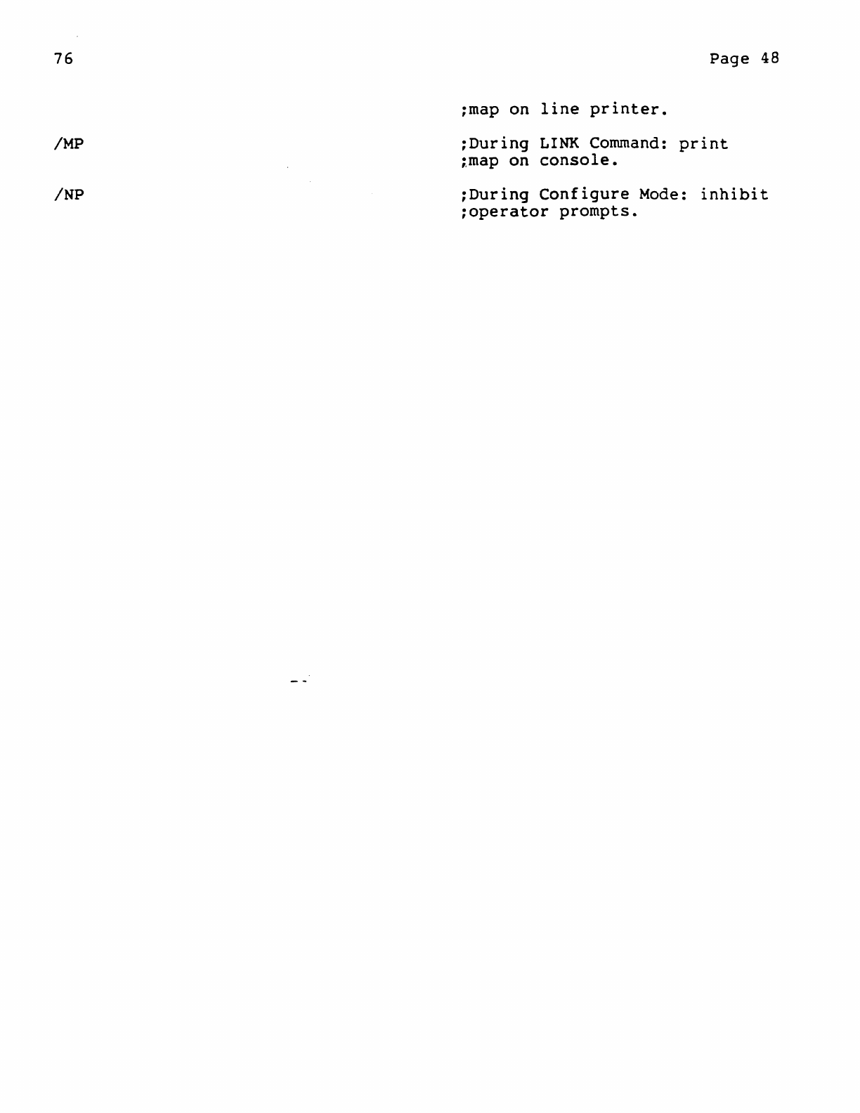
76
IMP
INP
Page
48
:map on
line
printer.
:During
LINK
Command:
print
:,map
on
console.
:During
Configure
Mode:
inhibit
:operator
prompts.
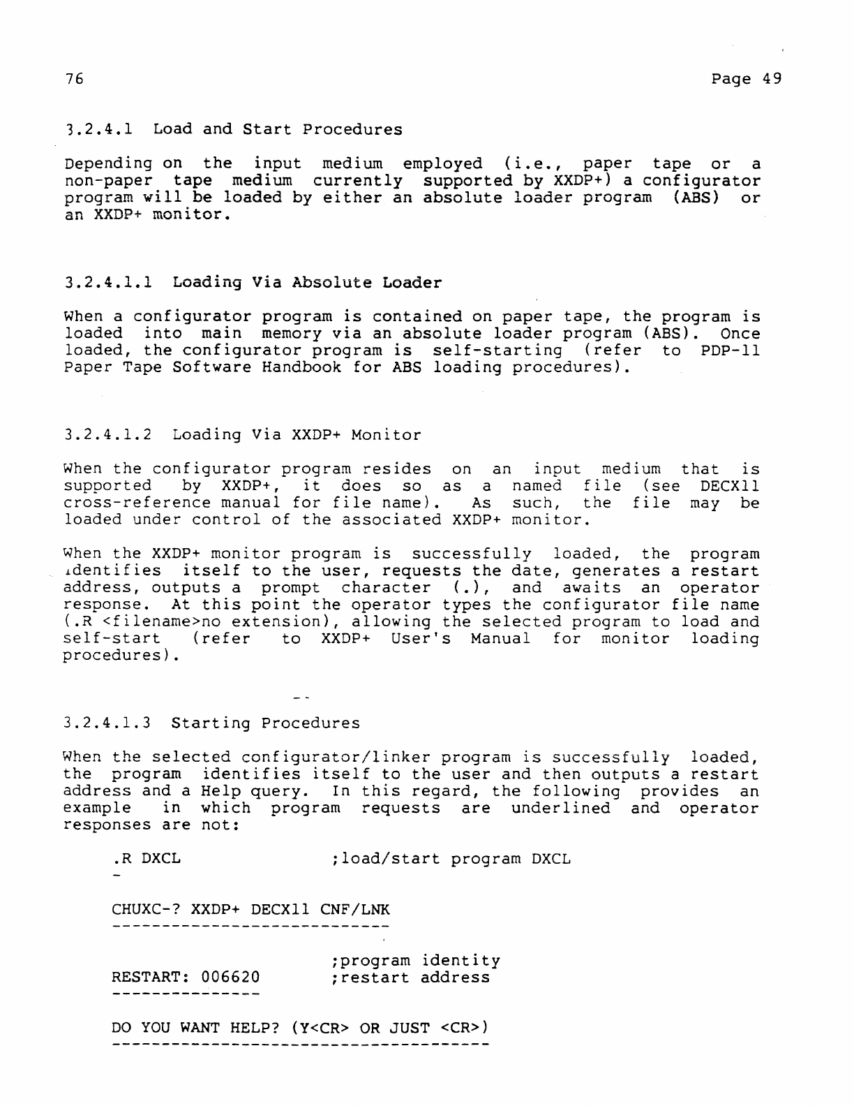
76
Page
49
3.2.4.1
Load
and
Start
Procedures
Depending
on
the
input
medium
employed
(i.e.,
paper
tape
or
a
non-paper
tape
medium
currently
supported
by
XXDP+)
a
configurator
program
will.be
loaded
by
either
an
absolute
loader
program
(ABS)
or
an
XXDP+
monltor.
3.2.4.1.1
Loading
Via
Absolute
Loader
When
a
configurator
program
is
contained
on
paper
tape,
the
program
is
loaded
into
main
memory
via
an
absolute
loader
program
(ABS). Once
loaded,
the
configurator
program
is
self-starting
(refer
to
PDP-II
Paper
Tape
Software
Handbook
for
ABS
loading
procedures).
3.2.4.1.2
Loading
Via
XXDP+
Monitor
When
the
configurator
program
resides
on
an
input
medium
that
is
supported
by
XXDP+,
it
does
so
as
a named
file
(see
DECXll
cross-reference
manual
for
file
name).
As
such,
the
file
may
be
loaded
under
control
of
the
associated
XXDP+
monitor.
When
the
XXDP+
monitor
program
is
successfully
loaded,
the
program
identifies
itself
to
the
user,
requests
the
date,
generates
a
restart
address,
outputs
a
prompt
character
(.),
and
awaits
an
operator
response.
At
this
point
the
operator
types
the
configurator
file
name
(.R
<filename>no
extension),
allowing
the
selected
program
to
load
and
self-start
(refer
to
XXDP+
User's
Manual
for
monitor
loading
procedures).
3.2.4.1.3
Starting
Procedures
When
the
selected
configurator/linker
program
is
successfully
loaded,
the
program
identifies
itself
to
the
user
and
then
outputs
a
restart
address
and
a
Help
query.
In
this
regard,
the
following
provides
an
example
in
which
program
requests
are
underlined
and
operator
responses
are
not:
.R
DXCL
;load/start
program
DXCL
CHUXC-?
XXDP+
DECXll
CNF/LNK
RESTART:
006620
;program
identity
;restart
address
DO
YOU
WANT
HELP?
(Y<CR>
OR
JUST
<CR»
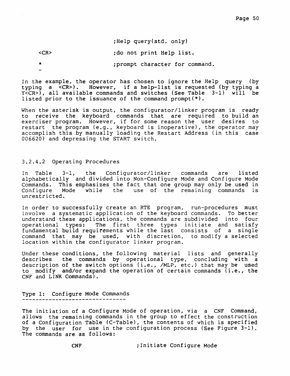
<CR>
*
;Help
query(std.
only)
;do
not
prin~
Help
list.
;prompt
character
for
command.
Page
50
In
the
example,
the
operator
has
chosen
to
ignore
the
Help
query
(by
typing
a
<CR».
However,
if
a
help-list
is
requested
(by
typing
a
Y<CR»,
all
available
commands
and
switches
(See
Table
3-1)
will
be
listed
prior
to
the
issuance
of
the
command
prompt(*).
When
the
asterisk
is
output,
the
configurator/linker
program
is
ready
to
receive
the
keyboard
commands
that
are
required
to
build
an
exerciser
program.
However,
if
for
some
reason
the
user
desires
to
restart
the
program
(e.g.,
keyboard
is
inoperative),
the
operator
may
accomplish
this
by
manually
loading
the
Restart
Address
(in
this
case
006620)
and
depressing
the
START
switch.
3.2.4.2
Operating
Procedures
In
Table
3-1,
the
Configurator/linker
commands
are
listed
alphabetically
and
divided
into
Non-Configure
Mode
and
Configure
Mode
Commands.
This
emphasizes
the
fact
that
one
group
may
only
be
used
in
Configure
Mode
while
the
use
of
the
remaining
commands
is
unrestricted.
In
order
to
successfully
create
an
RTE
program,
run-procedures
must
involve
a
systematic
application
of
the
keyboard
commands.
To
better
understand
these
applications,
the
commands
are
subdivided
into
four
operational
types:
The
first
three
types
initiate
and
satisfy
fundamental
build
requirements
while
the
last
consists
of
a
single
command
that
may
be
used,
with
discretion,
to
modify
a
selected
location
within
the
configurator
linker
program.
Under
these
conditions,
the
following
material
lists
and
generally
describes
the
commands
by
operational
type,
concluding
with
a
description
of
the
switch
options
(i.e.,
/MLP,
etc.)
that
may
be
used
to
modify
and/or
expand
the
operation
of
certain
commands
(i.e.,
the
CNF
and
LINK
Commands).
Type
1:
Configure
Mode Commands
The
initiation
of
a
Configure
Mode
of
operation,
via
a
CNF
Command,
allows
the
remaining
commands
in
the
group
to
effect
the
construction
of
a
Configuration
Table
<C-Table),
the
contents
of
which
is
specified
by
the
user
for
use
in
the
configuration
process
(See
Figure
3-1).
The commands
are
as
follows:
CNF
;Initiate
Configure
Mode
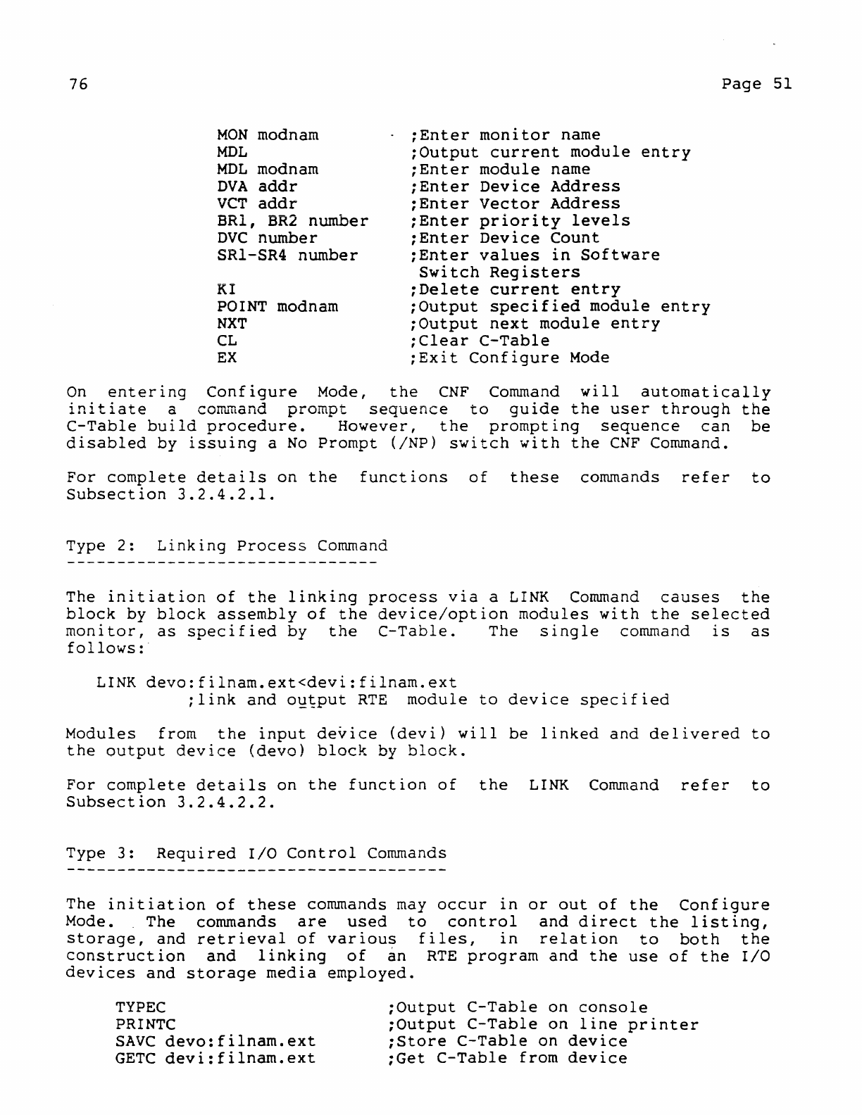
76
MON
modnam
MDL
MDL
modnam
DVA
addr
veT
addr
BRI,
BR2
number
DVC
number
SR1-SR4
number
KI
POINT modnarn
NXT
CL
EX
;Enter
monitor
name
;Output
current
module
entry
;Enter
module
name
;Enter
Device
Address
;Enter
Vector
Address
;Enter
priority
levels
;Enter
Device
Count
;Enter
values
in
Software
Switch
Registers
;Delete
current
entry
;Output
specified
module
entry
;Output
next
module
entry
;Clear
C-Table
;Exit
Configure
Mode
Page
51
On
entering
Configure
Mode,
the
CNF
Command
will
automatically
initiate
a
co~~and
prompt
sequence
to
gUloe
the
user
through
the
C-Table
build
procedure.
However,
the
prompting
sequence
can
be
disabled
by
issuing
a
No
Prompt
(/NP)
switch
with
the
CNF
Command.
For
complete
details
on
the
functions
of
these
commands
refer
to
Subsection
3.2.4.2.1.
Type
2:
Linking
Process
Command
The
initiation
of
the
linking
process
via
a
LINK
Command
causes
the
block
by
block
assembly
of
the
device/option
modules
with
the
selected
monitor,
as
specified
by
the
C-Table.
The
single
command
is
as
follows:
LINK
devo:filnam.ext<devi:filnam.ext
;link
and
o~~put
RTE
module
to
device
specified
Modules
from
the
input
device
(devi)
will
be
linked
and
delivered
to
the
output
device
(devo)
block
by
block.
For
complete
details
on
the
function
of
the
LINK
Command
refer
to
Subsection
3.2.4.2.2.
Type
3:
Required
I/O
Control
Commands
The
initiation
of
these
commands may
occur
in
or
out
of
the
Configure
Mode.
The
commands
are
used
to
control
and
direct
the
listing,
storage,
and
retrieval
of
various
files,
in
relation
to
both
the
construction
and
linking
of
an
RTE
program
and
the
use
of
the
I/O
devices
and
storage
media
employed.
TYPEC
PRINTC
SAve
devo:filnam.ext
GETC
devi:filnam.ext
;Output
C-Table
on
console
;Output
C-Table
on
line
printer
;Store
C-Table
on
device
;Get
C-Table
from
device
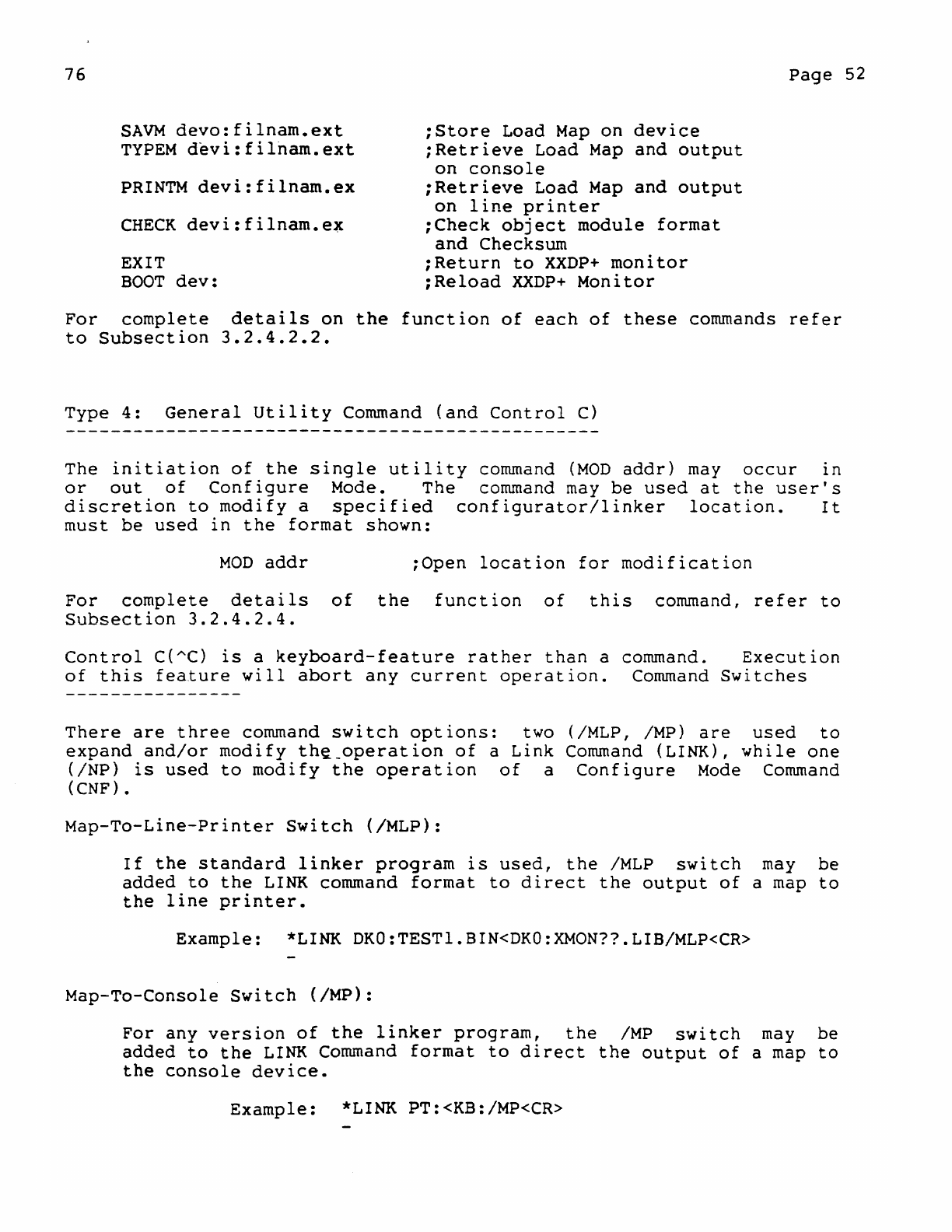
76
SAVM
devo:filnam.ext
TYPEM
devi:filnam.ext
PRINTM
devi:filnam.ex
CHECK
devi:filnam.e~
EXIT
BOOT
dev:
;Store
Load
Map
on
device
;Retrieve
Load
Map
and
output
on
console
;Retrieve
Load
Map
and
output
on
line
printer
;Check
object
module
format
and
Checksum
;Return
to
XXDP+
monitor
;Reload
XXDP+
Monitor
Page
52
For
complete
details
on
the
function
of
each
of
these
commands
refer
to
Subsection
3.2.4.2.2.
Type
4:
General
Utility
Command
(and
Control
C)
The
initiation
of
the
single
utility
command
(MOD
addr)
may
occur
in
or
out
of
Configure
Mode. The command
may
be
used
at
the
user's
discretion
to
modify
a
specified
configurator/linker
location.
It
must
be
used
in
the
format
shown:
MOD
addr
;Open
location
for
modification
For
complete
details
of
the
function
of
this
command,
refer
to
Subsection
3.2.4.2.4.
Control
C{AC)
is
a
keyboard-feature
rather
than
a command.
Execution
of
this
feature
will
abort
any
current
operation.
Command
Switches
There
are
three
command
switch
options:
two (/MLP, /MP)
are
used
to
expand
and/or
modify
th~_operation
of
a
Link
Command
(LINK),
while
one
(/NP)
is
used
to
modify
the
operation
of
a
Configure
Mode
Command
(CNF).
Map-To-Line-Printer
Switch
(/MLP):
If
the
standard
linker
program
is
used,
the
IMLP
switch
may
be
added
to
the
LINK
command
format
to
direct
the
output
of
a
map
to
the
line
printer.
Example:
*LINK DKO:TESTl.BIN<DKO:XMON??LIB/MLP<CR>
Map-To-Console
Switch
(IMP):
For
any
version
of
the
linker
program,
the
IMP
switch
may
be
added
to
the
LINK
Command
format
to
direct
the
output
of
a
map
to
the
console
device.
Example:
*LINK PT:<KB:/MP<CR>

76
Page
53
No-Prompt
Switch
(/NP):
If
the
standard
configurator
program
is
used,
the
/NP
switch
may
be
added
to
the
CNF
Command
to
disable
the
output
of
operator
~rornpts
during
the
building
of
the
C-Table.
Example:
*CNF/NP<CR>
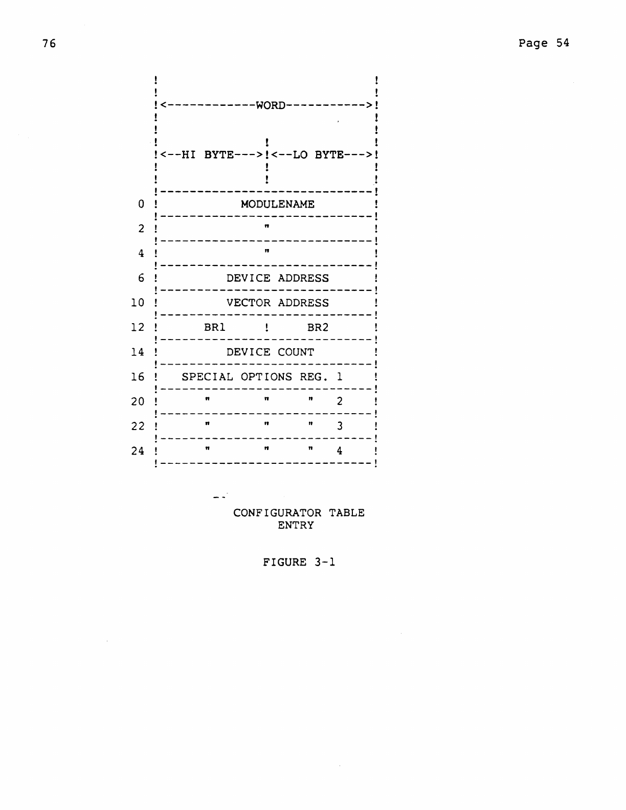
76
o
2
4
6
10
12
!
!<------------WORD----------->!
!
!<--HI
BYTE--->!<--LO
BYTE--->!
.!
!-----------------------------!
MODULENAME
!-----------------------------!
"
!-----------------------------!
" !
!-----------------------------!
DEVICE
ADDRESS
!
!-----------------------------!
VECTOR
ADDRESS
!
!-----------------------------!
BRI
BR2
!-----------------------------!
14
DEVICE
COUNT
!
!-----------------------------!
16
SPECIAL
OPTIONS
REG.
1
20
22
24
!-----------------------------!
" " n 2
!-----------------------------!
n " n 3
!-----------------------------!
n " n 4
!-----------------------------!
CONFIGURATOR
TABLE
ENTRY
FIGURE
3-1
Page
54
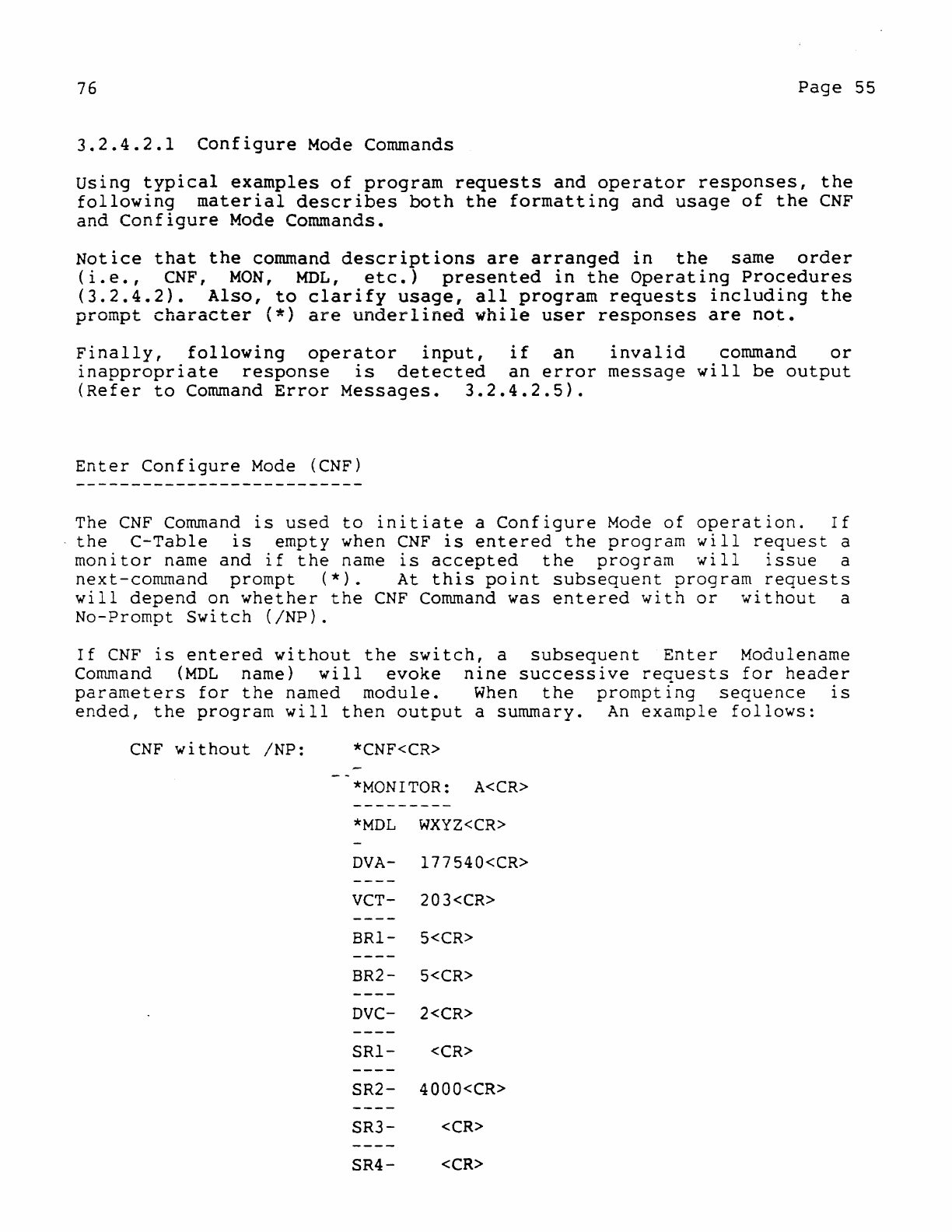
76
Page
55
3.2.4.2.1
Configure
Mode Commands
using
typical
examples
of
program
requests
and
operator
responses,
the
following
material
describes
both
the
formatting
and
usage
of
the
CNF
and
Configure
Mode Commands.
Notice
that
the
command
descriptions
are
arranged
in
the
same
order
(i.e.,
CNF,
MON,
MDL,
etc.)
presented
in
the
Operating
Procedures
(3.2.4.2).
Also,
to
clarify
usage,
all
program
requests
including
the
prompt
character
(*)
are
underlined
while
user
responses
are
not.
Finally,
following
operator
input,
if
an
invalid
command
or
inappropriate
response
is
detected
an
error
message
will
be
output
(Refer
to
Command
Error
Messages.
3.2.4.2.5).
Enter
Configure
Mode
(CNF)
The
CNF
Command
is
used
to
initiate
a
Configure
Mode
of
operation.
If
the
C-Table
is
empty
when
CNF
is
entered
the
program
will
request
a
monitor
name
and
if
the
name
is
accepted
the
program
will
issue
a
next-command
prompt
(*).
At
this
point
subsequent
program
requests
will
depend
on
whether
the
CNF
Command
was
entered
with
or
without
a
No-Prompt
Switch
(/NP).
If
CNF
is
entered
without
the
switch,
a
subsequent
Enter
Modulename
Command
(MDL
name)
will
evoke
nine
successive
requests
for
header
parameters
for
the
named
module.
When
the
prompting
sequence
IS
ended,
the
program
will
then
output
a summary.
An
example
follows:
CNF
without
/NP:
*CNF<CR>
*MONITOR:
A<CR>
---------
*MDL
WXYZ<CR>
DVA-
177540<CR>
VCT-
203<CR>
BRl-
5<CR>
BR2-
5<CR>
DVC-
2<CR>
SRl-
<CR>
SR2-
4000<CR>
SR3-
<CR>
SR4-
<CR>
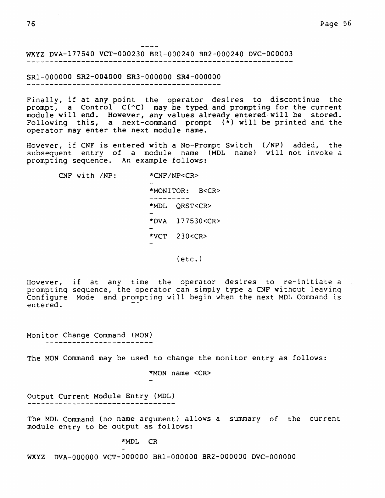
76
Page
56
WXYZ
DVA-177540
VCT-000230
BRI-000240
BR2-000240
DVC-000003
SRI-OOOOOO
SR2-004000
SR3-000000
SR4-000000
Finally,
if
at
any
point
the
operator
desires
to
discontinue
the
prompt,
a
Control
C(AC) may
be
typed
and
prompting
for
the
current
module
will
end.
However,
any
values
already
entered-will
be
stored.
Following
this,
a
next-command
prompt
(*)
will
be
printed
and
the
operator
may
enter
the
next
module
name.
However,
if
CNF
is
entered
with
a
No-Prompt
Switch
subsequent
entry
of
a
module
name
(MDL
name)
prompting
sequence.
An
example
follows:
CNF
with
/NP:
*CNF/NP<CR>
*MONITOR:
B<CR>
*MDL
QRST<CR>
*DVA
I77530<CR>
*VCT
230<CR>
(etc.)
(/NP)
added,
the
will
not
invoke
a
However,
if
at
any
time
the
operator
desires
to
re-initiate
a
prompting
sequence,
the
operator
can
simply
type
a
CNF
without
leaving
Configure
Mode
and
prompting
will
begin
when
the
next
MOL
Command
is
entered.
Monitor
Change
Command
(MON)
The
MON
Command
may
be
used
to
change
the
monitor
entry
as
follows:
*MON
name
<CR>
Output
Current
Module
Entry
(MOL)
The
MDL
Command
(no
name
argument)
allows
a summary
of
the
current
module
entry
to
be
output
as
follows:
*MDL
CR
WXYZ
DVA-OOOOOO
VCT-OOOOOO
BRI-OOOOOD
BR2-000000
DVC-OOOOOO
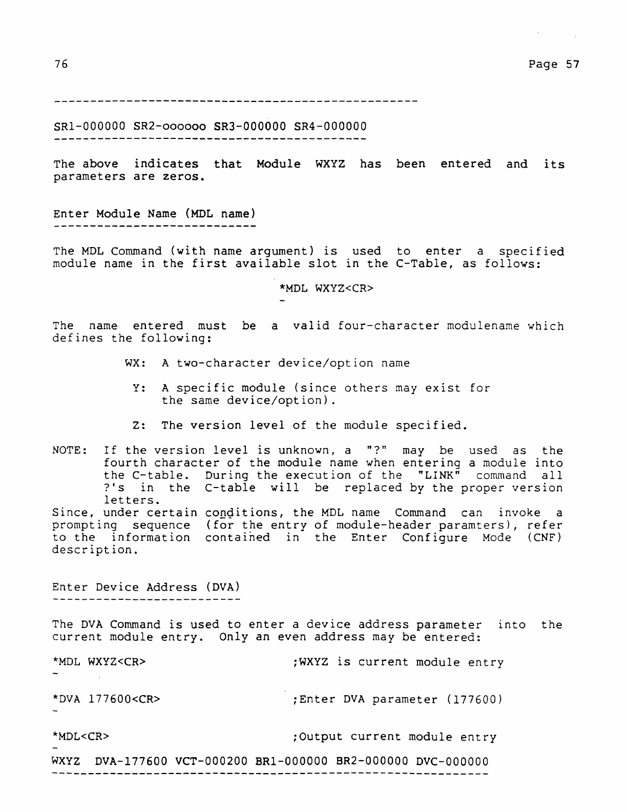
76
Page
57
SRI-000000
SR2-oooooo
SR3-000000
SR4-000000
The
above
indicates
that
Module
WXYZ
has
been
entered
and
its
parameters
are
zeros.
Enter
Module
Name
(MDL
name)
The
MDL
Command
(with
name
argument)
is
used
to
enter
a
specified
module
name
in
the
first
available
slot
in
the
C-Table,
as
follows:
*MDL
WXYZ<CR>
The name
entered
must
be
a
valid
four-character
modulename
which
defines
the
following:
WX:
A
two-character
device/option
name
Y:
A
specific
module
(since
others
may
exist
for
the
same
device/option).
Z: The
version
level
of
the
module
specified.
NOTE:
If
the
version
level
is
unknown, a
"?"
may
be
used
as
the
fourth
character
of
the
module
name when
entering
a
module
into
the
C-table.
During
the
execution
of
the
"LINK" command
all
?'s
in
the
C-table
will
be
replaced
by
the
proper
version
letters.
Since,
under
certain
prompting
sequence
to
the
information
description.
conditions,
the
MDL
name
Command
can
invoke
a
(for
the
entry
of
module-header
paramters),
refer
contained
in
the
Enter
Configure
Mode
(CNF)
Enter
Device
Address
(DVA)
The
DVA
Command
is
used
to
enter
a
device
address
parameter
into
the
current
module
entry.
Only
an
even
address
may
be
entered:
*MDL
WXYZ<CR>
;WXYZ
is
current
module
entry
*DVA
177600<CR>
;Enter
DVA
parameter
(177600)
*MDL<CR>
;Output
current
module
entry
WXYZ
DVA-177600 VCT-000200
BRI-000000
BR2-000000
DVC-OOOOOO
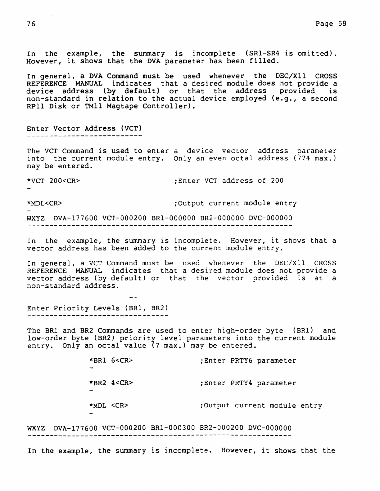
76
Page
58
In
the
example,
the
summary
is
incomplete
(SRI-SR4
is
omitted).
However,
it
shows
that
the
DVA
parameter
has
been
filled.
In
general,
a
DVA
Command
must
be
used
whenever
the
DEC/XII
CROSS
REFERENCE
MANUAL
indicates
that
a
desired
module
does
not
provide
a
device
address
(by
default)
or
that
the
address
provided
is
non-standard
in
relation
to
the
actual
device
employed
(e.g.,
a
second
RPII
Disk
or
TMII
Magtape
Controller).
Enter
Vector
Address
(VCT)
The
VCT
Command
is
used
to
enter
a
device
vector
address
parameter
into
the
current
module
entry.
Only
an
even
octal
address
(774
max.)
may
be
entered.
*VCT
200<CR>
iEnter
VCT
address
of
200
*MDL<CR>
:Output
current
module
entry
WXYZ
DVA-177600 VCT-000200
BRI-OOOOOO
BR2-000000
DVC-OOOOOO
In
the
example,
the
summary
is
incomplete.
However,
it
shows
that
a
vector
address
has
been
added
to
the
current
module
entry.
In
general,
a
VCT
Command
must
be
used
whenever
the
DEC/XII
CROSS
REFERENCE
MANUAL
indicates
that
a
desired
module
does
not
provide
a
vector
address
(by
default)
or
that
the
vector
provided
is
at
a
non-standard
address.
Enter
Priority
Levels
(BRI,
BR2)
The
BRI
and
BR2
Commands
are
used
to
enter
high-order
byte
(BRI)
and
low-order
byte
(BR2)
priority
level
parameters
into
the
current
module
entry.
Only
an
octal
value
(7
max.)
may
be
entered.
*BRI
6<CR>
;Enter
PRTY6
parameter
*BR2
4<CR>
;Enter
PRTY4
parameter
*MDL
<CR>
:Output
current
module
entry
WXYZ
DVA-177600 VCT-000200
BRI-000300
BR2-000200
DVC-OOOOOO
In
the
example,
the
summary
is
incomplete.
However,
it
shows
that
the
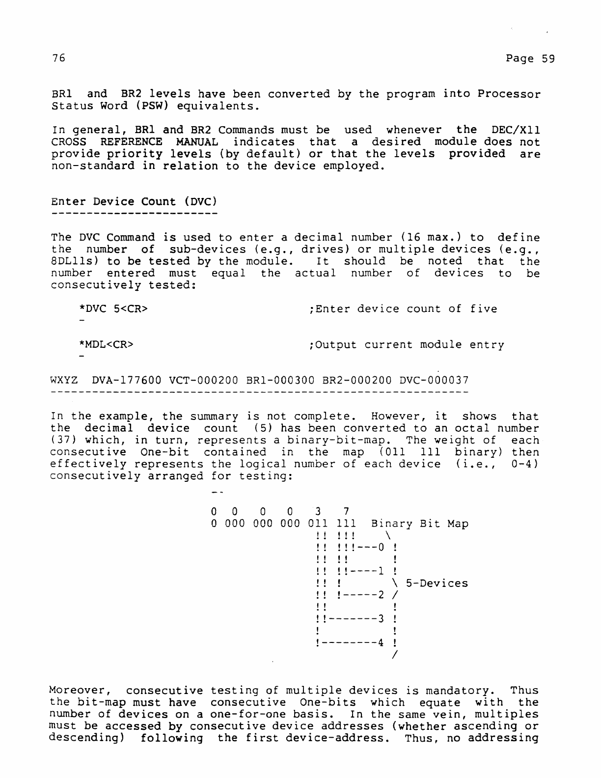
76
Page
59
BRI
and
BR2
levels
have
been
converted
by
the
program
into
Processor
Status
Word
(PSW)
equivalents.
In
general,
BRI
and
BR2
Commands
must
be
used
whenever
the
DEC/XII
CROSS
REFERENCE
MANUAL
lnOlcates
that
a
desired
module
does
not
provide
priority
levels
(by
default)
or
that
the
levels
provided
are
non-standard
in
relation
to
the
device
employed.
Enter
Device
Count
(DVC)
The
DVC
Command
is
used
to
enter
a
decimal
number
(16
max.)
to
define
the
number
of
sub-devices
(e.g.,
drives)
or
mUltiple
devices
(e.g.,
8DLlls)
to
be
tested
by
the
module.
It
should
be
noted
that
the
number
entered
must
equal
the
actual
number
of
devices
to
be
consecutively
tested:
*DVC
5<CR>
;Enter
device
count
of
five
*MDL<CR>
;Output
current
module
entry
WXYZ
DVA-177600 VCT-000200 BRI-000300 BR2-000200
Dve-000037
In
the
example,
the
summary
is
not
complete.
However,
it
shows
that
the
decimal
device
count
(5)
has
been
converted
to
an
octal
number
(37)
which,
in
turn,
represents
a
binary-bit-map.
The
weight
of
each
consecutive
One-bit
contained
in
the
map
(all
III
binary)
then
effectively
represents
the
logical
number
of
each
device
(i.e.,
0-4)
consecutively
arranged
for
testing:
0 a 0 a
a
000
000
000
3 7
all
III
Binary
B~~
~
~
Map
! ! ! !
! ! !
!---O
! !
! !
!----1
! !
! !
-----2
! !
!!-------3
!--------4
\
\
5-Devices
/
/
Moreover,
consecutive
testing
of
multiple
devices
is
mandatory.
Thus
the
bit-map
must
have
consecutive
One-bits
which
equate
with
the
number
of
devices
on
a
one-for-one
basis.
In
the
same
vein,
multiples
must
be
accessed
by
consecutive
device
addresses
(whether
ascending
or
descending)
following
the
first
device-address.
Thus,
no
addressing
76
Page
60
holes
are
permitted.
Software
Switch
Registers
(SRI-SR4)
The SRI
through
SR4
Commands
are
used
separately
to
enter
individual
octal
values
into
the
Software
Switch
Registers
for
the
current
module
entry.
Values
must
be
entered
as
directed
by
the
DEC/XII
CROSS
REFERENCE
MANUAL
to
modify
the
execution
of
a
module,
thus
accommodating
any
standard,
optional,
and/or
special
features
that
may
be
available
to
a
device.
*SR2
4000<CR>
;Set
Bit
11
in
Sft.
Sw.
Reg.
2.
*MDL<CR>
;Output
current
module
entry.
WXYZ
DVA-177600
VCT-000200
BRI-000300
BR2-000200
DVC-000037
SRI-OOOOOO
SR2-004000
SR3-000000
SR4-000000
In
the
example,
Bit
11
in
Software
Switch
Register
2
has
been
set
to
provide
a
flag
for
a
device
feature:
the
line
printer
to
be
used
has
132
columns
(instead
of
80>
and
Bit
11
(set)
is
the
indicator.
Delete
Current
Entry
(KI)
The
KI
Command
is
used
to
delete
the
current
module
entry
(including
all
its
associated
parameter
values)
from
the
C-Table:
*KI<CR>
;Kill
the
last
entry
referenced
When
a module
entry
is
deleted
in
this
manner,
subsequent
requests
for
a summary
of
the
C-Table
(via
a
TYPEC
or
PRINTC
Command)
will
cause
the
output
of
an
Empty
Indicator
«EMPTY»
message
for
the
deleted
entry.
Search
and
Output
Specified
Entry
(POINT)
The
POINT
Command
is
used
to
initiate
a
search
through
the
C-Table
from
the
current
module
entry
position
for
a
specified
module.
*POINT
WXYZ<CR>
;Search,
from
last
referenced
entry,
;for
Module
WXYZ.
If
found,
output
;content.
If
the
desired
module
name
is
found,
the
contents
of
the
entry
is
76
Page
61
output.
Conversely,
if
the
desired
entry
is
not
found,
a
message
(?
INVALID
NAME)
is
output.
Output
Next Module
Entry
(NXT)
The
NEXT
Command
is
used
to
output
the
contents
of
the
module
entry
that
directly
follows
the
last
referenced
entry
(i.e.,
the
current
entry).
If
a
next-entry
does
not
exist,
an
asterisk
(*)
will
be
output.
*NXT<CR>
Clear
C-Table
(CL)
;Output
contents
of
next
module
entry
;(if
existent).
The
CL
Command
is
used
to
initiate
a
clear
of
the
entire
Configuration
Table.
When
the
C-Table
is
cleared,
a
monitor
prompt
request
is
issued
by
the
program
(as
in
the
CNF
Command).
*CL<CR>
;Clear
entire
C-Table
*MONITOR:
name
;Enter
monitor
name
Exit
Configure
Mode
(EXr-
The
EX
Command
is
used
to
exit
from
the
Configure
Mode
of
operation
when
the
construction
of
a
C-Table
is
completed.
Re-entry
is
via
a
CNF
Command.
If
re-entry
is
made,
the
availability
of
a
valid
monitor
entry
negates
the
need
for
a
monitor
request.
Thus,
the
program
merely
points
to
the
first
module
entry
in
the
C-Table
and
outputs
a
command
prompt
(*).
*EX<CR>
;Exit
Configure
Mode
*CNF<CR>
;Re-enter
Configure
Mode
*
;Enter
Command
prompt
3.2.4.2.2
Linking
Process
Command
76
Page
62
Following
an
exit
from
the
Configure
Mode,
the
linking
process
(as
briefly
described
in
the
Operating
Procedures
subsection,
3.2.4.2)
may
be
initiated
via
the
formatting
of
the
LINK
Command. From a
general
format,
the
command may
be
applied
in
one
of
two
ways:
(1)
for
non-directory
devices
(e.g.,
paper
tape"
magtape,
etc.)
or
(2)
for
directory
devices
(e.g.,
disk,
dectape,
etc.)
as
follows:
General
Format:
LINK
devo:[filnam.ext]<devi:[filnam.ext]
(If
devo
or
devi
is
omitted,
the
default
is
the
system
device.)
1.
LINK
devo:<devi:
The
non-directory
device
format
requires
that
only
the
I/O
devices
<i.e.,
devi/devo)
be
specified.
During
execution,
the
required
paper
tapes
for
the
monitor
and
option
modules
will
be
requested
via
a
prompt
sequence.
2.
LINK
devo:filnam.ext<devi:LIBNAM.LIB
The
directory
device
format
requires
that,
along
with
the
I/O
devices,
the
file
name
of
the
monitor
library
input
(LIBNAM.LIB)
must
be
specified
while
the
RTE
output
must
be
specified
by
a
file
name
devised
by
the
user
(FILNAM.BIN
or
FILNAM.BIC).
For
.BIC
extensions
refer
to
XXDP+
chain
mode
operations.
During
execution,
the
monitor
and
option
modules
are
automatically
selected.
In
either
case,
the
LINK
Command
allows
the
monitor
and
option
modules
to
be
extracted
from
the
input
device
(devi)
for
linking
as
defined
by
the
current
C-Table,
thus
producing
an
executable
RTE
program
for
delivery
to
the
output
device
(devo).
Once
the
RTE
module
is
output,
a
completion
message
follows
(LINK
DONE)
and
the
program
returns
to
command mode
(*).
However,
prior
to
termination,
a
LoaG
Map
may
be
invoked
by
including
in-the
command a Load
Map
To
Line
Printer
(/MLP)
or
Load
Map
To
Console
(IMP)
switch.
Two
typical
examples
of
LINK
Command
usage
(non-directory
and
directory)
follow,
in
which
all
program
requests
for
user
response
are
underlined.
However,
prior
to
analyzing
the
examples,
the
reader
should
note
the
following
possibility:
If,
during
the
processing
of
the
LINK
Command
(also
SAVM
and
SAVC
Commands),
the
output
file
specified
in
the
format
already
exists
on
the
specified
medium,
the
program
will
query
the
operator
as
to
whether
or
not
the
old
file
should
be
deleted
with
the
following
message:
DELETE
OLD?(Y
<CR>
OR
JUST
<CR»
If
an
affirmative
answer
is
entered
(y
<CR»,
the
old
file
will
be
deleted,
the
LINK
command
will
be
processed,
and
the
new
file
will
be
output.
If
the
operator
enters
a
negative
response
«CR»,
the
old
file
will
not
be
deleted
and
the
LINK
Command
will
not
be
processed.
Instead,
a
message
(?
USE
NEW
FILE
NAME)
will
be
output,
and
a new
prompt
will
be
typed.
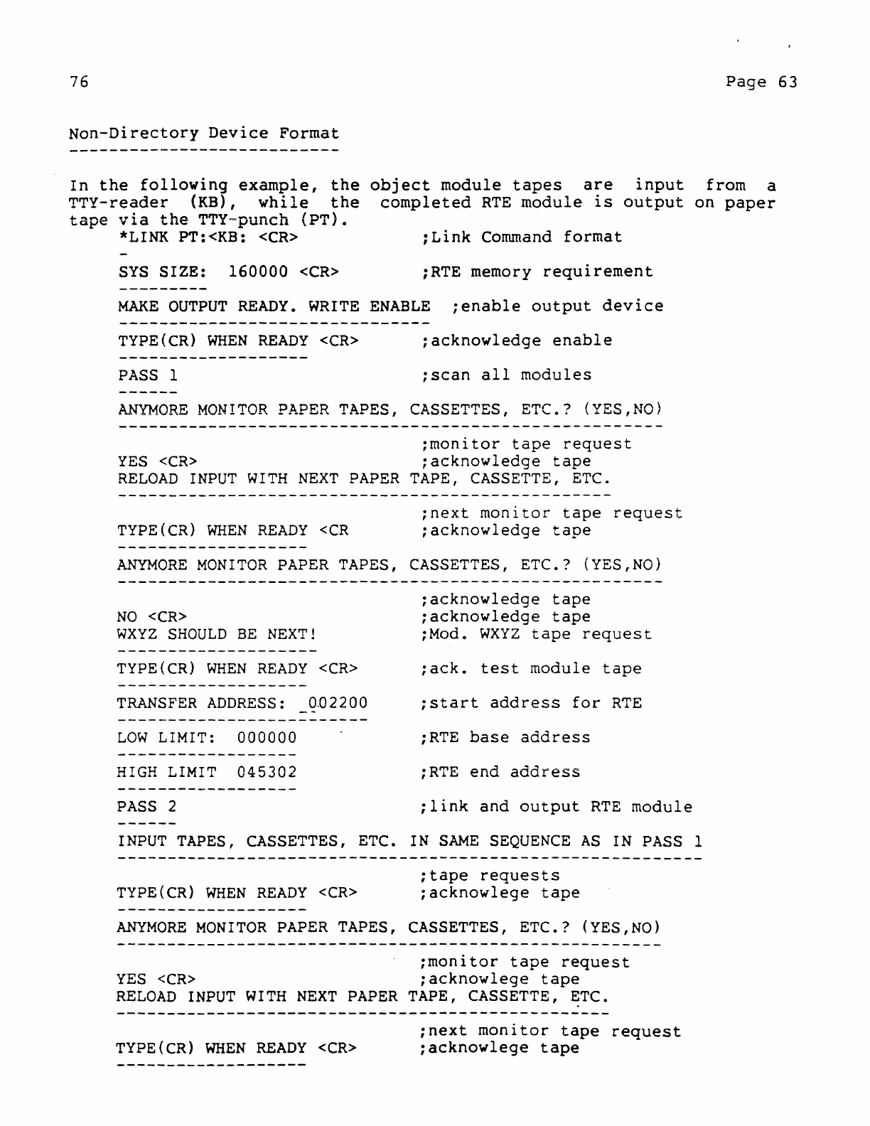
76
Page
63
Non-Directory
Device
Format
In
the
following
example,
the
object
module
tapes
are
input
from
a
TTY-reader
(KB),
while
the
completed
RTE
module
is
output
on
paper
tape
via
the
TTY=punch
(PT).
*LINK PT:<KB:
<CR>
:Link
Command
format
SYS
SIZE:
160000
<CR>
:RTE memory
requirement
MAKE
OUTPUT
READY.
WRITE
ENABLE
;enable
output
device
TYPE(CR)
WHEN
READY
<CR>
;acknowledge
enable
PASS
1
;scan
all
modules
ANYMORE
MONITOR
PAPER
TAPES, CASSETTES,
ETC.?
(YES,NO)
;monitor
tape
request
YES
<CR>
;acknowledge
tape
RELOAD
INPUT
WITH
NEXT
PAPER
TAPE, CASSETTE, ETC.
TYPE(CR)
WHEN
READY
<CR
;next
monitor
tape
request
;acknowledge
tape
ANYMORE
MONITOR
PAPER
TAPES, CASSETTES,
ETC.?
(YES,NO)
NO
<CR>
WXYZ
SHOULD
BE
NEXT!
TYPE(CR)
WHEN
READY
<CR>
TRANSFER
ADDRESS:
0.02200
LOW
LIMIT:
000000
HIGH LIMIT
045302
PASS
2
;acknowledge
tape
;acknowledge
tape
;Mod.
WXYZ
tape
request
;ack.
test
module
tape
;start
address
for
RTE
;RTE
base
address
;RTE
end
address
:link
and
output
RTE
module
INPUT
TAPES, CASSETTES, ETC. IN
SAME
SEQUENCE
AS
IN
PASS
1
TYPE(CR)
WHEN
READY
<CR>
:tape
requests
:acknowlege
tape
ANYMORE
MONITOR
PAPER
TAPES, CASSETTES,
ETC.?
(YES,NO)
:monitor
tape
request
YES
<CR>
;acknowlege
tape
RELOAD
INPUT
WITH
NEXT
PAPER
TAPE, CASSETTE,
~TC.
TYPE(CR)
WHEN
READY
<CR>
:next
monitor
tape
request
:acknowlege
tape
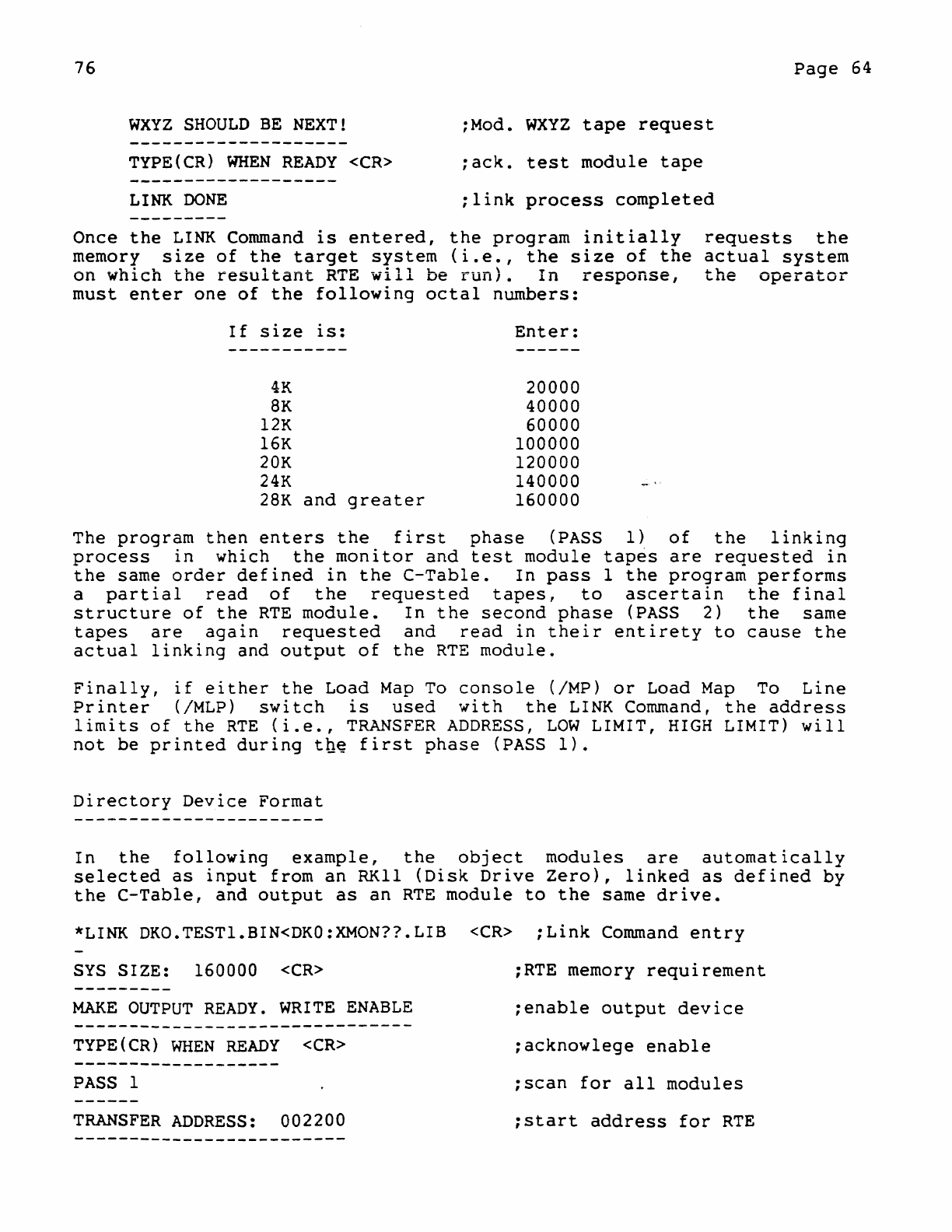
76
Page
64
WXYZ
SHOULD
BE
NEXT!
:Mod.
WXYZ
tape
request
TYPE(CR)
WHEN
READY
<CR>
:ack.
test
module
tape
LINK
DONE
:link
process
completed
Once
the
LINK
Command
is
entered,
the
program
initially
requests
the
memory
size
of
the
target
system
(i.e.,
the
size
of
the
actual
system
on
which
the
resultant
RTE
will
be
run).
In
response,
the
operator
must
enter
one
of
the
following
octal
numbers:
If
size
is:
Enter:
-----------
------
4K
20000
8K
40000
12K
60000
16K
100000
20K
120000
24K
140000
-'
28K
and
greater
160000
The
program
then
enters
the
first
phase
(PASS
1)
of
the
linking
process
In
which
the
monitor
and
test
module
tapes
are
requested
in
the
same
order
defined
in
the
C-Table.
In
pass
1
the
program
performs
a
partial
read
of
the
requested
tapes,
to
ascertain
the
final
structure
of
the
RTE
module.
In
the
second
phase
(PASS
2)
the
same
tapes
are
again
requested
and
read
in
their
entirety
to
cause
the
actual
linking
and
output
of
the
RTE
module.
Finally,
if
either
the
Load
Map
To
console
(IMP)
or
Load
Map
To
Line
Printer
(/MLP)
switch
is
used
with
the
LINK
Command,
the
address
limits
of
the
RTE
(i.e.,
TRANSFER
ADDRESS,
LOW
LIMIT,
HIGH
LIMIT)
will
not
be
printed
during
the
first
phase
(PASS
1).
Directory
Device
Format
In
the
following
example,
the
object
modules
are
automatically
selected
as
input
from
an
RK11
(Disk
Drive
Zero),
linked
as
defined
by
the
C-Table,
and
output
as
an
RTE
module
to
the
same
drive.
*LINK
DKO.TESTl.BIN<DKO:XMON??LIB
<CR>
;Link
Command
entry
SYS
SIZE: 160000
<CR>
:RTE memory
requirement
MAKE
OUTPUT
READY.
WRITE
ENABLE
:enable
output
device
TYPE
(
CR)
WHEN
READY
<CR>
:acknowlege
enable
PASS
1
:scan
for
all
modules
TRANSFER
ADDRESS:
002200
:start
address
for
RTE
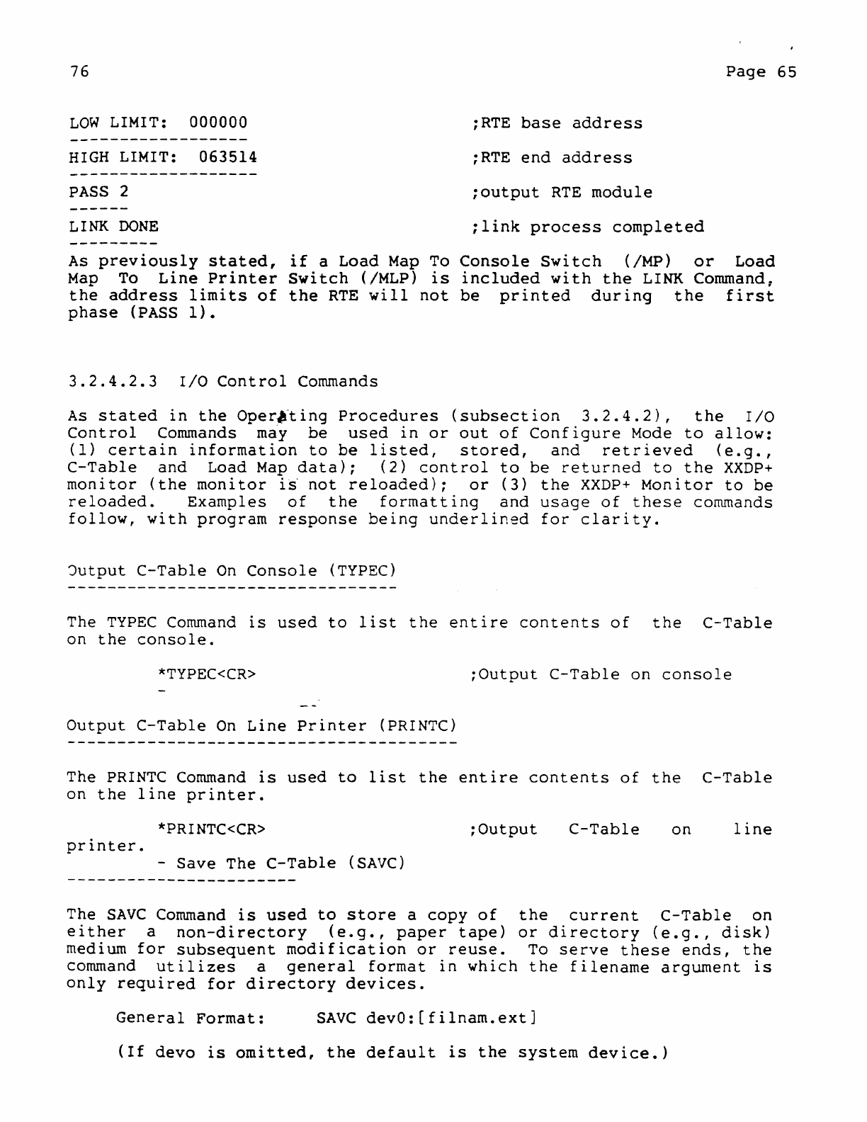
76
Page
65
LOW
LIMIT:
000000
;RTE
base
address
HIGH
LIMIT:
063514
;RTE
end
address
PASS
2
;output
RTE
module
LINK
DONE
;link
process
completed
As
previously
stated,
if
a
Load
Map
To
Console
Switch
(/MP)
or
Load
Map
To
Line
Printer
Switch
(/MLP)
is
included
with
the
LINK Command.
the
address
limits
of
the
RTE
will
not
be
printed
during
the
first
phase
(PASS
1).
3.2.4.2.3
I/O
Control
Commands
As
stated
in
the
Oper"'ling
Procedures
(subsection
3.2.4.2),
the
I/O
Control
Conunands may
be
used
in
or
out
of
Configure
Mode
to
allow:
(1)
certain
information
to
be
listed,
stored,
and
retrieved
(e.g.,
C-Table
and
Load
Map
data);
(2)
control
to
be
returned
to
the
XXDP+
monitor
(the
monitor
i~
not
reloaded);
or
(3)
the
XXDP+
Monitor
to
be
reloaded.
Examples
of
the
formatting
and
usage
of
these
commands
follow,
with
program
response
being
underlined
for
clarity.
Jutput
C-Table
On
Console
(TYPEC)
The
TYPEC
Command
is
used
to
list
the
entire
contents
of
the
C-Table
on
the
console.
*TYPEC<CR>
;Output
C-Table
on
console
Output
C-Table
On
Line
Printer
(PRINTC)
The
PRINTC Command
is
used
to
list
the
entire
contents
of
the
C-Table
on
the
line
printer.
*PRINTC<CR>
;Output
C-Table
on
line
printer.
-
Save
The
C-Table
(SAVC)
The
SAVC
Command
is
used
to
store
a
copy
of
the
current
C-Table
on
either
a
non-directory
(e.g.,
paper
tape)
or
directory
(e.g.,
disk)
medium
for
subsequent
modification
or
reuse.
To
serve
these
ends,
the
command
utilizes
a
general
format
in
which
the
filename
argument
is
only
required
for
directory
devices.
General
Format:
SAve
devO:[filnam.ext]
(If
devo
is
omitted,
the
default
is
the
system
device.)
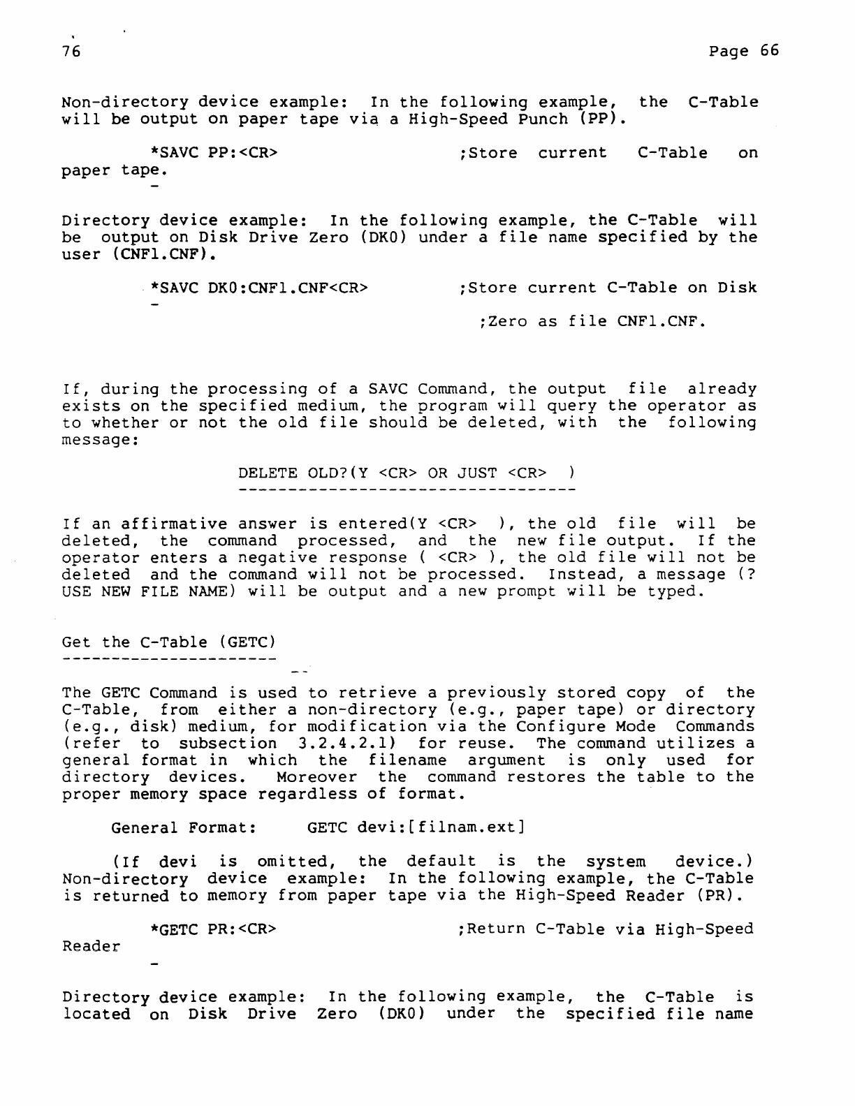
76
Page
66
Non-directory
device
example:
In
the
following
example,
the
C-Table
will
be
output
on
paper
tape
via
a
High-Speed
Punch
(pp).
*SAVC
PP:<CR>
paper
tape.
:Store
current
C-Table
on
Directory
device
example:
In
the
following
example,
the
C-Table
will
be
output
on
Disk
Drive
Zero
(DKO)
under
a
file
name
specified
by
the
user
(CNFl.CNF).
.
*SAVC
DKO:CNFl.CNF<CR>
:Store
current
C-Table
on
Disk
;Zero
as
file
CNFl.CNF.
If,
during
the
processing
of
a
SAVC
Command,
the
output
file
already
exists
on
the
specified
medium,
the
program
will
query
the
operator
as
to
whether
or
not
the
old
file
should
be
deleted,
with
the
following
message:
DELETE
OLD?(Y
<CR>
OR
JUST
<CR>
If
an
affirmative
answer
is
entered(Y
<CR>
),
the
old
file
will
be
deleted,
the
command
processed,
and
the
new
file
output.
If
the
operator
enters
a
negative
response
(
<CR>
),
the
old
file
will
not
be
deleted
and
the
command
will
not
be
processed.
Instead,
a
message
(?
USE
NEW
FILE
NAME)
will
be
output
and
a new
prompt
will
be
typed.
Get
the
C-Table
(GETC)
The
GETC
Command
is
used
to
retrieve
a
previously
stored
copy
of
the
C-Table,
from
either
a
non-directory
(e.g.,
paper
tape)
or
directory
(e.g.,
disk)
medium,
for
modification
via
the
Configure
Mode Commands
(refer
to
subsection
3.2.4.2.1)
for
reuse.
The
command
utilizes
a
general
format
in
which
the
filename
argument
is
only
used
for
directory
devices.
Moreover
the
command
restores
the
table
to
the
proper
memory
space
regardless
of
format.
General
Format:
GETC
devi:[filnam.ext]
(If
devi
is
omitted,
the
default
is
the
system
device.)
Non-directory
device
example:
In
the
following
example,
the
C-Table
is
returned
to
memory
from
paper
tape
via
the
High-Speed
Reader
(PR).
*GETC
PR:<CR>
:Return
C-Table
via
High-Speed
Reader
Directory
device
example:
In
the
following
example,
the
C-Table
is
located
on
Disk
Drive
Zero
(DKO)
under
the
specified
file
name
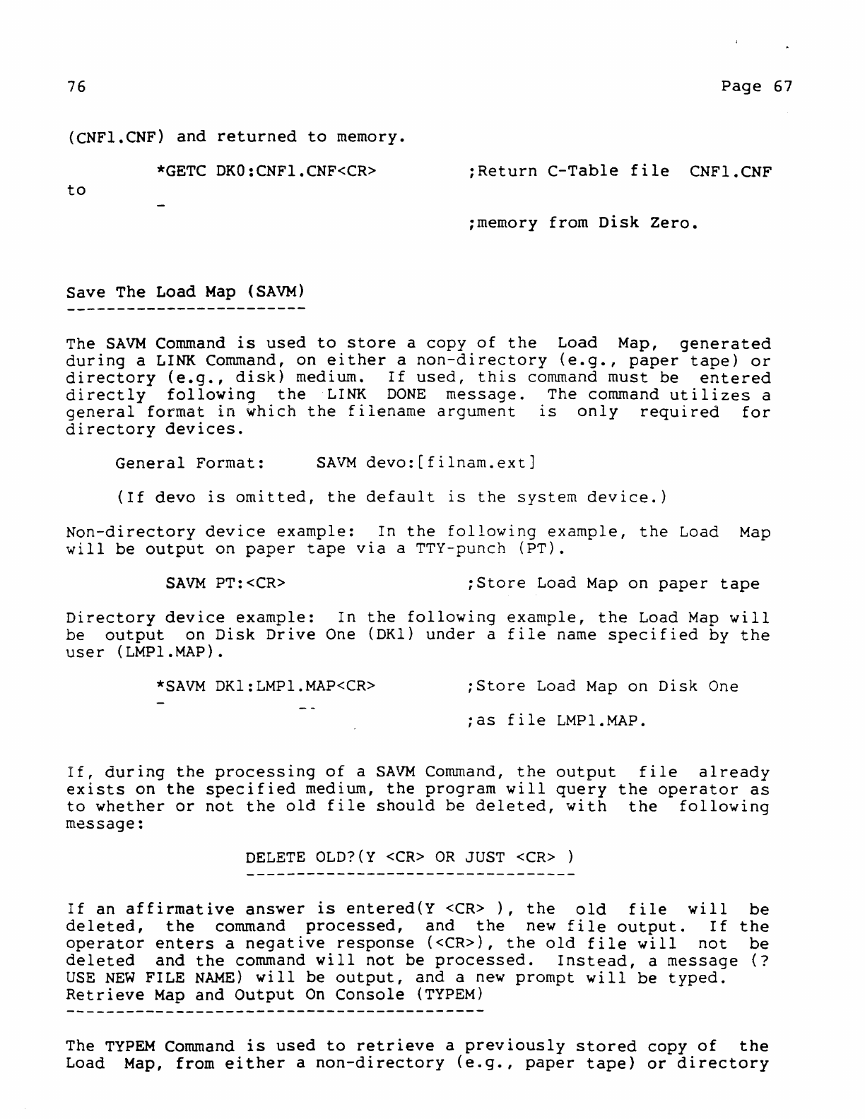
76
Page
67
(CNFl.CNF)
and
returned
to
memory.
*GETC
DKO:CNFl.CNF<CR>
:Return
C-Table
file
CNFl.CNF
to
;memory
from
Disk
Zero.
Save
The Load
Map
(SAVM)
The
SAVM
Command
is
used
to
store
a
copy
of
the
Load Map,
generated
during
a
LINK
Command,
on
either
a
non-directory
(e.g.,
paper
tape)
or
directory
(e.g.,
disk)
medium.
If
used,
this
command
must
be
entered
directly
following
the
LINK
DONE
message.
The command
utilizes
a
general
format
in
which
the
filename
argument
is
only
required
for
directory
devices.
General
Format:
SAVM
devo:[filnam.ext]
(If
devo
is
omitted,
the
default
is
the
system
device.)
Non-directory
device
example:
In
the
following
example,
the
Load
Map
will
be
output
on
paper
tape
via
a TTY-punch
(PT).
SAVM
PT:<CR>
:Store
Load
Map
on
paper
tape
Directory
device
example:
In
the
following
example,
the
Load
Map
will
be
output
on
Disk
Drive
One (DKl)
under
a
file
name
specified
by
the
user
(LMPl.MAP).
*SAVM
DKl:LMPl.MAP<CR>
;Store
Load
Map
on
Disk
One
;as
file
LMPl.MAP.
If,
during
the
processing
of
a
SAVM
Command,
the
output
file
already
exists
on
the
specified
medium,
the
program
will
query
the
operator
as
to
whether
or
not
the
old
file
should
be
deleted,
with
the
following
message:
DELETE
OLD?(Y
<CR>
OR
JUST
<CR>
)
If
an
affirmative
answer
is
entered(Y
<CR>
),
the
old
file
will
be
deleted,
the
command
processed,
and
the
new
file
output.
If
the
operator
enters
a
negative
response
«CR»,
the
old
file
will
not
be
deleted
and
the
command
will
not
be
processed.
Instead,
a
message
(?
USE
NEW
FILE
NAME)
will
be
output,
and
a
new
prompt
will
be
typed.
Retrieve
Map
and
Output
On
Console
(TYPEM)
The
TYPEM
Command
is
used
to
retrieve
a
previously
stored
copy
of
the
Load Map, from
either
a
non-directory
(e.g.,
paper
tape)
or
directory
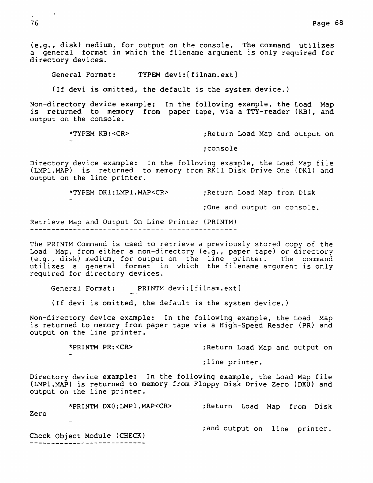
76
Page
68
(e.g.,
disk)
medium,
for
output
on
the
console.
The command
utilizes
a
general
format
in
which
the
filename
argument
is
only
required
for
directory
devices.
General
Format:
TYPEM
devi:[filnam.ext]
(If
devi
is
omitted,
the
default
is
the
system
device.)
Non-directory
device
example:
is
returned
to
memory
from
output
on
the
console.
In
the
following
example,
the
Load
Map
paper
tape,
via
a
TTY-reader
(KB),
and
*TYPEM
KB:<CR>
;Return
Load
Map
and
output.
on
;console
Directory
device
example:
In
the
following
example,
the
Load
Map
file
(LMPl.MAP)
is
returned
to
memory from
RKll
Disk
Drive
One (DKl)
and
output
on
the
line
printer.
*TYPEM
DK1:LMPl.MAP<CR>
;Return
Load
Map
from
Disk
;One
and
output
on
console.
Retrieve
Map
and
Output
On
Line
Printer
(PRINTM)
The
PRINTM
Command
is
used
to
retrieve
a
previously
stored
copy
of
the
Load Map, from
either
a
non-directory
(e.g.,
paper
tape)
or
directory
(e.g.,
disk)
medium,
for
output
on
the
line
printer.
The command
utilizes
a
general
format
in
which
the
filename
argument
is
only
required
for
directory
devices.
General
Format:
PRINTM
devi:[filnam.ext]
(If
devi
is
omitted,
the
default
is
the
system
device.)
Non-directory
device
example:
In
the
following
example,
the
Load
Map
is
returned
to
memory
from
paper
tape
via
a
High-Speed
Reader
(PR)
and
output
on
the
line
printer.
*PRINTM
PR:<CR>
;Return
Load
Map
and
output
on
;line
printer.
Directory
device
example:
In
the
following
example,
the
Load
Map
file
(LMPl.MAP)
is
returned
to
memory from
Floppy
Disk
Drive
Zero
(DXO)
and
output
on
the
line
printer.
*PRINTM
DXO:LMPl.MAP<CR>
;Return
Load
Map
from
Disk
Zero
Check
Object
Module
(CHECK)
;and
output
on
line
printer.
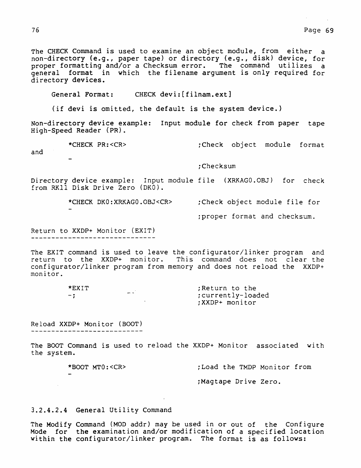
76
Page
69
The
CHECK
Command
is
used
to
examine
an
object
module,
from
either
a
non-directory
(e.g.,
paper
tape)
or
directory
(e.g.,
disk)
device,
for
proper
formatting
and/or
a
Checksum
error.
The
command
utilizes
a
general
format
in
which
the
filename
argument
is
only
required
for
directory
devices.
General
Format:
CHECK
devi:(filnam.ext]
(if
devi
is
omitted,
the
default
is
the
system
device.)
Non-directory
device
example:
Input
module
for
check
from
paper
tape
High-Speed
Reader
(PR).
*CHECK
PR:<CR>
;Check
object
module
format
and
;Checksum
Directory
device
example:
Input
module
file
(XRKAGO.OBJ)
for
check
from
RKll
Disk
Drive
Zero
(DKO).
*CHECK
DKO:XRKAGO.OBJ<CR>
;Check
object
module
file
for
;proper
format
and
checksum.
Return
to
XXDP+
Monitor
(EXIT)
The EXIT command
is
used
to
leave
the
configurator/linker
program
and
return
to
the
XXDP+
monitor.
This
command
does
not
clear
the
configurator/linker
program
from
memory
and
does
not
reload
the
XXDP+
monitor.
*EXIT
_.
,
Reload
XXDP+
Monitor
(BOOT)
;Return
to
the
;currently-loaded
;XXDP+
monitor
The
BOOT
Command
is
used
to
reload
the
XXDP+
Monitor
associated
with
the
system.
*BOOT
MTO:<CR>
;Load
the
TMDP
Monitor
from
:Magtape
Drive
Zero.
3.2.4.2.4
General
Utility
Command
The
Modify
Command
(MOD
addr)
may
be
used
in
or
out
of
the
Configure
Mode
for
the
examination
and/or
modification
of
a
specified
location
within
the
configurator/linker
program.
The
format
is
as
follows:
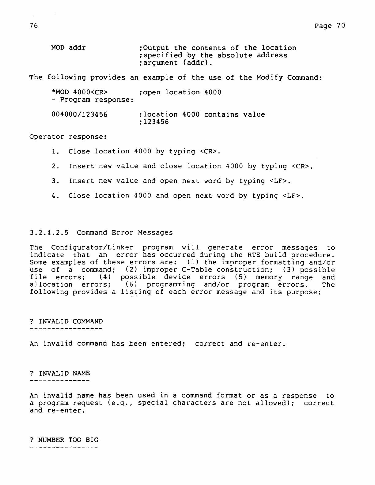
76
MOD
addr
:Output
the
contents
of
the
location
;specified
by
the
absolute
address
;argument
(addr).
Page
70
The
following
provides
an
example
of
the
use
of
the
Modify
Command:
*MOD
4000<CR>
;open
location
4000
-
Program
response:
004000/123456
;location
4000
contains
value
:123456
Operator
response:
1.
Close
location
4000 by
typing
<CR>.
2.
Insert
new
value
and
close
location
4000
by
typing
<CR>.
3.
Insert
new
value
and
open
next
word
by
typing
<LF>.
4.
Close
location
4000
and
open
next
word
by
typing
<LF>.
3.2.4.2.5
Command
Error
Messages
The
Configurator/Linker
program
will
generate
error
messages
to
indicate
that
an
error
has
occurred
during
the
RTE
build
procedure.
Some
examples
of
these
errors
are:
(1)
the
improper
formatting
and/or
use
of
a command;
(2)
improper
C-Table
construction;
(3)
possible
file
errors;
(4)
possible
device
errors
(5)
memory
range
and
allocation
errors;
(6)
programming
and/or
program
errors.
The
following
provides
a
li~~ing
of
each
error
message
and
its
purpose:
?
INVALID
COMMAND
An
invalid
command
has
been
entered;
correct
and
re-enter.
?
INVALID
NAME
An
invalid
name
has
been
used
in
a command
format
or
as
a
response
to
a
program
request
(e.g.,
special
characters
are
not
allowed);
correct
and
re-enter.
?
NUMBER
TOO
BIG
76
Page
71
rhe
number·
typed
in
response
to
a
program
request
is
larger
than
is
allowed
for
the
requested
parameter.
For
example,
the
device
count
in
the
C-Table
must
not
exceed
decimal
16;
vector
addresses
must
not
exceed
octal
774,
etc.;
correct
and
re-enter.
?
INVALID
SWITCH
An
invalid
switch
has
been
used
with
a command
(if
command
will
accomodate
a
valid
switch)
or
a
switch
has
been
included
with
a
command
that
does
not
accomodate
switches.
?
CHECKSL~
ERROR
A Checksum
error
has
occurred
during
the
reading
of
a
binary
formatted
block.
FILNAMEXT?
NON-EXISTANT
FILE
THE
file
named
FILNAM.EXT,
which
has
been
specified
in
the
command
format
which
does
not
in
fact
exist
on
the
employed
medium;
correct
and
re-enter.
?
END-OF-MEDIUM
This
messaqe
indicates
that
the
end
of
an
input
medlum
has
been
reached
(e.g.,
EOT),
and
can
occur
as
the
result
of
an
unsuccessful
block
search
within
a
file
(e.g.,
EOF).
?
PROGRAM
OVERFLOW
This
message
indicates
that
the
block
size
of
the
input
file
is
greater
than
the
size
of
the
input
buffer.
?
NOT
IN
CNF
MODE
This
message
indicates
that
a
Configure
Mode
Command
(e.g.,
DVA,
veT,
BRl,
etc.)
has
been
illegally
entered
in
non-configure
mode;
re-enter
76
Page
72
Configure
Mode
(i.e.,
CNF<CR»
and
re-enter
command.
?
MUST
BE
OCTAL
The number
typed
in
response
to
a
program
request
was
not
octal
and
should
have
been.
?
NO
ROOM
FOR
A
DRIVER
The
device
driver
specified
in
the
command
cannot
be
placed
in
the
driver
buffer.
?
CNF
TABLE
FULL
This
message
indicates
that
the
maximum number
of
entries
(i.e.,
20
or
40)
have
been
made
in
the
Configuration
Table.
?
COR
EXCD
This
message
indicates
that
during
the
linking
process
(refer
to
subsection
3.2.4.2.2)
the
range
of
the
RTE
program
exceeds
the
core
size
of
the
system
for
which
it
is
being
generated.
?
SYMBOL
TABLE
OVERFLOW
During
pass
1
of
the
linking
process,
the
symbol
table
has
used
up
all
available
memory
space;
use
a
system
with
a
larger
memory.
?
USE
NEW
FILE
NAME
A
file
name
specified
in
the
command
already
exists:
use
another
name
or
delete
the
old
file.
?
DEVICE
FULL
76
Page
73
There
is
no
more
room
available
on
the
specified
output
device.
?
READ
ERROR
An
error
was
encountered
while
attempting
to
read
from
the
specified
input
medium.
?
WRITE
ERROR
An
error
was
encountered
while
attempting
to
write
onto
the
specified
output
medium.
(ERROl) Symbol
Table
Error
The
program
has
detected
an
error
in
the
Symbol
Table
during
the
linking
process.
(ERR02)
Global
Search
Error
A
global
search
in
the
Relocation
Directory
(RLD)
has
failed
during
the
linking
process.
(ERR03)
No
PC
Mod
Command
The
Relocation
Directory
(RLD)
does
not
contain
a
Program
Counter
(PC)
modification
command.
Program
error
has
been
detected
during
linking
process.
(ERR04)
GSD
Block
Missing
A
Global
Symbol
Directory
(GSD)
block
has
not
been
found
at
the
start
of
the
object
module.
This
could
be
a
program
error
detected
during
the
linking
process.
However,
if
paper
tape
is
the
input
medium,
the
tape
could
have
been
loaded
backwards.
(ERROSf Module
Name
Missing
From
GSD
-------------------------------~----
The
first
entry
in
the
Global
Symbol
Directory
(GSD)
is
not
an
object
module
name.
This
could
be
a
program
error
detected
during
the
linking
process.
However,
if
paper
tape
is
the
input
medium,
the
wrong
tape
could
have
been
loaded.
76
Page
74
(ERR06)
Section
Name
Missing
A
Section
Name,
specified
by
the
Relocation
Directory
(RLO),
cannot
be
found;
program
error.
(ERR07)
Can't
Find
Module
Name
In
Symbol
Table
A
module
name
is
missing
from
the
symbol
table.
possible
reason
is
an
option
module's
filename
does
not
match
the
name
in
the
header.
(ERR09) Jump
Table
Index
Error
The
Jump
Table
index
value
exceeds
the
required
range
(i.e.,
the
GSO
code
byte
is
too
large);
program
error.
(ERRI2) Load
Module
Error
The
program
detected
an
error
during
the
writing
of
the
RTE
load
module
on
the
output
medium.
3.2.5
Generating
A
Run-Time
Exerciser
Module
The
following
provides
a
brief
summary
of
the
configuration
and
linking
process
in
regard
to:
(1)
construction
and/or
modification
of
the
C-Table,
(2)
execution
of
the
Link
Command,
and
(3)
generation
of
the
RTE
module.
The
text
includes
references
to
certain
configurator/linker
commands
but
does
not
provide
detailed
descriptions
related
fa
formatting
and
usage.
For
such
information
the
reader
may
refer
to
the
material
available
under
Operating
Procedures
(3.2.4.2)
for
the
configurator/linker
program.
3.2.5.1
The
Configuration
Table
(C-Table)
The
use
of
the
C-Table
facilitates
the
linking
process,
and
simplifies
the
formatting
of
the
LINK
Command,
by
providing
an
easily
accessible
area
for
option
module
and
monitor
data.
The
C-Table
accommodates
a maximum
of
40
entries
(i.e.,
39
option
modules
and
one
monitor
entry)
with
each
entry
accommodating
eleven
words
(See
Figure
3-1).
The
construction
of
a
C-Table
may
begin
when
the
configurator/linker
program
is
loaded
and
a
Configure
Mode
of
operation
is
initiated
via
the
entry
of
a
CNF
Command.
76
Page
75
Clearing
the
C-Table
If
the
C-Table
is
empty
when
CNF
is
entered,
the
program
will
request
a
monitor
name
and
the
user
may
initiate
a new
builde
However,
if
the
table
is
not
empty,
the
program
ass~~es
that
the
user
intends
to
modify
existent
entries
and
a
request
for
a
monitor
name
will
not
be
made.
Therefore,
if
the
C-Table
is
not
empty
and
a new
build
is
desired,
the
table
must
be
initially
cleared
by
entering
a
CL
Command.
Current
Entry
Pointer
As
a
build
proceeds,
the
configurator
program
adjusts
a
pointer
to
specify
the
current
module
entry
(i.e.,
the
entry
effected
by
the
last
MDL
name Command).
Thus,
as
each
parameter
entry
command
(e.g.,
DVA,
DVC,
etc.)
is
used,
it
only
affects
the
content
of
the
module
so
soecified.
Under
these
conditions,
a
current
entry
may
be
deleted
bv
entering
a
KI
Command
without
affecting
the
location
of
the
pointer
..
Finally,
two
additional
Configure
Mode commands
(i.e.,
NXT
and
POINT
name Command)
can
be
used
to
affect
the
location
of
the
Dointer
if
the
modification
of
a
filled
C-Table
is
in
progress.
Respectively,
the
commands
will
adjust
the
pointer
to
the
next
entry
(if
it
exists)
or
to
a
specified
entry
and
output
the
contents
of
the
entry.
Listing
and
Saving
the
C-Table
To
obtain
a
console
listing
of
the
completed
C-Table,
the
TYPEC
Command
is
used.
A
line
printer
listing
is
obtained
by
entering
a
PRINTC
Command.
These
commands may
be
entered
in
or
out
of
Configure
Mode.
The
completed
C-Table
can
be
saved
under
a
file
name
by
entering
a
SAVC
Command.
The
file
may
then
be
retrieved
by
entering
a
GETC
Co~mand.
These
co~mands
may
also
be
issued
in
or
out
of
Configure
Mode.
3.2.5.2
The
Linking
Process
(LINK Command)
The
LINK
Command
pieces
together
a
Run-Time
Exerciser
(RTE)
program
by
linking
all
of
the
required
monitor
modules
and
all
of
the
requested
option
modules
to
produce
a
single
executable
binary
file.
Processing
Phases
The
linking
process
consists
of
two
phases
which
the
linker
defines
for
the
user
as
PASS
1
and
PASS
2.
During
Phase
One,
only
a
portion
76
Page
76
of
each
monitor
module
and
each
option
module
is
read
to
memory
for
an
initial
evaluation
(e.g.,
global
references
are
identified
and
evaluated).
During
Phase
TWo,
the
remaining
portions
of
each
module
are
also
read
to
memory,
absolute
addresses
are
assigned,
and
the
RTE
module
is
produced
as
a
single
output
file.
Processing
Phase
One (PASS
1)
When
a
LINK
command
is
entered,
the
eventual
execution
of
Phase
One
is
indicated
to
the
user
by
the
typing
of
PASS
1.
During
this
phase,
the
linker
examines
the
C-Tab1e
to
determine
which
monitor
has
been
requested
by
the
user.
The
program
then
searches
the
monitor
library
to
determine
which
monitor
modules
are
required
to
satisfy
the
request.
As
the
appropriate
modules
are
read,
Phase
One
processing
is
separately
performed
for
each
one.
If
the
monitor
library
resides
on
a
directory
device
(non-paper
tape)
the
linker
can
automatically
reference
the
library's
modules.
If
the
library
resides
on
paper
tapes,
the
user
must
mount
the
first
library
tape
on
the
reader
to
start
the
process.
When
the
linker
has
completed
processing
the
first
tape
the
user
will
be
prompted
to
load
the
next
tape
and
all
subsequent
tapes
that
may
be
required.
When
Phase
One
processing
of
the
mpnitor
modules
is
completed,
the
linker
will
again
examine
the
C-Table
to
determine
which
option
modules
have
been
requested
by
the
user
for
processing.
If
the
option
modules
reside
on a
directory
device,
the
linker
processes
each
module
automatically.
If
the
modules
are
contained
on
paper
tapes,
the
user
will
be
specifically
prompted
to
load
each
tape.
At
this
point
it
is
important
to
note
that
since
only
a
small
portion
of
any
paper
tape
will
be
read
during
Phase
One,
the
user
should
not
misconstrue
this
to
be
a
malfun~tion,
unless
of
course
the
program
fails
to
request
a
tape;-
When
Phase
One
is
completed,
the
address
range
of
the
RTE
module
is
printed.
However,
if
either
a
map-to-console
(IMP)
or
map-to-line-printer
(/MLP)
switch
is
included
with
the
LINK
Command, a
load
map
will
be
printed
instead
followed
by a
PASS
2,
the
latter
indicating
that
Phase
Two
of
the
linking
process
has
been
initiated.
Processing
Phase
Two
(PASS
2)
Using
the
information
stored
in
the
C-Table
and
that
derived
during
the
Phase
One
module
scan,
the
general
structure
of
the
final
RTE
module
has
been
determined
when
Phase
Two
is
entered.
Thus,
in
Phase
Two,
the
actual
linking
process
will
be
initiated~
Phase
Two
begins
with
the
block-by-block
transfer
to
memory from
the
monitor
library
of
each
of
the
monitor
modules.
As
each
individual
block
of
the
monitor
modules
is
read,
it
is
subjected
to
Phase
Two
Processing,
and
separately
output
as
a
portion
of
the
RTE
module,
76
Page
77
~ontinuing
until
the
monitor
modules
are
processed
in
their
entirety.
Again,
if
the
monitor
library
is
contained
on
paper
tapes,
the
user
must
load
each
tape
on
request.
Similarly,
each
entire
test
module
is
read,
and
if
contained
on
paper
tapes,
similarly
requested.
In
this
manner
the
linker
outputs
the
test
module
portions
of
the
RTE
to
the
specified
medium
until
the
build
is
complete,
at
which
time
the
program
generates
a
completion
message
(LINK
DONE).
3.2.3.3
The Run-Time
Exerciser
(RTE)
The
completed
exerciser
load
module
is
a
binary
file
configured
in
Absolute
Loader
(ABS)
format.
As
such,
the
configured
module
may
be
output
on
paper
tape
or
on
another
type
of
load
medium
as
a named
file~
'Considering
the
medium
employed,
an
RTE
module
will
either
be
loaded
via
a
paper
tape
ABS
Loader
or
under
the
control
of
an
associated
XXDP+
monitor.
3.3
RUN-TIME
EXERCISER
PROCEDURES
Run-Time
Exerciser
(RTE)
programs
are
not
self-loading.
Therefore,
loading
depends
on
the
input
medium
employed
(i.e.,
paper
tape
or
~on-paper
tape):
An
RTE
program
is
loaded
from a
paper
tape
device
via
a
Paper
Tape
Loader
(ABS)
program,
and
from
a
non-paper
tape
device
via
an
associated
XXDP+
monitor
program.
The
loader
programs
are
themselves
loaded
by
the
manual
insertion
of
a
bootstrap
program
or
the
availability
of
a
ROM
bootstrap
option.
With
these
considerations,
the
following
information
initially
provides
a
listing
of
the
hardware
and
software
required
to
successfully
load,
sta~t,
and
operate
an
RTE
program.
This
is
followed
by
procedural
information
which
includes
an
extensive
analysis
of
the
available
keyboard
commands
and
message
print-outs.
3.3.1
Hardware
And
Software
Requirements
Depending
on
the
load
medium
employed,
the
following
hardware
and
software
are
required
to
load,
start,
and
run
an
RTE
program.
Common
Hardware
Requirements
PDP-II
Processor
Minimum memory
capacity'of
12K
Console
device
(e.g.,
ASR33,35; VT05;
etc.)
ROM
bootstrap
loader
(e.g.,
M930l,
etc.)
A
ROM
bootstrap
loader
is
not
required.
However,
the
availability
of
76
Page
78
this
option
facilitates
the
loading
of
an
ABS
loader
program
for
paper
tape
or
the
loading
of
an
XXDP+
monitor
program.
Paper
Tape
Hardware
Either:
A
PCll
High
Speed
Reader/Punch
or:
A
Teletype
(ASR33
or
ASR3S)
XXDP+
Hardware
Any
type
of
device
that
is
currently
supported
by
XXDP+
(refer
to
XXDP+
User's
Manual).
Software
Requirements
For
paper
tape
systems:
The
ABS
Loader
Program
The DEC/XII
RTE
Paper
Tape
For
non-paper
tape
systems:
The
device
associated
XXDP+
monitor
program
The DEC/XII
RTE
file
on
an
associated
XXDP+
medium.
3.3.2
Load
And
Start
Procedures
Depending
on
the
input
medium
employed,
a
configured
exerciser
program
(RTE)
is
loaded
and
started
as
follows:
3.3.2.1
Load/Start
Via
Absolute
Loader
When
an
RTE
program
is
contained
on
paper
tape,
the
module
is
loaded
into
maln
memory
via
an
Absolute
Loader
(ABS)
program.
Once
loaded,
the
user
starts
the
program
at
address
0200
and
may
restart
the
program
at
address
1000.
When
the
program
starts
it
identifies
itself
to
the
user,
specifies
the
memory
capacity
of
the
system,
and
indicates
the
availability
of
certain
optional
features
(i.e.,
memory
management,
parity
memory,
etc.).
Available
features
are
turned
on
(default
condition)
as
follows:
DEC/XII
EXERCISER
(MONITOR
VOO.OO>
MD-XX-XXXXX-X
;Identity
of
RTE
program
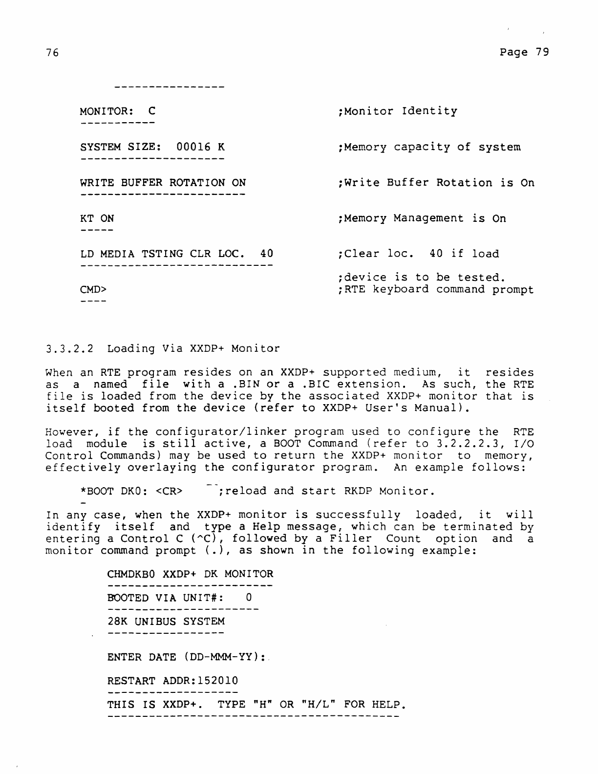
76
Page
79
MONITOR:
C
:Monitor
Identity
SYSTEM
SIZE:
00016
K
WRITE
BUFFER
ROTATION
ON
:Write
Buffer
Rotation
is
On
KT
ON
:Memory
Management
is
On
LD
MEDIA
TSTING
CLR
LOC.
40
:Clear
loc.
40
if
load
;device
is
to
be
tested.
CMD>
;RTE
keyboard
command
prompt
3.3.2.2
Loading
Via
XXDP+
Monitor
When
an
RTE
program
resides
on
an
XXDP+
supported
medium,
it
resides
as
a named
file
with
a
.BIN
or
a
.BIC
extension.
As
such,
the
RTE
file
is
loaded
from
the
device
by
the
associated
XXDP+
monitor
that
is
itself
booted
from
the
device
(refer
to
XXDP+
User's
Manual).
However,
if
the
configurator/linker
program
used
to
configure
the
RTE
load
module
is
still
active,
a
BOOT
Command
(refer
to
3.2.2.2.3,
I/O
Control
Commands)
may
be
used
to
return
the
XXDP+
monitor
to
memory,
effectively
overlaying
the
configurator
program.
An
example
follows:
*BOOT
DKO:
<CR>
;reload
and
start
RKDP
Monitor.
In
any
case,
when
the
XXDP+
monitor
is
successfully
loaded,
it
will
identify
itself
and
type
a
Help
message.
which
can
be
terminated
by
entering
a
Control
C
(AC),
followed
by
a
Filler
Count
option
and
a
monitor
command
prompt
(.),
as
shown
in
the
following
example:
CHMDKBO
XXDP+
DK
MONITOR
BOOTED
VIA
UNIT#: 0
28K
UNIBUS
SYSTEM
ENTER
DATE
(DD-MMM-YY):,
RESTART
ADDR:152010
THIS
IS
XXDP+.
TYPE
"H"
OR
"H/L"
FOR
HELP.
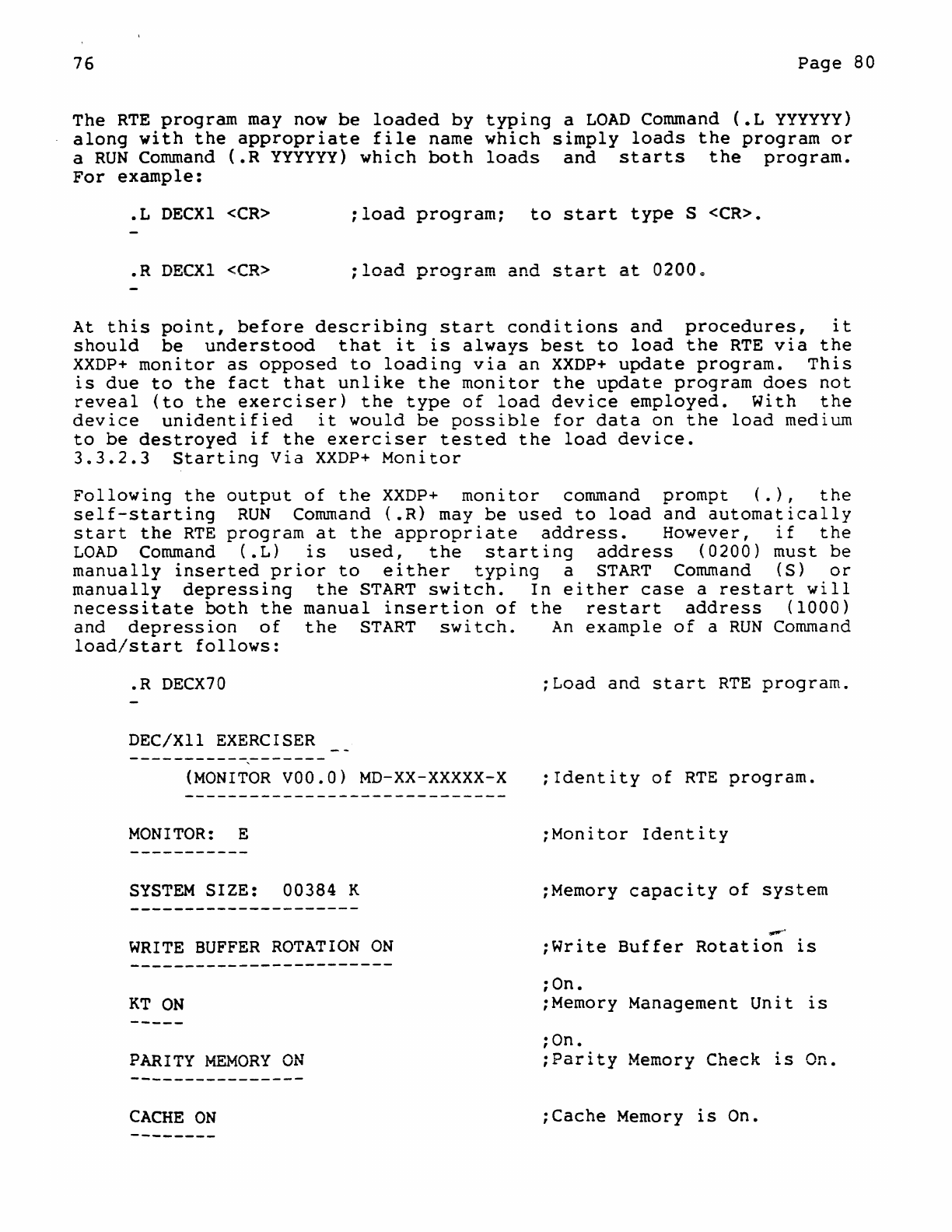
76
Page
80
The
RTE
program
may now
be
loaded
by
typing
a
LOAD
Command
(.L
yyyyyy)
along
with
the
appropriate
file
name
which
simply
loads
the
program
or
a
RUN
Command
(.R
yyyyyy)
which
both
loads
and
starts
the
program.
For
example:
• L
DECXl
<CR>
;load
program;
to
start
type
S
<CR>
•
.R
DECXl
<CR>
;load
program
and
start
at
0200=
At
this
point,
before
describing
start
conditions
and
procedures,
it
should
be
understood
that
it
is
always
best
to
load
the
RTE
via
the
XXDP+
monitor
as
opposed
to
loading
via
an
XXDP+
update
program.
This
is
due
to
the
fact
that
unlike
the
monitor
the
update
program
does
not
reveal
(to
the
exerciser)
the
type
of
load
device
employed.
With
the
device
unidentified
it
would
be
possible
for
data
on
the
load
medium
to
be
destroyed
if
the
exerciser
tested
the
load
device.
3.3.2.3
Starting
Via
XXDP+
Monitor
Following
the
output
of
the
XXDP+
monitor
command
prompt
(.),
the
self-starting
RUN
Command
(.R)
may
be
used
to
load
and
automatically
start
the
RTE
program
at
the
appropriate
address.
However,
if
the
LOAD
Command
(.L)
is
used,
the
starting
address
(0200)
must
be
manually
inserted
prior
to
either
typIng
a
START
Command
(S>
or
manually
depressing
the
START
switch.
In
either
case
a
restart
will
necessitate
both
the
manual
insertion
of
the
restart
address
(1000)
and
depression
of
the
START
switch.
An
example
of
a
RUN
Command
load/start
follows:
. R
DECX70
;Load
and
start
RTE
program
.
DEC/XII
EXERCISER
(MONITOR
VOO.O)
MD-XX-XXXXX-X
;Identity
of
RTE
program.
MONITOR:
E
;Monitor
Identity
SYSTEM
SIZE:
00384 K ;Memory
capacity
of
system
"*"'"'
WRITE
BUFFER
ROTATION
ON
;Write
Buffer
Rotation
is
;On.
KT
ON
;Memory Management
Unit
is
;On.
PARITY
MEMORY
ON
;Parity
Memory Check
is
CACHE
ON
;Cache
Memory
is
On.
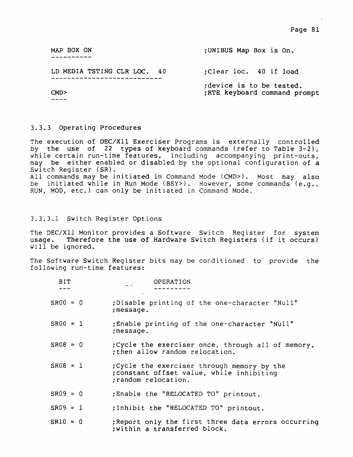
Page
81
MAP
BOX
ON
:UNIBUS
Map
Box
is
On.
LD
MEDIA
TSTING
CLR
LOC.
40
;Clear
loc.
40
if
load
CMD>
;device
is
to
be
testede
;RTE
keyboard
command
prompt
3.3.3
Operating
Procedures
The
execution
of
DEC/XII
Exerciser
Programs
is
externally
controlled
by
the
use
of
22
types
of
keyboard
commands
(refer
to
Table
3-2),
while
certain
run-time
features,
including
accompanying
print-outs,
may
be
either
enabled
or
disabled
by
the
optional
configuration
of
a
Switch
Register
(SR).
All
commands
may
be
initiated
in
Command
Mode
(CMD».
Most may
also
be
initiated
while
in
Run Mode
(BSY».
However,
some commands
(e.g.,
RUN,
MOD,
etc.)
can
only
be
initiated
in
Command Mode.
3.3.3.1
Switch
Register
Options
The DEC/XII
Monitor
provides
a
Software
Switch
Register
for
system
usage.
Therefore
the
use
of
Hardware
Switch
Registers
(if
it
occurs)
will
be
ignored.
The
Software
Switch
Register
bits
may
be
co~ditioned
to
provide
the
following
run-time
features:
BIT
SROO
= 0
SROO
= 1
SRoa = 0
SRoa = 1
SR09 = 0
SR09 = 1
SRIO
= 0
OPERATION
:Disable
printing
of
the
one-character
"Null"
;message.
;Enable
printing
of
the
one-character
"Null"
;message.
;Cycle
the
exerciser
once,
through
all
of
memory,
;then
allow
random
relocation.
:Cycle
the
exerciser
through
memory
by
the
;constant
offset
value,
while
inhibiting
:random
relocation.
;Enable
the
"RELOCATED
TO"
printout.
;Inhihit
the
"RELOCATED
TO"
printout.
;Report
only
the
first
three
data
errors
occurring
:within
a
transferred
block.
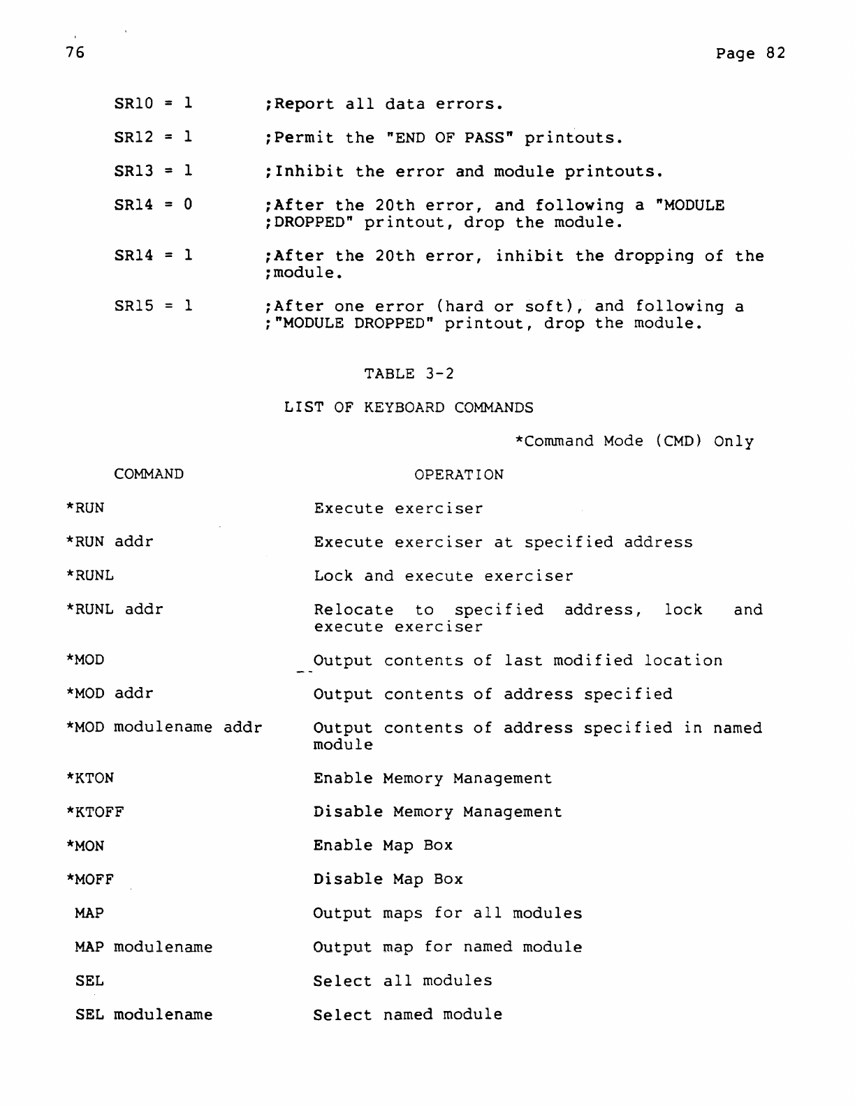
76
SRIO = 1
SR12
= 1
SR13
= 1
SR14
= 0
SR14
= 1
SR15
= 1
COMMAND
*RUN
*RUN
addr
*RUNL
*RUNL
addr
*MOD
*MOD
addr
*MOD
modulename
*KTON
*KTOFF
*MON
*MOFF
MAP
MAP
modulename
SEL
SEL
modulename
addr
Page
82
;Report
all
data
errors.
:Permit
the
"END
OF
PASS"
printouts.
:Inhibit
the
error
and
module
printouts.
;After
the
20th
error,
and
following
a
"MODULE
:DROPPED"
printout,
drop
the
module.
:After
the
20th
error,
inhibit
the
dropping
of
the
:module.
;After
one
error
(hard
or
soft),
and
following
a
;
"MODULE
DROPPED"
printout,
drop
the
module.
TABLE
3-2
LIST
OF
KEYBOARD
COMMANDS
*Command
Mode
(CMD)
Only
OPERATION
Execute
exerciser
Execute
exerciser
at
specified
address
Lock
and
execute
exerciser
Relocate
to
specified
address,
lock
and
execute
exerciser
Output
contents
of
last
modified
location
Output
contents
of
address
specified
Output
contents
of
address
specified
in
named
module
Enable
Memory Management
Disable
Memory Management
Enable
Map
Box
Disable
Map
Box
Output
maps
for
all
modules
Output
map
for
named
module
Select
all
modules
Select
named
module
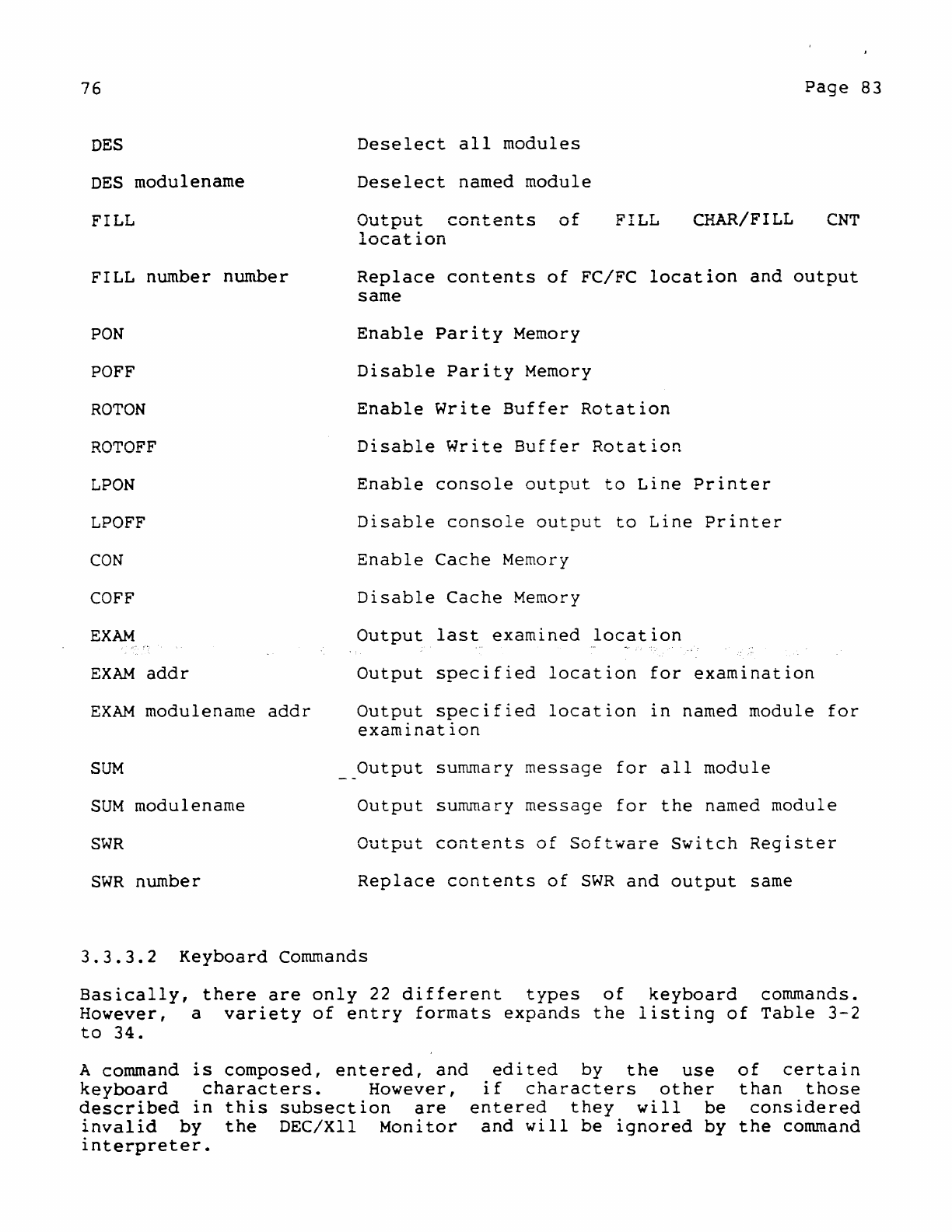
76
DES
DES
modulename
FILL
Deselect
all
modules
Deselect
named
module
Output
contents
of
location
Page
83
FILL CHAR/FILL
CNT
FILL number
number
Replace
contents
of
FC/FC
location
and
output
same
PON
Enable
Parity
Memory
POFF
Disable
Parity
Memory
ROTON
Enable
Write
Buffer
Rotation
ROTOFF
Disable
Write
Buffer
Rotation
LPON
Enable
console
output
to
Line
Printer
LPOFF
Disable
console
output
to
Line
Printer
CON
Enable
Cache
Memory
COFF
Disable
Cache
Memory
EXAM
Output
last
examined
location
EXAM
addr
Output
specified
location
for
examination
EXAM
rnodulename
addr
Output
specified
location
in
named
module
for
examination
SUM
__
Output
summary
message
for
all
module
SUM
modulenarne
Output
summary
message
for
the
named
module
SWR
Output
contents
of
Software
Switch
Register
SWR
number
Replace
contents
of
SWR
and
output
same
3.3.3.2
Keyboard
Commands
Basically,
there
are
only
22
different
types
of
keyboard
commands.
However,
a
variety
of
entry
formats
expands
the
listing
of
Table
3-2
to
34.
A command
is
composed,
entered,
and
keyboard
characters.
However,
described
in
this
subsection
are
invalid
by
the
DEC/XII
Monitor
interpreter.
edited
by
the
use
of
certain
if
characters
other
than
those
entered
they
will
be
considered
and
will
be
ignored
by
the
command
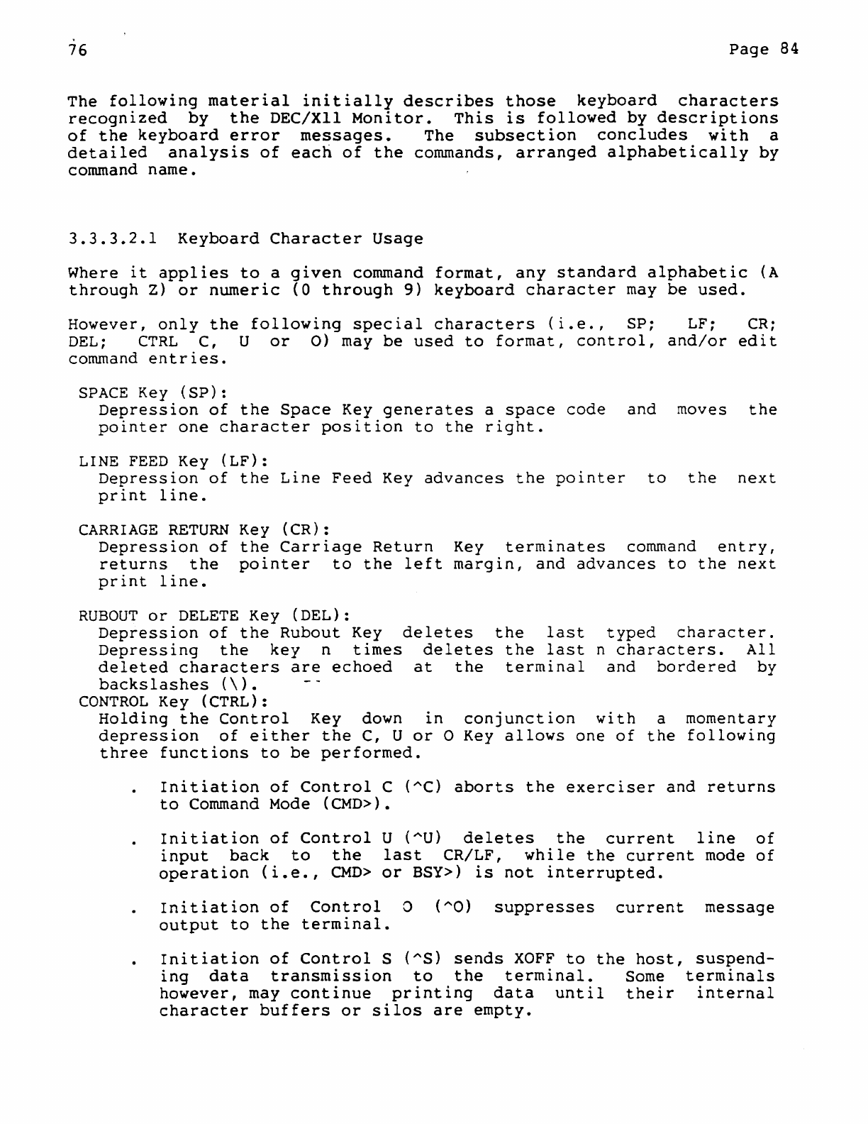
76
Page
84
The
following
material
initially
describes
those
keyboard
characters
recognized
by
the
DEC/XII
Monitor.
This
is
followed
by
descriptions
of
the
keyboard
error
messages.
The
subsection
concludes
with
a
detailed
analysis
of
each
of
the
commands,
arranged
alphabetically
by
command
name.
3.3.3.2.1
Keyboard
Character
Usage
Where
it
applies
to
a
given
command
format,
any
standard
alphabetic
(A
through
Z)
or
numeric
(0
through
9)
keyboard
character
may
be
used.
However,
only
the
following
special
characters
(i.e.,
SP;
LF;
CR;
DEL;
CTRL
C, U
or
0)
may
be
used
to
format,
control,
and/or
edit
command
entries.
SPACE
Key
(SP):
Depression
of
the
Space
Key
generates
a
space
code
and
moves
the
pointer
one
character
position
to
the
right.
LINE
FEED
Key
(LF):
Depression
of
the
Line
Feed
Key
advances
the
pointer
to
the
next
print
line.
CARRIAGE
RETURN
Key
(CR):
Depression
of
the
Carriage
Return
Key
terminates
command
entry,
returns
the
pointer
to
the
left
margin,
and
advances
to
the
next
print
line.
RUBOUT
or
DELETE
Key
(DEL):
Depression
of
the
Rubout
Key
deletes
the
last
typed
character.
Depressing
the
key
n
times
deletes
the
last
n
characters.
All
deleted
characters
are
echoed
at
the
terminal
and
bordered
by
backslashes
(\).
CONTROL
Key (CTRL):
Holding
the
Control
Key down
in
conjunction
with
a
momentary
depression
of
either
the
C, U
or
0 Key
allows
one
of
the
following
three
functions
to
be
performed.
Initiation
of
Control
C (AC)
aborts
the
exerciser
and
returns
to
Command Mode
(CMD».
Initiation
of
Control
U
(AU)
deletes
the
current
line
of
input
back
to
the
last
CR/LF,
while
the
current
mode
of
operation
(i.e.,
CMD>
or
BSY»
is
not
interrupted.
Initiation
of
Control
a
(AO)
suppresses
current
message
output
to
the
terminal.
Initiation
of
Control
S (AS)
sends
XOFF
to
the
host,
suspend-
ing
data
transmission
to
the
terminal.
Some
terminals
however,
may
continue
printing
data
until
their
internal
character
buffers
or
silos
are
empty.
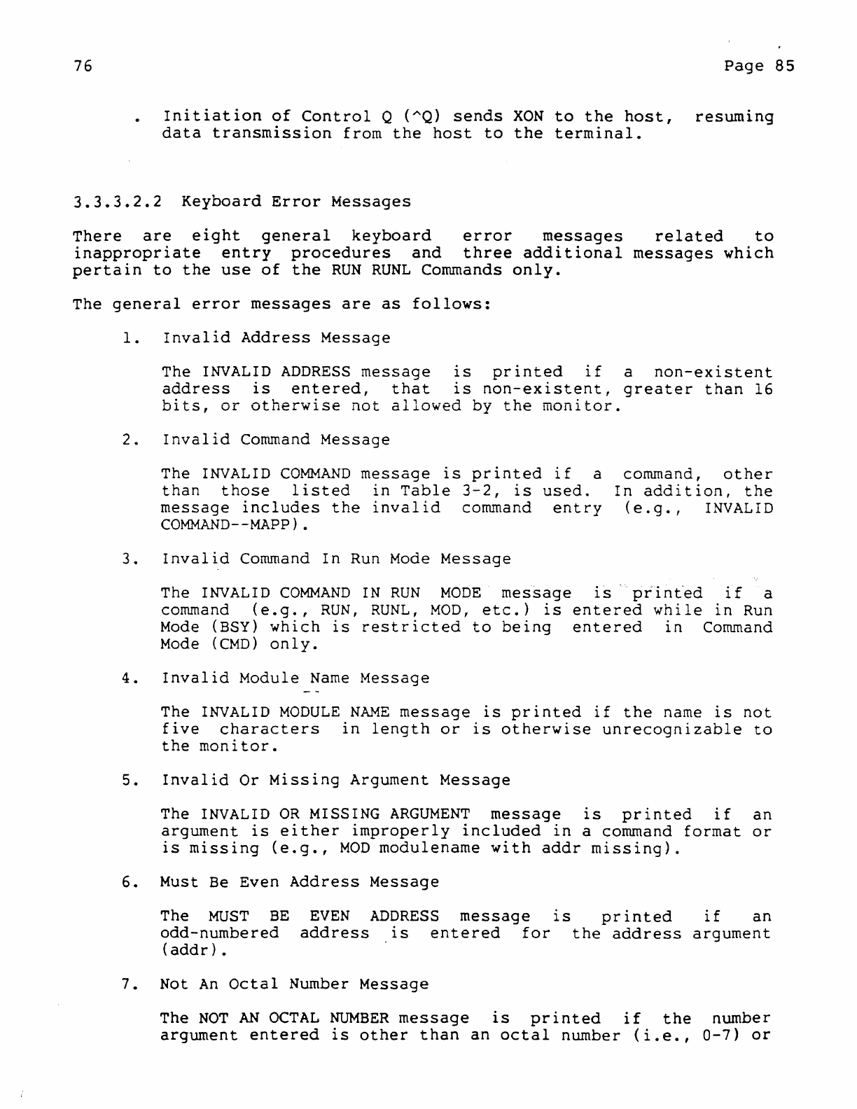
76
Page
85
Initiation
of
Control
Q
(AQ)
sends
XON
to
the
host,
resuming
data
transmission
from
the
host
to
the
terminal.
3.3.3.2.2
Keyboard
Error
Messages
There
are
eight
general
keyboard
error
messages
related
to
inappropriate
entry
procedures
and
three
additional
messages
which
pertain
to
the
use
of
the
RUN
RUNL
Commands
only.
The
general
error
messages
are
as
follows:
1.
Invalid
Address
Message
The
INVALID
ADDRESS
message
is
printed
if
a
non-existent
address
is
entered,
that
is
non-existent,
greater
than
16
bits,
or
otherwise
not
allowed
by
the
monitor.
2.
Invalid
Command
Message
The
INVALID
COMMAND
message
is
printed
if
a
than
those
listed
in
Table
3-2,
is
used.
message
includes
the
invalid
command
entry
COMMAND-
-
MAPP)
.
3.
Invalid
Command
In
Run Mode
Message
command,
other
In
addition,
the
( e . g • , I
NV
AL
I D
The
INVALID
COMMAND
IN
RUN
MODE
message
is
prinfed
if
a
command
(e.g.,
RUN,
RUNL,
MOD,
etc.)
is
entered
while
in
Run
Mode
(BSY)
which
is
restricted
to
being
entered
in
Command
Mode
(CMD)
only.
4.
Invalid
Module
Name
Message
The
INVALID
MODULE
NAME
message
is
printed
if
the
name
is
not
five
characters
in
length
or
is
otherwise
unrecognizable
to
the
monitor.
5.
Invalid
Or
Missing
Argument
Message
The
INVALID
OR
MISSING
ARGUMENT
message
is
printed
if
an
argument
is
either
improperly
included
in
a command
format
or
is
missing
(e.g.,
MOD
modulename
with
addr
missing).
6.
Must
Be
Even
Address
Message
The
MUST
BE
odd-numbered
(addr).
EVEN
ADDRESS
message
is
printed
if
an
address
is
entered
for
the
address
argument
7.
Not
An
Octal
Number
Message
The
NOT
AN
OCTAL
NUMBER
message
is
printed
if
the
number
argument
entered
is
other
than
an
octal
number
(i.e.,
0-7)
or
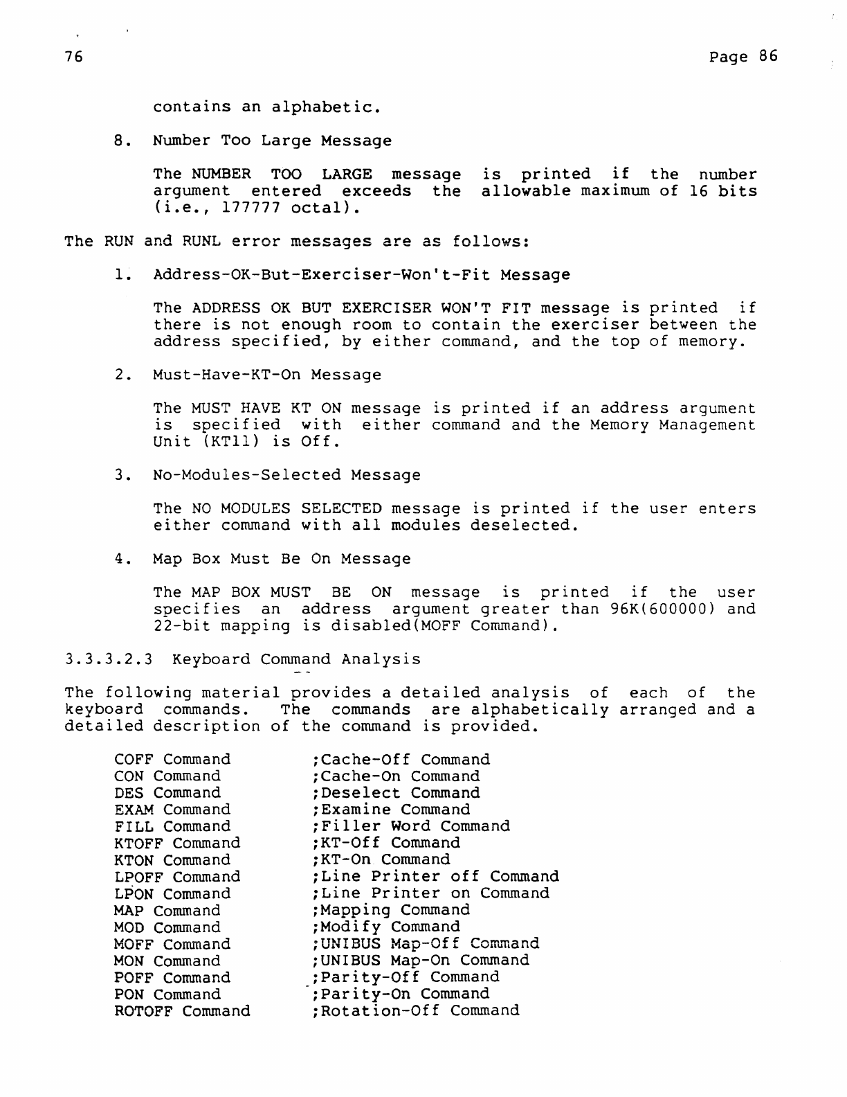
76
contains
an
alphabetic.
8.
Number Too
Large
Message
The
NUMBER
TOO
LARGE
message
argument
entered
exceeds
the
(i.e.,
177777
octal).
Page
86
is
printed
if
the
number
allowable
maximum
of
16
bits
The
RUN
and
RUNL
error
messages
are
as
follows:
1.
Address-OK-But-Exerciser-Won't-Fit
Message
The
ADDRESS
OK
BUT
EXERCISER
WON'T
FIT
message
is
printed
if
there
is
not
enough
room
to
contain
the
exerciser
between
the
address
specified,
by
either
command,
and
the
top
of
memory.
2.
Must-Have-KT-On
Message
The
MUST
HAVE
KT
ON
message
is
printed
if
an
address
argument
is
specified
with
either
command
and
the
Memory Management
Unit
(KTl1)
is
Off.
3.
No-Modules-Selected
Message
The
NO
MODULES
SELECTED
message
is
printed
if
the
user
enters
either
command
with
all
modules
deselected.
4.
Map
Box
Must
Be
On
Message
The
MAP
BOX
MUST
BE
ON
message
is
printed
if
the
user
specifies
an
address
argument
greater
than
96K(600000)
and
22-bit
mapping
is
disabled(MOFF
Command).
3.3.3.2.3
Keyboard
Command
Analysis
The
following
material
provides
a
detailed
analysis
of
each
of
the
keyboard
commands.
The
commands
are
alphabetically
arranged
and
a
detailed
description
of
the
command
is
provided.
COFF
Command
CON
Command
DES
Command
EXAM
Command
FILL
Command
KTOFF
Command
KTON
Command
LPOFF
Command
LPON
Command
MAP
Command
MOD
Command
MOFF
Corrunand
MON
Command
POFF
Command
PON
Command
ROTOFF
Command
;Cache-Off
Command
;Cache-On
Command
;Deselect
Command
;Exarnine
Command
;Filler
Word Command
;KT-Off
Command
;KT-On Command
;Line
Printer
off
Command
;Line
Printer
on
Command
;Mapping
Command
;Modify
Command
;UNIBUS
Map-Off
Co~~and
;UNIBUS Map-On Command
;Parity-Off
Command
;Parity-On
Command
;Rotation-Off
Command
76
RaTON
Command
RUN
Command
RUNL
Command
SEL
Command
SUM
Command
SWR
Command
!
COFF
Command
!
Function
;Rotation-On
Command
;Run
Mode
Command
;Run
Locked
Command
;Select
Command
;Surnmary
Command
;Switch
Register
Command
Page
87
The
Cache
Off
Command
(COFF)
is
used
to
disable
a
system's
Cache
Memory.
Format
COFF
;turn
off
cache
memory.
Characteristics
A
system's
Cache
Memory
is
automatically
enabled
when
an
exerciser
program
is
started.
However,
the
memory may
be
disabled
via
the
COFF
Command
and
re-enabled
by
executing
a
Cache
On
Command
(CON).
Associated
Messages
Refer
to
subsection
Example
.COFF<CR>
;disable
cache
memory.
76
Page
88
!
CON
Command
!
Function
The
Cache
On
Command
(CON)
is
used
to
re-enable
a
system's
Cache
Memory.
Format
CON
;turn
on
cache
memory.
Characteristics
A
system's
Cache
Memory
is
automatically
enabled
when
an
exerciser
program
is
started.
However,
the
memory
may
be
disabled
by
executing
a
Cache
Off
Command
(COFF)
and
re-enabled
via
the
CON
Command.
Associated
Messages
Refer
to
subsection
Example
.CON<CR>
;re-enable
cache
memory.
76
Page
89
!
DES
Command !
Function
The
Deselect
Command (DES)
allows
all
modules
or
a
single
specified
module
to
be
deselected.
Format
General:
DES
[modulename]
1.
DES
Deselect
all
modules.
2.
DES
modulename
Deselect
the
specified
(modulename)
module.
Characteristics
When
the
exerciser
is
initially
loaded,
all
modules
are
automatically
selected
for
execution;
this
is
the
default
condition.
However,
if
the
user
desires
to
run
a
single
module,
the
remaining
modules
must
be
deselected;
and
if
the
user
desires
to
run
all
modules
except
one,
the
exception
must
be
deselected.
Thus,
the
Deselect
Command (DES)
is
generally
used
in
conjunction
with
a
Select
Command
(SEL).
The
latter
allows
all
modules,
or
a
specified
module,
to
be
selected.
Example:
To
deselect
one
module:
SEL
DES
modulename
;select
all
modules
;deselect
named
module
Example:
To
deselect
all
but
one
module
DES
SEL
modulename
;deselect
all
modules
;select
named
module
Restrictions
The
modulename
argument
must
be
five
c~aracters
in
length.
Associated
Messages
Refer
to
subsection
Examples
76
Format
1:
.DES<CR>
Format
2:
.DES
DCAAO<CR>
Page
90
:deselect
all
modules
:deselect
Module
DCAAO
76
Page
91
!
EXAM
Command
!
Function
The
examine
Command
(EXAM)
is
used
to
output
the
contents
of
the
location
specified
by
either
the
last
EXAM
Command
or
the
current
command.
Format
General:
EXAM[[modulenarne]addr]
1.
EXAM
Output
the
contents
of
the
last
examined
location.
2.
EXAM
addr
Output
the
contents
of
the
location
specified
by
the
address
argument
(addr).
3.
EXAM
modulename
addr
Output
the
contents
of
the
location,
specified
by
a
relative
address
(addr)
within
the
named
module
(modulename).
Characteristics
The
EXAM
Command
makes
it
possible
to
examine
the
contents
of
a
location
while
the
system
is
operating
in
the
Run
Mode
(BSY».
When
Format
1
is
used,
the
contents
of
the
last
location
accessed
by
an
EXAM
Command
will
be
output.
When
Format
2
is
used,--the
address
argument
specifies
a
virtual
address.
When
Format
3
is
used,
the
address
argument
specifies
the
offset
value
for
a
word,
within
a named
module,
relative
to
the
virtual
base
address
of
the
module.
However,
the
Monitor
response
defines
the
word
address
relative
to
the
virtual
base
address
of
the
exerciser.
Restrictions
The
address
argument
has
a maximum
length
of
16
bits.
The modulename
argument
must
be
five
characters
in
length.
Associated
Messages
Refer
to
subsection
Examples
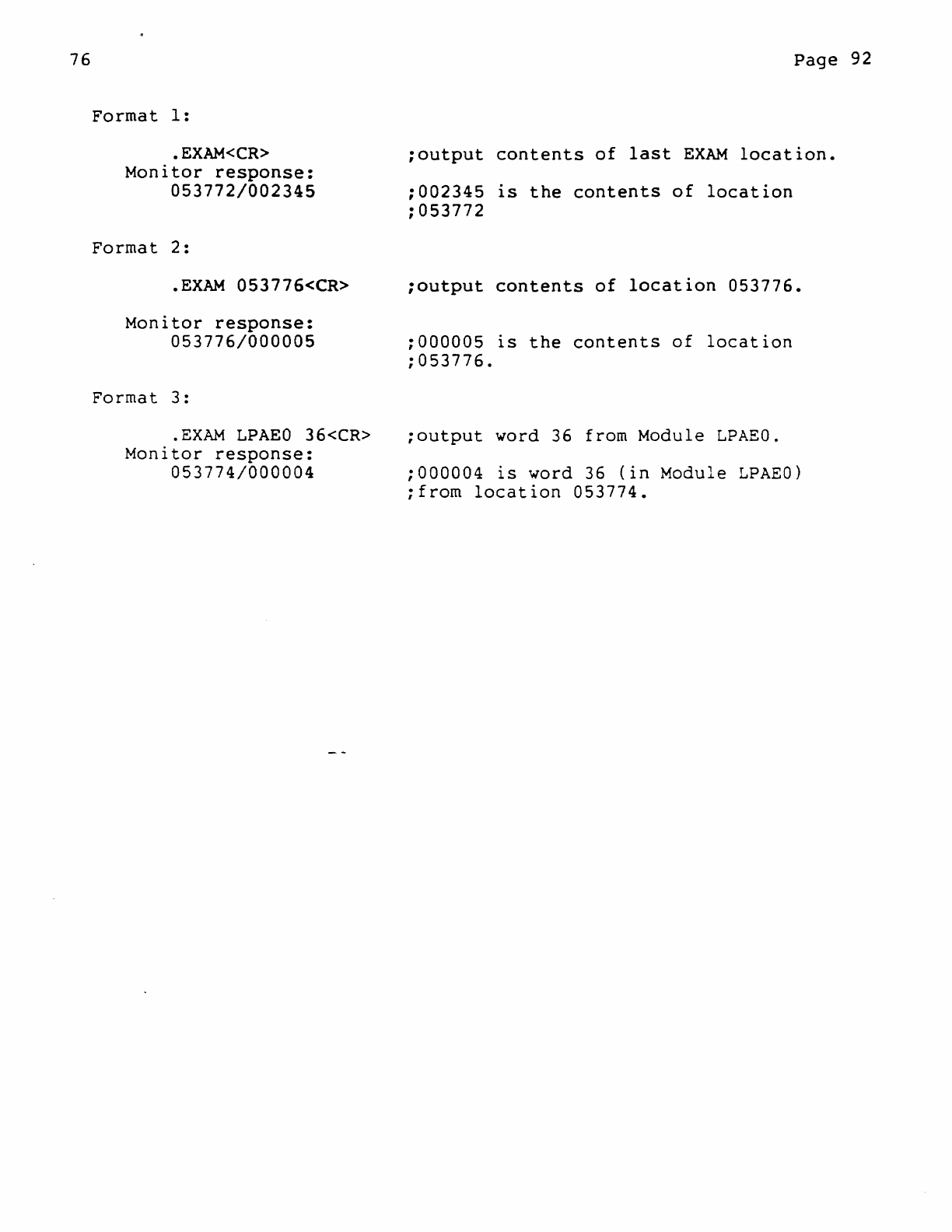
76
Format
1:
.
EXAM<CR>
Monitor
response:
053772/002345
Format
2:
•
EXAM
053776<CR>
Monitor
response:
053776/000005
Format
3:
.
EXAM
LPAEO
36<CR>
Monitor
response:
053774/000004
Page
92
;output
contents
of
last
EXAM
location
•
;002345
is
the
contents
of
location
;053772
;output
contents
of
location
053776
•
;000005
is
the
contents
of
location
;053776.
;output
word
36
from Module
LPAEO
.
;000004
is
word
36
(in
Module
LPAEO)
;from
location
053774.
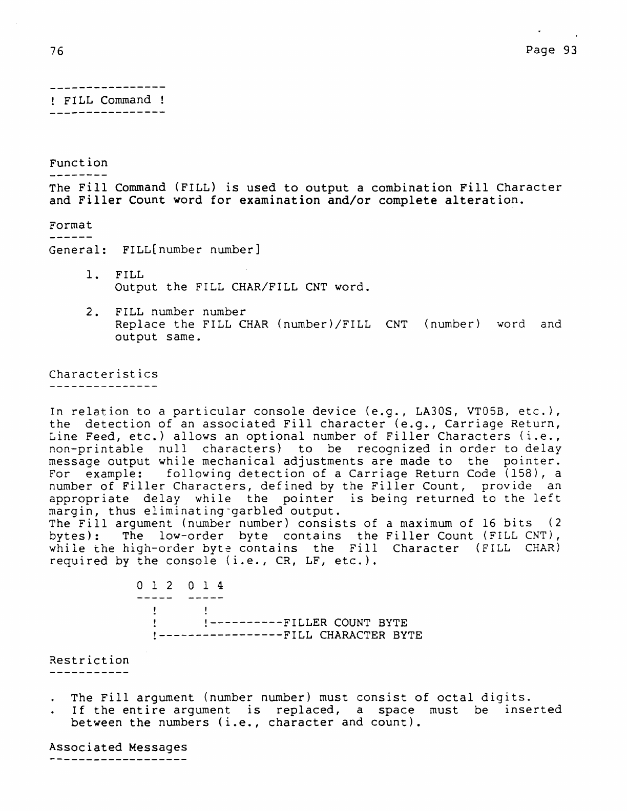
76
Page
93
! FILL
Command
!
Function
The
Fill
Command
(FILL)
is
used
to
output
a
combination
Fill
Character
and
Filler
Count
word
for
examination
and/or
complete
alteration.
Format
General:
FILL[number
number]
1.
FILL
Output
the
FILL CHAR/FILL
CNT
word.
2.
FILL number number
Replace
the
FILL
CHAR
(number)/FILL
CNT
(number)
word
and
output
same.
Characteristics
In
relation
to
a
particular
console
device
(e.g.,
LA30S, VT05B,
etc.),
the
detection
of
an
associated
Fill
character
(e.g.,
Carriage
Return,
Line
Feed,
etc.)
allows
an
optional
number
of
Filler
Characters
(i.e.,
non-printable
null
characters)
to
be
recognized
in
order
to
delay
message
output
while
mechanical
adjustments
are
made
to
the
pointer.
For
example:
following
detection
of
a
Carriage
Return
Code
(158),
a
number
of
Filler
Characters,
defined
by
the
Filler
Count,
provide
an
appropriate
delay
while
the
pointer
is
being
returned
to
the
left
margin,
thus
eliminating-garbled
output.
The
Fill
argument
(number
number)
consists
of
a maximum
of
16
bits
(2
bytes):
The
low-order
byte
contains
the
Filler
Count
(FILL CNT),
while
the
high-order
byt~
contains
the
Fill
Character
(FILL
CHAR)
required
by
the
console
(i.e.,
CR,
LF,
etc.).
Restriction
012
014
!----------FILLER
COUNT
BYTE
!-----------------FILL
CHARACTER
BYTE
The
Fill
argument
(number
number)
must
consist
of
octal
digits.
If
the
entire
argument
is
replaced,
a
space
must
be
inserted
between
the
numbers
(i.e.,
character
and
count).
Associated
Messages
76
Refer
to
subsection
Examples
Format
1:
• FILL<CR>
Monitor
response:
FILL/006401
Format
2:
.FILL
15 14<CR>
Monitor
response:
FILL/006414
Page
94
;output
current
Fill
Word •
;FILL
CHAR
is
CR
with
FILL
COUNT
of
One,
;right
justified
(0
000 110 100 000
;001).
;rep1ace
character
with
CR
and
;count
with
14,
output
same.
;replacement
right
justified.
76
Page
95
!
KTOFF
Command !
Function
The
Memory-Management-Off
Command
(KTOFF)
is
used
to
disable
the
Memory Management
Unit
(KT)
and
clear
its
status
indicator
(KTSTAT)0
Format
KTOFF
;Disable
the
Memory
Management
Unit
Characteristics
If
a Memory Management
Unit
(KT)
is
available
to
a
system,
the
unit
is
automatically
enabled
when a DEC/XII
Exerciser
Program
is
loaded
and
started.
The
KT
Status
(KTSTAT)
indicator
is
then
set
and
mapping
occurs
as
required.
The
user
now
has
the
option
in
Command
Mode
(CMD»
of
disabling
(KTOFF)
the
unit
or
re-enabling
(KTON)
the
unit,
as
the
case
may
be.
Restrictions
The
KTOFF
command
must
be
entered
in
Command
Mode
(CMD»
only.
Associated
Messages
Refer
to
subsection
Example
.
KTOFF<CR>
;Disable
KT
Unit
and
clear
KTSTAT
flag
.
76
Page
96
!
KTON
Command
!
Function
The
Memory-Management-On Command
(KTON)
is
used
to
re-enable
the
Memory Management
Unit
(KT).
Format
KTON
;Re-enable
the
Memory Management
Unit
Characteristics
If
a Memory Management
Unit
(KT)
is
available
to
a
system,
the
unit
is
automatically
enabled
when
the
DEC/XII
Exerciser
Program
is
loaded
and
started.
The
KT
Status
(KTSTAT)
indicator
is
then
set
and
mapping
occurs
as
required.
The
user
now
has
the
option
in
Command
Mode
(CMD»
of
disabling
(KTOFF)
the
unit
or
re-enabling
(KTON)
the
unit,
as
the
case
may
be.
Restriction
The
KTON
Command
must
be
entered
in
Command
Mode
(CMD»
only.
Associated
Messages
Refer
to
subsection
Example
.
KTON<CR>
;Re-enable
KT
Unit
and
setKTSTAT
flag
.
76
LPOFF
Function
The
Line
Printer
Off
Co~mand(LPOFF)
is
used
to
redirect
the
line
printer
back
to
the
console.
Format
LPOFF
;turn
off
line
printer
Characteristics
... , 1
Q.L.L
Page
97
output
for
When
the
LPOFF
Command
is
entered,
all
subsequent
output(i.e.,
prompts,
messages,
summaries
etc.)
and
operator
input(i.e.,
program
querIes
and
request
responses)
are
re-directed
from
the
line
printer
back
to
the
console.
Associated
Messages
Refer
to
subsection
Example
.LPOFF
<CR>
;disable
line
printer
76
Page
98
LPON
Command
!
Function
The
Line
Printer
On
command(LPON)
is
used
to
redirect
all
output
for
the
console
to
the
line
printer.
Format
LPON
;turn
on
line
printer
Characteristics
When
the
LPON
Command
is
entered,
all
subsequent
output
(i.e.,
prompts,
messages,
summaries,
etc.)
and
operator
input
(i.e.,
program
query
and
request
response)
are
re-directed
from
the
console(default
condition)
to
the
line
printer.
Thus
console
echoing
is
effectively
disabled.
Associated
Messages
Refer
to
subsection
Example
.LPON
<CR>
;enable
line
printer
76
Page
99
!
MAP
Command
!
Function
The Mapping
Command
(MAP)
is
used
to
output
a
message
from
the
monitor
concerning
the
identity
and
current
status
of
all
of
the
resident
modules,
or
single
specified
modulee
Format
General:
MAP
[modulenarne]
1.
MAP
Output
Map
message
information
for
all
modules.
2.
MAP
modulename
Output
Map
message
information
for
the
named
module.
Characteristics
Each
line
of
a
Map
message
1S
formatted
as
follows:
{modulenarne}
AT
VA:
(address)
STAT:
(status
word)
Modulename:
The
five-character
modulename
indicates
the
following:
Address:
R K A D a
!------Copy
Number
(0-7)
!--------Version
Letter
!-------------Identifier
Letters
The
virtual
address
defines
the
first
word
of
the
module
(i.e.,
word
zero
of
the
header).
Status
Word:
With
the
exception
of
bits
11,
13
and
14,
the
remaining
bits
of
the
16-bit
status
word
(00-15)
are
used
to
define
the
module
type
(i.,e.,
Input/Output,
Background,
etc.);
while
bits
11, 13,
and
14
are
used
to
define
the
current
status
of
the
module
(i.e.,
Active,
Dropped,
or
Selected),
as
follows:
Excepting
bits
11,
13
and
14:
all
bits
cleared
(000000)
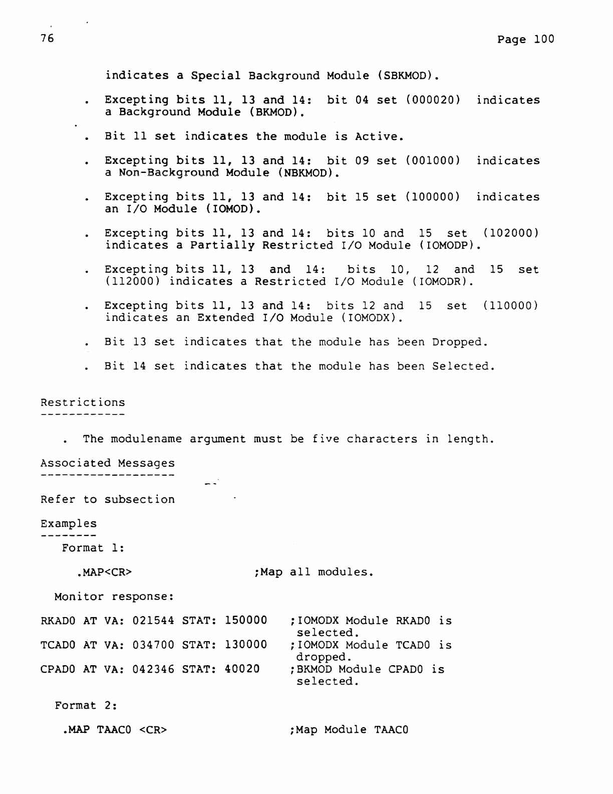
76
Page
100
indicates
a
Special
Background
Module
(SBKMOO).
Excepting
bits
11,
13
and
14:
bit
04
set
(000020)
indicates
a
Background
Module
(BKMOD).
Bit
11
set
indicates
the
module
is
Active.
Excepting
bits
11,
13
and
14:
bit
09
set
(001000)
indicates
a
Non-Background
Module
(NBKMOD).
Excepting
bits
11,
13
and
14:
bit
15
set
(100000)
indicates
an
I/O
Module
(IOMOD).
Excepting
bits
11,
13
and
14:
bits
10
and
15
set
(102000)
indicates
a
Partially
Restricted
I/O
Module (IOMODP).
Excepting
bits
11,
13
and
14:
bits
10,
12
and
15
set
(112000)
indicates
a
Restricted
I/O
Module
(IOMODR).
Excepting
bits
11,
13
and
14:
bits
12
and
15
set
(110000)
indicates
an
Extended
I/O
Module
(IOMODX).
Bit
13
set
indicates
that
the
module
has
been
Dropped.
Bit
14
set
indicates
that
the
module
has
been
Selected.
Restrictions
The modulename
argument
must
be
five
characters
in
length.
Associated
Messages
Refer
to
subsection
Examples
Format
1:
•
MAP<CR>
:Map
all
modules
•
Monitor
response:
RKADO
AT
VA:
021544
STAT:
150000
:
IOMODX
Module
RKADO
is
selected.
TCADO
AT
VA:
034700
STAT:
130000
:
IOMODX
Module
TCADO
is
dropped.
CPADO
AT
VA:
042346
STAT:
40020
:BKMOD
Module
CPADO
is
selected.
Format
2:
.MAP
TAACO
<CR>
:Map Module
TAACO

76
Monitor
response:
TAACO
AT
VA:
037460 STAT:
140000
:
IOMOD
Module
TAACO
is
selected.
Page
101
76
Page
102
!
MOD
Command
!
Function
The
Modifv
Command
(MOD)
is
used
to
examine
and/or
modify
the
contents
of
selected
storage
locations.
Format
General:
MOD
[[modulenarne]
addr]
1.
MOD
Output
the
contents
of
the
last
modified
location.
2.
MOD
addr
Output
the
contents
of
the
location
specified
by
the
absolute
address
argument
(addr).
3.
MOD
modulename
addr
Output
the
contents
of
the
location
module
name
and
its
associated
(modulename
addr).
Characteristics
specified
by
both
the
relative
address
argument
The
MOD
Command
makes
it-possible
to
open
and/or
modify
absolute
as
well
as
relative
addresses
(i.e.,
relative
to
the
starting
address
of
the
specified
module).
In
addition,
when a
relative
address
is
specified,
the
monitor
will
respond
by
printing
the
equivalent
absolute
address.
Restrictions
The
MOD
Command
must
be
entered
in
Command
Mode
(CMD»
only.
All
specified
addresses
must
be
less
than
32k
words
or
the
largest
available
address,
whichever
is
smaller.
All
specified
addresses
must
be
even.
Associated
Messages
Refer
to
subsection
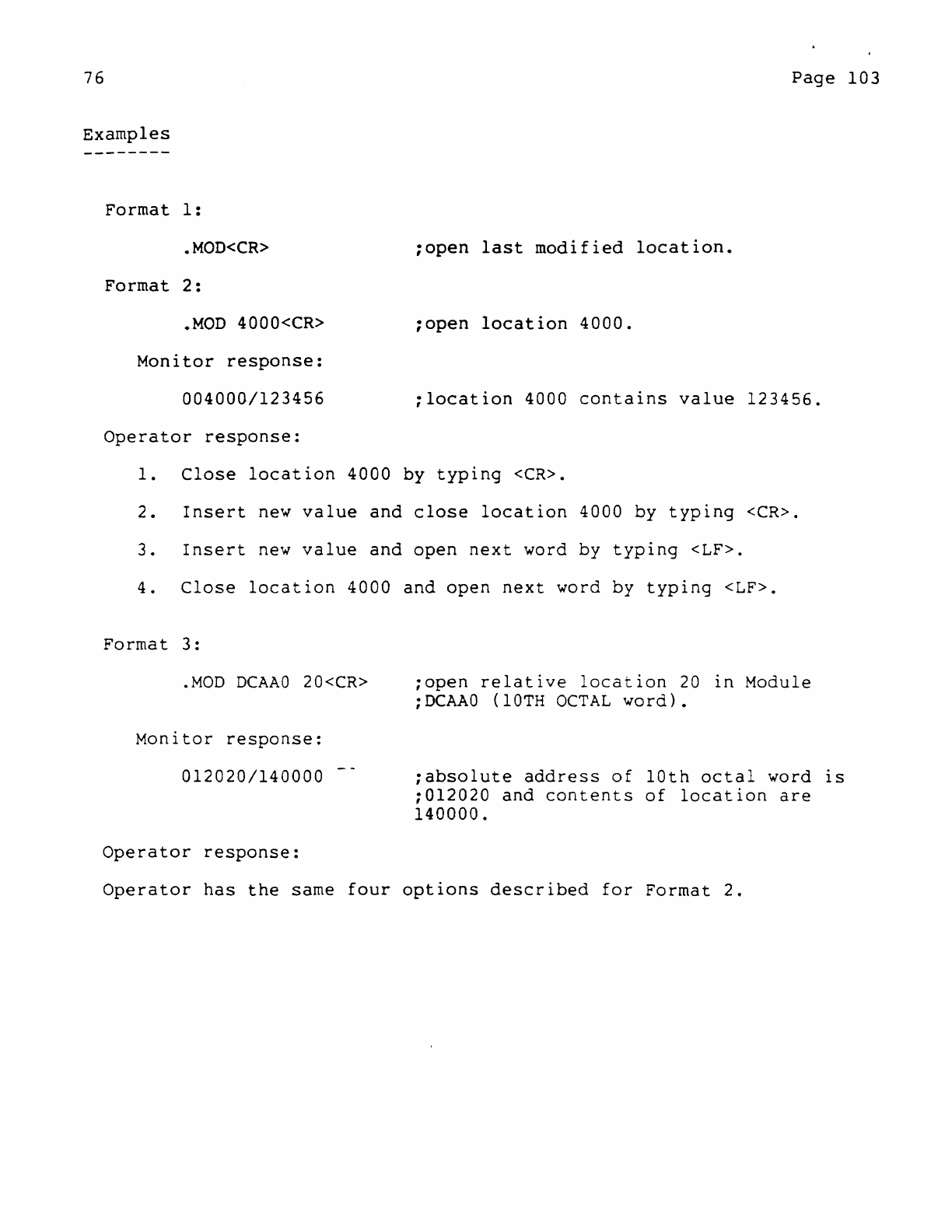
76
Page
103
Examples
Format
1:
•
MOD<CR>
;open
last
modified
location
•
Format
2:
•
MOD
4000<CR>
;open
location
4000 .
Monitor
response:
004000/123456
:location
4000
contains
value
123456.
Operator
response:
1.
Close
location
4000
by
typing
<CR>.
2.
Insert
new
value
and
close
location
4000
by
typing
<CR>.
3.
Insert
new
value
and
open
next
word by
typing
<LF>.
4.
Close
location
4000
and
open
next
word
by
typing
<LF>.
Format
3:
.MOD
DCAAO
20<CR>
Monitor
response:
012020/140000
Operator
response:
;open
relative
location
20
in
Module
;DCAAO
(10TH
OCTAL
word).
:absolute
address
of
10th
octal
word
IS
:012020
and
contents
of
location
are
140000.
Operator
has
the
same
four
options
described
for
Format
2.
76
Page
104
!
MOFF
Command
!
Function
The UNIBUS-Map-Off
Cow~and
(MOFF)
is
used
to
disable
a
system's
UNIBUS
mapping
logic.
Format
MOFF
;turn
off
the
UNIBUS
Map
Logic.
Characteristics
The
UNIBUS
mapping
hardware
is
automatically
enabled
when
the
exerciser
is
started.
The
logic
may
be
disabled
via
the
MOFF
Command
and
re-enabled
by
executing,
in
Command
Mode
(CMD»
only,
a
UNIBUS-Map-On
Command
(MON).
Restrictions
The
MOFF
Command
may
be
entered
in
Command
Mode
(CMD»
only.
Associated
Messages
Refer
to
subsection
Example
•
MOFF<CR>
;disable
the
UNIBUS
Map
Logic
.
76
Page
105
!
MON
Command
!
Function
The UNIBUS-Map-On
Command
(MON)
is
used
to
re-enable
the
system's
UNIBUS
mapping
logic.
Format
MON
;turn
on
UNIBUS
Map
Logic
Characteristics
The
UNIBUS
mapping
hardware
is
automatically
enabled
when
the
exerciser
is
initializede
The
logic
may
be
disabled
by
executing,
in
Command
Mode
(CMD»
only,
a UNIBUS-Map-Off
Command
(MOFF). The
logic
may
then
be
re-enabled
via
the
MON
Command.
Restrictions
The
MON
Command
may
be
entered
in
Command
Mode
(CMD»
only.
Associated
Messages
Refer
to
subsection
Example
•
MON
<CR>
;re-enable
the
UNIBUS
Map
Logic
.
76
Page
106
!
POFF
Command
!
Function
The
Parity-Off
Command
(POFF)
is
used
to
disable
the
system's
Parity
Check
Logic.
Format
POFF
;disable
parity
checking
logic.
Characteristics
The
parity
checking
hardware
is
automatically
enabled
when
the
execiser
program
is
initialized.
The
logic
may
be
disabled
via
the
POFF
Command
and
re-enabled
by
executing
a
Parity-On
command (PON).
Associated
Messages
Refer
to
subsection
Example
.
POFF
<CR>
~disable
parity
checking
logic
.
76
Page
107
!
PON
Command
!
The
Parity-On
Command
(PON)
is
used
to
re-enable
a
system's
Parity
Check
Logic.
The
logic
is
used
to
verify
the
integrity
of
data
transfered
from Main Memory
or
Cache
Memory.
Format
PON
;turn
on
parity
checking
logic
Characteristics
The
parity
checking
hardware
is
automatically
enabled
when
the
exerciser
program
is
initialized.
The
logic
may
be
disabled
by
executing
a
Parity-Off
Command
(POFF)
and
re-enabled
via
the
PON
Command.
Associated
Messages
Refer
to
subsection
Example
.PON
<CR>
;re-enable
parity
checking
logic
76
Page
108
!
ROTOFF
Command !
Function
The
Rotation-Off
Command (ROTOFF)
is
used
to
disable
Write
Buffer
Rotation.
Format
ROTOFF
:turn
off
Write
Buffer
Rotation.
Characteristics
Write
Buffer
Rotation
is
automatically
enabled
when
an
exerciser
program
is
initialized.
The
feature
may
be
disabled
via
a
ROTOFF
Command
and
re-enabled
by
executing
a
Rotation-On
Command
(ROTON).
Associated
Messages
Refer
to
subsection
Example
.
ROTOFF
<CR>
;disable
Write
Buffer
Rotation
.
76
Page
109
-----------------
!
ROTON
Command
!
Function
The
Rotation-On
Command
(ROTON)
is
used
to
re-enable
Write
Buffer
Rotation.
Format
ROTON
:turn
on
Write
Buffer
Rotation.
Characteristics
Write
Buffer
Rotation
is
automatically
enabled
when
an
exerciser
program
is
initialized.
The
feature
may
be
disabled
by
executing
a
Rotation
Off
Command
(ROTOFF)
and
re-enabled
via
a
ROTaN
Command.
Associated
Messages
Refer
to
subsection
Example
.
ROTON
<CR>
;re-enable
Write
Buffer
Rotation
.
76
Page
110
!
RUN
command !
Function
The
Run
Co~~and
(Run)
is
used
to
initiate
the
Run
Mode
(BSY»
and
start
the
option
modules.
Only
those
modules
selected
for
execution
will
be
run.
The
Run
Command
is
identical
to
the
RUNL
Command
with
one
exception:
The
RUN
Command
allows
the
periodic
relocation
of
the
exerciser
program*
if
an
adequate
amount
of
core
is
available
for
relocation
and
a Memory Management
Unit
(KT)
is
available
and
enabled.
Format
General:
RUN
[addr]
1.
RUN
Initiate
Run
Mode
(BSY»
and
execute
option
modules.
2.
RUN
addr
Initiate
Run
Mode
(BSY»
and,
following
an
initial
relocation
to
the
address
specified,
execute
the
option
modules.
Characteristics
Module
Execution
Sequence:
When
a
RUN
Command
is
entered,
Run
Mode
(BSY»
is
initiated
and
the
Selected
modules
are
executed
as
follows:
First,
single
passes
are
separately
made
through
the
Special
Background
Modules
(SBKMOD).
Second,
passes
are
separately
made
through
the
Non-Back-ground
Modules
(NBKMOD).
Third,
the
Background
Modules
(BKMOD)
will
execute
a I
iteration
pass.
Fourth,
the
interrupt-driven
I/O
Modules
(IOMOD,X,P,
AND
R)
are
enabled.
Finally,
single
passes
are
separately
made
through
the
Background
Modules
(BKMOD).
Write
nuffer
Rotation:
Write
Buffer
Rotation
will
occur
if
the
rotation
is
initially
enabled
by
default,
Command,
and
re-enabled
by
a
ROTON
Command.
Initial
Program
Relocation:
operation
disabled
is
enabled:
via
a
ROTOFF
As
stated,
if
both
adequate
core
and
a
KT
Unit
are
avilable
and
the
KT
76
Page
III
is
enabled
(i.e.,
by
default
or
a
KTON
Command),
the
movable*
portion
of
the
exerciser
program
will
be
periodically
relocated;
however,
an
initial
relocation
address
may
be
specified
by
the
user
(Format
2).
If
an
initial
relocation
address
is
specified
by
the
user,
care
must
be
taken
to
ensure
that
the
address
chosen
satisfies
the
memory
requirements
of
the
movable
portion
of
the
execiser
in
relation
to
the
availability
of
usable
core.
With
this
assurance,
initial
relocation
to
the
nearest
32-word
boundary
of
the
address
will
occur
prior
to
the
execution
of
the
modules.
Aborting
The
Exerciser:
Once
started,
the
option
modules
will
continue
to
run
until
aborted
by
one
or
more
of
the
following
occurrences
(at
which
a SUM Command may
be
used
to
provide
a
run-time
summary
of
module
activity):
A
Control
C (AC)
ii
entered:
causing
the
Monitor
to
cease
execution
of
the
option
modules,
return
the
program
to
its
original
memory
space
(if
necessary)
and
return
the
system
to
Command
Mode
(CMD».
All
modules
are
dropped
due
to
module
errors:
causing
the
Monitor
to
return
the
program
to
its
original
memory
space
(if
necessary)
and
return
the
system
to
Command
Mode
(CMD».
The
occurrence
of
a
fatal
error
(e.g.,
too
many
system
errors
occur):
causing
the
Monitor
to
cease
execution
of
the
option
modules,
return
the
program
to
its
original
memory
space
(if
necessary),
and
return
the
system
to
Command Mode
(CMD».
Restrictions
The
RUN
Command
mustJ5e
entered
1n
Command
Mode
(CMD».
The
address
argument
(addr)
has
a minimum
restriction
of
octal
20,000*
the
address
argument
(addr)
must
satisfy
both
the
core
requirements
of
the
exerciser
and
the
core
availability
of
the
system.
Associated
Messages
Refer
to
subsection
Examples
*A
portion
of
the
execiser
program
always
resides
in
the
lowest
4K
words
of
memory,
within
a
range
of
0-17776(8),
and
is
never
relocated.
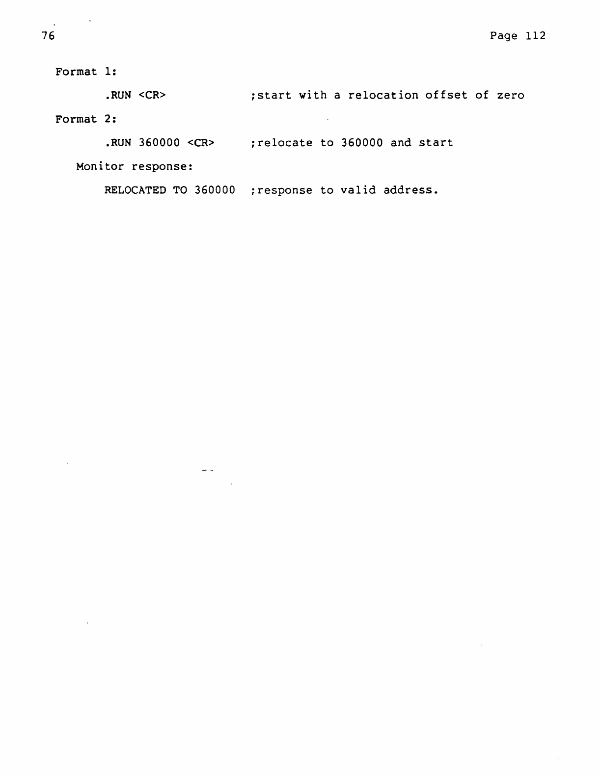
76
Format
1:
.RUN
<CR>
Format
2:
.RUN
360000
<CR>
Monitor
response:
Page
112
;start
with
a
relocation
offset
of
zero
;re1ocate
to
360000
and
start
RELOCATED
TO
360000
~response
to
valid
address.
76
Page
113
!
RUNL
Command
!
Function
The Run-Locked
Command
(RUNL)
is
used
to
initiate
the
Run Mode
(BSY»
and
start
the
option
modules.
Only
those
modules
selected
for
execution
will
be
run.
The
RUNL
Command
is
identical
to
the
RUN
Command
with
one
exception:
The
RUNL
Command
inhibits
periodic
relocation
of
the
movable*
portion
of
the
execiser
program
by
locking
in
the
load
address
or
the
initial
relocation
address
that
may
be
defined
by
the
user.
Format
General:
RUNL
[addr]
1.
RUNL
Initiate
Run
Mode
(BSY»,
lock,
and
start
option
modules.
2.
RUNL
addr
Initiate
Run
Mode
(BSY»,
relocate
to
user
specified
address
(addr),
lock
and
start
option
modules.
Characteristics
Module
Execution
Sequen~~:
When
a
RUNL
Command
is
entered,
Run
Mode
(BSY»
is
initiated,
and
the
Selected
modules
are
executed
as
follows:
First,
single
passes
are
separately
made
through
the
Special
Background
Modules
(SBKMOO);
second,
single
passes
are
separately
made
through
the
Non-Background
Modules
(NBKMOD);
third,
the
Background
modules
(BKMOn)
will
execute
a 1
iteration
pass;
fourth,
the
interrupt-driven
I/O
Modules
(IOMOD,X,P and
R)
are
enabled:
finally,
single
passes
are
separately
made
through
the
Background
Modules
(BKMOO).
Write
Buffer
Rotation:
Write
Buffer
Rotation
will
occur,
for
initial
relocation,
if
the
operation
is
enabled.
Rotation
is
initially
enabled
by
default,
disabled
via
a
ROTOFF
Command,
and
re-enabled
by a
ROTaN
Command.
Initial
Program
Relocation:
If
both
adequate
core
and
a
KT
Unit
are
available,
and
the
KT
is
enabled
<i.e.,
by
default
or
a
KTON
Command),
the
movable
portion
of
76
Page
114
the
exerciser
program
can
be
initially
relocated
to
an
address
specified
by
the
user
(Format
2);
whereupon
the
address
will
be
locked
and
no
further
relocation
will
occur.
If
an
initial
relocation
address
is
specified
by
the
user,
care
must
be
taken
to
ensure
that
the
address
chosen
satisfies
the
memory
requirements
of
the
movable
portion
of
the
execiser
in
relation
to
the
availability
of
usable
core;
with
this
assurance,
initial
relocation
to
the
nearest
32-word
boundary
of
the
address
will
be
made,
the
address
will
be
locked,
and
execution
of
the
modules
will
occur~
Aborting
the
Exerciser:
Once
started,
the
option
modules
will
continue
to
run
until
aborted
by
one
or
more
of
the
following
occurrences
(at
which
time
a
SUM
Command
may
be
used
to
provide
a
run-time
summary
of
module
activity):
A
Control
C
(AC)
is
entered:
causing
the
Monitor
to
cease
execution
of
the
option
modules,
return
the
program
to
its
original
memory
space
(if
necessary),
and
return
the
system
to
Command
Mode
(CMD».
All
modules
are
dropped
due
to
module
errors:
causing
the
Monitor
to
return
the
program
to
its
original
memory
space
(if
necessary),
and
return
the
system
to
Command
Mode(CMD».
The
occurrence
of
a
fatal
error
(e.g.,
too
many
system
errors):
causing
the
Monitor
to
cease
execution
of
the
option
modules,
return
the
program
to
its
original
memory
space
(if
necessary),
and
return
the
system
to
Command
Mode
(CMD».
Restrictions
The
RUNL
Command
must-be
entered
in
Command
Mode
(CMD».
The
address
argument
(addr)
has
a minimum
restriction
of
octal
20,000*.
The
address
argument
(addr)
must
satisfy
both
the
core
requirements
of
the
exerciser
and
the
core
availability
of
the
system.
Associated
Messages
Refer
to
subsection
Examples
*A
portion
of
the
exerciser
program
always
resides
in
the
lowest
4K
words
of
memory,
within
a
range
of
0-17776(8),
and
is
never
relocated.
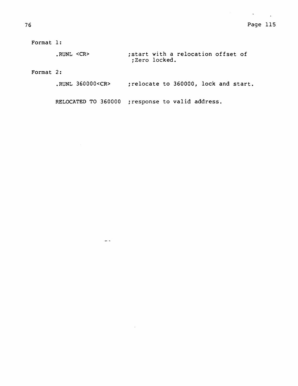
76
Format
1:
.RUNL
<CR>
Format
2:
;start
with
a
relocation
offset
of
;Zero
locked.
Page
115
.RUNL
360000<CR>
;relocate
to
360000,
lock
and
start.
RELOCATED
TO
360000
;response
to
valid
address.
76
Page
116
!
SEL
Command
!
Function
The
Select
Command
(SEL)
allows
all
modules,
or
a
single
specified
module,
to
be
selected
for
execution.
Format
General:
SEL
[modulename]
1.
SEL
Select
all
modules
for
execution.
2.
SEL
modulename
Select
the
specified
(modulename)
module
for
execution.
Characteristics
When
the
exerciser
is
initially
loaded,
all
modules
are
automatically
selected
for
execution;
this
is
the
default
condition.
However,
if
the
user
desires
to
run
a
single
module,
the
remaining
modules
must
be
deselected
and,
if
the
user
desires
to
run
all
modules
except
one,
the
exception
must
be
deselected.
Thus,
the
Select
Command
(SEL)
is
generally
used
in
conjunction
with
a
Deselect
Command
(DES). The
latter
allows
all
modules,
or
a
specified
module,
to
be
deselected.
Example:
To
select
one
module:
DES
;deselect
all
modules
SEL
modulename
;select
named
module
Example:
To
select
all
but
one
module.
SEL
;select
all
modules
DES
modulename
;deselect
named
module
Restrictions
The modulename
argument
must
be
five
characters
in
length.
Associated
Messages
76
Page
117
Examples
Format
1:
.SEL<CR>
;select
all
modules
Format
2:
.SEL
DCAAO<CR>
;select
Module
DCAAO
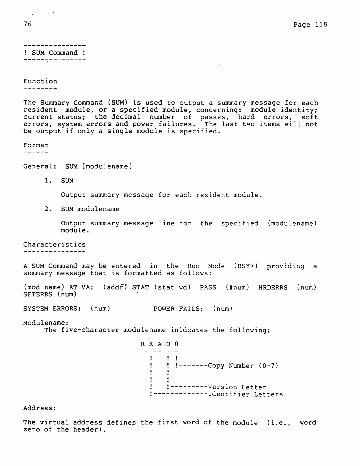
76
Page
118
!
SUM
Command !
Function
The
Summary
Corr~and
(SUM)
is
used
to
output
a summary
message
for
each
resident
module,
or
a
specified
module,
concerning:
module
identity;
current
status;
the
decimal
number
of
passes,
hard
errors,
soft
errors,
system
errors
and
power
failures.
The
last
two
items
will
not
be
output
if
only
a
single
module
is
specified.
Format
General:
SUM
[modulename]
1.
SUM
Output
summary
message
for
each
resident
module.
2.
SUM
modulename
Output
summary
message
line
for
the
specified
(modulename)
module.
Characteristics
A
SUM
Command
may
be
entered
in
the
Run
Mode
(BSY»
providing
a
summary
message
that
is
formatted
as
follows:
(mod name)
AT
VA:
(addrJ
STAT
(stat
wd)
PASS
(#num)
HRDERRS
(num)
SFTERRS
(nurn)
SYSTEM
ERRORS:
(num)
POWER
FAILS: (num)
Modulename:
The
five-character
modulename
inidcates
the
following:
Address:
R K
ADO
!-------Copy
Number
<0-7)
!
!---------Version
Letter
!-------------Identifier
Letters
The
virtual
address
defines
the
first
word
of
the
module
(i.e.,
word
zero
of
the
header).
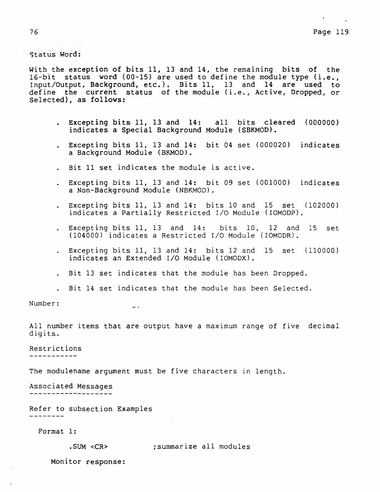
76
Page
119
~tatus
Word:
with
the
exception
of
bits
11,
13
and
14,
the
remaInlng
bits
of
the
16-bit
status
word
(00-15)
are
used
to
define
the
module
type
(i.e.,
Input/Output,
Background,
etc.).
Bits
11,
13
and
14
are
used
to
define
the
current
status
of
the
module
(i.e.,
Active,
Dropped,
or
Selected),
as
follows:
Number:
Exceotinq
bits
11,
13
and
14:
all
bits
cleared
(OOOOOO)
indicates
a
Special
Background
Module
(SBKMOn).
Excepting
bits
11,
13
and
14:
bit
04
set
(000020)
indicates
a
Background
Module
(BKMOD).
Bit
11
set
indicates
the
module
is
active.
Excepting
bits
11,
13
and
14:
bit
09
set
(001000)
indicates
a
Non-Background
Module
(NBKMOD).
Excepting
bits
11,
13
and
14:
bits
10
and
15
set
(102000)
indicates
a
Partially
Restricted
I/O
Module
(IOMODP).
Excepting
bits
11,
13
and
14:
bits
10,
12
and
15
set
(104000)
indicates
a
Restricted
I/O
Module
(IOMODR).
Excepting
bits
II,
13
and
14:
bits
12
and
15
set
(110000)
indicates
an
Extended
I/O
Module
(IOMODX).
Bit
13
set
indicates
that
the
module
has
been
Dropped.
Bit
14
set
indicates
that
the
module
has
been
Selected.
All
number
items
that
are
output
have
a maximum
range
of
five
decimal
digits.
Restrictions
The
modu1ename
argument
must
be
five
characters
in
length.
Associated
Messages
Refer
to
subsection
Examples
Format
1:
.SUM
<CR>
;summarize
all
modules
Monitor
response:
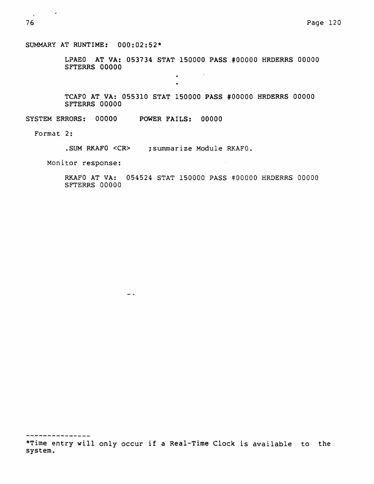
76
Page
120
SUMMARY
AT
RUNTIME:
000:02:52*
LPAEO
AT
VA:
053734
STAT
150000
PASS
#00000
HRDERRS
00000
SFTERRS
00000
TCAFO
AT
VA:
055310
STAT
150000
PASS
#00000
HRDERRS
00000
SFTERRS
00000
SYSTEM
ERRORS:
00000
POWER
FAILS:
00000
Format
2:
• SUM
RKAFO
<CR>
;summarize
Module
RKAFO.
Monitor
response:
RKAFO
AT
VA:
054524
STAT
150000
PASS
#00000
HRDERRS
00000
SFTERRS
00000
*Time
entry
will
only
occur
if
a
Real-Time
Clock
is
available
to
the
system.
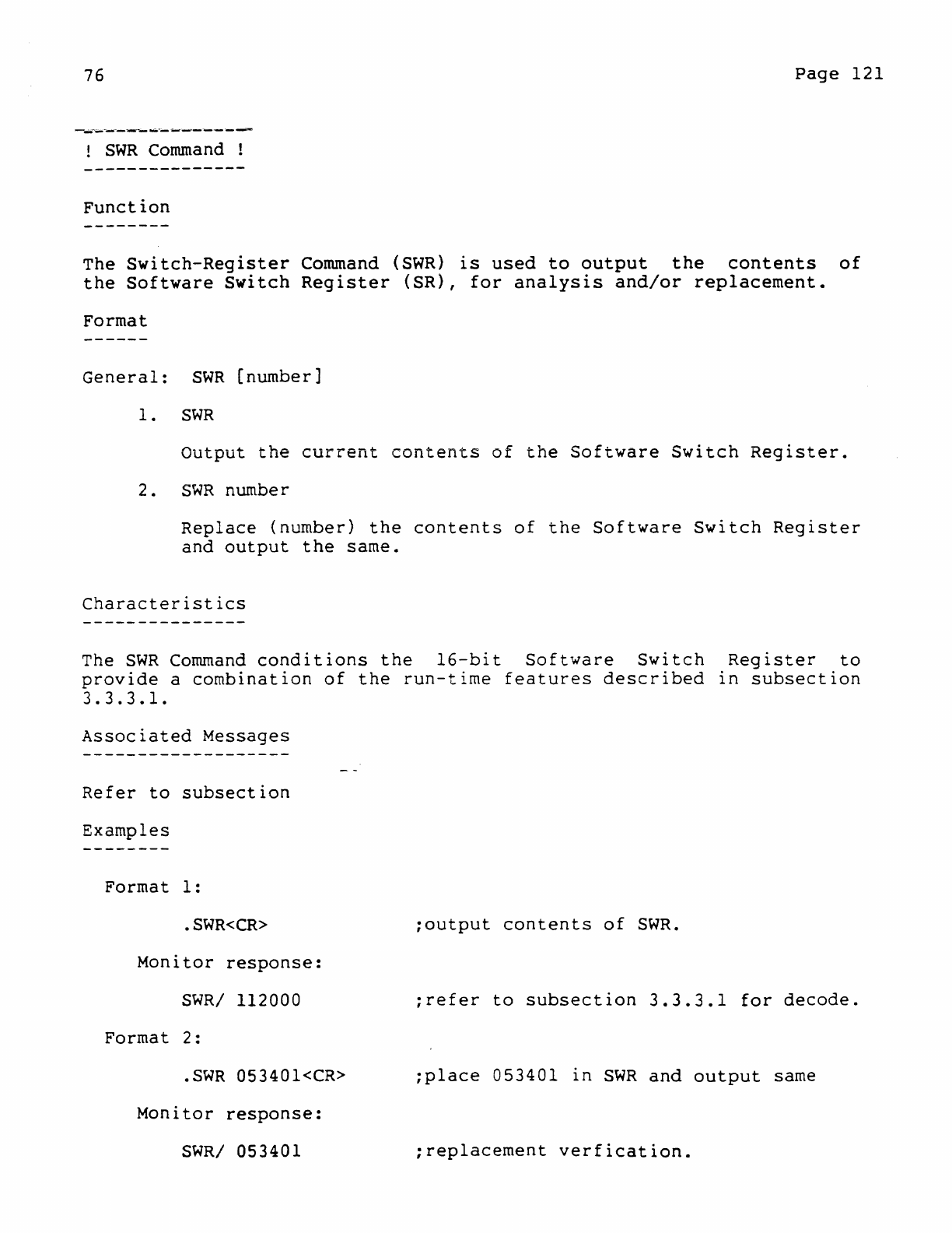
76
Page
121
!
SWR
Command
!
Function
The
Switch-Register
Command
(SWR)
is
used
to
output
the
contents
of
the
Software
Switch
Register
(SR),
for
analysis
and/or
replacement.
Format
General:
SWR
[number]
1.
SWR
Output
the
current
contents
of
the
Software
Switch
Register.
2.
SWR
number
Replace
(number)
the
contents
of
the
Software
Switch
Register
and
output
the
same.
Characteristics
The
SWR
Command
conditions
the
l6-bit
Software
Switch
Register
to
provide
a
combination
of
the
run-time
features
described
in
subsection
3.3.3.1.
Associated
Messages
Refer
to
subsection
Examples
Format
1:
.
SWR<CR>
;output
contents
of
SWR
.
Monitor
response:
SWR/
112000
;refer
to
subsection
3.3.3.1
for
decode.
Format
2:
.SWR
053401<CR>
;place
053401
in
SWR
and
output
same
Monitor
response:
SWR/
053401
;replacement
verfication.
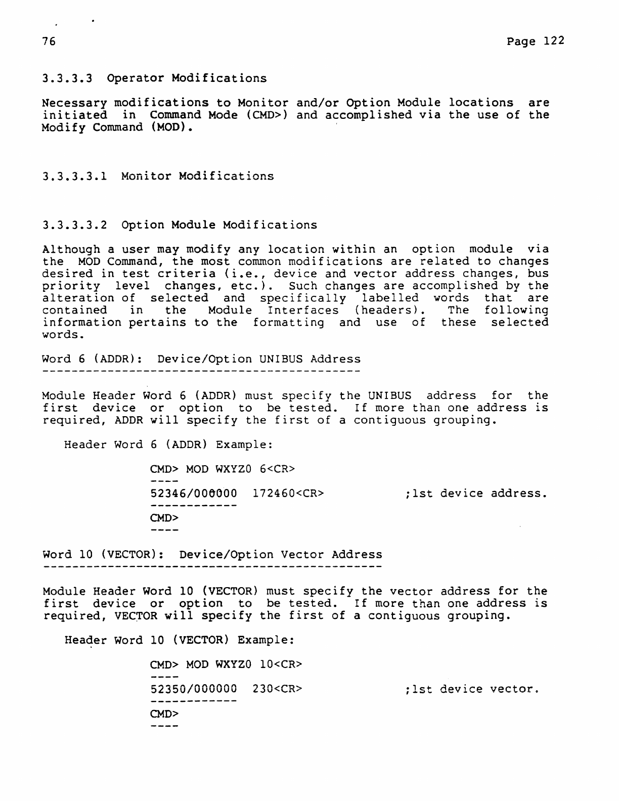
76
Page
122
3.3.3.3
Operator
Modifications
Necessary
modifications
to
Monitor
and/or
Option
Module
locations
are
initiated
in
Command
Mode
(CMD»
and
accomplished
via
the
use
of
the
Modify
Command
(MOD).
3.3.3.3.1
Monitor
Modifications
3.3.3.3.2
Option
Module
Modifications
Although
a
user
may
modify
any
location
within
an
option
module
via
the
MOD
Command,
the
most
common
modifications
are
related
to
changes
desired
in
test
criteria
<i.e.,
device
and
vector
address
changes,
bus
priority
level
changes,
etc.).
Such
changes
are
accomplished
by
the
alteration
of
selected
and
specifically
labelled
words
that
are
contained
in
the
Module
Interfaces
(headers).
The
following
information
pertains
to
the
formatting
and
use
of
these
selected
words.
Word 6
(ADDR):
Device/Option
UNIBUS
Address
Module
Header
Word 6
(ADDR)
must
specify
the
UNIBUS
address
for
the
first
device
or
option
to
be
tested.
If
more
than
one
address
is
required,
ADDR
will
specify
the
first
of
a
contiguous
grouping.
Header
Word 6
(ADDR)
Example:
CMD>
MOD
WXYZO
6<CR>
52346/006000
l72460<CR>
;lst
device
address.
CMD>
Word 10 (VECTOR):
Device/Option
Vector
Address
Module
Header
Word 10
(VECTOR)
must
specify
the
vector
address
for
the
first
device
or
option
to
be
tested.
If
more
than
one
address
is
required,
VECrOR
will
specify
the
first
of
a
contiguous
grouping.
Header
Word 10
(VECTOR)
Example:
CMD>
MOD
WXYZO
lO<CR>
52350/000000
230<CR>
:lst
device
vector~
CMD>
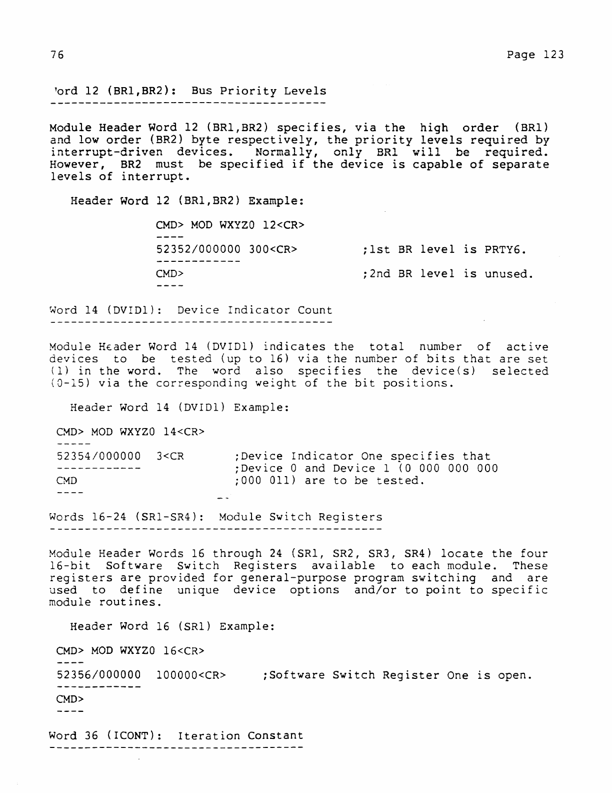
76
Page
123
lord
12
(BR1,BR2):
Bus
Priority
Levels
Module
Header
Word 12 (BRI,BR2)
specifies,
via
the
high
order
(BRI)
~nd
low
orde:
(BR2)
brte
respectively,
the
priority
levels
required
by
lnterrupt-drlven
devlces.
Normally,
only
BRl
will
be
required.
However,
BR2
must
be
specified
if
the
device
is
capable
of
separate
levels
of
interrupt.
Header
Word 12 (BRI,BR2)
Example:
CMD>
MOD
WXYZO
12<CR>
52352/000000
300<CR>
;lst
BR
level
is
PRTY6.
CMD>
;2nd
BR
level
is
unused.
Word
14
(DVIDl):
Device
Indicator
Count
Module
HEader
Word 14 (DVID1)
indicates
the
total
number
of
active
devices
to
be
tested
(up
to
16)
via
the
number
of
bits
that
are
set
(1)
in
the
word.
The
word
also
specifies
the
device(s)
selected
(0-15)
via
the
corresponding
weight
of
the
bit
positions.
Header
Word 14 (DVIDl)
Example:
CMD>
MOD
WXYZO
14<CR>
52354/000000
3<CR
CMD
;Device
Indicator
One
specifies
that
;Device
0
and
Device
1
(0
000 000 000
;000
011)
are
to
be
tested.
Words
16-24
(SRl-SR4):
Module
Switch
Registers
Module
Header
Words 16
through
24
(SRI,
SR2, SR3, SR4)
locate
the
four
16-bit
Software
Switch
Registers
available
to
each
module.
These
registers
are
provided
for
general-purpose
program
switching
and
are
used
to
define
unique
device
options
and/or
to
point
to
specific
module
routines.
Header
Word 16
(SRI)
Example:
CMD>
MOD
WXYZO
16<CR>
52356/000000
100000<CR>
;Software
Switch
Register
One
is
open.
CMD>
Word 36 (ICONT):
Iteration
Constant
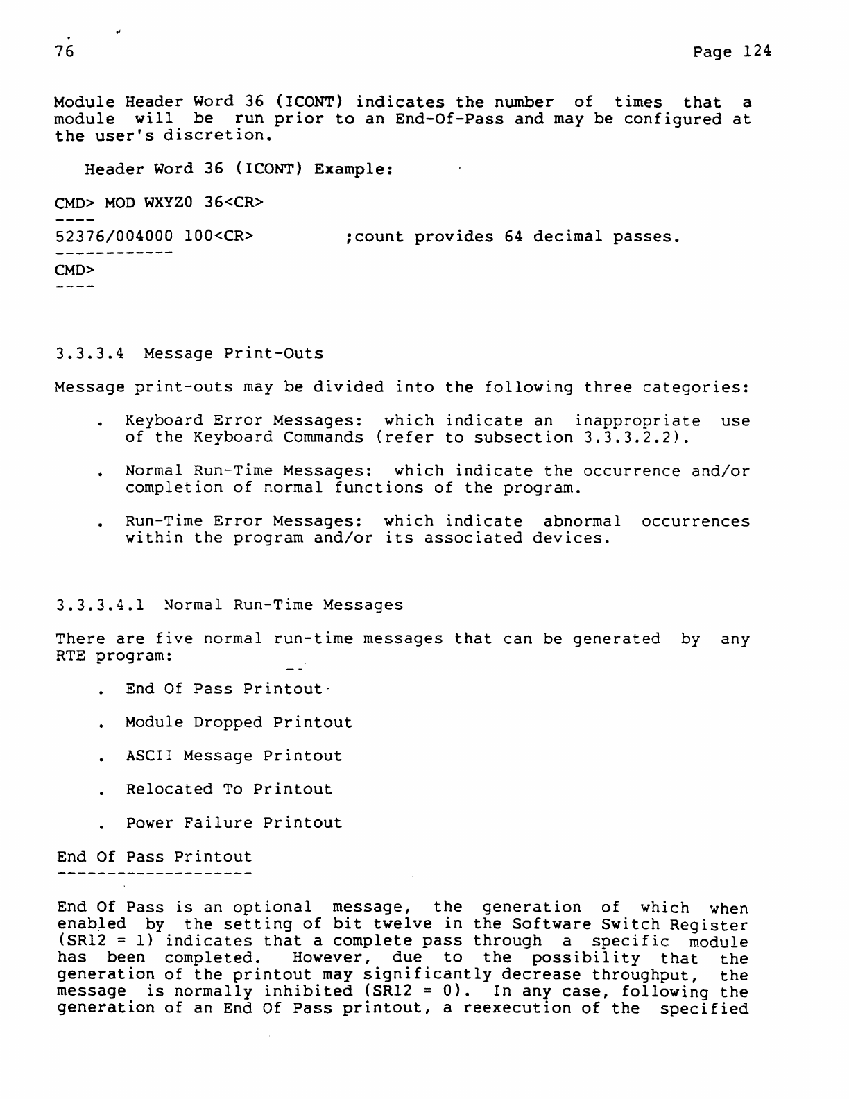
76
Page
124
Module
Header
Word 36 (ICONT)
indicates
the
number
of
times
that
a
module
will
be
run
prior
to
an
End-Of-Pass
and
may
be
configured
at
the
user's
discretion.
Header
Word 36 (ICONT)
Example:
CMD>
MOD
WXYZO
36<CR>
52376/004000
100<CR>
;count
provides
64
decimal
passes.
CMD>
3.3.3.4
Message
Print-Outs
Message
print-outs
may
be
divided
into
the
following
three
categories:
Keyboard
Error
Messages:
which
indicate
an
inappropriate
use
of
the
Keyboard
Commands
(refer
to
subsection
3.3.3.2.2).
Normal Run-Time
Messages:
which
indicate
the
occurrence
and/or
completion
of
normal
functions
of
the
program.
Run-Time
Error
Messages:
which
indicate
abnormal
occurrences
within
the
program
and/or
its
associated
devices.
3.3.3.4.1
Normal Run-Time
Messages
There
are
five
normal
run-time
messages
that
can
be
generated
by
any
RTE
program:
End Of
Pass
Printout-
Module
Dropped
Printout
ASCII
Message
Printout
Relocated
To
Printout
Power
Failure
Printout
End Of
Pass
Printout
End Of
Pass
is
an
optional
message,
the
generation
of
which
when
enabled
by
the
setting
of
bit
twelve
in
the
Software
Switch
Register
(SR12 =
1)
indicates
that
a
complete
pass
through
a
specific
module
has
been
completed.
However,
due
to
the
possibility
that
the
generation
of
the
printout
may
significantly
decrease
throughput,
the
message
is
normally
inhibited
(SR12 =
0).
In
any
case,
following
the
generation
of
an
End Of
Pass
printout,
a
reexecution
of
the
specified
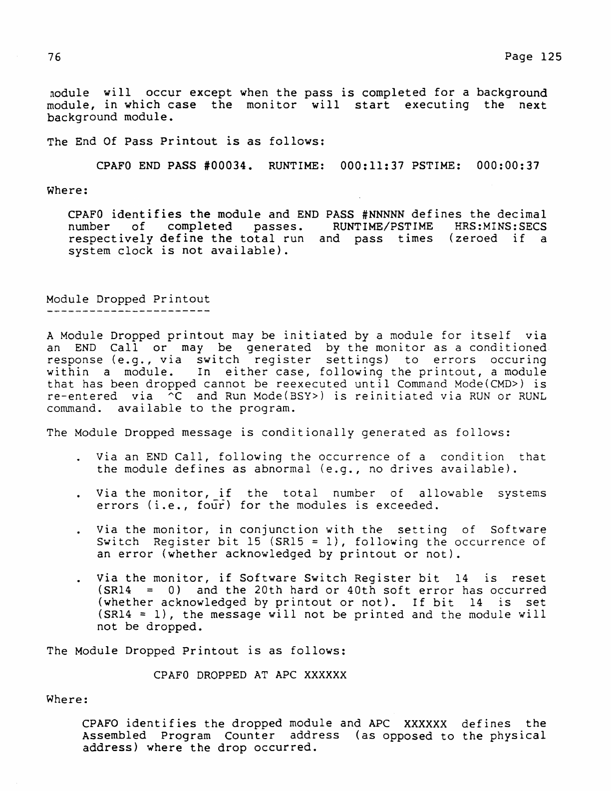
76
Page
125
nodule
will
occur
except
when
the
pass
is
completed
for
a
background
module,
in
which
case
the
monitor
will
start
executing
the
next
background
module.
The
End Of
Pass
Printout
is
as
follows:
CPAFO
END
PASS
#00034.
RUNTIME:
000:11:37
PSTIME:
000:00:37
Where:
CPAFO
identifies
the
module
and
END
PASS
#NNNNN
defines
the
decimal
number
of
completed
passes.
RUNTIME!PSTIME HRS:MINS:SECS
respectively
define
the
total
run
and
pass
times
(zeroed
if
a
system
clock
is
not
available).
Module
Dropped
Printout
A
Module
Dropped
printout
may
be
initiated
by
a
module
for
itself
via
an
END
Call
or
may
be
generated
by
the
monitor
as
a
conditioned
response
(e.g.,
via
switch
reglster
settings)
to
errors
occuring
within
a
module.
In
either
case,
following
the
printout,
a
module
that
has
been
dropped
cannot
be
reexecuted
until
Command
Mode(CMD»
is
re-entered
via
AC
and
Run Mode(BSY»
is
reinitiated
via
RUN
or
RUNL
command.
available
to
the
program.
The
Module
Dropped
message
is
conditionally
generated
as
follows:
Via
an
END
Call,
following
the
occurrence
of
a
condition
that
the
module
defines
as
abnormal
(e.g.,
no
drives
available).
Via
the
monitor,
if
the
total
number
of
allowable
systems
errors
(i.e.,
four)
for
the
modules
is
exceeded.
Via
the
monitor,
in
conjunction
with
the
setting
of
Software
Switch
Register
bit
15
{SR15 =
l},
following
the
occurrence
of
an
error
(whether
acknowledged
by
printout
or
not).
Via
the
monitor,
if
Software
Switch
Register
bit
14
is
reset
(SR14 =
O)
and
the
20th
hard
or
40th
soft
error
has
occurred
(whether
acknowledged
by
printout
or
not).
If
bit
14
is
set
(SR14 =
1),
the
message
will
not
be
printed
and
the
module
will
not
be
dropped.
The
Module
Dropped
Printout
is
as
follows:
CPAFO
DROPPED
AT
APC
XXXXXX
Where:
CPAFO
identifies
the
dropped
module
and
APC
XXXXXX
defines
the
Assembled
Program
Counter
address
(as
opposed
to
the
physical
address)
where
the
drop
occurred.
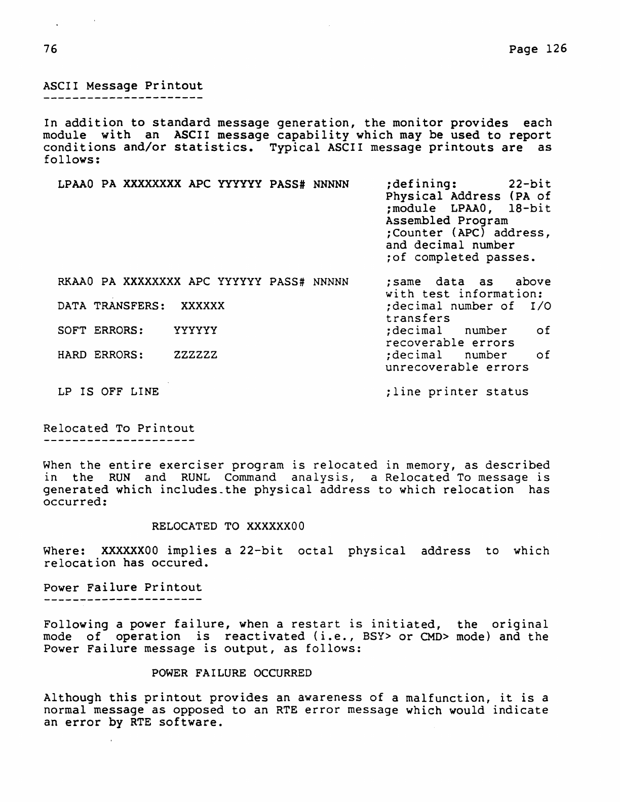
76
Page
126
ASCII
Message
Printout
In
addition
to
standard
message
generation,
the
monitor
provides
each
module
with
an
ASCII
message
capability
which
may
be
used
to
report
conditions
and/or
statistics.
Typical
ASCII
message
printouts
are
as
follows:
LPAAO
PA
XXXXXXXX
APe
YYYYYY
PASS#
NNNNN
RKAAO
PA
XXXXXXXX
APC
YYYYYY
PASS#
NNNNN
DATA
TRANSFERS:
XXX XXX
SOFT
ERRORS:
YYYYYY
HARD
ERRORS:
ZZZZZZ
LP
IS
OFF
LINE
Relocated
To
Printout
;defining:
22-bit
Physical
Address
(PA
of
;module
LPAAO,
IS-bit
Assembled
Program
;Counter
(APC)
address,
and
decimal
number
;of
completed
passes.
;sarne
data
as
above
with
test
information:
;decimal
number
of
I/O
transfers
;decimal
number
of
recoverable
errors
;decimal
number
of
unrecoverable
errors
;line
printer
status
When
the
entire
exerciser
program
is
relocated
in
memory,
as
described
in
the
RUN
and
RUNL
Command
analysis,
a
Relocated
To
message
is
generated
which
includes_the
physical
address
to
which
relocation
has
occurred:
RELOCATED
TO
XXXXXXOO
Where:
XXXXXXOO
implies
a
22-bit
octal
physical
address
to
which
relocation
has
occured.
Power
Failure
Printout
Following
a power
failure,
when a
restart
is
initiated,
the
original
mode
of
operation
is
reactivated
(i.e.,
BSY>
or
CMD>
mode)
and
the
Power
Failure
message
is
output,
as
follows:
POWER
FAILURE
OCCURRED
Although
this
printout
provides
an
awareness
of
a
malfunction,
it
is
a
normal
message
as
opposed
to
an
RTE
error
message
which
would
indicate
an
error
by
RTE
software.
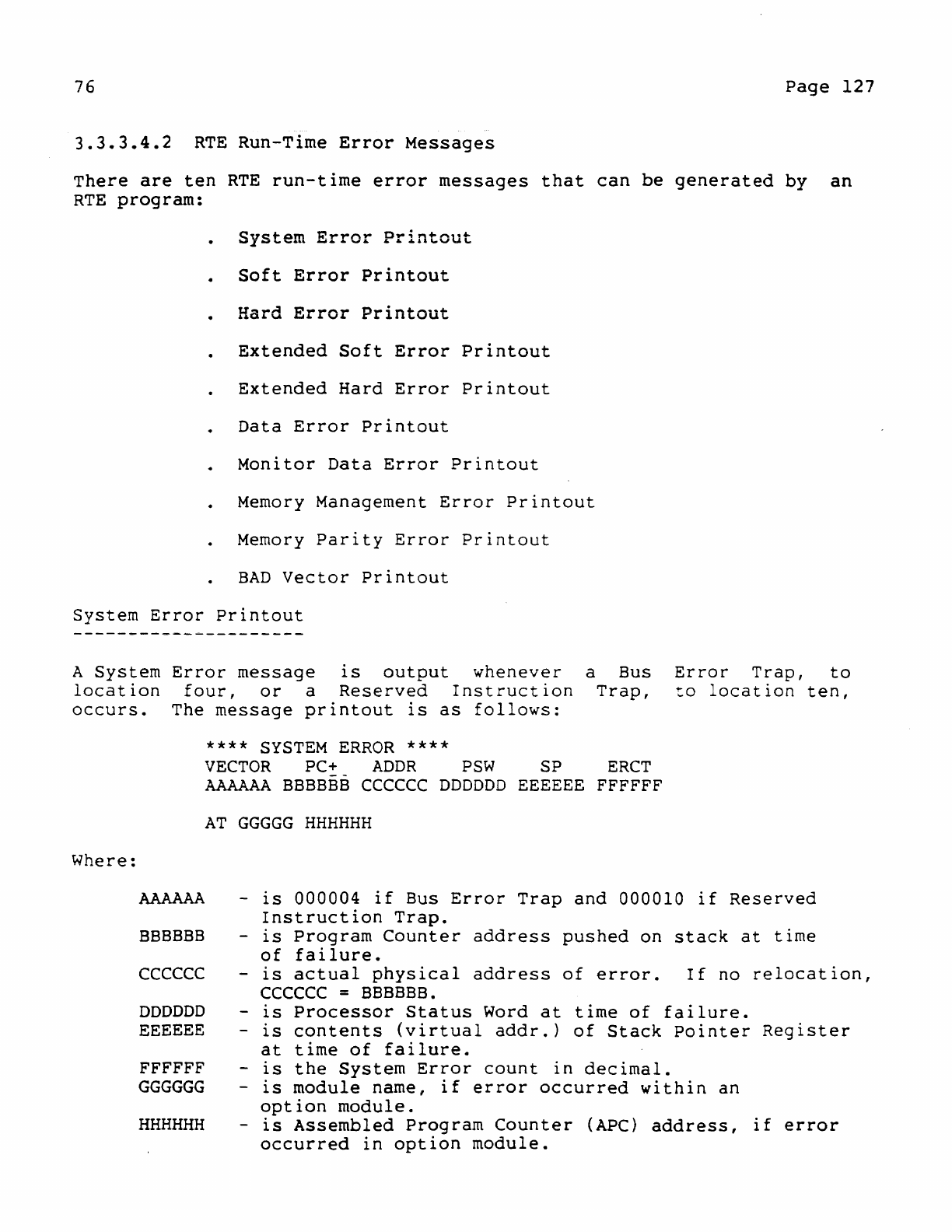
76
Page
127
3.3.3.4.2
RTE
Run-Time
Error
Messages
There
are
ten
RTE
run-time
error
messages
that
can
be
generated
by
an
RTE
program:
System
Error
Printout
Soft
Error
Printout
Hard
Error
Printout
Extended
Soft
Error
Printout
Extended
Hard
Error
Printout
Data
Error
Printout
Monitor
Data
Error
Printout
Memory Management
Error
Printout
Memory
Parity
Error
Printout
BAD
Vector
Printout
System
Error
Printout
A
System
Error
message
is
output
whenever
a Bus
location
four,
or
a
Reserved
Instruction
Trap,
occurs.
The
message
printout
is
as
follows:
Error
Trap,
to
to
location
ten,
Where:
AAAAAA
BBBBBB
CCCCCC
DDDDDD
EEEEEE
FFFFFF
GGGGGG
HHHHHH
****
SYSTEM
ERROR
****
VECTOR
PC+
ADDR
PSW
SP
ERCT
AAAAAA
BBBBBB
CCCCCC
DDDDDD
EEEEEE
FFFFFF
AT
GGGGG
HHHHHH
-
is
000004
if
Bus
Error
Trap
and
000010
if
Reserved
Instruction
Trap.
-
is
Program
Counter
address
pushed
on
stack
at
time
of
failure.
-
is
actual
physical
address
of
error.
If
no
relocation,
CCCCCC
=
BBBBBB.
-
is
Processor
Status
Word
at
time
of
failure.
-
is
contents
(virtual
addr.)
of
Stack
Pointer
Register
at
time
of
failure.
-
is
the
System
Error
count
in
decimal.
-
is
module
name,
if
error
occurred
within
an
option
module.
-
is
Assembled
Program
Counter
(APC)
address,
if
error
occurred
in
option
module.
76
Page
128
Once
the
system
error
message
has
been
output,
the
monitor
will
cause
the
following:
If,
when
the
error
occurred,
tqe
system
was
in
Command
Mode
(CMD»,
it
will
remain
in
Command
Mode.
If,
when
the
error
occured,
the
(BSY»,
or
in
Chain
Mode, Run
Moreover,
pass
count
and
error
cleared.
system
was
in
Run
Mode
Mode
will
be
reinitiated.
count
data
will
not
be
For
additional
message
possibilities
refer
to
section
entitled:
Special
System
Error
Printouts.
Soft
and
Hard
Error
Printouts
In
regard
to
an
operating
system,
Soft
Errors
are
recoverable
and
Hard
Errors
are
not.
In
regard
to
an
exerciser
program,
soft
and
hard
error
message
information
is
identical,
with
an
exception
only
to
type
(i.e.,
SOFT
or
HARD).
The
following
is
an
example
of
a
Hard
Error
printout:
ABCDO
PA
XXXXXXXX
APC
YYYYYY
PASS#
NNNNN
HARD
ERR#
NNNNN
CSRA
AAAAAA
eSRe
ccecce
STATe
SSSSSS
ERRTYP
NNNNN
Where:
ABCDO
PA
XXXXXXXX
APC
YYYYYY
PASS
#
NNNNN
HARD
ERR#NNNNN
CSRA
AAAAAA
CSRA
ceccce
STATC
SSSSSS
ERRTYP
NNNNN
-
1S
name
of
failing
module
-
is
actual
22-bit
physical
address
of
error
calls
-
is
Assembled
PC
of
error
call
-
is
decimal
pass
number
during
which
error
occurred.
-
is
total
decimal
number
of
hard
errors
encountered.
-
is
address
of
Control
Status
Register
for
failing
device
(if
any).
-
is
contents
of
device
CSR
(if
any).
-
is
contents
of
Device
Status
Register
(if
any).
-
is
octal
code
which
defines
the
type
of
error
(for
meaning
of
code
refer
to
DEC/Xll
Cross
Reference
Manual).
Locating
the
error
call
that
evoked
the
message:
Referring
to
the
listing
the
user
may
locate
the
call
which
evoked
the
error
message,
by
referencing
the
address
defined
by
the
Assembled
Program
Counter
(APe
yyyyyy)
printout.
To
facilitate
this
task,
all
error
calls
are
clearly
emphasized
within
the
listing
by a
boundary
of
asterisks(*).
Extended
Soft
and
Hard
Error
Printouts
76
Page
129.
xtended
Soft
and
Hard
Error
messages
contain
the
same
information
described
for
Soft
and
Hard
Error
Printouts.
With
an
extended
printout,
one
or
more
additional
lines
of
error
information
are
provided
which
may
consist
of
up
to
eight
octal
values
per
line.
The
meaning
of
this
additional
data,
for
the
module
specified,
may
be
found
in
the
DEC/XII
Cross
Reference
Manual.
The
following
is
an
example
of
an
Extended
Hard
Error
printout:
ABCDO
PA
XXXXXXXX
APe
YYYYYY
PASS#
NNNNNHARD
ERR'
NNNNN
CSRA
AAAAAA
CSRC
CCCCCC
STATe
SSSSSS
ERRTYP
NNNNN
XXX
XXX
XXXXXX
XXX
XXX
XXXXXX
XXXXXX
XXX
XXX
XXXXXX
XXXXXX
Locating
the
error
call
that
evoked
the
message
is
accomplished
in
the
manner
described
in
Soft
and
Hard
Error
Printouts.
Data
Error
Printout
with
the
exception
of
Extended
I/O
Modules
(IOMODX),
all
test
modules
report
data
transfer
errors
via
a
Data
Error
printout,
that
is
invoked
by
a
DATERS
Call.
The
message
is
as
follows:
DCAAO
PA
XXXXXXXX
APC
YYYYYY
PASS#
MMMMM
ERR#
NNNNN
DATA
ERROR
CSRA
AAAAAA
S/B
BBBBBB
WAS
WWWWWW
WRADR
DDDDDD
RDADR
EEEEEE
Ihe
re:
DCAAO
PA
XXXXXXXX
APC
YYYYYY
PASS
NNNNN
ERR
NNNNN
CSRA
AAAAAA
SIB
BBBBBB
WAS
WWWWWW
WRADR
DDDDDD
RDADR
EEEEEE
-
is
name
of
failing
module.
-
is
22-bit
physical
address
of
DaterS
Call
-
is
Assembled
PC
address
of
DATERS
Call.
-
is
decimal
pass
number
during
which
error
occurred.
-
is
total
decimal
error
count
for
current
test
run.
-
is
address
of
Control
Status
Register
for
failing
device.
-
is
good
expected
data.
-
is
bad
obtained
data.
-
is
write
address
of
good
and
expected
data.
-
is
read
address
of
bad
and
obtained
data.
Locating
the
DATERS
Call
that
evoked
the
error
message:
Referring
to
the
listing,
the
user
may
locate
the
call
that
evoked
the
error
message
by
referencing
-the
address
defined
by
the
Assembled
Program
Counter
(APC
yyyyyy)
printout.
To
facilitate
this
task,
all
DATERS
Calls
are
clearly
emphasized
within
the
listing
by
a
boundary
)f
asterisks(*).
76
Page
130
Monitor
Data
Error
Printout
---------------------------
Data
transfer
errors
associated
with
Extended
I/O
Modules
(IOMODX)
are
detected
by
the
monitor
via
a
Check
Data
Call
(CDATA$)
request.
This
is
necessary
because
the
modules
are
not
mapped
contiguously
with
their
write
buffers.
Thus,
the
data
cannot
be
checked
directly~
In
any
case,
a
Monitor
Data
Error
message
is
similar
to
a
Data
Error
printout
except
for
the
following,
interpretations
and
additions:
All
errors
detected
within
a
given
transfer
(e.g.,
a 256
word
block)
will
be
counted
as
a
single
error
(i.e.,
ERR#
00001).
The
count
will
not
be
indicated
until
each
error
has
been
reported
by
a
separate
printout.
The
reporting
of
all
errors
depends
on
the
setting
of
SRI0 (SRI0 =
1).
If
the
switch
is
cleared
(SRI0 =
0),
only
three
such
errors
will
be
reported.
An
additional
summary
message
is
provided
which
defines
the
total
"decimal
number
of
errors
that
have
occurred
during
the
transfer.
The
Monitor
Check
Data
Error
Printout
is
as
follows:
RKAFO
PA
XXXXXXXX
APC
YYYYYY
PASS#
NNNNN
ERR#
NNNNN
DATA
ERROR
CSRA
AAAAAA
SIB
BBBBBB
WAS
WWWWWW
WRADR
DDDDDD
RDADR
EEEEEE
RKAAO
HAD
NNNNN
ERRORS
OUT
OF
256
WORDS
READ
Memory Management
Error
Printout
Aborts
and
traps
generated
by
the
Memory Management
Unit
(KT1l)
are
vectored
through
virtual
location
250.
The Memory Management
Status
Registers
(SRO
through
SR3)
are
used
to
differentiate
an
abort
from a
trap,
determine
why
one
or
the
other
ocurred,
and
allow
for
a
program
restart.
The
following
printout
accompanies
a Memory Management
abort
or
trap:
***
KT
SRO
CCCCCC
SRI
ccccce
TRAP ***
SR2
ececcc
SR3
eccccc
Memory
Parity
Error
Printout
iidentifies
SRO
and
SR2
icontents
Of
SRO
and
SR2
;if
SRI
and
SR3
are
available,
icontents
of
SRI
and
SR3
Aborts
and
traps
generated
by
Main
or
Cache
Memory
parity
errors
or
Main
Memory
Eee
errors
are
vectored
through
virtual
location
114.
The
Control
Status
Register
(CSR)
will
contain
the
failure
information.
The
following
printout
accompanies
a memory
parity
or
Eee
error:
****
TRAP
THROUGH
VECTOR
114
****
CSR
CONTENTS
;AAAAAA
=
address
of
eSR(parity
or
ECe)
AAAAAA
BBBBBB
:BBBBBB
=
contents
of
CSR
76
Page
131
ad
Vector
Printout
The
Bad
Vector
message
indicates
that
the
address
pointer
is
invalid
since
an
Interrupt
Service
Routine
cannot
be
located.
This
error
will
not
interfere
with
the
operation
of
the
RTE
HOwever,
the
module
containing
the
faulty
pointer
will
not
output
on
End-Of-Pass
and
will
therefore
eventually
be
dropped
if
a
system
clock
is
available.
The
message
is
as
follows:
BAD
VECTOR:
200
:vector
200
is
invalid
for
device
When
the
faulty
module
is
found,
Word
10
of
the
module
header
may
be
corrected
via
hardware
documentation
or
module
abstract
analysis.
Special
System
Error
Printouts
If
a
system
error
occurs
in
a
PDP-ll/60
or
11/70
Processor
(with
an
associated
DEC/XII
Monitor),
related
Error
Log
messages
are
output
in
addition
to
the
standard
System
Error
printout
previously
described.
For
a
PDP-Il/60,
the
following
is
included
with
the
System
Error
printout:
11/60
ERROR
LOG
JAM/XXXXXX
SRV/XXXXXX
PBA/XXXXXX
CUA/XXXXXX
FLG-INT/XXXXXX
WHAMI/XXXXXX
CDATA/XXXXXX
CTAG-CPU/XXXXXX
Where:
JAM
SRV
PBA
I'""T T
J\
~Ul"\
FLG/INT
WHAM!
CDATA
CTAG/CPU
is
JAM
Register
status
is
Service
Register
of
status
is
Physical
Bus
Address
Register
(bits
16,17)
is
Microprogram
Address
is
Flag
Request
Register
of
status/last
interrupt
vector
serviced
is
various
Processor
Option
Status
bits
is
Cache
Memory
data
word
is
Cache
memory Tag
Data/Hit
Register
For
a
PDP-11/70,
the
following
is
included
with
the
System
Errror
printout:
11/70
ERROR
LOG
MEMERREG/XXXXXX
CPUERREG/XXXXXX
ADDR/XXXXXXXX
;only
output
if
parity
error
Where:
MEMERREG
is
Memory
System
Error
Register
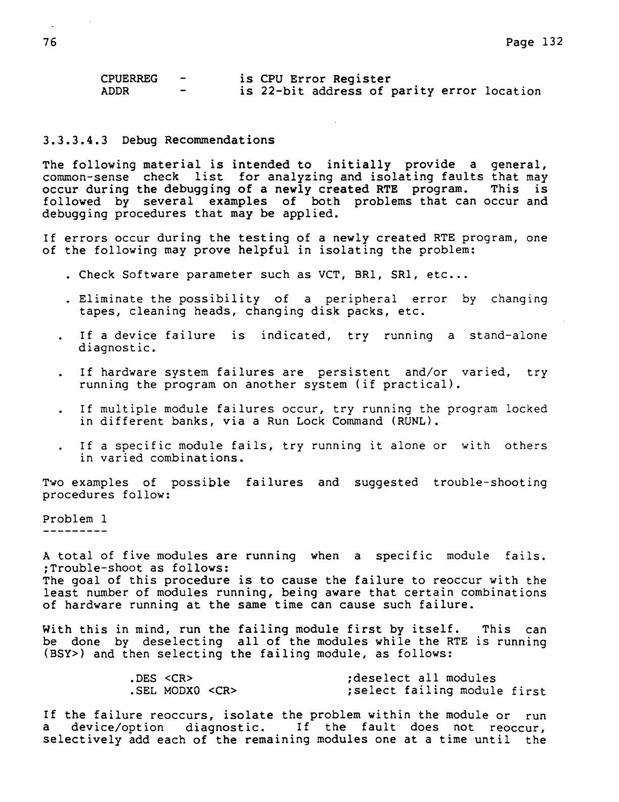
76
CPUERREG
ADDR
Page
132
is
CPU
Error
Register
is
22-bit
address
of
parity
error
location
3.3.3.4.3
Debug
Recommendations
The
following
material
is
intended
to
initially
provide
a
common=sense
check
list
for
analyzing
and
isolating
faults
occur
during
the
debugging
of
a
newly
created
RTE
program.
followed
by
several
examples
of
both
problems
that
can
debugging
procedures
that
may
be
applied.
general,
that
may
This
is
occur
and
If
errors
occur
during
the
testing
of
a
newly
created
RTE
program,
one
of
the
following
may
prove
helpful
in
isolating
the
problem:
• Check
Software
parameter
such
as
VCT,
BRl,
SRI,
etc
•..
.
Eliminate
the
possibility
of
a
peripheral
error
by
changing
tapes,
cleaning
heads,
changing
disk
packs,
etc.
If
a
device
failure
is
indicated,
try
running
a
stand-alone
diagnostic.
If
hardware
system
failures
are
persistent
and/or
varied,
try
running
the
program
on
another
system
(if
practical).
If
mUltiple
module
failures
occur,
try
running
the
program
locked
in
different
banks,
via
a Run Lock
Command
(RUNL).
If
a
specific
module
fails,
try
running
it
alone
or
with
others
in
varied
combinations.
Two
examples
of
possibl~
failures
and
suggested
trouble-shooting
procedures
follow:
Problem
1
A
total
of
five
modules
are
running
when a
specific
module
fails.
;Trouble-shoot
as
follows:
The
goal
of
this
procedure
is
to
cause
the
failure
to
reoccur
with
the
least
number
of
modules
running,
being
aware
that
certain
combinations
of
hardware
running
at
the
same
time
can
cause
such
failure.
With
this
in
mind,
run
the
failing
module
first
by
itself.
This
can
be
done
by
deselecting
all
of
the
modules
while
the
RTE
is
running
(BSY»
and
then
s~lecting
the
failing
module,
as
follows:
.DES
<CR>
.SEL
MODXO
<CR>
;deselect
all
modules
;select
failing
module
first
If
the
failure
reoccurs,
isolate
the
problem
within
the
module
or
run
a
device/option
diagnostic.
If
the
fault
does
not
reoccur,
selectively
add
each
of
the
remaining
modules
one
at
a
time
until
the
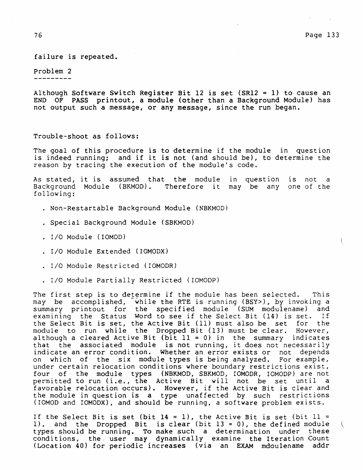
76
Page
133
failure
is
repeated.
Problem
2
Altnough
Software
Switch
Register
Bit
12
is
set
(SR12 =
1)
to
cause
an
END
OF
PASS
printout,
a
module
(other
than
a
Background
Module)
has
not
output
such
a
message,
or
any
message,
since
the
run
began.
Trouble-shoot
as
follows:
The
goal
of
this
procedure
is
to
determine
if
the
module
in
question
is
indeed
runnIng;
and
if
it
is
not
(and
should
be),
to
determine
the
reason
by
tracing
the
execution
of
the
module's
code.
As
stated,
it
is
assumed
that
the
module
Background
Module
(BKMOn).
Therefore
it
following:
·
Non-Restartable
Background
Module
(NBKMOn)
·
Special
Background
Module
(SBKMOn)
·
r/o
Module
(IOMOD)
·
I/O
Module
Extended
(IOMODX)
·
r/o
Module
Restricted
(IOMODR)
·
r/o
Module
Partially
Restricted
(rOMODP)
in
may
question
be
any
is
not
a
one
of
the
The
first
step
is
to
determine
if
the
module
has
been
selected.
This
may
be
accomplished,
-while
the
RTE
is
running
(BSY»,
by
invoking
a
summary
printout
for
the
specified
module
(SUM
modulename)
and
examining
the
Status
Word
to
see
if
the
Select
Bit
(14)
is
set.
If
the
Select
Bit
is
set,
the
Active
Bit
(11)
must
also
be
set
for
the
module
to
run
while
the
Dropped
Bit
(13)
must
be
clear.
However,
although
a
cleared
Active
Bit
(bit
11
=
0)
in
the
summary
indicates
that
the
associated
module
is
not
running,
it
does
not
necessarily
indicate
an
error
condition.
Whether
an
error
exists
or
not
depends
on
which
of
the
six
module
types
is
being
analyzed.
For
example,
under
certain
relocation
conditions
where
boundary
restrictions
exist,
four
of
the
module
types
(NBKMOD,
SBKMOD,
rOMODR,
rOMODP)
are
not
permitted
to
run
(i.e.,
the
Active
Bit
will
not
be
set
until
a
favorable
relocation
occurs).
However,
if
the
Active
Bit
is
clear
and
the
module
in
question
is
a
type
unaffected
by
such
restrictions
(rOMOD
and
IOMODX),
and
should
be
running,
a
software
problem
exists.
If
the
Select
Bit
is
set
(bit
14 =
1),
the
Active
Bit
is
set
(bit
11 =
1),
and
the
Dropped
Bit
is
clear
(bit
13 =
0),
~he
defined
module
types
should
be
running.
To make
such
a
determination
under
these
conditions,
the
I
user
may
dynamically
examine
the
Iteration
Count
(Location
40)
for
periodic
increases
(via
an
EXAM
mdoulename
addr

76
Page
134
~ommand).
If
no
increase
is
detected,
the
user
may
then
stop
the
program
and
selectively
insert
(via
a
MOD
modulename
addr
Command)
a
Halt
Instruction
in
the
module
code
in
order
to
isolate
the
error.
For
example,
in
the
case
of
the
I/O
modul~
types
(IOMOD,
X,R,P,),
a
Halt
is
placed
in
the
module's
Interrupt
Routine
and,
if
the
device
interrupt
is
working,
a
halt
will
occur
when
the
program
is
restarted.
If
a
halt
does
not
occur,
it
may
be assumed
that
the
device
is
defective.
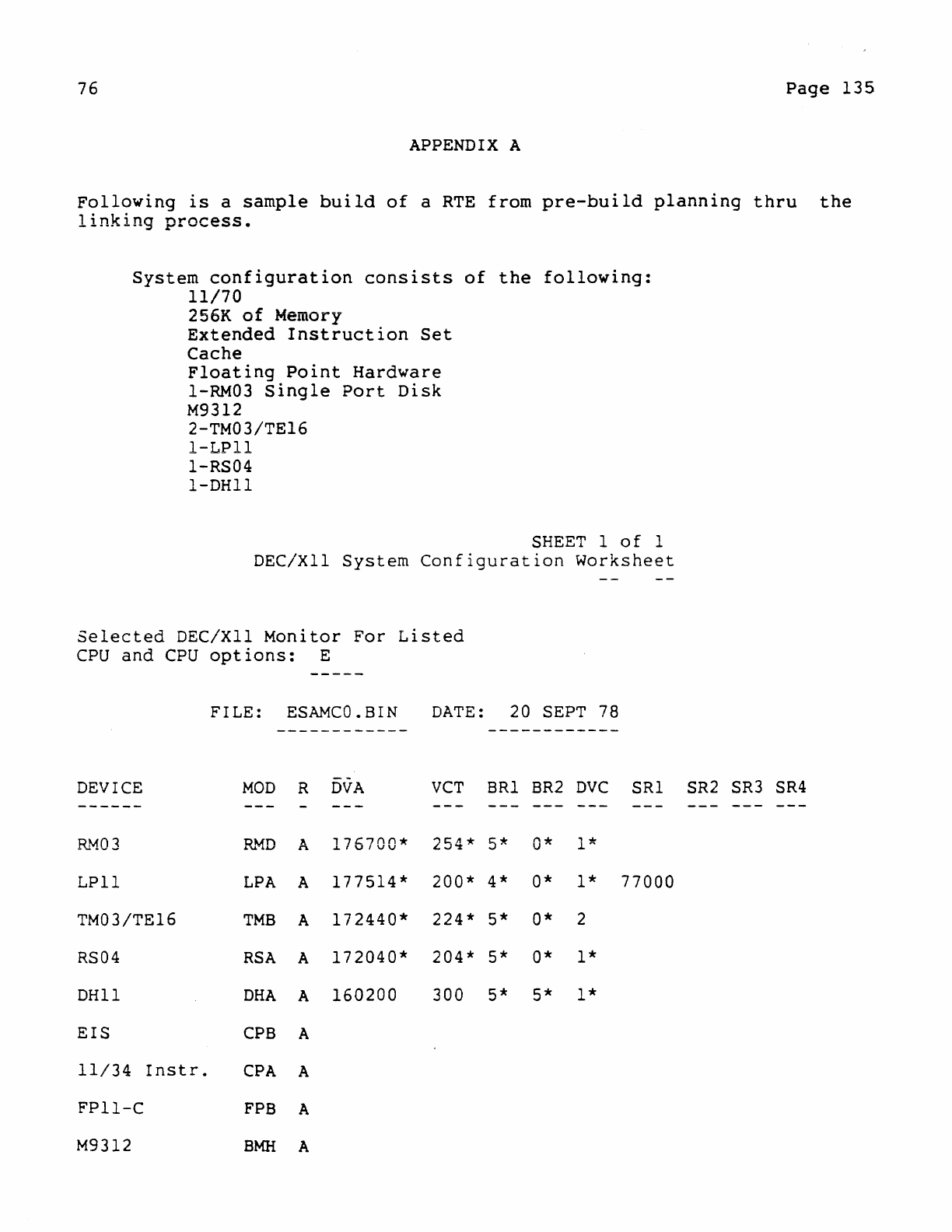
76
Page
135
APPENDIX
A
Following
is
a
sample
build
of
a
RTE
from
pre-build
planning
thru
the
linking
process.
System
configuration
consists
of
the
following:
11/70
256K
of
Memory
Extended
Instruction
Set
Cache
Floating
Point
Hardware
1-RM03
Single
Port
Disk
M9312
2-TM03/TE16
l-LPll
l-RS04
I-DHl1
SHEET
1
of
1
DEC/XII
System
Configuration
Worksheet
Selected
DEC/XII
Monitor
For
Listed
CPU
and
CPU
options:
E
FILE:
ESAMCO.BIN
DATE:
20
SEPT
78
DEVICE
MOD
R
OVA
VCT
SRI
SR2
DVC
------
~J-iO
3
R~D
A
176700*
254*
5*
0* '
....
..L.~
LPll
LPA
A
177514*
200* 4* 0* 1*
TM03/TE16
TMB
A
172440*
224* 5* 0* 2
RS04
RSA
A
172040*
204* 5* 0* 1*
DHll
DHA
A
160200
300 5* 5* 1*
EIS
CPB
A
11/34
Instr.
CPA
A
FP11-C
FPB
A
M9312
BMH
A
SRI
77000
SR2
SR3
SR4
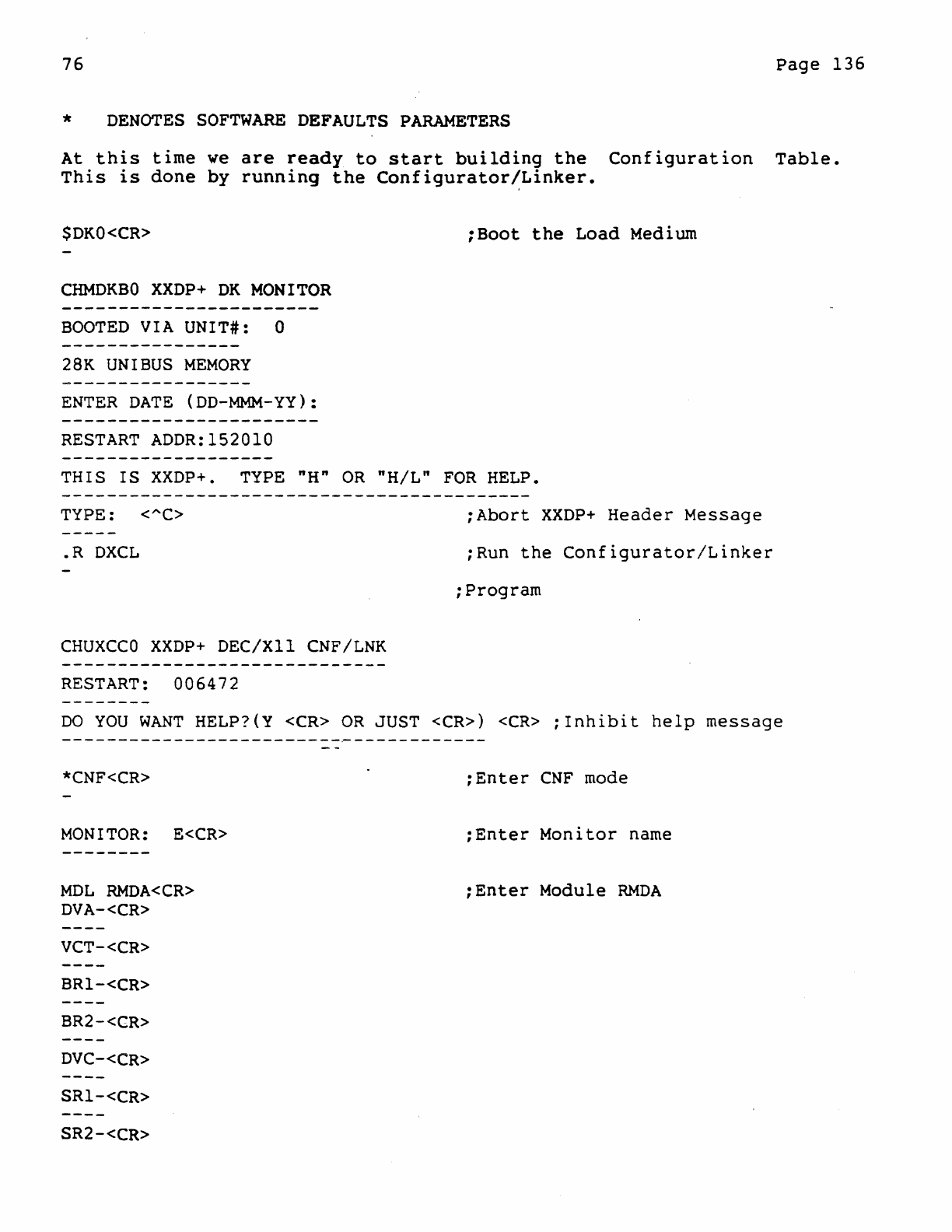
76
Page
136
*
DENOTES
SOFTWARE
DEFAULTS
PARAMETERS
At
this
time
we
are
ready
to
start
building
the
Configuration
Table.
This
is
done
by
running
the
Configurator!Linker.
$DKO<CR>
;Boot
the
Load
Medium
CHMDKBO
XXDP+
DK
MONITOR
BOOTED
VIA
UNIT#:
0
28K UNIBUS
MEMORY
ENTER
DATE
(DD-MMM-YY):
RESTART
ADDR:152010
THIS
IS
XXDP+. TYPE
"H"
OR
"H/L"
FOR
HELP.
TYPE: <"C>
;Abort
XXDP+
Header
Message
.R
DXCL
;Run
the
Configurator/Linker
;Program
CHUXCCO
XXDP+
DEC/XII
CNF/LNK
RESTART:
006472
DO
YOU
WANT
HELP?{Y <CR>
OR
JUST <CR»
<CR>
;Inhibit
help
message
*CNF<CR>
MONITOR:
E<CR>
MDL
RMDA<CR>
DVA-<CR>
VCT-<CR>
BRI-<CR>
BR2-<CR>
DVC-<CR>
SRl-<CR>
SR2-<CR>
;Enter
CNF
mode
;Enter
Monitor
name
;Enter
Module
RMDA
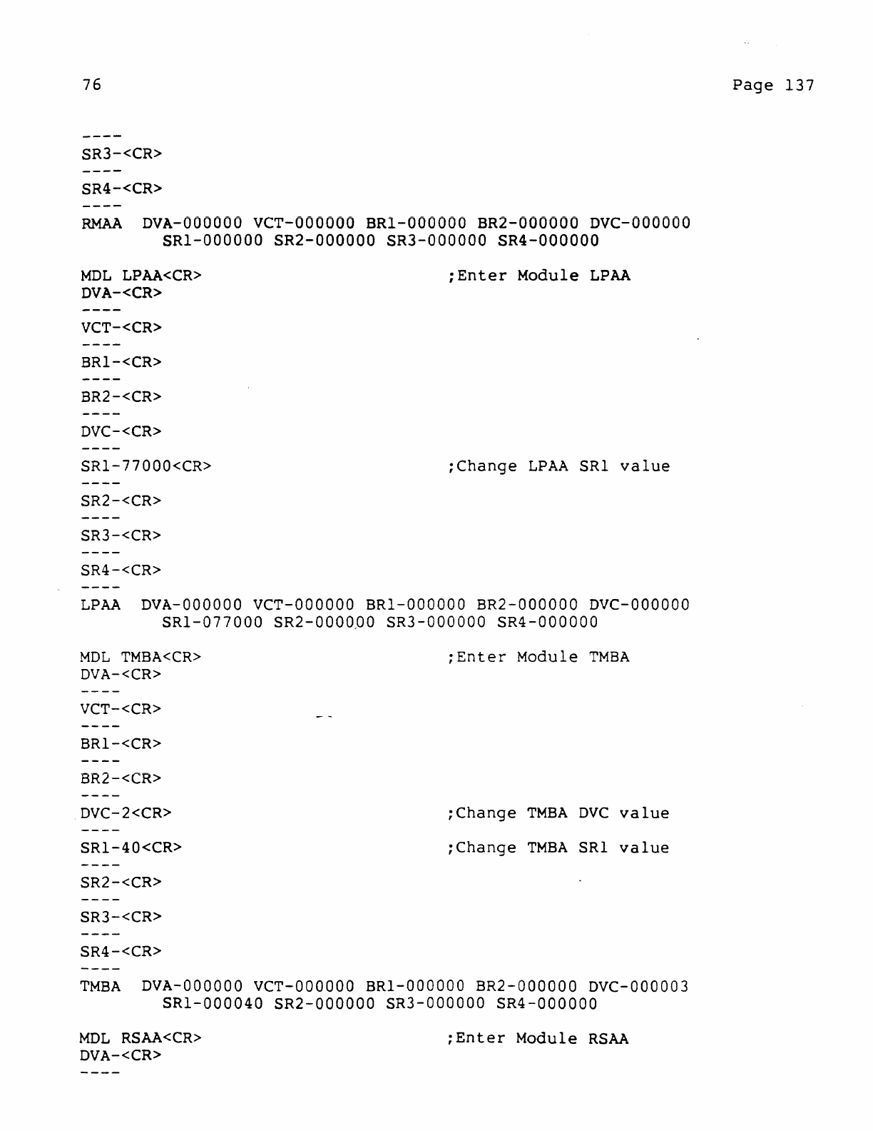
76
SR3-<CR>
SR4-<CR>
RMAA
DVA-OOOOOO
veT-OOOOOO
BRl-OOOOOO
BR2-000000
Dvc-oooaao
SRl-OOOOOO
SR2-000000
SR3-000000
SR4-000000
MDL
LPAA<CR>
DVA-<CR>
VCT-<CR>
BRl-<CR>
BR2-<CR>
DVC-<CR>
SRl-77000<CR>
SR2-<CR>
SR3-<CR>
SR4-<CR>
;Enter
Module
LPAA
;Change
LPAA
SRI
value
LPAA
DVA-OOOOOO
VeT-OOOOOO
BRl-OOOOOO
BR2-000000
DVC-OOOOOO
SRI-077000
SR2-0000QO
SR3-000000
SR4-000000
MDL
TMBA<CR>
DVA-<CR>
VCT-<CR>
BRI-<CR>
BR2-<CR>
DVC-2<CR>
SRI-40<CR>
SR2-<CR>
SR3-<CR>
SR4-<CR>
;Enter
Module
TMBA
;Change
TMBA
Dve
value
;Change
TMBA
SRI
value
TMBA
DVA-OOOOOO
VeT-OOOOOO
BRI-OOOOOO
BR2-000000
DVC-000003
SRI-000040
SR2-000000
SR3-000000
SR4-QOOOOO
MDL
RSAA<CR>
DVA-<CR>
;Enter
Module
RSAA
Page
137
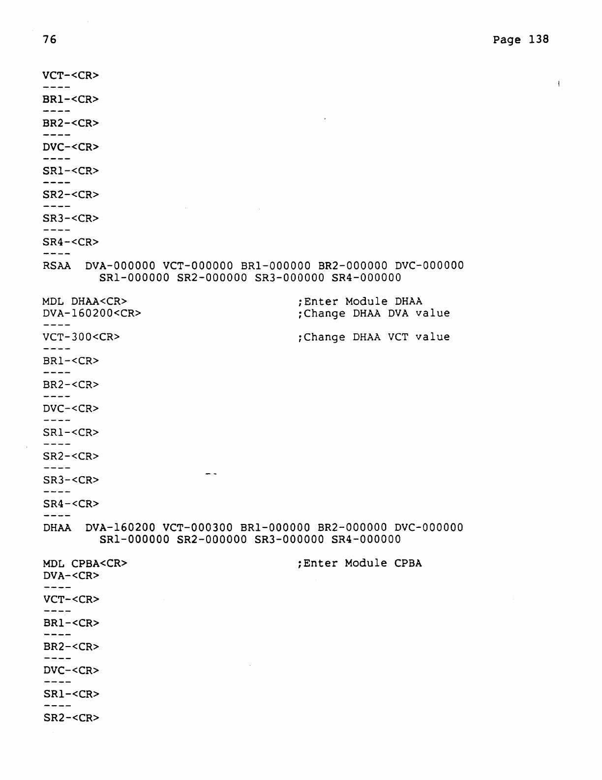
76
VCT-<CR>
BRl-<CR>
BR2-<CR>
DVC-<CR>
SRl-<CR>
SR2-<CR>
SR3-<CR>
SR4-<CR>
RSAA
DVA-OOOOOO
VCT-OOOOOO
BRI-OOOOOO
BR2-000000
DVC-OOOOOO
SRI-OOOOOO
SR2-000000
SR3-000000
SR4-000000
MDL
DHAA<CR>
DVA-160200<CR>
VCT-300<CR>
BRI-<CR>
BR2-<CR>
DVC-<CR>
SRI-<CR>
SR2-<CR>
SR3-<CR>
SR4-<CR>
;Enter
Module
DHAA
;Change
DHAA
DVA
value
:Change
DHAA
veT
value
DHAA
DVA-160200
VCT-000300
BRI-OOOOOO
BR2-000000
DVC-OOOOOO
SRI-OOOOOO
SR2-000000
SR3-000000
SR4-000000
MDL
CPBA<CR>
DVA-<CR>
VCT-<CR>
BRI-<CR>
BR2-<CR>
DVC-<CR>
SRI-<CR>
SR2-<CR>
:Enter
Module
CPBA
Page
138
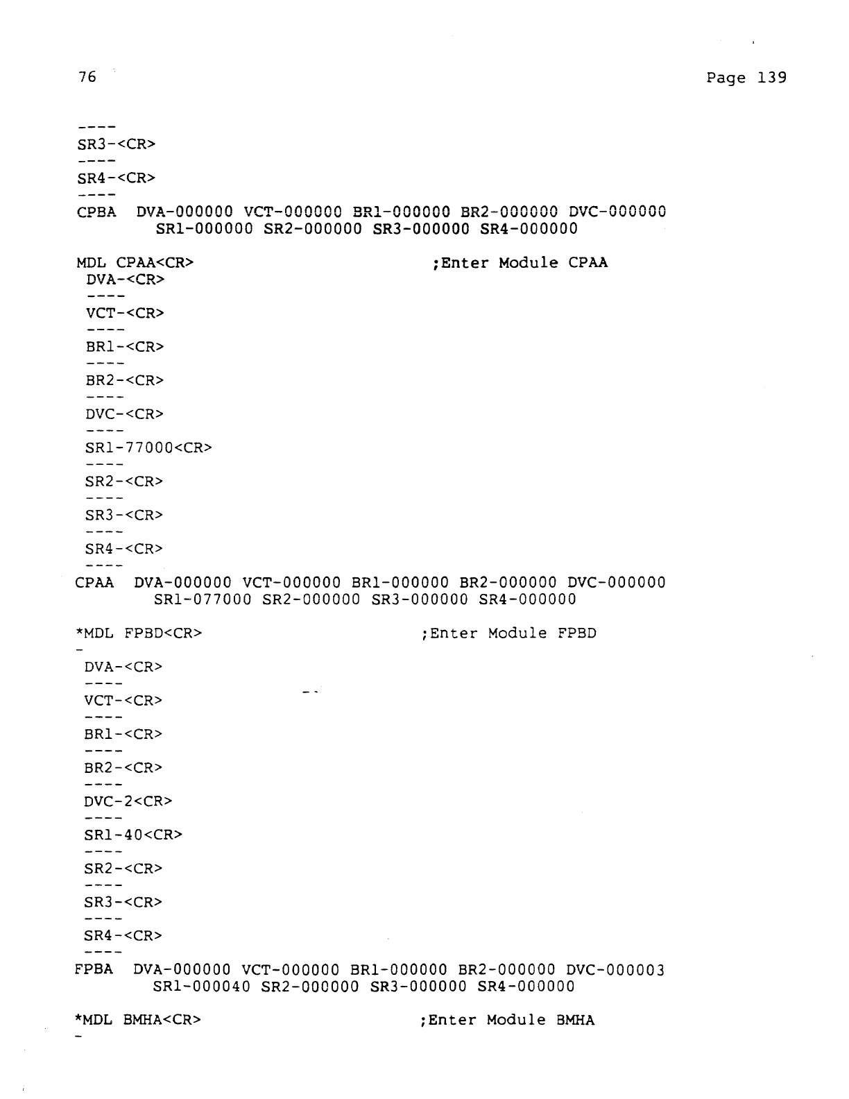
76
SR3-<CR>
SR4-<CR>
CPBA
DVA-OOOaao
veT-OOOOOO
BRI-ooeoee
BR2=OOOOOO
DVC-OOOOOO
SRI-OOOOOO
SR2-000000
SR3-000000
SR4-000000
MDL
CPAA<CR>
DVA-<CR>
VCT-<CR>
BR1-<CR>
BR2-<CR>
DVC-<CR>
SRl-77000<CR>
SR2-<CR>
SR3-<CR>
SR4-<CR>
;Enter
Module
CPAA
CPAA
DVA-OOOOOO
VCT-OOOOOO
BRI-OOOOOO
BR2-000000
DVC-OOOOOO
SRI-077000
SR2-000000
SR3-000000
SR4-000000
*MDL
FPBD<CR>
;Enter
Module
FPBD
DVA-<CR>
VCT-<CR>
BR1-<CR>
BR2-<CR>
DVC-2<CR>
SRl-40<CR>
SR2-<CR>
SR3-<CR>
SR4-<CR>
FPBA
DVA-OOOOOO
VCT-OOOOOO
BRI-OOOOOO
BR2-000000
DVC-000003
SRI-000040
SR2-000000
SR3-000000
SR4-000000
*MDL
BMHA<CR>
;Enter
Module
BMHA
Page
139
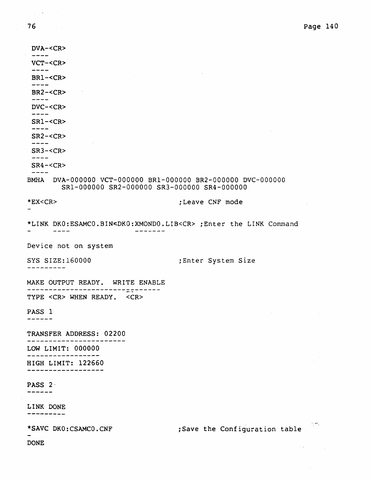
76
DVA-<CR>
VCT-<CR>
BRI-<CR>
BR2-<CR>
DVC-<CR>
SRI-<CR>
SR2-<CR>
SR3-<CR>
SR4-<CR>
BMRA
DVA-OOOOOO
VCT-OOOOOO
BRI-OOOOOO
BR2-000000
DVC-OOOOOO
SRI-OOOOOO
SR2-000000
SR3-000000
SR4-000000
*EX<CR>
;Leave
CNF
mode
*LINK
DKO:ESAMCO.BIN~DKO:XMONDO.LIB<CR>
;Enter
the
LINK
Command
Device
not
on
system
SYS
SIZE:160000
;Enter
System
Size
MAKE
OUTPUT
READY.
WRITE
ENABLE
TYPE
<CR>
WHEN
READY.
<CR>
PASS
I
TRANSFER
ADDRESS:
02200
LOW
LIMIT: 000000
HIGH
LIMIT:
122660
PASS
2·
LINK
DONE
*SAVC
DKO:CSAMCO.CNF
;Save
the
Configuration
table
DONE
Page
140
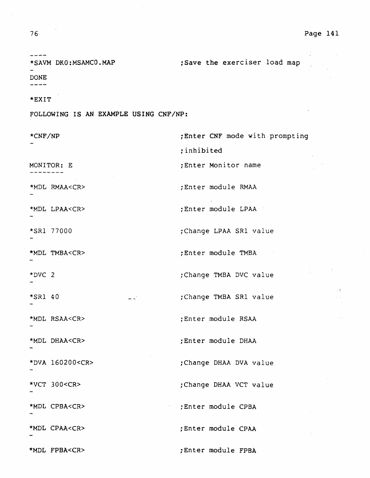
76
*SAVM
DKO:MSAMCO.MAP
DONE
*EXIT
Page
141
;Save
the
exerciser
load
map
FOLLOWING
IS
AN
EXAMPLE
USING
CNF/NP:
*CNF/NP
MONITOR:
E
--------
*MDL
RMAA<CR>
*MDL
LPAA<CR>
*SRI 77000
*MDL
TMBA<CR>
*DVC
2
*SRI 40
*MDL
RSAA<CR>
*MDL
DHAA<CR>
*DVA
160200<CR>
*VCT
300<CR>
*MDL
CPBA<CR>
*MDL
CPAA<CR>
*MDL
FPBA<CR>
;Enter
CNF
mode
with
prompting
;
inhibited
;Enter
Monitor
name
;Enter
module
RMAA
;Enter
module
LPAA
;Change
LPAA
SRI
value
;Enter
module
TMBA
;Change
TMBA
DVC
value
;Change
TMBA
SRI
value
;Enter
module
RSAA
;Enter
module
DHAA
;Change
DHAA
DVA
value
;Change
DHAA
VCT
value
;Enter
module
CPBA
;Enter
module
CPAA
;Enter
module
FPBA
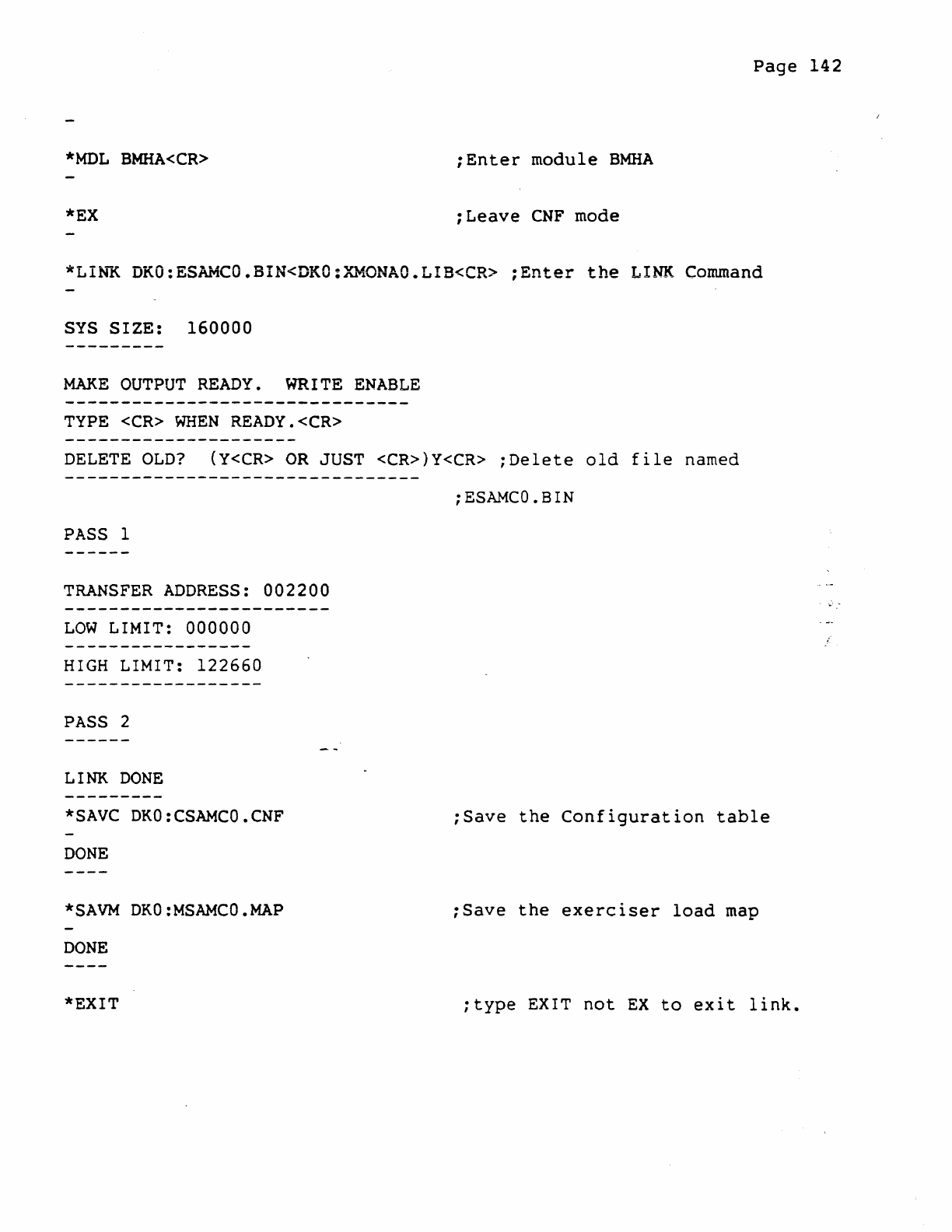
Page
142
*MDL
BMHA<CR>
;Enter
module
BMHA
*EX
;Leave
CNF
mode
*LINK
DKO:ESAMCO.BIN<DKO:XMONAO.LIB<CR>
;Enter
the
LINK
Command
SYS
SIZE:
160000
MAKE
OUTPUT
READY.
WRITE
ENABLE
TYPE
<CR>
WHEN
READY.<CR>
DELETE
OLD?
{Y<CR>
OR
JUST <CR»Y<CR>
;Delete
old
file
named
;ESAMCO.BIN
PASS
1
TRANSFER
ADDRESS:
002200
LOW
LIMIT: 000000
HIGH
LIMIT:
122660
PASS
2
LINK
DONE
*SAVC
DKO:CSAMCO.CNF
;Save
the
Configuration
table
DONE
*SAVM
DKO:MSAMCO.MAP
;Save
the
exerciser
load
map
DONE
*EXIT
;type
EXIT
not
EX
to
exit
link.
