Contents ACI 530 11 Masonry WALL 002
User Manual: ACI 530-11 Masonry-WALL-002
Open the PDF directly: View PDF ![]() .
.
Page Count: 4
Software Verification
PROGRAM NAME:
ETABS
REVISION NO.:
0
EXAMPLE ACI 530-11 Masonry Wall-002
P-M INTERACTION CHECK FOR WALL
EXAMPLE DESCRIPTION
The Demand/Capacity ratio for a given axial loading and moment is tested in this
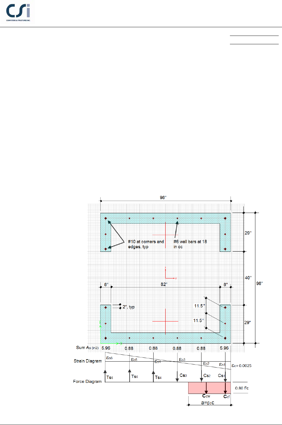
example. The wall is reinforced as shown below. The concrete core wall is
loaded with a factored axial load Pu = 1496 k and moments Mu3 = 7387 k-ft. The
design capacity ratio is checked by hand calculations and the results are
compared with ETABS program results.
GEOMETRY, PROPERTIES AND LOADING
EXAMPLE ACI 530-11 Masonry Wall-002 - 1
Software Verification
PROGRAM NAME:
ETABS
REVISION NO.:
0
TECHNICAL FEATURES OF ETABS TESTED
Concrete wall flexural Demand/Capacity ratio
RESULTS COMPARISON
Independent results are hand calculated and compared with ETABS design
check.
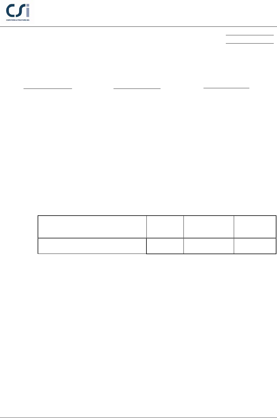
Output Parameter ETABS Independent Percent
Difference
Column Demand/Capacity Ratio 0.998 1.00 -0.20%
COMPUTER FILE: ACI 530-11 MASONRY WALL-002
CONCLUSION
The ETABS results show an acceptable comparison with the independent results.
Material Properties
E = 3600 k/in2
ν = 0.2
G = 1500 k/in2
Section Properties
Design Properties
f ′
c
= 4 k/in2
fy = 60 k/in2
tb = 8 in
h = 98 in
As1= As6 = 2-#10,2#6 (5.96 in^2)
As2, As3, As4 and As5 = 2-#6 (0.88 in^2)
EXAMPLE ACI 530-11 Masonry Wall-002 - 2

Software Verification
PROGRAM NAME:
ETABS
REVISION NO.:
0
HAND CALCULATION
Wall Strength under compression and bending
1) A value of e = 59.24 inches was determined using
/
uu
eM P=
where
u
M
and
u
P
were taken from the ETABS test model interaction diagram. The values of
u
M
and
u
P
were large enough to produce a flexural D/C ratio very close to or equal to one.
The depth to the neutral axis, c, was determined by iteration using an excel
spreadsheet so that equations 1 and 2 below were equal.
2) From the equation of equilibrium:
=
n1 c s
P CCT+−
where
′
=β= =
10.8•2.5•12 24.0
cm
C f ab a a
( ) () ( )
′ ′′ ′′ ′
=−+−+−
11 2 2 33
0.8 0.8 0.8
s sm s m s m
CAf fAf fAf f
s4 s4 s5 s5 s6 s6
T=A f A f A f++
( ) ( )
( )
′ ′′ ′
=+−+−+
′′
− −−−
1 11 2 2
3 3 44 55 66
24 0.8 0.8
0.8
n sm s m
s m ss ss ss
P aAf f Af f
A f f Af Af Af
(Eqn. 1)
3) Taking moments about As6:
( ) ( ) ( )
( ) ( ) ( )
−
−+ − + −+ +
=
′
−−
12
2
345
' '4
12
32
f
cf cw s s
n
ss s
at
C dd C d C dd C s
PeC sT sTs
(Eqn. 2)
where
( )
1 11
0.8
s sm
C Af f
′′
= −
;
( )
0.8
sn n sn m
C Af f
′′
= −
;
sn sn sn
T fA=
; and the bar strains
are determined below. The plastic centroid is at the center of the section and
d′′
= 45
inch
′ ′′
=+= +=59.24 45 104.24e ed
inch.
EXAMPLE ACI 530-11 Masonry Wall-002 - 3

Software Verification
PROGRAM NAME:
ETABS
REVISION NO.:
0
4) Iterating on a value of c until equations 1 and 2 are equal c is found to be c = 41.15
inches.
0.8• 0.8•41.15 32.92
ac
= = =
inches
5) Assuming the extreme fiber strain equals 0.0025 and c = 41.15 inches, the steel
stresses and strains can be calculated. When the bar strain exceeds the yield strain,
then
sy
ff
=
:
1
'0.0025
s
cd
c
ε
−
=
= 0.00226;
ss y
f EF
ε
= ≤
;
1s
f
= 60.00 ksi
2
'0.0025
s
csd
c
ε
−−
=
= 0.00116
2s
f
= 33.74 ksi
3
2'
0.0025
s
c sd
c
ε
−−
=
= 0.00007
3s
f
= 2.03 ksi
46
2
ss
dc s
dc
εε
−−
=
−
= 0.00102
4s
f
= 29.7 ksi
56ss
dcs
dc
εε
−−
=
−
= 0.00212
5s
f
= 60.00 ksi
6
0.0025
s
dc
c
ε
−
=
= 0.00321
6s
f
= 60.00 ksi
Substituting the above values of the compression block depth, a, and the rebar
stresses into equations Eqn. 1 and Eqn. 2 give
=
n1
P
1662 k
=
n2
P
1662 k
nn
M Pe= =
1662(41.15) /12
= 8208 k-ft
6) Calculate the capacity,
( )
= 0.9 1622 1496
n
Pφ=
kips
( )
= 0.9 8208 7387
n
Mφ=
k-ft.
EXAMPLE ACI 530-11 Masonry Wall-002 - 4
