ADA014398_Users_Guide_to_the_Terminal_IMP_Aug75 ADA014398 Users Guide To The Terminal IMP Aug75
ADA014398_Users_Guide_to_the_Terminal_IMP_Aug75 ADA014398_Users_Guide_to_the_Terminal_IMP_Aug75
User Manual: ADA014398_Users_Guide_to_the_Terminal_IMP_Aug75
Open the PDF directly: View PDF ![]() .
.
Page Count: 68
A
D
-
A
0
14
3
9^
TERMINAL
INTERFACE
MESSAGE
PROCESSOR:
USER'S
GUIDE
TO
THE
TERMIN
A
L
I
M
P
J
.
M
a
1
ir
a
n
Bolt
B
e
r
a
n
e
k
and
New
m
an,
Incorporated
Prepared
for:
Advanced
Research
Projects
Agency
/\ugust
1975
DISTRIBUTED
BY:
tm
National
Technical
Information
Service
U.
S.
DEPARTMENT
OF
COMMERCE
J

258110
T
1^«
/
-
ü
\-
\
<
«>
^
}
Approved
for
public
releoMf
Dldtnbuticm
unlimited
D
D
C
SEP
8
1975
NATIONAl
TECHNICAL
INFORMATION
SERVICE
SpftoflftoM.
VA.
«151
Report
Mo.
2183
Bolt
Boranek
and
Nnwman
Inc.
NIC
No.
10916
USER'S
GUIDE
TO
THE
TERMINAL
IMP
August
1975
Revision
Sponsored
by:
Advanced
Research
Projects
Agency
ARPA
Order
No.
2351
Contract
No.
F
08606-75-C-0032
Report
No.
2183
Bolt
Beranek
and
Newman
Inc.
August
1975
Revision
UPDATE
HISTCV.Y
Originally
written
Dec.
1971
by
W.R.
Crowther
Updated
July
1972
by
D.C.
Waiden
Completely
revised
Sept.
1972
by
D.C.
Waiden
Updated
Oct.
1972
by
D.C.
Waiden
Updated
Jan.
1973
by
D.C.
Waiden
Completely
revised
June
1973
by
D.C.
Waiden
Updated
Nov,
1973
by
J.
Malman
Updated
June
1974
by
J.
Malman
Updated
Dec.
1974
by
J.
Malman
Completely
revised
August
1975
by
J.
Malman
il
Report
No.
2183
Seit
Beranok
and
Newman
Inc.
August
1975
Revision
TABLE
OF
CONTENTS
Page
1.
INTRODUCTION
1-1
2.
THE
NETWORK
VIRTUAL
TERMINAL
2-1
3.
THE
TIP
COMMAND
FORMAT
3-1
4.
TYPICAL
USE
OF
THE
TIP
4-1
A.
Hardware
Stage
4-2
B.
Establishing
Parameters
4-6
C.
Connection
to
Remote
Sites
4-8
D.
Use
of
Remote
Sites
4-10
E.
Connection
Loss
and
Restoration
4-12
F.
TIP
News
and
User
Feedback
4-13
5.
UNUSUAL
USES
OF
THE
TIP
5-1
A.
Device
Parameters
5-2
B.
Talking
to
Another
TIP
5-4
C.
Binary
Mode
5-
f
'
D.
Setting
Another
Terminal's
Parameters
5-7
E.
The
DIVERT
OUTPUT
Command
5-8
F.
Editing
5-9
G.
Wild
5-10
H.
Low
Level
Protocol
Commands
5-11
1.
Commands
from
the
Network
5-12
J.
The
RESET
Device
Command
5-13
K.
TIP
Configuration
and
Device
Pre-initialization
5-1
u
6.
MAPPING
THE
VARIOUS
DEVICES
INTO
THE
NETWORK
VIRTUAL
TERMINAL
6-1
A.
TTY
and
TTY-like
Devices
6-1
B.
2741
and
2741-like
Devices
6-1
C.
ASCII/2741
Conversion
Table
6-2
7.
TIP
MESSAGES
TO
THE
TERMINAL
USER
7-]
8.
THE
TIP
MAGNETIC
TAPE
OPTION
8-1
9.
CONNECTION
OF
TERMINALS
TO
THE
TIP
9-1
APPENDICES
A-l
A.
Host
Addresses
A-l
B.
Command
Summary
B-l
C.
Bibliography
C-l
D.
Terminals
Used
with
the
TIP
0-1
111
Report
No.
21d3
Bolt
Boranok
and
Nownan
Inc.
August
1975
Revision
1.
INTRODUCTION
This
report
describes
the
use
of
a
terminal
connected
to
a
Terminal
IMP
(TIP)
in
the
ARPA
Network.
The
report
assumes
that
the
user
knows
how
to
operate
a
server
Hose
system
somewhere
on
the
network
once
he
becomes
connected
to
that
system,
and
the
report
defines
the
procedures
and
options
the
user
has
available
to
establish
that
connection.
The
ARPA
Network,
IMPs
and
TIPs,
hardware
maintenance,
TIP
operation,
and
formats
and
protocols
are
not
described
here.
The
bibliography
(Appendix
C)
lists
the
relevant
documents.
At
the
time
of
this
writing
we
at
Bolt
Beranek
and
Newman
Inc.
(BBN)
have
operated
the
TIP
extensively
with
the
following
terminal
types:
KSR-33
Teletype
KSR-37
Teletype
IBM-2741
(Correspondence)*
IBM-2741
(P.T.7.C.)*
DATA
100
(at
3
10,
150,
300,
600,
and
1200
bps)
EXECUPORT
(at
110,
150,
and
300
bps)
INFOTON
VISTAP
I
(at
110,
150,
300,
600,
1200,
1800,
2400,
and
9600
bps)
IMLAC
PDS-l
(at
1800,
9600
bps,
and
synchronous)
ODEC
132
LINE
PRINTER
TELETYPE
INKTROMICS
(Lino
printer)
TI
733
DATA
PRODUCTS
LINE
PRINTER
MODEL
2410
or
2411
Where
possible,
all
these
devices
have
been
operated
with
direct
connections
to
the
TIP
and
also
over
a
103A
dial-up
modem.
We
have
also
briefly
operated
the
TIP
or
heard
of
the
TIP
being
operated
with
a
variety
of
other
types
of
terminals.
These
are
listed
in
Appendix
D.
For
your
own
safety,
before
you
purchase
any
terminal
listed
in
Appendix
D
or
any
other
terminal
for
use
with
the
TIP,
you
should
check
with
BBN
and
try
it
with
a
TIP.
The
TIP
can
also
be
configured
with
a
magnetic
tape
drive
as
discussed
m
Section
8.
*For
a
2741
to
operate
with
the
TIP,
the
2741
must
have
the
transmit
interrupt
option
and
receive
option.
1-1
Report
No.
218
3
Bolt
Beranek
and
Ncwnan
Inc.
August
1975
Revision
2.
THE
NETWORK
VIRTUAL
TERMINAL
IV
key
concept
in
the
use
of
the
network
is
the
notion
of
the
Virtual
terminal.
Instead
of
asking
each
Host
system
to
cope
with
every
iterminal
type
at
every
other
Host
in
the
network,
we
ask
the
Host
Ito
cope
with
a
single
(imaginary)
terminal
called
the
Network
Virtual
Terminal.
Your
TIP
will
translate
the
data
you
type
to
make
it
look
like
virtual
terminal
code,
and
translate
the
remote
system's
response
back
into
your
terminal's
code.
While
we
will
often
pretend
that
this
translation
does
not
exist,
it
is,
in
fact,
always
present
and
of
crucial
importance
to
the
user.
It
is
probable
that
the
manual
describing
the
use
of
the
remote
system
is
written
in
terms
of
a
user
at
the
virtual
terminal,
most
likely
as
a
system
description
based
on
local
terminals
plus
an
add-on
piece
telling
how
to
use
the
virtual
terminal
as
a
local
terminal.
Virtual
terminal
code
may
include
symbols
which
do
not
exist
on
your
own
keyboard.
Combinations
of
your
available
characters
are
used
in
such
cases.
You
may
even
find
that
the
translation
makes
your
terminal
different
from
a
local
terminal
of
the
same
make.
We
have
tried
to
minimize
this
problem.
The
Network
Virtual
Terminal
has
128
keys,
often
in
apper
case/lower
case
pairs.
These
keys
correspond
to
the
full
ASCII
set.
In
addition,
there
are
a
few
control
keys,
like
the
"BREAK"
key.
The
terminal
is
capable
of
full
and
half
duplex
operation,
under
control
of
a
user-orientec
switch.
The
meaning
of
the
control
keys
and
the
way
to
enter
the
full
128
keys
from
each
of
the
terminal
types
which
the
TIP
supports
is
described
in
Section
6
of
this
report.
The
user
talks
to
the
TIP
after
the
code
conversion
has
been
made;
that
is,
the
TIP
expects
virtual
terminal
characters.
The
descriptions
below
are
in
terms
of
virtual
terminal
codes.
2-1
Report
No.
218
3
August
in7
r
)
Revision
Bolt
Boranok
nun
Mowninn
Ine
3.
TUT
Tip
COMMANP
FORMAT
The
user
at
a
terminal
will
at
various
times
be
talkinq
directly
to
his
TIP
instead
of
to
the
remote
Host.
A
typical
message
of
this
sort
miqht
look
like:
OPFN
i
>-,
Such
a
command
always
starts
with
symbol
P
and
ends
with
either
a
linefeed*
or
a
rubout,
depending
on
whether
the
user
is
satisfied
with
the
command
or
wishes
to
abort
it.
"he
only
exception
to
this
rule
is
the
specific
command
ja
a
which
inserts
an
0
in
the
data
stream
to
the
Host.
Commands
may
occur
anywhere,
and
need
not
start
on
a
new
line.
Upper
and
lower
case
may
be
freely
intermixed
in
the
command.
Between
the
'
a
and
the
linefeed
there
will
typically
be
one
or
more
words
to
identify
the
command,
perhaps
followed
by
a
single
parameter.
The
TIP
is
not
very
sophisticated,
and
thinks
the
or
1
y
important
thing
about
a
word
is
its
first
letter.
This
permits
the
user
to
abbreviate
a
bit;
the
more
usual
renderinq
of
the
first
example
miqht
be:
fan
is
Once
the
user
has
started
typing
the
parameter
of
a
command
the
old
value
of
the
command
will
have
been
destroyed,
and
cannot
be
recovered
by
aborting
the
command.
Almost
without
exception
the
effect
of
a
TIP.
command
is
to
set
a
parameter
or
mode
for
the
terminal.
Even
apparently
direct
commands
like
rd
OPEN
15
(which
initiates
an
elaborate
exchange
of
messages
resultinn
in
a
connection
to
the
remote
Host
system)
actually
set
a
mode
flaq
to
request
the
appropriate
action
when
the
TIP
is
free
to
undertake
it.
To
understand
the
TIP
behavior
is
really
to
understand
the
complete
set
of
parameters
and
the
commands
to
change
them.
Normally,
any
parameter
can
be
changed
at
any
tine
by
the
user
at
his
terminal.
Exceptions
occur
when
the
user
tries
to
change
connection
parameters
*0n
2741
terminals
the
return
key
transmits
carriage-return/
linefeed
to
the
TIP
and
ASCII
terminals
are
normally
operated
in
a
mode
where
typing
a
carriage-return
is
interpreted
as
carriage-return/linefeed;
both
car
be
used
to
terminate
TIP
commands
in
addition
to
a
linefeed
alone.
3-1
Report
No.
218
3
Bolt
Boranek
and
bowman
Inc.
Auqust
1975
Revision
on
an
open
connection.
An
(aoPEN
13
executed
while
talkinq
to
Host
IS
would
generate
the
error
message
"Can't"
(the
connection
to
Host
15
must
be
closed
before
a
connection
can
be
opened
to
Host
13).
Commands
often
consist
of
several
command
wo^ds;
for
example,
0
DEVICE
CODE
ASCII
Such
commands
may
be
abbreviated;
tor
example
0
D
C
A
The
spaces
are
required;
0
DCA
is
not
a
legal
command.
Upper
and
lower
case
letters
may
be
freely
intermixed.
An
unusual
variation
in
command
format
is
to
place
a
number
between
the
0
and
the
first
word
of
the
command.
In
this
case,
the
command
is
not
meant
for
the
terminal
typing
but
for
the
terminal
attached
to
the
port
of
that
nr.aber
on
the
same
TIP
as
the
user.
This
feature
is
described
in
some
detail
in
the
section
on
unusual
uses
of
the
TIP,
section
5.
W
Report
Nr.
2183
BoU
Boranok
and
Newman
Inc.
August
1975
Revision
4.
TYPICAL
USE
OF
TMF
TIP
In
the
normal
course
of
thinqs,
a
user
will
qo
throuqh
four
more
or
less
distinct
staqes
in
typinq
into
the
net.
First,
he
will
be
concerned
with
hardware-power,
dialinq
in,
etc.
Then
ho
will
establish
a
dialogue
with
the
TIP
to
get
a
comfortable
set
of
parameters
for
this
usage.
Next,
he
will
instruct
the
TIP
to
open
a
connection
to
a
remote
Host;
and
finally,
he
will
mostly
ignore
the
TIP
as
he
talks
to
the
remote
Host.
The
following
sections
will
describe
these
stages
in
more
detail.
14-1
Report
No.
2183
Bolt
Efranek
and
Newman
Inc.
August
1975
Revision
A.
Hardware
Stage
The
hardware
stage
is
primarily
described
in
Section
9.
This
section
describes
only
the
final
step
of
this
stage,
when
the
TIP
detects
a
terminal
on
one
of
its
previously
idle
lines.
At
that
point
the
TIP
normally
goes
into
a
"hunt"
mode.
In
this
mcde
it
expects
the
very
first
character
it
sees
to
describe
the
terminal,
according
to
the
following
scheme
ASCII
Terminals
at
110,
150,
or
300
baud
type
E.
(Note
that
this
must
be
upper
case.)
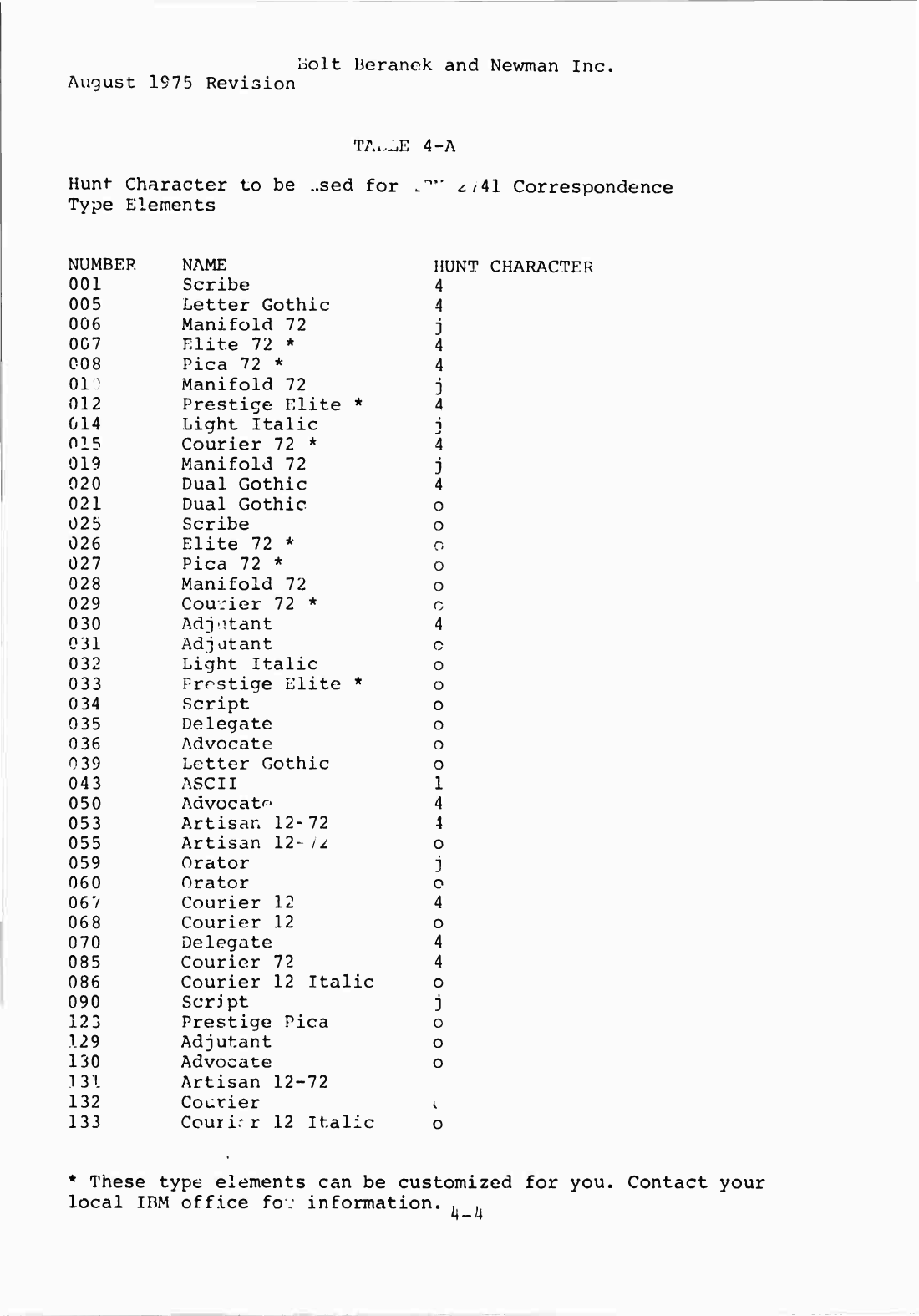
2741
Correspondence
Terminals
type
j,
4,
o,
or
1
depending
on
the
element
used
with
the
terminal
—
see
Table
4-A.
2741
PTTC
Terminals
type:
6
for
model*
938,
939,
96],
362,
or
997
o
for
model
942
or
943
v
for
model
94
7
or
94
8
f
for
model
963,
996,
or
998
ASCII
Terminais
transmitting
at
110
but
receiving
at
1200
baud
type
D.
(Again,
upper
case)
The
TIP
will
deduce
terminal
rate,
character
size,
and
code
conversion
based
on
the
character
typed.
When
the
TIP
makes
its
decision
it
types
out
TIP's
name
in
the
terminal's
own
language
followed
by
the
version
number
of
the
TIP
software
system
and
the
octal
port
number.
Then
it
is
ready
to
go.
If
no
TIP
name
appears,
or
if
garbage
appears,
hang
up
your
data
set
and
redial.
For
direct
connections
Power
Off
is
usually
equivalent
to
hanging
up.
Some
terminals
need
special
delays
at
the
end
of
their
lines
in
order
not
to
lose
characters
when
running
at
high
speed.
The
TIP
currently
knows
how
to
do
this
timing
for
the
ODEC
line
printer
and
several
other
devices.
The
two
commands
0
DEVICE
CODE
EXTRA-PADDING
/a
DEVICE
CODE
OTHER-PADDING
will
instruct
the
TIP
to
insert
these
delays.
One
device
we
know
of,
a
Model
37
Teletype,
requires
a
special
parity
computation
to
be
able
to
print
correctly.
The
command
@
DEVICE
CODE
37
*The
model
name
and
number
is
stamped
on
the
top
of
the
element.
If
you
can't
find
it,
trial
and
error
works.
Try
"f"
first.
iU2
Report
No.
2183
Bolt
Beranek
and
Newman
Inc.
August
1975
Revision
instructs
the
TIP
to
insert
the
proper
parity;
when
not
in
this
mode
the
TIP
sets
the
parity
bit
to
zero
for
all
output
characters.
Echoed
characters
are
echoed
without
parity
calculation.
These
commands
are
discussed
more
fully
in
section
5.
On
all
terminals
which
hunt
to
300
baud,
Device
Code
Extra-padding
((a
D
C
E)
automatically
will
be
in
effect.
On
all
terminals
which
hunt
to
150
baud,
Device
Code
37
(0
D
C
3)
automatically
will
be
in
effect.
These
effects
can
be
canceled
with
the
command
^DEVICE
CODE
ASCII
(0
D
C
A).
I-."5
August
1975
Revision
Bolt
Beranek
and
Newman
Inc.
TAi^E
4-A
Hunt-
Character
to
be
..sed
for
Type
Elements
41
Correspondence
NUMBER
NAME
HUNT
CHARACTER
001
Scribe
4
005
Letter
Gothic
4
006
Manifold
72
j
007
Elite
72
*
4
008
Pica
72
*
4
010
Manifold
72
j
012
Prestige
Elite
*
4
014
Light
Italic
I
015
Courier
72
*
4
019
Manifold
72
j
020
Dual
Gothic
4
021
Dual
Gothic
o
025
Scribe
o
026
Elite
72
*
0
027
Pica
72
*
0
028
Manifold
72
o
029
Courier
72
*
o
030
Adjutant
4
031
Adj
atant
o
032
Light
Italic
o
033
Prestige
Elite
*
o
034
Script
o
035
Delegate
o
036
Advocate
o
039
Letter
Gothic
o
043
ASCII
1
050
Advocate
4
053
Artisan
12-72
4
055
Artisan
12-
1
2
o
059
Orator
j
060
Orator
o
06
7
Courier
12
4
068
Courier
12
o
070
Delegate
4
085
Courier
72
4
086
Courier
12
Italic
o
090
Script
j
123
Prestige
Pica
o
129
Adjutant
0
130
Advocate
o
131
Artisan
12-72
132
Courier
<
133
Courir
r
12
Italic
o
*
These
type
elements
can
be
customized
for
you.
Contact
your
local
IBM
office
fo:
information.
.
.
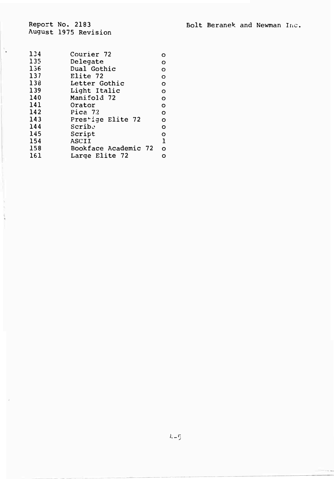
Report
No
,
2183
August
1975
Revision
134
Courier
72
o
135
Delegate
o
136
Dual
Gothic
o
137
Elite
72
o
138
Letter
Gothic
o
139
Light
Italic
o
140
Manifold
72
o
141
Orator
o
142
Pica
12
o
143
Prestige
Elite
72
o
144
Scribe
o
145
Script
o
154
ASCII
1
158
Bookface
Academic
72
o
161
Large
Elite
72
o
Bolt
Beranek
and
Newman
Inc.
iu^
Report
No.
2183
Bolt
Beranek
and
Newman
Inr-.
August
1975
Revision
B.
Establishing
Parameterr
In
stage
two,
the
user
is
concerned
with
initiaüizinq
parameters.
The
naive
user
should
skip
stage
two
and
accept
the
TIP's
default
parameters
until
an
obvious
problem
arises.
The
following
questions
are
answered
in
stage
two:
1.
When
shall
the
TIP
send
off
messages
to
the
remote
Host?
Here
there
are
several
options.
(The
TIP
is
initialized
to
send
on
every
character,
which
is
simple
but
inefficient.)
(9
TRANSMIT
NOW
(3
TRANSMIT
ON
MESSAGE-END
(3
TRANSMIT
ON
LINEFEED
(3
TRANSMIT
EVERY
#
TRANSMIT
NOW
causes
the
message
currently
being
accumulated
to
be
sent
as
soon
as
possible.
TRANSMIT
ON
MESSAGE-END
causes
a
message
to
be
sent
as
soon
as
possible
after
an
ASCII
DC3
(control-S)
is
encountered.
TRANSMIT
ON
LINEFEED
causes
a
message
to
be
sent
as
soon
as
possible
after
a
linefeed
is
encountered.
Additionally,
both
TRANSMIT
ON
MESSAGE-END
and
TRANSMIT
ON
LINEFEED
cause
characters
to
be
accumulated
in
the
message
buffer
until
it
is
almost
full.
TRANSMIT
EVERY
*
causes
a
message
to
be
sent
as
near
as
possible
to
every
#th
character.
The
command
TRANSMIT
EVERY
0
will
reset
the
TIP
to
its
initial
state,
transmitting
every
character.
If
the
parameter
to
TRANSMIT
EVERY
is
a
large
number
(e.g.,
250)
the
TIP
will
save
up
as
many
characters
as
it
can
before
sending
a
message,
but
does
not
offer
any
guarantee
that
the
total
number
specified
can
be
buffered.
2.
Who
shall
echo,
and
when?
Echoing
is
a
complex
problem,
without
any
neat
solution.
We
have
chosen
to
give
the
user
the
means
to
tell
us
how
he
wants
it
done,
since
it
is
hard
to
guess
correctly
in
advance.
Basically,
echoing
can
occur
at
the
terminal
hardware,
in
the
TIP,
or
m
the
remote
Host.
The
corresponding
TIP
commands
are:
0
ECHO
HALFDUPLEX
<
*cho
at
terminal)
(a
ECHO
ALL
(
:hc
at
TIP)
«a
ECHO
NONE
(bcho
at
remote
Host)
(a
ECHO
REMOTE
(Send
TELNET
"remote
echo"
a
1
id
perform
internal
P
E
N)
0
ECHO
LOCAL
(Send
TELNET
"local
echo"
and
perform
internal
(a
E
A)
In
the
ECHO
NONE
mode,
although
characters
for
the
remote
Host
are
not
echoed,
the
TIP
will
echo
commands.
Network
protocol
specifies
that
echoing
shall
start
out
in
the
ß
ECHO
ALL
or
0
FCHO
HALF
modes.
The
TIP
will
try
to
guess
from
the
terminal
type
which
of
the
two
is
appropriate.
The
goal
of
echoing
strategy
is
to
avoid
the
unreadable
alternatives
of
the
blank
page
and
the
doubling
of
every
character.
The
naive
user
is
advised
to
accept
14-6
Report
No,
2183
Bolt
Beranek
and
Newman
Inc.
August
1975
Revision
the
TIP's
default
parameters
until
trouble
of
this
sort
arises.
A
2741
is
incapable
of
changing
echo
mode;
it
is
always
echo
halfduplex.
To
allow
more
complex
echoing
conventions,
the
TELNET
protocol
provides
a
mechanism
whereby
the
remote
terminal
user
may
instruct
the
serving
Host
whether
or
not
to
echo
chara.!:ers.
The
ECHO
REMOTE
and
ECHO
LOCAL
commands
at
the
TIP
allow
TIP
users
to
use
this
mechanism
after
the
connection
is
made.
Finally,
many
Hosts
which
provide
service
request
the
TIP
to
allow
them
to
do
the
echoing.
The
TIP
always
grants
this
request
(even
for
2741
terminals)r
The
user,
if
he
does
not
desire
this
mode,
must
cancel
it
AFTER
the
connection
to
the
Host
is
established.
^-7
Report
No.
2183
Bolt
Beranek
and
Newman
Inc.
August
1975
Revision
C.
Connection
to
Remote
Sites
In
stage
three,
the
user
is-
concerned
with
establishing
a
connection
to
a
remote
site.
0
OPEN
15
This
amounts
to
"set
the
Host
number
parameter"
and
"add
the
user
to
the
queue
of
users
waiting
for
the
Tip's
connection
nechanism".
Appendix
A
lists
the
Host
numbers
of
all
the
sites
currently
in
the
network.
Connecting
to
a
Host
requires
establishing
a
bi-directional
link,
so
that
the
terminal
can
send
characters
to
the
Host
and
vice
versa.
The
request
to
connect
to
a
Host
is
thus
really
a
request
to
establish
both
transmit
and
receive
sections.
When
the
user
reaches
the
head
of
the
queue
waiting
for
the
TIP'S
"connection"
mechanism,
the
TIP
will
type
"Trying...".
Following
the
message
"^rying",
the
user
will
receive
some
of
the
following
messages:
Open
success*
Net
Trouble
remote
site
cannot
be
reached
Refused
remote
site
up
but
refusing
Host
Scheduled
Down
Until
Sat.
at
1850
GMT
Host
will
be
back
up
at
time
and
date
indicated
Host
r
n
s
c
he
d
u
l
e
d
Down
Until
Sat.
at
1850
GM^
Host
will
Lick
up
at
time
and
date
indicated
Host
not
responding
Remote
site
not
up,
unknown
when
up
service
will
resume
ICP
Interfered
With
The
Host
has
not
performed
the
ICP
correctly
and
the
TIP
has
refused
to
open
a
connection.
The
connection
mechanism
will
run
continuously
until
a
state
described
above
occurs.
This
can
be
annoying
when
the
remote
site
is
obviously
not
going
to
respond.
The
command
o
cLosr
-"Open"
indicates
both
halves
of
the
TELNET
connection
have
been
opened
simultaneously.
Sometimes
"Open
R"
followed
by
"Open
T'
(or
vice
versa)
will
be
printed;
this
too
indicates
both
halves
of
the
connection
have
been
opened,
but
not
simultaneously.
If
only
"Open
R"
or
"Open
T"
is
printed,
then
the
server
Host
has
failed
to
open
one
half
of
the
TELNET
connection.
^-6
Report
No.
2183
Bolt
Beranek
and
Newnan
Inc.
August
1975
Revision
will
abort
the
current
connection
attempt.
The
user
is
then
free
to
reattempt
to
open
the
connection
or
to
attempt
to
open
a
connection
to
some
other
Host.
The
TIP's
connection
mechanism
has
caused
users
some
problems.
Perhaps
a
discussion
of
what
the
connection
mechanism
is
doing
and
how
it
works
will
alleviate
some
of
the
grief.
First
of
all,
users
attempting
to
connect
to
different
Hosts
will
never
interfere
with
each
other,
although
users
simultaneously
attempting
to
connect
to
the
same
Host
will
be
serviced
serially.
For
the
user,
opening
proceeds
in
three
phases.
In
the
first,
the
user
is
queued
up
waiting
to
"c,et"
the
TIP's
connection
mechanism.
In
the
second,
the
user
has
gotten
the
TIP's
connection
mechanism
and
is
beginning
the
connection
sequence.
In
the
third,
the
user
has
completed
the
connection
sequence
and
i?
waiting
for
the
Host
to
open
up
the
actual
data
connections.
Many
of
the
problems
stem
from
the
fact
that
only
one
user
may
be
proceeding
through
phase
2
at
a
given
time
-o
a
given
Host.
Hence
the
the
TIP
types
out
"Trying"
when
you
get
off
the
queue
and
the
connection
mechanism
begins
trying
to
open
your
connections.
Thus
the
"Trying"
message
signifies
the
transition
from
phase
1
to
phase
2.
i*-9
Report
No.
2183
Bolt
Beranek
and
Newman
Inc.
August
1975
Revision
D.
Use
of
Remote
Sites
In
stage
four,
the
user
is
normally
talking
to
the
Host
without
concern
for
the
TIP.
All
the
TIP
commands
are
still
available.
One
command
that
will
eventually
be
of
interest
here
is
0
CLOSE
This
command
starts
the
shut-down
procedure.
The
TIP
will
echo
"Closed"*
when
the
process
is
finished.
The
TIP
does
not
know
how
to
log
you
out
of
the
remote
Host.
You
must
do
this
yourself
before
closing
the
connection.
The
virtual
terminal
has
a
key
labeled
"BREAK".
Some
real
terminal
have
a
break
key,
and
some
Host
systems
expect
to
see
breaks.
Those
terminals
with
a
break
key
(but
not
the
2741
ATTN
key)
may
simply
use
it.
Others
must
type
the
command
(9
SEND
BREAK
The
interpretation
of
the
break
is
entirely
up
to
the
receiving
Host
--
many
Hosts
ignore
it.
The
virtual
terminal
also
has
a
key
labeled
"SYNC".
No
real
terminals
have
such
a
key,
and
the
function
is
unique
to
network
use.
The
"SYNC"
key
is
a
clue
to
the
remote
Host
that
there
is
an
important
message
which
seems
to
be
buffered
in
an
"inaccessible"
place.
The
TIP
and
the
Host
go
to
some
trouble
to
get
the
SYNC
indication
over
a
different
channel
which
bypasses
the
normal
buffering
conventions.
The
command
to
send
a
SYNC
is
(3
SEND
SYNC
Typical
usage
of
these
commands
might
be
(a
S
B
followed
by
ß
S
S.
As
stated
earlier,
the
TIP
nominally
treats
a
carriage-
return
typed
by
a
user
as
a
carriage-return/linefeed.
The
user
may
cause
the
TIP
to
treat
carriage-return
as
only
caniage-return
by
executing
the
command
(aCLEAR
INSERT
LINEFEED
*"Closed"
indicates
that
the
server
Host,
agreed
to
close
both
halves
of
the
TELNET
connection
simultaneously.
If
the
halves
of
the
connection
are
closed
one
after
another,
"Closed
R"
followed
by
"Closed
T"
(or
vice
versa)
will
be
printed.
If
only
one
of
"Closed
T"
or
"Closed
R"
is
printed,
wait
a
minute
and
the
TIP
will
force
the
other
half
of
the
connection
to
be
closed.
^-10
Report
No.
2183
Bolt
Beranek
and
Newman
Inc.
August
1975
Revision
To
return
to
the
nominal
moae
of
carriage-return/lincfeod,
the
coirunand
(?INSERT
LINEFEED
should
be
executed.
If
at
any
given
time
the
user
types
characters
faster
than
a
server
Host
will
take
them
from
the
TIP,
the
TIP
discards
characters
it
can
not
buffer
and
echos
them
with
^n
ASCII
BEL
(on
a
2741,
the
type
element
is
wiggled).
The
user
may
sometimes
use
a
server
Host
with
which
it
is
desirable
not
to
have
(9
be
a
TIP
reserved
character.
The
user
can
change
the
character
which
introduces
TIP
commands
using
the
command
(aINTERCEPT
#
By
typing
^INTERCEPT
followed
by
a
decimal
number
representing
an
ASCII
character,
the
user
changes
the
TIP
command
character
for
his
device
to
the
ASCII
character
represented
by
the
number.
The
INTERCEPT
ESC
command
resets
the
TIP
command
character
to
at-sign
(§).
Thus,
0INTERCEPT
42
♦
I
N
TERCEPT
ESC
changes
the
TIP
command
character
to
asterisk
(*)
and
back
to
at-sign
C
3
)
assuming
the
device
was
in
the
nominal
mode
(G)
before
the
first
command
was
executed.
If
the
user
attempts
to
change
the
intercept
character
but
fails
to
type
a
valid
decimal
number
(or
a
character
string
beginning
with
E)
the
TIP
will
type
the
diagnostic
"Num"
and
will
set
the
intercept
character
to
at-sign.
^-11
Report
No.
2183
Bolt
Beranek
and
Newman
Inc.
August
1975
Revision
i-.
Connection
Loss
and
Restoration
Starting
with
TENEX
Hosts*
running
Software
Version
1.32,
if
TEMEX
halts,
the
TIP
will
notify
users
connected
to
it
of
this
fact
by
typing
"Connection
Suspended".
At
this
point
the
users
are
free
to
do
one
of
two
things.
First,
they
can
wait
till
TENEX
restores
service,
in
which
case
the
TIP
will
type
out
"Connection
Restored"
(or
if
after
the
the
service
interruption
the
connection
could
not
be
restored,
the
TIP
will
type
out
"Host
broke
the
connection").
Alternatively,
the
user
is
free
to
open
a
connection
to
any
other
Host,
in
which
case
the
TIP
will
invisibly
close
the
TENEX
connection.
It
is
also
important
to
point
out
that
if
a
user
just
leaves
his
terminal
unattended
across
a
TENEX
service
outage
without
releasing
the
connection
(any
network
related
command
such
as
@H,
(30,
(QN,
(ac
will
do
the
job)
his
job,
directory,
etc.,
are
left
at
the
mercy
of
anyone
who
acquires
that
terminal.
Other
Hosts
may
also
implement
the
mechanisms
which
will
allow
the
suspension
and
restoration
of
connections.
4-12
Report
No
2183
Bolt
Beranek
and
Newman
Inc.
August
1975
Revision
r
.
TIP
News
and
User
Feedback
There
is
frequently
information
which
the
group
developing
and
debugging
the
TIP
system wishes
to
convey
to
TIP
users.
For
instance,
when
a
bug
is
detected,
we
may
wish
to
warn
users
not
to
use
a
certain
feature
until
the
bug
is
fixed.
When
a
minor
improvement
is
made,
we
may
wish
to
notify
users.
Further,
there
is
frequently
news
about
the
state
of
the
network
or
the
state
of
a
particular
Host
which
should
ha
conveyed
to
TIP
users.
Finally,
TIP
userr
may
wish
to
communicate
with
the
TIP
development
staff
or
the
Network
Control
Center
staff
about
problems
or
suggested
improvements
for
the
TIP
or
the
network.
Consequently,
we
have
constructed
a
mechanism
which
we
hope
will
provide
for
communication
in
all
the
above
directions.
This
mechanism
is
the
Network
Virtual
TIP
Executive.*
To
activate
this
mechanism,
the
TIP
user
may
give
the
TIP
command
(aN.
This
command
causes
the
TIP
to
perform
the
necessary
protocol
to
make
a
connection
to
the
Network
Virtual
TIP
Executive
which
resides
on
severa]
of
the
network
TENEX
systems.
Once
the
Network
Virtual
TIP
Executive
has
Deen
activated,
we
think
its
operation
is
self-explanatory.
Presently
available
features
within
the
Network
Virtual
TIP
Executive
are
a
Network
News
feature,
a
Host
Status
feature,
and
a
"Gripe"
feature.
The
latter
provides
users
with
a
mechanism
for
sending
messages
to
the
TIP
development
or
NCC
staffs.
We
recommend
that
TIP
use^s
get
the
network
news
at
the
beginning
of
every
TIP
session.
The
TIP
will
normally
prompt
the
user
to
consider
reading
the
news
by
typing
the
message:
Latest
net
news
DATE
Use
"QlKcrs"
followed
by
"netnews<cr>"
at
some
point
(s)
during
the
usei'«5
session.
The
point
chosen
is
at
the
time
of
terminal
recognition
for
"hunting"
terminals
(see
Section
4.A),
or
at
each
time
a
connection
is
closed
for
"non-huntirg"
terminals
(see
Section
5.A).
When
a
user
issues
an
^N
command,
the
TIP
requests
support
from
all
cooperating
servers.
Thus,
the
user
should
be
able
to
reach
a
news
facility.
somewhere,
almost
all
of
the
time.
However,
in
the
event
that
no
cooperating
server
is
available
the
TIP
will
time
out
the
(3N
command
in
about
thirty
seconds.
An
@C
command
will
abort
an
(^N
immediately.
*A
version
of
the
Resource
Sharing
Executive
being
developed
by
the
BBN
TENEX
Group.
4-13

Report
No.
2183
Bolt
Beranek
and
Newman
inc.
August
1975
Revision
Of
course,
TIP
users
with
an
immediate
need
for
communication
with
the
NCC
or
TIP
development
staffs
should
telephone
(collect)
the
Network
Control
Center
(617-661-0100).
Users
with
general
questions
about
network
usage
(How
do
I
find
out
if
Host
X
is
ever
going
to
be
up
again?
What's
happening
with
a
Host/Host
protocol
for
graphics?)
may
also
call
the
NCC.
H-1H
Report
No.
218
3
Bolt
Beranek
and
Newnan
Inc.
August
1975
Revision
5.
UNUSUAL
USES
OF
THE
TIP
The
"usual"
use
of
a
TIP
is
to
connect
one
of
the
terminals
which
the
TIP
supports
to
a
remote
Host.
We
have
tried
to
make
this
operation
as
easy
and
natural
as
possible
for
the
user.
"Unusual"
uses
of
the
TIP
are
such
things
as
connectincr
a
non-standard
terminal,
talking
terminal-to-terminal,
or
using
unusual
protocols.
Such
uses
are
possible,
but
within
the
constraints
of
the
TIP's
size
it
has
not
always
been
feasible
to
make
them
easy.
5-1
Report
No.
2183
August
1975
Revision
Bolt
Beiranek
and
Newman
Inc.
A.
Device
Parameters
The
TIP
uses
a
Hunt
algorithm
to
aetermine
device
parameters.
On
standard
low
speed
terminals
it
works
well
and
easily.
If
something
more
complicated
is
desired,
like
entablishinq
a
rate
over
300
bps,
the
user
must
set
these
parameters
himself.
The
^DEVICE
RATE
command
does
not
affect
the
hunt-bit.
Therefore,
the
only
way
to
change
a
port
to,
or
from,
being
hunting
is
to
have
the
TIP
site
liaison
call
the
NCC
and
have
it
done.
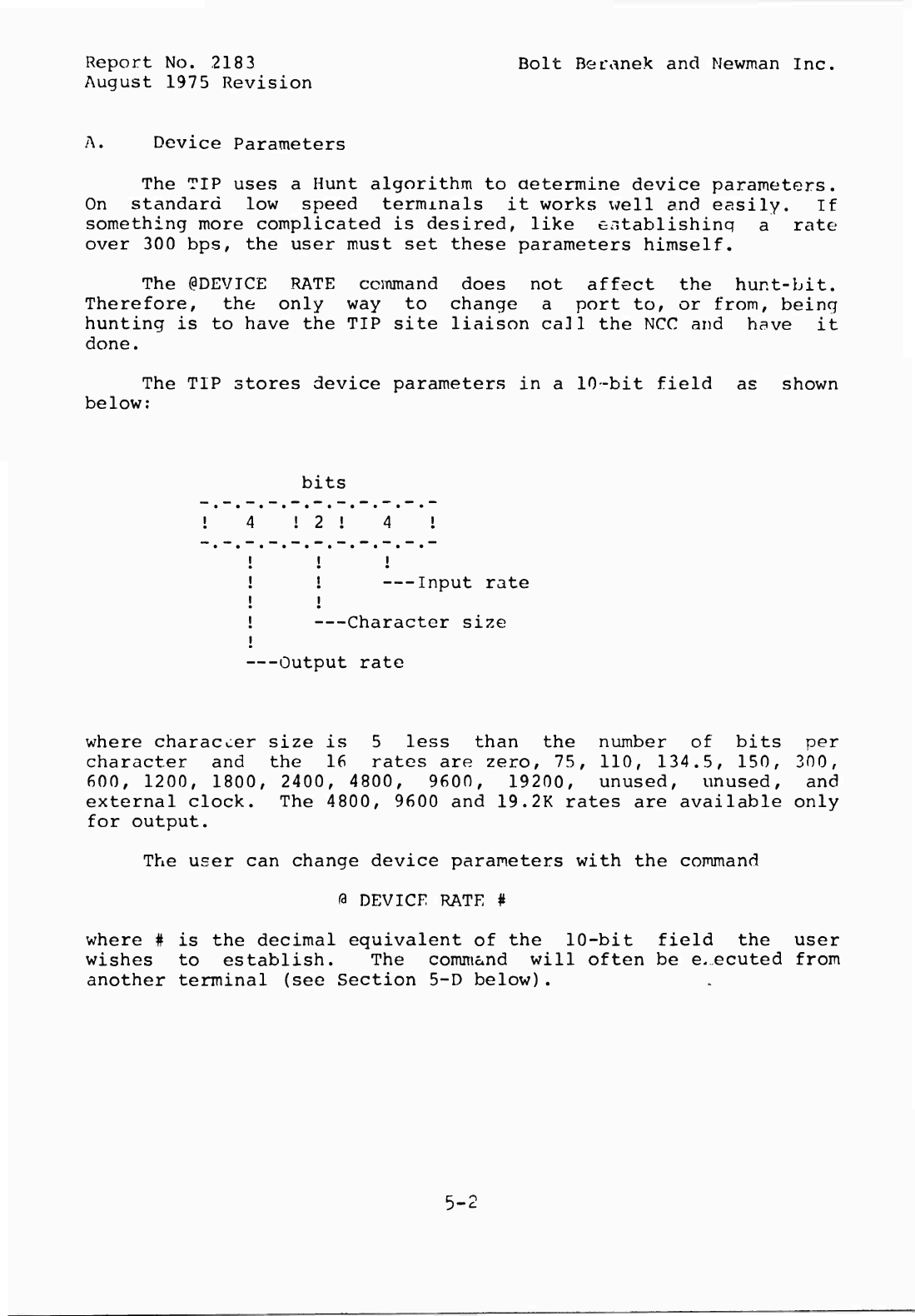
The
TIP
stores
device
parameters
in
a
10-bit
field
below:
as
shown
bits
1
2
!
t
i
!
I
np
u
t
rate
i
Character
size
Output
rate
where
character
size
is
5
less
than
the
number
of
bits
per
character
and
the
16
rates
are
zero,
75,
110,
134.5,
150,
300,
600,
1200,
1800,
2400,
4800,
9600,
19200,
unused,
unused,
and
external
clock.
The
4800,
9600
and
19.2K
rates
are
available
only
for
output.
The
user
can
change
device
parameters
with
the
command
0
DEVICE
RATE
#
where
#
is
the
decimal
equivalent
of
the
10-bit
field
the
user
wishes
to
establish.
The
command
will
often
be
executed
from
another
terminal
(see
Section
5-D
below).
Report
No.
2183
Bolt
Poranek
and
Newman
Inc.
August
1975
Revision
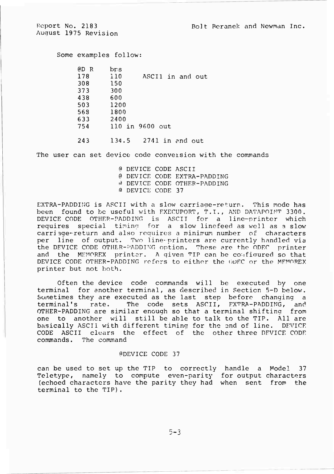
Some
examples
follow:
@D
R
bps
178
110
ASCII
i
308
150
373
300
438
600
503
1200
568
1800
633
2400
754
110
in
9600
out
243
134.5
2741
in
and
out
The
user
can
set
device
code
conversion
with
the
commands
(3
DEVICE
CODE
ASCII
(9
DEVICE
CODE
EXTRA-PADDING
«3
DEVICE
CODE
OTHEP-PADDING
fa
DEVICE
CODE
37
EXTRA-PADDING
is
ASCII
with
a
slow
carriacre-return.
This
mode
has
been
found
to
be
useful
with
EXECUPORT,
T.I.,
AND
DATAPOINT
3300.
DEVICE
CODE
OTHEP-PADDING
is
ASCII
for
a
line-printer
which
requires
special
timinn
for
a
slow
linefeed
as
well
as
a
slow
carri
age-return
and
also
requires
a
minimum
number
of
characters
per
line
of
output.
Two
line-printers
are
currently
handled
via
the
DEVICE
CODE
OTHER-PADDING
option.
These
are
the
ODEC
printer
and
the
MEMOREX
printer.
A
qiven
^IP
can
be
co-ifinured
so
that
DEVICE
CODE
OTHER-PADDING
refers
to
either
the
OUKC
nr
the
MFMOREX
printer
but
not
both.
Often
the
device
code
commands
will
be
executed
by
one
terminal
for
another
terminal,
as
described
in
Section
5-D
below.
Sometimes
they
are
executed
as
the
last
step
before
changing
a
terminal's
rate.
The
code
sets
ASCII,
EXTRA-PADDING,
and
OTHER-PADDING
are
similar
enough
so
that
a
terminal
shifting
from
one
to
another
will
still
be
able
to
talk
to
the
TIP.
All
are
basically
ASCII
with
different
timing
for
the
3nd
of
line.
DEVICE
CODE
ASCII
clears
the
effect
of
the
other
three
DEVICE
CODE
commands.
The
command
ODEVICE
CODE
37
can
be
used
to
set
up
the
TIP
to
correctly
handle
a
Model
37
Teletype,
namely
to
compute
even-parity
for
output
characters
(echoed
characters
have
the
parity
they
had
when
sent
from
the
terminal
to
the
TIP).
5-3
Report
No.
2183
Bolt
Beranek
and
Newman
Im
igust
1975
revision
B.
Talking
to
Another
TIP
One
can
talk
to
a
device
on
another
TIP
(or
your
own
TIP)
using
the
TIP
as
a
fancy
telephone
connection.
This
is
not
particularly
easy,
especially
since
the
only
label
a
TIP
knows
for
a
device
is
its
hardware
port
number,
which
neither
user
may
happen
to
know.
Supposing
the
port
numbers
arc
known,
one
must
establish
a
pair
of
connections
between
the
two
ports.
The
protocol
for
makinc-
connections
specifies
that
each
end
of
each
connection
will
be
labeled
by
a
32-bit
socket
number.
The
TIP
puts
the
port
number
in
the
high
order
16
bits
of
the
r
cket
number,
and
2
(or
3)
in
the
low
order
bits
for
the
receiving
(or
sending)
socket.
The
user
must
tell
the
TIP
the
Host
number
(in
decimal)
and
socket
number
(in
octal)
for
the
foreign
end
of
both
the
transmit
and
receive
connections,
for
example,
the
commands
0
SEND
TO
HOST
158
(9
RECEIVE
FROM
HOST
15
8
(d
SEND
TO
SOCKET
1600002
(a
RECEIVE
FROM
SOCKFP
1600003
Simultaneously
the
far
end
must
establish
the
corresponding
parameters
for
his
half
of
the
connection.
Then
one
side
or
the
other
must
initiate
the
connections
usinn
the
two
commands
%
PROTOCOL
TO
TRANSMIT
a
PROTOCOL
TO
RECEIVE
This
will
open
the
full
duple:-:
connection.
In
the
example
above
the
connection
is
to
Pore
7
-it
Host
158.
Alternately,
a
shorter
sequence
of
commancls
nay
be
used,
namely
(a
HOST
158
0
SEND
TO
SOCKET
1600002
<a
RECEIVE
FROM
SOCKET
1
160000
3
(3
PROTOCOL
BOTH
If
the
terminals
are
full
duplex,
it
will
probably
be
necessary
for
each
terminal
to
use
ECHO
ALL
mode.
A
problem
in
making
TlP-to-^jp
connections
is
ascertaining
the
port
numbers
of
the
TIP
ports
between
which
communication
is
desired.
The
greeting
message
typed
by
the
TIP
on
a
huntina
port
incluoes
the
octal
port
number.
The
ORESET
command
on
non-hunting
ports
also
provides
this
information
(although
it
also
logs
out
a
logged-in
user).
In
addition,
the
The
Network
Virtual
TIP
Executive
((SN)
offers
aid
in
this
area
through
its
TRMINF
command.
The
socket
number
printed
by
the
TRMINF
command
is
the
octal
port
number
of
the
TIP
terminal
executina
the
TRMINF
command
via
the
@N
command.
In
the
future,
we
will
make
available
via
the
Network
Virtual
TIP
Executive
a
capability
to
link
and
send
messages
to
users
on
5-^
Report
No.
2183
Bolt
Beranek
and
Newrian
Inc.
August
1975
Revision
other
TIPs
and
TIP
ports
by
name.
The
capability
already
exists
in
the
Network
Virtual
TIP
Executive
for
linking
to
users
of
some
server
Hosts.
5-5
Report
No.
2183
Bolt
Beranek
and
Newnan
Inc.
August
1975
Revision
C.
Binary
Mode
Seven-bit
binary
is
possible
using
the
regular
TELNET
Protocol.
It
is
necessary
to
turn
on
and
off
command
interpretation
to
allow
the
TIP
input
routines
to
pass
along
all
128
possible
input
characters.
There
are
two
commands
to
do
this,
(9
INTERCEPT
ESC
(9
INTERCEPT
NONE
The
first
command
puts
the
TIP
in
its
normal
mode,
the
second
in
7-bit
binary
mode.
Eight-bit
binary
mode
is
possible
asing
the
commands
(3
BINARY
INPUT
START
(?
BINARY
INPUT
END
(9
BINARY
OUTPUT
START
(3
BINARY
OUTPUT
END
When
a
TIP
is
in
binary
output
mode,
all
eight
bits
of
characteis
coming
from
the
network
are
sent
to
the
terminal.
This
nay
result
in
strange
things
being
printed
on
a
printer.
It
would
probably
make
more
sense
to
send
8-bit
binary
output
to
devices
such
as
paper
tape
punches.
When
a
TIP
is
in
binary
input
mode,
all
eight
bits
of
characters
entered
at
the
terminal
are
sent
to
the
network.
Since
commands
from
a
terminal
in
binary
input
mode
or
INTERCEPT
NONE
mode
can
no
longer
be
recognized,
removing
a
terminal
from
these
modes
must
be
done
with
a
command
from
another
terminal
as
described
immediately
below.
As
the
Tip's
default
mode
is
INSERT
LINEFEED,
the
user
will
probably
desire
to
CLEAR
INSERT
LINEFEED
(OC
I
L)
before
using
8-bit
binary
mode;
perhaps
also
for
7-bit
binary
mode.
5-6
Report
No.
2183
Bolt
Beranek
and
Newman
Inc.
August
1975
Revision
D.
Setting
Another
Terminal's
Parameters
Any
command
may
be
preceded
by
a
number,
in
which
case
it
is
meant
for
a
device
other
than
your
own.
The
device
port
number
must
be
in
octal.
For
example,
§
16
DEVICE
RATE
6
33
would
set
the
characteristics
for
device
16
to
ASCII
code,
2400
baud
input
and
output.
In
this
case
we
speak
of
"capturing"
device
16.
Such
a
mechanism
needs
some
form
of
protection:
the
TIP
remembers
the
number
of
the
capturing
device
and
does
not
allow
a
second
device
also
to
capture
until
the
first
device
explicitly
gives
up
control
with
the
command
§
16
GIVE
BACK
If
a
device
chooses
to
capture
himself
by
preceding
any
command
by
his
own
device
number
he
is
then
invulnerable
to
tampering
from
another
device.
This
format
is
usually
used
in
conjunction
with
the
DEVICE
RATE
command
to
initialize
some
non-standard
device,
like
a
printer
or
a
high-speed
CRT
terminal.
5-7
Report
No.
218
3
Bolt
Beranek
and
Newman
Inc.
August
1975
Revision
K.
The
DIVERT
OUTPUT
Command
It
is
possible
(with
some
care)
to
divert
the
output
intended
for
one
terminal
to
another
terminal.
Presumably
the
jecond
terminal
has
a
desired
feature,
like
hard
copy
or
high
speed.
The
command
(3
16
DIVERT
OUTPUT
will
cause
all
remotely
generated
output
to
be
diverted
from
the
terminal
on
which
the
cor-jnand
was
typed
to
Terminal
16.
This
state
will
continue
until
any
other
command
is
executed
at
the
diverting
terminal.
(Executing
another
command
does
not
do
a
Give
Back.)
Local-echoing
will
not
be
diverted,
and
input
may
proceed
at
the
diverting
terminal.
This
mechanism
is
not
natural
to
the
structure
of
the
program.
In
particular,
the
buffer
allocation
structure
becomes
confused
if
the
diversion
aborts
while
output
is
in
progress.
Chained
diversion
will
also
confuse
the
TIP.
Please
don't
try
these
things:
all
that
will
happen
is
that
one
or
both
terminals
involved
will
stop
responding.
In
fact,
in
general,
we
discourage
use
of
the
DIVERT
OUTPUT
command
and
sugaest
printing
to
TIP
devices
other
than
the
user's
own
terminal
by
programs
Guch
as
the
TIPCOPY
program
which
runs
on
many
network
TENEXs.
5-3
Report
No.
2183
Bolt
Beranek
and
Newman
Inc.
August
1975
Revision
F.
Editing
At
the
moment
the
only
editing
command
available
is
(a
FLUSH
'
hich
deletes
all
the
characters
in
the
TIP's
input
buffer.
In
current
practice
this
command
is
used
to
clear
out
any
odd
characters
stuck
in
a
TIP
prior
to
giving
an
OPEN
command.
(The
TIP
accumulates
characters
typed
in
during
periods
of
non-connection
and
sends
them
as
the
first
data
over
a
new
connection.)
To
abort
a
command,
type
a
rubout
or
merely
make
something
about
the
command
illegal;
for
example,
(30
X
The
"X"
aborts
the
OPEN
command.
5-9
Report
No.
2183
Bolt
Beranek
and
Newman
Inc.
August
1975
Revision
G.
Wild
Setting
a
device
wild
allows
the
device
to
receive
any
connection
from
a
designated
Host
or
to
receive
any
connection
from
any
Host.
TIP
ports
cannot
be
set
permanently
wild
from
other
TIP
ports,
they
must
be
set
wild
by
the
NCC.
The
command
to
set
a
port
wild
is
(aSET
DEVICE
WILD
This
instructs
the
TIP
to
accept
an
attempt
to
connect
from
any
Host
using
any
sockets.
This
command
can
be
cancelled
by
the
command
PCLEAR
DEVICE
WILD
If
a
user
desires
to
accept
an
attempt
to
connect
from
a
particular
Host
using
any
sockets
the
set
of
commands
moST
#
(aSEND
TO
WILD
(aRFCEIVE
FROM
WILD
should
be
used.
This
instructs
the
TIP
to
accept
any
attempt
to
connect
from
the
Host
whose
decimal
address
is
specified
in
the
Host
command.
5-10
Report
No.
2183
Bolt
Beranek
and
:
T
e
wman
Inc.
August
1975
Revision
11.
Low
level
Protocol
Commands
Several
low
level
TIP
commands
exist
which
allow
the
user
to
manually
do
Host/Host
protocol.
These
commands
are
^
INITIAL
CONNECTION
PROTOCOL
(3
PROTOCOL
BOTH
§
CLOSE
(3
PROTOCOL
TO
TRANSMIT
(3
PROTOCOL
TO
RECEIVE
(3
RECEIVE
FROM
HOS^
#
(3
SEND
TO
HOST
#
(3
HOST
#
13
SEND
TO
SOCKET
#
(3
RECEIVE
FROM
SOCKET
#
Examples
of
the
use
of
some
of
these
commands
are
given
below.
(3H
69
/"logging
in"
to
a
socket
(3R
F
S
13
/other
than
socket
1
(31
C
P
/on
a
server
Host
(3C
/attempt
to
close
both
halves
of
/an
open
connection
Closed
R
/closed
R
side
of
connection
Closed
T
/closed
T
side
of
connection
The
rest
of
the
low
level
protocol
commands
listed
above
were
used
in
the
example
of
section
5-B.
There
is
one
other
low
level
protocol
command,
a
command
to
reset
the
NCP
in
the
Host
specified
in
a
ß
SEND
TO
HOS^
command.
Since
this
command
resets
all
connections
between
the
TIP
and
the
specified
Hoc"
-
,
it
should
only
be
used
as
a
last
resort.
A
responsible
person
at
the
TIP
site
should
contact
the
NCC
if
the
need
arises.
5-11
Report
No.
2183
Bolt
Beranek
and
Newman
Inc.
August
1975
Revision
I.
Commands
from
tne
Network
When
a
TIP
terminal
receives
the
character
207
(octal)
in
the
input
stream
from
the
network,
the
characters
following
the
207
up
to
the
next
linefeed
are
treated
as
a
command
typed
on
the
terminal
keyboard.
(The
207
takes
the
place
of
the
(3;
the
P
should
not
be
sent
through
the
network.)
In
this
way
Hosts
can
remotely
control
the
TIP
terminals.
For
example,
a
Host
might
send
a
command
to
the
TIP
which
causes
maximum
size
messages
to
be
sent
from
the
TIP
terminal
to
the
Host.
The
TIPs
themselves
can
send
commands
to
other
TIP
terminals
by
using
the
command
@
SEND
COMMAND
which
inserts
the
207
character
in
the
output
stxeam
to
the
network.
This
feature
is
evolving,
so
we
do
not
recommend
its
use
at
the
present
time.
5-1?
Report
No.
2183
Bolt
Bera»iek
and
Newman
Inc.
August
1975
Revision
J.
The
RESET
Device
Command
The
reset
device
command
(PRESET)
will
restore
a
port
to
its
initial
state.
Implicit
in
this
command
is
the
concept
of
a
"permanent
device."
Currently,
"permanent"
is
the
same
as
"non-hunting"
(see
section
5~A),
but
this
will
not
always
be
so.
Permanent
devices
are
those
requiring
a
particular
set
of
parameters
that
is
not
expected
to
change
or
perhaps
for
which
the
TIP
cannot
hunt.
Examples
are
the
IMLAC
(no
high
speed
hunt)
and
a
line
printer
(no
input
possible).
Everything
is
reset
as
follows:
a.
All
network
connections
and
attempts
to
open
connections
are
cleared;
b.
If
this
device
is
captured
by
any
other
device,
that
state
ii.
cleared
and
if
this
device
is
capturing
any
other
devices,
that
state
is
cleared;
c.
Input
buffers
are
initialized;
d.
"Connection"
parameters
are
reset
to
a
default
state*
(i.e.,
echoing
all,
terminate
every
character,
no
insert
linefeed,
no
device
wild,
intercept
all);
e.
The
code,
rate,
and
size
are
set
to
the
hunting
state.
f.
The
port's
data
set
is
hung-up.
For
permanent
devices
the
RESET
command
does
only
a,
b,
c,
and
f
above
and
prints
"TIP
NAME"
followed
by
the
TIP
version
number
and
the
octal
port
number.
*The
default
state
for
"binary"
mode
(Section
5.C)
is
rather
complicated
and
is
being
somewhat
revised.
For
current
infor-
mation,
contact
the
NCC.
5-13
Report
No.
2183
Bolt
Beranek
and
Newman
Inc.
August
1975
Revision
K.
TIP
Configuration
and
Device
Pre-imtialization
The
set
of
terminals
and
uses
of
these
terminals
typically
varies
from
TIP
site
to
TIP
site.
Therefore,
the
TIP
software
system
has
been
constructed
in
a
way
which
is
somewhat
modular
to
permit
varying
configurations
of
the
TIP
software
at
different
sites.
For
instance,
with
line
printers,
it
is
possible
for
a
given
TIP
system
to
contain
code
to
handle
an
ODEC
line
printer
or
a
MEMOREX
line
printer
or
neither
(not
both).
As
another
example,
it
is
possible
to
distribute
the
available
space
for
device
buffers
among
all
sixty-three
TIP
ports
or
to
allocate
the
available
space
to
only
a
few
ports
(thus
effectively
disabling
the
remaining
ports).
Finally,
it
is
possible
to
configure
the
TIP
so
certain
ports
are
automatically
set
up
to
have
pre-determined
parameters
at
TIP
initialization
time,
thus
relieving
TIP
site
personnel
or
users
of
the
burden
of
manually
setting
up
these
device
parameters.
The
complete
list
of
presently
available
options
is
given
below:
1.
TIP
configured
with
ODEC
code
or
MEMOREX
code
or
neither.
2.
TIP
configured
with
EXTRA-PADDING
code
or
without
it.
3.
TIP
port
pre-initialization
a.
Input
buffer
size
b.
Output
buffer
size
c.
Input
rate
d.
Output
rate
e.
No
hunt
or
hunt
(see
section
A)
f.
Extra-padding
(D
C
F)
or
not
g.
Other-padding
(D
C
0)
or
not
h.
Wild
(S
D
W)
or
not
i.
No
insert
linefeed
(C
I
L)
or
not
j.
Half
duplex
(E
H)
or
not
k.
No
intercept
character
(I
N)
or
any
intercept
character
1.
Echo
none
(E
N)
or
not
m.
Compute
37
parity
(D
C
3)
or
not
Of
the
above,
f
and
g
are
mutually
exclusive,
j
and
1
are
mutually
exclusive,
and
f
through
m
depend
on
e
being
set
to
no
hunt.
Some
configuration
must
be
specified
for
each
TIP.
If
nothina
is
specified
by
the
TIP
site
personnel,
the
TIP
will
be
configured
in
an
arbitrary
(but
hopefully
reasonable)
manner.
Requests
for
specific
TIP
configurations
should
be
made
by
the
designated
representative
of
the
TIP
site
to
the
Network
Control
Center.
5-14
Report
No.
2183
Bolt
Beranek
and
Newman
Inc.
August
1975
Revision
6.
MAPPING
THE
VARIOUS
DEVICES
INTO
THE
NETWORK
VIRTUAL
TERMINAL
A.
TTY
and
TTY-like
Devices
(ASCII)
At
the
moment
this
conversion
follows
the
simple
rule
that
if
the
terminal
can
generate
and/or
print
the
code
it
will
be
sent
and/or
received.
Otherwise
there
is
no
way
to
use
the
code.
For
example,
there
is
no
way
to
enter
lower
case
characters
from
a
Model
33
Teletype.
B.
2741
and
2741-like
Devices
(transmit
interrupt
and
receive
interrupt
options
required)
The
rule
for
these
devices
is
if
the
terminal
has
the
ASCII
graphic
it
will
translaue
directly
to
that
graphic.
Otherwise
a
number
of
equivalences
are
defined,
most
of
which
consist
of
the
character
double-quote
followed
by
some
other
character.
For
each
of
the
eight
variations
of
2741
that
we
have
considered
there
is
at
least
one
way
to
type
in
the
desired
ASCII
graphic.
To
actually
type
in
the
character
double
quote,
two
double
quotes
must
be
struck
in
succession.
On
output,
ASCII
characters
which
print
on
a
Model
37
Teletype
but
have
no
representation
on
a
2741
are
printed
as
the
equivalents
used
to
type
in
the
character,
with
some
exceptions.
ASCII
characters
which
do
not
print
on
a
Model
37
Teletype
do
not
print
on
a
2741.
A
double
quote
is
not
printed
as
two
double
quotes;
thus,
on
output
the
user
must
sometimes
determine
what
was
printed
from
the
context
as
there
is
no
urambiguous
representation
of
all
the
ASCII
characters.
The
ATTN
key
is
used
to
interrupt
output.
It
signals
the
TIP
to
hold
off
output
for
the
duration
of
one
TIP
command;
it
is
not
seen
by
the
remote
Host.
If
used
during
input
it
is
taken
as
a
request
to
send
all
the
accumulated
characters
to
the
remote
Host
(like
^TRANSMIT
NOW).
6-1

Report
No.
2183
Bolt
Beranek
and
Newman
Inc.
Dec.
1974
Update
C.
ASCII/2741
Conversion
Table
If
this
table
is
printed
on-line,
it
is
meant
to
be
printed
on
a
printer
possessing
the
full
ASCII
character
set.
Except
where
noted,
on
input,
any
of
the
alternate
2741
representations
of
the
ASCII
character
which
it
is
possible
to
type
on
the
given
2741
may
be
used.
On
output,
the
single
character
representation
is
chosen
when
possible.
In
the
"Symbol"
column
of
the
tablp,
t
is
used
to
indicate
control;
e.g.,
iR
means
control-R.
Not
all
ASCII
terminals
have
a
left
arrow
—
some
have
an
urderbar
instead.
Likewise,
some
ASCII
terminals
have
a
caret
where
others
have
an
uparrow.
6-2
12/74
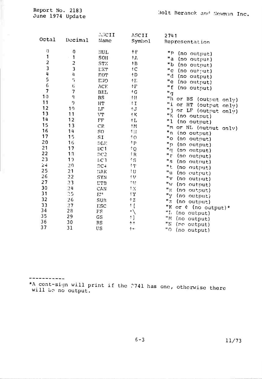
Report
No.
2183
June
1974
Update
Jolt
Beranek
anr'
Mnv/min
Inc.
Octal
Decimal
0
1
2
3
a
5
r,
7
10
11
12
13
la
15
16
17
20
21
22
23
24
25
26
27
30
31
32
33
34
35
36
37
0
1
2
3
i|
5
h
1
0
10
11
12
13
ia
15
16
17
13
10
JO
21
22
23
2a
25
2
6
27
28
29
30
31
A.SCII
rJame
MUL
SOU
STX
I;XT
FOT
E;JO
ACK
BEL
BS
HT
LF
VT
FF
CR
SO
SI
DLF
DC1
PC
2
DC3
.004
rjAK
SYN
ETS
CAN
E.
M
sun
ESC
FS
GS
RS
US
ASCII
Symbol
n*
tA
tc
ID
tr,
tG
IH
IT
A
J
+
K
1L
tM
tM
^O
tp
'Q
fR
ts
tu
tv
tw
tx
iy
tz
M
t]
tf
-t-
2741
Representation
"P
(no
output)
"a
(no
output)
"b
(no
output)
"c
(no
oufr>ut)
"d
(no
output)
"e
(no
output)
M
f
(no
outnut)
"a
"h
or
BS
(output
only)
M
i
or
HT
(output
onlv)
M
j
or
LF
(output
onlv)
"k
(no
output)
"1
(no
output)
"m
or
NL
(outnut
onlv)
"n
(no
output)
"o
(no
output)
"p
(no
output)
"q
(no
output)
"r
(no
output)
"s
(no
outnut)
"t
(no
output)
"u
(no
output)
"v
(no
output)
M
w
(no
outnut)
"x
(no
output)
"y
(no
output)
"?.
(no
output)
"K
or
<;
(no
output)*
"L
(no
output)
"M
(no
output)
"N
(no
output)
"0
(no
output)
*A
ccnt-siyn
will
print
if
the
r741
has
one,
otherwise
there
will
bo
no
output.
n-j
11/73
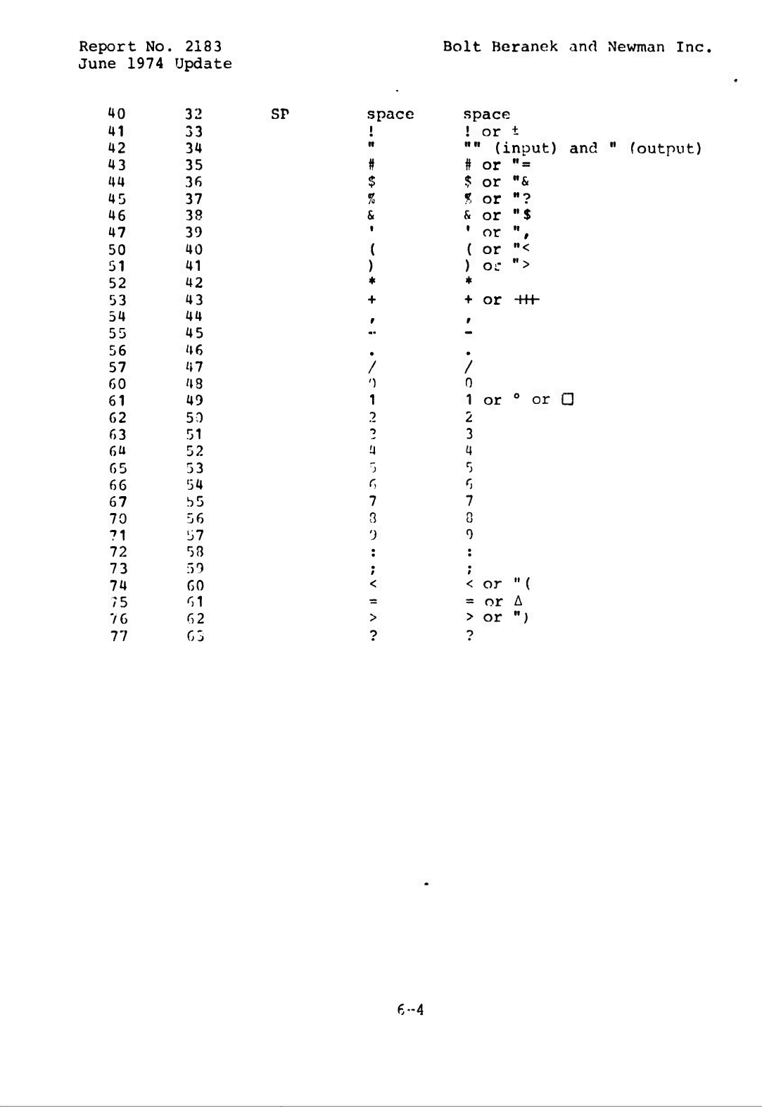
Report
No,
.
2183
June
1974
Update
40
32
41
33
42
34
43
35
44
36
45
37
46
38
47
39
50
40
51
41
52
42
53
43
54
44
55
45
56
46
57
47
60
43
61
49
62
50
63
51
6a
52
65
53
66
54
67
55
70
56
71
57
72
5B
73
59
74
60
75
61
76
62
77
65
Bolt
Beranek
and
Newman
Inc.
SP
space
i
•
*
+
space
!
or
t
,,M
(inout)
and
"
#
or
"
=
$
or
M
&
%
or
"7
&
or
"$
1
or
(
or
)
or
+
or
-H-h
foutput)
•I
••<
">
/
/
')
0
1
1
or
0
or
a
2
2
2
3
'4
a
")
5
6
6
7
7
3
0
')
0
•
•
•
t
<
<
or
"
(
-
s
or
A
>
>
or
")
o
•?
6-4
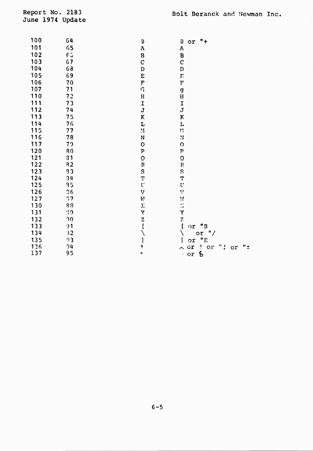
Report
No.
.
2183
June
1974
Update
100
64
101
65
102
6G
103
67
10U
68
105
69
106
70
107
71
110
72
111
73
112
74
113
75
114
76
115
77
116
78
117
79
120
80
121
31
122
82
123
83
12U
34
125
85
126
n6
127
^7
130
88
131
0
>9
132
yo
133
yi
134
)2
135
^3
136
04
137
95
Bolt
Beranck
and
Newman
Inc.
3
3
or
"+
A
A
B
B
C
C
D
D
E
F
F
F
r,
g
H
ii
I
i
J
J
K
K
L
L
M
n
N
M
0
0
P
P
0
0
R
R
S
S
T
T
V
U
V
\r
w
W
X
M
Y
Y
z
7
1
[
or
M
B
\
\
or
V
]
1
or
"E
i
/N
or
^
or
"«-
or
t
or
•»
+
6-5
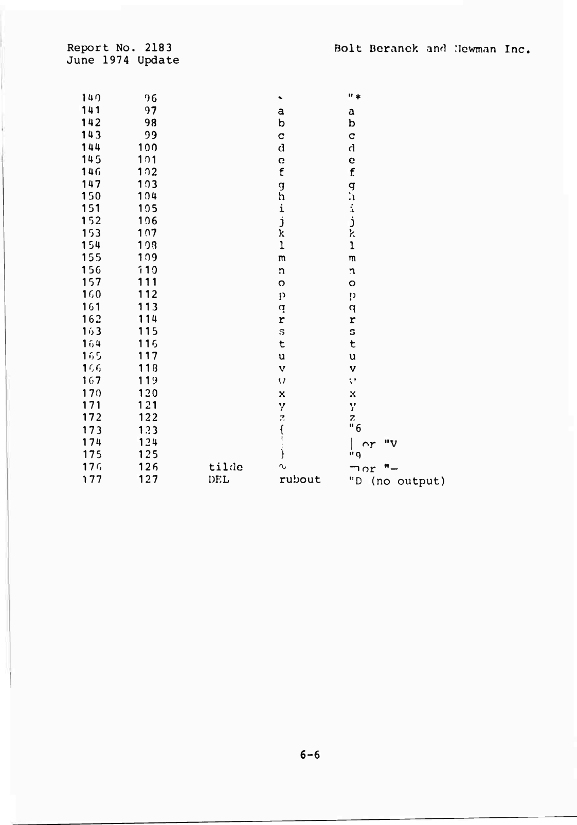
Report
No
.
2183
June
1974
Update
mo
f
)6
141
97
142
98
143
99
144
100
145
101
146
102
147
103
150
104
151
105
152
106
153
107
154
10^
155
109
15G
110
157
111
1G0
112
161
113
162
114
163
115
1n4
116
K>5
117
1
C
0
118
1G7
119
170
120
171
121
172
122
173
123
174
124
175
125
170
126
177
127
Bolt
Deranck
aivl
:icwm<in
Inc.
"
*
a
b
a
b
c
6
c
f
c
f
9
h
i
'L
j
k
1
j
k
1
m
TTl
n
n
o
o
P
n
r
q
r
s
G
t
t
u
u
V
V
w
;'
X
X
y
'{
if
7.
"6
tilde
DEL
1
;
i
/
rubout
j
nr
"V
-ior
,,
-
"D
(no
output)
6-6
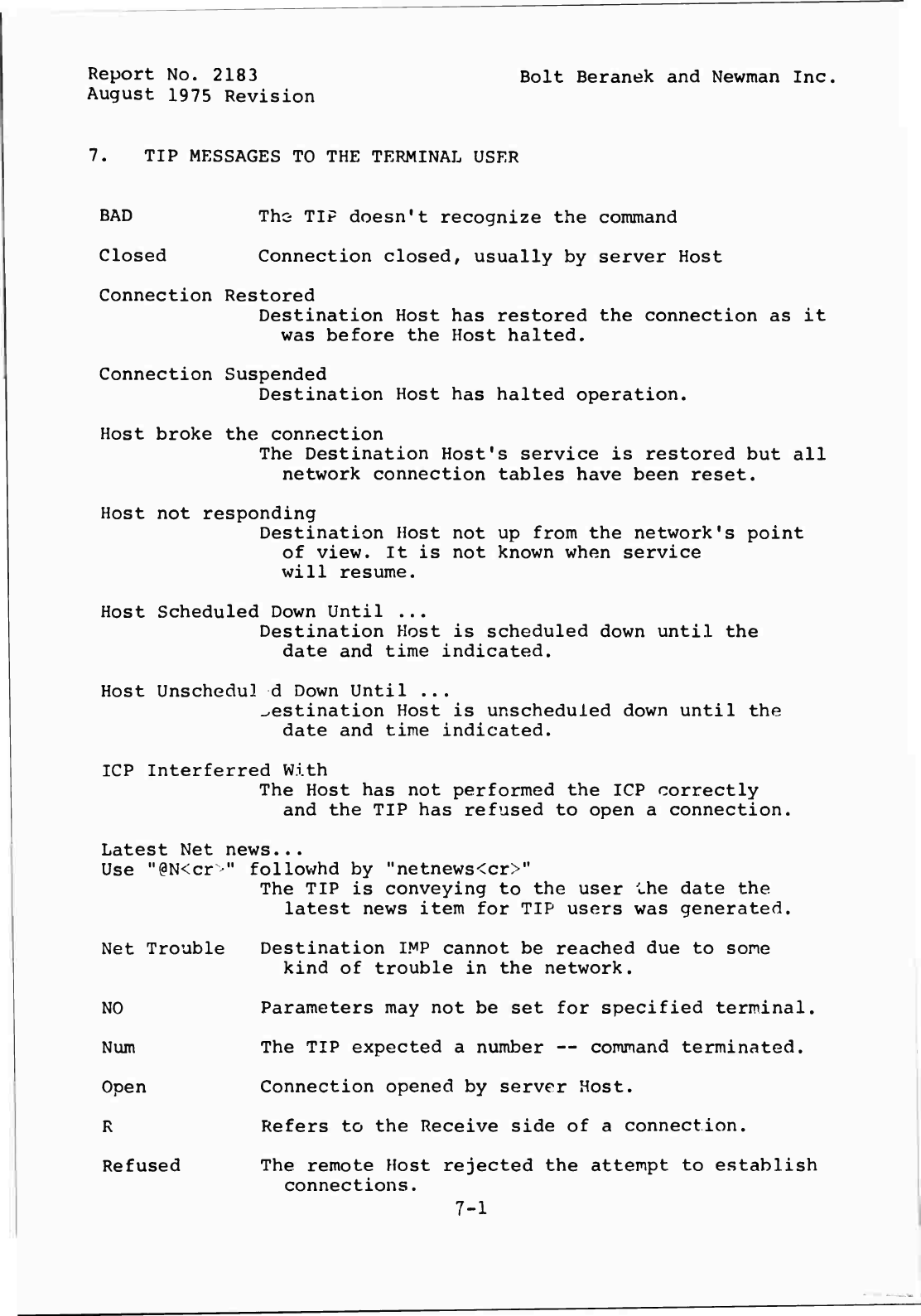
Report
No.
2183
Bolt
Beranek
and
Newman
Inc.
August
1975
Revision
7.
TIP
MESSAGES
TO
THE
TERMINAL
USER
BAD
The
TIP
doesn't
recognize
the
conunand
Closed
Connection
closed,
usually
by
server
Host
Connection
Restored
Destination
Host
has
restored
the
connection
as
it
was
before
the
Host
halted.
Connection
Suspended
Destination
Host
has
halted
operation.
Host
broke
the
connection
The
Destination
Host's
service
is
restored
but
all
network
connection
tables
have
been
reset.
Host
not
responding
Destination
Host
not
up
from
the
network's
point
of
view.
It
is
not
known
when
service
will
resume.
Host
Scheduled
Down
Until
...
Destination
Host
is
scheduled
down
until
the
date
and
time
indicated.
Host
UnscheduJ.
d
Down
Until
...
destination
Host
is
unscheduled
down
until
the
date
and
time
indicated.
ICP
Interferred
With
The
Host
has
not
performed
the
ICP
correctly
and
the
TIP
has
refused
to
open
a
connection.
Latest
Net
news...
Use
M
(
aN<cr
•"
followhd
by
"netnews<cr>"
The
TIP
is
conveying
to
the
user
Lhe
date
the
latest
news
item
for
TIP
users
was
generated.
Net
Trouble
Destination
IMP
cannot
be
reached
due
to
some
kind
of
trouble
in
the
network.
NO
Parameters
may
not
be
set
for
specified
terminal.
Num
The
TIP
expected
a
number
—
command
terminated.
Open
Connection
opened
by
server
Host.
R
Refers
to
the
Receive
side
of
a
connection.
Refused
The
remote
Host
rejected
the
attempt
to
establish
connections.
7-1
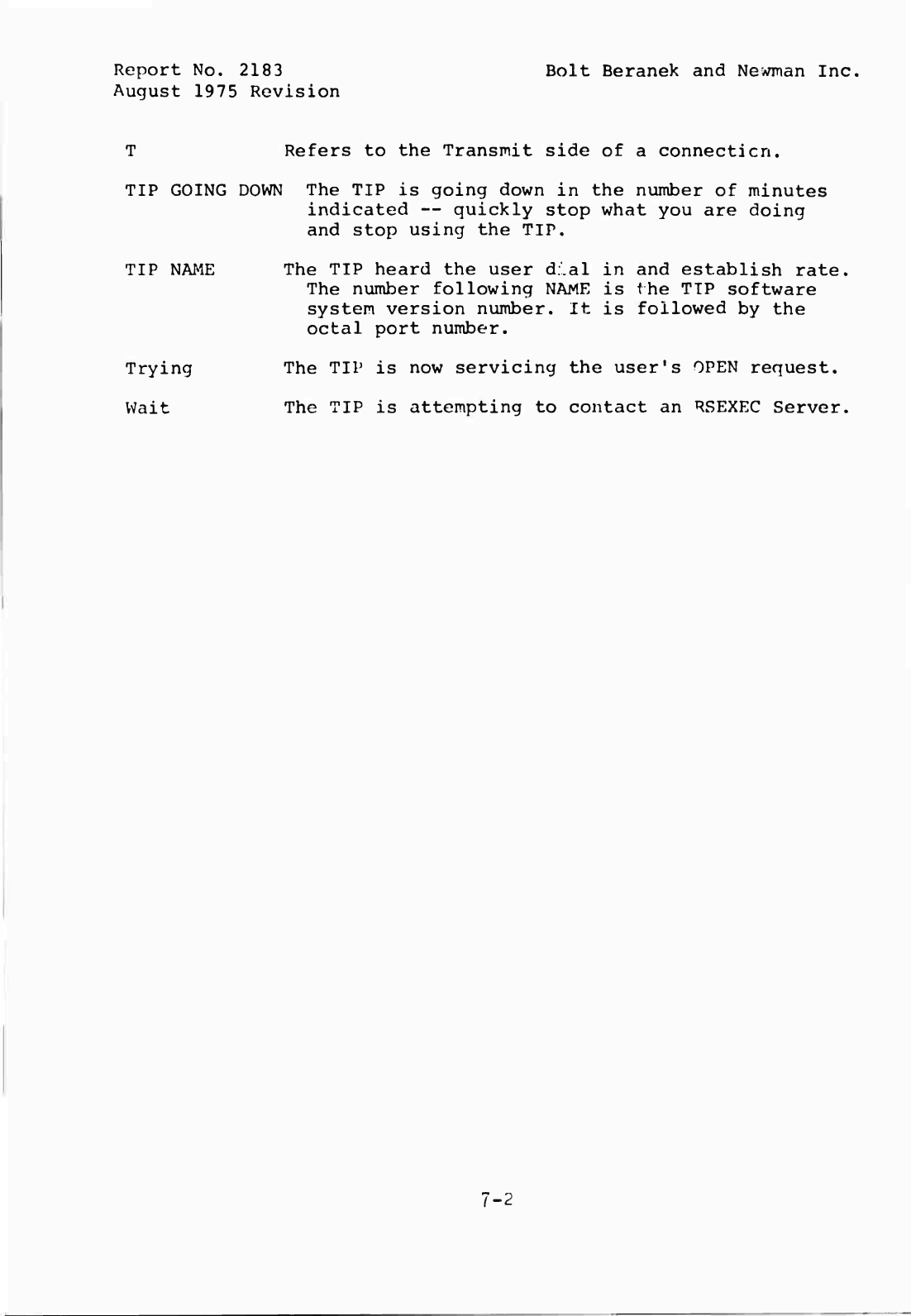
Report
No.
2183
Bolt
Beranek
and
Newman
Inc.
August
1975
Revision
T
Refers
to
the
Transmit
side
of
a
connect!en.
TIP
GOING
DOWN
The
TIP
is
going
down
in
the
number
of
minutes
indicated
—
quickly
stop
what
you
are
doing
and
stop
using
the
TIP.
TIP
NAME
The
TIP
heard
the
user
d.'.al
in
and
establish
rate.
The
number
following
NAME
is
the
TIP
software
system
version
number.
It
is
followed
by
the
octal
port
number.
Trying
The
TIP
is
now
servicing
the
user's
OPEN
request.
Wait
The
TIP
is
attempting
to
contact
an
RSEXEC
Server.
7-2
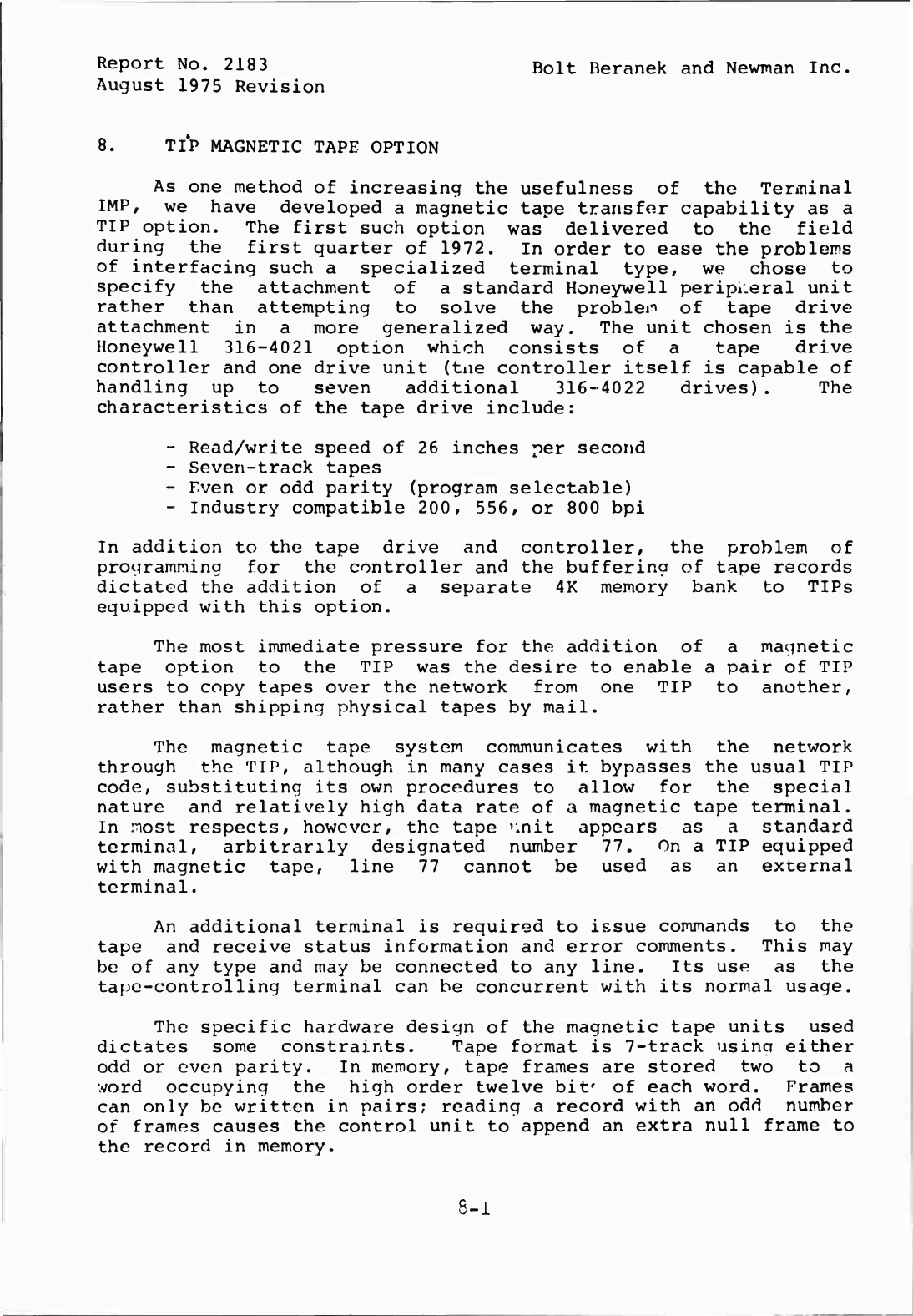
Report
No.
2183
Bolt
Beranek
and
Newman
Inc.
August
1975
Revision
8.
TIP
MAGNETIC
TAPE
OPTION
As
one
method
of
increasing
the
usefulness
of
the
Terminal
IMP,
we
have
developed
a
magnetic
tape
transfer
capability
as
a
TIP
option.
The
first
such
option
was
delivered
to
the
field
during
the
first
quarter
of
1972.
In
order
to
ease
the
problems
of
interfacing
such
a
specialized
terminal
type,
we
chose
to
specify
the
attachment
of
a
standard
Honeywell
peripheral
unit
rather
than
attempting
to
solve
the
problem
of
tape
drive
attachment
in
a
more
generalized
way.
The
unit
chosen
is
the
Honeywell
316-4021
option
which
consists
of
a
tape
drive
controller
and
one
drive
unit
(tae
controller
itself
is
capable
of
handling
up
to
seven
additional
316-4022
drives).
The
characteristics
of
the
tape
drive
include:
-
Read/write
speed
of
26
inches
per
second
-
Seven-track
tapes
-
Even
or
odd
parity
(program
selectable)
-
Industry
compatible
200,
556,
or
800
bpi
In
addition
to
the
tape
drive
and
controller,
the
problem
of
programming
for
the
controller
and
the
buffering
of
tape
records
dictated
the
addition
of
a
separate
4K
memory
bank
to
TIPs
equipped
with
this
option.
The
most
immediate
pressure
for
the
addition
of
a
magnetic
tape
option
to
the
TIP
was
the
desire
to
enable
a
pair
of
TIP
users
to
copy
tapes
over
the
network
from
one
TIP
to
another,
rather
than
shipping
physical
tapes
by
mail.
The
magnetic
tape
system
communicates
with
the
network
through
the
TIP,
although
in
many
cases
it
bypasses
the
usual
TIP
code,
substituting
its
own
procedures
to
allow
for
the
special
nature
and
relatively
high
data
rate
of
a
magnetic
tape
terminal.
In
nost
respects,
however,
the
tape
nnit
appears
as
a
standard
terminal,
arbitrarily
designated
number
77.
On
a
TIP
equipped
with
magnetic
tape,
line
77
cannot
be
used
as
an
external
terminal.
An
additional
terminal
is
required
to
issue
commands
to
the
tape
and
receive
status
information
and
error
comments.
This
may
be
of
any
type
and
may
be
connected
to
any
line.
Its
use
as
the
tape-controlling
terminal
can
be
concurrent
with
its
normal
usage.
The
specific
hardware
design
of
the
magnetic
tape
units
used
dictates
some
constraints.
Tape
format
is
7-track
usincr
either
odd
or
even
parity.
In
memory,
tape
frames
are
stored
two
to
a
word
occupying
the
high
order
twelve
bit'
of
each
word.
Frames
can
only
be
written
in
pairs;
reading
a
record
with
an
odd
number
of
frames
causes
the
control
unit
to
append
an
extra
null
frame
to
the
record
in
memory.
8-1
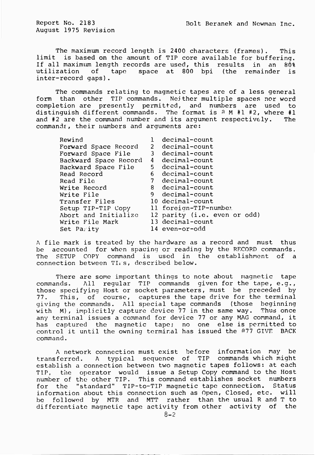
Report
No.
218
3
August
1975
Revision
Bolt
Beranek
and
Newman
Inc.
The
maximum
record
length
is
2400
characters
(frames).
This
limit
is
based
on
the
amount
of
TIP
core
available
for
buffering.
If
all
maximum
length
records
are
used,
this
results
in
an
80%
utilization
of
tape
space
at
800
bpi
(the
remainder
is
inter-record
gaps).
The
commands
relating
to
magnetic
tapes
are
of
a
less
general
form
than
other
TIP
commands.
Neither
multiple
spaces
nor
word
completion
are
presently
permitted,
and
numbers
are
used
to
distinguish
different
commands.
The
format
is
3
M
#1
#2,
where
#1
and
#2
are
the
command
number
and
its
argument
respectively.
The
commands,
their
numbers
and
arguments
are:
Rewind
Forward
Space
Record
Forward
Space
File
Backward
Space
Record
Backward
Space
File
Read
Record
Read
File
Write
Record
Write
File
Transfer
Files
Setup
TIP-TIP
Copy
Abort
and
Initialize
Write
File
Mark
Set
Pa.-
ity
1
decimal-count
2
decimal-count
3
decimal-count
4
decimal-count
5
decimal-count
6
decimal-count
7
decimal-count
8
decimal-count
9
decimal-count
10
decimal-count
11
foreign-TIP-number
12
parity
(i.e.
even
or
odd)
13
decimal-count
14
even-or-odd
A
file
mark
is
treated
by
the
hardware
as
a
record
and
must
thus
be
accounted
for
when
spacing
or
reading
by
the
RECORD
commands.
The
SETUP
COPY
command
is
used
in
the
establishment
of
a
connection
between
TIis,
described
below.
There
are
some
important
things
to
note
about
magnetic
tape
commands.
All
regular
TIP
commands
given
for
the
tape,
e.g.,
those
specifying
Host
or
socket
parameters,
must
be
preceded
by
77.
This,
of
course,
captures
the
tape
drive
for
the
terminal
giving
the
commands.
All
special
tape
commands
(those
beginning
with
M),
implicitly
capture
device
77
in
the
same
way.
Thus
once
any
terminal
issues
a
command
for
device
77
or
any
MAG
command,
it
has
captured
the
magnetic
tape;
no
one
else
is
permitted
to
control
it
until
the
owning
terminal
has
issued
the
077
GIVE
BACK
command.
A
network
connection
must
exist
before
information
may
be
transferred.
A
typical
sequence
of
TIP
commands
which
might
establish
a
connection
between
two
magnetic
tapes
follows:
at
each
TIP,
the
operator
would
issue
a
Setup
Copy
command
to
the
Host
number
of
the
other
TIP.
This
command
establishes
socket
numbers
for
the
"standard"
TIP-to-TIP
magnetic
tape
connection.
Status
information
about
this
connection
such
as
Open,
Closed,
etc.
will
be
followed
by
MTR
and
MTT
rather
than
the
usual
R
and
T
to
differentiate
magnetic
tape
activity
from
other
activity
of
the
8-2
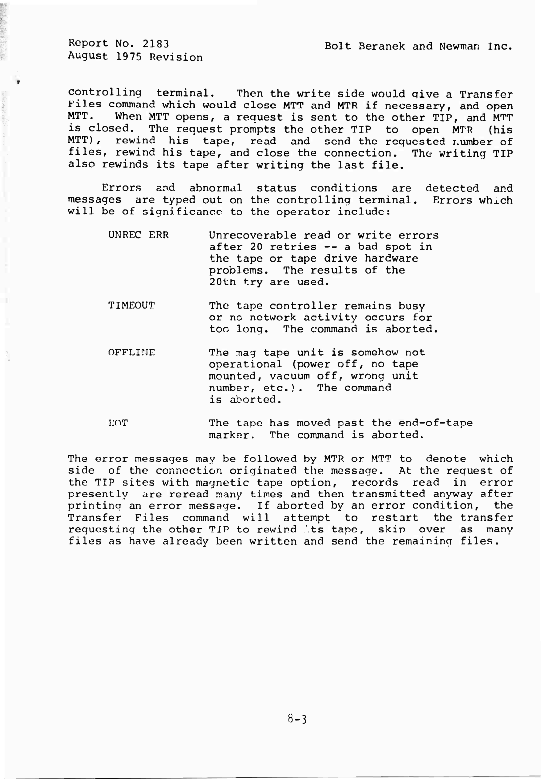
Report
No.
2183
August
1975
Revision
Bolt
Beranek
and
Newman
Inc.
controlling
terminal.
Then
the
write
side
would
qive
a
Transfer
tiles
command
which
would
close
MTT
and
MTR
if
necessary,
and
open
MTT.
When
MTT
opens,
a
request
is
sent
to
the
other
TIP,
and
MTT
is
closed.
The
request
prompts
the
other
TIP
to
open
MTR
(his
MTT),
rewind
his
tape,
read
and
send
the
requested
r.umber
of
files,
rewind
his
tape,
and
close
the
connection.
The
writing
TIP
also
rewinds
its
tape
after
writing
the
last
file.
Errors
and
abnormal
status
conditions
are
detected
and
messages
are
typed
out
on
the
controlling
terminal.
Errors
whxch
will
be
of
significance
to
the
operator
include:
UNREC
ERR
TIMEOUT
OFFLINE
EOT
Unrecoverable
read
or
write
errors
after
20
retries
—
a
bad
spot
in
the
tape
or
tape
drive
hardware
problems.
The
results
of
the
20tn
try
are
used.
The
tape
controller
remains
busy
or
no
network
activity
occurs
for
too
long.
The
command
is
aborted.
The
mag
tape
unit
is
somehow
not
operational
(power
off,
no
tape
mounted,
vacuum
off,
wrong
unit
number,
etc.).
The
command
is
aborted.
The
tape
has
moved
past
the
end-of-tape
marker.
The
command
is
aborted.
The
error
messages
may
be
followed
by
MTR
or
MTT
to
denote
which
side
of
the
connection
originated
the
message.
At
the
request
of
the
TIP
sites
with
magnetic
tape
option,
records
read
in
error
presently
are
reread
many
times
and
then
transmitted
anyway
after
printing
an
error
message.
If
aborted
by
an
error
condition,
the
Transfer
Files
command
will
attempt
to
restart
the
transfer
requesting
the
other
TIP
to
rewind
'.ts
tape,
skip
over
as
many
files
as
have
already
been
written
and
send
the
remaining
files.
8-3
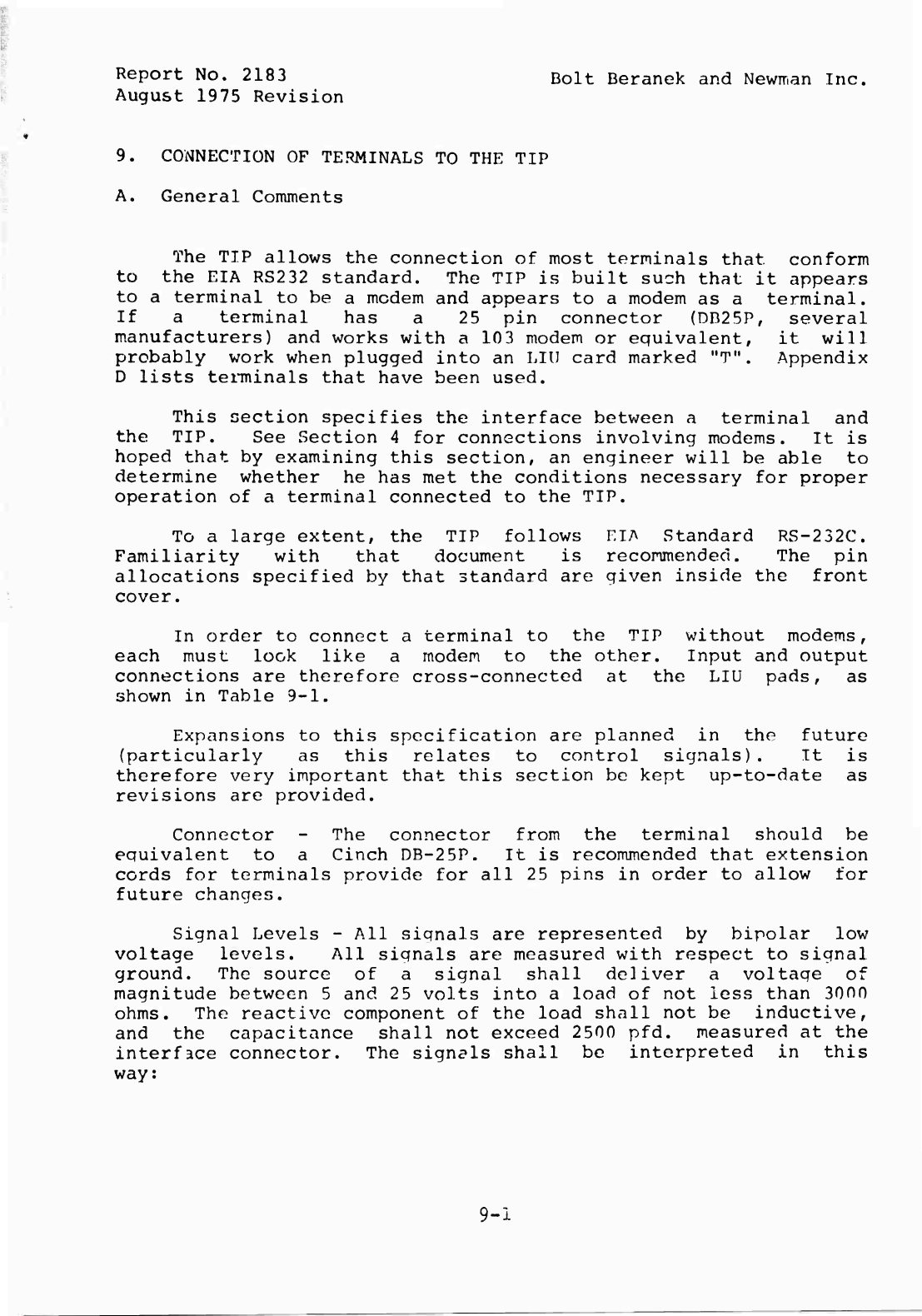
Report
No.
2183
Bolt
Beranek
and
Newirian
Inc.
August
1975
Revision
9.
CONNECTION
OF
TERMINALS
TO
THE
TIP
A.
General
Comments
The
TIP
allows
the
connection
of
most
terminals
that
conform
to
the
EIA
RS232
standard.
The
TIP
is
built
such
that
it
appears
to
a
terminal
to
be
a
modem
and
appears
to
a
modem
as
a
terminal.
If
a
terminal
has
a
25
pin
connector
(DD25P,
several
manufacturers)
and
works
with
a
10
3
modem
or
equivalent,
it
will
probably
work
when
plugged
into
an
LIU
card
marked
"T".
Appendix
D
lists
terminals
that
have
been
used.
This
section
specifies
the
interface
between
a
terminal
and
the
TIP.
See
Section
4
for
connections
involving
modems.
It
is
hoped
that
by
examining
this
section,
an
engineer
will
be
able
to
determine
whether
he
has
met
the
conditions
necessary
for
proper
operation
of
a
terminal
connected
to
the
TIP.
To
a
large
extent,
the
TIP
follows
EIA
Standard
RS-232C.
Familiarity
with
that
document
is
recommended.
The
pin
allocations
specified
by
that
standard
are
given
inside
the
front
cover.
In
order
to
connect
a
terminal
to
the
TIP
without
modems,
each
must
look
like
a
modem
to
the
other.
Input
and
output
connections
are
therefore
cross-connected
at
the
LIU
pads,
as
shown
in
Table
9-1.
Expansions
to
this
specification
are
planned
in
the
future
(particularly
as
this
relates
to
control
signals).
It
is
therefore
very
important
that
this
section
be
kept
up-to-date
as
revisions
are
provided.
Connector
-
The
connector
from
the
terminal
should
be
equivalent
to
a
Cinch
DB-25P.
It
is
recommended
that
extension
cords
for
terminals
provide
for
all
25
pins
in
order
to
allow
for
future
changes.
Signal
Levels
-
All
signals
are
represented
by
bipolar
low
voltage
levels.
All
signals
are
measured
with
respect
to
signal
ground.
The
source
of
a
signal
shall
deliver
a
voltage
of
magnitude
between
5
and
25
volts
into
a
load
of
not
less
than
3000
ohms.
The
reactive
component
of
the
load
shall
not
be
inductive,
and
the
capacitance
shall
not
exceed
2500
pfd.
measured
at
the
interface
connector.
The
signals
shall
be
interpreted
in
this
way:
9-1
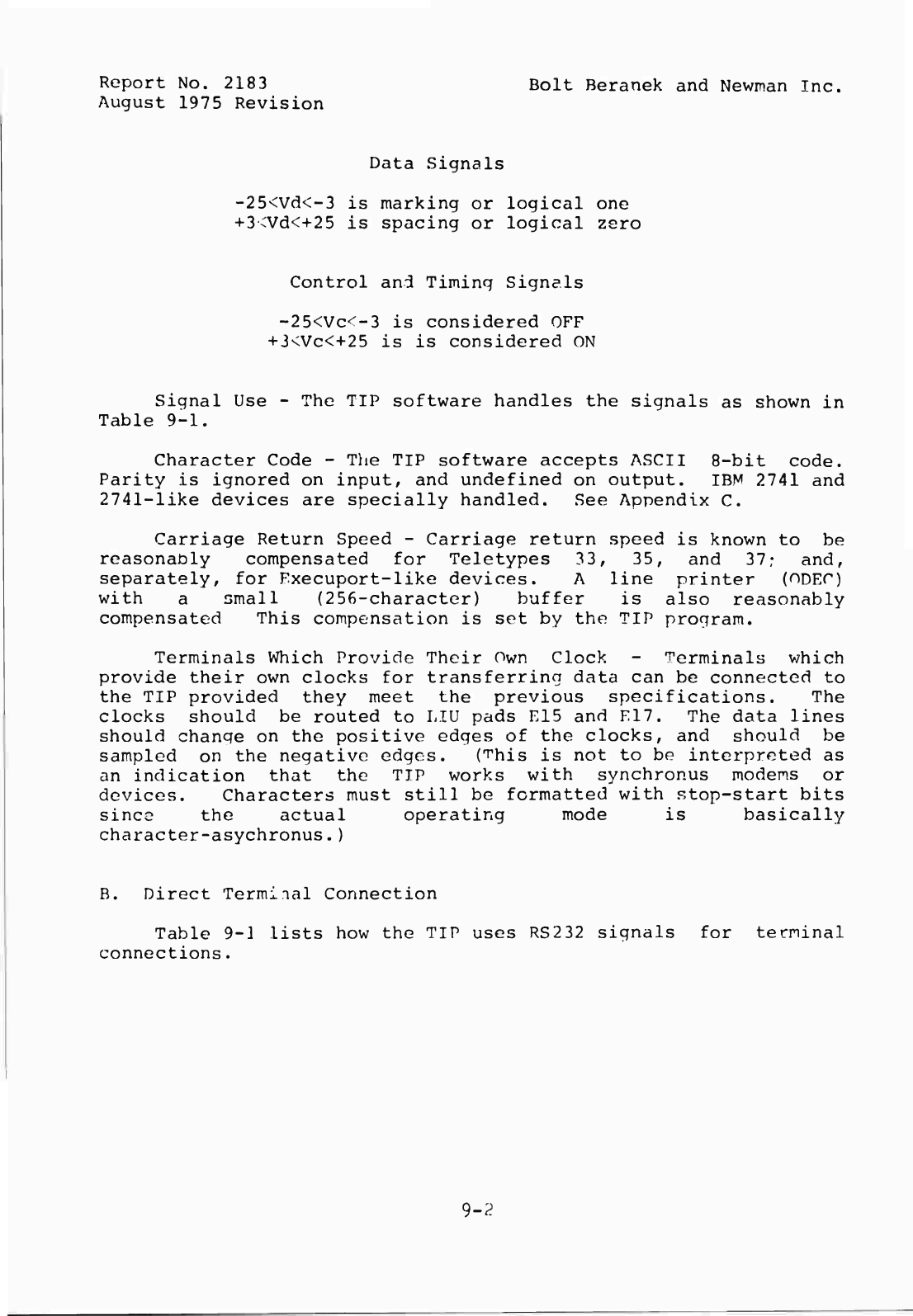
Report
No.
2183
Bolt
Beranek
and
Newman
Inc.
August
1975
Revision
Data
Signals
-25<Vd<-3
is
marking
or
logical
one
-»-3<Vd<+25
is
spacing
or
logical
zero
Control
and
Timing
Signals
-25<Vc<-3
is
considered
OFF
+3<Vc<+25
is
is
considered
ON
Signal
Use
-
The
TIP
software
handles
the
signals
as
shown
in
Table
9-1.
Character
Code
-
The
TIP
software
accepts
ASCII
8-bit
code.
Parity
is
ignored
on
input,
and
undefined
on
output.
IBM
2741
and
2741-like
devices
are
specially
handled.
See
Appendix
C.
Carriage
Return
Speed
-
Carriage
return
speed
is
known
to
be
reasonably
compensated
for
Teletypes
33,
35,
and
37?
and,
separately,
for
Fxecuport-like
devices.
A
line
printer
(ODEC)
with
a
small
(256-character)
buffer
is
also
reasonably
compensated
This
compensation
is
set
by
the
TIP
program.
Terminals
Which
Provide
Their
Own
Clock
-
Terminals
which
provide
their
own
clocks
for
transferring
data
can
be
connected
to
the
TIP
provided
they
meet
the
previous
specifications.
The
clocks
should
be
routed
to
LIU
pads
E15
and
E17.
The
data
lines
should
change
on
the
positive
edges
of
the
clocks,
and
should
be
sampled
on
the
negative
edges.
(^his
is
not
to
be
interpreted
as
an
indication
that
the
TIP
works
with
synchronus
modems
or
devices.
Characters
must
still
be
formatted
with
stop-start
bits
since
the
actual
operating
mode
is
basically
character-asychronus.)
B.
Direct
Terminal
Connection
Table
9-]
lists
how
the
TIP
uses
RS232
signals
for
terminal
connections.
9-2
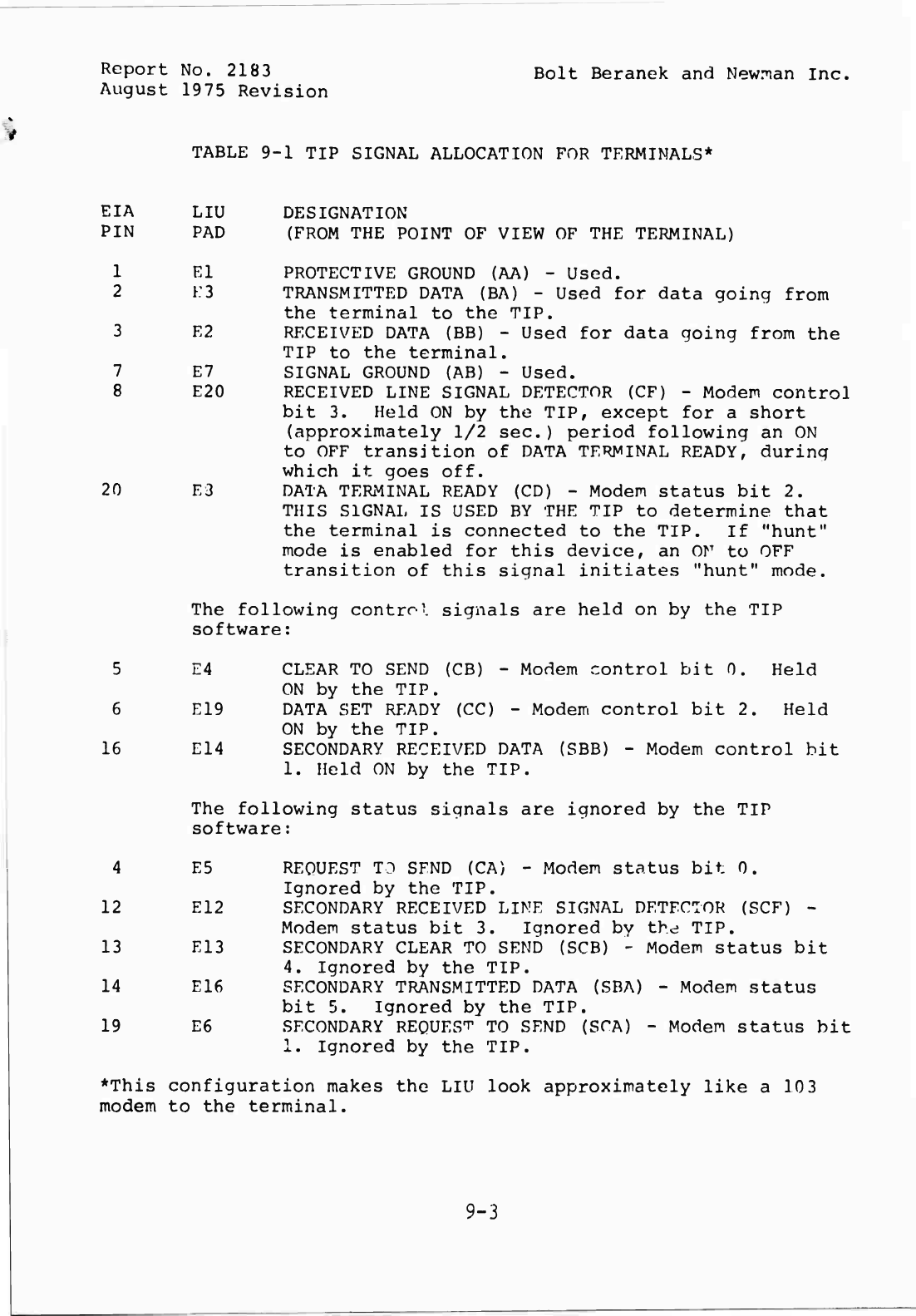
Report
No.
2183
Bolt
Beranek
and
Newman
Inc.
August
1975
Revision
TABLE
9-1
TIP
SIGNAL
ALLOCATION
FOR
TERMINALS*
EIA
LIU
DESIGNATION
PIN
PAD
(FROM
THE
POINT
OF
VIEW
OF
THE
TERMINAL)
1
El
PROTECTIVE
GROUND
(AA)
-
Used.
2
K3
TRANSMITTED
DATA
(BA)
-
Used
for
data
going
from
the
terminal
to
the
TIP.
3
E2
RECEIVED
DATA
(BB)
-
Used
for
data
going
from
the
TIP
to
the
terminal.
7
E7
SIGNAL
GROUND
(AB)
-
Used.
8
E20
RECEIVED
LINE
SIGNAL
DETECTOR
(CF)
-
Modem
control
bit
3.
Held
ON
by
the
TIP,
except
for
a
short
(approximately
1/2
sec.)
period
following
an
ON
to
OFF
transition
of
DATA
TERMINAL
READY,
during
which
it
goes
off.
20
E3
DATA
TERMINAL
READY
(CD)
-
Modem
status
bit
2.
THIS
SIGNAL
IS
USED
BY
THE
TIP
to
determine
that
the
terminal
is
connected
to
the
TIP.
If
"hunt"
mode
is
enabled
for
this
device,
an
or
to
OFF
transition
of
this
signal
initiates
"hunt"
mode.
The
following
control
signals
are
held
on
by
the
TIP
software:
CLEAR
TO
SEND
(CB)
-
Modem
control
bit
0.
Held
ON
by
the
TIP.
DATA
SET
READY
(CC)
-
Modem
control
bit
2.
Held
ON
by
the
TIP.
SECONDARY
RECEIVED
DATA
(SBB)
-
Modem
control
bit
1.
Held
ON
by
the
TIP.
The
following
status
signals
are
ignored
by
the
TIP
software:
4
E5
REQUEST
TO
SFND
(CA)
-
Modem
status
bit
0.
Ignored
by
the
TIP.
12
E12
SECONDARY
RECEIVED
LINE
SIGNAL
DETECTOR
(SCF)
-
Modem
status
bit
3.
Ignored
by
the
TIP.
13
E13
SECONDARY
CLEAR
TO
SEND
(SCB)
-
Modem
status
bit
4.
Ignored
by
the
TIP.
14
E16
SECONDARY
TRANSMITTED
DATA
(SBA)
-
Modem
status
bit
5.
Ignored
by
the
TIP.
19
E6
SECONDARY
REQUEST
TO
SEND
(SCA)
-
Modem
status
bit
1.
Ignored
by
the
TIP.
*This
configuration
makes
the
LIU
look
approximately
like
a
10
3
modem
to
the
terminal.
5
E4
6
E19
16
E14
9-3
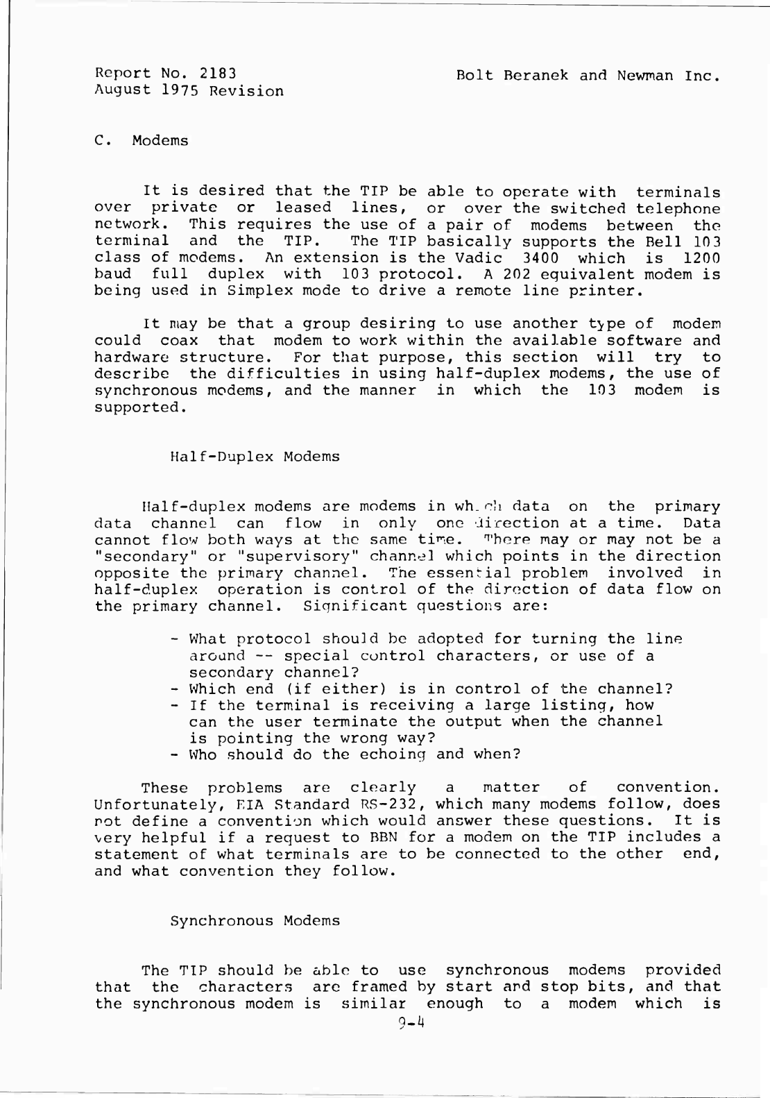
Report
No.
2183
August
1975
Revision
Bolt
Beranek
and
Newman
Inc.
C.
Modems
It
is
desired
that
the
TIP
be
able
to
operate
with
terminals
over
private
or
leased
lines,
or
over
the
switched
telephone
network.
This
requires
the
use
of
a
pair
of
modems
between
the
terminal
and
the
TIP.
The
TIP
basically
supports
the
Bell
103
class
of
modems.
An
extension
is
the
Vadic
3400
which
is
1200
baud
full
duplex
with
10
3
protocol.
A
202
equivalent
modem
is
being
used
in
Simplex
mode
to
drive
a
remote
line
printer.
It
may
be
that
a
group
desiring
to
use
another
t^pe
of
modem
could
coax
that
modem
to
work
within
the
available
software
and
hardware
structure.
For
that
purpose,
this
section
will
try
to
describe
the
difficulties
in
using
half-duplex
modems,
the
use
of
synchronous
modems,
and
the
manner
in
which
the
10
3
modem
is
supported.
Half-Duplex
Modems
Half-duplex
modems
are
modems
in
wh.ch
data
on
the
primary
data
channel
can
flow
in
only
one
direction
at
a
time.
Data
cannot
flow
both
ways
at
the
same
time.
There
may
or
may
not
be
a
"secondary"
or
"supervisory"
channel
which
points
in
the
direction
opposite
the
primary
channel.
The
essenrial
problem
involved
in
half-duplex
operation
is
control
of
the
direction
of
data
flow
on
the
primary
channel.
Significant
questions
are:
-
What
protocol
should
be
adopted
for
turning
the
line
around
--
special
control
characters,
or
use
of
a
secondary
channel?
-
Which
end
(if
either)
is
in
control
of
the
channel?
-
If
the
terminal
is
receiving
a
large
listing,
how
can
the
user
terminate
the
output
when
the
channel
is
pointing
the
wrong
way?
-
Who
should
do
the
echoing
and
when?
These
problems
are
clearly
a
matter
of
convention.
Unfortunately,
EIA
Standard
RS-232,
which
many
modems
follow,
does
not
define
a
convention
which
would
answer
these
questions.
It
is
very
helpful
if
a
request
to
BBN
for
a
modem
on
the
TIP
includes
a
statement
of
what
terminals
are
to
be
connected
to
the
other
end,
and
what
convention
they
follow.
Synchronous
Modems
The
TIP
should
be
able
to
use
synchronous
modems
provided
that
the
characters
are
framed
by
start
and
stop
bits,
and
that
the
synchronous
modem
is
similar
enough
to
a
modem
which
is
9-^
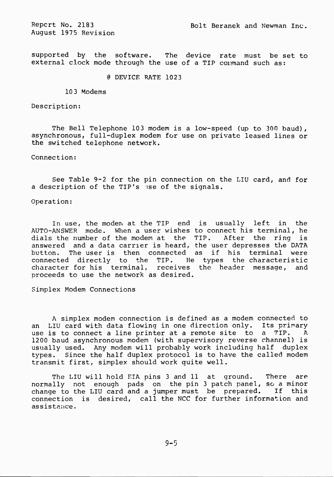
Report
No.
2183
Bolt
Beranek
and
Newman
Inc.
August
1975
Revision
supported
by
the
software.
The
device
rate
must
be
set
to
external
clock
mode
through
the
use
of
a
TIP
command
such
as:
(3
DEVICE
RATE
1023
10
3
Modems
Description:
The
Bell
Telephone
103
modem
is
a
low-speed
(up
to
300
baud),
asynchronous,
full-duplex
modem
for
use
on
private
leased
lines
or
the
switched
telephone
network.
Connection:
See
Table
9-2
for
the
pin
connection
on
the
LIU
card,
and
for
a
description
of
the
TIP's
ise
of
the
signals.
Operation:
In
use,
the
modem
at
the
TIP
end
is
usually
left
in
the
AUTO-ANSWER
mode.
When
a
user
wishes
to
connect
his
terminal,
he
dials
the
number
of
the
modem
at
the
TIP.
After
the
ring
is
answered
and
a
data
carrier
is
heard,
the
user
depresses
the
DATA
button.
The
user
is
then
connected
as
if
his
terminal
were
connected
directly
to
the
TIP.
He
types
the
characteristic
character
for
his
terminal,
receives
the
header
message,
and
proceeds
to
use
the
network
as
desired.
Simplex
Modem
Connections
A
simplex
modem
connection
is
defined
as
a
modem
connected
to
an
LIU
card
with
data
flowing
in
one
direction
only.
Its
primary
use
is
to
connect
a
line
printer
at
a
remote
site
to
a
TIP.
A
1200
baud
asynchronous
modem
(with
supervisory
reverse
channel)
is
usually
used.
Any
modem
will
probably
work
including
half
duplex
types.
Since
the
half
duplex
protocol
is
to
have
the
called
modem
transmit
first,
simplex
should
work
quite
well.
The
LIU
will
hold
EIA
pins
3
and
11
at
ground.
There
are
normally
not
enough
pads
on
the
pin
3
patch
panel,
so
a
minor
change
to
the
LIU
card
and
a
jumper
must
be
prepared.
If
this
connection
is
desired,
call
the
NCC
for
further
information
and
assistance.
9-5
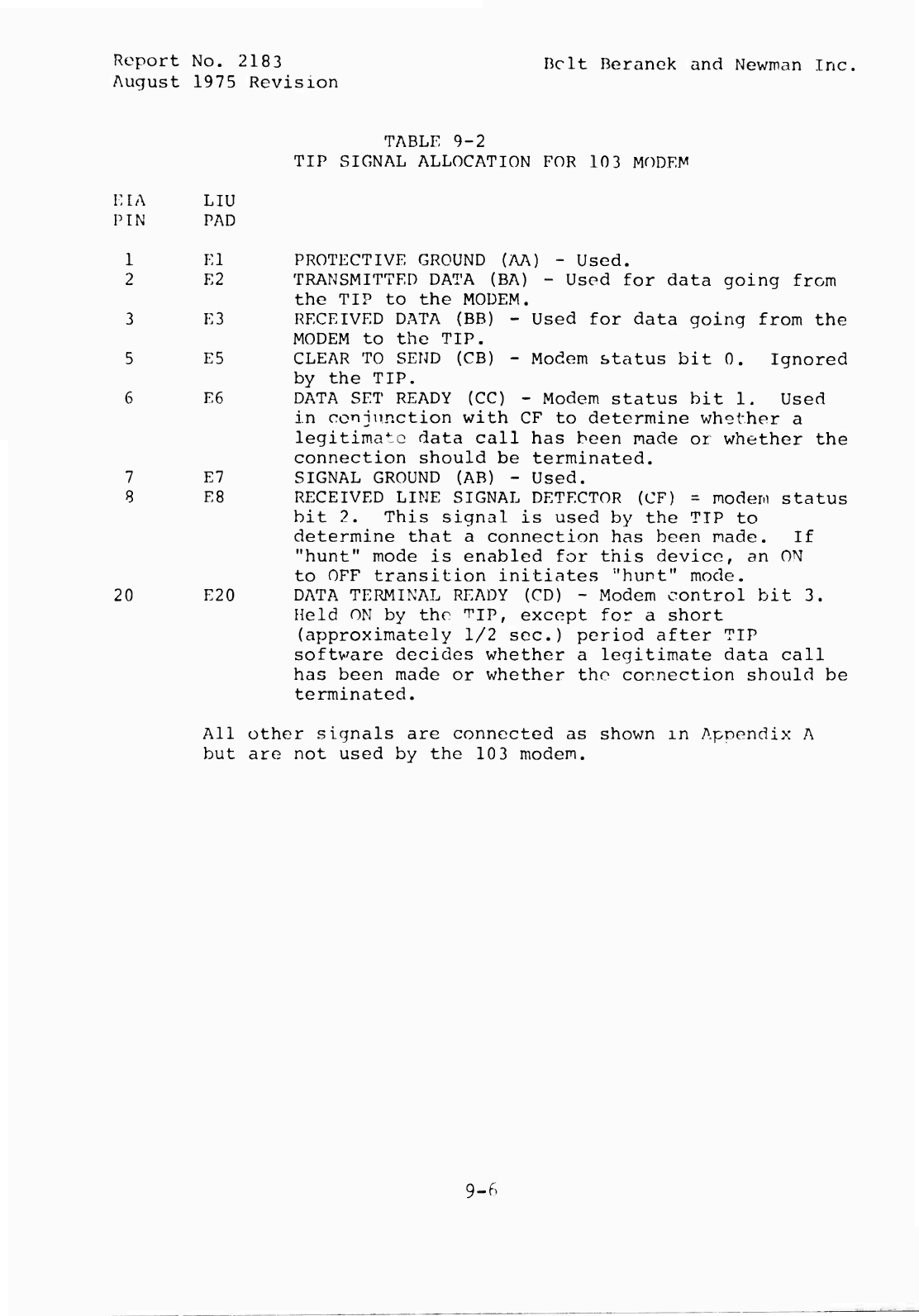
Report
No.
2183
Belt
Beranek
and
Newman
Ino,
August
1975
Revision
TABLE
9-2
TIP
SIGNAL
ALLOCATION
FOR
10
3
MODEN'
KIA
LIU
PIN
PAD
1
El
2
E2
PROTECTIVE
GROUND
(AA)
-
Used.
TRANSMITTED
DATA
(BA)
-
Used
for
data
going
from
the
TIP
to
the
MODEM.
3
E3
RECEIVED
DATA
(BB)
-
Used
for
data
going
from
the
MODEM
to
the
TIP.
5
E5
CLEAR
TO
SEND
(CB)
-
Modem
status
bit
0.
Ignored
by
the
TIP.
6
E6
DATA
SET
READY
(CC)
-
Modem
status
bit
1.
Used
in
conjunction
with
CF
to
determine
whether
a
legitimate
data
call
has
been
made
or
whether
the
connection
should
be
terminated.
7
E7
SIGNAL
GROUND
(AB)
-
Used.
8
E8
RECEIVED
LINE
SIGNAL
DETECTOR
(CF)
=
modem
status
bit
2.
This
signal
is
used
by
the
TIP
to
determine
that
a
connection
has
been
made.
If
"hunt"
mode
is
enabled
for
this
device,
an
ON
to
OFF
transition
initiates
:,
h
u
n
t
"
mode.
20
E20
DATA
TERMINAL
READY
(CD)
-
Modem
control
bit
3.
Held
ON
by
the
TIP,
except
for
a
short
(approximately
1/2
sec.)
period
after
TIP
software
decides
whether
a
legitimate
data
call
has
been
made
or
whether
the
connection
should
be
terminated.
All
other
signals
are
connected
as
shown
m
Appendix
A
but
are
not
used
by
the
10
3
modem.
9-6
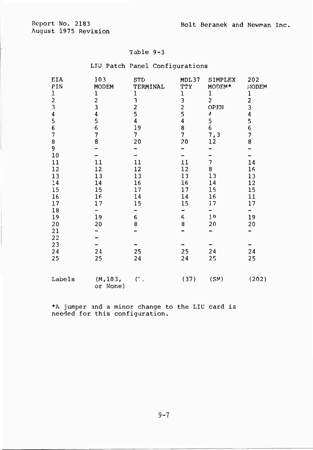
Report
No.
;
2183
Bolt
Beranek
and
Newma
August
1975
Revision
Table
9-3
LTU
Patch
Panel
Conf;
Lgurations
EIA
103
STD
MDL
3
7
SIMPLEX
202
PIN
MODEM
TERMINAL
TTY
MODEM*
MODEM
1
1
1
1
1
1
2
2
3
3
2
2
3
3
2
2
OPEN
3
4
4
5
5
4
4
5
5
4
4
5
5
6
6
19
8
6
6
7
7
7
7
7,3
7
8
8
20
20
12
8
9
-
-
-
-
-
10
-
-
-
-
-
11
11
11
11
7
14
12
12
12
12
8
16
13
13
13
13
13
13
14
14
16
16
14
12
15
15
17
17
15
15
16
16
14
14
16
11
17
17
15
15
17
17
18
-
-
-
-
-
19
19
6
6
IQ
19
20
20
8
8
20
20
21
-
-
-
-
-
22
-
23
-
-
-
-
-
24
2
4
25
25
24
24
25
25
24
24
25
25
Labels
(M,
or
103,
None)
r,
(37)
(SM)
(202)
*A
jumper
and
a
minor
change
to
the
LIU
card
is
needed
for
this
configuration.
9-7
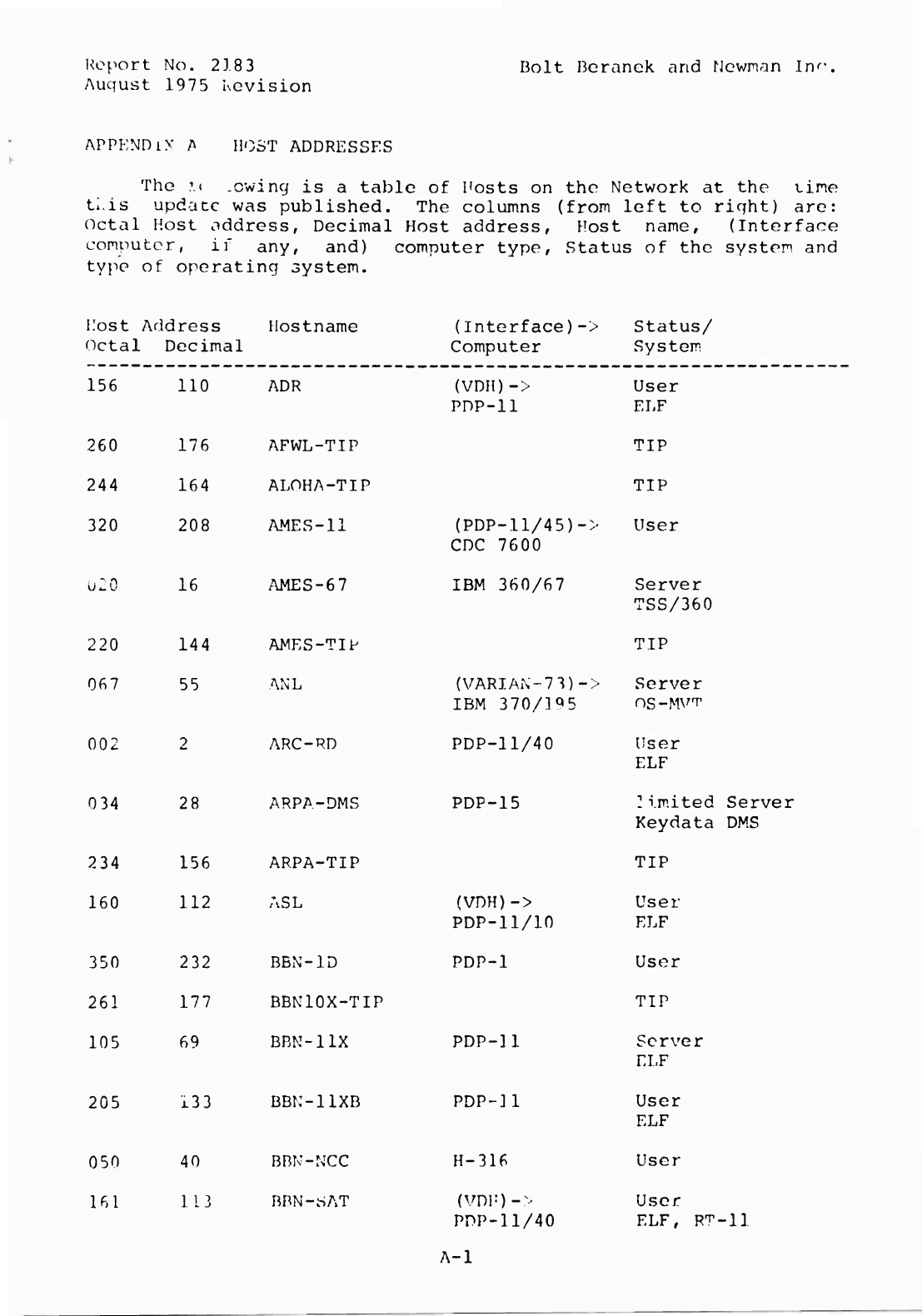
Report
No.
2183
Auqust
1975
Kevision
Bolt
Beranek
and
Newman
Inc
APPENDiX
A
HOST
ADDRESSES
The
1
(
.owing
is
a
table
of
Hosts
on
the
Network
at
the
tine
ti.is
update
was
published.
The
columns
(from
left
to
right)
are:
Octal
Host
oddress,
Decimal
Host
address,
Host
name,
(Interface
computer,
if
any,
and)
computer
type,
Status
of
the
system
and
type
of
operating
system.
Host
Octa
Address
1
Decimal
Hostname
(Interface)->
Computer
Status/
System
156
110
ADR
(VDH)->
PDP-ll
User
ELF
260
176
AFWL-TIP
TIP
244
164
ALOHA-TIP
TIP
320
208
AMES-11
(PDP-ll/45)->
CDC
7600
User
u:o
16
AMES-67
IBM
360/67
Server
TSS/360
220
144
AMES-TIP
TIP
067
55
ANL
(VARIAN-73)->
IBM
370/1^5
Server
OS-MVT
002
2
ARC-RD
PDP-11/40
User
ELF
034
28
ARPA-DMS
PDP-15
I
i
mited
Keydata
Server
DMS
234
156
ARPA-TIP
TIP
160
112
ASL
(VDH)->
PDP-11/10
User
ELF
350
232
BBN-1D
PDP-1
User
261
177
BBN10X-TIP
TIP
105
69
BBN-11X
PDP-11
Server
ELF
205
133
BBK-11XB
PDP-U
User
ELF
050
40
BBN-NCC
H-316
User
161
113
BBN-riAT
(vni-)->
PPP-ll/40
User
ELF,
R^-
-11
A-l
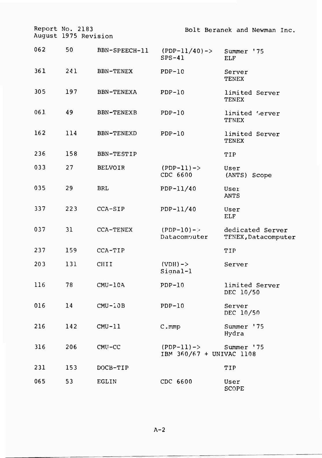
Report
No.
2183
August
1975
Revision
Bolt
Beranek
and
Newman
Inc.
062
361
305
061
035
337
037
116
016
216
316
50
241
197
49
162
114
236
158
BBN-TESTIP
033
27
BELVOIR
29
31
78
14
206
BBN-SPEECH-
•11
(PDP-11/40)->
SPS-41
Summer
'
ELF
75
BBN-TENEX
PDP-10
Server
TENEX
BBN-TENEXA
PDP-10
limited
TENEX
Server
BBN-TENEXB
PDP-10
limited
TFNEX
Server
BBN-TENEXD
PDP-10
limited
TENEX
Server
BRL
223
CCA-SIP
CCA-TENEX
237
159
CCA-TIP
203
131
CHII
CMU-1CA
CMU-10B
142
CMU-11
CMU-CC
231
153
DOCB-TIP
065
53
EGLIN
TIP
(PDP-ll)->
CDC
6600
User
(ANTS)
Scope
PDP-11/40
User
ANTS
PDP-11/40
User
ELF
{PDP-10)-:>
Datacom
T
3uter
dedicated
Serv
TENEX,Datacomp
TIP
(VDH)->
Signal-1
Server
PDP-10
limited
Server
DEC
10/50
PDP-10
Server
DEC
10/50
C.mmp
Summer
'75
Hydra
(PDP-ll)->
Summer
'75
IBM
360/67
+
UNIVAC
1108
CDC
6600
TIP
User
SCOPE
A-2
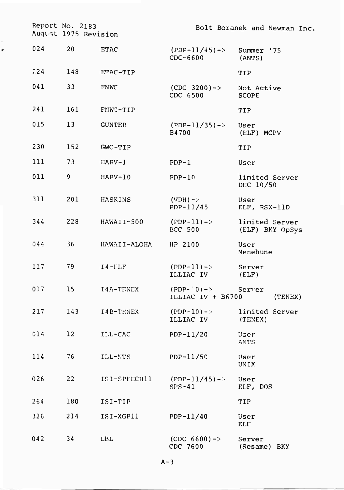
Report
No.
2183
Augvit
1975
Revision
Bolt
Beranek
and
Newman
Inc,
024
044
117
017
217
014
114
026
20
36
79
15
143
12
76
22
ETAC
r.24
148
ETAC-TIP
041
33
FNWC
241
161
FNWC-TIP
015
13
GUNTER
230
152
GWC-TIP
111
73
HARV-1
Oil
9
HARV-10
311
201
HASKINS
344
228
HAWAII-500
HAWAII-ALOHA
I4-FLF
I4A-TENEX
I4B-TENEX
ILL-CAC
ILL-NTS
ISI-SPFECH11
264
180
ISI-TIP
326
214
ISI-XGP11
(PDP-11/45)->
CDC-6600
(CDC
3200)->
CDC
6500
(PDP-11/35)-:
B4700
PDP-1
PDP-in
(VDH)->
PDP-11/45
(PDP-11)-:
BCC
500
HP
2100
(PDP-11)->
ILLIAC
IV
Sununer
,
7
5
(ANTS)
TIP
Not
Active
SCOPE
TIP
User
(ELF)
MCPV
TIP
User
limited
Server
DEC
10/50
User
ELF,
RSX-11D
limited
Server
(ELF)
BKY
OpSys
User
Menehune
Server
(ELF)
(PDP-'0)->
Ser^
er
ILLIAC
IV
+
B6700
(TENEX)
(PDP-10)->
limited
Server
ILLIAC
IV
(TENEX)
PDP-11/20
User
ANTS
PDP-11/50
User
UNIX
(PDP-11/45)-'
User
SPS-41
ELF,
DOS
042
34
LBL
PDP-11/40
(CDC
6600)->
CDC
7600
TIP
User
ELF
Server
(Sesame)
BKY
A-3
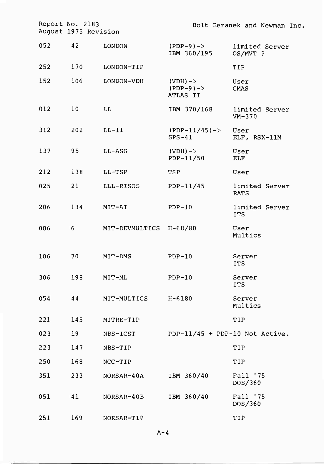
Report
No.
218
3
August
1975
Revision
Bolt
Beranek
and
Newman
Inc.
052
42
LONDON
(PDP-9)->
IBM
360/195
limited
Server
OS/MVT
?
252
170
LONDON-TIP
TIP
152
106
LONDON~VDH
(VDH)->
(PDP-9)->
ATLAS
II
User
CMAS
012
10
LL
IBM
370/168
limited
Server
VM-370
312
202
LL-11
(PDP-11/45)-
SPS-41
->
User
ELF,
RSX-11M
137
95
LL-ASG
(VDH)->
PDP-11/50
User
ELF
212
138
LL-TSP
TSP
User
025
21
LLL-RISOS
PDP-11/45
limited
Server
RATS
206
134
MIT-AI
PDP-10
limited
Server
ITS
006
6
MIT-DEVMULTICS
H-68/80
User
Multics
106
70
MIT-DMS
PDP-10
Server
ITS
306
198
MIT-ML
PDP-10
Server
ITS
054
44
MIT-MULTICS
H-6180
Server
Multics
221
145
MITRE-TIP
TIP
023
19
NBS-ICST
PDP-11/45
+
PDP-10
Not
Active.
223
147
NBS-TIP
TIP
250
168
NCC-TIP
TIP
351
233
NORSAR-40A
IBM
360/40
Fall
'75
DOS/360
051
41
NORSAR-40B
IBM
360/40
Fall
'75
DOS/360
251
169
NORSAR-T1P
TIP
A-4
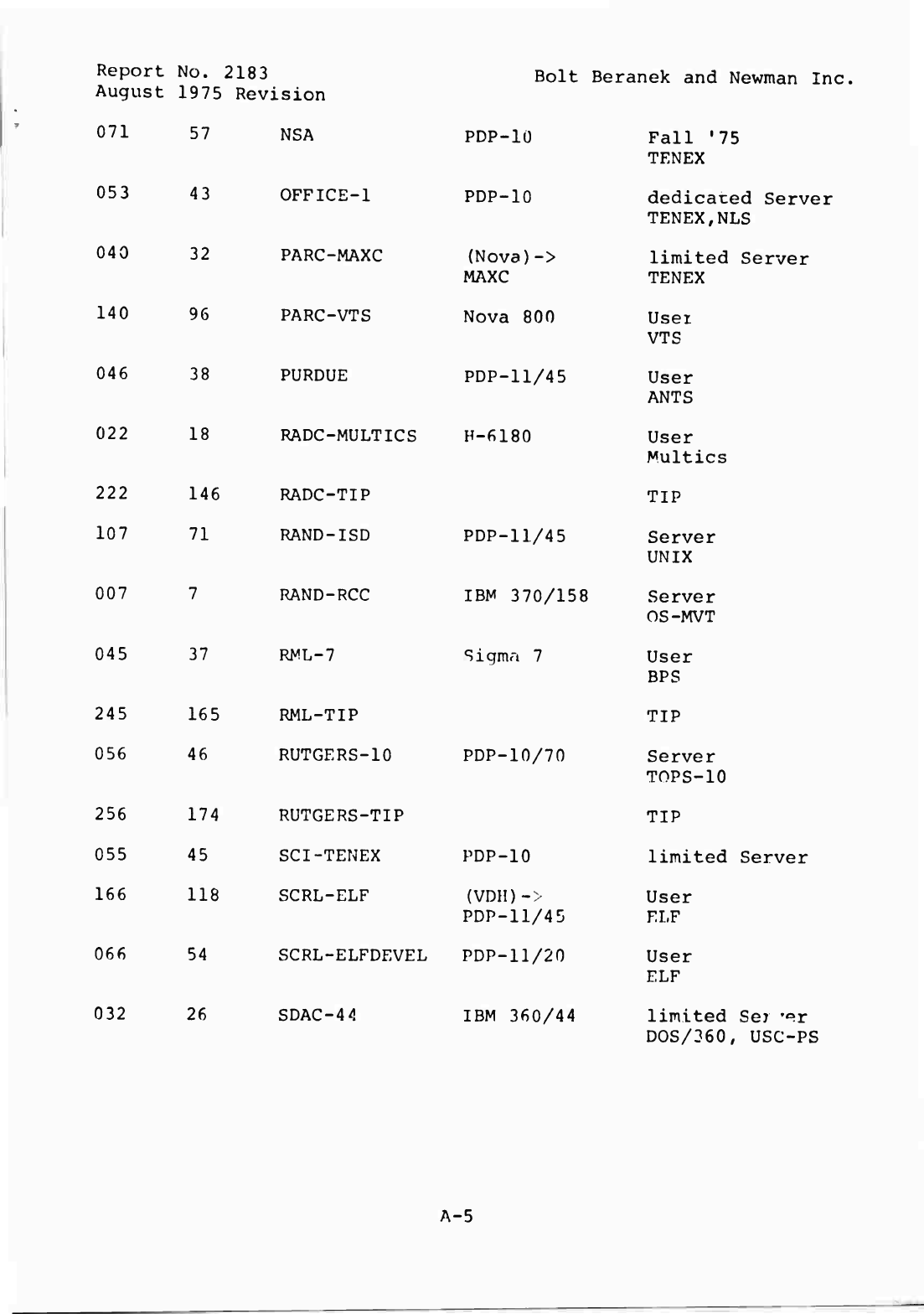
Report
No.
2183
August
1975
Revision
Bolt
Beranek
and
Newman
Inc,
071
053
040
140
046
022
007
045
57
43
32
96
38
18
37
NSA
PDP-1Ü
Fall
'75
TENEX
OFFICE-1
PDP-10
dedicated
Server
TENEX,NLS
PAROMAXC
(Nova)->
limited
Server
MAXC
TENEX
PARC-VTS
Nova
800
User
VTS
PURDUE
PDP-11/45
User
ANTS
RADC-MULTICS
H-6180
User
Multics
222
146
RADC-TIP
107
71
RAND-ISD
RAND-RCC
RNL-7
245
165
RML-TIP
056
46
RUTGERS-10
PDP-10/70
256
174
RUTGERS-TIP
055
45
SCI-TENEX
PDP-10
166
118
SCRL-ELF
(VDH)->
PDP-11/45
066
54
SCRL-ELFDEVEL
PDP-11/20
032
26
SDAC-4
4
IBM
360/44
TIP
PDP-11/45
Server
UNIX
IBM
370/158
Server
OS-MVT
Sigmri
7
User
BPS
TIP
Server
TOPS-10
TIP
limited
Server
User
ELF
User
ELF
limited
Ser
'«r
DOS/360,
USC-PS
A-5
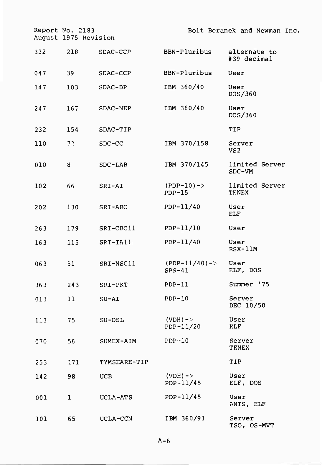
Report
No.
2183
August
1975
Revision
Bolt
Beranek
and
Newman
Inc.
332
218
SDAOCC*
5
BBN-Pluribus
alternate
to
#39
decimal
047
39
SDAC-CCP
BBN-Pluribus
User
14
7
103
SDAC-DP
IBM
360/40
User
DOS/360
247
167
SDAONEP
IBM
360/40
User
DOS/360
232
154
SDAC-TIP
TIP
110
7^
SDC-CC
IBM
370/158
Server
VS2
010
8
SDC-LAB
IBM
370/145
limited
Server
SDC-VM
102
66
SRI-AI
(PDP-10)->
PDP-15
limited
Server
TENEX
202
130
SRI-ARC
PDP-11/40
User
ELF
263
179
SRI-CBC11
PDP-11/10
User
163
115
SRI-IA11
PDP-11/40
User
RSX-llM
063
51
SRI-NSC11
(PDP-ll/40)->
SPS-41
User
ELF,
DOS
363
243
SRI-PKT
PDP-11
Summer
'75
013
11
SU-AI
PDP-10
Server
DEC
10/50
113
75
SU-DSL
(VDH)->
PDP-11/20
User
ELF
070
56
SUMEX-AIM
PDP-10
Server
TENEX
253
171
TYMSHARE-TIP
TIP
142
98
UCB
(VDH)->
PDP-11/45
User
ELF,
DOS
001
1
UCLA-ATS
PDP-11/45
User
ANTS,
ELF
101
65
UCLA-CCN
IBM
360/91
Server
TSO,
OS-MVT
A-6
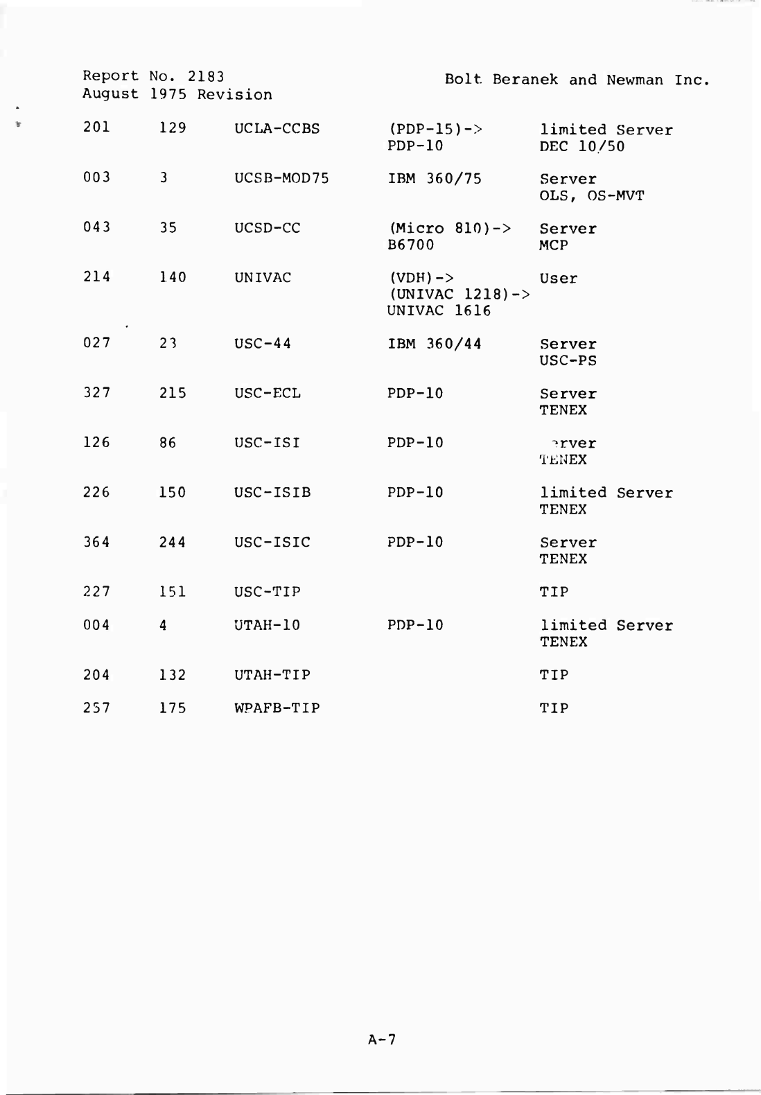
Report
No.
2183
August
1975
Revision
201
129
Bolt
Beranek
and
Newman
Inc.
003
043
214
027
126
35
140
23
327
215
86
226
150
364
244
227
151
USC-TIP
004
4
UTAH-10
204
132
UTAH-TIP
257
175
WPAFB-TIP
UCLA-CCBS
(PDP-15)->
PDP-10
limited
Server
DEC
10/50
UCSB~MOD75
IBM
360/75
Server
OLS,
OS-MVT
UCSD-CC
(Micro
810)->
B6700
Server
MCP
UNIVAC
(VDH)->
(UNIVAC
1218)-
UNIVAC
1616
User
>
USC-44
IBM
360/44
Server
USC-PS
USC-ECL
PDP-10
Server
TENEX
USC-ISI
PDP-10
^rver
TENEX
USC-ISIB
PDP-10
limited
Server
TENEX
USC-ISIC
PDP-10
Server
TENEX
PDP-10
TIP
limited
Server
TENEX
TIP
TIP
A-7
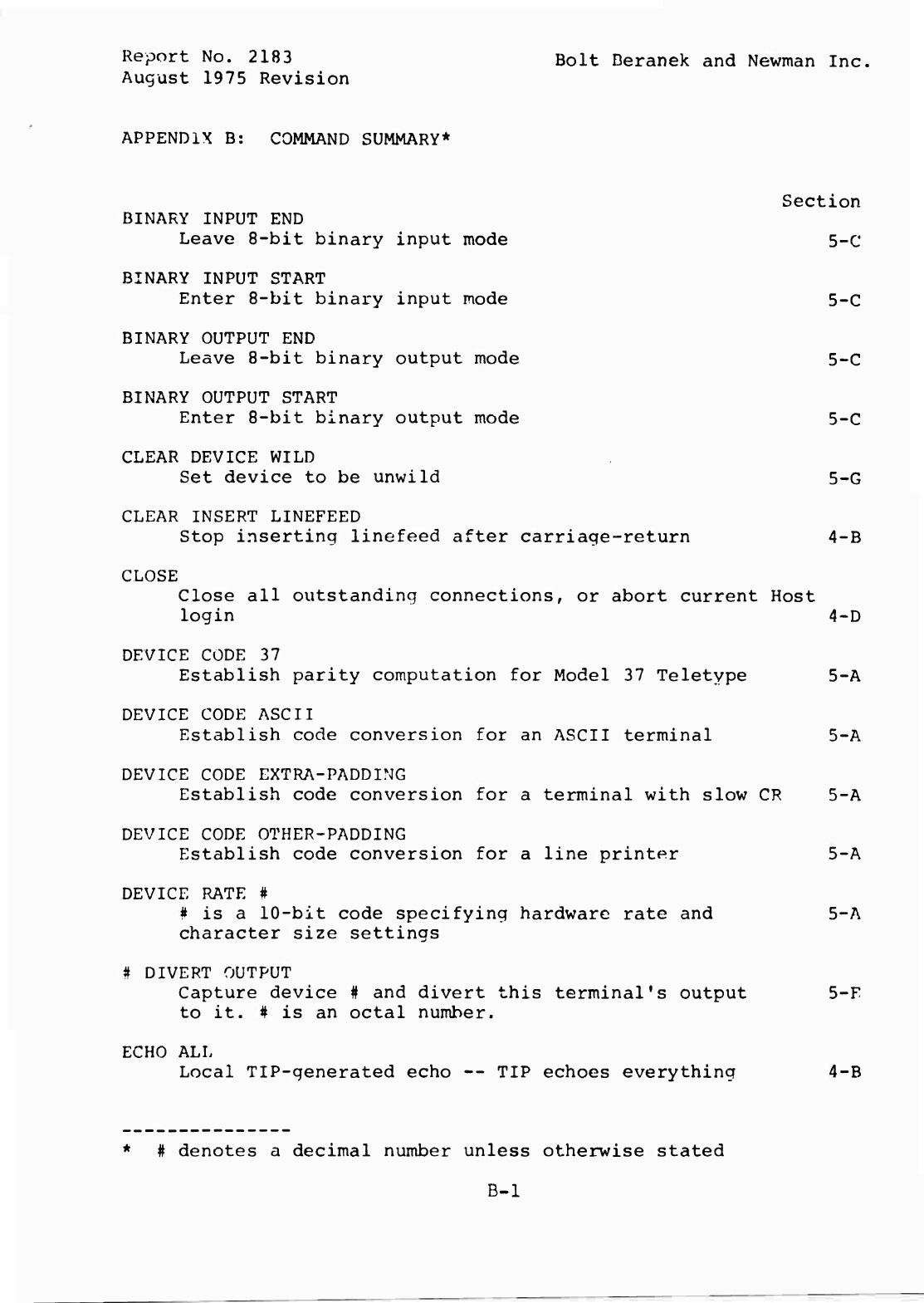
Report
No.
2183
Bolt
Deranek
and
Newman
Inc,
August
1975
Revision
APPENDIX
B:
COMMAND
SUMMARY*
Section
BINARY
INPUT
END
Leave
8-bit
binary
input
mode
5-C
BINARY
INPUT
START
Enter
8-bit
binary
input
mode
5-C
BINARY
OUTPUT
END
Leave
8-bit
binary
output
mode
5-C
BINARY
OUTPUT
START
Enter
8-bit
binary
output
mode
5-C
CLEAR
DEVICE
WILD
Set
device
to
be
unwild
5-G
CLEAR
INSERT
LINEFEED
Stop
inserting
linefeed
after
carriage-return
4-B
CLOSE
Close
all
outstanding
connections,
or
abort
current
Host
login
4-D
DEVICE
CODE
37
Establish
parity
computation
for
Model
37
Teletype
5-A
DEVICE
CODE
ASCII
Establish
code
conversion
for
an
ASCII
terminal
5-A
DEVICE
CODE
EXTRA-PADDING
Establish
code
conversion
for
a
terminal
with
slow
CR
5-A
DEVICE
CODE
OTHER-PADDING
Establish
code
conversion
for
a
line
printer
5-A
DEVICE
RATE
#
#
is
a
10-bit
code
specifying
hardware
rate
and
5-A
character
size
settings
#
DIVERT
OUTPUT
Capture
device
#
and
divert
this
terminal's
output
5-F
to
it.
#
is
an
octal
number.
ECHO
ALL
Local
TIP-generated
echo
—
TIP
echoes
everything
4-B
*
#
denotes
a
decimal
number
unless
otherwise
stated
B-l
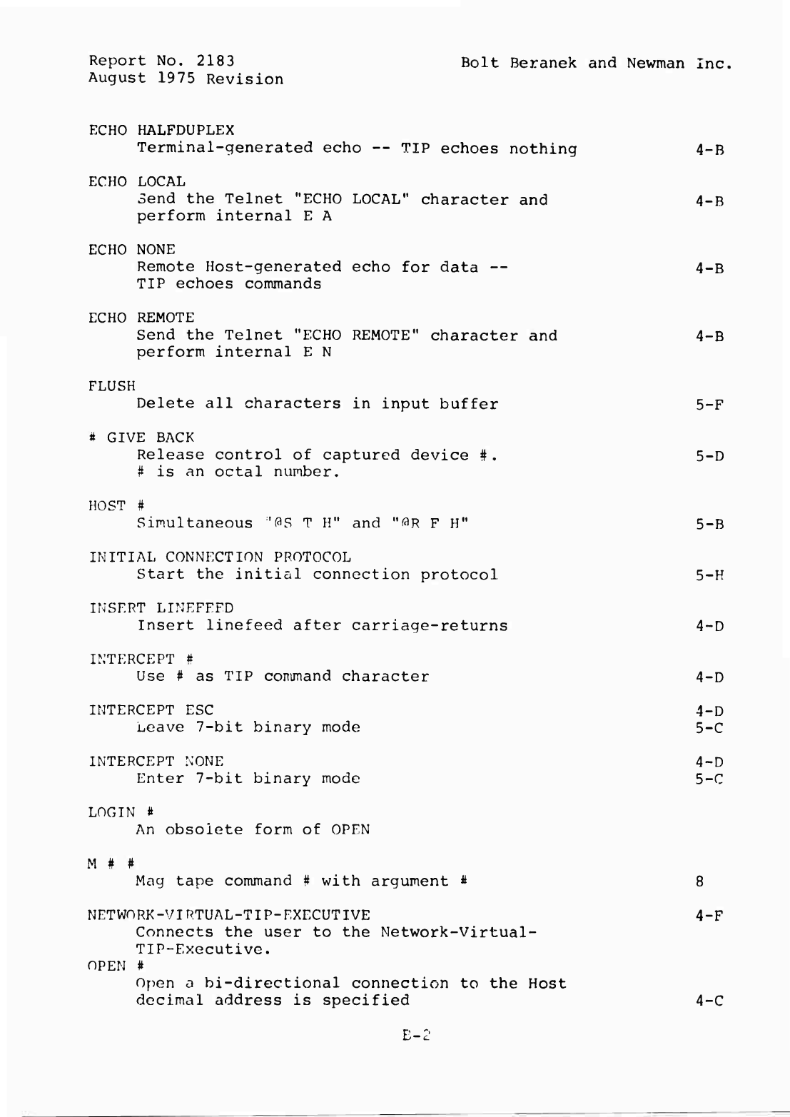
Report
No.
2183
Bolt
Beranek
and
Newman
Inc.
August
1975
Revision
ECHO
HALFDUPLEX
Terminal-generated
echo
—
TIP
echoes
nothing
4-B
ECHO
LOCAL
Send
the
Telnet
"ECHO
LOCAL"
character
and
4-B
perform
internal
E
A
ECHO
NONE
Remote
Host-generated
echo
for
data
—
4-B
TIP
echoes
commands
ECHO
REMOTE
Send
the
Telnet
"ECHO
REMOTE"
character
and
4-B
perform
internal
E
N
FLUSH
Delete
all
characters
in
input
buffer
5-F
#
GIVE
BACK
Release
control
of
captured
device
#.
5-D
#
is
an
octal
number.
HOST
#
Simultaneous
''OS
T
H"
and
"OR
F
H"
5-B
INITIAL
CONNECTION
PROTOCOL
Start
the
initial
connection
protocol
5-H
INSERT
LINEFEED
Insert
linefeed
after
carriage-returns
4~D
INTERCEPT
#
Use
#
as
TIP
command
character
4-D
INTERCEPT
ESC
4-D
Leave
7-bit
binary
mode
5-C
INTERCEPT
NONE
4~D
Enter
7-bit
binary
mode
5-C
LOGIN
a
An
obsolete
form
of
OPEN
M
#
#
Mag
tape
command
#
with
argument
*
8
NETWORK-VIRTUAL-TIP-EXECUTIVE
4-F
Connects
the
user
to
the
Network-Virtual-
TIP-Executive.
OPEN
#
Open
a
bi-directional
connection
to
the
Host
decimal
address
is
specified
4-C
E-2
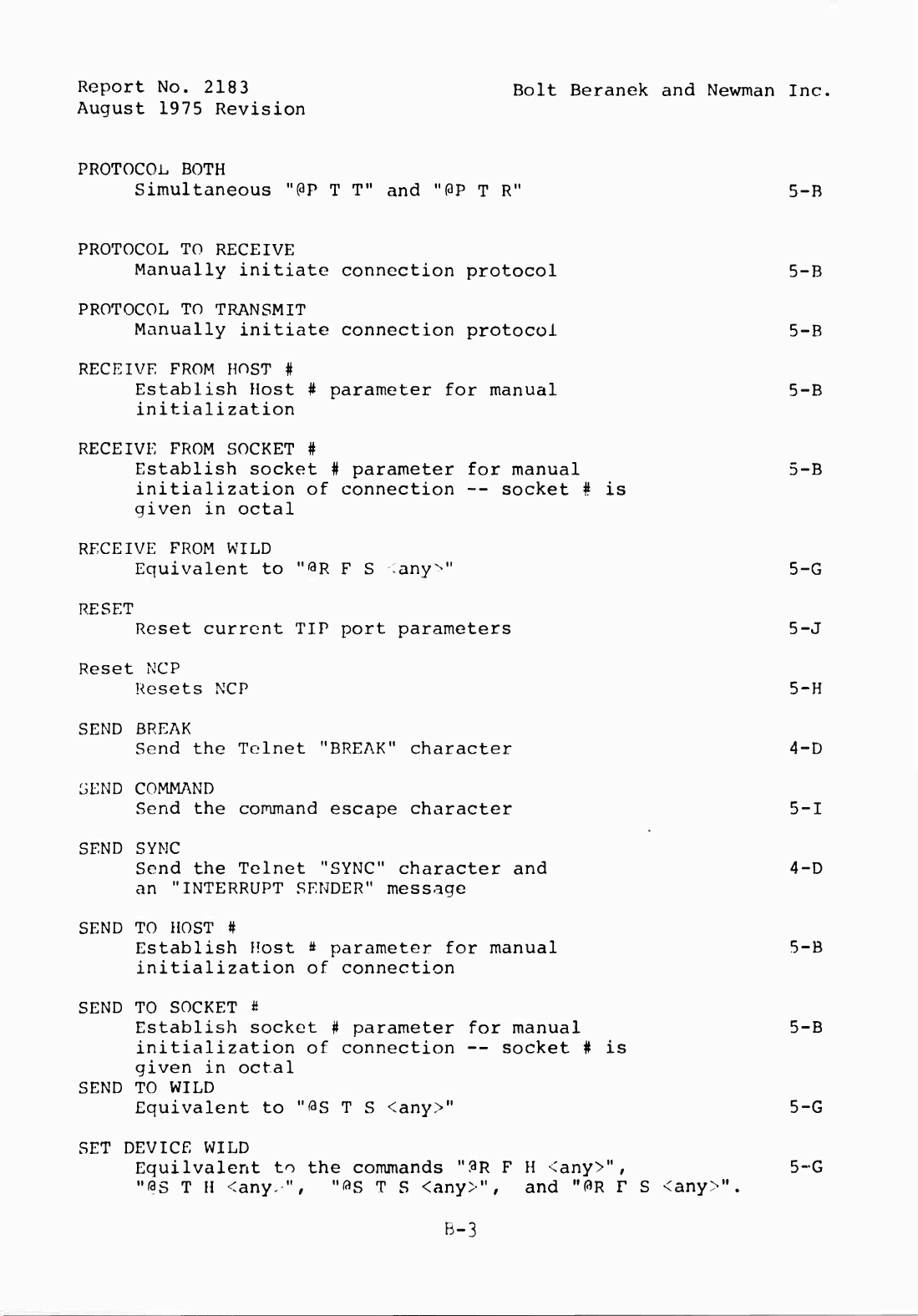
Report
No.
2183
Bolt
Beranek
and
Newman
Inc.
August
1975
Revision
PROTOCOL
BOTH
Simultaneous
"PP
T
T
M
and
"OP
T
R"
5-B
PROTOCOL
TO
RECEIVE
Manually
initiate
connection
protocol
5-B
PROTOCOL
TO
TRANSMIT
Manually
initiate
connection
protocol
5-B
RECEIVE
FROM
HOST
#
Establish
Host
#
parameter
for
manual
5-B
initialization
RECEIVE
FROM
SOCKET
#
Establish
socket
#
parameter
for
manual
5-B
initialization
of
connection
--
socket
#
is
given
in
octal
RECEIVE
FROM
WILD
Equivalent
to
M
^
R
F
S
any^"
5-G
RESET
Reset
current
TIP
port
parameters
5-J
Reset
NCP
Resets
NCP
5-H
SEND
BREAK
Send
the
Telnet
"BREAK"
character
4-D
SEND
COMMAND
Send
the
command
escape
character
5-1
SEND
SYNC
Send
the
Telnet
"SYNC"
character
and
4-D
an
"INTERRUPT
SENDER"
message
SEND
TO
HOST
#
Establish
Host
#
parameter
for
manual
5-B
initialization
of
connection
SEND
TO
SOCKET
#
Establish
socket
#
parameter
for
manual
5-B
initialization
of
connection
—
socket
#
is
given
in
octal
SEND
TO
WILD
Equivalent
to
"^S
T
S
<any>"
5-G
SET
DEVICE
WILD
Equilvalent
to
the
commands
"PR
F
H
<any>",
5-G
"0S
T
H
<any.",
"^S
T
S
<any>"
r
and
"OR
p
S
<any>".
B-3
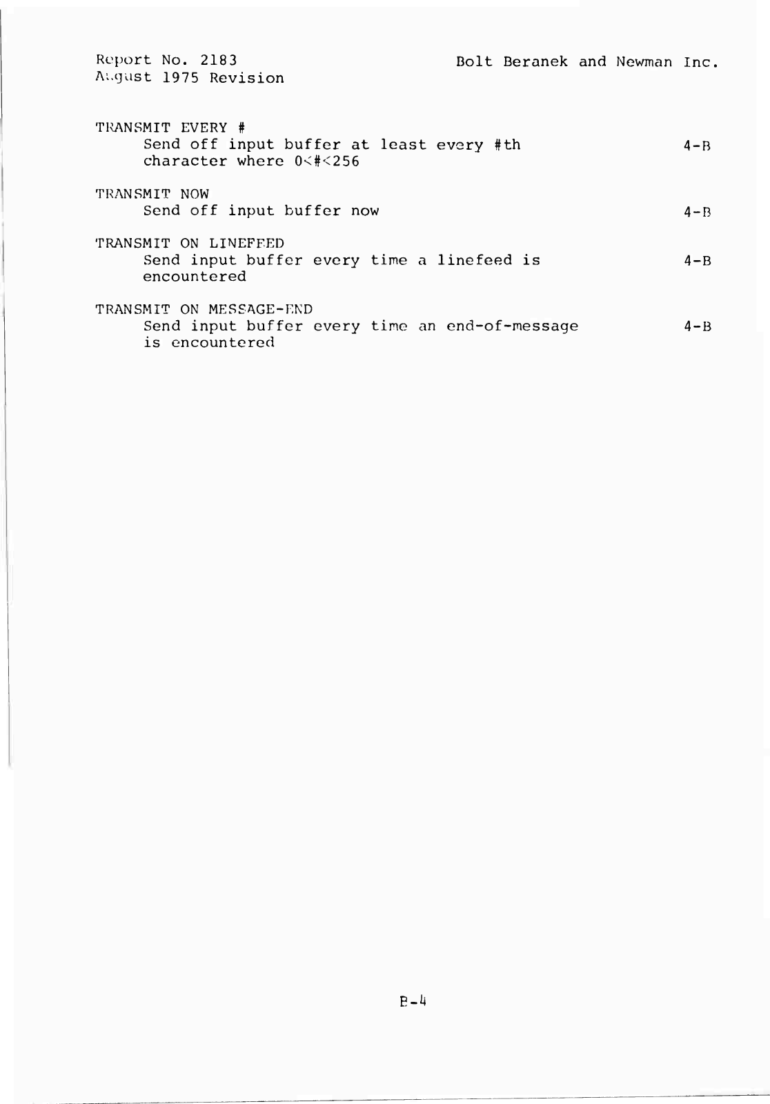
Report
No.
2183
Bolt
Beranek
and
Newman
Inc,
August
1975
Revision
TRANSMIT
EVERY
#
Send
off
input
buffer
at
least
every
#th
4-B
character
where
0<#<256
TRANSMIT
NOW
Send
off
input
buffer
now
4-B
TRANSMIT
ON
LINEFEED
Send
input
buffer
every
time
a
linefeed
is
4-B
encountered
TRANSMIT
ON
MESSAGE-END
Send
input
buffer
every
time
an
end-of-message
4-B
is
encountered
B~k
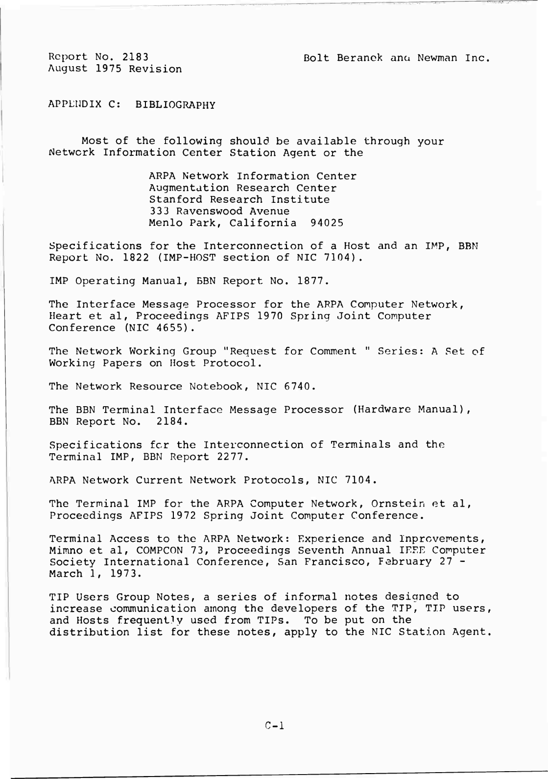
Report
No.
2183
Bolt
Beranok
ana
Newman
Inc.
August
1975
Revision
APPENDIX
C:
BIBLIOGRAPHY
Most
of
the
following
should
be
available
through
your
Network
Information
Center
Station
Agent
or
the
ARPA
Network
Information
Center
Augmentation
Research
Center
Stanford
Research
Institute
33
3
Ravenswood
Avenue
Menlo
Park,
California
94025
Specifications
for
the
Interconnection
of
a
Host
and
an
IMP,
BBM
Report
No.
1822
(IMP-HOST
section
of
NIC
7104).
IMP
Operating
Manual,
BBN
Report
No.
1877.
The
Interface
Message
Processor
for
the
ARPA
Computer
Network,
Heart
et
al,
Proceedings
AFIPS
1970
Spring
Joint
Computer
Conference
(NIC
4655).
The
Network
Working
Group
"Request
for
Comment
"
Series:
A
Set
of
Working
Papers
on
Host
Protocol.
The
Network
Resource
Notebook,
NIC
6740.
The
BBN
Terminal
Interface
Message
Processor
(Hardware
Manual),
BBN
Report
No.
2184.
Specifications
fcr
the
Interconnection
of
Terminals
and
the
Terminal
IMP,
BBN
Report
2277.
ARPA
Network
Current
Network
Protocols,
NIC
7104.
The
Terminal
IMP
for
the
ARPA
Computer
Network,
Ornstein
et
al,
Proceedings
AFIPS
1972
Spring
Joint
Computer
Conference.
Terminal
Access
to
the
ARPA
Network:
Experience
and
Inprcvements,
Mimno
et
al,
COMPCON
73,
Proceedings
Seventh
Annual
IFFE
Computer
Society
International
Conference,
San
Francisco,
February
27
-
March
1,
1973.
TIP
Users
Group
Notes,
a
series
of
informal
notes
designed
to
increase
communication
among
the
developers
of
the
TIP,
TIP
users,
and
Hosts
frequently
used
from
TIPs.
To
be
put
on
the
distribution
list
for
these
notes,
apply
to
the
NIC
Station
Agent.
C-l
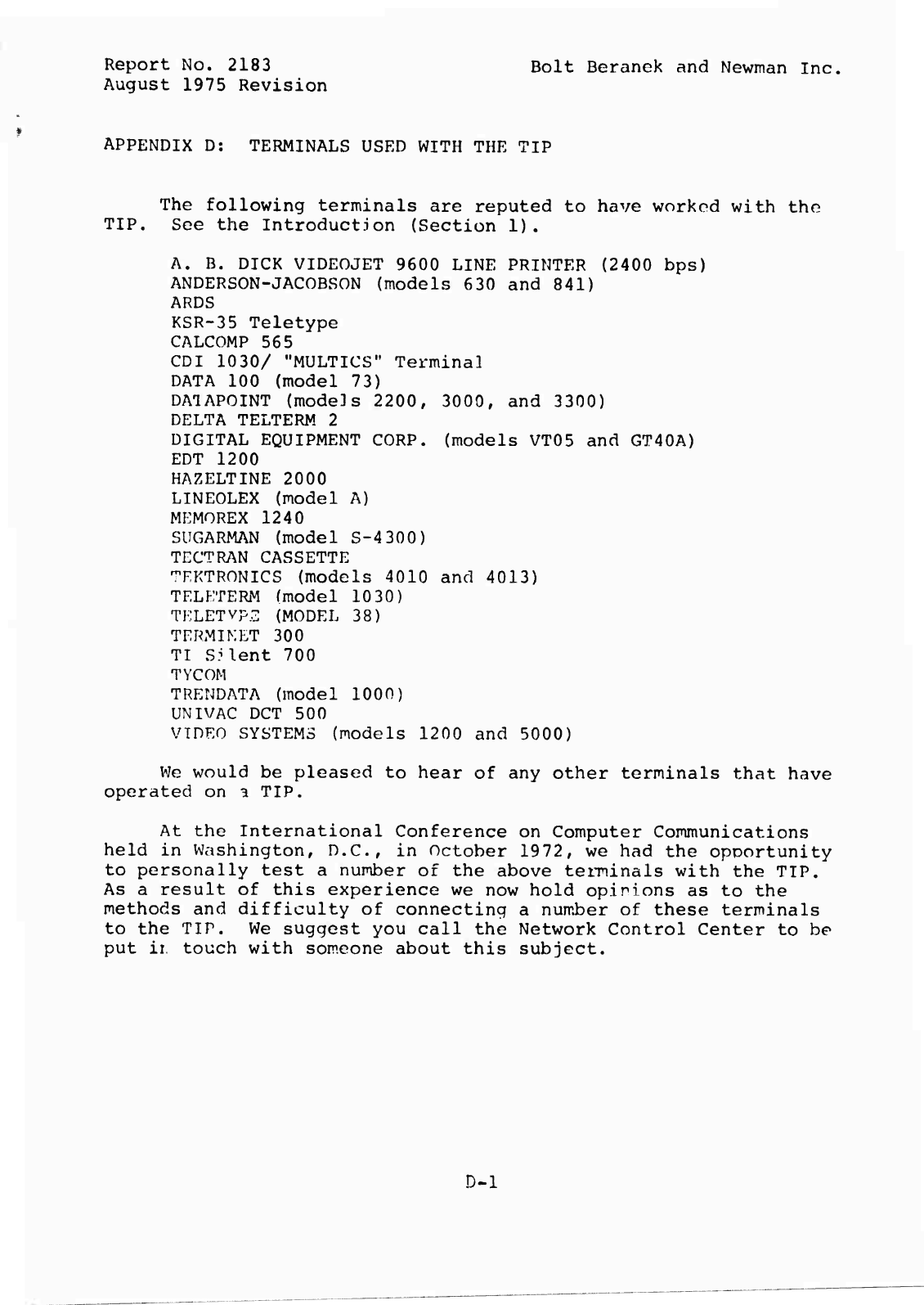
Report
No.
2183
Bolt
Beranek
and
Newman
Inc.
August
1975
Revision
APPENDIX
D:
TERMINALS
USED
WITH
THE
TIP
The
following
terminals
are
reputed
to
have
worked
with
the
TIP.
See
the
Introduction
(Section
1).
A.
B.
DICK
VIDEOJET
9600
LINE
PRINTER
(2400
bps)
ANDERSON-JACOBSON
(models
630
and
841)
ARDS
KSR-35
Teletype
CALCOMP
565
CDI
1030/
"MULTICS"
Terminal
DATA
100
(model
73)
DATAPOINT
(models
2200,
3000,
and
3300)
DELTA
TELTERM
2
DIGITAL
EQUIPMENT
CORP.
(models
VT05
and
GT40A)
EDT
1200
HAZELTINE
2000
LINEOLEX
(model
A)
MEMOREX
1240
SUGARMAN
(model
S-4
300)
TECTRAN
CASSETTE
TKKTRONICS
(models
4010
and
4013)
TELETERM
(model
10
30)
TELETYPE
(MODEL
38)
TERMIKET
300
TI
S?lent
700
TYCOM
TRENDATA
(model
1000)
UNIVAC
DCT
500
VIDEO
SYSTEMS
(models
1200
and
5000)
We
would
be
pleased
to
hear
of
any
other
terminals
that
have
operated
on
a
TIP.
At
the
International
Conference
on
Computer
Communications
held
in
Washington,
D.C.,
in
October
1972,
we
had
the
opportunity
to
personally
test
a
number
of
the
above
terminals
with
the
TIP.
As
a
result
of
this
experience
we
now
hold
opinions
as
to
the
methods
and
difficulty
of
connecting
a
number
of
these
terminals
to
the
TIP.
We
suggest
you
call
the
Network
Control
Center
to
be
put
ii
touch
with
someone
about
this
subject.
D-l
