AGPS Dirt Pro_manual Pro Manual
User Manual: AGPS-DirtPro_manual
Open the PDF directly: View PDF ![]() .
.
Page Count: 52

Manual revision date: 4/18/14

2
Table of Contents
Welcome ............................................................................................................................................................ 4
Basic Concepts ................................................................................................................................................. 4
Units of Measure ...................................................................................................................................................... 5
Glossary of Terms .................................................................................................................................................... 5
The Main Working Screen ........................................................................................................................... 7
The Main Working Screen – Overhead View ................................................................................................... 7
The Working Screen – Blade View ...................................................................................................................... 7
The Working Screen – Menu Bar ........................................................................................................................ 8
The Plot Screen –Overhead View ........................................................................................................................ 9
The Plot Screen – Blade View ............................................................................................................................. 10
The Working Screen – Info Bar.......................................................................................................................... 10
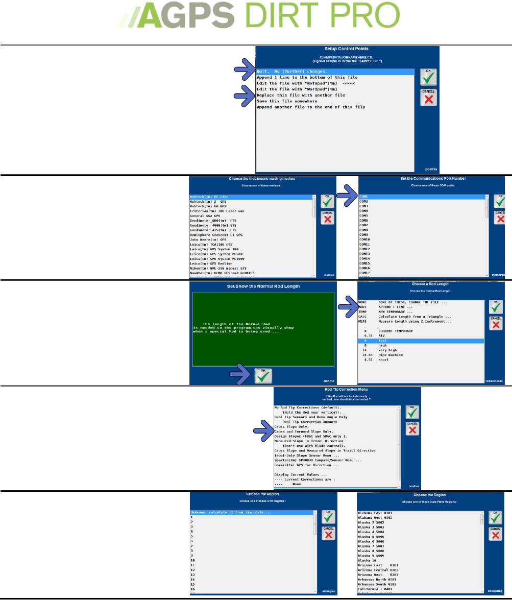
Setting up the program.............................................................................................................................. 11
Setting up the program for the first time: ...................................................................................................... 11
Starting a New Job or Restarting a Current Job: ........................................................................................... 14
Simulated Laser Setup ......................................................................................................................................... 16
Working with RTK-GPS ........................................................................................................................................ 18
Configuring my GPS............................................................................................................................................... 18
GPS Status ................................................................................................................................................................ 19
Troubleshooting my GPS ..................................................................................................................................... 20
Control Points (.ctl file) ....................................................................................................................................... 20
Surface Setup .......................................................................................................................................................... 21
Working with Designs and .FBG Files .................................................................................................................................. 21
Commitment to an Elevation ................................................................................................................................................... 25
Commitment to a Tipped Plane .............................................................................................................................................. 26
Path and Offset menu ........................................................................................................................................... 28
Rod Length ............................................................................................................................................................... 29
Working with the Program ...................................................................................................................... 30
Adjusting the view ................................................................................................................................................. 30
The Buttons Menu ......................................................................................................................................................................... 31
The Click Menu ................................................................................................................................................................................ 32
The Light Bars ......................................................................................................................................................... 33
The Light Bar Menu ...................................................................................................................................................................... 33
The Grid .................................................................................................................................................................... 34
Setting up the Grid ........................................................................................................................................................................ 34
Setting up the Color Grid ............................................................................................................................................................ 36
Color Grid Key ................................................................................................................................................................................. 38
Loading Background Images .............................................................................................................................. 39
Collecting Field Data .................................................................................................................................. 40
Topography data and Pass Labels .................................................................................................................... 40
Pass Types ............................................................................................................................................................... 40
Collecting a Reference (Control) Point ........................................................................................................... 41
Finishing a Job .............................................................................................................................................. 42
Exporting Stake Report........................................................................................................................................ 42
Quit Menu Options ................................................................................................................................................ 42

3
Menus .............................................................................................................................................................. 43
Main Menu ............................................................................................................................................................... 43
Instrument Menu ................................................................................................................................................... 44
Plot Menu ................................................................................................................................................................. 45
Survey File Menu ................................................................................................................................................... 46
Devices Menu .......................................................................................................................................................... 48
Miscellaneous actions .......................................................................................................................................... 49
Quit this Application ............................................................................................................................................. 51
UTM Zones ............................................................................................................................................................... 52
State Plane ............................................................................................................................................................... 52
4
Welcome
Thank you for purchasing AGPS-Dirt Pro™. This manual will guide you through the setup and
running of the program.
AGPS-Dirt Pro™ provides assistance in land moving operations. The program can import a
completed design file (made using AGPS-Shape Pro™ or another third-party design program) and
then control the machine or it can be used to design simple, complex or multi-slope projects in
the field.
If you have further questions, please contact your AGPS Dealer or the AGPS technical support via
email: support@agpsinc.com
Basic Concepts
AGPS-Dirt Pro™ will load a design file (such as CAD), convert it to a cut/fill map (both 2-D and 3-
D) and control the machine making the cut. It can also be used to design (either in the field or in
the office) simple, complex or multi-slope projects.
* What should you ask for when requesting data?
1. An AutoCAD™ 2000 compatible DXF is the preferred method; text points or DWG may be
acceptable as well.
2. This file must have a proposed surface in 3D (Northing Easting Elevation)
3. The surface must be one of the following “Triangles”, “Lines forming Triangles”, or “Lines,
Arcs, and Points”.
4. Any other features included on the drawing (boundaries, existing features etc.) must have an
elevation that does not disrupt the proposed surface OR must have an elevation of 0. (a user
can enter the lowest elevation of points to load, so a greater number than 0 could be used if the user is aware.)
Other features intended for a “background drawing” or “blueprint” view could be provided in
a separate DXF (elevations not important)
5. Coordinate system must be known when setting up the program. This may be Local Points,
State Plane, or UTM. Any of these could use a Stretch K factor if required.
6. Control points (benchmarks) in the same coordinate system are needed as well as
information about where the points are physically on the ground.
7. The overall goal is replicating a setup as if a surveyor was grade checking.
AGPS-Dirt Pro™ can be navigated with either the touch-screen interface or utilizing a standard
keyboard. Most of the instructions in this manual are based on utilizing the touch-screen
interface. For shortcut keys with a keyboard, see the Buttons menu on page 31.
The touch-screen interface has an on-screen keyboard function – when you need to enter text
(job name, naming a control point, etc.) simply touch where you need to enter text and the on-
screen keyboard will pop-up.
5
Units of Measure
AGPS-Dirt Pro™ can be set to work in Feet (International); Feet (U.S. Survey); or Meters. A
typical user in the United States will choose Feet (U.S. Survey). For both Feet (International) and
Feet (U.S. Survey) will be calculated and displayed in tenths of feet, so that 6.5’ is the same as 6’6”.
Inches and Eighths to Decimals of a Foot
In.
0
1/8
1/4
3/8
1/2
5/8
3/4
7/8
0
.00
.01
.02
.03
.04
.05
.06
.07
1
.08
.09
.10
.11
.12
.14
.15
.16
2
.17
.18
.19
.20
.21
.22
.23
.24
3
.25
.26
.27
.28
.29
.30
.31
.32
4
.33
.34
.35
.36
.38
.39
.40
.41
5
.42
.43
.44
.45
.46
.47
.48
.49
6
.50
.51
.52
.53
.54
.55
.56
.57
7
.58
.59
.60
.61
.62
.63
.64
.65
8
.67
.68
.69
.70
.71
.72
.73
.74
9
.75
.76
.77
.78
.79
.80
.81
.82
10
.83
.84
.85
.86
.88
.89
.90
.91
11
.92
.93
.94
.95
.96
.97
.98
.99
Example: 3-½” = .29”
Glossary of Terms
Capture
Auto Capture: Automatically captures a data points after user set interval (typically 10 feet) has
been traveled. This distance uses both horizontal and vertical measurement. Toggling the Auto
Capture button on and off will capture a single point at your current location. Toggled ON/OFF
by keyboard spacebar.
Machine
Control
In the program the term Machine Control refers to the automatic control of the blade. The
control can be toggled by keyboard 0. There are other places in the program that blade used in
a sentence will have different context.
6
Control
point
(.ctl file)
Sometimes called a benchmark, this point is a known world feature in which coordinates are
also known. Control points are important to make your coordinates match those used earlier.
See Control Points on page 41.
Data folder
All job file data opened and saved by the program is stored by default in C:\amw\data\
Device
Other forms: Device Menu, External Device, Control Device, etc. The Device refers to interface
device that operates the automatic blade control, such as a DAC-7000™ or a LaserTech™ 308
control module.
Instrument
Other forms: Instrument Menu, Measuring Instrument, Read Instrument, etc. The instrument is
the positional equipment. Although typically a GPS, there are many other types, and
combinations of multiple instruments. See Working with RTK-GPS on page 18.
Local Point
A NEZ coordinate system that uses “fake” coordinates, meaning they are not consistent with
State Plane or UTM. An example of this is program default “ptafake 5000 2000 100”.
NEZ
Abbreviation for Northing(N) Easting(E) Elevation (Z). Coordinates are always in NEZ. NEZ
coordinates are in Feet (or meters if selected) rather than Latitude Longitude and Altitude.
.nez file
A file that uses the following columns: “Name Northing(N) Easting(E) Elevation(Z)
Description”. (Description is optional)
Plot
Other forms: Plot Menu, Plot Window, etc. The Plot is the lower screen that the field is
graphically drawn in. Any options to adjust a feature drawn here are found in the Plot Menu.
See Plot Menu on page 45.
Resetup
mode
A toggled option to automatically start AGPS-Dirt and Resetup Program (same job), instead of
going to the Main menu to select an application.
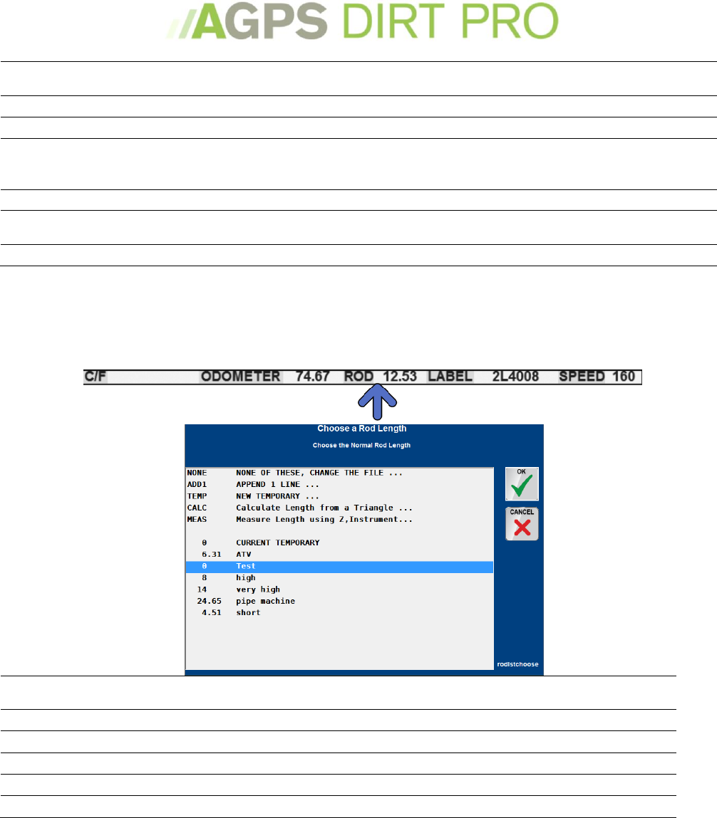
Rod (length)
The distance from the reading point (on the GPS antenna) to the blade or ground. See Rod
Length on page 29.
State Plane
A NEZ coordinate system with zones designed for a particular US State. Every State has one or
more zones. See UTM and State Plane on page 52.
Odometer
The current distance from the start of the selected Path.
Status (GPS)
Shown on the working screen to describe GPS status and other related messages. Shows
something like “ok: 9 4 1.1 /53” Where 9=satellites 4=datatype 1.1=precision and /53=read
counter.
Use the table below to evaluate the data type and precision meaning for your GPS.
RTK
Fixed
RTK Float
No RTK
base
Precision
GGA (Most manufacturers)
4
5
1
HDOP
John Deere™
4
3=extend
5=float.
1
HDOP
NovAtel™/ Raven™/Beeline™
50
49/48/34/17
16
Alt. Std.
Deviation
Topcon™ (Javad™ GGA)
4
5
1
HDOP
Trimble™ (GGK)
3
2
1
PDOP
Surface file
(.fbg, .fb*)
A file that shows a proposed or existing ground. This file uses NEZ format points, and can be
easily built from a "DXF" file exported from some "CAD" program. After the points are loaded a
TIN is created automatically. See Surface Setup on page 20.
Survey File
(.svy)
This file will contain all data points captured. Also, "Location Instrument" setup information
and other relevant information are logged to this file. Points from this file will be displayed on
your plot window as dots. The Survey File Menu includes options to modify this file.
UTM
A NEZ coordinate system with zones designed on Longitude lines. The program can
automatically detect your UTM zone. See UTM and State Plane on page 52.
7
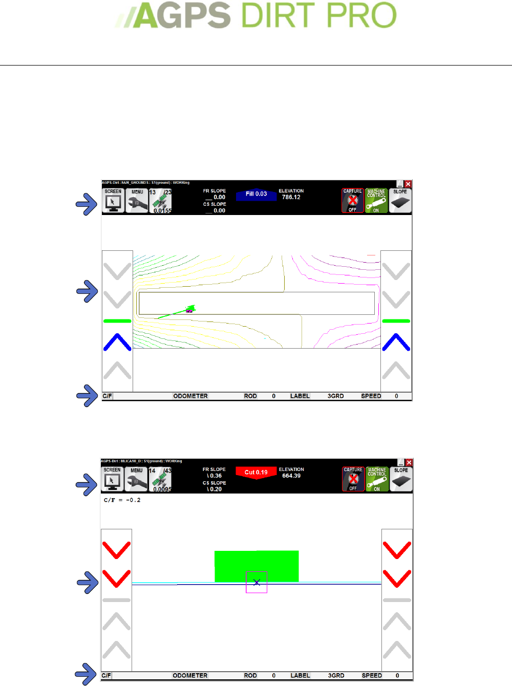
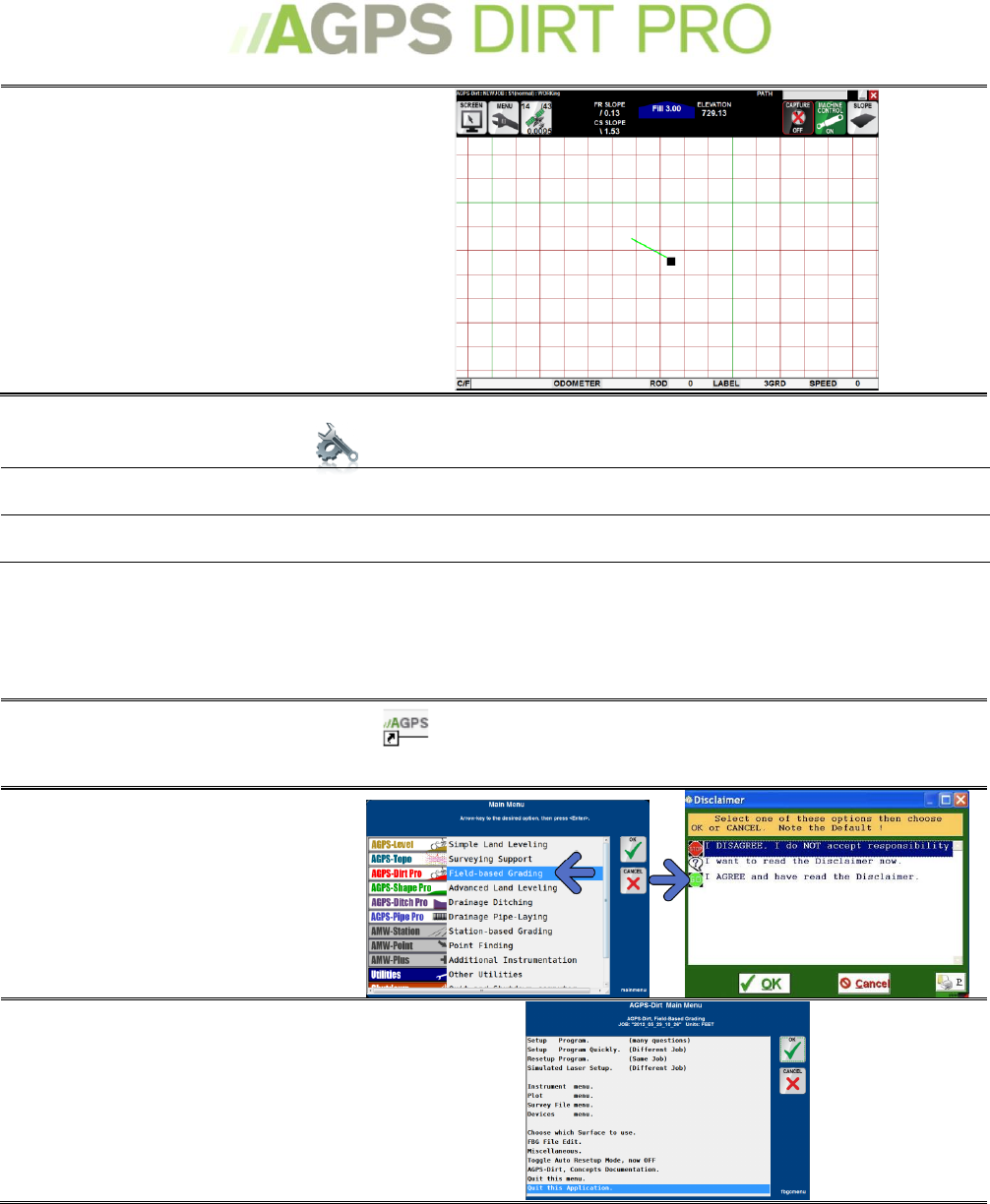
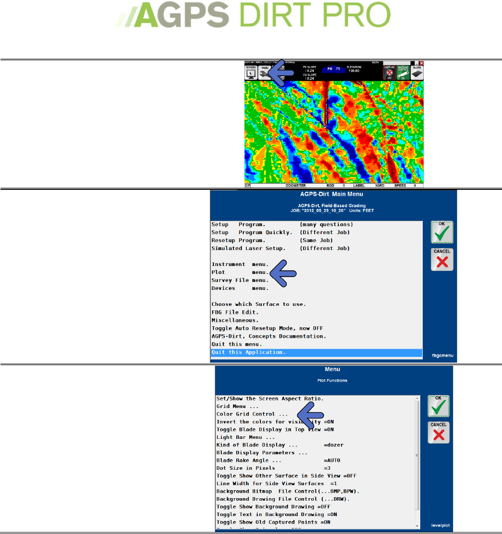
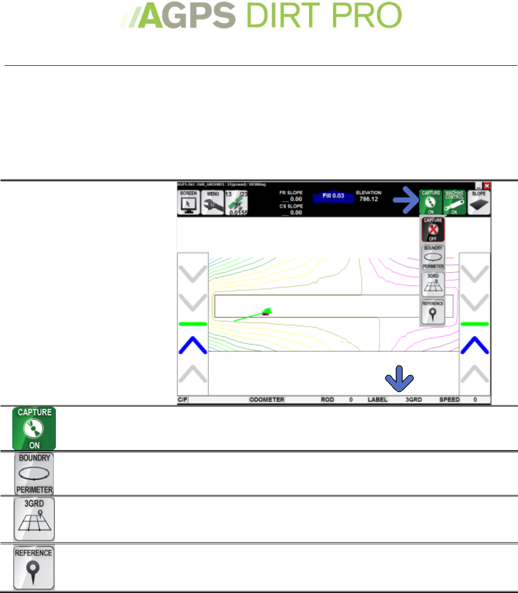
The Main Working Screen
The AGPS-Dirt Pro™ working screen is divided into three sections:
1. The Top Menu Bar on page 8
2. The Middle Plot Screen, with an Overhead View on page 9 and a Profile View on page 10
3. The Bottom Info Bar on page 10
The Main Working Screen – Overhead View
The Working Screen – Blade View
Menu Bar
Plot screen
Info Bar
Menu Bar
Info Bar
Plot screen
8
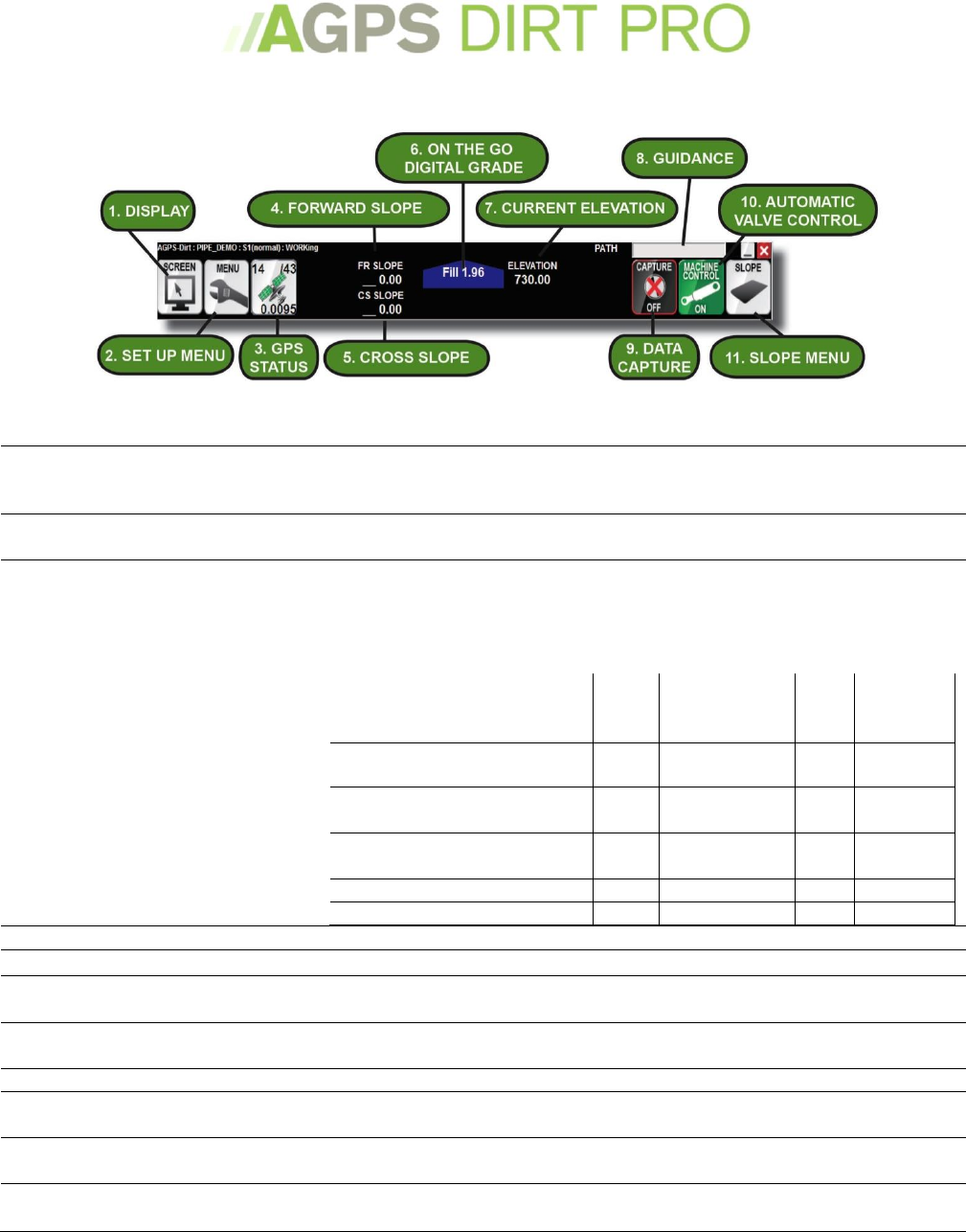
The Working Screen – Menu Bar
The majority of icons in the Menu Bar are touch active. Several also have a secondary function
that can be accessed by pressing and holding the icon for 3 seconds.
1.
Display
Touch this icon to drop down the display menu where you can adjust the
zoom level, scroll around the screen or adjust the grid. See Adjusting the
View on page 30.
2.
Set Up Menu
Touch this icon to start a new job, switch to a different job or adjust your
parameters. See Setting up the Program on page 11.
3.
GPS Status
Icon showing current GPS status. Must be green for the program to work.
Touch to access the Instrument Menu see Instrument Menu on page 44.
The following menu shows the data types for often used RTK-GPS systems.
Shows something like “ok: 9 4 1.1 /53” Where 9=satellites 4=datatype
1.1=precision and /53=read counter.
RTK
Fixed
RTK Float
No
RTK
base
Precision
GGA (Most manufacturers)
4
5
1
HDOP
John Deere™
4
3=extend
5=float.
1
HDOP
Raven™/NovAtel™/Beeline™
50
49/48/34/17
16
Alt. Std.
Deviation
Topcon™ (Javad™ GGA)
4
5
1
HDOP
Trimble™ (GGK)
3
2
1
PDOP
4.
Forward Slope
Tells the Forward Slope (slope running parallel to the direction of flow)
5.
Cross Slope
Tells the Cross Slope (slope running perpendicular to the direction of flow)
6.
Digital Grade
Visual real-time indicator of the position of the blade in relation to designed
grade. Cut will be displayed in Red, On Grade in Green and Fill in Blue
7.
Current Elevation
The current elevation of the blade. Can be in meters, feet-international or
feet-survey. See Setting up the Program on page 11.
8.
Guidance
Distance from the set path.
9.
Data Capture
Data Capture icon. Touch to capture the perimeter, random ground or
reference point Green for On, black/red for Off.
10.
Valve Control
Automatic control of the machine. Green for On, black/red for Off. Press
and Hold to access the Devices (machine control menu).
11.
Slope Menu
Opens the Path and Offset Menu. Touch to change path mode, or tipped
plane commitments. See Path and Offset Menu on page 28.
9
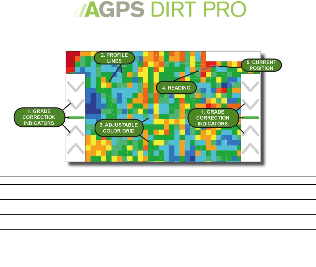
The Plot Screen –Overhead View
1.
Grade Correction Indicators
Tells you how far from grade you are.
2.
Profile Lines
Profile lines from designing in AGPS-Shape Pro™. For more information
on AGPS-Shape Pro™ contact your AGPS dealer
3.
Adjustable Color Grid
Color grid can be set to display Cut/Fill amount, Deflection amount or
Visits count. See Color Grid Menu on page 36.
4.
Heading
Green line that shows real time heading of the current position. The
heading is drawn from the upper left-hand corner of the icon.
5.
Current Position
Visual real-time indicator of the position of the machine. The upper left-
hand corner of the icon is considered the ‘true’ position of the blade. You
can set a ‘fake’ position by touching the screen and either setting where
you touched as the fake position or by ‘snapping’ to a point and setting
that as the ‘fake’ position. ‘Fake’ positions are useful in rotating the grid.
10
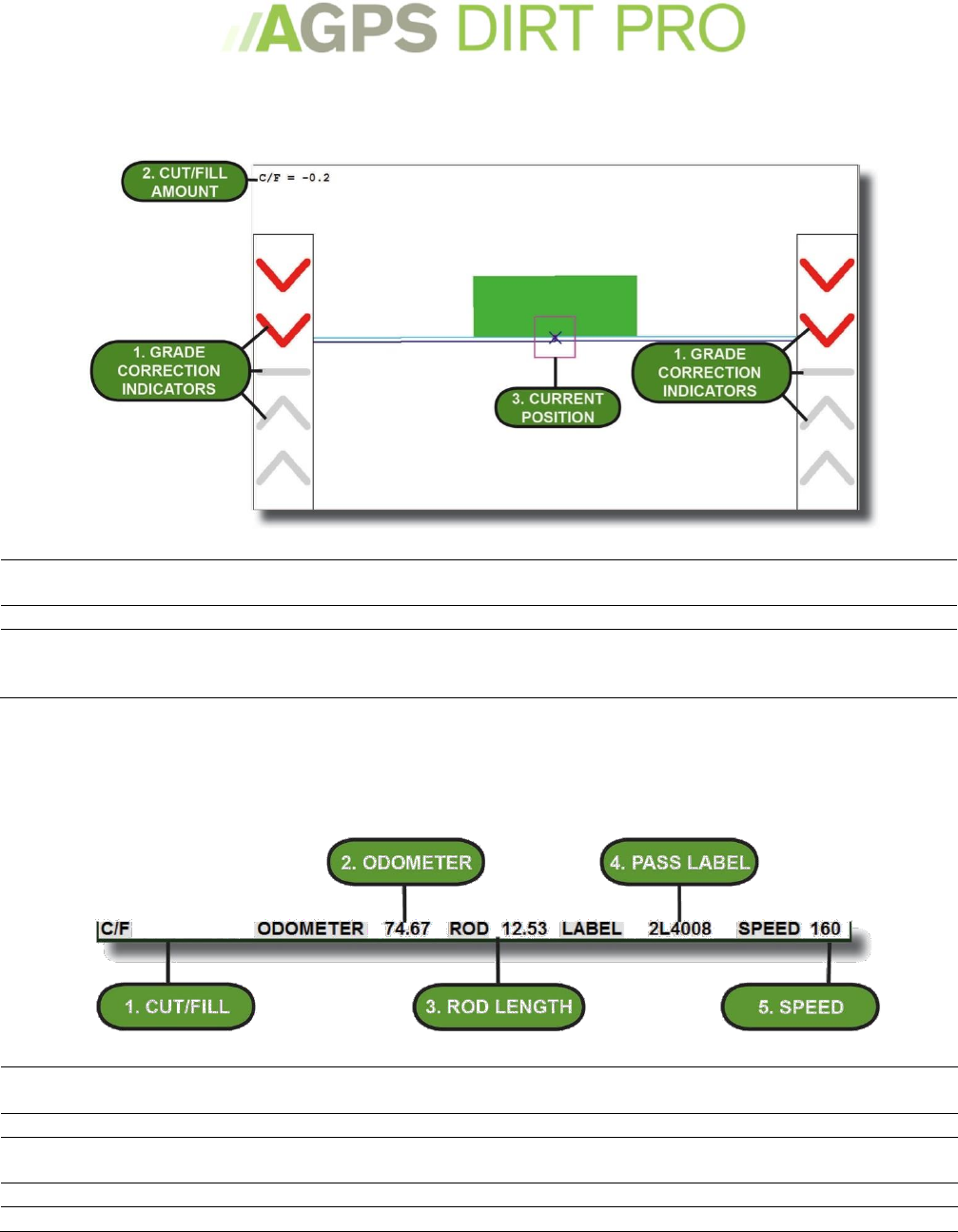
The Plot Screen – Blade View
1.
Grade Correction Indicators
Real time Elevation guidance light bar. Visual indicator of how far off the
Profile the blade is.
2.
Cut/Fill Amount
Amount the blade is offset above or below finish grade.
3.
Current Position
Visual real-time indicator of the vertical position of the blade. The X of
the icon is considered the ‘true’ position of the blade. Can be offset if
using a slope sensor to get a more ‘true’ position of the blade.
The Working Screen – Info Bar
1.
Cut/Fill
The current amount above or below grade AGPS-Dirt Pro™ is controlling the blade. Touch
to set a different Cut/Fill.
2.
Odometer
Real time odometer of the distance of the current pass
3.
Rod Length
The Current Rod Length. The rod length is defined as the distance from the measuring
instrument (i.e. GPS globe) and the tip of the blade. See Rod Length on page 29
4.
Pass Label
Current pass label. Touch to choose a different label. See Pass Labels on page 40.
5.
Speed
Current speed in feet or meters per minute
11
Setting up the program
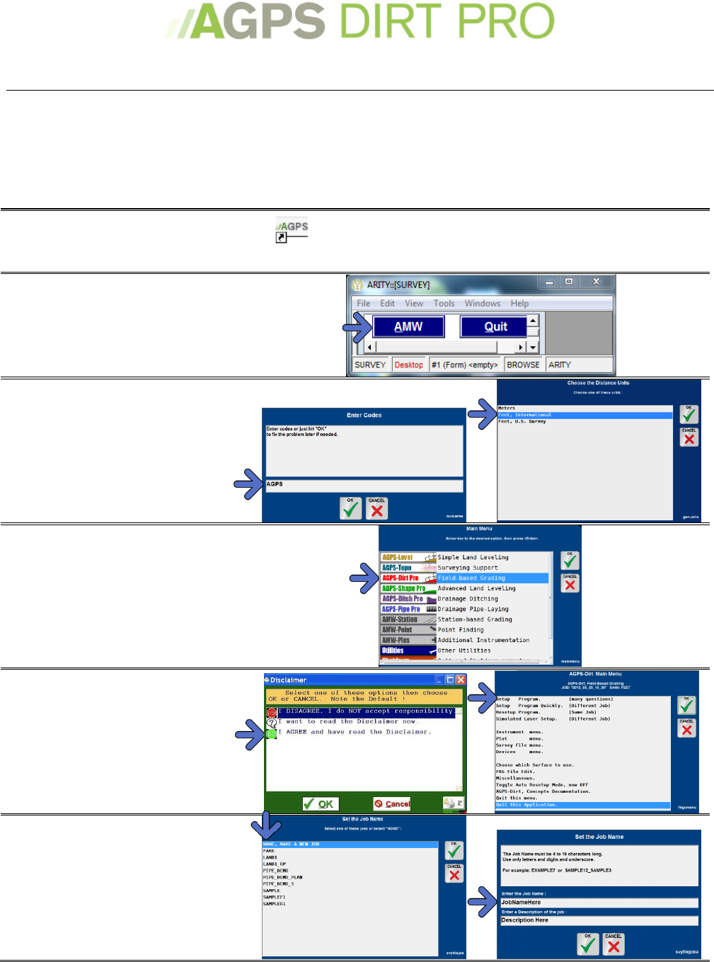
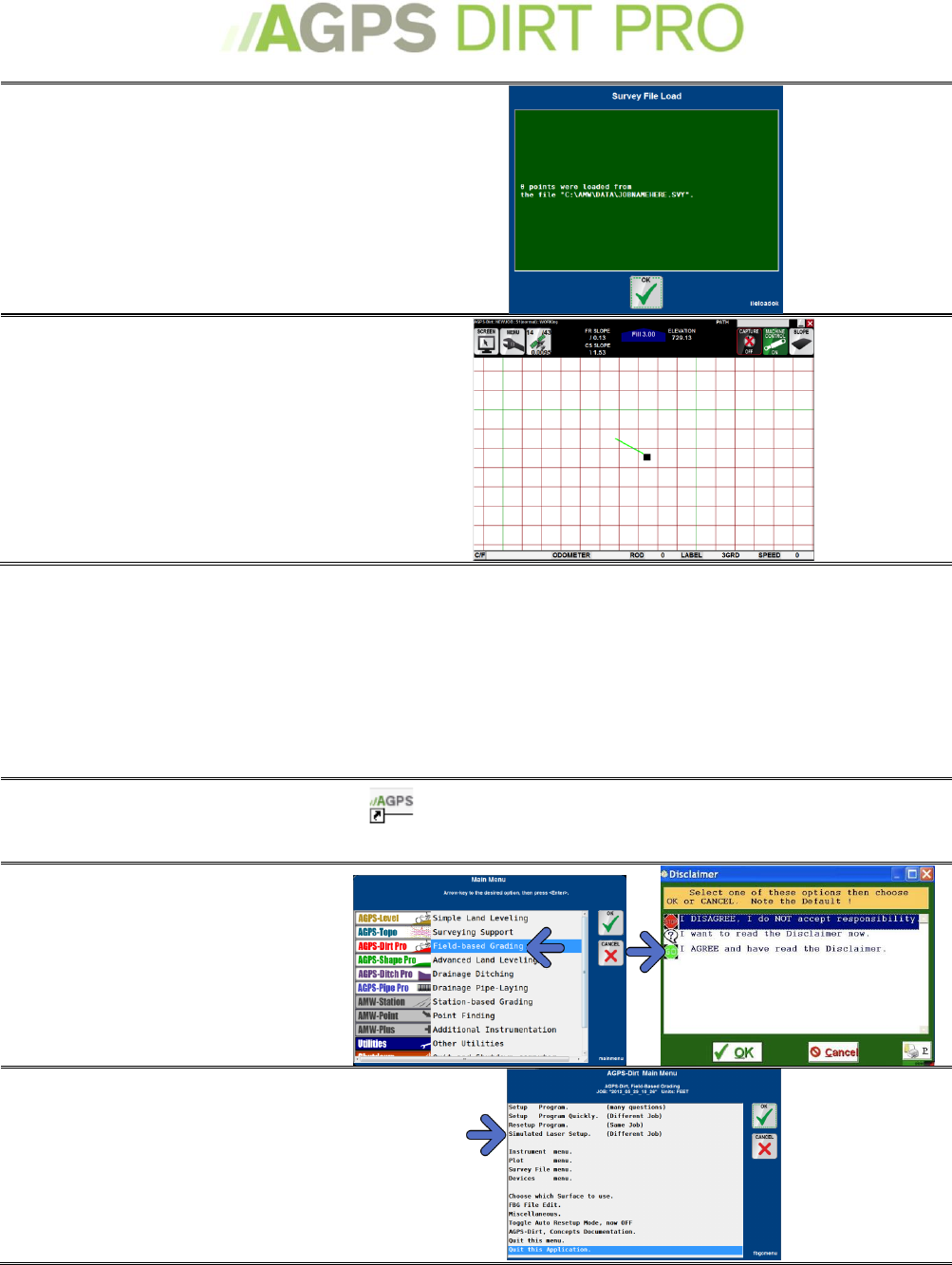
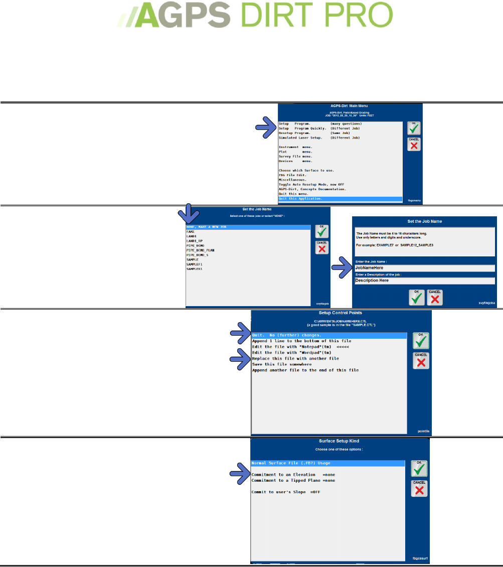
Setting up the program for the first time:
Follow these procedures for the first time you set up AGPS-Dirt Pro™. If you have previously set
up the program or an AGPS-Dirt Pro™ Technician has completed these setup procedures, please
skip to Starting a New Job or Restarting a Current Job on page 14
Start AGPS ™
If the program does not load on computer startup,
locate the AGPS icon on the desktop or in the Start
Menu to load. A starting screen will briefly appear.
Select the AMW button. NOTE:
This step will only need to be
performed once.
Enter the code AGPS. Touch the
entry field to pull up a touch screen
keypad.
Select the unit of measure (typically
Feet U.S. Survey for U.S. users).
Select AGPS-Dirt Pro™ from
the main menu.
Agree to the Disclaimer (you
must do this every time you
start AGPS-Dirt Pro™
Select Setup Program (many
questions).
Select None, Make a New Job.
Enter the name of the job (i.e.
the name of the field or the name of
the customer). You may also enter a
description of the job.
12
Setup your control points. If
you have no control point for this job,
select Quit, No (further) Changes.
If you have control points (see Control
Points on page 41) you can choose to
edit the control point file and add
the point.
Choose the Instrument (GPS).
The GPS instrument must be
configured to output the correct
message type. Cousult the GPS
manufacturer for specifics.
Then Choose the Com Port the GPS is
outputting messages to.
Select the Normal Rod Length.
The Normal Rod is the typical rod
length.
To add your rod length, select Add1.
Select Rod Tip Corrections. If
you have a slope sensor, select it here.
Set the Location-Instrument
Position. If you use UTM, select
UTM 0 point. If you do not know the
UTM zone, select Unknown, Calculate.
If you use State Plane, select State
Plane 0 point and select the State
Plane.
or
13
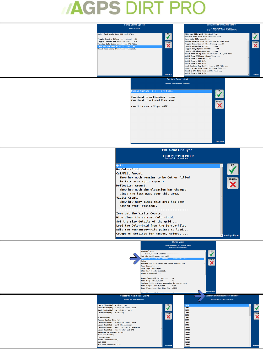
Bitmap control option or
Background Drawing
You can load a bitmap image for a
background drawing. See Loading
Background Images on page 39.
Surface Setup Kind
You can choose the type of Surface you
want to use:
Surface File (previously designed file);
Commitment to an Elevation (grading
to a specific elevation); Commitment
to a Tipped Plane (grading with a
forward and/or cross slope); Commit
to user’s Slope (commit to a simple
slope)
See Surface Setup on page 20.
Color-Grid Type
Select and adjust the type of Color Grid
you would like.
For more details, see Color Grid Menu
on page 36.
Device Menu. Select the type of
auto-blade controller you have.
Contact the Auto-Blade control
manufactuerer for more details on
setting up the device.
Typical controllers are the
LaserTech™ with MultiPlexor or
DAC 7000™ control. Then select
the Com port the controller is
plugged into.
14
The Main Working Screen will
appear: You should be able to
begin working.
TroubleShooting Tips:
I finished the setup, but the screen
flashes red
This is typically related to the GPS signal. See Troubleshooting My GPS on
page 20.
I missed/mess up a step
You can go through the setup process again from the Main Menu. Press the
Menu Icon on the Working Screen.
Starting a New Job or Restarting a Current Job:
Follow these procedures each time you start up AGPS-Dirt Pro™.
1. Start AGPS-Dirt Pro™
If the program does not load on computer startup,
locate the AGPS icon on the desktop or in the Start
Menu to load. A starting screen will briefly appear.
2. Select AGPS-Dirt Pro™
3. Agree to the Disclaimer
(you must do this every time you start
AGPS-Dirt Pro™
4. Select Setup Program
(Different Job) for a new job or
Resetup Program for the job
you’re currently working on
(skip to step 6)
15
5. For a New Job:
Select None, Make a New Job.
Enter the name of the job
(i.e. the name of the field or the name
of the customer). You may also enter a
description of the job.
6. Setup the Location
Instrument
- If you have a control point, Select
UTM 1 point or State Plane 1 point.
- If no control point, Select UTM 0
point or State Plane 0 point
- If you are re-setting up a job and
nothing has changed, select
Do nothing now, keep existing
setup and skip to step 10.
7. Set the Location-
Instrument Position.
Select your UTM Zone or your State
Plane Region. If you do not have a
control point, skip to step 10.
or
8. Load a Control Point
- Select the Rod Length you are going
to use to read the instrument
- Select the Control Point you want to
read (if you have a control point but it
is not loaded into the program, choose
None of These, Change the File)
9. Read the Instrument
- Read the Instrument after you have
set the pause amount and # of tries
(see Control Points on page 20 for
more detail)
- Check the Setup: The program will
tell you how many reads were
successful and what the averages
were. Press OK
16
10. Survey load
You will see a status screen that tell
you if any points were loaded (new
jobs should have 0 points loaded).
Select OK.
The Main Working Screen will
appear: You should be able to
begin working.
Simulated Laser Setup
A Simulated Laser Setup is used for on the job setup of single or multi-slope leveling. You start at
a drainage point, set a control point, and then drive to where you want the main slope (long
slope) to drain. The program will calculate the real slope between the two points, which you can
use or you can enter your own slope. You can also then enter a cross slope. After you have
completed a Simulated Laser Setup, you can recall the entries in the Surface Setup Menu under
Commitment to a Tipped Plane.
1. Start AGPS-Dirt Pro™
If the program does not load on computer startup,
locate the AGPS icon on the desktop or in the Start
Menu to load. A starting screen will briefly appear.
2. Select AGPS-Dirt Pro™
3. Agree to the Disclaimer
(you must do this every time you start
AGPS-Dirt Pro™
4. Select Simulated Laser
Setup
17
5. For a New Job:
Select None, Make a New Job.
Enter the name of the job
(i.e. the name of the field or the name
of the customer). You may also enter a
description of the job.
6. Stop at the first point
Stop at the first point that you want to
read, put the blade on the ground and
press ok. Typically this will be the high
point of the long slope.
7. Read the Instrument at the
First Point
You can adjust the instrument before
reading if you need to. This read will
also create a control point.
8. Set the elevation above the
control point
Default is 100 (this will show the start
point of the tip at 100 feet, avoiding
negative numbers while you grade)
9. Drive to and Stop at the
Second point
Stop at the second point that you want
to read, put the blade on the ground
and press ok. Typically this will be the
low point of the long slope.
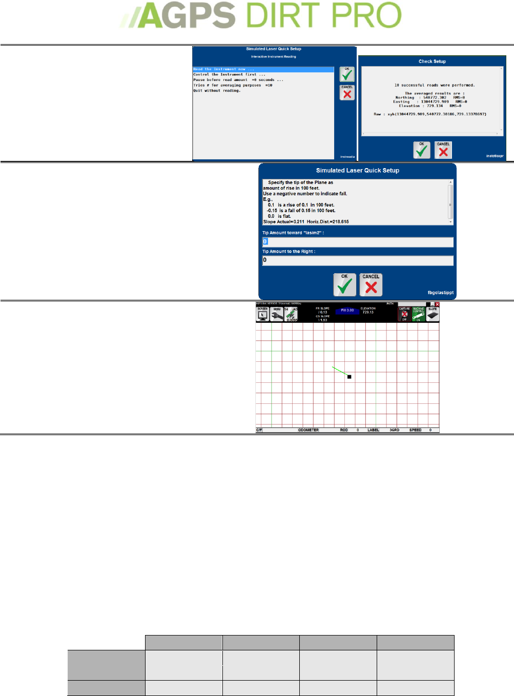
18
10. Read the Instrument at
the Second Point
You can adjust the instrument before
reading if you need to. This read will
also create a control point.
11. Set the Tipped amounts
- Specify the amount of the Long slope
and the Cross slope. The actual long
slope amount will be displayed. Enter
a negative number to reverse the tip
amount.
The Main Working Screen will
appear: You should be able to
begin working.
Working with RTK-GPS
AGPS-Dirt Pro™ is designed to be used with most high-grade RTK-GPS systems. The accuracy of
AGPS-Dirt Pro™ is directly related to the accuracy of the RTK-GPS system that you utilize. Not all
RTK-GPS systems are the same and offer the same accuracy and repeatability. Contact your
AGPS-Dirt Pro™ dealer for recommendations on current RTK-GPS systems.
Configuring my GPS
The following tables list the output options that should be enabled on common brands of GPS
systems. If your GPS system does not appear on this list, please contact your AGPS-Dirt Pro™
Dealer or Technician for setup details. The Hz (update) rate and Baud rate must also be set in
the AGPS-Dirt Pro™ program. To set these, press the Menu icon, select Instrument Menu, Control
the Instrument and adjust both the Hz and Baud rates.
Ashtech
TopCon
JD ITC
JD 3000
Msg type
GGA
GGA
GGA
GGA
HZ rate
10
10
5
10
BAUD rate
57600
57600
38400
57600
19
NovAtel
300/ 410
Trimble
(older)
Trimble
(newer)
Msg type
BestPos
BestPos
GGK
GGA
HZ rate
10
10
10 & ASAP
10
BAUD rate
57600
57600
38400
57600
GPS Status
Each individual RTK-GPS system will have it’s own standard for being in ‘fix’ and the type of
data/degree of precision it returns.
Common GPS Systems data:
RTK Fixed
RTK Float
No RTK base
Precision
GGA (Most manufacturers)
4
5
1
HDOP
John Deere™
4
3=extend
5=float.
1
HDOP
NovAtel™/ Raven™/Beeline™
50
49/48/34/17
16
Alt. Std. Deviation
Topcon™ (Javad™ GGA)
4
5
1
HDOP
Trimble™ (GGK)
3
2
1
PDOP
A Note on ‘DOP’:
HDOP, VDOP, and PDOP are respectively Horizontal, Vertical, and Positional (3D) Dilution of
Precision. The precision of multiple satellites in view of a receiver combine according to the
relative position of the satellites to determine the level of precision in each dimension of the
receiver measurement. When visible GPS satellites are close together in the sky, the geometry is
said to be weak and the DOP value is high; when far apart, the geometry is strong and the DOP
value is low. Thus a low DOP value represents a better GPS positional precision due to the wider
angular separation between the satellites used to calculate a GPS unit's position. Other factors
that can increase the effective DOP are obstructions such as nearby mountains or buildings.
DOP
Value
Rating
Description
<1
Ideal
This is the highest possible confidence level to be used for applications demanding the
highest possible precision at all times.
1-2
Excellent
At this confidence level, positional measurements are considered accurate enough to
meet all but the most sensitive applications.
2-3
Good
Represents a level that marks the minimum appropriate for making business decisions.
Positional measurements could be used to make reliable in-route navigation
suggestions to the user.
>3
Poor
Should be used only to indicate a very rough estimate of the current location.
20
Troubleshooting my GPS
TroubleShooting Tips:
COM Port already in use
The Communications Port that the GPS is plugged into is being used by
another program or is closed for some reason.
1. Verify that the GPS is plugged into the correct COM port.
2. Unplug the GPS from the COM port, power-cycling the computer,
restarting AGPS-Dirt Pro™ and then re-plugging the GPS.
No GPS Data
The GPS is sending no signal, or the computer is receiving nothing.
1. Verify the GPS is powered on.
2. Verify the GPS is plugged into the COM port.
3. Verify the GPS is sending the configured correctly as described in
Configuring my GPS on page 18.
Bad Data
The GPS is sending bad or incorrect data
1. Verify the GPS is plugged into the correct COM port
2. Verify the GPS is configured correctly
3. Verify AGPS-Dirt Pro™ is configured to the correct instrument and
to the correct incoming Baud and Update rate.
Bad Position Type X (#)
Where X is the type, see table
under "GPS Status"
The GPS is not seeing the base station
1. Verify the base station is powered on.
2. Verify the base station is within the manufacturer guidelines for
distance.
3. Verify the rover is configured to read the base station.
4. Double check radio antennas and cable connections.
Goes in and out of fix
The GPS going in and out of fix can be a symptom of several different
problems:
Poor line-of-site with the base.
Poor Satellite visibility.
Damaged GPS Rover Antenna.
Control Points (.ctl file)
A Control Point (sometimes referred to as a Benchmark) is a known location in the real world
that has associated coordinate data and can be accessed at a later date.
Control points allow for exact repeatability from topography collection to day-to-day operations.
They assure that the GPS correction data is correct from day-to-day, month-to-month and year-
to-year, independent of a base station or repeater system.
AGPS-Dirt Pro™ requires the use of Control Points in any pre-survey operation (such as designs
created from previously collected data) and recommends the use of control points in day-to-day
operations.
TroubleShooting Tips:
Where should I set the control point?
A location that isn’t likely to change and that you can easily re-locate and
access in the future (e.g. culvert, fence-post)
What’s the best way to capture/load
control points from day-to-day
Capture a control point where you stop for the day (with the blade raised
up to avoid settling) and load the control point before moving the next day.
My RTK Base station has an internal
memory; do I still need control
points?
We highly recommend using them. Base stations can lose their memory;
people can steal the tripod you left in the field.
21
Surface Setup
The surface is how the job is handled. The surface can be a series of previously designed files (for
instance a final grade surface and an underlayment surface), a commitment to an elevation (for
grading to a flat plane) or a commitment to a tipped plane (for dual-slope drainage)
Normal Surface File (.FB?)
An FBG surface file is built from a design file. Almost always used for a job
where that has been previously designed. You can import many different file
types and they will be converted to an .fbg file. See Working with Designs
and .FBG Files on page 21.
Commitment to an
Elevation
Commits to an elevation. You can enter a known elevation that you would like
to level to. See Commitment to an Elevation on page 25.
Commitment to a Tipped
Plane
Commits to a tipped plane for multi-slope drainage. If you know the slopes
you want to use, you can enter them; otherwise use the Simulated Laser
Setup to design a dual-slope drainage solution.
Commit to user’s Slope
Allows the user to enter a slope to commit to.
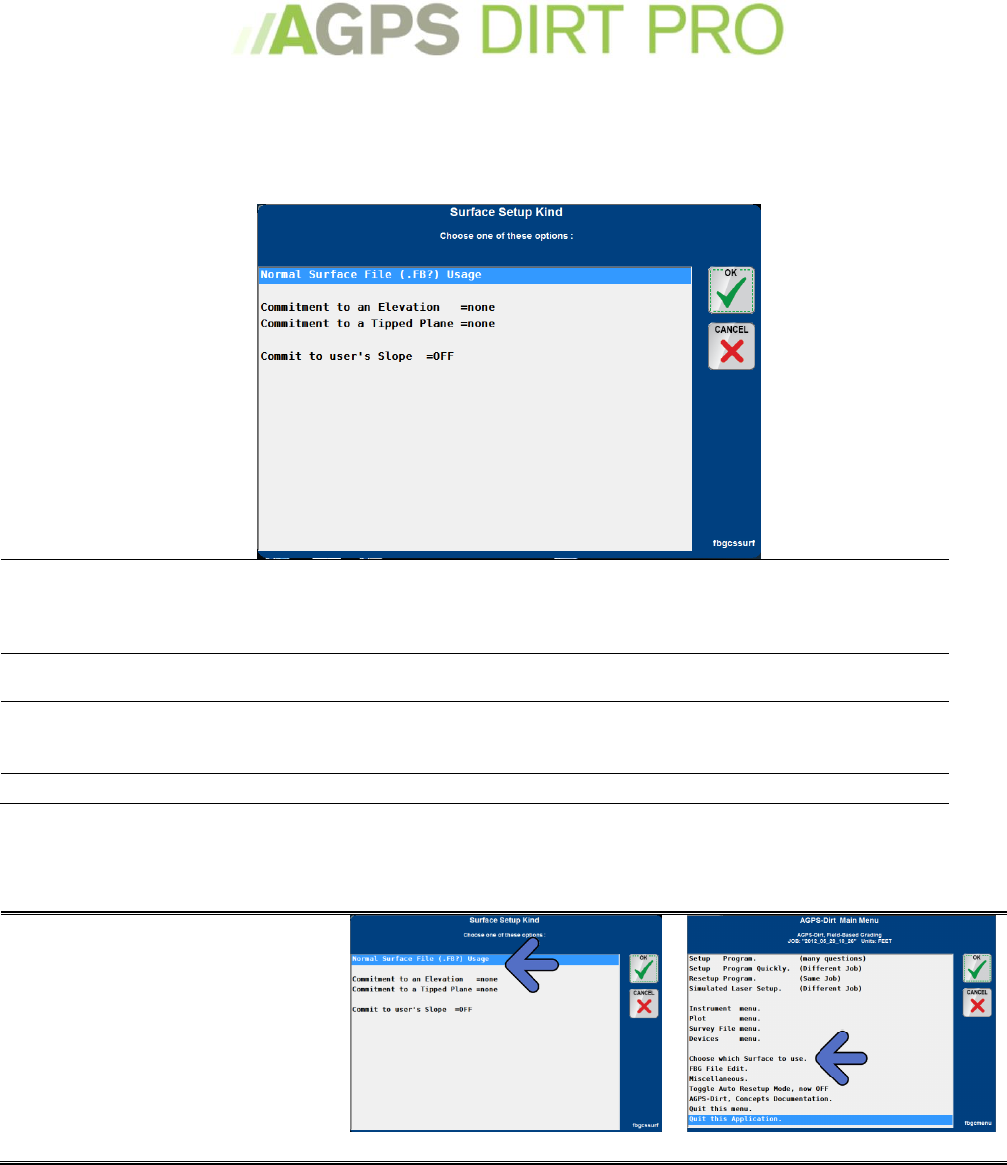
Working with Designs and .FBG Files
To load a design file, select
‘Normal Surface File (.FB?)
Usage’ in the Surface Setup
Menu (appears when you
start a new job or restart
current job), or select ‘Choose
which Surface to use’ from the
Main Menu.
or
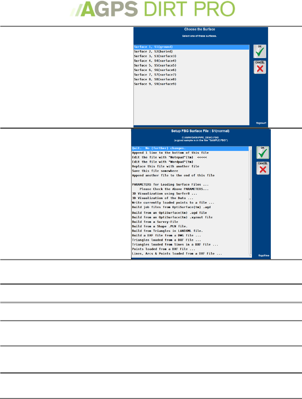
22
Select your surface. You can
have multiple surfaces in the
job. You can toggle between
surfaces while you are
working, but you must load
the file for each surface.
Select they type of file to load.
Most often you will either
Replace this file or Build from
a different file.
Append 1 line to the bottom
of the file
Allows you to add a line of data to the bottom of the .fbg file
once it has been loaded
Edit the file with ‘Notepad’
Opens the .fbg file with Microsoft Notepad (if installed) for
editing.
Edit the file with ‘Wordpad’
Opens the .fbg file with Microsoft Worldpad (if installed) for
editing.
Replace this file with
another file
Allows you to choose a file to load as the .fbg file. Use this
option if you have a text file in the correct format.
Save this file somewhere
Allows you to save the .FBG File to your hard drive (usefull if
you have created the .FBG file in the AGPS Dirt Pro™ program
and want to save it to a flash drive)
Append another file to the
end of this file
Allows you to add an addendum file to the .FBG file (if there is
data to add)
23
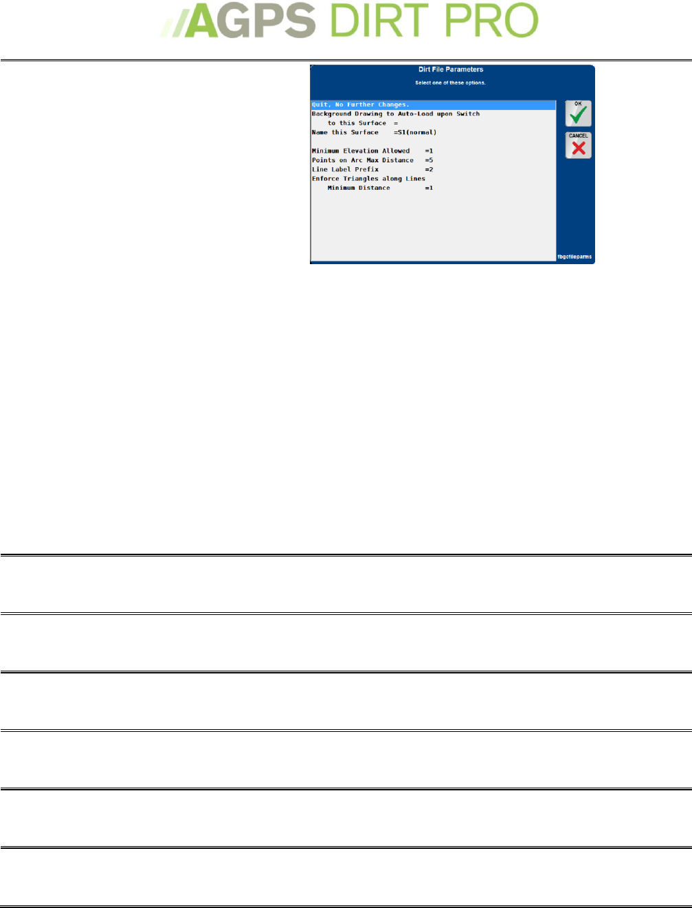
Parameters for loading
surface files
Sets the parameters for
loading file into AGPS Dirt
Pro™. Typically the defaults
will be sufficent for most jobs.
Background Drawing to Auto-Load: Sets the background
drawing that will be loaded when you select the surface. Will
also be set if you load a.drw file. See Load Background Image on
page 39.
Name this Surface: Can be used to rename the surface.
Minimum Elevation allowed: Default is 1, must be changed if
working below sea-level
Points on Arc Max Distance: If loading an .dxf file and arcs are
found, the maximum distance between points on those arcs.
Line Label Prefix: When a point-label is being loaded, the
prefex that indicates the point is part of a line. Default is ‘2’.
Enforce Triangles along Lines minimum distance: When the
program is loading an .fbg file that contains points and lines,
sets the minimum distance that triangle edges can be along a
line. Default is 1.
3D Visualization using
Surfer8
Creates a 3D visualization of the .FBG data using Surfer8™, or
newer (if installed.)
3D Visualization of the Data
Creates a 3D visualization of the .FBG data using an internal 3D
visualization program.
Write currently loaded
points to a file
Writes all of the points in loaded in a file to a .FBG file (useful if
you collect topography data and want to add it to the .FBG file).
Build job files from
OptiSurface™ .agd file
Builds and loads a .FBG file from an OptiSurface™ .agd file.
Build job files from
OptiSurface™ .xyzout file
Builds and loads a .FBG file from an OptiSurface™ .xyzout file.
Build from a Survey-File
Builds and loads a .FBG file from an AGPS-Dirt Pro™ Survey-File
24
Build from a Shape .PLN File
Builds and loads a .FBG file from an AGPS-Shape Pro™ .PLN file.
Build from Triangles in
LANDXML file
Builds and loads a .FBG file from the Triangles in an LANDXML
file.
Build a .DXF File from
a .DWG file
Creates a .dxf file from a .dwg (AutoCad™) file. Useful for
creating background images to import into AGPS-Dirt Pro™.
Triangles loaded from
a .DXF file
Loads traingles from a .dxf file.
Triangles loaded from lines
in a .DXF file
Creates and loads triangles from the lines in a .DXF file.
Points loaded from a .DXF
file
Creates and loads points from a .DXF file.
Lines, Arcs and Points
loaded from a .DXF file
Creates and loads Lines, Arcs and Points from a .DXF file.
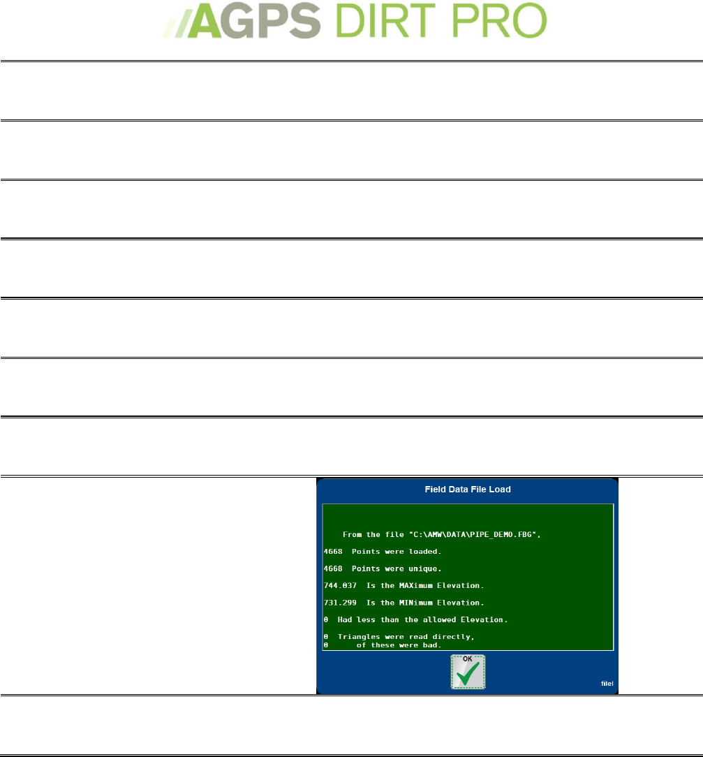
After you select or create
an .FBG File, the data will load
and you will see the Field
Date File Load completion
screen. Check that the Min
and Max Elevations are
correct.
You can edit the .FBG file from
the Main Menu at any time.
25
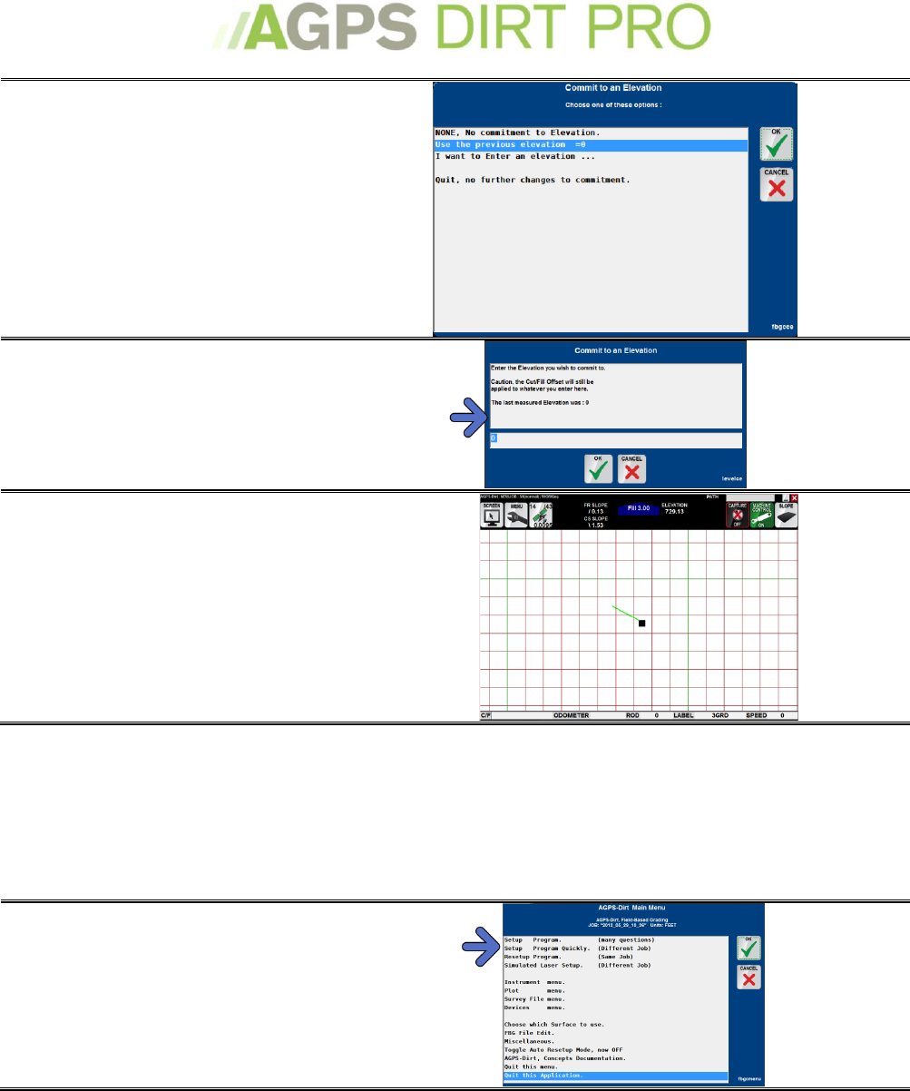
Commitment to an Elevation
Committing to an Elevation is used when you simply want to level a piece of land to a certain
elevation without a design having been made. If you want to know the cut/fill amounts, you will
have to capture that data.
From the AGPS-Dirt Pro™
Main Menu
Select Setup Program Quickly
(Different Job) or ReSetup
Program if you have already
have a job (skip to Setup
Control Points)
Select None, Make a New Job.
Enter the name of the job (i.e.
the name of the field or the name of
the customer). You may also enter a
description of the job.
Setup your control points. If
you have no control point for this job,
select Quit, No (further) Changes.
If you have control points (see Control
Points on page 41) you can choose to
edit the control point file and add
the point.
Choose Commitment to an
Elevation.
26
Choose Either ‘Use the
Previous Elevation’ (setup
complete)
or ‘I want to Enter an
Elevation. (go to the next
step)
Enter the Elevation. If you know
the elevation you want to commit to,
enter it here.
The Working Screen will be
displayed
Commitment to a Tipped Plane
Committing to a Tipped Plane is used if you are doing single or multi-slope drainage without a
previous design. Typically a Simulated Laser Setup is done previously, and a Commitment to a
Tipped Plane is used to continue work at a later time. If you want to know the cut/fill amounts,
you will have to capture that data.
From the AGPS-Dirt Pro™
Main Menu
Select Setup Program Quickly
(Different Job) or ReSetup
Program if you have already
have a job (skip to Setup
Control Points)
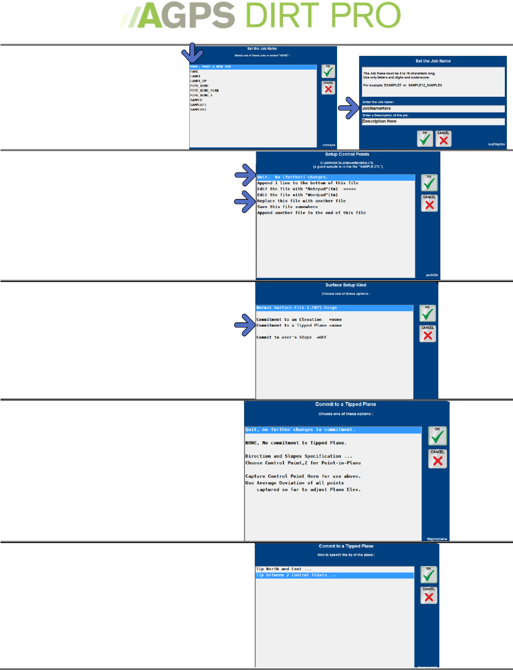
27
Select None, Make a New Job.
Enter the name of the job (i.e.
the name of the field or the name of
the customer). You may also enter a
description of the job.
Setup your control points. If
you have no control point for this job,
select Quit, No (further) Changes.
If you have control points (see Control
Points on page 41) you can choose to
edit the control point file and add
the point.
Choose Commitment to an
Tipped Plane.
You can specify the direction
and slope or tip between two
captured control points by
using Direction and Slopes
Specification or you can tip
from a control point +/- some
elevation with Choose Control
Point, Z for Point in Plane
Direction and Slopes
Specification: Choose between
Tip North and East or Tip
between 2 control points.
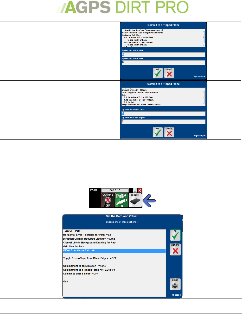
28
Tip North and East: Enter the
tip amount to the North (a
negative number will tip to the
South) and to the East (a
negative number will tip to the
West)
Tip between 2 Control Points:
You will select 2 previously
captured Control Points to tip
between.
Path and Offset menu
The Path and Offset, or “Slope” menu will allow selecting a horizontal Path to follow. Also you
can change your commitment to an elevation or tipped plane without needing to go through a
program Setup again. To access this menu, touch the Slopes icon in the upper-right corner of the
working screen.
Turn OFF Path
Turns off any selected Path. The Path bar will then be blank.
Horizontal Error Tolerance for Path
The allowable distance off the Path line for the Guidance bar to say ‘OK’.
Direction Change Required Distance
The distance travelled before the program shows a new direction
heading.
29
Closest Line in Background Drawing
for Path
Selects the nearest Background Drawing line to follow with the
Guidance bar.
Grid Line for Path
Selects the nearest Grid Line to follow with the Guidance bar.
Offset from above Path =0
Enter a + or – Offset from the actual path.
Toggle Cross-Slope from Blade Edges
When this is ON, the program will calculate the desired Cross slope
from the surface at the edges of the blade, rather than the location of
the GPS antenna.
Commitment to an Elevation
Allows you to select or change commitment to a known elevation at 0%
Commitment to a Tipped Plane
Set or change commitment as shown on the previous page (of this
manual.)
Commit to user's Slope =OFF
Use a specified cross slope % instead of the current design.
Rod Length
The rod length is the distance from the GPS Antenna to the bottom of the cutting edge. This
number may change. To adjust your Rod Length, press the Rod Length button on the bottom Info
Bar.
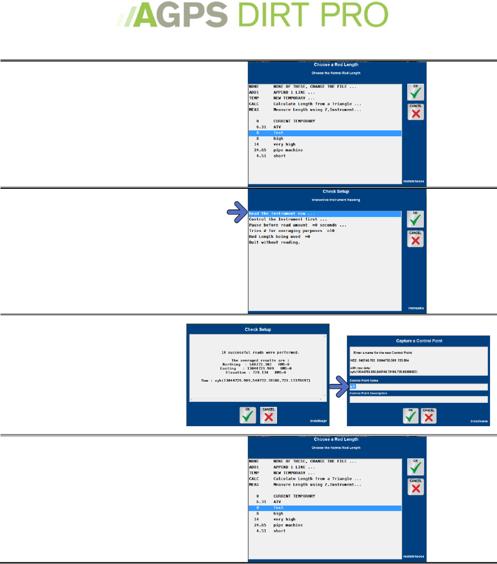
NONE
Allows you to change the entire rod length list, adding or deleting any
lengths/descriptions you would like.
Add1
Adds a user-defined label to the Rod Length list.
Temp
Creates a new temporary length but does not add it to the permanent list.
CALC
Calculate the length from a triangle. Not used in AGPS-Dirt Pro™
MEAS
Measures the length using Z and the Instrument. Not often used.
The remainders are the rod lengths saved in the program.
30
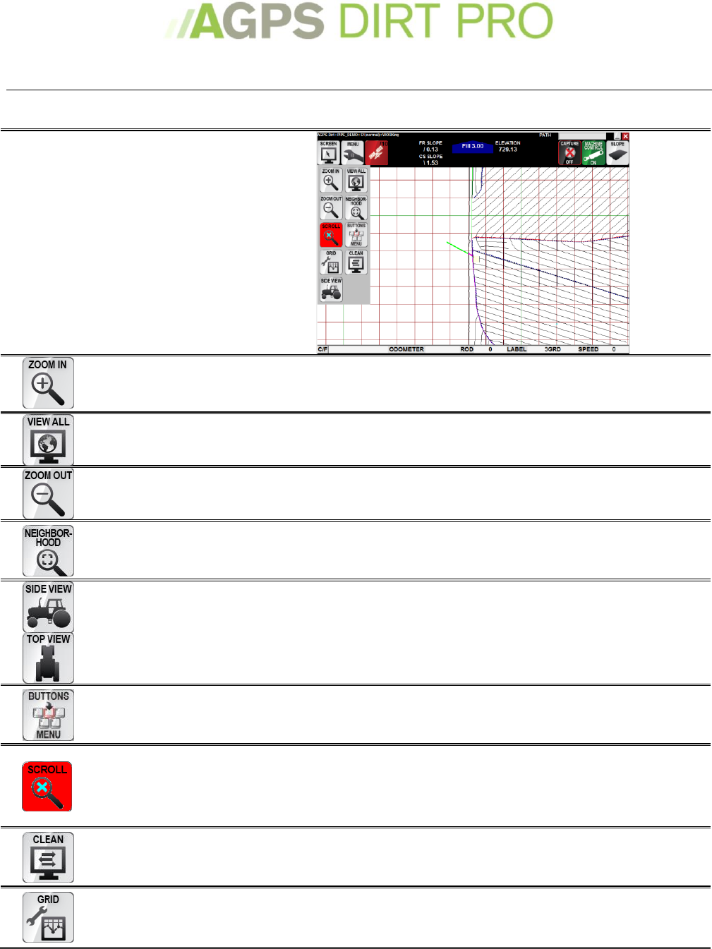
Working with the Program
Adjusting the view
To adjust the view in the
Working Screen
Press the Screen Icon
Note: When in Overhead View, the
Side View Icon will be visible, and
when in Side View, the Topography
Icon.
Zoom In
Pressing the Zoom In Icon will Zoom the view in, centered on
your current position (either real or fake).
View All
Pressing the View All Icon will Zoom the screen to show all
completed lines or the entire background image/drawing.
Zoom Out
Pressing the Zoom Out icon will Zoom the view out, centered
on your current position (either real or fake).
Neighborhood
The Neighborhood Icon will Zoom the screen into the
neighborhood of your current position (either real or fake).
Side/Top View
Toggles between a Side View (Topography) and Top View
(Blade View).
Buttons Menu
Displays the Buttons Menu. The Buttons Menu has shortcuts
with keyboard hotkeys for commonly used program functions.
Scroll
Pressing the Scroll Icon allows you to recenter the view where
you touch the screen by placing a ‘fake’ position where you
touch. To shut off scroll view, press the scroll icon and then
select “Turn off any Fake Current Position”
Clean
Locks the screen for 45 seconds, allowing you to wipe the
screen clean. With a keyboard, you may press Esc to exit early.
Grid
Displays the Grid Menu.
31
The Buttons Menu
The Buttons Menu will display all of the keyboard ‘hotkeys’ for the program. You can also select
the option in the Buttons Menu to do that action.
BackSpace
Toggle Blade Riding/Working
P
Path Menu
PageUp
Move Blade Up
Q
Quit Menu
Page Down
Move Blade Down
R
Specify Radius to Show
ArrowUp
Half of PageUp
S
Show View from the Side
Arrow Down
Half of pageDown
T
Show View from the Top
SpaceBar
Toggle Auto Capture
U
Main Menu
Mouse Left
Button
Click Menu
V
Toggle between Side/Top view
A
Show All Points
W
Show view from the West
B
Show Buttons Menu
X
Grid Menu
C
Find Closest Control Point
Y
Negative Blade Slope
D
Find Closest Data Point
Z
Show 3D View looking NNE
E
Show View from the East
0
Toggle Machine Control On/Off
F
Cut/Fill Offset (subgrade)
1
Set Rod Length
G
Toggle stop/go mode
2
Set Point Label
I
Zoom In
3
Specify a 3D View
K
Mark Special Points
4
Set the next point number
L
Log a Stake
6
Control the Instrument
M
Manually capture a point
7
Capture a Note
N
Show Neighborhood of current
position
8
Display/Plot Menu
O
Zoom out
9
Devices Menu
-
Switch Laser Light Planes
=
Switch Rod-Length Offset
32
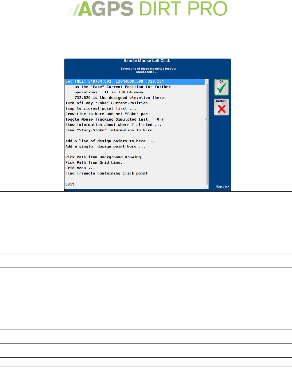
The Click Menu
When you touch the screen you will see the click menu. This menu has many operations that you
may want to do while surveying or working. You can toggle the Click Menu on and off in the
Miscellaneous Actions Menu, on page 49
Set NEZ as ‘fake position’
Sets the current NEZ (it will be displayed) as a ‘fake position’. A 'fake position' will
be used for any zoom, grid, and other functions, rather than your actual position.
Turn off any ‘fake’ current
positions
Turns off any ‘fake’ positions. After using the scroll icon to move around the
screen, you must turn off any ‘fake’ positions to re-center the screen on the real
current position.
Snap to closest point
Will snap to the closest captured point for the NEZ point to be used instead of the
clicked point.
Draw Line to here
Will draw a line between the current position and where you clicked (or snapped
to closest point)
Toggle Mouse Tracking
Simulated Inst.
Used for GPS Simulators.
Show information about
where I clicked
Will show information about where you clicked, including it’s NEZ (if a previously
captured topo is loaded or if you clicked a known point), it’s distance from the
current position, slope distance and angle (very useful for rotating a grid to a
known point).
Show ‘Story-Stake’
Information to here
Gives information for putting a line of grade stakes between your location and
your click.
Add a line of design points
to here
Design points will be added to the surface file, between your nearest point (or a
fake position) and the point you clicked. You will be shown more information
about these two points, and asked how far apart the new points should be.
Add a single design point
here
Adds a design point to the surface file.
Pick Path from Background
Drawing
Will choose the closest background line for guidance.
Pick Path from Grid Line
Will choose the closest grid line for guidance.
Grid Menu
Opens the Grid Menu. See Grid Menu on page 34.
Find Triangle containing
click point.
Displays a single triangle from the Surface file.
33
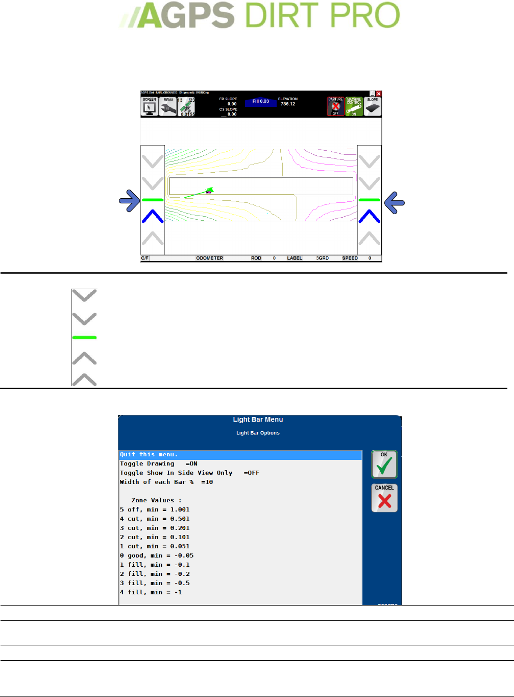
The Light Bars
The Light Bars allow a visual indication of your vertical accuracy. The lightbar also acts as a blade
offset. The lightbar menu is a part of the plot menu, details on page 45.
Vertical Lightbar
The Vertical lightbar will indicate how far from grade the
machine is operating. If using a cross-slope sensor, it will tell
you the tilt of the blade from grade. It also acts as a blade
offset. By pressing the down or up chevrons, the program will
offset the blade the amount set in the Miscellaneous menu for
distance blade moved by Pg Up,Pg Dn. To change this amount,
see the Miscellaneous Menu, on page 49
The Light Bar Menu
Toggle Drawing
Toggles between the light bars being ON or OFF. Must =ON to see the light bars.
Toggle show in Side View
Only
Toggles showing the light bars in the side (blade) view only.
Width of each Bar
The % width of the Vertical Bar(s). Increase to make the Vertical Bar(s) wider.
Zone Values
The value(s) at which the Vertical Light Bar will display the given correction. The
Default values are shown. In the defaults shown, the Vertical Bar will display
Green for good between .051 and -.05
34
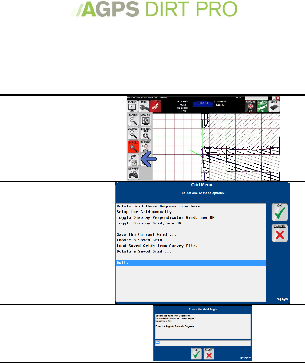
The Grid
The Grid allows for a visual indication of distance. The grid can be set to any spacing and rotated
to any angle. There is also a color grid option of 3 different sets of data: cut/fill amount;
deflection amount; and visits count. If you are building your design in AGPS-Shape Pro™,
importing an .fbg or building you field in Opti-surface, this data will often be included in the file.
If you are designing in the field, you would need to capture this data.
Setting up the Grid
Press the Screen Icon
Select Grid
The grid menu is where you
adjust the grid
Rotate Grid these Degrees
Allows you to rotate the grid a
number of degrees from its current
angle.
35
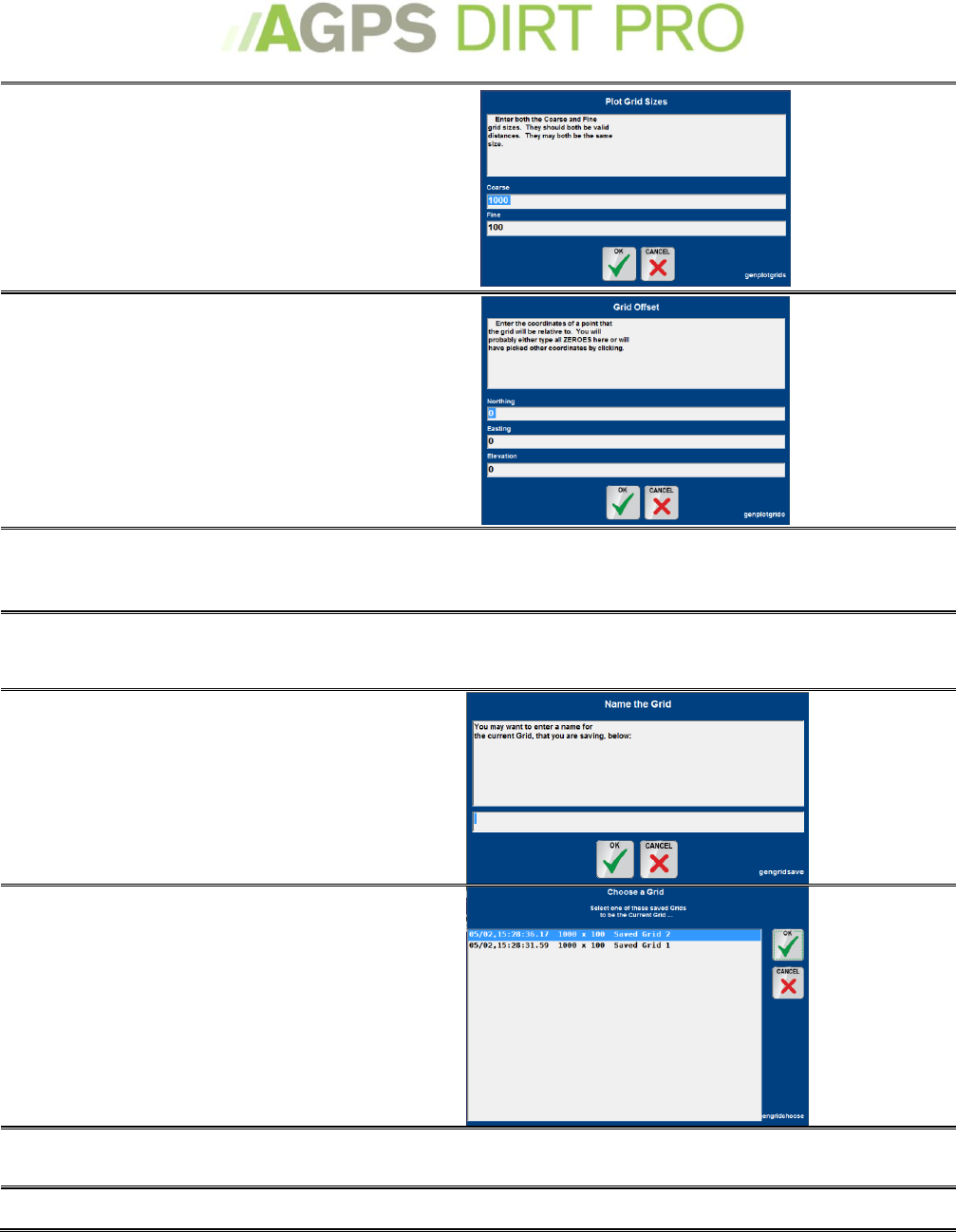
Setup Grid Manually
Allows you to set the course and
fine of the grid. Fine will be
displayed in RED, course in GREEN.
For instance, if you were tiling
every 35 feet, you would set the
course for 70 and the fine for 35,
alternating the grid red and green
every 35 feet.
Setup Grid Manually
Grid Offset
Allows you to offset the grid some
amount N (north) and E (east) and
Z (elevation – uncommon)
For instance, if you wanted to offset
the grid 10 feet NorthWest from
your current grid, you would add 10
feet to N and subtract 10 feet from
E.
Toggle Display
Perpendicular Grid
When the perpendicular grid is ON, there will be two grids
meeting at right angles. Turning it OFF goes to a Single Grid
(parallel lines)
Toggle Display Grid
Toggle the entire grid On and OFF.
Save the Current Grid
You can save and name your
current grid to return to it later
Choose a Saved Grid
Recall a saved grid
Load Saved Grids From
Survey File
Selecting this option will allow you to pick from grids saved
across different jobs. After selecting it, Choose a Saved Grid.
Delete a Saved Grid
Delete a grid you have saved.
36
Setting up the Color Grid
Press the Menu Icon
Select Plot Menu
Select Color Grid Control
37
Color Grid Type
The menu for the Color Grid Type.
Cut/Fill Amount
This is the recommened selection.
Shows the amount to be cut/filled
for each grid section. After you
select the option you can change the
color for each zone (not
recommended).
Deflection Amount
Shows how much the elevation has
changed since the last pass over the
area. After you select the option you
can change the color for each zone
(not recommended).
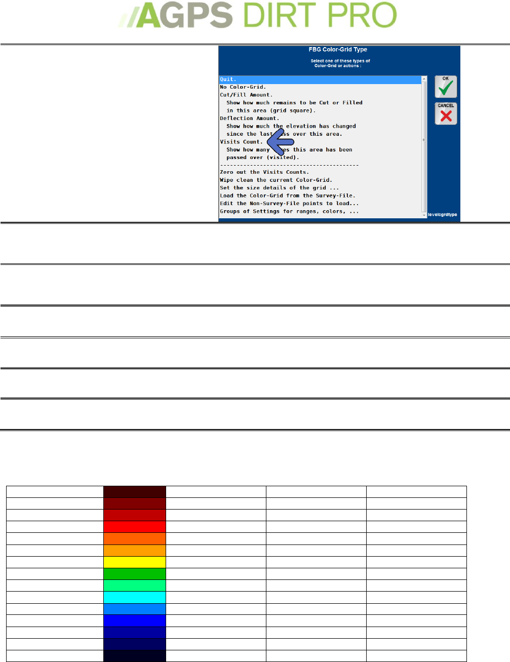
38
Visits Amount
Shows how often you have visited
an area of the grid. After you select
the option you can change the color
for each zone (not recommended).
Zero out the Visits Count
Allows you to set the visit count to zero (cannot be undone)
Wipe clean the current
color-grid
Removes the data for a given color-grid
Set the size details of the
grid
Allows you to manually set the size of the grid (same as setting
up the grid)
Load a Color-Grid from the
survey-file
Reloads the Color-Grid information from the file.
Edit the non-survey-file
points to load
Edit the .GPE points file. This file is similar to a .NEZ file, and
should be loaded with topo points that are not in the .SVY
Groups of Settings for
ranges, colors . . .
Allows you to save a group of settings for the color-grid (if you
have created custom colors, etc)
Color Grid Key
Alternate Groups
Default Flat_land_level Indicate
99 > 2.01
rgb(64,0,0)
99 > 0.751
99 > 2.01
2.00 > 1.01
rgb(128,0,0)
0.75 > 0.501
2.00 > 1.01
1.00 > 0.501
rgb(192,0,0)
0.50 > 0.331
1.00 > 0.501
0.50 > 0.351
rgb(255,0,0)
0.33 > 0.201
0.50 > 0.401
0.35 > 0.201
rgb(255,96,0)
0.20 > 0.101
0.40 > 0.301
0.20 > 0.101
rgb(255,160,0)
0.10 > 0.051
0.30 > 0.201
0.10 > 0.051
rgb(255,255,0)
0.05 > 0.031
0.20 > 0.101
0.05 > -0.05
rgb(0,192,0)
0.03 > -0.03
0.10 > -0.10
-0.051 > -0.10
rgb(0,255,128)
-0.031 > -0.05
-0.101 > -0.20
-0.101 > -0.20
rgb(0,255,255)
-0.051 > -0.10
-0.201 > -0.30
-0.201 > -0.35
rgb(0,128,255)
-0.101 > -0.20
-0.301 > -0.40
-0.351 > -0.50
rgb(0,0,255)
-0.201 > -0.33
-0.401 > -0.50
-0.501 > -1.00
rgb(0,0,160)
-0.331 > -0.50
-0.501 > -1.00
-1.01 > -2.00
rgb(0,0,96)
-0.501 > -0.75
-1.01 > -2.00
-2.01 > -99
rgb(0,0,32)
-0.751 > -99
-2.01 > -99
39
Loading Background Images
Background Images can range from 3-D polylines that are selectable to a bitmap image to a
topography map.
Typically AGPS-Dirt Pro™ Supports Bitmap images in the .bmp format with a
georeferencing .bpw file associated with it or .drw polyline files. Consult your AGPS-Dirt Pro™
Technician with any questions about these file types.
1. Press the Menu Icon
2. Select Plot Menu
The Plot menu controls how things are
displayed on the Working Screen
3. Select Background Bitmap
(step 4) or
Background Drawing (Step 5)
A Bitmap image is a flat image (such as
you would export from Ag Data
Viewer™).
A Background Drawing is a 3-D object
with polylines that the program can
‘read’ (such as you would export from
Auto-CAD or other 3-D design
program)
4. Load Bitmap
Select Copy BMP, BPW.
Select the Bitmap Image
You must have a .bpw file in the same
directory on your computer for the
image to load properly. Make sure the
Show Bitmap and Toggle Convert are
ON.
5. Load Backgound Drawing
The Load Background Drawing Menu
has multiple options for loading or
creating a drawing file. Typically you
will ‘Build from a .dxf’. If you have
a .drw file, Select ‘Replace this File’
and then selct the .drw file.
Contact an AGPS-Dirt Pro™ Technician
for help with other supported file
types.
40
Collecting Field Data
Topography data and Pass Labels
Pass labels define the type of data you are collecting (Boundry Perimeter, Random Ground or
Reference Point). If you are going to design in the field by using Opti-Surface, you must capture
your topography data first.
Pass Types
There are several different types of data you can collect in AGPS-Dirt Pro™.
To select the pass you want
Press the Capture Icon.
To see what type of pass
label is currently selected,
note at the label portion of
the bottom working bar
Capture On/Off
Touch to toggle capturing data On/Off. Note that when there is
a design loaded, Machine Control will control to grade
regardless if Capture is turned On or Off.
Boundry
Perimeter
Select to set data collection to Boundry/Perimeter. This will tell
the program where the edge of the job is. Its pass label is 2PER.
Random
Ground
Select to set data collection of Random Ground. This is
topography data collected throughout the field. Its pass label is
3GRD.
Reference
Select to collect a reference point (also known as a control
point) somewhere in the field.
41
Collecting a Reference (Control) Point
Select your Rod Length
This may be the typical rod length of
the machine or a different Rod Length
(e.g. if you were taking the GPS globe
off of the machine to reach a culvert)
Read the Instrument
On this screen you may also
-Control the Instrument
-Pause before read (usually used if
capturing a control point by yourself)
-Set the ‘Tries’ for averaging (10 is
common, if you are in dense tree cover
you may increase it to 20)
Name the Point
You will receive a confirmation that
the reads were successful.
You can name the point and put a
description. The default name is a1
(this number increases each time you
capture a control point.)
The point name must be between 1
and 8 letters and/or numbers long.
Description can be any length.
Set your Rod Length back
If you changed your Rod Length you
can set it back.
42
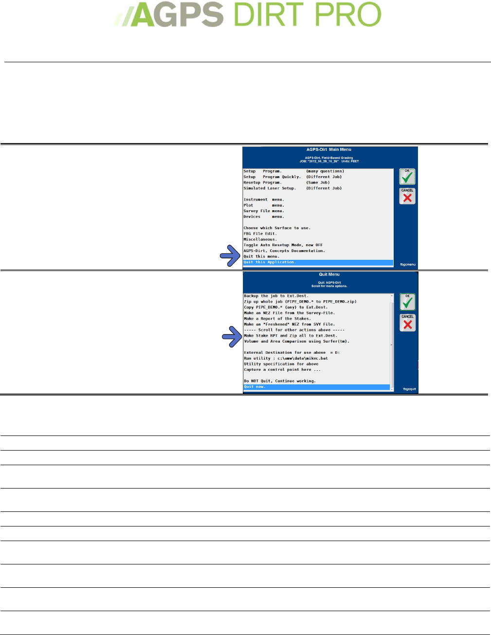
Finishing a Job
When you have finished a job there are typically two things you will want to do: Create a report
and Export the data.
Exporting Stake Report
The stake report is in an .rpt format that can be opened by most word processors (such as
Microsoft Word™ or even WordPad).
1. Press the Menu Icon
2. Select Quit this Application
3. Select Make Stake RPT and
Zip all to Ext. Dest
Quit Menu Options
AGPS-Dirt Pro™ can export your data in most common data types.
Backup the job to Ext.Dest
Creates a backup of the data and saves it to the external destination selected.
Zip up whole job
Creates a .zip directory of all of the files pertaining to the current job.
Copy (any) to external
destination
Copies any files with the current job name to an external destination.
Make an NEZ file from the
Survey-File
Creates a NEZ (northing-easting-elevation) data file from the survey-file.
Make a Report of the Stakes
Generates a report of the staking done during work.
Make an ‘Freshened’NEZ
Make Stake RPT an Zip all
to Ext.Dest.
See above
Volume and Area
Comparison
If you have Surfer™ installed, you can see a volume and area comparison.
External Destination for use
above
Sets the drive letter of your external destination. (If there is no drive installed,
defaults to the data directory of AGPS.)
Capture a Control Point
here
The same steps as Collecting a Reference (Control) point, on page 41
43
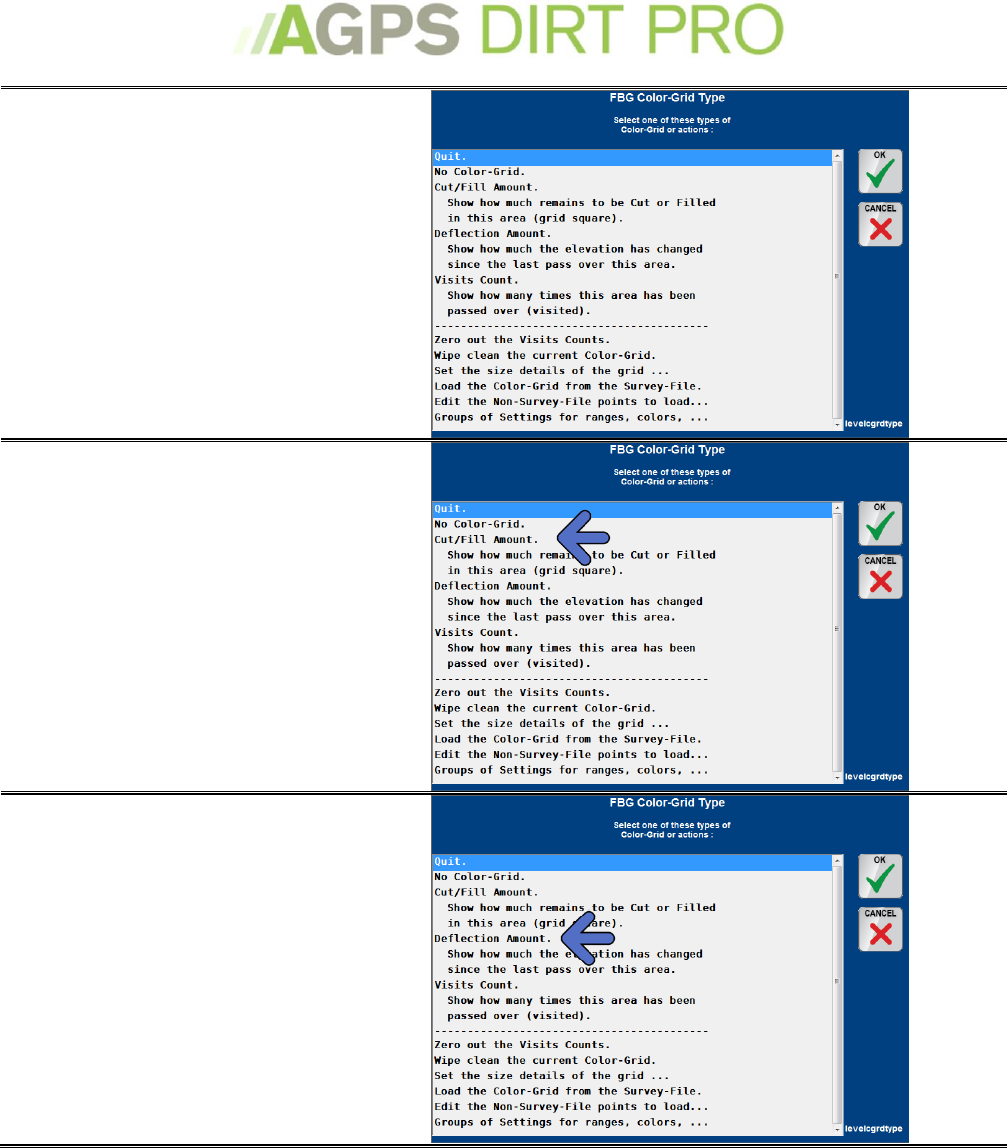
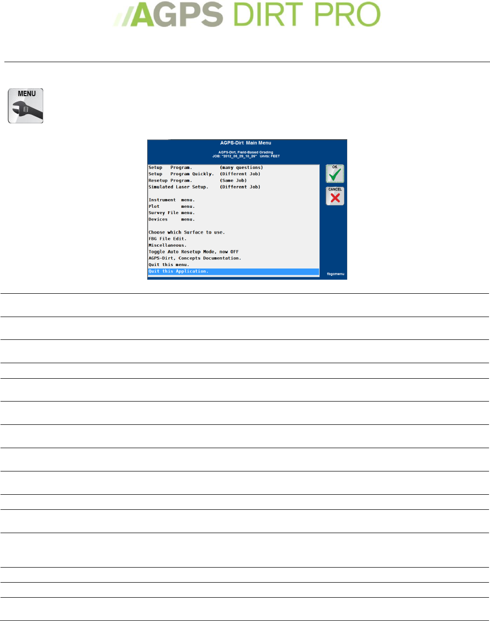
Menus
Main Menu
Pressing the Menu Icon will bring up the Main Menu. From here you can select the action
you want to perform.
Setup Program (many
questions)
Used to perform an initial set-up of the program (select GPS, machine control,
etc.). See Setting up the Program for the first time on page 11
Setup Program Quickly
Used to start a new job or to select a previously created job. See Starting a New
Job or Restarting a Current Job on page 14.
Resetup Program
Used to continue in the job you are currently working on. See Starting a New Job
or Restarting a Current Job on page 14.
Simulated Laser Setup
Used to start a new job with in the field designing. See Surface Setup on page 20.
Instrument Menu
Control the GPS and the GPS Settings as well as Control Point settings and Rod
settings. See Instrument Menu on page 44.
Plot Menu
Controls how things are drawn/displayed on the Main Working Screen. See Plot
Menu on page 45.
Survey File Menu
Control how the survey file is saved, export survey file, or edit the survey file. See
Survey File on page 46.
Devices Menu
Set or adjust Machine Controls and/or slope sensors. See Devices Menu on page
47.
Choose which Surface to
use
Select from different surfaces (for instance if using multiple .fbg files)
FBG File Edit
Edit the current .fbg file (if you need to add a data point, etc.)
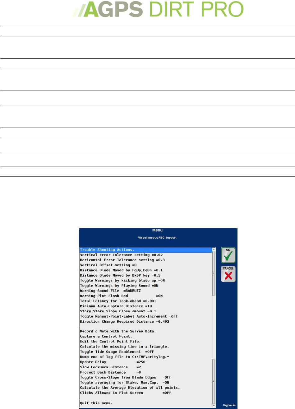
Miscellaneous actions
Miscellaneous actions that can be performed. See Miscellaneous actions on page
49.
Toggle Auto ReSetup Mode
If Quick Setup Mode is toggled ON, AGPS-Dirt Pro™ will skip asking you to choose
the program you want to run on startup and load directly to the AGPS-Dirt Pro™
Main Menu.
Concepts Documentation
Brings up a digital copy of this Menu.
Quit this Menu
Closes the current menu
Quit this Application
Brings up the Quit Menu, which will allow you to quit the program as well as
export data or capture a control point. See Quit this Application Menu on page 51.
44
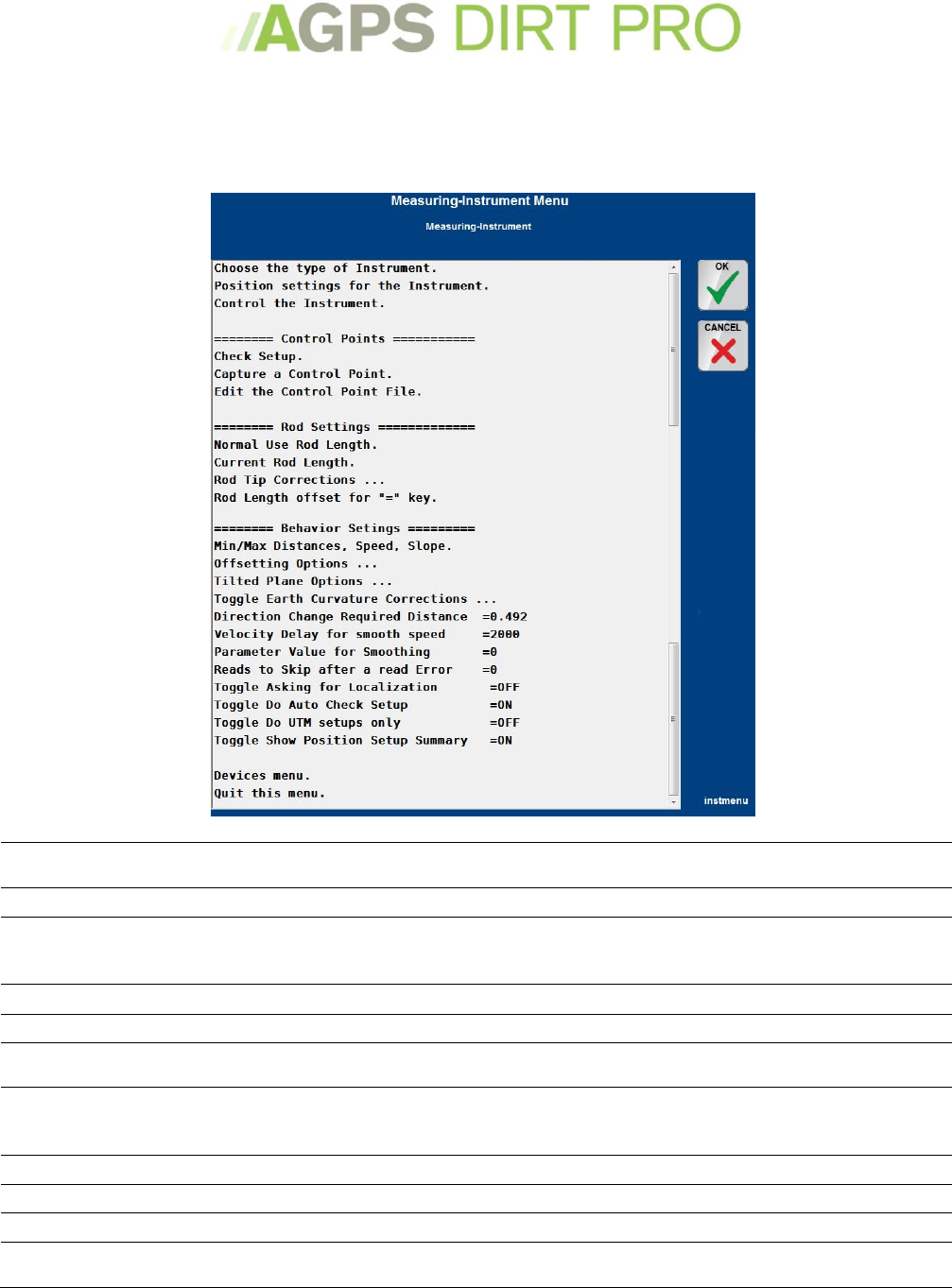
Instrument Menu
The Instrument Menu controls the GPS and other forms of measurement
From the Main Menu Select the Instrument Menu.
Choose the Type of
Instrument
Choose the brand/type of GPS or GPS Simulator the program will use.
Position Settings
Set up the UTM or State Plane of the Instrument. See UTM/State Plane on page 52.
Control the Instrument
Allows you to setup/adjust/troubleshoot the GPS. Please Note: The settings,
capabilities and types of data can vary widely between different brands of GPS.
Please speak to your GPS Manufacturer with any questions.
Check Setup
Check the setup of the current control point.
Capture a control point
Allows you to capture a control point. See Control Points on page 41.
Edit the control point file
Allows you to edit/adjust the control point file (.ctl). Useful if you need to enter a
control point or delete a bad control point.
Normal use Rod Length
Set the ‘Normal Use’ rod length. The Normal Use rod length will cause the ‘current
location’ icon on the main working screen to display as a square. Using a rod
length different than the ‘normal use’ will display a rectangle.
Current Rod Length
Change the current Rod Length. See Rod Length on page 20
Rod Tip Corrections
Change/adjust the current Rod Tip Corrections.
Rod Length offset
Adjust the amount the rod length is adjusted by pressing the = key.
Min/Max settings
Set Minimum and Maximum distance, speed and slope for the GPS instrument to
function.
45
Offsetting options
Set how the instrument is offset in relation to the blade point.
Tilted Plane Options
Not recommended for use except in rare scenarios benching into a tilted job.
Toggle Earth Curvature
Toggle correction for Earth Curvature.
Direction Change Required
How much direction change must be experienced before the instrument shows a
change in direction
Velocity Delay for Smooth
A setting for how the program determines speed.
Parameter value smoothing
Smooths elevation input. Do not use without advice from a AGPS Technician first.
Reads to skip after a read
error
Allows you to set how many ‘reads’ are skipped after the instrument sends an
error message.
Toggle Asking for
Localization
Toggle ON or OFF the program asking you to set special local stretch.
Toggle Do Auto Check
Toggles between asking or not asking you to check a control point after every
startup.
Toggle Do UTM only
Toggles between showing or not showing State Plane/Local options in the
Instrument-Localization setup screen.
Toggle Show Position Setup
Toggle between showing or not showing the results of a position setup.
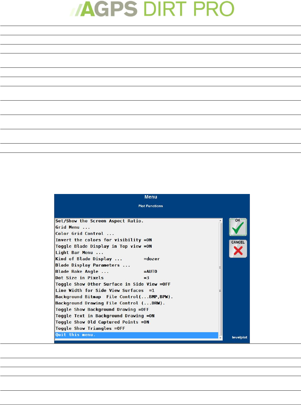
Plot Menu
The Plot Menu controls how things are drawn/displayed on the Main Working Screen
From the Main Menu Select the Plot Menu or press ‘8’ on the keyboard.
Set/Show the Screen Aspect
Ratio
Set the current Screen Aspect Ratio.
Grid Menu
Takes you to the Grid Menu. See Grid Menu on page 34
Color Grid Control
Takes you to the Color Grid Control Menu. See Setting up the Color Grid on page 36
Invert the colors for
Visibility
Toggle between a ‘day’ color palate and a ‘night’ color palate.
Toggle Blade Display in Top
View
Toggle the blade display in top view
46
Light Bar Menu
See The Light Bars on page 33
Kind of Blade Display
Icon to use in Blade Display. Options are T, Dozer, Grader, Dozer Solid, or Dozer
Hollow.
Blade Display Parameters
Sets the Width, Height and Instrument Offset (all in feet) for the blade display in
side view
Blade Rake Angle
Allows you to set the horizontal angle (in degrees) that the blade is rotated
relative to the machine. If you have a blade controller that sends the rake angle,
leave this on auto, otherwise set the blade rake angle here.
Dot size
Change the Pixel size for dots.
Toggle Show Other Surface
in Side View
If multiple surfaces have been loaded, you can enable the display in the side view.
Line Width for Side View
Surfaces
The width of a line in Side View (1 is standard).
Background Bitmap
See Loading Background Images on page 39
Background Drawing
See Loading Background Images on page 39
Toggle Show Background
Drawing
Toggle ON or OFF showing a Background Drawing (.DRW file).
Toggle Show Background
Text
Toggle ON or OFF showing Text in a Background Drawing
Toggle Show Old Captured
Points
Toggle showing old captured points ON or OFF.
Toggle Show Triangles
Shows the triangles in the TIN. Useful to see if an imported data has sufficient
data/triangles for accurate surface control.
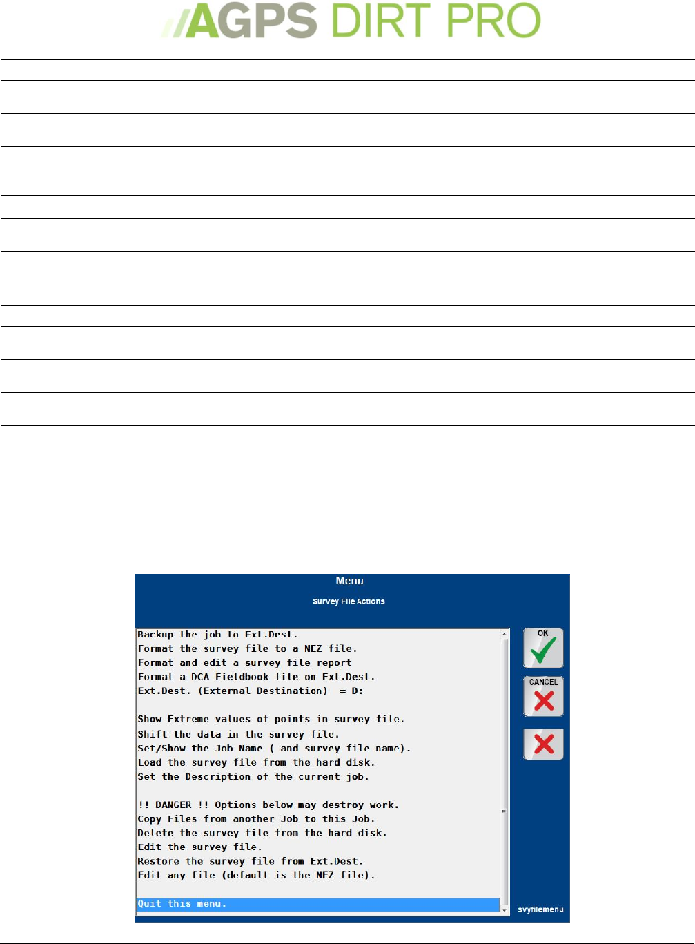
Survey File Menu
The Survey File Menu controls how the survey file is saved, export survey file, edit the survey file.
From the Main Menu Select the Survey File Menu.
Backup the Job
Backup the current job to the external destination (Typically USB drive).

47
Format the survey file to a
NEZ file
Turns the .svy file into a .nez file and exports it.
Format and edit a survey
file report
Turns the .svy file into a .prt file and allows you to edit it.
Format a DCA Fieldbook file
Turns the .svy file into a .dca file
Ext.Dest
External destination (Typically USB Port) used for copying/backing up data.
Show extreme values of
points
See a Minimum and Maximum for the survey file.
Shift the Data
Shift the Survey File. Typically used if your control point was slightly off of a
known world location.
Set/Show the Job Name
Change the Job Name
Load the Survey File
Reloads the survey file if you have made changes below
Set the Description
Change the description of the current job.
Copy Files
Copy the survey file of a different job to the current job (for instance, if you
brought a second machine into a job and wanted to load the data that had been
captured to that point)
Delete the Survey File
Deletes the survey file (but keeps the job).
Edit the Survey File
Edit the survey file like a text file (i.e you had a known point you couldn’t reach
with the machine you wanted to add to a line).
Restore the Survey File
If you backed the survey file to a USB drive and wanted to load it into the
computer (usually after a computer failure).
Edit any file
Allows you to choose and edit a file.
48
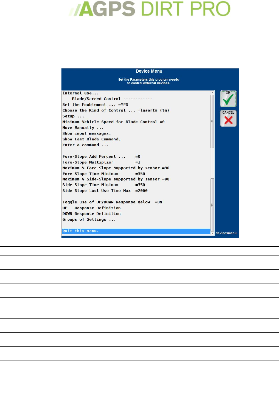
Devices Menu
The Devices Menu configures the blade control/machine control device.
Press and Hold the Machine Control Icon or from the Main Menu Select the Devices Menu or
press ‘9’ on the keyboard.
Internal Use
Used to send a command-line to the device or software.
Set the Enablement
Sets Machine Control ON or OFF. Must be =YES for Machine Control to
function.
Choose the Kind of
Control
Choose the type of Machine Controller. Speak to the manufacturer of the
Machine Controller with questions.
Setup
Setup the Machine Controller. Allows you to set COM port and other options.
Speak to the manufacturer of the Machine Controller with questions.
Minimum Vehicle Speed
The minimum speed (in feet or meters per minute) the machine must be
travelling for Machine Control to function. Often set to a low number so
Machine Control will automatically stop when the Machine is motionless.
Move Manually
Used to manually activate the Machine Control. Useful for
testing/troubleshooting the Machine Control.
Show Input Messages
Shows the current message strings from the Machine Controller. Useful for
testing/troubleshooting.
Show Last Blade
Command
Shows the immediately previous command sent from AGPS-Dirt Pro™ to the
Machine Controller. Useful for testing/troubleshooting.
Enter a Command
Allows you to enter a command to send to the Machine Controller. Command
must be in the data-string type used by the Machine Controller. Useful for
testing/troubleshooting.
Fore-Slope add percent
Additional percentage to add to Fore-Slope. Useful for adjusting level.
Fore-Slope Multiplier
Allows you to ‘reverse’ the slope that the program sends out. 1 is normal, -1
49
is reversed
Maximum Percentage
Maximum percentage-slope allowed by the Slope Sensor. Set this at the limit
of the slope sensor – anything over this number will be treated as an error
and will cause no action.
Fore Slope Time
The minimum number of milliseconds between attempts to adjust the slope.
Maximum Percentage
Side-Slope
Maximum percentage-slope allowed by the Slope Sensor. Set this at the limit
of the slope sensor – anything over this number will be treated as an error
and will cause no action.
Side Slope Time Minimum
The minimum number of milliseconds between attempts to adjust the side-
slope.
Side Slope Last Use Time
Max
Setting this at 2000 (default) will wait to adjust between commands from the
slope sensor. Setting it at 0 will use the last command until a new command
is sent.
Toggle Use of Up/Down
Toggles the Up/Down settings ON or OFF
UP Response Settings
Allows you to adjust the UP response settings of the Machine Control. Please
speak to an AGPS Technical Specialist before changing these settings.
DOWN Response Settings
Allows you to adjust the DOWN response settings of the Machine Control.
Please speak to an AGPS Technical Specialist before changing these settings.
Groups of Settings
Allows you to save different groups of UP/DOWN Response Settings
Miscellaneous actions
Miscellaneous actions that can be performed.
From the Main Menu Select the Miscellaneous Actions.
50
Trouble Shooting Actions
Opens the troubleshooting menu.
Vertical Error Tolerance
Sets the Vertical Difference where the program will show ‘good’.
Horizontal Error
Tolerance
Sets the Horizontal Difference where the program will show ‘good’.
Vertical Offset Setting
Sets a Vertical ‘Cut/Fill’ Offset amount.
Distance Blade Moved by
PgUp,PgDn
Sets the Cut/Fill offset amount added/subtracted by pressing Page Up or
Page Down on the Keyboard or by pressing the chevrons on the Vertical Light
Bar. NOTE: Up Arrow and Down Arrow or inner chevrons are half this value.
Distance Blade Moved by
BkSP
Offsets the blade up into a "Riding Mode". Pressing Backspace again will put it
back to "Working Mode" and the previous Cut/Fill Offset.
Toggle Warnings by
kicking blade up
Automatically raises the blade when there is an error (i.e. bad GPS signal).
This helps prevent over-cutting when automatic control stops.
Toggle Warnings by
Playing Sound
Toggles a warning sound that plays if there is an error (i.e. bad GPS signal)
Warning Sound File
Change the warning sound file.
Warning Plot Flash Red
Toggles whether or not the screen will flash red if there is a warning.
Total Latency for look-
ahead
How quick the Instrument (GPS) responds, so how far ahead the program
looks. Most modern GPS systems have a very low latency (10 Hz). Default is
0.1
Minimum Auto-Capture
Distance
How often the program will capture a point. A lower number means that the
program will capture a point more often. Default is 10
Story Stake Slope Close
amount
The difference in slope percentage to consider in reporting as the same slope
when making a stake report.
Toggle Manual-Point-
Label Auto-Increment
Toggle manually or automatically incrementing the point number when
capturing a point or stake.
Direction Change
Required Distance
The distance that you need to move in 1 second for the program to recognize
a change in direction in movement
Record a Note with the
Survey Data
Record a Note that will be saved with the survey data
Capture a control point
Capture a Reference (Control) Point. See Capturing a Reference Point on page
41.
Edit the Control Point File
Edit or manually enter a Reference (Control) Point.
Calculate the Missing line
of a triangle
If working with previous topo, will calculate a missing line from a triangle as
close as mathematically possible.
Toggle Tide Gauge
Enablement
Dump end of log file
Saves the end of the program log for sending to a Tech for troubleshooting.
Update Delay
Set the Update Delay, which is the time in milliseconds before the working
screen is updated because a lookup was performed.
Slow Look back Distance
A distance back to look when traveling very slowly. It affects how Fore-Slope
is calculated.
Project Back Distance
Toggle Cross Slope from
Blade Edges
Toggle calculating slope and blade edges by using Project Back Distance
instead of normal use.
Toggle averaging for
Stake, Man.Cap
Toggles the prompt for using several averaged reads for capturing a stake or
reference point.
Calculate Average
Elevation of All Points
Calculates the average of all captured points.
Clicks Allowed in Plot
Screen
Toggles allowing the Click Menu to be displayed when the screen is touched.
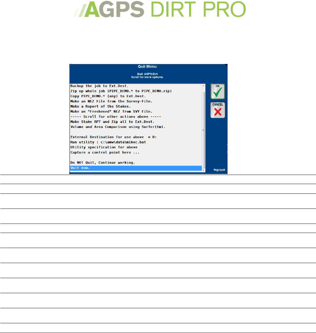
51
Quit this Application
All of the actions that can be performed before quitting the program.
Press the Red X in the upper right corner of the program or select ‘Quit this Application’ from the
Main Menu or press ‘Q’ on the keyboard.
Backup the job to Ext.Dest
Creates a backup of the data and saves it to the external destination selected.
Zip up whole job
Creates a .zip directory of all of the files pertaining to the current job.
Copy (any) to external
destination
Copies any files with the current job name to an external destination.
Make an NEZ file from the
Survey-File
Creates a .NEZ (northing-easting-elevation) data file from the survey-file.
Make a Report of the Stakes
Generates a report of the staking done during work.
Make an ‘Freshened’ NEZ
Creates a .NEZ file with only the most recent points, ignoring older points within a
certain radius.
Make Stake RPT and Zip all
to Ext.Dest.
See above
Volume and Area
Comparison
If you have Surfer™ installed, you can see a volume and area comparison.
External Destination for use
above
Sets the drive letter of your external destination. (If there is no drive installed,
defaults to the data directory of AGPS.)
Capture a Control Point
here
The same steps as Collecting a Reference (Control) point, on page 41.
Do not quit, Continue
Working
Returns to working Screen
Quit Now
Quits to the AGPS Main Menu.
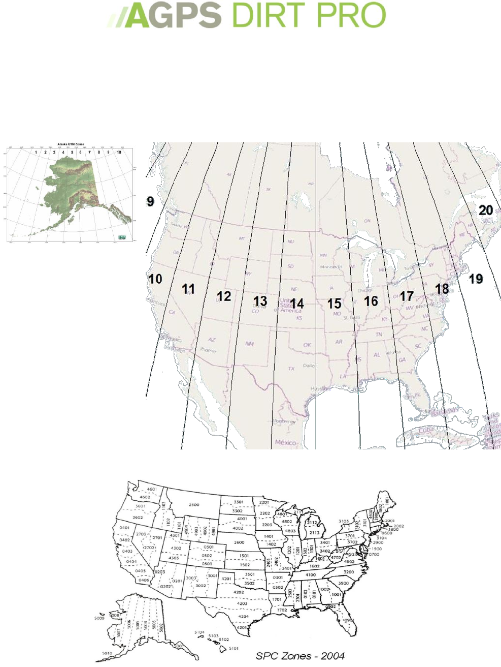
52
UTM Zones and State Plane
UTM Zone (Universal Transverse Mercator (UTM) geographic coordinate system)
and State Planes are coordinate systems to help GPS signals be more accurate in the real world.
UTM is a world-wide system that takes earth curvature into account, State Plane ‘ignores’ earth
curvature.
UTM Zones
State Plane
