AIRI™ Configuration Guide With Cisco Nexus 9300 Switch AIRI Config
User Manual:
Open the PDF directly: View PDF ![]() .
.
Page Count: 15

AIRI CONFIGURATION
GUIDE
WHITE PAPER
SCALEOUT AIREADY INFRASTRUCTURE
ARCHITECTED BY PURE STORAGE AND NVIDIA
WITH CISCO NEXUS 9300 SWITCH

2
TABLE OF CONTENTS
INTRODUCTION ......................................................................................................................................... 3
HOW TO USE THIS GUIDE ....................................................................................................................... 4
SYSTEM ARCHITECTURE ....................................................................................................................... 4
PREREQUISITES ........................................................................................................................................ 5
Install Additional Package Dependencies ................................................................................... 5
NETWORK CONFIGURATION ................................................................................................................ 5
Switch Configuration .......................................................................................................................... 6
DGX-1 Configuration ........................................................................................................................... 8
Configure Network Interfaces ......................................................................................................... 9
TCP Trac Evaluation ...................................................................................................................... 10
RDMA Trac Evaluation .................................................................................................................. 11
FlashBlade Configuration ............................................................................................................... 12
ADDITIONAL RESOURCES .................................................................................................................... 13
APPENDIX A: HOROVOD CONTAINER IMAGE .................................................................................. 14
3
INTRODUCTION
Recent advances in AI and deep learning hold tremendous promise for a new
wave of innovation for enterprises, turning their data into intelligent applications and
products. Researchers have fueled these advancements using high-performance
GPUs and leveraging massive growth in available datasets. While enterprises seek to
get started on their AI journey, they are stuck with legacy technologies like CPUs and
spinning disk, and the complexities of building an AI-ready infrastructure with them.
Designing, configuring, and maintaining infrastructure to satisfy the challenges of
large-scale deep learning requires a significant investment of time and resources to
avoid unforeseen delays, bottlenecks, or downtime. Engineers at NVIDIA® and Pure
Storage® collaborated to address many of the complexities that come with scale-out
infrastructure for AI workloads.
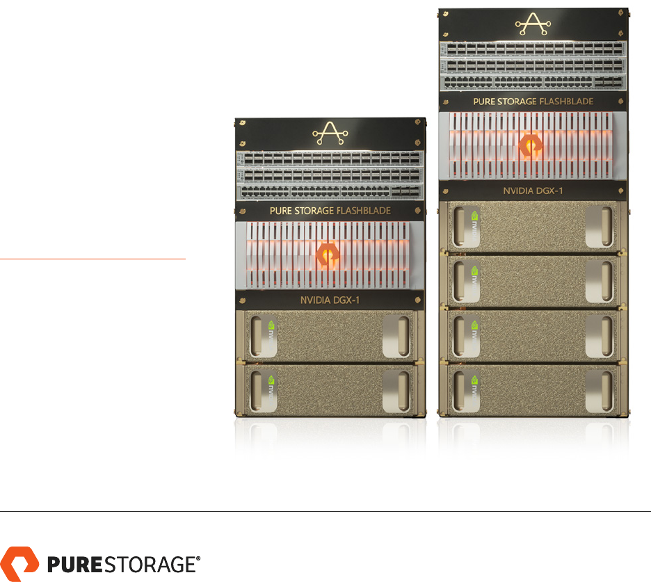
AIRI™ is the industry’s first complete AI-ready infrastructure, architected
by Pure Storage and NVIDIA to extend the power of NVIDIA® DGX™
systems, enabling AI-at-scale for every enterprise. AIRI is a converged
infrastructure stack, purpose-built for large-scale deep learning
environments. The entire stack
is configured and tested as a
complete solution, avoiding the
intricate configuration and tuning
required otherwise.
To learn more, please refer to the
AIRI Cisco Reference Architecture.
FIGURE 1. “AIRI Mini” and AIRI with 100GbE Cisco Nexus 9000 Switches
HOW TO USE THIS GUIDE
This guide describes how to configure an AIRI system containing 4x NVIDIA DGX-1 servers and a Pure Storage
FlashBlade. To optimize DGX-1 node-to-node communication, the configuration uses an RDMA over Converged
Ethernet (RoCE) fabric. The same high-performance fabric carries storage trac from FlashBlade to the DGX-1 servers,
simplifying system configuration and deployment.
An Installation Engineer is available to assist with installing and configuring the system and can help with questions or
assistance during setup.
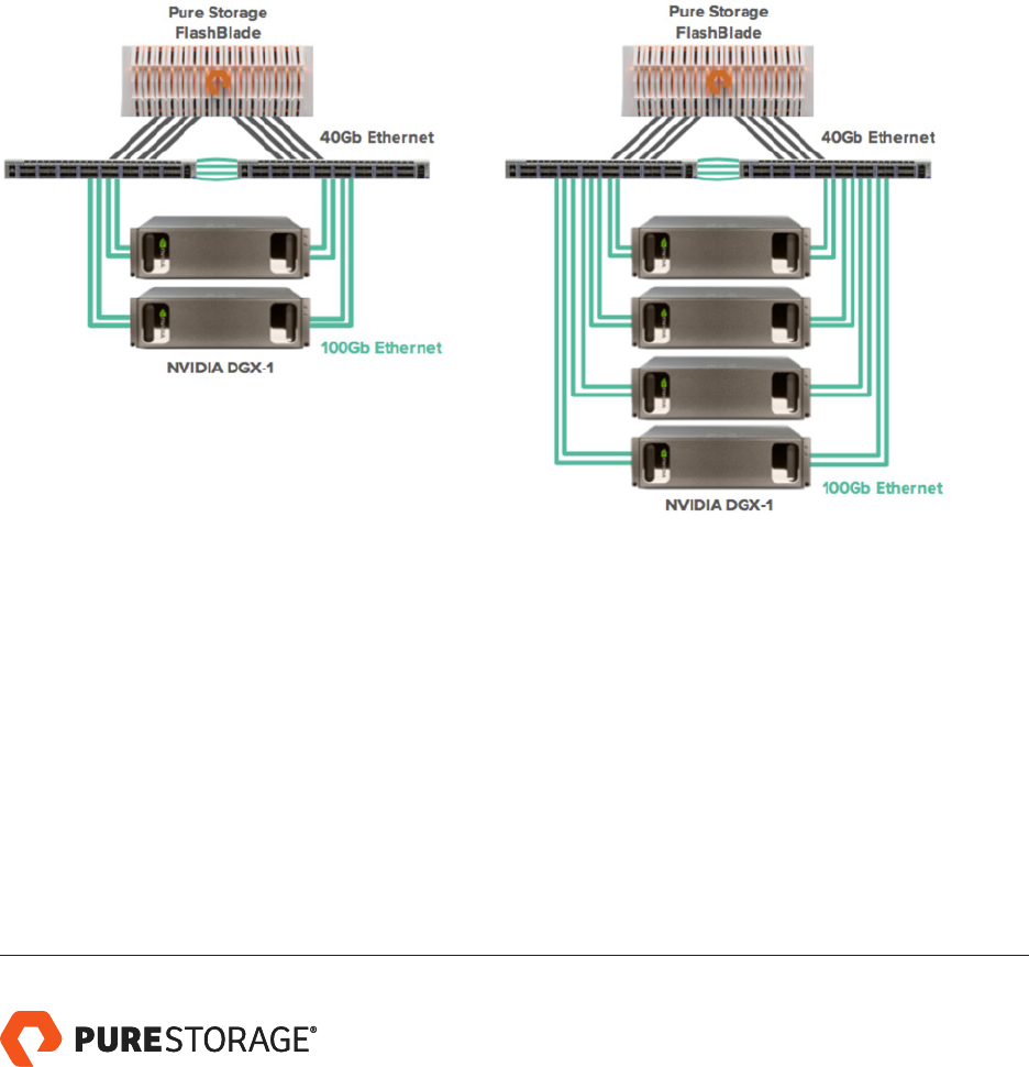
SYSTEM ARCHITECTURE
The architecture for AIRI Mini and AIRI looks as follows:
FIGURE 2. AIRI architecture
The AIRI architecture is designed for scale-out deep learning workloads and is not restricted to these sizes.
As datasets and workload requirements scale, additional DGX-1 servers can be provisioned and instantly access
all available data. Similarly, as storage capacity or performance demands grow, additional blades can be added to
the FlashBlade system with zero downtime or re-configuration.
4
5
PREREQUISITES
Configure DGX-1 servers and FlashBlade according to their respective setup guides. For the initial setup, configure the
10Gb/s connections on the DGX-1 servers for management, and create a subnet and VIP on FlashBlade for this network.
For the remainder of this guide, we assume four DGX-1 servers have been configured and given names (via /etc/hosts)
dgx-X, where X is 1-4.
Install Additional Package Dependencies
These packages are necessary for the subsequent configuration of vlan networking and TCP/IP network testing.
$ sudo apt-get update
$ sudo apt-get install -y vlan iperf3
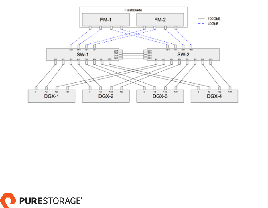
NETWORK CONFIGURATION
The diagram below shows the overall network topology of AIRI, excluding a separate management network. In the
diagram, FM-1/2 are the two internal fabric modules of FlashBlade, SW-1/2 are dual 100G switches, and DGX-1 (a),
DGX-1 (b), DGX-1 (c), and DGX-1 (d) are the DGX-1 servers. Each of the numbers on SW-1/2 indicate the Ethernet port
number, and the numbers on the DGX label which of the ethernet devices (enp5s0, enp12s0, etc.). The network
topology for AIRI Mini is the same except that there are only two DGX-1 servers (DGX-1 (a) & DGX-1 (b)).
FIGURE 3. Overall network topology
Our reference configuration used Cisco 100G, 36-port Ethernet switches (Nexus 9336c-FX2, running NXOS 7.0(3)I7(3)),
but other switch models may be used in the future. We configure the network to support two classes of trac over the
unified fabric: a VLAN for TCP flows, which includes NFS access from FlashBlade; and the RDMA-over-Converged-

Ethernet (RoCE) trac used between DGX-1 servers during distributed deep learning. For more details on the network
architecture and configuration, please refer to the AIRI Cisco Configuration Guide.
Each DGX is connected into the overall topology by four distinct 100Gb/s links, with two ports connected to each of
the two switches. The FlashBlade fabric modules have all 8 of their QSFP uplinks connected, with each fabric module
connecting two ports into each switch. The two switches SW-1 and SW-2 have 4x 100Gb/s connections between them
in an MLAG for inter-switch trac.
There are two logical networks configured on this fabric. First, the DGX-1s use an untagged VLAN (id 1) to carry
RoCE trac. All four 100G ports on each DGX-1 are configured on this VLAN and participate in node-to-node RoCE
communications.
Second, there is a TCP network that runs in VLAN 3000. On each DGX-1, two of the 100G ports – enp5s0 and
enp132s0 – are selected to carry VLAN 3000. These are placed in an active-backup bond in the Linux bonding driver.
The RoCE trac is configured in a priority-flow-control class on both the server endpoints and switches, allowing the
more latency-sensitive trac between DGX-1 servers to take priority over the TCP trac used for storage access.
Switch Configuration
For each of the 100Gb/s data switches (Nexus 9336C-FX2), log into the switch console and issue the following commands:
! QOS class-maps for matching marked ROCE & control frames
class-map type qos match-all ROCE-class
match cos 3
match dscp 24-31
class-map type qos match-all control-class
match cos 5-7
match dscp 40-63
! QOS policy-map setting qos-group for each class
policy-map type qos marking-policy
class control-class
set qos-group 7
class ROCE-class
set qos-group 3
class class-default
set qos-group 0
! Queuing policy dening priority queue & DWRR queues
policy-map type queuing queuing-policy
6

class type queuing c-out-8q-q7
priority level 1
class type queuing c-out-8q-q6
bandwidth remaining percent 0
class type queuing c-out-8q-q5
bandwidth remaining percent 0
class type queuing c-out-8q-q4
bandwidth remaining percent 0
class type queuing c-out-8q-q3
bandwidth remaining percent 80
class type queuing c-out-8q-q2
bandwidth remaining percent 0
class type queuing c-out-8q-q1
bandwidth remaining percent 0
class type queuing c-out-8q-q-default
bandwidth remaining percent 20
! Network QOS policy identifying PFC-eligible trafc
policy-map type network-qos ROCE-NQ-policy
class type network-qos c-8q-nq7
mtu 1500
class type network-qos c-8q-nq3
pause pfc-cos 3
mtu 4200
class type network-qos c-8q-nq-default
mtu 1500
! Applies network QOS and queuing globally to the switch
system qos
service-policy type network-qos ROCE-NQ-policy
service-policy type queuing output queuing-policy
! Enables PFC and applies QOS marking policy on interface(s)
interface Ethernet x/x
priority-ow-control mode auto
mtu 9216
service-policy type qos input marking-policy
In addition, add vlan 3000 to the switchport trunk allowed list for the port-channel connected to FlashBlade.
7

DGX-1 Configuration
To switch VPI cards from Infiniband to Ethernet mode, first start the Mellanox Software Tools (MST) set:
$ mst start
Starting MST (Mellanox Software Tools) driver set
Loading MST PCI module - Success
Loading MST PCI conguration module - Success
Create devices
Unloading MST PCI module (unused) - Success
Then, change the port type to Ethernet (LINK_TYPE = 2):
$ mlxcong -d /dev/mst/mt4115_pciconf0 set LINK_TYPE_P1=2
Device #1:
----------
Device type: ConnectX4
PCI device: /dev/mst/mt4115_pciconf0
Congurations: Current New
LINK_TYPE_P1 1 2
Apply new Conguration? ? (y/n) [n] : y
A p ply in g... D o n e!
-I- Please reboot machine to load new congurations.
Repeat for the other three devices:
$ mlxcong -d /dev/mst/mt4115_pciconf1 set LINK_TYPE_P1=2
$ mlxcong -d /dev/mst/mt4115_pciconf2 set LINK_TYPE_P1=2
$ mlxcong -d /dev/mst/mt4115_pciconf3 set LINK_TYPE_P1=2
Reboot the server to complete. After rebooting, run:
$ ibv_devinfo
And confirm that all four devices show link_layer: Ethernet.
8

Configure Network Interfaces
In the following, we use iproute2 commands (e.g., ip link add…). These are fast to execute and easy to debug, but are
not persistent across reboots. Create a persistent version of the network setup by either writing a script to execute the
following commands on startup, or create the equivalent using /etc/network/interfaces (man 5 interfaces).
The commands below will configure:
• VLAN 3000 virtual interfaces on NICs enp5s0 and enp132s0
• A bond0 active/backup pair over the VLAN3000 interfaces
• A private 198.18.0.0/24 address for bond0
• MTU 9000 (jumbo frames) on all interfaces
Note that the example below uses 198.18.0.11 for one server. Substitute unique addresses for each server in the cluster.
All other settings are common across servers. All commands are assumed to be run as root.
$ modprobe bonding mode=active-backup miimon=100
$ ip link add name enp5s0.3000 link enp5s0 type vlan id 3000
$ ip link add name enp132s0.3000 link enp132s0 type vlan id 3000
$ ip address add 198.18.0.11/24 dev bond0 # unique address / DGX
$ ip link set dev enp5s0 mtu 9000
$ ip link set dev enp12s0 mtu 9000
$ ip link set dev enp132s0 mtu 9000
$ ip link set dev enp139s0 mtu 9000
$ ip link set dev enp5s0.3000 mtu 9000
$ ip link set dev enp132s0.3000 mtu 9000
$ ip link set dev enp5s0 up
$ ip link set dev enp12s0 up
$ ip link set dev enp132s0 up
$ ip link set dev enp139s0 up
$ ip link set dev enp5s0.3000 up
$ ip link set dev enp132s0.3000 up
$ ip link set dev bond0 up
$ ifenslave bond0 enp5s0.3000 enp132s0.3000
Configure the VLAN interfaces used for TCP trac as priority 0 (low) egress trac:
$ for I in {0..7}; do vcong set_egress_map enp5s0.3000 $I 0; done
$ for I in {0..7}; do vcong set_egress_map enp132s0.3000 $I 0; done
9

And configure the raw VPI devices to use PFC priority 3:
$ mlnx_qos -i enp5s0 --pfc 0,0,0,1,0,0,0,0
$ tc_wra p.py -i enp5s0 -u 3,3,3,3,3,3,3,3,3,3,3,3,3,3,3,3
$ mlnx_qos -i enp12s0 --pfc 0,0,0,1,0,0,0,0
$ tc_wra p.py -i enp12s0 -u 3,3,3,3,3,3,3,3,3,3,3,3,3,3,3,3
$ mlnx_qos -i enp132s0 --pfc 0,0,0,1,0,0,0,0
$ tc_wra p.py -i enp132s0 -u 3,3,3,3,3,3,3,3,3,3,3,3,3,3,3,3
$ mlnx_qos -i enp139s0 --pfc 0,0,0,1,0,0,0,0
$ tc_wra p.py -i enp139s0 -u 3,3,3,3,3,3,3,3,3,3,3,3,3,3,3,3
TCP Trac Evaluation
We use iperf3 to exercise the 100Gb TCP VLAN (3000) and ensure all DGX-DGX pairs are operating at full network
bandwidth for TCP trac. Because iperf3 is a single-threaded process, we must use multiple client-server pairs to
saturate the 100Gb link.
From one of the DGX-1 systems, run two server processes as daemons. These commands start two listener processes
on ports 5201 and 5202. For the example below, assume we run these on the DGX-1 with IP address 198.18.0.11.
$ iperf3 -s -p 5201 -D
$ iperf3 -s -p 5202 -D
On another DGX-1, run the following commands concurrently:
$ iperf3 -c 198.18.0.11 -t 30 -l 1M -p 5201 -R
$ iperf3 -c 198.18.0.11 -t 30 -l 1M -p 5202 -R
These client processes will report total bandwidth sent, similar to the following:
[ ID] Interval Transfer Bandwidth Retr
[ 4] 0.00-30.00 sec 161 GBytes 46.2 Gbits/sec 96 sender
[ 4] 0.00-30.00 sec 161 GBytes 46.2 Gbits/sec receiver
[ ID] Interval Transfer Bandwidth Retr
[ 4] 0.00-30.00 sec 174 GBytes 49.9 Gbits/sec 15 sender
[ 4] 0.00-30.00 sec 174 GBytes 49.9 Gbits/sec receiver
As shown, the total bandwidth sent is 46.2 + 49.9 = 96.1 Gb/s. Repeating these results with all pairs, we confirm the
TCP network is operational and able to saturate the bond as configured.
10

RDMA Trac Evaluation
The DGX-1 ships with the OpenFabrics’ perftests suite for evaluating native IB verbs performance. These tools run
exclusively on RDMA-capable networks, supporting both Infiniband and RDMA-over-Converged-Ethernet physical layers.
On one of the DGX-1 systems – in the example below, this is “dgx-1” – start a server process with to run a
bandwidth test:
$ ib_send_bw --report_gbits -aF -d mlx5_0
On a second DGX-1 system, run the client:
$ ib_send_bw --report_gbits -aF -d mlx5_0 dgx-1
-----------------------------------------------------------------------------
Send BW Test
Dual-port : OFF Device : mlx5_0
Number of qps : 1 Transport type : IB
Connection type : RC Using SRQ : OFF
TX depth : 128
CQ Moderation : 100
Mtu : 4096[B]
Link type : Ethernet
GID index : 1
Max inline data : 0[B]
rdma_cm QPs : OFF
Data ex. method : Ethernet
-----------------------------------------------------------------------------
local address: LID 0000 QPN 0x1d26 PSN 0xae3ea9
GID: 00:00:00:00:00:0 0:00:00:00:00:255:255:192:18:01:02
remote address: LID 0000 QPN 0x2589 PSN 0x554df6
GID: 00:00:00:00:00:0 0:00:00:00:00:255:255:192:18:01:01
-----------------------------------------------------------------------------
#bytes #iterations BW peak[Gb/sec] BW average[Gb/sec] MsgRate[Mpps]
2 1000 0.12 0.12 7.411412
4 1000 0.25 0.23 7.068284
8 1000 0.52 0.46 7.141944
16 1000 1.03 0.91 7.140323
32 1000 1.32 1.31 5.099323
64 1000 3.97 3.62 7.067015
128 1000 8.14 8.12 7.930033
11

256 1000 15.88 15.24 7.439436
512 1000 31.55 31.40 7.667043
1024 1000 54.00 49.16 6.001562
2048 1000 78.86 73.32 4.475048
4096 1000 91.97 91.61 2.795752
8192 1000 93.04 92.99 1.418913
16384 1000 95.80 95.77 0.730660
32768 1000 96.57 96.57 0.368391
65536 1000 97.04 96.85 0.184723
131072 1000 97.25 97.24 0.092740
262144 1000 97.43 97.42 0.046453
524288 1000 97.48 97.48 0.023240
1048576 1000 97.52 97.52 0.011625
2097152 1000 97.69 97.69 0.005823
4194304 1000 97.81 97.80 0.002915
8388608 1000 97.81 97.81 0.001457
-----------------------------------------------------------------------------
The previous pair of commands can be repeated for each of the four devices on each DGX-1 host: mlx5_0, mlx5_1,
mlx5_2, mlx5_3. Furthermore, all DGX-1 nodes can be tested pairwise to confirm full RoCE connectivity.
FlashBlade Configuration
On the Settings > Network tab of the FlashBlade UI, or using the corresponding CLI commands, create a subnet for
198.18.0.0/24 as follows:
Name: data-net1
Prex: 198.18.0.0/24
VLAN: 3000
Gateway: (leave empty)
MTU: 9000
Add an interface for data trac in 198.18.0.0/24 as follows:
Name: data1
A d dre s s: 198.18.0.10 0
From the Storage tab, or using the corresponding CLI commands, create a filesystem to use for storing datasets:
Name: datasets
Protocols: enable NFS
12

On each of the DGX-1 servers, mount FlashBlade using the following commands:
$ mkdir -p /mnt/datasets
$ mount -t nfs 198.18.0.100:/datasets /mnt/datasets
Note that all NFS mount options are left at the OS defaults, which corresponds to a 512kB read- and write-size with
FlashBlade and the local file caching option (fsc) disabled.
ADDITIONAL RESOURCES
• AIRI Github Site
• AIRI Reference Architecture
• AIRI Product Page
13

APPENDIX A: HOROVOD CONTAINER IMAGE
The following Dockerfile is used to create an image, derived from the base NVIDIA container for Tensorflow, to run
Horovod in an OpenMPI environment.
FROM nvcr.io/nvidia/tensorow:17.12
RUN mkdir /build
WORKDIR /build
RUN apt-get update && apt-get install -y --no-install-recommends \
libibverbs1 \
libibverbs-dev \
lib mlx5-1 \
librdmacm-dev \
librdmac m1 \
openssh-client \
openssh-server \
le \
&& \
rm -rf /var/lib/apt/lists/*
ENV OPENMPI_VERSION 3.0.0
ENV OPENMPI_TAR openmpi-${OPENMPI_VERSION}.tar.gz
ENV OPENMPI_URL https://www.open-mpi.org/software/ompi/v3.0/downloads
RUN wget -q -O - ${OPENMPI_URL}/${OPENMPI_TAR} | tar -xzf - && \
cd openmpi-${OPENMPI_VERSION} && \
./congure --enable-orterun-prex-by-default \
--with-cuda --with-verbs \
--prex=/usr/local/mpi --disable-getpwuid && \
make -j"$(nproc)" install && \
cd .. && rm -rf openmpi-${OPENMPI_VERSION}
ENV PATH /usr/local/mpi/bin:$PATH
RUN mkdir -p /var/run/sshd && \
mkdir -p /root/.ssh && \
echo "StrictHostKeyChecking no" >> /etc/ssh/ssh_cong && \
echo "UserKnownHostsFile /dev/null" >> /etc/ssh/ssh_cong && \
echo "LogLevel quiet" >> /etc/ssh/ssh_cong && \
sed -i 's/^Port 22/Port 2222/' /etc/ssh/sshd_cong && \
14

echo "HOST *" > /root/.ssh/cong && \
echo "PORT 2222" > /root/.ssh/cong && \
mkdir -p /root/.ssh && \
ssh-keygen -t rsa -b 4096 -f /root/.ssh/id_rsa -N "" && \
cp /root/.ssh/id_rsa.pub /root/.ssh/authorized_keys && \
chmod 700 /root/.ssh && \
chmod 600 /root/.ssh/*
RUN export HOROVOD_GPU_ALLREDUCE=NCCL && \
export HOROVOD_NCCL_INCLUDE=/usr/include && \
export HOROVOD_NCCL_LIB=/usr/lib/x86_64-linux-gnu && \
ln -s /usr/local/cuda/lib64/stubs/libcuda.so ./libcuda.so.1 && \
export LD_LIBRARY_PATH=$LD_LIBRARY_PATH:$PWD && \
pip2 install --no-cache-dir horovod && \
rm ./libcuda.so.1
RUN ldcong
EXPOSE 2222
SALES@PURESTORAGE.COM | 800379PURE | @PURESTORAGE
© 2018 Pure Storage, Inc. All rights reserved.
AIRI, the AIRI logo, Pure Storage, the P Logo, and FlashBlade are trademarks or registered trademarks of Pure Storage, Inc. in the U.S. and
other countries. NVIDIA, DGX-1, and the NVIDIA logo are trademarks or registered trademarks of NVIDIA Corporation. All other trademarks
are registered marks of their respective owners.
The Pure Storage and NVIDIA products and programs described in this documentation are distributed under a license agreement restricting
the use, copying, distribution, and decompilation/reverse engineering of the products. No part of this documentation may be reproduced
in any form by any means without prior written authorization from Pure Storage, Inc. and its licensors, if any. Pure Storage and NVIDIA may
make improvements and/or changes in the Pure Storage and NVIDIA products and/or the programs described in this documentation at any
time without notice.
THIS DOCUMENTATION IS PROVIDED "AS IS" AND ALL EXPRESS OR IMPLIED CONDITIONS, REPRESENTATIONS AND WARRANTIES,
INCLUDING ANY IMPLIED WARRANTY OF MERCHANTABILITY, FITNESS FOR A PARTICULAR PURPOSE, OR NON-INFRINGEMENT, ARE
DISCLAIMED, EXCEPT TO THE EXTENT THAT SUCH DISCLAIMERS ARE HELD TO BE LEGALLY INVALID. PURE STORAGE SHALL NOT BE
LIABLE FOR INCIDENTAL OR CONSEQUENTIAL DAMAGES IN CONNECTION WITH THE FURNISHING, PERFORMANCE, OR USE OF THIS
DOCUMENTATION. THE INFORMATION CONTAINED IN THIS DOCUMENTATION IS SUBJECT TO CHANGE WITHOUT NOTICE.
ps_wp15p_airi-configuration-guide_ltr_02
