Contents AISC 360 05 Example 001
User Manual: AISC-360-05 Example 001
Open the PDF directly: View PDF ![]() .
.
Page Count: 8
Software Verification
PROGRAM NAME:
ETABS
REVISION NO.:
3
AISC-360-05 Example 001
COMPOSITE GIRDER DESIGN
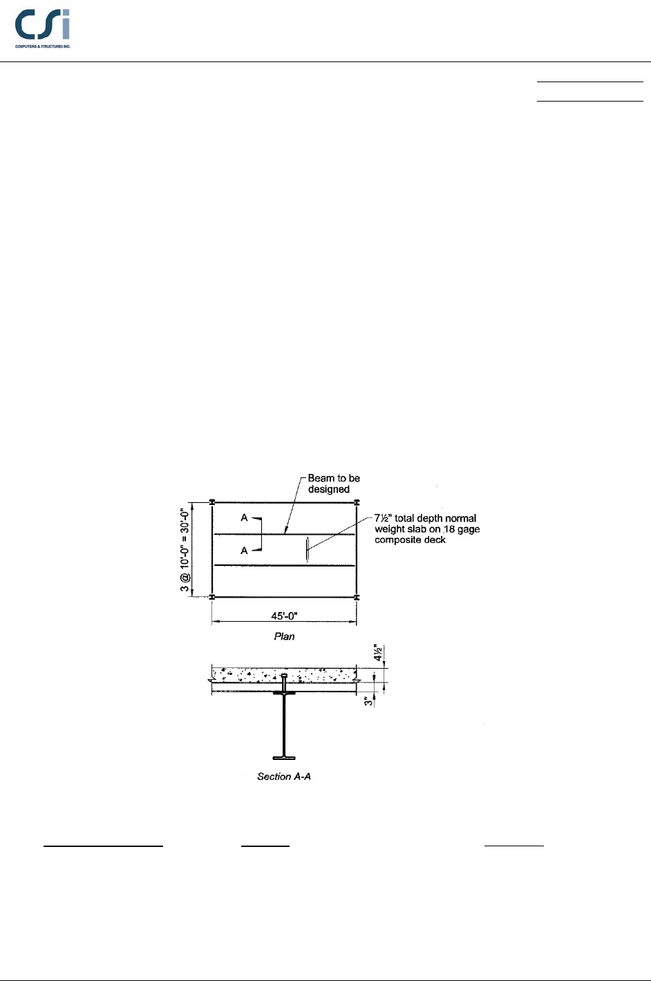
EXAMPLE DESCRIPTION
A series of 45-ft. span composite beams at 10 ft. o/c carry the loads shown
below. The beams are ASTM A992 and are unshored during construction. The
concrete has a specified compressive strength,
4 ksi.
c
f′=
Design a typical floor
beam with 3-in., 18-gage composite deck and 4 ½ in. normal weight concrete
above the deck, for fire protection and mass. Select an appropriate beam and
determine the required number of ¾ in.-diameter shear studs.
GEOMETRY, PROPERTIES AND LOADING
Member Properties
W21x55
E = 29000 ksi
F
y
= 50 ksi
Loading
w = 830 plf (Dead Load)
w = 200 plf (Construction)
w = 100 plf (SDL)
w = 1000 plf (Live Load)
Geometry
Span, L = 45 ft
AISC-360-05 Example 001 - 1
Software Verification
PROGRAM NAME:
ETABS
REVISION NO.:
3
TECHNICAL FEATURES OF ETABS TESTED
Composite beam design, including:
Selection of steel section, camber and shear stud distribution
Member bending capacities, at construction and in service
Member deflections, at construction and in service
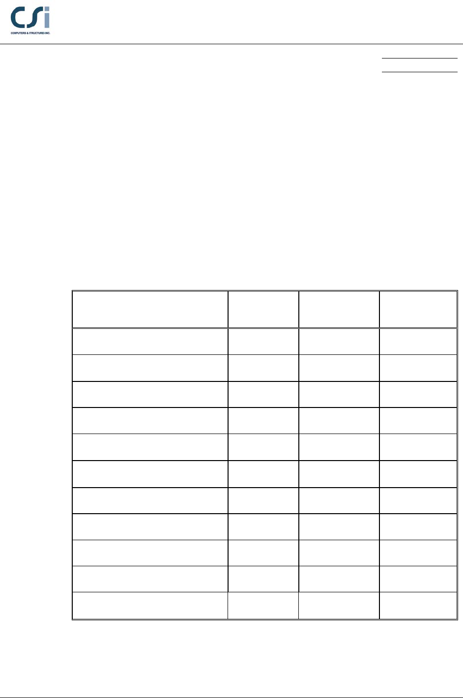
RESULTS COMPARISON
Independent results are referenced from Example I.1 from the AISC Design
Examples, Version 13.0.
Output Parameter ETABS Independent Percent
Difference
Pre-composite Mu (k-ft) 333.15 333.15 0.00%
Pre-composite ΦbMn (k-ft) 472.5 472.5 0.00%
Pre-composite Deflection (in.) 2.3 2.3 0.00%
Required Strength Mu (k-ft) 687.5 687.5 0.00%
Full Composite ΦbMn (k-ft) 1027.1 1027.1 0.00%
Partial Composite ΦbMn (k-ft) 770.3 770.3 0.00 %
Shear Stud Capacity Qn 17.2 17.2 0.00 %
Shear Stud Distribution 35 34 2.9%
Live Load Deflection (in.) 1.35 1.30 3.70%
Required Strength Vu (kip) 61.1 61.1 0.00%
ΦVn (k) 234 234 0.00%
AISC-360-05 Example 001 - 2

Software Verification
PROGRAM NAME:
ETABS
REVISION NO.:
3
COMPUTER FILE: AISC-360-05 EXAMPLE 001.EDB
CONCLUSION
The ETABS results show an acceptable comparison with the independent results.
The live load deflection differs due to a difference in methodology. In the AISC
example, the live load deflection is computed based on a lower bound value of
the beam moment of inertia, whereas in ETABS, it is computed based on the
approximate value of the beam moment of inertia derived from Equation (C-I3-6)
from the Commentary on the AISC Load and Resistance Factor Design
Specification – Second Edition.
AISC-360-05 Example 001 - 3
Software Verification
PROGRAM NAME:
ETABS
REVISION NO.:
3
HAND CALCULATION
Properties:
Materials:
ASTM A572 Grade 50 Steel
E = 29,000 ksi, Fy = 50 ksi, wsteel = 490 pcf
4000 psi normal weight concrete
Ec = 3,644 ksi,
4 ksi,
c
f′=
wconcrete = 145 pcf
Section:
W21x55
d = 20.8 in, bf = 8.22 in, tf = 0.522 in, tw = 0.38 in, h = 18.75 in., rfillet = 0.5 in.
Asteel = 16.2 in2, Ssteel = 109.6 in3, Zsteel = 126 in3, Isteel = 1140 in4
Deck:
tc =4 ½ in., hr = 3 in., sr =12 in., wr = 6 in.
Shear Connectors:
d = ¾ in, h =4 ½ in, Fu = 65 ksi
Design for Pre-Composite Condition:
Construction Required Flexural Strength:
( )
3
10 77.5 55.125 10 0.830125 kip/ft
D
w−
=•+ •=
3
10 20 10 0.200 kip/ft
L
w−
=•• =
1.2 0.830125 1.6 0.200 1.31615 kip/ft
u
w=• +• =
22
1.31615 45 333.15 kip-ft
88
u
u
wL
M••
= = =
Moment Capacity:
()
0.9 126 50 12 472.5 kip-ftΦ =Φ• • = • • =
bn b s y
M ZF
AISC-360-05 Example 001 - 4
Software Verification
PROGRAM NAME:
ETABS
REVISION NO.:
3
Pre-Composite Deflection:
( )
4
4
0.830
5 45 12
512 2.31 in.
384 384 29,000 1,140
• ••
∆= = =
••
D
nc
wL
EI
Design for Composite Flexural Strength:
Required Flexural Strength:
1.2 0.830 1.2 0.100 1.6 1 2.71 kip/ft
u
w=• +• +•=
22
2.68 45 687.5 kip-ft
88
u
u
wL
M••
= = =
Full Composite Action Available Flexural Strength:
Effective width of slab:
eff
10.0 45.0 f
•2 sides 10.0 ft 11.25 ft
28
t
b= =≤=
Resistance of steel in tension:
16.2 50 810 kips
y sy
CP AF==•= •=
controls
Resistance of slab in compression:
( )
2
eff 10 12 4.5 540 in= •= • • =
cc
Ab t
0.85 ' 0.85 4 540 1836 kips
cc
C fA= • = •• =
Depth of compression block within slab:
( )
eff
810 1.99 in.
0.85 ' 0.85 10 12 4
= = =
•• •••
c
C
abf
Moment resistance of composite beam for full composite action:
1
2.00
( ) (4.5 3) 6.51 in.
22
cr
a
d th= + −= +− =
1
20.8/12
• • 0.9 810•6.51/12 810• 1027.1 kip-ft
22
nyy
d
M Pd P
Φ=Φ + = + =
AISC-360-05 Example 001 - 5
Software Verification
PROGRAM NAME:
ETABS
REVISION NO.:
3
Partial Composite Action Available Flexural Strength:
Assume 36.1% composite action:
0.361 0.361 810 292.4 kips
y
CP= •= • =
Depth of compression block within concrete slab:
( )
eff
292.4 0.72 in.
0.85 ' 0.85 10 12 4
= = =
•• •••
c
C
abf
( ) ( )
1
0.72
4.5 3 7.14 in.
22
= + −= +− =
cr
a
d th
Compression force within steel section:
( )
( )
2 810 292.4 2 258.8 kips
y
PC−=− =
Tensile resistance of one flange:
flange y
8.22 0.522 50 214.5 kip= •• = • • =
ff
F btF
Tensile resistance of web:
web y
18.75 0.375 50 351.75 kips=•• = • • =
w
F Tt F
Tensile resistance of one fillet area:
( )
()
fillet y flange web
2 2 810 2 214.5 351.2 2 14.6 kips
= −• − = −• − =F PFF
Compression force in web:
web flange fillet
( ) / 2 258.8 214.5 14.6 29.7 kips
y
C PC F F
=− − −= − −=
Depth of compression block in web:
web
web
29.7 18.76 1.584 in.
351.75
C
xT
F
= •= • =
Location of centroid of steel compression force measured from top of steel section:
( ) ( )
( ) ( )
flange fillet fillet fillet web
2
0.5 0.5 F 0.5 x C
( )/2
0.5 0.522 214.5 0.522 0.5 0.5 14.6 0.522 0.5 0.5 1.58 29.7 0.467 in.
258.8
ff f
y
tF t r tr
dPC
•• ++• • ++ +••
= =
−
• • + +• • + ++• •
= =
AISC-360-05 Example 001 - 6

Software Verification
PROGRAM NAME:
ETABS
REVISION NO.:
3
Moment resistance of composite beam for partial composite action:
( ) ( )
( )
12 32
20.8
0.9 292.4 7.14 0.467 810 0.467 12 770.3 kip-ft
2
ny
M Cdd P dd
Φ =Φ • + +• −
= • + +• − =
Shear Stud Strength:
From AISC Manual Table 3.21 assuming one shear stud per rib placed in the
weak position, the strength of ¾ in.-diameter shear studs in normal weight
concrete with
and deck oriented perpendicular to the4 ksi beam is:
′=
c
f
17.2 kips=
n
Q
Shear Stud Distribution:
292.4 17 from each end to mid-span, rounded up to 35 total
17.2
Σ
= = =
n
n
Q
nQ
Live Load Deflection:
Modulus of elasticity ratio:
29,000 3,644 8.0= = =
c
n EE
Transformed elastic moment of inertia assuming full composite action:
Element
Transformed
Area
A (in2)
Moment Arm
from
Centroid
y (in.) Ay
(in.3) Ay2
(in,4) I0
(in.4)
Slab
67.9
15.65
1,062
16,620
115
W21x50
16.2
0
0
0
1,140
84.1
1,062
16,620
1,255
24
01,255 16,620 17,874 in.
x
I I Ay=+= + =
1,062 12.6 in.
84.1
= =y
224
17,874 82.6 12.6 4,458 in= −• = − • =
tr x
I I Ay
AISC-360-05 Example 001 - 7
Software Verification
PROGRAM NAME:
ETABS
REVISION NO.:
3
Effective moment inertia assuming partial composite action:
( ) ( )
4
equiv 1,140 0.361 4,458 1,140 3,133 in= +Σ − = + − =
s n y tr s
I I QPI I
4
eff equiv
0.75 0.75 3,133 2,350 in=•=• =II
( ) ( )
4
4
eff
5 1 12 30 12
51.35 in.
384 384 29,000 2,350
L
LL
wL
EI
• ••
∆= = =
••
Design for Shear Strength:
Required Shear Strength:
1.2 0.830 1.2 0.100 1.6 1 2.71 kip/ft
u
w=• +• +•=
2.71 45 61.1 kip-ft
22
u
u
wL
V••
= = =
Available Shear Strength:
•0.6• • • 1.0•0.6• 20.8•0.375•50 234 kips
n wy
V dt FΦ=Φ = =
AISC-360-05 Example 001 - 8
