Contents AISC 360 10 Example 001
User Manual: AISC-360-10 Example 001
Open the PDF directly: View PDF ![]() .
.
Page Count: 4
Software Verification
PROGRAM NAME:
ETABS
REVISION NO.:
0
AISC-360-10 Example 001
COMPOSITE COLUMN DESIGN
EXAMPLE DESCRIPTION
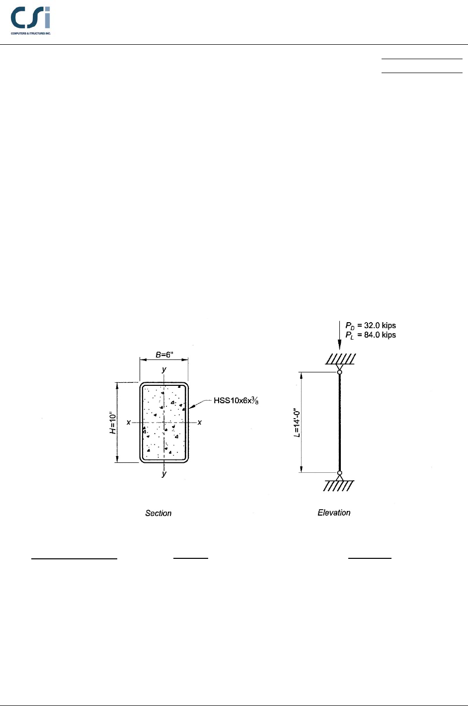
Determine if the 14-ft.-long filled composite member illustrated below is
adequate for the indicated dead and live loads. The composite member consists
of an ASTM A500 Grade B HSS with normal weight (145 lb/ft3) concrete fill
having a specified compressive strength,
5 ksi.
c
f′=
GEOMETRY, PROPERTIES AND LOADING
Member Properties
HSS10x6 x⅜
E = 29,000 ksi
Fy = 46 ksi
Loading
P
D
= 32.0 kips
PL = 84.0 kips
Geometry
Height, L = 14 ft
AISC-360-10 Example 001 - 1
Software Verification
PROGRAM NAME:
ETABS
REVISION NO.:
0
TECHNICAL FEATURE OF ETABS TESTED
Compression capacity of composite column design.
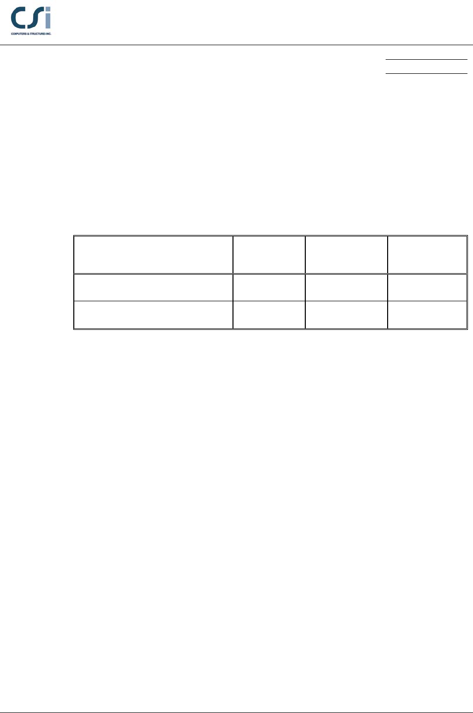
RESULTS COMPARISON
Independent results are referenced from Example I.4 from the AISC Design
Examples, Version 14.0.
Output Parameter ETABS Independent Percent
Difference
Required Strength Pu (kip) 172.8 172.8 0.00%
Available Strength ΦPn (kip) 342.93 354.78 3.34%
COMPUTER FILE: AISC-360-10 EXAMPLE 001.EDB
CONCLUSION
The ETABS results show an acceptable comparison with the independent results.
AISC-360-10 Example 001 - 2
Software Verification
PROGRAM NAME:
ETABS
REVISION NO.:
0
HAND CALCULATION
Properties:
Materials:
ASTM A500 Grade B Steel
E = 29,000 ksi, Fy = 46 ksi, Fu = 58 ksi
5000 psi normal weight concrete
Ec = 3,900 ksi,
5 ksi,
′=
c
f
wconcrete = 145 pcf
Section dimensions and properties:
HSS10x6x⅜
H = 10.0 in, B= 6.00 in, t = 0.349 in
As = 10.4 in2, Isx = 137 in4, Isy = 61.8 in4
Concrete area
2 10 2 0.349 9.30 in.
i
hH t= −•= −• =
2 6 2 0.349 5.30 in.
i
bB t= −•=−• =
2 22
(4 ) 5.30 9.30 (0.349) (4 ) 49.2 in.= • − • −π = • − • −π =
c ii
A bht
Moment of inertia for bending about the y-y axis:
2
332 4 2
3 32 4
22
4
( 4) ( 4 ) (9 64) 4 4
12 6 36 2 3
(10 4 0.349) 5.30 0.349 (6 4 0.349) (9 64) 0.349
12 6 36
6 4 0.349 4 0.349
0.349 ( )
23
114.3 in.
−• • • −• π− • −• •
= + + +π• −
•π •π
−• • • −• π− •
= + ++
•π
−• •
π• − •π
=
t
cy
H tb tBt t Bt t
It
Design for Compression:
Required Compressive Strength:
1.2 1.6 1.2 32.0 1.6 84.0 172.8 kips
u DL
PPP=•+•=• +• =
AISC-360-10 Example 001 - 3
Software Verification
PROGRAM NAME:
ETABS
REVISION NO.:
0
Nominal Compressive Strength:
2
′
= =•+• +
s
no p y s c c sr
c
E
P P FAC fAA
E
where
2
0.85 for rectangular sectionsC=
0 when no reinforcing is present within the HSS
sr
A=
46 10.4 0.85 5 (49.2 0.0) 687.5 kips
no
P= • + •• + =
Weak-axis Elastic Buckling Force:
30.6 2 0.9
10.4
0.6 2 0.9
49.2 10.4
0.949 0.9 0.9 controls
=+≤
+
=+≤
+
= >
s
cs
A
CAA
eff 3
2
29,000 62.1 0 0.9 3,900 114.3
2,201,000 kip-in
=•+•+••
= • ++ • •
=
s sy s sr c cy
EI EI EI CEI
22
eff
( )( )= π
e
P EI KL
where K = 1.0 for a pin-ended member
2
2
2,201,000 769.7 kips
1.0 (14.0 12)
π•
= =
••
e
P
Available Compressive Strength:
688 0.893 2.25
769.7
no
e
P
P= = <
Therefore, use AISC Specification Equation I2-2:
0.893
0.658 0.75 687.5 (0.658) 354.8 kips
no
e
P
P
n no
PP
Φ=Φ = • • =
AISC-360-10 Example 001 - 4
