Contents AISC 360 10 Example 001
User Manual: AISC-360-10 Example 001
Open the PDF directly: View PDF ![]() .
.
Page Count: 9
Software Verification
PROGRAM NAME:
ETABS
REVISION NO.:
3
AISC-360-10 Example 001
COMPOSITE GIRDER DESIGN
EXAMPLE DESCRIPTION
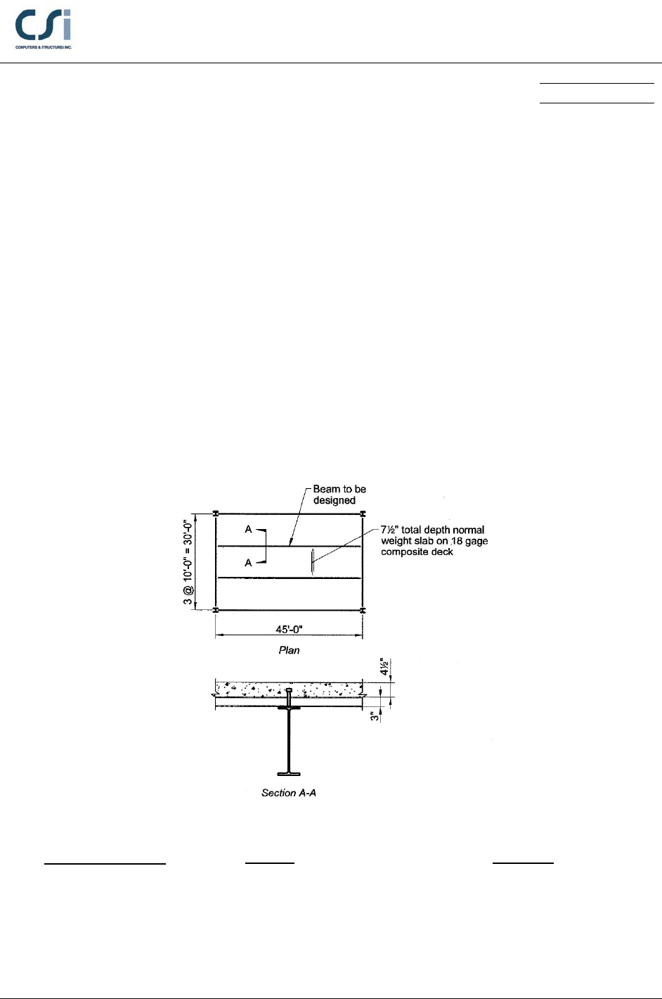
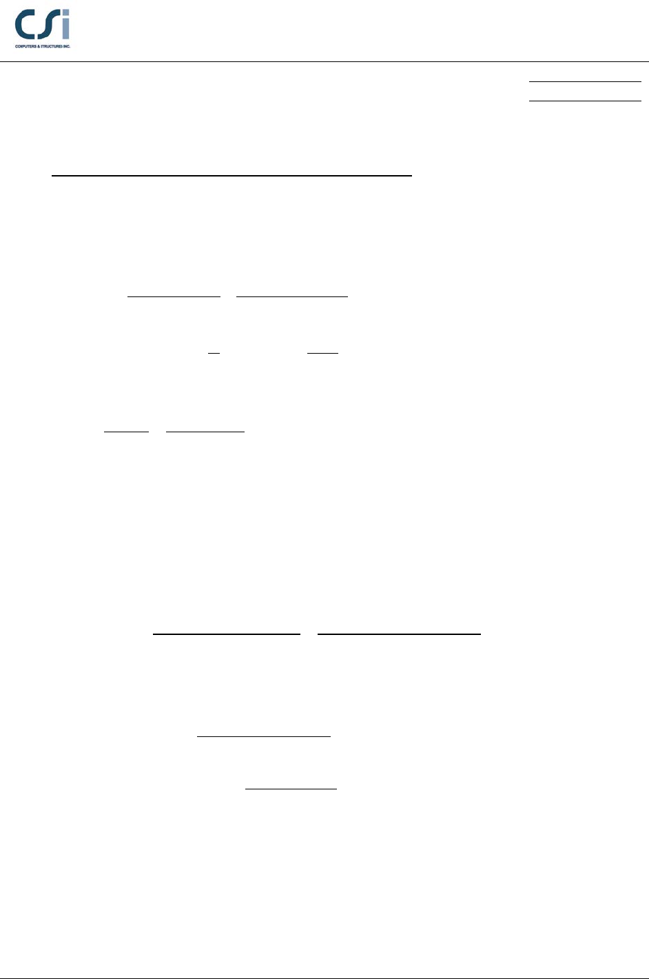
A typical bay of a composite floor system is illustrated below. Select an
appropriate ASTM A992 W-shaped beam and determine the required number of
¾ in.-diameter steel headed stud anchors. The beam will not be shored during
construction. To achieve a two-hour fire rating without the application of spray
applied fire protection material to the composite deck, 4 ½ in. of normal weight
(145 lb/ft3) concrete will be placed above the top of the deck. The concrete has a
specified compressive strength,
4 ksi.
′=
c
f
GEOMETRY, PROPERTIES AND LOADING
Member Properties
W21x50
E = 29000 ksi
F
y
= 50 ksi
Loading
w = 800 plf (Dead Load)
w = 250 plf (Construction)
w = 100 plf (SDL)
w = 1000 plf (Live Load)
Geometry
Span, L = 45 ft
AISC-360-10 Example 001 - 1
Software Verification
PROGRAM NAME:
ETABS
REVISION NO.:
3
TECHNICAL FEATURES OF ETABS TESTED
Composite beam design, including:
Selection of steel section, camber and shear stud distribution
Member bending capacities, at construction and in service
Member deflections, at construction and in service
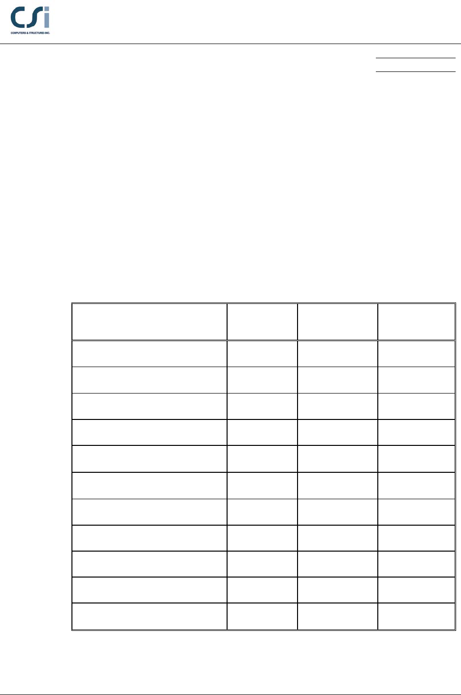
RESULTS COMPARISON
Independent results are referenced from Example I.1 from the AISC Design
Examples, Version 14.0.
Output Parameter ETABS Independent Percent
Difference
Pre-composite Mu (k-ft) 344.2 344.2 0.00%
Pre-composite ΦbMn (k-ft) 412.5 412.5 0.00%
Pre-composite Deflection (in.) 2.6 2.6 0.00%
Required Strength Mu (k-ft) 678.3 678.4 0.01%
Full Composite ΦbMn (k-ft) 937.1 937.1 0.00%
Partial Composite ΦbMn (k-ft) 763.2 763.2 0.00%
Shear Stud Capacity Qn 17.2; 14.6 17.2; 14.6 0.00%
Shear Stud Distribution 46 46 0.00%
Live Load Deflection (in.) 1.34 1.26 6.0%
Required Strength Vu (kip) 60.3 60.3 0.00%
ΦVn (k) 237.1 237.1 0.00%
AISC-360-10 Example 001 - 2

Software Verification
PROGRAM NAME:
ETABS
REVISION NO.:
3
COMPUTER FILE: AISC-360-10 EXAMPLE 001.EDB
CONCLUSION
The ETABS results show an acceptable comparison with the independent results.
The live load deflection differs due to a difference in methodology. In the AISC
example, the live load deflection is computed based on a lower bound value of
the beam moment of inertia, whereas in ETABS, it is computed based on the
approximate value of the beam moment of inertia derived from Equation (C-I3-6)
from the Commentary on the AISC Load and Resistance Factor Design
Specification – Second Edition.
AISC-360-10 Example 001 - 3
Software Verification
PROGRAM NAME:
ETABS
REVISION NO.:
3
HAND CALCULATION
Properties:
Materials:
ASTM A572 Grade 50 Steel
E = 29,000 ksi, Fy = 50 ksi, wsteel = 490 pcf
4000 psi normal weight concrete
Ec = 3,644 ksi,
4 ksi,
′=
c
f
wconcrete = 145 pcf
Section:
W21x50
d = 20.8 in, bf = 6.53 in, tf = 0.535 in, tw = 0.38 in, k = 1.04 in
Asteel = 14.7 in2, Ssteel = 94.6 in3, Zsteel = 110 in3, Isteel = 984 in4
Deck:
tc =4 ½ in., hr = 3 in., sr =12 in., wr = 6 in.
Shear Connectors:
d = ¾ in, h =4 ½ in, Fu = 65 ksi
Design for Pre-Composite Condition:
Construction Required Flexural Strength:
3
(10 75 50) 10 0.800 kip/ft
D
w
−
= •+ • =
3
10 25 10 0.250 kip/ft
L
w−
=•• =
1.2 0.800 1.6 0.250 1.36 kip/ft
u
w=• +• =
22
1.36 45 344.25 kip-ft
88
u
u
wL
M••
= = =
Moment Capacity:
(0.9 110 50) 12 412.5 kip-ftΦ =Φ• • = • • =
bn b s y
M ZF
AISC-360-10 Example 001 - 4
Software Verification
PROGRAM NAME:
ETABS
REVISION NO.:
3
Pre-Composite Deflection:
( )
4
40.800
5 45 12
512 2.59 in.
384 384 29,000 984
• ••
∆= = =
••
D
nc
wL
EI
Camber 0.8 0.8 2.59 2.07 in.,= •∆ = • =
nc
which is rounded down to 2 in.
Design for Composite Flexural Strength:
Required Flexural Strength:
1.2 0.800 1.2 0.100 1.6 1 2.68 kip/ft
u
w=• +• +•=
22
2.68 45 678.38 kip-ft
88
u
u
wL
M••
= = =
Full Composite Action Available Flexural Strength:
Effective width of slab:
eff
10.0 45.0 ft
•2 sides 10.0 ft 11.25 ft
28
b= =≤=
Resistance of steel in tension:
14.7 50 735 kips
y sy
CP AF
==•= •=
controls
Resistance of slab in compression:
( )
2
eff 10 12 4.5 540 in= •= • • =
cc
Ab t
0.85 ' 0.85 4 540 1836 kips
cc
C fA= • = •• =
Depth of compression block within slab:
()
eff
735 1.80 in.
0.85 ' 0.85 10 12 4
= = =
•• •••
c
C
abf
Moment resistance of composite beam for full composite action:
() ( )
1
1.80
4.5 3 6.60 in.
22
= + −= +− =
cr
a
d th
1
20.8/12
0.9 735 6.60 /12 735 937.1 kip-ft
22
nyy
d
M Pd P
Φ =Φ •+• = • + • =
AISC-360-10 Example 001 - 5
Software Verification
PROGRAM NAME:
ETABS
REVISION NO.:
3
Partial Composite Action Available Flexural Strength:
Assume 50.9% composite action:
0.509 373.9 kips
y
CP= •=
Depth of compression block within concrete slab:
()
eff
373.9
0.92 in.
0.85 ' 0.85 10 12 4
c
C
abf
= = =
•• •••
()
( )
0.92
4.5 3 7.04 in.
122
a
d th
cr
= + −= +− =
Compressive force in steel section:
735 373.9 180.6 kips
22
y
PC−−
= =
Steel section flange ultimate compressive force:
6.53 0.535 50 174.7 kips
flange f f y
C btF= •• = • • =
Steel section web (excluding fillet areas) ultimate compressive force:
( 2 ) (20.8 2 1.04) 0.38 50 355.7 kips
web w y
C d ktF
= −• • • = −• • • =
Steel section fillet ultimate compressive force:
(2 ) 735 (2 174.7 355.7) 14.5 kips
22
y flange web
fillet
P CC
C−• + −• +
= = =
Assuming a rectangular fillet area, the distance from the bottom of the top flange to
the neutral axis of the composite section is:
f
( )/2
(k t )
180.6 174.7
(1.04 0.535) 0.20 in.
14.98
y flange
fillet
PC C
xC
−−
=−•
−
=−• =
AISC-360-10 Example 001 - 6
Software Verification
PROGRAM NAME:
ETABS
REVISION NO.:
3
Distance from the centroid of the compressive force in the steel section to the top of
the steel section:
y
2
/2 ((P )/2 ) ( /2)
( )/2
174.7 0.535/ 2 (180.6 174.7) (0.535 0.2 / 2) 0.279 in.
180.6
flange f flange f
y
C t C C tx
dPC
• + − − •+
=−
• +−•+
= =
Moment resistance of composite beam for partial composite action:
( ) ( )
( )
12 32
20.8
0.9 373.9 7.04 0.279 735 0.279 12 763.2 kip-ft
2
ny
M Cdd P dd
Φ =Φ • + +• −
= • + +• − =
Shear Stud Strength:
From AISC Manual Table 3.21, assuming the shear studs are placed in the weak
position, the strength of ¾ in.-diameter shear studs in normal weight concrete with
and deck oriented perpendicular to the4 ksi beam is:
′=
c
f
17.2 kips
n
Q=
for one shear stud per deck flute
14.6 kips
n
Q=
for two shear studs per deck flute
Shear Stud Distribution:
There are at most 22 deck flutes along each half of the clear span of the beam.
ETABS only counts the studs in the first 21 deck flutes as the 22nd flute is potentially
too close to the point of zero moment for any stud located in it to be effective. With
two shear studs in the first flute, 20 in the next in the next twenty flutes, and one
shear stud in the 22nd flute, in each half of the beam, there is a total of 46 shear studs
on the beam, and the total force provided by the shear studs in each half span is:
2 14.6 20 17.2 373.9kip
n
QΣ=• +• =
AISC-360-10 Example 001 - 7
Software Verification
PROGRAM NAME:
ETABS
REVISION NO.:
3
Live Load Deflection:
Modulus of elasticity ratio:
29,000 3,644 8.0
c
n EE
= = =
Transformed elastic moment of inertia assuming full composite action:
Element
Transformed
Area
A (in2)
Moment Arm
from Centroid
y (in.) Ay
(in.3) Ay2
(in,4) I0
(in.4)
Slab
67.9
15.65
1,062
16,620
115
W21x50
14.7
0
0
0
984
82.6
1,062
16,620
1,099
24
0
1,099 16,620 17,719 in.
x
I I Ay
=+= + =
1,062 12.9 in.
82.6
y= =
224
17,719 82.6 12.9 4,058 in
tr x
I I Ay= −• = − • =
Effective moment inertia assuming partial composite action:
4
equiv / ( ) 984 0.51(4,058 984) 3,176 in
s n y tr s
I I Q PI I= +Σ − = + − =
4
eff equiv
0.75 0.75 3,176 2,382 inII=•=• =
44
eff
5 5 (1/12) (30 12) 1.34 in.
384 384 29,000 2,382
L
LL
wL
EI
• ••
∆= = =
••
Design for Shear Strength:
Required Shear Strength:
1.2 0.800 1.2 0.100 1.6 1 2.68 kip/ft
u
w=• +• +•=
2.68 45 60.3 kip-ft
22
u
u
wL
V••
= = =
AISC-360-10 Example 001 - 8

Software Verification
PROGRAM NAME:
ETABS
REVISION NO.:
3
Available Shear Strength:
0.6 1.0 0.6 20.8 0.38 50 237.1 kips
n wy
V dt FΦ=Φ••••=•• • •=
AISC-360-10 Example 001 - 9
