1 Pug_vol_soft_body AITR 1643
AITR-1643 AITR-1643
User Manual: AITR-1643
Open the PDF directly: View PDF ![]() .
.
Page Count: 104 [warning: Documents this large are best viewed by clicking the View PDF Link!]
The Artificial Intelligence Laboratory and
The Research Laboratory of Electronics
at the
Massachusetts Institute of Technology
Cambridge, Massachusetts 02139
Proceedings of the
Third
PHANTOM Users Group Workshop
Edited by:
Dr. J. Kenneth Salisbury and Dr. Mandayam A. Srinivasan
A.I. Technical Report No. 1643
R.L.E. Technical Report No. 624
December 1998
Massachusetts Institute of Technology
Proceedings of the
Third
PHANTOM Users Group Workshop
October 3 – 6, 1998
Endicott House, Dedham MA
Massachusetts Institute of Technology, Cambridge, MA
Hosted by
Dr. J. Kenneth Salisbury, AI Lab & Dept of ME, MIT
Dr. Mandayam A. Srinivasan, RLE & Dept of ME, MIT
Sponsored by
SensAble Technologies, Inc., Cambridge, MA
The Third PHANTOM Users Group Workshop
On October 3-6, 1998, the Third PHANTOM Users Group Workshop was held at the MIT
Endicott House in Dedham Massachusetts. Designed as a forum for sharing results and insights,
the workshop was attended by more than 70 participants from 9 countries. In an expansion over
previous years, this year's workshop was organized into a three day event. It began with a day of
tutorials offered by staff members from SensAble Technologies. This was followed by a two-day
symposium of presentations from the user community. Twenty-two diverse presentations were
made on subjects including rendering techniques, user interface design, system building tools,
applications, human psychophysical issues and more. These excellent talks and the usual liberal
dose of discussion, debate, and hands-on demonstration provided for an enjoyable and productive
exchange of information and sharing of excitement.
Following the tradition begun last year, one presenter was selected to receive the best
presentation award (and a coveted SensAble Technologies leather jacket). This year the award
went to Markus von der Heyde of the University of Rochester for presentation of his
PHANTOM-supported psychophysical studies. Runners up for the best presentation award were
Rob Shaw of the Interval Corporation for his work on collision detection, Andy Mor from the
Carnegie-Mellon University Robotics Institute for his presentation on a 5-degree-of-freedom
haptic interface, and Len Wanger, from Interactive Simulations, Inc., for his presentation on
interactive simulation for molecular modeling.
We would like to express our sincere gratitude to all the participants for helping make the
workshop a success and look forward to future meetings. We would also like to thank the staff of
SensAble Technologies for their generous support and assistance in making the workshop run
smoothly. We also wish to extend special thanks to Jacqui Taylor of MIT for cheerful and expert
assistance in pulling together all the organizational and administrative details that made the event
a success.
Kenneth Salisbury
Mandayam Srinivasan
Cambridge, December 1998
PUG98 Organizational Committees
Executive Committee
Kenneth Salisbury, Chair MIT
Mandayam Srinivasan MIT
Thomas Massie STI
Bill Aulet STI
Program Committee
Mandayam Srinivasan, Chair MIT
Rick Avila GE
Walter Aviles STI
Arthurine Breckenridge Sandia
Scott Davidson NAWC/TSD
Hiromi Kobayashi VRCY
Karon MacLean Interval
Thomas Massie STI
Wendy Plesniak MIT
Kenneth Salisbury MIT
Registration and Local Arrangements
Jacqui Taylor, Chair MIT
Kate Hilburn STI
Marjorie Matty STI
Publications Committee
Marjorie Matty, Chair STI
Jacqui Taylor MIT
Demonstrations Committee
Walt Aviles, Chair STI
Ron Howard, Facilities STI
1998 PHANTOM Users Group Workshop Program
------------------------------------------------------------------------
Saturday Oct 3 ARRIVAL AND SETUP
------------------------------------------------------------------------
3:00-6:00 Arrival at Endicott House
6:00-7:30 Dinner
7:30-9:00 Welcome Reception and Refreshments
------------------------------------------------------------------------
Sunday Oct 4 TUTORIALS AND DEMONSTRATIONS
------------------------------------------------------------------------
8:00-9:00 Breakfast
9:00-10:00 Tutorial I: "Using the GHOST SDK to quickly integrate
3D Touch into Applications"
10:00-10:30 Break
10:30-11:30 Tutorial II: "Beyond the GHOST SDK: extending
capabilities by subclassing"
11:30-12:00 Demonstrations
12:00-1:30 Lunch
1:30-2:30 Tutorial III: "How low can you go: creating your own
force effects from scratch"
2:30-3:00 Break
3:00-4:00 Tutorial IV: "Question/Answer with the GHOST team"
4:00-5:00 Demonstrations
6:00-7:30 Dinner
7:30-9:00 Refreshments
------------------------------------------------------------------------
Monday Oct 5 SYMPOSIUM, DAY 1
------------------------------------------------------------------------
8:00-9:00 Breakfast
9:00-9:20 Introductory remarks (MIT and STI welcome)
9:20-10:20 Paper Session M-1: Rendering I
Haptic Rendering of Volumetric Soft-Bodies Objects
Jon Burgin (1), Bryan Stephens (2), Farida Vahora (2), Bharti Temkin
(2), William Marcy (2), Paul Gorman (3), Thomas Krummel (3).
(1) On Board Software Inc., (2) Texas Tech University, (3) Penn State
University College of Medicine
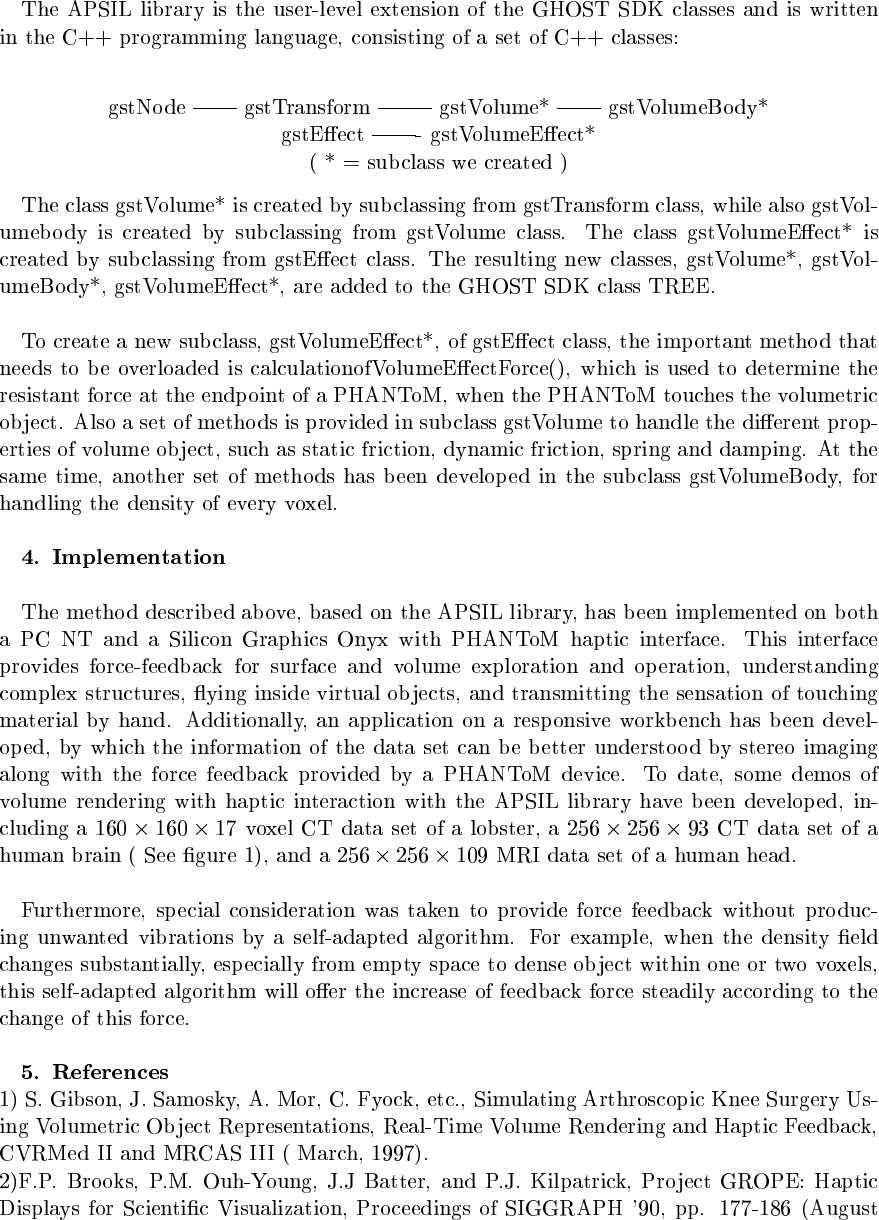
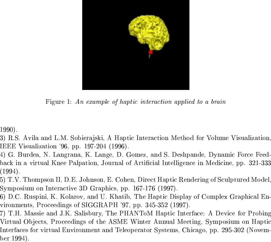
Volume Rendering with Haptic Interaction
Chewei Huang, Huamin Qu, Arie E. Kaufman.
Computer Science Department, SUNY at Stony Brook
Haptic Volume Rendering in Different Scenarios of Surgical Planning
Christoph Giess, Harald Evers, Hans-Peter Meinzer
Deutsches Krebsforschungszentrum
Abteilung Medizinische und Biologische Informatik
Heidelberg, Germany
10:20-10:40 Break & Demos
10:40-12:00 Paper Session M-2: Rendering II
Rapid Rendering of "Tool-Tissue" Interactions in Surgical
Simulations: Thin Walled Membrane Models
Suvranu De and Mandayam A. Srinivasan
Laboratory for Human and Machine Haptics
Department of Mechanical Engineering
and Research Laboratory of Electronics, MIT
Assessment and Validation of a Force Feedback Virtual Reality Based
Surgical Simulator
Paul J. Gorman, J.D. Lieser, W.B. Murray, Randy S. Haluck
and Thomas M. Krummel.
Departments of Surgery and Anesthesia, Penn State University College
of Medicine
Soil Simulation With a PHANToM
Donald Green and J. Kenneth Salisbury
AI Laboratory
Mass Inst. of Technology
Cambridge MA
"Nearest Neighbor" Approach to Haptic Collision Detection
Robert Shaw
Interval Corp.
12:00-2:00 Lunch (and Demos 1:00-2:00)
2:00-3:20 Paper Session M-3: User Interfaces
Adding Haptic Device to Virtual Reality Based User Interface Systems
Masahiro Nakamura
Cyber Media Laboratory
Lexer Research inc.
5 DOF Force Feedback Using the 3DOF Phantom and a 2DOF Device
Andrew B. Mor
Carnegie-Mellon University
Tactile MAX: A Haptic Interface for 3D Studio MAX
Geoff Marcy, Bharti Temkin
Department of Computer Science
Texas Tech University
Paul J. Gorman, Thomas M. Krummel
Penn State University College of Medicine
Implementation Issues in Adding Force Feedback to the X Desktop
Timothy Miller
Dept. of Computer Science
Brown University
3:20-3:40 Break & Demos
3:40-5:00 Paper Session M-4: Tools
Assembly Simulation Through Haptic Virtual Prototypes
Gutierrez T., Barbero J.I., Aizpitarte M., Carrillo A.R., Eguidazu A.
Unidad de Mecanica, Labein Reseach Center, Bilbao, Spain
Springs and Constraints for 3D Drawing
Scott Snibbe, Sean Anderson and Bill Verplank
Interval Corp.
Network Access to a PHANToM Through VRPN
Russell M. Taylor II
University of North Carolina
Chapel Hill NC
Acoustic Cues for Haptic Rendering Systems
Diego Ruspini, Oussama Khatib
Stanford Robotics Laboratory
5:00-6:00 Demos
6:00-7:30 Dinner
7:30-9:00 Refreshments
------------------------------------------------------------------------
Tuesday Oct 6 SYMPOSIUM, DAY 2
------------------------------------------------------------------------
8:00-9:00 Breakfast
9:00-10:00 Paper Session T-1: Applications
SCIRun Haptic Display for Scientific Visualization
Lisa J. K. Durbeck, Nicholas J. Macias, David M. Weinstein, Chris R.
Johnson, John M. Hollerbach
University of Utah
Haptically Enhanced Molecular Modeling: A Case Study
Len Wanger
Interactive Simulations, Inc.
San Diego CA
Incorporating Haptics into Mining Industry Applications
Paul Veldkamp (1), Greg Turner (2), Chris Gunn (1), Duncan Stevenson (1)
(1) CSIRO Mathematical and Information Sciences
(2) SenseOre Services Pty Ltd.
10:00-10:40 Break & Demos
10:40-12:00 Paper Session T-2: The Human Operator
The Role of Haptic Communication in Shared Virtual Environments
Cagatay Basdogan (1), Chih-Hao Ho (1), Mel Slater (2), Mandayam A.
Srinivasan (1)
(1) Laboratory for Human and Machine Haptics, Department ME and RLE, MIT
(2) Department of Computer Science, University College, London
A Project to Study Human Motor System
L. Piron (1), M. Dam (1), E. Trivello (1), E. Bricolo (2)
(1) Department of Neurology and Psychiatry, University of Padova, Italy
(2) SISSA, Trieste, Italy
Visually Impaired Persons' Use of the PHANToM for Information About
Texture and 3D Form of Virtual Objects
Gunnar Jansson (1), Jens Faenger (2), Henry Konig (2), and Katarina
Billberger (1)
(1) Department of Psychology, Uppsala University, Sweden
(2) Department of Simulation and Graphics, University of Magdeburg, Germany
Psychophysical Experiments in a Complex Virtual Environment
Markus von der Heyde and Charlotte Hager-Ross
University of Rochester
Rochester NY
12:00-1:30 Lunch
1:30-3:00 Discussion & Wrap Up
3:00-5:00 Cleanup and Departure (Optional Bus to
Airport by prior arrangement)

1
Haptic Rendering of Volumetric Soft-Bodies Objects
Jon Burgin, Ph.D
On Board Software Inc.
Bryan Stephens, Farida Vahora, Bharti Temkin, Ph.D, William Marcy, Ph.D
Texas Tech University
Dept. of Computer Science, Lubbock, TX 79409,
(806-742-3527), temkin@coe.ttu.edu
Paul J. Gorman, MD, Thomas M. Krummel, MD,
Dept. of Surgery, Penn State Geisinger Health System
Introduction
The interfacing of force-feedback devices to computers adds touchability in
computer interactions, called computer haptics. Collision detection of virtual objects
with the haptic interface device and determining and displaying appropriate force
feedback to the user via the haptic interface device are two of the major components of
haptic rendering. Most of the data structures and algorithms applied to haptic rendering
have been adopted from non-pliable surface-based graphic systems, which is not always
appropriate because of the different characteristics required to render haptic systems.
We use advanced computer modeling and coding techniques to implement (on
266 MHz PC/NT): 1) Haptic rendering of 3D volumetric objects using occupancy-map
algorithm (OMA) for collision detection. This is an extension of currently available
OMA for solid non-deformable convex virtual objects. 2) Chainmail algorithm (CMA)
for generation of the real-time forces feedback while allowing deformation of the soft-
bodied object to occur. This is an enhancement of currently available CMA used for
calculating the behavior of convex surface virtual objects. Using these techniques we
establish the viability of being able to work with volumetric soft-bodied objects.
Occupancy-map Collision Detection and Chainmail Algorithms
The very first step of interacting with virtual objects is to establish a collision with
the virtual object. In a haptic virtual reality system (HVRS) an interaction with a virtual
object is done by “touching” the object using a haptic interface device (in our case this is
the PHANToM stylus). For a real-time HVRS this implies that a very efficient collision
detection algorithm is essential, since otherwise the system would be useless.
The virtual environment and virtual objects are stored in memory in a three
dimensional array called an occupancy map. When the occupancy map is initialized,
each position in the map is set to –1 meaning that it is unoccupied. When a virtual object
is added to the scene, the appropriate positions in the occupancy map are set to 0. The
borders of the virtual scene follow this same pattern as well.
2
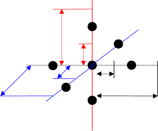
Similar to the movements of a chained armor, the chaimail algorithm provides the
minimum, maximum, and “shear” distances that a voxel and its linked neighboring
voxels are allowed to move. Once the OMA determines a collision, the CMA determines
the geometry of the neighboring vertices including the direction(s) of the movements.
Figures 1 and 2 clarify these concepts. Whenever the distances are violated between two
voxels, the neighboring voxels are adjusted to compensate for the discrepancy. This
process is recursively implemented until all the voxels in the system reach stability, i.e.
meet the minimum, maximum and shear distance criteria for x, y and z directions.
At any given time, the position of the PHANToM stylus and the occupancy map
are used to determine a collision between the voxel at that position and the stylus tip.
Further more, the direction of approach and “chain mesh” of the CMA are taken into
account to resolve the collision with “ripple effects of other voxels” and the deformation
(movement of the voxel) that occurs due to the collision.
Figure 1. Chainmail Model Nearest Neighbor Distance
δ
zmax
δ
zmin
δ
ymin
δ
ymax
δ
xmin
δ
xmax
3
Figure 2. Chainmail Model for Shear
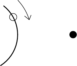
Issues encountered
Stability of the system
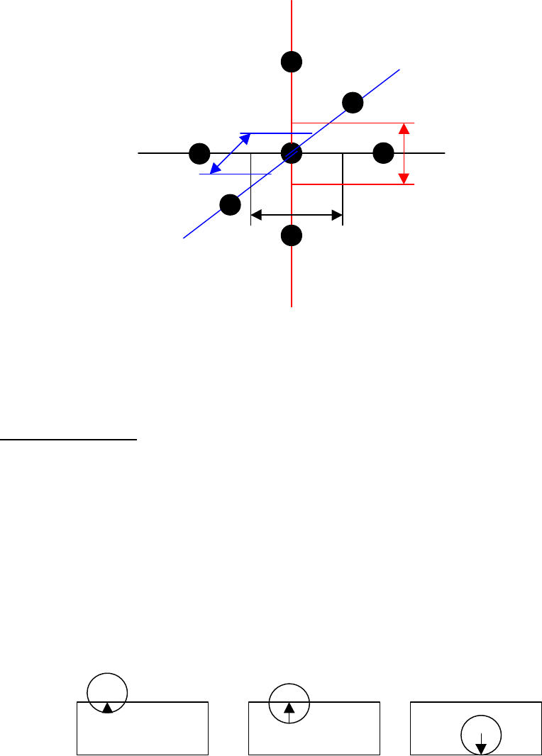
In surface based haptic rendering with thin objects, phantom’s virtual position
passes through the surface and becomes closer to the far edge than the edge it originally
passed through. Since the force vector is proportional to the distance of the proxy and the
nearest surface, this causes the change in direction of the force. Creating a virtual proxy
that remains on the surface solved this problem. Figures 3 and 4 explain the concept and
the solution.
Figure 3. Surface Based Haptic Rendering without proxy
δ
yshear
-
δ
zshear
-
δ
xshear
δ
zshear
-
δ
yshear
δ
xshear
4
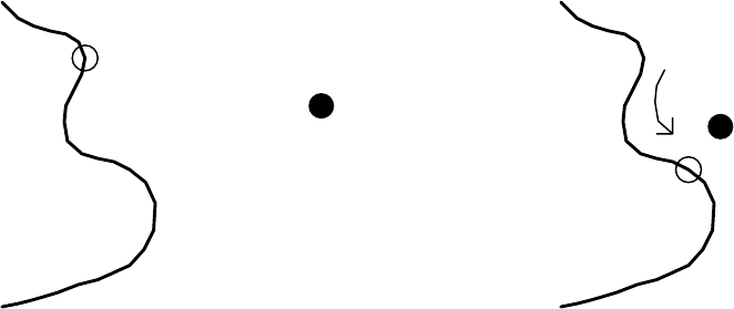
Figure 4. Surface Based Haptic Rendering with Proxy
Similarly with volumetric rendering technique the contact is momentarily
lost if the force is strong enough to bounce the phantom away from the surface, although
the user is still pushing towards the surface. The net effect is that the phantom position
and the surface voxel pass through each other (Figure 5). Since there is no contact with
the voxel, there is no force feedback from the haptic device and since there is no pressure
against the surface, the voxel relaxes outward. To help resolve this problem the collision
was checked at the location of proxy and at the six directional points at a fixed radius
distance from the proxy until the contact is made.
Figure 5. Bounce Surface Contact Instability
Relax Stability
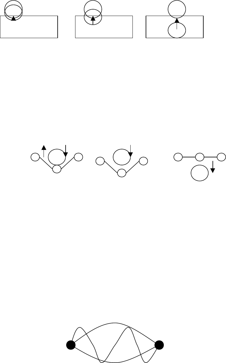
The relax stability problem is believed to be caused by the bounding of the
voxels together. When the voxels attempt to move to their lowest energy relationship to
their neighbors, they actually impose energy on the system as a result of their movement.
The result is similar to a string that has been drawn tight between two points and then
plucked. If this occurs in a system without energy loss the string will vibrate forever.
This system is visualized in figure 6. We found that our system required damping of the
relax function such that only a small movement to the desired location occurred during
any relax step. Otherwise the entire virtual object will vibrate. Interestingly, the
vibration does not cause problems with the haptic rendering, but does cause an unpleasant
visual effect to the simulations.
Figure 6. Stable Vibration States of Bound String
P P
P
Force
User
User
User

5
Conclusion
The hardware requirements for this implementation make the technique
computationally expensive, but allow for haptic presentation of materials with non-
homogenous internal behavior. The average memory usage for this system is between the
range of 11.5 to 12MB for a scene of 11,200 polygons. Although this would indicate a
need for substantial memory requirement, the continuing decline in price of memory
chips would offset the cost.
References
[1] C. Tarr, J. K. Salisbury, “Haptic Rendering of Visco-Elastic and Plastic Surfaces,”
Proceedings of the Second PHANToM Users Group Workshop, A.I. Technical
Report No. 1617, Massachusetts Institute of Technology, Cambridge
Massachusetts, J. K. Salsbury, M. A. Srinivasan, editors. 1997.
[2] S. F. F. Gibson, “Linked Volumetric Objects for Physics-based Modeling, “ Technical
Report TR97-20, Mitsubishi Electric Research Laboratories Cambridge Research
Center. Nov 5, 1997.
[3] S. F. Gibson Frisken, “Beyond Volume Rendering: Visualization, Haptic Exploration,
and Physical Modeling of Voxel-Based Objects,” Visualization in Scientific
Computing ’95: Proceeding of Eruographics Workshop, pp. 10-24.

Haptic Volume Rendering in Different Scenarios
of Surgical Planning
Christoph Giess, Harald Evers, Hans-Peter Meinzer
Deutsches Krebsforschungszentrum
Abteilung Medizinische und Biologische Informatik
Im Neuenheimer Feld 280
D-69120 Heidelberg, Germany
Ch.Giess@DKFZ-Heidelberg.de
Abstract This paper presents ongoing research in the field of surgical planning using a PHANToM force feedback
device. Previous research and use of haptic systems in medicine mainly concentrated on surgical simulation. Since
preoperative planning and, especially, segmentation are prerequisites for simulation, they are relevant for physi-
cians. Experience from projects in virtual liver tumor resection and heart surgery indicated that segmentation and
measurements are desired functionalities. For that, a general and adaptable haptic rendering method
for unsegmented images from various modalities (CT, EBT, MRI, Doppler ultrasound) was developed based on
the haptic volume rendering algorithm described by Avila. Additionally, this algorithm is coupled with the Heidel-
berg Raytracing Model to get coherent perceptions (what you see is what you feel). Virtual elements, such as re-
section planes, which are necessary for a surgical planning system are described as OpenGL primitives. For that, a
hybrid rendering approach was introduced combining volume and surface rendering.
Index Terms haptic rendering, surgical planning, segmentation
1 Introduction
Developing better tools for surgical planning is important to improve the quality of operations. In the field of brain
surgery it is common to use machines to compute the best access to the operation area. In other surgical domains,
finding the best surgical strategy depends more on the physician‘s experience. In this paper, we will describe some
scenarios where haptic rendering can support the planning process in liver surgery to resect tumors.
2 Background
The resection of liver tumors is planned based on information about the individual liver anatomy. The data pro-
cessing consists of three main steps [Glombitza 98]:
• Interactive classification of liver parenchyma, vessel trees and tumor
• Segmentation of liver segments by means of the preprocessed vessel trees
• Calculation of the parenchyma mass which will be available after resection
2.1 Interactive Classification
Currently, classification of different tissues in medical images is performed using VolMes [Demiris 98]. This tool,
developed in our division, provides several interactive algorithms for region growing and correction to mis-clas-
sifications. It takes a skilled user about 1 minute to classify the liver parenchyma, the vessel trees and the tumor
in a single CT image. The data size is about 256x256x180 voxel which results in an overall classification time of
3 hours. Up to now, no automatic classification algorithms is known that fulfills the requirements regarding accu-
racy. For that, the first aim using the PHANToM was to speed up the interactive classification process.
2.2 Liver Segmentation
The segmentation of liver segments (see fig. 1) is based on the information derived from the classified vessel tree. In
spite of interactive classification, the vessel tree may be incorrect in terms of missing or wrong connections due to the
limited resolution of the CT scanner and variances when absorbing the contrast liquid. These errors have also to be
corrected manually.
Planes between liver segments are computed after correcting the vessel tree. These planes can be further
manipulated. To control the automatic determination of the segments, the user (physician) can adjust them afterwards.
3 System Design
Beside the scenario described above, haptic interaction can also be useful in other surgical planning tasks. To achieve
this, the primary design goal is to integrate haptic rendering in our image processing environment. This environment
consists of a client/server architecture as described in [Mayer]. An image processing server holds the volume data dur-
ing the whole processing stage and performs all algorithms on them. On request the client receives 2D image for dis-
playing. These requested images can either be arbitrary slices from the original volume or 3D reconstructions. The
reconstructions are computed using the Heidelberg Raytracing Model.
Connecting the PHANToM directly to the server was the only way to integrate it in our environment.
Duplicating the volume images on the client leads to problems with procedures which will manipulate the data. A
new requirement of the planning tool was the handling of virtual elements such as cut planes. To do so, they had to be
integrated in the image processing server. On client side, the virtual elements exist as corresponding OpenGL
primitives. To display a hybrid scene, the volume visualization and OpenGL primitives are rendered independently.
The client has to combine both images using a z-buffer-merging.
3.1 Haptic Rendering
The haptic volume rendering is based on the gradient magnitude segmentation method described by [Avila 96]. Be-
cause the algorithm operates on unsegmented data, only grayvalues are considered to calculate force responses. All
parameters of the rendering algorithm can be adjusted to support various images from different modalities. The force
model is not intended to give a realistic feeling with this algorithm, but the user should distinguish different tissues
and the transitions between them. These requirements are fulfilled with the simplified algorithm.
The virtual elements were surface rendered using the mass-spring model. The forces from both haptic
rendering techniques were combined as described in equation (1). The weighting factor a can be adjusted depending
on the users needs.
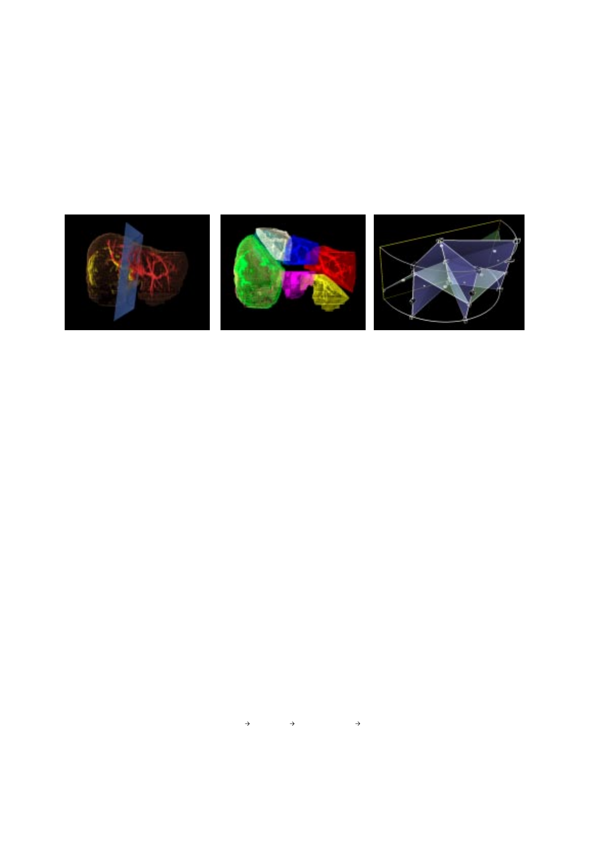
Figure 1: (left) 3D-reconstruction of a human liver including vessel tree
(middle) segment model
(right) OpenGL model of cut planes and landmarks (white spheres)
Fresult aFvolume 1a–()Fsurface
+= (eq. 1)
3.2 Displaying
Our experience in visualization of medical images showed that shadows are an important depth-clue when observing
3D-reconstructions. This led to the development of the Heidelberg Raytracing Model [Meinzer 91] which employs two
light sources. Virtual elements, as the pointer of the PHANToM, are rendered in the surgical planning tool using the
same lighting model as the raytracer. The OpenGL rendered primitives throws shadows on the raytraced objects. This
allows the user to determine the pointer position relative to the object without wearing stereo glasses.
The mapping of density-grayvalues is used for both the Heidelberg Raytracing Model and the haptic rendering
to establish a coherent perception (what you see is what you feel). The user can change this mapping interactively.
3.3 Liver Segmentation
To achieve a remarkable speedup when classifying volume images, the process has to be done in 3D. Until now, no
3D classification algorithm produced any usable result. Giving the classification algorithm some points on the surface
of the object will improve these results significantly [Makabe 98]. We use the PHANToM to construct such contour
points around the objects to classify. The force generated on the transition between two objects makes this method fast
and accurate.
The haptic feedback also enables the user to navigate precisely through the vessel tree. This allows a correct
cutting of wrongly connected vessels as well as connecting them.
All landmarks used to define the planes between segments are situated inside the vessel tree. As in the
correction phase, the PHANToM makes a fast and correct navigation in 3D possible. Seeing the whole vessel tree in
the 3D reconstruction allows to set all 10 landmarks from some viewpoints only. This replaces the time consuming
search for the „best slice“ where to set each landmark.
The calculated planes are a suggestion how the liver may be surgically treated. The physicians should have
always the opportunity to change it for further planning. For that, it is possible to change the landmarks and move the
planes in all directions.
4 Current status
Most of the described functionality of the surgical planning system was developed independently and is implemented
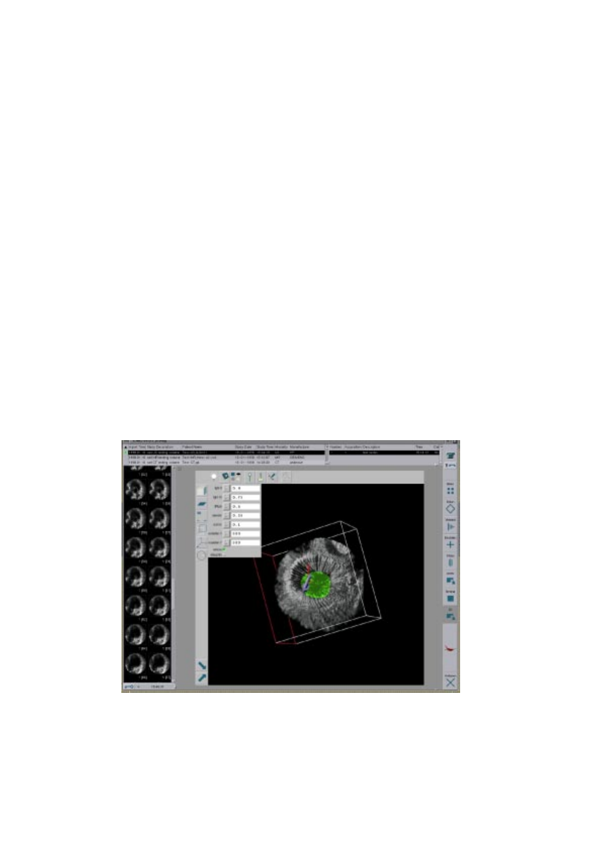
Figure 2: Teleradiology system Chili with 3D-visualization PlugIn

in several prototypes. Currently, these algorithms are integrated as a PlugIn [Evers 98] for the teleradiology system
Chili (see fig. 2). Since image transfer, management and visualization is covered by this host system, developments
can be concentrated on interactive visualization and segmentation in combination with haptic rendering.
5 Acknowledgements
This research was performed at the Division of Medical and Biological Informatics at the German Cancer Research
Center. The work was funded by the Tumorzentrum Heidelberg/Mannheim (Virtual Liver Resection) and the Deutsche
Forschungsgemeinschaft (SFB 414: Information Technology in Medicine - Computer and Sensor Supported Surgery).
Further thanks to the „Liver-Team“ Dr. Gerald Glombitza, Marc-Roger Göpfert and Matthias Thorn.
6 References
[Glombitza 98] Glombitza G, Lamadé W, Demiris AM, Göpfert M, Mayer A, Bahner ML, Meinzer HP: „Technical
Aspects of Liver Reseaction Planning,“ in Cesnik B, McCray AT, Scherrer JR (eds). MedInfo‘98;
9th World Congress on Medical Informatics. Amsterdam: IOS Press (1998) 1041-1045.
[Demiris 98] Demiris AM, Cárdenas CE, Meinzer HP: „Eine modulare Architektur zur Vereinfachung der
Entwicklung klinischer Bildverarbeitungssysteme,“ in Lehmann T, Metzler V, Spitzer K, Tolxdorff
T (eds). Bildverarbeitung für die Medizin 1998 - Algorithmen Systeme Anwendungen: Springer
(1998) 184-188.
[Mayer] Mayer A, Meinzer HP: „High Performance Medical Image Processing in Client/Server-
Environments,“ Computer Methods and Programs in Biomedicine, (accepted paper).
[Avila 96] Avila RS, Sobierajski LM: „A Haptic Interaction Method for Volume Visualization“,
Proc.Visualization‘96,“ (1996) 197-204.
[Meinzer 91] Meinzer, HP, Meetz K, Scheppelmann D, Engelmann U, Baur HJ: „The Heidelberg Raytracing
Model,“ IEEE Computer Graphics & Applications, November (1991) 34-43.
[Makabe 98] Makabe MH, Albers J, Schroeder A, Heiland M, Vahl CF, Meinzer HP: „Adaptive segmentation and
standardized visualization of aortic stenosis in tomographical image data for cardiac surgery
planning,“ in Lemke HU, Vannier MW, Inamura K, Farman AG (eds). CAR‘98; 12th International
Symposium and Exhibition Computer Assisted Radiology and Surgery. Amsterdam: Elsevier
Science B.V. (1998) 753-758.
[Evers 98] Evers H, Mayer A, Engelmann U, Schröter A, Baur U, Wolsiffer K, Meinzer HP: „Volume
visualization and interactive tools plugged into a teleradiology system,“ in Medical Imaging 1998:
Image Display, Kim Y, Mun SK (eds). Proceedings of SPIE Vol. 3335, (1998) 100-107.

Rapid Rendering of “Tool – Tissue” Interactions in Surgical
Simulations : Thin Walled Membrane Models
Suvranu De
Laboratory for Human and Machine Haptics &
Finite Element Research Group,
Massachusetts Institute of Technology,
Email: suvranu@mit.edu
Mandayam A. Srinivasan
Laboratory for Human and Machine Haptics,
Massachusetts Institute of Technology,
Email: srini@mit.edu
Introduction
This paper presents a novel approach for physically based, real-time rendering of interactions between
surgical tools and soft tissues for surgical simulations in multimodal virtual environments (VEs). Such
VE systems require graphical rendering of organ motion and deformation together with haptic rendering
of tool-tissue interaction forces (Basdogan, et. al., 1998). Since these systems are aimed at training
medical personnel, the sensory displays need to be realistic, requiring fast rendering of physically based
models. Accurate analysis of tool-tissue mechanics is computationally very intensive due to inherent
complexities of the governing partial differential equations and the nonlinearities resulting from large
deformations and material behavior (De et. al., 1998). Therefore, optimal choice of organ models with
respect to computational speed and accuracy is crucial. We propose here models and algorithms for
physically based rapid graphical and haptic rendering, especially those encountered during palpation,
piercing or incision of soft tissues.
Thin Walled Membrane Models
The real world is three dimensional and this results in considerable computational burdens when it comes
to modeling the objects we see around us. Moreover, if we consider dynamics, the fourth dimension of
time adds to the complexity. Since we do not have the computational resources to solve for the behavior
of all the material components that constitute the object, we perform some kind of discretization, be it in
terms of a mesh or in terms of discrete, lumped-parameter particles. Increased dimensionality of the
problem results in larger matrices and the solution cost goes up roughly as the cube of the number of
unknowns. But haptic and visual interaction with three dimensional bodies are primarily superficial.
While touching an object through a tool, we see the surface deforming under pressure and feel the net
force due to the traction distribution at the area of contact between the tool and the object. Hence, if by
some means, we could reflect the properties of the material constituents “inside” the solid to its surface,
the computational burden could be reduced significantly. This is the basic idea behind the approach
developed in this paper.
We view volumetric solid objects as being represented by “thin-walled” structures for the computation of
surface deformations and interaction forces. Thin walled structures are found all around us. The simplest
example is a balloon. It is a thin walled membrane filled (when inflated) with a gas. A more complex
example of a thin walled structure is an auto-body or the fuselage of an aircraft. The important point is
that such structures are common and we have efficient techniques for solving their behavior. The novelty
of our approach is that we model general three dimensional deformable bodies as “thin-walled” structures
so far as visual and haptic interaction with them are concerned.
A wide class of compliant organs like the stomach, spleen, etc., may be modeled as membranes enclosing
a fluid, much like “water-beds” (Srinivasan, 1989). The degree of compressibility of the organ can be
controlled by defining an appropriate Bulk Modulus for the fluid inside. When bending stiffnesses are
higher, the model can be extended by replacing the membrane with a shell structure with or without fluid
inside. The “surface model” of the organ, used to define its geometry in computer graphics algorithms, is
adopted as the surface of the thin-walled structure. But, unlike the “surface models”, we endow the organ
surface with a thickness that can be variable across the surface. Finite element analysis is performed by
discretizing the membrane with the same triangular elements used in representing the organ geometry
graphically (see Fig 1). A total Lagrangian formulation (Bathe, 1996) is adopted to obtain the incremental
equations of motion, thereby transforming the nonlinear problem into a sequence of simpler linear
problems. The effect of the internal fluid pressure manifests itself in two ways. First, it adds extra terms to
the tangent stiffness matrix and secondly, it shows up as an applied force term in the equilibrium
equations. The choice of simple triangular elements results in closed form computation of the global
tangent stiffness matrices (non-symmetric), resulting in a substantially accelerated computational
procedure.
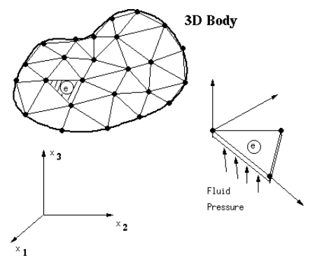
Figure 1 A general three dimensional body is modeled as a membrane filled with a fluid and discretized
with linear triangular elements. One such triangular element is also shown in its local coordinates. The
fluid pressure acts on one face of the triangle.
Results
One of the major strengths of this modeling scheme is that it is capable of simulating the nonlinear force-
displacement behavior observed in actual in vivo experiments performed on biological tissues. To
illustrate this point, we have shown in Figure 2 the force-displacement results (dashed lines) obtained
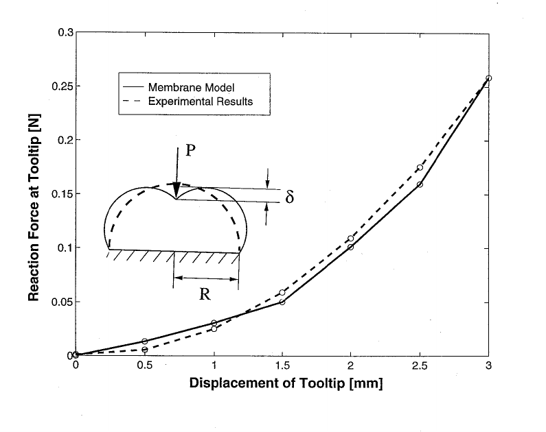
when a human fingerpad is indented by a point load (Srinivasan et. al., 1998). The fingerpad has been
modeled as a semicylindrical membrane in plane strain, enclosing an incompressible fluid. The solid line
indicates the result of the simulation.
Figure 2 This figure shows the match in force-displacement response between in vivo experiments
performed on the human fingerpad by a point load and numerical simulations performed on a fluid filled
membrane model of the fingerpad. The dashed curve represents the force (N) versus displacement (mm)
response of a human fingerpad under steady state conditions when indented by a point load to various
depths of indentation. The fingerpad is modeled as a semicylindrical membrane of radius R = 10 mm,
filled with an incompressible fluid and subjected to the same depths of indentation , δ, by a pointed
tooltip. The solid curve shows the corresponding force-displacement relationship at the tooltip obtained
from the model.
Conclusions
In this paper we have presented a new way of modeling soft tissue behavior during surgical simulations.
The novelty lies in modeling 3D continua as thin walled membrane structures filled with fluid. These
simple models reduce the dimensionality of the problem from 3D to 2D and are therefore computationally
extremely efficient. Moreover, they have the power to predict the non-linear force-displacement response
as well as the surface deformation profiles as observed in in vivo experimental data on soft tissues.
Among other benefits of using this approach are the flexibility to model inhomogeneous and viscoelastic
tissue behavior, ability to deal with realistic three-dimensional organs with relatively low computational
overheads and a unified approach to haptic and graphical rendering of general deformable media.
References
Basdogan, C., Ho and Srinivasan, M.A., “Force Interactions in Laparoscopic Simulations: Haptic
Rendering of Soft Tissues.” Medicine Meets Virtual Reality, pp 385-391, 1998.
Bathe K.J., “Finite Element Procedures”. Prentice Hall, NJ, 1996.
De, S. and Srinivasan, M.A., “A Finite Element Model of the Human Fingerpad Incorporating
Viscoelasticity”. 1998 (Manuscript in preparation).
Srinivasan, M.A., “Surface Deformation of Primate Fingerpad Under Line Load”, J. Biomechanics, Vol.
22, No. 4, pp. 343-349, 1989.
Srinivasan M.A., Gulati, R.J., and De, S., “Force Response of the Human Fingerpad to Dynamic
Indentations”, 1998 (Manuscript in preparation)
ASSESSMENT AND VALIDATION OF A FORCE FEEDBACK
VIRTUAL REALITY BASED SURGICAL SIMULATOR
Paul J. Gorman, MD, J.D. Lieser, BS, W.B. Murray, MD*, Randy S. Haluck, MD, and
Thomas M. Krummel, MD
Laboratory for Simulation Development and Cognitive Science
Departments of Surgery and Anesthesia*, Penn State University College of Medicine,
Hershey, PA
BACKGROUND:
The goal of surgery residency training programs is the production of a
“skilled, safe, technically adept surgeon with keen judgment, dedicated to the welfare of
his or her patient” (Aufses, 1989). Surgical education and training is a lengthy, expensive
process based upon the apprenticeship model. Trainees (surgical residents) learn technical
skill by the “see one, do one, teach one” method. This practice is not without risk to the
patient, and often leads to increased operating room time, a higher complication rate, and
greater cost (Krummel, 1996). The development, assessment, and validation of a virtual
reality based, force feedback surgical simulator has been undertaken to counter this
educational model.
The novel concept of virtual reality (VR) based simulation in surgical training is
derived from the airline industry, where the use of simulators is well established. Full scale
simulation is fully integrated into commercial and combat pilot training at all levels, and
has been shown to effectively train pilots for all manner of flight conditions (Rolfe, 1986).
Surgical simulators for education and training are not commonly used due to the
early developmental stage of many of the applications, the relatively high cost of building
or acquiring systems, and the lack of strong data confirming their validity. All of these
factors must be addressed before widespread adoption of surgical simulators as training
tools takes place. However, the use of virtual reality and simulation in surgical training is
gaining credibility (Krummel, 1998). Currently, information on optimal training programs
(learning curves) for surgical trainers is not readily available. In our laboratory, we are
studying learning curves generated from various training protocols designed for a force
feedback surgical simulator.
Surgical skill is difficult to measure. Attempts at evaluation have included skill
laboratories with video monitoring, self-instruction modules, and physical models (Barnes,
1989). Other assessment criteria depend upon subjective faculty evaluations, or raw
scores generated from paper and pencil examinations (Polk, 1983). Few objective
standards, if any, exist. We used a VR based, force feedback surgical simulator to
determine if objective documentation of early skill acquisition were possible. Baseline skill
data were collected on beginning surgery residents in an attempt to measure skill in a
single surgical task, and to discover the extent to which, if any, psychomotor learning took
place.
METHODS:
The system that was used is centered upon an innovative, double-armed, force
feedback surgical simulator developed in collaboration between the Penn State College of
Medicine Department of Surgery and Boston Dynamics, Inc (Cambridge, MA). A
surgical needle driver and forceps are attached to two Phantom haptic devices (Sensable
Technologies, Inc., Cambridge, MA). A desktop computer is used to control the haptic
element, while a separate computer provides the graphics component. A dedicated
software program measures six variables (below) of operator performance.
Eleven beginning surgery residents underwent a standardized training program on
the surgical trainer. Each participant spent fifteen minutes per day (three days total, days
two and three non-consecutive) driving a simulated needle through a target overlying a
simulated blood vessel with photo-realistic graphics and rudimentary tissue properties.
Data were collected on time on task, accuracy, peak force applied, tissue damage, surface
damage, and angle error. An overall score was derived, and the overall scores of days
one, two, and three were compared using Fisher’s Exact Probability Test. A p value of
less than 0.05 was considered significant.
A second pilot study involving five surgical novices was undertaken to determine
the amount of training required to reach a skill level “plateau.” Each subject’s task in the
virtual environment was, as above, to complete multiple passes of a simulated needle
through a target on a simulated blood vessel. Data were collected on, and an overall score
was generated from, the six parameters mentioned above. This was done until the overall
scores leveled off. Twenty minutes were allotted per session (one session per day,
weekends excluded).
RESULTS:
The resident’s overall scores on day one (39.78 ± 12.36, mean ± standard
deviation) increased on day two (49.12 ± 16.75), with a further increase noted on day
three (56.31 ± 12.33). The daily increases were not statistically significant (p=0.085 and
1.0 respectively). However, day three scores were significantly higher than day one
(p=0.0009). Four subjects improved their overall score by more than 10 points from day
one to day two, and four from day two to day three.
The group consisting of surgical novices underwent daily sessions (range 13-17)
over a 24 day period. On average, the overall score began to plateau after 7 to 11
sessions. Group average day one scores of 25.2 ± 18.5 (mean ± standard deviation)
improved to 73.4 ± 7.1 by the end of the study (p<0.05).
DISCUSSION:
Using this methodology and instrumentation, we were able to collect baseline skill
level data on beginning surgical trainees, and demonstrate that learning took place by
showing improved psychomotor performance. The second study showed that multiple,
discrete sessions contributed to attaining a training plateau. Session-free days did not
appear to adversely effect the learning process.
These findings complement the work of O’Toole and others, whom, while testing a
similar surgical simulator, found that practicing surgeons outperformed medical students
on identical tasks, and concluded that the simulator “may be useful in quantifying surgical
skill” (O’Toole, 1997).
Problems with the system as presently configured include accurately defining and
quantifying concepts such as tissue damage, peak force, and surface damage. Currently,
there are no reliable standards for measuring these behaviors in living tissue. Correlation
of raw scores with expert surgeon evaluation is needed to further refine the importance
(weighting) given to each of the six individual parameters.
We conclude that this VR based, force feedback surgical simulator may prove
useful in measuring, in an objective fashion, psychomotor learning. In addition, training on
this surgical simulator does lead to significant score improvement in six performance
metrics, with eventual learning curve plateau.
Acknowledgments:
The authors wish to thank Boston Dynamics, Inc., for contributing to the conception and
development of this surgical simulator.
BIBLIOGRAPHY:
Aufses, A.H., “Residency Training Programs Then and Now: Surgery,” The Mount Sinai
Journal of Medicine, vol.56, no.5, 1989, pp.367-369.
Krummel, T.M., “Simulation: The Future is Now,” Medical Simulation and Training,
vol.1, no.2, 1996, p.32.
Rolfe, J.M., Staples, K.J., “The Flight Simulator as a Training Device,” Flight Simulation,
Cambridge University Press, 1986, p.233.
Krummel, T.M., “High-Tech Training Tools Available,” Bulletin of the American College
of Surgeons, vol.83, no.8, 1998, pp.44-45.
Barnes, R.W., Lang, N.P., Whiteside, M.F., “Halstedian Technique Revisited: Innovations
in Teaching Surgical Skill,” Annals of Surgery, vol.210, no.1, 1989, pp.118-121.
Polk, H.C., “The Evaluation of Residents,” Bulletin of the American College of
Surgeons,” vol.68, no.3, 1983, pp.7-10.
O’Toole, R., et.al, “A Novel Virtual Reality Surgical Trainer with Force Feedback:
Surgeon vs. Medical Student Performance,” Proceedings of the Second Phantom User’s
Group Workshop, MIT, October 19-22, 1997.
Soil Simulation with a PHANToM
Donald F. Green and J. Kenneth Salisbury
MIT Artificial Intelligence Lab.
dfg@mit.edu
Abstract
A method for haptically simulating soil
is presented. The simulation is created by using a
physical model of the dynamics of a rigid planar
surface moving through a particulate system to
calculate appropriate force output commands to
the haptic interface. The technique was applied
using a PHANToM haptic interface device with
good initial results.
Introduction
This paper presents a technique for
simulating haptic interactions with virtual soil.
The approach to creating the simulation is based
on physically modeling the forces generated
when a flat, straight, and rectangular plow blade
moves through a soil with a given set of
properties. A simple example of the kind of
interaction under discussion is pushing beach
sand around with a spatula or shovel. The
mechanical model used to drive the simulation is
a modification of one presented in original
research conducted by McKyes and Ali
[McKyes]. In the original model, the forces on a
plowing surface may be calculated based upon
the geometry of the plowing surface and certain
soil properties. The geometric specifics of the
plow blade that are included in the McKyes and
Ali model are its width, depth of penetration into
the soil, and orientation of the blade surface with
respect to the direction of motion through the
soil. The three soil properties included in the
model are density, cohesion, and angle of
internal friction.
Both the Viking and Pathfinder Mars
exploration missions also used the McKyes and
Ali model as the basis for a method of roughly
determining Martian soil properties [Moore]
[Rover Team]. It was the goal of our research to
provide a means to simulate soil properties in a
scientifically meaningful manner in order to
provide researchers interested in soil properties
with a tool for gaining an intuitive understanding
of remotely sensed soil data.
Dynamic Model
The basis of the model is to assume that
at any instant as a plow moves through the soil a
discrete volume of material disturbed. The
magnitude and dimensions of this volume can be
determined by calculating a shear failure
boundary based on mechanical properties of the
soil, the geometry of the plow blade, and the
angle of attack. From this volume the forces
acting on the blade can be computed based on
the density, angle of internal friction, and
cohesion of the soil, as well as any load on the
surface of the soil and friction between the plow
blade and soil. The model neglects inertial forces
assuming they are relatively insignificant.
Dry, sandy soils may be considered
cohesionless and shear strength arises from the
friction between particles. Cohesive shear
strength is derived from ionic bonding between
soil particles and has been found to be the
dominant source of shear strength in clay-based
soils [Liu p235-236].
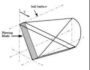
Figure 1. Disturbed Soil Volume
Figure 1 illustrates the basic idea of the
McKyes and Ali construct. It consists of a
triangular center volume bordered by conic
sections on either side (in figure 1 one side has
been omitted for clarity). From these sections we
can compute the forces on the blade by
computing the force factors from the separate
volume sections and summing the results. Figure
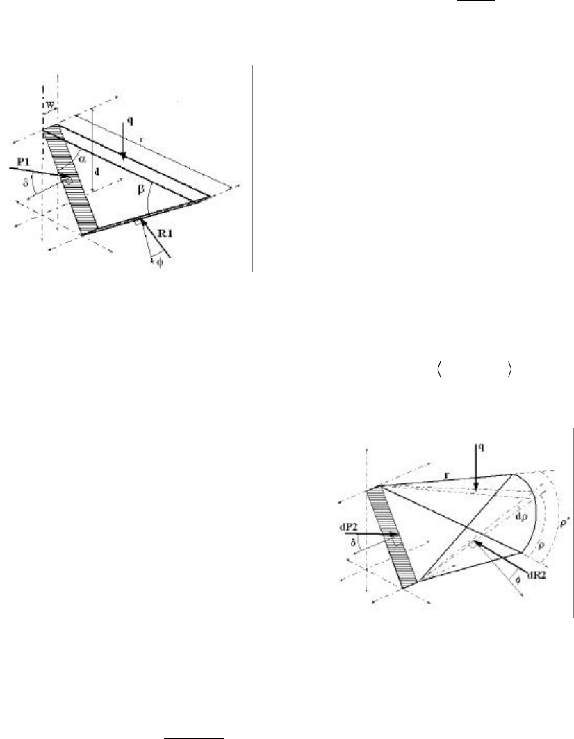
2 shows the model for the center section of the
disturbed soil volume.
Figure 2. Model for Center Volume
The force generated on the plow blade
from this section is derived from a force balance
equation. The variables and constants involved
are listed below and all variables are in SI units.
w Width of Blade (m).
d Depth of Blade Penatration Into Soil (m).
P1 Magnitude of Force Blade Exerts On Soil (N).
R1 Magnitude of Force Exerted on Soil Shear Failure
Plane by Undisturbed Soil (N).
q Load on Surface (N /m
r Radius of Failure Zone At Surface (m).
Soil /Metal Interface Friction Angle (Rad).
Soil Internal Friction Angle (Rad).
Angle of Plow Blade From Horizontal (Rad).
Angle of Soil Shear Failure Plane (Rad).
c Cohesion of Soil (N /m
Bulk Density of Soil (N /m).
+
2
2
3
≡
≡
≡
≡
≡
≡
≡
≡
≡
≡
≡
≡
=+=
).
).
δ
α
β
φ
γ
θαδθβφ1 2
The forces are resolved into their horizontal and
vertical components in the force balance
equations and then combined to solve for the
force P1 that the blade is exerting on the soil
volume. The horizontal force balance equation
may be written
P1 sin( ) - R1 sin( ) = c d w cos
sin
θ θ
β
β
1 2
Equation 1.
where the right hand side of the equation
represents force from the cohesion of the soil.
Similarly, the vertical forces can be represented
by the equation
P1 cos + R1 cos = d r w
2 c w d + q r wθ θ
γ
1 2 +
Equation 2.
where the right hand terms, read from left to
right, represent forces from the density of the
soil, cohesion of the soil, and surcharge load on
the surface of the soil. Now, solving for R1 in
terms of P1 in equation 1 and substituting the
result into equation 2 we finally solve for P1and
find
[
]
[
]
P1 = w 0.5 d r + c d 1 + cot cot + q r
cos + sin cot
γβθ
θ θ θ
2
1 1 2
Equation 3.
which is the solution to the magnitude of the
component of force the plowing blade must be
exerting on the displaced soil volume to balance
the forces on the center section. This force
magnitude is the resolved into its horizontal and
vertical components,
11 cos,sin P1 =θθ
P1
F
Equation 4.
resulting in a two dimensional force vector.
Figure 3. Model For Side Volume
Figure 3 shows the model used to
compute forces on the plowing blade from a side
wedge. The analysis is based on integrating
forces from differential volume elements dρ over
the total angle ρ’ subtended by the section.
Pausing then to properly define the new
variables,
d Differential volume element (m
Angular displacement of d (Rad).
' Total angle subtended by section (Rad).
3
ρ
ρ ρ
ρ
≡
≡
≡
).
we approach the problem as before, computing
the force balance equation for each differential
element. First, the force balance in the horizontal
direction
dP2 sin - dR2 sin = c r d d cos
2 sin
1 2
θ θ
ρ
β
β
Equation 5.
where the term on the right hand side of the
equation is the force arising due to the cohesion
of the soil. The vertical forces sum as follows
dP2 cos + dR2 cos = 1
6 d r d + c d r d
2 + 1
2 q r d
1 2
2 2
θ θ γρ
ρ
ρ
Equation 6.
where the right hand terms, from left to right, are
forces due to the soil’s bulk density, its cohesion,
and surcharge load on the surface. Proceeding as
before we solve for dR2 in terms of dP2 in
equation 5 to eliminate the dR2 term, and
substitute the result into equation 6 in place of
dR2. Solving for dP2 we find
[
]
[
]
dP2 = d r + c r d 1 + cot cot + q r d
cos + sin cot
1
62 1
221
22
1 1 2
γβθρ
θ θ θ
Equation 7.
as the solution to the magnitude of the force that
the blade is exerting on the differential soil
volume dρ. This resolves into the horizontal and
vertical components shown in equation 8.
dH = dP2 sin cos
dV = dP2 cos
P2 1
P2 1
θ ρ
θ.
Equation 8.
These force components are then
integrated over the total angle subtended by the
wedge ρ’ to compute the total force the plow
blade exerts on the side conic section of
disturbed soil.
[
]
[
]
[]
[]
V2H2, =
cot sin + cos
' cos r q + cot cot + 1 dr c + r d
= dV2 = V2
cot sin + cos
'sin sin r q + cot cot + 1 dr c + r d
= dH2 = H2
'
0211
1
2
2
1
2
2
1
2
6
1
'
0211
1
2
2
1
2
2
1
2
6
1
FP2
∫
∫
ρ
ρ
θθθ
ρθθβγ
θθθ
ρθθβγ
Equation 9.
We now have a solution to the problem
of computing force on the blade of a plow as it
moves through soil of a given bulk density and
cohesion with a given internal friction angle. The
force on the plow then is the vector sum in
equation 10 where FP2 is doubled to account for
the second conic section of soil.
)F*2 + (F - = P2P1
F.
Equation 10.
Implementation
In the implementation of the soil
simulator values were taken from a source text
on soil mechanics [Liu p. 411] to match the
properties of cohesion c, bulk density γ, and
angle of internal friction φ for various sandy
soils. The soil types that the PHANToM and
dynamic model are suited to mimicking are
limited to loosely packed, medium-to-fine
grained sands, silts, and dry clays. High cohesion
factors require forces too large for the
PHANToM to render and large grain sizes,
relative to the plow-bladed size, break down the
validity of the model.
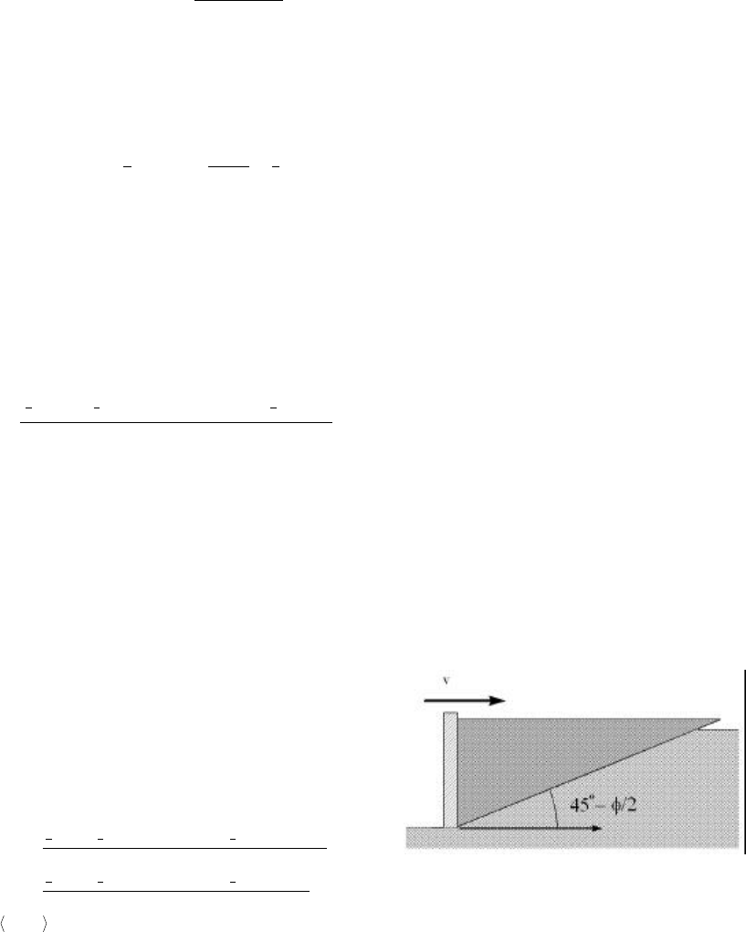
In a departure from the McKyes model
a failure plane angle β is chosen based upon the
Rankine theory for passive lateral earth pressures
[Liu p.401]. The McKyes and Ali plowing
theory model selects a failure plane angle β that
minimizes the horizontal force term arising from
the soil density [McKyes p.48]. This
minimization process is too costly in terms of
processing time for a control loop and so this
simplification was made. The Rankine model
provides a method for computing forces on earth
bearing walls that are moving relative to the soil.
Figure 4. Rankine Model Failure Plane Angle
Figure 4 shows the predicted failure
plane angle as an earth retaining wall moves
toward the soil mass.
In order to give the simulation a more
realistic feel the friction angle φ and the failure
plane angle β are perturbed with the Gaussian
random distribution algorithm. As stated above
base values for these factors are taken from civil
engineering sources such as [Liu] and [Lambe]
and used as the mean values, while the standard
deviation values used are found through trial and
error to give the most natural feeling results.
The two-dimensional force vectors
calculated above are then applied in the
instantaneous direction of motion. This is
approximated by first finding the vector
difference between the current and last positions
of the end-effector in virtual space. The
projection of this vector into the horizontal plane
is then normalized to get a unit vector in the
current direction of motion in the horizontal
plane. Force output to the haptic device can then
be applied in the calculated direction.
Results
The soil simulation results are
encouraging. A reasonably convincing
simulation of probe/soil interaction is created
using the methods described. The soil parameters
of density, and internal friction angle may be
varied to achieve palpably different feeling soils.
Cohesion needs to be very large (hundereds to
thousands of Kilo-Pascals) to achieve perceptible
changes in the soil behavior and was left at or
near zero for most simulations. The validity of
this choice is supported in the soil mechanics
literature [Liu pp. 235-242] which contains
statements to the effect that dry sandy soils are
virtually cohesionless. Cohesion becomes a
dominant factor when examining the shear
strength of clay based soils.
The plow blade dimensions were also
changed to observe the effect on the simulated
soil interaction and the results were as would be
intuitively expected. Specifying a wider blade in
the model causes more resistance to movement
while a narrow blade achieves the opposite
effect. Experiments were conducted to observe
the effect of velocity on the impedance
experienced by a real plow blade moving
through real sand to verify the validity of the
model’s velocity independence. Impedance was
found to be independent of the angular velocity
of the PHANToM for a set of velocities within a
range of values tested from 0.25 to 1.5 Rad/sec.
A more detailed discussion of these experiments
appears in [Green Chpt 4.].
Bibliography
1.) Green, Donald F. “Haptic Simulation of
Naturally Occurring Textures and Soil
Properties” SM Thesis, Department of
Mechanical Engineering, Massachusetts Institute
of Technology, May 1998.
2.) Lambe, T.W; Whitman, R.V. “Soil
Mechanics” New York, John Wiley & Sons, Inc.
1969.
3.) Liu, C., Evett, J. B. Soils and Foundations,
4th ed., Prentice-Hall, Inc., Upper Saddle River,
N.J., 1998.
4.) McKyes, E., Ali, O.S. “The Cutting of Soil
by Narrow Blades” Journal of Terramechanics.
V. 14, No. 2, pps. 43-58, 1977.
5.) Moore, H.J., Clow, G.D., Hutton, R.E. “A
Summary of Viking Sample-Trench Analyses for
Angles of Internal Friction and Cohesions.”
Journal of Geophysical Research, Vol. 87, No.
B12, pp. 10043-10050. Nov. 30, 1982.
6.) The Rover Team. “The Pathfinder
Microrover” Journal of Geophysical Research, v.
102, No E2, pp. 3989-4001. Feb. 1997.
"Nearest Neighbor" Approach to Haptic Collision Detection
Rob Shaw
Interval Research Corporation
shaw@interval.com
Some form of collision detection is usually central to any haptic simulation. Typically, a user moves
some device though physical space, and motors are turned on appropriately to give the sensation of
contact with some virtual object. So the "collision detection" required is between a physical probe and
a presumed virtual object. The situation seems simpler in haptics than in computer graphics, in the
former we need only consider possible collisions between a single probe point and the virtual
environment, whereas in the latter one often considers possible collisions between many differently
shaped objects. Diego Ruspini [1] has used a "bubble tree" approach to haptic collision detection, one
searches down a pre-constructed tree of finer and finer resolutions to check for collisions of the
probe point with the virtual object. This method in fact works just fine, but one might criticize the
fact that one throws away the position of the probe at each time step, and has to begin the tree search
anew. In fact, the probe point moves smoothly and, usually, slowly, on the computer’s time scale. One
should be able to use the information of the prior probe position to speed up the search. A method
which will clearly work for convex objects is suggested by the figure below:
Fig. 1
One imagines a point charge free to run around on the surface which is attracted towards the probe
point. For a convex shape, the moving surface charge will strive to be as close as possible to the
probe point, and is guaranteed to be directly under the probe point if it should hit the surface. So,
to do collision detection, one need only compute the distance between the probe point and the cruising
surface point, and turn on the motors when this distance becomes zero. This is pretty obvious, and in
fact is a simple case of the "Lin-Canny" algorithm for performing collision detection between any
number of convex objects[2].
Surfaces are represented in the computer by vertices and edges, typically forming a net of triangles,
so the strategy of the haptic nearest-neighbor collision detection would be to find the three vertices
closest to the probe point, and check for collision with the triangle so formed. Finding the vertex
nearest the probe point is easy, if one has an idea of where it was at an earlier time step. In advance
one constructs a look-up table of the neighbors of each vertex, and at each time step one computes the
distance of each neighbor of the old surfaceposition to the probe position, and hops the new surface
position to whichever neighbor vertex is now closest. Because only a table lookup is required, and a
sum of three squares computed for relative distances, this process is extremely fast. In fact basically
this idea was presented by Chih-Hao Ho, at the recent Phantom user’s group meeting, for the case when a
probe is kept in contact with a virtual object[3]. This is not collision detection per se, but the same
sort of nearest-neighbor data structures were used to quickly keep track of the probe position as it
slides along the surface.
The fly in the ointment for haptic collision detection is, what about the case of non-convex objects?
One can readily imagine an object with hills and valleys, which could trap the moving surface point in a
local minimum, so that it would not actually be at the closest point on the surface to the probe point.
The Lin-Canny algorithm in fact fails for non-convex objects.
The purpose of this note is to point out the surprising fact that this nearest-neighbor attraction
algorithm for collision detection between a closed surface and a probe point will still work for a rather
wide class of concave shapes. Further, that whether or not this algorithm will work can be the basis
for an interesting and perhaps novel geometrical classification of solid shapes. So let’s present the
following
Theorem:
A point constrained to a smooth closed surface, which moves to be as close as possible to an
external probe point, will always be directly under the probe point should it touch the surface, no
matter what the path of the probe point,
if
A: No normal to the smooth closed surface re-intersects the surface, and
B: Certain special initial positions of the surface point are avoided.
A few diagrams of the two-dimensional case will illustrate the ideas, and indicate a sketch
of a proof.
2a 2b
In figure 2a above the surface point is trapped in a local distance minimum which is clearly not the
global minimum distance from the probe point to the surface. But note what happens when the probe
point approaches the surface. (Fig 2b) If the concavity is shallow enough, the local distance minimum
will disappear, and the surface point will slide under the probe point. The condition for a "shallow
enough" concavity is exactly that no normal re-intersects the curve, see fig. 3 below. Note that this
condition requires a pretty extreme concavity, if a normal re-intersects, the surface point can be
pulled in the direction of the arrow in the figure, away from the probe point, as measured along the
surface.
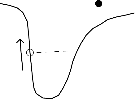
Fig. 3
A careful proof requires technique beyond that which the writer possesses, the writer hopes that a
mathematician might find these arguments interesting enough to clarify. But informally, the proof of
the theorem seems almost self-evident. If the external probe touches the object without the surface
point being present, the moving point must be hung up on some lobe of the object, at a local gradient
minimum, as in Fig.3. By definition, the ray from the surface point to the probe must be normal to the
surface. Thus, for nearest-neighbor to fail, normal re-intersection is necessary.
The initial condition caveat is required for the situation when the surface point is trapped in a dimple
behind the object, and the probe is in front of the object, the surface point won’t be there to meet the probe
point when it touches the front surface. But note that this configuration is unstable, once the surface
point is on the front surface, the special initial configuration cannot be re-established, no matter
what the path of the probe point. Again, an informal proof is not too difficult, we have to consider
appearance and disappearance of basins of attraction as the probe point is moved around the surface.
We have to show that a) a basin never appears directly under the surface point, and b) the surface
point never crosses a basin boundary. I think both of these are clear, a) is true because basins can only
appear "over the horizon" if the normal condition is obeyed, and b) is true by definition of basin
boundary.
The above arguments work for closed surfaces in three dimensions, except that the no re-intersecting
normals condition is sufficient but not necessary for freely sliding surface points. An example is a
simple donut, which certainly has re-intersecting normals, but no trapping regions. Note that the
surface areas with re-intersecting normals are negative curvature saddles, the surface point, while
trapped in one surface direction, can slide toward the probe point along the other direction. The complete
necessary condition is the following. For "bumps", i.e. two positive radii of curvature, no
re-intersecting normals is a necessary condition. A normal emanating from a "dimple", with two
negative radii of curvature, must not re-intersect within a distance equal to the smaller of the two
radii in absolute value. For the saddle case, the surface point will slide away from the normal for a
distance out along the normal greater than the absolute value of the negative radius of curvature.
Comments:
The presumed attraction between the probe and the surface point can be thought of as a gradient field
centered on the probe, the projection of this gradient onto the surface produces a vector field on the
surface, which the surface point follows as it strives to be as close as possible to the probe. This sort
of construction falls under the purview of "Morse theory". A clear exposition of Morse theory, in fact
the only exposition which the writer with his limited background found accessible, is contained in
David J. Kreigman’s work entitled "Let them fall where they may" [4]. In this work Kreigman considers
the "capture regions" which lead to one or another of the "stable poses" of a solid shape on a smooth flat
table. This problem has a two-dimensional configuration space, corresponding to the two-dimensional
set of possible orientations of the solid shape. As far as I can see, the topological possibilities
Kriegman considers are identical to those encountered in my problem in the case where the probe point
is infinitely far away, this also posseses a two-dimensional parameter space. The full problem has a
three-dimensional parameter space, as the center of force can approach the solid object. The basins of
attraction of various "capture regions" can merge and/or disappear, I may or may not be the person
to carry out this analysis.
Even in the absence of practical application, the normal-reintersection criterion supplies an interesting
geometrical classification of smooth solid shapes into "convex", "concave", and "very concave". But for
the polygonal models of a computer representation, we have to find the appropriate discrete versions of
concepts such as "normal" and radius of curvature which are defined on smooth surfaces. This so far is
incomplete, but the writer believes it is possible, and is trying to prove the following conjecture.
Nearest-neighbor attraction collision detection will work for an arbitrary polygonal mesh, if one allows
at most one non-local entry in the lookup table of each vertex. Maybe typically only a few isolated
"bridges" are needed, to slide the surface point out of a region where it has become stuck. Can a scheme
like this be used to extend the Lin-Canny algorithm?
I would like to thank Gavin Miller, Norman Packard, and Bill Verplank for helpful discussions.
[1] Diego Ruspini, "Adding Motion to Constraint Bsed Haptic Rendering Systems: Issues & Solutions",
Proceedings, Second PHANToM Users Group Workshop, December, 1997
[2] M. Lin and J. Canny, "A Fast Algorithm for Incremental Distance Calculation",
http://http.cs.berkeley.edu/~jfc/papers/mlin/report.ps
[3] Chih-Hao Ho, Cagatay Basdogan, and Mandayam A. Srinivasan, "Haptic Rendering: Point- and
Ray-Based Interactions", Proceedings, Second PHANToM Users Group Workshop, December, 1997
[4] David Kriegman, "LetThem Fall Where They May: Capture Regions of Curved Objects and
Polyhedra", Yale Center for Systems Science Technical Report 9508, 1995
http://giskard.eng.yale.edu/vision/papers/publications.html
- 1 -
Adding Haptic Device to
Virtual Reality Based User Interface Systems
Masahiro Nakamura
Cyber Media Laboratory
LEXER RESEARCH inc.
nack@lexer.co.jp
Katsunori Inoue
Joining and Welding Research Insitute
Osaka University
inoue@jwri.osaka-u.ac.jp
Abstract
Ability of haptics technology will be realized and spread with its connection to other technology like a visual
simulation or network system.
LEXER RESEARCH is a Japanese company that provides a software tool 'aWORLD' that has GUI for virtual
reality system for industry, education, creation or network communication.
At this time, LEXER RESEARCH has developed the aWORLD family software 'aWORLD-HAPTICS' to connect
aWORLD to PHANToM device. Using this system, CAD data is ready-to-use with the PHANToM device. aWORLD-
HAPTICS will make it possible to not only touch objects as well as watch objects, but also deform object with
elastic mathematical deformation model.
This system can make PHANToM a general device in VR user interface, and can apply haptics technology to
many fields.
Introduction
One of a purpose of this work is to investigate the haptic device activity with connection to multi-purpose visual
system. Another is to investigate the optimized system architecture to connect Haptics device to 3D visualize
system. Human recognition toward scene is consisted of multi modal concerned with human sensation. And virtual
reality technology can be utilized as cyber space interface system. Regarding virtual reality system as user interface
system, it is important that haptics sense and interaction will be supported. Haptics device will provide the
impressionable reality in virtual reality scene, but there are few virtual reality systems provide such a function. On
the other hand, although application fields of haptics technology will be going to spread, there are few tools to
integrate the application system with haptic device.
In order to develop more effective and convenient environment of virtual reality, it is one of the way that haptics
device will be added to multi-purpose visual virtual reality system. In this work, we adopted PHANToM to visual
virtual reality system ‘aWORLD’ that has the distributed network system architecture and can indicate the ability of
haptic device.
- 2 -
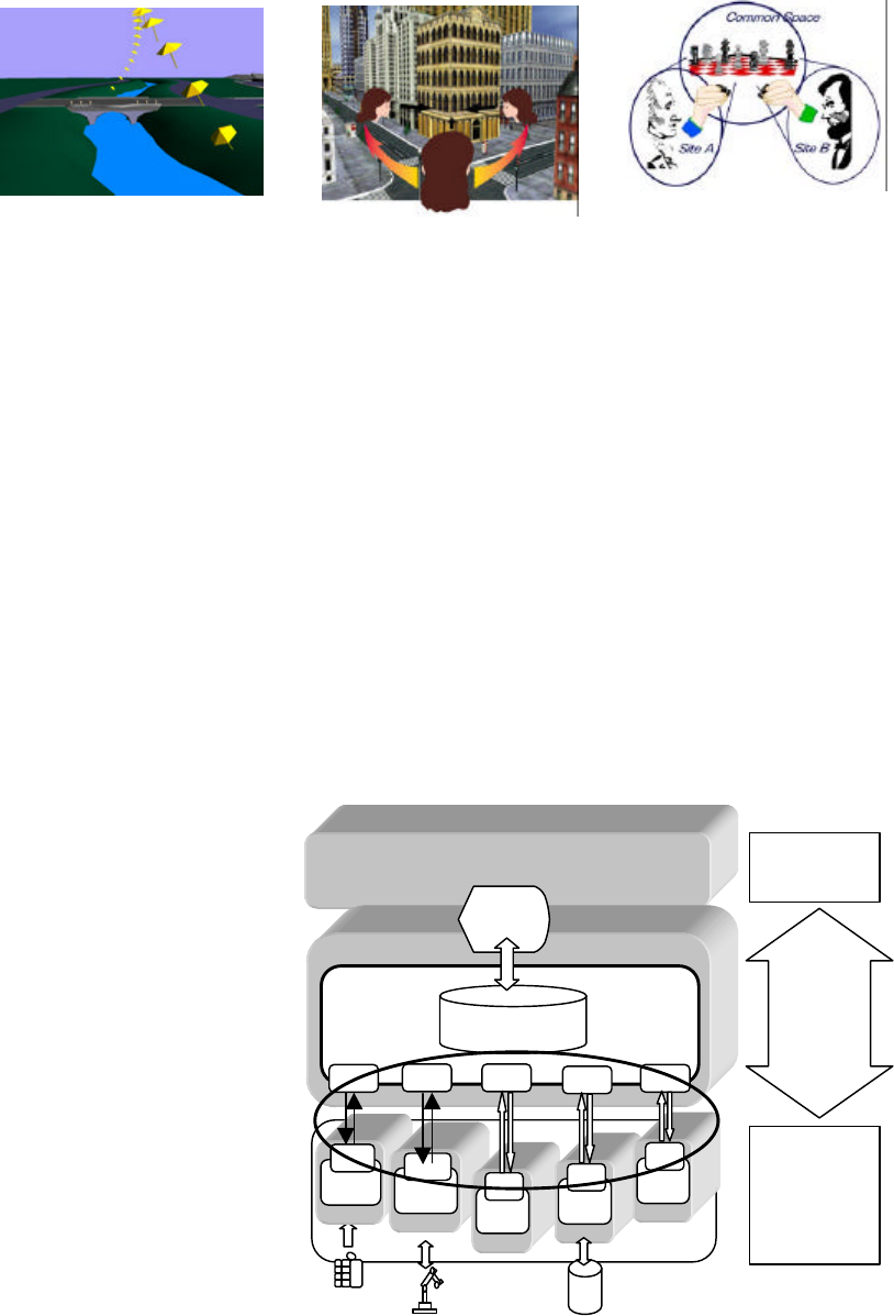
Figure 1 deTach&atTach Figure 2 Rasso View Figure3 Common Space
Vitural Reality system ‘aWORLD’
LEXER RESEARCH has been investigating scene recognition and human interface technology for information
system. Among these investigations, LEXER RESEARCH has developed the virtual reality system ‘aWORLD’ that
has GUI, scene data interface and functions for virtual reality system for industry, engineering, education, creation
or communication.
This system has many useful scene authoring functions as user-interface function such like a ‘deTach&atTach’
that works as 3D-drag&drop with mouse(Figure 1), or ‘Rasso’ view that makes a user view move around,
approach, ascend or descend with mouse dragging toward a 3D-point that is pointed and focused by mouse.
(Figure 2)
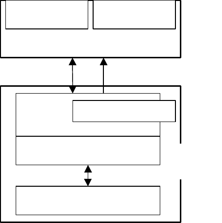
On the other hand, aWORLD has the excellent system architecture that is able to make the network distributed
system for adoptive system function or system devices or user applications. (Figure 4) This system is consisted on
aWNC(aWORLD Network Connection) that can be connect a graphics rendering subsystem to other subsystem
with several methods. Through
this architecture, aWORLD can
be defined as a sensible
interface system between user
and intelligent systems. We call
this idea, VRUI(=Virtual
Reality User Interface) as user
interface concept with virtual
reality technology.
Additionally saying, utilizing
aWORLD Network server,
aWORLD will be extended to
multi-user system to integrate
common 3D space for
collaborative creation (Figure 3)
In this project this flexible
system architecture is applied in
order to integrate haptics
device.
SceneDatabase
D
W
D
User
Display
API
Intelligent
System
A
vi
API API API API
W
Sensor
API
W
Ctrl
API
W
API
W
DB
MS
API
W
API
Dynamic
s
Aplicatn
aWCC
aWCC aWMC aWMC aWMC
aWORLD
VRUI
User
Figure 4 aWORLD Network Connection System
aWNC
- 3 -
Connection between PHANToM to visualize subsystem
In this project, we used GHOST haptic module
as haptic rendering engine. Both visual and haptic
rendering process will take much cost for computer
performance. It is one of way with regard to this
problem to separate visual rendering process and
hapic rendering process in multi processing
environment. In order to do this implementation,
aWORLD network connection system (aWNC)
that makes the connection between graphics
rendering system and haptics rendering system is
adoped. aWNC provides two methods for
connection between subsystems, one is to transfer
channel values to another subsystem each
other,(aWCC: aWORLD Channel Connection)
another is to transfer messages to control another
subsystem each other.(aWMC: aWORLD Message
Connection) (Figure 5) This connection system
works on UNIX, Windows95 and WindowsNT
platform in Eathernet environment. aWCC prepares
virtual channel that automatically transfer value
data and keep consistency between subsystems on UDP/IP protocol. On the other hand, aWMC prepares many
messages to control another system and callbacks to be controlled by other system on TCP/IP protocol. With aWNC
network API which aWORLD provides, application can be built without consciousness toward network system.
In this project, visualize rendering system runs on SGI/UNIX and haptics rendering system runs on WindowsNT,
because of each system having proper performance for each purpose, visualize rendering and haptics rendering. Our
approach increases visual rendering rate and haptics servo rate and that makes system stability higher.
To connect subsystems each other this project developed the communication system with channel connection
(aWCC) as visual pointer control corresponding to PHANToM haptics pointer and message connection (aWMC) as
scene databases bi-way control that makes haptics database update from visual database update and visual database
update from haptics database. Utilizing this connection system, visualize system scene control functions, for
example, object data loader, object move control or material change control (include haptics material) will be
automatically applied to haptics system and haptics system scene update will be automatically applied to visual
system. We named this system ‘aWORLD HAPTICS’ for visual-haptics virtual reality system. Thus, in this project
with aWNC, total system consistency is built with keeping system flexibility.
Besides, there is a limit of quantity for haptic database ability. To solve this problem, this system provides
selectable data loading system to control the load of haptics rendering system. In case of material name having
haptics parameter, graphics scene database transfer object data to haptics scene database. Therefore, only setting
material name having haptics parameter to several objects that user needs to touch, haptics rendering load will be
reduced, while all the objects will graphically displayed.
aWORLD
GHOST
PHANToM
Visualizer User Interface
aWMC aWCC
aWORLD
HAPTICS
Figure 5 System Architecture
Haptic
manager Elastics dynamics generator
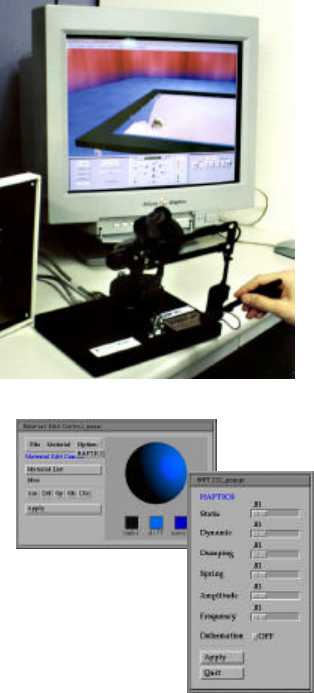
- 4 -
Elastic model implementation
To be useful in haptics applications, not only touching effect but also object deformation will be effective. And
ability of scene manipulation will be useful too. In order to implement these functions, we append elastic module
and manipulation module to ‘aWORLD HAPTICS’. These modules is set in front end of ‘aWORLD HAPTICS’
module to visual rendering subsystem. (Figure 5)
In this work, dynamic elastic deformation function was implemented. For elastic deformation, propagation
method spreading from touching point with PHANToM was applied. Data model for the propagation process is
quoted from visual model in order to sustain user’s controllability for deformation. It’s depend on the idea that
optimization will be controlled by user in unknown system performance environment. In the generation of
propagation model, a connectivity between vertexes that constitutes
object polygons is needed to preserve. Therefore, the connectivity of
vertexes in the object is generated simultaneously with getting data
from visual rendering scene database.
Example
To demonstrate the use of this system, some demonstration has been
made for aWORLD HAPTICS.
In this work, we tried to build a trampoline demonstration that has
elastic face and hard frame. (Figure 7) With 3D CAD system, we had
made frame objects and rubber face objects that have triangle mesh
structure to deform like realistic pushing rubber face. If each frame is
defined with a material name having haptics parameter, a haptic
trampoline scene will be build only reading trampoline data file from
aWORLD system menu. If user needs to change haptics material,
haptics material parameter will be changed with GUI of aWORLD.
(Figure 8)
Conclusions
In this work, total system consistency in multi-processing
environment for visual and haptics rendering processes is built with
keeping system flexibility via aWNC provided with aWORLD. Thus,
according to the connection of haptic device to standard virtual reality
system, 3D haptic interfacing device will be a general device in VR
user interface, and can be easily applied to many fields.
References
[1] LEXER RESEARCH, Inc. Japan, Product Definition aWORLD. “aWNC Reference”, Ver. 1.2, 1998
[2]SensAble Technologies. “GHOST Software Developer’s Toolkit, API Reference”, Version 1.1, 1997
[3]Masahiro Nakamura, “Virtual Reality, or epistemological space”, Image Laboratory 1992/2 vol.3 no.2
Figure 7 Trampoline model
Figure 8
GUI for material

ABSTRACT
This paper describes the development of a 5 active
degree of freedom haptic interface intended for
arthroscopic surgery simulation. Arthroscopic
surgery is an increasingly common surgery for
which more advanced training methods would prove
very useful. The interface, a 2 DOF planar device
which supplements a 3 degree of freedom device, can
apply general forces and moments in all directions,
except moments about the tool handle axis.
I. INTRODUCTION
Arthroscopic knee surgery, and arthroscopic and
laporascopic procedures in general, is becoming more
popular due to the effectiveness of the procedure
combined with its minimization of scarring, trauma,
and operating room and recovery time. The procedures
are performed with the use of long slender tools,
inserted into the body through small incisions in the
skin and underlying membranes. Small camera lenses
are inserted through other, nearby, incisions to provide
visual access to the site of the operation. Because only
small incisions are made, trauma to the patient is
reduced when compared to conventional, open surgery.
This reduction in trauma subsequently leads to reduced
recovery time, allowing the patient to return to normal
activity much sooner. Due to the increase in popularity
of these procedures, a large number of physicians
require training. Currently, training is done in one of
three ways: on a plastic model, either with or without
fluid; on a cadaver; or, on a patient. A virtual reality
training simulator could be more realistic than the first
two methods, while maintaining a higher level of
patient safety than the last method mentioned.
Through conversations with surgeons and use of the
current state of the art in haptic devices, it was clear that
for this application, point forces would not be sufficient.
During arthroscopic procedures, the shaft of the tool
that the surgeon is holding passes through a portal into
the patients knee, thereby limiting the motion of the
device. Additionally, while an experienced surgeon
might not feel any large moments on the tool during
surgery, a new surgical resident will require a learning
period to adjust to the constraints of the surgical setup.
During this period, the resident will be more likely to
unintentionally hit structures with the shaft of the tool
he is holding, generating moments when measured
about the tip of the tool. There are three main
contributors to moments acting on the tool: the fibrous
membrane that the tool shaft passes through and levers
against; inadvertent contact between the shaft of the
tool and structures inside the knee; and, when exploring
the back compartment of the knee, pressure from the
collateral ligaments.
Because these moments are very important when
learning these procedures, a device that can display
moments is required. Instead of designing and building
a completely new device, an addition to the Phantom
haptic interface was deemed most tenable, in terms of
both cost and performance. A completely new device
would take much longer to design and build, and given
the constraints of the task domain, breaking the problem
down into two parts provided simplicity: one part, the
Phantom, generated the majority of the force to display
to the user; the second part, the new device, generated a
planar force at a point along the shaft of the tool,
thereby generating a moment measured about the tip of
the tool. The 2 DOF device is a planar device with a 4
DOF gimbal attached at the distal end. The gimbal
allows free motion of the tool shaft around all rotational
axes and along the axis of rotation of the shaft. It
constrains the shaft of the tool to pass through a point
on a plane. An analogy would be to view the world as a
hollow cube, with the shaft of the tool constrained to
pass through a point in the center of one side of the box.
The tip of the tool is connected to a Phantom to measure
position and apply point forces. The 2DOF device is
then placed on the side of the box, and the shaft of the
tool passes through the gimbal. Motion of the 2DOF
device will apply moments to the shaft of the tool that
will be felt by the user. In this manner, two force vectors
acting on the shaft of the tool at distinct points, a force
and moment are generated.
II. DEVICE DESCRIPTION
The 5 DOF consists of a 2 DOF planar device and a
3 DOF device, the Phantom. The shaft of the tool handle
connected to the Phantom passes through the 4 DOF
gimbal of the planar device. In this manner, the planar
device can only apply forces in the plane to the shaft of
the tool. When this planar force is combined with the
general point force applied to the tip of the tool handle
by the Phantom, a force and moment are generated.
5 DOF Force Feedback Using the
3 DOF Phantom and a 2 DOF Device
Andrew B. Mor
Robotics Institute, Carnegie Mellon University, Pittsburgh, PA
abm@ri.cmu.edu
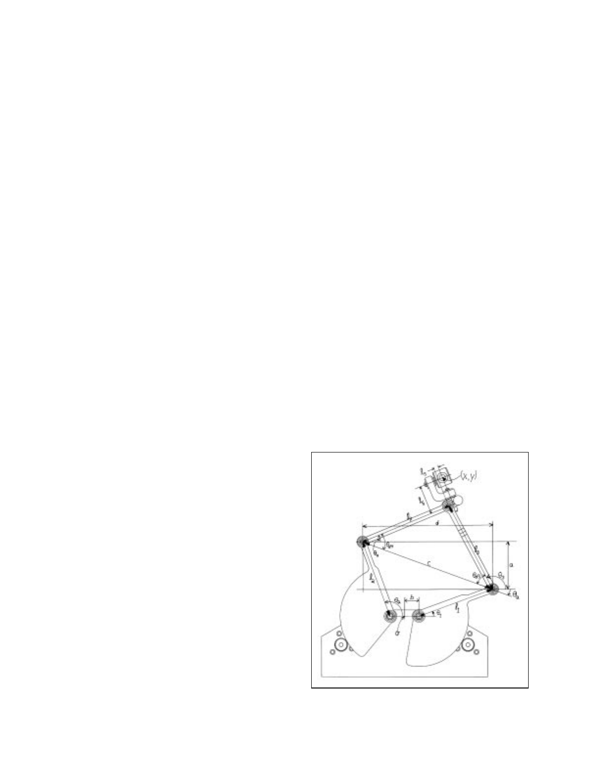
The 2 DOF planar device is a classic five bar
mechanism. The two inner links are the same length, as
are the two outer links, although the inner link lengths
and the outer link lengths are different. This symmetry
provides for a more well conditioned and symmetric
workspace. Link lengths were generated using data
from [1], to provide a workspace of sufficient size based
on design criteria described in the next section. Hard
stops are provided to limit the inner links motion, and to
allow for accurate zeroing of the motors at a known
angle. A stop is also built into the outer links to keep the
device from going through its singularity, when the
angle between the outer links is 180 degrees.
The 4 DOF gimbal attached to the distal end of one
of the outer links is designed to allow free motion of all
uncontrolled degrees of freedom of the device, i.e. all
motion out of the plane of the device. In that manner,
the gimbal allows free rotation about all axes and
translation along the tool’s long axis. Two of the
rotational degrees of freedom utilize simple rotational
bearings, while the third rotational degree and the
translation degree of freedom are enabled by a plane
linear bearing, which allows both free translation and
rotation.
The inner links are driven by Maxon servo motors
through a tensioned cable drive. Direct drive motors
were investigated, due to increases in performance
through decreased static friction and inertia, but
sufficient position resolution was not found to be
possible. Motor choice was based on similarity to the
Phantom motors, so that standard Sensable
Technologies, Inc. amplifiers could be used.
III. GENERAL DESIGN CRITERIA
Video tape of arthroscopic knee surgery was acquired
to help determine workspace requirements. The video
was analyzed to find out how much motion of the tool
portal occurs during typical procedures. Angular
excursions of the probe were also ascertained. The
motion of the portal roughly describes a circular disk
with a diameter of approximately 1”, dependant on the
patient. The angular excursion of the tool, with respect
to the normal direction at the portal location, describes
a cone with a 120 degree included angle, again,
dependant on the patient.
Gear ratio is determined by the desired nominal
position resolution, given 500 count encoders that are
standard on Maxon motors. Nominal position has both
inner links at 45 degrees from horizontal.
Interference between the device and the user’s hand
is also an issue. The motors of the device protrude in the
direction normal to the motion of the device. With the
motors pointing into the workspace, interference with
the Phantom is possible. Preferable to this is to have the
motors sticking out of the workspace, with possible
interference with the user’s hand. To minimize
interference, the motors were spread as far apart as
possible, to allow more clearance through the center of
the device. Direct drive motors would have caused the
most interference in this case, since their location can
not be modified. The motors were also moved back
from the plane created by the proximal ends of the inner
links, again to minimize interference.
IV. MATHEMATICS OF PLANAR DEVICE
The planar device is a closed chain device without
simple symmetry, unlike the Phantom. Therefore, the
forward kinematics and Jacobian calculations are more
difficult and computationally expensive. Position of the
endpoint based on motor angles is calculated through
the determination of the interior angles of the device.
Referring to Figure 1, b is the horizontal distance
between the proximal end of each of the two inner links
and the origin of the workspace, . is the length of
the ith link. is the angle of the ith link. and
are two of the interior angles of the triangle formed by
the two outer links and the line joining the distal ends of
the inner links. a is the vertical distance and d is the
horizontal distance between the distal ends of the inner
links, while c is the shortest distance between them and
is the angle between c and the horizontal, and has a
negative value in Figure 1.
Figure 1 Schematic of planar device
Ol
i
θiθd3θd4
θa

Then d,a, and c are determined through simple
geometry, and is the inverse tangent of a over c.
and are calculated using the law of cosines, and
then and are once again determined through
simple geometry. The position of the endpoint of the
five bar mechanism, (x,y), is then determined through
geometry, where is the distance between the distal
end of the outer links and the center of the gimbal along
the axis of link 4. is the distance between the distal
end of the outer links and the center of the gimbal
normal to the axis of link 4. The Jacobian J is calculated
in the usual manner to facilitate the determination of the
motor toques, , to apply to the actuators to achieve the
desired force . The equations described above are as
follows:
[1]
[2]
[3]
[4]
[5]
[6]
[7]
[8]
[9]
[10]
[11]
θaθd3
θd4
θ3θ4
l5
l6
τ
Fd
d2bl
1θ1
cos l2θ2
cos–+=
al
1θ1
sin l2θ2
sin–=
ca
2d2
+=
θaa
d
---atan=
θd3
l32c2l42
–+
2l3c
------------------------------acos=
θd4
l42c2l32
–+
2l4c
------------------------------acos=
θ3πθ
d3
–θa
+=
θ4θd4θa
+=
xbl
1θ1
cos l3θ3
cos
l5θ4
cos l6θ4π
2
---+
cos
+++
+
=
yl
1θ1
sin l3θ3
sin
l5θ4
sin l6θ4π
2
---+
sin
++
+
=
J
x∂
θ1
∂
---------x∂
θ2
∂
---------
y∂
θ1
∂
---------y∂
θ2
∂
---------
=
[12]
Referring to Figure 2, the way in which the forces at
the tip and at the point where the shaft passes through
the gimbal of the planar device are generated by the
following relations. is the total force to be felt by the
user, and is the moment to be felt by the user.
Given the values of and , and the vector
between the tip position of the tool and the linear
bearing of the five bar mechanism, the forces to
generate at the tip and through the collar can be
determined. Let represent the world coordinate
frame where all positions and forces are measured and
be the coordinate frame of the five bar mechanism
where is normal to the plane that the device moves
in. Then, is the position of the tip of the tool and
is the position of the five bar mechanism. is the
vector from the five bar mechanism position to the
position of the tip of the tool, while is the normalized
direction of . Similarly, is the normalized
direction of .
First, the minimum force vector which would
generate the moment , , is calculated at the five
bar mechanism position:
[13]
will normally not lie in the plane defined by the
five bar mechanism, but will always satisfy the moment
equation, . It is also always perpendicular
to the vector .
Next, the force is projected onto the plane of the
five bar mechanism, so that the force applied by the
device, , will also satisfy the equation .
This projection force, which is perpendicular to the
force, , is generated by:
τJTFd
=
FT
M
M FTS
w
d
Z
ˆd
P
w
p
P
w
dS
S
ˆ
S M
ˆ
M
M Fd'
Fd'M
ˆS
ˆ
×()
M
S
------
=
Fd'
MSF
d'×=
S
Fd'
FdMSF
d
×=
Fd'
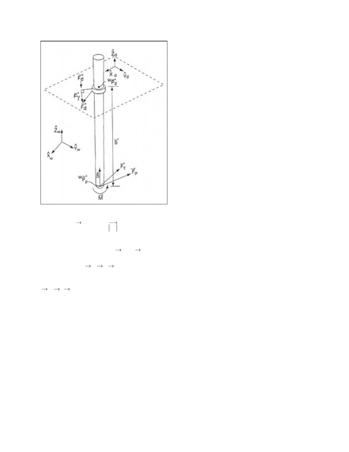
[14]
The force that will be generated by the five bar
mechanism is the vector sum of and :
[15]
The force applied to the tip of the tool is
, to maintain the total force displayed to
the user.
V. RESULTS
Given the workspace requirements outlined above,
and charts from [1], links lengths for the inner links,
outer links, and spacing between the inner links were
generated. The distance between the proximal ends of
the inner links is 0.875”, the inner link length is 2.375”,
and the outer link length is 2.813”. There is also an
offset along the outer link to where the gimbal is
attached, and that length is 0.150”, while the
perpendicular distance from the outer link to the center
of the gimbal is 0.854”. The diameter of the drum of the
inner links is 1.500” and the diameter of the cable
capstan is 0.360”, providing a gear ratio of 8.333. Given
the above gear ratio and link lengths, the nominal
Figure 2 Device force determination
Fγ
Z
ˆdFd'
ˆ
⋅
Z
ˆdS
ˆ
⋅
----------------Fd'–
S
ˆ
=
Fd'Fγ
FdFd'Fγ
+=
FpFTFd
–=
position resolution is 0.0007”, or 1450 dpi. These link
lengths generate a workspace with a diameter of 1.875”,
which allows the planar device to be placed away from
the surface of the simulated skin, allowing a phantom
skin model to be physically placed within the working
area of the devices to add to the realism for the user. The
skin model also allows users to visually position
themselves and the tool within the simulated world.
Two example applications have been implemented.
The first is a simple simulation of simple geometric
objects, in which the user can lever the tool between
multiple objects, thereby generating large moments on
the tool shaft. The other simulation is of the tip of a
surgical probe interacting with a volumetric description
of a knee, while the planar device servos on a point.
This simulation doesn’t explicitly generate and display
torques, but in the same manner as above, the two
distinct forces do generate a force and moment. The
planar device servoing on a point could also be viewed
as similar to the force generated by the fibrous
membrane surrounding the knee. Qualitative results
from the second application were mixed. These mixed
impressions are believed to be caused in part by most
user’s unfamiliarity with the physical setup of
arthroscopic surgery, where the tool passes through a
portal. Results from the first demonstration application
were very positive, showing the power of displaying
more than a point force when interacting with complex
environments.
VI. ACKNOWLEDGMENTS
The author would like to thank the Mitsubishi
Electric Research Laboratory for providing equipment
and resources necessary for this research.
The author would also like to thank Dr. Scott Martin
of Brigham and Women’s Hospital for his input on
procedures and his feedback on the feel of the
simulator, and Joseph Samosky and Michael Leventon
for help in videotaping surgery and analyzing
videotape.
REFERENCES
[1] Hayward, V., et al., “Design and Multi-Objective
Optimization of a Linkage for a Haptic Interface,”
Advances in Robot Kinematics and Computational
Geometry, Lenarcic, J. and Ravani, B., eds. 1994,
Kluwer Academic Publishers, Netherlands.

1
Tactile Max: A Haptic Interface for 3D Studio Max
Geoff Marcy, Bharti Temkin, Ph.D.,
Texas Tech University
Dept. of Computer Science, Lubbock, TX 79409,
(806-742-3527), temkin@coe.ttu.edu
Paul J. Gorman, MD, Thomas M. Krummel, MD,
Dept. of Surgery, Penn State Geisinger Health System
Introduction
The creation of realistic haptic objects and environments for use with simulation and
procedural training has, in the past been relagated to tedious OpenGL programming techniques.
This required programming in c++ with the GHOST SDK and/or OPEN GL. What was needed in
our opinion was a more rapid way to create a touchable virtual environment. Research indicated
that a PC/NT based full featured animation program like 3D Studio Max would be ideal for the
development of a plug-in that would allow the PHANToM to interact with objects created or
imported into the animation software. By using Max as the platform for development we can take
advantage of all of the modeling and animation tools as well as 3D models that already exist. This
allows extensive, complex data sets to be made haptic very rapidly.
3D Studio Max SDK
The 3D Studio MAX SDK provides a comprehensive set of classes that developers can
use to create plug-ins. The Tactile Max is a modifier-type plug-in and from user’s point of view it is
simply a button added to the Modify command panel for the 3D Studio MAX user interface.
Because MAX plug-ins are modeless, Tactile Max comes in and out of focus, as the system
requires processing on its part. The classes created by the plug-in provide procedures to be
called when needed.
The modifier plug-in type was chosen in particular because it allows modification of
objects in the 3D Studio MAX scene dynamically in any of the MAX viewports. This functionality is
necessary to make a mesh object haptic because the GHOST Polymesh class requires that the
topology of a mesh object consist of all triangles. So the object itself must be modified. Another
reason the modifier plug-in type was chosen is that it is a part of the Geometry Pipeline System.

2
The GHOST SDK
The GHOST SDK was used in the development of Tactile Max. GHOST stands for
General Haptics Open Software Toolkit. The GHOST API (application programming interface)
enables application developers to interact with PHANToM haptic device and create haptic
environments at the virtual object level. The GHOST SDK does not generate visual
representations of objects within the haptic scene graph, [1]. It does however provide graphic
callback mechanisms to facilitate integration between haptics and graphics domains. These
mechanisms were used to interface the PHANToM with 3D Studio Max.
Application Design
The application is composed of two primary processes. A client process (running inside
3D Studio MAX) and a Server process, running separately controlling the PHANToM haptic
device. This setup is desirable because it allows decoupling of the low-level force servo loop from
the high-level control. This is important since the haptic servo loop must run at a very high rate,
typically greater than 1000Hz, to achieve a high fidelity force display, [2]. Another reason for this
setup is that the GHOST SDK and the MAX SDK use conflicting naming conventions for their
data types. By separating the two processes and using a pipe in memory for inter-application
communication the problem is solved. Having the two processes separated means that the
application can run across a network on two different computers. The haptic server receives high
level commands from the client, tracks the position of the haptic device, updates the position of
the proxy, and sends control commands to the haptic device.
The client side of the application is the Tactile Max modifier that is placed on a 3D Studio
Max object. The client queries objects and converts objects (composed entirely of polygons) into
tri-objects. This is done to get the mesh in the right format for the GHOST SDK class
gstPolyMesh that is used to create the haptic representation of the object. GstPolyMesh is a class
that describes the haptic object as a set of triangles. After queries about the object’s topology the
client side of the application returns information on the number of vertices, the number of faces
(polygons), the XYZ position’s of the vertices, and an index of point adjacency for each face. The
server uses this information to instantiate a GHOST gstPolyMesh object.
At this point the server sends messages confirming the creation of an object and it is
added to the scene graph. XYZ coordinates are then passed and the client side of the software in
Max tracks the Phantom’s stylus tip. The following figure represents the software architecture of
the plug-in.
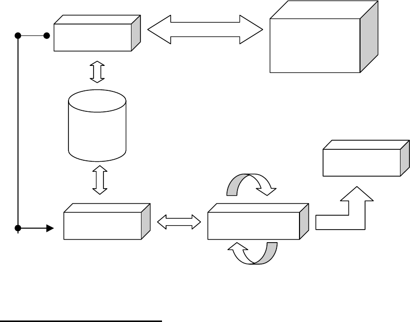
3
T_Client 3DS MAX
Viewport
Pipe
Phantom
T_Server Servo-Loop
Comments and Conclusions
The haptic interface will be useful for many types of applications that can be built on this
framework. These applications will have the ability to interact with the objects in more than one
way. For example in a hypothetical medical simulation a layer of skin could be removed to see an
underlying bone by clicking the stylus button and holding shift. The ability to dynamically change
the object and see it updated in a Max viewport will be useful in the event that this software is
extended to support the simulation of soft-bodied objects.
A 3D painting program could be created that would allow artists to interact with their
media palpably using the friction capabilities of the PHANToM. Modern 3d Painting programs do
not incorporate any direct feedback from the object being painted to the user. They allow you to
paint on an object in 3D but do not allow you to feel the object being painted. Adding a haptic
interface to the paradigm would extend the current technology. Being able to feel the object that
you are painting and simulate brushes and pencils would be an advantage to any 3D artist
involved in the creation of realistic 3D objects, creatures, and humans.

4
References
1. GHOST Software Developers Toolkit, Programmer’s Guide Version 1.2, October, 1997
SensAble Technologies, Inc.
2. Ruspini, D., Kolarov, K., and Khatib, O. “The Haptic Display of Complex Graphical
Environments”, Stanford University, Interval Research Corporation.
3. 3D Studio MAX Software Development Kit, Kinetix, a division of Autodesk.
Implementation Issues in Adding Force Feedback to the X
Desktop
Timothy Miller
Department of Computer Science
Box 1910
Brown University
Providence, RI 02912
tsm@cs.brown.edu
ABSTRACT
This paper describes implementation issues encountered
in a project to add force feedback to the X Window Sys-
tem desktop in an attempt to add true “feel” to the win-
dow system’s “look and feel”. Haptic additions to the
interface include adding ridges around icons and menu
items to aid interaction, alignment guides for moving
windows, and a number of other enhancements to win-
dow manipulation. The issues discussed here include
the precise descriptions of the forces computed, as well
as lower-level issues such as how to achieve those forces
with GHOST.
INTRODUCTION
Graphical user interfaces (GUIs) have long involved
haptics in what amounts to an accidental manner: the
feel of mouse buttons being pressed, the feel of keys
on the keyboard, and the friction and proprioception
involved in moving the mouse all give feedback that
comes entirely from the basic physical properties of the
input devices and does not change with the state of the
human-computer interaction. Although these forms of
accidental haptic feedback often correlate with the user’s
input and prove useful during interaction, in the con-
text of the virtual environment that GUIs seek to provide
they are still impoverished compared with the rich feed-
back of real-world interactions. Adding explicit pro-
gram control of haptic feedback can radically change an
interface, adding true “feel” to its “look and feel” and
potentially leveraging additional real-world skillsets.
This paper focuses on the implementation issues
encountered in the initial stages of a project to add
haptics to standard GUI elements of the X Window
System [Scheifler–92], using a 1.0-workspace PHAN-
ToM [Massie–96] with encoder gimbal.
PREVIOUS WORK
Rosenberg and Brave [Rosenberg–96a, Rosenberg–96b,
Rosenberg–97] have worked on enhancing 2D GUIs
with 2-DOF input/2-DOF output devices, while M¨unch
and Stangenberg [M¨unch–96] enhanced a 2D GUI
somewhat differently, using a modified mouse with vi-
brotactile and braking feedback to add predictive target
acquisition aids. Our system provides different DOFs
and manipulation affordances from the devices used
in these approaches, thus leading to different interface
choices.
Many of the demos that come with the PHANToM
and GHOST have 2D arrays of haptic buttons and slid-
ers arranged on a plane as part of their interface, as does
the FLIGHT system [Anderson–97]; each of these may
be regarded as effectively a 3D haptification of a very
simple 2D user interface, albeit with 3D-looking visual
feedback. Adding haptics to the existing X desktop is
further constrained by dealing with existing applications
and existing 2D visual feedback, leading to different in-
terface choices; in addition, different interface elements
were haptified in this project, involving different haptic
techniques.
XDESKTOP TECHNIQUES
We added force feedback to icons, windows, and menus
by adding dimples, ridges, negative viscosity, pressure
sensitivity,and buttonlikeclicks; see [Miller–98] for fur-
ther details about how these techniques were used. The
basic workspace for the haptification was a shallow box
whose longer two dimensions
corresponded to the screen and were hor-
izontal; the tip of the stylus was constrained to remain
inside the box. Nearly all the forces in the implemented
techniques occur throughinteraction with the surfaces of
the box, possibly with slight changes in their geometry
(ridges added along windows, for instance). The bottom
is the primary interaction surface; the sides merely pre-
vent the stylus from getting out of range; and the upper
surface has a mirror image of all the interaction features
of the lower surface and in addition one special interac-
tion for raising windows.
IMPLEMENTATION
Architecture and X Interface
The system was implemented on an SGI R10000 O2
using SensAble Technologies’ GHOST toolkit. The X
pointer was controlled through the fairly standard XIn-
put extension; an SGI addition allows new input devices
to be made available through that extension simply by
writing a loadable kernel STREAMS module rather than
having to recompile the X server. Communication from
the clients to the haptics server was done by setting X
properties on the client windows.
1
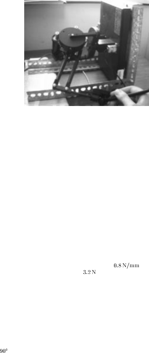
Because the PHANToM has only one button but typ-
ical X interaction requires three buttons, the haptics
server uses the XInput extension to open the mouse de-
vice and forward its middle and right button states as
though they were the PHANToM’s. Since many styli
made for use with tablets come with multiple buttons, it
is to be hoped that future PHANToMs will remedy this
deficiency by adding more buttons. The user’s interac-
tions while pushing down to slide windows and pulling
up to raise them were communicated by pretending that
the PHANToM XInput device had two extra buttons,
whose events were then intercepted by the window man-
ager.
Forwarding the normal mouse’s button states requires
the haptics server to get data back from the X server.
However, X allows a client to grab the server, halting all
transations with all other clients. Because certain inter-
face techniques wait for a button release before releas-
ing the grab, but the button waited for may be one of
the forwarded ones, the haptics process uses the XTEST
extension to make itself immune to X server grabs and
thus prevent deadlock.
The Generic Window Manager, gwm (avail-
able by anonymous ftp from ftp.x.org in
contrib/window_managers/gwm), was hap-
tified first because it is programmable in a form of
Lisp, thus not requiring recompiling to make interface
changes. As a result, its C-code modifications were
only slight, primarily to allow setting of X properties on
the window manager’s windows rather than just client
windows.
The haptics server implements its own message queue
for input received from X, via the main loop, to the hap-
tics thread. Since it seems better the haptics thread miss
a (relatively infrequent) update from X and thus reflect
incorrect state for one millisecond than to subject the
user to unexpected jerking or even have the program
exit because the haptics thread was waiting for the main
loop, a design goal for the synchronization of this queue
was that the haptics thread should never block. Instead,
if the queue lock is unavailable, the haptics thread sim-
ply continues simulation with possibly old data. How-
ever, once the haptics thread has registered an interest
in the lock, the main thread is prevented from reacquir-
ing it until the haptics thread has gotten its chance, thus
avoiding starvation. Since another project used a version
of this locking strategy on NT, code exists to implement
it on NT as well as Irix. On Irix it can be implemented
directly using the Irix polled semaphore facility, but on
NT the implementation is more complicated, involving
both a Mutex and an Event and relying on poorly docu-
mented behavior of the Event object.
Haptic Details
General Issues
Trying to use the stylus as a pen with
the PHANToM in its standard orientation (rotated
clockwise from Figure 1) makes the armature interfere
with the stylus and user’s hand, often resulting in unin-
tentional button clicks. To address this, the makeshift
mounting shown in Figure 1 was used. Unfortunately,
Figure 1: The 1.0-workspace PHANToM in its
tilted home.
the stylus encoders are not counterbalanced in this po-
sition, giving rise to a force attempting to twist the sty-
lus out of the user’s hand. Makeshift counterbalances
were attempted, but the most promising approach seems
to be to use the new desktop PHANToM, which lacks
the ungainly stylus encoders. The bottom of the hap-
tic workspace was moved as close as possible to the
physical desktop to encourage a stylus grip approximat-
ing that of a normal pen, and a handrest made of four
stacked mousepads was used to lift the user’s hand to
about the level of the virtual desktop. That virtual desk-
top is currently horizontal, although some tilt towards
the user might well be better.
Many of the force parameters in the implementation
were simply guessed at and not adjusted, because the
initial guess worked out well. For a few, however, a lit-
tle closer attention has been paid: friction is set to ap-
proximate that between pencil and paper while maxi-
mizing pointer movement controllability, with resulting
static and dynamic friction coefficients of 0.15. The ba-
sic surface spring constant was set to ,and
the user must exert at least downward to slide win-
dows; this is a compromise between larger values, which
produce discomfort and intermittent loss of the window,
and smaller values, which produce accidental window
movement.
GHOST’s implementation of friction appears to pre-
vent the reported SCP position from moving all the way
to an inner corner of an object. Apparently, the tangen-
tial force in GHOST is computed by comparing the stic-
tion point with the SCP reported by the object, rather
than the user’s position. (The algorithm used to im-
plement friction in GHOST is presumed to be similar
to that in [Salisbury–95] because their behaviors match
and because at least two of the authors are involved with
SensAble.) This means that when the user comes to a
concave-outward corner that “traps” the SCP, the stic-
tion point remains some distance away from the corner,
2
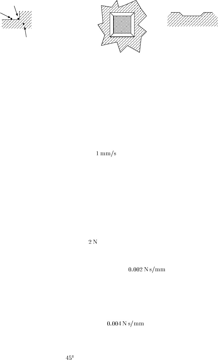
User Position
Object SCP
Stiction Point
(reported SCP)
Figure 2: GHOST’s implementation of friction can
prevent the SCP from moving all the way to the
edge of an object.
no matter how hard the user pushes (see Figure 2). Since
the stiction point appears to be what GHOST reports as
the SCP value to the user interface, the cursor cannot
be moved all the way to the edge of the screen in the
presence of friction. The difference is small in physical
terms, but very noticable on screen with the large mag-
nification from the haptic workspace to the application
screen size. It also gets worse as the user grows more
frustrated and thus presses the stylus down harder, in-
creasing the force of static friction.
To work around this problem, GHOST’s friction con-
stants are set to zero, and the object’s SCP computation
routine implements friction itself. The object maintains
its own stiction point, which is simply what it last re-
ported as an SCP (it can’t just use what GHOST re-
ports as the previous SCP because that value may be
different if other objects are interacting with the SCP).
The SCP computation routine computes a “frictionless
SCP”, which would have been the reported SCP in the
absence of friction, and a “pseudo-SCP”, which is the
projection of the user’s current position onto the line
between the frictionless SCP and the stiction point. If
the stiction SCP and frictionless SCP do not share any
face of the object in common, the stiction point is sim-
ply set to the frictionless SCP. Otherwise, it is moved
towards the frictionless SCP following the algorithm
of [Salisbury–95], using the pseudo-SCP for the user’s
position. The computed stiction point is then reported as
the SCP for the object.
Low-friction surfaces in GHOST feel as though they
have more friction than they should; this is apparently
because GHOST’s implementation of surface contact
damping damps velocity in all directions whenever the
stylus is in contact with a surface. This program works
around this problem by implementing its own damping
with a gstEffect that damps only the velocity component
normal to the surface.
Technique Implementation
Part of the haptification
of menu items, icons, and windows was done by dim-
pling them into the lower surface of the workspace, as
shown in Figure 3. The sides were always at a
slope and one pixel wide for all elements except drag-
and-drop targets, which had 12.5-pixel-wide sides. The
dimples were thought of as volumes subtracted from
the workspace bottom; intersection testing was done by
finding the first intersection with a surface (of a dimple
or the workspace) not inside the region cut away by an-
Top View Side View
Figure 3: Geometry of the haptic dimple used in
menu items, icons, and windows.
other dimple; this simplified calculations for intersect-
ing dimples and in particular obviated the need to ex-
plicitly compute polygonal CSGs. Making the dimples
just abruptly disappear, for instance when a menu is re-
moved, would put the PHANToM suddenly underneath
the surface and thus displaying no forces; instead, the
system offsets the workspace by the depth of the dimple
and gradually restores it to its original position at a rate
of . The program causes GHOST to maintain
most of the SCP positions properly by using a gstDy-
namic subclass to do the offset restoration, but needs to
explicitly modify the stiction point recorded to imple-
ment friction to keep it maintained properly as well.
Another common haptification technique involved us-
ing infinitesimal ridges, places where the reported SCP
is constrained not to move outside of some area. This
constraint feels to the user as though there is a little ridge
on the surface that disappears as soon as the stylus is
lifted off. In some cases the user can “pop through” the
ridge; this was implemented by temporarily suspending
the constraint on the SCP if the user exerted more than
sideways against the ridge.
An earlier, very preliminary pilotproject explored us-
ing negative viscosity in the direction of potential tar-
gets for drag-and-drop operations. The original imple-
mentation used in the direction towards
the target and positive viscosity of the same absolute
value in the direction perpendicular to the direction to
the target. From our preliminary observations this nega-
tive viscosity has little significant effect, and few people
notice—presumably because the implementation is so
gentle that it merely offsets viscosity naturally present
in the device itself, the user’s hand, etc. Higher levels of
around are noticeable, but feel disruptive
and destabilizing.
The user was allowed to raise windows by pulling
up against the top of the workspace over the window;
the sensation was like pulling up on an inverted phys-
ical button. Pulling up where there is no window that
can be raised simply feels like a normal hard surface,
so that the haptic feedback matches the possibility of
performing the operation. The program implements the
buttonlike “click” by computing its own normal force
in a gstEffect subclass that works in conjunction with
the desktop object. Another implementation possibil-
3

ity would have been to use a gstDynamic subclass to
move the whole workspace; the approach used here was
chosen instead because code already existed from an-
other project that couldn’tuse the gstDynamic approach.
A standard button model was simulated with an initial
springy area and hard stop having the same spring con-
stants as the rest of the ceiling, while the dead band had
a restoring force of . The pointer is considered to
be over a window that can be raised when it is contained
in any mapped, non-override-redirect top-level window
but not contained in any mapped, override-redirect top-
level window.
CONCLUSIONS
Adding force feedback to 2D GUIs seems to be a
promising area to explore, and the GHOST environment
seems to be flexible enough to handle that exploration
without too much implementation difficulty. Although
the PHANToM 1.0 has problematic ergonomics for this
application, the new desktop model appears to be a sig-
nificant improvement.
From our preliminary observations [Miller–98], some
of the techniques implemented, such as using dimples
in drag-and-drop operations, seem to make a noticeable
improvement in interaction speed, while one, adding
the dimples used here to menu items, has a notica-
ble negative effect. Further research is clearly needed
to investigate what techniques work under what con-
ditions. (Since another paper [Rosenberg–96b] reports
increased performance with a different haptification of
menu items, presumably the problem with the dimples
lies in the technique and not in the general idea of hap-
tifying menu items.)
Debugging the details of some of the more compli-
cated haptic behavior of this system has been labori-
ous, apparently largely because the haptics update rate
is so fast and force feedback itself essentially involves
the physical world to such an extent that most debugging
techniques entailing stepping through the code or stop-
ping the program to examine its state become useless.
In addition, the simulation is computationally demand-
ing enough that even running a debugger on the program
at all can significantly change its behavior or cause it not
to work. Currently, the program has been instrumented
to record various hoped-to-be-pertinent values that are
then dumped on receiving a trigger and plowed through
by hand to find the problem. In the future, however,
it would be much nicer to have an organized facility to
record this data and then display the results graphically,
with the ability to use a debugger in conjunction with a
playback mechanism.
ACKNOWLEDGMENTS
Thanks to Robert Zeleznik for many helpful discussions
and suggesions for the user interface component, Tom
Doeppner for help with the message queue synchroniza-
tion method and implementation on NT, and Katrina Av-
ery for reading this paper and making suggestions. This
work is supported in part by the NSF Graphics and Visu-
alization Center, Alias/Wavefront, Advanced Networks
and Services, Autodesk, Microsoft, Sun Microsystems,
Silicon Graphics, Inc., and TACO.
REFERENCES
[Anderson–97] Tom Anderson. FLIGHT: A 3D
Human-Computer Interface and Application Devel-
opment Environment. In J. K. Salisbury and
M. A. Srinivasan, eds., The Proceedings of the Sec-
ond PHANToM Users Group Workshop (December
1997). Published as MIT Artificial Intelligence Lab-
oratory Technical Report AITR-1617 and Research
Laboratory for Electronics Technical Report No. 618.
[Massie–96] Thomas Harold Massie. Initial Haptic Ex-
plorations with the Phantom: Virtual Touch Through
Pointer Interaction. Master’s thesis, Massachusetts
Institute of Technology (February 1996).
[Miller–98] Timothy Miller and Robert Zeleznik. An
Insidious Haptic Invasion: Adding Force Feedback
to the X Desktop. In User Interface Software and
Technology. ACM (November 1998).
[M¨unch–96] Stefan M¨unch and Martin Stangenberg.
Intelligent Control for Haptic Displays. Com-
puter Graphics Forum 15(3), C217–C226 (Septem-
ber 1996). Proceedings of EUROGRAPHICS’96.
[Rosenberg–96a] Louis Rosenberg and Scott Brave.
Using Force Feedback to Enhance Human Perfor-
mance in Graphical User Interfaces. In CHI 96, pp.
291–292. ACM SIGCHI (April 1996).
[Rosenberg–96b] Louis B. Rosenberg and Scott Brave.
The use of force feedback to enhance graphical user
interfaces. In Mark T. Bolas, Scott S. Fisher, and
John O. Merritt, eds., Stereoscopic Displays and Vir-
tual Reality Systems III, pp. 243–248 (1996). Proc
SPIE 2653.
[Rosenberg–97] Louis B. Rosenberg. FEELit
Mouse: Adding a realistic sense of FEEL
to the Computing Experience (October 1997).
URL http://www.force-feedback.com/
feelit/white-paper.html.
[Salisbury–95] K. Salisbury, D. Brock, T. Massie,
N. Swarup, and C. Ziles. Haptic Rendering: Pro-
gramming Touch Interaction With Virtual Objects.
In 1995 Symposium on Interactive 3D Graphics, pp.
123–130. ACM SIGGRAPH (1995).
[Scheifler–92] Robert W. Scheifler and James Gettys. X
Window System. Digital Press, Burlington, MA, third
ed. (1992).
4
0
ASSEMBLY SIMULATION THROUGH HAPTIC VIRTUAL
PROTOTYPES
Gutiérrez T. , Barbero J.I., Aizpitarte M., Carrillo A. R., Eguidazu A.
Unidad de Mecánica, LABEIN
Cuesta de Olabeaga 16, 48013 Bilbao (SPAIN)
tere@labein.es
Abstract : this paper describes a haptic CAD environment that has been developed by means of the link between a
haptic device (PHANToM, Personal Haptic iNTerface Mechanism, SensAble Technologies Inc USA) and a CAD
system developed by LABEIN (DATum, an object oriented non-manifold variational geometric modeller). The
integration of both systems allows the user to interact with the 3D designs in a new and more realistic way than
the traditional systems: now the user can not only view the objects designed in the CAD environment, but also
touch, grasp and move them by the virtual space detecting the possible collisions with other objects. This may
have multiple applications, but this work is focused in the simulation of assembly and maintenance operations of
mechanical components.
1. INTRODUCTION
The Virtual Reality is a powerful technology that can help and solve some of the limitations of the traditional
simulation systems. Most of the current virtual reality tools are focused in the visualisation and navigation
providing the user with the feeling that he is inside of a real environment. However, the impossibility of touching
objects or detecting collisions among them makes more difficult a complete user-environment integration.
On the other hand, a 3D CAD design of a mechanical assembly provides information about its size and
components, but this information is insufficient to deduce the assembly or disassembly sequence. It is at this point
where the Virtual Reality can have an important role, allowing the user to get into a "virtual world" by means of
special tools (glasses, helmets, etc., ...) and simulate different assembly and maintenance operations of mechanical
components. This would be a great aid for the designers and maintenance personnel.
This paper describes a haptic CAD environment that has been developed by the integration of a geometric
modeller and a haptic device that allows the user to interact with the objects designed in the CAD system, in a
more realistic way than the traditional systems. The geometric modeller that has been integrated with PHANToM
and the haptic CAD environment that has been developed are described in the following sections.
2. DATum
DATum is an object oriented variational non-manifold geometric modeller developed by LABEIN, with a STEP
translator compliant with ISO 10303-AP203 (International Standard for the representation and the exchange of
product data between different CAD systems) and a VRML translator.
DATum uses a hybrid representation scheme between the two most common representations within the field of the
Geometric Modelling: the Constructive Solid Geometry (CSG, see [5]) and the Boundary Representation (B_rep,
see [4]), exploiting the advantages of each one of these representations. In this way, any model has associated a
boundary representation and can be defined by a tree data structure whose nodes are the Boolean operations
(union, intersection and difference) and whose leaves are: primitive models (blocks, cylinders,...), general B_rep
models or others CSG trees.
1
DATum is a non-manifold modeller [6]. This capability allows to represent solid, surface and wireframe models in
an unified and simultaneous way and to deal with the “region” concept. In this way, a model can be composed by
several regions associated, for example, to different materials.
DATum is also a variational modeller. The variational geometry is based on the definition and modification of
geometric models through a set of functional restrictions, instead of the classical parameters. In this way, the
model can include the design intent.
3. THE HAPTIC CAD APPLICATION
The haptic CAD environment that has been developed allows the user to interact with any object designed within
DATum, or translated from another CAD system through STEP files or translated from VRML files, making use of
different utilities: touch, move, detect collisions and simulate assembly and maintenance operations. All the objects
that are being manipulated with PHANToM are visualised on the screen, being possible the use of stenographic
glasses to get a more realistic perception.
The objects that can be manipulated with the new application can be solid or surface models and be defined by
conics (lines, circles and ellipses), quadrics (planes, cylinders, cones, spheres, torus) or geometry more complex
like b_splines curves and surfaces.
The work flow of the integration between DATum and PHANToM is the following:
1. The user creates the 3D model/s with DATum graphical interface and/or imports the geometry from another
CAD system through the STEP interface or from a VRML file.
2. The device PHANToM is activated.
3. DATum gets the position of PHANToM (corresponding to the position of the user’s finger), analyses it
according to the utility that is being used and calculates the force that is necessary to send PHANToM.
4. The force is sent PHANToM.
5. Goto step 3.
As has been mentioned above, four main capabilities have been implemented: touch, move, detect collisions and
simulate assemblies.
3.1 Touch
The user can touch any 3D object and move himself along its external surface, detecting edges and corners. In
addition to the 3D object a point that indicates the position of the user’s finger (the position of PHANToM) is
visualised on the screen.
The algorithm to touch objects is based on the analysis of the position of PHANToM with respect to the object. If
the object is a solid model that generates a closed volume, it will be necessary to check if the point is inside or
outside of the volume. If the object corresponds to a surface model it will be necessary to check if some of its faces
is being gone through. In order to reach the constant frequency required by PHANToM (1000 Hz) it has been
necessary to define some special strategies depending on the type of the model and its geometry.
Primitives
In the case of primitive models, such as blocks, spheres, cylinders and cones, some simplifications can be made
according to the specific geometric features of each one of them.
General Models
In the case of a general model the implemented strategy is based on local checking, i.e. the analysis of a point is
based on the position of the last studied point with respect to the model. There are three possibilities:
2
1. The previous point was out of the model. In this case to check if the new point is inside or outside of the model,
it will be necessary to intersect the line that joins both points (the last and the new one) with all the faces of the
model. This is the most global checking.
2. The previous point was inside of a face of the model but not on its boundary (i.e. it was not on an edge of the
face). In this case, the minimum distance point to the face is calculated to compare the movement direction
with the normal vector to the face on the minimum distance point.
3. The previous point was a vertex or was on an edge of the model. In this case, it is necessary to check if the
movement direction is inside of the model and get the minimum distance points to the adjacent faces to the
corresponding vertex/edge.
If the model is a surface model an additional checking has to be done to take into account the side of the face where
the user’s finger point is located.
In order to implement this strategy it has been necessary to optimise and adapt some algorithms already
implemented in DATum to increase their efficiency. Some of these algorithms are:
• Algorithms to check if a point is inside of a volume or a face
• Algorithms to calculate the intersection between curve-curve and curve-surface
• Algorithms to get the minimum distance points between point - curve, point - surface and point - face
3.2 Grasp and Move
Any object that can be touched can also be grasped and moved by the user. There are two types of movements:
simple translations, when only one PHANToM is used, or general transformations including rotations, when two
PHANToMs are used.
The user can move his finger along the virtual workspace until touching an object (with one PHANToM) or
grasping it (with two PHANToMs), from then on the object is moved together with the user’s finger. The
movement described by PHANToM (by the user’s finger) is applied to the object in order to transform its position.
In this case, the force sent PHANToM corresponds to the friction force (if only one PHANToM is used), or to the
object weight (if two PHANToMs are used). This has required the implementation of some algorithms to calculate
the volume and the area of any 3D object.
3.3 Collision detection
This utility detects any collision between an object that is being moved with PHANToM and any other object of the
working space. In this way the object can not penetrate into another and only real feasible movements are allowed.
The implemented algorithm deals with one moving object and any number of static objects. It can be divided in
three phases, see [1], [2] and [3]:
1. Analyse the collisions among the boxes containing the 3D objects in order to detect the possible collisions in a
fast way.
2. Analyse the collisions among the faceted models of the objects whose boxes were intersecting. In this
algorithm, a boxes hierarchy containing the model is created in order to facilitate the detection of the parts of
the models (if any) that can be colliding.
3. Analyse the collisions with the exact geometry of the models, if a more precise collision detection is required.
This phase is undertaken after the first two ones have been done and only with the parts of the models that
have been detected during the above phase.
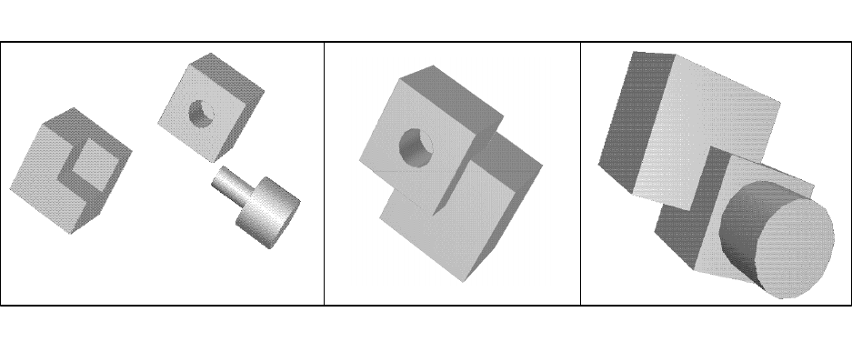
3
When a collision is detected the user is not allowed to move in the collision direction, but he can change the
movement direction in order to avoid the collision. Sound aids have been implemented to warn the user when a
collision is produced.
3.4 Assembly
This capability is used to simulate the assembly/disassembly process of a mechanical component. All the other
capabilities, Touch, Move and Collision detection, are enclosed here. The two specific assembly methods that have
been developed are described below.
Assembly two objects with three pairs of coincident surfaces
This method is used to simulate the assembly of two objects with three pairs of coincident surfaces (see the middle
drawing of the figure 1). Each pair of surfaces is assembled consecutively. This algorithm consists of four phases:
1. The user moves himself by the working space until touching one of the objects.
2. This object is moved together with the user’s finger until finding the first pair of coincident surfaces.
3. The object is slid (through sliding forces) along the coincident surface until finding the second pair of
coincident surfaces.
4. The object is slid (through sliding forces) along the intersection line between the surfaces of the two pairs of
coincident surfaces until finding the third pair of coincident surfaces
Insert a pin in a hole
This method is used to simulate the insertion of an object “pin” in a hole, checking if the object “pin” collides
with other objects of the working space along its movement (see the last drawing of the figure 1). The hole can
have any shape (circular, quadrangular, etc.,...) and can be a through all hole or not. The algorithm consists of
three phases:
1. The user moves himself by the working space until touching the “pin” object.
2. The “pin” object is moved together with the user’s finger until finding a common assembly axis with the hole.
3. The “pin” object is slid (through sliding forces) along the assembly axis until the two objects are assembled.
Fig. 1. Different Assembly Methods
4. CONCLUSIONS
In recent years the Physical Mock-Ups are being replaced by Virtual Prototypes. In this way, computer data models
are being used as the core part of the design process where the users can work on the same model and perform
several analyses to validate the model. This allows reduced costs, lead time and better competition.
4
Nowadays, the Virtual Prototypes have a broad range of utilities, but do not cover all the utilities provided by the
physical models. One of these topics is the interface between the user and the model. The sense of touch is one of
the most important human tools to perceive and analyse an object and it is something missing in the Virtual
Prototypes. Haptic interfaces can add this missing piece and make more realistic the interaction between the user
and the virtual world.
The work presented in this paper tries to fill this gap integrating a haptic device and a general CAD tool. The user
can touch, grasp and move 3D CAD models feeling like interacting with real parts. The main focus is the
simulation of assembly and maintenance operations of mechanical components. Although many other applications
may be also addressed.
5. ACKNOWLEDGMENTS
This work has been partly supported by the following organisms and projects:
1. UET/SPRI Basque Government. DAME project. Ref: CO97AE01
2. ATYCA MINER. PROVIME project. Ref: R0136/1997
6. REFERENCES
[1] Gottschal S., Lin M.C., Manocha D., “OBBTree: A Hierarchical Structure for Rapid Interference Detection”.
Univ. of North Caroline, Chapell Hill.
[2]Hubbard P.M., PhD Thesis “Collision Detection for Interactive Graphics Applications”. Dept. Computer
Science, Brown University, April 1995.
[3]Hudson T.C., Lin M.C., Cohen J., Gottschalk S., Manocha D., “V-Collide: Accelerated Collision Detection
for VRML”. Univ. of North Caroline, Chapell Hill.
[4]Mantyla M., “A Note on the Modelling space of Euler operators”. In Computer Vision, Graphics and Image
Processing 26, 1984, pg. 45-60.
[5]Requicha A., Voelcker H., “Constructive Solid Geometry”. In Production Automation Project, Tech. Memo
25, Univ. Rochester, Nov. 1977.
[6]Weiler K., “Thesis Topological structures for Geometric Modelling”. Resselaer Polytechnic Institute, 1986.
Springs and Constraints for 3D Drawing
Scott Snibbe, Sean Anderson and Bill Verplank
snibbe@interval.com, seander@cs.stanford.edu, verplank@interval.com
Interval Research Corporation
1801 Page Mill Road, Building C
Palo Alto, CA 94107
ABSTRACT
In this paper we present examples of haptic sculpting
mediated by a physical model or constraint. Most current
work in haptic drawing and sculpting focuses on interacting
with a static model and properly simulating contact forces.
Our work proposes dynamic models for the creative
process. These are based on physical models, but present
physically impossible scenarios which allow new forms of
expression. By focusing on models not realizable in the real
world we show an expansion of the creative process
through haptic feedback.
As example applications we present two prototypes.
Dynasculpt allows 3D sculpting by attaching a sprung
virtual mass to the Phantom position and creating a ribbon
or tube along the path taken by the mass through space.
Griddraw is used for constrained 3D drawing – a uniform
3D grid of detents is haptically superimposed over 3D
space, allowing the easy production of straight lines and
right angles. Both focus on dynamics as intrinsic to the
creative process.
Our initial reflections and observations indicate that this
paradigm is a fruitful one for haptically enhanced creation
of static models. The standard problem of users comparing
their experience to the superior real-world experience is
circumvented in this work by presenting novel experiences
impossible to feel or construct in the physical world. By
presenting ourselves and naïve users with simple target
tasks, we have informally analyzed the controllability of
each tool. Our two prototypes seem to lie on extremes in a
continuum of expressivity/controllability – Dynasculpt can
become difficult to control – often at the edge of chaos,
while Griddraw can be overly constraining. Active force
feedback in both cases can serve to stabilize unstable or
chaotic models.
INTRODUCTION
A natural and immediately apparent use for haptic feedback
is in the area of three-dimensional modeling. Architecture,
industrial design, and sculpting all benefit from natural
haptic feedback. Real-world haptic feedback is present in
scale models of works-in-progress: architectural models,
sculptural maquettes and full-scale industrial prototypes.
Haptic feedback is also present in tactile building materials
such as clay, foam, wood, metal and plastic. Most current
work in the haptic enhancement of sculpting, drawing and
architectural design focuses on the first problem – haptic
rendering of a rigid, usually static model via simulation of
contact forces [1].
The majority of the work in haptic modeling has focused on
the simulation of real-world materials – particularly hard
geometric objects. This approach suffers from two
problems based on comparison with the real world
phenomena. First, only single-point contact forces are
possible using the Phantom and users may find this
manipulation weak in comparison to the full
tactile/kinesthetic feedback provided by real materials.
Second, the low refresh rate and smaller forces of the
Phantom suffer in comparison to the real-world phenomena.
At Interval, we are exploring non-physically based dynamic
models for haptic sculpting, sketching and drawing. We
believe that providing experiences based in dynamic
systems, but not directly reflecting real-world phenomena is
a fruitful approach to creative expression with haptic
devices. By using a model not based in reality, we provide
the users with an experience otherwise impossible to
achieve – giving them new creative potential. At the same
time, the tools discourage comparison with the real world
because the models are not based on real phenomena. Our
initial experiments in this realm are described in this paper.
A deeper exploration of this space and further applications
will appear in a future publication.
PRIOR WORK
In the graphics community there are a number of examples
of interactive sketching without haptic feedback, notably
the 3D geometric sketching work done at Brown University
[2], Paul Haeberli’s image-based impressionistic painting
algorithms [3] and the 2D non-photorealistic sketching at
the University of Washington [4]. Passive haptic feedback
in a sculpting application was attempted in the Sculpt
application [5].
A strong inspiration for us is an application called
Dynadraw by Paul Haeberli [6]. Dynadraw is a drawing
program that connects a virtual mass to the cursor position
via a damped spring. As the user draws, the path that the
mass follows is stroked, instead of the mouse position. This
creates smooth, calligraphic strokes (Figure 1). This
application is the first example we know of which mediates
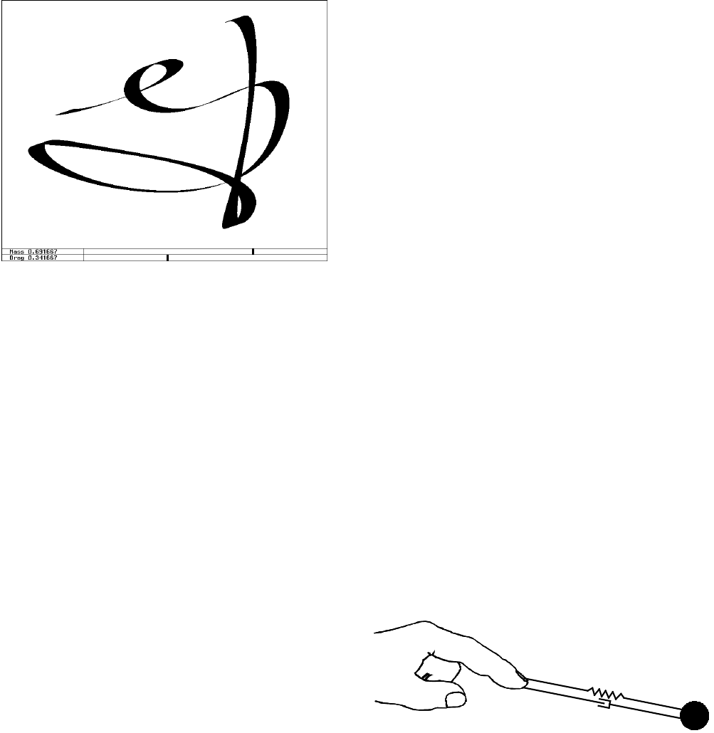
a creative experience (drawing) through a physical model.
Dynadraw involves no haptic feedback. Our first
explorations in haptically mediated sculpting involve
adding haptic feedback to a similar application.
APPLICATIONS FOR DYNAMIC SCULPTING
DYNASCULPT
Dynasculpt allows sculpting by attaching a virtual mass to
the 3D Phantom position and constructing a ribbon or tube
along the path taken by the mass through space. A linear,
damped spring is used to attach the mass to the finger
position (Figure 2). The spring force between the mass and
finger is calculated using Hooke’s law with a damping term:
mfm )( xxxf &
bk −−−=
where k is the spring constant, b is the damping constant, xm
is the virtual position of the mass and xf is the real-world
finger position as measured by the Phantom. The position
of the mass can be expressed as a Newtonian system:
mfmm )( xxxx &&& bkm −−−=
where m indicates the mass. We solve this second order
differential equation using Euler’s method. Continuous
haptic feedback is provided to the user by applying the
equal and opposite force -f to the user via the Phantom. The
user is also provided with two “clutches”. The first controls
whether the pen leaves a stroke through space – controlled
via the Phantom stylus button. The second is a spring-
loaded force enable on the keyboard. Users can modify the
mass, spring constant and damping via sliders.
Drawing is significantly altered by haptic feedback (Error!
Reference source not found.). In purely physical terms,
the user’s hand is pulled towards the mass point. If only a
modest force is applied, the Phantom cursor is drawn along
behind the virtual mass and both soon come to a rest.
Without haptic feedback, the dynamics are those of a fixed
point attached to a moving mass - in the original Dynadraw
and in Dynasculpt without haptic feedback, the finger
position is in effect nailed rigidly to the virtual mass with
no intervening dynamics. The simulation consists of, in the
case of Dynasculpt, movements which are opposite but
balanced; whereas with Dynadraw it reflects the movement
of the mass alone. Dynasculpt demonstrates the distinction
between real and virtual objects in a haptically enhanced
environment. The position of the virtual mass is updated via
discrete steps in a simulation, while the position of the real
mass must be updated through a human user’s reaction to
real forces. By understanding implication of this difference,
we can start to find the applications where haptic feedback
presents valuable and novel experiences.
Via informal evaluation of our colleagues and our own
experiences going back several years, we have observed
other ways in which haptic feedback alters the sculpting
experience. As users interact with the system, they can often
build up quite a strong rotational inertia in the virtual mass.
The kinesthetic feedback provided by the Phantom helps
them to fine-tune their speed and inertia to create a desired
periodic behavior. We find that removing the force
feedback results in less controllability in these cases. When
the damping constant is reduced in the original Dynadraw
or in Dynasculpt, small changes tend to continually add
energy into the system, resulting in wildly oscillating and
sometimes exploding dynamics. As soon as haptic feedback
is introduced into these under-damped systems the human
operator’s muscles and reflexes serve to naturally damp the
system. This is one of our more important (if obvious)
observations, that a human operator can serve to dampen
chaotic or overly energetic systems. Thus, the dynamic
system can operate closer to the limits of the system without
becoming unstable.
GRIDDRAW
A typical problem encountered in 3D sculpting applications
is effectively navigating the 3D space [5]. Using 2D screens
is an obvious cause of this problem, but even in
experiments with stereo or immersive displays, users’
movements tend to be uncoordinated and unsteady. These
sculptors have trouble both maintaining and guiding their
absolute position through space [7].
Figure 1. Paul Haeberli’s Dynadraw.
Figure 2. Dynamic model for Dynasculpt.
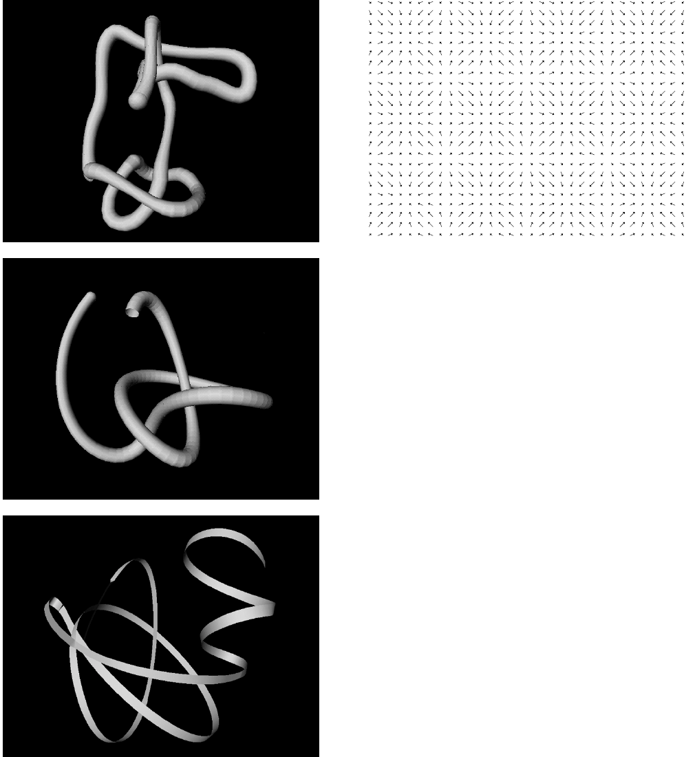
Griddraw is an experiment in constrained sculpting. We
chose the simplest possible constraint we could think of – a
3D grid. This grid is created by haptically overlaying a
sinusoidal force grid on top of the 3D Phantom workspace:
)sin( f
xf gs kk=
where ks is the strength of the grid force and kg is the
density of the grid spacing (Figure 4). This results in two
qualitatively different constraints. First, motion is naturally
constrained along the orthogonal X, Y, and Z-axes, easily
enabling straight lines to be drawn (Figure 5). Second, the
Phantom maintains its position when a user lets go of the
stylus. Thus, work is more naturally picked up and put
down, without the clumsy fumbling to locate a particular
position in three-space.
We certainly found that our users could draw straight lines
quite easily. Further, users were able to more easily
complete drawing tasks, such as drawing a cube. Finally,
users were more likely to move along the Z-axis, moving
into the space of the screen. We experimented with two
drawing methodologies. The first methodology actually
constrained the on-screen sculpture to the grid-lines. Our
second algorithm exactly stroked the path followed by the
stylus, even when straining against the constraint, and we
find the latter method more interesting. With normal
constrained drawing in a non-haptic application using a
mouse and a graphic display, the former method is the only
one available – the on-screen object’s movement or
structure is modified by the constraint. With haptic
feedback, the user has the choice to follow or diverge from
the constraint. A continuum of behavior is possible without
switching modes. Thus force feedback allows a constraint
to be followed in degrees, rather than the binary
constrained/unconstrained choice.
Figure 3. Dynasculpt. Different sculptural qualities can
be achieved by varying the dynamic parameters. All three
drawings used the same spring constant. With low
damping and small mass, rapid oscillations induce
wiggles in the shape (top). High damping and large mass
result is smooth, slowly varying shapes (middle). High
mass and moderate damping result in relatively quick
variation while still smoothing the path (bottom).
Figure 4. Griddraw force vectors (2D slice).
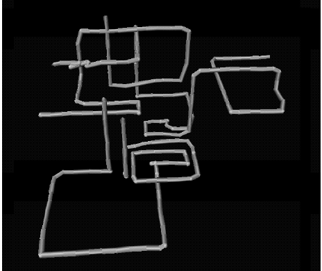
IMPLEMENTATION DETAILS
Both Dynasculpt and Griddraw are implemented on an SGI
Indigo2 R10K. We run in two separate processes which
communicate through shared memory. The graphics process
is implemented using Inventor and is refreshed at a constant
rate of 30Hz (subject to degradation due to graphics
performance). Our custom software updates the haptic
process at a constant 2.5Khz using the real-time scheduling
provided by the IRIX 6.5 OS and communicating directly
with a Phantom SW Desktop model. Since our model is a
simple one, we can update the mass/spring/damper system
at the haptic refresh rate. The graphics process looks at the
computed values for mass and finger position whenever a
new frame is drawn. We have found real-time scheduling to
be a reliable method for obtaining guaranteed haptic refresh
rates using a single processor SGI machine. However, one
must take care to insure that computation doesn’t exceed
the allocated time-slice. Models that have no constant or
upper bound on time complexity are unsuited to this
solution.
OBSERVATIONS AND REFLECTIONS
We believe our two applications lie near the extremes of a
large space of dynamic sculpting applications. Dynadraw
presents a near-chaotic model in which the system is fun to
play with, but most users find it difficult to achieve any
drawing goals. A seemingly simple task of drawing a knot
was only successfully achieved by only a small percentage
of our users. In contrast, Griddraw presents an over-
constrained system – it is easy to achieve certain drawing
goals, but the tool only allows a limited range of
expression. Both applications are similar in that their
dynamic models enforce a strong style on the works
created.
We found that despite using a 3D input device, many users
worked only in the plane parallel to the computer screen
while sculpting. We are not certain if this is due to prior
experience – being accustomed to mice, tablets and other
2D devices – or if this is a natural expression of human
creativity. Do we tend to think and create in planes? Does
our body geometry encourage movement in planes? Or is it
the experience of seeing a 2D display that dominates the
experience?
FUTURE WORK
As we further explore this space we would like to find
applications in the middle ground between Dynadraw and
Griddraw. More controllability is essential to a tool for real-
world tasks. More sophisticated constraints might influence
the users’ style to a much lesser degree – for example
constraints sensitive to specific orientations, speeds or
positions.
We would like to administer more formal testing of our
applications with a set of drawing tasks. We also would like
to experiment with stereoscopic displays as a more natural
3D display. We also think that a comparison between
stereoscopic and monoscopic displays will help us to
understand the tendency to draw in planes.
REFERENCES
[1] D. Ruspini, K. Kolarov, and O. Khatib, The Haptic
Display of Complex Graphical Environments, Computer
Graphics Proceedings, Annual Conference Series,
September 1997.
[2] R. C. Zeleznik, K. Herndon, and J. F. Hughes,
SKETCH: An interface for sketching 3D scenes,
Computer Graphics Proceedings, Annual Conference
Series, September 1997.
[3] Paul Haeberli. Paint by Numbers: Abstract Image
Representations. Proceedings of SIGGRAPH ’90.
Computer Graphics Proceedings, Annual Conference
Series, August 1990.
[4] M. Salisbury, S. E. Anderson, Ronen Barzel, and
David H. Salesin. Interactive Pen and Ink Illustration,
Computer Graphics Proceedings, Annual Conference
Series, July 1994.
[5] Galyean, T. A., & Hughes, J. F. Sculpting: An
Interactive Volumetric Modeling Technique. Computer
Graphics Proceedings, Annual Conference Series, July
1991.
[6] Paul Haeberli. Dynadraw, Silicon Graphics
Corporation, Mountain View, California, 1989.
[7] Butterworth, Jeff, Andrew Davidson, Stephen Hench,
and T. Marc Olano. 3DM: A Three-Dimensional
Modeler Using a Head-Mounted Display. Computer
Graphics: Proceedings 1992 Symposium on Interactive
3D Graphics, April 1992.
Figure 5. Griddraw. Lines do not travel along precisely
straight lines, since the grid constraint is imposed
haptically rather than graphically.
Network Access to a PHANToM Through VRPN
Russell M. Taylor II
University of North Carolina at Chapel Hill
taylorr@cs.unc.edu
Abstract
At UNC-CH, we have several graphics engines, several force-feedback devices and several
applications that make use of each. Each application uses the force device, graphics engine and
location most favorable to it. This requires flexibility in providing access to devices, and has for
several years pushed us to provide switched video capabilities for our graphics engines and
network connections for our force devices.
Recently, we have built our network access on top of the GHOST toolkit to access the
PHANToM force-feedback devices in our laboratories. This access is through our Virtual-
Reality Peripheral Network (VRPN) library. This library allows an application to treat a
PHANToM like the other tracker and button input devices in our laboratory while also allowing
it to provide force output.
We present the VRPN/GHOST interface and some applications that have used it fruitfully.
Introduction
It has been known for some time that it is proper to uncouple the low-level haptic rendering
of simple representations of objects from the high-level simulation of complicated objects.
(Adachi, Kumano et al. 1995) The GHOST toolkit separates haptic update from both graphics
and simulation using a separate haptic rendering thread that communicates with the main
application through shared memory. This is a very effective solution for single-machine
applications. Other toolkits provide a network link between the application process and the
haptic display process, using either TCP/IP or a mix of TCP/IP and UDP/IP for updates. (Mark,
Randolph et al. 1996; Ruspini, Kolarov et al. 1997) This approach allows the use of multiple
computers within a single application (one computer more suited for graphics and one more
suited for haptics). It also introduces network latency and possible loss into the system.
Our environment is one of several different display stations, each of which has its own
particular tracking technology (optical/mechanical, magnetic, custom optical). (Arthur, Preston
et al. 1998; Grant, Helser et al. 1998; Welch and Bishop 1998) The displays are driven from a
number of graphics computers, with analog video switched between them. Applications use
whichever station suits them best, often moving from one station to another. This requires
hooking each graphics engine up to each tracker at various times. To enable this, we have
developed a set of servers that sit on the network, each one running the tracker and button input
devices at a particular location. We have developed a library to enable applications to talk work
in the same manner no matter which physical device they are connected to. This library is called
the Virtual Reality Peripheral Network (VRPN). (Taylor II 1998)
VRPN
The Virtual-Reality Peripheral Network (VRPN) is a set of classes within a library and a set
of servers that are designed to implement a network-transparent interface between application
programs and the set of physical devices used in a virtual-reality (VR) system. The idea is to
have a PC or other host at each VR station that controls the peripherals (tracker, button device,
sound, etc). VRPN provides a connection between an application and all of its devices using the
appropriate class of service for each type of device sharing this link. The application remains
unaware of the network topology.
VRPN also provides an abstraction layer that makes all devices of the same base class look
the same; for example, all tracking devices look like they are of the type vrpn_Tracker. This
merely means that all trackers produce the same types of reports. At the same time, it is possible
for an application that requires access to specialized features of a certain tracking device (for
example, telling a certain type of tracker how often to generate reports), to derive a class that
communicates with this type of tracker. If this specialized class were used with a tracker that did
not understand how to set its update rate, that tracker would ignore the specialized commands.
The VRPN client (application-side) library has been tested on SGI/Irix, PC/Win32,
HP700/Hpux and PC/Linux. The server-side library compiles under SGI/Irix, PC/Win32 (not yet
for serial-port devices) and PC/Linux. VRPN is in the public domain; information about
downloading the system can be found at http://www.cs.unc.edu/Research/nano/manual/vrpn.
Connection
The heart of the VRPN library is the vrpn_Connection class. This class dispatches messages
locally and across network connections, delivering the messages using callback handlers.
Application code does not normally deal directly with the vrpn_Connection class, but rather
accesses it through one or more device classes. It is the device-specific class which deals most
intimately with the vrpn_Connection class. Thus, only those writing device classes need to
thoroughly understand how this class works.
All messages in VRPN have a time, a sender and a type associated with them. The time is
defined by the sender, and usually corresponds to the time at which the action generating the
message occurred (local clock time). For example, the vrpn_Button class reports the time that a
button was pressed or released. Clock synchronization is performed between the client and server
when a connection is established so that all time values reported to a particular machine are
relative to its local clock.
Application code deals with various objects layered on top of the vrpn_Connection class.
Each type of object (tracker, button, force device, etc) implements both a client-side type which
the application uses and a server-side type specific to each particular device.
Trackers
Vrpn_Tracker objects report their position and perhaps velocity and acceleration. Some
trackers allow the application to specify the rate of reporting; others ignore this request.
Orientation is specified as unit quaternions. (Shoemake 1985) Trackers with multiple sensors
send a report for each. Tracker commands (such as requests to send at a certain rate or requests
for parameters) are sent over the network reliably, as are their results. Tracker reports are sent
unreliably, since it is better to wait for a new report than to spend time re-sending an old one that
has been lost.
Buttons
Vrpn_Button objects report press and release events, and the time at which the event
occurred. They can be set to toggle or momentary under application. All button messages are
sent over the network reliably.
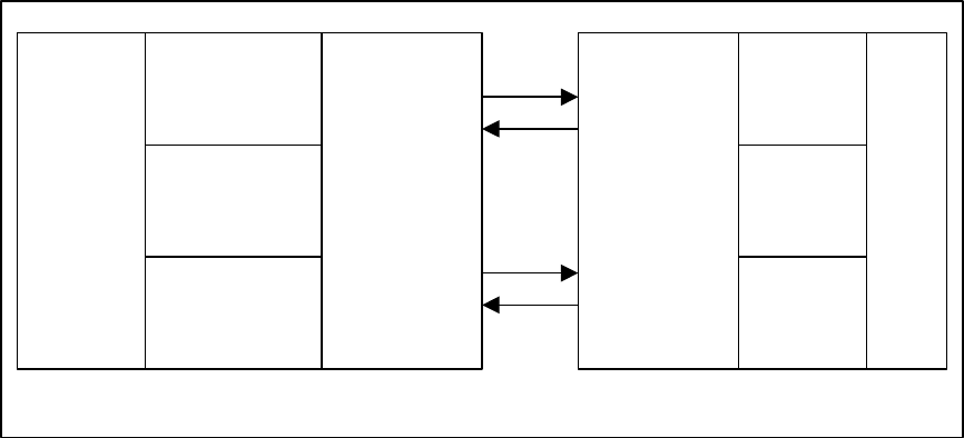
Force Devices
Whereas tracker and button devices are primarily for input, the vrpn_ForceDevice is used for
output. The application sends local surface representations to the device, which it presents
haptically to the user. These representations can be meshes (which are mapped to the GHOST
mesh primitive) or local plane approximations (which are implemented using the GHOST
callback feature). Controllable surface parameters include the stiffness and friction. For the
visualization of multiple data sets, were are also adding the capability to provide textures and
vibrations to simulated surfaces.
PHANToM Over VRPN
When an application opens a force device, such as the PHANToM, it also wants access to the
position reports from the device and also any buttons that are on the device. The application gets
access to these by opening the device with the same name as a vrpn_Tracker_Remote, a
vrpn_Button_Remote, and a vrpn_ForceDevice_Remote. VRPN takes care of mapping all of
these devices to use the same connection to communicate over, and the application treats the
three separate functions of the device independently. Since devices ignore unrecognized
messages, it is possible for applications that use force feedback to connect to a normal tracker for
testing of the input function and only to a force device when needed. It is also possible for
applications that do not require force feedback to use the PHANToM as a tracker and button
device, ignoring its force capabilities.
Applications
VRPN was originally designed for use by generic virtual-reality applications. The particular
application that required use of the PHANToM was the nanoManipulator. (Finch, Chi et al.
1995) This application uses a single plane to approximate a surface being scanned by a probe
microscope; the plane is updated as new data arrives from the microscope tip.
There is also a group at Wright Patterson Air Force Base that is implementing a version of
the Docker program (see (Ouh-young 1990)) using a PHANToM. They are working with NCSA
on the development of new force-display algorithms for this extremely difficult simulation. They
are developing a new force model that presents not a surface but a force field.
TCP
UDP
Server side Client side
GHOST
Tracker
Server
Button
Server
ForceDevice
Server
Connection Connection
Tracker
Button
Force
Device
App

We are also using this system as a base for the investigation of alternate collision-detection
algorithms. (Gregory, Lin et al. 1998) This work uses meshes as the local representation of
remote geometry. Simpler early work by Adam Seeger implemented a Venus fly-trap model that
would close and trap the user if they were not quick enough after tripping the trap.
Conclusions and Comments
Good things: VRPN provides normalization of devices while still allowing specialization. It
runs either locally or across the network. It is extensible, in that either new devices or new
classes of devices can be created within its framework. This makes it easy to use a PHANToM
within a multi-device environment, allowing access to it from any computer on the network.
VRPN is in the public domain. You can have the source code.
Bad things: VRPN does not present the GHOST interface to the application. This means that
existing PHANToM applications cannot use it directly without change. It would be possible to
write a GHOST-like layer on top of the VRPN client library that would allow applications to link
with it rather than GHOST, but that is not the direction we are headed so it won’t be done by us.
VRPN is not supported as a product.
If you are using or planning to use PHANToMs in a heterogeneous or networked
environment, we would like to work with you to extend VRPN for your situation. We can be
reached at vrpn@cs.unc.edu.
References
Adachi, Y., T. Kumano, et al. (1995). Intermediate Representation for Stiff Virtual Objects. Proc.
IEEE Virtual Reality Annual International Symposium (VRAIS'95), Research Triangle Park,
NC. pp. 203-210.
Arthur, K., T. Preston, et al. (1998). The PIT: Design, Implementation, and Next Steps. to appear
in the proceedings of the IPT98 Workshop. pp.
Finch, M., V. Chi, et al. (1995). Surface Modification Tools in a Virtual Environment Interface
to a Scanning Probe Microscope. Computer Graphics: Proceedings of the ACM Symposium
on Interactive 3D Graphics, Monterey, CA, ACM SIGGRAPH. pp. 13-18.
Grant, B., A. Helser, et al. (1998). Adding Force Display to a Stereoscopic Head-Tracked
Projection Display. to appear in the proceedings of VRAIS '98, Atlanta. pp.
Gregory, A., M. C. Lin, et al. (1998). H-COLLIDE: A Framework for Fast and Accurate
Collision Detection for Haptic Interaction. In preparation. pp.
Mark, W., S. Randolph, et al. (1996). Adding Force Feedback to Graphics Systems: Issues and
Solutions. Computer Graphics: Proceedings of SIGGRAPH '96. pp. 447-452.
Ouh-young, M. (1990). Force Display In Molecular Docking. Computer Science. Chapel Hill,
University of North Carolina: Tech Report #90-004.
Ruspini, D. C., K. Kolarov, et al. (1997). The Haptic Display of Complex Graphical
Environments. SIGGRAPH '97, Los Angeles, ACM SIGGRAPH. pp. 345-352.
Shoemake, K. (1985). Quaternion Calculus for Animation. SIGGRAPH '85, San Fransisco,
ACM SIGGRAPH. pp. 245-254.
Taylor II, R. M. (1998). The Virtual Reality Peripheral Network (VRPN).
http://www.cs.unc.edu/Research/nano/manual/vrpn.
Welch, G. and G. Bishop (1998). SCAAT: Incremental Tracking with Incomplete Information.
SIGGRAPH '97, Los Angeles, ACM SIGGRAPH. pp. 333-344.
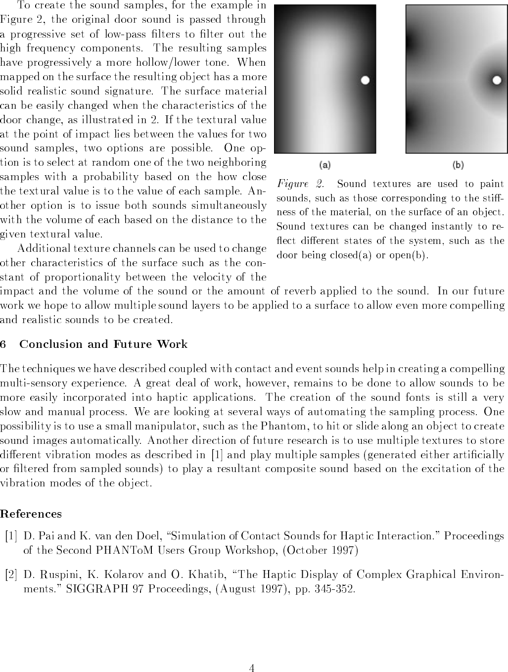
1
SCIRun Haptic Display for Scientific Visualization
Lisa J. K. Durbeck, Nicholas J. Macias, David M. Weinstein, Chris R. Johnson,
John M. Hollerbach
University of Utah
Introduction
The overall goal of this research is to enhance scientific visualization by the use of haptic feedback. We have chosen
to approach this goal by incorporating a haptic interface into an existing full-featured scientific visualization tool.
People who use scientific visualizations are generally trying to analyze or solve a scientific problem. The
visualizations are usually animations or interactive graphics that scientists create for themselves. The visualizations
are intermediate representations intended to represent the problem or its solution graphically (1, 2). Ideally these
visualizations are accurate, information-rich, interactive, and illustrative of key features of the phenomenon or data
set. They should make the problem (or its solution) easier to understand. Toward this goal we augmented existing
graphical visualizations with force feedback (3), as well as true 3-D interaction, in ways that highlight key features
such as flow lines. The haptic interface we have developed allows the user to form a high-level view of his data more
quickly and accurately.
Scientific visualization research has been underway at the University of Utah for much of this decade (4). One
outcome of that research is a problem-solving environment for scientific computing called SCIRun (5,6). For this
project, we interfaced SCIRun to a haptic device, and we then used SCIRun to create two displays, one graphic and
one haptic, which operate together on a common visualization. The work described here uses the system to interact
with vector fields, 3-D volumes in which every point in the volume has a vector associated with it. Examples of
vectors are gravity, pressure, force, current, and velocity as well as scalar gradients.
Users of our new system can simultaneously see and feel a vector field. Haptic feedback is displayed on a SensAble
PHANToM Classic 1.5 (7). The graphics are displayed on an SGI Octane. The user has a haptic display registered to
a graphic display. She directs both displays by moving the PHANToM endpoint through the haptic representation of
the data volume. The haptic display presents each vector as a force corresponding to the vector’s magnitude and
direction. The graphic display presents a subset of the vector field as lit directional line segments (8) or as the
traditional arrow glyphs.
This haptic/graphic display is useful for displaying flow fields, vector fields such as fluid flow models for airplane
wings in which the vectors tend to align into strong directional paths (9). The haptics feel as if you put your fingertip
into a river: the vectors act upon your fingertip, drawing it in the same direction as the local flow field. If the user
does not apply any force, the forces displayed onto the PHANToM endpoint naturally draw his finger along the flow
lines. This allows the user to trace his finger along the various flow lines within the vector field. The user can also
move his finger onto a new path, and again the endpoint begins to follow this new path. This interface allows the
vector field to act upon the PHANToM endpoint in a similar manner as a traditional visualization technique called
seed point insertion or particle advection (1). The graphical display reinforces the haptic display by showing the
endpoint moving along the flow line and by showing the part of the flow line that lies ahead of the current position.
The user receives haptic and visual feedback which helps him stay on the path. Figure 1 shows a still image from a
user’s interaction with a flow line and Figure 2 shows an image of several traced flow lines composited over time.
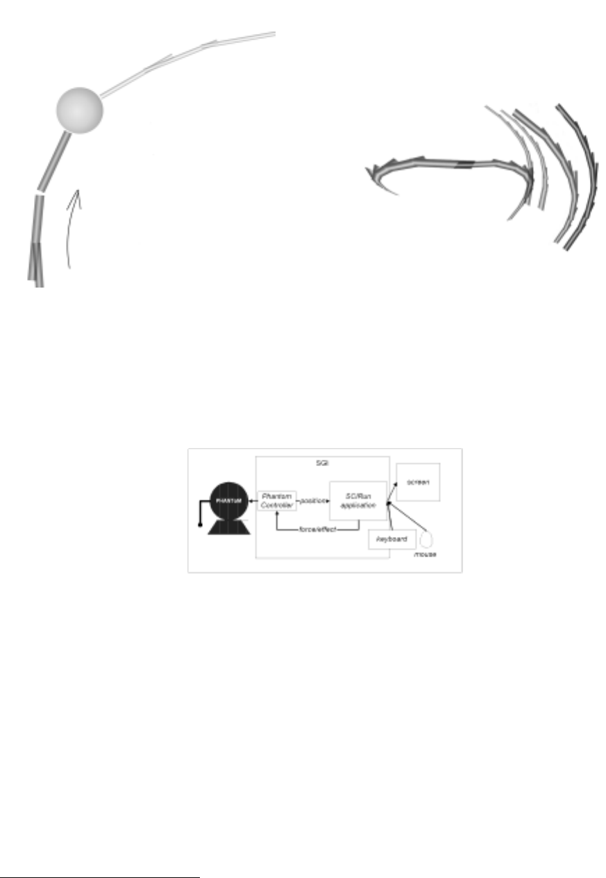
2
Fig 1 (left). Illustration of user interaction with flow line. The display sweeps out the path to and from the current endpoint position. The
pencilled arrow indicates the direction of travel. The sphere represents the current PHANToM endpoint position; the fatter, darker lit lines are the
path already taken by the user; the thin, lighter lines are the flow line leading from the current position.
Fig. 2 (right) Illustration of 3 separate flow line traces composited into one image. As the user interrogates the volume, the display forms an
image of the flow lines within the field.
System Architecture
Figure 3 shows a high-level view of the software and hardware used for this system.
Fig. 3 High level view of system hardware & software
The software runs on an SGI, 02 or better, with a PCI or ISA slot for the PHANToM card.1 SCIRun and the
PHANToM controller are two separate client-server applications (10,11,12,13) which communicate via sockets.
The PHANToM controller acts as the server and SCIRun acts as the client. The Appendix contains a full listing of
our control loop, written using a small subset of the Ghost SDK. As the size of this listing illustrates, the PHANToM
controller is minimal: all the data and computations are handled by the program within SCIRun. Figure 4 shows a
dataflow diagram representing the program we wrote within the SCIRun programming environment. The program
consists of two loops, the haptic display loop and the graphic display loop. Within the haptic display loop, the
program receives the latest PHANToM endpoint position, calculates a force based on that position, and sends out a
force to the PHANToM controller. Within the graphic display loop, the program receives the latest PHANToM
endpoint position, redraws the endpoint in the graphic display, and recalculates and redraws the vector field display.
1 Typically we use an SGI Octane with dual 195 MHz R10000 processors, 128 MB memory, and an SGI MXI graphics card.
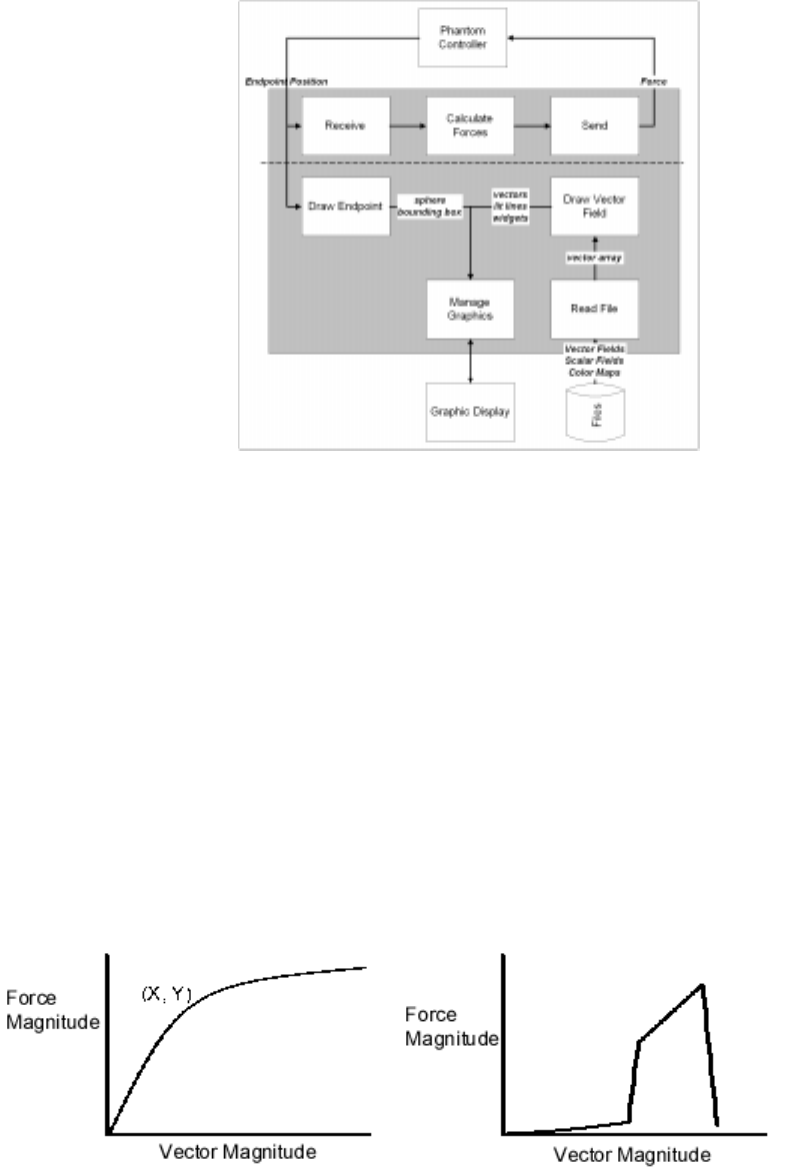
3
Fig. 4 Dataflow diagram of our software. Each labelled boxes represents a distinct component of the software system. All components within the
shaded box run within SCIRun; the rest run outside of the SCIRun runtime environment. The components above the line are particular to the
haptic display, while those below are particular to the graphical display.
Future Work
The user can change aspects of the graphic and haptic displays at runtime. One interesting visualization technique we
would like to explore is user-defined transfer functions. Rather than mapping data vectors linearly to force vectors,
we could map them based on a nonlinear or piecewise linear function defined by the user. Figure 5a) shows an
example of a function that could be used to re-map one dimension of the vector field such as magnitude. Vectors
with magnitude X along the x-axis are mapped to forces with magnitude Y. The transfer function in Figure 5a)
amplifies the effect of small vectors and could be used to fine-tune the display for examining small vectors. The
transfer function graphed in Figure 5b) effectively weeds out all vectors in the field except for those within the
specified range. If the full range of force magnitudes is used within this smaller data range, then the effect is a haptic
"zoom". Note that in 1 dimension, these transfer functions look like traditional force profiles (14) but are data-
dependent, not position-dependent.
We also anticipate making use of multiprocessor scheduling on the Octane in order to maintain interactive rates for
large visualizations or complex force calculations.
Fig 5a (left), 5b (right). Simple nonlinear transfer functions which map from data vector magnitude to force magnitude.

4
Acknowledgments
This work was supported in part by the Department of Defense through a DURIP equipment grant, the National
Science Foundation, and the Department of Energy. Furthermore, the authors appreciate access to facilities that are
part of the SGI-Utah Visual Supercomputing Center.
References
1 R. S. Gallagher, ed. Computer Visualization: Graphics Techniques for Scientific and Engineering Analysis. CRC
Press, Boca Raton, 1995.
2 W. Schroeder, K. Martin, & B. Lorensen. The Visualization Toolkit, 2nd edition. Prentice Hall, New York, 1998.
3 J.P. Fritz & K.E. Barner. Haptic Scientific Visualization. Proceedings of the First PHANToM User’s Group
Workshop, 1996.
4 see http://www.cs.utah.edu/~sci/publications
5 S.G. Parker, D.M. Weinstein, & C.R. Johnson. The SCIRun computational steering software system. Modern
Software Tools in Scientific Computing, E. Arge, A.M. Bruaset, & H.P.Langtangen, eds. Birkhuaser Press, 1997: 1-
44.
6 S.G. Parker & C.R. Johnson. SCIRun: A Scientific Programming Environment for Computational Steering.
Supercomputing '95, 1995.
7 T.H. Massie. Design of a Three Degree of Freedom Force-Reflecting Haptic Interface. SB Thesis, Department of
Electrical Engineering and Computer Science, M.I.T. May 1993
8 M. Zockler, D. Stalling, H.C. Hege. Interactive Visualization of 3D-Vector Fields Using Illuminated Stream Lines.
Visualization ’96, 1996: pp 107-113.
9 J. Helman & L. Hesselink. Visualizing Vector Field Topology in Fluid Flows. IEEE Computer Graphics and
Applications, May 1991.
10 W.R. Mark, S.C. Randolph, M. Finch, J.M. Van Verth, R.M. Taylor II. Adding Force Feedback to Graphics
Systems: Issues and Solutions. Siggraph ’96 Computer Graphics Proceedings, 1996: 447-452.
11 W. Plesniak & J. Underkoffler. SPI Haptics Library. Proceedings of the First PHANToM User’s Group
Workshop, 1996.
12 S. Vedula & D. Baraff. Force Feedback in Interactive Dynamic Simulation. Proceedings of the First PHANToM
User’s Group Workshop, 1996.
13 S.W. Davidson. A Haptic Process Architecture using the PHANToM as an I/O Device in a Virtual Electronics
Trainer. Proceedings of the First PHANToM User’s Group Workshop, 1996.
14 A.J. Kelley & S.E. Salcudean. The Development of a Force Feedback Mouse and its Integration into a Graphical
User Interface. In Proceedings of the International Mechanical Engineering Congress and Exposition. Chicago USA
1994. DSC-Vol. 55-1: 287-294
5
Appendix: Program Listing for PHANToM Controller
// PHANToM_controller.cpp - main loop for PHANToM Controller program
// derived from hello.cpp provided by SensAble
#include <stdlib.h>
#include <gstBasic.h>
#include <gstSphere.h>
#include <gstPHANToM.h>
#include <gstSeparator.h>
#include <gstScene.h>
#include "ljdForceInput.h"
#include "server.c"
main() {
gstScene *scene = new gstScene;
gstSeparator *root = new gstSeparator;
printf("put the PHANToM in neutral position and hit return...\n");
getchar();
gstPHANToM *PHANToM = new gstPHANToM("PHANToM.ini");
root->addChild(PHANToM);
scene->setRoot(root);
ljdForceInput * forces = new ljdForceInput; // force from SCIRun
PHANToM->setEffect(forces);
PHANToM->startEffect();
scene->startServoLoop();
gstPoint pos; // holds current PHANToM position
double u,v,w;
sock_init();
while (!scene->getDoneServoLoop()) {
pos = PHANToM->getPosition_WC();
write_triple(pos.x(), pos.y(), pos.z()); // send position to client, SCIRun
if (read_triple(&u,&v,&w) == 0) { // read resulting force from SCIRun
// copy to readable location
scirun_force = gstVector(u,v,w);
// the next time calcEffectForce() happens, it will see this new force.
}
else {
printf("client scirun has shut down.\n");
sock_deinit();
}
}
PHANToM->stopEffect(); // quit my force input
}
--------------------------------------------------------------
// ljdForceInput.h derived directly from Ghost SDK CalcEffect.h
#include <math.h>
#include <gstBasic.h>
#include <gstEffect.h>
gstVector scirun_force; // set by main loop
class ljdForceInput:public gstEffect
{
public: ljdForceInput():gstEffect(){} //Constructor
~ljdForceInput() {} // Destructor
virtual gstVector calcEffectForce(void *PHANToMN)
{
if (PHANToMN); // To remove compiler warning
if (!active) return gstVector(0.0, 0.0, 0.0); // check first
gstPoint pos;
double xc, yc, zc; // force vector components
xc = scirun_force.x(); yc = scirun_force.y(); zc = scirun_force.z();
return gstVector(xc, yc, zc);
}
};
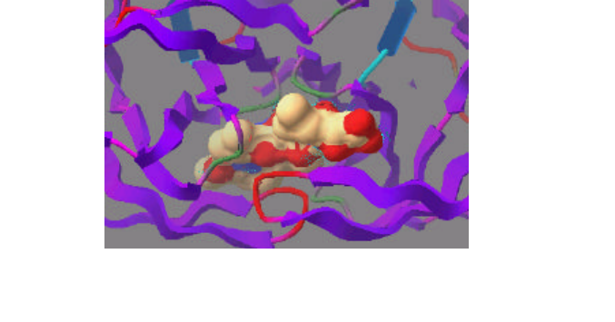
1
Haptically Enhanced Molecular Modeling: A Case Study
Len Wanger
Interactive Simulations, Inc., San Diego, CA
(wanger@intsim.com)
INTRODUCTION
SCULPT [Surles 92,94] is a commercial, molecular modeling, software application used widely by chemists and
biologists to design and analyze molecular structures. SCULPT’s main design goal is to reduce the mental energy
required to control the human computer interface (HCI), allowing the chemists to instead concentrate on the difficult
chemistry issues involved in molecular modeling. Towards this end, SCULPT attempts to emulate the familiar
experience of manipulating a physical (i.e. Dreiding) model, allowing users to modify the molecule by grabbing atoms
with the mouse and pulling on them. Haptic feedback is a natural expansion to this direct manipulation paradigm, as it
allows the user to physically feel both the shape of the molecule and the forces acting upon it. The importance of this is
exemplified in docking, which requires accurate positioning of the ligand within the protein receptor site, while
constantly monitoring a variety of forces resulting from complex interactions between the ligand and receptor (see
Figure 1).
We have recently experimented with adding high quality haptic feedback to SCULPT to aid in combinatorial chemistry
and rational drug design tasks. This paper describes the implementation using the SensAble Technologies Ghost 2.0
API, and reports on some preliminary results. While the application is specifically geared towards drug discovery, this
paper presents a case study that should be generally useful to developers interested in providing haptic support for real-
time, dynamic simulations.
ADDING HAPTICS
To keep a structure in a physically valid conformation while it is being modified, SCULPT tightly couples three-
dimensional graphics with a proprietary, real-time, energy minimizer. While tugging on an atom, a virtual spring is
added between the atom and the cursor. The energy minimization subsequently tries to minimize the length of the
spring to reduce the energy in the system. Because the spring is factored in with the other molecular constraints defined
on the model, this influences the atom to move towards the cursor without violating the physical constraints of the
structure.
Internally, the graphics and user interface are managed by the Display Manager and the energy minimization by the
Minimizer. These two processes communicate through messages over a socket. Haptic rendering is supported by adding
the Haptics Manager; which communicates via socket with the Display Manager, and is responsible for managing the
Ghost scene graph and reporting back changes in the PHANToM state (Figure 2).
Figure 1:
this image of an experimental protease inhibitor (shown as a solvent
accessible surface) located in the active site of HIV Protease is indicative of the
complex three-dimensional geometries found in docking studies
.
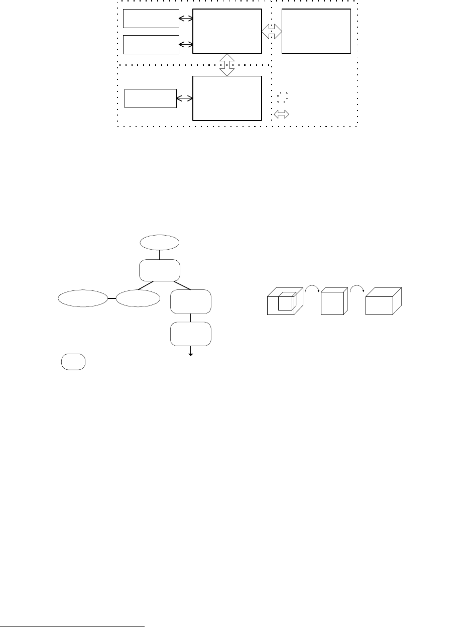
2
The scene graph used for haptic SCULPT is structured to allow the data to be specified in SCULPT’s model space. This is
achieved by adding all of the geometry under two, nested transformations (gstSeparator nodes). The first transform
maps from SCULPT space to PHANToM space, and the second adds the SCULPT camera transform to synchronize the
visual and haptic views (see Figure 3). These transforms are kept separately to allow the camera transform to be
updated independently when the Haptics Manager receives Update_view messages.
The SCULPT to PHANToM space transform can be conceptualized as the concatenation of four transformations. The
first translation and scale map from SCULPT space to an axis aligned unit cube, and the second set maps from the unit
cube to the PHANToM’s space:
Sculpt to phantom transform: = T 1S1S2T2, where:
T1 = translate by (-Sculptxmin, -Sculptymin, Sculptzmin + Sculptzmax)
S1 = uniform scale by 1 / (Sculpt zmax – Sculptzmin)
S2 = uniform scale by Phantom zmax-zmin
T2 = translate by (Phantomzmin, Phantomymin, Phantomzmin)
There are a couple of nuances to note in this transform. First, transforms S1 and S2 use uniform scale factors, as Ghost
requires uniform scales within separator transforms. This means that the graphics windows used in the application must
maintain the same aspect ratio as used in the boundary cube1. Using differing aspect ratios would result in the
PHANToM’s workspace holding a subset of graphics view, or much it remaining unoccupied. The second nuance leads
to the translation by Sculptzmin + Sculptzmax in transform T1.In the SCULPT view model, the front
1 The Ghost boundary cube is a misnomer as the workspace used often has unequal axis lengths.
gstScene
gstPhantomgstSpringEffect Model to
Phantom
Transform
root
Sculpt
Camera
Transform
gstSeparator
node Geometry
nodes
Viewport/camera
within Sculpt
model space
(Angstroms)
Unit
Cube Phantom
Space
(Centimeters)
Figure 3: The scene graph consists of: a gstPHANToM node, a gstSpringEffect (used for springs), and a sub-
graph for the geometry. Two gstSeparator transforms are added to allow the coordinates of the geometry to be
defined in SCULPT model space. The transformations can be thought of as transforming from SCULPT space to an
axis aligned unit cube, then from the unit cube to the PHANToM’s space.
OpenGL
Heidi
Win32
X/Motif
Haptics
Manager
Display
Manager Minimizer
Thread boundary
Virtual socket
Ghost
Figure 2:
the
Haptic Manager
is added to provide haptic feedback support. It is implemented
as a separate thread process that communicates bidirectionally with the Display Manager.
3
clipping plane is always defined at Z=0. This aids in picking and clip plane management, and is required to support
graphics APIs, such as Heidi, which cannot render coordinates lying behind the eye point.
Setting the camera transformation is simplified by keeping the individual components of the camera transformation
separately, and allows the viewing parameters to be sent to the Haptics Manager. Sending the camera matrix is not
possible as it generally contains Ghost hostile, non-affine elements such as perspective projection. The camera
transform is:
Sculpt camera transform = TwSRTCOR, where:
Tw = translate by (-Sculptxmin, -Sculptymin, -Sculptzmin)
R = camera rotation (based on virtual track ball model in Sculpt)
S = uniform scale for zoom factor
Tcor = translate by center of rotation (COR X, CORY, CORZ)
Defining the transformations in this manner allows all of the geometry to be added in SCULPT model coordinates as
child nodes of the camera transform separator. This in turn makes it easy to update coordinates when the energy
minimization runs. Updates are performed via Update_coordinates messages, which contain an array of updated atom
coordinates. An associative array in the Haptics Manager maps SCULPT atom indices to their respective Ghost nodes.
Coordinates are then changed on the nodes by calling their setTranslate method.
One problem encountered is that the Ghost servo loop timed out when all of the atoms in a complicated protein
structure were simultaneously placed in the scene graph. To circumvent this, geometry nodes are created for the entire
structure, but only movable atoms (“thawed” in SCULPT) are added to the scene graph. Fixed/frozen atoms lie dormant
until a Change_active_set message informs the Haptics Manager to add them to the scene graph.
The final node in the scene graph is a spring effect (gstSpringEffect) that is attached to the PHANToM and is used to
haptically render springs when the user manipulates a structure. This is a custom node that is derived from gstEffect.
Unfortunately, a gstConstraint point effect cannot be used as the force phase-in timer is restarted everytime the fixed
point is moved (i.e. the atoms coordinate changes). When a tug is started the spring effect is turned on, with the fixed
end of the spring attached to the center of the atoms being dragged. The force vector lies on the vector from the atom
center to the cursor, with a magnitude determined by Hooke’s law.
When not processing incoming messages, the Haptics Manager informs the Display Manager of changes in the
PHANToM end effector position and stylus button state. Positional and orientational information is used to update the
3D cursor, and button changes to grab and release atoms. To prevent the Haptics Manager from flooding the display
side with messages, PHANToM state changes are only reported when the stylus button state is changed, or the end
effector position changes in excess of a delta factor.
When the stylus button is pressed the Display Manager determines if an object is within the pick radius of the end
effector. Successful picks are relayed to the Haptics Manager, which turns on the spring effect. The Haptics Manager
also calls touchableByPHANToM on the model to phantom transform separator, making the geometry sub-graph
untouchable. This speeds execution of the servo loop and allows the spring to move freely without colliding with the
geometry. Both of these operations are then reversed when the stylus button is released.
RESULTS
While we are still early in the implementation of Haptic SCULPT, several chemists have tested the prototype. We plan to
perform formal user studies when the system has matured, but for now the results are based on informal comments
made by users during and after haptic modeling sessions involving three common modeling tasks.
1. Analysis of conformational flexibility: Assessment of the flexibility of small molecules by interactively
exploring the resistance required to rotate bond angles and the strain energy required to match a known
conformer.
2. Exploration of surfaces and properties: Exploration of the distribution of properties on a structure. This is
currently limited to feeling the three-dimensional shape formed by the intersecting electron shells (i.e. a
CPK model).
4
3. Interactive docking: Interactive guiding of a ligand into a receptor site, while haptically reflecting the
forces acting on the ligand. The current version does not support rotating the ligand.
All of the tests were met with extreme enthusiasm, with users commenting that the PHANToM provided a natural and
highly functional interface. The general consensus was that haptic feedback was intriguing, but the update rate needed
to be increased before it would significantly enhance modeling. This was due to a choppy, “ratcheting” effect that was
felt as the fixed spring point was updated in sync with the minimizer at approximately 3 Hertz. This result is supported
by the literature, which suggests update rates in excess of 30 Hertz are needed to provide high quality sensation of
springs. We were able to eliminate the ratcheting sensation by loosening the spring constant, however doing so made it
difficult to feel forces acting on the structure. Users also noted that docking requires the ability to rotate the ligand to be
useful, and that six-degree of freedom haptic output is also desired to feel torsions acting on the structure.
Several users were able to contrast Haptic SCULPT to the haptic docking experiments performed as part of the GRIP
project at the University of North Carolina at Chapel Hill [Ouh-Young-90]. Several distinct advantages were noted.
The PHANToM hardware provides improved ergonomics and a significant reduction in cost compared to GRIP’s
Argonne arm. Users were also quite impressed with the speeds achieved by SCULPT on a Pentium II class PC, and liked
the ability to perform flexible docking and the ability to use the mouse and PHANToM simultaneously.
FUTURE WORK
There are two main areas being examined for future work. First, is to improve the saliency of the haptic feedback. To
do so we are looking at several ways to increase the haptic update rate. While the cursor can be drawn in overlay planes
on top of the scene in the mouse driven version, the true 3D nature of the PHANToM requires the full scene to be
redrawn to reflect cursor movements. We hope to reduce this bottleneck by only redrawing the image region
underneath the cursor when nothing else changes. This can be done by saving the image region underneath the cursor
before it is drawn, and restoring it before updating the cursor. The second technique is to linearly interpolate the fixed
spring point position in between simulation updates as was done in the nano-manipulator project [Taylor-96].
Other future work involves improvements to the functionality of the system. Beyond the problem areas mentioned by
users (such as changing orientation), there are a large number of interesting avenues to pursue in this relatively
unexplored application area. Two interesting examples are: haptically rendering attractions and repulsions of field
properties surrounding structures (e.g. charge), and adding haptic support for de novo design of proteins. For the latter,
it would be interesting to make large scale structural changes by directly tugging on secondary structures.
ACKNOWLEDGMENTS
This work could not be performed without the hard work of the SCULPT team (Isabelle Gouni, Gary Hanyzewski,
Christoph Koelmel, Max Muir, Mike Mull, Phil Rios, and Mark Surles). Thanks also go out to: Jane and Dave
Richardson, Russ Taylor, and for all of the support from SensAble Technologies -- particularly to Craig Musicant, Ted
Bardasz, and Chris Tarr for technical assistance.
REFERENCES
[Ouh-Young-90] Ouh-Young, Ming, (1990), Force Display in Molecular Docking, Ph.D. Dissertation, University of
North Carolina at Chapel Hill, TR90-004, February, 1990.
[Taylor-96] Taylor II, Russell M, 1996, Programming Force Feedback Devices in Computer Graphics Systems, Course
Notes for The Use of Touch as an I/O Device for Graphics and Visualization, SIGGRAPH '96.
[Surles-92] Surles, M.C. (1992). Techniques For Interactive Manipulation of Graphical Protein Models. Ph.D.
Dissertation, Department of Computer Science, University of North Carolina at Chapel Hill.
[Surles-94] Surles, M.C., Richardson, J.S., Richardson, D.C. & Brooks, F.P., Jr. (1994). Sculpting Proteins
Interactively: Continual Energy Minimization Embedded in a Graphical Modeling System. Protein Science 3, 198-210.

Incorporating Haptics into Mining Industry Applications
Paul Veldkamp
CSIRO Mathematical & Information Sciences, Canberra, Australia
Paul.Veldkamp@cmis.csiro.au
Greg Turner
SenseOre Services Pty Ltd, Perth, Australia
Senseore@iinet.net.au
Chris Gunn
CSIRO Mathematical & Information Sciences, Canberra, Australia
Chris.Gunn@cmis.csiro.au
Duncan Stevenson
CSIRO Mathematical & Information Sciences, Canberra, Australia
Duncan.Stevenson@cmis.csiro.au
Abstract
This paper describes how we are incorporating haptics into geoscientific applications. These
applications involve the creation and modification of complex 3D structural geological models. Current
commercial software tends to use 2D displays, which limits the scope for effective visualisation and, in
particular, effective interaction with models of realistic complexity. The use of the Haptic Workbench in
these tasks improves both the quality of the visualisation and of the interaction with the models. The
Haptic Workbench consists of a small-scale immersive virtual environment (a Virtual Workbench) and a
co-located PHANToM 1.5.
We describe a typical 3D geological modelling task that occurs in the metalliferous mining industry. We
show how hapto-visual techniques can make a substantial improvement to the task and how they are
very dependent on the development of both good data representations and translators from existing data
formats produced by commercial software packages.
1. Introduction
Haptic interaction has a major role in future mining industry applications involving such interactive
tasks as minerals exploration, geological and ore-body modelling, mine planning and mine production
management. The fundamental task is that of constructing models and testing hypotheses in a three-
dimensional earth-modelling framework. In this framework, haptic interaction will allow both haptic
rendering of data and haptic assistance with ergonomics.
Our work towards incorporating haptics into mining industry applications combines two strands:
• Experiments with 3D co-located haptics and graphics, and placing the resulting prototypes in use
at a mine site
• Object-oriented software development to support the entities required for the next generation of
mining applications
The experiments combined a PHANToM 1.5 haptic device with the Virtual Workbench small-scale
immersive virtual environment from what is now Kent Ridge Digital Laboratories in Singapore [Poston-
94] and resulted in a demonstration suite which was presented at SIGGRAPH’97 as part of SensAble
Technologies’ booth. We are calling the result of this integration of haptic and visual displays the
Haptic Workbench. These experiments were conducted as part of a collaborative project within the
Advanced Computational Systems Cooperative Research Centre [http:acsys.anu.edu.au] with three
companies from the mining industry as partners. The experiments showed that immersive Virtual
Environment systems using haptic interaction offer major benefits in this industry.
2. The Target Mining Application
We chose as our first application the task of modelling geological surfaces – ore-body envelopes,
contacts between different rock types and fault planes. The task has three phases:
• Collecting field data (from drillhole logs, mine workings, geophysical surveys) and fusing the
data to form a 3D modelling context
• Performing the modelling task by constructing surfaces in the 3D space to represent geological
features (both constructing new models and editing existing ones)
• Using these models for decision making in mine management.
The second phase is the focus of our work; the first and third phases are covered by existing software.
We aim to provide hard and soft constraints using both visual and haptic media to assist the geologist.
At the heart of the task is building a triangulated surface that passes through known points on drillholes,
or known lines on the sides of the mine workings. Since the data points are sparse and sometimes
unreliable, we need to hapticly render soft constraints so that a geologist can apply his or her expert
knowledge to the surface modelling task. We are working with two Australian mining industry
companies, WMC Resources Ltd and Fractal Graphics Pty Ltd, to set the requirements for this work and
to review successive prototypes. We are placing a Haptic Workbench at a mine site in Kambalda,
Western Australia, where the prototypes will be used to do real application tasks.
3. Building Blocks for Geoscientific Applications
3.1 The Haptic Workbench
Haptic interaction with data requires a method of integrating the user, the haptic device and the
application context. We provide this integration with our “Haptic Workbench” which is a small-scale
immersive virtual environment combining co-located graphics and haptics. The Haptic Workbench is
based on a “hands in” interaction paradigm where the user sits at the workbench and uses virtual tools to
do work with objects and data in the display [Stevenson-99].
Writing applications for the Haptic Workbench requires a scenegraph based programming interface that
handles haptics and graphics in a unified manner. Work towards such a programming interface is being
done jointly by ACSys and ReachIn Technologies AB [http://www.reachin.se]. Work towards this
mining application draws on successive prototypes of this programming interface.
3.2 CSIRO DataModel and GeoEditor
To bring a new technology like haptics to an application domain, a programmer needs high-level
programming support for the underlying data and attributes inherent in that domain. For our geological
applications, the CSIRO DataModel and GeoEditor for 3D geoscientific data provides that support
[Power-95, Lin-95]. CSIRO has been working since 1992 on software infrastructure to support the next
generation of geological software applications and the “DataModel” and “GeoEditor” are some of the
results. The DataModel is a set of C++ class libraries to support the 3-dimensional geometry and
topology needed to describe geological entities. The GeoEditor is an application framework built on the
DataModel. It provides support for generalised attribute handling including storage of attributes and
their mapping to a range of visual representations and is designed to handle the wide variety of
information required in a geological application.
3.3 CSIRO DataTranslator
Our approach to using haptics for mining applications has been to target niche activities that benefit
from haptic interaction and to rely on existing or legacy software to support the other components of the
broader task. We needed the ability to import and export data and attributes from a range of software
systems so that our niche applications would slot cleanly into the workflow currently used in the mining
industry. The CSIRO Data Translator provides this facility. An extension of the GeoEditor framework,
the Data Translator is itself a programming framework and we are using it as the starting point for our
development work.
3.4 Wavelet Technologies
Wavelet-based subdivision of a triangulated surface provides the secondary mesh points within larger
triangles to support geological interpolation between data points and change-of-scale editing. The
required wavelet toolkit has been developed within ACSys in response to the need for such features in
our application prototypes. [Stollnitz-97]. We expect wavelets to assist in two areas. Change-of-scale
surface editing allows the user to sketch in a coarse triangulation of a surface, then progressively refine
the triangulation [either point by point or with some haptic deformation tool] as more detail becomes
available. The user can also revert to the coarser triangulations to correct initial errors without losing
the fine detail. Change-of-scale display allows the software to decide on an appropriate level of detail
for display. This might involve culling features that are sub-pixel in display size, or it might involve
reducing the graphics load for rotating, moving or animating the displayed objects.
4. Haptics in a Geological Modelling Environment
4.1 General ergonomic benefits of haptics co-located with graphics
These benefits apply widely and are not unique to geological applications. The value of co-located
haptics and graphics, as against graphics alone, is strongly seen in two features:
• Haptic interaction is effectively instantaneous, allowing the user to move at normal human speeds
rather than the slow actions needed when relying on graphical feedback
• Haptic displays are read directly by the finger, hand and arm muscle receptors (rather than via the
visual pathway and the conscious part of the brain) which leads to a strikingly realistic perception
of the objects in the scene.
In our geological modelling task, the 3D metaphor of virtual environments translates directly to 3D
models of underground geology and the illusion of 3D reality strongly enhances the user’s understanding
of the geological scene.
4.2 Specific geological haptic metaphors
In his use of haptics (via the Haptic Workbench) in interpreting 3D seismic oil exploration data
McLaughlin [McLaughlin-97] showed the importance of getting a good match between haptic properties
of objects and meanings that those objects have for experts in a particular discipline or application. We
face a similar problem with our chosen geological application, and are focusing on the following haptic
metaphors.
Surface deformation
We have demonstrated using a haptic tool with variable radius of curvature to deform a surface, where
the surface is made up of finely sub-divided triangles, as if moulding a thin sheet of deformable material.
The user can feel the surface resisting being deformed, and can use this haptic feedback to guide very
fine modifications to the surface’s shape.
Attraction to drillholes and to lithology boundaries
Two basic tasks in building geological models are identifying lithology boundaries on drillholes and
joining up contact points from drillhole to drillhole to form sparse triangulated surfaces. We can
allowing the haptic stylus to be attracted to a drillhole then move freely along the line of the hole while
the user selects locations for contact points. We can also allow the haptic stylus to be drawn towards a
contact point. Both assist the user to do the modelling task.
Attraction to a surface
We are experimenting with attracting the haptic stylus to a surface, so that the stylus is free to move over
the surface but resists being taken off the surface. This type of surface movement constraint will allow
geologists to work easily on a selected surface without the physical and mental effort of keeping an
otherwise unconstrained stylus located in 3-space. An example would be marking the line where two
geological contact surfaces meet to bound a rock type that has “pinched out”.
5. Conclusions
We have described the process of incorporating haptics into an industrial application, in this case
geological interpretation for minerals exploration and mining. We have shown how this required:
• An existing industrial process which was well supported by domain-specific software libraries
• A niche activity in the application with a focus on 3D interaction
• Software support for import/export to connect the niche activity to the existing application
• Committed industrial partners to help with specifications and field-testing.
The niche activity must have concepts and data in the problem domain that map well onto 3D haptic
interaction. We chose an application where both the data items and concepts/models actually exist in
real life as 3D objects. This assisted the process of designing haptic attributes and haptic interactions.
Finally, we conclude that it is very important to have co-located graphical representation of the entities
in the application. The graphic and haptic displays reinforce each other in the mind of the user, leading
to successful application development.
Acknowledgments
The following people made a significant contribution to the work that has been described in this paper:
Nick Archibald and Robert Woodcock, Fractal Graphics Pty Ltd, Perth, Australia
Peter Hornby, CSIRO Exploration & Mining, Perth, Australia
Peter Williams, Resolute Ltd, Perth, Australia; formerly WMC Resources Ltd, Australia
John McLaughlin, ReachIn Technologies AB, Sweden; on leave from CSIRO Mathematical &
Information Sciences, Canberra, Australia
References
[Lin-95] T. Lin, M.O. Ward, W.L. Power, D.M. Landy, "From Databases to Visualisation - Providing a
User Friendly Visual Environment for Creating 3D Solid Geology Models", Proceedings of
APCOM XXV, 9-14 July 1995.
[Power-95] W.L. Power, P. Lamb and F.G. Horowitz, "From Databases to Visualisation -Data Transfer
Standards and Data Structures for 3D Geological Modelling", Proceedings of APCOM XXV, 9-
14 July 1995.
[McLaughlin-97] J.P. McLaughlin and B.J. Orenstein, "Haptic Rendering of 3D Seismic Data", Second
PHANToM Users' Group Workshop, Boston, October 1997.
[Poston-94] T Poston & L Serra, “The Virtual Workbench: Dextrous VR”, Proc. ACM VRST'94 - Virtual
Reality Software and Technology Singapore, G. Singh, S. K. Feiner, D. Thalmann (eds.), World
Scientific, Singapore,1994, pp. 111-122
[Stevenson-99] D.R. Stevenson, K.A. Smith, J.P. McLaughlin, C.J. Gunn, J.P. Veldkamp, M.J. Dixon “Haptic
Workbench – A Multi-Sensory Virtual Environment”, submitted to The Engineering Reality of
Virtual Reality, IS&T/SPIE Symposium on Electronic Imaging ’99, San Jose, January 1999.

[SensAble-98] SensAble Devices Inc web site: http://www.sensable.com
[Stollnitz-97] Stollnitz et al, “Wavelets for Computer Graphics”, Morgan Kaufmann, San Francisco, 1997
The Role of Haptic Communication in Shared Virtual
Environments
Cagatay Basdogan, Chih-Hao Ho, Mel Slater*, and Mandayam A. Srinivasan
Laboratory for Human and Machine Haptics
Department of Mechanical Engineering and
Research Laboratory of Electronics
Massachusetts Institute of Technology
basdogan, chihhao, srini@mit.edu
*Department of Computer Science,
University College London, UK.
m.slater@cs.ucl.ac.uk
Abstract
We are conducting a set of human experiments to investigate the role of haptics in shared virtual environments
(SVEs). Our efforts are aimed at exploring (1) whether haptic communication through force feedback can facilitate
a sense of togetherness between two people at different locations while interacting with each other in SVEs, (2)
what types of haptic communication/negotiation strategies they follow, and (3) if gender, personality, or emotional
experiences of users can affect the haptic communication in SVEs. In general, the experiments concern a scenario
where two people, at remote sites, co-operate to perform a joint task or play a game in a SVE. The experiments are
abstractions from real situations in order to create a more controlled environment suitable for experimental studies
in the laboratory. This paper discusses the design specifications of three experiments and presents the results of one
of the experiments. Initial results suggest that haptic feedback significantly contributes to the feeling of “sense of
togetherness” in SVEs.
1. Introduction
Investigating the sense of being and collaborating with someone in shared environments has become an
increasingly interesting research topic for engineers, computer and cognitive scientists, and psychologists who
conduct research in the areas of virtual reality, teleoperators, and human-machine interfaces. Although there have
been several studies recently focused on development of multisensory virtual environments (VEs) to study
presence, little attention has been paid to co-presence, that is the sense that participants have of being and
interacting with each other. Furthermore, to our knowledge, no attention paid at all to what extent the addition of
touch and force-feedback between people would contribute to the shared experience.
In the past few years, we have developed rendering techniques for multimodal VEs that include visual and auditory
displays together with haptic interactions (reviewed in Srinivasan and Basdogan, 1997). Recently, we used our VE
set-up for performing a set of human experiments to study whether haptic communication through force feedback
has any influence on the sense of togetherness between two people. To assess the effect of haptic cues on the sense
of being together in VEs, we use performance as well as subjective measures (Ho et al., 1998; Durlach and Slater,
1998).
The results of the proposed experiments will enable us to understand the impact of force feedback (1) on the
performance of the task, (2) on the sense of being together as reported by the participants, and (3) on the extent to
which participants can identify the personality characteristics and emotional feelings of each other based on what
they could feel in shared virtual environments. The outcomes of this research can have an impact on the
development of next generation human-computer interfaces and network protocols that integrates touch and force
feedback technology into the internet; development of protocols and techniques for collaborative teleoperation such
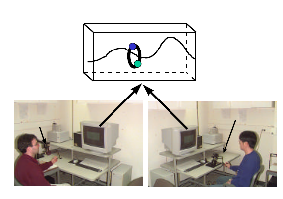
as hazardous material removal, space station repair, and remote surgery; new telecommunication devices and
enhancement of virtual environments for performing collaborative tasks in networked shared virtual worlds such as
co-operative training, planning and design, cyber games, and social gatherings.
2. Design and Implementation of Experiments
We have designed three different experiments involving co-operative manipulation, navigation, and game playing
to investigate the role of haptic communication in SVEs. This section describes the protocol and design of each
experiment. At the time of writing, we have completed the design and implementation of all the experiments. We
report here only the results of one experiment.
A) Experimental protocol and conditions
During each experiment, subjects were asked to perform a collaborative task in a SVE. Subjects were not allowed
to meet their remote partner, and did not know where their partner was located. The participants were in different
rooms but saw the same visual scene on their monitor and felt the objects in the scene via a force feedback device,
the PHANToM (Figure 1).
Visual Display
Haptic
Display Haptic
Display
Figure 1. Our VR set-up enables two people at remote locations interact with each other through visual and haptic
displays. For example, subjects can hold and move a ring on a wire in a collaborative manner as depicted in this
figure.
The shared visual scene depended on the type of experiment. Three different types of experiments have been
designed to be conducted. Two sensory conditions have been explored to investigate the effect of haptic
communication on the sense of togetherness:
(a) both visual and haptic feedback provided to the participants
(b) only visual feedback was provided to the participants
Short description of each experiment and its protocol are provided in the next section. In general, when the subject
manipulates the stylus of the PHANToM with his/her right hand, a cursor moves in 3D space, so that the
controlled object translates or rotates depending on the task. In particular, the following set of collaborative tasks
was designed to study the effect of haptic interaction in shared virtual environments.
B) Description of experiments
1. Move the ring on a wire: The goal of this task is to move a ring with the help of another person without
touching a wire (see Figure 1). A ring, a wire, and two cursors (green and blue small spheres that represent the
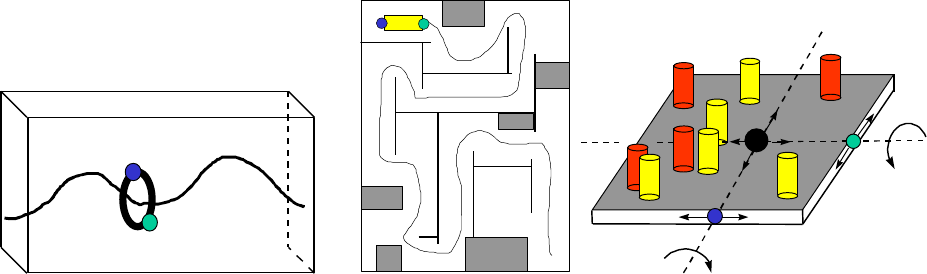
contact points of each subject) attached to the ring were displayed to the subjects (Figure 2a). Haptic
interactions between cursors as well as between cursor and the ring were modeled using a spring-damper
system and a point-based haptic rendering technique (Ho et al., 1997 and 1998). Subjects were asked to move
the ring back and forth on the wire many times, in collaboration with each other such that contact between the
wire and the ring was minimized or avoided. If the ring touched the wire, the colors of the ring and the
surrounding walls were changed to red to warn the subject of an error. They were changed back to their
original colors when the subjects corrected the position of the ring. To hold the ring, both subjects needed to
press on the ring towards each other above a threshold force (see Figure 2a). If they did not press on the ring at
the same time, the ring did not move and its color was changed to gray to warn them. To move the ring along
the wire, they each needed to apply an additional lateral force.
2. Navigate in a maze: The goal of this task is to move a rectangular block inside a maze with the help of the
other person without touching the walls of the maze (see Figure 2b). The block was modeled as a line segment
and the ray-based haptic rendering technique was utilized to detect the collisions with the walls of the maze
(Basdogan et al., 1997). If the block touched a wall, the scene color was changed to red to warn the subject of
an error. It returned to the original color when the subjects corrected the position of the block. To translate the
block inside the maze, subjects needed to push and pull the block in a collaborative manner. They needed to
apply lateral forces to rotate the block while turning the corners.
3. Tilt the board: The goal of this task is to control the orientation of a rectangular board with the help of the
other person in order to make the ball, initially located in the center of the board, roll and touch all the light
colored cylinders, but avoid contact with the dark ones (see Figure 2c). Each subject could tilt the board in
only one direction via the use of PHANToM.
Ring
Green
Cursor
Blue
Cursor
Start
Finish
(a) (b) (c)
Figure 2. Experimental designs: (a) Move the ring on a wire (b) Navigate in a maze (c) Tilt the board.
3. Development of measures and analysis of data
Our aim was to understand the effect of haptic cues on the sense of being together in VEs using performance and
subjective measures. Subjective measures were correlated with performance measures to quantify the role of haptic
communication in SVEs.
A) Performance Measures
A performance measure (e.g. score) for the “sense of togetherness” was derived from the following measurements:
(1) total amount time takes to complete task (2) number of times subjects made errors (error is defined slightly
different for each experiment: error occurs when the ring touches the wire in experiment 1, when the block touches
the walls of the maze in experiment 2, and when the ball hits the red cylinders in experiment 3) (3) the ratio of
erroneous-time to total time (for experiment 3, this is the ratio of number of times the ball hits the red cylinder to
the total number of cylinders).
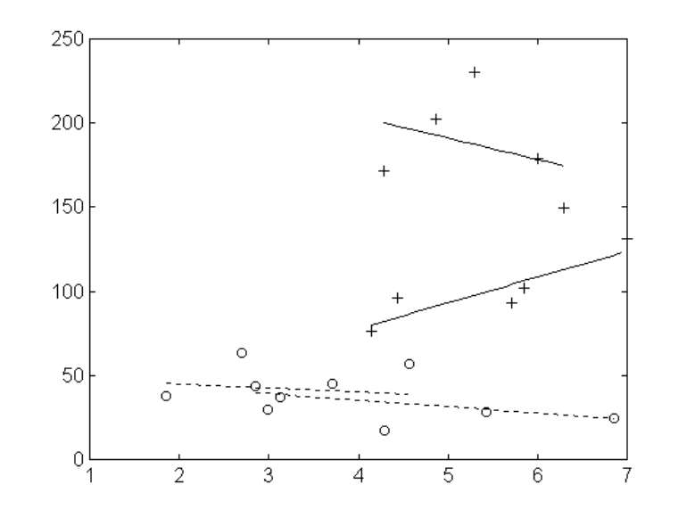
B) Subjective Measures
After each experiment, each subject answered a questionnaire, which supplied basic demographic and background
information. Several subjective questions were asked in four categories including their (1) performance, (2) their
sense of ‘being together’, (3) emotional reactions, and (4) personality profile. Each of the questions in categories
1,2, and 3 were rated on a 1-7 scale. This is in line with rating system used in previous studies of presence (Slater
and Wilbur, 1997).
Results
We present the results of the first experiment (i.e. Move the ring on a wire). All the subjects played the game with
one of the experimenters who was an "expert" player. Two separate groups of subjects, total of 10, participated to
the experiment. The subjects in Group I (5 naive subjects) received first visual and haptic (Condition 1), and then
later visual only (Condition 2) feedback. The subjects in Group II (5 naive subjects) received first visual only
feedback and then later visual and haptic feedback. Subjects repeated the same task at least 10 times for each
experimental condition. For each trial, the performance of the subject was recorded to generate a performance
score. An overall performance score was obtained for each subject by averaging the scores obtained for each trial.
Subjects were also asked to complete a subjective questionnaire for each experimental condition tested. There were
seven questions that related to the sense of togetherness experienced. The subjective level of togetherness
experienced by a player was computed by averaging the responses given to seven different questions. A plot of this
averaged subjective sense of togetherness against the averaged performance score realized in the game is shown in
Figure 3 for the subjects in group I and group II. It can be observed from the plot that there is a direct correlation
between the subject’s performance and his/her subjective sense of togetherness. Moreover, haptic plus visual
condition results in a higher sense of reported togetherness than the visual only condition based on our
measurement system (see Figure 4).
Group II
With Haptic Feedback
Group I
With Haptic Feedback
Group II
No Haptic Feedback Group I
No Haptic Feedback
Performance Measure
Subjective Measure
Figure 3. The Y-axis shows the average performance score achieved by a player during the trials. The score was
based on the number and proportion of contact times between the ring and the wire. The X-axis shows the average
subjective score of a player based on the seven 'togetherness' questions.
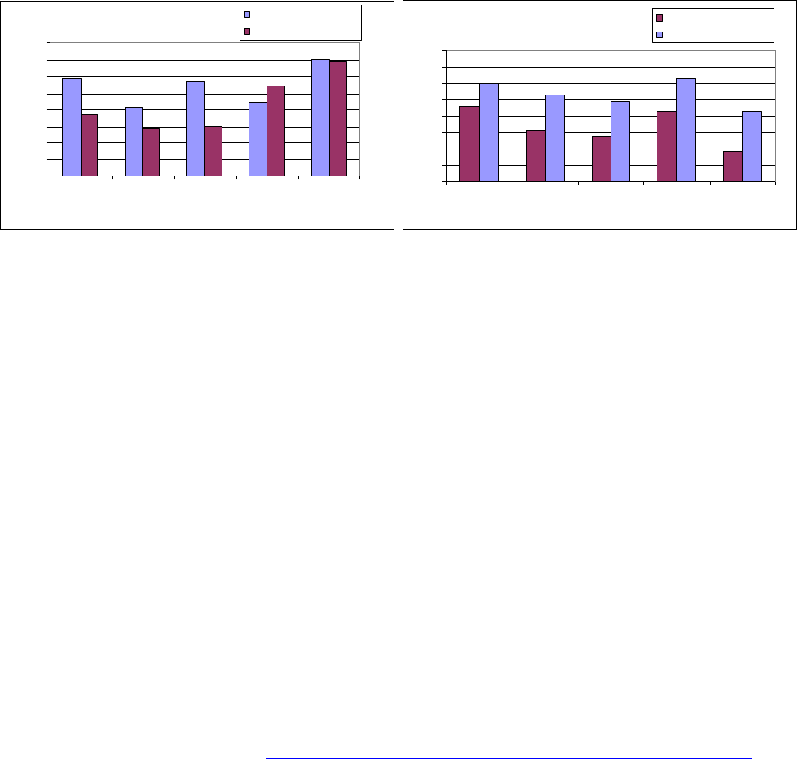
Group 1
0
1
2
3
4
5
6
7
8
1 2 3 4 5
Subject No.
Subjective Measure
With Haptic Feedback
No Haptic Feedback Group 2
0
1
2
3
4
5
6
7
8
12345
Subject No.
Subjective Measure
No Haptic Feedback
With Haptic Feedback
(a) (b)
Figure 4. Subjective scores (i.e. score for “sense of togetherness”) of each subject in groups I and II are represented
as bar charts for comparison of experimental conditions (condition 1 vs. condition 2). Results show that subjective
sense of togetherness increases in all subjects, except one, with the addition of haptic feedback.
Conclusions
This papers reports the results of ongoing experiments to examine the extent to which haptic communication, in
addition to the usual visual feedback, influences the sense of togetherness between remote participants in a SVE.
The results obtained suggest that haptic feedback adds significantly to the sense of togetherness. There is also a
clear influence of haptic feedback on the performance of the task. More experimental studies, including
experiments 2 and 3, will be conducted to further investigate the role of haptic feedback in SVEs.
References
Basdogan, C., Ho, C., Srinivasan, M.A. (1997) “A Ray-Based Haptic Rendering Technique for Displaying Shape and
Texture of 3D Objects in Virtual Environments”, Proceedings of the ASME Dynamic Systems and Control Division,
Vol. 61, pp. 77-84.
Ho, C., Basdogan, C., Srinivasan, M.A., (1997), "Haptic Rendering: Point - and Ray - Based Interactions",
Proceedings of the Second PHANToM Users Group Workshop, Dedham, MA, Oct. 20-21.
Ho, C., Basdogan, C., Slater, M., Durlach, N., Srinivasan, M.A. (1998). An Experiment on The Influence of
Haptic Communication on the Sense of Being Together, British Telecom Workshop on Presence in Shared Virtual
Environments, Ipswich, June 10-11, http://www.cs.ucl.ac.uk/staff/m.slater/BTWorkshop/touchexp.html
Ho, C., Basdogan C., Srinivasan, M.A. (1998). An efficient haptic rendering technique for displaying polyhedral
objects and their surface details in virtual environments, submitted to Presence: Teleoperators and Virtual
Environments.
Durlach, N., Slater, M., (1998), "Presence in shared virtual environments and virtual togetherness", British
Telecom Workshop on Presence in Shared Virtual Environments, Ipswich, June 10-11,
http://www.cs.ucl.ac.uk/staff/m.slater/BTWorkshop/durlach.html
Slater, M., Wilbur S. (1997) A Framework for Immersive Virtual Environments (FIVE): Speculations on the Role
of Presence in Virtual Environments, Presence: Teleoperators and Virtual Environments, MIT Press, 6(6), 603-
616.
Srinivasan, M.A., Basdogan, C., 1997, “Haptics in Virtual Environments: Taxonomy, Research Status, and
Challenges”, Computers and Graphics (Special issue on “Haptic Displays in Virtual Environments”), Vol. 21, No.
4, pp. 393-404.
"A PROJECT TO STUDY HUMAN MOTOR SYSTEM"
L. Piron*§, M. Dam§, E. Trivello§,P. Tonin*, and E. Bricolo**
* San Camillo Hospital, Lido di Venezia, ITALY
§ Dept of Neurology and Psychiatry, University of Padova, ITALY
** SISSA, Trieste, ITALY
Introduction
An essential ability of the human motor system is to learn new movement sequences to
adapt to external environments.
Previous studies have shown how young subjects adapt to external forces perturbing the
motion of their arms [1,2,3]. The subjects learned quickly how to compensate the
displacement of their arms caused by the perturbing forces.
This learning was localized at the specific positions where the forces were applied and
decayed smoothly with the distance from these positions, suggesting a local model of
adaptation. However motor learning may decline with increasing age, as it has been
demonstrated for other cognitive domains. The characterization of the motor function in
elderly may have some therapeutic implications; for instance it may help to plan
scientifically based rehabilitation programs for aged people with motor impairments due to
brain lesions such as stroke.
Along this line we designed a study protocol for identifying motor learning and motor
control features in normal subjects over fifty years old, using Phantom 3.0 Robot (Sensable
Technologies). Our experimental procedure was similar to the one used by Shadmehr et al.,
Gandolfo et al. at M.I.T. for testing young people [1,2].
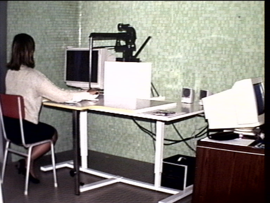
Apparatus
The experimental setup is shown in the figure below.
Subjects are seated in front of a computer screen placed upon a wooden table, the high of which is
adjustable in order to provide the most comfortable setup. A special kind of thick Teflon was glued on
the top of the table to obtain a very slippery surface. Furthermore, the subject's arm is positioned in a
thermoplastic support, which slides very well on Teflon with a minimum degree of viscosity. Subjects
are grasping the stylus of a manipulandum (Phantom Robot) which can be freely moved in any
direction of the surface of the table. The stylus is equipped with thermic sensors (safety switch) so that
when the surface temperature drops suddenly, as when the subject leave the stylus, the apparatus turns
off. The trajectories produced by the subject are visualized on the computer screen. The operator can
follow the task in the connected PC computer (Pentium Intel II 200 Mhz), which records the motor
performances. In addition he has a safety switch to interrupt the task whenever is required.
A Visual C++ program, working on Windows NT Platform, controls the system.
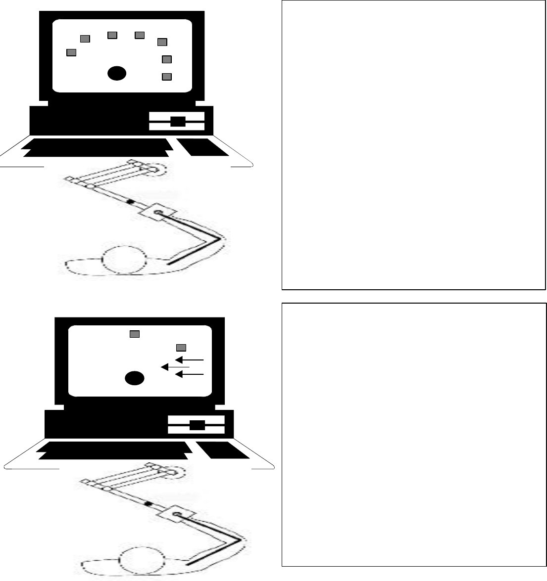
Task
At the beginning the subject is required to set the stylus in a position corresponding to the starting point
(black circle in the Figures) located in the workspace of the computer screen.
.
Training session
.
Subjects have to reach, moving the
manipulandum, a squared target (grey in the
Figure), which randomly appears on the screen
in 1 of the 7 prefixed positions, within 500 ± 50
ms. Visual and auditory feedback are provided:
when the movement is too fast the target turns
red, when it is too slow the target turns blue
and when it is within the time range the target
blows-up and a sound is heard. The training
session comprises 300 reaching movements.
At the end of the session subjects have
learned to perform the task at the prefixed
speed.
Learning session
Only two target positions are tested in this
session (at 0° and 45° in respect to the
subject). A velocity proportional perturbation
(arrows in the figure) is applied through the
robot. With time, subjects learn to compensate
the external perturbation and to reach the
target within the prefixed time (500±50 ms).
The initial distorted trajectories resume the
prototypical straight shape. This session
consists of 500 trials.
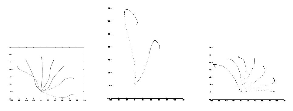
Testing session
Once learning is again accomplished, a third set of 200 trials are administered. All the target positions
used during the training session are tested. In this session we study the effects of force field removal on
motor performance.
Results
We have tested 18 over fifty year old subjects and five young volonteers, ranging in age from 16 to 35
years. No adverse reactions to the experimental procedure were registered.
The figure shows the typical straigth shape trajectories of the reaching movements to visual targets
during the training session (A), the trajectories distorted by the force field applied, when the subjects is
still unable to compensate the perturbation (B), and the aftereffects once the perturbation is removed
(C). The aftereffects are the mirror images of the trajectories observed at the beginning of force field
exposition. Notice that the aftereffects are more evident in the two position where the force field was
applied (position 0° and 45°), while it is minimal at 90°.
AB C
Conclusions
Our data in young people are in agreement with the results obtained in the previous study with a
different apparatus. Therefore, we believe that the Phantom is a reliable and safe tool for studying
motor system function in humans.
In the 18 subjects over fifty, there is evidence of force compensation learning. In fact they are able to
perform nearly straight trajectories under force field perturbation. In addition, we have found that the
magnitude of the aftereffects decreases with the distance from the positions that experienced the force
perturbations, suggesting the persistence of a local model of adaptation in elderly.
However, some subjects have a big latency in learning the baseline of the task (reaching the target
within the required time). In addition old subjects seem to learn force compensation less quickly than
younger people do and the aftereffects persist for a longer time. These data may indicate that some
alterations in the mechanisms of motor learning take place with advancing age.
References
1) Motor learning by field approximation. F. Gandolfo, F.A. Mussa Ivaldi and E. Bizzi.Proc. Natl.
Acad. Sci. USA 93; 1996: 3843-3846.
2) Adaptive representation of dynamics during learning of a motor task. R. Scadmehr and F. A. Mussa
Ivaldi. J. Neurosci. 14; 1994: 3208-3224.
3) Postural force fields of the human arm and their role in generating multijoint movements. R.
Scadmehr, F. A. Mussa Ivaldi and E. Bizzi. J. Neurosci 13; 1993: 45-62.
1
VISUALLY IMPAIRED PERSONS’ USE OF THE PHANToM
FOR INFORMATION ABOUT TEXTURE AND 3D FORM
OF VIRTUAL OBJECTS
Gunnar Jansson
Department of Psychology, Uppsala University, Uppsala, Sweden
gunnar.jansson@psyk.uu.se
Jens Fänger
Department of Simulation and Graphics, University of Magdeburg, Magdeburg, Germany
jens.faenger@student.uni-magdeburg.de
Henry König
Department of Simulation and Graphics, University of Magdeburg, Magdeburg, Germany
hkoenig@iff.fhg.de
Katarina Billberger
Department of Psychology, Uppsala University, Uppsala, Sweden
kattisbillberger@hotmail.com
Abstract
The experiments reported are part of a series of studies aiming to investigate the potentials of a force feed-
back device such as the PHANToM to solve visually impaired people’s problem of getting effective and easily
read depictions, including 3D scenes. It was shown that the roughness of virtual textures and the 3D form of
simple objects could be judged without visual guidance. An experiment with visually impaired observers indicated
that many of them can perform on a similar level as blindfolded sighted observers, but that some of them have
problems in performing the task. On-going experiments investigate if these problems can be solved by extra train-
ing in method of exploration.
The PHANToM Used Without Visual Information
A main problem concerning depictions for the visually impaired is that it is often very difficult to perceive 3D
aspects of 2D tactile pictures (cf. Jansson, 1988). A display providing easy access to these aspects would mean an
important breakthrough. The haptic force feedback displays, such as the PHANToM, provide potentially a solution
to this problem.
However, even if virtual 3D objects are certainly rendered by the PHANToM, it has to be proved that the
information presented can be utilized by the users, in the present case visually impaired users. A general problem
is that the PHANToM virtual objects can not be explored in the same way as real objects. Normally, sufficiently
small objects are manipulated by the observer holding them with both hands using several fingers. For exploration
with the PHANToM there is never more than one point of contact between the observer and the object at a time.
This point of contact, whether within a ”thimble” or at the end of a stylus, is located differently from any of the
natural contact points between observer and a real object. The problems these special ways of exploring may cause
might be enhanced when vision is not available, as haptics in this case is deprived of the normally close coopera-
tion between vision and haptics (cf. Heller, 1982). This means, for instance, that a visually impaired person has
problems with getting an overview of a scene and finding its relevant parts.
2
Another potential problem is that a virtual haptic object is not an exact copy of a corresponding real object.
The differences may not be important, but it can not be known for sure, especially not if they can not be compen-
sated for by visual information.
The present paper is one in a series intending to study the usefulness of the PHANToM for depicting virtual
scenes without vision being involved. Studies on two aspects basic for haptic perception, texture and 3D form of
objects, are reported.
Experiment 1. Perceived Roughness of Real and Virtual Sandpapers
Haptics is very accurate in discriminating and identifying textures, sometimes better than vision. The physical
properties of textures may be very complex and difficult to reproduce for virtual textures. Green & Salisbury
(1997) developed a method to acquire data about the physical properties of textures with the help of the PHAN-
ToM by registering lateral forces and the z position of the endpoint of a stylus when it is moved over the surface.
The virtual surfaces are based on parameters from these measurements. They are not exact copies of the physical
surfaces but the intention is that they should be sufficient for accurate perception of the textures.
The aim of the experiment, described in more detail in Jansson (1998), was to compare corresponding real and
virtual sandpapers rendered by a PHANToM 1.5A with the Green & Salisbury method. Twelve paid sighted blind-
folded university students explored the two kinds of sandpaper with a stylus and made magnitude estimations of
the roughness of sandpapers with four different degrees of physical coarseness. Their judgments were based on
haptics alone, the auditory information being masked.
The result was that corresponding real and virtual sandpapers were judged to have very similar degrees of
roughness. There was a tendency for the virtual sandpapers to be judged as somewhat rougher than the real ones,
but the difference was not statistically significant.
Experiment 2. Identification of 3D Virtual Geometric Forms
A necessary prerequisite for a haptic display to be useful for visually impaired people is that the form of objects
can be identified without visual guidance. The aim of this experiment was to investigate to what extent objects of
some 3D geometric forms of different sizes could be identified when rendered with the PHANToM.
The preparation of the series of experiments required the development of a model editor that allowed easy
creation of virtual 3D scenes. As the import of OpenInventor models is possible but haptic parameters like friction
are not included within these models, it proved necessary to develop a new system which was named
ENCHANTER (see Fig. 1).
ENCHANTER – An ENvironment for Creation and HANdling of Tactile ExpeRiments
The main purpose of ENCHANTER is the insertion and the manipulation of primitive objects. In addition, it
makes possible the combination of different scenes for experiments. The PHANToM is used as an input device for
the model editor. One task it is well-suited for is the transformation of haptic objects using the gstManipulator
classes provided by the GHOST SDK. Object picking in 3D scenes is also very easy to perform with the PHAN-
ToM’s help. In the ENCHANTER you simply tap an object to select it, another tap will deselect it. In contrast to
mouse selection, this method allows a far more natural way of interacting, especially because the user feels the
object while selecting it. Another aspect is that mouse selection is limited to objects visible on the screen, whereas
the PHANToM can be used to select all objects in the 3D environment resulting in higher precision and speed.
Even if it was not utilized in the present experiment, it may be mentioned that several regular textures (sinus,
triangular and rectangular), as well as textures produced by other software programs, can be rendered with
ENCHANTER. The texture mapper was extended to make these textures available to all haptic objects, of any
form, provided by the GHOST SDK. This was done by introducing an effect class, making it possible to adjust the
force normals returned from a collision detection. Using this, it is only necessary to subclass the shape in order to
introduce data members for the texture properties. A side effect of this approach is the possibility to render the
textures on dynamic objects as well.
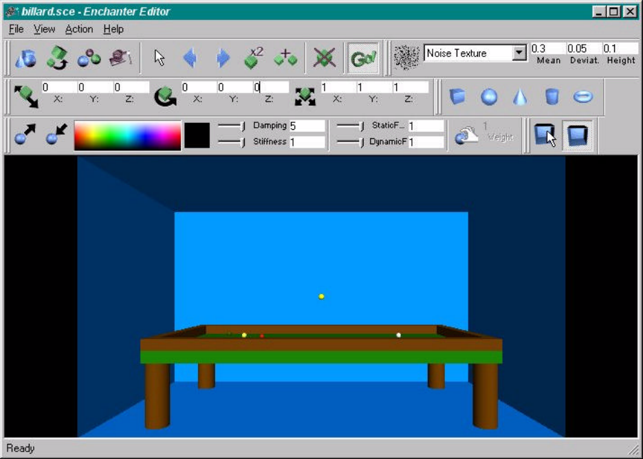
3
During an experiment these scenes are presented to an observer in fixed or random order. While the experi-
ment is running, the movement of the PHANToM can be recorded and played back later using the force-feedback
device as a robot that guides the observer’s hand.
Figure 1. ENCHANTER with example of scene (not used in the experiments).
Experiment 2a. Blindfolded Sighted Observers
Four virtual geometric forms of three sizes, rendered by a PHANToM 1.5A under ENCHANTER, were pre-
sented to ten paid blindfolded sighted university students who explored the objects with a stylus. The experiment
is described in more detail in Jansson (1998). The result was that the observers could very effectively identify the
virtual forms, especially after some experience with the device. For the second and third replication of the stimuli
95 % of all the forms and sizes were correctly identified within an exploration time of about 10 - 20 sec (range for
the means of each stimulus).
Experiment 2b. Visually Impaired Observers
Problem. The experiment just mentioned demonstrated that vision is not necessary for correct identification of
3D geometric forms. Even if a similar result can be expected to be applicable also to a comparable group of visu-
ally impaired observers (especially concerning the relations between the experimental conditions), there may be
complications for these observers. On one hand, they have more training in using the haptic sense; on the other
hand, they have less experience of spatial relations in the environment as these are experienced by sighted people.
The absolute level of the results may be different, the former fact suggesting a better result, the letter a not as good

4
one. Further, it would be of interest to investigate the result in a group with wider range in age and, maybe, abili-
ties. How will such a group of visually impaired observers perform in a task similar to the one in Experiment 2a?
Virtual Geometric Forms. Four 3D forms (sphere, cube, cylinder, and cone) in five sizes (all three dimensions
being 6, 8, 10, 50 and 100 mm, respectively) were rendered with a PHANToM 1.5A under ENCHANTER. In
order to simplify finding the objects, each was localized in the middle of a cubical enclosure its dimensions being
20 mm for the three smaller forms and 100 and 200 mm for the 50 and 100 mm forms, respectively. To help the
discrimination between object and enclosure, the object to be identified was given no static friction and the insides
of the enclosure were given high such friction.
Procedure. The observers were informed about the PHANToM and the safety aspects and they were allowed to
acquaint themselves with the device. The geometric forms to be used were explained and wooden models of the
forms (all three dimensions being 25 mm) were demonstrated. There were no restrictions applied on how the
observers should hold the stylus, but the observers usually held it similar to a pen. A head protective device com-
mon in industry was applied, as was an eye cover for observers with any remaining vision. Further, earphones
were applied to mask any sound by playing white noise
1. Before the experiment proper, the observers were
allowed to try up to ten objects of different form and size under the experimental conditions without any record-
ing.
During the experiment the observers were presented with three blocks of all the virtual objects (four objects in
five sizes) one by one in random order within the block, thus in all 60 objects. The observers’ task was to name the
form of the objects as fast and accurately as possible, with equal emphasis on both aspects. A maximum of 60 sec
was allowed for each object. The time elapsing from the start of exploration within the enclosure until the begin-
ning of the response was recorded, as was the verbal response.
Observers. Ten visually impaired persons (three women and seven men) were paid to participate. Their age
varied between 23 and 50 years with a mean of 38 years. Six of them were totally blind; of the remaining four two
had some sense of light and two had some low vision within a small visual angle. One of the observers got blind
when in an incubator; the others had been sighted for different numbers of years. They had been visually impaired
for 6-31 years.
Results. Six of the ten observers got results similar to those of the sighted blindfolded observers in Experiment
2a. Their results are given in Fig. 2. Four of the observers had difficulties in performing the task, resulting in
many mistakes and unfinished tasks.
Discussion. The result in Experiment 2b differed partly from that in Experiment 2a. Six of the visually
impaired observers performed similarly to the sighted observers, but four did not. The two groups were not
matched and they are too small to make detailed comparisons meaningful, but one hypothesis, based on informal
observations, is that the visual impaired observers with low performance had some basic difficulties in
understanding the task, finding the objects, and/or exploring them in an effective way. A follow-up study where
low-performing observers are asked to return to get training in finding and exploring the virtual objects before
new test sessions is in progress.
General discussion
1 It can be discussed if masking sound should be used. If the practical situation of a visually impaired person using
the PHANToM is considered, sounds may be looked upon as additional potentially useful information and not
masked. On the other hand, if the capabilities of haptics alone is considered the sounds should be masked. There
were indications in Experiment 2a, where the sounds from the PHANToM were not masked, that the sounds pro-
duced when the stylus end passed edges might have been used by the observers. We chose here to study haptics
alone and applied thus a masking sound.
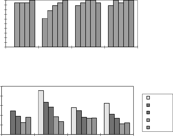
5
The experiments demonstrated that the texture and 3D form of virtual objects rendered with a PHANToM
device can be perceived accurately and with reasonable speed without the guidance of vision. Experiment 2b dem-
onstrated that many visually impaired observers can perform on the same level as blindfolded sighted observers,
but also that some observers with visual impairment have problems in performing the task. An experiment in pro-
gress investigates if these problems can be solved by extra training of the exploration method.
It should be noted that the haptic perception of only a few properties of 3D objects have been investigated.
Many aspects remain to be studied. An important parameter for future studies is the complexity of the virtual
scene. A reasonable hypothesis is that increase of the complexity of texture and 3D form would mean increased
problems for haptic perception of the virtual scenes.
0
10
20
30
40
50
60
70
80
90
100
cylinder cone cube sphere
3D geometric form
Percent correct
responses
0
10
20
30
40
50
cylinder cone cube sphere
3D geometric form
Mean exploration time
(sec)
6 mm
8 mm
10 mm
50 mm
100 mm
Figure 2. Means of percent correct responses (top) and of exploration times (bottom) for each of the objects for six
of the ten observers. (Data for the 6 mm cylinder missing for technical reasons.)
Acknowledgments
This study was made possible by grants from the Swedish Council for Research in Humanities and Social
Sciences and from the Swedish Transport and Communications Research Board. The authors are indebted to
Donald Green and Kenneth Salisbury, Massachusetts Institute of Technology, Cambridge, MA, for making the
computer software PALPATE available for this study and to Lars-Erik Larsson for technical assistance.
References
Green, D. F. & Salisbury, J. K. (1997). Texture sensing and simulation using the PHANToM: Towards remote
sensing of soil properties, In J. K. Salisbury & N. A. Srinivasan (Eds), Proceedings of the Second PHANToM
6
Users Group Workshop (A. I. Technical Report No. 1617 and R. L. E. Technical Report No. 618). Cambridge,
MA: Massachusetts Institute of Technology.
Heller, M. A. (1982). Visual and tactual texture perception: Intersensory cooperation. Perception & Psychophys-
ics, 31, 339-344.
Jansson, G. (1988). What are the problems with tactual pictures, and what can we do to solve them?. In C. W. M.
Magnée, F. J. M. Vlaskamp, M. Soede, & G. Butcher (Eds.), Man-Machine Interfaces, Graphics and Practical
Applications (pp. 18-24). London: Royal National Institute for the Blind.
Jansson, G. (1998). Can a haptic force feedback display provide visually impaired people with useful information
about texture roughness and 3D form of virtual objects? In P. Sharkey, D. Rose & J.-I. Lindström (Eds.), The
2nd European Conference on Disability, Virtual Reality and Associated Technologies. Proceedings (pp. 105-
111). Reading, UK: University of Reading, Department of Cybernetics.
Psychophysical experiments in
a complex virtual environment
Markus von der Heyde
University of Rochester NIH Virtual Reality Lab
(email: mvonderh@cs.rochester.edu)
Charlotte H¨
ager-Ross
University of Rochester Medical Center
(email: chr@cvs.rochester.edu)
Abstract
We are using two PHANToM 3.0 force feedback devices in one workspace in order to perform studies of one-hand
precision grip tasks or two handed pointing tasks. The visual environment is rendered by an Onyx workstation and
presented in a specialized stereo head mounted display that allows eye tracking. The head position and orientation is
tracked with an electromagnetic system (Fastrak). Together, these systems allow the current gaze direction in world
coordinates to be computed in real time. The artificial visual and haptic environment may contain free movable
objects as well as stationary parts, whereas the objects can be complex or simple. The graphical user interface allows
all object properties to be changed online. In addition, we are using free programmable force effects that depend
on position or velocity information. Psychophysical experiments that simulate eye-hand coordination in complex 3D
scenes demonstrate results that seem to be in line with previous research in real environments. Thus, we believe
that the dual-PHANToM instrument is an experimental device that is well suited for various studies of visual motor
coordination, with special reference to aspects like timing and adaptation.
keywords: human experiments: psychophysics, vision, sensori-motor control; virtual reality
1 The Virtual Reality Setup
The National Institute of Health (NIH) Virtual Reality Lab integrates several devices in one co-located environment
in order to simulate many aspects of human sensori-motor coordination. Devices like head mounted displays (HMD)
and 3D position and orientation trackers (Fastrak, Polhemus Inc) are used to present a virtual scene for subjects, in
which they can interact using a force feedback system (PHANToM, SensAble Technologies, Inc.). All devices are
integrated in a flexible experimental setup, in which movable as well as stationary virtual objects and their physical
properties can be controlled by the experimenter. The program controlling experiments and virtual presentations to
subjects allows online control over all parameters concerning the objects and the devices. The simulation runs on
a specialized Onyx Infinite Reality machine (Silicon Graphics, Inc.). The graphical rendering as well as the haptic
interactions are controlled by the same computer in order to minimize the latency of the simulation.
1.1 The PHANToM 3.0
The current system is designed to have two PHANToM 3.0 force feedback devices acting in one physical and virtual
workspace with a dimension of 30x40x40 cm. The two PHANToM devices face each other, mounted on epoxy blocks
situated on a table (Fig. 1).
A crucial setup problem is to achieve an exact alignment of the workspaces of the two PHANToMs. Each device
needs to be calibrated to the precise location in the shared three dimensional workspace. Through careful calibration
of the mounting position and by using an optimal starting position (90 degree angles) for the PHANToM arms, we
achieved an error below 1 mm on average between the physical point in 3D space and the virtual space of each
1
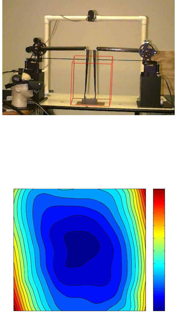
Figure 1: The VR setup with workspace (cube)
PHANToM. The average distance for the same physical point between both PHANToMs is below 1.5 mm. However,
the errors increase from the calibration center towards the edges of the common workspace (see Fig. 2 for more details
on the error distribution).
−150 −100 −50 0 50 100 150
−200
−150
−100
−50
0
50
100
150
200
X Axis [mm]
Y Axis [mm]
0.44093
0.44093
0.763
0.763
0.763
0.763
0.763
1.0851
1.0851
1.0851
1.0851
1.0851
1.0851
1.4072
1.4072
1.4072
1.4072
1.4072
1.4072
1.7292
1.7292
1.7292
1.7292
2.0513
2.0513
2.0513
2.0513
2.3734
2.3734
2.3734
2.3734
2.6955
2.
6955
2.6955
2.6955
3.0175
3.0175
3.0175
0.5
1
1.5
2
2.5
3
3.5
4
4.5
Figure 2: Contours of position mismatch in mm
2

1.2 Head Mounted Display with eye-tracking
The observers perspective of the scene is presented in a V8 HMD (Virtual Research Systems, Inc.) and depends on
the position and orientation of the subject’s head in real 3D space. This six-degrees-of-freedom tracking is realized
with the Fastrak device. Low frequency magnetic fields are generated by three co-located antennas inside a transmitter
and received by similar remote antennas inside a receiver. The signal is transformed by a mathematical algorithm to
compute the relative distance and the orientation for the transmitter and the receiver. The appropriate view is presented
to the subject inside the helmet with a delay below 30 ms. The resolution of the LCD is VGA standard (640x480 pixels
for each eye) in true color and the screen is updated with a frequency of 60 Hz.
The customized HMD allows the tracking of movements of the subject’s left eye. A built-in eye-camera connected
to a separate computer provides information of the subject’s gaze angle. Since the presented view is known in detail,
the program can intersect the ray of sight with the virtual scene and calculate where the subject is looking. This
information is valuable for experiments that address eye-hand coordination as well as experiments that focus on human
memory (for more examples see [Jackson et al., 1995], [Messier and Kalaska, 1997] and [Toni et al., 1996]). The lab
is in the process of developing several experiments along these lines.
2 Psychophysical experiments
The device has special characteristics that have to be considered when doing psychophysical experiments in this virtual
environment. For instance, the normal tactile feedback when touching and handling an object is absent. Instead, the
skin of the fingertips is in constant contact with the inside of the finger thimbles. Cutaneous receptors normally provide
the central nervous system with information related to touch and slippage between the object and the finger when we
grasp something. The character of the surface material in contact with the fingertips is therefore essential for the
fingertip force coordination when handling real objects. We observed that the surface inside the thimbles strongly
influences the force that the subjects apply, even though the force feedback gives the subject information about object
contact (see below).
In a virtual environment as rich and complex as this, one can think of a variety of studies. Of particular interest are
experiments that not only allow a good approximation to similar conditions in reality, but that also add control over
parameters that are not easily studied or manipulated under normal conditions.
The current software was developed to design and control experiments involving many different parameters in-
cluding object properties such as: mass, visual and haptic size, color and texture, transparency, surface spring, surface
damping, dynamic and static surface friction, surface smoothness (necessary only for complex shapes), object elasticity
during collisions etc. Additional features involve control over the field of gravity, viscous damping in the surround-
ing medium, position and velocity, haptic and visual rendering, collision detection and even movement restrictions
to planes and axis. Moreover, the program allows control of some HMD parameters and offers a fast and flexible
interface to data collection. The data is already processed by the computer and only has to be saved to a file at an ad-
justable sampling frequency of up to 1000 Hz. Most of the object properties and the device settings can be predefined
in configuration files or controlled online via the graphical user interface. Specialized control windows offer a flexible
design and setup of separate experiments in a short time.
Below we present some examples of experiments in which different tasks involving sensori-motor control in the
virtual environment have been studied. These serve to illustrate the potential of the device and the program.
Sorting objects by weight:
Subjects sorted four cylinders according to their weight, which was randomized to any value between 25 and
250 g. In addition, the size of the cylinder could vary independently. The results of the classical weight-size illu-
sion were confirmed, i.e., subjects make systematic errors in discriminating objects of similar weights, when the
size is not related to the weight, by judging a bigger object as being lighter ([Woodworth and Schlosberg, 1938]).
An analysis discriminating between the subject’s ability to detect mass or density was used to implement a linear
model that could explain the error rate.
Reaching through force fields:
Subjects performed reaching tasks from a starting point towards a final point, which could be an object as
well as just a marked target/region in space. Experimental conditions like invisible fingertips, invisible targets
at the onset of the movement ([Miall and Haggard, 1995]) and different instructions concerning the speed of
3

the movement showed results in accordance with previous findings in reaching tasks ([Jeannerod, 1984] and
[Jeannerod, 1988]). When a force field was introduced during the movement somewhere between the start and
end point, the subject adequately compensated for the perturbation. In one experiment the force field depended
on position (see [Conditt et al., 1997] for similar experiment) and in the other case it depended on the subject’s
fingertip velocity (see artificial perturbation in [Coello et al., 1996]). In both cases the subject was able to adapt
after a couple of trials.
Lifting cylinders with different physical properties and with a reversed field of gravity:
In another series of experiments the subjects performed simple lifts of an object (cylinder). The visual properties
were always constant, but the haptic conditions and physical properties of the object were changed between
trials. In the analysis we separated the force perpendicular to the field of gravity (grip force) and the lifting
force in the direction opposite to the field of gravity (load-force). The grip and load forces are coordinated in
parallel and are directly related to various object properties like weight, size, shape etc as shown in a number
of studies by Johansson and colleagues (for review see [Johansson, 1997]). Subjects applied grip and load
forces according to changes of the physical properties of the object and to changes of the direction of gravity.
The surface in contact with the fingers in the thimbles was important for the grip force regulation. A more
slippery surface like the standard metal thimble results in higher grip forces throughout the lift compared to
when sandpaper was used inside the thimbles.
Acknowledgement
This material is based upon work supported by the National Institutes of Health/Public Health Service research grant
number 2 P41 RR09283.
References
[Coello et al., 1996] Y. Coello, J. P. Orliaguet, and C. Prablanc. Pointing movement in an artificial perturbing inertial
field: a prospective paradigm for motor control study. Neuropsychologia, 34(9):879–892, 1996.
[Conditt et al., 1997] M. A. Conditt, F. Gandolfo, and F. A. Mussa-Ivaldi. The motor system does not learn the
dynamics of the arm by rote memorization of past experience. Journal of Neurophysiology, 78(1):554–560, 1997.
[Jackson et al., 1995] S. R. Jackson, G. M. Jackson, and J. Rosicky. Are non-relevant objects represented in work-
ing memory? The effect of non-target objects on reach and grasp kinematics. Experimental Brain Research,
102(3):519–530, 1995.
[Jeannerod, 1984] M. Jeannerod. The timing of natural prehension movements. Journal of Motor Behaviour, 16:235–
254, 1984.
[Jeannerod, 1988] M. Jeannerod. The neural and behavioural organization of goal-directed movements. Clarendon
Press, Oxford, 1988.
[Johansson, 1997] R. S. Johansson. Hand and Brain; The neurophysiology and psychology of hand movements.
A. Wing, P. Haggard, and R. Flanagan (eds.), Accademic Press, Inc., San Diego, California, 1997.
[Messier and Kalaska, 1997] J. Messier and J. F. Kalaska. Differential effect of task conditions on error of direction
and extent of reaching movements. Experimental Brain Research, 115(3):469–478, 1997.
[Miall and Haggard, 1995] R. C. Miall and P. N. Haggard. The curvature of human arm movements in the absence of
visual experience. Experimental Brain Research, 103(3):421–428, 1995.
[Toni et al., 1996] I. Toni, M. Gentilucci, M. Jeannerod, and J. Decety. Differential influence of the visual framework
on end point accuracy and trajectory specification of arm movements. Experimental Brain Research, 111(3):447–
454, 1996.
[Woodworth and Schlosberg, 1938] R. S. Woodworth and H. Schlosberg. Experimental Psychology. Rinehart, H.
(ed.), New York, 1938.
4
