6011_mlGas_SrvInstl_0404 Alto Shaam Inc. Oven 2020ESG ALT 610ML Spm
User Manual: Alto-Shaam Inc. Oven 2020ESG
Open the PDF directly: View PDF ![]() .
.
Page Count: 40

INSTALLATION
SERVICE
AND
MAINTENANCE
W164 N9221 Water Street ●P.O. Box 450 ●Menomonee Falls, Wisconsin 53052-0450 ●U.S.A.
PHONE: (262)251-3800 (800)558-8744 U.S.A./CANADA ●FAX: (262)251-7067 (800)329-8744 U.S.A. (262)251-1907 INTL
www.alto-shaam.com
PRINTED IN USA #6011ML•4/04
COMBINATION
OVEN/STEAMERS
COMBITHERM®
GGAASS
MMLL SSEERRIIEESS
®
COMBITHERM
FOUR/CONVECTION VAPEUR
6•10ML, 7•14ML, 10•10ML,
10•20ML, 12•18ML & 20•20ML GAS
ADVERTISSEMENT
Ne pas entreposer ni utiliser de l'essence ni d'autres
vapeurs ou liquides inflammables dans le voisinage de
cet appareil, ni de tout autre appareil.
ADVERTISSEMENT
Une installation, un ajustement, une altération, un
service ou un entretien non conforme aux normes peut
causer des dommages a'la propriété, des blessures ou la
mort. Lisez attentivement les directives d'installation,
d'opération et d'entretien avant de faire l'enstallation ou
l'entretiende cet équipement.
NOTE: En dernier reours, les instructions provenant
du fournisseur local de gas doivent être mises
en evidence de maniere a indiquer les
procedures à suivre au cas ou l'utilizateur
sentirait le gaz.
MIES EN GARDE
Les informations contenues dans ce manuel
sont importantes pour l'installation
l'utilisation et l'entretien de ce four. S'il
vous plait lisez-le tres attentivement et
conservez-le. La non-application de ces
consignes annule toutes garanties.
COMBITHERM GAS MODELS
6•10ML,7•14ML,10•10ML,
10•20ML,12•18ML & 20•20ML
SAFETY:
Do not store or use gasoline or other flammable vapors or
liquids in the vicinity of this or any other appliance.
WARNING:
Improper installation, adjustment, alteration, service or
maintenance can cause property damage, injury or
death. Read the installation, operating, and
maintenance instructions thoroughly before installing
or servicing this equipment.
NOTE: Instructions obtained from the local gas
supplier, indicating procedures to be
followed in the event that the user smells
gas, must be posted In a prominent
location.
The information contained in this manual is
important for the proper installation, use and
maintenance of this oven. Please read
carefully and retain for future reference.
Improper connection of this appliance
will nullify all warranties.
MISE EN GARDE
INSTALLATION, SERVICE AND
MAINTENANCE MANUAL
MANUEL D'INSTALLATION, DE MISE EN
ROUTE ET D'ENTRETIEN MODELES :
®
COMBITHERM
GAS
ALTO-SHAAM, INC.®
P.O. BOX 450, W164 N9221 WATER STREET
MENOMONEE FALLS, WI 53052-0450, USA
MODEL SERIAL NO.
GAS TYPE MANIFOLD GAS PRESSURE IN. W.C.
INPUT RATE BTU/HR
ELECTRICAL: 110-120V, 60 Hz, 1 PH AMP WATTS
MINIMUM CLEARANCES FOR COMBUSTIBLE AND NON-COMBUSTIBLES
CONSTRUCTION: LEFT= 4 INCHES / RIGHT = 1 INCH / REAR = 1 INCH
FOR USE ONLY ON DOIT ETRE UTILISE SEULEMENT
NON-COMBUSTIBLE FLOORS SUR DES PLANCHERS INCOMBUSTIBLES
FOR INSTALLATION UNDER POUR UNE INSTALLATION SOUS UNE
VENTILATION HOOD ONLY HOTTE D'EVACUATION SEULEMENT
INTENDED FOR OTHER THAN DESTINE A UN USAGE AUTRE QUE
HOUSEHOLD USE DOMESTIQUE
ANSI/NSF4
ANS Z83.11-CSA 1.8-2002
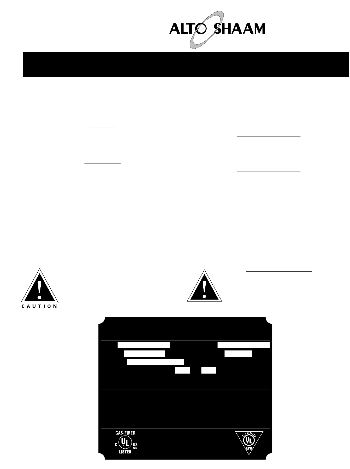
The Alto-Shaam Gas
Combitherm oven/steamer
has a specification plate
affixed to the left-hand side
panel of the oven. The
plate includes electrical and
gas connection
specifications and should
be reviewed prior to
service.
Contact the factory if any
servicing assistance is
required. Remember to
provide the model number
and serial number of the
oven which can be found on
on this oven nameplate.
®
COMBITHERM
GAS
1.0 INSTALLATION
1.1 Receiving & Transportation . . . . . . .1
1.2 Basic Installation Site Requirements . . .1
1.3 Ventilation Requirements . . . . . . . . .2
1.4 Positioning On Site . . . . . . . . . . . . .2
1.5 Installation Codes & Standards . . . .2
1.6 Installation Requirements . . . . . . . .3
1.7 Air Supply Requirements . . . . . . . . .4
1.8 Assembly Requirements . . . . . . . . . .4
1.8.1 Exhaust Gas Flue Diverter . . . .4
1.8.2 Sound Absorber . . . . . . . . . . . .4
1.8.3 Hand Shower Holder . . . . . . . .4
1.8.4 Drip Tray . . . . . . . . . . . . . . . . .4
1.8.5 Roll-In Cart (TROLLEY) Guide Rails . . . .5
1.9 Electrical Connection . . . . . . . . . . . .5
1.10 Water Supply . . . . . . . . . . . . . . . . . .6
1.11 Water Drainage . . . . . . . . . . . . . . . .6
1.12 Gas Connection Requirements . . . . .7
1.13 Gas Type and Pressure . . . . . . . . . . .7
1.14 Gas Connection . . . . . . . . . . . . . . . .7
1.15 Leak Testing . . . . . . . . . . . . . . . . . .8
1.16 Fuel Interlock System . . . . . . . . . . .8
1.17 Gas Exhaust . . . . . . . . . . . . . . . . . . .8
1.18 Gas Pressure Chart . . . . . . . . . . . . .9
1.19 Gas Flame Patterns . . . . . . . . . . . . .9
1.20 Burner Pilot Adjustment . . . . . . . .10
1.20.1 Checking Pressure . . . . . . . . .10
1.20.2 Adjust Pilot Burner . . . . . . . .10
1.20.3 Manifold Pressure Adjustment . . .10
1.20.4 Ignition & Burner Check . . . . .10
1.20.5 Verify Sequence of Operation . . . .10
1.21 Sequence of Operation . . . . . . . . . .11
1.22 Stacking Combitherm Connections .12
1.23 Post Installation Check List . . . . . .13
1.24 Emergency Operation . . . . . . . . . . .14
2.0 CONTROL PANEL IDENTIFICATION . . .15
. . . . . . . . . . . . . . . . . . . . . . . . . . . . . . .16
2.1 Safety Precautions . . . . . . . . . . . . .17
2.2 Preventive Maintenance . . . . . . . . .18
2.3 Routine Cleaning Requirements . . .18
2.4 DAILY CLEANING
2.4.1 Cleaning Instructions . . . . . . .19
2.4.2 Automatic Cleaning Program .20
2.5 MONTHLY CLEANING
2.5.1 Water Intake Filter Cleaning . . . .21
2.5.2 Drain Pipe Cleaning . . . . . . . . . . .21
2.5.3 Flue Outlet Cleaning . . . . . . . . . .21
2.5.4 Fan Cleaning . . . . . . . . . . . . . . . . .22
2.6 Roll-In Cart/Food Trolley Cleaning . .23
2.7 Daily Gasket Cleaning . . . . . . . . . .23
3.0 SERVICE SECTION
3.1 Combitherm Service Record . . . . . .24
3.2 Combitherm Gas
3.2.1 Exterior Component Identification . .25
3.2.2 Operating Schematic . . . . . . . .25
3.2.3 Plumbing System . . . . . . . . . .25
3.3 Service Views — LEFT-SIDE PANEL
Models 6•10, 7•14, 10•10, 10•20, 12.18 . . . .26
Motor Contactor & Protection Switches . . . .27
3.4 Service Views— LEFT-SIDE PANEL
Model 20•20 . . . . . . . . . . . . . . . . . . . . . . . . . . .28
Motor Contactor & Protection Switches . . . .29
3.5 Troubleshooting . . . . . . . . . . . . . . . . . . . . . . . .30
. . . . . . . . . . . . . . . . . . . . . . . . . . . . . . . . . . . . . . . . . . .31
3.6 Combitherm Gas Parts List . . . . . . . . . . . . . .32
. . . . . . . . . . . . . . . . . . . . . . . . . . . . . . . . . . . . . . . . . . .34
Wiring Diagrams . . . . . . . . . . . . . . . . . . . . . . . . .35-36
Transportation & Damage Claims . . . .37
Limited Warranty . . . . . . . . . . . . . . . .37
TABLE OF CONTENTS
COMBITHERM®GAS INSTALLATION
COMBITHERM GAS INSTALLATION AND MAINTENANCE MANUAL — 6011ML
PG.1
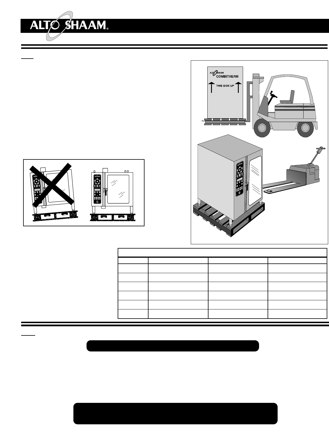
1.1 RECEIVING & TRANSPORTATION
Upon receipt of the Combitherm combination oven/ steamer,
check the exterior of the shipping carton for any physical
damage that could result in damage to the contents. If the
oven was not received from the carrier in an upright position,
there is a stronger possibility of concealed damage. Remove
the carton or uncrate the unit carefully and inspect for any
transit damage. Immediately report any damage to the
delivering freight carrier.
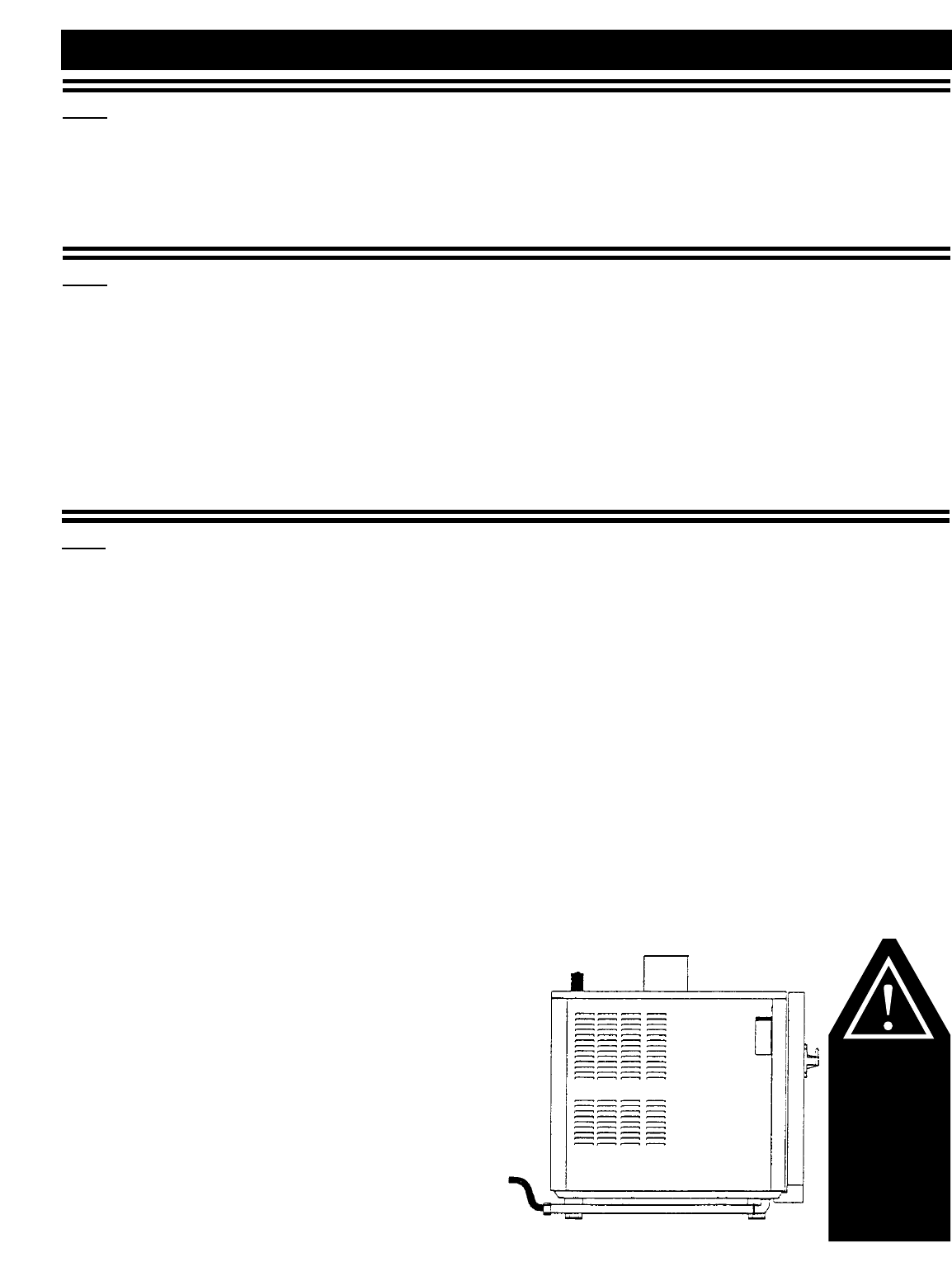
The oven must remain on the pallet while
being moved to the installation site by fork
lift or pallet lift truck.
Note the
dimensions
required for
doorways
and aisles
for access of
the oven and
pallet to the
installation
site.Transport the oven in an upright and level position
only. Do not tilt the oven.
With the oven on the original
pallet, remove the carton and all
packaging materials. Open the
oven door and remove all
documents and other materials
from the oven interior. Remove
the roll-in cart if so equipped.
®
MODEL
6•10MLGAS
10•10MLGAS
7•14MLGAS
10•20MLGAS
12•18MLGAS
20•20MLGAS
WIDTH
42" (1067mm)
42" (1067mm)
45" (1143mm)
51" (1295mm)
51" (1295mm)
58" (1473mm)
DEPTH
35" (889mm)
35" (889mm)
51" (1295mm)
49" (1245mm)
49" (1245mm)
44" (1118mm)
HEIGHT W/PALLET
42" (1067mm)
48" (1219mm)
68" (1727mm)
65" (1651mm)
65" (1651mm)
85" (2159mm)
A
TTENTION
A
TTENTION
PALLETIZED DIMENSIONS
1.2 BASIC INSTALLATION SITE REQUIREMENTS
HOOD INSTALLATION IS REQUIRED
• Installation surface must be level.
• Do not install adjacent to flammable surfaces.
• Deep fat fryers or similar heat producing equipment must not be installed in
the immediate vicinity of the hand shower.
• The installation surface must be non-combustible (unable to burn).
The oven must remain on the pallet while being moved
to the installation site with fork lift or pallet lift truck.
COMBITHERM GAS INSTALLATION AND MAINTENANCE MANUAL — 6011ML
PG.2
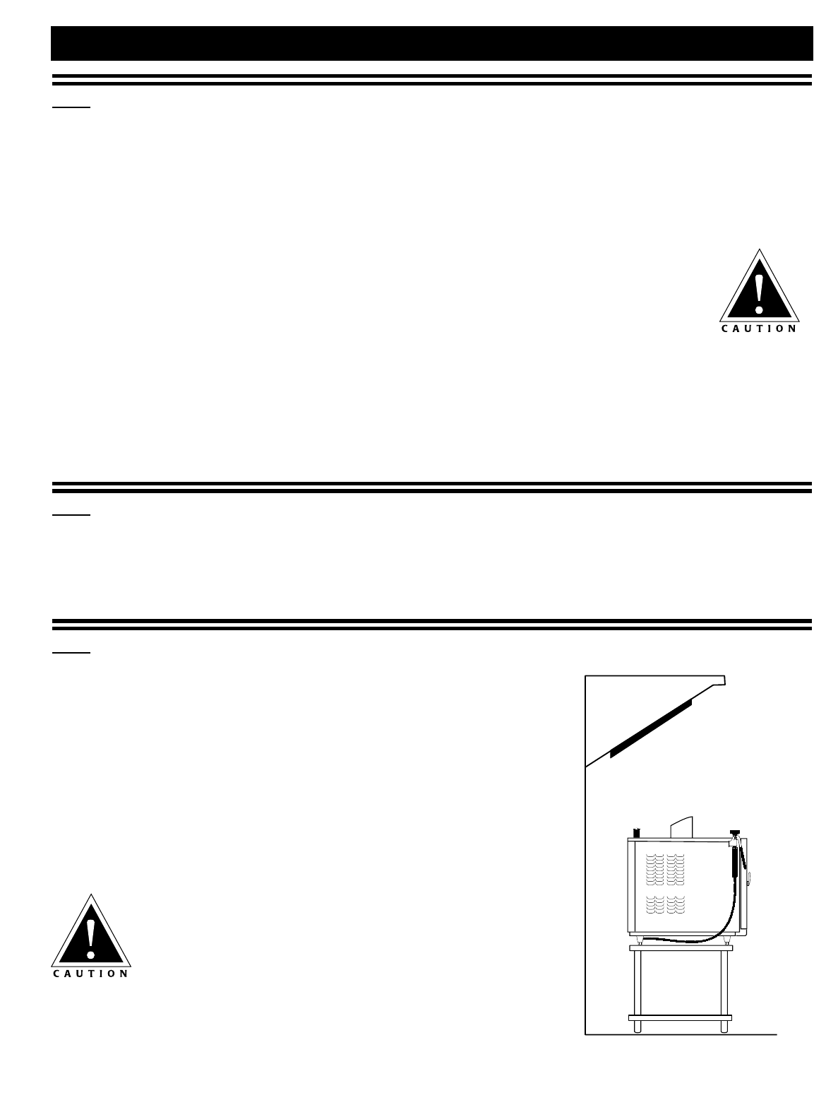
1.3 VENTILATION REQUIREMENTS
A steam ventilation hood is mandatory for the operation of the oven. The ventilation hood must be installed
in accordance with local building codes for steam exhaust and must protrude 12-inches to 20-inches
(300mm to 500mm) over the front side of the oven. A grease filter must be located in the protruding area of
the hood. Grease filters should be thoroughly cleaned on a regular basis following manufacturer's
instructions. Ventilation hoods must ensure an adequate amount of incoming air during operation and must
be operated whenever the combination oven/steamer is used in order to avoid the accumulation of
condensation in the hood area. See the section titled Gas Exhaust.
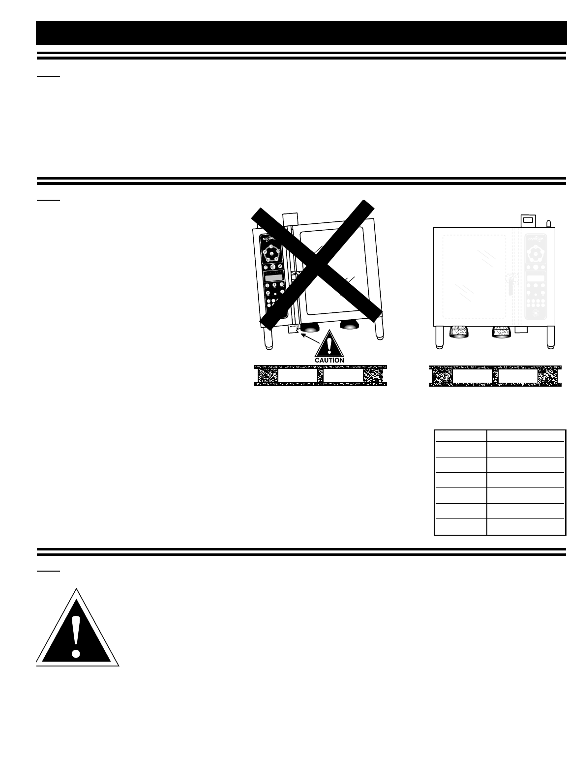
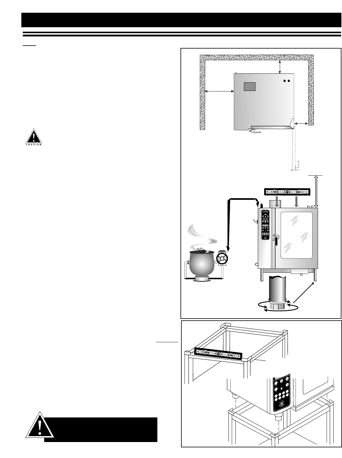
1.4 POSITIONING ON SITE
Lift the oven from the pallet with a fork
lift or pallet lift truck positioned at the
front of the oven. For damage protection,
the use of two wooden boards, placed
between the bottom of the oven and the
lifting forks, is strongly recommended.
Stand the oven in a level position. Use the
adjustable feet to overcome an uneven
floor and ensure that the unit is level.
It is strongly recommended that table top
models be mounted on a factory supplied
stand or a stand that is stable, open, level,
and non-combustible. Recommended height
is 23-inches (584mm).
Adjust the height of floor models for
smooth access of the trolley or cart.
Ensure that the unit is level, right-to-left
and back-to-front. When positioning the
oven, observe the minimum space allocation
requirements shown.
To insure proper operation, the installation of this oven must be completed
by qualified technicians in accordance with the instructions provided in
this manual. Failure to follow the instructions provided may result in
damage to the oven, building, or cause personal injury to personnel.
1.5 INSTALLATION CODES & STANDARDS
The following codes and standards are required for installation of this oven:
AIR SUPPLY, ELECTRICAL CONNECTIONS, WATER CONNECTIONS,
GAS CONNECTIONS, GAS EXHAUST, AND WASTE WATER DISCHARGE.
Installation must comply with local codes required for gas appliances. In the absence of local
codes, installation must comply with the National Fuel Gas Code, ANSI Z223.1 (latest
edition). In Canada, the appropriate code is the Natural Gas Installation Code,
CAN/CGA-B149.1 or the Propane Installation Code, CAN/CGA-B. Adherence to code by a qualified installer
is essential for the following: Gas Plumbing, Gas Appliance Installation, Commercial Cooking Ventilation,
Water and Plumbing, and OSHA Regulations. The installation surface must be heat resistant and non-
combustible (unable to burn). See your local codes or the National Fuel Gas Code for the definition of
combustible and non-combustible construction.
COMBITHERM®GAS INSTALLATION
MODEL
6•10MLGAS
10•10MLGAS
7•14MLGAS
10•20MLGAS
12•18MLGAS
20•20MLGAS
NET WEIGHT
377 lb (171 kg)
490 lb (222 kg)
528 lb (239 kg)
573 lb (260 kg)
666 lb (302 kg)
838 lb (380 kg)
OBSERVE ATTENTION LABEL
ON OVEN FOR
AREA TO AVOID
WITH LIFTING FORK.
COMBITHERM GAS INSTALLATION AND MAINTENANCE MANUAL — 6011ML
PG.3
1.6 INSTALLATION REQUIREMENTS
The installation surface must be
non-combustible (unable to burn).
➡➡
➡➡Do not install oven adjacent to flammable surfaces.
Strictly observe all local fire safety regulations.
➡➡
➡➡In order to ensure proper ventilation, a minimum
distance of at least 6-inches (152mm) must be kept
from the control panel side [LEFT] of the oven and
any adjoining surfaces.
In addition to ventilation requirements,
additional clearance is needed for service access.
A minimum distance of 18-inches (457mm)
is strongly recommended. If adequate service
clearance is not provided, it will be necessary to
disconnect the gas, water, and drain to move the
oven with a fork lift for service access. Charges
in connection with inadequate service access is
not covered under warranty.
➡➡
➡➡Allow a minimum of 4-inches (102mm) from the
right side of the oven to allow the door to open to
at least a 90°angle. Fully opened, the door will
extend up to a 225°angle. If the oven is furnished
with the retractable door option, allow a minimum
clearance of 6-1/2-inches (16cm).
➡➡
➡➡Allow a minimum clearance of 4-inches (102mm)
from the back of the oven for plumbing connections.
➡➡
➡➡Allow a 20-inch (50cm) clearance at the top of the
oven for free air movement and for the steam
vent(s) located at the top [RIGHT-REAR].
➡➡
➡➡Do not install the oven adjacent to heat producing
equipment such as fryers, broilers, etc. Heat from such
appliances may cause damage to the controls of the
Combitherm. Minimum clearance recommended:
20-inches (50cm).
Place the Combitherm oven on a stable, LEVEL
horizontal surface. For counter-top models, the oven
stand must be level. In addition, the overall height of
the oven should be positioned so the operating
controls and shelves may be conveniently reached
from the front.
ALL INSTALLATION INSTRUCTIONS
AND REQUIREMENTS MUST BE
STRICTLY OBSERVED.
IMPROPER CONNECTION
OF THIS APPLIANCE
NULLIFIES ALL WARRANTIES.
COMBITHERM®GAS INSTALLATION
18"
(46cm)
4"
(102mm)
4" (102mm)
RETRACTABLE
DOOR OPTION:
6-1/2" (165mm)
20"
(50cm)
MINIMUM
20"
(50cm)
COMBITHERM GAS INSTALLATION AND MAINTENANCE MANUAL — 6011ML
PG.4
1.7 AIR SUPPLY REQUIREMENTS
Installation of this oven must include a provision
for an adequate flow of fresh air for gas combustion.
This requirement must be observed by the installer
as well as the operator. The bottom of the oven
provides air supply access for gas combustion and
must be kept clear at all times.
OPERATOR
CAUTION
Make certain the area around
the bottom of the oven is kept
clear of obstructions to allow a
continuous supply of fresh air
for gas combustion.
Make certain the oven installation maintains
adequate air ventilation to provide
cooling for electrical and gas
components. The area
around the oven
should be
clear of any
obstructions
which might
retard the flow
of cooling air.
Failure to
observe this
caution may
result in damage
to the control
components and will
void the warranty.
OPERATOR
CAUTION
Do not use circulating fans on
the floor. Floor fans will cause
the loss of pilot flame and will
affect burner operation.
Local and the National Fuel Gas Code provide rules
for determining the amount of fresh air necessary
for combustion and ventilation of commercial
cooking appliances. The codes will help determine
if additional outside air may be necessary to meet
health and safety regulations.
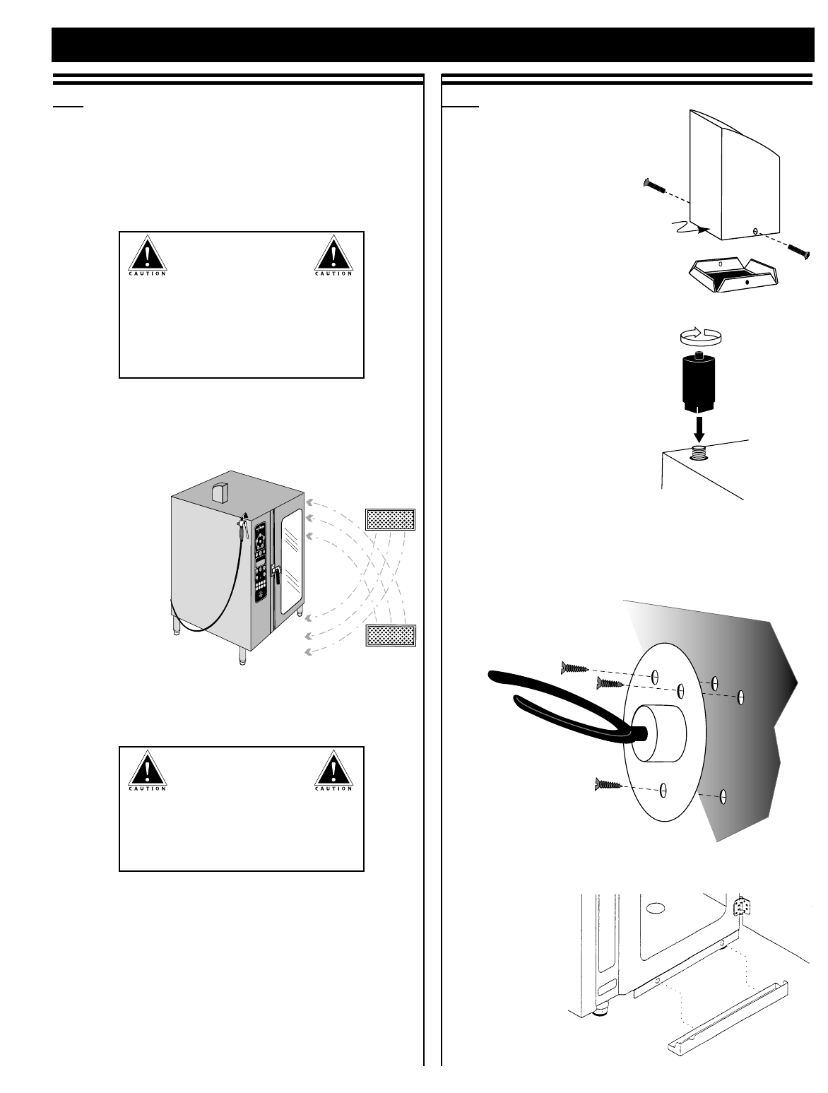
1.8 ASSEMBLY REQUIREMENTS
1.8.1 EXHAUST GAS
FLUE DIVERTER
Install the diverter as
shown on the drawing.
Make certain the wire
screen is in place before
attaching with the
screws provided with
the diverter.
1.8.2 SOUND ABSORBER
Screw the sound absorber
on the threaded nipple
located at the top of the
oven on the back, left-
hand side.
1.8.3 HAND SHOWER HOLDER
Fasten the hand shower holder in the holes
provided on the oven using the three (3) screws
packaged with the holder.
1.8.4 DRIP TRAY
Hang the drip
tray at the front
of the oven as
indicated on
the drawing.
COMBITHERM®GAS INSTALLATION
FRONT
OF OVEN
COMBITHERM GAS INSTALLATION AND MAINTENANCE MANUAL — 6011ML
PG.5
COMBITHERM®GAS INSTALLATION
1.8 ASSEMBLY REQUIREMENTS
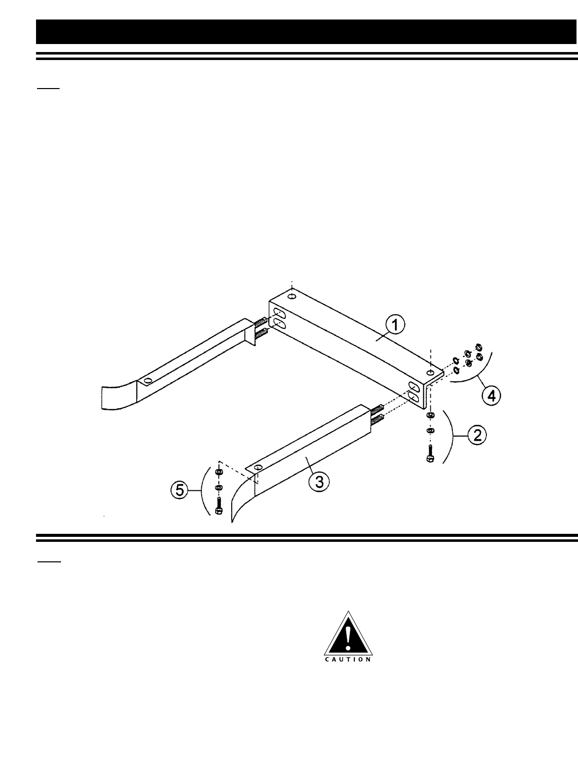
1.8.5 ROLL-IN CART (TROLLEY) GUIDE RAILS
(ON CART EQUIPPED MODELS)
Mount REAR SUPPORT on the bottom of the oven
toward the back. Fasten each end of the REAR SUPPORT
with a WASHER,LOCK WASHER, and BOLT . Align each
GUIDE RAIL with the slotted holes located at the
front of the REAR SUPPORT. Loosely fasten each GUIDE
RAIL from the back of the REAR SUPPORT with a WASHER,
LOCK WASHER, and NUT .
Do not tighten GUIDE RAIL fasteners. Attach the front
end of each GUIDE RAIL to the oven base with a
WASHER, LOCK WASHER, and BOLT .
Push the roll-in cart (trolley) into the oven, center
the cart right-to-left, and close the oven door. From
the rear of the oven, slide both guide rails toward
the center of the oven until they make contact with
the roll-in cart. Lock the GUIDE RAILS into position by
tightening both NUTS at the back of the REAR
SUPPORT . At the front of the oven, make certain
contact has been made between the oven and the
cart along the total width of the oven to create a
complete seal. When a full seal has been determined,
recheck each connection to make certain it has been
fully tightened.
1.9 ELECTRICAL CONNECTION
Ensure the power supply matches the electrical
specification located on the oven data plate. Gas
models shipped within the United States and Canada
are typically rated 110-120V, 60Hz, 1Ph and include
an electrical cord. Fuses are located behind the left
side panel.
Installation of electrical connections and wiring must
be made by a licensed electrical contractor. The oven
must be electrically grounded in accordance with local
codes, or in the absence of local codes, with the
National Electrical Code, ANSI/NFPA 70 (latest
edition). In Canada, electrical connections must
comply with the Canadian Electrical Code, CSA C22.1.
ACCESSING CONTROL AREA
Access the electrical control system through the left
side panel of the oven.
MAKE CERTAIN TO DISCONNECT POWER AND
ENSURE THE GAS SUPPLY IS SHUT OFF
BEFORE REMOVING THE LEFT SIDE PANEL.
An electrical diagram is affixed inside the left-hand
side control area. A copy of the electrical diagram is
also located at the back of this manual. Service or
changes must be done by a licensed electrical
contractor and in accordance with local codes
and regulations.
COMBITHERM GAS INSTALLATION AND MAINTENANCE MANUAL — 6011ML
PG.6
1.10 WATER SUPPLY CONNECT TO POTABLE (DRINKABLE) COLD WATER ONLY
COMBITHERM®GAS INSTALLATION
WATER PRESSURE REQUIREMENTS:
MINIMUM 30 PSI (2 BAR)
MAXIMUM 90 PSI (6 BAR)
Flush the water line at the installation site before
connecting the oven to the water supply. A shut-off
valve and approved back-flow preventer must be
installed when connecting the oven to the cold water
intake. The water supply line must be a minimum of
3/4-inch (NPT) (19mm). A hose connector is supplied
for flexible hose connection to the COLD water source.
A water filtration system is recommended if the water
supply is between 7 and 9 grains of hardness. If water
tests over 14 grains of hardness, the installation of a
water softener is strongly recommended.
THE SHUT-OFF VALVE MUST BE IN THE OPEN POSITION
WHEN THE OVEN IS BEING USED.
PIPE SEALING TAPE (TEFLON®) MUST
BE USED AT ALL CONNECTION POINTS.
The use of a pipe sealing compound is not recommended.
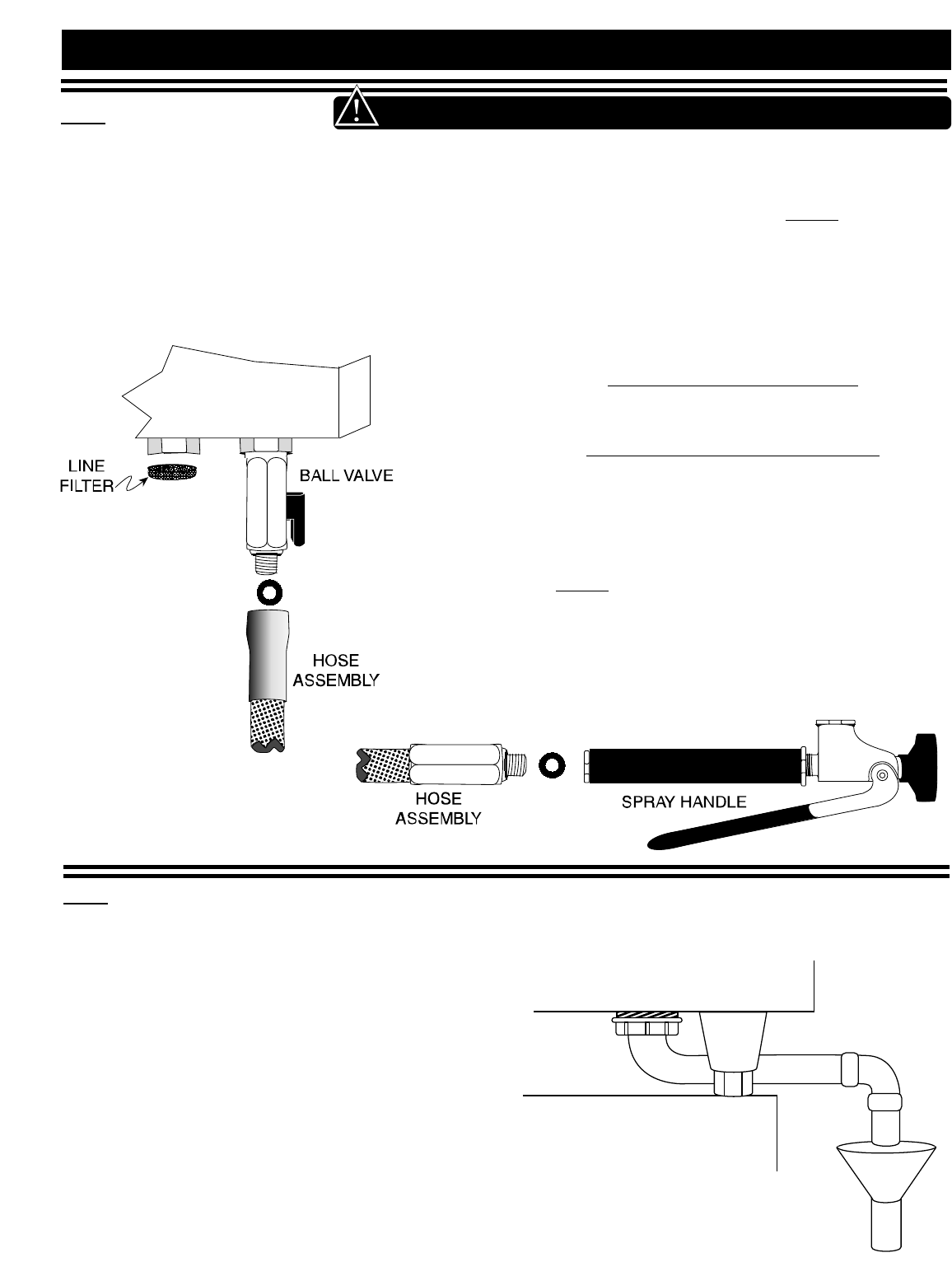
The hand shower spray hose is installed adjacent
to the cold water intake connection. A ball valve
is installed on the oven for hose connection to
the COLD water source. Assemble the washer
and the flexible hose on the ball valve and hang the
spray handle on the holder previously installed
on the oven.
The oven must discharge through an indirect waste
pipe by means of an air gap. The drain thread is
1-1/4-inch (32mm) NPT. A union is required. Install
a 1-1/4-inch (32mm) diameter drain line. The drain
line must always be a positive gradient away from
the oven and not more than 12-inches (305mm)
before an air gap.
NOTE: In the U.S.A., this equipment is to be
installed to comply with the Basic Plumbing
Code of the Building Officials and Code
Administrators International, Inc. [BOCA],
and the Food Service Sanitation Manual of
the Food & Drug Administration [FDA].
If several units are to be connected to one drain pipe,
the dimensions of the pipe must be sufficient to allow
an unobstructed water drain system.
AVERAGE DRAIN WATER TEMPERATURE
149°F (65°C)
NOTE: Install with the use of
the elbow and
washers provided
with the gas
Combitherm oven.
1.11 WATER DRAINAGE
COMBITHERM GAS INSTALLATION AND MAINTENANCE MANUAL — 6011ML
PG.7
COMBITHERM®GAS INSTALLATION
1.13 GAS TYPE AND PRESSURE
1.14 GAS CONNECTION
1.12 GAS CONNECTION REQUIREMENTS
Installation of this oven must be completed by a qualified installer familiar with the local codes and
regulations governing the installation of commercial gas appliances.
Installation must be in accordance with local codes, and in the absence of local codes, with the National Fuel
Gas Code ANSI Z223.1 (latest edition). In Canada, the appropriate code is the Natural Gas Installation Code,
CAN/CGA-B149.1 or the Propane Installation Code, CAN/CGA-B.
Check the oven nameplate information to determine
if the oven was manufactured for use with natural or
propane gas. Make certain the gas supply matches
the nameplate information.
Check the oven nameplate to determine the gas
manifold pressure for the oven. The minimum
supply pressure to the oven must exceed this value
by at least 1" w.c. It is recommended that the supply
pressure be between 5" w.c. and 14" w.c. for natural
gas, and 11" w.c. and 14" w.c. for propane.
An alternate gas supply inlet may be required
for installation sites with elevations at 3,000
feet (914m) above sea level. Please check
with the factory.
Should conversion to the opposite fuel be desired,
conversion parts must be ordered from the factory.
Conversion must be completed by a qualified service
person only. Always remember to reflect the
conversion on the oven's nameplate.
The minimum size requirement for gas piping or a
flexible connector is 3
/
4- inch (19mm). For long runs
of gas piping, the pipe diameter must conform to the
tables in the National Fuel Gas Code, ANSI/NFPA
Z223.1.
A listed gas shut-off valve must be installed
upstream of the appliance to shut off the gas supply
during servicing. The shut-off valve should be
accessible with the appliance in the normal
installation position.
If the oven or the oven stand is supplied with casters,
gas connection must be made with a flexible
connector that complies with the Standard for
Connectors for Movable Gas Appliances, ANSI
Z21.69; or in Canada, Connectors for Movable Gas
Appliances, CAN/CGA-6.16-M87. When using a
flexible connector, a quick disconnect device must be
used to comply with the Standard for Quick-
Disconnect Devices for Gas Fuels, ANSI Z21.41; or in
Canada, Quick Disconnect Devices for Use with Gas
Fuels, CAN1-6.9.
When a quick disconnect device and flexible
connector are used, a restraining device must be
installed to limit the movement of the appliance and
prevent damage to the connector or quick disconnect.
An example of a restraining device would consist of
a 2000 pound test, stainless steel cable, attached to a
structural member of the kitchen wall behind the
oven. The means of attachment should consist of a
quick connect snap so that the oven can be
disconnected when the appliance must be moved
away from the wall.
The other end of the cable should be permanently
attached to the rear frame of the oven. The cable
should be of sufficient length so that no strain is ever
placed on the flexible gas connector in the event of
accidental movement of the oven without properly
disconnecting the gas connector. The flexible
connector should be routed to form a downward "U"
loop between the building gas supply and the
permanent attachment at the rear of the oven.
The routing of the flexible connector must not be
made under the oven. Oven temperatures achieved
during operation are too hot for safe operation. Gas
piping should be installed from the point of gas
connection at the bottom, front of the oven to the
back of the oven where the flexible connector may
be safely used. See the illustration for the
recommended placement.
CAUTION
OVERHEATING
DANGER
Gas piping
must never
be installed
to run under
the burner.
COMBITHERM GAS INSTALLATION AND MAINTENANCE MANUAL — 6011ML
PG.8
If a pressure leak test above 1/2 psi is to be
performed on the building supply gas piping, the
shut-off gas valve and oven inlet gas supply line
must be disconnected from the building supply
piping before conducting the pressure test. Failure
to do so may result in damage to the manual gas
valve, gas components in the oven, or both.
If any gas leak tests are to be conducted at pressures
equal to or below 1/2 psi, the manual gas shut-off
valve upstream of the oven must be turned off before
conducting the tests.
Leak testing of the internal oven piping system was
conducted before shipping the oven from the factory.
If additional testing is needed, it should only be
conducted at normal gas supply pressures. If the
testing is performed using combustible gas in the
piping, the leak checking should be done with a soap
solution (bubble checking).
The use of an electronic combustible gas leak detector
is helpful, however, this type of detector can be
oversensitive. Electronic detectors may indicate false
leaks from other sources which would not be detected
when checking with a liquid solution to verify a
no-hazard gas connection.
NEVER CHECK FOR LEAKS
USING AN OPEN FLAME.
When starting the oven after initial installation, the
gas lines must be free of air. It may take up to 30
minutes to eliminate all air from the lines. If, after
this time there is no pilot, call for factory assistance.
1.15 LEAK TESTING
1.17 GAS EXHAUST
COMBITHERM®GAS INSTALLATION
The oven is not designed for direct connection to a chimney vent
system or for direct connection to a horizontal exhaust system.
The oven must be installed under a ventilation hood listed to
ANSI/UL 705 (latest edition), and the installation must be
completed in accordance with the ANSI/NFPA 96-1987,
Standard for Ventilation Control and Fire Protection of
Commercial Cooking Operations.
The oven is supplied with a flue diverter which must be installed
on the oven prior to installation. See Assembly Requirements
toward the front of this manual.
Oven operators should be instructed with regard to the
hazards of placing any material on top of the oven that
would obstruct the flow of flue products out the
opening of the flue diverter. Operators should also
be instructed with regard to the hazards of hot flue
gases and that any material or items placed on top of, or in front
of the flue defector could be damaged or cause a fire hazard.
1.16 FUEL INTERLOCK SYSTEM
Local codes may require the fuel supply to the oven be interlocked to the ventilation hood. If that is the case,
a separate, electrically operated gas valve must be installed in the gas line. Valve selection is at the discretion
of the installer, however, the valve must be recognized by the authority which has jurisdiction.
COMBITHERM GAS INSTALLATION AND MAINTENANCE MANUAL — 6011ML
PG.9
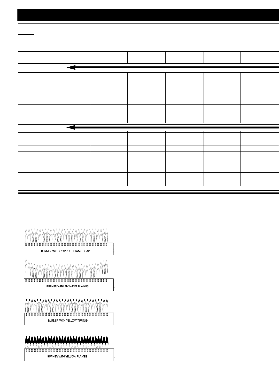
1.19 GAS FLAME PATTERNS
When starting the oven after initial installation, the gas lines must be free of air. It may take up to 30 minutes
to eliminate all air from the lines. If, after this time there is no pilot, call for factory assistance.
After the installation is complete, the oven must be test fired to
ensure that the system is operating properly. Follow the operating
instructions located in the cooking guide furnished with the oven.
Under most circumstances, initial operation will be the only
installer check necessary.
The flame pattern under both hot and cold conditions should be
stable on all burner ports. There should be no lifting or blowing
after 15 seconds of operation. Gas Combitherm ovens are not
equipped with air shutter adjustment on the burners. If the flame
pattern does not match correct pattern shown, contact the factory
for further directions.
Make certain the electric igniter lights the pilot burner quickly. The
main burner should light within 4 seconds, without problems and
should light smoothly with no harsh noise. When the oven is COLD,
cycle the oven ON and OFF five times to verify proper operation.
Allow the oven to heat for 5 minutes and repeat the process.
Check the flame pattern on the burners. The flames should be blue
in color with little or no yellow in the flame. Some yellow tipping
is normal with propane gas models, however, there should be no
indication any yellow tipping will produce soot on the combustion
chamber walls, pilot, or main burner.
COMBITHERM®GAS INSTALLATION
1.18 GAS PRESSURE CHART
The gas valve, pilot burner and nozzles for the main burner have been fitted according to the gas
type specified on the name plate. Technical specifications for the gas system are as follows:
Combitherm 6•10 7•14 10•10 10•20 20•20
ML Gas Model 12•18
Natural Gas
Connected pressure rating 7 in. W.C. 7 in. W.C. 7 in. W.C. 7 in. W.C. 7 in. W.C.
Min. connected pressure 5 in. W.C. 5 in. W.C. 5 in. W.C. 5 in. W.C. 5 in. W.C.
Max. connected pressure 14 in. W.C. 14 in. W.C. 14 in. W.C. 14 in. W.C. 14 in. W.C.
Nozzle pilot burner —————
Nozzle burner 220 315 280 400 400
Manifold pressure 3.5 in. W.C. 3.5 in. W.C. 3.5 in. W.C. 3.5 in. W.C. 3.5 in. W.C.
Gas Consumption 45 cu.ft/hr 81.9 cu.ft/hr 67 cu.ft/hr 112 cu.ft/hr 168.1 cu.ft/hr
Gross thermal output 45,500 Btu/hr 82,000 Btu/hr 68,000 Btu/hr 113,000 Btu/hr 170,000 Btu/hr
Propane Gas
Connected pressure rating 11 in. W.C. 11 in. W.C. 11 in. W.C. 11 in. W.C. 11 in. W.C.
Min. connected pressure 11 in. W.C. 11 in. W.C. 11 in. W.C. 11 in. W.C. 11 in. W.C.
Max. connected pressure 14 in. W.C. 14 in. W.C. 14 in. W.C. 14 in. W.C. 14 in. W.C.
Nozzle pilot burner —————
Nozzle burner 135 190 170 220 220
Manifold pressure 10 in. W.C. 10 in. W.C. 10 in. W.C. 10 in. W.C. 10 in. W.C.
Gas Consumption 17.7 cu.ft/hr 32.9 cu.ft/hr 26.5 cu.ft/hr 44.1 cu.ft/hr 66.5 cu.ft/hr
Gross thermal output 45,500 Btu/hr 82,000 Btu/hr 68,000 Btu/hr 113,000 Btu/hr 170,000 Btu/hr
COMBITHERM GAS INSTALLATION AND MAINTENANCE MANUAL — 6011ML
PG.10
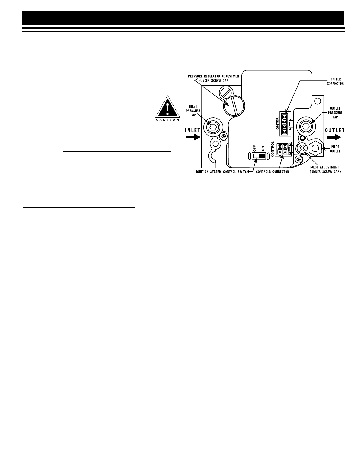
Combitherm gas ovens are equipped with intermittent pilot-
based operation and are fitted with a Honeywell gas valve.
The gas valve has a built-in pressure regulator and a hot
surface intermittent pilot ignition control for safe operation.
The valve has a step open feature (standard) for natural gas
operation. For propane, a full open feature is standard.
Explanation of the gas valve is shown in the illustration.
1.20.1 CHECKING PRESSURE
A. Turn gas connection OFF. Open gas inlet
pressure connection cap and unscrew the
tap. Connect pressure gauge at pressure
tap. Read pressure.
B. If pressure measured is higher or lower than that
specified in the Pressure Table located in this
manual, DO NOT PROCEED WITH INITIAL OPERATION.
C. Remove pressure gauge, screw in the tap, and close with
protective cap.
1.20.2 ADJUST PILOT BURNER
The pilot burner assembly installed in the oven is tested
prior to shipment and does not require any adjustment. If
adjustment is desired, the following instructions are to be
completed by a qualified technician only.
A. Turn main power switch ON and switch the ignition
control switch on the gas valve to the ON position.
B. Set temperature and timer and press the START/STOP
key. Follow oven operational instructions.
C. The pilot flame should be lit and blue in color with
very little or no yellow tipping.
1.20.3 MANIFOLD PRESSURE ADJUSTMENT
The gas valve has a built-in pressure regulator and regulates
the manifold pressure according to specifications presented
in the Pressure Table in this manual. The valve requires no
adjustment; however, if adjustment is desired, a qualified
technician only should follow the instructions shown below.
A. Turn power and gas supply OFF.
B. Remove protective cap from outlet gas/manifold gas
tap. Unscrew, connect pressure gauge.
C. Turn main power switch ON, and switch the ignition
control switch on the gas valve to ON position.
D. Select a program, set temperature and timer, and
press the START/STOP key. Follow the oven
operational instructions.
E. The gas valve will open and the main burner flame
should be established.
F. Measure manifold pressure. If it requires adjustment,
open the cap on the pressure regulator and adjust the
screw for increased or decreased gas pressure.
DO NOT SET THE REGULATOR TO ANY OTHER SETTING
OTHER THAN TO THE DATA SPECIFIED IN THE
PRESSURE CHART IN THIS MANUAL.
G. Turn the gas valve OFF or to the PILOT position.
H. Close pressure regulator and manifold/outlet gas tap
with protective caps.
NOTE: If this procedure is not clearly understood, DO NOT
perform any changes. Call the factory for assistance.
1.20.4 IGNITION & BURNER CHECK
After the installation is complete the oven needs to be test
fired to ensure that the system is operating properly.
Follow the operating instructions located in the cooking
guide furnished with the oven. Under most circumstances,
initial operation will be the only installer check necessary.
The flame pattern under both hot and cold conditions should
be stable on all burner ports. There should be no lifting or
blowing after 15 seconds of operation. Gas Combitherm
ovens are not equipped with air shutter adjustment on the
burners. If the flame pattern does not match correct pattern
shown, contact the factory for further directions.
Make certain the electric igniter lights the pilot burner
quickly. The main burner should light within 4 seconds,
without problems and should light smoothly with no harsh
noise. When the oven is COLD, cycle the oven ON and OFF
five times to verify proper operation. Allow the oven to
heat for 5 minutes and repeat the process.
Check the flame pattern on the burners. The flames should
be blue in color with little or no yellow in the flame. Some
yellow tipping is normal with propane gas models,
however, there should be no indication any yellow tipping
will produce soot on the combustion chamber walls, pilot,
or main burner.
1.20.5 VERIFY SEQUENCE OF OPERATION
The Gas Combitherm is fitted with an intermittent pilot and a
Honeywell gas valve, which provides automatic pilot ignition and
main burner ignition. The ignition control system will routinely
undergo three ignition trials (for pilot burner ignition) before
identifying an ignition failure to timeout. The normal sequence of
operation is illustrated on the following page of this manual.
When starting the oven after initial installation, the gas lines must
be free of air. It may take up to 30 minutes to do this. If, after this
time there is no pilot, call for factory assistance.
COMBITHERM®GAS INSTALLATION
1.20 BURNER PILOT ADJUSTMENTS
COMBITHERM GAS INSTALLATION AND MAINTENANCE MANUAL — 6011ML
PG.11
COMBITHERM®GAS INSTALLATION
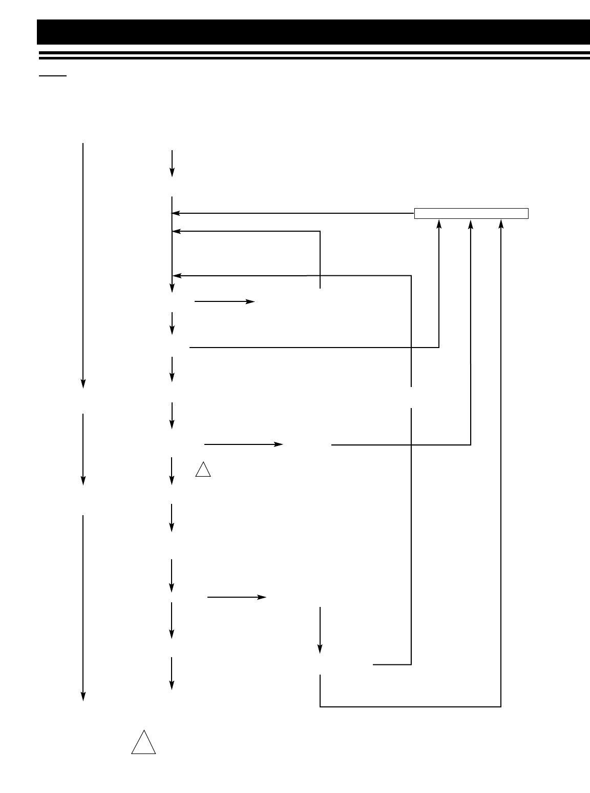
1.21 SEQUENCE OF OPERATION
Honeywell SmartValve™System
• Pilot Valve/Ignition Off
• Wait for Flame Signal to Disappear
Five Minute Retry Delay
Apply 24 VAC
to Appliance
Start
Main
Burner
Operation
End
Igniter will turn off about 30 seconds into the trial for ignition if the pilot flame has not lit. It will turn
back on for the final 30 seconds of the 90 second trial for ignition. The pilot valve will be energized
during the entire trial for ignition. This is normal operation for this gas ignition system.
Trial for
Ignition
YES
YES
NO
Thermostat
Calls for Heat
• Pilot Valve Closes
• Igniter Off
• Main and Pilot Valves Close
• EFT Output De-energizes
Flame Lost More than Five
Times in One Call for Heat?
Flame Signal
Detected!
Internal Check
Okay?
Pilot Lights and Flame
is sensed during
Trial for Ignition?
• Igniter Off
• Main Valve Opens
Electronic Fan
Timer (EFT)
Output Energizes
Flame Signal Lost?
Thermostat Call for
Heat Ends
• Main and Pilot Valves Close
• EFT Output De-energizes
• Pilot Valve Opens
• Igniter Powered Three Second Flame Failure
Recycle Delay
NO
NO
NO
NO
YES
YES
1
1
COMBITHERM GAS INSTALLATION AND MAINTENANCE MANUAL — 6011ML
PG.12
COMBITHERM®GAS INSTALLATION
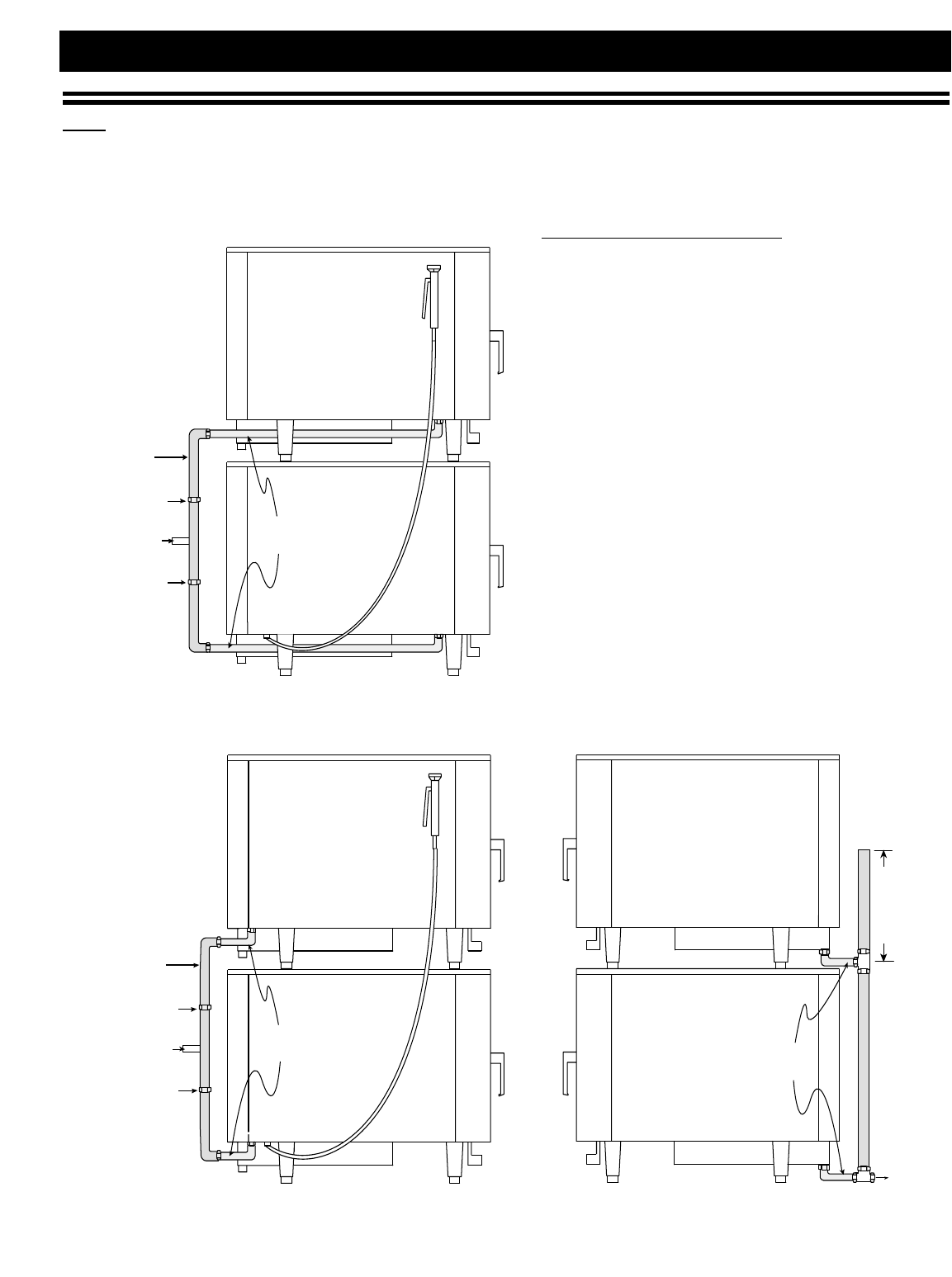
1.22 STACKING COMBITHERM CONNECTIONS
Stacking Combitherm ovens require two (2) water connections, two (2) drain connections, and two (2)
gas connections.
IF LOCAL CODE ALLOWS,the gas, water,
and drain may be manifolded as long as the
size of the water inlet is increased to 1-inch
(25,4mm) and the drains include an external
vent. The drawing illustrates one suggested
method of a manifold installation.
3/4"
(19mm)
1"
(25,4mm)
UNION
UNION
Intake
1" (25,4mm)
VENT
15" (381mm)
1-1/4"
(32mm)
1-1/2" (38mm)
3/4"
(19mm)
1"
(25,4mm)
UNION
UNION
Intake
1" (25,4mm)
GAS
WATER DRAIN
COMBITHERM GAS INSTALLATION AND MAINTENANCE MANUAL — 6011
PG.13
1.23 POST-INSTALLATION CHECK LIST
In order for this oven to operate properly, installation must conform with the instructions provided in this
manual. Following full installation the following list is provided as a final check to help assure conformance.
INSTALLER REQUIREMENTS INITIALS/DATE
■■
■■Bottom of oven has been checked for damage due to improper positioning on site.
■■
■■Proper clearances have been allowed at the top of the oven and from all adjacent surfaces
with allowance of free air access to all vents.
■■
■■Clearance has been provided at the left of the oven for service access.
■■
■■A minimum distance of 20-inches (1/2 meter) has been provided between the oven and
any heat producing equipment such as fryers, broilers, etc.
■■
■■The oven has been leveled on a stable surface.
■■
■■The oven has been connected to COLD water on a single water connection.
■■
■■Incoming water pressure is between a minimum of 30 PSI (2 BAR) and a maximum of 90 PSI (6 BAR).
■■
■■A water conditioner is highly recommended, especially if the water hardness is
NOT pH5 and 9. Contact factory for assistance.
■■
■■Installation of drain is at a minimum of 1-1/4" (32mm) with a positive descending slope.
■■
■■2" (51mm) air gap at drain is free of obstructions.
INSTRUCTIONS TO OWNER/OPERATOR INITIALS/DATE
■■
■■Owner/operator has been instructed on the importance of cleaning the oven along with
proper cleaning procedures, and daily cleaning of the interior.
■■
■■Owner/operator has been advised to use authorized Combitherm oven cleaner only.
■■
■■Owner/operator has been informed of the safety warnings located in the operation guide
including the warning not to handle pans containing liquid or semi liquid products
positioned above eye level of the operator.
Damage directly attributed to improper set up, installation, or cleaning can invalidate warranty claims.
COMBITHERM®GAS INSTALLATION
COMBITHERM GAS INSTALLATION AND MAINTENANCE MANUAL — 6011ML
PG.14
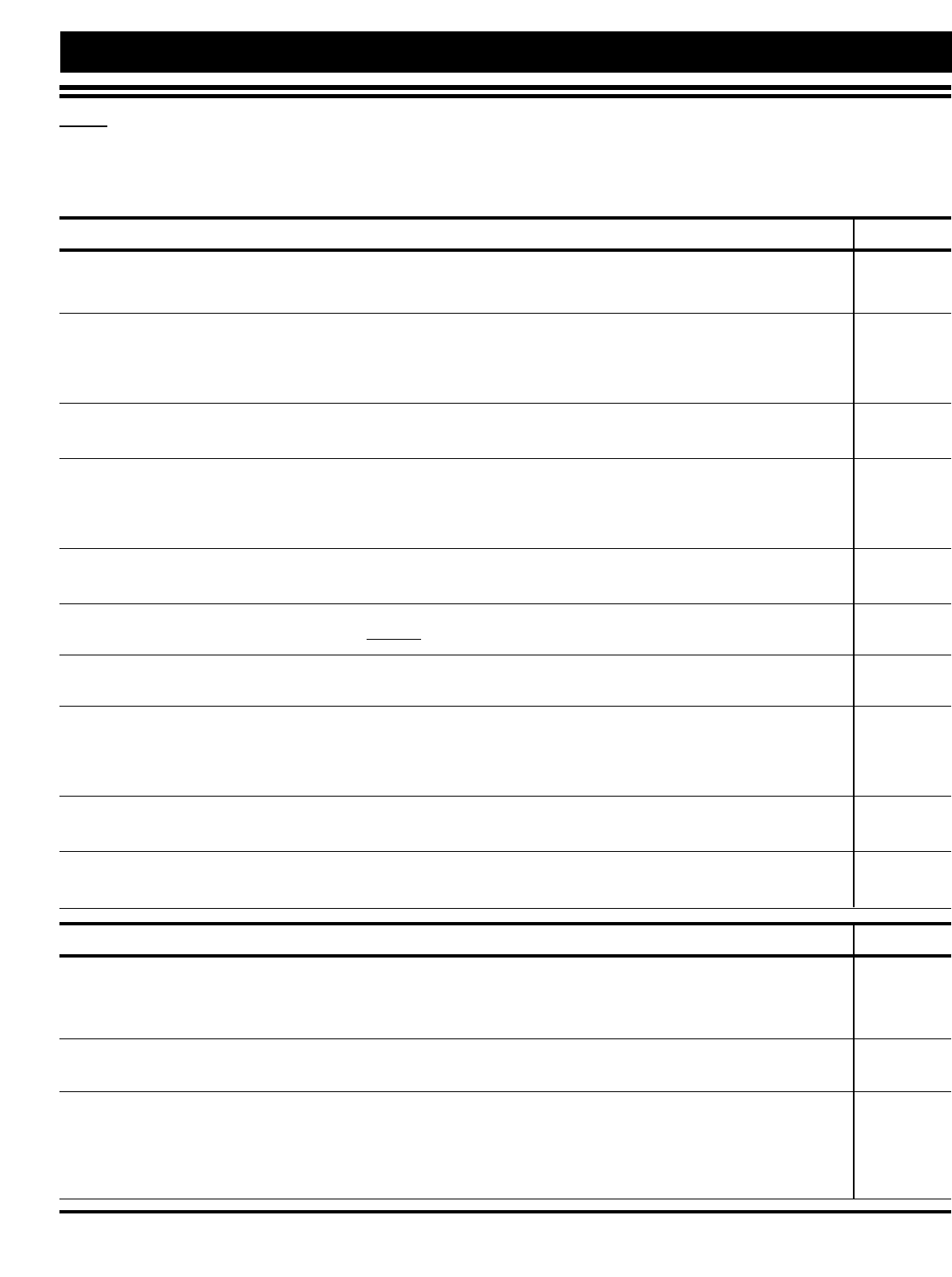
1.24 EMERGENCY OPERATION
In the event of an error code, operation of the Combitherm can be continued on a limited basis for a short
duration. Cooking times may be longer than normal operation and close monitoring of the cooking
process is recommended. Contact an authorized service agency immediately if the problem cannot be
rectified with simple steps in the troubleshooting guidelines located in this manual. Error conditions
under which continued operation can be conducted are indicated by YES in the chart shown below.
When the oven malfunctions, an error code will appear in the display.
PRESS THE START/STOP KEY TO ACKNOWLEDGE THE ERROR.
The keys for the usable operational modes will begin to flash and can be operated normally.
SELECT AND PRESS ONE OF THE COOKING MODES INDICATED.
The oven control will only respond to the oven mode keys flashing.
SET THE OVEN CONTROLS AS IF OPERATING UNDER NORMAL CIRCUMSTANCES.
Depending on the error code involved, oven function, such as temperature range, may be limited.
PRESS THE START/STOP KEY TO BEGIN THE COOKING PROCESS.
PRESS THE START/STOP KEY WHEN THE TIMER EXPIRES.
WHEN THE OVEN FAULT IS CORRECTED, THE COMBITHERM WILL RETURN TO NORMAL OPERATION.
1 Cooking time increases significantly. Food on the upper shelves is finished first
2Water injection into the condenser is activated for the entire cooking mode (high water consumption).
3When error codes E23 and E26 appear simultaneously, steam generator does not preheat.
ERROR DISPLAY MESSAGE GAS ELECTRIC STEAM1SUPERHEATED CONVECTION RETHERM DELTA-T
CODE MODE STEAM MODE MODE MODE MODE
E01 Low water level YES YES NO NO up to 356°F NO YES
(180°C)
E02 EL-temperature too high YES YES YES Up to 284°F Up to 284°F Up to 284°F Up to 284°F
CONTROL COMPARTMENT TEMP (140°C) (140°C) (140°C) (140°C)
E03 Fan Fault NO YES Up to 212°FNO NONONO
BLOWER FAN (100°C)
E04 EL-fan fault NO YES YES Up to 284°F Up to 284°F Up to 284°F Up to 284°F
CONTROL COOLING FAN (140°C) (140°C) (140°C) (140°C)
E05 Gas fault YES NO YES YES YES YES YES
E15 Condenser oven temperature YES YES NO NO Up to 356°F NO YES
HIGH CONDENSATE TANK TEMP (180°C)
E21 Oven probe error NO YES 212°F only NO NO NO NO
TEMPERATURE PROBE (100°C)
E22 CTC error TEMPERATURE PROBE YES YES YES YES YES YES YES
E23 SG-probe error YES YES YES YES YES YES YES
STEAM GENERATOR PROBE B4
E24 Bypass probe error NO YES Up to 210°F NO YES NO YES
(99°C)
E25 Condenser probe error NO YES YES 2Up to 356°F2Up to 356°F2Up to 356°F2YES 2
B3 PROBE (180°C) (180°C) (180°C)
E26 SG probe error NO YES YES YES YES YES YES
STEAM GENERATOR PROBE
E23 & SG probe error3NO YES YES 3YES 3YES 3NO YES 3
E26 STEAM GENERATOR PROBE B4
E33 SG heat error NO YES YES YES YES YES YES
STEAM GENERATOR ELEMENT
E34 Steam Generator pump error NO YES YES YES YES YES YES
E81 Program memory error YES YES YES YES YES YES YES
E83 Algorithm error YES YES YES YES YES YES YES
E89 12C error YES YES YES YES YES YES YES
COMBITHERM GAS INSTALLATION AND MAINTENANCE MANUAL — 6011
PG.15
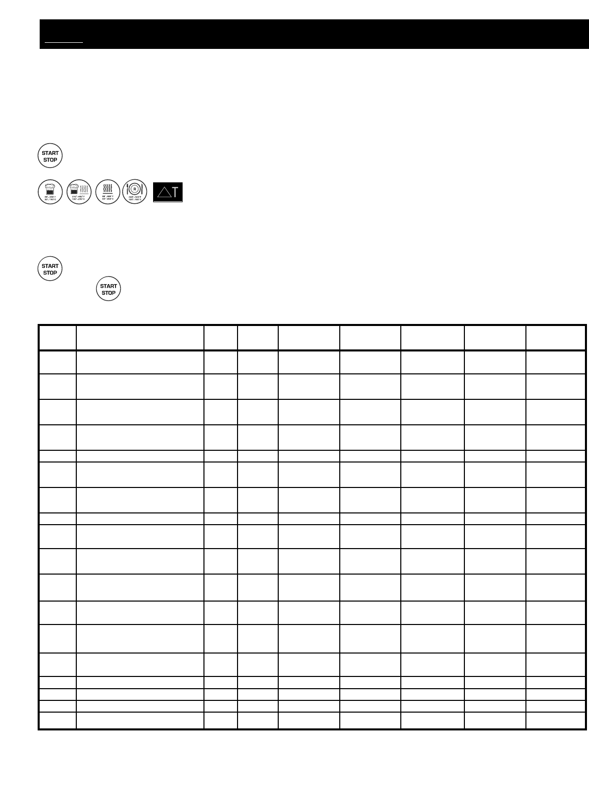
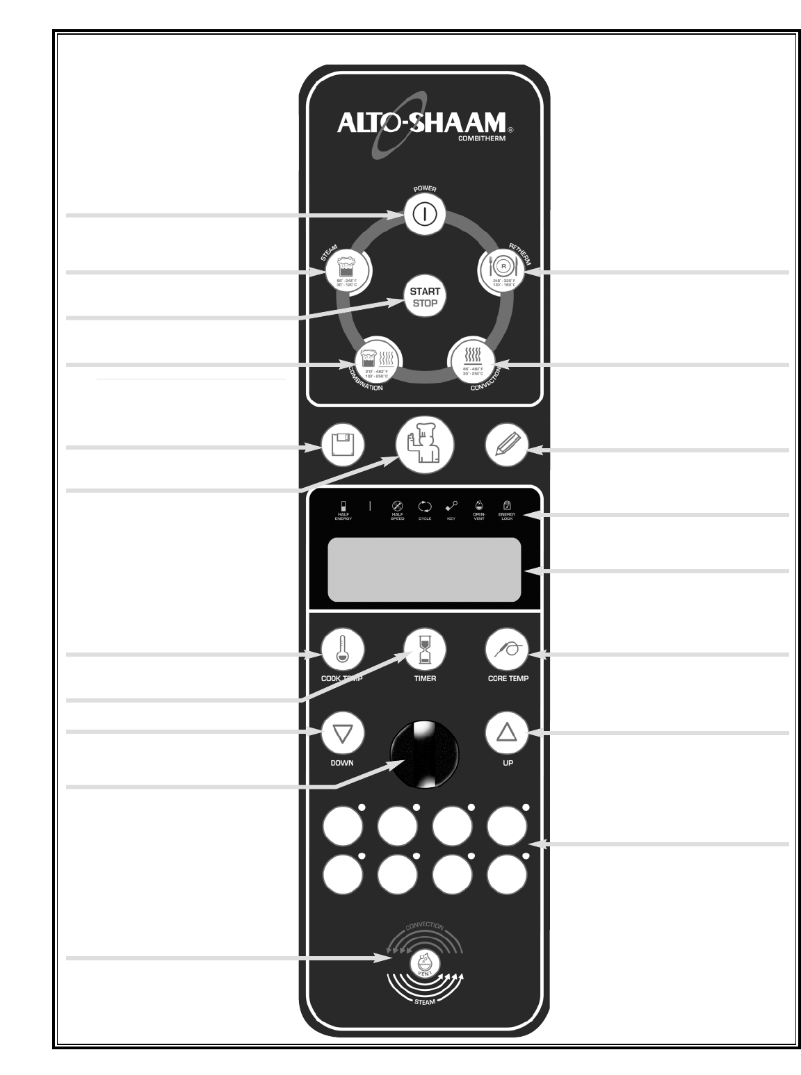
POWER ON/OFF KEY
STEAM MODE KEY
PROGRAMMED MENU KEY
COOKING TEMPERATURE KEY
DOWN ARROW KEY
MOISTURE VENT KEY
START/STOP KEY
CHEF FUNCTION KEY
TIME KEY
SUPERHEATED STEAM AND
RETHERM MODE KEY
CONVECTION MODE KEY
PROGRAM INSTALL/EDIT KEY
FUNCTION & OPERATING
CONTROL PANEL DISPLAY
CORE TEMPERATURE KEY
UP ARROW KEY
QUICK PROGRAM KEYS
CONVECTION MODE KEY
INDICATORS
DELUXE MODELS ONLY
DELUXE MODELS ONLY DELUXE MODELS ONLY
ELECTRIC MODELS ONLY
2.0 CONTROL PANEL IDENTIFICATION
ADJUSTMENT KNOB
COMBITHERM GAS INSTALLATION AND MAINTENANCE MANUAL — 6011ML
PG. 16
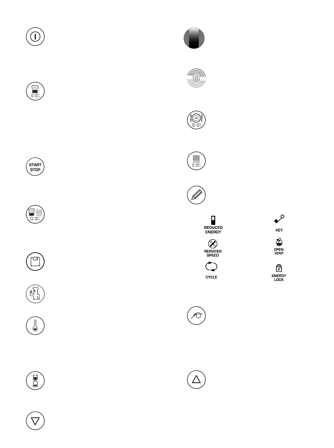
POWER ON/OFF KEY
Activates power to the oven and
automatically fills the steam generator with
water which will heat to a stand-by mode
temperature of 150°F (65°C). The steam
generator flush is also activated by pressing
this key.
STEAM MODE KEY
The oven will operate in the steam mode at
a temperature range of 86°F to 248°F
(30°C to 120°C).
• Automatic steaming at 212°F (100°C).
FACTORY-SET DEFAULT.
• Quick steaming between 213°F and 248°F
(101°C and 120°C).
• Low Temperature Steaming between
86°F and 211°F (30°C and 99°C).
START/STOP KEY
Initiates all cooking mode functions and
programmed procedures stored in memory.
Stops an activated cooking mode or
programmed procedure currently in
progress, and exits Chef function key.
SUPERHEATED STEAM AND
CONVECTION MODE KEY
Selection key for the combination steam
and convection cooking mode which can be
set within a temperature range of
212°F to 482°F (100°C and 250°C).
PROGRAMMED MENU KEY
Shows a list menu in display of all stored
cooking programs and is also used to exit
the list menu display. DELUXE MODELS ONLY.
CHEF FUNCTION KEY
Used to select programmed menu
functions, various auxiliary functions, and
several chef help instructions.
COOKING TEMPERATURE KEY
Used to set the required cooking
temperature, to recall the set cooking
temperature, or to check the actual oven
temperature in conjunction with the down
arrow key , the up arrow key or the
adjustment knob .
TIME KEY
Used to set the required cooking time or
recall the set cooking time in conjunction
with the down arrow key , the up arrow
key or the adjustment knob .
DOWN ARROW KEY
Used to decrease displayed cook temperature ,
time , or core temperature and as a
scrolling key for programming functions.
ADJUSTMENT KNOB
Serves the same function as the up and
down arrow keys to increase or decrease
the displayed cook temperature , time ,
or core temperature .
MOISTURE VENT KEY
Immediately vents steam and condensate
from the oven compartment while cooking in
the Convection mode or in the
Superheated Steam and Convection mode .
RETHERM MODE KEY
Food rethermalization or reheating mode
will operate with automatic steam injection
at a temperature range of 248°F and 320°F
(120°C and 160°C).
CONVECTION MODE KEY
Selection key for convection cooking
without steam at a temperature range of
86°F to 482°F (30°C and 250°C).
PROGRAM INSTALL AND EDIT KEY
Used to create, change, duplicate, and delete
programmed menus. DELUXE MODELS ONLY.
FUNCTION & OPERATING INDICATORS
CONTROL PANEL DISPLAY
CORE TEMPERATURE KEY
Used to set the required internal product
temperature, to recall the internal product
temperature set by the operator, or to
display the current internal temperature of
the product in conjunction with the down
arrow key , the up arrow key or the
adjustment knob .
UP ARROW KEY
Used to increase displayed cook temperature ,
time , or core temperature and as a
scrolling key for programming functions.
QUICK PROGRAM KEYS
Immediate access to frequently used
operator set programs including cooking
modes, cleaning, and other oven functions.
DELUXE MODELS ONLY.
2.0 CONTROL PANEL IDENTIFICATION
Reduced Power
Reduced Fan Speed
Confirmation of
Oven Operation
Key Lock
Moisture Vent
Peak Power Use
Energy Protection
ELECTRIC MODELS ONLY
COMBITHERM GAS INSTALLATION AND MAINTENANCE MANUAL — 6011
PG.17
2.1 IMPORTANT SAFETY PRECAUTIONS
For safe release of the cooking
compartment steam, initially
open the door approximately
2" (50mm) only. Stand
behind the door as the hot
steam is released.
STEAM
DO NOT USE THE ATTACHED HAND-HELD HOSE TO SPRAY ANYTHING OTHER
THAN THE INTERIOR OF THE COMBITHERM OVEN COMPARTMENT.
AT NO TIME SHOULD THE EXTERIOR OF THE OVEN BE STEAM
CLEANED, HOSED-DOWN WITH THE HAND-SPRAYER, FLOODED WITH
WATER, OR FLOODED WITH LIQUID SOLUTION OF ANY KIND.
DO NOT USE THE SPRAY HOSE IN A HOT COOKING COMPARTMENT. ALLOW
THE OVEN TO COOL TO A MINIMUM OF 150°F (66°C).
DO NOT USE HIGH PRESSURE WATER CLEANING METHODS ON THE INTERIOR
OR EXTERIOR OF THE COMBITHERM OVEN.
DO NOT HANDLE PANS CONTAINING LIQUID OR SEMI LIQUID PRODUCTS
POSITIONED ABOVE EYE LEVEL OF THE OPERATOR. SUCH PRODUCTS
CAN SCALD AND CAUSE SERIOUS INJURY.
USE AUTHORIZED COMBITHERM LIQUID OVEN CLEANER ONLY.
UNAUTHORIZED CLEANING AGENTS MAY DISCOLOR OR HARM INTERIOR SURFACES OF THE
OVEN. READ AND UNDERSTAND LABEL AND MATERIAL SAFETY DATA SHEET BEFORE
USING THE OVEN CLEANER.
FOR OPERATOR SAFETY
NOTE AND OBSERVE ALL SAFETY PRECAUTIONS LOCATED THROUGHOUT THIS MANUAL.
COMBITHERM GAS INSTALLATION AND MAINTENANCE MANUAL — 6011ML
PG.18
2.2 Preventive Maintenance
In addition to the routine cleaning and maintenance procedures, there are several additional steps to be
taken for both sanitation purposes and to keep the oven running at top operating efficiency. These
additional safeguards will help prevent inconvenient down time and costly repairs.
●DO NOT DISPOSE OF GREASE, FAT, OR SOLID WASTE DOWN THE OVEN DRAIN. Fats and
solids will eventually coagulate in the drain system, causing blockage.
●MAKE CERTAIN THE DRAIN SCREEN IS ALWAYS IN PLACE. REMOVE ANY SOLID WASTE
MATERIAL FROM THE DRAIN SCREEN BEFORE IT ENTERS THE DRAIN SYSTEM. The routine
removal of solids from the drain screen will help prevent blockage.
●USE THE AUTHORIZED COMBITHERM OVEN CLEANER ONLY. The use of unauthorized
cleaning agents may discolor or harm the interior surfaces of the oven.
●TO PROLONG THE LIFE OF THE DOOR GASKET, REMOVE AND CLEAN THIS ITEM DAILY. The
acids and related compounds found in fat, particularly chicken fat, will weaken the composition
of the gasket unless cleaned on a daily basis.
●TO ADDITIONALLY PROTECT GASKET LIFE, ALLOW OVEN DOOR TO REMAIN SLIGHTLY
OPEN AT THE END OF THE PRODUCTION DAY. An open door will relieve the pressure on the
door gasket.
●ROUTINELY CLEAN DOOR HINGES. Open oven door to relieve tension. Clean all parts of the hinge.
2.3 Routine Cleaning Requirements
DAILY OVEN CLEANING
To be performed at the end of each production day or between production shifts.
MONTHLY CLEANING
WATER INTAKE FILTER CLEANING
CLEANING THE DRAIN PIPE
CLEANING THE FLUE OUTLET
FAN CLEANING
DAILY GASKET CLEANING
It is important to prolong the life of the oven gasket by cleaning this item on a daily basis. Routine cleaning
will help protect the composition of the gasket from deterioration caused by acidic foods. After allowing the
oven to cool, remove pull-out gasket and wash in hot, soapy water. Do not place in the dishwasher.
COMBITHERM®CLEANING & MAINTENANCE
Always replace the gasket before cleaning the oven interior or operating the oven.
COMBITHERM GAS INSTALLATION AND MAINTENANCE MANUAL — 6011
PG.19
2.4 DAILY OVEN CLEANING
DO NOT SPRAY CLEANER INTO A HOT OVEN.
ALLOW THE OVEN TO COOL TO 150°F (66°C).
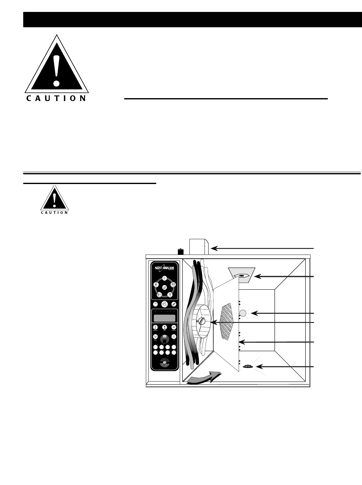
2.4.1
1. Remove all food scraps and
residue from the oven drain .
2. Wearing safety glasses and rubber
gloves, remove the drain screen
and spray Combitherm liquid
oven cleaner directly into the drain
pipe . Replace the drain screen.
3. Generously spray the interior oven
surfaces with an even coat of
Combitherm Liquid Oven Cleaner.
Spray all built-in components,
shelves, side racks, and pans.
4. Once a week, loosen the thumb
screw(s) and swing Fan Guard
Cover Plate toward the back of the oven. Spray the back of the Fan Guard Cover Plate, the oven fan,
and the left-hand side of the oven. Close the swing out Cover Plate . Lock the cover into place and
tighten thumb screw(s).
5. Insert the Combitherm Liquid Oven Cleaner spray nozzle directly into the High Pressure Relief Port
and spray several times.
6. Securely close the oven door.
GAS EXHAUST
FLUE DIVERTER
HIGH PRESSURE
RELIEF PORT
OVEN LIGHT
FAN
FAN GUARD
COVER PLATE
OVEN DRAIN
RUBBER GLOVES AND PROTECTIVE EYE WEAR
MUST BE WORN WHEN USING THE OVEN CLEANER.
USE AUTHORIZED COMBITHERM
LIQUID OVEN CLEANER ONLY.
Unauthorized cleaning agents may discolor or harm interior surfaces of the oven. Read and understand
label and material safety data sheet before using the oven cleaner.
Causes severe burns. Do not get in eyes, on skin, or on clothing. Do not wear contacts. Harmful or
fatal if swallowed. Do not breathe mist. Use in well ventilated area. Keep out of reach of children.
Do not use on aluminum. Do not mix with anything but water.
THOROUGHLY RINSE EMPTY CONTAINER WITH WATER AND SAFELY DISCARD.
COMBITHERM®CLEANING & MAINTENANCE
The temperature in the display indicates the air temperature inside the oven compartment and
The temperature in the display indicates the air temperature inside the oven compartment and
not the interior walls of the oven. Always make certain to allow the oven walls to cool to a
not the interior walls of the oven. Always make certain to allow the oven walls to cool to a
minimum of 150
minimum of 150°
°F (60
F (60°
°C) before spraying the compartment with oven cleaner
C) before spraying the compartment with oven cleaner.
.
COMBITHERM GAS INSTALLATION AND MAINTENANCE MANUAL — 6011ML
PG.20
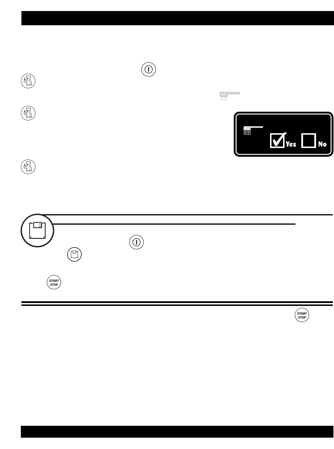
2.4.2 AUTOMATIC CLEANING PROGRAM
The Combitherm automatic cleaning function selects the proper temperature
for each step of the cleaning process.
With the oven power on:
PRESS THE CHEF FUNCTION KEY.
Rotate the adjustment knob until the clean symbol is highlighted in the display.
PRESS THE CHEF FUNCTION KEY.
Press the up and down arrow keys or rotate
the adjustment knob to select YES for the automatic
cleaning function.
PRESS THE CHEF FUNCTION KEY TO CONFIRM THE SETTING AND START THE CLEANING PROGRAM.
THE OVEN WILL BEGIN A 20 MINUTE, 2-STEP CLEANING CYCLE.
• 10 minutes at 86°F (30°C) to allow the cleaning agent to work
• 10 minutes at full steam temperature of 212°F (100°C) to clean the oven
FOR DELUXE OVENS WITH A PROGRAMMED MENU KEY
FOLLOW STEPS 1 THROUGH 6 ON THE PRECEDING PAGE.
With the oven power on:
PRESS THE PROGRAMMED MENU KEY.
Rotate the adjustment knob to program 250 = CLEAN.
PRESS THE START KEY.
DELUXE MODELS CAN ALSO BE CLEANED AS SHOWN IN THE PREVIOUS INSTRUCTIONS.
7. When the buzzer signals the end of the cleaning process, press the start/stop key to
deactivate the audible signal or open the oven door.
8. With the door open, use the hand held hose and direct a stream of water into the High Pressure Relief
Port to rinse away oven cleaner residue.
9. Rinse the interior and all sprayed components with the hand-held hose. Make certain to thoroughly
rinse all surfaces to remove any cleaning solution residue. Use a non-abrasive cleaning pad for any
problem areas.
10. Loosen the thumb screw(s) and swing Fan Guard Cover Plate toward the back of the oven.
Thoroughly rinse the back of the Fan Guard Cover Plate, the oven fan, and the left-hand side of the
oven. Close the swing out Cover Plate . Lock the cover into place and tighten thumb screw(s).
LEAVE DOOR SLIGHTLY OPEN AFTER CLEANING
Clean
➡
➡
➡
COMBITHERM®CLEANING & MAINTENANCE
COMBITHERM GAS INSTALLATION AND MAINTENANCE MANUAL — 6011
PG.21
COMBITHERM®CLEANING & MAINTENANCE
2.5 Monthly Cleaning — GAS
Perform once a month in addition to
the daily oven cleaning procedure.
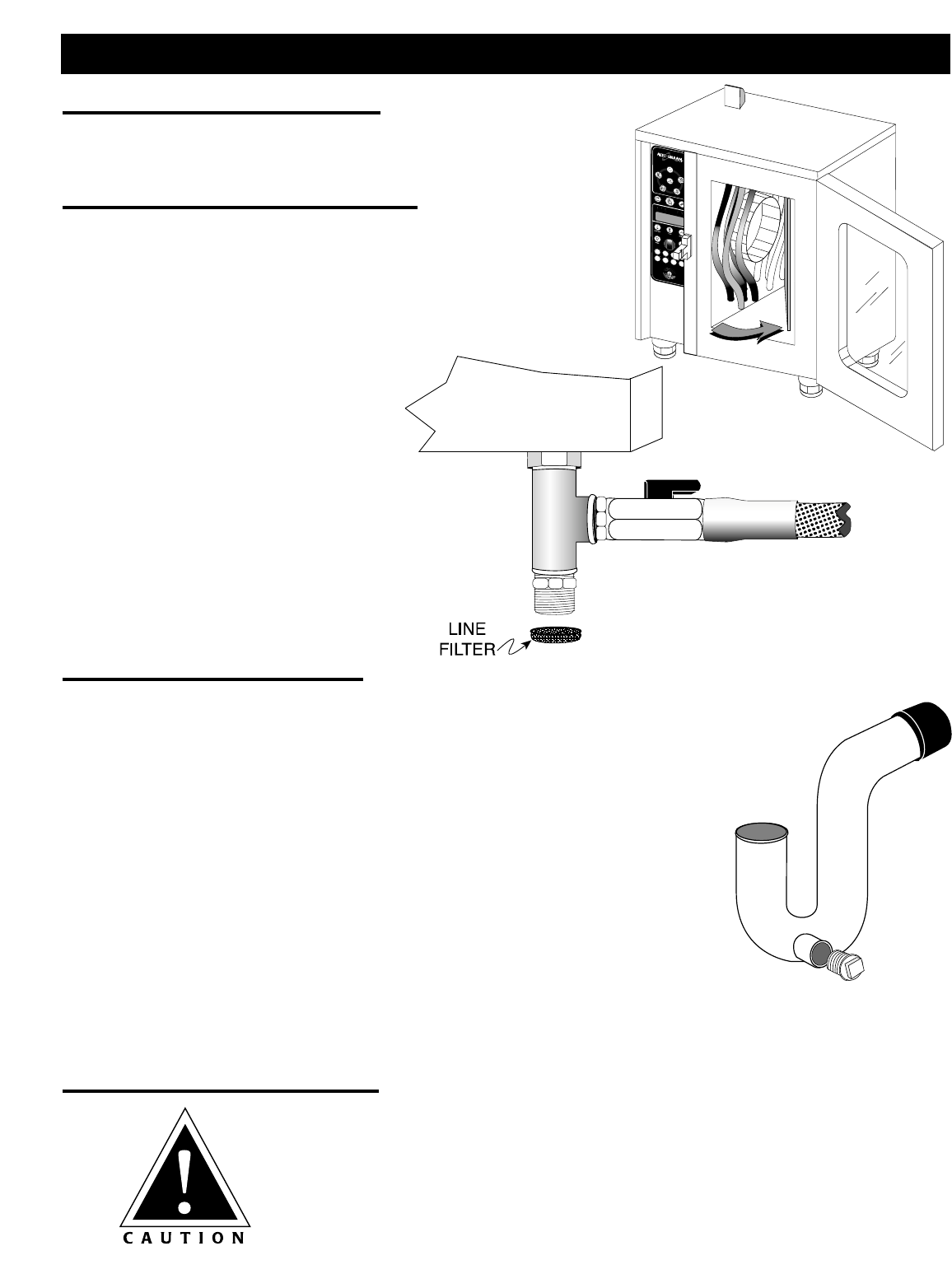
2.5.1 WATER INTAKE FILTER CLEANING
Monthly cleaning of the filter at the front of the water intake
connection will prevent the water injection system from
becoming blocked.
1. Press the oven power switch to the OFF position.
2. Disconnect the water intake connection
located below the oven.
3. Remove the line filter and
clean thoroughly.
4. Replace the line filter and
reconnect the water.
5. Press the oven power switch to the
ON position and check to make
certain the water intake connection
does not leak.
2.5.2 CLEANING THE DRAIN PIPE
Fats and solids will eventually coagulate in the drain system, causing blockage.
Consequently, water will back-up into the interior oven compartment, resulting
in an oven that is inoperable. Monthly cleaning of the oven drain will prevent
the drain from becoming blocked.
1. Press the oven power switch to the OFF position.
2. Locate the drain outlet below the oven and remove the drain plug
with a wrench.
3. Thoroughly dislodge and remove the accumulated deposits through
the drain plug outlet or through the drain opening at the bottom of
the oven interior. Rinse out the open drain with the hand-held hose.
4. Replace the drain plug and tighten securely with a wrench.
5. Press the oven power switch to the ON position and check to make certain the drain does not leak.
2.5.3 CLEANING THE FLUE OUTLET
Inspect the flue diverter assembly located on the top of the oven on a monthly
basis. Remove accumulated dirt and debris.
KEEP THE OVEN EXHAUST OUTLET CLEAR
OF ALL OBJECTS THAT COULD OBSTRUCT
THE FLOW OF COMBUSTION GASES.
COMBITHERM GAS INSTALLATION AND MAINTENANCE MANUAL — 6011ML
PG.22
Monthly Cleaning
Thoroughly clean the fan at
a minimum of once every six months.
This procedure will remove the heavy
build-up of grease which
will accumulate on the oven fan.
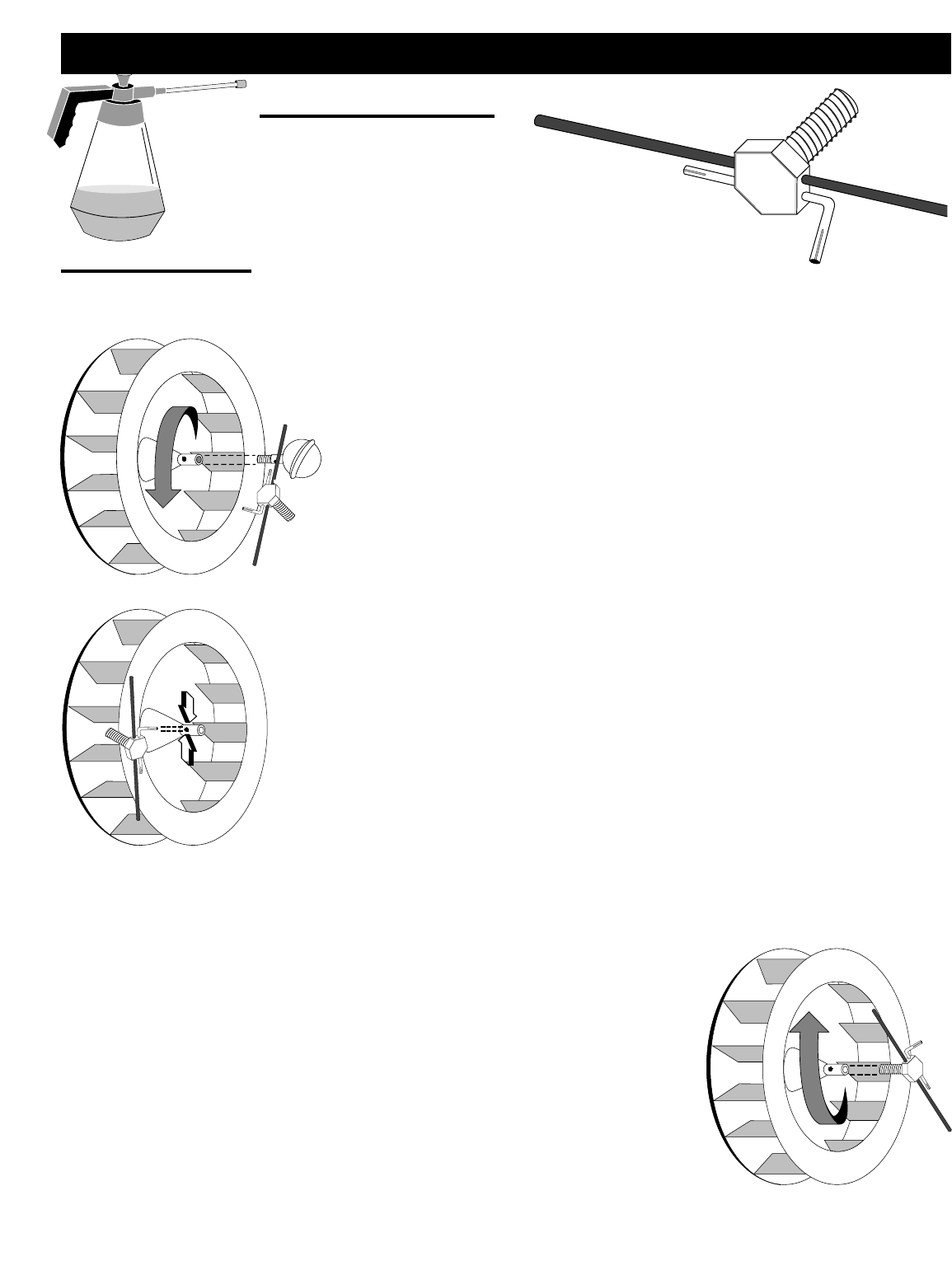
2.5.4 FAN CLEANING
A Fan Service Tool is included with each Combitherm shipment. This tool
must be used for both disassembling and reassembling the fan whenever a
thorough cleaning is required.
1. Press the oven power switch to the OFF position.
2. Remove the oven shelves and side rack shelf supports.
3. Loosen the fasteners holding the fan guard door and swing the door to
the fully open position.
4. While holding the fan wheel in place, insert the shaft attachment of the
Fan Service Tool through the hole in the ball-shaped water diffuser and
rotate counter-clockwise to completely remove the diffuser.
5. Loosen the two hexagon socket bolts located on either side of the central
wheel hub with the allen-wrench attachment of the Fan Service Tool.
6. Insert the bolt attachment of the Fan Service Tool into the central wheel
hub and turn clockwise until the wheel is completely disengaged from
the mounting shaft.
7. Place the fan and the ball-shaped water diffuser in the bottom of the
oven compartment. Wearing safety glasses and rubber gloves, spray
these items, the walls of the heat exchanger compartment, the pipes and
the back side of the fan-guard door with Combitherm liquid oven
cleaner and let stand for approximately 5 minutes.
8. Thoroughly rinse all sprayed components with the hand-held hose to remove all detergent residue.
9. Dry the fan mounting shaft. Place the fan wheel on the mounting shaft
and lightly tap into place.
10. Tighten the two hexagon socket bolts located on either side of the central
wheel hub with the allen-wrench attachment of the Fan Service Tool.
11. Screw the ball-shaped water diffuser into the central wheel hub and
firmly tighten by hand.
12. Attach the fan guard door with the four screws and replace the side rack
shelf supports and the oven shelves.
COMBITHERM®CLEANING & MAINTENANCE
COMBITHERM®CLEANING & MAINTENANCE
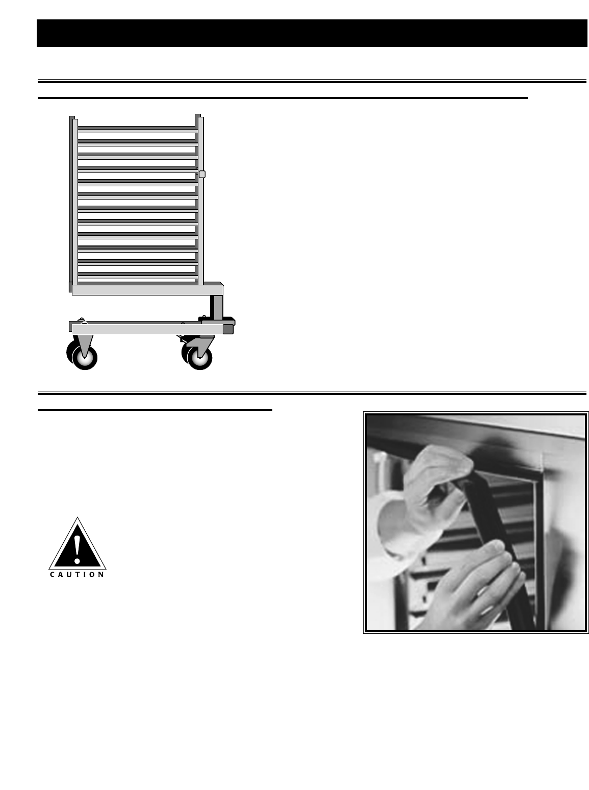
2.6 ROLL-IN CART/FOOD TROLLEY CLEANING (ON EQUIPPED MODELS)
1. Remove food trolley to a cart wash area. Trolleys may be cleaned
using any mild cleaning detergent and warm water.
2. Hand wipe all framing, slides, drip pan, and base. Thoroughly
clean debris from the casters. A spray hose can be used for
easier cart cleaning.
3. Remove detergent solution with warm water.
4. Wipe or spray with a sanitizing solution designed for use on metal
and vinyl food contact surfaces.
5. Allow trolley to air dry.
As an alternative, trolleys can be sprayed with Combitherm
liquid oven cleaner while inside the oven. Allow the trolley to
remain in the oven through the normal cleaning cycle,
followed by steps 2 through 5 above.
2.7 DAILY GASKET CLEANING
It is important to prolong the life of the oven gasket by cleaning this
item on a daily basis. Routine cleaning will help protect the
composition of the gasket from deterioration caused by acidic foods.
After allowing the oven to cool, remove pull-out gasket and wash in
hot, soapy water. Do not place in the dishwasher.
Always replace the gasket before cleaning the
oven interior or operating the oven.
COMBITHERM GAS INSTALLATION AND MAINTENANCE MANUAL — 6011ML
PG.23

COMBITHERM GAS INSTALLATION AND MAINTENANCE MANUAL — 6011ML
PG.24
Alto-Shaam urges the user to maintain a record of service performed on the Combitherm Gas Oven/Steamer.
Model: ______________________ Serial No: ______________________ Gas Type: ______________________
DATE PROBLEM DETECTED CORRECTION PERFORMED
3.0 COMBITHERM®GAS SERVICE SECTION
3.1 COMBITHERM SERVICE
COMBITHERM GAS INSTALLATION AND MAINTENANCE MANUAL — 6011ML
PG.25
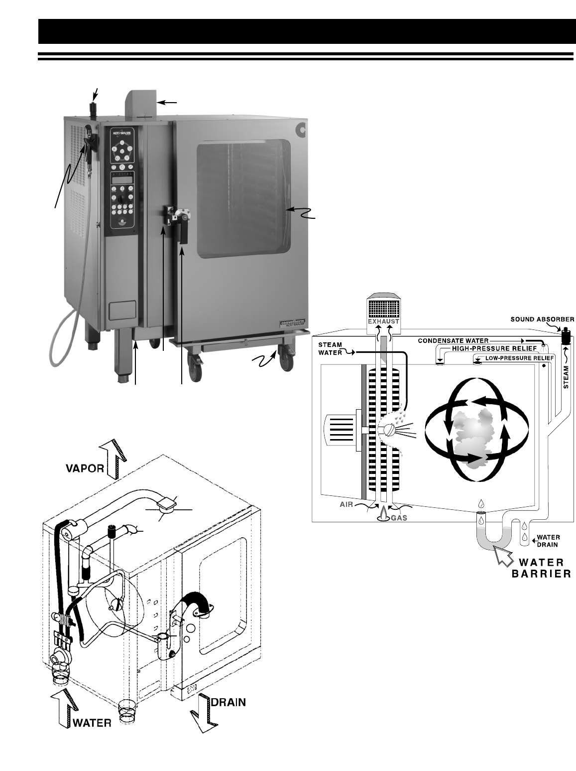
COMBITHERM®GAS SERVICE SECTION
Sound Absorber (EXHAUST SILENCER)
Flue Diverter
Spray
Hose
Burner
Tubes
Door
Latch
Door
Handle
Cart
(Trolley)
Food
Probe
Cold water is used for
generating steam and for
cooling the drain water. The
water is sprayed over the
hottest area of the oven and
is converted into steam.
Steam is blown into the oven
by means of a fan wheel.
3.2 COMBITHERM GAS
3.2.3 PLUMBING SYSTEM
3.2.1 EXTERIOR COMPONENTS
3.2.2 OPERATING
SCHEMATIC
COMBITHERM GAS INSTALLATION AND MAINTENANCE MANUAL — 6011ML
PG.26
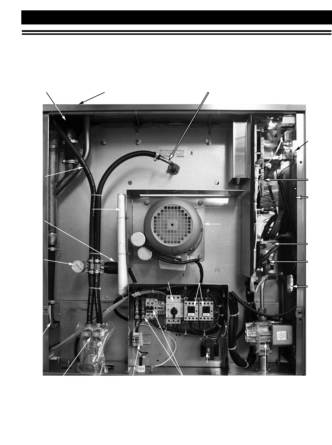
COMBITHERM®GAS SERVICE SECTION
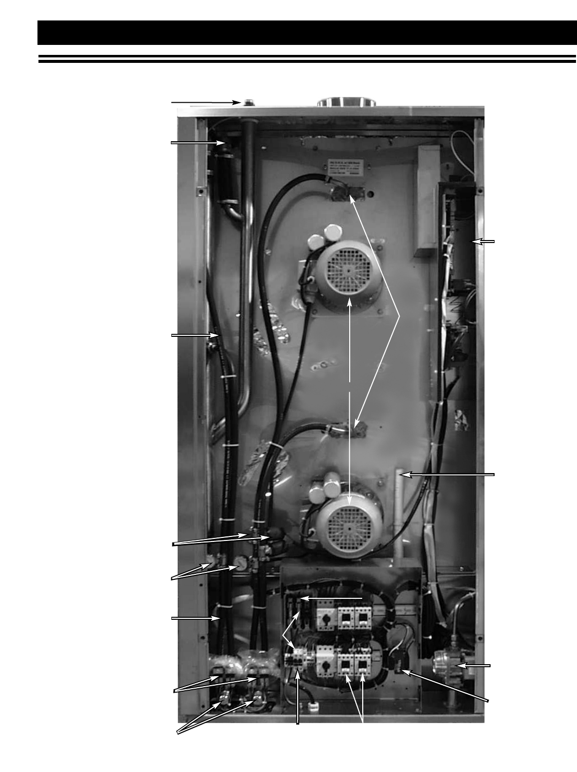
3.3 SERVICE VIEW: Left Side Panel Components
Combitherm Gas Models 6•10ML, 7•14ML, 10•10ML, 10•20ML and 12•18ML
Bypass Probe Sound Absorber Water Nozzle
Motor
Transformer
Water
Cooling
Line
Light
Relay
Board
Control
Board
High
Limit
Power
Board
Closed
System
Board
Pressure
Switch
Pressure
Gauge
Bypass
to Drain
Solenoid Valve
Motor
Contactor
Motor
Overload
Terminals Fuse — Holder Gas Valve
WIRING
DIAGRAM
COMBITHERM GAS INSTALLATION AND MAINTENANCE MANUAL — 6011ML
PG.27
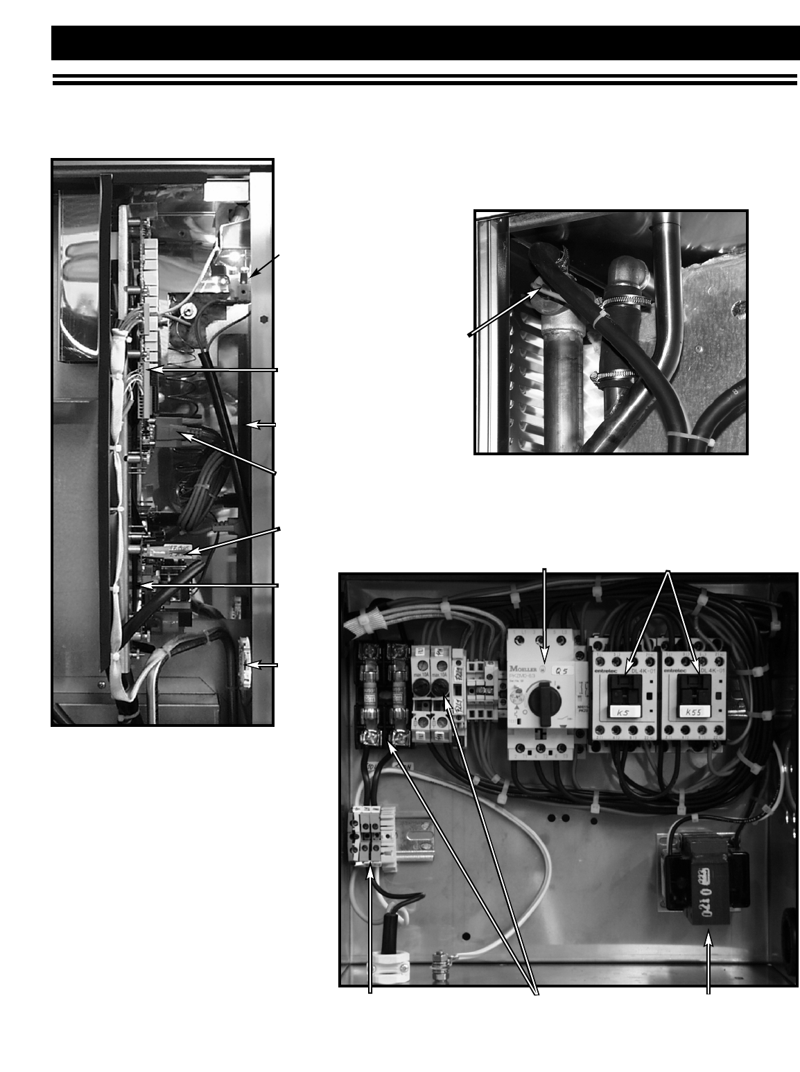
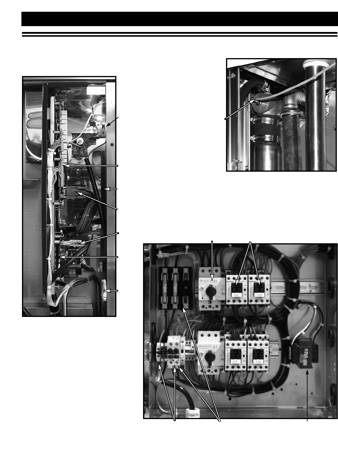
COMBITHERM®GAS SERVICE SECTION
3.3 SERVICE VIEW: Motor Contactor & Protection Switches
Combitherm Gas Models 6•10ML, 7•14ML, 10•10ML, 10•20ML and 12•18ML
BYPASS
Light
Relay
Board
Bypass
Probe
Control
Board
Communication
Cable
High
Limit
Power
Board
Closed
System
Board
Transformer
Motor
Contactor
Motor
Overload
Terminals Fuse — Holder
COMBITHERM GAS INSTALLATION AND MAINTENANCE MANUAL — 6011ML
PG.28
Water
Nozzle
Display
Control
Board
Motors
Transformer
110/24V
Gas Valve
Fuse — Holder, 35A
Motor Contactor
Fuses
Terminals
Solenoid Valves
Water Pressure
Adjustment
Bypass to Drain
Pressure Gauges
Pressure Switches
Water Cooling Line
Bypass Probe
Sound Absorber
Wiring Diagram
COMBITHERM®GAS SERVICE SECTION
3.4 SERVICE VIEW: Left Side Panel Components Combitherm Gas Model 20•20ML
COMBITHERM GAS INSTALLATION AND MAINTENANCE MANUAL — 6011ML
PG.29
Fuse — Holder
BYPASS
COMBITHERM®GAS SERVICE SECTION
3.4 SERVICE VIEW: Motor Contactor & Protection Switches
Light
Relay
Board
Control
Board
High
Limit
Power
Board
Closed
System
Board
Combitherm Gas Model 20•20ML
Transformer
Motor
Contactor
Motor
Overload
Terminals
Communication
Cable
Bypass
Probe

COMBITHERM GAS INSTALLATION AND MAINTENANCE MANUAL — 6011ML
PG.30
3.5 TROUBLESHOOTING
In the event of a Combitherm malfunction during operation, an error code and message will appear in the
display to assist in finding a rapid solution to the problem. The following is a list of all error codes which
includes the cause along with a possible solution.
ERROR
CODE
E01
E01
E02
E03
E03
E04
E11
E13
E15
DESCRIPTION OF ERROR
Low water level: Sufficient water level in steam generator
has not been reached with 3 minutes.
Low water level: Water pressure is under 11 PSI (0.7 bar)
after the solenoid valve is opened for 5 seconds.
Excessive temperature in service area: An additional fan
will engage at a temperature of 113°F (45°C) and the
error message will occur at a service area temperature of
176°F (80°C).
Fan motor shuts down from a tripped internal PTC.
Motor shuts down fan.
Auxiliary 120 fan motor not running.
Oven probe (N6 thermocouple) measures a temperature in
excess of 572°F (300°C).
Steam generator probe (B4 thermocouple) measures a
temperature in excess of 248°F (120°C).
Condenser probe (B3 thermocouple) measures a temperature
in excess of 212°F (100°C).
POSSIBLE CAUSE/REMEDY
Water tap is closed.
Filter in solenoid valve or water connection is clogged.
Water level probe is calcified or defective.
Solenoid valve Y1 is defective.
Pressure loop is calcified.
Steam generator drain cap is not water tight.
Water tap is closed.
Filter in solenoid valve or water connection is clogged.
Solenoid valve Y1 is defective.
Auxiliary 12 V fan does not turn on due to defective
thermostat or contactor.
Ventilation vents are blocked due to inefficient distance from
wall at installation site.
Minimum distance to equipment such as fryers, grills,
kettles, etc. has not been maintained.
A phase from the main power supply is missing.
The fan motor is defective.
Power phase reversed causing fan to run in reverse.
A fuse is tripped.
Trip circuit has been set too low.
Direction of motor rotation is wrong.
A phase is missing from the main power supply.
The motor protection switch is defective.
Power phase reversed causing fan to run in reverse.
The fan motor is defective.
Auxiliary fan is defective.
Defective wiring or loose connection to auxiliary fan.
Convection contactors are burned and no longer disengage.
Motor not operating due to two defective F10 fuses.
Calcification in steam generator.
Water level probe is grounded causing immersion elements
to energize.
Water tap is closed.
Oven is connected to warm water supply.
Inlet filter on solenoid valve is dirty.
Condenser cooling solenoid valve or solenoid valve coil
is defective.
COMBITHERM GAS INSTALLATION AND MAINTENANCE MANUAL — 6011ML
PG.31
3.5 TROUBLESHOOTING
Alto-Shaam has established a twenty-four hour emergency service
call center to offer immediate customer access to a local authorized
service agency outside of standard business hours. The
emergency service access is provided exclusively for
Alto-Shaam equipment and is available throughout
the United States through the use of Alto-Shaam's toll-
free number. Emergency service access is available seven
days a week including holidays
.
ERROR
CODE
E23
E25
E26
E27
E33
E34
E80
E95
DESCRIPTION OF ERROR
Steam generator probe (B4 thermocouple) is interrupted.
Condenser probe (B3 thermocouple) is interrupted.
Safety temperature probe (N8 thermocouple) is interrupted.
STB (N8 thermocouple) measures a temperature in excess of
266°F (130°C).
Steam generator probe (B3) fails to measure increase in
temperature to 41°F (5°C) within a 3 minute period of time.
Steam generator pump malfunction.
ID (identity) error.
Software error.
POSSIBLE CAUSE/REMEDY
Probe connection is bad at X6 on the control module.
Steam generator probe (B4) is defective.
Bad probe connection.
Probe connection is bad at X6 on the control module.
Condenser probe (B3) is interrupted or defective.
Bad probe connection.
Probe connection is bad at X6 on the control module.
STB steam generator probe (N8) is interrupted or defective.
Bad probe connection.
Calcification in steam generator.
Water level probe is grounded causing immersion elements
to energize.
Immersion heater defective.
Heater contactors defective.
B3 probe calcified.
Pump (M4) defective.
Pump blocked or dirty.
Ground short on water level probe due to calcification.
Fill opening in water settling area of level probe is calcified.
The electronic control cannot differentiate between gas or
electric operation and disconnects all circuit connections.
Contact problem on X3 connection.
Communication problem between software and hardware.
Incompatibility between software and hardware.

COMBITHERM GAS INSTALLATION AND MAINTENANCE MANUAL — 6011ML
PG.32
Board, Closed System BA-33733 BA-33733 BA-33733 BA-33733 BA-33733 BA-33733
Board, Communication BA-33738 BA-33738 BA-33738 BA-33738 BA-33738 BA-33738
Board, Control BA-33732 BA-33732 BA-33732 BA-33732 BA-33732 BA-33732
Board, Fastening Nut NU-25095 NU-25095 NU-25095 NU-25095 NU-25095 NU-25095
Board, Program Module BA-33742 BA-33742 BA-33742 BA-33742 BA-33742 BA-33742
Board, Power Supply BA-33737 BA-33737 BA-33737 BA-33737 BA-33737 BA-33737
Board, Relay BA-33736 BA-33736 BA-33736 BA-33736 BA-33736 BA-33736
Board, Spacer BU-25094 BU-25094 BU-25094 BU-25094 BU-25094 BU-25094
Burner, Gas Orifice (NATURAL GAS)BN-23606 BN-23860 BN-23608 BN-23610 BN-23610 BN-23610
Burner, Gas Orifice (PROPANE GAS)BN-23607 BN-23861 BN-23609 BN-23611 BN-23611 BN-23611
Cable, Board Connection CB-33750 CB-33750 CB-33750 CB-33750 CB-33750 CB-33750
Cable, Ribbon CB-33750 CB-33750 CB-33750 CB-33750 CB-33750 CB-33750
Connector, x1 TM-33747 TM-33747 TM-33747 TM-33747 TM-33747 TM-33747
Connector, x2 TM-33748 TM-33748 TM-33748 TM-33748 TM-33748 TM-33748
Connector, x3 TM-33749 TM-33749 TM-33749 TM-33749 TM-33749 TM-33749
Connector, x5 CR-33739 CR-33739 CR-33739 CR-33739 CR-33739 CR-33739
Connector, x6 TM-33773 TM-33773 TM-33773 TM-33773 TM-33773 TM-33773
Connector, x7 TM-33774 TM-33774 TM-33774 TM-33774 TM-33774 TM-33774
Connector, x11/x12 CR-33743 CR-33743 CR-33743 CR-33743 CR-33743 CR-33743
Connector, Ground CR-33295 CR-33295 CR-33295 CR-33295 CR-33295 CR-33295
Contactor, 22 Amp CN-33402 CN-33402 CN-33402 CN-33402 CN-33402 CN-33402
Door (MINUS HANDLE AND GASKET)DR-25626 DR-25628 DR-25627 DR-25629 DR-25630 DR-25631
Door, Drip Tray PN-23594 PN-23867 PN-23594 N/APN-23866 N/A
Door, Handle HD-2934 HD-2934 HD-2934 HD-2934 HD-2934 HD-2934
Door Hinge HG-25618 HG-25618 HG-25618 HG-25617 HG-25617 HG-25617
Door, Latch LT-2935 LT-2935 LT-2935 LT-2935 LT-2935 LT-2935
Door, Latch Dowel CT-22551 CT-22551 CT-22551 CT-22551 CT-22551 CT-22551
Door, Interlock Switch SW-33275 SW-33275 SW-33275 SW-33275 SW-33275 SW-33275
Door, Magnet MA-23859 MA-23859 MA-23859 MA-23859 MA-23859 MA-23859
Door, Magnet Cover MA-24643 MA-24643 MA-24643 MA-24643 MA-24643 MA-24643
Drain, Rubber Elbow EB-25755 EB-25755 EB-25755 EB-25755 EB-25755 EB-25755
Drain, Screen DA-2943 DA-2943 DA-2943 DA-2943 DA-2943 DA-2943
Drain, Hookup Kit for Gas DR-24485 DR-24485 DR-24485 DR-24485 DR-24485 DR-24485
Drip Tray, Trolley N/AN/AN/APN-24642 PN-24642 PN-24642
Exhaust Silencer PB-23600 PB-23600 PB-23600 PB-23600 PB-23600 PB-33851
Fan, Two-Speed Motor MO-33263 MO-33263 MO-33263 MO-33853 MO-33853 MO-33854
Fan, Wheel WH-33433 WH-33434 WH-33434 WH-33435 WH-33435 WH-33436
Fan, Wheel Removal Tool FA-23701 FA-23701 FA-23701 FA-23701 FA-23701 FA-23701
Flue Diverter, Exhaust Gas PP-23601 PP-23602 PP-23601 PP-23602 PP-23602 PP-23602
Fuse, 0.25 Amp FU-3673 FU-3673 FU-3673 FU-3673 FU-3673 FU-3673
3.6 - Parts List • Combitherm ML Gas
PART DESCRIPTION 6•10MLGAS 7•14MLGAS 10•10MLGAS 10•20MLGAS 12•18MLGAS 20•20MLGAS

COMBITHERM GAS INSTALLATION AND MAINTENANCE MANUAL — 6011ML
PG.33
Fuse, 2 Amp FU-3774 FU-3774 FU-3774 FU-3774 FU-3774 FU-3774
Fuse Holder, 2 Amp FU-3772 FU-3772 FU-3772 FU-3772 FU-3772 FU-3772
Fuse, 6.3 Amp FU-33451 FU-33451 FU-33451 FU-33451 FU-33451 FU-33451
Fuse Holder, 6.3 Amp FU-33756 FU-33756 FU-33756 FU-33756 FU-33756 FU-33756
Fuse, 15 Amp FU-3775 FU-3775 FU-3775 FU-3775 FU-3775 N/A
Fuse Holder, 15 Amp FU-3842 FU-3842 FU-3842 FU-3842 FU-3842 N/A
Fuse, 35 Amp N/AN/AN/AN/AN/AFU-33127
Fuse Holder, 35 Amp N/AN/AN/AN/AN/AFU-33039
Gasket, Door GS-23591 GS-23856 GS-23592 GS-25658 GS-23858 GS-25624
Gasket, Trolley N/AN/AN/AGS-24371 GS-24371 GS-24371
Gasket, Trolley Upper Seal (OLD)N/AN/AN/AGS-24474 N/AGS-24474
Gasket, Trolley Lower Seal (OLD)N/AN/AN/AGS-24475 GS-24475 GS-24474
Gasket, Window GS-24464 GS-24467 GS-24465 N/AN/AN/A
Gasket, Inner Window N/AN/AN/AN/AGS22163 N/A
Gasket, Outer Window N/AN/AN/AN/AGS-22252 N/A
Gauge, Pressure PB-24726 PB-24726 PB-24726 PB-24726 PB-24726 PB-24726
Glass, Double Window GL-25616 GL-26009 GL-25614 N/AGL-25615 N/A
Glass, Inner Door N/AN/AN/ADR-25622 N/ADR-25623
HAND SHOWER ASSEMBLY
Hand Shower (FULL ASSEMBLY)PB-24483 PB-24484 PB-24483 PB-24484 PB-24484 PB-24484
Hose, Assembly PB-23922 PB-23922 PB-23922 PB-24066 PB-24066 PB-24066
Hose, Spray Handle PB-23920 PB-23920 PB-23920 PB-23920 PB-23920 PB-23920
Hose, Spray Nozzle PB-23919 PB-23919 PB-23919 PB-23919 PB-23919 PB-23919
Hose, Ball Valve VA-22684 VA-22684 VA-22684 VA-22684 VA-22684 VA-22684
Hose, Washer WS-22334 WS-22334 WS-22334 WS-22334 WS-22334 WS-22334
Hose, Water Intake HO-24482 HO-24482 HO-24482 HO-24482 HO-24482 HO-24482
Intake Line Filter, 1/2" (12,7mm) FI-2946 FI-2946 FI-2946 FI-2946 FI-2946 FI-2946
Hose, Gas Line (WITH QUICK CONNECT)CR-33543 CR-33543 CR-33543 CR-33543 CR-33543 CR-33543
Knob, Lower KN-33734 KN-33734 KN-33734 KN-33734 KN-33734 KN-33734
Knob, Spacer SP-25097 SP-25097 SP-25097 SP-25097 SP-25097 SP-25097
Knob, Upper KN-33735 KN-33735 KN-33735 KN-33735 KN-33735 KN-33735
Latch, Inner Door N/AN/AN/ALT-25620 N/ALT-25620
Leg, Attachment N/AN/AN/ALG-24633 LG-24633 LG-24633
Leg, Leveler Insert N/AN/AN/ALG-24632 LG_24632 LG-24632
Leg Insert (COMPLETE)N/AN/AN/ALG-25625 LG-25625 LG-25625
Light, Bulb LP-33274 LP-33274 LP-33274 LP-33274 LP-33274 LP-33274
Light, Glass Cover GL-24461 GL-24461 GL-24461 GL-24461 GL-24461 GL-24461
Light, Seal SA-24757 SA-24757 SA-24757 SA-24757 SA-24757 SA-24757
Light, Socket RP-3986 RP-3986 RP-3986 RP-3986 RP-3986 RP-3986
Motor, Cover (LEFT SIDE SERVICE PANEL) PE-23603 PE-23604 PE-23604 PE-23605 PE-23605 N/A
Motor, Handle Cover PL-22607 PL-22607 PL-22607 PL-22607 PL-22607 PL-22607
3.6 - Parts List • Combitherm ML Gas
PART DESCRIPTION 6•10MLGAS 7•14MLGAS 10•10MLGAS 10•20MLGAS 12•18MLGAS 20•20MLGAS

COMBITHERM GAS INSTALLATION AND MAINTENANCE MANUAL — 6011ML
PG.34
Motor, Mounting Box BX-24473 BX-24473 BX-24473 BX-24473 BX-24473 BX-24473
Motor, Seal Kit SA-24097 SA-24097 SA-24097 SA-24097 SA-24097 SA-24097
Motor, Stuffing Box Cap CP-24472 CP-24472 CP-24472 CP-24472 CP-24472 CP-24472
Panel, Cover (RIGHT SIDE) PE-25647 PE-25649 PE-25648 PE-25650 PE-25650 PE-25651
Panel, Control Overlay (DELUXE MODEL)PE-25323 PE-25323 PE-25323 PE-25323 PE-25323 PE-25323
Panel, Control Overlay (STANDARD MODEL)PE-25322 PE-25322 PE-25322 PE-25322 PE-25322 PE-25322
Panel, Quick Program Icons (DELUXE MODEL)PE-25345 PE-25345 PE-25345 PE-25345 PE-25345 PE-25345
Panel, Direction PE-25637 PE-25639 PE-25638 PE-25640 PE-25640 PE-25641
Panel, Fasten Screw Suction SC-24481 SC-24481 SC-24481 SC-24481 SC-24481 SC-24481
Panel, Pivot Screw Suction SC-24480 SC-24480 SC-24480 SC-24480 SC-24480 SC-24480
Pilot Orifice (NATURAL GAS)BN-23776 BN-23776 BN-23776 BN-23776 BN-23776 BN-23776
Pilot Orifice (PROPANE GAS)BN-23777 BN-23777 BN-23777 BN-23777 BN-23777 BN-23777
Pilot Assembly HSI*(NATURAL GAS)BN-33371 BN-33371 BN-33371 BN-33371 BN-33371 BN-33371
Pilot Assembly HSI*(PROPANE GAS)BN-33372 BN-33372 BN-33372 BN-33372 BN-33372 BN-33372
Pipe, Cooling Elbow EB-24590 EB-24590 EB-24590 EB-24590 EB-24590 EB-24590
Probe, Bypass PR-33848 PR-33848 PR-33848 PR-33848 PR-33848 PR-33848
Probe, Oven PR-33850 PR-33850 PR-33850 PR-33850 PR-33850 PR-33850
Probe, Product PR-33746 PR-33746 PR-33746 PR-33746 PR-33746 PR-33746
Probe Seal, Product SA-22320 SA-22320 SA-22320 SA-22320 SA-22320 SA-22320
Probe Seal, Product SA-22321 SA-22321 SA-22321 SA-22321 SA-22321 SA-22321
Probe Seal, Product SA-22322 SA-22322 SA-22322 SA-22322 SA-22322 SA-22322
Side Racks, Left SR-25344 SR-25613 SR-23586 N/AN/AN/A
Side Racks, Right SR-25343 SR-25612 SR-24549 N/AN/AN/A
Side Racks, Left and Right N/AN/AN/AN/ASR-23850 N/A
Switch, Motor Protection, 6.3A SW-33856 SW-33856 SW-33556 N/AN/AN/A
Switch, Motor Protection, 10A N/AN/AN/AN/AN/ASW-33855
Switch, Motor Protection, 16A N/AN/AN/ASW-33857 SW-33857 N/A
Switch, Pressure SW-33280 SW-33280 SW-33280 SW-33280 SW-33280 SW-33280
Switch, Pressure Connect Nozzle PB-24738 PB-24738 PB-24738 N/AN/AN/A
Tape, Sealing GS-23622 GS-23622 GS-23622 GS-23622 GS-23622 GS-23622
Thermostat, Safety TT-33325 TT-33325 TT-33325 TT-33325 TT-33325 TT-33325
Transformer, 120/240V TN-33282 TN-33282 TN-33282 TN-33282 TN-33282 TN-33282
Trolley, Roll-in (COMPLETE CART)N/AN/AN/ACT-25333 CT-23361 CT-25334
Trolley, Side Seals, 4-inch (102mm) N/AN/AN/AGS-24370 GS-24370 GS-24370
Trolley Guide N/AN/AN/AGI-24479 GI-24479 GI-24478
Tube, Injection (FOR DIRECTION PA)PB-25652 PB-25654 PB-25653 PB-25655 PB-25655 PB-25656
Valve, Low Pressure Relief VA-24469 VA-24469 VA-24469 VA-24469 VA-24469 VA-24469
Valve, Over Pressure Relief VA-24470 VA-24470 VA-24470 VA-24470 VA-24470 VA-24470
Valve HSI,*Natural Gas VA-33369 VA-33369 VA-33369 VA-33369 VA-33369 VA-33369
Valve HSI,*Propane Gas VA-33370 VA-33370 VA-33370 VA-33370 VA-33370 VA-33370
Valve, Water Solenoid VA-33283 VA-33283 VA-33283 VA-33283 VA-33283 VA-33283
Water Diffuser PB-23692 PB-23692 PB-23692 PB-23692 PB-23692 PB-25632
3.6 - Parts List • Combitherm ML Gas
PART DESCRIPTION 6•10MLGAS 7•14MLGAS 10•10MLGAS 10•20MLGAS 12•18MLGAS 20•20MLGAS
*HSI = Hot Surface Ignition (Intermittent Pilot)
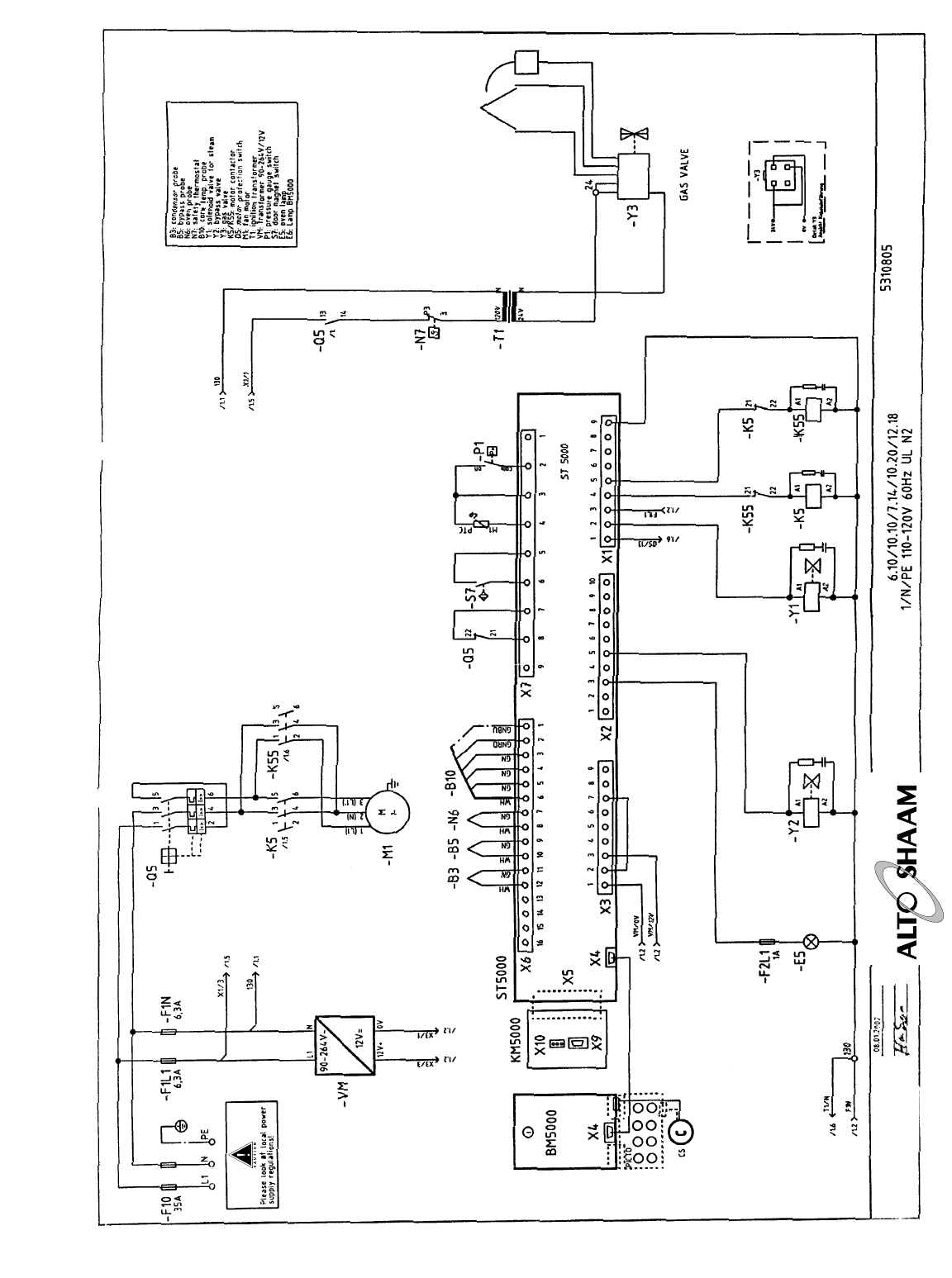
COMBITHERM GAS INSTALLATION AND MAINTENANCE MANUAL — 6011
PG.35
®
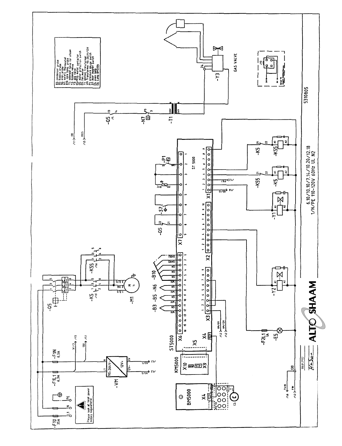
COMBITHERM GAS INSTALLATION AND MAINTENANCE MANUAL — 6011ML
PG.36
®

TRANSPORTATION
DAMAGE and CLAIMS
All Alto-Shaam
equipment is sold F.O.B.
shipping point, and
when accepted by the
carrier, such shipments
become the property of
the consignee.
Should damage occur in shipment, it is a matter between
the carrier and the consignee. In such cases, the carrier is
assumed to be responsible for the safe delivery of the
merchandise, unless negligence can be established on the
part of the shipper.
1. Make an immediate inspection while the equipment is
still in the truck or immediately after it is moved to the
receiving area. Do not wait until after the material is
moved to a storage area.
2. Do not sign a delivery receipt or a freight bill until you
have made a proper count and inspection of all
merchandise received.
3. Note all damage to packages directly on the carrier’s
delivery receipt.
4. Make certain the driver signs this receipt. If he refuses
to sign, make a notation of this refusal on the receipt.
5. If the driver refuses to allow inspection, write the
following on the delivery receipt:
Driver refuses to allow inspection
of containers for visible damage.
6. Telephone the carrier’s office immediately upon finding
damage and request an inspection. Mail a written
confirmation of the time, date, and the person called.
7. Save any packages and packing material for further
inspection by the carrier.
8. Promptly file a written claim with the carrier and
attach copies of all supporting paperwork.
We will continue our policy of assisting our customers in
collecting claims which have been properly filed and
actively pursued. We cannot, however, file any damage
claims for you, assume the responsibility of any claims,
nor accept deductions in payment for such claims.
LIMITED
WARRANTY
Alto-Shaam, Inc. warrants to the original purchaser that
any original part that is found to be defective in material
or workmanship will, at our option, subject to provisions
hereinafter stated, be replaced with a new or rebuilt part.
The labor warranty remains in effect one (1) year from
installation or fifteen (15) months from the shipping date,
whichever occurs first.
The parts warranty remains in effect one (1) year from
installation or fifteen (15) months from the shipping date,
whichever occurs first.
Exceptions to the one year part warranty period are as listed:
A. Halo Heat cook/hold ovens include a five (5) year
parts warranty on the heating element. Labor will be
covered under the terms of the standard warranty
period of one (1) year or fifteen (15) months.
B. Alto-Shaam Quickchillers include a five (5) year parts
warranty on the refrigeration compressor. Labor will
be covered under the terms of the standard warranty
period of one (1) year or fifteen (15) months.
This warranty does not apply to:
1. Calibration.
2. Replacement of light bulbs and/or the replacement of
display case glass due to damage of any kind.
3. Equipment damage caused by accident, shipping,
improper installation or alteration.
4. Equipment used under conditions of abuse, misuse,
carelessness or abnormal conditions.
5. Any losses or damage resulting from malfunction,
including loss of product or consequential or
incidental damages of any kind.
6. Equipment modified in any manner from original model,
substitution of parts other than factory authorized parts,
removal of any parts including legs, or addition of any parts.
This warranty is exclusive and is in lieu of all other warranties,
expressed or implied, including the implied warranties of
merchantability and fitness for purpose. In no event shall the
Company be liable for loss of use, loss of revenue, or loss of
product or profit, or for indirect or consequential damages.
This warranty is in lieu of all other warranties expressed or
implied and Alto-Shaam, Inc. neither assumes or authorizes
any persons to assume for it any other obligation or liability in
connection with Alto-Shaam equipment.
ALTO-SHAAM, INC.
Warranty effective January 1, 2000
W164 N9221 Water Street ●P.O. Box 450 ●Menomonee Falls, Wisconsin 53052-0450 ●U.S.A.
PHONE: 262.251.3800 FAX: 262.251.7067 ●800.329.8744 U.S.A./CANADA WEBSITE:
800.558.8744 U.S.A./CANADA 262.251.1907 INTERNATIONAL WWW.alto-shaam.com
PRINTED IN U.S.A.
RECORD THE MODEL AND SERIAL NUMBER OF THE OVEN FOR EASY REFERENCE. ALWAYS REFER TO
BOTH MODEL AND SERIAL NUMBER IN ANY CONTACT WITH ALTO-SHAAM REGARDING THE OVEN.
Model Number: _____________________________________ Date Installed: _____________________________________
Voltage: ____________________________________________ Purchased From: ____________________________________
Serial Number: ______________________________________ ____________________________________________________
