Application Note 904 An Introduction To The Differential SCSI Interface 0904
User Manual: AN-0904
Open the PDF directly: View PDF ![]() .
.
Page Count: 6
An Introduction to the
Differential SCSI Interface
OVERVIEW
The scope of this application note is to provide an introduc-
tion to the SCSI Parallel Interface and insight into the differ-
ential option specified by the SCSI standards. This applica-
tion covers the following topics:
•The SCSI Interface
•Why Differential SCSI?
•The SCSI Bus
•SCSI Bus States
•SCSI Options: Fast and Wide
•The SCSI Termination
•SCSI Controller Requirements
•Summary of SCSI Standards
•References/Standards
THE SCSI INTERFACE
The Small Computer System Interface is an ANSI (American
National Standards Institute) interface standard defining a
peer to peer generic input/output bus (I/O bus). The intention
of the SCSI standard is to provide a fast, multipoint parallel
bus that is easily upgradeable and keeps pace with advanc-
ing technologies.
The SCSI interface is commonly the interconnect of choice
for high performance hard disk drives. Being a generic inter-
face, the SCSI bus is not limited to only one type of periph-
eral. It is also commonly used to interconnect optical drives,
tape drives, disk arrays, scanners, printers, and other targets
to a wide range of terminals, computers, and other hosts. It
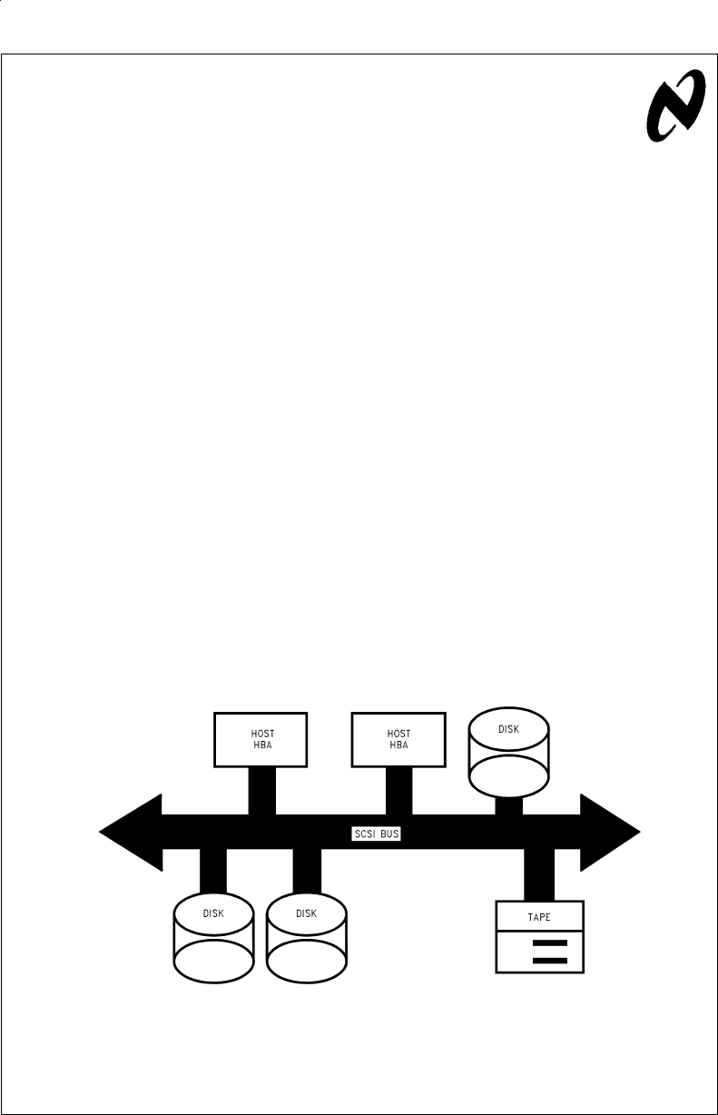
is important to also remember that a SCSI bus is not a point
to point bus, but rather a multipoint bus, allowing up to eight
different devices to be connected to the same daisy chained
cable (SCSI-1 and 2 allows up to eight devices while the pro-
posed SCSI-3 standard will allow up to 32 devices). A typical
SCSI bus configuration is shown in
Figure 1
.
WHY DIFFERENTIAL SCSI?
In comparison to single-ended SCSI, differential SCSI costs
more and has additional power and PC board space require-
ments. However, the gained benefits are well worth the addi-
tional IC cost, PCB space, and required power in many appli-
cations. Differential SCSI provides the following benefits
over single-ended SCSI:
•Reliable High Transfer Rates — easily capable of operat-
ing at 10MT/s (Fast SCSI) without special attention to termi-
nations. Even higher data rates are currently being standard-
ized (FAST-20 @20MT/s).
The companion Application Note (AN-905) focuses on the
features of National’s new RS-485 hex transceiver. The
DS36BC956 specifically designed for use in differential SCSI
applications is also optimal for use in other high speed, par-
allel, multipoint applications.
•High Noise Rejection — the differential transmission
scheme provides excellent common mode rejection over a
wide bus voltage range.
•Long Cable Lengths — cables can be as long as 25
meters in length compared to 3 meters or less for
single-ended interfaces.
•Superior AC Performance — high performance transceiv-
ers with tightly specified and guaranteed AC performance.
•Fault Tolerance — current limiting and thermal shutdown
protection integrated into the differential driver design.
Signal quality and long cable runs are the two major en-
hancements differential SCSI offers over single-ended SCSI.
As stated above, differential SCSI allows for cable runs up to
25 meters in length compared to only 3 meters of
single-ended SCSI. Differential SCSI is optimal for connect-
ing together terminals with storage arrays located in a sepa-
AN011897-1
FIGURE 1. Typical SCSI Bus Configuration-Multiple Hosts/Multiple Targets
National Semiconductor
Application Note 904
John Goldie
August 1993
An Introduction to the Differential SCSI Interface AN-904
© 1998 National Semiconductor Corporation AN011897 www.national.com

rate cooled computer room. The differential transmission
scheme offers superior noise rejection and signal quality
compared to a TTL single-ended bus.
Differential buses are also immune to minor termination
problems that commonly plague the single-ended SCSI bus.
These problems can, and commonly do have major impact
on single-ended system performance. By expanding the
cable length beyond 3 meters, by mixing different cable
types (impedance), by using different types of termination, or
by using the standard passive termination, system through-
put may be reduced as great as 50%. Since it has been de-
termined that the original single-ended termination recom-
mended in the SCSI-1 standard does not provide adequate
signal termination performance for Fast SCSI, the SCSI-2
and proposed SCSI-3 standards recommend the use of al-
ternate terminations. There are three popular alternatives to
the passive resistive terminators. These are the Boulay ter-
mination (voltage regulated), Current Regulated Termina-
tions, and the FPT (forced perfect termination). Each has its
own merits and limitations, and in fact the FPT offers good
performance but is not sanctioned by the standard. Trouble
can arise in single-ended SCSI applications when different
types of termination are used on the bus. In addition, some
SCSI controllers now provide totem pole outputs on the high
speed lines (REQ and ACK) to improve the signal quality on
those lines on the de-assert edge (active negation in industry
jargon). These active negation drivers can become in con-
tention with the alternative termination techniques and cause
thermal problems and data corruption. Single-ended SCSI
termination have caused much grief, and discussion in the
SCSI standard committee.
In contrast Differential SCSI has not encountered the prob-
lems that drove the single-ended interface to develop so
many alternative terminations. Differential SCSI uses a stan-
dard passive resistor termination (described in detail later in
this application note). This terminator remains unchanged
from the original SCSI-1 standard to the proposed SCSI-3
physical layer.
National’s DS36954 Quad Differential Bus Transceiver is de-
signed for Differential SCSI applications up to 10 MT/s.
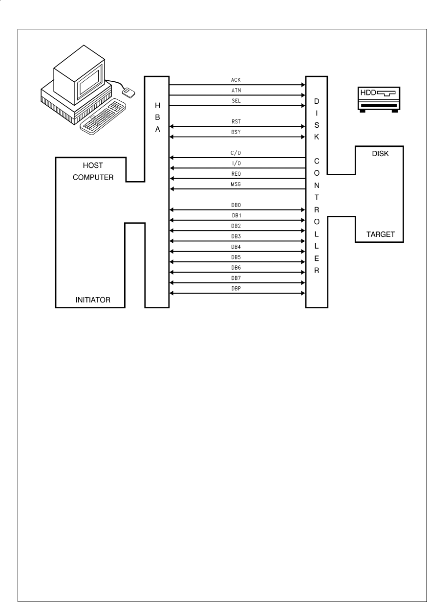
THE SCSI BUS
The SCSI bus is composed of a minimum of 18 signal lines.
An option is provided to add extra bytes to boost system
throughput (Mega Bytes per second (MB/s)) if required by
the application. The SCSI 1 and 2 standards define two
types of electrical characteristics; single-ended and differen-
tial.
Single-ended drivers (typically 48 mA open drain drivers)
and receivers are commonly integrated onto the SCSI con-
troller chips. For the differential option, external RS-485
transceivers are required. Integrating the differential trans-
ceivers onto the SCSI controller is not feasible due to the ad-
ditional pins required for differential operation, and the addi-
tional power dissipation. Additionally the semiconductor
processes commonly used for the controllers are not com-
patible with the special high speed/high voltage breakdown
processes used for RS-485 transceivers.
The single-ended and differential modes are exclusive, and
can not inter-operate. Of the 18 lines, 9 are data path (data
plus parity) and the others are control. The lines are:
•Data Path
— DB(7–0,P) — Data Bus
•Control
— REQ — Request
— ACK — Acknowledge
— BSY — Busy
— SEL — Select
— C/D — Control/Data
— I/O — Input/Output
— MSG — Message
— ATN — Attention
— RST — Reset
The SCSI Standard has two types of devices, which are “Ini-
tiators” (typically a host computer); and “Targets” (typically
drives). Of the 18 lines, 9 are bi-directional, 7 are
uni-directional direction, and 2 are wire-ORed. The data bus
(DB0–DB7 and DBP) are the bi-directional lines. Three con-
trol lines are lnitiator to Target only lines; these are the ACK,
ATN, and SEL*lines. Four lines are Target to lnitiator only
lines; these are the C/D, I/O, REQ, and MSG lines. A pictorial
representation of the signal lines is shown in
Figure 2
.
(*SEL can also be a wire-ORed line, but is more commonly
implemented as a initiator to target line).
www.national.com 2
Of the 18 lines, two, REQ and ACK, can operate at switching
rates up to 10 MHz. They are defined as handshake lines,
that in the asynchronous mode, strobe every byte of data.
The maximum defined data transfer rate is 10MT/s for Fast
SCSI. This corresponds to a bit width of 100 ns. The data
path bits are the second fastest lines on the SCSI bus oper-
ating at 10MT/s maximum (5 MHz maximum for a 1-0-1-0
pattern). The other control lines are low speed lines and are
level sensitive not edge sensitive. These lines typically only
switch between bus states, and a substantial amount of time
is provided for settling.
SCSI BUS STATES
The SCSI bus has eight different states which are:
•BUS FREE
•ARBITRATION
•SELECTION
•RESELECTION
•COMMAND
•DATA
•STATUS
•MESSAGE
The SCSI bus state is determined by the state of the SEL,
BSY, I/O, MSG, and C/D control lines. Initiators are in control
of the bus up to the command phase, and targets control the
last three information transfer phases. For example when
SEL and BSY are both false, the SCSI bus is in a bus free
state.
SCSI OPTIONS: FAST AND WIDE
The FAST option allows for operation at 10MT/s (Mega
Transfers per second) compared to the original 5MT/s speci-
fied in the original SCSI standard (now commonly referred to
as SCSI-1). Single-ended drivers and receivers should be
limited to cables less than 3 meters in length and be properly
terminated. In contrast, the differential RS-485 transceivers
can operate at 10MT/s over 25 meters of cable and due to
the differential scheme, offer high noise rejection. The
SCSI-2 (draft, 1993) introduced this option to SCSI and has
gained wide acceptance.
The WIDE option (also introduced in the SCSI-2 specifica-
tion) defines extra lines that double or quadruple the system
throughput (MB/s). Adding a second byte of data can be ac-
complished in two different ways. First, one could select the
P cable which, with 68 conductors can house both bytes of
data and the nine control lines (for a total of 27 lines). The
other option specifies two cables (A and B); the A for the first
byte and the nine control lines, while the B cable carries the
second byte plus an additional REQB and ACKB line (for a
total of 29 lines). Since the second option requires two sets
of connectors and cables, the P cable has become the more
popular of the two, as it saves money and back panel space.
The P cable (and Q for Byte 3 and 4) is included in the
SCSI-3 Parallel Interface (known as SPI) draft standard,
however A and B 50-pin cables are also still allowed. With
two bytes of data being transferred, 20MB/s is obtainable.
AN011897-2
FIGURE 2. The SCSI Signal Lines
www.national.com3
Four bytes achieves a 40MB/s maximum transfer rate. How-
ever, the four byte option is not very popular since it again re-
quires two cables (P and Q).
THE SCSI TERMINATION
The differential SCSI bus requires line termination at both
ends of the cable. Unlike the single-ended SCSI option, only
one type of termination is defined. The line is terminated with
a 3 resistor network commonly called a power termination.
The three resistors are: 330Ωbetween the -Signal and the
termination voltage (+5V), 150Ωbetween the signal pair
(−Signal and +Signal), and 330Ωfrom +Signal to ground.
The equivalent resistance of this network is 122Ω(150Ω//
(330Ω+ 330Ω)), and closely approximates the characteristic
impedance (Z
O
) of the defined cable. The termination net-
work is shown in
Figure 3
.
By using this termination reflections are minimized and a fail-
safe bias is provided. When all drivers are in TRI-STATE®
(OFF), the resistors bias the line to approximately −1V differ-
ential. The SCSI standard defines this as a FALSE state or
not-asserted. The minus sign comes from the fact that the
+Signal is less in potential than the −Signal by one volt. It
does not imply that the voltage is one volt below ground. A
common problem that occurs when installing SCSI networks
is employing greater than two termination networks. Devices
connected in the middle of the bus should not include (en-
abled) termination networks. The termination networks
should only be located at the extreme ends of the cable. In-
stalling three or more terminations loads down the driver’s
output signal and reduces or eliminates the noise margin.
SCSI CONTROLLER REQUIREMENTS
Not all SCSI controllers support the differential mode. This is
due to the fact that the external transceivers require direction
control signals.
SUMMARY OF SCSI STANDARDS
This application note provides an introduction and brief over-
view of the differential option for the SCSI parallel interface.
The reader is referenced to the standards listed below for
complete, current SCSI specifications. Also, a number of
SCSI handbooks are available that cover SCSI basics and
protocol details written in plain English compared to the
more encrypted standards.
Various manufactures reference different version of the
SCSI standard. This creates some confusion to new users.
The original version of SCSI released in 1986 is commonly
referred to as SCSI or SCSI-1. The ANSI committee has cre-
ated the second edition of SCSI known as SCSI-2, which is
currently in industry ballot (1993). This is still a draft standard
until balloting is compIete. Approval should occur some time
in 1993. Work has started on SCSI-3 also. This proposed
standard was broken down into many smaller standards to
speed up the ballot/approval process. The parallel interface
standard is specified in the SPI document (SCSI Parallel In-
terface). SCSI-3 differs from SCSl-1 and -2 in the fact that it
also specifies alternate physical layers. Currently a serial
bus based on a proposed IEEE standard (P1394) is being
standardized for small form factor drives and also a fiber
physical layer.
Table 1
describes some of the major differ-
ences in the physical layers in SCSI-1, 2, and 3 standard and
draft standards.
TABLE 1. SCSI Standard Comparison
Parameter SCSI-1 SCSI-2 SCSI-3
Maximum 8 8 8, 16,
Nodes and 32
Fast SCSI NO YES YES
Wide SCSI NO YES YES
Maximum 5MT/s 10MT/s 10MT/s
Transfer Rate
MB/s-1 Byte 5 10 10
MB/s-2 Byte X 20 20
MB/s-4 Byte X 40 40
Document X3.131 X3.131 SPI
-1986 -199x draft
REFERENCES/STANDARDS
Electrical Characteristics of Generators and Receivers for
use in Balanced Digital Multipoint Systems, EIA
RS-485-1983, TIA/EIA
Small Computer System Interface (SCSI-1), X3.131-1986,
ANSI
Small Computer System Interface (SCSI-2), X3.131-199x,
ANSI
SCSI-3 Parallel Interface (SPI), X3T9.2/91-010, Draft Stan-
dard, ANSI
AN011897-3
FIGURE 3. The SCSI Differential Termination
www.national.com 4

5

LIFE SUPPORT POLICY
NATIONAL’S PRODUCTS ARE NOT AUTHORIZED FOR USE AS CRITICAL COMPONENTS IN LIFE SUPPORT DE-
VICES OR SYSTEMS WITHOUT THE EXPRESS WRITTEN APPROVAL OF THE PRESIDENT OF NATIONAL SEMI-
CONDUCTOR CORPORATION. As used herein:
1. Life support devices or systems are devices or sys-
tems which, (a) are intended for surgical implant into
the body, or (b) support or sustain life, and whose fail-
ure to perform when properly used in accordance
with instructions for use provided in the labeling, can
be reasonably expected to result in a significant injury
to the user.
2. A critical component in any component of a life support
device or system whose failure to perform can be rea-
sonably expected to cause the failure of the life support
device or system, or to affect its safety or effectiveness.
National Semiconductor
Corporation
Americas
Tel: 1-800-272-9959
Fax: 1-800-737-7018
Email: support@nsc.com
www.national.com
National Semiconductor
Europe Fax: +49 (0) 1 80-530 85 86
Email: europe.support@nsc.com
Deutsch Tel: +49 (0) 1 80-530 85 85
English Tel: +49 (0) 1 80-532 78 32
Français Tel: +49 (0) 1 80-532 93 58
Italiano Tel: +49 (0) 1 80-534 16 80
National Semiconductor
Asia Pacific Customer
Response Group
Tel: 65-2544466
Fax: 65-2504466
Email: sea.support@nsc.com
National Semiconductor
Japan Ltd.
Tel: 81-3-5620-6175
Fax: 81-3-5620-6179
AN-904 An Introduction to the Differential SCSI Interface
National does not assume any responsibility for use of any circuitry described, no circuit patent licenses are implied and National reserves the right at any time without notice to change said circuitry and specifications.
