AN 994 Simplified Intelligent Port Design Using The 74ACT1284
User Manual: 994
Open the PDF directly: View PDF ![]() .
.
Page Count: 6

To learn more about ON Semiconductor, please visit our website at
www.onsemi.com
Is Now Part of
ON Semiconductor and the ON Semiconductor logo are trademarks of Semiconductor Components Industries, LLC dba ON Semiconductor or its subsidiaries in the United States and/or other countries. ON Semiconductor owns the rights to a number
of patents, trademarks, copyrights, trade secrets, and other intellectual property. A listing of ON Semiconductor’s product/patent coverage may be accessed at www.onsemi.com/site/pdf/Patent-Marking.pdf. ON Semiconductor reserves the right
to make changes without further notice to any products herein. ON Semiconductor makes no warranty, representation or guarantee regarding the suitability of its products for any particular purpose, nor does ON Semiconductor assume any liability
arising out of the application or use of any product or circuit, and specifically disclaims any and all liability, including without limitation special, consequential or incidental damages. Buyer is responsible for its products and applications using ON
Semiconductor products, including compliance with all laws, regulations and safety requirements or standards, regardless of any support or applications information provided by ON Semiconductor. “Typical” parameters which may be provided in ON
Semiconductor data sheets and/or specifications can and do vary in different applications and actual performance may vary over time. All operating parameters, including “Typicals” must be validated for each customer application by customer’s
technical experts. ON Semiconductor does not convey any license under its patent rights nor the rights of others. ON Semiconductor products are not designed, intended, or authorized for use as a critical component in life support systems or any FDA
Class 3 medical devices or medical devices with a same or similar classification in a foreign jurisdiction or any devices intended for implantation in the human body. Should Buyer purchase or use ON Semiconductor products for any such unintended
or unauthorized application, Buyer shall indemnify and hold ON Semiconductor and its officers, employees, subsidiaries, affiliates, and distributors harmless against all claims, costs, damages, and expenses, and reasonable attorney fees arising out
of, directly or indirectly, any claim of personal injury or death associated with such unintended or unauthorized use, even if such claim alleges that ON Semiconductor was negligent regarding the design or manufacture of the part. ON Semiconductor
is an Equal Opportunity/Affirmative Action Employer. This literature is subject to all applicable copyright laws and is not for resale in any manner.
© 2000 Fairchild Semiconductor Corporation AN012115 www.fairchildsemi.com
Fairchild Semiconductor
Application Note
May 1995
Revised December 2000
AN-994 Simplified Intelligent Port Design Using the 74ACT1284
AN-994
Simplified Intelligent Port Design Using the 74ACT1284
Introduction
Until recently a standard for parallel port data transfer has
been missing in the industry. IEEE1284, approved by the
IEEE in March 1994, addresses the lack of a parallel port
specification. The standard, entitled “A Standard Signaling
Method for a Bi-Directional Parallel Peripheral Interface for
Personal Computers”, will eventually displace the anti-
quated, slow, quasi-bi-directional method of transferring
data between host and peripheral. Described within the
standard is a high speed, fully interlocked bi-directional
peripheral connectivity port which greatly improves perfor-
mance while maintaining backward compatibility with sys-
tems which are IEEE 1284 non-compliant.
There are five operational modes described in the stan-
dard. the two truly bi-directional modes, the EPP
(enhanced parallel port) and the ECP (extended capabili-
ties port) provide for the greatest increase in port perfor-
mance. The EPP and ECP modes allow half duplex data
communication between the host and its peripheral at
speeds greater than 100 times that of the SPP (standard
parallel port). This translates to a remarkable speed
upgrade of more than 2 Mbytes/sec. However, in order to
realize the tremendous increase in speed and the advan-
tages of true bi-directionality made possible by IEEE 1284,
system designers must pay particular attention to the port
interface circuitry.
There are key areas one needs to be concerned with when
designing IEEE 1284 compliant systems. Of primary impor-
tance is ensuring data integrity at the high rates made pos-
sible by the new standard. Another important consideration
is the limitations peripheral ASIC controllers may have
when attempting to directly drive the IEEE 1284 specified
10 meter cable lengths. These things serve to underscore
the fact that port I/O drive and receive components must
possess the capability for maintaining IEEE 1284 specified
signal levels and timing.
74ACT1284
The 74ACT1284 provides the necessary low impedance
drive for transmission of the control and data signals nec-
essary for reliable intelligent peripheral and host interface
communication. The device was developed in response to
the IEEE 1284 standard and an anticipated expansion in
the intelligent peripheral market. Fairchild Semiconductor
design philosophy for the 74ACT1284 was to accommo-
date the IEEE 1284 standard and to provide system manu-
facturers a solution to the problems associated with using
ASICs to drive the high bandwidth IEEE 1284 port. the
74ACT1284 meets or exceeds all IEEE 1284 specified
parameters for driving and receiving signals over an intelli-
gent peripheral interface port and addresses such critical
design areas as high speed parallel port handshaking, low
impedance cable driving, and increased ESD protection.
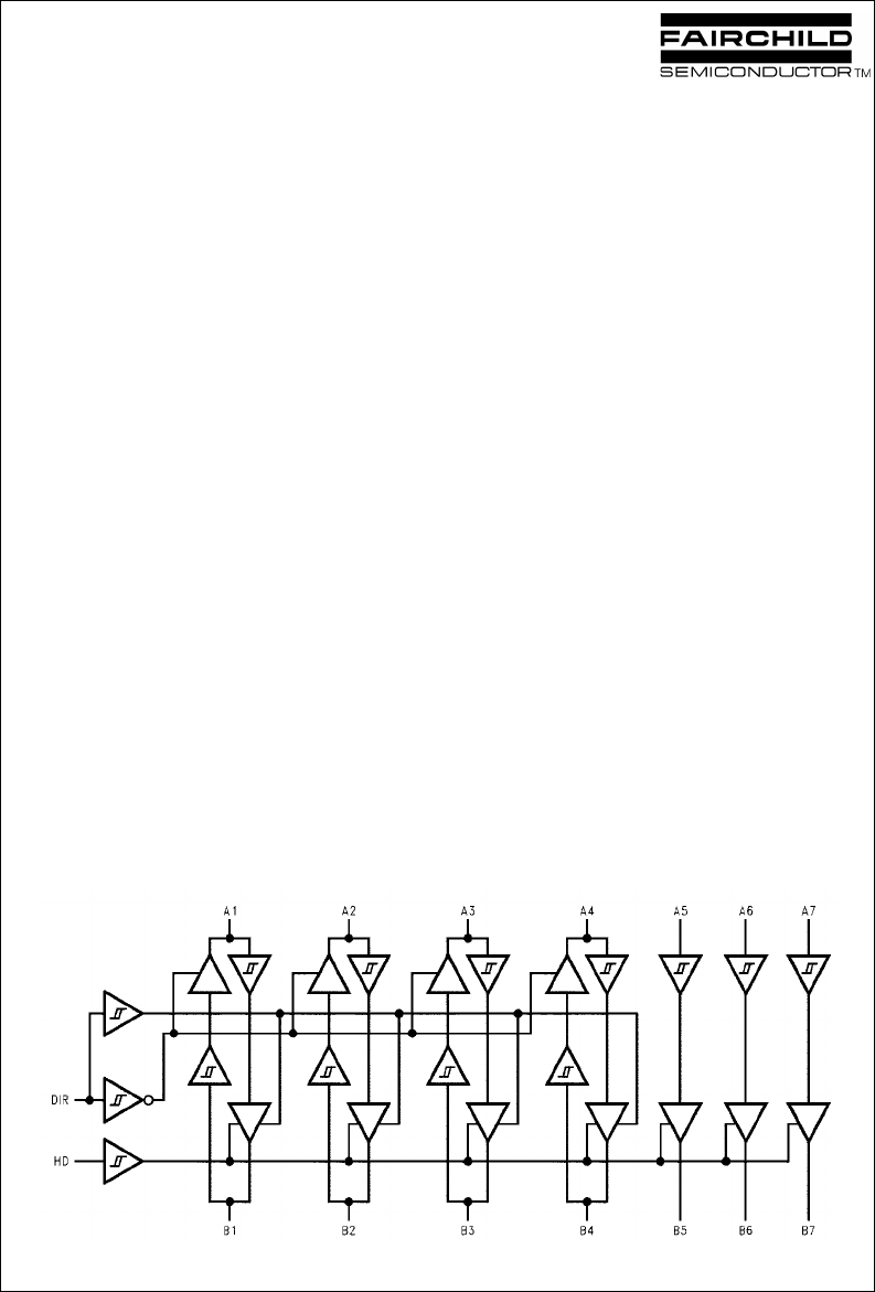
The 74ACT1284 device functions as a 7-bit bus transceiver
designed for asynchronous two-way communication. As
shown in the logic diagram, Figure 1, the IC contains four
non-inverting bi-directional buffers and three non-inverting
unidirectional buffers. The B Port buffers can be configured
either as open drain or high drive outputs. The HD input pin
enables the B Ports to switch from open drain to a high
drive totem pole configuration, capable of sourcing and
sinking 14 mA on all seven buffers. The DIR input deter-
mines the direction of data flow on the bi-directional buff-
ers. The DIR control function implementation helps to
minimize external timing requirements.
FIGURE 1. 74ACT1284 Logic Diagram

www.fairchildsemi.com 2
AN-994
74ACT1284 (Continued)
The FSC 74ACT1284 gives the designer significant advan-
tage when designing the port interface circuitry. System
manufacturers who design to the IEEE 1284 standard
using an ASIC controller to drive the parallel port directly
may encounter problems. ASIC controller power and drive
constraints become evident when attempting to drive
lengthy, highly capacitive, low impedance cables. Conse-
quently, IEEE 1284 specifications may not be met. When
using the 74ACT1284, designers have an integrated solu-
tion which ensures that critical port interface signal proper-
ties are preserved.
Some advantages for using the 74ACT1284 at an IEEE
1284 compliant port are the following:
•Full IEEE 1284 specification compliance
•Provides a solution for easing controller power and drive
design constraints
•Bi-directional Port buffering with input hysteresis
•Optimized printed circuit layout through localization of
port drive circuitry
•Advanced CMOS technology for low power consumption
•Guaranteed class 3 ESD performance for protection of
sensitive I/O signal controllers
•TTL and CMOS compatible input thresholds
Host-Side Application
of the 74ACT1284
Perhaps it is more likely that the 74ACT1284 function will
be utilized at the intelligent peripheral port, however, there
are benefits for its use at both the host and peripheral port
interfaces. There are several important advantages for
using the 74ACT1284 at the host as well as the peripheral.
They are as follows: 1) adequate cable drive over the
required IEEE 1284 data bandwidth 2) increased port ESD
protection and most importantly 3) the assurance of full
IEEE 1284 compliance.
An application example for using the 74ACT1284 at the
host in ECP mode appears in Figure 2. In the figure, a
generic host controller is shown with three 74ACT1284s
(shown as one block) placed at the I/O port. The diagram
denotes compatibility mode signals, with ECP mode sig-
nals shown in parenthesis, interconnecting the host and
peripheral. 74ACT1284 devices are used here to drive and
buffer signals between host and peripheral, insuring signal
integrity and protection of the host controller from damage
caused by noise spikes should the peripheral be powered
down or arbitrarily disconnected.
FIGURE 2. Host-Side 74ACT1284 Application

3 www.fairchildsemi.com
AN-994
Peripheral-Side Application
of the 74ACT1284
Similar to Figure 2, Figure 3 shows a diagram of periph-
eral-side application of the 74ACT1284. Both Figure 2 and
Figure 3 application examples depict the peripheral and
host controller direct I/O port interface portion of the system
only.
Register names and hooks will vary depending on control-
ler design, therefore, it is likely that not all register connec-
tions will be shown in the figures. We would like to re-
emphasize that buffering of all signals at the port is the best
way of assuring system functionality and reliability.
The peripheral can take many forms and still support IEEE
1284. Other devices that use the new IEEE 1284 standard
are scanners, tape backup, CD ROM and network/LAN
adapters.
For clarity, Figure 4 has been included to show the signal
connections which comprise the entire system. It is beyond
the scope of this paper to assume how all signals might be
used to and from the controller registers. The examples
show basic IEEE 1284 control signal names. There may be
other signals used which are not shown in the examples.
FIGURE 3. Peripheral-Side 74ACT1284 Application
FIGURE 4. Host/Peripheral System Signals
Summary
With the advent of IEEE 1284, system designers are look-
ing at a new horizon with which to implement the informa-
tion exchange between computer and peripheral. The
proliferation of high performance computing systems cou-
pled with IEEE 1284 compliant intelligent peripheral
devices will serve to outmode the old methods of transport-
ing data via the parallel port and its external support
medium.
For new IEEE 1284 compliant designs to reach their mar-
ket in a shorter time, solutions which enhance the design
cycle through simplication are usually a good alternative.
The 74ACT1284 was developed to provide a packaged
solution to the design of the bus interface in IEEE 1284
compliant systems. It is a device intended to alleviate the
problems associated with IEEE 1284 specification con-
formance and can be thought of as a drop-in stage for
ensurance of IEEE 1284 compliance.

www.fairchildsemi.com 4
AN-994 Simplified Intelligent Port Design Using the 74ACT1284
Fairchild does not assume any responsibility for use of any circuitry described, no circuit patent licenses are implied and
Fairchild reserves the right at any time without notice to change said circuitry and specifications.
LIFE SUPPORT POLICY
FAIRCHILD’S PRODUCTS ARE NOT AUTHORIZED FOR USE AS CRITICAL COMPONENTS IN LIFE SUPPORT
DEVICES OR SYSTEMS WITHOUT THE EXPRESS WRITTEN APPROVAL OF THE PRESIDENT OF FAIRCHILD
SEMICONDUCTOR CORPORATION. As used herein:
1. Life support devices or systems are devices or systems
which, (a) are intended for surgical implant into the
body, or (b) support or sustain life, and (c) whose failure
to perform when properly used in accordance with
instructions for use provided in the labeling, can be rea-
sonably expected to result in a significant injury to the
user.
2. A critical component in any component of a life support
device or system whose failure to perform can be rea-
sonably expected to cause the failure of the life support
device or system, or to affect its safety or effectiveness.
www.fairchildsemi.com

www.onsemi.com
1
ON Semiconductor and are trademarks of Semiconductor Components Industries, LLC dba ON Semiconductor or its subsidiaries in the United States and/or other countries.
ON Semiconductor owns the rights to a number of patents, trademarks, copyrights, trade secrets, and other intellectual property. A listing of ON Semiconductor’s product/patent
coverage may be accessed at www.onsemi.com/site/pdf/Patent−Marking.pdf. ON Semiconductor reserves the right to make changes without further notice to any products herein.
ON Semiconductor makes no warranty, representation or guarantee regarding the suitability of its products for any particular purpose, nor does ON Semiconductor assume any liability
arising out of the application or use of any product or circuit, and specifically disclaims any and all liability, including without limitation special, consequential or incidental damages.
Buyer is responsible for its products and applications using ON Semiconductor products, including compliance with all laws, regulations and safety requirements or standards,
regardless of any support or applications information provided by ON Semiconductor. “Typical” parameters which may be provided in ON Semiconductor data sheets and/or
specifications can and do vary in different applications and actual performance may vary over time. All operating parameters, including “Typicals” must be validated for each customer
application by customer’s technical experts. ON Semiconductor does not convey any license under its patent rights nor the rights of others. ON Semiconductor products are not
designed, intended, or authorized for use as a critical component in life support systems or any FDA Class 3 medical devices or medical devices with a same or similar classification
in a foreign jurisdiction or any devices intended for implantation in the human body. Should Buyer purchase or use ON Semiconductor products for any such unintended or unauthorized
application, Buyer shall indemnify and hold ON Semiconductor and its officers, employees, subsidiaries, affiliates, and distributors harmless against all claims, costs, damages, and
expenses, and reasonable attorney fees arising out of, directly or indirectly, any claim of personal injury or death associated with such unintended or unauthorized use, even if such
claim alleges that ON Semiconductor was negligent regarding the design or manufacture of the part. ON Semiconductor is an Equal Opportunity/Affirmative Action Employer. This
literature is subject to all applicable copyright laws and is not for resale in any manner.
PUBLICATION ORDERING INFORMATION
N. American Technical Support: 800−282−9855 Toll Free
USA/Canada
Europe, Middle East and Africa Technical Support:
Phone: 421 33 790 2910
Japan Customer Focus Center
Phone: 81−3−5817−1050
www.onsemi.com
LITERATURE FULFILLMENT:
Literature Distribution Center for ON Semiconductor
19521 E. 32nd Pkwy, Aurora, Colorado 80011 USA
Phone: 303−675−2175 or 800−344−3860 Toll Free USA/Canada
Fax: 303−675−2176 or 800−344−3867 Toll Free USA/Canada
Email: orderlit@onsemi.com
ON Semiconductor Website: www.onsemi.com
Order Literature: http://www.onsemi.com/orderlit
For additional information, please contact your local
Sales Representative
© Semiconductor Components Industries, LLC
