D00001152 ANT FS Reference Design User Manual Rev 2 0
User Manual:
Open the PDF directly: View PDF ![]() .
.
Page Count: 45

P +1 403.932.9292 F +1 403.932.4196
ANT-FS
Reference Design
User Manual
D00001152 Rev2.0
Dynastream Innovations Inc.

2 of 45
228 River Avenue, Cochrane, Alberta, Canada T4C 2C1 thisisant.com
Copyright Information and Usage Notice
This information disclosed herein is the exclusive property of Dynastream Innovations Inc. No part of this
publication may be reproduced or transmitted in any form or by any means including electronic storage,
reproduction, execution or transmission without the prior written consent of Dynastream Innovations Inc.
The recipient of this document by its retention and use agrees to respect the copyright of the information
contained herein.
The information contained in this document is subject to change without notice and should not be
construed as a commitment by Dynastream Innovations Inc. unless such commitment is expressly given in
a covering document.
The Dynastream Innovations Inc. ANT Products described by the information in this document are not
designed, intended, or authorized for use as components in systems intended for surgical implant into the
body, or other applications intended to support or sustain life, or for any other application in which the
failure of the Dynastream product could create a situation where personal injury or death may occur. If
you use the Products for such unintended and unauthorized applications, you do so at your own risk and
you shall indemnify and hold Dynastream and its officers, employees, subsidiaries, affiliates, and
distributors harmless against all claims, costs, damages, and expenses, and reasonable attorney fees
arising out of, directly or indirectly, any claim of personal injury or death associated with such unintended
or unauthorized use, even if such claim alleges that Dynastream was negligent regarding the design or
manufacture of the Product.
©2010 Dynastream Innovations Inc. All Rights Reserved.

3 of 45
228 River Avenue, Cochrane, Alberta, Canada T4C 2C1 thisisant.com
Table of Contents
1
Introduction ........................................................................................................................................................... 4
2
Relevant Documents ............................................................................................................................................. 4
3
ANT-FS PC Reference Designs .............................................................................................................................. 5
3.1
ANT Library Files............................................................................................................................... 5
3.1.1
ANT Common Library ..................................................................................................................... 5
3.1.2
ANT Managed Library .................................................................................................................... 5
3.1.3
Architecture Overview .................................................................................................................... 6
4
ANT-FS PC Host ...................................................................................................................................................... 7
4.1
Options ............................................................................................................................................ 7
4.1.1
General ......................................................................................................................................... 8
4.1.2
ANT Channel ............................................................................................................................... 11
4.1.3
Host Parameters .......................................................................................................................... 13
4.1.4
Security ...................................................................................................................................... 14
4.2
General Operation........................................................................................................................... 16
4.2.1
Open .......................................................................................................................................... 16
4.2.2
Close .......................................................................................................................................... 16
4.2.3
Cancel ......................................................................................................................................... 16
4.2.4
Search and Connect ..................................................................................................................... 16
4.2.5
Authentication ............................................................................................................................. 17
4.2.6
Transport .................................................................................................................................... 19
4.2.7
Erase. ......................................................................................................................................... 21
4.2.8
Disconnecting .............................................................................................................................. 22
4.2.9
Return to Broadcast ..................................................................................................................... 22
5
ANT-FS PC Client .................................................................................................................................................. 23
5.1
Options .......................................................................................................................................... 23
5.1.1
General ....................................................................................................................................... 23
5.1.2
ANT Channel ............................................................................................................................... 26
5.1.3
Beacon........................................................................................................................................ 27
5.1.4
Security ...................................................................................................................................... 29
5.2
Managing the Directory ................................................................................................................... 30
5.2.1
Adding and Editing Directory Entries............................................................................................. 31
5.2.2
Directory Entry Editor .................................................................................................................. 31
5.2.3
Deleting Directory Entries ............................................................................................................ 32
5.3
General Operation........................................................................................................................... 32
5.3.1
Open .......................................................................................................................................... 33
5.3.2
Close .......................................................................................................................................... 33
5.3.3
Open Beacon ............................................................................................................................... 33
5.3.4
Connecting to a Host Device ........................................................................................................ 34
5.3.5
Transport .................................................................................................................................... 35
5.3.6
Disconnecting from a Host Device ................................................................................................ 35
5.3.7
Broadcast ANT-FS........................................................................................................................ 36
6
ANT-FS Embedded Client .................................................................................................................................... 38
6.1
Architecture Overview ..................................................................................................................... 38
6.1.1
base ........................................................................................................................................... 39
6.1.2
antfs ........................................................................................................................................... 39
6.2
Reference Design Setup .................................................................................................................. 39
6.3
Options .......................................................................................................................................... 43
6.4
General Operation........................................................................................................................... 44
6.4.1
Start ........................................................................................................................................... 44
6.4.2
Connect ...................................................................................................................................... 44
6.4.3
Authenticate ................................................................................................................................ 44
6.4.4
Download .................................................................................................................................... 44
6.4.5
Upload ........................................................................................................................................ 44
6.4.6
Erase .......................................................................................................................................... 45

4 of 45
228 River Avenue, Cochrane, Alberta, Canada T4C 2C1 thisisant.com
1 Introduction
The ANT File Share (ANT-FS) system specification provides a robust framework for transferring files
between two ANT enabled devices. This document describes the PC and embedded reference designs that
are provided as part of the ANT-FS developer distribution.
The PC reference designs are useful tools that aid with the development of ANT-FS client and host
devices. The PC reference designs make use of the ANT Common Library, a statically linked library that
may be compiled directly into Windows, MacOS, and Linux applications. The reference designs provide an
example on the usage of the library for the development of ANT-FS applications. Both are distributed as
binaries for Windows.
The embedded ANT-FS reference design includes source code that can be compiled directly for use with
the MSP430 microcontroller, but may be easily ported to other target architectures due to its modular
design.
It is assumed that the reader of this document is familiar with basic ANT concepts, C/C++ programming,
and the ANT-FS Technical Specification.
2 Relevant Documents
It is strongly recommended that the reader be familiar with the following documents:
• ANT-FS Technical Specification
• ANT Message Protocol and Usage
• Interfacing with ANT General Purpose Chipsets and Modules

5 of 45
228 River Avenue, Cochrane, Alberta, Canada T4C 2C1 thisisant.com
3 ANT-FS PC Reference Designs
The ANT-FS PC reference designs are PC applications that allow the user to test and develop PC host and
client ANT-FS devices. The source code for this tool is based on the ANT Common Library files which may
be used directly in custom user applications. As such, the ANT-FS PC tools have a dual purpose. First,
they serve as development tools that allow the user to test and explore the functionality of ANT-FS.
Second, they serve as reference designs showing how to use the library files to develop ANT-FS PC
applications.
3.1 ANT Library Files
3.1.1
ANT Common Library
The ANT Common Library (ANT_LIB) is a collection of files and classes that allow full control of an ANT
enabled USB stick, including integration of the ANT-FS protocol extension. The entire library is contained
within the following three directories:
• Common: The
common
directory contains files that provide common functionality, for example
checksum (CRC) calculations.
• Inc: The
inc
directory contains all relevant include files for creating ANT-FS, or generic ANT, PC
applications based on this library.
• Software: The
software
directory contains the core functionality of the ANT library. This includes
serial drivers, ANT message framing, debugging and threading, and the ANT-FS protocol
extension. This directory is further sub-divided into the following four sub-directories:
• ANTFS: contains the files that implement the PC ANT-FS Host and Client classes. Applications
with ANT-FS Host and Client functionality interface directly to the ANTFSHost and
ANTFSClient classes contained within this directory. The ANTFSHost and ANTFSClient classes
interface to lower level serial, framing and threading classes.
• Serial: contains files that handle the serial communication with USB devices. The
Serial
subdirectory also contains the ANT message framing, with all the messages described in the
“ANT Message Protocol and Usage” document.
• System: contains functionality for threading, debugging and timing. This functionality has
been abstracted such that these services can be used on a variety of OS platforms.
• USB: contains files with handles for USB devices, and provides low level access to the serial
drivers. As the ANT Common Library is designed to compile across multiple operating
systems, this directory contains files that interface to a virtual com port driver (Mac OS or
Linux), libusb driver (PC), iokit driver (Mac OS) and USB Express driver (PC).
For complete documentation of the ANTFSHost and ANTFSClient classes, please refer to the source code.
The header files are thoroughly documented with descriptions of each available function.
3.1.2
ANT Managed Library
The ANT Managed Library is a wrapper around the ANT Common Library that allows simplified
development of ANT enabled applications using the Microsoft .NET framework. The ANTFS_Host and
ANTFS_Client classes in this library expose the ANT-FS functionality in the ANT Common Library to
managed applications, while taking care of threading and interoperability with the unmanaged code. For
complete documentation of the ANTFS_Host and ANTFS_Client classes, please refer to the source code,
and the ANT_NET.xml file.
6 of 45
228 River Avenue, Cochrane, Alberta, Canada T4C 2C1 thisisant.com
3.1.3
Architecture Overview
The ANT-FS PC Host tool is a C++/CLI application, interfacing directly to the ANTFSHost class in the ANT
Common Library. This class in turn makes use of lower level functionality made available by other library
files and classes.
The ANT-FS PC Client tool is a C# application, and interfaces directly to the ANTFS_Client class in the ANT
Managed Library. The ANT Managed Library makes use of the ANTFSClient class in the ANT Common
library to encapsulate the serial messaging, message framing and threading along with the functionality of
an ANT-FS client.
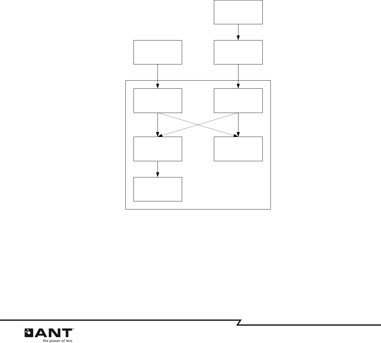
A high level class diagram of the class relationships for this application is depicted in Figure 3-1.
Figure 3-1. Simplified Class Diagram
Class ANTFSHost Class ANTFSClient
Class
DSISerialGeneric
Class
DSIFramerANT
Class USBDevice
ANT-FS Host
Reference Design
ANT-FS Client
Reference Design
ANT Managed
Library
ANT Common
Library
7 of 45
228 River Avenue, Cochrane, Alberta, Canada T4C 2C1 thisisant.com
4 ANT-FS PC Host
The ANT-FS PC Host application is a development tool that may be used to exercise almost all of the
features of ANT-FS with any ANT-FS enabled Client device. The tool supports all three methods of
authentication: pairing, passkey and pass-thru. Also, it allows files to be uploaded or downloaded from a
client device, and provides quick configurations to connect to popular ANT-FS devices such as FR-50 or
FR-60 watches, as well as other ANT+ devices with file transfer capabilities. However, tool does not do
any data decoding or encoding other than optional encryption during a data transfer. Data
encoding/decoding is left to the user or other applications.
4.1 Options
The ANT-FS PC Host Development tool allows the user to set several options for a specific ANT-FS
implementation. This includes parameters specific to the USB port, the ANT channel and selection of the
ANT-FS Client to interface with. On startup, options are loaded from a configuration file called “config.txt”
located in the current user’s Application Data directory. If this file is missing or corrupt, default options
are set. On exit, the application will save its current settings to the “config.txt” file. Furthermore, the
application allows the user to save and load configuration files for particular test implementations. More
details on this process are provided in later sections.
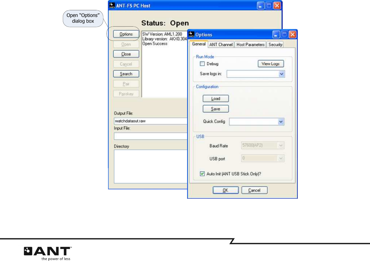
Options may be viewed and changed by clicking on the “Options” button in the application (Figure 4-1).
General options must be changed prior to connecting to the USB Stick (Open button), while most other
options need to be changed prior to beginning the search operation (Search button).
Figure 4-1. Opening the Options Dialog Box
The options are categorized under four tabs: General, ANT Channel, Client and Security, and are described
in the following sections.
8 of 45
228 River Avenue, Cochrane, Alberta, Canada T4C 2C1 thisisant.com
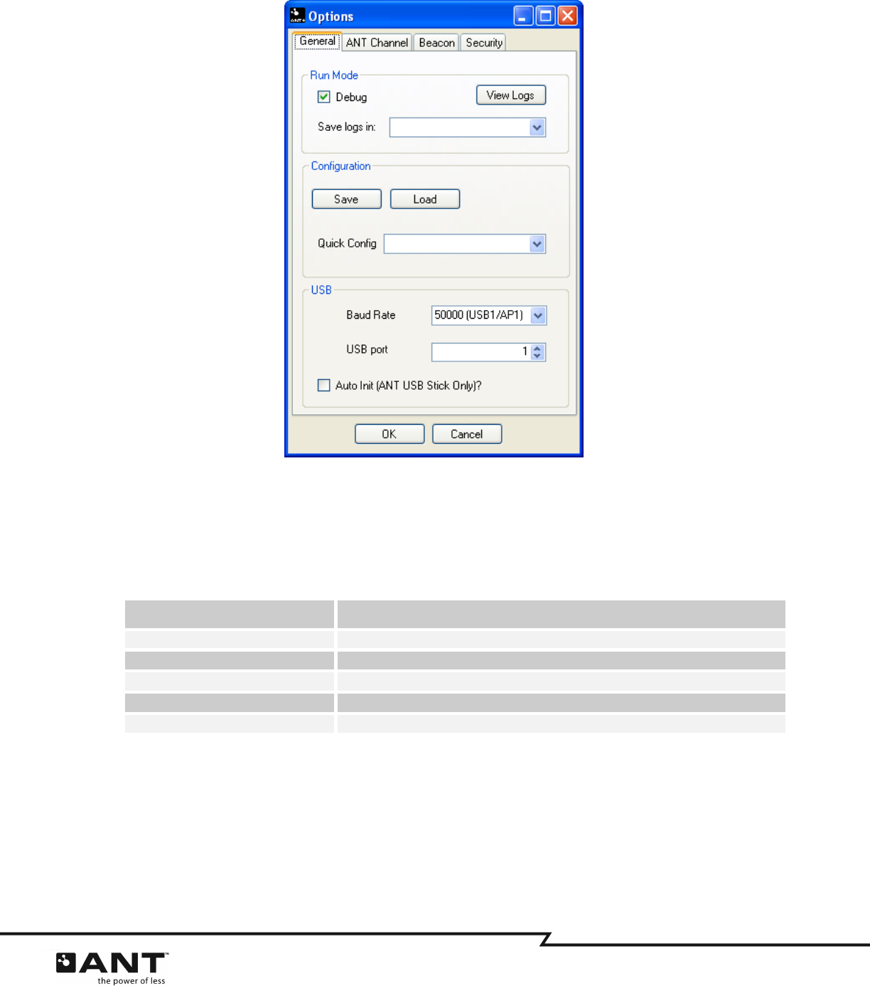
4.1.1
General
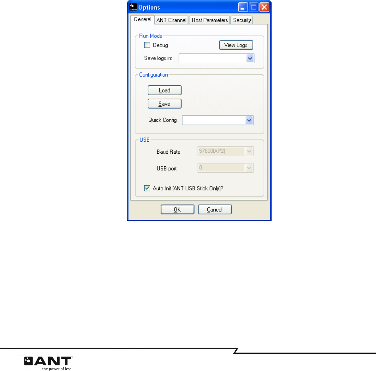
The “General” tab (Figure 4-2) allows the user to set various options that are not directly applicable to
ANT-FS. This includes selecting debug mode and USB port connection settings. It also allows the user to
preload and save options from/to a configuration file, or load pre-configured settings for popular ANT-FS
devices such as the Garmin FR-60 watch.
Figure 4-2. General Options Tab
9 of 45
228 River Avenue, Cochrane, Alberta, Canada T4C 2C1 thisisant.com
4.1.1.1 Run Mode
The run mode box is used to specify if the application will run in debug or normal mode. Running the
application in debug mode forces the ANT-FS library to generate debug log files as it progresses through
an ANT-FS connection, providing useful information for testing and debugging. The debug files generated
in the ANT-FS PC Host tool’s directory are outlined in Table 4-1.
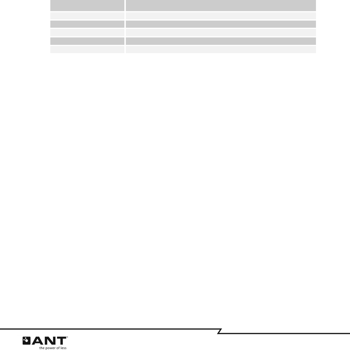
Table 4-1. Host Log Files
Log File Name Description
ao_debug_ANTReceive.txt Log of all ANT channel and protocol events received
ao_debug_ANTFS.txt Log of ANT-FS events
ao_debug_Application.txt Log of application initiated events
ao_debug_Timer.txt Log of timer events
Device0.txt Log of all communication on the serial port between ANT and the PC.
The Debug mode checkbox MUST be set prior to opening the ANT-FS connection. Log files will not be
generated if the Debug mode checkbox is set after opening the connection.
Debug files are stored in the Application Data directory for the current user, for example, for Windows XP:
C:\Documents and Settings\UserName\Application Data\ANTFS_PC_Host\logs
To open the directory containing the logs, click the ‘View Logs’ button.
To store the debug files in a different directory, choose the ‘Select…’ option in the ‘Save logs in’ pull-down
menu, and browse to the desired location. This is particularly useful in selecting different locations for
particular debugging sessions. Custom debug file directories are not automatically saved, and must be
configured every time the application is started.
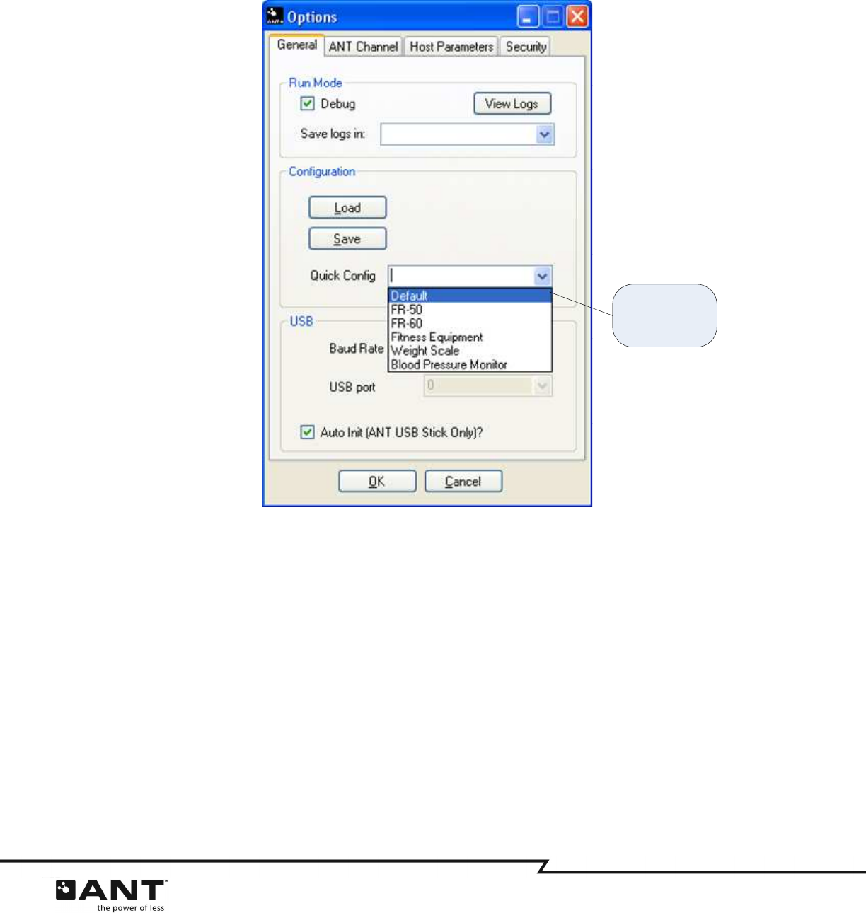
4.1.1.2 Configuration
The configuration box allows the user to save the current options to a file, load options from a file, or
select a preset configuration from a drop down box.
Click the ‘Save’ button, to save the current options. A Save File Dialog box will then be opened and the
user may specify the desired file name and location. Please note that saving to the “config.txt” file in the
base directory will overwrite the default startup configuration. To load options from a previously saved
file, click on the ‘Load’ button and select the desired options file. All options set by the user, including
USB port and debug configuration are saved in/loaded from these files.
10 of 45
228 River Avenue, Cochrane, Alberta, Canada T4C 2C1 thisisant.com
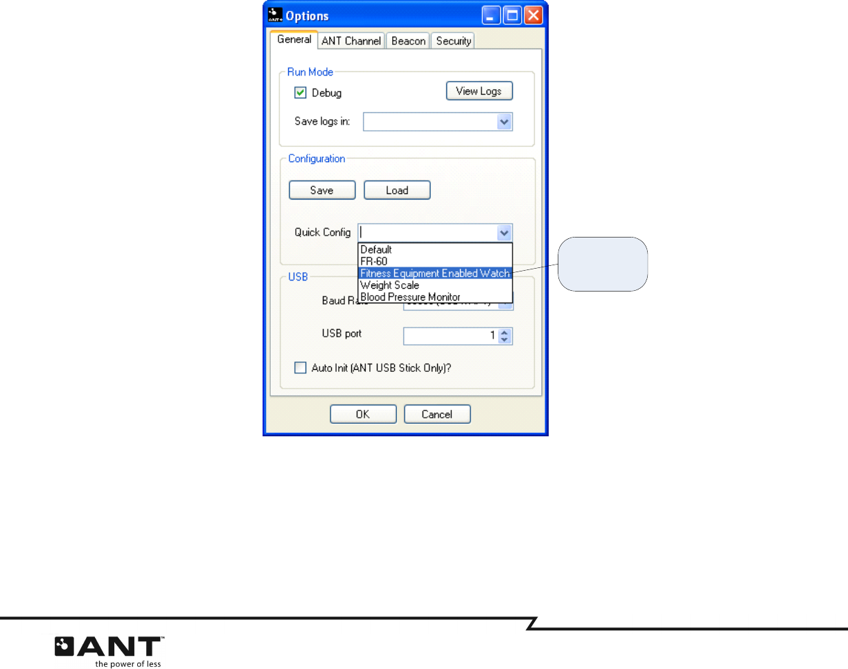
To select a pre-configured option, select the desired device from the ‘Quick Config’ drop down box. This
will set the ANT Channel options and Client options accordingly to communicate with that device. Using
pre-configured options won’t affect the USB port or debug settings.
Figure 4-3. Selecting Pre-Configured Options
4.1.1.3 USB
The USB box allows the user to select the USB port configuration. The baud rate selected will depend on
the ANT chip mounted on the USB stick. The AP1 connects at 50000, and all other ANT solutions connect
at 57600. The USB Port drop down menu is used to select the port to which the USB stick is connected. As
a general rule, the first USB stick connected to a PC will be assigned port 0, the next port 1 and so on,
provided all USB sticks have the same VID/PID. The Auto Init option enables the library to automatically
select the baud rate for a USB stick connected to port 0; this feature is only available for ANT USB1 and
USB2 sticks (black plastic case). Selecting this option will disable the baud and port options. This option is
generally recommended for production level products to alleviate the user from having to select a specific
baud rate and USB port number.
If no USB stick is connected, clicking open will not fail. Instead the library will poll the USB periodically
until a USB stick is detected.
Select preset
ANT-FS client to
connect to
11 of 45
228 River Avenue, Cochrane, Alberta, Canada T4C 2C1 thisisant.com
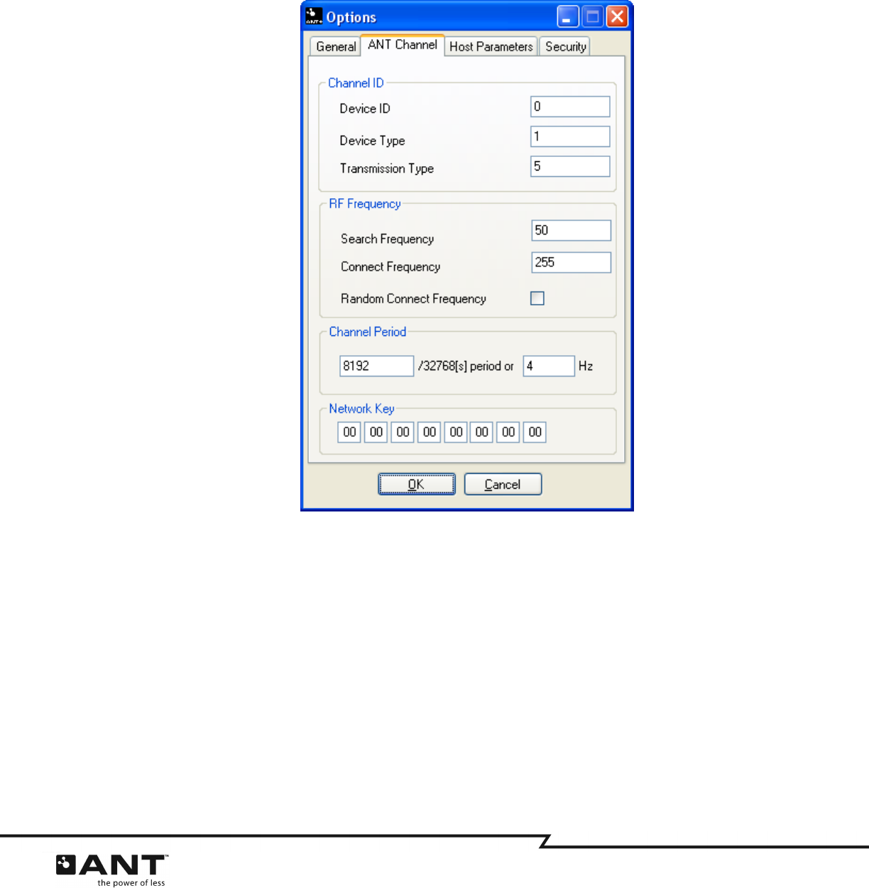
4.1.2
ANT Channel
The “ANT Channel” tab allows the user to set specific ANT channel parameters. This includes channel ID,
search and connect radio frequencies, channel period and network key. All other channel parameters are
set by the ANT-FS library. Caution must be exercised when changing the channel parameters as this may
interfere with the interoperability of devices.
Figure 4-4. ANT Channel Options Tab
4.1.2.1 Channel ID
The Channel ID refers to the 4 byte ANT channel ID that is comprised of a 2 byte Device ID, 1 byte
Device Type and 1 byte Transmission Type.If not searching for a specific, known, channel ID it is
recommended that the host wildcards both the Device ID and Transmission Type fields.
4.1.2.2 RF Channel Frequency
There are two RF channel frequencies relevant to ANT-FS. The first is the Search frequency. This is the
frequency at which the ANT-FS channel is opened and searches for client devices in the Link Layer. The
second radio frequency is the Connect Frequency. This is the frequency at which communication above the
Link Layer will occur. The Connect Frequency is set by the host using the LINK command as per the ANT-
FS Protocol specification. The Connect Frequency may be explicitly set to a specific, or random, value. If
set to a random value, the host library will choose from one of the frequencies listed in Table 4-2.

12 of 45
228 River Avenue, Cochrane, Alberta, Canada T4C 2C1 thisisant.com
Table 4-2. RF Channel Frequency Table (in MHz) for Random Link
Random Frequency Values
2403 2407 2415 2420 2425 2429 2434 2440 2445 2449 2354 2460 2465 2470 2475 2480
Once the frequency is set by the LINK Command, the ANT-FS session will remain at that frequency for the
duration of the Authenticate and Transport layers. It is important to implement this level of frequency
agility as the Transport Layer requires significant bursting, consuming high bandwidth which may interfere
with other ANT-FS devices in the area. Therefore, it is recommended to use the random frequency feature
implemented by the ANT Common Library as this will decrease the likelihood of multiple devices within the
Transport Layer operating on the same RF channel frequency.
4.1.2.3 Channel Period
The channel period is controlled by the host and does not necessarily need to match that of the client
while in the Link layer. The host will set the client’s channel period using the Link command. In order to
conserve power, the client may be designed to beacon at lower message rates.
The channel period is set as a fraction of a 32kHz counter. For example, to set a 4Hz message rate, the
count is:
count = 32768/4 = 8192
Alternatively, the channel period can be configured in Hz. The data will be updated automatically
depending on user input.
4.1.2.4 Network Key
The network key can be set to a public, managed or private network key. Please contact Dynastream
Innovations for information on obtaining network keys.
The network is entered as hex byte pairs, without the leading 0x.
13 of 45
228 River Avenue, Cochrane, Alberta, Canada T4C 2C1 thisisant.com
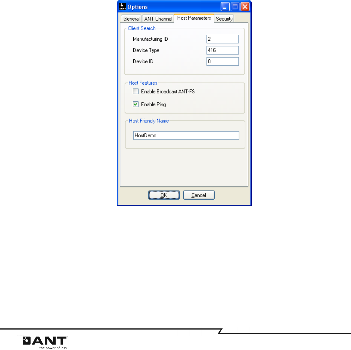
4.1.3
Host Parameters
The “Host Parameters” options tab (Figure 4-5) allows the user to enter details regarding the particular
client device that the host wishes to connect to. This includes beacon parameters such as Manufacturing
ID and Device Type, as well as the Device ID of a particular device. This tab also provides configuration
details for managing ANT-FS sessions.
Figure 4-5. Host Parameters Options Tab
4.1.3.1 Client Search
The “Client Search” options tab lets the user specify the identifier of the client that it will search for. The
client has a device descriptor consisting of 3 parameters. The Manufacturing ID and Device Type are both
2 byte values that are included in the beacon of the client while it is in Link state. For managed networks,
the Manufacturing ID is maintained by Dynastream. Please contact Dynastream for further details.
The Device ID is a 4 byte value that is passed to the host from the client during the Authentication Layer.
This value is often derived from the serial number of the device. All three client parameters may be set
explicitly or wild carded by setting to 0.
4.1.3.2 Host Features
The ‘Host Features’ group refers to specific features the host uses to manage ANT-FS sessions.
14 of 45
228 River Avenue, Cochrane, Alberta, Canada T4C 2C1 thisisant.com
To allow the host device to discover and request an ANT-FS session from a broadcast device, select the
‘Enable Broadcast ANT-FS Search’ option. When this option is enabled, the ANT-FS host will find a
broadcasting device matching the configured ANT channel parameters, and will automatically request an
ANT-FS session..
To ensure an ANT-FS session is maintained, select the ‘Enable Ping’ option. The host will periodically send
a Ping message to prevent the client from timing out and returning to the unconnected Link state.
4.1.3.3 Friendly Name
The Friendly Name is a string that the host may pass to the client as part of the Authentication process.
The client may display the friendly name to its user before proceeding with a connection. The friendly
name may be up to 255 bytes long. This field is optional and may be omitted by setting the text box to
blank (i.e. 0 length string).
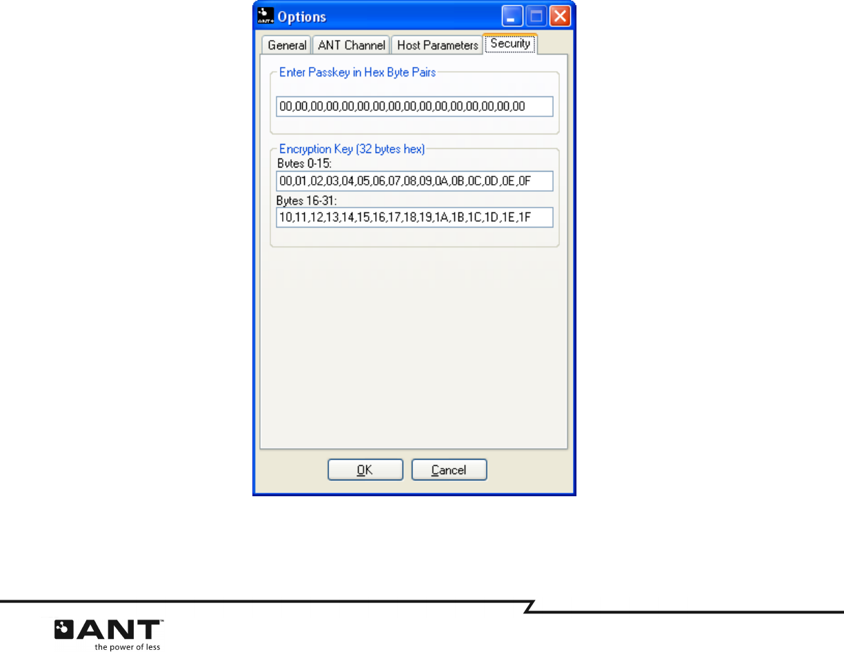
4.1.4
Security
The ‘Security’ options tab (Figure 4-6) refers to control settings for the authentication and confidentiality
of the ANT-FS session.
Figure 4-6. Security Options Tab
15 of 45
228 River Avenue, Cochrane, Alberta, Canada T4C 2C1 thisisant.com
4.1.4.1 Passkey
The passkey is used to authenticate the client device using the passkey method of authentication. If it is
known, the user may enter the passkey explicitly.
The passkey is also sent to the client as part of the pairing process. As such, if the passkey has been
obtained during pairing, it will be displayed here, and made available for future use. The passkey may be
up to 255 bytes long, and should be entered as ASCII hex byte values (without the 0x) and separated by a
comma as shown in Figure 4-6.
4.1.4.2 Encryption Key
The encryption key is used to encrypt and decrypt transmitted data. If a file is marked with the Crypto
flag, the file will be encrypted when it is uploaded and downloaded from a client device. Files will be
decrypted before they are stored on the file system if the ‘Debug encrypted files’ checkbox on the main
window is selected, as shown in Figure 4-7. The encryption key is a 32 byte value, and should be entered
as ASCII hex byte values (without 0x) and separated by a comma as shown in Figure 4-6.
Figure 4-7. Main Window

16 of 45
228 River Avenue, Cochrane, Alberta, Canada T4C 2C1 thisisant.com
4.2 General Operation
The ANT-FS PC Host Tool is designed such that each ANT-FS layer can be stepped through with each
appropriate button press. Care must be taken to ensure that timeouts are not exceeded while stepping
through the layers. Buttons are only enabled if the host is in a state that is appropriate for a particular
action. For example, the Pair button will not be enabled unless the host is in the Authentication Layer.
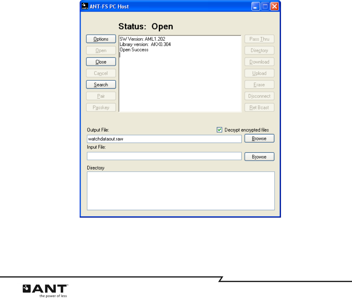
The current status of the application is displayed in the Status label at the top of the main window, as
depicted in Figure 4-7.
4.2.1
Open
The first step is to open and connect to the ANT USB stick. Pressing the ‘Open’ button will initialize the
ANT library and connect to the USB stick at the specified baud rate and USB Port. The host will attempt to
connect to the first available USB stick, polling the USB ports until one is found. The USB port parameters
are set in the Options dialog box as described in Section 4.1.1.3. The status text will show “Idle polling
USB” while attempting to connect to a USB stick, and “Open” when it is connected to a USB stick.
4.2.2
Close
The ‘Close’ button will destroy all ANT-FS library threads, and close the connection to the USB stick. It will
also destroy any memory that was allocated to downloaded or uploaded files. Any transactions that were
in progress will be aborted immediately, which should force the client to timeout and return to the
unconnected Link Layer.
4.2.3
Cancel
Pressing ‘Cancel’ will abort the current ANT-FS operation and return to the layer prior to the cancelled
operation. If Cancel is pressed while the host is connected to a client but no operations are taking place,
the host will disconnect from the client, returning to the Link Layer.
4.2.4
Search and Connect
Pressing the ‘Search’ button will set the host ANT channel’s network key, channel period, channel ID and
then open the channel; initiating the search for the specified client, at the designated frequency. Once a
matching client is found, the host will send a Link command to the client, specifying the Connect RF
channel frequency and channel period.
The host will then wait until the client beacon is detected at the new frequency indicating that it has
progressed to the Authentication state. Once in the Authentication Layer, the host will request the serial
number of the device by sending the AUTH command with Auth type set to 0 (serial number request). If
the request was successful, the host will acquire the serial number (Device ID) of the client. If a Device
ID was configured in the ‘Client’ options tab, the host will only proceed if the IDs match. The host is now
connected to the client and will progress to the Authentication state. If any step in this sequence fails, the
host will return to the Link Layer searching state.
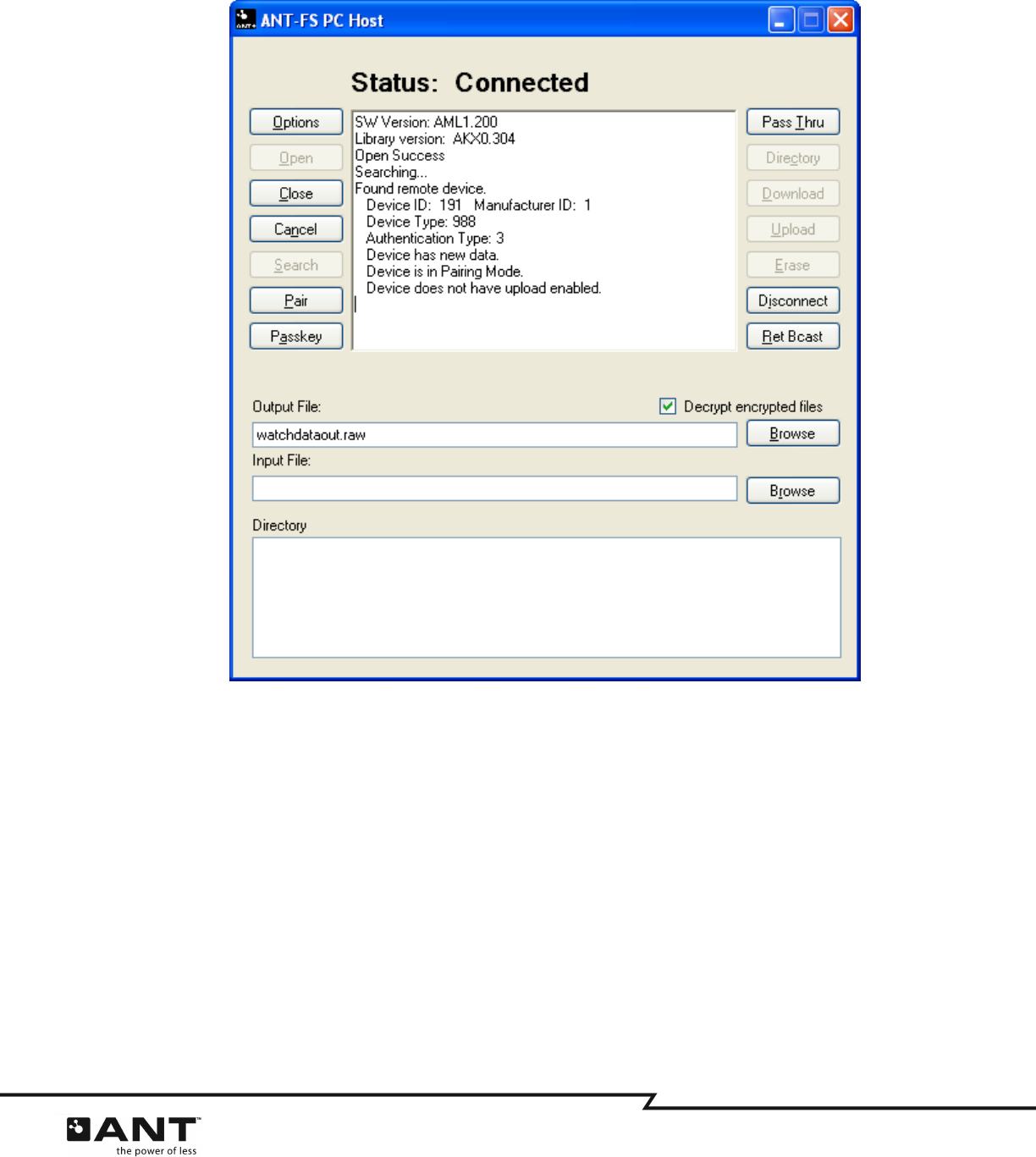
Figure 4-8 shows a successful search for a Garmin FR-60 client device. Note that the client parameters,
including beacon contents, are listed in the text box of the application window. The status of the host is
reflected in the Status label on top of the text box.
17 of 45
228 River Avenue, Cochrane, Alberta, Canada T4C 2C1 thisisant.com
Figure 4-8. Successful Search and Connect to a Client Device
4.2.5
Authentication
Once both client and host devices have successfully exchanged Link commands/responses, they will be in
the Authentication state. The ANT-FS PC Host application supports three methods of authentication:
pairing, passkey and pass-thru, as described earlier.
18 of 45
228 River Avenue, Cochrane, Alberta, Canada T4C 2C1 thisisant.com
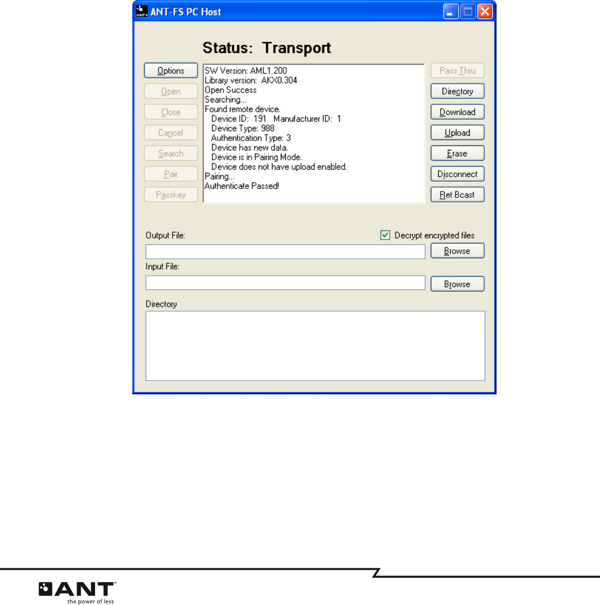
4.2.5.1 Pair
The user may pair to the client device by pressing the ‘Pair’ button. The host will send a pairing request to
the client, which the client may accept or reject. Figure 4-9 shows the ANT-FS Host after completing a
successful pairing request. If the request is accepted, the client may also send a passkey to the host
which can be used for future passkey authentication. Please note that this operation will overwrite
whatever passkey was previously set in the options dialog.
Figure 4-9. Pairing Accepted by Client
4.2.5.2 Passkey
If the passkey for a client is known, then the passkey method of authentication may be used. If the
passkey matches that of the client, authentication will pass; however, if the passkey does not match, the
client will reject the request and the host will return to the unconnected Link state. The passkey may be
entered directly via the Options dialog, or acquired as part of the pairing process.
4.2.5.3 Pass Thru
If supported by the client, pass-thru authentication may also be used. In this mode the host simply asks
the client to move to the Transport Layer, without requesting permission or providing passkey data.
If authentication is successful, both the Client and the host will move to the Transport Layer.
19 of 45
228 River Avenue, Cochrane, Alberta, Canada T4C 2C1 thisisant.com
4.2.6
Transport
Once in the transport layer, the user may upload, download and erase files on the client device. It is
recommended that the host request the client’s directory structure before doing any other operations. The
directory structure is a special file located at index 0 that describes the file contents of the client device.
Please note that some devices may not implement the directory structure. For example, the FR-50 is a
single file device and does not have a directory structure; instead, it stores a single file at location 0.
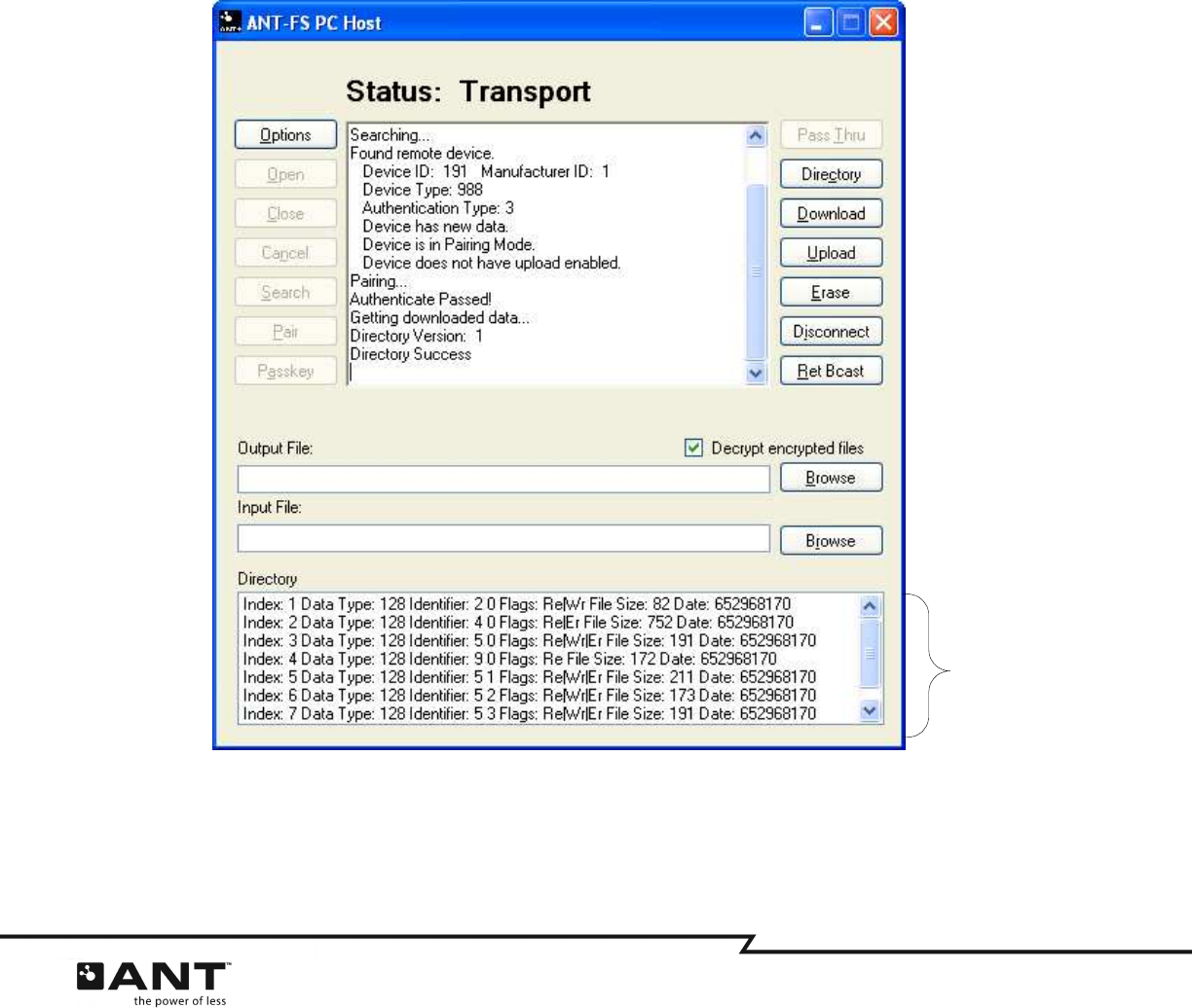
4.2.6.1 Directory
Pressing the ‘Directory’ button prompts the host to request the file located at file index 0 on the client
device. The application will interpret this downloaded file to be a directory structure and display the
contents in the lower text box titled “Directory”. If the client device is a known single file device, this
button should not be used. It is recommended that ALL new client devices implement a directory
structure, and that the host request the directory prior to any other Transport Layer commands. Figure
4-10 shows an example directory structure downloaded from an ANT-FS PC Client.
Figure 4-10. Downloaded Directory Structure
Refer to the ANT-FS Technical Specification for details of the directory structure.
Directory
Structure
20 of 45
228 River Avenue, Cochrane, Alberta, Canada T4C 2C1 thisisant.com
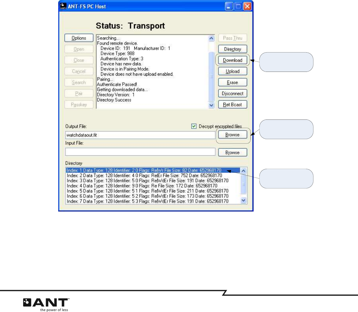
4.2.6.2 Download
Downloading a file requires three steps. First, the user must select a file name and location on the hard
drive to which downloaded client data is stored. The user may set the file name in the “Output File:” text
box or using the browse button to the right of the text box. The Browse button also opens a dialog box
that will allow the user to change the file location.
Secondly, the user shall specify the file index of the data to download from the client. This is done by
selecting one of the files listed in the directory structure. . The selected file location must exist and be
readable (Re flag), otherwise the download will fail.
Finally, to start the download process, click the ‘Download’ button, OR double click the selected file in the
directory structure, as shown in Figure 4-11. Once downloading commences, the status will be displayed
in the status box at the top of the application.
Figure 4-11. Starting Download from Client
If the directory was not downloaded (for example if the client is a single file device), pressing the
download button will force a download of the file from index 0. In other words, if no file is explicitly
specified by selecting from the directory structure, clicking download will try to download data from file
index 0. This is the only method to download data from an FR-50 watch.
(1) Select download
location
(2) Select file to
download
(3) Start download
21 of 45
228 River Avenue, Cochrane, Alberta, Canada T4C 2C1 thisisant.com
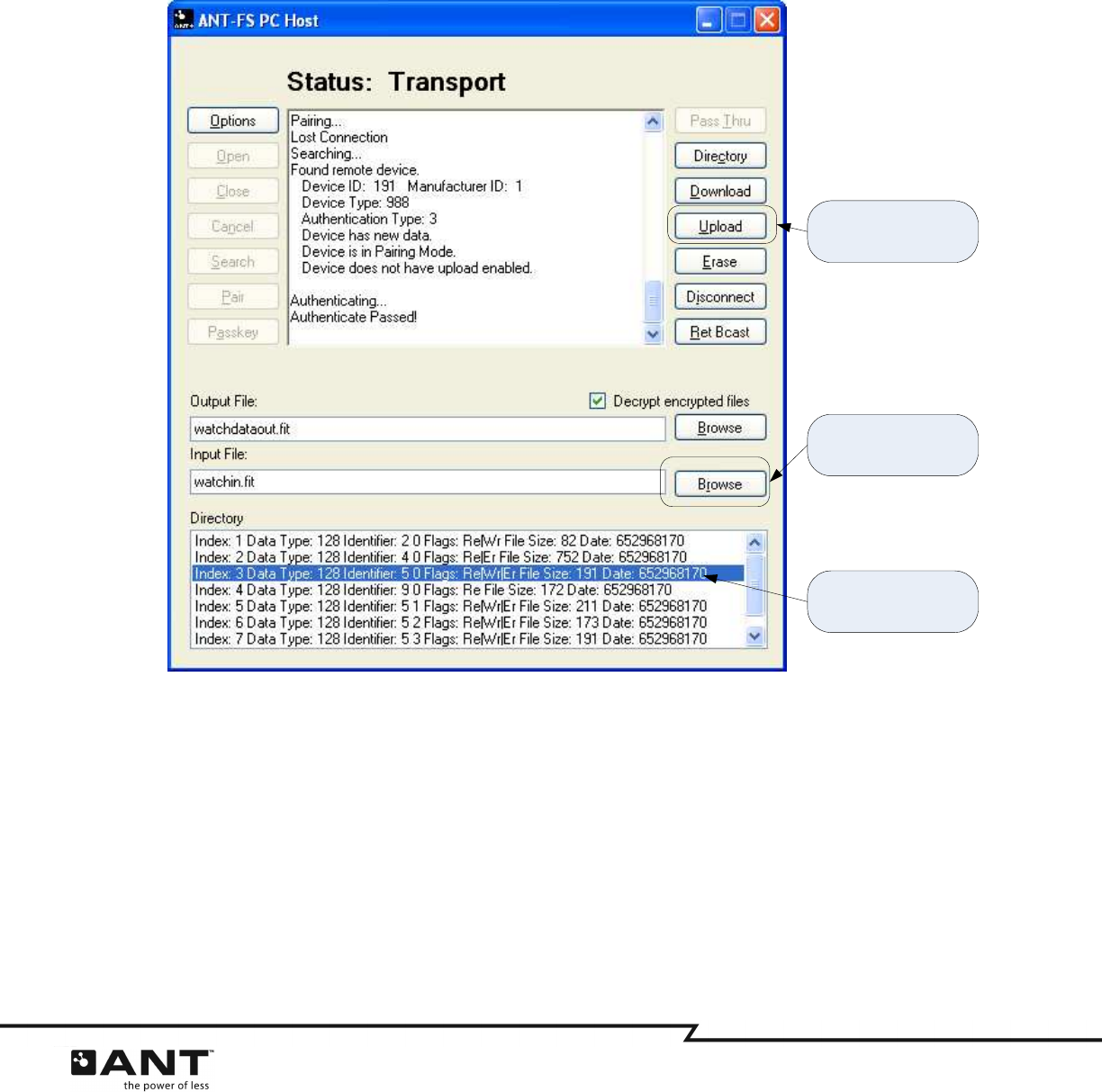
4.2.6.3 Upload
Uploading a file is very similar to downloading a file. The first step is to download the directory structure
from the client device. Next, select a file to upload in the Input File text box. This file may be of any size
and content, provided that it is supported by the client device. Once a file is selected, a file location (or
index) must be selected in the directory structure. The selected file location must exist and be writeable
(Wr flag), otherwise the upload will fail. Finally, pressing the ‘Upload’ button will commence the file
upload. The process for a successful file transfer is illustrated in Figure 4-12.
Figure 4-12. Uploading a file to the Client Device
Uploading files to a single file client device is not supported by this reference design.
An easy way to test uploads is to first download a file from the client, and then try to upload the same file
back.
4.2.7
Erase.
To erase a file from the client device, the user must select a file from the directory structure and click
erase. The host will send a request to the client to erase the selected file. The selected file location must
exist and be eraseable (Er flag), otherwise the erase operation will fail.
(1) Select file to upload
(2) Select file index to
upload to
(3) Start upload

22 of 45
228 River Avenue, Cochrane, Alberta, Canada T4C 2C1 thisisant.com
4.2.8
Disconnecting
The host may disconnect from the client at any time. To disconnect from the client device simply press
the ‘Disconnect’ button while in any layer. Disconnect will put the client and the host back into the Link
Layer. It does not disconnect the application from the USB stick.
4.2.9
Return to Broadcast
The host may disconnect from a client that supports Broadcast ANT-FS, and request it to return to its
broadcast state instead of Link. To instruct a client to return to broadcast, press the ‘Ret Bcast’ button
while in any layer. This will put the client back into broadcast mode, if it supports this feature, or into the
Link layer. In this particular implementation, the host will return to the Link layer.

23 of 45
228 River Avenue, Cochrane, Alberta, Canada T4C 2C1 thisisant.com
5 ANT-FS PC Client
The ANT-FS PC Client application is a development tool that may be used to demonstrate almost all ANT-
FS client features with any ANT-FS enabled host device. The tool supports all three methods of
authentication: pairing, passkey and pass-thru. It allows configuration of a directory, associated with data
in the file system, and downloading files to a host device. Upload functionality is not currently supported.
The client tool also provides quick configurations to beacon as preset ANT-FS devices, such as fitness
watches or other ANT+ file based devices. The tool does not perform any decoding or encoding of data,
other than optional encryption during data transfer.
5.1 Options
The ANT-FS PC Client Development tool allows the user to set several options for a specific ANT-FS
implementation. This includes parameters specific to the USB port, the ANT channel and selection of the
beacon configuration. On startup, options are loaded from a configuration file called “ClientConfig.txt”
located in the current user’s Application Data directory. If this file is missing or corrupt, default options
are set. On exit, the application will save its current settings to the “ClientConfig.txt” file. Furthermore,
the application allows the user to save and load configuration files for particular test implementations.
More details on this process are provided in later sections.
Options may be viewed and changed by clicking on the “Options” button in the application. General
options must be changed prior to connecting to the USB Stick (Open button), while most other options
need to be changed prior to opening the beacon (Open Beacon button).
The options are categorized under four tabs: General, ANT Channel, Beacon and Security, and are
described in the following sections.
5.1.1
General
The “General” tab (Figure 5-1) allows the user to set various options that are not directly applicable to
ANT-FS. This includes selecting debug mode and USB port connection settings. It also allows the user to
preload and save options from/to a configuration file, or load preset configurations.
24 of 45
228 River Avenue, Cochrane, Alberta, Canada T4C 2C1 thisisant.com
Figure 5-1. General Options Tab
5.1.1.1 Run Mode
When running in debug mode, the ANT-FS library will generate debug log files during the ANT-FS session.
This provides useful information for testing and debugging ANT-FS connections, on both client and host
sides. Debug files generated in the ANT-FS PC Client tool’s directory are outlined in Table 5-1.
Table 5-1. Client Log Files
Log File Name Description
ao_debug_ClientANTReceive.txt A log of all ANT channel and protocol events received
ao_debug_ANTFSClient.txt A log of ANT-FS events
ao_debug_ClientApplication.txt A log of application initiated events
ao_debug_ClientTimer.txt A log of timer events
Device0.txt A log of all communication on the serial port between ANT and the PC.
Debug mode MUST be set prior to opening the ANT-FS connection. Checking the Debug box after opening
the connection will have no effect.
The debug files are stored in the Application Data directory for the current user, for example:
C:\Documents and Settings\UserName\Application Data\ANTFS_PC_Client\logs
To open the directory containing the logs, click the ‘View Logs’ button.
25 of 45
228 River Avenue, Cochrane, Alberta, Canada T4C 2C1 thisisant.com
To store the debug files in an alternate location, select the ‘Select…’ option in the ‘Save logs in’ pull-down
menu, and browse to the desired location. This is particularly useful to select a different location for a
particular debugging session. Custom debug file directories are stored in the configuration.
5.1.1.2 Configuration
The Configuration box allows the user to save current options to a file, load options from a file, or select a
preset from a drop down box.
To save the current options, click ‘Save’. This will open a Save File Dialog box where the user can specify
the desired file location and name. Please note that saving to the “ClientConfig.txt” file in the Application
Data directory will overwrite the default startup configuration. To load options from a previously saved
file, simply click on the ‘Load’ button and select the desired options file. All options set by the user,
including USB port and debug configuration are saved in/loaded from these files.
To select a pre-configured option, select the desired device from the ‘Quick Config’ drop down box. This
will set the ANT Channel options and beacon parameters corresponding to the device to simulate. Using
pre-configured options won’t affect the USB port or debug settings. For successful communication
between the PC Host and Client tools, select the same preset for both devices.
Figure 5-2. Client Preset Configurations
5.1.1.3 USB
The USB group box allows the user to select the USB port configuration. The baud rate selected will
depend on the ANT chip mounted on the USB stick (AP1 connects at 50000, all other solutions at 57600).
The USB Port selects the port the USB stick is connected to. As a general rule, the first USB stick plugged
into the PC will be assigned port 0, the next port 1 and so on, provided all USB sticks have the same
Select preset
ANT-FS client to
simulate
26 of 45
228 River Avenue, Cochrane, Alberta, Canada T4C 2C1 thisisant.com
VID/PID. The Auto Init option enables the library to automatically select the baud rate for a USB stick
connected to port 0; this feature is only available for ANT USB1 and USB2 sticks (black plastic case).
Selecting this option will disable the baud and port options. This option is generally recommended for
production level products to alleviate the user from having to select a specific baud rate and USB port
number.
If no USB stick is plugged in, clicking open will not fail. Instead the library will poll the USB periodically
until a USB stick is detected.
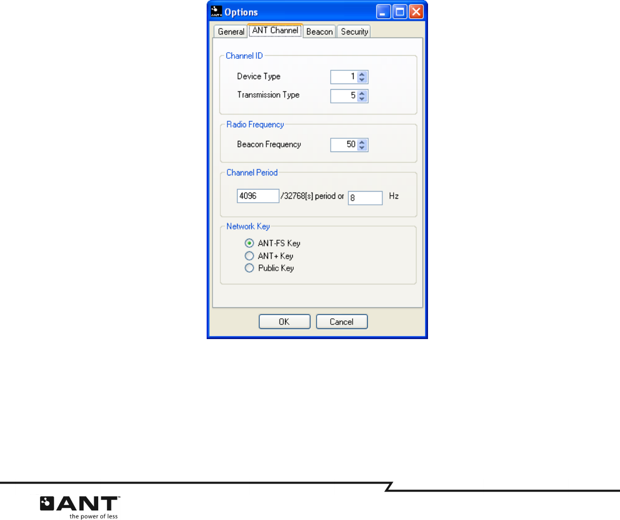
5.1.2
ANT Channel
The “ANT Channel” tab allows the user to set the ANT channel specific parameters. This includes channel
ID, beacon RF channel frequency, channel period and network key. All other channel parameters are set
by the ANT-FS library. Caution must be exercised when changing the channel parameters as this may
interfere with the interoperability of devices.
Figure 5-3. ANT Channel Options Tab
5.1.2.1 Channel ID
Channel ID refers to the 4 byte ANT channel ID (2 byte Device ID, 1 byte Device Type and 1 byte
Transmission Type). The Device ID is derived from the lower two bytes of the client serial number
(Beacon tab), so it is only necessary to configure the Device Type and Transmission Type. No wildcards
(0) are allowed on the client device.
27 of 45
228 River Avenue, Cochrane, Alberta, Canada T4C 2C1 thisisant.com
5.1.2.2 Radio Frequency
The beacon frequency is the frequency at which the ANT-FS channel is open, where the client advertises
its presence through the beacon in the Link Layer. The ANT-FS specification sets this number at 2450MHz,
while most ANT+ devices operate at 2457MHz.
5.1.2.3 Channel Period
This box represents the channel period of the client device while in the Link Layer. The channel period is
set as a fraction of a 32kHz counter. For example, to set a 4Hz message rate, the count is:
count = 32768/4 = 8192
Alternatively, the channel period can be configured in Hz. The input boxes will be updated automatically
depending on user input.
5.1.2.4 Network Key
The network key can be set to the ANT-FS, ANT+ or public key. Most ANT+ file based profiles specify the
use of the ANT+ key.
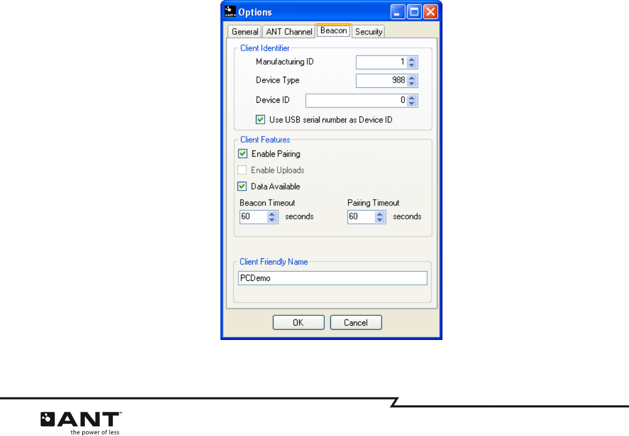
5.1.3
Beacon
The ‘Beacon’ tab (Figure 5-4) includes configuration options for the ANT-FS client beacon. This includes
device identifier parameters, such as the Manufacturing ID and Device Type, as well as the Device ID.
This tab also provides configuration parameters for the capabilities of the client device, and allows the
user to specify an optional friendly name
.
Figure 5-4. Beacon Options Tab

28 of 45
228 River Avenue, Cochrane, Alberta, Canada T4C 2C1 thisisant.com
5.1.3.1 Client Identifier
The client is identified with 3 parameters: manufacturing ID, Device Type and Device ID. The
Manufacturing ID and Device Type are both 2 byte values that are included in the client’s beacon while in
the Link state. For managed networks, the Manufacturing ID is maintained by Dynastream. Please contact
Dynastream for further details.
The Device ID is a 4 byte value that identifies a particular device, and can be sent to the host during the
Authentication Layer, upon request. The Manufacturing ID and Device Type must not be set to zero –
wildcards are not allowed on the client device.
To automatically set the serial number of the USB device as the client Device ID, select the option ‘Use
USB serial number as Device ID’ or set the Device ID to 0.
5.1.3.2 Client Features
The ‘Client Features’ group refers to options related to the capabilities of the client device. To allow the
pairing authentication method, select the ‘Enable Pairing’ checkbox. If this option is selected, the client
will indicate in its beacon that pairing is supported, and that it will process pairing authentication
requests. If this option is not selected, pairing authentication requests will automatically be rejected.
To enable uploads in the client device, select the ‘Enable Uploads’ checkbox. Note, uploads are not
currently supported in this tool.
To indicate data availability in the client’s beacon, select the ‘Data Available’ option. This allows a host
device to determine whether a connection is desired.
There are two timeouts that are relevant to an ANT-FS Session: beacon and pairing timeouts. The ‘Beacon
Timeout’ is the duration a client will wait without receiving any commands from the host before returning
to the Link Layer. The ‘Pairing Timeout’ is the time a client will wait for a user to respond to a pairing
request. If no response is received within the pairing timeout, the request will be rejected. To set the
timeouts for an ANT-FS session, specify the beacon and pairing timeout values in seconds. For an infinite
timeout (i.e. session never times out) set to 255.
5.1.3.3 Client Friendly Name
The friendly name is a string that the client may optionally pass to the host as part of the authentication
process. The host can use the friendly name to display to the user before proceeding with a connection.
The friendly name may be up to 255 bytes long. This field is optional and may be omitted by setting the
text box to blank (or 0 length string).
29 of 45
228 River Avenue, Cochrane, Alberta, Canada T4C 2C1 thisisant.com
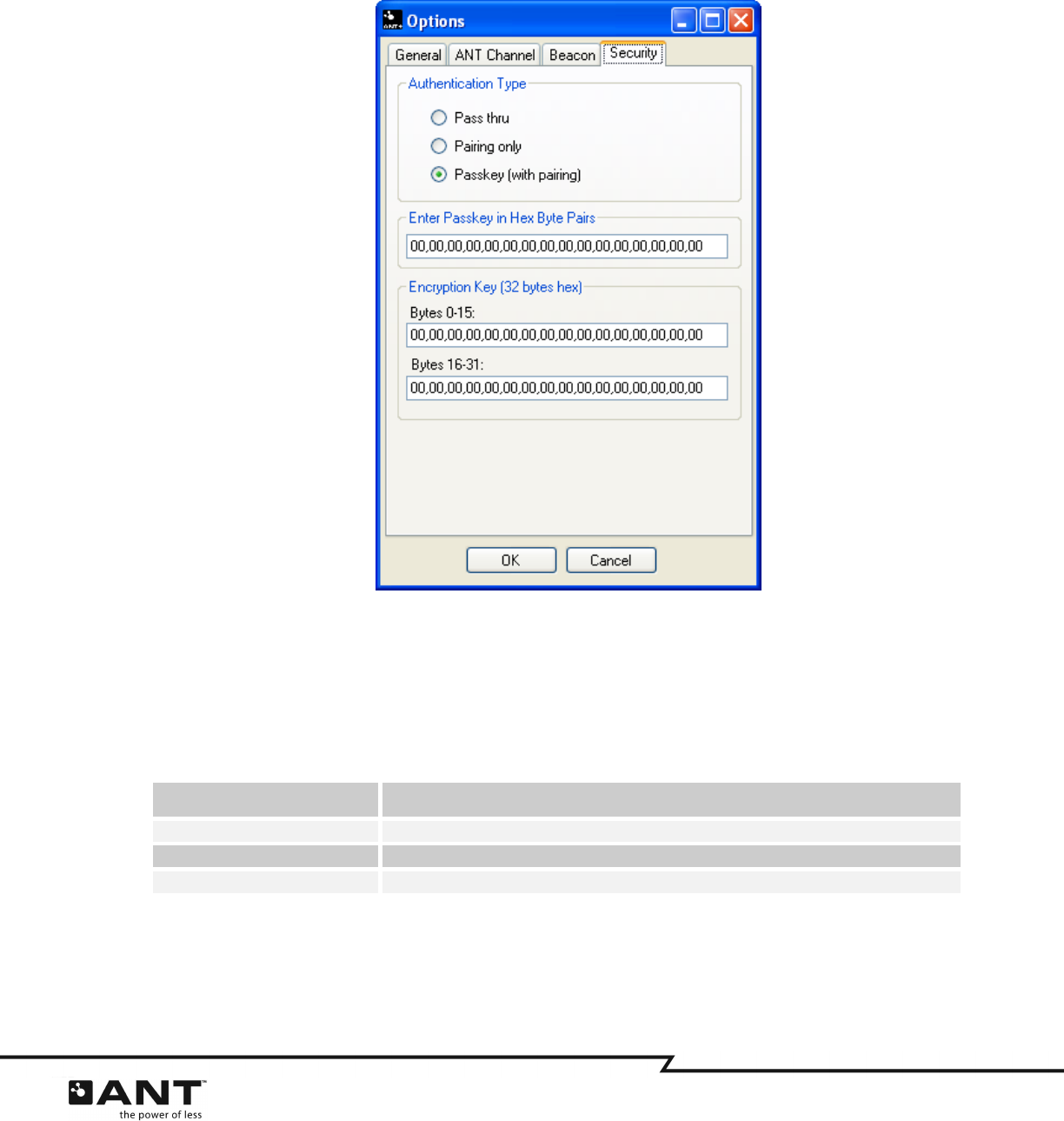
5.1.4
Security
The ‘Security’ options tab (Figure 4-6) refers to control settings for authentication and confidentiality of
the ANT-FS session.
Figure 5-5. Security Options Tab
5.1.4.1 Authentication Type
The authentication type indicates the authentication methods supported in the client device and shall be
included in the beacon. Available authentication types for this implementation are given in Table 5-2.
Table 5-2. Authentication Type
Authentication Type Description
Pass thru All three authentication methods (pass thru, pairing, passkey) are available
Pairing only Only pairing authentication is available.
Passkey (with pairing) Pairing and passkey authentication are available.
For more details on the operation of the different authentication types, refer to the ANT-FS Technical
Specification.
30 of 45
228 River Avenue, Cochrane, Alberta, Canada T4C 2C1 thisisant.com
5.1.4.2 Passkey
The passkey is used to authenticate a host device. The passkey transmitted by the host shall be compared
with the value configured in the client device. The passkey may be up to 255 bytes long, and entered as
ASCII hex byte values without the 0x and separated by a comma as shown in Figure 5-5.
5.1.4.3 Encryption Key
The encryption key is used to encrypt and decrypt transmitted data. If a file is marked with the Crypto
flag, the file will be encrypted when it is downloaded to a host device. Files will be decrypted before they
are stored on the file system if the ‘Debug encrypted files’ checkbox on the main window is selected. The
encryption key is a 32 byte value, and should be entered as ASCII hex byte values without the 0x and
separated by a comma as shown in Figure 5-5.
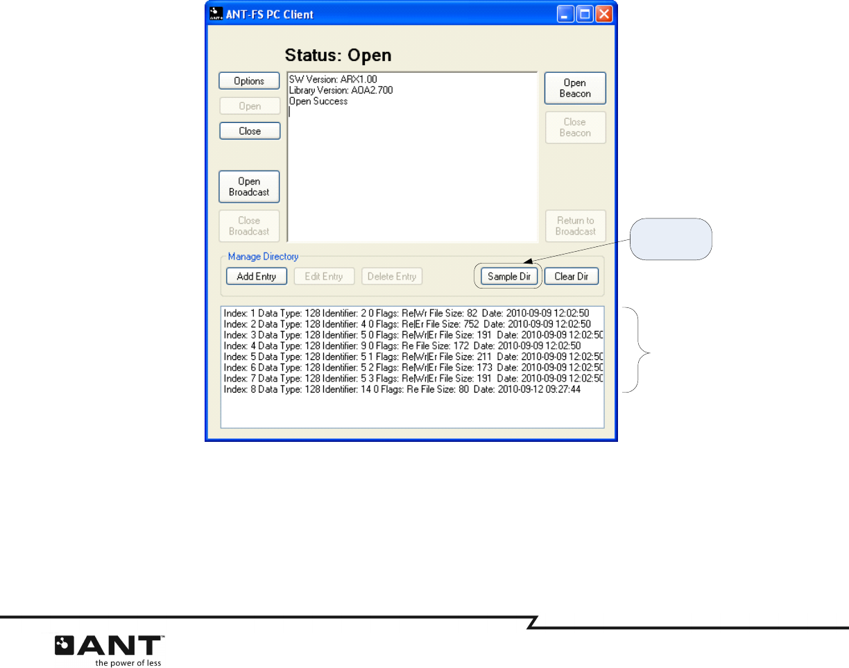
5.2 Managing the Directory
Before data can be downloaded from an ANT-FS client device, its directory must be configured to specify
the data files available for download, along with additional information about each file, such as size, type,
date and access permission flags. For a detailed description of the directory structure, refer to the ANT-FS
Technical Specification.
Figure 5-6. Loading the sample directory
The ‘Manage Directory’ section in the main windows allows configuration of the client directory. For quick
start, press the ‘Sample Dir’ button, as shown inFigure 5-6. This will load a set of sample files into the
directory. These example files are provided with the application and include example FIT Settings,
Activity, Workout, Weight and Blood Pressure files.
Load sample
directory
Sample
Directory
Structure
31 of 45
228 River Avenue, Cochrane, Alberta, Canada T4C 2C1 thisisant.com
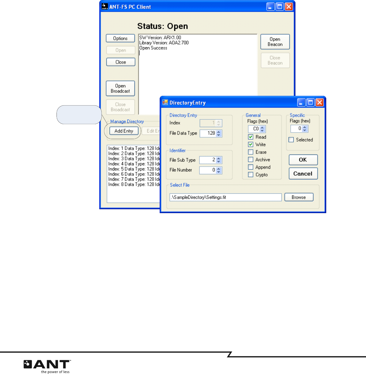
5.2.1
Adding and Editing Directory Entries
To manually add a custom file to the directory, select the “Add Entry” button. This will open the Directory
Entry editor window. The “Directory Entry” editor window can also be launched by selecting an existing
entry from the directory structure, and clicking the “Edit Entry” button.
Figure 5-7. Opening the directory entry editor
5.2.2
Directory Entry Editor
The ‘Directory Entry’ editor window allows the user to set up and modify all parameters of an entry in the
directory. For a detailed description of ANT-FS directory formats, refer to the ANT-FS Technical
Specification.
The index uniquely identifies the file within the directory; this value is incremented with each new file
added to the directory.
The file data type specifies the file type; set to 128 for FIT files.
The Identifier group allows specific file details to be configured. For FIT files, the identifier field is divided
into File Sub Type and File Number. The File Sub Type indicates the FIT file type; for example, a Workout
or Settings file. The File Number is the number of the particular instance of a given file/sub type. For
example, if multiple workout files are available in the device, they would all have the same file sub type,
but different file numbers.
Open Directory
Entry editor
32 of 45
228 River Avenue, Cochrane, Alberta, Canada T4C 2C1 thisisant.com
The General and Specific Flags section allows the user to select flags providing additional information
about the files. The flags can be selected individually by clicking on the associated checkbox. The hex
byte representing the flag bit field will be updated automatically as flags are selected or removed.
To associate a data file with the entry, click ‘Browse’ and select a file from the file system. Once all the
details are complete, click ‘OK’ to finish editing the entry, returning to the main window. To return without
saving any changes, click ‘Cancel’.
5.2.3
Deleting Directory Entries
To delete a single entry from the directory, select the file from the directory listing and click ‘Delete
Entry’. To delete all entries in the directory; click on ’Clear Dir’. Deleting entries from the directory does
not delete any files from the file system.
5.3 General Operation
The ANT-FS PC Client Tool is designed such that each ANT-FS layer can be stepped through with each
appropriate button press. Most ANT-FS operations are initiated by the host and handled automatically by
the client according to its configuration. Buttons are only enabled if the client is in a state that is
appropriate for a particular action. The current status of the application is displayed in the Status label at
the top of the main window, as seen in Figure 5-8.
Figure 5-8. Main Window
33 of 45
228 River Avenue, Cochrane, Alberta, Canada T4C 2C1 thisisant.com
5.3.1
Open
Before any other action is taken, the ANT USB stick must first be opened and connected to. This is
accomplished by pressing the ‘Open’ button. The Open button will initialize the ANT library and connect to
the USB stick at the specified baud rate and USB Port. The client will attempt to connect to the first
available USB stick, polling the specified USB port until one is found.
The USB port parameters are set in the Options dialog box as described earlier. The Status text will show
“Idle polling USB” while attempting to connect to a USB stick, and “Open” when it is connected to a USB
stick.
5.3.2
Close
The ‘Close’ button will close all ANT channels, destroy all ANT-FS library threads, and close the connection
to the USB stick. It will also destroy any memory that was allocated to files in transfer. Any transactions
that were in progress will be aborted immediately, which should force the host to timeout and return to its
default state.
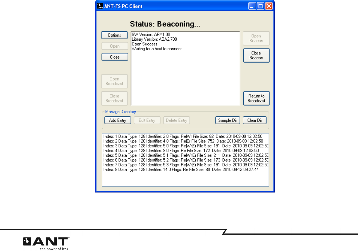
5.3.3
Open Beacon
Pressing the ‘Open Beacon’ button will configure the ANT channel’s parameters and then open the
channel. The client will begin to beacon, and will wait to be discovered by a host device. All beacon
parameters must be configured prior to opening the beacon. Once the ANT channel has been successfully
opened, the Status label on top of the text box will change to “Beaconing”, as shown in Figure 5-9.
Figure 5-9. Open Beacon
34 of 45
228 River Avenue, Cochrane, Alberta, Canada T4C 2C1 thisisant.com
5.3.4
Connecting to a Host Device
Once a host finds the client device, it will send a Link command, and the client shall progress to the
Authentication state and wait for an authentication request. The client will process incoming
authentication requests based on its configuration, and progress to the Transport layer if the request is
accepted, or to the Link layer if it is rejected.
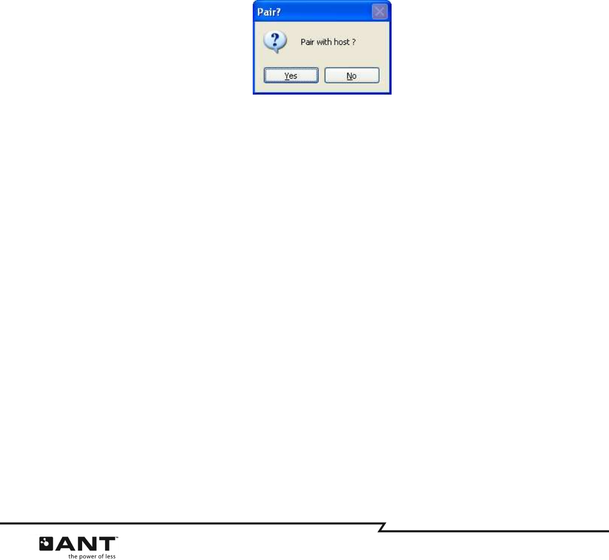
5.3.4.1 Pair
If the host sends a pairing request to the client and pairing authentication is enabled, a pop up window
will ask the user to accept or reject the pairing request (Figure 5-10). If the host friendly name was
received with the request, it will also be displayed.
Figure 5-10. Pairing dialog
To accept the pairing request, click “Yes”. The client will then send a response, along with the passkey (if
configured). To reject the pairing request, click “No”. If no option is selected before the pairing operation
times out, the request will be rejected.
5.3.4.2 Passkey
If the host sends a passkey authentication request and passkey authentication is enabled, the client will
compare the passkey provided by the host with the one configured in the ‘Security’ options tab. If the
passkey matches, authentication will pass; otherwise, it will be rejected.
5.3.4.3 Pass Thru
If the host requests pass-thru authentication, and the client supports pass through, the client will simply
move to the Transport Layer, without requiring additional authentication parameters.
35 of 45
228 River Avenue, Cochrane, Alberta, Canada T4C 2C1 thisisant.com
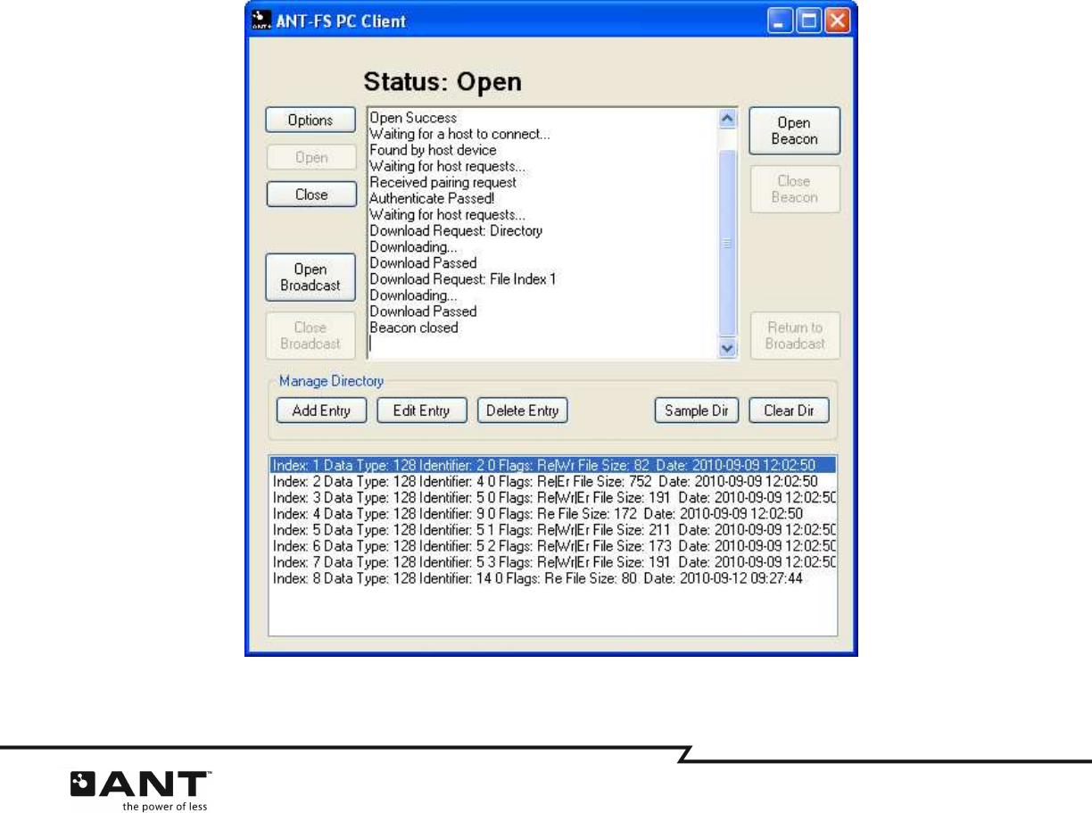
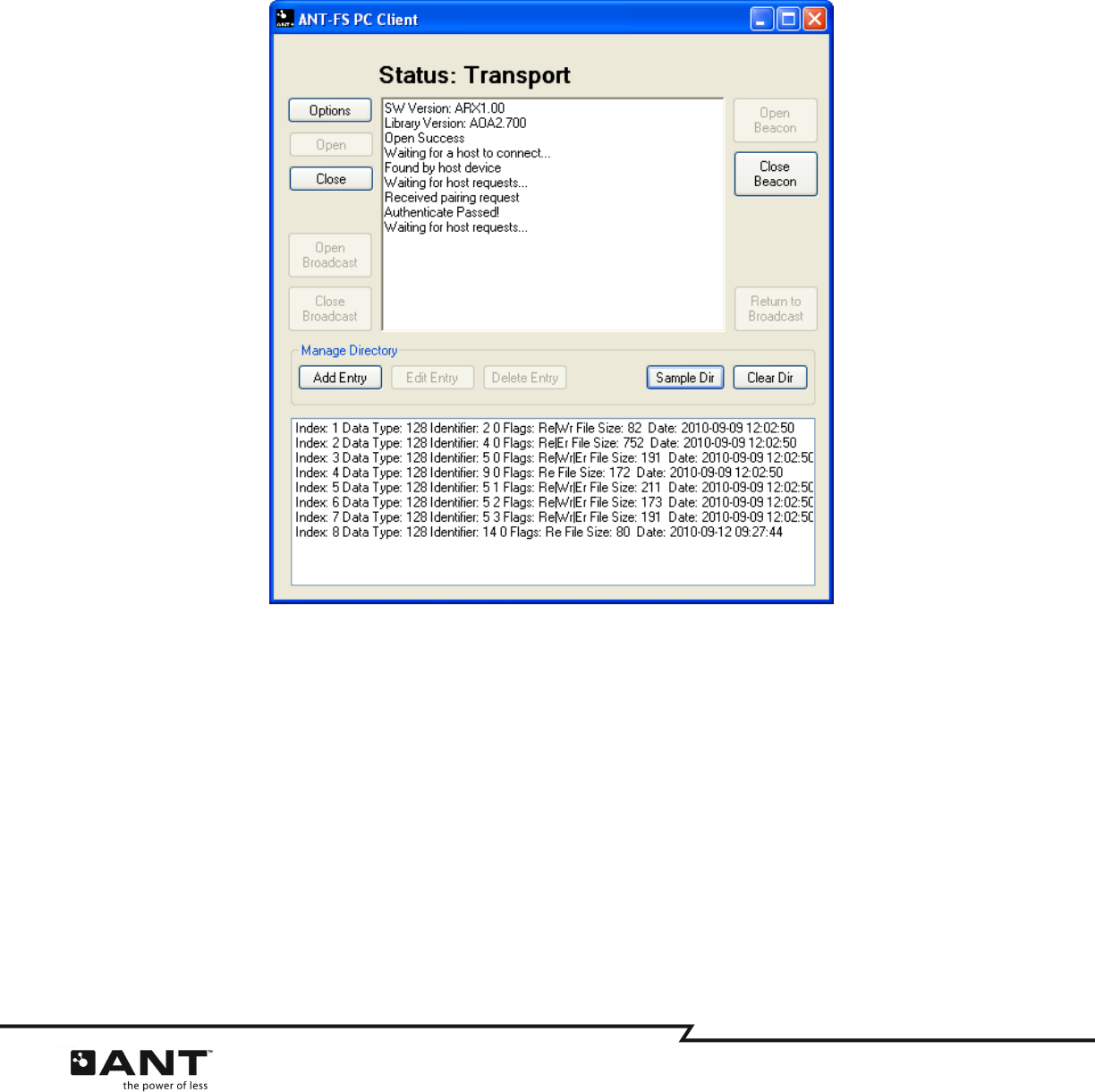
5.3.5
Transport
Once in the transport layer, the client waits for requests from the host device, and handles them
automatically. If the host requests to download a file, the client will find it in the directory and send the
download. If the host requests to erase a file, the client will remove the entry from the directory, but will
not erase any files from the file system. The Status label at the top will be updated to reflect the current
status of the client.
Figure 5-11. Transport Layer
5.3.6
Disconnecting from a Host Device
5.3.6.1 Disconnect
The client can process requests to disconnect from the host device at any time during the session. If a
disconnect request is received, the client will stop all pending operations, and will return to the Link state,
or broadcast mode, depending on the request (see Sections 4.2.8 and 4.2.9).
5.3.6.2 Close Beacon
The client can end the session and stop beaconing at any time without waiting for a request from the
host. To do this, click the ‘Close Beacon’ button while in any layer. The application will remain connected
to the USB stick, and will either close the channel or return to broadcast mode, depending on its initial
mode of operation.
36 of 45
228 River Avenue, Cochrane, Alberta, Canada T4C 2C1 thisisant.com
5.3.7
Broadcast ANT-FS
Broadcast ANT-FS provides a mechanism for ANT-FS to take place on a device that is already broadcasting
on an established channel, without having to open a second channel. For a detailed description of this
feature, refer to the ANT-FS Technical Specification.
The ANT-FS PC Client incorporates some features to simulate broadcast ANT-FS devices, including the
ability to initiate in standard broadcast mode, processing requests to begin an ANT-FS session and
returning to broadcast mode after the ANT-FS session is ended.
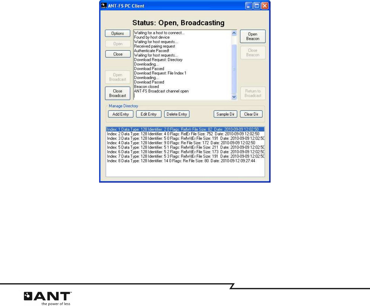
5.3.7.1 Open Broadcast
To establish a standard ANT broadcast channel, press the ‘Open Broadcast’ button. The ANT channel will
be configured as per the ‘ANT Channel’ options tab. Once the channel is successfully opened, the client
will begin broadcasting. The last byte of the payload will be increased sequentially, in a similar manner to
ANTwareII. The Status label will be updated to reflect that the client device is “Open, Broadcasting”
(Figure 5-12).
Figure 5-12. Starting in Broadcast ANT-FS mode
Once the channel receives a request for an ANT-FS session, it will maintain its current channel
configuration and commence transmitting the ANT-FS link beacon. After the client has moved into the Link
state, its operation is identical to that described in Sections 5.3.3 to 5.3.6.
The client can also begin an ANT-FS session without waiting for a request from the host. To do this, press
the ‘Open Beacon’ button while the device is broadcasting.

37 of 45
228 River Avenue, Cochrane, Alberta, Canada T4C 2C1 thisisant.com
5.3.7.2 Close Broadcast
The client can stop broadcasting at any time. To do this, click the ‘Close Broadcast’ button. The ANT
channel will be closed, but the application will remain connected to the USB stick.
5.3.7.3 Return to Broadcast
The client can return to broadcast mode at any time during an ANT-FS session if a disconnect command is
received from the host device. It is also possible to return to broadcast mode while in Link state without
waiting for a request from the host. To do this, press the ‘Return to Broadcast’ button while in the Link
layer. The client will stop transmitting the ANT-FS beacon, but the channel will remain open.
38 of 45
228 River Avenue, Cochrane, Alberta, Canada T4C 2C1 thisisant.com
6 ANT-FS Embedded Client
The ANT-FS Embedded client reference design consists of firmware that implements the ANT-FS client
functionality. The ANT-FS reference design intends to illustrate the basic operation of an ANT-FS client as
well as provide a reference design for the development of ANT-FS embedded client devices.
The ANT-FS embedded client reference design can be used in conjunction with the ANT-FS PC Host tool to
explore most ANT-FS features. This reference design supports all three methods of authentication defined
in the ANT-FS specification: pairing, passkey and pass-thru. It also supports the simulation of
downloading and erasing files. Other functionality that is not defined in the ANT-FS specification, such as
the user interface, file system implementation and data decoding/encoding are left to the application.
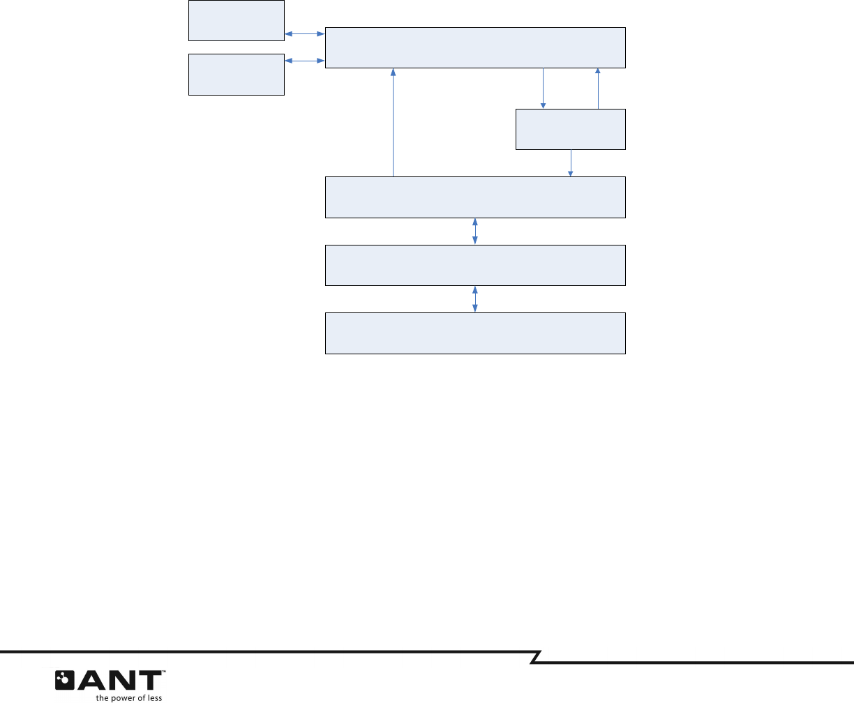
6.1 Architecture Overview
The general architecture of the ANT-FS Embedded client reference design is illustrated in Figure 6-1.
Figure 6-1. ANT-FS Embedded Client Architecture
The serial interface handles communication with ANT. Byte synchronous communication is enabled by
default, but drivers for bit synchronous and asynchronous communication are also available. The ANT
Interface handles the ANT protocol messaging. When ANT messages are received by the application, they
are sent to the ANT-FS module for further processing. The ANT-FS module contains the core functionality
of ANT-FS, and can be easily incorporated into custom applications. The application also processes ANT-FS
events, which are generated when user interaction or access to the file system is required.
The source code for the ANT-FS Embedded Client reference design is organized in the directories
described in the following two sections.
Application
ANT-FS
ANT Interface
ANT Messages
ANT Messages ANT-FS Events
Response Parameters
ANT Messages
Serial Interface
ANT
File System
UI

39 of 45
228 River Avenue, Cochrane, Alberta, Canada T4C 2C1 thisisant.com
6.1.1
base
The
base
directory contains files that provide the basic functionality of the reference design. This includes
hardware specific functionality, such as serial drivers, I/O, and timers, as well as more generic
functionality for ANT embedded applications, such as ANT message framing and CRC and checksum
calculations.
6.1.2
antfs
The
antfs
directory contains all relevant files for the development of ANT-FS embedded client applications.
This directory includes the core ANT-FS embedded implementation, as well as a sample ANT-FS enabled
application and a sample directory structure to demonstrate the downloading and erasing operations.
6.2 Reference Design Setup
The firmware for the ANT-FS Embedded Client reference design has been written for an MSP430F2274
MCU using a byte synchronous serial interface to an ANT module. A block diagram of the setup is shown
in Figure 6-2. Although specific to this hardware platform, the firmware has been written such that it is
easily ported to any target host MCU. For more information regarding interfacing a host MCU to ANT,
please refer to the “Interfacing with ANT General Purpose Chipsets and Modules” document.
Figure 6-2. ANT/MCU Connectivity
The ANT-FS Embedded Client reference design can be compiled with Code Composer Essentials, a
development environment for the MSP430 available as a free download from Texas Instruments:
http://focus.ti.com/docs/toolsw/folders/print/msp-cce430.html
MSP430
2274 ANT
Module
SMSGRDY
/SEN
/SRDY
SCLK
SOUT
SIN
P3.0
P2.1
P2.5
P3.3
P3.2
P3.1
40 of 45
228 River Avenue, Cochrane, Alberta, Canada T4C 2C1 thisisant.com
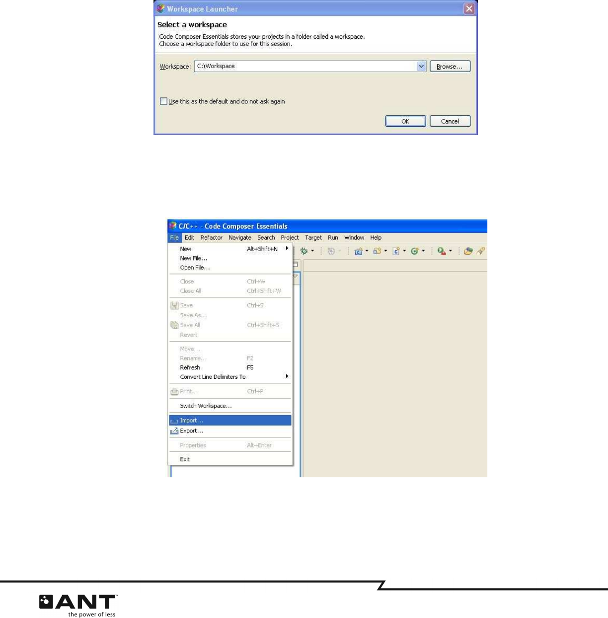
The following steps illustrate how to set up and compile the source of the ANT-FS Embedded Client
reference design:
1. Open Code Composer Essentials and select a Workspace. The workplace directory will hold all
your working projects and files.
Figure 6-3. Selecting a workspace
2. To add the ANT-FS client embedded reference design to your workspace, select
File > Import
from the menu.
Figure 6-4. Importing a project
41 of 45
228 River Avenue, Cochrane, Alberta, Canada T4C 2C1 thisisant.com
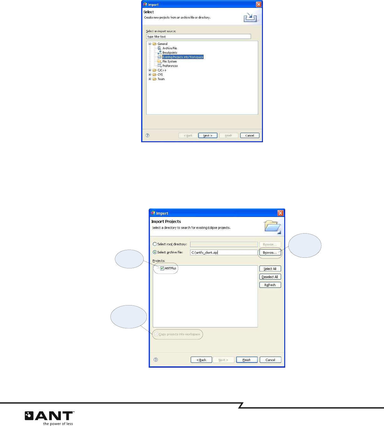
3. Select “Existing Projects into Workspace” as the import source
Figure 6-5. Importing an existing project
4. Browse to the ANT-FS Embedded Client reference design location. Select the ANTPlus Project. It
is not necessary to decompress the reference design, as the ZIP archive can be imported directly
into your workspace. Make sure the option to “Copy projects into workspace” is checked; this
option should already be checked by default if you are importing a project from a ZIP archive.
Figure 6-6. Importing the ANT-FS Embedded Client Reference Design
Select the
location of the
reference
design file
Select the
ANTPlus
project
Copy the project
into your
workspace
42 of 45
228 River Avenue, Cochrane, Alberta, Canada T4C 2C1 thisisant.com
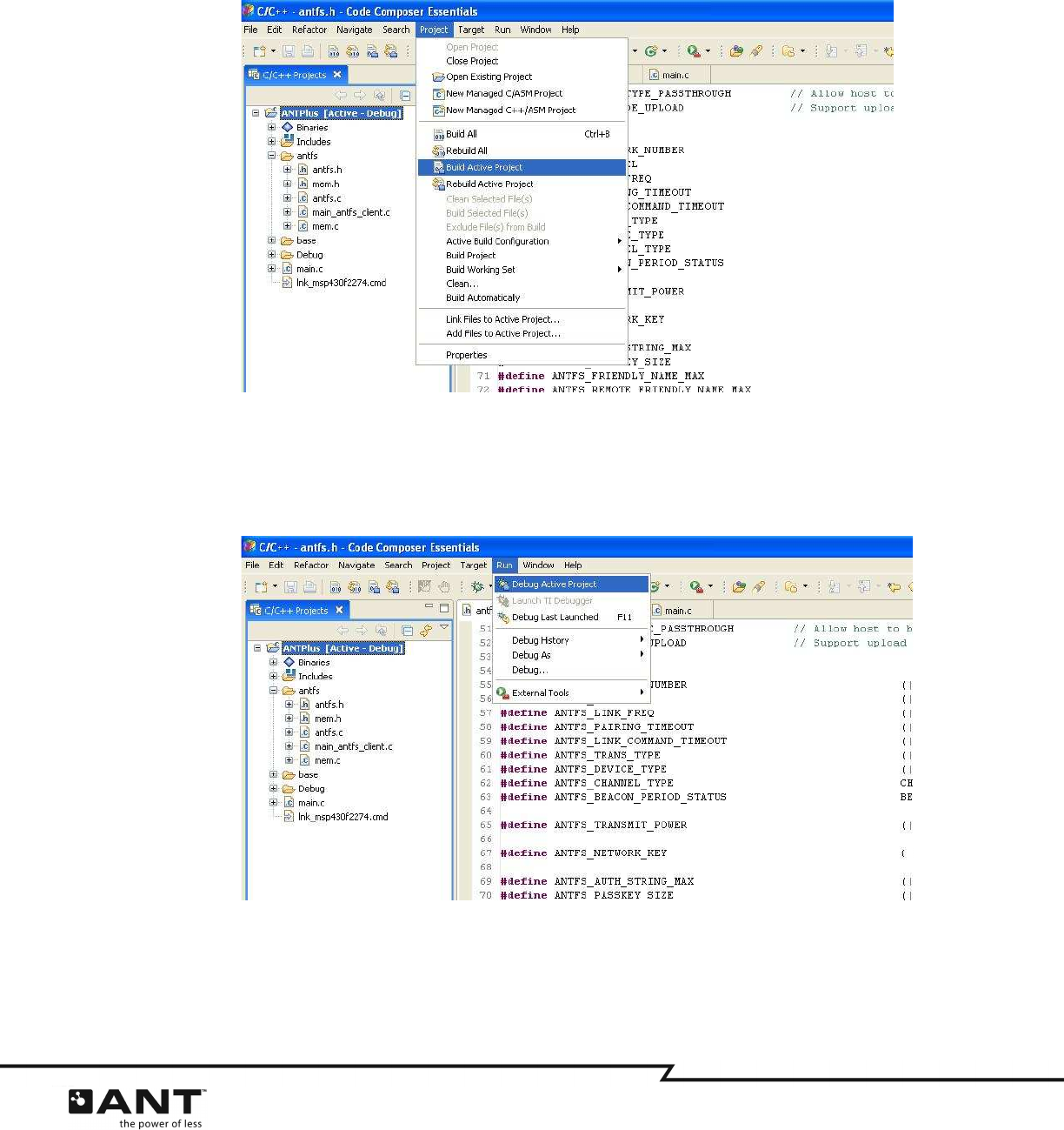
5. To load the embedded firmware on the target processor, you will first need to build the project.
Select
Project > Build Active Project
from the menu. You will need to add the ANT-FS network key
to the antfs.h file before you are able to successfully build the project.
Figure 6-7. Building a project
6. After the project is build successfully, select
Run > Debug Active Project
to load the firmware on
the target processor and run it.
Figure 6-8. Debugging a project
For more details on developing using Code Composer Essentials and the MSP430, please refer to the
Technical Documentation for this tool provided by Texas Instruments.
43 of 45
228 River Avenue, Cochrane, Alberta, Canada T4C 2C1 thisisant.com
6.3 Options
The ANT-FS Embedded Client reference design provides the user several configuration options to suit
various ANT-FS implementations. These include ANT channel parameters, ANT-FS protocol settings and
implementation specific details of the ANT-FS Client. Client specific parameters can be configured on
main_antfs_client.c
, while ANT channel and general ANT-FS parameters can be set on
antfs.h
. Table 6-1
lists the configuration parameters available on the ANT-FS Embedded Client reference design.
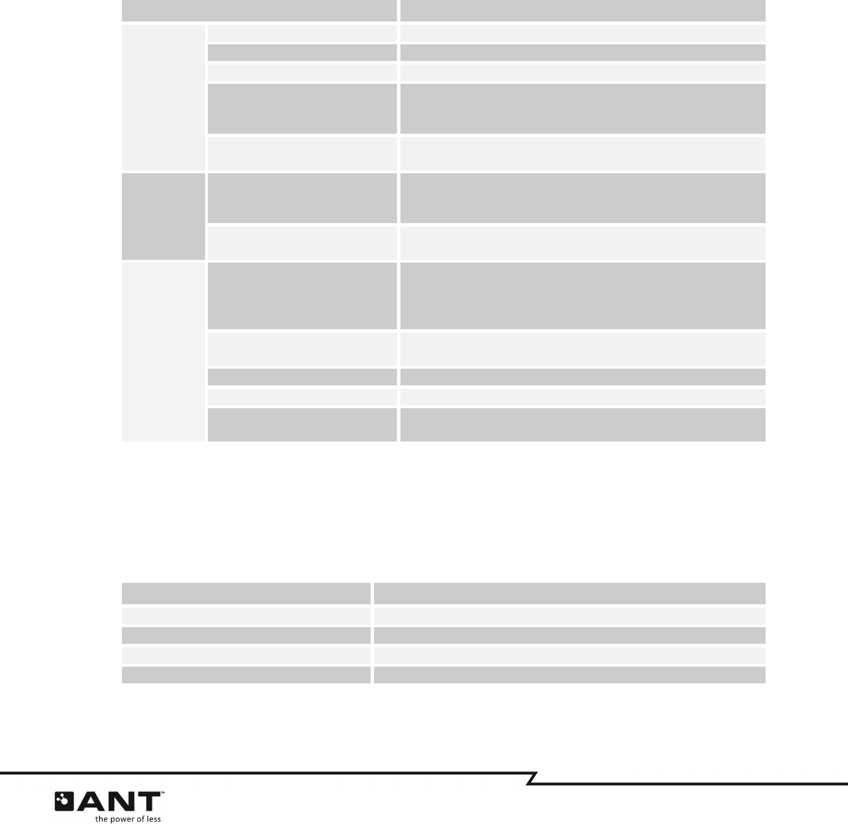
Table 6-1. ANT-FS Client Configuration Parameters
Parameter Description
ANT
Channel
Parameters
ANTFS_NETWORK_KEY ANT-FS Network Key.
ANTFS_DEVICE_TYPE Device Type (Channel ID).
ANTFS_TRANS_TYPE Transmission Type (Channel ID).
ANTFS_LINK_FREQ
RF channel frequency of the client device while in the Link layer.
This frequency should match the search frequency of the host
device. The default value is 2450MHz.
ANTFS_BEACON_PERIOD_STATUS
Message period of the client device while in the Link layer. The
default value is 8 Hz.
ANT-FS
General
Parameters
ANTFS_COMMAND_TIMEOUT
Maximum time (in seconds) the client device will wait without
receiving any commands from the host before switching to the
Link layer.
ANTFS_PAIRING_TIMEOUT Maximum time (in seconds) the client will wait for user response
to a pairing request during the authentication stage.
ANT-FS
Client
Parameters
ANTFS_CLIENT_ESN
Serial number of the client device. The device number in the
Channel ID is derived from the lower two bytes of the serial
number. The four bytes of the serial number are sent to the host
during the Authenticate layer as the device ID.
ANTFS_CLIENT_NAME Friendly name of the client device. The length of this string should
not exceed ANTFS_REMOTE_FRIENDLY_NAME_MAX.
ANTFS_CLIENT_DEV_TYPE Device Type (ANT-FS Client Identifier).
ANTFS_CLIENT_MANUF_ID Manufacturing ID (ANT-FS Client Identifier).
ANTFS_CLIENT_PASSKEY Passkey used in the pairing and passkey authentication methods.
Its length should be equal to ANTFS_PASSKEY_SIZE.
The reference design implements the pairing, pass key and pass-thru authentication methods, which can
be enabled using compile switches. All three authentication methods are enabled by default. Upload
functionality can also be enabled through a compile switch. The compile switches can be set on
antfs.h
,
and are listed below.
Table 6-2. ANT-FS Client Compile Switches
Parameter Description
ANTFS_AUTH_TYPE_PAIRING Use pairing and passkey exchange authentication
ANTFS_AUTH_TYPE_PASSKEY Use passkey authentication
ANTFS_AUTH_TYPE Allow host to bypass authentication
ANTFS_INCLUDE_UPLOAD Support upload operation

44 of 45
228 River Avenue, Cochrane, Alberta, Canada T4C 2C1 thisisant.com
To establish communication, the host and client devices should have matching configurations. The host
device may wish to wildcard any of the fields in the Channel ID and Client Identifier by setting them to
zero, but the network key and RF channel frequency should be the same. The channel period of the client
does not necessarily need to match the channel period of the host.
As an example, a simple user interface consisting of an LED and two buttons is used for events where
user interaction is required. The pins used as digital inputs/outputs can be configured in the
Config.h
file.
6.4 General Operation
The ANT-FS Embedded Client reference design progresses automatically through each ANT-FS layer, as
per the commands received from the ANT-FS host. User interaction is only required when using pairing
authentication, to confirm or reject a pairing request.
6.4.1
Start
Compile and load the firmware for the reference design as described in section 6.2. To load the firmware
on the target MCU, you can select
Run > Debug Active Project
, and then run the reference design by
selecting
Run > Run
while in debug mode.
6.4.2
Connect
Once a host detects a client with ANT Channel and ANT-FS client parameters matching its search criteria,
it will send a Link command to the client, specifying the Link RF channel frequency and channel period.
The client will automatically switch to the new frequency and channel period, and indicate in its beacon
that it has moved to the Authentication stage.
6.4.3
Authenticate
Once both the client and host are in the Authentication layer, the host can request to pair with the client
device. The ANT-FS Embedded Client reference design supports three methods of authentication: pairing,
passkey and pass-thru.
When using the passkey and pass-thru authentication methods, the client will automatically accept or
reject the authentication as outlined by the ANT-FS specification. Intervention from the user is only
required when using the pairing authentication method. If the client receives a pairing request from the
host, it will turn on an LED to let the user know that a host device wishes to pair with it. The user can
accept or reject the pairing request by pressing the one of the appropriate buttons. If no response from
the user is received before the pairing timeout expires, the request will be rejected.
6.4.4
Download
A sample directory structure is implemented in this reference design, however, no actual files or file
systems are present in the reference design.
The client will send the directory to the host if it receives a request to download the directory (file index
0). When the host requests a download for any other files, the client will check if the file exists in its
directory, and if there is permission to download that file. If the file can be downloaded, the client will
simulate a file by sending sequential data with size matching the requested file size; otherwise, it will
reject the download.
6.4.5
Upload
When the host requests an upload, the client will check if the file index exists in its directory, if there is
permission to write on that file, and if there is enough space to write the requested data. Once the client
sends a response accepting the upload request, the host can start uploading data. The reference design
does not include actual files, so data is not written to memory; however, the client keeps track of the CRC
of the received data to verify the integrity of the upload.

45 of 45
228 River Avenue, Cochrane, Alberta, Canada T4C 2C1 thisisant.com
6.4.6
Erase
If the client receives a request to erase a file, it will check in its directory to see if the file exists and if
there is permission to erase that file. As there are no actual files to delete in this reference design, if the
file can be erased, the client will simply send a response to the host indicating the file was erased;
otherwise, it will reject the request.
