AOS Command Reference Guide
User Manual: AOS Command Reference Guide
Open the PDF directly: View PDF ![]() .
.
Page Count: 3968 [warning: Documents this large are best viewed by clicking the View PDF Link!]
- ADTRAN Operating System (AOS)
- Table of Contents
- Reference Guide Introduction
- AOS Unit Introduction
- Introduction to Command Line Interface
- Using the CLI
- Command Descriptions
- Command Set Access Path Quick Reference Guide
- System Command Sets
- Line Interface Command Sets
- Physical Interface Command Sets
- ADSL Interface Command Set
- BRI Interface Command Set
- Cellular Interface Command Set
- DDS Interface Command Set
- DSX-1 Interface Command Set
- E1 Interface Command Set
- Ethernet Interface Command Set
- FDL Interface Command Set
- FXO Interface Command Set
- FXS Interface Command Set
- G.703 Interface Command Set
- HSSI Interface Command Set
- MEF Ethernet Interface
- Modem Interface Command Set
- PRI Interface Command Set
- Serial Interface Command Set
- SHDSL Interface Command Set
- T1 Interface Command Set
- T3 Interface Command Set
- Virtual Interface Command Sets
- ATM Interface Command Set
- ATM Subinterface Command Set
- BVI Interface Command Set
- Demand Interface Command Set
- EFM Group Command Set
- Frame Relay Interface Command Set
- Frame Relay Subinterface Command Set
- HDLC Interface Command Set
- Loopback Interface Command Set
- Port Channel Interface Command Set
- PPP Interface Command Set
- Tunnel Interface Command Set
- VLAN Command Set
- VLAN Database Command Set
- VLAN Interface Command Set
- Wireless Interface Command Sets
- Routing Protocol Command Sets
- AS Path List Command Set
- BGP Command Set
- BGP Neighbor Command Set
- BGP Address Family Command Set
- BGP AF Neighbor Command Set
- Community List Command Set
- Network Monitor Probe Command Set
- Network Monitor Probe Responder Command Set
- Network Monitor Track Command Set
- Router (OSPF) Command Set
- Router (PIM Sparse) Command Set
- Router (RIP) Command Set
- Security and Services Command Sets
- Desktop Auditing Local Policy Command Set
- DHCPv4 Pool Command Set
- DHCPv6 Pool Command Set
- DHCPv6 Server Pool Host Command Set
- Ethernet OAM CFM Command Set
- Hardware ACL and Access Map Command Set
- IPv4 Access Control List Command Set
- IPv4 Access Control Policy Command Set
- IPv6 Access Control List Command Set
- IPv6 Access Control Policy Command Set
- Mail Agent Command Set
- MEF EVC Command Set
- MEF EVC Map Command Set
- MEF Policer Policy Command Set
- MGCP Command Set
- Packet Capture Command Set
- Quality of Service Map Command Set
- RADIUS Group Command Set
- Route Map Command Set
- Security Monitor Command Set
- SIP HMR Command Set
- TACACS+ Group Command Set
- Top Traffic Command Set
- Voice Groups Command Sets
- Voice Trunks Command Sets
- Voice Accounts Command Sets
- Voice Services Command Sets
- Voice Auto Attendant Command Set
- Voice Call Queuing Command Set
- Voice Coverage Command Set
- Voice CODEC List Command Set
- Voice CoS Command Set
- FindMe-FollowMe Action Script Command Set
- FindMe-FollowMe Contact Group Command Set
- Voice Music on Hold Command Set
- Proxy User Template Command Set
- Voicemail CoS Command Set
- VQM Reporter Command Set
- VPN Parameter Command Sets

ADTRAN OPERATING SYSTEM (AOS)
Command Reference Guide
AOS Version R10.1.0
June 2012
60000CRG0-35E

Command Reference Guide
60000CRG0-35E Copyright © 2012 ADTRAN, Inc. 2
Trademarks
Any brand names and product names included in this manual are trademarks, registered trademarks,
service marks, or trade names of their respective holders.
To the Holder of this Manual
The contents of this manual are current as of the date of publication. ADTRAN reserves the right to change
the contents without prior notice.
In no event will ADTRAN be liable for any special, incidental, or consequential damages or for
commercial losses even if ADTRAN has been advised thereof as a result of issue of this publication.
Be advised that certain security risks are inherent in the use of any telecommunications or networking
equipment, including but not limited to, toll fraud, Denial of Service (DoS) attacks, loss or theft of data,
and the unauthorized or illegal use of said equipment. ADTRAN OFFERS NO WARRANTIES, EITHER
EXPRESSED OR IMPLIED, REGARDING THE PREVENTION, DETECTION, OR DETERRENCE
OF TOLL FRAUD, NETWORKING ATTACKS, OR UNAUTHORIZED, ILLEGAL, OR IMPROPER
USE OF ADTRAN EQUIPMENT OR SOFTWARE. THEREFORE, ADTRAN IS NOT LIABLE FOR
ANY LOSSES OR DAMAGES RESULTING FROM SUCH FRAUD, ATTACK, OR IMPROPER USE,
INCLUDING, BUT NOT LIMITED TO, HUMAN AND DATA PRIVACY, INTELLECTUAL
PROPERTY, MATERIAL ASSETS, FINANCIAL RESOURCES, LABOR AND LEGAL COSTS.
Ultimately, the responsibility for securing your telecommunication and networking equipment rests with
you, and you are encouraged to review documentation regarding available security measures, their
configuration and implementation, and to test such features as is necessary for your network.
Software Licensing Agreement
Each ADTRAN product contains a single license for ADTRAN supplied software. Pursuant to the
Licensing Agreement, you may: (a) use the software on the purchased ADTRAN device only and (b) keep
a copy of the software for backup purposes. This Agreement covers all software installed on the system, as
well as any software available on the ADTRAN website. In addition, certain ADTRAN systems may
contain additional conditions for obtaining software upgrades.
901 Explorer Boulevard
P.O. Box 140000
Huntsville, AL 35814-4000
Phone: (256) 963-8000
www.adtran.com
60000CRG0-35E
All Rights Reserved.
Printed in the U.S.A.

Command Reference Guide
60000CRG0-35E Copyright © 2012 ADTRAN, Inc. 3
Conventions
Service and Warranty
For information on the service and warranty of ADTRAN products, visit the ADTRAN website at
http://www.adtran.com/support.
Export Statement
An Export License is required if an ADTRAN product is sold to a Government Entity outside of the EU+8
(Austria, Australia, Belgium, Czech Republic, Denmark, Finland, France, Germany, Greece, Hungary,
Ireland, Italy, Japan, Luxembourg, Netherlands, New Zealand, Norway, Poland, Portugal, Spain, Sweden,
Switzerland and the United Kingdom). This requirement is per DOC/BIS ruling G030477 issued 6/6/03.
This product also requires that the Exporter of Record file a semi-annual report with the BXA detailing the
information per EAR 740.17(5)(e)(2).
DOC - Department of Commerce
BIS - Bureau of Industry and Security
BXA - Bureau of Export Administration
Notes provide additional useful information.
Cautions signify information that could prevent service interruption.
Warnings provide information that could prevent damage to the equipment or
endangerment to human life.

Command Reference Guide
60000CRG0-35E Copyright © 2012 ADTRAN, Inc. 4
Table of Contents
Basic Mode Command Set . . . . . . . . . . . . . . . . . . . . . . . . . . . . . . . . . . . . . . . . . . . . . . . . . . . . . . 36
Common Commands . . . . . . . . . . . . . . . . . . . . . . . . . . . . . . . . . . . . . . . . . . . . . . . . . . . . . . . . . . . 65
Enable Mode Command Set . . . . . . . . . . . . . . . . . . . . . . . . . . . . . . . . . . . . . . . . . . . . . . . . . . . . . 83
Global Configuration Mode Command Set. . . . . . . . . . . . . . . . . . . . . . . . . . . . . . . . . . . . . . . . . 852
Line (Console) Interface Command Set . . . . . . . . . . . . . . . . . . . . . . . . . . . . . . . . . . . . . . . . . . 1464
Line (SSH) Interface Command Set . . . . . . . . . . . . . . . . . . . . . . . . . . . . . . . . . . . . . . . . . . . . . 1481
Line (Telnet) Interface Command Set . . . . . . . . . . . . . . . . . . . . . . . . . . . . . . . . . . . . . . . . . . . . 1498
ADSL Interface Command Set . . . . . . . . . . . . . . . . . . . . . . . . . . . . . . . . . . . . . . . . . . . . . . . . . 1517
BRI Interface Command Set . . . . . . . . . . . . . . . . . . . . . . . . . . . . . . . . . . . . . . . . . . . . . . . . . . . 1525
Cellular Interface Command Set . . . . . . . . . . . . . . . . . . . . . . . . . . . . . . . . . . . . . . . . . . . . . . . . 1537
DDS Interface Command Set . . . . . . . . . . . . . . . . . . . . . . . . . . . . . . . . . . . . . . . . . . . . . . . . . . 1556
DSX-1 Interface Command Set. . . . . . . . . . . . . . . . . . . . . . . . . . . . . . . . . . . . . . . . . . . . . . . . . 1565
E1 Interface Command Set . . . . . . . . . . . . . . . . . . . . . . . . . . . . . . . . . . . . . . . . . . . . . . . . . . . . 1576
Ethernet Interface Command Set. . . . . . . . . . . . . . . . . . . . . . . . . . . . . . . . . . . . . . . . . . . . . . . . 1594
FDL Interface Command Set. . . . . . . . . . . . . . . . . . . . . . . . . . . . . . . . . . . . . . . . . . . . . . . . . . . 1741
FXO Interface Command Set . . . . . . . . . . . . . . . . . . . . . . . . . . . . . . . . . . . . . . . . . . . . . . . . . . 1748
FXS Interface Command Set. . . . . . . . . . . . . . . . . . . . . . . . . . . . . . . . . . . . . . . . . . . . . . . . . . . 1759
G.703 Interface Command Set . . . . . . . . . . . . . . . . . . . . . . . . . . . . . . . . . . . . . . . . . . . . . . . . . 1778
HSSI Interface Command Set . . . . . . . . . . . . . . . . . . . . . . . . . . . . . . . . . . . . . . . . . . . . . . . . . . 1785
MEF Ethernet Interface . . . . . . . . . . . . . . . . . . . . . . . . . . . . . . . . . . . . . . . . . . . . . . . . . . . . . . . 1790
Modem Interface Command Set . . . . . . . . . . . . . . . . . . . . . . . . . . . . . . . . . . . . . . . . . . . . . . . . 1859
PRI Interface Command Set . . . . . . . . . . . . . . . . . . . . . . . . . . . . . . . . . . . . . . . . . . . . . . . . . . . 1865
Serial Interface Command Set. . . . . . . . . . . . . . . . . . . . . . . . . . . . . . . . . . . . . . . . . . . . . . . . . . 1884
SHDSL Interface Command Set . . . . . . . . . . . . . . . . . . . . . . . . . . . . . . . . . . . . . . . . . . . . . . . . 1894
T1 Interface Command Set . . . . . . . . . . . . . . . . . . . . . . . . . . . . . . . . . . . . . . . . . . . . . . . . . . . . 1913
T3 Interface Command Set . . . . . . . . . . . . . . . . . . . . . . . . . . . . . . . . . . . . . . . . . . . . . . . . . . . . 1932
ATM Interface Command Set . . . . . . . . . . . . . . . . . . . . . . . . . . . . . . . . . . . . . . . . . . . . . . . . . . 1944
ATM Subinterface Command Set . . . . . . . . . . . . . . . . . . . . . . . . . . . . . . . . . . . . . . . . . . . . . . . 1949
BVI Interface Command Set . . . . . . . . . . . . . . . . . . . . . . . . . . . . . . . . . . . . . . . . . . . . . . . . . . . 2042
Demand Interface Command Set. . . . . . . . . . . . . . . . . . . . . . . . . . . . . . . . . . . . . . . . . . . . . . . . 2086
EFM Group Command Set . . . . . . . . . . . . . . . . . . . . . . . . . . . . . . . . . . . . . . . . . . . . . . . . . . . . 2166
Frame Relay Interface Command Set . . . . . . . . . . . . . . . . . . . . . . . . . . . . . . . . . . . . . . . . . . . . 2171
Frame Relay Subinterface Command Set . . . . . . . . . . . . . . . . . . . . . . . . . . . . . . . . . . . . . . . . . 2193
HDLC Interface Command Set . . . . . . . . . . . . . . . . . . . . . . . . . . . . . . . . . . . . . . . . . . . . . . . . . 2308
Loopback Interface Command Set . . . . . . . . . . . . . . . . . . . . . . . . . . . . . . . . . . . . . . . . . . . . . . 2389
Port Channel Interface Command Set . . . . . . . . . . . . . . . . . . . . . . . . . . . . . . . . . . . . . . . . . . . . 2438
PPP Interface Command Set . . . . . . . . . . . . . . . . . . . . . . . . . . . . . . . . . . . . . . . . . . . . . . . . . . . 2463
Tunnel Interface Command Set. . . . . . . . . . . . . . . . . . . . . . . . . . . . . . . . . . . . . . . . . . . . . . . . . 2588
VLAN Command Set . . . . . . . . . . . . . . . . . . . . . . . . . . . . . . . . . . . . . . . . . . . . . . . . . . . . . . . . 2690

Command Reference Guide
60000CRG0-35E Copyright © 2012 ADTRAN, Inc. 5
VLAN Database Command Set. . . . . . . . . . . . . . . . . . . . . . . . . . . . . . . . . . . . . . . . . . . . . . . . . 2695
VLAN Interface Command Set . . . . . . . . . . . . . . . . . . . . . . . . . . . . . . . . . . . . . . . . . . . . . . . . . 2704
AP Interface Command Set . . . . . . . . . . . . . . . . . . . . . . . . . . . . . . . . . . . . . . . . . . . . . . . . . . . . 2797
Radio Interface Command Set. . . . . . . . . . . . . . . . . . . . . . . . . . . . . . . . . . . . . . . . . . . . . . . . . . 2813
VAP Interface Command Set . . . . . . . . . . . . . . . . . . . . . . . . . . . . . . . . . . . . . . . . . . . . . . . . . . 2837
AS Path List Command Set . . . . . . . . . . . . . . . . . . . . . . . . . . . . . . . . . . . . . . . . . . . . . . . . . . . . 2855
BGP Command Set . . . . . . . . . . . . . . . . . . . . . . . . . . . . . . . . . . . . . . . . . . . . . . . . . . . . . . . . . . 2858
BGP Neighbor Command Set . . . . . . . . . . . . . . . . . . . . . . . . . . . . . . . . . . . . . . . . . . . . . . . . . . 2878
BGP Address Family Command Set . . . . . . . . . . . . . . . . . . . . . . . . . . . . . . . . . . . . . . . . . . . . . 2895
BGP AF Neighbor Command Set . . . . . . . . . . . . . . . . . . . . . . . . . . . . . . . . . . . . . . . . . . . . . . . 2916
Community List Command Set . . . . . . . . . . . . . . . . . . . . . . . . . . . . . . . . . . . . . . . . . . . . . . . . . 2935
Network Monitor Probe Command Set . . . . . . . . . . . . . . . . . . . . . . . . . . . . . . . . . . . . . . . . . . . 2938
Network Monitor Probe Responder Command Set. . . . . . . . . . . . . . . . . . . . . . . . . . . . . . . . . . 2966
Network Monitor Track Command Set . . . . . . . . . . . . . . . . . . . . . . . . . . . . . . . . . . . . . . . . . . . 2977
Router (OSPF) Command Set . . . . . . . . . . . . . . . . . . . . . . . . . . . . . . . . . . . . . . . . . . . . . . . . . . 2994
Router (PIM Sparse) Command Set . . . . . . . . . . . . . . . . . . . . . . . . . . . . . . . . . . . . . . . . . . . . . 3015
Router (RIP) Command Set. . . . . . . . . . . . . . . . . . . . . . . . . . . . . . . . . . . . . . . . . . . . . . . . . . . . 3020
Desktop Auditing Local Policy Command Set . . . . . . . . . . . . . . . . . . . . . . . . . . . . . . . . . . . . . 3037
DHCPv4 Pool Command Set . . . . . . . . . . . . . . . . . . . . . . . . . . . . . . . . . . . . . . . . . . . . . . . . . . 3044
DHCPv6 Pool Command Set . . . . . . . . . . . . . . . . . . . . . . . . . . . . . . . . . . . . . . . . . . . . . . . . . . 3067
DHCPv6 Server Pool Host Command Set . . . . . . . . . . . . . . . . . . . . . . . . . . . . . . . . . . . . . . . . 3087
Ethernet OAM CFM Command Set . . . . . . . . . . . . . . . . . . . . . . . . . . . . . . . . . . . . . . . . . . . . . 3091
Hardware ACL and Access Map Command Set . . . . . . . . . . . . . . . . . . . . . . . . . . . . . . . . . . . . 3109
IPv4 Access Control List Command Set . . . . . . . . . . . . . . . . . . . . . . . . . . . . . . . . . . . . . . . . . . 3126
IPv4 Access Control Policy Command Set . . . . . . . . . . . . . . . . . . . . . . . . . . . . . . . . . . . . . . . . 3144
IPv6 Access Control List Command Set . . . . . . . . . . . . . . . . . . . . . . . . . . . . . . . . . . . . . . . . . . 3162
IPv6 Access Control Policy Command Set . . . . . . . . . . . . . . . . . . . . . . . . . . . . . . . . . . . . . . . . 3192
Mail Agent Command Set . . . . . . . . . . . . . . . . . . . . . . . . . . . . . . . . . . . . . . . . . . . . . . . . . . . . . 3201
MEF EVC Command Set . . . . . . . . . . . . . . . . . . . . . . . . . . . . . . . . . . . . . . . . . . . . . . . . . . . . . 3213
MEF EVC Map Command Set . . . . . . . . . . . . . . . . . . . . . . . . . . . . . . . . . . . . . . . . . . . . . . . . . 3217
MEF Policer Policy Command Set . . . . . . . . . . . . . . . . . . . . . . . . . . . . . . . . . . . . . . . . . . . . . . 3223
MGCP Command Set . . . . . . . . . . . . . . . . . . . . . . . . . . . . . . . . . . . . . . . . . . . . . . . . . . . . . . . . 3229
Packet Capture Command Set . . . . . . . . . . . . . . . . . . . . . . . . . . . . . . . . . . . . . . . . . . . . . . . . . . 3259
Quality of Service Map Command Set . . . . . . . . . . . . . . . . . . . . . . . . . . . . . . . . . . . . . . . . . . . 3269
RADIUS Group Command Set . . . . . . . . . . . . . . . . . . . . . . . . . . . . . . . . . . . . . . . . . . . . . . . . . 3296
Route Map Command Set . . . . . . . . . . . . . . . . . . . . . . . . . . . . . . . . . . . . . . . . . . . . . . . . . . . . . 3300
Security Monitor Command Set . . . . . . . . . . . . . . . . . . . . . . . . . . . . . . . . . . . . . . . . . . . . . . . . 3333
SIP HMR Command Set . . . . . . . . . . . . . . . . . . . . . . . . . . . . . . . . . . . . . . . . . . . . . . . . . . . . . . 3338
TACACS+ Group Command Set . . . . . . . . . . . . . . . . . . . . . . . . . . . . . . . . . . . . . . . . . . . . . . . 3361
Top Traffic Command Set. . . . . . . . . . . . . . . . . . . . . . . . . . . . . . . . . . . . . . . . . . . . . . . . . . . . . 3364
Voice Call Pickup Group Command Set. . . . . . . . . . . . . . . . . . . . . . . . . . . . . . . . . . . . . . . . . . 3372

Command Reference Guide
60000CRG0-35E Copyright © 2012 ADTRAN, Inc. 6
Voice ISDN Group Command Set . . . . . . . . . . . . . . . . . . . . . . . . . . . . . . . . . . . . . . . . . . . . . . 3375
Voice Operator Ring Group Command Set. . . . . . . . . . . . . . . . . . . . . . . . . . . . . . . . . . . . . . . . 3384
Voice Paging Group Command Set. . . . . . . . . . . . . . . . . . . . . . . . . . . . . . . . . . . . . . . . . . . . . . 3402
Voice Ring Group Command Set . . . . . . . . . . . . . . . . . . . . . . . . . . . . . . . . . . . . . . . . . . . . . . . 3407
Voice Trunk Group Command Set . . . . . . . . . . . . . . . . . . . . . . . . . . . . . . . . . . . . . . . . . . . . . . 3430
Voice Analog Trunk Command Set . . . . . . . . . . . . . . . . . . . . . . . . . . . . . . . . . . . . . . . . . . . . . 3443
Voice ISDN Trunk Command Set. . . . . . . . . . . . . . . . . . . . . . . . . . . . . . . . . . . . . . . . . . . . . . . 3493
Voice SIP Trunk Command Set . . . . . . . . . . . . . . . . . . . . . . . . . . . . . . . . . . . . . . . . . . . . . . . . 3532
Voice T1 Trunk Command Set . . . . . . . . . . . . . . . . . . . . . . . . . . . . . . . . . . . . . . . . . . . . . . . . . 3603
Voice Line Account Command Set . . . . . . . . . . . . . . . . . . . . . . . . . . . . . . . . . . . . . . . . . . . . . . 3656
Voice Loopback Account Command Set . . . . . . . . . . . . . . . . . . . . . . . . . . . . . . . . . . . . . . . . . 3679
Voice User Account Command Set. . . . . . . . . . . . . . . . . . . . . . . . . . . . . . . . . . . . . . . . . . . . . . 3697
Voice Auto Attendant Command Set . . . . . . . . . . . . . . . . . . . . . . . . . . . . . . . . . . . . . . . . . . . . 3778
Voice Call Queuing Command Set . . . . . . . . . . . . . . . . . . . . . . . . . . . . . . . . . . . . . . . . . . . . . . 3781
Voice Coverage Command Set . . . . . . . . . . . . . . . . . . . . . . . . . . . . . . . . . . . . . . . . . . . . . . . . . 3799
Voice CODEC List Command Set . . . . . . . . . . . . . . . . . . . . . . . . . . . . . . . . . . . . . . . . . . . . . . 3803
Voice CoS Command Set . . . . . . . . . . . . . . . . . . . . . . . . . . . . . . . . . . . . . . . . . . . . . . . . . . . . . 3807
FindMe-FollowMe Action Script Command Set . . . . . . . . . . . . . . . . . . . . . . . . . . . . . . . . . . . 3844
FindMe-FollowMe Contact Group Command Set . . . . . . . . . . . . . . . . . . . . . . . . . . . . . . . . . . 3852
Voice Music on Hold Command Set. . . . . . . . . . . . . . . . . . . . . . . . . . . . . . . . . . . . . . . . . . . . . 3862
Proxy User Template Command Set . . . . . . . . . . . . . . . . . . . . . . . . . . . . . . . . . . . . . . . . . . . . . 3865
Voicemail CoS Command Set. . . . . . . . . . . . . . . . . . . . . . . . . . . . . . . . . . . . . . . . . . . . . . . . . . 3876
VQM Reporter Command Set . . . . . . . . . . . . . . . . . . . . . . . . . . . . . . . . . . . . . . . . . . . . . . . . . . 3885
CA Profile Command Set . . . . . . . . . . . . . . . . . . . . . . . . . . . . . . . . . . . . . . . . . . . . . . . . . . . . . 3899
Certificate Command Set. . . . . . . . . . . . . . . . . . . . . . . . . . . . . . . . . . . . . . . . . . . . . . . . . . . . . . 3911
Crypto Map IKE Command Set . . . . . . . . . . . . . . . . . . . . . . . . . . . . . . . . . . . . . . . . . . . . . . . . 3916
Crypto Map Manual Command Set. . . . . . . . . . . . . . . . . . . . . . . . . . . . . . . . . . . . . . . . . . . . . . 3933
IKE Client Command Set . . . . . . . . . . . . . . . . . . . . . . . . . . . . . . . . . . . . . . . . . . . . . . . . . . . . . 3943
IKE Policy Attributes Command Set. . . . . . . . . . . . . . . . . . . . . . . . . . . . . . . . . . . . . . . . . . . . . 3948
IKE Policy Command Set . . . . . . . . . . . . . . . . . . . . . . . . . . . . . . . . . . . . . . . . . . . . . . . . . . . . . 3955

Command Reference Guide Reference Guide Introduction
60000CRG0-35E Copyright © 2012 ADTRAN, Inc. 7
REFERENCE GUIDE INTRODUCTION
This manual provides information about connecting your product, using the ADTRAN Operating System’s
(AOS) command line interface (CLI), and executing the commands available with the NetVanta Series
units and Total Access 900 Series units.
If you are new to the AOS CLI or new to the world of routers, please take a few moments to review the
information provided in the sections which follow.
If you are already familiar with ADTRAN NetVanta and Total Access 900 units and looking for
information on a specific command or group of commands, please proceed to Command Descriptions on
page 23 of this guide.
AOS UNIT INTRODUCTION
External Parts
To connect and use your new AOS unit, first familiarize yourself with the external setup of the unit. Each
product has a serial port on the back of the unit. The port is marked CONSOLE and connects the unit
directly to your PC via a standard DB-9 serial cable.
Other features vary from unit to unit, but include power connections, physical interface connections (such
as dial backup (DBU) or wide area network (WAN)), and status LEDs along the front that indicate the
status of your unit. For a more detailed description of your particular product, please refer to the Hardware
Installation Guide available online at www.adtran.com.
Internal Parts
In order to fully understand product operation and receive the full benefit of the included guides, you
should be familiar with the unit’s internal parts, which can be divided into five main categories.
1. ROM - Read Only Memory
Read only memory (ROM) is a permanent form of memory stored in chips within the unit and houses
information used by the AOS unit on initial startup. Examples of information stored in ROM are the
Power-On Self Test, which initializes upon boot up and checks the unit’s functionality; the Bootstrap
Startup Program, which actually starts the unit; and the basic form of the AOS software.
2. Flash Memory
Flash Memory is memory located in a memory chip that is not only erasable, but also reprogrammable,
allowing for software upgrades without chip removal. The flash memory in your unit contains the full
AOS and can be used to house copies of the configuration files and application images that are used at
initial unit startup.

Command Reference Guide Internal Parts
60000CRG0-35E Copyright © 2012 ADTRAN, Inc. 8
3. RAM - Random Access Memory
RAM is the computer memory that functions as the working memory of your AOS unit. When the unit
is on, the RAM provides memory for caching, packet buffering, holding routing tables, and housing
the running operating system. When the unit is first powered on, RAM executes the application codes
from flash memory and the startup configurations from nonvolatile random access memory
(NVRAM), and when the unit is powered off or reset, RAM loses all data.
4. NVRAM - Nonvolatile Random Access Memory
NVRAM is the general name for any RAM that does not lose its information at power down (for
example, flash memory). In this case, NVRAM has a separate memory function than the flash memory
and is used to house the unit’s startup configurations.
5. Interfaces
Interface is the term used to describe how your unit is connected with its outside environment. There
are a variety of interface categories, as well as interface types. Interface categories include line
interfaces, physical interfaces, and virtual interfaces.
• Line interfaces describe the way you are communicating with your unit (for example, by console
or Telnet).
• Physical interfaces describe the way your unit is physically connected to other units or devices (for
example, via Ethernet, T3, serial, or asymmetric digital subscriber line (ADSL)).
• Virtual interfaces describe the way your unit receives information, whether by Frame Relay,
Point-to-Point Protocol (PPP), virtual local area network (VLAN), or asynchronous transfer mode
(ATM), to name a few.
The user can configure a unit’s interfaces through the interface command sets (refer to Configuration
Command Sets on page 14).

Command Reference Guide Introduction to Command Line Interface
60000CRG0-35E Copyright © 2012 ADTRAN, Inc. 9
INTRODUCTION TO COMMAND LINE INTERFACE
The CLI is the method used to communicate with your AOS unit. While it describes the method used to
communicate, such as by console or Telnet, it also refers to the way information is passed to the unit. As a
text-based user interface, the CLI prompts you to input commands line by line when you interface with the
AOS unit (hence the name command line interface).
Introduction to Commands
The most important part is understanding that your commands make the AOS unit function. The right
commands lead to a fully functioning unit, whereas improperly entered or forgotten commands keep the
unit from functioning. To properly use commands, you must understand what function you want the AOS
unit to complete and what syntax the unit understands as instructions. Each command has its own role
within the operating system, and it is the responsibility of the operator to become familiar with specific
commands and command sets.
How Commands Function
Commands are composed of two main parts. The most important part is the command itself, or the
command word. Most command words are short and straightforward (for example, do, exit, or
configure). Command words are entered immediately after the command prompt in the CLI.
The second part of a command is its argument. An argument is a specification that modifies the command.
In the command show flash, show is the command word and flash is the argument because it modifies the
command show. Commands can have any number of arguments, depending upon the action required of the
unit, and in some instances you have a choice of arguments to use.
AOS Command System
ADTRAN products, training tools, and manuals follow a specific system for entering and referencing
commands. Items that are typed in bold are the required commands and arguments for a certain action. In
the following documentation, you will see commands in bold after an example prompt. They look similar
to this:
>enable
#configure terminal
(config)#line telnet 4
(config-telnet4)#
In the example above, the characters >, #, (config)#, and (config-telnet4)# are the prompts after which
commands are entered. In this example, the words in bold (enable, configure terminal, and line telnet 4)
are the entire commands and constitute what should be typed after the prompt. It is important to pay
attention to the prompt you are given when communicating with your unit, as some commands only work
in certain modes, which are signified by the prompt. The different prompts and modes are discussed later
in this guide.
In some commands, you are given a choice of arguments. If this is the case, the manual or guide will place
a vertical bar (|) between your choices as seen in this example:

Command Reference Guide Types of Commands
60000CRG0-35E Copyright © 2012 ADTRAN, Inc. 10
#show flash | cflash
Again, remember the # is your prompt, the command word is show, and your choices of arguments are
flash and cflash.
Other commands require you to enter your own information. Information within a command line that
pertains to your personal unit is set off with the greater-than (<) and less-than symbols (>). The description
of the information required is contained within the greater-than and less-than symbols and is typed in
italics. For example:
#copy <file source location> <config-file> tftp
In this case, # is again your prompt, the command word is copy, the information needed from you is the
source location of the file you want to copy (the first set of < >) and the configuration file type (second set
of < >), and tftp represents the location in which to copy the file.
Types of Commands
There are three types of commands in the CLI. Each type of command signifies a different function.
Global Commands
Global commands make changes to the functioning of the entire unit. Global commands correspond to the
Global Configuration mode of the unit and require a password to access since they affect the entire system.
Major Commands
Major commands allow only parts of the product to be configured. Major commands correspond to the
Enable mode of the unit and also require a password since they affect functioning parts of the unit, even
though they do not affect the entire system.
Subcommands
Subcommands are the commands that do the actual work of configuring unit parts. Subcommands
typically follow major commands, and in essence tell the unit to follow through with the major command’s
direction.

Command Reference Guide Using the CLI
60000CRG0-35E Copyright © 2012 ADTRAN, Inc. 11
USING THE CLI
This portion of the Command Reference Guide introduces you to the basic concepts and strategies
associated with using the AOS CLI.
Connecting the Unit . . . . . . . . . . . . . . . . . . . . . . . . . . . . . . . . . . . . . . . . . . . . . . . . . . . . . . . . . . . . . . 11
Accessing the CLI from Your PC . . . . . . . . . . . . . . . . . . . . . . . . . . . . . . . . . . . . . . . . . . . . . . . . . . . . 11
Understanding Command Modes . . . . . . . . . . . . . . . . . . . . . . . . . . . . . . . . . . . . . . . . . . . . . . . . . . . . 12
Understanding Configurations . . . . . . . . . . . . . . . . . . . . . . . . . . . . . . . . . . . . . . . . . . . . . . . . . . . . . . 14
Using CLI Shortcuts . . . . . . . . . . . . . . . . . . . . . . . . . . . . . . . . . . . . . . . . . . . . . . . . . . . . . . . . . . . . . . 20
Performing Common CLI Functions . . . . . . . . . . . . . . . . . . . . . . . . . . . . . . . . . . . . . . . . . . . . . . . . . . 21
Understanding CLI Error Messages . . . . . . . . . . . . . . . . . . . . . . . . . . . . . . . . . . . . . . . . . . . . . . . . . . 22
Connecting the Unit
For the initial use, the unit should be connected to a computer or a VT100 terminal. To connect the unit,
simply connect a DB-9 straight-through male-to-female serial cable to the CONSOLE port (on the back)
and to your PC or VT100 terminal.
Accessing the CLI from Your PC
All products using the AOS are initially accessed by connecting a VT100 terminal to the unit or using a
terminal emulation program with a PC. Most Windows® PCs come with a program called HyperTerminal,
which is located under Programs>Accessories>Communications. The latest versions of HyperTerminal
can also be downloaded from the Internet.
Emulation Settings
Once you have connected via VT100 terminal or have found the HyperTerminal program, set the program
settings as follows:
• 9600 baud
• 8 data bits
• No parity
• 1 stop bit
• No flow control
If you are using a HyperTerminal program, name your new connection and then set up the new connection
via the resulting dialogue box. The box allows you to determine the type of connection you are using.
Verify COM 1 and select OK.
Another dialogue box appears for entering the COM 1 properties. Enter the program settings in this box;
select APPLY and then OK. You should then be presented with a terminal window with which to interface
with your unit.

Command Reference Guide Understanding Command Modes
60000CRG0-35E Copyright © 2012 ADTRAN, Inc. 12
Unit Boot Up
After configuring your PC (or VT100 terminal), plug the unit into the wall and turn on the power. The unit
begins the boot up process, which includes the following:
• The Power-On Self Test runs. This test checks the unit hardware for normal operation. The hard-
ware includes the central processing unit (CPU), the memory, and the interfaces.
• The Bootstrap Startup Program (factory set in the ROM) runs.
• The Bootstrap Startup Program is read by the unit to discover the proper source for the operating
system image.
• The operating system image is loaded into RAM.
• The configuration file saved in NVRAM is loaded into RAM, where it is accessed by the unit and
then executed one line at a time.
If no configuration file is found in NVRAM (there will not be one found on initial setup), you are
presented with the following prompt on your terminal or HyperTerminal screen:
Session Now Available
Press RETURN to get started
After pressing return, a prompt appears for communication with your unit.
Understanding Command Modes
As you begin communication, you should understand the command modes. Just as there are different
levels of commands in the CLI, there are different modes for commands within AOS itself. Each command
mode enables the user to access more commands, and make more changes in the unit’s configuration.
The CLI has three command modes: Basic, Enable, and Global. The three command modes are organized
in a three-tiered hierarchy with Basic at the bottom, Enable in the middle, and Global at the top.
Basic Mode
Interaction with your unit begins at the Basic mode. The commands supported at this command tier are
limited, as is interaction with the unit itself. The Basic mode is to keep users without access to the higher
tiered commands from changing the preferred configurations of the unit. The following table describes the
Basic mode.
For more information on the Basic mode, please refer to Basic Mode Command Set on page 36.
Mode Access By... Mode Prompt Accessible Commands
Basic Beginning an AOS session > • Display system information
• Perform traceroute and ping
functions
• Open a Telnet session

Command Reference Guide Understanding Command Modes
60000CRG0-35E Copyright © 2012 ADTRAN, Inc. 13
Enable Mode
Enable mode is the mid-level tier in the command hierarchy, one step up from the Basic mode. ADTRAN
suggests that a password be required to access the Enable mode. Refer to the quick configuration guides
and quick start guides located online at https://supportforums.adtran.com for more information on
configuring a password.
From the Enable mode, you can access the configurations of your product, as well as handle how your unit
boots and runs, among other things. The following table describes the Enable mode.
For more information regarding the Enable command set, refer to the Enable Mode Command Set on page
83.
Global Mode
The Global mode is the highest level tier within AOS. The Global mode allows the user to make changes
regarding the entire product system. All of your system’s configurations are accessed through the Global
mode. From this level, you can access not only line configurations, router configurations, and interface
configurations, but also any other configurations or parameters on your system. The following table
describes the Global mode.
For more information on the Global mode, refer to Global Configuration Mode Command Set on page 852.
Mode Access By.... Mode Prompt Accessible Commands
Enable Entering enable while in the
Basic mode as follows:
>enable
# • Manage the startup and running
configurations
• Use the debug commands
• Enter any of the configuration modes
Mode Access By... Mode Prompt Accessible Commands
Global Entering config while at the
Enable mode as follows:
>enable
#
#config
(config)# • Set the system’s Enable-level
password(s)
• Configure the system global IP
parameters
• Configure the SNMP parameters
• Enter any of the configuration modes

Command Reference Guide Understanding Configurations
60000CRG0-35E Copyright © 2012 ADTRAN, Inc. 14
Understanding Configurations
Configurations are the means by which you set up your unit and system according to your personal
requirements and preferences. You must configure your unit to work within your network, based on your
hardware and communication systems.
All configurations are accessed through the Global Configuration mode. By typing in config at the Enable
mode prompt, you will be ready to specify the configuration you want to access.
For each configuration, enter the word or phrase that correlates with the system you are configuring. There
are different command sets for each type of configuration. These command sets are detailed in the
following section.
Configuration Command Sets
The configuration command sets are broken down into categories of similar functions. For example, all
commands dealing with configuring the line interface are grouped together, as are configuration
commands dealing with your hardware, commands dealing with your virtual network, and so on. The
following sections deal with each category of command sets. For a complete list of command sets and their
reference pages, refer to Command Descriptions on page 23.
Line Interface Command Sets
The line interface commands deal specifically with the way in which you communicate with your device.
The first time you connect with your unit, you must use the CONSOLE port in the rear of the unit, but
connections thereafter can be set up via the CONSOLE port, a terminal interface, or by Telnet. The line
interface command sets allow you to configure each method of connection to your preferences.
The following table gives an example of the line interface command set. For a more detailed description,
refer to Command Descriptions on page 23.
Command
Set
Accessed By... Sample Prompt With This Set You Can...
Line Interface Specifying a line (console,
Telnet, SSH) at the Global
Configuration mode prompt
as follows:
>enable
#config
(config)#line console 0
(config-con0)# • Configure the console or terminal
settings (data rate, login password,
etc.)
• Create Telnet logins and specify their
parameters (login password, etc.)

Command Reference Guide Configuration Command Sets
60000CRG0-35E Copyright © 2012 ADTRAN, Inc. 15
Physical Interface Command Sets
The physical interface commands of your unit deal with the medium over which your data is actually
transmitted and the physical hardware associated with your unit. Included in the physical interfaces are
Ethernet cables, serial interfaces, T1 cables, etc. These configurations must be set up to work with the type
of network you have.
The following table describes the physical interface command sets. For a more detailed description of the
physical interface command sets, please refer to Command Descriptions on page 23.
Virtual Interface Command Sets
The virtual interface is similar to the physical interface in function, except that it deals with your virtual
network. In essence, as your physical interfaces deal with your actual physical connections, virtual
interfaces deal with how your information is transmitted over those physical connections. Virtual
interfaces deal with your networking through protocols, such as ATM, Frame Relay, high level data link
control (HDLC), PPP, VLAN, etc. The virtual interface commands allow you to fully integrate your unit
into your existing networking setup.
The following table gives an example of the virtual interface command set. For more information on
virtual interfaces, refer to Command Descriptions on page 23.
Command
Set
Accessed By... Sample Prompt With This Set You Can...
Physical
Interface
Specifying an interface at
the Global Configuration
mode prompt as follows:
>enable
#config
(config)#interface adsl 0/1
(config-adsl0/1)# • Configure the parameters of your
physical connections
• Configure your physical network
Command
Set
Accessed By... Sample Prompt With This Set You Can...
Virtual
Interface
Specifying an interface at
the Global Configuration
mode prompt as follows:
>enable
#config
(config)#interface
frame-relay 1
(config-fr 1)# • Determine the parameters of
information flow
• Configure your unit’s methods for
communicating with other devices

Command Reference Guide Configuration Command Sets
60000CRG0-35E Copyright © 2012 ADTRAN, Inc. 16
Wireless Interface Command Sets
The wireless interface is similar to both the physical and virtual interfaces in function, except that it deals
with your wireless network. Wireless interfaces allow the configuration of wireless access points (APs),
access point radios, and virtual access points (VAPs).
The following table gives an example of the wireless interface command set. For more information on
wireless interfaces, refer to Command Descriptions on page 23.
Routing Command Sets
The routing command sets for the product serve two functions. Routing commands not only address the
manner in which your unit routes and disseminates information, but they also provide an additional level of
security for your network. Routing commands include parameters, such as AS path list, community list,
and network monitoring, and they determine whether your unit routes via Routing Information Protocol
(RIP), open shortest path first (OSPF), or protocol-independent multicast (PIM) sparse.
The following table gives an example of the routing command sets. For a complete list of routing
commands, refer to the Command Descriptions on page 23.
Command Set Accessed By... Sample Prompt With This Set You Can...
Wireless
Interface
Specifying a wireless
interface at the Global
Configuration mode prompt
as follows:
>enable
#config
(config)#interface dot11ap 1
(config-dot11ap
1)#
• Configure your unit’s wireless
parameters (radios, APs, and
VAPs)
• Configure how your wireless
network will integrate with your
wired network
Command Set Accessed By... Sample Prompt With This Set You Can...
Routing Specifying which routing
parameter you wish to set at
the Global Configuration mode
prompt as follows:
>enable
#config
(config)#router ospf
(config-ospf)# • Determine which devices are
compatible with your network
• Determine how your unit
routes traffic and information

Command Reference Guide Configuration Command Sets
60000CRG0-35E Copyright © 2012 ADTRAN, Inc. 17
Security and Services Command Sets
The security and services command sets provide methods for you to configure additional security for your
unit, as well as determine the types of services you want your unit to perform. Included in these command
sets are quality of service (QoS) maps, Dynamic Host Configuration Protocol (DHCP) pools, and route
map configurations.
The following table includes an example of the security and services commands. For a more detailed
listing of the command sets, refer to Command Descriptions on page 23.
Voice Group Command Sets
Voice group command sets deal with the configuration and organization of voice groups within your
network. The commands allow you to configure voice features as part of a collective group, and to define
how these groups behave.
The following table gives a small example of the voice group command sets. For a more detailed
description, refer to Command Descriptions on page 23.
Command
Set
Accessed By... Sample Prompt With This Set You Can...
Security and
Services
Specifying the service you
would like to perform at the
Global Configuration mode
prompt as follows:
>enable
#config
(config)#aaa group server
radius myServer
(config-sg-radius)# • Map the quality of a variety of
services
• Set the parameters for the DHCP
• Configure the unit’s route map
Command Set Accessed By... Sample Prompt With This Set You Can...
Voice Groups Specifying the voice group you
would like to configure at the
Global Configuration mode
prompt as follows:
>enable
#config
(config)#voice ring-group
1234
(config-1234)# • Set parameters for ring groups,
operator groups, trunk groups,
paging groups, and more
• Specify the behaviors and
permissions of voice groups,
as well as define the members
of the groups

Command Reference Guide Configuration Command Sets
60000CRG0-35E Copyright © 2012 ADTRAN, Inc. 18
Voice Trunks Command Sets
Voice trunks command sets deal with the configuration of voice trunks within your network. The
commands allow you to configure various trunks and specify how these trunks function.
The following table gives a small example of the voice trunks command sets. For a more detailed
description, refer to Command Descriptions on page 23.
Voice Accounts Command Sets
Voice accounts command sets deal with the configuration and organization of differing accounts within
your voice network. The commands allow you to configure such items as user permissions, voice line
behaviors, and voice loopback services.
The following table gives a small example of the voice accounts command sets. For a more detailed
description, refer to Command Descriptions on page 23.
Command Set Accessed By... Sample Prompt With This Set You Can...
Voice Trunks Specifying the voice trunk type
you would like to configure at
the Global Configuration mode
prompt as follows:
>enable
#config
(config)#voice trunk t01
(config-t01)# • Set parameters for analog
trunks, T1 trunks, Session
Initiation Protocol (SIP) trunks,
and more
• Specify the behaviors and
permissions of these trunks
Command Set Accessed By... Sample Prompt With This Set You Can...
Voice Accounts Specifying the voice account
you would like to configure at
the Global Configuration mode
prompt as follows:
>enable
#config
(config)#voice user 4444
(config-4444)# • Set parameters for user
accounts, line accounts, and
loopback accounts
• Specify the behaviors and
permissions of these accounts
within the voice network

Command Reference Guide Configuration Command Sets
60000CRG0-35E Copyright © 2012 ADTRAN, Inc. 19
Voice Services Command Sets
Voice services command sets deal with the configuration and implementation of various voice services
within your network. The commands allow you to configure voice features to improve network operation,
set voicemail parameters, and monitor your voice network.
The following table gives a small example of the voice services command sets. For a more detailed
description, refer to Command Descriptions on page 23.
Virtual Private Network (VPN) Parameter Command Sets
The virtual private network (VPN) parameter command sets deal with the encryption and security on your
private network. To allow you the utmost in security, the VPN parameter commands allow you to
configure how your unit will behave as it communicates with other devices. VPN command sets allow you
to configure Internet key exchange (IKE) parameters, crypto parameters, and certificate parameters.
The following table gives an example of the VPN parameter commands. For a more detailed listing of
commands, refer to Command Descriptions on page 23.
Command Set Accessed By... Sample Prompt With This Set You Can...
Voice Services Specifying the voice service
you would like to configure at
the Global Configuration mode
prompt as follows:
>enable
#config
(config)#voice autoattendant
Example 1212
(config-aa1212)# • Set parameters for class of
service (CoS) on the voice
network, configure voicemail
and auto attendant, use voice
quality monitoring reporters,
and more
• Specify the behaviors and
permissions of voice features
within the network
Command Set Accessed By... Sample Prompt With This Set You Can...
VPN Parameters Specifying which parameter you
wish to set at the Global
Configuration mode prompt as
follows:
>enable
#config
(config)#crypto ca certificate
chain MyProfile
(config-cert-
chain)#
• Determine how your unit
authenticates communication
• Set the parameters for keeping
your unit secure

Command Reference Guide Using CLI Shortcuts
60000CRG0-35E Copyright © 2012 ADTRAN, Inc. 20
Using CLI Shortcuts
The AOS CLI provides several shortcuts to help you configure your AOS product more easily. See the
following table for descriptions.
Shortcut Description
Up arrow key To redisplay a previously entered command, use the up arrow key. Continuing to
press the up arrow key cycles through all commands entered, starting with the most
recent command.
<Tab> key Pressing the <Tab> key after entering a partial (but unique) command will complete
the command, display it on the command prompt line, and wait for further input.
?The AOS CLI contains help to guide you through the configuration process. Using the
question mark, do any of the following:
Display a list of all subcommands in the current mode. For example:
(config-t1 1/1)#coding ?
ami - Alternate Mark Inversion
b8zs - Bipolar Eight Zero Substitution
Display a list of available commands beginning with certain letter(s). For example:
(config)#ip d?
default-gateway dhcp-server domain-lookup domain-name domain-proxy
Obtain syntax help for a specific command by entering the command, a space, and
then a question mark (?). The AOS CLI displays the range of values and a brief
description of the next parameter expected for that particular command. For example:
(config-eth 0/1)#mtu ?
<64-1500> - MTU (bytes)
<Ctrl + A> Jump to the beginning of the displayed command line. This shortcut is helpful when
using the no form of commands (when available). For example, pressing <Ctrl + A>
at the following prompt will place the cursor directly after the #:
(config-eth 0/1)#ip address 192.33.55.6
<Ctrl + E> Jump to the end of the displayed command line. For example, pressing <Ctrl + E> at
the following prompt will place the cursor directly after the 6:
(config-eth 0/1)#ip address 192.33.55.6
<Ctrl + U> Clears the current displayed command line. The following provides an example of the
<Ctrl + U> feature:
(config-eth 0/1)#ip address 192.33.55.6 (Press <Ctrl + U> here)
(config-eth 0/1)#
auto finish You need only enter enough letters to identify a command as unique. For example,
entering int t1 1/1 at the Global Configuration mode prompt provides you access to
the configuration parameters for the specified T1 interface. Entering interface t1 1/1
would work as well, but is not necessary.

Command Reference Guide Performing Common CLI Functions
60000CRG0-35E Copyright © 2012 ADTRAN, Inc. 21
Performing Common CLI Functions
The following table contains descriptions of common CLI commands.
Command Description
do The do command provides a way to execute commands in other command
sets without taking the time to exit the current command set. The following
example shows the do command used to view the Frame Relay interface
configuration while in the T1 interface command set:
(config)#interface t1 1/1
(config-t1 1/1)#do show interfaces fr 7
no shutdown To activate an interface, enter no shutdown followed by the interface.
For example:
no shutdown t1 1/1
no To undo an issued command or to disable a feature, enter no before the
command.
no debug voice
copy running-config
startup-config
When you are ready to save the changes made to the configuration, enter this
command. This copies your changes to the unit’s NVRAM. Once the save is
complete, the changes are retained even if the unit is shut down or suffers a
power outage.
show running config Displays the current configuration.
debug Use the debug command to troubleshoot problems you may be experiencing
on your network. These commands provide additional information to help you
better interpret possible problems. For information on specific debug
commands, refer to the debug section beginning on page 219.
undebug all To turn off any active debug commands, enter this command.
The overhead associated with the debug command takes up a large portion of your AOS
product’s resources, and at times can halt other processes. It is best to use the debug
command only during times when the network resources are in low demand (nonpeak
hours, weekends, etc.).

Command Reference Guide Understanding CLI Error Messages
60000CRG0-35E Copyright © 2012 ADTRAN, Inc. 22
Understanding CLI Error Messages
The following table lists and defines some of the more common error messages given in the CLI
.
Message Helpful Hints
%Ambiguous command
%Unrecognized command
The command may not be valid in the current command mode, or you
may not have entered enough correct characters for the command to be
recognized. Try using the ? command to determine your error. Refer to
Using CLI Shortcuts on page 20 for more information.
%Invalid or incomplete
command
The command may not be valid in the current command mode, or you
may not have entered all of the pertinent information required to make
the command valid. Try using the ? command to determine your error.
Refer to Using CLI Shortcuts on page 20 for more information.
%Invalid input detected at
“^” marker
The error in command entry is located where the caret (^) mark appears.
Enter a question mark at the prompt. The system displays a list of
applicable commands or gives syntax information for the entry.

Command Reference Guide Command Descriptions
60000CRG0-35E Copyright © 2012 ADTRAN, Inc. 23
COMMAND DESCRIPTIONS
This portion of the guide provides a detailed listing of all available commands for the AOS CLI (organized
by command set). Each command listing contains pertinent information, including the default value, a
description of all subcommand parameters, functional notes for using the command, and a brief technology
review. To search for information on a group of commands within a particular command set, use the linked
references given below:
Basic Mode Command Set on page 36
Common Commands on page 65
Enable Mode Command Set on page 83
Global Configuration Mode Command Set on page 852
Line Interface Command Sets
Line (Console) Interface Command Set on page 1464
Line (SSH) Interface Command Set on page 1481
Line (Telnet) Interface Command Set on page 1498
Physical Interface Command Sets
ADSL Interface Command Set on page 1517
BRI Interface Command Set on page 1525
Cellular Interface Command Set on page 1537
DDS Interface Command Set on page 1556
DSX-1 Interface Command Set on page 1565
E1 Interface Command Set on page 1576
Ethernet Interface Command Set on page 1594
FDL Interface Command Set on page 1741
FXO Interface Command Set on page 1748
FXS Interface Command Set on page 1759
G.703 Interface Command Set on page 1778
HSSI Interface Command Set on page 1785
MEF Ethernet Interface on page 1790
Modem Interface Command Set on page 1859
PRI Interface Command Set on page 1865
Serial Interface Command Set on page 1884
SHDSL Interface Command Set on page 1894
T1 Interface Command Set on page 1913
T3 Interface Command Set on page 1932

Command Reference Guide Command Descriptions
60000CRG0-35E Copyright © 2012 ADTRAN, Inc. 24
Virtual Interface Command Sets
ATM Interface Command Set on page 1944
ATM Subinterface Command Set on page 1949
BVI Interface Command Set on page 2042
Demand Interface Command Set on page 2086
EFM Group Command Set on page 2166
Frame Relay Interface Command Set on page 2171
Frame Relay Subinterface Command Set on page 2193
HDLC Interface Command Set on page 2308
Loopback Interface Command Set on page 2389
Port Channel Interface Command Set on page 2438
PPP Interface Command Set on page 2463
Tunnel Interface Command Set on page 2588
VLAN Command Set on page 2690
VLAN Database Command Set on page 2695
VLAN Interface Command Set on page 2704
Wireless Interface Command Sets
AP Interface Command Set on page 2797
Radio Interface Command Set on page 2813
VAP Interface Command Set on page 2837
Routing Command Sets
AS Path List Command Set on page 2855
BGP Command Set on page 2858
BGP Neighbor Command Set on page 2878
BGP Address Family Command Set on page 2895
BGP AF Neighbor Command Set on page 2916
Community List Command Set on page 2935
Network Monitor Probe Command Set on page 2938
Network Monitor Probe Responder Command Set on page 2966
Network Monitor Track Command Set on page 2977
Router (OSPF) Command Set on page 2994
Router (PIM Sparse) Command Set on page 3015
Router (RIP) Command Set on page 3020
Security and Services Command Sets
Desktop Auditing Local Policy Command Set on page 3037
DHCPv4 Pool Command Set on page 3044

Command Reference Guide Command Descriptions
60000CRG0-35E Copyright © 2012 ADTRAN, Inc. 25
DHCPv6 Pool Command Set on page 3067
DHCPv6 Server Pool Host Command Set on page 3087
Ethernet OAM CFM Command Set on page 3091
Hardware ACL and Access Map Command Set on page 3109
IPv4 Access Control List Command Set on page 3126
IPv4 Access Control Policy Command Set on page 3144
IPv6 Access Control List Command Set on page 3162
IPv6 Access Control Policy Command Set on page 3192
Mail Agent Command Set on page 3201
MEF EVC Command Set on page 3213
MEF EVC Map Command Set on page 3217
MEF Policer Policy Command Set on page 3223
MGCP Command Set on page 3229
Packet Capture Command Set on page 3259
Quality of Service Map Command Set on page 3269
RADIUS Group Command Set on page 3296
Route Map Command Set on page 3300
Security Monitor Command Set on page 3333
SIP HMR Command Set on page 3338
TACACS+ Group Command Set on page 3361
Top Traffic Command Set on page 3364
Voice Groups Command Sets
Voice Call Pickup Group Command Set on page 3372
Voice ISDN Group Command Set on page 3375
Voice Operator Ring Group Command Set on page 3384
Voice Paging Group Command Set on page 3402
Voice Ring Group Command Set on page 3407
Voice Trunk Group Command Set on page 3430
Voice Trunks Command Sets
Voice Analog Trunk Command Set on page 3443
Voice ISDN Trunk Command Set on page 3493
Voice SIP Trunk Command Set on page 3532
Voice T1 Trunk Command Set on page 3603

Command Reference Guide Command Descriptions
60000CRG0-35E Copyright © 2012 ADTRAN, Inc. 26
Voice Accounts Command Sets
Voice Line Account Command Set on page 3656
Voice Loopback Account Command Set on page 3679
Voice User Account Command Set on page 3697
Voice Services Command Sets
Voice Auto Attendant Command Set on page 3778
Voice Call Queuing Command Set on page 3781
Voice Coverage Command Set on page 3799
Voice CODEC List Command Set on page 3803
Voice CoS Command Set on page 3807
FindMe-FollowMe Action Script Command Set on page 3844
FindMe-FollowMe Contact Group Command Set on page 3852
Voice Music on Hold Command Set on page 3862
Proxy User Template Command Set on page 3865
Voicemail CoS Command Set on page 3876
VQM Reporter Command Set on page 3885
VPN Parameter Command Sets
CA Profile Command Set on page 3899
Certificate Command Set on page 3911
Crypto Map IKE Command Set on page 3916
Crypto Map Manual Command Set on page 3933
IKE Client Command Set on page 3943
IKE Policy Attributes Command Set on page 3948
IKE Policy Command Set on page 3955

Command Reference Guide Command Set Access Path Quick Reference Guide
60000CRG0-35E Copyright © 2012 ADTRAN, Inc. 27
COMMAND SET ACCESS PATH QUICK REFERENCE GUIDE
Physical Interface Command Set Access Paths
Command Set Sample Access Path For Full Command
List, See...
ADSL (config)#interface adsl 0/1
(config-adsl 0/1)#
page 1517
BRI (config)#interface bri 1/2
(config-bri 1/2)#
page 1525
Cellular (config)#interface cellular 1/1
(config-cellular 1/1)#
page 1537
DDS (config)#interface dds 1/1
(config-dds 1/1)#
page 1556
DSX-1 (config)#interface t1 1/2
(config-t1 1/2)#
page 1565
E1 (config)#interface e1 1/1
(config-e1 1/1)#
page 1576
Ethernet (config)#interface ethernet 0/1
(config-eth 0/1)#
page 1594
Ethernet Subinterface (config)#interface ethernet 0/1.1
(config-eth 0/1.1)#
page 1594
Gigabit Ethernet (config)#interface gigabit-ethernet 0/3
(config-giga-eth 0/3)#
page 1594
Gigabit Switchport (config)#interface gigabit-switchport 0/3
(config-giga-swx 0/3)#
page 1594
Switchport (config)#interface switchport 0/1
(config-swx 0/1)#
page 1595
Range of Ethernet
Interfaces
(in this example, eth 0/1
through eth 0/8)
(config)#interface range ethernet 0/1, 0/8
(config-eth 0/1, 0/8)#
page 1595
FDL (config)#interface fdl 1/1
(config-fdl 1/1)#
page 1741
FXO (config)#interface fxo 0/1
(config-fxo 0/1)#
page 1748
FXS (config)#interface fxs 2/1
(config-fxs 2/1)#
page 1759
G.703 (config)#interface e1 1/2
(config-e1 1/2)#
page 1778
HSSI (config)#interface hssi 1/1
(config-hssi 1/1)#
page 1785
MEF Ethernet (config)#interface mef-ethernet 0/1.1
(config-mef-ethernet 0/1.1)#
page 1790

Command Reference Guide Virtual Interface Command Set Access Paths
60000CRG0-35E Copyright © 2012 ADTRAN, Inc. 28
Virtual Interface Command Set Access Paths
Modem (config)#interface modem 1/2
(config-modem 1/2)#
page 1859
PRI (config)#interface pri 2
(config-pri 2)#
page 1865
Serial (config)#interface serial 1/1
(config-ser 1/1)#
page 1884
SHDSL (config)#interface shdsl 1/1
(config-shdsl 1/1)#
page 1894
T1 (config)#interface t1 1/1
(config-t1 1/1)#
page 1913
T3 (config)#interface t3 1/1
(config-t3 1/1)#
page 1932
Command Set Sample Access Path For Full Command
List, See...
ATM (config)#interface atm 1
(config-atm 1)#
page 1944
ATM Subinterface (config)#interface atm 1.1
(config-atm 1.1)#
page 1949
BVI Interface (config)#bridge irb
(config)#interface bvi 1
(config-bvi 1)#
page 2042
Demand (config)#interface demand 1
(config-demand 1)#
page 2086
EFM Group (config)#interface efm-group 1
(config-efm-group-1)#
page 2166
Frame Relay (config)#interface frame-relay 1
(config-fr 1)#
page 2171
Frame Relay Subinterface (config)#interface frame-relay 1.16
(config-fr 1.16)#
page 2193
HDLC (config)#interface hdlc 1
(config-hdlc 1)#
page 2308
Loopback (config)#interface loopback 1
(config-loop 1)#
page 2389
Port Channel (config)#interface port-channel 1
(config-p-chan1)#
page 2438
PPP (config)#interface ppp 1
(config-ppp 1)#
page 2463
Tunnel (config)#interface tunnel 1 gre ip
(config-tunnel 1)#
page 2588
Command Set Sample Access Path For Full Command
List, See...

Command Reference Guide Wireless Interface Command Set Access Paths
60000CRG0-35E Copyright © 2012 ADTRAN, Inc. 29
Wireless Interface Command Set Access Paths
Routing Protocol Command Set Access Paths
VLAN Configuration (config)#vlan 1
(config-vlan 1)#
page 2690
VLAN Database (config)#vlan database
(vlan)#
page 2695
VLAN Interface (config)#interface vlan 1
(config-interface-vlan 1)#
page 2704
Command Set Sample Access Path For Full Command
List, See...
Access Point (config)#interface dot11ap 1
(config-dot11ap 1)#
page 2797
Radio (config)#interface dot11ap 1/1
(config-dot11ap 1/1-bg)#
page 2813
Virtual Access Point (config)#interface dot11ap 1/1.1
(config-dot11ap 1/1.1-bg)#
page 2837
Command Set Sample Access Path For Full Command
List, See...
AS Path List (config)#ip as-path-list MyList
(config-as-path-list)#
page 2855
BGP (config)#router bgp 1
(config-bgp)#
page 2858
BGP Neighbor (config-bgp)#neighbor 192.22.15.101
(config-bgp-neighbor)#
page 2878
BGP Address Family (config-bgp)#address-family ipv4
(config-bgp-ipv4)#
page 2895
BGP Address Family
Neighbor
(config-bgp-ipv4)#neighbor 192.22.15.101
(config-bgp-ipv4-neighbor)#
page 2916
Community List (config)#ip community-list listname
(config-comm-list)#
page 2935
Network Monitor Probe (config)#probe probe1 icmp-echo
(config-probe-probe1)#
page 2938
Network Monitor Probe
Responder
(config)#probe responder twamp
(config-responder-twamp)#
page 2966
Network Monitor Track (config)#track track1
(config-track-track1)#
page 2977
OSPF (config)#router ospf
(config-ospf)#
page 2994
Command Set Sample Access Path For Full Command
List, See...

Command Reference Guide Security and Services Command Set Access Paths
60000CRG0-35E Copyright © 2012 ADTRAN, Inc. 30
Security and Services Command Set Access Paths
PIM Sparse (config)#router pim-sparse
(config-pim-sparse)#
page 3015
RIP (config)#router rip
(config-rip)#
page 3020
Command Set Sample Access Path For Full Command
List, See...
Desktop Auditing Local
Policy
(config)#desktop-auditing local-policy
(desktop-audit-policy)#
page 3037
DHCP Pool (config)#ip dhcp pool MyPool
(config-dhcp)#
page 3044
DHCPv6 Pool (config)#ipv6 dhcp pool MyPool
(config-dhcpv6)#
page 3067
DHCPv6 Server Pool (config)#ipv6 dhcp pool MYPOOL
(config-dhcpv6)#host client-identifier F2A4C9
(config-dhcpv6-host)#
page 3087
Ethernet OAM CFM (config)#ethernet cfm domain domain1 level 6
(config-ecfm-domain)#
page 3091
Hardware ACL and
Access Map
(config)#ip hw-access-list extended Trusted
(config-ext-ip-hw-nacl)#
page 3109
IPv4 Access Control List (config)#ip access-list standard MATCHALL
(config-std-nacl)#
page 3126
IPv4 Access Control
Policy
(config)#ip policy-class PRIVATE
(config-policy-class)#
page 3144
IPv6 Access Control List (config)#ipv6 access-list standard
MATCHALLv6
(config-std-nacl)#
page 3162
IPv6 Access Control
Policy
(config)#ipv6 policy-class PRIVATEv6
(config-policy-class)#
page 3192
Mail Agent (config)#mail-client myagent
(config-mail-client-myagent)#
page 3201
MEF EVC (config)#mef evc 1
(config-evc-1)#
page 3213
MEF EVC Map (config)#mef evc-map 1
(config-evc-map-1)#
page 3217
MEF Policer (config)#mef evc 1
(config-policer-1)#
page 3223
MGCP Endpoint (config)#voice mgcp-endpoint 1
(config-mgcp-1)#
page 3229
Command Set Sample Access Path For Full Command
List, See...

Command Reference Guide Voice Groups Command Set Access Paths
60000CRG0-35E Copyright © 2012 ADTRAN, Inc. 31
Voice Groups Command Set Access Paths
Voice Trunks Command Set Access Paths
Packet Capture (config)#packet-capture 1CAPTURE standard
(config-packet-capture-1CAPTURE)#
page 3259
QoS Map (config)#qos map VOICEMAP 10
(config-qos-map)#
page 3269
RADIUS Group (config)#aaa group server radius myServers
(config-sg-radius)#
page 3296
Route Map (config)#route-map MyMap permit 100
(config-route-map)#
page 3300
Security Monitor (config)#ip security monitor
(config-secmon)#
page 3333
SIP HMR (config)#sip hmr policy POLICY1
(config-policy-POLICY1)#
page 3338
TACACS+ Group (config)#aaa group server tacacs+ TEST_
GROUP
(config-sg-tacacs+)#
page 3361
Top Traffic (config)#ip flow top-talkers
(config-top-talkers)#
page 3364
Command Set Sample Access Path For Full Command
List, See...
Voice Call Pickup Group (config)#voice pickup-group Sales
(config-Sales)#
page 3372
Voice ISDN Group (config)#isdn-group 1
(config-isdn-group 1)#
page 3375
Voice Operator Group (config)#voice operator-group
(config-operator-group)#
page 3384
Voice Paging Group (config)#voice paging-group 8956
(config-8956)#
page 3402
Voice Ring Group (config)#voice ring-group 1234
(config-1234)#
page 3407
Voice Trunk Group (config)#voice grouped-trunk TestGroup
(config-TestGroup)#
page 3430
Command Set Sample Access Path For Full Command
List, See...
Voice Analog Trunk DPT (config)#voice trunk t01 type analog
supervision dpt
(config-t01)#
page 3443
Command Set Sample Access Path For Full Command
List, See...

Command Reference Guide Voice Accounts Command Set Access Paths
60000CRG0-35E Copyright © 2012 ADTRAN, Inc. 32
Voice Accounts Command Set Access Paths
Voice Analog Trunk
Ground Start (GS)
(config)#voice trunk t01 type analog
supervision ground-start
(config-t01)#
page 3443
Voice Analog Trunk Loop
Start (LS)
(config)#voice trunk t01 type analog
supervision loop-start
(config-t01)#
page 3443
Voice ISDN Trunk (config)#voice trunk t01 type isdn
(config-t01)#
page 3493
Voice SIP Trunk (config)#voice trunk t01 type sip
(config-t01)#
page 3532
Voice T1 Trunk Feature
Group D
(config)#voice trunk t01 type t1-rbs
supervision fgd role user
(config-t01)#
page 3603
Voice Trunk T1 Ground
Start (GS)
(config)#voice trunk t01 type t1-rbs
supervision ground-start role user
(config-t01)#
page 3603
Voice T1 Trunk Immediate (config)#voice trunk t01 type t1-rbs
supervision immediate role [network | user]
(config-t01)#
page 3603
Voice T1 Trunk (config)#voice trunk t01
(config-t01)#
page 3603
Voice T1 Trunk Loop Start
(LS)
(config)#voice trunk t01 type t1-rbs
supervision loop-start role user
(config-t01)#
page 3603
Voice T1 Trunk Wink Role (config)#voice trunk t01 type t1-rbs
supervision wink role [network | user]
(config-t01)#
page 3603
Command Set Sample Access Path For Full Command
List, See...
Voice Line Account (config)#voice line sales
(config-sales)#
page 3656
Voice Loopback Account (config)#voice loopback 5555
(config-LB-5555)#
page 3679
Voice User Account (config)#voice user 4444
(config-4444)#
page 3697
Command Set Sample Access Path For Full Command
List, See...

Command Reference Guide Voice Services Command Set Access Paths
60000CRG0-35E Copyright © 2012 ADTRAN, Inc. 33
Voice Services Command Set Access Paths
VPN Parameter Command Set Access Paths
Command Set Sample Access Path For Full Command
List, See...
Voice Auto Attendant (config)#voice autoattendant Example 1212
(config-aa1212)#
page 3778
Voice Call Queuing (config)#voice queue 6407
(config-6407)#
page 3781
Voice Coverage List (config)#voice coverage Evening
(config-gch)#
page 3799
Voice CODEC List (config)#voice codec-list List1
(config-codec)#
page 3803
Voice CoS (config)#voice class-of-service set1
(config-cos-set1)#
page 3807
FindMe-FollowMe Action
Script
(config)#voice user 4444
(config-4444)#script Business
(config-4444-sc-Business)#
page 3844
FindMe-FollowMe Contact
Group
(config)#voice user 4444
(config-4444)#contact-group 1
(config-4444-cg-1)#
page 3852
Music on Hold (config)#voice music-on-hold player moh1
(config-moh1)#
page 3862
Proxy User Template (config)#ip sip proxy user-template Set1
(config-template-Set1)#
page 3865
Voicemail CoS (config)#voice mail class-of-service class1
(config-vm-class1)#
page 3876
Voice Quality Monitoring
Reporter
(config)#ip rtp quality-monitoring reporter
Reporter1
(config-rtp-reporter-Reporter1)#
page 3885
Command Set Sample Access Path For Full Command
List, See...
CA Profile (config)#crypto ca profile MyProfile
(ca-profile)#
page 3899
Certificate (config)#crypto ca certificate chain MyProfile
(config-cert-chain)#
page 3911
Crypto Map IKE (config)#crypto map Map-Name 10 ipsec-ike
(config-crypto-map)#
page 3916
Crypto Map Manual (config)#crypto map Map-Name 10
ipsec-manual
(config-crypto-map)#
page 3933

Command Reference Guide VPN Parameter Command Set Access Paths
60000CRG0-35E Copyright © 2012 ADTRAN, Inc. 34
IKE Client (config)#crypto ike client configuration pool
ConfigPool1
(config-ike-client-pool)#
page 3943
IKE Policy Attributes (config)#crypto ike policy 1
(config-ike)#attribute 10
(config-ike-attribute)#
page 3948
IKE Policy (config)#crypto ike policy 1
(config-ike)#
page 3955
Command Set Sample Access Path For Full Command
List, See...


Command Reference Guide Basic Mode Command Set
60000CRG0-35E Copyright © 2012 ADTRAN, Inc. 36
BASIC MODE COMMAND SET
To activate the Basic mode, simply log in to the unit. After connecting the unit to a VT100 terminal (or
terminal emulator) and activating a terminal session, the following prompt displays:
>
The following command is common to multiple command sets and is covered in a centralized section of
this guide. For more information, refer to the section listed below:
exit on page 73
All other commands for this command set are described in this section in alphabetical order.
enable on page 37
logout on page 38
ping on page 39
ping ethernet on page 43
ping ipv6 on page 46
ping stack-member <number> on page 49
ping twamp on page 50
show clock on page 53
show snmp on page 54
show version on page 55
telnet <ip address> on page 56
traceroute on page 58
traceroute ethernet on page 60
traceroute ipv6 on page 63

Command Reference Guide Basic Mode Command Set
60000CRG0-35E Copyright © 2012 ADTRAN, Inc. 37
enable
Use the enable command (at the Basic Command mode prompt) to enter the Enable Command mode. Use
the disable command to exit the Enable Command mode. Refer to show arp on page 415 for more
information.
Syntax Description
No subcommands.
Default Values
No default values are necessary for this command.
Command History
Release 1.1 Command was introduced.
Functional Notes
The Enable Command mode provides access to operating and configuration parameters and should be
password protected to prevent unauthorized use. Use the enable password command (found in the
Global Configuration mode) to specify an Enable Command mode password. If the password is set,
access to the Enable Commands (and all other “privileged” commands) is only granted when the correct
password is entered. Refer to enable password <password> on page 942 for more information.
Usage Examples
The following example enters the Enable Command mode and defines an Enable Command mode
password:
>enable
#configure terminal
(config)#enable password ADTRAN
At the next login, the following sequence must occur:
>enable
Password: ******
#

Command Reference Guide Basic Mode Command Set
60000CRG0-35E Copyright © 2012 ADTRAN, Inc. 38
logout
Use the logout command to terminate the current session and return to the login screen.
Syntax Description
No subcommands.
Default Values
No default values are necessary for this command.
Command History
Release 1.1 Command was introduced.
Usage Examples
The following example shows the logout command being executed in the Basic mode:
>logout
Session now available
Press RETURN to get started.
Command Reference Guide Basic Mode Command Set
60000CRG0-35E Copyright © 2012 ADTRAN, Inc. 39
ping
Use the ping command (at the Enable mode prompt) to verify IPv4 network connectivity. For information
on how to verify IPv6 network connectivity, refer to ping ipv6 on page 46. Variations of this command
include:
ping
ping [ip] <ipv4 address | hostname>
ping [ip] <ipv4 address | hostname> <interface>
ping [ip] <ipv4 address | hostname> data <string>
ping [ip] <ipv4 address | hostname> repeat <number>
ping [ip] <ipv4 address | hostname> size <value>
ping [ip] <ipv4 address | hostname> source <ipv4 address>
ping [ip] <ipv4 address | hostname> timeout <value>
ping [ip] <ipv4 address | hostname> verbose
ping [ip] <ipv4 address | hostname> wait <interval>
ping [ip] vrf <name> <ipv4 address | hostname>
ping [ip] vrf <name> <ipv4 address | hostname> <interface>
ping [ip] vrf <name> <ipv4 address | hostname> data <string>
ping [ip] vrf <name> <ipv4 address | hostname> repeat <number>
ping [ip] vrf <name> <ipv4 address | hostname> size <value>
ping [ip] vrf <name> <ipv4 address | hostname> source <ipv4 address>
ping [ip] vrf <name> <ipv4 address | hostname> timeout <value>
ping [ip] vrf <name> <ipv4 address | hostname> verbose
ping [ip] vrf <name> <ipv4 address | hostname> wait <interval>
Syntax Description
ip Optional. Specifies an IPv4 ping.
<interface> Optional. Specifies the egress interface when pinging an IPv4 address.
Interfaces are specified in the <interface type> <slot/port | interface id>
format. For example, for an Ethernet interface, use eth 0/1. Type ping
<ipv4 address | hostname> ? to display a list of valid interfaces.
<ipv4 address | hostname> Optional. Specifies the IPv4 address or host name of the system to ping.
IPv4 addresses should be expressed in dotted decimal notation (for
example, 10.10.10.1).
Entering the ping command with no specified
Internet Protocol version 4 (IPv4) address prompts the user with parameters
for a more detailed ping configuration. Refer to Functional Notes (below) for
more information.
data <string> Optional. Specifies an alphanumerical string to use (the ASCII equivalent)
as the data pattern in the ECHO_REQ packets.
After specifying the target IPv4 address to ping, the other parameters can be entered in
any order. Use the ? after each specified subcommand for a valid list of arguments and
settings.

Command Reference Guide Basic Mode Command Set
60000CRG0-35E Copyright © 2012 ADTRAN, Inc. 40
repeat <number> Optional. Specifies the number of loopback messages to be sent. Range is
1 to 1024.
size <value> Optional. Specifies the datagram size (in bytes) of the ping packet. Valid
range is 1 to 1448 bytes.
source <ipv4 address> Optional. Specifies the IPv4 address to use as the source address in the
ECHO_REQ (or interface) packets. The source IPv4 address must be a
valid address local to the router on the specified VPN routing and
forwarding (VRF) instance.
timeout <value> Optional. Specifies the timeout period after which the ping is considered
unsuccessful. Valid range is 1 to 60 seconds.
verbose Optional. Enables detailed messaging.
vrf <name> Optional. Specifies the VRF where the IPv4 address exists.
wait <interval> Optional. Specifies a minimum time to wait between sending test packets.
Valid range is 100 to 60000 milliseconds.
Default Values
By default, the data pattern is set to abcd.
By default, the repeat is set to 5.
By default, the size value is set to 100 bytes.
By default, the timeout value is set to 2 seconds.
By default, the wait value is set to 100 milliseconds.
Command History
Release 1.1 Command was introduced.
Release 16.1 Command was expanded to include the vrf parameter.
Release 17.2 Command was expanded to include the verbose and wait parameters, also
changes were made to the repeat and timeout values.
Release 17.4 Command was expanded to include the count and interval parameters.
The repeat and wait parameters were removed.
Release A4.01 Command was expanded to return the wait parameter.
Release 18.3 Command was expanded to include the optional ip and <interface>
parameters.
Functional Notes
The ping command can be issued from both the Basic and Enable modes.
The ping command helps diagnose basic IPv4 network connectivity using the Packet Internet Groper
program to repeatedly bounce Internet Control Message Protocol version 4 (ICMPv4) ECHO_REQ
packets off a system (using a specified IPv4 address). AOS allows executing a standard ping request to a
specified IP address, or provides a set of prompts to configure a more specific ping configuration.

Command Reference Guide Basic Mode Command Set
60000CRG0-35E Copyright © 2012 ADTRAN, Inc. 41
The following is a list of output messages from the ping command:
! Success
- Destination Host Unreachable
$ Invalid Host Address
X TTL Expired in Transit
? Unknown Host
* Request Timed Out
The following is a list of available extended ping fields with descriptions:
Extended Commands Specifies whether additional commands are desired for more ping
configuration parameters. Answer yes (y) or no (n).
Source Address Specifies the IPv4 address to use as the source address in the ECHO_REQ
(or interface) packets.
Data Pattern Specifies an alphanumerical string to use (the ASCII equivalent) as the data
pattern in the ECHO_REQ packets.
Sweep Range of Sizes Varies the sizes of the ECHO_REQ packets transmitted.
Sweep Min Size Specifies the minimum size of the ECHO_REQ packet. Valid range is 0 to
1488.
Sweep Max Size Specifies the maximum size of the ECHO_REQ packet. Valid range is the
sweep minimum size to 1448.
Sweep Interval Specifies the interval used to determine packet size when performing the
sweep. Valid range is 1 to 1448.
Verbose Output Specifies an extended results output.
VRF on AOS products allows a single physical router to be partitioned into multiple virtual routers. Each
router instance has its own route table and interface assignments. Beginning with Release 16.1, all AOS
routers supporting multiple VRF instances (multi-VRF) have an unnamed default VRF instance regardless
of whether multi-VRF is configured. Therefore, executing the abovementioned commands without
specifying a VRF will only affect the default unnamed VRF.
Usage Examples
The following is an example of a successful ping command:
>ping
VRF Name [-default-]:
Target IP address:192.168.0.30
Repeat count [5]:5
Datagram Size [100]:100
Timeout in seconds [2]:2
Wait interval in milliseconds [100]:100
Extended Commands? [n]:n
Type CTRL+C to abort.
Legend: '!' = Success, '?' = Unknown host, '$' = Invalid host address
'*' = Request timed out, '-' = Destination host unreachable

Command Reference Guide Basic Mode Command Set
60000CRG0-35E Copyright © 2012 ADTRAN, Inc. 42
'x' = TTL expired in transit, 'e' = Unknown error
Sending 5, 100-byte ICMP Echos to 192.168.0.30, timeout is 2 seconds:
!!!!!
Success rate is 100 percent (5/5), round-trip min/avg/max = 1/1/2 ms

Command Reference Guide Basic Mode Command Set
60000CRG0-35E Copyright © 2012 ADTRAN, Inc. 43
ping ethernet
Use the ping ethernet command to initiate a loopback message from one Ethernet operations,
administration, and maintenance (OAM) connectivity fault management (CFM) maintenance endpoint
(MEP) to another MEP. These loopback messages are used to test the accessibility of the destination MEP.
Variations of this command include:
ping ethernet <target-mac-address | target-mep-id>
ping ethernet <target-mac-address | target-mep-id> count <number>
ping ethernet <target-mac-address | target-mep-id> data <pattern>
ping ethernet <target-mac-address | target-mep-id> domain <domain name> association <association
name>
ping ethernet <target-mac-address | target-mep-id> domain none association <association name>
ping ethernet <target-mac-address | target-mep-id> drop-eligible
ping ethernet <target-mac-address | target-mep-idl> interface <interface>
ping ethernet <target-mac-address | target-mep-id> mep <mep id>
ping ethernet <target-mac-address | target-mep-id> priority <priority>
ping ethernet <target-mac-address | target-mep-id> repeat <number>
ping ethernet <target-mac-address | target-mep-id> size <bytes>
ping ethernet <target-mac-address | target-mep-id> timeout <timeout>
ping ethernet <target-mac-address | target-mep-id> validate-data
ping ethernet <target-mac-address | target-mep-id> verbose
ping ethernet <target-mac-address | target-mep-id> wait <interval>
Syntax Description
<target-mac-address | target-mep-id> Specifies the destination for the loopback message. Medium
access control (MAC) addresses are entered in the format
HH:HH:HH:HH:HH:HH. Target MEP IDs are the unique
numerical values identifying MEPs. MEP IDs range from 1 to
8191.
count <number> Optional. Specifies the number of loopback messages to send.
Range is 1 to 1000000.
data <pattern> Optional. Specifies the pattern to be carried in the data time
length value (TLV) of the loopback message. Pattern is up to four
hexadecimal digits. Pattern range is 0 to ffff.
domain <domain name> Optional. Specifies the maintenance domain to which the
transmitting MEP belongs.
domain none Optional. Specifies no maintenance domain.
association <association name> Optional. Specifies the maintenance association to which the
transmitting MEP belongs.
After specifying the target for the loopback messages, the other parameters can be entered
in any order.

Command Reference Guide Basic Mode Command Set
60000CRG0-35E Copyright © 2012 ADTRAN, Inc. 44
drop-eligible Optional. Specifies the drop eligible bit value in the virtual local
area network (VLAN) tag.
interface <interface> Optional. Specifies the interface on which the transmitting MEP is
configured. Specify an interface in the format <interface type
[slot/port | slot/port.subinterface id | interface id | interface
id.subinterface id]>. For example, for an Ethernet subinterface,
use eth 0/1.1. For a list of appropriate interfaces, enter interface
? at the prompt.
mep <mep id> Specifies the MEP ID of the transmitting MEP. MEP ID range is 1
to 8191.
priority <priority> Optional. Specifies the 802.1 priority bits that are sent in the
loopback message. Range is 0 to 7.
repeat <number> Optional. Specifies the number of loopback messages to be sent.
Range is 1 to 1024.
size <bytes> Optional. Specifies the size of the loopback message. Size
ranges from 1 to 60 bytes.
timeout <timeout> Optional. Specifies the time that the MEP will wait for a response
to the loopback message. Range is 0 to 60 seconds.
validate-data Optional. Specifies whether or not the transmitting MEP validates
the contents of the data TLV in the received loopback messages.
verbose Optional. Specifies that the results are in detailed, rather than
summary, format.
wait <interval> Optional. Specifies a minimum time to wait between sending
loopback messages. Valid range is 100 to 60000 milliseconds.
Default Values
By default, the count value is set to 5.
By default, the data pattern is set to abcd.
By default, the drop-eligible value is not set.
By default, the interval is set to 1000 milliseconds.
By default, the priority value is the priority specified in the MEP’s configuration.
By default, the size value is set to 2 bytes.
By default, the timeout value is set to 2 seconds.
By default, the validate-data parameter is disabled.
Command History
Release 17.4 Command was introduced.
Release A4.01 Command was expanded to include the Metro Ethernet Forum (MEF)
Ethernet interface and the wait and repeat parameters.
Command Reference Guide Basic Mode Command Set
60000CRG0-35E Copyright © 2012 ADTRAN, Inc. 45
Functional Notes
The ping ethernet command can be issued from both the Basic and Enable modes.
If the MEP ID is used as the target, the remote MEP must exist in the MEP continuity check message
(CCM) database (meaning the remote MEP is transmitting valid CCMs) so that the MEP ID can be
translated to the MAC address before the loopback message is transmitted.
Both the domain <domain name> and association <association name> parameters are not required if the
source MEP ID of the MEP is specified and unique through the AOS device.
If the domain and association of the transmitting MEP are specified, and there is only one MEP in that
domain or association, or if there is only one MEP configured on the unit, the mep <mep id> parameter is
not required.
For more information regarding Ethernet OAM CFM and its operation on AOS products, refer to the
Ethernet OAM CFM in AOS configuration guide available online at https://supportforums.adtran.com
(article number 3013).
Usage Examples
The following example initiates the Ethernet ping utility from an MEP in Domain1 association MA1 with a
destination to an MEP with an MEP ID of 201:
>ping ethernet 201 domain Domain1 association MA1
Type CTRL+C to abort.
Legend: ‘!’ = Success, ‘*’ = Request timed out, ‘d’ = Data Mismatch
‘o’ = Out of order, ‘.’ = No reply, ‘e’ = Unknown error.
Sending 5, 100-byte LBRs to MEP 201 from MEP 1, timeout is 2 seconds:
!!!!!
Success rate is 100 percent (5/5), round-trip min/avg/max = 202/668/1011 ms
This command will not appear in the command line interface (CLI) unless Ethernet OAM
CFM is enabled. To enable Ethernet OAM CFM, refer to the command ethernet cfm on
page 943.
Command Reference Guide Basic Mode Command Set
60000CRG0-35E Copyright © 2012 ADTRAN, Inc. 46
ping ipv6
Use the ping ipv6 command (at the Basic mode prompt) to verify IPv6 network connectivity. For
information on how to verify IPv4 network connectivity, refer to ping on page 39. Variations of this
command include:
ping ipv6 <ipv6 address>
ping ipv6 <ipv6 address> <interface>
ping ipv6 <ipv6 address> data <string>
ping ipv6 <ipv6 address> destination-option
ping ipv6 <ipv6 address> hop-by-hop-option
ping ipv6 <ipv6 address> repeat <number>
ping ipv6 <ipv6 address> size <value>
ping ipv6 <ipv6 address> source <ipv6 address>
ping ipv6 <ipv6 address> timeout <value>
ping ipv6 <ipv6 address> verbose
ping ipv6 <ipv6 address> wait <interval>
ping ipv6 vrf <name> <ipv6 address>
ping ipv6 vrf <name> <ipv6 address> <interface>
ping ipv6 vrf <name> <ipv6 address> data <string>
ping ipv6 vrf <name> <ipv6 address> destination-option
ping ipv6 vrf <name> <ipv6 address> hop-by-hop-option
ping ipv6 vrf <name> <ipv6 address> repeat <interval>
ping ipv6 vrf <name> <ipv6 address> size <value>
ping ipv6 vrf <name> <ipv6 address> source <ipv6 address>
ping ipv6 vrf <name> <ipv6 address> timeout <value>
ping ipv6 vrf <name> <ipv6 address> verbose
ping ipv6 vrf <name> <ipv6 address> wait <interval>
Syntax Description
<interface> Specifies the egress interface when pinging an IPv6 link-local address (any
address that has the prefix FE80::/64). Interfaces are specified in the
<interface type> <slot/port | interface id> format. For example, for an
Ethernet interface, use eth 0/1. Type ping ipv6 <ipv6 address> ? to display
a list of valid interfaces. This variable is mandatory when pinging a link-local
address. This variable is ignored when using a non-link-local address.
<ipv6 address> Specifies the IPv6 address of the system to ping. IPv6 addresses should be
expressed in colon hexadecimal format (X:X:X:X::X). For example,
2001:DB8:1::1.
Entering the ping ipv6 command using a link-local
destination address prompts the user for an egress interface.
After specifying the target IPv6 address to ping, the other parameters can be entered in
any order. Use the ? after each specified subcommand for a valid list of arguments and
settings.

Command Reference Guide Basic Mode Command Set
60000CRG0-35E Copyright © 2012 ADTRAN, Inc. 47
data <string> Optional. Specifies an alphanumerical string to use (the ASCII equivalent)
as the data pattern in the ICMPv6 ECHO_REQ packets.
destination-option Optional. Includes the destination option in the ICMPv6 ECHO_REQ
packets.
hop-by-hop-option Optional. Includes the hop-by-hop option in the ICMPv6 ECHO_REQ
packets. This typically causes intermediate routers to process switch the
packets, potentially detecting switching issues in these devices.
repeat <number> Optional. Specifies the number of loopback messages to be sent. Range is
1 to 1024.
size <value> Optional. Specifies the datagram size (in bytes) of the ping packet. Valid
range is 1 to 1448 bytes.
source <ipv6 address> Optional. Specifies the IPv6 address to use as the source address in the
ICMPv6 ECHO_REQ (or interface) packets. IPv6 addresses should be
expressed in colon hexadecimal format (X:X:X:X::X). For example,
2001:DB8:1::1.
Entering the ping ipv6 command using a link-local
destination address prompts the user for an egress interface. The source
IPv6 address must be a valid address local to the router on the specified
VPN routing and forwarding (VRF) instance.
timeout <value> Optional. Specifies the timeout period after which the ping is considered
unsuccessful. Valid range is 1 to 60 seconds.
verbose Optional. Enables detailed messaging.
vrf <name> Optional. Specifies the VRF where the IPv6 address exists.
wait <interval> Optional. Specifies a minimum time to wait between sending test packets.
Valid range is 100 to 60000 milliseconds.
Default Values
By default, the data pattern is set to abcd.
By default, the repeat is set to 5.
By default, the size value is set to 100 bytes.
By default, the timeout value is set to 2 seconds.
By default, the wait value is set to 100 milliseconds.
Command History
Release 18.1 Command was introduced.
Functional Notes
The ping ipv6 command can be issued from both the Basic and Enable modes.
The ping ipv6 command helps diagnose basic IPv6 network connectivity using the Packet Internet Groper
program to repeatedly bounce Internet Control Message Protocol version 6 (ICMPv6) ECHO_REQ
packets off a system (using a specified IPv6 address). AOS allows executing a standard ping ipv6 request
to a specified IPv6 address, or provides keywords to configure a more specific ping ipv6 configuration.

Command Reference Guide Basic Mode Command Set
60000CRG0-35E Copyright © 2012 ADTRAN, Inc. 48
The following is a list of output messages from the ping ipv6 command:
! Success
- Destination Host Unreachable
$ Invalid Host Address
x TTL Expired in Transit
? Unknown Host
* Request Timed out
e Unknown Error
B Packet too Big
VRF on AOS products allows a single physical router to be partitioned into multiple virtual routers. Each
router instance has its own route table and interface assignments. Beginning with Release 16.1, all AOS
routers supporting multiple VRF instances (multi-VRF) have an unnamed default VRF instance regardless
of whether multi-VRF is configured. Therefore, executing the abovementioned commands without
specifying a VRF will only affect the default unnamed VRF.
Usage Examples
The following is example pings 2001:DB8:1A0::3 with 200 byte ICMPv6 ECHO_REQ packets:
>ping ipv6 2001:DB8:1A0::3 size 200
Type CTRL+C to abort.
Legend: '!' = Success, '?' = Unknown host, '$' = Invalid host address
'*' = Request timed out, '-' = Destination host unreachable
'x' = TTL expired in transit, 'e' = Unknown error
'B' = Packet too big
Sending 5, 200-byte ICMP Echos to 2001:DB8:1A0::3, timeout is 2 seconds:
!!!!!
Success rate is 100 percent (5/5), round-trip min/avg/max = 1/1/2 ms

Command Reference Guide Basic Mode Command Set
60000CRG0-35E Copyright © 2012 ADTRAN, Inc. 49
ping stack-member <number>
Use the ping stack-member command to ping a member of the stack. Variations of this command include:
ping stack-member <number>
ping stack-member <number> vrf <name>
Syntax Description
<number> Specified which member of the stack to ping.
vrf <name> Optional. Specifies the VPN routing and forwarding (VRF) where the
stack-member exists.
Default Values
No default values are necessary for this command.
Command History
Release 8.1 Command was introduced.
Release 16.1 Command was expanded to include the vrf parameter.
Functional Notes
The ping stack-member command can be issued from both the Basic and Enable modes.
VRF on AOS products allows a single physical router to be partitioned into multiple virtual routers. Each
router instance has its own route table and interface assignments. Beginning with Release 16.1, all AOS
routers supporting multiple VRF instances (multi-VRF) have an unnamed default VRF instance regardless
of whether multi-VRF is configured. Therefore, executing the abovementioned commands without
specifying a VRF will only affect the default unnamed VRF.
Usage Examples
The following example pings a member of the stack:
>ping stack-member 3
Type CTRL+C to abort.
Legend: '!' = Success, '?' = Unknown host, '$' = Invalid host address
'*' = Request timed out, '-' = Destination host unreachable
'x' = TTL expired in transit
Sending 5, 100-byte ICMP Echos to 169.254.0.3, timeout is 2 seconds:
!!!!!
Success rate is 100 percent (5/5), round-trip min/avg/max = 2/2.2/3 ms
#

Command Reference Guide Basic Mode Command Set
60000CRG0-35E Copyright © 2012 ADTRAN, Inc. 50
ping twamp
Use the ping twamp command to execute a Two-Way Active Measurement Protocol (TWAMP) type ping
to measure the packet loss, delay, and interpacket delay variation (IPDV) and display the results of the test.
Use the subcommands in any combination, in any order, when specifying the destination site. Variations of
this command include:
ping twamp
ping twamp <ip address | hostname>
ping twamp <ip address | hostname> control-port <port>
ping twamp <ip address | hostname> data pattern
ping twamp <ip address | hostname> data pattern ascii <pattern>
ping twamp <ip address | hostname> data pattern hex <pattern>
ping twamp <ip address | hostname> data random
ping twamp <ip address | hostname> data zero
ping twamp <ip address | hostname> dscp <value>
ping twamp <ip address | hostname> interval <value>
ping twamp <ip address | hostname> port <port>
ping twamp <ip address | hostname> repeat <value>
ping twamp <ip address | hostname> size <value>
ping twamp <ip address | hostname> source <ip address>
ping twamp <ip address | hostname> source-port <port>
ping twamp <ip address | hostname> timeout <value>
ping twamp <ip address | hostname> verbose
ping twamp <ip address | hostname> wait <value>
Syntax Description
<ip address | hostname> Optional. Specifies the IP address or host name of the system to ping. IP
addresses should be expressed in dotted decimal notation (for example,
10.10.10.1).
Entering the ping twamp command with no specified IP
address prompts the user with parameters for a more detailed ping twamp
configuration.
control-port <port> Optional. Specifies the destination TWAMP control port. Port range is 1 to
65535.
data Optional. Specifies data used to pad packets. The following options are
available:
pattern Pads the packet with a user-specified pattern.
ascii <pattern> Pads the packet with a user-specified ascii pattern.
hex <pattern> Pads the packet with a user-specified hex pattern.
random Pads the packet with random numbers.
The subcommands can be used in a string of any available combination. Use the ? after
each specified subcommand for a valid list of arguments and settings.

Command Reference Guide Basic Mode Command Set
60000CRG0-35E Copyright © 2012 ADTRAN, Inc. 51
zero Pads the packet with all zeros.
dscp <value> Optional. Specifies the differentiated services code point (DSCP) value.
Valid range is 0 to 63.
interval <value> Optional. Specifies the interval between consecutive ping TWAMPs (in
milliseconds). Valid range is 5 to 5000.
port <port> Optional. Specifies the destination port for the TWAMP test packets. Valid
range is 1 to 65535.
repeat <value> Optional. Specifies the number of ping TWAMP packets. Valid range is 1 to
1000.
size <value> Optional. Specifies the datagram size. Valid range is 0 to 1462.
source <ip address> Optional. Specifies the source IP address. IP addresses should be
expressed in dotted decimal notation (for example, 10.10.10.1).
source-port <port> Optional. Specifies the source port for the TWAMP test packets. Valid range
is 1 to 65535.
timeout <value> Optional. Specifies the timeout value in milliseconds. Valid range is 100 to
60000.
verbose Optional. Displays the detailed two-way ping verbose results for the
specified IP address or host name.
wait <value> Optional. Specifies the interval (in milliseconds) between consecutive
TWAMP test packets. Range is 5 to 5000.
Default Values
By default, the data is zero, the dscp is 0, the interval value is 20, the port value is 0, the repeat value is
100, the size is 0, and the timeout is 2000 milliseconds.
Command History
Release 17.4 Command was introduced to replace the twping command.
Release 17.6 Command was expanded to include control-port and wait keywords.
Release A4.01 Command was expanded to include the ascii and hex pattern parameters.
Functional Notes
The ping twamp command can be issued from both the Basic and Enable modes.
Usage Examples
The following example executes a TWAMP ping:
>ping twamp
2009.06.03 11:18:24 IP.TWPING CTRL EVNT Attempting to connect
2009.06.03 11:18:24 IP.TWPING CTRL EVNT State changed Init -> Opening (event=Open Connection)
2009.06.03 11:18:24 IP.TWPING CTRL EVNT State changed Opening -> Setup (event=RX
Server-Greeting)
2009.06.03 11:18:24 IP.TWPING CTRL EVNT State changed Setup -> Starting (event=TX

Command Reference Guide Basic Mode Command Set
60000CRG0-35E Copyright © 2012 ADTRAN, Inc. 52
Setup-Response)
2009.06.03 11:18:24 IP.TWPING CTRL PKT Sending Setup-Response (len=140)
mode=1
keyId=00 00 00 00 00 00 00 00 00 00 00 00 00 00 00 00 00 00 00 00
00 00 00 00 00 00 00 00 00 00 00 00 00 00 00 00 00 00 00 00
00 00 00 00 00 00 00 00 00 00 00 00 00 00 00 00 00 00 00 00
00 00 00 00 00 00 00 00 00 00 00 00 00 00 00 00 00 00 00 00 --MORE--

Command Reference Guide Basic Mode Command Set
60000CRG0-35E Copyright © 2012 ADTRAN, Inc. 53
show clock
Use the show clock command to display the system time and date entered using the clock set command.
Refer to clock set <time> <day> <month> <year> on page 181 for more information.
Syntax Description
No subcommands.
Default Values
No default values are necessary for this command.
Command History
Release 1.1 Command was introduced.
Usage Examples
The following example displays the current time and data from the system clock:
>show clock
23:35:07 UTC Tue Aug 20 2002

Command Reference Guide Basic Mode Command Set
60000CRG0-35E Copyright © 2012 ADTRAN, Inc. 54
show snmp
Use the show snmp command to display the system Simple Network Management Protocol (SNMP)
parameters and current status of SNMP communications.
Syntax Description
No subcommands.
Default Values
No default values are necessary for this command.
Command History
Release 1.1 Command was introduced.
Usage Examples
The following is an example output using the show snmp command for a system with SNMP disabled and
the default chassis and contact parameters:
>show snmp
Chassis: Chassis ID
Contact: Customer Service
0 Rx SNMP packets
0 Bad community names
0 Bad community uses
0 Bad versions
0 Silent drops
0 Proxy drops
0 ASN parse errors

Command Reference Guide Basic Mode Command Set
60000CRG0-35E Copyright © 2012 ADTRAN, Inc. 55
show version
Use the show version command to display the current AOS version information.
Syntax Description
No subcommands.
Default Values
No default values are necessary for this command.
Command History
Release 1.1 Command was introduced.
Usage Examples
The following is sample output from the show version command:
>show version
AOS version 06.01.00
Checksum: 1F0D5243 built on Fri Nov 08 13:12:06 2002
Upgrade key: de76efcfeb4c8eeb6901188475dd0917
Boot ROM version 03.00.18
Checksum: 7A3D built on: Fri Nov 08 13:12:25 2002
Copyright (c) 1999-2002 ADTRAN Inc.
Serial number C14C6308
UNIT_2 uptime is 0 days 4 hours 59 minutes 43 seconds
System returned to ROM by Warm Start
Current system image file is "030018adv.biz"
Boot system image file is “030018adv.biz”

Command Reference Guide Basic Mode Command Set
60000CRG0-35E Copyright © 2012 ADTRAN, Inc. 56
telnet <ip address>
Use the telnet command to open a Telnet session (through AOS) to another system on the network.
Variations of this command include the following:
telnet <ip address | hostname>
telnet <ip address | hostname> port <tcp port>
telnet vrf <name> <ip address | hostname>
telnet vrf <name> <ip address | hostname> port <tcp port>
Syntax Description
<ip address | hostname> Specifies the IP address or host name of the remote system. IPv4
addresses should be expressed in dotted decimal notation (for example,
10.10.10.1). IPv6 addresses should be expressed in colon hexadecimal
format (X:X:X:X::X). For example, 2001:DB8:1::1.
port <tcp port> Optional. Specifies the Transmission Control Protocol (TCP) port number to
be used when connecting to a host through Telnet. Range is 1 to 65535.
vrf <name> Optional. Specifies the VPN routing and forwarding (VRF) where the IP
address or host name exists.
Default Values
No default values are necessary for this command.
Command History
Release 1.1 Command was introduced.
Release 14.1 Command was expanded to specify the port number.
Release 16.1 Command was expanded to include the vrf parameter.
Functional Notes
VRF on AOS products allows a single physical router to be partitioned into multiple virtual routers. Each
router instance has its own route table and interface assignments. Beginning with Release 16.1, all AOS
routers supporting multiple VRF instances (multi-VRF) have an unnamed default VRF instance regardless
of whether multi-VRF is configured. Therefore, executing the abovementioned commands without
specifying a VRF will only affect the default unnamed VRF.
Usage Examples
The following example opens a Telnet session with a remote system (10.200.4.15):
>telnet 10.200.4.15
User Access Login:
Password:

Command Reference Guide Basic Mode Command Set
60000CRG0-35E Copyright © 2012 ADTRAN, Inc. 57
The following example opens a Telnet session with a remote system (10.200.4.15) on port 8010:
>telnet 10.200.4.15 port 8010
User Access Login:
Password:

Command Reference Guide Basic Mode Command Set
60000CRG0-35E Copyright © 2012 ADTRAN, Inc. 58
traceroute
Use the traceroute command to display the Internet Protocol version 4 (IPv4) routes a packet takes to
reach the specified destination. Variations of this command include:
traceroute
traceroute [ip] <ipv4 address | hostname>
traceroute [ip] <ipv4 address | hostname> <interface>
traceroute [ip] <ipv4 address | hostname> source <ipv4 address>
traceroute [ip] <ipv4 address | hostname> <interface> source <ipv4 address>
traceroute [ip] vrf <name> <ipv4 address | hostname>
traceroute [ip] vrf <name> <ipv4 address | hostname> <interface>
traceroute [ip] vrf <name> <ipv4 address | hostname> source <ipv4 address>
traceroute [ip] vrf <name> <ipv4 address | hostname> <interface> source <ipv4 address>
Syntax Description
ip Optional. Specifies an IPv4 trace.
<interface> Optional. Specifies the egress interface to use for the trace. Interfaces are
specified in the <interface type> <slot/port | interface id> format. For
example, for an Ethernet interface, use eth 0/1. Type traceroute <ipv4
address | hostname> ? to display a list of valid interfaces.
<ipv4 address | hostname> Optional. Specifies the IPv4 address or host name of the remote system’s
route to trace.
source <ipv4 address> Optional. Specifies the IPv4 address of the interface to use as the source of
the trace. IPv4 addresses should be expressed in dotted decimal notation
(for example, 10.10.10.1).
vrf <name> Optional. Specifies the VPN routing and forwarding (VRF) where the route
exists.
Default Values
No default values are necessary for this command.
Command History
Release 1.1 Command was introduced.
Release 16.1 Command was expanded to include the vrf parameter.
Release 18.3 Command was expanded to include the <interface> and ip parameters.
Functional Notes
The traceroute command can be issued from both the Basic and Enable modes.

Command Reference Guide Basic Mode Command Set
60000CRG0-35E Copyright © 2012 ADTRAN, Inc. 59
VRF on AOS products allows a single physical router to be partitioned into multiple virtual routers. Each
router instance has its own route table and interface assignments. Beginning with Release 16.1, all AOS
routers supporting multiple VRF instances (multi-VRF) have an unnamed default VRF instance regardless
of whether multi-VRF is configured. Therefore, executing the abovementioned commands without
specifying a VRF will only affect the default unnamed VRF.
Usage Examples
The following is sample output from the traceroute command:
>traceroute 192.168.0.1
Type CTRL+C to abort.
Tracing route to 192.168.0.1 over a maximum of 30 hops
1 22ms 20ms 20ms 192.168.0.65
2 23ms 20ms 20ms 192.168.0.1
Command Reference Guide Basic Mode Command Set
60000CRG0-35E Copyright © 2012 ADTRAN, Inc. 60
traceroute ethernet
Use the traceroute ethernet command to initiate a linktrace message from one Ethernet operations,
administration, and maintenance (OAM) connectivity fault management (CFM) maintenance endpoint
(MEP) to another MEP. These linktrace messages are used to trace the packet route to a destination MEP.
Variations of this command include:
traceroute ethernet <target-mac-address | target-mep-id>
traceroute ethernet <target-mac-address | target-mep-id> domain <domain name> association
<association name>
traceroute ethernet <target-mac-address | target-mep-id> domain none association <association
name>
traceroute ethernet <target-mac-address | target-mep-id> fdb-only
traceroute ethernet <target-mac-address | target-mep-id> interface <interface>
traceroute ethernet <target-mac-address | target-mep-id> mep <mep id>
traceroute ethernet <target-mac-address | target-mep-id> sorted
traceroute ethernet <target-mac-address | target-mep-id> timeout <timeout>
traceroute ethernet <target-mac-address | target-mep-id> ttl <value>
Syntax Description
<target-mac-address | target-mep-id> Specifies the destination for the linktrace message. Medium
access control (MAC) addresses are entered in the format
HH:HH:HH:HH:HH:HH. Target MEP IDs are the unique
numerical values identifying MEPs. MEP IDs range from 1 to
8191.
domain <domain name> Optional. Specifies the maintenance domain to which the
transmitting MEP belongs.
domain none Optional. Specifies no maintenance domain.
association <association name> Optional. Specifies the maintenance association to which the
transmitting MEP belongs.
fdb-only Optional. Specifies that the maintenance points on the route
only use their forwarding database, and not their continuity
check message (CCM) database when deciding if/how to
forward linktrace messages.
interface <interface> Optional. Specifies the interface on which the transmitting MEP
is configured. Specify an interface in the format <interface type
[slot/port | slot/port.subinterface id | interface id | interface
id.subinterface id]>. For example, for an Ethernet subinterface,
use eth 0/1.1. For a list of appropriate interfaces, enter
interface ? at the prompt.
After specifying the target for the linktrace messages, the other parameters can be entered
in any order.

Command Reference Guide Basic Mode Command Set
60000CRG0-35E Copyright © 2012 ADTRAN, Inc. 61
mep <mep id> Optional. Specifies the MEP ID of the transmitting MEP. MEP ID
range is 1 to 8191.
sorted Optional. Specifies the traceroute utility waits until all traceroute
results have been received and sorted by hop count before
displaying them.
timeout <timeout> Optional. Specifies the time that the MEP will wait for a
response to the linktrace message. Range is 0 to 60 seconds.
ttl <value> Optional. Specifies the time to live (TTL) field of the linktrace
message. Range is 0 to 255.
Default Values
By default, the timeout value is set to 5 seconds.
By default, the ttl value is set to 5 seconds.
Command History
Release 17.4 Command was introduced.
Release A4.01 Command was expanded to include the Metro Ethernet Forum (MEF) Metro
Ethernet interface and the Gigabit Switchport interface.
Functional Notes
The traceroute ethernet command can be issued from both the Basic and Enable modes.
If the MEP ID is used as the target, the remote MEP must exist in the MEP CCM database (meaning the
remote MEP is transmitting valid CCMs) so that the MEP ID can be translated to the MAC address before
the linktrace message is transmitted.
Both the domain <domain name> and association <association name> parameters are not required if the
source MEP ID of the MEP is specified and unique through the AOS device.
If the domain and association of the transmitting MEP are specified, and there is only one MEP in that
domain or association, or if there is only one MEP configured on the unit, the mep <mep id> parameter is
not required.
For more information regarding Ethernet OAM CFM and its operation on AOS products, refer to the
Ethernet OAM CFM in AOS configuration guide available online at https://supportforums.adtran.com
(article number 3013).
Command Reference Guide Basic Mode Command Set
60000CRG0-35E Copyright © 2012 ADTRAN, Inc. 62
Usage Examples
The following example initiates the Ethernet traceroute utility from a MEP with the ID 1 to an MEP with an
MEP ID of 201:
>traceroute ethernet 201 mep 1
Type CTRL+C to abort.
TTL 255. LTM Timeout is 5 seconds
Tracing route to MEPID 201 (00:10:94:00:00:06)
from MEPID 1
in Domain_1/MA_1
MD Level 7, vlan 0
Traceroute sent via interface eth 0/1
--------------------------------------------------------------------------------------------------------------------------------------------
Hops Mac Flags Ingress-Action Relay Action
PrevHop Egress-Action
--------------------------------------------------------------------------------------------------------------------------------------------
1 00:10:94:00:00:00 Forwarded InNoTLV RLY_MPDB
00:A0:C8:16:96:0D EgOK
3 00:10:94:00:00:05 Forwarded InNoTLV RLY_MPDB
00:10:94:00:00:04 EgOK
2 00:10:94:00:00:04 Forwarded InNoTLV RLY_MPDB
00:10:94:00:00:00 EgOK
4 00:10:94:00:00:06 (Eg) Terminal InNoTLV RLY_HIT
00:10:94:00:00:05
Destination reached
Remember that linktrace can be a tree-structure, and is not always linear. The “PrevHop”
for Hop 3 in the previous example tells you the MAC of Hop 2. This gives you a way to
trace the linktrace message when a tree-structure exists. Refer to Section J.5 of IEEE
802.1ag for more information.

Command Reference Guide Basic Mode Command Set
60000CRG0-35E Copyright © 2012 ADTRAN, Inc. 63
traceroute ipv6
Use the traceroute ipv6 command to display the IPv6 nodes traversed to reach the specified destination.
Variations of this command include:
traceroute ipv6 <ipv6 address>
traceroute ipv6 <ipv6 address> <interface>
traceroute ipv6 <ipv6 address> <interface> source <ipv6 address>
traceroute ipv6 <ipv6 address> source <ipv6 address>
traceroute ipv6 vrf <name> <ipv6 address>
traceroute ipv6 vrf <name> <ipv6 address> <interface>
traceroute ipv6 vrf <name> <ipv6 address> <interface> source <ipv6 address>
traceroute ipv6 vrf <name> <ipv6 address> source <ipv6 address>
Syntax Description
<interface> Optional. Specifies the egress interface when tracing a route to an IPv6
link-local address (any address that has the prefix FE80::/64). Interfaces
are specified in the <interface type> <slot/port | interface id> format. For
example, for an Ethernet interface, use eth 0/1. Type traceroute ipv6 <ipv6
address> ? to display a list of valid interfaces. This variable is ignored when
using a non-link-local address.
<ipv6 address> Specifies the IPv6 address of the remote system’s route to trace. IPv6
addresses should be expressed in colon hexadecimal format (X:X:X:X::X).
For example, 2001:DB8:1::1.
Entering the traceroute ipv6 command using
a link-local destination address prompts the user for an egress interface.
source <ipv6 address> Optional. Specifies the IPv6 address to use as the source address in the
probing packets. The source IPv6 address must be a valid address local to
the router on the specified VPN routing and forwarding (VRF) instance.
vrf <name> Optional. Specifies the VRF where the IPv6 address exists.
Default Values
No default values are necessary for this command.
Command History
Release 18.1 Command was introduced.
Functional Notes
The traceroute ipv6 command can be issued from both the Basic and Enable modes.
VRF on AOS products allows a single physical router to be partitioned into multiple virtual routers. Each
router instance has its own route table and interface assignments. Beginning with Release 16.1, all AOS
platforms supporting multiple VRF instances (multi-VRF) have an unnamed default VRF instance
regardless of whether multi-VRF is configured. Therefore, executing the abovementioned commands
without specifying a VRF will only affect the default unnamed VRF.

Command Reference Guide Basic Mode Command Set
60000CRG0-35E Copyright © 2012 ADTRAN, Inc. 64
Usage Examples
The following is sample output from the traceroute ipv6 command:
>traceroute ipv6 2001:DB8:1A0::3
Tracing route to over a maximum of 30 hops
Type CTRL+C to abort.
Legend: '!' = Success, '?' = Unknown host, '$' = Invalid host address
'*' = Request timed out, '-' = Destination host unreachable
'x' = TTL expired in transit, 'e' = Unknown error
'B' = Packet too big
1 2ms 2ms 3ms 2001:DB8:0:F820::5
2 102ms 109ms 102ms 2001:DB8:1A0::3

Command Reference Guide Common Commands
60000CRG0-35E Copyright © 2012 ADTRAN, Inc. 65
COMMON COMMANDS
The following section contains descriptions of commands that are common across multiple command sets.
These commands are listed in alphabetical order.
alias “<text>” on page 66
cross-connect on page 67
description <text> on page 70
do on page 71
end on page 72
exit on page 73
interface on page 74
shutdown on page 82

Command Reference Guide Common Commands
60000CRG0-35E Copyright © 2012 ADTRAN, Inc. 66
alias “<text>”
Use the alias command to populate the ifAlias object identifier (OID) (Interface Table MIB of RFC 2863)
for all physical and virtual interfaces when using Simple Network Management Protocol (SNMP)
management stations. Use the no form of this command to remove an alias.
Syntax Description
“<text>”Describes the interface (for SNMP) using an alphanumeric character string
enclosed in quotation marks (limited to 64 characters).
Default Values
No default values are necessary for this command.
Applicable Command Modes
Applies to all interface mode command sets.
Command History
Release 1.1 Command was introduced.
Functional Notes
The ifAlias OID is a member of the ifXEntry object-type (defined in RFC 2863) used to provide a
nonvolatile, unique name for various interfaces. This name is preserved through power cycles. Enter a
string (using the alias command) which clearly identifies the interface.
Usage Examples
The following example defines a unique character string for the T1 interface:
(config)#interface t1 1/1
(config-t1 1/1)#alias “CIRCUIT_ID_23-908-8887-401”
Technology Review
Please refer to RFC 2863 for more detailed information on the ifAlias display string.

Command Reference Guide Common Commands
60000CRG0-35E Copyright © 2012 ADTRAN, Inc. 67
cross-connect
Use the cross-connect command to create a cross-connection between a created time division multiplexing
(TDM) group on an interface to a virtual interface, or to create a cross-connection between a Point-to-Point
Protocol (PPP) interface and a Frame Relay interface for use with PPP over Frame Relay (PPPoFR).
Variations of this command include:
cross-connect <number> <from interface> <to interface>
cross-connect <number> <from interface> <group number> <to interface>
Syntax Description
<number> Identifies the cross connection using a number descriptor or label (useful in
systems that allow multiple cross connections). Valid range is 1 to 1024.
<from interface> Specifies the interface (physical or virtual) on one end of the cross connection.
Specify an interface in the format <interface type [slot/port | slot/port.subinterface
id | interface id | interface id.subinterface id]>. For example, for a T1 interface, use
t1 0/1; for an Ethernet subinterface, use eth 0/1.1; and for an ATM subinterface,
use atm 1.1. Type cross-connect 1 ? for a list of valid interfaces.
<group number> Optional. Specifies which configured TDM group to use for this cross connection.
This subcommand only applies to T1 physical interfaces.
<to interface> Specifies the virtual interface on the other end of the cross connection. Specify an
interface in the format <interface type [slot/port | slot/port.subinterface id |
interface id | interface id.subinterface id]>. For example, for a T1 interface, use
t1 0/1; for an Ethernet subinterface, use eth 0/1.1; for a PPP interface, use ppp 1;
and for an ATM subinterface, use atm 1.1. Use the ? to display a list of valid
interfaces.
Default Values
By default, there are no configured cross connections.
Applicable Command Modes
Applies to all interface mode command sets.
Command History
Release 1.1 Command was introduced.
Release 5.1 Command was expanded to include the E1 interface.
Release 17.7 Command was expanded to include its use with the PPPoFR feature.
Release A4.01 Command was expanded to include the Metro Ethernet Forum (MEF) Metro
Ethernet interface.
Changing cross-connect settings could potentially result in service interruption.

Command Reference Guide Common Commands
60000CRG0-35E Copyright © 2012 ADTRAN, Inc. 68
Functional Notes
Cross connections provide the mechanism for connecting a configured virtual (Layer 2) endpoint with a
physical (Layer 1) interface. Supported Layer 2 protocols include Frame Relay and PPP. This command
can be used both to connect the Frame Relay interface with a TDM group on a T1 circuit and to connect a
PPP interface to a Frame Relay interface for use with PPPoFR encapsulation. When using the
cross-connect command to connect a Frame Relay endpoint to a T1 interface, the command is issued
from the Frame Relay Interface Configuration mode or from the Global Configuration mode. When using
the cross-connect command to link a PPP interface to a Frame Relay interface in PPPoFR, the command
is issued from the PPP Interface Configuration mode.
Usage Examples
The following example creates a Frame Relay endpoint and connects it to the T1 1/1 physical interface:
1. Create the Frame Relay virtual endpoint and set the signaling method:
(config)#interface frame-relay 1
(config-fr 1)#frame-relay lmi-type cisco
2. Create the subinterface and configure the PVC parameters (including DLCI and IP address):
(config-fr 1)#interface fr 1.1
(config-fr 1.1)#frame-relay interface-dlci 17
(config-fr 1.1)#ip address 168.125.33.252 255.255.255.252
3. Create the TDM group of 12 DS0s (64K) on the T1 physical interface:
(THIS STEP IS ONLY VALID FOR T1 INTERFACES.)
(config)#interface t1 1/1
(config-t1 1/1)#tdm-group 1 timeslots 1-12 speed 64
(config-t1 1/1)#exit
4. Connect the Frame Relay subinterface with port T1 1/1:
(config)#cross-connect 1 t1 1/1 1 fr 1
The following example creates a PPP interface and connects it to the Frame Relay interface for use with
PPPoFR. The Frame Relay interface in this example is based on the interface configured in the previous
example.
1. Create the PPP interface and enter its configuration mode:
(config)#interface ppp 1
(config-ppp 1)#
2. Configure the PPP interface (including IP address and PPP authentication information):
(config-ppp 1)#ip address 65.162.109.202 255.255.255.252
(config-ppp 1)#ppp authentication chap
(config-ppp 1)#ppp chap hostname USERNAME
(config-ppp 1)#ppp chap password PASSWORD
(config-ppp 1)#no shutdown
3. Connect the PPP interface with the Frame Relay interface:
(config-ppp 1)#cross-connect 2 fr 1.1 ppp 1

Command Reference Guide Common Commands
60000CRG0-35E Copyright © 2012 ADTRAN, Inc. 69
Technology Review
Creating an endpoint that uses a Layer 2 protocol (such as Frame Relay) is generally a four-step process:
Step 1:
Create the Frame Relay virtual endpoint (using the interface frame-relay command) and set the signaling
method (using the frame-relay lmi-type command). Also included in the Frame Relay virtual endpoint are
all the applicable Frame Relay timers logging thresholds, encapsulation types, etc. Generally, most Frame
Relay virtual interface parameters should be left at their default state. For example, the following creates a
Frame Relay interface labeled 7 and sets the signaling method to ansi.
(config)#interface frame-relay 7
(config-fr 7)#frame-relay lmi-type ansi
Step 2:
Create the subinterface and configure the permanent virtual circuit (PVC) parameters. Using the
subinterface, apply access policies to the interface, create bridging interfaces, configure dial-backup,
assign an IP address, and set the PVC data link connection identifier (DLCI). For example, the following
creates a Frame Relay subinterface labeled 22, sets the DLCI to 30, and assigns an IP address of
193.44.69.253 to the interface.
(config-fr 7)#interface fr 7.22
(config-fr 7.22)#frame-relay interface-dlci 30
(config-fr 7.22)#ip address 193.44.69.253 255.255.255.252
Step 3: (VALID ONLY FOR T1 INTERFACES)
Specify the group of DS0s used for signaling on the T1 interface by creating a TDM group. Group any
number of contiguous DS0s together to create a data pipe for Layer 2 signaling. Also use the tdm-group
command to specify the per-DS0 signaling rate on the interface. For example, the following creates a TDM
group labeled 9 containing 20 DS0s (each DS0 having a data rate of 56 kbps).
(config)#interface t1 1/1
(config-t1 1/1)#tdm-group 9 timeslots 1-20 speed 56
(config-t1 1/1)#exit
Step 4:
Make the association between the Layer 2 endpoint and the physical interface using the cross-connect
command. Supported Layer 2 protocols include Frame Relay and Point-to-Point Protocol (PPP). For
example, the following creates a cross-connect (labeled 5) to make an association between the Frame
Relay virtual interface (fr 7) and the TDM group configured on interface t1 1/1 (tdm-group 9).
(config)#cross-connect 5 t1 1/1 9 fr 7
The cross-connect command is also used by the PPP interface when using PPPoFR. PPPoFR can be
used with a single T1 circuit, when using Multilink PPP, or when using Multilink Frame Relay. Configuration
considerations vary according to the type of PPPoFR being used. For more information regarding
PPPoFR, refer to the PPPoFR Configuration Guide (article number 3114) available online at
https://supportforums.adtran.com.

Command Reference Guide Common Commands
60000CRG0-35E Copyright © 2012 ADTRAN, Inc. 70
description <text>
Use the description command to identify the specified interface (for example, circuit ID, contact
information, etc.). Use the no form of this command to remove a description.
Syntax Description
<text> Identifies the specified interface using up to 80 alphanumeric characters.
Default Values
No default values are necessary for this command.
Applicable Command Modes
Applies to all interface mode command sets.
Command History
Release 1.1 Command was introduced.
Usage Examples
The following example enters comment information using the description command:
(config)#interface t1 1/1
(config-t1 1/1)#description This is the Dallas office T1

Command Reference Guide Common Commands
60000CRG0-35E Copyright © 2012 ADTRAN, Inc. 71
do
Use the do command to execute any AOS command, regardless of the active configuration mode. It
provides a way to execute commands in other modes without taking the time to exit the current mode and
enter the desired one.
Syntax Description
No subcommands.
Default Values
No default values are necessary for this command.
Applicable Command Modes
Applies to all mode command sets.
Command History
Release 2.1 Command was introduced.
Functional Notes
Use the do command to view configurations or interface states after configuration changes are made
without exiting to the Enable mode.
Usage Examples
The following example shows the do command used to view the Frame Relay interface configuration while
currently in the T1 Interface Configuration mode:
(config)#interface t1 1/1
(config-t1 1/1)#do show interfaces fr 7
fr 7 is ACTIVE
Signaling type is ANSI signaling role is USER
Polling interval is 10 seconds full inquiry interval is 6 polling intervals
Output queue: 0/0 (highest/drops)
0 packets input 0 bytes
0 pkts discarded 0 error pkts 0 unknown protocol pkts
0 packets output 0 bytes
0 tx pkts discarded 0 tx error pkts

Command Reference Guide Common Commands
60000CRG0-35E Copyright © 2012 ADTRAN, Inc. 72
end
Use the end command to exit the current configuration mode and enter the Enable Security mode.
Syntax Description
No subcommands.
Default Values
No default values are necessary for this command.
Applicable Command Modes
Applies to all mode command sets except Basic mode.
Command History
Release 1.1 Command was introduced.
Usage Examples
The following example shows the end command being executed in the T1 Interface Configuration mode:
(config-t1 1/1)#end
#
#- Enable Security mode command prompt
When exiting the Global Configuration mode, remember to perform a copy
running-config startup-config to save all configuration changes.

Command Reference Guide Common Commands
60000CRG0-35E Copyright © 2012 ADTRAN, Inc. 73
exit
Use the exit command to exit the current configuration mode and enter the previous one. For example,
using the exit command in an interface configuration mode will activate the Global Configuration mode.
When using the exit command in the Basic mode, the current session will be terminated.
Syntax Description
No subcommands.
Default Values
No default values are necessary for this command.
Applicable Command Modes
Applies to all mode command sets.
Command History
Release 1.1 Command was introduced.
Usage Examples
The following example shows the exit command being executed in the Global Configuration mode:
(config)#exit
#
#- Enable Security mode command prompt
When exiting the Global Configuration mode, remember to perform a copy
running-config startup-config to save all configuration changes.

Command Reference Guide Common Commands
60000CRG0-35E Copyright © 2012 ADTRAN, Inc. 74
interface
Use the interface command to activate the interface command set for the specified physical or virtual
interface on an AOS unit. The following interfaces are considered physical interfaces and are available for
configuration based upon the hardware installed (ADSL, basic rate interface (BRI), digital data service
(DDS), digital signal level 1 cross connect (DSX-1), E1, Ethernet, facility data link (FDL), foreign
exchange office (FXO), foreign exchange station (FXS), G.703, high speed serial interface (HSSI),
modem, primary rate interface (PRI), serial, single-pair high-speed digital subscriber line (SHDSL), T1,
and T3). The following interfaces are considered virtual interfaces and are available for configuration
depending on the type of unit and the features enabled (ATM, BVI, demand, Frame Relay, HDLC,
loopback, port channel, PPP, tunnel, and VLAN).
This command can be issued from the Global Configuration mode prompt or from any configuration mode
to navigate to an interface configuration mode without issuing the exit command. The interface command
is also used to create virtual interfaces (this only applies to ATM, demand, Frame Relay, HDLC, loopback,
port channel, PPP, tunnel, and VLAN interfaces) prior to entering the configuration command set.
Type interface ? for a complete list of valid interface types on the unit. Refer to the command interface
range <interface type> <slot/port> - <slot/port> on page 980 for more information. Use the no form of
this command to delete a configured interface. Variations of this command include:
interface adsl <slot/port>
interface atm <port | port.sublink>
interface bri <slot/port>
interface bvi <interface id>
interface cellular <slot/port>
interface dds <slot/port>
interface demand <interface id>
interface dot11ap <ap | ap/radio | ap/radio.vap> [ap-type nv150 | radio-type [802.11a | 802.11bg]]
interface e1 <slot/port>
interface ethernet <slot/port>
interface fdl <slot/port>
interface frame-relay <port | port.sublink>
interface fxo <slot/port>
interface fxs <slot/port>
interface gigabit-ethernet <slot/port>
interface hdlc <interface id>
interface hssi <slot/port>
interface loopback <interface id>
interface mef-ethernet <slot/port | slot/port.subinterface>
interface modem <slot/port>
interface port-channel <interface id>
interface ppp <interface id>
interface pri <slot/port>
interface serial <slot/port>
interface shdsl <slot/port>
interface switchport <slot/port>

Command Reference Guide Common Commands
60000CRG0-35E Copyright © 2012 ADTRAN, Inc. 75
interface t1 <slot/port>
interface t3 <slot/port>
interface tunnel <interface id> gre ip
interface vlan <interface id>
Syntax Description
adsl <slot/port> Identifies asymmetric digital subscriber line (ADSL) interfaces.
Slot and port number ranges are dependent upon the hardware
installed in the unit. Type interface adsl ? for information
regarding valid ranges.
atm <port | port.sublink> Identifies and creates asynchronous transfer mode (ATM) virtual
interfaces or subinterfaces. Port number range is 1 to 1024.
Sublink number range is 1 to 65535.
bri <slot/port> Identifies basic rate interfaces (BRIs). Slot and port number
ranges are dependent upon the hardware installed in the unit.
Type interface bri ? for information regarding valid ranges.
bvi <interface id> Identifies bridged virtual interfaces (BVIs). This ID must
correspond to an existing bridge group. Valid range is 1 to 255.
cellular <slot/port> Identifies cellular interfaces. Slot numbers are either 0 or 1. Port
numbers begin at 1 with a range dependent on the unit.
dds <slot/port> Identifies digital data service (DDS) interfaces. Slot and port
number ranges are dependent upon the hardware installed in the
unit. Type interface dds ? for information regarding valid ranges.
demand <interface id> Identifies and creates demand routing interfaces. Valid range is
1 to 1024.
dot11ap <ap | ap/radio | ap/radio.vap> Identifies wireless access point, radio, and/or virtual access point
(VAP) interfaces. The AP number range is 1 to 8. The radio is
either 1 or 2. The VAP number range is 1 to 8.
ap-type nv150 Specifies the wireless access point (AP) type. Valid interface type
is nv150.
radio-type [802.11a | 802.11bg] Specifies the radio interface type. Valid interface types are
802.11a and 802.11bg.
e1 <slot/port> Identifies E1 interfaces. Slot and port number ranges are
dependent upon the hardware installed in the unit. Type interface
e1 ? for information regarding valid ranges.
ethernet <slot/port> Identifies Ethernet interfaces. Slot and port number ranges are
dependent upon the hardware installed in the unit. Type interface
ethernet ? for information regarding valid ranges.
fdl <slot/port> Identifies facility data link (FDL) interfaces. Slot and port number
ranges are dependent upon the hardware installed in the unit.
Type interface fdl ? for information regarding valid ranges.
frame-relay <port | port.sublink> Identifies and creates Frame Relay interfaces. Port number range
is 1 to 1024. Sublink range is 1 to 1007.

Command Reference Guide Common Commands
60000CRG0-35E Copyright © 2012 ADTRAN, Inc. 76
fxo <slot/port> Identifies foreign exchange office (FXO) interfaces. Slot and port
number ranges are dependent upon the hardware installed in the
unit. Type interface fxo ? for information regarding valid ranges.
fxs <slot/port> Identifies foreign exchange station (FXS) interfaces. Slot and port
number ranges are dependent upon the hardware installed in the
unit. Type interface fxs ? for information regarding valid ranges.
gigabit-ethernet <slot/port> Identifies gigabit Ethernet interfaces. Slot and port number ranges
are dependent upon the hardware installed in the unit. Type
interface gigabit-ethernet ? for information regarding valid
ranges.
hdlc <interface id> Identifies and creates high level data link control (HDLC)
interfaces. Valid range is 1 to 1024.
hssi <slot/port> Identifies high speed serial interfaces (HSSIs). Slot and port
number ranges are dependent upon the hardware installed in the
unit. Type interface hssi ? for information regarding valid ranges.
loopback <interface id> Identifies and creates loopback interfaces. Valid range is 1 to
1024.
mef-ethernet <slot/port> Identifies Metro Ethernet Forum (MEF) Metro Ethernet interfaces.
Slot and port number ranges are dependent upon the hardware
installed in the unit.
modem <slot/port> Identifies analog modem interfaces. Slot and port number ranges
are dependent upon the hardware installed in the unit. Type
interface modem ? for information regarding valid ranges.
port-channel <interface id> Creates and configures link aggregation interfaces. Valid range is
1 to 6.
ppp <interface id> Identifies and creates Point-to-Point Protocol (PPP) interfaces.
Valid range is 1 to 1024.
pri <slot/port> Identifies primary rate interfaces (PRIs). Slot and port number
ranges are dependent upon the hardware installed in the unit.
Type interface pri ? for information regarding valid ranges.
serial <slot/port> Identifies serial ports. Slot and port number ranges are dependent
upon the hardware installed in the unit. Type interface serial ? for
information regarding valid ranges.
shdsl <slot/port> Identifies single-pair high-speed digital subscriber lline (SHDSL)
interfaces. Slot and port number ranges are dependent upon the
hardware installed in the unit. Type interface shdsl ? for
information regarding valid ranges.
switchport <slot/port> Identifies switchport interfaces. Slot and port number ranges are
dependent upon the hardware installed in the unit. Type interface
switchport ? for information regarding valid ranges.
t1 <slot/port> Identifies T1 interfaces. Slot and port number ranges are
dependent upon the hardware installed in the unit. Type interface
t1 ? for information regarding valid ranges.

Command Reference Guide Common Commands
60000CRG0-35E Copyright © 2012 ADTRAN, Inc. 77
t3 <slot/port> Identifies T3 interfaces. Slot and port number ranges are
dependent upon the hardware installed in the unit. Type interface
t3 ? for information regarding valid ranges.
tunnel <interface id> gre ip Identifies and creates Internet Protocol version 4 (IPv4) generic
routing encapsulation (GRE) tunnel interfaces. Valid range is 1 to
1024.
vlan <interface id> Identifies and creates virtual local area network (VLAN) interfaces.
Valid range is 1 to 4094.
Default Values
By default, an interface is inactive. To activate the interface, enter the no shutdown command from within
the specific interface command set; for example, (config-ppp 7)#no shutdown. There are no default
values for these commands.
Command History
Release 1.1 Command was introduced.
Release 3.1 Command was expanded to include the loopback interface.
Release 8.1 Command was expanded to include the asynchronous transfer
mode (ATM) interface.
Release 9.1 Command was expanded to include the high level data link control
(HDLC) interface.
Release 11.1 Command was expanded to include demand, foreign exchange
office (FXO), and primary rate interface (PRI) interfaces.
Release 15.1 Command was expanded to allow navigation from one interface to
another without exiting the current configuration mode. Also,
expanded to include access point (AP), radio, virtual access point
(VAP), and bridged virtual interface (BVI) interfaces.
Release 17.2 Command was expanded to include cellular interface.
Release A4.01 Command was expanded to include the Metro Ethernet Forum
(MEF) Metro Ethernet interface.
Release 18.1 Command was expanded to include the ap-type and radio-type
parameters.
Release R10.1.0 The tunnel <interface id> command was changed to tunnel
<interface id> gre ip.
Functional Notes
When identifying a physical interface slot and port, keep the following in mind:
• Built-in nonremovable interfaces are identified by slot 0.
• Removable interfaces are identified by the physical labels on the slots.
• Interfaces are numbered per slot, from left to right, starting with 1.

Command Reference Guide Common Commands
60000CRG0-35E Copyright © 2012 ADTRAN, Inc. 78
Usage Examples
The following example uses the interface command to navigate from the T1 Interface Configuration mode
to a Frame Relay interface:
(config)#interface t1 1/1
(config-t1 1/1)#interface fr 7
(config-fr 7)#
The following examples activate the interface configuration mode for the specified interface type:
For an ADSL interface:
(config)#interface adsl 1/1
(config-adsl 1/1)#
For an ATM subinterface:
(config)#interface atm 1.1
(config-atm 1.1)#
For a BRI interface:
(config)#interface bri 1/2
(config-bri 1/2)#
For a BVI interface:
(config)#bridge irb
(config)#interface bvi 1
(config-bvi 1)#
For a cellular interface:
(config)#interface cellular 1/1
(config-cellular 1/1)#
For a DDS interface:
(config)#interface dds 1/1
(config-dds 1/1)#
For a demand interface:
(config)#interface demand 1
(config-demand 1)#
For a dot11ap interface:
(config)#interface dot11ap 1
(config-dot11ap 1)#

Command Reference Guide Common Commands
60000CRG0-35E Copyright © 2012 ADTRAN, Inc. 79
For an E1 interface:
(config)#interface e1 1
(config-e1 1)#
For an Ethernet interface:
(config)#interface ethernet 0/1
(config-eth 0/1)#
For an Ethernet subinterface:
(config)#interface eth 0/1.1
(config-eth 0/1.1)#
For an FDL interface:
(config)#interface fdl 1/1
(config-fdl 1/1)#
For a Frame Relay subinterface:
(config)#interface frame-relay 1.16
(config-fr 1.16)#
For an FXO interface:
(config)#interface fxo 0/1
(config-fxo 0/1)#
For an FXS interface:
(config)#interface fxs 2/1
(config-fxs 2/1)#
For a Gigabit Ethernet interface:
(config)#interface gigabit-ethernet 0/3
(config-giga-eth 0/3)#
For an HDLC interface:
(config)#interface hdlc 1
(config-hdlc 1)#
For an HSSI interface:
(config)#interface hssi 1/1
(config-hssi 1/1)#
For a loopback interface:
(config)#interface loopback 8
(config-loop 8)#

Command Reference Guide Common Commands
60000CRG0-35E Copyright © 2012 ADTRAN, Inc. 80
For an MEF Ethernet interface:
(config)#interface mef-ethernet 2/1
(config-mef-ethernet 2/1)#
For a modem interface:
(config)#interface modem 1/1
(config-modem 1/1)#
For a port channel interface:
(config)#interface port-channel 6
Creating Port Channel interface 6.
(config-p-chan6)#
For a PPP interface:
(config)#interface ppp 100
(config-ppp 100)#
For a PRI interface:
(config)#interface pri 2
(config-pri 2)#
For a serial interface:
(config)#interface serial 1/1
(config-serial 1/1)#
For an SHDSL interface:
(config)#interface shdsl 1/1
(config-shdsl 1/1)#
For a switchport interface:
(config)#interface switchport 0/2
(config-swx 0/2)#
For a T1 interface:
(config)#interface t1 1/1
(config-t1 1/1)#
For a T3 interface:
(config)#interface t3 1/1
(config-t3 1/1)#

Command Reference Guide Common Commands
60000CRG0-35E Copyright © 2012 ADTRAN, Inc. 81
For a tunnel interface:
(config)#interface tunnel 300 gre ip
(config-tunnel 300)#
For a VLAN interface:
(config)#interface vlan 300
(config-vlan 300)#
For a wireless access point:
(config)#interface dot11ap 1/1.1
(config-dot11ap 1/1.1-bg)#

Command Reference Guide Common Commands
60000CRG0-35E Copyright © 2012 ADTRAN, Inc. 82
shutdown
Use the shutdown command to disable the interface (both physical and virtual) so that no data will be
passed through. Use the no form of this command to turn on the interface and allow it to pass data. By
default, all interfaces are disabled.
Syntax Description
No subcommands.
Default Values
By default, all interfaces are disabled.
Applicable Command Modes
Applies to all interface mode command sets.
Command History
Release 1.1 Command was introduced.
Usage Examples
The following example administratively disables the modem interface:
(config)#interface modem 1/2
(config-modem 1/2)#shutdown

Command Reference Guide Enable Mode Command Set
60000CRG0-35E Copyright © 2012 ADTRAN, Inc. 83
ENABLE MODE COMMAND SET
To activate the Enable mode, enter the enable command at the Basic mode prompt. (If an enable password
has been configured, a password prompt will display.) For example:
>enable
Password: XXXXXXX
#
In AOS Release 17.1, output modifiers were introduced for all show commands. These modifiers help
specify the information displayed in the show command output. The modifiers are appended to the end of
the show command, preceded by the pipe character (|), and followed by the <text> to exclude, include, or
with which to begin the display. The following output modifiers are common for all show commands:
| begin <text> Produces output that begins with lines, including the specified text and
every line thereafter.
| exclude <text> Produces output that excludes any lines containing the specified text.
| include <text> Produces output that only displays lines with the specified text.
In the following example, the show command was modified to begin its display with the lines ip http
server and display all lines thereafter:
#show run | begin ip http server
no ip http server
no ip http secure-server
no ip snmp agent
no ip ftp server
ip ftp server default-filesystem flash
no ip scp server
no ip sntp server
!
In the following example, the exclude modifier was used with the show command to exclude lines of text
containing the words no shutdown:
#show run interface ppp 1 | exclude no shutdown
!
!
interface ppp 1
ip address 10.2.0.1 255.255.255.0
ip access-policy UNTRUSTED
crypto map SITE2SITE
no lldp send-and-receive
cross-connect 1 t1 1/1 1 ppp 1
!

Command Reference Guide Enable Mode Command Set
60000CRG0-35E Copyright © 2012 ADTRAN, Inc. 84
In the following example, the include modifier was used with the show command to only display
information about interfaces:
#show run | include interface
interface switchport 0/1
interface switchport 0/2
interface switchport 0/3
interface switchport 0/4
interface switchport 0/5
interface switchport 0/6
interface switchport 0/7
--MORE--
The following command is common to multiple command sets and is covered in a centralized section of
this guide. For more information, refer to the section listed below:
exit on page 73
All other commands for this command set are described in this section in alphabetical order.
boot config on page 86
boot system on page 87
clear commands begin on page 89
clock auto-correct-dst on page 179
clock no-auto-correct-dst on page 180
clock set <time> <day> <month> <year> on page 181
clock timezone <value> on page 182
configure on page 185
copy on page 186
copy cflash on page 188
copy console on page 191
copy dynvoice-config on page 193
copy flash on page 196
copy http on page 200
copy https on page 202
copy ramdisk on page 204
copy running-config on page 207
copy startup-config on page 210
copy tftp on page 213
copy usbdrive0 on page 215
copy xmodem on page 217
debug commands begin on page 219
dir on page 380

Command Reference Guide Enable Mode Command Set
60000CRG0-35E Copyright © 2012 ADTRAN, Inc. 85
disable on page 382
eject usbdrive0 on page 383
erase on page 384
events on page 386
exception report generate on page 387
factory-default on page 388
logout on page 389
mount usbdrive0 on page 390
ping on page 391
ping ethernet on page 395
ping ipv6 on page 398
ping stack-member <number> on page 401
ping twamp on page 402
port-auth re-authenticate on page 405
ramdisk <size> on page 406
reload on page 407
reload dot11 interface dot11ap <ap interface> on page 408
run audit security on page 409
run checkdisk cflash on page 412
run checkdisk usbdrive0 on page 413
run-tcl <filename> track <name> on page 414
show commands begin on page 415
sip check-sync on page 832
telnet on page 833
telnet stack-member <unit id> on page 835
telnet vrf <name> stack-member <number> on page 836
terminal length <number> on page 837
traceroute on page 838
traceroute ethernet on page 840
traceroute ipv6 on page 843
undebug all on page 845
verify-file on page 846
vlan database on page 847
voice dsp capture on page 848
voice loopback-call on page 849
wall <message> on page 850
write on page 851

Command Reference Guide Enable Mode Command Set
60000CRG0-35E Copyright © 2012 ADTRAN, Inc. 86
boot config
Use the boot config command to modify system boot parameters by specifying the location and name of
primary and secondary configuration files. Use the no form of this command to use the default startup
configuration file. Variations of this command include:
boot config cflash <primary filename>
boot config cflash <primary filename> cflash <secondary filename>
boot config cflash <primary filename> flash <secondary filename>
boot config flash <primary filename>
boot config flash <primary filename> cflash <secondary filename>
boot config flash <primary filename> flash <secondary filename>
Syntax Description
cflash Specifies that the configuration file is located in CompactFlash memory.
flash Specifies that the configuration file is located in flash memory.
<primary filename> Specifies the name of the primary configuration file (file names are case
sensitive).
<secondary filename> Optional. Specifies the name of the backup configuration file.
Default Values
No default values are necessary for this command.
Command History
Release 18.2 Command was introduced
Usage Examples
The following example specifies the file myconfig.biz (located in flash memory) as the primary system
boot file:
>enable
(config)#boot config flash myconfig.biz
The following example specifies the file myconfig.biz (located in flash memory) as the primary system
boot file and the file mybackupconfig.biz (located in CompactFlash memory) as the backup configuration
file:
>enable
(config)#boot config flash myconfig.biz cflash mybackupconfig.biz
The cflash parameter is only valid for units with CompactFlash® capabilities.
Command Reference Guide Enable Mode Command Set
60000CRG0-35E Copyright © 2012 ADTRAN, Inc. 87
boot system
Use the boot system command to specify the system image loaded at startup. Variations of this command
include:
boot system cflash <primary filename>
boot system cflash <primary filename> verify
boot system cflash <primary filename> cflash <secondary filename>
boot system cflash <primary filename> cflash <secondary filename> verify
boot system cflash <primary filename> flash <secondary filename>
boot system cflash <primary filename> flash <secondary filename> verify
boot system cflash <primary filename> no-backup
boot system cflash <primary filename> no-backup verify
boot system flash <primary filename>
boot system flash <primary filename> verify
boot system flash <primary filename> <secondary filename>
boot system flash <primary filename> <secondary filename> verify
boot system flash <primary filename> cflash <secondary filename>
boot system flash <primary filename> cflash <secondary filename> verify
boot system flash <primary filename> flash <secondary filename>
boot system flash <primary filename> flash <secondary filename> verify
boot system flash <primary filename> no-backup
boot system flash <primary filename> no-backup verify
Syntax Description
cflash Specifies the system image is located in CompactFlash memory.
flash Specifies the system image is located in flash memory.
no-backup Specifies that there is no backup image present.
<primary filename> Specifies the file name of the image (file names are case sensitive). Image
files should have a .biz extension.
<secondary filename> Specifies a name for the backup image.
verify Optional. Verifies the image checksum.
Default Values
No default values are necessary for this command.
The cflash parameter is only valid for units with CompactFlash® capabilities.
For units without CompactFlash capabilities, the secondary media type does not need to
be specified. Refer to the last example under Usage Examples.

Command Reference Guide Enable Mode Command Set
60000CRG0-35E Copyright © 2012 ADTRAN, Inc. 88
Command History
Release 18.2 Command was introduced.
Functional Notes
Detailed instructions for upgrading AOS and loading files into flash memory are found on the
AOS
Documentation CD
.
Usage Examples
The following example specifies myimage.biz (located in CompactFlash memory) as the primary image
file with no backup image:
>enable
#boot system cflash myimage.biz no-backup
The following example specifies myimage.biz (located in flash memory) as the primary image file with no
backup image:
>enable
#boot system flash myimage.biz no-backup
The following example specifies myimage.biz (located in flash memory) as the primary image file and
mybackupimage.biz (also located in flash memory) as the backup image:
>enable
#boot system flash myimage.biz mybackupimage.biz

Command Reference Guide Enable Mode Command Set
60000CRG0-35E Copyright © 2012 ADTRAN, Inc. 89
clear arp-cache
Use the clear arp-cache command to remove all dynamic entries from the Address Resolution Protocol
(ARP) cache table. Variations of this command include:
clear arp-cache
clear arp-cache vrf <name>
Syntax Description
vrf <name> Optional. Clears the ARP cache entry for a specific VPN routing and
forwarding (VRF).
Default Values
No default values are necessary for this command.
Command History
Release 1.1 Command was introduced.
Release A1 Command was expanded to include the vrf parameter.
Usage Examples
The following example removes all dynamic entries from the ARP cache:
>enable
#clear arp-cache

Command Reference Guide Enable Mode Command Set
60000CRG0-35E Copyright © 2012 ADTRAN, Inc. 90
clear arp-entry <ip address>
Use the clear arp-entry command to remove a single entry from the Address Resolution Protocol (ARP)
cache. Variations of this command include:
clear arp-entry <ip address>
clear arp-entry <ip address> vrf <name>
Syntax Description
<ip address> Specifies a valid IP address to remove. IP addresses should be expressed
in dotted decimal notation (for example, 10.10.10.1).
vrf <name> Optional. Clears the ARP entry for a specific VPN routing and forwarding
(VRF).
Default Values
No default values are necessary for this command.
Command History
Release 1.1 Command was introduced.
Release A1 Command was expanded to include the vrf parameter.
Usage Examples
The following example removes the entry for 10.10.10.1 from the ARP cache:
>enable
#clear arp-entry 10.10.10.1

Command Reference Guide Enable Mode Command Set
60000CRG0-35E Copyright © 2012 ADTRAN, Inc. 91
clear bgp
Use the clear bgp command to clear information for Internet Protocol version 4 (IPv4) or Internet Protocol
version 6 (IPv6) Border Gateway Protocol (BGP). You can clear BGP neighbors, BGP IPv4 and IPv6 route
information, and BGP connections on the default or nondefault VPN routing and forwarding (VRF)
instances. Variations of this command include:
clear bgp *
clear bgp <number>
clear bgp <ipv4 address>
clear bgp <ipv6 address>
clear bgp any-vrf [* | <number> | <ipv4 address>] [in | out | soft]
clear bgp any-vrf [* | <number> | <ipv6 address>] [in | out | soft]
clear bgp any-vrf ipv4 [* | <number> | <ipv4 address>] [in | out | soft]
clear bgp any-vrf ipv6 [* | <number> | <ipv6 address>] [in | out | soft]
clear bgp ipv4 [* | <number> | <ipv4 address>] [in | out | soft]
clear bgp ipv6 [* | <number> | <ipv6 address>] [in | out | soft]
clear bgp vrf <name> [* | <number> | <ipv4 address>] [in | out | soft]
clear bgp vrf <name> ipv4 [* | <number> | <ipv4 address>] [in | out | soft]
clear bgp vrf <name> ipv6 [* | <number> | <ipv6 address>] [in | out | soft]
Syntax Description
*Clears all BGP neighbors.
<number> Clears all BGP neighbors with the specified autonomous system (AS)
number. Range is 1 to 4294967295.
<ipv4 address> Clears the BGP neighbor with the specified IPv4 address. IPv4 addresses
should be expressed in dotted decimal notation (for example, 10.10.10.1).
<ipv6 address> Clears the BGP neighbor with the specified IPv6 address. IPv6 addresses
should be expressed in colon hexadecimal format (for example,
2001:DB8:1::1).
any-vrf Optional. Clears BGP connections for all VRF instances.
ipv4 Optional. Clears all BGP IPv4 route information.
ipv6 Optional. Clears all BGP IPv6 route information.
in Causes a soft reset inbound with a neighbor, reprocessing routes
advertised by that neighbor.
out Causes a soft reset outbound with a neighbor, resending advertised routes
to that neighbor.
soft Causes a soft reset both inbound and outbound.
vrf <name> Optional. Clears connections for a nondefault VRF instance.
Default Values
No default values are necessary for this command.

Command Reference Guide Enable Mode Command Set
60000CRG0-35E Copyright © 2012 ADTRAN, Inc. 92
Command History
Release 8.1 Command was introduced.
Release 18.1 Command was altered to support 4-byte AS number (previously AOS only
supported 2-byte numbers).
Release 18.3 Command syntax was changed to remove the ip keyword for ADTRAN
internetworking products. In addition, the any-vrf, vrf <name>, and ipv4
parameters were added.
Release R10.1.0 Command was expanded to include IPv6 BGP capability, and the ipv6 and
<ipv6 address> parameters were added. In addition, the command syntax
was changed to remove the ip keyword for ADTRAN voice products.
Functional Notes
The clear bgp command must be issued to re-initialize the BGP process between the peers matching the
given arguments. Most neighbor changes, including changes to prefix-list filters, do not take effect until the
clear command is issued. A hard reset clears the Transmission Control Protocol (TCP) connection with the
specified peers, which results in clearing the table. This method of clearing is disruptive and causes peer
routers to record a route flap for each route.
The out version of this command provides a soft reset out to occur by causing all routes to be re-sent to
the specified peer(s). TCP connections are not torn down, so this method is less disruptive. Output
filters/policies are re-applied before sending the update.
The in version of this command provides a soft reset in to occur by allowing the router to receive an
updated table from a peer without tearing down the TCP connection. This method is less disruptive and
does not count as a route flap. Currently, all of the peer's routes are stored permanently, even if they are
filtered by a prefix list. The command causes the peer's routes to be reprocessed with any new
parameters.
Usage Examples
The following example causes a hard reset with peers with an AS number of 101:
>enable
#clear bgp 101

Command Reference Guide Enable Mode Command Set
60000CRG0-35E Copyright © 2012 ADTRAN, Inc. 93
clear bridge <number>
Use the clear bridge command to clear all counters associated with bridging (or for a specified bridge
group). Variations of this command include:
clear bridge
clear bridge <number>
Syntax Description
<number>
Optional. Specifies a single bridge group. Range is 1 to 255.
Default Values
No default values are necessary for this command.
Command History
Release 1.1 Command was introduced.
Usage Examples
The following example clears all counters for bridge group 17:
>enable
#clear bridge 17

Command Reference Guide Enable Mode Command Set
60000CRG0-35E Copyright © 2012 ADTRAN, Inc. 94
clear buffers max-used
Use the clear buffers max-used command to clear the maximum-used statistics for buffers displayed in
the show memory heap command.
Syntax Description
No subcommands.
Default Values
No default values are necessary for this command.
Command History
Release 3.1 Command was introduced.
Usage Examples
The following example clears the maximum-used buffer statics:
>enable
#clear buffers max-used

Command Reference Guide Enable Mode Command Set
60000CRG0-35E Copyright © 2012 ADTRAN, Inc. 95
clear counters <interface>
Use the clear counters command to clear all interface counters (or the counters for a specified interface).
Syntax Description
<interface> Specifies an interface in the format <interface type [slot/port |
slot/port.subinterface id | interface id | interface id.subinterface id | ap |
ap/radio | ap/radio.vap]>. For example, for a T1 interface, use t1 0/1; for an
Ethernet subinterface, use eth 0/1.1; for a PPP interface, use ppp 1; for an
ATM subinterface, use atm 1.1; and for a wireless virtual access point, use
dot11ap 1/1.1. Type clear counters ? or show interface ? for a complete
list of interfaces.
Default Values
No default values are necessary for this command.
Command History
Release 1.1 Command was introduced.
Release 9.1 Command was expanded to include the high level data link control (HDLC)
and tunnel interfaces.
Release A4.01 Command was expanded to include the Metro Ethernet Forum (MEF)
Ethernet interface and the Gigabit Switchport interface.
Release A5.01 Command was expanded to include the Gigabit Ethernet interface.
Usage Examples
The following example clears all counters associated with the Ethernet 0/1 interface:
>enable
#clear counters ethernet 0/1

Command Reference Guide Enable Mode Command Set
60000CRG0-35E Copyright © 2012 ADTRAN, Inc. 96
clear counters efm-group <group number>
Use the clear counters efm-group command to clear the counters of the specified Ethernet in the first mile
(EFM) group.
Syntax Description
<group number> Specifies the EFM group. Range is 1 to 1024.
Default Values
No default values are necessary for this command.
Command History
Release A4.01 Command was introduced.
Usage Examples
The following example clears the counters for the EFM group 1:
>enable
#clear counters efm-group 1

Command Reference Guide Enable Mode Command Set
60000CRG0-35E Copyright © 2012 ADTRAN, Inc. 97
clear counters ethernet cfm
Use the clear counters ethernet cfm command to clear all statistics held by Ethernet operations,
administration, and maintenance (OAM) connectivity fault management (CFM) maintenance endpoints
(MEPs). Variations of this command include:
clear counters ethernet cfm
clear counters ethernet cfm domain <domain name> association <association name>
clear counters ethernet cfm domain none association <association name>
clear counters ethernet cfm interface <interface>
clear counters ethernet cfm level <level>
clear counters ethernet cfm mep-id <mep id>
Syntax Description
domain <domain name> Optional. Specifies that only statistics for MEPs in the named domain
are cleared.
domain none Optional. Specifies that no domain is named and all MEP statistics,
regardless of domain, are cleared.
association <association name> Optional. Specifies that only statistics for MEPs in the named
association are cleared.
interface <interface> Optional. Specifies that only statistics for MEPs configured on the
specified interface are cleared. Specify an interface in the format
<interface type [slot/port | slot/port.subinterface id | interface id |
interface id.subinterface id]>. For example, for an Ethernet
subinterface, use eth 0/1.1. For a list of appropriate interface, enter
interface ? at the prompt.
level <level> Optional. Specifies that only statistics for MEPs within the specified
maintenance domain level are cleared. Level range is 0 to 7.
mep-id <mep id> Optional. Specifies that only statistics for MEPs with the specified MEP
ID are cleared. MEP ID range is 1 to 8191.
Default Values
No default values necessary for this command.
Command History
Release 17.4 Command was introduced.
Release A4.01 Command was expanded to include the Metro Ethernet Forum (MEF)
Ethernet interface.
Release A5.01 Command was expanded to include the Gigabit Ethernet interface.
Functional Notes
For more information regarding Ethernet OAM CFM and its operation on AOS products, refer to the
Ethernet OAM CFM in AOS configuration guide available online at https://supportforums.adtran.com
(article number 3013).

Command Reference Guide Enable Mode Command Set
60000CRG0-35E Copyright © 2012 ADTRAN, Inc. 98
Usage Examples
The following example clears all statistics associated with Ethernet OAM CFM MEPs:
>enable
#clear counters ethernet cfm
The following example clears all statistics associated with MEPs on maintenance domain level 5:
>enable
#clear counters ethernet cfm level 5

Command Reference Guide Enable Mode Command Set
60000CRG0-35E Copyright © 2012 ADTRAN, Inc. 99
clear counters hmr
Use the clear counters hmr command to clear any Session Initiation Protocol (SIP) header manipulation
rules (HMR) statistics. Variations of this command include:
clear counters hmr
clear counters hmr direction inbound
clear counters hmr direction outbound
clear counters hmr policy <name>
clear counters hmr user <extension>
clear counters hmr user global
clear counters hmr user proxy-server
clear counters hmr user proxy-user
Syntax Description
direction inbound Optional. Clears HMR statistics for inbound SIP traffic.
direction outbound Optional. Clears HMR statistics for outbound SIP traffic.
policy <name> Optional. Clears HMR statistics for a specific HMR policy.
user Optional. Clears HMR statistics for a specific user.
<extension> Optional. Clears HMR statistics for a specific user.
global Optional. Clears HMR statistics for SIP global traffic.
proxy-server Optional. Clears HMR statistics for SIP proxy server traffic.
proxy-user Optional. Clears HMR statistics for SIP proxy user traffic.
Default Values
No default values are necessary for this command.
Command History
Release R10.1.0 Command was introduced.
Usage Examples
The following example clears all HMR statistics:
>enable
#clear counters hmr

Command Reference Guide Enable Mode Command Set
60000CRG0-35E Copyright © 2012 ADTRAN, Inc. 100
clear counters media-gateway
Use the clear counters media-gateway command to reset cumulative totals for all Realtime Transport
Protocol (RTP) channels or for a specific RTP channel. Variations of this command include the following:
clear counters media-gateway
clear counters media-gateway channel <value>
clear counters media-gateway dtmf
Syntax Description
channel <value> Optional. Specifies the ID of a particular media-gateway channel to be reset
(for example, 0/1.1).
dtmf Optional. Specifies that dual tone multi-frequency (DTMF) counters are
reset.
Default Values
No default values are necessary for this command.
Command History
Release 9.3 Command was introduced.
Release A2 Command was expanded to include the dtmf parameter.
Usage Examples
The following example resets the counters on media gateway channel 0/1.1:
>enable
#clear counters media-gateway channel 0/1.1
Counters on media-gateway channel reset by console.

Command Reference Guide Enable Mode Command Set
60000CRG0-35E Copyright © 2012 ADTRAN, Inc. 101
clear counters probe
Use the clear counters probe command to reset counters on all probe objects or on a specific probe.
Variations of this command include:
clear counters probe
clear counters probe <name>
Syntax Description
<name> Specifies a probe object to reset counter.
Default Values
No default values are necessary for this command.
Command History
Release 13.1 Command was introduced.
Usage Examples
The following example resets the counters for all configured probes:
>enable
#clear counters probe
The following example resets the counters only for the probe named probe_A:
>enable
#clear counters probe probe_A

Command Reference Guide Enable Mode Command Set
60000CRG0-35E Copyright © 2012 ADTRAN, Inc. 102
clear counters shdsl <slot/port> splice-detect
Use the clear counters shdsl splice-detect command to clear all bad splice detection test data for the
specified single-pair high-speed digital subscriber line (SHDSL) interface.
Syntax Description
<slot/port> Specifies the slot and port of the interface for which you want to clear the
test data.
Default Values
No default values are necessary for this command.
Command History
Release A4.05 Command was introduced.
Usage Examples
The following example clears all bad splice detection test data associated with the SHDSL 1/1 interface:
>enable
#clear counters shdsl 1/1 splice-detect

Command Reference Guide Enable Mode Command Set
60000CRG0-35E Copyright © 2012 ADTRAN, Inc. 103
clear counters track
Use the clear counters track command to reset counters on all track objects or on a specifically named
track.
clear counters track
clear counters track <name>
Syntax Description
<name> Specifies a track object to reset counter.
Default Values
No default values are necessary for this command.
Command History
Release 13.1 Command was introduced.
Usage Examples
The following example resets the counters for all configured tracks:
>enable
#clear counters track
The following example resets the counters only for the track named track_1:
>enable
#clear counters track track_1

Command Reference Guide Enable Mode Command Set
60000CRG0-35E Copyright © 2012 ADTRAN, Inc. 104
clear counters vlan <vlan id>
Use the clear counters vlan command to reset counters on the specified virtual local area network
(VLAN) interface.
Syntax Description
<vlan id> Specifies a valid VLAN interface ID. Range is 1 to 4094.
Default Values
No default values are necessary for this command.
Command History
Release 5.1 Command was introduced.
Usage Examples
The following example resets the counters on VLAN interface 7:
>enable
#clear counters vlan 7

Command Reference Guide Enable Mode Command Set
60000CRG0-35E Copyright © 2012 ADTRAN, Inc. 105
clear counters voice-trunk
Use the clear counters voice-trunk command to reset counters on all voice trunks or on a specific voice
trunk. Variations of this command include:
clear counters voice-trunk all
clear counters voice-trunk <trunk id>
Syntax Description
all Clears all voice trunk counters.
<trunk id> Specifies clearing a specific voice trunk using the trunk's two-digit identifier
following T (for example, T01).
Default Values
No default values are necessary for this command.
Command History
Release 9.3 Command was introduced.
Usage Examples
The following example resets the counters for all configured voice trunks:
>enable
#clear counters voice-trunk all

Command Reference Guide Enable Mode Command Set
60000CRG0-35E Copyright © 2012 ADTRAN, Inc. 106
clear crypto ike sa
Use the clear crypto ike sa command to clear existing Internet key exchange (IKE) security associations
(SAs). Use the policy and remote-id options to clear specific SAs without clearing them all. Variations of
this command include:
clear crypto ike sa
clear crypto ike sa peak
clear crypto ike sa policy <value>
clear crypto ike sa remote-id <remote id>
Syntax Description
peak Optional. Clears the peak IKE SA count reached.
policy <value> Optional. Removes all IKE SAs associated with the specified policy priority
value. This number is assigned using the command
crypto ike on page 920
.
remote-id <remote id>
Optional. Removes all IKE SAs associated with the specified IKE remote ID.
A
delete payload is sent to the peers prior to deletion of the SA. This
command is preferred to the clear crypto ike sa policy <value> command
when multiple unique SAs have been created on the same IKE policy, but
the user wants to delete only the SA to a unique peer.
Default Values
No default values are necessary for this command.
Command History
Release 4.1 Command was introduced.
Release 12.1 Command was expanded to include the policy and remote-id parameters.
Release 17.5 Command was expanded to include the peak parameter.
Usage Examples
The following example clears the entire database of IKE SAs (including the active associations):
>enable
#clear crypto ike sa
The following example clears IKE SAs associated with policy 101:
>enable
#clear crypto ike sa policy 101
The following example clears an IKE SA associated with remote-id netvanta:
>enable
#clear crypto ike sa remote-id netvanta

Command Reference Guide Enable Mode Command Set
60000CRG0-35E Copyright © 2012 ADTRAN, Inc. 107
clear crypto ipsec sa
Use the clear crypto ipsec sa command to clear existing Internet Protocol security (IPsec) security
associations (SAs), including active ones. Variations of this command include the following:
clear crypto ipsec sa
clear crypto ipsec sa entry <ip address> ah <SPI>
clear crypto ipsec sa entry <ip address> esp <SPI>
clear crypto ipsec sa map <name>
clear crypto ipsec sa peak
clear crypto ipsec sa peer <ip address>
clear crypto ipsec sa remote-id <remote-id>
Syntax Description
entry <ip address> Optional. Clears only the SAs related to the specified destination IP
address. IP addresses should be expressed in dotted decimal notation (for
example, 10.10.10.1).
ah <SPI> Optional. Clears only a portion of the SAs by specifying the Authentication
Header (AH) Protocol and a security parameter index (SPI). You can
determine the correct SPI value using the show crypto ipsec sa
command.
esp <SPI> Optional. Clears only a portion of the SAs by specifying the Encapsulating
Security Payload (ESP) Protocol and an SPI. You can determine the correct
SPI value using the show crypto ipsec sa command.
map <name> Optional. Clears only the SAs associated with the specified crypto map.
peak Optional. Clears the peak IPsec SA count reached.
peer <ip address> Optional. Clears only the SAs associated with the specified far-end IP
address. IP addresses should be expressed in dotted decimal notation (for
example, 10.10.10.1).
remote-id <remote-id> Opti
onal. Removes all IPsec SAs associated with the specified IPsec remote
ID.
Default Values
No default values are necessary for this command.
Command History
Release 4.1 Command was introduced.
Release 15.1 Command was expanded to include the remote-id parameter.
Release 17.5 Command was expanded to include the peak parameter.

Command Reference Guide Enable Mode Command Set
60000CRG0-35E Copyright © 2012 ADTRAN, Inc. 108
Usage Examples
The following example clears all IPsec SAs:
>enable
#clear crypto ipsec sa
The following example clears the IPsec SA used for ESP traffic with the SPI of 300 to IP address
63.97.45.57:
>enable
#clear crypto ipsec sa entry 63.97.45.57 esp 300

Command Reference Guide Enable Mode Command Set
60000CRG0-35E Copyright © 2012 ADTRAN, Inc. 109
clear desktop-auditing
Use the clear desktop-auditing command to remove the collected network access protection (NAP)
statistics for clients connected to the network. Statistics can be cleared for a single client or for all clients.
Variations of this command include:
clear desktop-auditing
clear desktop-auditing host <hostname>
clear desktop-auditing interface gigabit-switchport <slot/port>
clear desktop-auditing ip <ip address>
clear desktop-auditing mac <mac address>
clear desktop-auditing vlan <vlan id>
Syntax Description
host <hostname> Optional. Clears the statistics for the client with the specified
host name.
interface gigabit-switchport <slot/port> Optional. Clears the statistics for the client using the specified
interface.
ip <ip address> Optional. Clears the statistics for the client with the specified
IP address. IP addresses should be expressed in dotted
decimal notation (for example, 10.10.10.1).
mac <mac address> Optional. Clears the statistics for the client with the specified
medium access control (MAC) address. MAC addresses
should be expressed in the following format: xx:xx:xx:xx:xx:xx
(for example, 00:A0:C8:00:00:01).
vlan <vlan id> Optional. Clears the statistics for the client with the specified
virtual local area network (VLAN) identification number.
VLAN IDs range from 1 to 4096.
Default Values
No default values are necessary for this command.
Command History
Release 17.8 Command was introduced.
Usage Examples
The following example clears all collected NAP statistics for all clients:
>enable
#clear desktop-auditing

Command Reference Guide Enable Mode Command Set
60000CRG0-35E Copyright © 2012 ADTRAN, Inc. 110
The following example clears all collected NAP statistics for the client with the MAC address
00:A0:C8:00:00:01:
>enable
#clear desktop-auditing mac 00:A0:C8:00:00:01

Command Reference Guide Enable Mode Command Set
60000CRG0-35E Copyright © 2012 ADTRAN, Inc. 111
clear dot11 client <mac address>
Use the clear dot11 client command to disassociate with the client that has the specified medium access
control (MAC) address.
Syntax Description
<mac address> Specifies the MAC address of the client for which disassociation is desired.
MAC addresses should be expressed in the following format:
xx:xx:xx:xx:xx:xx (for example, 00:A0:C8:00:00:01).
Default Values
No default values are necessary for this command.
Command History
Release15.1 Command was introduced.
Usage Examples
The following example disassociates with a client with the MAC address 00:40:96:AB:38:5E:
>enable
#clear dot11 client 00:40:96:AB:38:5E
This Station has been removed.

Command Reference Guide Enable Mode Command Set
60000CRG0-35E Copyright © 2012 ADTRAN, Inc. 112
clear dump-core
The clear dump-core command clears diagnostic information appended to the output of the show version
command. This information results from an unexpected unit reboot.
Syntax Description
No subcommands.
Default Values
No default values are necessary for this command.
Command History
Release 6.1 Command was introduced.
Usage Examples
The following example clears the entire database of Internet key exchange (IKE) SAs (including the active
associations):
>enable
#clear dump-core

Command Reference Guide Enable Mode Command Set
60000CRG0-35E Copyright © 2012 ADTRAN, Inc. 113
clear ethernet cfm mep remote
Use the clear ethernet cfm mep remote command to clear remote maintenance endpoint (MEP) entries
from the Ethernet operations, administration, and maintenance (OAM) connectivity fault management
(CFM) continuity check message (CCM) database. Variations of this command include:
clear ethernet cfm mep remote
clear ethernet cfm mep remote domain <domain name> association <association name>
clear ethernet cfm mep remote domain none association <association name>
clear ethernet cfm mep remote mep-id <mep id>
clear ethernet cfm mep remote remote-mep <mep id>
Syntax Description
domain <domain name> Optional. Specifies that only statistics for remote MEPs in the named
domain are cleared.
domain none Optional. Specifies that no domain is named and all remote MEP
statistics, regardless of domain, are cleared.
association <association name> Optional. Specifies that only statistics for remote MEPs in the named
association are cleared.
mep-id <mep id> Optional. Specifies that only statistics for local MEPs with the specified
MEP ID are cleared. MEP ID range is 1 to 8191.
remote mep-id <mep id> Optional. Specifies that only statistics for remote MEPs with the
specified MEP ID are cleared. MEP ID range is 1 to 8191.
Default Values
No default values are necessary for this command.
Command History
Release 17.4 Command was introduced.
Functional Notes
For more information regarding Ethernet OAM CFM and its operation on AOS products, refer to the
Ethernet OAM CFM in AOS configuration guide available online at https://supportforums.adtran.com
(article number 3013).
Usage Examples
The following example clears all CCM entries for all remote MEPs:
>enable
#clear ethernet cfm mep remote

Command Reference Guide Enable Mode Command Set
60000CRG0-35E Copyright © 2012 ADTRAN, Inc. 114
clear event-history
Use the clear event-history command to clear all messages logged to the local event-history.
Syntax Description
No subcommands.
Default Values
No default values are necessary for this command.
Command History
Release 1.1 Command was introduced.
Usage Examples
The following example clears all local event-history messages:
>enable
#clear event-history
Messages cleared from the local event-history (using the clear event-history command) are
no longer accessible.

Command Reference Guide Enable Mode Command Set
60000CRG0-35E Copyright © 2012 ADTRAN, Inc. 115
clear gvrp statistics
Use the clear gvrp statistics command to clear counter statistics on GARP VLAN Registration Protocol
(GVRP) interfaces. Variations of this command include:
clear gvrp statistics all
clear gvrp statistics interface <interface>
Syntax Description
all Clears the information for all GVRP interfaces.
interface <interface> Clears the information for the specified interface. Specify an interface in the
format <interface type [slot/port | slot/port.subinterface id | interface id |
interface id.subinterface id | ap | ap/radio | ap/radio.vap]>. For example, for
a T1 interface, use t1 0/1; for an Ethernet subinterface, use eth 0/1.1; for a
PPP interface, use ppp 1; for an ATM subinterface, use atm 1.1; and for a
wireless virtual access point, use dot11ap 1/1.1. Type clear gvrp statistics
interface ? for a complete list of applicable interfaces.
Default Values
No default values are necessary for this command.
Command History
Release 8.1 Command was introduced.
Usage Examples
The following example clears counter statistics on the GVRP interfaces:
>enable
#clear gvrp statistics all

Command Reference Guide Enable Mode Command Set
60000CRG0-35E Copyright © 2012 ADTRAN, Inc. 116
clear host
Use the clear host command to clear a host name when using the domain naming system (DNS) proxy.
Variations of this command include:
clear host *
clear host <hostname>
clear host vrf <name> <hostname>
Syntax Description
*Clears all hosts from the host table.
<hostname> Clears a specific host entry from the host-to-address table.
vrf <name> Optional. Clears the host table entry for a specific VPN routing and
forwarding (VRF).
Default Values
No default values are necessary for this command.
Command History
Release 10.1 Command was introduced.
Release 16.1 Command was expanded to include the vrf parameter.
Functional Notes
VRF on AOS products allows a single physical router to be partitioned into multiple virtual routers. Each
router instance has its own route table and interface assignments. Beginning with Release 16.1, all AOS
routers supporting multiple VRF instances (multi-VRF) have an unnamed default VRF instance regardless
of whether multi-VRF is configured. Therefore, executing the abovementioned commands without
specifying a VRF will only affect the default unnamed VRF.
Usage Examples
The following example clears all dynamic host names:
>enable
#clear host *

Command Reference Guide Enable Mode Command Set
60000CRG0-35E Copyright © 2012 ADTRAN, Inc. 117
clear ip access-list
Use the clear ip access-list command to clear all counters associated with all Internet Protocol version 4
(IPv4) access control lists (ACLs) or a specified IPv4 ACL. Variations of this command include:
clear ip access-list
clear ip access-list <ipv4 acl name>
Syntax Description
<ipv4 acl name> Optional. Specifies the name (label) of an IPv4 ACL to clear.
Default Values
No default values are necessary for this command.
Command History
Release 1.1 Command was introduced.
Release 17.9 Command was changed to require the ip keyword for ADTRAN
internetworking products only.
Release R10.1.0 Command was changed to require the ip keyword for ADTRAN voice
products.
Usage Examples
The following example clears all counters for the IPv4 ACL labeled MatchAll:
>enable
#clear ip access-list MatchAll

Command Reference Guide Enable Mode Command Set
60000CRG0-35E Copyright © 2012 ADTRAN, Inc. 118
clear ip cache
Use the clear ip cache command to delete cache table entries. Add the counters parameter to reset the
counters on the cache table. The command can be limited to a specific VPN routing and forwarding (VRF).
Variations of this command include:
clear ip cache
clear ip cache counters
clear ip cache vrf <name>
clear ip cache vrf <name> counters
Syntax Description
counters Optional. Resets counters in the cache table.
vrf <name> Optional. Clears all fast-cache entries for a specific VRF.
Default Values
No default values are necessary for this command.
Command History
Release 11.1 Command was introduced.
Release 14.1 Command was expanded to include the counters parameter.
Release 16.1 Command was expanded to include the vrf parameter.
Functional Notes
VRF on AOS products allows a single physical router to be partitioned into multiple virtual routers. Each
router instance has its own route table and interface assignments. Beginning with Release 16.1, all AOS
routers supporting multiple VRF instances (multi-VRF) have an unnamed default VRF instance regardless
of whether multi-VRF is configured. Therefore, executing the abovementioned commands without
specifying a VRF will only affect the default unnamed VRF.
Usage Examples
The following example removes all entries from the cache table:
>enable
#clear ip cache
The following example resets all fast-cache entries just for the VRF RED:
>enable
#clear ip cache vrf RED counters

Command Reference Guide Enable Mode Command Set
60000CRG0-35E Copyright © 2012 ADTRAN, Inc. 119
clear ip dhcp binding
Use the clear ip dhcp binding command to clear Dynamic Host Configuration Protocol version 4
(DHCPv4) server binding entries. Variations of this command include:
clear ip dhcp binding *
clear ip dhcp binding <ipv4 address>
clear ip dhcp binding vrf <name> *
clear ip dhcp binding vrf <name> <ipv4 address>
Syntax Description
*Clears all automatic DHCPv4 server binding entries.
vrf <name> Optional. Clears DHCPv4 server binding entries on the specified VPN
routing and forwarding (VRF) instance.
<ipv4 address> Clears a specific DHCPv4 server binding associated with an IPv4 address.
IPv4 addresses should be expressed in dotted decimal notation (for
example, 10.10.10.1).
Default Values
No default values are necessary for this command.
Command History
Release 16.1 Command was introduced.
Release 17.1 Command was expanded to include the vrf parameter.
Release 18.3 Command syntax was changed to remove the hyphen and the server
keyword for ADTRAN internetworking products.
Release R10.1.0 Command syntax was changed to remove the hyphen and the server
keyword for ADTRAN voice products.
Usage Examples
The following example clears all DHCPv4 server bindings on the default VRF:
>enable
#clear ip dhcp binding *
The following example clears all DHCPv4 server bindings from the VRF RED:
>enable
#clear ip dhcp binding vrf RED *

Command Reference Guide Enable Mode Command Set
60000CRG0-35E Copyright © 2012 ADTRAN, Inc. 120
clear ip ffe
Use the clear ip ffe command to remove the RapidRoute Engine entries on all interfaces or on a specific
interface. Variations of this command include:
clear ip ffe <interface>
clear ip ffe ipsec
clear ip ffe ipsec <rapidroute interface ID>
Syntax Description
<interface> Specifies an interface in the format <interface type [slot/port |
slot/port.subinterface id | interface id | interface id.subinterface id]>. For
example, for a T1 interface, use t1 0/1; for an Ethernet subinterface, use
eth 0/1.1; for a PPP interface, use ppp 1; for an ATM subinterface, use
atm 1.1. Type clear ip ffe? for a complete list of valid interfaces.
ipsec Specifies that all RapidRoute entries to and from an Internet Protocol
security (IPsec) security association (SA) are cleared.
<rapidroute interface ID> Specifies that RapidRoute entries to and from an IPsec SA on a specified
RapidRoute interface are cleared. RapidRoute interface identifiers range
from 1 to 16777215.
Default Values
No default values are necessary for this command.
Command History
Release 13.1 Command was introduced.
Release 17.6 Command was expanded to include ipsec parameters.
Release A4.01 Command was expanded to include the Metro Ethernet Forum (MEF)
Ethernet interface.
Release A5.01 Command was expanded to include the Gigabit Ethernet interface.
Usage Examples
The following example clears all RapidRoute entries for the Ethernet 0/1 interface:
>enable
#clear ip ffe ethernet 0/1

Command Reference Guide Enable Mode Command Set
60000CRG0-35E Copyright © 2012 ADTRAN, Inc. 121
clear ip flow stats
Use the clear ip flow stats command to clear all statistics associated with an integrated traffic monitoring
(ITM) observation point.
Syntax Description
No subcommands.
Default Values
No default values are necessary for this command.
Command History
Release 16.1 Command was introduced.
Usage Examples
The following example clears all ITM statistics associated with an observation point:
#clear ip flow stats

Command Reference Guide Enable Mode Command Set
60000CRG0-35E Copyright © 2012 ADTRAN, Inc. 122
clear ip flow top-talkers
Use the clear ip flow top-talkers command to clear all statistics associated with integrated traffic
monitoring (ITM) Top Talker listings.
Syntax Description
No subcommands.
Default Values
No default values are necessary for this command.
Command History
Release 17.1 Command was introduced.
Usage Examples
The following example clears all Top Talker statistics:
#clear ip flow top-talkers

Command Reference Guide Enable Mode Command Set
60000CRG0-35E Copyright © 2012 ADTRAN, Inc. 123
clear ip igmp group
Use the clear ip igmp group command to clear entries from the Internet Group Management Protocol
(IGMP) tables. If no address or interface is specified, all nonstatic IGMP groups are cleared with this
command. Variations of this command include:
clear ip igmp group
clear ip igmp group <multicast address>
clear ip igmp group <interface>
Syntax Description
<multicast address>
Optional. Clears the IGMP tables of a specific multicast group IP address. The
multicast group IP address range is 244.0.0.0 to 239.255.255.255 or
224.0.0.0 /4.
<interface> Optional. Clears the IGMP tables of all interfaces of the specified type or a
specific interface of a particular type. Specify an interface in the format
<interface type [slot/port | slot/port.subinterface id | interface id | interface
id.subinterface id | ap | ap/radio | ap/radio.vap]>. For example, for a T1
interface, use t1 0/1; for an Ethernet subinterface, use eth 0/1.1; for a PPP
interface, use ppp 1; for an ATM subinterface, use atm 1.1; and for a
wireless virtual access point, use dot11ap 1/1.1. Type clear ip igmp group
? for a list of valid interfaces.
Default Values
No default values are necessary for this command.
Command History
Release 7.1 Command was introduced.
Release 9.1 Command was expanded to include the high-bit-rate digital subscriber line
(HDSL) and tunnel interfaces.
Release A4.01 Command was expanded to include the Metro Ethernet Forum (MEF)
Ethernet interface.
Release A5.01 Command was expanded to include the Gigabit Ethernet interface.
Usage Examples
The following example clears all statistics from the IGMP tables for all nonstatic IGMP groups:
>enable
#clear ip igmp group

Command Reference Guide Enable Mode Command Set
60000CRG0-35E Copyright © 2012 ADTRAN, Inc. 124
clear ip ospf
Use the clear ip ospf command to reset open shortest path first (OSPF) information. Variations of this
command include:
clear ip ospf process
clear ip ospf redistribution
Syntax Description
process Restarts the OSPF process.
redistribution Refreshes routes redistributed over OSPF.
Default Values
No default values are necessary for this command.
Command History
Release 11.1 Command was introduced.
Usage Examples
The following example resets the OSPF process:
>enable
#clear ip ospf process

Command Reference Guide Enable Mode Command Set
60000CRG0-35E Copyright © 2012 ADTRAN, Inc. 125
clear ip policy-sessions
Use the clear ip policy-sessions command to clear Internet Protocol version 4 (IPv4) access control policy
(ACP) firewall sessions. You may clear all the IPv4 sessions or a specific session. Use the show ip
policy-sessions command to view a current IPv4 session listing. Variations of this command include:
clear ip policy-sessions
clear ip policy-sessions any-vrf
clear ip policy-sessions pending
clear ip policy-sessions <ipv4 acp name> [ahp | esp | gre | icmp | tcp | udp | <protocol>] <ipv4 source>
<source port> <ipv4 destination> <destination port>
clear ip policy-sessions <ipv4 acp name> [ahp | esp | gre | icmp | tcp | udp | <protocol>] <ipv4 source>
<source port> <ipv4 destination> <destination port> [destination | source] <nat ipv4 address>
<nat address port>
clear ip policy-sessions vrf <name>
clear ip policy-sessions vrf <name> <ipv4 acp name> [ahp | esp | gre | icmp | tcp | udp | <protocol>]
<ipv4 source> <source port> <ipv4 destination> <destination port>
clear ip policy-sessions vrf <name> <ipv4 acp name> [ahp | esp | gre | icmp | tcp | udp | <protocol>]
<ipv4 source> <source port> <ipv4 destination> <destination port> [destination | source]
<nat ipv4 address> <nat port>
Syntax Description
any-vrf Optional. Clears the current ACP associations for all VPN routing and
forwarding (VRF) instances.
pending Optional. Clears pending ACP associations that are waiting on unknown
traffic.
<ipv4 acp name> Specifies the IPv4 ACP from which to clear the firewall sessions.
ahp Specifies Authentication Header (AH) Protocol.
esp Specifies Encapsulating Security Payload (ESP) Protocol.
gre Specifies Generic Routing Encapsulation (GRE) Protocol.
icmp Specifies Internet Control Message Protocol (ICMP).
tcp Specifies Transmission Control Protocol (TCP).
udp Specifies User Datagram Protocol (UDP).
<protocol> Specifies a protocol. Valid range is 0 to 255.
<ipv4 source> Specifies the source IPv4 address. IPv4 addresses should be expressed in
dotted decimal notation (for example, 10.10.10.1).
<source port> Specifies the source port (in hex format AH, ESP, and GRE; decimal for all
other protocols).
<ipv4 destination> Specifies the destination IPv4 address. IPv4 addresses should be
expressed in dotted decimal notation (for example, 10.10.10.1).
<destination port> Specifies the destination port (in hex format for AH, ESP, and GRE; decimal
for all other protocols).
[destination | source] For network address translation (NAT) sessions, this specifies whether to
select a NAT source or NAT destination session.

Command Reference Guide Enable Mode Command Set
60000CRG0-35E Copyright © 2012 ADTRAN, Inc. 126
<nat ipv4 address> For NAT sessions, this specifies the NAT IP address. IP addresses should
be expressed in dotted decimal notation (for example, 10.10.10.1).
<nat port> For NAT sessions, this specifies the NAT port (in hex format for AH, ESP,
and GRE; decimal for all other protocols).
vrf <name> Optional. Specifies the VRF instance to impact. Executing the above
mentioned commands without specifying a VRF will only affect the default
unnamed VRF.
Default Values
No default values are necessary for this command.
Command History
Release 2.1 Command was introduced.
Release 17.1 Command was expanded to include the vrf and any-vrf parameters.
Release R10.1.0 Command was expanded to include the pending parameter.
Functional Notes
The second half of this command, beginning with the source IPv4 address, may be copied and pasted
from a row in the show ip policy-sessions table for easier use.
VRF on AOS products allows a single physical router to be partitioned into multiple virtual routers. Each
router instance has its own route table and interface assignments. Beginning with Release 16.1, all AOS
routers supporting multiple VRF instances (multi-VRF) have an unnamed default VRF instance regardless
of whether multi-VRF is configured. Therefore, executing the abovementioned commands without
specifying a VRF will only affect the default unnamed VRF.
Usage Examples
The following example clears the Telnet association (TCP port 23) for an IPv4 policy class PCLASS1 with
source IPv4 address 192.22.71.50 and destination 192.22.71.130:
>enable
#clear ip policy-sessions PCLASS1 tcp 192.22.71.50 23 192.22.71.130 23
The following example clears all IPv4 policy class sessions for the VRF instance named RED:
>enable
#clear ip policy-sessions vrf RED
Clearing pending ACP sessions may temporarily disrupt any applications that depend on
the presence of pending ACP sessions to allow the application traffic through the firewall.

Command Reference Guide Enable Mode Command Set
60000CRG0-35E Copyright © 2012 ADTRAN, Inc. 127
clear ip policy-stats
Use the clear ip policy-stats command to clear statistical counters for Internet Protocol version 4 (IPv4)
access control policies (ACPs). Variations of this command include:
clear ip policy-stats
clear ip policy-stats <ipv4 acp name>
clear ip policy-stats <ipv4 acp name> entry <number>
Syntax Description
<ipv4 acp name>
Optional. Specifies the IPv4 ACP to clear. If no IPv4 ACP is specified, statistics
are cleared for all policies.
entry <number>
Optional.
Clears the statistics of a specific IPv4 ACP. Number range is 1 to
4294967295.
Default Values
No default values are necessary for this command.
Command History
Release 2.1 Command was introduced.
Usage Examples
The following example clears statistical counters for all IPv4 ACPs:
>enable
#clear ip policy-stats
The following example clears statistical counters for the IPv4 ACP MatchALL:
>enable
#clear ip policy-stats MatchALL

Command Reference Guide Enable Mode Command Set
60000CRG0-35E Copyright © 2012 ADTRAN, Inc. 128
clear ip prefix-list <name>
Use the clear ip prefix-list command to clear the IP prefix list hit count shown in the show ip prefix-list
detail command output. Refer to show ip prefix-list on page 588 for more information.
Syntax Description
<name> Clears the count statistics of the specified IP prefix list.
Default Values
No default values are necessary for this command.
Command History
Release 8.1 Command was introduced.
Usage Examples
The following example clears the hit count statistics for prefix list test:
>enable
#clear ip prefix-list test

Command Reference Guide Enable Mode Command Set
60000CRG0-35E Copyright © 2012 ADTRAN, Inc. 129
clear ip route
Use the clear ip route command to remove all learned routes from the IP route table. Static and connected
routes are not cleared by this command. The command can be limited to a specific VPN routing and
forwarding (VRF). Variations of this command include:
clear ip route *
clear ip route <ip address> <subnet mask>
clear ip route vrf <name> *
clear ip route vrf <name> <ip address> <subnet mask>
Syntax Description
*Deletes all destination routes.
<ip address> Specifies the IP address of the destination routes to be deleted. IP
addresses should be expressed in dotted decimal notation (for example,
10.10.10.1).
<subnet mask> Specifies the subnet mask that corresponds to a range of IP addresses
(network) or a specific host. Subnet masks can be expressed in dotted
decimal notation (for example, 255.255.255.0) or as a prefix length (for
example, /24).
vrf <name> Optional. Clears the IP route table for the specified VRF.
Default Values
No default values are necessary for this command.
Command History
Release 1.1 Command was introduced.
Release 16.1 Command was expanded to include the vrf parameter.
Functional Notes
VRF on AOS products allows a single physical router to be partitioned into multiple virtual routers. Each
router instance has its own route table and interface assignments. Beginning with Release 16.1, all AOS
routers supporting multiple VRF instances (multi-VRF) have an unnamed default VRF instance regardless
of whether multi-VRF is configured. Therefore, executing the abovementioned commands without
specifying a VRF will only affect the default unnamed VRF.
Usage Examples
The following example removes all learned routes from the route table:
>enable
#clear ip route *

Command Reference Guide Enable Mode Command Set
60000CRG0-35E Copyright © 2012 ADTRAN, Inc. 130
The following example removes all learned routes from the route table on the VRF RED:
>enable
#clear ip route vrf RED *

Command Reference Guide Enable Mode Command Set
60000CRG0-35E Copyright © 2012 ADTRAN, Inc. 131
clear ip route-cache express
Use the clear ip route-cache express command to remove all routes from the hardware forwarding table.
Syntax Description
No subcommands.
Default Values
No default values are necessary for this command.
Command History
Release 17.5 Command was introduced.
Usage Examples
The following example clears all routes from the hardware forwarding table:
>enable
#clear ip route-cache express

Command Reference Guide Enable Mode Command Set
60000CRG0-35E Copyright © 2012 ADTRAN, Inc. 132
clear ip rtp quality-monitoring
Use the clear ip rtp quality-monitoring command to clear all voice quality monitoring (VQM) statistics
or only VQM statistics from the call history or a particular interface. Variations of this command include:
clear ip rtp quality-monitoring
clear ip rtp quality-monitoring call-history
clear ip rtp quality-monitoring interface <interface>
Syntax Description
call-history Optional. Removes call statistics from the call history only.
interface <interface> Optional. Clears all interface VQM statistics for the specified interface.
Specifies an interface in the format <interface type [slot/port |
slot/port.subinterface id | interface id | interface id.subinterface id | ap |
ap/radio | ap/radio.vap]>. For example, for a T1 interface, use t1 0/1; for an
Ethernet subinterface, use eth 0/1.1; for a PPP interface, use ppp 1; for an
ATM subinterface, use atm 1.1; and for a wireless virtual access point, use
dot11ap 1/1.1. Type clear ip rtp quality-monitoring interface ? for a valid
list of interfaces.
Default Values
No default values are necessary for this command.
Command History
Release 17.1 Command was introduced.
Release A4.01 Command was expanded to include the Metro Ethernet Forum (MEF)
Ethernet interface.
Usage Examples
The following example clears all VQM statistics from the call history:
>enable
#clear ip rtp quality-monitoring call-history

Command Reference Guide Enable Mode Command Set
60000CRG0-35E Copyright © 2012 ADTRAN, Inc. 133
clear ip rtp quality-monitoring reporter
Use the clear ip rtp quality-monitoring reporter command to clear all statistics associated with all
configured voice quality monitoring (VQM) reporters. Variations of this command include:
clear ip rtp quality-monitoring reporter
clear ip rtp quality-monitoring reporter <name>
Syntax Description
<name> Optional. Clears statistics for only the specified VQM reporter.
Default Values
No default values are necessary for this command.
Command History
Release 17.6 Command was introduced.
Usage Examples
The following example clears only the statistics associated with VQM reporter Reporter1:
>enable
#clear ip rtp quality-monitoring reporter Reporter1

Command Reference Guide Enable Mode Command Set
60000CRG0-35E Copyright © 2012 ADTRAN, Inc. 134
clear ip security
Use the clear ip security command to clear all statistics associated with the security monitor. Variations of
this command include:
clear ip security any-vrf threats
clear ip security monitor
clear ip security threats
clear ip security vrf <name> threats
Syntax Description
any-vrf threats Clears statistics on any available VRF on the device.
monitor Clears all statistics associated with the security monitor.
threats Clears the IP security threats list.
vrf <name> threats Clears statistics on the named VRF.
Default Values
No default values are necessary for this command.
Command History
Release 17.5 Command was introduced.
Functional Notes
The clear ip security command is used to clear all statistics associated with the security monitor including
policy-stats and excluding timeline and virtual private network (VPN) statistics. The time of the clear is
saved.
Usage Examples
The following example clears threat statistics for the named VRF MyVRF:
>enable
#clear ip security vrf MyVRF threats

Command Reference Guide Enable Mode Command Set
60000CRG0-35E Copyright © 2012 ADTRAN, Inc. 135
clear ip urlfilter statistics
Use the clear ip urlfilter statistics command to clear all statistics counters for uniform resource locator
(URL) filter requests and responses.
Syntax Description
No subcommands.
Default Values
No default values are necessary for this command.
Command History
Release 12.1 Command was introduced.
Usage Examples
The following example clears all counters for URL filter requests and responses:
>enable
#clear ip urlfilter statistics

Command Reference Guide Enable Mode Command Set
60000CRG0-35E Copyright © 2012 ADTRAN, Inc. 136
clear ip urlfilter top-websites
Use the clear ip urlfilter top-websites command to clear all statistics for top websites reporting.
Syntax Description
No subcommands.
Default Values
No default values are necessary for this command.
Command History
Release 16.1 Command was introduced.
Usage Examples
The following example clears all statistics for top websites reporting:
>enable
#clear ip urlfilter top-websites

Command Reference Guide Enable Mode Command Set
60000CRG0-35E Copyright © 2012 ADTRAN, Inc. 137
clear ipv6 access-list
Use the clear ip access-list command to clear all counters associated with all Internet Protocol version 6
(IPv6) access control lists (ACLs) or a specified IPv6 ACL. Variations of this command include:
clear ipv6 access-list
clear ipv6 access-list <ipv6 acl name>
Syntax Description
<ipv6 acl name> Optional. Specifies the name (label) of an IPv6 ACL to clear.
Default Values
No default values are necessary for this command.
Command History
Release 18.1 Command was introduced.
Usage Examples
The following example clears all counters for the IPv6 ACL labeled MatchAll:
>enable
#clear ipv6 access-list MatchAll

Command Reference Guide Enable Mode Command Set
60000CRG0-35E Copyright © 2012 ADTRAN, Inc. 138
clear ipv6 cache
Use the clear ipv6 cache command to clear all the Internet Protocol version 6 (IPv6) route cache entries in
a given virtual private network (VPN) routing and forwarding (VRF) instance. Variations of this command
include:
clear ipv6 cache
clear ipv6 cache counters
clear ipv6 cache vrf <name>
clear ipv6 cache vrf <name> counters
Syntax Description
counters Optional. Specifies that only the use-count statistics are cleared for each
IPv6 route cache entry.
vrf <name> Optional. Specifies a nondefault VRF instance on which to clear all the IPv6
route cache entries. If no VRF instance is specified, all entries on the default
VRF instance are cleared.
Default Values
No default values are necessary for this command.
Command History
Release 18.3 Command was introduced.
Usage Examples
The following example clears all the IPv6 route cache entries on the default VRF instance:
>enable
#clear ipv6 cache

Command Reference Guide Enable Mode Command Set
60000CRG0-35E Copyright © 2012 ADTRAN, Inc. 139
clear ipv6 dhcp binding
Use the clear ipv6 dhcp binding command to remove one or all of the Dynamic Host Control Protocol for
Internet Protocol version 6 (DHCPv6) server binding entries. Variations of this command include:
clear ipv6 dhcp binding *
clear ipv6 dhcp binding <ipv6 address>
clear ipv6 dhcp binding client-identifier <client DUID>
clear ipv6 dhcp binding vrf <name> *
clear ipv6 dhcp binding vrf <name> <ipv6 address>
clear ipv6 dhcp binding vrf <name> client-identifier <client DUID>
Syntax Description
*Clears all DHCPv6 server IPv6 address bindings.
<ipv6 address> Clears DHCPv6 server bindings for a single IPv6 address. IPv6
addresses should be expressed in colon hexadecimal format
(X:X:X:X::X), for example, 2001:DB8:1::1.
client-identifier <client DUID> Clears the DHCPv6 server bindings for a single DHCPv6 client. The
client DHCP unique identifier (DUID) is expressed as a hexadecimal
value.
vrf <name> Optional. specifies a nondefault VPN routing and forwarding (VRF)
instance from which to remove the binding entries. If no VRF instance is
specified, the binding entries are cleared on the default VRF instance.
Default Values
No default values are necessary for this command.
Command History
Release R10.1.0 Command was introduced.
Usage Examples
The following example specifies that the DHCPv6 server bindings on the default VRF instance for all IPv6
addresses are cleared:
>enable
#clear ipv6 dhcp binding *

Command Reference Guide Enable Mode Command Set
60000CRG0-35E Copyright © 2012 ADTRAN, Inc. 140
clear ipv6 dhcp conflict
Use the clear ipv6 dhcp conflict command to remove one or all of the Dynamic Host Control Protocol for
Internet Protocol version 6 (DHCPv6) server addresses that conflict. Variations of this command include:
clear ipv6 dhcp conflict *
clear ipv6 dhcp conflict <ipv6 address>
clear ipv6 dhcp conflict vrf <name> *
clear ipv6 dhcp conflict vrf <name> <ipv6 address>
Syntax Description
*Specifies that all IPv6 address conflicts are cleared.
<ipv6 address> Specifies that the conflicts for a single IPv6 address are cleared. IPv6
addresses should be expressed in colon hexadecimal format (X:X:X:X::X),
for example, 2001:DB8:1::1.
vrf <name> Optional. Specifies a nondefault VPN routing and forwarding (VRF) instance
from which to remove the conflicting address entries. If no VRF instance is
specified, the conflicting entries are cleared on the default VRF instance.
Default Values
No default values are necessary for this command.
Command History
Release R10.1.0 Command was introduced.
Usage Examples
The following example clears the DHCPv6 server conflict addresses on the default VRF instance for all
IPv6 addresses:
>enable
#clear ipv6 dhcp conflict *

Command Reference Guide Enable Mode Command Set
60000CRG0-35E Copyright © 2012 ADTRAN, Inc. 141
clear ipv6 interfaces <interface> prefix
Use the clear ipv6 interfaces prefix command to clear Internet Protocol version 6 (IPv6) address prefix
information from a specified interface.
Syntax Description
<interface> Specifies the interface on which to clear IPv6 address prefix information.
Specify interfaces in the <interface> <slot/port | interface id> format. For
example, to specify a Point-to-Point Protocol (PPP) interface, enter ppp 1.
Enter clear ipv6 interfaces ? for a list of available interfaces.
Default Values
No default values are necessary for this command.
Command History
Release 18.1 Command was introduced.
Release R10.1.0 Command was expanded to include the tunnel interface.
Usage Examples
The following example specifies that all IPv6 address prefix information is cleared for the ethernet 0/1
interface:
>enable
#clear ipv6 interfaces ethernet 0/1 prefix

Command Reference Guide Enable Mode Command Set
60000CRG0-35E Copyright © 2012 ADTRAN, Inc. 142
clear ipv6 neighbors
Use the clear ipv6 neighbors command to clear dynamic entries from the Internet Protocol version 6
(IPv6) neighbor cache. Variations of this command include:
clear ipv6 neighbors
clear ipv6 neighbors <ipv6 address>
clear ipv6 neighbors statistics
clear ipv6 neighbors <interface>
clear ipv6 neighbors <interface> <ipv6 address>
clear ipv6 neighbors <interface> statistics
clear ipv6 neighbors vrf <name>
clear ipv6 neighbors vrf <name> <ipv6 address>
clear ipv6 neighbors vrf <name> statistics
Syntax Description
<ipv6 address> Optional. Specifies that the neighbor cache entries for a specific IPv6
address are cleared. Specify IPv6 addresses in colon hexadecimal format
(X:X:X:X::X). For example, 2001:DB8:1::1. If no IPv6 address is specified,
all entries are cleared.
<interface> Optional. Specifies that the neighbor cache entries for a specific interface
are cleared. Specify interfaces in the <interface> <slot/port | interface id>
format. For example, to specify a Point-to-Point Protocol (PPP) interface,
enter ppp 1. If no interface is specified, all entries for all interfaces on the
VPN routing and forwarding (VRF) instance are cleared.
statistics Optional. Specifies that statistics for the neighbor cache and protocol
interaction are cleared.
vrf <name> Optional. Specifies that neighbor cache entries for a specific VRF instance
are cleared. If no VRF is specified, entries on the default unnamed VRF are
cleared.
Default Values
By default, if no options are specified, entering this command clears all neighbor cache entries on all
interfaces assigned to the default VRF.
Command History
Release 18.1 Command was introduced.
Usage Examples
The following example clears all entries in the neighbor cache for the default VRF:
>enable
#clear ipv6 neighbors

Command Reference Guide Enable Mode Command Set
60000CRG0-35E Copyright © 2012 ADTRAN, Inc. 143
clear ipv6 policy-sessions
Use the clear ipv6 policy-sessions command to clear Internet Protocol version 6 (IPv6) access control
policy (ACP) sessions from the firewall association database. Clearing a session typically terminates the
session’s communication, therefore this command should be used carefully, particularly if the session is
one used for access to the command line interface (CLI). You may clear all the IPv6 sessions or a specific
IPv6 session. Use the show ipv6 policy-sessions command to view a current IPv6 session listing.
Variations of this command include:
clear ipv6 policy-sessions
clear ipv6 policy-sessions <ipv6 acp name> [ahp | esp | gre | <protocol>] <ipv6 source> [<interface>]
<ipv6 destination>
clear ipv6 policy-sessions <ipv6 acp name> [tcp | udp] <ipv6 source> [<interface>] <source port>
<ipv6 destination> <destination port>
clear ipv6 policy-sessions <ipv6 acp name> icmpv6 <ipv6 source> [<interface>] <id>
<ipv6 destination> <type/code>
clear ipv6 policy-sessions any-vrf
clear ipv6 policy-sessions pending
clear ipv6 policy-sessions pending any-vrf
clear ipv6 policy-sessions pending <ipv6 acp name> [ahp | esp | gre | <protocol>] <ipv6 source>
[<interface>] <ipv6 destination>
clear ipv6 policy-sessions pending <ipv6 acp name> [tcp | udp] <ipv6 source> [<interface>] <source
port> <ipv6 destination> <destination port>
clear ipv6 policy-sessions pending <ipv6 acp name> icmpv6 <ipv6 source> [<interface>] <id>
<ipv6 destination> <type/code>
clear ipv6 policy-sessions vrf <name>
clear ipv6 policy-sessions vrf <name> <ipv6 acp name> [ahp | esp | gre | <protocol>] <ipv6 source>
[<interface>] <ipv6 destination>
clear ipv6 policy-sessions vrf <name> <ipv6 acp name> [tcp | udp | <protocol>] <ipv6 source>
[<interface>] <source port> <ipv6 destination> <destination port>
clear ipv6 policy-sessions vrf <name> <ipv6 acp name> icmpv6 <ipv6 source> [<interface>] <id>
<ipv6 destination> <type/code>
Syntax Description
any-vrf Optional. Specifies that all sessions in all VPN routing and forwarding (VRF)
instances are cleared.
pending Optional. Specifies that any associations waiting on unknown traffic are
cleared.
<ipv6 acp name> Optional. Specifies the IPv6 ACP from which to clear the firewall sessions.
ahp Specifies Authentication Header (AH) Protocol.
esp Specifies Encapsulating Security Payload (ESP) Protocol.
gre Specifies Generic Routing Encapsulation (GRE) Protocol.
icmpv6 Specifies Internet Control Message Protocol (ICMP) version 6 (ICMPv6).
tcp Specifies Transmission Control Protocol (TCP).
udp Specifies User Datagram Protocol (UDP).

Command Reference Guide Enable Mode Command Set
60000CRG0-35E Copyright © 2012 ADTRAN, Inc. 144
<protocol> Specifies a protocol. Valid range is 0 to 255.
<ipv6 source> Specifies the source IPv6 address. IPv6 addresses should be expressed in
colon hexadecimal notation (X:X:X:X::X). For example, 2001:DB8:1::1.
<source port> Specifies the source port for TCP and UDP sessions. Range is 0 to 65535.
<ipv6 destination> Specifies the destination IPv6 address. IPv6 addresses should be
expressed in colon hexadecimal notation (X:X:X:X::X). For example,
2001:DB8:1::1.
<destination port> Specifies the destination port for TCP and UDP sessions. Range is 0 to
65535.
<interface> Specifies the interface when a link-local IPv6 address is entered (addresses
beginning with FE80::). Interfaces must be entered when using a link-local
address. Specify interfaces in the <interface> <slot/port | interface id>
format. For example, to specify a Point-to-Point Protocol (PPP) interface,
enter ppp 1.
<id> Specifies the ICMPv6 ID. Valid range is 0 to 65535.
<type/code> Specifies the type and code of the ICMPv6 session to be cleared. Type and
code ranges are 0 to 255.
vrf <name> Optional. Specifies the VRF instance to impact. Executing the
abovementioned commands without specifying a VRF will only affect the
default unnamed VRF.
Default Values
No default values are necessary for this command.
Command History
Release 18.1 Command was introduced.
Release R10.1.0 Command was expanded to include the tunnel interface and the pending
parameter.
Functional Notes
The second half of this command, beginning with the source IPv6 address, can be copied and pasted from
a row in the show ipv6 policy-sessions table for easier use.
VRF on AOS products allows a single physical router to be partitioned into multiple virtual routers. Each
router instance has its own route table and interface assignments. Beginning with Release 16.1, all AOS
routers supporting multiple VRF instances (multi-VRF) have an unnamed default VRF instance regardless
of whether multi-VRF is configured. Therefore, executing the abovementioned commands without
specifying a VRF will only affect the default unnamed VRF.

Command Reference Guide Enable Mode Command Set
60000CRG0-35E Copyright © 2012 ADTRAN, Inc. 145
Usage Examples
The following example clears the Telnet association (TCP port 23) for IPv6 ACP pclass1 with source IPv6
address FE80::2AO:C8FF:FE61:3082 and destination IPv6 address 2003::2AO:C8FF:FE61:3084.
Because the source IPv6 address is a link-local address (FE80::), the appropriate interface (in this case
ethernet 0/1) must be entered after the source IPv6 address. Enter the command as follows:
>enable
#clear ipv6 policy-sessions pclass1 tcp FE80::2AO:C8FF:FE61:3082 ethernet 0/1
2003::2AO:C8FF:FE61:3084
The following example clears all IPv6 policy class sessions for the VRF instance named RED:
>enable
#clear ipv6 policy-sessions vrf RED

Command Reference Guide Enable Mode Command Set
60000CRG0-35E Copyright © 2012 ADTRAN, Inc. 146
clear ipv6 policy-stats
Use the clear ipv6 policy-stats command to clear statistical counters for IPv6 access control policies
(ACPs). Variations of this command include:
clear ipv6 policy-stats
clear ipv6 policy-stats <ipv6 acp name>
clear ipv6 policy-stats <ipv6 acp name> entry <number>
Syntax Description
<ipv6 acp name>
Optional. Specifies the IPv6 ACP statistics to clear. If no IPv6 ACP is specified,
statistics are cleared for all IPv6 ACPs.
entry <number>
Optional.
Specifies only a specific entry within the IPv6 ACP is cleared.
Number range is 1 to 4294967295.
Default Values
No default values are necessary for this command.
Command History
Release 18.1 Command was introduced.
Usage Examples
The following example clears statistical counters for all IPv6 ACPs:
>enable
#clear ipv6 policy-stats
The following example clears statistical counters for the IPv6 ACP MatchALL:
>enable
#clear ipv6 policy-stats MatchALL
The following example clears statistical counters for the 6th entry in the IPv6 ACP MatchALL:
>enable
#clear ipv6 policy-stats MatchALL entry 6

Command Reference Guide Enable Mode Command Set
60000CRG0-35E Copyright © 2012 ADTRAN, Inc. 147
clear ipv6 prefix-list <name>
Use the clear ipv6 prefix-list command to clear statistics associated with the Internet Protocol version 6
(IPv6) prefix list.
Syntax Description
<name> Clears the hit count statistics of the specified IPv6 prefix list.
Default Values
No default values are necessary for this command.
Command History
Release R10.1.0 Command was introduced.
Usage Examples
The following example clears the hit count statistics for the IPv6 prefix list TEST1:
>enable
#clear ipv6 prefix-list TEST1

Command Reference Guide Enable Mode Command Set
60000CRG0-35E Copyright © 2012 ADTRAN, Inc. 148
clear ipv6 routers
Use the clear IPv6 routers command to clear the Internet Protocol version 6 (IPv6) list of routers learned
from router advertisement (RA) messages from locally reachable routers. Variations of this command
include:
clear ipv6 routers
clear ipv6 routers conflict
clear ipv6 routers <interface>
clear ipv6 routers <interface> conflict
clear ipv6 routers vrf <name>
clear ipv6 routers vrf <name> conflict
Syntax Description
conflict Optional. Specifies that learned routers with misconfigurations are cleared
from locally reachable routers.
<interface> Optional. Specifies an interface from which to clear the learned router list. If
no interface is specified, learned routers on all interfaces of the VPN routing
and forwarding (VRF) are cleared. Specify interfaces in the <interface>
<slot/port | interface id> format. For example, to specify a Point-to-Point
Protocol (PPP) interface, enter ppp 1. Enter clear ipv6 routers ? for a list
of available interfaces.
vrf <name> Optional. Specifies a VRF on which to clear learned routers. If no VRF is
specified, learned routers for all interfaces on the default VRF are cleared.
Default Values
By default, all learned routers from all interfaces on the default VRF are cleared when no options are
specified.
Command History
Release 18.1 Command was introduced.
Release R10.1.0 Command was expanded to include the tunnel interface.
Usage Examples
The following example specifies that learned routers are cleared from all interfaces on the default VRF:
>enable
#clear ipv6 routers

Command Reference Guide Enable Mode Command Set
60000CRG0-35E Copyright © 2012 ADTRAN, Inc. 149
clear lldp counters interface <interface>
Use the clear lldp counters interface command to reset all Link Layer Discovery Protocol (LLDP) packet
counters to zero on all interfaces.
Syntax Description
<interface> Clears the information for the specified interface. Specify an interface in the
format <interface type [slot/port | slot/port.subinterface id | interface id |
interface id.subinterface id | ap | ap/radio | ap/radio.vap]>. For example, for
a T1 interface, use t1 0/1; for an Ethernet subinterface, use eth 0/1.1; for a
PPP interface, use ppp 1; for an ATM subinterface, use atm 1.1; and for a
wireless virtual access point, use dot11ap 1/1.1. Type clear lldp counters
interface ? for a complete list of applicable interfaces.
Default Values
No default values are necessary for this command.
Command History
Release 8.1 Command was introduced.
Release A4.01 Command was expanded to include the Metro Ethernet Forum (MEF)
Ethernet interface.
Release A5.01 Command was expanded to include the Gigabit Ethernet and Gigabit
Switchport interfaces.
Usage Examples
The following example resets all LLDP counters:
>enable
#clear lldp counters interface

Command Reference Guide Enable Mode Command Set
60000CRG0-35E Copyright © 2012 ADTRAN, Inc. 150
clear lldp neighbors
Use the clear lldp neighbors command to remove all neighbors from this unit’s database. As new Link
Layer Discovery Protocol (LLDP) frames are received, the database will contain information about
neighbors included in those frames.
Syntax Description
No subcommands.
Default Values
No default values are necessary for this command.
Command History
Release 8.1 Command was introduced.
Functional Notes
This command generates output indicating the names of any neighbors deleted from the database and the
name of the interface on which the neighbor was learned.
Usage Examples
The following example clears LLDP neighbor Switch_1 from the Ethernet interface 0/7:
>enable
#clear lldp neighbors
LLDP: Deleted neighbor “Switch_1” on interface eth 0/7
#

Command Reference Guide Enable Mode Command Set
60000CRG0-35E Copyright © 2012 ADTRAN, Inc. 151
clear mac address-table dynamic
Use the clear mac address-table dynamic command to remove dynamic medium access control (MAC)
addresses from the MAC address table. Variations of this command include:
clear mac address-table dynamic <interface>
clear mac address-table dynamic address <mac address>
Syntax Description
<interface> Removes the MAC address of the specified interface. Specify an interface
in the format <interface type [slot/port | slot/port.subinterface id | interface id
| interface id.subinterface id | ap | ap/radio | ap/radio.vap]>. For example, for
a T1 interface, use t1 0/1; for an Ethernet subinterface, use eth 0/1.1; for a
PPP interface, use ppp 1; for an ATM subinterface, use atm 1.1; and for a
wireless virtual access point, use dot11ap 1/1.1. Type clear mac
address-table dynamic interface ? for a complete list of applicable
interfaces.
address <mac address> Removes a specific MAC address from the table. MAC addresses should
be expressed in the following format xx:xx:xx:xx:xx:xx (for example,
00:A0:C8:00:00:01).
Default Values
No default values are necessary for this command.
Command History
Release 5.1 Command was introduced.
Usage Examples
The following example removes the dynamic address A0:B1:C2:D3:E4:A1 from the MAC address table:
>enable
#clear mac address-table dynamic address A0:B1:C2:D3:E4:A1
The following example removes all dynamic addresses from the MAC address table:
>enable
#clear mac address-table dynamic

Command Reference Guide Enable Mode Command Set
60000CRG0-35E Copyright © 2012 ADTRAN, Inc. 152
clear mac address-table multicast
Use the clear mac address-table multicast command to clear all entries in the multicast address
resolution lookup (ARL) table or filter the entries based on certain criteria. Variations of this command
include:
clear mac address-table multicast
clear mac address-table multicast igmp-snooping
clear mac address-table multicast user
clear mac address-table multicast vlan <vlan id>
clear mac address-table multicast vlan <vlan id> igmp-snooping
clear mac address-table multicast vlan <vlan id> user
Syntax Description
igmp-snooping Optional. Clears entries in the multicast ARL table that were added
dynamically (via IGMP snooping).
user Optional. Clears entries in the multicast ARL table that were added statically
(by the user).
vlan <vlan id> Optional. Clears entries in the multicast ARL table based on virtual local
area network (VLAN).
Default Values
No default values are necessary for this command.
Command History
Release 12.1 Command was introduced.
Usage Examples
The following example removes the entries in the multicast ARL table for VLAN 200:
>enable
#clear mac address-table multicast vlan 200

Command Reference Guide Enable Mode Command Set
60000CRG0-35E Copyright © 2012 ADTRAN, Inc. 153
clear mail-client body <agent name>
Use the clear mail-client body command to clear the body text of the pending email message for a specific
mail agent.
Syntax Description
<agent name> Specifies which mail agent body text is cleared.
Default Values
No default values are necessary for this command.
Command History
Release 17.2 Command was introduced.
Usage Examples
The following example clears pending email body text for mail agent myagent:
>enable
#clear mail-client body myagent

Command Reference Guide Enable Mode Command Set
60000CRG0-35E Copyright © 2012 ADTRAN, Inc. 154
clear mail-client counters
Use the clear mail-client counters command to clear all statistical counters associated with all mail
agents. Variations of this command include:
clear mail-client counters
clear mail-client counters <agent name>
Syntax Description
<agent name> Optional. Specifies that only a specific mail agent’s counters are cleared.
Default Values
No default values are necessary for this command.
Command History
Release 17.2 Command was introduced.
Usage Examples
The following example clears all counters for all configured mail agents:
>enable
#clear mail-client counters

Command Reference Guide Enable Mode Command Set
60000CRG0-35E Copyright © 2012 ADTRAN, Inc. 155
clear network-forensics ip dhcp
Use the clear network-forensics ip dhcp command to remove the Dynamic Host Configuration Protocol
(DHCP) statistics for clients connected to the network. Statistics can be cleared for a single client or for all
clients. Variations of this command include:
clear network-forensics ip dhcp
clear network-forensics ip dhcp hostname <hostname>
clear network-forensics ip dhcp interface gigabit-switchport <slot/port>
clear network-forensics ip dhcp ip <ip address>
clear network-forensics ip dhcp mac <mac address>
clear network-forensics ip dhcp vlan <vlan id>
Syntax Description
hostname <hostname> Optional. Clears statistics for the client with the specified host
name.
interface gigabit-switchport <slot/port> Optional. Clears statistics for the client using the specified
interface.
ip <ip address> Optional. Clears the statistics for the client with the specified
IP address. IP addresses should be expressed in dotted
decimal notation (for example, 10.10.10.1).
mac <mac address> Optional. Clears the statistics for the client with the specified
medium access control (MAC) address. MAC addresses
should be expressed in the following format: xx:xx:xx:xx:xx:xx
(for example, 00:A0:C8:00:00:01).
vlan <vlan id> Optional. Clears the statistics for the client with the specified
virtual local area network (VLAN) identification number.
VLAN IDs range from 1 to 4094.
Default Values
No default values are necessary for this command.
Command History
Release 17.8 Command was introduced.
Usage Examples
The following example clears all collected DHCP statistics for all clients:
>enable
#clear network-forensics ip dhcp

Command Reference Guide Enable Mode Command Set
60000CRG0-35E Copyright © 2012 ADTRAN, Inc. 156
The following example clears all collected DHCP statistics for the client with the MAC address
00:A0:C8:00:00:01:
>enable
#clear network-forensics ip dhcp mac 00:A0:C8:00:00:01

Command Reference Guide Enable Mode Command Set
60000CRG0-35E Copyright © 2012 ADTRAN, Inc. 157
clear ntp
Use the clear ntp command to restart the Network Time Protocol (NTP) daemon.
Syntax Description
No subcommands.
Default Values
No default values are necessary for this command.
Command History
Release 17.2 Command was introduced.
Usage Examples
The following example restarts the NTP daemon:
>enable
#clear ntp

Command Reference Guide Enable Mode Command Set
60000CRG0-35E Copyright © 2012 ADTRAN, Inc. 158
clear port-security
Use the clear port-security command to clear the dynamic or sticky secure medium access control (MAC)
addresses associated with an interface. This can be done on a per-address or per-port basis. Variations of
this command include the following:
clear port-security dynamic address <mac address>
clear port-security dynamic interface <interface>
clear port-security sticky address <mac address>
clear port-security sticky interface <interface>
Syntax Description
dynamic Clears the dynamic MAC addresses.
sticky Clears the sticky secure MAC addresses.
address <mac address> Clears the information for the specified MAC address. MAC addresses
should be expressed in the following format xx:xx:xx:xx:xx:xx (for example,
00:A0:C8:00:00:01).
interface <interface> Clears the information for the specified interface. Specify an interface in the
format <interface type [slot/port | slot/port.subinterface id | interface id |
interface id.subinterface id | ap | ap/radio | ap/radio.vap]>. For example, for
a T1 interface, use t1 0/1; for an Ethernet subinterface, use eth 0/1.1; for a
PPP interface, use ppp 1; for an ATM subinterface, use atm 1.1; and for a
wireless virtual access point, use dot11ap 1/1.1. Type clear port-security
sticky interface ? or clear port-security dynamic interface ? for a
complete list of applicable interfaces.
Default Values
No default values are necessary for this command.
Command History
Release 8.1 Command was introduced.
Usage Examples
The following command clears all dynamic secure MAC addresses associated with the Ethernet interface
0/1:
>enable
#clear port-security dynamic interface eth 0/1

Command Reference Guide Enable Mode Command Set
60000CRG0-35E Copyright © 2012 ADTRAN, Inc. 159
clear port-security violation-count <interface>
Use the clear port-security violation-count command to clear the violation count associated with a
particular interface.
Syntax Description
<interface> Clears the information for the specified Ethernet interface. Specify an
interface in the format <interface type [slot/port | slot/port.subinterface id |
interface id | interface id.subinterface id | ap | ap/radio | ap/radio.vap]>. For
example, for a T1 interface, use t1 0/1; for an Ethernet subinterface, use
eth 0/1.1; for a PPP interface, use ppp 1; for an ATM subinterface, use
atm 1.1; and for a wireless virtual access point, use dot11ap 1/1.1. Type
clear port-security violation-count interface ? for a complete list of
applicable interfaces.
Default Values
No default values are necessary for this command.
Command History
Release 8.1 Command was introduced.
Usage Examples
The following command clears the violation count associated with the Ethernet interface 0/1:
>enable
#clear port-security violation-count eth 0/1

Command Reference Guide Enable Mode Command Set
60000CRG0-35E Copyright © 2012 ADTRAN, Inc. 160
clear pppoe <interface>
Use the clear pppoe command to terminate the current Point-to-Point Protocol over Ethernet (PPPoE)
client session and cause AOS to attempt to re-establish the session.
Syntax Description
<interface> Specifies the Point-to-Point Protocol (PPP) interface ID number to clear.
Specify an interface in the format <interface type [slot/port |
slot/port.subinterface id | interface id | interface id.subinterface id | ap |
ap/radio | ap/radio.vap]>. For example, for a T1 interface, use t1 0/1; for an
Ethernet subinterface, use eth 0/1.1; for a PPP interface, use ppp 1; for an
ATM subinterface, use atm 1.1; and for a wireless virtual access point, use
dot11ap 1/1.1. Type clear pppoe ? for a complete list of valid interfaces.
Default Values
No default values are necessary for this command.
Command History
Release 5.1 Command was introduced.
Usage Examples
The following example ends the current PPPoE client session for ppp 1:
>enable
#clear pppoe 1

Command Reference Guide Enable Mode Command Set
60000CRG0-35E Copyright © 2012 ADTRAN, Inc. 161
clear probe responder
Use the clear probe responder command to remove entries from the probe responders. Variations of this
command include:
clear probe responder counters
clear probe responder icmp-timestamp counters
clear probe responder twamp counters
clear probe responder udp-echo counters
Syntax Description
counters Clears the probe responder counters.
icmp-timestamp Clears the Internet Control Message Protocol (ICMP) timestamp probe
responder counters.
twamp Clears the Two-Way Active Measurement Protocol (TWAMP) probe
responder counters.
udp-echo Clears the User Datagram Protocol (UDP) echo probe responder counters.
Default Values
No default values are necessary for this command.
Command History
Release 17.2 Command was introduced.
Usage Examples
The following example removes the TWAMP responder counters:
>enable
#clear probe responder twamp counters

Command Reference Guide Enable Mode Command Set
60000CRG0-35E Copyright © 2012 ADTRAN, Inc. 162
clear processes cpu max
Use the clear processes cpu max command to clear the maximum CPU usage statistic, which is displayed
in the show process cpu command output.
Syntax Description
No subcommands.
Default Values
No default values are necessary for this command.
Command History
Release 5.1 Command was introduced.
Usage Examples
The following example resets the CPU maximum usage statistics:
>enable
#clear processes cpu max

Command Reference Guide Enable Mode Command Set
60000CRG0-35E Copyright © 2012 ADTRAN, Inc. 163
clear processes queue
Use the clear processes queue command to clear the contents of the system processing queues.
Syntax Description
No subcommands.
Default Values
No default values are necessary for this command.
Command History
Release 5.1 Command was introduced.
Usage Examples
The following example clears the contents of the system processing queues:
>enable
#clear processes queue

Command Reference Guide Enable Mode Command Set
60000CRG0-35E Copyright © 2012 ADTRAN, Inc. 164
clear qos map
Use the clear qos map command to clear the statistics for all defined quality of service (QoS) maps or for
maps meeting user-configured specifications. Variations of this command include the following:
clear qos map
clear qos map <name>
clear qos map <name> default
clear qos map <name> <number>
clear qos map interface <interface>
Syntax Description
<name> Optional. Clears the statistics of a defined QoS map.
<number> Optional. Clears the statistics for one of the map’s specified sequence
numbers.
default Optional. Clears the default QoS map entry.
interface <interface> Optional. Clears QoS map statistics for the specified interface. Specify an
interface in the format <interface type [slot/port | slot/port.subinterface id |
interface id | interface id.subinterface id | ap | ap/radio | ap/radio.vap]>. For
example, for a T1 interface, use t1 0/1; for an Ethernet subinterface, use
eth 0/1.1; for a PPP interface, use ppp 1; for an ATM subinterface, use
atm 1.1; and for a wireless virtual access point, use dot11ap 1/1.1.Type
clear qos map interface ? for a complete list of applicable interfaces.
Default Values
No default values are necessary for this command.
Command History
Release 6.1 Command was introduced.
Release A4.01 Command was expanded to include the Metro Ethernet Forum (MEF)
Ethernet interface.
Release A5.01 Command was expanded to include the default parameter and Ethernet
interface.
Usage Examples
The following example clears statistics for all defined QoS maps:
#clear qos map
The following example clears statistics for all entries in the priority QoS map:
#clear qos map priority
The following example clears statistics in entry 10 of the priority QoS map:

Command Reference Guide Enable Mode Command Set
60000CRG0-35E Copyright © 2012 ADTRAN, Inc. 165
#clear qos map priority 10
The following example clears QoS statistics for a specified interface:
#clear qos map interface frame-relay 1
The clear counters command clears ALL interface statistics (including QoS map interface
statistics).

Command Reference Guide Enable Mode Command Set
60000CRG0-35E Copyright © 2012 ADTRAN, Inc. 166
clear relay
Use the clear relay command to reset the door contact relay.
Syntax Description
No subcommands.
Default Values
No default values are necessary for this command.
Command History
Release 11.1 Command was introduced.
Usage Examples
The following example resets the door contact relay:
>enable
#clear relay

Command Reference Guide Enable Mode Command Set
60000CRG0-35E Copyright © 2012 ADTRAN, Inc. 167
clear route-map counters
Use the clear route-map counters command to reset route map hit counters. Variations of this command
include:
clear route-map counters
clear route-map counters <name>
Syntax Description
<name> Optional. Clears the counters for the specified route map.
Default Values
No default values are necessary for this command.
Command History
Release 11.1 Command was introduced.
Usage Examples
The following example clears all route map counters:
>enable
#clear route-map counters

Command Reference Guide Enable Mode Command Set
60000CRG0-35E Copyright © 2012 ADTRAN, Inc. 168
clear sip location <username>
Use the clear sip location command to clear Session Initiation Protocol (SIP) location database statistics.
Variations of this command include:
clear sip location *
clear sip location <username>
Syntax Description
*Clears all SIP location database statistics.
<username> Clears the statistics for the specified user name.
Default Values
No default values are necessary for this command.
Command History
Release 11.1 Command was introduced.
Usage Examples
The following example deletes all dynamic location entries:
>enable
#clear sip location *

Command Reference Guide Enable Mode Command Set
60000CRG0-35E Copyright © 2012 ADTRAN, Inc. 169
clear sip resources
Use the clear sip resources command to clear the counters for Session Initiation Protocol (SIP) resources
currently in use. Refer to show sip on page 737 for information about using the show sip resources
command to display the current SIP resource information.
Syntax Description
No subcommands.
Default Values
No default values are necessary for this command.
Command History
Release 17.9 Command was introduced for AOS data products.
Release A4.01 Command was included for AOS voice products.
Usage Examples
The following example clears SIP server resource counters:
>enable
#clear sip resources

Command Reference Guide Enable Mode Command Set
60000CRG0-35E Copyright © 2012 ADTRAN, Inc. 170
clear sip trunk-registration
Use the clear sip trunk-registration command to clear local Session Initiation Protocol (SIP) registration
information for one or more trunks. Variations of this command include:
clear sip trunk-registration
clear sip trunk-registration <Txx>
clear sip trunk-registration <Txx> <trunk id>
Syntax Description
<Txx> Optional. Specifies the trunk to clear using its two-digit identifier (for
example, T01).
<trunk id> Optional. Clears the registration information for the specified trunk.
Default Values
No default values are necessary for this command.
Command History
Release 11.1 Command was introduced.
Usage Examples
The following example clears SIP registration information for trunk 01:
>enable
#clear sip trunk-registration T01

Command Reference Guide Enable Mode Command Set
60000CRG0-35E Copyright © 2012 ADTRAN, Inc. 171
clear sip user-registration
Use the clear sip user-registration command to clear local Session Initiation Protocol (SIP) server
registration information.
Syntax Description
No subcommands.
Default Values
No default values are necessary for this command.
Command History
Release 11.1 Command was introduced.
Usage Examples
The following example clears all SIP server registration information:
>enable
#clear sip user-registration

Command Reference Guide Enable Mode Command Set
60000CRG0-35E Copyright © 2012 ADTRAN, Inc. 172
clear spanning-tree counters
The clear spanning-tree counters command clears the following counts: bridge protocol data unit
(BPDU) transmit, BPDU receive, and number of transitions to forwarding state. Variations of this
command include:
clear spanning-tree counters
clear spanning-tree counters interface <interface>
Syntax Description
interface <interface> Optional.
Specifies a single interface.
Specify an interface in the format
<interface type [slot/port | slot/port.subinterface id | interface id | interface
id.subinterface id | ap | ap/radio | ap/radio.vap]>. For example, for a T1
interface, use t1 0/1; for an Ethernet subinterface, use eth 0/1.1; for a PPP
interface, use ppp 1; for an ATM subinterface, use atm 1.1; and for a
wireless virtual access point, use dot11ap 1/1.1. Type
clear spanning-tree
counters ? for a complete list of interfaces.
Default Values
No default values are necessary for this command.
Command History
Release 6.1 Command was introduced.
Release A4.01 Command was expanded to include the Metro Ethernet Forum (MEF)
Ethernet interface.
Usage Examples
The following example clears the spanning tree counters for Ethernet 0/10:
>enable
#clear spanning-tree counters interface eth 0/10

Command Reference Guide Enable Mode Command Set
60000CRG0-35E Copyright © 2012 ADTRAN, Inc. 173
clear spanning-tree detected-protocols
Use the clear spanning-tree detected-protocols command to restart the protocol migration process.
Variations of this command include:
clear spanning-tree detected-protocols
clear spanning-tree detected-protocols interface <interface>
Syntax Description
interface <interface> Optional. Specifies a valid interface to clear. Specify an interface in the
format <interface type [slot/port | slot/port.subinterface id | interface id |
interface id.subinterface id | ap | ap/radio | ap/radio.vap]>. For example, for
a T1 interface, use t1 0/1; for an Ethernet subinterface, use eth 0/1.1; for a
PPP interface, use ppp 1; for an ATM subinterface, use atm 1.1; and for a
wireless virtual access point, use dot11ap 1/1.1. Type clear spanning-tree
detected-protocols interface ? for a complete list of applicable interfaces.
Default Values
No default values are necessary for this command.
Command History
Release 5.1 Command was introduced.
Release A4.01 Command was expanded to include the Metro Ethernet Forum (MEF)
Ethernet interface.
Functional Notes
The switch has the ability to operate using the rapid spanning-tree protocol or the legacy 802.1D version of
spanning-tree. When a bridge protocol data unit (BPDU) of the legacy version is detected on an interface,
the switch automatically regresses to using the 802.1D spanning-tree protocol for that interface. Issue the
clear spanning-tree detected-protocols command to return to rapid spanning-tree operation.
Usage Examples
The following example re-initiates the protocol migration process on Ethernet interface 0/3:
>enable
#clear spanning-tree detected-protocols interface ethernet 0/3
The following example re-initiates the protocol migration process on all interfaces:
>enable
#clear spanning-tree detected-protocols

Command Reference Guide Enable Mode Command Set
60000CRG0-35E Copyright © 2012 ADTRAN, Inc. 174
clear tacacs+ statistics
Use the clear tacacs+ statistics command to delete all terminal access controller access-control system
plus (TACACS+) protocol statistics.
Syntax Description
No subcommands.
Default Values
No default values are necessary for this command.
Command History
Release 11.1 Command was introduced.
Usage Examples
The following example clears all TACACS+ protocol statistics:
>enable
#clear tacacs+ statistics

Command Reference Guide Enable Mode Command Set
60000CRG0-35E Copyright © 2012 ADTRAN, Inc. 175
clear user
Use the clear user command to detach a user from a given line. Variations of this command include:
clear user console <number>
clear user ssh <number>
clear user telnet <number>
Syntax Description
console <number> Detaches a specific console user. Valid range is 0 to 1.
ssh <number> Detaches a specific secure shell (SSH) user. Valid range is 0 to 4.
telnet <number> Detaches a specific Telnet user. Valid range is 0 to 5.
Default Values
No default values are necessary for this command.
Command History
Release 11.1 Command was introduced.
Usage Examples
The following example detaches the console 1 user:
>enable
#clear user console 1

Command Reference Guide Enable Mode Command Set
60000CRG0-35E Copyright © 2012 ADTRAN, Inc. 176
clear voice logging smdr
Use the clear voice logging smdr command to clear the local station messaging detail record (SMDR) log.
Syntax Description
No subcommands.
Default Values
No default values are necessary for this command.
Command History
Release A5.01 Command was introduced.
Usage Examples
The following example clears the SMDR log:
>enable
#clear voice logging smdr

Command Reference Guide Enable Mode Command Set
60000CRG0-35E Copyright © 2012 ADTRAN, Inc. 177
clear voice queue <extension>
Use the clear voice queue command to reset statistics for all call queues or the specified call queue.
Syntax Description
<extension> Indicates the extension of the call queue.
Default Values
No default values are necessary for this command.
Command History
Release A4.01 Command was introduced.
Usage Examples
The following example resets the statistics on the call queue on extension 6407:
>enable
#clear voice queue 6407

Command Reference Guide Enable Mode Command Set
60000CRG0-35E Copyright © 2012 ADTRAN, Inc. 178
clear vrrp counters
Use the clear vrrp counters command to clear the Virtual Router Redundancy Protocol (VRRP) statistics.
The following are variations of this command:
clear vrrp counters
clear vrrp counters interface <interface>
clear vrrp counters interface <interface> group <number>
Syntax Description
interface <interface> Optional. Clears all VRRP statistics on the specified interface. Specify an
interface in the format <interface type [slot/port | slot/port.subinterface id |
interface id | interface id.subinterface id | ap | ap/radio | ap/radio.vap]>. For
example, for an Ethernet subinterface, use eth 0/1.1; for a PPP interface,
use ppp 1; for an ATM subinterface, use atm 1.1; and for a wireless virtual
access point, use dot11ap 1/1.1. Type clear vrrp counters interface ? for
a complete list of valid interfaces.
group <number> Optional. Clears all VRRP statistics for the specified group on the specified
interface. Group numbers range from 1 to 255.
Default Values
No default values are necessary for this command.
Command History
Release 16.1 Command was introduced.
Release A4.01 Command was expanded to include the Metro Ethernet Forum (MEF)
Ethernet interface.
Release A5.01 Command was expanded to include the Gigabit Ethernet interface.
Functional Notes
Although VRRP group virtual router IDs (VRIDs) can be numbered between 1 and 255, only two VRRP
routers per interface are supported.
Usage Examples
The following example clears all VRRP group statistics on all interfaces:
>enable
#clear vrrp counters

Command Reference Guide Enable Mode Command Set
60000CRG0-35E Copyright © 2012 ADTRAN, Inc. 179
clock auto-correct-dst
The clock auto-correct-dst command allows the automatic one-hour correction for daylight savings time
(DST). Use the clock no-auto-correct-dst command to disable this feature.
Syntax Description
No subcommands.
Default Values
By default, this command is enabled.
Command History
Release 6.1 Command was introduced.
Usage Examples
The following example allows for automatic DST correction:
>enable
#clock auto-correct-dst

Command Reference Guide Enable Mode Command Set
60000CRG0-35E Copyright © 2012 ADTRAN, Inc. 180
clock no-auto-correct-dst
The clock no-auto-correct-dst command allows you to override the automatic one-hour correction for
daylight savings time (DST).
Syntax Description
No subcommands.
Default Values
No default values are necessary for this command.
Command History
Release 6.1 Command was introduced.
Functional Notes
Many time zones include an automatic one-hour correction for daylight savings time at the appropriate
time. You may override it at your location using this command.
Usage Examples
The following example overrides the one-hour offset for DST:
>enable
#clock no-auto-correct-dst

Command Reference Guide Enable Mode Command Set
60000CRG0-35E Copyright © 2012 ADTRAN, Inc. 181
clock set <time> <day> <month> <year>
Use the clock set command to configure the system software clock. For the command to be valid, all fields
must be entered. Refer to the Usage Examples below for an example.
Syntax Description
<time> Sets the time (in 24-hour format) of the system software clock in the format
hours:minutes:seconds (HH:MM:SS).
<day> Sets the current day of the month. Valid range is 1 to 31.
<month> Sets the current month. Valid range is January to December. You need only
enter enough characters to make the entry unique. This entry is not case
sensitive.
<year> Sets the current year. Valid range is 2000 to 2100.
Default Values
No default values are necessary for this command.
Command History
Release 1.1 Command was introduced.
Usage Examples
The following example sets the system software clock for 3:42 p.m., August 22, 2004:
>enable
#clock set 15:42:00 22 Au 2004

Command Reference Guide Enable Mode Command Set
60000CRG0-35E Copyright © 2012 ADTRAN, Inc. 182
clock timezone <value>
The clock timezone command sets the unit’s internal clock to the time zone of your choice. This setting is
based on the difference in time (in hours) between Greenwich Mean Time (GMT) or Central Standard
Time (CST) and the time zone for which you are setting up the unit. Use the no form of this command to
disable this feature.
Syntax Description
<value> Clock time zone values are specified in the Functional Notes section for this
command.
Default Values
No default values are necessary for this command.
Command History
Release 6.1 Command was introduced.
Release 11.1 Command was expanded to include the clock timezone 0.

Command Reference Guide Enable Mode Command Set
60000CRG0-35E Copyright © 2012 ADTRAN, Inc. 183
Functional Notes
The following list shows sample cities and their time zone codes.
clock timezone +1-Amsterdam
clock timezone +1-Belgrade
clock timezone +1-Brussels
clock timezone +1-Sarajevo
clock timezone +1-West-Africa
clock timezone +10-Brisbane
clock timezone +10-Canberra
clock timezone +10-Guam
clock timezone +10-Hobart
clock timezone +10-Vladivostok
clock timezone +11
clock timezone +12-Auckland
clock timezone +12-Fiji
clock timezone +13
clock timezone +2-Athens
clock timezone +2-Bucharest
clock timezone +2-Cairo
clock timezone +2-Harare
clock timezone +2-Helsinki
clock timezone +2-Jerusalem
clock timezone +3-Baghdad
clock timezone +3-Kuwait
clock timezone +3-Moscow
clock timezone +3-Nairobi
clock timezone +3:30
clock timezone +4-Abu-Dhabi
clock timezone +4-Baku
clock timezone +4:30
clock timezone +5-Ekaterinburg
clock timezone +5-Islamabad
clock timezone +5:30
clock timezone +5:45
clock timezone +6-Almaty
clock timezone +6-Astana
clock timezone +6-Sri-Jay
clock timezone +6:30
clock timezone +7-Bangkok
clock timezone +7-Kranoyarsk
clock timezone +8-Bejing
clock timezone +8-Irkutsk
clock timezone +8-Kuala-Lumpur
clock timezone +8-Perth
clock timezone +8-Taipei
clock timezone +9-Osaka
clock timezone +9-Seoul
clock timezone +9-Yakutsk
clock timezone +9:30-Adelaide
clock timezone +9:30-Darwin
clock timezone -1-Azores
clock timezone -1-Cape-Verde
clock timezone -10
clock timezone -11
clock timezone -12
clock timezone -2
clock timezone -3-Brasilia
clock timezone -3-Buenos-Aires
clock timezone -3-Greenland
clock timezone -3:30
clock timezone -4-Atlantic-Time
clock timezone -4-Caracus
clock timezone -4-Santiago
clock timezone -5
clock timezone -5-Bogota
clock timezone -5-Eastern-Time
clock timezone -6-Central-America
clock timezone -6-Central-Time
clock timezone -6-Mexico-City
clock timezone -6-Saskatchewan
clock timezone -7-Arizona
clock timezone -7-Mountain-Time
clock timezone -8
clock timezone -9
clock timezone 0-Universal Coordinated Time
(UTC)
clock timezone GMT-Casablanca
clock timezone GMT-Dublin

Command Reference Guide Enable Mode Command Set
60000CRG0-35E Copyright © 2012 ADTRAN, Inc. 184
Usage Examples
The following example sets the time zone for Santiago, Chile.
>enable
#clock timezone -4-Santiago

Command Reference Guide Enable Mode Command Set
60000CRG0-35E Copyright © 2012 ADTRAN, Inc. 185
configure
Use the configure command to enter the Global Configuration mode or to configure the system from
memory. Refer to Global Configuration Mode Command Set on page 852 for more information. Variations
of this command include:
configure memory
configure network
configure overwrite-network
configure terminal
Syntax Description
memory Configures the active system with the commands located in the default
configuration file stored in nonvolatile random access memory (NVRAM).
network Configures the system from a Trivial File Transfer Protocol (TFTP) network
host.
overwrite-network Overwrites NVRAM memory from a TFTP network host.
terminal Enters the Global Configuration mode.
Default Values
No default values are necessary for this command.
Command History
Release 1.1 Command was introduced.
Usage Examples
The following example enters the Global Configuration mode from the Enable mode:
>enable
#configure terminal
(config)#

Command Reference Guide Enable Mode Command Set
60000CRG0-35E Copyright © 2012 ADTRAN, Inc. 186
copy
Use the copy command to copy the specified file from the source (flash memory) to the specified
destination.
Variations of this command (valid only on AOS units WITHOUT CompactFlash®) include:
copy <source file> <new file>
copy <source file> boot
copy <source file> default-config
copy <source file> fpga
copy <source file> interface <interface>
copy <source file> startup-config
Syntax Description
<source file> Specifies the name of the file to copy.
<new file> Makes a copy of the specified source file and saves it in flash memory using
the specified new name.
boot Copies the specified source file and overwrites the boot read only memory
(ROM).
default-config Replaces the default configuration with the specified file copied from flash
memory.
fpga Updates the field-programmable gate array (FPGA) using a copy of the
specified file.
interface <interface> Updates the specified interface using a copy of the specified file. Specify an
interface in the format <interface type [slot/port | slot/port.subinterface id |
interface id | interface id.subinterface id | ap | ap/radio | ap/radio.vap]>. For
example, for a T1 interface, use t1 0/1; for an Ethernet subinterface, use
eth 0/1.1; for a PPP interface, use ppp 1; for an ATM subinterface, use
atm 1.1; and for a wireless virtual access point, use dot11ap 1/1.1. Type
copy <source file> interface ? to display a list of valid interfaces.
startup-config Replaces the startup configuration with the specified file copied from flash
memory.
Default Values
No default values are necessary for this command.
Command History
Release 1.1 Command was introduced.
Release 16.1 Command was expanded to include the default-config.
Release 17.2 Command was expanded to include the cellular interface.
Release A4.01 Command was expanded to include the Metro Ethernet Forum (MEF)
Ethernet interface.

Command Reference Guide Enable Mode Command Set
60000CRG0-35E Copyright © 2012 ADTRAN, Inc. 187
Release A4.05 Command was expanded to include the asymmetric digital subscriber line
(ADSL) interface.
Release A5.01 Command was expanded to include the fpga parameter.
Functional Notes
Updates to the boot ROM are required periodically to enhance and expand the unit’s operation. The
bootcode can be updated from within the command line interface (CLI) using the copy <source file> boot
command.
Usage Examples
The following example copies the file myfile.biz (located in flash memory) and overwrites the boot ROM:
>enable
#copy myfile.biz boot
Upgrading bootcode is a critical process that cannot be interrupted. If something were to happen and the
process was not able to be completed, it would render your unit inoperable. It is for this reason that during
a bootcode upgrade, all other system tasks will be halted. This means packets will not be routed, and all
console sessions will not respond during the upgrade process. Once the process finishes, the system will
function as it did before. This process will take approximately 20 seconds.
Do you want to proceed? [yes/no]y
WARNING!! A bootcode upgrade has been initiated. Your session will become
nonresponsive for the duration of the upgrade (approx. 20 seconds). A message
will be sent when the upgrade is completed.
Bootcode upgrade process done. Your session should function normally.
Success!!!!!

Command Reference Guide Enable Mode Command Set
60000CRG0-35E Copyright © 2012 ADTRAN, Inc. 188
copy cflash
Use the copy cflash command to copy files located on the CompactFlash® card to the specified
destination.
Variations of this command (valid only on AOS units WITH CompactFlash) include:
copy cflash <source file> boot
copy cflash <source file> cflash <new file>
copy cflash <source file> http <url> port <port>
copy cflash <source file> https <url> port <port>
copy cflash <source file> flash
copy cflash <source file> flash <new file>
copy cflash <source file> interface <interface>
copy cflash <source file> startup-config
copy cflash tftp
copy cflash xmodem
Syntax Description
<new file> Specifies the name of the file (located on the CompactFlash card) to copy.
<source file> Specifies the name of the file (located on the CompactFlash card) to copy.
boot Copies the specified source file and overwrites the boot read only memory
(ROM).
cflash <new file> Copies the specified source file and saves it to the CompactFlash card
using the specified new file name.
flash <new file> Copies the specified source file and saves it to flash memory using the
specified file name.
http <url> Copies the specified source file and transfers it to a Hypertext Transfer
Protocol (HTTP) server using the specified HTTP server uniform resource
locator (URL). Use HTTP PUT operation.
https <url> Copies the specified source file and transfers it to a secure socket
Hypertext Transfer Protocol Secure (HTTPS) server using the specified
HTTPS server URL. Use HTTPS PUT operation.
interface <interface> Updates the specified interface using a copy of the specified file. Specify an
interface in the format <interface type [slot/port | slot/port.subinterface id |
interface id | interface id.subinterface id | ap | ap/radio | ap/radio.vap]>. For
example, for a T1 interface, use t1 0/1; for an Ethernet subinterface, use
eth 0/1.1; for a PPP interface, use ppp 1; for an ATM subinterface, use
atm 1.1; and for a wireless virtual access point, use dot11ap 1/1.1. Type
copy cflash <source file> interface ? to display a list of valid interfaces.
port <port> Optional. Specifies the port used to transfer the specified file to an HTTP or
HTTPS server. Range is 0 to 65335.
startup-config Replaces the startup configuration with the specified file copied from the
CompactFlash card.

Command Reference Guide Enable Mode Command Set
60000CRG0-35E Copyright © 2012 ADTRAN, Inc. 189
tftp Copies any file on the CompactFlash card to a specified Trivial File Transfer
Protocol (TFTP) server.
After entering copy cflash tftp, AOS prompts for the following information:
Address of remote host: Specifies the IP address of the TFTP server.
Source filename: Specifies the name of the file to copy to the TFTP
server.
Destination filename: Specifies the file name to use when storing the
copied file on the TFTP server. (The file will be
placed in the default directory established by the
TFTP server.)
xmodem Copies any file on the CompactFlash card (using the XMODEM protocol) to
the terminal connected to the console port. XMODEM capability is provided
in VT100 terminal emulation software, such as HyperTerminal.
After entering copy cflash xmodem, AOS prompts for the following
information:
Source filename: Specifies the name of the file to copy from
CompactFlash to the connected terminal.
Default Values
No default values are necessary for this command.
Command History
Release 8.1 Command was introduced.
Release 16.1 Command was expanded to include HTTP and HTTPS.
Release 17.2 Command was expanded to include the cellular interface.
Release A4.01 Command was expanded to include the Metro Ethernet Forum (MEF)
Ethernet interface.
Release A4.05 Command was expanded to include the asymmetric digital subscriber line
(ADSL) interface.
Usage Examples
The following example copies the source file myfile.biz (located on the CompactFlash card) to flash
memory (naming the new file newfile.biz):
>enable
#copy cflash myfile.biz flash newfile.biz
The following example creates a copy of the file myfile.biz (located on the CompactFlash card), names
the new file newfile.biz, and places the new file on the installed CompactFlash card:
>enable
#copy cflash myfile.biz cflash newfile.biz

Command Reference Guide Enable Mode Command Set
60000CRG0-35E Copyright © 2012 ADTRAN, Inc. 190
The following example replaces the startup configuration file with the file newconfig.txt:
>enable
#copy cflash newconfig.txt startup-config
The following example copies the file myfile.biz (located on the CompactFlash card) to the specified TFTP
server:
>enable
#copy cflash tftp
Address of remote host?10.200.2.4
Source filename myfile.biz
Destination filename myfile.biz
Initiating TFTP transfer...
Received 45647 bytes.
Transfer Complete!
>enable
#copy cflash xmodem
Source filename myfile.biz
Begin the Xmodem transfer now...
Press CTRL+X twice to cancel
CCCCCC
AOS is now ready to transmit the file on the CONSOLE port (using the XMODEM protocol). The next step
in the process may differ depending on the type of terminal emulation software you are using. For
HyperTerminal, you will now select Transfer > Receive File and select the destination. Once the transfer
is complete, information similar to the following is displayed:
Received 231424 bytes.
Transfer complete

Command Reference Guide Enable Mode Command Set
60000CRG0-35E Copyright © 2012 ADTRAN, Inc. 191
copy console
Use the copy console command to copy the console’s input to a text file. To stop copying to the text file,
type <Ctrl+D>. The file will be saved in the AOS root directory.
Variations of this command (valid only on AOS units WITHOUT CompactFlash® capability) include:
copy console <filename>
Variations of this command (valid only on AOS units WITH CompactFlash capability) include:
copy console cflash <filename>
copy console cflash <filename> force-overwrite
copy console flash <filename>
copy console flash <filename> force-overwrite
Variations of this command (valid only on AOS units WITH Universal Serial Bus (USB) flash dirve
capability) include:
copy console usbdrive0 <filename>
copy console usbdrive0 <filename> force-overwrite
Syntax Description
<filename> Copies the console input and saves it to flash memory using the specified
file name.
cflash <filename> Copies the console input and saves it to CompactFlash memory using the
specified file name.
flash <filename> Copies the console input and saves it to flash memory using the specified
file name.
force-overwrite Optional. Specifies a force override to copy the file.
usbdrive0 <filename> Copies the console input and saves it to USB flash drive memory using the
specified file name.
Default Values
No default values are necessary for this command.
Command History
Release 8.1 Command was introduced.
Release 18.2 Command was expanded to include USB flash drive memory.
Release R10.1.0 Command was expanded to include the cflash keyword.

Command Reference Guide Enable Mode Command Set
60000CRG0-35E Copyright © 2012 ADTRAN, Inc. 192
Functional Notes
The copy console command works much like a line editor. Prior to pressing <Enter>, changes can be
made to the text on the line. Changes can be made using <Delete> and <Backspace> keys. The text can
be traversed using the arrow keys, <Ctrl+A> (to go to the beginning of a line), and <Ctrl+E> (to go to the
end of a line). To end copying to the text file, type <Ctrl+D>. The file will be saved in the AOS root
directory. Use the dir command to see a list of files in the root directory.
Usage Examples
The following example copies the console input into the file config.txt (located in the AOS root directory):
>enable
#copy console flash config.txt

Command Reference Guide Enable Mode Command Set
60000CRG0-35E Copyright © 2012 ADTRAN, Inc. 193
copy dynvoice-config
Use the copy dynvoice-config command to copy the dynamic voice configuration file to the specified
destination.
Variations of this command (valid only on AOS units WITH CompactFlash® AND voice capability)
include:
copy dynvoice-config cflash <filename>
copy dynvoice-config flash <filename>
copy dynvoice-config http <url>
copy dynvoice-config running-config
copy dynvoice-config tftp
copy dynvoice-config xmodem
Syntax Description
cflash <filename> Copies the dynamic voice configuration file and saves it to the
CompactFlash card using the specified file name.
flash <filename> Copies the dynamic voice configuration file and saves it to flash memory
using the specified file name.
http <url> Copies the dynamic voice configuration file and transfers it to a Hypertext
Transfer Protocol (HTTP) server using the specified HTTP server uniform
resource locator (URL). Use HTTP PUT operation.
running-config Replaces the active running configuration with a copy of the dynamic voice
configuration file.
tftp Copies the dynamic voice configuration file and saves it to the specified
Trivial File Transfer Protocol (TFTP) server.
After entering copy dynvoice-config tftp, AOS prompts for the following
information:
Address of remote host: Specifies the IP address of the TFTP server.
Source filename: Specifies the name of the file (located on the
CompactFlash card) to copy to the TFTP server.
Destination filename: Specifies the file name to use when storing the
copied file on the TFTP server. (The file will be
placed in the default directory established by the
TFTP server.)
xmodem Copies the dynamic voice configuration file (using the XMODEM protocol)
and saves it to the terminal connected to the console port. XMODEM
capability is provided in VT100 terminal emulation software, such as
HyperTerminal.
After entering copy dynvoice-config xmodem, AOS prompts for the
following information:
Source filename: Specifies the name of the file to copy from
CompactFlash to the connected terminal.

Command Reference Guide Enable Mode Command Set
60000CRG0-35E Copyright © 2012 ADTRAN, Inc. 194
Default Values
No default values are necessary for this command.
Command History
Release 8.1 Command was introduced.
Release 16.1 Command was expanded to include HTTP.
Usage Examples
The following example copies the dynamic voice configuration file and saves it to the CompactFlash card
using the name myvoice-config:
>enable
#copy dynvoice-config cflash myvoice-config
Percent Complete 100%
The following example copies the dynamic voice configuration file and saves it to flash memory using the
name myvoice-config:
>enable
#copy dynvoice-config flash myvoice-config
Percent Complete 100%
The following example replaces the active running configuration with a copy of the dynamic voice
configuration file:
>enable
#copy dynvoice-config running-config
Percent Complete 100%
The following example copies the dynamic voice configuration file and saves it to the TFTP server:
>enable
#copy dynvoice-config tftp
Address of remote host?10.200.2.4
Destination filename?myvoice-config
Initiating TFTP transfer...
Sent 5221 bytes.
Transfer complete.

Command Reference Guide Enable Mode Command Set
60000CRG0-35E Copyright © 2012 ADTRAN, Inc. 195
The following example copies the dynamic voice configuration file (using the XMODEM protocol) and
saves it to the terminal connected to the console port:
>enable
#copy dynvoice-config xmodem
Begin the Xmodem transfer now...
Press CTRL+X twice to cancel
CCCCCC
AOS is now ready to transmit the file on the CONSOLE port (using the XMODEM protocol). The next step
in the process may differ depending on the type of terminal emulation software you are using. For
HyperTerminal, you will now select Transfer > Receive File and select the destination. Once the transfer
is complete, information similar to the following is displayed:
Sent 5221 bytes.
Transfer complete

Command Reference Guide Enable Mode Command Set
60000CRG0-35E Copyright © 2012 ADTRAN, Inc. 196
copy flash
Use the copy flash command to copy files located in flash memory to a specified destination.
Variations of this command (valid on all AOS units) include:
copy flash tftp
copy flash xmodem
copy flash <source file> http <url> port <port>
copy flash <source file> https <url> port <port>
Variations of this command (valid only on AOS units WITH CompactFlash® capability) include:
copy flash <source file> boot
copy flash <source file> cflash
copy flash <source file> cflash <new file>
copy flash <source file> flash <new file>
copy flash <source file> interface <interface>
copy flash <source file> startup-config
Variations of this command (valid only on AOS units WITH CompactFlash AND voice capability)
include:
copy flash <source file> dynvoice-config
Variations of this command (valid only on AOS units WITH ramdisk enabled) include:
copy flash <source file> ramdisk
copy flash <source file> ramdisk <new file>
Variations of this command (valid only on AOS units WITH Universal Serial Bus (USB) flash drive
capability) include:
copy flash <source file> usbdrive0
copy flash <source file> usbdrive0 <new file>
Variations of this command (valid only on AOS units WITH field-programmable gate arrays (FPGAs))
include:
copy flash <source file> fpga
Syntax Description
<source file> Specifies the name of the file (located in flash memory) to copy.
<new file> Saves the file using the specified file name.
boot Copies the specified source file and overwrites the boot read only memory
(ROM).
cflash Copies a file and saves it to the CompactFlash card.
dynvoice-config Replaces the dynamic voice configuration file with the specified file copied
from flash memory.

Command Reference Guide Enable Mode Command Set
60000CRG0-35E Copyright © 2012 ADTRAN, Inc. 197
flash Copies the specified file and saves it to flash memory.
fpga Copies the specified file and saves it as the FPGA image.
http <url> Copies the specified source file and transfers it to a Hypertext Transfer
Protocol (HTTP) server using the specified HTTP server uniform resource
locator (URL). Use HTTP PUT operation.
https <url> Copies the specified source file and transfers it to a secure socket
Hypertext Transfer Protocol Secure (HTTPS) server using the specified
HTTPS server URL. Use HTTPS PUT operation.
interface <interface> Updates the specified interface using a copy of the specified file. Specify an
interface in the format <interface type [slot/port | slot/port.subinterface id |
interface id | interface id.subinterface id | ap | ap/radio | ap/radio.vap]>. For
example, for a T1 interface, use t1 0/1; for an Ethernet subinterface, use
eth 0/1.1; for a PPP interface, use ppp 1; for an ATM subinterface, use
atm 1.1; and for a wireless virtual access point, use dot11ap 1/1.1. Type
copy flash <source file> interface ? to display a list of valid interfaces.
port <port> Optional. Specifies the port used to transfer the specified file to an HTTP or
HTTPS server. Range is 0 to 65335.
ramdisk Copies a file and saves it to the volatile RAM disk.
startup-config Replaces the startup configuration file with a copy of the specified file.
tftp Copies any file located in flash memory to a specified Trivial File Transfer
Protocol (TFTP) server.
After entering copy flash tftp, AOS prompts for the following information:
Address of remote host: Specifies the IP address of the TFTP server.
Source filename: Specifies the name of the file (located in flash
memory) to copy to the TFTP server.
Destination filename: Specifies the file name to use when storing the
copied file on the TFTP server. (The file will be
placed in the default directory established by the
TFTP server.)
usbdrive0 <new file> Copies the specified file and saves it to USB flash drive memory.
xmodem Copies any file located in flash memory (using the XMODEM protocol) to
the terminal connected to the console port. XMODEM capability is provided
in VT100 terminal emulation software, such as HyperTerminal.
After entering copy flash xmodem, AOS prompts for the following
information:
Source filename: Specifies the name of the file to copy from system
flash memory using XMODEM.
Default Values
No default values are necessary for this command.
Command History
Release 1.1 Command was introduced.
Release 16.1 Command was expanded to include HTTP and HTTPS.

Command Reference Guide Enable Mode Command Set
60000CRG0-35E Copyright © 2012 ADTRAN, Inc. 198
Release 17.2 Command was expanded to include the cellular interface.
Release 17.7 Command was expanded to include the ramdisk parameter.
Release A4.01 Command was expanded to include the Metro Ethernet Forum (MEF)
Ethernet interface.
Release A4.05 Command was expanded to include the asymmetric digital subscriber line
(ADSL) interface.
Release 18.2 Command was expanded to include USB flash drive memory.
Release A5.01 Command was expanded to include the fpga parameter.
Usage Examples
The following example creates a copy of the file myfile.biz (located in flash memory), names the new file
newfile.biz, and places the new file in flash memory:
>enable
#copy flash myfile.biz flash newfile.biz
The following example copies the file myfile.biz (located in flash memory) to CompactFlash memory
(naming the new file newfile.biz):
>enable
#copy flash myfile.biz cflash newfile.biz
The following example copies the file new_startup_config.txt (located in flash memory) to the startup
configuration:
>enable
#copy flash new_startup_config.txt startup-config
The following example copies the software file myfile.biz (located in flash memory) to a TFTP server:
>enable
#copy flash tftp
Address of remote host? 10.200.2.4
Source filename? myfile.biz
Destination filename? myfile.biz
Initiating TFTP transfer...
Sent 769060 bytes.
Transfer Complete!
The following example copies the file myfile.biz (located in flash memory) to USB flash drive memory
(naming the new file newfile.biz):
>enable
#copy flash myfile.biz usbdrive0 newfile.biz

Command Reference Guide Enable Mode Command Set
60000CRG0-35E Copyright © 2012 ADTRAN, Inc. 199
The following example copies the software file myfile.biz (located in flash memory) to the connected
terminal using XMODEM protocol:
>enable
#copy flash xmodem
Source filename? myfile.biz
Begin the Xmodem transfer now...
Press CTRL+X twice to cancel
CCCCCC
AOS is now ready to transmit the file on the CONSOLE port (using the XMODEM protocol). The next step
in the process may differ depending on the type of terminal emulation software you are using. For
HyperTerminal, you will now select Transfer > Receive File and select the destination. Once the transfer
is complete, information similar to the following is displayed:
Sent 231424 bytes.
Transfer complete

Command Reference Guide Enable Mode Command Set
60000CRG0-35E Copyright © 2012 ADTRAN, Inc. 200
copy http
Use the copy http command to copy a file located on a network Hypertext Transfer Protocol (HTTP)
server to a specified destination.
Variations of this command (valid on all AOS units) include:
copy http <url> flash <destination file>
copy http <url> flash <destination file> force-overwrite
copy http <url> flash <destination file> force-overwrite port <port>
copy http <url> flash <destination file> port <port>
copy http <url> running-config
copy http <url> running-config port <port>
copy http <url> startup-config
copy http <url> startup-config port <port>
Variations of this command (valid only on AOS units WITH CompactFlash® capability) include:
copy http <url> cflash <destination file>
copy http <url> cflash <destination file> force-overwrite
copy http <url> cflash <destination file> force-overwrite port <port>
copy http <url> cflash <destination file> port <port>
copy http <url> cflash running-config
copy http <url> cflash running-config port <port>
Variations of this command (valid only on AOS units WITH CompactFlash AND voice capability)
include:
copy http <url> dynvoice-config
Variations of this command (valid only on AOS units WITH ramdisk enabled) include:
copy http <url> ramdisk <destination file>
copy http <url> ramdisk <destination file> force-overwrite
copy http <url> ramdisk <destination file> force-overwrite port <port>
copy http <url> ramdisk <destination file> port <port>
copy http <url> ramdisk running-config
copy http <url> ramdisk running-config port <port>
Variations of this command (valid only on AOS units WITH Universal Serial Bus (USB) flash drive
capability) include:
copy http <url> usbdrive0 <destination file>
copy http <url> usbdrive0 <destination file> force-overwrite
copy http <url> usbdrive0 <destination file> force-overwrite port <port>
copy http <url> usbdrive0 <destination file> port <port>

Command Reference Guide Enable Mode Command Set
60000CRG0-35E Copyright © 2012 ADTRAN, Inc. 201
Syntax Description
cflash Copies a file from the HTTP server to the CompactFlash card.
<destination file> Specifies the new name of the file after it is copied.
dynvoice-config Specifies that the file copied from the HTTP server overwrite the dynamic
voice configuration file.
flash Copies a file from the HTTP server to the flash memory.
force-overwrite Optional. Specifies a force override to copy the file.
http <url> Specifies the URL of the HTTP server.
port <port> Optional. Specifies the port used to transfer the specified file from an HTTP
server. Range is 0 to 65335.
ramdisk Copies a file from the HTTP server to the volatile RAM disk.
running-config Replaces the active running configuration with the file copied from the
HTTP server.
startup-config Replaces the startup configuration with the file copied from the HTTP
server.
usbdrive0 Copies a file from the HTTP server to the USB flash drive memory.
Default Values
By default, the port value is 80.
Command History
Release 16.1 Command was introduced.
Release 17.7 Command was expanded to include the ramdisk parameter.
Release 18.2 Command was expanded to include the USB flash drive memory.
Usage Examples
The following example replaces the current running configuration file with newconfig.txt from the HTTP
server (10.200.2.4):
#copy http http://10.200.2.4/newconfig.txt running-config
Initiating HTTP transfer...
Received 4562 bytes.
Transfer Complete!
#
The following example copies the file myfile.biz from the HTTP server (10.200.2.4) and saves it
CompactFlash memory (naming the copy newfile.biz):
#copy http http://10.200.2.4/SomeDirectory/AnotherDirectory/myfile.biz cflash newfile.biz
Initiating HTTP transfer...
Received 45647 bytes.
Transfer Complete!

Command Reference Guide Enable Mode Command Set
60000CRG0-35E Copyright © 2012 ADTRAN, Inc. 202
copy https
Use the copy https command to copy a file located on a secure socket Hypertext Transfer Protocol Secure
(HTTPS) server to a specified destination using the HTTPS PUT operation.
Variations of this command (valid on all AOS units) include:
copy https <url> flash <destination file>
copy https <url> flash <destination file> force-overwrite
copy https <url> flash <destination file> force-overwrite port <port>
copy https <url> flash <destination file> port <port>
copy http <url> running-config
copy http <url> running-config port <port>
copy http <url> startup-config
copy http <url> startup-config port <port>
Variations of this command (valid only on AOS units WITH CompactFlash® capability) include:
copy https <url> cflash <destination file>
copy https <url> cflash <destination file> force-overwrite
copy https <url> cflash <destination file> force-overwrite port <port>
copy https <url> cflash <destination file> port <port>
copy https <url> cflash running-config
copy https <url> cflash running-config port <port>
Variations of this command (valid only on AOS units WITH CompactFlash AND voice capability)
include:
copy https <url> dynvoice-config
Variations of this command (valid only on AOS units WITH ramdisk enabled) include:
copy https <url> ramdisk <destination file>
copy https <url> ramdisk <destination file> force-overwrite
copy https <url> ramdisk <destination file> force-overwrite port <port>
copy https <url> ramdisk <destination file> port <port>
copy https <url> ramdisk running-config
copy https <url> ramdisk running-config port <port>
Variations of this command (valid only on AOS units WITH Universal Serial Bus (USB) flash drive
capability) include:
copy https <url> usbdrive0 <destination file>
copy https <url> usbdrive0 <destination file> force-overwrite
copy https <url> usbdrive0 <destination file> force-overwrite port <port>
copy https <url> usbdrive0 <destination file> port <port>

Command Reference Guide Enable Mode Command Set
60000CRG0-35E Copyright © 2012 ADTRAN, Inc. 203
Syntax Description
cflash Copies a file from the HTTP secure server to the CompactFlash card.
<destination file> Specifies the new name of the file after it is copied.
dynvoice-config Specifies that the file copied from the HTTP secure server overwrite the
dynamic voice configuration file.
flash Copies a file from the HTTP secure server to the flash memory.
force-overwrite Optional. Specifies a force override to copy the file.
https <url> Specifies the URL of the HTTP secure server.
port <port> Optional. Specifies the port used to transfer the specified file from an HTTP
secure server. Range is 0 to 65335.
ramdisk Copies a file from the HTTP secure server to the volatile RAM disk.
running-config Replaces the active running configuration with the file copied from the
HTTP secure server.
startup-config Replaces the startup configuration with the file copied from the HTTP
secure server.
usbdrive0 Copies a file from the HTTP secure server to the USB flash drive memory.
Default Values
By default, the port value is 443.
Command History
Release 16.1 Command was introduced.
Release 17.7 Command was expanded to include the ramdisk parameter.
Release 18.2 Command was expanded to include USB flash drive memory.
Usage Examples
The following example replaces the current running configuration file with newconfig.txt from the HTTPS
server (MyWebServer):
#copy https https://MyWebServer.com/newconfig.txt running-config
Initiating HTTPS transfer...
Received 4562 bytes.
Transfer Complete!
#
The following example copies the file myfile.biz from the HTTPS server (10.200.2.4) and saves it
CompactFlash memory (naming the copy newfile.biz):
#copy https https://10.200.2.4/myfile.biz cflash newfile.biz
Initiating HTTPS transfer...
Received 45647 bytes.
Transfer Complete!
#

Command Reference Guide Enable Mode Command Set
60000CRG0-35E Copyright © 2012 ADTRAN, Inc. 204
copy ramdisk
Use the copy ramdisk command to copy files located in the volatile RAM disk memory to a specified
destination. Variations of this command include:
copy ramdisk <source file> flash
copy ramdisk <source file> flash <new file>
copy ramdisk <source file> overwrite primary
copy ramdisk <source file> overwrite primary verify
copy ramdisk <source file> overwrite secondary
copy ramdisk <source file> overwrite secondary verify
copy ramdisk tftp
copy ramdisk xmodem
Syntax Description
<source file> Specifies the name of the file (located on the RAM disk) to copy.
flash Copies the specified file and saves it to the system flash memory using the
same file name.
flash <new file> Copies the specified file and saves it to the system flash memory using the
specified file name.
overwrite primary Replaces the primary boot image file with the file from RAM disk. The file to
be overwritten is deleted prior to copying the new file. In order for this
command to succeed, the RAM disk must be mounted, the specified file
must exist, and the specified file must verify with a valid signature for the
unit.
overwrite secondary Replaces the secondary boot image file with the file from RAM disk. The file
to be overwritten is deleted prior to copying the new file. In order for this
command to succeed, the RAM disk must be mounted, the specified file
must exist, and the specified file must verify with a valid signature for the
unit.
tftp Copies the specified file from the RAM disk to a specified Trivial File
Transfer Protocol (TFTP) server.
After entering the command, AOS prompts for the following information:
Address of remote host: Specifies the IP address of the TFTP server.
Source filename: Specifies the name of the file (located on the
RAM disk) to copy to the TFTP server.
Destination filename: Specifies the file name to use when storing the
copied file on the TFTP server. (The file will be
placed in the default directory established by the
TFTP server.)
Not all units are capable of using a RAM disk file system. Use the copy ? command to
display a list of valid commands at the enable prompt.

Command Reference Guide Enable Mode Command Set
60000CRG0-35E Copyright © 2012 ADTRAN, Inc. 205
xmodem Copies the specified file from the RAM disk (using the XMODEM protocol)
to the terminal connected to the console port. XMODEM capability is
provided in VT100 terminal emulation software, such as HyperTerminal.
After entering the command, AOS prompts for the following information:
Source filename: Specifies the name of the file (located on the
RAM disk) to copy using XMODEM.
verify Optional. Specifies that a second verification of the new primary or
secondary boot system image is performed after it is copied.
Default Values
No default values are necessary for this command.
Command History
Release 17.7 Command was introduced.
Usage Examples
The following example creates a copy of the file myfile.biz (located on the RAM disk), names the new file
newfile.biz, and places the new file in flash memory:
>enable
#copy ramdisk myfile.biz flash newfile.biz
The following example copies the software file myfile.biz (located on the RAM disk) to a TFTP server:
>enable
#copy ramdisk tftp
Address of remote host? 10.200.2.4
Source filename? myfile.biz
Destination filename? myfile.biz
Initiating TFTP transfer...
Sent 769060 bytes.
Transfer Complete!

Command Reference Guide Enable Mode Command Set
60000CRG0-35E Copyright © 2012 ADTRAN, Inc. 206
The following example copies the software file myfile.biz (located on the RAM disk) to the connected
terminal using XMODEM protocol:
>enable
#copy ramdisk xmodem
Source filename? myfile.biz
Begin the Xmodem transfer now...
Press CTRL+X twice to cancel
CCCCCC
AOS is now ready to transmit the file on the CONSOLE port (using the XMODEM protocol). The next step
in the process may differ depending on the type of terminal emulation software you are using. For
HyperTerminal, you will now select Transfer > Receive File and select the destination. Once the transfer
is complete, information similar to the following is displayed:
Sent 231424 bytes.
Transfer complete

Command Reference Guide Enable Mode Command Set
60000CRG0-35E Copyright © 2012 ADTRAN, Inc. 207
copy running-config
Use the copy running-config command to create a copy of the current running configuration and replace
the current startup configuration or save it to a specified location.
Variations of this command (valid on all AOS units) include:
copy running-config <filename>
copy running-config http <url>
copy running-config https <url>
copy running-config tftp
copy running-config xmodem
Variations of this command (valid only on AOS units WITH CompactFlash® capability) include:
copy running-config cflash <filename>
copy running-config cflash startup-config
copy running-config flash <filename>
copy running-config flash startup-config
Variations of this command (valid only on AOS units WITH CompactFlash AND voice capability)
include:
copy running-config dynvoice-config
copy running-config dynvoice-config tftp
copy running-config dynvoice-config http <url>
copy running-config non-dynvoice-config http <url>
Variations of this command (valid only on AOS units WITH ramdisk enabled) include:
copy running-config ramdisk <filename>
Variations of this command (valid only on AOS units WITH Universal Serial Bus (USB) flash drive
capability) include:
copy running-config usbdrive0 <filename>
copy running-config usbdrive0 startup-config
Syntax Description
cflash Copies the current running configuration and saves it to the CompactFlash
card.
dynvoice-config Copies the current active voice running configuration and saves it to the
dynamic voice configuration file.
<filename> Specifies the filename to use when saving the configuration file.
flash Copies the current running configuration and saves it to flash memory.

Command Reference Guide Enable Mode Command Set
60000CRG0-35E Copyright © 2012 ADTRAN, Inc. 208
http <url> Copies the current running configuration file or newly stored dynamic voice
configuration file, and transfers it to a Hypertext Transfer Protocol (HTTP)
server using the specified HTTP server uniform resource locator (URL).
Uses the HTTP PUT operation.
https <url> Copies the current running configuration file and transfers it to a secure
socket Hypertext Transfer Protocol Secure (HTTPS) server using the
specified HTTPS server URL. Uses the HTTPS PUT operation.
non-dynvoice-config Copies the current nondynamic portion of the voice running configuration
and saves it to the nondynamic voice configuration file.
ramdisk Copies current running configuration to the volatile RAM disk.
startup-config Replaces the startup configuration (located in either CompactFlash or
system flash) with a copy of the current running configuration.
tftp Copies the current running configuration or newly stored dynamic voice
configuration file to the specified Trivial File Transfer Protocol (TFTP)
server.
After entering copy running-config tftp or copy running-config
dynvoice-config tftp, AOS prompts for the following information:
Address of remote host: Specifies the IP address of the TFTP server.
Destination filename: Specifies the file name to use when storing the
copied file on the TFTP server. (The file will be
placed in the default directory established by the
TFTP server.)
usbdrive0 Copies current running configuration to the USB flash drive memory.
xmodem Copies the current running configuration (using the XMODEM protocol) to
the terminal connected to the console port. XMODEM capability is provided
in VT100 terminal emulation software, such as HyperTerminal.
Default Values
No default values are necessary for this command.
Command History
Release 8.1 Command was introduced.
Release 16.1 Command was expanded to include HTTP and HTTPS.
Release 17.7 Command was expanded to include the ramdisk parameter.
Release 18.2 Command was expanded to include USB flash drive memory.
Usage Examples
The following example copies the current running configuration to the startup configuration located in flash
memory:
>enable
#copy running-config flash startup-config
Building configuration...
Done. Success!

Command Reference Guide Enable Mode Command Set
60000CRG0-35E Copyright © 2012 ADTRAN, Inc. 209
The following example copies the current running configuration to CompactFlash memory and names the
file config_01.txt:
>enable
#copy running-config cflash config_01.txt
Percent Compete 100%
#
The following example copies the current running configuration to a TFTP server and names the file
config_01.txt:
>enable
#copy running-config tftp
Address of remote host? 10.200.2.4
Destination filename? config_01.txt
Initiating TFTP transfer...
Sent 3099 bytes.
Transfer Complete!
The following example copies the current running configuration to the connected terminal using XMODEM
protocol:
>enable
#copy running-config xmodem
Begin the Xmodem transfer now...
Press CTRL+X twice to cancel
CCCCCC
AOS is now ready to transmit the file on the CONSOLE port (using the XMODEM protocol). The next step
in the process may differ depending on the type of terminal emulation software you are using. For
HyperTerminal, you will now select Transfer > Receive File and select the destination. Once the transfer
is complete, information similar to the following is displayed:
Sent 3704 bytes.
Transfer complete

Command Reference Guide Enable Mode Command Set
60000CRG0-35E Copyright © 2012 ADTRAN, Inc. 210
copy startup-config
Use the copy startup-config command to create a copy of the current startup configuration file and replace
the current running configuration or save it to a specified memory location.
Variations of this command (valid on all AOS units) include:
copy startup-config <filename>
copy startup-config http <url>
copy startup-config https <url>
copy startup-config running-config
copy startup-config tftp
copy startup-config xmodem
Variations of this command (valid only on AOS units WITH CompactFlash® capability) include:
copy startup-config cflash <filename>
copy startup-config flash <filename>
Variations of this command (valid only on AOS units WITH ramdisk enabled) include:
copy startup-config ramdisk <filename>
Variations of this command (valid only on AOS units WITH Universal Serial Bus (USB) flash drive
capability) include:
copy startup-config usbdrive0 <filename>
Syntax Description
cflash Copies the startup configuration and saves it to the CompactFlash card
using the specified file name.
flash Copies the startup configuration and saves it to flash memory using the
specified file name.
<filename> Specifies the filename to use when saving the startup configuration file.
http <url> Copies the startup configuration file and transfers it to a Hypertext Transfer
Protocol (HTTP) server using the specified HTTP server uniform resource
locator (URL). Uses HTTP PUT operation.
https <url> Copies the startup configuration file and transfers it to a secure socket
Hypertext Transfer Protocol Secure (HTTPS) server using the specified
HTTPS server URL. Uses HTTPS PUT operation.
ramdisk <filename> Copies current startup configuration to the volatile RAM disk using the
specified file name.
running-config Merges the current running configuration with the startup configuration.

Command Reference Guide Enable Mode Command Set
60000CRG0-35E Copyright © 2012 ADTRAN, Inc. 211
tftp Copies the current startup configuration to a specified Trivial File Transfer
Protocol (TFTP) server.
After entering copy startup-config tftp, AOS prompts for the following
information:
Address of remote host: Specifies the IP address of the TFTP server.
Destination filename: Specifies the file name to use when storing the
copied file on the TFTP server. (The file will be
placed in the default directory established by the
TFTP server.)
usbdrive0 Copies the startup configuration and saves it to the USB flash drive memory
using the specified file name.
xmodem Copies the current startup configuration (using the XMODEM protocol) to
the terminal connected to the console port. XMODEM capability is provided
in VT100 terminal emulation software, such as HyperTerminal.
Default Values
No default values are necessary for this command.
Command History
Release 8.1 Command was introduced.
Release 16.1 Command was expanded to include HTTP and HTTPS.
Release 17.7 Command was expanded to include the ramdisk parameter.
Release 18.2 Command was expanded to include USB flash drive memory.
Usage Examples
The following example copies the startup configuration file to the current running configuration:
>enable
#copy startup-config running-config
Opening and applying file...
The following example copies the startup configuration (located in flash memory) to CompactFlash and
names the file config_01.txt:
>enable
#copy startup-config cflash config_01.txt
Percent Complete 100%
#
Any changes made to the current running configuration of the AOS unit that have not been
saved to the startup configuration file (using the write command) will be lost when the
copy startup-config running-config command is entered.

Command Reference Guide Enable Mode Command Set
60000CRG0-35E Copyright © 2012 ADTRAN, Inc. 212
The following example copies the current startup configuration to a TFTP server and names the file
startup_01.txt:
>enable
#copy startup-config tftp
Address of remote host? 10.200.2.4
Destination filename? startup_01.txt
Initiating TFTP transfer...
Sent 3099 bytes.
Transfer Complete!
The following example copies the current startup configuration to the connected terminal using XMODEM
protocol:
>enable
#copy startup-config xmodem
Begin the Xmodem transfer now...
Press CTRL+X twice to cancel
CCCCCC
AOS is now ready to transmit the file on the CONSOLE port (using the XMODEM protocol). The next step
in the process may differ depending on the type of terminal emulation software you are using. For
HyperTerminal, you will now select Transfer > Receive File and select the destination. Once the transfer
is complete, information similar to the following is displayed:
Sent 3704 bytes.
Transfer complete

Command Reference Guide Enable Mode Command Set
60000CRG0-35E Copyright © 2012 ADTRAN, Inc. 213
copy tftp
Use the copy tftp command to copy a file located on a network Trivial File Transfer Protocol (TFTP)
server to a specified destination.
Variations of this command (valid on all AOS units) include:
copy tftp flash
copy tftp running-config
copy tftp startup-config
Variations of this command (valid only on AOS units WITH CompactFlash® capability) include:
copy tftp cflash
Variations of this command (valid only on AOS units WITH CompactFlash AND voice capability)
include:
copy tftp dynvoice-config
Variations of this command (valid only on AOS units WITH ramdisk enabled) include:
copy tftp ramdisk
Variations of this command (valid only on AOS units WITH Universal Serial Bus (USB) flash drive
capability) include:
copy tftp usbdrive0
Syntax Description
cflash Copies a file from the TFTP server to the CompactFlash card.
dynvoice-config Specifies that the file copied from the TFTP server overwrite the dynamic
voice configuration file.
flash Copies a file from the TFTP server to the flash memory.
ramdisk Copies a file from the TFTP server to the volatile RAM disk.
running-config Replaces the active running configuration with the file copied from the TFTP
server.
startup-config Replaces the startup configuration with the file copied from the TFTP
server.
After entering copy tftp and specifying the destination, AOS prompts for the
following information:
Address of remote host: Specifies the IP address of the TFTP server.
Source filename: Specifies the name of the file to copy from the
TFTP server.
Destination filename: Specifies the file name to use when storing the
copied file. (Valid only for the copy tftp cflash,
copy tftp flash, copy tftp ramdisk commands.)

Command Reference Guide Enable Mode Command Set
60000CRG0-35E Copyright © 2012 ADTRAN, Inc. 214
usbdrive0 Copies a file from the TFTP server to the USB flash drive memory.
Default Values
No default values are necessary for this command.
Command History
Release 1.1 Command was introduced.
Release 17.7 Command was expanded to include the ramdisk parameter.
Release 18.2 Command was expanded to include USB flash drive memory.
Usage Examples
The following example replaces the current running configuration file with newconfig.txt from the TFTP
server (10.200.2.4):
#copy tftp running-config
Address of remote host? 10.200.2.4
Source filename? newconfig.txt
Initiating TFTP transfer...
Received 4562 bytes.
Transfer Complete!
#
The following example copies the file myfile.biz from the TFTP server (10.200.2.4) and saves it
CompactFlash memory (naming the copy newfile.biz):
#copy tftp cflash
Address of remote host? 10.200.2.4
Source filename? myfile.biz
Destination filename? newfile.biz
Initiating TFTP transfer...
Received 45647 bytes.
Transfer Complete!
#

Command Reference Guide Enable Mode Command Set
60000CRG0-35E Copyright © 2012 ADTRAN, Inc. 215
copy usbdrive0
Use the copy usbdrive0 command to copy files located in Universal Serial Bus (USB) flash drive memory
to a specified destination.
Variations of this command include:
copy usbdrive0 <source file> boot
copy usbdrive0 <source file> flash
copy usbdrive0 <source file> flash <new file>
copy usbdrive0 <source file> http <url>
copy usbdrive0 <source file> http <url> port <port>
copy usbdrive0 <source file> https <url>
copy usbdrive0 <source file> https <url> port <port
copy usbdrive0 <source file> startup-config
copy usbdrive0 <source file> usbdrive0 <new file>
copy usbdrive0 tftp
copy usbdrive0 xmodem
Syntax Description
<source file> Specifies the name of the file (located in flash memory) to copy.
<new file> Saves the file using the specified file name.
boot Copies the specified source file and overwrites the boot read only memory
(ROM).
flash Copies the specified file and saves it to flash memory.
http <url> Copies the specified source file and transfers it to a Hypertext Transfer
Protocol (HTTP) server using the specified HTTP server uniform resource
locator (URL). Use HTTP PUT operation.
https <url> Copies the specified source file and transfers it to a secure socket
Hypertext Transfer Protocol Secure (HTTPS) server using the specified
HTTPS server URL. Use HTTPS PUT operation.
iport <port> Optional. Specifies the port used to transfer the specified file to an HTTP or
HTTPS server. Range is 0 to 65335.
startup-config Replaces the startup configuration file with a copy of the specified file.
tftp Copies any file located in USB flash drive memory to a specified Trivial File
Transfer Protocol (TFTP) server.
After entering copy usbdrive0 tftp, AOS prompts for the following
information:
Address of remote host: Specifies the IP address of the TFTP server.
Source filename: Specifies the name of the file (located in USB flash
drive memory) to copy to the TFTP server.
Destination filename: Specifies the file name to use when storing the
copied file on the TFTP server. (The file will be
placed in the default directory established by the
TFTP server.)

Command Reference Guide Enable Mode Command Set
60000CRG0-35E Copyright © 2012 ADTRAN, Inc. 216
usbdrive0 <new file> Copies the specified file and saves it to USB flash drive memory.
xmodem Copies any file located in USB flash drive memory (using the XMODEM
protocol) to the PC connected to the console port. XMODEM capability is
provided in VT100 terminal emulation software, such as HyperTerminal.
After entering copy flash xmodem, AOS prompts for the following
information:
Source filename: Specifies the name of the file to copy from USB
flash drive memory using XMODEM.
Default Values
No default values are necessary for this command.
Command History
Release 18.2 Command was introduced.
Usage Examples
The following example creates a copy of the file myfile.biz (located in USB flash drive memory), names
the new file newfile.biz, and places the new file in flash memory:
>enable
#copy usbdrive0 myfile.biz flash newfile.biz
The following example copies the file myfile.biz (located in USB flash drive memory) to CompactFlash
memory (naming the new file newfile.biz):
>enable
#copy usbdrive0 myfile.biz cflash newfile.biz
The following example copies the file new_startup_config.txt (located in USB flash drive memory) to the
startup configuration:
>enable
#copy usbdrive0 new_startup_config.txt startup-config

Command Reference Guide Enable Mode Command Set
60000CRG0-35E Copyright © 2012 ADTRAN, Inc. 217
copy xmodem
Use the copy xmodem command to copy a file (using the XMODEM protocol) to a specified destination.
XMODEM capability is provided in VT100 terminal emulation software, such as HyperTerminal.
Variations of this command (valid only on AOS units WITH CompactFlash® capability) include:
copy xmodem cflash
Variations of this command (valid only on AOS units WITH CompactFlash AND voice capability)
include:
copy xmodem dynvoice-config
Variations of this command (valid only on AOS units WITH ramdisk enabled) include:
copy xmodem ramdisk
Variations of this command (valid only on AOS units WITH Universal Serial Bus (USB) flash drive
capability) include:
copy xmodem usbdrive0
Variations of this command (valid on all AOS units) include:
copy xmodem flash
copy xmodem running-config
copy xmodem startup-config
Syntax Description
cflash Copies a file from the terminal connected to the console port and saves it to
the CompactFlash card.
After entering copy xmodem cflash, AOS prompts for the following
information:
Destination filename: Specifies the file name to use when storing the
copied file to cflash memory.
dynvoice-config Specifies that the file copied from the terminal connected to the console port
overwrite the dynamic voice configuration file.
flash Copies a file from the terminal connected to the console port and saves it to
flash memory.
After entering copy xmodem flash, AOS prompts for the following
information:
Destination filename: Specifies the file name to use when storing the
copied file to flash memory.
ramdisk Copies a file from the terminal connected to the console port and saves it to
the volatile RAM disk.

Command Reference Guide Enable Mode Command Set
60000CRG0-35E Copyright © 2012 ADTRAN, Inc. 218
running-config Replaces the active running configuration with a file copied from the
terminal connected to the console port.
startup-config Replaces the startup configuration with a file copied from the terminal
connected to the console port.
usbdrive0 Copies a file from the terminal connected to the console port and saves it to
the USB flash drive memory.
Default Values
No default values are necessary for this command.
Command History
Release 1.1 Command was introduced.
Release 17.7 Command was expanded to include the ramdisk parameter.
Release 18.2 Command was expanded to include USB flash drive memory.
Usage Examples
The following example copies a software file (myfile.biz) to flash memory and renames it newfile.biz:
#copy xmodem flash
Destination filename? newfile.biz
Begin the Xmodem transfer now...
Press CTRL+X twice to cancel
CCCCCC
AOS is now ready to accept the file on the CONSOLE port (using the XMODEM protocol). The next step in
the process may differ depending on the type of terminal emulation software you are using. For
HyperTerminal, you will now select Transfer > Send File and browse to the file you wish to copy
myfile.biz. Once the transfer is complete, information similar to the following is displayed:
Received 531424 bytes.
Transfer complete

Command Reference Guide Enable Mode Command Set
60000CRG0-35E Copyright © 2012 ADTRAN, Inc. 219
debug aaa
Use the debug aaa command to activate debug messages associated with authentication from the
authentication, authorization, and accounting (AAA) subsystem. Debug messages are displayed (real time)
on the terminal (or Telnet) screen. Use the no form of this command to disable the debug messages.
Syntax Description
No subcommands.
Default Values
By default, all debug messages in AOS are disabled.
Command History
Release 5.1 Command was introduced.
Functional Notes
The debug aaa events include connection notices, login attempts, and session tracking.
Usage Examples
The following is sample output for this command:
>enable
#debug aaa
AAA: New Session on portal 'TELNET 0 (172.22.12.60:4867)'.
AAA: No list mapped to 'TELNET 0'. Using 'default'.
AAA: Attempting authentication (username/password).
AAA: RADIUS authentication failed.
AAA: Authentication failed.
AAA: Closing Session on portal 'TELNET 0 (172.22.12.60:4867)'.
Turning on a large amount of debug information can adversely affect the performance of
your unit.

Command Reference Guide Enable Mode Command Set
60000CRG0-35E Copyright © 2012 ADTRAN, Inc. 220
debug access-list <name>
Use the debug access-list command to activate debug messages (for a specified list) associated with access
control list (ACL) operation. Debug messages are displayed (real time) on the terminal (or Telnet) screen.
Use the no form of this command to disable the debug messages.
Syntax Description
<name> Specifies a configured ACL.
Default Values
By default, all debug messages in AOS are disabled.
Command History
Release 6.1 Command was introduced.
Functional Notes
The debug access-list command provides debug messages to aid in troubleshooting ACL issues. These
debug messages are populated by traffic matches that occur when traffic is filtered through the ACL. The
ACL must have the logging feature enabled in order to populate the debug message. To enable ACL
match logging, refer to the IPv4 Access Control List Command Set on page 3126.
Usage Examples
The following is sample output of debug messages for the ACL labeled MatchAll:
>enable
#debug access-list MatchAll
2009.06.09 14:15:03 ACCESS_LIST.MatchAll permit host 192.168.0.1 log (1 matches)
2009.06.09 14:15:13 ACCESS_LIST.MatchAll permit host 192.168.0.1 log (3 matches)
2009.06.09 14:15:57 ACCESS_LIST.MatchAll permit host 192.168.0.1 log (1 matches)
Turning on a large amount of debug information can adversely affect the performance of
your unit.

Command Reference Guide Enable Mode Command Set
60000CRG0-35E Copyright © 2012 ADTRAN, Inc. 221
debug arp
Use the debug arp command to activate debug messages associated with IP Address Resolution Protocol
(ARP) transactions. Debug messages are displayed (real time) on the terminal (or Telnet) screen. Use the
no form of this command to disable the debug messages.
Syntax Description
No subcommands.
Default Values
By default, all debug messages in AOS are disabled.
Command History
Release 9.3 Command was introduced.
Usage Examples
The following example activates debug messages associated with ARP transactions:
>enable
#debug arp
Turning on a large amount of debug information can adversely affect the performance of
your unit.

Command Reference Guide Enable Mode Command Set
60000CRG0-35E Copyright © 2012 ADTRAN, Inc. 222
debug atm events
Use the debug atm events command to display events on all asynchronous transfer mode (ATM) ports and
all virtual circuits. Debug messages are displayed (real time) to the terminal (or Telnet) screen. Use the no
form of this command to disable the debug messages.
Syntax Description
No subcommands.
Default Values
By default, all debug messages in AOS are disabled.
Command History
Release 8.1 Command was introduced.
Usage Examples
The following example activates ATM event messages:
>enable
#debug atm events
Turning on a large amount of debug information can adversely affect the performance of
your unit.

Command Reference Guide Enable Mode Command Set
60000CRG0-35E Copyright © 2012 ADTRAN, Inc. 223
debug atm oam
Use the debug atm oam command to display operations, administration, and maintenance (OAM) packets
for an asynchronous transfer mode (ATM) virtual circuit descriptor (VCD). Debug messages are displayed
(real time) to the terminal (or Telnet) screen. Use the no form of this command to disable the debug
messages. Variations of this command include the following:
debug atm oam
debug atm oam <vcd>
debug atm oam <vcd> loopback end-to-end
debug atm oam <vcd> loopback end-to-end <LLID>
debug atm oam <vcd> loopback segment
debug atm oam <vcd> loopback segment <LLID>
Syntax Description
<vcd> Optional. Shows OAM packets for a specific VCD.
loopback Optional. Configures an OAM loopback.
end-to-end Optional. Configures an end-to-end OAM loopback.
segment Optional. Configures a segment loopback.
<LLID> Optional. Specifies 16 byte OAM loopback location ID (LLID).
Default Values
By default, all debug messages in AOS are disabled.
Command History
Release 8.1 Command was introduced.
Usage Examples
The following example activates ATM OAM debug messages for VCD 1:
>enable
#debug atm oam 1
Turning on a large amount of debug information can adversely affect the performance of
your unit.

Command Reference Guide Enable Mode Command Set
60000CRG0-35E Copyright © 2012 ADTRAN, Inc. 224
debug atm packet
Use the debug atm packet command to activate debug messages associated with packets on asynchronous
transfer mode (ATM) ports and virtual circuits. Debug messages are displayed (real time) to the terminal
(or Telnet) screen. Use the no form of this command to disable the debug messages. Variations of this
command include the following:
debug atm packet
debug atm packet interface atm <port id>
debug atm packet interface atm <port id> vcd <number>
debug atm packet vc <VPI/VCI>
Syntax Description
interface atm <port id> Optional. Activates packet debug messages for a specific ATM port and for
all virtual circuits.
vc <VPI/VCI> Optional. Activates packet debug messages for the specified virtual circuit
identified by the virtual path identifier and virtual channel identifier
(VPI/VCI).
vcd <number> Optional. Activates packet debug messages for the specified virtual circuit
descriptors (VCDs).
Default Values
By default, all debug messages in AOS are disabled.
Command History
Release 8.1 Command was introduced.
Usage Examples
The following example activates debug ATM packet debug messages on ATM port 1:
>enable
#debug atm packet interface atm 1
Turning on a large amount of debug information can adversely affect the performance of
your unit.

Command Reference Guide Enable Mode Command Set
60000CRG0-35E Copyright © 2012 ADTRAN, Inc. 225
debug auto-config
Use the debug auto-config command to activate debug messages associated automatic configuration
events. Debug messages are displayed (real time) on the terminal (or Telnet) screen. Use the no form of
this command to disable the debug messages.
Syntax Description
No subcommands.
Default Values
By default, all debug messages in AOS are disabled.
Command History
Release 11.1 Command was introduced.
Usage Examples
The following example activates debug messages associated with automatic configuration events:
>enable
#debug auto-config
Turning on a large amount of debug information can adversely affect the performance of
your unit.

Command Reference Guide Enable Mode Command Set
60000CRG0-35E Copyright © 2012 ADTRAN, Inc. 226
debug auto-link
Use the debug auto-link command to display event messages for the auto-link feature configuration.
Debug messages are displayed (real time) to the terminal (or Telnet) screen. Use the no form of this
command to disable the debug messages.
Syntax Description
No subcommands.
Default Values
By default, all debug messages in AOS are disabled.
Command History
Release 17.3/A2 Command was introduced.
Usage Examples
The following example activates auto-link debug messages:
>enable
#debug auto-link
Turning on a large amount of debug information can adversely affect the performance of
your unit.
Command Reference Guide Enable Mode Command Set
60000CRG0-35E Copyright © 2012 ADTRAN, Inc. 227
debug bgp
Use the debug bgp command to activate debug messages associated with Internet Protocol version 4
(IPv4) Border Gateway Protocol (BGP). Debug messages display general BGP events, such as sent and
received message summaries, route processing actions, and results. These messages are displayed (real
time) on the terminal (or Telnet) screen. Use the no form of this command to disable the debug messages.
Variations of this command include:
debug bgp
debug bgp events
debug bgp in
debug bgp out
debug bgp keepalives
debug bgp scan
debug bgp scan database
debug bgp scan route-table
debug bgp scan soft-reset
debug bgp updates
debug bgp updates quiet
Syntax Description
events Optional. Displays significant BGP events, such as a neighbor state
change.
in/out Optional. Displays the same information as debug bgp, but limits
messages to the specified direction (in or out).
keepalives Optional. Displays BGP keepalive packets.
scan Optional. Displays BGP background scan details.
database Optional. Limits output to BGP database scan details.
route-table Optional. Limits output to BGP route table scan details.
soft-reset Optional. Limits output to BGP soft reset scan details.
updates Optional. Displays detailed information on BGP updates for all neighbors.
updates quiet Optional. Displays summary information about BGP neighbor updates.
(Note: updates quiet displays a one-line summary of what update displays
in 104 lines.)
Default Values
By default, all debug messages in AOS are disabled.
Turning on a large amount of debug information can adversely affect the performance of
your unit.

Command Reference Guide Enable Mode Command Set
60000CRG0-35E Copyright © 2012 ADTRAN, Inc. 228
Command History
Release 8.1 Command was introduced.
Release 18.3 Command syntax was changed to remove the ip keyword for IPv6 support
in ADTRAN internetworking products. In addition, the scan, database,
route-table, and soft-reset parameters were added.
Release R10.1.0 Command syntax was changed to remove the ip keyword for IPv6 support
in ADTRAN voice products.
Functional Notes
If no arguments are given, the debug bgp command displays general BGP events, such as sent/received
message summaries, route processing actions, and results. Keepalive packets are not debugged with this
command.
Usage Examples
The following example enables debug messages on general outbound BGP messages and events:
>enable
#debug bgp out
07:42:39: BGP OUT 10.15.240.1[2]: Transmitting msg, type=UPDATE (2), len=142

Command Reference Guide Enable Mode Command Set
60000CRG0-35E Copyright © 2012 ADTRAN, Inc. 229
debug bridge
Use the debug bridge command to display messages associated with bridge events. Debug messages are
displayed (real time) to the terminal (or Telnet) screen. Use the no form of this command to disable the
debug messages.
Syntax Description
No subcommands.
Default Values
By default, all debug messages in AOS are disabled.
Command History
Release 8.1 Command was introduced.
Usage Examples
The following example activates bridge debug messages:
>enable
#debug bridge
Turning on a large amount of debug information can adversely affect the performance of
your unit.

Command Reference Guide Enable Mode Command Set
60000CRG0-35E Copyright © 2012 ADTRAN, Inc. 230
debug chat-interfaces <chat interface>
Use the debug chat-interfaces command to activate debug messages associated with chat AT
command-driven interfaces. Debug messages are displayed (real time) on the terminal (or Telnet) screen.
Use the no form of this command to disable the debug messages.
Syntax Description
<chat interface> Activates debug messages for the specified chat interface identified by the
slot/port.
Default Values
By default, all debug messages in AOS are disabled.
Command History
Release 11.1 Command was introduced.
Usage Examples
The following example activates debug messages for the chat interface 0/1:
>enable
#debug chat-interfaces 0/1
Turning on a large amount of debug information can adversely affect the performance of
your unit.

Command Reference Guide Enable Mode Command Set
60000CRG0-35E Copyright © 2012 ADTRAN, Inc. 231
debug color
Use the debug color command to activate color coding of debug messages. Debug messages are displayed
(real time) on the terminal (or Telnet) screen. Use the no form of this command to disable the color coding
of debug messages.
Syntax Description
No subcommands.
Default Values
By default, all debug messages in AOS are disabled.
Command History
Release 16.1 Command was introduced.
Functional Notes
Color coding is based on the debug source and color choices are not configurable.
Usage Examples
The following example enables color coding of debug messages:
>enable
#debug color
Turning on a large amount of debug information can adversely affect the performance of
your unit.
Command Reference Guide Enable Mode Command Set
60000CRG0-35E Copyright © 2012 ADTRAN, Inc. 232
debug crypto
Use the debug crypto command to activate debug messages associated with Internet key exchange (IKE)
and Internet Protocol security (IPsec) functions. Debug messages are displayed (real time) to the terminal
(or Telnet) screen. Use the no form of this command to disable the debug messages.Variations of this
command include:
debug crypto ike
debug crypto ike client authentication
debug crypto ike client configuration
debug crypto ike negotiation
debug crypto ipsec
debug crypto pki
Syntax Description
ike Activates all IKE debug messages.
ike client authentication Optional. Displays IKE client authentication messages as they occur.
ike client configuration Optional. Displays mode-config exchanges as they take place over the IKE
SA. It is enabled independently from the debug ike negotiation
messaging.
ike negotiation Optional. Activates only IKE key management debug messages (e.g.,
handshaking).
ipsec Activates all IPsec debug messages.
pki Activates all public key infrastructure (PKI) debug messages.
Default Values
By default, all debug messages in AOS are disabled.
Command History
Release 4.1 Command was introduced.
Release 6.1 Debug pki command was introduced.
Usage Examples
The following example activates the IPsec debug messages:
>enable
#debug crypto ipsec
Turning on a large amount of debug information can adversely affect the performance of
your unit.

Command Reference Guide Enable Mode Command Set
60000CRG0-35E Copyright © 2012 ADTRAN, Inc. 233
debug data-call
Use the debug data-call command to activate debug messages associated with data call errors and events.
Debug messages are displayed (real time) on the terminal (or Telnet) screen. Use the no form of this
command to disable the debug messages.
Syntax Description
No subcommands.
Default Values
By default, all debug messages in AOS are disabled.
Command History
Release 11.1 Command was introduced.
Usage Examples
The following example activates debug messages associated with data call errors and events:
>enable
#debug data-call
Turning on a large amount of debug information can adversely affect the performance of
your unit.

Command Reference Guide Enable Mode Command Set
60000CRG0-35E Copyright © 2012 ADTRAN, Inc. 234
debug demand-routing
Use the debug demand-routing command to activate debug messages associated with demand routing
errors and events. Debug messages are displayed (real time) to the terminal (or Telnet) screen. Use the no
form of this command to disable the debug messages.
Syntax Description
No subcommands.
Default Values
By default, all debug messages in AOS are disabled.
Command History
Release 11.1 Command was introduced.
Usage Examples
The following example activates demand routing error and event messages:
>enable
#debug demand-routing
Turning on a large amount of debug information can adversely affect the performance of
your unit.

Command Reference Guide Enable Mode Command Set
60000CRG0-35E Copyright © 2012 ADTRAN, Inc. 235
debug desktop-auditing
Use the debug desktop-auditing command to enable debug messages for clients connected to the
network. The desktop auditing debug messages include the network access protection (NAP) messages
sent between clients and the server. Debug messages can be activated for all clients connected to the
network, or only for specific clients. Using the no form of this command disables debug messaging for
desktop auditing clients. Variations of this command include:
debug desktop-auditing
debug desktop-auditing hostname <hostname>
debug desktop-auditing interface gigabit-switchport <slot/port>
debug desktop-auditing ip <ip address>
debug desktop-auditing mac <mac address>
Syntax Description
hostname <hostname> Optional. Activates debug messages only for the client with
the specified host name.
interface gigabit-switchport <slot/port> Optional. Activates debug messages only for the client using
the specified interface.
ip <ip address> Optional. Activates debug messages only for the client with
the specified IP address. IP addresses should be expressed
in dotted decimal notation (for example, 10.10.10.1).
mac <mac address> Optional. Activates debug messages only for the client with
the specified medium access control (MAC) address. MAC
addresses should be expressed in the following format:
xx:xx:xx:xx:xx:xx (for example, 00:A0:C8:00:00:01).
Default Values
No default values are necessary for this command.
Command History
Release 17.8 Command was introduced.
Turning on a large amount of debug information can adversely affect the performance of
your unit.

Command Reference Guide Enable Mode Command Set
60000CRG0-35E Copyright © 2012 ADTRAN, Inc. 236
Usage Examples
The following is sample output of the debug desktop-auditing command:
2009.08.31 14:30:30 DESKTOP_AUDITING.DHCP.giga-swx 0/5 from 00:E0:29:0E:D5:E3 NAP Capable
client
2009.08.31 14:30:31 DESKTOP_AUDITING.DHCP.giga-swx 0/24 from 00:E0:29:0E:D5:E5 to
00:E0:29:0E:D5:E3 NAP Capable Server
2009.08.31 14:30:31 DESKTOP_AUDITING.DHCP.giga-swx 0/5 from 00:E0:29:0E:D5:E3 to
00:E0:29:0E:D5:E5 NAP SoH: Firewall is 3rd-Party, AutoUpdates not downloading or installing
2009.08.31 14:30:31 DESKTOP_AUDITING.DHCP.giga-swx 0/24 from 00:E0:29:0E:D5:E5 to
00:E0:29:0E:D5:E3 NAP SoHR: OK

Command Reference Guide Enable Mode Command Set
60000CRG0-35E Copyright © 2012 ADTRAN, Inc. 237
debug dial-backup
Use the debug dial-backup command to activate debug messages associated with dial-backup operation.
Debug messages are displayed (real time) to the terminal (or Telnet) screen. Use the no form of this
command to disable the debug messages.
Syntax Description
No subcommands.
Default Values
By default, all debug messages in AOS are disabled.
Command History
Release 1.1 Command was introduced.
Release 2.1 Additional debug messages were implemented for dial-backup operation to
ADTRAN’s IQ and Express Series products.
Functional Notes
The debug dial-backup command activates debug messages to aid in the troubleshooting of dial-backup
links.
Usage Examples
The following example activates debug messages for dial-backup operation:
>enable
#debug dial-backup
Turning on a large amount of debug information can adversely affect the performance of
your unit.

Command Reference Guide Enable Mode Command Set
60000CRG0-35E Copyright © 2012 ADTRAN, Inc. 238
debug dialup-interfaces
Use the debug dialup-interfaces command to generate debug messages used to aid in troubleshooting
problems with all dialup interfaces, such as the modem or the basic rate interface (BRI) cards. Debug
messages are displayed (real time) on the terminal (or Telnet) screen. Use the no form of this command to
disable the debug messages.
Syntax Description
No subcommands.
Default Values
By default, all debug messages in AOS are disabled.
Command History
Release 2.1 Command was introduced.
Functional Notes
When enabled, these messages provide status information on incoming calls, dialing and answering
progress, etc. These messages also give information on why certain calls are dropped or rejected. It is
beneficial to use this command when troubleshooting dial backup (in addition to the debug dial-backup
command).
Usage Examples
The following example activates the debug messages for dialup interfaces:
>enable
#debug dialup-interfaces
Turning on a large amount of debug information can adversely affect the performance of
your unit.

Command Reference Guide Enable Mode Command Set
60000CRG0-35E Copyright © 2012 ADTRAN, Inc. 239
debug dns-client
Use the debug dns-client command to activate debug messages associated with domain naming system
(DNS) client operation in AOS. Debug messages are displayed (real time) to the terminal (or Telnet)
screen. Use the no form of this command to disable the debug messages.
Syntax Description
No subcommands.
Default Values
By default, all debug messages in AOS are disabled.
Command History
Release 3.1 Command was introduced.
Release 18.3 Command syntax was changed to remove the ip keyword for IPv6 support
in ADTRAN internetworking products.
Release R10.1.0 Command syntax was changed to remove the ip keyword for IPv6 support
in ADTRAN voice products.
Functional Notes
The debug dns-client command activates debug messages to provide information on DNS client activity
in AOS. The IPv4 and IPv6 DNS capability allows for DNS-based host translation (name-to-address).
Usage Examples
The following example activates debug messages associated with DNS client activity:
>enable
#debug dns-client
Turning on a large amount of debug information can adversely affect the performance of
your unit.

Command Reference Guide Enable Mode Command Set
60000CRG0-35E Copyright © 2012 ADTRAN, Inc. 240
debug dns-proxy
Use the debug dns-proxy command to activate debug messages associated with domain naming system
(DNS) proxy operation in AOS. Debug messages are displayed (real time) to the terminal (or Telnet)
screen. Use the no form of this command to disable the debug messages.
Syntax Description
No subcommands.
Default Values
By default, all debug messages in AOS are disabled.
Command History
Release 3.1 Command was introduced.
Release 18.3 Command syntax was changed to remove the ip keyword for IPv6 support
in ADTRAN internetworking products.
Release R10.1.0 Command syntax was changed to remove the ip keyword for IPv6 support
in ADTRAN voice products.
Functional Notes
The debug dns-proxy command activates debug messages to provide information on DNS proxy activity
in AOS. The IP DNS capability allows for DNS-based host translation (name-to-address).
Usage Examples
The following example activates debug messages associated with DNS proxy activity:
>enable
#debug dns-proxy
Turning on a large amount of debug information can adversely affect the performance of
your unit.

Command Reference Guide Enable Mode Command Set
60000CRG0-35E Copyright © 2012 ADTRAN, Inc. 241
debug dns-table
Use the debug dns-table command to activate debug messages associated with domain naming system
(DNS) table operation in AOS. Debug messages are displayed (real time) to the terminal (or Telnet)
screen. Use the no form of this command to disable the debug messages.
Syntax Description
No subcommands.
Default Values
By default, all debug messages in AOS are disabled.
Command History
Release 15.1 Command was introduced.
Release 18.3 Command syntax was changed to remove the ip keyword for IPv6 support
in ADTRAN internetworking products.
Release R10.1.0 Command syntax was changed to remove the ip keyword for IPv6 support
in ADTRAN voice products.
Functional Notes
The debug dns-table command activates debug messages to provide information on DNS table activity in
AOS. The IP DNS capability allows for DNS-based host translation (name-to-address).
Usage Examples
The following example activates debug messages associated with DNS table activity:
>enable
#debug dns-table
Turning on a large amount of debug information can adversely affect the performance of
your unit.

Command Reference Guide Enable Mode Command Set
60000CRG0-35E Copyright © 2012 ADTRAN, Inc. 242
debug dot11 all
Use the debug dot11 all command to enable all dot11 debugging for the wireless access controller (AC).
Debug messages are displayed (real time) on the terminal (or Telnet) screen. Use the no form of this
command to disable the debug messages.
Syntax Description
No subcommands.
Default Values
By default, all debug messages in AOS are disabled.
Command History
Release 15.1 Command was introduced.
Usage Examples
The following example activates all dot11 debug messages on the AC:
>enable
#debug dot11 all
Turning on a large amount of debug information can adversely affect the performance of
your unit.
Command Reference Guide Enable Mode Command Set
60000CRG0-35E Copyright © 2012 ADTRAN, Inc. 243
debug dot11 client
Use the debug dot11 client command to enable all dot11 client debugging for the wireless access
controller (AC). Debugging can also be limited to clients on a specific access point (AP) interface. Debug
messages are displayed (real time) on the terminal (or Telnet) screen. Use the no form of this command to
disable the debug messages. Variations of this command include:
debug dot11 client
debug dot11 client interface dot11ap <ap interface>
Syntax Description
interface dot11ap <ap interface> Optional. Activates debug messages for the specified AP interface.
Range is 1 to 8.
Default Values
By default, all debug messages in AOS are disabled.
Command History
Release 15.1 Command was introduced.
Usage Examples
The following example activates debug messages for clients on AP interface 1:
>enable
#debug dot11 client interface dot11ap 1
2006.12.23 19:47:04 Dot11 Client: AP(1) Radio(1) VAP(1)Rx associate command from AP for
00:40:96:AB:3B:5E.
2006.12.23 19:48:40 Dot11 Client: AP(1) Radio(1) VAP(1)Rx disassociate command from AP for
00:40:96:AB:3B:5E.
Turning on a large amount of debug information can adversely affect the performance of
your unit.
These debug messages were captured as a wireless client associated and then
disassociated with the AP.

Command Reference Guide Enable Mode Command Set
60000CRG0-35E Copyright © 2012 ADTRAN, Inc. 244
debug dot11 packet-events
Use the debug dot11 packet-events command to enable debugging for all 802.11 control protocol packet
events. Debugging can also be limited to a specified interface. Debug messages are displayed (real time)
on the terminal (or Telnet) screen. Use the no form of this command to disable the debug messages.
Variations of this command include:
debug dot11 packet-events
debug dot11 packet-events interface <interface>
Syntax Description
interface <interface> Optional. Activates debug messages for the specified interface. Specify an
interface in the format <interface type [slot/port | slot/port.subinterface id |
interface id | interface id.subinterface id | ap | ap/radio | ap/radio.vap]>. For
example, for a T1 interface, use t1 0/1; for an Ethernet subinterface, use
eth 0/1.1; for a PPP interface, use ppp 1; for an ATM subinterface, use
atm 1.1; and for a wireless virtual access point, use dot11ap 1/1.1. Type
debug dot11 packet-events interface ? for a complete list of valid
interfaces.
Default Values
By default, all debug messages in AOS are disabled.
Command History
Release 15.1 Command was introduced.
Usage Examples
The following example activates packet-events debug messages on access point (AP) interface 1:
>enable
#debug dot11 packet-events interface dot11ap 1
#2006.12.23 18:54:25 Dot11 Packet Events: Rx Echo Req from MAC(00:A0:C8:1D:F8:57) AP(1)
2006.12.23 18:54:25 Dot11 Packet Events: Tx Echo Resp to MAC(00:A0:C8:1D:F8:57) AP(1)
2006.12.23 18:54:29 Dot11 Packet Events: Tx Query Req to MAC(00:A0:C8:1D:F8:57) AP(1)
2006.12.23 18:54:29 Dot11 Packet Events: Rx Query Resp from MAC(00:A0:C8:1D:F8:57) AP(1)
2006.12.23 18:54:36 Dot11 Packet Events: Rx Disc Resp from MAC(00:A0:C8:1D:F8:57) AP(1)
Turning on a large amount of debug information can adversely affect the performance of
your unit.

Command Reference Guide Enable Mode Command Set
60000CRG0-35E Copyright © 2012 ADTRAN, Inc. 245
debug dot11 session
Use the debug dot11 session command to debug all dot11 sessions for the wireless access controller (AC).
Debugging may also be limited to a specified interface. Debug messages are displayed (real time) on the
terminal (or Telnet) screen. Use the no form of this command to disable the debug messages. Variations of
this command include:
debug dot11 session
debug dot11 session interface <interface>
Syntax Description
interface <interface> Optional. Activates debug messages for the specified interface. Specify an
interface in the format <interface type [slot/port | slot/port.subinterface id |
interface id | interface id.subinterface id | ap | ap/radio | ap/radio.vap]>. For
example, for a T1 interface, use t1 0/1; for an Ethernet subinterface, use
eth 0/1.1; for a PPP interface, use ppp 1; for an ATM subinterface, use
atm 1.1; and for a wireless virtual access point, use dot11ap 1/1.1. Type
debug dot11 session interface ? for a complete list of valid interfaces.
Default Values
By default, all debug messages in AOS are disabled.
Command History
Release 15.1 Command was introduced.
Usage Examples
The following example activates all dot11 session debug messages:
>enable
#debug dot11 session
2006.12.23 19:56:22 DOT11.Session : AP 1: AP reboot.
2006.12.23 19:56:22 DOT11.Session : AP 1: Control session lost.
2006.12.23 19:56:22 DOT11.Session : AP 1: Control session established.
Turning on a large amount of debug information can adversely affect the performance of
your unit.

Command Reference Guide Enable Mode Command Set
60000CRG0-35E Copyright © 2012 ADTRAN, Inc. 246
debug dynamic-dns
Use the debug dynamic-dns command to activate debug messages associated with dynamic domain
naming system (DNS). Debug messages are displayed (real time) to the terminal (or Telnet) screen. Use
the no form of this command to disable the debug messages. Variations of this command include:
debug dynamic-dns
debug dynamic-dns verbose
Syntax Description
verbose Optional. Activates detailed debug messages.
Default Values
By default, all debug messages in AOS are disabled.
Command History
Release 11.1 Command was introduced.
Usage Examples
The following example activates dynamic DNS debug messages:
>enable
#debug dynamic-dns verbose
Turning on a large amount of debug information can adversely affect the performance of
your unit.

Command Reference Guide Enable Mode Command Set
60000CRG0-35E Copyright © 2012 ADTRAN, Inc. 247
debug efm config
Use the debug efm config command to enable debug messaging for all Ethernet in the first mile (EFM)
components configured on the unit. Debug messages are displayed (real time) to the terminal (or Telnet)
screen. Use the no form of this command to disable the debug messages.
Syntax Description
No subcommands.
Default Values
By default, all debug messages in AOS are disabled.
Command History
Release A4.05 Command was introduced.
Usage Examples
The following example enables debug messaging for all EFM components:
>enable
#debug efm config
Turning on a large amount of debug information can adversely affect the performance of
your unit.

Command Reference Guide Enable Mode Command Set
60000CRG0-35E Copyright © 2012 ADTRAN, Inc. 248
debug efm oam
Use the debug efm oam command to enable debug messaging for all Ethernet in the first mile (EFM)
operations, administration, and management (OAM) and pre-provisioning components configured on the
unit. Debug messages are displayed (real time) to the terminal (or Telnet) screen. Use the no form of this
command to disable the debug messages.
Syntax Description
No subcommands.
Default Values
By default, all debug messages in AOS are disabled.
Command History
Release A4.05 Command was introduced.
Usage Examples
The following example enables debug messaging for all EFM OAM components:
>enable
#debug efm oam
Turning on a large amount of debug information can adversely affect the performance of
your unit.

Command Reference Guide Enable Mode Command Set
60000CRG0-35E Copyright © 2012 ADTRAN, Inc. 249
debug ethernet cfm
Use the debug ethernet cfm command to activate all debug messages associated with Ethernet operations,
administration, and maintenance (OAM) connectivity fault management (CFM). Debug messages are
displayed (real time) on the terminal (or Telnet) screen. Use the no form of this command to disable the
debug messages.
Syntax Description
No subcommands.
Default Values
By default, all debug messages in AOS are disabled.
Command History
Release 17.4 Command was introduced.
Functional Notes
For more information regarding Ethernet OAM CFM and its operation on AOS products, refer to the
Ethernet OAM CFM in AOS configuration guide available online at https://supportforums.adtran.com
(article number 3013).
Usage Examples
The following example activates system-wide Ethernet OAM CFM debug messages:
>enable
#debug ethernet cfm
2008.09.22 11:00:08 CFM.MD MD:BenchTest|MA:BenchAssoc|MEP:1|CCR|Rx CCM from MEPID 2
2008.09.22 11:00:09 CFM.MD MD:BenchTest|MA:BenchAssoc|MEP:1|CCM|Sent CCM (ID=195)
2008.09.22 11:00:09 CFM.MD MD:BenchTest|MA:BenchAssoc|MEP:1|CCR|Rx CCM from MEPID 2
2008.09.22 11:00:10 CFM.MD MD:BenchTest|MA:BenchAssoc|MEP:1|CCM|Sent CCM (ID=196)
2008.09.22 11:00:10 CFM.MD MD:BenchTest|MA:BenchAssoc|MEP:1|CCR|Rx CCM from MEPID 2
2008.09.22 11:00:11 CFM.MD MD:BenchTest|MA:BenchAssoc|MEP:1|CCM|Sent CCM (ID=197)
2008.09.22 11:00:11 CFM.MD MD:BenchTest|MA:BenchAssoc|MEP:1|CCR|Rx CCM from MEPID 2
2008.09.22 11:00:12 CFM.MD MD:BenchTest|MA:BenchAssoc|MEP:1|CCM|Sent CCM (ID=198)
2008.09.22 11:00:12 CFM.MD MD:BenchTest|MA:BenchAssoc|MEP:1|CCR|Rx CCM from MEPID 2
Use this command with caution as it causes a large amount of debug information. Large
amounts of debug information can adversely affect the performance of your unit. To avoid
an excess of debug information generation, select a debug command that does not activate
all CFM debug messages at once.
Command Reference Guide Enable Mode Command Set
60000CRG0-35E Copyright © 2012 ADTRAN, Inc. 250
debug ethernet cfm alarm
Use the debug ethernet cfm alarm command to activate debug messages associated with Ethernet
operations, administration, and maintenance (OAM) connectivity fault management (CFM) fault alarms.
Debug messages are displayed (real time) on the terminal (or Telnet) screen. Use the no form of this
command to disable the debug messages. Variations of this command include:
debug ethernet cfm alarm
debug ethernet cfm alarm domain <domain name>
debug ethernet cfm alarm domain <domain name> association <association name>
debug ethernet cfm alarm domain <domain name> association <association name> mep <mep id>
Syntax Description
domain <domain name> Optional. Specifies that debug output is limited to alarm information for
maintenance endpoints (MEPs) of a specific domain.
association <association name> Optional. Specifies that debug output is limited to alarm information for
MEPs of a specific association.
mep <mep id> Optional. Specifies that debug output is limited to alarm information for
MEPs that match a specific MEP ID. MEP ID range is 1 to 8191.
Default Values
By default, all debug messages in AOS are disabled.
Command History
Release 17.4 Command was introduced.
Functional Notes
For more information regarding Ethernet OAM CFM and its operation on AOS products, refer to the
Ethernet OAM CFM in AOS configuration guide available online at https://supportforums.adtran.com
(article number 3013).
Turning on a large amount of debug information can adversely affect the performance of
your unit.

Command Reference Guide Enable Mode Command Set
60000CRG0-35E Copyright © 2012 ADTRAN, Inc. 251
Usage Examples
The following example enables all Ethernet OAM CFM alarm debug messages:
>enable
#debug ethernet cfm alarm
2008.09.22 11:06:20 CFM.FNG MD:BenchTest|MA:BenchAssoc|MEP:1|FNG|Set state: FNG_DEFECT
2008.09.22 11:06:22 CFM.FNG MD:BenchTest|MA:BenchAssoc|MEP:1|FNG|Set state:
FNG_REPORT_DEFECT
2008.09.22 11:06:22 CFM.FNG MD:BenchTest|MA:BenchAssoc|MEP:1|FNG|Set state:
FNG_DEFECT_REPORTED
2008.09.22 11:06:22 CFM.MD:BenchTest|MA:BenchAssoc|MEP:1| mep signaled new fault
Command Reference Guide Enable Mode Command Set
60000CRG0-35E Copyright © 2012 ADTRAN, Inc. 252
debug ethernet cfm ccm rcv
Use the debug ethernet cfm ccm rcv command to activate debug messages associated with Ethernet
operations, administration, and maintenance (OAM) connectivity fault management (CFM) continuity
check message (CCM) receive paths. Debug messages are displayed (real time) on the terminal (or Telnet)
screen. Use the no form of this command to disable the debug messages. Variations of this command
include:
debug ethernet cfm ccm rcv
debug ethernet cfm ccm rcv domain <domain name>
debug ethernet cfm ccm rcv domain <domain name> association <association name>
debug ethernet cfm ccm rcv domain <domain name> association <association name> mep <mep id>
Syntax Description
domain <domain name> Optional. Specifies that debug output is limited to CCM receive path
information for maintenance endpoints (MEPs) of a specific domain.
association <association name> Optional. Specifies that debug output is limited to CCM receive path
information for MEPs of a specific association.
mep <mep id> Optional. Specifies that debug output is limited to CCM receive path
information for MEPs that match a specific MEP ID. MEP ID range is
1 to 8191.
Default Values
By default, all debug messages in AOS are disabled.
Command History
Release 17.4 Command was introduced.
Functional Notes
For more information regarding Ethernet OAM CFM and its operation on AOS products, refer to the
Ethernet OAM CFM in AOS configuration guide available online at https://supportforums.adtran.com
(article number 3013).
Turning on a large amount of debug information can adversely affect the performance of
your unit.

Command Reference Guide Enable Mode Command Set
60000CRG0-35E Copyright © 2012 ADTRAN, Inc. 253
Usage Examples
The following example enables Ethernet OAM CFM debug messages for all CCM receive paths:
>enable
#debug ethernet cfm ccm rcv
2008.09.22 11:02:49 CFM.CCR MD:BenchTest|MA:BenchAssoc|MEP:1|CCR|Rx CCM from MEPID 2
2008.09.22 11:02:50 CFM.CCR MD:BenchTest|MA:BenchAssoc|MEP:1|CCR|Rx CCM from MEPID 2
2008.09.22 11:02:51 CFM.CCR MD:BenchTest|MA:BenchAssoc|MEP:1|CCR|Rx CCM from MEPID 2
2008.09.22 11:02:52 CFM.CCR MD:BenchTest|MA:BenchAssoc|MEP:1|CCR|Rx CCM from MEPID 2
2008.09.22 11:02:53 CFM.CCR MD:BenchTest|MA:BenchAssoc|MEP:1|CCR|Rx CCM from MEPID 2

Command Reference Guide Enable Mode Command Set
60000CRG0-35E Copyright © 2012 ADTRAN, Inc. 254
debug ethernet cfm ccm xmit
Use the debug ethernet cfm ccm xmit command to activate debug messages associated with Ethernet
operations, administration, and maintenance (OAM) connectivity fault management (CFM) continuity
check message (CCM) transmit paths. Debug messages are displayed (real time) on the terminal (or
Telnet) screen. Use the no form of this command to disable the debug messages. Variations of this
command include:
debug ethernet cfm ccm xmit
debug ethernet cfm ccm xmit domain <domain name>
debug ethernet cfm ccm xmit domain <domain name> association <association name>
debug ethernet cfm ccm xmit domain <domain name> association <association name> mep <mep id>
Syntax Description
domain <domain name> Optional. Specifies that debug output is limited to CCM transmit path
information for maintenance endpoints (MEPs) of a specific domain.
association <association name> Optional. Specifies that debug output is limited to CCM transmit path
information for MEPs of a specific association.
mep <mep id> Optional. Specifies that debug output is limited to CCM transmit path
information for MEPs that match a specific MEP ID. MEP ID range is
1 to 8191.
Default Values
By default, all debug messages in AOS are disabled.
Command History
Release 17.4 Command was introduced.
Functional Notes
For more information regarding Ethernet OAM CFM and its operation on AOS products, refer to the
Ethernet OAM CFM in AOS configuration guide available online at https://supportforums.adtran.com
(article number 3013).
Turning on a large amount of debug information can adversely affect the performance of
your unit.

Command Reference Guide Enable Mode Command Set
60000CRG0-35E Copyright © 2012 ADTRAN, Inc. 255
Usage Examples
The following example enables Ethernet OAM CFM debug messages for all CCM transmit paths:
>enable
#debug ethernet cfm ccm xmit
2008.09.22 11:01:43 CFM.CCM MD:BenchTest|MA:BenchAssoc|MEP:1|CCM|Sent CCM (ID=290)
2008.09.22 11:01:44 CFM.CCM MD:BenchTest|MA:BenchAssoc|MEP:1|CCM|Sent CCM (ID=291)
2008.09.22 11:01:45 CFM.CCM MD:BenchTest|MA:BenchAssoc|MEP:1|CCM|Sent CCM (ID=292)
2008.09.22 11:01:46 CFM.CCM MD:BenchTest|MA:BenchAssoc|MEP:1|CCM|Sent CCM (ID=293)

Command Reference Guide Enable Mode Command Set
60000CRG0-35E Copyright © 2012 ADTRAN, Inc. 256
debug ethernet cfm linktrace
Use the debug ethernet cfm linktrace command to activate debug messages associated with Ethernet
operations, administration, and maintenance (OAM) connectivity fault management (CFM) linktrace
message paths. Debug messages are displayed (real time) on the terminal (or Telnet) screen. Use the no
form of this command to disable the debug messages. Variations of this command include:
debug ethernet cfm linktrace request
debug ethernet cfm linktrace request domain <domain name>
debug ethernet cfm linktrace request domain <domain name> association <association name>
debug ethernet cfm linktrace request domain <domain name> association <association name>
mep <mep id>
debug ethernet cfm linktrace response
debug ethernet cfm linktrace response domain <domain name>
debug ethernet cfm linktrace response domain <domain name> association <association name>
debug ethernet cfm linktrace response domain <domain name> association <association name>
mep <mep id>
Syntax Description
request Specifies debug messages are enabled for linktrace message request
paths.
response Specifies debug messages are enabled for linktrace message response
paths.
domain <domain name> Optional. Specifies that debug output is limited to linktrace message
path information for maintenance endpoints (MEPs) of a specific
domain.
association <association name> Optional. Specifies that debug output is limited to linktrace message
path information for MEPs of a specific association.
mep <mep id> Optional. Specifies that debug output is limited to linktrace message
path information for MEPs that match a specific MEP ID. MEP ID range
is 1 to 8191.
Default Values
By default, all debug messages in AOS are disabled.
Command History
Release 17.4 Command was introduced.
Turning on a large amount of debug information can adversely affect the performance of
your unit.

Command Reference Guide Enable Mode Command Set
60000CRG0-35E Copyright © 2012 ADTRAN, Inc. 257
Functional Notes
For more information regarding Ethernet OAM CFM and its operation on AOS products, refer to the
Ethernet OAM CFM in AOS configuration guide available online at https://supportforums.adtran.com
(article number 3013).
Usage Examples
The following example enables Ethernet OAM CFM debug messages for all linktrace message request
paths:
>enable
#debug ethernet cfm linktrace request
Command Reference Guide Enable Mode Command Set
60000CRG0-35E Copyright © 2012 ADTRAN, Inc. 258
debug ethernet cfm loopback
Use the debug ethernet cfm loopback command to activate debug messages associated with Ethernet
operations, administration, and maintenance (OAM) connectivity fault management (CFM) loopback
message paths. Debug messages are displayed (real time) on the terminal (or Telnet) screen. Use the no
form of this command to disable the debug messages. Variations of this command include:
debug ethernet cfm loopback request
debug ethernet cfm loopback request domain <domain name>
debug ethernet cfm loopback request domain <domain name> association <association name>
debug ethernet cfm loopback request domain <domain name> association <association name>
mep <mep id>
debug ethernet cfm loopback response
debug ethernet cfm loopback response domain <domain name>
debug ethernet cfm loopback response domain <domain name> association <association name>
debug ethernet cfm loopback response domain <domain name> association <association name>
mep <mep id>
Syntax Description
request Specifies debug messages are enabled for loopback message request
paths.
response Specifies debug messages are enabled for loopback message
response paths.
domain <domain name> Optional. Specifies that debug output is limited to loopback message
path information for maintenance endpoints (MEPs) of a specific
domain.
association <association name> Optional. Specifies that debug output is limited to loopback message
path information for MEPs of a specific association.
mep <mep id> Optional. Specifies that debug output is limited to loopback message
path information for MEPs that match a specific MEP ID. MEP ID range
is 1 to 8191.
Default Values
By default, all debug messages in AOS are disabled.
Command History
Release 17.4 Command was introduced.
Turning on a large amount of debug information can adversely affect the performance of
your unit.

Command Reference Guide Enable Mode Command Set
60000CRG0-35E Copyright © 2012 ADTRAN, Inc. 259
Functional Notes
For more information regarding Ethernet OAM CFM and its operation on AOS products, refer to the
Ethernet OAM CFM in AOS configuration guide available online at https://supportforums.adtran.com
(article number 3013).
Usage Examples
The following example enables Ethernet OAM CFM debug messages for all loopback message request
paths:
>enable
#debug ethernet cfm loopback request
Command Reference Guide Enable Mode Command Set
60000CRG0-35E Copyright © 2012 ADTRAN, Inc. 260
debug ethernet cfm remote-mep
Use the debug ethernet cfm remote-mep command to activate debug messages associated with Ethernet
operations, administration, and maintenance (OAM) connectivity fault management (CFM) remote
maintenance endpoints (MEPs). Debug messages are displayed (real time) on the terminal (or Telnet)
screen. Use the no form of this command to disable the debug messages. Variations of this command
include:
debug ethernet cfm remote-mep
debug ethernet cfm remote-mep domain <domain name>
debug ethernet cfm remote-mep domain <domain name> association <association name>
debug ethernet cfm remote-mep domain <domain name> association <association name>
mep <mep id>
Syntax Description
domain <domain name> Optional. Specifies that debug output is limited to information for remote
maintenance endpoints (MEPs) of a specific domain.
association <association name> Optional. Specifies that debug output is limited to information for remote
MEPs of a specific association.
mep <mep id> Optional. Specifies that debug output is limited to information for remote
MEPs that match a specific MEP ID. MEP ID range is 1 to 8191.
Default Values
By default, all debug messages in AOS are disabled.
Command History
Release 17.4 Command was introduced.
Functional Notes
For more information regarding Ethernet OAM CFM and its operation on AOS products, refer to the
Ethernet OAM CFM in AOS configuration guide available online at https://supportforums.adtran.com
(article number 3013).
Turning on a large amount of debug information can adversely affect the performance of
your unit.

Command Reference Guide Enable Mode Command Set
60000CRG0-35E Copyright © 2012 ADTRAN, Inc. 261
Usage Examples
The following example enables Ethernet OAM CFM debug messages for all remote MEPs:
>enable
#debug ethernet cfm remote-mep
2008.09.22 11:13:50 CFM.RMEP MD:BenchTest|MA:BenchAssoc|MEP:1|RMEP|Set CCMdefect: true
2008.09.22 11:13:53 CFM.MD:BenchTest|MA:BenchAssoc|MEP:1| mep signaled new fault alarm state (3)

Command Reference Guide Enable Mode Command Set
60000CRG0-35E Copyright © 2012 ADTRAN, Inc. 262
debug frame-relay lmi
Use the debug frame-relay lmi command to activate debug messages associated with the Frame Relay
operation for the local management interface (LMI), such as data link connection identifier (DLCI) status
signaling state, etc. Debug messages are displayed (real time) to the terminal (or Telnet) screen. Use the no
form of this command to disable the debug messages.
Syntax Description
No subcommands.
Default Values
By default, all debug messages in AOS are disabled.
Command History
Release 1.1 Command was introduced.
Release 17.6 Command was altered to remove events and llc2 options.
Functional Notes
The debug frame-relay lmi command activates debug messages to aid in the troubleshooting of Frame
Relay links.
Usage Examples
The following example activates debug messages associated with Frame Relay LMI operation:
>enable
#debug frame-relay lmi
Turning on a large amount of debug information can adversely affect the performance of
your unit.

Command Reference Guide Enable Mode Command Set
60000CRG0-35E Copyright © 2012 ADTRAN, Inc. 263
debug frame-relay multilink
Use the debug frame-relay multilink command to activate debug messages associated with Frame Relay
multilink operation. Debug messages are displayed (real time) to the terminal (or Telnet) screen. Use the
no form of this command to disable the debug messages. Variations of this command include:
debug frame-relay multilink
debug frame-relay multilink <interface>
debug frame-relay multilink states
Syntax Description
<interface> Optional. Activates debug messages for the specified interface. Specify an
interface in the format <interface type [slot/port | slot/port.subinterface id |
interface id | interface id.subinterface id | ap | ap/radio | ap/radio.vap]>. For
example, for a T1 interface, use t1 0/1; for an Ethernet subinterface, use
eth 0/1.1; for a PPP interface, use ppp 1; for an ATM subinterface, use
atm 1.1; and for a wireless virtual access point, use dot11ap 1/1.1. Type
debug frame-relay multilink ? for a complete list of applicable interfaces.
states Optional. Activates the debug messages for Link Integrity Protocol (LIP).
Default Values
By default, all debug messages in AOS are disabled.
Command History
Release 9.1 Command was introduced.
Usage Examples
The following example activates debug messages associated with multilink operation for all Frame Relay
interfaces:
>enable
#debug frame-relay multilink
Turning on a large amount of debug information can adversely affect the performance of
your unit.

Command Reference Guide Enable Mode Command Set
60000CRG0-35E Copyright © 2012 ADTRAN, Inc. 264
debug gvrp bpdus
Use the debug gvrp bpdus command to display debug messages showing all GARP VLAN Registration
Protocol (GVRP) configuration messages sent and received on the switch. Debug messages are displayed
(real time) on the terminal (or Telnet) screen. Use the no form of this command to disable the debug
messages.
Syntax Description
No subcommands.
Default Values
By default, all debug messages in AOS are disabled.
Command History
Release 8.1 Command was introduced.
Functional Notes
With GVRP enabled on many ports, this command can produce a lot of output. To display these messages
for individual interfaces, refer to the command debug gvrp interface <interface> on page 265.
Usage Examples
The following example displays debug messages showing GVRP configuration messages sent and
received on Ethernet interface 0/24:
>enable
#debug gvrp bpdus
2000.07.31 23:15:51 GVRP BPDUS.eth 0/24: TX = (Len:2 LeaveAll) (Len:4 JoinIn Vlan:1) (End) ... SENT
2000.07.31 23:15:52 GVRP BPDUS.eth 0/24: RX = (Len:4 Empty Vlan:2) (Len:4 JoinIn Vlan:20) (end)
2000.07.31 23:15:52 GVRP BPDUS.eth 0/24: TX = (Len:4 JoinIn Vlan:1) (End) ... SENT
2000.07.31 23:15:52 GVRP BPDUS.eth 0/24: RX = (Len:4 JoinIn Vlan:20) (end)
2000.07.31 23:16:00 GVRP BPDUS.eth 0/24: RX = (Len:2 LeaveAll) (end)
#
Turning on a large amount of debug information can adversely affect the performance of
your unit.

Command Reference Guide Enable Mode Command Set
60000CRG0-35E Copyright © 2012 ADTRAN, Inc. 265
debug gvrp interface <interface>
Use the debug gvrp interface command to display GARP VLAN Registration Protocol (GVRP) debug
messages related to a particular interface. Debug messages are displayed (real time) on the terminal (or
Telnet) screen. Use the no form of this command to disable the debug messages. Variations of this
command include:
debug gvrp interface <interface> bpdus
debug gvrp interface <interface> vlans
Syntax Description
<interface> Activates debug messages for the specified interface. Specify an interface
in the format <interface type [slot/port | slot/port.subinterface id | interface id
| interface id.subinterface id | ap | ap/radio | ap/radio.vap]>. For example, for
a T1 interface, use t1 0/1; for an Ethernet subinterface, use eth 0/1.1; for a
PPP interface, use ppp 1; for an ATM subinterface, use atm 1.1; and for a
wireless virtual access point, use dot11ap 1/1.1. Type debug gvrp
interface ? for a complete list of applicable interfaces.
bpdus Displays debug messages showing all GVRP configuration messages sent
and received on the interface.
vlans Displays debug messages showing all GVRP-related VLAN changes
occurring on the interface.
Default Values
By default, all debug messages in AOS are disabled.
Command History
Release 8.1 Command was introduced.
Usage Examples
The following example displays debug messages showing GVRP configuration messages sent and
received on Ethernet interface 0/24:
>enable
#debug gvrp interface ethernet 0/24 bpdus
2000.07.31 23:15:51 GVRP BPDUS.eth 0/24: TX = (Len:2 LeaveAll) (Len:4 JoinIn Vlan:1) (End) ... SENT
2000.07.31 23:15:52 GVRP BPDUS.eth 0/24: RX = (Len:4 Empty Vlan:2) (Len:4 JoinIn Vlan:20) (end)
2000.07.31 23:15:52 GVRP BPDUS.eth 0/24: TX = (Len:4 JoinIn Vlan:1) (End) ... SENT
--MORE--
Turning on a large amount of debug information can adversely affect the performance of
your unit.

Command Reference Guide Enable Mode Command Set
60000CRG0-35E Copyright © 2012 ADTRAN, Inc. 266
debug gvrp vlans
Use the debug gvrp vlans command to display debug messages showing all GARP VLAN Registration
Protocol (GVRP) VLAN changes. Debug messages are displayed (real time) on the terminal (or Telnet)
screen. Use the no form of this command to disable the debug messages. Variations of this command
include:
debug gvrp vlans
debug gvrp vlans <vlan id>
Syntax Description
<vlan id> Optional. Activates debug messages for GVRP-related VLAN changes for
the specified VLAN. Range is 1 to 4094.
Default Values
By default, all debug messages in AOS are disabled.
Command History
Release 8.1 Command was introduced.
Functional Notes
With GVRP enabled on many ports, this command can produce a lot of output. To display these messages
for an individual interface, refer to the command debug gvrp interface <interface> on page 265.
Usage Examples
The following example displays debug messages showing GVRP-related VLAN changes for VLAN 1:
>enable
#debug gvrp vlans 1
#
2000.07.31 22:05:42 GVRP VLANS: Creating dynamic VLAN 20
2000.07.31 22:05:42 GVRP VLANS.eth 0/24: Dynamically adding port to VLAN 20
#
2000.07.31 22:05:56 INTERFACE_STATUS.eth 0/24 changed state to down
2000.07.31 22:06:08 GVRP VLANS.eth 0/24: Dynamically removing port from VLAN 20
2000.07.31 22:06:08 GVRP VLANS: Last port removed from VLAN 20, destroying VLAN
Turning on a large amount of debug information can adversely affect the performance of
your unit.

Command Reference Guide Enable Mode Command Set
60000CRG0-35E Copyright © 2012 ADTRAN, Inc. 267
debug hmr
Use the debug hmr command to enable debug messaging for either Session Initiation Protocol (SIP)
header manipulation rules (HMR) processes or rules. Use the no form of this command to disable debug
messaging. Variations of this command include:
debug hmr
debug hmr configuration
debug hmr traffic
Syntax Description
configuration Optional. Specifies that whenever HMR configuration changes, debug
messages outlining HMR rule configuration events are generated.
traffic Optional. Specifies that whenever HMR policies are applied to traffic, debug
messages outlining HMR message processing events are generated.
Default Values
By default, debug messaging is disabled. When HMR debug messaging is enabled, if neither optional
keyword is specified when the command is entered, then HMR debug messages are generated on any
HMR rule changes that occur.
Command History
Release R10.1.0 Command was introduced.
Usage Examples
The following example enables debug messaging for HMR policies and their application to SIP traffic:
>enable
#debug sip stack messages
#debug hmr traffic
00:52:13.323 SIP.STACK MSG Rx: UDP src=10.17.142.1:5060 dst=10.17.142.252:5060
00:52:13.323 SIP. STACK MSG INVITE sip:2565550052@10.17.142.252 SIP /2.0
00:52:13.324 SIP. STACK MSG Via: SIP/2.0/UDP
10.17.142.1:5060;branch=z9hG4bk-2834-1-0
00:52:13.324 SIP. STACK MSG From: 2565550052
<sip:256555052@10.17.142.1:5060;tag=2384SIPpTag001>
00:52:13.325 SIP. STACK MSG To: 2565550051
<sip:2565550051@10.17.142.252:5060>
00:52:13.325 SIP. STACK MSG Call-ID: 1-2384@10.17.142.1
00:52:13.326 SIP.STACK MSG
Turning on a large amount of debug information can adversely affect the performance of
your unit.

Command Reference Guide Enable Mode Command Set
60000CRG0-35E Copyright © 2012 ADTRAN, Inc. 268
CSeq: 1 INVITE
00:52:13.327 SIP.STACK MSG
Contact: 2565550052 <sip:2565550052@10.17.142.1:5060;transport=UDP>
00:52:13.327 SIP.STACK MSG
Max-forwards: 70
00:52:13.328 SIP.STACK MSG
Content-Type: application/sdp
00:52:13.328 SIP.STACK MSG
Content-Length: 132
00:52:13.329 SIP.STACK MSG
00:52:13.329 SIP.STACK MSG
v=0
00:52:13.329 SIP.STACK MSG
o=user1 53655765 2353687637 IN IP4 10.17.142.1
00:52:13.330 SIP.STACK MSG
s=-
00:52:13.330 SIP.STACK MSG
c=IN IP4 10.17.142.1
00:52:13.331 SIP.STACK MSG
t=0 0
00:52:13.332 SIP.STACK MSG
m=audio 10000 RTP/AVP 0
00:52:13.332 SIP.STACK MSG
a-rtpmap:0 PCMU/8000
00:52:13.332 SIP.STACK MSG
00:52:13.337 SIP.HMR PROCESS
Processing SIP message with compiled policy myPolicy
00:52:13.337 SIP.HMR PROCESS
Rule matches message, applying action rules
00:52:13.338 SIP.HMR PROCESS
Modifying SIP message headers matching from
00:52:13.338 SIP.HMR PROCESS
Header From: changed to 2565550052 <sip:2565550052@10.17.142.1:5060>;tag=2384SIPpTag001
00:52:13.339 SIP.HMR PROCESS
Found 1 headers: Modified 1 headers using /(.*)(;tag.*)/

Command Reference Guide Enable Mode Command Set
60000CRG0-35E Copyright © 2012 ADTRAN, Inc. 269
debug http client
Use the debug http client command to activate debug messages associated with Hypertext Transfer
Protocol (HTTP) client operation in AOS. Debug messages are displayed (real time) to the terminal (or
Telnet) screen. Use the no form of this command to disable the debug messages.
Syntax Description
No subcommands.
Default Values
By default, all debug messages in AOS are disabled.
Command History
Release 16.1 Command was introduced.
Release 18.3 Command syntax was changed to remove the ip keyword for IPv6 support
in ADTRAN internetworking products.
Release R10.1.0 Command syntax was changed to remove the ip keyword for IPv6 support
in ADTRAN voice products.
Usage Examples
The following example activates debug messages associated with HTTP client activity:
>enable
#debug http client
Turning on a large amount of debug information can adversely affect the performance of
your unit.

Command Reference Guide Enable Mode Command Set
60000CRG0-35E Copyright © 2012 ADTRAN, Inc. 270
debug http server
Use the debug http server command to activate debug messages associated with Hypertext Transfer
Protocol (HTTP) server operation in AOS. Debug messages are displayed (real time) to the terminal (or
Telnet) screen. Use the no form of this command to disable the debug messages. Variations of this
command include:
debug http server
debug http server verbose
Syntax Description
verbose Optional. Activates detailed debug messages for HTTP operation.
Default Values
By default, all debug messages in AOS are disabled.
Command History
Release 6.1 Command was introduced.
Release 15.1 Command was updated.
Release 18.3 Command syntax was changed to remove the ip keyword for IPv6 support
in ADTRAN internetworking products.
Release R10.1.0 Command syntax was changed to remove the ip keyword for IPv6 support
in ADTRAN voice products.
Usage Examples
The following example activates debug messages associated with HTTP server activity:
>enable
#debug http server
Turning on a large amount of debug information can adversely affect the performance of
your unit.
Command Reference Guide Enable Mode Command Set
60000CRG0-35E Copyright © 2012 ADTRAN, Inc. 271
debug hw-access-list <name>
Use the debug hw-access-list command to activate debug messages that display traffic matches logged by
the named hardware access control list (ACL). Use the no form of this command to disable the debug
messages.
Syntax Description
<name> Specifies the name of the hardware ACL.
Default Values
By default, all debug messages in AOS are disabled.
Command History
Release 17.6 Command was introduced.
Functional Notes
The debug hw-access-list <name> command displays data gathered by a configured hardware ACL. The
specified hardware ACL must have logging enabled to populate the debug message. For more information
on hardware ACLs and event match logging, refer to the Hardware ACL and Access Map Command Set
on page 3109.
Usage Examples
Enter the command as follows to enable debug messages for the hardware ACL ADTN:
>enable
#debug hw-access-list ADTN
2009.05.07 11:32:39 ACCESS_LIST.ADTN permit mac 00:a0:c8:00:00:00 00:00:00:ff:ff:ff any log
(44864 matches)
2009.05.07 11:32:45 ACCESS_LIST.ADTN permit mac 00:a0:c8:00:00:00 00:00:00:ff:ff:ff any log
(106 matches)
2009.05.07 11:32:49 ACCESS_LIST.ADTN permit mac 00:a0:c8:00:00:00 00:00:00:ff:ff:ff any log
(90 matches)
Turning on a large amount of debug information can adversely affect the performance of
your unit.
Only hardware ACL debug messages can be displayed using this command. If you enter a
software ACL name in this command, you will receive an error message.

Command Reference Guide Enable Mode Command Set
60000CRG0-35E Copyright © 2012 ADTRAN, Inc. 272
debug interface <interface>
Use the debug interface command to activate debug messages associated with the specified interface.
Debug messages are displayed (real time) to the terminal (or Telnet) screen. Use the no form of this
command to disable the debug messages.
Syntax Description
<interface> Activates debug messages for the specified interface. Specify an interface
in the format <interface type [slot/port | slot/port.subinterface id | interface id
| interface id.subinterface id | ap | ap/radio | ap/radio.vap]>. For example, for
a T1 interface, use t1 0/1; for an Ethernet subinterface, use eth 0/1.1; for a
PPP interface, use ppp 1; for an ATM subinterface, use atm 1.1; and for a
wireless virtual access point, use dot11ap 1/1.1. Type debug
interface ? for a complete list of applicable interfaces.
Default Values
By default, all debug messages in AOS are disabled.
Command History
Release 3.1 Command was introduced.
Release 6.1 Command was expanded to include the T1 and foreign exchange station
(FXS) interfaces.
Release 7.1 Command was expanded to include the foreign exchange office (FXO)
interface.
Release 9.1 Command was expanded to include the tunnel interface.
Release A4.05 Command was expanded to include the asymmetric digital subscriber line
(ADSL) interface.
Release A5.01 Command was expanded to include the Gigabit Ethernet interface.
Functional Notes
The debug interface command activates debug messages to aid in the troubleshooting of physical
interfaces.
Usage Examples
The following example activates all possible debug messages associated with the Ethernet port:
>enable
#debug interface ethernet
Turning on a large amount of debug information can adversely affect the performance of
your unit.

Command Reference Guide Enable Mode Command Set
60000CRG0-35E Copyright © 2012 ADTRAN, Inc. 273
debug interface adsl events
Use the debug interface adsl events command to activate debug messages associated with asymmetric
digital subscriber line (ADSL) events. Debug messages are displayed (real time) to the terminal (or Telnet)
screen. Use the no form of this command to disable the debug messages.
Syntax Description
No subcommands.
Default Values
By default, all debug messages in AOS are disabled.
Command History
Release 9.1 Command was introduced.
Usage Examples
The following example activates debug messages for ADSL events:
>enable
#debug interface adsl events
Turning on a large amount of debug information can adversely affect the performance of
your unit.

Command Reference Guide Enable Mode Command Set
60000CRG0-35E Copyright © 2012 ADTRAN, Inc. 274
debug interface cellular
Use the debug interface cellular command to activate debug messages associated with the cellular
interface. Debug messages are displayed (real time) to the terminal (or Telnet) screen. Use the no form of
this command to disable the debug messages. Variations of this command include:
debug interface cellular
debug interface cellular <slot/port>
debug interface cellular <slot/port> data
debug interface cellular <slot/port> data-hdlc
debug interface cellular <slot/port> diag-hdlc
debug interface cellular <slot/port> diagnostic
debug interface cellular <slot/port> diagnostic rx
debug interface cellular <slot/port> diagnostic tx
debug interface cellular <slot/port> diagnostic both
debug interface cellular <slot/port> download
Syntax Description
<slot/port> Optional. Activates debug messages for the specified cellular interface.
data Optional. Activates debug messages for the handshaking signals on the
data channel.
data-hdlc Optional. Activates debug messages for high level data link control (HDLC)
errors on the data channel.
diag-hdlc Optional. Activates debug messages for HDLC errors on the diagnostic
channel.
diagnostic Optional. Activates debug messages for all packets.
diagnostic rx Optional. Activates debug messages for packets moving from the cellular
interface to the network.
diagnostic tx Optional. Activates debug messages for packets moving from the network
to the cellular interface.
diagnostic both Optional. Activates debug messages for both transmitted and received
packets.
download Optional. Activates debug messages for application downloads.
Default Values
By default, all debug messages in AOS are disabled.
Turning on a large amount of debug information can adversely affect the performance of
your unit.

Command Reference Guide Enable Mode Command Set
60000CRG0-35E Copyright © 2012 ADTRAN, Inc. 275
Command History
Release 17.2 Command was introduced.
Release 17.4 Command was expanded to include the keyword both.
Usage Examples
The following example activates error and event debug messages associated with the cellular interface:
>enable
#debug interface cellular

Command Reference Guide Enable Mode Command Set
60000CRG0-35E Copyright © 2012 ADTRAN, Inc. 276
debug ip dhcp client
Use the debug ip dhcp client command to activate debug messages associated with Dynamic Host
Configuration Protocol version 4 (DHCPv4) client operation in AOS. Debug messages are displayed (real
time) to the terminal (or Telnet) screen. Use the no form of this command to disable the debug messages.
Variations of this command include:
debug ip dhcp client
debug ip dhcp client <interface>
Syntax Description
<interface> Optional. Specifies an interface to which an IPv4 address can be assigned
in the format <interface type [slot/port | slot/port.subinterface id | interface id
| interface id.subinterface id | ap | ap/radio | ap/radio.vap]>. For example, for
an Ethernet subinterface, use eth 0/1.1; for a PPP interface, use ppp 1; for
an ATM subinterface, use atm 1.1; and for a wireless virtual access point,
use dot11ap 1/1.1. Type debug ip dhcp-client ? for a list of valid
interfaces.
Default Values
By default, all debug messages in AOS are disabled.
Command History
Release 2.1 Command was introduced.
Release 16.1 Command was expanded to include the interface parameter.
Release A4.01 Command was expanded to include the Metro Ethernet Forum (MEF)
Ethernet interface.
Release 18.3 Command syntax was changed to remove the hyphen (from dhcp-client)
for ADTRAN internetworking products.
Release R10.1.0 Command syntax was changed to remove the hyphen (from dhcp-client)
for ADTRAN voice products.
Functional Notes
The debug ip dhcp client command activates debug messages to provide information on DHCPv4 client
activity in AOS. The AOS DHCPv4 client capability allows interfaces to dynamically obtain an IPv4 address
from a network DHCPv4 server.
Usage Examples
The following example activates debug messages associated with DHCPv4 client activity:
Turning on a large amount of debug information can adversely affect the performance of
your unit.

Command Reference Guide Enable Mode Command Set
60000CRG0-35E Copyright © 2012 ADTRAN, Inc. 277
>enable
#debug ip dhcp client

Command Reference Guide Enable Mode Command Set
60000CRG0-35E Copyright © 2012 ADTRAN, Inc. 278
debug ip dhcp relay
Use the debug ip dhcp relay command to activate debug messages associated with Dynamic Host
Configuration Protocol version 4 (DHCPv4) relay operation in AOS. Debug messages are displayed (real
time) to the terminal (or Telnet) screen. Use the no form of this command to disable the debug messages.
Variations of this command include:
debug ip dhcp relay
debug ip dhcp relay vrf <name>
Syntax Description
vrf <name> Optional. Displays debug information for the specified VPN routing and
forwarding (VRF) instance.
Default Values
By default, all debug messages in AOS are disabled.
Command History
Release 18.2 Command was introduced.
Release 18.3 Command syntax was changed to remove the hyphen (from dhcp-relay)
for ADTRAN internetworking products.
Release R10.1.0 Command syntax was changed to remove the hyphen (from dhcp-relay)
for ADTRAN voice products.
Functional Notes
The debug ip dhcp relay command activates debug messages to provide information on DHCPv4 relay
activity in AOS. The AOS DHCPv4 relay capability allows AOS to relay DHCPv4 messages to a configured
destination on the network.
VRF on AOS products allows a single physical router to be partitioned into multiple virtual routers. Each
router instance has its own route table and interface assignments. Beginning with Release 16.1, all AOS
routers supporting multiple VRF instances (multi-VRF) have an unnamed default VRF instance regardless
of whether multi-VRF is configured. Therefore, executing the abovementioned commands without
specifying a VRF will only affect the default unnamed VRF.
Usage Examples
The following example activates debug messages associated with DHCPv4 server activity only on the
default VRF instance:
>enable
Turning on a large amount of debug information can adversely affect the performance of
your unit.

Command Reference Guide Enable Mode Command Set
60000CRG0-35E Copyright © 2012 ADTRAN, Inc. 279
#debug ip dhcp relay

Command Reference Guide Enable Mode Command Set
60000CRG0-35E Copyright © 2012 ADTRAN, Inc. 280
debug ip dhcp server
Use the debug ip dhcp server command to activate debug messages associated with Dynamic Host
Configuration Protocol version 4 (DHCPv4) server operation in AOS. Debug messages are displayed (real
time) to the terminal (or Telnet) screen. Use the no form of this command to disable the debug messages.
Variations of this command include:
debug ip dhcp server
debug ip dhcp server vrf <name>
Syntax Description
vrf <name> Optional. Displays debug information for the specified VPN routing and
forwarding (VRF) instance.
Default Values
By default, all debug messages in AOS are disabled.
Command History
Release 2.1 Command was introduced.
Release 17.1 Command was expanded to include the vrf parameter.
Release 18.3 Command syntax was changed to remove the hyphen (from dhcp-server)
for ADTRAN internetworking products.
Release R10.1.0 Command syntax was changed to remove the hyphen (from dhcp-server)
for ADTRAN voice products.
Functional Notes
The debug ip dhcp server command activates debug messages to provide information on DHCPv4
server activity in AOS. The AOS DHCPv4 server capability allows AOS to dynamically assign IPv4
addresses to hosts on the network.
VRF on AOS products allows a single physical router to be partitioned into multiple virtual routers. Each
router instance has its own route table and interface assignments. Beginning with Release 16.1, all AOS
routers supporting multiple VRF instances (multi-VRF) have an unnamed default VRF instance regardless
of whether multi-VRF is configured. Therefore, executing the abovementioned commands without
specifying a VRF will only affect the default unnamed VRF.
Usage Examples
The following example activates debug messages associated with DHCPv4 server activity only on the
default VRF instance:
Turning on a large amount of debug information can adversely affect the performance of
your unit.

Command Reference Guide Enable Mode Command Set
60000CRG0-35E Copyright © 2012 ADTRAN, Inc. 281
>enable
#debug ip dhcp server

Command Reference Guide Enable Mode Command Set
60000CRG0-35E Copyright © 2012 ADTRAN, Inc. 282
debug ip flow
Use the debug ip flow command to display debug messages associated with integrated traffic monitoring
(ITM) operation. Use the no form of this command to disable the debug messages. Variations of this
command include:
debug ip flow cache entry
debug ip flow cache expiration
debug ip flow export
Syntax Description
cache entry Specifies a debug message will be generated every time traffic flow data is
added to the flow cache.
cache expiration Specifies a debug message will be generated every time traffic flow data
expires from the flow cache.
export Specifies a debug message will be generated every time a message is sent
to an external data collector.
Default Values
By default, debug messages in AOS are disabled.
Command History
Release 16.1 Command was introduced.
Usage Examples
The following example enables debug messages for the ip flow export command and gives sample
output:
#debug ip flow export
#show run
ip flow export destination 10.22.22.254 3000
ip flow export vrf BLUE destination 172.16.4.5 65774
*Dec 18 22:45:43: IPFLOW: Sent export pkt #32958 to 10.22.22.254:3000
*Dec 18 22:45:43: IPFLOW: Sent export pkt #32958 to 172.16.4.5:65774 (BLUE)
Turning on a large amount of debug information can adversely affect the performance of
your unit.

Command Reference Guide Enable Mode Command Set
60000CRG0-35E Copyright © 2012 ADTRAN, Inc. 283
The following is sample output from the debug ip flow cache expiration command:
#debug ip flow cache expiration
#show run
interface shdsl 2/1
16:38:37: FLOW.CACHE: Expired 10.23.197.244:23 > 172.22.77.208: 1188 out eth 0/1 <T=0/P=6>
16:38:37: FLOW.CACHE: ^Idle Time = 60, Active Time = 60
interface adsl 1/1
16:39:20: FLOW.CACHE: Expired 10.23.197.244.23 > 172.22.77.208:1189 out eth 0/1 <T=0/P=6>
16:39:20: FLOW.CACHE: ^Idle Time = 60, Active Time = 90
The following is sample output from the debug ip flow cache entry command:
#debug ip flow cache entry
#show run
16:52:20: FLOW.CACHE: Added 172.22.77.208: 1189 > 10.23.197.244: 23 in eth 0/1 <T=0/P=6>

Command Reference Guide Enable Mode Command Set
60000CRG0-35E Copyright © 2012 ADTRAN, Inc. 284
debug ip firewall
Use the debug ip firewall command to activate debug messages associated with the AOS Internet Protocol
version 4 (IPv4) firewall operation. Debug messages are displayed (real time) to the terminal (or Telnet)
screen. Use the no form of this command to disable the debug messages. Variations of this command
include:
debug ip firewall
debug ip firewall vrf <name>
Syntax Description
vrf <name> Optional. Displays debug information for the specified VPN routing and
forwarding (VRF) instance.
Default Values
By default, all debug messages in AOS are disabled.
Command History
Release 2.1 Command was introduced.
Release 17.1 Command was expanded to include the vrf parameter.
Release 17.9 Command was changed to require the ip keyword for ADTRAN
internetworking products only.
Release R10.1.0 Command was changed to require the ip keyword for ADTRAN voice
products.
Functional Notes
The debug ip firewall command activates debug messages to provide real-time information about the
IPv4 AOS stateful inspection firewall operation.
VRF on AOS products allows a single physical router to be partitioned into multiple virtual routers. Each
router instance has its own route table and interface assignments. Beginning with Release 16.1, all AOS
routers supporting multiple VRF instances (multi-VRF) have an unnamed default VRF instance regardless
of whether multi-VRF is configured. Therefore, executing the abovementioned commands without
specifying a VRF will only affect the default unnamed VRF.
Usage Examples
The following example activates the debug messages for the IPv4 AOS stateful inspection firewall:
>enable
#debug ip firewall
Turning on a large amount of debug information can adversely affect the performance of
your unit.

Command Reference Guide Enable Mode Command Set
60000CRG0-35E Copyright © 2012 ADTRAN, Inc. 285
The following example activates the IPv4 firewall debug messages for the VRF instance gray and provides
sample output:
>enable
#debug ip firewall vrf gray
2000.05.11 19:29:04 FIREWALL_VRF.Gray SrcPort: 41801, DstPort: 80
2000.05.11 19:29:04 FIREWALL_VRF.Gray Selector2: Dir=Public, int=vlan 309, Protocol=6, VRF Black
cookie-> vlan 306
2000.05.11 19:29:04 FIREWALL_VRF.Gray SrcIp: 192.168.10.140, DstIp: 192.168.9.6
2000.05.11 19:29:04 FIREWALL_VRF.Gray SrcPort: 80, DstPort: 41801
2000.05.11 19:29:04 FIREWALL_VRF.Gray Deleting Association
2000.05.11 19:29:04 FIREWALL_VRF.Gray Assoc Index = 6242787, Count (total, policy-class) = 127,
126
2000.05.11 19:29:04 FIREWALL_VRF.Gray nat source -> 192.168.9.6, flags = 0x2000003F, 0x00000004,
timeout = 6

Command Reference Guide Enable Mode Command Set
60000CRG0-35E Copyright © 2012 ADTRAN, Inc. 286
debug ip firewall alg sip
Use the debug ip firewall alg sip command to activate debug messages associated with Session Initiation
Protocol (SIP) information with AOS firewall operation. Debug messages are displayed (real time) on the
terminal (or Telnet) screen. Use the no form of this command to disable the debug messages. Variations of
this command include:
debug ip firewall alg sip
debug ip firewall alg sip packets
debug ip firewall alg sip verbose
Syntax Description
packets Optional. Activates firewall application-level gateway (ALG) SIP packet
debug messages.
verbose Optional. Activates detailed debug messages.
Default Values
By default, all debug messages in AOS are disabled.
Command History
Release 9.3 Command was introduced.
Release A1 Command was expanded to include the packets parameter.
Release 17.9 Command was changed to require the ip keyword for ADTRAN
internetworking products only.
Release R10.1.0 Command was changed to require the ip keyword for ADTRAN voice
products.
Usage Examples
The following example activates debug messages associated with SIP information with AOS firewall
operation:
>enable
#debug ip firewall alg sip
Turning on a large amount of debug information can adversely affect the performance of
your unit.

Command Reference Guide Enable Mode Command Set
60000CRG0-35E Copyright © 2012 ADTRAN, Inc. 287
debug ip ftp-server
Use the debug ip ftp-server command to activate debug messages associated with File Transfer Protocol
(FTP) server events in the AOS device. Debug messages are displayed (real time) to the terminal (or
Telnet) screen. Use the no form of this command to disable the debug messages.
Syntax Description
No subcommands.
Default Values
By default, all debug messages in AOS are disabled.
Command History
Release 13.1 Command was introduced.
Functional Notes
The debug ip ftp-server command activates debug messages to provide information on FTP server
activity in AOS. The FTP server capability allows for fast file management and transport for local or remote
devices.
Usage Examples
The following example activates debug messages associated with FTP server activity:
>enable
#debug ip ftp-server
Turning on a large amount of debug information can adversely affect the performance of
your unit.
Command Reference Guide Enable Mode Command Set
60000CRG0-35E Copyright © 2012 ADTRAN, Inc. 288
debug ip icmp
Use the debug ip icmp command to show all Internet Control Message Protocol (ICMP) version 4
(ICMPv4) messages as they come into the router or are originated by the router. If an optional keyword
(send or recv) is not used, all results are displayed. Debug messages are displayed (real time) on the
terminal (or Telnet) screen. Use the no form of this command to disable the debug messages. Variations of
this command include:
debug ip icmp
debug ip icmp send
debug ip icmp recv
Syntax Description
send
Optional. Displays only ICMPv4 messages sent by the router.
recv
Optional. Displays only ICMPv4 messages received by the router.
Default Values
By default, all debug messages in AOS are disabled.
Command History
Release 3.1 Command was introduced.
Usage Examples
The following example activates the debug ip icmp send and receive messages for ICMPv4 in AOS:
>enable
#debug ip icmp
ICMP SEND: From (0.0.0.0) to (172.22.14.229) Type=8 Code=0 Length=72 Details:echo request
ICMP RECV: From (172.22.14.229) to (10.100.23.19) Type=0 Code=0 Length=72 Details:echo reply
ICMP SEND: From (0.0.0.0) to (172.22.14.229) Type=8 Code=0 Length=72 Details:echo request
ICMP RECV: From (172.22.14.229) to (10.100.23.19) Type=0 Code=0 Length=72 Details:echo reply
ICMP RECV: From (172.22.255.200) to (10.100.23.19) Type=11 Code=0 Length=36 Details:TTL equals 0
during transit
ICMP RECV: From (172.22.14.229) to (10.100.23.19) Type=3 Code=3 Length=36 Details:port
unreachable
ICMP RECV: From (172.22.14.229) to (10.100.23.19) Type=3 Code=3 Length=36 Details:port
unreachable
Turning on a large amount of debug information can adversely affect the performance of
your unit.

Command Reference Guide Enable Mode Command Set
60000CRG0-35E Copyright © 2012 ADTRAN, Inc. 289
debug ip igmp
Use the debug ip igmp command to enable debug messages for Internet Group Management Protocol
(IGMP) transactions (including helper activity). Debug messages are displayed (real time) on the terminal
(or Telnet) screen. Use the no form of this command to disable the debug messages. Variations of this
command include:
debug ip igmp
debug ip igmp <ip address>
Syntax Description
<ip address> Optional. Specifies the
IP address of a multicast group.
IP addresses should
be expressed in dotted decimal notation (for example, 10.10.10.1).
Default Values
By default, all debug messages in AOS are disabled.
Command History
Release 7.1 Command was introduced.
Usage Examples
The following example enables IGMP debug messages for the specified multicast group:
>enable
#debug ip igmp 224.1.1.1
Turning on a large amount of debug information can adversely affect the performance of
your unit.

Command Reference Guide Enable Mode Command Set
60000CRG0-35E Copyright © 2012 ADTRAN, Inc. 290
debug ip igmp snooping
Use the debug ip igmp snooping command to enable debug messages for Internet Group Management
Protocol (IGMP) snooping errors and events. Debug messages are displayed (real time) on the terminal (or
Telnet) screen. Use the no form of this command to disable the debug messages. Variations of this
command include:
debug ip igmp snooping
debug ip igmp snooping verbose
Syntax Description
verbose Optional. Enables detailed debug messages
.
Default Values
By default, all debug messages in AOS are disabled.
Command History
Release 12.1 Command was introduced.
Usage Examples
The following example enables IGMP snooping debug messages:
>enable
#debug ip igmp snooping
Turning on a large amount of debug information can adversely affect the performance of
your unit.

Command Reference Guide Enable Mode Command Set
60000CRG0-35E Copyright © 2012 ADTRAN, Inc. 291
debug ip mrouting
Use the debug ip mrouting command to activate debug messages associated with multicast table routing
events. Debug messages are displayed (real time) on the terminal (or Telnet) screen. Use the no form of
this command to disable the debug messages.
Syntax Description
No subcommands.
Default Values
By default, all debug messages in AOS are disabled.
Command History
Release 10.1 Command was introduced.
Usage Examples
The following sample activates ip mrouting debug messages:
>enable
#debug ip mrouting
Turning on a large amount of debug information can adversely affect the performance of
your unit.
Command Reference Guide Enable Mode Command Set
60000CRG0-35E Copyright © 2012 ADTRAN, Inc. 292
debug ip ospf
Use the debug ip ospf command to activate debug messages associated with open shortest path first
(OSPF) routing operations. Debug messages are displayed (real time) to the terminal (or Telnet) screen.
Use the no form of this command to disable the debug messages. Variations of this command include:
debug ip ospf
debug ip ospf adj
debug ip ospf database-timer
debug ip ospf events
debug ip ospf flood
debug ip ospf hello
debug ip ospf lsa-generation
debug ip ospf packet
debug ip ospf retransmission
debug ip ospf spf
debug ip ospf tree
Syntax Description
adj Optional. Displays OSPF adjacency events.
database-timer Optional. Displays OSPF database timer.
events Optional. Displays OSPF events.
flood Optional. Displays OSPF flooding.
hello Optional. Displays OSPF hello events.
lsa-generation Optional. Displays OSPF link state advertisement (LSA) generation.
packet Optional. Displays OSPF packets.
retransmission Optional. Displays OSPF retransmission events.
spf Optional. Displays OSPF shortest path first (SPF) calculations.
tree Optional. Displays OSPF database tree.
Default Values
By default, all debug messages in AOS are disabled.
Command History
Release 3.1 Command was introduced.
Turning on a large amount of debug information can adversely affect the performance of
your unit.

Command Reference Guide Enable Mode Command Set
60000CRG0-35E Copyright © 2012 ADTRAN, Inc. 293
Usage Examples
The following is an example of debug ip ospf command results:
>enable
#debug ip ospf flood
OSPF: Update LSA: id=c0a8020d rtid=192.168.2.13 area=11.0.0.0 type=1
OSPF: Update LSA: id=0b003202 rtid=11.0.50.2 area=11.0.0.0 type=1
OSPF: Queue delayed ACK lasid=0b003202 lsartid=11.0.50.2 nbr=11.0.50.2
OSPF: Rx ACK lasid=c0a8020d lsartid=192.168.2.13 nbr=11.0.50.2
OSPF: Received LSA ACK LSA_ID=-64.-88.2.13 LSA_RT_ID=-64.-88.2.13
OSPF: Rx ACK lasid=00000000 lsartid=192.168.2.13 nbr=11.0.50.2
OSPF: Received LSA ACK LSA_ID=0.0.0.0 LSA_RT_ID=-64.-88.2.13
OSPF: Sending delayed ACK
OSPF: Update LSA: id=c0a8020d rtid=192.168.2.13 area=11.0.0.0 type=1
OSPF: Flooding out last interface
OSPF: Update LSA: id=0b003202 rtid=11.0.50.2 area=11.0.0.0 type=1
Command Reference Guide Enable Mode Command Set
60000CRG0-35E Copyright © 2012 ADTRAN, Inc. 294
debug ip packet
Use the debug ip packet command to display debug messages for every IP packet forwarded through the
unit. Adding the VRF name to this command displays debug information only for the named VPN routing
and forwarding (VRF). Debug messages are displayed (real time) to the terminal (or Telnet) screen. Use
the no form of this command to disable the debug messages. Variations of this command include the
following:
debug ip packet
debug ip packet detail
debug ip packet dump
debug ip packet <acl name>
debug ip packet <acl name> detail
debug ip packet <acl name> dump
debug ip packet any-vrf
debug ip packet any-vrf <acl name>
debug ip packet any-vrf <acl name> detail
debug ip packet any-vrf <acl name> dump
debug ip packet any-vrf detail
debug ip packet any-vrf dump
debug ip packet vrf <name>
debug ip packet vrf <name> <acl name>
debug ip packet vrf <name> <acl name> detail
debug ip packet vrf <name> <acl name> dump
debug ip packet vrf <name> detail
debug ip packet vrf <name> dump
Syntax Description
detail Optional. Displays IP packet detailed information.
dump Optional. Displays IP packet detailed information, as well as a hex dump of
the packets payload.
Note: The console stream can be captured to a log file and used as an input
file for display with ETHEREAL/Wireshark by using text2pcap.exe, which is
a part of the ETHEREAL/Wireshark distribution.
Execute as follows: text2pcap -l 101 <input_file> <output_file>
Turning on a large amount of debug information can adversely affect the performance of
your unit.

Command Reference Guide Enable Mode Command Set
60000CRG0-35E Copyright © 2012 ADTRAN, Inc. 295
Next, open the output file with ETHEREAL/Wireshark for display and
decode. The typical lower layer information in ETHEREAL/Wireshark may
not be present. This converted capture file is treated as a raw IP capture
and also has no timestamp data. Remember to take advantage of access
control lists (ACLs) to narrow down the amount of data being processed
with this facility. This is a CPU-intensive operation, and also disables any
fast flow/fast cache routing.
<acl name> Optional. Displays debug information for a specific ACL.
any-vrf Optional. Displays debug information for all VRFs, including the default.
vrf <name> Optional. Displays debug information for the specified VRF.
Default Values
By default, all debug messages in AOS are disabled.
Command History
Release 12.1 Command was introduced.
Release 16.1 Command was expanded to include the vrf parameter.
Functional Notes
VRF on AOS products allows a single physical router to be partitioned into multiple virtual routers. Each
router instance has its own route table and interface assignments. Beginning with Release 16.1, all AOS
routers supporting multiple VRF instances (multi-VRF) have an unnamed default VRF instance regardless
of whether multi-VRF is configured. Therefore, executing the abovementioned commands without
specifying a VRF will only affect the default unnamed VRF.
Usage Examples
The following is sample output for the debug ip packet command, which provides debug information for
the default VRF only:
>enable
#debug ip packet
IP: s= 192.168.8.101 (eth 0/1) d=192.168.7.2 (eth 0/2) g= 192.168.7.2, forward
IP: s= 192.168.7.2 (eth 0/2) d=192.168.8.101 (eth 0/1) g= 192.168.8.101, forward
IP: s= 192.168.8.101 (eth 0/1) d=192.168.7.2 (eth 0/2) g= 192.168.7.2, forward
IP: s= 192.168.7.2 (eth 0/2) d=192.168.8.101 (eth 0/1) g= 192.168.8.101, forward
Where:
s=192.168.8.101 (eth 0/1) indicates source address and interface of received packet.
d=192.168.7.2 (eth 0/2) indicates destination address and interface from which the packet is being sent.
g=192.168.7.2 indicates the address of the next-hop gateway.
forward indicates the router is forwarding this packet.

Command Reference Guide Enable Mode Command Set
60000CRG0-35E Copyright © 2012 ADTRAN, Inc. 296
The following is sample output for the debug ip packet vrf <name> command for the VRF named Red:
>enable
#debug ip packet vrf RED
IP: s=192.168.1.100 (eth 0/1.4) d=192.168.1.255 (Loopback), vrf=RED, rcvd
IP: s=192.168.1.101 (eth 0/1.4) d=192.168.1.1 (Loopback), vrf=RED, rcvd
IP: s=192.168.1.1 (Loopback) d=192.168.1.101 (eth 0/1.4) g=192.168.1.101, vrf=RED, forward
IP: s=192.168.1.100 (eth 0/1.4) d=192.168.1.1 (Loopback), vrf=RED, rcvd
IP: s=192.168.1.1 (Loopback) d=192.168.1.100 (eth 0/1.4) g=192.168.1.100, vrf=RED, forward
Where:
rcvd indicates the router received this packet.
The following is sample output for the debug ip packet any-vrf command:
>enable
#debug ip packet any-vrf
IP: s=192.168.1.15 (eth 0/1.1) d=192.168.1.1 (Loopback), rcvd
IP: s=192.168.1.1 (Loopback) d=192.168.1.15 (eth 0/1.1) g=192.168.1.15, forward
IP: s=192.168.1.101 (eth 0/1.4) d=255.255.255.255 (Loopback), vrf=RED, rcvd
IP: s=192.168.1.1 (Loopback) d=192.168.1.101 (eth 0/1.4) g=192.168.1.101, vrf=RED, forward
IP: s=192.168.2.33 (eth 0/1.3) d=192.168.2.1 (Loopback), vrf=BLU, rcvd
IP: s=192.168.2.1 (Loopback) d=192.168.2.33 (eth 0/1.3) g=192.168.2.33, vrf=BLU, forward
IP: s=192.168.1.101 (eth 0/1.4) d=192.168.1.1 (Loopback), vrf=RED, rcvd
IP: s=192.168.1.1 (Loopback) d=192.168.1.101 (eth 0/1.4) g=192.168.1.101, vrf=RED, forward
Where:
if the vrf=<name> statement is not present, the packet was present on the default VRF.
vrf=<name> indicates the nondefault VRF from which the packet was received.
forward indicates the router transmitted this packet.
g=x.x.x.x indicates the next-hop IP address to which the packet was forwarded.

Command Reference Guide Enable Mode Command Set
60000CRG0-35E Copyright © 2012 ADTRAN, Inc. 297
debug ip pim-sparse
Use the debug ip pim-sparse command to display all protocol-independent multicast (PIM) sparse mode
information. Debug messages are displayed (real time) to the terminal (or Telnet) screen. Use the no form
of this command to disable the debug messages.
Syntax Description
No subcommands.
Default Values
By default, all debug messages in AOS are disabled.
Command History
Release 11.1 Command was introduced.
Usage Examples
The following example activates all PIM sparse mode messages:
>enable
#debug ip pim-sparse
Turning on a large amount of debug information can adversely affect the performance of
your unit.

Command Reference Guide Enable Mode Command Set
60000CRG0-35E Copyright © 2012 ADTRAN, Inc. 298
debug ip pim-sparse assert
Use the debug ip pim-sparse assert command to display debug messages associated with
protocol-independent multicast (PIM) sparse assert transactions. Debug messages are displayed (real time)
to the terminal (or Telnet) screen. Use the no form of this command to disable the debug messages.
Variations of this command include:
debug ip pim-sparse assert
debug ip pim-sparse assert event
debug ip pim-sparse assert event <multicast address>
debug ip pim-sparse assert state
debug ip pim-sparse assert state <multicast address>
Syntax Description
event Optional. Displays PIM sparse assert events.
state Optional. Displays PIM sparse assert state changes.
<multicast address> Optional. Specifies multicast group IP address to filter.
The multicast group
IP address range is 244.0.0.0 to 239.255.255.255 or 224.0.0.0 /4.
Default Values
By default, all debug messages in AOS are disabled.
Command History
Release 11.1 Command was introduced.
Usage Examples
The following example activates all PIM sparse assert event messages:
>enable
#debug ip pim-sparse assert event
14:25:05: PIMSM: Assert - MRoute (*, 239.255.255.250, eth 0/2) processed Received Join in NoInfo state
14:25:29: PIMSM: Assert - MRoute (10.100.13.240, 239.192.19.136, eth 0/2) processed Received Join in
NoInfo state
14:25:29: PIMSM: Assert - MRoute (*, 239.192.19.136, eth 0/2) processed Received Join in NoInfo state
14:26:05: PIMSM: Assert - MRoute (*, 239.255.255.250, eth 0/2) processed Received Join in NoInfo state
Turning on a large amount of debug information can adversely affect the performance of
your unit.

Command Reference Guide Enable Mode Command Set
60000CRG0-35E Copyright © 2012 ADTRAN, Inc. 299
debug ip pim-sparse hello
Use the debug ip pim-sparse hello command to display protocol-independent multicast (PIM) sparse
mode hello transactions. Debug messages are displayed (real time) to the terminal (or Telnet) screen. Use
the no form of this command to disable the debug messages.
Syntax Description
No subcommands.
Default Values
By default, all debug messages in AOS are disabled.
Command History
Release 11.1 Command was introduced.
Usage Examples
The following example activates PIM sparse mode hello messages:
>enable
#debug ip pim-sparse hello
Turning on a large amount of debug information can adversely affect the performance of
your unit.
Command Reference Guide Enable Mode Command Set
60000CRG0-35E Copyright © 2012 ADTRAN, Inc. 300
debug ip pim-sparse joinprune
Use the debug ip pim-sparse joinprune command to display protocol-independent multicast (PIM)
sparse mode join and prune transactions. Debug messages are displayed (real time) to the terminal (or
Telnet) screen. Use the no form of this command to disable the debug messages. Variations of this
command include:
debug ip pim-sparse joinprune
debug ip pim-sparse joinprune event
debug ip pim-sparse joinprune event <multicast address>
debug ip pim-sparse joinprune state
debug ip pim-sparse joinprune state <multicast address>
Syntax Description
event Optional. Displays PIM sparse join and prune events.
state Optional. Displays PIM sparse join and prune state changes.
<multicast address> Optional. Specifies multicast group IP address to filter.
The multicast group
IP address range is 244.0.0.0 to 239.255.255.255 or 224.0.0.0 /4.
Default Values
By default, all debug messages in AOS are disabled.
Command History
Release 11.1 Command was introduced.
Usage Examples
The following example activates PIM sparse mode messages for all join and prune events and state
changes:
>enable
#debug ip pim-sparse joinprune
14:27:05: PIMSM: Processed JOIN(*, 239.255.255.250) from 10.10.10.2
14:27:29: PIMSM: Processed JOIN(10.100.13.240, 239.192.19.136) from 10.10.10.2
14:27:29: PIMSM: Processed JOIN(*, 239.192.19.136) from 10.10.10.2
14:27:56: PIMSM: Sent JOIN(10.100.13.240, 239.192.19.136) to 10.100.13.240
14:28:05: PIMSM: Processed JOIN(*, 239.255.255.250) from 10.10.10.2
Turning on a large amount of debug information can adversely affect the performance of
your unit.

Command Reference Guide Enable Mode Command Set
60000CRG0-35E Copyright © 2012 ADTRAN, Inc. 301
debug ip pim-sparse packets
Use the debug ip pim-sparse packets command to display protocol-independent multicast (PIM) sparse
mode packet information. Debug messages are displayed (real time) to the terminal (or Telnet) screen. Use
the no form of this command to disable the debug messages.Variations of this command include:
debug ip pim-sparse packets
debug ip pim-sparse packets in
debug ip pim-sparse packets in <interface>
debug ip pim-sparse packets out
debug ip pim-sparse packets out <interface>
Syntax Description
in Optional. Displays messages for inbound PIM sparse packets.
out Optional. Displays messages for outbound PIM sparse packets.
<interface> Optional. Specifies an interface in the format <interface type [slot/port |
slot/port.subinterface id | interface id | interface id.subinterface id | ap |
ap/radio | ap/radio.vap]>. For example, for a T1 interface, use t1 0/1; for an
Ethernet subinterface, use eth 0/1.1; for a PPP interface, use ppp 1; for an
ATM subinterface, use atm 1.1; and for a wireless virtual access point, use
dot11ap 1/1.1. Type debug ip pim-sparse packets ? for a list of valid
interfaces.
Default Values
By default, all debug messages in AOS are disabled.
Command History
Release 11.1 Command was introduced.
Release A4.01 Command was expanded to include the Metro Ethernet Forum (MEF)
Ethernet interface.
Release A5.01 Command was expanded to include the Gigabit Ethernet interface.
Usage Examples
The following example activates all PIM sparse packet messages (both inbound and outbound):
>enable
#debug ip pim-sparse packets
Turning on a large amount of debug information can adversely affect the performance of
your unit.
Command Reference Guide Enable Mode Command Set
60000CRG0-35E Copyright © 2012 ADTRAN, Inc. 302
debug ip pim-sparse register
Use the debug ip pim-sparse register command to display protocol-independent multicast (PIM) sparse
source registration messages. Debug messages are displayed (real time) to the terminal (or Telnet) screen.
Use the no form of this command to disable the debug messages. Variations of this command include:
debug ip pim-sparse register
debug ip pim-sparse register event
debug ip pim-sparse register event <multicast address>
debug ip pim-sparse register state
debug ip pim-sparse register state <multicast address>
Syntax Description
event Optional. Displays PIM sparse register events.
state Optional. Displays PIM sparse register state changes.
<multicast address> Optional. Specifies multicast group IP address to filter.
The multicast group
IP address range is 244.0.0.0 to 239.255.255.255 or 224.0.0.0 /4.
Default Values
By default, all debug messages in AOS are disabled.
Command History
Release 11.1 Command was introduced.
Usage Examples
The following example activates all PIM sparse registration changes:
>enable
#debug ip pim-sparse register
18:14:22: PIMSM: Registered new source (10.100.13.240, 239.192.19.136) from 10.10.10.1
18:14:22: PIMSM: RegisterStop(10.100.13.240, 239.192.19.136) sent to 10.10.10.1
18:14:53: PIMSM: RegisterStop(10.100.13.240, 239.192.19.136) sent to 10.10.10.1
18:16:17: PIMSM: RegisterStop(10.100.13.240, 239.192.19.136) sent to 10.10.10.1
Turning on a large amount of debug information can adversely affect the performance of
your unit.

Command Reference Guide Enable Mode Command Set
60000CRG0-35E Copyright © 2012 ADTRAN, Inc. 303
debug ip policy
Use the debug ip policy command to display policy-based routing events. Debug messages are displayed
(real time) to the terminal (or Telnet) screen. Use the no form of this command to disable the debug
messages. Variations of this command include the following:
debug ip policy
debug ip policy <acl name>
Syntax Description
<acl name> Optional. Displays debug information only for the specified access control
list (ACL).
Default Values
By default, all debug messages in AOS are disabled.
Command History
Release 11.1 Command was introduced.
Release 16.1 Command was expanded to filter based on an ACL.
Usage Examples
The following example creates a standard ACL named PVT, which permits packets sourced from the
10.22.0.0/16 network and displays only these policy-based routing event messages:
>enable
#ip access-list standard PVT
#permit 10.22.0.0 0.0.255.255
#deny any
#debug ip policy PVT
Turning on a large amount of debug information can adversely affect the performance of
your unit.

Command Reference Guide Enable Mode Command Set
60000CRG0-35E Copyright © 2012 ADTRAN, Inc. 304
debug ip rip
Use the debug ip rip command to activate debug messages associated with Routing Information Protocol
(RIP) operation in AOS. Debug messages are displayed (real time) to the terminal (or Telnet) screen. Use
the no form of this command to disable the debug messages. Variations of this command include:
debug ip rip
debug ip rip events
Syntax Description
events Optional.
Displays only RIP protocol events.
Default Values
By default, all debug messages in AOS are disabled.
Command History
Release 1.1 Command was introduced.
Functional Notes
The debug ip rip command activates debug messages to provide information on RIP activity in AOS. RIP
allows hosts and routers on a network to exchange information about routes.
Usage Examples
The following example activates debug messages associated with RIP activity:
>enable
#debug ip rip
Turning on a large amount of debug information can adversely affect the performance of
your unit.

Command Reference Guide Enable Mode Command Set
60000CRG0-35E Copyright © 2012 ADTRAN, Inc. 305
debug ip route-cache express
Use the debug ip route-cache express command to activate debug messages associated with Layer 3
switching.
Syntax Description
No subcommands.
Default Values
By default, all debug messages in AOS are disabled.
Command History
Release 17.5 Command was introduced.
Usage Examples
The following is sample output for this command:
>enable
#debug ip route-cache express
xRt: Periodic ARP for 10.2.42.254
xRt: Processed 1 ARP events, with 0 remaining
xRt: host entry added: IP=192.168.1.10, MAC=00:10:94:00:00:01, Vlan=1
xRt: host entry added: IP=192.168.3.10, MAC=00:10:95:00:00:01, Vlan=3
xRt: host entry not added (no ARL entry): IP=192.168.5.10, MAC=00:10:96:00:00:01, Vlan=5
xRt: host entry added: IP=192.168.7.10, MAC=00:10:97:00:00:01, Vlan=7
xRt: host entry added: IP=192.168.9.10, MAC=00:10:98:00:00:01, Vlan=9
xRt: host entry added: IP=192.168.11.10, MAC=00:10:99:00:00:01, Vlan=11
xRt: host entry added: IP=192.168.13.10, MAC=00:10:9a:00:00:01, Vlan=13
xRt: host entry not added (no ARL entry): IP=192.168.15.10, MAC=00:10:9b:00:00:01, Vlan=15
xRt: host entry added: IP=192.168.17.10, MAC=00:10:9c:00:00:01, Vlan=17
xRt: host entry added: IP=192.168.19.10, MAC=00:10:9d:00:00:01, Vlan=19
xRt: Processed 10 ARP events, with 605 remaining
xRt: Processed 10 L2 events, with 393 remaining
xRt: host entry added (ARL entry found): IP=192.168.1.20, MAC=00:10:94:00:00:0b, Vlan=1
xRt: host entry added (ARL entry found): IP=192.168.15.10, MAC=00:10:9b:00:00:01, Vlan=15
xRt: host entry added (ARL entry found): IP=192.168.3.18, MAC=00:10:95:00:00:09, Vlan=3
xRt: host entry added (ARL entry found): IP=192.168.3.41, MAC=00:10:95:00:00:20, Vlan=3
xRt: Processed 10 L2 events, with 217 remaining
xRt: Processed 10 ARP events, with 228 remaining
Turning on a large amount of debug information can adversely affect the performance of
your unit.

Command Reference Guide Enable Mode Command Set
60000CRG0-35E Copyright © 2012 ADTRAN, Inc. 306
xRt: ARP entry for 192.168.3.10 was updated
xRt: ARP entry for 192.168.3.11 was updated
xRt: ARP entry for 192.168.3.12 was updated
xRt: ARP entry for 192.168.3.13 was updated
xRt: ARP entry for 192.168.3.14 was updated

Command Reference Guide Enable Mode Command Set
60000CRG0-35E Copyright © 2012 ADTRAN, Inc. 307
debug ip routing
Use the debug ip routing command to activate debug messages associated with Internet Protocol
version 4 (IPv4) routing table events. Adding the VRF name to this command displays debug information
for the named VPN routing and forwarding (VRF). Debug messages are displayed (real time) to the
terminal (or Telnet) screen. Use the no form of this command to disable the debug messages. Variations of
this command include the following:
debug ip routing
debug ip routing vrf <name>
Syntax Description
vrf <name> Optional. Displays debug information only for the specified VRF. If a VRF is
not specified, the default VRF is assumed.
Default Values
By default, all debug messages in AOS are disabled.
Command History
Release 10.1 Command was introduced.
Release 16.1 Command was expanded to include the vrf parameter.
Functional Notes
VRF on AOS products allows a single physical router to be partitioned into multiple virtual routers. Each
router instance has its own route table and interface assignments. Beginning with Release 16.1, all AOS
routers supporting multiple VRF instances (multi-VRF) have an unnamed default VRF instance regardless
of whether multi-VRF is configured. Therefore, executing the abovementioned commands without
specifying a VRF will only affect the default unnamed VRF.
Usage Examples
The following example activates debug messages associated with IPv4 routing table events:
>enable
#debug ip routing
Turning on a large amount of debug information can adversely affect the performance of
your unit.

Command Reference Guide Enable Mode Command Set
60000CRG0-35E Copyright © 2012 ADTRAN, Inc. 308
The following example activates the debug messages associated with IPv4 routing table events on the
nondefault VRF named RED and provides sample output:
>enable
#debug ip routing vrf RED
ip route vrf RED 1.2.3.0 255.255.255.0 192.168.10.10
15:32:29: ROUTING: Add route for 1.2.3.0/24 nh=192.168.10.10 vrf=RED
15:32:29: ROUTING: Remove route for 1.2.3.0/24 nh=192.168.10.10 vrf=RED
15:32:29: ROUTING: Add route for 1.2.3.0/24 nh=192.168.10.10 vrf=RED
15:32:29: ROUTING: Remove route for 1.2.3.0/24 nh=192.168.10.10 vrf=RED
15:32:29: ROUTING: Add route for 1.2.3.0/24 nh=192.168.10.10 vrf=RED
Where:
nh=192.168.10.10 indicates the next-hop address.
vrf=RED indicates the nondefault VRF where the route is present.

Command Reference Guide Enable Mode Command Set
60000CRG0-35E Copyright © 2012 ADTRAN, Inc. 309
debug ip rtp media-anchoring
Use the debug ip rtp media-anchoring command to display media anchoring event debug messages (real
time) to the terminal (or Telnet) screen. Debug messages are generated for media anchoring functions,
such as the beginning and ending of anchoring sessions and the creation and destruction of associations.
Use the no form of this command to disable the debug messages.
Syntax Description
No subcommands.
Default Values
By default, all debug messages in AOS are disabled.
Command History
Release R10.1.0 Command was introduced.
Usage Examples
The following example activates RTP packets debug messages for media anchoring:
>enable
#debug ip rtp media-anchoring
2012.02.09 09:50:37 SIP.PROXY DB added proxy user 2565559001@10.2.160.161
09:50:43 MEDIA.ANCHORING ANCHORING Call ID map : Added new entry : call ID 2 : session
BroadWorks3959070INIP410.2.60.251 : version 1 : index 8
09:50:43 MEDIA.ANCHORING ANCHORING New anchor entry : call 2 : session
BroadWorks3959070INIP410.2.60.251 : IP 10.2.160.166 ports 10252 - 10253 : remote IP 10.2.60.251
ports 10000 - 10001.
09:50:43 MEDIA.ANCHORING ANCHORING Call ID map : Added new port : call ID 2 : session
BroadWorks3959070INIP410.2.60.251 : version 1 : index 10
09:50:43 MEDIA.ANCHORING ANCHORING New anchor entry : call 2 : session
BroadWorks3959070INIP410.2.60.251 : IP 10.2.160.166 ports 10254 - 10255 : remote IP 10.2.60.251
ports 10002 - 10003.
09:50:43 MEDIA.ANCHORING ANCHORING Call ID map : Added new session ID : call ID 2 : session
ICG76519620INIP410.2.160.161 : version 76519620 : index 12
09:50:43 MEDIA.ANCHORING ANCHORING New anchor entry : call 2 : session
ICG76519620INIP410.2.160.161 : IP 10.2.60.249 ports 10256 - 10257 : remote IP 10.2.160.161 ports
10000 - 10001.
09:50:43 MEDIA.ANCHORING ANCHORING Call ID map : Added new port : call ID 2 : session
ICG76519620INIP410.2.160.161 : version 76519620 : index 14
09:50:43 MEDIA.ANCHORING ANCHORING New anchor entry : call 2 : session
Turning on a large amount of debug information can adversely affect the performance of
your unit.

Command Reference Guide Enable Mode Command Set
60000CRG0-35E Copyright © 2012 ADTRAN, Inc. 310
ICG76519620INIP410.2.160.161 : IP 10.2.60.249 ports 10258 - 10259 : remote IP 10.2.160.161 ports
10002 - 10003.
09:50:43 MEDIA.ANCHORING ANCHORING Connect : call 2 : sessions
BroadWorks3959070INIP410.2.60.251 - ICG76519620INIP410.2.160.161 : IP 10.2.160.166 ports
10252 - 10253 : IP 10.2.60.249 ports 10256 - 10257.
09:50:43 MEDIA.ANCHORING ANCHORING Connect : call 2 : sessions
BroadWorks3959070INIP410.2.60.251 - ICG76519620INIP410.2.160.161 : IP 10.2.160.166 ports
10254 - 10255 : IP 10.2.60.249 ports 10258 - 10259.
09:50:43 MEDIA.ANCHORING ANCHORING Connecting anchored entries 10.2.160.166:10252 and
10.2.60.249:10256 - Remote 10.2.60.251:10000 and 10.2.160.161:10000.
09:50:43 MEDIA.ANCHORING ANCHORING Connecting anchored entries 10.2.160.166:10253 and
10.2.60.249:10257 - Remote 10.2.60.251:10001 and 10.2.160.161:10001.
09:50:43 MEDIA.ANCHORING ANCHORING Connecting anchored entries 10.2.160.166:10254 and
10.2.60.249:10258 - Remote 10.2.60.251:10002 and 10.2.160.161:10002.
09:50:43 MEDIA.ANCHORING ANCHORING Connecting anchored entries 10.2.160.166:10255 and
10.2.60.249:10259 - Remote 10.2.60.251:10003 and 10.2.160.161:10003.

Command Reference Guide Enable Mode Command Set
60000CRG0-35E Copyright © 2012 ADTRAN, Inc. 311
debug ip rtp quality-monitoring
Use the debug ip rtp quality-monitoring command to display voice quality monitoring (VQM) event
debug messages (real time) to the terminal (or Telnet) screen. Use the no form of this command to disable
the debug messages. Variations of this command include the following:
debug ip rtp quality-monitoring
debug ip rtp quality-monitoring packets
debug ip rtp quality-monitoring packets rtcp
debug ip rtp quality-monitoring packets rtp
debug ip rtp quality-monitoring packets round-trip-delay
Syntax Description
packets Optional. Displays VQM debug events of voice traffic packets.
packets rtcp Optional. Displays VQM debug messages for Realtime Transport Control
Protocol (RTCP) packet events.
packets rtp Optional. Displays VQM debug messages for Realtime Transport Protocol
(RTP) packet events.
packets round-trip-delay Optional. Displays VQM debug messages for round-trip delay mechanism
events.
Default Values
By default, all debug messages in AOS are disabled.
Command History
Release 17.1 Command was introduced.
Release A1 Command was included in the AOS voice products.
Usage Examples
The following example activates RTP packets debug messages for VQM:
>enable
#debug ip rtp quality-monitoring packets rtp
2007.10.23 17:35:06 VQM.PACKET RTCP Sender SSRC=1244609021
2007.10.23 17:35:06 VQM.PACKET RTCP NTP timestamp (MSW)=3402167683 (0xcac8f583)
2007.10.23 17:35:06 VQM.PACKET RTCP NTP timestamp (LSW)=1116355952 (0x428a3d70)
2007.10.23 17:35:06 VQM.PACKET RTCP RTP timestamp=3990799999
2007.10.23 17:35:06 VQM.PACKET RTCP SSRC=1919245558
2007.10.23 17:35:06 VQM.PACKET RTCP Last SR timestamp=4119950126 (0xf591732e)
2007.10.23 17:35:06 VQM.PACKET RTCP Delay since last SR timestamp=175671
Turning on a large amount of debug information can adversely affect the performance of
your unit.

Command Reference Guide Enable Mode Command Set
60000CRG0-35E Copyright © 2012 ADTRAN, Inc. 312
2007.10.23 17:35:06 VQM.PACKET RTCP handle=0x6179810ebu
2007.10.23 17:35:09 VQM.PACKET RTCP Rx RTCP SR pkt from 10.22.41.91
2007.10.23 17:35:09 VQM.PACKET RTCP call-ID=30bbb408417e519a00be27ac15d5776b@1
0.22.41.52
2007.10.23 17:35:09 VQM.PACKET RTCP Sender SSRC=1919245558
2007.10.23 17:35:09 VQM.PACKET RTCP NTP timestamp (MSW)=3402167702 (0xcac8f596)
2007.10.23 17:35:09 VQM.PACKET RTCP NTP timestamp (LSW)=1932399624 (0x732e1408)
2007.10.23 17:35:09 VQM.PACKET RTCP RTP timestamp=2621875150
2007.10.23 17:35:09 VQM.PACKET RTCP SSRC=1244609021
2007.10.23 17:35:09 VQM.PACKET RTCP Last SR timestamp=4119020170 (0xf583428a)
2007.10.23 17:35:09 VQM.PACKET RTCP Delay since last SR timestamp=151436
2007.10.23 17:35:09 VQM.PACKET RTCP handle=0x6524010g all

Command Reference Guide Enable Mode Command Set
60000CRG0-35E Copyright © 2012 ADTRAN, Inc. 313
debug ip rtp quality-monitoring reporter
Use the debug ip rtp quality-monitoring reporter to activate debug messages associated with voice
quality monitoring (VQM) reporters. Debug messages are displayed (real time) on the terminal (or Telnet)
screen. Use the no form of this command to disable the debug messages. Variations of this command
include:
debug ip rtp quality-monitoring reporter
debug ip rtp quality-monitoring reporter <name>
Syntax Description
<name> Optional. Specifies that debug messages are enabled only for the named
reporter.
Default Values
By default, all debug messages in AOS are disabled.
Command History
Release 17.6 Command was introduced.
Usage Examples
The following is sample output of debug messages for VQM reporter Reporter1:
>enable
#debug ip rtp quality-monitoring reporter Reporter1
08:46:13 VQM.REPORTER Reporter1 1 Enqueuing VQM Report - 2575556352@10.1.3.9 to
6353@10.1.3.9, RTP=10.10.20.2:2234->10.17.138.1:3000
08:46:13 VQM.REPORTER Reporter1 1 Generating VQM Report
08:46:13 VQM.REPORTER Reporter1 1 Sending VQM Report
08:46:13 VQM.REPORTER Reporter1 1 Transaction 0x022ad5f0: state changed -> Client General
Request Sent
Turning on a large amount of debug information can adversely affect the performance of
your unit.

Command Reference Guide Enable Mode Command Set
60000CRG0-35E Copyright © 2012 ADTRAN, Inc. 314
debug ip security monitor
Use the debug ip security monitor command to activate debug messages associated with the IP security
monitor. Debug messages are displayed (real time) on the terminal (or Telnet) screen. Use the no form of
this command to disable the debug messages.
Syntax Description
No subcommands.
Default Values
By default, all debug messages in AOS are disabled.
Command History
Release 17.5 Command was introduced.
Functional Notes
The debug ip security monitor events include statistic collection associated with the timeline.
Usage Examples
The following is sample output for this command:
>enable
#debug ip security monitor
SECURITY_MONITOR.EVENTS Regular update: timeline interval scheduled to end at 23:00:16
SECURITY_MONITOR.EVENTS [ curr=269095, sched=272343 ]
SECURITY_MONITOR.EVENTS Regular update: timeline interval scheduled to end at 23:00:16
SECURITY_MONITOR.EVENTS [ curr=269154, sched=272343 ] no debug ip security monitor
#
Turning on a large amount of debug information can adversely affect the performance of
your unit.

Command Reference Guide Enable Mode Command Set
60000CRG0-35E Copyright © 2012 ADTRAN, Inc. 315
debug ip tcp
Use the debug ip tcp command to activate debug messages associated with Transmission Control Protocol
(TCP) state changes, session allocation and deallocation, and packet information (for example, sequence
numbers, acknowledgement numbers, and packet length) in AOS. Debug messages are displayed (real
time) to the terminal (or Telnet) screen. Use the no form of this command to disable the debug messages.
Variations of this command include:
debug ip tcp
debug ip tcp events
debug ip tcp md5
Syntax Description
events Optional. Displays only messages regarding TCP state changes and TCP
session allocation.
md5 Optional. Displays messages related to the TCP Message Digest 5 (MD5)
authentication process.
Default Values
By default, all debug messages in AOS are disabled.
Command History
Release 4.1 Command was introduced.
Release 9.1 Command was expanded to include the md5 parameter.
Functional Notes
The debug events for this command are logged for packets that are sent or received from the router.
Forwarded TCP packets are not included in the output.
In the debug ip tcp events output, TCB stands for TCP task control block. The numbers which sometimes
appear next to TCB (e.g., TCB5 in the following example) represent the TCP session number. This allows
you to differentiate debug messages for multiple TCP sessions.
These debug events are logged for packets that are sent or received from the router.
Forwarded TCP packets are not included.
Turning on a large amount of debug information can adversely affect the performance of
your unit.

Command Reference Guide Enable Mode Command Set
60000CRG0-35E Copyright © 2012 ADTRAN, Inc. 316
Output for the debug ip tcp md5 command can include messages such as: MD5 authentication was
expected but not received, MD5 authentication was not expected but was received, MD5 authentication
failed, and MD5 authentication passed. Debug messages will only be generated for TCP ports that have
MD5 authentication enabled.
Usage Examples
The following is sample output for this command:
>enable
#debug ip tcp events
2003.02.17 07:40:56 IP.TCP EVENTS TCP: Allocating block 5
2003.02.17 07:40:56 IP.TCP EVENTS TCB5: state change: FREE->SYNRCVD
2003.02.17 07:40:56 IP.TCP EVENTS TCB5: new connection from 172.22.75.246:3473 to
10.200.2.201:23
2003.02.17 07:40:56 IP.TCP EVENTS TCB5: state change: SYNRCVD->ESTABLISHED
[172.22.75.246:3473]
2003.02.17 07:41:06 IP.TCP EVENTS TCB5: Connection aborted -- error = RESET
2003.02.17 07:41:06 IP.TCP EVENTS TCB5: De-allocating tcb

Command Reference Guide Enable Mode Command Set
60000CRG0-35E Copyright © 2012 ADTRAN, Inc. 317
debug ip tftp
Use the debug ip tftp command to activate debug messages associated with Trivial File Transfer Protocol
(TFTP) packets. Debug messages are displayed (real time) to the terminal (or Telnet) screen. Use the no
form of this command to disable the debug messages. Variations of this command include:
debug ip tftp client packets
debug ip tftp server events
debug ip tftp server packets
Syntax Description
client packets Activates TFTP client packet debug messages.
server events Activates TFTP server event debug messages.
server packets Activates TFTP server packet debug messages.
Default Values
By default, all debug messages in AOS are disabled.
Command History
Release 11.1 Command was introduced.
Release 14.1 Command changed from debug tftp to debug ip tftp.
Usage Examples
The following example activates debug messages associated with TFTP server packets:
>enable
#debug ip tftp server packets
Turning on a large amount of debug information can adversely affect the performance of
your unit.
Command Reference Guide Enable Mode Command Set
60000CRG0-35E Copyright © 2012 ADTRAN, Inc. 318
debug ip udp
Use the debug ip udp command to activate debug messages associated with User Datagram Protocol
(UDP) send and receive events in AOS. Debug messages are displayed (real time) to the terminal (or
Telnet) screen. Use the no form of this command to disable the debug messages.
Syntax Description
No subcommands.
Default Values
By default, all debug messages in AOS are disabled.
Command History
Release 4.1 Command was introduced.
Functional Notes
In the debug ip udp information, the message no listener means that there is no service listening on this
UDP port (i.e., the data is discarded).
Usage Examples
The following is sample output for this command:
>enable
#debug ip udp
2003.02.17 07:38:48 IP.UDP RX: src=10.200.3.236:138, dst=10.200.255.255:138, 229 bytes, no listener
2003.02.17 07:38:48 IP.UDP RX: src=10.200.2.7:138, dst=10.200.255.255:138, 227 bytes, no listener
2003.02.17 07:38:48 IP.UDP RX: src=10.200.201.240:138, dst=10.200.255.255:138, 215 bytes, no
listener
These debug events are logged for packets that are sent or received from the router.
Forwarded UDP packets are not included.
The overhead associated with this command takes up a large portion of your router’s
resources and at times can halt other router processes. It is best to only use the command
during times when the network resources are in low demand (nonpeak hours, weekends,
etc.).
Turning on a large amount of debug information can adversely affect the performance of
your unit.

Command Reference Guide Enable Mode Command Set
60000CRG0-35E Copyright © 2012 ADTRAN, Inc. 319
debug ip urlfilter
Use the debug ip urlfilter command to display a summary of debug information for all uniform resource
locator (URL) filters being used. Debug messages are displayed (real time) to the terminal (or Telnet)
screen. The verbose option gives more detailed information. Use the no form of this command to disable
the debug messages. Variations of this command include:
debug ip urlfilter
debug ip urlfilter verbose
Syntax Description
verbose Optional. Enables detailed debug messages.
Default Values
By default, all debug messages in AOS are disabled.
Command History
Release 12.1 Command was introduced.
Usage Examples
The following example shows the debug summary for all URL filters being used:
>enable
#debug ip urlfilter
2005.11.06 05:31:52 Connected to a Websense server
2005.11.06 05:33:26 Allowed http://www.adtran.com/
Turning on a large amount of debug information can adversely affect the performance of
your unit.

Command Reference Guide Enable Mode Command Set
60000CRG0-35E Copyright © 2012 ADTRAN, Inc. 320
debug ip urlfilter top-websites
Use the debug ip urlfilter top-websites command to display the times at which the generated top websites
lists merge (as the 15-minute list is rolled into the hourly list, the hourly list into the daily list, and so on).
Debug messages are displayed (real time) to the terminal (or Telnet) screen. Use the no form of this
command to disable the debug messages.
Syntax Description
No subcommands.
Default Values
By default, all debug messages in AOS are disabled.
Command History
Release 16.1 Command was introduced.
Usage Examples
The following example shows the debug summary for top websites reporting:
>enable
#debug ip urlfilter top-websites
P2007.05.08 09:55:00 Merging displayed 15 minute list into hour list
2007.05.08 09:55:00 Merging hour list into twenty-four hour list
2007.05.08 09:55:00 Validating timers; timerAdj=0, update=0, lastThen=462
2007.05.08 09:55:00 Scheduled next run in 900; timerAdj=0, nowUpTime=462,
last Period=306
Turning on a large amount of debug information can adversely affect the performance of
your unit.

Command Reference Guide Enable Mode Command Set
60000CRG0-35E Copyright © 2012 ADTRAN, Inc. 321
debug ipv6 dhcp
Use the debug ipv6 dhcp command to enable debug messages for Dynamic Host Control Protocol
version 6 (DHCPv6) operation in AOS. Debug messages are displayed (real time) to the terminal (or
Telnet) screen. Use the no form of this command to disable the debug messages. Variations of this
command include:
debug ipv6 dhcp detail
debug ipv6 dhcp relay
debug ipv6 dhcp server
Syntax Description
detail Specifies that DHCPv6 packet content is displayed.
relay Specifies that DHCPv6 relay information is displayed.
server Specifies that DHCPv6 server information is displayed.
Default Values
No default values are necessary for this command.
Command History
Release 18.3 Command was introduced.
Usage Examples
The following example displays sample output for DHCPv6 relay debug information:
>enable
#debug ipv6 dhcp relay
2011.01.01 21:40:24 DHCPv6.RELAY Relaying SOLICIT from FE80::B098:1B0E:27CA:A8AB on eth 0/2
2011.01.01 21:40:24 DHCPv6.RELAY to FE80::2A0:C8FF:FE65:702 eth 0/1
2011.01.01 21:40:24 DHCPv6.RELAY Sending RELAY-FORWARD to FE80::2A0:C8FF:FE65:702 eth 0/1
2011.01.01 21:40:24 DHCPv6.RELAY Received RELAY-REPLY from FE80::2A0:C8FF:FE65:702 eth 0/1
2011.01.01 21:40:24 DHCPv6.RELAY Relaying RELAY-REPLY from FE80::2A0:C8FF:FE65:702 eth 0/1
2011.01.01 21:40:24 DHCPv6.RELAY to FE80::B098:1B0E:27CA:A8AB on eth 0/2
2011.01.01 21:40:24 DHCPv6.RELAY Sending REPLY to FE80::B098:1B0E:27CA:A8AB eth 0/2 on eth
0/2
Turning on a large amount of debug information can adversely affect the performance of
your unit.

Command Reference Guide Enable Mode Command Set
60000CRG0-35E Copyright © 2012 ADTRAN, Inc. 322
debug ipv6 firewall
Use the debug ipv6 firewall command to activate debug messages associated with AOS Internet Protocol
version 6 (IPv6) firewall operation. Debug messages are displayed (real time) to the terminal (or Telnet)
screen. Use the no form of this command to disable the debug messages. Variations of this command
include:
debug ipv6 firewall
debug ipv6 firewall vrf <name>
Syntax Description
vrf <name> Optional. Displays debug information for the specified VPN routing and
forwarding (VRF) instance. If no VRF is specified, information for the default
VRF is displayed.
Default Values
By default, all debug messages in AOS are disabled.
Command History
Release 18.1 Command was introduced.
Functional Notes
VRF on AOS products allows a single physical router to be partitioned into multiple virtual routers. Each
router instance has its own route table and interface assignments. Beginning with Release 16.1, all AOS
routers supporting multiple VRF instances (multi-VRF) have an unnamed default VRF instance regardless
of whether multi-VRF is configured. Therefore, executing the abovementioned commands without
specifying a VRF will only affect the default unnamed VRF.
Usage Examples
The following example activates the debug messages for IPv6 firewall processing:
>enable
#debug ipv6 firewall
Turning on a large amount of debug information can adversely affect the performance of
your unit.

Command Reference Guide Enable Mode Command Set
60000CRG0-35E Copyright © 2012 ADTRAN, Inc. 323
The following example activates the IPv6 firewall debug messages for the VRF instance gray and provides
sample output:
>enable
#debug ipv6 firewall vrf gray
2010.08.17 20:39:25 FIREWALL_V6.VRF gray id=firewall time=”2010-08-17 20:39:25”
fw=NV3430 pri=6 proto=icmpv6 src=2001:DB8:1:1::2 dst=2001:DB8:1:1::1 msg=”ICMPv6
type=128 code=0; Bytes processed over policy-session (bytes=256) from PRIVATEV6
policy-class on the interface eth 0/1.1”
2010.08.17 20:39:25 FIREWALL_V6.VRF gray Deleted policy-session due to clear all policy-sessions
command
Policy-session ID = 2; Count (total, policy-class) = 0, 0
Protocol = 58; Flags = 0x1; Timeout = 60
Initiating side: Policy-class = PRIVATEV6
From/To: eth 0/1.1 -> Loopback
Source: 2001.DB8:1:1::2
Destination: 2001:DB8:1:1::1
ICMPv6 Type/Code: 128/0; ID: 0
Responding side: Policy-class = self
From/To: Loopback -> eth 0/1.1
Source: 2001:DB8:1:1::2
Destination: 2001:DB8:1:1::2
ICMPv6 Type/Code: 129/0; ID: 0

Command Reference Guide Enable Mode Command Set
60000CRG0-35E Copyright © 2012 ADTRAN, Inc. 324
debug ipv6 firewall ndar
Use the debug ipv6 firewall ndar command to activate debug messages associated with AOS Internet
Protocol version 6 (IPv6) firewall Neighbor Discovery (ND) operation. Debug messages are displayed
(real time) to the terminal (or Telnet) screen. Use the no form of this command to disable the debug
messages. Variations of this command include:
debug ipv6 firewall ndar
debug ipv6 firewall vrf <name> ndar
Syntax Description
ndar Specifies that ND address resolution events are displayed.
vrf <name> Optional. Displays debug information for the specified VPN routing and
forwarding (VRF) instance. If no VRF is specified, information for the default
VRF is displayed.
Default Values
By default, all debug messages in AOS are disabled.
Command History
Release 18.3 Command was introduced.
Functional Notes
VRF on AOS products allows a single physical router to be partitioned into multiple virtual routers. Each
router instance has its own route table and interface assignments. Beginning with Release 16.1, all AOS
routers supporting multiple VRF instances (multi-VRF) have an unnamed default VRF instance regardless
of whether multi-VRF is configured. Therefore, executing the abovementioned commands without
specifying a VRF will only affect the default unnamed VRF.
Usage Examples
The following example activates the debug messages for IPv6 firewall ND address resolution processing
on the default VRF instance:
>enable
#debug ipv6 firewall ndar
Turning on a large amount of debug information can adversely affect the performance of
your unit.

Command Reference Guide Enable Mode Command Set
60000CRG0-35E Copyright © 2012 ADTRAN, Inc. 325
debug ipv6 icmp
Use the debug ipv6 icmp command to show all Internet Control Message Protocol (ICMP) version 6
(ICMPv6) messages being sent or received by the local IPv6 stack. For IPv6, these messages do not
include ICMP packets being exchanged between other devices because those packets appear only as IPv6
packets (rather than ICMPv6 packets) to the local router. If an optional keyword (send or recv) is not used,
all results are displayed. Debug messages are displayed (real time) on the terminal (or Telnet) screen. Use
the no form of this command to disable the debug messages. Variations of this command include:
debug ipv6 icmp
debug ipv6 icmp send
debug ipv6 icmp recv
Syntax Description
send
Optional. Displays only ICMPv6 messages sent by the IPv6 stack.
recv
Optional. Displays only ICMPv6 messages received by the IPv6 stack.
Default Values
By default, all debug messages in AOS are disabled.
Command History
Release 18.1 Command was introduced.
Usage Examples
The following example activates the debug ipv6 icmp send and receive messages for ICMPv6 in AOS:
>enable
#debug ipv6 icmp
ICMPv6 SEND: To [2001:DB8:8967::10] Type=128 Code=0 Length=108 Details:echo request
id=0036 seq=0001
ICMPv6 SEND: Source changed to [2001:DB8:8967:1::100] before transmit
ICMPv6 RECV: From [1001:DB8:8967::10] to [2001:DB8:8967:1::100] [eth 0/1]
Type=129 Code=0 Length=108 Details: echo reply
id=0036 seq=0001
--MORE--
Turning on a large amount of debug information can adversely affect the performance of
your unit.

Command Reference Guide Enable Mode Command Set
60000CRG0-35E Copyright © 2012 ADTRAN, Inc. 326
debug ipv6 nd
Use the debug ipv6 nd command to activate debug messages for Internet Protocol version 6 (IPv6)
Neighbor Discovery (ND) functions on the router. This command details the processing of ND messages
and all resulting state changes and errors. Debug messages are displayed (real time) on the terminal (or
Telnet) screen. Use the no form of this command to disable the debug messages. Variations of this
command include:
debug ipv6 nd ar
debug ipv6 nd dad
debug ipv6 nd neighbor-state
debug ipv6 nd packet neighbor
debug ipv6 nd packet router
Syntax Description
ar Optional. Activates debug messaging for address resolution (AR) changes.
dad Optional. Activates debug messaging for duplicate address detection (DAD)
events.
neighbor-state Optional. Activates debug messaging for state changes in the neighbor
cache.
packet neighbor Optional. Activates debug messaging for ND packets.
packet router Optional. Activates debug messaging for router advertisement (RA)
packets.
Default Values
By default, all debug messages in AOS are disabled.
Command History
Release 18.1 Command was introduced.
Usage Examples
The following example activates debug messaging for all ND DAD events:
>enable
#debug ipv6 nd dad
Turning on a large amount of debug information can adversely affect the performance of
your unit.

Command Reference Guide Enable Mode Command Set
60000CRG0-35E Copyright © 2012 ADTRAN, Inc. 327
debug ipv6 routing
Use the debug ipv6 routing command to activate debug messages associated with Internet Protocol
version 6 (IPv6) routing table events. Adding the VRF name to this command displays debug information
for the named VPN routing and forwarding (VRF). Debug messages are displayed (real time) to the
terminal (or Telnet) screen. Use the no form of this command to disable the debug messages. Variations of
this command include the following:
debug ipv6 routing
debug ipv6 routing vrf <name>
Syntax Description
vrf <name> Optional. Displays debug information only for the specified VRF. If a VRF is
not specified, the default unnamed VRF is assumed.
Default Values
By default, all debug messages in AOS are disabled.
Command History
Release 18.1 Command was introduced.
Functional Notes
VRF on AOS products allows a single physical router to be partitioned into multiple virtual routers. Each
router instance has its own route table and interface assignments. Beginning with Release 16.1, all AOS
routers supporting multiple VRF instances (multi-VRF) have an unnamed default VRF instance regardless
of whether multi-VRF is configured. Therefore, executing the abovementioned commands without
specifying a VRF will only affect the default unnamed VRF.
Usage Examples
The following example activates debug messages associated with IPv6 routing table events:
>enable
#debug ipv6 routing
Turning on a large amount of debug information can adversely affect the performance of
your unit.

Command Reference Guide Enable Mode Command Set
60000CRG0-35E Copyright © 2012 ADTRAN, Inc. 328
debug isdn
Use the debug isdn command to activate debug messages associated with integrated services digital
network (ISDN) events in AOS. Debug messages are displayed (real time) to the terminal (or Telnet)
screen. Use the no form of this command to disable the debug messages. Variations of this command
include the following:
debug isdn cc-ie
debug isdn cc-ie pri
debug isdn cc-ie pri <number>
debug isdn cc-messages
debug isdn cc-messages pri
debug isdn cc-messages pri <number>
debug isdn endpoint
debug isdn endpoint pri
debug isdn endpoint pri <number>
debug isdn interface
debug isdn interface pri
debug isdn interface pri <number>
debug isdn l2-formatted
debug isdn l2-formatted pri
debug isdn l2-formatted pri <number>
debug isdn l2-messages
debug isdn l2-messages pri
debug isdn l2-messages pri <number>
Syntax Description
cc-ie Displays call control information elements.
cc-messages Displays call control messages.
endpoint Displays endpoint events.
interface Displays ISDN interface events.
l2-formatted Displays Layer 2 formatted messages.
l2-messages Displays Layer 2 messages.
pri Optional. Specifies the ISDN interface.
pri <number> Optional. Specifies a specific ISDN interface. Range is 1 to 255.
Default Values
By default, all debug messages in AOS are disabled.
Turning on a large amount of debug information can adversely affect the performance of
your unit.

Command Reference Guide Enable Mode Command Set
60000CRG0-35E Copyright © 2012 ADTRAN, Inc. 329
Command History
Release 11.1 Command was introduced.
Usage Examples
The following example activates all Layer 2 formatted messages:
>enable
#debug isdn l2-formatted
The following example activates Layer 2 formatted messages received on ISDN interface primary rate
interface (PRI) 1:
>enable
#debug isdn l2-formatted pri 1

Command Reference Guide Enable Mode Command Set
60000CRG0-35E Copyright © 2012 ADTRAN, Inc. 330
debug isdn group
Use the debug isdn group command to activate integrated services digital network (ISDN) group errors
and messages. Debug messages are displayed (real time) to the terminal (or Telnet) screen. Use the no
form of this command to disable the debug messages. Variations of this command include:
debug isdn group
debug isdn group <number>
Syntax Description
<number> Optional. Specifies the ISDN group. Valid range is 1 to 255.
Default Values
By default, all debug messages in AOS are disabled.
Command History
Release 11.1 Command was introduced.
Usage Examples
The following example activates debug messages for all ISDN groups:
>enable
#debug isdn group
Turning on a large amount of debug information can adversely affect the performance of
your unit.

Command Reference Guide Enable Mode Command Set
60000CRG0-35E Copyright © 2012 ADTRAN, Inc. 331
debug isdn resource-manager
Use the debug isdn resource-manager command to activate integrated services digital network (ISDN)
resource manager errors and messages. Debug messages are displayed (real time) to the terminal (or
Telnet) screen. Use the no form of this command to disable the debug messages.
Syntax Description
No subcommands.
Default Values
By default, all debug messages in AOS are disabled.
Command History
Release 11.1 Command was introduced.
Usage Examples
The following example activates debug messages associated with the ISDN resource manager:
>enable
#debug isdn resource-manager
Turning on a large amount of debug information can adversely affect the performance of
your unit.

Command Reference Guide Enable Mode Command Set
60000CRG0-35E Copyright © 2012 ADTRAN, Inc. 332
debug isdn verbose
Use the debug isdn verbose command to activate all debug messages associated with integrated services
digital network (ISDN) events in AOS. Debug messages are displayed (real time) to the terminal (or
Telnet) screen. Use the no form of this command to disable the debug messages.
Syntax Description
No subcommands.
Default Values
By default, all debug messages in AOS are disabled.
Command History
Release 11.1 Command was introduced.
Usage Examples
The following example activates all debug messages associated with ISDN activity:
>enable
#debug isdn verbose
Turning on a large amount of debug information can adversely affect the performance of
your unit.

Command Reference Guide Enable Mode Command Set
60000CRG0-35E Copyright © 2012 ADTRAN, Inc. 333
debug lldp
Use the debug lldp command to display debug output for all Link Layer Discovery Protocol (LLDP)
receive and transmit packets. Debug messages are displayed (real time) on the terminal (or Telnet) screen.
Use the no form of this command to disable the debug messages. Variations of this command include:
debug lldp
debug lldp rx
debug lldp rx verbose
debug lldp tx
debug lldp tx verbose
debug lldp verbose
Syntax Description
rx Optional. Shows information about received packets.
tx Optional. Shows information about transmitted packets.
verbose Optional. Shows detailed debugging information.
Default Values
By default, all debug messages in AOS are disabled.
Command History
Release 8.1 Command was introduced.
Usage Examples
The following example activates both transmit and receive messages associated with LLDP operation:
>enable
#debug lldp
Turning on a large amount of debug information can adversely affect the performance of
your unit.
Command Reference Guide Enable Mode Command Set
60000CRG0-35E Copyright © 2012 ADTRAN, Inc. 334
debug mail-client
Use the debug mail-client command to enable mail agent debug messages. Variations of this command
include:
debug mail-client
debug mail-client <agent name>
Syntax Description
<agent name> Optional. Specifies debug messages are enabled only for the specified mail
agent.
Default Values
By default, all debug messages in AOS are disabled.
Command History
Release 17.2 Command was introduced.
Usage Examples
The following example enables debug messaging for all configured mail agents:
>enable
#debug mail-client
Turning on a large amount of debug information can adversely affect the performance of
your unit.

Command Reference Guide Enable Mode Command Set
60000CRG0-35E Copyright © 2012 ADTRAN, Inc. 335
debug mef config
Use the debug mef config command to enable debug messaging for all Metro Ethernet Forum (MEF)
components configured on the unit. Debug messages are displayed (real time) to the terminal (or Telnet)
screen. Use the no form of this command to disable the debug messages. Variations of this command
include:
debug mef config
debug mef config detail
Syntax Description
detail Optional. Specifies that detailed debug information is displayed.
Default Values
By default, all debug messages in AOS are disabled.
Command History
Release A4.05 Command was introduced.
Usage Examples
The following example enables debug messages for all MEF component configurations:
>enable
#debug mef config
Turning on a large amount of debug information can adversely affect the performance of
your unit.

Command Reference Guide Enable Mode Command Set
60000CRG0-35E Copyright © 2012 ADTRAN, Inc. 336
debug mgcp stack
Use the debug mgcp stack command to display information about the Media Gateway Control Protocol
(MGCP) stack and MGCP messages. Variations of this command include:
debug mgcp stack
debug mgcp stack messages
debug mgcp stack messages summary
debug mgcp stack verbose
Syntax Description
messages Optional. Specifies that MGCP stack messages information is displayed.
messages summary Optional. Specifies that MGCP message summary information is displayed.
verbose Optional. Specifies that detailed MGCP stack information is displayed.
Default Values
No default values are necessary for this command.
Command History
Release A2 Command was introduced.
Usage Examples
The following is sample output from the debug mgcp stack messages summary command:
#debug mgcp stack messages summary
19:20:22 MGCP.STACK MSGSUM TX: -> 47.234.101.60:2727
19:20:22 MGCP.STACK MSGSUM TX: ntfy 88 aaln/1@65.162.109.238 MGCP 1.0
19:20:22 MGCP.STACK MSGSUM RX: <- 47.234.101.60:2727
19:20:22 MGCP.STACK MSGSUM RX: 200 88 OK
19:20:22 MGCP.STACK MSGSUM RX: <- 47.234.101.60:2727
19:20:22 MGCP.STACK MSGSUM RX: RQNT 30425 aaln/1@65.162.109.238 MGCP 1.0
Turning on a large amount of debug information can adversely affect the performance of
your unit.

Command Reference Guide Enable Mode Command Set
60000CRG0-35E Copyright © 2012 ADTRAN, Inc. 337
debug mgcp verbose
Use the debug mgcp verbose command to display detailed information about Media Gateway Control
Protocol (MGCP) transmissions and receptions.
Syntax Description
No subcommands.
Default Values
No default values are necessary for this command.
Command History
Release A2 Command was introduced.
Usage Examples
The following is sample output from the debug mgcp verbose command:
#debug mgcp verbose
19:02:35 MGCP.STACK DEBUG adEndpointEvent(int=0:1, pkg=, evt=hd)
19:02:35 MGCP.STACK MSG TX: -> 47.234.101.60:2727
19:02:35 MGCP.STACK MSG TX: ntfy 58 aaln/1@65.162.109.238 MGCP 1.0
K: 57
X: 22410
O: l/hd
19:02:35 MGCP.STACK MSG RX: <- 47.234.101.60:2727
19:02:35 MGCP.STACK MSG RX: 200 58 OK
19:02:35 MGCP.STACK MSG RX: <- 47.234.101.60:2727
19:02:35 MGCP.STACK MSG RX: RQNT 30081 aaln/1@65.162.109.238 MGCP 1.0
X: 22414
S:
R: L/hu(N)
Q: loop
Turning on a large amount of debug information can adversely affect the performance of
your unit.

Command Reference Guide Enable Mode Command Set
60000CRG0-35E Copyright © 2012 ADTRAN, Inc. 338
debug network-forensics ip dhcp
Use the debug network-forensics ip dhcp command to display Dynamic Host Configuration Protocol
(DHCP) information collected from messages sent between clients connected to the network and the
network server. Debug messages are displayed (real time) on the terminal (or Telnet) screen. Debug
messages can be activated for all clients or for specific clients connected to the network. Use the no form
of this command to disable the debug messages. Variations of this command include:
debug network-forensics ip dhcp
debug network-forensics ip dhcp hostname <hostname>
debug network-forensics ip dhcp interface gigabit-switchport <slot/port>
debug network-forensics ip dhcp ip <ip address>
debug network-forensics ip dhcp mac <mac address>
Syntax Description
hostname <hostname> Optional. Activates debug messages for the client with the
specified host name.
interface gigabit-switchport <slot/port> Optional. Activates debug messages for the client using the
specified interface.
ip <ip address> Optional. Activates debug messages for the client with the
specified IP address. IP addresses should be expressed in
dotted decimal notation (for example, 10.10.10.1).
mac <mac address> Optional. Activates debug messages for the client with the
specified medium access control (MAC) address. MAC
addresses should be expressed in the following format:
xx:xx:xx:xx:xx:xx (for example, 00:A0:C8:00:00:01).
Default Values
No default values are necessary for this command.
Command History
Release 17.8 Command was introduced.
Turning on a large amount of debug information can adversely affect the performance of
your unit.

Command Reference Guide Enable Mode Command Set
60000CRG0-35E Copyright © 2012 ADTRAN, Inc. 339
Usage Examples
The following is sample output of the debug network-forensics ip dhcp command:
>enable
#debug network-forensics ip dhcp
2009.08.31 14:30:30 NETWORK_FORENSICS.IP.DHCP.giga-swx 0/5 Discover from 00:E0:29:0E:D5:E3
(xpsp3-host)
2009.08.31 14:30:31 NETWORK_FORENSICS.IP.DHCP.giga-swx 0/24 Offer from
00:E0:29:0E:D5:E5/10.23.220.254 to 00:E0:29:0E:D5:E3 of 10.23.220.1/255.255.255.0(xpsp3-host)
2009.08.31 14:30:31 NETWORK_FORENSICS.IP.DHCP.giga-swx 0/5 Request from 00:E0:29:0E:D5:E3
10.23.220.1/255.255.255.0 (xpsp3-host) to 00:E0:29:0E:D5:E5/10.23.220.254
2009.08.31 14:30:31 NETWORK_FORENSICS.IP.DHCP.giga-swx 0/24 Ack from
00:E0:29:0E:D5:E5/10.23.220.254 to 00:E0:29:0E:D5:E3 of 10.23.220.1/255.255.255.0 (xpsp3-host)

Command Reference Guide Enable Mode Command Set
60000CRG0-35E Copyright © 2012 ADTRAN, Inc. 340
debug ntp
Use the debug ntp command to activate debug messages associated with the Network Time Protocol
(NTP) daemon information. Debug messages are displayed (real time) on the terminal (or Telnet) screen.
Use the no form of this command to disable the debug messages.
Syntax Description
No subcommands.
Default Values
By default, all debug messages in AOS are disabled.
Command History
Release 17.2 Command was introduced.
Usage Examples
The following example activates debug messages associated with NTP:
>enable
#debug ntp
Turning on a large amount of debug information can adversely affect the performance of
your unit.

Command Reference Guide Enable Mode Command Set
60000CRG0-35E Copyright © 2012 ADTRAN, Inc. 341
debug packet-capture
Use the debug packet-capture command to enable debug messaging for all packet-capture activities. Use
the no form of this command to disable packet-capture debug messaging.
Syntax Description
No subcommands.
Default Values
No default values are necessary for this command.
Command History
Release R10.1.0 Command was introduced.
Usage Examples
The following example enables debug messaging for all packet-capture activities:
>enable
#debug packet-capture
Turning on a large amount of debug information can adversely affect the performance of
your unit.
Command Reference Guide Enable Mode Command Set
60000CRG0-35E Copyright © 2012 ADTRAN, Inc. 342
debug ping twamp
Use the debug ping twamp command to activate debug messages associated with Two-Way Active
Measurement Protocol (TWAMP) ping activity. Debug messages are displayed (real time) on the terminal
(or Telnet) screen. Use the no form of this command to disable the debug messages. Variations of this
command include:
debug ping twamp
debug ping twamp control
debug ping twamp control events
debug ping twamp control packets
debug ping twamp test
debug ping twamp test events
debug ping twamp test packets
Syntax Description
control Optional. Activates TWAMP control debug messages.
events Optional. Displays TWAMP control events and messages.
packets Optional. Displays TWAMP control events and packets.
test Activates TWAMP Test debug messages.
events Optional. Displays TWAMP test events and messages.
packets Optional. Displays TWAMP test events and packets.
Default Values
By default, all debug messages in AOS are disabled.
Command History
Release 17.6 Command was introduced.
Usage Examples
The following example enables debug messaging for TWAMP control events and messages:
>enable
#debug ping twamp control
Type CTRL+C to abort. Test will complete in approximately 7 seconds.
2009.06.03 11:18:51 IP.TWPING CTRL EVNT Attempting to connect
2009.06.03 11:18:51 IP.TWPING CTRL EVNT State changed Init -> Opening (event=Open Connection)
2009.06.03 11:18:51 IP.TWPING CTRL EVNT State changed Opening -> Setup (event=RX
Turning on a large amount of debug information can adversely affect the performance of
your unit.

Command Reference Guide Enable Mode Command Set
60000CRG0-35E Copyright © 2012 ADTRAN, Inc. 343
Server-Greeting)
2009.06.03 11:18:51 IP.TWPING CTRL EVNT State changed Setup -> Starting (event=TX
Setup-Response)
2009.06.03 11:18:51 IP.TWPING CTRL PKT Sending Setup-Response (len=140)
mode=1
keyId=00 00 00 00 00 00 00 00 00 00 00 00 00 00 00 00 00 00 00 00
00 00 00 00 00 00 00 00 00 00 00 00 00 00 00 00 00 00 00 00
00 00 00 00 00 00 00 00 00 00 00 00 00 00 00 00 00 00 00 00
00 00 00 00 00 00 00 00 00 00 00 00 00 00 00 00 00 00 00 00
token=00 00 00 00 00 00 00 00 00 00 00 00 00 00 00 00 00 00 00 00
00 00 00 00 00 00 00 00 00 00 00 00 00 00 00 00 00 00 00 00
2009.06.03 11:18:51 IP.TWPING CTRL EVNT State changed Starting -> Active (event=RX Server-Start)
2009.06.03 11:18:51 IP.TWPING CTRL PKT Received Server-Start (len=48)
accept=0 serverIV=3d97e36d000000000178343030386337 startTime=4a26a1ad.2be49403
2009.06.03 11:18:51 IP.TWPING CTRL EVNT State changed Active -> Register-Session (event=TX
Request-Session)
2009.06.03 11:18:51 IP.TWPING CTRL PKT Sending Request-Session (len=112)
ipVer=4 confSender=0 confReceiver=0 numSchedSlots=0 numPkts=10
senderPort=1090 receiverPort=0 senderIp=10.22.135.18 receiverIp=10.22.130.44
sessId=00000000000000000000000000000000 padLen=0
startTime=0.0 timeout=2.0 dscp=0
2009.06.03 11:18:51 IP.TWPING CTRL EVNT State changed Register-Session -> Active (event=RX
Accept-Session)
2009.06.03 11:18:51 IP.TWPING CTRL PKT Received Accept-Session (len=48)
accept=0 port=1063 sessId=0000000000000025cf198506ac7bb859
2009.06.03 11:18:51 IP.TWPING CTRL EVNT State changed Active -> Start-Sessions (event=TX
Start-Sessions)
2009.06.03 11:18:51 IP.TWPING CTRL PKT Sending Start-Sessions (len=32)
2009.06.03 11:18:51 IP.TWPING CTRL EVNT State changed Start-Sessions -> Active (event=RX
Start-Ack)
2009.06.03 11:18:51 IP.TWPING CTRL PKT Received Start-Ack (len=32)
accept=0--- statistics from [10.22.135.18]:1090 to [10.22.130.44]:1063
SID: 00000003720725133617212318489
10 sent, 0 lost (0.000%)
Delay
round-trip min/avg/max = 0 0 0 ms
num/sum/sum2 = 10 9 9 ms
out min/avg/max = -6 -6 -6 ms
num/sum/sum2 = 10 -62 388 ms
in min/avg/max = 7 7 7 ms
num/sum/sum2 = 10 72 522 ms

Command Reference Guide Enable Mode Command Set
60000CRG0-35E Copyright © 2012 ADTRAN, Inc. 344
IPDV-abs
round-trip min/avg/max = 0 0 0 ms
num/sum/sum2 = 9 0 0 ms
out min/avg/max = 0 0 0 ms
num/sum/sum2 = 9 0 0 ms
in min/avg/max = 0 0 0 ms
num/sum/sum2 = 9 0 0 ms
IPDV-pos
round-trip min/avg/max = 0 0 0 ms
num/sum/sum2 = 4 0 0 ms
out min/avg/max = 0 0 0 ms
num/sum/sum2 = 2 0 0 ms
in min/avg/max = 0 0 0 ms
num/sum/sum2 = 7 0 0 ms
IPDV-neg
round-trip min/avg/max = 0 0 0 ms
num/sum/sum2 = 5 0 0 ms
out min/avg/max = 0 0 0 ms
num/sum/sum2 = 7 0 0 ms
in min/avg/max = 0 0 0 ms
num/sum/sum2 = 2 0 0 ms
clock error
local = sync, 0.488281 ms
remote = sync, 0.488281 ms
2009.06.03 11:18:53 IP.TWPING CTRL EVNT State changed Active -> Stop-Sessions (event=TX
Stop-Session)
2009.06.03 11:18:53 IP.TWPING CTRL PKT Sending Stop-Sessions (len=32)
accept=0 numSessions=0
2009.06.03 11:18:53 IP.TWPING CTRL EVNT State changed Stop-Sessions -> Active (event=Stopping
Tests)
2009.06.03 11:18:53 IP.TWPING CTRL EVNT Closing connection
2009.06.03 11:18:53 IP.TWPING CTRL EVNT State changed Active -> Closed (event=Close Connection)
Command Reference Guide Enable Mode Command Set
60000CRG0-35E Copyright © 2012 ADTRAN, Inc. 345
debug port-auth
Use the debug port-auth command to generate debug messages used to aid in troubleshooting problems
during the port authentication process. Debug messages are displayed (real time) on the terminal (or
Telnet) screen. Use the no form of this command to disable the debug messages. Variations of this
command include the following:
debug port-auth
debug port-auth auth-sm
debug port-auth bkend-sm
debug port-auth general
debug port-auth packet
debug port-auth packet [both | tx | rx]
debug port-auth reauth-sm
debug port-auth supp-sm
Syntax Description
auth-sm Optional. Displays AuthPAE-state machine information.
bkend-sm Optional. Displays backend-state machine information.
general Optional. Displays configuration changes to the port authentication system.
packet both Optional. Displays packet exchange information in both receive and
transmit directions.
packet rx Optional. Displays packet exchange information in the receive-only
direction.
packet tx Optional. Displays packet exchange information in the transmit-only
direction.
reauth-sm Optional. Displays reauthentication-state machine information.
supp-sm Optional. Displays supplicant-state machine information.
Default Values
By default, all debug messages in AOS are disabled.
Command History
Release 9.1 Command was introduced.
Release 10.1 New options were introduced.
Release 13.1 New options were introduced.
Turning on a large amount of debug information can adversely affect the performance of
your unit.

Command Reference Guide Enable Mode Command Set
60000CRG0-35E Copyright © 2012 ADTRAN, Inc. 346
Usage Examples
The following example activates port authentication debug information on received packets:
>enable
#debug port-auth packet rx
Rcvd EAPOL Start for sess 1 on int eth 0/2

Command Reference Guide Enable Mode Command Set
60000CRG0-35E Copyright © 2012 ADTRAN, Inc. 347
debug port security
Use the debug port security command to display messages associated with port security. Debug messages
are displayed (real time) to the terminal (or Telnet) screen. Use the no form of this command to disable the
debug messages.
Syntax Description
No subcommands.
Default Values
By default, all debug messages in AOS are disabled.
Command History
Release 8.1 Command was introduced.
Usage Examples
The following example activates port security debug messages:
>enable
#debug port security
Turning on a large amount of debug information can adversely affect the performance of
your unit.

Command Reference Guide Enable Mode Command Set
60000CRG0-35E Copyright © 2012 ADTRAN, Inc. 348
debug ppp
Use the debug ppp command to activate debug messages associated with Point-to-Point Protocol (PPP)
operation in AOS. Debug messages are displayed (real time) to the terminal (or Telnet) screen. Use the no
form of this command to disable the debug messages. Variations of this command include:
debug ppp authentication
debug ppp errors
debug ppp negotiation
debug ppp verbose
Syntax Description
authentication Activates debug messages pertaining to PPP authentication
(Challenge-Handshake Authentication Protocol (CHAP), Password
Authentication Protocol (PAP), Extensible Authentication Protocol
(EAP), etc.).
errors Activates debug messages that indicate a PPP error was detected
(mismatch in negotiation authentication, etc.).
negotiation Activates debug messages associated with PPP negotiation.
verbose Activates detailed debug messages for PPP operation.
Default Values
By default, all debug messages in AOS are disabled.
Command History
Release 1.1 Command was introduced.
Functional Notes
The debug ppp command activates debug messages to provide information on PPP activity in the system.
PPP debug messages can be used to aid in troubleshooting PPP links.
Usage Examples
The following example activates debug messages associated with PPP authentication activity:
>enable
#debug ppp authentication
Turning on a large amount of debug information can adversely affect the performance of
your unit.

Command Reference Guide Enable Mode Command Set
60000CRG0-35E Copyright © 2012 ADTRAN, Inc. 349
debug pppoe client
Use the debug pppoe client command to activate debug messages associated with Point-to-Point Protocol
over Ethernet (PPPoE) operation in AOS. Debug messages are displayed (real time) to the terminal (or
Telnet) screen. Use the no form of this command to disable the debug messages.
Syntax Description
No subcommands.
Default Values
By default, all debug messages in AOS are disabled.
Command History
Release 6.1 Command was introduced.
Usage Examples
The following example activates debug messages associated with PPPoE activity:
>enable
#debug pppoe client
Turning on a large amount of debug information can adversely affect the performance of
your unit.
Command Reference Guide Enable Mode Command Set
60000CRG0-35E Copyright © 2012 ADTRAN, Inc. 350
debug probe
Use the debug probe command to activate debug messages associated with activities performed by the
named probe object. Debug messages are displayed (real time) on the terminal (or Telnet) screen. Use the
no form of this command to disable the debug messages. Variations of this command include:
debug probe
debug probe <name>
debug probe <name> twamp
debug probe <name> twamp control
debug probe <name> twamp control events
debug probe <name> twamp control packets
debug probe <name> twamp test
debug probe <name> twamp test events
debug probe <name> twamp test packets
Syntax Description
<name> Optional. Specifies the probe object or activates the probe database debug
event messages for the specified probe.
twamp Optional. Specifies Two-Way Active Measurement Protocol (TWAMP)
probe verbose output.
control Activates TWAMP control probe verbose messages.
events Optional. Activates TWAMP control probe events.
packets Optional. Activates decode TWAMP control packets messages.
test Activates TWAMP Test probe verbose output.
events Optional. Activates TWAMP Test probe events.
packets Optional. Activates decode TWAMP Test packets messages.
Default Values
By default, all debug messages in AOS are disabled.
Command History
Release 16.1 Command was introduced.
Release 17.3 Command was expanded to include the TWAMP probe verbose output.
Turning on a large amount of debug information can adversely affect the performance of
your unit.

Command Reference Guide Enable Mode Command Set
60000CRG0-35E Copyright © 2012 ADTRAN, Inc. 351
Usage Examples
The following example activates all debug messages associated with the probes:
>enable
#debug probe
The following example activates debug messages associated with the probe object named probe_A:
>enable
#debug probe probe_A
Command Reference Guide Enable Mode Command Set
60000CRG0-35E Copyright © 2012 ADTRAN, Inc. 352
debug probe responder
Use the debug probe responder command to display probe responder event messages or activate debug
messages associated with activities performed by the named probe object. Debug messages are displayed
(real time) to the terminal (or Telnet) screen. Use the no form of this command to disable the debug
messages. Variations of this command include:
debug probe responder twamp
debug probe responder twamp control
debug probe responder twamp control event
debug probe responder twamp control event <address>
debug probe responder twamp control packet
debug probe responder twamp control packet <address>
debug probe responder twamp test
debug probe responder twamp test event
debug probe responder twamp test event <address>
debug probe responder twamp test packet
debug probe responder twamp test packet <address>
Syntax Description
twamp Optional. Activates probe debug messages for all Two-Way Active
Measurement Protocol (TWAMP) responder verbose output.
control Optional. Activates probe debug messages for TWAMP control responder
verbose output.
event <address> Optional. Activates probe debug messages for TWAMP control responder
events. Specify the far-end IP address to activate remote events.
packet <address> Optional. Activates probe debug messages to decode TWAMP control
packets. Enter an IP address to decode TWAMP control packets from a
specific address.
test Optional. Activates probe debug messages for TWAMP test responder
verbose output.
event <address> Optional. Activates probe debug messages for TWAMP test responder
events. Enter a far-end IP address to display events from the specified
address.
packet <address> Optional. Activates probe debug messages to decode TWAMP test packets.
Enter an IP address to decode TWAMP test packets from a specific
address.
Default Values
By default, all debug messages in AOS are disabled.
Turning on a large amount of debug information can adversely affect the performance of
your unit.

Command Reference Guide Enable Mode Command Set
60000CRG0-35E Copyright © 2012 ADTRAN, Inc. 353
Command History
Release 13.1 Command was introduced.
Release 17.2 Command was expanded to include the TWAMP responder debug options.
Usage Examples
The following example activates debug messages associated with all probe objects:
>enable
#debug probe
The following example activates debug messages associated with the probe object named probe_A:
>enable
#debug probe probe_A
The following example activates probe responder debug messages:
>enable
#debug probe responder

Command Reference Guide Enable Mode Command Set
60000CRG0-35E Copyright © 2012 ADTRAN, Inc. 354
debug radius
Use the debug radius command to enable debug messages from the remote authentication dial-in user
service (RADIUS) subsystem. Debug messages are displayed (real time) to the terminal (or Telnet) screen.
Use the no form of this command to disable the debug messages.
Syntax Description
No subcommands.
Default Values
By default, all debug messages in AOS are disabled.
Command History
Release 5.1 Command was introduced.
Functional Notes
The debug radius messages show the communication process with the remote RADIUS servers.
Usage Examples
The following is sample output for the debug radius command:
>enable
#debug radius
RADIUS AUTHENTICATION: Sending packet to 172.22.48.1 (1645).
RADIUS AUTHENTICATION: Received response from 172.22.48.1.
Turning on a large amount of debug information can adversely affect the performance of
your unit.

Command Reference Guide Enable Mode Command Set
60000CRG0-35E Copyright © 2012 ADTRAN, Inc. 355
debug restore
Use the debug restore command to restore the last saved debug filters to the unit.
Syntax Description
No subcommands.
Default Values
No default values are necessary for this command.
Command History
Release 17.4 Command was introduced.
Functional Notes
This command is used to restore filters saved using the command debug save on page 356. To view the
saved filters without restoring them to the unit, use the show debugging saved-filters command (refer to
show debugging on page 463).
Usage Examples
The following example restores previously saved debug filters on the AOS unit:
>enable
#debug restore
Restoring saved debug filters...
Filters to restore:
debug mail-client agent
debug probe test1
Running restoration script...done
Turning on a large amount of debug information can adversely affect the performance of
your unit.

Command Reference Guide Enable Mode Command Set
60000CRG0-35E Copyright © 2012 ADTRAN, Inc. 356
debug save
Use the debug save command to perform a persistent save of the debug filters enabled in the current
command line interface (CLI) session. The saved filters can be restored at a later time.
Syntax Description
No subcommands.
Default Values
No default values are necessary for this command.
Command History
Release 17.4 Command was introduced.
Functional Notes
This command is used to save debug filters across a unit reboot. Filters are restored using the command
debug restore on page 355. To view the saved filters without restoring them to the unit, use the show
debugging saved-filters command (refer to show debugging on page 463).
Only one set of filters can be saved per instance of AOS. If a previous set of filters has been saved, issuing
the debug save command overwrites the previously saved filters with the current set of filters. If no filters
are currently active, issuing debug save has no effect so that the last saved files are not lost.
Usage Examples
The following example saves the debug filters from the current CLI session:
>enable
#debug save
Saving debug filters enabled in this session...
debug mail-client agent
debug probe test1
Done.
Turning on a large amount of debug information can adversely affect the performance of
your unit.

Command Reference Guide Enable Mode Command Set
60000CRG0-35E Copyright © 2012 ADTRAN, Inc. 357
debug schedule
Use the debug schedule command to activate debug messages associated with a schedule. Variations of
this command include:
debug schedule
debug schedule <name>
Syntax Description
<name> Optional. Displays only the debug information for a specific schedule.
Default Values
By default, all debug messages in AOS are disabled.
Command History
Release 17.5 Command was introduced.
Usage Examples
The following example enables debug information for any configured schedules:
>enable
#debug schedule
01:00:15: NETMON.SCHEDULE MIDNIGHT: status changed to inactive
Turning on a large amount of debug information can adversely affect the performance of
your unit.
Command Reference Guide Enable Mode Command Set
60000CRG0-35E Copyright © 2012 ADTRAN, Inc. 358
debug sip
Use the debug sip command to activate debug messages associated with Session Initiation Protocol (SIP)
events. Debug messages are displayed (real time) on the terminal (or Telnet) screen. Use the no form of
this command to disable the debug messages. Variations of this command include:
debug sip cldu
debug sip location
debug sip manager
debug sip name-service
debug sip syntax
debug sip tdu
debug sip trunk-registration
debug sip trunk-registration <Txx>
debug sip trunk-registration <Txx> <trunk id>
debug sip user-registration
debug sip user-registration <extension>
Syntax Description
cldu Activates SIP CLDU event debug messages.
location Activates SIP location database event debug messages.
manager Activates SIP stack manager event debug messages.
name-service Activates SIP name-service event debug messages.
syntax Activates SIP syntax event debug messages.
tdu Activates SIP transaction distribution unit (TDU) debug messages.
trunk-registration Activates all SIP trunk-registration event debug messages.
trunk-registration <Txx> Optional. Activates SIP trunk-registration event debug messages
for a specific trunk. For example: Txx (T01) where xx is the trunk’s
two-digit identifier.
trunk-registration <Txx> <trunk id> Optional. Activates SIP trunk-registration event debug messages
for a specific trunk. For example: Txx (T01) where xx is the trunk’s
two-digit identifier and <trunk id> is the specific name associated
with the trunk.
user-registration Activates all SIP user-registration event debug messages.
user-registration <extension> Optional. Activates SIP user-registration event debug messages for
a specific trunk.
Default Values
By default, all debug messages in AOS are disabled.
Turning on a large amount of debug information can adversely affect the performance of
your unit.

Command Reference Guide Enable Mode Command Set
60000CRG0-35E Copyright © 2012 ADTRAN, Inc. 359
Command History
Release 9.3 Command was introduced.
Release 11.1 Command was expanded to include the proxy event messages.
Release 15.1 Command was expanded to include the name-service messages.
Release 16.1 Command was expanded to include the TDU messages.
Release 17.3 Command was expanded to include the syntax messages.
Usage Examples
The following example activates all debug messages associated with SIP CLDU events:
>enable
#debug sip cldu

Command Reference Guide Enable Mode Command Set
60000CRG0-35E Copyright © 2012 ADTRAN, Inc. 360
debug sip proxy
Use the debug sip proxy command to activate debug messages associated with Session Initiation Protocol
(SIP) proxy events. Debug messages are displayed (real time) on the terminal (or Telnet) screen. Use the
no form of this command to disable the debug messages. Variations of this command include:
debug sip proxy database
debug sip proxy dialogs
debug sip proxy register rate-adaption
debug sip proxy routing
debug sip proxy transactions
debug sip proxy verbose
Syntax Description
database Activates SIP proxy database debug event debug messages.
dialogs Activates SIP proxy DOM event debug messages.
register rate-adaption Activates SIP proxy REGISTER rate adaption debug messages.
routing Activates SIP proxy message-routing events.
transactions Activates SIP proxy event debug messages that shows the interaction
between the SIP proxy and the SIP stack.
verbose Activates all SIP proxy debug messages.
Default Values
By default, all debug messages in AOS are disabled.
Command History
Release 16.1 Command was introduced.
Release A5.02 Command was expanded to include the register rate-adaption parameter.
Usage Examples
The following example activates all debug messages associated with SIP proxy events:
>enable
#debug sip proxy verbose
Turning on a large amount of debug information can adversely affect the performance of
your unit.
Command Reference Guide Enable Mode Command Set
60000CRG0-35E Copyright © 2012 ADTRAN, Inc. 361
debug sip stack
Use the debug sip stack command to activate debug messages associated with Session Initiation Protocol
(SIP) stack events. Debug messages are displayed (real time) on the terminal (or Telnet) screen. Use the no
form of this command to disable the debug messages. Variations of this command include:
debug sip stack debug
debug sip stack errors
debug sip stack exceptions
debug sip stack info
debug sip stack messages [ack | all | bye | cancel | info | invite | message | notify | options | prack |
publish | refer | register | request | response | subscribe | update] [from <user> | request |
response | rx | to <user> | tx]
debug sip stack messages [from <user> | request | response | rx | to <user> | tx]
debug sip stack messages summary [ack | all | bye | cancel | info | invite | message | notify | options
| prack | publish | refer | register | request | response | subscribe | update] [from <user> | request
| response | rx | to <user> | tx]
debug sip stack verbose
debug sip stack warnings
Syntax Description
debug Activates SIP stack debug event debug messages.
errors Activates SIP stack error event debug messages.
exceptions Activates SIP stack exception event debug messages.
info Activates SIP stack info event debug messages.
messages Specify which SIP debug messages to activate from the list below.
ack Activates SIP ACK debug messages.
all Activates all SIP debug messages.
bye Activates SIP BYE debug messages.
cancel Activates SIP CANCEL debug messages.
from <user> Activates SIP debug messages from the specified user.
info Activates SIP INFO debug messages.
invite Activates SIP INVITE debug messages.
message Activates SIP MESSAGES debug messages.
Turning on a large amount of debug information can adversely affect the performance of
your unit.
The majority of the debug sip stack messages variations are available in any order, at any
time within the subcommand. Use the ? at any level after each variation listed within the
brackets to view additional arguments and variations for the subcommand(s).

Command Reference Guide Enable Mode Command Set
60000CRG0-35E Copyright © 2012 ADTRAN, Inc. 362
notify Activates SIP NOTIFY debug messages.
options Activates SIP OPTIONS debug messages.
prack Activates SIP PRACK debug messages.
publish Activates SIP PUBLISH debug messages.
refer Activates SIP REFER debug messages.
register Activates SIP REGISTER debug messages.
request Activates the specified SIP request debug messages.
response Activates the specified SIP response debug messages.
rx Activates received SIP debug messages to or from a specific user.
subscribe Activates SIP SUBSCRIBE debug messages.
summary Activates SIP debug messages and displays only a summary (first line) of
the available messages.
to <user> Activates SIP debug messages to the specified user.
tx Activates transmitted SIP debug messages to or from a specific user.
update Activates SIP UPDATE debug messages.
verbose Activates all SIP stack event debug messages.
warnings Activates SIP stack warning event debug messages.
Default Values
By default, all debug messages in AOS are disabled.
Command History
Release 9.3 Command was introduced.
Release A1 Command was expanded in the AOS voice products.
Usage Examples
The following example activates all debug messages associated with SIP stack events:
>enable
#debug sip stack all

Command Reference Guide Enable Mode Command Set
60000CRG0-35E Copyright © 2012 ADTRAN, Inc. 363
debug snmp packets
Use the debug snmp packets command to enable debug output from local Simple Network Management
Protocol (SNMP) traffic. Debug messages are displayed (real time) to the terminal (or Telnet) screen.
When SNMP packets ingress or egress the unit (local traffic only), the traffic is displayed in a partially
decoded form. Use the no form of this command to disable the debug messages.
Syntax Description
No subcommands.
Default Values
By default, all debug messages in AOS are disabled.
Command History
Release 14.1 Command was introduced.
Usage Examples
The following is an example of debug output for snmp packets:
>enable
#debug snmp packets
#SNMP V1 RX: GET-NEXT Request PDU from 10.23.1.157:2922 (community=public)
request id=3, error status=0, error index=0
max repetitions=0, non repetitions=0
VarBinds:
OID=1.3.6.1.2.1.1.3
value=empty
#SNMP V1 TX: GET Response PDU to 10.23.1.157:2922 (community=public)
request id=3, error status=0, error index=0
max repetitions=1, non repetitions=0
VarBinds:
OID=1.3.6.1.2.1.1.3.0
value=410825
Turning on a large amount of debug information can adversely affect the performance of
your unit.

Command Reference Guide Enable Mode Command Set
60000CRG0-35E Copyright © 2012 ADTRAN, Inc. 364
debug sntp
Use the debug sntp command to enable debug messages associated with the Simple Network Time
Protocol (SNTP). All SNTP packet exchanges and time decisions are displayed with these debugging
events enabled. Debug messages are displayed (real time) to the terminal (or Telnet) screen. Use the no
form of this command to disable the debug messages. Variations of this command include the following:
debug sntp client
debug sntp server
Syntax Description
client Displays SNTP client information.
server Displays SNTP server information.
Default Values
By default, all debug messages in AOS are disabled.
Command History
Release 3.1 Command was introduced.
Release 13.1 Command was expanded to include the client and server options.
Functional Notes
The debug sntp command activates debug messages to aid in troubleshooting SNTP issues.
Usage Examples
The following is sample output for the debug sntp client command:
>enable
#debug sntp client
#configure terminal
#sntp server ntp.adtran.com
2009.03.16 15:38:06 SNTP.CLIENT sent Version 1 SNTP time request to 172.22.48.13
2009.03.16 15:38:06 SNTP.CLIENT received SNTP reply packet from 172.22.48.13
2009.03.16 15:38:06 SNTP.CLIENT setting time to 03-16-2009 15:37:54 CDT
2009.03.16 15:37:54 SNTP.CLIENT waiting for 86400 seconds for the next poll interval
Turning on a large amount of debug information can adversely affect the performance of
your unit.
Command Reference Guide Enable Mode Command Set
60000CRG0-35E Copyright © 2012 ADTRAN, Inc. 365
debug spanning-tree bpdu
Use the debug spanning-tree bpdu command to display bridge protocol data unit (BPDU) debug
messages. When enabled, a debug message is displayed for each BPDU packet that is transmitted or
received by the unit. Debug messages are displayed (real time) on the terminal (or Telnet) screen. Use the
no form of this command to disable the debug messages. Variations of this command include:
debug spanning-tree bpdu all
debug spanning-tree bpdu receive
debug spanning-tree bpdu transmit
Syntax Description
all Displays debug messages for BPDU packets that are transmitted and
received by the unit.
receive Displays debug messages for BPDU packets received by the unit.
transmit Displays debug messages for BPDU packets transmitted by the unit.
Default Values
By default, all debug messages in AOS are disabled.
Command History
Release 5.1 Command was introduced.
Usage Examples
The following example displays debug messages for BPDU packets that are transmitted and received by
the unit:
>enable
#debug spanning-tree bpdu all
Turning on a large amount of debug information can adversely affect the performance of
your unit.
Refer to debug spanning-tree on page 366 for more information.

Command Reference Guide Enable Mode Command Set
60000CRG0-35E Copyright © 2012 ADTRAN, Inc. 366
debug spanning-tree
Use the debug spanning-tree command to enable the display of spanning-tree debug messages. Debug
messages are displayed (real time) on the terminal (or Telnet) screen. Use the no form of this command to
disable the debug messages. Variations of this command include:
debug spanning-tree config
debug spanning-tree events
debug spanning-tree general
debug spanning-tree topology
Syntax Description
config Enables the display of spanning-tree debug messages when configuration
changes occur.
events Enables the display of debug messages when spanning-tree protocol
events occur.
general Enables the display of general spanning-tree debug messages.
topology Enables the display of debug messages when spanning-tree protocol
topology events occur.
Default Values
By default, all debug messages in AOS are disabled.
Command History
Release 5.1 Command was introduced.
Release 12.1 Command was expanded to include topology.
Usage Examples
The following example enables the display of general spanning-tree debug messages:
>enable
#debug spanning-tree general
Turning on a large amount of debug information can adversely affect the performance of
your unit.
Refer to debug spanning-tree bpdu on page 365 for more information.

Command Reference Guide Enable Mode Command Set
60000CRG0-35E Copyright © 2012 ADTRAN, Inc. 367
debug stack
Use the debug stack command to enable switch-stacking debug messages. Debug messages are displayed
(real time) on the terminal (or Telnet) screen. Use the no form of this command to disable the debug
messages.Variations of this command include:
debug stack
debug stack switch
debug stack verbose
Syntax Description
switch Optional. Enables messages specific to the stack ports (stack switch
application program interface (API) information).
verbose Optional. Enables detailed messages specific to the stack protocol.
Default Values
By default, all debug messages in AOS are disabled.
Command History
Release 8.1 Command was introduced.
Usage Examples
The following example activates the possible debug stack messages:
>enable
#debug stack switch
#debug stack verbose
Turning on a large amount of debug information can adversely affect the performance of
your unit.

Command Reference Guide Enable Mode Command Set
60000CRG0-35E Copyright © 2012 ADTRAN, Inc. 368
debug system
Use the debug system command to enable debug messages associated with system events (i.e., login,
logouts, etc.). Debug messages are displayed (real time) to the terminal (or Telnet) screen. Use the no form
of this command to disable the debug messages.
Syntax Description
No subcommands.
Default Values
By default, all debug messages in AOS are disabled.
Command History
Release 3.1 Command was introduced.
Usage Examples
The following example activates debug messages associated with system information:
>enable
#debug system
Turning on a large amount of debug information can adversely affect the performance of
your unit.

Command Reference Guide Enable Mode Command Set
60000CRG0-35E Copyright © 2012 ADTRAN, Inc. 369
debug tacacs+
Use the debug tacacs+ command to activate debug messages associated with terminal access controller
access-control system plus (TACACS+) protocol. Debug messages are displayed (real time) to the
terminal (or Telnet) screen. Use the no form of this command to disable the debug messages. Variations of
this command include:
debug tacacs+
debug tacacs+ events
debug tacacs+ packets
Syntax Description
events Optional. Activates TACACS+ event debug messages.
packets Optional. Activates TACACS+ packet debug messages.
Default Values
By default, all debug messages in AOS are disabled.
Command History
Release 11.1 Command was introduced.
Usage Examples
The following example activates debug messages associated with the TACACS+ protocol:
>enable
#debug tacacs+ packets
Turning on a large amount of debug information can adversely affect the performance of
your unit.

Command Reference Guide Enable Mode Command Set
60000CRG0-35E Copyright © 2012 ADTRAN, Inc. 370
debug tcl
Use the debug tcl command to activate debug messages associated with tool command language (Tcl)
interpreter operation. Debug messages are displayed (real time) on the terminal (or Telnet) screen. Use the
no form of this command to disable the debug messages. Variations of this command include:
debug tcl cli
debug tcl cli <filename>
debug tcl track <name>
Syntax Description
cli Displays debug messages for the Tcl interpreter to the command line
interface (CLI).
<filename> Optional. Displays debug messages only for the specified Tcl script file.
track <name> Displays debug messages for the specified track. The track parameter is
only available on platforms with Network Monitoring enabled.
Default Values
By default, all debug messages in AOS are disabled.
Command History
Release 16.1 Command was introduced.
Usage Examples
The following example activates debug messages for the Tcl interpreter while running the file test1.tcl:
>enable
#debug tcl test1.tcl
Turning on a large amount of debug information can adversely affect the performance of
your unit.

Command Reference Guide Enable Mode Command Set
60000CRG0-35E Copyright © 2012 ADTRAN, Inc. 371
debug track
Use the debug track command to activate debug messages associated with activities performed by track
objects. Debug messages are displayed (real time) to the terminal (or Telnet) screen. Use the no form of
this command to disable the debug messages. Variations of this command include:
debug track
debug track <name>
Syntax Description
<name> Optional. Displays information about the specified track rather than all
configured tracks.
Default Values
By default, all debug messages in AOS are disabled.
Command History
Release 13.1 Command was introduced.
Usage Examples
The following example activates debug messages associated with all track objects:
>enable
#debug track
The following example activates debug messages associated with the track object named track_1:
>enable
#debug track track_1
Turning on a large amount of debug information can adversely affect the performance of
your unit.

Command Reference Guide Enable Mode Command Set
60000CRG0-35E Copyright © 2012 ADTRAN, Inc. 372
debug voice
Use the debug voice command to activate debug messages associated with voice functionality. Debug
messages are displayed (real time) on the terminal (or Telnet) screen. Use the no form of this command to
disable the debug messages. Variations of this command include the following:
debug voice account-status
debug voice autoattendant
debug voice conference local
debug voice dsp
debug voice dsp fax
debug voice dsp fax detailed
debug voice dsp isu_cp_det
debug voice dsp isu_cp_det <number>
debug voice dsp voip <slot/port> channel verbose
debug voice dsp voip <slot/port> channel <number> ecan
debug voice dsp voip <slot/port> channel <number> rfc2833
debug voice erltool
debug voice erltool info
debug voice erltool statemachine
debug voice findme-followme
debug voice findme-followme <extension>
debug voice lineaccount
debug voice lineaccount <line>
debug voice linemanager
debug voice linemanager <line>
debug voice loopback
debug voice mail
debug voice mail <subsource>
debug voice moh
debug voice moh app
debug voice moh player
debug voice paging-group
debug voice paging-group <extension>
debug voice phonemanager
debug voice phonemanager <slot:port>
debug voice promptstudio
debug voice proxydial
debug voice queue
debug voice replication
debug voice ring-group
debug voice rtp channel
debug voice rtp conference local
debug voice rtp manager
debug voice rtp provider
debug voice rtp verbose
Command Reference Guide Enable Mode Command Set
60000CRG0-35E Copyright © 2012 ADTRAN, Inc. 373
debug voice services-interface
debug voice smdr
debug voice smdr <number>
debug voice stationaccount
debug voice stationaccount <extension>
debug voice statusgroups
debug voice summary
debug voice switchboard
debug voice switchboard <subsource>
debug voice switchboard call
debug voice switchboard call <subsource>
debug voice switchboard ccm
debug voice toneservices
debug voice toneservices <notifies>
debug voice toneservices <interface>
debug voice toneservices <interface> <slot/port>
debug voice trunkaccount
debug voice trunkaccount <trunk id>
debug voice trunkaccount <trunk id> <appearance>
debug voice trunkmanager
debug voice trunkmanager <trunk id>
debug voice trunkport
debug voice trunkport <slot:port:DS0>
debug voice verbose
Syntax Description
account-status Activates station account status event debug messages.
autoattendant Activates auto attendant event debug messages.
dsp Activates digital signal processor (DSP) event debug messages.
fax Optional. Activates the t.38 fax debug feature.
detailed Optional. Provides additional t.38 fax information from the DSP.
isu_cp_det Optional. Activates call progress tone detection debug feature.
<number> Optional. Specifies the debugging level. Enter debug voice dsp
isu_cp_det ? for a description of debugging levels.
voip <slot/port> channel Optional. Activates DSP on the specified interface and DSP channel.
<number> Optional. Activates DSP on the specified interface and DSP channel.
ecan Optional. Activates the echo canceller debug feature.
rfc2833 Optional. Activates the RFC 2833 debug feature.
Turning on a large amount of debug information can adversely affect the performance of
your unit.

Command Reference Guide Enable Mode Command Set
60000CRG0-35E Copyright © 2012 ADTRAN, Inc. 374
verbose Optional. Activates detailed DSP event debug messages for the specified
interface and channel.
erltool Activates the echo return loss (ERL) debug messages to monitor the
progress of the testing.
info Optional. Activates information events related to the ERL tool testing
progress.
statemachine Optional. Activates ERL tool state machine events.
findme-followme Activates all FindMe-FollowMe event debug messages.
<extension> Optional. Activates FindMe-FollowMe event debug messages for a specific
extension.
lineaccount Activates all line account event debug messages.
<line> Optional. Activates a specific line account event debug messages.
linemanager Activates all line manager event debug messages.
<line> Optional. Activates a specific line manager event debug messages.
loopback Activates all voice loopback account event debug messages.
mail Activates all voicemail event debug messages.
<subsource> Optional. Activates voicemail event debug messages for a specific
subsource.
moh Activates all music on hold debug messages.
app Optional. Activates debug messages for the music on hold application.
player Optional. Activates debug messages for the music on hold player.
paging-group Activates all handset paging group event debug messages.
<extension> Optional. Activates handset paging group event debug messages for a
specific paging group extension.
phonemanager Activates all phone manager event debug messages.
<slot:port> Optional. Activates phone manager event debug messages for a specific
slot and port.
promptstudio Activates prompt-studio event debug messages.
proxydial Activates proxy dial event debug messages.
queue Activates call queue debug messages.
replication Activates packet replicator event debug messages.
ring-group Activates ring-group event debug messages.
rtp Activates Realtime Transport Protocol (RTP) event debug messages.
channel Activates RTP channel event debug messages.
conference local Activates local conference session debug messages.
manager Activates RTP manager event debug messages.
provider Activates RTP provider event debug messages.
verbose Activates detailed RTP debug messages.
services-interface Activates debug messages for services interface events.

Command Reference Guide Enable Mode Command Set
60000CRG0-35E Copyright © 2012 ADTRAN, Inc. 375
smdr Activates all station message detail reporting (SMDR) event debug
messages.
<number> Optional. Activates SMDR event debug messages for a specific to or from
number.
stationaccount Activates all station account event debug messages.
<extension> Optional. Activates station account event debug messages for a specific
extension.
statusgroups Activates status group event debug messages.
summary Activates simple voice event debug messages.
switchboard Activates all switchboard event debug messages.
<subsource> Optional. Activates switchboard event debug messages for a specific
subsource.
call Activates switchboard call state machine event debug messages.
call <subsource> Optional. Activates switchboard call state machine event debug messages
for a specific subsource.
ccm Activates switchboard call connection manager event debug messages.
toneservices Activates all tone service events debug messages.
<notifies> Optional. Activates tone service events debug messages for the specified
interface type. For example, for a foreign exchange station (FXS) interface,
use fxs.
<interface> Optional. Activates tone service events debug messages for the specified
interface type.
<interface> <slot/port> Optional. Activates tone service events debug messages for the specified
slot and port of the interface type. For example, for an individual FXS port
use, fxs 0/1.
trunkaccount Activates all trunk account event debug messages.
<trunk id> Optional. Activates trunk account event debug messages for a specific
trunk.
<trunk id> <appearance> Optional. Specifies specific trunk appearance.
trunkmanager Activates all trunk manager event debug messages.
<trunk id> Optional. Activates trunk manager event debug messages for a specific
trunk.
trunkport Activates all trunk port event debug messages.
<slot:port:DS0> Optional. Activates trunk port event debug messages for a specific slot,
port, and digital signal 0 (DS0).
verbose Optional. Displays the entire running configuration to the terminal screen
(versus only the nondefault values).
Default Values
By default, all debug messages in AOS are disabled.

Command Reference Guide Enable Mode Command Set
60000CRG0-35E Copyright © 2012 ADTRAN, Inc. 376
Command History
Release 9.3 Command was introduced.
Release 10.1 Command was expanded to include more parameters.
Release 12.1 Command was expanded to include more parameters.
Release 13.1 Command was expanded to include more parameters.
Release 14.1 Command was expanded to include more parameters.
Release 15.1 Command was expanded to include more parameters.
Release A1 Command was expanded to include the loopback parameter.
Release A2 Command was expanded to include the conference local and dsp
parameters.
Release A2.04 Command was expanded to include the erltool, paging-group, and
replication parameters.
Release A4.01 Command was expanded to include the moh, findme-followme,
pickup-group, queue, and conference local parameters.
Release A4.05 Command was altered to exclude the color and pickup-group parameters.
The color parameter is covered by the debug color command on page 231
and the pickup-group parameter is covered using the debug voice
verbose command. Command was expanded to include the
services-interface and ring-group parameters.
Release A5.01 Command was expanded to include the fax, detailed, and isu_cp_det
parameters.
Usage Examples
The following example activates all debug messages associated with voice functionality:
>enable
#debug voice summary
The following is sample output from the debug voice paging-group command for paging group 6299:
>enable
#debug voice paging-group 6299
16:08:50:737 HPG.6299 rcvd: deliver from SB
16:08:50:738 HPG.6299 Undo of previous operation not required (RTP NAT Entry for 10.10.20.2:2228 not
found)
16:08:50:739 HPG.6299 Checking for internal Media Gateway IP Address
16:08:50:739 HPG.6299 Given RTP Channel is null, checking for hairpinned RTP Channel
16:08:50:739 HPG.6299 Unable to find hairpinned RTP Channel
16:08:50:739 HPG.6299 RTP Channel is NULL, Media Gateway must not be involved in call
16:08:50:739 HPG.6299 Checking need for firewall traversal
16:08:50:740 HPG.6299 Testing firewall policies
16:08:50:740 HPG.6299 NAT not required, no need for firewall traversal here
16:08:50:740 HPG.6299 sent: deliverResponse to SB
16:08:50:740 HPG.6299 In - State change >> Idle -> Ringing

Command Reference Guide Enable Mode Command Set
60000CRG0-35E Copyright © 2012 ADTRAN, Inc. 377
16:08:50:741 HPG.6299 Out.6002.Idle recvd: callMember
16:08:50:741 HPG.6299 sent: call to SB
16:08:50:741 HPG.6299 Out.6002 - State change >> Idle -> Calling
16:08:50:741 HPG.6299 Out.6004.Idle recvd: callMember
16:08:50:742 HPG.6299 sent: call to SB
16:08:50:742 HPG.6299 Out.6004 - State change >> Idle -> Calling
16:08:50:744 HPG.6299 Out.6002.Calling rcvd: callResponse from SB
16:08:50:748 HPG.6299 Out.6004.Calling rcvd: callResponse from SB
16:08:50:758 HPG.6299 Ignoring deliverResponse
16:08:50:759 HPG.6299 Ignoring deliverResponse
16:08:51:034 HPG.6299 Out.6004.Calling rcvd: connect from SB
16:08:51:035 HPG.6299 Undo of previous operation not required (RTP NAT Entry for 10.10.20.6:3004 not
found)
16:08:51:035 HPG.6299 Checking for internal Media Gateway IP Address
16:08:51:037 HPG.6299 Given RTP Channel is null, checking for hairpinned RTP Channel
16:08:51:037 HPG.6299 Unable to find hairpinned RTP Channel
16:08:51:037 HPG.6299 RTP Channel is NULL, Media Gateway must not be involved in call
16:08:51:037 HPG.6299 Checking need for firewall traversal
16:08:51:038 HPG.6299 Testing firewall policies
16:08:51:038 HPG.6299 NAT not required, no need for firewall traversal here
16:08:51:038 HPG.6299 sent: connectResponse to SB
16:08:51:038 HPG.6299 In.Ringing processConnectedMember
16:08:51:038 HPG.6299 Out.6004 - State change >> Calling -> Connected
--MORE--
Command Reference Guide Enable Mode Command Set
60000CRG0-35E Copyright © 2012 ADTRAN, Inc. 378
debug vrrp
Use the debug vrrp command to enable Virtual Router Redundancy Protocol (VRRP) debug messages.
Debug messages are displayed (real time) on the terminal (or Telnet) screen. Use the no form of this
command to disable the debug messages. Variations of this command include the following:
debug vrrp
debug vrrp error
debug vrrp interface <interface> error
debug vrrp interface <interface> group <number> error
debug vrrp interface <interface> group <number> packet
debug vrrp interface <interface> packet
debug vrrp packet
Syntax Description
error Optional. Displays debug messages for all VRRP errors in all groups on all
interfaces or on a specified interface.
interface <interface> Optional. Displays debug messages for all VRRP groups on the specified
interface. Specify an interface in the format <interface type [slot/port |
slot/port.subinterface id | interface id | interface id.subinterface id]>. For
example, for an Ethernet subinterface, use eth 0/1.1; for a PPP interface,
use ppp 1; for an ATM subinterface, use atm 1.1; and for a virtual local area
network (VLAN) interface, use vlan 1. Type debug vrrp interface ? for a
complete list of valid interfaces.
group <number> Optional. Specifies debug messages for a single VRRP group on a
specified interface are generated. Group numbers range from 1 to 255.
error Optional. Displays debug messages for VRRP errors for a single group on a
specified interface.
packet Optional. Displays debug messages for VRRP packets for a single group on
a specified interface.
packet Optional. Displays debug messages for all VRRP packets in all groups on
all interfaces or on a specified interface.
Default Values
By default, all debug messages in AOS are disabled.
Command History
Release 16.1 Command was introduced.
Release A4.01 Command was expanded to include the Metro Ethernet Forum (MEF)
Ethernet interface.
Turning on a large amount of debug information can adversely affect the performance of
your unit.

Command Reference Guide Enable Mode Command Set
60000CRG0-35E Copyright © 2012 ADTRAN, Inc. 379
Release A5.01 Command was expanded to include the Gigabit Ethernet interface.
Functional Notes
Although VRRP group virtual router IDs (VRIDs) can be numbered between 1 and 255, only two VRRP
routers per interface are supported.
Usage Examples
The following example gives sample output from the debug vrrp packet command:
>enable
#debug vrrp packet
2007.05.26 15:48:57 VRRP.PKT eth 0/1 grp 1 Sent Advertisement pri: 125, ipCnt:1
2007.05.26 15:48:57 VRRP.PKT eth 0/1 grp 2 Received Advertisement pri: 125 from 10.23.197.236

Command Reference Guide Enable Mode Command Set
60000CRG0-35E Copyright © 2012 ADTRAN, Inc. 380
dir
Use the dir command to display a directory list of all files on the system or just those matching the
specified pattern, located in a specified location. Variations of this command include:
dir
dir <pattern>
dir cflash
dir cflash <pattern>
dir flash
dir flash <pattern>
dir ramdisk
dir ramdisk <pattern>
dir usbdrive0
dir usbdrive0 <pattern>
Syntax Description
<pattern> Optional. Displays all files that match the specified pattern. When a wildcard
(*) is specified, only files located in the specified location matching the listed
pattern are displayed. For example, *.biz displays all files with the .biz
extension.
When no wildcard is specified, the entire contents of flash memory is
displayed.
cflash Optional. Displays files located on the installed CompactFlash® card.
flash Optional. Displays files located on the system in flash memory.
ramdisk Optional. Displays files located on the volatile RAM disk.
usbdrive0 Optional. Displays files located on the Universal Serial Bus (USB) flash
drive memory.
Default Values
No default values are necessary for this command.
Command History
Release 10.1 Command was introduced.
Release 12.1 Command was expanded to include CompactFlash.
Release 17.7 Command was expanded to include the ramdisk parameter.
Release 18.2 Command was expanded to include USB flash drive memory.
Usage Examples
The following is sample output from the dir flash command:
>enable
#dir flash

Command Reference Guide Enable Mode Command Set
60000CRG0-35E Copyright © 2012 ADTRAN, Inc. 381
3563529 NV2100A-10-05-00-E.biz
2438 startup-config
2484 startup-config.bak
3694712 bytes used, 3007368 available, 6702080 total
The following is sample output from the dir ramdisk command displaying the contents of the RAM disk,
space occupied by each file, the total ramdisk space allocated, available space, and used space:
>enable
#dir ramdisk
10005125 NV3130A-17-07-00-26-AE.biz
10007923 bytes used, 7429514 available, 17437437 total

Command Reference Guide Enable Mode Command Set
60000CRG0-35E Copyright © 2012 ADTRAN, Inc. 382
disable
Use the disable command to exit the Enable mode and enter the Basic mode.
Syntax Description
No subcommands.
Default Values
No default values are necessary for this command.
Command History
Release 1.1 Command was introduced.
Usage Examples
The following example exits the Enable mode and enters the Basic Command mode:
#disable
>

Command Reference Guide Enable Mode Command Set
60000CRG0-35E Copyright © 2012 ADTRAN, Inc. 383
eject usbdrive0
Use the eject usbdrive0 command to safely eject a specified Universal Serial Bus (USB) device before
removing it from the AOS unit.
Syntax Description
No subcommands.
Default Values
No default values are necessary for this command.
Command History
Release 18.2 Command was introduced.
Usage Examples
The following example ejects an attached USB flash drive device.
#eject usbdrive0

Command Reference Guide Enable Mode Command Set
60000CRG0-35E Copyright © 2012 ADTRAN, Inc. 384
erase
Use the erase command to erase the files from a specified location.
Variations of this command (valid on all AOS units) include:
erase <filename>
erase startup-config
Variations of this command (valid only on AOS units WITH CompactFlash®) include:
erase cflash <filename>
erase flash <filename>
erase file-system cflash
Variations of this command (valid only on AOS units WITH voice capability) include:
erase dynvoice-config
erase file-system flash
erase file-system interface mef-ethernet <interface>
Variations of this command (valid only on AOS units WITH ramdisk enabled) include:
erase ramdisk <filename>
Variations of this command (valid only on AOS units WITH Universal Serial Bus (USB) flash drive
capability) include:
erase file-system usbdrive0
erase usbdrive0 <filename>
Syntax Description
<filename> Specifies the name of the file to erase. The asterisk (*) can be used as a
wildcard to specify a pattern for erasing multiple files. When a wildcard is
specified, only files matching the listed pattern are erased.
cflash Specifies the location of the file to erase as the installed CompactFlash
card.
dynvoice-config Erases the dynamic voice configuration file stored in the flash memory.
file-system Erases the system files stored in either the system flash, CompactFlash, or
USB flash drive memory.
flash Specifies the location of the file to erase as the system flash memory.
mef-ethernet <interface> Erases the file system on the specified MEF-Ethernet interface.
Erasing the file system removes all files and directories located in the unit’s memory,
including firmware images. If the primary boot image is located on the erased file system,
the unit will be adversely affected after a reboot. The firmware has to be replaced using the
procedure explained in the Upgrading AOS Firmware configuration guide, article number
1630, available online at https://supportforums.adtran.com.

Command Reference Guide Enable Mode Command Set
60000CRG0-35E Copyright © 2012 ADTRAN, Inc. 385
ramdisk Specifies the location of the file to erase as the volatile RAM disk.
startup-config Erases the startup configuration file stored in flash memory.
usbdrive0 Specifies the location of the file to erase as the USB flash drive memory.
Default Values
No default values are necessary for this command.
Command History
Release 1.1 Command was introduced.
Release 12.1 Command was expanded to include the dynvoice-config parameter.
Release 14.1 Command was expanded to include the file-system cflash parameter.
Release A2.04 Command was expanded to include the file-system flash parameter.
Release 17.7 Command was expanded to include the ramdisk parameter.
Release A4.01 Command was expanded to include the Metro Ethernet Forum (MEF)
Ethernet interface.
Release 18.2 Command was expanded to include the USB flash drive memory.
Usage Examples
The following example erases the startup configuration file stored in flash memory:
>enable
#erase startup-config
If a new startup configuration file is not specified before cycling the power on the unit, AOS will initialize
using a blank configuration.
The following example erases all files located on the installed CompactFlash card:
>enable
#erase file-system cflash
This will erase ALL files on compact flash. Proceed? [y/n]
The following example erases all files located in the system flash memory:
>enable
#erase file-system flash
WARNING! You are about to erase all files on the flash file system.
This includes all firmware images and configuration files. This cannot be undone.
This will erase ALL files on flash. Proceed? [y/n]

Command Reference Guide Enable Mode Command Set
60000CRG0-35E Copyright © 2012 ADTRAN, Inc. 386
events
Use the events command to enable event reporting to the current command line interface (CLI) session.
Use the no form of this command to disable all event reporting to the current CLI session.
Syntax Description
No subcommands.
Default Values
By default, this command is enabled.
Command History
Release 3.1 Command was introduced.
Usage Examples
The following example enables event reporting:
>enable
#events

Command Reference Guide Enable Mode Command Set
60000CRG0-35E Copyright © 2012 ADTRAN, Inc. 387
exception report generate
Use the exception report generate command to immediately generate an exception report.
Syntax Description
No subcommands.
Default Values
No default values are necessary for this command.
Command History
Release 10.1 Command was introduced.
Usage Examples
The following example immediately generates an exception report:
>enable
#exception report generate

Command Reference Guide Enable Mode Command Set
60000CRG0-35E Copyright © 2012 ADTRAN, Inc. 388
factory-default
Use the factory-default command to reset the unit to the factory default setting.
Syntax Description
No subcommands.
Default Values
No default values are necessary for this command.
Command History
Release 5.1 Command was introduced.
Functional Notes
After you issue this command, the system responds by first warning you that restoring the factory default
settings will erase the current configurations. It then asks if you would like to proceed. Choose n to return
to the command prompt (no configuration changes are made). Choose y to erase the
startup-configuration, replace it with the factory-default configuration, and reboot the unit. After reboot, the
new configuration takes effect.
Usage Examples
The following example resets the unit to the factory default settings:
>enable
#factory-default
WARNING - Restoring the factory default settings will erase the current startup and running configurations
and will reboot the unit.
Restore factory default settings?[y/n]y
Startup configuration written.
Rebooting the system. Please wait...
Performing an AOS factory-default disrupts data traffic.

Command Reference Guide Enable Mode Command Set
60000CRG0-35E Copyright © 2012 ADTRAN, Inc. 389
logout
Use the logout command to terminate the current session and return to the login screen.
Syntax Description
No subcommands.
Default Values
No default values are necessary for this command.
Command History
Release 1.1 Command was introduced.
Usage Examples
The following example shows the logout command being executed in Enable mode:
>enable
#logout
Session now available
Press RETURN to get started.

Command Reference Guide Enable Mode Command Set
60000CRG0-35E Copyright © 2012 ADTRAN, Inc. 390
mount usbdrive0
Use the mount usbdrive0 command to mount a Universal Serial Bus (USB) flash drive device.
Syntax Description
No subcommands.
Default Values
No default values are necessary for this command.
Command History
Release 18.2 Command was introduced.
Usage Examples
The following example mounts a USB flash drive device onto the AOS unit:
>enable
#mount usbdrive0

Command Reference Guide Enable Mode Command Set
60000CRG0-35E Copyright © 2012 ADTRAN, Inc. 391
ping
Use the ping command (at the Enable mode prompt) to verify IPv4 network connectivity. For information
on how to verify IPv6 network connectivity, refer to ping ipv6 on page 398. Variations of this command
include:
ping
ping [ip] <ipv4 address | hostname>
ping [ip] <ipv4 address | hostname> <interface>
ping [ip] <ipv4 address | hostname> data <string>
ping [ip] <ipv4 address | hostname> repeat <number>
ping [ip] <ipv4 address | hostname> size <value>
ping [ip] <ipv4 address | hostname> source <ipv4 address>
ping [ip] <ipv4 address | hostname> timeout <value>
ping [ip] <ipv4 address | hostname> verbose
ping [ip] <ipv4 address | hostname> wait <interval>
ping [ip] vrf <name> <ipv4 address | hostname>
ping [ip] vrf <name> <ipv4 address | hostname> <interface>
ping [ip] vrf <name> <ipv4 address | hostname> data <string>
ping [ip] vrf <name> <ipv4 address | hostname> repeat <number>
ping [ip] vrf <name> <ipv4 address | hostname> size <value>
ping [ip] vrf <name> <ipv4 address | hostname> source <ipv4 address>
ping [ip] vrf <name> <ipv4 address | hostname> timeout <value>
ping [ip] vrf <name> <ipv4 address | hostname> verbose
ping [ip] vrf <name> <ipv4 address | hostname> wait <interval>
Syntax Description
ip Optional. Specifies an IPv4 ping.
<interface> Optional. Specifies the egress interface when pinging an IPv4 address.
Interfaces are specified in the <interface type> <slot/port | interface id>
format. For example, for an Ethernet interface, use eth 0/1. Type ping
<ipv4 address | hostname> ? to display a list of valid interfaces.
<ipv4 address | hostname> Optional. Specifies the IPv4 address or host name of the system to ping.
IPv4 addresses should be expressed in dotted decimal notation (for
example, 10.10.10.1).
Entering the ping command with no specified
Internet Protocol version 4 (IPv4) address prompts the user with parameters
for a more detailed ping configuration. Refer to Functional Notes (below) for
more information.
data <string> Optional. Specifies an alphanumerical string to use (the ASCII equivalent)
as the data pattern in the ECHO_REQ packets.
After specifying the target IPv4 address to ping, the other parameters can be entered in
any order. Use the ? after each specified subcommand for a valid list of arguments and
settings.

Command Reference Guide Enable Mode Command Set
60000CRG0-35E Copyright © 2012 ADTRAN, Inc. 392
repeat <number> Optional. Specifies the number of loopback messages to be sent. Range is
1 to 1024.
size <value> Optional. Specifies the datagram size (in bytes) of the ping packet. Valid
range is 1 to 1448 bytes.
source <ipv4 address> Optional. Specifies the IPv4 address to use as the source address in the
ECHO_REQ (or interface) packets. The source IPv4 address must be a
valid address local to the router on the specified VPN routing and
forwarding (VRF) instance.
timeout <value> Optional. Specifies the timeout period after which the ping is considered
unsuccessful. Valid range is 1 to 60 seconds.
verbose Optional. Enables detailed messaging.
vrf <name> Optional. Specifies the VRF where the IPv4 address exists.
wait <interval> Optional. Specifies a minimum time to wait between sending test packets.
Valid range is 100 to 60000 milliseconds.
Default Values
By default, the data pattern is set to abcd.
By default, the repeat is set to 5.
By default, the size value is set to 100 bytes.
By default, the timeout value is set to 2 seconds.
By default, the wait value is set to 100 milliseconds.
Command History
Release 1.1 Command was introduced.
Release 16.1 Command was expanded to include the vrf parameter.
Release 17.2 Command was expanded to include the verbose and wait parameters, also
changes were made to the repeat and timeout values.
Release 17.4 Command was expanded to include the count and interval parameters.
The repeat and wait parameters were removed.
Release A4.01 Command was expanded to return the wait parameter.
Release 18.3 Command was expanded to include the optional ip and <interface>
parameters.
Functional Notes
The ping command can be issued from both the Basic and Enable modes.
The ping command helps diagnose basic IPv4 network connectivity using the Packet Internet Groper
program to repeatedly bounce Internet Control Message Protocol version 4 (ICMPv4) ECHO_REQ
packets off a system (using a specified IPv4 address). AOS allows executing a standard ping request to a
specified IP address, or provides a set of prompts to configure a more specific ping configuration.

Command Reference Guide Enable Mode Command Set
60000CRG0-35E Copyright © 2012 ADTRAN, Inc. 393
The following is a list of output messages from the ping command:
! Success
- Destination Host Unreachable
$ Invalid Host Address
X TTL Expired in Transit
? Unknown Host
* Request Timed Out
The following is a list of available extended ping fields with descriptions:
Extended Commands Specifies whether additional commands are desired for more ping
configuration parameters. Answer yes (y) or no (n).
Source Address Specifies the IPv4 address to use as the source address in the ECHO_REQ
(or interface) packets.
Data Pattern Specifies an alphanumerical string to use (the ASCII equivalent) as the data
pattern in the ECHO_REQ packets.
Sweep Range of Sizes Varies the sizes of the ECHO_REQ packets transmitted.
Sweep Min Size Specifies the minimum size of the ECHO_REQ packet. Valid range is 0 to
1488.
Sweep Max Size Specifies the maximum size of the ECHO_REQ packet. Valid range is the
sweep minimum size to 1448.
Sweep Interval Specifies the interval used to determine packet size when performing the
sweep. Valid range is 1 to 1448.
Verbose Output Specifies an extended results output.
VRF on AOS products allows a single physical router to be partitioned into multiple virtual routers. Each
router instance has its own route table and interface assignments. Beginning with Release 16.1, all AOS
routers supporting multiple VRF instances (multi-VRF) have an unnamed default VRF instance regardless
of whether multi-VRF is configured. Therefore, executing the abovementioned commands without
specifying a VRF will only affect the default unnamed VRF.
Usage Examples
The following is an example of a successful ping command:
>enable
#ping
VRF Name [-default-]:
Target IP address:192.168.0.30
Repeat count [5]:5
Datagram Size [100]:100
Timeout in seconds [2]:2
Wait interval in milliseconds [100]:100
Extended Commands? [n]:n
Type CTRL+C to abort.
Legend: '!' = Success, '?' = Unknown host, '$' = Invalid host address

Command Reference Guide Enable Mode Command Set
60000CRG0-35E Copyright © 2012 ADTRAN, Inc. 394
'*' = Request timed out, '-' = Destination host unreachable
'x' = TTL expired in transit, 'e' = Unknown error
Sending 5, 100-byte ICMP Echos to 192.168.0.30, timeout is 2 seconds:
!!!!!
Success rate is 100 percent (5/5), round-trip min/avg/max = 1/1/2 ms
Command Reference Guide Enable Mode Command Set
60000CRG0-35E Copyright © 2012 ADTRAN, Inc. 395
ping ethernet
Use the ping ethernet command to initiate a loopback message from one Ethernet operations,
administration, and maintenance (OAM) connectivity fault management (CFM) maintenance endpoint
(MEP) to another MEP. These loopback messages are used to test the accessibility of the destination MEP.
Variations of this command include:
ping ethernet <target-mac-address | target-mep-id>
ping ethernet <target-mac-address | target-mep-id> count <number>
ping ethernet <target-mac-address | target-mep-id> data <pattern>
ping ethernet <target-mac-address | target-mep-id> domain <domain name> association <association
name>
ping ethernet <target-mac-address | target-mep-id> domain none association <association name>
ping ethernet <target-mac-address | target-mep-id> drop-eligible
ping ethernet <target-mac-address | target-mep-id> interface <interface>
ping ethernet <target-mac-address | target-mep-id> mep <mep id>
ping ethernet <target-mac-address | target-mep-id> priority <priority>
ping ethernet <target-mac-address | target-mep-id> repeat <number>
ping ethernet <target-mac-address | target-mep-id> size <bytes>
ping ethernet <target-mac-address | target-mep-id> timeout <timeout>
ping ethernet <target-mac-address | target-mep-id> validate-data
ping ethernet <target-mac-address | target-mep-id> verbose
ping ethernet <target-mac-address | target-mep-id> wait <interval>
Syntax Description
<target-mac-address | target-mep-id> Specifies the destination for the loopback message. Medium
access control (MAC) addresses are entered in the format
HH:HH:HH:HH:HH:HH. Target MEP IDs are the unique
numerical values identifying MEPs. MEP IDs range from 1 to
8191.
count <number> Optional. Specifies the number of loopback messages to send.
Range is 1 to 1000000.
data <pattern> Optional. Specifies the pattern to be carried in the data time
length value (TLV) of the loopback message. Pattern is up to four
hexadecimal digits. Pattern range is 0 to ffff.
domain <domain name> Optional. Specifies the maintenance domain to which the
transmitting MEP belongs.
domain none Optional. Specifies no maintenance domain.
association <association name> Optional. Specifies the maintenance association to which the
transmitting MEP belongs.
After specifying the target for the loopback messages, the other parameters can be entered
in any order.

Command Reference Guide Enable Mode Command Set
60000CRG0-35E Copyright © 2012 ADTRAN, Inc. 396
drop-eligible Optional. Specifies the drop eligible bit value in the virtual local
area network (VLAN) tag.
interface <interface> Optional. Specifies the interface on which the transmitting MEP is
configured. Specify an interface in the format <interface type
[slot/port | slot/port.subinterface id | interface id | interface
id.subinterface id]>. For example, for an Ethernet subinterface,
use eth 0/1.1. For a list of appropriate interfaces, enter
interface ? at the prompt.
mep <mep id> Specifies the MEP ID of the transmitting MEP. MEP ID range is 1
to 8191.
priority <priority> Optional. Specifies the 802.1 priority bits that are sent in the
loopback message. Range is 0 to 7.
repeat <number> Optional. Specifies the number of loopback messages to be sent.
Range is 1 to 1024.
size <bytes> Optional. Specifies the size of the loopback message. Size
ranges from 1 to 60 bytes.
timeout <timeout> Optional. Specifies the time that the MEP will wait for a response
to the loopback message. Range is 0 to 60 seconds.
validate-data Optional. Specifies whether or not the transmitting MEP validates
the contents of the data TLV in the received loopback messages.
verbose Optional. Specifies that the results are in detailed, rather than
summary, format.
wait <interval> Optional. Specifies a minimum time to wait between sending
loopback messages. Valid range is 100 to 60000 milliseconds.
Default Values
By default, the count value is set to 5.
By default, the data pattern is set to abcd.
By default, the drop-eligible value is not set.
By default, the interval is set to 1000 milliseconds.
By default, the priority value is the priority specified in the MEP’s configuration.
By default, the size value is set to 2 bytes.
By default, the timeout value is set to 2 seconds.
By default, the validate-data parameter is disabled.
Command History
Release 17.4 Command was introduced.
Release A4.01 Command was expanded to include the Metro Ethernet Forum
(MEF) Ethernet interface and the wait and repeat parameters.
Command Reference Guide Enable Mode Command Set
60000CRG0-35E Copyright © 2012 ADTRAN, Inc. 397
Release A5.01 Command was expanded to include the Gigabit Ethernet
interface.
Functional Notes
The ping ethernet command can be issued from both the Basic and Enable modes.
If the MEP ID is used as the target, the remote MEP must exist in the MEP continuity check message
(CCM) database (meaning the remote MEP is transmitting valid CCMs) so that the MEP ID can be
translated to the MAC address before the loopback message is transmitted.
Both the domain <domain name> and association <association name> parameters are not required if the
source MEP ID of the MEP is specified and unique through the AOS device.
If the domain and association of the transmitting MEP are specified, and there is only one MEP in that
domain or association, or if there is only one MEP configured on the unit, the mep <mep id> parameter is
not required.
For more information regarding Ethernet OAM CFM and its operation on AOS products, refer to the
Ethernet OAM CFM in AOS configuration guide available online at https://supportforums.adtran.com
(article number 3013).
Usage Examples
The following example initiates the Ethernet ping utility from an MEP in Domain1 association MA1 with a
destination to an MEP with an MEP ID of 201:
>enable
#ping ethernet 201 domain Domain1 association MA1
Type CTRL+C to abort.
Legend: ‘!’ = Success, ‘*’ = Request timed out, ‘d’ = Data Mismatch
‘o’ = Out of order, ‘.’ = No reply, ‘e’ = Unknown error.
Sending 5, 100-byte LBRs to MEP 201 from MEP 1, timeout is 2 seconds:
!!!!!
Success rate is 100 percent (5/5), round-trip min/avg/max = 202/668/1011 ms
This command will not appear in the command line interface (CLI) unless Ethernet OAM
CFM is enabled. To enable Ethernet OAM CFM, refer to the command ethernet cfm on
page 943.

Command Reference Guide Enable Mode Command Set
60000CRG0-35E Copyright © 2012 ADTRAN, Inc. 398
ping ipv6
Use the ping ipv6 command (at the Enable mode prompt) to verify IPv6 network connectivity. For
information on how to verify IPv4 network connectivity, refer to ping on page 391. Variations of this
command include:
ping ipv6 <ipv6 address>
ping ipv6 <ipv6 address> <interface>
ping ipv6 <ipv6 address> data <string>
ping ipv6 <ipv6 address> destination-option
ping ipv6 <ipv6 address> hop-by-hop-option
ping ipv6 <ipv6 address> repeat <number>
ping ipv6 <ipv6 address> size <value>
ping ipv6 <ipv6 address> source <ipv6 address>
ping ipv6 <ipv6 address> timeout <value>
ping ipv6 <ipv6 address> verbose
ping ipv6 <ipv6 address> wait <interval>
ping ipv6 vrf <name> <ipv6 address>
ping ipv6 vrf <name> <ipv6 address> <interface>
ping ipv6 vrf <name> <ipv6 address> data <string>
ping ipv6 vrf <name> <ipv6 address> destination-option
ping ipv6 vrf <name> <ipv6 address> hop-by-hop-option
ping ipv6 vrf <name> <ipv6 address> repeat <interval>
ping ipv6 vrf <name> <ipv6 address> size <value>
ping ipv6 vrf <name> <ipv6 address> source <ipv6 address>
ping ipv6 vrf <name> <ipv6 address> timeout <value>
ping ipv6 vrf <name> <ipv6 address> verbose
ping ipv6 vrf <name> <ipv6 address> wait <interval>
Syntax Description
<interface> Specifies the egress interface when pinging an IPv6 link-local address (any
address that has the prefix FE80::/64). Interfaces are specified in the
<interface type> <slot/port | interface id> format. For example, for an
Ethernet interface, use eth 0/1. Type ping ipv6 <ipv6 address> ? to display
a list of valid interfaces. This variable is mandatory when pinging a link-local
address. This variable is ignored when using a non-link-local address.
<ipv6 address> Specifies the IPv6 address of the system to ping. IPv6 addresses should be
expressed in colon hexadecimal format (X:X:X:X::X). For example,
2001:DB8:1::1. Entering the ping ipv6 command using a link-local
destination address prompts the user for an egress interface.
After specifying the target IPv6 address to ping, the other parameters can be entered in
any order. Use the ? after each specified subcommand for a valid list of arguments and
settings.

Command Reference Guide Enable Mode Command Set
60000CRG0-35E Copyright © 2012 ADTRAN, Inc. 399
data <string> Optional. Specifies an alphanumerical string to use (the ASCII equivalent)
as the data pattern in the ICMPv6 ECHO_REQ packets.
destination-option Optional. Includes the destination option in the ICMPv6 ECHO_REQ
packets.
hop-by-hop-option Optional. Includes the hop-by-hop option in the ICMPv6 ECHO_REQ
packets. This typically causes intermediate routers to process switch the
packets, potentially detecting switching issues in these devices.
repeat <number> Optional. Specifies the number of loopback messages to be sent. Range is
1 to 1024.
size <value> Optional. Specifies the datagram size (in bytes) of the ping packet. Valid
range is 1 to 1448 bytes.
source <ipv6 address> Optional. Specifies the IPv6 address to use as the source address in the
ICMPv6 ECHO_REQ (or interface) packets. IPv6 addresses should be
expressed in colon hexadecimal format (X:X:X:X::X). For example,
2001:DB8:1::1. Entering the ping ipv6 command using a link-local
destination address prompts the user for an egress interface. The source
IPv6 address must be a valid address local to the router on the specified
VPN routing and forwarding (VRF) instance.
timeout <value> Optional. Specifies the timeout period after which the ping is considered
unsuccessful. Valid range is 1 to 60 seconds.
verbose Optional. Enables detailed messaging.
vrf <name> Optional. Specifies the VRF where the IPv6 address exists.
wait <interval> Optional. Specifies a minimum time to wait between sending test packets.
Valid range is 100 to 60000 milliseconds.
Default Values
By default, the data pattern is set to abcd.
By default, the repeat is set to 5.
By default, the size value is set to 100 bytes.
By default, the timeout value is set to 2 seconds.
By default, the wait value is set to 100 milliseconds.
Command History
Release 18.1 Command was introduced.
Functional Notes
The ping ipv6 command can be issued from both the Basic and Enable modes.
The ping ipv6 command helps diagnose basic IPv6 network connectivity using the Packet Internet Groper
program to repeatedly bounce Internet Control Message Protocol version 6 (ICMPv6) ECHO_REQ
packets off a system (using a specified IPv6 address). AOS allows executing a standard ping ipv6 request
to a specified IPv6 address, or provides keywords to configure a more specific ping ipv6 configuration.

Command Reference Guide Enable Mode Command Set
60000CRG0-35E Copyright © 2012 ADTRAN, Inc. 400
The following is a list of output messages from the ping ipv6 command:
! Success
- Destination Host Unreachable
$ Invalid Host Address
x TTL Expired in Transit
? Unknown Host
* Request Timed out
e Unknown Error
B Packet too Big
VRF on AOS products allows a single physical router to be partitioned into multiple virtual routers. Each
router instance has its own route table and interface assignments. Beginning with Release 16.1, all AOS
routers supporting multiple VRF instances (multi-VRF) have an unnamed default VRF instance regardless
of whether multi-VRF is configured. Therefore, executing the abovementioned commands without
specifying a VRF will only affect the default unnamed VRF.
Usage Examples
The following example pings 2001:DB8:1A0::3 with 200 byte ICMPv6 ECHO_REQ packets:
>enable
#ping ipv6 2001:DB8:1A0::3 size 200
Type CTRL+C to abort.
Legend: '!' = Success, '?' = Unknown host, '$' = Invalid host address
'*' = Request timed out, '-' = Destination host unreachable
'x' = TTL expired in transit, 'e' = Unknown error
'B' = Packet too big
Sending 5, 200-byte ICMP Echos to 2001:DB8:1A0::3, timeout is 2 seconds:
!!!!!
Success rate is 100 percent (5/5), round-trip min/avg/max = 1/1/2 ms

Command Reference Guide Enable Mode Command Set
60000CRG0-35E Copyright © 2012 ADTRAN, Inc. 401
ping stack-member <number>
Use the ping stack-member command to ping a member of the stack. Variations of this command include:
ping stack-member <number>
ping stack-member <number> vrf <name>
Syntax Description
<number> Specified which member of the stack to ping.
vrf <name> Optional. Specifies the VPN routing and forwarding (VRF) where the
stack-member exists.
Default Values
No default values are necessary for this command.
Command History
Release 8.1 Command was introduced.
Release 16.1 Command was expanded to include the vrf parameter.
Functional Notes
The ping stack-member command can be issued from both the Basic and Enable modes.
VRF on AOS products allows a single physical router to be partitioned into multiple virtual routers. Each
router instance has its own route table and interface assignments. Beginning with Release 16.1, all AOS
routers supporting multiple VRF instances (multi-VRF) have an unnamed default VRF instance regardless
of whether multi-VRF is configured. Therefore, executing the abovementioned commands without
specifying a VRF will only affect the default unnamed VRF.
Usage Examples
The following example pings a member of the stack:
>enable
#ping stack-member 3
Type CTRL+C to abort.
Legend: '!' = Success, '?' = Unknown host, '$' = Invalid host address
'*' = Request timed out, '-' = Destination host unreachable
'x' = TTL expired in transit
Sending 5, 100-byte ICMP Echos to 169.254.0.3, timeout is 2 seconds:
!!!!!
Success rate is 100 percent (5/5), round-trip min/avg/max = 2/2.2/3 ms
#

Command Reference Guide Enable Mode Command Set
60000CRG0-35E Copyright © 2012 ADTRAN, Inc. 402
ping twamp
Use the ping twamp command to execute a Two-Way Active Measurement Protocol (TWAMP) type ping
to measure the packet loss, delay, and interpacket delay variation (IPDV) and display the results of the test.
Use the subcommands in any combination, in any order, when specifying the destination site. Variations of
this command include:
ping twamp
ping twamp <ip address | hostname>
ping twamp <ip address | hostname> control-port <port>
ping twamp <ip address | hostname> data pattern
ping twamp <ip address | hostname> data pattern ascii <pattern>
ping twamp <ip address | hostname> data pattern hex <pattern>
ping twamp <ip address | hostname> data random
ping twamp <ip address | hostname> data zero
ping twamp <ip address | hostname> dscp <value>
ping twamp <ip address | hostname> interval <value>
ping twamp <ip address | hostname> port <port>
ping twamp <ip address | hostname> repeat <value>
ping twamp <ip address | hostname> size <value>
ping twamp <ip address | hostname> source <ip address>
ping twamp <ip address | hostname> source-port <port>
ping twamp <ip address | hostname> timeout <value>
ping twamp <ip address | hostname> verbose
ping twamp <ip address | hostname> wait <value>
Syntax Description
<ip address | hostname> Optional. Specifies the IP address or host name of the system to ping. IP
addresses should be expressed in dotted decimal notation (for example,
10.10.10.1).
Entering the ping twamp command with no specified IP
address prompts the user with parameters for a more detailed ping twamp
configuration.
control-port <port> Optional. Specifies the destination TWAMP control port. Port range is 1 to
65535.
data Optional. Specifies data used to pad packets. The following options are
available:
pattern Pads the packet with a user-specified pattern.
ascii <pattern> Pads the packet with a user-specified ascii pattern.
hex <pattern> Pads the packet with a user-specified hex pattern.
random Pads the packet with random numbers.
The subcommands can be used in a string of any available combination. Use the ? after
each specified subcommand for a valid list of arguments and settings.

Command Reference Guide Enable Mode Command Set
60000CRG0-35E Copyright © 2012 ADTRAN, Inc. 403
zero Pads the packet with all zeros.
dscp <value> Optional. Specifies the differentiated services code point (DSCP) value.
Valid range is 0 to 63.
interval <value> Optional. Specifies the interval between consecutive ping TWAMPs (in
milliseconds). Valid range is 5 to 5000.
port <port> Optional. Specifies the destination port for the TWAMP test packets. Valid
range is 1 to 65535.
repeat <value> Optional. Specifies the number of ping TWAMP packets. Valid range is 1 to
1000.
size <value> Optional. Specifies the datagram size. Valid range is 0 to 1462.
source <ip address> Optional. Specifies the source IP address. IP addresses should be
expressed in dotted decimal notation (for example, 10.10.10.1).
source-port <port> Optional. Specifies the source port for the TWAMP test packets. Valid range
is 1 to 65535.
timeout <value> Optional. Specifies the timeout value in milliseconds. Valid range is 100 to
60000.
verbose Optional. Displays the detailed two-way ping verbose results for the
specified IP address or host name.
wait <value> Optional. Specifies the interval (in milliseconds) between consecutive
TWAMP test packets. Range is 5 to 5000.
Default Values
By default, the data is zero, the dscp is 0, the interval value is 20, the port value is 0, the repeat value is
100, the size is 0, and the timeout is 2000 milliseconds.
Command History
Release 17.4 Command was introduced to replace the twping command.
Release 17.6 Command was expanded to include control-port and wait keywords.
Release A4.01 Command was expanded to include the ascii and hex pattern parameters.
Functional Notes
The ping twamp command can be issued from both the Basic and Enable modes.
Usage Examples
The following example executes a TWAMP ping:
>enable
#ping twamp
2009.06.03 11:18:24 IP.TWPING CTRL EVNT Attempting to connect
2009.06.03 11:18:24 IP.TWPING CTRL EVNT State changed Init -> Opening (event=Open Connection)
2009.06.03 11:18:24 IP.TWPING CTRL EVNT State changed Opening -> Setup (event=RX
Server-Greeting)

Command Reference Guide Enable Mode Command Set
60000CRG0-35E Copyright © 2012 ADTRAN, Inc. 404
2009.06.03 11:18:24 IP.TWPING CTRL EVNT State changed Setup -> Starting (event=TX
Setup-Response)
2009.06.03 11:18:24 IP.TWPING CTRL PKT Sending Setup-Response (len=140)
mode=1
keyId=00 00 00 00 00 00 00 00 00 00 00 00 00 00 00 00 00 00 00 00
00 00 00 00 00 00 00 00 00 00 00 00 00 00 00 00 00 00 00 00
00 00 00 00 00 00 00 00 00 00 00 00 00 00 00 00 00 00 00 00
00 00 00 00 00 00 00 00 00 00 00 00 00 00 00 00 00 00 00 00
--MORE--

Command Reference Guide Enable Mode Command Set
60000CRG0-35E Copyright © 2012 ADTRAN, Inc. 405
port-auth re-authenticate
Use the port-auth re-authenticate command to force the reauthentication of every currently authorized
host on all interfaces in the AOS unit. Variations of this command include:
port-auth re-authenticate
port-auth re-authenticate <interface>
Syntax Description
<interface> Optional. Specifies reauthentication of a specific interface. Interfaces are
specified in the format <interface type [slot/port | slot/port.subinterface id |
interface id | interface id.subinterface id | ap | ap/radio | ap/radio.vap]>. For
example, for a T1 interface, use t1 0/1; for an Ethernet subinterface, use
eth 0/1.1; for a PPP interface, use ppp 1; for an ATM subinterface, use atm
1.1; and for a wireless virtual access point, use dot11ap 1/1.1. Type
port-auth re-authenticate ? for a complete list of available interfaces.
Default Values
No default values are necessary for this command.
Command History
Release 18.3 Command was introduced.
Usage Examples
The following example specifies that the authorized hosts on the interface eth 1/1 are reauthenticated:
>enable
#port-auth re-authenticate eth 1/1

Command Reference Guide Enable Mode Command Set
60000CRG0-35E Copyright © 2012 ADTRAN, Inc. 406
ramdisk <size>
Use the ramdisk command to create a volatile RAM disk file system and allocate memory in bytes to the
newly created RAM disk. Use the no form of this command to delete the RAM disk.
Syntax Description
<size> Specifies the size of the RAM disk in bytes. Valid range is 65536 to the
maximum available heap size on the unit. Input for this value allows the use
of the following characters as multipliers: M, m, K, and k.
Default Values
No default values are necessary for this command.
Command History
Release 17.7 Command was introduced.
Usage Examples
The following example creates a volatile RAM disk file system and allocates 128000 bytes of memory:
>enable
#ramdisk 128000
The following example creates a volatile RAM disk file system and uses the multiplier k to allocate 131072
bytes of memory (where 128k is 128 x 1024 = 131072):
>enable
#ramdisk 128k
Not all units are capable of using a RAM disk file system. Use the ? command to display a
list of valid commands at the enable prompt.

Command Reference Guide Enable Mode Command Set
60000CRG0-35E Copyright © 2012 ADTRAN, Inc. 407
reload
Use the reload command to perform a manual reload of AOS. Variations of this command include:
reload
reload cancel
reload in <delay>
Syntax Description
cancel Optional.
Deactivates a pending
reload
command.
in <delay> Optional.
Specifies a delay period
in minutes (mm) or hours and minutes
(hh:mm)
that AOS will wait before reloading.
Default Values
No default values are necessary for this command.
Command History
Release 1.1 Command was introduced.
Usage Examples
The following example reloads the AOS software in 3 hours and 27 minutes:
>enable
#reload in 03:27
The following example reloads the AOS software in 15 minutes:
>enable
#reload in 15
The following example terminates a pending reload command:
>enable
#reload cancel
Performing an AOS reload disrupts data traffic.

Command Reference Guide Enable Mode Command Set
60000CRG0-35E Copyright © 2012 ADTRAN, Inc. 408
reload dot11 interface dot11ap <ap interface>
Use the reload dot11 interface dot11ap command to perform a cold start of a wireless access point (AP)
that is currently controlled by the wireless access controller (AC) on which the command is executed.
Variations of this command include:
reload dot11 interface dot11ap <ap interface>
reload dot11 interface dot11ap <ap interface> factory-default
Syntax Description
<ap interface> Specifies the AP interface number to reload. Range is 1 to 8.
factory-default Optional. Specifies reloading the unit with the factory default settings.
Default Values
No default values are necessary for this command.
Command History
Release 15.1 Command was introduced.
Usage Examples
The following example performs a cold start for AP interface 1:
>enable
#reload dot11 interface dot11ap 1
AP 1 reloaded
Router#
2006.12.23 19:14:03 DOT11.Session : AP 1: AP reboot.
2006.12.23 19:14:03 DOT11.Session : AP 1: Control session lost.
2006.12.23 19:14:03 DOT11.Session : AP 1: Control session established.

Command Reference Guide Enable Mode Command Set
60000CRG0-35E Copyright © 2012 ADTRAN, Inc. 409
run audit security
Use the run audit security command to run a security audit on the AOS device. Variations of this
command include:
run audit security
run audit security log
run audit security log cflash
run audit security log usbdrive0
Syntax Description
cflash Optional. Specifies saving the log file to CompactFlash® memory.
log Optional. Specifies saving the audit results to a file named
securityAudit_<timestamp>. The file name has the timestamp attached in
the format yyyymmddhhmmss. If cflash is not specified, the file is saved to
flash memory.
usbdrive0 Optional. Specifies saving the log file to Universal Serial Bus (USB) flash
drive memory.
Default Values
No default values are necessary for this command.
Command History
Release 17.7 Command was introduced.
Release 18.2 Command was expanded to include the usbdrive0 parameter.
Functional Notes
The security audit tool is used to identify possible security violations. The results of the audit can be viewed
by using the show audit security command (refer to show audit security on page 421), or by viewing the
log file using the commands show flash on page 500 or show cflash on page 447.
The show audit security command displays a summary of the security audit results including: the type of
defect, severity, and a brief description. The show audit security detail command lists the summary, as
well as details of the defect and recommends corrective action. It is up to the customer to determine if the
findings are a true risk in their system, and to make the necessary adjustments to their configuration. Some
items could be recorded as possible risks that are not actual risks based on the entire network
configuration.
Once the audit is in process, the session will be blocked until the audit is completed or until
Ctrl+C is issued.

Command Reference Guide Enable Mode Command Set
60000CRG0-35E Copyright © 2012 ADTRAN, Inc. 410
If two people are logged in simultaneously (for example, one via Telnet and one via the console) and both
try to run the audit security tool, the user who begins the audit first will take precedence. An error message
will be displayed to the second user that an audit is in progress.
The following table lists the configuration items that are audited for security risks.
Violation Type Severity Description
Startup-Config High Indicates that the startup configuration file does not match the
running configuration file. This is determined by comparing the MD5
checksum of both files for a match.
Passwords/Keys High Identifies nonsecure passwords. If a password has MD5 encryption
enabled, the tool tests for common password sequences,
such as qwerty, 1234, abc, xyz, etc. If MD5 is disabled, an alert is
issued if the password:
• Is less than 7 characters.
• Does not contain alphabetic and numeric characters.
• Matches common sequences, such as qwerty, 1234, abc, xyz,
etc.
• Matches the default passwords.
• Matches another password in the system.
• Service password encryption is not enabled.
Firewall High Indicates the firewall is disabled.
Policy-Class High Identifies any of the following access control policy (ACP)
vulnerabilities:
• Stateful inspection is disabled.
• An undefined access control list (ACL) exists in the ACP.
• An interface with a private IP address (10.x.x.x, 172.16.x.x,
192.168.x.x) has an ACP assigned that does not have NAT
configured.
• An interface is enabled without an ACP assigned.
SNMP High Indicates the SNMP agent is enabled and configured to allow
SNMPv1 or SNMPv2. Both of these versions are considered
nonsecure. SNMPv3 group and SNMPv3 user are preferred.
Network Protocols High Identifies any of the following network protocols are enabled and
considered a security risk: HTTP, HTTPS SSLv2, FTP, TFTP, and
Telnet. SSH is suggested as a replacement for Telnet and HTTPS
SSLv3 instead of HTTPS SSLv2.
WIFI High Identifies any of the following wireless vulnerabilities:
• Security mode is set to anything but WPA2 (including none).
• Service set identifier (SSID) broadcast is enabled.
• A weak key.
Session Timeout High Identifies the console, HTTP, SSH, or Telnet session timeout is set
to a value greater than 15 minutes. Long session timeouts can
compromise the system. The recommended setting is 15 minutes or
less.

Command Reference Guide Enable Mode Command Set
60000CRG0-35E Copyright © 2012 ADTRAN, Inc. 411
Usage Examples
The following example initiates the security audit and saves the results to a log file in flash memory:
>enable
#run audit security log
Audit Complete
Time-Server High Indicates the time server (SNTP or NTP) is not configured or is
configured but not synchronized. It is important to have a valid
timestamp on all logs generated by the system.
Logging Medium Indicates user activity is not being logged. User activity should be
logged either by enabling syslog or TACACS+ accounting. (The
syslog can be enabled by using the logging forwarding on
command.)
Domain Lookup Medium Indicates ip domain-lookup is enabled but a DNS server has not
been configured. This allows DNS requests to be broadcast.
Interfaces Medium Identifies the following interface vulnerabilities:
• The ip directed-broadcast is enabled which could make an
interface vulnerable to denial of service attacks.
• A static ACL assigned to an interface. A more secure option is to
enable the firewall and assign an ACP.
Enable Password Low Indicates the enable password is not set for MD5 encryption. MD5
encryption is more secure than standard password encryption.
Banner Low Indicates the default executive banner is still set. It is recommended
that a custom banner be displayed when a user attempts to login.
The banner warns of the legal consequences of unauthorized
access to the unit.
TCL Scripts Low Indicates Tcl scripting is enabled. Scripts could cause damage to
configuration of the unit.
Violation Type Severity Description

Command Reference Guide Enable Mode Command Set
60000CRG0-35E Copyright © 2012 ADTRAN, Inc. 412
run checkdisk cflash
Use the run checkdisk cflash to run checkdisk to check and fix file system errors. This command should
only be issued promptly after system reboot while voicemail processes are idle. Issuing the command
while voicemail processes are active could result in file system corruption.
Syntax Description
No subcommands.
Default Values
No default values are necessary for this command.
Command History
Release A4.03 Command was introduced.
Usage Examples
The following example checks and fixes file system errors:
>enable
#run checkdisk cflash

Command Reference Guide Enable Mode Command Set
60000CRG0-35E Copyright © 2012 ADTRAN, Inc. 413
run checkdisk usbdrive0
Use the run checkdisk usbdrive0 to run checkdisk to check and fix file system errors on the Universal
Serial Bus (USB) drive. Variations of this command include:
run checkdisk usbdrive0
run checkdisk usbdrive0 dontfix
Syntax Description
dontfix Specifies the unit to run checkdisk on the USB flash drive without fixing
errors.
Default Values
No default values are necessary for this command.
Command History
Release 18.2 Command was introduced.
Usage Examples
The following example checks and fixes file system errors on the USB flash drive:
>enable
#run checkdisk usbdrive0

Command Reference Guide Enable Mode Command Set
60000CRG0-35E Copyright © 2012 ADTRAN, Inc. 414
run-tcl <filename> track <name>
Use the run-tcl track command to initiate a tool command language (Tcl) script based on the result of
monitoring the change of state of a track. Use the no form of this command to disable the track monitoring
for the given script. This command is only available on platforms with Network Monitoring enabled. For
more information on creating tracks, refer to track <name> on page 1372 and the Network Monitor Track
Command Set on page 2977. Variations of this command include:
run-tcl <filename> track <name> on-pass
run-tcl <filename> track <name> on-fail
Syntax Description
<filename> Specifies a Tcl script file.
<name> Specifies the name of the track to be monitored.
on-pass Specifies the file should be run when the track meets the passing condition.
on-fail Specifies the file should be run when the track meets the failure condition.
Default Values
No default values are necessary for this command.
Command History
Release 16.1 Command was introduced.
Usage Examples
The following example activates a Tcl script to be run when the failure condition is met on track_a:
>enable
#run-tcl test1.tcl track track_a on-fail

Command Reference Guide Enable Mode Command Set
60000CRG0-35E Copyright © 2012 ADTRAN, Inc. 415
show arp
Use the show arp command to display the Address Resolution Protocol (ARP) table. Variations of this
command include:
show arp
show arp realtime
show arp vrf <name>
show arp vrf <name> realtime
Syntax Description
realtime Optional. Displays full-screen output in real time. Refer to the Functional
Notes below for more information.
vrf <name> Optional. Displays information only for the specified VPN routing and
forwarding (VRF). If a VRF is not specified, the default VRF is assumed.
Default Values
No default values are necessary for this command.
Command History
Release 1.1 Command was introduced.
Release 10.1 The realtime display parameter was introduced.
Release 16.1 Command was expanded to include the vrf parameter.
Release 17.1 Command was expanded to include the modifiers begin, exclude, and
include.
The output of all show commands can be limited by appending the following modifiers to
the end of the command: | begin <text>, | exclude <text>, and | include <text>. The
include modifier limits output to lines that contain the specified text, the exclude modifier
excludes any lines with the specified text, and the begin modifier displays the first line of
output with the specified text and all lines thereafter.
For specific instructions and examples regarding these modifiers, refer to the introduction
of the Enable Mode Command Set on page 83.
Using the realtime argument for this command can adversely affect the performance or
your unit.

Command Reference Guide Enable Mode Command Set
60000CRG0-35E Copyright © 2012 ADTRAN, Inc. 416
Functional Notes
Use the realtime argument for this command to display full-screen output in real time. Information is
continuously updated on the console until you either freeze the data (by pressing the F key) or exit
realtime mode (by pressing Ctrl-C). If there is not enough room on the screen for all available data, the
information will truncate at the bottom of the screen. In order to maximize the amount of data displayed,
increase the terminal length (using the terminal length command; refer to terminal length <number> on
page 837).
VRF on AOS products allows a single physical router to be partitioned into multiple virtual routers. Each
router instance has its own route table and interface assignments. Beginning with Release 16.1, all AOS
routers supporting multiple VRF instances (multi-VRF) have an unnamed default VRF instance regardless
of whether multi-VRF is configured. Therefore, executing the abovementioned commands without
specifying a VRF will only affect the default unnamed VRF.
Usage Examples
The following is sample output from the show arp command:
>enable
#show arp
ADDRESS TTL(min) MAC ADDRESS INTERFACE TYPE
10.22.18.3 19 00:E0:29:6C:BA:31 eth 0/1 Dynamic
192.168.20.2 16 00:A0:C8:0D:E9:AD eth 0/2 Dynamic
224.0.0.5 20 01:00:5E:00:00:05 eth 0/2 Permanent

Command Reference Guide Enable Mode Command Set
60000CRG0-35E Copyright © 2012 ADTRAN, Inc. 417
show as-path-list
Use the show as-path-list command to display any AS path lists that have been configured in the router,
along with any permit and deny clauses in each list. Variations of this command include:
show as-path-list
show as-path-list <name>
Syntax Description
<name> Optional. Specifies that the command display only the list matching the
specified AS path list name. If not specified, all AS path lists are displayed.
Default Values
By default, this command displays all AS path lists.
Command History
Release 10.1 Command was introduced.
Release 17.1 Command was expanded to include the modifiers begin, exclude, and
include.
Release R10.1.0 Command syntax was changed and the ip keyword was removed for all
AOS products.
Usage Examples
In the following example, all AS path lists defined in the router are displayed.
>enable
#show as-path-list
as-path-list AsPathList1:
permit 100
permit 200
permit 300
deny 6500
as-path-list AsPathList2:
permit 400
permit 500
The output of all show commands can be limited by appending the following modifiers to
the end of the command: | begin <text>, | exclude <text>, and | include <text>. The
include modifier limits output to lines that contain the specified text, the exclude modifier
excludes any lines with the specified text, and the begin modifier displays the first line of
output with the specified text and all lines thereafter.
For specific instructions and examples regarding these modifiers, refer to the introduction
of the Enable Mode Command Set on page 83.

Command Reference Guide Enable Mode Command Set
60000CRG0-35E Copyright © 2012 ADTRAN, Inc. 418
show atm pvc
Use the show atm pvc command to display information specific to the asynchronous transfer mode (ATM)
interface’s permanent virtual circuit (PVC). Variations of this command include the following:
show atm pvc
show atm pvc interfaces atm <interface>
Syntax Description
interfaces atm <interface> Optional. Displays the ATM PVC information for a specific PVC. Specify an
ATM interface (valid range is 1 to 1023) or a subinterface in the format
<interface id.subinterface id> (for example, 1.1). Using this command
without specifying an interface will display all information for all ATM PVCs.
Default Values
No default values are necessary for this command.
Command History
Release 8.1 Command was introduced.
Release 17.1 Command was expanded to include the modifiers begin, exclude, and
include.
Usage Examples
The following is sample output from the show atm pvc interfaces command:
>enable
#show atm pvc interface atm 1.1
Name VPI VCI Encap Type SC Peak Kbps Avg/Min Kbps Burst Cells Status
atm 1.1 0 200 SNAP N/A 0 0 0 Active
The output of all show commands can be limited by appending the following modifiers to
the end of the command: | begin <text>, | exclude <text>, and | include <text>. The
include modifier limits output to lines that contain the specified text, the exclude modifier
excludes any lines with the specified text, and the begin modifier displays the first line of
output with the specified text and all lines thereafter.
For specific instructions and examples regarding these modifiers, refer to the introduction
of the Enable Mode Command Set on page 83.

Command Reference Guide Enable Mode Command Set
60000CRG0-35E Copyright © 2012 ADTRAN, Inc. 419
show atm traffic interface atm <interface>
Use the show atm traffic interface atm command to display traffic information specific to the
asynchronous transfer mode (ATM) interface.
Syntax Description
<interface> Specifies an ATM port number. Specify an ATM interface (valid range is 1 to
1023) or a subinterface in the format <interface id.subinterface id> (for
example, 1.1).
Default Values
No default values are necessary for this command.
Command History
Release 8.1 Command was introduced.
Release 17.1 Command was expanded to include the modifiers begin, exclude, and
include.
Usage Examples
The following is sample output from the show atm traffic command from ATM interface 1:
>enable
#show atm traffic interface atm 1
atm 1 is UP, line protocol is UP
BW 896 Kbit/s
16 maximum active VCCs, 16 VCCs per VP, 1 current VCCs
Queueing strategy: Per VC Queueing
5 minute input rate 32 bits/sec, 0 packets/sec
5 minute output rate 0 bits/sec, 0 packets/sec
19 packets input, 1357 bytes
0 pkts discarded, 0 error pkts, 0 unknown protocol pkts
45 cells received, 0 OAM cells received
0 packets output, 0 bytes
0 tx pkts discarded, 0 tx error pkts 0 internal tx error pkts
0 cells sent, 0 OAM cells sent
The output of all show commands can be limited by appending the following modifiers to
the end of the command: | begin <text>, | exclude <text>, and | include <text>. The
include modifier limits output to lines that contain the specified text, the exclude modifier
excludes any lines with the specified text, and the begin modifier displays the first line of
output with the specified text and all lines thereafter.
For specific instructions and examples regarding these modifiers, refer to the introduction
of the Enable Mode Command Set on page 83.

Command Reference Guide Enable Mode Command Set
60000CRG0-35E Copyright © 2012 ADTRAN, Inc. 420
The following is sample output from the show atm traffic command from ATM subinterface 1.1:
#show atm traffic interface atm 1.1
27 Input Packets
0 Output Packets
72 Cells received, 0 OAM cells received
F5 InEndLoopReq: 0 F5 InEndLoopResp: 0 F5 InAIS: 0 F5 InRDI: 0
0 Cells sent, 0 OAM cells sent
F5 OutEndLoopReq: 0 F5 OutEndLoopResp: 0 F5 OutAIS: 0 F5 OutRDI: 0
0 OAM Loopback Successes 0 OAM Loopback Failures

Command Reference Guide Enable Mode Command Set
60000CRG0-35E Copyright © 2012 ADTRAN, Inc. 421
show audit security
Use the show audit security command to display the results of the security audit including: the type of
defect, severity, and a brief description. The security audit must be initiated first using the command run
audit security on page 409. Variations of this command include:
show audit security
show audit security detail
Syntax Description
detail Optional. Displays the details of the security audit and recommends
corrective action.
Default Values
No default values are necessary for this command.
Command History
Release 17.7 Command was introduced.
Functional Notes
The security audit tool is used to identify possible security violations and is initiated by using the command
run audit security on page 409.
The show audit security detail command lists a summary of the results, as well as details of the defect
and recommends corrective action. It is up to the customer to determine if the findings are a true risk in
their system, and to make the necessary adjustments to their configuration. Some items could be recorded
as possible risks that are not actual risks based on the entire network configuration.
Usage Examples
The following is sample output from the show audit security command:
>enable
#show audit security
Using 2214 bytes
**SUMMARY**
The output of all show commands can be limited by appending the following modifiers to
the end of the command: | begin <text>, | exclude <text>, and | include <text>. The
include modifier limits output to lines that contain the specified text, the exclude modifier
excludes any lines with the specified text, and the begin modifier displays the first line of
output with the specified text and all lines thereafter.
For specific instructions and examples regarding these modifiers, refer to the introduction
of the Enable Mode Command Set on page 83.

Command Reference Guide Enable Mode Command Set
60000CRG0-35E Copyright © 2012 ADTRAN, Inc. 422
-------------------------------------------------------------------------------------------------------------------
Severity Type Description
-------------------------------------------------------------------------------------------------------------------
LOW Enable Password MD5 encryption is not enabled
HIGH Network Protocol FTP server enabled
HIGH Network Protocol TFTP server enabled
HIGH Network Protocol HTTP server enabled
HIGH Network Protocol Telnet enabled
HIGH Policy-Class Private, undefined ACL
HIGH Policy-Class Private, stateless
HIGH Policy-Class Public, stateless
HIGH Policy-Class Public, NAT not enabled
HIGH Policy-Class Interfaces using default policy-class
HIGH Password Weak Passwords
HIGH Password Duplicate Passwords
HIGH Session Timeout Console timeout >= 15 minutes
HIGH Session Timeout Telnet 0 timeout >= 15 minutes
HIGH Session Timeout Telnet 1 timeout >= 15 minutes
HIGH Session Timeout Telnet 2 timeout >= 15 minutes
HIGH Session Timeout Telnet 3 timeout >= 15 minutes
HIGH Session Timeout Telnet 4 timeout >= 15 minutes
HIGH Session Timeout SSH 0 timeout >= 15 minutes
HIGH Session Timeout SSH 1 timeout >= 15 minutes
HIGH Session Timeout SSH 2 timeout >= 15 minutes
HIGH Session Timeout SSH 3 timeout >= 15 minutes
HIGH SNMP Using SNMPv1/v2, not secure
-------------------------------------------------------------------------------------------------------------------
The following is sample output from the show audit security detail command:
>enable
#show audit security detail
Using 4193 bytes
**DETAIL**
-------------------------------------------------------------------------------------------------------------------
-------------------------------------------------------------------------------------------------------------------
ENABLE PASSWORD:
-------------------------------------------------------------------------------------------------------------------
* The enable password is not set for MD5 encryption. MD5 encryption is more
secure than standard password encryption.
-------------------------------------------------------------------------------------------------------------------
NETWORK PROTOCOLS:
-------------------------------------------------------------------------------------------------------------------
* The following protocols are enabled and may be a security risk.
Disable if not needed. Use SSH instead of Telnet and HTTP SSLv3 instead of

Command Reference Guide Enable Mode Command Set
60000CRG0-35E Copyright © 2012 ADTRAN, Inc. 423
HTTP SSLv2.
* FTP
* TFTP
* HTTP
* Telnet
-------------------------------------------------------------------------------------------------------------------
POLICY-CLASS:
-------------------------------------------------------------------------------------------------------------------
* Potential vulnerabilities were found with the following policies. Note: NAT
may not be required on all policies; however, broadcast of IP addresses from the
internal network to the Internet should be restricted. This tool did not take
into account how the policies are used. Depending upon the configuration of your
network, these policies may or may not make your network vulnerable.
***********************************************************************************************
Name Line Description
***********************************************************************************************
Private 2 Allows undefined ACL
Private 3 Allows stateless-inspection
Public 4 Allows stateless-inspection
Public N/A NAT not enabled for
Private interface, eth 0/1
* The following interfaces are enabled but do not have a policy-class
assigned. Not having a policy-class assigned will leave the interface open to
attack.
* vlan 1210
-------------------------------------------------------------------------------------------------------------------
PASSWORDS / KEYS:
-------------------------------------------------------------------------------------------------------------------
* Passwords should be at least 7 characters and have both alphabetic and
numeric characters. Some passwords are considered weak if they match default
passwords or contain common sequences. For example Qwerty123 is considered a
weak password even though it contains both numeric and alphabetic characters.
The following weak passwords were found:
* 1f1965f156e907907d3a8ed5172557a86736(encrypted)
* 2b2d9aa78c8dfb9fca1cf745d72e2e28cc99(encrypted)
* 373fbaa34722617409e24b9d9a707cb09fe3(encrypted)
* 1610d7b313a09983a2de5bb4f1a77997f346(encrypted)
* 24223699587eef35644778c8a901cca82a70(encrypted)
* 46400f529e54aeb56fa224fadb14c111f007(encrypted)

Command Reference Guide Enable Mode Command Set
60000CRG0-35E Copyright © 2012 ADTRAN, Inc. 424
* Each user should have a unique password. The following passwords
are duplicated:
* 2b2d9aa78c8dfb9fca1cf745d72e2e28cc99(encrypted)
* 46400f529e54aeb56fa224fadb14c111f007(encrypted)
-------------------------------------------------------------------------------------------------------------------
SESSION TIMEOUT:
-------------------------------------------------------------------------------------------------------------------
* The following sessions have timeout values of 15 minutes or greater. Long
session timeouts may allow your system to be compromised. To increase
security, set the timeout value to less than 15 minutes.
* Console
* Telnet 0
* Telnet 1
* Telnet 2
* Telnet 3
* Telnet 4
* SSH 0
* SSH 1
* SSH 2
* SSH 3
-------------------------------------------------------------------------------------------------------------------
SNMP:
-------------------------------------------------------------------------------------------------------------------
* The SNMP agent is enabled and is configured to allow SNMPv1 and
SNMPv2 which are not secure. If SNMP is needed, remove the community
names and add SNMPv3 group and SNMPv3 user.
-------------------------------------------------------------------------------------------------------------------

Command Reference Guide Enable Mode Command Set
60000CRG0-35E Copyright © 2012 ADTRAN, Inc. 425
show auto-config
Use the show auto-config command to display auto-configuration status.
Syntax Description
No subcommands.
Default Values
No default values are necessary for this command.
Command History
Release 11.1 Command was introduced.
Release 17.1 Command was expanded to include the modifiers begin, exclude, and
include.
Usage Examples
The following is sample output from the show auto-config command:
>enable
#show auto-config
Auto-Config is enabled, current status: Done.
TFTP Server is 10.20.20.1
Config filename is 1524STfile
Maximum retry count is 0 (repeat indefinitely), total retries is 0
The output of all show commands can be limited by appending the following modifiers to
the end of the command: | begin <text>, | exclude <text>, and | include <text>. The
include modifier limits output to lines that contain the specified text, the exclude modifier
excludes any lines with the specified text, and the begin modifier displays the first line of
output with the specified text and all lines thereafter.
For specific instructions and examples regarding these modifiers, refer to the introduction
of the Enable Mode Command Set on page 83.

Command Reference Guide Enable Mode Command Set
60000CRG0-35E Copyright © 2012 ADTRAN, Inc. 426
show auto-link
Use the show auto-link command to display the auto-link feature configuration and current status.
Syntax Description
No subcommands.
Default Values
No default values are necessary for this command.
Command History
Release 17.3/A2 Command was introduced.
Usage Examples
The following is sample output of the show auto-link command:
>enable
#show auto-link
Auto-link: Enabled
Use Http: Enabled
Server URL: 10.14.1.55/aps/DiscoveryProcessor?action=devinfo
Server SERVER: 10.14.1.55
Recontact Interval: 3600 seconds
Last Contact: Tue, June 17, 2008 10:32:01 AM
Next Contact: Tue, June 17, 2008 11:30:23 AM
Status: Discovered
The output of all show commands can be limited by appending the following modifiers to
the end of the command: | begin <text>, | exclude <text>, and | include <text>. The
include modifier limits output to lines that contain the specified text, the exclude modifier
excludes any lines with the specified text, and the begin modifier displays the first line of
output with the specified text and all lines thereafter.
For specific instructions and examples regarding these modifiers, refer to the introduction
of the Enable Mode Command Set on page 83.

Command Reference Guide Enable Mode Command Set
60000CRG0-35E Copyright © 2012 ADTRAN, Inc. 427
show bgp
Use the show bgp command to display details about Border Gateway Protocol (BGP) configuration on the
AOS device, including the specified route, advertising router IPv4 or IPv6 address, router ID, and the list
of neighbors to which this route is being advertised. Variations of this command include:
show bgp any-vrf ipv4
show bgp any-vrf ipv4 <ipv4 address>
show bgp any-vrf ipv4 <ipv4 address> <subnet mask>
show bgp any-vrf ipv4 summary
show bgp ipv4
show bgp ipv4 <ipv4 address>
show bgp ipv4 <ipv4 address> <subnet mask>
show bgp ipv4 summary
show bgp vrf <name> ipv4
show bgp vrf <name> ipv4 <ipv4 address>
show bgp vrf <name> ipv4 <ipv4 address> <subnet mask>
show bgp vrf <name> ipv4 summary
show bgp any-vrf ipv6
show bgp any-vrf ipv6 <ipv6 address/prefix-length>
show bgp any-vrf ipv6 summary
show bgp ipv6
show bgp ipv6 <ipv6 address/prefix-length>
show bgp ipv6 summary
show bgp vrf <name> ipv6
show bgp vrf <name> ipv6 <ipv6 address/prefix-length>
show bgp vrf <name> ipv6 summary
Syntax Description
any-vrf Optional. Displays BGP information for all VPN routing and forwarding
(VRF) instances.
ipv4 Displays IPv4 BGP route information.
ipv6 Displays IPv6 BGP route information.
vrf <name> Optional. Displays BGP information for a specific VRF instance.
<ipv4 address> Optional. Specifies a valid IPv4 address. IPv4 addresses should be
expressed in dotted decimal notation (for example, 10.10.10.1).
The output of all show commands can be limited by appending the following modifiers to
the end of the command: | begin <text>, | exclude <text>, and | include <text>. The
include modifier limits output to lines that contain the specified text, the exclude modifier
excludes any lines with the specified text, and the begin modifier displays the first line of
output with the specified text and all lines thereafter.
For specific instructions and examples regarding these modifiers, refer to the introduction
of the Enable Mode Command Set on page 83.

Command Reference Guide Enable Mode Command Set
60000CRG0-35E Copyright © 2012 ADTRAN, Inc. 428
<subnet mask> Optional. Specifies the subnet mask that corresponds to a range of IPv4
addresses (network) or a specific host. Subnet masks can be expressed in
dotted decimal notation (for example, 255.255.255.0) or as a prefix length
(for example, /24).
<ipv6 address/prefix-length> Optional. Specifies a valid IPv6 address and prefix. IPv6 addresses should
be expressed in colon hexadecimal format (for example,
2001:DB8:3F::/48).
summary Optional. Displays the status of all BGP connections.
Default Values
No default values are necessary for this command.
Command History
Release 8.1 Command was introduced.
Release 17.1 Command was expanded to include the modifiers begin, exclude, and
include.
Release 18.3 Command syntax was changed to remove the ip keyword for IPv6 support
in ADTRAN internetworking products. Command was also expanded to
include the any-vrf, ipv4, and vrf <name> parameters.
Release R10.1.0 Command syntax was changed to remove the ip keyword for IPv6 support
in ADTRAN voice products. Command was also expanded to include the
ipv6 and <ipv6 address/prefix-length> parameters.
Usage Examples
The following sample output of the show bgp ipv4 summary command shows a summarized list of the
configured BGP neighbors, as well as their status and statistics.
>enable
#show bgp ipv4 summary
BGP router identifier 192.168.3.1, local AS number 304
8 network entries, 5 paths, and 23 BGP path attribute entries
Neighbor V AS MsgRcvd MsgSent InQ OutQ Up/Down State/PfxRcd
10.22.131.1 4 302 95 104 0 0 01:30:06 9
10.22.131.9 4 302 97 105 0 0 01:30:07 21
10.22.132.9 4 303 200 179 0 0 02:43:09 21
10.22.134.1 4 304 166 178 0 0 02:43:15 3
10.22.134.10 4 304 174 179 0 0 02:43:24 7
10.22.134.26 4 304 172 174 0 0 02:41:43 10
10.22.134.34 4 304 164 174 0 0 02:41:40 4

Command Reference Guide Enable Mode Command Set
60000CRG0-35E Copyright © 2012 ADTRAN, Inc. 429
show bgp community
Use the show bgp community command to display only those routes learned using Border Gateway
Protocol (BGP) that match the community numbers specified in the command. If no communities are
specified, all BGP routes containing a community attribute are shown. Variations of this command
include:
show bgp any-vrf ipv4 community
show bgp any-vrf ipv4 community <number>
show bgp any-vrf ipv4 community exact
show bgp any-vrf ipv4 community internet
show bgp any-vrf ipv4 community local-as
show bgp any-vrf ipv4 community no-advertise
show bgp any-vrf ipv4 community no-export
show bgp ipv4 community
show bgp ipv4 community <number>
show bgp ipv4 community exact
show bgp ipv4 community internet
show bgp ipv4 community local-as
show bgp ipv4 community no-advertise
show bgp ipv4 community no-export
show bgp vrf <name> ipv4 community
show bgp vrf <name> ipv4 community <number>
show bgp vrf <name> ipv4 community exact
show bgp vrf <name> ipv4 community internet
show bgp vrf <name> ipv4 community local-as
show bgp vrf <name> ipv4 community no-advertise
show bgp vrf <name> ipv4 community no-export
show bgp any-vrf ipv6 community
show bgp any-vrf ipv6 community <number>
show bgp any-vrf ipv6 community exact
show bgp any-vrf ipv6 community internet
show bgp any-vrf ipv6 community local-as
show bgp any-vrf ipv6 community no-advertise
show bgp any-vrf ipv6 community no-export
show bgp ipv6 community
show bgp ipv6 community <number>
show bgp ipv6 community exact
show bgp ipv6 community internet
show bgp ipv6 community local-as
show bgp ipv6 community no-advertise
show bgp ipv6 community no-export
show bgp vrf <name> ipv6 community
show bgp vrf <name> ipv6 community <number>
show bgp vrf <name> ipv6 community exact
show bgp vrf <name> ipv6 community internet

Command Reference Guide Enable Mode Command Set
60000CRG0-35E Copyright © 2012 ADTRAN, Inc. 430
show bgp vrf <name> ipv6 community local-as
show bgp vrf <name> ipv6 community no-advertise
show bgp vrf <name> ipv6 community no-export
Syntax Description
any-vrf Optional. Displays BGP information for all VPN routing and forwarding
(VRF) instances.
ipv4 Displays IPv4 BGP route information.
ipv6 Displays IPv6 BGP route information.
vrf <name> Optional. Displays BGP information for a specific VRF instance.
<number> Optional. Displays routes that contain this value in their community
attribute. This is a numeric value that can be an integer from 1 to
4294967295 or string in the form aa:nn, where the value of aa is the
autonomous system (AS) number and the value of nn is the desired local
preference to be used in the service provider network. Multiple
community-number parameters can be present in the command.
exact Optional. Displays only BGP routes that have the same communities.
internet Optional. Displays routes that contain this value in their community
attribute. This represents the well-known reserved community INTERNET.
local-as Optional. Displays routes that contain this value in their community
attribute. This represents the well-known reserved community string
NO_EXPORT_SUBCONFED. Routes containing this attribute should not
be advertised to external BGP peers.
no-advertise Optional. Displays routes containing this value in the community attribute.
This represents the well-known reserved community string
NO_ADVERTISE. Routes containing this attribute should not be advertised
to any BGP peer.
no-export Optional. Displays routes containing this value in the community attribute.
This represents the well-known reserved community string NO_EXPORT.
Routes containing this attribute should not be advertised to BGP peers
outside a confederation boundary.
Default Values
By default, this command displays all BGP routes.
The output of all show commands can be limited by appending the following modifiers to
the end of the command: | begin <text>, | exclude <text>, and | include <text>. The
include modifier limits output to lines that contain the specified text, the exclude modifier
excludes any lines with the specified text, and the begin modifier displays the first line of
output with the specified text and all lines thereafter.
For specific instructions and examples regarding these modifiers, refer to the introduction
of the Enable Mode Command Set on page 83.

Command Reference Guide Enable Mode Command Set
60000CRG0-35E Copyright © 2012 ADTRAN, Inc. 431
Command History
Release 10.1 Command was introduced.
Release 17.1 Command was expanded to include the modifiers begin, exclude, and
include.
Release 18.3 Command syntax was changed to remove the ip keyword for IPv6 support
in ADTRAN internetworking products. Command was also expanded to
include the any-vrf, ipv4, vrf <name>, and exact parameters.
Release R10.1.0 Command syntax was changed to remove the ip keyword for IPv6 support
in ADTRAN voice products. Command was also expanded to include the
ipv6 parameter.
Usage Examples
In the following example, all BGP routes are displayed whose community numbers match those listed in
the show bgp community command.
>enable
#show bgp ipv4 community local-as 10:405
BGP local router ID is 10.22.131.241, local AS is 302.
Status codes: * valid, > best, i - internal, o - local
Origin codes: i - IGP, e - EGP, ? - incomplete
NetworkNext HopMetric LocPrf Path
10.22.152.20/3010.22.131.10304302 300 1 3 4 i
10.22.152.24/2910.22.131.10304302 300 1 3 4 5 i
10.22.152.36/3010.22.131.10 304302 300 1 3 4 i
10.22.152.52/3010.22.131.10304302 300 1 3 4 i
11.0.0.0/3010.22.131.10304 302 300 1 3 4 6 i
12.0.0.0/30 10.22.131.10304 302 300 1 3 4 6 i
13.0.0.0/30 10.22.131.10304 302 300 1 3 4 6 i
14.0.0.0/3010.22.131.10304 302 300 1 3 4 6 i
Total RIB entries = 8
Information displayed includes: the ID of this router and its autonomous system (AS) number; the
destination Network address of the route learned; the Next-Hop address to that network; the Metric; the
Local Preference (LocPrf) value (set using the command set local-preference); and the AS Path to the
destination network.
The following is sample output for the show bgp ipv4 community command with an exact match
specified. BGP routes with the community numbers specified and only those specified are shown.

Command Reference Guide Enable Mode Command Set
60000CRG0-35E Copyright © 2012 ADTRAN, Inc. 432
>enable
#show bgp ipv4 community 1001 2001 3001 exact
BGP local router ID is 192.168.9.1, local AS is 252.
Status codes: * valid, > best, i - internal, o - local
Origin codes: i - IGP, e - EGP, ? - incomplete
Network NextHop Metric LocPrf Path
* 192.168.11.0/24 10.22.27.251 249 251 i
* 192.168.12.0/24 10.22.27.251 249 251 i
*> 192.168.32.0/24 10.22.27.249 249 i
*> 192.168.33.0/24 10.22.27.249 249 i
Total RIB entries = 4

Command Reference Guide Enable Mode Command Set
60000CRG0-35E Copyright © 2012 ADTRAN, Inc. 433
show bgp community-list
Use the show bgp community-list command to display Border Gateway Protocol (BGP) routes that are
permitted by the specified community list. Variations of this command include:
show bgp any-vrf ipv4 community-list <name>
show bgp any-vrf ipv4 community-list <name> exact
show bgp ipv4 community-list <name>
show bgp ipv4 community-list <name> exact
show bgp vrf <name> ipv4 community-list <name>
show bgp vrf <name> ipv4 community-list <name> exact
show bgp any-vrf ipv6 community-list <name>
show bgp any-vrf ipv6 community-list <name> exact
show bgp ipv6 community-list <name>
show bgp ipv6 community-list <name> exact
show bgp vrf <name> ipv6 community-list <name>
show bgp vrf <name> ipv6 community-list <name> exact
Syntax Description
any-vrf Optional. Displays BGP information for all VPN routing and forwarding
(VRF) instances.
ipv4 Displays IPv4 BGP route information.
ipv6 Displays IPv6 BGP route information.
vrf <name> Optional. Displays BGP information for a specific VRF instance.
<name> Specifies the name of the community list whose routes you wish to display.
exact Optional. Restricts the routes displayed to only those whose community lists
exactly match those specified in the named community list. If this parameter
is omitted, all routes matching any part of the specified community list will
be displayed.
Default Values
No default values are necessary for this command.
Command History
Release 10.1 Command was introduced.
The output of all show commands can be limited by appending the following modifiers to
the end of the command: | begin <text>, | exclude <text>, and | include <text>. The
include modifier limits output to lines that contain the specified text, the exclude modifier
excludes any lines with the specified text, and the begin modifier displays the first line of
output with the specified text and all lines thereafter.
For specific instructions and examples regarding these modifiers, refer to the introduction
of the Enable Mode Command Set on page 83.

Command Reference Guide Enable Mode Command Set
60000CRG0-35E Copyright © 2012 ADTRAN, Inc. 434
Release 17.1 Command was expanded to include the modifiers begin, exclude, and
include.
Release 18.3 Command syntax was changed to remove the ip keyword for IPv6 support
in ADTRAN internetworking products. The command was also expanded to
include the any-vrf, ipv4, and vrf <name> parameters.
Release R10.1.0 Command syntax was changed to remove the ip keyword for IPv6 support
in ADTRAN voice products. The command was also expanded to include
the ipv6 parameter.
Functional Notes
Information displayed includes the ID of this router and its autonomous system (AS) number, the
destination Network address of the route learned, the Next-Hop address to that network, the Metric, the
Local Preference (LocPrf) value (set using the command set local-preference * on ????), and the AS
Path to the destination network.
Usage Examples
In the following example, all IPv4 BGP routes are displayed whose community numbers match those
defined in the community list named CList1.
>enable
#show bgp ipv4 community-list CList1
BGP local router ID is 10.22.131.241, local AS is 302.
Status codes: * valid, > best, i - internal, o - local
Origin codes: i - IGP, e - EGP, ? - incomplete
NetworkNext HopMetric LocPrf Path
10.22.152.20/3010.22.131.10304302 300 1 3 4 i
10.22.152.24/2910.22.131.10304302 300 1 3 4 5 i
10.22.152.36/3010.22.131.10 304302 300 1 3 4 i
10.22.152.52/3010.22.131.10304302 300 1 3 4 i
11.0.0.0/3010.22.131.10304 302 300 1 3 4 6 i
12.0.0.0/30 10.22.131.10304 302 300 1 3 4 6 i
13.0.0.0/30 10.22.131.10304 302 300 1 3 4 6 i
14.0.0.0/3010.22.131.10304 302 300 1 3 4 6 i
20.0.0.0/30 10.22.131.10304 302 300 1 3 4 5 i
21.0.0.0/3010.22.131.10304 302 300 1 3 4 5 i
Total RIB entries = 10

Command Reference Guide Enable Mode Command Set
60000CRG0-35E Copyright © 2012 ADTRAN, Inc. 435
show bgp neighbors
Use the show bgp neighbors command to display information for the specified Border Gateway Protocol
(BGP) neighbor. Variations of this command include the following:
show bgp any-vrf ipv4 neighbors
show bgp any-vrf ipv4 neighbors <ipv4 address>
show bgp any-vrf ipv4 neighbors <ipv4 address> advertised-routes
show bgp any-vrf ipv4 neighbors <ipv4 address> received-routes
show bgp any-vrf ipv4 neighbors <ipv4 address> routes
show bgp ipv4 neighbors
show bgp ipv4 neighbors <ipv4 address>
show bgp ipv4 neighbors <ipv4 address> advertised-routes
show bgp ipv4 neighbors <ipv4 address> received-routes
show bgp ipv4 neighbors <ipv4 address> routes
show bgp vrf <name> ipv4 neighbors
show bgp vrf <name> ipv4 neighbors <ipv4 address>
show bgp vrf <name> ipv4 neighbors <ipv4 address> advertised-routes
show bgp vrf <name> ipv4 neighbors <ipv4 address> received-routes
show bgp vrf <name> ipv4 neighbors <ipv4 address> routes
show bgp any-vrf ipv6 neighbors
show bgp any-vrf ipv6 neighbors <ipv6 address>
show bgp any-vrf ipv6 neighbors <ipv6 address> advertised-routes
show bgp any-vrf ipv6 neighbors <ipv6 address> received-routes
show bgp any-vrf ipv6 neighbors <ipv6 address> routes
show bgp ipv6 neighbors
show bgp ipv6 neighbors <ipv6 address>
show bgp ipv6 neighbors <ipv6 address> advertised-routes
show bgp ipv6 neighbors <ipv6 address> received-routes
show bgp ipv6 neighbors <ipv6 address> routes
show bgp vrf <name> ipv6 neighbors
show bgp vrf <name> ipv6 neighbors <ipv6 address>
show bgp vrf <name> ipv6 neighbors <ipv6 address> advertised-routes
show bgp vrf <name> ipv6 neighbors <ipv6 address> received-routes
show bgp vrf <name> ipv6 neighbors <ipv6 address> routes
The output of all show commands can be limited by appending the following modifiers to
the end of the command: | begin <text>, | exclude <text>, and | include <text>. The
include modifier limits output to lines that contain the specified text, the exclude modifier
excludes any lines with the specified text, and the begin modifier displays the first line of
output with the specified text and all lines thereafter.
For specific instructions and examples regarding these modifiers, refer to the introduction
of the Enable Mode Command Set on page 83.

Command Reference Guide Enable Mode Command Set
60000CRG0-35E Copyright © 2012 ADTRAN, Inc. 436
Syntax Description
any-vrf Optional. Displays BGP information for all VPN routing and forwarding
(VRF) instances.
ipv4 Displays IPv4 BGP route information.
ipv6 Displays IPv6 BGP route information.
vrf <name> Optional. Displays BGP information for a specific VRF instance.
<ipv4 address> Optional. Displays information for the specified neighbor. IPv4 addresses
should be expressed in dotted decimal notation (for example, 10.10.10.1).
If no IPv4 address is entered, information for all neighbors is displayed.
<ipv6 address> Optional. Displays information for the specified neighbor. IPv6 addresses
should be expressed in colon hexadecimal format (for example,
2001:DB8:1::1).
If no IPv6 address is entered, information for all neighbors is displayed.
advertised-routes Optional. Displays all routes being advertised to the specified neighbor.
Command output is the same as for show bgp except filtered to only the
BGP routes being advertised to the specified neighbor.
received-routes Optional. Displays all routes (accepted and rejected) advertised by the
specified neighbor. Routes may be rejected by inbound filters, such as
prefix list filters.
routes Optional. Displays all accepted received routes advertised by the specified
neighbor. Routes displayed have passed inbound filtering. This command
output is the same as show ip bgp except the output is filtered to those
learned from the specified neighbor.
Default Values
No default values are necessary for this command.
Command History
Release 8.1 Command was introduced.
Release 17.1 Command was expanded to include the modifiers begin, exclude, and
include.
Release 18.3 Command syntax was changed to remove the ip keyword for IPv6 support
in ADTRAN internetworking products. Command was also expanded to
include the any-vrf, ipv4, and vrf <name> parameters.
Release R10.1.0 Command syntax was changed to remove the ip keyword for IPv6 support
in ADTRAN voice products. Command was also expanded to include the
ipv6 and <ipv6 address> parameters.
Functional Notes
Entries that are not filtered by prefix lists are marked with an asterisk (*) to show they are valid. Entries that
are deemed the best path to advertised route are marked with a caret (>).

Command Reference Guide Enable Mode Command Set
60000CRG0-35E Copyright © 2012 ADTRAN, Inc. 437
Usage Examples
The following are output variations of the show bgp ipv4 neighbors command:
>enable
#show bgp ipv4 neighbors
BGP neighbor is 10.15.43.17, remote AS 100, external link
Configured hold time is 180, keepalive interval is 60 seconds
Default minimum time between advertisement runs is 30 seconds
Connections established 6; dropped 5
Last reset: Interface went down
Connection ID: 15
BGP version 4, remote router ID 8.1.1.1
BGP state is Established, for 01:55:05
Negotiated hold time is 180, keepalive interval is 60 seconds
Message statistics:
InQ depth is 0, OutQ depth is 0
Local host: 10.15.43.18, Local port: 179
Sent Rcvd
Opens:1 1
Notifications: 00
Updates: 0 8
Keepalives: 116116
Unknown: 0 0
Total: 117 125
Foreign host: 10.15.43.17, foreign port: 1048
Flags: passive open
#show bgp ipv4 neighbors 10.15.43.34 advertised-routes
BGP local router ID is 10.0.0.1, local AS is 101.
Status codes: * valid, > best, i - internal
Origin codes: i - IGP, e - EGP, ? - incomplete
NetworkNextHopMetric Path
*> 1.0.0.0/810.15.43.171 100 i
*> 2.0.0.0/910.15.43.171 100 i
#show bgp ipv4 neighbors 10.15.43.17 received-routes
BGP local router ID is 10.0.0.1, local AS is 101.
Status codes: * valid, > best, i - internal
Origin codes: i - IGP, e - EGP, ? - incomplete
NetworkNextHopMetric Path
*> 1.0.0.0/810.15.43.171 100 i
*> 2.0.0.0/910.15.43.171 100 i

Command Reference Guide Enable Mode Command Set
60000CRG0-35E Copyright © 2012 ADTRAN, Inc. 438
#show ip bgp neighbors 10.15.43.17 routes
BGP local router ID is 10.0.0.1, local AS is 101.
Status codes: * valid, > best, i - internal
Origin codes: i - IGP, e - EGP, ? - incomplete
NetworkNextHopMetric Path
*> 1.0.0.0/810.15.43.171 100 i
*> 2.0.0.0/910.15.43.171 100

Command Reference Guide Enable Mode Command Set
60000CRG0-35E Copyright © 2012 ADTRAN, Inc. 439
show bgp regexp <expression>
Use the show bgp regexp command to display a summary of the Border Gateway Protocol (BGP) route
table that includes routes whose autonomous system (AS) path matches the specified expression.
Variations of this command include:
show bgp any-vrf ipv4 regexp <expression>
show bgp ipv4 regexp <expression>
show bgp vrf <name> ipv4 regexp <expression>
show bgp any-vrf ipv6 regexp <expression>
show bgp ipv6 regexp <expression>
show bgp vrf <name> ipv6 regexp <expression>
Syntax Description
<expression> Displays routes whose AS path matches the regular expression specified.
any-vrf Optional. Displays BGP information for all VPN routing and forwarding
(VRF) instances.
ipv4 Displays IPv4 BGP route information.
ipv6 Displays IPv6 BGP route information.
vrf <name> Optional. Displays BGP information for a specific VRF instance.
Default Values
No default values are necessary for this command.
Command History
Release 8.1 Command was introduced.
Release 17.1 Command was expanded to include the modifiers begin, exclude, and
include.
Release 18.3 Command syntax was changed to remove the ip keyword for IPv6 support
in ADTRAN internetworking products. Command was also expanded to
include the any-vrf, ipv4, and vrf <name> parameters.
Release R10.1.0 Command syntax was changed to remove the ip keyword for IPv6 support
in ADTRAN voice products. Command was also expanded to include the
ipv6 parameter.
The output of all show commands can be limited by appending the following modifiers to
the end of the command: | begin <text>, | exclude <text>, and | include <text>. The
include modifier limits output to lines that contain the specified text, the exclude modifier
excludes any lines with the specified text, and the begin modifier displays the first line of
output with the specified text and all lines thereafter.
For specific instructions and examples regarding these modifiers, refer to the introduction
of the Enable Mode Command Set on page 83.

Command Reference Guide Enable Mode Command Set
60000CRG0-35E Copyright © 2012 ADTRAN, Inc. 440
Functional Notes
Entries that are not filtered by prefix lists are marked with an asterisk (*) to show they are valid. Entries that
are deemed the best path to advertised route are marked with a caret (>).
Usage Examples
The following sample output of the show bgp ipv4 regexp _303_ command shows all of the entries in the
BGP database that contain “303” in the AS path.
>enable
#show bgp ipv4 regexp _303_
BGP local router ID is 192.168.3.1, local AS is 304.
Status codes: * valid, > best, i - internal, o - local
Origin codes: i - IGP, e - EGP, ? - incomplete
Network NextHop Metric LocPrf Path
10.22.130.8/29 10.22.132.9 303 304 302 i
* i10.22.130.240/28 0.22.132.1 100 303 300 i
* 10.22.130.240/28 10.22.132.9 303 300 i
10.22.131.0/29 10.22.132.9 303 304 302 i
10.22.131.8/29 10.22.132.9 303 304 302 i
* i10.22.131.16/29 10.22.132.1 0 100 303 i
* 10.22.131.16/29 10.22.132.9 0 303 i
* i10.22.131.240/28 10.22.132.1 100 303 300 i
* 10.22.131.240/28 10.22.132.9 303 300 i
* 10.22.132.0/29 10.22.131.1 0 302 303 i
* 10.22.132.0/29 10.22.131.9 0 302 303 i
* i10.22.132.0/29 10.22.132.1 0 100 303 i
*> 10.22.132.0/29 10.22.132.9 0 303 i
* 10.22.132.8/29 10.22.131.1 0 302 303 i
* 10.22.132.8/29 10.22.131.9 0 302 303 i
* 10.22.132.8/29 10.22.132.9 0 303 i
* i10.22.132.240/28 10.22.132.1 0 100 303 i
*> 10.22.132.240/28 10.22.132.9 0 303 i
10.22.134.0/29 10.22.132.9 303 304 i
10.22.134.8/29 10.22.132.9 303 304 i
10.22.134.16/29 10.22.132.9 303 304 i
10.22.134.24/29 10.22.132.9 303 304 i
10.22.134.32/29 10.22.132.9 303 304 i
10.22.134.40/29 10.22.132.9 303 304 i
10.22.134.48/29 10.22.132.9 303 304 i
10.22.134.56/29 10.22.132.9 303 304 i
10.22.134.64/29 10.22.132.9 303 304 i
10.22.134.80/29 10.22.132.9 303 304 i
10.22.135.0/29 10.22.132.9 303 304 305 i
10.22.135.8/29 10.22.132.9 303 304 305 i
Total RIB entries = 30

Command Reference Guide Enable Mode Command Set
60000CRG0-35E Copyright © 2012 ADTRAN, Inc. 441
show bridge
Use the show bridge command to display a list of all configured bridge groups (including individual
members of each group). Enter an interface or a bridge number to display the corresponding list. Variations
of this command include:
show bridge
show bridge <interface>
show bridge <number>
Syntax Description
<interface> Optional.
Displays all bridge groups associated with the specific interface.
Specify an interface in the format <interface type [slot/port |
slot/port.subinterface id | interface id | interface id.subinterface id | ap |
ap/radio | ap/radio.vap]>. For example, for a T1 interface, use t1 0/1; for an
Ethernet subinterface, use eth 0/1.1; for a PPP interface, use ppp 1; for an
ATM subinterface, use atm 1.1; and for a wireless virtual access point, use
dot11ap 1/1.1.
Type the
show bridge ?
command to display a list of
applicable interfaces
.
<number> Optional.
Displays a specific bridge group.
Default Values
No default values are necessary for this command.
Command History
Release 1.1 Command was introduced.
Release 9.1 Command was expanded to include the high level data link control (HDLC)
interface.
Release 17.1 Command was expanded to include the modifiers begin, exclude, and
include.
Release A4.01 Command was expanded to include the Metro Ethernet Forum (MEF)
Ethernet interface.
The output of all show commands can be limited by appending the following modifiers to
the end of the command: | begin <text>, | exclude <text>, and | include <text>. The
include modifier limits output to lines that contain the specified text, the exclude modifier
excludes any lines with the specified text, and the begin modifier displays the first line of
output with the specified text and all lines thereafter.
For specific instructions and examples regarding these modifiers, refer to the introduction
of the Enable Mode Command Set on page 83.

Command Reference Guide Enable Mode Command Set
60000CRG0-35E Copyright © 2012 ADTRAN, Inc. 442
Usage Examples
The following is sample output from the show bridge command:
>enable
#show bridge
Total of 300 station blocks 295 free
Address Action Interface Age Rx Count Tx Count
00:04:51:57:4D:5A forward eth 0/1 0 7133392 7042770
00:04:5A:57:4F:2A forward eth 0/1 0 402365 311642
00:10:A4:B3:A2:72 forward eth 0/1 4 2 0
00:A0:C8:00:8F:98 forward eth 0/1 0 412367 231
00:E0:81:10:FF:CE forward fr 1.17 0 1502106 1486963

Command Reference Guide Enable Mode Command Set
60000CRG0-35E Copyright © 2012 ADTRAN, Inc. 443
show buffers
Use the show buffers command to display the statistics for the buffer pools on the network server.
Variations of this command include:
show buffers
show buffers realtime
Syntax Description
realtime Optional. Displays full-screen output in real time. Refer to the Functional
Notes below for more information.
Default Values
No default values are necessary for this command.
Command History
Release 3.1 Command was introduced.
Release 17.1 Command was expanded to include the modifiers begin, exclude, and
include.
Functional Notes
Use the realtime argument for this command to display full-screen output in real time. Information is
continuously updated on the console until you either freeze the data (by pressing the F key) or exit
realtime mode (by pressing Ctrl-C). If there is not enough room on the screen for all available data, the
information will truncate at the bottom of the screen. In order to maximize the amount of data displayed,
increase the terminal length (using the terminal length command; refer to terminal length <number> on
page 837).
The output of all show commands can be limited by appending the following modifiers to
the end of the command: | begin <text>, | exclude <text>, and | include <text>. The
include modifier limits output to lines that contain the specified text, the exclude modifier
excludes any lines with the specified text, and the begin modifier displays the first line of
output with the specified text and all lines thereafter.
For specific instructions and examples regarding these modifiers, refer to the introduction
of the Enable Mode Command Set on page 83.
Using the realtime argument for this command can adversely affect the performance of
your unit.

Command Reference Guide Enable Mode Command Set
60000CRG0-35E Copyright © 2012 ADTRAN, Inc. 444
Usage Examples
The following is sample output from the show buffers command:
>enable
#show buffers
Buffer handles: 119 of 2000 used.
Pool Size Total Used Available Max. Used
0 1800 1894 119 1775 122
1 2048 64 0 64 0
2 4096 32 0 32 0
3 8192 4 0 4 0

Command Reference Guide Enable Mode Command Set
60000CRG0-35E Copyright © 2012 ADTRAN, Inc. 445
show buffers users
Use the show buffers users command to display a list of the top users of packet buffers. Typically, this
command will only be used as a debug tool by ADTRAN personnel. Variations of this command include:
show buffers users
show buffers users realtime
Syntax Description
realtime Optional. Displays full-screen output in real time. Refer to the Functional
Notes below for more information.
Default Values
No default values are necessary for this command.
Command History
Release 3.1 Command was introduced.
Release 17.1 Command was expanded to include the modifiers begin, exclude, and
include.
Functional Notes
Use the realtime argument for this command to display full-screen output in real time. Information is
continuously updated on the console until you either freeze the data (by pressing the F key) or exit
realtime mode (by pressing Ctrl-C). If there is not enough room on the screen for all available data, the
information will truncate at the bottom of the screen. In order to maximize the amount of data displayed,
increase the terminal length (using the terminal length command; refer to terminal length <number> on
page 837).
The output of all show commands can be limited by appending the following modifiers to
the end of the command: | begin <text>, | exclude <text>, and | include <text>. The
include modifier limits output to lines that contain the specified text, the exclude modifier
excludes any lines with the specified text, and the begin modifier displays the first line of
output with the specified text and all lines thereafter.
For specific instructions and examples regarding these modifiers, refer to the introduction
of the Enable Mode Command Set on page 83.
Using the realtime argument for this command can adversely affect the performance of
your unit.

Command Reference Guide Enable Mode Command Set
60000CRG0-35E Copyright © 2012 ADTRAN, Inc. 446
Usage Examples
The following is sample output from the show buffers users command:
>enable
#show buffers users
Number of users: 7
Ran User Count
1 0x0052f4f8 59
2 0x0051a4fc 32
3 0x00528564 8
4 0x0053c1c8 7
5 fixedsize 5
6 0x001d8298 2
7 0x0010d970 1
8 0x00000000 0
9 0x00000000 0
10 0x00000000 0
11 0x00000000 0

Command Reference Guide Enable Mode Command Set
60000CRG0-35E Copyright © 2012 ADTRAN, Inc. 447
show cflash
Use the show cflash command to display a list of all files currently stored in CompactFlash® memory or
details about a specific file stored in CompactFlash memory. Variations of this command include:
show cflash
show cflash <filename>
Syntax Description
<filename> Optional. Displays details for a specified file located in flash memory. Enter
a wildcard (such as *.biz) to display the details for all files matching the
entered pattern.
Default Values
No default values are necessary for this command.
Command History
Release 12.1 Command was introduced.
Release 17.1 Command was expanded to include the modifiers begin, exclude, and
include.
Usage Examples
The following is sample output from the show cflash command:
>enable
#show cflash
(dir) 0 SystemDefaultPrompts
(dir) 0 VoiceMail
9377163 NV7100A-12-00-23-E.biz
11110890 sip.ld
8767439 NV7100A-11-03-02-E.biz
8771176 NV7100A-11-03-02d-E.biz
8773148 NV7100A-11-03-03-E.biz
48508928 bytes used, 207319040 available, 255827968 total
The output of all show commands can be limited by appending the following modifiers to
the end of the command: | begin <text>, | exclude <text>, and | include <text>. The
include modifier limits output to lines that contain the specified text, the exclude modifier
excludes any lines with the specified text, and the begin modifier displays the first line of
output with the specified text and all lines thereafter.
For specific instructions and examples regarding these modifiers, refer to the introduction
of the Enable Mode Command Set on page 83.

Command Reference Guide Enable Mode Command Set
60000CRG0-35E Copyright © 2012 ADTRAN, Inc. 448
show channel-group
Use the show channel-group command to display detailed information regarding port aggregation of a
specified channel group (i.e., channel groups and their associated ports). Variations of this command
include the following:
show channel-group port-channel load-balance
show channel-group summary
show channel-group <number> summary
Syntax Description
port-channel load-balance Displays the current load-balance scheme.
summary Summarizes the state of all channel groups or of a specific channel group (if
specified by the <number> argument).
<number> Optional. Specifies the channel group using the channel group ID (16).
Default Values
No default values are necessary for this command.
Command History
Release 5.1 Command was introduced.
Release 17.1 Command was expanded to include the modifiers begin, exclude, and
include.
Usage Examples
The following is sample output from the show channel-group command:
>enable
#show channel-group summary
Channel Group Port channel Associated Ports
-------------------- ----------------- -----------------------
1 1 eth 0/2 eth 0/3
2 2 eth 0/5 eth 0/6 eth 0/7
The output of all show commands can be limited by appending the following modifiers to
the end of the command: | begin <text>, | exclude <text>, and | include <text>. The
include modifier limits output to lines that contain the specified text, the exclude modifier
excludes any lines with the specified text, and the begin modifier displays the first line of
output with the specified text and all lines thereafter.
For specific instructions and examples regarding these modifiers, refer to the introduction
of the Enable Mode Command Set on page 83.

Command Reference Guide Enable Mode Command Set
60000CRG0-35E Copyright © 2012 ADTRAN, Inc. 449
show clock
Use the show clock command to display the system time and date entered using the clock set command.
Refer to clock set <time> <day> <month> <year> on page 181 for more information. Variations of this
command include:
show clock
show clock detail
Syntax Description
detail Optional.
Displays more detailed clock information, including the time source.
Default Values
No default values are necessary for this command.
Command History
Release 1.1 Command was introduced.
Release 17.1 Command was expanded to include the modifiers begin, exclude, and
include.
Usage Examples
The following example displays the current time and data from the system clock:
>enable
#show clock
23:35:07 UTC Tue Aug 20 2002
The output of all show commands can be limited by appending the following modifiers to
the end of the command: | begin <text>, | exclude <text>, and | include <text>. The
include modifier limits output to lines that contain the specified text, the exclude modifier
excludes any lines with the specified text, and the begin modifier displays the first line of
output with the specified text and all lines thereafter.
For specific instructions and examples regarding these modifiers, refer to the introduction
of the Enable Mode Command Set on page 83.

Command Reference Guide Enable Mode Command Set
60000CRG0-35E Copyright © 2012 ADTRAN, Inc. 450
show community-list
Use the show community-list command to display any or all defined community lists in the router
configuration. Variations of this command include:
show community-list
show community-list <name>
Syntax Description
<name> Optional. Specifies the name of the community list you wish to display. If this
parameter is omitted, all defined community lists will be displayed.
Default Values
No default values are necessary for this command.
Command History
Release 10.1 Command was introduced.
Release 17.1 Command was expanded to include the modifiers begin, exclude, and
include.
Release R10.1.0 Command syntax was changed to remove the ip keyword for IPv6 support
in ADTRAN products.
Usage Examples
The following example shows two community lists, one of which permits all routes containing community
number 10:67, and another which permits routes containing community number 10:68 and the Internet
community number, but denies routes containing community number 10:45.
>enable
#show community-list
community-list CommList1:
permit 10:67
community-list CommList2:
permit 10:68 internet
deny 10:45
The output of all show commands can be limited by appending the following modifiers to
the end of the command: | begin <text>, | exclude <text>, and | include <text>. The
include modifier limits output to lines that contain the specified text, the exclude modifier
excludes any lines with the specified text, and the begin modifier displays the first line of
output with the specified text and all lines thereafter.
For specific instructions and examples regarding these modifiers, refer to the introduction
of the Enable Mode Command Set on page 83.

Command Reference Guide Enable Mode Command Set
60000CRG0-35E Copyright © 2012 ADTRAN, Inc. 451
show configuration
Use the show configuration command to display a text printout of the startup configuration file stored in
nonvolatile random access memory (NVRAM).
Syntax Description
No subcommands.
Default Values
No default values are necessary for this command.
Command History
Release 1.1 Command was introduced.
Release 17.1 Command was expanded to include the modifiers begin, exclude, and
include.
Usage Examples
The following is sample output from the show configuration command:
>enable
#show configuration
!
!
no enable password
!
ip subnet-zero
ip classless
ip routing
!
event-history on
no logging forwarding
logging forwarding priority-level info
no logging email
!
ip policy-timeout tcp all-ports 600
ip policy-timeout udp all-ports 60
ip policy-timeout icmp 60
The output of all show commands can be limited by appending the following modifiers to
the end of the command: | begin <text>, | exclude <text>, and | include <text>. The
include modifier limits output to lines that contain the specified text, the exclude modifier
excludes any lines with the specified text, and the begin modifier displays the first line of
output with the specified text and all lines thereafter.
For specific instructions and examples regarding these modifiers, refer to the introduction
of the Enable Mode Command Set on page 83.

Command Reference Guide Enable Mode Command Set
60000CRG0-35E Copyright © 2012 ADTRAN, Inc. 452
!
!
!
interface eth 0/1
speed auto
no ip address
shutdown
!
interface dds 1/1
shutdown
!
interface bri 1/2
shutdown
!
!
ip access-list standard Outbound
permit host 10.3.50.6
permit 10.200.5.0 0.0.0.255
!
!
ip access-list extended UnTrusted
deny icmp 10.5.60.0 0.0.0.255 any source-quench
deny tcp any any
!
no ip snmp agent
!
!
!
line con 0
no login
!
line telnet 0
login
line telnet 1
login
line telnet 2
login
line telnet 3
login
line telnet 4
login
!

Command Reference Guide Enable Mode Command Set
60000CRG0-35E Copyright © 2012 ADTRAN, Inc. 453
show connections
Use the show connections command to display information (including time division multiplexing (TDM)
group assignments) for all active connections.
Syntax Description
No subcommands.
Default Values
No default values are necessary for this command.
Command History
Release 7.1 Command was introduced.
Release 17.1 Command was expanded to include the modifiers begin, exclude, and
include.
Usage Examples
The following is sample output from the show connections command:
>enable
#show connections
Displaying all connections....
Conn ID From To
_____________________________________________________________
1 atm 1 adsl 1/1
2 ppp 1 t1 2/1, tdm-group 1
3 ppp 1 t1 2/2, tdm-group 1
4 ppp 3 e1 3/1, tdm-group 1
5 ppp 3 e1 3/2, tdm-group 1
6 ppp 3 e1 3/3, tdm-group 1
The output of all show commands can be limited by appending the following modifiers to
the end of the command: | begin <text>, | exclude <text>, and | include <text>. The
include modifier limits output to lines that contain the specified text, the exclude modifier
excludes any lines with the specified text, and the begin modifier displays the first line of
output with the specified text and all lines thereafter.
For specific instructions and examples regarding these modifiers, refer to the introduction
of the Enable Mode Command Set on page 83.

Command Reference Guide Enable Mode Command Set
60000CRG0-35E Copyright © 2012 ADTRAN, Inc. 454
show crypto ca
Use the show crypto ca command to display information regarding certificates and profiles. Variations of
this command include:
show crypto ca certificates
show crypto ca crls
show crypto ca profiles
Syntax Description
certificates Displays information on all certificates.
crls Displays a summary of all certificate revocation lists (CRLs) for each
certificate authority (CA).
profiles Displays information on all configured CA profiles.
Default Values
No default values are necessary for this command.
Command History
Release 5.1 Command was introduced (enhanced software version only).
Release 17.1 Command was expanded to include the modifiers begin, exclude, and
include.
The output of all show commands can be limited by appending the following modifiers to
the end of the command: | begin <text>, | exclude <text>, and | include <text>. The
include modifier limits output to lines that contain the specified text, the exclude modifier
excludes any lines with the specified text, and the begin modifier displays the first line of
output with the specified text and all lines thereafter.
For specific instructions and examples regarding these modifiers, refer to the introduction
of the Enable Mode Command Set on page 83.

Command Reference Guide Enable Mode Command Set
60000CRG0-35E Copyright © 2012 ADTRAN, Inc. 455
Usage Examples
The following is sample output from the show crypto ca certificates command:
>enable
#show crypto ca certificates
CA Certificate
Status: Available
Certificate Serial Number: 012d
Subject Name: /C=FI/O=SSH Communications Security/OU=Web test/CN=Test CA 1
Issuer: /C=FI/O=SSH Communications Security/OU=Web test/CN=Test CA 1
CRL Dist. Pt: /C=FI/O=SSH Communications Security/OU=Web test/CN=Test CA 1
Start date is Jan 9 16:25:15 2003 GMT
End date is Dec 31 23:59:59 2003 GMT
Key Usage:
Non-Repudiation
Key Encipherment
Data Encipherment
CRL Signature
Encipherment Only

Command Reference Guide Enable Mode Command Set
60000CRG0-35E Copyright © 2012 ADTRAN, Inc. 456
show crypto ike
Use the show crypto ike command to display information regarding the Internet key exchange (IKE)
configuration. Variations of this command include the following:
show crypto ike client configuration pool
show crypto ike client configuration pool <name>
show crypto ike policy
show crypto ike policy <value>
show crypto ike remote-id <remote-id>
show crypto ike sa
show crypto ike sa brief
Syntax Description
client configuration pool Displays the list of all configured IKE client configuration pools.
<name> Optional. Displays detailed information regarding the specified IKE client
configuration pool.
policy Displays information on all IKE policies. Indicates if client configuration is
enabled for the IKE policies and displays the pool names.
<value> Optional. Displays detailed information on the specified IKE policy. This
number is assigned using the crypto ike policy command. Refer to crypto
ike on page 920 for more information.
remote-id <remote-id> Displays information on all IKE information regarding the remote-id. The
remote-id value is specified using the crypto ike remote-id command.
Refer to crypto ike remote-id on page 924 for more information.
sa Displays all Internet Protocol security (IPsec) security associations (SAs).
sa brief Optional. Displays a brief listing of IPsec SAs.
Default Values
No default values are necessary for this command.
The output of all show commands can be limited by appending the following modifiers to
the end of the command: | begin <text>, | exclude <text>, and | include <text>. The
include modifier limits output to lines that contain the specified text, the exclude modifier
excludes any lines with the specified text, and the begin modifier displays the first line of
output with the specified text and all lines thereafter.
For specific instructions and examples regarding these modifiers, refer to the introduction
of the Enable Mode Command Set on page 83.

Command Reference Guide Enable Mode Command Set
60000CRG0-35E Copyright © 2012 ADTRAN, Inc. 457
Command History
Release 4.1 Command was introduced.
Release 15.1 Command was expanded to include the brief parameter.
Release 17.1 Command was expanded to include the modifiers begin, exclude, and
include.
Usage Examples
The following is sample output from the show crypto ike policy command:
>enable
#show crypto ike policy
Crypto IKE Policy 100
Main mode
Using System Local ID Address
Peers:
63.105.15.129
initiate main
respond anymode
Attributes:
10
Encryption: 3DES
Hash: SHA
Authentication: Pre-share
Group: 1
Lifetime: 900 seconds
The following is sample output from the show crypto ike sa brief command:
>enable
#show crypto ike sa brief
Using 3 SAs out of 2000
IKE Security Associations:
(NOTE: The Remote ID may be truncated)
Peer IP Address Lifetime Status IKE Policy Remote ID
10.22.19.4 19800 UP (SA_MATURE) 100 nv1224r
10.22.19.2 0 MM_SA_WAIT 101 UNKNOWN
10.22.19.6 86365 UP (SA_MATURE) 102 security2

Command Reference Guide Enable Mode Command Set
60000CRG0-35E Copyright © 2012 ADTRAN, Inc. 458
show crypto ipsec
Use the show crypto ipsec command to display information regarding the Internet Protocol security
(IPsec) configuration. Variations of this command include the following:
show crypto ipsec sa
show crypto ipsec sa address <ip address>
show crypto ipsec sa brief
show crypto ipsec sa ffe-id <rapidroute interface ID>
show crypto ipsec sa map <name>
show crypto ipsec sa remote-id <name>
show crypto ipsec timeline
show crypto ipsec transform-set
show crypto ipsec transform-set <name>
Syntax Description
sa Displays all IPsec security associations (SAs).
sa address <ip address> Optional. Displays all IPsec SAs associated with the designated peer
IP address. IP addresses should be expressed in dotted decimal
notation (for example, 10.10.10.1).
sa brief Optional. Displays a brief listing of IPsec SAs.
sa ffe-id <rapidroute interface ID> Optional. Displays all IPsec SAs associated with a specific
RapidRoute interface. RapidRoute interfaces have a numerical
identifier that ranges between 1 and 16777215. These identifiers are
displayed in the various outputs of the show ip ffe commands
beginning with the command show ip ffe on page 546.
sa map <name> Optional. Displays all IPsec SAs associated with the specified crypto
map.
sa remote-id Optional. Displays all IPsec SAs associated with the designated peer
remote ID.
timeline Optional. Displays a timeline of VPN tunnel creation and peak number
of tunnels per hour.
transform-set Displays all defined transform sets.
<name> Optional. Displays information for a specific transform set.
The output of all show commands can be limited by appending the following modifiers to
the end of the command: | begin <text>, | exclude <text>, and | include <text>. The
include modifier limits output to lines that contain the specified text, the exclude modifier
excludes any lines with the specified text, and the begin modifier displays the first line of
output with the specified text and all lines thereafter.
For specific instructions and examples regarding these modifiers, refer to the introduction
of the Enable Mode Command Set on page 83.

Command Reference Guide Enable Mode Command Set
60000CRG0-35E Copyright © 2012 ADTRAN, Inc. 459
Default Values
No default values are necessary for this command.
Command History
Release 4.1 Command was introduced.
Release 15.1 Command was expanded to include the brief parameter.
Release 17.1 Command was expanded to include the modifiers begin, exclude, and
include.
Release 17.6 Command was expanded to include the ffe-id parameter.
Release A4.01 Command was expanded to include the timeline parameter.
Usage Examples
The following is sample output from the show crypto ipsec sa command:
>enable
#show crypto ipsec sa
Using 2 SAs out of 4000
Peak concurrent SAs: 2
IPsec Security Associations:
Peer IP Address: 3.3.3.1
Remote ID: 3.3.3.2
Crypto Map: VPN 10
Direction: Inbound
Encapsulation: ESP
SPI: 0xF38B37A1 (4085987233)
FFE ID: 1
RX Bytes: 281728
Selectors: Src:10.0.2.0/255.255.255.0 Port:ANY Proto:ALL IP
Dst:10.0.1.0/255.255.255.0 Port:ANY Proto:ALL IP
Hard Lifetime: 28570
Soft Lifetime: 0
Out-of-Sequence Errors: 0

Command Reference Guide Enable Mode Command Set
60000CRG0-35E Copyright © 2012 ADTRAN, Inc. 460
The following is sample output from the show crypto ipsec sa brief command:
>enable
#show crypto ipsec sa brief
Using 4 SAs out 4000
IPsec Security Associations:
(NOTE: Crypto Map and Remote ID may be truncated)
Peer IP Address # Bytes Crypto Map Remote ID
10.22.19.34 RX 384 VPN 10 nv1224r
10.22.19.34 RX0 VPN 30 security2
10.22.19.4 TX 512 VPN 10 nv1224r
10.22.19.6 TX 128 VPN 30 security2

Command Reference Guide Enable Mode Command Set
60000CRG0-35E Copyright © 2012 ADTRAN, Inc. 461
show crypto map
Use the show crypto map command to display information regarding crypto map settings. Variations of
this command include the following:
show crypto map
show crypto map interface <interface>
show crypto map <name>
show crypto map <name> <number>
Syntax Description
interface <interface> Optional. Displays the crypto map settings for the specified interface.
Specify an interface in the format <interface type [slot/port |
slot/port.subinterface id | interface id | interface id.subinterface id | ap |
ap/radio | ap/radio.vap]>. For example, for a T1 interface, use t1 0/1; for an
Ethernet subinterface, use eth 0/1.1; for a PPP interface, use ppp 1; for an
ATM subinterface, use atm 1.1; and for a wireless virtual access point, use
dot11ap 1/1.1. Type show crypto map interface ? for a complete list of
valid interfaces.
<name> Optional. Specifies a specific crypto map name.
<number> Optional. Specifies a specific crypto map number.
Default Values
No default values are necessary for this command.
Command History
Release 4.1 Command was introduced.
Release 17.1 Command was expanded to include the modifiers begin, exclude, and
include.
Release A4.01 Command was expanded to include the Metro Ethernet Forum (MEF)
Ethernet interface.
The output of all show commands can be limited by appending the following modifiers to
the end of the command: | begin <text>, | exclude <text>, and | include <text>. The
include modifier limits output to lines that contain the specified text, the exclude modifier
excludes any lines with the specified text, and the begin modifier displays the first line of
output with the specified text and all lines thereafter.
For specific instructions and examples regarding these modifiers, refer to the introduction
of the Enable Mode Command Set on page 83.

Command Reference Guide Enable Mode Command Set
60000CRG0-35E Copyright © 2012 ADTRAN, Inc. 462
Usage Examples
The following is sample output from the show crypto map command:
>enable
#show crypto map testMap
Crypto Map “testMap” 10 ipsec-ike
Extended IP access list NewList
Peers:
63.97.45.57
Transform sets:
esp-des
Security-association lifetimes:
0 kilobytes
86400 seconds
No PFS group configured
Interfaces using crypto map testMap:
eth 0/1

Command Reference Guide Enable Mode Command Set
60000CRG0-35E Copyright © 2012 ADTRAN, Inc. 463
show debugging
Use the show debugging command to display a list of all activated debug message categories. Variations
of this command include:
show debugging
show debugging saved-filters
Syntax Description
saved-filters Optional. Displays the last debug filters saved using the command debug
save on page 356.
Default Values
No default values are necessary for this command.
Command History
Release 1.1 Command was introduced.
Release 17.1 Command was expanded to include the modifiers begin, exclude, and
include.
Release 17.4 Command was expanded to include the saved-filters keyword.
Usage Examples
The following is sample output from the show debugging command:
>enable
#show debugging
debug access-list MatchAll
debug firewall
debug ip rip
debug frame-relay events
debug frame-relay llc2
debug frame-relay lmi
The output of all show commands can be limited by appending the following modifiers to
the end of the command: | begin <text>, | exclude <text>, and | include <text>. The
include modifier limits output to lines that contain the specified text, the exclude modifier
excludes any lines with the specified text, and the begin modifier displays the first line of
output with the specified text and all lines thereafter.
For specific instructions and examples regarding these modifiers, refer to the introduction
of the Enable Mode Command Set on page 83.

Command Reference Guide Enable Mode Command Set
60000CRG0-35E Copyright © 2012 ADTRAN, Inc. 464
The following is sample output from the show debugging saved-filters command:
>enable
#show debugging saved-filters
Saved filters:
debug mail-client agent
debug probe test1

Command Reference Guide Enable Mode Command Set
60000CRG0-35E Copyright © 2012 ADTRAN, Inc. 465
show demand
Use the show demand command to display information regarding demand routing parameters and
statistics. Variations of this command include the following:
show demand
show demand interface demand <interface>
show demand resource pool
show demand resource pool <name>
show demand sessions
Syntax Description
interface demand <interface> Optional. Displays information for a specific demand routing interface.
Valid range is 1 to 1024. Type show demand interface ? for a list of valid
interfaces.
resource pool Optional. Displays all resource pool information.
<name> Optional. Displays resource pool information for a specific resource pool
name.
sessions Optional. Displays active demand sessions.
Default Values
No default values are necessary for this command.
Command History
Release 11.1 Command was introduced.
Release 17.1 Command was expanded to include the modifiers begin, exclude, and
include.
Usage Examples
The following is sample output from the show demand interface command:
>enable
#show demand int 1
Demand 1 is UP (connected)
Configuration:
Keep-alive is set (10 sec.)
Admin MTU = 1500
The output of all show commands can be limited by appending the following modifiers to
the end of the command: | begin <text>, | exclude <text>, and | include <text>. The
include modifier limits output to lines that contain the specified text, the exclude modifier
excludes any lines with the specified text, and the begin modifier displays the first line of
output with the specified text and all lines thereafter.
For specific instructions and examples regarding these modifiers, refer to the introduction
of the Enable Mode Command Set on page 83.

Command Reference Guide Enable Mode Command Set
60000CRG0-35E Copyright © 2012 ADTRAN, Inc. 466
Mode: Either, 1 dial entries, idleTime = 120, fastIdle = 20
Resource pool demand
No authentication configured
IP address 10.100.0.2 255.255.255.0
Connect Sequence: Successes = 0, Failures = 0
Seq DialString Technology Successes Busys NoAnswers NoAuths InUse
5 5552222 ISDN 0 0 0 0
Current values:
Local IP address 10.100.0.2, Peer IP address 10.100.0.1
Seconds until disconnect: 63
Queueing method: weighted fair
Output queue: 0/1/428/64/0 (size/highest/max total/threshold/drops)
Conversations 0/1/256 (active/max active/max total)
Available Bandwidth 48 kilobits/sec
Bandwidth=64 Kbps
Link through bri 1/3, Uptime 0:01:10
IN: Octets 588, Frames 19, Errors 0
OUT: Octets 498, Frames 18, Errors 0
Last callerID 2565552222, last called num 5552222
The following is sample output from the show demand interface demand command:
>enable
#show demand interface demand 1
demand 1
Idle timer (120 secs), Fast idle timer (20 secs)
Dialer state is data link layer up
Dial reason: answered
Interface bound to resource bri 1/3
Time until disconnect 105 secs
Current call connected 00:00:27
Connected to 2565552222
Number of active calls = 1
Interesting Traffic = list junk
Connect Sequence: Successes = 0, Failures = 0
Seq DialString Technology Successes Busys NoAnswers NoAuths InUse
5 5552222 ISDN0 0 0 0

Command Reference Guide Enable Mode Command Set
60000CRG0-35E Copyright © 2012 ADTRAN, Inc. 467
The following is sample output from the show demand resource pool command:
>enable
#show demand resource pool
Pool demand
Resources: bri 1/3, bri 2/3
Demand Interfaces: demand 1
The following is sample output from the show demand sessions command:
>enable
#show demand sessions
Session 1
Interface demand 1
Local IP address = 10.100.0.2
Remote IP address = 10.100.0.1
Remote Username =
Dial reason: ip (s=, d=)
Link 1
Dialed number = 5552222
Resource interface = bri 1/3, Multilink not negotiated
Connect time: 0:0:13
Idle Timer: 119

Command Reference Guide Enable Mode Command Set
60000CRG0-35E Copyright © 2012 ADTRAN, Inc. 468
show desktop-auditing dhcp
Use the show desktop-auditing dhcp command to display collected network access protection (NAP) and
Dynamic Host Configuration Protocol (DHCP) information for clients connected to the network. The
display of the collected information can be for all connected clients or for a specific client. Variations of
this command include:
show desktop-auditing dhcp
show desktop-auditing dhcp antispyware 3rd-party
show desktop-auditing dhcp antispyware disabled
show desktop-auditing dhcp antispyware out-of-date
show desktop-auditing dhcp antispyware snoozed
show desktop-auditing dhcp antivirus 3rd-party
show desktop-auditing dhcp antivirus disabled
show desktop-auditing dhcp antivirus out-of-date
show desktop-auditing dhcp antivirus snoozed
show desktop-auditing dhcp auto-updates disabled
show desktop-auditing dhcp auto-updates not-checking
show desktop-auditing dhcp auto-updates not-downloading
show desktop-auditing dhcp auto-updates not-installing
show desktop-auditing dhcp brief
show desktop-auditing dhcp firewall 3rd-party
show desktop-auditing dhcp firewall disabled
show desktop-auditing dhcp firewall snoozed
show desktop-auditing dhcp hostname <hostname>
show desktop-auditing dhcp interface gigabit-switchport <slot/port>
show desktop-auditing dhcp ip <ip address>
show desktop-auditing dhcp local-violators
show desktop-auditing dhcp mac <mac address>
show desktop-auditing dhcp server-restricted
show desktop-auditing dhcp server-violators
Syntax Description
antispyware Optional. Displays NAP information only for clients with the
specified antispyware status.
3rd-party Displays NAP information only for clients with third-party
antispyware.
The output of all show commands can be limited by appending the following modifiers to
the end of the command: | begin <text>, | exclude <text>, and | include <text>. The
include modifier limits output to lines that contain the specified text, the exclude modifier
excludes any lines with the specified text, and the begin modifier displays the first line of
output with the specified text and all lines thereafter.
For specific instructions and examples regarding these modifiers, refer to the introduction
of the Enable Mode Command Set on page 83.

Command Reference Guide Enable Mode Command Set
60000CRG0-35E Copyright © 2012 ADTRAN, Inc. 469
disabled Displays NAP information only for clients with disabled
antispyware.
out-of-date Displays NAP information only for clients with out-of-date
antispyware.
snoozed Displays NAP information only for clients with inactive
antispyware.
antivirus Optional. Displays NAP information only for clients with the
specified antivirus status.
3rd-party Displays NAP information only for clients with third-party
antivirus software.
disabled Displays NAP information only for clients with disabled
antivirus software.
out-of-date Displays NAP information only for clients with out-of-date
antivirus software.
snoozed Displays NAP information only for clients with inactive
antivirus software.
auto-updates Optional. Displays NAP information only for clients with the
specified auto-update status.
disabled Displays NAP information only for clients with disabled
auto-updates.
not-checking Displays NAP information only for clients that are not
checking for auto-updates.
not-downloading Displays NAP information only for clients that are not
downloading auto-updates.
not-installing Displays NAP information only for clients that are not
installing auto-updates.
brief Optional. Displays information for all NAP clients in a table
format.
firewall Optional. Displays NAP information only for clients with the
specified firewall state.
3rd-party Displays NAP information only for clients with third-party
firewall software.
disabled Displays NAP information only for clients with disabled
firewall software.
snoozed Displays NAP information only for clients with inactive firewall
software is displayed.
hostname <hostname> Optional. Displays NAP information only for the client with the
specified host name.
interface gigabit-switchport <slot/port> Optional. Displays NAP information only for the client using
the specified interface.
ip <ip address> Optional. Displays NAP information only for the client at the
specified IP address. IP addresses should be expressed in
dotted decimal notation (for example, 10.10.10.1).

Command Reference Guide Enable Mode Command Set
60000CRG0-35E Copyright © 2012 ADTRAN, Inc. 470
local-violators Optional. Displays NAP information only for clients that
violate the local policy.
mac <mac address> Optional. Displays NAP information only for the client at the
specified medium access control (MAC) address. MAC
addresses should be expressed in the following format:
xx:xx:xx:xx:xx:xx (for example, 00:A0:C8:00:00:01).
server-restricted Optional. Displays NAP information only for the clients
restricted by the server.
server-violators Optional. Displays NAP information only for the clients that
violate the server policy.
Default Values
No default values are necessary for this command.
Command History
Release 17.8 Command was introduced.
Functional Notes
Output of the show desktop-auditing dhcp command can be limited by specific client or by specific
criteria (feature states), but not by both.
Local policies are defined by using the command desktop-auditing local-policy on page 933.
For more information about configuring local policies, refer to Desktop Auditing Local Policy Command Set
on page 3037.
For more information about configuring desktop auditing, refer to the Configuring Desktop Auditing in AOS
configuration guide available online at https://supportforums.adtran.com.
Usage Examples
The following is sample output from the show desktop-auditing dhcp command:
#show desktop-auditing dhcp
Client MAC/IP: 00:E0:29:0E:D5:E3 / 10.23.220.1 / xpsp3-host
Collected: DHCP
VLAN ID: 100
Source Port: gigabit-switchport 0/2
Date/Time Collected: 2009.08.25 10:33:42
Client NAP: Enabled
Server NAP: Enabled
Client OS Version: Windows XP
Client OS Service Pack: 3
Client Processor Architecture: x86 architecture
Client Firewall: Microsoft
Disabled but Up-To-Date
Client Antivirus: Symantec Antivirus Corporate Edition

Command Reference Guide Enable Mode Command Set
60000CRG0-35E Copyright © 2012 ADTRAN, Inc. 471
Enabled & Up-To-Date
Client Antispyware: None Installed
Client Automatic Security Updates: Enabled, Download, but Don’t Install
Client Security Updates: From 10.10.10.3
Up-To-Date (2009.08.25 10:33:42)
Client Requires Remediation: False
Network Connectivity: Not restricted
The following is sample output from the show desktop-auditing dhcp brief command. Because of the
brief keyword, the results are displayed in table format.
#show desktop-auditing dhcp brief
Columns: E = Enabled, U = Up-to-date, 3 = 3rd party (not MS), S = Snoozed
C = Check for Updates, D = Download Updates, I = Install Updates
! = Error (not installed, other)
Indicators: + = True, - = False, ? = Unknown State
! = Attention
Server
Response R = Client Requires Remediation, N = Client Network Restricted
Codes: . = No Server Response
Client FireWall AntiVir AntiSpy AutoUpd SecUpd Server
E3S! EU3S! EU3S! ECDI! Severity Response
---------------------------------------------------------------------------------------------------------------------------------------
00:E0:29:0E:D5:E3 +-- +++- +++- ++-- Important
00:E0:29:0E:D5:E4 --- +-+- ----! ++++ Low RN
The preceding output is for one client. This same information will be displayed for all
connected clients unless one of the filtering parameters is used in conjunction with the
show desktop-auditing dhcp command.

Command Reference Guide Enable Mode Command Set
60000CRG0-35E Copyright © 2012 ADTRAN, Inc. 472
show dial-backup interfaces
Use the show dial-backup interfaces command to display all configured dial-backup interfaces and the
associated parameters for each.
Syntax Description
No subcommands.
Default Values
No default values are necessary for this command.
Command History
Release 1.1 Command was introduced.
Release 5.1 Command was expanded to include the Point-to-Point Protocol (PPP) dial
backup.
Release 17.1 Command was expanded to include the modifiers begin, exclude, and
include.
Usage Examples
The following example enters the Enable mode and uses the show command to display dial-backup
interface information:
>enable
#show dial-backup interfaces
Dial-backup interfaces...
fr 1.16 backup interface:
Backup state: idle
Backup protocol: PPP
Call mode: originate
Auto-backup: enabled
Auto-restore: enabled
Priority: 50
Backup delay: 10 seconds
Restore delay: 10 seconds
Connect timeout: 60 seconds
--MORE--
The output of all show commands can be limited by appending the following modifiers to
the end of the command: | begin <text>, | exclude <text>, and | include <text>. The
include modifier limits output to lines that contain the specified text, the exclude modifier
excludes any lines with the specified text, and the begin modifier displays the first line of
output with the specified text and all lines thereafter.
For specific instructions and examples regarding these modifiers, refer to the introduction
of the Enable Mode Command Set on page 83.

Command Reference Guide Enable Mode Command Set
60000CRG0-35E Copyright © 2012 ADTRAN, Inc. 473
show dialin interfaces
Use the show dialin interfaces command to display information regarding remote console dialin.
Syntax Description
No subcommands.
Default Values
No default values are necessary for this command.
Command History
Release 4.1 Command was introduced.
Release 17.1 Command was expanded to include the modifiers begin, exclude, and
include.
Usage Examples
The following is sample output from the show dialin interfaces command:
>enable
#show dialin interfaces
Dialin interfaces...
modem 1/3 dialin interface:
Connection Status: Connected
Caller ID info: name-John Smith number-5551212 time-14:23:10 2/17/2003
The output of all show commands can be limited by appending the following modifiers to
the end of the command: | begin <text>, | exclude <text>, and | include <text>. The
include modifier limits output to lines that contain the specified text, the exclude modifier
excludes any lines with the specified text, and the begin modifier displays the first line of
output with the specified text and all lines thereafter.
For specific instructions and examples regarding these modifiers, refer to the introduction
of the Enable Mode Command Set on page 83.

Command Reference Guide Enable Mode Command Set
60000CRG0-35E Copyright © 2012 ADTRAN, Inc. 474
show dos counters
Use the show dos counters command to display denial of service (DoS) attack statistics.
Syntax Description
No subcommands.
Default Values
By default, DoS protection in AOS is disabled.
Command History
Release 17.7 Command was introduced.
Usage Examples
The following example displays attack statistics for the AOS unit:
>enable
#show dos counters
DOS Fragment Error 0
DOS ICMP Error 0
DOS L3 Header Error 0
DOS L4 Header Error 1269620
DOS Source MAC equal Destination MAC 0
#

Command Reference Guide Enable Mode Command Set
60000CRG0-35E Copyright © 2012 ADTRAN, Inc. 475
show dos-id
Use the show dos-id command to list all denial of service (DoS) attacks the DoS protection feature
provides protection against, along with their corresponding threat IDs.
Syntax Description
No subcommands.
Default Values
By default, DoS protection in AOS is disabled.
Command History
Release 17.7 Command was introduced.
Functional Notes
The IDs obtained with the show dos-id command are used in the dos-protection <id> command to add
or remove threat protection for specific threats.
Usage Examples
The following is sample output for this command:
>enable
#show dos-id
DOS L4 Header Error
TCP pkts w/ control flags and seq# equal to 0 [1]
TCP pkts w/ SYN and FIN bits set [2]
TCP pkts w/ FIN,URG,PSH bits set with ACK bit & seq# equal to 0 [3]
TCP pkts w/ source port equal to destination port [4]
UDP pkts w/ source port equal to destination port [5]
TCP SYN pkts w/source port 0-1023 for the first fragment [6]
DOS L3 Header Error
Source IP equal to Destination IP [20]
DOS ICMP Error
Fragmented ICMP pkts [40]
ICMPV4 ping pkts w/payload greater than specified [41]
ICMPV6 ping pkts w/payload greater than specified [42]
DOS Fragment Error
TCP fragments w/ offset value set to 1 [60]
First TCP fragments w/ TCP header smaller than specified [61]
#

Command Reference Guide Enable Mode Command Set
60000CRG0-35E Copyright © 2012 ADTRAN, Inc. 476
show dot11 access-point
Use the show dot11 access-point command to display information about wireless access points (APs) for
the wireless access controllers (ACs) in the network. Variations of this command include the following:
show dot11 access-point
show dot11 access-point detail
show dot11 access-point mac-address <mac address>
show dot11 access-point mac-address <mac address> detail
show dot11 access-point managed
show dot11 access-point managed detail
show dot11 access-point managed realtime
show dot11 access-point name <name>
show dot11 access-point name <name> detail
show dot11 access-point realtime
show dot11 access-point status available
show dot11 access-point status available detail
show dot11 access-point status download
show dot11 access-point status download detail
show dot11 access-point status init
show dot11 access-point status init detail
show dot11 access-point status no_session
show dot11 access-point status no_session detail
show dot11 access-point status ready
show dot11 access-point status ready detail
show dot11 access-point status recovery
show dot11 access-point status recovery detail
show dot11 access-point status running
show dot11 access-point status running detail
show dot11 access-point status session
show dot11 access-point status session detail
show dot11 access-point unmanaged
show dot11 access-point unmanaged detail
show dot11 access-point unmanaged realtime
The output of all show commands can be limited by appending the following modifiers to
the end of the command: | begin <text>, | exclude <text>, and | include <text>. The
include modifier limits output to lines that contain the specified text, the exclude modifier
excludes any lines with the specified text, and the begin modifier displays the first line of
output with the specified text and all lines thereafter.
For specific instructions and examples regarding these modifiers, refer to the introduction
of the Enable Mode Command Set on page 83.

Command Reference Guide Enable Mode Command Set
60000CRG0-35E Copyright © 2012 ADTRAN, Inc. 477
Syntax Description
mac-address <mac address> Optional. Displays a particular access point (AP) by medium access
control (MAC) address. MAC addresses should be expressed in the
following format xx:xx:xx:xx:xx:xx (for example, 00:A0:C8:00:00:01).
managed Optional. Displays a list of APs managed by this AC.
name <name> Optional. Displays a particular AP by name.
status Optional. Displays APs at a certain status. (Refer to the options below.)
available Optional. Displays APs at available session state.
download Optional. Displays APs at download state.
init Optional. Displays APs at init state.
no_session Optional. Displays APs at no session state.
ready Optional. Displays APs at ready state.
recovery Optional. Displays APs at recovery state.
running Optional. Displays APs at running state.
session Optional. Displays APs at session state.
unmanaged Optional. Displays a list of APs not managed by this AC.
detail Optional. Displays a detailed list of all discovered APs.
realtime Optional. Displays full-screen output in real time. Refer to the
Functional Notes below for more information.
Default Values
No default values are necessary for this command.
Command History
Release 15.1 Command was introduced.
Release 16.1 Command was expanded to include the available session state.
Release 17.1 Command was expanded to include the modifiers begin, exclude, and
include.
Functional Notes
Use the realtime argument for this command to display full-screen output in real time. Information is
continuously updated on the console until you either freeze the data (by pressing the F key) or exit
realtime mode (by pressing Ctrl-C). If there is not enough room on the screen for all available data, the
information will truncate at the bottom of the screen. In order to maximize the amount of data displayed,
increase the terminal length (using the terminal length command; refer to terminal length <number> on
page 837).
Using the realtime argument for this command can adversely affect the performance of
your unit.

Command Reference Guide Enable Mode Command Set
60000CRG0-35E Copyright © 2012 ADTRAN, Inc. 478
Usage Examples
The following is sample output from the show dot11 access-point command:
>enable
#show dot11 access-point
Wireless Access Points:
Name MAC-Address AP Status Cfg’d Control Status
------------------------------------------------------------------------------ ------- -----------------------
ADTN1DF857 00:A0:C8:1D:F8:57 Session Y Ctl_by_This_AC

Command Reference Guide Enable Mode Command Set
60000CRG0-35E Copyright © 2012 ADTRAN, Inc. 479
show dot11 clients
Use the show dot11 clients command to display stations associated with all wireless access points (APs).
Variations of this command include the following:
show dot11 clients interface dot11ap <ap interface>
show dot11 clients mac-address <mac address>
Syntax Description
interface dot11ap Displays stations associated with APs by interface.
<ap interface> Specifies AP interface number. Range is 1 to 8.
mac-address Displays stations associated with APs by medium access control (MAC)
address.
<mac address> Specifies a valid client 48-bit MAC address. MAC addresses should be
expressed in the following format xx:xx:xx:xx:xx:xx (for example,
00:A0:C8:00:00:01).
Default Values
No default values are necessary for this command.
Command History
Release 15.1 Command was introduced.
Release 17.1 Command was expanded to include the modifiers begin, exclude, and
include.
Usage Examples
The following command initiates a request to display a list of clients for AP interface 1.
>enable
#show dot11 clients interface dot11ap 1
Wireless Access Point Clients:
Ap Station MAC-Address
------ -------------------
1 00:40:96:AB:3B:5E
The output of all show commands can be limited by appending the following modifiers to
the end of the command: | begin <text>, | exclude <text>, and | include <text>. The
include modifier limits output to lines that contain the specified text, the exclude modifier
excludes any lines with the specified text, and the begin modifier displays the first line of
output with the specified text and all lines thereafter.
For specific instructions and examples regarding these modifiers, refer to the introduction
of the Enable Mode Command Set on page 83.

Command Reference Guide Enable Mode Command Set
60000CRG0-35E Copyright © 2012 ADTRAN, Inc. 480
The following command initiates a request to display a list of clients for MAC address 00:40:96:ab:3b:5e:
>enable
#show dot11 clients mac-address 00:40:96:ab:3b:5e
Wireless Access Point Clients:
Ap Radio Vap Station MAC-Address
------ ------ ------ ---------------------------
1 1 1 00:40:96:AB:3B:5E
Command Reference Guide Enable Mode Command Set
60000CRG0-35E Copyright © 2012 ADTRAN, Inc. 481
show dot11 statistics interface dot11ap
Use the show dot11 statistics interface dot11ap command to display counters of an 802.11 radio and its
virtual access points (VAPs). Variations of this command include the following:
show dot11 statistics interface dot11ap <ap/radio>
show dot11 statistics interface dot11ap <ap/radio.vap>
Syntax Description
<ap> Specifies the wireless access point (AP). Range is 1 to 8.
</radio> Specifies the radio associated with the AP. Range is 1 to 2.
<.vap> Specifies the VAP associated with the radio. Range is 1 to 8.
Default Values
No default values are necessary for this command.
Command History
Release 15.1 Command was introduced.
Release 17.1 Command was expanded to include the modifiers begin, exclude, and
include.
The output of all show commands can be limited by appending the following modifiers to
the end of the command: | begin <text>, | exclude <text>, and | include <text>. The
include modifier limits output to lines that contain the specified text, the exclude modifier
excludes any lines with the specified text, and the begin modifier displays the first line of
output with the specified text and all lines thereafter.
For specific instructions and examples regarding these modifiers, refer to the introduction
of the Enable Mode Command Set on page 83.
The radio must be specified in the format <ap/radio>. For example, 2/1 indicates radio 1
on access point 2. The VAP must be specified in the format <ap/radio.vap>. For example,
2/1.1 indicates virtual access point 1 on radio 1 on access point 2.

Command Reference Guide Enable Mode Command Set
60000CRG0-35E Copyright © 2012 ADTRAN, Inc. 482
Usage Examples
The following is sample output for the radio 1 on AP interface 1 using the show dot11 statistics interface
dot11ap command:
>enable
#show dot11 statistics interface dot11ap 1/1
Authentication Count: 17
Deauthentication Count: 48
Association Count: 18
Disassociation Count: 12
Reassociation Count: 0
Wireless MSDU Rx Packets: 346
Wireless Data Rx Packets: 7221
Wireless Multicast Rx Packets: 308
Wireless Management Rx Packets: 675805
Wireless Control Rx Packets: 0
Wireless MSDU Tx Packets: 237259
Wireless Data Tx Packets: 236856
Wireless Multicast Tx Packets: 236812
Wireless Management Tx Packets: 599
Wireless Control Tx Packets: 0

Command Reference Guide Enable Mode Command Set
60000CRG0-35E Copyright © 2012 ADTRAN, Inc. 483
show dynamic-dns
Use the show dynamic-dns command to show information related to the dynamic domain naming system
(DNS) configuration.
Syntax Description
No subcommands.
Default Values
No default values are necessary for this command.
Command History
Release 8.1 Command was introduced.
Release 17.1 Command was expanded to include the modifiers begin, exclude, and
include.
Usage Examples
The following is sample output from this command:
>enable
#show dynamic-dns
eth 0/1:
Hostname: host
Is Updated: no
Last Registered IP: 10.15.221.33
Last Update Time: 00:00:00 UTC Thu Jan 01 1970
The output of all show commands can be limited by appending the following modifiers to
the end of the command: | begin <text>, | exclude <text>, and | include <text>. The
include modifier limits output to lines that contain the specified text, the exclude modifier
excludes any lines with the specified text, and the begin modifier displays the first line of
output with the specified text and all lines thereafter.
For specific instructions and examples regarding these modifiers, refer to the introduction
of the Enable Mode Command Set on page 83.

Command Reference Guide Enable Mode Command Set
60000CRG0-35E Copyright © 2012 ADTRAN, Inc. 484
show ethernet cfm association
Use the show ethernet cfm association command to display Ethernet operations, administration, and
maintenance (OAM) connectivity fault management (CFM) maintenance association (MA) configuration
and statistical information. Variations of this command include:
show ethernet cfm association
show ethernet cfm association <domain name>
show ethernet cfm association <domain name> <association name>
show ethernet cfm association <domain name> <association name> detail
show ethernet cfm association detail
show ethernet cfm association none <association name>
show ethernet cfm association none <association name> detail
Syntax Description
<domain name> Optional. Specifies that output is limited to associations in the specified
domain.
<association name> Optional. Specifies that output is limited to the specified association.
detail Optional. Specifies the output is displayed in detail, rather than summary,
format.
none Optional. Specifies that no domain name is used.
Default Values
No default values are necessary for this command.
Command History
Release 17.4 Command was introduced.
Functional Notes
For more information regarding Ethernet OAM CFM and its operation on AOS products, refer to the
Ethernet OAM CFM in AOS configuration guide available online at https://supportforums.adtran.com
(article number 3013).
The output of all show commands can be limited by appending the following modifiers to
the end of the command: | begin <text>, | exclude <text>, and | include <text>. The
include modifier limits output to lines that contain the specified text, the exclude modifier
excludes any lines with the specified text, and the begin modifier displays the first line of
output with the specified text and all lines thereafter.
For specific instructions and examples regarding these modifiers, refer to the introduction
of the Enable Mode Command Set on page 83.

Command Reference Guide Enable Mode Command Set
60000CRG0-35E Copyright © 2012 ADTRAN, Inc. 485
Usage Examples
The following is sample output from the show ethernet cfm association command:
>enable
#show ethernet cfm association
--------------------------------------------------------------------------------------------------------------------------------
Index Domain/Association CCM MEP-Cnt
Component VID Sender-ID
--------------------------------------------------------------------------------------------------------------------------------
1 Bogus/Test 1sec 0
1 BenchTest/BenchAssoc 1min 3
giga-eth 0/2 0 none
The following is sample output from the show ethernet cfm association detail command:
>enable
#show ethernet cfm association detail
Domain Name: Bogus
Assoc Name: Test
SNMP Index: 1
CCM Interval: 1sec
Components:
MEP Count: 0
Domain Name: BenchTest
Assoc Name: BenchAssoc
SNMP Index: 1
CCM Interval: 1min
Components:
giga-eth 0/2 (VLAN=0, ID=none)
MEP Count: 3
1 (remote)
2 (remote)
3 (local)

Command Reference Guide Enable Mode Command Set
60000CRG0-35E Copyright © 2012 ADTRAN, Inc. 486
show ethernet cfm domain
Use the show ethernet cfm domain command to display Ethernet operations, administration, and
maintenance (OAM) connectivity fault management (CFM) maintenance domain (MD) configuration and
statistical information. Variations of this command include:
show ethernet cfm domain
show ethernet cfm domain <domain name>
show ethernet cfm domain <domain name> detail
show ethernet cfm domain detail
show ethernet cfm domain none
Syntax Description
<domain name> Optional. Specifies that output is limited to associations in the specified
domain.
detail Optional. Specifies the output is displayed in detail, rather than summary,
format.
none Optional. Specifies that no domain name is used.
Default Values
No default values are necessary for this command.
Command History
Release 17.4 Command was introduced.
Functional Notes
For more information regarding Ethernet OAM CFM and its operation on AOS products, refer to the
Ethernet OAM CFM in AOS configuration guide available online at https://supportforums.adtran.com
(article number 3013).
The output of all show commands can be limited by appending the following modifiers to
the end of the command: | begin <text>, | exclude <text>, and | include <text>. The
include modifier limits output to lines that contain the specified text, the exclude modifier
excludes any lines with the specified text, and the begin modifier displays the first line of
output with the specified text and all lines thereafter.
For specific instructions and examples regarding these modifiers, refer to the introduction
of the Enable Mode Command Set on page 83.

Command Reference Guide Enable Mode Command Set
60000CRG0-35E Copyright © 2012 ADTRAN, Inc. 487
Usage Examples
The following is sample output from the show ethernet cfm domain command:
>enable
#show ethernet cfm domain
----------------------------------------------------------------------------------------------------
Index Domain Lvl Assoc-Count
----------------------------------------------------------------------------------------------------
1 Bogus 5 1
2 BenchTest 5 1
The following is sample output from the show ethernet cfm domain detail command:
>enable
#show ethernet cfm domain detail
Domain Name: Bogus
SNMP Index: 1
Level: 5
Associations: 1
test
Domain Name: BenchTest
SNMP Index: 2
Level: 5
Associations: 1
BenchAssoc

Command Reference Guide Enable Mode Command Set
60000CRG0-35E Copyright © 2012 ADTRAN, Inc. 488
show ethernet cfm mep local
Use the show ethernet cfm mep local command to display configuration and statistical information for all
Ethernet operations, administration, and maintenance (OAM) connectivity fault management (CFM)
maintenance endpoints (MEPs) configured on the system. Variations of this command include:
show ethernet cfm mep local
show ethernet cfm mep local detail
show ethernet cfm mep local domain <domain name> association <association name>
show ethernet cfm mep local fault
show ethernet cfm mep local interface <interface>
show ethernet cfm mep local mep-id <mep id>
show ethernet cfm mep local statistics
Syntax Description
detail Optional. Specifies the format is in detail, rather than summary, format.
domain <domain name> Optional. Specifies that output is limited to MEPs in the specified
domain.
association <association name> Optional. Specifies that output is limited to MEPs in the specified
association.
fault Optional. Specifies that output is limited to only MEP fault information.
interface <interface> Optional. Specifies that output is limited to the MEPs configured on the
specified interface. Specify an interface in the format <interface type
[slot/port | slot/port.subinterface id | interface id |
interface id. subinterface id]>. For example, for an Ethernet
subinterface, use eth 0/1.1. For a list of appropriate interface, enter
interface ? at the prompt.
mep-id <mep id> Optional. Specifies that output is limited to MEPs with the specified ID.
MEP ID range is 1 to 8191.
statistics Optional. Specifies that only MEP statistics are displayed.
Default Values
No default values are necessary for this command.
The output of all show commands can be limited by appending the following modifiers to
the end of the command: | begin <text>, | exclude <text>, and | include <text>. The
include modifier limits output to lines that contain the specified text, the exclude modifier
excludes any lines with the specified text, and the begin modifier displays the first line of
output with the specified text and all lines thereafter.
For specific instructions and examples regarding these modifiers, refer to the introduction
of the Enable Mode Command Set on page 83.

Command Reference Guide Enable Mode Command Set
60000CRG0-35E Copyright © 2012 ADTRAN, Inc. 489
Command History
Release 17.4 Command was introduced.
Release A4.01 Command was expanded to include the Metro Ethernet Forum (MEF)
Ethernet interface.
Release A5.01 Command was expanded to include the Gigabit Ethernet interface.
Functional Notes
For more information regarding Ethernet OAM CFM and its operation on AOS products, refer to the
Ethernet OAM CFM in AOS configuration guide available online at https://supportforums.adtran.com
(article number 3013).
Usage Examples
The following is sample output from the show ethernet cfm mep local detail command:
>enable
#show ethernet cfm mep local detail
MEPs configured on this device
MEP-ID: 3
Domain/Assoc: BenchTest/Test
Mac Address: 00:A0:C9:00:D8:B2 Interface: giga-eth 0/2 Vlan: 0
Level: 5 Direction: down Priority: 7
Admin State: up CCM State: yes
Fault Notification Settings
-----------------------------------------------
Highest Allowed Defect: MacStatus
AlarmTime: 2500 ms ResetTime: 10000 ms
SNMP Trap: Disabled
Current Fault State
-----------------------------------
Fault State: Defect Last Reported Fault: 08:41 PM, 09/16/2008
Current Highest Defect: None
Current Defects (Highest to Lowest defect priority):
Xcon CCM: -
Err'd CCM: -
Remote CCM: -
MAC Status: -
RDI: -
Message Statistics
-----------------------------------
CCMs Transmitted: 2787 CCMs Received Out of Sequence: 4
LBRs Transmitted: 0 Next LBM ID: 36

Command Reference Guide Enable Mode Command Set
60000CRG0-35E Copyright © 2012 ADTRAN, Inc. 490
LBRs Received: 30 LBRs Received Out of Order: 0
LBRs with bad data: 0
Next LTM ID: 1 Unexpected LTRs: 0
The following is sample output from the show ethernet cfm mep local fault command:
>enable
#show ethernet cfm mep local fault
MEPs configured on this device
MEP-ID: 3
Domain/Assoc: BenchTest/Test
Mac Address: 00:A0:C9:00:D8:B2 Interface: giga-eth 0/2 Vlan: 0
Level: 5 Direction: down Priority: 7
Admin State: up CCM State: yes
Fault Notification Settings
------------------------------------------------
Highest Allowed Defect: MacStatus
AlarmTime: 2500 ms ResetTime: 10000 ms
SNMP Trap: Disabled
Current Fault State
-------------------------------------
Fault State: Defect Last Reported Fault: 08:41 PM, 09/16/2008
Current Highest Defect: None
Current Defects (Highest to Lowest defect priority):
Xcon CCM: -
Err'd CCM: -
Remote CCM: -
MAC Status: -
RDI:

Command Reference Guide Enable Mode Command Set
60000CRG0-35E Copyright © 2012 ADTRAN, Inc. 491
show ethernet cfm mep remote
Use the show ethernet cfm mep remote command to display configuration and statistical information for
all remote Ethernet operations, administration, and maintenance (OAM) connectivity fault management
(CFM) maintenance endpoints (MEPs) stored on the system. Variations of this command include:
show ethernet cfm mep remote
show ethernet cfm mep remote domain <domain name> association <association name>
show ethernet cfm mep remote domain none association <association name>
show ethernet cfm mep remote interface <interface>
show ethernet cfm mep remote level <level>
show ethernet cfm mep remote local-mep <mep id>
show ethernet cfm mep remote remote-mep <mep id>
Syntax Description
domain <domain name> Optional. Specifies that output is limited to MEPs in the specified
domain.
none Optional. Specifies no domain name is used.
association <association name> Optional. Specifies that output is limited to MEPs in the specified
association.
interface <interface> Optional. Specifies that output is limited to the MEPs configured on
the specified interface. Specify an interface in the format <interface
type [slot/port | slot/port.subinterface id | interface id |
interface id. subinterface id]>. For example, for an Ethernet
subinterface, use eth 0/1.1. For a list of appropriate interfaces, enter
interface ? at the prompt.
level <level> Optional. Specifies that output is limited to MEPs in the specified
maintenance level. Levels range from 0 to 7.
local-mep <mep id> Optional. Specifies that output is limited to the remote MEPs for all
local MEPs with the specified ID. MEP ID range is 1 to 8191.
remote-mep <mep id> Optional. Specifies that output is limited to the remote MEPs with the
specified ID. MEP ID range is 1 to 8191.
Default Values
By default, all remote MEPs for all local MEPs are displayed.
By default, MEPs in all levels are displayed.
The output of all show commands can be limited by appending the following modifiers to
the end of the command: | begin <text>, | exclude <text>, and | include <text>. The
include modifier limits output to lines that contain the specified text, the exclude modifier
excludes any lines with the specified text, and the begin modifier displays the first line of
output with the specified text and all lines thereafter.
For specific instructions and examples regarding these modifiers, refer to the introduction
of the Enable Mode Command Set on page 83.

Command Reference Guide Enable Mode Command Set
60000CRG0-35E Copyright © 2012 ADTRAN, Inc. 492
By default, all remote MEPs are displayed.
Command History
Release 17.4 Command was introduced.
Release A4.01 Command was expanded to include the Metro Ethernet Forum (MEF)
Ethernet interface.
Release A5.01 Command was expanded to include the Gigabit Ethernet interface.
Functional Notes
For more information regarding Ethernet OAM CFM and its operation on AOS products, refer to the
Ethernet OAM CFM in AOS configuration guide available online at https://supportforums.adtran.com
(article number 3013).
Usage Examples
The following is sample output from the show ethernet cfm mep remote command:
>enable
#show ethernet cfm mep remote
Local MEP 3
Domain/Assoc: BenchTest/BenchAssoc
Level: 5 VLAN: 0
Interface: giga-eth 0/2
Remote MEPs: (* = static)
ID State Age MAC RDI Port Iface
--------------------------------------------------------------------------------------------------------------
* 1 Ok 165936 00:A0:C8:1F:CE:B0 - No TLV Up
* 2 Ok 165936 00:A0:C8:00:62:F2 - No TLV Up

Command Reference Guide Enable Mode Command Set
60000CRG0-35E Copyright © 2012 ADTRAN, Inc. 493
show ethernet cfm stack
Use the show ethernet cfm stack command to display statistics and information about the Ethernet
operations, administration, and maintenance (OAM) connectivity fault management (CFM) stack.
Variations of this command include:
show ethernet cfm stack
show ethernet cfm stack interface <interface>
show ethernet cfm stack level <level>
show ethernet cfm stack vlan <vlan id>
show ethernet cfm stack vlan none
Syntax Description
interface <interface> Optional. Specifies that output is limited to the specified interface. Specify
an interface in the format <interface type [slot/port | slot/port.subinterface id
| interface id | interface id. subinterface id]>. For example, for an Ethernet
subinterface, use eth 0/1.1. For a list of appropriate interface, enter
interface ? at the prompt.
level <level> Optional. Specifies that output is limited a specified maintenance level.
Levels range from 0 to 7.
vlan <vlan id> Optional. Specifies that output is limited to a specific virtual local area
network (VLAN). VLAN ID range is 1 to 4095.
none Optional. Specifies that output is limited to all VLANs.
Default Values
By default, all interfaces are displayed.
By default, all maintenance levels are displayed.
By default, all VLANs are displayed.
The output of all show commands can be limited by appending the following modifiers to
the end of the command: | begin <text>, | exclude <text>, and | include <text>. The
include modifier limits output to lines that contain the specified text, the exclude modifier
excludes any lines with the specified text, and the begin modifier displays the first line of
output with the specified text and all lines thereafter.
For specific instructions and examples regarding these modifiers, refer to the introduction
of the Enable Mode Command Set on page 83.

Command Reference Guide Enable Mode Command Set
60000CRG0-35E Copyright © 2012 ADTRAN, Inc. 494
Command History
Release 17.4 Command was introduced.
Release A4.01 Command was expanded to include the Metro Ethernet Forum (MEF)
Ethernet interface.
Release A5.01 Command was expanded to include the Gigabit Ethernet interface.
Functional Notes
For more information regarding Ethernet OAM CFM and its operation on AOS products, refer to the
Ethernet OAM CFM in AOS configuration guide available online at https://supportforums.adtran.com
(article number 3013).
Usage Examples
The following is sample output from the show ethernet cfm stack command:
>enable
#show ethernet cfm stack
0------------1--------------2-------------3-------------4-------------5-------------6-----------7-------------8
123456789012345678901234567890123456789012345678901234567890
------------------------------------------------------------------------------------------------------------------------
Interface Vlan Lvl Domain/Assoc
MEPID MAC
------------------------------------------------------------------------------------------------------------------------
eth 0/1 0 7 Domain_1/MA_1
1 00:A0:C8:16:96:0D
eth 0/2 20 5 Domain1/Assoc2
2012 00:0a:c8:00:01:03

Command Reference Guide Enable Mode Command Set
60000CRG0-35E Copyright © 2012 ADTRAN, Inc. 495
show event-history
Use the show event-history command to display all entries in the current local event-history log.
Syntax Description
No subcommands.
Default Values
No default values are necessary for this command.
Command History
Release 1.1 Command was introduced.
Release 17.1 Command was expanded to include the modifiers begin, exclude, and
include.
Usage Examples
The event history provides useful information regarding the status of the system and individual port states.
Use the event history as a troubleshooting tool when identifying system issues. The following is sample
output from the event-history log.
>enable
#show event-history
Using 526 bytes
2002.07.12 15:34:01 T1.t1 1/1 Yellow
2002.07.12 15:34:01 INTERFACE_STATUS.t1 1/1 changed state to down.
2002.07.12 15:34:02 T1.t1 1/1 No Alarms
2002.07.12 15:34:02 INTERFACE_STATUS.t1 1/1 changed state to up.
2002.07.12 15:34:03 INTERFACE_STATUS.eth 0/1 changed state to up.
2002.07.12 15:34:10 OPERATING_SYSTEM Warm Start
2002.07.12 15:34:12 PPP.NEGOTIATION LCP up
2002.07.12 15:34:12 PPP.NEGOTIATION IPCP up
The output of all show commands can be limited by appending the following modifiers to
the end of the command: | begin <text>, | exclude <text>, and | include <text>. The
include modifier limits output to lines that contain the specified text, the exclude modifier
excludes any lines with the specified text, and the begin modifier displays the first line of
output with the specified text and all lines thereafter.
For specific instructions and examples regarding these modifiers, refer to the introduction
of the Enable Mode Command Set on page 83.

Command Reference Guide Enable Mode Command Set
60000CRG0-35E Copyright © 2012 ADTRAN, Inc. 496
show fan-tach
Use the show fan-tach command to view the unit’s current fan speed.
Syntax Description
No subcommands.
Default Values
No default values are necessary for this command.
Command History
Release 6.1 Command was introduced.
Release 17.1 Command was expanded to include the modifiers begin, exclude, and
include.
Usage Examples
The following example shows the current fan speed:
>enable
#show fan-tach
Fan Tach (in rpm) Current Min Max Avg
Processor 8160 8100 17804 8544
Chassis 1 3060 3060 31380 4237
Chassis 2 3120 3060 31560 4277
The output of all show commands can be limited by appending the following modifiers to
the end of the command: | begin <text>, | exclude <text>, and | include <text>. The
include modifier limits output to lines that contain the specified text, the exclude modifier
excludes any lines with the specified text, and the begin modifier displays the first line of
output with the specified text and all lines thereafter.
For specific instructions and examples regarding these modifiers, refer to the introduction
of the Enable Mode Command Set on page 83.
Command Reference Guide Enable Mode Command Set
60000CRG0-35E Copyright © 2012 ADTRAN, Inc. 497
show file
Use the show file command to display a specified file to the terminal screen. Variations of this command
include:
show file <filename>
show file <filename> checksum
show file cflash <filename>
show file cflash <filename> checksum
show file flash <filename>
show file flash <filename> checksum
show file ramdisk <filename>
show file ramdisk <filename> checksum
show file usbdrive0 <filename>
show file usbdrive0 <filename> checksum
Syntax Description
<filename> Displays information on the specified file. Wildcard entries (such as *.biz)
are not valid for the show file command.
cflash Specifies a file located in CompactFlash memory.
checksum Optional. Displays the message digest 5 (MD5) checksum of the specified
file.
flash Specifies a file located in flash memory.
The output of all show commands can be limited by appending the following modifiers to
the end of the command: | begin <text>, | exclude <text>, and | include <text>. The
include modifier limits output to lines that contain the specified text, the exclude modifier
excludes any lines with the specified text, and the begin modifier displays the first line of
output with the specified text and all lines thereafter.
For specific instructions and examples regarding these modifiers, refer to the introduction
of the Enable Mode Command Set on page 83.
To display files located in the flash memory on products with CompactFlash® capability,
the flash keyword must be specified whether or not a CompactFlash card is installed.
Not all units are capable of using a RAM disk file system or have a CompactFlash card
installed. Use the show file ? command to display a list of valid commands at the enable
prompt.
The contents of the file are displayed only if the file is less than 300 kilobytes.
The checksum is displayed only if the file is less than 500 kilobytes.

Command Reference Guide Enable Mode Command Set
60000CRG0-35E Copyright © 2012 ADTRAN, Inc. 498
ramdisk Specifies a file located in volatile RAM disk.
usbdrive0 Specifies a file located in Universal Serial Bus (USB) flash drive memory.
Default Values
No default values are necessary for this command.
Command History
Release 1.1 Command was introduced.
Release 12.1 Command was expanded to include the cflash parameter.
Release 17.1 Command was expanded to include the modifiers begin, exclude, and
include.
Release 17.7 Command was expanded to include the ramdisk parameter.
Release 18.2 Command was expanded to include the usbdrive0 parameter.
Usage Examples
The following is sample output from the show file cflash command:
>enable
#show file cflash startup-config
Router#show file startup-config
Using 2558 bytes
!
!
hostname “Router”
enable password password
!
clock timezone -6-Central-Time
!
ip subnet-zero
ip classless
ip routing
!
no auto-config
!
event-history on
no logging forwarding
no logging email
logging email priority-level info
!
no service password-encryption
!
username “admin” password “password”
!
--MORE--

Command Reference Guide Enable Mode Command Set
60000CRG0-35E Copyright © 2012 ADTRAN, Inc. 499
The show file ramdisk command issues the following error message if the file is greater than
300 kilobytes:
>enable
#show file ramdisk NV3130A-17-07-00-26-AE.biz
%Cannot show files larger than 300000 bytes.
The following is sample show file ramdisk <filename> checksum output:
>enable
#show file ramdisk default-config.txt checksum
AA02EC815B93B0E41C738A71C6AFCBC4

Command Reference Guide Enable Mode Command Set
60000CRG0-35E Copyright © 2012 ADTRAN, Inc. 500
show flash
Use the show flash command to display a list of all files currently stored in flash memory. Variations of
this command include:
show flash
show flash <filename>
Syntax Description
<filename> Optional. Displays details for a specified file located in flash memory. Enter
a wildcard (such as *.biz) to display the details for all files matching the
entered pattern.
Default Values
No default values are necessary for this command.
Command History
Release 1.1 Command was introduced.
Release 17.1 Command was expanded to include the modifiers begin, exclude, and
include.
Usage Examples
The following is sample output from the show flash command:
>enable
#show flash
Files:
245669 010100boot.biz
1141553 new.biz
821 startup-config
1638 startup-config.old
1175679 020016.biz
821 startup-config.bak
2572304 bytes used 4129776 available 6702080 total
System image file is “020100.biz”
The output of all show commands can be limited by appending the following modifiers to
the end of the command: | begin <text>, | exclude <text>, and | include <text>. The
include modifier limits output to lines that contain the specified text, the exclude modifier
excludes any lines with the specified text, and the begin modifier displays the first line of
output with the specified text and all lines thereafter.
For specific instructions and examples regarding these modifiers, refer to the introduction
of the Enable Mode Command Set on page 83.

Command Reference Guide Enable Mode Command Set
60000CRG0-35E Copyright © 2012 ADTRAN, Inc. 501
show frame-relay
Use the show frame-relay command to display configuration and status parameters for configured virtual
Frame Relay interfaces. Variations of this command include the following:
show frame-relay lmi
show frame-relay pvc
show frame-relay pvc interface frame-relay <interface>
show frame-relay pvc interface frame-relay <interface> realtime
show frame-relay pvc realtime
Syntax Description
lmi Displays local management interface (LMI) statistics for each virtual
Frame Relay interface.
pvc Displays permanent virtual circuit (PVC) configuration and statistics
for all virtual Frame Relay interfaces (or a specified interface).
interface frame-relay <interface> Optional. Displays Frame Relay PVC statistics for a specific Frame
Relay interface (for example, fr 1).
realtime Optional. Displays full-screen output in real time. Refer to the
Functional Notes below for more information.
Default Values
No default values are necessary for this command.
Command History
Release 1.1 Command was introduced.
Release 10.1 Realtime parameter was introduced.
Release 17.1 Command was expanded to include the modifiers begin, exclude,
and include.
The output of all show commands can be limited by appending the following modifiers to
the end of the command: | begin <text>, | exclude <text>, and | include <text>. The
include modifier limits output to lines that contain the specified text, the exclude modifier
excludes any lines with the specified text, and the begin modifier displays the first line of
output with the specified text and all lines thereafter.
For specific instructions and examples regarding these modifiers, refer to the introduction
of the Enable Mode Command Set on page 83.
Using the realtime argument for this command can adversely affect the performance of
your unit.

Command Reference Guide Enable Mode Command Set
60000CRG0-35E Copyright © 2012 ADTRAN, Inc. 502
Functional Notes
Use the realtime argument for this command to display full-screen output in real time. Information is
continuously updated on the console until you either freeze the data (by pressing the F key) or exit
realtime mode (by pressing Ctrl-C). If there is not enough room on the screen for all available data, the
information will truncate at the bottom of the screen. In order to maximize the amount of data displayed,
increase the terminal length (using the terminal length command; refer to terminal length <number> on
page 837).
Usage Examples
The following are sample outputs from various show frame-relay commands:
>enable
#show frame-relay lmi
LMI statistics for interface FR 1 LMI TYPE = ANSI
Num Status Enq. Sent 79 Num Status Msgs Rcvd 71
Num Update Status Rcvd 12 Num Status Timeouts 5
>enable
#show frame-relay pvc
Frame Relay Virtual Circuit Statistics for interface FR 1
Active Inactive Deleted Static
local 2 0 0 2
DLCI = 16 DLCI USAGE = LOCAL PVC STATUS = ACTIVE INTERFACE = FR 1.16
MTU: 1500
input pkts: 355 output pkts: 529 in bytes: 23013
out bytes: 115399 dropped pkts: 13 in FECN pkts: 0
in BECN pkts: 0 in DE pkts: 0 out DE pkts: 0
pvc create time: 00:00:00:12 last time pvc status changed: 00:00:13:18
DLCI = 20 DLCI USAGE = LOCAL PVC STATUS = ACTIVE INTERFACE = FR 1.20
MTU: 1500
input pkts: 0 output pkts: 44 in bytes: 0
out bytes: 22384 dropped pkts: 11 in FECN pkts: 0
in BECN pkts: 0 in DE pkts: 0 out DE pkts: 0
pvc create time: 00:00:01:25 last time pvc status changed: 00:00:13:18

Command Reference Guide Enable Mode Command Set
60000CRG0-35E Copyright © 2012 ADTRAN, Inc. 503
show frame-relay fragment
Use the show frame-relay fragment command to display detailed fragmentation statistics for Frame
Relay subinterfaces with FRF.12 fragmentation enabled. Variations of this command include:
show frame-relay fragment
show frame-relay fragment interface frame-relay <subinterface>
Syntax Description
interface frame-relay <subinterface> Optional.
Displays detailed fragmentation statistics for the specified
Frame Relay subinterface. Subinterfaces are expressed in the
format
interface id.subinterface id (for example, fr 1.16).
Default Values
No default values are necessary for this command.
Command History
Release 6.1 Command was introduced.
Release 17.1 Command was expanded to include the modifiers begin,
exclude, and include.
Usage Examples
The following are sample outputs from various show frame-relay fragment commands:
>enable
#show frame-relay fragment
interface dlci frag_size rx_frag tx_frag dropped_frag
fr 1.1 17 100 46 48 0
fr 1.2 18 200 42 21 0
The output of all show commands can be limited by appending the following modifiers to
the end of the command: | begin <text>, | exclude <text>, and | include <text>. The
include modifier limits output to lines that contain the specified text, the exclude modifier
excludes any lines with the specified text, and the begin modifier displays the first line of
output with the specified text and all lines thereafter.
For specific instructions and examples regarding these modifiers, refer to the introduction
of the Enable Mode Command Set on page 83.

Command Reference Guide Enable Mode Command Set
60000CRG0-35E Copyright © 2012 ADTRAN, Inc. 504
>enable
#show frame-relay fragment frame-relay 1.1
DLCI = 17 FRAGMENT SIZE = 100
rx frag. pkts 46 tx frag. pkts 48
rx frag. bytes 4598 tx frag. bytes 4724
rx non-frag. pkts 18 tx non-frag. pkts 28
rx non-frag. bytes 1228 tx non-frag. bytes 1960
rx assembled pkts 23 tx pre-fragment pkts 34
rx assembled bytes 5478 tx pre-fragment bytes 6324
dropped reassembling pkts 0 dropped fragmenting pkts 0
rx out-of-sequence fragments 0
rx unexpected beginning fragment 0

Command Reference Guide Enable Mode Command Set
60000CRG0-35E Copyright © 2012 ADTRAN, Inc. 505
show frame-relay multilink
Use the show frame-relay multilink command to display information associated with the Frame Relay
multilink interface. Variations of this command include:
show frame-relay multilink
show frame-relay multilink detailed
show frame-relay multilink <interface>
show frame-relay multilink <interface> detailed
show frame-relay multilink interface frame-relay <subinterface>
Syntax Description
<interface> Optional. Specifies the display of information for a specific
interface. Enter the show frame-relay multilink ? command for
a complete list of interfaces.
detailed Optional. Displays more detailed information.
interface frame-relay <subinterface> Optional. Displays detailed fragmentation statistics for the
specified Frame Relay subinterface. Subinterfaces are expressed
in the form
at
interface id.subinterface id (for example, fr 1.16).
Default Values
No default values are necessary for this command.
Command History
Release 9.1 Command was introduced.
Release 17.1 Command was expanded to include the modifiers begin,
exclude, and include.
Usage Examples
The following is sample output from the show frame-relay multilink command:
>enable
#show frame-relay multilink
Bundle: frame-relay 1 is DOWN; class A bundle
Near-end BID: MFR1; Far-end BID: unknown
The output of all show commands can be limited by appending the following modifiers to
the end of the command: | begin <text>, | exclude <text>, and | include <text>. The
include modifier limits output to lines that contain the specified text, the exclude modifier
excludes any lines with the specified text, and the begin modifier displays the first line of
output with the specified text and all lines thereafter.
For specific instructions and examples regarding these modifiers, refer to the introduction
of the Enable Mode Command Set on page 83.

Command Reference Guide Enable Mode Command Set
60000CRG0-35E Copyright © 2012 ADTRAN, Inc. 506
show garp timer
Use the show garp timer command to display the current configured Generic Attribute Registration
Protocol (GARP) application timer values.
Syntax Description
No subcommands.
Default Values
No default values are necessary for this command.
Command History
Release 8.1 Command was introduced.
Release 17.1 Command was expanded to include the modifiers begin, exclude, and
include.
Usage Examples
The following example displays the current configured GARP application timer values:
>enable
#show garp timer
Timer Timer Value (milliseconds)
-------- --------------------------
Join 200
Leave 600
LeaveAll 10000
The output of all show commands can be limited by appending the following modifiers to
the end of the command: | begin <text>, | exclude <text>, and | include <text>. The
include modifier limits output to lines that contain the specified text, the exclude modifier
excludes any lines with the specified text, and the begin modifier displays the first line of
output with the specified text and all lines thereafter.
For specific instructions and examples regarding these modifiers, refer to the introduction
of the Enable Mode Command Set on page 83.

Command Reference Guide Enable Mode Command Set
60000CRG0-35E Copyright © 2012 ADTRAN, Inc. 507
show gvrp configuration
Use the show gvrp configuration command to show a GARP VLAN Registration Protocol (GVRP)
configuration summary for the switch.
Syntax Description
No subcommands.
Default Values
No default values are necessary for this command.
Command History
Release 8.1 Command was introduced.
Release 17.1 Command was expanded to include the modifiers begin, exclude, and
include.
Usage Examples
The following example displays a GVRP configuration summary for the switch:
>enable
#show gvrp configuration
Global GVRP Configuration:
GVRP Feature is currently enabled globally.
GVRP Timers (milliseconds)
Join 200
Leave 600
LeaveAll 20000
Port based GVRP Configuration:
GVRP enabled ports
----------------------------------------------------
eth 0/24
#
The output of all show commands can be limited by appending the following modifiers to
the end of the command: | begin <text>, | exclude <text>, and | include <text>. The
include modifier limits output to lines that contain the specified text, the exclude modifier
excludes any lines with the specified text, and the begin modifier displays the first line of
output with the specified text and all lines thereafter.
For specific instructions and examples regarding these modifiers, refer to the introduction
of the Enable Mode Command Set on page 83.

Command Reference Guide Enable Mode Command Set
60000CRG0-35E Copyright © 2012 ADTRAN, Inc. 508
show gvrp members vlan <vlan id>
Use the show gvrp members vlan command to display GARP VLAN Registration Protocol (GVRP)
GARP information propagation members.
Syntax Description
<vlan id> Specifies which VLAN’s members are displayed.
Default Values
No default values are necessary for this command.
Command History
Release 17.5 Command was introduced.
Usage Examples
The following example displays sample output from this command:
>enable
#show gvrp members vlan 200
VLAN 200: Total Members 1
The output of all show commands can be limited by appending the following modifiers to
the end of the command: | begin <text>, | exclude <text>, and | include <text>. The
include modifier limits output to lines that contain the specified text, the exclude modifier
excludes any lines with the specified text, and the begin modifier displays the first line of
output with the specified text and all lines thereafter.
For specific instructions and examples regarding these modifiers, refer to the introduction
of the Enable Mode Command Set on page 83.

Command Reference Guide Enable Mode Command Set
60000CRG0-35E Copyright © 2012 ADTRAN, Inc. 509
show gvrp state vlan <vlan id> interface <interface>
Use the show gvrp state vlan interface command to display the GARP VLAN Registration Protocol
(GVRP) state.
Syntax Description
<vlan id> Specifies the VLAN to display.
<interface> Specifies the interface to display. Specify an interface in the format
<interface type [slot/port | slot/port.subinterface id | interface id | interface
id.subinterface id]>. For example, for a T1 interface, use t1 0/1; for an
Ethernet subinterface, use eth 0/1.1; for a PPP interface, use ppp 1; and
for an ATM subinterface, use atm 1.1. Type interface ? for a complete list
of valid interfaces.
Default Values
No default values are necessary for this command.
Command History
Release 17.5 Command was introduced.
Usage Examples
The following example displays the state of VLAN 200 on switchport interface 0/2:
>enable
#show gvrp state vlan 200 interface switchport 0/2
Port swx 0/2:
Registrar: Empty, Forbidden
Applicant: Very Anxious, Observer
The output of all show commands can be limited by appending the following modifiers to
the end of the command: | begin <text>, | exclude <text>, and | include <text>. The
include modifier limits output to lines that contain the specified text, the exclude modifier
excludes any lines with the specified text, and the begin modifier displays the first line of
output with the specified text and all lines thereafter.
For specific instructions and examples regarding these modifiers, refer to the introduction
of the Enable Mode Command Set on page 83.

Command Reference Guide Enable Mode Command Set
60000CRG0-35E Copyright © 2012 ADTRAN, Inc. 510
show gvrp statistics
Use the show gvrp statistics command to show statistics related to GARP VLAN Registration Protocol
(GVRP). Variations of this command include:
show gvrp statistics
show gvrp statistics interface <interface>
Syntax Description
interface <interface> Optional. Shows the information for the specified interface. Specify an
interface in the format <interface type [slot/port | slot/port.subinterface id |
interface id | interface id.subinterface id | ap | ap/radio | ap/radio.vap]>. For
example, for a T1 interface, use t1 0/1; for an Ethernet subinterface, use
eth 0/1.1; for a PPP interface, use ppp 1; for an ATM subinterface, use
atm 1.1; and for a wireless virtual access point, use dot11ap 1/1.1. Type
show gvrp statistics interface ? for a complete list of applicable
interfaces.
Default Values
No default values are necessary for this command.
Command History
Release 8.1 Command was introduced.
Release 17.1 Command was expanded to include the modifiers begin, exclude, and
include.
Usage Examples
The following example displays statistics related to GVRP for Ethernet interface 0/24:
>enable
#show gvrp statistics interface ethernet 0/24
Name: eth 0/24
Join Empty Received: 0
Join In Received: 272
Empty Received: 30
Leave Empty Received: 0
--MORE--
The output of all show commands can be limited by appending the following modifiers to
the end of the command: | begin <text>, | exclude <text>, and | include <text>. The
include modifier limits output to lines that contain the specified text, the exclude modifier
excludes any lines with the specified text, and the begin modifier displays the first line of
output with the specified text and all lines thereafter.
For specific instructions and examples regarding these modifiers, refer to the introduction
of the Enable Mode Command Set on page 83.
Command Reference Guide Enable Mode Command Set
60000CRG0-35E Copyright © 2012 ADTRAN, Inc. 511
show hmr
Use the show hmr command to display Session Initiation Protocol (SIP) header manipulation rules (HMR)
statistics from traffic to which an HMR policy is applied. The output can be filtered based on policy, policy
user, rule set, direction, and message type. In addition, you can sort the output by policy, policy user, rule
set, direction, or message type. This command can be used to determine the activity of an HMR policy,
where they policy is most used, and by whom. Variations of this command include:
show hmr
show hmr direction in
show hmr direction out
show hmr message-type request
show hmr message-type response
show hmr policy <name>
show hmr rule-set <name>
show hmr sort direction in
show hmr sort direction out
show hmr sort message-type request
show hmr sort message-type response
show hmr sort policy <name>
show hmr sort user
show hmr user global
show hmr user proxy-server
show hmr user proxy-user
show hmr user <user>
Syntax Description
direction in Optional. Limits the command output to SIP HMR statistics for inbound SIP
traffic.
direction out Optional. Limits the command output to SIP HMR statistics for outbound
SIP traffic.
message-type request Optional. Limits the command output to SIP HMR statistics for request
messages.
Each of the show hmr command variations can be used multiple times within a single
command. For example, you can display SIP HMR statistics for a specified policy and
direction by entering show hmr policy MYPOLICY1 direction in.
The output of all show commands can be limited by appending the following modifiers to
the end of the command: | begin <text>, | exclude <text>, and | include <text>. The
include modifier limits output to lines that contain the specified text, the exclude modifier
excludes any lines with the specified text, and the begin modifier displays the first line of
output with the specified text and all lines thereafter.
For specific instructions and examples regarding these modifiers, refer to the introduction
of the Enable Mode Command Set on page 83.

Command Reference Guide Enable Mode Command Set
60000CRG0-35E Copyright © 2012 ADTRAN, Inc. 512
message-type response Optional. Limits the command output to SIP HMR statistics for response
messages.
policy <name> Optional. Limits the command output to SIP HMR statistics for a specified
HMR policy.
rule-set <name> Optional. Limits the command output to SIP HMR statistics for a specified
rule set.
sort Optional. Sorts SIP HMR statistics by direction, message type, policy name,
or policy user.
user global Optional. Limits the command output to SIP HMR statistics for the SIP
stack.
user proxy-server Optional. Limits the command output to SIP HMR statistics for SIP proxy
servers.
user proxy-user Optional. Limits the command output to SIP HMR statistics for SIP proxy
users.
user <user> Optional. Limits the command output to SIP HMR statistics for a specified
user.
Default Values
No default values necessary for this command.
Command History
Release R10.1.0 Command was introduced.
Usage Examples
The following example displays all HMR statistics:
>enable
#show hmr
Policy: MyPolicy1
Msgs Evaluated: 0
Msgs Altered: 0
User Application: Global inbound request
Rule Set Message Rule Action Seq # Count
----------------------------------------------------------------------------------------------------------
Set 1 Rule1 Modify Variable 10 0
Modify Variable 20 0
Add Header 30 3
Modify Header 40 2

Command Reference Guide Enable Mode Command Set
60000CRG0-35E Copyright © 2012 ADTRAN, Inc. 513
show hosts
Use the show hosts command to display the contents of the domain naming system (DNS) host table.
Output from this command displays both Internet Protocol version 4 (IPv4) and IPv6 entries, as well as
separate server addresses for the DNS client and proxy. Variations of this command include:
show hosts
show hosts realtime
show hosts verbose
show hosts vrf <name>
show hosts vrf <name> realtime
show hosts vrf <name> verbose
Syntax Description
realtime Optional. Displays information in real time.
verbose Optional. Displays the details of the IP name, style, name servers, and host
table entries without the truncation of long IP addresses and host names.
vrf <name> Optional. Displays DNS information for the specified VPN routing and
forwarding (VRF) instance. If no VRF instance is specified, host table
information for the default VRF instance is displayed.
Default Values
No default values are necessary for this command.
Command History
Release 3.1 Command was introduced.
Release 16.1 Command was expanded to include the vrf <name> parameter.
Release 17.1 Command was expanded to include the modifiers begin, exclude, and
include.
Release 18.3 Command was expanded to include both IPv4 and IPv6 entries in the
output and the realtime keyword.
The output of all show commands can be limited by appending the following modifiers to
the end of the command: | begin <text>, | exclude <text>, and | include <text>. The
include modifier limits output to lines that contain the specified text, the exclude modifier
excludes any lines with the specified text, and the begin modifier displays the first line of
output with the specified text and all lines thereafter.
For specific instructions and examples regarding these modifiers, refer to the introduction
of the Enable Mode Command Set on page 83.

Command Reference Guide Enable Mode Command Set
60000CRG0-35E Copyright © 2012 ADTRAN, Inc. 514
Functional Notes
The list below describes the fields contained in the DNS host table:
• Flags: Indicate whether the entry is permanent (perm) or temporary (temp).
• Age: Indicates the age of the entry.
• Type: Shows the protocol type as addresses (A) or service (SRV).
• Priority: 1 or 2.
• Address: Displays the IP address for the entry.
VRF on AOS products allows a single physical router to be partitioned into multiple virtual routers. Each
router instance has its own route table and interface assignments. Beginning with Release 16.1, all AOS
routers supporting multiple VRF instances (multi-VRF) have an unnamed default VRF instance regardless
of whether multi-VRF is configured. Therefore, executing the abovementioned commands without
specifying a VRF will only affect the default unnamed VRF.
Usage Examples
The following example is sample output from the show hosts command:
>enable
#show hosts
Name/address lookup uses domain name service
DNS Proxy is enabled
Name servers are 10.23.115.254
Current proxy server is 10.23.115.254
Current client server is 10.23.115.254
Host Flags Age Type Priority Address/Alias
abc.com temp 193 A -2000:ef0a::1500:37af:362:ed
Archive.msstate.edu temp 16907 A -130.18.80.18
dns11.11nwd.net temp 673 A -200:a50:1a0e::1500:eddf

Command Reference Guide Enable Mode Command Set
60000CRG0-35E Copyright © 2012 ADTRAN, Inc. 515
show hw-access-list
Use the show hw-access-list command to display hardware access control list (ACL) configuration and
statistics. Variations of this command include:
show hw-access-list
show hw-access-list <name>
Syntax Description
<name> Optional. Specifies a particular hardware ACL to display.
Default Values
No default values are necessary for this command.
Command History
Release 17.6 Command was introduced.
Functional Notes
The show hw-access-list command displays all configured hardware ACLs in the system. All entries in
the ACL are displayed, and a counter indicating the number of frames matching the entry is listed.
Usage Examples
The following is sample output from the show hw-access-list <name> command, using the hardware
ACL NET135:
>enable
#show hw-access-list NET135
Extended IP hardware access list NET135
permit ip 10.22.135.0 0.0.0.255 any log (302 matches)
permit ip any 10.22.135.0 0.0.0.255 log (279 matches)
The output of all show commands can be limited by appending the following modifiers to
the end of the command: | begin <text>, | exclude <text>, and | include <text>. The
include modifier limits output to lines that contain the specified text, the exclude modifier
excludes any lines with the specified text, and the begin modifier displays the first line of
output with the specified text and all lines thereafter.
For specific instructions and examples regarding these modifiers, refer to the introduction
of the Enable Mode Command Set on page 83.

Command Reference Guide Enable Mode Command Set
60000CRG0-35E Copyright © 2012 ADTRAN, Inc. 516
The following is sample output from the show hw-access-list command which displays information for all
configured hardware ACLs:
>enable
#show hw-access-list
Extended IP hardware access list NET135
permit ip 10.22.135.0 0.0.0.255 any log (131 matches)
permit ip any 10.22.135.0 0.0.0.255 log (110 matches)
Extended MAC hardware access list ADTN
permit mac 00:a0:c8:00:00:00 00:00:00:ff:ff:ff any log (44055 matches)
permit mac any 00:a0:c8:00:00:00 00:00:00:ff:ff:ff log (3011 matches)

Command Reference Guide Enable Mode Command Set
60000CRG0-35E Copyright © 2012 ADTRAN, Inc. 517
show hw-access-map
Use the show hw-access-map command to display hardware access map configuration and statistics.
Variations of this command include:
show hw-access-map
show hw-access-map <name>
Syntax Description
<name> Optional. Displays only the statistics for the named hardware access map.
Default Values
No default values are necessary for this command.
Command History
Release 17.6 Command was introduced.
Usage Examples
The following is sample output from the show hw-access-map <name> command, using the access map
HW-FILTER:
>enable
#show hw-access-map HW-FILTER
Hardware Access Map HW-FILTER
Forward: mac ADTN and ip NET135
VLANs: 2-3
The output of all show commands can be limited by appending the following modifiers to
the end of the command: | begin <text>, | exclude <text>, and | include <text>. The
include modifier limits output to lines that contain the specified text, the exclude modifier
excludes any lines with the specified text, and the begin modifier displays the first line of
output with the specified text and all lines thereafter.
For specific instructions and examples regarding these modifiers, refer to the introduction
of the Enable Mode Command Set on page 83.

Command Reference Guide Enable Mode Command Set
60000CRG0-35E Copyright © 2012 ADTRAN, Inc. 518
show hw-filter-resource
Use the show hw-filter-resource command to display the used and available hardware filter resources.
This information is valuable when making changes to configured hardware access control lists (ACLs) and
hardware access maps. For more information on hardware ACLs and access maps, refer to the Hardware
ACL and Access Map Command Set on page 3109.
Syntax Description
No subcommands.
Default Values
No default values are necessary for this command.
Command History
Release 17.6 Command was introduced.
Functional Notes
Changing hardware ACL or hardware access map configuration or application causes new information to
be reinstalled on the hardware. It is possible to run out of hardware resources depending on how many
resources are needed to apply the desired change. If there are not enough hardware resources to install
the new criteria, an error message is displayed.
Usage Examples
The following is sample output from the show hw-filter-resource command:
>enable
#show hw-filter-resource
Total Rules: 512
Rules Used: 128
The output of all show commands can be limited by appending the following modifiers to
the end of the command: | begin <text>, | exclude <text>, and | include <text>. The
include modifier limits output to lines that contain the specified text, the exclude modifier
excludes any lines with the specified text, and the begin modifier displays the first line of
output with the specified text and all lines thereafter.
For specific instructions and examples regarding these modifiers, refer to the introduction
of the Enable Mode Command Set on page 83.

Command Reference Guide Enable Mode Command Set
60000CRG0-35E Copyright © 2012 ADTRAN, Inc. 519
show interfaces
Use the show interfaces command to display configuration parameters and current statistics for all
switchport interfaces (or a specified switchport interface). These commands are valid only on switchports.
Variations of this command include the following:
show interfaces
show interfaces description
show interfaces status
show interfaces <interface> extended
show interfaces <interface> switchport
show interfaces <interface> switchport vlans
show interfaces gigabit-switchport <slot/port>
show interfaces gigabit-switchport <slot/port> realtime
Syntax Description
description Optional. Displays information, such as description, administrative status,
line protocol status, and description for all the interfaces.
extended Optional. Displays extended medium attachment unit (MAU) statistics.
gigabit-switchport <slot/port> Optional. Displays information, such as description, administrative status,
line protocol status, Layer 3 switching statistics, and description for a
specific Gigabit Ethernet switchport.
<interface> Optional. Specifies a switchport interface in the format <interface type
[slot/port | slot/port.subinterface id | interface id | interface id.subinterface
id]>. For example, for a T1 interface, use t1 0/1; for an Ethernet
subinterface, use eth 0/1.1; for a PPP interface, use ppp 1; and for an
ATM subinterface, use atm 1.1. Type show interfaces ? for a complete
list of valid interfaces.
realtime Optional. Displays full-screen output in real time. Refer to the Functional
Notes below for more information.
status Displays information, such as description, type, status, virtual local area
network (VLAN), speed, and duplex for all the Ethernet interfaces only.
switchport Displays information, such as description, administrative status, line
protocol status, and description for all the switchports.
vlans Optional. Displays the VLAN membership information for a specific
switchport or series of switchports.
The output of all show commands can be limited by appending the following modifiers to
the end of the command: | begin <text>, | exclude <text>, and | include <text>. The
include modifier limits output to lines that contain the specified text, the exclude modifier
excludes any lines with the specified text, and the begin modifier displays the first line of
output with the specified text and all lines thereafter.
For specific instructions and examples regarding these modifiers, refer to the introduction
of the Enable Mode Command Set on page 83.

Command Reference Guide Enable Mode Command Set
60000CRG0-35E Copyright © 2012 ADTRAN, Inc. 520
Default Values
No default values are necessary for this command.
Command History
Release 1.1 Command was introduced.
Release 6.1 Command was expanded to include the switchport parameter.
Release 10.1 Command was expanded to include the vlans parameter.
Release 11.1 Description and status parameters were introduced.
Release 17.1 Command was expanded to include the modifiers begin, exclude, and
include.
Release 17.5 Command was expanded to include the gigabit-switchport parameter.
Release A4.01 Command was expanded to include the Metro Ethernet Forum (MEF)
Ethernet interface.
Release A5.01 Command was expanded to include the realtime parameter.
Release 18.3 Command was expanded to include the extended parameter.
Functional Notes
Use the realtime argument for this command to display full-screen output in real time. Information is
continuously updated on the console until you either freeze the data (by pressing the F key) or exit
realtime mode (by pressing Ctrl-C). If there is not enough room on the screen for all available data, the
information will truncate at the bottom of the screen. In order to maximize the amount of data displayed,
increase the terminal length (using the terminal length command; refer to terminal length <number> on
page 837).
Usage Examples
The following is sample output from the show interfaces description command:
>enable
#show interfaces description
Interface Status Protocol Description
eth 0/1 Admin Up Line Up Desk 1
eth 0/2 Admin Up Line Up Desk 2
eth 0/3 Admin Up Line Up Desk 3
eth 0/4 Admin Up Line Up Desk 4
eth 0/5 Admin Up Line Up Desk 5
eth 0/6 Admin Up Line Up Desk 6
eth 0/7 Admin Up Line Up Desk 7
eth 0/8 Admin Up Line Down Desk 8
eth 0/9 Admin Up Line Up Desk 9
eth 0/10 Admin Up Line Up Desk 10
eth 0/11 Admin Up Line Up Desk 11
eth 0/12 Admin Up Line Up Desk 12
eth 0/13 Admin Up Line Up Desk 13

Command Reference Guide Enable Mode Command Set
60000CRG0-35E Copyright © 2012 ADTRAN, Inc. 521
eth 0/14 Admin Up Line Up Desk 14
eth 0/15 Admin Up Line Up Desk 15
eth 0/16 Admin Up Line Up Desk 16
eth 0/17 Admin Up Line Up Desk 17
eth 0/18 Admin Up Line Up Desk 18
eth 0/19 Admin Up Line Up Desk 19
eth 0/20 Admin Up Line Up Desk 20
eth 0/21 Admin Up Line Up Desk 21
eth 0/22 Admin Up Line Up Desk 22
eth 0/23 Admin Up Line Up Desk 23
eth 0/24 Admin Up Line Up Desk 24
giga-eth 0/1 Admin Up Line Up Uplink Trunk
giga-eth 0/2 Admin Up Line Down Unused
The following is sample output from the show interfaces gigabit-switchport command:
>enable
#show interfaces gigabit-switchport 0/1
giga-swx 0/21 is UP, line protocol is UP
Hardware address is 00:A0:C8:00:24:4F
RJ-45 Shielded
100Mb/s, negotiated full-duplex, configured full-duplex
ARP type: ARPA; ARP timeout is 20 minutes
5 minute input rate 6232 bits/sec, 10 packets/sec
5 minute output rate 344 bits/sec, 0 packets/sec
3432 packets input, 237372 bytes
6 unicasts, 1 broadcasts, 3067 multicasts input
0 unknown protocol, 2781 discards
0 input errors, 0 crc errors
358 packets output, 28552 bytes
7 unicasts, 0 broadcasts, 351 multicasts output
0 output errors, 0 deferred, 0 discards
0 single, 0 multiple, 0 late collisions
0 excessive collisions
L3 Switch
25 packets input, 25 packets forwarded
0 header errors, 0 discards
The following is sample output from the show interfaces switchport command:
>enable
#show interfaces switchport
Name: eth 0/1
Switchport: enabled
Administrative mode: access
Negotiation of Trunking: access

Command Reference Guide Enable Mode Command Set
60000CRG0-35E Copyright © 2012 ADTRAN, Inc. 522
Access mode VLAN: 1
Trunking Native mode VLAN: 1
Trunking VLAN Enabled: 1-4094
Name: eth 0/2
Switchport: enabled
Administrative mode: access
Negotiation of Trunking: access
Access mode VLAN: 12.....
Command Reference Guide Enable Mode Command Set
60000CRG0-35E Copyright © 2012 ADTRAN, Inc. 523
show interfaces <interface>
Use the show interfaces command to display configuration parameters and current statistics for all
interfaces (or a specified interface). Variations of this command include the following:
show interfaces <interface>
show interfaces <interface> extended
show interfaces <interface> performance-statistics
show interfaces <interface> performance-statistics <x-y>
show interfaces <interface> performance-statistics total-24-hour
show interfaces <interface> realtime
show interfaces <interface> verbose
show interfaces <interface> version
Syntax Description
<interface> Specifies an interface in the format <interface type [slot/port |
slot/port.subinterface id | interface id | interface id.subinterface id | ap |
ap/radio | ap/radio.vap]>. For example, for a T1 interface, use t1 0/1; for an
Ethernet subinterface, use eth 0/1.1; for a PPP interface, use ppp 1; for an
ATM subinterface, use atm 1.1; and for a wireless virtual access point, use
dot11ap 1/1.1. Type show interfaces ? for a complete list of valid
interfaces.
extended Optional. Displays extende medium attachment unit (MAU) statistics.
performance-statistics Optional. Displays all 96 stored intervals.
<x-y> Optional. Shows a specified interval (x) or range of intervals (x-y).
total-24-hour Optional. Displays the current 24-hour totals.
realtime Optional. Displays full-screen output in real time. Refer to the Functional
Notes below for more information.
Not all subcommands apply to all interfaces. Type show interfaces <interface> ? for a list
of valid subcommands for the specified interface.
The output of all show commands can be limited by appending the following modifiers to
the end of the command: | begin <text>, | exclude <text>, and | include <text>. The
include modifier limits output to lines that contain the specified text, the exclude modifier
excludes any lines with the specified text, and the begin modifier displays the first line of
output with the specified text and all lines thereafter.
For specific instructions and examples regarding these modifiers, refer to the introduction
of the Enable Mode Command Set on page 83.
Using the realtime argument for this command can adversely affect the performance of
your unit.

Command Reference Guide Enable Mode Command Set
60000CRG0-35E Copyright © 2012 ADTRAN, Inc. 524
verbose Optional. Displays detailed configuration information on the terminal screen
(versus only the nondefault values).
version Optional. Displays current version information (e.g., model and list number,
software version, etc.) for the interface.
Default Values
No default values are necessary for this command.
Command History
Release 1.1 Command was introduced.
Release 6.1 Command was updated to include the performance-statistics parameter.
Release 9.1 Command was expanded to include the high level data link control (HDLC)
and tunnel interfaces.
Release 10.1 The realtime parameter and primary rate interface (PRI) were added.
Release 11.1 Description, status, and verbose options were introduced. The demand,
foreign exchange office (FXO), and serial interfaces were added.
Release 17.1 Command was expanded to include the modifiers begin, exclude, and
include.
Release A5.01 Command was expanded to include the extended parameter and Gigabit
Ethernet interface.
Functional Notes
Use the realtime argument for this command to display full-screen output in real time. Information is
continuously updated on the console until you either freeze the data (by pressing the F key) or exit
realtime mode (by pressing Ctrl-C). If there is not enough room on the screen for all available data, the
information will truncate at the bottom of the screen. In order to maximize the amount of data displayed,
increase the terminal length (using the terminal length command; refer to terminal length <number> on
page 837).
Usage Examples
The following are samples from various show interfaces commands:
>enable
#show interfaces t1 1/1
t1 1/1 is UP
T1 coding is B8ZS framing is ESF
Clock source is line FDL type is ANSI
Line build-out is 0dB
No remote loopbacks No network loopbacks
DS0 Status: 123456789012345678901234
NNNNNNNNNNNNNNNNNNNNNNNN
Line Status: -- No Alarms --
Current Performance Statistics:

Command Reference Guide Enable Mode Command Set
60000CRG0-35E Copyright © 2012 ADTRAN, Inc. 525
0 Errored Seconds 0 Bursty Errored Seconds
0 Severely Errored Seconds 0 Severely Errored Frame Seconds
0 Unavailable Seconds 0 Path Code Violations
0 Line Code Violations 0 Controlled Slip Seconds
0 Line Errored Seconds 0 Degraded Minutes

Command Reference Guide Enable Mode Command Set
60000CRG0-35E Copyright © 2012 ADTRAN, Inc. 526
#show interfaces modem 1/2
modem 1/2 is UP
Line status: on-hook
Caller ID will be used to route incoming calls
0 packets input 0 bytes 0 no buffer
0 runts 0 giants 0 throttles
0 input errors 0 CRC 0 frame
0 abort 0 ignored 0 overruns
0 packets output 0 bytes 0 underruns
0 input clock glitches 0 output clock glitches
0 carrier lost 0 cts lost
#show interfaces eth 0/1
Ip address is 10.200.1.50
Netmask is 255.255.0.0
MTU is 1500
Fastcaching is Enabled
RIP Authentication is Disabled
RIP Tx uses global version value
RIP Rx uses global version value
#show interfaces dds 1/1
dds 1/1 is UP line protocol is UP
Encapsulation FRAME-RELAY (fr 1)
Loop rate is set to 56000 actual rate is 56000
Clock source is line
Data scrambling is disabled
No Loopbacks
75 packets input 6108 bytes 0 no buffer
0 runts 0 giants 0 throttles
0 input errors 0 CRC 0 frame
0 abort 0 ignored 0 overruns
81 packets output 11496 bytes 0 underruns
0 input clock glitches 0 output clock glitches
0 carrier lost 0 cts lost
#show interfaces fr 1
TDM group 10 line protocol is UP
Encapsulation FRAME-RELAY (fr 1)
463 packets input 25488 bytes 0 no buffer
0 runts 0 giants 0 throttles
0 input errors 0 CRC 0 frame
0 abort 0 ignored 0 overruns
864 packets output 239993 bytes 0 underruns
0 input clock glitches 0 output clock glitches
0 carrier lost 0 cts lost

Command Reference Guide Enable Mode Command Set
60000CRG0-35E Copyright © 2012 ADTRAN, Inc. 527
Line Status: -- No Alarms --
Current Performance Statistics:
0 Errored Seconds 0 Bursty Errored Seconds
0 Severely Errored Seconds 0 Severely Errored Frame Seconds
0 Unavailable Seconds 0 Path Code Violations
0 Line Code Violations 0 Controlled Slip Seconds
0 Line Errored Seconds 0 Degraded Minutes
#show interfaces fr 1.100
fr 1.100 is Active
Ip address is 63.97.45.57, mask is 255.255.255.248
Interface-dlci is 100
MTU is 1500 bytes, BW is 96000 Kbit (limited)
Average utilization is 53%
#show interfaces shdsl 1/1
shdsl 1/1 is UP, line protocol is DOWN
Encapsulation FRAME-RELAY IETF (fr 1)
Equipment type is cpe
Line rate is 2056kbps
No alarms.
SHDSL training complete. EOC is up.
No local loopbacks, No remote loopbacks
SNR margin is 18dB currently, 15dB minimum, 30dB maximum
Loop attenuation is 1dB currently, 1dB minimum, 1dB maximum
Current 15-minute performance statistics (115 seconds elapsed):
0 code violations, 0 loss of sync word seconds
0 errored seconds, 0 severely errored seconds
0 unavailable seconds
Packet Statistics:
0 packets input, 0 bytes, 0 no buffer
0 runts, 0 giants, 0 throttles
0 input errors, 0 CRC, 0 frame
0 abort, 0 ignored, 0 overruns
32 packets output, 0 bytes, 0 underruns
0 input clock glitches, 0 output clock glitches
If the user has configured a Bc and Be value on the virtual circuit, the bandwidth (BW)
displayed is the sum of those values (Bc + Be). If not, the value for BW is the speed of the
interface. The Average utilization displayed is the average utilization of the displayed
bandwidth. If the bandwidth number is the Bc + Be value, the (limited) text appears (as
shown above).

Command Reference Guide Enable Mode Command Set
60000CRG0-35E Copyright © 2012 ADTRAN, Inc. 528
show interfaces adsl <slot/port>
Use the show interfaces adsl command to display information related to the asymmetric digital subscriber
line (ADSL) port. Variations of this command include:
show interfaces adsl <slot/port>
show interfaces adsl <slot/port> information
show interfaces adsl <slot/port> information atuc
show interfaces adsl <slot/port> information atur
show interfaces adsl <slot/port> information bit-allocation
show interfaces adsl <slot/port> performance-statistics
show interfaces adsl <slot/port> performance-statistics <x-y>
show interfaces adsl <slot/port> performance-statistics total-24-hour
show interfaces adsl <slot/port> performance-statistics total-previous-24-hour
show interfaces adsl <slot/port> version
Syntax Description
<slot/port> Specifies ADSL interface slot and port number.
information Optional. Displays all ADSL interface information.
atuc Optional. Displays only ADSL remote information.
atur Optional. Displays only ADSL local information.
bit-allocation Optional. Displays only ADSL DMT bit-allocation table.
performance-statistics Optional. Displays all 96 stored intervals.
<x-y> Optional. Displays only a specified interval (x) or range of intervals (x-y).
total-24-hour Optional. Displays only the current 24-hour totals.
total-previous-24-hour Optional. Displays only the previous 24-hour totals.
version Optional. Displays current version information (e.g., model and list number,
software version, etc.) for the interface.
Default Values
No default values are necessary for this command.
The output of all show commands can be limited by appending the following modifiers to
the end of the command: | begin <text>, | exclude <text>, and | include <text>. The
include modifier limits output to lines that contain the specified text, the exclude modifier
excludes any lines with the specified text, and the begin modifier displays the first line of
output with the specified text and all lines thereafter.
For specific instructions and examples regarding these modifiers, refer to the introduction
of the Enable Mode Command Set on page 83.

Command Reference Guide Enable Mode Command Set
60000CRG0-35E Copyright © 2012 ADTRAN, Inc. 529
Command History
Release 8.1 Command was introduced.
Release 17.1 Command was expanded to include the modifiers begin, exclude, and
include.
Usage Examples
The following is sample output for this command:
>enable
#show interfaces adsl 1/1 information
adsl 1/1 line information
adsl 1/1 Local Line Information
Vendor Id: 00000000
Serial Number: 00000000
Firmware Version:
ADSL Capabilities G.DMT, G.LITE, ADSL2, ADSL2+
adsl 0/1 Remote Line Information
Vendor Id: 00000000
Serial Number: 00000000
Firmware Version: 0
ADSL Capabilities G.DMT, G.LITE, ADSL2, ADSL2+

Command Reference Guide Enable Mode Command Set
60000CRG0-35E Copyright © 2012 ADTRAN, Inc. 530
show interfaces cellular
Use the show interfaces cellular command to display configuration parameters and current statistics for a
cellular interface. Variations of this command include the following:
show interfaces cellular <slot/port>
show interfaces cellular <slot/port> hardware
show interfaces cellular <slot/port> profile
show interfaces cellular <slot/port> realtime
show interfaces cellular <slot/port> version
Syntax Description
<slot/port> Specifies cellular interface slot and port number.
hardware Optional. Specifies cellular hardware information is displayed.
profile Optional. Specifies cellular profile information is displayed.
realtime Optional. Specifies display output is shown in real time.
version Optional. Specifies cellular version information is displayed.
Default Values
No default values are necessary for this command.
Command History
Release 17.2 Command was introduced.
Usage Examples
The following example displays cellular hardware information for cellular interface 1/1:
>enable
#show interfaces cellular 1/1 hardware
Electronic Serial Number (ESN) : 0x12345678
Preferred Roaming List (PRL) Version : 12345
Mobile Directory Number (MDN) : 0123456789
Mobile Station ID (MSID) : 0123456789
System ID (SID) : 1234
Network ID (NID) : 12
The output of all show commands can be limited by appending the following modifiers to
the end of the command: | begin <text>, | exclude <text>, and | include <text>. The
include modifier limits output to lines that contain the specified text, the exclude modifier
excludes any lines with the specified text, and the begin modifier displays the first line of
output with the specified text and all lines thereafter.
For specific instructions and examples regarding these modifiers, refer to the introduction
of the Enable Mode Command Set on page 83.
Command Reference Guide Enable Mode Command Set
60000CRG0-35E Copyright © 2012 ADTRAN, Inc. 531
show interfaces dot11ap
Use the show interfaces dot11ap command to display information related to a wireless access point (AP),
radio, or virtual access point (VAP) interface. Variations of this command include:
show interfaces dot11ap [<ap> | <ap/radio> | <ap/radio.vap>]
show interfaces dot11ap <ap> control-protocol
show interfaces dot11ap [<ap/radio> | <ap/radio.vap>] dot11
Syntax Description
<ap> Specifies the AP. Range is 1 to 8.
</radio> Specifies the radio associated with the AP. Range is 1 to 2.
<.vap> Specifies the VAP associated with the radio. Range is 1 to 8.
control-protocol Optional. Displays properties of the control protocol for the AP.
dot11 Optional. Displays counters of an 802.11 radio’s VAPs.
Default Values
No default values are necessary for this command.
Command History
Release 15.1 Command was introduced.
Release 17.1 Command was expanded to include the modifiers begin, exclude, and
include.
The output of all show commands can be limited by appending the following modifiers to
the end of the command: | begin <text>, | exclude <text>, and | include <text>. The
include modifier limits output to lines that contain the specified text, the exclude modifier
excludes any lines with the specified text, and the begin modifier displays the first line of
output with the specified text and all lines thereafter.
For specific instructions and examples regarding these modifiers, refer to the introduction
of the Enable Mode Command Set on page 83.
The radio must be specified in the format <ap/radio> (for example, 2/1 indicates radio 1
on access point 2). The virtual access point must be specified in the format
<ap/radio.vap> (for example, 2/1.1 indicates virtual access point 1 on radio 1 on access
point 2).

Command Reference Guide Enable Mode Command Set
60000CRG0-35E Copyright © 2012 ADTRAN, Inc. 532
Usage Examples
The following is sample output for the AP interface 1 using the show interfaces dot11ap command:
>enable
#show interfaces dot11ap 1
Dot11 AP 1 line protocol is UP
Controller Status: Local AC in control
Ap Version: FW: 1.0 0.4, DRVR: 1.0 0.0, HW: 1.0 0.0
Ap S/N: LBADTN0625XC975
AP MAC address: 00:A0:C8:1D:F8:57
Radio1 - 802.11bg - Enabled, channel 0, address: 00:A0:C8:1D:F8:59
Radio2 - 802.11a - Disabled, channel 0, address: 00:A0:C8:1D:F8:58
Bootup Status: Normal
Ap Status: With Session
Controlling AC: 00:A0:C8:20:E7:D6
802.1Q Encapsulation - Disabled
Auto 100Mbps, Full Duplex
Ethernet Statistics:
Ethernet Rx Packets: 291476
Ethernet Rx Bytes: 20908434
Ethernet Tx Packets: 67346
Ethernet Tx Bytes: 10606783
The following is sample output for the AP interface 1 using the show interfaces dot11ap <ap>
control-protocol command:
>enable
#show interfaces dot11ap 1 control-protocol
AP State: Running with session
Control State: Controlled by this AC
Control Protocol Transmit Bytes: 4080386
Control Protocol Receive Bytes: 9435172
Control Protocol Transmit Packets: 52203
Control Protocol Receive Packets: 65931
Control Protocol Receive Keepalives: 14914
Control Protocol Receive Security Errors: 0
Control Protocol Dropped Packets: 0
Control Protocol Protocol Errors: 0
Control Protocol Protocol No Responses: 0

Command Reference Guide Enable Mode Command Set
60000CRG0-35E Copyright © 2012 ADTRAN, Inc. 533
The following is sample output for the radio interface 1 on AP interface 1 using the show interfaces
dot11ap <ap/radio> dot11 command:
>enable
#show interfaces dot11ap 1/1 dot11
Authentication Count: 17
Deauthentication Count: 48
Association Count: 18
Disassociation Count: 12
Reassociation Count: 0
Wireless MSDU Rx Packets: 346
Wireless Data Rx Packets: 7221
Wireless Multicast Rx Packets: 308
Wireless Management Rx Packets: 667521
Wireless Control Rx Packets: 0
Wireless MSDU Tx Packets: 236613
Wireless Data Tx Packets: 236210
Wireless Multicast Tx Packets: 236166
Wireless Management Tx Packets: 599
Wireless Control Tx Packets: 0

Command Reference Guide Enable Mode Command Set
60000CRG0-35E Copyright © 2012 ADTRAN, Inc. 534
show interfaces efm-group
Use the show interfaces efm-group command to view the interface statistics for the specified Ethernet in
the first mile (EFM) group. Variations of this command include:
show interfaces efm-group all
show interfaces efm-group all connections
show interfaces efm-group <group number>
show interfaces efm-group <group number> connections interval 15-minute <value>
show interfaces efm-group <group number> connections interval 24-hour <value>
show interfaces efm-group <group number> interval 15-minute <value>
show interfaces efm-group <group number> interval 24-hour <value>
Syntax Description
all Displays statistics for all EFM groups.
<group number> Displays statistics for a single EFM group. Range is 1 to 1024.
connections Optional. Displays the statistics for the connected interfaces.
interval 15-minute Optional. Displays the statistics for a 15-minute period in the last 24 hours.
interval 24-hour Optional. Displays the statistics for a 24-hour period in the last 7 days.
<value> Specifies which 15-minute period in the last 24 hours or which 24-hour
period in the last 7 days is displayed. Range for 15-minute periods is 1 to 4;
range for 24-hour periods is 1 to 7.
Default Values
No default values are necessary for this command.
Command History
Release A4.01 Command was introduced.
The output of all show commands can be limited by appending the following modifiers to
the end of the command: | begin <text>, | exclude <text>, and | include <text>. The
include modifier limits output to lines that contain the specified text, the exclude modifier
excludes any lines with the specified text, and the begin modifier displays the first line of
output with the specified text and all lines thereafter.
For specific instructions and examples regarding these modifiers, refer to the introduction
of the Enable Mode Command Set on page 83.

Command Reference Guide Enable Mode Command Set
60000CRG0-35E Copyright © 2012 ADTRAN, Inc. 535
Usage Examples
The following example shows the statistics for the interfaces connected to EFM group 1 in the first
15-minute period of the last 24 hours:
>enable
#show interfaces efm-group 1 connections interval 15-minute 1
EFM Group 1 Connections (15-Minute Interval 1):
412/900 seconds elapsed in interval
interface shdsl 1/1 connected
NE in sync, FE in sync,
NE in tx, FE in tx
No alarms.
109 fragments input, 1111 fragments output
0 errored fragments, 0 discarded fragments
0 fragments too small, 0 fragments too large
0 fcs errors, 0 coding errors
interface shdsl 1/2 connected
NE in sync, FE in sync,
NE in tx, FE in tx
No alarms.
109 fragments input, 1111 fragments output
0 errored fragments, 0 discarded fragments
0 fcs errors, 0 coding errors
interface shdsl 1/3 connected
NE in sync, FE in sync,
NE in tx, FE in tx
No alarms.
109 fragments input, 1121 fragments output
0 errored fragments, 0 discarded fragments
0 fcs errors, 0 coding errors
interface shdsl 1/4 connected
NE in sync, FE in sync,
NE in tx, FE in tx
No alarms.
109 fragments input, 1109 fragments output
0 errored fragments, 0 discarded fragments
0 fcs errors, 0 coding errors

Command Reference Guide Enable Mode Command Set
60000CRG0-35E Copyright © 2012 ADTRAN, Inc. 536
show interface shdsl <slot/port> splice-detect
Use the show interface shdsl splice-detect command to view the bad splice detection test results for the
specified interface. Variations of this command include:
show interface shdsl <slot/port> splice-detect 24-hour
show interface shdsl <slot/port> splice-detect 24-hour <interval>
Syntax Description
<slot/port> Specifies the slot and port of the interface on which the test was run.
splice-detect 24-hour Displays the bad splice detection test results for the last 24 hours.
<interval> Optional. Specifies that results from one or more of the previous 24-hour
intervals are displayed. Valid interval range is 1 to 7. You can enter a single
interval, or a range of intervals when separated by a dash.
Default Values
No default values are necessary for this command.
Command History
Release A4.05 Command was introduced.
Usage Examples
The following example displays the bad splice detection test results for SHDSL interface 1/1 over the past
24 hours:
#show interface shdsl 1/1 splice-detect 24-hour
Current Splice Detect Data
Summary: No Trouble Found
Distance (ft) Count
00
200 0
400 0
600 0
800 0
1000 0
1200 0
The output of all show commands can be limited by appending the following modifiers to
the end of the command: | begin <text>, | exclude <text>, and | include <text>. The
include modifier limits output to lines that contain the specified text, the exclude modifier
excludes any lines with the specified text, and the begin modifier displays the first line of
output with the specified text and all lines thereafter.
For specific instructions and examples regarding these modifiers, refer to the introduction
of the Enable Mode Command Set on page 83.

Command Reference Guide Enable Mode Command Set
60000CRG0-35E Copyright © 2012 ADTRAN, Inc. 537
show ip access-lists
Use the show ip access-lists command to display all configured Internet Protocol version 4 (IPv4) access
control lists (ACLs) in the system. Variations of this command include:
show ip access-lists
show ip access-lists <ipv4 acl name>
Syntax Description
<ipv4 acl name> Optional. Specifies a particular IPv4 ACL to display.
Default Values
No default values are necessary for this command.
Command History
Release 2.1 Command was introduced.
Release 17.1 Command was expanded to include the modifiers begin, exclude, and
include.
Functional Notes
The show ip access-lists command displays all configured IPv4 ACLs in the system. All entries in the
IPv4 ACL are displayed, and a counter indicating the number of packets matching the entry is listed.
Usage Examples
The following is sample output from the show ip access-lists command, and displays information for IPv4
ACLs:
>enable
#show ip access-lists
Standard IP access list MatchAll
permit host 10.3.50.6 (0 matches)
permit 10.200.5.0 wildcard bits 0.0.0.255 (0 matches)
Extended IP access list UnTrusted
deny icmp 10.5.60.0 wildcard bits 0.0.0.255 any source-quench (0 matches)
deny tcp any any (0 matches)
The output of all show commands can be limited by appending the following modifiers to
the end of the command: | begin <text>, | exclude <text>, and | include <text>. The
include modifier limits output to lines that contain the specified text, the exclude modifier
excludes any lines with the specified text, and the begin modifier displays the first line of
output with the specified text and all lines thereafter.
For specific instructions and examples regarding these modifiers, refer to the introduction
of the Enable Mode Command Set on page 83.

Command Reference Guide Enable Mode Command Set
60000CRG0-35E Copyright © 2012 ADTRAN, Inc. 538
show ip arp
Use the show ip arp command to display the Address Resolution Protocol (ARP) table. Variations of this
command include:
show ip arp
show ip arp realtime
show ip arp vrf <name>
show ip arp vrf <name> realtime
Syntax Description
realtime Optional. Displays full-screen output in real time. Refer to the Functional
Notes below for more information.
vrf <name> Optional. Displays information only for the specified VPN routing and
forwarding (VRF).
Default Values
No default values are necessary for this command.
Command History
Release 2.1 Command was introduced.
Release 10.1 The realtime display parameter was introduced.
Release 16.1 Command was expanded to include the vrf parameter.
Release 17.1 Command was expanded to include the modifiers begin, exclude, and
include.
The output of all show commands can be limited by appending the following modifiers to
the end of the command: | begin <text>, | exclude <text>, and | include <text>. The
include modifier limits output to lines that contain the specified text, the exclude modifier
excludes any lines with the specified text, and the begin modifier displays the first line of
output with the specified text and all lines thereafter.
For specific instructions and examples regarding these modifiers, refer to the introduction
of the Enable Mode Command Set on page 83.
Using the realtime argument for this command can adversely affect the performance or
your unit.

Command Reference Guide Enable Mode Command Set
60000CRG0-35E Copyright © 2012 ADTRAN, Inc. 539
Functional Notes
Use the realtime argument for this command to display full-screen output in real time. Information is
continuously updated on the console until you either freeze the data (by pressing the F key) or exit
realtime mode (by pressing Ctrl-C). If there is not enough room on the screen for all available data, the
information will truncate at the bottom of the screen. In order to maximize the amount of data displayed,
increase the terminal length (using the terminal length command; refer to terminal length <number> on
page 837).
VRF on AOS products allows a single physical router to be partitioned into multiple virtual routers. Each
router instance has its own route table and interface assignments. Beginning with Release 16.1, all AOS
routers supporting multiple VRF instances (multi-VRF) have an unnamed default VRF instance regardless
of whether multi-VRF is configured. Therefore, executing the abovementioned commands without
specifying a VRF will only affect the default unnamed VRF.
Usage Examples
The following is sample output from the show ip arp command:
>enable
#show ip arp
ADDRESS TTL(min) MAC ADDRESS INTERFACE TYPE
10.22.18.3 19 00:E0:29:6C:BA:31 eth 0/1 Dynamic
192.168.20.2 16 00:A0:C8:0D:E9:AD eth 0/2 Dynamic
224.0.0.5 20 01:00:5E:00:00:05 eth 0/2 Permanent

Command Reference Guide Enable Mode Command Set
60000CRG0-35E Copyright © 2012 ADTRAN, Inc. 540
show ip cache
Use the show ip cache command to display the contents of the Internet Protocol version 4 (IPv4) route
cache for each interface in a given virtual private network (VPN) routing and forwarding (VRF) instance.
The route cache contains information about which egress interface, IPv4 gateway address, and MAC
address to use when forwarding packets to a given destination. Variations of this command include:
show ip cache
show ip cache vrf <name>
Syntax Description
vrf <name> Optional. Specifies a nondefault VRF instance for which to display route
cache information. If no VRF instance is specified, route cache information
for the default VRF instance is displayed.
Default Values
No default values are necessary for this command.
Command History
Release 9.3 Command was introduced.
Release 16.1 Command was expanded to include the vrf parameter.
Release 17.1 Command was expanded to include the modifiers begin, exclude, and
include.
Functional Notes
VRF on AOS products allows a single physical router to be partitioned into multiple virtual routers. Each
router instance has its own route table and interface assignments. Beginning with Release 16.1, all AOS
routers supporting multiple VRF instances (multi-VRF) have an unnamed default VRF instance regardless
of whether multi-VRF is configured. Therefore, executing the abovementioned commands without
specifying a VRF will only affect the default unnamed VRF.
The output of all show commands can be limited by appending the following modifiers to
the end of the command: | begin <text>, | exclude <text>, and | include <text>. The
include modifier limits output to lines that contain the specified text, the exclude modifier
excludes any lines with the specified text, and the begin modifier displays the first line of
output with the specified text and all lines thereafter.
For specific instructions and examples regarding these modifiers, refer to the introduction
of the Enable Mode Command Set on page 83.

Command Reference Guide Enable Mode Command Set
60000CRG0-35E Copyright © 2012 ADTRAN, Inc. 541
Usage Examples
The following is sample output from the show ip cache command for the default VRF (router):
>enable
#show ip cache
DESTINATION INTERFACE NEXT HOP USE COUNT MAC ADDRESS
224.0.0.5 Loopback 127.0.0.1 0
10.22.18.3 eth 0/1 10.22.18.3 0 00:E0:29:6C:BA:31
10.22.18.6 Loopback 127.0.0.1 18
192.168.30.2 eth 0/2 192.168.20.2 0 00:A0:C8:0D:E9:AD
10.22.18.255 Loopback 127.0.0.1 2
255.255.255.255 Loopback 127.0.0.1 2
192.168.20.1 Loopback 127.0.0.1 25
IP routing cache 7 entries

Command Reference Guide Enable Mode Command Set
60000CRG0-35E Copyright © 2012 ADTRAN, Inc. 542
show ip dhcp lease
Use the show ip dhcp lease command to display all Dynamic Host Client Protocol version 4 (DHCPv4)
lease information for interfaces that have dynamically assigned IPv4 addresses. Variations of this
command include:
show ip dhcp lease
show ip dhcp lease <interface>
Syntax Description
<interface> Optional.
Displays the information for the specified interface type.
Specify an
interface in the format <interface type [slot/port | slot/port.subinterface id |
interface id | interface id.subinterface id | ap | ap/radio | ap/radio.vap]>. For
example, for a T1 interface, use t1 0/1; for an Ethernet subinterface, use
eth 0/1.1; for a PPP interface, use ppp 1; for an ATM subinterface, use
atm 1.1; and for a wireless virtual access point, use dot11ap 1/1.1.
Type
show ip dhcp lease ? for a complete list of applicable interfaces.
Default Values
No default values are necessary for this command.
Command History
Release 2.1 Command was introduced.
Release 17.1 Command was expanded to include the modifiers begin, exclude, and
include.
Release A4.01 Command was expanded to include the Metro Ethernet Forum (MEF)
Ethernet interface.
Release A5.01 Command was expanded to include the Gigabit Ethernet interface.
Release 18.3 Command syntax was changed to remove the hyphen and the client
keyword for ADTRAN internetworking products.
Release R10.1.0 Command syntax was changed to remove the hyphen and the client
keyword for ADTRAN voice products.
The output of all show commands can be limited by appending the following modifiers to
the end of the command: | begin <text>, | exclude <text>, and | include <text>. The
include modifier limits output to lines that contain the specified text, the exclude modifier
excludes any lines with the specified text, and the begin modifier displays the first line of
output with the specified text and all lines thereafter.
For specific instructions and examples regarding these modifiers, refer to the introduction
of the Enable Mode Command Set on page 83.

Command Reference Guide Enable Mode Command Set
60000CRG0-35E Copyright © 2012 ADTRAN, Inc. 543
Usage Examples
The following is sample output from the show ip dhcp lease command:
>enable
#show ip dhcp lease
Interface: ethernet 0/1
Temp IP address: 10.100.23.64 Mask: 0.0.0.0
DHCP Lease server: 10.100.23.207 State: Bound (3)
Lease: 120 seconds
Temp default gateway address: 0.0.0.0
Client-ID: N/A

Command Reference Guide Enable Mode Command Set
60000CRG0-35E Copyright © 2012 ADTRAN, Inc. 544
show ip dhcp binding
Use the show ip dhcp binding command to display the Dynamic Host Client Protocol version 4
(DHCPv4) server client table with associated information. Variations of this command include:
show ip dhcp binding
show ip dhcp binding <ipv4 address>
show ip dhcp binding vrf <name>
show ip dhcp binding vrf <name> <ipv4 address>
Syntax Description
<ipv4 address> Optional. Specifies the IPv4 address of the specified client. IPv4 addresses
should be expressed in dotted decimal notation (for example, 10.10.10.1).
vrf <name> Optional. Displays information only for the specified VPN routing and
forwarding (VRF) instance. If a VRF is not specified, the default VRF is
assumed.
Default Values
No default values are necessary for this command.
Command History
Release 2.1 Command was introduced.
Release 17.1 Command was expanded to include the vrf parameter and the modifiers
begin, exclude, and include.
Release 18.3 Command syntax was changed to remove the hyphen and the server
keyword on ADTRAN internetworking products.
Release R10.1.0 Command syntax was changed to remove the hyphen and the server
keyword on ADTRAN voice products.
Functional Notes
VRF on AOS products allows a single physical router to be partitioned into multiple virtual routers. Each
router instance has its own route table and interface assignments. Beginning with Release 16.1, all AOS
routers supporting multiple VRF instances (multi-VRF) have an unnamed default VRF instance regardless
of whether multi-VRF is configured. Therefore, executing the abovementioned commands without
specifying a VRF will only affect the default unnamed VRF.
The output of all show commands can be limited by appending the following modifiers to
the end of the command: | begin <text>, | exclude <text>, and | include <text>. The
include modifier limits output to lines that contain the specified text, the exclude modifier
excludes any lines with the specified text, and the begin modifier displays the first line of
output with the specified text and all lines thereafter.
For specific instructions and examples regarding these modifiers, refer to the introduction
of the Enable Mode Command Set on page 83.

Command Reference Guide Enable Mode Command Set
60000CRG0-35E Copyright © 2012 ADTRAN, Inc. 545
Usage Examples
The following is sample output from the show ip dhcp binding command:
>enable
#show ip dhcp binding
IP Address Client Id Lease Expiration Client Name
10.100.23.64 01:00:a0:c8:00:8f:b3 Aug 15 2002 11:02 AM Router
The following is sample output from the show ip dhcp binding vrf Gray command:
>enable
#show ip dhcp binding vrf Gray
IP Address Client Id Lease Expiration Client Name
192.168.19.2 01:00:e0:29:91:1e:27 Oct 16 2007 10:58 AM Estclair4
192.168.19.3 01:00:e0:81:01:53:01 Oct 16 2007 12:42 PM sylvester
192.168.19.4 01:00:15:c5:6a:69:ec Oct 16 2007 1:35 PM Dell-Wifi06

Command Reference Guide Enable Mode Command Set
60000CRG0-35E Copyright © 2012 ADTRAN, Inc. 546
show ip ffe
Use the show ip ffe command to display current RapidRoute Engine entries. Variations of this command
include:
show ip ffe
show ip ffe destination <ip address>
show ip ffe destination <ip address> egress <interface>
show ip ffe destination <ip address> ingress <interface>
show ip ffe destination-port <port>
show ip ffe destination-port <port> egress <interface>
show ip ffe destination-port <port> ingress <interface>
show ip ffe details
show ip ffe details egress <interface>
show ip ffe details ingress <interface>
show ip ffe egress <interface>
show ip ffe egress <interface> destination <ip address>
show ip ffe egress <interface> destination-port <port>
show ip ffe egress <interface> details
show ip ffe egress <interface> icmp-type <type>
show ip ffe egress <interface> protocol <protocol>
show ip ffe egress <interface> source <ip address>
show ip ffe egress <interface> source-port <port>
show ip ffe egress <interface> type <type>
show ip ffe egress ipsec <rapidroute interface ID>
show ip ffe icmp-type <type>
show ip ffe icmp-type <type> egress <interface>
show ip ffe icmp-type <type> ingress <interface>
show ip ffe ingress <interface>
show ip ffe ingress <interface> destination <ip address>
show ip ffe ingress <interface> destination-port <port>
show ip ffe ingress <interface> details
show ip ffe ingress <interface> icmp-type <type>
show ip ffe ingress <interface> protocol <protocol>
show ip ffe ingress <interface> source <ip address>
show ip ffe ingress <interface> source-port <port>
show ip ffe ingress <interface> type <type>
show ip ffe ingress ipsec <rapidroute interface ID>
show ip ffe protocol <protocol>
show ip ffe protocol <protocol> egress <interface>
show ip ffe protocol <protocol> ingress <interface>
show ip ffe source <ip address>
show ip ffe source <ip address> egress <interface>
show ip ffe source <ip address> ingress <interface>
show ip ffe source-port <port>
show ip ffe source-port <port> egress <interface>

Command Reference Guide Enable Mode Command Set
60000CRG0-35E Copyright © 2012 ADTRAN, Inc. 547
show ip ffe source-port <port> ingress <interface>
show ip ffe type <type>
show ip ffe type <type> egress <interface>
show ip ffe type <type> ingress <interface>
Syntax Description
destination <ip address> Optional. Filters output by a destination IP address. IP
addresses should be expressed in dotted decimal notation (for
example, 10.10.10.1).
destination-port <port> Optional. Filters output by destination Transmission Control
Protocol (TCP) or User Datagram Protocol (UDP) port. Ports
range from 0 to 65535.
details Optional. Displays detailed information. Refer to the Functional
Notes for more information about using the details keyword.
egress <interface> Optional. Displays RapidRoute entries for an egress interface.
Specify an interface in the format <interface type [slot/port |
slot/port.subinterface id | interface id | interface id.subinterface
id]>. For example, for a T1 interface, use t1 0/1; for an Ethernet
subinterface, use eth 0/1.1; for a PPP interface, use ppp 1; for
an ATM subinterface, use atm 1.1. Type show ip ffe egress ?
for a complete list of valid interfaces.
egress ipsec <rapidroute interface ID> Optional. Displays RapidRoute entries that come from an
Internet Protocol security (IPsec) security association (SA) on a
specified RapidRoute interface. RapidRoute interface
identifiers range from 1 to 16777215.
icmp-type <type> Optional. Displays RapidRoute entries using a specific Internet
Control Message Protocol (ICMP) type. There are three types
of ICMP to choose from:
echo Displays ICMP echo RapidRoute entries.
reply Displays ICMP reply RapidRoute entries.
0 to 255 Displays other ICMP types.
The output of all show commands can be limited by appending the following modifiers to
the end of the command: | begin <text>, | exclude <text>, and | include <text>. The
include modifier limits output to lines that contain the specified text, the exclude modifier
excludes any lines with the specified text, and the begin modifier displays the first line of
output with the specified text and all lines thereafter.
For specific instructions and examples regarding these modifiers, refer to the introduction
of the Enable Mode Command Set on page 83.

Command Reference Guide Enable Mode Command Set
60000CRG0-35E Copyright © 2012 ADTRAN, Inc. 548
ingress <interface> Optional. Displays RapidRoute entries for an ingress interface.
Specify an interface in the format <interface type [slot/port |
slot/port.subinterface id | interface id | interface id.subinterface
id]>. For example, for a T1 interface, use t1 0/1; for an Ethernet
subinterface, use eth 0/1.1; for a PPP interface, use ppp 1; for
an ATM subinterface, use atm 1.1. Type show ip ffe ingress ?
for a complete list of valid interfaces.
ingress ipsec <rapidroute interface ID> Optional. Displays RapidRoute entries that go to an IPsec SA
on a specified RapidRoute interface. RapidRoute interface
identifiers range from 1 to 16777215.
protocol <protocol> Optional. Displays RapidRoute entries that use a specified
protocol. Protocols can be specified by selecting one of the
following:
ah Displays Authentication Header (AH) Protocol
RapidRoute entries.
esp Displays Encapsulating Security Payload (ESP)
Protocol RapidRoute entries.
gre Displays Generic Route Encapsulation (GRE)
Protocol RapidRoute entries.
icmp Displays ICMP RapidRoute entries.
tcp Displays TCP RapidRoute entries.
udp Displays UDP RapidRoute entries.
0 to 255 Displays other protocol types.
source <ip address> Optional. Displays RapidRoute entries for a specified source IP
address. IP addresses should be expressed in decimal dotted
notation (for example, 10.10.10.1).
source-port <port> Optional. Displays RapidRoute entries for a specified TCP or
UDP source port. Ports range from 0 to 65535.
type <type> Optional. Displays RapidRoute entries of a specific type.
Specified types include one of the following:
ineligible Displays only ineligible RapidRoute entries.
rejected Displays only rejected RapidRoute entries.
valid Displays only valid RapidRoute entries.
Default Values
No default values are necessary for this command.
Command History
Release 13.1 Command was introduced.
Release 17.1 Command was expanded to include the modifiers begin, exclude, and
include.
Release 17.6 Command was expanded to include the ipsec and gre parameters.
Command Reference Guide Enable Mode Command Set
60000CRG0-35E Copyright © 2012 ADTRAN, Inc. 549
Release A4.01 Command was expanded to include the Metro Ethernet Forum (MEF)
Ethernet interface.
Release A5.01 Command was expanded to include the Gigabit Ethernet interface.
Functional Notes
The show ip ffe command can be further filtered by adding any combination of the following parameters:
destination <ip address>
destination-port <port>
details
egress <interface>
egress ipsec <rapidroute interface ID>
icmp-type <type>
ingress <interface>
ingress ipsec <rapidroute interface ID>
protocol <protocol>
source <ip address>
source-port <port>
type <type>
For example, the destination <ip address> and source <ip address> parameters can be used in
conjunction with one another. In this case, the command would look like this:
#show ip ffe destination 10.10.10.3 source 10.10.10.1
These parameters can be combined in any order, and as many times as is necessary to get the desired
output.
Usage Examples
The following is sample output from the show ip ffe command:
>enable
#show ip ffe
Timeout TCP UDP ICMP AH ESP GRE Other
Age: 30m0s 30m0s 30m0s 30m0s 30m0s 30m0s 30m0s
Inactive: 15s 15s 15s 15s 15s 15s 15s
Type: * valid, ! ineligible, - rejected
Flags: F firewall, N NAT, T altered ToS, D don't fragment, I IPsec
--------------------------------
Ingress: eth 0/1
149 hits, 62553 misses, 0 drops
T Proto Source Destination Specific Age Used Drops Flags
! udp 10.200.2.7 10.200.205.255 3959 137 17s 10 0
The detail keyword must be the last keyword in the command. For example, show ip ffe
destination <ip address> egress <interface> source-port <port> details is acceptable,
but show ip ffe destination <ip address> details egress <interface> is not.

Command Reference Guide Enable Mode Command Set
60000CRG0-35E Copyright © 2012 ADTRAN, Inc. 550
! udp 10.200.201.170 10.200.255.255 138 138 16s 0 0
! udp 10.200.7.200 10.200.255.255 138 138 16s 0 0
! udp 10.200.201.198 10.200.255.255 138 138 4s 0 0
! udp 10.200.201.198 10.200.255.255 137 137 7s 2 0
! tcp 172.22.77.208 10.200.1.134 2668 23 6s 36 0
Number of entries: 6 of 6 (4096 maximum)
--------------------------------
Total number of entries: 6 of 6 (16384 maximum)
The following is sample output from the show ip ffe details command:
Timeout TCP UDP ICMP AH ESP GRE Other
Age: 30m0s 30m0s 30m0s 30m0s 30m0s 30m0s 30m0s
Inactive: 15s 15s 15s 15s 15s 15s 15s
Type: * valid, ! ineligible, - rejected
Flags: F firewall, N NAT, T altered ToS, D don't fragment, I IPsec
--------------------------------
Ingress: eth 0/1
706189 hits, 45 misses, 0 drops
T Proto Source Destination Specific Age Used Drops Flags
* icmp 10.0.1.2 10.0.2.2 echo 13 13s 129 0 I
egress: Outbound ESP SA 2
Number of entries: 1 of 1 (4096 maximum)
--------------------------------
Ingress: Inbound ESP SA 1
129 hits, 1 misses, 0 drops
T Proto Source Destination Specific Age Used Drops Flags
* icmp 10.0.2.2 10.0.1.2 reply 13 13s 129 0 I
egress: eth 0/1 (10.0.1.2)
Number of entries: 1 of 1 (4096 maximum)
--------------------------------
Ingress: Outbound ESP SA 2
129 hits, 1 misses, 0 drops
T Proto Source Destination Specific Age Used Drops Flags
* esp 3.3.3.1 3.3.3.2 0x923dbab4 13s 129 0 I
egress: hdlc 1
Number of entries: 1 of 1 (256 maximum)
--------------------------------
Total number of entries: 3 of 3 (16384 maximum)

Command Reference Guide Enable Mode Command Set
60000CRG0-35E Copyright © 2012 ADTRAN, Inc. 551
show ip ffe summary
Use the show ip ffe summary command to display a summary of all the current RapidRoute Engine
entries.
Syntax Description
No subcommands.
Default Values
No default values are necessary for this command.
Command History
Release 13.1 Command was introduced.
Release 17.1 Command was expanded to include the modifiers begin, exclude, and
include.
Usage Examples
The following is sample output from the show ip ffe summary command:
>enable
#show ip ffe summary
Ingress MaxEntries Entries Hits Misses Drops
eth 0/1 4096 1 0 56 0
global 16384 1 0 56 0
The output of all show commands can be limited by appending the following modifiers to
the end of the command: | begin <text>, | exclude <text>, and | include <text>. The
include modifier limits output to lines that contain the specified text, the exclude modifier
excludes any lines with the specified text, and the begin modifier displays the first line of
output with the specified text and all lines thereafter.
For specific instructions and examples regarding these modifiers, refer to the introduction
of the Enable Mode Command Set on page 83.

Command Reference Guide Enable Mode Command Set
60000CRG0-35E Copyright © 2012 ADTRAN, Inc. 552
show ip flow
Use the show ip flow command to display information regarding the configuration of integrated traffic
monitoring (ITM) on your AOS product. Variations of this command include:
show ip flow cache
show ip flow export
show ip flow interface
Syntax Description
cache Displays a summary of the current state of the cache of nonexpired traffic
flows.
export Displays information on export packets sent to a destination.
interface Displays the ITM configuration of each interface on the router.
Default Values
No default values are necessary for this command.
Command History
Release 16.1 Command was introduced.
Release 17.1 Command was expanded to include the modifiers begin, exclude, and
include.
Usage Examples
The following is sample output from the show ip flow export command:
#show ip flow export
Traffic Flow export is ENABLED
Version: 9
Export Destinations
10.22.16.132: 9991
vrf BLUE
source ppp 1
10.5.22.203: 30000
11 flows exported in 8 udp datagrams
0 flows failed to export
The output of all show commands can be limited by appending the following modifiers to
the end of the command: | begin <text>, | exclude <text>, and | include <text>. The
include modifier limits output to lines that contain the specified text, the exclude modifier
excludes any lines with the specified text, and the begin modifier displays the first line of
output with the specified text and all lines thereafter.
For specific instructions and examples regarding these modifiers, refer to the introduction
of the Enable Mode Command Set on page 83.

Command Reference Guide Enable Mode Command Set
60000CRG0-35E Copyright © 2012 ADTRAN, Inc. 553
The following is sample output from the show ip flow cache command:
#show ip flow cache
IP Traffic Flow Cache
Size: 682/4096 entries
8206 total entries added
95545 aging polls, last aging poll occurred 3 seconds ago
The following is sample output from an AOS product with an Ethernet interface and a point-to-point
interface configured for ITM:
#show ip flow interface
eth 0/1
ip flow ingress
ppp 1
ip flow ingress
ip flow egress

Command Reference Guide Enable Mode Command Set
60000CRG0-35E Copyright © 2012 ADTRAN, Inc. 554
show ip flow top-talkers
Use the show ip flow top-talkers command to view information pertinent to integrated traffic monitoring
(ITM) Top Talker configuration and to reveal possible configuration problems. Variations of this
command include:
show ip flow top-talkers
show ip flow top-talkers day
show ip flow top-talkers hour
show ip flow top-talkers day detail
show ip flow top-talkers hour detail
show ip flow top-talkers port
show ip flow top-talkers port detail
Syntax Description
day Optional. Specifies the display of Top Talker data for the current 24-hour
period.
hour Optional. Specifies the display of Top Talker data for the current hour.
port Optional. Specifies the display of Top Talker monitored port traffic for the
current interval.
detail Optional. Specifies the display of information for previous and current
intervals.
Default Values
No default values are necessary for this command.
Command History
Release 17.1 Command was introduced.
The output of all show commands can be limited by appending the following modifiers to
the end of the command: | begin <text>, | exclude <text>, and | include <text>. The
include modifier limits output to lines that contain the specified text, the exclude modifier
excludes any lines with the specified text, and the begin modifier displays the first line of
output with the specified text and all lines after.
For specific instructions and examples regarding these modifiers, refer to the introduction
of the Enable Mode Command Set on page 83.

Command Reference Guide Enable Mode Command Set
60000CRG0-35E Copyright © 2012 ADTRAN, Inc. 555
Usage Examples
The following is sample output from the show ip flow top-talkers command:
#show ip flow top-talkers
Current Interval Top Talkers:
1:00 PM to 1:15 PM
Top Traffic Sources: Top Traffic Destinations:
IP Address Packets IP Address Packets
10.100.43.254 1451 10.22.162.3 735
10.100.43.161 860 10.22.166.222 707
10.22.160.253 384 10.22.160.7 407
10.100.43.200 292 224.0.0.6 393
10.22.165.17 222 10.22.130.6 391
Top 5 talkers shown. 742 flows processed.

Command Reference Guide Enable Mode Command Set
60000CRG0-35E Copyright © 2012 ADTRAN, Inc. 556
show ip igmp groups
Use the show ip igmp groups command to display the multicast groups that have been registered by
directly connected receivers using Internet Group Management Protocol (IGMP). If no multicast group IP
address is specified, all groups are shown with this command. Variations of this command include:
show ip igmp groups
show ip igmp groups <multicast address>
Syntax Description
<multicast address> Optional.
Displays the IP address of a multicast group. The multicast group IP
address range is 244.0.0.0 to 239.255.255.255 or 224.0.0.0 /4.
Default Values
No default values are necessary for this command.
Command History
Release 7.1 Command was introduced.
Release 17.1 Command was expanded to include the modifiers begin, exclude, and
include.
Usage Examples
The following is sample output from this command:
>enable
#show ip igmp groups
IGMP Connected Group Membership
Group Address Interface Uptime Expires Last Reported
172.0.1.50 Loopback100 00:42:57 00:02:50 172.23.23.1
172.1.1.1 Ethernet0/1 00:05:26 00:02:51 1.1.1.2
172.1.1.1 Loopback100 00:42:57 00:02:51 172.23.23.1
The output of all show commands can be limited by appending the following modifiers to
the end of the command: | begin <text>, | exclude <text>, and | include <text>. The
include modifier limits output to lines that contain the specified text, the exclude modifier
excludes any lines with the specified text, and the begin modifier displays the first line of
output with the specified text and all lines thereafter.
For specific instructions and examples regarding these modifiers, refer to the introduction
of the Enable Mode Command Set on page 83.

Command Reference Guide Enable Mode Command Set
60000CRG0-35E Copyright © 2012 ADTRAN, Inc. 557
show ip igmp interface
Use the show ip igmp interface command to display multicast-related information per-interface. If no
interface is specified, this command shows information for all interfaces. Variations of this command
include:
show ip igmp interface
show ip igmp interface <interface>
Syntax Description
<interface> Optional. Displays information for a specific interface type. Specify an
interface in the format <interface type [slot/port | slot/port.subinterface id |
interface id | interface id.subinterface id | ap | ap/radio | ap/radio.vap]>. For
example, for a T1 interface, use t1 0/1; for an Ethernet subinterface, use
eth 0/1.1; for a PPP interface, use ppp 1; for an ATM subinterface, use
atm 1.1; and for a wireless virtual access point, use dot11ap 1/1.1.
Enter
the
show ip igmp interface ?
command for a complete list of interfaces
.
Default Values
No default values are necessary for this command.
Command History
Release 7.1 Command was introduced.
Release 9.1 Command was expanded to include the high level data link control (HDLC)
and tunnel interfaces.
Release 17.1 Command was expanded to include the modifiers begin, exclude, and
include.
Release A5.01 Command was expanded to include the Gigabit Ethernet interface.
The output of all show commands can be limited by appending the following modifiers to
the end of the command: | begin <text>, | exclude <text>, and | include <text>. The
include modifier limits output to lines that contain the specified text, the exclude modifier
excludes any lines with the specified text, and the begin modifier displays the first line of
output with the specified text and all lines thereafter.
For specific instructions and examples regarding these modifiers, refer to the introduction
of the Enable Mode Command Set on page 83.

Command Reference Guide Enable Mode Command Set
60000CRG0-35E Copyright © 2012 ADTRAN, Inc. 558
Usage Examples
The following example is sample output from the show ip igmp interface command:
>enable
#show ip igmp interface
eth 0/1 is UP
Ip Address is 10.22.120.47, netmask is 255.255.255.0
IGMP is enabled on interface
Current IGMP version is 2
IGMP query interval is 60 seconds
IGMP querier timeout is 120 seconds
IGMP max query response time is 10 seconds
Last member query count is 2
Last member query response interval is 1000 ms
IGMP activity: 548 joins, 0 leaves
IGMP querying router is 0.0.0.0
IGMP helper address is disabled
Command Reference Guide Enable Mode Command Set
60000CRG0-35E Copyright © 2012 ADTRAN, Inc. 559
show ip igmp snooping
Use the show ip igmp snooping command to display Internet Group Management Protocol (IGMP)
snooping information. Variations of this command include:
show ip igmp snooping
show ip igmp snooping mrouter
show ip igmp snooping mrouter vlan <vlan id>
show ip igmp snooping vlan
show ip igmp snooping vlan <vlan id>
Syntax Description
mrouter Optional. Displays the ports associated with multicast routers.
vlan Optional. Displays whether IGMP snooping is enabled or disabled for all
VLAN
s.
vlan <vlan id> Optional. Di
splays whether IGMP snooping is enabled or disabled for a
particular VLAN.
Default Values
No default values are necessary for this command.
Command History
Release 12.1 Command was introduced.
Release 17.1 Command was expanded to include the modifiers begin, exclude, and
include.
Global IGMP snooping overrides the virtual local area network (VLAN) IGMP snooping.
If global snooping is disabled, you cannot enable VLAN IGMP snooping. If global
snooping is enabled, you can enable or disable VLAN IGMP snooping. Refer to ip igmp
snooping on page 1035 for more information.
The output of all show commands can be limited by appending the following modifiers to
the end of the command: | begin <text>, | exclude <text>, and | include <text>. The
include modifier limits output to lines that contain the specified text, the exclude modifier
excludes any lines with the specified text, and the begin modifier displays the first line of
output with the specified text and all lines thereafter.
For specific instructions and examples regarding these modifiers, refer to the introduction
of the Enable Mode Command Set on page 83.

Command Reference Guide Enable Mode Command Set
60000CRG0-35E Copyright © 2012 ADTRAN, Inc. 560
Usage Examples
The following is sample output from the show ip igmp snooping vlan command:
>enable
#show ip igmp snooping vlan 1
Vlan 1: IGMP snooping is enabled on this VLAN
The following is sample output from the show ip igmp snooping mrouter vlan command:
>enable
#show ip igmp snooping mrouter vlan 200
VLAN Ports
-----------------+ ----------------------------------
200 Gi0/2(static)

Command Reference Guide Enable Mode Command Set
60000CRG0-35E Copyright © 2012 ADTRAN, Inc. 561
show ip interfaces
Use the show ip interfaces command to display the status information for all Internet Protocol version 4
(IPv4) interfaces (or a specific IPv4 interface). Variations of this command include:
show ip interfaces
show ip interfaces <interface>
show ip interfaces <interface> brief
Syntax Description
<interface> Optional. Displays status information for a specific IPv4 interface. Specify
an interface in the format <interface type [slot/port | slot/port.subinterface id
| interface id | interface id.subinterface id | ap | ap/radio | ap/radio.vap]>. For
example, for a T1 interface, use t1 0/1; for an Ethernet subinterface, use
eth 0/1.1; for a PPP interface, use ppp 1; for an ATM subinterface, use
atm 1.1; and for a wireless virtual access point, use dot11ap 1/1.1.
Type
show ip interfaces ? f
or a complete list of applicable interfaces. If no
interface is specified, status information for all interfaces is displayed.
brief Optional. Displays an abbreviated version of interface statistics for all IPv4
interfaces.
Default Values
No default values are necessary for this command.
Command History
Release 1.1 Command was introduced.
Release 9.1 Command was expanded to include the high level data link control (HDLC)
and tunnel interfaces.
Release 11.1 Demand interface was added.
Release 17.1 Command was expanded to include the modifiers begin, exclude, and
include.
To view secondary IP addresses, use the show running-config command.
The output of all show commands can be limited by appending the following modifiers to
the end of the command: | begin <text>, | exclude <text>, and | include <text>. The
include modifier limits output to lines that contain the specified text, the exclude modifier
excludes any lines with the specified text, and the begin modifier displays the first line of
output with the specified text and all lines thereafter.
For specific instructions and examples regarding these modifiers, refer to the introduction
of the Enable Mode Command Set on page 83.

Command Reference Guide Enable Mode Command Set
60000CRG0-35E Copyright © 2012 ADTRAN, Inc. 562
Release A5.01 Command was expanded to include the Gigabit Ethernet interface.
Usage Examples
The following is sample output of the show ip interfaces command, and displays information for IPv4
interfaces:
>enable
#show ip interfaces
eth 0/1 is UP, line protocol is UP
Ip address is 10.10.10.1
Netmask is 255.255.255.0
MTU is 1500
Fastcaching is Enabled
RIP Authentication is Disabled
RIP Tx uses global version value

Command Reference Guide Enable Mode Command Set
60000CRG0-35E Copyright © 2012 ADTRAN, Inc. 563
show ip local policy
Use the show ip local policy command to display information about the route-map used for local
policy-based routing. Variations of this command include the following:
show ip local policy
show ip local policy vrf <name>
Syntax Description
vrf <name> Optional. Displays information for only the specified VPN routing and
forwarding (VRF).
Default Values
No default values are necessary for this command.
Command History
Release 11.1 Command was introduced.
Release 16.1 Command was expanded to include the vrf parameter.
Release 17.1 Command was expanded to include the modifiers begin, exclude, and
include.
Functional Notes
VRF on AOS products allows a single physical router to be partitioned into multiple virtual routers. Each
router instance has its own route table and interface assignments. Beginning with Release 16.1, all AOS
routers supporting multiple VRF instances (multi-VRF) have an unnamed default VRF instance regardless
of whether multi-VRF is configured. Therefore, executing the abovementioned commands without
specifying a VRF will only affect the default unnamed VRF.
The output of all show commands can be limited by appending the following modifiers to
the end of the command: | begin <text>, | exclude <text>, and | include <text>. The
include modifier limits output to lines that contain the specified text, the exclude modifier
excludes any lines with the specified text, and the begin modifier displays the first line of
output with the specified text and all lines thereafter.
For specific instructions and examples regarding these modifiers, refer to the introduction
of the Enable Mode Command Set on page 83.

Command Reference Guide Enable Mode Command Set
60000CRG0-35E Copyright © 2012 ADTRAN, Inc. 564
Usage Examples
The following is sample output (just for the default VRF) from this command:
>enable
#show ip local policy
Local policy routing is enabled, using route-map SAMPLE_RTEMAP
route-map SAMPLE_RTEMAP, permit, sequence 1
Match clauses:
ip address (access-lists): SAMPLE_ACL
Set clauses:
BGP Filtering matches: 0 routes
Policy routing matches: 0 packets 0 bytes
Redistribution Filtering matches: 0 routes

Command Reference Guide Enable Mode Command Set
60000CRG0-35E Copyright © 2012 ADTRAN, Inc. 565
show ip mroute
Use the show ip mroute command to display IP multicasting routing table information. Variations of this
command include:
show ip mroute
show ip mroute all
show ip mroute <ip address>
show ip mroute <interface>
show ip mroute summary
Syntax Description
all Optional. Displays all multicast routes, including those not used to forward
multicast traffic.
<ip address> Optional. Displays
IP address of a multicast group.
IP addresses should be
expressed in dotted decimal notation (for example, 10.10.10.1).
<interface> Optional. Specify an interface in the format <interface type [slot/port |
slot/port.subinterface id | interface id | interface id.subinterface id | ap |
ap/radio | ap/radio.vap]>. For example, for a T1 interface, use t1 0/1; for an
Ethernet subinterface, use eth 0/1.1; for a PPP interface, use ppp 1; for an
ATM subinterface, use atm 1.1; and for a wireless virtual access point, use
dot11ap 1/1.1. Type show ip mroute ? for a complete list of interfaces.
summary Optional. Displays a single-line summary for each entry in the IP multicast
routing table.
Default Values
No default values are necessary for this command.
The output of all show commands can be limited by appending the following modifiers to
the end of the command: | begin <text>, | exclude <text>, and | include <text>. The
include modifier limits output to lines that contain the specified text, the exclude modifier
excludes any lines with the specified text, and the begin modifier displays the first line of
output with the specified text and all lines thereafter.
For specific instructions and examples regarding these modifiers, refer to the introduction
of the Enable Mode Command Set on page 83.

Command Reference Guide Enable Mode Command Set
60000CRG0-35E Copyright © 2012 ADTRAN, Inc. 566
Command History
Release 7.1 Command was introduced.
Release 9.1 Command was expanded to include the high level data link control (HDLC)
and tunnel interfaces.
Release 11.1 The all parameter was added.
Release 17.1 Command was expanded to include the modifiers begin, exclude, and
include.
Release A4.01 Command was expanded to include the Metro Ethernet Forum (MEF)
Ethernet interface.
Release A5.01 Command was expanded to include the Gigabit Ethernet interface.
Usage Examples
The following is sample output from the show ip mroute all command:
>enable
#show ip mroute all
IP Multicast Routing Table
Flags: S - Sparse, C - Connected, P - Pruned, J - Join SPT, T - SPT-bit Set,
F - Register, R - RP-bit Set
Timers: Uptime/Expires
(*, 225.1.0.1), 01:17:34/00:03:25, RP 192.168.0.254, Flags: SC
Forwarding Entry: Yes
Incoming interface: tunnel 2, RPF nbr 172.16.2.10
Outgoing interface list:
eth 0/1, Forward, 01:17:34/00:03:25

Command Reference Guide Enable Mode Command Set
60000CRG0-35E Copyright © 2012 ADTRAN, Inc. 567
show ip ospf
Use the show ip ospf command to display general information regarding open shortest path first (OSPF)
processes.
Syntax Description
No subcommands.
Default Values
No default values are necessary for this command.
Command History
Release 3.1 Command was introduced.
Release 17.1 Command was expanded to include the modifiers begin, exclude, and
include.
Usage Examples
The following is sample output from the show ip ospf command:
>enable
#show ip ospf
Summary of OSPF Process with ID: 192.2.72.101
Supports only single Type Of Service routes (TOS 0)
SPF delay timer: 5 seconds, Hold time between SPFs: 10 seconds
LSA interval: 240 seconds
Number of external LSAs: 0, Checksum Sum: 0x0
Number of areas: 0, normal: 0, stub: 0, NSSA: 0
The output of all show commands can be limited by appending the following modifiers to
the end of the command: | begin <text>, | exclude <text>, and | include <text>. The
include modifier limits output to lines that contain the specified text, the exclude modifier
excludes any lines with the specified text, and the begin modifier displays the first line of
output with the specified text and all lines thereafter.
For specific instructions and examples regarding these modifiers, refer to the introduction
of the Enable Mode Command Set on page 83.

Command Reference Guide Enable Mode Command Set
60000CRG0-35E Copyright © 2012 ADTRAN, Inc. 568
show ip ospf database
Use the show ip ospf database command to display information from the open shortest path first (OSPF)
database regarding a specific router. There are several variations of this command which you can use to
obtain information about different OSPF link state advertisements. The variations are shown below:
show ip ospf <area id> database
show ip ospf <area id> database adv-router <ip address>
show ip ospf <area id> database database-summary
show ip ospf <area id> database network
show ip ospf <area id> database network <link-state id>
show ip ospf <area id> database network <link-state id> adv-router <ip address>
show ip ospf <area id> database network adv-router <ip address>
show ip ospf <area id> database router
show ip ospf <area id> database router <link-state id>
show ip ospf <area id> database router <link-state id> adv-router <ip address>
show ip ospf <area id> database router adv-router <ip address>
show ip ospf <area id> database summary
show ip ospf <area id> database summary <link-state id>
show ip ospf <area id> database summary <link-state id> adv-router <ip address>
show ip ospf <area id> database summary adv-router <ip address>
show ip ospf database
show ip ospf database adv-router <ip address>
show ip ospf database database-summary
show ip ospf database external
show ip ospf database external <link-state id>
show ip ospf database external <link-state id> adv-router <ip address>
show ip ospf database external adv-router <ip address>
show ip ospf database network
show ip ospf database network <link-state id>
show ip ospf database network <link-state id> adv-router <ip address>
show ip ospf database network adv-router <ip address>
show ip ospf database router
show ip ospf database router <link-state id>
show ip ospf database router <link-state id> adv-router <ip address>
show ip ospf database router adv-router <ip address>
show ip ospf database summary
show ip ospf database summary <link-state id>
show ip ospf database summary <link-state id> adv-router <ip address>
show ip ospf database summary adv-router <ip address>

Command Reference Guide Enable Mode Command Set
60000CRG0-35E Copyright © 2012 ADTRAN, Inc. 569
Syntax Description
<area id> Optional.
Specifies an OSPF area ID. Refer to
network <ip address>
<wildcard mask> area <area id> on page 3005
for more information.
adv-router <ip address> Optional. Displays information about link state advertisements (LSAs) from
the specified advertising router IP address. IP addresses should be
expressed in dotted decimal notation (for example, 10.10.10.1).
database-summary Optional. Displays a simplified list of LSAs for the specified area.
external Optional. Displays information about external LSAs from the specified
link-state ID.
network Optional. Displays information about network LSAs for the specified area or
from the specified link-state ID.
router Optional. Displays information about router LSAs for the specified area or
from the specified link-state ID.
summary Optional. Displays information about summary LSAs for the specified area
or from the specified link-state ID.
<link-state id> Optional. Displays information from a specific link state ID
. The value defined
in this field is tied to the advertisement’s loop start (LS) type.
Default Values
No default values are necessary for this command.
Command History
Release 3.1 Command was introduced.
Release 17.1 Command was expanded to include the modifiers begin, exclude, and
include.
The output of all show commands can be limited by appending the following modifiers to
the end of the command: | begin <text>, | exclude <text>, and | include <text>. The
include modifier limits output to lines that contain the specified text, the exclude modifier
excludes any lines with the specified text, and the begin modifier displays the first line of
output with the specified text and all lines thereafter.
For specific instructions and examples regarding these modifiers, refer to the introduction
of the Enable Mode Command Set on page 83.

Command Reference Guide Enable Mode Command Set
60000CRG0-35E Copyright © 2012 ADTRAN, Inc. 570
Functional Notes
The link state ID differs depending on whether the LSA in question describes a network or a router.
If describing a network, this ID is one of the following:
• The network’s IP address. This is true for type 3 summary link advertisements and in autonomous
system external link advertisements.
• An address obtained from the link state ID. If the network link advertisement’s link state ID is masked
with the network’s subnet mask, this will yield the network’s IP address.
If describing a router, this ID is always the router’s OSPF router ID.
Usage Examples
The following example shows the database link state summary for all areas:
>enable
#show ip ospf database

Command Reference Guide Enable Mode Command Set
60000CRG0-35E Copyright © 2012 ADTRAN, Inc. 571
show ip ospf interface
Use the show ip ospf interface command to display open shortest path first (OSPF) information for a
specific interface. Variations of this command include:
show ip ospf interface
show ip ospf interface <interface>
Syntax Description
<interface> Optional. Specifies an interface in the format <interface type [slot/port |
slot/port.subinterface id | interface id | interface id.subinterface id | ap |
ap/radio | ap/radio.vap]>. For example, for a T1 interface, use t1 0/1; for an
Ethernet subinterface, use eth 0/1.1; for a PPP interface, use ppp 1; for an
ATM subinterface, use atm 1.1; and for a wireless virtual access point, use
dot11ap 1/1.1.
Type show ip ospf interface ?
for a complete list of
applicable interfaces.
Default Values
No default values are necessary for this command.
Command History
Release 3.1 Command was introduced.
Release 9.1 Command was expanded to include the high level data link control (HDLC)
and tunnel interfaces.
Release 17.1 Command was expanded to include the modifiers begin, exclude, and
include.
Usage Examples
The following example shows OSPF information for the PPP 1 interface.
>enable
#show ip ospf interface ppp 1
The output of all show commands can be limited by appending the following modifiers to
the end of the command: | begin <text>, | exclude <text>, and | include <text>. The
include modifier limits output to lines that contain the specified text, the exclude modifier
excludes any lines with the specified text, and the begin modifier displays the first line of
output with the specified text and all lines thereafter.
For specific instructions and examples regarding these modifiers, refer to the introduction
of the Enable Mode Command Set on page 83.

Command Reference Guide Enable Mode Command Set
60000CRG0-35E Copyright © 2012 ADTRAN, Inc. 572
show ip ospf neighbor
Use the show ip ospf neighbor command to display open shortest path first (OSPF) neighbor information
for a specific interface. Variations of this command include:
show ip ospf neighbor
show ip ospf neighbor detail
show ip ospf neighbor <interface>
show ip ospf neighbor <interface> detail
show ip ospf neighbor <interface> <neighbor id>
show ip ospf neighbor <interface> <neighbor id> detail
show ip ospf neighbor <neighbor id>
show ip ospf neighbor <neighbor id> detail
Syntax Description
detail Optional. Displays detailed information on neighbors.
<interface> Optional. Specifies an interface in the format <interface type [slot/port |
slot/port.subinterface id | interface id | interface id.subinterface id | ap |
ap/radio | ap/radio.vap]>. For example, for a T1 interface, use t1 0/1; for an
Ethernet subinterface, use eth 0/1.1; for a PPP interface, use ppp 1; for an
ATM subinterface, use atm 1.1; and for a wireless virtual access point, use
dot11ap 1/1.1.
Type
show ip ospf neighbor ?
for a complete list of
applicable interfaces.
<neighbor id> Optional. Specifies a specific neighbor’s router ID.
Default Values
No default values are necessary for this command.
Command History
Release 3.1 Command was introduced.
Release 9.1 Command was expanded to include the high level data link control (HDLC)
and tunnel interfaces.
Release 17.1 Command was expanded to include the modifiers begin, exclude, and
include.
Release A4.01 Command was expanded to include the Metro Ethernet Forum (MEF)
Ethernet interface.
The output of all show commands can be limited by appending the following modifiers to
the end of the command: | begin <text>, | exclude <text>, and | include <text>. The
include modifier limits output to lines that contain the specified text, the exclude modifier
excludes any lines with the specified text, and the begin modifier displays the first line of
output with the specified text and all lines thereafter.
For specific instructions and examples regarding these modifiers, refer to the introduction
of the Enable Mode Command Set on page 83.

Command Reference Guide Enable Mode Command Set
60000CRG0-35E Copyright © 2012 ADTRAN, Inc. 573
Usage Examples
The following example shows detailed information on the OSPF neighbors:
>enable
#show ip ospf neighbor

Command Reference Guide Enable Mode Command Set
60000CRG0-35E Copyright © 2012 ADTRAN, Inc. 574
show ip ospf summary-address
Use the show ip ospf summary-address command to display a list of all summary address redistribution
information for the system.
Syntax Description
No subcommands.
Default Values
No default values are necessary for this command.
Command History
Release 3.1 Command was introduced.
Release 17.1 Command was expanded to include the modifiers begin, exclude, and
include.
Usage Examples
The following example displays all summary address redistribution information for the system:
>enable
#show ip ospf summary-address
The output of all show commands can be limited by appending the following modifiers to
the end of the command: | begin <text>, | exclude <text>, and | include <text>. The
include modifier limits output to lines that contain the specified text, the exclude modifier
excludes any lines with the specified text, and the begin modifier displays the first line of
output with the specified text and all lines thereafter.
For specific instructions and examples regarding these modifiers, refer to the introduction
of the Enable Mode Command Set on page 83.

Command Reference Guide Enable Mode Command Set
60000CRG0-35E Copyright © 2012 ADTRAN, Inc. 575
show ip pim-sparse
Use the show ip pim-sparse command to display protocol-independent multicast (PIM) configuration
information. Sparse mode or PIM-SM is a routing protocol used to establish and maintain the multicast
distribution tree. Routers can participate in the shared tree (RPT) rooted at the rendezvous point (RP)
router or the shortest path tree (SPT) rooted at a multicast source. PIM-SM also establishes both shared
trees and SPTs. Variations of this command include:
show ip pim-sparse
show ip pim-sparse interfaces <interface>
show ip pim-sparse neighbor
show ip pim-sparse rp-map
show ip pim-sparse rp-set
show ip pim-sparse state
show ip pim-sparse traffic
Syntax Description
interfaces <interface> Optional. Displays PIM-SM configuration and status information for a
specific interface. Specify an interface in the format <interface type [slot/port
| slot/port.subinterface id | interface id | interface id.subinterface id | ap |
ap/radio | ap/radio.vap]>. For example, for a T1 interface, use t1 0/1; for an
Ethernet subinterface, use eth 0/1.1; for a PPP interface, use ppp 1; for an
ATM subinterface, use atm 1.1; and for a wireless virtual access point, use
dot11ap 1/1.1. Type show ip pim-sparse interface ? to display a list of
applicable interfaces.
neighbor Optional. Displays neighbor adjacency information.
rp-map Optional. Displays active group-to-RP mappings.
rp-set Optional. Displays a list of statically configured RP candidates. The
multicast group IP address is 224.0.0.0 /4 when no access group was
applied to the rp-address command (refer to rp-address <ip address> on
page 3018). Otherwise, it is the name of the access group.
state Optional. Displays multicast route PIM state information.
traffic Optional. Displays active PIM-SM control traffic statistics.
Default Values
No default values are necessary for this command.
The output of all show commands can be limited by appending the following modifiers to
the end of the command: | begin <text>, | exclude <text>, and | include <text>. The
include modifier limits output to lines that contain the specified text, the exclude modifier
excludes any lines with the specified text, and the begin modifier displays the first line of
output with the specified text and all lines thereafter.
For specific instructions and examples regarding these modifiers, refer to the introduction
of the Enable Mode Command Set on page 83.

Command Reference Guide Enable Mode Command Set
60000CRG0-35E Copyright © 2012 ADTRAN, Inc. 576
Command History
Release 11.1 Command was introduced.
Release 17.1 Command was expanded to include the modifiers begin, exclude, and
include.
Release A4.01 Command was expanded to include the Metro Ethernet Forum (MEF)
Ethernet interface.
Usage Examples
The following is sample output from the show ip pim-sparse command:
>enable
#show ip pim-sparse
Global PIM Sparse Mode Settings
Join/Prune interval: 60, SPT threshold: 1
The following is sample output from the show ip pim-sparse interfaces command:
>enable
#show ip pim-sparse interfaces
eth 0/1 is UP
PIM Sparse
DR: itself
Local Address: 192.168.1.254
Hello interval (sec): 30, Neighbor timeout (sec): 105
Propagation delay (ms): 500, Override interval (ms): 2500
tunnel 1 is UP
PIM Sparse
DR: 172.16.1.10
Local Address: 172.16.1.9
Hello interval (sec): 30, Neighbor timeout (sec): 105
Propagation delay (ms): 500, Override interval (ms): 2500
tunnel 2 is UP
PIM Sparse
DR: 172.16.2.10
Local Address: 172.16.2.9
Hello interval (sec): 30, Neighbor timeout (sec): 105
Propagation delay (ms): 500, Override interval (ms): 2500
The following is sample output from the show ip pim-sparse neighbor command:
>enable
#show ip pim-sparse neighbor

Command Reference Guide Enable Mode Command Set
60000CRG0-35E Copyright © 2012 ADTRAN, Inc. 577
Port Neighbor Holdtime(sec) Age(sec) Uptime(sec)
------------------------------------------------------------------------------------------------------
tunnel 1 172.16.1.10 105 19 241908
tunnel 2 172.16.2.10 105 23 241913
The following is sample output from the show ip pim-sparse rp-map command:
>enable
#show ip pim-sparse rp-map
Number of group-to-RP mappings: 5
Group address RP address
---------------------------------------------------------
225.1.0.1 192.168.0.254
225.1.0.2 192.168.0.254
225.1.0.3 192.168.0.254
The following is sample output from the show ip pim-sparse rp-set command:
>enable
#show ip pim-sparse rp-set
Group address Static-RP-address
--------------------------------------------------------------
224.0.0.0/4 192.168.0.254
MCAST_ACL_1 192.168.1.254
MCAST_ACL_2 192.168.2.254
MCAST_ACL_3 192.168.3.254
The following is sample output from the show ip pim-sparse state command:
>enable
#show ip pim-sparse state
PIM-SM State Table
Flags: S - Sparse, C - Connected, P - Pruned, J - Join SPT, T - SPT-bit Set,
F - Register, R - RP-bit Set
Timers: Uptime/Expires
(*, 225.1.0.1), 02:42:03/00:03:04, RP 192.168.0.254, Flags: SC
Forwarding Entry: Yes
Incoming interface: tunnel 2, RPF nbr 172.16.2.10
Upstream Join/Prune State: Joined
Register State: No Info
RegStop Timer (sec): stopped
Join/Prune Timer (sec): 57
Override Timer (sec): stopped
Multicast Border Router: 0.0.0.0
Packets Forwarded: 2

Command Reference Guide Enable Mode Command Set
60000CRG0-35E Copyright © 2012 ADTRAN, Inc. 578
Outgoing interface list:
eth 0/1, Forward, 02:42:03/00:03:03
Downstream Join/Prune State: Join
Assert Winner State: No Info
Assert Timer (sec): stopped
Assert Winner: 0.0.0.0
Assert Winner Metric: infinity
Local Membership: Yes
Forwarding State: Forwarding
Inherited output list:
eth 0/1
The following is sample output from the show ip pim-sparse traffic command:
>enable
#show ip pim-sparse traffic
Rx Tx Rx Tx
Port: eth 0/1
Hello: 7 8334 J/P: 0 0
Register: 0 0 RegStop: 0 0
Assert: 0 0
Port: tunnel 1
Hello: 8327 8333 J/P: 0 57
Register: 0 0 RegStop: 0 0
Assert: 0 0
Port: tunnel 2
Hello: 8323 8334 J/P: 0 11949
Register: 0 0 RegStop: 0 0
Assert: 0 0
Total
Hello: 16657 25001 J/P: 0 12006
Register: 0 0 RegStop: 0 0
Assert: 0 0

Command Reference Guide Enable Mode Command Set
60000CRG0-35E Copyright © 2012 ADTRAN, Inc. 579
show ip policy
Use the show ip policy command to display the interfaces which have route maps configured. This
command is used for troubleshooting policy-based routing.
Syntax Description
No subcommands.
Default Values
No default values are necessary for this command.
Command History
Release 11.1 Command was introduced.
Release 17.1 Command was expanded to include the modifiers begin, exclude, and
include.
Usage Examples
The following is sample output from the show ip policy command:
>enable
#show ip policy
Interface Route-map
eth 0/1 ISP_A
eth 0/2 ISP_B
The output of all show commands can be limited by appending the following modifiers to
the end of the command: | begin <text>, | exclude <text>, and | include <text>. The
include modifier limits output to lines that contain the specified text, the exclude modifier
excludes any lines with the specified text, and the begin modifier displays the first line of
output with the specified text and all lines thereafter.
For specific instructions and examples regarding these modifiers, refer to the introduction
of the Enable Mode Command Set on page 83.
Command Reference Guide Enable Mode Command Set
60000CRG0-35E Copyright © 2012 ADTRAN, Inc. 580
show ip policy-class
Use the show ip policy-class command to display the configured session limit and specific host IP
addresses of all current sessions. Refer to ip policy-class <ipv4 acp name> on page 1058 for information
on configuring access policies.Variations of this command include:
show ip policy-class
show ip policy-class <name>
show ip policy-class host-sessions
show ip policy-class <name> host-sessions
Syntax Description
host-sessions Optional. Displays specific host IP addresses of all current sessions.
<name> Optional.
Displays policy class information for a specific policy class.
Default Values
No default values are necessary for this command.
Command History
Release 3.1 Command was introduced.
Release 12.1 Command was expanded to include host-sessions.
Release 17.1 Command was expanded to include the modifiers begin, exclude, and
include.
The output of all show commands can be limited by appending the following modifiers to
the end of the command: | begin <text>, | exclude <text>, and | include <text>. The
include modifier limits output to lines that contain the specified text, the exclude modifier
excludes any lines with the specified text, and the begin modifier displays the first line of
output with the specified text and all lines thereafter.
For specific instructions and examples regarding these modifiers, refer to the introduction
of the Enable Mode Command Set on page 83.

Command Reference Guide Enable Mode Command Set
60000CRG0-35E Copyright © 2012 ADTRAN, Inc. 581
Usage Examples
The following is sample output from the show ip policy-class command:
>enable
#show ip policy-class
Maximum policy-sessions: 17400
Policy-class “Private”:
136 current sessions (5800 max)
Entry 1 - allow list self self
Entry 2 - nat source list wizard-ics interface ppp 1 overload
Policy-class “Public”:
0 current sessions (5800 max)
The following is sample output from the show ip policy-class host-sessions command:
>enable
#show ip policy-class host-sessions
Policy-class “Private”:
100 policy-sessions allowed per source address.
Src IP Address Sessions
--------------- --------
192.168.1.100 1
192.168.1.101 35
192.168.1.121 100 (maximum allowed)
Policy-class “Public”:
No limit for policy-sessions allowed per host.
The following is sample output from the show ip policy-class <name> host-sessions command for the
policy class named Private:
>enable
#show ip policy-class Private host-sessions
Policy-class “Private”:
100 policy-sessions allowed per source address.
Src IP Address Sessions
--------------- --------
192.168.1.100 1
192.168.1.101 35
192.168.1.121 100 (maximum allowed)

Command Reference Guide Enable Mode Command Set
60000CRG0-35E Copyright © 2012 ADTRAN, Inc. 582
show ip policy-sessions
Use the show ip policy-sessions command to display a list of current Internet Protocol version 4 (IPv4)
access control policy (ACP) associations. Refer to ip policy-class <ipv4 acp name> on page 1058 for
information on configuring ACPs. Variations of this command include:
show ip policy-sessions
show ip policy-sessions pending
show ip policy-sessions timeline
show ip policy-sessions <ipv4 acp name>
show ip policy-sessions <ipv4 acp name> include-deleted
show ip policy-sessions <ipv4 acp name> timeline
show ip policy-sessions any-vrf
show ip policy-sessions any-vrf include-deleted
show ip policy-sessions any-vrf timeline
show ip policy-sessions include-deleted
show ip policy-sessions vrf <name>
show ip policy-sessions vrf <name> include-deleted
show ip policy-sessions vrf <name> timeline
Syntax Description
<ipv4 acp name> Optional. Displays policy class associations for the spe
cified IPv4 ACP.
include-deleted Optional. Displays all IPv4 ACP firewall sessions, including active
associations (through which the firewall is allowed to pass traffic), and
associations flagged for deletion (through which the firewall is forbidden to
pass traffic). Associations flagged for deletion will usually be freed within a
few seconds of timeout or deletion, depending on packet congestion;
servicing of packets is given priority. New traffic matching an association will
create a new active association, provided the traffic still matches an ACP
allow or network address translation (NAT) entry. (This parameter is only
valid on the NetVanta 3200.)
pending Optional. Displays any currently pending ACP sessions.
timeline Optional. Displays a timeline of IPv4 ACP firewall session creations and
peak numbers of policy sessions per hour over the last 24 hours.
any-vrf Optional. Displays information for all VPN routing and forwardings (VRFs),
including the default.
The output of all show commands can be limited by appending the following modifiers to
the end of the command: | begin <text>, | exclude <text>, and | include <text>. The
include modifier limits output to lines that contain the specified text, the exclude modifier
excludes any lines with the specified text, and the begin modifier displays the first line of
output with the specified text and all lines thereafter.
For specific instructions and examples regarding these modifiers, refer to the introduction
of the Enable Mode Command Set on page 83.

Command Reference Guide Enable Mode Command Set
60000CRG0-35E Copyright © 2012 ADTRAN, Inc. 583
vrf <name> Optional. Displays information only for the specified VRF. If a VRF is not
specified, the default unnamed VRF is assumed.
Default Values
No default values are necessary for this command.
Command History
Release 3.1 Command was introduced.
Release 11.1 Command was expanded to include the all parameter.
Release 17.1 Command was expanded to include the parameters vrf and
include-deleted (NetVanta 3200 only), as well as the modifiers begin,
exclude, and include.
Release 17.5 Command was expanded to include the timeline parameter.
Release R10.1.0 Command was expanded to include the pending parameter.
Functional Notes
VRF on AOS products allows a single physical router to be partitioned into multiple virtual routers. Each
router instance has its own route table and interface assignments. Beginning with Release 16.1, all AOS
routers supporting multiple VRF instances (multi-VRF) have an unnamed default VRF instance regardless
of whether multi-VRF is configured. Therefore, executing the abovementioned commands without
specifying a VRF will only affect the default unnamed VRF.
Usage Examples
The following is sample output from the show ip policy-sessions command, and displays information for
IPv4 ACPs:
>enable
#show ip policy-sessions
Protocol (TTL) [in crypto map] -> [out crypto map] Dest VRF, Dest policy-class
Src IP Address Src Port Dest IP Address Dst Port NAT IP Address NAT Port
-------------------------------------------------------------------------------------------------------------------------------------------
Policy class “Public”:
tcp (13)
192.168.1.142 2621 192.168.19.2 1 10.10.10.1 3000
tcp (13)
192.168.1.142 2622 192.168.19.2 2 10.10.10.1 3001
tcp (13)
192.168.1.142 2623 192.168.19.2 3 10.10.10.1 3002
The following is sample output from the show ip policy-sessions include-deleted command:
>enable
#show ip policy-sessions include-deleted

Command Reference Guide Enable Mode Command Set
60000CRG0-35E Copyright © 2012 ADTRAN, Inc. 584
Src Vrf (if not default), Src policy class:
Protocol (TTL) [in crypto map] -> [out crypto map] Dest VRF, Dest policy-class
Src IP Address Src Port Dest IP Address Dst Port NAT IP Address NAT Port
-------------------------------------------------------------------------------------------------------------------------------------------
Policy class "Private":
Policy class “Private_Aqua”:
Policy class “Private_Black”:
Policy class “Private_Crimson”:
Policy class “Private_Green”:
Policy class “Private_Orange”:
Policy class “Private_Purple”:
Policy class “Private_Yellow”:
Policy class "Public":
Policy class "Public2":
Policy class "self":
udp (60) -> Public2
10.22.160.134 1027 10.22.160.254 53
Policy class "default":
The following is sample output from the show ip policy-sessions any-vrf include-deleted command:
>enable
#show ip policy-sessions any-vrf include-deleted
Src Vrf (if not default), Src policy class:
Protocol (TTL) [in crypto map] -> [out crypto map] Dest VRF, Dest policy-class
Src IP Address Src Port Dest IP Address Dst Port NAT IP Address NAT Port
-------------------------------------------------------------------------------------------------------------------------------------------
Policy class "Private":
Policy class "Public":
Policy class "self":
Policy class "default":
VRF "Green", Policy class "Private":
tcp (418) -> Black, Public
192.168.121.2 35257 192.168.10.19 21 s 192.168.9.2 35257
tcp (593) -> Black, Public
192.168.121.2 35333 192.168.10.19 20 s 192.168.9.2 2759
tcp (600) -> Black, Public
192.168.121.2 65283 192.168.10.207 80 s 192.168.9.2 65283
tcp (4) -> Black, Public
192.168.121.2 1606 192.168.10.209 80 s 192.168.9.2 1606
tcp (600) -> Black, Public
192.168.121.2 3648 192.168.10.210 80 s 192.168.9.2 3648
tcp (502) -> Black, Public
192.168.121.3 52429 192.168.10.19 21 s 192.168.9.2 52429

Command Reference Guide Enable Mode Command Set
60000CRG0-35E Copyright © 2012 ADTRAN, Inc. 585
VRF "Green", Policy class "Public":
VRF "Green", Policy class "self":
VRF "Green", Policy class "default":
VRF "Black", Policy class "Private":
VRF "Black", Policy class "Public":
VRF "Black", Policy class "self":
VRF "Black", Policy class "default":
The following is sample output from the show ip policy-sessions timeline command:
#show ip policy-sessions timeline
Period: Feb 08 12:00 - Feb 09 12:00 Current Time: 09 Feb 2009 12:54:46
Hour New Peak
--------- ---------- -------
12:00 13115 818
13:00 13810 769
14:00 13177 748
15:00 13373 753
16:00 14451 982
17:00 13555 831
18:00 13825 741
19:00 14130 827
20:00 13005 870
21:00 13640 803
22:00 13081 781
23:00 13893 799
00:00 13003 783
01:00 14077 937
02:00 13240 854
03:00 12448 803
04:00 12518 1018
05:00 12533 843
06:00 12818 752
07:00 16119 934
08:00 22813 996
09:00 20361 1041
10:00 28474 1221
11:00 20361 1454

Command Reference Guide Enable Mode Command Set
60000CRG0-35E Copyright © 2012 ADTRAN, Inc. 586
#show ip policy-sessions pending
Protocol (TTL, [P]), ALG Name [Flags] [in crypto map] -> [out crypto map]
(P - Persistent. Pending session is duplicated before being made active)
(* - Primary selector, compared when searching the pending session list)
Src IP Address Src Port Dest IP Address Dst Port Policy Class [Selector 1]
Src IP Address Src Port Dest IP Address Dst Port Policy Class [Selector 2]
--------------- -------- ---------------- -------- ------------
udp (53), [0x20040C22 0x00000000]
192.168.48.100 5738 10.22.11.33 0 PRIVATE
* 10.22.11.33 0 10.22.11.48 57388 PUBLIC
udp (60), [0x20040C22 0x00000000]
192.168.48.100 57388 10.22.11.33 0 PRIVATE
* 10.22.11.33 0 10.22.11.48 57388 PUBLIC

Command Reference Guide Enable Mode Command Set
60000CRG0-35E Copyright © 2012 ADTRAN, Inc. 587
show ip policy-stats
Use the show ip policy-stats command to display a list of current Internet Protocol version 4 (IPv4) access
control policy (ACP) statistics. Refer to ip policy-class <ipv4 acp name> on page 1058 for information on
configuring IPv4 ACPs. Variations of this command include:
show ip policy-stats
show ip policy-stats <ipv4 acp name>
Syntax Description
<ipv4 acp name> Optional.
Displays policy class statistics for a specific IPv4 ACP.
Default Values
No default values are necessary for this command.
Command History
Release 3.1 Command was introduced.
Release 17.1 Command was expanded to include the modifiers begin, exclude, and
include.
Usage Examples
The following example displays a list of current IPv4 ACP statistics:
>enable
#show ip policy-stats
The output of all show commands can be limited by appending the following modifiers to
the end of the command: | begin <text>, | exclude <text>, and | include <text>. The
include modifier limits output to lines that contain the specified text, the exclude modifier
excludes any lines with the specified text, and the begin modifier displays the first line of
output with the specified text and all lines thereafter.
For specific instructions and examples regarding these modifiers, refer to the introduction
of the Enable Mode Command Set on page 83.

Command Reference Guide Enable Mode Command Set
60000CRG0-35E Copyright © 2012 ADTRAN, Inc. 588
show ip prefix-list
Use the show ip prefix-list command to display Border Gateway Protocol (BGP) prefix list information.
Variations of this command include:
show ip prefix-list <name>
show ip prefix-list detail <name>
show ip prefix-list summary <name>
Syntax Description
<name> Shows information for a specific prefix list.
detail Optional. Shows a listing of the prefix list rules and their hit counts.
summary Optional. Shows information about the entire prefix list.
Default Values
No default values are necessary for this command.
Command History
Release 8.1 Command was introduced.
Release 17.1 Command was expanded to include the modifiers begin, exclude, and
include.
Functional Notes
If the show ip prefix-list command is issued with no arguments, a listing of the prefix-list rules, but no hit
count statistics, is displayed.
Usage Examples
The following example displays information about the prefix list test.
>enable
#show ip prefix-list test
ip prefix-list test: 4 entries
seq 5 permit 0.0.0.0/0 ge 8 le 8
seq 10 deny 0.0.0.0/0 ge 9 le 9
seq 15 permit 0.0.0.0/0 ge 10 le 10
seq 20 deny 0.0.0.0/0 ge 11
The output of all show commands can be limited by appending the following modifiers to
the end of the command: | begin <text>, | exclude <text>, and | include <text>. The
include modifier limits output to lines that contain the specified text, the exclude modifier
excludes any lines with the specified text, and the begin modifier displays the first line of
output with the specified text and all lines thereafter.
For specific instructions and examples regarding these modifiers, refer to the introduction
of the Enable Mode Command Set on page 83.

Command Reference Guide Enable Mode Command Set
60000CRG0-35E Copyright © 2012 ADTRAN, Inc. 589
show ip protocols
Use the show ip protocols command to display IP routing protocol parameters and statistics. Variations of
this command include:
show ip protocols
show ip protocols vrf <name>
Syntax Description
vrf <name> Optional. Displays IP routing protocol parameters and statistics for the
specified VPN routing and forwarding (VRF) instance. If no VRF is
specified, statistics displayed are for the default (unnamed) VRF instance.
Default Values
No default values are necessary for this command.
Command History
Release 3.1 Command was introduced.
Release 17.1 Command was expanded to include the modifiers begin, exclude, and
include.
Release 18.3 Command was expanded to include the vrf <name> parameter.
Usage Examples
The following is sample output from the show ip protocols command:
>enable
#show ip protocols
Sending updates every 30 seconds, next due in 8 seconds
Invalid after 180 seconds, hold down time is 120 seconds
Redistributing: rip
Default version control: send version 2, receive version 2
Interface Send Ver. Rec Ver.
eth 0/1 2 2
ppp 1 2 2
Routing for networks:
1.1.1.0/24
The output of all show commands can be limited by appending the following modifiers to
the end of the command: | begin <text>, | exclude <text>, and | include <text>. The
include modifier limits output to lines that contain the specified text, the exclude modifier
excludes any lines with the specified text, and the begin modifier displays the first line of
output with the specified text and all lines thereafter.
For specific instructions and examples regarding these modifiers, refer to the introduction
of the Enable Mode Command Set on page 83.

Command Reference Guide Enable Mode Command Set
60000CRG0-35E Copyright © 2012 ADTRAN, Inc. 590
show ip route
Use the show ip route command to display the contents of the Internet Protocol version 4 (IPv4) route
table. Variations of this command include:
show ip route
show ip route <ipv4 address>
show ip route <ipv4 address> <subnet mask>
show ip route <ipv4 address> longer-prefixes
show ip route <ipv4 address> <subnet mask> longer-prefixes
show ip route bgp
show ip route bgp verbose
show ip route connected
show ip route ospf
show ip route ospf verbose
show ip route rip
show ip route rip verbose
show ip route static
show ip route static verbose
show ip route summary
show ip route summary realtime
show ip route table
show ip route vrf <name>
show ip route vrf <name> <ipv4 address>
show ip route vrf <name> <ipv4 address> <subnet mask>
show ip route vrf <name> <ipv4 address> longer-prefixes
show ip route vrf <name> <ipv4 address> <subnet mask> longer-prefixes
show ip route vrf <name> bgp
show ip route vrf <name> connected
show ip route vrf <name> ospf
show ip route vrf <name> rip
show ip route vrf <name> static
show ip route vrf <name> summary
show ip route vrf <name> table
The output of all show commands can be limited by appending the following modifiers to
the end of the command: | begin <text>, | exclude <text>, and | include <text>. The
include modifier limits output to lines that contain the specified text, the exclude modifier
excludes any lines with the specified text, and the begin modifier displays the first line of
output with the specified text and all lines thereafter.
For specific instructions and examples regarding these modifiers, refer to the introduction
of the Enable Mode Command Set on page 83.

Command Reference Guide Enable Mode Command Set
60000CRG0-35E Copyright © 2012 ADTRAN, Inc. 591
Syntax Description
<ipv4 address> Optional. Specifies a valid IPv4 address. IPv4 addresses should be
expressed in dotted decimal notation (for example, 10.10.10.1).
<subnet mask> Optional. Specifies the subnet mask that corresponds to a range of IPv4
addresses (network) or a specific host. Subnet masks can be expressed in
dotted decimal notation (for example, 255.255.255.0) or as a prefix length
(for example, /24).
bgp Optional. Displays only the IPv4 routes associated with Border Gateway
Protocol (BGP).
connected Optional. Displays only the IPv4 routes for directly connected networks.
longer-prefixes Optional. Displays only the IPv4 routes matching the specified network.
ospf Optional. Displays only the IPv4 routes associated with open shortest path
first (OSPF).
rip Optional. Displays only the IPv4 routes that were dynamically learned
through Routing Information Protocol (RIP).
static Optional. Displays only the IPv4 routes that were statically entered.
summary Optional. Displays a summary of all IPv4 route information.
summary realtime Optional. Displays full-screen output in real time. Refer to the Functional
Notes below for more information.
table Optional. Displays a condensed version of the IPv4 route table.
verbose Optional. Enables detailed messaging.
vrf <name> Optional. Displays
only the IPv4 routes for
the specified VPN routing and
forwarding (VRF).
Default Values
No default values are necessary for this command.
Command History
Release 1.1 Command was introduced.
Release 10.1 The realtime display parameter was introduced.
Release 16.1 Expanded to include the vrf parameter.
Release 17.1 Command was expanded to include the modifiers begin, exclude, and
include.
Release A1 Command was expanded to include the verbose parameter.
Release 17.2 Command was enhanced to show the best route to the given IP address
and the longer-prefixes parameter was added.
Using the realtime argument for this command can adversely affect the performance of
your unit.

Command Reference Guide Enable Mode Command Set
60000CRG0-35E Copyright © 2012 ADTRAN, Inc. 592
Functional Notes
Use the realtime argument for this command to display full-screen output in real time. Information is
continuously updated on the console until you either freeze the data (by pressing the F key) or exit
realtime mode (by pressing Ctrl-C). If there is not enough room on the screen for all available data, the
information will truncate at the bottom of the screen. In order to maximize the amount of data displayed,
increase the terminal length (using the terminal length command; refer to terminal length <number> on
page 837).
VRF on AOS products allows a single physical router to be partitioned into multiple virtual routers. Each
router instance has its own route table and interface assignments. Beginning with Release 16.1, all AOS
routers supporting multiple VRF instances (multi-VRF) have an unnamed default VRF instance regardless
of whether multi-VRF is configured. Therefore, executing the abovementioned commands without
specifying a VRF will only affect the default unnamed VRF.
Usage Examples
The following example shows how to display IPv4 routes learned via BGP. The values in brackets after a
BGP route entry represent the entry's administrative distance and metric:
>enable
#show ip route bgp
Codes: C - connected, S - static, R - RIP, O - OSPF, B - BGP
IA - OSPF inter area, N1 - OSPF NSSA external type 1
N2 - OSPF NSSA external type 2, E1 - OSPF external type 1
E2 - OSPF external type 2
Gateway of last resort is 10.15.43.17 to network 0.0.0.0
B 1.0.0.0/8 [30/0] via 10.15.43.17, fr 1.17
B 2.0.0.0/9 [30/0] via 10.15.43.17, fr 1.17
B 2.128.0.0/10 [30/0] via 10.15.43.17, fr 1.17
B 2.192.0.0/11 [30/0] via 10.15.43.17, fr 1.17
B 2.224.0.0/12 [30/0] via 10.15.43.17, fr 1.17
B 2.240.0.0/13 [30/0] via 10.15.43.17, fr 1.17
The following example shows output for the show ip route vrf RED summary command.
>enable
#show ip route vrf RED summary
Route Source FIB Local-RIB
Connected 16 16
Static 16 16
Other 31 31
Total 63 63

Command Reference Guide Enable Mode Command Set
60000CRG0-35E Copyright © 2012 ADTRAN, Inc. 593
The following example shows how to display IPv4 routes learned in VRF RED. The values in brackets after
a route entry represent the entry's administrative distance and metric:
>enable
#show ip route vrf RED
Codes: C - connected, S - static, R - RIP, O - OSPF, B - BGP
IA - OSPF inter area, N1 - OSPF NSSA external type 1
N2 - OSPF NSSA external type 2, E1 - OSPF external type 1
E2 - OSPF external type 2
Gateway of last resort is 192.168.1.1 to network 0.0.0.0
S 0.0.0.0/0 [1/0] via 192.168.1.1, eth 0/2.301
C 192.168.1.0/24 is directly connected, eth 0/2.301
C 192.168.50.0/30 is directly connected, fr 1.16
C 192.168.50.1/32 is directly connected, fr 1.16
C 192.168.51.0/30 is directly connected, fr 2.16
C 192.168.54.0/30 is directly connected, ppp 1
C 192.168.55.0/30 is directly connected, hdlc 1
C 192.168.56.0/30 is directly connected, fr 11.16
S 192.168.101.0/24 [1/0] via 192.168.50.1, fr 1.16
S 192.168.102.0/24 [1/0] via 192.168.51.1, fr 2.16
S 192.168.106.0/24 [1/0] via 192.168.55.1, hdlc 1
S 192.168.107.0/24 [1/0] via 192.168.56.1, fr 11.16
S 192.168.109.0/24 [1/0] via 192.168.1.253, eth 0/2.301
The following example shows output for the show ip route command. The values in brackets after a route
entry represent the entry's administrative distance and metric:
>enable
#show ip route
Codes: C - connected, S - static, R - RIP, O - OSPF, B - BGP
E1 - OSPF external type 1, E2 - OSPF external type 2
IA - OSPF inter area
Gateway of last resort is 10.22.18.254 to network 0.0.0.0
S 0.0.0.0/0 [1/0] via 10.22.18.254, eth 0/1
S 10.22.16.0/24 [1/0] via 10.22.18.254, eth 0/1
S 10.22.17.0/24 [1/0] via 10.22.18.254, eth 0/1
C 10.22.18.0/24 is directly connected, eth 0/1
C 192.168.25.0/31 is directly connected, loop 1
C 192.168.26.1/32 is directly connected, loop 2
C 192.168.27.0/24 is directly connected, loop 3
C 192.168.249.0/24 is directly connected, eth 0/2

Command Reference Guide Enable Mode Command Set
60000CRG0-35E Copyright © 2012 ADTRAN, Inc. 594
The following example shows output for the show ip route <ipv4 address> command. This data explains
the resulting route a packet will be sent through.
>enable
#show ip route 10.22.16.16
Routing entry for 10.22.16.0/24
Known via “static”
Distance 1, metric 0, candidate default path
Routing Next Hop(s):
10.22.18.254, via eth 0/1
Route metric is 0
The following example shows output for the show ip route <ipv4 address> longer-prefixes command.
Using the longer-prefixes parameter displays only the matching routes.
>enable
#show ip route 10.22.16.0 longer-prefixes
Codes: C - connected, S - static, R - RIP, O - OSPF, B - BGP
E1 - OSPF external type 1, E2 - OSPF external type 2
IA - OSPF inter area
Gateway of last resort is 10.22.18.254 to network 0.0.0.0

Command Reference Guide Enable Mode Command Set
60000CRG0-35E Copyright © 2012 ADTRAN, Inc. 595
show ip route-cache express
Use the show ip route-cache express command to display the addresses currently being express cached in
hardware. Variations of this command include:
show ip route-cache express
show ip route-cache express count
Syntax Description
count Optional. Displays only the total number of entries stored in the route cache.
Default Values
No default values are necessary for this command.
Command History
Release 17.5 Command was introduced.
Usage Examples
The following is sample output from the show ip route-cache express command:
>enable
#show ip route-cache express
DESTINATION MASK GATEWAY
----------------------------------------------------------------------------------------
199.0.50.2 255.255.255.255 10.100.43.251
199.0.45.2 255.255.255.255 10.100.43.251
198.110.47.2 255.255.255.255 10.100.43.251
198.50.42.2 255.255.255.255 10.100.43.251
198.0.46.2 255.255.255.255 10.100.43.251
198.0.41.2 255.255.255.255 10.100.43.251
The following is sample output from the show ip route-cache express count command:
>enable
#show ip route-cache express count
Total number of express routes: 26
The output of all show commands can be limited by appending the following modifiers to
the end of the command: | begin <text>, | exclude <text>, and | include <text>. The
include modifier limits output to lines that contain the specified text, the exclude modifier
excludes any lines with the specified text, and the begin modifier displays the first line of
output with the specified text and all lines thereafter.
For specific instructions and examples regarding these modifiers, refer to the introduction
of the Enable Mode Command Set on page 83.

Command Reference Guide Enable Mode Command Set
60000CRG0-35E Copyright © 2012 ADTRAN, Inc. 596
show ip route-cache express host-table
Use the show ip route-cache express host-table command to display the hardware host entries currently
used to route packets to directly connected networks in Layer 3 switching. Variations of this command
include:
show ip route-cache express host-table
show ip route-cache express host-table count
Syntax Description
count Optional. Specifies the output is limited to the number of entries stored in
the Address Resolution Protocol (ARP) table.
Default Values
No default values are necessary for this command.
Command History
Release 17.5 Command was introduced.
Usage Examples
The following is sample output from the show ip route-cache express host-table command:
>enable
#show ip route-cache express host-table
DESTINATION MAC ADDRESS INTERFACE
-------------------------------------------------------------------------------------------
10.23.131.254 00:A0:C8:00:7E:D3 vlan 1
20.1.1.2 00:DE:AD:00:55:55 vlan 20
21.1.1.2 00:A0:C8:00:78:A8 vlan 21
22.1.1.2 00:A0:C8:24:7E:6A vlan 22
The output of all show commands can be limited by appending the following modifiers to
the end of the command: | begin <text>, | exclude <text>, and | include <text>. The
include modifier limits output to lines that contain the specified text, the exclude modifier
excludes any lines with the specified text, and the begin modifier displays the first line of
output with the specified text and all lines thereafter.
For specific instructions and examples regarding these modifiers, refer to the introduction
of the Enable Mode Command Set on page 83.

Command Reference Guide Enable Mode Command Set
60000CRG0-35E Copyright © 2012 ADTRAN, Inc. 597
show ip rtp media-anchoring sessions
Use the show ip rtp media-anchoring sessions command to display all of the anchored Realtime
Transport Protocol (RTP) flow associations and the number of relayed packets per association currently
active in an anchored RTP flow. In addition, the time to live (TTL) for the association is displayed.
Syntax Description
No subcommands.
Default Values
No default values are necessary for this command.
Command History
Release R10.1.0 Command was introduced.
Usage Examples
The following example displays a summary of all gathered media-anchoring statistics:
#show ip rtp media-anchoring sessions
CallID Anchored Address Remote Address TTL Packets Ovrd Type
--------------------------------------------------------------------------------------------------------------------------
7 10.10.10.1:40008 10.10.10.2:2230 45 108062 No Audio
7 10.17.250.12:40010 10.17.250.14:10262 45 108063 No Audio
7 10.10.10.1:40009 10.10.10.2:2231 44 432 No Audio
7 10.17.250.12:40011 10.17.250.14:10263 44 432 No Audio
The output of all show commands can be limited by appending the following modifiers to
the end of the command: | begin <text>, | exclude <text>, and | include <text>. The
include modifier limits output to lines that contain the specified text, the exclude modifier
excludes any lines with the specified text, and the begin modifier displays the first line of
output with the specified text and all lines thereafter.
For specific instructions and examples regarding these modifiers, refer to the introduction
of the Enable Mode Command Set on page 83.

Command Reference Guide Enable Mode Command Set
60000CRG0-35E Copyright © 2012 ADTRAN, Inc. 598
show ip rtp quality-monitoring
Use the show ip rtp quality-monitoring command to display a summary of all voice quality monitoring
(VQM) statistics gathered from monitoring inbound Realtime Transport Protocol (RTP) streams across the
network.
Syntax Description
No subcommands.
Default Values
No default values are necessary for this command.
Command History
Release 17.1 Command was introduced.
Usage Examples
The following example displays a summary of all gathered VQM statistics:
#show ip rtp quality-monitoring
Voice Quality Monitoring is ENABLED
Jitter Buffer: adaptive 10/50/100 ms (min/nominal/max)
Quality Active Streams Call History All Streams MOS range
---------- --------------------- ---------------- ---------------- ----------------
Excellent 60 50 13462 4.40 - 4.00
Good 20 37 3456 3.99 - 3.60
Fair 3 1 45 3.59 - 2.60
Poor 1 7 7 2.59 - 0.00
----------- --------------------- --------------- --------------- ----------------
Totals: 84 95 16970
(Note: Statistics for All Streams are updated at call completion and do not include currently active
streams. Call history statistics are available for up to 100 streams.)
History thresholds:
MOS (LQ/CQ/PQ): 3.0/3.0/3.0
Loss: 20 pkts
The output of all show commands can be limited by appending the following modifiers to
the end of the command: | begin <text>, | exclude <text>, and | include <text>. The
include modifier limits output to lines that contain the specified text, the exclude modifier
excludes any lines with the specified text, and the begin modifier displays the first line of
output with the specified text and all lines thereafter.
For specific instructions and examples regarding these modifiers, refer to the introduction
of the Enable Mode Command Set on page 83.

Command Reference Guide Enable Mode Command Set
60000CRG0-35E Copyright © 2012 ADTRAN, Inc. 599
Out-of-order packets: 300 pkts
Jitter: 300 ms
Notification thresholds:
Metric Info Notice Warning Error
---------------- -------- ----------- ----------- --------
PQ MOS 4.4 4.0 3.6 2.6
LQ MOS 4.4 4.0 3.6 2.6
Loss N/A 25 50 100 pkts
Out-of-order N/A N/A 50 100 pkts
Jitter N/A 20 100 300 ms
Traps: ENABLED at Notice
Traps sent: 14

Command Reference Guide Enable Mode Command Set
60000CRG0-35E Copyright © 2012 ADTRAN, Inc. 600
show ip rtp quality-monitoring active-calls
Use the show ip rtp quality-monitoring active-calls command to display the voice quality monitoring
(VQM) statistics gathered from monitoring active calls on inbound Realtime Transport Protocol (RTP)
streams across the network. These statistics can be sorted by mean opinion score (MOS), jitter, or lost or
out-of-order packets. Variations of this command include:
show ip rtp quality-monitoring active-calls
show ip rtp quality-monitoring active-calls call-id <string>
show ip rtp quality-monitoring active-calls degradation
show ip rtp quality-monitoring active-calls detail
show ip rtp quality-monitoring active-calls from-uri <string>
show ip rtp quality-monitoring active-calls sort-by jitter
show ip rtp quality-monitoring active-calls sort-by loss
show ip rtp quality-monitoring active-calls sort-by lq-mos
show ip rtp quality-monitoring active-calls sort-by out-of-order
show ip rtp quality-monitoring active-calls sort-by pq-mos
show ip rtp quality-monitoring active-calls source-uri <string>
show ip rtp quality-monitoring active-calls to-uri <string>
Syntax Description
call-id <string> Optional. Displays active call statistics based on a substring of the Call-ID.
degradation Optional. Displays possible sources of voice quality degradation for active
calls.
detail Optional. Displays details of all available active call statistics.
from-uri <string> Optional. Displays active call statistics based on a substring of the From
URI.
sort-by jitter Optional. Displays active call statistics with the highest amount of jitter first.
sort-by loss Optional. Displays active call statistics with the highest number of lost
packets first.
sort-by lq-mos Optional. Displays active call statistics with the lowest listening quality (LQ)
MOS first.
sort-by out-of-order Optional. Displays active call statistics with the highest number of
out-of-order packets first.
sort-by pq-mos Optional. Displays active call statistics with the lowest perceived quality
(PQ) MOS first.
The output of all show commands can be limited by appending the following modifiers to
the end of the command: | begin <text>, | exclude <text>, and | include <text>. The
include modifier limits output to lines that contain the specified text, the exclude modifier
excludes any lines with the specified text, and the begin modifier displays the first line of
output with the specified text and all lines thereafter.
For specific instructions and examples regarding these modifiers, refer to the introduction
of the Enable Mode Command Set on page 83.

Command Reference Guide Enable Mode Command Set
60000CRG0-35E Copyright © 2012 ADTRAN, Inc. 601
source-uri <string> Optional. Displays active call statistics based on a substring of the
URI/extension from which the RTP stream is sourced.
to-uri <string> Optional. Displays active call statistics based on a substring of the To
uniform resource identifier (URI) or extension to which this RTP stream is
destined.
Default Values
By default, only the most commonly used statistics are shown.
Functional Notes
These statistics will not be available if VQM is disabled.
Command History
Release 17.1 Command was introduced.
Usage Examples
In the following example, VQM active call statistics are sorted by lost packets:
#show ip rtp quality-monitoring active-calls sort-by loss
Displaying 30 estimated stream statistics from 15 completed calls
RTP stream: 3.3.3.3 : 50000, ppp 1 -> 1.1.1.1 : 3000, vlan 1
To: 5551234@voip.com
Call-start (duration): 11 Apr 2010 20:58:39 (93 s)
MOS LQ: 3.800
MOS PQ: 3.800
Loss: 413 pkts
Out-of-order: 30 pkts
Jitter (max): 20 ms
CODEC: g711
RTP stream: 1.1.1.1 : 3000, vlan 1 -> 3.3.3.3: 50000, ppp 1
To: 5551234@voip.com
From: 5551235@voip.com
Call-start (duration): 11 Apr 2010 20:58:39 (93 s)
MOS LQ: 3.800
MOS PQ: 3.800
Loss: 0 pkts
Out-of-order: 0 pkts
Jitter (max): 1 ms
CODEC: g711
--MORE--

Command Reference Guide Enable Mode Command Set
60000CRG0-35E Copyright © 2012 ADTRAN, Inc. 602
show ip rtp quality-monitoring call-history
Use the show ip rtp quality-monitoring call-history command to display the voice quality monitoring
(VQM) statistics gathered from previously monitored calls on inbound Realtime Transport Protocol (RTP)
streams. These calls are stored in the VQM call history. These statistics can be sorted by mean opinion
score (MOS), jitter, or lost or out-of-order packets. Variations of this command include:
show ip rtp quality-monitoring call-history
show ip rtp quality-monitoring call-history call-id <string>
show ip rtp quality-monitoring call-history degradation
show ip rtp quality-monitoring call-history detail
show ip rtp quality-monitoring call-history from-uri <string>
show ip rtp quality-monitoring call-history sort-by jitter
show ip rtp quality-monitoring call-history sort-by loss
show ip rtp quality-monitoring call-history sort-by lq-mos
show ip rtp quality-monitoring call-history sort-by out-of-order
show ip rtp quality-monitoring call-history sort-by pq-mos
show ip rtp quality-monitoring call-history source-uri <string>
show ip rtp quality-monitoring call-history to-uri <string>
show ip rtp quality-monitoring call-history degradation
show ip rtp quality-monitoring call-history detail
Syntax Description
call-id <string> Optional. Displays past call statistics based on a substring of the Call-ID.
degradation Optional. Displays possible sources of voice quality degradation for past
calls.
detail Optional. Displays details of all available past call statistics.
from-uri <string> Optional. Displays past call statistics based on a substring of the From URI.
sort-by jitter Optional. Displays past call statistics with the highest amount of jitter first.
sort-by loss Optional. Displays past call statistics with the highest number of lost packets
first.
sort-by lq-mos Optional. Displays past call statistics with the lowest listening quality (LQ)
MOS first.
sort-by out-of-order Optional. Displays past call statistics with the highest number of out-of-order
packets first.
The output of all show commands can be limited by appending the following modifiers to
the end of the command: | begin <text>, | exclude <text>, and | include <text>. The
include modifier limits output to lines that contain the specified text, the exclude modifier
excludes any lines with the specified text, and the begin modifier displays the first line of
output with the specified text and all lines thereafter.
For specific instructions and examples regarding these modifiers, refer to the introduction
of the Enable Mode Command Set on page 83.

Command Reference Guide Enable Mode Command Set
60000CRG0-35E Copyright © 2012 ADTRAN, Inc. 603
sort-by pq-mos Optional. Displays past call statistics with the lowest perceived quality (PQ)
MOS first.
source-uri <string> Optional. Displays past call statistics based on a substring of the
URI/extension from which the RTP stream is sourced.
to-uri <string> Optional. Displays past call statistics based on a substring of the To uniform
resource identifier (URI) or extension to which this RTP stream is destined.
Default Values
By default, only the most commonly used statistics are shown.
Functional Notes
These statistics will still be available even if VQM is disabled.
Command History
Release 17.1 Command was introduced.
Usage Examples
In the following example, VQM past call statistics are sorted by lost packets:
#show ip rtp quality-monitoring call-history sort-by loss
Displaying 30 estimated stream statistics from 15 completed calls
RTP stream: 3.3.3.3 : 50000, ppp 1 -> 1.1.1.1 : 3000, vlan 1
To: 5551234@voip.com
Call-start (duration): 11 Apr 2010 20:58:39 (93 s)
MOS LQ: 3.800
MOS PQ: 3.800
Loss: 413 pkts
Out-of-order: 30 pkts
CODEC: g711
RTP stream: 1.1.1.1 : 3000, vlan 1 -> 3.3.3.3: 50000, ppp 1
To: 5551234@voip.com
From: 5551235@voip.com
Call-start (duration): 11 Apr 2010 20:58:39 (93 s)
MOS LQ: 3.800
MOS PQ: 3.800
Loss: 0 pkts
Out-of-order: 0 pkts
CODEC: g711
--MORE--

Command Reference Guide Enable Mode Command Set
60000CRG0-35E Copyright © 2012 ADTRAN, Inc. 604
show ip rtp quality-monitoring endpoints
Use the show ip rtp quality-monitoring endpoints command to display the voice quality monitoring
(VQM) statistics gathered on inbound Realtime Transport Protocol (RTP) streams for all voice endpoints.
These statistics can be sorted by mean opinion score (MOS), jitter, or lost or out-of-order packets.
Variations of this command include:
show ip rtp quality-monitoring endpoints
show ip rtp quality-monitoring endpoints sort-by jitter
show ip rtp quality-monitoring endpoints sort-by loss
show ip rtp quality-monitoring endpoints sort-by lq-mos
show ip rtp quality-monitoring endpoints sort-by out-of-order
show ip rtp quality-monitoring endpoints sort-by pq-mos
show ip rtp quality-monitoring endpoints summary
Syntax Description
sort-by jitter Optional. Displays voice endpoint statistics with the highest amount of jitter
first.
sort-by loss Optional. Displays voice endpoint statistics with the highest number of lost
packets first.
sort-by lq-mos Optional. Displays voice endpoint statistics with the lowest listening quality
(LQ) MOS first.
sort-by out-of-order Optional. Displays voice endpoint statistics with the highest number of
out-of-order packets first.
sort-by pq-mos Optional. Displays voice endpoint statistics with the lowest perceived quality
(PQ) MOS first.
summary Optional. Displays a summary of all voice endpoint VQM statistics.
Default Values
By default, only the most commonly used statistics are shown.
Functional Notes
These statistics will still be available even if VQM is disabled.
The output of all show commands can be limited by appending the following modifiers to
the end of the command: | begin <text>, | exclude <text>, and | include <text>. The
include modifier limits output to lines that contain the specified text, the exclude modifier
excludes any lines with the specified text, and the begin modifier displays the first line of
output with the specified text and all lines thereafter.
For specific instructions and examples regarding these modifiers, refer to the introduction
of the Enable Mode Command Set on page 83.

Command Reference Guide Enable Mode Command Set
60000CRG0-35E Copyright © 2012 ADTRAN, Inc. 605
Command History
Release 17.1 Command was introduced.
Usage Examples
In the following example, VQM endpoint statistics are summarized:
#show ip rtp quality-monitoring endpoints summary
Displaying 2 estimated endpoint statistics from 50 completed calls
RTP source: 3.3.3.3, ppp 1
Quality Completed Calls MOS range
----------- ------------------------ -----------------
Excellent 0 4.40 - 4.00
Good 0 3.99 - 3.60
Fair 24 3.59 - 2.60
Poor 3 2.59 - 0.00
----------- ------------------------ -----------------
Totals: 27 (of the last 100 recorded calls)
RTP source: 5.5.5.5, ppp 1

Command Reference Guide Enable Mode Command Set
60000CRG0-35E Copyright © 2012 ADTRAN, Inc. 606
show ip rtp quality-monitoring interface
Use the show ip rtp quality-monitoring interface command to display the voice quality monitoring
(VQM) statistics gathered from monitored calls on inbound Realtime Transport Protocol (RTP) streams
across interfaces with VQM enabled. These statistics can be sorted by mean opinion score (MOS), jitter, or
lost or out-of-order packets. Variations of this command include:
show ip rtp quality-monitoring interface
show ip rtp quality-monitoring interface <interface>
show ip rtp quality-monitoring interface <interface> detail
show ip rtp quality-monitoring interface detail
show ip rtp quality-monitoring interface <interface> sort-by jitter
show ip rtp quality-monitoring interface sort-by jitter
show ip rtp quality-monitoring interface <interface> sort-by loss
show ip rtp quality-monitoring interface sort-by loss
show ip rtp quality-monitoring interface <interface> sort-by lq-mos
show ip rtp quality-monitoring interface sort-by lq-mos
show ip rtp quality-monitoring interface <interface> sort-by out-of-order
show ip rtp quality-monitoring interface sort-by out-of-order
show ip rtp quality-monitoring interface <interface> sort-by pq-mos
show ip rtp quality-monitoring interface sort-by pq-mos
show ip rtp quality-monitoring interface <interface> summary
show ip rtp quality-monitoring interface summary
Syntax Description
detail Optional. Displays details of all available VQM interface statistics.
<interface> Optional. Displays VQM statistics for a specific interface. Specify the
interface in the format <interface type [slot/port | slot/port.subinterface id |
interface id | interface id.subinterface id]>. For example, for an Ethernet
subinterface, use eth 0/1.1; for a PPP interface, use ppp 1; and for an ATM
subinterface, use atm 1.1.
sort-by jitter Optional. Displays VQM interface statistics with the highest amount of jitter
first.
sort-by loss Optional. Displays VQM interface statistics with the highest number of lost
packets first.
sort-by lq-mos Optional. Displays VQM interface statistics with the lowest listening quality
(LQ) MOS first.
The output of all show commands can be limited by appending the following modifiers to
the end of the command: | begin <text>, | exclude <text>, and | include <text>. The
include modifier limits output to lines that contain the specified text, the exclude modifier
excludes any lines with the specified text, and the begin modifier displays the first line of
output with the specified text and all lines thereafter.
For specific instructions and examples regarding these modifiers, refer to the introduction
of the Enable Mode Command Set on page 83.

Command Reference Guide Enable Mode Command Set
60000CRG0-35E Copyright © 2012 ADTRAN, Inc. 607
sort-by out-of-order Optional. Displays VQM interface statistics with the highest number of
out-of-order packets first.
sort-by pq-mos Optional. Displays VQM interface statistics with the lowest perceived quality
(PQ) MOS first.
summary Optional. Displays a summary of VQM interface statistics.
Default Values
By default, only the most commonly used statistics are shown.
Functional Notes
These statistics will still be available even if VQM is disabled.
Command History
Release 17.1 Command was introduced.
Release A4.01 Command was expanded to include the Metro Ethernet Forum (MEF)
Ethernet interface.
Release A5.01 Command was expanded to include the Gigabit Ethernet interface.
Usage Examples
In the following example, a summary of all VQM interface statistics is shown:
#show ip rtp quality-monitoring interface summary
ppp 1
Quality Completed Calls MOS range
----------- ------------------------ -----------------
Excellent 0 4.40 - 4.00
Good 2 3.99 - 3.60
Fair 34 3.59 - 2.60
Poor 3 2.59 - 0.00
----------- ------------------------ -----------------
Totals: 37 (of the last 100 recorded calls)
vlan 1
Quality Completed Calls MOS range
----------- ------------------------ -----------------
Excellent 36 4.40 - 4.00
Good 1 3.99 - 3.60
Fair 0 3.59 - 2.60
Poor 0 2.59 - 0.00
----------- ------------------------ -----------------
Totals: 37 (of the last 100 recorded calls)
Command Reference Guide Enable Mode Command Set
60000CRG0-35E Copyright © 2012 ADTRAN, Inc. 608
show ip rtp quality-monitoring reporter
Use the show ip rtp quality-monitoring reporter command to display voice quality monitoring (VQM)
reporter statistics. Variations of this command include:
show ip rtp quality-monitoring reporter
show ip rtp quality-monitoring reporter realtime
show ip rtp quality-monitoring reporter <name>
show ip rtp quality-monitoring reporter <name> realtime
Syntax Description
<name> Optional. Specifies that only the statistics for the named VQM reporter are
displayed.
realtime Optional. Specifies that output is displayed in real time.
Default Values
No default values are necessary for this command.
Command History
Release 17.6 Command was introduced.
Functional Notes
Output of the show ip rtp quality-monitoring reporter command displays the reporter name (Name), the
queue volume or how many reports are waiting to send requests or receive responses (Depth), how many
successful responses have been received (Success), how many failure responses have been received
(Failed), how many requests have been transmitted (Request), how many challenge responses have
been received (Chalnge), how many requests did not receive responses at all (Rollovr), and how many
reports were discarded because the retry limit was exceeded (Discard).
The output of all show commands can be limited by appending the following modifiers to
the end of the command: | begin <text>, | exclude <text>, and | include <text>. The
include modifier limits output to lines that contain the specified text, the exclude modifier
excludes any lines with the specified text, and the begin modifier displays the first line of
output with the specified text and all lines thereafter.
For specific instructions and examples regarding these modifiers, refer to the introduction
of the Enable Mode Command Set on page 83.
Using the realtime argument for this command can adversely affect the performance of
your unit.

Command Reference Guide Enable Mode Command Set
60000CRG0-35E Copyright © 2012 ADTRAN, Inc. 609
Usage Examples
The following is sample output from this command showing VQM reporter statistics for all configured VQM
reporters:
>enable
#show ip rtp quality-monitoring reporter
Name Depth Success Failed Request Chalnge Rollovr Discard
-----------------------------------------------------------------------------------------------------------------
Test 1 400360366
Test 2 400360366
Test 3 0 0 10 10 0 0 0
Test 4 0 0 10 10 0 0 0
Test 5 0000000

Command Reference Guide Enable Mode Command Set
60000CRG0-35E Copyright © 2012 ADTRAN, Inc. 610
show ip security
Use the show ip security command to display a list of threats with descriptions, corresponding IDs, default
weights, and current weights. Variations of this command include:
show ip security any-vrf blocked-traffic timeline
show ip security any-vrf threats
show ip security any-vrf threats <id>
show ip security any-vrf threats <id> realtime
show ip security any-vrf threats realtime
show ip security any-vrf threats sort-by first-observed
show ip security any-vrf threats sort-by first-observed realtime
show ip security any-vrf threats sort-by hits
show ip security any-vrf threats sort-by hits realtime
show ip security any-vrf threats sort-by id
show ip security any-vrf threats sort-by id realtime
show ip security any-vrf threats sort-by last-observed
show ip security any-vrf threats sort-by last-observed realtime
show ip security any-vrf threats sort-by weight
show ip security any-vrf threats sort-by weight realtime
show ip security blocked-traffic timeline
show ip security threats
show ip security threats <id>
show ip security threats <id> realtime
show ip security threats realtime
show ip security threats sort-by first-observed
show ip security threats sort-by first-observed realtime
show ip security threats sort-by hits
show ip security threats sort-by hits realtime
show ip security threats sort-by id
show ip security threats sort-by id realtime
show ip security threats sort-by last-observed
show ip security threats sort-by last-observed realtime
show ip security threats sort-by weight
show ip security threats sort-by weight realtime
show ip security vrf <name> blocked-traffic timeline
show ip security vrf <name> threats
show ip security vrf <name> threats <id>
show ip security vrf <name> threats <id> realtime
show ip security vrf <name> threats realtime
show ip security vrf <name> threats sort-by first-observed
show ip security vrf <name> threats sort-by first-observed realtime
show ip security vrf <name> threats sort-by hits
show ip security vrf <name> threats sort-by hits realtime
show ip security vrf <name> threats sort-by id
show ip security vrf <name> threats sort-by id realtime

Command Reference Guide Enable Mode Command Set
60000CRG0-35E Copyright © 2012 ADTRAN, Inc. 611
show ip security vrf <name> threats sort-by last-observed
show ip security vrf <name> threats sort-by last-observed realtime
show ip security vrf <name> threats sort-by weight
show ip security vrf <name> threats sort-by weight realtime
Syntax Description
any-vrf Optional. Displays every available VPN routing and forwarding (VRF) on the
device.
blocked-traffic timeline Optional. Displays an hour-by-hour count of blocked threats and policy
discards.
first-observed Optional. Sorts the threat list by the first-observed threat.
hits Optional. Sorts the threat list by number of hits.
id Optional. Sorts the threat list by threat ID.
<id> Optional. Displays a specific threat as identified by its threat ID.
last-observed Optional. Sorts the threat list by the last-observed threat.
realtime Optional. Lists the threats as they occur in real time rather than historical
threat data.
sort-by <option> Optional. Defines the criteria, by <option>, by which the threat list will be
sorted. If sort-by is not indicated, the list will be sorted using the
descending order of hits. All options will be sorted in descending order with
the exception of threat IDs.
threats Optional. Displays all observed security threats.
vrf <name> Optional. Displays a specified named VRF.
weight Optional. Sorts the threat list by threat weight.
Default Values
No default values are necessary for this command.
Command History
Release 17.5 Command was introduced.
Functional Notes
The show ip security command displays a list of threats with descriptions, corresponding IDs, default
weights, and current weights. For threats that have been observed the number of hits, the time it was first
observed, and the time it was most recently observed is displayed. Threat lists are sorted by hits unless
another option is chosen by the user. All sorting options are displayed in descending order except for
threat IDs. A single ID can be specified to display only that threat’s information. The unnamed default VRF
is implied unless a named VRF or any-vrf is specified. Historical data is displayed unless realtime is
specified. Threats that have been blocked on the default unnamed VRF or any-vrf can also be viewed
using blocked-traffic timeline.

Command Reference Guide Enable Mode Command Set
60000CRG0-35E Copyright © 2012 ADTRAN, Inc. 612
Usage Examples
The following example displays a list of all threats on the default unnamed VRF sorted by threat weight:
>enable
#show ip security threats sort-by weight
The following example displays an hour-by-hour count of all blocked threats on the named VRF MyVRF:
>enable
#show ip security vrf MyVRF blocked-traffic timeline
Command Reference Guide Enable Mode Command Set
60000CRG0-35E Copyright © 2012 ADTRAN, Inc. 613
show ip traffic
Use the show ip traffic command to display all Internet Protocol version 4 (IPv4) traffic statistics.
Variations of this command include:
show ip traffic
show ip traffic netstat
show ip traffic realtime
Syntax Description
netstat Optional. Displays active IPv4 Transmission Control Protocol (TCP)
connections.
realtime Optional. Displays full-screen output in real time. Refer to the Functional
Notes below for more information.
Default Values
No default values are necessary for this command.
Command History
Release 3.1 Command was introduced.
Release 10.1 The realtime display parameter was introduced.
Release 17.1 Command was expanded to include the modifiers begin, exclude, and
include.
Release 17.5 Command was expanded to include the netstat keyword.
The output of all show commands can be limited by appending the following modifiers to
the end of the command: | begin <text>, | exclude <text>, and | include <text>. The
include modifier limits output to lines that contain the specified text, the exclude modifier
excludes any lines with the specified text, and the begin modifier displays the first line of
output with the specified text and all lines thereafter.
For specific instructions and examples regarding these modifiers, refer to the introduction
of the Enable Mode Command Set on page 83.
Using the realtime argument for this command can adversely affect the performance of
your unit.

Command Reference Guide Enable Mode Command Set
60000CRG0-35E Copyright © 2012 ADTRAN, Inc. 614
Functional Notes
Use the realtime argument for this command to display full-screen output in real time. Information is
continuously updated on the console until you either freeze the data (by pressing the F key) or exit
realtime mode (by pressing Ctrl-C). If there is not enough room on the screen for all available data, the
information will truncate at the bottom of the screen. In order to maximize the amount of data displayed,
increase the terminal length (using the terminal length command; refer to terminal length <number> on
page 837).
Usage Examples
The following example displays all IPv4 traffic statistics:
>enable
#show ip traffic
IP statistics:
Routing discards: 0
Rcvd: 15873 total, 7617 delivered
0 header errors, 0 address errors
0 unknown protocol, 0 discards
0 checksum errors, 0 bad hop counts
Sent: 8281 generated, 4459 forwarded
0 no routes, 0 discards
Frags: 0 reassemble required, 0 reassembled, 0 couldn't reassemble
0 created, 0 fragmented, 0 couldn't fragment
UDP statistics:
Rcvd: 3822 total, 0 checksum errors, 0 no port
Sent: 3822 total
TCP statistics:
Retrans Timeout Algorithm: 0
Min retrans timeout (ms): 0
Max retrans timeout (ms): 0
Max TCP Connections: 0
0 active opens, 64 passive opens, 0 failed attempts
5 establish resets, 1 establish current
3795 segments received, 4459 segments sent, 26 segments retransmitted

Command Reference Guide Enable Mode Command Set
60000CRG0-35E Copyright © 2012 ADTRAN, Inc. 615
show ip urlfilter
Use the show ip urlfilter command to display configured uniform resource locator (URL) filter and server
information.
Syntax Description
No subcommands.
Default Values
No default values are necessary for this command.
Command History
Release 12.1 Command was introduced.
Release 17.1 Command was expanded to include the modifiers begin, exclude, and
include.
Usage Examples
The following is sample output from the show ip urlfilter command:
>enable
#show ip urlfilter
Configured for Websense URL filtering.
Filters
-------
Name: “filter1”
Ports: HTTP(80)
Interfaces that filter is applied to:
eth 0/2 inbound
Servers
-------
IP address: 10.100.23.116
Port: 15868
Timeout: 5
Excluded domains
----------------
Permit www.adtran.com
Other Settings
The output of all show commands can be limited by appending the following modifiers to
the end of the command: | begin <text>, | exclude <text>, and | include <text>. The
include modifier limits output to lines that contain the specified text, the exclude modifier
excludes any lines with the specified text, and the begin modifier displays the first line of
output with the specified text and all lines thereafter.
For specific instructions and examples regarding these modifiers, refer to the introduction
of the Enable Mode Command Set on page 83.

Command Reference Guide Enable Mode Command Set
60000CRG0-35E Copyright © 2012 ADTRAN, Inc. 616
show ip urlfilter exclusive-domain
Use the show ip urlfilter exclusive-domain command to display all configured domains excluded (either
always allowed or always blocked) from uniform resource locator (URL) filtering.
Syntax Description
No subcommands.
Default Values
No default values are necessary for this command.
Command History
Release 12.1 Command was introduced.
Release 17.1 Command was expanded to include the modifiers begin, exclude, and
include.
Usage Examples
The following is sample output from the show ip urlfilter exclusive-domain command:
>enable
#show ip urlfilter exclusive-domain
Excluded domains
----------------
Permit www.adtran.com
The output of all show commands can be limited by appending the following modifiers to
the end of the command: | begin <text>, | exclude <text>, and | include <text>. The
include modifier limits output to lines that contain the specified text, the exclude modifier
excludes any lines with the specified text, and the begin modifier displays the first line of
output with the specified text and all lines thereafter.
For specific instructions and examples regarding these modifiers, refer to the introduction
of the Enable Mode Command Set on page 83.

Command Reference Guide Enable Mode Command Set
60000CRG0-35E Copyright © 2012 ADTRAN, Inc. 617
show ip urlfilter statistics
Use the show ip urlfilter statistics command to display statistics for uniform resource locator (URL) filter
requests and responses.
Syntax Description
No subcommands.
Default Values
No default values are necessary for this command.
Command History
Release 12.1 Command was introduced.
Release 17.1 Command was expanded to include the modifiers begin, exclude, and
include.
Usage Examples
The following is sample output from the show ip urlfilter statistics command:
>enable
#show ip urlfilter statistics
Current outstanding requests to filter server: 0
Current response packets buffered from web server: 2
Max outstanding requests to filter server: 3
Max response packets buffered from web server: 5
Total requests sent to filter server: 400
Total responses received from filter server: 400
Total requests allowed: 398
Total requests blocked: 2
The output of all show commands can be limited by appending the following modifiers to
the end of the command: | begin <text>, | exclude <text>, and | include <text>. The
include modifier limits output to lines that contain the specified text, the exclude modifier
excludes any lines with the specified text, and the begin modifier displays the first line of
output with the specified text and all lines thereafter.
For specific instructions and examples regarding these modifiers, refer to the introduction
of the Enable Mode Command Set on page 83.

Command Reference Guide Enable Mode Command Set
60000CRG0-35E Copyright © 2012 ADTRAN, Inc. 618
show ip urlfilter top-websites
Use the show ip urlfilter top-websites command to display configured uniform resource locator (URL)
filter and top websites reporting information. Variations of this command include the following:
show ip urlfilter top-websites
show ip urlfilter top-websites <number>
show ip urlfilter top-websites all
show ip urlfilter top-websites all <number>
show ip urlfilter top-websites daily
show ip urlfilter top-websites daily <number>
show ip urlfilter top-websites hourly
show ip urlfilter top-websites hourly <number>
Syntax Description
all Optional. Specifies that top websites statistics for all lists will be displayed.
daily Optional. Specifies that top websites statistics in daily increments will be
displayed.
hourly Optional. Specifies that top websites statistics in hourly increments will be
displayed.
<number> Optional. Specifies how many websites to show on the report. Range is 5 to
20 websites.
Default Values
By default, a 15-minute incremented list of the 10 top websites requests is shown.
Command History
Release 16.1 Command was introduced.
Release 17.1 Command was expanded to include the modifiers begin, exclude, and
include.
Functional Notes
The top websites statistic lists show the previous interval, not the current one. The output shows the period
for which the statistics were collected, as well as the current time so it can be determined when the next
update will occur.
The output of all show commands can be limited by appending the following modifiers to
the end of the command: | begin <text>, | exclude <text>, and | include <text>. The
include modifier limits output to lines that contain the specified text, the exclude modifier
excludes any lines with the specified text, and the begin modifier displays the first line of
output with the specified text and all lines thereafter.
For specific instructions and examples regarding these modifiers, refer to the introduction
of the Enable Mode Command Set on page 83.

Command Reference Guide Enable Mode Command Set
60000CRG0-35E Copyright © 2012 ADTRAN, Inc. 619
Usage Examples
The following example displays the top 5 websites visited in the last 15 minutes:
#show ip urlfilter top-websites 5
Top Websites Visited
Period: Apr 26 08:55:00--Apr 26 09:10:00 Current Time: 09:15:34
Allow mode: enabled
The visits listed below are visits which were permitted. These statistics do not include websites explicitly
filtered using exclusive domains.
Domain Name Visits Last Visitor Visit Time
www.gmail.com 767 10.22.160.7 Apr 26 08:55:47
www.google.com 540 10.22.160.88 Apr 26 09:05:27
www.adtran.com 67 10.22.160.107 Apr 26 08:59:16
www.cisco.com 67 10.22.160.5 Apr 26 09:01:05
www.partypoker.com 15 10.22.160.45 Apr 26 09:04:43

Command Reference Guide Enable Mode Command Set
60000CRG0-35E Copyright © 2012 ADTRAN, Inc. 620
show ipv6 access-list
Use the show ipv6 access-list command to display all configured Internet Protocol version 6 (IPv6) access
control lists (ACLs) in the system. Variations of this command include:
show ipv6 access-list
show ipv6 access-list <ipv6 acl name>
Syntax Description
<ipv6 acl name> Optional. Specifies a particular IPv6 ACL to display.
Default Values
No default values are necessary for this command.
Command History
Release 18.1 Command was introduced.
Functional Notes
The show ipv6 access-list command displays all configured IPv6 ACLs in the system. All entries in the
IPv6 ACL are displayed, and a counter indicating the number of packets matching the entry is listed.
Usage Examples
The following is sample output from the show ipv6 access-list command, and displays information for the
IPv6 ACL Privatev6:
>enable
#show ipv6 access-list Privatev6
Extended IPv6 access-list Privatev6
deny tcp any eq telnet any (0 matches)
deny tcp any any eq telnet (0 matches)
permit ipv6 any host 2000:1::1 (0 matches)
permit ipv6 host 2000:2::1 any (0 matches)
permit icmpv6 any any (0 matches)
The output of all show commands can be limited by appending the following modifiers to
the end of the command: | begin <text>, | exclude <text>, and | include <text>. The
include modifier limits output to lines that contain the specified text, the exclude modifier
excludes any lines with the specified text, and the begin modifier displays the first line of
output with the specified text and all lines thereafter.
For specific instructions and examples regarding these modifiers, refer to the introduction
of the Enable Mode Command Set on page 83.

Command Reference Guide Enable Mode Command Set
60000CRG0-35E Copyright © 2012 ADTRAN, Inc. 621
show ipv6 cache
Use the show ipv6 cache command to display the contents of the Internet Protocol version 6 (IPv6) route
cache for each interface in a given virtual private network (VPN) routing and forwarding (VRF) instance.
The route cache contains information about which egress interface, IPv6 gateway address, and MAC
address to use when forwarding packets to a given destination. Variations of this command include:
show ipv6 cache
show ipv6 cache vrf <name>
Syntax Description
vrf <name> Optional. Specifies a nondefault VRF instance for which to display route
cache information. If no VRF instance is specified, route cache information
for the default VRF instance is displayed.
Default Values
No default values are necessary for this command.
Command History
Release 18.3 Command was introduced.
Functional Notes
VRF on AOS products allows a single physical router to be partitioned into multiple virtual routers. Each
router instance has its own route table and interface assignments. Beginning with Release 16.1, all AOS
routers supporting multiple VRF instances (multi-VRF) have an unnamed default VRF instance regardless
of whether multi-VRF is configured. Therefore, executing the abovementioned commands without
specifying a VRF will only affect the default unnamed VRF.
The output of all show commands can be limited by appending the following modifiers to
the end of the command: | begin <text>, | exclude <text>, and | include <text>. The
include modifier limits output to lines that contain the specified text, the exclude modifier
excludes any lines with the specified text, and the begin modifier displays the first line of
output with the specified text and all lines thereafter.
For specific instructions and examples regarding these modifiers, refer to the introduction
of the Enable Mode Command Set on page 83.

Command Reference Guide Enable Mode Command Set
60000CRG0-35E Copyright © 2012 ADTRAN, Inc. 622
Usage Examples
The following example displays route cache statistics for the default VRF instance:
>enable
#show ipv6 cache
INGRESS: giga-eth 0/1.1001
DEST: 2001:1111:2222:3333:4444:5555:6666:7777, EGRESS: giga-eth 0/1.1002,
COUNT: 1000000000, GATEWAY: 2001:1111:2222:3333:4444:5555:6666:0001,
MAC: 00:a0:c8:00:00:01, ID: 0x01000000
DEST: 2001::1, EGRESS: ppp 1,
COUNT: 100, GATEWAY: 2001::1:0001,
MAC: n/a, ID: 0x01010000
DEST: 2001::2, EGRESS: ppp 1,
COUNT: 100, GATEWAY: 2001::1:0001,
MAC: n/a, ID: 0x01020000

Command Reference Guide Enable Mode Command Set
60000CRG0-35E Copyright © 2012 ADTRAN, Inc. 623
show ipv6 dhcp
Use the show ipv6 dhcp command to display the Dynamic Host Control Protocol version 6 (DHCPv6)
Unique Identifier (DUID) of the AOS device. The DUID is used to identify the entire DHCPv6 client
device independent of its interfaces and hardware.
Syntax Description
No subcommands.
Default Values
No default values are necessary for this command.
Command History
Release 18.3 Command was introduced.
Usage Examples
The following example displays output from the show ipv6 dhcp command:
>enable
#show ipv6 dhcp
The DHCPv6 unique identifier (DUID) of this device is: 0003000100A0C800611F
The output of all show commands can be limited by appending the following modifiers to
the end of the command: | begin <text>, | exclude <text>, and | include <text>. The
include modifier limits output to lines that contain the specified text, the exclude modifier
excludes any lines with the specified text, and the begin modifier displays the first line of
output with the specified text and all lines thereafter.
For specific instructions and examples regarding these modifiers, refer to the introduction
of the Enable Mode Command Set on page 83.

Command Reference Guide Enable Mode Command Set
60000CRG0-35E Copyright © 2012 ADTRAN, Inc. 624
show ipv6 dhcp binding
Use the show ipv6 dhcp binding command to display details about stateful information assigned and
bound to individual Dynamic Host Control Protocol version 6 (DHCPv6) clients as maintained by the
DHCPv6 server. Variations of this command include:
show ipv6 dhcp binding
show ipv6 dhcp binding <ipv6 address>
show ipv6 dhcp binding <ipv6 address> summary
show ipv6 dhcp binding summary
show ipv6 dhcp binding vrf <name>
show ipv6 dhcp binding vrf <name> <ipv6 address>
show ipv6 dhcp binding vrf <name> <ipv6 address> summary
show ipv6 dhcp binding vrf <name> summary
Syntax Description
<ipv6 address> Optional. Limits the output to a single DHCPv6 client IPv6 address. IPv6
addresses should be expressed in colon hexadecimal format (for example,
2001:DB8:1::1.
summary Optional. Summarizes the command output.
vrf <name> Optional. Limits output to a nondefault VPN routing and forwarding (VRF)
instance. If no VRF is specified, bindings on all VRF instances are
displayed.
Default Values
No default values necessary for this command.
Command History
Release R10.1.0 Command was introduced.
The output of all show commands can be limited by appending the following modifiers to
the end of the command: | begin <text>, | exclude <text>, and | include <text>. The
include modifier limits output to lines that contain the specified text, the exclude modifier
excludes any lines with the specified text, and the begin modifier displays the first line of
output with the specified text and all lines thereafter.
For specific instructions and examples regarding these modifiers, refer to the introduction
of the Enable Mode Command Set on page 83.

Command Reference Guide Enable Mode Command Set
60000CRG0-35E Copyright © 2012 ADTRAN, Inc. 625
Usage Examples
The following example displays all DHCPv6 binding information:
>enable
#show ipv6 dhcp binding
Client: FE80::20F:35FF:FE2E:2AB9 eth 0/2
DUID: 00030001000F352E2AB9
Hostname: <unassigned>
IA PD: IA ID 0x001A0001, T1 302400, T2 483840
Prefix: 55:44:33:22::/64
preferred lifetime 604800, valid lifetime 2592000
expires as 2011/11/23 AD at 13:05:40 CST (56 seconds)
Prefix: 44:33:22:11::/64
preferred lifetime 604800, valid lifetime 2592000
expires at 2011.11.23 AD at 13:05:40 CST (56 seconds)
IA NA: IA ID 0x00000001, T1 43200, T2 69120
Address: 2000:3::790DC94:6C36:9562 from pool MYPOOL
preferred lifetime 96400, valid lifetime 172800
expires at 2011.11.23 AD at 13:05:40 (56 seconds)
IA NA: IA ID 0x00000002, T1 43200, T2 69120
Address: 2000:3::4469:960:7C0E:EE6F
preferred lifetime 86400, valid lifetime 172800
expires at 2011.11.23 AD at 13:05:40 CST (56 seconds)

Command Reference Guide Enable Mode Command Set
60000CRG0-35E Copyright © 2012 ADTRAN, Inc. 626
show ipv6 dhcp conflict
Use the show ipv6 dhcp conflict command to display detailed information about any addresses deemed as
conflicting by a Dynamic Host Control Protocol version 6 (DHCPv6) client or by the DHCPv6 server
when the client is pinged. Variations of this command include:
show ipv6 dhcp conflict
show ipv6 dhcp conflict <ipv6 address>
show ipv6 dhcp conflict vrf <name>
show ipv6 dhcp conflict vrf <name> <ipv6 address>
Syntax Description
<ipv6 address> Optional. Limits the output to conflicting addresses for the specified client
address. IPv6 addresses should be expressed in colon hexadecimal format
(for example, 2001:DB8:1::1).
vrf <name> Optional. Limits the output to a nondefault VPN routing and forwarding
(VRF) instance. If no VRF is specified, conflicting addresses on all VRF
instances are displayed.
Default Values
No default values necessary for this command.
Command History
Release R10.1.0 Command was introduced.
Usage Examples
The following example displays all DHCPv6 conflicting IPv6 addresses:
>enable
#show ipv6 dhcp conflict
Address/Prefix Reason TTL (seconds)
1111:2222:333:4444:5555:66:7777/128 PING 44
1111:2222:333:4444:5555:66:7777/128 DECL 56
The output of all show commands can be limited by appending the following modifiers to
the end of the command: | begin <text>, | exclude <text>, and | include <text>. The
include modifier limits output to lines that contain the specified text, the exclude modifier
excludes any lines with the specified text, and the begin modifier displays the first line of
output with the specified text and all lines thereafter.
For specific instructions and examples regarding these modifiers, refer to the introduction
of the Enable Mode Command Set on page 83.

Command Reference Guide Enable Mode Command Set
60000CRG0-35E Copyright © 2012 ADTRAN, Inc. 627
show ipv6 dhcp interface
Use the show ipv6 dhcp interface command to display the Dynamic Host Control Protocol version 6
(DHCPv6) mode and settings for interfaces configured for DHCPv6. Variations of this command include:
show ipv6 dhcp interface <interface>
show ipv6 dhcp interface <interface> summary
Syntax Description
<interface> Specifies the interface for which to display DHCPv6 settings. Specify
interfaces in the format <interface type [slot/port | slot/port.subinterface id |
interface id | interface id.subinterface id>. For example, to specify a
Point-to-Point Protocol (PPP) interface, enter ppp 1. Enter show ipv6 dhcp
interface ? for a list of available interfaces.
summary Optional. Summarizes the command output.
Default Values
No default values necessary for this command.
Command History
Release R10.1.0 Command was introduced.
Usage Examples
The following example displays the DHCPv6 mode and settings for the eth 0/1 interface:
>enable
#show ipv6 dhcp interface eth 0/1
!
interface Ethernet 0/1
ipv6
ipv6 nd ra suppress
ipv6 address dhcp
ipv6 dhcp client pd prefix1
The output of all show commands can be limited by appending the following modifiers to
the end of the command: | begin <text>, | exclude <text>, and | include <text>. The
include modifier limits output to lines that contain the specified text, the exclude modifier
excludes any lines with the specified text, and the begin modifier displays the first line of
output with the specified text and all lines thereafter.
For specific instructions and examples regarding these modifiers, refer to the introduction
of the Enable Mode Command Set on page 83.

Command Reference Guide Enable Mode Command Set
60000CRG0-35E Copyright © 2012 ADTRAN, Inc. 628
show ipv6 dhcp pool
Use the show ipv6 dhcp pool command to display the information about each configured Dynamic Host
Control Protocol version 6 (DHCPv6) pool and the general statistics of the current pool assignments.
Variations of this command include:
show ipv6 dhcp pool
show ipv6 dhcp pool <name>
Syntax Description
<name> Optional. Limits the command output to only the statistics for the specified
DHCPv6 server pool.
Default Values
No default values necessary for this command.
Command History
Release R10.1.0 Command was introduced.
Usage Examples
The following example displays the configuration of all DHCPv6 server pools:
>enable
#show ipv6 dhcp pool
Pool POOL
Link Addresses:
22::/64
22::/96
Client Identifiers:
112233445566 2
112233445566
Address Prefixes:
22::/64 lifetime 60 30
Host client-identifier AABBCCDD
Hostname: server1
The output of all show commands can be limited by appending the following modifiers to
the end of the command: | begin <text>, | exclude <text>, and | include <text>. The
include modifier limits output to lines that contain the specified text, the exclude modifier
excludes any lines with the specified text, and the begin modifier displays the first line of
output with the specified text and all lines thereafter.
For specific instructions and examples regarding these modifiers, refer to the introduction
of the Enable Mode Command Set on page 83.

Command Reference Guide Enable Mode Command Set
60000CRG0-35E Copyright © 2012 ADTRAN, Inc. 629
Host client-identifier AABBCCDD1122
Hostname: AACCDDBB
Address: 22::99
Client: FE80::204:E2FF:FE3E:C786 eth 0/2
DUID: 00000000000000000000000000DF
Hostname: winxp
IA NA: IA ID 0x00000001, T1 15, T2 24
Address: 22::19C1:AC2:8277:CB39 from pool POOL
preferred lifetime 30, valid lifetime 60
expires at 2011.11.23 AD at 13:33: CST (47 seconds)
Client: FE80::B098:1B0E:27CA:A8AB eth 0/2
DUID: 000100010D86F190019B9324A8E
Hostname: <unassigned>
IA NA: IA ID 0x0E000475, T1 15, T2 24
Address: 22::4CC2:9F4E:3C68:1E55 from pool POOL
preferred lifetime 30, valid lifetime 60
expires at 2011.11.23 AD at 13:33:04 CST (46 seconds)

Command Reference Guide Enable Mode Command Set
60000CRG0-35E Copyright © 2012 ADTRAN, Inc. 630
show ipv6 interfaces
Use the show ipv6 interfaces command to display the status information for all Internet Protocol version 6
(IPv6) interfaces (or a specific IPv6 interface). This information includes IPv6 addressing, configured
parameters, and any IPv6 capabilities in use. Variations of this command include:
show ipv6 interfaces
show ipv6 interfaces brief
show ipv6 interfaces <interface>
show ipv6 interfaces <interface> prefix
Syntax Description
brief Optional. Displays an abbreviated version of interface statistics for all IPv6
interfaces.
<interface> Optional. Displays status information for a specific IPv6 interface. Specify
an IPv6 interface in the format <interface> <slot/port | interface id>. For
example, Point-to-Point Protocol (PPP) interface, enter ppp 1. If no
interface is specified, status information for all IPv6 interfaces is displayed.
prefix Optional. Displays the list of prefixes for the specified IPv6 interface.
Default Values
No default values are necessary for this command.
Command History
Release 18.1 Command was introduced.
Release R10.1.0 Command was expanded to include the tunnel interface.
Usage Examples
The following is sample output of the show ipv6 interfaces command, and displays information in brief
format for the ethernet 0/1 interface:
>enable
#show ipv6 interfaces brief ethernet 0/1
eth 0/1 [UP/UP]
FE80::2AO:C8FF:FE61:3082
2003::2AO:C8FF:FE61:3082
The output of all show commands can be limited by appending the following modifiers to
the end of the command: | begin <text>, | exclude <text>, and | include <text>. The
include modifier limits output to lines that contain the specified text, the exclude modifier
excludes any lines with the specified text, and the begin modifier displays the first line of
output with the specified text and all lines thereafter.
For specific instructions and examples regarding these modifiers, refer to the introduction
of the Enable Mode Command Set on page 83.

Command Reference Guide Enable Mode Command Set
60000CRG0-35E Copyright © 2012 ADTRAN, Inc. 631
show ipv6 neighbors
Use the show ipv6 neighbors command to display the Internet Protocol version 6 (IPv6) neighbor
discovery (ND) cache. This cache contains information about IPv6 nodes that have been added to the
cache, including the link-layer IPv6 address and the reachability state of that neighbor. Neighbor cache
entries are created when there is a packet to send to an on-link destination, or when a neighbor solicitation
(NS), router solicitation (RS), or router advertisement (RA) message is received. Variations of this
command include:
show ipv6 neighbors
show ipv6 neighbors <interface>
show ipv6 neighbors <interface> <ipv6 address>
show ipv6 neighbors <interface> statistics
show ipv6 neighbors statistics
show ipv6 neighbors vrf <name>
show ipv6 neighbors vrf <name> <ipv6 address>
show ipv6 neighbors vrf <name> statistics
Syntax Description
<interface> Optional. Displays the neighbor cache information for a specified interface.
IPv6 interfaces are specified in the <interface> <slot/port | interface id>
format. For example, to specify a Point-to-Point Protocol (PPP) interface,
enter ppp 1. If no interface is specified, information for all interfaces is
displayed.
<ipv6 address> Optional. Displays the neighbor cache information for a specified IPv6
address. IPv6 addresses should be expressed in colon hexadecimal format
(X:X:X:X::X). For example, 2001:DB8:1::1.
statistics Optional. Displays neighbor cache statistics and protocol interaction
information for the neighbor cache.
vrf <name> Optional. Displays the neighbor cache information for a specified VPN
routing and forwarding (VRF) instance. If no VRF is specified, information
for the unnamed default VRF is displayed.
Default Values
No default values are necessary for this command.
The output of all show commands can be limited by appending the following modifiers to
the end of the command: | begin <text>, | exclude <text>, and | include <text>. The
include modifier limits output to lines that contain the specified text, the exclude modifier
excludes any lines with the specified text, and the begin modifier displays the first line of
output with the specified text and all lines thereafter.
For specific instructions and examples regarding these modifiers, refer to the introduction
of the Enable Mode Command Set on page 83.

Command Reference Guide Enable Mode Command Set
60000CRG0-35E Copyright © 2012 ADTRAN, Inc. 632
Command History
Release 18.1 Command was introduced.
Functional Notes
VRF on AOS products allows a single physical router to be partitioned into multiple virtual routers. Each
router instance has its own route table and interface assignments. Beginning with Release 16.1, all AOS
routers supporting multiple VRF instances (multi-VRF) have an unnamed default VRF instance regardless
of whether multi-VRF is configured. Therefore, executing the abovementioned commands without
specifying a VRF will only affect the default unnamed VRF.
Usage Examples
The following is sample output of the show ipv6 neighbors command, which displays all information for
the ND cache:
>enable
#show ipv6 neighbors
IPv6 Address Age Link-layer Addr State Interface
2002::1 0 000f.352.3.2aba REACH eth 0/0
2003::ED9A:D1A3:BB9B:BDFF 0 0013.ce61.65b9 REACH eth 0/1
20FF:11::ED9A:D1A3:BB9B:BDFF 18 0013.ce.61.65b9 STALE eth 0/1
FE80::213:CEFF:FE61:65B9 10 0013.ce.61.65b9 DELAY eth 0/1
FE80::20F:35FF:FE2E:2ABA 1 000f.352e.2aba DELAY eth 0/1

Command Reference Guide Enable Mode Command Set
60000CRG0-35E Copyright © 2012 ADTRAN, Inc. 633
show ipv6 policy-sessions
Use the show ipv6 policy-sessions command to display a list of current Internet Protocol version 6 (IPv6)
access control policy (ACP) associations in the IPv6 firewall. Current associations are active or recently
active sessions allowed through the firewall. Refer to ipv6 policy-class <ipv6 acp name> on page 1215 for
information on configuring IPv6 ACPs. Variations of this command include:
show ipv6 policy-sessions
show ipv6 policy-sessions <ipv6 acp name>
show ipv6 policy-sessions any-vrf
show ipv6 policy-sessions vrf <name>
show ipv6 policy-sessions pending
show ipv6 policy-sessions pending <ipv6 acp name>
show ipv6 policy-sessions pending any-vrf
show ipv6 policy-sessions pending vrf <name>
Syntax Description
<ipv6 acp name> Optional. Displays IPv6 policy class associations for the spe
cified IPv6 ACP.
pending Optional. Displays any currently pending policy sessions.
any-vrf Optional. Displays information for all VPN routing and forwardings (VRFs)
policy sessions.
vrf <name> Optional. Specifies the particular firewall instance for which active policy
sessions will be displayed. If no VRF is specified, policy sessions are
displayed for the default VRF only.
Default Values
No default values are necessary for this command.
Command History
Release 18.1 Command was introduced.
Release R10.1.0 Command was expanded to include the pending parameter.
The output of all show commands can be limited by appending the following modifiers to
the end of the command: | begin <text>, | exclude <text>, and | include <text>. The
include modifier limits output to lines that contain the specified text, the exclude modifier
excludes any lines with the specified text, and the begin modifier displays the first line of
output with the specified text and all lines thereafter.
For specific instructions and examples regarding these modifiers, refer to the introduction
of the Enable Mode Command Set on page 83.

Command Reference Guide Enable Mode Command Set
60000CRG0-35E Copyright © 2012 ADTRAN, Inc. 634
Functional Notes
VRF on AOS products allows a single physical router to be partitioned into multiple virtual routers. Each
router instance has its own route table and interface assignments. Beginning with Release 16.1, all AOS
routers supporting multiple VRF instances (multi-VRF) have an unnamed default VRF instance regardless
of whether multi-VRF is configured. Therefore, executing the abovementioned commands without
specifying a VRF will only affect the default unnamed VRF.
Usage Examples
The following is sample output from the show ipv6 policy-sessions command and displays information
for IPv6 ACPs:
>enable
#show ipv6 policy-sessions
NOTE: The “Layer 4” info below for TCP and UDP is source port and dest port. For ICMPv6, it is ID and
type/code. For all other protocols, it is unused.
Src VRF (if not default), Src policy-class:
Protocol (TTL) -> Dest VRF, Dest policy-class
Src IPv6 Address Layer 4
Dest IPv6 Address Layer 4
------------------------ ----------
Ipv6 policy-class PRIVATEV6:
icmpv6 (59) -> self
2001:DB8:1:1::2 0
2001:DB8:1:1::1 128/0

Command Reference Guide Enable Mode Command Set
60000CRG0-35E Copyright © 2012 ADTRAN, Inc. 635
show ipv6 policy-stats
Use the show ipv6 policy-stats command to display a list of current Internet Protocol version 6 (IPv6)
access control policy (ACP) statistics. Refer to ipv6 policy-class <ipv6 acp name> on page 1215 for
information on configuring IPv6 ACPs. Variations of this command include:
show ipv6 policy-stats
show ipv6 policy-stats <ipv6 acp name>
Syntax Description
<ipv6 acp name> Optional.
Displays policy class statistics for a specific IPv6 ACP.
Default Values
No default values are necessary for this command.
Command History
Release 18.1 Command was introduced.
Usage Examples
The following example displays a list of current IPv6 ACP statistics:
>enable
#show ipv6 policy-stats
The output of all show commands can be limited by appending the following modifiers to
the end of the command: | begin <text>, | exclude <text>, and | include <text>. The
include modifier limits output to lines that contain the specified text, the exclude modifier
excludes any lines with the specified text, and the begin modifier displays the first line of
output with the specified text and all lines thereafter.
For specific instructions and examples regarding these modifiers, refer to the introduction
of the Enable Mode Command Set on page 83.

Command Reference Guide Enable Mode Command Set
60000CRG0-35E Copyright © 2012 ADTRAN, Inc. 636
show ipv6 prefix-list
Use the show ipv6 prefix-list command to display Internet Protocol version 6 (IPv6) Border Gateway
Protocol (BGP) prefix list information. Variations of this command include:
show ipv6 prefix-list <name>
show ipv6 prefix-list detail <name>
show ipv6 prefix-list summary <name>
Syntax Description
<name> Shows information for a specific prefix list.
detail Optional. Shows a listing of the specified prefix list rules and their hit counts.
summary Optional. Shows summarized information about the specified prefix list.
Default Values
No default values are necessary for this command.
Command History
Release R10.1.0 Command was introduced.
Functional Notes
If the show ipv6 prefix-list command is issued with no arguments, a listing of the prefix-list rules, but no
hit count statistics, is displayed.
Usage Examples
The following example displays information about the prefix list TEST1.
>enable
#show ipv6 prefix-list TEST1
ipv6 prefix-list TEST1: 4 entries
seq 5 permit 0.0.0.0/0 ge 8 le 8
seq 10 deny 0.0.0.0/0 ge 9 le 9
seq 15 permit 0.0.0.0/0 ge 10 le 10
seq 20 deny 0.0.0.0/0 ge 11
The output of all show commands can be limited by appending the following modifiers to
the end of the command: | begin <text>, | exclude <text>, and | include <text>. The
include modifier limits output to lines that contain the specified text, the exclude modifier
excludes any lines with the specified text, and the begin modifier displays the first line of
output with the specified text and all lines thereafter.
For specific instructions and examples regarding these modifiers, refer to the introduction
of the Enable Mode Command Set on page 83.

Command Reference Guide Enable Mode Command Set
60000CRG0-35E Copyright © 2012 ADTRAN, Inc. 637
show ipv6 route
Use the show ipv6 route command to display the contents of the Internet Protocol version 6 (IPv6) route
table. This table contains information about IPv6 networks and how to reach them. Variations of this
command include:
show ipv6 route
show ipv6 route <ipv6 address>
show ipv6 route <ipv6 address> longer-prefixes
show ipv6 route <ipv6 prefix/prefix-length>
show ipv6 route <ipv6 prefix/prefix-length> longer-prefixes
show ipv6 route bgp
show ipv6 route bgp verbose
show ipv6 route connected
show ipv6 route static
show ipv6 route static verbose
show ipv6 route summary
show ipv6 route summary realtime
show ipv6 route vrf <name>
show ipv6 route vrf <name> <ipv6 address>
show ipv6 route vrf <name> <ipv6 address> longer-prefixes
show ipv6 route vrf <name> <ipv6 prefix/prefix-length>
show ipv6 route vrf <name> <ipv6 prefix/prefix-length> longer-prefixes
show ipv6 route vrf <name> bgp
show ipv6 route vrf <name> connected
show ipv6 route vrf <name> static
show ipv6 route vrf <name> summary
The output of all show commands can be limited by appending the following modifiers to
the end of the command: | begin <text>, | exclude <text>, and | include <text>. The
include modifier limits output to lines that contain the specified text, the exclude modifier
excludes any lines with the specified text, and the begin modifier displays the first line of
output with the specified text and all lines thereafter.
For specific instructions and examples regarding these modifiers, refer to the introduction
of the Enable Mode Command Set on page 83.
Using the realtime argument for this command can adversely affect the performance of
your unit.

Command Reference Guide Enable Mode Command Set
60000CRG0-35E Copyright © 2012 ADTRAN, Inc. 638
Syntax Description
<ipv6 address> Optional. Specifies a valid IPv6 address. IPv6 addresses should be
expressed in colon hexadecimal notation (X:X:X:X::X). For example,
2001:DB8:1::1.
<ipv6 prefix/prefix-length> Optional. Specifies the IPv6 prefix. IPv6 prefixes should be expressed in
colon hexadecimal format (X:X::X/<Z>). For example, 2001:DB8:3F::/64.
The prefix length (<Z>) is an integer with a value between 0 and 128.
bgp Optional. Displays IPv6 route information for Border Gateway Protocol
(BGP) configurations.
connected Optional. Displays only the IPv6 routes for directly connected networks.
longer-prefixes Optional. Displays only the IPv6 routes matching the specified network.
static Optional. Displays only the IPv6 routes that were statically entered.
summary Optional. Displays a summary of all IPv6 route information.
summary realtime Optional. Displays full-screen output in real time. Refer to the Functional
Notes below for more information.
verbose Optional. Enables detailed messaging.
vrf <name> Optional. Displays
only the IPv6 routes for
the specified VPN routing and
forwarding (VRF).
Default Values
No default values are necessary for this command.
Command History
Release 18.1 Command was introduced.
Release R10.1.0 Command was expanded to include the bgp parameter.
Functional Notes
Use the realtime argument for this command to display full-screen output in real time. Information is
continuously updated on the console until you either freeze the data (by pressing the F key) or exit
realtime mode (by pressing Ctrl-C). If there is not enough room on the screen for all available data, the
information will truncate at the bottom of the screen. In order to maximize the amount of data displayed,
increase the terminal length (using the terminal length command; refer to terminal length <number> on
page 837).
VRF on AOS products allows a single physical router to be partitioned into multiple virtual routers. Each
router instance has its own route table and interface assignments. Beginning with Release 16.1, all AOS
routers supporting multiple VRF instances (multi-VRF) have an unnamed default VRF instance regardless
of whether multi-VRF is configured. Therefore, executing the abovementioned commands without
specifying a VRF will only affect the default unnamed VRF.

Command Reference Guide Enable Mode Command Set
60000CRG0-35E Copyright © 2012 ADTRAN, Inc. 639
Usage Examples
The following example shows how to display IPv6 routes table information for the IPv6 address prefix
2001::/64:
>enable
#show ipv6 route 2001::/64
Routing entry for 2001::/64
Known via “static”
Distance 1, metric 0
Routing Next Hop(s):
2002::1, via eth 0/1
Route metric is 0
The following example shows output for the show ipv6 route summary command.
>enable
#show ipv6 route summary
Route Source FIB Local-RIB
Connected 3 3
Other 18 18
Total 21 21

Command Reference Guide Enable Mode Command Set
60000CRG0-35E Copyright © 2012 ADTRAN, Inc. 640
show ipv6 routers
Use the show ipv6 routers command to display information learned from router advertisement (RA)
messages received from locally reachable routers when using Internet Protocol version 6 (IPv6).
Variations of this command include:
show ipv6 routers
show ipv6 routers conflict
show ipv6 routers <interface>
show ipv6 routers <interface> conflict
show ipv6 routers vrf <name>
show ipv6 routers vrf <name> conflict
Syntax Description
conflict Optional. Specifies that only information about routers whose
advertisements are in conflict with current configurations are displayed.
<interface> Optional. Displays information for the specified interface. Specify interfaces
in the <interface> <slot/port | interface id> format. For example, to specify a
Point-to-Point Protocol (PPP) interface, enter ppp 1.
vrf <name> Optional. Displays
only the IPv6 routes for
the specified VPN routing and
forwarding (VRF) instance. If no VRF is specified, information for the default
VRF is displayed.
Default Values
No default values are necessary for this command.
Command History
Release 18.1 Command was introduced.
Release R10.1.0 Command was expanded to include the tunnel interface.
Functional Notes
VRF on AOS products allows a single physical router to be partitioned into multiple virtual routers. Each
router instance has its own route table and interface assignments. Beginning with Release 16.1, all AOS
routers supporting multiple VRF instances (multi-VRF) have an unnamed default VRF instance regardless
of whether multi-VRF is configured. Therefore, executing the abovementioned commands without
specifying a VRF will only affect the default unnamed VRF.
The output of all show commands can be limited by appending the following modifiers to
the end of the command: | begin <text>, | exclude <text>, and | include <text>. The
include modifier limits output to lines that contain the specified text, the exclude modifier
excludes any lines with the specified text, and the begin modifier displays the first line of
output with the specified text and all lines thereafter.
For specific instructions and examples regarding these modifiers, refer to the introduction
of the Enable Mode Command Set on page 83.

Command Reference Guide Enable Mode Command Set
60000CRG0-35E Copyright © 2012 ADTRAN, Inc. 641
Usage Examples
In the following example, RA statistics for all interfaces on the default VRF are displayed:
>enable
#show ipv6 routers
Router FE80::20F:35FF:FE2E:2ABA on Ethernet 0/0, last update 1 min, CONFLICT
Hops 64, Lifetime 1800 sec, AddrFlag=0, OtherFlag=0, MTU=1500
Preference=Medium
Reachable time 0 (unspecified) ms, Retransmit time 0 (unspecified) ms
Prefix 2002::/64 on-link autoconfig
Valid lifetime 8002, preferred lifetime 2008

Command Reference Guide Enable Mode Command Set
60000CRG0-35E Copyright © 2012 ADTRAN, Inc. 642
show ipv6 traffic
Use the show ipv6 traffic command to display system-wide Internet Protocol version 6 (IPv6) and Internet
Control Message Protocol version 6 (ICMPv6) traffic statistics. Variations of this command include:
show ipv6 traffic
show ipv6 traffic realtime
Syntax Description
realtime Optional. Displays full-screen output in real time. Refer to the Functional
Notes below for more information.
Default Values
No default values are necessary for this command.
Command History
Release 18.1 Command was introduced.
Functional Notes
Use the realtime argument for this command to display full-screen output in real time. Information is
continuously updated on the console until you either freeze the data (by pressing the F key) or exit
realtime mode (by pressing Ctrl-C). If there is not enough room on the screen for all available data, the
information will truncate at the bottom of the screen. In order to maximize the amount of data displayed,
increase the terminal length (using the terminal length command; refer to terminal length <number> on
page 837).
The output of all show commands can be limited by appending the following modifiers to
the end of the command: | begin <text>, | exclude <text>, and | include <text>. The
include modifier limits output to lines that contain the specified text, the exclude modifier
excludes any lines with the specified text, and the begin modifier displays the first line of
output with the specified text and all lines thereafter.
For specific instructions and examples regarding these modifiers, refer to the introduction
of the Enable Mode Command Set on page 83.
Using the realtime argument for this command can adversely affect the performance of
your unit.

Command Reference Guide Enable Mode Command Set
60000CRG0-35E Copyright © 2012 ADTRAN, Inc. 643
Usage Examples
The following example displays all IPv6 traffic statistics:
>enable
#show ipv6 traffic
IPv6 statistics:
Rcvd: 0 total, 9 local destination
0 header errors, 0 address errors
0 unknown protocol, 0 discards
0 truncated, 0 bad hop counts
Sent: 0 locally generated, 59 forwarded
0 no route, 0 discards
Frag: 0 reassemble required, 0 reassembled, 0 couldn’t reassemble
0 created, 0 fragmented, 0 couldn’t fragment

Command Reference Guide Enable Mode Command Set
60000CRG0-35E Copyright © 2012 ADTRAN, Inc. 644
show isdn-group <number>
Use the show isdn-group command to display integrated services digital network (ISDN) group
information.
Syntax Description
<number> Displays information for a specific ISDN group. Valid range is 1 to 255.
Default Values
No default values are necessary for this command.
Command History
Release 11.1 Command was introduced.
Release 17.1 Command was expanded to include the modifiers begin, exclude, and
include.
Usage Examples
The following example displays information for ISDN group 5:
>enable
#show isdn-group 5
The output of all show commands can be limited by appending the following modifiers to
the end of the command: | begin <text>, | exclude <text>, and | include <text>. The
include modifier limits output to lines that contain the specified text, the exclude modifier
excludes any lines with the specified text, and the begin modifier displays the first line of
output with the specified text and all lines thereafter.
For specific instructions and examples regarding these modifiers, refer to the introduction
of the Enable Mode Command Set on page 83.

Command Reference Guide Enable Mode Command Set
60000CRG0-35E Copyright © 2012 ADTRAN, Inc. 645
show isdn-number-template
Use the show isdn-number-template command to display integrated services digital network (ISDN)
number templates. Variations of this command include:
show isdn-number-template
show isdn-number-template <value>
Syntax Description
<value> Optional. Displays information about a specific number template. Valid
range is 1 to 255.
Default Values
No default values are necessary for this command.
Command History
Release 11.1 Command was introduced.
Release 17.1 Command was expanded to include the modifiers begin, exclude, and
include.
Usage Examples
The following example displays information for ISDN number template 0:
>enable
#show isdn-number-template 0
Type ID Prefix Pattern
Subscriber 0 911
#
The output of all show commands can be limited by appending the following modifiers to
the end of the command: | begin <text>, | exclude <text>, and | include <text>. The
include modifier limits output to lines that contain the specified text, the exclude modifier
excludes any lines with the specified text, and the begin modifier displays the first line of
output with the specified text and all lines thereafter.
For specific instructions and examples regarding these modifiers, refer to the introduction
of the Enable Mode Command Set on page 83.

Command Reference Guide Enable Mode Command Set
60000CRG0-35E Copyright © 2012 ADTRAN, Inc. 646
show isdn resource
Use the show isdn resource command to display integrated services digital network (ISDN) resource
information. Variations of this command include:
show isdn resource
show isdn resource realtime
Syntax Description
realtime Optional. Displays full-screen output in real time. Refer to the Functional
Notes below for more information.
Default Values
No default values are necessary for this command.
Command History
Release 11.1 Command was introduced.
Release 17.1 Command was expanded to include the modifiers begin, exclude, and
include.
Functional Notes
Use the realtime argument for this command to display full-screen output in real time. Information is
continuously updated on the console until you either freeze the data (by pressing the F key) or exit
realtime mode (by pressing Ctrl-C). If there is not enough room on the screen for all available data, the
information will truncate at the bottom of the screen. In order to maximize the amount of data displayed,
increase the terminal length (using the terminal length command; refer to terminal length <number> on
page 837).
The output of all show commands can be limited by appending the following modifiers to
the end of the command: | begin <text>, | exclude <text>, and | include <text>. The
include modifier limits output to lines that contain the specified text, the exclude modifier
excludes any lines with the specified text, and the begin modifier displays the first line of
output with the specified text and all lines thereafter.
For specific instructions and examples regarding these modifiers, refer to the introduction
of the Enable Mode Command Set on page 83.
Using the realtime argument for this command can adversely affect the performance of
your unit.

Command Reference Guide Enable Mode Command Set
60000CRG0-35E Copyright © 2012 ADTRAN, Inc. 647
Usage Examples
The following example displays ISDN resource information:
>enable
#show isdn resource
--------------------------------------------------------------------------------------------------------------------------------------------
Interface: Channel Trunk: Appearance Slot/Prt: Call
ChannelId State:GID Appearance State B-Channel State
--------------------------------------------------------------------------------------------------------------------------------------------
pri 1:0 Reserved:1 T01:2 TAS_Connect 1/1:21 OutgoingConnect
pri 1:1 Reserved:1 T01:0 TAS_Alerting 1/1:23 IncomingAlertingSent
pri 1:2 Available --- --- --- ---
pri 1:3 Available --- --- --- ---
pri 1:4 Available --- --- --- ---
pri 1:5 Available --- --- --- ---
pri 1:6 Available --- --- --- ---
pri 1:7 Available --- --- --- ---
pri 1:8 Available --- --- --- ---
pri 1:9 Available --- --- --- ---
pri 1:10 Available --- --- --- ---
pri 1:11 Available --- --- --- ---
pri 1:12 Available --- --- --- ---
pri 1:13 Available --- --- --- ---
pri 1:14 Available --- --- --- ---
pri 1:15 Available --- --- --- ---
pri 1:16 Available --- --- --- ---
pri 1:17 Available --- --- --- ---
pri 1:18 Available --- --- --- ---
pri 1:19 Available --- --- --- ---
pri 1:20 Available --- --- --- ---
pri 1:21 Available --- --- --- ---
pri 1:22 Available --- --- --- ---

Command Reference Guide Enable Mode Command Set
60000CRG0-35E Copyright © 2012 ADTRAN, Inc. 648
show lldp
Use the show lldp command to display the Link Layer Discovery Protocol (LLDP) transmit interval and
transmitted time to live (TTL).
Syntax Description
No subcommands.
Default Values
No default values are necessary for this command.
Command History
Release 8.1 Command was introduced.
Release 17.1 Command was expanded to include the modifiers begin, exclude, and
include.
Functional Notes
The TTL is calculated by multiplying the transmit interval by the TTL multiplier. For more information, refer
to the command lldp on page 1233.
Usage Examples
The following is sample output for the LLDP timer configuration:
>enable
#show lldp
Global LLDP information:
Sending LLDP packets every 30 seconds
Sending TTL of 120 seconds
The output of all show commands can be limited by appending the following modifiers to
the end of the command: | begin <text>, | exclude <text>, and | include <text>. The
include modifier limits output to lines that contain the specified text, the exclude modifier
excludes any lines with the specified text, and the begin modifier displays the first line of
output with the specified text and all lines thereafter.
For specific instructions and examples regarding these modifiers, refer to the introduction
of the Enable Mode Command Set on page 83.

Command Reference Guide Enable Mode Command Set
60000CRG0-35E Copyright © 2012 ADTRAN, Inc. 649
show lldp device <name>
Use the show lldp device command to display neighbor information about an adjacent device on the same
IEEE 802 local area network (LAN).
Syntax Description
<name> Specifies the system name of the neighbor to display.
Default Values
No default values are necessary for this command.
Command History
Release 8.1 Command was introduced.
Release 17.1 Command was expanded to include the modifiers begin, exclude, and
include.
Functional Notes
If there is more than one neighbor with the same system name, all neighbors with that system name will be
displayed.
Usage Examples
The following example shows specific information about a neighbor for the system name Router:
>enable
#show lldp device Router
Chassis ID: 00:A0:C8:02:DD:2A (MAC Address)
System Name: Router
Device Port: eth 0/1 (Locally Assigned)
Holdtime: 30
Platform: NetVanta 3305
Software: Version: 08.00.22.sw1.D, Date: Mon Nov 01 10:28:55 2004
Capabilities: Bridge, Router
Enabled Capabilities: Router
Local Port: eth 0/3
Management Addresses:
Address Type: IP version 4, Address: 10.23.10.10
The output of all show commands can be limited by appending the following modifiers to
the end of the command: | begin <text>, | exclude <text>, and | include <text>. The
include modifier limits output to lines that contain the specified text, the exclude modifier
excludes any lines with the specified text, and the begin modifier displays the first line of
output with the specified text and all lines thereafter.
For specific instructions and examples regarding these modifiers, refer to the introduction
of the Enable Mode Command Set on page 83.

Command Reference Guide Enable Mode Command Set
60000CRG0-35E Copyright © 2012 ADTRAN, Inc. 650
show lldp interface
Use the show lldp interface command to display Link Layer Discovery Protocol (LLDP) configuration
and statistics for interfaces on this device. Variations of this command include:
show lldp interface
show lldp interface <interface>
Syntax Description
<interface> Optional. Displays the information for the specified interface. Specify an
interface in the format <interface type [slot/port | slot/port.subinterface id |
interface id | interface id.subinterface id | ap | ap/radio | ap/radio.vap]>. For
example, for a T1 interface, use t1 0/1; for an Ethernet subinterface, use
eth 0/1.1; for a PPP interface, use ppp 1; for an ATM subinterface, use
atm 1.1; and for a wireless virtual access point, use dot11ap 1/1.1. Type
show lldp interface ? for a complete list of applicable interfaces.
Default Values
No default values are necessary for this command.
Command History
Release 8.1 Command was introduced.
Release 17.1 Command was expanded to include the modifiers begin, exclude, and
include.
Release A4.01 Command was expanded to include the Metro Ethernet Forum (MEF)
Ethernet interface.
Release A5.01 Command was expanded to include the Gigabit Ethernet and Gigabit
Switchport interfaces.
The output of all show commands can be limited by appending the following modifiers to
the end of the command: | begin <text>, | exclude <text>, and | include <text>. The
include modifier limits output to lines that contain the specified text, the exclude modifier
excludes any lines with the specified text, and the begin modifier displays the first line of
output with the specified text and all lines thereafter.
For specific instructions and examples regarding these modifiers, refer to the introduction
of the Enable Mode Command Set on page 83.

Command Reference Guide Enable Mode Command Set
60000CRG0-35E Copyright © 2012 ADTRAN, Inc. 651
Usage Examples
The following example shows LLDP statistics for the Ethernet 0/1 interface:
>enable
#show lldp interface ethernet 0/1
eth 0/1 (TX/RX)
0 packets input
0 input errors
0 TLV errors, 0 TLVs Discarded
0 packets discarded
8799 packets output
0 neighbor ageouts
Command Reference Guide Enable Mode Command Set
60000CRG0-35E Copyright © 2012 ADTRAN, Inc. 652
show lldp neighbors
Use the show lldp neighbors command to display information about neighbors of this device learned
about via Link Layer Discovery Protocol (LLDP). Variations of this command include:
show lldp neighbors
show lldp neighbors detail
show lldp neighbors <interface>
show lldp neighbors interface <interface> detail
show lldp neighbors med
show lldp neighbors realtime
Syntax Description
detail Optional. Shows detailed neighbor information for all LLDP neighbors or
neighbors connected to the specified interface or interface type.
interface <interface> Optional. Displays a summary of all neighbors learned about through the
specified interface. Specify an interface in the format <interface type
[slot/port | slot/port.subinterface id | interface id | interface id.subinterface id
| ap | ap/radio | ap/radio.vap]>. For example, for a T1 interface, use t1 0/1;
for an Ethernet subinterface, use eth 0/1.1; for a PPP interface, use ppp 1;
for an ATM subinterface, use atm 1.1; and for a wireless virtual access
point, use dot11ap 1/1.1. Type show lldp neighbors interface ? for a
complete list of applicable interfaces.
med Optional. Displays neighbors that are capable of supporting LLDP-Media
Endpoint Discovery (LLDP-MED).
realtime Optional. Displays full-screen output in real time. Refer to the Functional
Notes below for more information.
Default Values
No default values are necessary for this command.
The output of all show commands can be limited by appending the following modifiers to
the end of the command: | begin <text>, | exclude <text>, and | include <text>. The
include modifier limits output to lines that contain the specified text, the exclude modifier
excludes any lines with the specified text, and the begin modifier displays the first line of
output with the specified text and all lines thereafter.
For specific instructions and examples regarding these modifiers, refer to the introduction
of the Enable Mode Command Set on page 83.
Using the realtime argument for this command can adversely affect the performance of
your unit.

Command Reference Guide Enable Mode Command Set
60000CRG0-35E Copyright © 2012 ADTRAN, Inc. 653
Command History
Release 8.1 Command was introduced.
Release 10.1 The realtime display parameter was introduced.
Release 17.1 Command was expanded to include the modifiers begin, exclude, and
include.
Release 17.2 Command was expanded to include the med parameter.
Release A4.01 Command was expanded to include the Metro Ethernet Forum (MEF)
Ethernet interface.
Release A5.01 Command was expanded to include the Gigabit Ethernet and Gigabit
Switchport interfaces.
Functional Notes
Use the realtime argument for this command to display full-screen output in real time. Information is
continuously updated on the console until you either freeze the data (by pressing the F key) or exit
realtime mode (by pressing Ctrl-C). If there is not enough room on the screen for all available data, the
information will truncate at the bottom of the screen. In order to maximize the amount of data displayed,
increase the terminal length (using the terminal length command; refer to terminal length <number> on
page 837).
Usage Examples
The following example shows detailed information about a device’s neighbors:
>enable
#show lldp neighbors interface eth 0/3 detail
Chassis ID: 00:A0:C8:02:DD:2A (MAC Address)
System Name: Router
Device Port: eth 0/1 (Locally Assigned)
Holdtime: 38
Platform: NetVanta 3305
Software: Version: 08.00.22.sw1.D, Date: Mon Nov 01 10:28:55 2004
Capabilities: Bridge, Router
Enabled Capabilities: Router
Local Port: eth 0/3
Management Addresses:
Address Type: IP version 4, Address: 10.23.10.10
Interface Type: Interface Index, Interface Id: 2
The following example shows LLDP-MED capable neighbors connected to a device:
>enable
#show lldp neighbors med
Capability Codes: R - Router, B - Bridge, H - Host, D - DOCSIS Device,
W - WLAN Access Point, r - Repeater, T - Telephone
System Name Port ID TTL Cap. Platform Local Int

Command Reference Guide Enable Mode Command Set
60000CRG0-35E Copyright © 2012 ADTRAN, Inc. 654
---------------------------------- --------------------------- --------- ----------- ------------------ -----------------
URL 5000@10.22.41 08:00:0F:2C:AB 96 --B--T-- swx 0/2

Command Reference Guide Enable Mode Command Set
60000CRG0-35E Copyright © 2012 ADTRAN, Inc. 655
show lldp neighbors statistics
Use the show lldp neighbors statistics command to display statistics about Link Layer Discovery
Protocol (LLDP) neighbor table actions.
Syntax Description
No subcommands.
Default Values
No default values are necessary for this command.
Command History
Release 8.1 Command was introduced.
Release 17.1 Command was expanded to include the modifiers begin, exclude, and
include.
Functional Notes
This command shows information about the changes in this device’s neighbor table. The information
displayed indicates the last time a neighbor was added to or removed from the table, as well as the number
of times neighbors were inserted into or deleted from the table.
System Last Change Time Shows the time at which the most recent change occurred in the neighbor
table.
Inserts Shows the number of times neighbors have been added to the table.
Deletes Shows how many times neighbors have been deleted from the table
because an interface was shut down.
Drops Shows how many times the insertion of a new neighbor into the table failed
because the table was full.
Age Outs Shows how many times neighbors have been removed from the table
because no new updates were received from that neighbor before its time
to live (TTL) timer expired.
The output of all show commands can be limited by appending the following modifiers to
the end of the command: | begin <text>, | exclude <text>, and | include <text>. The
include modifier limits output to lines that contain the specified text, the exclude modifier
excludes any lines with the specified text, and the begin modifier displays the first line of
output with the specified text and all lines thereafter.
For specific instructions and examples regarding these modifiers, refer to the introduction
of the Enable Mode Command Set on page 83.

Command Reference Guide Enable Mode Command Set
60000CRG0-35E Copyright © 2012 ADTRAN, Inc. 656
Usage Examples
The following is sample output for this command:
>enable
#show lldp neighbors statistics
System Last Change Time Inserts Deletes Drops Age Outs
10-15-2004 14:24:56 55 3 1 1

Command Reference Guide Enable Mode Command Set
60000CRG0-35E Copyright © 2012 ADTRAN, Inc. 657
show mac address-table
Use the show mac address-table command to display all static and dynamic entries in the medium access
control (MAC) address table for all virtual local area networks (VLANs) and physical interfaces.
Syntax Description
No subcommands.
Default Values
No default values are necessary for this command.
Command History
Release 5.1 Command was introduced.
Release 17.1 Command was expanded to include the modifiers begin, exclude, and
include.
Usage Examples
The following is sample output from the show mac address-table command:
>enable
#show mac address-table
Mac Address Table
------------------------------------------
Vlan Mac Address Type Ports
1 aa:bb:ee:d1:c2:33 STATIC eth 0/18
1 00:00:00:00:00:00 STATIC CPU
2 00:90:2b:7d:30:00 DYNAMIC eth 0/1
2 00:a0:c8:00:8e:a6 DYNAMIC eth 0/1
2 00:a0:c8:00:8f:ba DYNAMIC eth 0/1
2 00:a0:c8:00:8f:73 DYNAMIC eth 0/1
2 00:a0:c8:00:00:00 DYNAMIC eth 0/1
2 00:a0:c8:01:ff:02 DYNAMIC eth 0/1
2 00:a0:c8:01:09:d3 DYNAMIC eth 0/1
2 00:a0:c8:01:13:34 DYNAMIC eth 0/1
2 00:a0:c8:01:14:4a DYNAMIC eth 0/1
2 00:a0:c8:03:95:4b DYNAMIC eth 0/1
2 00:a0:c8:05:00:89 DYNAMIC eth 0/1
The output of all show commands can be limited by appending the following modifiers to
the end of the command: | begin <text>, | exclude <text>, and | include <text>. The
include modifier limits output to lines that contain the specified text, the exclude modifier
excludes any lines with the specified text, and the begin modifier displays the first line of
output with the specified text and all lines thereafter.
For specific instructions and examples regarding these modifiers, refer to the introduction
of the Enable Mode Command Set on page 83.

Command Reference Guide Enable Mode Command Set
60000CRG0-35E Copyright © 2012 ADTRAN, Inc. 658
show mac address-table address
Use the show mac address-table address command to display all medium access control (MAC)
addresses known by AOS. Variations of this command include the following:
show mac address-table address <mac address>
show mac address-table address <mac address> interface <interface>
show mac address-table address <mac address> interface <interface> vlan <vlan id>
show mac address-table address <mac address> vlan <vlan id>
Syntax Description
<mac address> Specifies a valid 48-bit MAC address. MAC addresses should be expressed
in the following format: xx:xx:xx:xx:xx:xx (for example, 00:A0:C8:00:00:01).
interface <interface> Optional. Shows information for a specific interface. Specify an interface in
the format <interface type [slot/port | slot/port.subinterface id | interface id |
interface id.subinterface id | ap | ap/radio | ap/radio.vap]>. For example, for
a T1 interface, use t1 0/1; for an Ethernet subinterface, use eth 0/1.1; for a
PPP interface, use ppp 1; for an ATM subinterface, use atm 1.1; and for a
wireless virtual access point, use dot11ap 1/1.1. Type show mac
address-table address interface ? for a list of valid interfaces.
vlan <vlan id> Optional. Specifies a valid virtual local area network (VLAN) interface ID.
Range is 1 to 4094.
Default Values
No default values are necessary for this command.
Command History
Release 5.1 Command was introduced.
Release 17.1 Command was expanded to include the modifiers begin, exclude, and
include.
The output of all show commands can be limited by appending the following modifiers to
the end of the command: | begin <text>, | exclude <text>, and | include <text>. The
include modifier limits output to lines that contain the specified text, the exclude modifier
excludes any lines with the specified text, and the begin modifier displays the first line of
output with the specified text and all lines thereafter.
For specific instructions and examples regarding these modifiers, refer to the introduction
of the Enable Mode Command Set on page 83.

Command Reference Guide Enable Mode Command Set
60000CRG0-35E Copyright © 2012 ADTRAN, Inc. 659
Usage Examples
The following is sample output from the show mac address-table address command displays information
regarding a specific MAC address from the MAC address table:
>enable
#show mac address-table address 00:a0:c8:7d:30:00
Mac Address Table
------------------------------------------
Vlan Mac Address Type Ports
-------- -------------------- --------- -----------
2 00:a0:c8:7d:30:00 DYNAMIC eth 0/1
The following is sample output from the show mac address-table address command displays information
regarding a specific MAC address and interface from the MAC address table:
>enable
#show mac address-table address 00:a0:c8:7d:30:00 ethernet 0/1
Mac Address Table
------------------------------------------
Vlan Mac Address Type Ports
-------- -------------------- --------- -----------
2 00:a0:c8:7d:30:00 DYNAMIC eth 0/1
Total Mac Addresses for this criterion: 1
#

Command Reference Guide Enable Mode Command Set
60000CRG0-35E Copyright © 2012 ADTRAN, Inc. 660
show mac address-table aging-time
Use the show mac address-table aging-time command to display information regarding the amount of
time dynamic entries remain in the medium access control (MAC) address table.
Syntax Description
No subcommands.
Default Values
No default values are necessary for this command.
Command History
Release 5.1 Command was introduced.
Release 17.1 Command was expanded to include the modifiers begin, exclude, and
include.
Usage Examples
The following is sample output from the show mac address-table aging-time command for a switch
configured with an address-table aging-time:
>enable
#show mac address-table aging-time
Aging Time
----------------
300 Seconds
The output of all show commands can be limited by appending the following modifiers to
the end of the command: | begin <text>, | exclude <text>, and | include <text>. The
include modifier limits output to lines that contain the specified text, the exclude modifier
excludes any lines with the specified text, and the begin modifier displays the first line of
output with the specified text and all lines thereafter.
For specific instructions and examples regarding these modifiers, refer to the introduction
of the Enable Mode Command Set on page 83.

Command Reference Guide Enable Mode Command Set
60000CRG0-35E Copyright © 2012 ADTRAN, Inc. 661
show mac address-table count
Use the show mac address-table count command to display information regarding the number of medium
access control (MAC) addresses in use (both static and dynamic).
Syntax Description
No subcommands.
Default Values
No default values are necessary for this command.
Command History
Release 5.1 Command was introduced.
Release 17.1 Command was expanded to include the modifiers begin, exclude, and
include.
Usage Examples
The following is sample output from the show mac address-table count command:
>enable
#show mac address-table count
Mac Table Entries:
--------------------------
Dynamic Address Count: 19
Static Address Count: 3
Total Mac Addresses: 23
Total Mac Address Space Available: 8169
The output of all show commands can be limited by appending the following modifiers to
the end of the command: | begin <text>, | exclude <text>, and | include <text>. The
include modifier limits output to lines that contain the specified text, the exclude modifier
excludes any lines with the specified text, and the begin modifier displays the first line of
output with the specified text and all lines thereafter.
For specific instructions and examples regarding these modifiers, refer to the introduction
of the Enable Mode Command Set on page 83.

Command Reference Guide Enable Mode Command Set
60000CRG0-35E Copyright © 2012 ADTRAN, Inc. 662
show mac address-table dynamic
Use the show mac address-table dynamic command to display all dynamic medium access control
(MAC) addresses learned by AOS. Variations of this command include the following:
show mac address-table dynamic
show mac address-table dynamic address <mac address>
show mac address-table dynamic address <mac address> interface <interface>
show mac address-table dynamic address <mac address> interface <interface> vlan <vlan id>
show mac address-table dynamic address <mac address> vlan <vlan id>
show mac address-table dynamic interface <interface>
show mac address-table dynamic interface <interface> vlan <vlan id>
show mac address-table dynamic vlan <vlan id>
Syntax Description
address <mac address> Optional. Specifies a valid 48-bit MAC address. MAC addresses should be
expressed in the following format xx:xx:xx:xx:xx:xx (for example,
00:A0:C8:00:00:01).
interface <interface> Optional. Shows information for a specific interface. Specify an interface in
the format <interface type [slot/port | slot/port.subinterface id | interface id |
interface id.subinterface id | ap | ap/radio | ap/radio.vap]>. For example, for
a T1 interface, use t1 0/1; for an Ethernet subinterface, use eth 0/1.1; for a
PPP interface, use ppp 1; for an ATM subinterface, use atm 1.1; and for a
wireless virtual access point, use dot11ap 1/1.1. Type show mac
address-table dynamic interface ? for a list of valid interfaces.
vlan <vlan id> Optional. Specifies a valid virtual local area network (VLAN) interface ID.
Range is 1 to 4094.
Default Values
No default values are necessary for this command.
Command History
Release 5.1 Command was introduced.
Release 17.1 Command was expanded to include the modifiers begin, exclude, and
include.
The output of all show commands can be limited by appending the following modifiers to
the end of the command: | begin <text>, | exclude <text>, and | include <text>. The
include modifier limits output to lines that contain the specified text, the exclude modifier
excludes any lines with the specified text, and the begin modifier displays the first line of
output with the specified text and all lines thereafter.
For specific instructions and examples regarding these modifiers, refer to the introduction
of the Enable Mode Command Set on page 83.

Command Reference Guide Enable Mode Command Set
60000CRG0-35E Copyright © 2012 ADTRAN, Inc. 663
Usage Examples
The following is sample output from the show mac address-table dynamic command:
>enable
#show mac address-table dynamic
Mac Address Table
----------------------------
Vlan Mac Address Type Ports
------- -------------------- -------- --------
1 00:a0:c8:7d:30:00 DYNAMIC eth 0/1
1 00:a0:c8:05:89:09 DYNAMIC eth 0/2
1 00:a0:c8:07:d9:d2 DYNAMIC eth 0/5
1 00:a0:c8:07:d9:19 DYNAMIC eth 0/7
1 00:a0:c8:09:95:6b DYNAMIC eth 0/7
1 00:a0:c8:0a:2d:7c DYNAMIC eth 0/12
1 00:a0:c8:f6:e9:a6 DYNAMIC eth 0/24
1 00:a0:c8:01:0a:ef DYNAMIC eth 0/23
1 00:a0:c8:0c:74:80 DYNAMIC eth 0/20
1 00:a0:c8:15:5a:9f DYNAMIC eth 0/7
1 00:a0:c8:6c:71:49 DYNAMIC eth 0/2
1 00:a0:c8:77:78:c1 DYNAMIC eth 0/3
1 00:a0:c8:6b:53:7b DYNAMIC eth 0/4
1 00:a0:c8:72:e6:d6 DYNAMIC giga-eth 0/2
1 00:a0:c8:05:00:e6 DYNAMIC giga-eth 0/1
Total Mac Addresses for this criterion: 15

Command Reference Guide Enable Mode Command Set
60000CRG0-35E Copyright © 2012 ADTRAN, Inc. 664
show mac address-table interface
Use the show mac address-table interface command to display information regarding medium access
control (MAC) address table entries specific to a certain interface. Variations of this command include:
show mac address-table interface <interface>
show mac address-table interface <interface> vlan <vlan id>
Syntax Description
<interface> Shows information for a specific interface type. Specify an interface in the
format <interface type [slot/port | slot/port.subinterface id | interface id |
interface id.subinterface id | ap | ap/radio | ap/radio.vap]>. For example, for
a T1 interface, use t1 0/1; for an Ethernet subinterface, use eth 0/1.1; for a
PPP interface, use ppp 1; for an ATM subinterface, use atm 1.1; and for a
wireless virtual access point, use dot11ap 1/1.1. Type show mac
address-table interface ? for a list of valid interfaces.
vlan <vlan id> Optional. Shows address-table information related to a specific virtual local
area network (VLAN). Valid range is 1 to 4094.
Default Values
No default values are necessary for this command.
Command History
Release 5.1 Command was introduced.
Release 17.1 Command was expanded to include the modifiers begin, exclude, and
include.
The output of all show commands can be limited by appending the following modifiers to
the end of the command: | begin <text>, | exclude <text>, and | include <text>. The
include modifier limits output to lines that contain the specified text, the exclude modifier
excludes any lines with the specified text, and the begin modifier displays the first line of
output with the specified text and all lines thereafter.
For specific instructions and examples regarding these modifiers, refer to the introduction
of the Enable Mode Command Set on page 83.

Command Reference Guide Enable Mode Command Set
60000CRG0-35E Copyright © 2012 ADTRAN, Inc. 665
Usage Examples
The following is sample output from the show mac address-table interface eth 0/1 command displaying
MAC address-table entries specifically on Ethernet 0/1:
>enable
#show mac address-table interface ethernet 0/1
Mac Address Table
Vlan Mac Address Type Ports
2 00:90:2b:7d:30:00 DYNAMIC eth 0/1
2 00:a0:c8:05:00:ac DYNAMIC eth 0/1
2 00:a0:c8:05:00:ad DYNAMIC eth 0/1
2 00:a0:c8:05:00:c2 DYNAMIC eth 0/1
2 00:a0:c8:05:01:6e DYNAMIC eth 0/1
2 00:a0:c8:09:95:6b DYNAMIC eth 0/1
2 00:a0:c8:0a:2d:7c DYNAMIC eth 0/1
Total Mac Addresses for this criterion: 7

Command Reference Guide Enable Mode Command Set
60000CRG0-35E Copyright © 2012 ADTRAN, Inc. 666
show mac address-table multicast
Use the show mac address-table multicast command to display all multicast medium access control
(MAC) addresses known by AOS. Variations of this command include the following:
show mac address-table multicast
show mac address-table multicast count
show mac address-table multicast igmp-snooping
show mac address-table multicast igmp-snooping count
show mac address-table multicast user
show mac address-table multicast user count
show mac address-table multicast vlan <vlan id>
show mac address-table multicast vlan <vlan id> count
show mac address-table multicast vlan <vlan id> igmp-snooping
show mac address-table multicast vlan <vlan id> igmp-snooping count
show mac address-table multicast vlan <vlan id> user
show mac address-table multicast vlan <vlan id> user count
Syntax Description
count Optional. Displays the multicast address count.
igmp-snooping Optional. Displays MAC addresses learned via Internet Group Management
Protocol (IGMP) snooping.
user Optional. Displays static MAC addresses entered by the user.
vlan <vlan id> Optional. Displays address table information related to a specific virtual
local area network (VLAN). Valid range is 1 to 4094.
Default Values
No default values are necessary for this command.
Command History
Release 14.1 Command was introduced.
Release 17.1 Command was expanded to include the modifiers begin, exclude, and
include.
The output of all show commands can be limited by appending the following modifiers to
the end of the command: | begin <text>, | exclude <text>, and | include <text>. The
include modifier limits output to lines that contain the specified text, the exclude modifier
excludes any lines with the specified text, and the begin modifier displays the first line of
output with the specified text and all lines thereafter.
For specific instructions and examples regarding these modifiers, refer to the introduction
of the Enable Mode Command Set on page 83.

Command Reference Guide Enable Mode Command Set
60000CRG0-35E Copyright © 2012 ADTRAN, Inc. 667
Usage Examples
The following is sample output from the show mac address-table multicast command:
>enable
#show mac address-table multicast
Multicast Mac Address Table
------------------------------------------
Vlan Mac Address Type Ports
------ ------------------- -------- --------
1 01:00:5e:00:01:01 igmp swx 0/10
1 01:00:5e:7f:ff:fa igmp swx 0/24
Total Mac Addresses for this criterion: 2

Command Reference Guide Enable Mode Command Set
60000CRG0-35E Copyright © 2012 ADTRAN, Inc. 668
show mac address-table static
Use the show mac address-table static command to display all static medium access control (MAC)
addresses known by AOS. Variations of this command include the following:
show mac address-table static
show mac address-table static address <mac address>
show mac address-table static address <mac address> interface <interface>
show mac address-table static address <mac address> interface <interface> vlan <vlan id>
show mac address-table static address <mac address> vlan <vlan id>
show mac address-table static interface <interface>
show mac address-table static interface <interface> vlan <vlan id>
show mac address-table static vlan <vlan id>
Syntax Description
address <mac address> Optional. Specifies a valid 48-bit MAC address. MAC addresses should be
expressed in the following format xx:xx:xx:xx:xx:xx (for example,
00:A0:C8:00:00:01).
interface <interface> Optional. Shows information for a specific interface. Specify an interface in
the format <interface type [slot/port | slot/port.subinterface id | interface id |
interface id.subinterface id | ap | ap/radio | ap/radio.vap]>. For example, for
a T1 interface, use t1 0/1; for an Ethernet subinterface, use eth 0/1.1; for a
PPP interface, use ppp 1; for an ATM subinterface, use atm 1.1; and for a
wireless virtual access point, use dot11ap 1/1.1. Type show mac
address-table static interface ? for a list of valid interfaces.
vlan <vlan id> Optional. Shows address-table information related to a specific virtual local
area network (VLAN). Valid range is 1 to 4094.
Default Values
No default values are necessary for this command.
Command History
Release 5.1 Command was introduced.
Release 17.1 Command was expanded to include the modifiers begin, exclude, and
include.
The output of all show commands can be limited by appending the following modifiers to
the end of the command: | begin <text>, | exclude <text>, and | include <text>. The
include modifier limits output to lines that contain the specified text, the exclude modifier
excludes any lines with the specified text, and the begin modifier displays the first line of
output with the specified text and all lines thereafter.
For specific instructions and examples regarding these modifiers, refer to the introduction
of the Enable Mode Command Set on page 83.

Command Reference Guide Enable Mode Command Set
60000CRG0-35E Copyright © 2012 ADTRAN, Inc. 669
Usage Examples
The following is sample output from the show mac address-table static command:
>enable
#show mac address-table static
Mac Address Table
Vlan Mac Address Type Ports
------ ------------------- -------- --------
1 00:a0:c8:00:88:40 STATIC CPU
Total Mac Addresses for this criterion: 1

Command Reference Guide Enable Mode Command Set
60000CRG0-35E Copyright © 2012 ADTRAN, Inc. 670
show mail-client
Use the show mail-client command to display statistical summary information for mail agents. Variations
of this command include:
show mail-client
show mail-client <agent name>
Syntax Description
<agent name> Optional. Specifies only statistics for the named mail agent are displayed.
Default Values
No default values are necessary for this command.
Command History
Release 17.2 Command was introduced.
Usage Examples
The following example displays statistical information for mail agent myagent:
>enable
#show mail-client myagent
Mail-client myagent is ENABLED
Capture output when track mail becomes PASS
Send message when track T becomes PASS
Send TO: joesmith@company.com
6 output captures triggered
18 commands captured
6 command errors
2 unrecognized commands
4 truncated commands
5 emails sent
Last email sent on 2/29/2008 at 16:20:10 PM
The output of all show commands can be limited by appending the following modifiers to
the end of the command: | begin <text>, | exclude <text>, and | include <text>. The
include modifier limits output to lines that contain the specified text, the exclude modifier
excludes any lines with the specified text, and the begin modifier displays the first line of
output with the specified text and all lines thereafter.
For specific instructions and examples regarding these modifiers, refer to the introduction
of the Enable Mode Command Set on page 83.

Command Reference Guide Enable Mode Command Set
60000CRG0-35E Copyright © 2012 ADTRAN, Inc. 671
show mail-client body <agent name>
Use the show mail-client body command to display the current buffer content for the body of the email
message in queue for a specific mail agent.
Syntax Description
<agent name> Specifies the mail agent buffer to display.
Default Values
No default values are necessary for this command.
Command History
Release 17.2 Command was introduced.
Usage Examples
The following example displays the email body buffer content for myagent mail agent:
>enable
#show mail-client body myagent
The output of all show commands can be limited by appending the following modifiers to
the end of the command: | begin <text>, | exclude <text>, and | include <text>. The
include modifier limits output to lines that contain the specified text, the exclude modifier
excludes any lines with the specified text, and the begin modifier displays the first line of
output with the specified text and all lines thereafter.
For specific instructions and examples regarding these modifiers, refer to the introduction
of the Enable Mode Command Set on page 83.

Command Reference Guide Enable Mode Command Set
60000CRG0-35E Copyright © 2012 ADTRAN, Inc. 672
show media-gateway
Use the show media-gateway command to show cumulative totals for all Realtime Transport Protocol
(RTP) channels. Variations of this command include:
show media-gateway
show media-gateway channel
show media-gateway channel <slot/dsp.channel>
show media-gateway info
show media-gateway session
show media-gateway session <slot/dsp.channel>
show media-gateway summary
show media-gateway summary active
Syntax Description
<slot/dsp.channel> Optional. Specifies the ID of the media-gateway channel to be displayed.
channel Optional. Shows cumulative totals for individual RTP channels.
info Optional. Shows media-gateway information.
session Optional. Shows current RTP sessions.
summary Optional. Shows summary of last active and current RTP sessions.
active Optional. Shows summary of currently active RTP sessions.
Default Values
No default values are necessary for this command.
Command History
Release 9.3 Command was introduced.
Release 17.1 Command was expanded to include the modifiers begin, exclude, and
include.
The output of all show commands can be limited by appending the following modifiers to
the end of the command: | begin <text>, | exclude <text>, and | include <text>. The
include modifier limits output to lines that contain the specified text, the exclude modifier
excludes any lines with the specified text, and the begin modifier displays the first line of
output with the specified text and all lines thereafter.
For specific instructions and examples regarding these modifiers, refer to the introduction
of the Enable Mode Command Set on page 83.

Command Reference Guide Enable Mode Command Set
60000CRG0-35E Copyright © 2012 ADTRAN, Inc. 673
Usage Examples
The following example shows sample output from the show media-gateway command:
>enable
#show media-gateway
Media-Gateway
1 slots, 1 DSPs, 24 channels
0 total sessions, 0 active sessions, 00:00:00 total session duration
0 total rx packets, 0 total rx bytes
0 total lost packets, 0 total unknown packets
0 total tx packets, 0 total tx bytes
0 highest max depth
0 total discards, 0 total overflows, 0 total underflows
0 total out-of-orders
Last clearing of counters: 9:46 PM Thu, Jan 1, 1970
#
Command Reference Guide Enable Mode Command Set
60000CRG0-35E Copyright © 2012 ADTRAN, Inc. 674
show mef
Use the show mef command to display Metro Ethernet Forum (MEF) Ethernet component configuration
and state information. Variations of this command include:
show mef
show mef connections
show mef connections discard
show mef connections evc <name>
show mef connections evc-map <name>
show mef connections men-port efm-group <group id>
show mef connections policer <name>
show mef connections uni mef-ethernet <name>
show mef evc-map
show mef evc-map <name>
show mef evc
show mef evc <name>
show mef policer
show mef policer <name>
Syntax Description
connections Optional. Displays information on all MEF Ethernet connections.
discard Optional. Displays discard connections.
evc <name> Optional. Displays connection information on the specified Ethernet
virtual connection (EVC).
evc-map <name> Optional. Displays connection information on the specified EVC
map.
men-port efm-group <group id> Optional. Displays connection information for the specified Metro
Ethernet network (MEN) Ethernet in the first mile (EFM) group.
policer <name> Optional. Displays connection information on the specified EVC
policer profile.
uni mef-ethernet <name> Optional. Displays connection information on the specified user
network Metro Ethernet interface.
evc-map Optional. Displays the MEN priority and MEN queue information for
all configured EVC maps.
The output of all show commands can be limited by appending the following modifiers to
the end of the command: | begin <text>, | exclude <text>, and | include <text>. The
include modifier limits output to lines that contain the specified text, the exclude modifier
excludes any lines with the specified text, and the begin modifier displays the first line of
output with the specified text and all lines thereafter.
For specific instructions and examples regarding these modifiers, refer to the introduction
of the Enable Mode Command Set on page 83.

Command Reference Guide Enable Mode Command Set
60000CRG0-35E Copyright © 2012 ADTRAN, Inc. 675
evc-map <name> Optional. Displays the MEN priority and MEN queue information for
the specified EVC map.
evc Optional. Displays status, s-tag, CE VLAN preservation, and
connected EVC map information for all configured EVCs.
evc <name> Optional. Displays status, s-tag, CE VLAN preservation, and
connected EVC map information for the specified EVC.
policer Optional. Displays configuration information for all EVC policer
policies.
policer <name> Optional. Displays configuration information for the specified EVC
policer policy.
Default Values
No default values are necessary for this command.
Command History
Release A4.01 Command was introduced.
Usage Examples
The following is sample output from the show mef command:
#show mef
MEN Configured EVCs for efm-group 1 :
2213 3216
EVC DATA : Admin UP Protocol Connected UP
Connected to MEN Port efm-group 1
Connected to EVC Map DATA
Tag 3216
Preserve CE VLAN No
EVC DEFAULT : Admin UP Protocol Connected UP
Connected to MEN Port efm-group 1
Connected to EVC Map DEFAULT
Tag 2213
Preserve CE VLAN Yes
EVC Map DATA : Admin UP Protocol Connected UP
Connected to UNI mef-ethernet 1/1
Connected to EVC DATA
MEN Priority Inherit
MEN Queue Inherit

Command Reference Guide Enable Mode Command Set
60000CRG0-35E Copyright © 2012 ADTRAN, Inc. 676
EVC Map DEFAULT : Admin UP Protocol Connected UP
Connected to UNI mef-ethernet 1/1
Connected to EVC DEFAULT
MEN Priority Inherit
MEN Queue Inherit
Connection : EVC Map DATA
UNI mef-ethernet 1/1
EVC DATA
MEN Port efm-group 1
Connection Status Connected UP
Connection : EVC Map DEFAULT
UNI mef-ethernet 1/1
EVC DEFAULT
MEN Port efm-group 1
Connection Status Connected UP#

Command Reference Guide Enable Mode Command Set
60000CRG0-35E Copyright © 2012 ADTRAN, Inc. 677
show memory
Use the show memory command to display statistics regarding memory, including memory allocation and
buffer use statistics. Shows how memory is in use (broken down by memory size) and how much memory
is free. Variations of this command include:
show memory heap
show memory heap realtime
show memory uncached-heap
Syntax Description
heap Shows how much memory is in use (broken down by memory block size)
and how much memory is free.
realtime Optional. Displays full-screen output in real time. Refer to the Functional
Notes below for more information.
uncached-heap Shows how much memory has been set aside to be used without memory
caching, how much memory is being used, and how much memory is free.
Default Values
No default values are necessary for this command.
Command History
Release 3.1 Command was introduced.
Release 10.1 The realtime display parameter was introduced.
Release 17.1 Command was expanded to include the modifiers begin, exclude, and
include.
The output of all show commands can be limited by appending the following modifiers to
the end of the command: | begin <text>, | exclude <text>, and | include <text>. The
include modifier limits output to lines that contain the specified text, the exclude modifier
excludes any lines with the specified text, and the begin modifier displays the first line of
output with the specified text and all lines thereafter.
For specific instructions and examples regarding these modifiers, refer to the introduction
of the Enable Mode Command Set on page 83.
Using the realtime argument for this command can adversely affect the performance of
your unit.

Command Reference Guide Enable Mode Command Set
60000CRG0-35E Copyright © 2012 ADTRAN, Inc. 678
Functional Notes
Use the realtime argument for this command to display full-screen output in real time. Information is
continuously updated on the console until you either freeze the data (by pressing the F key) or exit
realtime mode (by pressing Ctrl-C). If there is not enough room on the screen for all available data, the
information will truncate at the bottom of the screen. In order to maximize the amount of data displayed,
increase the terminal length (using the terminal length command; refer to terminal length <number> on
page 837).
Usage Examples
The following is sample output from the show memory heap command:
>enable
#show memory heap
Memory Heap:
HeapFree: 2935792
HeapSize: 8522736
Block Managers:
Mgr Size Used Free Max-Used
0 0 58 0 58
1 16 1263 10 1273
2 48 1225 2 1227
3 112 432 2 434
4 240 140 3 143
5 496 72 2 74
6 1008 76 1 26
7 2032 25 1 26
8 4080 2 1 3
9 8176 31 1 32
10 16368 8 0 8
11 32752 5 1 6
12 65520 3 0 30
13 131056 0 0 0

Command Reference Guide Enable Mode Command Set
60000CRG0-35E Copyright © 2012 ADTRAN, Inc. 679
show mgcp-endpoint
Use the show mgcp-endpoint command to display configuration statistics for all configured Media
Gateway Control Protocol (MGCP) endpoints. Variations of this command include:
show mgcp-endpoint
show mgcp-endpoint verbose
Syntax Description
verbose Optional. Enables detailed messaging.
Default Values
No default values are necessary for this command.
Command History
Release A2 Command was introduced.
Usage Examples
The following is sample output from the show mgcp-endpoint command:
#show mgcp-endpoint
Endpoint: 1
Name : aaln/1
FXS : 0/1
State : Connected
Endpoint: 2
Name : aaln/2
FXS : 0/2
State : Connected
Endpoint: 3
Name : aaln/3
FXS : 0/3
State : Connected
Endpoint: 4
Name : aaln/4
FXS : 0/4
State : Connected
The output of all show commands can be limited by appending the following modifiers to
the end of the command: | begin <text>, | exclude <text>, and | include <text>. The
include modifier limits output to lines that contain the specified text, the exclude modifier
excludes any lines with the specified text, and the begin modifier displays the first line of
output with the specified text and all lines thereafter.
For specific instructions and examples regarding these modifiers, refer to the introduction
of the Enable Mode Command Set on page 83.

Command Reference Guide Enable Mode Command Set
60000CRG0-35E Copyright © 2012 ADTRAN, Inc. 680
show modules
The show modules command displays information on the current system setup. Variations of this
command include:
show modules
show modules verbose
Syntax Description
verbose Optional. Enables detailed messaging.
Default Values
No default values are necessary for this command.
Command History
Release 6.1 Command was introduced.
Release 17.1 Command was expanded to include the modifiers begin, exclude, and
include.
Usage Examples
The following example displays the modules installed in the unit.
>enable
#show modules
Slot Ports Type Serial # Part # H/W Rev
0 3 NetVanta 5305 *********** 1200990L1 A
1 1 T3 Module *********** 1200832L1 A
2 - Empty ----------- ----------- ----------
3 - Empty ----------- ----------- ----------
4 - Empty ----------- ----------- ----------
5 - Empty ----------- ----------- ----------
6 - Empty ----------- ----------- ----------
7 - Empty ----------- ----------- ----------
The output of all show commands can be limited by appending the following modifiers to
the end of the command: | begin <text>, | exclude <text>, and | include <text>. The
include modifier limits output to lines that contain the specified text, the exclude modifier
excludes any lines with the specified text, and the begin modifier displays the first line of
output with the specified text and all lines thereafter.
For specific instructions and examples regarding these modifiers, refer to the introduction
of the Enable Mode Command Set on page 83.

Command Reference Guide Enable Mode Command Set
60000CRG0-35E Copyright © 2012 ADTRAN, Inc. 681
show monitor session
Use the show monitor session command to display information regarding a specified monitor session or to
display this information for all sessions. Variations of this command include:
show monitor session <number>
show monitor session all
Syntax Description
<number> Displays information for a single specific monitor session.
all Displays all sessions.
Default Values
No default values are necessary for this command.
Command History
Release 5.1 Command was introduced.
Release 17.1 Command was expanded to include the modifiers begin, exclude, and
include.
Usage Examples
The following is sample output from the show monitor session command:
>enable
#show monitor session 1
Monitor Session 1
-----------------
Source Ports:
RX Only: None
TX Only: None
Both: eth 0/2, eth 0/3
Destination Port: eth 0/6
The output of all show commands can be limited by appending the following modifiers to
the end of the command: | begin <text>, | exclude <text>, and | include <text>. The
include modifier limits output to lines that contain the specified text, the exclude modifier
excludes any lines with the specified text, and the begin modifier displays the first line of
output with the specified text and all lines thereafter.
For specific instructions and examples regarding these modifiers, refer to the introduction
of the Enable Mode Command Set on page 83.

Command Reference Guide Enable Mode Command Set
60000CRG0-35E Copyright © 2012 ADTRAN, Inc. 682
show name-server
Use the show name-server command to display the current domain naming system (DNS) name server’s
address and the source of its addresses. Address sources include Dynamic Host Control Protocol version 4
(DHCPv4), DHCP version 6 (DHCPv6), Point-to-Point Protocol and Internet Protocol Control Protocol
(PPP-IPCP), and user configured addresses. Variations of this command include:
show name-server
show name-server realtime
show name-server vrf <name>
show name-server vrf <name> realtime
Syntax Description
realtime Optional. Displays the name server information in real time.
vrf <name> Optional. Specifies a nondefault VPN routing and forwarding (VRF) instance
for which to display name server address information. If a VRF instance is
not specified, name server information for the default VRF instance is
displayed.
Default Values
No default values are necessary for this command.
Command History
Release 18.3 Command was introduced.
The output of all show commands can be limited by appending the following modifiers to
the end of the command: | begin <text>, | exclude <text>, and | include <text>. The
include modifier limits output to lines that contain the specified text, the exclude modifier
excludes any lines with the specified text, and the begin modifier displays the first line of
output with the specified text and all lines thereafter.
For specific instructions and examples regarding these modifiers, refer to the introduction
of the Enable Mode Command Set on page 83.

Command Reference Guide Enable Mode Command Set
60000CRG0-35E Copyright © 2012 ADTRAN, Inc. 683
Usage Examples
The following example shows output from the show name-server command:
>enable
#show name-server
Current Name server address Source
---------------------------------------------------------------------------------------------------
2000:ef0a::1500:37ag:362:ed DHCPv6
proxy --> 2000:a50:1a0e::1500:eddf DHCPv6
10.23.115.254 DHCPv4
client --> 192.168.101.1 PPP
8.8.8.8 User
8.8.4.4 User

Command Reference Guide Enable Mode Command Set
60000CRG0-35E Copyright © 2012 ADTRAN, Inc. 684
show network-forensics ip dhcp
Use the show network-forensics ip dhcp command to display collected Dynamic Host Configuration
Protocol (DHCP) information for clients connected to the network. The display of the collected
information can be for all connected clients or for a specific client. Variations of this command include:
show network-forensics ip dhcp
show network-forensics ip dhcp hostname <hostname>
show network-forensics ip dhcp interface gigabit-switchport <slot/port>
show network-forensics ip dhcp ip <ip address>
show network-forensics ip dhcp mac <mac address>
Syntax Description
hostname <hostname> Optional. Displays DHCP information for the client with the
specified host name.
interface gigabit-switchport <slot/port> Optional. Displays DHCP information for the client using the
specified interface.
ip <ip address> Optional. Displays DHCP information for the client at the
specified IP address. IP addresses should be expressed in
dotted decimal notation (for example, 10.10.10.1).
mac <mac address> Optional. Displays DHCP information for the client at the
specified medium access control (MAC) address. MAC
addresses should be expressed in the following format:
xx:xx:xx:xx:xx:xx (for example, 00:A0:C8:00:00:01).
Default Values
No default values are necessary for this command.
Command History
Release 17.8 Command was introduced.
The output of all show commands can be limited by appending the following modifiers to
the end of the command: | begin <text>, | exclude <text>, and | include <text>. The
include modifier limits output to lines that contain the specified text, the exclude modifier
excludes any lines with the specified text, and the begin modifier displays the first line of
output with the specified text and all lines thereafter.
For specific instructions and examples regarding these modifiers, refer to the introduction
of the Enable Mode Command Set on page 83.

Command Reference Guide Enable Mode Command Set
60000CRG0-35E Copyright © 2012 ADTRAN, Inc. 685
Usage Examples
The following is sample output from the show network-forensics ip dhcp command:
#show network-forensics ip dhcp
Client MAC/IP/Host: 00:E0:29:0E:D5:E3 / 10.23.220.1 / xpsp3-host
VLAN ID: 100
Source Port: gigabit-switchport 0/2
Server Mac/IP: 00:E0:29:0E:D5:E5 / 10.23.220.254
Lease from Time Collected: 3 days from 25 Aug 2009 10:33:42
Client Vendor Class: unknown
The preceding output is for one client. This same information will be displayed for all
connected clients unless one of the filtering parameters is used in conjunction with the
show network-forensics ip dhcp command.

Command Reference Guide Enable Mode Command Set
60000CRG0-35E Copyright © 2012 ADTRAN, Inc. 686
show ntp associations
Use the show ntp associations command to display the active Network Time Protocol (NTP) associations.
Syntax Description
No subcommands.
Default Values
No default values are necessary for this command.
Command History
Release 17.2 Command was introduced.
Usage Examples
The following example executes show ntp associations:
>enable
#show ntp associations
The output of all show commands can be limited by appending the following modifiers to
the end of the command: | begin <text>, | exclude <text>, and | include <text>. The
include modifier limits output to lines that contain the specified text, the exclude modifier
excludes any lines with the specified text, and the begin modifier displays the first line of
output with the specified text and all lines thereafter.
For specific instructions and examples regarding these modifiers, refer to the introduction
of the Enable Mode Command Set on page 83.

Command Reference Guide Enable Mode Command Set
60000CRG0-35E Copyright © 2012 ADTRAN, Inc. 687
show ntp status
Use the show ntp status command to display general information about the status on the Network Time
Protocol (NTP).
Syntax Description
No subcommands.
Default Values
No default values are necessary for this command.
Command History
Release 17.2 Command was introduced.
Usage Examples
The following example executes show ntp status:
>enable
#show ntp status
The output of all show commands can be limited by appending the following modifiers to
the end of the command: | begin <text>, | exclude <text>, and | include <text>. The
include modifier limits output to lines that contain the specified text, the exclude modifier
excludes any lines with the specified text, and the begin modifier displays the first line of
output with the specified text and all lines thereafter.
For specific instructions and examples regarding these modifiers, refer to the introduction
of the Enable Mode Command Set on page 83.

Command Reference Guide Enable Mode Command Set
60000CRG0-35E Copyright © 2012 ADTRAN, Inc. 688
show output-chkdsk
Use the show output-chkdsk command to display output from the CFLASH checkdisk that occurs at boot
up. File allocation table (FAT) errors detected or repaired are shown from the last boot up using this
command. If checkdisk passed without incident, the command displays the output File is empty. This
command is only applicable to ADTRAN integrated communications products (ICPs).
Syntax Description
No subcommands.
Default Values
No default values are necessary for this command.
Command History
Release 14.1 Command was introduced.
Release 17.1 Command was expanded to include the modifiers begin, exclude, and
include.
Usage Examples
The following is sample output from the show output-chkdsk command where checkdisk passed:
>enable
#show output-chkdsk
File is empty.
The following is sample output from the show output-chkdsk command where errors were detected and
repaired. An explanation of the errors found follows the output:
>enable
#show output-chkdsk
## 'SystemDefaultPrompts' The '.' entry has a non-zero size (repaired).
## 'SystemDefaultPrompts' The '..' entry points to cluster 2 (should be root directory - repaired).
## Cluster 583 chains to 435, but 583 is already used in another chain.
## Terminated subsequent instance of cross-linked chain starting at 205 at cluster 394.
## 'VoiceMail' The '.' first entry was not found.
## 'VoiceMail' Found 2 checksum mismatches (repaired).
## 'VoiceMail/Messages' Found 3 trailing entries (repaired).
## 'VoiceMail' Found 2 duplicate entries (repaired).
The output of all show commands can be limited by appending the following modifiers to
the end of the command: | begin <text>, | exclude <text>, and | include <text>. The
include modifier limits output to lines that contain the specified text, the exclude modifier
excludes any lines with the specified text, and the begin modifier displays the first line of
output with the specified text and all lines thereafter.
For specific instructions and examples regarding these modifiers, refer to the introduction
of the Enable Mode Command Set on page 83.

Command Reference Guide Enable Mode Command Set
60000CRG0-35E Copyright © 2012 ADTRAN, Inc. 689
The following errors are minor and can be ignored.
## 'SystemDefaultPrompts' The '.' entry has a non-zero size (repaired).
## 'SystemDefaultPrompts' The '..' entry points to cluster 2 (should be root directory - repaired).
The following errors are more serious, but have been repaired. They indicate that the FAT has been
corrupted. In some instances, major files may be lost (if they were corrupt or were contained within a
corrupt directory).
## Found 20 orphaned clusters (not free and not used - repaired).
## Cluster 583 chains to 435, but 583 is already used in another chain.
## Terminated subsequent instance of cross-linked chain starting at 205 at cluster 394.
The following error results in the removal of the entire directory:
## 'VoiceMail' The '.' first entry was not found.
The following errors are minor. They indicate that some corruption has occurred, specifically with the
naming units of the files involved. In most cases, these can be repaired without data loss.
## 'VoiceMail' Found 2 checksum mismatches (repaired).
## 'VoiceMail' Found 15 invalid names (repaired).
## 'VoiceMail/Messages' Found 3 trailing entries (repaired).
## 'VoiceMail' Found 2 duplicate entries (repaired).

Command Reference Guide Enable Mode Command Set
60000CRG0-35E Copyright © 2012 ADTRAN, Inc. 690
show output-errors
Use the show output-errors command to display the startup error log. If no errors are encountered during
startup, the command displays the output File is empty.
Syntax Description
No subcommands.
Default Values
No default values are necessary for this command.
Command History
Release A4.01 Command was introduced.
Usage Examples
The following example shows output from the show output-errors command:
>enable
#show output-errors
File is empty.
The output of all show commands can be limited by appending the following modifiers to
the end of the command: | begin <text>, | exclude <text>, and | include <text>. The
include modifier limits output to lines that contain the specified text, the exclude modifier
excludes any lines with the specified text, and the begin modifier displays the first line of
output with the specified text and all lines thereafter.
For specific instructions and examples regarding these modifiers, refer to the introduction
of the Enable Mode Command Set on page 83.

Command Reference Guide Enable Mode Command Set
60000CRG0-35E Copyright © 2012 ADTRAN, Inc. 691
show output-startup
Use the show output-startup command to display startup configuration output line by line. This output
can be copied into a text file and then used as a configuration editing tool.
Syntax Description
No subcommands.
Default Values
No default values are necessary for this command.
Command History
Release 3.1 Command was introduced.
Release 17.1 Command was expanded to include the modifiers begin, exclude, and
include.
Usage Examples
The following is sample output from the show output-startup command:
>enable
#show output-startup
!
#!
#hostname "UNIT_2"
UNIT_2#no enable password
UNIT_2#!
UNIT_2#ip subnet-zero
UNIT_2#ip classless
UNIT_2#ip routing
UNIT_2#!
UNIT_2#event-history on
UNIT_2#no logging forwarding
UNIT_2#logging forwarding priority-level info
UNIT_2#no logging email
--MORE--
The output of all show commands can be limited by appending the following modifiers to
the end of the command: | begin <text>, | exclude <text>, and | include <text>. The
include modifier limits output to lines that contain the specified text, the exclude modifier
excludes any lines with the specified text, and the begin modifier displays the first line of
output with the specified text and all lines thereafter.
For specific instructions and examples regarding these modifiers, refer to the introduction
of the Enable Mode Command Set on page 83.

Command Reference Guide Enable Mode Command Set
60000CRG0-35E Copyright © 2012 ADTRAN, Inc. 692
show packet-capture
Use the show packet-capture command to display packet capturing statistics and verify the
packet-capture configuration. Variations of this command include:
show packet-capture captures
show packet-capture captures memory-usage
show packet-capture captures memory-usage realtime
show packet-capture captures sip-calls
show packet-capture captures sip-calls realtime
show packet-capture captures realtime
show packet-capture interfaces
show packet-capture interfaces realtime
show packet-capture memory-usage
show packet-capture memory-usage captures
show packet-capture memory-usage captures realtime
show packet-capture memory-usage captures sip-calls
show packet-capture memory-usage captures sip-calls realtime
show packet-capture memory-usage interfaces
show packet-capture memory-usage interfaces realtime
show packet-capture memory-usage realtime
show packet-capture sip-calls
show packet-capture sip-calls realtime
show packet-capture verbose
show packet-capture verbose realtime
Syntax Description
captures Displays the active captures of every configured packet-capture.
interfaces Displays the interfaces with attached packet-captures and any observed
Netifs.
memory-usage Displays packet capturing memory usage statistics. These statistics can be
further limited by active captures, Session Initiation Protocol (SIP) calls, and
interfaces.
sip-calls Displays the active calls of every SIP packet-capture.
realtime Optional. Displays the command output in realtime.
verbose Optional. Displays detailed packet-capture information.
The output of all show commands can be limited by appending the following modifiers to
the end of the command: | begin <text>, | exclude <text>, and | include <text>. The
include modifier limits output to lines that contain the specified text, the exclude modifier
excludes any lines with the specified text, and the begin modifier displays the first line of
output with the specified text and all lines thereafter.
For specific instructions and examples regarding these modifiers, refer to the introduction
of the Enable Mode Command Set on page 83.

Command Reference Guide Enable Mode Command Set
60000CRG0-35E Copyright © 2012 ADTRAN, Inc. 693
Default Values
No default values are necessary for this command.
Command History
Release R10.1.0 Command was introduced.
Usage Examples
The following example displays the active captures of every configured packet-capture:
>enable
#show packet-capture captures
Active Captures:
CapturID Packet-capture State Size Start
331 1CAPTURE open 24 2011.03.15 23:50:10
332 2CAPTURE exporting 24 2011.03.15 23:48:27
Export Jobs (ongoing or recently completed):
CaptID Sent Destination Status
332 151K 10.17.127.251:69 In progress

Command Reference Guide Enable Mode Command Set
60000CRG0-35E Copyright © 2012 ADTRAN, Inc. 694
show port-auth
Use the show port-auth command to view port authentication information. Variations of this command
include:
show port-auth
show port-auth detailed
show port-auth detailed interface <interface>
show port-auth interface <interface>
show port-auth statistics
show port-auth statistics interface <interface>
show port-auth summary
show port-auth summary interface <interface>
show port-auth supplicant
show port-auth supplicant interface <interface>
show port-auth supplicant summary
Syntax Description
detailed Optional. Displays detailed port authentication information.
statistics Optional. Displays port authentication statistics.
summary Optional. Displays a summary of port authentication settings.
supplicant Optional. Displays port authentication supplicant information.
interface <interface> Optional. Displays port authentication information for the specified interface.
Specify an interface in the format <interface type [slot/port |
slot/port.subinterface id | interface id | interface id.subinterface id | ap |
ap/radio | ap/radio.vap]>. For example, for a T1 interface, use t1 0/1; for an
Ethernet subinterface, use eth 0/1.1; for a PPP interface, use ppp 1; for an
ATM subinterface, use atm 1.1; and for a wireless virtual access point, use
dot11ap 1/1.1. Type show port-auth interface ? for a list of valid
interfaces.
Default Values
No default values are necessary for this command.
The output of all show commands can be limited by appending the following modifiers to
the end of the command: | begin <text>, | exclude <text>, and | include <text>. The
include modifier limits output to lines that contain the specified text, the exclude modifier
excludes any lines with the specified text, and the begin modifier displays the first line of
output with the specified text and all lines thereafter.
For specific instructions and examples regarding these modifiers, refer to the introduction
of the Enable Mode Command Set on page 83.

Command Reference Guide Enable Mode Command Set
60000CRG0-35E Copyright © 2012 ADTRAN, Inc. 695
Command History
Release 10.1 Command was introduced.
Release 17.1 Command was expanded to include the modifiers begin, exclude, and
include, and the supplicant keyword.
Release A5.01 Command was expanded to include the Gigabit Ethernet and Gigabit
Switchport interfaces.
Usage Examples
The following example displays the port authentication information:
>enable
#show port-auth
Global Port-Authentication Parameters:
re-authentication enabled: False
reauth-period: 3600
quiet-period: 60
tx-period: 30
supp-timeout: 30
server-timeout: 30
reauth-max: 2
Port-Authentication Port Summary:
Interface Status Type Mode Authorized
---------------------------------------------------------------------------------------
eth 0/1 disabled port-based n/a n/a
eth 0/2 disabled port-based n/a n/a
eth 0/3 disabled port-based n/a n/a
eth 0/4 disabled port-based n/a n/a
eth 0/5 disabled port-based n/a n/a
eth 0/6 disabled port-based n/a n/a
eth 0/7 disabled port-based n/a n/a
eth 0/8 disabled port-based n/a n/a
eth 0/9 disabled port-based n/a n/a
eth 0/10 disabled port-based n/a n/a
eth 0/11 disabled port-based n/a n/a
eth 0/12 disabled port-based n/a n/a
eth 0/13 disabled port-based n/a n/a
eth 0/14 disabled port-based n/a n/a
eth 0/15 disabled port-based n/a n/a
eth 0/16 disabled port-based n/a n/a
eth 0/17 disabled port-based n/a n/a
eth 0/18 disabled port-based n/a n/a
eth 0/19 disabled port-based n/a n/a
eth 0/20 disabled port-based n/a n/a
eth 0/21 disabled port-based n/a n/a
Port Authentication Port Details:

Command Reference Guide Enable Mode Command Set
60000CRG0-35E Copyright © 2012 ADTRAN, Inc. 696
Port-Authentication is disabled on eth 0/1
Port-Authentication is disabled on eth 0/2

Command Reference Guide Enable Mode Command Set
60000CRG0-35E Copyright © 2012 ADTRAN, Inc. 697
show port-security
Use the show port-security command to display port security information. Variations of this command
include:
show port-security
show port-security address
show port-security interface <interface>
show port-security interface <interface> address
show port-security port-expiration
show port-security port-expiration detailed
Syntax Description
address Optional. Displays a list of secure medium access control (MAC) addresses
for all interfaces currently configured for port security.
interface <interface> Optional. Filters the output to include only information for the specified
interface. Specify an interface in the format <interface type [slot/port |
slot/port.subinterface id | interface id | interface id.subinterface id | ap |
ap/radio | ap/radio.vap]>. For example, for a T1 interface, use t1 0/1; for an
Ethernet subinterface, use eth 0/1.1; for a PPP interface, use ppp 1; for an
ATM subinterface, use atm 1.1; and for a wireless virtual access point, use
dot11ap 1/1.1. Type show port-security interface ? for a complete list of
valid interfaces.
port-expiration Optional. Displays the ports currently participating in port expiration and the
amount of time left until the port is shut down.
detailed Optional. Displays information for all interfaces, even if not configured for
port expiration.
Default Values
No default values are necessary for this command.
Command History
Release 8.1 Command was introduced.
Release 17.1 Command was expanded to include the modifiers begin, exclude, and
include.
Release 18.3 Command was expanded to include the xgigabit-switchport interface.
The output of all show commands can be limited by appending the following modifiers to
the end of the command: | begin <text>, | exclude <text>, and | include <text>. The
include modifier limits output to lines that contain the specified text, the exclude modifier
excludes any lines with the specified text, and the begin modifier displays the first line of
output with the specified text and all lines thereafter.
For specific instructions and examples regarding these modifiers, refer to the introduction
of the Enable Mode Command Set on page 83.

Command Reference Guide Enable Mode Command Set
60000CRG0-35E Copyright © 2012 ADTRAN, Inc. 698
Usage Examples
The following displays all secure MAC addresses related to the Ethernet 0/1 interface:
>enable
#show port-security interface eth 0/1 address
VLAN Mac Address Type of Entry Interface Remaining Time
--------------------------------------------------------------------------------------------------------------
1 00:a0:c8:0a:c6:4a Dynamic-Secure eth 0/1 --
1 00:a0:c8:0a:c6:4b Dynamic-Secure eth 0/1 --
--------------------------------------------------------------------------------------------------------------
Dynamic Address Count: 2
Static Address Count: 0
Sticky Address Count: 0
Total Address Count: 2

Command Reference Guide Enable Mode Command Set
60000CRG0-35E Copyright © 2012 ADTRAN, Inc. 699
show power inline
Use the show power inline command to display power information (in watts) for devices connected to
Power over Ethernet (PoE) interfaces. The command also displays the PoE interfaces that can be powered,
whether the interfaces are powered or not, and the IEEE class for the device(s) connected to the PoE
interfaces. Variations of this command include:
show power inline
show power inline <slot/port>
show power inline <slot/port> realtime
Syntax Description
<slot/port> Optional. Specifies the slot/port of a PoE interface. If specified, the
command only displays information related to that interface.
realtime Optional. Displays full-screen output in real time. Refer to the Functional
Notes below for more information.
Default Values
No default values are necessary for this command.
Command History
Release 9.1 Command was introduced.
Release 11.1 The realtime display parameter was added.
Release 17.1 Command was expanded to include the modifiers begin, exclude, and
include.
The output of all show commands can be limited by appending the following modifiers to
the end of the command: | begin <text>, | exclude <text>, and | include <text>. The
include modifier limits output to lines that contain the specified text, the exclude modifier
excludes any lines with the specified text, and the begin modifier displays the first line of
output with the specified text and all lines thereafter.
For specific instructions and examples regarding these modifiers, refer to the introduction
of the Enable Mode Command Set on page 83.
Using the realtime argument for this command can adversely affect the performance of
your unit.

Command Reference Guide Enable Mode Command Set
60000CRG0-35E Copyright © 2012 ADTRAN, Inc. 700
Functional Notes
Use the realtime argument for this command to display full-screen output in real time. Information is
continuously updated on the console until you either freeze the data (by pressing the F key) or exit
realtime mode (by pressing Ctrl-C). If there is not enough room on the screen for all available data, the
information will truncate at the bottom of the screen. In order to maximize the amount of data displayed,
increase the terminal length (using the terminal length command; refer to terminal length <number> on
page 837).
Usage Examples
The following example displays power information for all PoE interfaces:
>enable
#show power inline
Interface Admin Oper Power (watts) Class
eth 0/1 auto off n/a n/a
eth 0/2 auto off n/a n/a
--MORE--

Command Reference Guide Enable Mode Command Set
60000CRG0-35E Copyright © 2012 ADTRAN, Inc. 701
show power-supply
Use the show power-supply command to display the power supply status.
Syntax Description
No subcommands.
Default Values
No default values are necessary for this command.
Command History
Release 6.1 Command was introduced.
Release 17.1 Command was expanded to include the modifiers begin, exclude, and
include.
Usage Examples
The following example displays the power supply status:
>enable
#show power-supply
Power supply 1 is OK.
Power supply 2 is not present.
The output of all show commands can be limited by appending the following modifiers to
the end of the command: | begin <text>, | exclude <text>, and | include <text>. The
include modifier limits output to lines that contain the specified text, the exclude modifier
excludes any lines with the specified text, and the begin modifier displays the first line of
output with the specified text and all lines thereafter.
For specific instructions and examples regarding these modifiers, refer to the introduction
of the Enable Mode Command Set on page 83.

Command Reference Guide Enable Mode Command Set
60000CRG0-35E Copyright © 2012 ADTRAN, Inc. 702
show pppoe
Use the show pppoe command to display all Point-to-Point Protocol over Ethernet (PPPoE) settings and
associated parameters.
Syntax Description
No subcommands.
Default Values
No default values are necessary for this command.
Command History
Release 6.1 Command was introduced.
Release 17.1 Command was expanded to include the modifiers begin, exclude, and
include.
Usage Examples
The following example enters the Enable mode and uses the show command to display PPPoE
information:
>enable
#show pppoe
ppp 1
Outgoing Interface: eth 0/1
Outgoing Interface MAC Address: 00:A0:C8:00:85:20
Access-Concentrator Name Requested: FIRST VALID
Access-Concentrator Name Received: 13021109813703-LRVLGAOS90W_IFITL
Access-Concentrator MAC Address: 00:10:67:00:1D:B8
Session Id: 64508
Service Name Requested: ANY
Service Name Available:
PPPoE Client State: Bound (3)
Redial retries: unlimited
Redial delay: 10 seconds
Backup enabled all day on the following days:
Sunday Monday Tuesday Wednesday Thursday Friday Saturday
The output of all show commands can be limited by appending the following modifiers to
the end of the command: | begin <text>, | exclude <text>, and | include <text>. The
include modifier limits output to lines that contain the specified text, the exclude modifier
excludes any lines with the specified text, and the begin modifier displays the first line of
output with the specified text and all lines thereafter.
For specific instructions and examples regarding these modifiers, refer to the introduction
of the Enable Mode Command Set on page 83.
Command Reference Guide Enable Mode Command Set
60000CRG0-35E Copyright © 2012 ADTRAN, Inc. 703
show probe
Use the show probe command to display probe configuration and statistics. Refer to Network Monitor
Probe Command Set on page 2938 for information on configuring probe objects. Variations of this
command include the following:
show probe
show probe <name>
show probe <name> realtime
show probe responder icmp-timestamp
show probe responder icmp-timestamp realtime
show probe responder twamp
show probe responder twamp realtime
show probe responder udp-echo
show probe responder udp-echo realtime
show probe <name> statistics
show probe <name> statistics history
show probe statistics
show probe statistics history
Syntax Description
<name> Optional.
Displays configuration and statistics for a specific probe.
responder Displays the specified probe responder statistics.
icmp-timestamp Optional. Displays the Internet Control Message Protocol (ICMP) timestamp
probe responder statistics.
twamp Optional. Displays the Two-Way Active Measurement Protocol (TWAMP)
probe responder statistics.
udp-echo Optional. Clears the User Datagram Protocol (UDP) echo probe responder
statistics.
statistics Optional. Displays measured probe statistics.
history Optional. Displays the history of all measured probe statistics.
The output of all show commands can be limited by appending the following modifiers to
the end of the command: | begin <text>, | exclude <text>, and | include <text>. The
include modifier limits output to lines that contain the specified text, the exclude modifier
excludes any lines with the specified text, and the begin modifier displays the first line of
output with the specified text and all lines thereafter.
For specific instructions and examples regarding these modifiers, refer to the introduction
of the Enable Mode Command Set on page 83.
Using the realtime argument for this command can adversely affect the performance of
your unit.

Command Reference Guide Enable Mode Command Set
60000CRG0-35E Copyright © 2012 ADTRAN, Inc. 704
realtime Optional. Displays full-screen output in real time. Refer to the Functional
Notes below for more information.
Default Values
No default values are necessary for this command.
Command History
Release 13.1 Command was introduced.
Release 17.1 Command was expanded to include the modifiers begin, exclude, and
include.
Release 17.2 Command was expanded to include the probe responder options.
Functional Notes
A probe must be created first using the probe command. Issuing the shutdown command at the probe
configuration prompt will disable a probe, causing it to cease traffic generation. While a probe is shutdown,
it will not fail.
Use the realtime argument for this command to display full-screen output in real time. Information is
continuously updated on the console until you either freeze the data (by pressing the F key) or exit
realtime mode (by pressing Ctrl-C). If there is not enough room on the screen for all available data, the
information will truncate at the bottom of the screen. In order to maximize the amount of data displayed,
increase the terminal length (using the terminal length command; refer to terminal length <number> on
page 837).
Usage Examples
The following is sample output of the show probe probe_A command:
>enable
#show probe probe_A
Current State: PASS Admin. Status: DOWN
Type: ICMP Echo Period: 30 sec Timeout: 500 msec
Hostname: www.adtran.com
Tracked by: track_1
Tests Run: 121 Failed: 0
Time in current state: 25 days 2 hours, 34 minutes, 32 seconds
The following is sample output of the show probe responder twamp command:
>enable
#show probe responder twamp
0--------------1----------------2----------------3----------------4---------------5----------------6----------------7---------------8
12345678901234567890123456789012345678901234567890123456789012345678901234567890
TWAMP-Test: 360 rcvd, 360 sent
TWAMP-Control: 20 sessions opened, 18 sessions closed,
3 sessions rejected, 2 sessions active

Command Reference Guide Enable Mode Command Set
60000CRG0-35E Copyright © 2012 ADTRAN, Inc. 705
The following is sample output of the show probe responder icmp-timestamp command:
>enable
#show probe responder icmp-timestamp
0--------------1----------------2----------------3----------------4---------------5----------------6----------------7---------------8
12345678901234567890123456789012345678901234567890123456789012345678901234567890
ICMP Timestamp: 125 rcvd, 125 sent
The following is sample output of a TWAMP type probe named Houston:
>enable
#show probe Houston
0--------------1----------------2----------------3----------------4---------------5----------------6----------------7---------------8
12345678901234567890123456789012345678901234567890123456789012345678901234567890
Probe Houston:
Current State: PASS Admin. Status: UP
Type: TWAMP Period: 60 Timeout: 1500
Source: 192.168.1.255:17001 Destination: 10.10.20.254:17000
Data Size: 14 Num-packets 100 DSCP: 0
Data pad: Zero
Send-schedule: 20 msec Type: periodic
Authentication Mode: open Key: not set
Tracked by: Nothing
Tests Run: 194 Failed: 1
Tolerance: not set
Time in current state: 1 days, 2 hours, 50 minutes, 7 seconds
Packet Loss fail pass
Round Trip 1000 1000
Command Reference Guide Enable Mode Command Set
60000CRG0-35E Copyright © 2012 ADTRAN, Inc. 706
show processes
Use the show processes command to display process statistic information. Variations of this command
include:
show processes cpu
show processes cpu realtime
show processes history
show processes queue
show processes stack
Syntax Description
cpu Displays information about processes that are currently active.
realtime Optional. Displays full-screen CPU output in real time. Refer to the
Functional Notes below for more information.
history Displays the process switch history.
queue Displays process queue utilization.
stack Displays the process stack usage.
Default Values
No default values are necessary for this command.
Command History
Release 3.1 Command was introduced.
Release 10.1 New option was introduced.
Release 17.1 Command was expanded to include the modifiers begin, exclude, and
include.
Release 17.5 Command was expanded to include the stack parameter.
The output of all show commands can be limited by appending the following modifiers to
the end of the command: | begin <text>, | exclude <text>, and | include <text>. The
include modifier limits output to lines that contain the specified text, the exclude modifier
excludes any lines with the specified text, and the begin modifier displays the first line of
output with the specified text and all lines thereafter.
For specific instructions and examples regarding these modifiers, refer to the introduction
of the Enable Mode Command Set on page 83.
Using the realtime argument for this command can adversely affect the performance of
your unit.

Command Reference Guide Enable Mode Command Set
60000CRG0-35E Copyright © 2012 ADTRAN, Inc. 707
Functional Notes
Use the realtime argument for this command to display full-screen output in real time. Information is
continuously updated on the console until you either freeze the data (by pressing the F key) or exit
realtime mode (by pressing Ctrl-C). If there is not enough room on the screen for all available data, the
information will truncate at the bottom of the screen. In order to maximize the amount of data displayed,
increase the terminal length (using the terminal length command; refer to terminal length <number> on
page 837).
Usage Examples
The following is sample output from the show processes cpu command:
>enable
#show processes cpu
processes cpu
System load: 7.07% Min: 0.00% Max 85.89%
Context switch load: 0.21%
Task Task Invoked Exec Time Runtime Load%
D Name PRI STAT (count) (sec) (sec) (1 sec)
0 Idle 0 W 129689 1971 927923 92.79
1 FrontPanel 249 W 9658 165 3202 0.32
3 Stack Usage 11 W 485 305 325 0.03
4 Q Test 1 10 W 50 4 0 0.00
5 Q Test 2 11 W 50 6 0 0.00
--MORE--

Command Reference Guide Enable Mode Command Set
60000CRG0-35E Copyright © 2012 ADTRAN, Inc. 708
show qos
Use the show qos command to display information regarding quality of service (QoS) and 802.1p class of
service (CoS) settings. Variations of this command include:
show qos cos-map
show qos dscp-cos
show qos interface <interface>
show qos queuing
Syntax Description
cos-map Displays the CoS priority-to-queue map. The map outlines which CoS
priority is associated with which queue.
dscp-cos Displays the differentiated services code point (DSCP) to CoS map
settings.
interface <interface> Displays the configured values for default CoS and trust settings on a
specific interface. Specify an interface in the format <interface type [slot/port
| slot/port.subinterface id | interface id | interface id.subinterface id | ap |
ap/radio | ap/radio.vap]>. For example, for a T1 interface, use t1 0/1; for an
Ethernet subinterface, use eth 0/1.1; for a PPP interface, use ppp 1; for an
ATM subinterface, use atm 1.1; and for a wireless virtual access point, use
dot11ap 1/1.1. Type show qos interface ? for a complete list of valid
interfaces.
queuing Displays the type of queuing being used. If weighted round robin (WRR)
queuing is enabled, the command also displays the weight of each queue.
Default Values
No default values are necessary for this command.
Command History
Release 6.1 Command was introduced.
Release 7.1 Command was expanded to include the dscp-cos parameter.
Release 17.1 Command was expanded to include the modifiers begin, exclude, and
include.
The output of all show commands can be limited by appending the following modifiers to
the end of the command: | begin <text>, | exclude <text>, and | include <text>. The
include modifier limits output to lines that contain the specified text, the exclude modifier
excludes any lines with the specified text, and the begin modifier displays the first line of
output with the specified text and all lines thereafter.
For specific instructions and examples regarding these modifiers, refer to the introduction
of the Enable Mode Command Set on page 83.

Command Reference Guide Enable Mode Command Set
60000CRG0-35E Copyright © 2012 ADTRAN, Inc. 709
Usage Examples
The following is sample output from the show qos cos-map command:
>enable
#show qos cos-map
CoS Priority: 0 1 2 3 4 5 6 7
Priority Queue: 1 1 2 2 3 3 4 4
The following is sample output from the show qos interface command for Ethernet 0/8 interface:
>enable
#show qos interface ethernet 0/8
Ethernet 0/8
trust state: trusted
default CoS: 0
The following is sample output from the show qos queuing command with WRR queuing enabled:
>enable
#show qos queuing
Queue-type: wrr
Expedite queue: disabled
wrr weights:
qid - weight
1 - 12
2 - 45
3 - 55
4 - 65

Command Reference Guide Enable Mode Command Set
60000CRG0-35E Copyright © 2012 ADTRAN, Inc. 710
show qos map
The show qos map command outputs information about the quality of service (QoS) map. This
information differs based on how a particular map entry is defined. Variations of this command include the
following:
show qos map
show qos map <name>
show qos map <name> <number>
show qos map interface <interface>
Syntax Description
<name> Optional. Specifies the name of a defined QoS map.
<number> Optional. Specifies one of the map’s defined sequence numbers.
interface <interface> Optional. Displays the QoS map information for a specific interface. Specify
an interface in the format <interface type [slot/port | slot/port.subinterface id
| interface id | interface id.subinterface id | ap | ap/radio | ap/radio.vap]>. For
example, for a T1 interface, use t1 0/1; for an Ethernet subinterface, use
eth 0/1.1; for a PPP interface, use ppp 1; for an ATM subinterface, use
atm 1.1; and for a wireless virtual access point, use dot11ap 1/1.1. Type
show qos map interface ? command for a complete list of interfaces.
Default Values
No default values are necessary for this command.
Command History
Release 6.1 Command was introduced.
Release 9.1 Command was expanded to include the high level data link control (HDLC)
interface.
Release 11.1 Demand interface was added.
Release 17.1 Command was expanded to include the modifiers begin, exclude, and
include.
Release A4.01 Command was expanded to include the Metro Ethernet Forum (MEF) Metro
Ethernet interface.
The output of all show commands can be limited by appending the following modifiers to
the end of the command: | begin <text>, | exclude <text>, and | include <text>. The
include modifier limits output to lines that contain the specified text, the exclude modifier
excludes any lines with the specified text, and the begin modifier displays the first line of
output with the specified text and all lines thereafter.
For specific instructions and examples regarding these modifiers, refer to the introduction
of the Enable Mode Command Set on page 83.

Command Reference Guide Enable Mode Command Set
60000CRG0-35E Copyright © 2012 ADTRAN, Inc. 711
Usage Examples
The following example shows all QoS maps and all entries in those maps:
>enable
#show qos map
qos map priority
map entry 10
match IP packets with a precedence value of 6
priority bandwidth: 400 (kilobits/sec) burst: default
map entry 20
match ACL icmp
map entry 30
match RTP packets on even destination ports between 16000 and 17000
map entry 50
match ACL tcp
map entry 60
match IP packets with a dscp value of 2
set dscp value to 6
map entry 70
match NetBEUI frames being bridged by the router
priority bandwidth: 150 (kilobits/sec) burst: default
qos map tcp_map
map entry 10
match ACL tcp
priority bandwidth: 10 (kilobits/sec) burst: default
set precedence value to 5
map entry 20
match IP packets with a precedence value of 3
priority bandwidth: 50 (kilobits/sec) burst: default
The following example shows the QoS map named priority and all entries in that map:
>enable
#show qos map priority
qos map priority
map entry 10
match IP packets with a precedence value of 6
priority bandwidth: 400 (kilobits/sec) burst: default
map entry 20
match ACL icmp
map entry 30
match RTP packets on even destination ports between 16000 and 17000
map entry 50
match ACL tcp
map entry 60
match IP packets with a dscp value of 2

Command Reference Guide Enable Mode Command Set
60000CRG0-35E Copyright © 2012 ADTRAN, Inc. 712
set dscp value to 6
map entry 70
match NetBEUI frames being bridged by the router
priority bandwidth: 150 (kilobits/sec) burst: default
The following example shows only QoS map named priority with the sequence number 10:
>enable
#show qos map priority 10
qos map priority
map entry 10
match IP packets with a precedence value of 6
priority bandwidth: 400 (kilobits/sec) burst: default
The following examples show QoS map interface statistics associated with the applied map for the Frame
Relay 1 interface:
>enable
#show qos map interface frame-relay 1
fr 1
qos-policy out: priority
map entry 10
match IP packets with a precedence value of 6
budget 145/10000 bytes (current/max)
priority bandwidth: 400 (kilobits/sec)
packets matched on interface: 27289
packets dropped: 0
map entry 20
match IP packets with a DSCP value of af41
class bandwidth: 40 (% of remaining)
conversation: 235
packets matched: 23457
packets dropped: 0

Command Reference Guide Enable Mode Command Set
60000CRG0-35E Copyright © 2012 ADTRAN, Inc. 713
show queue <interface>
Use the show queue command to display conversation information associated with an interface queue.
This command shows summary and per-conversation information. The per-conversation details are nly
displayed if the interface has sufficient traffic to be congested and packets are being held in the interface
queue. Variations of this command include:
show queue <interface>
show queue <interface> child
Syntax Description
<interface> Displays the queueing information for the specified interface. Specify an
interface in the format <interface type [slot/port | slot/port.subinterface id |
interface id | interface id.subinterface id | ap | ap/radio | ap/radio.vap]>. For
example, for a T1 interface, use t1 0/1; for an Ethernet subinterface, use
eth 0/1.1; for a PPP interface, use ppp 1; for an ATM subinterface, use
atm 1.1; and for a wireless virtual access point, use dot11ap 1/1.1. Type
the show queue ? command to display a list of valid interfaces.
child Optional. Displays the subqueue statistics.
Default Values
No default values are necessary for this command.
Command History
Release 5.1 Command was introduced.
Release 9.1 Command was expanded to include the high level data link control (HDLC)
interface.
Release 11.1 Demand interface was added.
Release 17.1 Command was expanded to include the modifiers begin, exclude, and
include.
Release 17.4 Command was expanded to include the child keyword.
Release 17.5 Command was expanded to include the asynchronous transfer mode (ATM)
and Frame Relay interfaces.
Release A4.01 Command was expanded to include the Metro Ethernet Forum (MEF) Metro
Ethernet interface.
The output of all show commands can be limited by appending the following modifiers to
the end of the command: | begin <text>, | exclude <text>, and | include <text>. The
include modifier limits output to lines that contain the specified text, the exclude modifier
excludes any lines with the specified text, and the begin modifier displays the first line of
output with the specified text and all lines thereafter.
For specific instructions and examples regarding these modifiers, refer to the introduction
of the Enable Mode Command Set on page 83.

Command Reference Guide Enable Mode Command Set
60000CRG0-35E Copyright © 2012 ADTRAN, Inc. 714
Usage Examples
The following is sample output from the show queue command:
>enable
#show queue ethernet 0/2
Queueing method: weighted fair
Output queue: 4/222/540/64/176 (size/highest/max total/threshold/drops)
Conversations 0/4/256 (active/max active/max total)
Available Bandwidth 15000 kilobits/sec
(depth/weight/matches/discards) 4/32768/32456/0
Conversation 178, linktype: ip, length: 936
source: 10.22.13.34, destination: 10.22.2.3, id: 0xddc6, ttl: 127,
TOS: 0 prot: 6 (tcp), source port 1086, destination port 20

Command Reference Guide Enable Mode Command Set
60000CRG0-35E Copyright © 2012 ADTRAN, Inc. 715
show queuing
Use the show queuing command to display information associated with configured queuing methods.
Variations of this command include:
show queuing
show queuing fair
Syntax Description
fair Optional. Displays only information on the weighted fair queuing (WFQ)
configuration.
Default Values
No default values are necessary for this command.
Command History
Release 5.1 Command was introduced.
Release 17.1 Command was expanded to include the modifiers begin, exclude, and
include.
Usage Examples
The following is sample output from the show queuing command:
>enable
#show queuing
Interface Discard threshold Conversation subqueues
fr 1 64 256
fr 2 64 256
ppp 1 64 256
The output of all show commands can be limited by appending the following modifiers to
the end of the command: | begin <text>, | exclude <text>, and | include <text>. The
include modifier limits output to lines that contain the specified text, the exclude modifier
excludes any lines with the specified text, and the begin modifier displays the first line of
output with the specified text and all lines thereafter.
For specific instructions and examples regarding these modifiers, refer to the introduction
of the Enable Mode Command Set on page 83.

Command Reference Guide Enable Mode Command Set
60000CRG0-35E Copyright © 2012 ADTRAN, Inc. 716
show radius statistics
Use the show radius statistics command to display various statistics from the remote authentication
dial-in user service (RADIUS) subsystem. These statistics include number of packets sent, number of
invalid responses, number of timeouts, average packet delay, and maximum packet delay. Statistics are
shown for both authentication and accounting packets.
Syntax Description
No subcommands.
Default Values
No default values are necessary for this command.
Command History
Release 5.1 Command was introduced.
Release 17.1 Command was expanded to include the modifiers begin, exclude, and
include.
Usage Examples
The following is sample output from the show radius statistics command:
>enable
#show radius statistics
Auth. Acct.
Number of packets sent: 3 0
Number of invalid responses: 0 0
Number of timeouts: 0 0
Average delay: 2 ms 0 ms
Maximum delay: 3 ms 0 ms
The output of all show commands can be limited by appending the following modifiers to
the end of the command: | begin <text>, | exclude <text>, and | include <text>. The
include modifier limits output to lines that contain the specified text, the exclude modifier
excludes any lines with the specified text, and the begin modifier displays the first line of
output with the specified text and all lines thereafter.
For specific instructions and examples regarding these modifiers, refer to the introduction
of the Enable Mode Command Set on page 83.
Command Reference Guide Enable Mode Command Set
60000CRG0-35E Copyright © 2012 ADTRAN, Inc. 717
show ramdisk
Use the show ramdisk command to display a list of all files currently stored in volatile random access
memory (RAM) disk memory or details about a specific file stored in RAM disk memory. Variations of
this command include:
show ramdisk
show ramdisk <filename>
Syntax Description
<filename> Optional. Displays details for a specified file located in RAM disk file
system. Enter a wildcard (such as *.biz) to display the details for all files
matching the entered pattern.
Default Values
No default values are necessary for this command.
Command History
Release 17.7 Command was introduced for AOS units limited to only 16 Megabytes of
flash memory.
Usage Examples
The following is sample show ramdisk output displaying the contents of the RAM disk, space occupied by
each file, the total RAM disk space allocated, available space, and used space:
>enable
#show ramdisk
10005125 NV3130A-17-07-00-26-AE.biz
10007923 bytes used, 7429514 available, 17437437 total
The output of all show commands can be limited by appending the following modifiers to
the end of the command: | begin <text>, | exclude <text>, and | include <text>. The
include modifier limits output to lines that contain the specified text, the exclude modifier
excludes any lines with the specified text, and the begin modifier displays the first line of
output with the specified text and all lines thereafter.
For specific instructions and examples regarding these modifiers, refer to the introduction
of the Enable Mode Command Set on page 83.
Not all units are capable of using a RAM disk file system. Use the show ? command to
display a list of valid commands at the enable prompt.

Command Reference Guide Enable Mode Command Set
60000CRG0-35E Copyright © 2012 ADTRAN, Inc. 718
show route-map
Use the show route-map command to display any route maps that have been configured in the router. This
command displays any match and set clauses associated with the route map, as well as the number of
incoming routes that have matched each route map. Route maps can be used for Border Gateway Protocol
(BGP) and PBR. Variations of this command include:
show route-map
show route-map <name>
Syntax Description
<name> Optional. Displays only the route map matching the specified name.
Default Values
By default, this command displays all defined route maps.
Command History
Release 10.1 Command was introduced.
Release 17.1 Command was expanded to include the modifiers begin, exclude, and
include.
Usage Examples
In the example below, all route maps in the router are displayed.
>enable
#show route-map
route-map RouteMap1, permit, sequence 10
Match clauses:
community (community-list filter): CommList1
Set clauses:
local-preference 250
BGP Filtering matches: 75 routes
Policy routing matches: 0 packets 0 bytes
route-map RouteMap1, permit, sequence 20
Match clauses:
community (community-list filter): CommList2
The output of all show commands can be limited by appending the following modifiers to
the end of the command: | begin <text>, | exclude <text>, and | include <text>. The
include modifier limits output to lines that contain the specified text, the exclude modifier
excludes any lines with the specified text, and the begin modifier displays the first line of
output with the specified text and all lines thereafter.
For specific instructions and examples regarding these modifiers, refer to the introduction
of the Enable Mode Command Set on page 83.

Command Reference Guide Enable Mode Command Set
60000CRG0-35E Copyright © 2012 ADTRAN, Inc. 719
Set clauses:
local-preference 350
BGP Filtering matches: 87 routes
Policy routing matches: 0 packets 0 bytes
route-map RouteMap2, permit, sequence 10
Match clauses:
ip address (access-lists): Acl1
Set clauses:
metric 100
BGP Filtering matches: 10 routes
Policy routing matches: 0 packets 0 bytes
route-map RouteMap2, permit, sequence 20
Match clauses:
ip address (access-lists): Acl2
Set clauses:
metric 200
BGP Filtering matches: 12 routes
Policy routing matches: 0 packets 0 bytes
route-map RouteMap3, permit, sequence 10
Match clauses:
length 150 200
Set clauses:
ip next-hop: 10.10.11.254
BGP Filtering matches: 0 routes
Policy routing matches: 0 packets 0 bytes
route-map RouteMap3, permit, sequence 20
Match clauses:
ip address (access-lists): Acl3
Set clauses:
ip next-hop: 10.10.11.14
BGP Filtering matches: 0 routes
Policy routing matches: 144 packets 15190 bytes
In the example below, only RouteMap2 is displayed.
>enable
#show route-map RouteMap2
route-map RouteMap2, permit, sequence 10
Match clauses:
ip address (access-lists): Acl1
Set clauses:
metric 100
BGP Filtering matches: 10 routes
Policy routing matches: 0 packets 0 bytes
route-map RouteMap2, permit, sequence 20
--MORE--

Command Reference Guide Enable Mode Command Set
60000CRG0-35E Copyright © 2012 ADTRAN, Inc. 720
show rtp resources
Use the show rtp resources command to display Realtime Transfer Protocol (RTP) resource information.
Variations of this command include:
show rtp resources
show rtp resources debug
Syntax Description
debug Optional. Activates the RTP resources event debug messages.
Default Values
No default values are necessary for this command.
Command History
Release 10.1 Command was introduced.
Release 14.1 Command was expanded to include more options.
Release 17.1 Command was expanded to include the modifiers begin, exclude, and
include.
Usage Examples
The following is sample output from the show rtp resources command:
>enable
#show rtp resources
DSP Channel Type Port Status
------------------------------------------------------------------------
0/1 1 RTP N/A Available
0/1 2 RTP N/A Available
0/1 3 RTP N/A Available
0/1 4 RTP N/A Available
0/1 5 RTP N/A Available
0/1 6 RTP N/A Available
0/1 7 RTP N/A Available
0/1 8 RTP N/A Available
--MORE--
The output of all show commands can be limited by appending the following modifiers to
the end of the command: | begin <text>, | exclude <text>, and | include <text>. The
include modifier limits output to lines that contain the specified text, the exclude modifier
excludes any lines with the specified text, and the begin modifier displays the first line of
output with the specified text and all lines thereafter.
For specific instructions and examples regarding these modifiers, refer to the introduction
of the Enable Mode Command Set on page 83.

Command Reference Guide Enable Mode Command Set
60000CRG0-35E Copyright © 2012 ADTRAN, Inc. 721
show running-config
Use the show running-config command to display all the nondefault parameters contained in the current
Internet Protocol version 4 (IPv4) running configuration file. Specific portions of the running
configuration may be displayed, based on the command entered. Variations of this command include the
following:
show running-config
show running-config checksum
show running-config hmr
show running-config hmr policy
show running-config hmr policy <name>
show running-config hmr policy <name> verbose
show running-config hmr policy verbose
show running-config hmr rule-set
show running-config hmr rule-set <name>
show running-config hmr rule-set <name> verbose
show running-config hmr rule-set verbose
show running-config interface <interface>
show running-config interface <interface> verbose
show running-config ip access-lists
show running-config ip access-lists verbose
show running-config ip-crypto
show running-config ip-crypto verbose
show running-config ip mgcp
show running-config ip mgcp verbose
show running-config ip nat pool
show running-config ip nat pool verbose
show running-config ip rtp
show running-config ip rtp verbose
show running-config ip sdp
show running-config ip sdp verbose
show running-config ip security monitor
show running-config ip security monitor verbose
show running-config ip sip
show running-config ip sip verbose
show running-config ip sip proxy failover
show running-config ip sip proxy failover verbose
show running-config ip sip proxy user-template <name>
show running-config ip sip proxy user-template <name> verbose
show running-config ip policy-class
show running-config ip policy-class verbose
show running-config ip urlfilter
show running-config mef
show running-config mef verbose
show running-config probe

Command Reference Guide Enable Mode Command Set
60000CRG0-35E Copyright © 2012 ADTRAN, Inc. 722
show running-config probe verbose
show running-config qos-map
show running-config qos-map verbose
show running-config quality-monitoring
show running-config quality-monitoring verbose
show running-config router bgp
show running-config router pim-sparse
show running-config router pim-sparse verbose
show running-config track
show running-config track verbose
show running-config verbose
Syntax Description
hmr Optional. Displays the current running configuration for Session
Initiation Protocol (SIP) header manipulation rules (HMR).
hmr policy Optional. Displays the configured SIP HMR policies in the
running configuration.
hmr policy <name> Optional. Displays the specified SIP HMR policy in the running
configuration.
hmr rule-set Optional. Displays the configured SIP HMR rule sets in the
running configuration.
hmr rule-set <name> Optional. Displays the specified SIP HMR rule set in the running
configuration.
ip access-lists Optional. Displays the current running configuration for all
configured IPv4 access control lists (ACLs).
checksum Optional. Displays the encrypted message digest 5 (MD5)
version of the running configuration.
interface <interface> Optional. Displays the current running configuration for a
particular interface. Specify an interface in the format <interface
type [slot/port | slot/port.subinterface id | interface id | interface
id.subinterface id | ap | ap/radio | ap/radio.vap]>. For example, for
a T1 interface, use t1 0/1; for an Ethernet subinterface, use eth
0/1.1; for a PPP interface, use ppp 1; for an ATM subinterface,
use atm 1.1; and for a wireless virtual access point, use dot11ap
1/1.1. Type show running-config interface ? for a complete list
of valid interfaces.
The output of all show commands can be limited by appending the following modifiers to
the end of the command: | begin <text>, | exclude <text>, and | include <text>. The
include modifier limits output to lines that contain the specified text, the exclude modifier
excludes any lines with the specified text, and the begin modifier displays the first line of
output with the specified text and all lines thereafter.
For specific instructions and examples regarding these modifiers, refer to the introduction
of the Enable Mode Command Set on page 83.

Command Reference Guide Enable Mode Command Set
60000CRG0-35E Copyright © 2012 ADTRAN, Inc. 723
ip-crypto Optional. Displays the current running configuration for all IPv4
Internet Protocol security (IPsec) virtual private network (VPN)
settings.
ip mgcp Optional. Displays the current running configuration for all Media
Gateway Control Protocol (MGCP) parameters.
ip nat pool Optional. Displays the current running configuration for IPv4
network address translation (NAT) pool parameters.
ip rtp Optional. Displays the current running configuration for all IPv4
Realtime Transport Protocol (RTP) parameters.
ip sdp Optional. Displays the current running configuration for all
Session Description Protocol (SDP) parameters.
ip security monitor Optional. Displays the current running configuration for all IPv4
security monitor parameters.
ip sip Optional. Displays the current running configuration for all IPv4
Session Initiation Protocol (SIP) parameters.
ip sip proxy failover Optional. Displays the current running configurations for SIP
proxy failover.
ip sip proxy user-template <name> Optional. Displays the current running configuration for the
specified IPv4 SIP proxy user template.
ip urlfilter Optional. Displays the current running configuration for all IPv4
uniform resource locator (URL) filters.
ip policy-class Optional. Displays the current running configuration for all
configured IPv4 access control policies (ACPs).
mef Optional. Displays the current running configuration for all Metro
Ethernet Forum (MEF) components.
probe Optional. Displays the current configuration for all running
probes.
qos-map Optional. Displays the current running configuration for all
configured quality of service (QoS) maps.
quality-monitoring Optional. Displays the current running configuration for voice
quality monitoring (VQM).
router bgp Optional. Displays the current Border Gateway Protocol (BGP)
configuration.
router pim-sparse Optional. Displays the current global protocol-independent
multicast-sparse mode (PIM-SM) configuration.
track Optional. Displays the current running configuration for all tracks.
verbose Optional. Displays the entire running configuration to the terminal
screen (versus only the nondefault values).
Default Values
No default values are necessary for this command.

Command Reference Guide Enable Mode Command Set
60000CRG0-35E Copyright © 2012 ADTRAN, Inc. 724
Command History
Release 1.1 Command was introduced.
Release 9.1 Command was expanded to include the high level data link
control (HDLC) and tunnel interfaces.
Release 11.1 Demand, foreign exchange office (FXO), and serial interfaces
were added. The ip-crypto and router pim-sparse keywords
were added.
Release 13.1 Command was expanded to include the ip rtp, ip sdp, probe and
track subcommands+.
Release 17.1 Command was expanded to include the modifiers begin,
exclude, and include, and the ip urlfilter and
quality-monitoring keywords.
Release A1 Command was introduced in the AOS voice products.
Release A2 Command was expanded to include the mgcp parameter.
Release 17.4 Command was expanded to include the ip nat pool parameter.
Release 17.5 Command was expanded to include the security monitor
parameter.
Release A4.01 Command was expanded to include the Ethernet in the first mile
(EFM) group interface and the ip sip proxy user-template
parameter. Command was expanded to include the Metro
Ethernet Forum (MEF) parameter and the MEF Ethernet
interface.
Release 17.9 Command was changed to require the ip keyword for the
access-list and policy-class parameters for ADTRAN
internetworking products only.
Release A4.05 Command was expanded to include the asymmetric digital
subscriber line (ADSL) interface.
Release 18.2 Command was expanded to include the ip sip proxy failover
parameter.
Release A5.01 Command was expanded to include the Gigabit Ethernet and
Gigabit Switchport interfaces.
Release R10.1.0 Command was expanded to include the hmr parameters.
Command was also changed to require the ip keyword for the
access-list and policy-class parameters for ADTRAN voice
products.
Usage Examples
The following is sample output from the show running-config command:
>enable
#show running-config
Building configuration...
!
no enable password

Command Reference Guide Enable Mode Command Set
60000CRG0-35E Copyright © 2012 ADTRAN, Inc. 725
!
ip subnet-zero
ip classless
ip routing
!
event-history on
no logging forwarding
logging forwarding priority-level info
no logging email
!
!ip policy-timeout tcp all-ports 600
ip policy-timeout udp all-ports 60
ip policy-timeout icmp 60
!
interface eth 0/1
--MORE--

Command Reference Guide Enable Mode Command Set
60000CRG0-35E Copyright © 2012 ADTRAN, Inc. 726
show running-config ipv6
Use the show running-config ipv6 command to display all the nondefault parameters contained in the
current Internet Protocol version 6 (IPv6) running configuration file. Specific portions of the running
configuration may be displayed, based on the command entered. Variations of this command include the
following:
show running-config ipv6 access-lists
show running-config ipv6 access-lists verbose
show running-config ipv6 dhcp pool <name>
show running-config ipv6 dhcp pool <name> verbose
show running-config ipv6 policy-class
show running-config ipv6 policy-class verbose
Syntax Description
access-lists Displays the current running configuration for all configured IPv6
access control lists (ACLs).
dhcp pool <name> Displays the current running configuration for the specified
Dynamic Host Control Protocol version 6 (DHCPv6) server
address pool.
policy-class Displays the current running configuration for all configured IPv6
access control policies (ACPs).
verbose Optional. Displays the entire running configuration to the terminal
screen (versus only the nondefault values).
Default Values
No default values are necessary for this command.
Command History
Release 18.1 Command was introduced.
Release 18.3 Command was expanded to include the dhcp pool parameter.
The output of all show commands can be limited by appending the following modifiers to
the end of the command: | begin <text>, | exclude <text>, and | include <text>. The
include modifier limits output to lines that contain the specified text, the exclude modifier
excludes any lines with the specified text, and the begin modifier displays the first line of
output with the specified text and all lines thereafter.
For specific instructions and examples regarding these modifiers, refer to the introduction
of the Enable Mode Command Set on page 83.

Command Reference Guide Enable Mode Command Set
60000CRG0-35E Copyright © 2012 ADTRAN, Inc. 727
Usage Examples
The following example displays the IPv6 ACLs in the unit’s running configuration:
>enable
#show running-config ipv6 access-lists
ipv6 access-list extended Privatev6
deny tcp any eq telnet any
deny tcp any any eq telnet
permit ipv6 any host 2000:1::1
permit icmp any any
The following example displays the configured IPv6 ACPs in the unit’s running configuration:
>enable
#show running-config ipv6 policy-class
ipv6 policy-class UNTRUSTED
allow list localservicev6
discard list Webtraffic

Command Reference Guide Enable Mode Command Set
60000CRG0-35E Copyright © 2012 ADTRAN, Inc. 728
show running-config voice
Use the show running-config voice command to show running voice configurations. Variations of this
command include the following:
show running-config voice
show running-config voice ani
show running-config voice ani verbose
show running-config voice ani-list
show running-config voice ani-list verbose
show running-config voice ani-list <name>
show running-config voice ani-list <name> verbose
show running-config voice autoattendant
show running-config voice autoattendant verbose
show running-config voice class-of-service
show running-config voice class-of-service verbose
show running-config voice class-of-service <name>
show running-config voice class-of-service <name> verbose
show running-config voice directory
show running-config voice directory verbose
show running-config voice grouped-trunk
show running-config voice grouped-trunk verbose
show running-config voice grouped-trunk <name>
show running-config voice grouped-trunk <name> verbose
show running-config voice line
show running-config voice line verbose
show running-config voice line <number>
show running-config voice line <number> verbose
show running-config voice mail
show running-config voice mail verbose
show running-config voice match
show running-config voice match ani
show running-config voice match ani verbose
show running-config voice mgcp-endpoint
show running-config voice mgcp-endpoint verbose
show running-config voice mgcp-endpoint <index>
show running-config voice mgcp-endpoint <index> verbose
show running-config voice music-on-hold
show running-config voice music-on-hold mode
show running-config voice music-on-hold player
show running-config voice music-on-hold player <name>
show running-config voice music-on-hold preferredCodec
show running-config voice named-digit-timeouts
show running-config voice named-digit-timeouts verbose
show running-config voice named-digit-timeouts <name>
show running-config voice named-digit-timeouts <name> verbose

Command Reference Guide Enable Mode Command Set
60000CRG0-35E Copyright © 2012 ADTRAN, Inc. 729
show running-config voice operator-group
show running-config voice operator-group verbose
show running-config voice paging-group
show running-config voice paging-group verbose
show running-config voice paging-group <extension>
show running-config voice paging-group <extension> verbose
show running-config voice pickup-group
show running-config voice pickup-group <name>
show running-config voice queue
show running-config voice queue <extension>
show running-config voice queue verbose
show running-config voice queue <extension> verbose
show running-config voice ring-group
show running-config voice ring-group verbose
show running-config voice ring-group <name>
show running-config voice ring-group <name> verbose
show running-config voice speed-dial
show running-config voice speed-dial verbose
show running-config voice spre
show running-config voice spre verbose
show running-config voice spre-map
show running-config voice spre-map verbose
show running-config voice status-group
show running-config voice status-group verbose
show running-config voice status-group <name>
show running-config voice status-group <name> verbose
show running-config voice trunk
show running-config voice trunk verbose
show running-config voice trunk <Txx>
show running-config voice trunk <Txx> verbose
show running-config voice trunk-list
show running-config voice trunk-list verbose
show running-config voice trunk-list <name>
show running-config voice trunk-list <name> verbose
show running-config voice user
show running-config voice user verbose
show running-config voice user <number>
show running-config voice user <number> verbose
show running-config voice user <name>
show running-config voice user <name> verbose
show running-config voice user <name> <last name>
show running-config voice user <name> <last name> verbose
show running-config voice verbose

Command Reference Guide Enable Mode Command Set
60000CRG0-35E Copyright © 2012 ADTRAN, Inc. 730
Syntax Description
ani Optional. Displays automatic number identification (ANI) substitution
configurations.
ani-list Optional. Displays all ANI list configurations.
ani-list <name> Optional. Deploys a specific ANI list configuration.
autoattendant Optional. Displays auto attendant configuration.
class-of-service Optional. Displays all voice class of service (CoS) configurations.
class-of-service <name> Optional. Displays voice CoS configurations for the specified rule set.
directory Optional. Displays voice directory configuration.
grouped-trunk Optional. Displays all voice trunk group configurations.
grouped-trunk <name> Optional. Displays voice trunk group configurations for the specified trunk.
line Optional. Displays the voice line configuration.
line <number> Optional. Displays the voice line configuration for a specified extension.
mail Optional. Displays voicemail configuration.
match Optional. Displays all substitution configurations.
match ani Optional. Displays ANI substitution configurations.
mgcp-endpoint Optional. Displays all Media Gateway Control Protocol (MGCP) endpoint
configurations.
mgcp-endpoint <index> Optional. Displays a specific MGCP endpoint configuration.
music-on-hold Optional. Displays all Music on Hold (MoH) configurations.
music-on-hold mode Optional. Displays all MoH mode configurations.
music-on-hold player Optional. Displays all MoH player configurations.
music-on-hold player <name> Optional. Displays the MoH player configuration for the specified player.
named-digit-timeouts Optional. Displays all named-digit-timeouts.
named-digit-timeouts <name> Optional. Displays configuration for the specified named-digit-timeout.
operator-group Optional. Displays operator group configuration.
paging-group Optional. Displays all handset paging group configurations.
paging-group <extension> Optional. Displays handset paging group configuration for the specified
paging group.
pickup-group Optional. Displays all call pickup group configurations.
pickup-group <name> Optional. Displays call pickup group configuration for the specified call
pickup group.
The output of all show commands can be limited by appending the following modifiers to
the end of the command: | begin <text>, | exclude <text>, and | include <text>. The
include modifier limits output to lines that contain the specified text, the exclude modifier
excludes any lines with the specified text, and the begin modifier displays the first line of
output with the specified text and all lines thereafter.
For specific instructions and examples regarding these modifiers, refer to the introduction
of the Enable Mode Command Set on page 83.

Command Reference Guide Enable Mode Command Set
60000CRG0-35E Copyright © 2012 ADTRAN, Inc. 731
queue Optional. Displays all call queue configurations.
queue <extension> Optional. Displays call queue configuration for the specified call queue.
ring-group Optional. Displays all configured ring groups.
ring-group <name> Optional. Displays ring group configurations for the specified ring group.
speed-dial Optional. Displays all entries for speed-dial entries.
spre Optional. Displays entire special prefix (SPRE) related configuration,
including mode, overrides, local maps, and network template.
spre-map Optional. Displays only the SPRE mapping configuration.
status-group Optional. Displays all status group information.
status-group <name> Optional. Displays information on the specified status group.
trunk Optional. Displays all voice trunk configurations.
trunk <Txx> Optional. Displays voice trunk configurations for the specified trunk. Use
the trunk's two-digit identifier following T (for example, T99).
trunk-list Optional. Displays all trunk list configurations.
trunk-list <name> Optional. Displays a specific trunk list configuration.
user Optional. Displays all configured voice users.
<number> Optional. Displays voice user configurations for the specified number.
<name> Optional. Displays voice user configurations for the specified name. Enter
the first or last name.
<last name> Optional. Displays voice user configurations for the specified name. Enter
the last name only.
verbose Optional. Displays detailed information on all or on the specified voice
running configurations.
Default Values
No default values are necessary for this command.
Command History
Release 9.3 Command was introduced.
Release 11.1 Command was expanded.
Release 13.1 Command was expanded.
Release 14.1 Command was expanded.
Release 15.1 Command was expanded.
Release 16.1 Command was expanded.
Release 17.1 Command was expanded to include the modifiers begin, exclude, and
include parameters.
Release A2 Command was expanded to include the ani-list, match, mgcp-endpoint,
named-digit-timeouts, trunk-list, and user parameters.
Release A2.03 Command was expanded to include the spre and spre-map parameters.
Release A2.04 Command was expanded to include the paging-group parameter.

Command Reference Guide Enable Mode Command Set
60000CRG0-35E Copyright © 2012 ADTRAN, Inc. 732
Release A4.01 Command was expanded to include the pickup-group parameter, voice
queue, and music-on-hold.
Usage Examples
The following is sample output from the show running-config voice command:
>enable
#show running-config voice
Building configuration...
!
voice hold-reminder 15
voice flashhook mode interpreted
!
voice dial-plan 1 local 8000
!
voice class-of-service set1
billing-codes
!
voice class-of-service set2
!
voice class-of-service “set 1"
!
voice codec-list trunk
default
codec g711ulaw
codec g729
!
voice codec-list “list 1"
!
voice codec-list list1
!
voice trunk T99 type t1-rbs supervision wink role network
!
voice trunk T01 type sip
!
voice trunk T07 type t1-rbs supervision wink role network
!
voice trunk T02 type t1-rbs supervision wink role network
!
voice trunk T03 type t1-rbs supervision wink role network
!
voice trunk T12 type sip
!
voice grouped-trunk TEST
no description
reject 900XXXXXXX

Command Reference Guide Enable Mode Command Set
60000CRG0-35E Copyright © 2012 ADTRAN, Inc. 733
!voice grouped-trunk TESTGROUP
no description

Command Reference Guide Enable Mode Command Set
60000CRG0-35E Copyright © 2012 ADTRAN, Inc. 734
show schedule
Use the show schedule command to display information regarding the schedule configuration.
Syntax Description
No subcommands.
Default Values
No default values are necessary for this command.
Command History
Release 15.1 Command was introduced.
Release 17.1 Command was expanded to include the modifiers begin, exclude, and
include.
Usage Examples
The following is sample output from the show schedule command:
>enable
#show schedule
Schedule entry: DELAY-AFTER-BOOT (active)
Schedule entry: DELAY (inactive)
Technology Review
The scheduler provides a method for configuring a feature to operate during a specific time schedule and
to receive feedback when the feature should disable or enable. The goal of the scheduler is to eliminate
redundant code while providing an understandable, streamlined application program interface (API) for
rapid feature development with schedules. The show schedule command displays how many features are
scheduled and whether they are active or inactive.
The output of all show commands can be limited by appending the following modifiers to
the end of the command: | begin <text>, | exclude <text>, and | include <text>. The
include modifier limits output to lines that contain the specified text, the exclude modifier
excludes any lines with the specified text, and the begin modifier displays the first line of
output with the specified text and all lines thereafter.
For specific instructions and examples regarding these modifiers, refer to the introduction
of the Enable Mode Command Set on page 83.

Command Reference Guide Enable Mode Command Set
60000CRG0-35E Copyright © 2012 ADTRAN, Inc. 735
show sfp-info interface gigabit-switchport <slot/port>
Use the show sfp-info interface gigabit-switchport command to display small form-factor pluggable
(SFP) transceiver module serial ID information for the specified interface. This command is valid only on
Gigabit Ethernet switchport interfaces.
Syntax Description
<slot/port> Specifies a Gigabit Ethernet switchport interface slot and port number.
Default Values
No default values are necessary for this command.
Command History
Release 17.6 Command was introduced.
Functional Notes
Fields in the show command output reported as Unspecified are not applicable to the module type. Refer
to the Usage Examples for more information.
Usage Examples
The following is sample output from the show sfp-info interface gigabit-switchport <slot/port>
command:
>enable
#show sfp-info interface gigabit-switchport 0/25
SFP Manufacturer: FINISAR CORP.
Identifier: SFP Transceiver
Connector: LC
SONET Compliance Code: Unspecified
Gigabit Ethernet Compliance Code: 100BASE-SX
Fiber Channel Link Length: Intermediate Distance <I>
Fiber Channel Transmitter Technology: Shortwave laser w/o OFC <SN>
Fiber Channel Transmitter Media: Multi-Mode, 62.5m <M6>
Fiber Channel Speed: 200 MB/sec
Encoding: 8B10B
The output of all show commands can be limited by appending the following modifiers to
the end of the command: | begin <text>, | exclude <text>, and | include <text>. The
include modifier limits output to lines that contain the specified text, the exclude modifier
excludes any lines with the specified text, and the begin modifier displays the first line of
output with the specified text and all lines thereafter.
For specific instructions and examples regarding these modifiers, refer to the introduction
of the Enable Mode Command Set on page 83.

Command Reference Guide Enable Mode Command Set
60000CRG0-35E Copyright © 2012 ADTRAN, Inc. 736
Nominal Bit Rate: 2100 Mb/s
Supported Single-Mode Link Length <Km units>: Unspecified
Supported Single-Mode Link Length <100m units>: Unspecified
Supported Multi-Mode <50micron> Link Length <10m units>: 30
Supported Multi-Mode <62.5micron> Link Length <10m units>: 15
Supported Link Length Copper: Unspecified
Vendor OUI: 00:90:65
Vendor Part Number: FTRJ8519P1BNL
Vendor Revision: A
Options: LOS, TX_DISABLE
Bitrate, Max: Unspecified
Bitrate, Min: Unspecified
Vendor Serial Number: PA41HCB
Datecode: Jul 31. 2005

Command Reference Guide Enable Mode Command Set
60000CRG0-35E Copyright © 2012 ADTRAN, Inc. 737
show sip
Use the show sip command to display Session Initiation Protocol (SIP) statistical and registration
information. Variations of this command include:
show sip resources
show sip statistics
show sip user-registration
Syntax Description
resources Displays SIP server resource information.
statistics Displays SIP server statistic information.
user-registration Displays local SIP server registration information.
Default Values
No default values are necessary for this command.
Command History
Release 9.3 Command was introduced.
Release 11.1 Resources, statistics, and user-registration parameters were added.
Release 15.1 Name-service name-table parameter was added.
Release 17.1 Command was expanded to include the modifiers begin, exclude, and
include.
Release 17.3 Command was altered to remove the name-service name-table
parameter, which was replaced with the show voip name-service
name-table command.
Usage Examples
The following is sample output from the show sip statistics command:
>enable
#show sip statistics
Invites transmitted: 36
Invites received: 26
Invite Retransmits transmitted: 11
The output of all show commands can be limited by appending the following modifiers to
the end of the command: | begin <text>, | exclude <text>, and | include <text>. The
include modifier limits output to lines that contain the specified text, the exclude modifier
excludes any lines with the specified text, and the begin modifier displays the first line of
output with the specified text and all lines thereafter.
For specific instructions and examples regarding these modifiers, refer to the introduction
of the Enable Mode Command Set on page 83.

Command Reference Guide Enable Mode Command Set
60000CRG0-35E Copyright © 2012 ADTRAN, Inc. 738
Invite Retransmits received: 0
Non-Invites transmitted: 1869
Non-Invites received: 1911
Non-Invite Retransmits transmitted: 12
Non-Invite Retransmits received: 41
Responses transmitted: 1982
Responses received: 3535
Response Retransmits transmitted: 45
Response Retransmits received: 0
The following is sample output from the show sip user-registration command:
>enable
#show sip user-registration
EXT. TYPE IP ADDRESS PORT EXP
---------- ------------------ -------------- ------ -----
9001 SIP - Generic 1.1.1.2 5060 25
9002 SIP - Generic 10.10.10.2 5060 3419
Total phones registered: 2

Command Reference Guide Enable Mode Command Set
60000CRG0-35E Copyright © 2012 ADTRAN, Inc. 739
show sip location
Use the show sip location command to display Session Initiation Protocol (SIP) statistical and registration
information. Variations of this command include:
show sip location
show sip location dynamic
show sip location static
Syntax Description
dynamic Optional. Displays SIP location database dynamic entries.
static Optional. Displays SIP location database static entries.
Default Values
No default values are necessary for this command.
Command History
Release 11.1 Command was introduced.
Release 12.1 Command output was updated.
Release 17.1 Command was expanded to include the modifiers begin, exclude, and
include.
Usage Examples
The following is sample output from the show sip location static command:
>enable
#show sip location static
User IP Address Port Expires Source
-----------------------------------------------------------------------------
9001 1.1.1.2 5060 52 Registrar
9002 10.10.10.2 5060 3336 Registrar
The output of all show commands can be limited by appending the following modifiers to
the end of the command: | begin <text>, | exclude <text>, and | include <text>. The
include modifier limits output to lines that contain the specified text, the exclude modifier
excludes any lines with the specified text, and the begin modifier displays the first line of
output with the specified text and all lines thereafter.
For specific instructions and examples regarding these modifiers, refer to the introduction
of the Enable Mode Command Set on page 83.
Command Reference Guide Enable Mode Command Set
60000CRG0-35E Copyright © 2012 ADTRAN, Inc. 740
show sip proxy
Use the show sip proxy command to display Session Initiation Protocol (SIP) proxy statistical and
registration information. Variations of this command include:
show sip proxy registration
show sip proxy registration extended
show sip proxy registration range <range>
show sip proxy registration range <range> extended
show sip proxy registration range <range> realtime
show sip proxy registration realtime
show sip proxy registration user <user>
show sip proxy registration user <user> extended
show sip proxy registration user <user> realtime
show sip proxy registration verbose
show sip proxy resources
show sip proxy resources realtime
show sip proxy user
show sip proxy user extended
show sip proxy user realtime
show sip proxy user verbose
Syntax Description
resources Displays SIP proxy resource information.
registration Displays the SIP Proxy registration status for SIP proxy users.
range <range> Specifies a range of consecutive extensions to display. For example,
2565551000-2565551200.
user <user> Specifies a single user extension to display.
user Displays SIP proxy user database information.
extended Optional. Displays the extended form of SIP proxy user database.
realtime Optional. Displays SIP proxy information in real time. Refer to the
Functional Notes below for more information.
The output of all show commands can be limited by appending the following modifiers to
the end of the command: | begin <text>, | exclude <text>, and | include <text>. The
include modifier limits output to lines that contain the specified text, the exclude modifier
excludes any lines with the specified text, and the begin modifier displays the first line of
output with the specified text and all lines thereafter.
For specific instructions and examples regarding these modifiers, refer to the introduction
of the Enable Mode Command Set on page 83.
Using the realtime argument for this command can adversely affect the performance of
your unit.

Command Reference Guide Enable Mode Command Set
60000CRG0-35E Copyright © 2012 ADTRAN, Inc. 741
verbose Optional. Activates detailed debug messages.
Default Values
No default values are necessary for this command.
Command History
Release 16.1 Command was introduced.
Release 17.1 Command was expanded to include the modifiers begin, exclude, and
include.
Release 17.3 Command was expanded to include the extended modifier.
Release A2.03 Command was expanded to include the verbose modifier.
Release A5.02 Command was expanded to include the registration, range <range>, and
user <user> parameters
Functional Notes
Use the realtime argument for this command to display full-screen output in real time. Information is
continuously updated on the console until you either freeze the data (by pressing the F key) or exit
realtime mode (by pressing Ctrl-C). If there is not enough room on the screen for all available data, the
information will truncate at the bottom of the screen. In order to maximize the amount of data displayed,
increase the terminal length (using the terminal length command; refer to terminal length <number> on
page 837).
Usage Examples
The following is sample output from the show sip proxy resources command:
>enable
#show sip proxy resources
Type Name Allocated Currently in Use Max Used
-----------------------------------------------------------------------------------------------------------------------
Proxy proxyPoolElements 630 0 0
Command Reference Guide Enable Mode Command Set
60000CRG0-35E Copyright © 2012 ADTRAN, Inc. 742
show sip trunk-registration
Use the show sip trunk-registration command to display Session Initiation Protocol (SIP) statistical and
registration information. Variations of this command include the following:
show sip trunk-registration
show sip trunk-registration realtime
show sip trunk-registration registrar
show sip trunk-registration registrar realtime
show sip trunk-registration registrar <Txx>
show sip trunk-registration registrar <Txx> realtime
show sip trunk-registration registrar <Txx> <name>
show sip trunk-registration registrar <Txx> <name> realtime
show sip trunk-registration <Txx>
show sip trunk-registration <Txx> realtime
show sip trunk-registration <Txx> <name>
show sip trunk-registration <Txx> <name> realtime
Syntax Description
<Txx> Optional. Specifies the trunk identity; where xx is the trunk’s two-digit
identifier (e.g., T01).
<name> Optional. Specifies the name associated with the trunk.
realtime Optional. Displays local SIP client registration information in real time. Refer
to the Functional Notes below for more information.
registrar Optional. Displays the local SIP trunk registrar ip address information. Refer
to the Functional Notes below for more information.
Default Values
No default values are necessary for this command.
The output of all show commands can be limited by appending the following modifiers to
the end of the command: | begin <text>, | exclude <text>, and | include <text>. The
include modifier limits output to lines that contain the specified text, the exclude modifier
excludes any lines with the specified text, and the begin modifier displays the first line of
output with the specified text and all lines thereafter.
For specific instructions and examples regarding these modifiers, refer to the introduction
of the Enable Mode Command Set on page 83.
Using the realtime argument for this command can adversely affect the performance of
your unit.

Command Reference Guide Enable Mode Command Set
60000CRG0-35E Copyright © 2012 ADTRAN, Inc. 743
Command History
Release 12.1 Command was introduced.
Release 17.1 Command was expanded to include the modifiers begin, exclude, and
include.
Release A5.01 Command was expanded to include the registrar parameter
Functional Notes
Use the realtime argument for this command to display full-screen output in real time. Information is
continuously updated on the console until you either freeze the data (by pressing the F key) or exit
realtime mode (by pressing Ctrl-C). If there is not enough room on the screen for all available data, the
information will truncate at the bottom of the screen. In order to maximize the amount of data displayed,
increase the terminal length (using the command terminal length <number> on page 837).
Use the registrar to show the ip address of the registrar that each number is using on a SIP trunk.
Numbers on the same SIP trunk can use different registrars if sip-server validation is enabled (using the
command sip-server validation register on page 3598).
Usage Examples
The following is sample output from the show sip trunk-registration command:
>enable
#show sip trunk-registration
Ext Register Expire Grant Success Redirect Challenge Failed Timeout
---------------------------------------------------------------------------------------------------------------------------
4433 NO 0 0 0 0 0 0 #

Command Reference Guide Enable Mode Command Set
60000CRG0-35E Copyright © 2012 ADTRAN, Inc. 744
show snmp
Use the show snmp command to display the system Simple Network Management Protocol (SNMP)
current configuration. Variations of this command include the following:
show snmp engineID
show snmp group
show snmp user
Syntax Description
engineID Displays the hex string that defines the current local engine ID settings.
group Displays the list of all groups entered.
user Displays the list of all users entered.
Default Values
No default values are necessary for this command.
Command History
Release 1.1 Command was introduced.
Release 13.1 Command was expanded to include the engineID, group, and user
options.
Release 17.1 Command was expanded to include the modifiers begin, exclude, and
include.
Usage Examples
The following is sample output from the show snmp command for a system with SNMP disabled, and the
default chassis and contact parameters:
>enable
#show snmp
Chassis: Chassis ID
Contact: Customer Service
0 Rx SNMP packets
0 Bad community names
0 Bad community uses
0 Bad versions
0 Silent drops
The output of all show commands can be limited by appending the following modifiers to
the end of the command: | begin <text>, | exclude <text>, and | include <text>. The
include modifier limits output to lines that contain the specified text, the exclude modifier
excludes any lines with the specified text, and the begin modifier displays the first line of
output with the specified text and all lines thereafter.
For specific instructions and examples regarding these modifiers, refer to the introduction
of the Enable Mode Command Set on page 83.

Command Reference Guide Enable Mode Command Set
60000CRG0-35E Copyright © 2012 ADTRAN, Inc. 745
The following is sample output from the show snmp group command for a situation in which a group
called securityV3auth was defined (via the snmp-server group command) using version 3 and
authentication, and no access control list:
>enable
#show snmp group
Group: securityV3auth Security Model: v3
Read View: default Write View: <not specified>
Notify View: default

Command Reference Guide Enable Mode Command Set
60000CRG0-35E Copyright © 2012 ADTRAN, Inc. 746
show sntp
Use the show sntp command to display the system Simple Network Time Protocol (SNTP) parameters and
current status of SNTP communications.
Syntax Description
No subcommands.
Default Values
No default values are necessary for this command.
Command History
Release 3.1 Command was introduced.
Release 17.1 Command was expanded to include the modifiers begin, exclude, and
include.
Usage Examples
The following example displays the SNTP parameters and current status:
>enable
#show sntp
The output of all show commands can be limited by appending the following modifiers to
the end of the command: | begin <text>, | exclude <text>, and | include <text>. The
include modifier limits output to lines that contain the specified text, the exclude modifier
excludes any lines with the specified text, and the begin modifier displays the first line of
output with the specified text and all lines thereafter.
For specific instructions and examples regarding these modifiers, refer to the introduction
of the Enable Mode Command Set on page 83.
Command Reference Guide Enable Mode Command Set
60000CRG0-35E Copyright © 2012 ADTRAN, Inc. 747
show spanning-tree
Use the show spanning-tree command to display the status of the spanning-tree protocol. Variations of
this command include:
show spanning-tree
show spanning-tree <number>
show spanning-tree detail
show spanning-tree detail active
show spanning-tree realtime
show spanning-tree <number> realtime
show spanning-tree summary
Syntax Description
<number> Optional.
Displays spanning tree for a specific bridge group. This command is
only applicable to routers configured for bridging.
detail Optional. Displays detailed spanning tree information.
active Optional. Displays detailed information about all active interfaces.
realtime Optional. Displays full-screen spanning tree information in real time.
summary Optional. Displays a summary of all port states.
Default Values
No default values are necessary for this command.
Command History
Release 5.1 Command was introduced.
Release 10.1 Command was expanded to include the realtime parameter.
Release 17.1 Command was expanded to include the modifiers begin, exclude, and
include.
Release 17.5 Command was expanded to include the detail, active, and summary
keywords.
The output of all show commands can be limited by appending the following modifiers to
the end of the command: | begin <text>, | exclude <text>, and | include <text>. The
include modifier limits output to lines that contain the specified text, the exclude modifier
excludes any lines with the specified text, and the begin modifier displays the first line of
output with the specified text and all lines thereafter.
For specific instructions and examples regarding these modifiers, refer to the introduction
of the Enable Mode Command Set on page 83.
Using the realtime argument for this command may adversely affect system performance
and should be used with discretion.

Command Reference Guide Enable Mode Command Set
60000CRG0-35E Copyright © 2012 ADTRAN, Inc. 748
Functional Notes
Use the realtime argument for this command to display full-screen output in real time. Information is
continuously updated on the console until you either freeze the data (by pressing the F key) or exit
realtime mode (by pressing Ctrl-C). If there is not enough room on the screen for all available data, the
information will truncate at the bottom of the screen. In order to maximize the amount of data displayed,
increase the terminal length (using the terminal length command; refer to terminal length <number> on
page 837).
Usage Examples
The following is sample output from the show spanning-tree command:
>enable
#show spanning-tree
Spanning Tree enabled protocol ieee
Root ID Priority 32768
Address 00:a0:c8:00:88:41
We are the root of the spanning tree
Hello Time 2 sec Max Age 20 sec Forward Delay 15 sec
Bridge ID Priority 32768
Address 00:a0:c8:00:88:41
Hello Time 2 sec Max Age 20 sec Forward Delay 15 sec
Aging Time 300
Interface Role Sts Cost Prio. Nbr. Type
eth 0/2 Desg FWD 19 128.2 P2p
eth 0/3 Desg FWD 19 128.3 P2p
eth 0/4 Desg FWD 19 128.4 P2p
giga-eth 0/1 Desg FWD 4 128.25 P2p
giga-eth 0/2 Desg FWD 4 128.26 P2p

Command Reference Guide Enable Mode Command Set
60000CRG0-35E Copyright © 2012 ADTRAN, Inc. 749
show spanning-tree active
Use the show spanning-tree active command to display the spanning-tree status on active interfaces only.
Variations of this command include:
show spanning-tree active
show spanning-tree active detail
Syntax Description
detail
Optional. Displays the spanning-tree protocol status in detail.
Default Values
No default values are necessary for this command.
Command History
Release 5.1 Command was introduced.
Release 17.1 Command was expanded to include the modifiers begin, exclude, and
include.
Usage Examples
The following is sample output from the show spanning-tree active command:
>enable
#show spanning-tree active
Spanning Tree enabled protocol ieee
Root ID Priority 32768
Address 00:a0:c8:00:88:41
We are the root of the spanning tree
Hello Time 2 sec Max Age 20 sec Forward Delay 15 sec
Bridge ID Priority 32768
Address 00:a0:c8:00:88:41
Hello Time 2 sec Max Age 20 sec Forward Delay 15 sec
Aging Time 300
eth 0/9 Desg FWD 19 128.9 P2p
eth 0/2 Desg FWD 19 128.24 P2p
--MORE--
The output of all show commands can be limited by appending the following modifiers to
the end of the command: | begin <text>, | exclude <text>, and | include <text>. The
include modifier limits output to lines that contain the specified text, the exclude modifier
excludes any lines with the specified text, and the begin modifier displays the first line of
output with the specified text and all lines thereafter.
For specific instructions and examples regarding these modifiers, refer to the introduction
of the Enable Mode Command Set on page 83.

Command Reference Guide Enable Mode Command Set
60000CRG0-35E Copyright © 2012 ADTRAN, Inc. 750
show spanning-tree blockedports
Use the show spanning-tree blockedports command to display ports that are currently in a blocked state.
Syntax Description
No subcommands.
Default Values
No default values are necessary for this command.
Command History
Release 5.1 Command was introduced.
Release 17.1 Command was expanded to include the modifiers begin, exclude, and
include.
Usage Examples
The following is sample output from the show spanning-tree blockedports command:
>enable
#show spanning-tree blockedports
Blocked Interfaces List
------------------------------------
eth 0/3
giga-eth 0/2
p-chan 1
Number of blocked ports (segments) in the system: 3
The output of all show commands can be limited by appending the following modifiers to
the end of the command: | begin <text>, | exclude <text>, and | include <text>. The
include modifier limits output to lines that contain the specified text, the exclude modifier
excludes any lines with the specified text, and the begin modifier displays the first line of
output with the specified text and all lines thereafter.
For specific instructions and examples regarding these modifiers, refer to the introduction
of the Enable Mode Command Set on page 83.

Command Reference Guide Enable Mode Command Set
60000CRG0-35E Copyright © 2012 ADTRAN, Inc. 751
show spanning-tree interface <interface>
Use the show spanning-tree interface command to display spanning-tree protocol information for a
particular interface. Variations of this command include:
show spanning-tree interface <interface>
show spanning-tree interface <interface> active
show spanning-tree interface <interface> active detail
show spanning-tree interface <interface> cost
show spanning-tree interface <interface> edgeport
show spanning-tree interface <interface> priority
show spanning-tree interface <interface> rootcost
show spanning-tree interface <interface> state
Syntax Description
<interface> Specifies an interface in the format <interface type [slot/port |
slot/port.subinterface id | interface id | interface id.subinterface id | ap |
ap/radio | ap/radio.vap]>. For example, for a T1 interface, use t1 0/1; for an
Ethernet subinterface, use eth 0/1.1; for a PPP interface, use ppp 1; for an
ATM subinterface, use atm 1.1; and for a wireless virtual access point, use
dot11ap 1/1.1. Type show spanning-tree interface ? for a complete list of
valid interfaces.
active Optional. Displays information for an active interface.
active detail Optional. Displays detailed spanning-tree protocol information for an active
interface.
cost Optional. Displays only spanning-tree protocol path cost information.
edgeport Optional. Displays information for all interfaces configured as edgeports.
priority Optional. Displays only spanning-tree protocol priority information.
rootcost Optional. Displays only spanning-tree protocol root path cost information.
state Optional. Displays only spanning-tree protocol state information.
Default Values
No default values are necessary for this command.
The output of all show commands can be limited by appending the following modifiers to
the end of the command: | begin <text>, | exclude <text>, and | include <text>. The
include modifier limits output to lines that contain the specified text, the exclude modifier
excludes any lines with the specified text, and the begin modifier displays the first line of
output with the specified text and all lines thereafter.
For specific instructions and examples regarding these modifiers, refer to the introduction
of the Enable Mode Command Set on page 83.

Command Reference Guide Enable Mode Command Set
60000CRG0-35E Copyright © 2012 ADTRAN, Inc. 752
Command History
Release 5.1 Command was introduced.
Release 17.1 Command was expanded to include the modifiers begin, exclude, and
include.
Usage Examples
The following is sample output from the show spanning-tree interface ethernet command:
>enable
#show spanning-tree interface ethernet 0/2
Interface Role Sts Cost Prio. Nbr. Type
------------------- ------------------- ------------------ ----------- ------------- ---------------
eth 0/2 Desg LIS 19 128.2 P2p

Command Reference Guide Enable Mode Command Set
60000CRG0-35E Copyright © 2012 ADTRAN, Inc. 753
show spanning-tree pathcost method
Use the show spanning-tree pathcost method command to display the default pathcost method being
used.
Syntax Description
No subcommands.
Default Values
No default values are necessary for this command.
Command History
Release 5.1 Command was introduced.
Release 17.1 Command was expanded to include the modifiers begin, exclude, and
include.
Usage Examples
The following is sample output from the show spanning-tree pathcost method command. In this case,
32-bit values are being used when calculating path costs:
>enable
#show spanning-tree pathcost method
Spanning tree default pathcost method used is long
The output of all show commands can be limited by appending the following modifiers to
the end of the command: | begin <text>, | exclude <text>, and | include <text>. The
include modifier limits output to lines that contain the specified text, the exclude modifier
excludes any lines with the specified text, and the begin modifier displays the first line of
output with the specified text and all lines thereafter.
For specific instructions and examples regarding these modifiers, refer to the introduction
of the Enable Mode Command Set on page 83.

Command Reference Guide Enable Mode Command Set
60000CRG0-35E Copyright © 2012 ADTRAN, Inc. 754
show spanning-tree root
Use the show spanning-tree root command to display information regarding the spanning-tree protocol
root. Variations of this command include:
show spanning-tree root
show spanning-tree root address
show spanning-tree root cost
show spanning-tree root detail
show spanning-tree root forward-time
show spanning-tree root hello-time
show spanning-tree root id
show spanning-tree root max-age
show spanning-tree root port
show spanning-tree root priority
show spanning-tree root priority system-id
Syntax Description
address Optional. Displays the address of the spanning-tree root.
cost Optional. Displays the path cost of the spanning-tree root.
detail Optional. Displays the spanning-tree root information in detail.
forward-time Optional. Displays the forward-time of the spanning-tree root.
hello-time Optional. Displays the hello-time of the spanning-tree root.
id Optional. Displays the ID of the spanning-tree root.
max-age Optional. Displays the maximum age of the spanning-tree root.
port Optional. Displays the port of the spanning-tree root.
priority Optional. Displays the priority of the spanning-tree root.
priority system-id Optional. Displays the priority and system-id of the spanning-tree root.
Default Values
No default values are necessary for this command.
The output of all show commands can be limited by appending the following modifiers to
the end of the command: | begin <text>, | exclude <text>, and | include <text>. The
include modifier limits output to lines that contain the specified text, the exclude modifier
excludes any lines with the specified text, and the begin modifier displays the first line of
output with the specified text and all lines thereafter.
For specific instructions and examples regarding these modifiers, refer to the introduction
of the Enable Mode Command Set on page 83.

Command Reference Guide Enable Mode Command Set
60000CRG0-35E Copyright © 2012 ADTRAN, Inc. 755
Command History
Release 5.1 Command was introduced.
Release 17.1 Command was expanded to include the modifiers begin, exclude, and
include.
Usage Examples
The following is sample output from the show spanning-tree root command:
>enable
#show spanning-tree root
Root ID Root Cost Hello Time Max Age Fwd Dly Root Port
-------------------- -------------- ------------- ------------ -------------- ----------------
8191 00:a0:c8:b9:bb:82 108 2 20 15 eth 0/1

Command Reference Guide Enable Mode Command Set
60000CRG0-35E Copyright © 2012 ADTRAN, Inc. 756
show stack
Use the show stack command to view the status of all the switches configured for stacking. Displays the
mode of the switch as either master or member. If the mode is master, this command also gives the status
of the stack members. Variations of this command include:
show stack
show stack candidates
show stack candidates realtime
show stack realtime
show stack topology
show stack topology realtime
Syntax Description
candidates Optional. Displays all units that have registered with this stack master. This
option is only available on a switch configured as a stack master.
topology Optional. Displays the stack topology. This option is only available on a
switch configured as a stack master.
realtime Optional. Displays full-screen output in real time. Refer to Functional Notes
below for more information.
Default Values
No default values are necessary for this command.
Command History
Release 8.1 Command was introduced.
Release 10.1 The realtime display parameter was introduced.
Release 17.1 Command was expanded to include the modifiers begin, exclude, and
include.
The output of all show commands can be limited by appending the following modifiers to
the end of the command: | begin <text>, | exclude <text>, and | include <text>. The
include modifier limits output to lines that contain the specified text, the exclude modifier
excludes any lines with the specified text, and the begin modifier displays the first line of
output with the specified text and all lines thereafter.
For specific instructions and examples regarding these modifiers, refer to the introduction
of the Enable Mode Command Set on page 83.
Using the realtime argument for this command can adversely affect the performance of
your unit.

Command Reference Guide Enable Mode Command Set
60000CRG0-35E Copyright © 2012 ADTRAN, Inc. 757
Functional Notes
The stack candidates are a list of units that could be added to the stack. They are not yet members.
Use the realtime argument for this command to display full-screen output in real time. Information is
continuously updated on the console until you either freeze the data (by pressing the F key) or exit
realtime mode (by pressing Ctrl-C). If there is not enough room on the screen for all available data, the
information will truncate at the bottom of the screen. In order to maximize the amount of data displayed,
increase the terminal length (using the terminal length command; refer to terminal length <number> on
page 837).
Usage Examples
The following example displays the configuration of the switch stack while in stack-master mode:
>enable
#show stack
Stack mode is MASTER
Management Vlan is 2386, firmware version is 08.00.18.D
Stack network is 169.254.0.0/24
Stack members...
Member Mac Address Mgmt IP Address Source Interface State
2 00:A0:C8:02:CF:C0 169.254.0.2 Stack port Up
3 00:A0:C8:00:8C:20 169.254.0.3 Stack port Up
#
Member Specifies the stack member's Unit ID.
Mac Address Specifies the stack member's medium access control (MAC) address.
Mgmt IP Address Specifies the stack member's IP address.
Source Interface Specifies the interface that the stack member was learned from.
State Specifies the stack member’s state: Up (member is up and functioning
properly); Down (member was at one time functioning, but contact has
been lost); Waiting (waiting for the unit to register; when registered, it will
be added to the stack); Denied (the unit could not be added to the stack
because the stack protocol versions were not compatible).
The following example displays the configuration of the switch stack while in stack-member mode:
>enable
#show stack
Stack mode is STACK-MEMBER
My Unit ID is 3, management Vlan is 2386
Stack management network is 169.254.0.0/24
Stack Master info:
Master is “Switch”, learned via giga-eth 0/1
IP address is 169.254.0.1, MAC address is 00:DE:AD:00:65:83
#

Command Reference Guide Enable Mode Command Set
60000CRG0-35E Copyright © 2012 ADTRAN, Inc. 758
The following example displays all units that have registered with this stack-master:
>enable
#show stack candidates
Displaying all known Stack candidates...
MAC Address System Name Source Interface AOS Revision
00:A0:C8:00:8C:20 LabSwitch1 stack port 08.00.18
00:A0:C8:00:F5:6C LabSwitch2 stack port 08.00.19.D
00:A0:C8:02:CF:C0 LabSwitch3 stack port 08.00.20.D
#

Command Reference Guide Enable Mode Command Set
60000CRG0-35E Copyright © 2012 ADTRAN, Inc. 759
show startup-config
Use the show startup-config command to display a text printout of the startup configuration file stored in
nonvolatile random access memory (NVRAM). Variations of this command include:
show startup-config
show startup-config checksum
Syntax Description
checksum Optional. Displays the message digest 5 (MD5) checksum of the unit’s
startup configuration.
Default Values
No default values are necessary for this command.
Command History
Release 1.1 Command was introduced.
Release 17.1 Command was expanded to include the modifiers begin, exclude, and
include.
Functional Notes
This command is used in conjunction with the show running-config checksum command to determine
whether the configuration has changed since the last time it was saved.
Usage Examples
The following is sample output from the show startup-config command:
>enable
#show startup-config
!
!
no enable password
!
ip subnet-zero
ip classless
ip routing
!
The output of all show commands can be limited by appending the following modifiers to
the end of the command: | begin <text>, | exclude <text>, and | include <text>. The
include modifier limits output to lines that contain the specified text, the exclude modifier
excludes any lines with the specified text, and the begin modifier displays the first line of
output with the specified text and all lines thereafter.
For specific instructions and examples regarding these modifiers, refer to the introduction
of the Enable Mode Command Set on page 83.

Command Reference Guide Enable Mode Command Set
60000CRG0-35E Copyright © 2012 ADTRAN, Inc. 760
event-history on
no logging forwarding
logging forwarding priority-level info
no logging email
!
ip policy-timeout tcp all-ports 600
ip policy-timeout udp all-ports 60
ip policy-timeout icmp 60
!
!
!
interface eth 0/1
speed auto
no ip address
shutdown
!
interface dds 1/1
shutdown
!
interface bri 1/2
shutdown
!
!
ip access-list standard MatchAll
permit host 10.3.50.6
permit 10.200.5.0 0.0.0.255
!
!
ip access-list extended UnTrusted
deny icmp 10.5.60.0 0.0.0.255 any source-quench
deny tcp any any
!
no ip snmp agent
!
!
!

Command Reference Guide Enable Mode Command Set
60000CRG0-35E Copyright © 2012 ADTRAN, Inc. 761
show switchports
Use the show switchports command to display switchport information. Variations of this command
include:
show switchports
show switchports vlans
Syntax Description
vlans Optional. Displays the switchport vlan membership.
Default Values
No default values are necessary for this command.
Command History
Release 17.5 Command was introduced.
Usage Examples
The following is sample output from the show switchports command:
>enable
#show switchports
Name: swx 0/1
Switchport: enabled
Administrative Mode: access
Negotiation of Trunking: access
Access Mode VLAN (configured): 1
Trunking Native Mode VLAN: 1
Trunking VLAN Enabled: 1-4094
Trunking VLAN GVRP Fixed: none
Port Expiration: disabled
Port Security: disabled
Protected: false
The output of all show commands can be limited by appending the following modifiers to
the end of the command: | begin <text>, | exclude <text>, and | include <text>. The
include modifier limits output to lines that contain the specified text, the exclude modifier
excludes any lines with the specified text, and the begin modifier displays the first line of
output with the specified text and all lines thereafter.
For specific instructions and examples regarding these modifiers, refer to the introduction
of the Enable Mode Command Set on page 83.

Command Reference Guide Enable Mode Command Set
60000CRG0-35E Copyright © 2012 ADTRAN, Inc. 762
Name: swx 0/2
Switchport: enabled
Administrative Mode: access
Negotiation of Trunking: access
Access Mode VLAN (configured): 1
Trunking Native Mode VLAN: 1
Trunking VLAN Enabled: 1-4094
Trunking VLAN GVRP Fixed: none
Port Expiration: disabled
Port Security: disabled
Protected: false

Command Reference Guide Enable Mode Command Set
60000CRG0-35E Copyright © 2012 ADTRAN, Inc. 763
show system
The show system command shows the system version, timing source, power source, and alarm relay
status.
Syntax Description
No subcommands.
Default Values
No default values are necessary for this command.
Command History
Release 6.1 Command was introduced.
Release 17.1 Command was expanded to include the modifiers begin, exclude, and
include.
Usage Examples
The following is sample output from the show system command:
>enable
#show system
ADTRAN, Inc. OS version 07.00.20
Checksum: 3B2FCC0F, built on Tue Jun 01 13:36:36 2004
Boot ROM version 07.00.20
Checksum: 604D, built on: Tue Jun 01 13:59:11 2004
Copyright (c) 1999-2004, ADTRAN, Inc.
Platform: Total Access 900
Serial number TechPub
Flash: 8388608 bytes DRAM: 33554431 bytes
ICP uptime is 0 days, 0 hours, 53 minutes, 50 seconds
System returned to ROM by External Hard Reset
Current system image file is “070020.biz”
Boot system image file is “070020.biz”
Power Source: AC
Primary System clock source config: t1 0/1
Secondary System clock source config: t1 0/1
Active System clock source: t1 0/1
The output of all show commands can be limited by appending the following modifiers to
the end of the command: | begin <text>, | exclude <text>, and | include <text>. The
include modifier limits output to lines that contain the specified text, the exclude modifier
excludes any lines with the specified text, and the begin modifier displays the first line of
output with the specified text and all lines thereafter.
For specific instructions and examples regarding these modifiers, refer to the introduction
of the Enable Mode Command Set on page 83.

Command Reference Guide Enable Mode Command Set
60000CRG0-35E Copyright © 2012 ADTRAN, Inc. 764
show system mtu
Use the show system mtu command to display the current system maximum transmission unit (MTU)
setting.
Syntax Description
No subcommands.
Default Values
No default values are necessary for this command.
Command History
Release 17.6 Command was introduced.
Usage Examples
The following is sample output from the show system mtu command:
>enable
#show system mtu
MTU size is 9216 bytes
The output of all show commands can be limited by appending the following modifiers to
the end of the command: | begin <text>, | exclude <text>, and | include <text>. The
include modifier limits output to lines that contain the specified text, the exclude modifier
excludes any lines with the specified text, and the begin modifier displays the first line of
output with the specified text and all lines thereafter.
For specific instructions and examples regarding these modifiers, refer to the introduction
of the Enable Mode Command Set on page 83.

Command Reference Guide Enable Mode Command Set
60000CRG0-35E Copyright © 2012 ADTRAN, Inc. 765
show tacacs+ statistics
Use the show tacacs+ statistics command to display terminal access controller access control system
(TACACS+) client statistics.
Syntax Description
No subcommands.
Default Values
No default values are necessary for this command.
Command History
Release 1.1 Command was introduced.
Release 17.1 Command was expanded to include the modifiers begin, exclude, and
include.
Usage Examples
The following is sample output from the show tacacs+ statistics command:
>enable
#show tacacs+ statistics
Authentication Authorization Accounting
Packets sent: 0 0 0
Invalid responses: 0 0 0
Timeouts: 0 0 0
Average delay: 0ms 0ms 0ms
Maximum delay: 0ms 0ms 0ms
Socket Opens: 0
Socket Closes: 0
Socket Aborts: 0
Socket Errors: 0
Socket Timeouts: 0
Socket Failed Connections: 0
Socket Packets Sent: 0
Socket Packets Received: 0
The output of all show commands can be limited by appending the following modifiers to
the end of the command: | begin <text>, | exclude <text>, and | include <text>. The
include modifier limits output to lines that contain the specified text, the exclude modifier
excludes any lines with the specified text, and the begin modifier displays the first line of
output with the specified text and all lines thereafter.
For specific instructions and examples regarding these modifiers, refer to the introduction
of the Enable Mode Command Set on page 83.
Command Reference Guide Enable Mode Command Set
60000CRG0-35E Copyright © 2012 ADTRAN, Inc. 766
show tcp info
Use the show tcp info command to display Transmission Control Protocol (TCP) control block
information in AOS. This information is for troubleshooting and debug purposes only. For more detailed
information, you can optionally specify a particular TCP control block. When a particular TCP control
block is specified, the system provides additional information regarding crypto map settings that the show
tcp info command does not display. Variations of this command include:
show tcp info
show tcp info realtime
show tcp info <control block>
show tcp info <control block> realtime
Syntax Description
<control block> Optional.
Specifies a particular TCP control block for more detailed information.
realtime Optional. Displays full-screen output in real time. Refer to the Functional
Notes below for more information.
Default Values
No default values are necessary for this command.
Command History
Release 4.1 Command was introduced.
Release 10.1 The realtime display parameter was introduced.
Release 17.1 Command was expanded to include the modifiers begin, exclude, and
include.
The output of all show commands can be limited by appending the following modifiers to
the end of the command: | begin <text>, | exclude <text>, and | include <text>. The
include modifier limits output to lines that contain the specified text, the exclude modifier
excludes any lines with the specified text, and the begin modifier displays the first line of
output with the specified text and all lines thereafter.
For specific instructions and examples regarding these modifiers, refer to the introduction
of the Enable Mode Command Set on page 83.
Using the realtime argument for this command can adversely affect the performance of
your unit.

Command Reference Guide Enable Mode Command Set
60000CRG0-35E Copyright © 2012 ADTRAN, Inc. 767
Functional Notes
Use the realtime argument for this command to display full-screen output in real time. Information is
continuously updated on the console until you either freeze the data (by pressing the F key) or exit
realtime mode (by pressing Ctrl-C). If there is not enough room on the screen for all available data, the
information will truncate at the bottom of the screen. In order to maximize the amount of data displayed,
increase the terminal length (using the terminal length command; refer to terminal length <number> on
page 837).
Usage Examples
The following is sample output from the show tcp info command:
>enable
#show tcp info
TCP TCB Entries
ID STATE LSTATE OSTATE TYPE FLAGS RPORT LPORT SWIN SRT INTERFACE
0 FREE FREE FREE SRVR 0 0 0 0 0 NONE
1 LISTEN FREE FREE CONN 0 0 21 0 0 NONE
2 LISTEN FREE FREE CONN 0 0 80 0 0 NONE
3 LISTEN FREE FREE CONN 0 0 23 0 0 NONE
4 LISTEN FREE FREE CONN 0 0 5761 0 0 NONE
5 FREE FREE FREE SRVR 0 0 0 0 0 NONE
--MORE--

Command Reference Guide Enable Mode Command Set
60000CRG0-35E Copyright © 2012 ADTRAN, Inc. 768
show tech
Use the show tech command to save technical information to a file named showtech.txt. Variations of this
command include:
show tech
show tech terminal
Syntax Description
terminal Optional. Displays the showtech.txt file output to the terminal screen in real
time.
Default Values
No default values are necessary for this command.
Command History
Release 9.3 Command was introduced.
Release 17.1 Command was expanded to include the modifiers begin, exclude, and
include.
Functional Notes
The show tech command runs a script that creates a showtech.txt file in flash memory that contains the
command output from the following show commands:
show version
show modules
show flash
show cflash
show running-config verbose
show interfaces
show atm pvc
The output of all show commands can be limited by appending the following modifiers to
the end of the command: | begin <text>, | exclude <text>, and | include <text>. The
include modifier limits output to lines that contain the specified text, the exclude modifier
excludes any lines with the specified text, and the begin modifier displays the first line of
output with the specified text and all lines thereafter.
For specific instructions and examples regarding these modifiers, refer to the introduction
of the Enable Mode Command Set on page 83.
Not all listed show commands apply to all ADTRAN products.

Command Reference Guide Enable Mode Command Set
60000CRG0-35E Copyright © 2012 ADTRAN, Inc. 769
show dial-backup interfaces
show frame-relay lmi
show frame-relay pvc
show ip bgp neighbors
show ip bgp summary
show ip ospf neighbor
show ip ospf summary-address
show ip mroute
show ip bridge
show spanning-tree
show ip interfaces
show connections
show arp
show ip traffic
show tcp info
show ip protocols
show ip route
show ip access-lists
show event-history
show output-startup
show processes cpu
show buffers
show buffers users
show memory heap
show debugging
Usage Examples
The following example creates a showtech.txt file and displays it to the terminal screen:
>enable
#show tech
Opening and applying file.....
Done.

Command Reference Guide Enable Mode Command Set
60000CRG0-35E Copyright © 2012 ADTRAN, Inc. 770
show temperature
Use the show temperature command to display the unit temperature.
Syntax Description
No subcommands.
Default Values
No default values are necessary for this command.
Command History
Release 7.1 Command was introduced.
Release 17.1 Command was expanded to include the modifiers begin, exclude, and
include.
Usage Examples
The following is sample output from the show temperature command:
>enable
#show temperature
Temperature: 33 degrees C
The output of all show commands can be limited by appending the following modifiers to
the end of the command: | begin <text>, | exclude <text>, and | include <text>. The
include modifier limits output to lines that contain the specified text, the exclude modifier
excludes any lines with the specified text, and the begin modifier displays the first line of
output with the specified text and all lines thereafter.
For specific instructions and examples regarding these modifiers, refer to the introduction
of the Enable Mode Command Set on page 83.

Command Reference Guide Enable Mode Command Set
60000CRG0-35E Copyright © 2012 ADTRAN, Inc. 771
show timing-domain
Use the show timing-domain command to display the system timing domains.
Syntax Description
No subcommands.
Default Values
No default values are necessary for this command.
Command History
Release A5.01 Command was introduced.
Usage Examples
The following is sample output from the show timing-domain command:
>enable
#show timing-domain
Timing Domain Source Config Table
Domain Interface Config Source Status
1 t1 0/1 Primary Line Alarm
1 t1 0/2 None System Available
2 t1 0/3 None System Available
2 t1 0/4 Primary Line Alarm
Timing Domain System Config Table
Domain: 1 Active Source: System
Primary Interface Source Status
t1 0/1 t1 0/1 Alarm
Secondary Interface Source Status
The output of all show commands can be limited by appending the following modifiers to
the end of the command: | begin <text>, | exclude <text>, and | include <text>. The
include modifier limits output to lines that contain the specified text, the exclude modifier
excludes any lines with the specified text, and the begin modifier displays the first line of
output with the specified text and all lines thereafter.
For specific instructions and examples regarding these modifiers, refer to the introduction
of the Enable Mode Command Set on page 83.

Command Reference Guide Enable Mode Command Set
60000CRG0-35E Copyright © 2012 ADTRAN, Inc. 772
Domain: 2 Active Source: System
Primary Interface Source Status
t1 0/4 t1 0/4 Alarm
Secondary Interface Source Status

Command Reference Guide Enable Mode Command Set
60000CRG0-35E Copyright © 2012 ADTRAN, Inc. 773
show thresholds
Use the show thresholds command to display thresholds currently crossed for all DS1 interfaces.
Syntax Description
No subcommands.
Default Values
No default values are necessary for this command.
Command History
Release 11.1 Command was introduced.
Release 17.1 Command was expanded to include the modifiers begin, exclude, and
include.
Usage Examples
The following is sample output from the show thresholds command.
>enable
#show thresholds
t1 1/1:
SEFS 15 min threshold exceeded
UAS 15 min threshold exceeded
SEFS 24 hr threshold exceeded
UAS 24 hr threshold exceeded
t1 1/2:
No thresholds exceeded
The output of all show commands can be limited by appending the following modifiers to
the end of the command: | begin <text>, | exclude <text>, and | include <text>. The
include modifier limits output to lines that contain the specified text, the exclude modifier
excludes any lines with the specified text, and the begin modifier displays the first line of
output with the specified text and all lines thereafter.
For specific instructions and examples regarding these modifiers, refer to the introduction
of the Enable Mode Command Set on page 83.

Command Reference Guide Enable Mode Command Set
60000CRG0-35E Copyright © 2012 ADTRAN, Inc. 774
show toneservices resources
Use the show toneservices resources command to display digital signal processor (DSP) tone
information.
Syntax Description
No subcommands.
Default Values
No default values are necessary for this command.
Command History
Release 10.1 Command was introduced.
Release 17.1 Command was expanded to include the modifiers begin, exclude, and
include.
Usage Examples
The following is sample output from the show toneservices resources command:
>enable
#show toneservices resources
DSP Channel Type Port Status
-------------------------------------------------------------
0/1 1 RTP N/A Available
0/1 2 RTP N/A Available
0/1 3 RTP N/A Available
0/1 4 RTP N/A Available
0/1 5 RTP N/A Available
0/1 6 RTP N/A Available
0/1 7 RTP N/A Available
0/1 8 RTP N/A Available
0/1 9 RTP N/A Available
0/1 10 RTP N/A Available
0/1 11 RTP N/A Available
0/1 12 RTP N/A Available
0/1 13 RTP N/A Available
The output of all show commands can be limited by appending the following modifiers to
the end of the command: | begin <text>, | exclude <text>, and | include <text>. The
include modifier limits output to lines that contain the specified text, the exclude modifier
excludes any lines with the specified text, and the begin modifier displays the first line of
output with the specified text and all lines thereafter.
For specific instructions and examples regarding these modifiers, refer to the introduction
of the Enable Mode Command Set on page 83.

Command Reference Guide Enable Mode Command Set
60000CRG0-35E Copyright © 2012 ADTRAN, Inc. 775
show track
Use the show track command to display track object configuration and statistics. Refer to Network
Monitor Track Command Set on page 2977 for information on configuring track objects. Variations of this
command include the following:
show track
show track <name>
show track <name> realtime
Syntax Description
<name> Optional. Displays information only for the track object specified.
realtime Optional. Displays full-screen output in real time. Refer to the Functional
Notes below for more information.
Default Values
No default values are necessary for this command.
Command History
Release 13.1 Command was introduced.
Release 17.1 Command was expanded to include the modifiers begin, exclude, and
include.
Functional Notes
Use the realtime argument for this command to display full-screen output in real time. Information is
continuously updated on the console until you either freeze the data (by pressing the F key) or exit
realtime mode (by pressing Ctrl-C). If there is not enough room on the screen for all available data, the
information will truncate at the bottom of the screen. In order to maximize the amount of data displayed,
increase the terminal length (using the terminal length command; refer to terminal length <number> on
page 837).
The output of all show commands can be limited by appending the following modifiers to
the end of the command: | begin <text>, | exclude <text>, and | include <text>. The
include modifier limits output to lines that contain the specified text, the exclude modifier
excludes any lines with the specified text, and the begin modifier displays the first line of
output with the specified text and all lines thereafter.
For specific instructions and examples regarding these modifiers, refer to the introduction
of the Enable Mode Command Set on page 83.
Using the realtime argument for this command can adversely affect the performance of
your unit.

Command Reference Guide Enable Mode Command Set
60000CRG0-35E Copyright © 2012 ADTRAN, Inc. 776
Usage Examples
The following is sample output from the show track command:
>enable
#show track track_1
Current State: PASS
Dampening Interval: 30 seconds
Test Value: probe_A (PASS) AND probe_B (FAIL)
Track Changes: 3
Time in current state: 25 days 2 hours, 34 minutes, 32 seconds

Command Reference Guide Enable Mode Command Set
60000CRG0-35E Copyright © 2012 ADTRAN, Inc. 777
show udp info
Use the show udp info command to display User Datagram Protocol (UDP) session information.
Variations of this command include:
show udp info
show udp info realtime
show udp info <number>
show udp info <number> realtime
Syntax Description
<number> Optional. Specifies ID of session to display. Valid range is 0 to 31.
realtime Optional. Displays full-screen output in real time. Refer to the Functional
Notes below for more information.
Default Values
No default values are necessary for this command.
Command History
Release 9.3 Command was introduced.
Release 10.1 The realtime display parameter was introduced.
Release 17.1 Command was expanded to include the modifiers begin, exclude, and
include.
Functional Notes
Use the realtime argument for this command to display full-screen output in real time. Information is
continuously updated on the console until you either freeze the data (by pressing the F key) or exit
realtime mode (by pressing Ctrl-C). If there is not enough room on the screen for all available data, the
information will truncate at the bottom of the screen. In order to maximize the amount of data displayed,
increase the terminal length (using the terminal length command; refer to terminal length <number> on
page 837).
The output of all show commands can be limited by appending the following modifiers to
the end of the command: | begin <text>, | exclude <text>, and | include <text>. The
include modifier limits output to lines that contain the specified text, the exclude modifier
excludes any lines with the specified text, and the begin modifier displays the first line of
output with the specified text and all lines thereafter.
For specific instructions and examples regarding these modifiers, refer to the introduction
of the Enable Mode Command Set on page 83.
Using the realtime argument for this command can adversely affect the performance of
your unit.

Command Reference Guide Enable Mode Command Set
60000CRG0-35E Copyright © 2012 ADTRAN, Inc. 778
Usage Examples
The following example shows sample output from the show udp info command:
>enable
#show udp info
UDP Session Entries
ID Local Port IP Address Socket
--- --------------- ----------------- -----------
2 520 0.0.0.0 1
3 0 0.0.0.0 4
4 161 0.0.0.0 5
5 8 127.0.0.1 7
6 10 0.0.0.0 11
7 6 127.0.0.1 16
8 4 127.0.0.1 17
9 14 127.0.0.1 18
10 12 127.0.0.1 19

Command Reference Guide Enable Mode Command Set
60000CRG0-35E Copyright © 2012 ADTRAN, Inc. 779
show usbdrive0
Use the show usbdrive0 command to display a list of all files currently stored in Universal Serial Bus
(USB) flash drive memory. Variations of this command include:
show usbdrive0
show usbdrive0 <filename>
Syntax Description
<filename> Optional. Displays details for a specified file located in USB flash drive
memory. Enter a wildcard (such as *.biz) to display the details for all files
matching the entered pattern.
Default Values
No default values are necessary for this command.
Command History
Release 18.2 Command was introduced.
Usage Examples
The following is sample output from the show usbdrive0 command:
>enable
#show usbdrive0
Files:
245669 010100boot.biz
1141553 new.biz
821 startup-config
1638 startup-config.old
1175679 020016.biz
821 startup-config.bak
2572304 bytes used, 4129776 available, 6702080 total
The output of all show commands can be limited by appending the following modifiers to
the end of the command: | begin <text>, | exclude <text>, and | include <text>. The
include modifier limits output to lines that contain the specified text, the exclude modifier
excludes any lines with the specified text, and the begin modifier displays the first line of
output with the specified text and all lines thereafter.
For specific instructions and examples regarding these modifiers, refer to the introduction
of the Enable Mode Command Set on page 83.

Command Reference Guide Enable Mode Command Set
60000CRG0-35E Copyright © 2012 ADTRAN, Inc. 780
show usb attached-devices
Use the show usb attached-devices command to display statistics for universal serial bus (USB) devices
attached to the USB wireless wide area network (WWAN) network interface module (NIM) or the USB
port on the AOS unit. The output from this command includes the attached device identification, the
product identification, the device class, the device manufacturer and model, and the slot and port used by
the device. Variations of this command include:
show usb attached-devices
show usb attached-devices detail
Syntax Description
detail Displays all available device statistics.
Default Values
No default values are necessary for this command.
Command History
Release 17.8 Command was introduced.
Release 18.2 Command was expanded to include the detail parameter.
Usage Examples
The following is sample output from the show usb attached-devices command:
>enable
#show usb attached-devices
USB Device attached
VendorID: 1410
ProductID: 6000
DeviceClass: 0x2 (Communications)
The NetVanta USB WWAN NIM supports cellular connections through a USB cellular
modem provided by the service provider. For more information about configuring the
NetVanta USB WWAN NIM or the cellular interface, refer to Cellular Interface Command
Set on page 1537 or the USB WWAN NIM and the Cellular Interface configuration guide
available online at https://supportforums.adtran.com.
The output of all show commands can be limited by appending the following modifiers to
the end of the command: | begin <text>, | exclude <text>, and | include <text>. The
include modifier limits output to lines that contain the specified text, the exclude modifier
excludes any lines with the specified text, and the begin modifier displays the first line of
output with the specified text and all lines thereafter.
For specific instructions and examples regarding these modifiers, refer to the introduction
of the Enable Mode Command Set on page 83.

Command Reference Guide Enable Mode Command Set
60000CRG0-35E Copyright © 2012 ADTRAN, Inc. 781
Manufacturer: Novatel Wireless Inc.
Product: Novatel Wireless CDMA
Serial Number: 091138075581000
Slot/Port: 1/1
Number of Endpoints: 13
Endpoints: 1 INTERRUPT IN, 2 BULK IN, 2 BULK OUT, 4 BULK IN, 4 BULK OUT, 9 BULK IN, 9 BULK
OUT, 10 BULK IN, 10 BULK OUT, 5 BULK IN, 6 BULK OUT, 7 BULK IN, 8 BULK OUT
The following is sample output from the show usb attached-devices command if an unknown device is
attached to the 3G USB NIM:
>enable
#show usb attached-devices
USB Device attached
VendorID: 1457
ProductID: 1544
DeviceClass: 0x7 (Printer)
Manufacturer: Unknown
Product: Unknown
Serial Number: Unknown
Slot/Port: 1/1
Number of Endpoints: 0
Endpoints:
The following is sample output from the show usb attached-devices command if no USB device is
attached to the 3G USB NIM:
>enable
#show usb attached-devices
No USB Device attached
Command Reference Guide Enable Mode Command Set
60000CRG0-35E Copyright © 2012 ADTRAN, Inc. 782
show users
Use the show users command to display the name (if any) and state of users authenticated by the system.
Variations of this command include:
show users
show users realtime
Syntax Description
realtime Optional. Displays full-screen output in real time. Refer to the Functional
Notes below for more information.
Default Values
No default values are necessary for this command.
Command History
Release 5.1 Command was introduced.
Release 10.1 The realtime display parameter was introduced.
Release 17.1 Command was expanded to include the modifiers begin, exclude, and
include.
Functional Notes
Use the realtime argument for this command to display full-screen output in real time. Information is
continuously updated on the console until you either freeze the data (by pressing the F key) or exit
realtime mode (by pressing Ctrl-C). If there is not enough room on the screen for all available data, the
information will truncate at the bottom of the screen. In order to maximize the amount of data displayed,
increase the terminal length (using the terminal length command; refer to terminal length <number> on
page 837).
The output of all show commands can be limited by appending the following modifiers to
the end of the command: | begin <text>, | exclude <text>, and | include <text>. The
include modifier limits output to lines that contain the specified text, the exclude modifier
excludes any lines with the specified text, and the begin modifier displays the first line of
output with the specified text and all lines thereafter.
For specific instructions and examples regarding these modifiers, refer to the introduction
of the Enable Mode Command Set on page 83.
Using the realtime argument for this command can adversely affect the performance of
your unit.

Command Reference Guide Enable Mode Command Set
60000CRG0-35E Copyright © 2012 ADTRAN, Inc. 783
Displayed information includes:
• Connection location (for remote connections, this includes Transmission Control Protocol (TCP)
information)
• User name of authenticated user
• Current state of the login (in process or logged in)
• Current enabled state
• Time the user has been idle on the connection
Usage Examples
The following is sample output from the show users command:
>enable
#show users
- CONSOLE 0 'adtran' logged in and enabled
Idle for 00:00:00
- TELNET 0 (172.22.12.60:3998) 'password-only' logged in (not enabled)
Idle for 00:00:14
- FTP (172.22.12.60:3999) 'adtran' logged in (not enabled)
Idle for 00:00:03

Command Reference Guide Enable Mode Command Set
60000CRG0-35E Copyright © 2012 ADTRAN, Inc. 784
show version
Use the show version command to display the current ADTRAN Operating System (AOS) version
information.
Syntax Description
No subcommands.
Default Values
No default values are necessary for this command.
Command History
Release 1.1 Command was introduced.
Release 17.1 Command was expanded to include the modifiers begin, exclude, and
include.
Usage Examples
The following is sample output from the show version command:
>enable
#show version
ADTRAN, Inc. OS version A5.01.00.E
Mainline Version: M04
Checksum: 894C9C39
Built on: Fri Sep 09 11:31:09 2011
Upgrade key: 29be9733e227e21d8f7d4af849dc7603
Hardware version C.1
Boot ROM version A3.01.00
Checksum: 6A26
Built on: Wed Jul 08 16:52:15 2009
Copyright (c) 1999-2009, ADTRAN, Inc.
Platform: Netvanta 6334, part number 17006334G1, CLEI code is N/A
Serial number LBADTN0940AD077
Flash: 67108864 bytes DRAM: 134217727 bytes
The output of all show commands can be limited by appending the following modifiers to
the end of the command: | begin <text>, | exclude <text>, and | include <text>. The
include modifier limits output to lines that contain the specified text, the exclude modifier
excludes any lines with the specified text, and the begin modifier displays the first line of
output with the specified text and all lines thereafter.
For specific instructions and examples regarding these modifiers, refer to the introduction
of the Enable Mode Command Set on page 83.
Command Reference Guide Enable Mode Command Set
60000CRG0-35E Copyright © 2012 ADTRAN, Inc. 785
show vlan
Use the show vlan command to display current virtual local area network (VLAN) information. Variations
of this command include:
show vlan
show vlan brief
show vlan brief realtime
show vlan id <vlan id>
show vlan id <vlan id> realtime
show vlan name <name>
show vlan name <name> realtime
show vlan realtime
Syntax Description
brief Optional.
Shows an abbreviated version of the VLAN information (brief
description).
id <vlan id> Optional. Shows information regarding a s
pecific VLAN, specified by a VLAN
interface ID (valid range: 1
to
4094).
name <name> Optional. Shows informatio
n regarding a specific VLAN, specified by a VLAN
interface name (up to 32 characters).
realtime Optional. Displays full-screen output in real time. Refer to the Functional
Notes below for more information.
Default Values
No default values are necessary for this command.
The output of all show commands can be limited by appending the following modifiers to
the end of the command: | begin <text>, | exclude <text>, and | include <text>. The
include modifier limits output to lines that contain the specified text, the exclude modifier
excludes any lines with the specified text, and the begin modifier displays the first line of
output with the specified text and all lines thereafter.
For specific instructions and examples regarding these modifiers, refer to the introduction
of the Enable Mode Command Set on page 83.
Using the realtime argument for this command can adversely affect the performance of
your unit.

Command Reference Guide Enable Mode Command Set
60000CRG0-35E Copyright © 2012 ADTRAN, Inc. 786
Command History
Release 5.1 Command was introduced.
Release 10.1 The realtime display parameter was introduced.
Release 15.1 The realtime display parameter was added to show vlan id and show vlan
name.
Release 17.1 Command was expanded to include the modifiers begin, exclude, and
include.
Functional Notes
Use the realtime argument for this command to display full-screen output in real time. Information is
continuously updated on the console until you either freeze the data (by pressing the F key) or exit
realtime mode (by pressing Ctrl-C). If there is not enough room on the screen for all available data, the
information will truncate at the bottom of the screen. In order to maximize the amount of data displayed,
increase the terminal length (using the terminal length command; refer to terminal length <number> on
page 837).
Usage Examples
The following is sample output from the show vlan command:
>enable
#show vlan
VLAN
------------------
- 1
Name
--------------------
Default
Status
--------------
active
Ports
-----------
eth 0/5, eth 0/6, eth 0/8, eth 0/13, eth 0/14, eth 0/15,
eth 0/16, eth 0/17, eth 0/18, eth 0/19, eth 0/20,
eth 0/21, eth 0/22, eth 0/23, eth 0/24, giga-eth 0/1,
giga-eth 0/2
2 accounting active eth 0/1, eth 0/2
3 VLAN0003 active eth 0/3, eth 0/4, eth 0/7, eth 0/9, eth 0/10, eth 0/11,
eth 0/12
VLAN
------------------
- 1
2
3
Type
---------------
enet
enet
MTU
--------------
1500
1500

Command Reference Guide Enable Mode Command Set
60000CRG0-35E Copyright © 2012 ADTRAN, Inc. 787
The following is an example of the show vlan name command that displays VLAN 2 (accounting
VLAN) information:
>enable
#show vlan name accounting
VLAN
-------------------
- 2
VLAN
-------------------
- 2
Name
----------------
accounting
Type
----------------
enet
Status
-------------
active
MTU
-------------
1500
Ports
----------------
eth 0/1, eth 0/2

Command Reference Guide Enable Mode Command Set
60000CRG0-35E Copyright © 2012 ADTRAN, Inc. 788
show voice alias
Use the show voice alias command to display alias parameters. Aliases are used to mask identity settings,
such as names and extensions. Variations of this command include:
show voice alias
show voice alias global
show voice alias group
show voice alias system
show voice alias user
Syntax Description
global Optional. Displays global aliases.
group Optional. Displays group aliases.
system Optional. Displays system aliases.
user Optional. Displays user aliases.
Default Values
No default values are necessary for this command.
Command History
Release 12.1 Command was introduced.
Release 17.1 Command was expanded to include the modifiers begin, exclude, and
include.
Usage Examples
The following example shows sample output from the show voice alias command:
>enable
#show voice alias
Alias Translation Type
----------------- --------------- ------------------
MyAlias 4433 Global
Total Displayed: 1
The output of all show commands can be limited by appending the following modifiers to
the end of the command: | begin <text>, | exclude <text>, and | include <text>. The
include modifier limits output to lines that contain the specified text, the exclude modifier
excludes any lines with the specified text, and the begin modifier displays the first line of
output with the specified text and all lines thereafter.
For specific instructions and examples regarding these modifiers, refer to the introduction
of the Enable Mode Command Set on page 83.

Command Reference Guide Enable Mode Command Set
60000CRG0-35E Copyright © 2012 ADTRAN, Inc. 789
show voice available
Use the show voice available command to list foreign exchange station (FXS) ports that are not associated
with a user.
Syntax Description
No subcommands.
Default Values
No default values are necessary for this command.
Command History
Release 10.1 Command was introduced.
Release 17.1 Command was expanded to include the modifiers begin, exclude, and
include.
Usage Examples
The following example displays FXS ports that are not associated with a user:
>enable
#show voice available
Interface
-------------
fxs 0/1
fxs 0/2
The output of all show commands can be limited by appending the following modifiers to
the end of the command: | begin <text>, | exclude <text>, and | include <text>. The
include modifier limits output to lines that contain the specified text, the exclude modifier
excludes any lines with the specified text, and the begin modifier displays the first line of
output with the specified text and all lines thereafter.
For specific instructions and examples regarding these modifiers, refer to the introduction
of the Enable Mode Command Set on page 83.

Command Reference Guide Enable Mode Command Set
60000CRG0-35E Copyright © 2012 ADTRAN, Inc. 790
show voice conference local
Use the show voice conference local command to view current conference sessions. Variations of this
command include:
show voice conference local all
show voice conference local session <number>
Syntax Description
all Displays current status of all local conference sessions.
session <number> Displays current status of the specified local conference session.
Default Values
No default values are necessary for this command.
Command History
Release A2 Command was introduced.
Usage Examples
The following example displays information about all local active conference sessions:
>enable
#show voice conference local all
ID Originator (FXS) Remote1 Remote2 RtpRsrc
---- ---------------------- -------------------- -------------------- -------------
1 2001 (0/1) T01 (2565551234) T02 (2568675309) 0/1.(1,2,3)
2 2004 (0/4) 2002 (FXS 0/2) 3001 (SIP) 0/2.(1,4,5)
The following example only displays information for local conference session 2:
>enable
#show voice conference local session 2
ID Originator (FXS) Remote1 Remote2 RtpRsrc
---- -------------------- -------------------- -------------------- ----------------
2 2004 (0/4) 2002 (FXS 0/2) 3001 (SIP) 0/2.(1,4,5)
The output of all show commands can be limited by appending the following modifiers to
the end of the command: | begin <text>, | exclude <text>, and | include <text>. The
include modifier limits output to lines that contain the specified text, the exclude modifier
excludes any lines with the specified text, and the begin modifier displays the first line of
output with the specified text and all lines thereafter.
For specific instructions and examples regarding these modifiers, refer to the introduction
of the Enable Mode Command Set on page 83.

Command Reference Guide Enable Mode Command Set
60000CRG0-35E Copyright © 2012 ADTRAN, Inc. 791
show voice dial-plan
Use the show voice dial-plan command to view number display templates. Variations of this command
include:
show voice dial-plan
show voice dial-plan <number>
Syntax Description
<number> Optional. Displays information about a specific number display template.
Default Values
No default values are necessary for this command.
Command History
Release 10.1 Command was introduced.
Release 17.1 Command was expanded to include the modifiers begin, exclude, and
include.
Usage Examples
The following example displays information about number display template 1:
>enable
#show voice dial-plan 1
Type ID Pattern
------------------------------------------------------------------
Always Permitted 1 NXXNXXXXXX
The output of all show commands can be limited by appending the following modifiers to
the end of the command: | begin <text>, | exclude <text>, and | include <text>. The
include modifier limits output to lines that contain the specified text, the exclude modifier
excludes any lines with the specified text, and the begin modifier displays the first line of
output with the specified text and all lines thereafter.
For specific instructions and examples regarding these modifiers, refer to the introduction
of the Enable Mode Command Set on page 83.

Command Reference Guide Enable Mode Command Set
60000CRG0-35E Copyright © 2012 ADTRAN, Inc. 792
show voice did
Use the show voice did command to display direct inward dialing (DID) information. Variations of this
command include:
show voice did
show voice did groups
show voice did other
show voice did users
Syntax Description
groups Optional. Displays all DID entries for ring groups.
other Optional. Displays all nonuser and nonring group DID entries.
users Optional. Displays all DID entries for users.
Default Values
No default values are necessary for this command.
Command History
Release 10.1 Command was introduced.
Release 17.1 Command was expanded to include the modifiers begin, exclude, and
include.
Usage Examples
The following example displays DID entries for ring groups:
>enable
#show voice did groups
The output of all show commands can be limited by appending the following modifiers to
the end of the command: | begin <text>, | exclude <text>, and | include <text>. The
include modifier limits output to lines that contain the specified text, the exclude modifier
excludes any lines with the specified text, and the begin modifier displays the first line of
output with the specified text and all lines thereafter.
For specific instructions and examples regarding these modifiers, refer to the introduction
of the Enable Mode Command Set on page 83.

Command Reference Guide Enable Mode Command Set
60000CRG0-35E Copyright © 2012 ADTRAN, Inc. 793
show voice directory
Use the show voice directory command to display direct inward dialing (DID) information. Variations of
this command include:
show voice directory
show voice directory <name>
Syntax Description
<name> Optional. Specifies the name on the directory to display. Only extensions
included in the specified directory will appear.
Default Values
No default values are necessary for this command.
Command History
Release 10.1 Command was introduced.
Release 14.1 Command was expanded.
Release 17.1 Command was expanded to include the modifiers begin, exclude, and
include.
Usage Examples
The following example displays all extensions sorted by extension number:
>enable
#show voice directory
Directory Name: SYSTEM
User Name External Extension
------------------------------------------------------
John Smith 5006
Jane Doe 5005
Directory Name: Engineering
User Name External Extension
--------------------------------------------------------
John Doe Yes 5551212
The output of all show commands can be limited by appending the following modifiers to
the end of the command: | begin <text>, | exclude <text>, and | include <text>. The
include modifier limits output to lines that contain the specified text, the exclude modifier
excludes any lines with the specified text, and the begin modifier displays the first line of
output with the specified text and all lines thereafter.
For specific instructions and examples regarding these modifiers, refer to the introduction
of the Enable Mode Command Set on page 83.

Command Reference Guide Enable Mode Command Set
60000CRG0-35E Copyright © 2012 ADTRAN, Inc. 794
show voice door-phone
Use the show voice door-phone command to display the door phone account settings. A door phone is
used to communicate with visitors prior to them entering an establishment.
Syntax Description
No subcommands.
Default Values
No default values are necessary for this command.
Command History
Release 12.1 Command was introduced.
Release 17.1 Command was expanded to include the modifiers begin, exclude, and
include.
Usage Examples
The following example shows sample output from the show voice door-phone command:
>enable
#show voice door-phone
First Last Ext Interface Description
-------------------------------------------------------------------------------------
Front Door 4430 virtual Front Door of Building
The output of all show commands can be limited by appending the following modifiers to
the end of the command: | begin <text>, | exclude <text>, and | include <text>. The
include modifier limits output to lines that contain the specified text, the exclude modifier
excludes any lines with the specified text, and the begin modifier displays the first line of
output with the specified text and all lines thereafter.
For specific instructions and examples regarding these modifiers, refer to the introduction
of the Enable Mode Command Set on page 83.

Command Reference Guide Enable Mode Command Set
60000CRG0-35E Copyright © 2012 ADTRAN, Inc. 795
show voice extensions
Use the show voice extensions command to display all of the current voice extensions and their status.
Syntax Description
No subcommands.
Default Values
No default values are necessary for this command.
Command History
Release 10.1 Command was introduced.
Release 17.1 Command was expanded to include the modifiers begin, exclude, and
include.
Usage Examples
The following example displays all extensions and the status of the extension:
>enable
#show voice extension
AccountID Idle/Ring/Busy Available DND FWD
---------------------------------------------------------------------------------------
T01 Idle * - -
T06 Idle * - -
T02 Idle * - -
5200 Idle * - -
6000 Idle * - -
6001 Idle * - -
6002 Idle * - -
6003 Idle * - -
T03 Idle * - -
2 Idle * - -
1234 Idle * - -
The output of all show commands can be limited by appending the following modifiers to
the end of the command: | begin <text>, | exclude <text>, and | include <text>. The
include modifier limits output to lines that contain the specified text, the exclude modifier
excludes any lines with the specified text, and the begin modifier displays the first line of
output with the specified text and all lines thereafter.
For specific instructions and examples regarding these modifiers, refer to the introduction
of the Enable Mode Command Set on page 83.

Command Reference Guide Enable Mode Command Set
60000CRG0-35E Copyright © 2012 ADTRAN, Inc. 796
show voice grouped-trunk
Use the show voice grouped-trunk command to display all voice trunk groups.
Syntax Description
No subcommands.
Default Values
No default values are necessary for this command.
Command History
Release 10.1 Command was introduced.
Release 17.1 Command was expanded to include the modifiers begin, exclude, and
include.
Usage Examples
The following example displays all voice trunk groups:
>enable
#show voice grouped-trunk
Name Resource-Selection Description
---------------------------------------------------------------------------
SIP linear SIP trunk
DSX linear DSX trunk
DXS linear DXS trunk
The output of all show commands can be limited by appending the following modifiers to
the end of the command: | begin <text>, | exclude <text>, and | include <text>. The
include modifier limits output to lines that contain the specified text, the exclude modifier
excludes any lines with the specified text, and the begin modifier displays the first line of
output with the specified text and all lines thereafter.
For specific instructions and examples regarding these modifiers, refer to the introduction
of the Enable Mode Command Set on page 83.

Command Reference Guide Enable Mode Command Set
60000CRG0-35E Copyright © 2012 ADTRAN, Inc. 797
show voice line
Use the show voice line command to display voice line stations. Variations of this command include:
show voice line
show voice line <station>
Syntax Description
<station> Optional. Displays a specific voice line station name or extension on the
system base on the valid voice line descriptors entered into the system.
Default Values
No default values are necessary for this command.
Command History
Release 15.1 Command was introduced.
Release 17.1 Command was expanded to include the modifiers begin, exclude, and
include.
Usage Examples
The following example shows sample output from the show voice line command:
>enable
#show voice line
Line: 4444
Trunk: not configured
Registered Endpoints: 0
Call State: IDLE
Active Endpoints: N/A
DSP Resource: N/A
Line: Sales
Trunk: not configured
Registered Endpoints: 0
Call state: IDLE
--MORE--
The output of all show commands can be limited by appending the following modifiers to
the end of the command: | begin <text>, | exclude <text>, and | include <text>. The
include modifier limits output to lines that contain the specified text, the exclude modifier
excludes any lines with the specified text, and the begin modifier displays the first line of
output with the specified text and all lines thereafter.
For specific instructions and examples regarding these modifiers, refer to the introduction
of the Enable Mode Command Set on page 83.

Command Reference Guide Enable Mode Command Set
60000CRG0-35E Copyright © 2012 ADTRAN, Inc. 798
show voice loopback calls
Use the show voice loopback calls command to display the status of the loopback call(s).
Syntax Description
No subcommands.
Default Values
No default values are necessary for this command.
Command History
Release A1 Command was introduced.
Usage Examples
The following example displays all voice loopback calls:
>enable
#show voice loopback calls
ID Extension Codec Status Number Duration (hour:min:sec)
------------------------------------------------------------------------------------------------------------------------------------
1 1123 <ENDED (invalid number) -> 8837655 :01
2 1123 Calling -> 4001 :05
3 1123 <ENDED (no appearances) <- 4001 :01
4 1123 G729 Connected -> 4001 :07
The output of all show commands can be limited by appending the following modifiers to
the end of the command: | begin <text>, | exclude <text>, and | include <text>. The
include modifier limits output to lines that contain the specified text, the exclude modifier
excludes any lines with the specified text, and the begin modifier displays the first line of
output with the specified text and all lines thereafter.
For specific instructions and examples regarding these modifiers, refer to the introduction
of the Enable Mode Command Set on page 83.

Command Reference Guide Enable Mode Command Set
60000CRG0-35E Copyright © 2012 ADTRAN, Inc. 799
show voice mail
Use the show voice mail command to display voice mail information for the system or a specific user.
Variations of this command include:
show voice mail
show voice mail <number>
show voice mail notify-schedule <number>
Syntax Description
<number> Optional. Displays voice mail information for the specified user’s extension.
notify-schedule <number> Optional. Displays the voice mail notification schedule for the specified
user’s extension.
Default Values
No default values are necessary for this command.
Command History
Release 12.1 Command was introduced.
Release 17.1 Command was expanded to include the modifiers begin, exclude, and
include.
Usage Examples
The following example shows sample output from the show voice mail command:
>enable
#show voice mail
New Num Total Time Total Time Greeting
AccountID VM COS Msg Msg Used Free Time
--------------------------------------------------------------------------------------------------------------------------------------------
1000 - - 00:00:00 00:00:00 00:00
2000 - - 00:00:00 00:00:00 00:00
2001 normal_voicemail 38 38 00:09:54 00:00:06 00:02
2002 normal_voicemail 40 40 00:09:49 00:00:11 00:02
2003 normal_voicemail 39 39 00:09:54 00:00:06 00:02
2004 normal_voicemail 35 35 00:09:55 00:00:05 00:01
The output of all show commands can be limited by appending the following modifiers to
the end of the command: | begin <text>, | exclude <text>, and | include <text>. The
include modifier limits output to lines that contain the specified text, the exclude modifier
excludes any lines with the specified text, and the begin modifier displays the first line of
output with the specified text and all lines thereafter.
For specific instructions and examples regarding these modifiers, refer to the introduction
of the Enable Mode Command Set on page 83.

Command Reference Guide Enable Mode Command Set
60000CRG0-35E Copyright © 2012 ADTRAN, Inc. 800
2005 normal_voicemail 20 20 00:09:28 00:00:32 00:01
2006 normal_voicemail 41 41 00:09:54 00:00:06 00:02
2015 normal_voicemail 42 42 00:09:57 00:00:03 00:01
2016 executive_voi... 74 74 00:18:11 00:11:49 00:02
2017 executive_voi... 75 75 00:11:03 00:18:57 00:01
2018 normal_voicemail 34 34 00:09:38 00:00:22 00:01
2019 normal_voicemail 35 35 00:09:42 00:00:18 00:01
2020 executive_voi... 73 73 00:20:41 00:09:19 00:01
0 - - 00:00:00 00:00:00 00:00
The following is sample output for the show voice mail <number> command for extension 2017:
>enable
#show voice mail 2017
Voicemail information for account:?:5T
VM Class of Service: executive_voicemail
Standard Greeting: 00:09 Total Voicemail Usage: 00:11:04
Alternate Greeting: 00:10 Total Voicemail Free: 00:18:56
Recorded Name: 00:01
Message 1 of 75
Time/Date: 00:28:16 CST Sun Feb 07 2106
Calling Party: UNKNOWN (UNKNOWN)
Length: 00:00
Status: Old
The following is sample output for the show voice mail notify-schedule <number> command for
extension 2017:
>enable
#show voice mail notify-schedule 2017
Start End Email1 Email2
---------------------------------------------------------------------------------------------
Sun 12:00 am Mon 7:59 am ---- ----
Mon 8:00 am Thu 11:59 pm Yes ----
Fri 12:00 am Sat 11:59 pm ---- ----

Command Reference Guide Enable Mode Command Set
60000CRG0-35E Copyright © 2012 ADTRAN, Inc. 801
show voice match
Use the show voice match command to display voice automatic number identification (ANI) substitution
parameters. Variations of this command include:
show voice match
show voice match ani <template>
Syntax Description
match Displays all substitution configurations.
ani <template> Optional. Displays a specific ANI substitution entry.
Default Values
No default values are necessary for this command.
Command History
Release A2 Command was introduced.
Functional Notes
Examples and rules of use.
MATCH # SUBST #
1. 256-963-XXXX 9-963-XXXX
2. NXX-NXX-XXXX 9-1-NXX-NXX-XXXX
3. $ 9$
MATCH Number Rules -
1. All “,” characters are ignored.
2. All “[” and “]” brackets must match and contain numbers only [123].
3. If using a “$” wildcard, it is the only character allowed.
4. “X” matches [0-9], “N” matches [2-9].
The output of all show commands can be limited by appending the following modifiers to
the end of the command: | begin <text>, | exclude <text>, and | include <text>. The
include modifier limits output to lines that contain the specified text, the exclude modifier
excludes any lines with the specified text, and the begin modifier displays the first line of
output with the specified text and all lines thereafter.
For specific instructions and examples regarding these modifiers, refer to the introduction
of the Enable Mode Command Set on page 83.

Command Reference Guide Enable Mode Command Set
60000CRG0-35E Copyright © 2012 ADTRAN, Inc. 802
Usage Examples
The following example displays voice substitution information:
>enable
#show voice match
ani - match: 2323
substitute: 5555

Command Reference Guide Enable Mode Command Set
60000CRG0-35E Copyright © 2012 ADTRAN, Inc. 803
show voice music-on-hold statistics
Use the show voice music-on-hold statistics command to display music on hold player statistics.
Syntax Description
No subcommands.
Default Values
No default values are necessary for this command.
Command History
Release A4.01 Command was introduced.
Usage Examples
The following example displays music on hold player statistics:
>enable
#show voice music-on-hold statistics
MOH Player Codec IpAddress Port
System PCMU 10.17.20.38 3002 default player
MOH Player NumRegApps Codec Play Status File Name
System 1 PCMU Playing welcome.wav
#
The output of all show commands can be limited by appending the following modifiers to
the end of the command: | begin <text>, | exclude <text>, and | include <text>. The
include modifier limits output to lines that contain the specified text, the exclude modifier
excludes any lines with the specified text, and the begin modifier displays the first line of
output with the specified text and all lines thereafter.
For specific instructions and examples regarding these modifiers, refer to the introduction
of the Enable Mode Command Set on page 83.

Command Reference Guide Enable Mode Command Set
60000CRG0-35E Copyright © 2012 ADTRAN, Inc. 804
show voice named-digit-timeouts
Use the show voice named-digit-timeouts command to view configured named digit timeouts (NDTs)
and their values. The output for this command includes the default NDT value. Variations of this command
include:
show voice named-digit-timeouts
show voice named-digit-timeouts <name>
Syntax Description
<name> Optional. Displays information about a specific named digit timeout.
Default Values
No default values are necessary for this command.
Command History
Release A2 Command was introduced.
Usage Examples
The following example displays all named digit timeouts and their timeout value:
>enable
#show voice named-digit-timeouts
Name Timeout Value (secs)
--------------------------------------------------------------------------------
default 4
long 10
longer 12
longest 16
short 6
shorter 5
shortest 2
The output of all show commands can be limited by appending the following modifiers to
the end of the command: | begin <text>, | exclude <text>, and | include <text>. The
include modifier limits output to lines that contain the specified text, the exclude modifier
excludes any lines with the specified text, and the begin modifier displays the first line of
output with the specified text and all lines thereafter.
For specific instructions and examples regarding these modifiers, refer to the introduction
of the Enable Mode Command Set on page 83.

Command Reference Guide Enable Mode Command Set
60000CRG0-35E Copyright © 2012 ADTRAN, Inc. 805
show voice operator-group
Use the show voice operator-group command to display all operator groups.
Syntax Description
No subcommands.
Default Values
No default values are necessary for this command.
Command History
Release 14.1 Command was introduced.
Release 17.1 Command was expanded to include the modifiers begin, exclude, and
include.
Usage Examples
The following example displays all operator groups:
>enable
#show voice operator-group
Operator-group: 0 Call distribution type: all
Number of calls allowed: 1
Number of rings before coverage: 4
Extension Firstname Lastname Logged In
-------------------------------------------------------------------------------------
2001 John Smith *
Order # of Rings Call Coverage Action
---------------------------------------------------------------------
1 0 Auto Attendant
2 2 None
3 2 None
4 2 None
5 2 None
The output of all show commands can be limited by appending the following modifiers to
the end of the command: | begin <text>, | exclude <text>, and | include <text>. The
include modifier limits output to lines that contain the specified text, the exclude modifier
excludes any lines with the specified text, and the begin modifier displays the first line of
output with the specified text and all lines thereafter.
For specific instructions and examples regarding these modifiers, refer to the introduction
of the Enable Mode Command Set on page 83.

Command Reference Guide Enable Mode Command Set
60000CRG0-35E Copyright © 2012 ADTRAN, Inc. 806
show voice phone-files
Use the show voice phone-files command to display files required for Session Initiation Protocol (SIP)
phone configuration.
Syntax Description
No subcommands.
Default Values
No default values are necessary for this command.
Command History
Release 12.1 Command was introduced.
Release 17.1 Command was expanded to include the modifiers begin, exclude, and
include.
Usage Examples
The following example shows sample output from the show voice phone-files command:
>enable
#show voice phone-files
03/02/2006 16:03 PM 216 0004f203f69c.cfg
03/02/2006 16:03 PM 687 5001-0004f203f69c.cfg
03/02/2006 16:03 PM 216 0004f203b0d6.cfg
03/14/2006 16:03 PM 306 polycom.cfg
7 File(s) 132516 bytes
0 Dir(s) 0 bytes
21019575 bytes used, 9720360 available, 30739935 total
The output of all show commands can be limited by appending the following modifiers to
the end of the command: | begin <text>, | exclude <text>, and | include <text>. The
include modifier limits output to lines that contain the specified text, the exclude modifier
excludes any lines with the specified text, and the begin modifier displays the first line of
output with the specified text and all lines thereafter.
For specific instructions and examples regarding these modifiers, refer to the introduction
of the Enable Mode Command Set on page 83.

Command Reference Guide Enable Mode Command Set
60000CRG0-35E Copyright © 2012 ADTRAN, Inc. 807
show voice pickup-group
Use the show voice pickup-group command to display all configured call pickup groups (or a specific
group). Variations of this command include:
show voice pickup-group
show voice pickup-group <name>
Syntax Description
<name> Optional. Specifies a particular call pickup group to display.
Default Values
No default values are necessary for this command.
Command History
Release A4.01 Command was introduced.
Usage Examples
The following is sample output from the show voice pickup-group command:
(config)#show voice pickup-group
Pickup Group: Group1
Description: 4th floor sales
Pickup Group Extension: 8508
Members Firstname Lastname
-----------------------------------------------
0330 Vickie Spinaker
2003 Marc Starkalous
2013 Patrick Wales
2007 Drew Lever
2006 Sarah Williams
1012 Jessica Thomas
The output of all show commands can be limited by appending the following modifiers to
the end of the command: | begin <text>, | exclude <text>, and | include <text>. The
include modifier limits output to lines that contain the specified text, the exclude modifier
excludes any lines with the specified text, and the begin modifier displays the first line of
output with the specified text and all lines thereafter.
For specific instructions and examples regarding these modifiers, refer to the introduction
of the Enable Mode Command Set on page 83.
Command Reference Guide Enable Mode Command Set
60000CRG0-35E Copyright © 2012 ADTRAN, Inc. 808
show voice quality-stats
Use the show voice quality-stats command to display voice quality statistical information. Variations of
this command include the following:
show voice quality-stats
show voice quality-stats active
show voice quality-stats active realtime
show voice quality-stats <ID>
show voice quality-stats <ID> realtime
Syntax Description
active Displays all quality statistics for active calls.
<ID> Specifies an identity number of a call to obtain detailed statistics.
realtime Optional. Displays full-screen output in real time. Refer to the Functional
Notes below for more information.
Default Values
No default values are necessary for this command.
Command History
Release 13.1 Command was introduced.
Release 17.1 Command was expanded to include the modifiers begin, exclude, and
include.
The output of all show commands can be limited by appending the following modifiers to
the end of the command: | begin <text>, | exclude <text>, and | include <text>. The
include modifier limits output to lines that contain the specified text, the exclude modifier
excludes any lines with the specified text, and the begin modifier displays the first line of
output with the specified text and all lines thereafter.
For specific instructions and examples regarding these modifiers, refer to the introduction
of the Enable Mode Command Set on page 83.
Using the realtime argument for this command can adversely affect the performance of
your unit.

Command Reference Guide Enable Mode Command Set
60000CRG0-35E Copyright © 2012 ADTRAN, Inc. 809
Functional Notes
Use the realtime argument for this command to display full-screen output in real time. Information is
continuously updated on the console until you either freeze the data (by pressing the F key) or exit
realtime mode (by pressing Ctrl-C). If there is not enough room on the screen for all available data, the
information will truncate at the bottom of the screen. In order to maximize the amount of data displayed,
increase the terminal length (using the terminal length command; refer to terminal length <number> on
page 837).
Usage Examples
The following example displays voice quality statistics for all active calls:
>enable
#show voice quality-stats active
Start Lost Discard Delay
ID Time From To Duration Codec Pkts Pkts Avg Max
--------------------------------------------------------------------------------------------------------------------------------------------
4236 3:02 pm 5152222 5157744 6:55 G711 2 0 50 50

Command Reference Guide Enable Mode Command Set
60000CRG0-35E Copyright © 2012 ADTRAN, Inc. 810
show voice queue
Use the show voice queue command to display the status of the call queuing feature. Variations of this
command include:
show voice queue
show voice queue <extension>
show voice queue detail
show voice queue detail <extension>
Syntax Description
<extension> Optional. Specifies the extension of the call queue to display.
detail Optional. Displays detailed call queue information.
Default Values
No default values are necessary for this command.
Command History
Release A4.01 Command was introduced.
Usage Examples
The following example displays status information for the call queue at extension 6407:
>enable
#show voice queue 6407
Call Queue: 6407 Call distribution type: ring-all
Name: TSqueue
Description: Tech Support Call Queue
Max allowed number of queued calls: 16
Operation: active
State: unlocked
Current queue stats:
Calls: 1
Longest Wait: 30
The output of all show commands can be limited by appending the following modifiers to
the end of the command: | begin <text>, | exclude <text>, and | include <text>. The
include modifier limits output to lines that contain the specified text, the exclude modifier
excludes any lines with the specified text, and the begin modifier displays the first line of
output with the specified text and all lines thereafter.
For specific instructions and examples regarding these modifiers, refer to the introduction
of the Enable Mode Command Set on page 83.

Command Reference Guide Enable Mode Command Set
60000CRG0-35E Copyright © 2012 ADTRAN, Inc. 811
24 Hour Stats:
calls queued: 87
calls Abandoned: 1 calls overflowed:
longest wait time: 30 average wait time: 13
Members Firstname Lastname Logged In
----------------------------------------------------------------------------------------------------------------------------------
2013 Patrick Wales *
2004 John Taylor *
2003 Marc Starkalous *#

Command Reference Guide Enable Mode Command Set
60000CRG0-35E Copyright © 2012 ADTRAN, Inc. 812
show voice ring-group
Use the show voice ring-group command to display all ring groups. Variations of this command include:
show voice ring-group
show voice ring-group <number>
Syntax Description
<number> Optional. Displays information about a specific ring group extension.
Default Values
No default values are necessary for this command.
Command History
Release 10.1 Command was introduced.
Release 17.1 Command was expanded to include the modifiers begin, exclude, and
include.
Usage Examples
The following example displays all ring groups:
>enable
#show voice ring-group
ring-group 1234 type: linear
description:
Number of calls allowed: 1
First Last Ext Logged In
------------------------------------------------------------------------
Order NumRings Action
------------------------------------------------------------------------
1 2 None
2 2 None
3 2 None
4 2 None
5 2 None
The output of all show commands can be limited by appending the following modifiers to
the end of the command: | begin <text>, | exclude <text>, and | include <text>. The
include modifier limits output to lines that contain the specified text, the exclude modifier
excludes any lines with the specified text, and the begin modifier displays the first line of
output with the specified text and all lines thereafter.
For specific instructions and examples regarding these modifiers, refer to the introduction
of the Enable Mode Command Set on page 83.

Command Reference Guide Enable Mode Command Set
60000CRG0-35E Copyright © 2012 ADTRAN, Inc. 813
ring-group 2 type: linear
description:
Number of calls allowed: 1
First Last Ext Logged In
------------------------------------------------------------------------
Order NumRings Action
------------------------------------------------------------------------
1 2 None
2 2 None
3 2 None

Command Reference Guide Enable Mode Command Set
60000CRG0-35E Copyright © 2012 ADTRAN, Inc. 814
show voice speed-dial
Use the show voice speed-dial command to display system speed dial information. Variations of this
command include:
show voice speed-dial
show voice speed-dial <number>
Syntax Description
<number> Optional. Displays information about a specific speed dial number. Valid
range is 1 to 99.
Default Values
No default values are necessary for this command.
Command History
Release 11.1 Command was introduced.
Release 17.1 Command was expanded to include the modifiers begin, exclude, and
include.
Usage Examples
The following example displays information on speed dial number 50:
>enable
#show voice speed-dial 50
speed-dial - ID: 50
Name: Main Office
Number: 4000
The output of all show commands can be limited by appending the following modifiers to
the end of the command: | begin <text>, | exclude <text>, and | include <text>. The
include modifier limits output to lines that contain the specified text, the exclude modifier
excludes any lines with the specified text, and the begin modifier displays the first line of
output with the specified text and all lines thereafter.
For specific instructions and examples regarding these modifiers, refer to the introduction
of the Enable Mode Command Set on page 83.

Command Reference Guide Enable Mode Command Set
60000CRG0-35E Copyright © 2012 ADTRAN, Inc. 815
show voice spre
Use the show voice spre command to display all special prefix (SPRE) code mappings. Functions with no
SPRE code assigned are not displayed. Variations of this command include:
show voice spre local
show voice spre network
Syntax Description
local Displays all SPRE codes used locally.
network Displays all SPRE codes passed through to the network.
Default Values
No default values are necessary for this command.
Command History
Release 10.1 Command was introduced.
Release 17.1 Command was expanded to include the modifiers begin, exclude, and
include.
Usage Examples
The following example displays all local SPRE codes:
>enable
#show voice spre local
Current SPRE Handling Mode: Local
SPRE Code Description
-------------------------------------------------------------------------------------------------------------------
** Hands Free Auto-Answer
*20n System Mode 0=Deflt, 1=Night, 2=Wknd, 3=Lunch, 7=Override
*22xxxx Billing Code
*35 Call Forward Cancel
*36xxxx*pppp* Remote Call Forward Cancel
*39x Do Not Disturb Enable/Disable
The output of all show commands can be limited by appending the following modifiers to
the end of the command: | begin <text>, | exclude <text>, and | include <text>. The
include modifier limits output to lines that contain the specified text, the exclude modifier
excludes any lines with the specified text, and the begin modifier displays the first line of
output with the specified text and all lines thereafter.
For specific instructions and examples regarding these modifiers, refer to the introduction
of the Enable Mode Command Set on page 83.

Command Reference Guide Enable Mode Command Set
60000CRG0-35E Copyright © 2012 ADTRAN, Inc. 816
*44 Permanent Hold
*46xxxx*pppp* Hotel Login
*47pppp* Hotel Logout
*55xxxx* Group Login
*56xxxx* Group Logout
*57pppp User Station Lock
*58pppp User Station Unlock
*63xxxx*pppp* MACA Login
*69 Call Return
*70[pw-old]*[pw-new]* Set Account Password
*78z Call Park Retrieve
*85xxxx Set Message Waiting
*88 Transfer
*90xxxx Class of Service Override (xxxx=Override Passcode)
*97x Auto-Answer Do Not Disturb

Command Reference Guide Enable Mode Command Set
60000CRG0-35E Copyright © 2012 ADTRAN, Inc. 817
show voice status-group
Use the show voice status-group command to display information on all voice status groups or on a
specified group. Variations of this command include:
show voice status-group
show voice status-group <name>
Syntax Description
<name> Optional. Displays all users within the specified status group.
Default Values
No default values are necessary for this command.
Command History
Release 14.1 Command was introduced.
Release 17.1 Command was expanded to include the modifiers begin, exclude, and
include.
Usage Examples
The following example displays all voice status group extensions:
>enable
#show voice status-group
Status-group: Sales Team
Description:
Type Member ID Display Name Status
-----------------------------------------------------------------------
user 2001 Martha Idle
user 3002 Dan Idle
user 3003 Betty Idle
user 3004 Chris Idle
user 4001 Jami Idle
Number of members: 5
The output of all show commands can be limited by appending the following modifiers to
the end of the command: | begin <text>, | exclude <text>, and | include <text>. The
include modifier limits output to lines that contain the specified text, the exclude modifier
excludes any lines with the specified text, and the begin modifier displays the first line of
output with the specified text and all lines thereafter.
For specific instructions and examples regarding these modifiers, refer to the introduction
of the Enable Mode Command Set on page 83.

Command Reference Guide Enable Mode Command Set
60000CRG0-35E Copyright © 2012 ADTRAN, Inc. 818
show voice switchboard
Use the show voice switchboard command to display all voice switchboard extensions.
Syntax Description
No subcommands.
Default Values
No default values are necessary for this command.
Command History
Release 10.1 Command was introduced.
Release 17.1 Command was expanded to include the modifiers begin, exclude, and
include.
Usage Examples
The following example displays all voice switchboard extensions:
>enable
#show voice switchboard
Ext
----
1234
2
5200
6000
6001
6002
6003
The output of all show commands can be limited by appending the following modifiers to
the end of the command: | begin <text>, | exclude <text>, and | include <text>. The
include modifier limits output to lines that contain the specified text, the exclude modifier
excludes any lines with the specified text, and the begin modifier displays the first line of
output with the specified text and all lines thereafter.
For specific instructions and examples regarding these modifiers, refer to the introduction
of the Enable Mode Command Set on page 83.

Command Reference Guide Enable Mode Command Set
60000CRG0-35E Copyright © 2012 ADTRAN, Inc. 819
show voice system-mode
Use the show voice system-mode command to display the current system mode running on the unit.
Specifying a day will display any transitions configured for that day. Variations of this command include:
show voice system-mode
show voice system-mode sunday
show voice system-mode monday
show voice system-mode tuesday
show voice system-mode wednesday
show voice system-mode thursday
show voice system-mode friday
show voice system-mode saturday
Syntax Description
[sunday - saturday] Optional. Displays the specified system mode programmed in the unit.
Choose from Sunday through Saturday.
Default Values
No default values are valid for this command.
Command History
Release A1 Command was introduced.
Usage Examples
The following example shows sample output from the show voice system-mode monday command:
>enable
#show voice system-mode monday
Current system-mode: default
System-mode transition - Day: monday
Mode @ time: lunch @ 12:00
Mode @ time: default @ 13:00
Mode @ time: night @ 17:00
The output of all show commands can be limited by appending the following modifiers to
the end of the command: | begin <text>, | exclude <text>, and | include <text>. The
include modifier limits output to lines that contain the specified text, the exclude modifier
excludes any lines with the specified text, and the begin modifier displays the first line of
output with the specified text and all lines thereafter.
For specific instructions and examples regarding these modifiers, refer to the introduction
of the Enable Mode Command Set on page 83.

Command Reference Guide Enable Mode Command Set
60000CRG0-35E Copyright © 2012 ADTRAN, Inc. 820
The following is sample output from the show voice system-mode command:
>enable
#show voice system-mode
Current system-mode: weekend

Command Reference Guide Enable Mode Command Set
60000CRG0-35E Copyright © 2012 ADTRAN, Inc. 821
show voice trunk
Use the show voice trunk command to display all voice trunks. Variations of this command include:
show voice trunk
show voice trunk <trunk id>
show voice trunk connects <trunk id>
Syntax Description
connects Optional. Displays all trunk voice interface connections.
<trunk id> Optional. Displays voice trunk information for a specific trunk ID. Use T01,
T02, and so on for the trunk ID.
Default Values
No default values are necessary for this command.
Command History
Release 10.1 Command was introduced.
Release 17.1 Command was expanded to include the modifiers begin, exclude, and
include.
Usage Examples
The following example displays all voice trunks:
>enable
#show voice trunk
Busy Busy Busy Non Busy Busy Non Busy
Trunk Resource Admin. Admin. Attempts Attempts Attempts Attempts
Name Selection Config. Status Today Today Total Total
--------------------------------------------------------------------------------------------------------------------------------------------
T01 linear Not Busy Not Busy 0 0 0 7
T06 linear Not Busy No Connects 0 0 0 0
T02 linear Not Busy Not Busy 0 0 0 27
T03 linear Not Busy No Connects 0 0 0 0
The output of all show commands can be limited by appending the following modifiers to
the end of the command: | begin <text>, | exclude <text>, and | include <text>. The
include modifier limits output to lines that contain the specified text, the exclude modifier
excludes any lines with the specified text, and the begin modifier displays the first line of
output with the specified text and all lines thereafter.
For specific instructions and examples regarding these modifiers, refer to the introduction
of the Enable Mode Command Set on page 83.

Command Reference Guide Enable Mode Command Set
60000CRG0-35E Copyright © 2012 ADTRAN, Inc. 822
show voice users
Use the show voice users command to display all voice user stations. Variations of this command include:
show voice users
show voice users did
show voice users extension
show voice users last
show voice users location
Syntax Description
did Optional. Displays all users included in the directory.
extension Optional. Displays directory entries sorted by extensions.
last Optional. Displays directory entries sorted by last name.
location Optional. Displays the location of users in the directory.
Default Values
No default values are necessary for this command.
Command History
Release 10.1 Command was introduced.
Release 14.1 Command was expanded.
Release 17.1 Command was expanded to include the modifiers begin, exclude, and
include.
Release A4.03 Command was expanded to include the location parameter.
Usage Examples
The following example displays all voice users:
>enable
#show voice users
First Last Ext Interface Description
--------------------------------------------------------------------------------------------
Janet Smith 5200 virtual
Bill Jones 6000 virtual
The output of all show commands can be limited by appending the following modifiers to
the end of the command: | begin <text>, | exclude <text>, and | include <text>. The
include modifier limits output to lines that contain the specified text, the exclude modifier
excludes any lines with the specified text, and the begin modifier displays the first line of
output with the specified text and all lines thereafter.
For specific instructions and examples regarding these modifiers, refer to the introduction
of the Enable Mode Command Set on page 83.

Command Reference Guide Enable Mode Command Set
60000CRG0-35E Copyright © 2012 ADTRAN, Inc. 823
Sam Sampson 6001 virtual
Eve Smith 6002 virtual
Bob Wilson 6003 virtual

Command Reference Guide Enable Mode Command Set
60000CRG0-35E Copyright © 2012 ADTRAN, Inc. 824
show voice users sip
Use the show voice users sip command to display a list of Session Initiation Protocol (SIP) users with
their associated ports.
Syntax Description
No subcommands.
Default Values
No default values are necessary for this command.
Command History
Release 15.1 Command was introduced.
Release 17.1 Command was expanded to include the modifiers begin, exclude, and
include.
Usage Examples
The following is sample output from the show voice users sip command:
>enable
#show voice users sip
First Last Extension Interface MAC Address IP Address
-----------------------------------------------------------------------------------------------------------------------
Fronia Cobins 4430 Unregistered user - Unable to resolve port
Gorge Owens 4440 Unregistered user - Unable to resolve port
Heather Virginia 4450 Unregistered user - Unable to resolve port
Total number of configured SIP voice users: 3
The output of all show commands can be limited by appending the following modifiers to
the end of the command: | begin <text>, | exclude <text>, and | include <text>. The
include modifier limits output to lines that contain the specified text, the exclude modifier
excludes any lines with the specified text, and the begin modifier displays the first line of
output with the specified text and all lines thereafter.
For specific instructions and examples regarding these modifiers, refer to the introduction
of the Enable Mode Command Set on page 83.

Command Reference Guide Enable Mode Command Set
60000CRG0-35E Copyright © 2012 ADTRAN, Inc. 825
show voip name-service cache
Use the show voip name-service cache command to view Voice over Internet Protocol (VoIP) name
service information stored in the cache.
Syntax Description
No subcommands.
Default Values
No default values are necessary for this command.
Command History
Release A2.04 Command was introduced.
Functional Notes
The information displayed in the show command output consists of two columns. The left column lists the
host name of an entry in the VoIP Name Service Name Table. This corresponds with the entries shown in
the output of the command show voip name-service name-table on page 826. The right column shows the
corresponding last resolved IP address(es) of the entry. An IP address of all zeros indicates the particular
host has not been resolved. In the event all domain naming system (DNS) servers are unreachable and a
particular host name cannot be refreshed, the DNS uses the cached address to resolve the particular host.
Usage Examples
The following example displays name service information stored in the cache:
>enable
#show voip name-service cache
Name Last Resolved Address
----------------------------------------------------------------------------------------------------
test2.pprice.voice.test.adtran.com 1.2.3.3
bogus3.pprice.voice.test.adtran.com 1.2.3.3
test.pprice.voice.test.adtran.com 0.0.0.0
bogus1.pprice.voice.test.adtran.com 1.2.3.1
bogus2.pprice.voice.test.adtran.com 1.2.3.2
The output of all show commands can be limited by appending the following modifiers to
the end of the command: | begin <text>, | exclude <text>, and | include <text>. The
include modifier limits output to lines that contain the specified text, the exclude modifier
excludes any lines with the specified text, and the begin modifier displays the first line of
output with the specified text and all lines thereafter.
For specific instructions and examples regarding these modifiers, refer to the introduction
of the Enable Mode Command Set on page 83.

Command Reference Guide Enable Mode Command Set
60000CRG0-35E Copyright © 2012 ADTRAN, Inc. 826
show voip name-service name-table
Use the show voip name-service name-table command to view Voice over Internet Protocol (VoIP) name
service information in the name table.
Syntax Description
No subcommands.
Default Values
No default values are necessary for this command.
Command History
Release A2 Command was introduced.
Functional Notes
The following information is displayed in the show command output:
•Name - Indicates the name of the service.
•Proto - Indicates the protocol.
•Tpt - Indicates the transport method used, either User Datagram Protocol (UDP) or Transmission
Control Protocol (TCP).
•LastSrc - Indicates the last software object that requested this domain naming system (DNS) entry be
cached. Valid options are trunk, route, manual, proxy, MGCP, or derived.
•Interval - Indicates when the entry will expire.
•Users - Indicates the number of software objects using this entry.
•Resolved - Indicates whether or not the DNS has been able to resolve this entry.
Usage Examples
The following example displays name service information in the name table:
>enable
#show voip name-service name-table
Name Proto Tpt LastSrc Interval Users Resolved
--------------------------------------------------------------------------------------------------------------------------------------------
pq.adtran.com SIP UDP trunk 0h 59m 47s 2 Yes
bw2.pq.adtran.com SIP UDP trunk 0h 59m 46s 2 Yes
The output of all show commands can be limited by appending the following modifiers to
the end of the command: | begin <text>, | exclude <text>, and | include <text>. The
include modifier limits output to lines that contain the specified text, the exclude modifier
excludes any lines with the specified text, and the begin modifier displays the first line of
output with the specified text and all lines thereafter.
For specific instructions and examples regarding these modifiers, refer to the introduction
of the Enable Mode Command Set on page 83.

Command Reference Guide Enable Mode Command Set
60000CRG0-35E Copyright © 2012 ADTRAN, Inc. 827
Technology Review
VoIP name service maintains a list of service names relevant to VoIP transactions while also facilitating
access between VoIP-related queries to the external DNS server and the internal DNS client. Service
names are automatically entered and deleted from the internal service name table when configured or not
configured for VoIP-related subsystems. The VoIP name service begins polling external DNS servers for
recently added service names to preemptively resolve service names before they are deleted. Using the
show voip name-service name-table command will show the status of added service names.
Command Reference Guide Enable Mode Command Set
60000CRG0-35E Copyright © 2012 ADTRAN, Inc. 828
show vrf
Use the show vrf command to display the configured VPN routing and forwardings (VRFs) and the
interfaces associated with each one (or a specific VRF). Variations of this command include:
show vrf
show vrf <name>
show vrf interfaces
show vrf interfaces <name>
Syntax Description
<name> Optional. Displays information for only the specified VRF.
interfaces Optional. Displays information about interfaces associated with all
configured VRFs.
Default Values
No default values are necessary for this command.
Command History
Release 16.1 Command was introduced.
Release 17.1 Command was expanded to include the modifiers begin, exclude, and
include.
Release 17.8 The keyword ip was removed from this command.
Functional Notes
VRF on AOS products allows a single physical router to be partitioned into multiple virtual routers. Each
router instance has its own route table and interface assignments. Beginning with Release 16.1, all AOS
routers supporting multiple VRF instances (multi-VRF) have an unnamed default VRF instance regardless
of whether multi-VRF is configured. Therefore, executing the abovementioned commands without
specifying a VRF will only affect the default unnamed VRF.
The output of all show commands can be limited by appending the following modifiers to
the end of the command: | begin <text>, | exclude <text>, and | include <text>. The
include modifier limits output to lines that contain the specified text, the exclude modifier
excludes any lines with the specified text, and the begin modifier displays the first line of
output with the specified text and all lines thereafter.
For specific instructions and examples regarding these modifiers, refer to the introduction
of the Enable Mode Command Set on page 83.
To view secondary IP addresses, use the show running-config command.

Command Reference Guide Enable Mode Command Set
60000CRG0-35E Copyright © 2012 ADTRAN, Inc. 829
Usage Examples
The following is sample output from the show vrf command:
>enable
#show vrf
Name Default RD Interfaces
-Default- 0:0 eth 0/1
ppp 1
Engineering 100:1 vlan 11
vlan 12
Accounting 100:2 vlan 21
vlan 22
The following is sample output from the show vrf interfaces command:
>enable
#show vrf interfaces
Interface IP Address VRF Protocol
eth 0/1 10.0.0.1 DOWN
ppp 1 10.0.1.1 UP
vlan 11 1.1.1.1 Engineering UP
vlan 12 1.1.2.1 Engineering UP
vlan 21 2.1.1.1 Accounting UP

Command Reference Guide Enable Mode Command Set
60000CRG0-35E Copyright © 2012 ADTRAN, Inc. 830
show vrrp
Use the show vrrp command to display configuration and operating data for Virtual Router Redundancy
Protocol (VRRP) configurations. Variations of this command include:
show vrrp
show vrrp brief
show vrrp interface <interface>
show vrrp interface <interface> group <number>
show vrrp statistics
show vrrp statistics interface <interface>
show vrrp statistics interface <interface> group <number>
Syntax Description
brief Optional. Limits the amount of data shown.
group <number> Optional. Displays data or statistics for a specified VRRP group on the
specified interface. Group numbers range from 1 to 255.
interface <interface> Optional. Displays data or statistics for all VRRP groups or a specified
group on the specified interface. Specify an interface in the format
<interface type [slot/port | slot/port.subinterface id | interface id | interface
id.subinterface id]>. For example, for an Ethernet subinterface, use
eth 0/1.1; for a PPP interface, use ppp 1; for an ATM subinterface, use
atm 1.1; and for a virtual local area network (VLAN) interface, use vlan 1.
Type show vrrp interface ? for a complete list of valid interfaces.
statistics Optional. Displays statistics for all VRRP groups on all interfaces.
Default Values
No default values are necessary for this command.
Command History
Release 16.1 Command was introduced.
Release 17.1 Command was expanded to include the modifiers begin, exclude, and
include.
Release A4.01 Command was expanded to include the Metro Ethernet Forum (MEF) Metro
Ethernet interface and the Gigabit Switchport interface.
Release A5.01 Command was expanded to include the Gigabit Ethernet interface.
The output of all show commands can be limited by appending the following modifiers to
the end of the command: | begin <text>, | exclude <text>, and | include <text>. The
include modifier limits output to lines that contain the specified text, the exclude modifier
excludes any lines with the specified text, and the begin modifier displays the first line of
output with the specified text and all lines thereafter.
For specific instructions and examples regarding these modifiers, refer to the introduction
of the Enable Mode Command Set on page 83.

Command Reference Guide Enable Mode Command Set
60000CRG0-35E Copyright © 2012 ADTRAN, Inc. 831
Functional Notes
Although VRRP group virtual router identifiers (VRIDs) can be numbered between 1 and 255, only two
VRRP routers per interface are supported.
Usage Examples
The following example gives sample output from the show vrrp statistics command:
eth 0/1
Group 1
Became Master: 3
Priority Zero Packets Sent: 1
Priority Zero Packets Received: 0
Advertisements Sent: 105134
Advertisements Received: 241
Advertisements Interval Errors: 0
Advertisements TTL Errors: 0
Advertisements Address List Errors: 0
Advertisements Packet Length Errors: 0
Group 2
Became Master: 1
Priority Zero Packets Sent: 0
Priority Zero Packets Received: 0
Advertisements Sent: 897
Advertisements Received: 1628
Advertisements Interval Errors: 0
Advertisements TTL Errors: 0
Advertisements Address List Errors: 0
Advertisements Packet Length Errors: 0

Command Reference Guide Enable Mode Command Set
60000CRG0-35E Copyright © 2012 ADTRAN, Inc. 832
sip check-sync
Use the sip check-sync command to send a check-sync notification to all IP phones registered to the unit.
When an IP phone receives this check-sync notification, the phone will check for possible configuration
changes stored on the server. Variations of this command include the following:
sip check-sync
sip check-sync firmware-upgrade
sip check-sync <user name or ip address>
Syntax Description
firmware-upgrade Optional. Specifies a check-sync to be used when upgrading phone
firmware.
<user name or ip address> Optional. Specifies the phone to contact with configuration changes.
Default Values
No default values are necessary for this command.
Command History
Release 13.1 Command was introduced.
Usage Examples
The following example notifies all IP phones to check for a change in configuration:
>enable
#sip check-sync

Command Reference Guide Enable Mode Command Set
60000CRG0-35E Copyright © 2012 ADTRAN, Inc. 833
telnet
Use the telnet command to open a Telnet session (through AOS) to another system on the network.
Variations of this command include the following:
telnet <ip address | hostname>
telnet <ip address | hostname> port <tcp port>
telnet vrf <name> <ip address | hostname>
telnet vrf <name> <ip address | hostname> port <tcp port>
Syntax Description
<ip address | hostname> Specifies the IP address or host name of the remote system. IP addresses
should be expressed in dotted decimal notation (for example, 10.10.10.1).
port <tcp port> Optional. Specifies the Transmission Control Protocol (TCP) port number to
be used when connecting to a host through Telnet. Range is 1 to 65535.
vrf <name> Optional. Specifies the VPN routing and forwarding (VRF) where the IP
address or host name exists.
Default Values
No default values are necessary for this command.
Command History
Release 1.1 Command was introduced.
Release 14.1 Command was expanded to specify the port number.
Release 16.1 Command was expanded to include the vrf parameter.
Functional Notes
VRF on AOS products allows a single physical router to be partitioned into multiple virtual routers. Each
router instance has its own route table and interface assignments. Beginning with Release 16.1, all AOS
routers supporting multiple VRF instances (multi-VRF) have an unnamed default VRF instance regardless
of whether multi-VRF is configured. Therefore, executing the abovementioned commands without
specifying a VRF will only affect the default unnamed VRF.
Usage Examples
The following example opens a Telnet session with a remote system (10.200.4.15):
>enable
#telnet 10.200.4.15
User Access Login:
Password:

Command Reference Guide Enable Mode Command Set
60000CRG0-35E Copyright © 2012 ADTRAN, Inc. 834
The following example opens a Telnet session with a remote system (10.200.4.15) on port 8010:
>enable
#telnet 10.200.4.15 port 8010
User Access Login:
Password:

Command Reference Guide Enable Mode Command Set
60000CRG0-35E Copyright © 2012 ADTRAN, Inc. 835
telnet stack-member <unit id>
Use the telnet stack-member command to Telnet to a stack member.
Syntax Description
<unit id> Specifies unit ID of the stack member to connect via a Telnet session.
Default Values
No default values are necessary for this command.
Command History
Release 8.1 Command was introduced.
Functional Notes
This command is only available when in stack-master mode.
Usage Examples
The following example Telnets to a member of the stack:
>enable
#telnet stack-member 3
Trying Stack Member 3...Press Ctrl+C to abort

Command Reference Guide Enable Mode Command Set
60000CRG0-35E Copyright © 2012 ADTRAN, Inc. 836
telnet vrf <name> stack-member <number>
Use the telnet vrf stack-member command to open a Telnet session (through AOS) with a member of the
stack.
Syntax Description
vrf <name> Specifies the VPN routing and forwarding (VRF) where the stack member
exists.
stack-member <number> Specifies which member of the stack to which to Telnet.
Default Values
No default values are necessary for this command.
Command History
Release 16.1 Command was introduced.
Functional Notes
VRF on AOS products allows a single physical router to be partitioned into multiple virtual routers. Each
router instance has its own route table and interface assignments. Beginning with Release 16.1, all AOS
routers supporting multiple VRF instances (multi-VRF) have an unnamed default VRF instance regardless
of whether multi-VRF is configured. Therefore, executing the abovementioned commands without
specifying a VRF will only affect the default unnamed VRF.
Usage Examples
The following example opens a Telnet session with stack member 3 of the VRF red:
>enable
#telnet vrf red stack-member 3
Trying Stack Member 3...Press Ctrl+C to abort

Command Reference Guide Enable Mode Command Set
60000CRG0-35E Copyright © 2012 ADTRAN, Inc. 837
terminal length <number>
The terminal length command sets the number of rows (lines) for a terminal session. Use the no form of
this command to return to the default value. This command is only valid for the current session and returns
to the default (24 rows) when the session closes.
Syntax Description
<number> Specifies the number of rows for a terminal session. Range is 0 to 480 lines.
Setting the terminal length to 0 disables paging.
Default Values
The default setting for this command is 24 rows.
Command History
Release 6.1 Command was introduced.
Usage Examples
The following example sets the number of rows for a terminal session to 30.
>enable
#terminal length 30

Command Reference Guide Enable Mode Command Set
60000CRG0-35E Copyright © 2012 ADTRAN, Inc. 838
traceroute
Use the traceroute command to display the Internet Protocol version 4 (IPv4) routes a packet takes to
reach the specified destination. Variations of this command include:
traceroute
traceroute [ip] <ipv4 address | hostname>
traceroute [ip] <ipv4 address | hostname> <interface>
traceroute [ip] <ipv4 address | hostname> source <ipv4 address>
traceroute [ip] <ipv4 address | hostname> <interface> source <ipv4 address>
traceroute [ip] vrf <name> <ipv4 address | hostname>
traceroute [ip] vrf <name> <ipv4 address | hostname> <interface>
traceroute [ip] vrf <name> <ipv4 address | hostname> source <ipv4 address>
traceroute [ip] vrf <name> <ipv4 address | hostname> <interface> source <ipv4 address>
Syntax Description
ip Optional. Specifies an IPv4 trace.
<interface> Optional. Specifies the egress interface to use for the trace. Interfaces are
specified in the <interface type> <slot/port | interface id> format. For
example, for an Ethernet interface, use eth 0/1. Type traceroute <ipv4
address | hostname> ? to display a list of valid interfaces.
<ipv4 address | hostname> Optional. Specifies the IPv4 address or host name of the remote system’s
route to trace.
source <ipv4 address> Optional. Specifies the IPv4 address of the interface to use as the source of
the trace. IPv4 addresses should be expressed in dotted decimal notation
(for example, 10.10.10.1).
vrf <name> Optional. Specifies the VPN routing and forwarding (VRF) where the route
exists.
Default Values
No default values are necessary for this command.
Command History
Release 1.1 Command was introduced.
Release 16.1 Command was expanded to include the vrf parameter.
Release 18.3 Command was expanded to include the <interface> and ip parameters.
Functional Notes
The traceroute command can be issued from both the Basic and Enable modes.

Command Reference Guide Enable Mode Command Set
60000CRG0-35E Copyright © 2012 ADTRAN, Inc. 839
VRF on AOS products allows a single physical router to be partitioned into multiple virtual routers. Each
router instance has its own route table and interface assignments. Beginning with Release 16.1, all AOS
routers supporting multiple VRF instances (multi-VRF) have an unnamed default VRF instance regardless
of whether multi-VRF is configured. Therefore, executing the abovementioned commands without
specifying a VRF will only affect the default unnamed VRF.
Usage Examples
The following is sample output from the traceroute command:
>enable
#traceroute 192.168.0.1
Type CTRL+C to abort.
Tracing route to 192.168.0.1 over a maximum of 30 hops
1 22ms 20ms 20ms 192.168.0.65
2 23ms 20ms 20ms 192.168.0.1

Command Reference Guide Enable Mode Command Set
60000CRG0-35E Copyright © 2012 ADTRAN, Inc. 840
traceroute ethernet
Use the traceroute ethernet command to initiate a linktrace message from one Ethernet operations,
administration, and maintenance (OAM) connectivity fault management (CFM) maintenance endpoint
(MEP) to another MEP. These linktrace messages are used to trace the packet route to a destination MEP.
Variations of this command include:
traceroute ethernet <target-mac-address | target-mep-id>
traceroute ethernet <target-mac-address | target-mep-id> domain <domain name> association
<association name>
traceroute ethernet <target-mac-address | target-mep-id> domain none association <association
name>
traceroute ethernet <target-mac-address | target-mep-id> fdb-only
traceroute ethernet <target-mac-address | target-mep-id> interface <interface>
traceroute ethernet <target-mac-address | target-mep-id> mep <mep id>
traceroute ethernet <target-mac-address | target-mep-id> sorted
traceroute ethernet <target-mac-address | target-mep-id> timeout <timeout>
traceroute ethernet <target-mac-address | target-mep-id> ttl <value>
Syntax Description
<target-mac-address | target-mep-id> Specifies the destination for the linktrace message. Medium
access control (MAC) addresses are entered in the format
HH:HH:HH:HH:HH:HH. Target MEP IDs are the unique
numerical values identifying MEPs. MEP IDs range from 1 to
8191.
domain <domain name> Optional. Specifies the maintenance domain to which the
transmitting MEP belongs.
domain none Optional. Specifies no maintenance domain.
association <association name> Optional. Specifies the maintenance association to which the
transmitting MEP belongs.
fdb-only Optional. Specifies that the maintenance points on the route
only use their forwarding database, and not their continuity
check message (CCM) database when deciding if/how to
forward linktrace messages.
interface <interface> Optional. Specifies the interface on which the transmitting MEP
is configured. Specify an interface in the format <interface type
[slot/port | slot/port.subinterface id | interface id | interface
id.subinterface id]>. For example, for an Ethernet subinterface,
use eth 0/1.1. For a list of appropriate interfaces, enter
interface ? at the prompt.
After specifying the target for the linktrace messages, the other parameters can be entered
in any order.

Command Reference Guide Enable Mode Command Set
60000CRG0-35E Copyright © 2012 ADTRAN, Inc. 841
mep <mep id> Optional. Specifies the MEP ID of the transmitting MEP. MEP ID
range is 1 to 8191.
sorted Optional. Specifies the traceroute utility waits until all traceroute
results have been received and sorted by hop count before
displaying them.
timeout <timeout> Optional. Specifies the time that the MEP will wait for a
response to the linktrace message. Range is 0 to 60 seconds.
ttl <value> Optional. Specifies the time to live (TTL) field of the linktrace
message. Range is 0 to 255.
Default Values
By default, the timeout value is set to 5 seconds.
By default, the ttl value is set to 5 seconds.
Command History
Release 17.4 Command was introduced.
Release A4.01 Command was expanded to include the Metro Ethernet Forum
(MEF) Metro Ethernet interface and the Gigabit Switchport
interface.
Release A5.01 Command was expanded to include the Gigabit Ethernet
interface.
Functional Notes
The traceroute ethernet command can be issued from both the Basic and Enable modes.
If the MEP ID is used as the target, the remote MEP must exist in the MEP CCM database (meaning the
remote MEP is transmitting valid CCMs) so that the MEP ID can be translated to the MAC address before
the linktrace message is transmitted.
Both the domain <domain name> and association <association name> parameters are not required if the
source MEP ID of the MEP is specified and unique through the AOS device.
If the domain and association of the transmitting MEP are specified, and there is only one MEP in that
domain or association, or if there is only one MEP configured on the unit, the mep <mep id> parameter is
not required.
For more information regarding Ethernet OAM CFM and its operation on AOS products, refer to the
Ethernet OAM CFM in AOS configuration guide available online at https://supportforums.adtran.com
(article number 3013).
Command Reference Guide Enable Mode Command Set
60000CRG0-35E Copyright © 2012 ADTRAN, Inc. 842
Usage Examples
The following example initiates the Ethernet traceroute utility from a MEP with the ID 1 to an MEP with an
MEP ID of 201:
>enable
#traceroute ethernet 201 mep 1
Type CTRL+C to abort.
TTL 255. LTM Timeout is 5 seconds
Tracing route to MEPID 201 (00:10:94:00:00:06)
from MEPID 1
in Domain_1/MA_1
MD Level 7, vlan 0
Traceroute sent via interface eth 0/1
--------------------------------------------------------------------------------------------------------------------------------------------
Hops Mac Flags Ingress-Action Relay Action
PrevHop Egress-Action
--------------------------------------------------------------------------------------------------------------------------------------------
1 00:10:94:00:00:00 Forwarded InNoTLV RLY_MPDB
00:A0:C8:16:96:0D EgOK
3 00:10:94:00:00:05 Forwarded InNoTLV RLY_MPDB
00:10:94:00:00:04 EgOK
2 00:10:94:00:00:04 Forwarded InNoTLV RLY_MPDB
00:10:94:00:00:00 EgOK
4 00:10:94:00:00:06 (Eg) Terminal InNoTLV RLY_HIT
00:10:94:00:00:05
Destination reached
Remember that linktrace can be a tree-structure, and is not always linear. The PrevHop for
Hop 3 in the previous example tells you the MAC of Hop 2. This gives you a way to trace
the linktrace message when a tree-structure exists. Refer to Section J.5 of IEEE 802.1ag
for more information.

Command Reference Guide Enable Mode Command Set
60000CRG0-35E Copyright © 2012 ADTRAN, Inc. 843
traceroute ipv6
Use the traceroute ipv6 command to display the IPv6 nodes traversed to reach the specified destination.
Variations of this command include:
traceroute ipv6 <ipv6 address>
traceroute ipv6 <ipv6 address> <interface>
traceroute ipv6 <ipv6 address> <interface> source <ipv6 address>
traceroute ipv6 <ipv6 address> source <ipv6 address>
traceroute ipv6 vrf <name> <ipv6 address>
traceroute ipv6 vrf <name> <ipv6 address> <interface>
traceroute ipv6 vrf <name> <ipv6 address> <interface> source <ipv6 address>
traceroute ipv6 vrf <name> <ipv6 address> source <ipv6 address>
Syntax Description
<interface> Optional. Specifies the egress interface when tracing a route to an IPv6
link-local address (any address that has the prefix FE80::/64). Interfaces
are specified in the <interface type> <slot/port | interface id> format. For
example, for an Ethernet interface, use eth 0/1. Type traceroute ipv6 <ipv6
address> ? to display a list of valid interfaces. This variable is ignored when
using a non-link-local address.
<ipv6 address> Specifies the IPv6 address of the remote system’s route to trace. IPv6
addresses should be expressed in colon hexadecimal format (X:X:X:X::X).
For example, 2001:DB8:1::1.
Entering the traceroute ipv6 command using
a link-local destination address prompts the user for an egress interface.
source <ipv6 address> Optional. Specifies the IPv6 address to use as the source address in the
probing packets. The source IPv6 address must be a valid address local to
the router on the specified VPN routing and forwarding (VRF) instance.
vrf <name> Optional. Specifies the VRF where the IPv6 address exists.
Default Values
No default values are necessary for this command.
Command History
Release 18.1 Command was introduced.
Functional Notes
The traceroute ipv6 command can be issued from both the Basic and Enable modes.
VRF on AOS products allows a single physical router to be partitioned into multiple virtual routers. Each
router instance has its own route table and interface assignments. Beginning with Release 16.1, all AOS
platforms supporting multiple VRF instances (multi-VRF) have an unnamed default VRF instance
regardless of whether multi-VRF is configured. Therefore, executing the abovementioned commands
without specifying a VRF will only affect the default unnamed VRF.

Command Reference Guide Enable Mode Command Set
60000CRG0-35E Copyright © 2012 ADTRAN, Inc. 844
Usage Examples
The following is sample output from the traceroute ipv6 command:
>enable
#traceroute ipv6 2001:DB8:1A0::3
Tracing route to over a maximum of 30 hops
Type CTRL+C to abort.
Legend: '!' = Success, '?' = Unknown host, '$' = Invalid host address
'*' = Request timed out, '-' = Destination host unreachable
'x' = TTL expired in transit, 'e' = Unknown error
'B' = Packet too big
1 2ms 2ms 3ms 2001:DB8:0:F820::5
2 102ms 109ms 102ms 2001:DB8:1A0::3

Command Reference Guide Enable Mode Command Set
60000CRG0-35E Copyright © 2012 ADTRAN, Inc. 845
undebug all
Use the undebug all command to disable all activated debug messages.
Syntax Description
No subcommands.
Default Values
No default values are necessary for this command.
Command History
Release 2.1 Command was introduced.
Usage Examples
The following example disables all activated debug messages:
>enable
#undebug all

Command Reference Guide Enable Mode Command Set
60000CRG0-35E Copyright © 2012 ADTRAN, Inc. 846
verify-file
Use the verify-file command to validate a boot image file located in a specified memory location
(CompactFlash®, system flash, RAM disk, or USB flash drive). AOS initiates the validation process
automatically before an image can be set as the primary boot image. This command is used as a
precautionary step before erasing the primary boot image. Variations of this command include:
verify-file cflash <filename>
verify-file flash <filename>
verify-file ramdisk <filename>
verify-file usbdrive0 <filename>
Syntax Description
<filename> Specifies the name of the file to validate.
cflash Indicates the specified file is located on the CompactFlash card.
flash Indicates the specified file is located in the system flash memory.
ramdisk Indicates the specified file is located in the volatile RAM disk.
usbdrive0 Indicates the specified file is located in the USB flash drive memory.
Default Values
No default values are necessary for this command.
Command History
Release 17.7 Command was introduced.
Release 18.2 Command was expanded to include the usbdrive0 parameter.
Usage Examples
The following example validates the NV3120A-17-05-01-00-E.biz file (located in the volatile RAM disk) as
a possible candidate for the boot system file:
>enable
#verify-file ramdisk NV3120A-17-05-01-00-E.biz
Valid file signature
Not all units are capable of using a RAM disk file system, CompactFlash card, or
Universal Serial Bus (USB) flash drive. Use the verify-file ? command to display a list of
valid commands at the enable prompt.

Command Reference Guide Enable Mode Command Set
60000CRG0-35E Copyright © 2012 ADTRAN, Inc. 847
vlan database
Use the vlan database command to enter the Virtual Local Area Network (VLAN) Database
Configuration mode. Refer to the section VLAN Database Command Set on page 2695 for more
information.
Syntax Description
No subcommands.
Default Values
No default values are necessary for this command.
Command History
Release 5.1 Command was introduced.
Usage Examples
The following example enters the VLAN Configuration mode:
>enable
#vlan database

Command Reference Guide Enable Mode Command Set
60000CRG0-35E Copyright © 2012 ADTRAN, Inc. 848
voice dsp capture
Use the voice dsp capture command to initiate digital signal processor (DSP) captures. Use the no form of
this command to return to the default setting. Variations of this command include:
voice dsp capture start
voice dsp capture start <value>
voice dsp capture stop
voice dsp capture cancel
Syntax Description
start Starts the command line interface (CLI) wizard that prompts the user for the
necessary information to initiate a DSP capture.
<value> Optional. Specifies a DSP capture starting on a specific channel on DSP
0/1. The valid channel number range is 1 to 32.
stop Stops the current DSP capture and downloads the captured files to FLASH.
cancel Cancels the current DSP capture and discards the captured files.
Default Values
By default, the DSP capture is disabled.
Command History
Release 15.1 Command was introduced.
Functional Notes
The voice DSP captures are used to help diagnose voice issues. The channel numbers for this command
correspond to those seen in the show and debug commands (for example, the first channel is 1, not 0).
Output is received on all console sessions notifying you of a running DSP capture or download. Closing
the CLI session on which the capture was started will cancel the current capture. This method of DSP
capture is valid on AOS Release 15.1 or later, replacing the en8 int voip 0/1 method.
Usage Examples
The following example starts a DSP capture:
#voice dsp capture start
DSP Slot [0]: 0
DSP Port [1]: 1
DSP Channel [1]:1
%Warning! Performance of this unit may be degraded during a DSP capture!
Continue and start DSP Capture? [y/n] y
DSP UTILITIES. Voice Capture A DSP capture is active on VoIP 0/1 on channel 1dsp capture

Command Reference Guide Enable Mode Command Set
60000CRG0-35E Copyright © 2012 ADTRAN, Inc. 849
voice loopback-call
Use the voice loopback-call command to initiate and terminate voice loopback calls. Variations of this
command include:
voice loopback-call start from <number> to <number>
voice loopback-call stop account <number>
voice loopback-call stop all
voice loopback-call stop id <number>
Syntax Description
start from <number> Starts a loopback call from the specified extension number (loopback
account).
to <number> Specifies the extension number to call.
stop Stops active loopback calls.
account <number> Terminates the call(s) for the specific account.
all Terminates all loopback calls.
id <number> Terminates a specific loopback call based on the identity number of the call.
Default Values
By default, no loopback accounts are configured.
Command History
Release A1 Command was introduced.
Usage Examples
The following example starts a voice loopback call:
>enable
#voice loopback-call start from 5555 to 6100

Command Reference Guide Enable Mode Command Set
60000CRG0-35E Copyright © 2012 ADTRAN, Inc. 850
wall <message>
Use the wall command to send messages to all users currently logged into the AOS unit.
Syntax Description
<message> Sends a message to all users logged into the command line interface (CLI).
Default Values
No default values are necessary for this command.
Command History
Release 6.1 Command was introduced.
Usage Examples
The following example sends the message “Reboot in 5 minutes if no objections” to the CLI screen of
everyone currently connected:
>enable
#wall Reboot in 5 minutes if no objections

Command Reference Guide Enable Mode Command Set
60000CRG0-35E Copyright © 2012 ADTRAN, Inc. 851
write
Use the write command to save the running configuration to the unit’s nonvolatile random access memory
(NVRAM) or a Trivial File Transfer Protocol (TFTP) server. Also, use the write command to clear
NVRAM or to display the running configuration on the terminal screen. Entering the write command with
no other arguments copies your configuration changes to the unit’s NVRAM. Once the save is complete,
the changes are retained even if the unit is shut down or suffers a power outage. Variations of this
command include:
write
write dynvoice-config
write erase
write memory
write network
write terminal
Syntax Description
dynvoice-config Optional. Writes dynvoice configuration information to the unit’s NVRAM.
erase Optional. Erases the configuration files saved to the unit’s NVRAM.
memory Optional. Saves the current configuration to NVRAM.
network Optional. Saves the current configuration to the network TFTP server.
terminal Optional. Displays the current configuration on the terminal screen.
Default Values
No default values are necessary for this command.
Command History
Release 3.1 Command was introduced.
Usage Examples
The following example saves the current configuration to the unit’s NVRAM:
>enable
#write memory

Command Reference Guide Global Configuration Mode Command Set
60000CRG0-35E Copyright © 2012 ADTRAN, Inc. 852
GLOBAL CONFIGURATION MODE COMMAND SET
To activate the Global Configuration mode, enter the configuration command at the Enable mode prompt.
For example:
>enable
#configure terminal
(config)#
The following commands are common to multiple command sets and are covered in a centralized section
of this guide. For more information, refer to the sections listed below:
cross-connect on page 67
description <text> on page 70
do on page 71
end on page 72
exit on page 73
interface on page 74
shutdown on page 82
All other commands for this command set are described in this section in alphabetical order.
aaa accounting commands begin on page 858
aaa authentication commands begin on page 866
aaa authorization commands begin on page 878
aaa group server on page 886
aaa local authentication attempts max-fail <number> on page 888
aaa on on page 889
aaa processes <value> on page 890
arp <ip address> <mac address> arpa on page 891
as-path-list <name> on page 892
auto-config on page 893
auto-link on page 895
auto-link recontact-interval <value> on page 896
auto-link server <hostname | ip address> on page 897
banner on page 898
boot config on page 899
boot system on page 901
boot voip on page 903
bridge irb on page 904
bridge <number> protocol ieee on page 906
clock on page 907

Command Reference Guide Global Configuration Mode Command Set
60000CRG0-35E Copyright © 2012 ADTRAN, Inc. 853
clock set <time> <day> <month> <year> on page 908
clock timezone <value> on page 909
community-list <name> on page 912
crypto commands begin on page 913
data-call on page 930
desktop-auditing dhcp on page 932
desktop-auditing local-policy on page 933
desktop-auditing timeout <days> on page 934
domain-lookup on page 935
domain-name <domain name> on page 936
domain-proxy on page 938
dos-protection on page 940
dot11ap access-point-control on page 941
enable password <password> on page 942
ethernet cfm on page 943
ethernet cfm domain on page 944
ethernet cfm log-changes on page 946
event-history on on page 947
event-history priority on page 948
exception memory minimum <value> on page 950
exception report on page 951
ftp authentication <listname> on page 952
garp timer <value> on page 953
gvrp on page 954
hmr policy <name> on page 955
hmr rule-set <name> on page 956
hmr set public-variable <variable> new-value <pattern> on page 957
host on page 958
hostname <name> on page 960
http authentication <listname> on page 961
http ip access-class <ipv4 acl name> in on page 962
http ip secure-access-class <ipv4 acl name> in on page 963
http ipv6 access-class <ipv6 acl name> in on page 964
http ipv6 secure-access-class <ipv6 acl name> in on page 965
http language on page 966
http secure-ciphersuite on page 967
http secure-server on page 970
http server on page 971
http session-limit <number> on page 972

Command Reference Guide Global Configuration Mode Command Set
60000CRG0-35E Copyright © 2012 ADTRAN, Inc. 854
http session-timeout <value> on page 973
http source-interface <interface> on page 974
hw-access-map <name> on page 976
interface efm-group <group number> on page 978
interface mef-ethernet <slot/port> on page 979
interface range <interface type> <slot/port> - <slot/port> on page 980
ip commands begin on page 982
ipv6 commands begin on page 1181
isdn-group <number> on page 1227
isdn-number-template on page 1228
line on page 1231
lldp on page 1233
local <start ip address> <end ip address> global <start ip address> <end ip address> on page
1235
logging commands begin on page 1237
mac access-list standard <name> on page 1254
mac address-table aging-time <value> on page 1255
mac address-table static <mac address> on page 1256
mac hw-access-list extended <name> on page 1257
mail-client <agent name> on page 1259
mef evc <name> on page 1260
mef evc-map <name> on page 1261
mef policer <name> on page 1262
mef qos on page 1263
modem countrycode <value> on page 1265
monitor session <number> on page 1268
name-server on page 1270
network-forensics ip dhcp on page 1272
ntp commands begin on page 1273
policy-class max-sessions <number> on page 1282
portal-list <name> <portal1 portal2 portal3...> on page 1283
port-auth commands begin on page 1284
port-channel load-balance on page 1289
power-supply shutdown automatic on page 1290
probe on page 1291
probe responder on page 1293
qos commands begin on page 1294
radius-server on page 1300
radius-server host on page 1302

Command Reference Guide Global Configuration Mode Command Set
60000CRG0-35E Copyright © 2012 ADTRAN, Inc. 855
resource-utilization on page 1304
route-map on page 1305
router commands begin on page 1307
run tcl <filename> on page 1312
schedule <name> on page 1313
service password-encryption on page 1315
snmp agent on page 1316
snmp-server commands begin on page 1318
sntp retry-timeout <value> on page 1340
sntp server on page 1341
sntp wait-time <value> on page 1342
spanning-tree commands begin on page 1343
ssh-server <port> on page 1352
stack on page 1353
statistics rate-interval <value> on page 1355
system mtu <size> on page 1356
tacacs-server on page 1357
tacacs-server host on page 1358
test template match <string> to <pattern> on page 1363
telnet on page 1360
telnet-server <port> on page 1362
tftp server on page 1365
tftp source-interface <interface> on page 1366
tftp ip access-class <ipv4 acl> in on page 1367
tftp ipv6 access-class <ipv6 acl> in on page 1368
thresholds on page 1369
timing-source on page 1371
track <name> on page 1372
username <username> password <password> on page 1373
username <username> portal-list <name> password <password> on page 1374
vlan <vlan id> on page 1375
voice commands begin on page 1376
voip name-service host on page 1456
voip name-service verification attempts <number> interval <seconds> on page 1458
vrf <name> route-distinguisher on page 1460
vrf forwarding <name> on page 1462

Command Reference Guide Global Configuration Mode Command Set
60000CRG0-35E Copyright © 2012 ADTRAN, Inc. 856
aaa accounting commands
<level>
Use the aaa accounting commands command to create and define a default or named accounting method
list for use with authentication, authorization, and accounting (AAA) accounting services. The accounting
commands method lists specify the types of information recorded when users access specified command
levels (privileged or unprivileged). Use the no form of this command to disable the accounting commands
method list. Variations of this command include:
aaa accounting commands <level> default none
aaa accounting commands <level> default stop-only group <name>
aaa accounting commands <level> default stop-only group tacacs+
aaa accounting commands <level> <listname> none
aaa accounting commands <level> <listname> stop-only group <name>
aaa accounting commands <level> <listname> stop-only group tacacs+
Syntax Description
<level>
Specifies whether the method list applies to Level 1 (unprivileged) or
Level 15 (privileged) commands.
<listname>
Creates and names the accounting commands method list to use rather
than the default list.
default Creates and defines the default accounting commands method list to use
rather than a named list.
none Specifies that no accounting methods are used.
stop-only Records accounting information only when the connection terminates.
group
<name>
Specifies using a subset of terminal access controller access-control
system (TACACS+) servers for keeping accounting records. Subsets are
named server groups previously created using the command aaa group
server on page 886. A server group must be configured to use this method.
group tacacs+ Specifies using all TACACS+ servers for keeping accounting records.
TACACS+ servers must be configured to use this method. Refer to the
Functional Notes for more information.
Default Values
By default, AAA accounting is disabled and no accounting command method lists are defined.
Command History
Release 11.1 Command was introduced.
Functional Notes
AAA accounting is an AAA service that helps track the services and resources that network users are
accessing and using. Accounting works by sending records of user activity to a configured server that can
be used by network administrators to monitor network management, client billing, and auditing. In AOS,
AAA accounting can record the commands users are entering using the aaa accounting commands
command to create method lists that monitor specified command levels.

Command Reference Guide Global Configuration Mode Command Set
60000CRG0-35E Copyright © 2012 ADTRAN, Inc. 857
Before AAA accounting method lists can be configured or applied, AAA must be enabled. To enable AAA,
use the command aaa on on page 889.
Each AAA accounting method list relies on a combination of accounting methods. Each method must be
entered into the list in the order that they are to be performed. Although these methods can be entered in
any order, each can only be used once. The exception is the group <name> method that can be entered
multiple times to accommodate multiple configured server groups. When specifying methods for the AAA
accounting commands method list, it is important to remember that no additional parameters are available
when using the none option, and that group tacacs+ or group <name> methods are not available until
after specifying stop-only. Once you have specified stop-only as a method, you can specify group
tacacs+ and group <name> in any order or combination. If the unit fails to make a connection with the first
group listed, it will try the next group specified.
The two types of method lists created using the aaa accounting commands command are a default list
and a named list. A default list is one that is created and automatically applied to all line interfaces at the
global level. A named method list is one that does not perform any action until it is manually applied to an
interface. Named AAA accounting commands method lists are applied to line interfaces using the
accounting commands command from the appropriate line interface configuration mode (Line (Console)
Interface Command Set on page 1464, Line (Telnet) Interface Command Set on page 1498, or Line (SSH)
Interface Command Set on page 1481).
To use TACACS+ servers to record command accounting information (TACACS+ are the only servers
available for AOS AAA accounting; RADIUS servers are not supported), the TACACS+ servers must be
configured prior to creating the method list. You can configure all TACACS+ servers in the system using
the command tacacs-server on page 1357. You can configure individual TACACS+ servers using the
command tacacs-server host on page 1358. Once the TACACS+ servers have been configured, you can
use all TACACS+ servers for maintaining accounting records by using the group tacacs+ method. If you
only want to use some of the available TACACS+ servers for accounting, you can create a named server
group and add the TACACS+ servers to the group. Server groups are created using the command aaa
group server on page 886 and servers are added to the group as outlined in the TACACS+ Group
Command Set on page 3361.
For more information about AAA accounting, or AAA configuration in general, refer to the Configuring AAA
in AOS configuration guide available online at https://supportforums.adtran.com.
Usage Examples
The following example creates a list called myList and specifies that accounting records are generated for
all Level 1 commands when the connection terminates, and that these records are received by all
configured TACACS+ servers:
(config)#aaa accounting commands 1 myList stop-only group tacacs+

Command Reference Guide Global Configuration Mode Command Set
60000CRG0-35E Copyright © 2012 ADTRAN, Inc. 858
aaa accounting connection
Use the aaa accounting connection command to create and define a default or named accounting method
list for use with authentication, authorization, and accounting (AAA) accounting services. The accounting
connection method lists are used to specify the types of information recorded about outbound connections
made from the AOS unit. Use the no form of this command to disable the accounting connection method
list. Variations of this command include:
aaa accounting connection default none
aaa accounting connection default start-stop group <name>
aaa accounting connection default start-stop group tacacs+
aaa accounting connection default stop-only group <name>
aaa accounting connection default stop-only group tacacs+
aaa accounting connection <listname> none
aaa accounting connection <listname> start-stop group <name>
aaa accounting connection <listname> start-stop group tacacs+
aaa accounting connection <listname> stop-only group <name>
aaa accounting connection <listname> stop-only group tacacs+
Syntax Description
default Creates and defines the default accounting connection method list to use
rather than the named list.
<listname> Creates and names the accounting connection method list to create and
use rather than the default list.
none Specifies that no accounting methods are used.
start-stop Records accounting information when the connection begins and when the
connection terminates.
stop-only Records accounting information only when the connection terminates.
group <name> Specifies using a subset of terminal access controller access-control
system (TACACS+) servers for keeping accounting records. Subsets are
named server groups previously created using the command aaa group
server on page 886. A server group must be configured to use this method.
group tacacs+ Specifies using all TACACS+ servers for keeping accounting records.
TACACS+ servers must be configured to use this method. Refer to the
Functional Notes for more information.
Default Values
By default, AAA accounting connection is disabled and no accounting connection method lists are defined.
Command History
Release 13.1 Command was introduced.

Command Reference Guide Global Configuration Mode Command Set
60000CRG0-35E Copyright © 2012 ADTRAN, Inc. 859
Functional Notes
AAA accounting is an AAA service that helps track the services and resources that network users are
accessing and using. Accounting works by sending records of user activity to a configured server that can
be used by network administrators to monitor network management, client billing, and auditing. In AOS,
AAA accounting can record information about outbound connections made from the network access server
using the aaa accounting connection command to create method lists that monitor outbound
connections.
Before AAA accounting method lists can be configured or applied, AAA must be enabled. To enable AAA,
use the command aaa on on page 889.
Each AAA accounting method list relies on a combination of accounting methods. Each method must be
entered into the list in the order that they are to be performed. Although these methods can be entered in
any order, each can only be used once. The exception is the group <name> method that can be entered
multiple times to accommodate multiple configured server groups. When specifying methods for the AAA
accounting connection method list, it is important to remember that no additional parameters are available
when using the none option, and that group tacacs+ or group <name> methods are not available until
after specifying start-stop or stop-only. Once you have specified start-stop or stop-only as a method,
you can specify group tacacs+ and group <name> in any order or combination. If the unit fails to make a
connection with the first group listed, it will try the next group specified.
The two types of method lists created using the aaa accounting connection command are a default list
and a named list. A default list is one that is created and automatically applied to all line interfaces at the
global level. A named method list is one that does not perform any action until it is manually applied to an
interface. Named AAA accounting connection method lists are applied to line interfaces using the
accounting connection command from the appropriate line interface configuration mode (Line (Console)
Interface Command Set on page 1464, Line (Telnet) Interface Command Set on page 1498, or Line (SSH)
Interface Command Set on page 1481).
To use TACACS+ servers to record connection accounting information (TACACS+ are the only servers
available for AOS AAA accounting; RADIUS servers are not supported), the TACACS+ servers must be
configured prior to creating the method list. You can configure all TACACS+ servers in the system using
the command tacacs-server on page 1357. You can configure individual TACACS+ servers using the
command tacacs-server host on page 1358. Once the TACACS+ servers have been configured, you can
use all TACACS+ servers for maintaining accounting records by using the group tacacs+ method. If you
only want to use some of the available TACACS+ servers for accounting, you can create a named server
group and add the TACACS+ servers to the group. Server groups are created using the command aaa
group server on page 886 and servers are added to the group as outlined in the TACACS+ Group
Command Set on page 3361.
For more information about AAA accounting, or AAA configuration in general, refer to the Configuring AAA
in AOS configuration guide available online at https://supportforums.adtran.com.

Command Reference Guide Global Configuration Mode Command Set
60000CRG0-35E Copyright © 2012 ADTRAN, Inc. 860
Usage Examples
The following example creates a list called myList and sends the connection information to all TACACS+
servers when the connection terminates:
(config)#aaa accounting connection myList stop-only group tacacs+
The following example creates a list called myList and sends the connection information to the TACACS+
servers when the connection is made and when the connection terminates:
(config)#aaa accounting connection myList start-stop group tacacs+

Command Reference Guide Global Configuration Mode Command Set
60000CRG0-35E Copyright © 2012 ADTRAN, Inc. 861
aaa accounting exec
Use the aaa accounting exec command to create and define a default or named accounting method list for
use with authentication, authorization, and accounting (AAA) accounting services. AAA executive
accounting method lists are used to specify the types of information recorded about inbound connections
made by connecting to the line interfaces and creating a terminal session. Use the no form of this command
to disable the accounting exec method list. Variations of this command include:
aaa accounting exec default none
aaa accounting exec default start-stop group <name>
aaa accounting exec default start-stop group tacacs+
aaa accounting exec default stop-only group <name>
aaa accounting exec default stop-only group tacacs+
aaa accounting exec <listname> none
aaa accounting exec <listname> start-stop group <name>
aaa accounting exec <listname> start-stop group tacacs+
aaa accounting exec <listname> stop-only group <name>
aaa accounting exec <listname> stop-only group tacacs+
Syntax Description
default Creates and defines the default accounting exec method list to use rather
than the named list.
<listname> Creates and names the accounting exec method list to use rather than the
default list.
none Specifies that no accounting methods are used.
start-stop Records accounting information when the connection begins and when the
connection terminates.
stop-only Records accounting information only when the connection terminates.
group <name> Specifies using a subset of terminal access controller access-control
system (TACACS+) servers for keeping accounting records. Subsets are
named server groups previously created using the command aaa group
server on page 886. A server group must be configured to use this method.
group tacacs+ Specifies using all TACACS+ servers for keeping accounting records.
TACACS+ servers must be configured to use this method. Refer to the
Functional Notes for more information.
Default Values
By default, AAA accounting exec is disabled and no accounting exec method lists are defined.
Command History
Release 13.1 Command was introduced.

Command Reference Guide Global Configuration Mode Command Set
60000CRG0-35E Copyright © 2012 ADTRAN, Inc. 862
Functional Notes
AAA accounting is an AAA service that helps track the services and resources that network users are
accessing and using. Accounting works by sending records of user activity to a configured server that can
be used by network administrators to monitor network management, client billing, and auditing. In AOS,
AAA accounting can record information about inbound connections (made by connecting to the line
interfaces and creating a terminal session) using the aaa accounting exec command to create method
lists that monitor inbound connections.
Before AAA accounting method lists can be configured or applied, AAA must be enabled. To enable AAA,
use the command aaa on on page 889.
Each AAA accounting method list relies on a combination of accounting methods. Each method must be
entered into the list in the order that they are to be performed. Although these methods can be entered in
any order, each can only be used once. The exception is the group <name> method that can be entered
multiple times to accommodate multiple configured server groups. When specifying methods for the AAA
accounting exec method list, it is important to remember that no additional parameters are available when
using the none option, and that group tacacs+ or group <name> methods are not available until after
specifying start-stop or stop-only. Once you have specified start-stop or stop-only as a method, you
can specify group tacacs+ and group <name> in any order or combination. If the unit fails to make a
connection with the first group listed, it will try the next group specified.
The two types of method lists created using the aaa accounting exec command are a default list and a
named list. A default list is one that is created and automatically applied to all line interfaces at the global
level. A named method list is one that does not perform any action until it is manually applied to an
interface. Named AAA accounting exec method lists are applied to line interfaces using the accounting
exec command from the appropriate line interface configuration mode(Line (Console) Interface Command
Set on page 1464, Line (Telnet) Interface Command Set on page 1498, or Line (SSH) Interface Command
Set on page 1481).
To use TACACS+ servers to record exec accounting information (TACACS+ are the only servers available
for AOS AAA accounting; RADIUS servers are not supported), the TACACS+ servers must be configured
prior to creating the method list. You can configure all TACACS+ servers in the system using the command
tacacs-server on page 1357. You can configure individual TACACS+ servers using the command
tacacs-server host on page 1358. Once the TACACS+ servers have been configured, you can use all
TACACS+ servers for maintaining accounting records by using the group tacacs+ method. If you only
want to use some of the available TACACS+ servers for accounting, you can create a named server group
and add the TACACS+ servers to the group. Server groups are created using the command aaa group
server on page 886 and servers are added to the group as outlined in the TACACS+ Group Command Set
on page 3361.
For more information about AAA accounting, or AAA configuration in general, refer to the Configuring AAA
in AOS configuration guide available online at https://supportforums.adtran.com.

Command Reference Guide Global Configuration Mode Command Set
60000CRG0-35E Copyright © 2012 ADTRAN, Inc. 863
Usage Examples
The following example creates a list called myList and sends the connection/login records to the
TACACS+ servers when the connection is terminated:
(config)#aaa accounting exec myList stop-only group tacacs+

Command Reference Guide Global Configuration Mode Command Set
60000CRG0-35E Copyright © 2012 ADTRAN, Inc. 864
aaa accounting suppress null-username
Use the aaa accounting suppress null-username command to specify that authentication, authorization,
and accounting (AAA) accounting records for users with a NULL user name are not sent to the AAA
accounting server.
Syntax Description
No subcommands.
Default Values
By default, records of all user accounts, including NULL user names, are sent to the server.
Command History
Release 11.1 Command was introduced.
Functional Notes
Null users are those users whose user name string is NULL. Users might have this user name if they came
in on a line whose record type is none (typically, these are users that authenticated with a password-only
login or no login).
Usage Examples
The following example specifies that users with the user name NULL are not sent to the server:
(config)#aaa accounting suppress null-username

Command Reference Guide Global Configuration Mode Command Set
60000CRG0-35E Copyright © 2012 ADTRAN, Inc. 865
aaa accounting update
Use the aaa accounting update command to specify how often authentication, authorization, and
accounting (AAA) accounting records are sent to the accounting server(s). Use the no form of this
command to return to the default setting. Variations of this command include:
aaa accounting update newinfo
aaa accounting update periodic
<value>
Syntax Description
newinfo Specifies that information is sent to the server only when there is new
recorded information.
periodic
<value>
Specifies the time interval (in minutes) between sending accounting records
to the server. Interval range is 1 to 2147483647.
Default Values
By default, accounting records are sent to the server every 5 minutes.
Command History
Release 11.1 Command was introduced.
Usage Examples
The following example specifies that accounting records are sent to the accounting server every 60
minutes:
(config)#aaa accounting update periodic 60

Command Reference Guide Global Configuration Mode Command Set
60000CRG0-35E Copyright © 2012 ADTRAN, Inc. 866
aaa authentication banner <banner>
Use the aaa authentication banner command to specify the banner shown during authentication,
authorization, and accounting (AAA) login/authentication. Using the no form of this command returns the
banner to the default message.
Syntax Description
banner <banner> Sets the banner shown before user authentication is attempted. The banner
can be multiple lines. Enter a delimiter (such as #) to begin recording the
typed text message used for the banner. The message must end with the
same delimiter to indicate that the message is complete. The text delimiters
are not displayed to the screen during operation.
Default Values
By default, the authentication banner is User Access Verification.
Command History
Release 5.1 Command was introduced.
Usage Examples
The following example changes the authentication banner to read User Login Authentication:
(config)#aaa authentication banner #
Enter TEXT message. End with the character '#'.
User Login Authentication:#
(config)#
Command Reference Guide Global Configuration Mode Command Set
60000CRG0-35E Copyright © 2012 ADTRAN, Inc. 867
aaa authentication enable default
Use the aaa authentication enable default command to create and define the default authentication,
authorization, and accounting (AAA) authentication method list used for access to the Enable (privileged)
mode. Use the no form of this command to disable the authentication method list. Variations of this
command include:
aaa authentication enable default enable
aaa authentication enable default group radius
aaa authentication enable default group tacacs+
aaa authentication enable default group <name>
aaa authentication enable default line
aaa authentication enable default none
Syntax Description
none Specifies that no authentication methods are used. If this method is
entered, it should come at the end of the list of authentication methods in
the command entry. This method should only be used to prevent a lock-out
situation.
line Specifies using the line password (Telnet 0 through 4 or console 0 through
1) for authentication. The line password must be configured to use this
method (using the password <password> command from the appropriate
line interface configuration mode prompt).
enable Specifies using the Enable mode password for authentication. The Enable
mode password must be defined to use this method (using the command
enable password <password> on page 942).
group radius Specifies that all defined remote authentication dial-in user service
(RADIUS) servers are used for authentication. RADIUS servers must be
configured to use this method. Refer to the Functional Notes for more
information.
group tacacs+ Specifies that all defined terminal access controller access-control system
plus (TACACS+) servers are used for authentication. TACACS+ servers
must be configured to use this method. Refer to the Functional Notes for
more information.
group <name> Specifies using a subset of TACACS+ or RADIUS servers for
authentication. Subsets are named server groups previously created using
the command aaa group server on page 886. A server group must be
configured to use this method.
Each method parameter after default specifies the authentication method to be attempted
in the order in which they are to be tried. Multiple methods can be specified for
authentication, but the authentication procedure is dependent upon the entry order of the
methods.
Command Reference Guide Global Configuration Mode Command Set
60000CRG0-35E Copyright © 2012 ADTRAN, Inc. 868
Default Values
If the Enable mode password is used as an authentication method and the authentication request is going
to a RADIUS server, the user name $enabl15$is sent by default. If the request is going to a TACACS+
server, the user name used for login authentication is sent by default.
If no default methods list is configured, the unit uses the Enable mode password for authentication. If no
password is configured, consoles are allowed access (this prevents a lock-out condition).
Command History
Release 5.1 Command was introduced.
Release 11.1 The group tacacs+ command was added.
Functional Notes
AAA authentication is an AAA service that helps verify user logins, user access to the Enable mode, and
port usage. Authentication works by verifying user credentials with those stored on a server. In AOS, AAA
authentication can verify a user’s permission to access Enable mode by using the aaa authentication
enable default command to create the default method list that monitors user permissions.
Before AAA authentication method lists can be configured or applied, AAA must be enabled. To enable
AAA, use the command aaa on on page 889.
Each AAA authentication method list relies on a combination of authentication methods. Each method
must be entered into the list in the order that they are to be performed. Although these methods can be
entered in any order, each can only be used once. The exception is the group <name> method that can be
entered multiple times to accommodate multiple configured server groups. If the unit fails to make a
connection with the first group listed, it will try the next group specified.
The type of method lists created using the aaa authentication enable default command is a default list. A
default list is one that is created and automatically applied to all line interfaces at the global level.
To use TACACS+ servers to perform Enable mode authentication, the TACACS+ servers must be
configured prior to creating the method list. You can configure all TACACS+ servers in the system using
the command tacacs-server on page 1357. You can configure individual TACACS+ servers using the
command tacacs-server host on page 1358. Once the TACACS+ servers have been configured, you can
use all TACACS+ servers for authentication by using the group tacacs+ method. If you only want to use
some of the available TACACS+ servers for authentication, you can create a named server group and add
the TACACS+ servers to the group. Server groups are created using the command aaa group server on
page 886 and servers are added to the group as outlined in the TACACS+ Group Command Set on page
3361.
For security reasons, ADTRAN recommends that the local authentication method be used
instead of the none authentication method. Using the local authentication method
prevents unauthorized users from gaining access to the device during a period in which
the links to all authentication servers are down. The local user database contained within
the AOS device will always be available and serves as the last line of defense.

Command Reference Guide Global Configuration Mode Command Set
60000CRG0-35E Copyright © 2012 ADTRAN, Inc. 869
To use RADIUS servers to perform Enable mode authentication, the RADIUS servers must be configured
prior to creating the method list. You can configure all RADIUS servers in the system using the command
radius-server on page 1300. You can configure individual RADIUS servers using the command
radius-server host on page 1302. Once the RADIUS servers have been configured, you can use all
RADIUS servers for authentication by using the group radius method. If you only want to use some of the
available RADIUS servers for authentication, you can create a named server group and add the RADIUS
servers to the group. Server groups are created using the command aaa group server on page 886 and
servers are added to the group as outlined in the RADIUS Group Command Set on page 3296.
For more information about AAA authentication, or AAA configuration in general, refer to the Configuring
AAA in AOS configuration guide available online at https://supportforums.adtran.com.
Usage Examples
The following example specifies using the line password as the first method of authentication and using the
Enable mode password as the second:
(config)#aaa authentication enable default line enable

Command Reference Guide Global Configuration Mode Command Set
60000CRG0-35E Copyright © 2012 ADTRAN, Inc. 870
aaa authentication fail-message <message>
Use the aaa authentication fail-message command to specify the authentication, authorization, and
accounting (AAA) authentication fail message. This message is displayed if user authentication fails. Use
the no form of this command to return to the default message.
Syntax Description
<message> Specifies the message shown if user authentication fails. The message can
be multiple lines. Enter a delimiter (such as #) to begin recording the typed
text message displayed after a failed authentication attempt. The message
must end with the same delimiter to indicate that the message is complete.
The text delimiters are not displayed to the screen during operation.
Default Values
By default, the authentication fail message banner is set to Authentication failed.
Command History
Release 5.1 Command was introduced.
Usage Examples
The following example changes the authentication fail message to Failed Authentication. Please try
again.:
(config)#aaa authentication fail-message #
Enter TEXT message. End with the character ‘#’.
Failed Authentication. Please try again.
(config)#
Command Reference Guide Global Configuration Mode Command Set
60000CRG0-35E Copyright © 2012 ADTRAN, Inc. 871
aaa authentication login
Use the aaa authentication login command to create and define a default or named method list for use
with authentication, authorization, and accounting (AAA) authentication services. The AAA
authentication login method list specifies the methods used to authenticate a user upon login. Use the no
form of this command to disable the authentication login method list. Variations of this command include:
aaa authentication login default enable
aaa authentication login default group radius
aaa authentication login default group tacacs+
aaa authentication login default group <name>
aaa authentication login default line
aaa authentication login default local
aaa authentication login default none
aaa authentication login <listname> enable
aaa authentication login <listname> group radius
aaa authentication login <listname> group tacacs+
aaa authentication login <listname> group <name>
aaa authentication login <listname> line
aaa authentication login <listname> local
aaa authentication login <listname> none
Syntax Description
default Creates and defines the default login authentication method list to use
rather than a named list.
<listname> Creates and names the login authentication method list to use rather than
the default list.
none Specifies that no authentication methods are used. If this method is
entered, it should come at the end of the list of authentication methods in
the command entry. This method should only be used to prevent a lock-out
situation.
line Specifies using the line password (Telnet 0 through 4 or console 0 through
1) for authentication. The line password must be configured to use this
method (using the password <password> command from the appropriate
line interface configuration mode prompt).
enable Specifies using the Enable mode password for authentication. The Enable
mode password must be defined to use this method (using the command
enable password <password> on page 942).
Each method parameter after default or <listname> specifies the authentication method
to be attempted in the order in which they are to be tried. Multiple methods can be
specified for authentication, but the authentication procedure is dependent upon the entry
order of the methods.

Command Reference Guide Global Configuration Mode Command Set
60000CRG0-35E Copyright © 2012 ADTRAN, Inc. 872
local Specifies using the local user name for authentication. User names must be
in the local user name database to use this method. User names are set
using the command username <username> password <password> on page
1373.
group radius Specifies that all defined remote authentication dial-in user service
(RADIUS) servers are used for authentication. RADIUS servers must be
configured to use this method. Refer to the Functional Notes for more
information.
group tacacs+ Specifies that all defined terminal access controller access-control system
plus (TACACS+) servers are used for authentication. TACACS+ servers
must be configured to use this method. Refer to the Functional Notes for
more information.
group <name> Specifies using a subset of TACACS+ or RADIUS servers for
authentication. Subsets are named server groups previously created using
the command aaa group server on page 886. A server group must be
configured to use this method.
Default Values
By default, AAA authentication login method lists are not defined. Once a default list is defined, it is
automatically applied to all line interfaces unless a named list is created and applied manually.
Command History
Release 5.1 Command was introduced.
Release 11.1 The group tacacs+ command was added.
Functional Notes
AAA authentication is an AAA service that helps verify user logins, user access to the Enable mode, and
port usage. Authentication works by verifying user credentials with those stored on a server. In AOS, AAA
authentication can verify a user’s permission to access the unit by using the aaa authentication login
command to create a method list that monitors user access permissions.
Before AAA authentication method lists can be configured or applied, AAA must be enabled. To enable
AAA, use the command aaa on on page 889.
Each AAA authentication method list relies on a combination of authentication methods. Each method
must be entered into the list in the order that they are to be performed. Although these methods can be
entered in any order, each can only be used once. The exception is the group <name> method that can be
entered multiple times to accommodate multiple configured server groups. If the unit fails to make a
connection with the first group listed, it will try the next group specified.
For security reasons, ADTRAN recommends that the local authentication method be used
instead of the none authentication method. Using the local authentication method
prevents unauthorized users from gaining access to the device during a period in which
the links to all authentication servers are down. The local user database contained within
the AOS device will always be available and serves as the last line of defense.

Command Reference Guide Global Configuration Mode Command Set
60000CRG0-35E Copyright © 2012 ADTRAN, Inc. 873
The two types of method lists created using the aaa authentication login command are a default list and
a named list. A default list is one that is created and automatically applied to all line interfaces at the global
level. A named method list is one that does not perform any action until it is manually applied to an
interface. Named AAA login authentication method lists are applied to line interfaces using the login
authentication <listname> command from the appropriate line interface configuration mode (Line
(Console) Interface Command Set on page 1464, Line (Telnet) Interface Command Set on page 1498, or
Line (SSH) Interface Command Set on page 1481).
To use TACACS+ servers to perform login authentication, the TACACS+ servers must be configured prior
to creating the method list. You can configure all TACACS+ servers in the system using the command
tacacs-server on page 1357. You can configure individual TACACS+ servers using the command
tacacs-server host on page 1358. Once the TACACS+ servers have been configured, you can use all
TACACS+ servers for authentication by using the group tacacs+ method. If you only want to use some of
the available TACACS+ servers for authentication, you can create a named server group and add the
TACACS+ servers to the group. Server groups are created using the command aaa group server on page
886 and servers are added to the group as outlined in the TACACS+ Group Command Set on page 3361.
To use RADIUS servers to perform login authentication, the RADIUS servers must be configured prior to
creating the method list. You can configure all RADIUS servers in the system using the command
radius-server on page 1300. You can configure individual RADIUS servers using the command
radius-server host on page 1302. Once the RADIUS servers have been configured, you can use all
RADIUS servers for authentication by using the group radius method. If you only want to use some of the
available RADIUS servers for authentication, you can create a named server group and add the RADIUS
servers to the group. Server groups are created using the command aaa group server on page 886 and
servers are added to the group as outlined in the RADIUS Group Command Set on page 3296.
For more information about AAA authentication, or AAA configuration in general, refer to the Configuring
AAA in AOS configuration guide available online at https://supportforums.adtran.com.
Usage Examples
The following example creates a login authentication list called myList and specifies using the local
database as the first method, myGroup as the second method, and line password as the third method for
login authentication:
(config)#aaa authentication login myList local group myGroup line
The following command sets the default authentication list for logins to use the local database as the first
authentication method:
(config)#aaa authentication login default local

Command Reference Guide Global Configuration Mode Command Set
60000CRG0-35E Copyright © 2012 ADTRAN, Inc. 874
aaa authentication password-prompt <prompt>
Use the aaa authentication password-prompt command to specify the message shown when prompting a
user for their password during authentication, authorization, and accounting (AAA) authentication. The no
form of this command returns the prompt to the default prompt.
Syntax Description
<prompt> Specifies the prompt that displays when prompting users for their password.
Enter a single line of text enclosed in quotation marks.
Default Values
By default, the authentication password prompt is set to Password:.
Command History
Release 5.1 Command was introduced.
Usage Examples
The following example specifies the authentication password prompt reads Please Enter Your
Password::
(config)#aaa authentication password-prompt “Please Enter Your Password:”
Command Reference Guide Global Configuration Mode Command Set
60000CRG0-35E Copyright © 2012 ADTRAN, Inc. 875
aaa authentication port-auth default
Use the aaa authentication port-auth default command to create and define the default method list for
use with authentication, authorization, and accounting (AAA) port authentication services. Use the no
form of this command to disable the authentication list. Variations of this command include:
aaa authentication port-auth default group radius
aaa authentication port-auth default group <name>
aaa authentication port-auth default local
aaa authentication port-auth default none
Syntax Description
none Specifies that no authentication methods are used. If this method is
entered, it should come at the end of the list of authentication methods in
the command entry. This method should only be used to prevent a lock-out
situation.
local Specifies using the local user name for port authentication. User names
must be in the local user name database to use this method. User names
are set using the command username <username> password <password>
on page 1373.
group radius Specifies that all defined remote authentication dial-in user service
(RADIUS) servers are used for authentication. RADIUS servers must be
configured to use this method. Refer to the Functional Notes for more
information.
group <name> Specifies using a subset of RADIUS servers for port authentication. Subsets
are named server groups previously created using the command aaa group
server on page 886. A server group must be configured to use this method.
Default Values
By default, no port authentication method lists are defined.
Command History
Release 10.1 Command was introduced.
Functional Notes
AAA authentication is an AAA service that helps verify user logins, user access to the Enable mode, and
port usage. Authentication works by verifying user credentials with those stored on a server. In AOS, AAA
authentication can verify port usage by using the aaa authentication port-auth default command to
create the default method list that monitors port usage.
Each method parameter after default specifies the authentication method to be attempted
in the order in which they are to be tried. Multiple methods can be specified for
authentication, but the authentication procedure is dependent upon the entry order of the
methods.

Command Reference Guide Global Configuration Mode Command Set
60000CRG0-35E Copyright © 2012 ADTRAN, Inc. 876
Before AAA authentication method lists can be configured or applied, AAA must be enabled. To enable
AAA, use the command aaa on on page 889.
Each AAA authentication method list relies on a combination of authentication methods. Each method
must be entered into the list in the order that they are to be performed. Although these methods can be
entered in any order, each can only be used once. The exception is the group <name> method that can be
entered multiple times to accommodate multiple configured server groups. If the unit fails to make a
connection with the first group listed, it will try the next group specified.
The type of method lists created using the aaa authentication port-auth default command is a default
list. A default list is one that is created and automatically applied to all line interfaces at the global level.
To use RADIUS servers to perform port authentication, the RADIUS servers must be configured prior to
creating the method list. You can configure all RADIUS servers in the system using the command
radius-server on page 1300. You can configure individual RADIUS servers using the command
radius-server host on page 1302. Once the RADIUS servers have been configured, you can use all
RADIUS servers for authentication by using the group radius method. If you only want to use some of the
available RADIUS servers for authentication, you can create a named server group and add the RADIUS
servers to the group. Server groups are created using the command aaa group server on page 886 and
servers are added to the group as outlined in the RADIUS Group Command Set on page 3296.
For more information about AAA authentication, or AAA configuration in general, refer to the Configuring
AAA in AOS configuration guide available online at https://supportforums.adtran.com.
Usage Examples
The following example specifies that the local user database be used for port authentication:
(config)#aaa authentication port-auth default local
For security reasons, ADTRAN recommends that the local authentication method be used
instead of the none authentication method. Using the local authentication method
prevents unauthorized users from gaining access to the device during a period in which
the links to all authentication servers are down. The local user database contained within
the AOS device will always be available and serves as the last line of defense.

Command Reference Guide Global Configuration Mode Command Set
60000CRG0-35E Copyright © 2012 ADTRAN, Inc. 877
aaa authentication username-prompt <prompt>
Use the aaa authentication username-prompt command to specify the message shown when prompting
a user for their user name during authentication, authorization, and accounting (AAA) authentication. Use
the no form of this command to return to the default prompt.
Syntax Description
<prompt> Specifies the prompt that displays when prompting users for their user
name. Enter a single line of text enclosed in quotation marks.
Default Values
By default, the authentication user name prompt is set to Username:.
Command History
Release 5.1 Command was introduced.
Usage Examples
The following example specifies the authentication user name prompt reads Please Enter Your User
Name::
(config)#aaa authentication username-prompt “Please Enter Your User Name:”
Command Reference Guide Global Configuration Mode Command Set
60000CRG0-35E Copyright © 2012 ADTRAN, Inc. 878
aaa authorization commands <level>
Use the aaa authorization commands command to create and define a default or named authorization
method list for use with authentication, authorization, and accounting (AAA) authorization services. AAA
command authorization method lists are used to allow or restrict the use of certain commands on a per-user
basis. Use the no form of this command to disable the authorization commands method list. Variations of
this command include:
aaa authorization commands <level> default group tacacs+
aaa authorization commands <level> default group <name>
aaa authorization commands <level> default if-authenticated
aaa authorization commands <level> default none
aaa authorization commands <level> <listname> group tacacs+
aaa authorization commands <level> <listname> group <name>
aaa authorization commands <level> <listname> if-authenticated
aaa authorization commands <level> <listname> none
Syntax Description
<level> Specifies whether the method list applies to Level 1 (unprivileged) or Level
15 (privileged) commands.
<listname> Creates and names the authorization commands method list to use rather
than the default list.
default Creates and defines the default authorization commands method list to use
rather than a named list.
none Specifies that no authorization methods are used for command
authorization. If this method is entered, it should come at the end of the list
of authorization methods in the command entry. This method should only be
used to prevent a lock-out situation.
if-authenticated Specifies that authorization is successful if the user has already been
authenticated. AAA authentication must be configured to use this method.
Refer to the Functional Notes for more information.
group tacacs+ Specifies using all terminal access controller access-control system plus
(TACACS+) servers for authorizing command usage. TACACS+ servers
must be configured to use this method. Refer to the Functional Notes for
more information.
group <name> Specifies using a subset of TACACS+ servers for authorizing command
usage. Subsets are named server groups previously created using the
command aaa group server on page 886. A server group must be
configured to use this method.
Each method parameter after default or <listname> specifies the authorization method to
be attempted in the order in which they are to be tried. Multiple methods can be specified
for authorization, but the authorization procedure is dependent upon the entry order of the
methods.

Command Reference Guide Global Configuration Mode Command Set
60000CRG0-35E Copyright © 2012 ADTRAN, Inc. 879
Default Values
By default, no AAA authorization method lists are defined or applied.
Command History
Release 11.1 Command was introduced.
Functional Notes
AAA authorization is an AAA service that helps limit the network services available to users. Authorization
works by retrieving information from the user’s profile (stored either on the local database or security
server) and uses that information to determine the areas of the network to which the user is allowed
access. In AOS, AAA authorization can limit the commands available to a specific user and specify
whether or not users can access privileged command line interface (CLI) sessions. Limiting available
commands on a per-user basis is achieved by using the aaa authorization commands command to
create a default or named method list that specifies which level of commands (Level 1 or Level 15) are
authorized.
Before AAA authorization method lists can be configured or applied, AAA must be enabled. To enable
AAA, use the command aaa on on page 889.
Each AAA authorization method list relies on a combination of authorization methods. Each method must
be entered into the list in the order that they are to be performed. Although these methods can be entered
in any order, each can only be used once. The exception is the group <name> method that can be entered
multiple times to accommodate multiple configured server groups. If the unit fails to make a connection
with the first group listed, it will try the next group specified.
The user command privilege level (1 or 15) must be defined in addition to specifying all of
the commands available on a per-user basis in the configuration of the TACACS+ server.
Commands of a particular level are not checked for authorization unless explicitly defined
in the configuration with a method list. For example, if a method list is defined for Level 1
commands but not Level 15, then a user is able to enter any Level 15 commands since no
authorization takes place due to the lack of a Level 15 commands method list. The same
user will only be allowed to enter the Level 1 commands configured for the user in the
Level 1 commands method list.
For security reasons, ADTRAN recommends that the local authentication method be used
instead of the none authentication method. Using the local authentication method
prevents unauthorized users from gaining access to the device during a period in which
the links to all authentication servers are down. The local user database contained within
the AOS device will always be available and serves as the last line of defense.
Command Reference Guide Global Configuration Mode Command Set
60000CRG0-35E Copyright © 2012 ADTRAN, Inc. 880
The two types of method lists created using the aaa authorization commands command are a default list
and a named list. A default list is one that is created and automatically applied to all line interfaces at the
global level. A named method list is one that does not perform any action until it is manually applied to an
interface. Named AAA command authorization method lists are applied to line interfaces using the
authorization commands <level> <listname> command from the appropriate line interface configuration
mode (Line (Console) Interface Command Set on page 1464, Line (Telnet) Interface Command Set on
page 1498, or Line (SSH) Interface Command Set on page 1481).
To use TACACS+ servers to perform command authorization, the TACACS+ servers must be configured
prior to creating the method list. You can configure all TACACS+ servers in the system using the command
tacacs-server on page 1357. You can configure individual TACACS+ servers using the command
tacacs-server host on page 1358. Once the TACACS+ servers have been configured, you can use all
TACACS+ servers for authorization by using the group tacacs+ method. If you only want to use some of
the available TACACS+ servers for authorization, you can create a named server group and add the
TACACS+ servers to the group. Server groups are created using the command aaa group server on page
886 and servers are added to the group as outlined in the TACACS+ Group Command Set on page 3361.
For more information about AAA authorization, or AAA configuration in general, refer to the Configuring
AAA in AOS configuration guide available online at https://supportforums.adtran.com.
Usage Examples
The following example creates a command authorization method list called myList, which authorizes
unprivileged commands (this succeeds only if the user has been authenticated successfully):
(config)#aaa authorization commands 1 myList if-authenticated
The following command defines the default command authorization method list to authorize privileged
(level 15) commands against all defined TACACS+ servers:
(config)#aaa authorization commands 15 default group tacacs+
If command authorization is used in conjunction with a TACACS+ server, the same user
name that is used to access AOS must be configured on the server.

Command Reference Guide Global Configuration Mode Command Set
60000CRG0-35E Copyright © 2012 ADTRAN, Inc. 881
aaa authorization config-command
Use the aaa authorization config-command command to enable or disable authorization for
configuration mode commands in AOS authentication, authorization, and accounting (AAA) services. This
command is used to verify that command-level authorization is enabled before applying AAA command
authorization method lists to a specific line interface. Use the no form of this command to disable
authorization for configuration commands.
Syntax Description
No subcommands.
Default Values
By default, authorization for configuration commands is enabled.
Command History
Release 11.1 Command was introduced.
Functional Notes
The aaa authorization config-command command is used to ensure that authorization for configuration
commands is enabled at the global level before applying any AAA authorization method lists to a line
interface (console, Telnet, or secure shell (SSH)). This feature must be enabled before AAA authorization
method lists can be applied to the interface.
For more information about AAA authorization, or AAA configuration in general, refer to the Configuring
AAA in AOS configuration guide available online at https://supportforums.adtran.com.
Usage Examples
The following example enables authorization of configuration mode commands:
(config)#aaa authorization config-command

Command Reference Guide Global Configuration Mode Command Set
60000CRG0-35E Copyright © 2012 ADTRAN, Inc. 882
aaa authorization console
Use the aaa authorization console command to enable AOS authentication, authorization, and accounting
(AAA) on the console interface. This command is used to verify that the console interface will allow AAA
operation before an AAA authorization method list is applied to the console interface. Use the no form of
this command to disable AAA on the console interface.
Syntax Description
No subcommands.
Default Values
By default, authorization is disabled on a console line interface. This measure prevents accidental lockout
issues on directly connected lines.
Command History
Release 11.1 Command was introduced.
Functional Notes
AAA authorization method lists cannot be applied to a console interface until the aaa authorization
console command has been issued.
For more information about AAA authorization, or AAA configuration in general, refer to the Configuring
AAA in AOS configuration guide available online at https://supportforums.adtran.com.
Usage Examples
The following example enables AAA authorization use on console interfaces:
(config)#aaa authorization console
Command Reference Guide Global Configuration Mode Command Set
60000CRG0-35E Copyright © 2012 ADTRAN, Inc. 883
aaa authorization exec
Use the aaa authorization exec command to create and define a default or named authorization method
list for use with authentication, authorization, and accounting (AAA) authorization services. The
authorization exec method list sets the parameters for authorizing access to the Enable mode in the
command line interface (CLI). Use the no form of this command to disable the authorization method list.
Variations of this command include:
aaa authorization exec default group <name>
aaa authorization exec default group tacacs+
aaa authorization exec default if-authenticated
aaa authorization exec default none
aaa authorization exec <listname> group <name>
aaa authorization exec <listname> group tacacs+
aaa authorization exec <listname> if-authenticated
aaa authorization exec <listname> none
Syntax Description
default Creates and defines the default authorization method list to use rather than
a named method list.
<listname> Creates and names the authorization method list to use rather than the
default list.
none Specifies that no authorization methods are used for executive
authorization. If this method is entered, it should come at the end of the list
of authorization methods in the command entry. This method should only be
used to prevent a lock-out situation.
if-authenticated Specifies that authorization is successful if the user has already been
authenticated. AAA authentication must be configured to use this method.
group tacacs+ Specifies using all terminal access controller access-control system plus
(TACACS+) servers for authorizing executive CLI privileges. TACACS+
servers must be configured to use this method. Refer to the Functional
Notes for more information.
group <name> Specifies using a subset of TACACS+ servers for authorizing executive CLI
privileges. Subsets are named server groups previously created using the
command aaa group server on page 886. A server group must be
configured to use this method.
Default Values
By default, AAA authorization for executive CLI privileges is disabled and no authorization method lists are
defined.
Each method parameter after default or <listname> specifies the authorization method to
be attempted in the order in which they are to be tried. Multiple methods can be specified
for authorization, but the authorization procedure is dependent upon the entry order of the
methods.
Command Reference Guide Global Configuration Mode Command Set
60000CRG0-35E Copyright © 2012 ADTRAN, Inc. 884
Command History
Release 13.1 Command was introduced.
Functional Notes
AAA authorization is an AAA service that helps limit the network services available to users. Authorization
works by retrieving information from the user’s profile (stored either on the local database or security
server) and uses that information to determine the areas of the network to which the user is allowed
access. In AOS, AAA authorization can limit the commands available to a specific user and specify
whether or not users can access privileged CLI sessions. Limiting access to privileged CLI sessions is
achieved by using the aaa authorization exec command to create a default or named method list that
restricts access to Enable mode.
Before AAA authorization method lists can be configured or applied, AAA must be enabled. To enable
AAA, use the command aaa on on page 889.
Each AAA authorization method list relies on a combination of authorization methods. Each method must
be entered into the list in the order that they are to be performed. Although these methods can be entered
in any order, each can only be used once. The exception is the group <name> method that can be entered
multiple times to accommodate multiple configured server groups. If the unit fails to make a connection
with the first group listed, it will try the next group specified.
The two types of method lists created using the aaa authorization exec command are a default list and a
named list. A default list is one that is created and automatically applied to all line interfaces at the global
level. A named method list is one that does not perform any action until it is manually applied to an
interface. Named AAA exec authorization method lists are applied to line interfaces using the
authorization exec command from the appropriate line interface configuration mode (Line (Console)
Interface Command Set on page 1464, Line (Telnet) Interface Command Set on page 1498, or Line (SSH)
Interface Command Set on page 1481).
To use TACACS+ servers to perform Enable mode authorization, the TACACS+ servers must be
configured prior to creating the method list. You can configure all TACACS+ servers in the system using
the command tacacs-server on page 1357. You can configure individual TACACS+ servers using the
command tacacs-server host on page 1358. Once the TACACS+ servers have been configured, you can
use all TACACS+ servers for authorization by using the group tacacs+ method. If you only want to use
some of the available TACACS+ servers for authorization, you can create a named server group and add
the TACACS+ servers to the group. Server groups are created using the command aaa group server on
page 886 and servers are added to the group as outlined in the TACACS+ Group Command Set on page
3361.
For more information about AAA authorization, or AAA configuration in general, refer to the Configuring
AAA in AOS configuration guide available online at https://supportforums.adtran.com.
For security reasons, ADTRAN recommends that the local authentication method be used
instead of the none authentication method. Using the local authentication method
prevents unauthorized users from gaining access to the device during a period in which
the links to all authentication servers are down. The local user database contained within
the AOS device will always be available and serves as the last line of defense.
Command Reference Guide Global Configuration Mode Command Set
60000CRG0-35E Copyright © 2012 ADTRAN, Inc. 885
Usage Examples
The following example creates an executive mode authorization method list (called myList) to authorize
user access to Enable mode in the CLI (this succeeds only if the user has been authenticated
successfully):
(config)#aaa authorization exec myList if-authenticated
The following example specifies to use the default executive mode authorization method list to authorize
access to Enable mode using all TACACS+ servers:
(config)#aaa authorization exec default group tacacs+
If a TACACS+ server is used in conjunction with an executive mode access authorization
method list, the user name used to access the AOS device must be configured as a Level 15
user on the TACACS+ server.

Command Reference Guide Global Configuration Mode Command Set
60000CRG0-35E Copyright © 2012 ADTRAN, Inc. 886
aaa group server
Use the aaa group server command to create a group of remote authentication dial-in user service
(RADIUS) servers or a group of terminal access controller access-control system plus (TACACS+)
servers. These server groups can be used as methods for authentication, authorization, and accounting
(AAA) services in AOS. Use the no form of this command to remove a configured server group.
Variations of this command include:
aaa group server radius <group name>
aaa group server tacacs+ <group name>
Syntax Description
radius <group name> Creates and names a group of RADIUS servers.
tacacs+ <group name> Creates and names a group of TACACS+ servers.
Default Values
By default, no named server groups exist.
Command History
Release 5.1 Command was introduced.
Release 11.1 Command was expanded to include TACACS+ server support.
Functional Notes
Server groups can be beneficial when used with AAA method lists because they provide a way to verify
AAA services without using all of the configured RADIUS or TACACS+ servers. These server groups are a
subset of all RADIUS or TACACS+ servers and can save server resources for other network needs.
Servers must be configured before they can be added to the server group for use with AAA. To configure
RADIUS servers on an individual basis, use the command radius-server host on page 1302. To configure
all RADIUS servers alike, use the command radius-server on page 1300. To configure TACACS+ servers
on an individual basis, use the command tacacs-server host on page 1358. To configure all TACACS+
servers alike, use the command tacacs-server on page 1357. It is important to remember when configuring
servers for the server group that individual server configurations override any global server configurations.
Once the servers are configured, the aaa server group command allows you to begin creating a server
group. When you enter the command from the Global Configuration mode prompt, you enter the Server
Group Configuration mode. At this point, you can begin to add servers to the group using the server
command as detailed in the RADIUS Group Command Set on page 3296 and in the TACACS+ Group
Command Set on page 3361.
For more information on group server configurations and their use with AAA, refer to the Configuring AAA
in AOS configuration guide available online at https://supportforums.adtran.com.

Command Reference Guide Global Configuration Mode Command Set
60000CRG0-35E Copyright © 2012 ADTRAN, Inc. 887
Usage Examples
The following example creates the named list RADauthentication and enters the RADIUS Group
Configuration mode for RADIUS servers:
(config)#aaa group server radius RADauthentication
(config-sg-radius)#
The following example creates the named list TACaccount and enters the TACACS+ Group Configuration
mode for TACACS+ servers:
(config)#aaa group server tacacs+ TACaccount
(config-sg-tacacs+)#

Command Reference Guide Global Configuration Mode Command Set
60000CRG0-35E Copyright © 2012 ADTRAN, Inc. 888
aaa local authentication attempts max-fail <number>
Use the aaa local authentication attempts max-fail command to set the maximum number of failed
authentication attempts allowed before closing the terminal session when using AAA authentication. Use
the no form of this command to return to the default setting.
Syntax Description
<number> Specifies the maximum number of failed authentication attempts allowed
before closing the terminal session. Valid range is 1 to 25 attempts.
Default Values
By default, the session closes after 3 failed attempts.
Command History
Release 14.1 Command was introduced.
Usage Examples
The following example configures the device to allow a maximum of 10 failed authentication attempts
before closing the session:
(config)#aaa local authentication attempts max-fail 10

Command Reference Guide Global Configuration Mode Command Set
60000CRG0-35E Copyright © 2012 ADTRAN, Inc. 889
aaa on
Use the aaa on command to activate authentication, authorization, and accounting (AAA) services. Use
the no form of this command to deactivate AAA.
Syntax Description
No subcommands.
Default Values
By default, AAA is not activated.
Command History
Release 5.1 Command was introduced.
Functional Notes
By default, AAA is disabled. AAA must be enabled for additional AAA configuration commands to be
available. If AAA is enabled, AAA methods will override other security methods specified in the line
interface.
For more information about the use and configuration of AAA, refer to the Configuring AAA in AOS
configuration guide available online at https://supportforums.adtran.com.
Usage Examples
The following example activates AAA services:
(config)#aaa on

Command Reference Guide Global Configuration Mode Command Set
60000CRG0-35E Copyright © 2012 ADTRAN, Inc. 890
aaa processes <value>
Use the aaa processes command to set the number of threads available to the authentication, authorization,
and accounting (AAA) background processes. Use the no form of this command to return to the default
setting.
Syntax Description
<value> Specifies the number of threads available to the AAA subsystem. Range is
1 to 64 threads.
Default Values
By default, the number of threads is set to 1.
Command History
Release 5.1 Command was introduced.
Functional Notes
Increasing the number of threads may speed up simultaneous authentication processes, but can do so at
the cost of system resources (for example, memory).
For more information about AAA, refer to the Configuring AAA in AOS configuration guide available online
at https://supportforums.adtran.com.
Usage Examples
The following example specifies five available threads for AAA background processes:
(config)#aaa processes 5

Command Reference Guide Global Configuration Mode Command Set
60000CRG0-35E Copyright © 2012 ADTRAN, Inc. 891
arp <ip address> <mac address> arpa
Use the arp arpa command to enter static entries into the Address Resolution Protocol (ARP) table for a
specific VPN routing and forwarding (VRF) instance. Use the no form of this command to remove a static
ARP entry. Variations of this command include:
arp <ip address> <mac address> arpa
arp <ip address> <mac address> vrf <name> arpa
Syntax Description
<ip address> Specifies a valid IP address. IP addresses should be expressed in dotted
decimal notation (for example, 10.10.10.1).
<mac address> Specifies a valid 48-bit medium access control (MAC) address. MAC
addresses should be expressed in the following format xx:xx:xx:xx:xx:xx (for
example, 00:A0:C8:00:00:01).
vrf <name> Optional. Specifies the VRF where the ARP table exists.
Default Values
No default values are necessary for this command.
Command History
Release 5.1 Command was introduced.
Release 16.1 Command was expanded to include the vrf parameter.
Functional Notes
VRF on AOS products allows a single physical router to be partitioned into multiple virtual routers. Each
router instance has its own route table and interface assignments. Beginning with Release 16.1, all AOS
routers supporting multiple VRF instances (multi-VRF) have an unnamed default VRF instance regardless
of whether multi-VRF is configured. Therefore, executing the abovementioned commands without
specifying a VRF will only affect the default unnamed VRF.
Usage Examples
The following example enters the IP address and MAC address into the ARP table that is located in the
default VRF:
(config)#arp 10.10.10.1 00:A0:C8:00:00:01 arpa

Command Reference Guide Global Configuration Mode Command Set
60000CRG0-35E Copyright © 2012 ADTRAN, Inc. 892
as-path-list <name>
Use the as-path-list command to create IP autonomous system (AS) path lists for route map use. Use the
no form of this command to delete the AS path list.
Syntax Description
<name> Specifies the name of the AS path list. Refer to AS Path List Command Set
on page 2855 for more information on the available options.
Default Values
By default, no AS path lists are defined.
Command History
Release 9.3 Command was introduced.
Release R10.1.0 The ip keyword was removed from this command.
Functional Notes
AS path lists are a type of route filter that permits or denies Border Gateway Protocol (BGP) routes based
on the AS_PATH attribute. AS path lists define a list of AS specifications that, once created, may then be
referenced in a route map. Refer to the Usage Examples section below.
Usage Examples
The following example creates the AS path list list5 and enters the IP as-path-list command mode:
(config)#as-path-list list5
(config-as-path-list)#
Command Reference Guide Global Configuration Mode Command Set
60000CRG0-35E Copyright © 2012 ADTRAN, Inc. 893
auto-config
Use the auto-config command to enable the automatic self-configuration feature in AOS. For more
detailed information, refer to the Auto-Config configuration guide on the AOS Documentation CD. Use the
no form of this command to halt the automatic configuration process. Variations of this command include:
auto-config
auto-config filename <name>
auto-config restart
auto-config retry-count <number>
auto-config server [<hostname> | <ip address>]
Syntax Description
filename <name> Optional. Specifies the configuration file name to download.
restart Optional. Restarts automatic configuration parameters.
retry-count <number> Optional. Specifies the maximum number of retries. Range is
0 to 1000.
server [<hostname> | <ip address>]Optional. Specifies the IP address or host name of Trivial File
Transfer Protocol (TFTP) server from which to download. IP
addresses should be expressed in dotted decimal notation (for
example, 10.10.10.1).
Default Values
By default, automatic configuration is disabled.
Command History
Release 11.1 Command was introduced.
Usage Examples
The following example enables automatic configuration:
(config)#auto-config
The following command specifies the name of the file to download:
(config)#auto-config filename myConfig
Disabling and re-enabling auto-config restarts the download process.

Command Reference Guide Global Configuration Mode Command Set
60000CRG0-35E Copyright © 2012 ADTRAN, Inc. 894
The following command restarts the automatic configuration process:
(config)#auto-config restart
The following command sets the number of retries when downloading a configuration file to 100:
(config)#auto-config retry-count 100
The following command specifies the TFTP server IP address from which to download the configuration
file:
(config)#auto-config server 192.33.5.99
The following command specifies the TFTP server host name from which to download the configuration
file:
(config)#auto-config server myHost

Command Reference Guide Global Configuration Mode Command Set
60000CRG0-35E Copyright © 2012 ADTRAN, Inc. 895
auto-link
Use the auto-link command to enable the auto-link feature and to specify the communication method
between an AOS device and the n-Command® managed service provider (MSP) server. Communication
can be either via Hypertext Transfer Protocol (HTTP) or Hypertext Transfer Protocol over Secure Socket
Layer (HTTPS). Auto-link allows a client device to connect to an ADTRAN n-Command® MSP network
management appliance. Use the no form of this command to disable auto-link or to return to the default
communication method. Variations of this command include:
auto-link
auto-link http
auto-link https
Syntax Description
http Specifies that the client use the HTTP posting method.
https Specifies that the client use the HTTPS posting method.
Default Values
By default, auto-link is disabled. By default, auto-link uses HTTPS.
Command History
Release 17.3/A1 Command was introduced.
Functional Notes
The n-Command client must first be configured and enabled before the n-Command MSP server can be
contacted. The n-Command MSP server is a network management appliance that enables auto-discovery
of the AOS unit and provides a central management solution for configuration changes, firmware updates,
and basic monitoring. Without enabling auto-link, the client will not be detected by the server. For more
information about configuring the auto-link feature, refer to the configuration guide Configuring Auto-Link
for AOS and n-Command MSP (article number 3098) available online at https://supportforums.adtran.com.
Usage Examples
The following example enables auto-link:
(config)#auto-link
The following example specifies that the client use HTTP to communicate with the server:
(config)#auto-link http

Command Reference Guide Global Configuration Mode Command Set
60000CRG0-35E Copyright © 2012 ADTRAN, Inc. 896
auto-link recontact-interval <value>
Use the auto-link recontact-interval command to specify the intervals between contact attempts between
the AOS client and the n-Command® managed service provider (MSP) server. Use the no form of this
command to return to the default value.
Syntax Description
<value> Specifies the time in seconds between contact attempts. Range is 20 to
604800 seconds. Setting this value to 0 seconds disables the recontact
feature.
Default Values
By default, the recontact interval is set to 3600 seconds.
Command History
Release 17.3/A1 Command was introduced.
Usage Examples
The following example sets the recontact interval to 7200 seconds:
(config)#auto-link recontact-interval 7200

Command Reference Guide Global Configuration Mode Command Set
60000CRG0-35E Copyright © 2012 ADTRAN, Inc. 897
auto-link server <hostname | ip address>
Use the auto-link server command to specify the contact information for the n-Command® managed
service provider (MSP) server used by the AOS client. Use the no form of this command to remove the
server from the client configuration.
Syntax Description
<hostname | ip address> Specifies the server host name or IP address. IP addresses should be
expressed in the decimal dotted notation (for example 10.10.10.1).
Default Values
By default, no server is configured.
Command History
Release 17.3/A1 Command was introduced.
Usage Examples
The following example specifies the AOS client will communicate with the n-Command MSP server at IP
address 10.10.10.10:
(config)#auto-link server 10.10.10.10

Command Reference Guide Global Configuration Mode Command Set
60000CRG0-35E Copyright © 2012 ADTRAN, Inc. 898
banner
Use the banner command to specify messages to be displayed in certain situations. Use the no form of this
command to delete a previously configured banner. Variations of this command include:
banner exec <delimiter> <message> <delimiter>
banner login <delimiter> <message> <delimiter>
banner motd <delimiter> <message> <delimiter>
Syntax Description
exec Creates a message to be displayed when any executive-level process takes
place.
login Creates a message to be displayed before the user name and password
login prompts.
motd Creates a message-of-the-day (MOTD) banner.
<delimiter> Specifies the banner text delimiter. Press Enter after the delimiter character
to begin input of banner text. After typing the banner message, enter the
same delimiter character to end the message.
<message> Specifies the text message you wish to display.
Default Values
By default, no banners are configured.
Command History
Release 2.1 Command was introduced.
Functional Notes
Banners appear in the following order (if configured):
• MOTD banner appears at initial connection.
• Login banner follows the MOTD banner.
• Exec banner appears after successful login.
Usage Examples
The following example configures the system to display a message of the day:
(config)#banner motd *The system will be shut down today from 7PM to 11PM*
Command Reference Guide Global Configuration Mode Command Set
60000CRG0-35E Copyright © 2012 ADTRAN, Inc. 899
boot config
Use the boot config command to modify system boot parameters by specifying the location and name of
primary and secondary configuration files. Use the no form of this command to use the default startup
configuration file. Variations of this command include:
boot config cflash <primary filename>
boot config cflash <primary filename> cflash <secondary filename>
boot config cflash <primary filename> flash <secondary filename>
boot config flash <primary filename>
boot config flash <primary filename> cflash <secondary filename>
boot config flash <primary filename> flash <secondary filename>
boot config flash <primary filename> usbdrive0 <secondary filename>
boot config usbdrive0 <primary filename>
boot config usbdrive0 <primary filename> flash <secondary filename>
boot config usbdrive0 <primary filename> usbdrive0 <secondary filename>
Syntax Description
cflash Specifies that the configuration file is located in CompactFlash memory.
flash Specifies that the configuration file is located in flash memory.
usbdrive0 Specifies that the configuration file is located in USB flash drive memory.
<primary filename> Specifies the name of the primary configuration file (file names are case
sensitive).
<secondary filename> Optional. Specifies the name of the backup configuration file.
Default Values
No default values are necessary for this command.
Command History
Release 14.1 Command was introduced.
Release 18.2 Command was expanded to include USB flash drive memory.
The cflash parameter is only valid for units with CompactFlash® capabilities.
The usbdrive0 parameter is only valid for units with Universal Serial Bus (USB) flash
drive capabilities.

Command Reference Guide Global Configuration Mode Command Set
60000CRG0-35E Copyright © 2012 ADTRAN, Inc. 900
Usage Examples
The following example specifies the file myconfig.biz (located in flash memory) as the primary system
boot file:
(config)#boot config flash myconfig.biz
The following example specifies the file myconfig.biz (located in flash memory) as the primary system
boot file and the file mybackupconfig.biz (located in CompactFlash memory) as the backup configuration
file:
(config)#boot config flash myconfig.biz cflash mybackupconfig.biz

Command Reference Guide Global Configuration Mode Command Set
60000CRG0-35E Copyright © 2012 ADTRAN, Inc. 901
boot system
Use the boot system command to specify the system image loaded at startup. Variations of this command
include:
boot system cflash <primary filename>
boot system cflash <primary filename> verify
boot system cflash <primary filename> cflash <secondary filename>
boot system cflash <primary filename> cflash <secondary filename> verify
boot system cflash <primary filename> flash <secondary filename>
boot system cflash <primary filename> flash <secondary filename> verify
boot system cflash <primary filename> no-backup
boot system cflash <primary filename> no-backup verify
boot system flash <primary filename>
boot system flash <primary filename> verify
boot system flash <primary filename> <secondary filename>
boot system flash <primary filename> <secondary filename> verify
boot system flash <primary filename> cflash <secondary filename>
boot system flash <primary filename> cflash <secondary filename> verify
boot system flash <primary filename> flash <secondary filename>
boot system flash <primary filename> flash <secondary filename> verify
boot system flash <primary filename> no-backup
boot system flash <primary filename> no-backup verify
boot system flash <primary filename> usbdrive0 <secondary filename>
boot system flash <primary filename> usbdrive0 <secondary filename> verify
boot system usbdrive0 <primary filename>
boot system usbdrive0 <primary filename> verify
boot system usbdrive0 <primary filename> flash <secondary filename>
boot system usbdrive0 <primary filename> flash <secondary filename> verify
boot system usbdrive0 <primary filename> no-backup
boot system usbdrive0 <primary filename> no-backup verify
boot system usbdrive0 <primary filename> usbdrive0 <secondary filename>
boot system usbdrive0 <primary filename> usbdrive0 <secondary filename> verify
The cflash parameter is only valid for units with CompactFlash® capabilities.
For units without CompactFlash capabilities, the secondary media type does not need to
be specified. Refer to the last example under Usage Examples.

Command Reference Guide Global Configuration Mode Command Set
60000CRG0-35E Copyright © 2012 ADTRAN, Inc. 902
Syntax Description
cflash Specifies the system image is located in CompactFlash memory.
flash Specifies the system image is located in flash memory.
no-backup Specifies that there is no backup image present.
<primary filename> Specifies the file name of the image (file names are case sensitive). Image
files should have a .biz extension.
<secondary filename> Specifies a name for the backup image.
verify Optional. Verifies the image checksum.
usbdrive0 Specifies the system image is located in USB flash drive memory.
Default Values
No default values are necessary for this command.
Command History
Release 1.1 Command was introduced.
Release 12.1 Command was expanded to include CompactFlash.
Release 18.2 Command was expanded to include USB flash drive memory.
Functional Notes
Detailed instructions for upgrading AOS and loading files into flash memory are found on the
AOS
Documentation CD
.
Usage Examples
The following example specifies myimage.biz (located in CompactFlash memory) as the primary image
file with no backup image:
(config)#boot system cflash myimage.biz no-backup
The following example specifies myimage.biz (located in flash memory) as the primary image file with no
backup image:
(config)#boot system flash myimage.biz no-backup
The following example specifies myimage.biz (located in flash memory) as the primary image file and
mybackupimage.biz (also located in flash memory) as the backup image:
(config)#boot system flash myimage.biz mybackupimage.biz
The usbdrive0 parameter is only valid for units with Universal Serial Bus (USB) flash
drive capabilities.

Command Reference Guide Global Configuration Mode Command Set
60000CRG0-35E Copyright © 2012 ADTRAN, Inc. 903
boot voip
Use the boot voip command to specify the VoIP image file loaded at startup. Variations of this command
include:
boot voip default
boot voip flash <filename>
Syntax Description
default Uses default VoIP image.
flash <filename> Specifies the file name (located in flash memory) of the image (file names
are case sensitive). Image files should have a .biz extension.
Default Values
No default values are necessary for this command.
Command History
Release 10.1 Command was introduced.
Functional Notes
Detailed instructions for upgrading AOS and loading files into flash memory are found on the AOS
Documentation CD shipped with your unit or online at https://supportforums.adtran.com.
Usage Examples
The following example specifies the file myimage.biz, stored in flash memory, as the VoIP startup image:
(config)#boot voip flash myimage.biz

Command Reference Guide Global Configuration Mode Command Set
60000CRG0-35E Copyright © 2012 ADTRAN, Inc. 904
bridge irb
Use the bridge irb command to enable integrated routing and bridging (IRB) and also allow the creation of
bridged virtual interfaces (BVIs). Use the no form of this command to disable the IRB.
Syntax Description
No subcommands.
Default Values
By default, IRB is disabled.
Command History
Release 15.1 Command was introduced.
Functional Notes
The bridge irb must be enabled to create BVIs.
Once the command bridge irb is entered, the IP addresses for any interfaces connected to any bridge will
be removed. Also, the command ip address xx.xx.xx.xx.xx.xx.xx.xx will no longer be available on an
interface that is connected to the bridge.
The BVI must be removed before using the no bridge irb command.
For more information on BVI configuration, refer to the BVI Interface Command Set on page 2042.
Usage Examples
The following example enables IRB:
(config)#bridge irb
Technology Review
The IRB allows the routing of specified protocols between network interfaces and bridge groups. The
difference between IRB and concurrent routing and bridging (CRB) is that in IRB it is possible to route IP
between routed interfaces and BVIs, but with CRB the routed interfaces cannot communicate with bridged
interfaces. IRB’s primary goal is to bridge all protocols and route any IP traffic destined for the medium
access control (MAC) address of the BVI.
The IRB handles IP packets in the following manner: When an IP packet comes into the router and it is not
destined for the MAC address, it is bridged. If the IP packet is destined for the MAC address, it is sent to
the routing engine and routed as normal. The IRB allows for PCs in the bridge to get to routed networks
and routed networks to get to the bridge. The bridge group will isolate broadcasts from other routed
interfaces.
A BVI can only be created when IRB is enabled and a bridge group has been defined. The BVI number
corresponds directly to the bridge group.

Command Reference Guide Global Configuration Mode Command Set
60000CRG0-35E Copyright © 2012 ADTRAN, Inc. 905
When IRB is enabled and a BVI is configured, IP network configuration is removed for all bridged
interfaces. IP traffic destined for the BVI address is delivered to the local IP stack for routing (if routing is
enabled) or management. If no BVI is configured, the behavior is the same as if IRB is not enabled.
When IRB is not enabled, a BVI cannot be created. Bridged interfaces retain their IP configuration, and IP
traffic destined for those interfaces is delivered to the local IP stack.

Command Reference Guide Global Configuration Mode Command Set
60000CRG0-35E Copyright © 2012 ADTRAN, Inc. 906
bridge <number> protocol ieee
The bridge protocol ieee command configures a bridge group for the IEEE 802.1 Ethernet spanning-tree
protocol. Use the no form of this command (with the appropriate arguments) to delete this setting.
Syntax Description
<number> Specifies a bridge group number. Range is 1 to 255.
Default Values
By default, all configured bridge interfaces implement IEEE spanning-tree protocol.
Command History
Release 1.1 Command was introduced.
Usage Examples
The following example deletes the bridge protocol setting for bridge group 17:
(config)#no bridge 17 protocol ieee

Command Reference Guide Global Configuration Mode Command Set
60000CRG0-35E Copyright © 2012 ADTRAN, Inc. 907
clock
The clock auto-correct-DST command allows the unit to automatically correct for daylight savings time
(DST). Use the clock no-auto-correct-DST command to disable this feature. Variations of this command
include:
clock auto-correct-DST
clock no-auto-correct-DST
Syntax Description
auto-correct-DST Configures the unit to automatically correct for DST.
no-auto-correct-DST Disables DST correction.
Default Values
By default, DST correction takes place automatically.
Command History
Release 6.1 Command was introduced.
Release 11.1 Command was added to the Global command set.
Functional Notes
Depending on the clock timezone chosen (refer to clock timezone <value> on page 909 for more
information), one-hour DST correction may be enabled automatically. You may override this default using
this command.
Usage Examples
The following example allows for automatic DST correction:
(config)#clock auto-correct-DST
The following example overrides the one-hour offset for DST:
(config)#clock no-auto-correct-DST

Command Reference Guide Global Configuration Mode Command Set
60000CRG0-35E Copyright © 2012 ADTRAN, Inc. 908
clock set <time> <day> <month> <year>
Use the clock set command to configure the system software clock. For the command to be valid, all fields
must be entered. Refer to the Usage Examples below for an example.
Syntax Description
<time> Sets the time (in 24-hour format) of the system software clock in the format
hours:minutes:seconds (HH:MM:SS).
<day> Sets the current day of the month. Valid range is 1 to 31.
<month> Sets the current month. Valid range is January to December. You need
only enter enough characters to make the entry unique. This entry is not
case sensitive.
<year> Sets the current year. Valid range is 2000 to 2100.
Default Values
No default values are necessary for this command.
Command History
Release 6.1 Command was introduced.
Release 11.1 Command was added to the Global command set.
Usage Examples
The following example sets the system software clock for 3:42 pm, August 22 2004:
(config)#clock set 15:42:00 22 Au 2004
Command Reference Guide Global Configuration Mode Command Set
60000CRG0-35E Copyright © 2012 ADTRAN, Inc. 909
clock timezone <value>
The clock timezone command sets the unit’s internal clock to the time zone of your choice. This setting is
based on the difference in time (in hours) between Greenwich Mean Time (GMT) or Central Standard
Time (CST) and the time zone for which you are setting up the unit. Use the no form of this command to
disable this feature.
Syntax Description
<value> Time zone values are specified in the Functional Notes section for this
command.
Default Values
No default values are necessary for this command.
Command History
Release 6.1 Command was introduced.
Depending on the clock timezone chosen, one-hour daylight savings time (DST) correction
may be enabled automatically. Refer to the command clock on page 907 for more
information.

Command Reference Guide Global Configuration Mode Command Set
60000CRG0-35E Copyright © 2012 ADTRAN, Inc. 910
Functional Notes
The following list shows sample cities and their time zone codes.
clock timezone +1-Amsterdam
clock timezone +1-Belgrade
clock timezone +1-Brussels
clock timezone +1-Sarajevo
clock timezone +1-West-Africa
clock timezone +10-Brisbane
clock timezone +10-Canberra
clock timezone +10-Guam
clock timezone +10-Hobart
clock timezone +10-Vladivostok
clock timezone +11
clock timezone +12-Auckland
clock timezone +12-Fiji
clock timezone +13
clock timezone +2-Athens
clock timezone +2-Bucharest
clock timezone +2-Cairo
clock timezone +2-Harare
clock timezone +2-Helsinki
clock timezone +2-Jerusalem
clock timezone +3-Baghdad
clock timezone +3-Kuwait
clock timezone +3-Moscow
clock timezone +3-Nairobi
clock timezone +3:30
clock timezone +4-Abu-Dhabi
clock timezone +4-Baku
clock timezone +4:30
clock timezone +5-Ekaterinburg
clock timezone +5-Islamabad
clock timezone +5:30
clock timezone +5:45
clock timezone +6-Almaty
clock timezone +6-Astana
clock timezone +6-Sri-Jay
clock timezone +6:30
clock timezone +7-Bangkok
clock timezone +7-Kranoyarsk
clock timezone +8-Bejing
clock timezone +8-Irkutsk
clock timezone +8-Kuala-Lumpur
clock timezone +8-Perth
clock timezone +8-Taipei
clock timezone +9-Osaka
clock timezone +9-Seoul
clock timezone +9-Yakutsk
clock timezone +9:30-Adelaide
clock timezone +9:30-Darwin
clock timezone -1-Azores
clock timezone -1-Cape-Verde
clock timezone -10
clock timezone -11
clock timezone -12
clock timezone -2
clock timezone -3-Brasilia
clock timezone -3-Buenos-Aires
clock timezone -3-Greenland
clock timezone -3:30
clock timezone -4-Atlantic-Time
clock timezone -4-Caracus
clock timezone -4-Santiago
clock timezone -5
clock timezone -5-Bogota
clock timezone -5-Eastern-Time
clock timezone -6-Central-America
clock timezone -6-Central-Time
clock timezone -6-Mexico-City
clock timezone -6-Saskatchewan
clock timezone -7-Arizona
clock timezone -7-Mountain-Time
clock timezone -8
clock timezone -9
clock timezone -0-Universal Coordinated Time
(UTC)
clock timezone GMT-Casablanca
clock timezone GMT-Dublin

Command Reference Guide Global Configuration Mode Command Set
60000CRG0-35E Copyright © 2012 ADTRAN, Inc. 911
Usage Examples
The following example sets the time zone for Santiago, Chile.
>enable
(config)#clock timezone -4-Santiago

Command Reference Guide Global Configuration Mode Command Set
60000CRG0-35E Copyright © 2012 ADTRAN, Inc. 912
community-list <name>
Use the community-list command to create a community list for Border Gateway Protocol (BGP) route
map use. Use the no form of this command to delete a community list.
Syntax Description
<name> Specifies the name of the community to use in the community list attribute
for BGP routes. Refer to Community List Command Set on page 2935 for
more information on the available options.
Default Values
By default, this command is disabled.
Command History
Release 9.3 Command was introduced.
Usage Examples
The following example creates a community list MyList and enters the Community List Configuration
mode:
(config)#community-list MyList
(config-comm-list)#

Command Reference Guide Global Configuration Mode Command Set
60000CRG0-35E Copyright © 2012 ADTRAN, Inc. 913
crypto ca authenticate <name>
Use the crypto ca authenticate command to initiate certificate authority (CA) authentication procedures.
Syntax Description
<name>
Specifies a CA profile using an alphanumeric string up to 32 characters.
Default Values
No default values are necessary for this command.
Command History
Release 5.1 Command was introduced.
Functional Notes
The type of authentication procedure is based on the enrollment command and its settings. Refer to
enrollment terminal on page 3903 and enrollment url <url> on page 3904 for more information. When
enrollment is set to terminal, the CA authentication process is done manually, as shown in the following
Usage Examples.
Usage Examples
The following example initiates the CA authentication process:
(config)#crypto ca authenticate testCAprofile
Enter the base 64 encoded CA certificate. End with two consecutive carriage returns or the word “quit” on
a line by itself:
-----BEGIN X509 CERTIFICATE-----
MIIDEDCCAs6gAwIBAgICAXIwCwYHKoZIzjgEAwUAMFoxCzAJBgNVBAYTAkZJMSQw
IgYDVQQKExtTU0ggQ29tbXVuaWNhdGlvbnMgU2VjdXJpdHkxETAPBgNVBAsTCFdl
YiB0ZXN0MRIwEAYDVQQDEwlUZXN0IENBIDQwHhcNMDMwMTA5MTYyNTE1WhcNMDMx
MjMxMjM1OTU5WjBaMQswCQYDVQQGEwJGSTEkMCIGA1UEChMbU1NIIENvbW11bmlj
YXRpb25zIFNlY3VyaXR5MREwDwYDVQQLEwhXZWIgdGVzdDESMBAGA1UEAxMJVGVz
dCBDQSA0MIIBtzCCASsGByqGSM44BAEwggEeAoGBAPTo+NdCWh87hOSnuZ7dUL07
twjZZwY3beLHnDsERhfN8XoOZZcffulKc/lqTrYiu7M5yPJsXQ3u8dbCb6RWFU0A
T5Nd7/4cNn/hCmhbeb6xqsNZUsOcTZJxvClq8thkNo+gXg5bw0fiElgxZ/lEbFWL
UzeO8KgM4izkq0CrGtaFAhUA2+ja4RgbbgTgJk+qTXAxicG/8JMCgYBZvcPMO2/Y
Zc2sXYyrBPtv6k2ZGGYqXAUZ98/txm37JwQGafygePJ/64oeisVeDcLf2FTjveex
W5saydjSK00jXjreRZcJFEDmfRhUtWR8K8tm8mEnB3eg9n09lkWibIjihHn7n5MF
tBBAdbRHyctsr3DyofnieTt3DY78MDsNbgOBhQACgYEA6EKDS2IxrdMsogHfVvob
PkDSv2FjOsP5Tomc/tf9jvvuf6+vj9XTw+uAg1BU9/TyjGzAtnRrCvOUkTYoVxRY
vdDOi3GR2RcyNVdGrhYXWY1I5XuB5+NWij8VUQOgfXsJgbEMvPemECeYwQ4ASdhD
vw0E8NI2AEkJXsCAvYfXWzujIzAhMAsGA1UdDwQEAwIBhjASBgNVHRMBAf8ECDAG
AQH/AgEyMAsGByqGSM44BAMFAAMvADAsAhRa0ao0FbRQeWCc2oC24OZ1YZi8egIU
IZhxKAclhXksZHvOj+yIld5x0ec=
-----END X509 CERTIFICATE-----

Command Reference Guide Global Configuration Mode Command Set
60000CRG0-35E Copyright © 2012 ADTRAN, Inc. 914
quit
Hash: 4e904504dc4e5b95e08129430e2a0b97ceef0ad1394f905b42df2dfb8f751be0244a711bb0
6eddaa2f07dd640c187f14c16fa0bed28e038b28b6741a880539d6ed06a68b7e324bfdde6f3d0b17
83d94e58fd4943f5988a7a0f27f6b6b932dc0410378247160752853858dbe7a1951245cfb14b109e
ffc430e177623720de56f4
* Do you accept this certificate? [y]y

Command Reference Guide Global Configuration Mode Command Set
60000CRG0-35E Copyright © 2012 ADTRAN, Inc. 915
crypto ca certificate chain <name>
Use the crypto ca certificate chain command to enter the Certificate Configuration for the specified
certificate authority (CA). Refer to Certificate Command Set on page 3911 for more information.
Syntax Description
<name>
Specifies a CA profile using an alphanumeric string (up to 32 characters).
Default Values
No default values are necessary for this command.
Command History
Release 5.1 Command was introduced.
Functional Notes
Typically used only in the running-config and startup-config to restore certificates.
Usage Examples
The following example enters the Certificate Configuration mode for the CA profile MyProfile:
(config)#crypto ca certificate chain MyProfile

Command Reference Guide Global Configuration Mode Command Set
60000CRG0-35E Copyright © 2012 ADTRAN, Inc. 916
crypto ca enroll <name>
Use the crypto ca enroll command to begin certificate authority (CA) enrollment procedures. Use the no
form of this command to disable this feature.
Syntax Description
<name>
Specifies a CA profile using an alphanumeric string (up to 32 characters).
Default Values
No default values are necessary for this command.
Command History
Release 5.1 Command was introduced.
Functional Notes
The type of enrollment procedure is based on the enrollment command and its settings. Refer to
enrollment terminal on page 3903 and enrollment url <url> on page 3904 for more information. This
command initiates a dialog that is used to fill in the parameters that make up an enrollment request to be
forwarded to a certificate authority. Note that some of the parameters (such as IP address) may be filled in
using the values supplied in the crypto ca profile (in which case, the enrollment dialog will not prompt for
those parameters). Once all required parameters are defined using the dialog, this command assembles
them into an enrollment request to be sent to a certificate authority (including the generation of public and
private keys). Refer to crypto ca profile <name> on page 919 for more information.
If enrollment is set to terminal, you may view the request on the terminal screen.
If enrollment is set to url, the request is sent automatically to the certificate authority using the uniform
resource locator (URL) specified by the enrollment url command.
Usage Examples
The following example shows a typical enrollment dialog:
(config)#crypto ca enroll MyProfile
**** Press CTRL+C to exit enrollment request dialog. ****
* Enter signature algorithm (RSA or DSS) [rsa]:rsa
* Enter the modulus length to use [512]:1024
* Enter the subject name as an X.500 (LDAP) DN:CN=Router,C=US,L=Huntsville,S=AL
--The subject name in the certificate will be CN=CN=Router,C=US,L=Huntsville,S=AL.
* Include an IP address in the subject name [n]:y
* Enter IP address or name of interface to use:10.200.1.45
* Include fully qualified domain name [n]:y
* Enter the fully qualified domain name to use:FullyQualifiedDomainName
* Include an email address [n]:y
* Enter the email address to use:myEmail@adtran.com
myemail@email.com
Generating request (including keys)....

Command Reference Guide Global Configuration Mode Command Set
60000CRG0-35E Copyright © 2012 ADTRAN, Inc. 917
crypto ca import <name> certificate
Use the crypto ca import certificate command to import a certificate manually via the console terminal
.
Syntax Description
<name>
Specifies a certificate authority (CA) profile using an alphanumeric string
(up to 32 characters).
Default Values
No default values are necessary for this command.
Command History
Release 5.1 Command was introduced.
Functional Notes
Puts command line interface (CLI) in mode where the certificate can be entered manually. Enter quit and a
carriage return (or simply enter two consecutive carriage returns) to exit this mode. Abort this mode by
pressing Ctrl-C. This command only applies if the enrollment command is set to terminal. Refer to
enrollment terminal on page 3903.
Usage Examples
The following example imports a certificate via the console terminal:
(config)#crypto ca import MyProfile certificate
Enter the PM-encoded certificate. End with two consecutive
carriage returns or the word “quit” on a line by itself:
-----BEGIN CERTIFICATE-----
MIIDWTCCAwOgAwIBAgIKFLCsOgAAAAAAtjANBgkqhkiG9w0BAQUFADBjMQswCQYD
VQQGEwJVUzEQMA4GA1UECBMHQUxBQkFNQTETMBEGA1UEBxMKSHVudHN2aWxsZTEa
MBgGA1UEChMRQWR0cmFuVGVjaFN1cHBvcnQxETAPBgNVBAMTCHRzcm91dGVyMB4X
DTAzMDYyNTE0MTM1NVoXDTAzMTIwNjE0NDkxM1owJDEPMA0GA1UEChMGYWR0cmFu
MREwDwYDVQQDEwhNeVJvdXRlcjBcMA0GCSqGSIb3DQEBAQUAA0sAMEgCQQClUKqs
fbTalej5m9gk2DMsbC9df3TilBz+7nRx3ZzGw75AQsqEMYeBY5aWi62W59jmxGSE
WX+E8EwBVbZ6JKk5AgMBAAGjggHWMIIB0jAXBgNVHREEEDAOhwQKCgoKggZNeUZx
ZG4wHQYDVR0OBBYEFJAvBRIjx1PROnkZ4v0D89yB1eErMIGcBgNVHSMEgZQwgZGA
FHGwIRAr11495MgrLNPiLzjvrb4JoWekZTBjMQswCQYDVQQGEwJVUzEQMA4GA1UE
CBMHQUxBQkFNQTETMBEGA1UEBxMKSHVudHN2aWxsZTEaMBgGA1UEChMRQWR0cmFu
VGVjaFN1cHBvcnQxETAPBgNVBAMTCHRzcm91dGVyghAZql7OwISgsUhfaSeGh0Ot
MGkGA1UdHwRiMGAwLaAroCmGJ2h0dHA6Ly90c3JvdXRlci9DZXJ0RW5yb2xsL3Rz
cm91dGVyLmNybDAvoC2gK4YpZmlsZTovL1xcdHNyb3V0ZXJcQ2VydEVucm9sbFx0
c3JvdXRlci5jcmwwgY0GCCsGAQUFBwEBBIGAMH4wPAYIKwYBBQUHMAKGMGh0dHA6
Ly90c3JvdXRlci9DZXJ0RW5yb2xsL3Rzcm91dGVyX3Rzcm91dGVyLmNydDA+Bggr
BgEFBQcwAoYyZmlsZTovL1xcdHNyb3V0ZXJcQ2VydEVucm9sbFx0c3JvdXRlcl90
-----END CERTIFICATE-----
Success!

Command Reference Guide Global Configuration Mode Command Set
60000CRG0-35E Copyright © 2012 ADTRAN, Inc. 918
crypto ca import <name> crl
Use the crypto ca import crl command to import a certificate revocation list (CRL) manually via the
console terminal.
Syntax Description
<name>
Specifies a certificate authority (CA) profile using an alphanumeric string
(up to 32 characters).
Default Values
No default values are necessary for this command.
Command History
Release 5.1 Command was introduced.
Functional Notes
Puts command line interface (CLI) in a mode where the CRL can be entered manually. Enter quit and a
carriage return (or simply enter two consecutive carriage returns) to exit this mode. This command only
applies if the enrollment command is set to terminal. Refer to enrollment terminal on page 3903.
Usage Examples
The following example allows you to manually paste in the CA’s CRL:
(config)#crypto ca import MyProfile crl

Command Reference Guide Global Configuration Mode Command Set
60000CRG0-35E Copyright © 2012 ADTRAN, Inc. 919
crypto ca profile <name>
Use the crypto ca profile command to define a certificate authority (CA) and to enter the CA Profile
Configuration. Use the no form of this command to disable this feature. Refer to CA Profile Command Set
on page 3899 for more information.
Syntax Description
<name>
Creates a CA profile using an alphanumeric string (up to 32 characters).
Default Values
No default values are necessary for this command.
Command History
Release 5.1 Command was introduced.
Functional Notes
Use this to specify the type of enrollment, as well as enrollment request parameters. Refer to the
Functional Notes of the command crypto ca enroll <name> on page 916 for more information.
Usage Examples
The following example creates the CA profile called MyProfile and enters the CA Profile Configuration for
that certificate authority:
(config)#crypto ca profile MyProfile
Configuring New CA Profile MyProfile.
(ca-profile)#

Command Reference Guide Global Configuration Mode Command Set
60000CRG0-35E Copyright © 2012 ADTRAN, Inc. 920
crypto ike
Use the crypto ike command to define the system-level local ID for Internet key exchange (IKE)
negotiations and to enter the IKE Client or IKE Policy command sets. Use the no form of this command to
disable these features. Variations of this command include the following:
crypto ike client configuration pool <name>
crypto ike local-id address
crypto ike policy <value>
Syntax Description
client configuration pool
<name>
Creates a local pool, assigns it the name of your choice and
enters the IKE Client command set. Clients that connect via an
IKE policy that specifies this pool name will be assigned values
from this pool. Refer to the section IKE Policy Command Set on
page 3955 for more information.
local-id address Sets the local ID during IKE negotiation to be the IP address of
the interface from which the traffic exits. This setting can be
overridden on a per-policy basis using the local-id command.
Refer to local-id on page 3963 for more information.
policy
<value>
Creates an IKE policy, assigns the sequence number value of
your choice, and enters the IKE Policy command set. Refer to
section IKE Policy Command Set on page 3955 for more
information.
Default Values
No default values are necessary for this command.
Command History
Release 4.1 Command was introduced.
Usage Examples
The following example creates an IKE policy with a policy priority setting of 1 and enters the IKE Policy for
that policy:
(config)#crypto ike policy 1

Command Reference Guide Global Configuration Mode Command Set
60000CRG0-35E Copyright © 2012 ADTRAN, Inc. 921
Technology Review
The following example configures an AOS
product for virtual private network (VPN) using IKE aggressive
mode with preshared keys (PSKs). The AOS
product can be set to initiate IKE negotiation in main mode or
aggressive mode. The product can be set to respond to IKE negotiation in main mode, aggressive mode,
or any mode. In this example, the device is configured to initiate in aggressive mode and to respond to any
mode.
This example assumes that the AOS
product has been configured with a wide area network (WAN) IP
address of 63.97.45.57 on interface ppp 1 and a local area network (LAN) IP address of 10.10.10.254 on
interface ethernet 0/1. The peer private IP Subnet is 10.10.20.0.
For more detailed information on VPN configuration, refer to the VPN configuration guide located on the
AOS Documentation CD provided with your product.
Step 1:
Enter the Global Configuration mode (i.e., config terminal mode).
>enable
#configure terminal
Step 2:
Enable VPN support using the ip crypto command. This command allows crypto maps to be applied to
interfaces, and enables the IKE server to listen for IKE negotiation sessions on User Datagram Protocol
(UDP) port 500.
(config)#ip crypto
Step 3:
Set the local ID. During IKE negotiation, local IDs are exchanged between the local device and the peer
device. In AOS, the default setting for all local IDs are configured by the crypto ike local-id command.
The default setting is for all local IDs to be the IPv4 address of the interface over which the IKE negotiation
is occurring. In the future, a unique system-wide host name or fully qualified domain name (FQDN) could
be used for all IKE negotiation.
(config)#crypto ike local-id address
Step 4:
Create IKE policy. In order to use IKE negotiation, an IKE policy must be created. Within the system, a list
of IKE policies is maintained. Each IKE policy is given a priority number in the system. That priority number
defines the position of that IKE policy within the system list. When IKE negotiation is needed, the system
searches through the list, starting with the policy with priority of 1, looking for a match to the peer IP
address.
An individual IKE policy can override the system local ID setting by having the local-id command specified
in the IKE policy definition. This command in the IKE policy is used to specify the type of local ID and the
local ID data. The type can be of IPv4 address, FQDN, or user-specified FQDN.

Command Reference Guide Global Configuration Mode Command Set
60000CRG0-35E Copyright © 2012 ADTRAN, Inc. 922
An IKE policy may specify one or more peer IP addresses that will be allowed to connect to this system. To
specify multiple unique peer IP addresses, the peer A.B.C.D command is used multiple times within a
single IKE policy. To specify that all possible peers can use a default IKE policy, the peer any command is
given instead of the peer A.B.C.D command inside of the IKE policy. The policy with the peer any
command specified will match to any peer IP address (and, therefore, should be given the highest
numerical priority number). This will make the policy the last one to be compared against during IKE
negotiation.
(config)#crypto ike policy 10
(config-ike)#no local-id
(config-ike)#peer 63.105.15.129
(config-ike)#initiate aggressive
(config-ike)#respond anymode
(config-ike)#attribute 10
(config-ike-attribute)#encryption 3des
(config-ike-attribute)#hash sha
(config-ike-attribute)#authentication pre-share
(config-ike-attribute)#group 1
(config-ike-attribute)#lifetime 86400
Step 5:
Define the remote ID settings. The crypto ike remote-id command is used to define the remote ID for a
peer connecting to the system, specify the preshared key associated with the specific remote ID, and
(optionally) determine that the peer matching this remote ID should not use mode config (by using the
no-mode-config keyword). Refer to crypto ike remote-id on page 924 for more information.
(config)#crypto ike remote-id address 63.105.15.129 preshared-key mysecret123
Step 6:
Define the transform-set. A transform set defines the encryption and/or authentication algorithms to be
used to secure the data transmitted over the VPN tunnel. Multiple transform sets may be defined in a
system. Once a transform set is defined, many different crypto maps within the system can reference it. In
this example, a transform set named highly_secure has been created. This transform set defines
encapsulating security payload (ESP) with authentication implemented using 3DES encryption and SHA1
authentication.
(config)#crypto ipsec transform-set highly_secure esp-3des esp-sha-hmac
(cfg-crypto-trans)#mode tunnel
Step 7:
Define an IP access list. An extended access control list (ACL) is used to specify which traffic needs to be
sent securely over the VPN tunnel. The entries in the list are defined with respect to the local system. The
source IP address will be the source of the traffic to be encrypted. The destination IP address will be the
receiver of the data on the other side of the VPN tunnel.
(config)#ip access-list extended corporate_traffic
(config-ext-nacl)#permit ip 10.10.10.0 0.0.0.255 10.10.20.0 0.0.0.255 log deny ip any any

Command Reference Guide Global Configuration Mode Command Set
60000CRG0-35E Copyright © 2012 ADTRAN, Inc. 923
Step 8:
Create crypto map. A crypto map is used to define a set of encryption schemes to be used for a given
interface. A crypto map entry has a unique index within the crypto map set. The crypto map entry will
specify whether IKE is used to generate encryption keys or if manually specified keys will be used. The
crypto map entry will also specify who will be terminating the VPN tunnel, as well as which transform set or
sets will be used to encrypt and/or authenticate the traffic on that VPN tunnel. It also specifies the lifetime
of all created IPSec security associations (SAs).
(config)#crypto map corporate_vpn 1 ipsec-ike
(config-crypto-map)#match address corporate_traffic
(config-crypto-map)#set peer 63.105.15.129
(config-crypto-map)#set transform-set highly_secure
(config-crypto-map)#set security-association lifetime kilobytes 8000
(config-crypto-map)#set security-association lifetime seconds 28800
(config-crypto-map)#no set pfs
Step 9:
Configure a public interface. This process includes configuring the IP address for the interface and
applying the appropriate crypto map to the interface. Crypto maps are applied to the interface on which
encrypted traffic will be transmitted.
(config)#interface ppp 1
(config-ppp 1)#ip address 63.97.45.57 255.255.255.248
(config-ppp 1)#crypto map corporate_vpn
(config-ppp 1)#no shutdown
Step 10:
Configure a private interface. This process allows all traffic destined for the VPN tunnel to be routed to the
appropriate gateway.
(config)#interface ethernet 0/1
(config-eth 0/1)#ip address 10.10.10.254 255.255.255.0
(config-eth 0/1)#no shutdown
(config-eth 0/1)#exit
Command Reference Guide Global Configuration Mode Command Set
60000CRG0-35E Copyright © 2012 ADTRAN, Inc. 924
crypto ike remote-id
Use the crypto ike remote-id command to specify the remote ID and to associate a preshared key with the
remote ID. Use the no form of this command to disable these features. Variations of this command include
the following:
crypto ike remote-id address <ip address>
crypto ike remote-id address <ip address> <option>
crypto ike remote-id any
crypto ike remote-id any <option>
crytpo ike remote-id asn1-dn <name>
crypto ike remote-id asn1-dn <name> <option>
crypto ike remote-id fqdn <name>
crypto ike remote-id fqdn <name> <option>
crypto ike remote-id user-fqdn <name>
crypto ike remote-id user-fqdn <name> <option>
Syntax Description
address <ip address> Specifies a valid remote IP address. IP addresses should be
expressed in dotted decimal notation (for example,
10.10.10.1).
any Allows any remote ID (type and value).
asn1-dn <name> Specifies an abstract syntax notation distinguished name as
the remote ID (enter this value in (Lightweight Directory
Access Protocol (LDAP) format).
fqdn <name> Specifies a fully qualified domain name (FQDN) (e.g.,
adtran.com) as the remote ID.
user-fqdn <name> Specifies a user FQDN or email address (e.g.,
user1@adtran.com) as the remote ID.
<option> Specifies an optional parameter corresponding to this remote
ID. Optional parameters include the following list:
<wildcard mask> Optional. Specifies the wildcard mask that corresponds to a
range of IP addresses (network) or a specific host. Wildcard
masks are expressed in dotted decimal notation (for
example, 0.0.0.255).
The AOS virtual private network (VPN) feature must be enabled (using the ip crypto
command) for the VPN tunnel to be activated.
For VPN configuration example scripts, refer to the VPN configuration guide located on
the AOS Documentation CD provided with your unit.

Command Reference Guide Global Configuration Mode Command Set
60000CRG0-35E Copyright © 2012 ADTRAN, Inc. 925
crypto map <name> <number> Optional. Specifies the crypto map name and sequence
number this remote ID corresponds to.
ike policy <value> Optional. Specifies the Internet key exchange (IKE) policy
sequence number value this remote ID corresponds to.
preshared-key <key> Optional. Associates a preshared key with this remote ID.
no-mode-config Optional. Specifies that the peer matching this remote ID
should not use mode config.
no-xauth Optional. Specifies that the peer matching this remote ID
should not use Xauth.
nat-t [v1 l v2] [allow l force I disable] Optional. Denotes whether peers matching this remote ID
should allow, disable, or force network address translation
(NAT) traversal versions 1 or 2.
Default Values
No default values are necessary for this command.
Command History
Release 4.1 Command was introduced.
Release 5.1 Command was expanded to include the any, asn1-dn, and no-xauth
subcommands.
Release 7.1 Command was expanded to include the NAT traversal commands.
Functional Notes
The fqdn and user-fqdn <fqdn> line can include wildcard characters. The wildcard characters are “*” for a
0 or more character match and “?” for a single character match. Currently, the “?” cannot be set up using
the command line interface (CLI), but it can be transferred to the unit via the startup-config.
Example for user-fqdn:
john*@domain.com
will match:
johndoe@domain.com
johnjohn@adtran.comjohnjohn@myemail.com
john@adtran.comjohn@myemail.com
Example for fqdn:
*.domain.com
will match:
www.domain.com
ftp.domain.com
one.www.domain.com

Command Reference Guide Global Configuration Mode Command Set
60000CRG0-35E Copyright © 2012 ADTRAN, Inc. 926
The address remote ID can be in the form of a single host address or in the form of an IP address
wildcard.
Example for address type:
crypto ike remote id address 10.10.10.0 0.0.0.255
will match:
10.10.10.1
10.10.10.2
and all IP addresses in the form of 10.10.10.X (where X is 0 to 255)
The asn1-dn <name> line can include wildcard characters. The wildcard characters are “*” for a 0 or more
character match and “?” for a single character match. Currently, the “?” cannot be set up using the CLI, but
it can be transferred to the unit via the startup-config.
Example for typical asn1-dn format with no wildcards:
crypto ike remote-id asn1-dn “CN=MyRouter, C=US, S=AL
CA
, L=Huntsville, O=Adtran,
OU=TechSupport”
(matches only remote ID strings with all fields exactly the same)
Example for typical asn1-dn format with wildcards used to match a string within a field:
crypto ike remote-id asn1-dn “CN=*, C=*, S=*, L=*, O=*, OU=*”
(matches any asn1-dn remote ID string from a peer)
Example for typical asn1-dn format with wildcards used to match a portion of the remote ID:
crypto ike remote-id asn1-dn “CN=*, C=US, S=AL
CA
, L=Huntsville, O=Adtran, OU=*”
(matches any remote ID string with the same values for the C, S, L, and O fields, and any values in the CN
and OU fields)
Example for typical asn1-dn format with wildcards used to match a portion of a field:
crypto ike remote-id asn1-dn “CN=My*, C=US, S=AL
CA
, L=Huntsville, O=Adtran, OU=TechSupport”
(matches remote ID strings with all fields exactly the same, but with any CN field beginning with “My”)
Usage Examples
The following example assigns a remote ID of 63.97.45.57 and associates the preshared key mysecret
with the remote ID:
(config)#crypto ike remote-id address 63.97.45.57 preshared-key mysecret

Command Reference Guide Global Configuration Mode Command Set
60000CRG0-35E Copyright © 2012 ADTRAN, Inc. 927
crypto ipsec transform-set <name> <parameters>
Use the crypto ipsec transform-set command to define the transform configuration for securing data
(e.g., esp-3des, esp-sha-hmac, etc.). The transform set is then assigned to a crypto map using the map’s
set transform-set command. Refer to set transform-set on page 3932. Use the no form of this command to
disable this feature.
Syntax Description
<name> Assigns a name to the transform set you are about to define.
<parameters> Assigns a combination of up to three security algorithms from the following
list:
•ah-md5-hmac, ah-sha-hmac
•esp-des, esp-3des, esp-aes-128-cbc, esp-aes-192-cbc,
esp-aes-256-cbc, esp-null
•esp-md5-hmac, esp-sha-hmac
Default Values
No default values are necessary for this command.
Command History
Release 4.1 Command was introduced.
Functional Notes
Crypto map entries do not directly contain the transform configuration for securing data. Instead, the crypto
map is associated with transform sets that contain specific security algorithms.
If no transform set is configured for a crypto map, the entry is incomplete and will have no effect on the
system.
Usage Examples
The following example first creates a transform set (Set1) consisting of two security algorithms (up to three
may be defined), and then assigns the transform set to a crypto map (Map1):
(config)#crypto ipsec transform-set Set1 esp-3des esp-sha-hmac
(cfg-crypto-trans)#exit
(config)#crypto map Map1 1 ipsec-ike
(config-crypto-map)#set transform-set Set1
For virtual private network (VPN) configuration example scripts, refer to the VPN
configuration guide located on the AOS Documentation CD provided with your unit.
Command Reference Guide Global Configuration Mode Command Set
60000CRG0-35E Copyright © 2012 ADTRAN, Inc. 928
crypto map
Use the crypto map command to define crypto map names and numbers and to enter the associated mode
(either Crypto Map Internet key exchange (IKE) or Crypto Map Manual). Use the no form of this
command to disable this feature. Variations of this command include the following:
crypto map <name> <index> ipsec-ike
crypto map <name> <index> ipsec-manual
Syntax Description
<name> Names the crypto map. You can assign the same name to multiple crypto
maps, as long as the map index numbers are unique.
<index> Assigns a crypto map sequence number.
ipsec-ike Specifies the crypto map IKE (refer to Crypto Map IKE Command Set on
page 3916). This supports IPSec entries that will use IKE to negotiate keys.
ipsec-manual Specifies the crypto map manual (refer to Crypto Map Manual Command
Set on page 3933). This supports manually configured IPSec entries.
Default Values
No default values are necessary for this command.
Command History
Release 4.1 Command was introduced.
Functional Notes
Crypto map entries do not directly contain the transform configuration for securing data. Instead, the crypto
map is associated with transform sets that contain specific security algorithms (refer to crypto ipsec
transform-set <name> <parameters> on page 927).
Crypto map entries do not directly contain the selectors used to determine which data to secure. Instead,
the crypto map entry refers to an access control list (ACL). An ACL is assigned to the crypto map using the
match address command (refer to ike-policy <number> on page 3920).
If no transform set or access list is configured for a crypto map, the entry is incomplete and will have no
effect on the system.
When you apply a crypto map to an interface (using the crypto map command within the interface’s
mode), you are applying all crypto maps with the given map name. This allows you to apply multiple crypto
maps if you have created maps that share the same name, but have different map index numbers.
For virtual private network (VPN) configuration example scripts, refer to the VPN
configuration guide located on the AOS Documentation CD provided with your unit.

Command Reference Guide Global Configuration Mode Command Set
60000CRG0-35E Copyright © 2012 ADTRAN, Inc. 929
Usage Examples
The following example creates a new IPSec IKE crypto map called testMap with a map index of 10:
(config)#crypto map testMap 10 ipsec-ike
(config-crypto-map)#
Technology Review
A crypto map entry is a single policy that describes how certain traffic is to be secured. There are two types
of crypto map entries: ipsec-manual and ipsec-ike. Each entry is given an index that is used to sort the
ordered list. When a nonsecured packet arrives on an interface, the crypto map set associated with that
interface is processed in order. If a crypto map entry matches the nonsecured traffic, the traffic is
discarded.
When a packet is to be transmitted on an interface, the crypto map set associated with that interface is
processed in order. The first crypto map entry that matches the packet will be used to secure the packet. If
a suitable security association (SA) exists, it is used for transmission. Otherwise, IKE is used to establish
an SA with the peer. If no SA exists, and the crypto map entry is “respond only,” the packet is discarded.
When a secured packet arrives on an interface, its security parameter index (SPI) is used to look up an SA.
If an SA does not exist, or if the packet fails any of the security checks (bad authentication, traffic does not
match SA selectors, etc.), it is discarded. If all checks pass, the packet is forwarded normally.

Command Reference Guide Global Configuration Mode Command Set
60000CRG0-35E Copyright © 2012 ADTRAN, Inc. 930
data-call
Use the data-call command to set the preauthentication defaults for inbound demand routing calls. Use the
no form of this command to return to the default setting. Variations of this command include:
data-call authentication protocol chap
data-call authentication protocol pap
data-call mtu <number>
data-call multilink
data-call sent authentication protocol chap
data-call sent authentication protocol pap
Syntax Description
authentication protocol Sets the authentication protocol expected for inbound calls. For more
detailed information on Challenge-Handshake Authentication Protocol
(CHAP) and Password Authentication Protocol (PAP), refer to the
Technology Review section of the command ppp authentication on
page 2569.
chap Configures CHAP authentication.
pap Configures PAP authentication.
mtu <number> Sets the maximum size for the transmit unit. Valid range is 64 to 1520.
Refer to the command peer default ip address <ipv4 address> on page
2567 for more detailed syntax descriptions.
multilink Enables the negotiation of multilink maximum receive unit (MRU) size
for inbound calls.
sent authentication protocol Sets the authentication protocol sent for inbound calls. For more
detailed information on CHAP and PAP, refer to the Technology Review
section of the command ppp authentication on page 2569.
Default Values
By default, the authentication protocol is not configured, multilink is disabled, and the maximum
transmission unit (MTU) size is 1500.
Command History
Release 11.1 Command was introduced.
Functional Notes
There are certain Point-to-Point Protocol (PPP) parameters that must be known before PPP can negotiate
an inbound call when using demand routing. To ensure PPP convergence, it is recommended (in most
cases) that demand routing interfaces use the same settings as those specified in the data-call
commands. The data-call mtu <number> command sets the MTU and controls the negotiated MRU size
during incoming calls for Link Control Protocol (LCP) negotiation. If the PPP parameters do not match the
authenticated user, the link is renegotiated.

Command Reference Guide Global Configuration Mode Command Set
60000CRG0-35E Copyright © 2012 ADTRAN, Inc. 931
Usage Examples
The following example sets the authentication protocol expected for incoming calls to CHAP. The router
will then authenticate the peer using CHAP:
(config)#data-call authentication protocol chap
The following example specifies an MTU of 1200 on the demand routing interface:
(config)#data-call mtu 1200

Command Reference Guide Global Configuration Mode Command Set
60000CRG0-35E Copyright © 2012 ADTRAN, Inc. 932
desktop-auditing dhcp
Use the desktop-auditing dhcp command to enable desktop auditing. Using the no form of this command
disables desktop auditing.
Syntax Description
No subcommands.
Default Values
By default, desktop auditing is disabled.
Command History
Release 17.8 Command was introduced.
Functional Notes
Desktop auditing is an AOS feature that collects network access protection (NAP) information through
NAP messages sent in Dynamic Host Configuration Protocol (DHCP) messages between clients
connected to the network and the network server.
Desktop auditing is configured by enabling the feature (using the desktop-auditing dhcp command) and
by configuring filters to limit the output of the collected NAP information. Information is limited by specifying
local desktop auditing policies. The configuration of these policies is outlined in Desktop Auditing Local
Policy Command Set on page 3037. For more information about desktop auditing, refer to the Configuring
Desktop Auditing in AOS configuration guide available online at https://supportforums.adtran.com.
Usage Examples
The following example enables the desktop auditing feature:
(config)#desktop-auditing dhcp

Command Reference Guide Global Configuration Mode Command Set
60000CRG0-35E Copyright © 2012 ADTRAN, Inc. 933
desktop-auditing local-policy
Use the desktop-auditing local-policy command to create a local policy for determining when connected
network clients are violators of that policy. This command both creates the policy and enters the local
policy configuration mode. Use the no form of this command to remove the local policy.
Command Syntax
No subcommands.
Default Values
By default, no local policies are configured and all network access protection (NAP) information for all
clients is monitored.
Command History
Release 17.8 Command was introduced.
Functional Notes
Desktop auditing is an AOS feature that collects NAP information through NAP messages sent in Dynamic
Host Configuration Protocol (DHCP) messages between clients connected to the network and the network
server.
Desktop auditing is configured by enabling the feature (using the command desktop-auditing dhcp on page
932) and by configuring filters to limit the output of the collected NAP information. Information is limited by
specifying local desktop auditing policies. The local policy determines when a network access protection
(NAP) client may be a violator by collecting NAP information for the connected clients and comparing them
to the configured policies. You can choose to monitor the client’s firewall state, antivirus state, antispyware
status, auto-update status, and security update status. Selecting these policies filters the collected client
information.
The configuration of these policies is outlined in Desktop Auditing Local Policy Command Set on page
3037. For more information about desktop auditing, refer to the Configuring Desktop Auditing in AOS
configuration guide available online at https://supportforums.adtran.com.
Usage Examples
The following example creates a desktop auditing local policy and enters the policy’s configuration mode:
(config)#desktop-auditing local-policy
(desktop-audit-policy)#

Command Reference Guide Global Configuration Mode Command Set
60000CRG0-35E Copyright © 2012 ADTRAN, Inc. 934
desktop-auditing timeout <days>
Use the desktop-auditing timeout command to specify the amount of time that the AOS unit keeps
network access protection (NAP) information collected through desktop auditing. Use the no form of this
command to return to the default timeout period.
Syntax Description
<days> Specifies the amount of time (in days) that desktop auditing stores collected
NAP information. Range is 0 to 49710.
Default Values
By default, desktop auditing is set to timeout in 0 days, meaning the collected NAP information is stored
indefinitely.
Command History
Release 17.8 Command was introduced.
Functional Notes
Desktop auditing is an AOS feature that collects NAP information through NAP messages sent in Dynamic
Host Configuration Protocol (DHCP) messages between clients connected to the network and the network
server.
Desktop auditing is configured by enabling the feature (using the desktop-auditing dhcp command) and
by configuring filters to limit the output of the collected NAP information. Information is limited by specifying
local desktop auditing policies. The configuration of these policies is outlined in Desktop Auditing Local
Policy Command Set on page 3037. For more information about desktop auditing, refer to the Configuring
Desktop Auditing in AOS configuration guide available online at https://supportforums.adtran.com.
There is a storage limit of 2000 NAP entries on the AOS unit. When this limit is reached, new entries
overwrite the old entries.
Usage Examples
The following example specifies that NAP information collected by desktop auditing will expire in 7 days:
(config)#desktop-auditing timeout 7

Command Reference Guide Global Configuration Mode Command Set
60000CRG0-35E Copyright © 2012 ADTRAN, Inc. 935
domain-lookup
Use the domain-lookup command to enable the IPv4 or IPv6 domain naming system (DNS), allowing
DNS-based host translation (name-to-address). Use the no form of this command to disable DNS.
Syntax Description
No subcommands.
Default Values
By default, this command is enabled.
Command History
Release 3.1 Command was introduced.
Release 18.3 Command syntax was changed to remove the ip keyword for ADTRAN
internetworking products.
Release R10.1.0 Command syntax was changed to remove the ip keyword for ADTRAN
voice products.
Functional Notes
Use the domain-lookup command to enable the DNS client in the router. This will allow the user to input
Web addresses instead of IPv4 or IPv6 addresses for applications such as ping, Telnet, and traceroute.
Usage Examples
The following example enables DNS:
(config)#domain-lookup

Command Reference Guide Global Configuration Mode Command Set
60000CRG0-35E Copyright © 2012 ADTRAN, Inc. 936
domain-name <domain name>
Use the domain-name command to define a default IPv4 or IPv6 domain name to be used by AOS to
resolve host names. Use the no form of this command to disable this function. Variations of this command
include:
domain-name <domain name>
domain-name vrf <name> <domain name>
Syntax Description
<domain name> Specifies the default IPv4 or IPv6 domain name used to resolve unqualified
host names. Do not include the initial period that separates the unresolved
name from the default domain name.
vrf <name> Optional.
Specifies a nondefault
VPN routing and forwarding (VRF) instance
for the domain name.
Default Values
By default, this command is disabled.
Command History
Release 3.1 Command was introduced.
Release 16.1 Command was expanded to include the vrf parameter.
Release 18.3 Command syntax was changed to remove the ip keyword for ADTRAN
internetworking products.
Release R10.1.0 Command syntax was changed to remove the ip keyword for ADTRAN
voice products.
Functional Notes
Use the domain-name command to set a default name that will be used to complete any IPv4 or IPv6 host
name that is invalid (i.e., any name that is not recognized by the name server). When this command is
enabled, any IPv4 or IPv6 host name that is not initially recognized will have the domain-name appended
to it and the request will be re-sent.
VRF on AOS products allows a single physical router to be partitioned into multiple virtual routers. Each
router instance has its own route table and interface assignments. Beginning with Release 16.1, all AOS
routers supporting multiple VRF instances (multi-VRF) have an unnamed default VRF instance regardless
of whether multi-VRF is configured. Therefore, executing the abovementioned commands without
specifying a VRF will only affect the default unnamed VRF.
Each VRF instance has its own domain name. Specifying a VRF name in the command applies the domain
name to the named VRF. Issuing the command without specifying a VRF applies the command to the
default unnamed VRF.

Command Reference Guide Global Configuration Mode Command Set
60000CRG0-35E Copyright © 2012 ADTRAN, Inc. 937
Usage Examples
The following example defines adtran as the default domain name:
(config)#domain-name adtran
The following example defines adtran as the default domain name for the VRF RED:
(config)#domain-name vrf RED adtran

Command Reference Guide Global Configuration Mode Command Set
60000CRG0-35E Copyright © 2012 ADTRAN, Inc. 938
domain-proxy
Use the domain-proxy command to enable domain naming system (DNS) proxy for the default VPN
routing and forwarding (VRF) or for a specified VRF instance. This enables the router to act as a proxy for
other units on the network. Use the no form of this command to disable this feature. Variations of this
command include:
domain-proxy
domain-proxy failover
domain-proxy source-interface <interface>
domain-proxy vrf <name>
domain-proxy vrf <name> failover
Syntax Description
failover Enables DNS failover mode on the default domain proxy.
source-interface <interface> Optional. Specifies the source interface for DNS packets. Specify an
interface in the format <interface type [slot/port | slot/port.subinterface id
| interface id | interface id.subinterface id]>. For example, for an
Ethernet subinterface, use eth 0/1.1; for a PPP interface, use ppp 1;
and for an ATM subinterface, use atm 1.1. Valid interfaces are those
that can have an IP address. Type source ? for a complete list of valid
interfaces.
vrf <name> Optional. Specifies a nondefault VRF on which to enable DNS proxy.
Default Values
By default, this command is disabled.
Command History
Release 3.1 Command was introduced.
Release 16.1 Command was expanded to include the vrf parameter.
Release 17.9 Command was expanded to include the source-interface parameter.
Release 18.2 Command was expanded to include the failover parameter.
Release 18.3 Command syntax was changed to remove the ip keyword for ADTRAN
internetworking products.
Release R10.1.0 Command syntax was changed to remove the ip keyword for ADTRAN
voice products.
Functional Notes
When this command is enabled, incoming DNS requests will be handled by the router. It will first search its
host table for the query, and if it is not found there, the request will be forwarded to the servers configured
with the command name-server on page 1270.

Command Reference Guide Global Configuration Mode Command Set
60000CRG0-35E Copyright © 2012 ADTRAN, Inc. 939
VRF on AOS products allows a single physical router to be partitioned into multiple virtual routers. Each
router instance has its own route table and interface assignments. Beginning with Release 16.1, all AOS
routers supporting multiple VRF instances (multi-VRF) have an unnamed default VRF instance regardless
of whether multi-VRF is configured. Therefore, executing the abovementioned commands without
specifying a VRF will only affect the default unnamed VRF.
DNS failover allows the AOS unit to respond to a DNS request if the unit cannot reach the configured DNS
server and the entry exists in the unit’s DNS table as a preserved value. DNS failover is typically used with
the Voice of Internet Protocol (VoIP) name-server caching feature.
Usage Examples
The following example enables DNS proxy on the default VRF (router):
(config)#domain-proxy

Command Reference Guide Global Configuration Mode Command Set
60000CRG0-35E Copyright © 2012 ADTRAN, Inc. 940
dos-protection
Use the dos-protection command to enable and configure the denial of service (DoS) protection feature.
Use the no form of this command to disable the DoS protection feature. Variations of this command
include:
dos-protection all
dos-protection except <id>
dos-protection max-icmpv4-payload <bytes>
dos-protection max-icmpv6-payload <bytes>
dos-protection min-tcp-header <bytes>
Syntax Description
all Enables protection from all DoS attacks available in the feature.
except <ids> Enables protection from all available DoS attacks except those with the
listed threat ids.
max-icmpv4-payload <bytes> Sets the maximum ICMP payload size in bytes for IPv4 packets. Range
is 0 to 16 KB. Default is 512 bytes.
max-icmpv6-payload <bytes> Sets the maximum ICMP payload size in bytes for IPv6 packets. Range
is 0 to 16 KB. Default is 512 bytes.
min-tcp-header <bytes> Sets the minimum TCP header size in bytes. Range is 0 to 255 bytes.
Default is 20 bytes.
Default Values
By default, DoS protection in AOS is disabled.
Command History
Release 17.7 Command was introduced.
Functional Notes
The show dos-id command is used to obtain the DoS threat IDs necessary to create exceptions using the
dos-protection except <id> version of this command.
Usage Examples
The following example configures the DoS protection feature to protect against all available threats except
threat ID 40:
(config)#dos-protection except 40

Command Reference Guide Global Configuration Mode Command Set
60000CRG0-35E Copyright © 2012 ADTRAN, Inc. 941
dot11ap access-point-control
Use the dot11ap access-point-control command to globally enable the access point controller logic on the
platform. Use the no form of this command to disable the access controller (AC) logic on the platform.
Syntax Description
No subcommands.
Default Values
By default, the AC logic is disabled.
Command History
Release 15.1 Command was introduced.
Usage Examples
The following example enables the AC logic:
(config)#dot11ap access-point-control

Command Reference Guide Global Configuration Mode Command Set
60000CRG0-35E Copyright © 2012 ADTRAN, Inc. 942
enable password <password>
Use the enable password command to define a password (with optional encryption) for accessing the
Enable mode. Use the no enable password command to remove a configured password. Variations of this
command include:
enable password md5 <password>
enable password <password>
Syntax Description
md5
Optional.
Specifies message digest 5 (MD5) as the encryption protocol to
use when displaying the Enable password during show commands. If the
md5 keyword is not used, encryption is not used when displaying the
Enable password during show commands.
<password> Specifies the Enable password using a string (up to 30 characters in
length).
Default Values
By default, there is no password configured for the Enable mode.
Command History
Release 1.1 Command was introduced.
Usage Examples
To provide extra security, AOS
can encrypt the Enable password when displaying the current configuration.
For example, the following is a show configuration printout (password portion) with an unencrypted
Enable password (ADTRAN):
!
enable password ADTRAN
!
Alternately, the following is a show configuration printout (password portion) with an Enable password of
ADTRAN using MD5 encryption:
!
enable password md5 encrypted 5aa5fbae7d01a90e79fb57705ce74676
!
To prevent unauthorized users from accessing the configuration functions of your device,
immediately define an Enable-level password.

Command Reference Guide Global Configuration Mode Command Set
60000CRG0-35E Copyright © 2012 ADTRAN, Inc. 943
ethernet cfm
Use the ethernet cfm command to enable Ethernet operations, administration, and maintenance (OAM)
connectivity fault management (CFM) on the AOS device. Use the no form of this command to disable
Ethernet OAM CFM.
Syntax Description
No subcommands.
Default Values
By default, Ethernet OAM CFM is disabled.
Command History
Release 17.4 Command was introduced.
Functional Notes
For more information regarding Ethernet OAM CFM and its operation on AOS products, refer to the
Ethernet OAM CFM in AOS configuration guide available online at https://supportforums.adtran.com
(article number 3013).
For more information regarding specific Ethernet OAM CFM configuration commands, refer to the Ethernet
OAM CFM Command Set on page 3091.
Usage Examples
The following example enables Ethernet OAM CFM on an AOS device:
(config)#ethernet cfm

Command Reference Guide Global Configuration Mode Command Set
60000CRG0-35E Copyright © 2012 ADTRAN, Inc. 944
ethernet cfm domain
Use the ethernet cfm domain command to enable and create an Ethernet operations, administration, and
maintenance (OAM) connectivity fault management (CFM) maintenance domain (MD). Use the no form
of this command to remove the MD. Variations of this command include:
ethernet cfm domain <name> level <level>
ethernet cfm domain none level <level>
Syntax Description
domain <name> Specifies the MD’s name. The name can be up to 42 characters in length.
level <level> Specifies the MD’s maintenance level. Range is 0 to 7.
none Specifies that the MD’s name is not used to create the maintenance
association ID (MAID).
Default Values
By default, no MDs exist.
Command History
Release 17.4 Command was introduced.
Functional Notes
This command not only creates and enables the MD, it also enters the MD Configuration mode. From the
MD Configuration mode, maintenance associations (MAs) and maintenance endpoints (MEPs) can be
configured. For more information on configuring MAs and MEPs, refer to the Ethernet OAM CFM
Command Set on page 3091. When the no form of this command is used, the MD is deleted, as well as
any MAs and MEPs defined with the domain.
The domain name serves two purposes. One is to provide a text label used in the device configuration to
identify a particular domain, the other is to construct an MAID. The MAID is included in CFM continuity
check messages (CCMs), and identifies the MA to which the transmitting MEP belongs. The MAID also
allows MEPs receiving CCMs to detect CFM error conditions.
Because each MEP supported on an AOS device port or interface must be at a different MD level, each
MEP on a particular port or interface will have to be configured on a separate MD.
For more information about Ethernet OAM CFM and its operation on AOS products, refer to the Ethernet
OAM CFM in AOS configuration guide available online at https://supportforums.adtran.com (article number
3013).

Command Reference Guide Global Configuration Mode Command Set
60000CRG0-35E Copyright © 2012 ADTRAN, Inc. 945
Usage Examples
The following example creates, enables, and enters the configuration mode of a MD named Domain1,
created on level 6:
(config)#ethernet cfm domain Domain1 level 6
(config-ecfm-domain)#

Command Reference Guide Global Configuration Mode Command Set
60000CRG0-35E Copyright © 2012 ADTRAN, Inc. 946
ethernet cfm log-changes
Use the ethernet cfm log-changes command to enable Ethernet operations, administration, and
maintenance (OAM) connectivity fault management (CFM) warning messages on the AOS device.
Warning messages are generated when remote maintenance endpoint (MEP) defects are detected. The no
form of this command causes the warning messages to appear as debug messages.
Syntax Description
No subcommands.
Default Values
By default, warning messages are disabled.
Command History
Release 17.4 Command was introduced.
Functional Notes
For more information about Ethernet OAM CFM and its operation on AOS products, refer to the Ethernet
OAM CFM in AOS configuration guide available online at https://supportforums.adtran.com (article number
3013).
Usage Examples
The following example enables Ethernet OAM CFM warning messages:
(config)#ethernet cfm log-changes

Command Reference Guide Global Configuration Mode Command Set
60000CRG0-35E Copyright © 2012 ADTRAN, Inc. 947
event-history on
Use the event-history on command to enable event logging for the AOS system. Event log messages will
not be recorded unless this command has been issued (regardless of the event-history priority
configured). The event log may be displayed using the show event-history command. Use the no form of
this command to disable the event log.
Syntax Description
No subcommands.
Default Values
By default, the AOS event logging capabilities are disabled.
Command History
Release 1.1 Command was introduced.
Functional Notes
The event history provides useful information regarding the status of the system and individual port states.
Use the event history as a troubleshooting tool when identifying system issues. The following is a sample
event history log.
#show event-history
Using 526 bytes
2002.07.12 15:34:01 T1.t1 1/1 Yellow
2002.07.12 15:34:01 INTERFACE_STATUS.t1 1/1 changed state to down.
2002.07.12 15:34:02 T1.t1 1/1 No Alarms
2002.07.12 15:34:02 INTERFACE_STATUS.t1 1/1 changed state to up.
2002.07.12 15:34:03 INTERFACE_STATUS.eth 0/1 changed state to up.
2002.07.12 15:34:10 OPERATING_SYSTEM Warm Start
2002.07.12 15:34:12 PPP.NEGOTIATION LCP up
2002.07.12 15:34:12 PPP.NEGOTIATION IPCP up
Usage Examples
The following example enables the AOS
event logging feature:
(config)#event-history on

Command Reference Guide Global Configuration Mode Command Set
60000CRG0-35E Copyright © 2012 ADTRAN, Inc. 948
event-history priority
Use the event-history priority command to set the threshold for events stored in the event history. All
events with the specified priority or higher will be kept for viewing in the local event log. The event log
may be displayed using the show event-history command. Use the no form of this command to keep
specified priorities from being logged. Variations of this command include:
event-history priority debug
event-history priority error
event-history priority fatal
event-history priority info
event-history priority notice
event-history priority warning
Syntax Description
debug Logs subsystem debugging events.
error Logs events with error and fatal priorities.
fatal Logs only events with a fatal priority.
info Logs all events.
notice Logs events with notice, warning, error, and fatal priorities.
warning Logs events with warning, error, and fatal priorities.
Default Values
By default, no event messages are logged to the event history.
Command History
Release 1.1 Command was introduced.
Release R10.1.0 Command was expanded to include the debug keyword.
Functional Notes
The event history provides useful information regarding the status of the system and individual port states.
Use the event history as a troubleshooting tool when identifying system issues. The following is a sample
event history log.
Router#show event-history
Using 526 bytes
2002.07.12 15:34:01 T1.t1 1/1 Yellow
2002.07.12 15:34:01 INTERFACE_STATUS.t1 1/1 changed state to down.
2002.07.12 15:34:02 T1.t1 1/1 No Alarms
2002.07.12 15:34:02 INTERFACE_STATUS.t1 1/1 changed state to up.
2002.07.12 15:34:03 INTERFACE_STATUS.eth 0/1 changed state to up.
2002.07.12 15:34:10 OPERATING_SYSTEM Warm Start
2002.07.12 15:34:12 PPP.NEGOTIATION LCP up
2002.07.12 15:34:12 PPP.NEGOTIATION IPCP up

Command Reference Guide Global Configuration Mode Command Set
60000CRG0-35E Copyright © 2012 ADTRAN, Inc. 949
Usage Examples
The following example logs all events to the event history:
(config)#event-history priority info

Command Reference Guide Global Configuration Mode Command Set
60000CRG0-35E Copyright © 2012 ADTRAN, Inc. 950
exception memory minimum <value>
Use the exception memory minimum command to initiate a reboot when the specified minimum amount
of memory is no longer available. This ensures that adequate memory is available to store an exception
report. Use the no form of this command to disable rebooting when the minimum memory limitation is
violated.
Syntax Description
<value> Specifies the minimum amount of memory (in bytes) that must be free
before a reboot occurs.
Default Values
By default, exception memory minimum is disabled.
Command History
Release 12.1 Command was introduced.
Usage Examples
The following example sets the exception memory minimum to 3 MB:
(config)#exception memory minimum 30000000
Executing the exception memory minimum command may cause the unit to reboot.
ADTRAN recommends only using this command if advised by ADTRAN Technical Support.

Command Reference Guide Global Configuration Mode Command Set
60000CRG0-35E Copyright © 2012 ADTRAN, Inc. 951
exception report
Use the exception report command to specify the name of the output file for the exception report. Use the
no form of this command to return to the default setting. Variations of this command include:
exception report
exception report file-name <filename>
Syntax Description
file-name <filename> Optional. Specifies a file name for the exception report other than the
default file name.
Default Values
By default, the exception report file name is exception report-yyyyMMddHHmmss. (The
yyyyMMddHHmmss will be automatically replaced with the actual year, month, day, hour, minutes, and
seconds.)
Command History
Release 10.1 Command was introduced.
Usage Examples
The following example specifies example as the name of the output file for an exception report:
(config)#exception report file-name example
(config)#exit
#exception report generate
Exception report generated.
#show flash
1744 startup-config
45676 example-20050708080537
#config t
(config)#no exception report file-name
(config)#exit
Appropriate commands must be issued to preserve configuration.
#exception report generate
Exception report generated.
#show flash
1744 startup-config
45676 example-20050708080537
45900 exception-report-20050708080552

Command Reference Guide Global Configuration Mode Command Set
60000CRG0-35E Copyright © 2012 ADTRAN, Inc. 952
ftp authentication <listname>
Use the ftp authentication command to specify that an authentication, authorization, and accounting
(AAA) authentication method list is used by the AOS device’s internal File Transfer Protocol (FTP) server
for FTP authentication. AAA must be enabled to apply the method list to FTP authentication. Use the no
form of this command to remove the authentication method list from FTP authentication.
Syntax Description
<listname> Specifies the AAA authentication method list to apply to FTP authentication.
Default Values
By default, no AAA authentication method list is applied to FTP. If AAA is enabled (using the command aaa
on on page 889), but no list is assigned to FTP, FTP automatically uses the local user list for
authentication.
Command History
Release 5.1 Command was introduced.
Functional Notes
AAA must be enabled for an authentication list to be applied to FTP authentication. For more information
on enabling AAA, refer to the command aaa on on page 889.
AAA authentication lists for use with FTP can be lists that control user login permissions or lists that control
user Enable mode access permissions. These lists are created using the following commands: aaa
authentication login on page 871 and aaa authentication enable default on page 867.
For more information on AAA configuration, refer to the configuration guide Configuring AAA in AOS
available online at https://supportforums.adtran.com.
Usage Examples
The following example attaches the authentication method list MyList to the FTP server:
(config)#ftp authentication MyList

Command Reference Guide Global Configuration Mode Command Set
60000CRG0-35E Copyright © 2012 ADTRAN, Inc. 953
garp timer <value>
Use the garp timer command to adjust the timers used in all Generic Attribute Registration Protocol
(GARP) applications (currently only GARP VLAN Registration Protocol (GVRP)) on the switch. Use the
no form of this command to return to the default setting. Variations of this command include:
garp timer join <value>
garp timer leave <value>
garp timer leaveall <value>
Syntax Description
join <value> Specifies the timer value (in milliseconds) between GARP application join
messages.
leave <value> Specifies the timer value (in milliseconds) between GARP application leave
messages (must be at least three times longer than the join timer).
leaveall <value> Specifies the timer value (in milliseconds) between GARP application leave
all messages (must be greater than the leave timer).
Default Values
By default, the join timer is 200 milliseconds, the leave timer is 600 milliseconds, and the leaveall timer is
10000 milliseconds.
Command History
Release 8.1 Command was introduced.
Functional Notes
All devices communicating using GARP in the network need to have the same values for these timers.
Changing these values is not recommended.
Usage Examples
The following example specifies the time (in milliseconds) between GARP application leave all messages:
(config)#garp timer leaveall 20000

Command Reference Guide Global Configuration Mode Command Set
60000CRG0-35E Copyright © 2012 ADTRAN, Inc. 954
gvrp
Use the gvrp command to enable GARP VLAN Registration Protocol (GVRP) on the switch globally. Use
the no form of this command to disable this feature.
Syntax Description
No subcommands.
Default Values
By default, GVRP is disabled.
Command History
Release 8.1 Command was introduced.
Functional Notes
Disabling GVRP globally will disable GVRP on all interfaces.
Usage Examples
The following example enables GVRP on the switch globally:
(config)#gvrp

Command Reference Guide Global Configuration Mode Command Set
60000CRG0-35E Copyright © 2012 ADTRAN, Inc. 955
hmr policy <name>
Use the hmr policy command to create a Session Initiation Protocol (SIP) header manipulation rule
(HMR) policy and enter the policy’s configuration mode. The HMR policy is a named collection of one or
more HMR rule sets, and the policy is used to apply the rule sets to specific SIP traffic, SIP proxy user
traffic, SIP proxy server traffic, or trunks. Use the no version of this command to remove the HMR policy.
Syntax Descriptions
<name> Specifies the name of the HMR policy.
Default Values
By default, no HMR policies exist.
Command History
Release R10.1.0 Command was introduced.
Functional Notes
SIP header manipulation is achieved by creating an HMR policy, a set of HMR rules, and applying those
rules to the HMR policy. The policy is then applied to a SIP trunk, to all SIP traffic on the AOS device, to
SIP traffic sent or received by a SIP proxy user, or to a SIP traffic sent or received by a SIP proxy server.
The HMR policies can be applied to either inbound or outbound SIP traffic. For more information about
configuring SIP HMR policies, refer to SIP HMR Command Set on page 3338 or the configuration guide
Manipulating SIP Headers and Messages in AOS, available online at https://supportforums.adtran.com
(article number 3526).
Usage Examples
The following example creates the SIP HMR policy MYPOLICY1, and enters the policy’s configuration
mode:
(config)#hmr policy MYPOLICY1
(config-policy-MYPOLICY1)#

Command Reference Guide Global Configuration Mode Command Set
60000CRG0-35E Copyright © 2012 ADTRAN, Inc. 956
hmr rule-set <name>
Use the hmr rule-set command to create a Session Initiation Protocol (SIP) header manipulation rule
(HMR) rule set. An HMR rule set is a named collection of one or more sequenced message rules used for
SIP header and message manipulation. When a rule set is applied to a message, all matching message rules
are processed in sequence. Use the no form of this command to remove the HMR rule set.
Syntax Description
<name> Specifies the name of the HMR rule set. Names must be unique for each
configured rule set.
Default Values
By default, no HMR rule sets are configured.
Command History
Release R10.1.0 Command was introduced.
Functional Notes
HMR rule sets are used to apply message rules to SIP traffic. These message rules are a collection of one
or more SIP header commands, that determine the types of SIP headers to act upon, and the action to be
taken. For more information about the configuration of SIP HMR rules and rule sets, refer to SIP HMR
Command Set on page 3338 or the configuration guide Manipulating SIP Headers and Messages in AOS,
available online at https://supportforums.adtran.com (article number 3526).
Usage Examples
The following example creates the HMR rule set SET1, and enters the rule set’s configuration mode:
(config)#hmr rule-set SET1
(config-rule-set-SET1)#

Command Reference Guide Global Configuration Mode Command Set
60000CRG0-35E Copyright © 2012 ADTRAN, Inc. 957
hmr set public-variable <variable> new-value <pattern>
Use the hmr set public-variable command to specify a public variable to be used with Session Initiation
Protocol (SIP) header manipulation rule (HMR) configurations. Use the no form of this command to
remove the public variable.
Syntax Description
<variable> Specifies the variable to be set.
<pattern> Specifies the new value to be used by the variable. The pattern can be a
regular expression (regex) or a text string.
Default Values
By default, no public variables are configured.
Command History
Release R10.1.0 Command was introduced.
Functional Notes
For more information about the creation and use of public variables in SIP HMR, refer to the configuration
guide Manipulating SIP Headers and Messages in AOS, available online at
https://supportforums.adtran.com (article number 3526).
Usage Examples
The following example sets the value of the public variable paiTest:
(config)#hmr set public-variable paiTest new-value match
Public variables for SIP HMR can be set globally using this command, or from the HMR
Message Rule Configuration Mode (refer to SIP HMR Command Set on page 3338 for
more information).

Command Reference Guide Global Configuration Mode Command Set
60000CRG0-35E Copyright © 2012 ADTRAN, Inc. 958
host
Use the host command to define an Internet Protocol version 4 (IPv4) or Internet Protocol version 6 (IPv6)
host name either for the default VPN routing and forwarding (VRF) or for a specified VRF instance. This
allows you to statically enter host names and addresses in the host table. Use the no form of this command
to remove the static entries. Variations of this command include:
host <hostname> <ipv4 address>
host <hostname> <ipv6 address>
host vrf <name> <hostname> <ipv4 address>
host vrf <name> <hostname> <ipv6 address>
Syntax Description
<hostname> Defines the name of the host being added to the host table.
<ipv4 address> Specifies the IPv4 address associated with the host name. IPv4 addresses
should be expressed in dotted decimal notation (for example, 10.10.10.1).
<ipv6 address> Specifies the IPv6 address associated with the host name. IPv6 addresses
should be expressed in colon hexadecimal format (X:X:X:X::X). For
example, 2001:DB8:1::1.
vrf <name> Optional. Specifies a nondefault VRF instance on which to define the IPv4
or IPv6 host name. If no VRF instance is specified, the host name is defined
on the default VRF instance.
Default Values
By default, there are no static hosts configured.
Command History
Release 3.1 Command was introduced.
Release 16.1 Command was expanded to include the vrf parameter.
Release 18.3 Command was expanded to include the <ipv6 address> parameter. In
addition, the command syntax was changed to remove the ip keyword for
ADTRAN internetworking products.
Release R10.1.0 The command syntax was changed to remove the ip keyword for ADTRAN
voice products.
Functional Notes
The host name can be any combination of numbers and letters as long as it is not a valid IPv4 or IPv6
address or does not exceed 256 characters.
VRF instances on AOS products allow a single physical router to be partitioned into multiple virtual routers.
Each router instance has its own route table and interface assignments. Beginning with Release 16.1, all
AOS routers supporting multiple VRF instances (multi-VRF) have an unnamed default VRF instance
regardless of whether multi-VRF is configured. Therefore, executing the abovementioned commands
without specifying a VRF will only affect the default unnamed VRF.

Command Reference Guide Global Configuration Mode Command Set
60000CRG0-35E Copyright © 2012 ADTRAN, Inc. 959
Usage Examples
The following example defines three static entries to the host table:
(config)#host mac 10.2.0.2
(config)#host dal 172.38.7.12
(config)#host name1 2001:DB8:1::1

Command Reference Guide Global Configuration Mode Command Set
60000CRG0-35E Copyright © 2012 ADTRAN, Inc. 960
hostname <name>
Use the hostname command to create a name used to identify the unit. This alphanumeric string should be
used as a unique description for the unit. This string will be displayed in all prompts. Use the no form of
this command to remove a host name.
Syntax Description
<name> Identifies the unit using an alphanumeric string up to 32 characters.
Default Values
By default, the host name is router.
Command History
Release 1.1 Command was introduced.
Usage Examples
The following example creates a host name for the AOS
device of ATL_RTR to identify the system as the
Atlanta router:
(config)#hostname ATL_RTR

Command Reference Guide Global Configuration Mode Command Set
60000CRG0-35E Copyright © 2012 ADTRAN, Inc. 961
http authentication <listname>
Use the http authentication command to assign a specified authentication, authorization, and accounting
(AAA) list to use in authentication to the AOS device’s Hypertext Transfer Protocol (HTTP) or HTTP
secure (HTTPS) server. AAA must be enabled (using the command aaa on on page 889) before you can
apply an AAA list to HTTP authentication. Use the no form of this command to remove the AAA list name
from HTTP authentication.
Syntax Description
<listname> Specifies the AAA list to use in authentication to the AOS device’s
HTTP/HTTPS server.
Default Values
By default, no HTTP/HTTPS authentication is configured.
Command History
Release 3.1 Command was introduced.
Release 18.3 Command syntax was changed to remove the ip keyword for IPv6 support
in ADTRAN internetworking products.
Release R10.1.0 Command syntax was changed to remove the ip keyword for ADTRAN
voice products.
Usage Examples
The following example assigns the AAA list Mylist1 to HTTP authentication:
(config)#http authentication Mylist1

Command Reference Guide Global Configuration Mode Command Set
60000CRG0-35E Copyright © 2012 ADTRAN, Inc. 962
http ip access-class <ipv4 acl name> in
Use the http ip access-class in command to restrict access to the Hypertext Transfer Protocol (HTTP)
server using the specified Internet Protocol version 4 (IPv4) access control list (ACL). Use the no form of
this command to remove the IPv4 ACL from the HTTP connection.
Syntax Description
<ipv4 acl name> Specifies the previously configured IPv4 ACL to use for HTTP access
restriction.
Default Values
By default, no IPv4 ACLs are applied to HTTP connections.
Command History
Release 3.1 Command was introduced.
Release 18.3 Command syntax was changed to relocate the ip keyword for IPv6 support
in ADTRAN internetworking products.
Release R10.1.0 Command syntax was changed to relocate the ip keyword for IPv6 support
in ADTRAN voice products.
Usage Examples
The following example specifies that HTTP access is restricted by applying the previously configured IPv4
ACL (MyIPv4ACL):
(config)#http ip access-class MyIPv4ACL in

Command Reference Guide Global Configuration Mode Command Set
60000CRG0-35E Copyright © 2012 ADTRAN, Inc. 963
http ip secure-access-class <ipv4 acl name> in
Use the http ip secure-access-class in command to restrict access to the Hypertext Transfer Protocol
secure (HTTPS) server using the specified Internet Protocol version 4 (IPv4) access control list (ACL).
Use the no form of this command to remove the IPv4 ACL from the HTTPS connection.
Syntax Description
<ipv4 acl name> Specifies the previously configured IPv4 ACL to use for HTTPS access
restriction.
Default Values
By default, no IPv4 ACLs are applied to HTTPS connections.
Command History
Release 3.1 Command was introduced.
Release 18.3 Command syntax was changed to relocate the ip keyword for IPv6 support
in ADTRAN internetworking products.
Release R10.1.0 Command syntax was changed to relocate the ip keyword for IPv6 support
in ADTRAN voice products.
Usage Examples
The following example specifies that HTTPS access is restricted by applying the previously configured
IPv4 ACL (MyIPv4ACL):
(config)#http ip secure-access-class MyIPv4ACL in

Command Reference Guide Global Configuration Mode Command Set
60000CRG0-35E Copyright © 2012 ADTRAN, Inc. 964
http ipv6 access-class <ipv6 acl name> in
Use the http ipv6 access-class in command to restrict access to the Hypertext Transfer Protocol (HTTP)
secure server using the specified Internet Protocol version 6 (IPv6) access control list (ACL). Use the no
form of this command to remove the IPv6 ACL from the HTTP connection.
Syntax Description
<ipv6 acl name> Specifies the previously configured IPv6 ACL to use for HTTP access
restriction.
Default Values
By default, no IPv6 ACLs are applied to HTTP connections.
Command History
Release 18.3 Command was introduced.
Usage Examples
The following example specifies that HTTP access is restricted by applying the previously configured IPv6
ACL (MyIPv6ACL):
(config)#http ipv6 access-class MyIPv6ACL in

Command Reference Guide Global Configuration Mode Command Set
60000CRG0-35E Copyright © 2012 ADTRAN, Inc. 965
http ipv6 secure-access-class <ipv6 acl name> in
Use the http ipv6 secure-access-class in command to restrict access to the Hypertext Transfer Protocol
secure (HTTPS) server using the specified Internet Protocol version 6 (IPv6) access control list (ACL).
Use the no form of this command to remove the IPv6 ACL from the HTTPS connection.
Syntax Description
<ipv6 acl name> Specifies the previously configured IPv6 ACL to use for HTTP access
restriction.
Default Values
By default, no IPv6 ACLs are applied to HTTPS connections.
Command History
Release 18.3 Command was introduced.
Usage Examples
The following example specifies that HTTPS access is restricted by applying the previously configured
IPv6 ACL (MyIPv6ACL):
(config)#http ip secure-access-class MyIPv6ACL in

Command Reference Guide Global Configuration Mode Command Set
60000CRG0-35E Copyright © 2012 ADTRAN, Inc. 966
http language
Use the http language command to specify the language of the Web-based Graphical User Interface (GUI)
on the AOS device. Use the no form of this command to return the GUI language to the default value.
Variations of this command include:
http language english
http language frenchcanadian
http language italian
http language latinamspanish
http language simplifiedchinese
Syntax Description
english Specifies the GUI language is English.
frenchcanadian Specifies the GUI language is French Canadian.
italian Specifies the GUI language is Italian.
latinamspanish Specifies the GUI language is Latin American Spanish.
simplifiedchinese Specifies the GUI language is Simplified Chinese.
Default Values
By default, the GUI is displayed in English.
Command History
Release 3.1 Command was introduced.
Release 13.1 Command was expanded to include Italian.
Release 14.1 Command was expanded to include French Canadian, Latin American
Spanish, and Simplified Chinese languages.
Release 18.3 Command syntax was changed to remove the ip keyword to support IPv6 in
ADTRAN internetworking products.
Release R10.1.0 Command syntax was changed to remove the ip keyword for ADTRAN
voice products.
Usage Examples
The following example specifies that the AOS GUI is displayed in French Canadian:
(config)#http language frenchcanadian

Command Reference Guide Global Configuration Mode Command Set
60000CRG0-35E Copyright © 2012 ADTRAN, Inc. 967
http secure-ciphersuite
Use the http secure-ciphersuite command to enable a secure sockets layer (SSL) cipher suite on
Hypertext Transfer Protocol (HTTP) and HTTP secure (HTTPS) connections. Use the no form of this
command to remove the SSL cipher suite configuration. Variations of this command include:
http secure-ciphersuite aes128-sha
http secure-ciphersuite aes256-sha
http secure-ciphersuite des-cbc-md5
http secure-ciphersuite des-cbc-sha
http secure-ciphersuite des-cbc3-md5
http secure-ciphersuite des-cbc3-sha
http secure-ciphersuite dhe-rsa-aes128-sha
http secure-ciphersuite dhe-rsa-aes256-sha
http secure-ciphersuite edh-rsa-des-cbc-sha
http secure-ciphersuite edh-rsa-des-cbc3-sha
http secure-ciphersuite rc4-md5
http secure-ciphersuite rc4-sha
Syntax Description
aes128-sha Enables a secure sockets layer version 3.0 (SSLv3) cipher suite with the
following properties:
Key exchange algorithm (Kx) = Rivest, Sharmir, and Adleman (RSA)
Authentication (Auth) = RSA
Bulk encryption algorithm (E) = 128-bit Advanced Encryption Standard
(AES)
Hash function (Hash) = secure hash algorithm 1 (SHA-1)
aes256-sha Enables an SSLv3 cipher suite with the following properties:
Kx = RSA
Auth = RSA
E = 256-bit AES
Hash = SHA-1
des-cbc-md5 Enables a secure sockets layer version 2.0 (SSLv2) cipher suite with the
following properties:
Kx = RSA
Auth = RSA
E = 56-bit Data Encryption Standard (DES)
Hash = message-digest algorithm (MD5)
des-cbc-sha Enables an SSLv3 cipher suite with the following properties:
Kx = RSA
Auth = RSA
E = 56-bit DES
Hash = SHA-1

Command Reference Guide Global Configuration Mode Command Set
60000CRG0-35E Copyright © 2012 ADTRAN, Inc. 968
des-cbc3-md5 Enables an SSLv2 cipher suite with the following properties:
Kx = RSA
Auth = RSA
E = 168-bit Triple-DES (3DES)
Hash = MD5
des-cbc3-sha Enables an SSLv3 cipher suite with the following properties:
Kx = RSA
Auth = RSA
E = 168-bit 3DES
Hash = SHA-1
dhe-rsa-aes128-sha Enables an SSLv3 cipher suite with the following properties:
Kx = DH)
Auth = RSA
E = 128-bit AES
Hash = SHA-1
dhe-rsa-aes256-sha Enables an SSLv3 cipher suite with the following properties:
Kx = DH
Auth = RSA
E = 256-bit AES
Hash = SHA-1
edh-rsa-des-cbc-sha Enables an SSLv3 cipher suite with the following properties:
Kx = DH
Auth = RSA
E = 56-bit DES
Hash = SHA-1
edh-rsa-des-cbc3-sha Enables an SSLv3 cipher suite with the following properties:
Kx = DH
Auth = RSA
E = 168-bit 3DES
Hash = SHA-1
rc4-md5 Enables an SSLv2 or SSLv3 cipher suite with the following properties:
Kx = RSA
Auth = RSA
E = 128-bit Rivest Cipher 4 (RC4)
Hash = MD5
rc4-sha Enables an SSLv3 cipher suite with the following properties:
Kx = RSA
Auth = RSA
E = 128-bit RC4
Hash = SHA-1
Default Values
By default, no cipher suites are enabled.

Command Reference Guide Global Configuration Mode Command Set
60000CRG0-35E Copyright © 2012 ADTRAN, Inc. 969
Command History
Release 18.2 Command was introduced.
Release 18.3 Command syntax was changed to remove the ip keyword for IPv6 support
in ADTRAN internetworking products.
Release R10.1.0 Command syntax was changed to remove the ip keyword for ADTRAN
voice products.
Usage Examples
The following example enables the SSL cipher suite rc4-sha for HTTP connections:
(config)#http secure-ciphersuite rc4-sha

Command Reference Guide Global Configuration Mode Command Set
60000CRG0-35E Copyright © 2012 ADTRAN, Inc. 970
http secure-server
Use the http secure-server command to enable the Hypertext Transfer Protocol (HTTP) secure (HTTPS)
server and specify the server use secure sockets layer (SSL) version 3. Use the no form of this command to
disable the HTTP server. Variations of this command include:
http secure-server
http secure-server allow-sslv2
http secure-server <TCP port>
http secure-server <TCP port> allow-sslv2
Syntax Description
allow-sslv2 Optional. Allows the server to fall back to SSLv2 if it is unable to connect
using SSLv3.
<TCP port> Optional. Specifies an alternate Transmission Control Protocol (TCP) port to
use for HTTPS connections.
Default Values
By default, the HTTP secure server is disabled. When the HTTP secure server is enabled, it uses SSLv3
by default.
Command History
Release 3.1 Command was introduced.
Release 17.6 Command was expanded to include the allow-sslv2 parameter.
Release 18.3 Command syntax was changed to remove the ip keyword for IPv6 support
in ADTRAN internetworking products.
Release R10.1.0 Command syntax was changed to remove the ip keyword for ADTRAN
voice products.
Usage Examples
The following example enables the HTTP secure server:
(config)#http secure-server

Command Reference Guide Global Configuration Mode Command Set
60000CRG0-35E Copyright © 2012 ADTRAN, Inc. 971
http server
Use the http server command to enable the Hypertext Transfer Protocol (HTTP) server on the AOS
device. Enabling the server enables Web access to the AOS unit. Use the no form of this command to
disable the HTTP server. Variations of this command include:
http server
http server <TCP port>
Syntax Description
<TCP port> Optional. Specifies an alternate Transmission Control Protocol (TCP) port
for the HTTP server.
Default Values
By default, the HTTP server is disabled.
Command History
Release 3.1 Command was introduced.
Release 18.3 Command syntax was changed to remove the ip keyword for IPv6 support
in ADTRAN internetworking products.
Release R10.1.0 Command syntax was changed to remove the ip keyword for ADTRAN
voice products.
Usage Examples
The following example enables the HTTP server:
(config)#http server

Command Reference Guide Global Configuration Mode Command Set
60000CRG0-35E Copyright © 2012 ADTRAN, Inc. 972
http session-limit <number>
Use the http session-limit command to set the maximum number of Hypertext Transfer Protocol (HTTP)
or HTTP secure (HTTPS) sessions allowed on the AOS device. Use the no form of this command to return
the maximum number of allowed sessions to the default value.
Syntax Description
<number> Specifies the maximum number of allowed HTTP/HTTPS sessions. Valid
range is 0 to 100 sessions.
Default Values
By default, up to 100 HTTP/HTTPS sessions are allowed.
Command History
Release 3.1 Command was introduced.
Release 18.3 Command syntax was changed to remove the ip keyword for IPv6 in
ADTRAN internetworking products.
Release R10.1.0 Command syntax was changed to remove the ip keyword for ADTRAN
voice products.
Usage Examples
The following example limits the maximum number of allowed HTTP sessions to 75:
(config)#http session-limit 75

Command Reference Guide Global Configuration Mode Command Set
60000CRG0-35E Copyright © 2012 ADTRAN, Inc. 973
http session-timeout <value>
Use the http session-timeout command to set the Hypertext Transfer Protocol (HTTP) or HTTP secure
(HTTPS) session timeout value. Use the no form of this command to return the session timeout period to
the default value.
Syntax Description
<value> Specifies the HTTP/HTTPS session timeout period. Valid range is 10 to
86400 seconds.
Default Values
By default, the HTTP/HTTPS session times out after 600 seconds.
Command History
Release 3.1 Command was introduced.
Release 18.3 Command syntax was changed to remove the ip keyword for IPv6 support
in ADTRAN internetworking products.
Release R10.1.0 Command syntax was changed to remove the ip keyword for ADTRAN
voice products.
Usage Examples
The following example changes the HTTP session timeout period to 1500 seconds:
(config)#http session-timeout 1500
Command Reference Guide Global Configuration Mode Command Set
60000CRG0-35E Copyright © 2012 ADTRAN, Inc. 974
http source-interface <interface>
Use the http source-interface command to specify a source interface for Hypertext Transfer Protocol
(HTTP) traffic originated by the AOS unit. The IP address of the specified interface will be used to source
all HTTP traffic. Use the no form of this command if you do not wish to override the default source IP
address.
Syntax Description
<interface> Specifies the source interface for HTTP traffic. Specify an interface in the
format <interface type [slot/port | slot/port.subinterface id | interface id |
interface id.subinterface id | ap | ap/radio | ap/radio.vap]>. For example, for
a T1 interface, use t1 0/1; for an Ethernet subinterface, use eth 0/1.1; for a
PPP interface, use ppp 1; for an ATM subinterface, use atm 1.1; and for a
wireless virtual access point, use dot11ap 1/1.1. Type ip http
source-interface ? for a complete list of valid interfaces.
Default Values
By default, no HTTP source interface is defined.
Command History
Release 16.1 Command was introduced.
Release 17.1 Command was expanded to include the asynchronous transfer mode (ATM)
interface.
Release A4.01 Command was expanded to include the Metro Ethernet Forum (MEF)
Ethernet interface.
Release A5.01 Command was expanded to include the Gigabit Ethernet interface.
Release 18.3 Command syntax was changed to remove the ip keyword for IPv6 support
in ADTRAN internetworking products.
Release R10.1.0 Command syntax was changed to remove the ip keyword for ADTRAN
voice products.
Functional Notes
This command allows you to override the sender field in the IP packet. If you have multiple interfaces in
your unit, changing the sender tells the receiver where to send replies. This functionality can also be used
to allow packets to get through firewalls that would normally block the flow.
This command pertains to the HTTP client and not the HTTP server.

Command Reference Guide Global Configuration Mode Command Set
60000CRG0-35E Copyright © 2012 ADTRAN, Inc. 975
Usage Examples
The following example configures the unit to use the loopback 1 interface as the source IP for HTTP
traffic:
(config)#http source-interface loopback 1

Command Reference Guide Global Configuration Mode Command Set
60000CRG0-35E Copyright © 2012 ADTRAN, Inc. 976
hw-access-map <name>
Use the hw-access-map command to create and name a hardware access map. This command also enters
the map’s configuration mode. Using the no form of this command deletes the hardware access map.
Syntax Description
<name> Specifies the name of the hardware access map.
Default Values
By default, all AOS security features are disabled, and there are no configured hardware access maps.
Command History
Release 17.6 Command was introduced.
Functional Notes
This command only creates an empty hardware access map, it does not configure it. For additional
hardware access map configuration commands and configuration parameters, refer to the Hardware ACL
and Access Map Command Set on page 3109 or the Hardware ACLs in AOS configuration guide available
online at https://supportforums.adtran.com (article number 3088).
Usage Examples
The following example creates a hardware access map Map1 and enters the hardware access map
configuration mode:
(config)#hw-access-map Map1
(config-hw-access-map)#
Technology Review
Hardware access maps can only forward traffic. This action can be performed based on the criteria
outlined in a single IP hardware access control list (ACL), a single medium access control (MAC) hardware
ACL, or both. Like the hardware ACLs, the hardware access map will match traffic in top-down order.
If you configure the access map to reference a nonexistent IP or MAC hardware ACL, the ACL will be
created. Note that this newly created ACL will have permit any as the default entry because no other
entries are present.
For a complete list of all hardware access map configuration commands, refer to the
Hardware ACL and Access Map Command Set on page 3109.

Command Reference Guide Global Configuration Mode Command Set
60000CRG0-35E Copyright © 2012 ADTRAN, Inc. 977
Hardware access maps are not active until they are applied to a VLAN. For instructions on how to apply an
access map to a VLAN, refer to vlan <vlan id> on page 1375.
Changing hardware ACL or hardware access map configuration or application causes
new information to be reinstalled on the hardware. It is possible to run out of hardware
resources depending on how many resources are needed to apply the desired change. If
there are not enough hardware resources to install the new criteria in the hardware, an
error message is displayed. You can view the amount of hardware resources available
using the command show hw-filter-resource on page 518.

Command Reference Guide Global Configuration Mode Command Set
60000CRG0-35E Copyright © 2012 ADTRAN, Inc. 978
interface efm-group <group number>
Use the interface efm-group command to create an Ethernet in the first mile (EFM) group and enter the
group’s configuration. Use the no form of this command to remove the EFM group.
Syntax Description
<group number> Specifies the EFM group. Range is 1 to 1024.
Default Values
By default, no EFM groups exist.
Command History
Release A4.01 Command was introduced.
Functional Notes
The EFM group is a logical interface that represents the EFM bonding group. The interfaces that are
connected to the EFM group provide physical links to carry the bonded traffic. For more information about
configuring the EFM group, refer to EFM Group Command Set on page 2166.
Usage Examples
The following example creates EFM group 1 and enters the group’s configuration mode:
(config)#interface efm-group 1
(config-efm-group 1)#

Command Reference Guide Global Configuration Mode Command Set
60000CRG0-35E Copyright © 2012 ADTRAN, Inc. 979
interface mef-ethernet <slot/port>
Use the interface mef-ethernet command to enter the Metro Ethernet Forum (MEF) Ethernet Interface
Configuration mode.
Syntax Description
<slot/port> Specifies the slot and port of the MEF Ethernet interface.
Default Values
No default values are necessary for this command.
Command History
Release A4.01 Command was introduced.
Functional Notes
The MEF Ethernet interface is a virtual interface that provides connection between the Ethernet in the first
mile (EFM) network interface module (NIM2) and the AOS unit.
If you are using 802.1q encapsulation, you must have a native VLAN MEF Ethernet subinterface
configured for the EFM NIM2 to communicate with the AOS unit.
For more information about the MEF Ethernet interface, refer to MEF Ethernet Interface on page 1790. For
more information about the configuration of EFM NIM2s and the MEF Ethernet interface, refer to the
Configuring EFM NIM2s and the MEF Ethernet Interface in AOS configuration guide available online at
https://supportforums.adtran.com.
Usage Examples
The following example enters the configuration mode for MEF Ethernet interface in slot 1 port 1:
(config)#interface mef-ethernet 1/1

Command Reference Guide Global Configuration Mode Command Set
60000CRG0-35E Copyright © 2012 ADTRAN, Inc. 980
interface range <interface type> <slot/port> - <slot/port>
Use the interface range command to enter configuration mode for a range of interfaces.
Syntax Description
<interface type> Specifies the interface type (e.g., Ethernet, Gigabit Ethernet, etc.). Type
interface range ? for a complete list of valid interfaces.
<slot/port> Specifies the slot/port number of the first interface in the desired range of
interfaces to be configured, followed by a hyphen (-) for consecutive ports
or a comma (,) for nonconsecutive ports.
<slot/port> Specifies the slot/port number of the last interface in the desired range of
interfaces to be configured.
Default Values
No default values are necessary for this command.
Command History
Release 6.1 Command was introduced.
Release 11.1 Command was expanded to include the foreign exchange office (FXO)
range.
Release 14.1 Command was expanded to include the Gigabit Ethernet interfaces.
Release 18.2 Command was expanded to include the Single-Pair High-Speed Digital
Subscriber Line (SHDSL) interface.
Functional Notes
All configuration changes made in this mode will apply to all interfaces in the range specified.
Usage Examples
The following example selects seven consecutive Ethernet ports for configuration:
(config)#interface range eth 0/3-0/12
(config-eth 0/3-12)#
The following example selects nonconsecutive Ethernet ports for configuration:
(config)#interface range eth 0/14, 0/16, 0/18
(config-eth 0/14, 0/16, 0/18)#

Command Reference Guide Global Configuration Mode Command Set
60000CRG0-35E Copyright © 2012 ADTRAN, Inc. 981
interface tunnel <number> gre ip
Use the interface tunnel gre ip command to create a Generic Routing Encapsulation (GRE) tunnel and
enter the tunnel’s configuration mode. This command specifies that the tunnel is in GRE mode, and that it
is an Internet Protocol version 4 (IPv4) tunnel. When this command is used, the created tunnel interface
will encapsulate all IP traffic (both IPv4 and IPv6) in an IPv4/GRE delivery header. Use the no version of
this command to remove the IPv4 GRE tunnel.
Syntax Description
<number> Specifies the tunnel’s numerical label identifier. Valid range is 1 to 1024.
Default Values
By default, no tunnels are created. If a tunnel is created, it is in GRE mode by default.
Command History
Release R10.1.0 Command was introduced.
Functional Notes
The interface tunnel gre ip command replaces the tunnel mode gre command used from the Tunnel
interface in AOS firmware versions prior to R10.1.0. When the command is entered with the gre ip
parameter, and a new tunnel interface is being created, the parameter creates the tunnel interface,
specifies that all traffic (both IPv4 and IPv6) is encapsulated in an IPv4/GRE delivery header, and enters
the tunnel’s configuration mode. If the gre ip parameter is NOT used and the tunnel interface has not been
previously created, an error is generated because the tunnel mode must be specified when creating a new
tunnel interface. If the gre ip parameter is NOT used and the tunnel interface has been previously created,
the command enters the tunnel’s configuration mode.
Usage Examples
The following example creates a new tunnel interface, specifies the tunnel’s mode as GRE, and enters the
tunnel’s configuration mode:
(config)#interface tunnel 1 gre ip
(config-tunnel 1)#

Command Reference Guide Global Configuration Mode Command Set
60000CRG0-35E Copyright © 2012 ADTRAN, Inc. 982
ip access-list extended <ipv4 acl name>
Use the ip access-list extended command to create an empty Internet Protocol version 4 (IPv4) access
control list (ACL) and enter the Extended ACL Configuration mode. Use the no form of this command to
delete an extended ACL and all the entries contained in it.
Syntax Description
<ipv4 acl name>
Specifies the name of the IPv4 ACL.
Default Values
By default, all AOS
security features are disabled, and there are no configured IPv4 ACLs.
Command History
Release 2.1 Command was introduced.
Functional Notes
This command only creates an empty extended IPv4 ACL, it does not configure it. For additional extended
ACL configuration commands and configuration parameters, refer to the IPv4 Access Control List
Command Set on page 3126.
Usage Examples
The following example creates an extended IPv4 ACL AllowIKE and enters the Extended ACL
Configuration mode:
(config)#ip access-list extended AllowIKE
(config-ext-nacl)#
Technology Review
IPv4 ACLs are used as packet selectors by different AOS
IPv4
features (firewall, virtual private network
(VPN), quality of service (QoS)); by themselves they do nothing. ACLs are composed of an ordered list of
entries with an implicit deny all at the end of each list. An ACL entry contains two parts: an action (permit
or deny) and a packet pattern. A permit ACL is used to match packets (meeting the specified pattern) to
enter the router system. A deny ACL advances AOS
to the next access policy entry. AOS
provides two
types of ACLs: standard and extended. Standard ACLs match based on the source of the packet.
Extended ACLs match based on the source and destination of the packet.
ACLs are performed in order from the top of the list down. Generally, the most specific entries should be at
the top and the more general at the bottom.
For a complete list of all extended IPv4 ACL configuration commands, refer to the IPv4
Access Control List Command Set on page 3126.

Command Reference Guide Global Configuration Mode Command Set
60000CRG0-35E Copyright © 2012 ADTRAN, Inc. 983
IPv4 ACLs cannot have the same name as IPv6 ACLs. If you are using both IPv4 and IPv6, you must have
different ACLs for each IP version.
VPN routing and forwarding (VRF) on AOS products allows a single physical router to be partitioned into
multiple virtual routers. Each router instance has its own route table and interface assignments. Beginning
with Release 16.1, all AOS routers supporting multiple VRF instances (multi-VRF) have an unnamed
default VRF instance regardless of whether multi-VRF is configured. Therefore, executing the
abovementioned commands without specifying a VRF will only affect the default unnamed VRF.
More information on IPv4 ACL, ACP, and AOS firewall configuration is available in the IP Firewall
configuration guide, located online at https://supportforums.adtran.com (article number 1543).

Command Reference Guide Global Configuration Mode Command Set
60000CRG0-35E Copyright © 2012 ADTRAN, Inc. 984
ip access-list standard <ipv4 acl name>
Use the ip access-list standard command to create an empty IPv4 access control list (ACL) and enter the
Standard ACL Configuration mode. Use the no form of this command to delete an extended ACL and all
the entries contained in it.
Syntax Description
<ipv4 acl name>
Specifies the name of the IPv4 ACL.
Default Values
By default, all AOS
security features are disabled, and there are no configured IPv4 ACLs.
Command History
Release 2.1 Command was introduced.
Functional Notes
This command only creates an empty standard IPv4 ACL, it does not configure it. For additional standard
IPv4 ACL configuration commands and configuration parameters, refer to the IPv4 Access Control List
Command Set on page 3126.
Usage Examples
The following example creates a standard IPv4 ACL AllowIKE and enters the Standard ACL Configuration
mode:
(config)#ip access-list standard AllowIKE
(config-std-nacl)#
Technology Review
IPv4 ACLs are used as packet selectors by different IPv4 AOS
features (firewall, virtual private network
(VPN), quality of service (QoS)); by themselves they do nothing. ACLs are composed of an ordered list of
entries with an implicit deny all at the end of each list. An ACL entry contains two parts: an action (permit
or deny) and a packet pattern. A permit ACL is used to match packets (meeting the specified pattern) to
enter the router system. A deny ACL advances AOS
to the next access policy entry. AOS
provides two
types of ACLs: standard and extended. Standard ACLs match based on the source of the packet.
Extended ACLs match based on the source and destination of the packet.
ACLs are performed in order from the top of the list down. Generally, the most specific entries should be at
the top and the more general at the bottom.
For a complete list of all standard IPv4 ACL configuration commands, refer to the IPv4
Access Control List Command Set on page 3126.

Command Reference Guide Global Configuration Mode Command Set
60000CRG0-35E Copyright © 2012 ADTRAN, Inc. 985
IPv4 ACLs cannot have the same name as IPv6 ACLs. If you are using both IPv4 and IPv6, you must have
different ACLs for each IP version.
VPN routing and forwarding (VRF) on AOS products allows a single physical router to be partitioned into
multiple virtual routers. Each router instance has its own route table and interface assignments. Beginning
with Release 16.1, all AOS routers supporting multiple VRF instances (multi-VRF) have an unnamed
default VRF instance regardless of whether multi-VRF is configured. Therefore, executing the
abovementioned commands without specifying a VRF will only affect the default unnamed VRF.
More information on ACL, ACP, and AOS firewall configuration is available in the IP Firewall configuration
guide, located online at https://supportforums.adtran.com (article number 1543).

Command Reference Guide Global Configuration Mode Command Set
60000CRG0-35E Copyright © 2012 ADTRAN, Inc. 986
ip classless
Use the ip classless command to forward classless packets to the best supernet route available. A classless
packet is a packet addressed for delivery to a subnet of a network with no default network route.
Syntax Description
No subcommands.
Default Values
By default, this command is enabled.
Command History
Release 1.1 Command was introduced.
Functional Notes
AOS products only function in classless mode. You cannot disable this feature.
Usage Examples
The following example enables the system to forward classless packets:
(config)#ip classless
Command Reference Guide Global Configuration Mode Command Set
60000CRG0-35E Copyright © 2012 ADTRAN, Inc. 987
ip crypto
Use the ip crypto command to enable AOS virtual private network (VPN) functionality and allow crypto
maps to be added to the interfaces. Use the no form of this command to disable the VPN functionality.
Variations of this command include:
ip crypto
ip crypto fast-failover
Syntax Description
fast-failover Optional. This setting is used when the same crypto map is applied to two
different egress interfaces. It allows the quick deletion of Internet key
exchange (IKE) and IPSec SAs when the default route policy class
changes.
Default Values
By default, all AOS
VPN functionality is disabled.
Command History
Release 4.1 Command was introduced.
Release 11.2 Command was expanded to include the fast-failover feature.
Functional Notes
VPN-related settings will not go into effect until you enable VPN functionality using the ip crypto
command. AOS
allows you to perform all VPN-related configuration prior to enabling ip crypto, with the
exception of assigning a crypto map to an interface. The no ip crypto command removes all crypto maps
from the interfaces. Enabling ip crypto enables the IKE server on User Datagram Protocol (UDP) Port
500. The no form of this command disables the IKE server on UDP Port 500.
Usage Examples
The following example enables VPN functionality:
(config)#ip crypto
Disabling the AOS security features (using the no ip crypto command) does not affect VPN
configuration settings (with the exception of the removal of all crypto maps from the
interfaces). All other configuration parameters will remain intact, and VPN functionality
will be disabled.
For VPN configuration example scripts, refer to the VPN configuration guide located on the
AOS Documentation CD provided with your unit.

Command Reference Guide Global Configuration Mode Command Set
60000CRG0-35E Copyright © 2012 ADTRAN, Inc. 988
ip crypto ffe
Use the ip crypto ffe command to enable the RapidRoute Engine for IP Security Protocol (IPSec) security
associations (SAs). Use the no form of this command to disable the RapidRoute functionality for IPSec
SAs. Variations of this command include:
ip crypto ffe
ip crypto ffe max-entries <entries>
Syntax Description
max-entries <entries> Optional. Specifies the maximum number of entries per inbound
(decrypting) IPSec SA. Valid range is from 1 to 8192.
Default Values
By default, RapidRoute is not enabled for IPSec SAs. The default number of max-entries is 4096.
Command History
Release 17.6 Command was introduced
Functional Notes
The RapidRoute Engine can be used to help reduce routing overhead, and thus reduce overall routing
times. Routing times are reduced by the creation of a flow table on the ingress interface. The maximum
number of entries that can be stored in the flow table at any one time can be specified by using the
max-entries parameter.
Usage Examples
The following example enables RapidRoute for IPSec SAs and sets the maximum number of entries in the
flow table to 50:
(config)#ip crypto ffe max entries 50

Command Reference Guide Global Configuration Mode Command Set
60000CRG0-35E Copyright © 2012 ADTRAN, Inc. 989
ip default-gateway <ip address>
Use the ip default-gateway command to specify a default gateway on a switch or on a router if (and only
if) IP routing is NOT enabled on the router. Use the ip route command to add a default route to the route
table when using IP routing functionality. Refer to ip route on page 1070 for more information. Use the no
form of this command to disable this feature.
Syntax Description
<ip address> Specifies the default gateway IP address. IP addresses should be
expressed in dotted decimal notation (for example, 10.10.10.1).
Default Values
By default, there is no configured default gateway.
Command History
Release 1.1 Command was introduced.
Usage Examples
The following example disables IP routing on a router and configures a default gateway for 10.10.10.1:
(config)#no ip routing
(config)#ip default-gateway 10.10.10.1
The following example specifies a default gateway for the management interface on a switch:
(config)#ip default-gateway 10.10.10.1

Command Reference Guide Global Configuration Mode Command Set
60000CRG0-35E Copyright © 2012 ADTRAN, Inc. 990
ip dhcp database local
Use the ip dhcp database local command to configure a Dynamic Host Configuration Protocol version 4
(DHCPv4) database agent with local bindings. Use the no form of this command to disable this option.
Syntax Description
No subcommands.
Default Values
No default values are necessary for this command.
Command History
Release 10.1 Command was introduced.
Release 18.3 Command syntax was changed to remove the hyphen and the server
parameter for ADTRAN internetworking products.
Release R10.1.0 Command syntax was changed to remove the hyphen and the server
parameter for ADTRAN voice products.
Usage Examples
The following example configures the DHCPv4 database agent with local bindings:
(config)#ip dhcp database local

Command Reference Guide Global Configuration Mode Command Set
60000CRG0-35E Copyright © 2012 ADTRAN, Inc. 991
ip dhcp excluded-address
Use the ip dhcp excluded-address command to specify IPv4 addresses that cannot be assigned to
Dynamic Host Configuration Protocol version 4 (DHCPv4) clients. Use the no form of this command to
remove a configured IPv4 address restriction. Variations of this command include:
ip dhcp excluded-address <start ipv4 address>
ip dhcp excluded-address <start ipv4 address> <end ipv4 address>
ip dhcp excluded-address vrf <name> <start ipv4 address>
ip dhcp excluded-address vrf <name> <start ipv4 address> <end ipv4 address>
Syntax Description
<start ipv4 address> Specifies the lowest IPv4 address in the range OR a single IPv4 address to
be excluded.
<end ipv4 address> Optional. Specifies the highest IPv4 address in the range. This field is not
required when specifying a single IPv4 address.
IPv4 addresses should be expressed in dotted decimal notation (for
example, 10.10.10.1).
vrf <name> Optional. Specifies the nondefault VPN routing and forwarding (VRF)
instance to which the IPv4 addresses are associated. If a VRF is not
specified, the default VRF is assumed.
Default Values
By default, there are no excluded IPv4 addresses.
Command History
Release 2.1 Command was introduced.
Release 17.1 Command was expanded to include the vrf parameter.
Release 18.3 Command syntax was changed to remove the hyphen and the server
keyword in ADTRAN internetworking products.
Release R10.1.0 Command syntax was changed to remove the hyphen and the server
keyword in ADTRAN voice products.
Functional Notes
The AOS DHCPv4 server (by default) allows all IPv4 addresses for the DHCPv4 pool to be assigned to
requesting clients. This command is used to ensure that the specified address or addresses are never assigned
by the DHCPv4 server. When static-addressed hosts are present in the network, it is helpful to exclude the IPv4
addresses of the host from the DHCPv4 server IPv4 address pool. This will avoid IPv4 address conflict.
VRF on AOS products allows a single physical router to be partitioned into multiple virtual routers. Each router
instance has its own route table and interface assignments. Beginning with Release 16.1, all AOS routers
supporting multiple VRF instances (multi-VRF) have an unnamed default VRF instance regardless of whether
multi-VRF is configured. Therefore, executing the abovementioned commands without specifying a VRF will
only affect the default unnamed VRF.

Command Reference Guide Global Configuration Mode Command Set
60000CRG0-35E Copyright © 2012 ADTRAN, Inc. 992
Usage Examples
The following example excludes an IPv4 address of 172.22.5.100 and the range of IPv4 addresses
172.22.5.200 through 172.22.5.250:
(config)#ip dhcp excluded-address 172.22.5.100
(config)#ip dhcp excluded-address 172.22.5.200 172.22.5.250
The following example excludes an IPv4 address of 172.22.5.100 and the range of IPv4 addresses
172.22.5.200 through 172.22.5.250 for the VRF instance named RED:
(config)#ip dhcp excluded-address vrf RED 172.22.5.100
(config)#ip dhcp excluded-address vrf RED 172.22.5.200 172.22.5.250

Command Reference Guide Global Configuration Mode Command Set
60000CRG0-35E Copyright © 2012 ADTRAN, Inc. 993
ip dhcp ping packets <number>
Use the ip dhcp ping packets command to specify the number of ping packets the Dynamic Host
Configuration Protocol version 4 (DHCPv4) server will transmit before assigning an IPv4 address to a
requesting DHCPv4 client. Transmitting ping packets verifies that no other hosts on the network are
currently configured with the specified IPv4 address. Use the no form of this command to prevent the
DHCPv4 server from using ping packets as part of the IPv4 address assignment process.
Syntax Description
<number> Specifies the number of DHCPv4 ping packets sent on the network before
assigning the IPv4 address to a requesting DHCPv4 client.
Default Values
By default, the number of DHCPv4 server ping packets is set at 2 packets.
Command History
Release 2.1 Command was introduced.
Release 18.3 Command syntax was changed to remove the hyphen and the server
keyword in ADTRAN internetworking products.
Release R10.1.0 Command syntax was changed to remove the hyphen and the server
keyword in ADTRAN voice products.
Functional Notes
Before assigning an IPv4 address to a requesting client, the AOS
DHCPv4 server transmits a ping packet
on the network to verify there are no other network hosts already configured with the specified address. If
the DHCPv4 server receives no reply, the IPv4 address is assigned to the requesting client and added to
the DHCPv4 database as an assigned address. Configuring the ip dhcp ping packets command with a
value of 0 prevents the DHCPv4 server from using ping packets as part of the IPv4 address assignment
process.
Usage Examples
The following example configures the DHCPv4 server to transmit 4 ping packets before assigning an
address:
(config)#ip dhcp ping packets 4

Command Reference Guide Global Configuration Mode Command Set
60000CRG0-35E Copyright © 2012 ADTRAN, Inc. 994
ip dhcp ping timeout <value>
Use the ip dhcp ping timeout command to specify the interval (in milliseconds) the Dynamic Host
Configuration Protocol version 4 (DHCPv4) server will wait for a response to a transmitted DHCPv4 ping
packet. The DHCPv4 server transmits ping packets before assigning an IPv4 address to a requesting
DHCPv4 client. Transmitting ping packets verifies that no other hosts on the network are currently
configured with the specified IPv4 address. Use the no form of this command to return to the default
timeout interval.
Syntax Description
<value> Specifies the number of milliseconds the DHCPv4 server will wait for a
response to a transmitted DHCPv4 ping packet. Valid range is 1 to
1000 milliseconds.
Default Values
By default, the ip dhcp ping timeout is set to 500 milliseconds.
Command History
Release 2.1 Command was introduced.
Release 18.3 Command syntax was changed to remove the hyphen and the server
keyword in ADTRAN internetworking products.
Release R10.1.0 Command syntax was changed to remove the hyphen and the server
keyword in ADTRAN voice products.
Functional Notes
Before assigning an IPv4 address to a requesting client, the AOS
DHCPv4 server transmits a ping packet
on the network to verify there are no other network hosts already configured with the specified address. If
the DHCPv4 server receives no reply, the IPv4 address is assigned to the requesting client and added to
the DHCPv4 database as an assigned address.
Usage Examples
The following example configures the DHCPv4 server to wait 900 milliseconds for a response to a
transmitted DHCPv4 ping packet before considering the ping a failure:
(config)#ip dhcp ping timeout 900

Command Reference Guide Global Configuration Mode Command Set
60000CRG0-35E Copyright © 2012 ADTRAN, Inc. 995
ip dhcp pool <name>
Use the ip dhcp pool command to create a Dynamic Host Control Protocol version 4 (DHCPv4) server
address pool and enter the pool’s configuration mode. The server pool is used to define the information to
be assigned to DHCPv4 clients by the DHCPv4 server. The pool chosen to serve a specific client’s request
is determined by the current pool selection algorithm. Refer to the DHCPv4 Pool Command Set on page
3044 for more information.
Syntax Description
<name> Specifies the name of the DHCPv4 server address pool using an
alphanumeric string (up to 32 characters in length).
Default Values
By default, there are no configured DHCPv4 address pools.
Command History
Release 2.1 Command was introduced.
Release 18.3 Command syntax was changed to remove the hyphen and the server
keyword in ADTRAN internetworking products.
Release R10.1.0 Command syntax was changed to remove the hyphen and the server
keyword in ADTRAN voice products.
Functional Notes
Use the ip dhcp pool command to create multiple DHCPv4 server address pools for various segments of
the network. Multiple address pools can be created to service different segments of the network with
tailored configurations.
Usage Examples
The following example creates a DHCPv4 server address pool (labeled SALES) and enters the DHCPv4
server pool’s configuration mode:
(config)#ip dhcp pool SALES
(config-dhcp)#

Command Reference Guide Global Configuration Mode Command Set
60000CRG0-35E Copyright © 2012 ADTRAN, Inc. 996
ip ffe max-entries <value>
Use the ip ffe max-entries command to set the global maximum number of RapidRoute Engine entries
allowed. Use the no form of this command to return to the default value.
Syntax Description
<value> Specifies the total number of RapidRoute entries for all interfaces. Valid
range is 1 to 32768.
Default Values
By default, the ip ffe max-entries is set to 16384.
Command History
Release 13.1 Command was introduced.
Usage Examples
The following example sets the total maximum number of RapidRoute entries to 500:
(config)#ip ffe max-entries 500
Issuing this command will cause all RapidRoute entries in the unit to be cleared.

Command Reference Guide Global Configuration Mode Command Set
60000CRG0-35E Copyright © 2012 ADTRAN, Inc. 997
ip ffe timeout
Use the ip ffe timeout command to set the time to live (TTL) for RapidRoute Engine entries based on their
IP protocol. Use the no form of this command to return to the default value. Variations of this command
include:
ip ffe timeout ah <max timeout>
ip ffe timeout ah <max timeout> <inactive timeout>
ip ffe timeout esp <max timeout>
ip ffe timeout esp <max timeout> <inactive timeout>
ip ffe timeout gre <max timeout>
ip ffe timeout gre <max timeout> <inactive timeout>
ip ffe timeout icmp <max timeout>
ip ffe timeout icmp <max timeout> <inactive timeout>
ip ffe timeout other <max timeout>
ip ffe timeout other <max timeout> <inactive timeout>
ip ffe timeout tcp <max timeout>
ip ffe timeout tcp <max timeout> <inactive timeout>
ip ffe timeout udp <max timeout>
ip ffe timeout udp <max timeout> <inactive timeout>
Syntax Description
ah Specifies timeout values in seconds for Authentication Header (AH)
Protocol.
esp Specifies timeout values in seconds for Encapsulating Security Payload
(ESP) Protocol.
gre Specified timeout values in seconds for Generic Route Encapsulation
(GRE) Protocol.
icmp Specifies timeout values in seconds for Internet Control Message Protocol
(ICMP).
other Specifies timeout values in seconds for all protocols not listed.
tcp Specifies timeout values in seconds for Transmission Control Protocol
(TCP).
udp Specifies timeout values in seconds for User Datagram Protocol (UDP).
<max timeout> Specifies maximum age timeout in seconds. This is the maximum amount
of time an entry will be kept in the RapidRoute table regardless of activity.
Valid range is 60 to 86400 seconds.
<inactive timeout> Optional. Specifies idle timeout in seconds. This is the amount of time an
entry will remain in the RapidRoute table with no additional activity. Valid
range is 10 to 86400 seconds.
Default Values
By default, the maximum age timeouts are set to 1800 seconds and the inactive timeouts are set to
15 seconds.

Command Reference Guide Global Configuration Mode Command Set
60000CRG0-35E Copyright © 2012 ADTRAN, Inc. 998
Command History
Release 13.1 Command was introduced.
Release 17.6 Command was expanded to include the gre parameter.
Usage Examples
The following example sets the time to live for RapidRoute entries of TCP packets to 1000 seconds.
(config)#ip ffe timeout tcp 1000
Command Reference Guide Global Configuration Mode Command Set
60000CRG0-35E Copyright © 2012 ADTRAN, Inc. 999
ip firewall
Use the ip firewall command to enable Internet Protocol version 4 (IPv4) AOS security features, including
IPv4 access control policies (ACPs) and lists (ACLs), network address translation (NAT), and the stateful
inspection firewall. Use the no form of this command to disable the security functionality.
Syntax Description
No subcommands.
Default Values
By default, all AOS
IPv4 security features are disabled.
Command History
Release 2.1 Command was introduced.
Functional Notes
This command enables firewall processing for all interfaces with a configured policy class. Firewall
processing consists of the following functions:
Attack Protection: Detects and discards traffic that matches profiles of known networking exploits or
attacks.
Session Initiation Control: Allows only sessions that match traffic patterns permitted by ACPs to be
initiated through the router.
Ongoing Session Monitoring and Processing: Each session that has been allowed through the router is
monitored for any irregularities that match patterns of known attacks or exploits. This traffic will be
dropped. Also, if NAT is configured, the firewall modifies all traffic associated with the session according to
the translation rules defined in NAT access policies. Finally, if sessions are inactive for a user-specified
amount of time, the session will be closed by the firewall.
Application-Specific Processing: Certain applications need special handling to work correctly in the
presence of a firewall. AOS
uses application-level gateways (ALGs) for these applications.
Disabling the AOS IPv4 security features (using the no ip firewall command) does not
affect security configuration. All configuration parameters will remain intact, but no
security data processing will be attempted.
For information regarding the use of open shortest path first (OSPF) with ip firewall
enabled, refer to the Functional Notes for router ospf on page 1308.
Regarding the use of Internet key exchange (IKE) negotiation for virtual private network
(VPN) with ip firewall enabled, there can be up to six channel groups with 2 to 8 interfaces
per group. Dynamic protocols are not yet supported (only static). A physical interface can
be a member of only one channel group.

Command Reference Guide Global Configuration Mode Command Set
60000CRG0-35E Copyright © 2012 ADTRAN, Inc. 1000
AOS
includes several security features to provide controlled access to your network. The following
features are available when security is enabled (using the ip firewall command):
1. Stateful Inspection Firewall
AOS
(and your unit) act as an ALG and employ a stateful inspection firewall that protects an organization's
network from common cyber attacks, including Transmission Control Protocol (TCP) syn-flooding, IP
spoofing, Internet Control Message Protocol (ICMP) redirect, land attacks, ping-of-death, and IP
reassembly problems. In addition, further security is added with use of NAT and port address translation
(PAT) capability.
2. IPv4 Access Policies
AOS
IPv4
ACPs are used to allow, discard, or manipulate (using NAT) data for each physical interface.
Each ACP consists of an action (allow, discard, nat) and a selector (access control list (ACL)). In a sense,
the ACPs answer the question, “What should I do?” while the ACLs answer the question, “On which
packets?”
When packets are received on an interface with an ACP applied, the ACP is used to determine whether
the data is processed or discarded. Both ACLs and ACPs are order dependent. When a packet is
evaluated, the matching engine begins with the first entry in the list and progresses through the entries
until it finds a match. The first entry that matches is executed. The ACP has an implicit discard at the end
of the list. Typically, the most specific entries should be at the top and the most general at the bottom.
3. IPv4 Access Lists
IPv4 ACLs are used as packet selectors by ACPs. They must be assigned to an ACP in order to be active.
ACLs are composed of an ordered list of entries. Each entry contains two parts: an action (permit or deny)
and a packet pattern. A permit action is used to allow packets (meeting the specified pattern) to enter the
router system. A deny action is used to disregard packets (that do not match the pattern) and proceed to
the next entry on the ACP. The ACL has an implicit deny at the end of the list.
The AOS provides two types of ACLs: standard and extended. A standard ACL allows source IP address
packet patterns only. An extended ACL may specify patterns using most fields in the IP header and the
TCP or User Datagram Protocol (UDP) header.
Usage Examples
The following example enables the AOS
IPv4
security features:
(config)#ip firewall
Technology Review
Concepts: IPv4 access control using the AOS firewall has two fundamental parts: ACLs and ACPs. ACLs
are used as packet selectors by other AOS systems; by themselves they do nothing. ACPs consist of a
selector (ACL) and an action (allow, discard, nat). ACPs integrate both allow and discard policies with
NAT. ACPs have no effect until they are assigned to a network interface.
Both ACLs and ACPs are order dependent. When a packet is evaluated, the matching engine begins with
the first entry in the list and progresses through the entries until it finds a match. The first entry that
matches is executed.

Command Reference Guide Global Configuration Mode Command Set
60000CRG0-35E Copyright © 2012 ADTRAN, Inc. 1001
Packet Flow:
Case 1: Packets from interfaces with a configured policy class to any other interface
IPv4 ACPs are applied when packets are received on an interface. If an interface has not been assigned a
policy class, by default it will allow all received traffic to pass through. If an interface has been assigned a
policy class, but the firewall has not been enabled with the ip firewall command, traffic will flow normally
from this interface with no firewall processing.
Case 2: Packets that travel in and out a single interface with a configured policy class
These packets are processed through the IPv4 ACPs as if they are destined for another interface (identical
to Case 1).
Case 3: Packets from interfaces without a configured policy class to interfaces with one policy
class
These packets are routed normally and are not processed by the IPv4 firewall. The ip firewall command
has no effect on this traffic.
Case 4: Packets from interfaces without a configured policy class to other interfaces without a
configured policy class
This IPv4 traffic is routed normally. The ip firewall command has no effect on this traffic.
Attack Protection:
When the ip firewall command is enabled, IPv4 firewall attack protection is enabled. AOS
blocks traffic
(matching patterns of known networking exploits) from traveling through the device. For some of these
attacks, the user may manually disable checking/blocking while other attack checks are always on anytime
the firewall is enabled.

Command Reference Guide Global Configuration Mode Command Set
60000CRG0-35E Copyright © 2012 ADTRAN, Inc. 1002
The table (on the following pages) outlines the types of IPv4 traffic discarded by the firewall attack
protection engine. Many attacks use similar invalid traffic patterns; therefore, attacks other than the
examples listed below may also be blocked by the firewall. To determine if a specific attack is blocked by
the AOS
firewall, please contact ADTRAN technical support.
Invalid IPv4 Traffic Pattern Manually
Enabled?
AOS Firewall Response Common
Attacks
Larger than allowed packets No Any packets that are longer than those
defined by standards will be dropped.
Ping of Death
Fragmented IP packets that
produce errors when
attempting to reassemble
No The firewall intercepts all fragments for an
IP packet and attempts to reassemble
them before forwarding to destination. If
any problems or errors are found during
reassembly, the fragments are dropped.
SynDrop,
TearDrop,
OpenTear,
Nestea, Targa,
Newtear,
Bonk, Boink
Smurf Attack No The firewall will drop any ping responses
that are not part of an active session.
Smurf Attack
IP Spoofing No The firewall will drop any packets with a
source IP address that appears to be
spoofed. The IP route table is used to
determine if a path to the source address
is known (out of the interface from which
the packet was received). For example, if
a packet with a source IP address of
10.10.10.1 is received on interface fr 1.16
and no route to 10.10.10.1 (through
interface fr 1.16) exists in the route table,
the packet is dropped.
IP Spoofing
ICMP Control Message
Floods and Attacks
No The following types of ICMP packets are
allowed through the firewall: echo,
echo-reply, TTL expired, dest.
Unreachable, and quench. These ICMP
messages are only allowed if they appear
to be in response to a valid session. All
others are discarded.
Twinge
Attacks that send TCP URG
packets
Yes Any TCP packets that have the URG flag
set are discarded by the firewall.
Winnuke, TCP
XMAS Scan
Falsified IP Header Attacks No The firewall verifies that the packet’s
actual length matches the length indicated
in the IP header. If it does not, the packet
is dropped.
Jolt/Jolt2
Echo No All UDP echo packets are discarded by the
firewall.
Char Gen

Command Reference Guide Global Configuration Mode Command Set
60000CRG0-35E Copyright © 2012 ADTRAN, Inc. 1003
Application-Specific Processing
The following applications and protocols require special processing to operate concurrently with IPv4
NAT/firewall functionality. The AOS
IPv4
firewall includes ALGs for handling these applications and
protocols:
AOL Instant Messenger (AIM®)
VPN ALGS: ESP and IKE
FTP
H.323: H.245 Q.931 ASN1 PER decoding and Encoding
ICQ®
IRC
Microsoft® Games
Net2Phone
PPTP
Quake®
Real-Time Streaming Protocol
SMTP
HTTP
CUseeme
SIP
L2TP
PcAnywhere™
SQL
Microsoft Gaming Zone
To determine if a specific application requires special processing, contact ADTRAN technical support at
www.adtran.com.
Land Attack No Any packets with the same source and
destination IP addresses are discarded.
Land Attack
Broadcast Source IP No Packets with a broadcast source IP
address are discarded.
Invalid TCP Initiation
Requests
No TCP SYN packets that have ack, urg rst,
or fin flags set are discarded.
Invalid TCP Segment Number No The sequence numbers for every active
TCP session are maintained in the firewall
session database. If the firewall received a
segment with an unexpected (or invalid)
sequence number, the packet is dropped.
IP Source Route Option No All IP packets containing the IP source
route option are dropped.
Invalid IPv4 Traffic Pattern Manually
Enabled?
AOS Firewall Response Common
Attacks
Command Reference Guide Global Configuration Mode Command Set
60000CRG0-35E Copyright © 2012 ADTRAN, Inc. 1004
ip firewall alg
Use the ip firewall alg command to enable the Internet Protocol version 4 (IPv4) application-level
gateway (ALG) for a particular application. Use the no form of this command to disable ALG for the
application.
Variations of this command applicable for nonvoice capable ADTRAN products include the following:
ip firewall alg ftp
ip firewall alg h323
ip firewall alg h323 timeout <number>
ip firewall alg msn
ip firewall alg mszone
ip firewall alg pptp
ip firewall alg rtsp
ip firewall alg sip
Variations of this command applicable for voice capable ADTRAN products include the following:
ip firewall alg ftp
ip firewall alg h323
ip firewall alg h323 timeout <number>
ip firewall alg msn
ip firewall alg mszone
ip firewall alg pptp
p firewall alg rtsp
Syntax Description
ftp Enables the File Transfer Protocol (FTP) ALG.
h323 Enables the H.323 ALG. H.323 is a protocol that sets standards for
multimedia communications over packet-switched networks, allowing
dissimilar communication devices to communicate with each other via a
standard communication protocol.
h323 timeout <number> Optional. Allows the configuration of the timeout for the policy-session that
controls the H.323 call, and specifies the length of time before the H.323
call is terminated after a timeout. Range is 1 to 4294967295 seconds.
msn Enables the Microsoft Service Network (MSN) ALG.
mszone Enables the MSZONE ALG.
pptp Enables the PPTP ALG.
rtsp Enables the Real Time Streaming Protocol (RTSP) ALG.
The AOS IPv4 firewall must be enabled (using the command ip firewall on page 999) for
the stateful inspection firewall to be activated.

Command Reference Guide Global Configuration Mode Command Set
60000CRG0-35E Copyright © 2012 ADTRAN, Inc. 1005
sip Enables the Session Initiation Protocol (SIP) ALG. This ALG is only used in
ADTRAN router and switch products, not voice products.
Default Values
By default, all AOS IPv4 security features are disabled until the IPv4 firewall is enabled. By default, the
ALG for FTP, PPTP, RTSP, and SIP are enabled. Conversely, the ALG for MSN, MSZONE, and H.323 are
disabled by default. There are no SIP ALGs present on voice capable ADTRAN products. By default, the
timeout value for H.323 is set for 8 hours.
Command History
Release 8.1 Command was introduced.
Release 10.1 Command was expanded to include H.323.
Release 14.1 Command was expanded to include MSN.
Release 15.1 Command was expanded to include H.323 timeout feature.
Release 17.4 Command was expanded to include MSZONE.
Release R10.1.0 Command was expanded to include RTSP.
Functional Notes
Enabling the ALG for a specific protocol gives the firewall additional information about that complex
protocol and causes the firewall to perform additional processing for packets of that protocol. When the
ALG is disabled, the firewall treats the complex protocol as any other simple protocol. The firewall needs
no special knowledge to work well with simple protocols.
Microsoft Service Network (MSN) ALG Information
In some instances where the firewall is enabled and traffic is source NATed through the unit, some features
of MSN's instant messenger program will not work (i.e., file sharing, direct connection, etc.). Enabling the
MSN ALG allows the firewall to inspect the MSN messaging protocol to allow some of these features to
work through network address translation (NAT). If the traffic is not NATed, then this ALG is not required
and should be disabled.
Session Initiation Protocol (SIP) ALG Information
By default, the AOS SIP ALG is enabled. This ALG allows the firewall to examine the ALL SIP packets it
identifies and maintain knowledge of SIP transmissions on the network based on the SIP header.
Usage Examples
The following example disables ALG for FTP:
(config)#no ip firewall alg ftp
Disabling the IP firewall ALG may cause the firewall to block some of the traffic for the
specified protocol.

Command Reference Guide Global Configuration Mode Command Set
60000CRG0-35E Copyright © 2012 ADTRAN, Inc. 1006
The following example enables ALG for MSN:
(config)#ip firewall alg msn
Technology Review
SIP is one protocol in a suite of protocols that was designed to replace H.323 for IP telephony. SIP
operates in Layer 7 of the OSI model (application level) to create, modify, and terminate sessions between
nodes. SIP not only provides recommendations for IP telephony, but multimedia distribution and
conferences as well. SIP version 1.0 was defined in RFC 2453, and was refined to SIP version 2.0 in
RFC 3261.
SIP operations occur between SIP UAs and SIP servers. Types of SIP servers include proxy, redirect,
registrar, and presence. The part of a SIP UA that sends messages is known as the user agent client
(UAC). The part of a SIP UA that receives messages is known as a user agent server (UAS).
SIP was originally designed for use over User Datagram Protocol (UDP). SIP servers, by default, listen on
port 5060. Due to security concerns, SIP is now transitioning to Transmission Control Protocol (TCP) and
transport layer security (TLS). SIP servers using TLS-over-TCP listen on port 5061. SIP UAs listen on a
range of ports.
SIP uses the Session Description Protocol (SDP) to format the SIP message body in order to negotiate a
Realtime Transport Protocol (RTP)/Realtime Transport Control Protocol (RTCP) connection between two
or more UAs. The ports used for this will always be selected in a pair, with the even port used for RTP and
the odd port for RTCP. SIP, because it uses SDP and RTP, causes many problems for standard firewalls.
Neither SIP nor RTP are guaranteed to be symmetric, thus causing problems for stateful inspection
firewalls that rely on symmetric flows. SIP and SDP carry IP addresses and ports embedded in the packet,
and standard NAT implementations only modify the IP and TCP/UDP headers. A true SIP ALG is required
to modify the packets as needed for NAT, but also to open holes in the firewall as needed for traffic flow
based on the information carried in the SIP header.
Enabling the AOS SIP ALG (using the ip firewall alg sip command) configures the firewall to examine the
ALL SIP packets it identifies and maintain knowledge of SIP transmissions on the network. Since SIP
packet headers include port information for the call setup, the ALG must intelligently read the packets and
remember the information.

Command Reference Guide Global Configuration Mode Command Set
60000CRG0-35E Copyright © 2012 ADTRAN, Inc. 1007
ip firewall attack-log threshold <number>
Use the ip firewall attack-log threshold command to specify the number of possible attack conditions
AOS will identify and block before generating a log message when using Internet Protocol version 4
(IPv4). Use the no form of this command to return to the default threshold.
Syntax Description
<number> Specifies the number of possible attack conditions AOS IPv4 will identify
before generating a log message. Valid range is 0 to 4294967295.
Default Values
By default, the ip firewall attack-log threshold is set at 100.
Command History
Release 2.1 Command was introduced.
Usage Examples
The following example specifies a threshold of 25 attacks before generating a log message for the IPv4
firewall:
(config)#ip firewall attack-log threshold 25
The AOS IPv4 firewall must be enabled (using the command ip firewall on page 999) for
the stateful inspection firewall to be activated.

Command Reference Guide Global Configuration Mode Command Set
60000CRG0-35E Copyright © 2012 ADTRAN, Inc. 1008
ip firewall check reflexive-traffic
Use the ip firewall check reflexive-traffic command to enable the AOS stateful inspection firewall to
process Internet Protocol version 4 (IPv4) traffic from a primary subnet to a secondary subnet on the same
interface through the firewall. Use the no form of this command to disable this feature.
Syntax Description
No subcommands.
Default Values
All AOS IPv4 security features are disabled by default until the ip firewall command is issued at the Global
Configuration mode prompt. In addition, the reflexive traffic check is disabled until the ip firewall check
reflexive-traffic command is issued.
Command History
Release 8.1 Command was introduced.
Functional Notes
This command allows the firewall to process IPv4 traffic from a primary subnet to a secondary subnet on
the same interface through the firewall. If enabled, this IPv4 traffic will be processed through the access
policy on that interface and any actions specified will be executed on the traffic.
Usage Examples
The following example enables the AOS IPv4 reflexive traffic check:
(config)#ip firewall check reflexive-traffic
The AOS IPv4 firewall must be enabled (using the command ip firewall on page 999) for
the stateful inspection firewall to be activated.

Command Reference Guide Global Configuration Mode Command Set
60000CRG0-35E Copyright © 2012 ADTRAN, Inc. 1009
ip firewall check rst-seq
Use the ip firewall check rst-seq command to enable Transmission Control Protocol (TCP) reset sequence
number checking. Use the no form of this command to disable this feature.
Syntax Description
No subcommands.
Default Values
All AOS
security features are disabled by default until the ip firewall command is issued at the Global
Configuration mode prompt. In addition, TCP reset sequence number checking is disabled until the ip
firewall check rst-seq command is issued.
Command History
Release 8.1 Command was introduced.
Usage Examples
The following example enables TCP reset sequence number checking:
(config)#ip firewall check rst-seq
The AOS firewall must be enabled (using the command ip firewall on page 999) for the
stateful inspection firewall to be activated.

Command Reference Guide Global Configuration Mode Command Set
60000CRG0-35E Copyright © 2012 ADTRAN, Inc. 1010
ip firewall check syn-flood
Use the ip firewall check syn-flood command to enable the AOS stateful inspection firewall to filter out
phony Transmission Control Protocol (TCP) service requests and allow only legitimate requests to pass
through. Use the no form of this command to disable this feature.
Syntax Description
No subcommands.
Default Values
All AOS
security features are inactive until the ip firewall command is issued at the Global Configuration
mode prompt. In addition, the SYN-flood check is enabled by default but remains inactive until the ip
firewall command is issued.
Command History
Release 2.1 Command was introduced.
Functional Notes
SYN flooding is a well-known denial-of-service attack on TCP-based services. TCP requires a three-way
handshake before actual communications begin between two hosts. A server must allocate resources to
process new connection requests that are received. A potential intruder is capable of transmitting large
amounts of service requests (in a very short period of time), causing servers to allocate all resources to
process the phony incoming requests. Using the ip firewall check syn-flood command configures the
AOS
stateful inspection firewall to filter out phony service requests and allow only legitimate requests to
pass through.
Usage Examples
The following example disables the AOS
SYN-flood check:
(config)#no ip firewall check syn-flood
The AOS firewall must be enabled (using the command ip firewall on page 999) for the
stateful inspection firewall to be activated.

Command Reference Guide Global Configuration Mode Command Set
60000CRG0-35E Copyright © 2012 ADTRAN, Inc. 1011
ip firewall check winnuke
Use the ip firewall check winnuke command to enable the AOS stateful inspection firewall to discard all
out-of-band (OOB) data (to protect against WinNuke attacks). Use the no form of this command to disable
this feature.
Syntax Description
No subcommands.
Default Values
All AOS
security features are inactive until the ip firewall command is issued at the Global Configuration
mode prompt. In addition, WinNuke attack checking is disabled until the ip firewall check winnuke
command is issued.
Command History
Release 2.1 Command was introduced.
Functional Notes
WinNuke attack is a well-known denial-of-service attack on hosts running Microsoft Windows® operating
systems. An intruder sends OOB data over an established connection to a Windows user. Windows cannot
properly handle the OOB data, and the host reacts unpredictably. Normal shut-down of the hosts will
generally return all functionality. Using the ip firewall check winnuke command configures the AOS
stateful inspection firewall to filter all OOB data to prevent network problems.
Usage Examples
The following example enables the firewall to filter all OOB data:
(config)#ip firewall check winnuke
The AOS firewall must be enabled (using the command ip firewall on page 999) for the
stateful inspection firewall to be activated.
Command Reference Guide Global Configuration Mode Command Set
60000CRG0-35E Copyright © 2012 ADTRAN, Inc. 1012
ip firewall fast-allow-failover
Use the ip firewall fast-allow-failover command to automatically clear all open Internet Protocol version
4 (IPv4) firewall policy allow sessions when a route table change occurs. This allows the router to
immediately send traffic to the failover interface. Otherwise, the router tries to send traffic from existing
allowed policy sessions out from the failed IP address until the session times out, resulting in a loss of
connectivity. This command should be configured when destination-specific rules are configured.
Destination-specific rules are most often used in failover and IP load sharing configurations. Refer to the
command ip policy-class <ipv4 acp name> on page 1058 for more information. Use the no form of this
command to disable this feature.
Syntax Description
No subcommands.
Default Values
By default, all AOS IPv4 security features are disabled until the IPv4 firewall is enabled. By default, fast
allow failover is disabled.
Command History
Release R10.1.0 Command was introduced.
Functional Notes
In cases where failover takes place between an interface which uses network address translation (NAT)
and an interface which does not use NAT, both ip firewall fast-nat-failover and ip firewall
fast-allow-failover commands must be enabled. Using fast-nat-failover causes the policy session using
NAT to be deleted when the session fails over and the route table changes to indicate a route that does not
use NAT. Using fast-allow-failover causes the policy session to be deleted when the session is an
allowed policy session and the route table changes to indicate a route that uses NAT.
Usage Examples
The following example enables fast-allow-failover:
(config)#ip firewall fast-allow-failover
The AOS IPv4 firewall must be enabled (using the command ip firewall on page 999) for
the stateful inspection firewall to be activated.

Command Reference Guide Global Configuration Mode Command Set
60000CRG0-35E Copyright © 2012 ADTRAN, Inc. 1013
ip firewall fast-nat-failover
Use the ip firewall fast-nat-failover command to automatically clear all open Internet Protocol version 4
(IPv4) firewall policy sessions when a route table change occurs. This allows the router to immediately
send traffic to the failover interface. Otherwise, the router tries to send traffic from existing sessions out
from the failed IP address until the session times out, resulting in a loss of connectivity. This command
should be configured when destination-specific rules are configured. Destination-specific rules are most
often used in failover and IP load sharing configurations. Refer to the command ip policy-class <ipv4 acp
name> on page 1058 for more information. Use the no form of this command to disable this feature.
Syntax Description
No subcommands.
Default Values
By default, all AOS IPv4 security features are disabled until the IPv4 firewall is enabled. By default, fast
NAT failover is disabled.
Command History
Release 9.3 Command was introduced.
Functional Notes
In cases where failover takes place between an interface which uses network address translation (NAT)
and an interface which does not use NAT, both ip firewall fast-nat-failover and ip firewall
fast-allow-failover commands must be enabled. Using fast-nat-failover causes the policy session using
NAT to be deleted when the session fails over and the route table changes to indicate a route that does not
use NAT. Using fast-allow-failover causes the policy session to be deleted when the session is an
allowed policy session and the route table changes to indicate a route that uses NAT.
Usage Examples
The following example enables fast-nat-failover:
(config)#ip firewall fast-nat-failover
The AOS IPv4 firewall must be enabled (using the command ip firewall on page 999) for
the stateful inspection firewall to be activated.

Command Reference Guide Global Configuration Mode Command Set
60000CRG0-35E Copyright © 2012 ADTRAN, Inc. 1014
ip firewall fin-timeout <value>
Use the ip firewall fin-timeout command to specify the time period allowed for Transmission Control
Protocol (TCP) FIN. Use the no form of this command to return to the default setting.
Syntax Description
<value> Specifies the time period in seconds allowed for TCP FIN. Range is 0 to
4294967295 seconds.
Default Values
By default, ip firewall fin-timeout is set to 4 seconds.
Command History
Release 10.1 Command was introduced.
Usage Examples
The following example sets the TCP FIN time period to 120 seconds:
(config)#ip firewall fin-timeout 120
The AOS firewall must be enabled (using the command ip firewall on page 999) for the
stateful inspection firewall to be activated.

Command Reference Guide Global Configuration Mode Command Set
60000CRG0-35E Copyright © 2012 ADTRAN, Inc. 1015
ip firewall nat-preserve-source-port
Use the ip firewall nat-preserve-source-port command to enable the firewall to preserve the source port
of a Transmission Control Protocol (TCP) or User Datagram Protocol (UDP) session for traffic going
through source network address translation (NAT). By enabling this feature, the router will try to allocate
NAT ports that match the original source ports of the traffic. If the source port is already allocated for a
different traffic flow, it will choose the next available source port. Use the no form of this command to
disable this feature. Variations of this command include the following:
ip firewall nat-preserve-source-port
ip firewall nat-preserve-source-port record-source-address
Syntax Description
record-source-address Optional. Specifies that the original source port be preserved for multiple
TCP/UDP traffic flows with the same source address.
Default Values
By default, the nat-preserve-source-port feature is enabled.
Command History
Release 14.1 Command was introduced.
Functional Notes
Specifying record-source-address consumes 250 k of memory per public NAT IP address. Be sure there
is adequate memory available before enabling this feature.
Usage Examples
The following example enables nat-preserve-source-port:
(config)#ip firewall nat-preserve-source-port
The AOS firewall must be enabled (using the command ip firewall on page 999) for the
stateful inspection firewall to be activated.

Command Reference Guide Global Configuration Mode Command Set
60000CRG0-35E Copyright © 2012 ADTRAN, Inc. 1016
ip firewall policy-log threshold <value>
Use the ip firewall policy-log threshold command to specify the number of Internet Protocol version 4
(IPv4) access control policy (ACP) events identified by AOS before generating a log message. Use the no
form of this command to return to the default value.
Syntax Description
<value> Specifies the number of IPv4 policy events AOS identifies before creating
the log. Valid range is 0 to 4294967295.
Default Values
By default, the ip firewall policy-log threshold is set to 100.
Command History
Release 2.1 Command was introduced.
Usage Examples
The following example specifies that a log is generated when 150 IPv4 ACP events are detected on the
default VRF:
(config)#ip firewall policy-log threshold 150
The AOS IPv4 firewall must be enabled (using the command ip firewall on page 999) for
the stateful inspection firewall to be activated.

Command Reference Guide Global Configuration Mode Command Set
60000CRG0-35E Copyright © 2012 ADTRAN, Inc. 1017
ip firewall rst-timeout <value>
Use the ip firewall rst-timeout command to specify the time period allowed for Transmission Control
Protocol (TCP) reset. Use the no form of this command to return to the default setting.
Syntax Description
<value> Specifies the time period in seconds allowed for TCP reset. Range is 0 to
4294967295 seconds.
Default Values
By default, ip firewall rst-timeout is set to 20 seconds.
Command History
Release 10.1 Command was introduced.
Usage Examples
The following example sets the TCP reset time period to 120 seconds:
(config)#ip firewall rst-timeout 120
The AOS firewall must be enabled (using the command ip firewall on page 999) for the
stateful inspection firewall to be activated.

Command Reference Guide Global Configuration Mode Command Set
60000CRG0-35E Copyright © 2012 ADTRAN, Inc. 1018
ip firewall stealth
Use the ip firewall stealth command to disable Internet Protocol version 4 (IPv4) Transmission Control
Protocol (TCP) reset for denied IPv4 firewall associations. The stealth setting allows the route to be
invisible as a route hop to associated devices. Use the no form of this command to disable this feature.
Syntax Description
No subcommands.
Default Values
By default, the stealth option is disabled.
Command History
Release 9.3 Command was introduced.
Usage Examples
The following example enables the stealth option for the IPv4 firewall:
(config)#ip firewall stealth
The AOS IPv4 firewall must be enabled (using the command ip firewall on page 999) for
the stateful inspection firewall to be activated.

Command Reference Guide Global Configuration Mode Command Set
60000CRG0-35E Copyright © 2012 ADTRAN, Inc. 1019
ip firewall vrf <name>
Use the ip firewall vrf command to enable the firewall for a particular Internet Protocol version 4 (IPv4)
VPN routing and forwarding (VRF) instance. The IPv4 firewall can be enabled or disabled independently
for each VRF. Firewall settings are applied globally across all VRF instances and cannot be changed on an
individual VRF basis. Refer to the command ip firewall on page 999 for more information on configuring
IPv4 firewall settings. Use the no form of this command to disable the firewall for the specified VRF.
Syntax Description
<name> Specifies the VRF instance.
Default Values
By default, the IPv4 firewall is disabled.
Command History
Release 17.1 Command was introduced.
Functional Notes
VRF on AOS products allows a single physical router to be partitioned into multiple virtual routers. Each
router instance has its own route table and interface assignments. Beginning with Release 16.1, all AOS
routers supporting multiple VRF instances (multi-VRF) have an unnamed default VRF instance regardless
of whether multi-VRF is configured.
Usage Examples
The following example enables the IPv4 firewall on the VRF named RED:
(config)#ip firewall vrf RED
Command Reference Guide Global Configuration Mode Command Set
60000CRG0-35E Copyright © 2012 ADTRAN, Inc. 1020
ip flow cache sample one-out-of <number>
Use the ip flow cache sample one-out-of command to configure the integrated traffic monitoring (ITM)
cache sampling rate. The no form of this command disables sampling. Variations of this command include:
ip flow cache sample one-out-of <number> deterministic
ip flow cache sample one-out-of <number> random
Syntax Description
deterministic Specifies that traffic flow sampling be done at a fixed rate.
random Specifies that traffic flow sampling be done at a random rate.
<number> Specifies the number of traffic flow packets to be observed before another
packet is sampled. Range is 1 to 255 packets.
Default Values
By default, sampling is disabled and every packet is recorded.
Command History
Release 16.1 Command was introduced.
Release 17.1 Command was expanded to include the deterministic keyword.
Functional Notes
Sampling provides a snapshot of traffic flow activity. It allows the cache to collect only one out of a
specified number of IP packets that the interface is receiving or sending. Often, network traffic arrives in
fixed patterns. This pattern can make statistics inaccurate if deterministic sampling is used. Therefore,
random sampling is recommended over deterministic sampling to ensure an accurate sampling of traffic
flow patterns. By reducing the amount of traffic flow data collected, sampling minimizes memory and CPU
usage.
Usage Examples
The following example configures ITM to sample one packet out of every 100 at a random sample rate:
(config)#ip flow cache sample one-out-of 100 random
For users of large routers (for example, the NetVanta 5305), a sampling rate of greater
than or equal to one out of every 100 packets is recommended.

Command Reference Guide Global Configuration Mode Command Set
60000CRG0-35E Copyright © 2012 ADTRAN, Inc. 1021
ip flow cache timeout
Use the ip flow cache timeout command to configure the integrated traffic monitoring (ITM) cache for
entry expiration. The no form of this command resets the expiration time to the default setting. Variations
of this command include:
ip flow cache timeout active <minutes>
ip flow cache timeout inactive <seconds>
Syntax Description
active <minutes> Specifies the amount of time a single traffic flow that continues to have
packets detected at the observation point is stored before exportation.
Range is 1 to 60 minutes.
inactive <seconds> Specifies the amount of time that idle traffic flows (which no longer have
packets detected at the observation point) are stored before exportation.
Range is 10 to 600 seconds.
Default Values
By default, active flows are set to expire in 30 minutes, and inactive flows are set to expire in 15 seconds.
Command History
Release 16.1 Command was introduced.
Functional Notes
Traffic flow entry expiration can occur in one of three ways: (1) the configured expiration time has passed;
(2) the Transmission Control Protocol (TCP) connection between the cache and the flow collector has
expired due to FINISH/RESET signaling; or (3) critical configuration changes have been made (for
example, changing the sampling rate). The default mode of expiration is based on a configured number of
minutes for the traffic flow entry to be stored in the cache.
Usage Examples
The following example configures an expiration time of 15 minutes for active traffic flow entries:
(config)#ip flow cache timeout active 15

Command Reference Guide Global Configuration Mode Command Set
60000CRG0-35E Copyright © 2012 ADTRAN, Inc. 1022
ip flow export
Use the ip flow export command to configure traffic flow data exportation parameters for integrated
traffic monitoring (ITM). Use the no form of this command to disable the export functionality or to remove
an associated destination if multiple entries are specified. Variations of this command include:
ip flow export destination <ip address> <port>
ip flow export destination <ip address> <port> source <interface>
ip flow export vrf <name> destination <ip address> <port>
ip flow export vrf <name> destination <ip address> <port> source <interface>
Syntax Description
destination <ip address> <port> Specifies the IP address and User Datagram Protocol (UDP) port
through which the destination will receive data export packets.
source <interface> Specifies a source interface to send the data export packets. Specify an
interface in the format <interface type [slot/port | slot/port.subinterface id
| interface id | interface id.subinterface id]>. For example, for an
Ethernet subinterface, use eth 0/1.1; for a PPP interface, use ppp 1;
and for an ATM subinterface, use atm 1.1. Valid interfaces are those
that can have an IP address. Type source ? for a complete list of valid
interfaces.
vrf <name> Specifies the VPN routing and forwarding (VRF) location to be used in
data export.
Default Values
By default, ip flow export is disabled.
By default, if no source is specified, the router interface at the hop closest to the data collector will be
sourced.
Command History
Release 16.1 Command was introduced.
Release A4.01 Command was expanded to include the Metro Ethernet Forum (MEF)
Ethernet interface.
Functional Notes
Up to two different destinations can be specified for traffic flow data export.
Using the source command specifies an interface from which to send the data export packets. If using a
VRF destination, the source must be on the same VRF as the destination or it will be ignored and the
routing table will determine the source interface. Most often, a source will only need to be specified for
security purposes. For example, if an access control list (ACL) is active on the external data collector, a
source interface may need to be specified.

Command Reference Guide Global Configuration Mode Command Set
60000CRG0-35E Copyright © 2012 ADTRAN, Inc. 1023
Usage Examples
The following example configures the export destination to be the external data collector at the IP address
208.61.209.5 through the User Datagram Protocol (UDP) port 1010.
(config)#ip flow export destination 208.61.209.5 1010

Command Reference Guide Global Configuration Mode Command Set
60000CRG0-35E Copyright © 2012 ADTRAN, Inc. 1024
ip flow export template
Use the ip flow export template command to configure template exportation rates for integrated traffic
monitoring (ITM). Use the no form of this command to return rate values to the default setting. Variations
of this command include:
ip flow export template refresh-rate <packets>
ip flow export template timeout-rate <minutes>
Syntax Description
refresh-rate <packets> Specifies the number of packets to be sent before the template information
is sent to an external collector. Range is 1 to 600 packets.
timeout-rate <minutes> Specifies the time in minutes that passes between instances of resending
the template information. Range is 1 to 3600 minutes.
Default Values
By default, template information is sent every 20 packets, and template information is re-sent every
30 minutes.
Command History
Release 16.1 Command was introduced.
Usage Examples
The following example configures the template information to be sent every 50 packets:
(config)#ip flow export template refresh-rate 50
In the following example, traffic flow template information is configured to resend every 15 minutes:
(config)#ip flow export template timeout-rate 15
Technology Review
When exporting traffic flow data, there are multiple types of information sent to the external data flow
collector. There is data information about each traffic flow, system information about each traffic flow, and
the traffic flow record itself. The information about the traffic flow record is called a template. Templates are
used to describe the types and lengths of individual header fields within a traffic flow data record.
Templates also communicate to the external data collector what type of information to expect in the ITM
flow record.

Command Reference Guide Global Configuration Mode Command Set
60000CRG0-35E Copyright © 2012 ADTRAN, Inc. 1025
The following tables describe the information contained in each template.
Templates are sent to the external data collector after a user-specified number of expired traffic flow
entries. They are also re-sent periodically at user-defined intervals. The templates must be re-sent
periodically because User Datagram Protocol (UDP) is often unreliable, and the collector may discard all
traffic flow data lacking valid template information.
Table 1. Data Template Information
Source IP Address
Destination IP Address
Transport Protocol Type
Source Port
Destination Port
Type of Service (ToS) Bits
Packets in a Flow
Bytes in a Flow
Interface (Input or Output)
System Up Time of First Packet
System Up Time of Last Packet
Flow Direction
Table 2. Options (System) Template Information
Active-Flow Timeout
Inactive-Flow Timeout
Sampling Rate
Sampling Algorithm (Random)
Total Packets Exported to Collectors
Total Flows Exported to Collectors
Total Bytes Exported to Collectors

Command Reference Guide Global Configuration Mode Command Set
60000CRG0-35E Copyright © 2012 ADTRAN, Inc. 1026
ip flow top-talkers
Use the ip flow top-talkers command to enable Top Talker functionality for integrated traffic monitoring
(ITM) and enter Top Talker configuration mode. Use the no form of this command to disable the Top
Talkers functionality and remove all associated settings.
Syntax Description
No subcommands.
Default Values
By default, the Top Talkers feature is disabled.
Command History
Release 17.1 Command was introduced.
Usage Examples
The following example enables top talkers:
(config)#ip flow top-talkers
(config-top-talkers)#
Technology Review
Using the internal Top Talkers data collection feature of ITM, several of the most important flow cache
statistics can be viewed at a glance from within the router itself. The Top Talkers feature incorporates the
statistics of Top Talkers (top bandwidth users by source IP address), Top Listeners (top bandwidth users by
destination IP address), and Port Lists (amounts of traffic observed on specific ports) into easily viewed
output, accessed through either the command line interface (CLI) or Web-based graphical user interface
(GUI). These statistics are captured by the metering process at the traffic flow observation point, and
collected as traffic flow entries expire from the flow cache. These statistics allow the user to see the nature
of traffic being processed by the router without having to configure an external server to collect data.
The internal Top Talkers data collector can be enabled instead of or in conjunction with an external data
collector, or it can operate with no external data collector configured. Because Top Talkers collects and
processes expired flow cache entries in a separate function from their exportation, it can function
independently of an external collector. With both an external data collector and Top Talkers enabled,
expired flow cache entries are sent to both the external data collector and through the Top Talkers
collector. The separation of Top Talkers collection from external data collectors provides methods of
separate data collector configuration, therefore, allowing the enablement of only Top Talkers collection, Top
Talkers collection in addition to external data collection, or external data collection only. For more
information on the ITM Top Talkers feature, refer to the Integrated Traffic Monitoring configuration guide
available online at https://supportforums.adtran.com (article number 2157).
For Top Talkers functionality to be enabled, ITM must be enabled on an interface. Refer to
the ip flow egress | ingress command. Refer to ip flow on page 1628 for more information
on enabling ITM.

Command Reference Guide Global Configuration Mode Command Set
60000CRG0-35E Copyright © 2012 ADTRAN, Inc. 1027
ip forward-protocol udp <value>
Use the ip forward-protocol udp command to specify the protocols and ports AOS allows when
forwarding broadcast packets. Use the no form of this command to disable a specified protocol or port
from being forwarded.
Syntax Description
<value> Specifies the UDP traffic type (using source port).
The following is the list of UDP port numbers that may be identified using
the text name:
biff (Port 512) pim-auto-rp (Port 496)
bootps (Port 67) rip (Port 520)
discard (Port 9) snmp (Port 161)
dnsix (Port 195) snmptrap (Port 162)
domain (Port 53) sunrpc (Port 111)
echo (Port 7) syslog (Port 514)
isakmp (Port 500) tacacs (Port 49)
mobileip (Port 434) talk (Port 517)
nameserver (Port 42) tftp (Port 69)
netbios-dgm (Port 138) time (Port 37)
netbios-ns (Port 137) who (Port 513)
netbios-ss (Port 139) xdmcp (Port 177)
ntp (Port 123)
Alternately, the <value> may be specified using the following syntax:
<0-65535>. Specifies the port number used by UDP to pass information to
upper layers. All ports below 1024 are considered well-known ports and are
controlled by the Internet Assigned Numbers Authority (IANA). All ports
above 1024 are dynamically assigned ports that include registered ports for
vendor-specific applications.
Default Values
By default, AOS
forwards broadcast packets for all protocols and ports.
Command History
Release 2.1 Command was introduced.
The ip forward-protocol udp command can be used in conjunction with the ip
helper-address command, issued in a valid interface, to configure AOS to forward User
Datagram Protocol (UDP) broadcast packets.

Command Reference Guide Global Configuration Mode Command Set
60000CRG0-35E Copyright © 2012 ADTRAN, Inc. 1028
Functional Notes
Use this command to configure AOS
to forward UDP packets across the wide area network (WAN) link to
allow remote devices to connect to a UDP service on the other side of the WAN link.
Usage Examples
The following example forwards all domain naming system (DNS) broadcast traffic to the DNS server with
IP address 192.33.5.99:
(config)#ip forward-protocol udp domain
(config)#interface eth 0/1
(config-eth 0/1)#ip helper-address 192.33.5.99

Command Reference Guide Global Configuration Mode Command Set
60000CRG0-35E Copyright © 2012 ADTRAN, Inc. 1029
ip ftp access-class <name> in
Use the ip ftp access-class in command to assign an access policy to all self-bound File Transfer Protocol
(FTP) sessions. Use the no form of this command to disable this feature.
Syntax Description
<name> Specifies the configured access control policy (ACP) to apply to inbound
FTP traffic.
Default Values
By default, all FTP access is allowed.
Command History
Release 2.1 Command was introduced.
Usage Examples
The following example applies the configured ACP (labeled Inbound_FTP) to inbound FTP traffic:
(config)#ip ftp access-class Inbound_FTP in

Command Reference Guide Global Configuration Mode Command Set
60000CRG0-35E Copyright © 2012 ADTRAN, Inc. 1030
ip ftp server
Use the ip ftp server command to enable the File Transfer Protocol (FTP) server and optionally specify
the default location for the FTP server to store and retrieve files. Use the no form of this command to
disable the FTP server. Variations of this command include:
ip ftp server
ip ftp server default-filesystem cflash
ip ftp server default-filesystem flash
ip ftp server default-filesystem ramdisk
ip ftp server default-filesystem usbdrive0
Syntax Description
default-filesystem Specifies the default file system for the FTP server to use.
cflash Optional. Specifies the FTP server use the CompactFlash® card as the
default file system.
flash Optional. Specifies that the FTP server use the system flash as the default
file system.
ramdisk Optional. Specifies that the FTP server use the volatile RAM disk as the
default file system.
usbdrive0 Optional. Specifies that the FTP server use the Universal Serial Bus (USB)
flash drive as the default file system.
Default Values
By default, the ip ftp server default-filesystem is set to flash.
Command History
Release 13.1 Command was introduced.
Release 17.7 Command was expanded to include the ramdisk parameter.
Release 18.2 Command was expanded to include the usbdrive0 parameter.
Usage Examples
The following example enables the FTP server:
(config)#ip ftp server
The following example specifies cflash file system as the default:
(config)#ip ftp server default-filesystem cflash

Command Reference Guide Global Configuration Mode Command Set
60000CRG0-35E Copyright © 2012 ADTRAN, Inc. 1031
ip ftp source-interface <interface>
Use the ip ftp source-interface command to use the specified interface’s IP address as the source IP
address for File Transfer Protocol (FTP) traffic transmitted by the unit. Use the no form of this command if
you do not wish to override the normal source IP address.
Syntax Description
<interface> Specifies the interface to be used as the source IP address for FTP traffic.
Specify an interface in the format <interface type [slot/port |
slot/port.subinterface id | interface id | interface id.subinterface id | ap |
ap/radio | ap/radio.vap]>. For example, for a T1 interface, use t1 0/1; for an
Ethernet subinterface, use eth 0/1.1; for a PPP interface, use ppp 1; for an
ATM subinterface, use atm 1.1; and for a wireless virtual access point, use
dot11ap 1/1.1. Type ip ftp source-interface ? for a complete list of valid
interfaces.
Default Values
No default values are necessary for this command.
Command History
Release 6.1 Command was introduced.
Release 9.1 Command was expanded to include the high level data link control (HDLC)
interface.
Release 14.1 Command was expanded to include the tunnel interface.
Release 15.1 Command was expanded to include the bridged virtual interface (BVI).
Release 17.1 Command was expanded to include the asynchronous transfer mode (ATM)
interface.
Release A4.01 Command was expanded to include the Metro Ethernet Forum (MEF)
Ethernet interface.
Release A5.01 Command was expanded to include the Gigabit Ethernet interface.
Functional Notes
This command allows you to override the sender field in the IP packet. If you have multiple interfaces in
your unit, changing the sender tells the receiver where to send replies. This functionality can also be used
to allow packets to get through firewalls that would normally block the flow.
Usage Examples
The following example configures the unit to use the loopback 1 interface as the source IP for FTP traffic:
(config)#ip ftp source-interface loopback 1

Command Reference Guide Global Configuration Mode Command Set
60000CRG0-35E Copyright © 2012 ADTRAN, Inc. 1032
ip hw-access-list extended <name>
Use the ip hw-access-list extended command to create and name an IP hardware access control list
(ACL). This command also enters the ACL’s configuration mode. Using the no form of this command
deletes the IP hardware ACL.
Syntax Description
<name> Specifies the name of the IP hardware ACL.
Default Values
By default, all AOS security features are disabled, and there are no configured hardware ACLs.
Command History
Release 17.6 Command was introduced.
Functional Notes
This command only creates an empty hardware ACL, it does not configure it. For additional IP hardware
ACL configuration commands and configuration parameters, refer to the Hardware ACL and Access Map
Command Set on page 3109 or the Hardware ACLs in AOS configuration guide available online at
https://supportforums.adtran.com (article number 3088).
Usage Examples
The following example creates an IP hardware ACL Trusted and enters the IP hardware ACL
configuration mode:
(config)#ip hw-access-list extended Trusted
Configuring New IP Hardware Extended ACL “Trusted”
(config-ext-ip-hw-nacl)#
Technology Review
Hardware ACLs are used as traffic selectors by the hardware access maps; by themselves they do
nothing. Hardware ACLs are composed of an ordered list of entries with an implicit deny any at the end of
each list. A hardware ACL with no entries includes an implicit permit any. An ACL entry contains two parts:
an action (permit or deny) and a frame pattern. A permit ACL matches frames (meeting the specified
pattern) and allows them to enter the router system. A deny ACL advances AOS
to the next access list
entry.
For a complete list of all IP hardware ACL configuration commands, refer to the
Hardware ACL and Access Map Command Set on page 3109.

Command Reference Guide Global Configuration Mode Command Set
60000CRG0-35E Copyright © 2012 ADTRAN, Inc. 1033
ACL criteria are compared to the incoming frame in the order in which they were entered or from the top of
the list down. Generally, the most specific entries should be at the top and the more general at the bottom.
Changing hardware ACL or hardware access map configuration or application causes
new information to be reinstalled on the hardware. It is possible to run out of hardware
resources depending on how many resources are needed to apply the desired change. If
there are not enough hardware resources to install the new criteria in the hardware, an
error message is displayed. You can view the amount of hardware resources available
using the command show hw-filter-resource on page 518.

Command Reference Guide Global Configuration Mode Command Set
60000CRG0-35E Copyright © 2012 ADTRAN, Inc. 1034
ip igmp join <ip address>
Use the ip igmp join command to instruct the router stack to join a specific group. The stack may join
multiple groups. Use the no form of this command to disable this feature.
Syntax Description
<ip address> Specifies the IP address of a multicast group. IP addresses should be
expressed in dotted decimal notation (for example, 10.10.10.1).
Default Values
No default values are necessary for this command.
Command History
Release 7.1 Command was introduced.
Functional Notes
This command aids in debugging, allowing the router’s IP stack to connect to and respond on a multicast
group. The local stack operates as an Internet Control Messaging Protocol (ICMP) host on the attached
segment. In multicast stub applications, the global helper address takes care of forwarding IGMP
joins/responses on the upstream interface. The router may respond to ICMP echo requests for the joined
groups.
Usage Examples
The following example configures the unit to join with the specified multicast group:
(config)#ip igmp join 172.0.1.50

Command Reference Guide Global Configuration Mode Command Set
60000CRG0-35E Copyright © 2012 ADTRAN, Inc. 1035
ip igmp snooping
Use the ip igmp snooping command to globally enable Internet Group Management Protocol (IGMP)
snooping. Use the no form of this command to disable global IGMP snooping.
Syntax Description
No subcommands.
Default Values
By default, IGMP snooping is enabled.
Command History
Release 12.1 Command was introduced.
Functional Notes
IGMP snooping is a method of preventing switches from flooding all ports with received multicast streams.
By monitoring the conversations between a host and a router, the switch can determine which multicast
streams will interest a host and load its own forwarding tables to take advantage of that knowledge. When
the host sends a leave message to the router, the switch removes the entries after a timeout period.
Usage Examples
The following example globally enables IGMP snooping:
(config)#ip igmp snooping
Global IGMP snooping overrides the virtual local area network (VLAN) IGMP snooping.
If global snooping is disabled, you cannot enable VLAN IGMP snooping. If global
snooping is enabled, you can enable or disable VLAN IGMP snooping.

Command Reference Guide Global Configuration Mode Command Set
60000CRG0-35E Copyright © 2012 ADTRAN, Inc. 1036
ip igmp snooping vlan <vlan id>
Use the ip igmp snooping vlan command to enable Internet Group Management Protocol (IGMP)
snooping on the specified virtual local area network (VLAN). Use the no form of this command to disable
VLAN IGMP snooping.
Syntax Description
<vlan id> Specifies a valid VLAN interface ID. Range is 1 to 4095.
Default Values
By default, VLAN IGMP snooping is enabled.
Command History
Release 12.1 Command was introduced.
Usage Examples
The following example enables IGMP snooping on VLAN 1:
(config)#ip igmp snooping vlan 1
Global IGMP snooping overrides the VLAN IGMP snooping. If global snooping is
disabled, you cannot enable VLAN IGMP snooping. If global snooping is enabled, you can
enable or disable VLAN IGMP snooping. Refer to ip igmp snooping on page 1035 for more
information.
Command Reference Guide Global Configuration Mode Command Set
60000CRG0-35E Copyright © 2012 ADTRAN, Inc. 1037
ip igmp snooping vlan <vlan id> mrouter interface <interface>
Use the ip igmp snooping vlan mrouter interface command to add a static connection to a multicast
router. Use the no form of this command to remove a static connection to a multicast router.
Syntax Description
<vlan id> Specifies a valid VLAN interface ID. Range is 1 to 4094.
<interface> Specifies an interface to be added to the multicast router. Specify an
interface in the format <interface type [slot/port | slot/port.subinterface id |
interface id | interface id.subinterface id | ap | ap/radio | ap/radio.vap]>. For
example, for a T1 interface, use t1 0/1; for an Ethernet subinterface, use
eth 0/1.1; for a PPP interface, use ppp 1; for an ATM subinterface, use
atm 1.1; and for a wireless virtual access point, use dot11ap 1/1.1. Type ip
igmp snooping vlan <vlan id> mrouter interface ? for a complete list of
applicable interfaces.
Default Values
No default values are necessary for this command.
Command History
Release 12.1 Command was introduced.
Usage Examples
The following example adds Ethernet interface 0/1 to the list of multicast router interfaces:
(config)#ip igmp snooping vlan 1 mrouter interface ethernet 0/1
Global Internet Group Management Protocol (IGMP) snooping overrides the virtual local
area network (VLAN) IGMP snooping. If global snooping is disabled, you cannot enable
VLAN IGMP snooping. If global snooping is enabled, you can enable or disable VLAN
IGMP snooping. Refer to ip igmp snooping on page 1035 for more information.
Command Reference Guide Global Configuration Mode Command Set
60000CRG0-35E Copyright © 2012 ADTRAN, Inc. 1038
ip igmp snooping vlan <vlan id> static <mac address>
interface <interface>
Use the ip igmp snooping vlan static interface command to statically configure a Layer 2 interface as a
member of a multicast group. Use the no form of this command to remove a Layer 2 interface from a
multicast group.
Syntax Description
<vlan id> Specifies the VLAN ID of the multicast group. Range is 1 to 4094.
<mac address> Specifies the group’s 48-bit medium access control (MAC) address. MAC
addresses should be expressed in the following format xx:xx:xx:xx:xx:xx (for
example, 00:A0:C8:00:00:01).
<interface> Specifies an interface identification for the member interface. Specify an
interface in the format <interface type [slot/port | slot/port.subinterface id |
interface id | interface id.subinterface id | ap | ap/radio | ap/radio.vap]>. For
example, for a T1 interface, use t1 0/1; for an Ethernet subinterface, use
eth 0/1.1; for a PPP interface, use ppp 1; for an ATM subinterface, use
atm 1.1; and for a wireless virtual access point, use dot11ap 1/1.1. Type ip
igmp snooping vlan <vlan id> static <mac address> interface ? for a
complete list of applicable interfaces.
Default Values
No default values are necessary for this command.
Command History
Release 12.1 Command was introduced.
Functional Notes
There are two types of multicast addresses: MAC addresses and IP addresses. A multicast IP address is a
Class D address (224.0.0.0 to 239.255.255.255). These addresses are also referred to as group
destination addresses (GDAs). Each GDA has an associated multicast MAC address. A multicast MAC
address is formed by using the prefix 01-00-5e followed by the last 23 bits of the GDA. The <mac address>
specified in this command must be a multicast MAC address. The following table shows examples of
multicast MAC addresses.
Global Internet Group Management Protocol (IGMP) snooping overrides the virtual local
area network (VLAN) IGMP snooping. If global snooping is disabled, you cannot enable
VLAN IGMP snooping. If global snooping is enabled, you can enable or disable VLAN
IGMP snooping. Refer to ip igmp snooping on page 1035 for more information.

Command Reference Guide Global Configuration Mode Command Set
60000CRG0-35E Copyright © 2012 ADTRAN, Inc. 1039
This mapping of IP addresses is a many-to-one relationship. For example, 226.10.10.10 maps to the same
MAC address as 227.10.10.10. The entire Class D network is not available for multicast. The following
table shows the reserved addresses.
Usage Examples
The following example configures the Ethernet interface 0/1 as a member of the multicast group with
multicast MAC address 01:00:5E:01:01:01:
(config)#ip igmp snooping vlan 1 static 01:00:5E:01:01:01 interface ethernet 0/1
Multicast Addresses
Multicast IP Address Multicast MAC Address
226.10.10.10 01-00-5e-0a-0a-0a
228.20.20.20 01-00-5e-14-14-14
230.30.30.30 01-00-5e-1e-1e-1e
Reserved Multicast IP Addresses
224.0.0.1 All Multicast-capable hosts
224.0.0.2 All Multicast-capable routers
224.0.0.5 and 224.0.0.6 Reserved for OSPF
224.0.0.1 to 224.0.0.255 Generally reserved for various protocols

Command Reference Guide Global Configuration Mode Command Set
60000CRG0-35E Copyright © 2012 ADTRAN, Inc. 1040
ip load-sharing
Use the ip load-sharing command to configure whether parallel routes in the route table are used to
load-share forwarded packets. If this command is disabled, the route table uses a single “best” route for a
given subnet. If this command is enabled, the route table can use multiple “best” routes and alternate
between them. Use the no form of this command to disable this feature. Variations of this command
include:
ip load-sharing per-destination
ip load-sharing per-packet
Syntax Description
per-destination Specifies that the route used for forwarding a packet be based on a hash of
the source and destination IP address in the packet.
per-packet Specifies that each forwarding route lookup rotates through all the parallel
“best” routes. (Parallel routes are defined as routes to the same subnet with
the same metrics that only differ by their next-hop address.)
Default Values
By default, ip load-sharing is disabled.
Command History
Release 10.1 Command was introduced.
Usage Examples
The following example turns on load-sharing per destination:
(config)#ip load-sharing per-destination
The following example disables load-sharing:
(config)#no ip load-sharing

Command Reference Guide Global Configuration Mode Command Set
60000CRG0-35E Copyright © 2012 ADTRAN, Inc. 1041
ip local policy route-map <name>
Use the ip local policy route-map command to specify a route map for local policy routing on the device.
This setting is applied to the local network interface. It can be further specified to a specific VPN routing
and forwarding (VRF) by adding the VRF name. Use the no form of this command to return to the default
route map. Variations of this command include:
ip local policy route-map <name>
ip local policy route-map <name> vrf <name>
Syntax Description
<name> Specify the name of the route map.
vrf <name> Optional. Specifies a nondefault VRF on which to define the local policy
route map.
Default Values
By default, this command is disabled.
Command History
Release 11.1 Command was introduced.
Release 16.1 Command was expanded to include the vrf parameter.
Functional Notes
Before a route map can be specified, it must first be defined using the route-map command. Refer to
route-map on page 1305 for more information.
VRF on AOS products allows a single physical router to be partitioned into multiple virtual routers. Each
router instance has its own route table and interface assignments. Beginning with Release 16.1, all AOS
routers supporting multiple VRF instances (multi-VRF) have an unnamed default VRF instance regardless
of whether multi-VRF is configured. Therefore, executing the abovementioned commands without
specifying a VRF will only affect the default unnamed VRF.
There is only one local policy for each VRF instance.
Usage Examples
The following example specifies a route map entitled myMap for local policy routing:
(config)#ip local policy route-map myMap

Command Reference Guide Global Configuration Mode Command Set
60000CRG0-35E Copyright © 2012 ADTRAN, Inc. 1042
ip mcast-stub helper-address <ip address>
Use the ip mcast-stub helper-address command to specify an IP address toward which Internet Group
Management Protocol (IGMP) host reports and leave messages are forwarded. This command is used in IP
multicast stub applications in conjunction with the ip mcast-stub downstream and ip mcast-stub
upstream commands. Use the no form of this command to return to the default setting.
Syntax Description
<ip address> Specifies the address to which the IGMP host reports and leave messages
are forwarded. IP addresses should be expressed in dotted decimal
notation (for example, 10.10.10.1).
Default Values
By default, no helper-address is configured.
Command History
Release 7.1 Command was introduced.
Functional Notes
The helper address is configured globally and applies to all multicast-stub downstream interfaces. The
address specified may be the next upstream hop or any upstream address on the distribution tree for the
multicast source, up to and including the multicast source. The router selects, from the list of multicast-stub
upstream interfaces, the interface on the shortest path to the specified address. The router then proxies,
on the selected upstream interface (using an IGMP host function), any host joins/leaves received on the
downstream interface(s). The router retransmits these reports with addresses set as if the report originated
from the selected upstream interface.
For example, if the router receives multiple joins for a group, it will not send any extra joins out the
upstream interface. Also, if it receives a leave, it will not send a leave until it is certain that there are no
more subscribers on any downstream interface.
Usage Examples
The following example specifies 172.45.6.99 as the helper address:
(config)#ip mcast-stub helper-address 172.45.6.99

Command Reference Guide Global Configuration Mode Command Set
60000CRG0-35E Copyright © 2012 ADTRAN, Inc. 1043
ip mgcp
Use the ip mgcp command to enable the Media Gateway Control Protocol (MGCP) stack. Use the no form
of this command to disable the MGCP stack.
Syntax Description
No subcommands.
Default Values
By default, the MGCP stack is disabled.
Command History
Release A2 Command was introduced.
Usage Examples
The following example enables the MGCP stack:
(config)#ip mgcp

Command Reference Guide Global Configuration Mode Command Set
60000CRG0-35E Copyright © 2012 ADTRAN, Inc. 1044
ip mgcp bracketed-ip
Use the ip mgcp bracketed-ip command to prevent bracketed IP address format from being used in
specifying Media Gateway Control Protocol (MGCP) endpoint names. Use the no form of this command
to disable the bracket requirement when entering MGCP endpoint IP addresses.
Syntax Description
No subcommands.
Default Values
By default, brackets are used when specifying MGCP endpoints.
Command History
Release A2 Command was introduced.
Functional Notes
Some call agents require that brackets be used when an MGCP gateway uses an IP address as its local
domain name, and some call agents do not support the bracketed format. Bracketed IP addresses are
displayed as endpointname@[xx.xx.xx.xx], whereas nonbracketed endpoint IP addresses are displayed
as endpointname@xx.xx.xx.xx. Using this command allows the user to control whether IP addresses will
be bracketed or not, rather than entering all IP addresses as bracketed IP addresses.
Usage Examples
The following example disables bracketed IP address control:
(config)#no ip mgcp bracketed-ip
Command Reference Guide Global Configuration Mode Command Set
60000CRG0-35E Copyright © 2012 ADTRAN, Inc. 1045
ip mgcp call-agent primary <hostname | ipv4 address>
Use the ip mgcp call-agent primary command to specify the primary Media Gateway Control Protocol
(MGCP) call agent host name. Use the no form of this command to remove the specified primary call
agent.
Syntax Description
<hostname | ipv4 address> Specifies the call agent host name. Host names can be entered as either a
fully qualified domain name (FQDN) or as an IP version 4 (IPv4) address in
dotted decimal notation (XX.XX.XX.XX).
Default Values
By default, no primary call agents are configured.
Command History
Release A2 Command was introduced.
Functional Notes
The ip mgcp call-agent primary command identifies the call agent to the media gateway. Both primary
and secondary call agents can be established, but at minimum a primary call agent is required. If a
connection with the primary call agent fails, call agents will be tried in the order they are entered in the
configuration. For more information regarding call agents and MGCP configuration, refer to the MGCP in
AOS configuration guide available online at https://supportforums.adtran.com (article number 2347).
Usage Examples
The following example configures the primary MGCP call agent, ca1.company.com:
(config)#ip mgcp call-agent primary ca1.company.com
The no form of this command will only take effect if there are no secondary call agents
configured. If secondary call agents are configured, the primary call agent can be modified
by issuing this command with the new host name information.
The primary call agent host name cannot be removed while any secondary call agents are
configured. For more information about secondary call agents, refer to the command ip
mgcp call-agent secondary <hostname | ipv4 address> on page 1046.
Command Reference Guide Global Configuration Mode Command Set
60000CRG0-35E Copyright © 2012 ADTRAN, Inc. 1046
ip mgcp call-agent secondary <hostname | ipv4 address>
Use the ip mgcp call-agent secondary command to specify the secondary Media Gateway Control
Protocol (MGCP) call agent host name. Use the no form of this command to remove the specified
secondary call agent.
Syntax Description
<hostname | ipv4 address> Specifies the call agent host name. Host names can be entered as either a
fully qualified domain name (FQDN) or as an IP version 4 (IPv4) address in
dotted decimal notation (XX.XX.XX.XX).
Default Values
By default, no secondary call agents are configured.
Command History
Release A2 Command was introduced.
Functional Notes
Multiple secondary call agent host names can be configured. If a connection with the primary call agent
fails, call agents are tried in the order they are entered in the configuration. New secondary call agents are
added at the end of the list.
Usage Examples
The following example specifies the secondary MGCP call agent as ca2.company.com:
(config)#ip mgcp call-agent secondary ca2.company.com
If secondary call agents are configured, primary call agents cannot be removed. For more
information about primary call agents, refer to the command ip mgcp call-agent primary
<hostname | ipv4 address> on page 1045.

Command Reference Guide Global Configuration Mode Command Set
60000CRG0-35E Copyright © 2012 ADTRAN, Inc. 1047
ip mgcp local-domain-name
Use the ip mgcp local-domain-name command to specify the local Media Gateway Control Protocol
(MGCP) domain name. Use the no form of this command to remove the associated host name from the
AOS product. Variations of this command include:
ip mgcp local-domain-name <hostname | ipv4 address>
ip mgcp local-domain-name media-gateway
Syntax Description
<hostname | ipv4 address> Specifies the gateway host name in either a fully qualified domain name
(FQDN) format or as an IP version 4 (IPv4) address in dotted decimal
notation (XX.XX.XX.XX).
media-gateway Specifies that the local domain name is based on the media gateway setting
on the physical interface used for outbound traffic (for example, the
Point-to-Point Protocol (PPP) or the Ethernet interfaces).
Default Values
By default, a local domain name is not configured.
Command History
Release A2 Command was introduced.
Usage Examples
The following example specifies that the local domain name for the media gateway is
mygateway@company.com:
(config)#ip mgcp local-domain-name mygateway@company.com
(config)#

Command Reference Guide Global Configuration Mode Command Set
60000CRG0-35E Copyright © 2012 ADTRAN, Inc. 1048
ip mgcp max1 <value>
Use the ip mgcp max1 command to specify the number of Media Gateway Control Protocol (MGCP)
message retransmissions between the gateway and the call agent. Use the no form of this command to
return to the default value.
Syntax Description
<value> Specifies the number of message retransmissions that will occur between
the gateway and the call agent while the gateway waits for a response from
the call agent. Range is 1 to 255.
Default Values
By default, the max1 value is set to 5.
Command History
Release A2 Command was introduced.
Functional Notes
If the gateway does not receive a response from the call agent, the gateway retransmits MGCP messages
max1 times before the gateway either queries the domain naming system (DNS) to detect a possible
change in call agent interfaces or directs transmissions to alternate call agent IP addresses.
For more information about MGCP configuration, refer to the MGCP in AOS configuration guide available
online at https://supportforums.adtran.com (article number 2347).
Usage Examples
The following example sets the number of message transmissions between the gateway and the call agent
to 20:
(config)#ip mgcp max1 20
Command Reference Guide Global Configuration Mode Command Set
60000CRG0-35E Copyright © 2012 ADTRAN, Inc. 1049
ip mgcp max2 <value>
Use the ip mgcp max2 command to specify the number of Media Gateway Control Protocol (MGCP)
message retransmissions between the MGCP gateway and the call agent before the gateway disconnects.
Use the no form of this command to return to the default value.
Syntax Description
<value> Specifies the number of message retransmissions that will occur before the
gateway disconnects from the call agent. Range is 1 to 255.
Default Values
By default, MGCP retransmissions before gateway disconnection is set to 7.
Command History
Release A2 Command was introduced.
Functional Notes
When the gateway has retransmitted MGCP messages max2 times, it indicates that the gateway has
already exceeded the max1 value (refer to the command ip mgcp max1 <value> on page 1048) and it will
contact the domain naming system (DNS) to search for alternate call agent interfaces which to connect. If
the gateway does not find any available call agent interfaces for connection, the gateway will disconnect.
For more information about MGCP configuration, refer to the MGCP in AOS configuration guide available
online at https://supportforums.adtran.com (article number 2347).
Usage Examples
The following example specifies that the MGCP gateway will retransmit MGCP messages 30 times before
disconnecting from the call agent:
(config)#ip mgcp max2 30
The max2 value must always be greater than the max1 value. If the max1 value is
specified to be greater than the max2 value, the max2 value is automatically defined as
max1 + 1.

Command Reference Guide Global Configuration Mode Command Set
60000CRG0-35E Copyright © 2012 ADTRAN, Inc. 1050
ip mgcp persistent-notify
Use the ip mgcp persistent-notify command to enable persistent event notification to the Media Gateway
Control Protocol (MGCP) call agent. Use the no form of this command to disable persistent notification.
Variations of this command include:
ip mgcp persistent-notify hd
ip mgcp persistent-notify hu
ip mgcp persistent-notify hf
Syntax Description
hd Specifies that notification of endpoint hang down is sent to the call agent.
hu Specifies that notification of endpoint hang up is sent to the call agent.
hf Specifies that notification of endpoint hook flash is sent to the call agent.
Default Values
By default, persistent notification is disabled.
Command History
Release A2 Command was introduced.
Functional Notes
When persistent notification is disabled, the media gateway will not send event notifications of endpoint
hang down (hd), hang up (hu), or hook flash (hf). When the feature is enabled, the media gateway will
send notification of endpoint events even if it has not received a notification request from the call agent.
Some call agents require the use of persistent notification. For example, sometimes hd notification is
required for initial dial tone once the link has become active. Refer to the configuration materials provided
with your call agent for more information.
Usage Examples
The following example enables persistent notification of endpoint hang down:
(config)#ip mgcp persistent-notify hd
Multiple combinations of the hd, hu, and hf parameters can be entered.
Enabling persistent notification when it is not required can cause unexpected and
undesired operation.

Command Reference Guide Global Configuration Mode Command Set
60000CRG0-35E Copyright © 2012 ADTRAN, Inc. 1051
ip mgcp qos dscp <value>
Use the ip mgcp qos dscp command to specify the differentiated services code point (DSCP) value in the
Media Gateway Control Protocol (MGCP) packets transmitted by the MGCP gateway. This value can be
used by quality of service (QoS) mechanisms to give priority for this type of traffic. Use the no form of this
command to return to the default value.
Syntax Description
<value> Specifies the DSCP value. Range is 0 to 63.
Default Values
By default, the DSCP value for MGCP packets is 46.
Command History
Release A2 Command was introduced.
Usage Examples
The following example specifies the DSCP value for MGCP gateways as 10:
(config)#ip mgcp qos dscp 10

Command Reference Guide Global Configuration Mode Command Set
60000CRG0-35E Copyright © 2012 ADTRAN, Inc. 1052
ip mgcp retransmit-delay
Use the ip mgcp retransmit-delay command to specify the constant time between retransmissions of
Media Gateway Control Protocol (MGCP) messages. Use the no form of this command to return to the
default setting. Variations of this command include:
ip mgcp retransmit-delay 100ms
ip mgcp retransmit-delay 250ms
ip mgcp retransmit-delay 500ms
ip mgcp retransmit-delay 1sec
ip mgcp retransmit-delay 2sec
ip mgcp retransmit-delay 4sec
Syntax Description
100ms Specifies 100 milliseconds between retransmissions.
250ms Specifies 250 milliseconds between retransmissions.
500ms Specifies 500 milliseconds between retransmissions.
1sec Specifies 1 second between retransmissions.
2sec Specifies 2 seconds between retransmissions.
4sec Specifies 4 seconds between retransmissions.
Default Values
By default, retransmissions occur with longer and longer delays between retransmissions. These delays
are based on RFC 3435, which uses a User Datagram Protocol (UDP) back-off algorithm for MGCP
retransmission delay.
Command History
Release A2 Command was introduced.
Usage Examples
The following example specifies that retransmissions will occur at a constant rate of 1sec:
(config)#ip mgcp retransmit-delay 1sec

Command Reference Guide Global Configuration Mode Command Set
60000CRG0-35E Copyright © 2012 ADTRAN, Inc. 1053
ip mgcp rfc2833-signaling
Use the ip mgcp rfc2833-signaling command to enable the transmission and reception of ABCD signal
bits via RFC 2833 packets. Use the no form of this command to disable ABCD signaling.
Syntax Description
No subcommands.
Default Values
By default, ABCD signaling is disabled.
Command History
Release A2 Command was introduced.
Usage Examples
The following example enables ABCD signaling:
(config)#ip mgcp rfc2833-signaling
This command should only be used with gateways configured to send ABCD signaling bits
out-of-band for TDM passthrough. Configuring this command when it is not needed will
likely cause undesired operation.

Command Reference Guide Global Configuration Mode Command Set
60000CRG0-35E Copyright © 2012 ADTRAN, Inc. 1054
ip mgcp standard
Use the ip mgcp standard command to specify the Media Gateway Control Protocol (MGCP) standard
the gateway will use. Use the no form of this command to return to the default standard. Variations of this
command include:
ip mgcp standard rfc3435
ip mgcp standard ncs
Syntax Description
rfc3435 Specifies that the RFC 3435 MGCP standard is used.
ncs Specifies that the MGCP 0.1/NCS 1.0 standard is used.
Default Values
By default, MGCP gateways use the rfc3435 standard.
Command History
Release A2 Command was introduced.
Usage Examples
The following example sets the MGCP standard to ncs:
(config)#ip mgcp standard ncs

Command Reference Guide Global Configuration Mode Command Set
60000CRG0-35E Copyright © 2012 ADTRAN, Inc. 1055
ip mgcp udp <port>
Use the ip mgcp udp command to specify the local listening port for the Media Gateway Control Protocol
(MGCP) stack for User Datagram Protocol (UDP) information. Use the no form of this command to return
to the default port.
Syntax Description
<port> Specifies the port to listen for UDP information. Range is 1 to 65535.
Default Values
By default, the MGCP gateway listens for UDP on port 2427 as defined by RFC 3435.
Command History
Release A2 Command was introduced.
Usage Examples
The following example specifies that the MGCP gateway will listen for UDP information on port 2727:
(config)#ip mgcp udp 2727

Command Reference Guide Global Configuration Mode Command Set
60000CRG0-35E Copyright © 2012 ADTRAN, Inc. 1056
ip multicast-routing
Use the ip multicast-routing command to enable the multicast router process. The command does not
affect other multicast-related configurations. Use the no form of this command to disable this feature.
Disabling this command prevents multicast forwarding, but does not remove other multicast commands
and processes.
Syntax Description
No subcommands.
Default Values
By default, this command is disabled.
Command History
Release 7.1 Command was introduced.
Usage Examples
The following example enables multicast functionality:
(config)#ip multicast-routing

Command Reference Guide Global Configuration Mode Command Set
60000CRG0-35E Copyright © 2012 ADTRAN, Inc. 1057
ip nat pool <name>
Use the ip nat pool command to create a new static 1:1 network address translation (NAT) pool and enter
its configuration command set. This command can also be used to enter the command set for an existing
pool. Use the no form of this command to remove a configured NAT pool. Refer to the command local
<start ip address> <end ip address> global <start ip address> <end ip address> on page 1235 for more
information about mapping addresses for static 1:1 NAT pools. Variations of this command include:
ip nat pool <name>
ip nat pool <name> static
Syntax Description
<name> Enters the configuration commands set for an existing NAT pool identified
by the <name> variable.
<name> static Creates NAT pool for 1:1 static NAT and enters its configuration command
set. For a given configuration, a local address statically maps to a global
address and vice versa.
Default Values
By default, there are no NAT pools configured.
Command History
Release 17.4 Command was introduced to allow static NAT pools only.
Functional Notes
Static 1:1 NAT allows connections initiated from a particular private IP address to always map to a
particular public IP address. For every private host that requires a 1:1 NAT mapping, there must be a
corresponding NAT address on the public side. In previous versions of AOS, this was accomplished by
using an exhaustive list of all address mappings. AOS version 17.4 and later provided support for using
NAT pools that lists ranges of local and global IP addresses to create the 1:1 mappings.
Usage Examples
The following example creates a static 1:1 NAT pool named POOL1 and enters the NAT pool configuration
command set:
(config)#ip nat pool POOL1 static
The following example enters the configuration command set for an existing NAT pool named POOL2:
(config)#ip nat pool POOL2

Command Reference Guide Global Configuration Mode Command Set
60000CRG0-35E Copyright © 2012 ADTRAN, Inc. 1058
ip policy-class <ipv4 acp name>
Use the ip policy-class command to create an Internet Protocol version 4 (IPv4) access control policy
(ACP) and enter the IPv4 ACP command set. Use the no form of this command to delete an IPv4 ACP and
all the entries it contains. Refer to the IPv4 Access Control Policy Command Set on page 3144.
Syntax Description
<ipv4 acp name> Identifies the configured IPv4 ACP using an alphanumeric descriptor
(maximum of 50 characters). All ACP descriptors are case sensitive.
Default Values
By default, all AOS
IPv4 security features are disabled and there are no configured ACP entries.
Command History
Release 2.1 Command was introduced.
Functional Notes
AOS
IPv4
ACPs are used to allow, discard, or manipulate (using network address translation (NAT)) data
for each physical interface. Each ACP consists of an action (allow, discard, nat) and a selector access
control list (ACL). When IPv4 packets are received on an interface, the configured IPv4 ACPs are applied
to determine whether the data will be processed or discarded.
IPv4 ACPs and ACLs cannot have the same name as a configured IPv6 ACP or ACL.
Configured IPv4 ACPs will only be active if the command ip firewall on page 999 has been
entered at the Global Configuration mode prompt to enable the AOS IPv4 security
features. All configuration parameters are valid, but no security data processing will be
attempted unless the security features are enabled.
Before applying an ACP to an interface, verify your Telnet or secure shell (SSH)
connection will not be affected by the policy. If an ACP is applied to the interface you are
connecting through and it does not allow Telnet or SSH traffic, your connection will be
lost.
An implicit discard exists at the end of every IPv4 ACP. Specifying a discard list is
unnecessary in most applications and should be used with caution. A discard list can
adversely affect certain functions of a unit (virtual private network (VPN), routing
protocols, etc.). Specifying an empty ACL or a nonexistent ACL in an ACP will result in an
implicit permit.

Command Reference Guide Global Configuration Mode Command Set
60000CRG0-35E Copyright © 2012 ADTRAN, Inc. 1059
Usage Examples
The following example creates an IPv4 ACP named PRIVATEv4:
(config)#ip policy-class PRIVATEv4
(config-policy-class)#
Technology Review
IPv4 ACPs and ACLs regulate traffic through the routed network. Creating IPv4 ACPs and ACLs to
regulate traffic through the routed network is a four-step process:
Step 1:
Enable the IPv4 security features of AOS using the ip firewall command. Refer to the command ip firewall
on page 999 for more information.
Step 2:
Create an IPv4 ACP that uses a configured ACL by issuing the ip policy-class command. AOS IPv4
ACPs are used to allow, discard, or manipulate (using NAT) data for each physical interface. Each ACP
consists of an action (allow, discard, nat) and a selector (ACL). When packets are received on an
interface, the configured ACPs are applied to determine whether the data will be processed or discarded.
Step 3:
Create an IPv4 ACL to permit or deny specified traffic by using either the ip access-list extended or ip
access-list standard command. Standard IPv4 ACLs match based on the source IP address of the
packet. Extended IPv4 ACLs match based on the source and destination of the packet. Refer to the
command ip access-list extended <ipv4 acl name> on page 982 or the command ip access-list standard
<ipv4 acl name> on page 984 for more information. Sources can be expressed in one of four ways:
1. Using the keyword any to match any IP address.
2. Using host <ip address> to specify a single host address.
3. Using the <ip address> <wildcard> format to match all IPv4 addresses in a range. Wildcard masks
work in reverse logic from subnet masks. When broken out into binary form, a 0 indicates which bits of
the IPv4 address to consider, a 1 indicates which bits are disregarded. For example, specifying 255 in
any octet of the wildcard mask equates to a “don’t care” for that octet in the IP address. Additionally, a
30-bit mask would be represented with the wildcard string 0.0.0.3, a 28-bit mask with 0.0.0.15, a 24-bit
mask with 0.0.0.255, and so forth.
4. Using the keyword hostname to match based on a domain naming system (DNS) name. DNS servers
must be configured or host names must be locally defined for this function to work.
Step 4:
Apply the created IPv4 ACP to an interface. To assign an IPv4 ACP to an interface, enter the interface
configuration mode for the desired interface and enter ip access-policy <acpv4 name>. The following
example assigns ACP UNTRUSTED to the Ethernet 0/1 interface:
(config)#interface ethernet 0/1
(config-eth 0/1)#ip access-policy UNTRUSTED

Command Reference Guide Global Configuration Mode Command Set
60000CRG0-35E Copyright © 2012 ADTRAN, Inc. 1060
ip policy-class <name> max-host-sessions <number>
Use the ip policy-class max-host-sessions command to create or alter settings for an access control policy
(ACP). For more details on ACP functionality in AOS, refer to the IPv4 Access Control Policy Command
Set on page 3144. Use the no form of this command to return to the default value.
Syntax Description
<name> Identifies the configured ACP using an alphanumeric descriptor (maximum
of 50 characters). All ACP descriptors are case sensitive.
<number> Specifies the maximum number of allowed ACP sessions that can be
created from each unique source address. This command is used in
conjunction with a named ACP and only applies the limit to that particular
ACP.
The number must be within the appropriate range limits. The limits depend
on the type of AOS device being used. Setting this value to 0 restores the
default setting. By default, this feature is turned off (meaning no limits per
source address will be enforced).
Default Values
By default, all AOS
security features are disabled and there are no configured ACP entries.
Command History
Release 12.1 Command was introduced.
Usage Examples
The following example allows no more than 100 policy sessions to be sourced from a single host IP
address on the ACP named PRIVATE:
(config)#ip policy-class PRIVATE max-host-sessions 100

Command Reference Guide Global Configuration Mode Command Set
60000CRG0-35E Copyright © 2012 ADTRAN, Inc. 1061
ip policy-class <ipv4 acp name> max-sessions <number>
Use the ip policy-class max-sessions command to specify the number of allowed sessions for an Internet
Protocol version 4 (IPv4) access control policy (ACP). For more details on IPv4 ACP functionality in
AOS, refer to the IPv4 Access Control Policy Command Set on page 3144. Use the no form of this
command to return to the default value.
Syntax Description
<ipv4 acp name> Identifies the configured IPv4 ACP using an alphanumeric descriptor
(maximum of 50 characters). All ACP descriptors are case sensitive.
<number> Specifies the maximum number of allowed policy sessions for the named
IPv4 ACP.
This number must be within the appropriate range limits. The limits depend
on the type of AOS device being used. Setting this value to 0 restores the
default setting. When setting the max-sessions for all IPv4 ACPs, this
default is determined at boot time based on the amount of memory
available. For a named IPv4 ACP, this default is one-third of the total
number of allowed ACP sessions.
Default Values
By default, all AOS
security features are disabled and there are no configured ACP entries.
Command History
Release 2.1 Command was introduced.
Functional Notes
To set the system-wide maximum limit for ACP sessions (both IPv4 and IPv6), use the command
policy-class max-sessions <number> on page 1282. To set the maximum limit for IPv6 ACP sessions, use
the command ipv6 policy-class <ipv6 acp name> max-sessions <number> on page 1216.
Usage Examples
The following example allows no more than 100 IPv4 policy sessions on the ACP named PRIVATE:
(config)#ip policy-class PRIVATE max-sessions 100
The following example restores the default policy sessions limit on the ACP named PRIVATE:
(config)#no ip policy-class PRIVATE max-sessions

Command Reference Guide Global Configuration Mode Command Set
60000CRG0-35E Copyright © 2012 ADTRAN, Inc. 1062
ip policy-class <ipv4 acp name> rpf-check
Use the ip policy-class rpf-check command to verify that Internet Protocol version 4 (IPv4) traffic has
entered on the appropriate interface using a route lookup. Reverse path forwarding (RPF) is essentially a
spoofing check. For more details on IPv4 policy class functionality in AOS, refer to the IPv4 Access
Control Policy Command Set on page 3144. Use the no form of this command to disable this feature.
Syntax Description
<ipv4 acp name> Identifies the configured IPv4 access control policy (ACP) using an
alphanumeric descriptor (maximum of 50 characters). All ACP descriptors
are case sensitive.
rpf-check Enables RPF check (spoofing).
Default Values
This command is enabled by default.
Command History
Release 12.1 Command was introduced.
Functional Notes
The rpf-check feature should be disabled if your application allows IPv4 traffic to arrive on an interface
sourced from networks contradicting the route table. This feature can be disabled on a per ACP basis by
issuing this command in conjunction with the ACP name you do not want to be checked.
Usage Examples
The following example turns off the rpf-check feature for the IPv4 ACP named PRIVATE:
(config)#no ip policy-class PRIVATE rpf-check

Command Reference Guide Global Configuration Mode Command Set
60000CRG0-35E Copyright © 2012 ADTRAN, Inc. 1063
ip policy-timeout
Use multiple ip policy-timeout command to customize timeout intervals for the established Internet
Protocol version 4 (IPv4) firewall sessions. The policy session timeout determines when the time to live
(TTL) for thee session expires and ends the session. This command configures the policy timeout for the
following protocols: (Transmission Control Protocol (TCP), User Datagram Protocol (UDP), Internet
Control Message Protocol version 4 (ICMPv4), Authentication Header (AH) Protocol, generic routing
encapsulation (GRE), encapsulating security payload (ESP)) or specific services (by listing the particular
port number). Use the no form of this command to return to the default timeout values. Variations of this
command include:
ip policy-timeout [ahp | esp | gre | icmp] <timeout>
ip policy-timeout [tcp | udp] all-ports <timeout>
ip policy-timeout [tcp | udp] <port> <timeout>
ip policy-timeout [tcp | udp] range <beginning port> <ending port> <timeout>
Syntax Description
ahp Specifies the data protocol as AHP.
esp Specifies the data protocol as ESP.
gre Specifies the data protocol as GRE.
icmp Specifies the data protocol as ICMPv4.
<timeout> Specifies the wait interval (in seconds) before an active session is
closed. Valid range is 0 to 4294967295 seconds.
tcp Specifies the data protocol as TCP. If you are using TCP, you can also
specify the timeout for a specific port, a range of ports, or all TCP ports.
udp Specifies the data protocol as UDP. If you are using UDP, you can also
specify the timeout for a specific port, a range of ports, or all UDP ports.
all-ports Specifies all ports of either TCP or UDP are used if a specific match is
not found.
<port> Specifies a single TCP or UDP port. Keywords are available for
well-known protocols, as those listed below. Valid port range is 0 to
65535.
range Customizes timeout intervals for a range of TCP or UDP ports.
<beginning port>/<ending port> Specifies the range of ports, to which to apply the timeout value; valid
only for specifying TCP and UDP services. Valid ports range between 0
and 65535.
The following is the list of TCP port numbers that may be identified
using the text name (in bold):
bgp (Port 179) kshell (Port 544)
chargen (Port 19) login (Port 513)
cmd (Port 514) lpd (Port 515)
daytime (Port 13) nntp (Port 119)
discard (Port 9) pim-auto-rp (Port 496)

Command Reference Guide Global Configuration Mode Command Set
60000CRG0-35E Copyright © 2012 ADTRAN, Inc. 1064
domain (Port 53) pop2 (Port 109)
echo (Port 7) pop3 (Port 110)
exec (Port 512) smtp (Port 25)
finger (Port 79) ssh (Port 22)
ftp (Port 21) sunrpc (Port 111)
ftp-data (Port 20) tacacs (Port 49)
gopher (Port 70) talk (Port 517)
hostname (Port 101) telnet (Port 23)
https (Port 443) time (Port 37)
ident (Port 113) uucp (Port 540)
irc (Port 194) whois (Port 43)
klogin (Port 543) www (Port 80)
The following is the list of UDP port numbers that may be identified
using the text name (in bold):
biff (Port 512) pim-auto-rp (Port 496)
bootpc (Port 68 rip (Port 520)
bootps (Port 67) ripng (Port 521)
discard (Port 9) snmp (Port 161)
dnsix (Port 195) snmptrap (Port 162))
domain (Port 53) sunrpc (Port 111)
echo (Port 7) syslog (Port 514)
isakmp (Port 500) tacacs (Port 49)
mobile-ip (Port 434) talk (Port 517)
nameserver (Port 42) tftp (Port 69)
netbios-dgm (Port 138) time (Port 37)
netbios-ns (Port 137) who (Port 513)
netbios-ss (Port 139) xdmcp (Port 177)
ntp (Port 123)
<timeout> Specifies the wait interval (in seconds) before an active session is
closed. Valid range is 0 to 4294967295 seconds.
Default Values
By default, policy session timeouts are set to 600 seconds for established TCP policy sessions, and 60
seconds for all other protocols.
Command History
Release 2.1 Command was introduced.
Release 11.1 Added AHP, GRE, and ESP policies.
Release 18.2 The syslog option for TCP ports was removed.
Release R10.1.0 Command was expanded to include the ripng option for UDP ports.

Command Reference Guide Global Configuration Mode Command Set
60000CRG0-35E Copyright © 2012 ADTRAN, Inc. 1065
Usage Examples
The following example creates customized policy timeouts for the following:
Internet traffic (TCP Port 80) timeout 24 hours (86400 seconds)
Telnet (TCP Port 23) timeout 20 minutes (1200 seconds)
FTP (TCP Port 21) timeout 5 minutes (300 seconds)
All other TCP services timeout 8 minutes (480 seconds)
(config)#ip policy-timeout tcp www 86400
(config)#ip policy-timeout tcp telnet 1200
(config)#ip policy-timeout tcp ftp 300
(config)#ip policy-timeout tcp all-ports 480
The following example creates customized policy timeouts for UDP network basic input/output system
(NetBIOS) ports 137 to 139 of 200 seconds and UDP ports 6000 to 7000 of 300 seconds:
(config)#ip policy-timeout udp range netbios-ns netbios-ss 200
(config)#ip policy-timeout udp range 6000 7000 300
The following example creates a customized policy timeout of 1200 seconds for ESP:
(config)#ip policy-timeout esp 1200
The following example creates a customized policy timeout of 1200 seconds for GRE:
(config)#ip policy-timeout gre 1200
The following example creates a customized policy timeout of 1200 seconds for AHP:
(config)#ip policy-timeout ahp 1200

Command Reference Guide Global Configuration Mode Command Set
60000CRG0-35E Copyright © 2012 ADTRAN, Inc. 1066
ip prefix-list <name> description “<text>”
Use the ip prefix-list description command to create and name prefix lists. Use the no form of this
command to remove a prefix list.
Syntax Description
<name> Specifies a particular prefix list.
“<text>” Assigns text (enclosed in quotation marks) used as a description for the
prefix list. Maximum length is 80 characters.
Default Values
No default values are necessary for this command.
Command History
Release 8.1 Command was introduced.
Functional Notes
This command adds a string of up to 80 characters as a description for a prefix list. It also creates the
prefix list if a prefix list of that name does not already exist.
Usage Examples
The following example adds a description to the prefix-list test:
(config)#ip prefix-list test description “An example prefix list”

Command Reference Guide Global Configuration Mode Command Set
60000CRG0-35E Copyright © 2012 ADTRAN, Inc. 1067
ip prefix-list <name> seq <number>
Use the ip prefix-list seq command to specify a prefix to be matched or a range of mask lengths. Use the
no form of this command to remove a prefix list. Variations of this command include:
ip prefix-list <name> seq <number> deny <network ip /length>
ip prefix-list <name> seq <number> deny <network ip /length> ge <value>
ip prefix-list <name> seq <number> deny <network ip /length> le <value>
ip prefix-list <name> seq <number> permit <network ip /length>
ip prefix-list <name> seq <number> permit <network ip /length> ge <value>
ip prefix-list <name> seq <number> permit <network ip /length> le <value>
Syntax Description
<name> Specifies a particular prefix list.
<number> Specifies the entry's unique sequence number that determines the
processing order. Lower numbered entries are processed first. Range is
1 to 4294967294.
permit <network ip /length> Permits access to entries matching the specified network IP address and
the corresponding network prefix length (for example, 10.10.10.1 /24).
deny <network ip /length> Denies access to entries matching the specified network IP address and the
corresponding network prefix length (for example, 10.10.10.1 /24).
le <value> Specifies the upper end of the range. Range is 0 to 32.
ge <value> Specifies the lower end of the range. Range is 0 to 32.
Default Values
If no ge or le parameters are specified, an exact match is assumed. If only ge is specified, the range is
assumed to be from ge-value to 32. If only le is specified, the range is assumed to be from len to le-value.
Command History
Release 8.1 Command was introduced.
Functional Notes
This command specifies a prefix to be matched. If the network address is entered without specifying a
range for prefix lengths, the router assumes that the route must be an exact match. For example, if the
command ip prefix-list TEST seq 5 permit 10.1.0.0/16 is entered, the BGP interface will only accept
routes to the entire 10.1.0.0 /16 subnet. It will not accept routes to a network, such as 10.1.1.0/ 24, which
was subdivided from the /16 network.
Optionally, this command may specify a range of mask lengths. The following rule must be followed: len <
ge-value
<
le-value. A filter that exactly matches a prefix length can be created by entering the length for
both the ge and le values. A prefix list with no entries allows all routes. A route that does not match any
entries in a prefix list is dropped. As soon as a route is permitted or denied, there is no further processing
of the rule in the prefix list. A route that is denied at the beginning entry of a prefix list will not be allowed,
even if it matches a permitting entry further down the list.

Command Reference Guide Global Configuration Mode Command Set
60000CRG0-35E Copyright © 2012 ADTRAN, Inc. 1068
Usage Examples
The following example creates a prefix list entry in the prefix list TEST that allows all routes to subnets in
the 10.1.0.0 /16 network with a prefix length up to and including 24:
(config)#ip prefix-list TEST seq 5 permit 10.1.0.0/16 le 24
The following example creates a prefix list entry in the prefix list TEST that allows any route to a /24 subnet
in the 10.1.0.0 /16 range, but rejects routes destined for the entire 10.1.0.0 /16 network:
(config)#ip prefix-list TEST seq 5 permit 10.1.0.0/16 ge 24 le 24

Command Reference Guide Global Configuration Mode Command Set
60000CRG0-35E Copyright © 2012 ADTRAN, Inc. 1069
ip radius source-interface <interface>
Use the ip radius source-interface command to specify the network attached storage (NAS) IP address
attribute passed with the remote authentication dial-in user service (RADIUS) authentication request
packet. Use the no form of this command to remove a defined source interface.
Syntax Description
<interface> Specifies the source interface. Specify an interface in the format <interface
type [slot/port | slot/port.subinterface id | interface id | interface
id.subinterface id | ap | ap/radio | ap/radio.vap]>. For example, for a T1
interface, use t1 0/1; for an Ethernet subinterface, use eth 0/1.1; for a PPP
interface, use ppp 1; for an ATM subinterface, use atm 1.1; and for a
wireless virtual access point, use dot11ap 1/1.1. Type ip radius
source-interface ? for a complete list of interfaces.
Default Values
By default, no source interface is defined.
Command History
Release 5.1 Command was introduced.
Release 14.1 Command was expanded to include the tunnel interface.
Release 15.1 Command was expanded to include the bridged virtual interface (BVI).
Release 17.1 Command was expanded to include the asynchronous transfer mode (ATM)
interface.
Release A4.01 Command was expanded to include the Metro Ethernet Forum (MEF)
Ethernet interface.
Functional Notes
If this value is not defined, the address of the source network interface is used.
Usage Examples
The following example configures the Ethernet 0/1 port to be the source interface:
(config)#ip radius source-interface ethernet 0/1
The following example configures the BVI 1 interface to be the source interface:
(config)#ip radius source-interface bvi 1

Command Reference Guide Global Configuration Mode Command Set
60000CRG0-35E Copyright © 2012 ADTRAN, Inc. 1070
ip route
Use the ip route command to add an Internet Protocol version 4 (IPv4) static route to the IPv4 route table.
Use the no form of this command to remove a configured IPv4 static route. Variations of this command
include:
ip route <ip address> <subnet mask> <interface>
ip route <ip address> <subnet mask> <interface> <administrative distance>
ip route <ip address> <subnet mask> <interface> <administrative distance> tag <number>
ip route <ip address> <subnet mask> <interface> <administrative distance> track <name>
ip route <ip address> <subnet mask> <interface> <administrative distance> track <name> tag <number>
ip route <ip address> <subnet mask> <interface> tag <number>
ip route <ip address> <subnet mask> <ip address>
ip route <ip address> <subnet mask> <ip address> tag <number>
ip route <ip address> <subnet mask> <ip address> track <name>
ip route <ip address> <subnet mask> <ip address> tag <number> track <name>
ip route <ip address> <subnet mask> <ip address> <administrative distance>
ip route <ip address> <subnet mask> <ip address> <administrative distance> tag <number>
ip route <ip address> <subnet mask> <ip address> <administrative distance> track <name>
ip route <ip address> <subnet mask> <ip address> <administrative distance> track <name> tag
<number>
ip route <ip address> <subnet mask> null 0
ip route <ip address> <subnet mask> null 0 <administrative distance>
ip route <ip address> <subnet mask> null 0 <administrative distance> tag <number>
ip route <ip address> <subnet mask> null 0 <administrative distance> track <name>
ip route <ip address> <subnet mask> null 0 tag <number>
ip route <ip address> <subnet mask> null 0 track <name>
Syntax Description
<ip address> Specifies the IPv4 network address to add to the route table. IPv4
addresses should be expressed in dotted decimal notation (for example,
10.10.10.1).
<subnet mask> Specifies the subnet mask that corresponds to a range of IPv4 addresses
(network) or a specific host. Subnet masks can be expressed in dotted
decimal notation (for example, 255.255.255.0) or as a prefix length (for
example, /24).
[<interface> | <ip address>]Specifies the far-end IPv4 address or an egress interface in the unit. Use
the ip route <ip address> <subnet mask> ? command to display a
complete list of egress interfaces.
null 0 Optional. Specifies that traffic is routed to the null interface. The router
drops all packets destined for the null interface. Use the null interface to
allow the router to advertise a route, but not forward traffic to the route.
<administrative distance> Optional. Specifies an administrative distance associated with a particular
router used to determine the best route when multiple routes to the same
destination exist. The lower the administrative distance, the more preferable
the route. Range is 1 to 255.

Command Reference Guide Global Configuration Mode Command Set
60000CRG0-35E Copyright © 2012 ADTRAN, Inc. 1071
tag <number> Optional. Specifies a number to use as a tag for this route. Route tags are
used to label and filter routes when dynamically redistributing routes into a
routing protocol (such as Routing Information Protocol (RIP)/open shortest
path first (OSPF)/Border Gateway Protocol (BGP)). Range is 1 to 65535.
track <name> Optional. Enables tracking on the indicated route. Once the named track
enters a fail state, the route specified by the command is disabled and traffic
will no longer be routed using that route. For more information on
configuring tracks, refer to track <name> on page 1372.
Default Values
By default, there are no configured routes in the route table, and the tag of 0 is applied to the route.
Command History
Release 1.1 Command was introduced.
Release 9.1 Tunnel was added as a supported interface.
Release 11.1 Demand was added as a supported interface.
Release 13.1 Command was expanded to include the track feature.
Release 15.1 Command was expanded to include route tagging capability.
Usage Examples
The following example adds an IPv4 static route to the 10.220.0.0 /16 network through the next-hop router
192.22.45.254 and an IPv4 default route to 175.44.2.10:
(config)#ip route 10.220.0.0 255.255.0.0 192.22.45.254
(config)#ip route 0.0.0.0 0.0.0.0 175.44.2.10

Command Reference Guide Global Configuration Mode Command Set
60000CRG0-35E Copyright © 2012 ADTRAN, Inc. 1072
ip route-cache express
Use the ip route-cache express command to globally enable Layer 3 switching. Use the no form of this
command to disable Layer 3 switching.
Syntax Description
No subcommands.
Default Values
Layer 3 switching is disabled by default, except on the NetVanta 1544. Layer 3 switching is enabled by
default on the NetVanta 1544.
Functional Notes
Layer 3 switching cannot be disabled on the NetVanta 1544. For more information about Layer 3 switching,
refer to the Layer 3 Switching in AOS configuration guide available online at
https://supportforums.adtran.com (article number 3070).
Command History
Release 17.5 Command was introduced.
Usage Examples
The following example globally enables Layer 3 switching:
(config)#ip route-cache express

Command Reference Guide Global Configuration Mode Command Set
60000CRG0-35E Copyright © 2012 ADTRAN, Inc. 1073
ip route vrf
Use the ip route vrf command to create a static route in one of the nondefault VPN routing and forwarding
(VRF) instances. Use the no form of this command to remove the static route. Variations of this command
include:
ip route vrf <name> <ip address> <subnet mask> [<interface> | <ip address>]
ip route vrf <name> <ip address> <subnet mask> [<interface> | <ip address>] <distance>
ip route vrf <name> <ip address> <subnet mask> [<interface> | <ip address>] <distance> tag <number>
ip route vrf <name> <ip address> <subnet mask> [<interface> | <ip address>] <distance> tag <number>
track <name>
ip route vrf <name> <ip address> <subnet mask> [<interface> | <ip address>] <distance> track <name>
ip route vrf <name> <ip address> <subnet mask> [<interface> | <ip address>] <distance> track <name>
tag <number>
ip route vrf <name> <ip address> <subnet mask> [<interface> | <ip address>] tag <number>
ip route vrf <name> <ip address> <subnet mask> [<interface> | <ip address>] tag <number>
track <name>
ip route vrf <name> <ip address> <subnet mask> [<interface> | <ip address>] track <name>
ip route vrf <name> <ip address> <subnet mask> [<interface> | <ip address>] track <name>
tag <number>
ip route vrf <name> <ip address> <subnet mask> null 0
ip route vrf <name> <ip address> <subnet mask> null 0 <distance>
ip route vrf <name> <ip address> <subnet mask> null 0 <distance> tag <number>
ip route vrf <name> <ip address> <subnet mask> null 0 <distance> track <name>
ip route vrf <name> <ip address> <subnet mask> null 0 tag <number>
ip route vrf <name> <ip address> <subnet mask> null 0 tag <number> track <name>
ip route vrf <name> <ip address> <subnet mask> null 0 track <name>
ip route vrf <name> <ip address> <subnet mask> null 0 track <name> tag <number>
Syntax Description
<name> Specifies the name of the VRF instance.
<ip address> Specifies the network address to add to the route table. IP addresses
should be expressed in dotted decimal notation (for example, 10.10.10.1).
<subnet mask> Specifies the subnet mask that corresponds to a range of IP addresses
(network) or a specific host. Subnet masks can be expressed in dotted
decimal notation (for example, 255.255.255.0) or as a prefix length (for
example, /24). Valid prefix lengths are 0 to 32.
[<interface> | <ip address>]Specifies the far-end IP address or an egress interface in the unit. Use the
ip route <ip address> <subnet mask> ? command to display a complete list
of egress interfaces. IP addresses should be expressed in dotted decimal
notation (for example, 10.10.10.1).
null 0 Optional. Routes traffic destined for the specified network to the null
interface. The router drops all packets destined for the null interface. Use
the null interface to allow the router to advertise a route, but not forward
traffic to the route.

Command Reference Guide Global Configuration Mode Command Set
60000CRG0-35E Copyright © 2012 ADTRAN, Inc. 1074
<distance> Optional. Specifies an administrative distance associated with a particular
router used to determine the best route when multiple routes to the same
destination exist. The lower the administrative distance, the more preferable
the route. Range is 1 to 255.
track <name> Optional. Enables tracking on the indicated route. Once the named track
enters a fail state, the route specified by the command is disabled and traffic
will no longer be routed using that route. For more information on
configuring tracks, refer to track <name> on page 1372.
tag <number> Optional. Specifies a number to use as a tag for this route. Route tags are
used to label and filter routes when dynamically redistributing routes into a
routing protocol (such as Routing Information Protocol (RIP)/open shortest
path first (OSPF)/Border Gateway Protocol (BGP)). Range is 1 to 65535.
Default Values
No default values are necessary for this command.
Command History
Release 16.1 Command was introduced.
Release 17.5 Command was expanded to include the loopback interface.
Functional Notes
VRF on AOS products allows a single physical router to be partitioned into multiple virtual routers. Each
router instance has its own route table and interface assignments. Beginning with Release 16.1, all AOS
routers supporting multiple VRF instances (multi-VRF) have an unnamed default VRF instance regardless
of whether multi-VRF is configured.
The VRF must have already been created (using the command vrf <name> route-distinguisher on page
1460) before static routes can be configured.
Usage Examples
The following example adds a static route to the routing and forwarding tables used for the VRF RED:
(config)#ip route vrf RED 10.220.0.0 255.255.0.0 192.22.45.254
(config)#ip route vrf RED 0.0.0.0 0.0.0.0 175.44.2.10

Command Reference Guide Global Configuration Mode Command Set
60000CRG0-35E Copyright © 2012 ADTRAN, Inc. 1075
ip routing
Use the ip routing command to enable the AOS IP routing functionality. Use the no form of this command
to disable IP routing.
Syntax Description
No subcommands.
Default Values
By default, IP routing is enabled.
Command History
Release 1.1 Command was introduced.
Usage Examples
The following example enables the AOS
IP routing functionality:
(config)#ip routing

Command Reference Guide Global Configuration Mode Command Set
60000CRG0-35E Copyright © 2012 ADTRAN, Inc. 1076
ip rtp dtmf-relay min-duration <value>
Use the ip rtp dtmf-relay min-duration command to configure dual tone multi-frequency (DTMF) relay
duration that the DTMF digits must receive in order to be relayed. Use the no form of this command to
return to the default setting.
Syntax Description
<value> Specifies timeout period (in multiples of 10 milliseconds) allowed for DTMF
relay duration. Range is 20 to 250 seconds.
Default Values
By default, the DTMF relay value is 60.
Command History
Release A2 Command was introduced.
Usage Examples
The following example sets the DTMF relay duration to 50:
(config)#ip rtp dtmf-relay min-duration 50

Command Reference Guide Global Configuration Mode Command Set
60000CRG0-35E Copyright © 2012 ADTRAN, Inc. 1077
ip rtp firewall-traversal
Use the ip rtp firewall-traversal command to enable dynamic firewall traversal capability for RTP-based
traffic, allowing deep packet inspection of Session Description Protocol (SDP) packets to occur so RTP
will correctly traverse network address translation (NAT) in the firewall. This will open the proper ports
dynamically for the RTP traffic. Use the no form of this command to return to the default setting.
Variations of this command include:
ip rtp firewall-traversal
ip rtp firewall-traversal <start udp port>
ip rtp firewall-traversal <start udp port> <end udp port>
ip rtp firewall-traversal enforce-symmetric-ip
ip rtp firewall-traversal policy-timeout <value>
ip rtp firewall-traversal reuse-nat-ports
Syntax Description
<end udp port> Specifies the ending User Datagram Protocol (UDP) port to reserve for
NAT. Range is 2001 to 65535.
<start udp port> Specifies the starting UDP port to reserve for NAT. Range is 2000 to 65534.
enforce-symmetric-ip Optional. Specifies that the same IP address must be used for both transmit
and receive for the RTP stream.
policy-timeout <value> Optional. Specifies timeout period in seconds allowed for inactive RTP
sessions to remain in the firewall. Range is 1 to 4294967295 seconds.
reuse-nat-ports Optional. Specifies that NAT ports be reused during calls.
Default Values
By default, the RTP dynamic firewall traversal is disabled and the policy timeout period is 45 seconds.
By default, when the RTP dynamic firewall traversal is enabled for AOS voice products, the UDP starting
port is 50000, and the ending UDP port is 52999. If no range is specified, the default range is 3000, unless
the starting port is equal to or greater than 62538, in which case the range will be reduced such that the
ending port is 65535.
Command History
Release 10.1 Command was introduced.
Release 14.1 Command was updated to include the reuse-nat-ports option.
Release A2 Command was updated to include the enforce-symmetric-ip option.
Release 18.2 Command was updated to include the <start udp port> and <end udp port>
variables.
Release A5.01 Command was updated to include the <start udp port> and <end udp port>
variables for SIP RTP packets on AOS voice products, and the associated
voice product defaults.

Command Reference Guide Global Configuration Mode Command Set
60000CRG0-35E Copyright © 2012 ADTRAN, Inc. 1078
Functional Notes
Session Initiation Protocol (SIP) uses the SDP to format the SIP message body in order to negotiate a
Realtime Transport Protocol (RTP)/Realtime Transport Control Protocol (RTCP) connection between two
or more user agents (UAs). The ports used for this will always be selected in a pair, with the even port used
for RTP and the odd port for RTCP.
You can also specify which range of NAT UDP ports are reserved for use only for SIP RTP packets using
the <start udp port> <end udp port> parameters of this command.
The SIP application-level gateway (ALG) (enabled using the ip firewall alg sip command) configures the
firewall to examine the ALL SIP packets it identifies and maintain knowledge of SIP transmissions on the
network. Since SIP packet headers include port information for the call setup, the ALG must intelligently
read the packets and remember the information.
For a full SIP implementation, dynamic firewall traversal for RTP traffic must also be enabled using the ip
rtp firewall-traversal command. This allows the firewall to open the proper ports for the RTP traffic
between UAs. For more details on SIP functionality in AOS, refer to the Functional Notes and Technology
Review sections of the command ip firewall alg on page 1004.
Usage Examples
The following example enables dynamic firewall traversal, and sets the policy timeout period at 60
seconds:
(config)#ip rtp firewall-traversal policy-timeout 60

Command Reference Guide Global Configuration Mode Command Set
60000CRG0-35E Copyright © 2012 ADTRAN, Inc. 1079
ip rtp media-anchoring
Use the ip rtp media-anchoring command to enable media anchoring for all Real-time Transport Protocol
(RTP) calls. Use the no form of this command to return to the default setting.
ip rtp media-anchoring
ip rtp media-anchoring session timeout <value>
Syntax Description
session timeout <value> Specifies the timeout period, in seconds, of an anchoring association after
the associated RTP packet flow ends. Range is 32 to 900 seconds.
Default Values
By default, media anchoring is disabled. If media anchoring is enabled, the default session timeout value
is 45 seconds.
Command History
Release R10.1.0 Command was introduced.
Usage Examples
The following example sets the media anchoring session timeout period at 60 seconds:
(config)#ip rtp media-anchoring session timeout 60
Technology Review
Media anchoring, through the use of Session Description Protocol (SDP) manipulation, directs all RTP
packets generated in the local network to the media anchoring device (an AOS unit with media anchoring
enabled). Outgoing RTP packets, which contain the source IP address and port number of an Internet
Protocol (IP) private branch exchange (PBX) or phone, and the destination IP address and port of the
media anchoring device, are modified to be sourced from the gateway and destined to the public network.
The process is reversed for incoming RTP packets.
When a local Voice over Internet Protocol (VoIP) phone makes a call to the public network, the local
network will be configured to have all SIP messages routed to the media anchoring device. The media
anchoring device will receive a Session Initiation Protocol (SIP) packet with an SDP offer from the IP
phone when it tries to make the call.
If media anchoring is enabled, the media anchoring device will, based on the SDP offer, determine the
egress interface for relaying the SDP to the public network and substitute the IP address of that interface
for the connection information IP address contained in the original SDP offer. Additionally, it will substitute
a port number in the media anchoring range (User Datagram Protocol (UDP) 10000 and above) in any
media descriptions. The offer will then be relayed on the appropriate outbound SIP trunk. This will cause
RTP from the public endpoint to be routed to the media anchoring device instead of the VoIP phone.

Command Reference Guide Global Configuration Mode Command Set
60000CRG0-35E Copyright © 2012 ADTRAN, Inc. 1080
When the media anchoring device receives the SDP answer from the destination endpoint, the connection
information IP address and media description UDP port numbers will be replaced with the IP address of
the interface for which the SDP answer was originally destined (i.e. the interface on which the VoIP phone
is reachable) and a second port number within the media anchoring UDP port range. This will cause RTP
from the VoIP phone to be routed to the media anchoring device instead of the public network.
When the RTP session begins, packets inbound from the public network will have the far-end IP address
as the source and the media anchoring device as the destination. The anchoring implementation will
replace the source address with the IP address of the egress (to the IP phone) interface on the media
anchoring device, and it will replace the destination address with that of the VoIP phone. This information
is derived from the UDP port on which the packet was originally received from the network, because the
anchoring implementation stored this information when the port was allocated.
The same operation will occur on packets inbound from the IP phone. These packets will have the IP
phone's IP address and UDP port as the source and the media anchoring device as the destination. The
source IP address will be changed to that of the egress (to the public network) interface on the media
anchoring device, and the port will be changed to the anchoring port established when the SDP offer was
originally manipulated. The destination IP address and UDP port will be changed to that of the public
network endpoint.

Command Reference Guide Global Configuration Mode Command Set
60000CRG0-35E Copyright © 2012 ADTRAN, Inc. 1081
ip rtp nat-session timeout <value>
Use the ip rtp nat-session timeout command to configure the network address translation (NAT) session
timeout for the Realtime Transport Protocol (RTP) packets. Use the no form of this command to return to
the default setting.
Syntax Description
<value> Specifies the timeout period in seconds allowed for an inactive NAT
session. Range is 32 to 900 seconds.
Default Values
By default, the timeout period is 32 seconds.
Command History
Release A2.03 Command was introduced.
Usage Examples
The following example sets the NAT session timeout period at 60 seconds:
(config)#ip rtp nat-session timeout 60

Command Reference Guide Global Configuration Mode Command Set
60000CRG0-35E Copyright © 2012 ADTRAN, Inc. 1082
ip rtp nat-table-timeout <value>
Use the ip rtp nat-table timeout command to configure the network address translation (NAT) table
timeout for the Realtime Transport Protocol (RTP) packets. Use the no form of this command to return to
the default setting.
Syntax Description
<value> Specifies the timeout period in seconds allowed for an inactive NAT
session. Range is 32 to 900 seconds.
Default Values
By default, the timeout period is 32 seconds.
Command History
Release A4.01 Command was introduced.
Usage Examples
The following example sets the NAT session timeout period at 60 seconds:
(config)#ip rtp nat-session timeout 60

Command Reference Guide Global Configuration Mode Command Set
60000CRG0-35E Copyright © 2012 ADTRAN, Inc. 1083
ip rtp qos dscp <value>
Use the ip rtp qos dscp command to configure the differentiated services code point (DSCP) value with
which to mark IP Realtime Transport Protocol (RTP) packets. This marking can then be used by the
quality of service (QoS) mechanisms to give priority for this type of traffic in the unit. Use the no form of
this command to disable this feature.
Syntax Description
<value> Specifies the DSCP value. Valid range is 0 to 63.
Default Values
No default values are necessary for this command.
Command History
Release 10.1 Command was introduced.
Usage Examples
The following example sets the DSCP value to 63:
(config)#ip rtp qos dscp 63

Command Reference Guide Global Configuration Mode Command Set
60000CRG0-35E Copyright © 2012 ADTRAN, Inc. 1084
ip rtp quality-monitoring
Use the ip rtp quality-monitoring command to globally enable voice quality monitoring (VQM) of the
Realtime Transport Protocol (RTP) voice stream packets. Use the no form of this command to disable
VQM. Variations of this command include:
ip rtp quality-monitoring
ip rtp quality-monitoring scoring-adjustment japan
ip rtp quality-monitoring sip
ip rtp quality-monitoring udp
Syntax Description
scoring-adjustment japan Optional. Sets the region for scoring adjustment for Japan. In Japan, the
mean opinion score (MOS) statistics are calculated differently than in
other regions. VQM must be disabled and then enabled again for this
setting to take effect.
sip Optional. Specifies that Session Initiation Protocol (SIP) is the signaling
type of the RTP stream to monitor.
udp Optional. Specifies that User Datagram Protocol (UDP) is the signaling
type of the RTP stream to monitor.
Default Values
By default, the VQM is disabled globally.
Functional Notes
Disabling VQM on the global level (for example, to change the scoring adjustment) erases all active calls,
new calls, and interface statistics. Call history and endpoint statistics are not affected.
If the sip or udp parameters are specified, and VQM has not previously been enabled at the global level,
VQM will be enabled globally. Enabling UDP packet inspection forces the AOS unit to inspect every UDP
packet to determine if it is an RTP packet, placing a significant load on the AOS unit. UDP packet
inspection should only be enabled if IP phones are being used and they do not pass through the SIP ALG,
SIP proxy, or SIP B2BUA.
For more information about VQM configuration, refer to the configuration guide Configuring VQM in AOS
available online at https://supportforums.adtran.com (article number 2262).
Command History
Release 17.1 Command was introduced.
Usage Examples
The following example enables RTP quality monitoring at the global level and does not specify a scoring
region or RTP signaling type:
(config)#ip rtp quality-monitoring

Command Reference Guide Global Configuration Mode Command Set
60000CRG0-35E Copyright © 2012 ADTRAN, Inc. 1085
ip rtp quality-monitoring filter
Use the ip rtp quality-monitoring filter command to filter the number of Realtime Transport Protocol
(RTP) voice streams monitored by voice quality monitoring (VQM). Use the no form of this command to
remove the filter. Variations of this command include:
ip rtp quality-monitoring filter user <user>
ip rtp quality-monitoring filter access-class <name>
Syntax Description
user <user> Specifies that only calls from certain users are measured. Users are
specified by Session Initiation Protocol (SIP) To or From headers, in the
format user@host. Multiple users can be monitored simultaneously.
access-class <name> Specifies that only RTP streams that match the previously configured
access control list (ACL) are measured. The <name> parameter is the ACL
to be used. Only one ACL can be applied to VQM at a time.
Default Values
By default, VQM is not filtered by user or ACL.
Command History
Release A1 Command was introduced.
Usage Examples
The following example specifies that VQM only monitor RTP streams that match the previously configured
ACL, 4thFloorUsers:
(config)#ip rtp quality-monitoring filters access-class 4thFloorUsers

Command Reference Guide Global Configuration Mode Command Set
60000CRG0-35E Copyright © 2012 ADTRAN, Inc. 1086
ip rtp quality-monitoring history
Use the ip rtp quality-monitoring history commands to configure the call history storage for voice
quality monitoring (VQM). You can use this command variations to configure the size of the call history
and to specify the thresholds used to decide when calls are stored in the call history. Using the no forms of
these commands return the call history parameters to the default settings. Variations of this command
include:
ip rtp quality-monitoring history cq-mos <value>
ip rtp quality-monitoring history jitter <value>
ip rtp quality-monitoring history loss <value>
ip rtp quality-monitoring history lq-mos <value>
ip rtp quality-monitoring history max-streams <number>
ip rtp quality-monitoring history out-of-order <value>
ip rtp quality-monitoring history pq-mos <value>
Syntax Description
cq-mos <value> Specifies a threshold for the conversational quality (CQ) mean opinion
score (MOS), and stores statistics below this threshold. The range is 0 to
4.4.
jitter <value> Specifies a threshold for the jitter. Statistics above this threshold are stored
as jitter. The packet-to-packet delay variation is measured in milliseconds
(from nAvgPDV). The range is 0 to 30000.
loss <value> Specifies a threshold for loss (in packets). Statistics above this threshold is
stored as lost packets. The range is 0 to 30000.
lq-mos <value> Specifies a threshold for the listening quality (LQ) MOS, and stores statistics
below this threshold. The range is 0 to 4.4.
max-streams <number> Specifies a number of previously completed call statistics to store. This is a
count of Realtime Transport Protocol (RTP) streams; each call can contain
two RTP streams. The range is 0 to 2000.
out-of-order <value> Specifies a threshold for out-of-order packets to be logged. Statistics above
this threshold are stored. The range is 0 to 30000.
pq-mos <value> Specifies a threshold for LQ MOS normalized to the PESQ (PQ) scale, and
stores statistics below this threshold. The range is 0 to 4.4.
Default Values
By default, the maximum number of RTP streams allowed in the history is 100.
By default, MOS thresholds are set to 4.4, and jitter, loss, and out-of-order packet thresholds are set to 0.
Setting the size of the call history to a large number can result in the AOS unit running out
of memory.

Command Reference Guide Global Configuration Mode Command Set
60000CRG0-35E Copyright © 2012 ADTRAN, Inc. 1087
Command History
Release 17.1 Command was introduced.
Functional Notes
As calls complete, settings configured using this command are examined to determine whether the call
should be stored in the call history. The maximum number of streams to store may be configured; newer
calls will replace the oldest calls when the call history is full. The MOS, loss, out-of-order packets, and jitter
can also be examined when a call completes. By default, all calls are stored in the call history. However, if
threshold values are changed from their defaults, only calls with poorer quality than these nondefault
thresholds will be stored.
Usage Examples
The following example enables RTP quality monitoring history to store a maximum of 250 RTP streams:
(config)#ip rtp quality-monitoring history max-streams 250

Command Reference Guide Global Configuration Mode Command Set
60000CRG0-35E Copyright © 2012 ADTRAN, Inc. 1088
ip rtp quality-monitoring jitter-buffer
Use the ip rtp quality-monitoring jitter-buffer command to specify the jitter buffer type and
configuration for the jitter buffer emulator (JBE) that generates the observable jitter statistics in Realtime
Transport Protocol (RTP) quality monitoring. Use the no form of this command to return to the default
setting. Variations of this command include:
ip rtp quality-monitoring jitter-buffer
ip rtp quality-monitoring jitter-buffer adaptive min <delay> nominal <value>
ip rtp quality-monitoring jitter-buffer adaptive min <delay> nominal <value> max <value>
ip rtp quality-monitoring jitter-buffer fixed nominal <value> jitter-buffer-size <value>
Syntax Description
adaptive min <delay> Optional. Specifies the minimum acceptable jitter buffer delay to be used by
the JBE. The range is 10 to 240 milliseconds.
nominal <value> Optional. Specifies the starting delay applied to packets of the emulated
jitter buffer. The range is 10 to 240 milliseconds.
max <value> Optional. Specifies the maximum delay that the adaptive jitter buffer will be
allowed to use. The range is 40 to 320 milliseconds.
fixed nominal <value> Optional. Specifies the actual fixed delay that would be applied to the
packet in a nonemulated jitter buffer. The range is 4 to 250 milliseconds.
There is no default setting.
jitter-buffer-size <value> Optional. Specifies the number of packets that the emulated jitter buffer can
hold. The range is 10 to 500 packets. There is no default setting.
Default Values
By default, the jitter buffer is set to adaptive min 10 nominal 50 max 200.
Command History
Release 17.1 Command was introduced.
Release A1 Command was introduced in the AOS voice products.
Release A4.01 Command was modified to allow specifying the nominal value without
specifying the max value.
Usage Examples
The following example enables the JBE to hold up to 175 packets in fixed mode:
(config)#ip rtp quality-monitoring jitter-buffer fixed nominal 50 jitter-buffer-size 175

Command Reference Guide Global Configuration Mode Command Set
60000CRG0-35E Copyright © 2012 ADTRAN, Inc. 1089
ip rtp quality-monitoring jitter-threshold
Use the ip rtp quality-monitoring jitter-threshold command to specify the jitter thresholds for the voice
quality monitoring (VQM) simulated jitter buffer. These thresholds determine when packets are
considered either too early or too late for the jitter buffer window, and are then marked as discarded
packets. Changing the jitter threshold will not impact currently active calls, only the calls placed after the
configuration change has taken place. Use the no form of this command to return to the default setting.
Variations of this command include:
ip rtp quality-monitoring jitter-threshold early <value>
ip rtp quality-monitoring jitter-threshold late <value>
Syntax Description
early <value> Specifies the time by which packets are deemed to have arrived early. The
range is 0 to 1000 ms.
late <value> Specifies the time by which packets are deemed to have arrived late. The
range is 0 to 1000 ms.
Default Values
By default, jitter thresholds are set to early 10, and late 60.
Command History
Release 17.1 Command was introduced.
Usage Examples
The following example specifies the late jitter threshold at 45 ms:
(config)#ip rtp quality-monitoring jitter-threshold late 45

Command Reference Guide Global Configuration Mode Command Set
60000CRG0-35E Copyright © 2012 ADTRAN, Inc. 1090
ip rtp quality-monitoring reporter <name>
Use the ip rtp quality-monitoring reporter command to create and name a voice quality monitoring
(VQM) reporter. Use the no form of this command to delete the reporter.
Syntax Description
<name> Specifies the name of the VQM reporter.
Default Values
By default, no VQM reporter exists.
Command History
Release 17.6 Command was introduced.
Functional Notes
The ip rtp quality-monitoring reporter command creates a VQM reporter and also enters the reporter’s
configuration mode. For more information on configuring VQM reporters, refer to the VQM Reporter
Command Set on page 3885.
Usage Examples
The following example creates the VQM reporter Reporter1 and enters the reporter’s configuration mode:
(config)#ip rtp quality-monitoring reporter Reporter1
Configuring New Reporter “Reporter1”
(config-rtp-reporter-Reporter1)#

Command Reference Guide Global Configuration Mode Command Set
60000CRG0-35E Copyright © 2012 ADTRAN, Inc. 1091
ip rtp quality-monitoring round-trip-delay
Use the ip rtp quality-monitoring round-trip-delay command to enable packet round-trip calculations
for voice quality monitoring (VQM) and to specify the type of round-trip delay testing. Use the no form of
this command to disable VQM round-trip delay calculations. Variations of this command include:
ip rtp quality-monitoring round-trip-delay icmp-ping
ip rtp quality-monitoring round-trip-delay icmp-timestamp
Syntax Description
icmp-ping Specifies the use of Internet Control Message Protocol (ICMP) requests for
calculating round-trip delay.
icmp-timestamp Specifies the use of ICMP timestamp requests for calculating round-trip
delay.
Default Values
By default, the calculation type is icmp-ping.
Functional Notes
Round-trip delay settings appear in the VQM statistics; however, if Realtime Transport Protocol (RTP)
extended reports (RTCP XR) are also available, the received RTCP XR reports supersede the round-trip
delay settings.
The endpoints and local units must be synchronized (time and date) for the timestamp method to be
accurate. In addition, any firewalls between the voice endpoints must be configured to allow ICMP traffic to
pass.
For more information about VQM round-trip delay calculations, and VQM configuration, refer to the
configuration guide Configuring VQM in AOS available online at https://supportforums.adtran.com (article
number 2262).
Command History
Release 17.1 Command was introduced.
Usage Examples
The following example specifies timestamp requests are used to determine round-trip delay:
(config)#ip rtp quality-monitoring round-trip-delay icmp-timestamp

Command Reference Guide Global Configuration Mode Command Set
60000CRG0-35E Copyright © 2012 ADTRAN, Inc. 1092
ip rtp quality-monitoring sample one-out-of <number>
Use the ip rtp quality-monitoring sample one-out-of command to limit the number of Realtime
Transport Protocol (RTP) streams monitored by voice quality monitoring (VQM). Use the no form of this
command to disable VQM sampling.
Syntax Description
<number> Specifies the VQM jitter buffer sampling rate, which causes VQM to only
monitor 1 out of the specified number of RTP streams. Range is 1 to 100.
Default Values
By default, the VQM sampling rate is set to 1, which means that all RTP streams are monitored.
Command History
Release 17.1 Command was introduced.
Usage Examples
The following example specifies that VQM monitors 10 percent of all streams (one out of every 10):
(config)#ip rtp quality-monitoring sample one-out-of 10

Command Reference Guide Global Configuration Mode Command Set
60000CRG0-35E Copyright © 2012 ADTRAN, Inc. 1093
ip rtp quality-monitoring snmp trap
Use the ip rtp quality-monitoring snmp trap command to configure the Simple Network Management
Protocol (SNMP) trap parameters of voice quality monitoring (VQM). Using the no form of this command
disables VQM SNMP trap reports and collections. Variations of this command include:
ip rtp quality-monitoring snmp trap
ip rtp quality-monitoring snmp trap priority-level error
ip rtp quality-monitoring snmp trap priority-level info
ip rtp quality-monitoring snmp trap priority-level notice
ip rtp quality-monitoring snmp trap priority-level warning
Syntax Description
priority-level Optional. Specifies the priority level of the SNMP trap created by VQM.
error Specifies that an SNMP trap is created when VQM detects an error event.
info Specifies that an SNMP trap is created when VQM detects an info event.
notice Specifies that an SNMP trap is created when VQM detects a notice event.
warning Specifies that an SNMP trap is created when VQM detects a warning.
Default Values
By default, SNMP traps are not enabled for VQM.
Command History
Release 17.6 Command was introduced.
Usage Examples
The following example enables SNMP traps for VQM:
(config)#ip rtp quality-monitoring snmp trap

Command Reference Guide Global Configuration Mode Command Set
60000CRG0-35E Copyright © 2012 ADTRAN, Inc. 1094
ip rtp quality-monitoring threshold jitter
Use the ip rtp quality-monitoring threshold jitter command to specify the threshold values for logging
jitter events during voice quality monitoring (VQM). When more jitter is detected in the Realtime
Transport Protocol (RTP) than the specified event threshold, an event message is generated. Use the no
form of this command to disable the event reporting for that message type and threshold. Variations of this
command include:
ip rtp quality-monitoring threshold jitter error
ip rtp quality-monitoring threshold jitter error <value>
ip rtp quality-monitoring threshold jitter info
ip rtp quality-monitoring threshold jitter info <value>
ip rtp quality-monitoring threshold jitter notice
ip rtp quality-monitoring threshold jitter notice <value>
ip rtp quality-monitoring threshold jitter warning
ip rtp quality-monitoring threshold jitter warning <value>
Syntax Description
error Specifies the threshold for jitter error messages to be logged.
info Specifies the threshold for jitter information messages to be logged.
notice Specifies the threshold for jitter notice messages to be logged.
warning Specifies the threshold for jitter warning messages to be logged.
<value> Optional. The range is 0 to 30000.
Default Values
By default, the jitter logging thresholds are info 0, notice 250, warning 350, and error 450.
Command History
Release 17.1 Command was introduced.
Usage Examples
The following example enables VQM jitter warning messages to be logged if jitter occurs above 200 ms:
(config)#ip rtp quality-monitoring threshold jitter warning 200

Command Reference Guide Global Configuration Mode Command Set
60000CRG0-35E Copyright © 2012 ADTRAN, Inc. 1095
ip rtp quality-monitoring threshold loss
Use the ip rtp quality-monitoring threshold loss command to specify the threshold values for logging
packet loss events during voice quality monitoring (VQM). When more loss is detected in the Realtime
Transport Protocol (RTP) than the specified event threshold, an event message is generated. Use the no
form of this command disables the event reporting for that message type and threshold. Variations of this
command include:
ip rtp quality-monitoring threshold loss error
ip rtp quality-monitoring threshold loss error <value>
ip rtp quality-monitoring threshold loss info
ip rtp quality-monitoring threshold loss info <value>
ip rtp quality-monitoring threshold loss notice
ip rtp quality-monitoring threshold loss notice <value>
ip rtp quality-monitoring threshold loss warning
ip rtp quality-monitoring threshold loss warning <value>
Syntax Description
error Specifies the threshold for lost packets error messages to be logged.
info Specifies the threshold for lost packets information messages to be logged.
notice Specifies the threshold for lost packets notice messages to be logged.
warning Specifies the threshold for lost packets warning messages to be logged.
<value> Optional. The range is 0 to 30000.
Default Values
By default, the lost packets thresholds are info 0, notice 25, warning 50, and error 100.
Command History
Release 17.1 Command was introduced.
Usage Examples
The following example enables VQM lost packet info messages to be logged if loss occurs above 10
packets:
(config)#ip rtp quality-monitoring threshold loss info 10

Command Reference Guide Global Configuration Mode Command Set
60000CRG0-35E Copyright © 2012 ADTRAN, Inc. 1096
ip rtp quality-monitoring threshold lq-mos
Use the ip rtp quality-monitoring threshold lq-mos command to specify threshold values for logging
listening quality (LQ) mean opinion score (MOS) events during voice quality monitoring (VQM). When
the call quality detected in the Realtime Transport Protocol (RTP) stream is less than the specified event
threshold, an event message is generated. Use the no form of this command disables the event reporting for
that message type and threshold. Variations of this command include:
ip rtp quality-monitoring threshold lq-mos error
ip rtp quality-monitoring threshold lq-mos error <value>
ip rtp quality-monitoring threshold lq-mos info
ip rtp quality-monitoring threshold lq-mos info <value>
ip rtp quality-monitoring threshold lq-mos notice
ip rtp quality-monitoring threshold lq-mos notice <value>
ip rtp quality-monitoring threshold lq-mos warning
ip rtp quality-monitoring threshold lq-mos warning <value>
Syntax Description
error Specifies the threshold for LQ MOS error messages to be logged.
info Specifies the threshold for LQ MOS information messages to be logged.
notice Specifies the threshold for LQ MOS notice messages to be logged.
warning Specifies the threshold for LQ MOS warning messages to be logged. .
<value> Optional. The range is 0 to 4.4.
Default Values
By default, the LQ MOS thresholds are info 4.40, notice 4.00, warning 3.60, and error 2.60.
Command History
Release 17.1 Command was introduced.
Usage Examples
The following example enables VQM LQ MOS info messages to be logged if LQ MOS scores fall below
4.25:
(config)#ip rtp quality-monitoring threshold lq-mos info 4.25

Command Reference Guide Global Configuration Mode Command Set
60000CRG0-35E Copyright © 2012 ADTRAN, Inc. 1097
ip rtp quality-monitoring threshold out-of-order
Use the ip rtp quality-monitoring threshold out-of-order command to specify threshold values for
logging out-of-order packet events during voice quality monitoring (VQM). When more out-of-order
packets are detected in the Realtime Transport Protocol (RTP) stream than the specified event threshold,
an event message is generated. Use the no form of this command disables the event reporting for that
message type and threshold. Variations of this command include:
ip rtp quality-monitoring threshold out-of-order error
ip rtp quality-monitoring threshold out-of-order error <value>
ip rtp quality-monitoring threshold out-of-order info
ip rtp quality-monitoring threshold out-of-order info <value>
ip rtp quality-monitoring threshold out-of-order notice
ip rtp quality-monitoring threshold out-of-order notice <value>
ip rtp quality-monitoring threshold out-of-order warning
ip rtp quality-monitoring threshold out-of-order warning <value>
Syntax Description
error Specifies the threshold for out-of-order packet error messages to be logged.
info Specifies the threshold for out-of-order packet information messages to be
logged.
notice Specifies the threshold for out-of-order packet notice messages to be
logged.
warning Specifies the threshold for out-of-order packet warning messages to be
logged.
<value> Optional. The range is 0 to 30000.
Default Values
By default, the out-of-order packet thresholds are info 0, notice 25, warning 50, and error 100.
Command History
Release 17.1 Command was introduced.
Usage Examples
The following example enables VQM out-of-order packet info messages to be logged if the number of
out-of-order packets is greater than 5:
(config)#ip rtp quality-monitoring threshold out-of-order info 5

Command Reference Guide Global Configuration Mode Command Set
60000CRG0-35E Copyright © 2012 ADTRAN, Inc. 1098
ip rtp quality-monitoring threshold pq-mos
Use the ip rtp quality-monitoring threshold pq-mos command to specify threshold values for logging
perceived quality (PQ) mean opinion score (MOS) events during voice quality monitoring (VQM). When
the call quality detected in the Realtime Transport Protocol (RTP) stream is less than the specified event
threshold, an event message is generated. Use the no form of this command disables the event reporting for
that message type and threshold. Variations of this command include:
ip rtp quality-monitoring threshold pq-mos error
ip rtp quality-monitoring threshold pq-mos error <value>
ip rtp quality-monitoring threshold pq-mos info
ip rtp quality-monitoring threshold pq-mos info <value>
ip rtp quality-monitoring threshold pq-mos notice
ip rtp quality-monitoring threshold pq-mos notice <value>
ip rtp quality-monitoring threshold pq-mos warning
ip rtp quality-monitoring threshold pq-mos warning <value>
Syntax Description
error Specifies the threshold for listening quality PQ MOS error messages to be
logged.
info Specifies the threshold for listening quality PQ MOS information messages
to be logged.
notice Specifies the threshold for listening quality PQ MOS notice messages to be
logged.
warning Specifies the threshold for listening quality PQ MOS warning messages to
be logged.
<value> Optional. The range is 0 to 4.4.
Default Values
By default, the PQ MOS thresholds are info 4.40, notice 4.00, warning 3.60, and error 2.60.
Command History
Release 17.1 Command was introduced.
Usage Examples
The following example enables VQM PQ MOS info messages to be logged if the PQ MOS scores fall
below 4.25:
(config)#ip rtp quality-monitoring threshold pq-mos info 4.25

Command Reference Guide Global Configuration Mode Command Set
60000CRG0-35E Copyright © 2012 ADTRAN, Inc. 1099
ip rtp symmetric-filter
Use the ip rtp symmetric-filter command to enable filtering of received nonsymmetric Realtime
Transport Protocol (RTP) packets. Use the no form of this command to return to the default setting.
Syntax Description
No subcommands.
Default Values
By default, the RTP symmetric filter is disabled.
Command History
Release 14.1 Command was introduced.
Usage Examples
The following example enables ip rtp symmetric-filter:
(config)#ip rtp symmetric-filter

Command Reference Guide Global Configuration Mode Command Set
60000CRG0-35E Copyright © 2012 ADTRAN, Inc. 1100
ip rtp udp <number>
Use the ip rtp udp command to configure a global starting User Datagram Protocol (UDP) port for
Realtime Transport Protocol (RTP). Use the no form of this command to remove a configured UDP port.
Syntax Description
<number> Specifies the value of the starting UDP port. Valid range is 1026 to 60000.
Default Values
The default value for this command is 10000.
Command History
Release 10.1 Command was introduced.
Release 14.1 Command was updated.
Usage Examples
The following example configures 2000 as the starting value of the UDP port:
(config)#ip rtp udp 2000

Command Reference Guide Global Configuration Mode Command Set
60000CRG0-35E Copyright © 2012 ADTRAN, Inc. 1101
ip scp server
Use the ip scp server command to enable the secure copy server functionality in AOS. Enabling the secure
copy server allows AOS to support the transfer of files using a secure connection. A secure connection
helps provide protection against outside forces gaining access to configuration files. An external secure
copy server is required to facilitate the transfers from the terminal. Use the no form of this command to
disable this feature.
Syntax Description
No subcommands.
Default Values
By default, the secure copy server is disabled.
Command History
Release 10.1 Command was introduced.
Usage Examples
The following example enables the secure copy server function:
(config)#ip scp server

Command Reference Guide Global Configuration Mode Command Set
60000CRG0-35E Copyright © 2012 ADTRAN, Inc. 1102
ip sdp grammar hold
Use the ip sdp grammar hold command to specify how to format hold messages in Session Description
Protocol (SDP) announcements. Use the no form of this command to return to the default value. Variations
of this command include the following:
ip sdp grammar hold rfc2543
ip sdp grammar hold rfc3264
Syntax Description
rfc2543 Specifies the use of RFC 2543 for formatting hold messages.
rfc3264 Specifies the use of RFC 3264 for formatting hold messages.
Default Values
By default, RFC 2543 is used for formatting hold messages.
Command History
Release 12.1 Command was introduced.
Usage Examples
The following example specifies to use RFC 3264 to format hold messages:
(config)#ip sdp grammar hold rfc3264

Command Reference Guide Global Configuration Mode Command Set
60000CRG0-35E Copyright © 2012 ADTRAN, Inc. 1103
ip sdp grammar ptime
Use the ip sdp grammar ptime command to specify which packet times to send in Session Description
Protocol (SDP) announcements. Use the no form of this command to return to the default value. Variations
of this command include the following:
ip sdp grammar ptime explicit
ip sdp grammar ptime implicit
Syntax Description
explicit Specifies sending all packet times.
implicit Specifies sending only packet times of 10 and 30 ms.
Default Values
By default, implicit packet times are sent.
Command History
Release A4.01 Command was introduced.
Usage Examples
The following example specifies sending explicit packet times:
(config)#ip sdp grammar ptime explicit

Command Reference Guide Global Configuration Mode Command Set
60000CRG0-35E Copyright © 2012 ADTRAN, Inc. 1104
ip security monitor
Use the ip security monitor command to activate the AOS Security Monitor feature and enter the Security
Monitor Configuration mode. For more information on configuring the Security Monitor feature, refer to
the Security Monitor Command Set on page 3333.
Syntax Description
No Subcommands.
Default Values
No default values are necessary for this command.
Command History
Release 17.5 Command was introduced.
Usage Examples
The following example activates the Security Monitor Configuration feature:
(config-)#ip security monitor

Command Reference Guide Global Configuration Mode Command Set
60000CRG0-35E Copyright © 2012 ADTRAN, Inc. 1105
ip security monitor stats-filter <name>
Use the ip security monitor stats-filter command to create a new security monitor filter and enter the
filter configuration mode. For more information on configuring the security monitor statistics filter refer to
threat on page 3337. Use the no version of this command to delete the specified filter.
Syntax Description
<name> Specifies the filter to be applied.
Default Values
By default, no security monitor filters exist.
Command History
Release 17.5 Command was introduced.
Usage Examples
The following example applies a filter named F1:
(config)#ip security monitor stats-filter F1
Creating new filter “F1”.
(config-secmon-filter)#

Command Reference Guide Global Configuration Mode Command Set
60000CRG0-35E Copyright © 2012 ADTRAN, Inc. 1106
ip sip
Use the ip sip command to enable the AOS Session Initiation Protocol (SIP) stack and to specify the
protocol and port used by the SIP stack. When the SIP stack is enabled, memory is allocated for SIP
functionality. Use the no form of this command to disable the SIP stack and free the memory allocated to
the stack. Variations of this command include:
ip sip
ip sip tcp
ip sip tcp <port>
ip sip udp
ip sip udp <port>
Syntax Description
tcp Optional. Specifies that the SIP stack operates using Transmission Control
Protocol (TCP).
udp Optional. Specifies that the SIP stack operates using User Datagram
Protocol (UDP).
<port> Optional. Specifies the TCP or UDP port used by the SIP stack. Range is 1
to 65535.
Default Values
By default, the SIP stack is enabled on AOS voice products and disabled on AOS data products. The SIP
stack operates using UDP on port 5060 if no protocol or port are specified. If a protocol is specified, but no
port is specified, the SIP stack uses port 5060.
Command History
Release 11.1 Command was introduced.
Release 15.1 Command was expanded to include the tcp, udp, and <port> parameters.
Functional Notes
By default, the AOS SIP application layer gateway (ALG) is enabled. This ALG allows the firewall to
examine all SIP packets it identifies and to maintain information of SIP transmissions on the network based
on the SIP header. The SIP ALG requires the use of the SIP stack and the SIP proxy server in order to
properly route SIP calls and maintain the SIP information. For more details on the operation of SIP and the
SIP ALG, refer to the command ip firewall alg on page 1004.
For proper SIP operation, the firewall must also be configured to allow for dynamic holes for the Realtime
Transfer Protocol (RTP) and the Realtime Transfer Control Protocol (RTCP) traffic associated with SIP
calls between user agents. This functionality must be manually enabled. For more details on enabling this
functionality, refer to the command ip rtp firewall-traversal on page 1077.
The SIP stack is used for many AOS features, including Transparent Proxy and Voice Quality Monitoring
(VQM) Reporting. Refer to the configuration guides available online at https://supportforums.adtran.com
for more information about SIP operation with specific features.

Command Reference Guide Global Configuration Mode Command Set
60000CRG0-35E Copyright © 2012 ADTRAN, Inc. 1107
Usage Examples
The following example enables the SIP stack and specifies that the stack operates using TCP:
(config)#ip sip tcp

Command Reference Guide Global Configuration Mode Command Set
60000CRG0-35E Copyright © 2012 ADTRAN, Inc. 1108
ip sip access-class <name> in
Use the ip sip access-class in command to limit the traffic allowed to reach the Session Initiation Protocol
(SIP) stack by applying access control lists (ACLs) to incoming connections. Use the no form of this
command to disable this feature.
Syntax Description
<name> Specifies the name of a previously configured ACL to apply to incoming
traffic.
Default Values
By default, no ACL is configured or applied, and all traffic reaches the SIP stack.
Command History
Release 16.1 Command was introduced.
Functional Notes
The ip sip access-class in command can be entered multiple times to apply multiple ACLs to incoming
traffic to the SIP stack.
For more information regarding ACL configuration, refer to the IPv4 Access Control List Command Set on
page 3126.
Usage Examples
The following example specifies an IP SIP ACL name of HSV:
(config)#ip sip access-class HSV in

Command Reference Guide Global Configuration Mode Command Set
60000CRG0-35E Copyright © 2012 ADTRAN, Inc. 1109
ip sip authenticate
Use the ip sip authenticate command to enable the Session Initiation Protocol (SIP) server authentication.
Use the no form of this command to disable the feature.
Syntax Description
No subcommands.
Default Values
By default, the SIP server authentication is disabled.
Command History
Release 9.1 Command was introduced.
Usage Examples
The following example enables the SIP server authentication:
(config)#ip sip authenticate

Command Reference Guide Global Configuration Mode Command Set
60000CRG0-35E Copyright © 2012 ADTRAN, Inc. 1110
ip sip database local
Use the ip sip database local command to store the location database of Session Initiation Protocol (SIP)
user agents (UAs) across a power loss using memory on the local router. Use the no form of this command
to disable this feature.
Syntax Description
No subcommands.
Default Values
By default, this command is disabled.
Command History
Release 11.1 Command was introduced.
Usage Examples
The following example specifies storing the location database on the local router:
(config)#ip sip database local

Command Reference Guide Global Configuration Mode Command Set
60000CRG0-35E Copyright © 2012 ADTRAN, Inc. 1111
ip sip default-call-routing
Use the ip sip default-call-routing command to specify the method used to route a call in the internal
transaction distribution unit (TDU) when the destination of a call is ambiguous. Use the no form of this
command to return to the default setting. Variations of this command include:
ip sip default-call-routing proxy
ip sip default-call-routing reject
ip sip default-call-routing switchboard
Syntax Description
proxy Specifies that the call is routed to a proxy server.
reject Specifies that the call is rejected.
switchboard Specifies that the call is routed to an internal switchboard.
Default Values
By default, the call routing method is proxy.
Command History
Release 16.1 Command was introduced.
Functional Notes
The ip sip default-call-routing command is applicable to AOS voice products only. This command is not
available on AOS data products.
Usage Examples
The following example specifies that calls are routed to an internal switchboard:
(config)#ip sip default-call-routing switchboard

Command Reference Guide Global Configuration Mode Command Set
60000CRG0-35E Copyright © 2012 ADTRAN, Inc. 1112
ip sip grammar alert-info url <url>
Use the ip sip grammar alert-info url command to specify the Alert-Info header host in outbound Session
Initiation Protocol (SIP) messages. Use the no form of this command to return to the default setting.
Syntax Description
<url> Specifies an Hypertext Transfer Protocol (HTTP) uniform resource locator (URL)
to be used in the Alert-Info header for IP phone tone.
Default Values
By default, the local loopback address is the host in the Alert-Info header (127.0.0.1).
Command History
Release 13.1 Command was introduced.
Usage Examples
The following example sets the Alert-Info header to use a specific URL as shown in the sample header
below:
(config)#ip sip grammar alert-info url www.notused.com
Sample header:
Alert-Info:<http://www.notused.com>;info=alert-internal

Command Reference Guide Global Configuration Mode Command Set
60000CRG0-35E Copyright © 2012 ADTRAN, Inc. 1113
ip sip grammar
Use the ip sip grammar command to populate privacy lists, indicating how caller ID is handled. Use the
no form of this command to return to the default setting. Variations of this command include:
ip sip grammar default-privacy critical
ip sip grammar default-privacy header
ip sip grammar default-privacy none
ip sip grammar default-privacy session
ip sip grammar default-privacy user
ip sip grammar restricted-privacy critical
ip sip grammar restricted-privacy header
ip sip grammar restricted-privacy none
ip sip grammar restricted-privacy session
ip sip grammar restricted-privacy user
Syntax Description
default-privacy Specifies entries into the default-privacy list for unrestricted caller ID calls.
restricted-privacy Specifies entries into the restricted-privacy list for restricted caller ID calls.
critical Adds critical to the Privacy header format. At least one other entry must be
added to the list when using this setting.
header Adds header to the Privacy header format.
none Adds none to the Privacy header format. No other entries can be added to
the list when using this setting.
session Adds session to the Privacy header format.
user Adds user to the Privacy header format.
Default Values
By default, both privacy lists are empty.
Command History
Release 13.1 Command was introduced.
Usage Examples
The following example sets all calls to have session privacy:
(config)#ip sip grammar default-privacy session

Command Reference Guide Global Configuration Mode Command Set
60000CRG0-35E Copyright © 2012 ADTRAN, Inc. 1114
ip sip grammar from
Use the ip sip grammar from command to configure the From header on Session Initiation Protocol (SIP)
messages. Use the no form of this command to return to the default setting. Variations of this command
include:
ip sip grammar from host domain
ip sip grammar from host local
ip sip grammar from host override registered-users domain
ip sip grammar from host override registered-users local
ip sip grammar from host override registered-users sip-server
ip sip grammar from host sip-server
ip sip grammar from user domestic
ip sip grammar from user domestic <Txx>
ip sip grammar from user international
ip sip grammar from user international <Txx>
Syntax Description
host Specifies the Host field formatting.
domain Specifies the Domain for formatting the header.
local Specifies the Local IP for formatting the header.
override registered-users Overrides the current ip sip grammar from host setting for SIP messages
originating from registered users.
sip-server Specifies the SIP server for formatting the header.
user Specifies the User field formatting.
domestic Sends the number as specified by the calling party.
international Sends the number with E.164 formatting.
<Txx> Optional. Indicates a two-digit trunk identifier (i.e., T01).
Default Values
By default, the host for formatting messages is sip-server. Also, the default for the user format is
domestic.
Command History
Release 11.1 Command was introduced.
Release 13.1 Command was expanded to include the domestic and international formats
for the From User header.
Release A5.01 Command was expanded to include the override registered-users
parameter.
Functional Notes
Omitting the trunk option when issuing the ip sip grammar from user command specifies the User header
globally.
Command Reference Guide Global Configuration Mode Command Set
60000CRG0-35E Copyright © 2012 ADTRAN, Inc. 1115
Usage Examples
The following example sets the From header format to use a local IP:
(config)#ip sip grammar from host local
The following example sets the From header format to use calling party format on trunk T02:
(config)#ip sip grammar from user domestic T02
Technology Review
This technology review provides information about the E.164 recommendation for International numbering
plans and telephone number formats.
A fully specified telephone number can have a maximum of 15 digits, including country code, area code,
and the subscriber’s number. These numbers usually consist of a + prefix. E.164 numbers exclude dialing
prefixes. The most familiar prefixes are international direct dialing (IDD) and national direct dialing (NDD).
In countries other than the USA, the IDD and NDD are represented by different numbers.
Additionally, E.123 describes the use of + to indicate a fully specified international number. The + is used in
SIP headers to provide consistency across national and international phone calls.
AOS products provide support for E.164 by being able to specify a country code and an IDD prefix.
National format telephone numbers are converted to international format by prefixing them with + and the
country code. On outbound international calls, + is substituted for the IDD. On incoming international calls,
the + is removed. If the country code matches the configured value, it too is removed.
Setting the From header to international will cause phone numbers to be formatted as
indicated by E.164. The country code must be configured, and the number must be of type
national for this feature to work successfully.

Command Reference Guide Global Configuration Mode Command Set
60000CRG0-35E Copyright © 2012 ADTRAN, Inc. 1116
ip sip grammar p-asserted-identity host
Use the ip sip grammar p-asserted-identity host command to enable and format the private extensions to
Session Initiation Protocol (SIP) for asserted identity within trusted networks. Use the no form of this
command to return to the default setting. Variations of this command include:
ip sip grammar p-asserted-identity host domain
ip sip grammar p-asserted-identity host local
ip sip grammar p-asserted-identity host sip-server
Syntax Description
domain Specifies the domain host for formatting the header.
local Specifies the local IP as host for formatting the header.
sip-server Specifies the SIP server as host for formatting the header.
Default Values
By default, the host for formatting messages is sip-server.
Command History
Release 13.1 Command was introduced.
Usage Examples
The following example sets the p-asserted-identity to use a local IP:
(config)#ip sip grammar p-asserted-identity host local

Command Reference Guide Global Configuration Mode Command Set
60000CRG0-35E Copyright © 2012 ADTRAN, Inc. 1117
ip sip grammar proxy-require privacy
Use the ip sip grammar proxy-require privacy command to add a proxy-require header to Session
Initiation Protocol (SIP) message packets containing a privacy header. Use the no form of this command to
disable this feature.
Syntax Description
No subcommands.
Default Values
By default, this feature is disabled.
Command History
Release 13.1 Command was introduced.
Usage Examples
The following example allows a proxy-require header to be added to packets containing a privacy header:
(config)#ip sip grammar proxy-require privacy

Command Reference Guide Global Configuration Mode Command Set
60000CRG0-35E Copyright © 2012 ADTRAN, Inc. 1118
ip sip grammar refer-to
Use the ip sip grammar refer-to command to configure the Session Initiation Protocol (SIP) Refer-To
header on intratrunk attended transfers . Use the no form of this command to return to the default setting.
Variations of this command include:
ip sip grammar refer-to intratrunk-attended-transfer source contact
ip sip grammar refer-to intratrunk-attended-transfer source to-from
Syntax Description
intratrunk-attended-transfer source Configures the source for refer-to header of an intratrunk
attended transfer.
contact Specifies the Contact header as the source for the Refer-To
header.
to-from Specifies either the To or From header as the source for Refer-To
header.
Default Values
By default, the To or From header is the source for the Refer-To header on intratrunk attended transfers.
Command History
Release A5.01 Command was introduced.
Usage Examples
The following example specifies the Contact header as the source for the Refer-To header of an intratrunk
attended transfer:
(config)#ip sip grammar refer-to intratrunk-attended-transfer source contact

Command Reference Guide Global Configuration Mode Command Set
60000CRG0-35E Copyright © 2012 ADTRAN, Inc. 1119
ip sip grammar request-uri
Use the ip sip grammar request-uri command to format the Request uniform resource identifier (URI)
for IP Session Initiation Protocol (SIP) messages. Use the no form of this command to return to the default
setting. Variations of this command include:
ip sip grammar request-uri host domain
ip sip grammar request-uri host sip-server
ip sip grammar request-uri host-resolve
Syntax Description
host domain Specifies the domain for formatting the header.
host sip-server Specifies the SIP server IP for formatting the header.
host-resolve Enables the local unit to resolve the domain before resolving the request
URI.
Default Values
By default, the host for formatting messages is the SIP server. Also by default, host-resolve is disabled.
Command History
Release 11.1 Command was introduced.
Usage Examples
The following example enables IP SIP messages to resolve the request URI from the host domain:
(config)#ip sip grammar request-uri host domain
The following example enables IP SIP messages to resolve the request URI from the local unit:
(config)#ip sip grammar request-uri host-resolve

Command Reference Guide Global Configuration Mode Command Set
60000CRG0-35E Copyright © 2012 ADTRAN, Inc. 1120
ip sip grammar require 100rel
Use the ip sip grammar require 100rel command to add 100rel to the Require header of a Session
Initiation Protocol (SIP) provisional response. Use the no form of this command to return to the default
setting.
Syntax Description
No subcommands.
Default Values
By default, ip sip grammar require 100rel is disabled.
Command History
Release 15.1 Command was introduced.
Functional Notes
This command enables or disables the sending of reliable provisional responses to clients that support
100rel. Reliable provisional responses will always be sent to clients that require 100rel even with ip sip
grammar require 100rel disabled.
Usage Examples
The following example enables ip sip grammar require 100rel:
(config)#ip sip grammar require 100rel
Technology Review
There are two Require headers that may use the 100rel tag, one in the initial request, and one in the
provisional response.
The user agent client (UAC) is used to initiate SIP requests. When the UAC creates a new request, it can
require reliable provisional responses for that request by adding the option tag 100rel to the Require
header of that request.
The user agent server (UAS) contacts the user when SIP requests are received, and returns responses on
behalf of the user, using provisional responses for request progress information. Provisional responses
(100 to 199) are transmitted on a best-effort basis. By using reliable provisional responses, responses are
sent by the UAS until they are acknowledged as received. This is especially beneficial when sending
provisional responses over an unreliable transport, such as User Datagram Protocol (UDP).
The UAS must send any non-100 provisional responses reliably if the initial request contained a Require
header field with the option tag 100rel. If the UAS is unwilling to do so, it must reject the initial request with
a Bad Extension message and include an Unsupported header field containing the option tag 100rel. If the
client supports 100rel, the UAS has the option of sending provisional responses with or without the
Require 100rel tag as instructed by the ip sip grammar require 100rel command.

Command Reference Guide Global Configuration Mode Command Set
60000CRG0-35E Copyright © 2012 ADTRAN, Inc. 1121
ip sip grammar supported 100rel
Use the ip sip grammar supported 100rel command to include 100rel in the supported header of the
Session Initiation Protocol (SIP) message. Use the no form of this command to return to the default setting.
Syntax Description
No subcommands.
Default Values
By default, ip sip grammar supported 100rel is disabled.
Command History
Release 14.1 Command was introduced.
Usage Examples
The following example enables ip sip grammar supported 100rel:
(config)#ip sip grammar supported 100rel

Command Reference Guide Global Configuration Mode Command Set
60000CRG0-35E Copyright © 2012 ADTRAN, Inc. 1122
ip sip grammar to host
Use the ip sip grammar to host command to format the host format of the To header of a Session
Initiation Protocol (SIP) message. Use the no form of this command to return to the default setting.
Variations of this command include:
ip sip grammar to host domain
ip sip grammar to host sip-server
Syntax Description
domain Specifies the domain for formatting the header.
sip-server Specifies the SIP server for formatting the header.
Default Values
By default, the host for formatting messages is the SIP server.
Command History
Release 11.1 Command was introduced.
Usage Examples
The following example sets the To header format to use a domain host:
(config)#ip sip grammar to host domain

Command Reference Guide Global Configuration Mode Command Set
60000CRG0-35E Copyright © 2012 ADTRAN, Inc. 1123
ip sip grammar user-agent
Use the ip sip grammar user-agent command to configure the user agent (UA) header format in Session
Initiation Protocol (SIP) messages. The UA header can be given the default value for the product, a
user-defined value, or no value at all, in which case the UA header is not sent in SIP messages. Use the no
form of this command to return to the default of the product. Variations of this command include the
following:
ip sip grammar user-agent <word>
ip sip grammar user-agent default
ip sip grammar user-agent none
Syntax Description
<word> Specifies a word as a user-defined value to replace the default UA value.
Maximum 128 letters.
default Returns the UA header field value to the default value.
none Disables the UA header field resulting in no UA header sent in SIP
messages.
Default Values
By default, the UA value is set to the default value of the product.
Command History
Release 15.1 Command was introduced.
Usage Examples
The following example removes the UA header field from SIP messages:
(config)#ip sip grammar user-agent none

Command Reference Guide Global Configuration Mode Command Set
60000CRG0-35E Copyright © 2012 ADTRAN, Inc. 1124
ip sip hmr
Use the ip sip hmr command to apply a Session Initiation Protocol (SIP) header manipulation rule (HMR)
policy to all SIP traffic on the AOS device. Use the no form of this command to remove the HMR policy.
Variations of this command include:
ip sip hmr <name> in
ip sip hmr <name> out
Syntax Description
<name> Specifies the name of the HMR policy to apply to the SIP traffic.
in Specifies that the HMR policy is applied to ingress SIP traffic.
out Specifies that the HMR policy is applied to egress SIP traffic.
Default Values
By default, no SIP HMR policies are applied to SIP traffic.
Command History
Release R10.1.0 Command was introduced.
Functional Notes
For more information about SIP HMR and its uses and configuration, refer to the configuration guide
Manipulating SIP Headers and Messages in AOS, available online at https://supportforums.adtran.com
(article number 3526).
Usage Examples
The following example adds the HMR policy MYPOLICY1 to the AOS unit for all inbound SIP traffic:
(config)#ip sip hmr MYPOLICY1 in

Command Reference Guide Global Configuration Mode Command Set
60000CRG0-35E Copyright © 2012 ADTRAN, Inc. 1125
ip sip inbound-trunk-matching
Use the ip sip inbound-trunk-matching command to enable and configure inbound trunk matching. Use
the no form of this command to return to the default settings. Variations of this command include:
ip sip inbound-trunk-matching default-trunk <Txx>
ip sip inbound-trunk-matching prefer trunk-routing
ip sip inbound-trunk-matching require-registration
Syntax Description
default-trunk <Txx> Specifies a trunk to use when matching fails. The trunk is specified in the format
Txx (e.g., T01).
prefer trunk-routing Specifies that trunk matches are preferred over users.
require-registration Indicates that the request uniform resource identifier (URI) user is required to be
registered on a trunk.
Default Values
By default, there is no default trunk set and the require-registration option is disabled.
Command History
Release A2.03 Command was introduced.
Release A4.01 Command was expanded to include the prefer trunk-routing parameter.
Usage Examples
The following example configures AOS to require registration for inbound trunk matching:
(config)#ip sip inbound-trunk-matching require-registration

Command Reference Guide Global Configuration Mode Command Set
60000CRG0-35E Copyright © 2012 ADTRAN, Inc. 1126
ip sip location
Use the ip sip location command to manually add a Session Initiation Protocol (SIP) user agent (UA) to
the location database. Use the no form of this command to disable this feature. Variations of this command
include:
ip sip location <username> <ip address>
ip sip location <username> <ip address> <port>
ip sip location <username> <ip address> <port> tcp
ip sip location <username> <ip address> <port> tcp <number>
ip sip location <username> <ip address> <port> udp
ip sip location <username> <ip address> <port> udp <number>
Syntax Description
<username> Specifies the user name for the UA being added to the location database.
<ip address> Specifies the IP address for the UA being added to the location database.
IP addresses should be expressed in dotted decimal notation (for example,
10.10.10.1).
<port> Optional. Specifies the port of the UA to add to the database. If no port is
specified, default port is 5060.
tcp Optional. Specifies the use of Transmission Control Protocol (TCP) for
session communication.
udp Optional. Specifies the use of User Datagram Protocol (UDP) for session
communication.
<number> Optional. Specifies the time in seconds that a user is stored in the database.
Range from 0 to 36000. If no time is specified, default time is zero seconds.
Default Values
By default, this command is disabled.
Command History
Release 11.1 Command was introduced.
Release 15.1 Command was expanded to include a choice of transport protocols and
expiration time.
Usage Examples
The following example specifies an IP SIP location of 192.33.5.99 for a user named 2001:
(config)#ip sip location 2001 192.33.5.99

Command Reference Guide Global Configuration Mode Command Set
60000CRG0-35E Copyright © 2012 ADTRAN, Inc. 1127
ip sip prefer double-reinvite
Use the ip sip prefer double-reinvite command to specify globally that Session Initiation Protocol (SIP)
double reInvite messages are included in calls in the system. Calls that typically require a double reInvite
are forwarded calls from call overage and any attended transfer, and when these calls connect, a double
reInvite message is initiated when the feature is enabled. Using the no form of this command indicates that
double reInvites are not globally preferred. Use the commands prefer double-reinvite on page 3582 and
prefer reinvite-without-sdp on page 3583 to specify the trunk settings for this feature.
Syntax Description
No subcommands.
Default Values
By default, all calls in the system prefer a double reInvite.
Command History
Release A5.01 Command was introduced.
Functional Notes
The ip sip prefer double-reinvite command is used in the Global Configuration mode to determine
whether a double reInvite is preferred in calls in the system. By default, the system is configured so that
double reInvites are preferred, and all trunk accounts prefer a double reInvite. Double reInvites are used,
for example, when a SIP trunk in local transfer mode is providing ring-back during a blind transfer. In this
scenario, a double reInvite must occur in order to establish a talk path after the transfer target answers.
You can specify whether a specific trunk prefers a double reInvite by using the command prefer
double-reinvite on page 3582.
You can also specify whether Session Description Protocol (SDP) is used in the double reInvite message.
To send a double reInvite without SDP, refer to the command prefer reinvite-without-sdp on page 3583.
When a double reInvite is initiated, the first reInvite without SDP is not sent to the account that does not
require it. When both accounts do not require a reInvite with SDP, the target account sends the initial
reInvite message.
Usage Examples
The following example specifies that SIP double reInvites are not preferred in the system:
(config)#no ip sip prefer double-reinvite
This command should only be issued by advanced users or at the direction of ADTRAN
technical support.

Command Reference Guide Global Configuration Mode Command Set
60000CRG0-35E Copyright © 2012 ADTRAN, Inc. 1128
ip sip privacy
Use the ip sip privacy command to specify outbound calls to include privacy headers (when configured)
and inbound calls to be filtered on privacy settings. Use the no form of this command to return to the
default setting.
Syntax Description
No subcommands.
Default Values
By default, IP Session Initiation Protocol (SIP) privacy is disabled.
Command History
Release 13.1 Command was introduced.
Usage Examples
The following example enables IP SIP privacy:
(config)#ip sip privacy

Command Reference Guide Global Configuration Mode Command Set
60000CRG0-35E Copyright © 2012 ADTRAN, Inc. 1129
ip sip proxy
Use the ip sip proxy command to enable Stateful and Outbound modes of Session Initiation Protocol (SIP)
proxy operation at the global level. Use the no form of this command to disable this feature.
Syntax Description
No subcommands.
Default Values
By default, this feature is disabled.
Command History
Release 16.1 Command was introduced.
Functional Notes
Although the ip sip proxy command enables Stateful and Outbound modes of SIP proxy operation, it is
also necessary to use this command in conjunction with the ip sip proxy transparent command for
transparent proxy mode. For more information about transparent proxy, refer to the command ip sip proxy
transparent on page 1153.
For more information about SIP proxy, refer to the Configuring SIP Proxy in AOS configuration guide
available online at https://supportforums.adtran.com (article number 2183).
Usage Examples
The following example allows the SIP proxy server to operate in the Stateful and Outbound modes:
(config)#ip sip proxy

Command Reference Guide Global Configuration Mode Command Set
60000CRG0-35E Copyright © 2012 ADTRAN, Inc. 1130
ip sip proxy allowed-servers <hostname | ip address>
Use the ip sip proxy allowed-servers command to specify a server to which devices behind the proxy are
allowed to send Session Initiation Protocol (SIP) traffic. Use the no form of this command to return to the
default setting.
Syntax Description
<hostname | ip address> Specifies the fully qualified domain name (FQDN) or IP address of the SIP
proxy server. IP addresses should be expressed in dotted decimal notation
(for example, 208.61.209.1).
Default Values
By default, SIP traffic to any server is allowed in Transparent and Outbound proxy modes. This means that
if no server is specified, traffic to any server is permitted, but if this command is entered, only traffic to the
configured servers is allowed.
Command History
Release 16.1 Command was introduced.
Functional Notes
The ip sip proxy allowed-servers command can be entered multiple times to allow traffic to multiple
servers.
Usage Examples
The following example adds the server with an IP address of 10.200.1.9 as an allowed SIP proxy server:
(config)#ip sip proxy allowed-servers 10.200.1.9

Command Reference Guide Global Configuration Mode Command Set
60000CRG0-35E Copyright © 2012 ADTRAN, Inc. 1131
ip sip proxy dial-string source
Use the ip sip proxy dial-string source command to specify the dial-string source for the Session
Initiation Protocol (SIP) proxy server. Use the no form of this command to return to the default setting.
Variations of this command include:
ip sip proxy dial-string source request-uri
ip sip proxy dial-string source to
Syntax Description
request-uri Specifies the Request-URI user field as the dial-string source.
to Specifies the To header as the dial-string source.
Default Values
By default, the dial-string source is set to request-uri.
Command History
Release 16.1 Command was introduced.
Usage Examples
The following example sets the To header as the dial-string source:
(config)#ip sip proxy dial-string source to

Command Reference Guide Global Configuration Mode Command Set
60000CRG0-35E Copyright © 2012 ADTRAN, Inc. 1132
ip sip proxy domain <string>
Use the ip sip proxy domain command to specify a domain string for Session Initiation Protocol (SIP)
proxy messaging. Use the no form of this command to return to the default setting.
Syntax Description
<string> Specifies the domain string for SIP messaging.
Default Values
By default, ip sip proxy domain is not configured.
Command History
Release 16.1 Command was introduced.
Usage Examples
The following example specifies Sample as the SIP proxy domain string:
(config)#ip sip proxy domain Sample

Command Reference Guide Global Configuration Mode Command Set
60000CRG0-35E Copyright © 2012 ADTRAN, Inc. 1133
ip sip proxy emergency-call-routing
Use the ip sip proxy emergency-call-routing command to first specify the Session Initiation Protocol
(SIP) proxy method used to route a call during failover and to then specify the calls that are considered
emergency calls for SIP proxy emergency routing. Use the no form of this command to disable emergency
call routing and to remove the call routing templates. Variations of this command include:
ip sip proxy emergency-call-routing local
ip sip proxy emergency-call-routing proxy
ip sip proxy emergency call-routing accept <template>
ip sip proxy emergency-call-routing reject <template>
Syntax Description
local Specifies that all emergency calls are routed directly through the
switchboard.
proxy Specifies that all emergency calls are routed through the proxy before
sending them to the switchboard.
accept <template> Specifies that calls matching the template are accepted as emergency calls.
reject <template> Specifies that calls matching the template are rejected as emergency calls.
Default Values
By default, the SIP proxy is set to send all emergency calls directly through the switchboard (the local
parameter). By default, no emergency number templates or patterns are configured in the system;
therefore, no calls are classified as emergency calls.
Command History
Release 16.1 Command was introduced.
Functional Notes
Before specifying which calls are defined as emergency calls, you should configure the method used for
routing emergency calls (using the ip sip proxy emergency-call-routing local or ip sip proxy
emergency-call-routing proxy commands). For the default emergency call routing method (local) to
function on AOS data products, a local SIP gateway must be configured using the command ip sip proxy
local-gateway <hostname | ip address> on page 1147. On AOS voice products, the local SIP gateway is
enabled by default.
After the emergency call routing method has been specified, emergency calls must be defined for
emergency call routing to perform any action. Emergency call definitions are configured using the ip sip
proxy emergency-call routing accept <template> and ip sip proxy emergency-call-routing reject
<template> commands.

Command Reference Guide Global Configuration Mode Command Set
60000CRG0-35E Copyright © 2012 ADTRAN, Inc. 1134
Valid characters for accept and reject templates are as follows:
0-9 = Match exact digit only.
M = Any digit 1 to 8.
X = Any single digit (0 to 9).
N = Any digit 2 to 9.
[123] = Any digit contained in the bracketed list.
The special characters ( ), -, and + are always ignored in the template. The following are example template
entries using wildcards:
1) 555-81XX matches 555-8100 to 555-8199.
2) 555-812[012] matches 555-8120 to 555-8122.
3) NXX-XXXX matches 7 digit local.
4) 1-NXX-NXX-XXXX matches long distance calls in North America.
Usage Examples
The following example enables SIP proxy emergency call routing on an AOS voice product and specifies
the routing method as proxy:
(config)#ip sip proxy emergency-call-routing proxy
The following example specifies a local SIP gateway and enables SIP proxy emergency call routing on an
AOS data product:
(config)#ip sip proxy local-gateway 10.19.209.55
(config)#ip sip proxy emergency-call-routing local
The following example specifies that 911 calls are accepted as emergency calls on an AOS voice product:
(config)#ip sip proxy emergency-call-routing proxy
(config)#ip sip proxy emergency-call-routing accept 911
The following example specifies that 911 calls are accepted as emergency calls on an AOS data product:
(config)#ip sip proxy local-gateway 10.19.209.55
(config)#ip sip proxy emergency-call-routing local
(config)#ip sip proxy emergency-call-routing accept 911
Do not use dashes, commas, spaces, etc., inside the brackets. Commas are implied
between numbers in the brackets.

Command Reference Guide Global Configuration Mode Command Set
60000CRG0-35E Copyright © 2012 ADTRAN, Inc. 1135
ip sip proxy failover accept-registrations
Use the ip sip proxy failover accept-registrations command to configure the Session Initiation Protocol
(SIP) proxy server to accept new registrations when the system is in survivability (failover) mode. Use the
no form of this command to return to the default setting.
Syntax Description
No subcommands.
Default Values
By default, this feature is disabled.
Command History
Release A2.03 Command was introduced.
Usage Examples
The following example enables the server to accept registration during failover conditions:
(config)#ip sip proxy failover accept-registrations

Command Reference Guide Global Configuration Mode Command Set
60000CRG0-35E Copyright © 2012 ADTRAN, Inc. 1136
ip sip proxy failover codec-group <name>
Use the ip sip proxy failover codec-group command to specify the Session Initiation Protocol (SIP)
proxy server’s coder-decoder (CODEC) when the system is in failover mode. Use the no form of this
command to return to the default setting.
Syntax Description
<name> Specifies the name of a previously created CODEC list to be used during
failover.
Default Values
By default, no CODEC list is configured or applied.
Command History
Release 16.1 Command was introduced.
Functional Notes
The ip sip proxy failover codec-group command is available on AOS voice products only. This
command is not available on AOS data products. For more information regarding CODEC list
configuration, refer to the Voice CODEC List Command Set on page 3803.
For more information regarding SIP proxy configuration, refer to the Configuring SIP Proxy in AOS
configuration guide available online at https://supportforums.adtran.com (article number 2183).
Usage Examples
The following example enables the CODEC list named List1 during failover:
(config)#ip sip proxy failover codec-group List1

Command Reference Guide Global Configuration Mode Command Set
60000CRG0-35E Copyright © 2012 ADTRAN, Inc. 1137
ip sip proxy failover dial-string source
Use the ip sip proxy failover dial-string source command to specify the dial-string source for the Session
Initiation Protocol (SIP) proxy server when the system is in survivability (failover) mode. Use the no form
of this command to return to the default setting. Variations of this command include:
ip sip proxy failover dial-string source request-uri
ip sip proxy failover dial-string source to
Syntax Description
request-uri Specifies the Request-URI user field as the dial-string source.
to Specifies the To header as the dial-string source.
Default Values
By default, the dial-string source is request-uri.
Command History
Release 16.1 Command was introduced.
Usage Examples
The following example specifies using the To header for the dial-string source:
(config)#ip sip proxy failover dial-string source to

Command Reference Guide Global Configuration Mode Command Set
60000CRG0-35E Copyright © 2012 ADTRAN, Inc. 1138
ip sip proxy failover match-alias <pattern> substitute <pattern>
Use the ip sip proxy failover match-alias substitute command to configure an alias to match a dial string
and substitute the specified pattern. This feature is used to route a survivability call when the Session
Initiation Protocol (SIP) proxy is in failover mode. If an INVITE message is directed toward a matching
alias, the substitution pattern is evaluated and compared to current proxy users. The first user to match the
substitution pattern is selected to receive the SIP message. Use the no form of this command to return to
the default setting.
Syntax Description
<pattern> Specifies a number pattern using either traditional number matching or
regular expression matching methods. Refer to the Functional Notes below
for more information.
Default Values
By default, there are not match-alias substitutions defined.
Command History
Release A4.05 Command was introduced.
Functional Notes
SIP proxy failover occurs using an automatically created trunk contained in AOS’s basic configuration. This
trunk is a hidden SIP trunk with the same default settings as a regular SIP trunk. For more information
about configuring SIP proxy failover, refer to the Configuring SIP Proxy in AOS configuration guide
available online at https://supportforums.adtran.com (article number 2183).
Both the match-alias <pattern> and the substitute <pattern> parameters can be defined using traditional
number matching and regular expression matching methods. Traditional number matching uses numbers
and wildcard variables to enter a pattern. Available characters are as follows:
0-9 = Match exact digit only.
M = Any digit 1 to 8.
X = Any single digit 0 to 9.
N = Any digit 2 to 9.
[123] = Any digit contained in the bracketed list.
Do not use dashes, commas, spaces, etc., inside the brackets. Commas are implied
between numbers in the brackets.
Command Reference Guide Global Configuration Mode Command Set
60000CRG0-35E Copyright © 2012 ADTRAN, Inc. 1139
The special characters ( ), -, and + are always ignored in the template. The following are example template
entries using wildcards:
1) 555-81XX matches 555-8100 to 555-8199.
2) 555-812[012] matches 555-8120 to 555-8122.
3) NXX-XXXX matches 7 digit local.
4) 1-NXX-NXX-XXXX matches long distance calls in North America.
In regular expressions number matching, the match strings are encapsulated by paired / (slash) symbols.
This indicates that the pattern is to be treated as a regular expression. Using regular expressions allows
greater flexibility in matching multiple number templates with fewer expressions.
Usage Examples
The following example uses the traditional number matching method to match a 7-digit number beginning
with 555 and replace it with 5551111:
(config)#ip sip proxy failover match-alias “555XXXX” substitute “5551111”
The following example uses the regular expression number matching method to match a 7-digit number
beginning with 555 and replace it with 5551111:
(config)#ip sip proxy failover match-alias “/555\d{4}/” substitute “/5551111/”
AOS is compatible with Perl compatible regular expressions (PCREs). More information on
understanding and using regular expressions is available at http://www.pcre.org.
The use of quotation marks in a command syntax, when entering a string is not necessary
unless the string requires using a space or ?. Using either of these characters outside of
quotation marks is interpreted by the CLI as commands and not recognized as part of the
string. The use of quotation marks in the following examples are provided to cover all
possible user-entered strings. These examples can be entered without the quotation marks
and function in the same manner.

Command Reference Guide Global Configuration Mode Command Set
60000CRG0-35E Copyright © 2012 ADTRAN, Inc. 1140
ip sip proxy failover match-digits <value>
Use the ip sip proxy failover match-digits command to specify the number of least-significant digits of
the dial string to match in order to route a surviving call to proxy users during when in failover mode. Use
the no form of this command to return to the default setting.
Syntax Description
<value> Specifies the number of digits within a template to match during failover.
The valid range is 1 to 255.
Default Values
By default, the number of match-digits is not specified.
Command History
Release 16.1 Command was introduced.
Functional Notes
The ip sip proxy failover match-digits command can be entered multiple times.
Session Initiation Protocol (SIP) proxy failover occurs using an automatically created trunk contained in
AOS’s basic configuration. This trunk is a hidden SIP trunk with the same default settings as a regular SIP
trunk. For more information about configuring SIP proxy failover, refer to the Configuring SIP Proxy in AOS
configuration guide available online at https://supportforums.adtran.com (article number 2183).
Usage Examples
The following example sets the ip sip proxy failover match-digits to 7:
(config)#ip sip proxy failover match-digits 7

Command Reference Guide Global Configuration Mode Command Set
60000CRG0-35E Copyright © 2012 ADTRAN, Inc. 1141
ip sip proxy failover sip-keep-alive
Use the ip sip proxy failover sip-keep-alive command to configure the Session Initiation Protocol (SIP)
proxy server keep-alive method when the system is in survivability (failover) mode. Keep-alive messages
must be sent between the SIP device and the registrar to keep the connected channel open for
communication. Use the no form of this command to return to the default setting. Variations of this
command include the following:
ip sip proxy failover sip-keep-alive info
ip sip proxy failover sip-keep-alive info <value>
ip sip proxy failover sip-keep-alive options
ip sip proxy failover sip-keep-alive options <value>
Syntax Description
<value> Specifies the amount of time in seconds between keep-alive messages sent
during a call. The range is 30 to 3600 seconds.
info Specifies using the INFO keep-alive method on this trunk.
options Specifies using the OPTIONS keep-alive method on this trunk.
Default Values
By default, this command is not configured.
Command History
Release 16.1 Command was introduced.
Usage Examples
The following example enables the INFO method to be used as the SIP keep-alive method with the timeout
between messages set to 3 minutes:
(config)#ip sip proxy failover sip-keep-alive info 180

Command Reference Guide Global Configuration Mode Command Set
60000CRG0-35E Copyright © 2012 ADTRAN, Inc. 1142
ip sip proxy failover trust-domain
Use the ip sip proxy failover trust-domain command to enable the AOS unit to use P-Asserted Identity
Session Initiation Protocol (SIP) privacy when communicating with the softswitch when in failover mode.
Use the no form of this command to disable this feature. Variations of this command include:
ip sip proxy failover trust-domain
ip sip proxy failover trust-domain p-asserted-identity-required
Syntax Description
p-asserted-identity-required Specifies that P-Asserted-Identity is required for this domain.
Default Values
By default, this command is disabled.
Command History
Release 16.1 Command was introduced.
Functional Notes
The ip sip proxy failover trust-domain command allows the AOS unit to look at any P-Asserted-Identity
header the phones might send while the AOS device is in failover mode. The
p-asserted-identity-required parameter is only used with nonstandard softswitches and should not be
used in normal configurations.
Usage Examples
The following example specifies that P-Asserted-Identity is enabled:
(config)#ip sip proxy failover trust-domain

Command Reference Guide Global Configuration Mode Command Set
60000CRG0-35E Copyright © 2012 ADTRAN, Inc. 1143
ip sip proxy force-port-translation
Use the ip sip proxy force-port-translation command to enable force-port-translation for Session
Initiation Protocol (SIP) proxy operation. Enabling this feature allows a SIP user to register from multiple
phones to the SIP Proxy. Use the no form of this command to return to the default setting. Variations of
this command include:
ip sip proxy force-port-translation
ip sip proxy force-port-translation exclude-via
Syntax Description
exclude-via Indicates excluding the Via header from port translation.
Default Values
By default, this feature is disabled.
Command History
Release 17.9 Command was introduced for AOS data products.
Release A2.07 Command was included for AOS voice products.
Functional Notes
Enabling force-port-translation allows the SIP Proxy to create a unique registration in the user database
for the same user from multiple phones. This feature retains the key generated by the proxy and inserted
into the user portion of the Contact header. It also uses the source port that is generated by the firewall
when doing NAT. The source port is inserted at the end of the host portion of any address translated in the
SIP header. Enabling the exclude-via parameter on this command, excludes the Via header from the
source port translation.
Usage Examples
The following example enables force-port-translation:
(config)#ip sip proxy force-port-translation
This command has a very limited application and only applies to very specific network
configurations. If you are not familiar with its usage, contact ADTRAN Technical Support
for assistance.

Command Reference Guide Global Configuration Mode Command Set
60000CRG0-35E Copyright © 2012 ADTRAN, Inc. 1144
ip sip proxy grammar
Use the ip sip proxy grammar command to specify the Session Initiation Protocol (SIP) proxy grammar
options. Use the no form of this command to return to the default setting. Variations of this command
include:
ip sip proxy grammar contact outbound-server-reference host domain
ip sip proxy grammar contact outbound-server-reference host sip-server
ip sip proxy grammar expires param-conversion
ip sip proxy grammar non-invite domain-undo
ip sip proxy grammar from host domain
ip sip proxy grammar from host sip-server
ip sip proxy grammar request-uri host domain
ip sip proxy grammar request-uri host sip-server
ip sip proxy grammar to host domain
ip sip proxy grammar to host sip-server
Syntax Description
expires param-conversion Enables conversion of Expires parameters to Expires headers.
non-invite domain-undo Enables translation of domain address to proxy address for inbound stateful
requests.
from Configures grammar for the From header.
request-uri Configures grammar for the Request URI header.
to Configures grammar for the To header.
host Configures the host portion of the specified header.
domain Specifies using the configured domain string in the specified header.
sip-server Specifies using the resolved SIP server address in the specified header.
contact Configures grammar for the Contact header.
outbound-server-reference Configures the Contact header grammar for outbound server references.
Default Values
By default, ip sip proxy grammar for all option headers is sip-server.
Command History
Release 16.1 Command was introduced.
Release 17.3 Command was expanded to include the Expires header option.
Release A2 Command was expanded to include the Non-Invite header option.
Release A5.01 Command was expanded to include the Contact header option and
outbound-server-reference parameter.

Command Reference Guide Global Configuration Mode Command Set
60000CRG0-35E Copyright © 2012 ADTRAN, Inc. 1145
Usage Examples
The following example configures the To header using the configured SIP proxy domain string:
(config)#ip sip proxy grammar to host domain

Command Reference Guide Global Configuration Mode Command Set
60000CRG0-35E Copyright © 2012 ADTRAN, Inc. 1146
ip sip proxy hmr
Use the ip sip proxy hmr command to apply a Session Initiation Protocol (SIP) header manipulation rule
(HMR) policy to SIP traffic to or from devices (such as phones) behind a SIP proxy or to SIP proxy traffic
travelling to or from proxy servers. Use the no form of this command to remove the HMR policy.
Variations of this command include:
ip sip proxy hmr server <name> in
ip sip proxy hmr server <name> out
ip sip proxy hmr user <name> in
ip sip proxy hmr user <name> out
Syntax Description
<name> Specifies the name of the HMR policy to apply to the SIP traffic.
server Specifies that the HMR policy is applied to SIP traffic to or from SIP proxy
servers.
user Specifies that the HMR policy is applied to SIP traffic to or from devices
behind the SIP proxy (such as phones).
in Specifies the HMR policy is applied to ingress traffic.
out Specifies the HMR policy is applied to egress traffic.
Default Values
By default, no SIP HMR policies are applied to SIP traffic.
Command History
Release R10.1.0 Command was introduced.
Functional Notes
For more information about SIP HMR and its uses and configuration, refer to the configuration guide
Manipulating SIP Headers and Messages in AOS, available online at https://supportforums.adtran.com
(article number 3526).
Usage Examples
The following example adds the HMR policy MYPOLICY1 for all inbound SIP proxy user traffic:
(config)#ip sip hmr proxy user MYPOLICY1 in
The following example adds the HMR policy MYPOLICY1 for all inbound SIP proxy server traffic:
(config)#ip sip hmr proxy server MYPOLICY1 in

Command Reference Guide Global Configuration Mode Command Set
60000CRG0-35E Copyright © 2012 ADTRAN, Inc. 1147
ip sip proxy local-gateway <hostname | ip address>
Use the ip sip proxy local-gateway command to configure the local Session Initiation Protocol (SIP)
gateway. Use the no form of this command to disable this feature. Variations of this command include:
ip sip proxy local-gateway <hostname | ip address>
ip sip proxy local-gateway <hostname | ip address> tcp
ip sip proxy local-gateway <hostname | ip address> tcp <port>
ip sip proxy local-gateway <hostname | ip address> udp
ip sip proxy local-gateway <hostname | ip address> udp <port>
Syntax Description
<hostname | ip address> Specifies the host name or IP address of the local SIP proxy gateway. IP
addresses should be expressed in dotted decimal notation (for example,
10.10.10.1).
tcp Optional. Configures the gateway to use Transmission Control Protocol
(TCP).
udp Optional. Configures the gateway to use User Datagram Protocol (UDP).
<port> Optional. Specifies the TCP or UDP port used by the gateway. Range is 1 to
65535.
Default Values
By default, the ip sip proxy local-gateway is not configured. When configured, the default protocol is udp
on port 5060. If a particular protocol is configured and no port is specified, the default port is set to 5060.
Command History
Release 17.3 Command was introduced.
Functional Notes
The ip sip proxy local-gateway command enables the necessary local SIP gateway in AOS data
products. This gateway is necessary for routing emergency calls when using SIP proxy. On AOS voice
products, the local gateway is enabled by default.
Usage Examples
The following example sets the local gateway:
(config)#ip sip proxy local-gateway serviceprovider@network.com

Command Reference Guide Global Configuration Mode Command Set
60000CRG0-35E Copyright © 2012 ADTRAN, Inc. 1148
ip sip proxy register rate-adaption
Use the ip sip proxy register rate-adaption command to configure REGISTER rate-adaption for Session
Initiation Protocol (SIP) proxy users. This command allows you to reduce the rate that SIP proxy users’
REGISTER requests are forwarded by the unit to the SIP server. Use the no form of this command to
return to disable this feature. Variations of this command include:
ip sip proxy register rate-adaption
ip sip proxy register rate-adaption server-expires <value>
ip sip proxy register rate-adaption threshold absolute <value>
ip sip proxy register rate-adaption threshold percentage <percentage>
ip sip proxy register rate-adaption user-expires <value>
Syntax Description
server-expires <value> Specifies the expiration period requested from the SIP
server in the REGISTER request. Valid range is 30 to
86400 seconds.
threshold absolute <value> Specifies a fixed amount of time that is used to determine
when the unit will forward a REGISTER request from the
SIP proxy user to the SIP server. The value of this
parameter must be less than the value set by the
server-expires <value> parameter. Valid range is 5 to
604800 seconds
threshold percentage <percentage> Specifies a percentage of the REGISTER expiration period
that is used to determine when the unit will forward a
REGISTER request from the SIP proxy user to the SIP
server. Valid range is 10 to 90 percent.
user-expires <value> Specifies the expiration period (in seconds) given to the
SIP proxy user in the REGISTER response. Valid range is
30 to 86400 seconds.
Default Values
The default server-expires value is 3600. The default user-expires value is 60. The default threshold is
threshold percentage 50.
Command History
Release A5.02 Command was introduced.
Functional Notes
This command allows the unit to reduce the load of REGISTER requests sent by SIP proxy users to the
SIP server. When this command is enabled, the unit modifies the Expires header to be a large value in
outbound REGISTER requests to the SIP server (defined by the server-expires <value> parameter). In
the corresponding responses from the SIP server, the unit modifies the Expires header to be a small value
when forwarding the REGISTER response to the phone (defined by the user-expires <value> parameter).
The ratio between these two times determines how many REGISTER requests (after the first) the unit

Command Reference Guide Global Configuration Mode Command Set
60000CRG0-35E Copyright © 2012 ADTRAN, Inc. 1149
forwards to the SIP server and how many REGISTER requests the unit will handle locally. SIP proxy user
REGISTER requests are forwarded by the unit if the time remaining in the REGISTER expiration period is
less than or equal to the REGISTER expiration period received from the SIP server minus the threshold
(defined by the threshold absolute <value> and threshold percentage <percentage> parameters) minus
the modified REGISTER expiration period forwarded to the SIP proxy user. All other REGISTER requests
from SIP proxy users are handled locally by the unit. For example, if the REGISTER expiration period from
the SIP server is 3600 seconds, the threshold is set to threshold absolute 180, and the REGISTER
expiration period in the modified REGISTER response forwarded to the user is 60 seconds, then the first
REGISTER request from the SIP proxy user that occurs after 3360 seconds (3600 - 180 - 60) will be
forwarded to the SIP server. Similarly, if the REGISTER expiration period from the SIP server is 3600
seconds, the threshold is set to threshold percent 10, and the modified Expires period in the REGISTER
response given to the user is 60 seconds, then the first REGISTER request from the SIP proxy user that
occurs after 3180 seconds (3600 - .10(3600) - 60) will be forwarded to the SIP server.
Usage Examples
The following example specifies a rate-adaption threshold of 10 percent of the Expires period from the SIP
server:
(config)#ip sip proxy register rate-adaption threshold percentage 10

Command Reference Guide Global Configuration Mode Command Set
60000CRG0-35E Copyright © 2012 ADTRAN, Inc. 1150
ip sip proxy routing contact-comparison strict
Use the ip sip proxy routing contact-comparison strict command to configure the Session Initiation
Protocol (SIP) proxy server to make strict comparisons between Contact headers. Use the no form of this
command to return to the default setting.
Syntax Description
No subcommands.
Default Values
By default, this feature is disabled.
Command History
Release A2.03 Command was introduced.
Usage Examples
The following example modifies the Contact comparison settings to make strict comparisons of Contact
headers during routing:
(config)#ip sip proxy routing contact-comparison strict

Command Reference Guide Global Configuration Mode Command Set
60000CRG0-35E Copyright © 2012 ADTRAN, Inc. 1151
ip sip proxy sip-server primary
Use the ip sip proxy sip-server primary command to configure the primary Session Initiation Protocol
(SIP) server softswitch. Use the no form of this command to disable the softswitch. The softswitch cannot
be disabled unless all configured secondary softswitches are removed (refer to the command ip sip proxy
sip-server secondary on page 1152). Variations of this command include:
ip sip proxy sip-server primary <hostname | ip address>
ip sip proxy sip-server primary <hostname | ip address> tcp
ip sip proxy sip-server primary <hostname | ip address> tcp <port>
ip sip proxy sip-server primary <hostname | ip address> udp
ip sip proxy sip-server primary <hostname | ip address> udp <port>
Syntax Description
<hostname | ip address> Specifies the fully qualified domain name (FQDN) or IP address of the
outbound SIP proxy server. IP addresses should be expressed in dotted
decimal notation (for example, 208.61.209.1).
tcp Optional. Configures the softswitch to use Transmission Control Protocol
(TCP).
udp Optional. Configures the softswitch to use User Datagram Protocol (UDP).
<port> Optional. Specifies the TCP or UDP port used by the softswitch. Range is 1
to 65535.
Default Values
By default, no softswitches are configured. If a softswitch is configured, the default protocol is UDP on port
5060. If a particular protocol is configured and no port is specified, the default port is set to 5060.
Command History
Release 16.1 Command was introduced.
Functional Notes
The guidelines for configuring the softswitch(es) depend on the mode of operation selected. Softswitch
configuration is always needed for Stateful mode. It is only needed for Outbound mode and Transparent
mode when the SIP Request does not contain any fields that can be resolved to the softswitch’s location.
If a host name is used to specify the outbound SIP proxy server, a domain naming system (DNS) server
must be configured on the AOS unit using the command name-server on page 1270 or learned via a
dynamic IP interface.
Usage Examples
The following example sets the primary softswitch:
(config)#ip sip proxy sip-server primary 208.61.209.1

Command Reference Guide Global Configuration Mode Command Set
60000CRG0-35E Copyright © 2012 ADTRAN, Inc. 1152
ip sip proxy sip-server secondary
Use the ip sip proxy sip-server secondary command to configure the secondary Session Initiation
Protocol (SIP) softswitch. This command can be entered multiple times to specify numerous secondary
softswitches. Use the no form of this command to disable this feature. Variations of this command include:
ip sip proxy sip-server secondary <hostname | ip address>
ip sip proxy sip-server secondary <hostname | ip address> tcp
ip sip proxy sip-server secondary <hostname | ip address> tcp <port>
ip sip proxy sip-server secondary <hostname | ip address> udp
ip sip proxy sip-server secondary <hostname | ip address> udp <port>
Syntax Description
<hostname | ip address> Specifies the fully qualified domain name (FQDN) or IP address of the
outbound SIP proxy server. IP addresses should be expressed in dotted
decimal notation (for example, 208.61.209.2).
tcp Optional. Configures the softswitch to use Transmission Control Protocol
(TCP).
udp Optional. Configures the softswitch to use User Datagram Protocol (UDP).
<port> Optional. Specifies the TCP or UDP port used by the softswitch. Range is 1
to 65535.
Default Values
By default, no softswitches are configured. If a softswitch is configured, the default protocol is UDP on port
5060. If a particular protocol is configured and no port is specified, the default port is set to 5060.
Command History
Release 16.1 Command was introduced.
Functional Notes
The guidelines for configuring the softswitch(es) depend on the mode of operation selected. Softswitch
configuration is always needed for Stateful mode. It is only needed for Outbound mode and Transparent
mode when the SIP Request does not contain any fields that can be resolved to the softswitch’s location.
When disabling softswitches, all secondary softswitches must be removed before the primary softswitch
can be removed.
If a host name is used to specify the outbound SIP proxy server, a domain naming system (DNS) server
must be configured on the AOS unit using the command name-server on page 1270 or learned via a
dynamic IP interface.
Usage Examples
The following example sets the secondary softswitch:
(config)#ip sip proxy sip-server secondary 208.61.209.2

Command Reference Guide Global Configuration Mode Command Set
60000CRG0-35E Copyright © 2012 ADTRAN, Inc. 1153
ip sip proxy transparent
Use the ip sip proxy transparent command to enable Session Initiation Protocol (SIP) proxy operation in
the Transparent mode. Use the no form of this command to disable this feature. Variations of this
command include:
ip sip proxy transparent
ip sip proxy transparent nat-simulate
Syntax Description
nat-simulate Optional. Specifies the network address translation (NAT) simulation.
Default Values
By default, this feature is disabled.
Command History
Release 16.1 Command was introduced.
Release A1 Command was expanded to include the NAT simulation.
Functional Notes
For an AOS product to use SIP proxy in transparent mode, SIP proxy must be enabled. To enable SIP
proxy, enter the ip sip proxy command before entering the ip sip proxy transparent command.
For an AOS data product to use SIP proxy in transparent mode, the firewall SIP application layer gateway
(ALG) must be disabled. For more information on disabling the firewall SIP ALG, refer to the command ip
firewall alg on page 1004.
For more information on the operation and configuration of SIP proxy in transparent mode, refer to the the
Configuring SIP Proxy in AOS configuration guide available online at https://supportforums.adtran.com
(article number 2183).
Usage Examples
The following example enables SIP proxy to operate in transparent mode on an AOS voice product:
(config)#ip sip proxy
(config)#ip sip proxy transparent
The following example enables SIP proxy to operate in transparent mode on an AOS data product:
(config)#no ip firewall alg sip
(config)#ip sip proxy
(config)#ip sip proxy transparent

Command Reference Guide Global Configuration Mode Command Set
60000CRG0-35E Copyright © 2012 ADTRAN, Inc. 1154
ip sip proxy user-template <name>
Use the ip sip proxy user-template command to create a Session Initiation Protocol (SIP) proxy user
template and enter the proxy user template configuration mode. Use the no form of this command to
remove the template. Refer to the Proxy User Template Command Set on page 3865 for more information.
Syntax Description
<name> Specifies the name of the proxy user template being created.
Default Values
By default, this feature is disabled.
Command History
Release A4.01 Command was introduced.
Functional Notes
Additional information is available in the following sections of this guide:
For more information about SIP proxy, refer to the command ip sip proxy on page 1129. For more
information about transparent proxy, refer to the command ip sip proxy transparent on page 1153.
For more information about SIP proxy, refer to the configuration guide Configuring SIP Proxy in AOS
(article number 2183) available online at https://supportforums.adtran.com.
Usage Examples
The following example creates a proxy user template named Set1 and enters the proxy user template
configuration mode:
(config)#ip sip proxy user-template Set1
(config-template-Set1)#

Command Reference Guide Global Configuration Mode Command Set
60000CRG0-35E Copyright © 2012 ADTRAN, Inc. 1155
ip sip qos dscp <value>
Use the ip sip qos dscp command to configure the differentiated services code point (DSCP) value to mark
IP Session Initiation Protocol (SIP) packets with. This marking can then be used by the quality of service
(QoS) mechanisms to give priority for this type of traffic in the unit. Use the no form of this command to
disable this feature.
Syntax Description
<value> Specifies the DSCP value. Valid range is 0 to 63.
Default Values
No default values are necessary for this command.
Command History
Release 10.1 Command was introduced.
Usage Examples
The following example sets the DSCP value to 63:
(config)#ip sip qos dscp 63

Command Reference Guide Global Configuration Mode Command Set
60000CRG0-35E Copyright © 2012 ADTRAN, Inc. 1156
ip sip registrar
Use the ip sip registrar command to configure the Session Initiation Protocol (SIP) registrar server used
for registering user agents (UAs) into the location database. For more details on SIP operation, refer to the
Technology Review section of the command ip firewall alg on page 1004. Use the no form of the ip sip
registrar command to disable the registrar server. Variations of this command include:
ip sip registrar
ip sip registrar authenticate
ip sip registrar default-expires <value>
ip sip registrar max-expires <value>
ip sip registrar min-expires <value>
ip sip registrar realm <string>
Syntax Description
authenticate Specifies that authentication is required for each UA during registration.
default-expires <value> Specifies the default expiration period for the UA listing in the location
database. UAs requesting registration without specifying an expiration
period are given this default expiration period. Range is 0 to
2592000 seconds.
max-expires <value> Specifies the maximum expiration period for the UA listing in the location
database. All UAs registering with the SIP proxy server request an
expiration period for the listing in the database. UAs requesting an
expiration period between the max-expires and min-expires values are
honored. Range is 0 to 2592000 seconds.
min-expires <value> Specifies the minimum expiration period for the UA listing in the location
database. All UAs registering with the SIP proxy server request an
expiration period for the listing in the database. UAs requesting an
expiration period between the max-expires and min-expires values are
honored. Range is 0 to 2592000 seconds.
realm <string> Specifies a realm (using an ASCII character string) for the UA listing in the
location database.
Default Values
By default, the registrar server is disabled.
Command History
Release 11.1 Command was introduced.

Command Reference Guide Global Configuration Mode Command Set
60000CRG0-35E Copyright © 2012 ADTRAN, Inc. 1157
Usage Examples
The following example sets the default expiration to 5 seconds:
(config)#ip sip registrar default-expires 5
The following example sets the realm string:
(config)#ip sip registrar realm voice.adtran.com

Command Reference Guide Global Configuration Mode Command Set
60000CRG0-35E Copyright © 2012 ADTRAN, Inc. 1158
ip sip session-timer
Use the ip sip session-timer command to configure the Session Initiation Protocol (SIP) session timer.
This feature requires user agents (UAs) to periodically send re-INVITE requests (referred to as session
refresh requests) to keep the session alive. Use the no form of this command to disable the SIP session
timer. Variations of this command include:
ip sip session-timer
ip sip session timer min-se <value>
ip sip session timer session-expires <value>
Syntax Description
min-se <value> Specifies the minimum session interval the unit will accept. The value of this
parameter cannot be greater than the value of the session-expires
parameter. Range is 90 to 3600 seconds.
session-expires <value> Specifies the maximum amount of time that can occur between refresh
requests before the session is considered timed out and is torn down.
Range is 90 to 3600 seconds.
Default Values
By default, the SIP session timer is disabled.
Command History
Release 18.2 Command was introduced.
Functional Notes
Entering ip sip session-timer without designating values for session-expires or min-se assigns the
default values 1800 and 90 to session-expires and min-se, respectively.
Disabling the SIP session timer does not delete the stored values for min-se and session-expires; it only
disables the SIP session timer.
Usage Examples
The following example enables the SIP session timer and sets the session expiration to 2600 seconds:
(config)#ip sip session-timer session-expires 2600

Command Reference Guide Global Configuration Mode Command Set
60000CRG0-35E Copyright © 2012 ADTRAN, Inc. 1159
ip sip timer
Use the ip sip timer command to configure the Session Initiation Protocol (SIP) initial round trip timer
(RTT) estimate (T1 timer) and the maximum retransmit interval for nonINVITE requests and INVITE
responses (T2 timer). Use the no form of this command to return to the default value. Variations of this
command include:
ip sip timer T1 <value>
ip sip timer T2 <value>
Syntax Description
T1 <value> Specifies the T1 timer. This timer is an estimate of network round trip time,
and is used as the initial request retransmit interval. Several other SIP
timers are derived from the T1 value. Valid range is 50 to 1000 ms.
T2 <value> Specifies the T2 timer. This timer is the maximum retransmit interval for
non-INVITE requests and INVITE responses. Valid range is 1000 to
32000 ms.
Default Values
By default, the T1 timer is set to 500 milliseconds, and the T2 timer is set to 4000 milliseconds.
Command History
Release 13.1 Command was introduced.
Usage Examples
The following example configures the T1 timer to 1000 milliseconds:
(config)#ip sip timer T1 1000
ADTRAN does not recommend changing T1 and T2 timer values. T1 and T2 timers are
base timers within the unit, and any changes will affect other timers which are based off of
these timers.

Command Reference Guide Global Configuration Mode Command Set
60000CRG0-35E Copyright © 2012 ADTRAN, Inc. 1160
ip sip timer registration-failure-retry <value>
Use the ip sip timer registration-failure-retry command to configure the time (in seconds) that will
elapse before a Session Initiation Protocol (SIP) endpoint will retry registration with the SIP server after a
registration failure has occurred. Use the no form of this command to return to the default value.
Syntax Description
<value> Specifies time in seconds. Range is 10 to 604800 seconds.
Default Values
By default, the registration-failure-retry timer is set to 60 seconds.
Command History
Release 11.1 Command was introduced.
Usage Examples
The following example allows a retry attempt to begin after 32 seconds:
(config)#ip sip timer registration-failure-retry 32
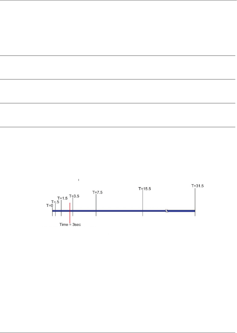
Command Reference Guide Global Configuration Mode Command Set
60000CRG0-35E Copyright © 2012 ADTRAN, Inc. 1161
ip sip timer rollover <value>
Use the ip sip timer rollover command to specify the time period (in seconds) that the Session Initiation
Protocol (SIP) proxy is set to wait for a response to a request before attempting to find an alternate
destination. Use the no form of this command to return to the default value.
Syntax Description
<value> Specifies the time period in seconds. Range is 1 to 32 seconds.
Default Values
By default, the rollover timer is set to 3 seconds.
Command History
Release 11.1 Command was introduced.
Functional Notes
The ip sip timer rollover command sets the SIP timer B value for Invite transactions originating from a
SIP trunk. When originating a call, the SIP trunk attempts to send Invite messages to the primary SIP
server and waits for a response. If there is no response, the SIP trunk waits for 0.5 seconds before
attempting to send another Invite to the same SIP server. If no response, the SIP trunk waits for 1 second
before attempting to send another Invite, then waits 2 seconds, and so on. These increasing intervals are
shown in the diagram below.
The rollover timer allows the user to control how long to wait before trying the next server. In the diagram
above, the red line indicates the rollover timer expiration. If there is no response after the timer expires, the
SIP trunk will attempt to send Invite messages to the highest priority backup SIP server obtained via DNS
service (SRV). The SIP trunk starts over at T=0 with the next server and doesn't send any more messages
to the timed out server. As long as the SIP trunk does not receive a response, it will continue this cycle until
it has attempted to contact all the SIP servers.
Times are shown in seconds.

Command Reference Guide Global Configuration Mode Command Set
60000CRG0-35E Copyright © 2012 ADTRAN, Inc. 1162
Usage Examples
The following example allows connection attempts to continue for up to 32 seconds before rolling over to
another destination:
(config)#ip sip timer rollover 32

Command Reference Guide Global Configuration Mode Command Set
60000CRG0-35E Copyright © 2012 ADTRAN, Inc. 1163
ip sip timer rollover register
Use the ip sip timer rollover register command to specify the time period (in seconds) that the Session
Initiation Protocol (SIP) proxy waits for a response to a REGISTER request before attempting to find an
alternate destination. Use the no form of this command to return to the default value. Variations of this
command include:
ip sip timer rollover register <value>
ip sip timer rollover register follow-primary
Syntax Description
<value> Specifies the rollover time period for REGISTER events in seconds. Range
is 1 to 32 seconds.
follow-primary Links the rollover timer for REGISTER events to the primary rollover timer
specified by the ip sip timer rollover command.
Default Values
By default, the rollover timer for REGISTER events is set to follow-primary.
Command History
Release 18.2 Command was introduced.
Usage Examples
The following example allows REGISTER request attempts to continue without response for up to 32
seconds before rolling over to another destination:
(config)#ip sip timer rollover register 32

Command Reference Guide Global Configuration Mode Command Set
60000CRG0-35E Copyright © 2012 ADTRAN, Inc. 1164
ip sip tone-file-prefix
Use the ip sip tone-file-prefix command to specify the file location (flash or CompactFlash) and location
prefix of the call progress tone files that the unit should use for blind transfers over Session Initiation
Protocol (SIP) trunks operating in local transfer mode. Use the no form of this command to return to the
default value. Variations of this command include:
ip sip tone-file-prefix cflash <location prefix>
ip sip tone-file-prefix flash <location prefix>
Syntax Description
<location prefix> Specifies the location prefix of the tone files to be used.
cflash Specifies that the tone files are located in the unit’s CompactFlash.
flash Specifies that the tone files are located in the unit’s flash memory.
Default Values
By default, AOS units with voice features that lack a digital signal processor (DSP) provide North American
ringback and disconnect tones.
By default, AOS units with a DSP use the DSP to generate ringback tones based on the system country
setting. For more information on how to configure the system country, refer to the command voice
system-country <name> on page 1444.
Command History
Release R10.1.0 Command was introduced.
Functional Notes
This command only designates the file location (flash or CompactFlash) and location prefix of call progress
tones used during blind transfers over SIP trunks operating in local transfer mode. To fully configure
international call progress tones during blind transfers, you must enable the AOS unit’s File Transfer
Protocol (FTP) server, upload the appropriate .wav files to the unit using an FTP client, and configure the
unit to use the uploaded files. For more information on configuring call progress tones for blind transfers
over SIP trunks operating in local transfer mode, refer to the International Configuration Guide available on
ADTRAN’s Support Forum at https://supportforums.adtran.com (article number 1824).

Command Reference Guide Global Configuration Mode Command Set
60000CRG0-35E Copyright © 2012 ADTRAN, Inc. 1165
Below is a list of the available countries or regions and their corresponding location prefix.
Usage Examples
The following example configures the unit to use tone files stored in flash memory that have the Adtran-UK
location prefix:
(config)#ip sip tone-file-prefix flash Adtran-UK
Australia
Belgium
Canada
China
Denmark
Finland
France
Germany
Hong Kong
India
Ireland
Italy
Adtran-UK
Adtran-BE
Adtran-NA
Adtran-CN
Adtran-ETSI
Adtran-FI
Adtran-FR
Adtran-DE
Adtran-HK
Adtran-IN
Adtran-IE
Adtran-ETSI
Japan
Luxembourg
Mexico
Netherlands
Norway
Spain
Sweden
Switzerland
UAE
UK
USA
Adtran-JP
Adtran-DE
Adtran-MX
Adtran-ETSI
Adtran-ETSI
Adtran-ETSI
Adtran-ETSI
Adtran-ETSI
Adtran-UK
Adtran-UK
Adtran-NA

Command Reference Guide Global Configuration Mode Command Set
60000CRG0-35E Copyright © 2012 ADTRAN, Inc. 1166
ip sip transaction fast-terminate
Use the ip sip transaction fast-terminate command to configure fast termination of Session Initiation
Protocol (SIP) transactions. Use the no form of this command to disable fast termination.
Syntax Description
No subcommands.
Default Values
By default, fast termination of SIP transaction is disabled.
Command History
Release A2 Command was introduced.
Usage Examples
The following example enables fast termination:
(config)#ip sip transaction fast-terminate

Command Reference Guide Global Configuration Mode Command Set
60000CRG0-35E Copyright © 2012 ADTRAN, Inc. 1167
ip sip trunk-auth-name-source
Use the ip sip trunk-auth-name-source command to configure the authentication name source for the
Session Initiation Protocol (SIP) trunks. Use the no form of this command to return to the default setting.
Variations of this command include:
ip sip trunk-auth-name-source account-id
ip sip trunk-auth-name-source message
Syntax Description
account-id Specifies using the corresponding account ID.
message Specifies using the To or From user when selecting the authentication name
and password.
Default Values
By default, the trunk authentication name source is message.
Command History
Release A2.03 Command was introduced.
Usage Examples
The following example configures the trunk authentication name source to use the account ID:
(config)#ip sip trunk-auth-name-source account-id

Command Reference Guide Global Configuration Mode Command Set
60000CRG0-35E Copyright © 2012 ADTRAN, Inc. 1168
ip sntp server
Use the ip sntp server command to enable the Simple Network Time Protocol (SNTP) server. This allows
the unit to accept SNTP requests. Use the no form of this command to disable the server.
Syntax Description
No subcommands.
Default Values
By default, the SNTP server is disabled.
Command History
Release 13.1 Command was introduced.
Usage Examples
The following example enables the SNTP server:
(config)#ip sntp server

Command Reference Guide Global Configuration Mode Command Set
60000CRG0-35E Copyright © 2012 ADTRAN, Inc. 1169
ip sntp server send-unsynced
Use the ip sntp server send-unsynced command to enable sending the system clock time when requested,
even if the device is not synchronized with the Simple Network Time Protocol (SNTP) server. Use the no
form of this command to disable this setting.
Syntax Description
No subcommands.
Default Values
By default, this feature is disabled.
Command History
Release 14.1 Command was introduced.
Usage Examples
The following example enables the device to send the system clock time regardless of synchronized status
with the sntp server:
(config)#ip sntp server send-unsynced

Command Reference Guide Global Configuration Mode Command Set
60000CRG0-35E Copyright © 2012 ADTRAN, Inc. 1170
ip sntp server source-interface <interface>
Use the ip sntp server source-interface command to specify a source interface for Simple Network Time
Protocol (SNTP) server traffic. The IP address of the specified interface will be used to source all SNTP
traffic. Use the no form of this command if you do not wish to override the default source IP address.
Syntax Description
<interface> Specifies the source interface for SNTP server traffic. Specify an interface in
the format <interface type [slot/port | slot/port.subinterface id | interface id |
interface id.subinterface id | ap | ap/radio | ap/radio.vap]>. For example, for
a T1 interface, use t1 0/1; for an Ethernet subinterface, use eth 0/1.1; for a
PPP interface, use ppp 1; for an ATM subinterface, use atm 1.1; and for a
wireless virtual access point, use dot11ap 1/1.1. Type ip sntp server
source-interface ? for a complete list of valid interfaces.
Default Values
By default, no SNTP server source interface is defined.
Command History
Release 6.1 Command was introduced.
Release 14.1 Command was expanded to include the tunnel interface.
Release 16.1 Command was expanded to include the bridged virtual interface (BVI),
Frame Relay, high level data link control (HDLC), and Point-to-Point
Protocol (PPP) interfaces.
Release 17.1 Command was expanded to include the asynchronous transfer mode (ATM)
interface.
Release A4.01 Command was expanded to include the Metro Ethernet Forum (MEF)
Ethernet interface.
Release A5.01 Command was expanded to include the Gigabit Ethernet interface.
Functional Notes
This command allows you to override the sender field in the IP packet. If you have multiple interfaces in
your unit, changing the sender tells the receiver where to send replies. This functionality can also be used
to allow packets to get through firewalls that would normally block the flow.
Usage Examples
The following example configures the unit to use the loopback 1 interface as the source IP for SNTP
traffic:
(config)#ip sntp server source-interface loopback 1

Command Reference Guide Global Configuration Mode Command Set
60000CRG0-35E Copyright © 2012 ADTRAN, Inc. 1171
ip sntp source-interface <interface>
Use the ip sntp source-interface command to specify a source interface for Simple Network Time
Protocol (SNTP) traffic originated by the unit. The IP address of the specified interface will be used to
source all SNTP traffic. Use the no form of this command if you do not wish to override the default source
IP address.
Syntax Description
<interface> Specifies the source interface for SNTP traffic. Specify an interface in the
format <interface type [slot/port | slot/port.subinterface id | interface id |
interface id.subinterface id | ap | ap/radio | ap/radio.vap]>. For example, for
a T1 interface, use t1 0/1; for an Ethernet subinterface, use eth 0/1.1; for a
PPP interface, use ppp 1; for an ATM subinterface, use atm 1.1; and for a
wireless virtual access point, use dot11ap 1/1.1. Type ip sntp
source-interface ? for a complete list of valid interfaces.
Default Values
By default, no SNTP source interface is defined.
Command History
Release 6.1 Command was introduced.
Release 14.1 Command was expanded to include the tunnel interface.
Release 16.1 Command was expanded to include the bridged virtual interface (BVI),
Frame Relay, high level data link control (HDLC), and Point-to-Point
Protocol (PPP) interfaces.
Release 17.1 Command was expanded to include the asynchronous transfer mode (ATM)
interface.
Release A4.01 Command was expanded to include the Metro Ethernet Forum (MEF)
Ethernet interface.
Release A5.01 Command was expanded to include the Gigabit Ethernet interface.
Functional Notes
This command allows you to override the sender field in the IP packet. If you have multiple interfaces in
your unit, changing the sender tells the receiver where to send replies. This functionality can also be used
to allow packets to get through firewalls that would normally block the flow.
Usage Examples
The following example configures the unit to use the loopback 1 interface as the source IP for SNTP
traffic:
(config)#ip sntp source-interface loopback 1

Command Reference Guide Global Configuration Mode Command Set
60000CRG0-35E Copyright © 2012 ADTRAN, Inc. 1172
ip subnet-zero
The ip subnet-zero command is the default operation and cannot be disabled. This command signifies the
router’s ability to route to subnet-zero subnets.
Syntax Description
No subcommands.
Default Values
By default, this command is enabled.
Command History
Release 3.1 Command was introduced.
Usage Examples
The following example subnet-zero is enabled:
(config)#ip subnet-zero

Command Reference Guide Global Configuration Mode Command Set
60000CRG0-35E Copyright © 2012 ADTRAN, Inc. 1173
ip tacacs source-interface <interface>
Use the ip tacacs source-interface command to specify a source interface for terminal access controller
access-control system plus (TACACS+) traffic originated by the unit. The IP address of the specified
interface will be used to source all TACACS+ traffic. Use the no form of this command if you do not wish
to override the default source IP address.
Syntax Description
<interface> Specifies the source interface for TACACS+ traffic. Specify an interface in
the format <interface type [slot/port | slot/port.subinterface id | interface id |
interface id.subinterface id | ap | ap/radio | ap/radio.vap]>. For example, for
a T1 interface, use t1 0/1; for an Ethernet subinterface, use eth 0/1.1; for a
PPP interface, use ppp 1; for an ATM subinterface, use atm 1.1; and for a
wireless virtual access point, use dot11ap 1/1.1. Type ip tacacs
source-interface ? for a complete list of valid interfaces.
Default Values
No default values are necessary for this command.
Command History
Release 12.1 Command was introduced.
Release 14.1 Command was expanded to include the tunnel interface.
Release 17.1 Command was expanded to include the asynchronous transfer mode (ATM)
interface.
Release A4.01 Command was expanded to include the Metro Ethernet Forum (MEF)
Ethernet interface.
Release A5.01 Command was expanded to include the Gigabit Ethernet interface.
Functional Notes
This command allows you to override the sender field in the IP packet. If you have multiple interfaces in
your unit, changing the sender tells the receiver where to send replies. This functionality can also be used
to allow packets to get through firewalls that would normally block the flow.
Usage Examples
The following example configures the unit to use the loopback 1 interface as the source IP for TACACS+
traffic:
(config)#ip tacacs source-interface loopback 1

Command Reference Guide Global Configuration Mode Command Set
60000CRG0-35E Copyright © 2012 ADTRAN, Inc. 1174
ip urlfilter <name> http
Use the ip urlfilter http command to create a uniform resource locator (URL) filter for Hypertext Transfer
Protocol (HTTP) (Transmission Control Protocol (TCP) port 80) traffic. Use the no form of this command
to delete the specified HTTP URL filter.
Syntax Description
<name> Specifies the URL filter name.
Default Values
By default, no URL filters are configured.
Command History
Release 12.1 Command was introduced.
Functional Notes
The firewall must be enabled using the ip firewall command in order to use URL filters. The URL filter
must be applied to the appropriate interface by using the ip urlfilter <name> [in | out] command. Refer to
this command in the appropriate interface for more information.
Usage Examples
The following example creates the HTTP URL filter called MyFilter that can be applied to an interface for
content filtering:
(config)#ip urlfilter MyFilter http
The URL filtering software runs on a server independent of the AOS product. For
additional information about the URL filtering technology, refer to the vendor’s website.

Command Reference Guide Global Configuration Mode Command Set
60000CRG0-35E Copyright © 2012 ADTRAN, Inc. 1175
ip urlfilter allowmode
Use the ip urlfilter allowmode command to allow all uniform resource locator (URL) requests in cases
when all URL filter servers are down. Use the no form of this command to block all URL requests when all
URL filter servers are down.
Syntax Description
No subcommands.
Default Values
By default, all URL requests will be blocked when all URL filter servers are down.
Command History
Release 12.1 Command was introduced.
Usage Examples
The following example permits all URL requests even when URL filter servers are down:
(config)#ip urlfilter allowmode

Command Reference Guide Global Configuration Mode Command Set
60000CRG0-35E Copyright © 2012 ADTRAN, Inc. 1176
ip urlfilter exclusive-domain
Use the ip urlfilter exclusive-domain command to instruct AOS to always allow or always block a
domain without first having to verify with the uniform resource locator (URL) filter server. Use the no
form of this command to remove an exclusive domain. Variations of this command include:
ip urlfilter exclusive-domain deny <name>
ip urlfilter exclusive-domain permit <name>
Syntax Description
deny <name> Specifies that the domain name be blocked without verifying with the URL
filter server.
permit <name> Specifies that the domain name be allowed without verifying with the URL
filter server.
Default Values
By default, no exclusive domains are configured.
Command History
Release 12.1 Command was introduced.
Functional Notes
Domain matching is based on an exact match between the Hypertext Transfer Protocol (HTTP) header
and entries in the ip urlfilter exclusive-domain command. In order to exactly match requests destined for
a domain, entries should list all possible variations of the domain that would appear in the Host field of an
HTTP header. Refer to the Usage Examples section of this command for more detailed information.
Usage Examples
The following example will always allow access to www.adtran.com and adtran.com without first having
to verify the domain with the URL filter server:
(config)#ip urlfilter exclusive-domain permit www.adtran.com
(config)#ip urlfilter exclusive-domain permit adtran.com
The following example will always block access to www.localnews.com without first having to verify the
domain with the URL filter server:
(config)#ip urlfilter exclusive-domain deny www.localnews.com

Command Reference Guide Global Configuration Mode Command Set
60000CRG0-35E Copyright © 2012 ADTRAN, Inc. 1177
ip urlfilter max-request <value>
Use the ip urlfilter max-request command to set the maximum number of outstanding uniform resource
locator (URL) lookup requests that can be sent to a URL filter server without a response. Use the no form
of this command to set the value back to its default setting.
Syntax Description
<value> The maximum number of outstanding URL lookup requests. Valid range
is 1 to 500 requests.
Default Values
By default, the number of outstanding requests is 500.
Command History
Release 12.1 Command was introduced.
Functional Notes
After the maximum number of URL lookup requests is reached, the no ip urlfilter allowmode setting will
be used to allow or block all following requests until enough URL lookup responses have been received
from the URL filter server.
Usage Examples
The following example sets the maximum number of URL lookup requests to 250:
(config)#ip urlfilter max-request 250

Command Reference Guide Global Configuration Mode Command Set
60000CRG0-35E Copyright © 2012 ADTRAN, Inc. 1178
ip urlfilter max-response <value>
Use the ip urlfilter max-response command to set the maximum number of responses allowed to buffer
before receiving an allow or block status from the uniform resource locator (URL) filter server. Use the no
form of this command to set the value back to its default setting.
Syntax Description
<value> Specifies the maximum number of responses allowed to buffer. Valid range
is 1 to 100 responses.
Default Values
By default, the value of buffered responses is 100.
Command History
Release 12.1 Command was introduced.
Functional Notes
When a URL request comes through the unit and URL filtering is enabled, a lookup request is sent to the
URL filter server and the Hypertext Transfer Protocol (HTTP) request is forwarded to the HTTP server at
the same time. If the HTTP server responds before the URL filter server, the response must be buffered
until the URL filter server responds with allow or block. Once the maximum number of buffered HTTP
responses is reached, all following HTTP responses are dropped until some of the existing buffered
responses are released. Buffered responses are released when the URL filter server sends a response, or
when the firewall association times out.
Usage Examples
The following example sets the maximum number of buffered responses to 50:
(config)#ip urlfilter max-response 50

Command Reference Guide Global Configuration Mode Command Set
60000CRG0-35E Copyright © 2012 ADTRAN, Inc. 1179
ip urlfilter server <ip address>
Use the ip urlfilter server command to identify a uniform resource locator (URL) filter server by IP
address and port number. Use the no form of this command to remove the server from use. Variations of
this command include:
ip urlfilter server <ip address>
ip urlfilter server <ip address> port <number>
ip urlfilter server <ip address> timeout <value>
Syntax Description
<ip address> Specifies the server IP address. IP addresses should be expressed in
dotted decimal notation (for example, 10.10.10.1).
port <number> Specifies the server Transmission Control Protocol (TCP) port number that
will receive requests.
timeout <value> Specifies the number of seconds to wait for a response from the URL
filtering server before determining that it is out of service. Range is 1 to
300 seconds.
Default Values
By default, there are no URL filtering servers configured. When configuring a URL filtering server, the port
default is 15,868, and the timeout default is 5 seconds.
Command History
Release 12.1 Command was introduced.
Usage Examples
The following example identifies a URL filtering server at IP address 10.1.1.1 that listens for URL filtering
requests on port 15,868 (default) and waits for a response for 10 seconds before determining that the
filtering server is down:
(config)#ip urlfilter server 10.1.1.1 timeout 10

Command Reference Guide Global Configuration Mode Command Set
60000CRG0-35E Copyright © 2012 ADTRAN, Inc. 1180
ip urlfilter top-website
Use the ip urlfilter top-website command to enable reporting of the websites most frequently requested
on the system. Use the no form of this command to disable top websites reporting.
Syntax Description
No subcommands.
Default Values
By default, top websites reporting is disabled.
Command History
Release 16.1 Command was introduced.
Usage Examples
The following example enables top websites reporting:
(config)#ip urlfilter top-website
Enabling this feature may cause a performance degradation in Web browsing.

Command Reference Guide Global Configuration Mode Command Set
60000CRG0-35E Copyright © 2012 ADTRAN, Inc. 1181
ipv6 access-list extended <ipv6 acl name>
Use the ipv6 access-list extended command to create an empty Internet Protocol version 6 (IPv6) access
control list (ACL) and enter the Extended ACL Configuration mode. Use the no form of this command to
delete an extended ACL and all the entries contained in it.
Syntax Description
<ipv6 acl name>
Specifies the name of the IPv6 ACL.
Default Values
By default, all AOS
security features are disabled, and there are no configured IPv6 ACLs.
Command History
Release 18.1 Command was introduced.
Functional Notes
This command only creates an empty extended IPv6 ACL, it does not configure it. For additional extended
ACL configuration commands and configuration parameters, refer to the IPv4 Access Control List
Command Set on page 3126.
Usage Examples
The following example creates an extended IPv6 ACL Allowv6 and enters the Extended ACL
Configuration mode:
(config)#ip access-list extended Allowv6
(config-ext6-nacl)#
Technology Review
IPv6 ACLs are used as packet selectors by different AOS
IPv6
features (firewall, virtual private network
(VPN), quality of service (QoS)); by themselves they do nothing. ACLs are composed of an ordered list of
entries with an implicit deny all at the end of each list. An ACL entry contains two parts: an action (permit
or deny) and a packet pattern. A permit ACL is used to match packets (meeting the specified pattern) to
enter the router system. A deny ACL advances AOS
to the next access policy entry. AOS
provides two
types of ACLs: standard and extended. Standard ACLs match based on the source of the packet.
Extended ACLs match based on the source and destination of the packet.
ACLs are performed in order from the top of the list down. Generally, the most specific entries should be at
the top and the more general at the bottom.
For a complete list of all extended IPv6 ACL configuration commands, refer to the IPv4
Access Control List Command Set on page 3126.

Command Reference Guide Global Configuration Mode Command Set
60000CRG0-35E Copyright © 2012 ADTRAN, Inc. 1182
IPv6 ACLs cannot have the same name as IPv4 ACLs. If you are using both IPv4 and IPv6, you must have
different ACLs for each IP version.
VPN routing and forwarding (VRF) on AOS products allows a single physical router to be partitioned into
multiple virtual routers. Each router instance has its own route table and interface assignments. Beginning
with Release 16.1, all AOS routers supporting multiple VRF instances (multi-VRF) have an unnamed
default VRF instance regardless of whether multi-VRF is configured. Therefore, executing the
abovementioned commands without specifying a VRF will only affect the default unnamed VRF.

Command Reference Guide Global Configuration Mode Command Set
60000CRG0-35E Copyright © 2012 ADTRAN, Inc. 1183
ipv6 access-list standard <ipv6 acl name>
Use the ipv6 access-list standard command to create an empty IPv6 access control list (ACL) and enter
the Standard ACL Configuration mode. Use the no form of this command to delete an extended ACL and
all the entries contained in it.
Syntax Description
<ipv6 acl name>
Specifies the name of the IPv6 ACL.
Default Values
By default, all AOS
security features are disabled, and there are no configured IPv6 ACLs.
Command History
Release 18.1 Command was introduced.
Functional Notes
This command only creates an empty standard IPv6 ACL, it does not configure it. For additional standard
IPv6 ACL configuration commands and configuration parameters, refer to the IPv6 Access Control Policy
Command Set on page 3192.
Usage Examples
The following example creates a standard IPv6 ACL Allowv6 and enters the Standard ACL Configuration
mode:
(config)#ipv6 access-list standard Allowv6
(config-std6-nacl)#
Technology Review
IPv6 ACLs are used as packet selectors by different IPv6 AOS
features (firewall, virtual private network
(VPN), quality of service (QoS)); by themselves they do nothing. ACLs are composed of an ordered list of
entries with an implicit deny all at the end of each list. An ACL entry contains two parts: an action (permit
or deny) and a packet pattern. A permit ACL is used to match packets (meeting the specified pattern) to
enter the router system. A deny ACL advances AOS
to the next access policy entry. AOS
provides two
types of ACLs: standard and extended. Standard ACLs match based on the source of the packet.
Extended ACLs match based on the source and destination of the packet.
ACLs are performed in order from the top of the list down. Generally, the most specific entries should be at
the top and the more general at the bottom.
For a complete list of all standard IPv6 ACL configuration commands, refer to the IPv6
Access Control Policy Command Set on page 3192.

Command Reference Guide Global Configuration Mode Command Set
60000CRG0-35E Copyright © 2012 ADTRAN, Inc. 1184
IPv6 ACLs cannot have the same name as IPv4 ACLs. If you are using both IPv4 and IPv6, you must have
different ACLs for each IP version.
VPN routing and forwarding (VRF) on AOS products allows a single physical router to be partitioned into
multiple virtual routers. Each router instance has its own route table and interface assignments. Beginning
with Release 16.1, all AOS routers supporting multiple VRF instances (multi-VRF) have an unnamed
default VRF instance regardless of whether multi-VRF is configured. Therefore, executing the
abovementioned commands without specifying a VRF will only affect the default unnamed VRF.

Command Reference Guide Global Configuration Mode Command Set
60000CRG0-35E Copyright © 2012 ADTRAN, Inc. 1185
ipv6 dhcp address limit <number>
Use the ipv6 dhcp address limit command to specify the maximum number of Internet Protocol version 6
(IPv6) addresses that can be assigned by the Dynamic Host Control Protocol version 6 (DHCPv6) server.
This command limits the number of addresses assigned by the DHCPv6 server to ensure that the AOS unit
does not run out of memory. Use the no form of this command to reset the count to the default value.
Syntax Description
<number> Specifies the number of IPv6 addresses that can be assigned. Valid range
is 1 to 10000. This maximum number is product-specific, and is equivalent
to the default value on the AOS unit.
Default Values
By default, only a certain number of addresses can be assigned by the DHCPv6 server. This number
varies by AOS product.
Command History
Release R10.1.0 Command was introduced.
Usage Examples
The following example changes the maximum number of IPv6 addresses that can be assigned by the
DHCPv6 server to 2000:
(config)#ipv6 dhcp address limit 2000

Command Reference Guide Global Configuration Mode Command Set
60000CRG0-35E Copyright © 2012 ADTRAN, Inc. 1186
ipv6 dhcp address conflict limit <number>
Use the ipv6 dhcp address conflict limit command to specify the maximum number of conflicting
Internet Protocol version 6 (IPv6) addresses that can be stored by the Dynamic Host Control Protocol
version 6 (DHCPv6) server. This command limits the number of conflicting addresses stored by the
DHCPv6 server to ensure that the AOS unit does not run out of memory. Use the no form of this command
to reset the count to the default value.
Syntax Description
<number> Specifies the maximum number of conflicting IPv6 addresses that can be
stored by the server. Valid range is 1 to 10000 addresses. This maximum
number is product-specific and is equivalent to the default value on the
product.
Default Values
By default, only a certain number of conflicting IPv6 addresses can be stored. This number varies by AOS
product.
Command History
Release R10.1.0 Command was introduced.
Usage Examples
The following example changes the number of conflicting IPv6 addresses stored by the DHCPv6 server to
3500:
(config)#ipv6 dhcp address conflict limit 3500

Command Reference Guide Global Configuration Mode Command Set
60000CRG0-35E Copyright © 2012 ADTRAN, Inc. 1187
ipv6 dhcp address client limit <number>
Use the ipv6 dhcp address client limit command to specify the maximum number of Internet Protocol
version 6 (IPv6) addresses assigned per client by the Dynamic Host Control Protocol version 6 (DHCPv6)
server. Use the no form of this command to return the maximum number of assigned addresses to the
default value.
Syntax Description
<number> Specifies the maximum number of IPv6 addresses that can be assigned to
a single DHCPv6 client. Valid range is 0 to 500. Setting the number to 0
returns the maximum number of allowed IPv6 addresses to the default
value.
Default Values
By default, a maximum number of 50 IPv6 addresses can be assigned to a single DHCPv6 client.
Command History
Release R10.1.0 Command was introduced.
Usage Examples
The following example specifies the maximum number of IPv6 addresses that can be assigned to a single
DHCPv6 client is 75:
(config)#ipv6 dhcp address client limit 75

Command Reference Guide Global Configuration Mode Command Set
60000CRG0-35E Copyright © 2012 ADTRAN, Inc. 1188
ipv6 dhcp database local
Use the ipv6 dhcp database local command to enable the Dynamic Host Control Protocol version 6
(DHCPv6) database. The DHCPv6 database stores local DHCPv6 bindings, allowing Internet Protocol
version 6 (IPv6) addresses assigned by the DHCPv6 server to be stored in non-volatile random access
memory (NVRAM) and preserved across a reboot of the AOS unit. Using this command enables the local
database to begin storing DHCPv6 information. Use the no form of this command to disable the DHCPv6
database.
Syntax Description
No subcommands.
Default Values
By default, the DHCPv6 database is disabled.
Command History
Release R10.1.0 Command was introduced.
Usage Examples
The following example enables the DHCPv6 database:
(config)#ipv6 dhcp database local

Command Reference Guide Global Configuration Mode Command Set
60000CRG0-35E Copyright © 2012 ADTRAN, Inc. 1189
ipv6 dhcp excluded-address
Use the ipv6 dhcp excluded-address command to specify Internet Protocol version 6 (IPv6) addresses to
exclude from any Dynamic Host Control Protocol version 6 (DHCPv6) server pool. These addresses are
excluded from the DHCPv6 server pool, and cannot be assigned to DHCP clients by the server of these
devices. Use the no form of this command to remove the address exclusion and make the address(es)
available for use by the DHCPv6 server. Variations of this command include:
ipv6 dhcp excluded-address <ipv6 address>
ipv6 dhcp excluded-address <beginning ipv6 address> <ending ipv6 address>
ipv6 dhcp excluded-address vrf <name> <ipv6 address>
ipv6 dhcp excluded-address vrf <name> <beginning ipv6 address> <ending ipv6 address>
Syntax Description
<ipv6 address> Specifies a single IPv6 address to exclude from any DHCPv6 server pool.
IPv6 addresses should be expressed in colon hexadecimal format
(X:X:X:X::X), for example, 2001:DB8:1::1.
<beginning ipv6 address> Specifies the lowest IPv6 address in the range of addresses to exclude.
IPv6 addresses should be expressed in colon hexadecimal format
(X:X:X:X::X), for example, 2001:DB8:1::1.
<ending ipv6 address> Specifies the highest IPv6 address in the range of addresses to exclude.
IPv6 addresses should be expressed in colon hexadecimal format
(X:X:X:X::X), for example, 2001:DB8:1::1.
vrf <name> Optional. Specifies a nondefault named virtual routing and forwarding (VRF)
instance on which to exclude the IPv6 addresses. If a VRF instance is not
specified, the addresses are excluded on the default VRF instance.
Default Values
By default, no IPv6 addresses are excluded.
Command History
Release R10.1.0 Command was introduced.
Usage Examples
The following example excludes the IPv6 addresses on the default VRF instance ranging from
2001:DB8:1::1 to 2001:DB8:1::5 from any DHCPv6 server pool:
(config)#ipv6 dhcp excluded-address 2001:DB8:1::1 2001:DB8:1::5

Command Reference Guide Global Configuration Mode Command Set
60000CRG0-35E Copyright © 2012 ADTRAN, Inc. 1190
ipv6 dhcp ping packets <number>
Use the ipv6 dhcp ping packets command to configure the number of ping packets transmitted by the
Dynamic Host Control Protocol version 6 (DHCPv6) server when testing an Internet Protocol version 6
(IPv6) address before it is assigned to a client. Use the no form of this command to prevent the DHCPv6
server from using ping packets as part of the IPv6 address assignment process.
Syntax Description
<number> Specifies the number of DHCPv6 ping packets sent on the network before
assigning the IPv6 address to a requesting DHCPv6 client. Valid range is 0
to 100 packets.
Default Values
By default, 2 ping packets are sent to test IPv6 addresses before assigning them to a DHCPv6 client.
Command History
Release R10.1.0 Command was introduced.
Usage Examples
The following example specifies that 8 ping packets are used by DHCPv6 to test IPv6 addresses before
assigning them to a client:
(config)#ipv6 dhcp ping packets 8

Command Reference Guide Global Configuration Mode Command Set
60000CRG0-35E Copyright © 2012 ADTRAN, Inc. 1191
ipv6 dhcp ping timeout <value>
Use the ipv6 dhcp ping timeout command to specify the interval the Dynamic Host Control Protocol
version 6 (DHCPv6) server waits for a response to a transmitted DHCPv6 ping packet when testing an
Internet Protocol version 6 (IPv6) packet. Use the no form of this command to return the timeout period to
the default value.
Syntax Description
<value> Specifies the DHCPv6 ping timeout value in milliseconds. Valid range is 10
to 1000 ms.
Default Values
By default, the DHCPv6 server waits 500 ms for a ping response when testing an IPv6 address.
Command History
Release R10.1.0 Command was introduced.
Usage Examples
The following example specifies the ping timeout value for the DHCPv6 server is 300 ms:
(config)#ipv6 dhcp ping timeout 300

Command Reference Guide Global Configuration Mode Command Set
60000CRG0-35E Copyright © 2012 ADTRAN, Inc. 1192
ipv6 dhcp pool <name>
Use the ipv6 dhcp pool command to create a Dynamic Host Control Protocol version 6 (DHCPv6) server
address pool and enter the pool’s configuration mode. The server pool is used to define the information to
be assigned to DHCPv6 clients by the DHCPv6 server. The pool chosen to serve a specific client’s request
is determined by the current pool selection algorithm, just as in DHCP version 4 (DHCPv4). Use the no
form of this command to remove the DHCPv6 server pool from the AOS unit’s configuration. Refer to the
DHCPv6 Pool Command Set on page 3067 for more information.
Syntax Description
<name> Specifies the name of the DHCPv6 pool using an alphanumeric string (up to
32 characters in length).
Default Values
By default, no DHCPv6 server pools are configured.
Command History
Release 18.3 Command was introduced.
Functional Notes
Use the ipv6 dhcp pool command to create multiple DHCPv6 server address pools for various segments
of the network. Multiple address pools can be created to service different segments of the network with
tailored configurations.
Usage Examples
The following example creates the DHCPv6 server address pool (labeled Pool1) and enters the DHCPv6
pool’s configuration mode:
(config)#ipv6 dhcp pool Pool1
(config-dhcpv6)#

Command Reference Guide Global Configuration Mode Command Set
60000CRG0-35E Copyright © 2012 ADTRAN, Inc. 1193
ipv6 firewall
Use the ipv6 firewall command to enable AOS Internet Protocol version 6 (IPv6) security features,
including IPv6 access control policies (ACPs) and lists (ACLs) and the stateful inspection firewall. Use the
no form of this command to disable the IPv6 security functionality. Variations of this command include:
ipv6 firewall
ipv6 firewall vrf <name>
Syntax Description
vrf <name> Optional. Enables or disables the IPv6 firewall for a specific VPN routing
and forwarding (VRF) instance.
Default Values
By default, all AOS
IPv6
security features are disabled.
Command History
Release 18.1 Command was introduced.
Usage Examples
The following example enables the AOS IPv6 security features:
(config)#ipv6 firewall
Disabling the AOS IPv6 security features (using the no ipv6 firewall command) does not
affect security configuration. All configuration parameters will remain intact, but no
security data processing will be attempted.

Command Reference Guide Global Configuration Mode Command Set
60000CRG0-35E Copyright © 2012 ADTRAN, Inc. 1194
ipv6 firewall alg ftp
Use the ipv6 firewall alg ftp command to enable the Internet Protocol version 6 (IPv6) File Transfer
Protocol (FTP) application-level gateway (ALG). Use the no form of this command to disable the FTP
ALG. Variations of this command include:
ipv6 firewall alg ftp
ipv6 firewall alg ftp tcp
ipv6 firewall alg ftp tcp port <port>
ipv6 firewall vrf <name> alg ftp
ipv6 firewall vrf <name> alg ftp tcp
ipv6 firewall vrf <name> alg ftp tcp port <port>
Syntax Description
tcp Optional. Specifies that the port on which the IPv6 FTP ALG is enabled is a
Transmission Control Protocol (TCP) port.
port <port> Optional. Specifies a single port on which to enable the IPv6 FTP ALG. Valid
range is 0 to 65535.
vrf <name> Optional. Specifies a nondefault (named) Virtual Routing and Forwarding
(VRF) instance on which to enable the IPv6 FTP ALG.
Default Values
By default, the IPv6 FTP ALG is enabled on all VRF instances on TCP port 21.
Command History
Release R10.1.0 Command was introduced.
Functional Notes
The IPv6 FTP ALG operates by parsing the Layer 5 contents of packets used for FTP, and when
necessary, opens pending policy sessions so that FTP data transfers are able to traverse the IPv6 firewall
without being dropped by configured access control policies (ACPs). In addition, the IPv6 FTP ALG has
the ability to perform FTP-specific attack checking.
During the process of an FTP flow, the IPv6 FTP ALG creates a pending policy session based on a
currently active policy session. This pending policy session listens for expected FTP data transfer traffic.
Any IPv6 firewall policy sessions created using a stateless ACP entry bypass all ALG processing, even if
the ALG is enabled for the ACP’s destination port, allowing global ALG processing for specific ports, but
bypassing the global configuration under certain circumstances (such as, on a particular ACP or for
particular hosts or networks based on IPv6 ACLs).
The IPv6 FTP ALG cannot be enabled on a protocol and port that is the default protocol and port for any
other ALG, even if the other ALG is disabled. The IPv6 FTP ALG also cannot be enabled on a TCP port
whose default filtering behavior has been overridden.

Command Reference Guide Global Configuration Mode Command Set
60000CRG0-35E Copyright © 2012 ADTRAN, Inc. 1195
Usage Examples
The following example disables the IPv6 FTP ALG on the default port (21), and then enables it on TCP
ports 10000 and 20000 on the default VRF instance:
(config)#no ipv6 firewall alg ftp tcp port 21
(config)#ipv6 firewall alg ftp tcp port 10000
(config)#ipv6 firewall alg ftp tcp port 20000

Command Reference Guide Global Configuration Mode Command Set
60000CRG0-35E Copyright © 2012 ADTRAN, Inc. 1196
ipv6 firewall attack-log threshold <number>
Use the ipv6 firewall attack-log threshold command to specify the number of possible attack conditions
AOS will identify and block before generating a log message when using Internet Protocol version 6
(IPv6). Use the no form of this command to return to the default threshold. Variations of this command
include:
ipv6 firewall attack-log threshold <number>
ipv6 firewall vrf <name> attack-log threshold <number>
Syntax Description
<number> Specifies the number of possible attack conditions AOS IPv6 will identify
before generating a log message. Valid range is 0 to 4294967295.
vrf <name> Optional. Specifies a VPN routing and forwarding (VRF) instance to monitor.
If no VRF is specified, the default VRF is monitored.
Default Values
By default, the ipv6 firewall attack-log threshold is set at 100.
Command History
Release 18.1 Command was introduced.
Usage Examples
The following example specifies a threshold of 25 attacks before generating a log message for the IPv6
firewall:
(config)#ipv6 firewall attack-log threshold 25
The AOS IPv6 firewall must be enabled (using the command ipv6 firewall on page 1193)
for the stateful inspection firewall to be activated.
Command Reference Guide Global Configuration Mode Command Set
60000CRG0-35E Copyright © 2012 ADTRAN, Inc. 1197
ipv6 firewall check duplicate-options
Use the ipv6 firewall check duplicate-options command to specify that Internet Protocol version 6 (IPv6)
packets with duplicate options within a Destination Options or Hop-by-Hop Options extension headers are
dropped. Using the no form of this command allows IPv6 packets with duplicate options. Variations of this
command include:
ipv6 firewall check duplicate-options
ipv6 firewall vrf <name> check duplicate-options
Syntax Description
vrf <name> Optional. Specifies a VPN routing and forwarding (VRF) instance on which
to drop IPv6 packets with duplicate options headers. If no VRF is specified,
the packets on the default VRF are dropped.
Default Values
By default, this feature is enabled.
Command History
Release 18.1 Command was introduced.
Usage Examples
The following example specifies that IPv6 packets with duplicate options headers are dropped on the
default VRF:
(config)#ipv6 firewall check duplicate-options
The AOS IPv6 firewall must be enabled (using the command ipv6 firewall on page 1193)
for the stateful inspection firewall to be activated.

Command Reference Guide Global Configuration Mode Command Set
60000CRG0-35E Copyright © 2012 ADTRAN, Inc. 1198
ipv6 firewall check ftp-bounce
Use the ipv6 firewall check ftp-bounce command enable the File Transfer Protocol (FTP) bounce attack
check for the Internet Protocol version 6 (IPv6) firewall. Use the no form of this command to disable the
FTP bounce attack check. Variations of this command include:
ipv6 firewall check ftp-bounce
ipv6 firewall vrf <name> check ftp-bounce
Syntax Description
vrf <name> Optional. Specifies a nondefault (named) Virtual Routing and Forwarding
(VRF) instance on which the enable the bounce attack check. If no VRF
instance is specified, the action is performed on the default VRF instance.
Default Values
By default, FTP bounce attack check is enabled on the IPv6 firewall.
Command History
Release R10.1.0 Command was introduced.
Functional Notes
In addition to allowing the flow of IPv6 FTP traffic through the IPv6 firewall, the IPv6 FTP application-level
gateway (ALG) can be used to protect against FTP bounce attacks. An FTP bounce attack is a network
attack where malicious hosts using proxy FTP can target a specific well-known service on one server
(Server A) by instructing another FTP server (Server B) to send a file to Server A that contains commands
relevant to the service being attacked. For example, this can allow a malicious host to forge mail on Server
A without making a direct connection. The lack of a direct file transfer between the attacker and the target
server makes the identity of the attacker difficult to determine.
The IPv6 FTP ALG, however, can be used to protect against such an attack. When this feature is enabled,
the IPv6 FTP ALG recognizes as an attack any extended port command (EPRT) sent by the FTP client that
has a TCP port number less than 1024, and the ALG closes the connection. The ALG performs this action
because TCP port numbers in the range from 0 to 1023 are used by well-known services.
Usage Examples
The following example enables the FTP bounce attack check on the nondefault VRF instance RED1:
(config)#ipv6 firewall vrf RED1 check ftp-bounce
Although the IPv6 FTP ALG can perform bounce attack checks when ports less than 1024
are specified in an EPRT, services running on ports greater than 1023 are still vulnerable
to FTP bounce attacks.
Command Reference Guide Global Configuration Mode Command Set
60000CRG0-35E Copyright © 2012 ADTRAN, Inc. 1199
ipv6 firewall check header-order
Use the ipv6 firewall check header-order command to enable the dropping of Internet Protocol version 6
(IPv6) packets that have extension headers in an order different than the recommendations proposed in the
Systems and Network Analysis Center (SNAC) document Firewall Design Considerations for IPv6. Use
the no form of this command to disable the feature and allow the processing of IPv6 packets with
extension headers according to RFC 2460. Variations of this command include:
ipv6 firewall check header-order
ipv6 firewall vrf <name> check header-order
Syntax Description
vrf <name> Optional. Specifies a VPN routing and forwarding (VRF) instance to
configure. If no VRF is specified, the default VRF is configured.
Default Values
By default, this feature is enabled.
Command History
Release 18.1 Command was introduced.
Usage Examples
The following example specifies that IPv6 packets with out-of-order headers are dropped on the default
VRF:
(config)#ipv6 firewall check header-order
The AOS IPv6 firewall must be enabled (using the command ipv6 firewall on page 1193)
for the stateful inspection firewall to be activated.

Command Reference Guide Global Configuration Mode Command Set
60000CRG0-35E Copyright © 2012 ADTRAN, Inc. 1200
ipv6 firewall check min-fragment-size <value>
Use the ipv6 firewall check min-fragment-size command to specify the smallest permitted size for
Internet Protocol version 6 (IPv6) fragmented packets. Packets less than the specified size are dropped.
Use the no form of this command to return to the default value. Variations of this command include:
ipv6 firewall check min-fragment-size <value>
ipv6 firewall vrf <name> check min-fragment-size <value>
Syntax Description
<value> Specifies the packet size in octets. Valid range is 56 to 1280 octets.
vrf <name> Optional. Specifies a VPN routing and forwarding (VRF) instance to
configure. If no VRF is specified, the default VRF is configured.
Default Values
By default, the IPv6 packet fragment size is set to 640 octets.
Command History
Release 18.1 Command was introduced.
Usage Examples
The following example changes the smallest permitted size for IPv6 packet fragments on the default VRF
to 800 octets:
(config)#ipv6 firewall check min-fragment-size 800
The AOS IPv6 firewall must be enabled (using the command ipv6 firewall on page 1193)
for the stateful inspection firewall to be activated.

Command Reference Guide Global Configuration Mode Command Set
60000CRG0-35E Copyright © 2012 ADTRAN, Inc. 1201
ipv6 firewall check multiple-pad1
Use the ipv6 firewall check multiple-pad1 command to specify that Internet Protocol version 6 (IPv6)
packets with more than one Pad1 option back-to-back within the Destination Options or Hop-by-Hop
Options extension headers are dropped. Use the no form of this command to allow packets with more than
one Pad1 option back-to-back. Variations of this command include:
ipv6 firewall check multiple-pad1
ipv6 firewall vrf <name> check multiple-pad1
Syntax Description
vrf <name> Optional. Specifies a VPN routing and forwarding (VRF) instance on which
to drop IPv6 packets with multiple Pad1 options. If no VRF is specified, the
packets on the default VRF are dropped.
Default Values
By default, this feature is disabled.
Command History
Release 18.1 Command was introduced.
Usage Examples
The following example specifies that packets on the default VRF with more than one Pad1 option are
dropped:
(config)#ipv6 firewall check multiple-pad1
The AOS IPv6 firewall must be enabled (using the command ipv6 firewall on page 1193)
for the stateful inspection firewall to be activated.

Command Reference Guide Global Configuration Mode Command Set
60000CRG0-35E Copyright © 2012 ADTRAN, Inc. 1202
ipv6 firewall check reflexive-traffic
Use the ipv6 firewall check reflexive-traffic command to enable the AOS stateful inspection firewall to
process Internet Protocol version 6 (IPv6) traffic and check for reflexive traffic. Reflexive traffic refers to
packets that are routed out of the same interface on which they arrived. Use the no form of this command
to disable this check. Variations of this command include:
ipv6 firewall check reflexive-traffic
ipv6 firewall vrf <name> check reflexive-traffic
Syntax Description
vrf <name> Optional. Specifies a VPN routing and forwarding (VRF) instance on which
to enable reflexive traffic checking. If no VRF is specified, IPv6 traffic is
checked on the default VRF.
Default Values
By default, this reflexive traffic is allowed to bypass the firewall and does not create a policy session.
Command History
Release 18.1 Command was introduced.
Usage Examples
The following example enables the AOS IPv6 reflexive traffic check for the default VRF:
(config)#ipv6 firewall check reflexive-traffic
The AOS IPv6 firewall must be enabled (using the command ipv6 firewall on page 1193)
for the stateful inspection firewall to be activated.

Command Reference Guide Global Configuration Mode Command Set
60000CRG0-35E Copyright © 2012 ADTRAN, Inc. 1203
ipv6 firewall check tcp-seq-and-ack
Use the ipv6 firewall check tcp-seq-and-ack command to direct the Internet Protocol version 6 (IPv6)
firewall to inspect each packet of a Transmission Control Protocol (TCP) flow to ensure that the sequence
numbers and acknowledgement (ACK) numbers are within the expected window for that firewall session.
Use the no form of this command to disable the TCP sequence and ACK number check. Variations of this
command include:
ipv6 firewall check tcp-seq-and-ack
ipv6 firewall vrf <name> check tcp-seq-and-ack
Syntax Description
vrf <name> Optional. Specifies a nondefault (named) Virtual Routing and Forwarding
(VRF) instance on which to enable or disable the TCP sequence and ACK
number check. If no VRF instance is specified, the action is performed on
the default VRF instance.
Default Values
By default, the TCP sequence and ACK number check is enabled.
Command History
Release R10.1.0 Command was introduced.
Usage Examples
The following example enables the TCP sequence and ACK number check on the nondefault VRF
instance RED1:
(config)#ipv6 firewall vrf RED1 check tcp-seq-and-ack

Command Reference Guide Global Configuration Mode Command Set
60000CRG0-35E Copyright © 2012 ADTRAN, Inc. 1204
ipv6 firewall check udp-checksum-zero
Use the ipv6 firewall check udp-checksum-zero command to specify that Internet Protocol version 6
(IPv6) User Datagram Protocol (UDP) packets with a checksum value of zero are dropped. Use the no
form of this command to allow UDP packets with a checksum value of zero. Variations of this command
include:
ipv6 firewall check udp-checksum-zero
ipv6 firewall vrf <name> check udp-checksum-zero
Syntax Descriptions
vrf <name> Optional. Specifies a VPN routing and forwarding (VRF) instance on which
to check UDP packets. If no VRF is specified, the default VRF is inspected.
Default Values
By default, this feature is enabled.
Command History
Release 18.1 Command was introduced.
Usage Examples
The following example specifies that UDP packets with a value of zero are dropped on the default VRF:
(config)#ipv6 firewall check udp-checksum-zero
The AOS IPv6 firewall must be enabled (using the command ipv6 firewall on page 1193)
for the stateful inspection firewall to be activated.

Command Reference Guide Global Configuration Mode Command Set
60000CRG0-35E Copyright © 2012 ADTRAN, Inc. 1205
ipv6 firewall check unknown-options
Use the ipv6 firewall check unknown-options command to specify that Internet Protocol version 6 (IPv6)
packets with unknown options in the Destination Options or Hop-by-Hop Options extension headers are
dropped. Use the no form of this command to allow IPv6 packets with unknown options in the extension
header. Variations of this command include:
ipv6 firewall check unknown-options
ipv6 firewall vrf <name> check unknown-options
Syntax Description
vrf <name> Optional. Specifies a VPN routing and forwarding (VRF) instance on which
to check IPv6 packets. If no VRF is specified, traffic on the default VRF is
dropped.
Default Values
By default, this feature is enabled.
Command History
Release 18.1 Command was introduced.
Usage Examples
The following example specifies that IPv6 packets with unknown option extension headers are dropped on
the default VRF:
(config)#ipv6 firewall check unknown-options
The AOS IPv6 firewall must be enabled (using the command ipv6 firewall on page 1193)
for the stateful inspection firewall to be activated.

Command Reference Guide Global Configuration Mode Command Set
60000CRG0-35E Copyright © 2012 ADTRAN, Inc. 1206
ipv6 firewall filtering-behavior
Use the ipv6 firewall filtering-behavior command to modify the filtering behavior of the Internet
Protocol version 6 (IPv6) firewall. Modifying the filtering behavior settings for a particular port and
protocol allow for application-level gateway (ALG)-like behavior in certain applications without requiring
parsing of the Layer 5 packet contents used by these applications. By modifying IPv6 firewall filtering
behavior, you can enable firewall traversal for applications by adding one or more configuration options if
no ALG is available for the application (such as with Trivial File Transfer Protocol (TFTP)). Use the no
form of this command to return the firewall filtering behavior to the default value. Variations of this
command include:
ipv6 firewall filtering-behavior [tcp <port> | udp <port>] address-dependent
ipv6 firewall filtering-behavior [tcp <port> | udp <port>] address-port-dependent
ipv6 firewall filtering-behavior [tcp <port> | udp <port>] endpoint-independent
ipv6 firewall vrf <name> filtering-behavior [tcp <port> | udp <port>] address-dependent
ipv6 firewall vrf <name> filtering-behavior [tcp <port> | udp <port>] address-port-dependent
ipv6 firewall vrf <name> filtering-behavior [tcp <port> | udp <port>] endpoint-independent
Syntax Description
tcp <port> Specifies a Transmission Control Protocol (TCP) port for which the IPv6
firewall filtering behavior is changed. Valid range is 0 to 65535. The port
corresponds to the destination port of the firewall policy session, which is
the destination port of the internal traffic.
udp <port> Specifies a User Datagram Protocol (UDP) port for which the IPv6 firewall
filtering behavior is changed. Valid range is 0 to 65535. The port
corresponds to the destination port of the firewall policy session, which is
the destination port of the internal traffic.
address-dependent Specifies that address-dependent filtering is used for traffic initiated using
the specified destination port.
address-port-dependent Specifies that address- and port-dependent filtering is used for traffic
initiated using the specified destination port. This is the default firewall
filtering behavior for most ports.
endpoint-independent Specifies that endpoint-independent filtering is used for traffic initiated using
the specified destination port.
vrf <name> Optional. Specifies a nondefault (named) Virtual Routing and Forwarding
(VRF) instance on which to apply the filtering behavior. If no VRF instance is
specified, the action is performed on the default VRF instance.
Default Values
By default, most ports are filtered by traditional firewall filtering (address-port-dependent). By default,
UDP port 69, the TFTP port, uses address-dependent filtering.
Command History
Release R10.1.0 Command was introduced.

Command Reference Guide Global Configuration Mode Command Set
60000CRG0-35E Copyright © 2012 ADTRAN, Inc. 1207
Functional Notes
In AOS firmware release R10.1.0, the ability to configure IPv6 firewall filtering behavior was introduced.
The ordinary filtering behavior of the IPv6 firewall is to restrict permitted return traffic to the exact source
and destination IP addresses and ports of the initial traffic flow. This is called address- and port-dependent
filtering. In some applications, including TFTP, the external traffic generated as part of the application can
respond from a different external port than the one specified in the firewall configuration. This traffic might
not be allowed to traverse the firewall, depending on the configured access control policy (ACP) rules. If
available, an ALG could be used to accommodate such an application. The ALG would parse the
application layer payload for traffic from the initiating host, and create an appropriate pending policy
session to allow the expected response. With the release of R10.1.0, the IPv6 firewall incorporates two
additional configurable filtering behaviors that can take the place of such ALGs for certain applications.
The first additional method of firewall filtering is using address-dependent filtering. In this type of filtering,
return traffic from an external host to the initiating internal host is allowed from any port, but traffic
originating from any other external host will continue to be blocked. The second additional method of
firewall filtering is using endpoint-independent filtering. In this type of filtering, any external host can
respond to traffic from the initiating host from any port.
For more information about the configuration and use of IPv6 firewall filtering behaviors, refer to the
configuration guide Using IPv6 in AOS, available online at https://supportforums.adtran.com (article
number 3505).
Usage Examples
The following example specifies that on the default VRF instance TCP port 10000 and UDP port 40 are
filtered by endpoint-independent filtering and that TCP port 20000 and UDP port 30 are filtered by
address-dependent filtering:
(config)#ipv6 firewall filtering-behavior tcp 10000 endpoint-independent
(config)#ipv6 firewall filtering-behavior tcp 20000 address-dependent
(config)#ipv6 firewall filtering-behavior udp 30 address-dependent
(config)#ipv6 firewall filtering-behavior udp 40 endpoint-independent

Command Reference Guide Global Configuration Mode Command Set
60000CRG0-35E Copyright © 2012 ADTRAN, Inc. 1208
ipv6 firewall policy-log threshold <value>
Use the ipv6 firewall policy-log threshold command to specify the number of Internet Protocol version 6
(IPv6) access control policy (ACP) events identified by AOS before generating a log message. Use the no
form of this command to return to the default value. Variations of this command include:
ipv6 firewall policy-log threshold <value>
ipv6 firewall vrf <name> policy-log threshold <value>
Syntax Description
<value> Specifies the number of IPv6 policy events AOS identifies before creating
the log. Valid range is 1 to 4294967295.
vrf <name> Optional. Specifies a VPN routing and forwarding (VRF) instance for AOS to
monitor. If no VRF is specified, the default VRF is monitored.
Default Values
By default, a log is generated after 100 policy events have been identified.
Command History
Release 18.1 Command was introduced.
Usage Examples
The following example specifies that a log is generated when 150 IPv6 ACP events are detected on the
default VRF:
(config)#ipv6 firewall policy-log threshold 150
The AOS IPv6 firewall must be enabled (using the command ipv6 firewall on page 1193)
for the stateful inspection firewall to be activated.

Command Reference Guide Global Configuration Mode Command Set
60000CRG0-35E Copyright © 2012 ADTRAN, Inc. 1209
ipv6 firewall fin-timeout <timeout>
Use the ipv6 firewall fin-timeout command to configure the firewall policy session timeout for a
Transmission Control Protocol (TCP) policy session closed by a bidirectional FINISH (FIN). The policy
session timeout determines when the time to live (TTL) for the session expires, and thus ends the session.
Using the no form of this command returns the timeout to the default value. Variations of this command
include:
ipv6 firewall fin-timeout <timeout>
ipv6 firewall vrf <name> fin-timeout <timeout>
Syntax Description
<timeout> Specifies the session timeout in seconds. Valid range is 0 to 4294967295
seconds.
vrf <name> Optional. Specifies a nondefault VPN routing and forwarding (VRF) instance on
which to perform the timeout. If no VRF is specified, the action occurs on the
default VRF.
Default Values
By default, the FIN timeout is set to 4 seconds.
Command History
Release 18.2 Command was introduced.
Functional Notes
A policy session closed by a TCP FIN is one in which a FIN has been received from both endpoints
participating in the session. This command is used when configuring firewall session timeouts for Internet
Protocol version 6 (IPv6).
If the timeout is defined to be zero, the policy session will be deleted immediately without entering a
post-connection state. This could be necessary for hosts that do not implement the TIME_WAIT TCP state
correctly, but instead permit immediately reopening closed sessions.
Usage Examples
The following example changes the IPv6 firewall session timeout for TCP policy sessions closed by a FIN
to 10 seconds:
(config)#ipv6 firewall fin-timeout 10

Command Reference Guide Global Configuration Mode Command Set
60000CRG0-35E Copyright © 2012 ADTRAN, Inc. 1210
ipv6 firewall rst-timeout <timeout>
Use the ipv6 firewall rst-timeout command to configure the firewall policy session timeout for a
Transmission Control Protocol (TCP) policy session closed by a RESET (RST). The policy session
timeout determines when the time to live (TTL) for the session expires, and thus ends the session. Using
the no form of this command returns the timeout to the default value. Variations of this command include:
ipv6 firewall rst-timeout <timeout>
ipv6 firewall vrf <name> rst-timeout <timeout>
Syntax Description
<timeout> Specifies the session timeout in seconds. Valid range is 0 to 4294967295
seconds.
vrf <name> Optional. Specifies a nondefault VPN routing and forwarding (VRF) instance on
which to perform the timeout. If no VRF is specified, the action occurs on the
default VRF.
Default Values
By default, the RST timeout is set to 20 seconds.
Command History
Release 18.2 Command was introduced.
Functional Notes
A TCP policy session closed by an RST is one in which an RST has been received from both endpoints
participating in the session, indicating that enough time has passed to complete the TCP reset process.
This command is used when configuring firewall session timeouts for Internet Protocol version 6 (IPv6).
If the timeout is defined to be zero, the policy session will be deleted immediately without entering a
post-connection state. This could be necessary for hosts that do not implement the TIME_WAIT TCP state
correctly, but instead permit immediately reopening closed sessions.
Usage Examples
The following example changes the IPv6 firewall session timeout for TCP policy sessions closed by a RST
sessions to 30 seconds:
(config)#ipv6 firewall rst-timeout 30

Command Reference Guide Global Configuration Mode Command Set
60000CRG0-35E Copyright © 2012 ADTRAN, Inc. 1211
ipv6 firewall stealth
Use the ipv6 firewall stealth command to place the Internet Protocol version 6 (IPv6) firewall in stealth
mode. The stealth setting allows the route to be invisible as a route hop to associated devices. Use the no
form of this command to disable the stealth feature. Variations of this command include:
ipv6 firewall stealth
ipv6 firewall vrf <name> stealth
Syntax Description
vrf <name> Optional. Specifies a VPN routing and forwarding (VRF) instance to put in
stealth mode. If no VRF is specified, the default VRF is placed in stealth
mode.
Default Values
By default, stealth mode is disabled.
Command History
Release 18.1 Command was introduced.
Usage Examples
The following example enables the stealth option for the default IPv6 VRF:
(config)#ipv6 firewall stealth
The AOS IPv6 firewall must be enabled (using the command ipv6 firewall on page 1193)
for the stateful inspection firewall to be activated.

Command Reference Guide Global Configuration Mode Command Set
60000CRG0-35E Copyright © 2012 ADTRAN, Inc. 1212
ipv6 firewall tcp-unestab-timeout <timeout>
Use the ipv6 firewall tcp-unestab-timeout command to configure the firewall policy session timeout for a
pre-established Transmission Control Protocol (TCP) policy session. The policy session timeout
determines when the time to live (TTL) for the session expires, and thus ends the session. Using the no
form of this command returns the timeout to the default value. Variations of this command include:
ipv6 firewall tcp-unestab-timeout <timeout>
ipv6 firewall vrf <name> tcp-unestab-timeout <timeout>
Syntax Description
<timeout> Specifies the session timeout in seconds. Valid range is 0 to 4294967295
seconds.
vrf <name> Optional. Specifies a nondefault VPN routing and forwarding (VRF) instance on
which to perform the timeout. If no VRF is specified, the action occurs on the
default VRF.
Default Values
By default, the timeout is set to 20 seconds for pre-established TCP firewall sessions.
Command History
Release 18.2 Command was introduced.
Functional Notes
A pre-established TCP policy session is a firewall session that has been opened by a TCP SYN, on which
the full three-way TCP handshake has not yet been observed. This command is used when configuring
firewall session timeouts for Internet Protocol version 6 (IPv6), and specifies the time period allowed for
TCP to complete the three-way handshake at the beginning of the connection.
Usage Examples
The following example changes the IPv6 firewall session timeout for pre-established TCP sessions to 30
seconds:
(config)#ipv6 firewall tcp-unestab-timeout 30

Command Reference Guide Global Configuration Mode Command Set
60000CRG0-35E Copyright © 2012 ADTRAN, Inc. 1213
ipv6 load-sharing
Use the ipv6 load-sharing command to allow parallel routes in the Internet Protocol version 6 (IPv6) route
table to be used to balance IPv6 traffic to a specific destination across up to six equal paths. When this
command is enabled, the IPv6 route table can use multiple best routes and alternate between them. When
this command is disabled, the IPv6 route table uses a single best route. Use the no form of this command to
disable IPv6 load sharing. Variations of this command include:
ipv6 load-sharing per-destination
ipv6 load-sharing per-packet
Syntax Description
per-destination Specifies that the route used to forward a packet is based on a hash of the
source and destination IPv6 packet.
per-packet Specifies that each forwarding route lookup rotates through all the parallel
best routes.
Default Values
By default, IPv6 load sharing is disabled.
Command History
Release R10.1.0 Command was introduced.
Usage Examples
The following example enables IPv6 load sharing based on the source and destination of the IPv6 packets:
(config)#ipv6 load-sharing per-destination

Command Reference Guide Global Configuration Mode Command Set
60000CRG0-35E Copyright © 2012 ADTRAN, Inc. 1214
ipv6 neighbor <ipv6 address> <interface> <mac address>
Use the ipv6 neighbor command to manually enter a static entry into the Internet Protocol version 6
(IPv6) Neighbor Discovery (ND) cache. Use the no form of this command to remove the static entry from
the neighbor cache.
Syntax Description
<ipv6 address> Specifies the IPv6 address of the neighbor entry. IPv6 addresses should be
specified in colon hexadecimal format (X:X:X:X::X). For example,
2001:DB8:1::1.
<interface> Specifies the interface of the link on which the neighbor entry is connected.
Interfaces are specified using the <interface> <slot/port | interface id>
format. For example, to specify a Point-to-Point Protocol (PPP) interface,
enter ppp 1.
<mac address> Specifies the medium access control (MAC) address of the neighbor. MAC
addresses should be expressed in the following format:
XX:XX:XX:XX:XX:XX (for example, 00:A0:C8:00:00:01).
Default Values
By default, no static neighbor entries exist in the neighbor cache.
Command History
Release 18.1 Command was introduced.
Functional Notes
In IPv6, neighbors are usually managed dynamically using the ND protocol. However, you can manually
enter a static entry into the neighbor cache using the ipv6 neighbor command. When you enter a static
entry into the neighbor cache, you should be aware of the following:
• A static entry entirely overrides an existing or new dynamic entry learned through ND.
• Neighbor unreachability detection (NUD) is not performed on static neighbors, so the neighbor’s state
is limited to either an incomplete modified state (interface is down) or a reachable modified state
(interface is up).
• Using the no form of the ipv6 neighbor command removes static entries and not dynamic entries
from the neighbor cache.
• Using the command clear ipv6 neighbors on page 142 clears the dynamic entries from the neighbor
cache, but not the static entries.
• Disabling IPv6 on an interface does not remove the static neighbor cache entries, although it will
change the entry state to incomplete.
Usage Examples
The following example adds a static neighbor with an IPv6 address of 2001:DB8:3F::/48 on the Ethernet
0/1 interface, and has a MAC address of 00:A0:C8:00:00:01 to the neighbor cache:
(config)#ipv6 neighbor 2001:DB8:3F::/48 ethernet 0/1 00:A0:C8:00:00:01

Command Reference Guide Global Configuration Mode Command Set
60000CRG0-35E Copyright © 2012 ADTRAN, Inc. 1215
ipv6 policy-class <ipv6 acp name>
Use the ipv6 policy-class command to create an Internet Protocol version 6 (IPv6) access control policy
(ACP) and enter the ACP configuration mode. Use the no form of this command to delete an IPv6 ACP
and all the entries it contains. Each ACP can contain up to 20 entries. For more information, refer to the
IPv6 Access Control Policy Command Set on page 3192.
Syntax Description
<ipv6 acp name> Identifies the configured IPv6 ACP using an alphanumeric descriptor
(maximum of 50 characters). All ACP descriptors are case sensitive.
Default Values
By default, there are no configured IPv6 ACPs.
Command History
Release 18.1 Command was introduced.
Functional Notes
AOS
IPv6
ACPs are used to allow or discard data for each physical interface. Each IPv6 ACP consists of
an action (allow, discard) and a selector IPv6 access control list (ACL). When IPv6 packets are received
on an interface, the configured IPv6 ACPs are applied to determine whether the data will be processed or
discarded.
IPv6 ACPs only work with IPv6 ACLs, and IPv4 ACPs only work with IPv4 ACLs. You cannot have an IPv6
ACP or ACL with the same name as an IPv4 ACP or ACL.
Usage Examples
The following example creates an IPv6 ACP named PRIVATEv6:
(config)#ip policy-class PRIVATEv6
(config-policy6-class)#
Configured IPv6 ACPs will only be active if the command ipv6 firewall on page 1193 has
been entered at the Global Configuration mode prompt to enable the AOS IPv6 security
features. All configuration parameters are valid, but no security data processing will be
attempted unless the security features are enabled.
Before applying an ACP to an interface, verify your Telnet or secure shell (SSH)
connection will not be affected by the policy. If an ACP is applied to the interface you are
connecting through and it does not allow Telnet or SSH traffic, your connection will be
lost.

Command Reference Guide Global Configuration Mode Command Set
60000CRG0-35E Copyright © 2012 ADTRAN, Inc. 1216
ipv6 policy-class <ipv6 acp name> max-sessions <number>
Use the ipv6 policy-class max-sessions command to specify the maximum number of allowed Internet
Protocol version 6 (IPv6) policy sessions on a specific IPv6 access control policy (ACP). For more details
on IPv6 ACP functionality in AOS, refer to the IPv6 Access Control Policy Command Set on page 3192.
Use the no form of this command to return to the default value.
Syntax Description
<ipv6 acp name> Identifies the configured IPv6 ACP to which the maximum session limit is
applied. Use an alphanumeric descriptor (maximum of 50 characters). All
ACP descriptors are case sensitive.
<number> Specifies the maximum number of allowed IPv6 ACP sessions. Valid range
is 1 up to a value based on the amount of RAM in the AOS unit (refer to
Default Values below).
Default Values
By default, the maximum IPv6 ACP sessions allowed are based on the amount of RAM in the AOS unit.
The following table outlines the default values based on RAM:
Command History
Release 18.1 Command was introduced.
Functional Notes
To set the system-wide maximum limit for ACP sessions (both IPv4 and IPv6), use the command
policy-class max-sessions <number> on page 1282.
Usage Examples
The following example allows no more than 100 policy sessions on the IPv6 ACP named PRIVATEv6:
(config)#ipv6 policy-class PRIVATEv6 max-sessions 100
RAM Amount Default Max Sessions
64 MB 10000
128 MB 30000
256 MB 80000
512 MB 200000
768 MB 300000
1 GB 450000

Command Reference Guide Global Configuration Mode Command Set
60000CRG0-35E Copyright © 2012 ADTRAN, Inc. 1217
ipv6 policy-class <ipv6 acp name> rpf-check
Use the ipv6 policy-class rpf-check command to verify that Internet Protocol version 6 (IPv6) traffic has
entered on the appropriate interface using a route lookup. Reverse path forwarding (RPF) is essentially a
spoofing check. For more details on IPv6 policy class functionality in AOS, refer to the IPv6 Access
Control Policy Command Set on page 3192. Use the no form of this command to disable this feature.
Syntax Description
<ipv6 acp name> Identifies the configured IPv6 access control policy (ACP) using an
alphanumeric descriptor (maximum of 50 characters). All ACP descriptors
are case sensitive.
rpf-check Enables RPF check (spoofing).
Default Values
This command is enabled by default.
Command History
Release 18.1 Command was introduced.
Functional Notes
When enabled, after an IPv6 packet is received, the IPv6 firewall performs a route lookup on the packet’s
source IPv6 address to determine what interface would be used to forward the packet back to that
address. The firewall then checks the IPv6 ACP assigned to that interface. If the IPv6 ACP does not match
the IPv6 ACP of the interface on which the packet was received, the packet is dropped.
The rpf-check feature should be disabled if your application allows traffic to arrive on an interface sourced
from networks contradicting the route table. This feature can be disabled on a per ACP basis by issuing
this command in conjunction with the ACP name you do not want to be checked.
Usage Examples
The following example turns off the rpf-check feature for the IPv6 ACP named PRIVATEv6:
(config)#no ip policy-class PRIVATEv6 rpf-check

Command Reference Guide Global Configuration Mode Command Set
60000CRG0-35E Copyright © 2012 ADTRAN, Inc. 1218
ipv6 policy-timeout
Use multiple ipv6 policy-timeout commands to customize policy timeout intervals for established Internet
Protocol version 6 (IPv6) firewall sessions. The policy session timeout determines when the time to live
(TTL) for the session expires and ends the session. This command configures the policy timeout for the
following protocols: (Transmission Control Protocol (TCP), User Datagram Protocol (UDP), Internet
Control Message Protocol version 6 (ICMPv6), Authentication Header (AH) Protocol, generic routing
encapsulation (GRE), encapsulating security payload (ESP)) or specific services (by listing the particular
port number). Use the no form of this command to return to the default timeout values. Variations of this
command include:
ipv6 policy-timeout [vrf <name>] match <ipv6 acl name> [policy <ipv6 acp name>] <timeout>
ipv6 policy-timeout [vrf <name>] [all-protocols | ahp | esp | gre | icmpv6 | tcp | udp | <protocol
number>] [policy <ipv6 acp name>] <timeout>
ipv6 policy-timeout [vrf <name>] [tcp | udp] all-ports [policy <ipv6 acp name>] <timeout>
ipv6 policy-timeout [vrf <name>] [tcp | udp] <port> [policy <ipv6 acp name>] <timeout>
ipv6 policy-timeout [vrf <name>] [tcp | udp] range <beginning port> <ending port> [policy <ipv6 acp
name>] <timeout>
Syntax Description
<timeout> Specifies the wait interval (in seconds) before an active session is
closed. Valid range is 1 to 4294967295 seconds.
match <ipv6 acl name> Specifies that if traffic creating the policy session matches the specified
IPv6 access control list (ACL), the policy timeout value set using this
command is used for the policy session. Because an ACL can be used
to specify protocol and port information, you do not need to specify
ports or protocols when using this version of the command. If the
named ACL does not exist when this command is issued, an implicit
ACL is created.
policy <ipv6 acp name> Optional. Specifies that if the policy session uses the specified IPv6
access control policy (ACP) as its ingress policy class, the policy
timeout value set using this command is used for the policy session
(provided the ACL or protocol/port information matches if specified). If
the named ACP does not exist when this command is issued, an
implicit ACP is created.
ahp Specifies the data protocol as AHP.
esp Specifies the data protocol as ESP.
gre Specifies the data protocol as GRE.
icmpv6 Specifies the data protocol as ICMPv6.
all-protocols Specifies the timeout for all protocols. This policy session timeout is
used when a specific protocol match is not found.

Command Reference Guide Global Configuration Mode Command Set
60000CRG0-35E Copyright © 2012 ADTRAN, Inc. 1219
<protocol number> Specifies the IPv6 next header value (protocol number) to match for
using the specified timeout. Valid protocol number range is 0 to 255.
The following are accepted protocol numbers and their associated
protocols: 51 (AHP), 50 (ESP), 47 (GRE), 58 (ICMPv6), 6 (TCP), and
17 (UDP). Protocol numbers reserved for extension headers cannot be
used. For example, you cannot use 0 (hop-by-hop options), 43
(routing), 44 (fragment), 59 (no next header), 60 (destination options),
or 135 (mobility).
tcp Specifies the data protocol as TCP. If you are using TCP, you can also
specify the timeout for a specific port, a range of ports, or all TCP ports.
udp Specifies the data protocol as UDP. If you are using UDP, you can also
specify the timeout for a specific port, a range of ports, or all UDP ports.
all-ports Specifies all ports of either TCP or UDP are used if a specific match is
not found.
<port> Specifies a single TCP or UDP port. Keywords are available for
well-known protocols, as those listed below. Valid port range is 0 to
65535.
range Customizes timeout intervals for a range of TCP or UDP ports.
<beginning port>/<ending port> Specifies the range of ports, to which to apply the timeout value; valid
only for specifying TCP and UDP services. Valid ports range between 0
and 65535.
The following is the list of TCP port numbers that may be identified
using the text name (in bold):
bgp (Port 179) kshell (Port 544)
chargen (Port 19) login (Port 513)
cmd (Port 514) lpd (Port 515)
daytime (Port 13) nntp (Port 119)
discard (Port 9) pim-auto-rp (Port 496)
domain (Port 53) pop2 (Port 109)
echo (Port 7) pop3 (Port 110)
exec (Port 512) smtp (Port 25)
finger (Port 79) ssh (Port 22)
ftp (Port 21) sunrpc (Port 111)
ftp-data (Port 20) tacacs (Port 49)
gopher (Port 70) talk (Port 517)
hostname (Port 101) telnet (Port 23)
https (Port 443) time (Port 37)
ident (Port 113) uucp (Port 540)
irc (Port 194) whois (Port 43)
klogin (Port 543) www (Port 80)

Command Reference Guide Global Configuration Mode Command Set
60000CRG0-35E Copyright © 2012 ADTRAN, Inc. 1220
The following is the list of UDP port numbers that may be identified
using the text name (in bold):
biff (Port 512) pim-auto-rp (Port 496)
bootpc (Port 68 rip (Port 520)
bootps (Port 67) ripng (Port 521)
discard (Port 9) snmp (Port 161)
dnsix (Port 195) snmptrap (Port 162))
domain (Port 53) sunrpc (Port 111)
echo (Port 7) syslog (Port 514)
isakmp (Port 500) tacacs (Port 49)
mobile-ip (Port 434) talk (Port 517)
nameserver (Port 42) tftp (Port 69)
netbios-dgm (Port 138) time (Port 37)
netbios-ns (Port 137) who (Port 513)
netbios-ss (Port 139) xdmcp (Port 177)
ntp (Port 123)
vrf <name> Optional. Specifies a nondefault VPN routing and forwarding (VRF)
instance on which to perform the policy timeout. If no VRF is specified,
the action is performed on the default VRF.
Default Values
By default, policy session timeouts are set to 600 seconds for established TCP policy sessions, and 60
seconds for all other protocols.
Command History
Release 18.2 Command was introduced.
Release R10.1.0 Command was expanded to include the ripng option for UDP ports.
Functional Notes
This ipv6 policy-timeout command is used to configure the session timeout value for established policy
sessions. Use the commands ipv6 firewall fin-timeout <timeout> on page 1209, ipv6 firewall rst-timeout
<timeout> on page 1210, and ipv6 firewall tcp-unestab-timeout <timeout> on page 1212 to configure
timeout values for TCP FINISH (FIN), TCP RESET (RST), and pre-established TCP policy sessions.
Established TCP policy sessions are firewall sessions in which a three-way handshake has been
observed, but no RST has been received by either endpoint, nor has a FIN been received from both
endpoints. Established policy sessions can also be a stateless TCP policy session prior to the receipt of an
RST from either endpoint or a FIN from both endpoints, or a policy session for all non-TCP protocols.
Established policy session timeouts are configured to customize timeout intervals for protocols (by
specifying the protocol or a specific access control list (ACL)), specific services (by specifying the port
used or a specific ACL), and specific ingress policy classes. Multiple commands can be used to specify
different timeouts for different protocols, services, and ingress policy classes.

Command Reference Guide Global Configuration Mode Command Set
60000CRG0-35E Copyright © 2012 ADTRAN, Inc. 1221
Usage Examples
The following examples configure multiple policy session timeouts based on different protocols (and the
associated ACLs):
(config)#ipv6 policy-timeout match A1 policy P1 1000
(config)#ipv6 policy-timeout match A2 policy P1 2000
(config)#ipv6 policy-timeout tcp ssh policy P1 3000
(config)#ipv6 policy-timeout tcp range 100 200 policy P1 4000
(config)#ipv6 policy-timeout tcp range 150 250 policy P1 5000
(config)#ipv6 policy-timeout tcp all-ports policy P1 6000
(config)#ipv6 policy-timeout match A3 7000
(config)#ipv6 policy-timeout tcp ssh 8000
(config)#ipv6 access-list extended A1
(config-ex6-nacl)#permit gre host 2001:DB8:1234:1::1 any
(config-ex6-nacl)#permit tcp any any eq www
(config)#ipv6 access-list extended A2
(config-ex6-nacl)#permit tcp host 2001:DB8:1234:1::1 any
(config)#ipv6 access-list extended A3
(config-ex6-nacl)#permit esp any any

Command Reference Guide Global Configuration Mode Command Set
60000CRG0-35E Copyright © 2012 ADTRAN, Inc. 1222
ipv6 prefix-list <name> seq <number>
Use the ipv6 prefix-list seq command to specify an Internet Protocol version 6 (IPv6) prefix to be matched
when filtering IPv6 routes. Use the no form of this command to remove a prefix list. Variations of this
command include:
ipv6 prefix-list <name> seq <number> deny <ipv6 address/prefix-length>
ipv6 prefix-list <name> seq <number> deny <ipv6 address/prefix-length> ge <value>
ipv6 prefix-list <name> seq <number> deny <ipv6 address/prefix-length> le <value>
ipv6 prefix-list <name> seq <number> permit <ipv6 address/prefix-length>
ipv6 prefix-list <name> seq <number> permit <ipv6 address/prefix-length> ge <value>
ipv6 prefix-list <name> seq <number> permit <ipv6 address/prefix-length> le <value>
Syntax Description
<name> Specifies a particular prefix list. Prefix list names can be up to 80
characters in length.
<number> Specifies the entry's unique sequence number that determines the
processing order. Lower numbered entries are processed first.
Range is 1 to 4294967294.
permit <ipv6 address/prefix-length> Permits access to entries matching the specified network IPv6
address and the corresponding network prefix length. IPv6
addresses and prefixes are expressed in colon hexadecimal format
(for example, 2001:DB8:0:3F3B::/64).
deny <ipv6 address/prefix-length> Denies access to entries matching the specified network IPv6
address and the corresponding network prefix length. IPv6
addresses and prefixes are expressed in colon hexadecimal format
(for example, 2001:DB8:0:3F3B::/64).
le <value> Specifies the upper end of the range and indicates that the length
must be less than or equal to the specified value in order to match.
Range is 0 to 32.
ge <value> Specifies the lower end of the range and indicates that the length
must be greater than or equal to the specified value in order to
match. Range is 0 to 32.
Default Values
If no ge or le parameters are specified, an exact match is assumed. If only ge is specified, the AOS device
assumes 32 as the upper limit. If only le is specified, the AOS device assumes the network address’s
length as the lower limit.
Command History
Release 10.1.0 Command was introduced.

Command Reference Guide Global Configuration Mode Command Set
60000CRG0-35E Copyright © 2012 ADTRAN, Inc. 1223
Functional Notes
This command specifies a prefix to be matched when filtering routes. Prefix lists can be useful in
configurations of Border Gateway Protocol (BGP) to define the routes that an AOS device can advertise to
or receive from a BGP address family (AF) neighbor. Common uses for prefix lists include: preventing a
network from becoming a transit for external traffic when multihoming, receiving only routes from remote
virtual private network (VPN) sites, prohibiting the advertisement of a network, and load balancing
outbound traffic. When using this command, if the network address is entered without specifying a range
for prefix lengths, the router assumes that the route must be an exact match.
Optionally, this command may specify a range of prefix lengths. The following rule must be followed: len <
ge-value
<
le-value. A filter that exactly matches a prefix length can be created by entering the length for
both the ge and le values. A prefix list with no entries allows all routes. A route that does not match any
entries in a prefix list is dropped. As soon as a route is permitted or denied, there is no further processing
of the rule in the prefix list. A route that is denied with the initial entry of a prefix list will not be allowed, even
if it matches a permitting entry further down the list.
Usage Examples
The following example creates a prefix list entry in the IPv6 prefix list TEST that allows all routes to prefixes
in the 2001:DB8:0:3F3B::/64 network:
(config)#ipv6 prefix-list TEST seq 5 permit 2001:DB8:0:3F3B::/64 le 24

Command Reference Guide Global Configuration Mode Command Set
60000CRG0-35E Copyright © 2012 ADTRAN, Inc. 1224
ipv6 route
Use the ipv6 route command to add an Internet Protocol version 6 (IPv6) static route to the IPv6 route
table. Use the no form of this command to remove a configured IPv6 static route. Variations of this
command include:
ipv6 route <ipv6 prefix/prefix length> <ipv6 address>
ipv6 route <ipv6 prefix/prefix length> <ipv6 address> <administrative distance>
ipv6 route <ipv6 prefix/prefix length> <ipv6 address> <administrative distance> tag <value>
ipv6 route <ipv6 prefix/prefix length> <ipv6 address> tag <value>
ipv6 route <ipv6 prefix/prefix length> <ipv6 address> <interface>
ipv6 route <ipv6 prefix/prefix length> <ipv6 address> <interface> <administrative distance>
ipv6 route <ipv6 prefix/prefix length> <ipv6 address> <interface> <administrative distance> tag <value>
ipv6 route <ipv6 prefix/prefix length> <ipv6 address> <interface> tag <value>
ipv6 route <ipv6 prefix/prefix length> <ipv6 address> null 0
ipv6 route <ipv6 prefix/prefix length> <ipv6 address> null 0 <administrative distance>
ipv6 route <ipv6 prefix/prefix length> <ipv6 address> null 0 <administrative distance> tag <value>
ipv6 route <ipv6 prefix/prefix length> <ipv6 address> null 0 tag <value>
ipv6 route vrf <name> <ipv6 prefix/prefix length> <ipv6 address>
ipv6 route vrf <name> <ipv6 prefix/prefix length> <ipv6 address> <administrative distance>
ipv6 route vrf <name> <ipv6 prefix/prefix length> <ipv6 address> <administrative distance> tag <value>
ipv6 route vrf <name> <ipv6 prefix/prefix length> <ipv6 address> tag <value>
ipv6 route vrf <name> <ipv6 prefix/prefix length> <ipv6 address> <interface>
ipv6 route vrf <name> <ipv6 prefix/prefix length> <ipv6 address> <interface> <administrative distance>
ipv6 route vrf <name> <ipv6 prefix/prefix length> <ipv6 address> <interface> <administrative distance>
tag <value>
ipv6 route vrf <name> <ipv6 prefix/prefix length> <ipv6 address> <interface> tag <value>
ipv6 route vrf <name> <ipv6 prefix/prefix length> <ipv6 address> null 0
ipv6 route vrf <name> <ipv6 prefix/prefix length> <ipv6 address> null 0 <administrative distance>
ipv6 route vrf <name> <ipv6 prefix/prefix length> <ipv6 address> null 0 <administrative distance>
tag <value>
ipv6 route vrf <name> <ipv6 prefix/prefix length> <ipv6 address> null 0 tag <value>
Syntax Description
<ipv6 prefix/prefix length> Specifies the network defined by this static route entry. IPv6 prefixes should
be expressed in colon hexadecimal format (X:X::X/<Z>). For example,
2001:DB8:3F::/64. The prefix length (<Z>) is an integer with a value
between 0 and 128. The IPv6 prefix cannot be a link-local address.
<ipv6 address> Specifies the next-hop IPv6 address defined by the static route. This is not a
link-local IPv6 address. IPv6 addresses should be expressed in colon
hexadecimal format (X:X:X:X::X). For example, 2001:DB8:1::1.
<interface> Optional. Specifies an egress interface on the router which connects to the
next-hop IPv6 device on the path toward the specified network. Interfaces
are entered in the <interface> <slot/port | interface id> format. You must use
the <interface> parameter in conjunction with the next-hop IPv6 address if
you are specifying a link-local IPv6 address (FE80::) as the next hop.

Command Reference Guide Global Configuration Mode Command Set
60000CRG0-35E Copyright © 2012 ADTRAN, Inc. 1225
null 0 Optional. Specifies that traffic is routed to the null interface. The router
drops all packets destined for the null interface. Use the null interface to
allow the router to advertise a route, but not forward traffic to the route.
<administrative distance> Optional. Specifies an administrative distance associated with the static
route, and is used to determine the best route when multiple routes to the
same destination exist. The route with the lowest administrative distance is
the preferred route. Administrative distance range is 1 to 255.
tag <value> Optional. Specifies a number to use as a tag for this route. Valid range is 1
to 65535.
Default Values
By default, no static routes are added to the IPv6 route table. If a static route is created, the administrative
distance is 1 by default.
Command History
Release 18.1 Command was introduced.
Release R10.1.0 Command was expanded to include the tunnel interface.
Functional Notes
Each static route is only added to the IPv6 route table when the IPv6 interface is configured and in an UP
state. There are three types of static routes that can be used: directly attached, recursive, and fully
specified.
A directly attached static route is a route in which the next hop for the route is entered as an interface.
Packets destined for the specified network are assumed to be directly reachable on the specified interface.
If you are using a directly attached static route, and the interface you are using uses Layer 2 addresses (for
example, as an Ethernet interface does), then address resolution is performed when a packet is delivered
to the network. For Point-to-Point Protocol (PPP) interfaces, the packet is simply forwarded through the
interface in the same way that a packet is forwarded when an IPv6 on-link prefix is defined at the interface.
A recursive static route is a route in which the next hop for the route is entered as the IPv6 address of the
next-hop router. When a recursive static route is used, AOS attempts to determine the interface used to
reach the next-hop address. Recursive routes are added to the route table only when the router has
determined which interface to use for egress traffic.
A fully specified static route is a route in which the next hop is entered as an IPv6 address and an interface
for the next-hop router is specified. This type of static route restricts the use of the route to the specified
interface. A fully specified static route MUST be used when the next hop is specified by its link-local
address, which alone has no context of location.
Usage Examples
The following example creates a static route in the IPv6 routing table that has a local-link next-hop
address, egresses from the ethernet 0/1 interface, includes a tag of 3, and has an administrative distance
of 2:
(config)#ipv6 route 2001:DB8:3F::/48 fe80::202:b3ff:fe1e:8345 ethernet 0/1 tag 3 2

Command Reference Guide Global Configuration Mode Command Set
60000CRG0-35E Copyright © 2012 ADTRAN, Inc. 1226
ipv6 unicast-routing
Use the ipv6 unicast-routing command to enable Internet Protocol version 6 (IPv6) unicast routing and
specify the router as an IPv6 neighbor. Use the no form of this command to disable the IPv6 routing
subsystem, remove any routing protocol entries from the IPv6 routing table, cease IPv6 routing functions,
and disable IPv6 unicast routing.
Syntax Description
No subcommands.
Default Values
By default, IPv6 unicast routing is disabled.
Command History
Release 18.1 Command was introduced.
Functional Notes
This ipv6 unicast-routing command functions similarly to the ip routing command for IPv4 services. In
order to enable IPv6 unicast routing, you must first configure interfaces to use IPv6 before IPv6
communication takes place. When IPv6 unicast routing is enabled globally, the router flag is set to 1 in
neighbor advertisement (NA) messages.
Using the no form of this command disables the IPv6 routing subsystem, removes any routing protocol
entries from the IPv6 route table, causes IPv6 routing functions to cease, and disables IPv6 unicast
routing. In addition, NA
messages are sent at each interface indicating the neighbor is no longer a router (router flag is set to 0),
and that the router is no longer the default router for any advertised prefixes. When IPv6 unicast routing is
disabled, the existing IPv6 configuration is retained, but no IPv6 packets are routed and no routing
resources are consumed.
If IPv6 unicast routing is not enabled, but an interface has IPv6 enabled, that interface may communicate
as an IPv6 host to other devices. If IPv6 packets are received that are not addressed to that interface, the
packets are dropped.
Usage Examples
The following example enables IPv6 unicast routing and specifies the router as an IPv6 neighbor:
(config)#ipv6 unicast-routing

Command Reference Guide Global Configuration Mode Command Set
60000CRG0-35E Copyright © 2012 ADTRAN, Inc. 1227
isdn-group <number>
Use the isdn-group command to enter the ISDN Group Configuration mode command set. Use the no
form of this command to disable this feature. Refer to the section Voice ISDN Group Command Set on
page 3375 for more information on the commands available for each group.
Syntax Description
<number> Specifies the integrated services digital network (ISDN) group. Range is 1 to
255.
Default Values
No default values are necessary for this command.
Command History
Release 11.1 Command was introduced.
Functional Notes
An ISDN group allows the user to specify the maximum and minimum number of B-channels that can be
used for a specific type of call. It is a logical group of B-channels from one or more ISDN interfaces. The
interfaces can be of different types (e.g., primary rate interface (PRI) and basic rate interface (BRI)). An
ISDN interface can be a member of multiple ISDN groups that makes it possible to share its B-channels
between different types of calls.
Usage Examples
The following example uses the isdn-group command to enter the ISDN Group Configuration mode for
ISDN group 1:
(config)#isdn-group 1
(config-isdn-group 1)#

Command Reference Guide Global Configuration Mode Command Set
60000CRG0-35E Copyright © 2012 ADTRAN, Inc. 1228
isdn-number-template
Use the isdn-number-template command to create an entry in the integrated services digital network
(ISDN) number-type template that is used when encoding the called party and calling party information
elements (IEs) for inbound and outbound ISDN calls. Use the no form of this command to delete the
configured entry. Variations of this command include the following:
isdn-number-template <template id> prefix <number> abbreviated <pattern>
isdn-number-template <template id> prefix <number> international <pattern>
isdn-number-template <template id> prefix <number> national <pattern>
isdn-number-template <template id> prefix <number> network-specific <pattern>
isdn-number-template <template id> prefix <number> subscriber <pattern>
isdn-number-template <template id> prefix <number> unknown <pattern>
isdn-number-template <template id> prefix <number> plan <indicator> type <number> <pattern>
Syntax Description
<template id> Specifies a numeric identifier for the template entry. Valid range is 1 to 255.
prefix <number> Specifies the expected prefix for the call type. Prefixes can be left blank
(using double quotation marks “ ”), or consist of unlimited length strings of
zeros and ones. For example, for international calls made from within the
United States, a prefix of 011 is expected.
abbreviated Specifies using abbreviated (bits 110) in the type of number (TON) octet.
Abbreviated is used mainly in private ISDN network applications and the
implementation is network dependent.
international Specifies using international (bits 001) in the TON octet. International is
used for calls destined outside the national calling area. International calls
have the international direct dialing (IDD) prefix removed. For example,
consider an international call of 011-N$, where the IDD prefix is 011 and the
N$ represents the digits necessary for routing the call at the destination.
When the called party IE is created for this call, the prefix is stripped and the
N$ digits are placed in the number digits field.
national Specifies using national (bits 010) in the TON octet. National is used for
calls destined for inside the national calling area (i.e., does not cross into an
international local access and transport area (LATA)). National calls have
the direct dialing prefix removed. For example, consider a national call with
a direct dialing prefix of 1 and NXX-NXX-XXXX to represent the ten-digit
number necessary for routing the call. When the called party IE is created
for this call, the prefix (1) is stripped and the NXX-NXX-XXXX digits are
placed in the number digits field.

Command Reference Guide Global Configuration Mode Command Set
60000CRG0-35E Copyright © 2012 ADTRAN, Inc. 1229
network-specific Specifies using network-specific (bits 011) in the TON octet.
Network-Specific is used for calls that require special access to a private
network, which requires the use of a prefix that should be stripped once
access to the network has been gained. Network-specific calls have the
dialing prefix removed. For example, a call to a private network with the 700
consists of 700-N$, where 700 is the dialing prefix and N$ represents the
digits necessary for routing the call at the destination. When the Called
Party IE is created for this call, the prefix is stripped and the N$ is placed in
the Number Digits field.
plan <indicator> Specifies the numbering plan indicator (NPI) to use in combination with the
TON and associate it with a number pattern. Valid range is 0 to 15.
subscriber Specifies using subscriber (bits 100) in the TON octet. Subscriber is used
for local calls (not long distance). Subscriber calls, by default, have the area
code removed. For example, a subscriber call to 916-555-1212 would have
the prefix 916 stripped and 555-1212 in the number digits field. For areas
with mandatory ten-digit dialing, a blank prefix should be entered to ensure
that all ten digits are passed to the number digits field.
type <number> Specifies the TON to use in combination with the NPI and associate it with a
number pattern. Valid range is 0 to 7.
unknown Specifies using unknown (bits 000) in the TON octet. Unknown is used
when the number type is not known. Unknown numbers are assumed to
have no prefix, and the entire dialed number is presented in the number
digits field.
<pattern> Specifies a pattern for this template.
Valid characters:
0-9 Match exact digit only.
XMatch any single digit 0 through 9.
NMatch any single digit 2 through 9.
MMatch any single digit 1 through 8.
[ ] Match any digit in the list. For example: [1,4,6] matches 1, 4, and 6
only. [1-3, 5] matches 1, 2, 3, and 5.
Default Values
By default, the following number template for domestic emergency calls (911) is the only template
preconfigured in AOS:
isdn-number-template 0 prefix “ ” subscriber 911
Command History
A4.05 Command was expanded to include the plan <indicator> type <number>
<pattern> parameter.

Command Reference Guide Global Configuration Mode Command Set
60000CRG0-35E Copyright © 2012 ADTRAN, Inc. 1230
Functional Notes
The following is an example number-type template:
Prefix Pattern Type
“ ” NXX-XXXX Subscriber
“1” NXX-NXX-XXXX National
“011” X$ International
“ ” N11 Subscriber (i.e., 411, 911, etc.)
The command isdn-number-template <template id> prefix <number> plan <indicator> type <number>
<pattern> is used to associate any combination of NPIs and TONs with a number pattern. Not all
combination values are allowed, and AOS does not check the entry validity. Refer to the International
Telecommunication Union (ITU) recommendation Q.931 for the most current information.
Usage Examples
The following example creates a number template (labeled 1) and prefix (labeled 1) for national calls:
(config)#isdn-number-template 1 prefix 1 national Nxx-Nxx-xxxx

Command Reference Guide Global Configuration Mode Command Set
60000CRG0-35E Copyright © 2012 ADTRAN, Inc. 1231
line
Use the line command to enter the line configuration for the specified console, Telnet, or secure shell
(SSH) session. Refer to the sections Line (Console) Interface Command Set on page 1464, Line (Telnet)
Interface Command Set on page 1498, and Line (SSH) Interface Command Set on page 1481 for
information on the subcommands. Variations of this command include:
line console <line number>
line ssh <line number>
line ssh <line number> <ending number>
line telnet <line number>
line telnet <line number> <ending number>
Syntax Description
console
Enters the configuration mode for the DB-9 (female) CONSOLE port located on
the rear panel of the unit.
Refer to the section Line (Console) Interface
Command Set on page 1464 for information on the subcommands found in
that command set.
telnet
Enters the configuration mode for Telnet session(s), allowing you to configure
for remote access.
Refer to the section Line (Telnet) Interface Command Set
on page 1498 for information on the subcommands found in that command
set.
ssh Enters the configuration mode for SSH. Refer to the section Line (SSH)
Interface Command Set on page 1481 for information on the subcommands
found in that command set.
<line number> Specifies the starting session to configure for remote access. Valid range for
console is 0. Valid range for Telnet and SSH is 0 to 4.
If configuring a single Telnet or SSH session, enter a single line number.
<ending number>
Optional.
Specifies the last Telnet or SSH session to configure for remote
access. Valid range is 0 to 4.
For example, to configure all available Telnet sessions, enter line telnet
0 4.
Default Values
By default, there are no configured Telnet or SSH sessions. By default, the AOS
line console parameters
are configured as follows:
Data Rate: 9600
Data bits: 8
Stop bits: 1
Parity Bits: 0
No flow control
Command History
Release 1.1 Command was introduced.

Command Reference Guide Global Configuration Mode Command Set
60000CRG0-35E Copyright © 2012 ADTRAN, Inc. 1232
Release 11.1 Command was expanded to include the SSH.
Usage Examples
The following example begins the configuration for the CONSOLE port located on the rear of the unit:
(config)#line console 0
(config-con0)#
The following example begins the configuration for all available Telnet sessions:
(config)#line telnet 0 4
(config-telnet0-4)#
The following example begins the configuration for all available SSH sessions:
(config)#line ssh 0 4
(config-ssh0-4)#

Command Reference Guide Global Configuration Mode Command Set
60000CRG0-35E Copyright © 2012 ADTRAN, Inc. 1233
lldp
Use the lldp command to configure global settings that control the way Link Layer Discovery Protocol
(LLDP) functions. Use the no form of this command to return to the default setting. Variations of this
command include:
lldp med-fast-start-interval <value>
lldp minimum-transmit-interval <value>
lldp reinitialization-delay <value>
lldp system-capabilities exclude telephone
lldp transmit-interval <value>
lldp ttl-multiplier <value>
Syntax Description
med-fast-start-interval Specifies the fast start transmit interval (in seconds) that LLDP-Media
Endpoint Discovery (LLDP-MED) time length values (TLVs) are sent once
every second, allowing rapid automatic configuration of LLDP-MED capable
endpoints at startup. Range is 1 to 10 seconds. Default value is 4 seconds.
minimum-transmit-interval Defines the minimum amount of time between transmission of LLDP frames
in seconds. Range is 1 to 8192 seconds.
reinitialization-delay Defines the minimum amount of time to delay after LLDP is enabled on a
port before allowing transmission of additional LLDP frames on that port
in seconds. Range is 1 to 10 seconds.
system-capabilities Configures local system capabilities.
exclude telephone Excludes telephone flag in the system capabilities TLV. Enabling this
command prevents the AOS unit from advertising the telephone system
capabilities in both the system capabilities and enabled capabilities portions
of the LLDP packet.
transmit-interval Defines the delay between LLDP frame transmission attempts during
normal operation in seconds. Range is 5 to 32768 seconds.
ttl-multiplier Defines the time to live (TTL) multiplier to be applied to the transmit interval
to compute the time to live for data sent in an LLDP frame. Range is 2 to 10.
<value> Specifies the interval, delay, or multiplier.
Default Values
By default, med-fast-start-interval is 4 seconds; minimum-transmit-interval is 2 seconds;
reinitialization-delay is 2 seconds; transmit-interval is 30 seconds; and ttl-multiplier is 4.
Command History
Release 8.1 Command was introduced.
Release 17.2 Command was expanded to include the med-fast-start-interval parameter.
Release A5.01 Command was expanded to include the system-capabilities and exclude
telephone parameters.

Command Reference Guide Global Configuration Mode Command Set
60000CRG0-35E Copyright © 2012 ADTRAN, Inc. 1234
Functional Notes
Once a device receives data from a neighboring device in an LLDP frame, it will retain that data for a
limited amount of time. This amount of time is called time to live, and it is part of the data in the LLDP
frame. The time to live transmitted in the LLDP frame is equal to the transmit interval multiplied by the TTL
multiplier.
Usage Examples
The following example sets the LLDP minimum transmit interval to 10 seconds:
(config)#lldp minimum-transmit-interval 10
The following example sets the LLDP reinitialization delay to 5 seconds:
(config)#lldp reinitialization-delay 5
The following example sets the LLDP transmit interval to 15 seconds:
(config)#lldp transmit-interval 15
The following example sets the LLDP transmit interval to 15 seconds and the TTL multiplier to 2 for all
LLDP frames transmitted from the unit. The resulting TTL is 30 seconds:
(config)#lldp transmit-interval 15
(config)#lldp ttl-multiplier 2

Command Reference Guide Global Configuration Mode Command Set
60000CRG0-35E Copyright © 2012 ADTRAN, Inc. 1235
local <start ip address> <end ip address> global <start ip address>
<end ip address>
Use the local global command to define local and global network range of addresses for static 1:1 network
address translation (NAT) mapping. This command is entered from within the NAT pool’s configuration
command set by using the ip nat pool command. Refer to ip nat pool <name> on page 1057 for more
information.
Syntax Description
<start ip address> Specifies the first IP address in the range.
<end ip address> Specifies the last IP address in the range.
IP addresses should be expressed in dotted decimal notation (for example,
10.10.10.1).
Default Values
No default values are necessary for this command.
Command History
Release 17.4 Command was introduced.
Functional Notes
Static pools define a local network range of addresses whose size must be equal to the global range.
Source NAT will translate from the local range to the global range. Destination NAT will translate from the
global range to the local range. The addresses do not have to start at the same offset. If this command is
entered and the two ranges are not of the same size, an error message is displayed. The command will fail
and the pool will remain in its original state. If the pool was configured with an existing address range prior
to issuing the failed command, that range will remain unchanged. If no address range was present, the
pool will remain incomplete.
In some situations, an address needs to be excluded that falls within a range. For example, suppose you
are excluding 10.1.1.10 because it is the address used for many-to-one source NAT for other nonstatic
NAT hosts. This can be accomplished by creating multiple pools. This configuration requires multiple policy
class entries, but each can use the same access control list (ACL).
Usage Examples
The following example creates a static NAT pool named POOL1 and defines the local range from 10.1.1.1
to 10.1.1.12 and the global range as 192.168.1.1 to 192.168.1.12:
(config)#ip nat pool POOL1 static
(config-natpool)#local 10.1.1.1 10.1.1.12 global 192.168.1.1 192.168.1.12

Command Reference Guide Global Configuration Mode Command Set
60000CRG0-35E Copyright © 2012 ADTRAN, Inc. 1236
The following example creates two static NAT pools named POOL1 and POOL2. This example defines the
local range from 10.1.1.1 to 10.1.1.254 and the global range as 192.168.1.1 to 192.168.1.254 while
excluding the address 10.1.1.10:
(config)#ip nat pool POOL1 static
(config-natpool)#local 10.1.1.1 10.1.1.9 global 192.168.1.1 192.168.1.9
(config)#ip nat pool POOL2 static
(config-natpool)#local 10.1.1.11 10.1.1.254 global 192.168.1.11 192.168.1.254

Command Reference Guide Global Configuration Mode Command Set
60000CRG0-35E Copyright © 2012 ADTRAN, Inc. 1237
logging console
Use the logging console command to enable AOS to log events to all consoles. Use the no form of this
command to disable console event logging.
Syntax Description
No subcommands.
Default Values
By default, logging console is disabled.
Command History
Release 5.1 Command was introduced.
Usage Examples
The following example enables AOS
to log events to all consoles:
(config)#logging console

Command Reference Guide Global Configuration Mode Command Set
60000CRG0-35E Copyright © 2012 ADTRAN, Inc. 1238
logging email address-list <email address> ; <email address>
Use the logging email address-list command to specify one or more email addresses that will receive
notification when an event matching the criteria configured using the logging email priority-level
command is logged by AOS. Refer to logging email priority-level on page 1243 for more information. Use
the no form of this command to remove a listed address.
Syntax Description
<email address> Specifies the complete email address to use when sending logged
messages. (This field allows up to 256 characters.)
Enter as many email addresses as desired, placing a semi-colon (;)
between addresses.
Default Values
By default, there are no configured logging email addresses.
Command History
Release 1.1 Command was introduced.
Usage Examples
The following example specifies three email addresses to use when sending logged messages:
(config)#logging email address-list
admin@adtranemail.com;ntwk@adtranemail.com;support@adtranemail.com

Command Reference Guide Global Configuration Mode Command Set
60000CRG0-35E Copyright © 2012 ADTRAN, Inc. 1239
logging email exception-report address-list <email address> ;
<email address>
Use the logging email exception-report address-list command to specify one or more email addresses to
receive an exception report for use in troubleshooting. Use the no form of this command to remove a listed
address.
Syntax Description
<email address> Specifies the complete email address to use when sending exception
reports. (This field allows up to 256 characters.)
Enter as many email addresses as desired, placing a semi-colon (;)
between addresses.
Default Values
By default, there are no configured logging email addresses.
Command History
Release 11.1 Command was introduced.
Functional Notes
When AOS experiences an exception, it will generate a file with detailed information that ADTRAN’s
Technical Support can use to diagnose the problem. This command allows the unit to email the exception
report to a list of addresses upon rebooting after the exception. This command should be used in
conjunction with the other logging email commands. Refer to logging email address-list <email address> ;
<email address> on page 1238, logging email on on page 1242, logging email priority-level on page 1243,
logging email sender on page 1245, and logging email source-interface <interface> on page 1247 for more
information.
Usage Examples
The following example will enable exception report forwarding to john.doe@company.com using the
1.1.1.1 SMTP email server:
(config)#logging email on
(config)#logging email receiver-ip 1.1.1.1
(config)#logging email exception-report address-list john.doe@company.com

Command Reference Guide Global Configuration Mode Command Set
60000CRG0-35E Copyright © 2012 ADTRAN, Inc. 1240
logging email ip urlfilter top-websites
Use the logging email ip urlfilter top-websites command to specify the parameters for receiving top
websites reports via email. Use the no form of this command to disable top websites reporting email
notification. Variations of this command include:
logging email ip urlfilter top-websites address-list <email addresses>
logging email ip urlfilter top-websites send-time <HH:MM:SS>
Syntax Description
address-list Specifies the configuration of a list of email addresses to receive top
websites reports.
send-time Specifies the configuration of when email reports for top websites will be
sent.
<email addresses> Specifies the complete email address to use when sending top websites
reports. (This field allows up to 256 characters.)
Enter as many email addresses as desired, placing a semi-colon (;)
between addresses.
<HH:MM:SS> Specifies the hours, minutes, and seconds in a 24-hour format for sending
top websites reports by email.
Default Values
By default, there are no configured logging email addresses or times for top websites reporting.
Once an address list is specified and top websites email reports are enabled, the default send-time for the
reports is 12:00 a.m.
Command History
Release 16.1 Command was introduced.
Usage Examples
The following example configures top websites reports to be emailed to sys.admin@adtran.com at
5:30 a.m.:
(config)#logging email ip urlfilter top-websites address-list sys.admin@adtran.com
(config)#logging email ip urlfilter top-websites send-time 05:30:00

Command Reference Guide Global Configuration Mode Command Set
60000CRG0-35E Copyright © 2012 ADTRAN, Inc. 1241
logging email max-queue-depth
Use the logging email max-queue-depth to specify the maximum number of queued email messages
awaiting delivery via Simple Mail Transfer Protocol (SMTP). Messages generated when the queue is full
will be discarded without notification (except for the exception report email, which is always permitted in
the queue). Variations of this command include:
logging email max-queue-depth
logging email max-queue-depth <value>
Syntax Description
<value> Optional. Specifies the maximum number of email messages allowed in the
queue.
Default Values
By default, 100 messages are allowed in the queue.
Command History
Release A5.01 Command was introduced.
Functional Notes
If messages are being generated faster than the SMTP client (or connected server) can process the
messages, the queue will become filled and subsequent messages will be discarded without notification. In
this case, the events causing the large number of messages to be generated should be investigated and
addressed, the severity threshold for email logging should be adjusted using the command logging email
priority-level on page 1243, or the queue size should be adjusted using this command, depending on
available memory resources.
Usage Examples
The following example specifies that 200 email messages are allowed in the queue:
(config)#logging email max-queue-depth 200

Command Reference Guide Global Configuration Mode Command Set
60000CRG0-35E Copyright © 2012 ADTRAN, Inc. 1242
logging email on
Use the logging email on command to enable the AOS email event notification feature. Use the logging
email address-list command to specify email address(es) that will receive notification when an event
matching the criteria configured using the logging email priority-level command is logged by AOS. Refer
to logging email priority-level on page 1243 for more information. Use the no form of this command to
disable the email notification feature.
Syntax Description
No subcommands.
Default Values
By default, email event notification is disabled.
Command History
Release 1.1 Command was introduced.
Functional Notes
The domain name is appended to the sender name when sending event notifications. Refer to the
command domain-name <domain name> on page 936 for related information.
Usage Examples
The following example enables the AOS email event notification feature:
(config)#logging email on

Command Reference Guide Global Configuration Mode Command Set
60000CRG0-35E Copyright © 2012 ADTRAN, Inc. 1243
logging email priority-level
Use the logging email priority-level command to set the threshold for events sent to the addresses
specified using the logging email address-list command. All events with the specified priority or higher
will be sent to all addresses in the list. The logging email on command must be enabled. Refer to logging
email address-list <email address> ; <email address> on page 1238 and logging email on on page 1242
for related information. Use the no form of this command to return to the default priority. Variations of this
command include:
logging email priority-level error
logging email priority-level fatal
logging email priority-level info
logging email priority-level notice
logging email priority-level warning
Syntax Description
Sets the minimum priority threshold for sending messages to email addresses specified using the logging
email address-list command. The following priorities are available (ranking from lowest to highest):
error Logs events with error and fatal priorities.
fatal Logs only events with a fatal priority.
info Logs all events.
notice Logs events with notice, warning, error, and fatal priorities.
warning Logs events with warning, error, and fatal priorities.
Default Values
By default, the logging email priority-level is set to warning.
Command History
Release 1.1 Command was introduced.
Usage Examples
The following example sends all messages with warning level or greater to the email addresses listed
using the logging email address-list command:
(config)#logging email priority-level warning

Command Reference Guide Global Configuration Mode Command Set
60000CRG0-35E Copyright © 2012 ADTRAN, Inc. 1244
logging email receiver-ip <ip address | hostname>
Use the logging email receiver-ip command to specify the IP address or host name of the email server to
use when sending email event notification. Use the no form of this command to remove a configured
address. Variations of this command include:
logging email receiver-ip <ip address | hostname>
logging email receiver-ip <ip address | hostname> port <number>
logging email receiver-ip <ip address | hostname> port <number> auth-username <username>
auth-password <password>
logging email receiver-ip <ip address | hostname> auth-username <username>
auth-password <password>
Syntax Description
<ip address | hostname> Specifies the IP address or host name of the email server to use when
sending logged messages. IP addresses should be expressed in dotted
decimal notation (for example, 10.10.10.1).
auth-username <username> Optional. Specifies the user name to use if your email server requires
authentication.
auth-password <password> Optional. Specifies the password to use if your email server requires
authentication.
port <number> Optional. Specifies the port number of the remote email server. Range is 1
to 65535.
Default Values
By default, there are no configured email server addresses.
Command History
Release 1.1 Command was introduced.
Release 15.1 Command was expanded to include the auth-username and
auth-password options.
Release 16.1 Command was expanded to include the port number specification option.
Usage Examples
The following example specifies an email server (with IP address 172.5.67.99) to use when sending
logged messages:
(config)#logging email receiver-ip 172.5.67.99

Command Reference Guide Global Configuration Mode Command Set
60000CRG0-35E Copyright © 2012 ADTRAN, Inc. 1245
logging email sender
Use the logging email sender command to specify the sender in an outgoing email message. This name
will appear in the From field of the receiver’s inbox. Use the no form of this command to disable this
feature.
Syntax Description
No subcommands.
Default Values
No default values are necessary for this command.
Command History
Release 6.1 Command was introduced.
Usage Examples
The following example sets a sender for outgoing messages:
(config)#logging email sender myUnit@myNetwork.com

Command Reference Guide Global Configuration Mode Command Set
60000CRG0-35E Copyright © 2012 ADTRAN, Inc. 1246
logging email smdr address-list <email address> ; <email address>
Use the logging email smdr address-list command to specify one or more email addresses that will
receive notification when the station messaging detail record (SMDR) log had reached 80 percent of its
total capacity. Use the no form of this command to remove a listed address.
Syntax Description
<email address> Specifies the complete email address to use when sending logged SMDR
messages. (This field allows up to 256 characters.)
Enter as many email addresses as desired, placing a semi-colon (;)
between addresses.
Default Values
By default, there are no configured logging email addresses.
Command History
Release A5.01 Command was introduced.
Usage Examples
The following example specifies three email addresses to use when sending logged SMDR messages:
(config)#logging email smdr address-list
admin@adtranemail.com;ntwk@adtranemail.com;support@adtranemail.com

Command Reference Guide Global Configuration Mode Command Set
60000CRG0-35E Copyright © 2012 ADTRAN, Inc. 1247
logging email source-interface <interface>
Use the logging email source-interface command to use the specified interface’s IP address as the source
IP address for email messages transmitted by the unit. Use the no form of this command if you do not wish
to override the normal source IP address.
Syntax Description
<interface> Specifies the interface to be used as the source IP address for email
messages. Specify an interface in the format <interface type [slot/port |
slot/port.subinterface id | interface id | interface id.subinterface id | ap |
ap/radio | ap/radio.vap]>. For example, for a T1 interface, use t1 0/1; for an
Ethernet subinterface, use eth 0/1.1; for a PPP interface, use ppp 1; for an
ATM subinterface, use atm 1.1; and for a wireless virtual access point, use
dot11ap 1/1.1. Type logging email source-interface ? for a complete list
of valid interfaces.
Default Values
No default values are necessary for this command.
Command History
Release 6.1 Command was introduced.
Release 14.1 Command was expanded to include the tunnel interface.
Release 17.1 Command was expanded to include the asynchronous transfer mode (ATM)
interface.
Release A4.01 Command was expanded to include the Metro Ethernet Forum (MEF)
Ethernet interface.
Release A5.01 Command was expanded to include the Gigabit Ethernet interface.
Functional Notes
This command allows you to override the sender field in the IP packet. If you have multiple interfaces in
your unit, changing the sender tells the receiver where to send replies. This functionality can also be used
to allow packets to get through firewalls that would normally block the flow.
Usage Examples
The following example configures the unit to use the loopback 1 interface as the source IP for email
messages:
(config)#logging email source-interface loopback 1

Command Reference Guide Global Configuration Mode Command Set
60000CRG0-35E Copyright © 2012 ADTRAN, Inc. 1248
logging facility <type>
Use the logging facility command to specify a syslog facility type for the syslog server. Error messages
meeting specified criteria are sent to the syslog server. For this service to be active, you must enable log
forwarding. Refer to logging forwarding on on page 1250 for related information. Facility types are
described under Functional Notes below. Use the no form of this command to return to the default setting.
Syntax Description
<type> Specifies the syslog facility type (refer to Functional Notes below). The
following is a list of all the valid facility types:
auth Authorization system
cron Cron facility
daemon System daemon
kern Kernel
local0 - local7 Reserved for locally defined messages
lpr Line printer system
mail Mail system
news USENET news
sys9 - sys14 System use
syslog System log
user User process
uucp UNIX-to-UNIX copy system
Default Values
The default value is local7.
Command History
Release 3.1 Command was introduced.
Usage Examples
The following example configures the syslog facility to the cron facility type:
(config)#logging facility cron

Command Reference Guide Global Configuration Mode Command Set
60000CRG0-35E Copyright © 2012 ADTRAN, Inc. 1249
logging forwarding auxiliary-receiver-ip <ip address>
Use the logging forwarding auxiliary-receiver-ip command to specify the IP address of a secondary
syslog server to use when logging events that match the criteria configured using the command logging
forwarding priority-level on page 1251. Use the no form of this command to remove the auxiliary server’s
configured address.
Syntax Description
<ip address> Specifies the IP address of a secondary syslog server to use when logging
messages. IP addresses should be expressed in dotted decimal notation
(for example, 10.10.10.1).
Default Values
By default, no secondary syslog servers are configured.
Command History
Release 17.7 Command was introduced.
Release A4.05 Command was introduced in AOS voice products.
Functional Notes
Configuring a secondary syslog server allows the redundant transmission of messages to two different
servers. This server configuration is optional, and does not function as a failover address; therefore, the
primary server should always be configured using the command logging forwarding receiver-ip <ip
address> on page 1252. Syslog transmits to this auxiliary address independently of normal server
addresses.
Usage Examples
The following example specifies that messages are logged to both a primary syslog server (172.5.67.99)
and an auxiliary syslog server (172.5.69.100):
(config)#logging forwarding receiver-ip 172.5.67.99
(config)#logging forwarding auxiliary-receiver-ip 172.5.69.100

Command Reference Guide Global Configuration Mode Command Set
60000CRG0-35E Copyright © 2012 ADTRAN, Inc. 1250
logging forwarding on
Use the logging forwarding on command to enable the AOS syslog event feature. Use the logging
forwarding priority-level command to specify the event matching the criteria used by AOS to determine
whether a message should be forwarded to the syslog server. Refer to logging forwarding priority-level on
page 1251 for related information. Use the no form of this command to disable the syslog event feature.
Syntax Description
No subcommands.
Default Values
By default, syslog event notification is disabled.
Command History
Release 1.1 Command was introduced.
Usage Examples
The following example enables the AOS syslog event feature:
(config)#logging forwarding on

Command Reference Guide Global Configuration Mode Command Set
60000CRG0-35E Copyright © 2012 ADTRAN, Inc. 1251
logging forwarding priority-level
Use the logging forwarding priority-level command to set the threshold for events sent to the configured
syslog server specified using the logging forwarding receiver-ip command. All events with the specified
priority or higher will be sent to all configured syslog servers. Refer to logging email priority-level on page
1243 for more information. Use the no form of this command to return to the default priority. Variations of
this command include:
logging forwarding priority-level debug
logging forwarding priority-level error
logging forwarding priority-level fatal
logging forwarding priority-level info
logging forwarding priority-level notice
logging forwarding priority-level smdr
logging forwarding priority-level warning
Syntax Description
Sets the minimum priority threshold for sending messages to the syslog server specified using the logging
forwarding receiver-ip command. The following priorities are available (ranking from lowest to highest):
debug Logs subsystem debugging events.
error Logs events with error and fatal priorities.
fatal Logs only events with a fatal priority.
info Logs all events.
notice Logs events with notice, warning, error, and fatal priorities.
smdr Logs events with smdr priorities.
warning Logs events with warning, error, and fatal priorities.
Default Values
By default, the logging forwarding priority-level is set to warning.
Command History
Release 1.1 Command was introduced.
Release 12.1 Command was expanded to include the smdr parameter.
Release R10.1.0 Command was expanded to include the debug keyword.
Usage Examples
The following example sends all messages with warning level or greater to the syslog server listed using
the logging forwarding receiver-ip command:
(config)#logging forwarding priority-level warning

Command Reference Guide Global Configuration Mode Command Set
60000CRG0-35E Copyright © 2012 ADTRAN, Inc. 1252
logging forwarding receiver-ip <ip address>
Use the logging forwarding receiver-ip command to specify the IP address of the syslog server to use
when logging events that match the criteria configured using the logging forwarding priority-level
command. Enter multiple logging forwarding receiver-ip commands to develop a list of syslog servers to
use. Refer to logging forwarding priority-level on page 1251 for related information. Use the no form of
this command to remove a configured address.
Syntax Description
<ip address> Specifies the IP address of the syslog server to use when logging
messages. IP addresses should be expressed in dotted decimal notation
(for example, 10.10.10.1).
Default Values
By default, there are no configured syslog server addresses.
Command History
Release 1.1 Command was introduced.
Usage Examples
The following example specifies a syslog server (with address 172.5.67.99) to use when logging
messages:
(config)#logging forwarding receiver-ip 172.5.67.99

Command Reference Guide Global Configuration Mode Command Set
60000CRG0-35E Copyright © 2012 ADTRAN, Inc. 1253
logging forwarding source-interface <interface>
Use the logging forwarding source-interface command to configure the specified interface’s IP address
as the source IP address for the syslog server to use when logging events. Use the no form of this command
if you do not wish to override the normal source IP address.
Syntax Description
<interface> Specifies the interface to be used as the source IP address for event log
traffic. Specify an interface in the format <interface type [slot/port |
slot/port.subinterface id | interface id | interface id.subinterface id | ap |
ap/radio | ap/radio.vap]>. For example, for a T1 interface, use t1 0/1; for an
Ethernet subinterface, use eth 0/1.1; for a PPP interface, use ppp 1; for an
ATM subinterface, use atm 1.1; and for a wireless virtual access point, use
dot11ap 1/1.1. Type logging forwarding source-interface? for a
complete list of valid interfaces.
Default Values
No default values are necessary for this command.
Command History
Release 6.1 Command was introduced.
Release 14.1 Command was expanded to include the tunnel interface.
Release 17.1 Command was expanded to include the asynchronous transfer mode (ATM)
interface.
Release A4.01 Command was expanded to include the Metro Ethernet Forum (MEF)
Ethernet interface.
Release A5.01 Command was expanded to include the Gigabit Ethernet interface.
Functional Notes
This command allows you to override the sender field in the IP packet. If you have multiple interfaces in
your unit, changing the sender tells the receiver where to send replies. This functionality can also be used
to allow packets to get through firewalls that would normally block the flow.
Usage Examples
Configures the unit to use the loopback 1 interface as the source IP for event log traffic:
(config)#logging forwarding source-interface loopback 1

Command Reference Guide Global Configuration Mode Command Set
60000CRG0-35E Copyright © 2012 ADTRAN, Inc. 1254
mac access-list standard <name>
Use the mac access-list standard command to create an empty medium access control (MAC) access
control list (ACL) and enter the Standard MAC Access List command set. Use the no form of this
command to delete a MAC ACL and all the entries contained in it. The mac access-list standard
command is currently for use only with wireless access points (APs). The following lists the complete
syntax for the mac access-list standard command:
(config)#mac access-list standard <name>
(config-std-mac-acl)#<action> <source>
Syntax Description
<name>
Identifies the configured MAC ACL using an alphanumeric descriptor. All MAC
ACL descriptors are case sensitive.
<action> permit
Permits entry to the access point for specified wireless station MACs.
<source> Specifies the source used for packet matching. Sources are expressed by
using host <mac address> to specify a single host address. MAC
addresses should be expressed in the following format: xx:xx:xx:xx:xx:xx
(for example, 00:A0:C8:00:00:01).
Default Values
By default, all AOS
security features are disabled and there are no configured MAC ACLs.
Command History
Release 15.1 Command was introduced.
Functional Notes
MAC ACLs are used as packet selectors by the wireless features; by themselves, the MAC ACLs do
nothing. A MAC ACL entry contains two parts: an action (permit) and a MAC address. A permit ACL is
used to match packets (meeting the specified pattern) to enter the AP. AOS
provides only standard MAC
ACLs. Standard ACLs match based on the source of the packet.
Usage Examples
The following example creates a MAC ACL named Trusted to permit all packets entry to the AP with MAC
address 00:A0:C8:00:00:01.
(config)#mac access-list standard Trusted
(config-std-mac-acl)#permit 00:A0:C8:00:00:01
For more information about configuring MAC ACLs, refer to the MAC ACL quick configuration guide
available online at https://supportforums.adtran.com (article number 3086).

Command Reference Guide Global Configuration Mode Command Set
60000CRG0-35E Copyright © 2012 ADTRAN, Inc. 1255
mac address-table aging-time <value>
Use the mac address-table aging-time command to set the length of time dynamic medium access control
(MAC) addresses remain in the switch or bridge forwarding table. Use the no form of this command to
reset this length to the default setting.
Syntax Description
<value> Sets an aging time in seconds. Range is 10 to 1000000 seconds. Set to 0 to
disable the timeout.
Default Values
By default, the aging time is 300 seconds.
Command History
Release 5.1 Command was introduced.
Usage Examples
The following example sets the aging time to 10 minutes:
(config)#mac address-table aging-time 600

Command Reference Guide Global Configuration Mode Command Set
60000CRG0-35E Copyright © 2012 ADTRAN, Inc. 1256
mac address-table static <mac address>
Use the mac address-table static command to insert a static medium access control (MAC) address entry
into the MAC address table. Use the no form of this command to remove an entry from the table.
Variations of this command include:
mac address-table static <mac address> bridge <bridge id> interface <interface>
mac address-table static <mac address> vlan <vlan id> interface <interface>
Syntax Description
<mac address> Specifies a valid 48-bit MAC address. MAC addresses should be expressed
in the following format xx:xx:xx:xx:xx:xx (for example, 00:A0:C8:00:00:01).
bridge <bridge id> Specifies a bridge interface ID. Valid range is 1 to 255.
vlan <vlan id> Specifies a virtual local area network (VLAN) interface ID.
Valid range is 1 to 4094.
interface <interface> Specifies an interface in the format <interface type [slot/port |
slot/port.subinterface id | interface id | interface id.subinterface id | ap |
ap/radio | ap/radio.vap]>. For example, for a T1 interface, use t1 0/1; for an
Ethernet subinterface, use eth 0/1.1; for a PPP interface, use ppp 1; for an
ATM subinterface, use atm 1.1; and for a wireless virtual access point, use
dot11ap 1/1.1. Type mac address-table static bridge interface ? or mac
address-table static <mac address> vlan <vlan id> interface ? for a
complete list of valid interfaces.
Default Values
By default, there are no static entries configured.
Command History
Release 5.1 Command was introduced
Release 10.1 Command was expanded to include the bridge interface.
Release A4.01 Command was expanded to include the Metro Ethernet Forum (MEF)
Ethernet interface.
Usage Examples
The following example adds a static MAC address to Point-to-Point Protocol (PPP) 1 on bridge 4:
(config)#mac address-table static 00:A0:C8:00:00:01 bridge 4 interface ppp 1
The following example adds a static MAC address to Ethernet 0/1 on VLAN 4:
(config)#mac address-table static 00:A0:C8:00:00:01 00:12:79:00:00:01 vlan 4 interface ethernet 0/1

Command Reference Guide Global Configuration Mode Command Set
60000CRG0-35E Copyright © 2012 ADTRAN, Inc. 1257
mac hw-access-list extended <name>
Use the mac hw-access-list extended command to create and name a medium access control (MAC)
hardware access control list (ACL). This command also enters the ACL’s configuration mode. Using the
no form of this command deletes the MAC hardware ACL.
Syntax Description
<name> Specifies the name of the MAC hardware ACL.
Default Values
By default, all AOS security features are disabled, and there are no configured hardware ACLs.
Command History
Release 17.6 Command was introduced.
Functional Notes
This command only creates an empty hardware ACL, it does not configure it. For additional MAC hardware
ACL configuration commands and configuration parameters, refer to the Hardware ACL and Access Map
Command Set on page 3109 or the Hardware ACLs in AOS configuration guide available online at
https://supportforums.adtran.com (article number 3088).
Usage Examples
The following example creates a MAC hardware ACL Trusted and enters the MAC hardware ACL
configuration mode:
(config)#mac hw-access-list extended Trusted
Configuring New MAC Hardware Extended ACL “Trusted”
(config-ext-mac-hw-nacl)#
Technology Review
Hardware ACLs are used as frame selectors by the hardware access maps; by themselves they do
nothing. Hardware ACLs are composed of an ordered list of entries with an implicit deny any at the end of
each list. A hardware ACL with no entries includes an implicit permit any. An ACL entry contains two parts:
an action (permit or deny) and a frame pattern. A permit ACL matches frames (meeting the specified
pattern) and allows them to enter the router system. A deny ACL advances AOS
to the next access list
entry.
For a complete list of all MAC hardware ACL configuration commands, refer to the
Hardware ACL and Access Map Command Set on page 3109.

Command Reference Guide Global Configuration Mode Command Set
60000CRG0-35E Copyright © 2012 ADTRAN, Inc. 1258
ACL criteria are compared to the incoming frame in the order in which they were entered or from the top of
the list down. Generally, the most specific entries should be at the top and the more general at the bottom.
Changing hardware ACL or hardware access map configuration or application causes
new information to be reinstalled on the hardware. It is possible to run out of hardware
resources depending on how many resources are needed to apply the desired change. If
there are not enough hardware resources to install the new criteria in the hardware, an
error message is displayed. You can view the amount of hardware resources available
using the command show hw-filter-resource on page 518.

Command Reference Guide Global Configuration Mode Command Set
60000CRG0-35E Copyright © 2012 ADTRAN, Inc. 1259
mail-client <agent name>
Use the mail-client command to create a general-purpose mail agent and enter the Mail Agent
Configuration mode. Use the no form of this command to delete the mail agent. Refer to the Mail Agent
Command Set on page 3201 for more information.
Syntax Description
<agent name> Specifies the name of the created mail agent.
Default Values
By default, no mail agents exist.
Command History
Release 17.2 Command was introduced.
Usage Examples
The following example creates a mail agent called myagent and enters the Mail Agent Configuration
mode:
(config)#mail-client myagent
(config-mail-client-myagent)#

Command Reference Guide Global Configuration Mode Command Set
60000CRG0-35E Copyright © 2012 ADTRAN, Inc. 1260
mef evc <name>
Use the mef evc command to create an Ethernet virtual connection (EVC) and enter the EVC configuration
mode. Using the no form of this command removes the EVC from the AOS unit’s configuration.
Syntax Description
<name> Specifies the name for the EVC.
Default Values
By default, no EVCs are configured.
Command History
Release A4.01 Command was introduced.
Functional Notes
The EVC connects two endpoints (for example, an Ethernet in the first mile (EFM) group and the Metro
Ethernet Forum (MEF) Ethernet interface) and passes Ethernet service frames though the endpoints. The
EVCs prevent data transfer between subscriber sites that are not part of the same EVC, thus providing
data privacy and security similar to a Frame Relay or an asynchronous transfer mode (ATM) permanent
virtual circuit (PVC). EVCs are configured to be part of a bonding group (EFM group).
More information about the configuration of EVCs can be found in the MEF EVC Command Set on page
3213 or in the Configuring EFM NIM2s and the MEF Ethernet Interface in AOS configuration guide
available online at https://supportforums.adtran.com.
Usage Examples
The following example creates an EVC named DATA and enters the EVC configuration mode:
(config)#mef evc DATA
(config-evc-DATA)#

Command Reference Guide Global Configuration Mode Command Set
60000CRG0-35E Copyright © 2012 ADTRAN, Inc. 1261
mef evc-map <name>
Use the mef evc-map command to create a Metro Ethernet Forum (MEF) Ethernet virtual connection
(EVC) map and enter the EVC Map Configuration mode. The EVC map is used to match traffic to a
specific EVC using matching criteria similar to that of quality of service (QoS) matching. Using the no
form of this command removes the EVC map from the AOS unit’s configuration.
Syntax Description
<name> Specifies the name of the EVC map.
Default Values
By default, no EVC maps are configured.
Command History
Release A4.01 Command was introduced.
Functional Notes
Once an EVC map is created, it must be configured and applied to both an EVC and a user network
interface (UNI). For more information about the configuration of EVC maps, refer to MEF EVC Map
Command Set on page 3217 or the Configuring EFM NIM2s and the MEF Ethernet Interface in AOS
configuration guide available online at https://supportforums.adtran.com.
Usage Examples
The following example creates the EVC map Map1 and enters the EVC Map Configuration mode:
(config)#mef evc-map Map1
(config-evc-map-Map1)#

Command Reference Guide Global Configuration Mode Command Set
60000CRG0-35E Copyright © 2012 ADTRAN, Inc. 1262
mef policer <name>
Use the mef policer command to create a Metro Ethernet Forum (MEF) policer policy and enter the MEF
Policer Policy Configuration mode. The EVC policer policy limits the amount of traffic outbound from the
AOS unit to the Metro Ethernet network (MEN). Using the no form of this command removes the MEF
policer policy from the AOS unit’s configuration.
Syntax Description
<name> Specifies the name of the MEF policer policy.
Default Values
By default, no MEF policer policies are configured.
Command History
Release A4.01 Command was introduced.
Functional Notes
The EVC policer policy can limit traffic on Ethernet virtual connections (EVCs), user network interfaces
(UNIs), or EVC maps based on traffic committed burst size (CBS), committed information rate (CIR),
excess burst size (EBS), and excess information rate (EIR). These thresholds are used to determine when
the EVC bandwidth usage is too great, and the traffic is either queued or dropped based on the configured
thresholds. For more information about the configuration and use of EVC policer policies, refer to MEF
Policer Policy Command Set on page 3223 or the Configuring EFM NIM2s and the MEF Ethernet Interface
in AOS configuration guide available online at https://supportforums.adtran.com.
Usage Examples
The following example creates the MEF policer policy Policy1 and enters the MEF Policer Policy
Configuration mode:
(config)#mef policer Policy1
(config-policer-Policy1)#

Command Reference Guide Global Configuration Mode Command Set
60000CRG0-35E Copyright © 2012 ADTRAN, Inc. 1263
mef qos
Use the mef qos command to configure the Metro Ethernet Forum (MEF) Ethernet quality of service
(QoS) parameters. These parameters specify the hardware queues used by the Ethernet virtual connection
(EVC) when traffic matching an EVC map is discovered, as well as the Metro Ethernet network (MEN)
priority given to untagged traffic. Using the no form of this command returns the MEF QoS settings to the
default values. Variations of this command include:
mef qos cos-map <number> <value>
mef qos untagged <value>
Syntax Description
cos-map <number> <value> Specifies default mapping of queues to class of service (CoS) markings for
EVC traffic. The <number> parameter is the queue to which a CoS value is
mapped. Valid range is 1 to 8. The <value> parameter is the CoS value
assigned to the queue. Valid value range is 0 to 7.
untagged <value> Specifies the MEN priority for untagged traffic on the EVC. Valid range is 0
to 7.
Default Values
By default, a MEN priority of 0 is assigned to untagged traffic.
The default MEF QoS queue assignments are outlined below.
Command History
Release A4.01 Command was introduced.
Queue and Assigned CoS Values One CoS Value Is Assigned to Each Queue
by Default
(config)#mef qos cos-map 1 1 CoS value 1 is assigned to queue 1 by default.
(config)#mef qos cos-map 2 0 CoS value 0 is assigned to queue 2 by default.
(config)#mef qos cos-map 3 2 CoS value 2 is assigned to queue 3 by default.
(config)#mef qos cos-map 4 3 CoS value 3 is assigned to queue 4 by default.
(config)#mef qos cos-map 5 4 CoS value 4 is assigned to queue 5 by default.
(config)#mef qos cos-map 6 5 CoS value 5 is assigned to queue 6 by default.
(config)#mef qos cos-map 7 6 CoS value 6 is assigned to queue 7 by default.
(config)#mef qos cos-map 8 7 CoS value 7 is assigned to queue 8 by default.

Command Reference Guide Global Configuration Mode Command Set
60000CRG0-35E Copyright © 2012 ADTRAN, Inc. 1264
Functional Notes
The MEF QoS CoS map values are used by the EVC map when the MEN queue setting is specified as
inherit. For more information about the relationships between and configuration of MEF components, refer
to the Configuring EFM NIM2s and the MEF Ethernet Interface in AOS configuration guide available online
at https://supportforums.adtran.com.
Usage Examples
The following example specifies that traffic with CoS values 3 and 4 are mapped to queue 1:
(config)#mef qos cos-map 1 3 4
The following example specifies the MEN priority for untagged traffic is 5:
(config)#mef qos untagged 5

Command Reference Guide Global Configuration Mode Command Set
60000CRG0-35E Copyright © 2012 ADTRAN, Inc. 1265
modem countrycode <value>
Use the modem countrycode command to specify the modem configuration for the applicable country.
Syntax Description
<value> Specifies the modem configuration for the applicable country. Refer to
Functional Notes for countrycode values.
Default Values
By default, modem countrycode is set to USA/Canada.
Command History
Release 10.1 Command was introduced.
Functional Notes
The following country codes are available for modem configuration:
Algeria - Algeria Modem configuration
Argentina - Argentina Modem configuration
Australia - Australia Modem configuration
Austria - Austria Modem configuration
Bahrain - Bahrain Modem configuration
Belgium - Belgium Modem configuration
Bolivia - Bolivia Modem configuration
Brazil - Brazil Modem configuration
Chile - Chile Modem configuration
China - China Modem configuration
Colombia - Colombia Modem configuration
Costa_Rica - Costa_Rica Modem configuration
Cyprus - Cyprus Modem configuration
Czechoslovakia - Czechoslovakia Modem configuration
Denmark - Denmark Modem configuration
Ecuador - Ecuador Modem configuration
Egypt - Egypt Modem configuration
Finland - Finland Modem configuration
France - France Modem configuration
Germany - Germany Modem configuration
Greece - Greece Modem configuration
Guatemala - Guatemala Modem configuration
Hong_Kong - Hong_Kong Modem configuration
Hungary - Hungary Modem configuration
India - India Modem configuration
Indonesia - Indonesia Modem configuration
Ireland - Ireland Modem configuration
Israel - Israel Modem configuration

Command Reference Guide Global Configuration Mode Command Set
60000CRG0-35E Copyright © 2012 ADTRAN, Inc. 1266
Italy - Italy Modem configuration
Japan - Japan Modem configuration
Jordan - Jordan Modem configuration
Korea - Korea Modem configuration
Kuwait - Kuwait Modem configuration
Lebanon - Lebanon Modem configuration
Malaysia - Malaysia Modem configuration
Mexico - Mexico Modem configuration
Morocco - Morocco Modem configuration
Netherlands - Netherlands Modem configuration
New_Zealand - New_Zealand Modem configuration
Norway - Norway Modem configuration
Oman - Oman Modem configuration
Panama - Panama Modem configuration
Peru - Peru Modem configuration
Philippines - Philippines Modem configuration
Poland - Poland Modem configuration
Portugal - Portugal Modem configuration
Puerto_Rico - Puerto_Rico Modem configuration
Qatar - Qatar Modem configuration
Russia - Russia Modem configuration
Saudi_Arabia - Saudi_Arabia Modem configuration
Singapore - Singapore Modem configuration
Slovakia - Slovakia Modem configuration
Slovenia - Slovenia Modem configuration
South_Africa - South_Africa Modem configuration
Spain - Spain Modem configuration
Sweden - Sweden Modem configuration
Switzerland - Switzerland Modem configuration
Syria - Syria Modem configuration
Taiwan - Taiwan Modem configuration
Thailand - Thailand Modem configuration
Trinidad - Trinidad Modem configuration
Tunisia - Tunisia Modem configuration
Turkey - Turkey Modem configuration
UAE - UAE Modem configuration
UK - UK Modem configuration
USA/Canada - USA/Canada Modem configuration
Uruguay - Uruguay Modem configuration
Venezuela - Venezuela Modem configuration
Yemen - Yemen Modem configuration

Command Reference Guide Global Configuration Mode Command Set
60000CRG0-35E Copyright © 2012 ADTRAN, Inc. 1267
Usage Examples
The following example specifies to use the USA/Canada modem configuration.
(config)#modem countrycode USA/Canada

Command Reference Guide Global Configuration Mode Command Set
60000CRG0-35E Copyright © 2012 ADTRAN, Inc. 1268
monitor session <number>
Use the monitor session command to configure a port mirroring session. Use the no form of this command
to remove a port mirroring session or to remove a source or destination interface. Variations of this
command include:
monitor session <number> destination interface <interface> no-isolate
monitor session <number> destination interface <interface> no-tag
monitor session <number> destination interface <interface> no-isolate no-tag
monitor session <number> destination interface <interface> no-tag no-isolate
monitor session <number> source interface <interface>
monitor session <number> source interface <interface> both
monitor session <number> source interface <interface> rx
monitor session <number> source interface <interface> tx
Syntax Description
<number> Selects the monitor session number (only one is allowed).
destination Selects the destination interface.
source Selects the source interface(s). A range of interfaces is allowed.
interface <interface> Specifies an interface in the format <interface type [slot/port |
slot/port.subinterface id | interface id | interface id.subinterface id | ap |
ap/radio | ap/radio.vap]>. For example, for a T1 interface, use t1 0/1; for an
Ethernet subinterface, use eth 0/1.1; for a PPP interface, use ppp 1; for an
ATM subinterface, use atm 1.1; and for a wireless virtual access point, use
dot11ap 1/1.1. Type monitor session <number> [destination | source]
interface ? for a complete list of valid interfaces.
both Optional. Monitors both transmitted and received traffic.
rx Optional. Monitors received traffic only.
tx Optional. Monitors transmitted traffic only.
no-tag Removes the virtual local area network (VLAN) tag that is normally
appended to mirrored traffic.
no-isolate Allows native traffic to continue to pass on the port set as the mirroring
session destination.
Default Values
By default, traffic is monitored in both directions. Also by default, the destination port is isolated from
passing native traffic.
Command History
Release 5.1 Command was introduced.
Release 13.1 Command was expanded to include the no-isolate parameter.

Command Reference Guide Global Configuration Mode Command Set
60000CRG0-35E Copyright © 2012 ADTRAN, Inc. 1269
Usage Examples
The following example sets Ethernet 0/1 as the destination interface and adds Ethernet 0/2, Ethernet 0/3,
and Ethernet 0/5 as source ports:
(config)#monitor session 1 destination interface eth 0/1
(config)#monitor session 1 source interface eth 0/2-3, eth 0/5
The following example sets Gigabit-Switchport 0/1 as the destination interface and removes the VLAN tag:
(config)#monitor session 1 destination interface gigabit-switchport 0/1 no-tag
The following example sets Switchport 0/1 as the source interface and monitors both transmitted and
received traffic:
(config)#monitor session 1 source interface switchport 0/1 both
The following example sets Gigabit-Switchport 0/1, and Switchport 0/2 through Switchport 0/12 as source
interfaces and monitors only received traffic:
(config)#monitor session 1 source interface gigabit 0/1, eth 0/2-12 rx

Command Reference Guide Global Configuration Mode Command Set
60000CRG0-35E Copyright © 2012 ADTRAN, Inc. 1270
name-server
Use the name-server command to designate an address for one or more name servers to use for
name-to-address domain naming server (DNS) resolution. This command can be applied to the default
virtual private network (VPN) routing and forwarding (VRF) instance or a specific VRF instance. Use the
no form of this command to remove an address. Variations of this command include:
name-server <ipv4 address>
name-server <ipv6 address>
name-server vrf <name> <ipv4 address>
name-server vrf <name> <ipv6 address>
Syntax Description
<ipv4 address> Specifies an Internet Protocol version 4 (IPv4) name server address. IPv4
addresses should be specified in dotted decimal notation (for example,
10.10.10.1).
<ipv6 address> Specifies an Internet Protocol version 6 (IPv6) name server address. IPv6
address should be expressed in colon hexadecimal format (X:X:X:X::X).
For example, 2001:DB8:1::1.
vrf <name> Optional. Specifies a nondefault VRF instance on which to add a name
server address. If no VRF instance is specified, the name server is added
on the default VRF instance.
Default Values
By default, no name servers are specified.
Command History
Release 3.1 Command was introduced.
Release 16.1 Command was expanded to include the vrf parameter.
Release 18.3 Command was expanded to include IPv6 support for ADTRAN
internetworking products.
Release R10.1.0 Command was expanded to include IPv6 support for ADTRAN voice
products.
Functional Notes
The addition of the server address occurs at the end of the IPv4 or IPv6 addresses in the server list. There
is no limit to the number of name server addresses that can be entered. Addresses added using this
command are combined with those learned dynamically, and if an IPv6 DNS name server is added, its
address is combined with those configured using IPv4 DNS.

Command Reference Guide Global Configuration Mode Command Set
60000CRG0-35E Copyright © 2012 ADTRAN, Inc. 1271
VRF on AOS products allows a single physical router to be partitioned into multiple virtual routers. Each
router instance has its own route table and interface assignments. Beginning with Release 16.1, all AOS
routers supporting multiple VRF instances (multi-VRF) have an unnamed default VRF instance regardless
of whether multi-VRF is configured. Therefore, executing the abovementioned commands without
specifying a VRF will only affect the default unnamed VRF.
Usage Examples
The following example specifies IPv4 host 172.34.1.111 as the primary name server and IPv4 host
172.34.1.2 as the secondary server:
(config)#name-server 172.34.1.111 172.34.1.2

Command Reference Guide Global Configuration Mode Command Set
60000CRG0-35E Copyright © 2012 ADTRAN, Inc. 1272
network-forensics ip dhcp
Use the network-forensics ip dhcp command to enable passive monitoring of Dynamic Host
Configuration Protocol (DHCP) message exchanges between the server and the client. Using the no form
of this command disables network forensics.
Syntax Description
No subcommands.
Default Values
By default, this feature is disabled.
Command History
Release 17.8 Command was introduced.
Functional Notes
Network forensics is an AOS feature that collects client information through DHCP messages sent
between clients connected to the network and the network server.
Once network forensics is enabled, the AOS unit begins collecting DHCP information. The collected data
can be viewed either by using the command show name-server on page 682 or debug network-forensics ip
dhcp on page 338 to view the information in realtime. For more information about network forensics, refer
to the Network Forensics in AOS troubleshooting guide available online at
https://supportforums.adtran.com.
Usage Examples
The following example enables the network forensics feature:
(config)#network-forensics ip dhcp

Command Reference Guide Global Configuration Mode Command Set
60000CRG0-35E Copyright © 2012 ADTRAN, Inc. 1273
ntp master
Use the ntp master command to globally set the system as an authoritative Network Time Protocol (NTP)
server. Variations of this command include:
ntp master
ntp master <value>
Syntax Description
<value> Optional. Specify the stratum number. The valid range is 1 to 15. We
recommend not setting the stratum higher than 2.
Default Values
By default, the NTP server is not enabled.
Command History
Release 17.2 Command was introduced.
Usage Examples
The following example enables the master NTP server:
(config)#ntp master

Command Reference Guide Global Configuration Mode Command Set
60000CRG0-35E Copyright © 2012 ADTRAN, Inc. 1274
ntp max-associations <value>
Use the ntp max-associations command to set the maximum number of simultaneous Network Time
Protocol (NTP) associations allowed with other NTP clients or peers. Use the no form of this command to
return to the default setting.
Syntax Description
<value> Specify the maximum number of associations. The valid range is
1 to 4294967295.
Default Values
By default, the maximum associations is 100.
Command History
Release 17.2 Command was introduced.
Usage Examples
The following example specifies the maximum associations of 250:
(config)#ntp max-associations 250

Command Reference Guide Global Configuration Mode Command Set
60000CRG0-35E Copyright © 2012 ADTRAN, Inc. 1275
ntp peer <name>
Use the ntp peer command to specify a peer association with another Network Time Protocol (NTP)
system and configure its parameters. Any combination of peer associations can be simultaneously
configured. Use the no form of this command to return to the default setting. Variations of this command
include:
ntp peer <name>
ntp peer <name> maxpoll <value>
ntp peer <name> minpoll <value>
ntp peer <name> normal-sync
ntp peer <name> prefer
ntp peer <name> source <interface>
ntp peer <name> version
Syntax Description
<name> Specify the host name or IP address of the NTP server.
maxpoll <value> Optional. Specifies the maximum polling interval for NTP packets, in
seconds as a power of two. The allowable range is 4 to 17. For example,
setting the maxpoll to 10 would indicate a maximum polling interval of
1024 seconds. Refer to Functional Notes on page 1276 for more
information.
minpoll <value> Optional. Specifies the minimum polling interval for NTP packets, in
seconds as a power of two. The allowable range is 4 to 17. For example,
setting the minpoll to 6 would indicate a minimum polling interval of
64 seconds. Refer to Functional Notes on page 1276 for more information.
normal-sync Optional. Disables the rapid synchronization feature.
prefer Optional. Specifies the preference of using the specified server above all
other configured NTP servers.
source <interface> Optional. Specifies the source interface (physical or virtual) to use for the
peer. Specify an interface in the format <interface type [slot/port |
slot/port.subinterface id | interface id | interface id.subinterface id]>. For
example, for an Ethernet subinterface, use eth 0/1.1; for a PPP interface,
use ppp 1; and for an ATM subinterface, use atm 1.1. Type ntp peer
<name> source ? for a list of valid interfaces.
version Specifies the version number for outgoing NTP packets. Valid range
is 2 to 4.
Default Values
By default, the ntp peer is not set. Once enabled, the default version is 4, the default minpoll interval is 6
(64 seconds) and the default maxpoll interval is 10 (1024 seconds).

Command Reference Guide Global Configuration Mode Command Set
60000CRG0-35E Copyright © 2012 ADTRAN, Inc. 1276
Command History
Release 17.2 Command was introduced.
Release 17.6 Command was expanded to include maxpoll and minpoll parameters.
Release A4.01 Command was expanded to include the Metro Ethernet Forum (MEF)
Ethernet interface.
Release A5.01 Command was expanded to include the Gigabit Ethernet interface.
Release R10.1.0 Command was expanded to include the bridged virtual interface (BVI).
Functional Notes
The ntp peer command can be executed with any combination of the following parameters:
maxpoll <value>
minpoll <value>
normal-sync
prefer
source <interface>
version
For example, the normal-sync and source <interface> parameters can be used in conjunction with one
another. In this case, the command would look like this:
#ntp peer 10.10.10.1 normal-sync source ppp 1
These parameters can be combined in any order to obtain the desired configuration.
In order to determine the appropriate value to enter for maxpoll or minpoll, use the following formula:
2n where n = <value>. For example, to set the minimum polling interval to 64 seconds, you would enter 6
as the minpoll value. This corresponds to 26 in the formula, or 2x2x2x2x2x2, which equals 64 seconds.
Usage Examples
The following example defines 10.10.10.1 as the NTP peer server:
(config)#ntp peer 10.10.10.1
The following example creates a peer association with 10.10.10.1 and sets the maximum polling interval of
64 seconds:
(config)#ntp peer 10.10.10.1 maxpoll 6

Command Reference Guide Global Configuration Mode Command Set
60000CRG0-35E Copyright © 2012 ADTRAN, Inc. 1277
ntp server <name>
Use the ntp server command to specify a server association with another Network Time Protocol (NTP)
system and configure its parameters. Any combination of server associations can be simultaneously
configured. Use the no form of this command to return to the default setting. Variations of this command
include:
ntp server <name>
ntp server <name> maxpoll <value>
ntp server <name> minpoll <value>
ntp server <name> prefer
ntp server <name> source <interface>
ntp server <name> version <number>
Syntax Description
<name> Specify the host name or IP address of the NTP server.
maxpoll <value> Optional. Specifies the maximum polling interval for NTP packets, in
seconds as a power of two. The allowable range is 4 to 17. For example,
setting the maxpoll to 10 would indicate a maximum polling interval of
1024 seconds. Refer to Functional Notes on page 1278 for more
information.
minpoll <value> Optional. Specifies the minimum polling interval for NTP packets, in
seconds as a power of two. The allowable range is 4 to 17. For example,
setting the minpoll to 6 would indicate a minimum polling interval of
64 seconds. Refer to Functional Notes on page 1278 for more information.
prefer Optional. Specifies the preference of using the specified server above all
other configured NTP servers.
source <interface> Optional. Specifies the source interface (physical or virtual) to use for the
server. Specify an interface in the format <interface type [slot/port |
slot/port.subinterface id | interface id | interface id.subinterface id]>. For
example, for an Ethernet subinterface, use eth 0/1.1; for a PPP interface,
use ppp 1; and for an ATM subinterface, use atm 1.1. Enter ntp server
<name> source ? for a list of valid interfaces.
version <number> Specifies the version number for outgoing NTP packets.
Valid range is 2 to 4.
Default Values
By default, the ntp server is not set. Once enabled, the default version is 3, the default minpoll interval is
6 (64 seconds) and the default maxpoll interval is 10 (1024 seconds).

Command Reference Guide Global Configuration Mode Command Set
60000CRG0-35E Copyright © 2012 ADTRAN, Inc. 1278
Command History
Release 17.2 Command was introduced.
Release 17.6 Command was expanded to include maxpoll and minpoll parameters.
Release A4.01 Command was expanded to include the Metro Ethernet Forum (MEF)
Ethernet interface.
Release A5.01 Command was expanded to include the Gigabit Ethernet interface.
Release R10.1.0 Command was expanded to include the bridged virtual interface (BVI).
Functional Notes
The ntp server command can be executed with any combination of the following parameters:
maxpoll <value>
minpoll <value>
prefer
source <interface>
version
For example, the prefer and source <interface> parameters can be used in conjunction with one another.
In this case, the command would look like this:
#ntp server 10.10.10.1 prefer source ppp 1
These parameters can be combined in any order to obtain the desired configuration.
In order to determine the appropriate value to enter for maxpoll or minpoll, use the following formula:
2n where n = <value>. For example, to set the minimum polling interval to 64 seconds, you would enter 6
as the minpoll value. This corresponds to 26 in the formula, or 2x2x2x2x2x2, which equals 64 seconds.
Usage Examples
The following example defines 10.10.10.1 as the preferred NTP server:
(config)#ntp server 10.10.10.1 prefer
The following example associates the NTP server 10.10.10.1 and sets the minimum polling interval of 256
seconds:
(config)#ntp server 10.10.10.1 maxpoll 8

Command Reference Guide Global Configuration Mode Command Set
60000CRG0-35E Copyright © 2012 ADTRAN, Inc. 1279
ntp source <interface>
Use the ntp source command to specify the source interface for the Network Time Protocol (NTP)
packets. Use the no form of this command to return to the default setting.
Syntax Description
<interface> Specifies the source interface (physical or virtual) to use for the server.
Specify an interface in the format <interface type [slot/port |
slot/port.subinterface id | interface id | interface id.subinterface id]>. For
example, for a T1 interface, use t1 0/1; for an Ethernet subinterface, use
eth 0/1.1; for a PPP interface, use ppp 1; and for an ATM subinterface, use
atm 1.1. Enter ntp source ? for a list of valid interfaces.
Default Values
By default, the NTP source interface is not set.
Command History
Release 17.2 Command was introduced.
Release A4.01 Command was expanded to include the Metro Ethernet Forum (MEF)
Ethernet interface.
Release A5.01 Command was expanded to include the Gigabit Ethernet interface.
Usage Examples
The following example defines NTP source interface as ppp 1:
(config)#ntp source ppp 1

Command Reference Guide Global Configuration Mode Command Set
60000CRG0-35E Copyright © 2012 ADTRAN, Inc. 1280
ntp update-rtc
Use the ntp update-rtc command to specify periodically updating the clock in real time. Use the no form
of this command to return to the default setting.
Syntax Description
No subcommands.
Default Values
By default, the Network Time Protocol (NTP) is disabled.
Command History
Release 17.2 Command was introduced.
Usage Examples
The following example sets the clock to periodically update the timing:
(config)#ntp update-rtc

Command Reference Guide Global Configuration Mode Command Set
60000CRG0-35E Copyright © 2012 ADTRAN, Inc. 1281
packet-capture <name>
Use the packet-capture command to create a packet-capture on the AOS device and enter the
packet-capture’s configuration mode. Packet-captures are used with network monitoring on interfaces to
effectively capture data packets as they traverse the network. Use the no form of this command to remove
the packet-capture. Variations of this command include:
packet-capture <name> standard
packet-capture <name> sip
Syntax Description
<name> Specifies the name of the packet-capture. Names can be between 1 and 32
characters in length.
standard Specifies that all ingress and egress Internet Protocol version 4 (IPv4)
packets are captured.
sip Specifies that all ingress and egress User Datagram Protocol (UDP)
packets that are related to Session Initiation Protocol (SIP) messages are
captured.
Default Values
By default, no packet-captures are configured.
Command History
Release R10.1.0 Command was introduced.
Functional Notes
The AOS packet capture feature is used with network monitoring to effectively capture data packets as
they traverse the network. As data packets pass through an interface on which the packet capturing
feature is enabled, a packet-capture monitors the traffic and captures the header and payload of specified
packets as they pass through. The captured packets are then exported and stored in either flash memory
or CompactFlash storage, and can then be reviewed to determine the cause of network problems, identify
security threats, and to maintain efficient data transmission over the network. For more information about
the configuration and use of packet capturing, refer to Packet Capture Command Set on page 3259 or the
configuration guide Configuring Packet Capture in AOS, available online at
https://supportforums.adtran.com, article number 3528.
Usage Examples
The following example creates the standard packet-capture 7CAPTURE and enters the packet-capture
configuration mode:
(config)#packet-capture 7CAPTURE standard
(config-packet-capture-7CAPTURE)#

Command Reference Guide Global Configuration Mode Command Set
60000CRG0-35E Copyright © 2012 ADTRAN, Inc. 1282
policy-class max-sessions <number>
Use the policy-class max-sessions command to specify the maximum number of allowed policy sessions
in the AOS product for both Internet Protocol version 4 (IPv4) and Internet Protocol version 6 (IPv6)
combined. This command sets the maximum session limit for ALL access control policies (ACPs) on the
AOS unit. To set the maximum number of policy sessions only for IPv4, use the command ip policy-class
<ipv4 acp name> max-sessions <number> on page 1061. To set the maximum number of policy sessions
only for IPv6, use the command ipv6 policy-class <ipv6 acp name> max-sessions <number> on page
1216. Use the no form of this command to return to the default value.
Syntax Description
<number> Specifies the number of allowed ACP sessions. Valid range is 1 to a value
based on the amount of RAM in the AOS unit (refer to Default Values
below).
Default Values
By default, the maximum IPv4 and IPv6 ACP sessions allowed are based on the amount of RAM in the
AOS unit. The following table outlines the default values based on RAM:
Command History
Release 18.1 Command was introduced.
Usage Examples
The following example sets the maximum number of ACP sessions allowed in the AOS unit (for both IPv4
and IPv6 ACP sessions) to 250000:
(config)#policy-class max-sessions 250000
RAM Amount Default Max Sessions
64 MB 10000
128 MB 30000
256 MB 80000
512 MB 200000
768 MB 300000
1 GB 450000

Command Reference Guide Global Configuration Mode Command Set
60000CRG0-35E Copyright © 2012 ADTRAN, Inc. 1283
portal-list <name> <portal1 portal2 portal3...>
Use the portal-list command to create a portal list to associate with a local user name. Use the command
username <username> portal-list <name> password <password> on page 1374 to assign this portal list
to an previously configured user name. Use the no form of this command to remove the portal list.
Syntax Description
<name> Specifies the name of the portal list (maximum of 80 characters).
<portal> Specifies the portals assigned to this portal list. The list can contain any
combination of the portals listed below:
console Allows the list holder to access the unit via the console.
ftp Allows the list holder to access the unit via File Transfer Protocol (FTP).
http-admin Allows the list holder to view the configuration and statistics via Hypertext
Transfer Protocol (HTTP).
ssh Allows the list holder to access the unit via secure shell (SSH).
telnet Allows the list holder to access the unit via Telnet.
Default Values
By default, no portal lists are defined.
Command History
Release 17.1 Command was introduced.
Functional Notes
The same portal list can be assigned to multiple user names. Once the list is assigned to the user name,
that user name can only authenticate the portals in the list. If a list is not assigned to a user name, that user
name can be used with any portal that is set for local login.
Usage Examples
The following example assigns the console, telnet, and ssh portals the portal list engineers:
(config)#portal-list engineers console telnet ssh
Entering this command with the same name, but a different portal list will overwrite the
original portal list.

Command Reference Guide Global Configuration Mode Command Set
60000CRG0-35E Copyright © 2012 ADTRAN, Inc. 1284
port-auth default
Use the port-auth default command to set all global port-authentication settings to their default states.
Syntax Description
No subcommands.
Default Values
No default values are necessary for this command.
Command History
Release 10.1 Command was introduced.
Usage Examples
The following example sets all global port-authentication settings to their default states:
(config)#port-auth default

Command Reference Guide Global Configuration Mode Command Set
60000CRG0-35E Copyright © 2012 ADTRAN, Inc. 1285
port-auth max-req <number>
Use the port-auth max-req command to specify the maximum number of identity requests the
authenticator will transmit before restarting the authentication process. Use the no form of this command
to return to the default setting.
Syntax Description
<number> Specifies the maximum number of authentication requests.
Default Values
By default, the maximum number of authentication requests is set at 2.
Command History
Release 10.1 Command was introduced.
Usage Examples
The following example sets the maximum number of authentication requests at 4:
(config)#port-auth max-req 4

Command Reference Guide Global Configuration Mode Command Set
60000CRG0-35E Copyright © 2012 ADTRAN, Inc. 1286
port-auth re-authentication
Use the port-auth re-authentication command to enable re-authentication. Use the no form of this
command to disable this feature.
Syntax Description
No subcommands.
Default Values
By default, re-authentication is disabled.
Command History
Release 10.1 Command was introduced.
Usage Examples
The following example enables re-authentication:
(config)#port-auth re-authentication

Command Reference Guide Global Configuration Mode Command Set
60000CRG0-35E Copyright © 2012 ADTRAN, Inc. 1287
port-auth supplicant
Use the port-auth supplicant command to enable the port-authentication supplicant mode feature and to
enter the Port-Authentication Supplicant Configuration mode. Use the no form of this command to remove
the supplicant mode parameters. Variations of this command include:
port-auth supplicant
port-auth supplicant username <username> password <password>
Syntax Description
supplicant Specifies that port authentication is in supplicant mode.
username <username> Specifies the user name used for supplicant authentication.
password <password> Specifies the password used for supplicant authentication.
Default Values
By default, port authentication and port authentication supplicant mode is disabled.
Command History
Release 10.1 Command was introduced.
Functional Notes
The supplicant user name and password can be stored in the port and set in the session if it exists. This
allows for the user name and password to be set before the supplicant functionality is enabled.
Usage Examples
The following example sets the user name of admin and the password of password for supplicant mode
authentication on the eth 0/1 interface:
(config)#interface eth 0/1
(config-eth-0/1)#port-auth supplicant username admin password password

Command Reference Guide Global Configuration Mode Command Set
60000CRG0-35E Copyright © 2012 ADTRAN, Inc. 1288
port-auth timeout
Use the port-auth timeout command to configure various port authentication timers. Use the no form of
this command to return to the default setting. Variations of this command include:
port-auth timeout quiet-period <value>
port-auth timeout re-authperiod <value>
port-auth timeout tx-period <value>
Syntax Description
quiet-period <value> Specifies the amount of time the system will wait before attempting another
authentication once a failure has occurred. Range is 1 to 65535 seconds.
re-authperiod <value> Specifies the amount of time between scheduled re-authentication
attempts. Range is 1 to 4294967295 seconds.
tx-period <value> Specifies the amount of time the authenticator will wait between identity
requests. Range is 1 to 65535 seconds.
Default Values
By default, quiet-period is set to 60 seconds, re-authperiod is set to 3600 seconds (1 hour), and
tx-period is set to 30 seconds.
Command History
Release 10.1 Command was introduced.
Usage Examples
The following example sets the quiet-period to 10 seconds:
(config)#port-auth timeout quiet-period 10

Command Reference Guide Global Configuration Mode Command Set
60000CRG0-35E Copyright © 2012 ADTRAN, Inc. 1289
port-channel load-balance
Use the port-channel load-balance command to configure port aggregation load distribution. Use the no
form of this command to reset distribution to its default setting. Variations of this command include:
port-channel load-balance dst-mac
port-channel load-balance src-mac
Syntax Description
dst-mac Specifies the destination medium access control (MAC) address.
src-mac Specifies the source MAC address.
Default Values
By default, load balance is set to src-mac.
Command History
Release 5.1 Command was introduced.
Functional Notes
During port aggregation, the port channel interface must determine on which physical port to transmit
packets. With the source-address configuration, the source MAC address of the received packets is used
to determine this allocation. Packets coming from a specific host always use the same physical port.
Likewise, when the destination address configuration is used, packets are forwarded based on the MAC
address of the destination. Packets destined for a specific host always use the same physical port.
Usage Examples
The following example sets the load distribution to use the destination MAC address:
(config)#port-channel load-balance dst-mac

Command Reference Guide Global Configuration Mode Command Set
60000CRG0-35E Copyright © 2012 ADTRAN, Inc. 1290
power-supply shutdown automatic
Use the power-supply shutdown automatic command to enable the power supplies to automatically shut
down when the unit temperature exceeds the maximum operating temperature. Use the no form of this
command to disable this feature.
Syntax Description
No subcommands.
Default Values
By default, this command is enabled.
Command History
Release 7.1 Command was introduced.
Usage Examples
The following example enables the power supplies to shut down automatically if the temperature gets too
high:
(config)#power-supply shutdown automatic
Command Reference Guide Global Configuration Mode Command Set
60000CRG0-35E Copyright © 2012 ADTRAN, Inc. 1291
probe
Use the probe command to create a probe as part of network monitoring. This command is also used to
enter into the Network Monitoring Probe command set once a probe is created. A probe can be one of five
types: http-request, icmp-echo, icmp-timestamp, tcp-connect, or twamp. Each probe type has a set of
commands used for configuration. These additional commands are covered in Network Monitor Probe
Command Set on page 2938. Use the no form of this command to delete the probe. Variations of this
command include:
probe <name> http-request
probe <name> icmp-echo
probe <name> icmp-timestamp
probe <name> tcp-connect
probe <name> twamp
Syntax Description
<name> Specifies the name of the probe being created, or indicates the probe
affected by the commands that follow.
http-request Specifies the probe type being created as an Hypertext Transfer Protocol
(HTTP) request.
icmp-echo Specifies the probe type being created as an Internet Control Message
Protocol (ICMP) echo.
icmp-timestamp Specifies the probe type being created as an ICMP timestamp.
tcp-connect Specifies the probe type being created as a Transmission Control Protocol
(TCP) connect.
twamp Specifies the probe type being created as a Two-Way Active Measurement
Protocol (TWAMP).
Default Values
By default, there are no probes configured.
Issue the no shutdown command to activate the probe once it is configured.
The probe is not operational until tolerance is defined. Refer to Network Monitor Probe
Command Set on page 2938 for more information.

Command Reference Guide Global Configuration Mode Command Set
60000CRG0-35E Copyright © 2012 ADTRAN, Inc. 1292
Command History
Release 13.1 Command was introduced.
Release 17.2 Command was expanded to include the ICMP timestamp and TWAMP
probe types.
Usage Examples
The following example creates an ICMP echo probe called probe1:
>enable
#configure terminal
(config)#probe probe1 icmp-echo
(config-probe-probe1)#
Technology Review
Probes are standalone objects that help determine the status of a route based on the success or failure of
probe traffic across the path. The probes can be configured to trigger at particular intervals. There are
three types of probes supported by AOS: icmp-echo, tcp-connect, and http-request. Commands
common to all the probe types are identified in the following section, as well as isolated commands that
only apply to the specific probe types.
Additional configuration commands are available for associating tracks with each probe. These are
explained in the Network Monitor Track Command Set on page 2977.
Command Reference Guide Global Configuration Mode Command Set
60000CRG0-35E Copyright © 2012 ADTRAN, Inc. 1293
probe responder
Use the probe responder command to enable a probe responder to respond to specific probe packets.
Additional commands for each responder type are covered in Network Monitor Probe Responder
Command Set on page 2966. Use the no form of this command to stop the probe responder from
responding to the specific probe packets. Variations of this command include:
probe responder icmp-timestamp
probe responder twamp
probe responder udp-echo
Syntax Description
icmp-timestamp Specifies the probe responder type as Internet Control Message Protocol
(ICMP) timestamp.
twamp Specifies the probe responder type as Two-Way Active Measurement
Protocol (TWAMP).
udp-echo Specifies the probe responder type as a User Datagram Protocol (UDP)
echo.
Default Values
By default, there are no probe responders enabled.
Command History
Release 17.2 Command was introduced.
Usage Examples
The following example enables the UDP echo probe responder:
>enable
#configure terminal
(config)#probe responder udp-echo
(config-probe-probe1)#
Issue the no shutdown command to activate the probe responder once it is configured.

Command Reference Guide Global Configuration Mode Command Set
60000CRG0-35E Copyright © 2012 ADTRAN, Inc. 1294
qos cos-map <cos queue id> <cos value>
Use the qos cos-map command to associate class of service (CoS) values with each queue. Use the no
form of this command to return to the default setting.
Syntax Description
<cos queue id>
Specifies the queue number that you are assigning CoS value(s).
<cos value>
Associates listed CoS values with a particular priority queue. Multiple CoS
values can be applied to a specified queue. Valid range is 0 to 7.
Default Values
By default, CoS 0 and 1 are mapped to queue 1; CoS 2 and 3 are mapped to queue 2; CoS 4 and 5 are
mapped to queue 3; CoS 6 and 7 are mapped to queue 4.
Command History
Release 5.1 Command was introduced.
Usage Examples
The following example maps CoS values 4 and 5 to queue 1:
(config)#qos cos-map 1 4 5

Command Reference Guide Global Configuration Mode Command Set
60000CRG0-35E Copyright © 2012 ADTRAN, Inc. 1295
qos dscp-cos
Use the qos dscp-cos command to set the differentiated services code point (DSCP) to class of service
(CoS) map and enable the mapping process. Use the no form of this command to disable mapping.
Variations of this command include:
qos dscp-cos <dscp value> to <cos value>
qos dscp-cos default
Syntax Description
<dscp value> Specifies DSCP values (separating multiple values with a space). Valid
range is 0 to 63.
<cos value> Specifies CoS values (separating multiple values with a space). Valid range
is 0 to 7.
default Sets the map to the following default values:
DSCP 0 | 8 | 16 | 24 | 32 | 40 | 48 | 56
CoS 0| 1| 2| 3| 4| 5| 6| 7
Default Values
By default, this command is disabled.
Command History
Release 7.1 Command was introduced.
Functional Notes
When one of the specified DSCP values is detected in an incoming packet, the CoS priority is altered
based on the corresponding map value. By configuring the list, the mapping functionality is enabled.
Usage Examples
The following example enables the mapping of DSCP values 24 and 48 to CoS values 1 and 2:
(config)#qos dscp-cos 24 48 to 1 2
The following example disables DSCP-to-CoS mapping:
(config)#no qos dscp-cos

Command Reference Guide Global Configuration Mode Command Set
60000CRG0-35E Copyright © 2012 ADTRAN, Inc. 1296
qos map <name> <number>
Use the qos map command to create a quality of service (QoS) map and activate the QoS Map Command
Set (which allows you to edit a QoS map). For details on specific commands, refer to the Quality of Service
Map Command Set on page 3269. Use the no form of this command to delete a map entry. Variations of
this command include:
qos map <name> <number>
qos map <name> <number> match-all
qos map <name> <number> match-any
Syntax Description
<name> Specifies the QoS map name.
<number> Assigns a sequence number to differentiate this QoS map and provide a
match order. Valid range is 0 to 65535.
match-all Optional. Indicates the traffic must match all conditions before the set action
is issued.
match-any Optional. Indicates the traffic can match any of the conditions to be
processed, which is the default behavior.
Default Values
By default, there are no QoS maps defined. Once created, the default behavior is to match any of the
conditions set for the QoS map.
Command History
Release 6.1 Command was introduced.
Release 17.2 Command was expanded to include the match-all and match-any
parameters.
Functional Notes
AOS uses QoS maps to classify packets into groups for matching. A QoS map contains multiple class
entries, each of which has packet match cases, and a set of actions for the particular group (actions are
defined by bandwidth, priority, set, and shape commands). Multiple map entries for the same QoS map
are differentiated by a sequence number. The sequence number is used to assign the order in which the
conditions are matched.
Once created, a QoS map must be applied to an interface (using the qos-policy out command) in order to
actively process traffic. Refer to qos-policy on page 1699 for more information on assigning the map to an
interface. Any traffic for the interface that is not sent to the priority queue is sent using the default queuing
method for the interface (such as weighted fair queuing (WFQ)).

Command Reference Guide Global Configuration Mode Command Set
60000CRG0-35E Copyright © 2012 ADTRAN, Inc. 1297
Usage Examples
The following example demonstrates basic settings for a QoS map and assigns a map to the Frame Relay
interface:
>enable
#config terminal
(config)#qos map VOICEMAP 10
(config-qos-map)#match precedence 5
(config-qos-map)#priority 512
(config-qos-map)#exit
(config)#interface fr 1
(config-fr 1)#qos-policy out VOICEMAP

Command Reference Guide Global Configuration Mode Command Set
60000CRG0-35E Copyright © 2012 ADTRAN, Inc. 1298
qos queue-type strict-priority
Use the qos queue-type strict-priority command to enable queuing based strictly on the priority of each
queue. Use the no form of this command to disable this feature.
Syntax Description
No subcommands.
Default Values
By default, the queue type is weighted round robin (WRR).
Command History
Release 5.1 Command was introduced.
Usage Examples
The following example enables strict-priority queuing:
(config)#qos queue-type strict-priority

Command Reference Guide Global Configuration Mode Command Set
60000CRG0-35E Copyright © 2012 ADTRAN, Inc. 1299
qos queue-type wrr
Use the qos queue-type wrr command to set weights for up to four queues. Use the no form of this
command to set all queues to be weighted round robin (WRR). Variations of this command include:
qos queue-type wrr <weight1> <weight2> <weight3> expedite
qos queue-type wrr <weight1> <weight2> <weight3> <weight4>
Syntax Description
<weight1-4>
Sets the weight of each queue (up to four). All queue weights must be
greater than zero, except for the weight for the last queue (queue 4). The
range for queues 1 to 3 is 1 to 255. The range for queue 4 is 0 to 255.
expedite The queue 4 entry can be replaced by the expedite command. If set to
expedite, then it becomes a high-priority queue. All outbound traffic is
transmitted on an expedite queue prior to any other traffic in other queues.
Default Values
By default, all four weights are set to 25.
Command History
Release 5.1 Command was introduced.
Functional Notes
The actual weight is a calculated value based on the sum of all entered weights. It is the ratio of the
individual weight over the sum of all weights.
For example:
If the user enters 10, 20, 30, and 40 as the weight values, the first queue will have a ratio of 1/10. This is
derived from the formula 10/(10+20+30+40). Therefore, this queue will transmit 1 packet out of every 10
opportunities.
Usage Examples
The following example configures weights for all four queues:
(config)#qos queue-type wrr 10 20 30 40

Command Reference Guide Global Configuration Mode Command Set
60000CRG0-35E Copyright © 2012 ADTRAN, Inc. 1300
radius-server
Use the radius-server command to configure several remote authentication dial-in user service (RADIUS)
parameters for all RADIUS servers on the network. Most of these global settings can be overridden on a
per-server basis (using the command radius-server host on page 1302). Use the no form of this command
to return to the default setting. Variations of this command include the following:
radius-server challenge-noecho
radius-server deadtime <value>
radius-server enable-username <name>
radius-server key <key>
radius-server retry <number>
radius-server timeout <value>
Syntax Description
challenge-noecho Specifies that when users enter text in response to challenge questions the
entered text does not appear on the screen.
deadtime
<value> Specifies the time to wait (in minutes) before attempting to reconnect to a
RADIUS server that has timed out. Range is 0 to 1440 minutes. Changing
this parameter changes the time to wait for all configured RADIUS servers.
enable-username <name> Specifies a user name to be used for authentication to enter the Enable
mode. This user name is the name sent for AAA Enable mode access
requests. Changing this parameter changes the user name for all
configured RADIUS servers.
key
<key> Specifies the encryption key shared by all RADIUS servers. This is a global
setting; however, it can be overridden on a per-server basis.
retry
<number> Specifies the number of connection attempts to a RADIUS server. Attempt
range is 0 to 10. This is a global setting; however, it can be overridden on a
per-server basis.
timeout
<value> Specifies the amount of time (in seconds) that RADIUS servers have to
respond to a request. Time range is 1 to 1000 seconds. This is a global
setting; however, it can be overridden on a per-server basis.
Default Values
challenge-noecho Echo is disabled and users do not see on-screen what they enter.
deadtime 0 minutes
enable-username $enab15$
key No default
retry 0 attempts
timeout 5 seconds

Command Reference Guide Global Configuration Mode Command Set
60000CRG0-35E Copyright © 2012 ADTRAN, Inc. 1301
Command History
Release 5.1 Command was introduced.
Release 7.1 Added the enable-username selection.
Functional Notes
It is recommended that you use a user name that is a unique name for your network and one that only the
network administrators know. If the default user name is used, it is possible for unauthorized users to gain
access to the network.
By default, there is a 0 minute wait time before attempting to reconnect to a timed out server. Leaving the
wait time at 0 minutes means that the server will never be declared dead. The time period value is 0 to
1440 minutes, although you should enter a value of at least 1 minute or greater.
Usage Examples
The following example shows a typical configuration of these parameters:
(config)#radius-server deadtime 10
(config)#radius-server enable-username fantastico
(config)#radius-server key mysecretkey
(config)#radius-server retry 4
(config)#radius-server timeout 2
Command Reference Guide Global Configuration Mode Command Set
60000CRG0-35E Copyright © 2012 ADTRAN, Inc. 1302
radius-server host
Use the radius-server host command to specify the parameters for a remote authentication dial-in user
service (RADIUS) server. Use the no form of this command to return to the default setting. Variations of
this command include:
radius-server host <hostname | ip address>
radius-server host <hostname | ip address> acct-port <port>
radius-server host <hostname | ip address> auth-port <port>
radius-server host <hostname | ip address> key <key>
radius-server host <hostname | ip address> retransmit <number>
radius-server host <hostname | ip address> timeout <value>
Syntax Description
<hostname | ip address> Specifies the server to configure. IP addresses should be expressed in
dotted decimal notation (for example, 10.10.10.1). If a host name is used, a
domain naming system (DNS) server should be learned by the AOS device
using Dynamic Host Configuration Protocol (DHCP), Point-to-Point Protocol
(PPP), or specified in the Global Configuration mode with the command
name-server on page 1270.
acct-port <port> Specifies the User Datagram Protocol (UDP) port used by the AAA
accounting server. Port range is 0 to 65535. This command is reserved for
future use as currently AOS does not allow RADIUS servers for use with
AAA accounting.
auth-port <port> Specifies the UDP port used by the AAA authentication server. The port
range is 0 to 65535.
key <key> Specifies the encryption key used by the RADIUS server. This command
overrides the global RADIUS key setting (set with the command
radius-server on page 1300). This command must be entered last in the
command line because everything after the key parameter is read as the
new key.
retransmit
<number> Specifies the number of connection attempts made to the server. Attempt
range is 1 to 100.
timeout <value> Specifies the time to wait (in seconds) for this server to reply to requests.
Range is 1 to 1000 seconds.
Default Values
By default, acct-port is set to 1813 and auth-port is set to 1812. By default, the key, retransmit and
timeout values are the values set by the command radius-server on page 1300.
Each parameter after <hostname | ip address> specifies the characteristics of the
individual RADIUS server. Parameters can be entered in a single command line, in any
order, but each may only be used once.

Command Reference Guide Global Configuration Mode Command Set
60000CRG0-35E Copyright © 2012 ADTRAN, Inc. 1303
Command History
Release 5.1 Command was introduced.
Functional Notes
At a minimum, the address (IP or host name) of the server must be given. The other parameters can be
entered in any order (except the key parameter) and, if the parameters are not specified, they will take
default values or fall back on the global RADIUS server’s default settings (set using the command
radius-server on page 1300).
Usage Examples
The following example specifies that the RADIUS server at IP address 10.10.10.2 uses the global key
setting (left unspecified), a timeout value of 10 seconds, the default authorization port (left unspecified),
and a retransmit number of 5:
(config)#radius-server host 10.10.10.2 retransmit 5 timeout 10

Command Reference Guide Global Configuration Mode Command Set
60000CRG0-35E Copyright © 2012 ADTRAN, Inc. 1304
resource-utilization
Use the resource-utilization command to set a threshold limit for CPU or heap utilization notifications.
When the utilization threshold is surpassed, a resource trap is sent. Use the no form of this command to
remove the threshold setting. Variations of this command include:
resource-utilization cpu threshold <percentage> time-interval <value>
resource-utilization heap threshold <percentage>
Syntax Description
cpu Sets the threshold for CPU utilization notification.
heap Sets the threshold for heap utilization notification.
threshold <percentage> Specifies the threshold limit as a percentage of resource utilization.
Valid range is 1 to 100 percent.
time-interval <value> Specifies the time interval for the actual utilization to exceed the threshold
before a notification is sent. Valid range is 1 to 86400 seconds.
Default Values
By default, there are no thresholds configured.
Command History
Release A2.04 Command was introduced.
Functional Notes
Simple Network Management Protocol (SNMP) resource traps must be enabled before exceeded
threshold notifications are sent. Refer to snmp-server enable traps on page 1322.
Usage Examples
The following example configures the CPU resource notification to be sent when the CPU usage maintains
at least 75 percent utilization for 40 seconds:
(config)#resource-utilization cpu threshold 75 time-interval 40

Command Reference Guide Global Configuration Mode Command Set
60000CRG0-35E Copyright © 2012 ADTRAN, Inc. 1305
route-map
Use the route-map command to create a route map and enter the Route Map Configuration command set.
A route map is a type of filter that matches various attributes and then performs actions on the way the
route is redistributed. Use the no form of this command to delete a route map. Variations of this command
include:
route-map <name> <number>
route-map <name> deny <number>
route-map <name> permit <number>
Syntax Description
<name> Specifies a name for the route map.
deny Specifies not to redistribute routes matching the route map attributes.
permit Redistributes routes matching the route map attributes.
<number> Specifies a sequence number of this route entry. Range is 1 to 4294967295.
Default Values
By default, no route maps are defined.
Command History
Release 9.3 Command was introduced.
Functional Notes
Route maps can be used to filter inbound and outbound routes and to apply attributes to the routes being
filtered. A route map applied to outbound data determines how the router advertises routes to a neighbor.
The outbound route map can be configured to perform such tasks as:
• Define the routes that the router can advertise according to specified attributes or prefixes.
• Prepend private AS numbers to specific routes to help balance inbound traffic.
• Set an MED on specific routes to help balance inbound traffic.
• Request that the neighbor advertise the route to certain communities only.
• When a route map is applied to inbound data, it determines which of the service provider advertised
routes the local router accepts.
The inbound route map can be configured to perform such tasks as:
• Filter external routes according to specified attributes or prefixes
• Apply attributes to filtered routes, including:
– Local preference
– Community
– MED value
– Prepended AS path
• Delete communities defined for the routes

Command Reference Guide Global Configuration Mode Command Set
60000CRG0-35E Copyright © 2012 ADTRAN, Inc. 1306
The route map itself is created first. Matching criteria and attributes are defined within the route map
configuration menu. Once a route map has been established, it can be assigned to a BGP neighbor.
Match and set commands used for filtering and defining attributes are found in the Route Map Command
Set on page 3300
.
Usage Examples
The following example creates the route map, specifies that routes matching its criteria will be denied, and
assigns a sequence number of 100:
(config)#route-map MyMap deny 100
(config-route-map)#
You can then define the attributes of the route map from the Route Map Configuration command set. Enter
a ? at the (config-route-map)# prompt to explore the available options.

Command Reference Guide Global Configuration Mode Command Set
60000CRG0-35E Copyright © 2012 ADTRAN, Inc. 1307
router bgp <value>
Use the router bgp command to enable BGP and enter the BGP Configuration mode. Refer to the BGP
Command Set on page 2858 for more information. Use the no form of this command to disable Border
Gateway Border (BGP) routing.
Syntax Description
<value> Specifies the AS number of the local system of which this BGP router is a
member. Range is 1 to 4294967295.
Default Values
By default, BGP is disabled.
Command History
Release 10.1 Command was introduced.
Release 18.1 Command was altered to support 4-byte AS numbers (previously AOS only
supported 2-byte numbers).
Functional Notes
The AS number of the local system of which this BGP router is a member must always be entered with this
command, even when re-entering BGP Configuration mode after BGP has already been activated on the
router.
Usage Examples
The following example uses the router bgp command to enable BGP and enter the BGP Configuration
mode:
(config)#router bgp 100
(config-bgp)#

Command Reference Guide Global Configuration Mode Command Set
60000CRG0-35E Copyright © 2012 ADTRAN, Inc. 1308
router ospf
Use the router ospf command to activate open shortest path first (OSPF) in the router and to enter the
OSPF Configuration mode. Refer to the Router (OSPF) Command Set on page 2994 for more information.
Use the no form of this command to disable OSPF routing.
Syntax Description
No subcommands.
Default Values
By default, OSPF is disabled.
Command History
Release 3.1 Command was introduced.
Functional Notes
AOS
can be configured to use OSPF with the firewall enabled (using the ip firewall command). To do this,
configure the OSPF networks as usual, specifying which networks the system will listen for and broadcast
OSPF packets to. Refer to ip firewall on page 999 for more information.
To apply stateful inspection to packets coming into the system, create a policy class that describes the type
of action desired and then associate that policy class to the particular interface (refer to ip policy-class
<ipv4 acp name> on page 1058). The firewall is intelligent and will only allow OSPF packets that were
received on an OSPF configured interface. No modification to the policy class is required to allow OSPF
packets into the system.
Usage Examples
The following example uses the router ospf command to enter the OSPF Configuration mode:
(config)#router ospf

Command Reference Guide Global Configuration Mode Command Set
60000CRG0-35E Copyright © 2012 ADTRAN, Inc. 1309
router pim-sparse
Use the router pim-sparse command to globally enable protocol-independent multicast (PIM) on the unit
and to enter the PIM Sparse Configuration mode. Use the no form of this command to disable PIM Sparse
routing. Refer to the Router (PIM Sparse) Command Set on page 3015 for more information on the
subcommands for PIM Sparse Configuration mode.
Syntax Description
No subcommands.
Default Values
No default values are necessary for this command.
Command History
Release 11.1 Command was introduced.
Functional Notes
Additional commands for PIM are found in the related interface configuration modes. Refer to the
ip pim-sparse commands in sections such as Ethernet Interface Command Set on page 1594, Frame
Relay Subinterface Command Set on page 2193, HDLC Interface Command Set on page 2308, Loopback
Interface Command Set on page 2389, PPP Interface Command Set on page 2463, Tunnel Interface
Command Set on page 2588, and VLAN Interface Command Set on page 2704 for more information.
Usage Examples
The following example uses the router pim-sparse command to enter the PIM Sparse Configuration
mode:
(config)#router pim-sparse
(config-pim-sparse)#

Command Reference Guide Global Configuration Mode Command Set
60000CRG0-35E Copyright © 2012 ADTRAN, Inc. 1310
router rip
Use the router rip command to enter the RIP Configuration mode. Use the no form of this command to
disable Routing Information Protocol (RIP) routing. Refer to the Router (RIP) Command Set on page 3020
for more information.
Syntax Description
No subcommands.
Default Values
By default, RIP is disabled.
Command History
Release 1.1 Command was introduced.
Usage Examples
The following example uses the router rip command to enter the RIP Configuration mode:
(config)#router rip
(config-rip)#
Technology Review
The RIP protocol is based on the Bellham-Ford (distance-vector) algorithm. This algorithm provides that a
network will converge to the correct set of shortest routes in a finite amount of time, provided that:
Gateways continuously update their estimates of routes.
Updates are not overly delayed and are made on a regular basis.
The radius of the network is not excessive.
No further topology changes take place.
RIP is described in RFC 1058 (Version 1) and updated in RFCs 1721, 1722, and 1723 for Version 2.
Version 2 includes components that ease compatibility in networks operating with RIP V1.
All advertisements occur on regular intervals (every 30 seconds). Normally, a route that is not updated for
180 seconds is considered dead. If no other update occurs in the next 60 seconds for a new and better
route, the route is flushed after 240 seconds. Consider a connected route (one on a local interface). If the
interface fails, an update is immediately triggered for that route only (advertised with a metric of 16).
Now consider a route that was learned and does not receive an update for 180 seconds. The route is
marked for deletion, and even if it was learned on an interface, a poisoned (metric equals 16) route should
be sent by itself immediately and during the next two update cycles with the remaining normal split horizon
update routes. Following actual deletion, the poison reverse update ceases. If an update for a learned
route is not received for 180 seconds, the route is marked for deletion. At that point, a 120-second garbage
collection (GC) timer is started. During the GC timer period, expiration updates are sent with the metric for
the timed-out route set to 16.

Command Reference Guide Global Configuration Mode Command Set
60000CRG0-35E Copyright © 2012 ADTRAN, Inc. 1311
If an attached interface goes down, the associated route is immediately (within the same random
five-second interval) triggered. The next regular update excludes the failed interface. This is the so-called
first hand knowledge rule. If a gateway has first hand knowledge of a route failure (connected interfaces) or
reestablishment, the same action is taken. A triggered update occurs, advertising the route as failed
(metric equals 16) or up (normal metric) followed by the normal scheduled update.
The assumption here is that if a gateway missed the triggered update, it will eventually learn from another
gateway in the standard convergence process. This conserves bandwidth.
RIP-Related Definitions:
Route A description of the path and its cost to a network.
Gateway A device that implements all or part of RIP (a router).
Hop A metric that provides the integer distance (number of intervening
gateways) to a destination network gateway.
Advertisement A broadcast or multicast packet to port 520 that indicates the route for a
given destination network.
Update An advertisement sent on a regular 30-second interval, including all routes
exclusive of those learned on an interface.

Command Reference Guide Global Configuration Mode Command Set
60000CRG0-35E Copyright © 2012 ADTRAN, Inc. 1312
run tcl <filename>
Use the run tcl command to initiate a tool command language (Tcl) script.
Syntax Description
<filename> Specifies the name of the Tcl script file to run.
Default Values
No default values are necessary for this command.
Command History
Release 16.1 Command was introduced.
Usage Examples
The following example initiates the test1.tcl Tcl script file:
#run tcl test1.tcl
Script execution complete
#

Command Reference Guide Global Configuration Mode Command Set
60000CRG0-35E Copyright © 2012 ADTRAN, Inc. 1313
schedule <name>
Use the schedule command to create a general-purpose schedule. Use the no form of this command to
delete a schedule. Variations of this command include:
schedule <name>
Additional subcommands are available once you have entered the Schedule Configuration mode:
absolute start <schedule> end <schedule>
periodic <day> [<time> to <time>]
periodic <day> <time> to <day> <time>
periodic <day> [<time> for <duration>]
periodic <day> <time> for <duration>
periodic <time> for <duration> <day>
periodic daily <time> to <time>
periodic daily <time> for <duration>
periodic weekday <time> to <time>
periodic weekday <time> for <duration>
periodic weekend <time> to <time>
periodic weekend <time> for <duration>
relative start-after <delay>
Syntax Description
<name> Specifies the name of the schedule.
absolute start end Indicates the schedule’s start and end time and date values.
<schedule> Specifies the start and end schedules. Schedules are expressed in the
format <time> <day> <month> <year> (for example, 08:15 2 February
2007).
<time> Time is expressed in the 24-hour format hours:minutes (hh:mm) (for
example, 08:15).
<day> The day of the month is expressed with a number. Range is 1 to 31.
<month> The name of the month can be spelled out or abbreviated.
<year> The year is expressed in the format yyyy (for example, 2007).
periodic Specifies the weekly behavior of the schedule by configuring start/end days,
times, and duration.
to Specifies the schedule’s start/end day and time.
for <duration> Specifies the schedule’s duration. Duration is expressed in the 24-hour
format hours:minutes (hh:mm).
daily Optional. Specifies recurring period to be every day of the week.
weekday Optional. Specifies recurring period to be Monday through Friday.
weekend Optional. Specifies recurring period to be Saturday and Sunday.
<time> Time is expressed in the 24-hour format hours:minutes (hh:mm) (for
example, 08:15).

Command Reference Guide Global Configuration Mode Command Set
60000CRG0-35E Copyright © 2012 ADTRAN, Inc. 1314
<day> The day of the week can be spelled out or abbreviated.
relative start-after <delay> Specifies the time delay before the schedule becomes active. Valid range is
1 to 65535 seconds.
Default Values
By default, no schedules exist.
Functional Notes
Periodic schedules can be expressed in the format <day> <time> to <day> <time> (for example, periodic
monday 08:15 to wednesday 17:15), or up to 7 days can be entered (for example, periodic tuesday
wednesday thursday 08:15 to 17:15).
Command History
Release 14.1 Command was introduced.
Release 15.1 Command was expanded.
Release 16.1 Command was expanded to include the for parameter.
Usage Examples
The following example creates a schedule Closed and enters the Schedule Configuration mode:
(config)#schedule Closed
(config-schedule-Closed)#
The following example sets the start time in the schedule named Closed to 8:15 a.m. on February 2, 2007,
and sets the end time to 10:15 a.m. on April 2, 2007:
(config-schedule-Closed)#absolute start 08:15 2 february 2007 end 10:15 2 april 2007
The following example sets the recurring start and end day and time in the schedule named Closed to
Saturday from 8:15 a.m. to 5:15 p.m.:
(config-schedule-Closed)#periodic saturday 08:15 to 17:15
The following example sets the execution delay for the schedule named Closed to 30 seconds:
(config-schedule-Closed)#relative start-after 30
The following example sets the duration for the schedule named Closed to 30 minutes at 1:00 p.m. every
day of the week:
(config-schedule-Closed)#periodic daily 13:00 for 00:30
Command Reference Guide Global Configuration Mode Command Set
60000CRG0-35E Copyright © 2012 ADTRAN, Inc. 1315
service password-encryption
Use the service password-encryption command to turn on global password protection. Use the no form
of this command to return to the default setting.
Syntax Description
No subcommands.
Default Values
By default, global password protection is disabled.
Command History
Release 11.1 Command was introduced.
Functional Notes
When enabled, all currently configured passwords are encrypted. Also, any new passwords are encrypted
after they are entered. Password encryption is applied to all passwords, including passwords for user
name, Enable mode, Telnet/console, Point-to-Point Protocol (PPP), Border Gateway Protocol (BGP), and
authentication keys. When passwords are encrypted, unauthorized persons cannot view them in
configuration files since the encrypted form of the password is displayed in the running-config. While this
provides some level of security, the encryption method used with password encryption is not a strong form
of encryption so you should take additional network security measures.
Usage Examples
The following example enables password encryption for all passwords on the unit:
(config)#service password-encryption
If you need to go back to a previous revision of the code (e.g., AOS Revision 10), this
command must be disabled first. Once the service is disabled, all necessary passwords
must be re-entered so that they are in the clear text form. If this is not done properly, you
will not be able to log back in to the unit after you revert to a previous revision that does
not support password encryption.
You cannot recover a lost encrypted password. You must erase the startup-config and set a
new password.

Command Reference Guide Global Configuration Mode Command Set
60000CRG0-35E Copyright © 2012 ADTRAN, Inc. 1316
snmp agent
Use the snmp agent command to enable the Simple Network Management Protocol (SNMP) agent. Use
the no form of this command to disable this feature.
Syntax Description
No subcommands.
Default Values
By default, the SNMP agent is disabled.
Command History
Release 1.1 Command was introduced.
Release 18.2 Command was changed from ip snmp agent to snmp agent to incorporate
Internet Protocol version 6 (IPv6) for ADTRAN internetworking products
only.
Release R10.1.0 Command syntax was changed to remove the ip keyword in ADTRAN voice
products.
Functional Notes
Allows a MIB browser to access standard MIBs within the product. This also allows the product to send
traps to a trap management station.
SNMP can be used with either Internet Protocol version 4 (IPv4) or IPv6.
Usage Examples
The following example enables the IP SNMP agent:
(config)#snmp agent

Command Reference Guide Global Configuration Mode Command Set
60000CRG0-35E Copyright © 2012 ADTRAN, Inc. 1317
snmp ifmib alias long
Use the snmp ifmib alias long command to configure the Simple Network Management Protocol (SNMP)
IF.MIB alias settings to allow an alias string to be up to 255 characters long. Use the no form of this
command to return to the default SNMP IF.MIB setting.
Syntax Description
No subcommands.
Default Values
By default, the maximum length of the SNMP IF.MIB alias is 64 characters.
Command History
Release 17.4 Command was introduced.
Usage Examples
The following example enables a longer SNMP IF.MIB alias length:
(config)#snmp ifmib alias long

Command Reference Guide Global Configuration Mode Command Set
60000CRG0-35E Copyright © 2012 ADTRAN, Inc. 1318
snmp-server chassis-id <string>
Use the snmp-server chassis-id command to specify an identifier for the Simple Network Management
Protocol (SNMP) server. Use the no form of this command to return to the default value.
Syntax Description
<string> Identifies the product using an alphanumeric string (up to 32 characters in
length).
Default Values
By default, the snmp-server chassis-id is set to Chassis ID.
Command History
Release 6.1 Command was introduced.
Usage Examples
The following example configures a chassis ID of A432692:
(config)#snmp-server chassis-id A432692

Command Reference Guide Global Configuration Mode Command Set
60000CRG0-35E Copyright © 2012 ADTRAN, Inc. 1319
snmp-server community
Use the snmp-server community command to specify a community string to control access to the Simple
Network Management Protocol (SNMP) information. Use the no form of this command to remove a
specified community. Variations of this command include:
snmp-server community <community>
snmp-server community <community> [ip access-class <ipv4 acl> | ipv6 access-class <ipv6 acl>]
snmp-server community <community> ro
snmp-server community <community> ro [ip access-class <ipv4 acl> | ipv6 access-class <ipv6 acl>]
snmp-server community <community> rw
snmp-server community <community> rw [ip access-class <ipv4 acl> | ipv6 access-class <ipv6 acl>]
snmp-server community <community> view <name>
snmp-server community <community> view <name> [ip access-class <ipv4 acl> | ipv6 access-class
<ipv6 acl>]
snmp-server community <community> view <name> ro
snmp-server community <community> view <name> ro [ip access-class <ipv4 acl> | ipv6
access-class <ipv6 acl>]
snmp-server community <community> view <name> rw
snmp-server community <community> view <name> rw [ip access-class <ipv4 acl> | ipv6
access-class <ipv6 acl>]
Syntax Description
<community> Specifies the community string (a password to grant SNMP access).
ip access-class <ipv4 acl>
Optional.
Specifies an Internet Protocol version 4 (IPv4) access control
list (ACL) name used to limit access. Refer to ip access-list extended
<ipv4 acl name> on page 982 and ip access-list standard <ipv4 acl
name> on page 984 for more information on creating ACLs
ipv6 access-class <ipv6 acl>
Optional.
Specifies an Internet Protocol version 6 (IPv6) ACL name
used to limit access. Refer to ipv6 access-list extended <ipv6 acl
name> on page 1181 and ipv6 access-list standard <ipv6 acl name> on
page 1183 for more information on creating ACLs.
ro
Optional.
Grants read-only access, allowing retrieval of MIB objects.
rw
Optional.
Grants read-write access, allowing retrieval and modification
of MIB objects.
view <name> Optional. Specifies a previously defined view. Views defined objects
available to the community. For information on creating a new view,
refer to snmp-server view <name> <value> on page 1339.
Default Values
By default, there are no configured SNMP communities.

Command Reference Guide Global Configuration Mode Command Set
60000CRG0-35E Copyright © 2012 ADTRAN, Inc. 1320
Command History
Release 1.1 Command was introduced.
Release 9.1 Command was expanded to include the view parameter.
Release 18.2 Command syntax was changed to include the ip access-class and
ipv6 access-class parameters for IPv6 support in ADTRAN
internetworking products only.
Release R10.1.0 Command syntax was changed to include the ip access-class and
ipv6 access-class parameters for IPv6 support in ADTRAN voice
products.
Usage Examples
The following example specifies a community named MyCommunity, specifies a previously defined view
named blockinterfaces, and assigns read-write access:
(config)#snmp-server community MyCommunity view blockinterfaces rw

Command Reference Guide Global Configuration Mode Command Set
60000CRG0-35E Copyright © 2012 ADTRAN, Inc. 1321
snmp-server contact
Use the snmp-server contact command to specify Simple Network Management Protocol (SNMP) server
contact information. Use the no form of this command to remove a configured contact. Variations of this
command include:
snmp-server contact email <address>
snmp-server contact pager <number>
snmp-server contact phone <number>
snmp-server contact “<string>”
Syntax Description
email <address> Specifies email address for the SNMP server contact.
pager <number> Specifies pager number for the SNMP server contact.
phone <number> Specifies phone number for the SNMP server contact.
“<string>” Populates the sysContact string using an alphanumeric string enclosed in
quotation marks (up to 32 characters in length).
Default Values
No default values are necessary for this command.
Command History
Release 10.1 Command was introduced.
Usage Examples
The following example specifies 6536999 for the pager number:
(config)#snmp-server contact pager 6536999

Command Reference Guide Global Configuration Mode Command Set
60000CRG0-35E Copyright © 2012 ADTRAN, Inc. 1322
snmp-server enable traps
Use the snmp-server enable traps command to enable all Simple Network Management Protocol
(SNMP) traps available on your system. Use the no form of this command to disable SNMP traps.
Variations of this command include:
snmp-server enable traps
snmp-server enable traps bgp
snmp-server enable traps frame-relay
snmp-server enable traps resource
snmp-server enable traps snmp
snmp-server enable traps track
snmp-server enable traps voice
Syntax Description
bgp Optional. Enables the Border Gateway Protocol (BGP) traps.
frame-relay Optional. Enables the Frame Relay notification traps.
resource Optional. Enables the resource utilization notification traps. This option is
only available on AOS voice products.
snmp Optional. Enables the SNMP notification traps.
The following traps are supported:
coldStart
warmStart
linkUp
linkDown
authenticationFailure
track Optional. Enables the network monitor track traps.
voice Optional. Enables voice notification traps.
Default Values
By default, there are no traps enabled.
Command History
Release 1.1 Command was introduced.
Release 17.3 Command was expanded to include the Frame Relay.
Release 17.6 Command was expanded to include voice traps.
Release A2.04 Command was expanded to include resource traps.
Release 18.1 Command was expanded to include bgp and track traps.
Functional Notes
Resource utilization traps are configured by using the command resource-utilization on page 1304.

Command Reference Guide Global Configuration Mode Command Set
60000CRG0-35E Copyright © 2012 ADTRAN, Inc. 1323
Usage Examples
The following example enables SNMP traps:
(config)#snmp-server enable traps snmp

Command Reference Guide Global Configuration Mode Command Set
60000CRG0-35E Copyright © 2012 ADTRAN, Inc. 1324
snmp-server engineID local <hex string>
Use the snmp-server engineID local command to change the default and manually set the Simple
Network Management Protocol (SNMP) version 3 (v3) engine ID for the local machine. Use the no form
of this command to return to the default engine ID.
Syntax Description
<hex string> Defines the engine ID for the system. Engine IDs are the 12-octet
hexadecimal representation (24 characters using 0 through 9 and/or
a through f) defining a system on the management domain. Refer to the
Technology Review for more detailed information on engine ID octet
assignments.
Default Values
By default, the local SNMP-server engine ID is 8000029803xxxxxxxxxxxx (where the string of Xs
represents the system medium access control (MAC) address).
Command History
Release 14.1 Command was introduced.
Usage Examples
The following example changes the default engine ID for the local system to 80 00 02 98 00 00 00 00 00 00
01 (where 80 00 02 98 represents the Internet Assigned Numbers Authority (IANA) ID for ADTRAN and
00 00 00 00 00 00 01 arbitrarily represents the first system on the management domain):
(config)#snmp-server engineID local 8000029800000000000001
Technology Review
The SNMP v3 engine ID is a unique identifier for a system on a management domain. The default engine
ID contains 11 octets (in hexadecimal notation) that represent certain information about the system. The
default engine ID format is as follows:
SNMP v3 requires unique engine IDs for all systems in the management domain. Use the
default engine ID when possible to ensure the uniqueness of the numbers. Problems can
occur on a management network that contains duplicate engine IDs.
Octets 1 to 4 Octet 5 Octets 6 to 11
IANA ID for the
product manufacturer
03
Identifies that octets 6
through 11 contain a
MAC address
System MAC address

Command Reference Guide Global Configuration Mode Command Set
60000CRG0-35E Copyright © 2012 ADTRAN, Inc. 1325
The first 4 octets of the default engine ID for ADTRAN products is 80000298. Octets 1 through 4 represent
the SNMP private enterprise number (assigned by the IANA) for the product manufacturer. The leading bit
of octet 1 (the most significant bit) will always be a 1 for a default engine ID (making the leading character
in the hex string an 8). ADTRAN products use the IANA ID of 664 (which is 02 98 in hexadecimal notation).
Octet 5 is set to 03 to indicate that the engine ID uses a MAC address as the unique identifier. The last six
octets of the default engine ID for ADTRAN routers contain the MAC address for the Ethernet 0/1 interface
(for example, 00127905257c).
The snmp-server engineID local command overrides the default engine ID and replaces it with the first
24 characters of the user-entered string. Because the string is in hexadecimal notation, only numbers 0
through 9 and characters a through f are valid. If fewer than 24 characters are entered in the string, pad the
end of the entered string with zeros (least significant bits) until the 24-character string is complete. For
example, a user input of 8000029805 results in an engine ID of 800002980500000000000000.

Command Reference Guide Global Configuration Mode Command Set
60000CRG0-35E Copyright © 2012 ADTRAN, Inc. 1326
snmp-server engineID remote <ip address> <string>
Use the snmp-server engineID remote command to identify a remote Simple Network Management
Protocol (SNMP) entity’s engine ID. The remote engine ID is necessary before SNMP version 3 (v3)
inform notifications can be acknowledged. For further information, refer to the command snmp-server user
on page 1336. Use the no form of this command to remove the remote SNMP entity’s engine ID.
Syntax Description
<ip address> Specifies the IP address for the remote SNMP device. IP addresses should
be expressed in dotted decimal notation (for example, 10.10.10.1).
<string> Specifies the engine ID for the remote SNMP device.
Default Values
By default, there are no remote engine IDs identified.
Command History
Release 14.1 Command was introduced.
Usage Examples
The following example identifies a remote SNMP device with an IP address of 10.10.12.2 and an engine ID
of 80000298000000A0C8000001:
(config)#snmp-server engineID remote 10.10.12.2 80000298000000A0C8000001

Command Reference Guide Global Configuration Mode Command Set
60000CRG0-35E Copyright © 2012 ADTRAN, Inc. 1327
snmp-server group
Use the snmp-server group command to specify a new Simple Network Management Protocol (SNMP)
group to control access to SNMP information. Use the no form of this command to remove a specified
group. Variations of this command include:
snmp-server group <groupname> v1 [ip access-class <ipv4 acl> | ipv6 access-class <ipv6 acl> |
notify <name> | read <name> | write <name>]
snmp-server group <groupname> v2c [ip access-class <ipv4 acl> | ipv6 access-class <ipv6 acl> |
notify <name> | read <name> | write <name>]
snmp-server group <groupname> v3 auth [ip access-class <ipv4 acl> | ipv6 access-class <ipv6 acl> |
notify <name> | read <name> | write <name>]
snmp-server group <groupname> v3 noauth [ip access-class <ipv4 acl> | ipv6 access-class
<ipv6 acl> | notify <name> | read <name> | write <name>]
snmp-server group <groupname> v3 priv [ip access-class <ipv4 acl> | ipv6 access-class <ipv6 acl> |
notify <name> | read <name> | write <name>]
Syntax Description
<groupname> Specifies the name of the SNMP group (32 characters maximum).
v1 Uses SNMP version 1 security model.
v2c Uses SNMP version 2c security model.
v3 Uses SNMP version 3 user-based security model (USM).
auth In version 3, indicates that authentication is used.
noauth In version 3, indicates that no authentication is used.
priv In version 3, indicates that privacy authentication is used.
ip access-class <ipv4 acl> Specifies an Internet Protocol version 4 (IPv4) access control list (ACL)
entry.
ipv6 access-class <ipv6 acl> Specifies an Internet Protocol version 6 (IPv6) ACL entry.
notify <name> Specifies a notify-view entry (32 characters maximum).
read <name> Specifies a read-view entry (32 characters maximum).
write <name> Specifies a write-view entry (32 characters maximum).
Default Values
If no views are specified, the system automatically assigns default read- and notify-views that have no
restrictions.
Command History
Release 13.1 Command was introduced.
Release 18.2 Command syntax was changed to include the ip access-class and
ipv6 access-class parameters for IPv6 support in ADTRAN
internetworking products only.

Command Reference Guide Global Configuration Mode Command Set
60000CRG0-35E Copyright © 2012 ADTRAN, Inc. 1328
Release R10.1.0 Command syntax was changed to include the ip access-class and
ipv6 access-class parameters for IPv6 support in ADTRAN voice
products.
Usage Examples
The following example defines a group called securityV3auth using version 3 security model,
authentication, and no ACL to verify:
(config)#snmp-server group securityV3auth v3 auth

Command Reference Guide Global Configuration Mode Command Set
60000CRG0-35E Copyright © 2012 ADTRAN, Inc. 1329
snmp-server host
Use the snmp-server host command to configure the host to receive Simple Network Management
Protocol (SNMP) notifications. Use the no form of this command to remove a specified host. Variations of
this command include the following:
snmp-server host <ip address> informs version 1 <community>
snmp-server host <ip address> informs version 1 <community> snmp
snmp-server host <ip address> informs version 2c <community>
snmp-server host <ip address> informs version 2c <community> snmp
snmp-server host <ip address> informs version 3 auth <community>
snmp-server host <ip address> informs version 3 auth <community> snmp
snmp-server host <ip address> informs version 3 noauth <community>
snmp-server host <ip address> informs version 3 noauth <community> snmp
snmp-server host <ip address> informs version 3 priv <community>
snmp-server host <ip address> informs version 3 priv <community> snmp
snmp-server host <ip address> traps <community>
snmp-server host <ip address> traps version 1 <community>
snmp-server host <ip address> traps version 1 <community> [bgp | frame-relay | snmp | track | voice]
snmp-server host <ip address> traps version 2c <community>
snmp-server host <ip address> traps version 2c <community> [bgp | frame-relay | snmp | track |
voice]
snmp-server host <ip address> traps version 3 auth <community>
snmp-server host <ip address> traps version 3 auth <community> [bgp | frame-relay | snmp | track |
voice]
snmp-server host <ip address> traps version 3 noauth <community>
snmp-server host <ip address> traps version 3 noauth <community> [bgp | frame-relay | snmp | track
| voice]
snmp-server host <ip address> traps version 3 priv <community> [bgp | frame-relay | snmp | track |
voice]
snmp-server host <ip address> traps version 3 priv [bgp | frame-relay | snmp | track | voice]
Syntax Description
<ip address> Specifies the IP address of the SNMP host that receives the SNMP
information. IP addresses should be expressed in dotted decimal notation
(for example, 10.10.10.1).
informs Enables INFORM messages to this host.
The following traps are supported:
coldStart
warmStart
linkUp
linkDown
authenticationFailure
traps Enables traps to this host. If the version is not specified, version 1 is used.

Command Reference Guide Global Configuration Mode Command Set
60000CRG0-35E Copyright © 2012 ADTRAN, Inc. 1330
version 1 Uses SNMP version 1 security model.
version 2c Uses SNMP version 2c security model.
version 3 Uses SNMP version 3 user-based security model (USM).
auth In version 3, indicates that authentication is used.
noauth In version 3, indicates that no authentication is used.
priv In version 3, indicates that privacy authentication is used.
<community> Specifies the community string (used as a password) (16 characters
maximum) for authorized agents to obtain access to SNMP information.
bgp Optional. Enables Border Gateway Protocol (BGP) traps only.
frame-relay Optional. Enables Frame Relay traps only.
snmp Optional. Enables SNMP traps only.
track Optional. Enables the network monitor track traps.
voice Optional. Enables voice traps only.
Default Values
No default values are necessary for this command.
Command History
Release 1.1 Command was introduced.
Release 13.1 Command was expanded to include the informs options.
Release 17.6 Command was expanded to include the frame-relay parameter.
Release 17.9 Command was expanded to include more frame-relay options, more snmp
options, and the voice parameter. In addition, the snmp-server host <ip
address> traps version 3 priv <community> version of the command was
removed.
Release 18.1 Command was expanded to include the bgp and track parameter.
Usage Examples
The following example sends all SNMP traps to the host at address 190.3.44.69 and community string
MyCommunity using SNMP version 2c:
(config)#snmp-server host 190.3.44.69 traps version 2c MyCommunity snmp

Command Reference Guide Global Configuration Mode Command Set
60000CRG0-35E Copyright © 2012 ADTRAN, Inc. 1331
snmp-server inform
Use the snmp-server inform command to set the number of retry attempts for a response and set the
amount of time to wait for a response before allowing a new request. Use the no form of this command to
return to the default setting. Variations of this command include the following:
snmp-server inform retries <number>
snmp-server inform timeout <value>
Syntax Description
retries <number> Specifies number of retries for a response. The range is from 1 to 100.
timeout <value> Specifies time (in seconds) to wait for a response. The range is from 1 to
1000 seconds.
Default Values
By default, the retry count is set to 3 and the timeout is set to 5 seconds.
Command History
Release 13.1 Command was introduced.
Usage Examples
The following example sets the retry count to 10:
(config)#snmp-server inform retries 10

Command Reference Guide Global Configuration Mode Command Set
60000CRG0-35E Copyright © 2012 ADTRAN, Inc. 1332
snmp-server location “<string>”
Use the snmp-server location command to specify the Simple Network Management Protocol (SNMP)
system location string. Use the no form of this command to return to the default value.
Syntax Description
“<string>” Populates the system location string using an alphanumeric string enclosed
in quotation marks (up to 32 characters in length).
Default Values
By default, the snmp-server location is set to ADTRAN.
Command History
Release 1.1 Command was introduced.
Usage Examples
The following example specifies a location of 5th Floor Network Room:
(config)#snmp-server location “5th Floor Network Room”

Command Reference Guide Global Configuration Mode Command Set
60000CRG0-35E Copyright © 2012 ADTRAN, Inc. 1333
snmp-server management-url <url>
Use the snmp-server management-url command to specify the uniform resource locator (URL) for the
device’s management software. Use the no form of this command to remove the management URL.
Syntax Description
<url> Specifies the URL for the management software.
Default Values
By default, no URL is defined.
Command History
Release 8.1 Command was introduced.
Usage Examples
The following example specifies the URL http://www.mywatch.com as the device’s management
software:
(config)#snmp-server management-url http://www.mywatch.com

Command Reference Guide Global Configuration Mode Command Set
60000CRG0-35E Copyright © 2012 ADTRAN, Inc. 1334
snmp-server management-url-label <label>
Use the snmp-server management-url-label command to specify a label for the uniform resource locator
(URL) of the device’s management software. Use the no form of this command to remove the label.
Syntax Description
<label> Specifies a label for the URL of the management software (maximum length
255 characters).
Default Values
No default values are necessary for this command.
Command History
Release 8.1 Command was introduced.
Usage Examples
The following example specifies the label watch for the management software:
(config)#snmp-server management-url-label watch

Command Reference Guide Global Configuration Mode Command Set
60000CRG0-35E Copyright © 2012 ADTRAN, Inc. 1335
snmp-server source-interface <interface>
Use the snmp-server source-interface command to specify a source interface for Simple Network
Management Protocol (SNMP) traffic (including traps and get/set requests) originated by the unit. The IP
address of the specified interface will be used to source all SNMP traffic. Use the no form of this command
to remove the specified interface.
Syntax Description
<interface> Specifies the interface that should originate SNMP traffic. Specify an
interface in the format <interface type [slot/port | slot/port.subinterface id |
interface id | interface id.subinterface id | ap | ap/radio | ap/radio.vap]>. For
example, for an Ethernet subinterface, use eth 0/1.1; for a PPP interface,
use ppp 1; for an ATM subinterface, use atm 1.1; and for a wireless virtual
access point, use dot11ap 1/1.1. Type snmp-server source-interface ?
for a complete list of valid interfaces.
Default Values
By default, there is no source-interface defined.
Command History
Release 7.1 Command was introduced.
Release 14.1 Command was expanded to include the tunnel interface.
Release 17.1 Command was expanded to include the asynchronous transfer mode (ATM)
interface.
Release A4.01 Command was expanded to include the Metro Ethernet Forum (MEF)
Ethernet interface.
Release A5.01 Command was expanded to include the Gigabit Ethernet interface.
Usage Examples
The following example specifies that the ethernet 0/1 should be the source for all SNMP traps and get/set
requests:
(config)#snmp-server source-interface ethernet 0/1

Command Reference Guide Global Configuration Mode Command Set
60000CRG0-35E Copyright © 2012 ADTRAN, Inc. 1336
snmp-server user
Use the snmp-server user command to configure Simple Network Management Protocol (SNMP) users to
control access to SNMP information. Use the no form of this command to remove a user from the specified
SNMP group. Variations of this command include:
snmp-server user <username> <groupname> v1
snmp-server user <username> <groupname> v1 [ip access-class <ipv4 acl> | ipv6 access-class
<ipv6 acl>]
snmp-server user <username> <groupname> v2c
snmp-server user <username> <groupname> v2c [ip access-class <ipv4 acl> | ipv6 access-class
<ipv6 acl>]
snmp-server user <username> <groupname> v3
snmp-server user <username> <groupname> v3 [ip access-class <ipv4 acl> | ipv6 access-class
<ipv6 acl>]
snmp-server user <username> <groupname> v3 auth md5 <auth password> [ip access-class <ipv4
acl> | ipv6 access-class <ipv6 acl>]
snmp-server user <username> <groupname> v3 auth sha <auth password> [ip access-class <ipv4
acl> | ipv6 access-class <ipv6 acl>]
snmp-server user <username> <groupname> v3 priv des <priv password> [ip access-class <ipv4 acl>
| ipv6 access-class <ipv6 acl>]
snmp-server user <username> <groupname> remote <host> v3
snmp-server user <username> <groupname> remote <host> v3 [ip access-class <ipv4 acl> |
ipv6 access-class <ipv6 acl>]
snmp-server user <username> <groupname> remote <host> v3 auth md5 <auth password>
[ip access-class <ipv4 acl> | ipv6 access-class <ipv6 acl>]
snmp-server user <username> <groupname> remote <host> v3 auth sha <auth password>
[ip access-class <ipv4 acl> | ipv6 access-class <ipv6 acl>]
snmp-server user <username> <groupname> remote <host> v3 priv des <priv password>
[ip access-class <ipv4 acl> | ipv6 access-class <ipv6 acl>]
Syntax Description
<username> Specifies the name of the user.
<groupname> Specifies the name of the group the user belongs to.
v1 Uses SNMP version 1 security model.
v2c Uses SNMP version 2c security model.
v3 Uses SNMP version 3 (user-based security model).
auth md5 <auth password> Uses the HMAC-MD5-96 authentication level and a password string to
build the key for the authentication level.
auth sha <auth password> Uses the HMAC-SHA-96 authentication level and a password string to
build the key for the authentication level.
If service password-encryption is enabled, the running configuration changes to include
the keyword encrypted before each password entry, which is masked. Refer to the
command service password-encryption on page 1315.
Command Reference Guide Global Configuration Mode Command Set
60000CRG0-35E Copyright © 2012 ADTRAN, Inc. 1337
priv des <priv password> Uses the CBC-DES privacy authentication algorithm and a password
string used for data encryption between the host and agent.
remote <host> Optional. Identifies the host name or IP address of a remote SNMP
entity to which the user belongs. The remote host is necessary for
acknowledgement of SNMP version 3 notifications.
ip access-class <ipv4 acl> Optional. Specifies an Internet Protocol version 4 (IPv4) access control
list (ACL) entry.
ipv6 access-class <ipv6 acl> Optional. Specifies an Internet Protocol version 6 (IPv6) ACL entry.
Default Values
No default values are necessary for this command.
Command History
Release 13.1 Command was introduced.
Release 14.1 Command was expanded to include the remote <host> parameter.
Release 18.2 Command syntax was changed to include the ip access-class and
ipv6 access-class parameters for IPv6 support in ADTRAN
internetworking products only.
Release R10.1.0 Command syntax was changed to include the ip access-class and
ipv6 access-class parameters for IPv6 support in ADTRAN voice
products.
Usage Examples
The following example enters a new user named BobbyW and assigns the user to a group called
securityV3auth using version 3 security model and authentication method message digest 5 (MD5) with a
password of passWORD6243 and no ACL to verify:
(config)#snmp-server user BobbyW securityV3auth v3 auth md5 passWORD6243
Technology Review
SNMP server users are configured and attached to a specified group with an SNMP version. The SNMP
version defines the security model of the group, with SNMP version 1 (SNMPv1) being the least secure
and SNMP version 3 (SNMPv3) the most secure. Groups also define the read, write, notify, and view
access for each user that resides in the group.
It is necessary to configure the SNMP engine ID before configuration of the remote users
for a particular agent can be completed. Refer to the command snmp-server engineID
remote <ip address> <string> on page 1326 for instructions in setting the engine ID with
the remote option.

Command Reference Guide Global Configuration Mode Command Set
60000CRG0-35E Copyright © 2012 ADTRAN, Inc. 1338
Trap notifications in SNMP v1 and SNMP version 2 (SNMPv2) are sent once and do not require an
acknowledgement upon receipt. With SNMPv3, a new form of notification type was introduced, called an
inform. Unlike a trap sent with SNMPv1/v2, an inform requires a response be sent to the originating entity.
If the originator of the inform notification does not receive the response before a specified timeout, the
originator can resend until an acknowledgement response is received or a specified retry value is reached.
Sending informs requires that the originator of the inform know the user, engine ID, security parameters,
and belong to a group that grants access to the information.
SNMPv3 uses services, such as authentication, privacy, and ACLs to provide a higher level of security not
present with v1 or v2. Of these new services, identifying an SNMP server user on a remote entity is
necessary to receive and originate notifications, and also to generate and respond to commands.
Remote users are specified with an IP address or port number for the remote SNMP entity where the user
resides. Configuration of the SNMP remote engine ID is necessary before SNMPv3 inform notifications
can be acknowledged. This is accomplished using the snmp-server engineID remote command. The
remote entity’s SNMP engine ID is used for password authentication and privacy digests. The
configuration acknowledgments of informs will fail if the remote engine ID is not configured first. A
management device must know about the user, the engine ID of the device, and security parameters, such
as authentication, passwords, and security level in order for the command to be processed by the
receiving agent.

Command Reference Guide Global Configuration Mode Command Set
60000CRG0-35E Copyright © 2012 ADTRAN, Inc. 1339
snmp-server view <name> <value>
Use the snmp-server view command to create or modify a Simple Network Management Protocol
(SNMP) view entry. Use the no form of this command to remove an entry. Variations of this command
include:
snmp-server view <name> <value> excluded
snmp-server view <name> <value> included
Syntax Description
<name> Specifies a label for the view record being created. The name is a record
reference.
<value> Specifies the object identifier (OID) to include or exclude from the view. To
identify the subtree, specify a string using numbers, such as 1.4.2.6.8.
Replace a single subidentifier with the asterisk (*) to specify a subtree
family.
excluded Specifies a view to be excluded.
included Specifies a view to be included.
Default Values
No default values are necessary for this command.
Command History
Release 9.1 Command was introduced.
Usage Examples
The snmp-server view command can include or exclude a group of OIDs. The following example shows
how to create a view (named blockInterfaces) to exclude the OID subtree family 1.3.3.1.2.1.2:
(config)#snmp-server view blockInterfaces 1.3.3.1.2.1.2.* excluded
The following example shows how to create a view (named block) to include a specific OID:
(config)#snmp-server view block 1.3.3.1.2.1.2. included

Command Reference Guide Global Configuration Mode Command Set
60000CRG0-35E Copyright © 2012 ADTRAN, Inc. 1340
sntp retry-timeout <value>
Use the sntp retry-timeout command to set the amount of time to wait for a response before allowing a
new request. Use the no form of this command to return to the default setting.
Syntax Description
<value> Specifies time (in seconds) to wait for a response before retrying. The range
is from 3 to 4294967294 seconds.
Default Values
By default, the retry timeout is set to 5 seconds.
Command History
Release 8.1 Command was introduced.
Usage Examples
The following example sets the Simple Network Time Protocol (SNTP) retry timeout to 10 seconds:
(config)#sntp retry-timeout 10

Command Reference Guide Global Configuration Mode Command Set
60000CRG0-35E Copyright © 2012 ADTRAN, Inc. 1341
sntp server
Use the sntp server command to set the host name of the Simple Network Time Protocol (SNTP) server,
as well as the version of SNTP to use. SNTP is an abbreviated version of the Network Time Protocol
(NTP). SNTP is used to set the time of the AOS product over a network. The SNTP server usually serves
the time to many devices within a network. Use the no form of this command to return to the default
setting. Variations of this command include:
sntp server [<hostname> | <ip address>]
sntp server [<hostname> | <ip address>] version <number>
Syntax Description
<hostname> Specifies the host name of the SNTP server.
<ip address> Specifies the IP address of the SNTP server. IP addresses should be
expressed in dotted decimal notation (for example, 10.10.10.1).
version <number> Optional. Specifies which NTP version is used. Valid range is 1 to 3.
Default Values
By default, NTP version is set to 1.
Command History
Release 3.1 Command was introduced.
Usage Examples
The following example sets the SNTP server to time.nist.gov using SNTP version 1 (the default version):
(config)#sntp server time.nist.gov
The following example sets the SNTP server as time.nist.gov. All requests for time use version 2 of the
SNTP:
(config)#sntp server time.nist.gov version 2

Command Reference Guide Global Configuration Mode Command Set
60000CRG0-35E Copyright © 2012 ADTRAN, Inc. 1342
sntp wait-time <value>
Use the sntp wait-time command to set the time between updates from the time server. Use the no form of
this command to return to the default setting.
Syntax Description
<value> Specifies time (in seconds) between updates. Range is 10 to 4294967294
seconds.
Default Values
By default, the wait time is set to 86400 seconds (1 day).
Command History
Release 8.1 Command was introduced.
Usage Examples
The following example sets the Simple Network Time Protocol (SNTP) wait time to two days:
(config)#sntp wait-time 172800

Command Reference Guide Global Configuration Mode Command Set
60000CRG0-35E Copyright © 2012 ADTRAN, Inc. 1343
spanning-tree edgeport bpdufilter default
Use the spanning-tree edgeport bpdufilter default command to enable the bridge protocol data unit
(BPDU) filter on all ports by default. Use the no form of this command to disable the setting.
Syntax Description
No subcommands.
Default Values
By default, spanning-tree edgeport bpdufilter default is disabled.
Command History
Release 5.1 Command was introduced.
Functional Notes
The BPDU filter blocks any BPDUs from being transmitted and received on an interface. This can be
overridden on an individual port.
Usage Examples
The following example enables the bpdufilter on all ports by default:
(config)#spanning-tree edgeport bpdufilter default
To disable the BPDU filter on a specific interface, issue the appropriate commands for the given interface
using the following commands as an example:
(config)#interface ethernet 0/1
(config-eth 0/1)#spanning-tree edgeport bpdufilter disable

Command Reference Guide Global Configuration Mode Command Set
60000CRG0-35E Copyright © 2012 ADTRAN, Inc. 1344
spanning-tree edgeport bpduguard default
Use the spanning-tree edgeport bpduguard default command to enable the bridge protocol data unit
(BPDU) guard on all ports by default. Use the no form of this command to disable the setting.
Syntax Description
No subcommands.
Default Values
Disabled by default.
Command History
Release 5.1 Command was introduced.
Functional Notes
The bpduguard blocks any BPDUs from being received on an interface. This can be overridden on an
individual port.
Usage Examples
The following example enables the BPDU guard on all ports by default.
(config)#spanning-tree edgeport bpduguard default
To disable the BPDU guard on a specific interface, issue the appropriate commands for the given interface
using the following commands as an example:
(config)#interface ethernet 0/1
(config-eth 0/1)#spanning-tree edgeport bpduguard disable

Command Reference Guide Global Configuration Mode Command Set
60000CRG0-35E Copyright © 2012 ADTRAN, Inc. 1345
spanning-tree edgeport default
Use the spanning-tree edgeport default command to configure all ports to be edgeports by default. Use
the no form of this command to disable the setting. This command is overridden by the spanning-tree
edgeport command configured in the interface configuration mode.
Syntax Description
No subcommands.
Default Values
Disabled by default.
Command History
Release 5.1 Command was introduced.
Usage Examples
The following example configures all interfaces running spanning tree to be edgeports by default:
(config)#spanning-tree edgeport default
An individual interface can be configured to not be considered an edgeport. For example:
(config)#interface ethernet 0/1
(config-eth 0/1)#spanning-tree edgeport disable
or
(config)#interface ethernet 0/1
(config-eth 0/1)#no spanning-tree edgeport

Command Reference Guide Global Configuration Mode Command Set
60000CRG0-35E Copyright © 2012 ADTRAN, Inc. 1346
spanning-tree forward-time <value>
Use the spanning-tree forward-time command to specify the delay interval (in seconds) when forwarding
spanning-tree packets. Use the no form of this command to return to the default interval.
Syntax Description
<value> Specifies the forwarding delay interval in seconds. Range is 4 to
30 seconds.
Default Values
By default, the forwarding delay is set to 15 seconds.
Command History
Release 5.1 Command was introduced.
Usage Examples
The following example sets the forwarding time to 18 seconds:
(config)#spanning-tree forward-time 18

Command Reference Guide Global Configuration Mode Command Set
60000CRG0-35E Copyright © 2012 ADTRAN, Inc. 1347
spanning-tree hello-time <value>
Use the spanning-tree hello-time command to specify the delay interval (in seconds) between hello
bridge protocol data units (BPDUs). To return to the default interval, use the no form of this command.
Syntax Description
<value> Specifies the delay interval (in seconds) between hello BPDUs. Range is
0 to 1000000 seconds.
Default Values
By default, the delay is set to 2 seconds.
Command History
Release 5.1 Command was introduced.
Usage Examples
The following example configures a spanning-tree hello-time interval of 10000 seconds:
(config)#spanning-tree hello-time 10000

Command Reference Guide Global Configuration Mode Command Set
60000CRG0-35E Copyright © 2012 ADTRAN, Inc. 1348
spanning-tree max-age <value>
Use the spanning-tree max-age command to specify the interval (in seconds) the spanning tree will wait
to receive bridge protocol data units (BPDUs) from the root bridge before assuming the network has
changed (thus re-evaluating the spanning-tree topology). Use the no form of this command to return to the
default interval.
Syntax Description
<value> Specifies the wait interval (in seconds) between received BPDUs (from the
root bridge). Range is 6 to 40 seconds.
Default Values
By default, the wait interval is set at 20 seconds.
Command History
Release 5.1 Command was introduced.
Usage Examples
The following example configures a wait interval of 35 seconds:
(config)#spanning-tree max-age 35

Command Reference Guide Global Configuration Mode Command Set
60000CRG0-35E Copyright © 2012 ADTRAN, Inc. 1349
spanning-tree mode
Use the spanning-tree mode command to choose a spanning tree mode of operation. Use the no form of
this command to return to the default setting. Variations of this command include:
spanning-tree mode rstp
spanning-tree mode stp
Syntax Description
rstp Enables Rapid Spanning Tree Protocol (RSTP).
stp Enables spanning-tree protocol.
Default Values
By default, spanning-tree mode is set to rstp.
Command History
Release 5.1 Command was introduced.
Usage Examples
The following example sets the spanning-tree mode to rstp:
(config)#spanning-tree mode rstp

Command Reference Guide Global Configuration Mode Command Set
60000CRG0-35E Copyright © 2012 ADTRAN, Inc. 1350
spanning-tree pathcost method
Use the spanning-tree pathcost method command to select a short or long pathcost method used by the
spanning-tree protocol. Use the no form of this command to return to the default setting. Variations of this
command include:
spanning-tree pathcost method long
spanning-tree pathcost method short
Syntax Description
long Specifies a long pathcost method.
short Specifies a short pathcost method.
Default Values
By default, spanning-tree pathcost is set to short.
Command History
Release 5.1 Command was introduced.
Usage Examples
The following example specifies that the spanning-tree protocol use a long pathcost method:
(config)#spanning-tree pathcost method long

Command Reference Guide Global Configuration Mode Command Set
60000CRG0-35E Copyright © 2012 ADTRAN, Inc. 1351
spanning-tree priority <value>
Use the spanning-tree priority command to set the priority for spanning-tree interfaces. The lower the
priority value, the higher the likelihood the configured spanning-tree interface will be the root for the
bridge group. To return to the default bridge priority value, use the no form of this command.
Syntax Description
<value> Sets a priority value for the bridge interface. Configuring this value to a low
number increases the interface’s chance of being the root. Therefore, the
maximum priority level would be 0. Range is 0 to 65535.
Default Values
By default, the priority level is set to 32768.
Command History
Release 5.1 Command was introduced.
Usage Examples
The following example sets spanning-tree priority to the maximum level:
(config)#spanning-tree priority 0

Command Reference Guide Global Configuration Mode Command Set
60000CRG0-35E Copyright © 2012 ADTRAN, Inc. 1352
ssh-server <port>
Use the ssh-server command to specify an alternate Transmission Control Protocol (TCP) port for secure
shell (SSH) servers. Use the no form of this command to return to the default setting.
Syntax Description
<port> Specifies the alternate TCP port for the SSH server.
Default Values
By default, the SSH server listens on TCP port 22.
Command History
Release 18.2 Command was introduced. This command replaces the ip ssh-server
<port> command for ADTRAN internetworking products only.
Release R10.1.0 Command was introduced. This command replaces the ip ssh-server
<port> command for ADTRAN voice products.
Functional Notes
SSH is a version of Telnet that allows you to run command line and graphical applications (as well as,
transfer files) over an encrypted connection.
Usage Examples
The following example configures the SSH server to listen on TCP port 2200, instead of the default port 22:
(config)#ip ssh-server 2200
To return to the default setting, use the no form of the command. For example:
(config)#no ip ssh-server 2200

Command Reference Guide Global Configuration Mode Command Set
60000CRG0-35E Copyright © 2012 ADTRAN, Inc. 1353
stack
Use the stack command to configure switch-stacking options. Use the no form of this command to disable
this feature. Variations of this command include:
stack master
stack master <vlan id>
stack master <vlan id> <ip address> <subnet mask>
stack member <mac address>
stack member <mac address> <unit id>
stack vlan <vlan id>
Syntax Description
master Specifies that the unit will be the master of the stack.
<vlan id> Specifies the virtual local area network (VLAN) ID the stack will use for
communication.
<ip address> Configures the network mask of the private IP network. IP addresses
should be expressed in dotted decimal notation (for example, 10.10.10.1).
<subnet mask> Specifies the subnet mask that corresponds to a range of IP addresses
(network). Subnet masks can be expressed in dotted decimal notation (for
example, 255.255.255.0) or as a prefix length (for example, /24).
member Adds a switch to the stack.
<mac address> Specifies a valid 48-bit medium access control (MAC) address of the unit
being added. MAC addresses should be expressed in the following format
xx:xx:xx:xx:xx:xx (for example, 00:A0:C8:00:00:01).
<unit id> Specifies the unit ID of the switch being added.
vlan <vlan id> Specifies the VLAN ID of the stack of which you are a member.
Default Values
By default, stack VLAN is 2386, and the stack IP network is 169.254.0.0 /24.
Command History
Release 8.1 Command was introduced.
Usage Examples
The following example configures the unit to be the stack master and use the default stack VLAN and IP
network.
(config)#stack master 2000
The following example configures the unit to be the stack master and use VLAN 2000 as the management
VLAN and 192.168.1.0 /24 as the management network.
(config)#stack master 2000 192.168.1.0 /24

Command Reference Guide Global Configuration Mode Command Set
60000CRG0-35E Copyright © 2012 ADTRAN, Inc. 1354
The following example adds the switch with the CPU MAC address 00:A0:C8:00:8C:20 to the stack; also
assigns the number 2 as the new stack member's unit ID.
(config)#stack member 00:A0:C8:00:8C:20 2
The following example specifies that this unit is in the stack using VLAN 2000 as its management VLAN;
also specifies that this unit is in stack member mode (not a stack-master).
(config)#stack vlan 2000

Command Reference Guide Global Configuration Mode Command Set
60000CRG0-35E Copyright © 2012 ADTRAN, Inc. 1355
statistics rate-interval <value>
Use the statistics rate-interval command to specify the interval (in seconds) to receive interface statistics.
Use the no form of this command to return to the default interval.
Syntax Description
<value> Specifies the wait interval. Range is 30 to 600 seconds (in 30 second
increments).
Default Values
By default, the wait interval is set at 300 seconds.
Command History
Release 17.4 Command was introduced.
Usage Examples
The following example configures a wait interval of 90 seconds:
(config)#statistics rate-interval 90
Command Reference Guide Global Configuration Mode Command Set
60000CRG0-35E Copyright © 2012 ADTRAN, Inc. 1356
system mtu <size>
Use the system mtu command to set the maximum transmission unit (MTU) size for all ports on the AOS
device and allow Ethernet frames larger than 1518 bytes (known as jumbo frames) to pass. Use the no
form of this command to return to the default.
Syntax Description
<size> Indicates the transmission size in bytes. The valid range is 1518 to the
maximum byte size allowed for the unit being configured.
Default Values
By default, the MTU size is 1518.
Command History
Release 17.6 Command was introduced.
Usage Examples
The following example sets the maximum transmission unit size for all ports on the device to 9216 bytes:
(config)#system mtu 9216
The MTU size specified does not include an 802.1Q virtual local area network (VLAN) tag.
For example, if the MTU size is set to allow 1518 bytes, an 802.1Q tagged packet of 1522
bytes would still be accepted.
Changing the default value (1518) in a switch already installed in a network could cause
traffic disruption.

Command Reference Guide Global Configuration Mode Command Set
60000CRG0-35E Copyright © 2012 ADTRAN, Inc. 1357
tacacs-server
Use the tacacs-server command to configure several terminal access controller access-control system plus
(TACACS+) parameters for all TACACS+ servers on the network. Most of these global settings can be
overridden on a per-server basis (using the command tacacs-server host on page 1358). Use the no form of
this command to return to the default setting. Variations of this command include the following:
tacacs-server key <key>
tacacs-server packet maxsize <value>
tacacs-server timeout <value>
Syntax Description
key <key> Specifies the encryption key used by all TACACS+ servers. This is a
global setting; however, it can be overridden on a per-server basis.
packet maxsize <value> Specifies the maximum packet size that can be sent to any TACACS+
server. Packet maxsize range is 10240 to 65535 kilobytes.
timeout <value> Specifies the time (in seconds) that the AOS unit will wait for the
server’s reply before declaring an error. The time range is 1 to 1000
seconds. This is a global setting; however, it can be overridden on a
per-server basis.
Default Values
By default, there is no key specified for TACACS+ servers, the packet maxsize is set to 10240 kb, and the
TACACS+ server timeout is set to 5 seconds.
Command History
Release 11.1 Command was introduced.
Usage Examples
The following example sets a timeout limit of 60 seconds for all TACACS+ servers:
(config)#tacacs-server timeout 60
Command Reference Guide Global Configuration Mode Command Set
60000CRG0-35E Copyright © 2012 ADTRAN, Inc. 1358
tacacs-server host
Use the tacacs-server host command to specify the parameters for a terminal access controller
access-control system plus (TACACS+) server. Use the no form of this command to return to the default
setting. Variations of this command include the following:
tacacs-server host <hostname> | <ip address>
tacacs-server host <hostname> | <ip address> key <key>
tacacs-server host <hostname> | <ip address> port <port>
tacacs-server host <hostname> | <ip address> timeout <value>
Syntax Description
<hostname> | <ip address> Specifies the server to configure. IP addresses should be expressed
in dotted decimal notation (for example, 10.10.10.1). If a host name is
used, a domain naming system (DNS) server should be learned by
the AOS device using Dynamic Host Configuration Protocol (DHCP),
Point-to-Point Protocol (PPP), or specified in the Global Configuration
mode with the command name-server on page 1270.
key <key> Specifies the encryption key used by the TACACS+ server. This
command overrides the global TACACS+ key setting (set with the
command tacacs-server on page 1357). This command must be
entered last in the command line because everything after the key
parameter is read as the new key.
port <port> Specifies the Transmission Control Protocol (TCP) port used by the
TACACS+ server. Range is 1 to 65535.
timeout <value> Specifies the time to wait (in seconds) for the server to reply to
requests. Range is 1 to 1000 seconds.
Default Values
By default, the TACACS+ server uses TCP port 49. By default, the key and timeout values are the values
set by the command tacacs-server on page 1357.
Command History
Release 11.1 Command was introduced.
Functional Notes
At a minimum, the address (IP or host name) of the server must be given. The other parameters can be
entered in any order (except the key parameter) and, if the parameters are not specified, they will take
default values or fall back on the global TACACS+ server’s default settings (set using the command
tacacs-server on page 1357).
Each parameter after <hostname | ip address> specifies the characteristics of the
individual TACACS+ server. Parameters can be entered in a single command line, in any
order, but each may only be used once.

Command Reference Guide Global Configuration Mode Command Set
60000CRG0-35E Copyright © 2012 ADTRAN, Inc. 1359
Usage Examples
The following example specifies that the TACACS+ server at IP address 10.10.10.4 uses the global key
setting (left unspecified), a timeout value of 10 seconds, and the default TCP port (left unspecified):
(config)#tacacs-server host 10.10.10.4 timeout 10

Command Reference Guide Global Configuration Mode Command Set
60000CRG0-35E Copyright © 2012 ADTRAN, Inc. 1360
telnet
Use the telnet command to open a Telnet session (through AOS) to another system on the network.
Variations of this command include the following:
telnet <ip address | hostname>
telnet <ip address | hostname> port <tcp port>
telnet vrf <name> <ip address | hostname>
telnet vrf <name> <ip address | hostname> port <tcp port>
Syntax Description
<ip address | hostname> Specifies the IP address or host name of the remote system. IP addresses
should be expressed in dotted decimal notation (for example, 10.10.10.1).
port <tcp port> Optional. Specifies the Transmission Control Protocol (TCP) port number to
be used when connecting to a host through Telnet. Range is 1 to 65535.
vrf <name> Optional. Specifies the VPN routing and forwarding (VRF) where the IP
address or host name exists.
Default Values
No default values are necessary for this command.
Command History
Release 1.1 Command was introduced.
Release 14.1 Command was expanded to specify the port number.
Release 16.1 Command was expanded to include the vrf parameter.
Functional Notes
VRF on AOS products allows a single physical router to be partitioned into multiple virtual routers. Each
router instance has its own route table and interface assignments. Beginning with Release 16.1, all AOS
routers supporting multiple VRF instances (multi-VRF) have an unnamed default VRF instance regardless
of whether multi-VRF is configured. Therefore, executing the abovementioned commands without
specifying a VRF will only affect the default unnamed VRF.
Usage Examples
The following example opens a Telnet session with a remote system (10.200.4.15):
>enable
#telnet 10.200.4.15
User Access Login:
Password:

Command Reference Guide Global Configuration Mode Command Set
60000CRG0-35E Copyright © 2012 ADTRAN, Inc. 1361
The following example opens a Telnet session with a remote system (10.200.4.15) on port 8010:
>enable
#telnet 10.200.4.15 port 8010
User Access Login:
Password:

Command Reference Guide Global Configuration Mode Command Set
60000CRG0-35E Copyright © 2012 ADTRAN, Inc. 1362
telnet-server <port>
Use the telnet-server command to specify an alternate Transmission Control Protocol (TCP) port for
Telnet servers. Use the no form of this command to return to the default setting.
Syntax Description
<port> Specifies the alternate TCP port for the Telnet server.
Default Values
By default, the Telnet server listens on TCP port 23.
Command History
Release 18.2 Command was introduced. This command replaces the ip telnet-server
<port> command for ADTRAN internetworking products only.
Release R10.1.0 Command was introduced. This command replaces the ip telnet-server
<port> command for ADTRAN voice products.
Usage Examples
The following example configures the Telnet server to listen on TCP port 2323, instead of the default port
23:
(config)#ip telnet-server 2323
To return to the default setting, use the no form of the command. For example:
(config)#no telnet-server 2200

Command Reference Guide Global Configuration Mode Command Set
60000CRG0-35E Copyright © 2012 ADTRAN, Inc. 1363
test template match <string> to <pattern>
Use the test template match to command to evaluate dial strings and regular expressions for template
matching and substitution. Once the command is entered, a response is provided indicating if the match
was successful. Variations of this command include the following:
test template match <string> to <pattern>
test template match <string> to <pattern> substitute-using <pattern>
Syntax Description
<string> Specifies a specific dial string to match. Valid entries can include a
combination of characters * and 0 through 9.
<pattern> Specifies a pattern using either traditional number matching or regular
expression matching methods. Refer to the Functional Notes below for
more information.
substitute-using Optional. Displays the resulting substitution.
Default Values
No default values are necessary for this command.
Command History
Release A4.05 Command was introduced.
Functional Notes
The <pattern> parameter can be defined using traditional number matching or regular expression
matching methods. Traditional number matching uses numbers and wildcard variables to enter a pattern.
Available characters are as follows:
0-9 = Match exact digit only.
M = Any digit 1 to 8.
X = Any single digit 0 to 9.
N = Any digit 2 to 9.
[123] = Any digit contained in the bracketed list.
The special characters ( ), -, and + are always ignored in the template. The following are example template
entries using wildcards:
1) 555-81XX matches 555-8100 to 555-8199.
2) 555-812[012] matches 555-8120 to 555-8122.
3) NXX-XXXX matches 7 digit local.
4) 1-NXX-NXX-XXXX matches long distance calls in North America.
Do not use dashes, commas, spaces, etc., inside the brackets. Commas are implied
between numbers in the brackets.
Command Reference Guide Global Configuration Mode Command Set
60000CRG0-35E Copyright © 2012 ADTRAN, Inc. 1364
In regular expressions number matching, the match strings are encapsulated by paired / (slash) symbols.
This indicates that the pattern is to be treated as a regular expression. Using regular expressions allows
greater flexibility in matching multiple number templates with fewer expressions.
v
Usage Examples
The following is a sample response using the test template match command with traditional number
matching:
(config)#test template match “5551234” to “555XXXX”
Match Result -> Match
The following is a sample response using the test template match command with regular expression
matching:
(config)#test template match “5551234” to “/555\d{4}/”
Match Result -> Match
The following is a sample response using the test template match <string> to <pattern>
substitute-using <pattern> command with traditional number matching:
(config)#test template match “5551234” to “555XXXX” substitute-using “1359555XXXX”
Substitute Result -> 13595551234
The following is a sample response using the test template match <string> to <pattern>
substitute-using <pattern> command with regular expression matching:
(config)#test template match “5552121DE” to “/(\d+).*/” substitute-using “/\1/”
Substitute Result -> 5552121
AOS is compatible with Perl compatible regular expressions (PCREs). More information on
understanding and using regular expressions is available at http://www.pcre.org.
The use of quotation marks in a command syntax, when entering a string is not necessary
unless the string requires using a space or ?. Using either of these characters outside of
quotation marks is interpreted by the command line interface (CLI) as a command and is
not recognized as part of the string. The use of quotation marks in the following examples
are provided to cover all possible user-entered strings. These examples can be entered
without the quotation marks and function in the same manner.

Command Reference Guide Global Configuration Mode Command Set
60000CRG0-35E Copyright © 2012 ADTRAN, Inc. 1365
tftp server
Use the tftp server command to enable the Trivial File Transfer Protocol (TFTP) server. The
default-filesystem parameter specifies the default location for the TFTP server to retrieve and store files.
Use the no form of this command to disable the TFTP server. Variations of this command include:
tftp server
tftp server overwrite
tftp server default-filesystem cflash
tftp server default-filesystem flash
tftp server default-filesystem usbdrive0
Syntax Description
overwrite Enables the TFTP server to overwrite existing files.
default-filesystem cflash Optional. Specifies that the TFTP server use CompactFlash® as the
default file system.
default-filesystem flash Optional. Specifies that the TFTP server use flash as the default file
system.
default-filesystem usbdrive0 Optional. Specifies that the TFTP server use Universal Serial Bus
(USB) flash drive memory as the default file system.
Default Values
By default, this command is disabled.
Command History
Release 9.3 Command was introduced.
Release 13.1 Command was expanded to include the overwrite feature.
Release 17.3 Command was expanded to include the default-filesystem parameter.
Release 18.2 Command was changed from ip tftp server to tftp server to accommodate
Internet Protocol version 6 (IPv6) for ADTRAN internetworking products
only. In addition, the command was expanded to include the usbdrive0
parameter.
Release R10.1.0 Command was changed from ip tftp server to tftp server to accommodate
Internet Protocol version 6 (IPv6) for ADTRAN voice products.
Usage Examples
The following example enables the TFTP server:
(config)#tftp server
The following example specifies CompactFlash as the default file system:
(config)#tftp server default-filesystem cflash

Command Reference Guide Global Configuration Mode Command Set
60000CRG0-35E Copyright © 2012 ADTRAN, Inc. 1366
tftp source-interface <interface>
Use the tftp source-interface command to use the specified interface’s IP address as the source IP address
for Trivial File Transfer Protocol (TFTP) client traffic transmitted by the unit. Use the no form of this
command if you do not wish to override the normal source IP address.
Syntax Description
<interface> Specifies the interface to be used as the source IP address for TFTP traffic.
Specify an interface in the format <interface type [slot/port |
slot/port.subinterface id | interface id | interface id.subinterface id | ap |
ap/radio | ap/radio.vap]>. For example, for a T1 interface, use t1 0/1; for an
Ethernet subinterface, use eth 0/1.1; for a PPP interface, use ppp 1; for an
ATM subinterface, use atm 1.1; and for a wireless virtual access point, use
dot11ap 1/1.1. Type tftp source-interface ? for a complete list of valid
interfaces.
Default Values
No default values are necessary for this command.
Command History
Release 6.1 Command was introduced.
Release 14.1 Command was expanded to include the tunnel interface.
Release 17.1 Command was expanded to include the asynchronous transfer mode (ATM)
interface.
Release A4.01 Command was expanded to include the Metro Ethernet Forum (MEF)
Ethernet interface.
Release 18.2 Command was changed from ip tftp source-interface to tftp
source-interface to incorporate Internet Protocol version 6 (IPv6) for
ADTRAN internetworking products only.
Release A5.01 Command was expanded to include the Gigabit Ethernet interface.
Release R10.1.0 Command was changed from ip tftp source-interface to tftp
source-interface to incorporate Internet Protocol version 6 (IPv6) for
ADTRAN voice products.
Functional Notes
This command allows you to override the sender field in the IP packet. If you have multiple interfaces in
your unit, changing the sender tells the receiver where to send replies. This functionality can also be used
to allow packets to get through firewalls that would normally block the flow.
Usage Examples
The following example configures the unit to use the loopback 1 interface as the source IP for TFTP
traffic:
(config)#tftp source-interface loopback 1

Command Reference Guide Global Configuration Mode Command Set
60000CRG0-35E Copyright © 2012 ADTRAN, Inc. 1367
tftp ip access-class <ipv4 acl> in
Use the tftp ip access-class class command to apply an Internet Protocol version 4 (IPv4) access control
list (ACL) to all self-bound IPv4 Trivial File Transfer Protocol (TFTP) incoming connections. Use the no
form of this command to remove the ACL.
Syntax Description
<ipv4 acl> Specifies the IPv4 ACL to apply to the TFTP connections.
in Specifies that the ACL is applied to incoming TFTP connections.
Default Values
By default, no ACLs are configured or applied to TFTP connections.
Command History
Release 18.2 Command was introduced.
Usage Examples
The following example applies the previously configured IPv4 ACL MatchAll to inbound TFTP
connections:
(config)#tftp ip access-class MatchAll in

Command Reference Guide Global Configuration Mode Command Set
60000CRG0-35E Copyright © 2012 ADTRAN, Inc. 1368
tftp ipv6 access-class <ipv6 acl> in
Use the tftp ip access-class class command to apply an Internet Protocol version 6 (IPv6) access control
list (ACL) to all self-bound IPv4 Trivial File Transfer Protocol (TFTP) incoming connections. Use the no
form of this command to remove the ACL.
Syntax Description
<ipv6 acl> Specifies the IPv6 ACL to apply to the TFTP connections.
in Specifies that the ACL is applied to incoming TFTP connections.
Default Values
By default, no ACLs are configured or applied to TFTP connections.
Command History
Release 18.2 Command was introduced.
Usage Examples
The following example applies the previously configured IPv6 ACL MatchAll to inbound TFTP
connections:
(config)#tftp ipv6 access-class MatchAll in
Command Reference Guide Global Configuration Mode Command Set
60000CRG0-35E Copyright © 2012 ADTRAN, Inc. 1369
thresholds
Use the thresholds command to specify DS1 performance counter thresholds. Use the no form of this
command to return to the default setting. Variations of this command include:
thresholds BES [15Min | 24Hr] <number>
thresholds CSS [15Min | 24Hr] <number>
thresholds DM [15Min | 24Hr] <number>
thresholds ES [15Min | 24Hr] <number>
thresholds LCV [15Min | 24Hr] <number>
thresholds LES [15Min | 24Hr] <number>
thresholds PCV [15Min | 24Hr] <number>
thresholds SEFS [15Min | 24Hr] <number>
thresholds SES [15Min | 24Hr] <number>
thresholds UAS [15Min | 24Hr] <number>
Syntax Description
BES Specifies the bursty errored seconds threshold.
CSS Specifies the controlled slip seconds threshold.
DM Specifies the degraded minutes threshold.
ES Specifies the errored seconds threshold.
LCV Specifies the line code violations threshold.
LES Specifies the line errored seconds threshold.
PCV Specifies the path coding violations threshold.
SEFS Specifies the severely errored framing seconds threshold.
SES Specifies the severely errored seconds threshold.
UAS Specifies the unavailable seconds threshold.
15Min Specifies that the threshold you are setting is for the counter’s 15-minute
statistics.
24Hr Specifies that the threshold you are setting is for the counter’s 24-hour
statistics.
<number> Specifies the maximum occurrences allowed for this error type. Once a
threshold is exceeded, an event is sent to the console specifying the
appropriate counter. Additionally, if Simple Network Management Protocol
(SNMP) traps are enabled, the unit will send a trap with the same
information as the console event.
Threshold settings are applied to ALL DS1s.

Command Reference Guide Global Configuration Mode Command Set
60000CRG0-35E Copyright © 2012 ADTRAN, Inc. 1370
Default Values
The default values for this command are as follows:
thresholds BES 15Min 10
thresholds BES 24Hr 100
thresholds CSS 15Min 1
thresholds CSS 24Hr 4
thresholds DM 15Min 1
thresholds DM 24Hr 4
thresholds ES 15Min 65
thresholds ES 24Hr 648
thresholds LCV 15Min 13340
thresholds LCV 24Hr 133400
thresholds LES 15Min 65
thresholds LES 24Hr 648
thresholds PCV 15Min 72
thresholds PCV 24Hr 691
thresholds SEFS 15Min 2
thresholds SEFS 24Hr 17
thresholds SES 15Min 10
thresholds SES 24Hr 100
thresholds UAS 15Min 10
thresholds UAS 24Hr 10
Command History
Release 11.1 Command was introduced.
Usage Examples
The following example sets the threshold for the 15-minute and 24-hour bursty errored seconds counter to
25 and 200, respectively:
(config)#thresholds BES 15Min 25
(config)#thresholds BES 24Hr 200

Command Reference Guide Global Configuration Mode Command Set
60000CRG0-35E Copyright © 2012 ADTRAN, Inc. 1371
timing-source
Use the timing-source command to configure the timing source used for reference timing. Use the no
form of this command to return to the default setting. Variations of this command include the following:
timing-source e1 <interface id> secondary
timing-source e1 <interface id>
timing-source internal
timing-source internal secondary
timing-source t1 <interface id>
timing-source t1 <interface id> secondary
Syntax Description
e1 <interface id> Recovers clocking from the specified E1 interface.
internal Provides timing using the internal 1.544 MHz clock generator.
t1 <interface id> Recovers clocking from the specified T1 or DSX-1 interface.
secondary Optional. Signifies that the clock source specified in the command is to be
the secondary clock source.
Default Values
By default, the primary clock source is set to internal.
Command History
Release 11.1 Command was introduced.
Release A5.01 Command was expanded to include the E1 interface.
Functional Notes
If both the primary and secondary clock sources fail, the unit automatically switches to internal timing.
Usage Examples
The following example configures the unit to use an internal timing source:
(config)#timing-source internal
The following examples set the t1 0/1 interface as the primary timing source and the t1 0/2 interface as the
secondary timing source:
(config)#timing-source t1 0/1
(config)#timing-source t1 0/2 secondary

Command Reference Guide Global Configuration Mode Command Set
60000CRG0-35E Copyright © 2012 ADTRAN, Inc. 1372
track <name>
Use the track command to create a track as part of network monitoring. This command is also used to
enter into the Network Monitoring Track command set once a track is created. These additional commands
are covered in Network Monitor Track Command Set on page 2977. Use the no form of this command to
delete the track.
Syntax Description
<name> Specifies the name of the track being created.
Default Values
By default, there are no tracks configured.
Command History
Release 13.1 Command was introduced.
Functional Notes
Track objects can be associated with probes to monitor their states. Upon a change in the probe state, the
probe sends an event to any track registered with the probe. In response, the track performs the action
indicated.
Track objects are associated with probes by using the commands test if on page 2983 and test list on page
2987.
Usage Examples
The following example creates an track called track_a:
>enable
#configure terminal
(config)#track track_a
(config-track-track_a)#
Technology Review
Tracks are objects created to monitor other objects for a change in their state. The tracks can be
configured to perform a specific action based upon the second object state detected. Association between
a track and another object (for example, a probe, schedule, or interface) occurs through referencing the
second object in the track’s configuration. Once the track is registered with the second object, whenever a
change occurs with that object’s state, an event is sent to the track.
Additional configuration commands are available for creating probes. These are explained in the Network
Monitor Probe Command Set on page 2938.

Command Reference Guide Global Configuration Mode Command Set
60000CRG0-35E Copyright © 2012 ADTRAN, Inc. 1373
username <username> password <password>
Use the username password command to configure the user name and password to use for all protocols
requiring a user name-based authentication system, including File Transfer Protocol (FTP) server
authentication, line (login local-user list), and Hypertext Transfer Protocol (HTTP) access. Use the no
form of this command to remove a user name and password.
Syntax Description
<username> Specifies a user name using an alphanumerical string up to 30 characters in
length (the user name is case sensitive).
<password> Specifies a password using an alphanumerical string up to 30 characters in
length (the password is case sensitive).
Default Values
By default, there is no established user name and password.
Command History
Release 1.1 Command was introduced.
Functional Notes
All users defined using the username/password command are valid for access to the unit using the login
local-userlist command.
Usage Examples
The following example creates a user name of ADTRAN with password ADTRAN:
(config)#username ADTRAN password ADTRAN

Command Reference Guide Global Configuration Mode Command Set
60000CRG0-35E Copyright © 2012 ADTRAN, Inc. 1374
username <username> portal-list <name> password <password>
Use the username portal-list password command to associate a portal list with a user name. Use the
command portal-list <name> <portal1 portal2 portal3...> on page 1283 to define the portal list. Use the
no form of this command to remove the portal list.
Syntax Description
<username> Specifies a user name using an alphanumerical string up to 30 characters in
length (the user name is case sensitive).
<name> Specifies the name of the portal list assigned to this user.
<password> Specifies the use of a password using an alphanumerical string up to
30 characters in length (the password is case sensitive).
Default Values
By default, no portal lists are assigned to user names.
Command History
Release 17.1 Command was introduced.
Release A1 Command was expanded to include the password parameter.
Usage Examples
The following example associates the portal list engineers with the user name ADTRAN and the
password word:
(config)#username ADTRAN portal-list engineers password word

Command Reference Guide Global Configuration Mode Command Set
60000CRG0-35E Copyright © 2012 ADTRAN, Inc. 1375
vlan <vlan id>
Use the vlan command to enter the Virtual Local Area Network (VLAN) Configuration mode. Use the no
form of this command to remove a VLAN ID. Refer to the VLAN Command Set on page 2690 for more
information.
Syntax Description
<vlan id> Specifies a valid VLAN ID. Range is 1 to 4094.
Default Values
No default values are necessary for this command.
Command History
Release 5.1 Command was introduced.
Usage Examples
The following example enters the VLAN Configuration mode for VLAN 1:
(config)#vlan 1
(config-vlan 1)#

Command Reference Guide Global Configuration Mode Command Set
60000CRG0-35E Copyright © 2012 ADTRAN, Inc. 1376
voice alias <name> equals <number>
Use the voice alias equals command to configure the name and number for the call routing alias. This
feature allows a single call destination to be reached by an alternate name and number. Use the no form of
this command to disable this feature.
Syntax Description
<name> Specifies the alias name to describe the call destination.
<number> Assigns the alias number to mask the original number.
Default Values
No default values are necessary for this command.
Command History
Release 12.1 Command was introduced.
Usage Examples
The following example activates the Lobby voice alias at extension 4100:
(config)#voice alias Lobby equals 4100
Command Reference Guide Global Configuration Mode Command Set
60000CRG0-35E Copyright © 2012 ADTRAN, Inc. 1377
voice ani-list <name>
Use the voice ani-list command to create a list of automatic number identification (ANI) information and
enter the ANI list configuration mode. Use the no form of this command to remove the ANI list.
Additional subcommands are available once you have entered the ANI list configuration mode:
ani <template>
Syntax Description
<name> Specifies the name of the ANI list.
ani <template> Specifies the ANI digits of the calling party to add to the ANI list. Digits
include a combination of wildcards and numerical digits. Refer to the
Functional Notes of this command for more information on using wildcards.
Default Values
By default, no ANI lists are configured.
Command History
Release A2 Command was introduced.
Functional Notes
ANI lists are used to permit or deny specific calling parties from accessing trunk groups to which the ANI
list is applied.
The available wildcards for this command are:
0-9 = Match exact digit only.
M = Any digit 1 to 8.
X = Any single digit (0 to 9).
N = Any digit 2 to 9.
[123] = Any digit contained in the bracketed list.
The special characters ( ), -, + are always ignored.
Examples: 1) 555-81xx matches 555-8100 to 555-8199.
2) 555-812[012] matches 555-8120 to 555-8122.
3) Nxx-xxxx matches 7 digit local.
4) 1-Nxx-Nxx-xxxx matches long distance calls in North America.
Do not use dashes, commas, spaces, etc., inside the brackets. Commas are implied between
numbers in the brackets.

Command Reference Guide Global Configuration Mode Command Set
60000CRG0-35E Copyright © 2012 ADTRAN, Inc. 1378
Usage Examples
The following example creates an ANI list called TEST1 and specifies which numbers are included in the
ANI list:
(config)#voice ani-list TEST1
(config-ani-list-TEST1)#ani 555-81xx

Command Reference Guide Global Configuration Mode Command Set
60000CRG0-35E Copyright © 2012 ADTRAN, Inc. 1379
voice autoattendant
Use the voice autoattendant command to configure the auto attendant options for the system. Use the no
form of the commands to disable the setting. For more voice auto attendant options, refer to voice
call-appearance-mode on page 1380. Variations of this command include the following:
voice autoattendant <name>
voice autoattendant <name> extension <number>
voice autoattendant alias <name>
voice autoattendant did <number>
voice autoattendant extension <number>
Syntax Description
<name> Specifies a name for this auto attendant.
alias <name> Specifies an alias name to use as an alternate when accessing the auto
attendant.
did <number> Configures the direct inward dialing (DID) number to assign to the auto
attendant.
extension <number> Specifies the extension for auto attendant system login access.
Default Values
No default values are necessary for this command.
Command History
Release 13.1 Command was introduced.
Usage Examples
The following example configures the aOperator as an alias for the auto attendant:
(config)#voice autoattendant alias aOperator

Command Reference Guide Global Configuration Mode Command Set
60000CRG0-35E Copyright © 2012 ADTRAN, Inc. 1380
voice call-appearance-mode
Use the voice call-appearance-mode command to configure the unit to allow single or multiple call
appearances to user account phones. Use the no form of this command to return to the default setting.
Variations of this command include:
voice call-appearance-mode multiple
voice call-appearance-mode single
Syntax Description
multiple Allows multiple call appearances. For analog phones, this will be limited to
two; for Session Initiation Protocol (SIP) phones, the number allowed
depends on the model of the phone.
single Allows only a single call appearance.
Default Values
By default, this is set to single.
Command History
Release 11.1 Command was introduced.
Functional Notes
Each incoming call is classified as a call appearance. For example, call waiting supports two call
appearances simultaneously. Without call waiting, only one call appearance is supported at a time.
Usage Examples
The following example sets the unit to allow multiple call appearances:
(config)#voice call-appearance-mode multiple

Command Reference Guide Global Configuration Mode Command Set
60000CRG0-35E Copyright © 2012 ADTRAN, Inc. 1381
voice caller-id timezone <value>
The voice caller-id timezone command sets the time zone used for the caller identification (ID) timestamp
of an inbound call. This setting is independent of the clock timezone set by the command clock timezone
<value> on page 909. The caller ID timestamp is calculated using the system clock (clock set <time>
<day> <month> <year> on page 908) and the caller ID time zone offset. Use the no form of this
command to disable this feature.
Syntax Description
<value> Time zone values are specified in the Functional Notes section for this
command.
Default Values
By default, the caller ID timezone is set to the current system time zone. For more information on the
system time zone, refer to the command clock timezone <value> on page 909.
Command History
Release R10.1.0 Command was introduced.
Functional Notes
The following list shows sample cities and their time zone codes.
Depending on the clock timezone chosen, one-hour daylight savings time (DST) correction
may be enabled automatically. Refer to the command clock on page 907 for more
information.
clock timezone +1-Amsterdam
clock timezone +1-Belgrade
clock timezone +1-Brussels
clock timezone +1-Sarajevo
clock timezone +1-West-Africa
clock timezone +10-Brisbane
clock timezone +10-Canberra
clock timezone +10-Guam
clock timezone +10-Hobart
clock timezone +10-Vladivostok
clock timezone +11
clock timezone +12-Auckland
clock timezone +12-Fiji
clock timezone +13
clock timezone +2-Athens
clock timezone +2-Bucharest
clock timezone +2-Cairo
clock timezone +2-Harare
clock timezone +8-Bejing
clock timezone +8-Irkutsk
clock timezone +8-Kuala-Lumpur
clock timezone +8-Perth
clock timezone +8-Taipei
clock timezone +9-Osaka
clock timezone +9-Seoul
clock timezone +9-Yakutsk
clock timezone +9:30-Adelaide
clock timezone +9:30-Darwin
clock timezone -1-Azores
clock timezone -1-Cape-Verde
clock timezone -10
clock timezone -11
clock timezone -12
clock timezone -2
clock timezone -3-Brasilia
clock timezone -3-Buenos-Aires

Command Reference Guide Global Configuration Mode Command Set
60000CRG0-35E Copyright © 2012 ADTRAN, Inc. 1382
Usage Examples
The following example sets the caller ID time zone for Santiago, Chile.
>enable
(config)#clock timezone -4-Santiago
clock timezone +2-Helsinki
clock timezone +2-Jerusalem
clock timezone +3-Baghdad
clock timezone +3-Kuwait
clock timezone +3-Moscow
clock timezone +3-Nairobi
clock timezone +3:30
clock timezone +4-Abu-Dhabi
clock timezone +4-Baku
clock timezone +4:30
clock timezone +5-Ekaterinburg
clock timezone +5-Islamabad
clock timezone +5:30
clock timezone +5:45
clock timezone +6-Almaty
clock timezone +6-Astana
clock timezone +6-Sri-Jay
clock timezone +6:30
clock timezone +7-Bangkok
clock timezone +7-Kranoyarsk
clock timezone -3-Greenland
clock timezone -3:30
clock timezone -4-Atlantic-Time
clock timezone -4-Caracus
clock timezone -4-Santiago
clock timezone -5
clock timezone -5-Bogota
clock timezone -5-Eastern-Time
clock timezone -6-Central-America
clock timezone -6-Central-Time
clock timezone -6-Mexico-City
clock timezone -6-Saskatchewan
clock timezone -7-Arizona
clock timezone -7-Mountain-Time
clock timezone -8
clock timezone -9
clock timezone -0-Universal Coordinated Time
(UTC)
clock timezone GMT-Casablanca
clock timezone GMT-Dublin

Command Reference Guide Global Configuration Mode Command Set
60000CRG0-35E Copyright © 2012 ADTRAN, Inc. 1383
voice callerid-type <method>
Use the voice callerid-type command to specify the caller ID method for the system. Select the caller ID
type that is required by your telecommunications provider. Use the no form of this command to disable the
setting.
Syntax Description
<method> Specifies the type of caller ID to use with the system. The available options
are:
• Australia_FSK
• Belgium_FSK
• Canada_Stentor
• Denmark_DTMF
• Finland_DTMF
• Italy_FSK
• Mexico_FSK
• Netherlands_DTMF
• Norway_FSK
• Sweden_DTMF
• UK_BT
• UK_CCA
• United_Arab_Emirates_FSK
• US_Bellcore
Default Values
By default, the caller ID type is set to US_Bellcore.
Command History
Release 15.1 Command was introduced.
Release A2 Command was expanded to include Australia_FSK.
Release A4.05 Command was expanded to include Mexico_FSK.
Release A5.01 Command was expanded to include United_Arab_Emirates_FSK.
Usage Examples
The following example specifies using the Italian method for the caller ID type:
(config)#voice callerid-type Italy_FSK

Command Reference Guide Global Configuration Mode Command Set
60000CRG0-35E Copyright © 2012 ADTRAN, Inc. 1384
voice cause-code-map
Use the voice cause-code-map command to configure the cause code and Session Initiation Protocol (SIP)
message numbers for the primary rate interface (PRI). Cause codes and SIP message numbers are
associated with a particular connection failure, and notifies the system when problems occur. Use the no
form of this command to return to the default setting. Variations of this command include:
voice cause-code-map from-pri <value> <value>
voice cause-code-map to-pri <value> <value>
Syntax Description
from-pri <value> <value> Enter the cause code number to map to the SIP message. The valid range
is 1 to 127. Next, enter the SIP message number to be used. The valid
range is 400 to 606.
to-pri <value> <value> Enter the SIP message number to map to the PRI cause code map. The
valid range is 400 to 606. The second <value> is the PRI cause code
number. The valid range is 1 to 127.
Default Values
No default values are necessary for this command.
Command History
Release 13.1 Command was introduced.
Usage Examples
The following example sets the cause code number to 28 to associate with SIP messages:
(config)#voice cause-code-map from-pri 28

Command Reference Guide Global Configuration Mode Command Set
60000CRG0-35E Copyright © 2012 ADTRAN, Inc. 1385
voice class-of-service <set name>
Use the voice class-of-service command to create a voice class of service (CoS) rule set and to enter the
Voice Class of Service command set. These additional commands are covered in Voice CoS Command Set
on page 3807. Use the no form of this command to delete a configured CoS rule set.
Syntax Description
<set name> Specifies the name of the CoS rule set.
Default Values
No default values are necessary for this command.
Command History
Release 9.3 Command was introduced.
Usage Examples
The following example creates a new CoS rule set called set1:
(config)#voice class-of-service set1
Configuring New Level “set1”.
(config-cos-set1)#

Command Reference Guide Global Configuration Mode Command Set
60000CRG0-35E Copyright © 2012 ADTRAN, Inc. 1386
voice codec-country <name>
Use the voice codec-country command to assign a country setting for the plain old telephone service
(POTS) (analog) coder-decoders (CODECs). Use the no form of this command to delete a configured
country setting.
Syntax Description
<name> Specifies the CODEC country name. The available options are Australia,
Belgium, Canada, China_Hong_Kong, Denmark, Etsi, Finland, France,
Germany, Ireland, Italy, Luxembourg, Mexico, Netherlands, Norway,
Puerto_Rico, Spain, Sweden, Switzerland, United_Arab_Emirates,
United_Kingdom, and United_States.
Default Values
By default, the CODEC country setting is United_States.
Command History
Release 15.1 Command was introduced.
Release A2 Command was expanded to include Australia.
Release A2.04 Command was expanded to include Belgium, France, Germany, Ireland,
Italy, Luxembourg, Spain, Switzerland, and United_Kingdom.
Release A4.05 Command was expanded to include China_Hong_Kong, Denmark, Etsi,
Finland, Mexico, Netherlands, Norway, Sweden, and
United_Arab_Emirates.
Usage Examples
The following example assigns Canada as the CODEC country:
(config)#voice codec-country Canada

Command Reference Guide Global Configuration Mode Command Set
60000CRG0-35E Copyright © 2012 ADTRAN, Inc. 1387
voice codec-list <name>
Use the voice codec-list command to create a named coder-decoder (CODEC) list for call negotiation and
to enter the CODEC list configuration mode. Use the no form of this command to delete a configured
CODEC list.
Syntax Description
<name> Specifies the CODEC list name.
Default Values
By default, there are no configured voice CODEC lists.
Command History
Release 9.3 Command was introduced.
Functional Notes
CODEC lists are list of CODECs arranged in preferred order with the first listed CODEC being the most
preferred for call negotiation. Using the voice codec-list command enters the configuration mode for the
CODEC list, where you can enter the types of CODECs to be used, and their order of preference. CODEC
lists are then applied to interfaces, voice trunks, or voice accounts to be used for call negotiation. For more
information on configuring and applying CODEC lists, refer to Voice CODEC List Command Set on page
3803.
Usage Examples
The following example creates a new CODEC list named List1:
(config)#voice codec-list List1
Configuring New Codec List “List1”.
(config-codec)#

Command Reference Guide Global Configuration Mode Command Set
60000CRG0-35E Copyright © 2012 ADTRAN, Inc. 1388
voice codec-priority
Use the voice codec-priority command to specify which coder-decoder (CODEC) list is set as the priority.
Use the no form of this command to disable the setting. Variations of this command include:
voice codec-priority trunk
voice codec-priority user
voice codec-priority offer-sdp
Syntax Description
trunk Specifies using the trunk’s CODEC list as the priority CODEC list.
user Specifies using the user’s CODEC list as the priority CODEC list.
offer-sdp Specifies using Session Description Protocol (SDP) offer/answer
exchanges to set CODEC priority.
Default Values
No default values are necessary for this command.
Command History
Release 9.3 Command was introduced.
Release A2 Command was expanded to include the offer-sdp parameter.
Functional Notes
The voice codec-priority command specifies the CODEC selection method at the unit’s global level.
Selections are made from preconfigured CODEC lists. For more information about configuring and
applying CODEC lists, refer to the Voice CODEC List Command Set on page 3803.
Usage Examples
The following example specifies using the trunk’s CODEC list as the priority CODEC list:
(config)#voice codec-priority trunk

Command Reference Guide Global Configuration Mode Command Set
60000CRG0-35E Copyright © 2012 ADTRAN, Inc. 1389
voice compand-type
Use the voice compand-type command to set the companding type to match your telecommunications
provider. Use the no form of this command to return to the default setting. Variations of this command
include:
voice compand-type a-law
voice compand-type u-law
Syntax Description
a-law Specifies the a-law compand type. This compand type is mainly used in
European telephone networks for the conversion between analog and
digital signals in pulse-code modulation (PCM) applications, and is similar
to the North American mu-law standard.
u-law Specifies the u-law compand type.This compand type is also known as
mu-law, and is the PCM quasi-logarithmic curve. It is the 64 kbps standard
North America voice amplitude sample used for encoding and decoding.
Default Values
By default, the companding type is set to u-law.
Command History
Release 15.1 Command was introduced.
Usage Examples
The following example configures the companding type to a-law:
(config)#voice compand-type a-law

Command Reference Guide Global Configuration Mode Command Set
60000CRG0-35E Copyright © 2012 ADTRAN, Inc. 1390
voice conference local
Use the voice conference local command to configure the local conference feature. The voice
conferencing-mode command must be first set to local before these commands will take effect. Refer to
voice conferencing-mode on page 1392. Use the no form of this command to return to the default setting.
Variations of this command include:
voice conference local max-sessions <number>
voice conference local originator flashhook drop
voice conference local originator flashhook ignore
voice conference local originator flashhook split
voice conference local originator onhook persist
voice conference local originator onhook terminate
voice conference local party-disconnect continue
voice conference local party-disconnect transfer
Syntax Description
max-sessions <number> Specifies the maximum number of simultaneous 3-way conference
sessions. If set to 0, the maximum number of sessions is defined by the
capability of the hardware platform.
originator Specifies the behavior of actions performed by the conference originator
once the conference has been established.
flashhook drop Indicates that when a flashhook is issued, the last party added to the 3-way
conference will be dropped and the call will continue between the two
remaining parties.
flashhook ignore Indicates that when a flashhook is issued, it will be ignored. The 3-way
conference will continue without interruption.
flashhook split Indicates that when a flashhook is issued, the 3-way conference will be split
into two calls, one between the originator and the first party and one
between the originator and the second party. When a flashhook is issued
after the split, it will toggle the originator between the two calls.
onhook persist Indicates that when the originator goes on-hook, the two parties in the
conference are connected together.
onhook terminate Indicates that when the originator goes on-hook, the remaining parties are
disconnected.
party-disconnect Specifies the conference behavior after a member disconnects.
continue Indicates the conference is maintained with the remaining parties.
transfer Indicates the conference is dropped and a direct connection between the
remaining parties is re-established.
Default Values
By default, the max-sessions is set to 3, originator onhook is set to persist, originator flashhook is set
to drop, and party-disconnect is set to continue.

Command Reference Guide Global Configuration Mode Command Set
60000CRG0-35E Copyright © 2012 ADTRAN, Inc. 1391
Command History
Release A2 Command was introduced.
Functional Notes
The voice conference local settings are only valid when the voice conferencing-mode is set to local.
Refer to voice conferencing-mode on page 1392 for more information.
Usage Examples
The following example sets the unit to a maximum of 5 local conference sessions:
(config)#voice conference local max-sessions 5
The following example sets the behavior of the conference session to ignore a flash-hook issued by the
conference originator:
(config)#voice conference local originator flashhook ignore

Command Reference Guide Global Configuration Mode Command Set
60000CRG0-35E Copyright © 2012 ADTRAN, Inc. 1392
voice conferencing-mode
Use the voice conferencing-mode command to determine if voice conferencing bridging will be handled
within the unit or from a far-end conferencing server. Use the no form of this command to return to the
default setting. Variations of this command include:
voice conferencing-mode local
voice conferencing-mode network
Syntax Description
local Specifies voice conferencing will be handled within the unit.
network Specifies voice conferencing will be handled by a far-end conferencing
server.
Default Values
By default, the voice conferencing mode is set to network.
Command History
Release A1 Command was introduced.
Functional Notes
The voice conferencing mode is only valid when the flashhook mode is set to interpreted. Refer to the
command voice flashhook mode on page 1405 for more information.
Usage Examples
The following example sets the conferencing mode to handle conference bridging within the local unit:
(config)#voice conferencing-mode local

Command Reference Guide Global Configuration Mode Command Set
60000CRG0-35E Copyright © 2012 ADTRAN, Inc. 1393
voice country-code <number>
Use the voice country-code command to enter the country code for this location. The country code is used
to determine if an incoming call is international. If a call originates from the Session Initiation Protocol
(SIP) wide area network (WAN) and it matches the voice country-code number, the call is not
international and the country code is stripped before passing the call to the customer premises equipment
(CPE). Use the no form of this command to delete the country code.
Syntax Description
<number> Specifies the country code of this location (three digit maximum).
Default Values
No default values are necessary for this command.
Command History
Release 13.1 Command was introduced.
Usage Examples
The following example specifies a voice country-code of 203:
(config)#voice country-code 203

Command Reference Guide Global Configuration Mode Command Set
60000CRG0-35E Copyright © 2012 ADTRAN, Inc. 1394
voice coverage <name>
Use the voice coverage command to create and modify a global call coverage list to be used to control call
routing when a user’s phone is not answered. This command also enters the global call coverage
configuration mode. Use the no form of this command to remove a call coverage list.
Syntax Description
<name> Specifies a name for the call coverage list.
Default Values
No default values are necessary for this command.
Command History
Release 12.1 Command was introduced.
Functional Notes
The voice coverage command creates a global call coverage list for the AOS product and enters the list’s
configuration mode. The configurable options for this list are detailed in Voice Coverage Command Set on
page 3799.
The global call coverage list can be overridden on a per-user or per-group basis using the coverage
command from the appropriate configuration mode.
Usage Examples
The following example specifies that the call coverage list named Absent be used for global call coverage:
(config)#voice coverage Absent
Configuring New Global Call Handling List “Absent”
(config-gch)#

Command Reference Guide Global Configuration Mode Command Set
60000CRG0-35E Copyright © 2012 ADTRAN, Inc. 1395
voice current-mode
Use the voice current-mode command to activate a particular system mode on the unit. Variations of this
command include:
voice current-mode custom1
voice current-mode custom2
voice current-mode custom3
voice current-mode default
voice current-mode lunch
voice current-mode night
voice current-mode override
voice current-mode weekend
Syntax Description
[custom1-custom3] Specifies the custom system mode to use.
default Specifies using the default system mode.
lunch Specifies using the lunch time system mode.
night Specifies using the night time system mode.
override Specifies using the override system mode.
weekend Specifies using the weekend system mode.
Default Values
By default, the system mode is set to default.
Command History
Release A1 Command was introduced.
Functional Notes
This command is used to put the unit into a specific system mode. The unit remains in the activated system
mode until it is changed manually or a schedule change occurs triggering a transition to another system
mode. Schedules are configured using the command voice system-mode on page 1445.
If the system is in override, the unit will ignore any schedule that exists. The unit will stay in override until
manually changed. This command is saved into the dynvoice-config file to preserve the state of the unit in
case of power failure.
Usage Examples
The following example sets the current system mode to lunch:
(config)#voice current-mode lunch

Command Reference Guide Global Configuration Mode Command Set
60000CRG0-35E Copyright © 2012 ADTRAN, Inc. 1396
voice dial-plan
Use the voice dial-plan command to add a global number complete pattern. Use the no form of this
command to delete configured dial plans. Variations of this command include:
voice dial-plan <pattern id> 900-number <pattern>
voice dial-plan <pattern id> 900-number <pattern> [<ndt name> | default | none]
voice dial-plan <pattern id> always-permitted <pattern>
voice dial-plan <pattern id> always-permitted <pattern> [<ndt name> | default | none]
voice dial-plan <pattern id> extensions <pattern>
voice dial-plan <pattern id> extensions <pattern> [<ndt name> | default | none]
voice dial-plan <pattern id> internal-operator <pattern>
voice dial-plan <pattern id> internal-operator <pattern> [<ndt name> | default | none]
voice dial-plan <pattern id> international <pattern>
voice dial-plan <pattern id> international <pattern> [<ndt name> | default | none]
voice dial-plan <pattern id> local <pattern>
voice dial-plan <pattern id> local <pattern> [<ndt name> | default | none]
voice dial-plan <pattern id> long-distance <pattern>
voice dial-plan <pattern id> long-distance <pattern> [<ndt name> | default | none]
voice dial-plan <pattern id> operator-assisted <pattern>
voice dial-plan <pattern id> operator-assisted <pattern> [<ndt name> | default | none]
voice dial-plan <pattern id> specify-carrier <pattern>
voice dial-plan <pattern id> specify-carrier <pattern> [<ndt name> | default | none]
voice dial-plan <pattern id> toll-free <pattern>
voice dial-plan <pattern id> toll-free <pattern> [<ndt name> | default | none]
voice dial-plan <pattern id> [user1 | user2 | user3] <pattern>
voice dial-plan <pattern id> [user1 | user2 | user3] <pattern> [<ndt name> | default | none]
Syntax Description
<pattern id> Specifies dial pattern identification. Valid range is 1 to 255.
900-number Adds a pattern to the 900 number group.
always-permitted Adds a pattern to the always permitted group.
extensions Adds a pattern to the internal group.
internal-operator Adds a pattern to the internal operator group.
international Adds a pattern to the international group.
local Adds a pattern to the local group.
long-distance Adds a pattern to the long distance group.
operator-assisted Adds a pattern to the operator assisted group.
specify-carrier Adds a pattern to the specify carrier group.
toll-free Adds a pattern to the toll free group.
user1 Adds a pattern to the user 1 group.
user2 Adds a pattern to the user 2 group.
user3 Adds a pattern to the user 3 group.

Command Reference Guide Global Configuration Mode Command Set
60000CRG0-35E Copyright © 2012 ADTRAN, Inc. 1397
<pattern> Specifies a dialing pattern. You can enter a complete phone number, or
wildcards can be used to define the dialing pattern. Refer to Functional
Notes of this command for more information on using wildcards.
<ndt name> Optional. Specifies the named-digit-timeout to associate with this dial plan
entry. The named-digit-timeout is assigned a timeout value with the voice
timeouts named-digit-timeout command (refer to voice timeouts on page
1446).
default Optional. Sets the named-digit-timeout to the default value. The default
value is set with the voice timeouts interdigit command (refer to voice
timeouts on page 1446).
none Optional. Indicates that no named-digit-timeout is associated with this dial
plan entry.
Default Values
By default, no dial plans are configured.
Command History
Release 9.3 Command was introduced.
Release A2 Command was expanded to include the named-digit-timeouts.
Functional Notes
The available wildcards for this command are:
0-9 = Match exact digit only.
M = Any digit 1 to 8.
X = Any single digit (0 to 9).
N = Any digit 2 to 9.
[123] = Any digit contained in the bracketed list.
The special characters ( ), -, + are always ignored.
Examples: 1) 555-81xx matches 555-8100 to 555-8199.
2) 555-812[012] matches 555-8120 to 555-8122.
3) Nxx-xxxx matches 7 digit local.
4) 1-Nxx-Nxx-xxxx matches long distance calls in North America.
Do not use dashes, commas, spaces, etc., inside the brackets. Commas are implied between
numbers in the brackets.

Command Reference Guide Global Configuration Mode Command Set
60000CRG0-35E Copyright © 2012 ADTRAN, Inc. 1398
Usage Examples
The following example adds the pattern 8000 to the local group:
(config)#voice dial-plan 1 local 8000
The following example adds the pattern NXX-XXXX to the local group and associates it with the short1
named-digit-timeout:
(config)#voice dial-plan 2 local NXX-XXXX short1

Command Reference Guide Global Configuration Mode Command Set
60000CRG0-35E Copyright © 2012 ADTRAN, Inc. 1399
voice did <number> extension <extension>
Use the voice did extension command to add a direct inward dialing (DID) number. Use the no form of
this command to delete a configured translation.
Syntax Description
<number> Specifies the direct inward dial lookup number.
<extension> Specifies the target account of the DID translation.
Default Values
No default values are necessary for this command.
Command History
Release 9.3 Command was introduced.
Usage Examples
The following example directs DID number 5558123 to extension 8123:
(config)#voice did 5558123 extension 8123

Command Reference Guide Global Configuration Mode Command Set
60000CRG0-35E Copyright © 2012 ADTRAN, Inc. 1400
voice directory <name>
Use the voice directory command to create or modify a voice directory and enter the Voice Directory
Configuration mode. Use the no form of this command to delete a configured voice directory. Variations
of this command include:
voice directory <name>
The following additional subcommands are available once you have entered the Voice Directory
Configuration mode:
directory-include <number> first-name <name>
directory-include <number> first-name <name> last-name <name>
Syntax Description
<name> Specifies the name of the directory to create or modify.
directory-include <number> Specifies the extension of the user to be added to the dial-by-name
directory. Adding users to the directory allows them to call parties using a
name stored in the system. Use the no form of this command to remove a
user from the directory.
first-name <name> Specifies the user’s first name.
last-name <name> Optional. Specifies the user’s last name.
Default Values
By default, no voice directories are configured.
Command History
Release 14.1 Command was introduced.
Functional Notes
Adding a voice directory is useful when taking advantage of the dial-by-name feature. By default, a system
directory is always available. All voice users are automatically added as members of the system directory.
Usage Examples
The following example creates a new voice directory with name Engineering:
(config)#voice directory Engineering
The following example adds Jan Doe to the Engineering dial-by-name directory:
(config)#voice directory Engineering
(config-dir)#directory-include 5555 first-name Jan last-name Doe

Command Reference Guide Global Configuration Mode Command Set
60000CRG0-35E Copyright © 2012 ADTRAN, Inc. 1401
voice disconnect-mode
Use the voice disconnect-mode command to control the disconnect mode of the unit. Use the no form of
this command to return to the default setting. Variations of this command include:
voice disconnect-mode dialtone
voice disconnect-mode fast-busy
Syntax Description
dialtone Specifies issuing dial tone after disconnect on the unit.
fast-busy Specifies issuing fast-busy tone after disconnect on the unit.
Default Values
By default, this command is set to dialtone.
Command History
Release A2.03 Command was introduced.
Usage Examples
The following example configures the unit to disconnect issuing a fast-busy tone:
(config)#voice disconnect-mode fast-busy

Command Reference Guide Global Configuration Mode Command Set
60000CRG0-35E Copyright © 2012 ADTRAN, Inc. 1402
voice fax-tone
Use the voice fax-tone command to choose which tones initiate modem passthrough mode or T.38 mode.
Use the no form of this command to inhibit a specified tone from initiating T.38 or modem passthrough
call handling. Variations of this command include:
voice fax-tone default
voice fax-tone modem-passthrough default
voice fax-tone modem-passthrough t30-cng
voice fax-tone modem-passthrough v21-preamble
voice fax-tone modem-passthrough v25-ans
voice fax-tone modem-passthrough v25-ans-pr
voice fax-tone modem-passthrough v8-ansam
voice fax-tone modem-passthrough v8-ansam-pr
voice fax-tone t38 default
voice fax-tone t38 t30-cng
voice fax-tone t38 v21-preamble
voice fax-tone t38 v25-ans
voice fax-tone t38 v25-ans-pr
voice fax-tone t38 v8-ansam
voice fax-tone t38 v8-ansam-pr
Syntax Description
default Restores the default tones for initiating modem passthrough mode or T.38
mode, depending on where it is used in the command syntax. For example,
issuing voice fax-tone default restores defaults for both modes, while
issuing voice fax-tone t38 default only restores defaults for T.38 mode.
modem-passthrough Specifies modem passthrough mode.
t38 Specifies T.38 mode.
t30-cng Specifies the T.30 calling tones.
v21-preamble Specifies the V.21 preamble flag tones.
v25-ans Specifies the V.25 answer tones.
v25-ans-pr Specifies the V.25 answer tones with phase reversals.
v8-ansam Specifies the V.8 answer tones with amplitude modulation.
v8-ansam-pr Specifies the V.8 answer tones with amplitude modulation and phase
reversals.
Default Values
By default, all tones are enabled for the modem-passthrough list. Only the v21-preamble is enabled by
default for the T.38 list.

Command Reference Guide Global Configuration Mode Command Set
60000CRG0-35E Copyright © 2012 ADTRAN, Inc. 1403
Command History
Release A2.04 Command was introduced.
Release A5.01 Command default was changed so that only the v21-preamble tone is
enabled by default for the T.38 tone list.
Functional Notes
When a fax tone is enabled, the tone is eligible to initiate either modem-passthrough or T.38 handling,
depending on the command entered. T.38 fax tone commands take priority over modem passthrough fax
tone commands. For example, in the default configuration with all commands enabled, any detected tone
on a call would cause a reINVITE to T.38, as long as T.38 is enabled on the user (or primary rate interface
(PRI/CAS trunk). If T.38 is not enabled, the call would be reINVITED to G.711 in modem passthrough
mode.
Usage Examples
The following example disables t30-cng fax tone for modem passthrough mode:
(config)#no voice fax-tone modem-passthrough t30-cng

Command Reference Guide Global Configuration Mode Command Set
60000CRG0-35E Copyright © 2012 ADTRAN, Inc. 1404
voice feature-mode
Use the voice feature-mode command to configure control of the voice features. Use the no form of this
command to return to the default setting. Variations of this command include:
voice feature-mode local
voice feature-mode network
Syntax Description
local Allows voice features to be handled by the local unit.
network Allows voice features to be handled by the network.
Default Values
By default, the voice feature mode is set to network.
Command History
Release 9.3 Command was introduced.
Usage Examples
The following example sets the control of the voice features to the local unit:
(config)#voice feature-mode local

Command Reference Guide Global Configuration Mode Command Set
60000CRG0-35E Copyright © 2012 ADTRAN, Inc. 1405
voice flashhook mode
Use the voice flashhook mode command to determine if flashhook events will be interpreted locally or
will be forwarded to the far end. Use the no form of this command to return to the default setting.
Variations of this command include:
voice flashhook mode interpreted
voice flashhook mode transparent
Syntax Description
interpreted Allows the local unit to interpret flashhook events.
transparent Specifies flashhook events to be transparent to the provider.
Default Values
By default, the voice flashhook mode is set to interpreted.
Command History
Release 9.3 Command was introduced.
Usage Examples
The following example sets the flashhook mode to allow the local unit to interpret flashhook events:
(config)#voice flashhook mode interpreted

Command Reference Guide Global Configuration Mode Command Set
60000CRG0-35E Copyright © 2012 ADTRAN, Inc. 1406
voice flashhook threshold <min time> <max time>
Use the voice flashhook threshold command to configure the minimum and maximum time the switch
hook must be held to be interpreted as a flash. Use the no form of this command to return to the default
setting.
Syntax Description
<min time> Specifies minimum flashhook time in milliseconds. Valid range is from
300 to 1000 milliseconds.
<max time> Specifies maximum flashhook time in milliseconds. Valid range is from
300 to 1000 milliseconds.
Default Values
By default, the flashhook threshold times are 300 milliseconds (minimum) and 1000 milliseconds
(maximum).
Command History
Release 9.3 Command was introduced.
Usage Examples
The following example configures the flashhook thresholds at a minimum of 400 to a maximum of 900:
(config)#voice flashhook threshold 400 900

Command Reference Guide Global Configuration Mode Command Set
60000CRG0-35E Copyright © 2012 ADTRAN, Inc. 1407
voice forward-mode
Use the voice forward-mode command to control the forwarding mode of the unit. Use the no form of this
command to return to the default setting. Variations of this command include:
voice forward-mode local
voice forward-mode network
Syntax Description
local Allows forwards to be handled locally by the unit.
network Allows forwards to be handled by the network.
Default Values
By default, this command is set to network.
Command History
Release 16.1 Command was introduced.
Usage Examples
The following example configures the unit to handle forwards locally:
(config)#voice forward-mode local

Command Reference Guide Global Configuration Mode Command Set
60000CRG0-35E Copyright © 2012 ADTRAN, Inc. 1408
voice grouped-trunk <trunk id>
Use the voice grouped-trunk command to create a grouped trunk and to enter the Grouped Trunk
command set. Refer to Voice Trunk Group Command Set on page 3430 for details. Use the no form of this
command to delete a configured grouped trunk.
Syntax Description
<trunk id> Specifies the name of the trunk group.
Default Values
By default, there are no configured grouped trunks.
Command History
Release 9.3 Command was introduced.
Usage Examples
The following example creates the trunk group trunk3:
(config)#voice grouped-trunk trunk3
(config-TRUNK3)#

Command Reference Guide Global Configuration Mode Command Set
60000CRG0-35E Copyright © 2012 ADTRAN, Inc. 1409
voice hold-reminder
Use the voice hold-reminder command to specify how long a call can be on hold before the hold reminder
rings the phone again. Use the no form of this command to return to the default setting. Variations of this
command include:
voice hold-reminder <value>
voice hold-reminder <value> <interval>
Syntax Description
<value> Specifies how long a call can be on hold before the hold reminder rings the
phone again. Range is 5 to 30 seconds.
<interval> Optional. Specifies the interval at which all subsequent reminder rings will
occur. Range is 10 to 120 seconds.
Default Values
The defaults for this command are a 10-second hold time before the first reminder ring with 30-second
intervals between subsequent rings.
Command History
Release 11.1 Command was introduced.
Usage Examples
The following example sets the first reminder ring to occur after the call has been on hold for 20 seconds
(with subsequent reminder rings occurring every 15 seconds until the call is picked up):
(config)#voice hold-reminder 20 15

Command Reference Guide Global Configuration Mode Command Set
60000CRG0-35E Copyright © 2012 ADTRAN, Inc. 1410
voice international-prefix
Use the voice international-prefix command to configure the international prefix for this unit. Use the no
form of this command to delete a configured prefix. Variations of this command include:
voice international-prefix <prefix>
voice international-prefix abbreviated
Syntax Description
abbreviated Specifies the international prefix be replaced with a plus symbol (+) in the
Session Initiation Protocol (SIP) header.
<prefix> Specifies the up to four digits for the prefix.
Default Values
By default, there is no configured international prefix.
Command History
Release 13.1 Command was introduced.
Usage Examples
The following example configures 011 as the international prefix:
(config)#voice international-prefix 011

Command Reference Guide Global Configuration Mode Command Set
60000CRG0-35E Copyright © 2012 ADTRAN, Inc. 1411
voice line <name>
Use the voice line command to create (or modify) a voice line and enter voice line’s configuration mode.
Use the no form of this command to delete a configured voice line.
Syntax Description
<name> Specifies the name or description of the voice line.
Default Values
By default, there are no configured voice lines.
Command History
Release 15.1 Command was introduced.
Usage Examples
The following example creates the voice line Public, and enters its voice line configuration mode:
(config)#voice line Public
Configuring New Line “Public”.
(config-Public)#

Command Reference Guide Global Configuration Mode Command Set
60000CRG0-35E Copyright © 2012 ADTRAN, Inc. 1412
voice logging smdr
Use the voice logging smdr command to enable station messaging detail record (SMDR) logging locally
on the unit. Use the no form of this command to disable storing SMDR logs of calls locally on the unit.
Variations of this command include:
voice logging smdr
voice logging smdr force-update
Syntax Description
force-update Optional. Flushes the local SMDR log from the memory buffer to
permanent storage on the unit.
Default Values
By default, SMDR logging is disabled.
Command History
Release A5.01 Command was introduced.
Usage Examples
The following example enables SMDR logging locally on the unit:
(config)#voice logging smdr

Command Reference Guide Global Configuration Mode Command Set
60000CRG0-35E Copyright © 2012 ADTRAN, Inc. 1413
voice loopback <number>
Use the voice loopback command to configure the auto attendant options for the system. Use the no form
of the commands to disable the setting. For more voice loopback account options, refer to Voice Loopback
Account Command Set on page 3679.
Syntax Description
<number> Specifies the extension for the loopback account.
Default Values
No default values are necessary for this command.
Command History
Release A1 Command was introduced.
Usage Examples
The following example creates a loopback with extension (account) number 5555:
(config)#voice loopback 5555

Command Reference Guide Global Configuration Mode Command Set
60000CRG0-35E Copyright © 2012 ADTRAN, Inc. 1414
voice mail
Use the voice mail command to configure voicemail options for the unit. Use the no form of this command
to disable the setting. Refer to voice mail check on page 1415 for additional arguments. Variations of this
command include the following:
voice mail alias <name>
voice mail asterisk
voice mail class-of-service <name>
voice mail did <number>
voice mail extension <extension>
voice mail internal
voice mail leave-extension <extension>
voice mail max-login-attempts <number>
Syntax Description
alias <name> Specifies an alias name to use as an alternate when accessing
voicemail.
asterisk Enables voicemail on an external Asterisk server.
class-of-service <name> Configures the voicemail class of services.
did <number> Configures the direct inward dialing (DID) number to assign to
voicemail.
internal Enables internal voicemail on the CompactFlash®.
extension <extension> Specifies the extension users will dial to retrieve their voicemail.
leave-extension <extension> Specifies the extension users will dial to leave a voicemail without
ringing an extension. If a user forwards their phone to this extension,
their calls will automatically forward to their voice mailbox.
max-login-attempts <number> Specifies the maximum number login attempts to voicemail accounts.
Range is 0 to 9 attempts.
Default Values
No default values are necessary for this command.
Command History
Release 11.1 Command was introduced.
Release 12.1 Command was expanded.
Usage Examples
The following example specifies extension 7500 for voicemail retrieval:
(config)#voice mail extension 7500

Command Reference Guide Global Configuration Mode Command Set
60000CRG0-35E Copyright © 2012 ADTRAN, Inc. 1415
voice mail check
Use the voice mail check command to configure user parameters for the voicemail check extension. Use
the no form of this command to disable the setting. Variations of this command include the following:
voice mail check alias <name>
voice mail check sip-identity <station> <Txx>
voice mail check sip-identity <station> <Txx> register
voice mail check sip-identity <station> <Txx> register auth-name <username> password <password>
Syntax Description
alias <name> Specifies an alias name to use as an alternate when accessing the
check extension.
sip-identity <station> <Txx> Specifies the station to be used for Session Initiation Protocol (SIP)
trunk (e.g., station extension). Also, specifies the SIP trunk through
which to register the server. The trunk is specified in the format Txx
(e.g., T01).
register Registers the user to the server.
auth-name <username> Sets the user name that will be required as authentication for
registration to the SIP server.
password <password> Sets the password that will be required as authentication for
registration to the SIP server.
Default Values
No default values are necessary for this command.
Command History
Release 13.1 Command was introduced.
Usage Examples
The following example configures the voice mail check sip-identity to use extension 6000 as its identity
on trunk T04:
(config)#voice mail check sip-identity 6000 T04

Command Reference Guide Global Configuration Mode Command Set
60000CRG0-35E Copyright © 2012 ADTRAN, Inc. 1416
voice mail leave
Use the voice mail leave command to configure user parameters for the voicemail leave extension. Use the
no form of this command to disable the setting. Variations of this command include the following:
voice mail leave alias <name>
voice mail leave sip-identity <station> <Txx>
voice mail leave sip-identity <station> <Txx> register
voice mail leave sip-identity <station> <Txx> register auth-name <username> password <password>
Syntax Description
alias <name> Specifies an alias name to use as an alternate when accessing the
check extension.
sip-identity <station> <Txx> Specifies the station to be used for Session Initiation Protocol (SIP)
trunk (e.g., station extension). Also, specifies the SIP trunk through
which to register the server. The trunk is specified in the format Txx
(e.g., T01).
register Registers the user to the server.
auth-name <username> Sets the user name that will be required as authentication for
registration to the SIP server.
password <password> Sets the password that will be required as authentication for
registration to the SIP server.
Default Values
No default values are necessary for this command.
Command History
Release 13.1 Command was introduced.
Usage Examples
The following example configures the voice mail leave sip-identity to use extension 8000 as its identity
on trunk T06:
(config)#voice mail leave sip-identity 8000 T06

Command Reference Guide Global Configuration Mode Command Set
60000CRG0-35E Copyright © 2012 ADTRAN, Inc. 1417
voice mail sip-identity
Use the voice mail sip-identity command to configure Session Initiation Protocol (SIP) voicemail options
for the unit. Use the no form of this command to disable the setting. Variations of this command include
the following:
voice mail sip-identity <sip ID> <sip trunk>
voice mail sip-identity <sip ID> <sip trunk> register
voice mail sip-identity <sip ID> <sip trunk> register auth-name <username> password <password>
Syntax Description
<sip ID> <sip trunk> Specifies a number to be used as the SIP ID (e.g., station
extension) and the SIP trunk through which you will register to the
server.
register Registers the user to the server.
auth-name <username> Sets the user name that will be required as AUTHENTICATION for
registration to the SIP server.
password <password> Sets the password that will be required as authentication for
registration to the SIP server.
Default Values
No default values are necessary for this command.
Command History
Release 11.1 Command was introduced.
Release 12.1 Command was expanded.
Usage Examples
The following example specifies trunk T02 and extension 5800 for voice mail sip-identity:
(config)#voice mail sip-identity 5800 T02

Command Reference Guide Global Configuration Mode Command Set
60000CRG0-35E Copyright © 2012 ADTRAN, Inc. 1418
voice match ani <template> substitute <template>
Use the voice match ani substitute command to configure automatic number identification (ANI)
substitution for inbound voice trunks. Use the no form of this command to remove the substitution.
Variations of this command include:
voice match ani <template> substitute <template>
Syntax Description
ani <template> Specifies the ANI information to be substituted. This information is entered
using wildcards and numerical digits. Refer to the Functional Notes of this
command for available wildcards and proper data entry.
substitute <template> Specifies the ANI information that is substituted for the original ANI
information. This information is entered using wildcards and numerical
digits. Refer to the Functional Notes of this command for available wildcards
and proper data entry.
Default Values
By default, no ANI substitution is configured.
Command History
Release A2 Command was introduced.
Functional Notes
The convention for ANI templates is very similar to dial plan entries. The available wildcards for this
command are:
0-9 = Match exact digit only.
X = Any single digit (0 to 9).
N = Any digit 2 to 9.
[123] = Any digit contained in the bracketed list.
The special characters ( ), -, and + are always ignored in the template. The following are example template
entries using wildcards:
Examples: 1) 555-81xx matches 555-8100 to 555-8199.
2) 555-812[012] matches 555-8120 to 555-8122.
3) Nxx-xxxx matches 7 digit local.
4) 1-Nxx-Nxx-xxxx matches long distance calls in North America.
Do not use dashes, commas, spaces, etc., inside the brackets. Commas are implied between
numbers in the brackets.
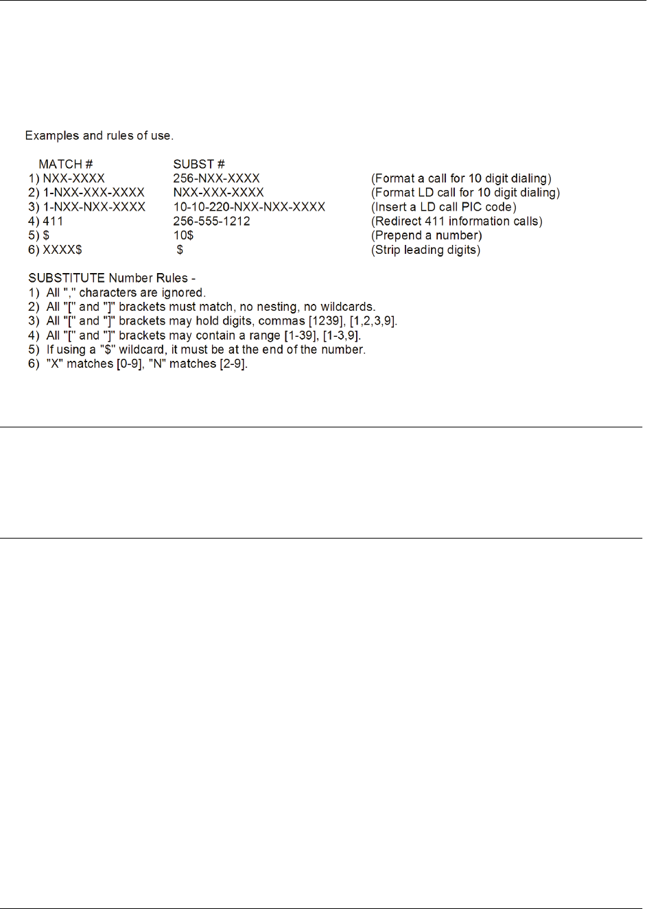
Command Reference Guide Global Configuration Mode Command Set
60000CRG0-35E Copyright © 2012 ADTRAN, Inc. 1419
Additional wildcards ($ and 0 to 9) can also be used. The command line interface (CLI) also contains
helpful information regarding the construction of the template and can be viewed by entering the match ani
command followed by a question mark. For example, entering the command as follows results in the
template input specifications:
(config)#match ani ?
Usage Examples
The following example specifies that the ANI information from numbers 555-8111 to 555-8115 on all
inbound trunks will be substituted by 555-8110:
(config)#voice match ani 555-811[125] substitute 555-8110
Technology Review
The traditional ANI substitution feature operates at a global level on inbound trunks. The feature allows the
substitution of calling party information with information determined by the user. This version of ANI
substitution is applied only to internal caller ID at the inbound trunk, and only affects the number, not the
name, of the calling party.
In this version of ANI substitution, DNIS substitution is also available. DNIS substitution is configured on a
per-trunk basis for outbound trunks. DNIS substitution in this version only affects the number, not the
name, of the called party.

Command Reference Guide Global Configuration Mode Command Set
60000CRG0-35E Copyright © 2012 ADTRAN, Inc. 1420
voice mgcp-endpoint <index>
Use the voice mgcp-endpoint command to create a Media Gateway Control Protocol (MGCP) endpoint,
assign it an index, and enter the endpoint configuration mode. Use the no form of this command to destroy
the specified endpoint.
Syntax Description
<index> Specifies the numerical value of the endpoint as part of the endpoint’s
default naming structure. Range is 1 to 255.
Default Values
By default, no endpoints are configured.
Command History
Release A2 Command was introduced.
Functional Notes
By default, when endpoints are created and given an index number, they are named in the following
format: aaln/x, where x is the index number. For example, an endpoint with an index of 4 will by default
have the name aaln/4. The most common way of defining the index is to use the FXS port number,
because the index is automatically appended to aaln/ for the endpoint name.
Assigning an index is essential for creating an endpoint; however, endpoints can be renamed using the
name endpoint command. Refer to name <text> on page 3239 for more information.
Usage Examples
The following example creates an endpoint with an index of 1, and enters the endpoint’s configuration
mode:
(config)#voice mgcp-endpoint 1
(config-mgcp-1)#

Command Reference Guide Global Configuration Mode Command Set
60000CRG0-35E Copyright © 2012 ADTRAN, Inc. 1421
voice modem-passthrough-mode auto-disable-call-wait
Use the voice modem-passthrough-mode auto-disable-call-wait command to disable call waiting on fax
and modem calls. Use the no form of this command to return to the default setting.
Syntax Description
No subcommands.
Default Values
By default, automatic disabling of call waiting for fax/modem calls is disabled.
Command History
Release A2.04 Command was introduced.
Usage Examples
The following example disables call waiting on a fax call:
(config)#voice modem-passthrough-mode auto-disable-call-wait

Command Reference Guide Global Configuration Mode Command Set
60000CRG0-35E Copyright © 2012 ADTRAN, Inc. 1422
voice num-rings <value>
Use the voice num-rings command to globally specify the number of times a station will ring before
beginning the coverage path that attempts to deliver a call to an available party. This setting can be
overridden on a per-user basis using the num-rings command in the Voice User command set. Refer to
Voice User Account Command Set on page 3697 for more information. Use the no form of this command
to return to the default setting.
Syntax Description
<value> Specifies the number of times a station can ring with no answer. Range is
0 to 9. Setting to 0 allows unlimited rings.
Default Values
The default for this command is 0 (unlimited rings).
Command History
Release 11.1 Command was introduced.
Usage Examples
The following example sets a limit on the number of times a station can ring:
(config)#voice num-rings 8

Command Reference Guide Global Configuration Mode Command Set
60000CRG0-35E Copyright © 2012 ADTRAN, Inc. 1423
voice number-complete disable
Use the voice number-complete disable command to globally disable the default number-complete
options. Use the no form of this command to return to the default setting. Variations of this command
include:
voice number-complete disable pound
voice number-complete disable star
Syntax Description
pound Disables using the pound (#) key to indicate that a number is complete.
star Disables using the star (*) key to indicate that a number is complete.
Default Values
By default, the pound (#) or star (*) key can be pressed to signify that the dialed number is complete.
Command History
Release A5.01 Command was introduced.
Functional Notes
When a user is dialing a phone number, the AOS unit will wait a configured amount of time (specified by
the command voice timeouts on page 1446) after a digit is pressed before attempting to send the dialed
set of digits. If the user does not want to wait for this timeout interval to elapse, the user can, by default,
press either the pound (#) or star (*) key to indicate that the dialed number is complete.
Usage Examples
The following example disables using the pound (#) key to indicate that a number is complete:
(config)#voice num-complete disable pound

Command Reference Guide Global Configuration Mode Command Set
60000CRG0-35E Copyright © 2012 ADTRAN, Inc. 1424
voice operator-group
Use the voice operator-group command to access the Voice Operator Group command mode. Refer to
Voice Operator Ring Group Command Set on page 3384 for more information. Use the no form of this
command to disable the setting.
Syntax Description
No subcommands.
Default Values
No default values are necessary for this command.
Command History
Release 12.1 Command was introduced.
Usage Examples
The following example enters the Operator Group configuration mode:
(config)#voice operator-group
Configuring Operator Group.
(config-operator-group)#

Command Reference Guide Global Configuration Mode Command Set
60000CRG0-35E Copyright © 2012 ADTRAN, Inc. 1425
voice overhead-paging connected-timeout <value>
Use the voice overhead-paging connected-timeout command to specify the timeout interval before an
overhead paging call is terminated. Use the no form of this command to return to the default setting.
Syntax Description
<value> Specifies the timeout value in seconds. Set to 0 to disable the timeout.
Default Values
The default setting is 120 seconds.
Command History
Release A2.04 Command was introduced.
Usage Examples
The following example configures a connected timeout of 30 seconds for overhead paging:
(config)#voice overhead-paging connected-timeout 30
This setting does not affect calls placed into handset paging groups. It only affects calls to
the overhead paging port on the back of the AOS unit.

Command Reference Guide Global Configuration Mode Command Set
60000CRG0-35E Copyright © 2012 ADTRAN, Inc. 1426
voice overhead-paging extension <number>
Use the voice overhead-paging extension command to specify the extension used for overhead paging.
Use the no form of this command to disable the setting.
Syntax Description
<number> Specifies the extension to use for overhead paging.
Default Values
No default values are necessary for this command.
Command History
Release 12.1 Command was introduced.
Usage Examples
The following example configures extension 3000 to be used for overhead paging:
(config)#voice overhead-paging extension 3000

Command Reference Guide Global Configuration Mode Command Set
60000CRG0-35E Copyright © 2012 ADTRAN, Inc. 1427
voice paging-group <extension>
Use the voice paging-group command to create a new handset paging group and enter the paging group’s
configuration. Use the no form of this command to remove the paging group.
Syntax Description
<extension> Specifies the numeric extension for the paging group.
Default Values
By default, no paging groups exist.
Command History
Release A2.04 Command was introduced.
Functional Notes
The voice paging-group command enters the configuration for a handset paging group. For more
information about handset paging, refer to the Handset Paging for the NetVanta 7000 Series quick
configuration guide available online at
https://supportforums.adtran.com
(article number 3102).
For more information about the commands used to configure handset paging, refer to the Voice Paging
Group Command Set on page 3402.
Usage Examples
The following example creates a paging group using extension 8956 and enters the group’s configuration
mode:
(config)#voice paging-group 8956
Configuring new paging group “8956”.
(config-8956)#

Command Reference Guide Global Configuration Mode Command Set
60000CRG0-35E Copyright © 2012 ADTRAN, Inc. 1428
voice park-return <value>
Use the voice park-return command to configure the time until a parked call returns. Use the no form of
this command to return to the default setting.
Syntax Description
<value> Specifies time in seconds until a call returns from park if not retrieved. Valid
range is 15 to 360 seconds.
Default Values
By default, the voice park-return time is set to 60 seconds.
Command History
Release 9.3 Command was introduced.
Usage Examples
The following example sets the time a call returns from park to 30 seconds:
(config)#voice park-return 30

Command Reference Guide Global Configuration Mode Command Set
60000CRG0-35E Copyright © 2012 ADTRAN, Inc. 1429
voice pickup-group <name>
Use the voice pickup-group command to create a new call pickup group and enter the group’s
configuration mode.
Syntax Description
<name> Specifies the name of the call pickup group.
Default Values
By default, no call pickup groups exist.
Command History
Release A4.01 Command was introduced.
Functional Notes
There is a limit of 10 call pickup groups on an AOS unit.
For more information about call pickup group configuration commands, refer to the Voice Call Pickup
Group Command Set on page 3372.
For more information about configuring the call pickup feature, refer to the Configuring the Call Pickup
Feature on AOS Voice Products quick configuration guide available online at
https://supportforums.adtran.com.
Usage Examples
The following example creates the call pickup group Sales and enters the group’s configuration mode:
(config)#voice pickup-group Sales
Configuring New Pickup Group “Sales”
(config-Sales)#

Command Reference Guide Global Configuration Mode Command Set
60000CRG0-35E Copyright © 2012 ADTRAN, Inc. 1430
voice prompt-language <language>
Use the voice prompt-language command to specify the language to use for voice prompts (such as
audios and voicemail menus) on the system. Use the no form of this command to disable the current
language setting.
Syntax Description
<language> Specifies the language to use for voice prompts. The available choices are
Dutch, English, FrenchCanadian, Italian, LatinAmSpanish (Latin
American Spanish), and UKEnglish (United Kingdom English).
Default Values
The default value for this command is English.
Command History
Release 15.1 Command was introduced.
Usage Examples
The following example specifies the voice prompt language as Italian:
(config)#voice prompt-language Italian

Command Reference Guide Global Configuration Mode Command Set
60000CRG0-35E Copyright © 2012 ADTRAN, Inc. 1431
voice ring-group <number>
Use the voice ring-group command to create or modify ring group parameters. These additional
commands are covered in Voice Ring Group Command Set on page 3407. Use the no form of this
command to delete a configured ring group.
Syntax Description
<number> Specifies the ring group's four-digit extension.
Default Values
By default, no ring groups are configured.
Command History
Release 9.3 Command was introduced.
Usage Examples
The following example creates a new ring group with extension 5678:
(config)#voice ring-group 5678
Configuring New Group “5678”.
(config-5678)#

Command Reference Guide Global Configuration Mode Command Set
60000CRG0-35E Copyright © 2012 ADTRAN, Inc. 1432
voice service-mode
Use the voice service-mode command to add a service mode transition. Variations of this command
include:
voice service-mode day <day> <time>
voice service-mode lunch <day> <time>
voice service-mode night <day> <time>
voice service-mode weekend <day> <time>
Syntax Description
day Specifies a transition to day mode.
lunch Specifies a transition to lunch mode.
night Specifies a transition to night mode.
weekend Specifies a transition to weekend mode.
<day> Specifies the day of week the transition occurs.
<time> Specifies the time for transition to occur (24-hour format - hours:minutes
(HH:MM)).
Default Values
By default, the voice service-mode is set to day.
Command History
Release 9.3 Command was introduced.
Usage Examples
The following example sets the voice service mode to day with a transition day of Monday and a transition
time of 8:00 AM:
(config)#voice service-mode day monday 08:00

Command Reference Guide Global Configuration Mode Command Set
60000CRG0-35E Copyright © 2012 ADTRAN, Inc. 1433
voice speed-dial <unique id> <number> <name>
Use the voice speed-dial command to create a list of IDs to be used as shortcuts to contact frequently
called numbers. Use the no form of this command to return to the default setting.
Syntax Description
<unique id> The speed-dial number that will be used to contact the <number> specified.
<number> Phone number associated with the speed-dial entry (digits only).
<name> Description of this speed-dial entry.
Default Values
No default values are necessary for this command.
Command History
Release 11.1 Command was introduced.
Usage Examples
The following example sets a speed-dial number of 8 for extension 9654:
(config)#voice speed-dial 8 9654 3rdFloorLab
Command Reference Guide Global Configuration Mode Command Set
60000CRG0-35E Copyright © 2012 ADTRAN, Inc. 1434
voice spre <pattern id> <pattern>
Use the voice spre command to add a global special prefix (SPRE) complete pattern. This command
allows users to enter a custom SPRE code. Use the no form of this command to delete a configured SPRE
pattern.
Syntax Description
<pattern id> Specifies the SPRE pattern ID. Valid range is 1 to 255.
<pattern> Specifies the SPRE pattern. Refer to Functional Notes below for more
information.
Default Values
No default values are necessary for this command.
Command History
Release 9.3 Command was introduced.
Functional Notes
This command allows users to enter a SPRE code pattern. Patterns begin with * or #. If the pattern is
followed by an &, then the dial plan number-complete templates are used to determine when the unit has
enough digits to dial the number (for example, 67&). However, if a dial plan does not exist for a particular
code that is needed, then a SPRE code may be entered followed by an independent dial plan
number-complete template (for example, *67NXX-XXXX). The available wildcards for this command are:
0-9 = Match exact digit only.
M = Any digit 1 to 8.
X = Any single digit (0 to 9).
N = Any digit 2 to 9.
[123] = Any digit contained in the bracketed list.
The special characters ( ), -, + are always ignored.
Examples: 1) 555-81xx matches 555-8100 to 555-8199.
2) 555-812[012] matches 555-8120 to 555-8122.
3) Nxx-xxxx matches 7 digit local.
4) 1-Nxx-Nxx-xxxx matches long distance calls in North America.
Usage Examples
The following sets the complete pattern for SPRE 1:
(config)#voice spre 1 *67NXX-XXXX
Do not use dashes, commas, spaces, etc., inside the brackets. Commas are implied between
numbers in the brackets.

Command Reference Guide Global Configuration Mode Command Set
60000CRG0-35E Copyright © 2012 ADTRAN, Inc. 1435
voice spre-mode
Use the voice spre-mode command to control whether special prefix (SPRE) codes will be interpreted by
the unit locally or forwarded to the network for interpretation. The override parameter indicates that the
specified SPRE code is to be overridden. Use the no form of this command to return to the default setting.
Variations of this command include:
voice spre-mode local
voice spre-mode network
voice spre-mode override *<nx>
Syntax Description
local Specifies that SPRE codes are interpreted locally by the unit.
network Specifies the forwarding of SPRE codes to the network for handling.
override *<nx> Indicates the configured SPRE processing mode is overridden for the
specified SPRE code. Valid range for n is 2 to 9. Valid range for x is 0 to 9.
Default Values
By default, this command is set to forward SPRE codes to the network and no overrides are configured.
Command History
Release 11.1 Command was introduced.
Release A2.03 Command was expanded to include the override option.
Functional Note
SPRE codes are used to map a sequence of digits to a particular functionality. For example, in a typical
network, *67 is used to block caller ID. When the AOS unit is configured to operate in network mode, the
digits are collected and sent to the network for appropriate handling. Using the override parameter allows
the unit to be configured so that certain SPRE codes are collected locally and the corresponding function is
initiated.
Usage Examples
The following example configures the unit to interpret SPRE codes:
(config)#voice spre-mode local
The following example configures the unit, which is configured to use the network mode, to instead
interpret the SPRE code *67 locally:
(config)#voice spre-mode network
(config)#voice spre-mode override *67

Command Reference Guide Global Configuration Mode Command Set
60000CRG0-35E Copyright © 2012 ADTRAN, Inc. 1436
voice spre-map
Use the voice spre-map command to change the default mapping of special prefix (SPRE) codes on the
AOS voice product. Functions and SPRE codes can be disabled by using the none keyword. Use the no
form of this command to return to the default setting. Variations of this command include:
voice spre-map all none
voice spre-map auto-answer-dnd *<nx>
voice spre-map auto-answer-dnd none
voice spre-map billing-code *<nx>
voice spre-map billing-code none
voice spre-map block-callid-delivery *<nx>
voice spre-map block-callid-delivery none
voice spre-map call-forward-cancel *<nx>
voice spre-map call-forward-cancel none
voice spre-map call-forward-extension *<nx>
voice spre-map call-forward-extension none
voice spre-map call-forward-remote *<nx>
voice spre-map call-forward-remote none
voice spre-map call-park-retrieve *<nx>
voice spre-map call-park-retrieve none
voice spre-map call-park-zone *<nx>
voice spre-map call-park-zone none
voice spre-map call-return *<nx>
voice spre-map call-return none
voice spre-map call-user-speed-dial *<nx>
voice spre-map call-user-speed-dial none
voice spre-map camp-on *<nx>
voice spre-map camp-on none
voice spre-map cancel-camp-on *<nx>
voice spre-map cancel-camp-on none
voice spre-map clear-message-waiting *<nx>
voice spre-map clear-message-waiting none
voice spre-map conference *<nx>
voice spre-map conference none
voice spre-map cos-override *<nx>
voice spre-map cos-override none
voice spre-map disable-call-waiting *<nx>
voice spre-map disable-call-waiting none
voice spre-map dnd-enable-disable *<nx>
voice spre-map dnd-enable-disable none
voice spre-map door-phone *<nx>
voice spre-map door-phone none
voice spre-map door-unlock *<nx>
voice spre-map door-unlock none
voice spre-map fwd-notificatn-cancel *<nx>

Command Reference Guide Global Configuration Mode Command Set
60000CRG0-35E Copyright © 2012 ADTRAN, Inc. 1437
voice spre-map fwd-notificatn-cancel none
voice spre-map group-login *<nx>
voice spre-map group-login none
voice spre-map group-logout *<nx>
voice spre-map group-logout none
voice spre-map hotel-login *<nx>
voice spre-map hotel-login none
voice spre-map hotel-logout *<nx>
voice spre-map hotel-logout none
voice spre-map maca-login *<nx>
voice spre-map maca-login none
voice spre-map maca-logout *<nx>
voice spre-map maca-logout none
voice spre-map page-intercom *<nx>
voice spre-map page-intercom none
voice spre-map page-overhead *<nx>
voice spre-map page-overhead none
voice spre-map permanent-hold *<nx>
voice spre-map permanent-hold none
voice spre-map program-speed-dial *<nx>
voice spre-map program-speed-dial none
voice spre-map redial *<nx>
voice spre-map redial none
voice spre-map remote-call-fwd-cancel *<nx>
voice spre-map remote-call-fwd-cancel none
voice spre-map set-account-password *<nx>
voice spre-map set-account-password none
voice spre-map set-message-waiting *<nx>
voice spre-map set-message-waiting none
voice spre-map system-mode *<nx>
voice spre-map system-mode none
voice spre-map system-speed-dial *<nx>
voice spre-map system-speed-dial none
voice spre-map transfer *<nx>
voice spre-map transfer none
voice spre-map user-station-lock *<nx>
voice spre-map user-station-lock none
voice spre-map user-station-unlock *<nx>
voice spre-map user-station-unlock none
Not all SPRE codes are supported by all AOS products. Type voice spre-map ? to view a
list of supported SPRE codes.

Command Reference Guide Global Configuration Mode Command Set
60000CRG0-35E Copyright © 2012 ADTRAN, Inc. 1438
Syntax Description
all Makes the SPRE code assignment for all functions.
none Removes the SPRE code for the specified function.
*<nx> Specifies the SPRE code to assign to this function.
Valid range for n is 2 to 9. Valid range for x is 0 to 9.
auto-answer-dnd Specifies the automatic answer do-not-disturb (DND) function.
billing-code Specifies the billing code function.
block-callid-delivery Specifies the block caller-ID delivery function.
call-forward-cancel Specifies the call forward cancel function.
call-forward-extension Specifies the call forward + extension function.
call-forward-remote Specifies the call forward remote function.
call-park-retrieve Specifies the call park retrieve function.
call-park-zone Specifies the call park + zone function.
call-return Specifies the call return function.
call-user-speed-dial Specifies the call user speed dial function.
camp-on Specifies the camp-on function.
cancel-camp-on Specifies the cancel camp-on function.
clear-message-waiting Specifies the clear message waiting function.
conference Specifies the 3-way conferencing function.
cos-override Specifies the class of service (CoS) override function.
disable-call-waiting Specifies the disable call waiting on a per-call basis function.
dnd-enable-disable Specifies the DND enable/disable function.
door-phone Specifies the door phone function.
door-unlock Specifies the door unlock function.
fwd-notificatn-cancel Specifies the forward notification cancel function.
group-login Specifies the group login function.
group-logout Specifies the group logout function.
hotel-login Specifies the hotel login function.
hotel-logout Specifies the hotel logout function.
maca-login Specifies the multiple access with collision avoidance (MACA) login
function.
maca-logout Specifies the MACA logout function.
page-intercom Specifies the intercom paging function.
page-overhead Specifies the overhead paging function.
permanent-hold Specifies the permanent hold function.
program-speed-dial Specifies the program user speed dial function.
redial Specifies the call last dialed number function.
remote-call-fwd-cancel Specifies the remote call forward cancel function.
set-account-password Specifies the set account password function.

Command Reference Guide Global Configuration Mode Command Set
60000CRG0-35E Copyright © 2012 ADTRAN, Inc. 1439
set-message-waiting Specifies the set message waiting function.
system-mode Specifies the system mode function.
system-speed-dial Specifies the system speed dial function.
transfer Specifies the transfer function.
user-station-lock Specifies the user station lock function.
user-station-unlock Specifies the user station unlock function.
Default Values
Default mappings between functions and SPRE codes are as indicated in the following table:
Command History
Release A2.03 Command was introduced.
SPRE
Code Function
SPRE
Code Function
*21 Billing Code *32 Forward Notification Cancel
*67 Block Caller-ID Delivery *55 Group Login
*97 Auto-Answer Do-Not-Disturb *56 Group Logout
*35 Call Forward Cancel *46 Hotel Login
*33 Call Forward + Extension *47 Hotel Logout
*34 Call Forward Remote *63 MACA Login
*78 Call Park Retrieve *64 MACA Logout
*77 Call Park + Zone *30 Page Overhead
*69 Call Return *44 Permanent Hold
*62 Call User Speed Dial *61 Program User Speed Dial
*66 Camp-on *72 Redial
*65 Cancel Camp-on *36 Remote Call Forward Cancel
*86 Clear Message Waiting *79 Set Account Password
*22 Conference 3-way *85 Set Message Waiting
*90 Class of Service Override *20 System Mode
*70 Disable Call Waiting Per Call Basis *25 System Speed Dial
*39 Do Not Disturb Enable/Disable *88 Transfer
*37 Door Phone *57 User Station Lock
*38 Door Unlock *58 User Station Unlock

Command Reference Guide Global Configuration Mode Command Set
60000CRG0-35E Copyright © 2012 ADTRAN, Inc. 1440
Release A5.01 Command was expanded to include the page-intercom parameter.
Functional Notes
SPRE codes are used to map a sequence of digits to a particular functionality. For example, in a typical
network, *67 is used to block caller ID. The codes and their functions are listed in the Default Values.
Functions and SPRE codes can be disabled by using the none keyword.
Usage Examples
The following example sets the SPRE code for call return to *79:
(config)#voice spre-map call-return *79

Command Reference Guide Global Configuration Mode Command Set
60000CRG0-35E Copyright © 2012 ADTRAN, Inc. 1441
voice status-group expires
Use the voice status-group expires command to add a status group subscription time for status group
clients. Any subscription time requests that fall between the minimum and maximum values will be
instructed to use the default value instead. Variations of this command include:
voice status-group default-expires <value>
voice status-group max-expires <value>
voice status-group min-expires <value>
Syntax Description
default-expires <value> Specifies a default subscription time. The valid range is 120 to
86400 seconds.
max-expires <value> Specifies a maximum subscription time. The valid range is 120 to
86400 seconds.
min-expires <value> Specifies a minimum subscription time. The valid range is 120 to
86400 seconds.
Default Values
By default, the voice status group default-expires value is set to 120 seconds, max-expires value is set to
3600, and the min-expires is set to 86400.
Command History
Release 14.1 Command was introduced.
Usage Examples
The following example sets the voice status group maximum subscription time to 2 hours:
(config)#voice status-group max-expires 7200

Command Reference Guide Global Configuration Mode Command Set
60000CRG0-35E Copyright © 2012 ADTRAN, Inc. 1442
voice status-group
Use the voice status-group command to create or modify a voice status group and enter the Voice Status
Group Configuration mode. Use the no form of this command to delete a voice status group. Variations of
this command include:
voice status-group <name>
The following additional subcommands are available once you have entered the Voice Status Group
Configuration mode:
park-zone <value>
user <number>
user <number> display-name <name>
user <number> dial-string <string>
user <number> display-name <name> dial-string <string>
use-spre-entities
Syntax Description
<name> Specifies the name of the voice status group to create, modify, or
delete.
park-zone <value> Specifies a new park zone number to add to this voice status
group. The valid range is 0 to 9.
user <number> Specifies the extension of a user to add to this voice status group.
display-name <name> Optional. Specifies an override name to appear as the user’s
name when displayed on the device (BLF). If the name includes
spaces, it must be surrounded by quotation marks as shown in
the Usage Examples.
dial-string <string> Optional. Specifies a specific number to dial. Valid entries can
include a combination of characters * and 0 through 9.
use-spre-entities Specifies that the system use special prefix (SPRE) codes for
extensible markup language (XML) entities in Notify messages
when applicable.
Default Values
By default, there are no voice status groups configured.
Unless the user explicitly enters a display-name or dial-string, these values will default to the user’s
extension number. The dial-string and display-name cannot be added or changed after a user is added
to a status group. The user must first be removed from the status group with the no user <number>
command, then re-added as a member with the appropriate display-name and/or dial-string. Refer to the
Usage Examples section for further details.
Command History
Release 14.1 Command was introduced.

Command Reference Guide Global Configuration Mode Command Set
60000CRG0-35E Copyright © 2012 ADTRAN, Inc. 1443
Release A2 Command was expanded to include the dial string entries.
Release A5.01 Command was expanded to include the use-spre-entities parameter.
Usage Examples
The following example creates a new voice status group with the name Engineering:
(config)#voice status-group Engineering
The following example adds park zone 4 to the Engineering status group directory:
(config)#voice status-group Engineering
(config-status-Engineering)#park-zone 4
The following example adds user 5555 to the Engineering status group directory, displaying the default
name 5555 with the default dial string of 5555:
(config)#voice status-group Engineering
(config-status-Engineering)#user 5555
The following example adds user 5555 to the Engineering status group directory, displaying the name
Test Lab with the default dial string of 5555:
(config)#voice status-group Engineering
(config-status-Engineering)#user 5555 display-name “Test Lab”
The following example adds user 5555 to the Engineering status group directory, displaying the default
name 5555 with a handsfree dial string of **5555:
(config)#voice status-group Engineering
(config-status-Engineering)#user 5555 dial-string **5555
The following example adds user 5555 to the Engineering status group directory, displaying the name
Test Lab with a handsfree dial string of **5555:
(config)#voice status-group Engineering
(config-status-Engineering)#user 5555 display-name “Test Lab” dial-string **5555

Command Reference Guide Global Configuration Mode Command Set
60000CRG0-35E Copyright © 2012 ADTRAN, Inc. 1444
voice system-country <name>
Use the voice system-country command to specify the system country. Use the no form of this command
to return to the default setting.
Syntax Description
<name> Specifies the system country name. The available options are: Australia,
Belgium, Canada, China_Hong_Kong, Denmark, ETSI, Finland,
France, Germany, Ireland, Italy, Luxembourg, Mexico, Netherlands,
Norway, Puerto_Rico, Spain, Sweden, Switzerland,
United_Arab_Emirates, United_Kingdom, and United_States.
Default Values
The default system country code is United_States.
Command History
Release A2.04 Command was introduced.
Release A4.05 Command was modified to accept the country name instead of numbers.
Functional Notes
The system country determines the default parameters for other items, such as Web-based graphical user
interface (GUI) language, voice prompt language (if applicable), plain old telephone service (POTS)
coder-decoder (CODEC) country, subcountry ID, companding, and caller ID type. Values for these
parameters may be viewed using show system on page 763.
Usage Examples
The following example sets the system country to Canada:
(config)#voice system-country Canada

Command Reference Guide Global Configuration Mode Command Set
60000CRG0-35E Copyright © 2012 ADTRAN, Inc. 1445
voice system-mode
Use the voice system-mode command to configure the system mode schedules. When triggered by the
system-clock, AOS units transition into a system mode based on the schedule. Use the no form of this
command to disable the setting. Variations of this command include the following:
voice system-mode custom1 <day> <time>
voice system-mode custom2 <day> <time>
voice system-mode custom3 <day> <time>
voice system-mode default <day> <time>
voice system-mode lunch <day> <time>
voice system-mode night <day> <time>
voice system-mode weekend <day> <time>
Syntax Description
<day> Specifies the day of the week. Choose from Sunday through Saturday.
<time> Specifies the time of the day in a 24-hour format hours:minutes (HH:MM).
custom1 - custom3 Indicates the custom mode (1 through 3) to configure.
default Indicates the default-time system mode to configure.
lunch Indicates the lunch-time system mode to configure.
night Indicates the night-time system mode to configure.
weekend Indicates the weekend system mode to configure.
Default Values
By default, no system mode commands are configured, the unit will operate in the default mode.
Command History
Release A1 Command was introduced.
Usage Examples
The following example configures a typical 5-day business week:
(config)#voice system-mode default Monday 8:00
(config)#voice system-mode night Monday 17:00
(config)#voice system-mode default Tuesday 8:00
(config)#voice system-mode night Tuesday 17:00
(config)#voice system-mode default Wednesday 8:00
(config)#voice system-mode night Wednesday 17:00
(config)#voice system-mode default Thursday 8:00
(config)#voice system-mode night Thursday 17:00
(config)#voice system-mode default Friday 8:00
(config)#voice system-mode weekend Friday 17:00

Command Reference Guide Global Configuration Mode Command Set
60000CRG0-35E Copyright © 2012 ADTRAN, Inc. 1446
voice timeouts
Use the voice timeouts command to configure the time limits for phases. Use the no form of this command
to return to the default setting or remove the named digit timeout (NDT) and its value.
Variations of this command include:
voice timeouts alerting <value>
voice timeouts connected <value>
voice timeouts interdigit <value>
voice timeouts named-digit-timeout <ndt name>
voice timeouts named-digit-timeout <ndt name> <value>
Syntax Description
alerting <value> Specifies the maximum time a call is allowed to remain in the alerting state.
The shorter of this timeout or the configured maximum number of rings will
determine how long a call is allowed to ring. The valid range is 0 (unlimited)
to 60 minutes.
connected <value> Specifies the maximum time a call is allowed to remain in the connected
state. The valid range is 0 (unlimited) to 1000 hours.
interdigit <value> Specifies the maximum time allowed between dialed digits. The valid range
is 1 to 16 seconds.
named-digit-timeout Creates a timeout with a name and a value to associate with a dial plan
template.
<ndt name> Specifies the name of the named-digit-timeout to be created.
<ndt name> <value> Optional. Indicates the timeout value in seconds to allow after the last digit
is dialed before routing the call. The valid range is 1 to 16 seconds.
Default Values
By default, the alerting timeout is 5 minutes, the connected timeout is 12 hours, and the interdigit
timeout is 4 seconds. If no value is indicated for the NDT, 0 seconds is applied.
Command History
Release 14.1 Command was introduced.
Release A2 Command was expanded to include the named-digit-timeouts.
When removing an NDT and its value, if the NDT is assigned to a dial plan entry, then the
deletion is not allowed. The dial plan must be removed first and added back into the system
without the NDT association.

Command Reference Guide Global Configuration Mode Command Set
60000CRG0-35E Copyright © 2012 ADTRAN, Inc. 1447
Functional Notes
The named-digit-timeout feature allows for multiple interdigit timeouts within the system. It provides a
means for associating a specific amount of time to wait after a template match is made before routing a
call. This added functionality allows short numbers and long numbers to coexist in the same system
(i.e., seven- and ten-digit patterns) without specifying additional characters (such as 1 or 9). This
enhancement was added in AOS release A2.
Usage Examples
The following example sets the alerting timeout to 30 seconds:
(config)#voice timeouts alerting 30
The following example creates a named-digit-timeout named short1 and sets the timeout value to
2 seconds:
(config)#voice timeouts named-digit-timeout short1 2

Command Reference Guide Global Configuration Mode Command Set
60000CRG0-35E Copyright © 2012 ADTRAN, Inc. 1448
voice transfer
Use the voice transfer command to set the unattended transfer for the system only. Use the no form of this
command to return to the default setting. Variations of this command include:
voice transfer blind
voice transfer unattended
Syntax Description
blind Converts unattended transfer attempts to RFC 3891-compliant blind
transfers.
unattended Unattended transfer attempts are not modified.
Default Values
The default setting is unattended.
Command History
Release 15.1 Command was introduced.
Usage Examples
The following example configures the voice transfer type to blind:
(config)#voice transfer blind

Command Reference Guide Global Configuration Mode Command Set
60000CRG0-35E Copyright © 2012 ADTRAN, Inc. 1449
voice transfer-mode
Use the voice transfer-mode command to specify whether transferred calls will be controlled by the unit
locally, or if the network will control them. Use the no form of this command to return to the default
setting. Variations of this command include:
voice transfer-mode local
voice transfer-mode network
Syntax Description
local Specifies that call transferring is controlled locally by the unit.
network Specifies that call transferring is controlled by the network.
Default Values
By default, the network controls call transfers.
Command History
Release 11.1 Command was introduced.
Usage Examples
The following example configures the unit to handle call transfers:
(config)#voice transfer-mode local

Command Reference Guide Global Configuration Mode Command Set
60000CRG0-35E Copyright © 2012 ADTRAN, Inc. 1450
voice transfer-on-hangup
Use the voice transfer-on-hangup command to enable this feature. When transferring a call, hanging up
initiates the transfer to the destination party. Use the no form of this command to disable this feature.
Syntax Description
No subcommands.
Default Values
By default, this feature is enabled.
Command History
Release 11.1 Command was introduced.
Usage Examples
The following example enables this feature:
(config)#voice transfer-on-hangup

Command Reference Guide Global Configuration Mode Command Set
60000CRG0-35E Copyright © 2012 ADTRAN, Inc. 1451
voice trunk-list <name>
Use the voice trunk-list command to create a permit/deny trunk list and to enter the trunk list
configuration mode. Use the no form of this command to remove the trunk list.
Additional subcommands are available once you have entered the trunk list configuration mode:
trunk <Txx>
Syntax Description
<name> Specifies the name of the trunk list.
trunk <Txx> Specifies the trunk to add to the trunk list. Trunks are specified by their
2-digit identifier. For example, T01.
Default Values
By default, no trunk lists are configured.
Command History
Release A2 Command was introduced.
Functional Notes
The trunk lists are permit/deny lists that operate in the same manner as automatic number identification
(ANI) lists, and are used to specify trunks that will be permitted or denied access on specified voice trunk
groups.
There is no limit on the number of trunks that can be added to the trunk list, and there is no limit on the
number of trunk lists that can be applied to a voice trunk group. The trunk lists are applied to the trunk
group in the order they are listed.
Usage Examples
The following example creates a trunk list called TEST2 and specifies the trunks to be included in the list:
(config)#voice trunk-list TEST2
(config-trunk-list-TEST2)#trunk T01
(config-trunk-list-TEST2)#trunk T03
Although there is no limit on the number of trunks allowed in a trunk list, or the number of
trunk lists applied to voice trunk groups, it is important to remember that the more lists
that are applied to a trunk group, the more the runtime performance of call routing will be
affected.
Command Reference Guide Global Configuration Mode Command Set
60000CRG0-35E Copyright © 2012 ADTRAN, Inc. 1452
voice trunk <trunk id> type
Use the voice trunk type command to define a new trunk for use with a Session Initiation Protocol (SIP)
or integrated services digital network (ISDN) interface. Executing this command activates the Voice Trunk
Configuration mode for the individual trunk. Refer to Voice ISDN Trunk Command Set on page 3493 for
information on the commands in that mode. Other trunk types are explained in voice trunk <trunk id> type
analog supervision on page 1453. Use the no form of this command to delete a configured voice trunk.
Variations of this command include:
voice trunk <trunk id> type isdn
voice trunk <trunk id> type sip
Syntax Description
<trunk id> Specifies the trunk's two-digit identifier in the format Txx (for example, T12).
isdn Configures the trunk for use with ISDN service.
sip Configures this trunk for use with SIP.
Default Values
No default values are necessary for this command.
Command History
Release 9.3 Command was introduced.
Release 11.1 Command was expanded to include the analog and ISDN support.
Usage Examples
The following example creates the new trunk T12 for use with SIP and enters the Voice Trunk
Configuration mode:
(config)#voice trunk t12 type sip
(config-T12)#
Refer to the SIP Trunk configuration guide and the Total Access 900 Series ISDN PRI
quick configuration guide for more information on voice trunks. These documents are
located on the AOS Documentation CD provided with your unit.

Command Reference Guide Global Configuration Mode Command Set
60000CRG0-35E Copyright © 2012 ADTRAN, Inc. 1453
voice trunk <trunk id> type analog supervision
Use the voice trunk type analog supervision command to define a new trunk for an analog interface.
Executing this command activates the Voice Trunk Analog Configuration mode for the individual trunk.
Use the no form of this command to delete a configured voice trunk. Refer to Voice Analog Trunk
Command Set on page 3443 for information on the commands in that mode. Variations of this command
include the following:
voice trunk <trunk id> type analog supervision dpt
voice trunk <trunk id> type analog supervision ground-start
voice trunk <trunk id> type analog supervision loop-start
Syntax Description
<trunk id> Specifies the trunk’s two-digit identifier in the format Txx (for example, T01).
dpt Specifies dial pulse terminate (DPT) with an assumed user role.
ground-start Specifies ground start (GS) with an assumed user role.
loop-start Specifies loop start (LS) with an assumed user role.
Default Values
No default values are necessary for this command.
Command History
Release 9.1 Command was introduced.
Usage Examples
The following example creates the new trunk T15 for use with an analog interface and enters the Voice
Trunk Analog DPT Configuration mode:
(config)#voice trunk t15 type analog supervision dpt
(config-T15)#

Command Reference Guide Global Configuration Mode Command Set
60000CRG0-35E Copyright © 2012 ADTRAN, Inc. 1454
voice trunk <trunk id> type t1-rbs supervision
Use the voice trunk type t1-rbs supervision command to define a new trunk for a T1 interface. Executing
this command activates the Voice Trunk T1 Configuration mode for the individual trunk. Use the no form
of this command to delete a configured voice trunk. Refer to Voice T1 Trunk Command Set on page 3603
for information on the commands in that mode. Other trunk types are explained in voice trunk <trunk id>
type on page 1452. Variations of this command include the following:
voice trunk <trunk id>
voice trunk <trunk id> type t1-rbs supervision fgd role user
voice trunk <trunk id> type t1-rbs supervision ground-start role user
voice trunk <trunk id> type t1-rbs supervision immediate role network
voice trunk <trunk id> type t1-rbs supervision immediate role user
voice trunk <trunk id> type t1-rbs supervision loop-start role user
voice trunk <trunk id> type t1-rbs supervision tie-fgd
voice trunk <trunk id> type t1-rbs supervision wink role network
voice trunk <trunk id> type t1-rbs supervision wink role user
Syntax Description
<trunk id> Specifies the trunk's two-digit identifier in the format Txx (for example, T01).
fgd Specifies feature group D (FGD) with an assumed user role.
ground-start Specifies ground start (GS) with an assumed user role.
immediate Specifies E&M immediate with an assumed network or user role.
loop-start Specifies loop start (LS) with an assumed user role.
tie-fgd Specifies tie trunk with FGD.
wink Specifies wink with an assumed network or user role.
role network Specifies the network role for this trunk.
role user Specifies the user role for this trunk.
Default Values
No default values are necessary for this command.
Command History
Release 10.1 Command was introduced.
Release 12.1 Command was expanded.
Usage Examples
The following example creates the new trunk T15 for use with a T1 interface and enters the Voice Trunk T1
Wink Configuration mode:
(config)#voice trunk t15 type t1-rbs supervision wink role network
(config-T15)#

Command Reference Guide Global Configuration Mode Command Set
60000CRG0-35E Copyright © 2012 ADTRAN, Inc. 1455
voice user <extension>
Use the voice user command to create a new user extension and to enter the Voice User command set. Use
the no form of this command to delete a configured extension or modify an existing extension’s
parameters. Refer to Voice User Account Command Set on page 3697 for details.
Syntax Description
<extension> Specifies user’s extension.
Default Values
By default, there are no configured voice users.
Command History
Release 9.3 Command was introduced.
Usage Examples
The following example creates a new user with extension 9876:
(config)#voice user 9876
Configuring New User “9876”.
(config-9876)#

Command Reference Guide Global Configuration Mode Command Set
60000CRG0-35E Copyright © 2012 ADTRAN, Inc. 1456
voip name-service host
Use the voip name-service host command to add a host to the Voice over Internet Protocol (VoIP) name
service (VNS) cache table. Using the no form of this command removes the host from the cache.
Variations of this command include:
voip name-service host <hostname> mgcp
voip name-service host <hostname> mgcp tcp
voip name-service host <hostname> mgcp udp
voip name-service host <hostname> sip
voip name-service host <hostname> sip tcp
voip name-service host <hostname> sip udp
Syntax Description
<hostname> Specifies the fully qualified domain name (FQDN) of the added host.
mgcp Specifies that Media Gateway Control Protocol (MGCP) is the service type
for the VNS service request.
sip Specifies that Session Initiation Protocol (SIP) is the service type for the
VNS service request.
tcp Optional. Specifies that Transmission Control Protocol (TCP) is the protocol
used for the service request.
udp Optional. Specifies that User Datagram Protocol (UDP) is the protocol used
for the service request.
Default Values
By default, both MGCP and SIP VNS requests use UDP.
Functional Notes
Voice and media signaling protocols (such as SIP) often rely on domain naming system (DNS) in order to
ease configuration and administration of endpoints and also to implement redundancy mechanisms
provided by DNS service records. Because voice and media signaling protocols are often directly coupled
to a user experience, applications are often very sensitive to latency introduced by the DNS mechanism.
AOS voice products rely on the ability to resolve names to one or more service or address records quickly
in order to place a call or register to an external voice server. The DNS server is often not local to the AOS
unit, and it is not guaranteed to be accessible, even when other mechanisms necessary for successful call
completion may be available. A DNS request for a particular host name results in local caching by the AOS
unit, after which the DNS information is quickly available without requiring additional requests. The cache
remains populated until the cached record expires.

Command Reference Guide Global Configuration Mode Command Set
60000CRG0-35E Copyright © 2012 ADTRAN, Inc. 1457
The VNS system in the AOS product implements preemptive and persistent caching of DNS records for
voice signaling protocols. The VNS system maintains a table of DNS records in a cache for voice signaling
protocols like SIP and MGCP. For example, if a request is generated from a SIP client (such as a SIP trunk
or SIP proxy), for which there is a configured SIP server entity (such as a proxy address or SIP server
address), the request is always serviced from the local DNS cache (rather than from an external DNS
server). This ensures that SIP access to DNS is always available immediately, even during transient DNS
outages.
The VNS system in AOS can be configured manually by adding a host to the cache (using the command
voip name-service host on page 1456) and by specifying the number of attempts used by VNS to verify the
DNS cache changes (using the command voip name-service verification attempts <number> interval
<seconds> on page 1458). You can view the VNS cache by using the commands show voip name-service
cache on page 825 and show voip name-service name-table on page 826.
Configuring an FQDN using the voip name-service host command forces the FQDN resolution (using
DNS) to never timeout from the DNS name table. Each DNS record has a time to live (TTL) value that
specifies the amount of time to cache the record. After this time, the DNS table (by default) removes the
record from the cache. VNS issues DNS queries in an attempt to keep voice-related records cached in the
DNS name table, but if the DNS name servers are not available, the records can expire from the DNS
name table. The records associated with configured VNS host FQDNs are not flushed from the cache
regardless of the TTL or age of the record, but rather are permanently cached dynamic resolutions.
Command History
Release A4.03 Command was introduced.
Usage Examples
The following example adds the SIP host example.user.net to the VNS/DNS cache, using TCP requests:
(config)#voip name-service host example.user.net sip tcp

Command Reference Guide Global Configuration Mode Command Set
60000CRG0-35E Copyright © 2012 ADTRAN, Inc. 1458
voip name-service verification attempts <number> interval <seconds>
Use the voip name-service verification attempts interval command to configure the Voice over Internet
Protocol (VoIP) name service (VNS) to verify any domain naming system (DNS) changes to the VNS
table. Using the no form of this command disables verification.
Syntax Description
attempts <number> Specifies the number of consecutive DNS answers that validate a change to
the VNS table. Valid range is 1 to 10.
interval <seconds> Specifies the time interval (in seconds) to wait between verification
attempts. Valid range is 1 to 600 seconds.
Default Values
By default, the VNS system does not verify DNS changes.
Functional Notes
Voice and media signaling protocols (such as SIP) often rely on DNS in order to ease configuration and
administration of endpoints and also to implement redundancy mechanisms provided by DNS service
records. Because voice and media signaling protocols are often directly coupled to a user experience,
applications are often very sensitive to latency introduced by the DNS mechanism.
AOS voice products rely on the ability to resolve names to one or more service or address records quickly
in order to place a call or register to an external voice server. The DNS server is often not local to the AOS
unit, and it is not guaranteed to be accessible, even when other mechanisms necessary for successful call
completion may be available. A DNS request for a particular host name results in local caching by the AOS
unit, after which the DNS information is quickly available without requiring additional requests. The cache
remains populated until the cached record expires.
The VNS system in the AOS product implements preemptive and persistent caching of DNS records for
voice signaling protocols. The VNS system maintains a table of DNS records in a cache for voice signaling
protocols like Session Initiation Protocol (SIP) and Media Gateway Control Protocol (MGCP). For example,
if a request is generated from a SIP client (such as a SIP trunk or SIP proxy), for which there is a
configured SIP server entity (such as a proxy address or SIP server address), the request is always
serviced from the local DNS cache (rather than from an external DNS server). This ensures that SIP
access to DNS is always available immediately, even during transient DNS outages.
The VNS system in AOS can be configured manually by adding a host to the cache (using the command
voip name-service host on page 1456) and by specifying the number of attempts used by VNS to verify the
DNS cache changes (using the command voip name-service verification attempts <number> interval
<seconds> on page 1458). You can view the VNS cache by using the commands show voip name-service
cache on page 825 and show voip name-service name-table on page 826.
Command History
Release A4.03 Command was introduced.

Command Reference Guide Global Configuration Mode Command Set
60000CRG0-35E Copyright © 2012 ADTRAN, Inc. 1459
Usage Examples
In the following example, the VNS system is configured to use 3 attempts to validate a DNS change, with
30 seconds between each attempt:
(config)#voip name-service verification attempts 3 interval 30

Command Reference Guide Global Configuration Mode Command Set
60000CRG0-35E Copyright © 2012 ADTRAN, Inc. 1460
vrf <name> route-distinguisher
Use the vrf route-distinguisher command to create a nondefault VPN routing and forwarding (VRF)
instance and assign it a route distinguisher. Use the no vrf command to remove all VRF instances
configured on the system. Use the no vrf route-distinguisher command to destroy the VRF instance and
any commands configured on the VRF. Variations of this command include:
vrf <name> route-distinguisher as-2byte <ASN:nn>
vrf <name> route-distinguisher as-4byte <ASN:nn>
vrf <name> route-distinguisher ip <ipv4 address:nn>
Syntax Description
<name> Specifies the name of the VRF instance. Valid range is up to 79
alphanumeric characters.
as-2byte <ASN:nn> Specifies the autonomous system number (ASN)-relative route
distinguisher as a 16-bit AS number (ASN) and a 32-bit arbitrary number
(nn).
as-4byte <ASN:nn> Specifies the ASN-relative route distinguisher as a 32-bit AS number (ASN)
and a 16-bit arbitrary number (nn).
ip <ipv4 address:nn> Specifies an IPv4 address-relative route distinguisher, which consists of an
IPv4 address and a 16-bit arbitrary number (nn). IPv4 addresses should be
expressed in decimal dotted notation (for example, 10.10.10.1).
Default Values
No default values are necessary for this command.
Command History
Release 16.1 Command was introduced.
Release 18.3 Command syntax was changed to remove the ip keyword for IPv6 support
in ADTRAN internetworking products. In addition, the as-2byte, as-4byte,
and ip <ipv4 address:nn> parameters were added.
Release R10.1.0 Command syntax was changed to remove the ip keyword for IPv6 support
in ADTRAN voice products. In addition, the as-2byte, as-4byte, and ip
<ipv4 address:nn> parameters were added.
Functional Notes
The route distinguisher 0:0 or 0.0.0.0:0 is reserved for the default (unnamed) VRF instance and cannot be
reassigned.
VRF on AOS products allows a single physical router to be partitioned into multiple virtual routers. Each
router instance has its own route table and interface assignments. Beginning with Release 16.1, all AOS
routers supporting multiple VRF instances (multi-VRF) have an unnamed default VRF instance regardless
of whether multi-VRF is configured.

Command Reference Guide Global Configuration Mode Command Set
60000CRG0-35E Copyright © 2012 ADTRAN, Inc. 1461
Once a nondefault VRF is created, it must be assigned to the appropriate interfaces. Use the voip
name-service host on page 1456 to assign interfaces to the VRF. By default, interfaces are assigned to the
default VRF. An interface can only be assigned to one VRF, but multiple interfaces can be assigned to the
same VRF.
Usage Examples
The following example creates the VRF Red and assigns the 2-byte route distinguisher 2:2:
(config)#vrf RED route-distinguisher as-2byte 2:2

Command Reference Guide Global Configuration Mode Command Set
60000CRG0-35E Copyright © 2012 ADTRAN, Inc. 1462
vrf forwarding <name>
Use the vrf forwarding command to assign an interface to a specific VPN routing and forwarding (VRF)
instance. Use the no form of this command to remove the interface from the named VRF instance and
assign it to the unnamed default VRF.
Syntax Description
<name> Specifies the name of the VRF to which to assign the interface.
Default Values
By default, interfaces are associated with the default VRF that is unnumbered.
Command History
Release 16.1 Command was introduced.
Release 17.8 The keyword ip was removed from this command.
Functional Notes
VRF instances must be created first before an interface can be assigned. An interface can only be
assigned to one VRF, but multiple interfaces can be assigned to the same VRF.
An interface will only forward IP traffic that matches its associated VRF.
VRF on AOS products allows a single physical router to be partitioned into multiple virtual routers. Each
router instance has its own route table and interface assignments. Beginning with Release 16.1, all AOS
routers supporting multiple VRF instances (multi-VRF) have an unnamed default VRF instance regardless
of whether multi-VRF is configured.
Usage Examples
The following example assigns the frame-relay 1.16 interface to the VRF instance named RED:
(config)#interface frame-relay 1.16
(config-fr 1.16)#vrf forwarding RED
Keep in mind that changing an interface’s VRF association will clear all IP-related
settings on that interface.


Command Reference Guide Line (Console) Interface Command Set
60000CRG0-35E Copyright © 2012 ADTRAN, Inc. 1464
LINE (CONSOLE) INTERFACE COMMAND SET
To activate the Line (Console) Interface Configuration mode, enter the line console 0 command at the
Global Configuration mode prompt. For example:
>enable
#configure terminal
(config)#line console 0
(config-con 0)#
The following commands are common to multiple command sets and are covered in a centralized section
of this guide. For more information, refer to the sections listed below:
cross-connect on page 67
do on page 71
end on page 72
exit on page 73
interface on page 74
All other commands for this command set are described in this section in alphabetical order.
accounting commands begin on page 1465
authorization commands begin on page 1468
databits <value> on page 1470
flowcontrol on page 1471
ipv6 policy-class <ipv6 acp name> max-sessions <number> on page 1472
line-timeout <value> on page 1473
login on page 1474
login authentication <listname> on page 1475
login local-userlist on page 1476
parity on page 1477
password <password> on page 1478
speed <rate> on page 1479
stopbits <value> on page 1480

Command Reference Guide Line (Console) Interface Command Set
60000CRG0-35E Copyright © 2012 ADTRAN, Inc. 1465
accounting commands <level> <listname>
Use the accounting commands command to assign authentication, authorization, and accounting (AAA)
command accounting method lists to line interfaces. You must first turn AAA on for this command to
become available (using the command aaa on on page 889). Use the no form of this command to remove
the AAA command accounting method list from the interface. Variations of this command include:
accounting commands <level> default
accounting commands <level> <listname>
Syntax Description
<level> Specifies whether the list applies to Level 1 (unprivileged) or Level 15
(privileged) commands.
default Applies the default AAA command accounting method list to the interface.
<listname> Applies the specified AAA command accounting method list to the interface.
Default Values
By default, no AAA command accounting method list is applied to the line interface.
Command History
Release 11.1 Command was introduced.
Functional Notes
AAA command accounting method lists are used to specify the types of information recorded when users
access specified command levels. For more information about configuring command accounting lists, refer
to the command aaa accounting connection on page 858.
For more information about configuring AAA on your network, refer to the configuration guide Configuring
AAA in AOS available online at https://supportforums.adtran.com.
Usage Examples
The following example specifies that AAA command accounting list Accounting1 is applied to all Level 15
commands on all console lines:
(config)#line console 0
(config-con 0)#accounting commands 15 Accounting1

Command Reference Guide Line (Console) Interface Command Set
60000CRG0-35E Copyright © 2012 ADTRAN, Inc. 1466
accounting connection <listname>
Use the accounting connection command to assign authentication, authorization, and accounting (AAA)
connection accounting method lists to line interfaces. You must first turn AAA on for this command to
become available (using the command aaa on on page 889). Use the no form of this command to remove
the AAA connection accounting method list from the interface. Variations of this command include:
accounting connection default
accounting connection <listname>
Syntax Description
default Applies the default AAA connection accounting method list to the interface.
<listname> Applies the specified AAA connection accounting method list to the
interface.
Default Values
By default, no AAA command accounting method list is applied to the line interface.
Command History
Release 13.1 Command was introduced.
Functional Notes
AAA connection accounting method lists are used to specify the types of information recorded about
outbound connections made from the AOS unit. For more information about configuring connection
accounting lists, refer to the command aaa accounting connection on page 858.
For more information about configuring AAA on your network, refer to the configuration guide Configuring
AAA in AOS available online at https://supportforums.adtran.com.
Usage Examples
The following example specifies that AAA connection accounting list AcctConn1 is applied to all console
lines:
(config)#line console 0
(config-con 0)#accounting connection AcctConn1

Command Reference Guide Line (Console) Interface Command Set
60000CRG0-35E Copyright © 2012 ADTRAN, Inc. 1467
accounting exec <listname>
Use the accounting exec command to assign authentication, authorization, and accounting (AAA)
executive accounting method lists to line interfaces. You must first turn AAA on for this command to
become available (using the command aaa on on page 889). Use the no form of this command to remove
the AAA executive accounting method list from the interface. Variations of this command include:
accounting exec default
accounting exec <listname>
Syntax Description
default Applies the default AAA connection accounting method list to the interface.
<listname> Applies the specified AAA connection accounting method list to the
interface.
Default Values
By default, no AAA command accounting method list is applied to the line interface.
Command History
Release 13.1 Command was introduced.
Functional Notes
AAA executive accounting method lists are used to specify the types of information recorded about
inbound connections made by connecting to the line interfaces and creating a terminal session. For more
information about configuring executive accounting lists, refer to the command aaa accounting exec on
page 861.
For more information about configuring AAA on your network, refer to the configuration guide Configuring
AAA in AOS available online at https://supportforums.adtran.com.
Usage Examples
The following example specifies that AAA executive accounting list Inboundacct1 is applied to the
console line:
(config)#line console 0
(config-con 0)#accounting exec Inboundacct1

Command Reference Guide Line (Console) Interface Command Set
60000CRG0-35E Copyright © 2012 ADTRAN, Inc. 1468
authorization commands <level> <listname>
Use the authorization commands command to assign authentication, authorization, and accounting
(AAA) command authorization method lists to line interfaces. You must first turn AAA on for this
command to become available (using the command aaa on on page 889). Use the no form of this
command to remove the AAA command authorization method list from the interface. Variations of this
command include:
authorization commands <level> default
authorization commands <level> <listname>
Syntax Description
<level> Specifies whether the list applies to Level 1 (unprivileged) or Level 15
(privileged) commands.
default Applies the default AAA command authorization method list to the interface.
<listname> Applies the specified AAA command authorization method list to the
interface.
Default Values
By default, no AAA command authorization method list is applied to the line interface.
Command History
Release 11.1 Command was introduced.
Functional Notes
AAA command authorization method lists are used to allow or restrict the use of certain commands on a
per-user basis. For more information about configuring command authorization lists, refer to the command
aaa authorization commands <level> on page 878.
For more information about configuring AAA on your network, refer to the configuration guide Configuring
AAA in AOS available online at https://supportforums.adtran.com.
Usage Examples
The following example specifies that AAA command authorization list Authorization1 is applied to the
Level 15 commands on all console line:
(config)#line console 0
(config-con 0)#authorization commands 15 Authorization1

Command Reference Guide Line (Console) Interface Command Set
60000CRG0-35E Copyright © 2012 ADTRAN, Inc. 1469
authorization exec <listname>
Use the authorization exec command to assign authentication, authorization, and accounting (AAA)
Enable mode authorization method lists to line interfaces. You must first turn AAA on for this command to
become available (using the command aaa on on page 889). Use the no form of this command to remove
the AAA Enable mode authorization method list from the interface. Variations of this command include:
authorization exec default
authorization exec <listname>
Syntax Description
default Applies the default AAA Enable mode authorization method list to the
interface.
<listname> Applies the specified AAA Enable mode authorization method list to the
interface.
Default Values
By default, no AAA Enable mode authorization method list is applied to the line interface.
Command History
Release 13.1 Command was introduced.
Functional Notes
AAA Enable mode authorization method lists are used to allow or restrict user access to the privileged
command line interface (CLI) mode (Enable mode). For more information about configuring Enable mode
authorization lists, refer to the command aaa authorization exec on page 883.
For more information about configuring AAA on your network, refer to the configuration guide Configuring
AAA in AOS available online at https://supportforums.adtran.com.
Usage Examples
The following example specifies that AAA Enable mode authorization list ExecList1 is applied to the
console line:
(config)#line console 0
(config-con 0)#authorization exec ExecList1

Command Reference Guide Line (Console) Interface Command Set
60000CRG0-35E Copyright © 2012 ADTRAN, Inc. 1470
databits <value>
Use the databits command to set the number of databits per character for a terminal session. This value
must match the configuration of your VT100 terminal or terminal emulator software. Use the no form of
this command to return to the default value.
Syntax Description
<value> Specifies the data bits per character. Select from 7 or 8 databits per
character.
Default Values
By default, the databits are set to 8.
Command History
Release 1.1 Command was introduced.
Usage Examples
The following example configures 7 databits per character for the console terminal session:
(config)#line console 0
(config-con 0)#databits 7

Command Reference Guide Line (Console) Interface Command Set
60000CRG0-35E Copyright © 2012 ADTRAN, Inc. 1471
flowcontrol
Use the flowcontrol command to set flow control for the line console. Use the no form of this command to
return to the default setting. Variations of this command include:
flowcontrol none
flowcontrol software in
Syntax Description
none Specifies no flow control.
software in Configures AOS to derive flow control from the attached device.
Default Values
By default, flow control is set to none.
Command History
Release 3.1 Command was introduced.
Usage Examples
The following example configures no flow control for the line console:
(config)#line console 0
(config-con 0)#flowcontrol none

Command Reference Guide Line (Console) Interface Command Set
60000CRG0-35E Copyright © 2012 ADTRAN, Inc. 1472
ipv6 policy-class <ipv6 acp name> max-sessions <number>
Use the ipv6 policy-class max-sessions command to specify the maximum number of allowed Internet
Protocol version 6 (IPv6) policy sessions on a specific IPv6 access control policy (ACP). For more details
on IPv6 ACP functionality in AOS, refer to the IPv6 Access Control Policy Command Set on page 3192.
Use the no form of this command to return to the default value.
Syntax Description
<ipv6 acp name> Identifies the configured IPv6 ACP to which the max-session limit is applied.
Use an alphanumeric descriptor (maximum of 50 characters). All ACP
descriptors are case sensitive.
<number> Specifies the maximum number of allowed IPv6 policy sessions. Valid range
is 1 up to a value based on the amount of RAM in the AOS unit (refer to
Default Values below).
Default Values
By default, the maximum IPv6 ACP sessions allowed are based on the amount of RAM in the AOS unit.
The following table outlines the default values based on RAM:
Command History
Release 18.1 Command was introduced.
Functional Notes
To set the system-wide maximum limit for ACP sessions (both IPv4 and IPv6), use the command
policy-class max-sessions <number> on page 1282.
Usage Examples
The following example allows no more than 100 policy sessions on the IPv6 ACP named PRIVATEv6:
(config)#line console 0
(config-con 0)#ipv6 policy-class PRIVATEv6 max-sessions 100
RAM Amount Default Max Sessions
64 MB 10000
128 MB 30000
256 MB 80000
512 MB 200000
768 MB 300000
1 GB 450000

Command Reference Guide Line (Console) Interface Command Set
60000CRG0-35E Copyright © 2012 ADTRAN, Inc. 1473
line-timeout <value>
Use the line-timeout command to specify the number of minutes a line session may remain inactive before
AOS terminates the session. Use the no form of this command to return to the default value.
Syntax Description
<value> Specifies the number of minutes a line session may remain inactive before
AOS terminates the session. Range is 0 to 35791 minutes.
Entering a line-timeout value of 0 disables the feature.
Default Values
By default, the line-timeout is set to 15 minutes (Console and Telnet).
Command History
Release 1.1 Command was introduced.
Usage Examples
The following example specifies a timeout of 2 minutes:
(config)#line console 0
(config-con 0)#line-timeout 2

Command Reference Guide Line (Console) Interface Command Set
60000CRG0-35E Copyright © 2012 ADTRAN, Inc. 1474
login
Use the login command to enable security login on the line session. Additionally, it is necessary to
configure the password using the command password <password> on page 1478. Use the no form of this
command to disable the login feature.
Syntax Description
No subcommands.
Default Values
By default, secure login is disabled.
Command History
Release 1.1 Command was introduced.
Usage Examples
The following example enables the security login feature and specifies a password (mypassword) on the
available console session:
(config)#line console 0
(config-console 0)#login
(config-con 0)#password mypassword

Command Reference Guide Line (Console) Interface Command Set
60000CRG0-35E Copyright © 2012 ADTRAN, Inc. 1475
login authentication <listname>
Use the login authentication command to apply the named authentication, authorization, and accounting
(AAA) login method list to the line interface for authenticating users connecting to the interface. Use the
no form of this command to remove the authentication method list from the interface.
Syntax Description
<listname> Specifies the AAA login authentication method list to use for authentication.
Default Values
By default, no AAA login authentication method list is specified. If AAA is enabled (using the command aaa
on on page 889), but no login authentication method list is specified, the default login authentication
method list is used. If the default list is used, but the default list has not been configured, console interfaces
will automatically grant access (to prevent a lockout situation).
Command History
Release 5.1 Command was introduced.
Functional Notes
AAA login authentication method lists are used to verify user logins on the line interface. For more
information about configuring login authentication method lists, refer to the command aaa authentication
login on page 871.
For more information about configuring AAA on your network, refer to the configuration guide Configuring
AAA in AOS available online at https://supportforums.adtran.com.
Usage Examples
The following example specifies that the AAA login authentication method list AuthList1 is applied to the
console line:
(config)#line console 0
(config-con 0)#login authentication AuthList1

Command Reference Guide Line (Console) Interface Command Set
60000CRG0-35E Copyright © 2012 ADTRAN, Inc. 1476
login local-userlist
Use the login local-userlist command to enable security login for the terminal session. It is required to
configure user names and passwords using the username/password command from the Global
Configuration mode (refer to username <username> password <password> on page 1373). Use the no
form of this command to disable the login local-userlist feature.
Syntax Description
No subcommands.
Default Values
By default, there is no login password set to access the unit.
Command History
Release 1.1 Command was introduced.
Usage Examples
The following example displays creating a local userlist and enabling the security login feature on the
CONSOLE port:
(config)#username my_user password my_password
(config)#line console 0
(config-con 0)#login local-userlist
When connecting to the unit, the following prompts are displayed:
User Access Login
Username: ADTRAN
Password:
Router#
All user properties assigned using the username/password command are valid when using
the login local-userlist command.

Command Reference Guide Line (Console) Interface Command Set
60000CRG0-35E Copyright © 2012 ADTRAN, Inc. 1477
parity
Use the parity command to specify the type of parity used as error correction. This value must match the
configuration of your VT100 terminal or terminal emulator software. Use the no form of this command to
return to the default value. Variations of this command include:
parity even
parity mark
parity none
parity odd
parity space
Syntax Description
even Sets the parity bit to 0 if the number of 1 bits in the data sequence is odd, or
set to 1 if the number of 1 bits is even.
mark Always sets the parity bit to 1.
none No parity bit used.
odd Sets the parity bit to 1 if the number of 1 bits in the data sequence is even,
or set to 1 if the number is odd.
space Always sets the parity bit to 0.
Default Values
By default, the parity option is set to none.
Command History
Release 1.1 Command was introduced.
Functional Notes
Parity is the process used to detect whether characters have been altered during the data transmission
process. Parity bits are appended to data frames to ensure that parity (whether it be odd or even) is
maintained.
Usage Examples
The following example specifies mark parity for the console terminal session:
(config)#line console 0
(config-con 0)#parity mark

Command Reference Guide Line (Console) Interface Command Set
60000CRG0-35E Copyright © 2012 ADTRAN, Inc. 1478
password <password>
Use the password command to configure the password (with optional encryption) required on the line
session when security login is enabled (using the command login on page 1474). Use the no form of this
command to remove a configured password. Variations of this command include:
password <password>
password md5 <password>
Syntax Description
<password> Specifies the password for the line session using an alphanumeric
character string (up to 16 characters).
md5 Specifies message digest 5 (MD5) as the encryption protocol to use when
displaying the enable password during show commands. If the MD5
keyword is not used, encryption is not used when displaying the enable
password during show commands.
Default Values
By default, there is no login password set for access to the unit.
Command History
Release 1.1 Command was introduced.
Release 6.1 Encryption was added.
Usage Examples
The following example enables the security login feature and specifies a password on the CONSOLE port:
(config)#line console 0
(config-con 0)#login
(config-con 0)#password mypassword
To provide extra security, AOS can encrypt the enable password when displaying the current configuration.
For example, the following is a show configuration printout (password portion) with an unencrypted
enable password (ADTRAN):
!
enable password ADTRAN
!
Alternately, the following is a show configuration printout (password portion) with an enable password of
ADTRAN using md5 encryption:
!
enable password md5 encrypted 5aa5fbae7d01a90e79fb57705ce74676
!

Command Reference Guide Line (Console) Interface Command Set
60000CRG0-35E Copyright © 2012 ADTRAN, Inc. 1479
speed <rate>
Use the speed command to specify the data rate for the CONSOLE port. This setting must match your
VT100 terminal emulator or emulator software. Use the no form of this command to restore the default
value.
Syntax Description
<rate> Specifies rate of data transfer on the interface (2400; 4800; 9600; 19200;
38400; 57600; or 115200 bps).
Default Values
By default, the speed is set to 9600 bps.
Command History
Release 1.1 Command was introduced.
Usage Examples
The following example configures the CONSOLE port for 19200 bps:
(config)#line console 0
(config-con 0)#speed 19200

Command Reference Guide Line (Console) Interface Command Set
60000CRG0-35E Copyright © 2012 ADTRAN, Inc. 1480
stopbits <value>
Use the stopbits command to set the number of stopbits per character for a terminal session. This value
must match the configuration of your VT100 terminal or terminal emulator software. The default is
1 stopbit per character. Use the no form of this command to return to the default value.
Syntax Description
<value> Specifies the stopbits per character. Select from 1 or 2 stopbits per
character.
Default Values
By default, the stopbits are set to 1.
Command History
Release 1.1 Command was introduced.
Usage Examples
The following example configures 2 stopbits per character for the console terminal session:
(config)#line console 0
(config-con 0)#stopbits 2

Command Reference Guide Line (SSH) Interface Command Set
60000CRG0-35E Copyright © 2012 ADTRAN, Inc. 1481
LINE (SSH) INTERFACE COMMAND SET
To activate the Line Secure Shell (SSH) Interface Configuration mode, enter the line ssh command
specifying a SSH session(s) at the Global Configuration mode prompt. For example:
>enable
#configure terminal
(config)#line ssh 0 4
(config-ssh0-4)#
You can select a single line by entering the line ssh command followed by the line number (0-4). For
example:
>enable
#configure terminal
(config)#line ssh 2
(config-ssh2)#
The following commands are common to multiple command sets and are covered in a centralized section
of this guide. For more information, refer to the sections listed below:
cross-connect on page 67
do on page 71
end on page 72
exit on page 73
interface on page 74
shutdown on page 82
All other commands for this command set are described in this section in alphabetical order.
accounting commands begin on page 1482
authorization commands begin on page 1485
ip access-class <ipv4 acl name> in on page 1487
ip access-policy <ipv4 acp name> on page 1489
ipv6 access-class <ipv6 acl name> in on page 1491
ipv6 policy-class <ipv6 acp name> max-sessions <number> on page 1493
line-timeout <value> on page 1494
login on page 1495
login authentication <listname> on page 1496
login local-userlist on page 1497

Command Reference Guide Line (SSH) Interface Command Set
60000CRG0-35E Copyright © 2012 ADTRAN, Inc. 1482
accounting commands <level> <listname>
Use the accounting commands command to assign authentication, authorization, and accounting (AAA)
command accounting method lists to line interfaces. You must first turn AAA on for this command to
become available (using the command aaa on on page 889). Use the no form of this command to remove
the AAA command accounting method list from the interface. Variations of this command include:
accounting commands <level> default
accounting commands <level> <listname>
Syntax Description
<level> Specifies whether the list applies to Level 1 (unprivileged) or Level 15
(privileged) commands.
default Applies the default AAA command accounting method list to the interface.
<listname> Applies the specified AAA command accounting method list to the interface.
Default Values
By default, no AAA command accounting method list is applied to the line interface.
Command History
Release 11.1 Command was introduced.
Functional Notes
AAA command accounting method lists are used to specify the types of information recorded when users
access specified command levels. For more information about configuring command accounting lists, refer
to the command aaa accounting connection on page 858.
For more information about configuring AAA on your network, refer to the configuration guide Configuring
AAA in AOS available online at https://supportforums.adtran.com.
Usage Examples
The following example specifies that AAA command accounting list Accounting1 is applied to all Level 15
commands on all secure shell (SSH) lines:
(config)#line ssh 0 4
(config-ssh0-4)#accounting commands 15 Accounting1

Command Reference Guide Line (SSH) Interface Command Set
60000CRG0-35E Copyright © 2012 ADTRAN, Inc. 1483
accounting connection <listname>
Use the accounting connection command to assign authentication, authorization, and accounting (AAA)
connection accounting method lists to line interfaces. You must first turn AAA on for this command to
become available (using the command aaa on on page 889). Use the no form of this command to remove
the AAA connection accounting method list from the interface. Variations of this command include:
accounting connection default
accounting connection <listname>
Syntax Description
default Applies the default AAA connection accounting method list to the interface.
<listname> Applies the specified AAA connection accounting method list to the
interface.
Default Values
By default, no AAA command accounting method list is applied to the line interface.
Command History
Release 13.1 Command was introduced.
Functional Notes
AAA connection accounting method lists are used to specify the types of information recorded about
outbound connections made from the AOS unit. For more information about configuring connection
accounting lists, refer to the command aaa accounting connection on page 858.
For more information about configuring AAA on your network, refer to the configuration guide Configuring
AAA in AOS available online at https://supportforums.adtran.com.
Usage Examples
The following example specifies that AAA connection accounting list AcctConn1 is applied to all secure
shell (SSH) lines:
(config)#line ssh 0 4
(config-ssh0-4)#accounting connection AcctConn1

Command Reference Guide Line (SSH) Interface Command Set
60000CRG0-35E Copyright © 2012 ADTRAN, Inc. 1484
accounting exec <listname>
Use the accounting exec command to assign authentication, authorization, and accounting (AAA)
executive accounting method lists to line interfaces. You must first turn AAA on for this command to
become available (using the command aaa on on page 889). Use the no form of this command to remove
the AAA executive accounting method list from the interface. Variations of this command include:
accounting exec default
accounting exec <listname>
Syntax Description
default Applies the default AAA connection accounting method list to the interface.
<listname> Applies the specified AAA connection accounting method list to the
interface.
Default Values
By default, no AAA command accounting method list is applied to the line interface.
Command History
Release 13.1 Command was introduced.
Functional Notes
AAA executive accounting method lists are used to specify the types of information recorded about
inbound connections made by connecting to the line interfaces and creating a terminal session. For more
information about configuring executive accounting lists, refer to the command aaa accounting exec on
page 861.
For more information about configuring AAA on your network, refer to the configuration guide Configuring
AAA in AOS available online at https://supportforums.adtran.com.
Usage Examples
The following example specifies that AAA executive accounting list Inboundacct1 is applied to all secure
shell (SSH) lines:
(config)#line ssh 0 4
(config-ssh0-4)#accounting exec Inboundacct1

Command Reference Guide Line (SSH) Interface Command Set
60000CRG0-35E Copyright © 2012 ADTRAN, Inc. 1485
authorization commands <level> <listname>
Use the authorization commands command to assign authentication, authorization, and accounting
(AAA) command authorization method lists to line interfaces. You must first turn AAA on for this
command to become available (using the command aaa on on page 889). Use the no form of this
command to remove the AAA command authorization method list from the interface. Variations of this
command include:
authorization commands <level> default
authorization commands <level> <listname>
Syntax Description
<level> Specifies whether the list applies to Level 1 (unprivileged) or Level 15
(privileged) commands.
default Applies the default AAA command authorization method list to the interface.
<listname> Applies the specified AAA command authorization method list to the
interface.
Default Values
By default, no AAA command authorization method list is applied to the line interface.
Command History
Release 11.1 Command was introduced.
Functional Notes
AAA command authorization method lists are used to allow or restrict the use of certain commands on a
per-user basis. For more information about configuring command authorization lists, refer to the command
aaa authorization commands <level> on page 878.
For more information about configuring AAA on your network, refer to the configuration guide Configuring
AAA in AOS available online at https://supportforums.adtran.com.
Usage Examples
The following example specifies that AAA command authorization list Authorization1 is applied to all
Level 15 commands on all secure shell (SSH) lines:
(config)#line ssh 0 4
(config-ssh0-4)#authorization commands 15 Authorization1

Command Reference Guide Line (SSH) Interface Command Set
60000CRG0-35E Copyright © 2012 ADTRAN, Inc. 1486
authorization exec <listname>
Use the authorization exec command to assign authentication, authorization, and accounting (AAA)
Enable mode authorization method lists to line interfaces. You must first turn AAA on for this command to
become available (using the command aaa on on page 889). Use the no form of this command to remove
the AAA Enable mode authorization method list from the interface. Variations of this command include:
authorization exec default
authorization exec <listname>
Syntax Description
default Applies the default AAA Enable mode authorization method list to the
interface.
<listname> Applies the specified AAA Enable mode authorization method list to the
interface.
Default Values
By default, no AAA Enable mode authorization method list is applied to the line interface.
Command History
Release 13.1 Command was introduced.
Functional Notes
AAA Enable mode authorization method lists are used to allow or restrict user access to the privileged
command line interface (CLI) mode (Enable mode). For more information about configuring Enable mode
authorization lists, refer to the command aaa authorization exec on page 883.
For more information about configuring AAA on your network, refer to the configuration guide Configuring
AAA in AOS available online at https://supportforums.adtran.com.
Usage Examples
The following example specifies that AAA Enable mode authorization list ExecList1 is applied to all secure
shell (SSH) lines:
(config)#line ssh 0 4
(config-ssh0-4)#authorization exec ExecList1

Command Reference Guide Line (SSH) Interface Command Set
60000CRG0-35E Copyright © 2012 ADTRAN, Inc. 1487
ip access-class <ipv4 acl name> in
Use the ip access-class in command to restrict Internet Protocol version 4 (IPv4) secure shell (SSH) access
using a configured access control list (ACL). Received IPv4 packets passed by the ACL will be allowed.
Use the ACL configuration to deny hosts or entire networks or to permit specified IPv4 addresses. Use the
no form of this command to disable this feature. Refer to ip access-list standard <ipv4 acl name> on page
984 and ip access-list extended <ipv4 acl name> on page 982 for more information about configuring
ACLs. Variations of this command include:
ip access-class <ipv4 acl name> in
ip access-class <ipv4 acl name> in any-vrf
Syntax Description
<ipv4 acl name> Identifies the configured IPv4 ACL using an alphanumeric descriptor (all
ACL descriptors are case sensitive).
any-vrf Optional. Allows incoming connections from any VPN routing and
forwarding (VRF) instance based on the parameters set in the access class
list. Without this keyword, the ACL only applies to the default VRF and all
Telnet/SSH connections on nondefault VRFs will be ignored.
Default Values
By default, there are no configured IPv4 ACLs associated with SSH sessions.
Command History
Release 11.1 Command was introduced.
Release 16.1 Command was expanded to include the vrf parameter.
Release 18.2 Command was changed to include the ip parameter to accommodate
Internet Protocol version 6 (IPv6) support for ADTRAN internetworking
products only.
Release R10.1.0 Command was changed to include the ip parameter to accommodate
Internet Protocol version 6 (IPv6) support for ADTRAN voice products.
Functional Notes
When using the ip access-class in command to associate an ACL with an SSH session, remember to
duplicate the ip access-class in command for all configured SSH sessions 0 through 4. SSH access to
the unit using a specific SSH session is not possible. Users will be assigned the first available SSH
session.
VRF on AOS products allows a single physical router to be partitioned into multiple virtual routers. Each
router instance has its own route table and interface assignments. Beginning with Release 16.1, all AOS
routers supporting multiple VRF instances (multi-VRF) have an unnamed default VRF instance regardless
of whether multi-VRF is configured.

Command Reference Guide Line (SSH) Interface Command Set
60000CRG0-35E Copyright © 2012 ADTRAN, Inc. 1488
Usage Examples
The following example associates the IPv4 ACL Trusted (to allow SSH sessions from the 192.22.56.0 /24
network) with all SSH sessions (0 through 4) on all VRF instances:
Create the IPv4 ACL:
(config)#ip access-list standard Trusted
(config)#permit 192.22.56.0 0.0.0.255
Enter the line (SSH):
(config)#line ssh 0 4
Associate the ACL with the SSH session:
(config-ssh0-4)#ip access-class Trusted in any-vrf

Command Reference Guide Line (SSH) Interface Command Set
60000CRG0-35E Copyright © 2012 ADTRAN, Inc. 1489
ip access-policy <ipv4 acp name>
Use the ip access-policy command to assign a specified Internet Protocol version 4 (IPv4) access control
policy (ACP) to an interface. IPv4 ACPs are applied to IPv4 traffic entering an interface. Use the no form
of this command to remove an ACP association. For more information on using IPv4 ACPs, refer to ip
policy-class <ipv4 acp name> on page 1058.
Syntax Description
<ipv4 acp name> Identifies the configured IPv4 ACP by alphanumeric descriptor (all ACP
descriptors are case sensitive).
Default Values
By default, there are no configured IPv4 ACPs associated with an interface.
Command History
Release 2.1 Command was introduced.
Release 5.1 Command was expanded to include the Ethernet subinterfaces.
Release 6.1 Command was expanded to include the virtual local area network (VLAN)
interfaces.
Release 15.1 Command was expanded to include the bridged virtual interfaces (BVIs).
Release 17.9 Command was changed to require the ip keyword for ADTRAN
internetworking products only.
Release R10.1.0 Command was changed to require the ip keyword for ADTRAN voice
products.
Functional Notes
To assign an IPv4 ACP to an interface, enter the interface configuration mode for the desired interface and
enter ip access-policy <ipv4 acp name>.
Usage Examples
The following example associates the IPv4 ACP PRIVATE (to allow inbound IPv4 traffic to the Web server)
to the Ethernet interface 0/1:
Enable the AOS security features:
(config)#ip firewall
Configured IPv4 ACPs will only be active if the ip firewall command has been entered at
the Global Configuration mode prompt to enable the AOS IPv4 security features. All
configuration parameters are valid, but no security data processing will be attempted
unless the security features are enabled.

Command Reference Guide Line (SSH) Interface Command Set
60000CRG0-35E Copyright © 2012 ADTRAN, Inc. 1490
Associate the ACP with the interface:
(config)#line ssh 0 4
(config-ssh0-4)#ip access-policy PRIVATE

Command Reference Guide Line (SSH) Interface Command Set
60000CRG0-35E Copyright © 2012 ADTRAN, Inc. 1491
ipv6 access-class <ipv6 acl name> in
Use the ipv6 access-class in command to restrict Internet Protocol version 6 (IPv6) secure shell (SSH)
access using a configured access control list (ACL). Received IPv6 packets passed by the ACL will be
allowed. Use the ACL configuration to deny hosts or entire networks or to permit specified IPv4 addresses.
Use the no form of this command to disable this feature. Refer to ipv6 access-list standard <ipv6 acl
name> on page 1183 and ipv6 access-list extended <ipv6 acl name> on page 1181 for more information
about configuring ACLs. Variations of this command include:
ipv6 access-class <ipv6 acl name> in
ipv6 access-class <ipv6 acl name> in any-vrf
Syntax Description
<ipv6 acl name> Identifies the configured IPv6 ACL using an alphanumeric descriptor (all
ACL descriptors are case sensitive).
any-vrf Optional. Allows incoming connections from any VPN routing and
forwarding (VRF) instance based on the parameters set in the access class
list. Without this keyword, the ACL only applies to the default VRF and all
Telnet/SSH connections on nondefault VRFs will be ignored.
Default Values
By default, there are no configured ACLs associated with SSH sessions.
Command History
Release 18.2 Command was introduced.
Functional Notes
When using the ipv6 access-class in command to associate an ACL with an SSH session, remember to
duplicate the ipv6 access-class in command for all configured SSH sessions 0 through 4. SSH access to
the unit using a specific SSH session is not possible. Users will be assigned the first available SSH
session.
VRF on AOS products allows a single physical router to be partitioned into multiple virtual routers. Each
router instance has its own route table and interface assignments. Beginning with Release 16.1, all AOS
routers supporting multiple VRF instances (multi-VRF) have an unnamed default VRF instance regardless
of whether multi-VRF is configured.

Command Reference Guide Line (SSH) Interface Command Set
60000CRG0-35E Copyright © 2012 ADTRAN, Inc. 1492
Usage Examples
The following example associates the IPv6 ACL Trustedv6 (to allow SSH sessions from the
2001:DB8:3F::/64 network) with all SSH sessions (0 through 4) on all VRF instances:
Create the IPv6 ACL:
(config)#ipv6 access-list extended Trustedv6
(config-ext6-nacl)#permit ipv6 2001:DB8:3F::/64 any
Enter the line (SSH):
(config)#line ssh 0 4
Associate the ACL with the SSH session:
(config-ssh0-4)#ipv6 access-class Trustedv6 in any-vrf

Command Reference Guide Line (SSH) Interface Command Set
60000CRG0-35E Copyright © 2012 ADTRAN, Inc. 1493
ipv6 policy-class <ipv6 acp name> max-sessions <number>
Use the ipv6 policy-class max-sessions command to specify the maximum number of allowed Internet
Protocol version 6 (IPv6) policy sessions on a specific IPv6 access control policy (ACP). For more details
on IPv6 ACP functionality in AOS, refer to the IPv6 Access Control Policy Command Set on page 3192.
Use the no form of this command to return to the default value.
Syntax Description
<ipv6 acp name> Identifies the configured IPv6 ACP to which the max-session limit is applied.
Use an alphanumeric descriptor (maximum of 50 characters). All ACP
descriptors are case sensitive.
<number> Specifies the maximum number of allowed IPv6 policy sessions. Valid range
is 1 up to a value based on the amount of RAM in the AOS unit (refer to
Default Values below).
Default Values
By default, the maximum IPv6 ACP sessions allowed are based on the amount of RAM in the AOS unit.
The following table outlines the default values based on RAM:
Command History
Release 18.1 Command was introduced.
Functional Notes
To set the system-wide maximum limit for ACP sessions (both IPv4 and IPv6), use the command
policy-class max-sessions <number> on page 1282.
Usage Examples
The following example allows no more than 100 policy sessions on the IPv6 ACP named PRIVATEv6:
(config)#line ssh 0 4
(config-ssh0-4)#ipv6 policy-class PRIVATEv6 max-sessions 100
RAM Amount Default Max Sessions
64 MB 10000
128 MB 30000
256 MB 80000
512 MB 200000
768 MB 300000
1 GB 450000

Command Reference Guide Line (SSH) Interface Command Set
60000CRG0-35E Copyright © 2012 ADTRAN, Inc. 1494
line-timeout <value>
Use the line-timeout command to specify the number of minutes a line session may remain inactive before
AOS terminates the session. Use the no form of this command to return to the default value.
Syntax Description
<value> Specifies the number of minutes a line session may remain inactive before
AOS terminates the session. Valid range: 0 to 35791.
Entering a line-timeout value of 0 disables the feature.
Default Values
By default, the line-timeout is set to 15 minutes.
Command History
Release 11.1 Command was introduced.
Usage Examples
The following example specifies a timeout of 2 minutes for all secure shell (SSH) sessions:
(config)#line ssh 0 4
(config-ssh0-4)#line-timeout 2

Command Reference Guide Line (SSH) Interface Command Set
60000CRG0-35E Copyright © 2012 ADTRAN, Inc. 1495
login
Use the login command to enable security login on the line session requiring the password configured
using the password command. Use the no form of this command to disable the login feature.
Syntax Description
No subcommands.
Default Values
By default, secure login is disabled.
Command History
Release 11.1 Command was introduced.
Usage Examples
The following example enables the security login feature and specifies a password (mypassword) on all
the available secure shell (SSH) sessions (0 through 4):
(config)#line ssh 0 4
(config-ssh0-4)#login
(config-ssh0-4)#password mypassword

Command Reference Guide Line (SSH) Interface Command Set
60000CRG0-35E Copyright © 2012 ADTRAN, Inc. 1496
login authentication <listname>
Use the login authentication command to apply the named authentication, authorization, and accounting
(AAA) login method list to the line interface for authenticating users connecting to the interface. Use the
no form of this command to remove the authentication method list from the interface.
Syntax Description
<listname> Specifies the AAA login authentication method list to use for authentication.
Default Values
By default, no AAA login authentication method list is specified. If AAA is enabled (using the command aaa
on on page 889), but no login authentication method list is specified, the default login authentication
method list is used. If the default list is used, but the default list has not been configured, secure shell
(SSH) interfaces use the local user database for authentication.
Command History
Release 5.1 Command was introduced.
Functional Notes
AAA login authentication method lists are used to verify user logins on the line interface. For more
information about configuring login authentication method lists, refer to the command aaa authentication
login on page 871.
For more information about configuring AAA on your network, refer to the configuration guide Configuring
AAA in AOS available online at https://supportforums.adtran.com.
Usage Examples
The following example specifies that the AAA login authentication method list AuthList1 is applied to all
SSH lines:
(config)#line ssh 0 4
(config-ssh0-4)#login authentication AuthList1

Command Reference Guide Line (SSH) Interface Command Set
60000CRG0-35E Copyright © 2012 ADTRAN, Inc. 1497
login local-userlist
Use the login local-userlist command to check the local list of user names and passwords configured using
the username/password Global Configuration command (refer to username <username> password
<password> on page 1373).
Syntax Description
No subcommands.
Default Values
By default, there is no login password set for access to the unit.
Command History
Release 11.1 Command was introduced.
Usage Examples
The following example creates a local userlist and enables the security login feature:
(config)#username my_user password my_password
(config)#line ssh 0
(config-ssh0)#login local-userlist
When connecting to the unit, the following prompts are displayed:
User Access Login
Username: my_user
Password:
#
All user properties assigned using the username/password command are valid when using
the login local-userlist command.

Command Reference Guide Line (Telnet) Interface Command Set
60000CRG0-35E Copyright © 2012 ADTRAN, Inc. 1498
LINE (TELNET) INTERFACE COMMAND SET
To activate the Line (Telnet) Interface Configuration mode, enter the line telnet command specifying a
Telnet session(s) at the Global Configuration mode prompt. For example:
>enable
#configure terminal
(config)#line telnet 0 4
(config-telnet0-4)#
You can select a single line by entering the line telnet command followed by the line number (0-4). For
example:
>enable
#configure terminal
(config)#line telnet 2
(config-telnet2)#
The following commands are common to multiple command sets and are covered in a centralized section
of this guide. For more information, refer to the sections listed below:
cross-connect on page 67
do on page 71
end on page 72
exit on page 73
interface on page 74
shutdown on page 82
All other commands for this command set are described in this section in alphabetical order.
accounting commands begin on page 1499
authorization commands begin on page 1502
ip access-class <ipv4 acl name> in on page 1504
ip access-policy <ipv4 acp name> on page 1506
ipv6 access-class <ipv6 acl name> in on page 1508
ipv6 policy-class <ipv6 acp name> max-sessions <number> on page 1510
line-timeout <value> on page 1511
login on page 1512
login authentication <listname> on page 1513
login local-userlist on page 1514
password <password> on page 1515

Command Reference Guide Line (Telnet) Interface Command Set
60000CRG0-35E Copyright © 2012 ADTRAN, Inc. 1499
accounting commands <level> <listname>
Use the accounting commands command to assign authentication, authorization, and accounting (AAA)
command accounting method lists to line interfaces. You must first turn AAA on for this command to
become available (using the command aaa on on page 889). Use the no form of this command to remove
the AAA command accounting method list from the interface. Variations of this command include:
accounting commands <level> default
accounting commands <level> <listname>
Syntax Description
<level> Specifies whether the list applies to Level 1 (unprivileged) or Level 15
(privileged) commands.
default Applies the default AAA command accounting method list to the interface.
<listname> Applies the specified AAA command accounting method list to the interface.
Default Values
By default, no AAA command accounting method list is applied to the line interface.
Command History
Release 11.1 Command was introduced.
Functional Notes
AAA command accounting method lists are used to specify the types of information recorded when users
access specified command levels. For more information about configuring command accounting lists, refer
to the command aaa accounting connection on page 858.
For more information about configuring AAA on your network, refer to the configuration guide Configuring
AAA in AOS available online at https://supportforums.adtran.com.
Usage Examples
The following example specifies that AAA command accounting list Accounting1 is applied to all Level 15
commands on all Telnet lines:
(config)#line telnet 0 4
(config-telnet0-4)#accounting commands 15 Accounting1

Command Reference Guide Line (Telnet) Interface Command Set
60000CRG0-35E Copyright © 2012 ADTRAN, Inc. 1500
accounting connection <listname>
Use the accounting connection command to assign authentication, authorization, and accounting (AAA)
connection accounting method lists to line interfaces. You must first turn AAA on for this command to
become available (using the command aaa on on page 889). Use the no form of this command to remove
the AAA connection accounting method list from the interface. Variations of this command include:
accounting connection default
accounting connection <listname>
Syntax Description
default Applies the default AAA connection accounting method list to the interface.
<listname> Applies the specified AAA connection accounting method list to the
interface.
Default Values
By default, no AAA command accounting method list is applied to the line interface.
Command History
Release 13.1 Command was introduced.
Functional Notes
AAA connection accounting method lists are used to specify the types of information recorded about
outbound connections made from the AOS unit. For more information about configuring connection
accounting lists, refer to the command aaa accounting connection on page 858.
For more information about configuring AAA on your network, refer to the configuration guide Configuring
AAA in AOS available online at https://supportforums.adtran.com.
Usage Examples
The following example specifies that AAA connection accounting list AcctConn1 is applied to all Telnet
lines:
(config)#line telnet 0 4
(config-telnet0-4)#accounting connection AcctConn1

Command Reference Guide Line (Telnet) Interface Command Set
60000CRG0-35E Copyright © 2012 ADTRAN, Inc. 1501
accounting exec <listname>
Use the accounting exec command to assign authentication, authorization, and accounting (AAA)
executive accounting method lists to line interfaces. You must first turn AAA on for this command to
become available (using the command aaa on on page 889). Use the no form of this command to remove
the AAA executive accounting method list from the interface. Variations of this command include:
accounting exec default
accounting exec <listname>
Syntax Description
default Applies the default AAA connection accounting method list to the interface.
<listname> Applies the specified AAA connection accounting method list to the
interface.
Default Values
By default, no AAA command accounting method list is applied to the line interface.
Command History
Release 13.1 Command was introduced.
Functional Notes
AAA executive accounting method lists are used to specify the types of information recorded about
inbound connections made by connecting to the line interfaces and creating a terminal session. For more
information about configuring executive accounting lists, refer to the command aaa accounting exec on
page 861.
For more information about configuring AAA on your network, refer to the configuration guide Configuring
AAA in AOS available online at https://supportforums.adtran.com.
Usage Examples
The following example specifies that AAA executive accounting list Inboundacct1 is applied to all Telnet
lines:
(config)#line telnet 0 4
(config-telnet0-4)#accounting exec Inboundacct1

Command Reference Guide Line (Telnet) Interface Command Set
60000CRG0-35E Copyright © 2012 ADTRAN, Inc. 1502
authorization commands <level> <listname>
Use the authorization commands command to assign authentication, authorization, and accounting
(AAA) command authorization method lists to line interfaces. You must first turn AAA on for this
command to become available (using the command aaa on on page 889). Use the no form of this
command to remove the AAA command authorization method list from the interface. Variations of this
command include:
authorization commands <level> default
authorization commands <level> <listname>
Syntax Description
<level> Specifies whether the list applies to Level 1 (unprivileged) or Level 15
(privileged) commands.
default Applies the default AAA command authorization method list to the interface.
<listname> Applies the specified AAA command authorization method list to the
interface.
Default Values
By default, no AAA command authorization method list is applied to the line interface.
Command History
Release 11.1 Command was introduced.
Functional Notes
AAA command authorization method lists are used to allow or restrict the use of certain commands on a
per-user basis. For more information about configuring command authorization lists, refer to the command
aaa authorization commands <level> on page 878.
For more information about configuring AAA on your network, refer to the configuration guide Configuring
AAA in AOS available online at https://supportforums.adtran.com.
Usage Examples
The following example specifies that AAA command authorization list Authorization1 is applied to all
Level 15 commands on all Telnet lines:
(config)#line telnet 0 4
(config-telnet0-4)#authorization commands 15 Authorization1

Command Reference Guide Line (Telnet) Interface Command Set
60000CRG0-35E Copyright © 2012 ADTRAN, Inc. 1503
authorization exec <listname>
Use the authorization exec command to assign authentication, authorization, and accounting (AAA)
Enable mode authorization method lists to line interfaces. You must first turn AAA on for this command to
become available (using the command aaa on on page 889). Use the no form of this command to remove
the AAA Enable mode authorization method list from the interface. Variations of this command include:
authorization exec default
authorization exec <listname>
Syntax Description
default Applies the default AAA Enable mode authorization method list to the
interface.
<listname> Applies the specified AAA Enable mode authorization method list to the
interface.
Default Values
By default, no AAA Enable mode authorization method list is applied to the line interface.
Command History
Release 13.1 Command was introduced.
Functional Notes
AAA Enable mode authorization method lists are used to allow or restrict user access to the privileged
command line interface (CLI) mode (Enable mode). For more information about configuring Enable mode
authorization lists, refer to the command aaa authorization exec on page 883.
For more information about configuring AAA on your network, refer to the configuration guide Configuring
AAA in AOS available online at https://supportforums.adtran.com.
Usage Examples
The following example specifies that AAA Enable mode authorization list ExecList1 is applied to all Telnet
lines:
(config)#line telnet 0 4
(config-telnet0-4)#authorization exec ExecList1

Command Reference Guide Line (Telnet) Interface Command Set
60000CRG0-35E Copyright © 2012 ADTRAN, Inc. 1504
ip access-class <ipv4 acl name> in
Use the ip access-class in command to restrict Internet Protocol version 4 (IPv4) telnet access using a
configured access control list (ACL). Received IPv4 packets passed by the ACL will be allowed. Use the
ACL configuration to deny hosts or entire networks or to permit specified IPv4 addresses. Use the no form
of this command to disable this feature. Refer to ip access-list standard <ipv4 acl name> on page 984 and
ip access-list extended <ipv4 acl name> on page 982 for more information about configuring ACLs.
Variations of this command include:
ip access-class <ipv4 acl name> in
ip access-class <ipv4 acl name> in any-vrf
Syntax Description
<ipv4 acl name> Identifies the configured IPv4 ACL using an alphanumeric descriptor (all
ACL descriptors are case sensitive).
any-vrf Optional. Allows incoming connections from any VPN routing and
forwarding (VRF) instance based on the parameters set in the access class
list. Without this keyword, the ACL only applies to the default VRF and all
Telnet/SSH connections on nondefault VRFs will be ignored.
Default Values
By default, there are no configured IPv4 ACLs associated with telnet sessions.
Command History
Release 11.1 Command was introduced.
Release 16.1 Command was expanded to include the vrf parameter.
Release 18.2 Command was changed to include the ip parameter to accommodate
Internet Protocol version 6 (IPv6) support for ADTRAN internetworking
products only.
Release R10.1.0 Command was changed to include the ip parameter to accommodate
Internet Protocol version 6 (IPv6) support for ADTRAN voice products.
Functional Notes
When using the ip access-class in command to associate an ACL with a telnet session, remember to
duplicate the ip access-class in command for all configured telnet sessions 0 through 4. Telnet access to
the unit using a specific telnet session is not possible. Users will be assigned the first available Telnet
session.
VRF on AOS products allows a single physical router to be partitioned into multiple virtual routers. Each
router instance has its own route table and interface assignments. Beginning with Release 16.1, all AOS
routers supporting multiple VRF instances (multi-VRF) have an unnamed default VRF instance regardless
of whether multi-VRF is configured.

Command Reference Guide Line (Telnet) Interface Command Set
60000CRG0-35E Copyright © 2012 ADTRAN, Inc. 1505
Usage Examples
The following example associates the IPv4 ACL Trusted (to allow telnet sessions from the 192.22.56.0 /24
network) with all telnet sessions (0 through 4) on all VRF instances:
Create the IPv4 ACL:
(config)#ip access-list standard Trusted
(config)#permit 192.22.56.0 0.0.0.255
Enter the line (telnet):
(config)#line telnet 0 4
Associate the ACL with the telnet session:
(config-telnet0-4)#ip access-class Trusted in any-vrf

Command Reference Guide Line (Telnet) Interface Command Set
60000CRG0-35E Copyright © 2012 ADTRAN, Inc. 1506
ip access-policy <ipv4 acp name>
Use the ip access-policy command to assign a specified Internet Protocol version 4 (IPv4) access control
policy (ACP) to an interface. IPv4 ACPs are applied to IPv4 traffic entering an interface. Use the no form
of this command to remove an ACP association. For more information on using IPv4 ACPs, refer to ip
policy-class <ipv4 acp name> on page 1058.
Syntax Description
<ipv4 acp name> Identifies the configured IPv4 ACP by alphanumeric descriptor (all ACP
descriptors are case sensitive).
Default Values
By default, there are no configured IPv4 ACPs associated with an interface.
Command History
Release 2.1 Command was introduced.
Release 5.1 Command was expanded to include the Ethernet subinterfaces.
Release 6.1 Command was expanded to include the virtual local area network (VLAN)
interfaces.
Release 15.1 Command was expanded to include the bridged virtual interfaces (BVIs).
Release 17.9 Command was changed to require the ip keyword for ADTRAN
internetworking products only.
Release R10.1.0 Command was changed to require the ip keyword for ADTRAN voice
products.
Functional Notes
To assign an IPv4 ACP to an interface, enter the interface configuration mode for the desired interface and
enter ip access-policy <ipv4 acp name>.
Usage Examples
The following example associates the IPv4 ACP PRIVATE (to allow inbound IPv4 traffic to the Web server)
to the Ethernet interface 0/1:
Enable the AOS security features:
(config)#ip firewall
Configured IPv4 ACPs will only be active if the ip firewall command has been entered at
the Global Configuration mode prompt to enable the AOS IPv4 security features. All
configuration parameters are valid, but no security data processing will be attempted
unless the security features are enabled.

Command Reference Guide Line (Telnet) Interface Command Set
60000CRG0-35E Copyright © 2012 ADTRAN, Inc. 1507
Associate the ACP with the interface:
(config)#line telnet 0 4
(config-telnet0-4)#ip access-policy PRIVATE

Command Reference Guide Line (Telnet) Interface Command Set
60000CRG0-35E Copyright © 2012 ADTRAN, Inc. 1508
ipv6 access-class <ipv6 acl name> in
Use the ipv6 access-class in command to restrict Internet Protocol version 6 (IPv6) telnet access using a
configured access control list (ACL). Received IPv6 packets passed by the ACL will be allowed. Use the
ACL configuration to deny hosts or entire networks or to permit specified IPv4 addresses. Use the no form
of this command to disable this feature. Refer to ipv6 access-list standard <ipv6 acl name> on page 1183
and ipv6 access-list extended <ipv6 acl name> on page 1181 for more information about configuring
ACLs. Variations of this command include:
ipv6 access-class <ipv6 acl name> in
ipv6 access-class <ipv6 acl name> in any-vrf
Syntax Description
<ipv6 acl name> Identifies the configured IPv6 ACL using an alphanumeric descriptor (all
ACL descriptors are case sensitive).
any-vrf Optional. Allows incoming connections from any VPN routing and
forwarding (VRF) instance based on the parameters set in the access class
list. Without this keyword, the ACL only applies to the default VRF and all
Telnet/SSH connections on nondefault VRFs will be ignored.
Default Values
By default, there are no configured ACLs associated with telnet sessions.
Command History
Release 18.2 Command was introduced.
Functional Notes
When using the ipv6 access-class in command to associate an ACL with a telnet session, remember to
duplicate the ipv6 access-class in command for all configured telnet sessions 0 through 4. Telnet access
to the unit using a specific telnet session is not possible. Users will be assigned the first available telnet
session.
VRF on AOS products allows a single physical router to be partitioned into multiple virtual routers. Each
router instance has its own route table and interface assignments. Beginning with Release 16.1, all AOS
routers supporting multiple VRF instances (multi-VRF) have an unnamed default VRF instance regardless
of whether multi-VRF is configured.

Command Reference Guide Line (Telnet) Interface Command Set
60000CRG0-35E Copyright © 2012 ADTRAN, Inc. 1509
Usage Examples
The following example associates the IPv6 ACL Trustedv6 (to allow telnet sessions from the
2001:DB8:3F::/64 network) with all telnet sessions (0 through 4) on all VRF instances:
Create the IPv6 ACL:
(config)#ipv6 access-list extended Trustedv6
(config-ext6-nacl)#permit ipv6 2001:DB8:3F::/64 any
Enter the line (telnet):
(config)#line telnet 0 4
Associate the ACL with the telnet session:
(config-telnet0-4)#ipv6 access-class Trustedv6 in any-vrf

Command Reference Guide Line (Telnet) Interface Command Set
60000CRG0-35E Copyright © 2012 ADTRAN, Inc. 1510
ipv6 policy-class <ipv6 acp name> max-sessions <number>
Use the ipv6 policy-class max-sessions command to specify the maximum number of allowed Internet
Protocol version 6 (IPv6) policy sessions on a specific IPv6 access control policy (ACP). For more details
on IPv6 ACP functionality in AOS, refer to the IPv6 Access Control Policy Command Set on page 3192.
Use the no form of this command to return to the default value.
Syntax Description
<ipv6 acp name> Identifies the configured IPv6 ACP to which the max-session limit is applied.
Use an alphanumeric descriptor (maximum of 50 characters). All ACP
descriptors are case sensitive.
<number> Specifies the maximum number of allowed IPv6 policy sessions. Valid range
is 1 up to a value based on the amount of RAM in the AOS unit (refer to
Default Values below).
Default Values
By default, the maximum IPv6 ACP sessions allowed are based on the amount of RAM in the AOS unit.
The following table outlines the default values based on RAM:
Command History
Release 18.1 Command was introduced.
Functional Notes
To set the system-wide maximum limit for ACP sessions (both IPv4 and IPv6), use the command
policy-class max-sessions <number> on page 1282.
Usage Examples
The following example allows no more than 100 policy sessions on the IPv6 ACP named PRIVATEv6:
(config)#line telnet 0
(config-telnet0)#ipv6 policy-class PRIVATEv6 max-sessions 100
RAM Amount Default Max Sessions
64 MB 10000
128 MB 30000
256 MB 80000
512 MB 200000
768 MB 300000
1 GB 450000

Command Reference Guide Line (Telnet) Interface Command Set
60000CRG0-35E Copyright © 2012 ADTRAN, Inc. 1511
line-timeout <value>
Use the line-timeout command to specify the number of minutes a line session may remain inactive before
AOS terminates the session. Use the no form of this command to return to the default value.
Syntax Description
<value> Specifies the number of minutes a line session may remain inactive before
AOS terminates the session. Range is 0 to 35791 minutes.
Entering a line-timeout value of 0 disables the feature.
Default Values
By default, the line-timeout is set to 15 minutes (Console and Telnet).
Command History
Release 1.1 Command was introduced.
Usage Examples
The following example specifies a timeout of 2 minutes:
(config)#line telnet 0
(config-telnet0)#line-timeout 2

Command Reference Guide Line (Telnet) Interface Command Set
60000CRG0-35E Copyright © 2012 ADTRAN, Inc. 1512
login
Use the login command to enable security login on the line session requiring the password configured
using the password command. Use the no form of this command to disable the login feature.
Syntax Description
No subcommands.
Default Values
By default, secure login is disabled.
Command History
Release 1.1 Command was introduced.
Usage Examples
The following example enables the security login feature and specifies a password on all the available
Telnet sessions (0 through 4):
(config)#line telnet 0 4
(config-telnet0-4)#login
(config-telnet0-4)#password mypassword

Command Reference Guide Line (Telnet) Interface Command Set
60000CRG0-35E Copyright © 2012 ADTRAN, Inc. 1513
login authentication <listname>
Use the login authentication command to apply the named authentication, authorization, and accounting
(AAA) login method list to the line interface for authenticating users connecting to the interface. Use the
no form of this command to remove the authentication method list from the interface.
Syntax Description
<listname> Specifies the AAA login authentication method list to use for authentication.
Default Values
By default, no AAA login authentication method list is specified. If AAA is enabled (using the command aaa
on on page 889), but no login authentication method list is specified, the default login authentication
method list is used. If the default list is used, but the default list has not been configured, Telnet interfaces
use the local user database for authentication.
Command History
Release 5.1 Command was introduced.
Functional Notes
AAA login authentication method lists are used to verify user logins on the line interface. For more
information about configuring login authentication method lists, refer to the command aaa authentication
login on page 871.
For more information about configuring AAA on your network, refer to the configuration guide Configuring
AAA in AOS available online at https://supportforums.adtran.com.
Usage Examples
The following example specifies that the AAA login authentication method list AuthList1 is applied to all
Telnet lines:
(config)#line telnet 0 4
(config-telnet0-4)#login authentication AuthList1

Command Reference Guide Line (Telnet) Interface Command Set
60000CRG0-35E Copyright © 2012 ADTRAN, Inc. 1514
login local-userlist
Use the login local-userlist command to enable security login for the terminal session requiring the user
names and passwords configured using the username/password Global Configuration command. Use the
no form of this command to disable the login local-userlist feature.
Syntax Description
No subcommands.
Default Values
By default, there is no login password set for access to the unit.
Command History
Release 1.1 Command was introduced.
Usage Examples
The following example displays creating a local userlist and enabling the security login feature:
(config)#username my_user password my_password
(config)#line telnet 0
(config-telnet0)#login local-userlist
When connecting to the unit, the following prompts are displayed:
User Access Login
Username: my_user
Password:
Router#
All user properties assigned using the username/password command are valid when using
the login local-userlist command.

Command Reference Guide Line (Telnet) Interface Command Set
60000CRG0-35E Copyright © 2012 ADTRAN, Inc. 1515
password <password>
Use the password command to configure the password (with optional encryption) required on the line
session when security login is enabled (using the login command). Use the no form of this command to
remove a configured password. Variations of this command include:
password <password>
password md5 <password>
Syntax Description
<password> Specifies the password for the line session using an alphanumeric
character string (up to 16 characters).
md5
Optional. Specifies message digest 5 (MD5) as the encryption protocol to use
when displaying the enable password during show commands. If the MD5
keyword is not used, encryption is not used when displaying the enable
password during show commands.
Default Values
By default, there is no login password set for access to the unit.
Command History
Release 1.1 Command was introduced.
Usage Examples
The following example enables the security login feature and specifies a password for the Telnet session 0:
(config)#line telnet 0
(config-telnet0)#login
(config-telnet0)#password mypassword
To provide extra security, AOS can encrypt the enable password when displaying the current configuration.
For example, the following is a show configuration printout (password portion) with an unencrypted
enable password (ADTRAN):
!
enable password ADTRAN
!
Alternately, the following is a show configuration printout (password portion) with an enable password of
ADTRAN using md5 encryption:
!
enable password md5 encrypted 5aa5fbae7d01a90e79fb57705ce74676
!

Command Reference Guide
60000CRG0-35E Copyright © 2012 ADTRAN, Inc. 1516
PHYSICAL INTERFACE COMMAND SETS
This section includes the following command sets:
•ADSL Interface Command Set on page 1517
•BRI Interface Command Set on page 1525
•Cellular Interface Command Set on page 1537
•DDS Interface Command Set on page 1556
•DSX-1 Interface Command Set on page 1565
•E1 Interface Command Set on page 1576
•Ethernet Interface Command Set on page 1594
•FDL Interface Command Set on page 1741
•FXO Interface Command Set on page 1748
•FXS Interface Command Set on page 1759
•G.703 Interface Command Set on page 1778
•HSSI Interface Command Set on page 1785
•MEF Ethernet Interface on page 1790
•Modem Interface Command Set on page 1859
•PRI Interface Command Set on page 1865
•Serial Interface Command Set on page 1884
•SHDSL Interface Command Set on page 1894
•T1 Interface Command Set on page 1913
•T3 Interface Command Set on page 1932

Command Reference Guide ADSL Interface Command Set
60000CRG0-35E Copyright © 2012 ADTRAN, Inc. 1517
ADSL INTERFACE COMMAND SET
To activate the ADSL Interface Configuration mode, enter the interface adsl command at the Global
Configuration mode prompt. For example:
>enable
#configure terminal
(config)#interface adsl 0/1
(config-adsl 0/1)#
The following commands are common to multiple command sets and are covered in a centralized section
of this guide. For more information, refer to the sections listed below:
alias “<text>” on page 66
cross-connect on page 67
description <text> on page 70
do on page 71
end on page 72
exit on page 73
interface on page 74
shutdown on page 82
All other commands for this command set are described in this section in alphabetical order.
interop-flag on page 1518
ipv6 policy-class <ipv6 acp name> max-sessions <number> on page 1519
phy-flag on page 1520
retrain on page 1521
snr-margin on page 1522
training-mode on page 1523

Command Reference Guide ADSL Interface Command Set
60000CRG0-35E Copyright © 2012 ADTRAN, Inc. 1518
interop-flag
This command is for future configuration and should not be modified.
Syntax Description
No subcommands.
Default Values
No default values are necessary for this command.
Command History
Release A4.05 Command was introduced.

Command Reference Guide ADSL Interface Command Set
60000CRG0-35E Copyright © 2012 ADTRAN, Inc. 1519
ipv6 policy-class <ipv6 acp name> max-sessions <number>
Use the ipv6 policy-class max-sessions command to specify the maximum number of allowed Internet
Protocol version 6 (IPv6) policy sessions on a specific IPv6 access control policy (ACP). For more details
on IPv6 ACP functionality in AOS, refer to the IPv6 Access Control Policy Command Set on page 3192.
Use the no form of this command to return to the default value.
Syntax Description
<ipv6 acp name> Identifies the configured IPv6 ACP to which the max-session limit is applied.
Use an alphanumeric descriptor (maximum of 50 characters). All ACP
descriptors are case sensitive.
<number> Specifies the maximum number of allowed IPv6 policy sessions. Valid range
is 1 up to a value based on the amount of RAM in the AOS unit (refer to
Default Values below).
Default Values
By default, the maximum IPv6 ACP sessions allowed are based on the amount of RAM in the AOS unit.
The following table outlines the default values based on RAM:
Command History
Release 18.1 Command was introduced.
Functional Notes
To set the system-wide maximum limit for ACP sessions (both IPv4 and IPv6), use the command
policy-class max-sessions <number> on page 1282.
Usage Examples
The following example allows no more than 100 policy sessions on the IPv6 ACP named PRIVATEv6:
(config)#interface adsl 0/1
(config-adsl 0/1)#ipv6 policy-class PRIVATEv6 max-sessions 100
RAM Amount Default Max Sessions
64 MB 10000
128 MB 30000
256 MB 80000
512 MB 200000
768 MB 300000
1 GB 450000

Command Reference Guide ADSL Interface Command Set
60000CRG0-35E Copyright © 2012 ADTRAN, Inc. 1520
phy-flag
This command is for future configuration and should not be modified.
Syntax Description
No subcommands.
Default Values
No default values are necessary for this command.
Command History
Release A4.05 Command was introduced.

Command Reference Guide ADSL Interface Command Set
60000CRG0-35E Copyright © 2012 ADTRAN, Inc. 1521
retrain
Use the retrain command to force the modem to retrain.
Syntax Description
No subcommands.
Default Values
No default values are necessary for this command.
Command History
Release 8.1 Command was introduced.
Usage Examples
The following example forces a modem retrain:
(config)#interface adsl 0/1
(config-adsl 0/1)#retrain

Command Reference Guide ADSL Interface Command Set
60000CRG0-35E Copyright © 2012 ADTRAN, Inc. 1522
snr-margin
Use the snr-margin command to enable monitoring and set the minimum signal-to-noise ratio (SNR)
during training and showtime. Use the no form of this command to disable monitoring. Variations of this
command include:
snr-margin <margin>
snr-margin showtime monitor
snr-margin training monitor
Syntax Description
<margin> Sets the minimum SNR margin value in dB. The range is from 1 to 15 dB.
showtime monitor Enables margin monitoring to retrain the asymmetric digital subscriber line
(ADSL) interface if the specified minimum margin is violated during
showtime.
training monitor Enables margin monitoring to retrain the ADSL interface if the specified
minimum margin is violated during training.
Default Values
By default, SNR margin monitoring is disabled.
Command History
Release 8.1 Command was introduced.
Usage Examples
The following example enables SNR margin monitoring during showtime with a minimum level of 7 dB:
(config)#interface adsl 0/1
(config-adsl 0/1)#snr-margin showtime monitor 7

Command Reference Guide ADSL Interface Command Set
60000CRG0-35E Copyright © 2012 ADTRAN, Inc. 1523
training-mode
Use the training-mode command to configure the asymmetric digital subscriber line (ADSL) training
mode. Use the no form of this command to disable a specific training mode. Variations of this command
include:
training-mode ADSL2
training-mode ADSL2+
training-mode ADSL2+ANNEX-M
training-mode G.DMT
training-mode G.LITE
training-mode Multi-Mode
training-mode Multi-Mode-no-T1413
training-mode READSL2
training-mode T1.413
Syntax Description
ADSL2 Specifies International Telecommunication Union (ITU) G.992.3 mode.
ADSL2+ Specifies ITU G.992.5 mode.
ADSL2+ANNEX-M Specifies ITU G.992.5 Annex M mode.
G.DMT Specifies ANSI full-rate mode.
G.LITE Specifies ANSI splitterless mode.
Multi-Mode Specifies auto detect mode. When set to multi-mode, the ADSL interface
attempts to train to the DSLAM using each of the supported training modes
until a match is found.
Multi-Mode-no-T1413 Specifies auto detect mode without ANSI T1.413 capability.
READSL2 Specifies ITU G.992.3 Annex L mode.
T1.413 Specifies ANSI T1.413 mode.
Default Values
By default, the training mode is set to Multi-Mode.
Command History
Release 8.1 Command was introduced.
Release 13.1 Command was expanded to include the ITU G.992.5 Annex M mode.
Release A4.05 Command was expanded to include the Multi-Mode-no-T1413 parameter.
Functional Notes
Some of the listed training modes (G.LITE, T1.413, ADSL2, ADSL2+, READSL2) are currently supported
for ADSL over plain old telephone service (POTS) (Annex A) and are not valid for ADSL over integrated
services digital network (ISDN) (Annex B) modules.

Command Reference Guide ADSL Interface Command Set
60000CRG0-35E Copyright © 2012 ADTRAN, Inc. 1524
Usage Examples
The following example sets the training mode to T1.413:
(config)#interface adsl 0/1
(config-adsl 0/1)#training-mode T1.413
Command Reference Guide BRI Interface Command Set
60000CRG0-35E Copyright © 2012 ADTRAN, Inc. 1525
BRI INTERFACE COMMAND SET
To activate the BRI Interface Configuration mode, enter the interface bri command at the Global
Configuration mode prompt. For example:
>enable
#configure terminal
(config)#interface bri 1/2
(config-bri 1/2)#
The following commands are common to multiple command sets and are covered in a centralized section
of this guide. For more information, refer to the sections listed below:
alias “<text>” on page 66
cross-connect on page 67
description <text> on page 70
do on page 71
end on page 72
exit on page 73
interface on page 74
shutdown on page 82
All other commands for this command set are described in this section in alphabetical order.
caller-id-override on page 1526
ipv6 policy-class <ipv6 acp name> max-sessions <number> on page 1527
isdn ldn on page 1528
isdn spid on page 1529
isdn switch-type on page 1531
loopback local on page 1532
loopback network on page 1533
maintenance on page 1534
resource pool-member <name> on page 1535
test-call on page 1536
The BRI number in the example above is shown as bri 1/2. This number is based on the
interface’s location (slot/port) and could vary depending on the unit’s configuration. Use
the do show interfaces command to determine the appropriate interface number.

Command Reference Guide BRI Interface Command Set
60000CRG0-35E Copyright © 2012 ADTRAN, Inc. 1526
caller-id-override
Use the caller-id-override command to configure the unit to replace caller ID information with a
user-specified number. Use the no form of this command to disable any caller ID overrides. Variations of
this command include:
caller-id-override always <number>
caller-id-override if-no-cid <number>
Syntax Description
always <number> Always forces replacement of the incoming caller ID number with the
number given.
if-no-cid <number> Replaces the incoming caller ID number with the number given only if there
is no caller ID information available for the incoming call.
Default Values
By default, this command is disabled.
Command History
Release 6.1 Command was introduced.
Functional Notes
This command forces a replacement of the incoming caller ID number with the number given. The received
caller ID, if any, is discarded, and the given override number is used to connect the incoming call to a
circuit of the same number.
Usage Examples
The following example configures the unit to always provide the given number as the caller ID number:
(config)#interface bri 1/2
(config-bri 1/2)#caller-id-override always 5551000

Command Reference Guide BRI Interface Command Set
60000CRG0-35E Copyright © 2012 ADTRAN, Inc. 1527
ipv6 policy-class <ipv6 acp name> max-sessions <number>
Use the ipv6 policy-class max-sessions command to specify the maximum number of allowed Internet
Protocol version 6 (IPv6) policy sessions on a specific IPv6 access control policy (ACP). For more details
on IPv6 ACP functionality in AOS, refer to the IPv6 Access Control Policy Command Set on page 3192.
Use the no form of this command to return to the default value.
Syntax Description
<ipv6 acp name> Identifies the configured IPv6 ACP to which the max-session limit is applied.
Use an alphanumeric descriptor (maximum of 50 characters). All ACP
descriptors are case sensitive.
<number> Specifies the maximum number of allowed IPv6 policy sessions. Valid range
is 1 up to a value based on the amount of RAM in the AOS unit (refer to
Default Values below).
Default Values
By default, the maximum IPv6 ACP sessions allowed are based on the amount of RAM in the AOS unit.
The following table outlines the default values based on RAM:
Command History
Release 18.1 Command was introduced.
Functional Notes
To set the system-wide maximum limit for ACP sessions (both IPv4 and IPv6), use the command
policy-class max-sessions <number> on page 1282.
Usage Examples
The following example allows no more than 100 policy sessions on the IPv6 ACP named PRIVATEv6:
(config)#interface bri 1/2
(config-bri 1/2)#ipv6 policy-class PRIVATEv6 max-sessions 100
RAM Amount Default Max Sessions
64 MB 10000
128 MB 30000
256 MB 80000
512 MB 200000
768 MB 300000
1 GB 450000

Command Reference Guide BRI Interface Command Set
60000CRG0-35E Copyright © 2012 ADTRAN, Inc. 1528
isdn ldn
Use the isdn ldn command to specify the local directory numbers (LDNs) for the basic rate interface
(BRI). This information should be supplied by your service provider. Use the no form of this command to
remove a configured LDN. Variations of this command include:
isdn ldn1 <ldn number>
isdn ldn2 <ldn number>
Syntax Description
ldn1 Specifies the LDN associated with the SPID entered as spid1.
ldn2 Specifies the LDN associated with the SPID entered as spid2.
<ldn number> Specifies the LDN assigned to the circuit by the service provider. The LDN
is the number used by remote callers to dial into the integrated services
digital network (ISDN) circuit.
Default Values
By default, there are no configured LDNs.
Command History
Release 12.1 Command was introduced.
Functional Notes
Inbound calls are not accepted on interfaces without programmed LDNs. LDNs can also be entered using
the isdn spid command. The isdn spid and isdn ldn commands overwrite the existing programmed LDN;
therefore, the latest LDN programmed takes precedence.
Usage Examples
The following example defines an LDN of 555-1111:
(config)#interface bri 1/2
(config-bri 1/2)#isdn ldn1 5551111
The BRI module requires all incoming calls to be directed to the LDN associated with the
service profile identifier (SPID ) programmed using the isdn spid1 command. All calls to
the LDN associated with SPID 2 will be rejected (unless part of a bonding call).

Command Reference Guide BRI Interface Command Set
60000CRG0-35E Copyright © 2012 ADTRAN, Inc. 1529
isdn spid
Use the isdn spid command to specify the service profile identifiers (SPIDs) and the local directory
numbers (LDNs) for the basic rate interface (BRI). This information should be supplied by your service
provider. Use the no form of this command to remove a configured SPID. Variations of this command
include:
isdn spid1 <spid number> <ldn number>
isdn spid2 <spid number> <ldn number>
Syntax Description
spid1 Specifies the primary SPID.
spid2 Specifies the secondary SPID.
<spid number> Specifies the 8- to 14-digit number identifying your BRI line in the central
office switch. A SPID is generally created using the area code and phone
number associated with the line and a four-digit suffix. For example, the
following SPIDs may be provided on a BRI line with phone numbers
555-1111 and 555-1112:
SPID 1: 701 555 1111 0101
SPID 2: 701 555 1112 0101
<ldn number> Optional. Specifies the LDN assigned to the circuit by the service provider.
An LDN programmed using the isdn spid1 command is automatically
associated with SPID 1. An LDN programmed using the isdn spid2
command is automatically associated with SPID 2. The LDN is the number
used by remote callers to dial into the integrated services digital network
(ISDN) circuit. Inbound calls are not accepted on interfaces without
programmed LDNs. LDNs can also be entered using the isdn ldn
command. The isdn spid and isdn ldn commands overwrite the existing
programmed LDN; therefore, the latest LDN programmed takes
precedence.
Default Values
By default, there are no configured SPIDs or LDNs.
Command History
Release 1.1 Command was introduced.
The BRI module requires all incoming calls to be directed to the LDN associated with the
SPID programmed using the isdn spid1 command. All calls to the LDN associated with
SPID 2 will be rejected (unless part of a bonding call).

Command Reference Guide BRI Interface Command Set
60000CRG0-35E Copyright © 2012 ADTRAN, Inc. 1530
Functional Notes
AOS does not support “SPID-less” 5ESS signaling. SPIDs are required for all configured BRI endpoints
using 5ESS signaling.
For European applications, a SPID is not necessary. Use the isdn ldn command to configure the LDN for
European applications.
Usage Examples
The following example defines a SPID of 704 555 1111 0101 with an LDN of 555 1111:
(config)#interface bri 1/2
(config-bri 1/2)#isdn spid1 70455511110101 5551111

Command Reference Guide BRI Interface Command Set
60000CRG0-35E Copyright © 2012 ADTRAN, Inc. 1531
isdn switch-type
Use the isdn switch-type command to specify the integrated services digital network (ISDN) signaling
type configured on the basic rate interface (BRI). The type of ISDN signaling implemented on the BRI
does not always match the manufacturer of the central office switch. Use the no form of this command to
return to the default value. Variations of this command include:
isdn switch-type basic-5ess
isdn switch-type basic-dms
isdn switch-type basic-net3
isdn switch-type basic-ni
Syntax Description
basic-5ess Specifies Lucent/AT&T 5ESS signaling.
basic-dms Specifies Nortel DMS-100 custom signaling.The basic-dms signaling type
is not compatible with proprietary SL-1 DMS signaling.
basic-net3 Specifies Net3 Euro-ISDN signaling.
basic-ni Specifies National ISDN-1 signaling.
Default Values
By default, the ISDN signaling is set to National ISDN-1 (basic-ni).
Command History
Release 1.1 Command was introduced.
Functional Notes
The isdn switch-type command specifies the type of ISDN signaling implemented on the BRI, not the
manufacturer of the central office switch. It is quite possible to have a Lucent Central Office switch
providing National ISDN signaling on the BRI.
Usage Examples
The following example configures a BRI for a circuit with Lucent 5ESS (custom) signaling:
(config)#interface bri 1/2
(config-bri 1/2)#isdn switch-type basic-5ess

Command Reference Guide BRI Interface Command Set
60000CRG0-35E Copyright © 2012 ADTRAN, Inc. 1532
loopback local
Use the loopback local command to enable a local loopback of the interface (towards the router). Use the
no form of this command to disable the loopback. Variations of this command include:
loopback local all
loopback local b1
loopback local b2
loopback local both
Syntax Description
all Loops the entire interface back towards the router (including the
D-channel). With an active loopback active all, the established D-channel
between the integrated services digital network (ISDN) module and the
central office switch drops.
b1 Loops the data on B1 back towards the router. A B1 loopback does not
disrupt D-channel signaling.
b2 Loops the data on B2 back towards the router. A B2 loopback does not
disrupt D-channel signaling.
both Loops the data on B1 and B2 back towards the router, but does not disrupt
D-channel signaling.
Default Values
No default values are necessary for this command.
Command History
Release 11.1 Command was introduced.
Usage Examples
The following example enables a B2 loopback of the basic rate interface (BRI) 1/2 interface:
(config)#interface bri 1/2
(config-bri 1/2)#loopback local b2

Command Reference Guide BRI Interface Command Set
60000CRG0-35E Copyright © 2012 ADTRAN, Inc. 1533
loopback network
Use the loopback network command to enable a loopback of the interface (towards the network). Use the
no form of this command to disable the loopback. Variations of this command include:
loopback network b1
loopback network b2
loopback network both
Syntax Description
b1 Loops the data on B1 back towards the network. A B1 loopback does not
disrupt D-channel signaling.
b2 Loops the data on B2 back towards the network. A B2 loopback does not
disrupt D-channel signaling.
both Loops the data on B1 and B2 back towards the network, but does not
disrupt D-channel signaling.
Default Values
No default values are necessary for this command.
Command History
Release 11.1 Command was introduced.
Usage Examples
The following example enables a B2 loopback of the basic rate interface (BRI) 1/2 interface:
(config)#interface bri 1/2
(config-bri 1/2)#loopback network b2

Command Reference Guide BRI Interface Command Set
60000CRG0-35E Copyright © 2012 ADTRAN, Inc. 1534
maintenance
Use the maintenance command to force a reset of the interface (initiating the SABME/UA process) or to
reset the D-channel (by sending a RESTART message). Variations of this command include:
maintenance reset
maintenance restart-d
Syntax Description
reset Forces a complete reset of the interface by initiating the SABME/UA
process.
restart-d Resets the D-channel by sending a Q.931 RESTART message to the
central office switch.
Default Values
No default values are necessary for this command.
Command History
Release 11.1 Command was introduced.
Usage Examples
The following example resets the basic rate interface (BRI) 1/2 interface:
(config)#interface bri 1/2
(config-bri 1/2)#maintenance reset
The maintenance command disrupts data flow on the integrated services digital network
(ISDN) interface. All active calls will drop when the reset or restart process begins.

Command Reference Guide BRI Interface Command Set
60000CRG0-35E Copyright © 2012 ADTRAN, Inc. 1535
resource pool-member <name>
Use the resource pool-member command to assign the interface to a resource pool, making it a demand
routing resource. Use the no form of this command to return to the default value. Variations of this
command include:
resource pool-member <name>
resource pool-member <name> <priority>
Syntax Description
<name> Specifies the name of the resource pool to which this interface is assigned.
<priority> Optional. Specifies the priority value of using this interface versus other
interfaces contained in the specified resource pool using a number 1 to 255.
Lower numbers indicate higher priority. Interfaces with the same priority are
selected in alphabetical order by interface name.
Default Values
By default, the interface is not assigned to any resource pool.
Command History
Release 11.1 Command was introduced.
Usage Examples
The following example configures a basic rate interface (BRI) as a member of resource pool MyPool:
(config)#interface bri 1/2
(config-bri 1/2)#resource pool-member MyPool

Command Reference Guide BRI Interface Command Set
60000CRG0-35E Copyright © 2012 ADTRAN, Inc. 1536
test-call
Use the test-call command to initiate a test call on the basic rate interface (BRI) to test integrated services
digital network (ISDN) connectivity without disrupting the primary interface for which the BRI interface is
a backup. Use the no form of this command to disable this feature. Variations of this command include:
test-call answer
test-call dial <number>
test-call dial <number> speed [56 | 64]
test-call hangup
test-call hangup channels <number>
Syntax Description
answer Places the unit in answer mode for test calls.
dial <number> Specifies a test number to dial. No special characters are allowed. For
example, 12125551212 is accepted, but 1-212-555-1212 and 1 (212)
555-1212 are not accepted.
speed [56 | 64] Optional. Specifies the channel speed (in kilobytes per second) of the call.
Valid speeds are 56 and 64.
hangup Terminates all test calls on all channels.
channels <number> Optional. Specifies a single channel on which to terminate a test call. For a
list of available channels, enter test-call hangup channels ? at the prompt.
Default Values
No default values are necessary for this command.
Command History
Release 18.1 Command was introduced.
Functional Notes
To successfully place a test call, a remote unit must be configured to answer the test call using the
test-call answer command, and a separate local unit must be used to dial the test call number using the
test-call dial <number> command.
Usage Examples
The following example places a test call over bri 1/1 to 5555300:
(config-bri 1/1)#test-call dial 5555300
2011.02.11 14:58:10 ISDN.INTERFACE BRI 1/1 Entering test-call mode.
2011.02.11 14:58:10 ISDN.INTERFACE BRI 1/1 Placing test-call to 5555300

Command Reference Guide Cellular Interface Command Set
60000CRG0-35E Copyright © 2012 ADTRAN, Inc. 1537
CELLULAR INTERFACE COMMAND SET
To create a cellular interface and activate the Cellular Interface Configuration mode, enter the interface
cellular command at the Global Configuration mode prompt. For example:
>enable
#configure terminal
(config)#interface cellular 1/1
(config-cellular 1/1)#
The following commands are common to multiple command sets and are covered in a centralized section
of this guide. For more information, refer to the sections listed below:
alias “<text>” on page 66
cross-connect on page 67
description <text> on page 70
exit on page 73
interface on page 74
shutdown on page 82
All other commands for this command set are described in this section in alphabetical order:
apn <name> on page 1538
cdma activate oma-dm on page 1539
cdma activate otasp on page 1540
cdma msl <number> on page 1541
custom-profile ha-shared-secret on page 1542
custom-profile home-address <ip address> on page 1543
custom-profile primary-ha-address <ip address> on page 1544
custom-profile secondary-ha-address <ip address> on page 1545
custom-profile username <username> on page 1546
ipv6 policy-class <ipv6 acp name> max-sessions <number> on page 1547
match ani <template> substitute <template> on page 1548
reset on page 1550
resource pool-member <name> on page 1551
retry-throttling on page 1552
snmp trap cellular on page 1553
snmp trap threshold-ecio <value> on page 1554
snmp trap threshold-rssi <value> on page 1555

Command Reference Guide Cellular Interface Command Set
60000CRG0-35E Copyright © 2012 ADTRAN, Inc. 1538
apn <name>
Use the apn command to change the name of the access point associated with your universal serial bus
(USB) cellular modem. Use the no version of this command to remove the name.
Syntax Description
<name> Specifies the modem’s access point name (APN) that is supplied by your
service provider.
Default Values
By default, the APN is set to the name provided by the cellular service provider.
Command History
Release 18.2 Command was introduced.
Functional Notes
If you purchased your USB cellular modem in the Unites States, your APN is automatically set correctly.
ADTRAN recommends that you do not change this setting. In countries other than the United States,
where modems and cellular service are sold separately, the APN may not be defined. If the APN is not
defined or incorrect, contact your service provider.
Usage Examples
In the following example, the APN is specified as isp.cingular:
(config)#interface cellular 1/1
(config-cellular 1/1)#apn isp.cingular

Command Reference Guide Cellular Interface Command Set
60000CRG0-35E Copyright © 2012 ADTRAN, Inc. 1539
cdma activate oma-dm
Use the cdma activate oma-dm command to activate the cellular interface for connection to the Sprint
wireless network.
Syntax Description
No subcommands.
Default Values
By default, the cellular interface is deactivated.
Command History
Release 17.4 Command was introduced.
Usage Examples
The following example activates cellular interface 1/1:
(config)#interface cellular 1/1
(config-cellular-1/1)#cdma activate oma-dm

Command Reference Guide Cellular Interface Command Set
60000CRG0-35E Copyright © 2012 ADTRAN, Inc. 1540
cdma activate otasp
Use the cdma activate otasp command to activate the cellular interface for connection to the Verizon
wireless network.
Syntax Description
No subcommands.
Default Values
By default, the cellular interface is disabled.
Command History
Release 17.2 Command was introduced.
Usage Examples
The following example activates cellular interface 1/1:
(config)#interface cellular 1/1
(config-cellular 1/1)#cdma activate otasp

Command Reference Guide Cellular Interface Command Set
60000CRG0-35E Copyright © 2012 ADTRAN, Inc. 1541
cdma msl <number>
Use the cdma msl command to enter the 6-digit Sprint Master Subsidy Lock (MSL) code. Use the no form
of this command to remove the code.
Syntax Description
<number> Specifies the 6-digit Sprint MSL code.
Default Values
By default, no MSL code is activated.
Command History
Release A4.01 Command was introduced.
Usage Examples
The following example enters MSL code 526510 on cellular interface 1/1:
(config)#interface cellular 1/1
(config-cellular-1/1)#cdma msl 526510

Command Reference Guide Cellular Interface Command Set
60000CRG0-35E Copyright © 2012 ADTRAN, Inc. 1542
custom-profile ha-shared-secret
Use the custom-profile ha-shared-secret command to specify the home agent shared secret for the
cellular custom profile. Use the no form of this command to remove the shared secret from the custom
profile configuration. Variations of this command include:
custom-profile ha-shared-secret ascii <shared secret>
custom-profile ha-shared-secret hexadecimal <shared secret>
Syntax Description
ascii <shared secret> Specifies a plain text secret. Secret can be up to 16 characters in length.
hexadecimal <shared secret> Specifies a hexadecimal secret. Secret can be up to 32 characters in
length.
Default Values
By default, no custom profile is configured.
Command History
Release 17.5 Command was introduced.
Functional Notes
Cellular custom profile settings are useful for services that require manual activation or for services that
allow remote access to private networks over the 3G network. For more information about custom profile
settings, refer to the 3G CDMA NIM and the Cellular Interface configuration guide available online at
https://supportforums.adtran.com (article number 2331).
Usage Examples
The following example creates a plain text home agent shared secret (sharedsecret) for the custom
profile:
(config)#interface cellular 1/1
(config-cellular 1/1)#custom-profile ha-shared-secret ascii sharedsecret

Command Reference Guide Cellular Interface Command Set
60000CRG0-35E Copyright © 2012 ADTRAN, Inc. 1543
custom-profile home-address <ip address>
Use the custom-profile home-address command to specify the home address for the cellular custom
profile. Use the no form of this command to remove the home address from the custom profile settings.
Syntax Description
<ip address> Specifies the IP address of the home address. Enter IP addresses in dotted
decimal notation (XX.XX.XX.XX).
Default Values
By default, no custom profile is configured.
Command History
Release 17.5 Command was introduced.
Functional Notes
Cellular custom profile settings are useful for services that require manual activation or for services that
allow remote access to private networks over the 3G network. For more information about custom profile
settings, refer to the 3G CDMA NIM and the Cellular Interface configuration guide available online at
https://supportforums.adtran.com (article number 2331).
Usage Examples
The following example creates the home address for the custom profile:
(config)#interface cellular 1/1
(config-cellular 1/1)#custom-profile home-address 192.168.1.1

Command Reference Guide Cellular Interface Command Set
60000CRG0-35E Copyright © 2012 ADTRAN, Inc. 1544
custom-profile primary-ha-address <ip address>
Use the custom-profile primary-ha-address command to specify the primary home agent IP address for
the cellular custom profile. Use the no form of this command to remove the primary home agent IP address
from the custom profile settings.
Syntax Description
<ip address> Specifies the IP address of the primary home agent. Enter IP addresses in
dotted decimal notation (XX.XX.XX.XX).
Default Values
By default, no custom profile is configured.
Command History
Release 17.5 Command was introduced.
Functional Notes
Cellular custom profile settings are useful for services that require manual activation or for services that
allow remote access to private networks over the 3G network. For more information about custom profile
settings, refer to the 3G CDMA NIM and the Cellular Interface configuration guide available online at
https://supportforums.adtran.com (article number 2331).
Usage Examples
The following example specifies the primary home agent IP address for the custom profile:
(config)#interface cellular 1/1
(config-cellular 1/1)#custom-profile primary-ha-address 192.168.1.5

Command Reference Guide Cellular Interface Command Set
60000CRG0-35E Copyright © 2012 ADTRAN, Inc. 1545
custom-profile secondary-ha-address <ip address>
Use the custom-profile secondary-ha-address command to specify the secondary home agent IP address
for the cellular custom profile. Use the no form of this command to remove the secondary home agent IP
address from the custom profile settings.
Syntax Description
<ip address> Specifies the IP address of the secondary home agent. Enter IP addresses
in dotted decimal notation (XX.XX.XX.XX).
Default Values
By default, no custom profile is configured.
Command History
Release 17.5 Command was introduced.
Functional Notes
Cellular custom profile settings are useful for services that require manual activation or for services that
allow remote access to private networks over the 3G network. For more information about custom profile
settings, refer to the 3G CDMA NIM and the Cellular Interface configuration guide available online at
https://supportforums.adtran.com (article number 2331).
Usage Examples
The following example specifies the secondary home agent IP address for the custom profile:
(config)#interface cellular 1/1
(config-cellular 1/1)#custom-profile secondary-ha-address 192.168.1.6

Command Reference Guide Cellular Interface Command Set
60000CRG0-35E Copyright © 2012 ADTRAN, Inc. 1546
custom-profile username <username>
Use the custom-profile username command to specify the username and password for the cellular custom
profile. Use the no form of this command to remove the username and password from the custom profile
settings. Variations of this command include:
custom-profile username <username>
custom-profile username <username> password ascii <password>
custom-profile username <username> password hexadecimal <password>
Syntax Description
username <username> Specifies the user name for the custom profile. The user
name is equivalent to network address identifier (NAI) user
identification. User names can be up to 72 characters in
length.
password ascii <password> Specifies the plain text password. Passwords are equivalent
to authentication, authorization, and accounting (AAA)
shared secrets. Passwords can be up to 16 characters in
length.
password hexadecimal <password> Specifies the hexadecimal password. Passwords are
equivalent to AAA shared secrets. Passwords can be up to
32 characters in length.
Default Values
By default, no custom profile is configured.
Command History
Release 17.5 Command was introduced.
Functional Notes
Cellular custom profile settings are useful for services that require manual activation or for services that
allow remote access to private networks over the 3G network. For more information about custom profile
settings, refer to the 3G CDMA NIM and the Cellular Interface configuration guide available online at
https://supportforums.adtran.com (article number 2331).
Usage Examples
The following example specifies the user name and plain text password for the custom profile:
(config)#interface cellular 1/1
(config-cellular 1/1)#custom-profile username USERNAME password ascii PASSWORD

Command Reference Guide Cellular Interface Command Set
60000CRG0-35E Copyright © 2012 ADTRAN, Inc. 1547
ipv6 policy-class <ipv6 acp name> max-sessions <number>
Use the ipv6 policy-class max-sessions command to specify the maximum number of allowed Internet
Protocol version 6 (IPv6) policy sessions on a specific IPv6 access control policy (ACP). For more details
on IPv6 ACP functionality in AOS, refer to the IPv6 Access Control Policy Command Set on page 3192.
Use the no form of this command to return to the default value.
Syntax Description
<ipv6 acp name> Identifies the configured IPv6 ACP to which the max-session limit is applied.
Use an alphanumeric descriptor (maximum of 50 characters). All ACP
descriptors are case sensitive.
<number> Specifies the maximum number of allowed IPv6 policy sessions. Valid range
is 1 up to a value based on the amount of RAM in the AOS unit (refer to
Default Values below).
Default Values
By default, the maximum IPv6 ACP sessions allowed are based on the amount of RAM in the AOS unit.
The following table outlines the default values based on RAM:
Command History
Release 18.1 Command was introduced.
Functional Notes
To set the system-wide maximum limit for ACP sessions (both IPv4 and IPv6), use the command
policy-class max-sessions <number> on page 1282.
Usage Examples
The following example allows no more than 100 policy sessions on the IPv6 ACP named PRIVATEv6:
(config)#interface cellular 1/1
(config-cellular 1/1)#ipv6 policy-class PRIVATEv6 max-sessions 100
RAM Amount Default Max Sessions
64 MB 10000
128 MB 30000
256 MB 80000
512 MB 200000
768 MB 300000
1 GB 450000

Command Reference Guide Cellular Interface Command Set
60000CRG0-35E Copyright © 2012 ADTRAN, Inc. 1548
match ani <template> substitute <template>
Use the match ani substitute command to configure automatic number identification (ANI) substitution
for outbound voice trunks. Use the no form of this command to remove the substitution. Variations of this
command include:
match ani <template> substitute <template>
match ani <template> substitute <template> name <name>
Syntax Description
ani <template> Specifies the ANI information to be substituted. This information is entered
using wildcards and numerical digits. Refer to the Functional Notes of this
command for available wildcards and proper data entry.
substitute <template> Specifies the ANI information that is substituted for the original ANI
information. This information is entered using wildcards and numerical
digits. Refer to the Functional Notes of this command for available wildcards
and proper data entry.
name <name> Optional. Specifies the name associated with the ANI information. This
option is only available on trunks that support ANI name information
(integrated services digital network (ISDN) trunks, Session Initiation
Protocol (SIP) trunks, T1 loop start (LS) network trunks, and T1 ground start
(GS) network trunks).
Default Values
By default, no ANI substitution is configured.
Command History
Release A2 Command was introduced.
Functional Notes
The convention for ANI templates is very similar to dial plan entries. Wildcards available for this command
are:
0-9 = Match exact digit only.
M = Any digit 1 to 8.
X = Any single digit (0 to 9).
N = Any digit 2 to 9.
[123] = Any digit contained in the bracketed list.
Do not use dashes, commas, spaces, etc., inside the brackets. Commas are implied between
numbers in the brackets.
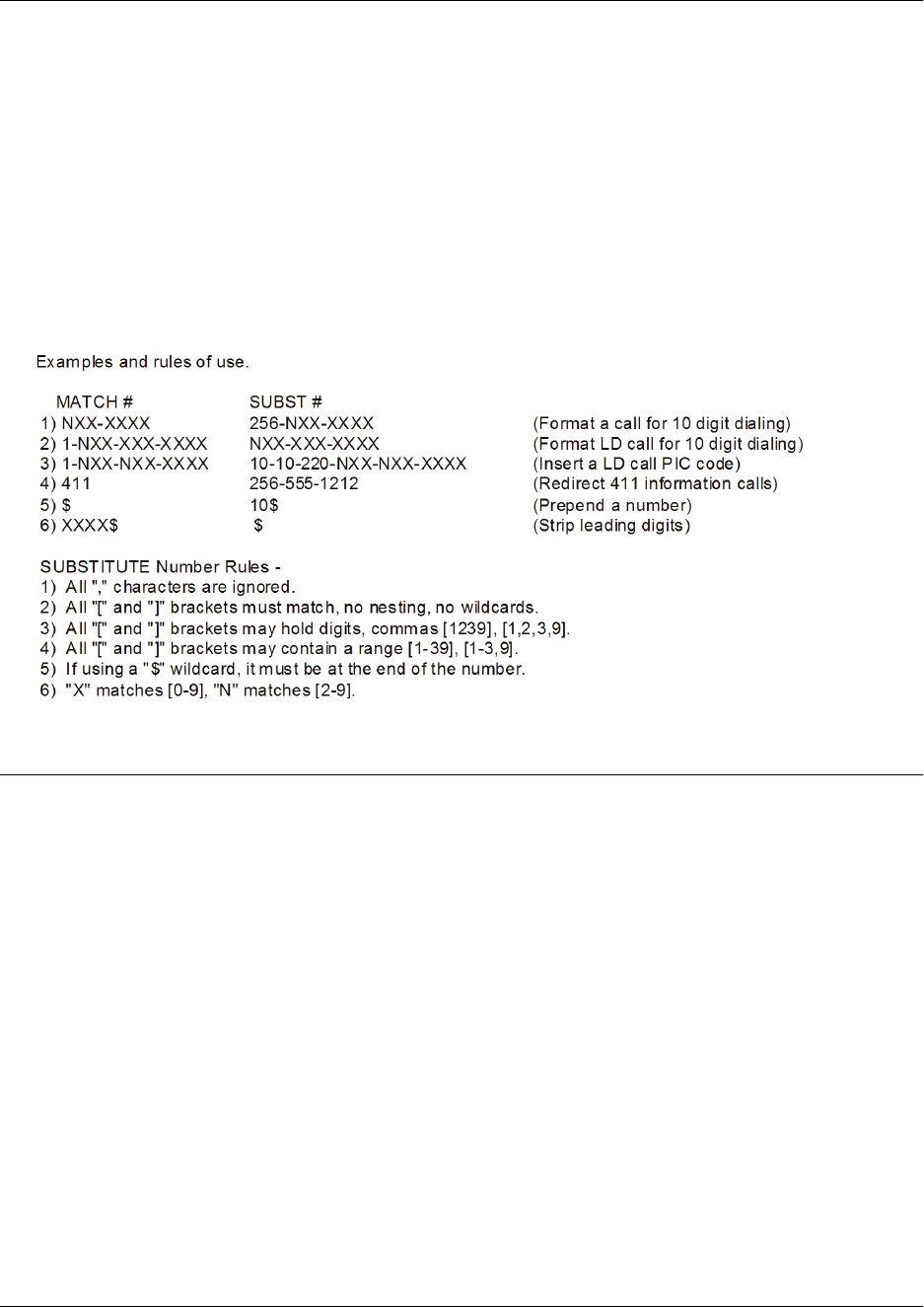
Command Reference Guide Cellular Interface Command Set
60000CRG0-35E Copyright © 2012 ADTRAN, Inc. 1549
The special characters ( ), -, and + are always ignored in the template. The following are example template
entries using wildcards:
Examples: 1) 555-81xx matches 555-8100 to 555-8199.
2) 555-812[012] matches 555-8120 to 555-8122.
3) Nxx-xxxx matches 7 digits local.
4) 1-Nxx-Nxx-xxxx matches long distance calls in North America.
Additional wildcards ($ and 0 to 9) can also be used. The command line interface (CLI) also contains
helpful information regarding the construction of the template and can be viewed by entering the match
ani command followed by a question mark. For example, entering the command as follows results in the
template input specifications:
(config)#match ani ?
Usage Examples
The following example specifies that the ANI information from numbers 555-8111 to 555-8115 will be
substituted by 555-8110 for outbound calls on interface 1/1:
(config)#interface cellular 1/1
(config-cellular 1/1)#match ani 555-811[125] substitute 555-8110

Command Reference Guide Cellular Interface Command Set
60000CRG0-35E Copyright © 2012 ADTRAN, Inc. 1550
reset
Use the reset command to reboot the cellular network interface module (NIM).
Syntax Description
No subcommands.
Default Values
No default values are necessary for this command.
Command History
Release 17.2 Command was introduced.
Usage Examples
The following example reboots the NIM associated with cellular interface 1/1:
(config)#interface cellular 1/1
(config-cellular 1/1)#reset

Command Reference Guide Cellular Interface Command Set
60000CRG0-35E Copyright © 2012 ADTRAN, Inc. 1551
resource pool-member <name>
Use the resource pool-member command to configure the cellular interface as a resource pool member
for the demand interface to draw upon when connecting to the cellular network. Use the no form of this
command to remove the interface from the resource pool. Variations of this command include:
resource pool-member <name>
resource pool-member <name> <priority>
Syntax Description
<name> Specifies the resource pool to which the cellular interface is assigned.
<priority> Optional. Specifies the priority this interface is given over other interfaces in
the same pool. Range is 1 to 255.
Default Values
By default, the cellular interface is not associated with any resource pools.
Command History
Release 17.2 Command was introduced.
Functional Notes
Lower priority values indicate a higher priority. Interfaces within the same resource pool with the same
priority are selected as resources in alphabetical order by interface name.
Usage Examples
The following example configures interface cellular 1/1 as a member of the cellular resource pool:
(config)#interface cellular 1/1
(config-cellular 1/1)#resource pool-member cellular

Command Reference Guide Cellular Interface Command Set
60000CRG0-35E Copyright © 2012 ADTRAN, Inc. 1552
retry-throttling
Use the retry-throttling command to enable retry throttling. Use the no form of this command to disable
retry throttling.
Syntax Description
No subcommands.
Default Values
In the Verizon cellular network, the retry throttle is enabled and cannot be disabled.
In the Sprint cellular network, the retry throttle is disabled by default but can be enabled by using this
command.
Command History
Release 17.5 Command was introduced.
Functional Notes
When the retry throttle is enabled, it will disable the cellular interface for 15 minutes if a data call fails.
Usage Examples
The following example enables retry throttling:
(config)#interface cellular 1/1
(config-cellular 1/1)#retry-throttling

Command Reference Guide Cellular Interface Command Set
60000CRG0-35E Copyright © 2012 ADTRAN, Inc. 1553
snmp trap cellular
Use the snmp trap cellular command to enable all of the cellular Simple Network Management Protocol
(SNMP) traps except the SNMP link-status trap. Use the no form of this command to disable all cellular
traps except the SNMP link-status trap.
Syntax Description
No subcommands.
Default Values
By default, all interfaces (except virtual Frame Relay interfaces and subinterfaces) have SNMP traps
enabled.
Command History
Release 4.01 Command was introduced.
Usage Examples
The following example enables all cellular SNMP traps on interface cellular 1/1:
(config)#interface cellular 1/1
(config-cellular 1/1)#snmp trap cellular

Command Reference Guide Cellular Interface Command Set
60000CRG0-35E Copyright © 2012 ADTRAN, Inc. 1554
snmp trap threshold-ecio <value>
Use the snmp trap threshold-ecio command to specify the threshold value that will generate a code
division multiple access (CDMA) correlated signal strength (Ec/Io) trap. Use the no form of this command
to remove the Ec/Io threshold.
Syntax Description
<value> Specifies the threshold value for the Ec/Io trap.
Default Values
By default, the Ec/Io trap threshold is -200.
Command History
Release 4.01 Command was introduced.
Usage Examples
The following example configures an Ec/Io threshold of -100 on interface cellular 1/1:
(config)#interface cellular 1/1
(config-cellular 1/1)#snmp trap threshold-ecio -100

Command Reference Guide Cellular Interface Command Set
60000CRG0-35E Copyright © 2012 ADTRAN, Inc. 1555
snmp trap threshold-rssi <value>
Use the snmp trap threshold-rssi command to specify the threshold value that will generate a recieved
signal strength indication (RSSI) trap. Use the no form of this command to remove the RSSI threshold.
Syntax Description
<value> Specifies the threshold value for the RSSI trap.
Default Values
By default, the RSSI trap threshold is -200.
Command History
Release 4.01 Command was introduced.
Usage Examples
The following example configures an RSSI threshold of -100 on interface cellular 1/1:
(config)#interface cellular 1/1
(config-cellular 1/1)#snmp trap threshold-rssi -100

Command Reference Guide DDS Interface Command Set
60000CRG0-35E Copyright © 2012 ADTRAN, Inc. 1556
DDS INTERFACE COMMAND SET
To activate the DDS Interface Configuration mode, enter the interface dds command at the Global
Configuration mode prompt. For example:
>enable
#configure terminal
(config)#interface dds 1/1
(config-dds 1/1)#
The following commands are common to multiple command sets and are covered in a centralized section
of this guide. For more information, refer to the sections listed below:
alias “<text>” on page 66
cross-connect on page 67
description <text> on page 70
do on page 71
end on page 72
exit on page 73
interface on page 74
shutdown on page 82
All other commands for this command set are described in this section in alphabetical order.
clock rate on page 1557
clock source on page 1558
data-coding scrambled on page 1559
ipv6 policy-class <ipv6 acp name> max-sessions <number> on page 1560
loopback on page 1561
remote-loopback on page 1562
snmp trap on page 1563
snmp trap link-status on page 1564

Command Reference Guide DDS Interface Command Set
60000CRG0-35E Copyright © 2012 ADTRAN, Inc. 1557
clock rate
Use the clock rate command to configure the data rate used as the operating speed for the interface. This
rate should match the rate required by the digital data service (DDS) service provider. Use the no form of
this command to return to the default value. Variations of this command include:
clock rate auto
clock rate bps56k
clock rate bps64k
Syntax Description
auto Automatically detects the clock rate and sets to match.
bps56k Sets the clock rate to 56 kbps.
bps64k Sets the clock rate to 64 kbps.
Default Values
By default, the rate is set to auto.
Command History
Release 1.1 Command was introduced.
Functional Notes
When operating at 64 kbps (clear channel operation), the data terminal equipment (DTE) data sequences
may mimic network loop maintenance functions and erroneously cause other network elements to activate
loopbacks. Use the data-coding scrambled command to prevent such occurrences. Refer to data-coding
scrambled on page 1559 for related information.
Usage Examples
The following example configures the clock rate for 56 kbps operation:
(config)#interface dds 1/1
(config-dds 1/1)#clock rate bps56k

Command Reference Guide DDS Interface Command Set
60000CRG0-35E Copyright © 2012 ADTRAN, Inc. 1558
clock source
Use the clock source command to configure the source timing used for the interface. The clock specified
using the clock source command is also the system master clock. Use the no form of this command to
return to the default value. Variations of this command include:
clock source internal
clock source line
Syntax Description
internal Configures the unit to provide clocking using the internal oscillator.
line Configures the unit to recover clocking from the digital data service (DDS)
circuit.
Default Values
By default, the clock source is set to line.
Command History
Release 1.1 Command was introduced.
Functional Notes
When operating on a DDS network, the clock source should be line. On a point-to-point private network,
one unit must be line and the other internal.
Usage Examples
The following example configures the unit to recover clocking from the circuit:
(config)#interface dds 1/1
(config-dds 1/1)#clock source line

Command Reference Guide DDS Interface Command Set
60000CRG0-35E Copyright © 2012 ADTRAN, Inc. 1559
data-coding scrambled
Use the data-coding scrambled command to enable the digital data service (DDS) OS scrambler to
combine user data with pattern data to ensure user data does not mirror standard DDS loop codes. The
scrambler may only be used on 64 kbps circuits without Frame Relay signaling (clear channel). Use the no
form of this command to disable this feature.
Syntax Description
No subcommands.
Default Values
By default, the scrambler is disabled.
Command History
Release 1.1 Command was introduced.
Functional Notes
When operating at 64 kbps (clear channel operation), there is a possibility the data terminal equipment
(DTE) data sequences may mimic network loop maintenance functions and erroneously cause other
network elements to activate loopbacks. Use the data-coding scrambled command to prevent such
occurrences. Do not use this command if using Frame Relay or if using Point-to-Point Protocol (PPP) to
another device other than an AOS product also running scrambled.
Usage Examples
The following example enables the DDS OS scrambler:
(config)#interface dds 1/1
(config-dds 1/1)#data-coding scrambled

Command Reference Guide DDS Interface Command Set
60000CRG0-35E Copyright © 2012 ADTRAN, Inc. 1560
ipv6 policy-class <ipv6 acp name> max-sessions <number>
Use the ipv6 policy-class max-sessions command to specify the maximum number of allowed Internet
Protocol version 6 (IPv6) policy sessions on a specific IPv6 access control policy (ACP). For more details
on IPv6 ACP functionality in AOS, refer to the IPv6 Access Control Policy Command Set on page 3192.
Use the no form of this command to return to the default value.
Syntax Description
<ipv6 acp name> Identifies the configured IPv6 ACP to which the max-session limit is applied.
Use an alphanumeric descriptor (maximum of 50 characters). All ACP
descriptors are case sensitive.
<number> Specifies the maximum number of allowed IPv6 policy sessions. Valid range
is 1 up to a value based on the amount of RAM in the AOS unit (refer to
Default Values below).
Default Values
By default, the maximum IPv6 ACP sessions allowed are based on the amount of RAM in the AOS unit.
The following table outlines the default values based on RAM:
Command History
Release 18.1 Command was introduced.
Functional Notes
To set the system-wide maximum limit for ACP sessions (both IPv4 and IPv6), use the command
policy-class max-sessions <number> on page 1282.
Usage Examples
The following example allows no more than 100 policy sessions on the IPv6 ACP named PRIVATEv6:
(config)#interface dds 1/1
(config-dds 1/1)#ipv6 policy-class PRIVATEv6 max-sessions 100
RAM Amount Default Max Sessions
64 MB 10000
128 MB 30000
256 MB 80000
512 MB 200000
768 MB 300000
1 GB 450000

Command Reference Guide DDS Interface Command Set
60000CRG0-35E Copyright © 2012 ADTRAN, Inc. 1561
loopback
Use the loopback command to initiate a specified loopback on the interface. Use the no form of this
command to deactivate the loop. Variations of this command include:
loopback dte
loopback line
loopback remote
Syntax Description
dte Initiates a loop to connect the transmit and receive path through the unit.
line Initiates a loop of the digital data service (DDS) circuit toward the network
by connecting the transmit path to the receive path.
remote Transmits a DDS loop code over the circuit to the remote unit. In response,
the remote unit should initiate a line loopback.
Default Values
No default values are necessary for this command.
Command History
Release 1.1 Command was introduced.
Usage Examples
The following example activates a line loopback on the DDS interface:
(config)#interface dds 1/1
(config-dds 1/1)#loopback line

Command Reference Guide DDS Interface Command Set
60000CRG0-35E Copyright © 2012 ADTRAN, Inc. 1562
remote-loopback
Use the remote-loopback command to configure the interface to respond to loopbacks initiated by a
remote unit (or the service provider). Use the no form of this command to disable this feature.
Syntax Description
No subcommands.
Default Values
By default, all interfaces respond to remote loopbacks.
Command History
Release 1.1 Command was introduced.
Usage Examples
The following example enables remote loopbacks on the digital data service (DDS) interface:
(config)#interface dds 1/1
(config-dds 1/1)#remote-loopback

Command Reference Guide DDS Interface Command Set
60000CRG0-35E Copyright © 2012 ADTRAN, Inc. 1563
snmp trap
Use the snmp trap command to enable all supported Simple Network Management Protocol (SNMP)
traps on the interface. Use the no form of this command to disable this trap.
Syntax Description
No subcommands.
Default Values
By default, all interfaces (except virtual Frame Relay interfaces and subinterfaces) have SNMP traps
enabled.
Command History
Release 1.1 Command was introduced.
Release 5.1 Command was expanded to include the Ethernet subinterfaces and Gigabit
Ethernet interfaces.
Release 6.1 Command was expanded to include the port channel and virtual local area
network (VLAN) interfaces.
Release 8.1 Command was expanded to the asynchronous transfer mode (ATM)
interface.
Release 16.1 Command was expanded to the tunnel interface.
Usage Examples
The following example enables SNMP capability on the digital data service (DDS) interface:
(config)#interface dds 1/1
(config-dds 1/1)#snmp trap

Command Reference Guide DDS Interface Command Set
60000CRG0-35E Copyright © 2012 ADTRAN, Inc. 1564
snmp trap link-status
Use the snmp trap link-status command to control the Simple Network Management Protocol (SNMP)
variable ifLinkUpDownTrapEnable (RFC 2863) to enable (or disable) the interface to send SNMP traps
when there is an interface status change. Use the no form of this command to disable this trap.
Syntax Description
No subcommands.
Default Values
By default, the ifLinkUpDownTrapEnable object identifier (OID) is enabled for all supported interfaces
except virtual Frame Relay interfaces.
Command History
Release 1.1 Command was introduced.
Release 5.1 Command was expanded to include the Ethernet subinterfaces and Gigabit
Ethernet interfaces.
Release 6.1 Command was expanded to include the E1, port channel, T3, and virtual
local area network (VLAN) interfaces.
Release 7.1 Command was expanded to the high speed serial interface (HSSI).
Release 8.1 Command was expanded to the asynchronous transfer mode (ATM)
interface.
Release 9.1 Command was expanded to the high level data link control (HDLC)
interface.
Release 11.1 Command was expanded to the demand interface.
Release 16.1 Command was expanded to the tunnel interface.
Functional Notes
The snmp trap link-status command is used to control the RFC 2863 ifLinkUpDownTrapEnable OID (OID
number 1.3.6.1.2.1.31.1.1.1.14.0).
Usage Examples
The following example disables the link-status trap on the digital data service (DDS) interface:
(config)#interface dds 1/1
(config-dds 1/1)#no snmp trap link-status

Command Reference Guide DSX-1 Interface Command Set
60000CRG0-35E Copyright © 2012 ADTRAN, Inc. 1565
DSX-1 INTERFACE COMMAND SET
To activate the DSX-1 Interface Configuration mode, enter the interface t1 command (and specify the
DSX-1 port) at the Global Configuration mode prompt. For example:
>enable
#configure terminal
(config)#interface t1 1/2
(config-t1 1/2)#
The following commands are common to multiple command sets and are covered in a centralized section
of this guide. For more information, refer to the sections listed below:
alias “<text>” on page 66
cross-connect on page 67
description <text> on page 70
do on page 71
end on page 72
exit on page 73
interface on page 74
shutdown on page 82
All other commands for this command set are described in this section in alphabetical order.
coding on page 1566
framing on page 1567
ipv6 policy-class <ipv6 acp name> max-sessions <number> on page 1568
line-length <value> on page 1569
loopback network on page 1570
loopback remote line inband on page 1571
remote-loopback on page 1572
signaling-mode on page 1573
snmp trap link-status on page 1574
test-pattern on page 1575

Command Reference Guide DSX-1 Interface Command Set
60000CRG0-35E Copyright © 2012 ADTRAN, Inc. 1566
coding
Use the coding command to configure the line coding for a DSX-1 physical interface. This setting must
match the line coding supplied on the circuit by the PBX. Use the no form of this command to return to the
default setting. Variations of this command include:
coding ami
coding b8zs
Syntax Description
ami Configures the line coding for alternate mark inversion (AMI).
b8zs Configures the line coding for bipolar eight zero substitution (B8ZS).
Default Values
By default, all DSX-1 interfaces are configured with b8zs line coding.
Command History
Release 1.1 Command was introduced.
Functional Notes
The line coding configured in the unit must match the line coding of the DSX-1 circuit. A mismatch will
result in line errors (e.g., bipolar violations (BPVs)).
Usage Examples
The following example configures the DSX-1 interface for ami line coding:
(config)#interface t1 1/2
(config-t1 1/2)#coding ami

Command Reference Guide DSX-1 Interface Command Set
60000CRG0-35E Copyright © 2012 ADTRAN, Inc. 1567
framing
Use the framing command to configure the framing format for the DSX-1 interface. This parameter
should match the framing format set on the external device. Use the no form of this command to return to
the default value. Variations of this command include:
framing d4
framing esf
Syntax Description
d4 Specifies D4 superframe (SF) format.
esf Specifies extended superframe (ESF) format.
Default Values
By default, the framing format is set to esf.
Command History
Release 1.1 Command was introduced.
Functional Notes
A frame is comprised of a single byte from each of the T1’s timeslots; there are 24 timeslots on a single T1
circuit. Framing bits are used to separate the frames and indicate the order of information arriving at the
receiving equipment. D4 and ESF are two methods of collecting and organizing frames over the circuit.
Usage Examples
The following example configures the DSX-1 interface for d4 framing:
(config)#interface t1 1/2
(config-t1 1/2)#framing d4

Command Reference Guide DSX-1 Interface Command Set
60000CRG0-35E Copyright © 2012 ADTRAN, Inc. 1568
ipv6 policy-class <ipv6 acp name> max-sessions <number>
Use the ipv6 policy-class max-sessions command to specify the maximum number of allowed Internet
Protocol version 6 (IPv6) policy sessions on a specific IPv6 access control policy (ACP). For more details
on IPv6 ACP functionality in AOS, refer to the IPv6 Access Control Policy Command Set on page 3192.
Use the no form of this command to return to the default value.
Syntax Description
<ipv6 acp name> Identifies the configured IPv6 ACP to which the max-session limit is applied.
Use an alphanumeric descriptor (maximum of 50 characters). All ACP
descriptors are case sensitive.
<number> Specifies the maximum number of allowed IPv6 policy sessions. Valid range
is 1 up to a value based on the amount of RAM in the AOS unit (refer to
Default Values below).
Default Values
By default, the maximum IPv6 ACP sessions allowed are based on the amount of RAM in the AOS unit.
The following table outlines the default values based on RAM:
Command History
Release 18.1 Command was introduced.
Functional Notes
To set the system-wide maximum limit for ACP sessions (both IPv4 and IPv6), use the command
policy-class max-sessions <number> on page 1282.
Usage Examples
The following example allows no more than 100 policy sessions on the IPv6 ACP named PRIVATEv6:
(config)#interface t1 1/2
(config-t1 1/2)#ipv6 policy-class PRIVATEv6 max-sessions 100
RAM Amount Default Max Sessions
64 MB 10000
128 MB 30000
256 MB 80000
512 MB 200000
768 MB 300000
1 GB 450000

Command Reference Guide DSX-1 Interface Command Set
60000CRG0-35E Copyright © 2012 ADTRAN, Inc. 1569
line-length <value>
Use the line-length command to set the line build out (LBO) (in feet or dB) for the DSX-1 interface. Use
the no form of this command to return to the default value.
Syntax Description
<value> Configures the LBO for the DSX-1 interface. Valid options include: -7.5 dB
or 0 to 655 feet. Use the -7.5 dB option for maximum attenuation.
Default Values
By default, the LBO is set to 0 feet.
Command History
Release 1.1 Command was introduced.
Functional Notes
The line-length value represents the physical distance between DSX equipment (measured in cable
length). Based on this setting, the AOS device increases signal strength to compensate for the distance
the signal must travel. Valid distance ranges are listed below:
• 0 to 133 feet
• 134 to 265 feet
• 266 to 399 feet
• 400 to 533 feet
• 534 to 655 feet
Usage Examples
The following example configures the DSX-1 interface line-length for 300 feet:
(config)#interface t1 1/2
(config-t1 1/2)#line-length 300

Command Reference Guide DSX-1 Interface Command Set
60000CRG0-35E Copyright © 2012 ADTRAN, Inc. 1570
loopback network
Use the loopback network command to initiate a loopback on the interface toward the network. Use the
no form of this command to deactivate the loopback. Variations of this command include:
loopback network line
loopback network payload
Syntax Description
line Initiates a metallic loopback of the physical DSX-1 network interface.
payload Initiates a loopback of the T1 framer (CSU portion) of the DSX-1 network
interface.
Default Values
No default values are necessary for this command.
Command History
Release 1.1 Command was introduced.
Functional Notes
The following diagram depicts the difference between a line and payload loopback.
Usage Examples
The following example initiates a payload loopback of the DSX-1 interface:
(config)#interface t1 1/2
(config-t1 1/2)#loopback network payload
T1 Network Interface
DS1
NI CSU
Payload Loopback
Line Loopback
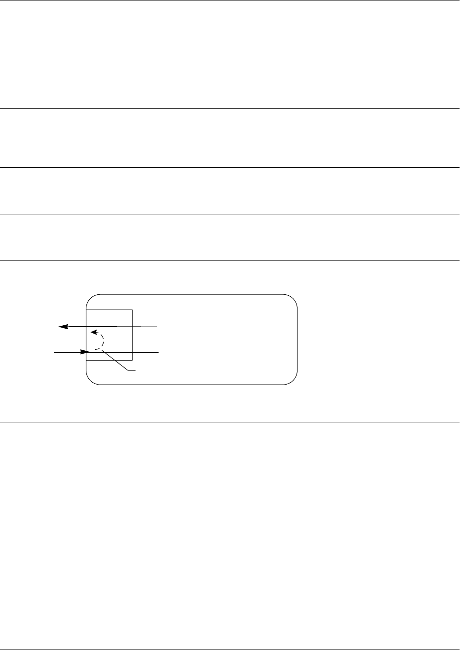
Command Reference Guide DSX-1 Interface Command Set
60000CRG0-35E Copyright © 2012 ADTRAN, Inc. 1571
loopback remote line inband
Use the loopback remote line inband command to send a loopback code to the remote unit to initiate a
line loopback. Use the no form of this command to send a loopdown code to the remote unit to deactivate
the loopback.
Syntax Description
inband Uses the inband channel to initiate a full 1.544 Mbps physical (metallic)
loopback of the signal received by the remote unit from the network.
Default Values
No default values are necessary for this command.
Command History
Release 1.1 Command was introduced.
Functional Notes
A remote loopback can only be issued if a cross connect does not exist on the interface and if the signaling
mode is set to none. The following diagram depicts the difference between a line and payload loopback.
Usage Examples
The following example initiates a remote line loopback using the inband channel:
(config)#interface t1 1/2
(config-t1 1/2)#loopback remote line inband
T1 Network Interface
DS1
NI CSU
Line Loopback

Command Reference Guide DSX-1 Interface Command Set
60000CRG0-35E Copyright © 2012 ADTRAN, Inc. 1572
remote-loopback
Use the remote-loopback command to configure the interface to respond to loopbacks initiated by a
remote unit (or the service provider). Use the no form of this command to disable this feature.
Syntax Description
No subcommands.
Default Values
By default, all interfaces respond to remote loopbacks.
Command History
Release 1.1 Command was introduced.
Usage Examples
The following example enables remote loopbacks on the DSX-1 interface:
(config)#interface t1 1/2
(config-t1 1/2)#remote-loopback

Command Reference Guide DSX-1 Interface Command Set
60000CRG0-35E Copyright © 2012 ADTRAN, Inc. 1573
signaling-mode
Use the signaling-mode command to configure the signaling type (robbed-bit for voice or clear channel
for data) for the level zero digital signals (DS0s) mapped to the DSX-1 port. Use the no form of this
command to return to the default setting. Variations of this command include:
signaling-mode message-oriented
signaling-mode none
signaling-mode robbed-bit
Syntax Description
message-oriented Specifies clear channel signaling on Channel 24 only. Use this signaling
type with QSIG installations.
none Specifies clear channel signaling on all 24 DS0s. Use this signaling type
with data-only or primary rate interface (PRI) DSX-1 installations.
robbed-bit Specifies robbed bit signaling on all DS0s. Use this signaling type for
voice-only DSX-1 applications.
Default Values
By default, the signaling mode is set to robbed-bit.
Command History
Release 1.1 Command was introduced.
Usage Examples
The following example configures the DSX-1 port for PRI compatibility:
(config)#interface t1 1/2
(config-t1 1/2)#signaling-mode none

Command Reference Guide DSX-1 Interface Command Set
60000CRG0-35E Copyright © 2012 ADTRAN, Inc. 1574
snmp trap link-status
Use the snmp trap link-status command to control the Simple Network Management Protocol (SNMP)
variable ifLinkUpDownTrapEnable (RFC 2863) to enable (or disable) the interface to send SNMP traps
when there is an interface status change. Use the no form of this command to disable this trap.
Syntax Description
No subcommands.
Default Values
By default, the ifLinkUpDownTrapEnable object identifier (OID) is enabled for all interfaces except virtual
Frame Relay interfaces.
Command History
Release 1.1 Command was introduced.
Release 5.1 Command was expanded to include the Ethernet subinterfaces and Gigabit
Ethernet interfaces.
Release 6.1 Command was expanded to include the E1, port channel, T3, and virtual
local area network (VLAN) interfaces.
Release 7.1 Command was expanded to the high speed serial interface (HSSI).
Release 8.1 Command was expanded to the asynchronous transfer mode (ATM)
interface.
Release 9.1 Command was expanded to the high level data link control (HDLC)
interface.
Release 11.1 Command was expanded to the demand interface.
Release 16.1 Command was expanded to the tunnel interface.
Functional Notes
The snmp trap link-status command is used to control the RFC 2863 ifLinkUpDownTrapEnable OID (OID
number 1.3.6.1.2.1.31.1.1.1.14.0).
Usage Examples
The following example disables the link-status trap on the DSX-1 interface:
(config)#interface t1 1/2
(config-t1 1/2)#no snmp trap link-status

Command Reference Guide DSX-1 Interface Command Set
60000CRG0-35E Copyright © 2012 ADTRAN, Inc. 1575
test-pattern
Use the test-pattern command to activate the built-in pattern generator and begin sending the specified
test pattern. This pattern generation can be used to verify a data path when used in conjunction with an
active loopback. Use the no form of this command to cease pattern generation. Variations of this command
include:
test-pattern ones
test-pattern zeros
Syntax Description
ones Generates a test pattern of continuous ones.
zeros Generates a test pattern of continuous zeros.
Default Values
No default values are necessary for this command.
Command History
Release 1.1 Command was introduced.
Usage Examples
The following example activates the pattern generator for a stream of continuous ones:
(config)#interface t1 1/2
(config-t1 1/2)#test-pattern ones

Command Reference Guide E1 Interface Command Set
60000CRG0-35E Copyright © 2012 ADTRAN, Inc. 1576
E1 INTERFACE COMMAND SET
To activate the E1 Interface Configuration mode, enter the interface e1 command (and specify the E1
port) at the Global Configuration mode prompt. For example:
>enable
#configure terminal
(config)#interface e1 1/1
(config-e1 1/1)#
The following commands are common to multiple command sets and are covered in a centralized section
of this guide. For more information, refer to the sections listed below:
alias “<text>” on page 66
cross-connect on page 67
description <text> on page 70
do on page 71
end on page 72
exit on page 73
interface on page 74
shutdown on page 82
All other commands for this command set are described in this section in alphabetical order.
clock source on page 1577
coding on page 1578
framing crc4 on page 1579
ipv6 policy-class <ipv6 acp name> max-sessions <number> on page 1580
loop-alarm-detect on page 1581
loopback network on page 1582
loopback remote v54 on page 1583
remote-loopback on page 1584
sa4tx-bit <value> on page 1585
snmp trap line-status on page 1586
snmp trap link-status on page 1587
snmp trap threshold-reached on page 1588
system-timing on page 1589
tdm-group <number> on page 1590
test-pattern on page 1591
timing-domain <domain> on page 1592
ts16 on page 1593

Command Reference Guide E1 Interface Command Set
60000CRG0-35E Copyright © 2012 ADTRAN, Inc. 1577
clock source
Use the clock source command to configure the source timing used for the interface. Use the no form of
this command to return to the default value. Variations of this command include:
clock source internal
clock source line
clock source system
clock source through
Syntax Description
internal Configures the unit to provide clocking using the internal oscillator.
line Configures the unit to recover clocking from the E1 circuit.
system Configures the unit to provide clocking from the chassis selection.
through Configures the unit to recover clocking from the circuit connected to the
G.703 interface.
Default Values
By default, the unit is configured to recover clocking from the primary circuit.
Command History
Release 5.1 Command was introduced.
Release A2 Command was expanded to include the system parameter.
Functional Notes
When operating on a circuit that is providing timing, setting the clock source to line can avoid errors, such
as clock slip seconds (CSS).
Usage Examples
The following example configures the unit to recover clocking from the primary circuit:
(config)#interface e1 1/1
(config-e1 1/1)#clock source line

Command Reference Guide E1 Interface Command Set
60000CRG0-35E Copyright © 2012 ADTRAN, Inc. 1578
coding
Use the coding command to configure the line coding for the E1 physical interface. This setting must
match the line coding supplied on the circuit by the service provider. Use the no form of this command to
return to the default setting. Variations of this command include:
coding ami
coding hdb3
Syntax Description
ami Configures the line coding for alternate mark inversion (AMI).
hdb3 Configures the line coding for high-density bipolar 3 (HDB3).
Default Values
By default, all E1 interfaces are configured with hdb3 line coding.
Command History
Release 5.1 Command was introduced.
Functional Notes
The line coding configured in the unit must match the line coding of the E1 circuit. A mismatch will result in
line errors (e.g., bipolar violations (BPVs)).
Usage Examples
The following example configures the E1 interface for ami line coding:
(config)#interface e1 1/1
(config-e1 1/1)#coding ami

Command Reference Guide E1 Interface Command Set
60000CRG0-35E Copyright © 2012 ADTRAN, Inc. 1579
framing crc4
Use the framing crc4 command to configure the framing format for the E1 interface. This parameter
should match the framing format provided by the service provider or external device. Use the no form of
this command to return to the default value.
Syntax Description
crc4 Enables CRC4 bits to be transmitted in the outgoing data stream. Also, the
received signal is checked for CRC4 errors.
Default Values
By default, CRC4 is disabled.
Command History
Release 5.1 Command was introduced.
Functional Notes
The framing value must match the configuration of the E1 circuit. A mismatch will result in a loss of frame
alarm.
Usage Examples
The following example configures the E1 interface for CRC4 framing:
(config)#interface e1 1/1
(config-e1 1/1)#framing crc4

Command Reference Guide E1 Interface Command Set
60000CRG0-35E Copyright © 2012 ADTRAN, Inc. 1580
ipv6 policy-class <ipv6 acp name> max-sessions <number>
Use the ipv6 policy-class max-sessions command to specify the maximum number of allowed Internet
Protocol version 6 (IPv6) policy sessions on a specific IPv6 access control policy (ACP). For more details
on IPv6 ACP functionality in AOS, refer to the IPv6 Access Control Policy Command Set on page 3192.
Use the no form of this command to return to the default value.
Syntax Description
<ipv6 acp name> Identifies the configured IPv6 ACP to which the max-session limit is applied.
Use an alphanumeric descriptor (maximum of 50 characters). All ACP
descriptors are case sensitive.
<number> Specifies the maximum number of allowed IPv6 policy sessions. Valid range
is 1 up to a value based on the amount of RAM in the AOS unit (refer to
Default Values below).
Default Values
By default, the maximum IPv6 ACP sessions allowed are based on the amount of RAM in the AOS unit.
The following table outlines the default values based on RAM:
Command History
Release 18.1 Command was introduced.
Functional Notes
To set the system-wide maximum limit for ACP sessions (both IPv4 and IPv6), use the command
policy-class max-sessions <number> on page 1282.
Usage Examples
The following example allows no more than 100 policy sessions on the IPv6 ACP named PRIVATEv6:
(config)#interface e1 1/1
(config-e1 1/1)#ipv6 policy-class PRIVATEv6 max-sessions 100
RAM Amount Default Max Sessions
64 MB 10000
128 MB 30000
256 MB 80000
512 MB 200000
768 MB 300000
1 GB 450000

Command Reference Guide E1 Interface Command Set
60000CRG0-35E Copyright © 2012 ADTRAN, Inc. 1581
loop-alarm-detect
The loop-alarm-detect command enables detection of a loop alarm on the E1 interface. Use the no form
of this command to disable this feature.
Syntax Description
No subcommands.
Default Values
By default, this command is enabled.
Command History
Release 6.1 Command was introduced.
Functional Notes
This command enables the detection of a loopback alarm. This alarm works in conjunction with the
sa4tx-bit command setting. The loopback condition is detected by comparing the transmitted sa4tx-bit
value to the received Sa4 bit value. If the bits match, a loopback is assumed. This detection method only
works with a network in which the far end is transmitting the opposite value for Sa4.
Usage Examples
The following example enables detection of a loop alarm on the E1 interface:
(config)#interface e1 1/1
(config-e1 1/1)#loop-alarm-detect
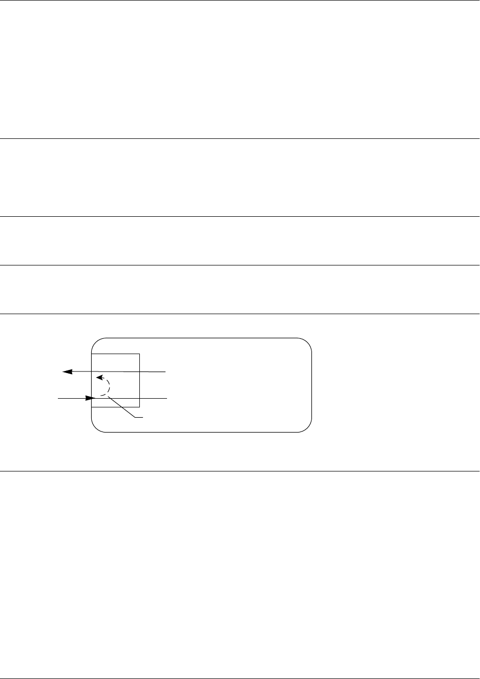
Command Reference Guide E1 Interface Command Set
60000CRG0-35E Copyright © 2012 ADTRAN, Inc. 1582
loopback network
Use the loopback network command to initiate a loopback on the interface toward the network. Use the
no form of this command to deactivate the loopback. Variations of this command include:
loopback network line
loopback network payload
Syntax Description
line Initiates a metallic loopback of the physical E1 network interface.
payload Initiates a loopback of the E1 framer (CSU) portion of the E1 network
interface.
Default Values
No default values are necessary for this command.
Command History
Release 5.1 Command was introduced.
Functional Notes
The following diagram depicts a line loopback.
Usage Examples
The following example initiates a line loopback of the E1 interface:
(config)#interface e1 1/1
(config-e1 1/1)#loopback network line
E1 Network Interface
NTWK E1
NI CSU
Line Loopback

Command Reference Guide E1 Interface Command Set
60000CRG0-35E Copyright © 2012 ADTRAN, Inc. 1583
loopback remote v54
The loopback remote v54 command initiates an E1 remote loopback test (with a V.54 loopback pattern).
Use the no form of this command to disable this feature.
Syntax Description
No subcommands.
Default Values
No default values are necessary for this command.
Command History
Release 6.1 Command was introduced.
Functional Notes
This command causes a V.54 inband loop code to be sent in the payload towards the far end.
Usage Examples
The following example sends a V.54 inband loop code to the far end:
(config)#interface e1 1/1
(config-e1 1/1)#loopback remote v54

Command Reference Guide E1 Interface Command Set
60000CRG0-35E Copyright © 2012 ADTRAN, Inc. 1584
remote-loopback
Use the remote-loopback command to configure the interface to respond to loopbacks initiated by a
remote unit (or the service provider). Use the no form of this command to disable this feature.
Syntax Description
No subcommands.
Default Values
By default, all interfaces respond to remote loopbacks.
Command History
Release 1.1 Command was introduced.
Functional Notes
This controls the acceptance of any remote loopback requests. When enabled, remote loopbacks are
detected and cause a loopback to be applied. When disabled, remote loopbacks are ignored.
Usage Examples
The following example enables remote loopbacks on the E1 interface:
(config)#interface e1 1/1
(config-e1 1/1)#remote-loopback

Command Reference Guide E1 Interface Command Set
60000CRG0-35E Copyright © 2012 ADTRAN, Inc. 1585
sa4tx-bit <value>
The sa4tx-bit command selects the Tx value of Sa4 in this E1 interface. Use the no form of this command
to return to the default value.
Syntax Description
<value> Specifies a 0 or a 1 for the transmit value of the SA4 bit on the E1.
Default Values
The default value for this command is 1.
Command History
Release 6.1 Command was introduced.
Functional Notes
This command assigns a value to the Tx spare bit in position 4. The odd-numbered frames of TS0 are not
used for frame alignment. Bits in position 4 through 8 are called spare bits. Values of 0 or 1 are accepted.
TS0 odd frame
Bit position 1 2 3 4 5 6 7 8
Bit use 0 1 RAI = 1 S S S S S
Usage Examples
The following example sets the Tx value of Sa4 to 0:
(config)#interface e1 1/1
(config-e1 1/1)#sa4tx-bit 0

Command Reference Guide E1 Interface Command Set
60000CRG0-35E Copyright © 2012 ADTRAN, Inc. 1586
snmp trap line-status
Use the snmp trap line-status command to control the Simple Network Management Protocol (SNMP)
variable dsx1LineStatusChangeTrapEnable (RFC 2495) to enable (or disable) the interface to send SNMP
traps when there is an interface status change. Use the no form of this command to disable this trap.
Syntax Description
No subcommands.
Default Values
By default, the dsx1LineStatusChangeTrapEnable object identifier (OID) is set to enabled for all interfaces
except virtual Frame Relay interfaces.
Command History
Release 11.1 Command was introduced.
Functional Notes
The snmp trap line-status command is used to control the RFC 2495 dsx1LineStatusChangeTrapEnable
OID (OID number 1.3.6.1.2.1.10.18.6.1.17.0).
Usage Examples
The following example disables the line-status trap on the T1 interface:
(config)#interface e1 1/1
(config-t1 1/1)#no snmp trap line-status

Command Reference Guide E1 Interface Command Set
60000CRG0-35E Copyright © 2012 ADTRAN, Inc. 1587
snmp trap link-status
Use the snmp trap link-status command to control the Simple Network Management Protocol (SNMP)
variable ifLinkUpDownTrapEnable (RFC 2863) to enable (or disable) the interface to send SNMP traps
when there is an interface status change. Use the no form of this command to disable this trap.
Syntax Description
No subcommands.
Default Values
By default, the ifLinkUpDownTrapEnable object identifier (OID) is enabled for all interfaces except virtual
Frame Relay interfaces.
Command History
Release 1.1 Command was introduced.
Release 5.1 Command was expanded to include the Ethernet subinterfaces and Gigabit
Ethernet interfaces.
Release 6.1 Command was expanded to include the E1, port channel, T3, and virtual
local area network (VLAN) interfaces.
Release 7.1 Command was expanded to the high speed serial interface (HSSI).
Release 8.1 Command was expanded to the asynchronous transfer mode (ATM)
interface.
Release 9.1 Command was expanded to the high level data link control (HDLC)
interface.
Release 11.1 Command was expanded to the demand interface.
Release 16.1 Command was expanded to the tunnel interface.
Functional Notes
The snmp trap link-status command is used to control the RFC 2863 ifLinkUpDownTrapEnable OID (OID
number 1.3.6.1.2.1.31.1.1.1.14.0).
Usage Examples
The following example disables the link-status trap on the E1 interface:
(config)#interface e1 1/1
(config-e1 1/1)#no snmp trap link-status

Command Reference Guide E1 Interface Command Set
60000CRG0-35E Copyright © 2012 ADTRAN, Inc. 1588
snmp trap threshold-reached
Use the snmp trap threshold-reached command to control the Simple Network Management Protocol
(SNMP) variable adGenAOSDs1ThresholdReached (adGenAOSDs1-Ext MIB) to enable the interface to
send SNMP traps when a DS1 performance counter threshold is reached. Use the no form of this command
to disable this trap.
Syntax Description
No subcommands.
Default Values
By default, the adGenAOSDs1ThresholdReached object identifier (OID) is disabled for all interfaces.
Command History
Release 11.1 Command was introduced.
Usage Examples
The following example disables SNMP threshold reached trap on the E1 interface:
(config)#interface e1 1/1
(config-e1 1/1)#no snmp trap threshold-reached

Command Reference Guide E1 Interface Command Set
60000CRG0-35E Copyright © 2012 ADTRAN, Inc. 1589
system-timing
Use the system-timing command to configure the system timing to use the E1 interface as the system
clock source. Use the no form of this command to return to the default value. Variations of this command
include:
system-timing primary
system-timing secondary
Syntax Description
primary Configures the unit to use the E1 interface as the source of the primary
system clock.
secondary Configures the unit to use the E1 interface as the source of the secondary
system clock.
Default Values
By default, the unit is configured to recover clocking from the primary circuit.
Command History
Release A2 Command was introduced.
Usage Examples
The following example configures the unit to use the E1 interface as the primary system timing source:
(config)#interface e1 1/1
(config-e1 1/1)#system-timing primary

Command Reference Guide E1 Interface Command Set
60000CRG0-35E Copyright © 2012 ADTRAN, Inc. 1590
tdm-group <number>
Use the tdm-group command to create a group of contiguous channels on this interface to be used during
the cross-connect process. Use the no form of this command to remove configured time division
multiplexing (TDM) groups. Refer to cross-connect on page 67 for related information. Variations of this
command include:
tdm-group <number> timeslots <value>
tdm-group <number> timeslots <value> speed [56 | 64]
Syntax Description
<number> Identifies the created TDM group. Valid range is 1 to 255.
timeslots <value> Specifies the channels to be used in the TDM group. Valid range is 1 to 31.
The timeslot value can be entered as a single number representing one of
the 31 E1 channel timeslots or as a contiguous group of channels. (For
example, 1-10 specifies the first 10 channels of the E1.)
speed [56 | 64] Optional. Specifies the individual channel rate on the E1 interface to be
56 or 64 kbps. The default speed is 64 kbps. 56 kbps operation is not
available on all E1 interfaces. Refer to the quick start guide provided with
your E1 module to determine whether 56 kbps is valid.
Default Values
By default, there are no configured TDM groups.
Command History
Release 5.1 Command was introduced.
Usage Examples
The following example creates a TDM group (labeled 5) of 10 channels at 64 kbps each:
(config)#interface e1 1/1
(config-e1 1/1)#tdm-group 5 timeslots 1-10 speed 64
Changing tdm-group settings could result in service interruption.

Command Reference Guide E1 Interface Command Set
60000CRG0-35E Copyright © 2012 ADTRAN, Inc. 1591
test-pattern
Use the test-pattern command to activate the built-in pattern generator and begin sending the specified
test pattern. This pattern generation can be used to verify a data path when used in conjunction with an
active loopback. Use the no form of this command to cease pattern generation. Variations of this command
include:
test-pattern clear
test-pattern errors
test-pattern insert
test-pattern ones
test-pattern p215
test-pattern p220
test-pattern p511
test-pattern qrss
test-pattern zeros
Syntax Description
clear Clears the test pattern error count.
errors Displays the test pattern error count.
insert Inserts an error into the currently active test pattern.
ones Generates test pattern of continuous ones.
p215 Generates a pseudorandom test pattern sequence based on a 15-bit shift
register.
p220 Generates a pseudorandom test pattern sequence based on a 20-bit shift
register.
p511 Generates a test pattern of repeating ones and zeros.
qrss Generates a test pattern of random ones and zeros.
zeros Generates test pattern of continuous zeros.
Default Values
No default values are necessary for this command.
Command History
Release 5.1 Command was introduced.
Usage Examples
The following example activates the pattern generator for a stream of continuous ones:
(config)#interface e1 1/1
(config-e1 1/1)#test-pattern ones

Command Reference Guide E1 Interface Command Set
60000CRG0-35E Copyright © 2012 ADTRAN, Inc. 1592
timing-domain <domain>
Use the timing-domain command to assign the interface to a system-wide voice timing domain. Use the
no form of this command to return to the default.
Syntax Description
<domain> Assigns the interface to a system-wide timing domain. Valid domains are 1
and 2.
Default Values
By default, interfaces are assigned to timing domain 1.
Command History
Release A5.01 Command was introduced.
Usage Examples
The following example assigns the interface to timing domain 2:
(config)#interface e1 1/1
(config-e1 1/1)#timing-domain 2

Command Reference Guide E1 Interface Command Set
60000CRG0-35E Copyright © 2012 ADTRAN, Inc. 1593
ts16
Use the ts16 command to enable timeslot 16 multiframe to be checked on the receive signal. Use the no
form of this command to disable timeslot 16.
Syntax Description
No subcommands.
Default Values
No default values are necessary for this command.
Command History
Release 5.1 Command was introduced.
Functional Notes
If timeslot 16 is used on the incoming E1, do not map timeslot 16 using the tdm-group command. By
default, all timeslots not physically mapped using the tdm-group command are passed through to the
G.703 interface. Leaving timeslot 16 unmapped makes it available for multiframe signaling by the
connected E1 device.
Usage Examples
The following example enables timeslot 16 multiframing:
(config)#interface e1 1/1
(config-e1 1/1)#ts16

Command Reference Guide Ethernet Interface Command Set
60000CRG0-35E Copyright © 2012 ADTRAN, Inc. 1594
ETHERNET INTERFACE COMMAND SET
There are multiple types of Ethernet interfaces associated with AOS:
• Basic Ethernet interfaces (e.g., eth 0/1)
• Gigabit Ethernet interfaces (e.g., giga-eth 0/3)
• Ethernet subinterfaces associated with a virtual local area network (VLAN) (e.g., eth 0/1.1)
• Switchport interfaces which are only available on specific platforms (e.g., swx 0/1)
• Gigabit Switchport interfaces which are only available on specific platforms (e.g., giga-swx 0/1)
To activate the basic Ethernet Interface Configuration mode, enter the interface ethernet command at the
Global Configuration mode prompt. For example:
>enable
#configure terminal
(config)#interface ethernet 0/1
(config-eth 0/1)#
To activate the Gigabit Ethernet Interface Configuration mode, enter the interface gigabit-ethernet
command at the Global Configuration mode prompt. For example:
>enable
#configure terminal
(config)#interface gigabit-ethernet 0/3
(config-giga-eth 0/3)#
Not all platforms have Ethernet subinterfaces, Gigabit Ethernet, switchport, or gigabit
switchport interfaces available. To see if your unit has this capability, type show interfaces
at the enable prompt.

Command Reference Guide Ethernet Interface Command Set
60000CRG0-35E Copyright © 2012 ADTRAN, Inc. 1595
To activate the Ethernet Subinterface Configuration mode, enter the interface ethernet command at the
Global Configuration mode prompt. For example:
>enable
#configure terminal
(config)#interface ethernet 0/1.1
(config-eth 0/1.1)#
To activate the Gigabit Switchport Interface Configuration mode, enter the interface gigabit-switchport
command at the Global Configuration mode prompt. For example:
>enable
#configure terminal
(config)#interface gigabit-switchport 0/3
(config-giga-swx 0/3)#
To activate the Switchport Interface Configuration mode, enter the interface switchport command at the
Global Configuration mode prompt. For example:
>enable
#configure terminal
(config)#interface switchport 0/1
(config-swx 0/1)#
To activate the Ethernet Configuration mode for a range of Ethernet interfaces, enter the interface range
command at the Global Configuration mode prompt. For example:
>enable
#configure terminal
(config)#interface range ethernet 0/1, 0/8
(config-eth 0/1, 0/8)#
Not all Ethernet commands apply to all Ethernet types. Use the ? command to display a list
of valid commands. For example:
>enable
Password:xxxxx
#config term
(config)#interface ethernet 0/1
(config-eth 0/1)#?
alias - A text name assigned by an SNMP NMS
arp - Set ARP commands
awcp - Enables Adtran Wireless Control Protocol on this interface
bandwidth - Set bandwidth parameter
etc.

Command Reference Guide Ethernet Interface Command Set
60000CRG0-35E Copyright © 2012 ADTRAN, Inc. 1596
The following commands are common to multiple command sets and are covered in a centralized section
of this guide. For more information, refer to the sections listed below:
alias “<text>” on page 66
cross-connect on page 67
description <text> on page 70
do on page 71
end on page 72
exit on page 73
interface on page 74
shutdown on page 82
All other commands for this command set are described in this section in alphabetical order.
arp arpa on page 1598
awcp on page 1599
bandwidth <value> on page 1600
bridge-group <number> on page 1601
bridge-group <number> vlan-transparent on page 1602
channel-group <number> mode on on page 1603
crypto map <name> on page 1604
dynamic-dns on page 1606
encapsulation 802.1q on page 1608
ethernet-cfm down on page 1609
ethernet-cfm mep on page 1610
full-duplex on page 1612
half-duplex on page 1613
ip commands begin on page 1614
ipv6 commands begin on page 1657
lldp receive on page 1685
lldp send on page 1686
mac-address <mac address> on page 1688
max-reserved-bandwidth <value> on page 1689
media-gateway ip on page 1690
no shutdown track <name> on page 1691
packet-capture <name> on page 1692
port-auth auth-mode on page 1693
port-auth control-direction on page 1694
port-auth multiple-hosts on page 1695
port-auth port-control on page 1696
power inline on page 1697

Command Reference Guide Ethernet Interface Command Set
60000CRG0-35E Copyright © 2012 ADTRAN, Inc. 1597
qos on page 1698
qos-policy on page 1699
rtp quality-monitoring on page 1701
snmp trap on page 1702
snmp trap link-status on page 1703
spanning-tree commands begin on page 1704
speed on page 1712
storm-control on page 1713
storm-control action shutdown on page 1715
subtended-host mode on page 1716
switchport commands begin on page 1717
traffic-shape rate <value> on page 1735
vlan-id <vlan id> on page 1736
vrf forwarding <name> on page 1737
vrrp <number> on page 1738

Command Reference Guide Ethernet Interface Command Set
60000CRG0-35E Copyright © 2012 ADTRAN, Inc. 1598
arp arpa
Use the arp arpa command to set ARPA as the standard Address Resolution Protocol (ARP) on this
interface. Use the no form of this command to return to the default setting.
Syntax Description
No subcommands.
Default Values
The default for this command is arpa.
Command History
Release 3.1 Command was introduced.
Release 5.1 Command was expanded to include the Ethernet subinterfaces and Gigabit
Ethernet interfaces.
Release A4.01 Command was expanded to include the Metro Ethernet Forum (MEF)
Ethernet Interface.
Usage Examples
The following example enables standard ARP for the Ethernet interface:
(config)#interface ethernet 0/1
(config-eth 0/1)#arp arpa

Command Reference Guide Ethernet Interface Command Set
60000CRG0-35E Copyright © 2012 ADTRAN, Inc. 1599
awcp
Use the awcp command to enable ADTRAN Wireless Control Protocol (AWCP) on this interface. The
AWCP is an ADTRAN proprietary protocol used by an access controller (AC) to communicate with an
access point (AP). Use the no form of this command to disable AWCP for this interface.
Syntax Description
No subcommands.
Default Values
By default, AWCP is enabled on the interface.
Command History
Release 15.1 Command was introduced.
Release A4.01 Command was expanded to include the Metro Ethernet Forum (MEF)
Ethernet Interface.
Functional Notes
When the global-level command dot11ap access-point-controller (refer to dot11ap access-point-control
on page 941 for more information) is enabled, the AWCP function can be disabled on a specific interface
by using the no form of this command from the desired interface. When the global-level command
dot11ap access-point-controller is disabled, it overrides the awcp command setting for the interface.
Usage Examples
The following example disables AWCP on Ethernet interface 0/1:
(config)#interface ethernet 0/1
(config-eth 0/1)#no awcp

Command Reference Guide Ethernet Interface Command Set
60000CRG0-35E Copyright © 2012 ADTRAN, Inc. 1600
bandwidth <value>
Use the bandwidth command to provide the bandwidth value of an interface to the higher level protocols.
This value is used in cost calculations. Use the no form of this command to restore the default value.
Syntax Description
<value> Specifies bandwidth in kbps. Range is 1 to 4294967295 kbps.
Default Values
To view default value, use the show interfaces command.
Command History
Release 3.1 Command was introduced.
Release 5.1 Command was expanded to include the Ethernet subinterfaces.
Release A4.01 Command was expanded to include the Metro Ethernet Forum (MEF)
Ethernet Interface.
Functional Notes
The bandwidth command is an informational value that is communicated to the higher level protocols to
be used in cost calculations. This is a routing parameter only and does not affect the physical interface.
Usage Examples
The following example sets bandwidth of the Ethernet 0/1 interface to 10 Mbps:
(config)#interface ethernet 0/1
(config-eth 0/1)#bandwidth 10000

Command Reference Guide Ethernet Interface Command Set
60000CRG0-35E Copyright © 2012 ADTRAN, Inc. 1601
bridge-group <number>
Use the bridge-group command to assign an interface to the specified bridge group. Use the no form of
this command to remove the interface from the bridge group.
Syntax Description
<number> Specifies the bridge group (by number) to which to assign this interface.
Range is 1 to 255.
Default Values
By default, there are no configured bridge groups.
Command History
Release 1.1 Command was introduced.
Functional Notes
A bridged network can provide excellent traffic management to reduce collisions and limit the amount of
bandwidth wasted with unnecessary transmissions when routing is not necessary. Any two interfaces can
be bridged (e.g., Ethernet to T1 bridge, Ethernet to Frame Relay subinterface).
Usage Examples
The following example assigns the Ethernet interface to bridge-group 17:
(config)#interface ethernet 0/1
(config-eth 0/1)#bridge-group 17

Command Reference Guide Ethernet Interface Command Set
60000CRG0-35E Copyright © 2012 ADTRAN, Inc. 1602
bridge-group <number> vlan-transparent
Use the bridge-group vlan-transparent command to prevent an interface from removing the virtual local
area network (VLAN) tag. Use the no form of this command to allow the interface to remove the VLAN
tag from the packet.
Syntax Description
<number> Specifies the bridge group number. Valid range is 1 to 255.
Default Values
By default, VLAN tags are removed from the data.
Command History
Release 12.1 Command was introduced.
Release 14.1 Command was expanded to include the high level data link control (HDLC)
interface and Frame Relay subinterface.
Usage Examples
The following example removes the VLAN tags from the packets on the Ethernet interface 0/1:
(config)#interface ethernet 0/1
(config-eth 0/1)#bridge-group 1 vlan-transparent
The bridge-group vlan-transparent command is not a global command. The command
must be applied on all interfaces of the bridge group.

Command Reference Guide Ethernet Interface Command Set
60000CRG0-35E Copyright © 2012 ADTRAN, Inc. 1603
channel-group <number> mode on
Use the channel-group mode on command to statically add the interface to a channel group. To remove
an interface from a channel group, use the no form of this command.
Syntax Description
<number> Specifies the channel-group number. Range is 1 to 6.
Default Values
By default, the interface is not part of a channel group.
Command History
Release 5.1 Command was introduced.
Functional Notes
There can be up to six channel groups with 2 to 8 interfaces per group. Dynamic protocols are not yet
supported (only static). A physical interface can be a member of only one channel group.
Usage Examples
The following example adds the Ethernet 0/1 interface to channel group 1:
(config)#interface ethernet 0/1
(config-eth 0/1)#channel-group 1 mode on
(config-eth 0/1)#

Command Reference Guide Ethernet Interface Command Set
60000CRG0-35E Copyright © 2012 ADTRAN, Inc. 1604
crypto map <name>
Use the crypto map command to associate crypto maps with the interface. Use the no form of this
command to remove a crypto map from an interface.
Syntax Description
<name> Specifies the crypto map name that you wish to assign to the interface.
Default Values
By default, no crypto maps are assigned to an interface.
Command History
Release 4.1 Command was introduced.
Release 5.1 Command was expanded to include the Ethernet subinterfaces.
Release A4.01 Command was expanded to include the Metro Ethernet Forum (MEF)
Ethernet Interface.
Functional Notes
When configuring a system to use both the stateful inspection firewall and Internet key exchange (IKE)
negotiation for VPN, keep the following notes in mind.
When defining the policy class and associated access control lists (ACLs) that describe the behavior of the
firewall, do not forget to include the traffic coming into the system over a VPN tunnel terminated by the
system. The firewall should be set up with respect to the unencrypted traffic that is destined to be sent or
received over the VPN tunnel. The following diagram represents typical AOS data-flow logic.
When you apply a map to an interface, you are applying all crypto maps with the given
map name. This allows you to apply multiple crypto maps if you have created maps that
share the same name, but have different map index numbers.
For virtual private network (VPN) configuration example scripts, refer to the VPN
configuration guide available on the AOS Documentation CD shipped with your product.
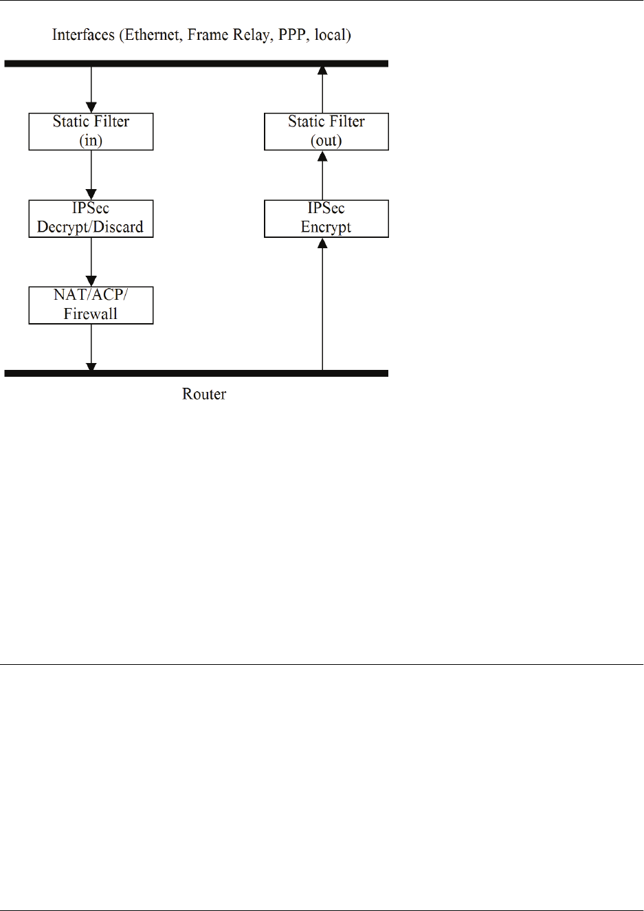
Command Reference Guide Ethernet Interface Command Set
60000CRG0-35E Copyright © 2012 ADTRAN, Inc. 1605
As shown in the diagram above, data coming into the product is first processed by the static filter
associated with the interface on which the data is received. This access group is a true static filter and is
available for use regardless of whether the firewall is enabled or disabled. Next (if the data is encrypted), it
is sent to the IPSec engine for decryption. The decrypted data is then processed by the stateful inspection
firewall. Therefore, given a terminating VPN tunnel, only unencrypted data is processed by the firewall.
The ACLs for a crypto map on an interface work in reverse logic to the ACLs for a policy class on an
interface. When specifying the ACLs for a crypto map, the source information is the private local side,
unencrypted source of the data. The destination information will be the far-end, unencrypted destination of
the data. However, ACLs for a policy class work in reverse. The source information for the ACL in a policy
class is the far end. The destination information is the local side.
Usage Examples
The following example applies all crypto maps with the name MyMap to the Ethernet interface:
(config)#interface ethernet 0/1
(config-eth 0/1)#crypto map MyMap

Command Reference Guide Ethernet Interface Command Set
60000CRG0-35E Copyright © 2012 ADTRAN, Inc. 1606
dynamic-dns
Use the dynamic-dns command to configure Dynamic DNS service provided by Dynamic Network
Services, Inc. (www.dyndns.org). Use the no form of this command to disable this feature. Variations of
this command include:
dynamic-dns custom <hostname> <minutes>
dynamic-dns dyndns <hostname> <username> <password>
dynamic-dns dyndns-custom <hostname> <username> <password>
dynamic-dns dyndns-static <hostname> <username> <password>
Syntax Description
<hostname> Specifies the host name for the server that updates the dynamic domain
naming system (DNS).
<minutes> Specifies the intervals in minutes to update the server with information
(updates also occur when the interface’s IP address changes regardless of
the update intervals).
<username> Specifies the user name.
<password> Specifies the password.
Refer to Functional Notes below for additional argument descriptions.
Default Values
No default values are necessary for this command.
Command History
Release 8.1 Command was introduced.
Release 12.1 Command was expanded.
Release A4.01 Command was expanded to include the Metro Ethernet Forum (MEF)
Ethernet Interface.
Functional Notes
custom - Constanttime.com’s Custom Dynamic DNSSM service allows you complete access and
management control over your domain name regardless of where you purchased/registered it. This allows
you to manage IP address mappings (A records), domain aliases (CNAME records), and mail servers (mail
exchange (MX) records).
dyndns - The Dynamic DNSSM offered by Dynamic Network Services, Inc. (DynDNS.org) allows you to
alias a dynamic IP address to a static host name in various domains. This allows your unit to be more
easily accessed from various locations on the Internet. This service is provided for up to five host names.
dyndns-custom
- DynDNS.org's Custom DNSSM service provides a full DNS solution, giving you
complete control over an entire domain name. A Web-based interface provides two levels of control over
your domain, catering to average or advanced users. Five globally redundant DNS servers ensure that
your domain will always resolve.

Command Reference Guide Ethernet Interface Command Set
60000CRG0-35E Copyright © 2012 ADTRAN, Inc. 1607
A choice of two interfaces is available. The basic interface is designed for most users. It comes
preconfigured for most common configurations and allows for easy creation of most common record types.
The advanced interface is designed for system administrators with a solid DNS background, and provides
layout and functionality similar to a BIND zone file allowing for the creation of nearly any record type.
Custom DNSSM can be used with both static and dynamic IPs, and has the same automatic update
capability through Custom DNS-aware clients as Dynamic DNS.
dyndns-static
- The Static DNS service is similar to DynDNS.org’s Dynamic DNSSM service in that it
allows a host name, such as yourname.dyndns.org, to point to your IP address. Unlike a Dynamic DNS
host, a Static DNS host does not expire after 35 days without updates, but updates take longer to
propagate through the DNS system. This service is provided for up to five host names.
If your IP address does not change often or at all, but you still want an easy name to remember it by
(without having to purchase your own domain name), Static DNS service is ideal for you.
If you would like to use your own domain name (such as yourname.com), you need Custom DNS service
that also provides full dynamic and static IP address support.
Usage Examples
The following example sets the Dynamic DNS to dyndns-custom with host name host, user’s name user,
and password pass:
(config)#interface ethernet 0/1
(config-eth 0/1)#dynamic-dns dyndns-custom host user pass

Command Reference Guide Ethernet Interface Command Set
60000CRG0-35E Copyright © 2012 ADTRAN, Inc. 1608
encapsulation 802.1q
Use the encapsulation 802.1q command to put the interface into 802.1q virtual local area network
(VLAN) mode.
Syntax Description
No subcommands.
Default Values
No default values are necessary for this command.
Command History
Release 6.1 Command was introduced.
Release A4.01 Command was expanded to include the Metro Ethernet Forum (MEF)
Ethernet Interface.
Usage Examples
The following example puts Ethernet interface 0/1 in 802.1q mode and configures a subinterface for VLAN
usage:
(config)#interface ethernet 0/1
(config-eth 0/1)#encapsulation 802.1q
(config-eth 0/1)#interface ethernet 0/1.1
(config-eth 0/1.1)#vlan-id 3

Command Reference Guide Ethernet Interface Command Set
60000CRG0-35E Copyright © 2012 ADTRAN, Inc. 1609
ethernet-cfm down
Use the ethernet-cfm down command to enable Ethernet operations, administration, and maintenance
(OAM) connectivity fault management (CFM) on the Ethernet interface. Use the no form of this command
to disable Ethernet OAM CFM on this interface.
Syntax Description
No subcommands.
Default Values
By default, Ethernet OAM CFM is disabled.
Command History
Release 17.4 Command was introduced.
Release A4.01 Command was expanded to include the Metro Ethernet Forum (MEF)
Ethernet Interface.
Functional Notes
For more information about Ethernet OAM CFM and its operation on AOS products, refer to the Ethernet
OAM CFM in AOS configuration guide available online at https://supportforums.adtran.com (article number
3013).
For more information regarding specific Ethernet OAM CFM configuration commands on the Ethernet
interface, refer to the Ethernet OAM CFM Command Set on page 3091.
Usage Examples
The following example enables Ethernet OAM CFM on Ethernet interface 0/1:
(config)#interface eth 0/1
(config-eth 0/1)#ethernet-cfm down

Command Reference Guide Ethernet Interface Command Set
60000CRG0-35E Copyright © 2012 ADTRAN, Inc. 1610
ethernet-cfm mep
Use the ethernet-cfm mep command to create an Ethernet operations, administration, and maintenance
(OAM) connectivity fault management (CFM) maintenance endpoint (MEP) on the Ethernet interface. Use
the no form of this command to remove the MEP from the interface. Variations of this command include:
ethernet-cfm mep <name> <name> <mep id> down
ethernet-cfm mep none <name> <mep id> down
Syntax Description
<name> Specifies the MEP’s maintenance domain.
<name> Specifies the MEP’s maintenance association.
<mep id> Specifies the unique numerical ID for this MEP. Range is 1 to 8191.
none Optional. Specifies no domain name is used.
down Specifies the direction of the MEP.
Default Values
By default, no MEPs exist on the interface.
Command History
Release 17.4 Command was introduced.
Release A4.01 Command was expanded to include the Metro Ethernet Forum (MEF)
Ethernet Interface.
Functional Notes
For more information about Ethernet OAM CFM and its operation on AOS products, refer to the Ethernet
OAM CFM in AOS configuration guide available online at https://supportforums.adtran.com (article number
3013).
For more information about specific MEP configuration commands, refer to the Ethernet OAM CFM
Command Set on page 3091.
Usage Examples
The following example creates an MEP, with the MEP ID 100, on Ethernet interface eth 0/1. The MEP is
associated with maintenance domain Domain1 and association association1:
(config)#interface eth 0/1
(config-eth 0/1)#ethernet-cfm mep Domain1 association1 100 down
(config-eth 0/1-mep)

Command Reference Guide Ethernet Interface Command Set
60000CRG0-35E Copyright © 2012 ADTRAN, Inc. 1611
flowcontrol receive
Use the flowcontrol receive command to enable incoming flow control for the Ethernet interface. If
flowcontrol recieve is enabled, the unit will honor received pause frames. Use the no form of this
command to disable flow control.
Syntax Description
No subcommands.
Default Values
By default, flow control is disabled.
Command History
Release 18.2 Command was introduced.
Usage Examples
The following example specifies that Ethernet interface giga-eth 0/1 honors received pause frames:
(config)#interface gigabit-ethernet 0/1
(config-giga-eth 0/1)#flowcontrol receive

Command Reference Guide Ethernet Interface Command Set
60000CRG0-35E Copyright © 2012 ADTRAN, Inc. 1612
full-duplex
Use the full-duplex command to configure the Ethernet interface for full-duplex operation. This allows the
interface to send and receive simultaneously. Use the no form of this command to return to the default
half-duplex operation.
Syntax Description
No subcommands.
Default Values
By default, all Ethernet interfaces are configured for half-duplex operation.
Command History
Release 1.1 Command was introduced.
Functional Notes
Full-duplex Ethernet is a variety of Ethernet technology currently being standardized by the IEEE. Because
there is no official standard, vendors are free to implement their independent versions of full-duplex
operation. Therefore, it is not safe to assume that one vendor’s equipment will work with another.
Devices at each end of a full-duplex link have the ability to send and receive data simultaneously over the
link. Theoretically, this simultaneous action can provide twice the bandwidth of normal (half-duplex)
Ethernet. To deploy full-duplex Ethernet, each end of the link must only connect to a single device (a
workstation or a switched hub port). With only two devices on a full-duplex link, there is no need to use the
medium access control mechanism (to share the signal channel with multiple stations) and listen for other
transmissions or collisions before sending data.
The 10Base-T, 100Base-TX, and 100Base-FX signaling systems support full-duplex operation (because
they have transmit and receive signal paths that can be simultaneously active).
Usage Examples
The following example configures the Ethernet interface for full-duplex operation:
(config)#interface ethernet 0/1
(config-eth 0/1)#full-duplex
Some Ethernet equipment (though rare) is unable to negotiate duplex if speed is manually
determined. To avoid incompatibilities, manually set the duplex if the speed is manually set.
Refer to speed on page 1712 for more information.
Command Reference Guide Ethernet Interface Command Set
60000CRG0-35E Copyright © 2012 ADTRAN, Inc. 1613
half-duplex
Use the half-duplex command to configure the Ethernet interface for half-duplex operation. This setting
allows the Ethernet interface to either send or receive at any given moment, but not simultaneously. Use
the no form of this command to disable half-duplex operation.
Syntax Description
No subcommands.
Default Values
By default, all Ethernet interfaces are configured for half-duplex operation.
Command History
Release 1.1 Command was introduced.
Functional Notes
Half-duplex Ethernet is the traditional form of Ethernet that employs the carrier sense multiple
access/collision detect (CSMA/CD) protocol to allow two or more hosts to share a common transmission
medium while providing mechanisms to avoid collisions. A host on a half-duplex link must “listen” on the
link and only transmit when there is an idle period. Packets transmitted on the link are broadcast (so it will
be “heard” by all hosts on the network). In the event of a collision (two hosts transmitting at once), a
message is sent to inform all hosts of the collision and a backoff algorithm is implemented. The backoff
algorithm requires the station to remain silent for a random period of time before attempting another
transmission. This sequence is repeated until a successful data transmission occurs.
Usage Examples
The following example configures the Ethernet interface for half-duplex operation:
(config)#interface ethernet 0/1
(config-eth 0/1)#half-duplex
Some Ethernet equipment (though rare) is unable to negotiate duplex if speed is
manually determined. To avoid incompatibilities, manually set the duplex if the speed
is manually set. Refer to speed on page 1712 for more information.

Command Reference Guide Ethernet Interface Command Set
60000CRG0-35E Copyright © 2012 ADTRAN, Inc. 1614
ip access-group <ipv4 acl name>
Use the ip access-group command to apply an Internet Protocol version 4 (IPv4) access control list (ACL)
to be used for IPv4 packets transmitted on or received from the specified interface. Use the no form of this
command to disable this type of control. Variations of this command include:
ip access-group <ipv4 acl name> in
ip access-group <ipv4 acl name> out
Syntax Description
<ipv4 acl name> Applies the named IPv4 ACL to the interface.
in Enables access control on IPv4 packets received on the specified interface.
out Enables access control on IPv4 packets transmitted on the specified
interface.
Default Values
By default, these commands are disabled.
Command History
Release 3.1 Command was introduced.
Release 5.1 Command was expanded to include the Ethernet subinterfaces.
Release A4.01 Command was expanded to include the Metro Ethernet Forum (MEF)
Ethernet Interface.
Functional Notes
When this command is enabled, the IPv4 destination address of each packet must be validated before
being passed through. If the packet is not acceptable per these settings, it is dropped.
Usage Examples
The following example configures the router to only allow IPv4 Telnet traffic (as defined in the
user-configured TelnetOnly ACL) into the Ethernet interface:
(config)#ip access-list extended TelnetOnly
(config-ext-nacl)#permit tcp any any eq telnet
(config-ext-nacl)#interface ethernet 0/1
(config-eth 0/1)#ip access-group TelnetOnly in

Command Reference Guide Ethernet Interface Command Set
60000CRG0-35E Copyright © 2012 ADTRAN, Inc. 1615
ip access-policy <ipv4 acp name>
Use the ip access-policy command to assign a specified Internet Protocol version 4 (IPv4) access control
policy (ACP) to an interface. IPv4 ACPs are applied to IPv4 traffic entering an interface. Use the no form
of this command to remove an ACP association. For more information on using IPv4 ACPs, refer to ip
policy-class <ipv4 acp name> on page 1058.
Syntax Description
<ipv4 acp name> Identifies the configured IPv4 ACP by alphanumeric descriptor (all ACP
descriptors are case sensitive).
Default Values
By default, there are no configured IPv4 ACPs associated with an interface.
Command History
Release 2.1 Command was introduced.
Release 5.1 Command was expanded to include the Ethernet subinterfaces.
Release 6.1 Command was expanded to include the virtual local area network (VLAN)
interfaces.
Release 15.1 Command was expanded to include the bridged virtual interfaces (BVIs).
Release 17.9 Command was changed to require the ip keyword for ADTRAN
internetworking products only.
Release R10.1.0 Command was changed to require the ip keyword for ADTRAN voice
products.
Functional Notes
To assign an IPv4 ACP to an interface, enter the interface configuration mode for the desired interface and
enter ip access-policy <ipv4 acp name>.
Usage Examples
The following example associates the IPv4 ACP PRIVATE (to allow inbound IPv4 traffic to the Web server)
to the Ethernet interface 0/1:
Enable the AOS security features:
(config)#ip firewall
Configured IPv4 ACPs will only be active if the ip firewall command has been entered at
the Global Configuration mode prompt to enable the AOS IPv4 security features. All
configuration parameters are valid, but no security data processing will be attempted
unless the security features are enabled.

Command Reference Guide Ethernet Interface Command Set
60000CRG0-35E Copyright © 2012 ADTRAN, Inc. 1616
Associate the ACP with the Ethernet interface 0/1:
(config)#interface eth 0/1
(config-eth 0/1)#ip access-policy PRIVATE

Command Reference Guide Ethernet Interface Command Set
60000CRG0-35E Copyright © 2012 ADTRAN, Inc. 1617
ip address dhcp
Use the ip address dhcp command to use Dynamic Host Configuration Protocol (DHCP) to obtain an
address on the interface. Use the no form of this command to remove a configured IP address (using
DHCP) and disable DHCP operation on the interface. Variables that may be used with this command to
further define the DHCP configuration include:
ip address dhcp client-id [<interface> | <identifier>] [hostname <“string”>] [track <name>]
[<administrative distance>]
ip address dhcp hostname “<string>” [no-default-route | no-domain-name | no-nameservers]
[track <name>] [<administrative distance>]
ip address dhcp [no-default-route | no-domain-name | no-nameservers] [track <name>]
[<administrative distance>]
ip address dhcp track <name> [<administrative distance>]
Syntax Description
<administrative distance> Optional. Specifies the administrative distance to use when adding the
DHCP gateway into the route table. It is used to determine the best route
when multiple routes to the same destination exist. The lower the
administrative distance, the more reliable the route. Range is 1 to 255.
client-id Optional. Specifies the client identifier used when obtaining an IP address
from a DHCP server.
<interface> Specifies an interface, thus defining the client identifier as the hexadecimal
medium access control (MAC) address of the specified interface (including
a hexadecimal number added to the front of the MAC address to identify the
media type).
For example, specifying the client-id ethernet 0/1 (where the Ethernet
interface has a MAC address of d217.0491.1150) defines the client
identifier as 01:d2:17:04:91:11:50 (where 01 defines the media type as
Ethernet). Refer to hardware-address on page 3052 for a detailed listing of
media types.
<identifier> Specifies a custom client-identifier using a text string (that is converted to a
hexadecimal equivalent) or 7 to 28 hexadecimal numbers (with colon
delimiters).
For example, a custom client identifier of 0f:ff:ff:ff:ff:51:04:99:a1 may be
entered using the <identifier> option.
hostname <“string”> Optional. Specifies a text string (to override the global router name) to use
as the name in the DHCP option 12 field. The string is enclosed in quotation
marks and can consist of up to 35 characters.
no-default-route Optional. Specifies that no default route is obtained via DHCP.
no-domain-name Optional. Specifies that no domain name is obtained via DHCP.
no-nameservers Optional. Specifies that no domain naming system (DNS) servers are
obtained via DHCP.

Command Reference Guide Ethernet Interface Command Set
60000CRG0-35E Copyright © 2012 ADTRAN, Inc. 1618
track <name> Optional. Attaches a network monitoring track to the DHCP client. The
DHCP gateway route for this client will only reside in the route table while
the track is in the pass state. For more information on configuring track
objects, refer to track <name> on page 1372.
Default Values
<administrative distance> By default, the administrative distance value is 1.
client-id Optional. By default, the client identifier is populated using the following
formula:
TYPE: INTERFACE SPECIFIC INFO : MAC ADDRESS
Where TYPE specifies the media type in the form of one hexadecimal byte
(refer to hardware-address on page 3052 for a detailed listing of media
types), and the MAC ADDRESS is the medium access control (MAC)
address assigned to the first Ethernet interface in the unit in the form of six
hexadecimal bytes. (For units with a single Ethernet interface, the MAC
ADDRESS assigned to Ethernet 0/1 is used in this field.)
INTERFACE SPECIFIC INFO is only used for Frame Relay interfaces and
can be determined using the following:
FR_PORT#: Q.922 ADDRESS
Where the FR_PORT# specifies the label assigned to the virtual Frame
Relay interface using four hexadecimal bytes. For example, a virtual Frame
Relay interface labeled 1 would have a FR_PORT# of 00:00:00:01.
The Q.922 ADDRESS field is populated using the following:
Where the FECN, BECN, C/R, DE, and high order extended address (EA)
bits are assumed to be 0 and the lower order EA bit is set to 1.
The following list provides a few example DLCIs and associated Q.922
address:
DLCI (decimal) / Q.922 address (hex)
16 / 0x0401
50 / 0x0C21
60 / 0x0CC1
70 / 0x1061
80 / 0x1401
hostname “<string>” By default, the host name is the name configured using the Global
Configuration hostname command.
DLCI (high order)
DLCI (lower) EA
EA
DE
C/R
FECN BECN
876 5 4 3 2 1

Command Reference Guide Ethernet Interface Command Set
60000CRG0-35E Copyright © 2012 ADTRAN, Inc. 1619
Command History
Release 2.1 Command was introduced.
Release 8.1 Command was expanded to include the asynchronous transfer mode (ATM)
subinterface.
Release 13.1 Command was expanded to include the track and administrative distance.
Release A4.01 Command was expanded to include the Metro Ethernet Forum (MEF)
Ethernet Interface.
Release A5.01 Command was expanded to include the Gigabit Ethernet interface.
Functional Notes
DHCP allows interfaces to acquire a dynamically assigned IP address from a configured DHCP server on
the network. Many Internet service providers (ISPs) require the use of DHCP when connecting to their
services. Using DHCP reduces the number of dedicated IP addresses the ISP must obtain. Consult your
ISP to determine the proper values for the client-id and hostname fields.
Usage Examples
The following example enables DHCP operation on the Ethernet interface 0/1:
(config)#interface ethernet 0/1
(config-eth 0/1)#ip address dhcp
The following example enables DHCP operation on the Ethernet interface 0/1 utilizing host name adtran
and does not allow obtaining a default route, domain name, or name servers. It also sets the administrative
distance as 5:
(config)#interface ethernet 0/1
(config-eth 0/1)#ip address dhcp hostname “adtran” no-default-route no-domain-name
no-nameservers 5

Command Reference Guide Ethernet Interface Command Set
60000CRG0-35E Copyright © 2012 ADTRAN, Inc. 1620
ip address <ipv4 address> <subnet mask>
Use the ip address command to define an Internet Protocol version 4 (IPv4) address on the specified
interface (only one primary address is allowed). Use the optional secondary keyword to define a
secondary IPv4 address. Use the no form of this command to remove a configured IPv4 address.
Variations of this command include:
ip address <ipv4 address> <subnet mask>
ip address <ipv4 address> <subnet mask> secondary
Syntax Description
<ipv4 address> Specifies a valid IPv4 address. IPv4 addresses should be expressed in
dotted decimal notation (for example, 10.10.10.1).
<subnet mask> Specifies the subnet mask that corresponds to a range of IPv4 addresses
(network) or a specific host. Subnet masks can be expressed in dotted
decimal notation (for example, 255.255.255.0) or as a prefix length (for
example, /24).
secondary
Optional. Configures a secondary IPv4 address for the specified interface.
Default Values
By default, there are no assigned IPv4 addresses.
Command History
Release 1.1 Command was introduced.
Release 5.1 Command was expanded to include the Ethernet subinterfaces.
Release A4.01 Command was expanded to include the Metro Ethernet Forum (MEF)
Ethernet Interface.
Functional Notes
Use secondary IPv4 addresses to allow dual subnets on a single interface (when you need more IP
addresses than the primary subnet can provide). When using secondary IPv4 addresses, avoid routing
loops by verifying that all devices on the network segment are configured with secondary IPv4 addresses
on the secondary subnet.
Usage Examples
The following example configures a secondary IPv4 address of 192.22.72.101 /30:
(config)#interface ethernet 0/1
(config-eth 0/1)#ip address 192.22.72.101 /30 secondary

Command Reference Guide Ethernet Interface Command Set
60000CRG0-35E Copyright © 2012 ADTRAN, Inc. 1621
ip address range <start ip address> <end ip address> <subnet mask>
secondary
Use the ip address range secondary command to specify a range of secondary Internet Protocol version 4
(IPv4) addresses on the specified interface. Use the no form of this command to remove the range of
configured IPv4 addresses.
Syntax Description
<start ipv4 address> Specifies the first IPv4 address in the range.
<end ipv4 address> Specifies the last IPv4 address in the range.
IPv4 addresses should be expressed in dotted decimal notation (for
example, 10.10.10.1).
<subnet mask> Specifies the subnet mask that corresponds to a range of IPv4 addresses
(network) or a specific host. Subnet masks can be expressed in dotted
decimal notation (for example, 255.255.255.0) or as a prefix length (for
example, /24).
Default Values
By default, no IPv4 address range is defined.
Command History
Release 17.4 Command was introduced.
Release R10.1.0 Command was added to the facility data link (FDL) interface.
Functional Notes
Use secondary IPv4 addresses to allow dual subnets on a single interface (when you need more IPv4
addresses than the primary subnet can provide). When using secondary IPv4 addresses, avoid routing
loops by verifying that all devices on the network segment are configured with secondary IPv4 addresses
on the secondary subnet.
Usage Examples
The following example configures a range of secondary IPv4 addresses from 192.22.72.1 to 192.22.72.10
on subnet 255.255.255.252:
(config)#interface ethernet 0/1
(config-eth 0/1)#ip address range 192.22.72.1 192.22.72.10 255.255.255.252 secondary

Command Reference Guide Ethernet Interface Command Set
60000CRG0-35E Copyright © 2012 ADTRAN, Inc. 1622
ip dhcp
Use the ip dhcp command to release or renew the Dynamic Host Configuration Protocol (DHCP) Internet
Protocol version 4 (IPv4) address. This command is only applicable when using DHCP for IP address
assignment. Variations of this command include:
ip dhcp release
ip dhcp renew
Syntax Description
release Releases the DHCP IPv4 address.
renew Renews the DHCP IPv4 address.
Default Values
No default values are necessary for this command.
Command History
Release 3.1 Command was introduced.
Release 8.1 Command was added to the asynchronous transfer mode (ATM)
subinterface.
Release A4.01 Command was expanded to include the Metro Ethernet Forum (MEF)
Ethernet interface.
Release R10.1.0 Command was added to the bridged virtual interface (BVI).
Usage Examples
The following example releases the IPv4 address assigned (by DHCP) on the Ethernet interface 0/1:
(config)#interface ethernet 0/1
(config-eth 0/1)#ip dhcp release

Command Reference Guide Ethernet Interface Command Set
60000CRG0-35E Copyright © 2012 ADTRAN, Inc. 1623
ip dhcp relay destination <ipv4 address>
Use the ip dhcp relay destination command to enable Dynamic Host Control Protocol (DHCP) for
Internet Protocol version 4 (IPv4) and to specify the IPv4 address for the DHCPv4 messages. Using the no
form of this command disables the relay functionality for the specified destination. When all destinations
are removed, DHCPv4 relay functionality is disabled on the interface.
Syntax Description
<ipv4 address> Specifies the IPv4 address for the DHCPv4 messages. IPv4 addresses
should be expressed in dotted decimal notation (for example, 10.10.10.1)..
Default Values
By default, no DHCP relay agent destinations are configured and the relay agent mode is disabled.
Command History
Release 18.2 Command was introduced.
Usage Examples
The following example enables DHCPv4 relay agent functionality and specifies the destination address as
192.33.4.251:
(config)#interface ethernet 0/1
(config-eth 0/1)#ip dhcp relay destination 192.33.4.251

Command Reference Guide Ethernet Interface Command Set
60000CRG0-35E Copyright © 2012 ADTRAN, Inc. 1624
ip directed-broadcast
Use the ip directed-broadcast command to allow reception/forwarding of directed broadcasts. Use the no
form of this command to disable this feature. Variations of this command include:
ip directed-broadcast
ip directed-broadcast <name>
Syntax Description
<name> Optional. Specifies an IP access control list (ACL) to filter traffic.
Default Values
By default, this command is disabled.
Command History
Release 14.1 Command was introduced.
Release A4.01 Command was expanded to include the Metro Ethernet Forum (MEF)
Ethernet Interface.
Functional Notes
A directed broadcast is a packet intended for all nodes on a nonlocal network. For example, the broadcast
address 255.255.255.255 reaches all nodes on a network; the directed broadcast address 128.1.255.255
is intended for all nodes whose network address is 128.1.0.0. A router not directly attached to 128.1.0.0
simply forwards the directed broadcast packet to the next hop. A router on network 128.1.0.0 that has ip
directed-broadcast enabled, accepts and forwards the packet to all nodes whose network address is
128.1.0.0. Routers connecting subnets of 128.1.0.0 also accept and forward the packet to the nodes on
their respective subnets. When a directed broadcast packet reaches a router that is directly connected to
its destination subnet, that packet is distributed as a broadcast on the destination subnet. The packet is
then sent as a link-layer broadcast.
The ip directed-broadcast command controls the distribution of directed broadcasts when they reach
their target subnets. Only the final transmission of the directed broadcast on its ultimate destination subnet
is affected. It does not affect the transit unicast routing of IP directed broadcasts.
If ip directed-broadcast is enabled for this interface, incoming IP packets whose addresses identify them
as directed broadcasts intended for the subnet to which this interface is attached will be forwarded as
broadcasts on that subnet. Forwarding of the packets can be limited by specifying an ACL with this
command. In this case, only directed broadcasts that are permitted by the specified ACL will be forwarded,
and all other directed broadcasts directed to this interface subnet will be dropped.
Disabling the ip directed-broadcast command will cause directed broadcasts destined for the subnet to
which this interface is attached to be dropped.
This option is a requirement for routers as described in RFC 1812, section 4.2.2.11. Furthermore, it is
disabled by default (RFC 2644), with the intended goal of reducing the efficacy of certain types of denial of
service (DoS) attacks.

Command Reference Guide Ethernet Interface Command Set
60000CRG0-35E Copyright © 2012 ADTRAN, Inc. 1625
Usage Examples
The following example enables forwarding of directed broadcasts on the interface ethernet 0/1:
(config)#interface ethernet 0/1
(config-eth 0/1)#ip directed-broadcast

Command Reference Guide Ethernet Interface Command Set
60000CRG0-35E Copyright © 2012 ADTRAN, Inc. 1626
ip ffe
Use the ip ffe command to enable the RapidRoute Engine on this interface with the default number of
entries. Use the no form of this command to disable this feature. Variations of this command include:
ip ffe
ip ffe max-entries <value>
Syntax Description
max-entries <value> Optional. Specifies the maximum number of entries stored in the flow table.
Valid range is from 1 to 8192.
Default Values
By default, the RapidRoute Engine is disabled. The default number of max-entries is 4096.
Command History
Release 13.1 Command was introduced.
Release 17.6 Command was expanded to include the high level data link control (HDLC)
and tunnel interfaces.
Release A4.01 Command was expanded to include the Metro Ethernet Forum (MEF)
Ethernet Interface.
Functional Notes
RapidRoute can be used to help reduce routing overhead, and thus reduce overall routing times. Routing
times are reduced by the creation of a flow table on the ingress interface. The maximum number of entries
that can be stored in the flow table at any one time may be specified by using the max-entries parameters.
Usage Examples
The following example enables RapidRoute and sets the maximum number of entries in the flow table to
50:
(config)#interface ethernet 0/1
(config-eth 0/1)#ip ffe max-entries 50
Issuing this command will cause all RapidRoute entries on this interface to be cleared.

Command Reference Guide Ethernet Interface Command Set
60000CRG0-35E Copyright © 2012 ADTRAN, Inc. 1627
Technology Review
The RapidRoute system goal is to increase IP packet throughput by moving as much of the packet
processing into the engine as possible. Packets are classified into flows based upon the IP protocol
(Transmission Control Protocol (TCP), User Datagram Protocol (UDP), Internet Control Message Protocol
(ICMP), etc.), the source and destination IP addresses, IP type of service (ToS), and the protocol-specific
information, such as the source and destination port numbers. Flows are defined as the unidirectional
representation of a conversation between two IP hosts. Each ingress interface keeps its own flow table, a
collection of flow entries.
The first packet in a flow that is forwarded through the unit will build a flow entry. When a flow entry is
looked up but no entry is found, a RapidRouteBuilder object is allocated and attached to the packet. As the
packet passes through the various processing layers, each subsystem will add processing to the
RapidRouteBuilder. When packet is about to be forwarded out of the egress interface, the
RapidRouteBuilder will be finalized. That is, the flow entry being built will be checked for completeness and
committed to the flow table on the ingress interface. Subsequent flow matches can then bypass the normal
processing layers.

Command Reference Guide Ethernet Interface Command Set
60000CRG0-35E Copyright © 2012 ADTRAN, Inc. 1628
ip flow
Use the ip flow command to enable integrated traffic monitoring (ITM) for all traffic received or
forwarded on an interface. Use the no form of this command to disable traffic monitoring. Variations of
this command include:
ip flow egress
ip flow egress <name>
ip flow ingress
ip flow ingress <name>
Syntax Description
egress Specifies that all outgoing traffic be monitored.
ingress Specifies that all incoming traffic be monitored.
<name> Optional. Specifies the name of an access control list (ACL) to use for
filtering traffic.
Default Values
By default, no traffic monitoring is enabled.
Command History
Release 16.1 Command was introduced.
Release A4.01 Command was expanded to include the Metro Ethernet Forum (MEF)
Ethernet Interface.
Usage Examples
The following example enables traffic monitoring on an Ethernet interface to monitor incoming traffic
through an ACL called myacl:
(config)#interface ethernet 0/1
(config-eth 0/1)#ip flow ingress myacl

Command Reference Guide Ethernet Interface Command Set
60000CRG0-35E Copyright © 2012 ADTRAN, Inc. 1629
ip helper-address <ip address>
Use the ip helper-address command to configure AOS to forward User Datagram Protocol (UDP)
broadcast packets received on the interface. Use the no form of this command to disable forwarding
packets.
Syntax Description
<ip address> Specifies the destination IP address for the forwarded UDP packets. IP
addresses should be expressed in dotted decimal notation (for example,
10.10.10.1).
Default Values
By default, broadcast UDP packets are not forwarded.
Command History
Release 1.1 Command was introduced.
Release 5.1 Command was expanded to include the Ethernet subinterfaces.
Release A4.01 Command was expanded to include the Metro Ethernet Forum (MEF)
Ethernet Interface.
Functional Notes
When used in conjunction with the ip forward-protocol command, the ip helper-address feature allows
you to customize which broadcast packets are forwarded.
To implement the helper address feature, assign helper address(es) (specifying the device that needs to
receive the broadcast traffic) to the interface closest to the host that transmits the broadcast packets.
When broadcast packets (of the specified type forwarded using the ip forward-protocol command) are
received on the interface, they will be forwarded to the device that needs the information.
Only packets meeting the following criteria are considered eligible by the ip helper-address feature:
1. The packet IP protocol is UDP.
2. Any UDP port specified using the ip forward-protocol command.
3. The medium access control (MAC) address of the frame is an all-ones broadcast address (ffff.ffff.ffff).
4. The destination IP address is broadcast defined by all ones (255.255.255.255) or a subnet broadcast
(for example, 192.33.4.251 for the 192.33.4.248 /30 subnet).
The ip helper-address command must be used in conjunction with the ip forward-protocol
command to configure AOS to forward UDP broadcast packets.

Command Reference Guide Ethernet Interface Command Set
60000CRG0-35E Copyright © 2012 ADTRAN, Inc. 1630
Usage Examples
The following example forwards all domain naming system (DNS) broadcast traffic to the DNS server with
IP address 192.33.5.99:
(config)#ip forward-protocol udp domain
(config)#interface ethernet 0/1
(config-eth 0/1)#ip helper-address 192.33.5.99

Command Reference Guide Ethernet Interface Command Set
60000CRG0-35E Copyright © 2012 ADTRAN, Inc. 1631
ip igmp
Use the ip igmp command to configure multicasting related functions for the interface. Variations of this
command include:
ip igmp immediate-leave
ip igmp last-member-query-interval <milliseconds>
ip igmp querier-timeout <seconds>
ip igmp query-interval <seconds>
ip igmp query-max-response-time <seconds>
ip igmp static-group <address>
ip igmp version [1 | 2]
Syntax Description
immediate-leave Specifies that if only one host (or Internet Group Management Protocol
(IGMP) snooping switch) is connected to the interface, when a leave is
received, multicast of that group is immediately terminated as opposed
to sending a group query and timing out the group if no device responds.
Works in conjunction with ip igmp last-member-query-interval.
Applies to all groups when configured. Use the no form of this command
to disable the immediate-leave feature.
last-member-query-interval
<milliseconds>
Controls the timeout (in milliseconds) used to detect whether any group
receivers remain on an interface after a receiver leaves a group. If a
receiver sends a leave-group message (IGMP Version 2), the router
sends a group-specific query on that interface. After twice the time
specified by this command plus as much as one second longer, if no
receiver responds, the router removes that interface from the group and
stops sending that group's multicast packets to the interface. Range is
100 to 65535 ms. Use the no form of this command to return to the
default setting.
querier-timeout <seconds> Specifies the interval (in seconds) that the router waits after the current
querier’s last query before it takes over as querier (IGMP V2). Range is
60 to 300 seconds. Use the no form of this command to return to the
default setting.
query-interval <seconds> Specifies the interval (in seconds) at which IGMP queries are sent on an
interface. Host query messages are addressed to the all-hosts multicast
group with an IP time to live (TTL) of 1. The router uses queries to detect
whether multicast group members are on the interface and to select an
IGMP designated router (DR) for the attached segment (if more than one
multicast router exists). Only the DR for the segment sends queries. For
IGMP V2, the DR is the router with the lowest IP address on the
segment. Range is 0 to 65535 seconds. Use the no form of this
command to return to the default setting.
query-max-response-time
<seconds>
Specifies the maximum response time (in seconds) advertised by this
interface in queries when using IGMP V2. Hosts are allowed a random
time within this period to respond, reducing response bursts. Use the no
form of this command to return to the default setting.

Command Reference Guide Ethernet Interface Command Set
60000CRG0-35E Copyright © 2012 ADTRAN, Inc. 1632
Default Values
The defaults for this command are:
last-member-query-interval 1000 milliseconds
querier-timeout 2x the query-interval value
query-interval 60 seconds
query-max-response-time 10 seconds
version Version 1
There are no default values for immediate-leave and static-group.
Command History
Release 7.1 Command was introduced.
Release A4.01 Command was expanded to include the Metro Ethernet Forum (MEF)
Ethernet Interface.
Usage Examples
The following example sets the query message interval on the interface to 200 milliseconds:
(config)#interface ethernet 0/1
(config-eth 0/1)#ip igmp last-member-query-interval 200
static-group <address> Configures the router's interface to be a statically connected member of
the specified group. Packets received on the correct reverse path
forwarding (RPF) interface are forwarded to this interface regardless of
whether any receivers have joined the specified group using IGMP. Use
the no form of this command to remove a configured static group.
version [1 | 2] Sets the interface’s IGMP version. Use the no form of this command to
return to the default setting.
Syntax Description

Command Reference Guide Ethernet Interface Command Set
60000CRG0-35E Copyright © 2012 ADTRAN, Inc. 1633
ip mcast-stub downstream
Use the ip mcast-stub downstream command to enable multicast forwarding and Internet Group
Management Protocol (IGMP) (router mode) on an interface, and to place it in multicast stub downstream
mode. Use the no form of this command to disable this feature.
Syntax Description
No subcommands.
Default Values
By default, this command is disabled.
Command History
Release 7.1 Command was introduced.
Release A4.01 Command was expanded to include the Metro Ethernet Forum (MEF)
Ethernet Interface.
Functional Notes
This command is used in IP multicast stub applications in conjunction with the ip mcast-stub
helper-address and ip mcast-stub upstream commands. Downstream interfaces connect to segments
with multicast hosts. Multiple interfaces may be configured in downstream mode; however, interfaces
connecting to the multicast network (upstream) should not be configured in downstream mode. Interfaces
configured as downstream should have the lowest IP address of all IGMP-capable routers on the
connected segment in order to be selected as the designated router (DR) and ensure proper forwarding.
Refer to ip mcast-stub helper-address <ip address> on page 1042 and ip mcast-stub upstream on page
1636 for more information.
Usage Examples
The following example enables multicast forwarding and IGMP on the interface:
(config)#interface ethernet 0/1
(config-eth 0/1)#ip mcast-stub downstream

Command Reference Guide Ethernet Interface Command Set
60000CRG0-35E Copyright © 2012 ADTRAN, Inc. 1634
ip mcast-stub fixed
Use the ip mcast-stub fixed command to allow forwarding of multicast traffic on a selected interface after
enabling multicast routing. Use the no form of this command to disable this mode.
Syntax Description
No subcommands.
Default Values
By default, this command is disabled.
Command History
Release 12.1 Command was introduced.
Release A4.01 Command was expanded to include the Metro Ethernet Forum (MEF)
Ethernet Interface.
Functional Notes
Multicast routing must be enabled prior to setting ip mcast-stub fixed on the selected interface. Also, use
the ip igmp static-group <ip address> command to receive multicast traffic without host-initiated Internet
Group Management Protocol (IGMP) activity on the selected interface. Otherwise, all host-initiated IGMP
transactions will enter multicast routes on the router’s interface involved with IGMP activities.
Usage Examples
The following example enables multicast traffic forwarding and IGMP on the interface:
(config)#interface ethernet 0/1
(config-eth 0/1)#ip mcast-stub fixed

Command Reference Guide Ethernet Interface Command Set
60000CRG0-35E Copyright © 2012 ADTRAN, Inc. 1635
ip mcast-stub helper-enable
Use the ip mcast-stub helper-enable command to assign the ip mcast-stub helper-address as the
Internet Group Management Protocol (IGMP) proxy. Use the no form of this command to disable this
feature.
Syntax Description
No subcommands.
Default Values
By default, this command is disabled.
Command History
Release 8.1 Command was introduced.
Release A4.01 Command was expanded to include the Metro Ethernet Forum (MEF)
Ethernet Interface.
Functional Notes
This command is used in IP multicast stub applications in conjunction with the ip mcast-stub
helper-address, ip mcast-stub upstream, and ip mcast-stub downstream commands. When enabled,
the interface becomes a helper forwarding interface. The IGMP host function is dynamically enabled and
the interface becomes the active upstream interface, enabling the unit to perform as an IGMP proxy. Refer
to ip mcast-stub helper-address <ip address> on page 1042, ip mcast-stub downstream on page 1633,
and ip mcast-stub upstream on page 1636 for more information.
Usage Examples
The following example sets the helper address as the IGMP proxy:
(config)#interface ethernet 0/1
(config-eth 0/1)#ip mcast-stub helper-enable

Command Reference Guide Ethernet Interface Command Set
60000CRG0-35E Copyright © 2012 ADTRAN, Inc. 1636
ip mcast-stub upstream
Use the ip mcast-stub upstream command to enable multicast forwarding on an interface and place it in
multicast stub upstream mode. Use the no form of this command to disable this feature.
Syntax Description
No subcommands.
Default Values
By default, this command is disabled.
Command History
Release 7.1 Command was introduced.
Release A4.01 Command was expanded to include the Metro Ethernet Forum (MEF)
Ethernet Interface.
Functional Notes
This command is used in IP multicast stub applications in conjunction with the ip mcast-stub
helper-address and ip mcast-stub downstream commands. When enabled, the interface becomes a
candidate to be a helper forwarding interface. If chosen as the best path toward the helper address by the
router's unicast route table, the Internet Group Management Protocol (IGMP) host function is dynamically
enabled and the interface becomes the active upstream interface, enabling the router to perform as an
IGMP proxy. Though multiple interfaces may be candidates, no more than one interface will actively serve
as the helper forwarding interface. Refer to ip mcast-stub helper-address <ip address> on page 1042 and
ip mcast-stub downstream on page 1633 for more information.
Usage Examples
The following example enables multicast forwarding on the interface:
(config)#interface ethernet 0/1
(config-eth 0/1)#ip mcast-stub upstream

Command Reference Guide Ethernet Interface Command Set
60000CRG0-35E Copyright © 2012 ADTRAN, Inc. 1637
ip mtu <size>
Use the ip mtu command to configure the Internet Protocol version 4 (IPv4) maximum transmission unit
(MTU) size for the active interface. Use the no form of this command to return to the default value.
Syntax Description
<size> Configures the window size for transmitted IPv4 packets. The valid ranges
for the various interfaces are listed below:
ATM subinterfaces 64 to 1520
BVIs 64 to 2100
Demand interfaces 64 to 1520
Ethernet interfaces (all types) 64 to 1500
FDL interfaces 64 to 256
Frame Relay subinterfaces 64 to 1520
HDLC interfaces (NetVanta 5305) 64 to 4600
HDLC interfaces (all other NetVanta products) 64 to 2100
Loopback interfaces 64 to 1500
PPP interfaces (NetVanta 5305) 64 to 4600
PPP interfaces (all other NetVanta products) 64 to 2100
Tunnel interfaces 64 to 18190
Default Values
<size> The default values for the various interfaces are listed below:
ATM subinterfaces 1500
BVIs 1500
Demand interfaces 1500
Ethernet interfaces (all types) 1500
FDL interfaces 256
Frame Relay subinterfaces 1500
HDLC interfaces 1500
Loopback interfaces 1500
PPP interfaces 1500
Tunnel interfaces 1476
Command History
Release 1.1 Command was introduced.
Release 11.1 Command was expanded to include the demand interface.
Release 17.9 Command was changed to require the ip keyword for ADTRAN
internetworking products only.
Release R10.1.0 Command was changed to require the ip keyword for ADTRAN voice
products.

Command Reference Guide Ethernet Interface Command Set
60000CRG0-35E Copyright © 2012 ADTRAN, Inc. 1638
Functional Notes
Open shortest path first (OSPF) will not become adjacent on links where the MTU sizes do not match. If
router A and router B are exchanging hello packets but their MTU sizes do not match, they will never reach
adjacency. This is by design and required by the RFC.
Usage Examples
The following example specifies an IPv4 MTU of 1200 on the Ethernet interface 0/1:
(config)#interface eth 0/1
(config-eth 0/1)#ip mtu 1200

Command Reference Guide Ethernet Interface Command Set
60000CRG0-35E Copyright © 2012 ADTRAN, Inc. 1639
ip ospf
Use the ip ospf command to customize open shortest path first (OSPF) settings (if needed). Use the no
form of this command to return to the default setting. Variations of this command include:
ip ospf authentication-key <password>
ip ospf cost <value>
ip ospf dead-interval <seconds>
ip ospf hello-interval <seconds>
ip ospf message-digest-key [1 | 2] md5 <key>
ip ospf priority <value>
ip ospf retransmit-interval <seconds>
ip ospf transmit-delay <seconds>
Syntax Description
authentication-key <password> Assigns a simple-text authentication password to be used by
other routers using the OSPF simple password authentication.
cost <value> Specifies the OSPF cost of sending a packet on the interface.
This value overrides any computed cost value. Range is
1 to 65535.
dead-interval <seconds> Sets the maximum interval (in seconds) allowed between hello
packets. If the maximum is exceeded, neighboring devices will
determine that the device is down. Range is 0 to 32767
seconds.
hello-interval <seconds> Specifies the interval (in seconds) between hello packets sent
on the interface. Range is 0 to 32767 seconds.
message-digest-key [1 | 2] md5 <key> Configures OSPF message digest 5 (MD5) authentication
(16 byte maximum) keys.
priority <value> Sets the OSPF priority. The value set in this field helps
determine the designated router (DR) for this network. Range is
0 to 255.
retransmit-interval <seconds> Specifies the interval (in seconds) between link state
advertisements (LSAs). Range is 0 to 32767 seconds.
transmit-delay <seconds> Sets the estimated time (in seconds) required to send a link
state advertisement (LSA) on the interface. Range is 0 to
32767 seconds.
Default Values
The defaults for this command are:
dead-interval <seconds> 40 seconds
hello-interval <seconds> 10 seconds: Ethernet, Frame Relay, and Point-to-Point
Protocol (PPP)
priority <value 1
retransmit-interval <seconds> 5 seconds
transmit-delay <seconds> 1 second

Command Reference Guide Ethernet Interface Command Set
60000CRG0-35E Copyright © 2012 ADTRAN, Inc. 1640
Command History
Release 3.1 Command was introduced.
Release 5.1 Command was expanded to include the Ethernet subinterfaces.
Release A4.01 Command was expanded to include the Metro Ethernet Forum (MEF)
Ethernet Interface.
Usage Examples
The following example specifies an OSPF priority of 120 on the Ethernet interface:
(config)#interface ethernet 0/1
(config-eth 0/1)#ip ospf priority 120

Command Reference Guide Ethernet Interface Command Set
60000CRG0-35E Copyright © 2012 ADTRAN, Inc. 1641
ip ospf authentication
Use the ip ospf authentication command to authenticate an interface that is performing open shortest path
first (OSPF) authentication. Use the no form of this command to return to the default setting. Variations of
this command include:
ip ospf authentication
ip ospf authentication message-digest
ip ospf authentication null
Syntax Description
message-digest
Optional. Selects message-digest authentication type.
null
Optional. Specifies that no authentication is used.
Default Values
By default, this is set to null (meaning no authentication is used).
Command History
Release 3.1 Command was introduced.
Release 5.1 Command was expanded to include the Ethernet subinterfaces.
Release A4.01 Command was expanded to include the Metro Ethernet Forum (MEF)
Ethernet Interface.
Usage Examples
The following example specifies that no authentication will be used on the Ethernet interface:
(config)#interface ethernet 0/1
(config-eth 0/1)#ip ospf authentication null

Command Reference Guide Ethernet Interface Command Set
60000CRG0-35E Copyright © 2012 ADTRAN, Inc. 1642
ip ospf network
Use the ip ospf network command to specify the type of network on this interface. Use the no form of this
command to return to the default setting. Variations of this command include:
ip ospf network broadcast
ip ospf network point-to-point
Syntax Description
broadcast Sets the network type for broadcast.
point-to-point Sets the network type for point-to-point.
Default Values
By default, Ethernet defaults to broadcast. Point-to-Point Protocol (PPP) and Frame Relay default to
point-to-point.
Command History
Release 3.1 Command was introduced.
Release 5.1 Command was expanded to include the Ethernet subinterfaces.
Release A4.01 Command was expanded to include the Metro Ethernet Forum (MEF)
Ethernet Interface.
Functional Notes
A point-to-point network will not elect designated routers.
Usage Examples
The following example designates a broadcast network type:
(config)#interface ethernet 0/1
(config-eth 0/1)#ip ospf network broadcast

Command Reference Guide Ethernet Interface Command Set
60000CRG0-35E Copyright © 2012 ADTRAN, Inc. 1643
ip pim sparse-mode
Use the ip pim sparse-mode command to enable protocol-independent multicast (PIM) sparse mode for
this interface. Use the no form of this command to disable PIM sparse mode.
Syntax Description
No subcommands.
Default Values
By default, PIM sparse mode for this interface is disabled.
Command History
Release 11.1 Command was introduced.
Release A4.01 Command was expanded to include the Metro Ethernet Forum (MEF)
Ethernet Interface.
Functional Notes
PIM sparse mode is a multicast routing protocol that makes use of the unicast forwarding table. It builds
unidirectional shared trees rooted at a rendezvous point (RP) for a multicast group or a shortest path tree
rooted at a specific source for a multicast group.
Usage Examples
The following example enables PIM sparse mode on the interface:
(config)#interface ethernet 0/1
(config-eth 0/1)#ip pim sparse-mode

Command Reference Guide Ethernet Interface Command Set
60000CRG0-35E Copyright © 2012 ADTRAN, Inc. 1644
ip pim-sparse dr-priority <value>
Use the ip pim-sparse dr-priority command to specify the priority for the designated router (DR). This
command modifies the router’s priority in the DR election process. Use the no form of this command to
return to the default value.
Syntax Description
<value> Specifies the priority of this interface (to be used when determining the DR).
Valid range is 1 to 4294967295.
Default Values
By default, the priority of all protocol-independent multicast (PIM) interfaces is 1.
Command History
Release 11.1 Command was introduced.
Release A4.01 Command was expanded to include the Metro Ethernet Forum (MEF)
Ethernet Interface.
Functional Notes
Interfaces advertise their configured priority values in the hello messages transmitted on the interface.
Routers use the priority values to determine the appropriate DR. The router on the network segment with
the highest priority is selected as the DR. If a hello message is received on the interface from a router on
the network segment and it does not contain a priority, the entire network segment defaults to DR selection
based on IP addresses instead of priority. In this instance, the DR is selected as the router on the network
segment that has the highest IP address. AOS will always include a priority in all transmitted hello
messages. If no priority is specifically designated by the user, the priority is set as the default of 1.
Usage Examples
The following example specifies a priority of 100 on the Ethernet 0/1 interface:
(config)#interface ethernet 0/1
(config-eth 0/1)#ip pim-sparse dr-priority 100

Command Reference Guide Ethernet Interface Command Set
60000CRG0-35E Copyright © 2012 ADTRAN, Inc. 1645
ip pim-sparse hello-timer <value>
Use the ip pim-sparse hello-timer command to specify protocol-independent multicast (PIM) sparse hello
timer period. This is the time interval at which periodic hellos are sent out on all interfaces of a
PIM-capable router. Use the no form of this command to return to the default value.
Syntax Description
<value> Specifies the interval (in seconds) at which periodic hellos are sent out of
the interface. Valid range is 10 to 3600 seconds.
Default Values
By default, the hellos are transmitted on PIM interfaces every 60 seconds.
Command History
Release 11.1 Command was introduced.
Release A4.01 Command was expanded to include the Metro Ethernet Forum (MEF)
Ethernet Interface.
Functional Notes
Hello messages are used to inform neighbors of a router’s presence. Hello messages normally generate a
small amount of traffic on an interface. Setting the hello-timer to a small interval increases the number of
hellos sent (thus increasing the amount of traffic). Set the hello-timer to a reasonable value, taking into
consideration the bandwidth available on the interface.
Usage Examples
The following example specifies hellos be sent on the Ethernet 0/1 interface every 3600 seconds:
(config)#interface ethernet 0/1
(config-eth 0/1)#ip pim-sparse hello-timer 3600

Command Reference Guide Ethernet Interface Command Set
60000CRG0-35E Copyright © 2012 ADTRAN, Inc. 1646
ip pim-sparse nbr-timeout <value>
Use the ip pim-sparse nbr-timeout command to specify protocol-independent multicast (PIM) sparse
neighbor timeout. This is the time interval after which a PIM-capable router will consider a neighbor not
present. Use the no form of this command to return to the default value.
Syntax Description
<value> Specifies the time interval in seconds after which a neighbor is considered
not present. Valid range is 30 to 10800 seconds.
Default Values
By default, the nbr-timeout is set to 105 seconds.
Command History
Release 11.1 Command was introduced.
Release A4.01 Command was expanded to include the Metro Ethernet Forum (MEF)
Ethernet Interface.
Usage Examples
The following example sets the neighbor timeout to 300 seconds:
(config)#interface ethernet 0/1
(config-eth 0/1)#ip pim-sparse nbr-timeout 300

Command Reference Guide Ethernet Interface Command Set
60000CRG0-35E Copyright © 2012 ADTRAN, Inc. 1647
ip pim-sparse override-interval <value>
Use the ip pim-sparse override-interval command to specify the protocol-independent multicast (PIM)
sparse join/prune override interval. This delay interval is the period after a join/prune that another router on
the local area network (LAN) may override a join/prune. Use the no form of this command to return to the
default value.
Syntax Description
<value> Specifies the delay time in milliseconds. Valid range is 0 to
65535 milliseconds.
Default Values
By default, the override interval is set to 2500 milliseconds.
Command History
Release 11.1 Command was introduced.
Release A4.01 Command was expanded to include the Metro Ethernet Forum (MEF)
Ethernet Interface.
Usage Examples
The following example sets the override interval to 3000 milliseconds:
(config)#interface ethernet 0/1
(config-eth 0/1)#ip pim-sparse override-interval 3000

Command Reference Guide Ethernet Interface Command Set
60000CRG0-35E Copyright © 2012 ADTRAN, Inc. 1648
ip pim-sparse propagation-delay <value>
Use the ip pim-sparse propagation-delay command to specify the expected propagation delay for
join/prune messages. Set the propagation delay (in milliseconds) to estimate the amount of delay found in
the local link. Use the no form of this command to return to the default value.
Syntax Description
<value> Specifies the expected propagation delay in the local link in milliseconds.
Valid range is 0 to 32767 milliseconds.
Default Values
By default, the propagation delay is set to 500 milliseconds.
Command History
Release 11.1 Command was introduced.
Release A4.01 Command was expanded to include the Metro Ethernet Forum (MEF)
Ethernet Interface.
Usage Examples
The following example sets the propagation delay to 300 milliseconds:
(config)#interface ethernet 0/1
(config-eth 0/1)#ip pim-sparse propagation-delay 300

Command Reference Guide Ethernet Interface Command Set
60000CRG0-35E Copyright © 2012 ADTRAN, Inc. 1649
ip policy route-map <name>
Use the ip policy route-map command to assign a policy route-map to this interface. Use the no form of
this command to remove the route-map policy.
Syntax Description
<name> Specifies the name of the policy route map to assign to this interface.
Default Values
By default, no policy route map is assigned to this interface.
Command History
Release 11.1 Command was introduced.
Release A4.01 Command was expanded to include the Metro Ethernet Forum (MEF)
Ethernet Interface.
Usage Examples
The following example assigns the policy route map policy1 to the interface:
(config)#interface ethernet 0/1
(config-eth 0/1)#ip policy route-map policy1

Command Reference Guide Ethernet Interface Command Set
60000CRG0-35E Copyright © 2012 ADTRAN, Inc. 1650
ip proxy-arp
Use the ip proxy-arp command to enable proxy Address Resolution Protocol (ARP) on the interface. Use
the no form of this command to disable this feature.
Syntax Description
No subcommands.
Default Values
By default, proxy ARP is enabled.
Command History
Release 1.1 Command was introduced.
Release 5.1 Command was expanded to include the Ethernet subinterfaces.
Release A4.01 Command was expanded to include the Metro Ethernet Forum (MEF)
Ethernet Interface.
Functional Notes
In general, the principle of proxy ARP allows a router to insert its IP address in the source IP address field
of a packet (if the packet is from a host on one of its subnetworks). This allows hosts to reach devices on
other subnetworks without implementing routing or specifying a default gateway.
If proxy ARP is enabled, AOS will respond to all ARP requests with its specified medium access control
(MAC) address and forward packets accordingly.
Enabling proxy ARP on an interface may introduce unnecessary ARP traffic on the network.
Usage Examples
The following example enables proxy ARP on the Ethernet interface:
(config)#interface ethernet 0/1
(config-eth 0/1)#ip proxy-arp

Command Reference Guide Ethernet Interface Command Set
60000CRG0-35E Copyright © 2012 ADTRAN, Inc. 1651
ip rip receive version
Use the ip rip receive version command to configure the Routing Information Protocol (RIP) version the
unit accepts in all RIP packets received on the interface. Variations of this command include:
ip rip receive version 1
ip rip receive version 2
Syntax Description
1Accepts only RIP version 1 packets received on the interface.
2Accepts only RIP version 2 packets received on the interface.
Default Values
By default, all interfaces implement RIP version 1 (the default value for the version command).
Command History
Release 1.1 Command was introduced.
Release 5.1 Command was expanded to include the Ethernet subinterfaces.
Release A4.01 Command was expanded to include the Metro Ethernet Forum (MEF)
Ethernet Interface.
Functional Notes
Use the ip rip receive version command to specify a RIP version that overrides the version (in the
Router RIP) configuration. Refer to version on page 3035 for more information.
AOS only accepts one version (either 1 or 2) on a given interface.
Usage Examples
The following example configures the Ethernet interface to accept only RIP version 2 packets:
(config)#interface ethernet 0/1
(config-eth 0/1)#ip rip receive version 2

Command Reference Guide Ethernet Interface Command Set
60000CRG0-35E Copyright © 2012 ADTRAN, Inc. 1652
ip rip send version
Use the ip rip send version command to configure the Routing Information Protocol (RIP) version the
unit sends in all RIP packets transmitted on the interface. Variations of this command include:
ip rip send version 1
ip rip send version 2
Syntax Description
1Transmits only RIP version 1 packets on the interface.
2Transmits only RIP version 2 packets on the interface.
Default Values
By default, all interfaces transmit RIP version 1 (the default value for the version command).
Command History
Release 1.1 Command was introduced.
Release 5.1 Command was expanded to include the Ethernet subinterfaces.
Release A4.01 Command was expanded to include the Metro Ethernet Forum (MEF)
Ethernet Interface.
Functional Notes
Use the ip rip send version command to specify a RIP version that overrides the version (in the Router
RIP) configuration. Refer to version on page 3035 for more information.
AOS only transmits one version (either 1 or 2) on a given interface.
Usage Examples
The following example configures the Ethernet interface to transmit only RIP version 2 packets:
(config)#interface ethernet 0/1
(config-eth 0/1)#ip rip send version 2

Command Reference Guide Ethernet Interface Command Set
60000CRG0-35E Copyright © 2012 ADTRAN, Inc. 1653
ip rip summary-address <ip address> <subnet mask>
Use the ip rip summary-address command to manually summarize the routes Routing Information
Protocol (RIP) will advertise and send out a specified interface. Use the no form of this command to
disable this mode.
Syntax Description
<ip address> Specifies the summarized network IP address. IP addresses should be
expressed in dotted decimal notation (for example, 10.10.10.0).
<subnet mask> Specifies the subnet mask that corresponds to the range of IP addresses
(network). Subnet masks can be expressed in dotted decimal notation (for
example, 255.255.255.0) or as a prefix length (for example, /24).
Default Values
By default, no manual summarization is applied by RIP.
Command History
Release 12.1 Command was introduced.
Release A4.01 Command was expanded to include the Metro Ethernet Forum (MEF)
Ethernet Interface.
Functional Notes
Unlike the automatic summarization on classful network boundaries, only specific network advertisements
are made by RIP using the ip rip summary-address command. This command is only effective if RIP
version 2 is configured.
Usage Examples
The following example enables manual summarization on the specified IP address:
(config)#interface eth 0/1
(config-eth 0/1)#ip rip summary-address 10.10.123.0 255.255.255.0

Command Reference Guide Ethernet Interface Command Set
60000CRG0-35E Copyright © 2012 ADTRAN, Inc. 1654
ip route-cache
Use the ip route-cache command to enable Internet Protocol version 4 (IPv4) fast-cache switching on the
interface. Use the no form of this command to disable fast-cache switching and return to process switching
mode.
Syntax Description
No subcommands.
Default Values
By default, fast-cache switching is enabled on all Ethernet and virtual Frame Relay subinterfaces. IP route
cache is enabled for all virtual Point-to-Point Protocol (PPP) interfaces.
Command History
Release 2.1 Command was introduced.
Release 5.1 Command was expanded to include the Ethernet subinterfaces.
Release A4.01 Command was expanded to include the Metro Ethernet Forum (MEF)
Ethernet Interface.
Functional Notes
Fast switching allows an IPv4 interface to provide optimum performance when processing IPv4 traffic.
Usage Examples
The following example enables IPv4 fast switching on the Ethernet interface:
(config)#interface ethernet 0/1
(config-eth 0/1)#ip route-cache
Using network address translation (NAT) or the AOS firewall capabilities on an interface
requires process switching mode (using the no ip route-cache command).

Command Reference Guide Ethernet Interface Command Set
60000CRG0-35E Copyright © 2012 ADTRAN, Inc. 1655
ip unnumbered <interface>
Use the ip unnumbered command to use the IP address assigned to the specified interface for all IP
processing on the active interface. Use the no form of this command to remove the unnumbered
configuration.
Syntax Description
<interface> Specifies the interface that contains the IP address to use as the source
address for all packets transmitted on this interface. Specify an interface in
the format <interface type [slot/port | slot/port.subinterface id | interface id |
interface id.subinterface id | ap | ap/radio | ap/radio.vap]>. For example, for
a T1 interface, use t1 0/1; for an Ethernet subinterface, use eth 0/1.1; for a
PPP interface, use ppp 1; for an ATM subinterface, use atm 1.1; and for a
wireless virtual access point, use dot11ap 1/1.1. Type ip unnumbered ?
for a list of valid interfaces.
Default Values
By default, all interfaces are configured to use a specified IP address (using the ip address command).
Command History
Release 1.1 Command was introduced.
Release 5.1 Command was expanded to include the Ethernet subinterfaces.
Release 6.1 Command was expanded to include the virtual local area network (VLAN)
interfaces.
Release 11.1 Command was expanded to include the demand interfaces.
Functional Notes
If ip unnumbered is enabled on an interface, all IP traffic from the interface will use a source IP address
taken from the specified interface. For example, specifying ip unnumbered ppp 1 while in the Ethernet
Interface Configuration mode configures the Ethernet interface to use the IP address assigned to the
Point-to-Point Protocol (PPP) interface for all IP processing. In addition, AOS uses the specified interface
information when sending route updates over the unnumbered interface.
Usage Examples
The following example configures the Ethernet interface 0/1 to use the IP address assigned to the PPP
interface (ppp 1):
(config)#interface ethernet 0/1
(config-eth 0/1)#ip unnumbered ppp 1

Command Reference Guide Ethernet Interface Command Set
60000CRG0-35E Copyright © 2012 ADTRAN, Inc. 1656
ip urlfilter <name>
Use the ip urlfilter command to apply a universal resource locator (URL) filter to the interface for all
inbound or outbound traffic. Use the no form of this command to remove the URL filter from an interface.
Variations of this command include:
ip urlfilter <name> in
ip urlfilter <name> out
Syntax Description
<name> Specifies the URL filter name to use on the interface.
in Applies the filter to the inbound traffic.
out Applies the filter to the outbound traffic.
Default Values
By default, there are no URL filters applied to any interfaces.
Command History
Release 12.1 Command was introduced.
Release 14.1 Command was expanded to include the virtual local area network (VLAN)
interfaces.
Release A4.01 Command was expanded to include the Metro Ethernet Forum (MEF)
Ethernet Interface.
Functional Notes
The firewall must be enabled using the ip firewall command in order to use URL filters. The URL filter
must be created by using the ip urlfilter <filtername> http command before applying it to the interface.
Refer to ip urlfilter <name> http on page 1174 for more information on using this command.
Usage Examples
The following example performs URL filtering on all traffic entering through the Ethernet interface and
matches the URL filter named MyFilter:
(config)#interface ethernet 0/1
(config-eth 0/1)#ip urlfilter MyFilter in

Command Reference Guide Ethernet Interface Command Set
60000CRG0-35E Copyright © 2012 ADTRAN, Inc. 1657
ipv6
Use the ipv6 command to enable Internet Protocol version 6 (IPv6) processing and create a link-local
address on an interface. Use the no form of this command to disable IPv6 processing and remove all IPv6
configuration on the interface.
Syntax Description
No subcommands.
Default Values
By default, IPv6 is not enabled on the interface.
Command History
Release 18.1 Command was introduced.
Functional Notes
Because AOS uses the dual-stack for IPv6 implementation, IPv6 features must be enabled for the
supported IPv6 features to be used. Enabling IPv6 in AOS is completed by using an IPv6 address or using
the ipv6 keyword with specific commands. For example, to enable IPv6 on an interface and cause the
interface to join the link scoped all-nodes and all-routers multicast group, enter an IPv6 address on the
interface.
Use the ipv6 command to enable IPv6 processing and create a link-local address on an interface when
other unicast IPv6 addresses are not needed on the interface. This command is not necessary nor
effectual when any other form of an IPv6 address command is also present on the interface.
Usage Examples
The following example enables IPv6 and creates a link-local IPv6 address on the interface:
(config)#interface ethernet 0/1
(config-eth 0/1)#ipv6

Command Reference Guide Ethernet Interface Command Set
60000CRG0-35E Copyright © 2012 ADTRAN, Inc. 1658
ipv6 access-group <ipv6 acl name>
Use the ipv6 access-group command to apply an Internet Protocol version 6 (IPv6) access control list
(ACL) to be used for IPv6 packets transmitted on or received from the specified interface. Use the no form
of this command to disable this type of control. Variations of this command include:
ipv6 access-group <ipv6 acl name> in
ipv6 access-group <ipv6 acl name> out
Syntax Description
<ipv6 acl name> Applies the named IPv6 ACL to the interface.
in Enables access control on IPv6 packets received on the specified interface.
out Enables access control on IPv6 packets transmitted on the specified
interface.
Default Values
By default, these commands are disabled.
Command History
Release 18.1 Command was introduced.
Functional Notes
Only one IPv6 ACL can be applied in each traffic direction.
Unlike in IPv4, IPv6 traffic filters include an implicit permit for neighbor solicitation and advertisement
packets in an ACL before the traditional implicit deny at the end of the ACL. This prevents blocking of
address resolution and unreachability detection, although this can be overridden by entering explicit deny
commands in the IPv6 ACL.
Usage Examples
The following example applies the IPv6 ACL Privatev6 to incoming IPv6 traffic on the interface:
(config)#interface ethernet 0/1
(config-eth 0/1)#ipv6 access-group Private6 in

Command Reference Guide Ethernet Interface Command Set
60000CRG0-35E Copyright © 2012 ADTRAN, Inc. 1659
ipv6 access-policy <ipv6 acp>
Use the ipv6 access-policy command to assign a specified Internet Protocol version 6 (IPv6) access
control policy (ACP) to an interface. IPv6 ACPs are applied to IPv6 traffic entering an interface. Use the
no form of this command to remove an ACP association.
Syntax Description
<ipv6 acp> Identifies the configured IPv6 ACP by alphanumeric descriptor (all ACP
descriptors are case sensitive).
Default Values
By default, there are no configured IPv6 ACPs associated with an interface.
Command History
Release 18.1 Command was introduced.
Usage Examples
The following example applies the IPv6 ACP PRIVATEv6 to the interface:
Enable the AOS security features:
(config)#ipv6 firewall
Associate the ACP with the Ethernet interface 0/1:
(config)#interface eth 0/1
(config-eth 0/1)#ipv6 access-policy PRIVATEv6

Command Reference Guide Ethernet Interface Command Set
60000CRG0-35E Copyright © 2012 ADTRAN, Inc. 1660
ipv6 address <ipv6 address/prefix-length>
Use the ipv6 address command to assign a unicast Internet Protocol version 6 (IPv6) address to the
interface and enable IPv6 processing on the interface. Use the no form of this command to remove the
IPv6 address from the interface.
Syntax Description
<ipv6 address/prefix-length> Specifies the IPv6 unicast address to add to the interface. IPv6 prefixes
should be expressed in colon hexadecimal format (X:X::X/<Z>). For
example, 2001:DB8:3F::/64. The prefix length (<Z>) is an integer with a
value between 0 and 128.
Default Values
By default, no IPv6 address is configured on the interface and IPv6 processing is not enabled on the
interface.
Command History
Release 18.1 Command was introduced.
Functional Notes
The IPv6 unicast address can be a global unicast address or a unique local address, but it cannot be a
link-local IPv6 address (FE80::). Link-local addresses are created on the interface using the command
ipv6 address <ipv6 link-local address> link-local on page 1662.
The address created by this command is a manually configured IPv6 address, which must have all parts
(prefix and host bits) specified.
Using the no form of this command with a specified IPv6 address removes only that IPv6 address from the
interface. Using the no form of this command without a specified IPv6 address removes all manually
configured IPv6 addresses from the interface.
Usage Examples
The following example adds a unicast IPv6 address to the interface and enables IPv6 processing on the
interface:
(config)#interface ethernet 0/1
(config-eth 0/1)#ipv6 address 2001:DB8::/32

Command Reference Guide Ethernet Interface Command Set
60000CRG0-35E Copyright © 2012 ADTRAN, Inc. 1661
ipv6 address <ipv6 prefix/prefix-length> eui-64
Use the ipv6 address eui-64 command to assign a unicast Internet Protocol version 6 (IPv6) address and
enable IPv6 processing on the interface. Use the no form of this command to remove the IPv6 address
from the interface.
Syntax Description
<ipv6 prefix/prefix-length> Specifies the IPv6 prefix. IPv6 prefixes should be expressed in colon
hexadecimal format (X:X::X/<Z>). For example, 2001:DB8:3F::/64. The
prefix length (<Z>) is an integer with a value between 0 and 128.
eui-64 Specifies that the IPv6 address is constructed using the specified prefix in
the high-order bits and followed by the EUI-64 Interface ID in the lower
64 bits.
Default Values
By default, no IPv6 address is configured on the interface and IPv6 processing is not enabled on the
interface.
Command History
Release 18.1 Command was introduced.
Functional Notes
The IPv6 unicast address can be a global unicast address or a unique local address, but it cannot be a
link-local IPv6 address (FE80::). Link-local addresses are created on the interface using the command
ipv6 address <ipv6 link-local address> link-local on page 1662.
The address created by this command is an EUI-64 unicast address. For this type of address, the EUI-64
interface ID is automatically placed in the IPv6 address. Any manually configured bits beyond the
address’s prefix length are set to 0; however, any manually configured bits within the prefix length that
extend into the lower 64 bits take precedence over the Interface ID bits.
Using the no form of this command with a specified IPv6 address removes only that IPv6 address from the
interface. Using the no form of this command without a specified IPv6 address removes all manually
configured IPv6 addresses from the interface.
Usage Examples
The following example adds a unicast IPv6 address with an EUI-64 Interface ID to the interface and
enables IPv6 processing on the interface:
(config)#interface ethernet 0/1
(config-eth 0/1)#ipv6 address 2001:DB8:3F::/48 eui-64

Command Reference Guide Ethernet Interface Command Set
60000CRG0-35E Copyright © 2012 ADTRAN, Inc. 1662
ipv6 address <ipv6 link-local address> link-local
Use the ipv6 address link-local command to manually assign a link-local Internet Protocol version 6
(IPv6) address to the interface and enable IPv6 processing on the interface. Use the no form of this
command to remove the IPv6 address from the interface.
Syntax Description
<ipv6 link-local address> Specifies the link-local IPv6 address. Link-local addresses are specified in
colon hexadecimal notation, and begin with FE80::<bits>. The <bits> are
the lower 64 bits of the link-local IPv6 address, and since link-local
addresses have no prefix, the bits entered form the entire IPv6 address.
link-local Specifies this is a manually configured link-local address. Manually
configured link-local addresses replace automatically configured link-local
addresses on the interface.
Default Values
By default, no IPv6 address is configured for the interface and IPv6 processing is not enabled.
Command History
Release 18.1 Command was introduced.
Functional Notes
A single link-local address can be manually configured on an interface. The lower 64 bits of the specified
address become the Interface ID for the interface, overriding the default interface ID. Any other address
that uses the EUI-64 parameter to automatically place the interface ID in the lower 64 bits of the IPv6
address use the new value for the interface ID.
The <ipv6 address> for a link-local IPv6 address is specified in the format FE80::<bits>. The <bits> are the
lower 64 bits of the link-local IPv6 address, and since this form of address has no prefix, the bits entered
form the entire IPv6 address. These bits also become the new interface ID for the interface and can be
derived from the interface’s medium access control (MAC) address.
The link-local parameter specifies this is a manually configured link-local address. Any manually
configured link-local address will replace an automatically configured link-local address for the interface.
Using the no form of this command with a specified IPv6 address removes that IPv6 address from the
interface. Using the no form of this command without a specified IPv6 address removes all manually
configured IPv6 addresses from the interface.
Usage Examples
The following example manually creates a link-local IPv6 address on the interface and enables IPv6
processing:
(config)#interface eth 0/1
(config-eth 0/1)#ipv6 address FE80::220:8FF:FE54:F9D8 link-local

Command Reference Guide Ethernet Interface Command Set
60000CRG0-35E Copyright © 2012 ADTRAN, Inc. 1663
ipv6 address autoconfig
Use the ipv6 address autoconfig command to enable Internet Protocol version 6 (IPv6) processing on the
interface, create a local-link IPv6 address for the interface, and allow the interface to automatically
configure itself based on advertisements from other routers on the link. Use the no form of this command
to remove all autoconfigured addresses, prefixes, and any resulting routes from the interface and also
causes the interface to cease processing received router advertisements (RAs).Variations of this command
include:
ipv6 address autoconfig
ipv6 address autoconfig default
ipv6 address autoconfig default metric <value>
Syntax Description
default Optional. Specifies that the interface maintain a list of advertising routers
that are willing to be IPv6 default routers.
metric <value> Optional. Specifies the administrative distance for a default router
maintained in the default router list. Range is 1 to 255. Routes with lower
administrative distance are favored.
Default Values
By default, no IPv6 addresses are configured for the interface and IPv6 processing is not enabled. When
an IPv6 address is configured automatically, the administrative distance for default routers is 2 by default.
Command History
Release 18.1 Command was introduced.
Functional Notes
When autoconfiguration is enabled, the interface listens for RA messages that tell the interface how it
should be configured. The interface then creates addresses for advertised 64-bit prefixes with the A flag in
the IPv6 address set using stateless address autoconfiguration (SLAAC). The addresses use the EUI-64
interface ID in the lower 64 bits of the address. A route type of Connected is added to the route table if the
L flag on the prefix advertisement (on-link flag) is also set.
Usage Examples
The following example enables IPv6 processing on the interface, creates a link-local IPv6 address for the
interface, and allows the interface to automatically configure itself for IPv6:
(config)#interface ethernet 0/1
(config-eth 0/1)#ipv6 address autoconfig

Command Reference Guide Ethernet Interface Command Set
60000CRG0-35E Copyright © 2012 ADTRAN, Inc. 1664
ipv6 dhcp relay destination <ipv6 address>
Use the ipv6 dhcp relay destination command to enable Dynamic Host Control Protocol (DHCP) for
Internet Protocol version 6 (IPv6) and to specify the IPv6 address for the DHCPv6 messages. Using the no
form of this command disables the relay functionality for the specified destination. When all destinations
are removed, DHCPv6 relay functionality is disabled on the interface. Variations of this command include:
ipv6 dhcp relay destination <ipv6 address>
ipv6 dhcp relay destination <ipv6 address> <interface>
Syntax Description
<ipv6 address> Specifies the IPv6 address for the DHCPv6 messages. IPv6 addresses
should be specified in colon hexadecimal format (X:X:X:X::X). For
example, 2001:DB8:1::1.
<interface> Optional. Specifies an output interface to use when sending messages to
the DHCPv6 server. If no interface is specified, the interface is selected by
the routing table. This parameter is only required when the IPv6 address is
a link-scoped address. Interfaces are specified in the <interface type>
<slot/port | interface id> format. For example, for an Ethernet interface, use
eth 0/1. Type ipv6 dhcp relay destination <ipv6 address> ? to display a
list of valid interfaces.
Default Values
By default, no DHCP relay agent destinations are configured and the relay agent mode is disabled.
Command History
Release 18.2 Command was introduced.
Release R10.1.0 Command was expanded to include the Tunnel interface.
Functional Notes
To configure an interface to function as a DHCPv6 relay agent, you must first enable IPv6 on the interface
using the command ipv6 on page 1657.
Usage Examples
The following example enables DHCPv6 relay agent functionality and specifies the destination address as
2001:DB8:2::1:
(config)#interface ethernet 0/1
(config-eth 0/1)#ipv6
(config-eth 0/1)#ipv6 dhcp relay destination 2001:DB8:2::1

Command Reference Guide Ethernet Interface Command Set
60000CRG0-35E Copyright © 2012 ADTRAN, Inc. 1665
Technology Review
DHCPv6, like DHCP in IPv4, is used in IP networks to supply hosts with IP addresses and other
networking information. DHCPv6, however, functions slightly differently than DHCPv4 by providing relay
agents with the ability to send relay-forward and relay-reply messages. In addition, in DHCPv4, when
DHCP messages are sent to a DHCP server whose address is not known, the IPv4 client uses the
broadcast address. In DHCPv6, the IPv6 client sends messages using the link-scoped mulitcast address.
This address is the All DHCP Relay Agents and Servers link, designated as FF02::1:2.
In AOS, DHCPv6 relay agents are used when the DHCP server is not on the same link as the DHCP client.
The relay is typically a router on the same link as the client, which acts as an intermediary to help the
client’s DHCP messages reach the DHCP server. DHCPv6 relay agents operate transparently to the
DHCP client, and can be configured in chains, meaning that information about each agent encountered is
encapsulated into the relay message. Relay agents add fields to the DHCP message as they send these
messages to the server, thus providing a method to properly manage the DHCP client.
For more information about DHCPv6 functionality in AOS, refer to the configuration guide Using IPv6 in
AOS, available online at https://supportforums.adtran.com (article number 3505).

Command Reference Guide Ethernet Interface Command Set
60000CRG0-35E Copyright © 2012 ADTRAN, Inc. 1666
ipv6 dhcp server
Use the ipv6 dhcp server command to enable Internet Protocol version 6 (IPv6) Dynamic Host Control
Protocol (DHCP) on the interface and specify that the interface is functioning as a DHCPv6 server. This
command not only enables the DHCPv6 server on the interface, it also configures specific parameters of
the DHCPv6 server. Hence, the parameters of this command can be entered multiple times and in any
order. Use the no form of this command to disable DHCPv6 on the interface. Variations of this command
include:
ipv6 dhcp server automatic
ipv6 dhcp server automatic allow-hint
ipv6 dhcp server automatic preference <number>
ipv6 dhcp server automatic rapid-commit
ipv6 dhcp server <pool name>
ipv6 dhcp server <pool name> allow-hint
ipv6 dhcp server <pool name> preference <number>
ipv6 dhcp server <pool name> rapid-commit
Syntax Description
automatic Enables automatic selection of the DHCPv6 server pool based on
information extracted from the DHCPv6 client’s request. You must specify
the pool selection method before configuring other options for this
command.
<pool name> Specifies the DHCPv6 server pool that services this interface. All DHCPV^
requests received on this interface are serviced from this pool. If a pool
name is not specified, the server pool is selected automatically. You must
specify the pool selection method before configuring the other options for
this command.
allow-hint Optional. Specifies that the DHCPv6 server attempts to honor the DHCPv6
client’s request for specific values as hinted in the client’s request (if they
are valid and not already assigned). If this option is not specified, any hints
from the DHCPv6 client are ignored.
preference <number> Optional. Specifies the preference value advertised by the server. This
option is sent by the server to a DHCPv6 client to influence the selection of
a server when there are multiple servers from which to choose. Valid range
is 0 to 255, with a default value of 0. When the preference value is set to a
non-zero value, the server includes a preference option containing the
value. If the preference value is not set, or is set to 0, the option is omitted
and the client assumes the value is 0.
rapid-commit Optional. Allows the client to request the use of a two message DHCPv6
address exchange instead of the normal four message exchange. This
option should not be used if more than one DHCPv6 server is available to
clients on the network being served.

Command Reference Guide Ethernet Interface Command Set
60000CRG0-35E Copyright © 2012 ADTRAN, Inc. 1667
Default Values
By default, DHCPv6 server mode is not enabled on the interface.
Command History
Release R10.1.0 Command was introduced.
Functional Notes
Enabling the interface as a DHCPv6 server using this command places the interface into DHCPv6 server
mode. DHCPv6 modes (server or relay) are mutually exclusive at the interface. Any existing mode will be
removed if a different mode is specified, and a message will be shown indicating the change in DHCPv6
mode.
Usage Examples
The following example enables the interface as a DHCPv6 server, and specifies that the DHCPv6 server
pool POOL1 is associated with the interface:
(config)#interface ethernet 0/1
(config-eth 0/1)#ipv6 address 2001:DB8:1::1/64
(config-eth 0/1)#ipv6 dhcp server POOL1

Command Reference Guide Ethernet Interface Command Set
60000CRG0-35E Copyright © 2012 ADTRAN, Inc. 1668
ipv6 mtu <size>
Use the ipv6 mtu command to specify the maximum transmission unit (MTU) for Internet Protocol
version 6 (IPv6) packets on the interface. Use the no form of this command to return to the default value.
Syntax Description
<size> Specifies the MTU value. Valid range is 1280 to 1500 bytes.
Default Values
By default, the MTU of the interface is set to 1280 bytes.
Command History
Release 18.1 Command was introduced.
Functional Notes
In IPv6, the minimum MTU is 1280 octets. Any link that has an MTU less than 1280 octets must use link
fragmentation and reassembly that is transparent to IPv6 (for example, the Fragmentation Header).
Sources in the IPv6 network are expected to perform path maximum transmission unit (PMTU) discovery
to send packets larger than 1280 octets. PMTU works in the following manner: First, the sending node
assumes the link MTU of the interface from which the traffic is being forwarded and then sends the IPv6
packet at the link MTU size. If a router on the path is unable to forward the packet, it sends an ICMP
Packet Too Big message back to the sending node containing the link MTU of the link on which the packet
forwarding failed. The sending node then rests the PMTU to the value of the MTU field in the Internet
Control Message Protocol version 6 (ICMPv6) Packet Too Big message, and the packet is resent.
The MTU for IPv6 packets can be set on a per-interface basis. There are two methods for setting MTUs for
interfaces if required: one for Layer 3 interfaces, and one for the underlying Layer 1 and Layer 2 interfaces.
For all interface types, use the ipv6 mtu <size> command to specify the IPv6 MTU in bytes from the
interface’s configuration mode. The minimum MTU setting for IPv6 is 1280 bytes, and the maximum is
1500 bytes. The IPv6 MTU value is independent of the IPv4 MTU setting (set with the command ip mtu
<size> on page 1637).
When the interface is forwarding the IPv6 packet as a router, if the packet size exceeds the IPv6 MTU of
the egress interface, the packet is dropped and ICMPv6 Packet Too Big message is sent to the source.
When originating an IPv6 packet from the local IPv6 stack, and the packet is larger than the IPv6 MTU of
the egress interface, the packet is fragmented and sent.
Usage Examples
The following example specifies the IPv6 MTU value for the interface:
(config)#interface ethernet 0/1
(config-eth 0/1)#ipv6 mtu 1350

Command Reference Guide Ethernet Interface Command Set
60000CRG0-35E Copyright © 2012 ADTRAN, Inc. 1669
ipv6 nd advertisement-interval
Use the ipv6 nd advertisement-interval command to specify that the Advertisement Interval Option is
sent in Internet Protocol version 6 (IPv6) router advertisement (RA) messages from the router. This
command is effectual only when the interface is in router mode. Use the no form of this command to return
to the default interval.
Syntax Description
No subcommands.
Default Values
By default, Advertisement Interval Options are not sent in RA messages.
Command History
Release 18.1 Command was introduced.
Functional Notes
Sending the Advertisement Interval Option should be enabled when the router is functioning in a mobile IP
environment to aid movement detection by mobile nodes. This option contains the current value of the
maximum router advertisement interval configured using the command ipv6 nd ra interval on page 1678.
Usage Examples
The following example specifies that the interface include Advertisement Interval Options in RA messages
sent from the router:
(config)#interface ethernet 0/1
(config-eth 0/1)#ipv6 nd advertisement-interval

Command Reference Guide Ethernet Interface Command Set
60000CRG0-35E Copyright © 2012 ADTRAN, Inc. 1670
ipv6 nd dad attempts <number>
Use the ipv6 nd dad attempts command to specify the number of neighbor solicitation (NS) messages
sent by the interface when performing Internet Protocol version 6 (IPv6) duplicate address detection
(DAD). This command is effectual when the interface is in either host or router mode. Use the no form of
this command to return to the default value.
Syntax Description
<number> Specifies the number of NS messages that will be sent. Range is 0 to 10
messages. A value of 0 disables DAD on the interface.
Default Values
By default, the interface sends 1 NS message.
Command History
Release 18.1 Command was introduced.
Functional Notes
DAD is used by devices to determine if IPv6 addresses are unique before they are applied to interfaces.
DAD is used in NS messages to detect duplicate unicast addresses. The Target Address fields in the NS
messages are set to the IPv6 address for which duplication is being detected. Destination IPv6 addresses
for DAD in NS messages are the solicited-node multicast version of the address being tested. Source IPv6
addresses for DAD are set to the IPv6 unspecified address (::). Once the IPv6 address is determined by
DAD to be unique, it can be applied to the IPv6 interface on the node.
DAD in AOS is performed when an interface transitions state from DOWN to UP or when manually
configuring an address. When performing DAD because of an interface transition, DAD will happen
immediately after the interface transition and again 40 seconds later to cooperate with the port being
connected to an Ethernet switch.
Usage Examples
The following example specifies that 3 NS messages are sent by the interface when performing DAD:
(config)#interface ethernet 0/1
(config-eth 0/1)#ipv6 nd dad attempts 3

Command Reference Guide Ethernet Interface Command Set
60000CRG0-35E Copyright © 2012 ADTRAN, Inc. 1671
ipv6 nd managed-config-flag
Use the ipv6 nd managed-config-flag command to specify the M flag in Internet Protocol version 6
(IPv6) router advertisement (RA) messages. The M flag instructs hosts receiving the RA that they can use
stateful Dynamic Host Configuration Protocol version 6 (DHCPv6) to configure addresses and nonaddress
information. Use the no form of this command to disable the setting of the M flag.
Syntax Description
No subcommands.
Default Values
By default, the M flag is not set in RAs.
Command History
Release 18.1 Command was introduced.
Functional Notes
If you specify that the M flag is set in RA messages, you do not need to set the 0 flag (it becomes
redundant).
Usage Examples
The following example sets the M flag for RA messages sent by the interface:
(config)#interface ethernet 0/1
(config-eth 0/1)#ipv6 nd managed-config-flag

Command Reference Guide Ethernet Interface Command Set
60000CRG0-35E Copyright © 2012 ADTRAN, Inc. 1672
ipv6 nd ns-interval <value>
Use the ipv6 nd ns-interval command to specify the interval between transmission of certain Internet
Protocol version 6 (IPv6) Neighbor Discovery (ND) messages and to control what ND value is advertised
in router advertisement (RA) messages. This command is effectual whether the interface is in host or
router mode. Use the no form of this command to return the interval to the default value.
Syntax Description
<value> Specifies the time (in milliseconds) between neighbor message
transmissions. Valid range is 1000 to 3600000 ms.
Default Values
By default, the interval is set to 1000 ms for internal use by the router and 0 (unspecified) is sent in RA
messages.
Command History
Release 18.1 Command was introduced.
Functional Notes
This command controls the spacing of neighbor solicitation (NS) messages for functions such as address
resolution, reachability detection, and duplicate address detection (DAD). For DAD it also serves as the
amount of time after the last transmission before the detection phase of autoconfiguration terminates. In
addition, the command controls the interval between unsolicited neighbor advertisement (NA) messages.
Usage Examples
The following example changes the interval between RA messages sent from the interface to 2000 ms:
(config)#interface ethernet 0/1
(config-eth 0/1)#ipv6 nd ns-interval 2000

Command Reference Guide Ethernet Interface Command Set
60000CRG0-35E Copyright © 2012 ADTRAN, Inc. 1673
ipv6 nd other-config-flag
Use the ipv6 nd other-config-flag command to specify the O flag in Internet Protocol version 6 (IPv6)
router advertisement (RA) messages. This command is only effectual when the interface is in router mode.
When the O flag is set, hosts receiving the RA messages are instructed that they may use stateless Dynamic
Host Configuration Protocol version 6 (DHCPv6) to receive information that is not IPv6 addressing
information, and to use some other method (whether through manual configuration, stateless address
autoconfiguration (SLAAC), etc.) for addressing information. Use the no form of this command to disable
the O flag setting.
Syntax Description
No subcommands.
Default Values
By default, the O flag is not set in RA messages.
Command History
Release 18.1 Command was introduced.
Functional Notes
If the M flag is set for RA messages, you do not need to set the O flag.
Usage Examples
The following example sets the O flag in RA messages from the interface:
(config)#interface ethernet 0/1
(config-eth 0/1)#ipv6 nd other-config-flag

Command Reference Guide Ethernet Interface Command Set
60000CRG0-35E Copyright © 2012 ADTRAN, Inc. 1674
ipv6 nd prefix
Use the ipv6 nd prefix command to specify the Internet Protocol version 6 (IPv6) address prefixes used in
router advertisement (RA) messages sent from the interface. Use the no form of this command to remove
the specified prefix configuration from the interface. Variations of this command include:
ipv6 nd prefix [<ipv6 prefix/prefix-length> | default]
ipv6 nd prefix [<ipv6 prefix/prefix-length> | default] [no-advertise]
ipv6 nd prefix [<ipv6 prefix/prefix-length> | default] [<valid lifetime> | infinite] [<preferred lifetime> |
infinite]
ipv6 nd prefix [<ipv6 prefix/prefix-length> | default] [no-advertise] [<valid lifetime> | infinite]
<preferred lifetime | infinite>
ipv6 nd prefix [<ipv6 prefix/prefix-length> | default] [<valid lifetime> | infinite] [<preferred lifetime> |
infinite] [no-advertise] [no-autoconfig] [no-rtr-address] [no-onlink] [off-link]
Syntax Description
<ipv6 prefix/prefix-length> Specifies the IPv6 prefix and length to be advertised. Pv6 prefixes should
be expressed in colon hexadecimal format (X:X::X/<Z>). For example,
2001:DB8:3F::/64. The prefix length (<Z>) is an integer with a value
between 0 and 128.
default Specifies the default values for the IPv6 prefix parameters. Refer to the
Functional Notes below for more information.
<valid lifetime> Optional. Specifies the valid lifetime to advertise for this route in each RA
message. Range is 0 to 4294967295 seconds.
<preferred lifetime> Optional. Specifies the preferred lifetime to advertise for this route in each
RA message. Range is 0 to 4294967295 seconds.
infinite Optional. Specifies that the the valid and preferred lifetimes of the prefix do
not expire.
no-advertise Optional. Specifies that the prefix is excluded from the RA message.
no-autoconfig Optional. Sets the A flag in the RA message to 0, indicating that hosts may
not create an address for this prefix using stateless address
autoconfiguration (SLAAC). This parameter only affects hosts receiving the
RA message, it does not affect the operation of the local router.
no-rtr-address Optional. Sets the R flag in the RA message to 0 and specifies the full router
IPv6 address is not included in the RA message.
no-onlink Optional. Specifies that the IPv6 prefix in the RA message is not to be used
for on-link determination.
off-link Optional. Sets the L flag value to 0 in RA messages, which indicates the RA
makes no statement about the on-link or off-link properties of the IPv6
prefix.
Default Values
By default, all prefixes derived from the interface’s configured IPv6 addresses are advertised using the
system default values.

Command Reference Guide Ethernet Interface Command Set
60000CRG0-35E Copyright © 2012 ADTRAN, Inc. 1675
By default, the valid lifetime advertised for a prefix is 2592000 seconds and the preferred lifetime
advertised is 604800 seconds.
By default, the L flag is set to 1, the R flag is set to 1, and the A flag is set to 1.
Command History
Release 18.1 Command was introduced.
Functional Notes
This command works for both routers and hosts, but in host implementations it is used to manually add
on-link prefixes that do not have an IPv6 address or to make off-link a prefix generated by an IPv6 address
command. Hosts do not send RA messages, so the command only adds prefixes to RA messages when
the interface is in router mode. This command can also be used to change the defaults used on configured
prefixes when all options are not specified.
Prefixes advertised can be a subset or a superset of the prefixes derived from the IPv6 addresses
configured on the interface. Prefixes for IPv6 addresses configured on a router interface are automatically
eligible to be advertised on that interface using system or configured default values without having to enter
a prefix command. To impose additional controls on those prefixes, an entry must be made using this
command with the desired settings.
The default parameter is used to change the default settings for the IPv6 prefix parameters. Changing
these settings can be useful when multiple prefixes are implemented that will use the same set of
parameters. When configuring IPv6 prefixes, the prefix default values are only used if no other parameters
are specified after specifying the IPv6 prefix and length (for example, ipv6 nd prefix 2001:DB8::/64). If
additional parameters are specified, any unspecified parameters use the system default values rather than
the configured default values. When the default values are changed, any prefix that uses them will also
change. Using this command to change prefix default values also affects prefixes derived from configured
IPv6 addresses on the interface.
The optional <valid lifetime> parameter specifies the valid lifetime to advertise for this route in each
advertisement. Hosts will reset the lifetime to this value each time the route is advertised, and they will
keep this prefix until the valid lifetime expires.
The optional <preferred lifetime> parameter specifies the preferred lifetime to advertise for this route in
each advertisement. Hosts will reset the lifetime to this value each time the route is advertised, and they
will keep the prefix in the preferred state during this time period. After the preferred time period expires, the
prefix transitions to the deprecated state where it remains until the valid lifetime expires and the route is
removed. The <preferred lifetime> value must be set to be shorter than the <valid lifetime> value.
Changing the prefix defaults will affect prefixes derived from configured IPv6
addresses, as well as prefixes configured using the ipv6 nd prefix command.

Command Reference Guide Ethernet Interface Command Set
60000CRG0-35E Copyright © 2012 ADTRAN, Inc. 1676
The optional off-link parameter sets the L flag (on-link flag) value to 0 in RA messages. When the L flag is
set to 0, the advertisement makes no statement about on-link or off-link properties of the prefix. When the
L flag is set, the prefix is considered on-link and locally reachable by hosts on the link (meaning a router is
not needed). Hosts attached to the link will add on-link prefixes to their prefix list or route table. When
off-link is not specified, a connected route is added to the route table of this router for this prefix. When
off-link is specified, no route is added to the route table. By default, prefixes are advertised as on-link with
the L flag set to 1.
The optional no-rtr-address parameter sets the R flag (router flag) of the RA to 0 and does not include the
full router address in the advertisement. The router address is typically included in the RA to assist in
Mobile IP environments. By default, the R flag is set to 1 and the router address is sent in RA messages.
The optional no-autoconfig parameter sets the A flag of the RA to 0, indicating that hosts may not create
an address for this prefix using SLAAC. If the A flag is set to 1 (the default setting), hosts perform SLAAC
to generate an address based on the prefix. This parameter only affects hosts receiving the RA, it does not
effect the operation of the local router.
The optional no-advertise parameter specifies that the prefix is excluded from RA messages. By default,
the prefix is included in RA messages. The no-onlink parameter informs the router that the prefix is not to
be used for on-link determination.
By default, all prefixes derived from the interface’s configured IPv6 addresses are advertised using the
system default values.
Usage Examples
The following example specifies that the IPv6 prefix 2001:DB8:3F::/48 has an infinite valid and preferred
lifetime advertised in RA messages sent from the interface:
(config)#interface ethernet 0/1
(config-eth 0/1)#ipv6 nd prefix 2001:DB8:3F::/48 infinite infinite
The following example changes the default values and behaviors of prefixes included in RA messages to
infinite valid and preferred lifetimes, and specifies that the on- or off-link state of the prefix is not included in
the RA and that hosts receiving the RA may not use the prefix for creating an IPv6 address:
(config)#interface ethernet 0/1
(config-eth 0/1)#ipv6 nd prefix default infinite infinite off-link no-autoconfig

Command Reference Guide Ethernet Interface Command Set
60000CRG0-35E Copyright © 2012 ADTRAN, Inc. 1677
ipv6 nd purge-timer <value>
Use the ipv6 nd purge-timer command to specify the maximum amount of time an unused Internet
Protocol version 6 (IPv6) neighbor entry remains in the neighbor cache. This command applies to
interfaces in either host or router mode. Use the no form of this command to return the purging interval to
the default value.
Syntax Description
<value> Specifies the neighbor cache entry storage time in minutes. Valid range is
10 to 1440 minutes.
Default Values
By default, idle (STALE) neighbor cache entries are cleared after 1440 minutes (24 hours).
Command History
Release 18.1 Command was introduced.
Functional Notes
This command applies to interfaces in either router or host mode. A neighbor entry is typically purged
when neighbor unreachability detection (NUD) is invoked and the neighbor is determined to no longer be
reachable. However, NUD is not performed on idle (STALE) neighbor entries, so this command provides a
method for purging unused entries after a specified amount of time.
Usage Examples
The following example specifies that idle neighbor entries in the neighbor cache are removed after
800 minutes:
(config)#interface ethernet 0/1
(config-eth 0/1)#ipv6 nd purge-timer 800

Command Reference Guide Ethernet Interface Command Set
60000CRG0-35E Copyright © 2012 ADTRAN, Inc. 1678
ipv6 nd ra interval
Use the ipv6 nd ra interval command to specify the interval between transmission of Internet Protocol
version 6 (IPv6) router advertisement (RA) messages. This command is only effectual when the interface
is in router mode. Use the no form of this command to return to the default value. Variations of this
command include:
ipv6 nd ra interval <max time>
ipv6 nd ra interval <max time> <min time>
ipv6 nd ra interval msec <max time>
ipv6 nd ra interval msec <max time> <min time>
Syntax Description
<max time> Specifies the maximum interval between RA message transmission. Time
can be specified in seconds or milliseconds. Range is 4 to 1800 seconds
and 70 to 1800000 ms.
<min time> Optional. Specifies the minimum interval between RA message
transmission. Time can be specified in seconds or milliseconds. Range is
3 seconds to 75 percent of the configured maximum time value in seconds,
or 30 ms to 75 percent of the configured maximum time value in ms.
msec Optional. Specifies that the time values are in milliseconds.
Default Values
By default, the interval is set in seconds and has a maximum interval time of 200 seconds and a minimum
interval time of 75 percent of the maximum seconds value, but not less than 3 seconds.
Command History
Release 18.1 Command was introduced.
Functional Notes
If this router is used as a default router, the interval between RA messages should not be set to a larger
value than the RA lifetime set by the command ipv6 nd ra lifetime <value> on page 1679, which has a
default value of 1800 seconds.
Usage Examples
The following example specifies that the maximum interval in seconds between RA message
transmissions is 300:
(config)#interface eth 0/1
(config-eth 0/1)#ipv6 nd ra interval 300

Command Reference Guide Ethernet Interface Command Set
60000CRG0-35E Copyright © 2012 ADTRAN, Inc. 1679
ipv6 nd ra lifetime <value>
Use the ipv6 nd ra lifetime command to specify the router lifetime advertised in Internet Protocol version
6 (IPv6) router advertisement (RA) messages. This command is effectual when the interface is in router
mode. Use the no form of this command to return to the default setting.
Syntax Description
<value> Specifies the router lifetime in seconds. Range is 0 to 9000 seconds. A
value of 0 indicates this is not a default router. A value other than 0
indicates to other nodes that this router can be used as a default router.
Default Values
By default, the router lifetime is set to 1800 seconds.
Command History
Release 18.1 Command was introduced.
Functional Notes
A value other than 0 for a router lifetime should be larger than the router advertisement interval specified in
the command ipv6 nd ra interval on page 1678.
Usage Examples
In the following example, the router lifetime advertised in RA messages is 3000 seconds:
(config)#interface ethernet 0/1
(config-eth 0/1)#ipv6 nd ra lifetime 3000

Command Reference Guide Ethernet Interface Command Set
60000CRG0-35E Copyright © 2012 ADTRAN, Inc. 1680
ipv6 nd ra reachable-time <value>
Use the ipv6 nd ra reachable-time command to specify the value advertised for reachable time in Internet
Protocol version 6 (IPv6) router advertisement (RA) messages. This command also specifies the internal
base reachable time used by the router. This command is effectual for interfaces in either host or router
mode. Use the no form of this command to return the reachability value to the default setting.
Syntax Description
<value> Specifies the reachability time in milliseconds. Range is 0 to 3600000 ms. A
value of 0 indicates the reachable time is unspecified.
Default Values
By default, the router advertises a reachability time of 0 ms and uses an internal value of 30000 ms.
Command History
Release 18.1 Command was introduced.
Functional Notes
This command is effectual for interfaces in either router or host mode. For hosts, this value sets the internal
reachable time used by the host if no RAs are received specifying a different value. For routers, the value
indicates the amount of time a device is considered reachable after having received a reachability
confirmation in neighbor unreachabililty detection (NUD).
Usage Examples
The following example specifies that a reachability time of 50000 ms is advertised in RA messages:
(config)#interface ethernet 0/1
(config-eth 0/1)#ipv6 nd ra reachable-time 50000

Command Reference Guide Ethernet Interface Command Set
60000CRG0-35E Copyright © 2012 ADTRAN, Inc. 1681
ipv6 nd ra suppress
Use the ipv6 nd ra suppress command to specify whether Internet Protocol version 6 (IPv6) router
advertisement (RA) messages will be suppressed. This command only applies to interfaces in router mode.
Use the no form of this command to begin sending RA messages.
Syntax Description
No subcommands.
Default Values
By default, RA messages are not suppressed. When IPv6 routing is not enabled on the router, or when
implemented in a host-only mode, the default setting is to suppress advertisements on all interface types.
Command History
Release 18.1 Command was introduced.
Usage Examples
The following example suppresses RA messages on the interface:
(config)#interface eth 0/1
(config-eth 0/1)#ipv6 nd ra suppress

Command Reference Guide Ethernet Interface Command Set
60000CRG0-35E Copyright © 2012 ADTRAN, Inc. 1682
ipv6 nd router-preference
Use the ipv6 nd router-preference command to specify the default router preference value set in Internet
Protocol version 6 (IPv6) router advertisement (RA) messages. Setting this preference helps the receivers
of RA messages to determine the preference of one router over another as a default router in environments
with multiple routers. Use the no form of this command to return the preference to the default setting.
Variations of this command include:
ipv6 nd router-preference high
ipv6 nd router-preference low
ipv6 nd router-preference medium
Syntax Description
high Specifies the preference value is high.
low Specifies the preference value is low.
medium Specifies the preference value is medium.
Default Values
By default, the router preference is set to medium.
Command History
Release 18.1 Command was introduced.
Usage Examples
The following example specifies that the advertised default router preference is high:
(config)#interface ethernet 0/1
(config-eth 0/1)#ipv6 nd router-preference high

Command Reference Guide Ethernet Interface Command Set
60000CRG0-35E Copyright © 2012 ADTRAN, Inc. 1683
ipv6 policy-class <ipv6 acp name> max-sessions <number>
Use the ipv6 policy-class max-sessions command to specify the maximum number of allowed Internet
Protocol version 6 (IPv6) policy sessions on a specific IPv6 access control policy (ACP). For more details
on IPv6 ACP functionality in AOS, refer to the IPv6 Access Control Policy Command Set on page 3192.
Use the no form of this command to return to the default value.
Syntax Description
<ipv6 acp name> Identifies the configured IPv6 ACP to which the max-session limit is applied.
Use an alphanumeric descriptor (maximum of 50 characters). All ACP
descriptors are case sensitive.
<number> Specifies the maximum number of allowed IPv6 policy sessions. Valid range
is 1 up to a value based on the amount of RAM in the AOS unit (refer to
Default Values below).
Default Values
By default, the maximum IPv6 ACP sessions allowed are based on the amount of RAM in the AOS unit.
The following table outlines the default values based on RAM:
Command History
Release 18.1 Command was introduced.
Functional Notes
To set the system-wide maximum limit for ACP sessions (both IPv4 and IPv6), use the command
policy-class max-sessions <number> on page 1282.
Usage Examples
The following example allows no more than 100 policy sessions on the IPv6 ACP named PRIVATEv6:
(config)#interface ethernet 0/1
(config-eth 0/1)#ipv6 policy-class PRIVATEv6 max-sessions 100
RAM Amount Default Max Sessions
64 MB 10000
128 MB 30000
256 MB 80000
512 MB 200000
768 MB 300000
1 GB 450000

Command Reference Guide Ethernet Interface Command Set
60000CRG0-35E Copyright © 2012 ADTRAN, Inc. 1684
ipv6 route-cache
Use the ipv6 route-cache command to enable Internet Protocol version 6 (IPv6) fast-cache switching on
the interface. Use the no form of this command to disable fast-cache switching and return to process
switching mode.
Syntax Description
No subcommands.
Default Values
By default, fast-cache switching is enabled on all Ethernet and virtual Frame Relay subinterfaces. IP route
cache is enabled for all virtual Point-to-Point Protocol (PPP) interfaces.
Command History
Release 18.2 Command was introduced.
Functional Notes
Fast switching allows an IPv6 interface to provide optimum performance when processing IPv6 traffic.
Usage Examples
The following example enables IPv6 fast switching on the Ethernet interface:
(config)#interface ethernet 0/1
(config-eth 0/1)#ipv6 route-cache

Command Reference Guide Ethernet Interface Command Set
60000CRG0-35E Copyright © 2012 ADTRAN, Inc. 1685
lldp receive
Use the lldp receive command to allow Link Layer Discovery Protocol (LLDP) packets to be received on
this interface. Use the no form of this command to prevent LLDP packets from being received on the
interface.
Syntax Description
No subcommands.
Default Values
By default, all interfaces are configured to send and receive LLDP packets.
Command History
Release 8.1 Command was introduced.
Release A4.01 Command was expanded to include the Metro Ethernet Forum (MEF)
Ethernet Interface.
Usage Examples
The following example configures Ethernet interface 0/1 to receive LLDP packets:
(config)#interface ethernet 0/1
(config-eth 0/1)#lldp receive

Command Reference Guide Ethernet Interface Command Set
60000CRG0-35E Copyright © 2012 ADTRAN, Inc. 1686
lldp send
Use the lldp send command to configure this interface to transmit Link Layer Discovery Protocol (LLDP)
packets or to control the types of information contained in the LLDP packets transmitted by this interface.
Use the no form of this command to prevent certain information from being transmitted by the interface.
Variations of this command include:
lldp send 802.3-info mac-phy-config
lldp send management-address
lldp send med-info network-policy
lldp send port-description
lldp send system-capabilities
lldp send system-description
lldp send system-name
lldp send-and-receive
Syntax Description
802.3-info mac-phy-config Enables transmission of the capability and settings of the duplex and speed
on this interface.
management-address Enables transmission of management address information on this interface.
med-info network-policy Enables transmission of LLDP-Media Endpoint Discovery (LLDP-MED)
network policy information on the interface.
port-description Enables transmission of port description information on this interface.
system-capabilities Enables transmission of this device’s system capabilities on this interface.
system-description Enables transmission of this device’s system description on this interface.
system-name Enables transmission of this device’s system name on this interface.
and-receive Configures this interface to both transmit and receive LLDP packets. This is
the default setting.
Default Values
By default, all interfaces that support LLDP except routed Ethernet are configured to transmit and receive
LLDP packets. LLDP is disabled by default on routed Ethernet interfaces.
Command History
Release 8.1 Command was introduced.
Release 17.2 Command was expanded to include the 802.3 and LLDP-MED information.
Release A4.01 Command was expanded to include the Metro Ethernet Forum (MEF)
Ethernet Interface.
The 802.3 MAC/PHY status configuration and LLDP-MED network policy time length
values (TLVs) are only supported on switchport interfaces and NetVanta 1524ST Gigabit
Ethernet interfaces.

Command Reference Guide Ethernet Interface Command Set
60000CRG0-35E Copyright © 2012 ADTRAN, Inc. 1687
Functional Notes
Individual LLDP information can be enabled or disabled using the various forms of the lldp send
command. For example, use the lldp send-and-receive command to enable transmit and receive of all
LLDP information. Then use the no lldp send port-description command to prevent LLDP from
transmitting port description information.
Usage Examples
The following example configures Ethernet interface 0/1 to transmit LLDP packets containing all enabled
information types:
(config)#interface ethernet 0/1
(config-eth 0/1)#lldp send
The following example configures Ethernet interface 0/1 to transmit and receive LLDP packets containing
all enabled information types:
(config)#interface ethernet 0/1
(config-eth 0/1)#lldp send-and-receive

Command Reference Guide Ethernet Interface Command Set
60000CRG0-35E Copyright © 2012 ADTRAN, Inc. 1688
mac-address <mac address>
Use the mac-address command to specify the medium access control (MAC) address of the unit. Only the
last three values of the MAC address can be modified. The first three values contain the ADTRAN
reserved number (00:0A:C8) by default. Use the no form of this command to return to the default MAC
address programmed by ADTRAN.
Syntax Description
<mac address> Specifies a valid 48-bit MAC address. MAC addresses should be expressed
in the following format xx:xx:xx:xx:xx:xx (for example, 00:A0:C8:00:00:01).
Default Values
A unique default MAC address is programmed in each unit shipped by ADTRAN.
Command History
Release 1.1 Command was introduced.
Release 5.1 Command was expanded to include the Gigabit Ethernet interfaces.
Release A4.01 Command was expanded to include the Metro Ethernet Forum (MEF)
Ethernet Interface.
Usage Examples
The following example configures a MAC address of 00:0A:C8:5F:00:D2:
(config)#interface ethernet 0/1
(config-eth 0/1)#mac-address 00:0A:C8:5F:00:D2

Command Reference Guide Ethernet Interface Command Set
60000CRG0-35E Copyright © 2012 ADTRAN, Inc. 1689
max-reserved-bandwidth <value>
Use the max-reserved-bandwidth command to specify the percentage of interface bandwidth reserved for
use in user-defined (priority or class-based) queues. The remainder of the interface bandwidth is reserved
for system-critical traffic and is not available to user-defined queues. Use the no form of this command to
restore the default value.
Syntax Description
<value> Specifies the maximum percentage of bandwidth to reserve for quality of
service (QoS). This setting is configured as a percentage of the total
interface speed. Range is 1 to 100 percent.
Default Values
By default, max-reserved-bandwidth is set to 75 percent, which reserves 25 percent of the interface
bandwidth for system-critical traffic.
Command History
Release 11.1 Command was introduced.
Release A4.01 Command was expanded to include the Metro Ethernet Forum (MEF)
Ethernet subinterface.
Usage Examples
The following example specifies 85 percent of the bandwidth on the Ethernet interface 0/1 be available for
use in user-defined queues:
(config)#interface ethernet 0/1
(config-eth 0/1)#max-reserved-bandwidth 85
Reserving a portion of the interface bandwidth for system-critical traffic is necessary for
proper operation. Specifying the entire interface bandwidth for use in user-defined queues
can cause undesirable operation.

Command Reference Guide Ethernet Interface Command Set
60000CRG0-35E Copyright © 2012 ADTRAN, Inc. 1690
media-gateway ip
Use the media-gateway ip command to associate an IP address source to use for Realtime Transport
Protocol (RTP) traffic. When configuring Voice over Internet Protocol (VoIP), RTP traffic must have an
IP address associated with it. However, some interfaces allow dynamic configuration of IP addresses,
causing this value to change periodically. Use the no form of this command to disable this function.
Variations of this command include:
media-gateway ip loopback <interface id>
media-gateway ip primary
media-gateway ip secondary <ip address>
Syntax Description
loopback <interface id> Specifies an IP address statically defined to a loopback interface for RTP
traffic. This is helpful when using a single IP address across multiple wide
area network (WAN) interfaces for RTP traffic. The valid range for loopback
interface identifiers is 1 to 1024. The interface ID is used to uniquely identify
a loopback interface. The entered value cannot be in use by another
loopback interface.
primary Specifies using this interface’s configured primary IP address for RTP
traffic. Applies to static, Dynamic Host Configuration Protocol (DHCP), or
negotiated addresses.
secondary <ip address> Specifies using this interface’s statically defined secondary IP address for
RTP traffic. IP addresses should be expressed in dotted decimal notation
(for example, 10.10.10.1).
Default Values
By default, media-gateway ip is disabled.
Command History
Release 10.1 Command was introduced.
Release 17.3 Command was updated with the loopback interface identification option.
Release A4.01 Command was expanded to include the Metro Ethernet Forum (MEF)
Ethernet Interface.
Usage Examples
The following example configures the unit to use the primary IP address for RTP traffic:
(config)#interface ethernet 0/1
(config-eth 0/1)#media-gateway ip primary

Command Reference Guide Ethernet Interface Command Set
60000CRG0-35E Copyright © 2012 ADTRAN, Inc. 1691
no shutdown track <name>
Use the no shutdown track command to restore the Gigabit switchport interface when the specified track
passes. For more information about tracks, refer to track <name> on page 1372 and the Network Monitor
Track Command Set on page 2977.
Syntax Description
<name> Specifies the name of the track to associate with the activation of the
interface.
Default Values
By default, this command is not configured.
Command History
Release 17.5 Command was introduced.
Usage Examples
The following example enables the interface based on the specified track:
(config)#interface gigabit-switchport 0/1
(config-giga-swx 0/1)#no shutdown track work-hours

Command Reference Guide Ethernet Interface Command Set
60000CRG0-35E Copyright © 2012 ADTRAN, Inc. 1692
packet-capture <name>
Use the packet-capture command to apply a previously configured packet capture instance to the
interface. Use the no form of this command to remove the packet capture instance.
Syntax Description
<name> Specifies the name of the packet capture instance to apply to the interface.
Default Values
By default, no packet capture instances are configured or applied to the interface.
Command History
Release R10.1.0 Command was introduced.
Functional Notes
The AOS packet capture feature is used with network monitoring to effectively capture data packets as
they traverse the network. For more information about packet capturing, its uses, and its implementation in
AOS, refer to the configuration guide Configuring Packet Capture in AOS, available online at
https://supportforums.adtran.com (article number 3528).
Usage Examples
The following example applies the previously configured packet capture 1CAPTURE to the interface:
(config)#interface ethernet 0/1
(config-eth 0/1)#packet-capture 1CAPTURE

Command Reference Guide Ethernet Interface Command Set
60000CRG0-35E Copyright © 2012 ADTRAN, Inc. 1693
port-auth auth-mode
Use the port-auth auth-mode command to configure the authentication mode. Use the no form of this
command to return to the default setting. Variations of this command include:
port-auth auth-mode mac-based
port-auth auth-mode port-based
Syntax Description
mac-based Specifies a medium access control (MAC)-based authentication mode.
Each host must authenticate separately.
port-based Specifies a port-based authentication mode. Only a single host can
participate in the authentication process.
Default Values
By default, the authentication mode is port based.
Command History
Release 10.1 Command was introduced.
Usage Examples
The following example configures the unit for MAC-based authentication mode:
(config)#interface ethernet 0/1
(config-eth 0/1)#port-auth auth-mode mac-based

Command Reference Guide Ethernet Interface Command Set
60000CRG0-35E Copyright © 2012 ADTRAN, Inc. 1694
port-auth control-direction
Use the port-auth control-direction command to configure the direction in which traffic is blocked. This
command is only applicable when authentication is port based. Use the no form of this command to return
to the default setting. Variations of this command include:
port-auth control-direction both
port-auth control-direction in
Syntax Description
both Blocks traffic in both directions when the port becomes unauthorized.
in Blocks only incoming traffic when the port becomes unauthorized.
Default Values
By default, traffic is blocked in both directions.
Command History
Release 10.1 Command was introduced.
Usage Examples
The following example causes traffic to be blocked in both directions when the port becomes unauthorized:
(config)#interface ethernet 0/1
(config-eth 0/1)#port-auth control-direction both

Command Reference Guide Ethernet Interface Command Set
60000CRG0-35E Copyright © 2012 ADTRAN, Inc. 1695
port-auth multiple-hosts
Use the port-auth multiple-hosts command to allow multiple hosts to access an authorized port without
going through the authentication process. This command is only applicable when authentication is port
based. Use the no form of this command to return to the default setting.
Syntax Description
No subcommands.
Default Values
By default, this command is disabled.
Command History
Release 10.1 Command was introduced.
Usage Examples
The following example enables multiple hosts to access an authorized port:
(config)#interface ethernet 0/1
(config-eth 0/1)#port-auth multiple-hosts

Command Reference Guide Ethernet Interface Command Set
60000CRG0-35E Copyright © 2012 ADTRAN, Inc. 1696
port-auth port-control
Use the port-auth port-control command to configure the port-authorization state. Use the no form of
this command to return to the default setting. Variations of this command include:
port-auth port-control auto
port-auth port-control force-authorized
port-auth port-control force-unauthorized
Syntax Description
auto Enables the port-authentication process.
force-authorized Forces the port into an authorized state.
force-unauthorized Forces the port into an unauthorized state.
Default Values
By default, all ports are forced to an authorized state.
Command History
Release 10.1 Command was introduced.
Usage Examples
The following example forces Ethernet port 0/1 into an unauthorized state:
(config)#interface ethernet 0/1
(config-eth 0/1)#port-auth port-control force-unauthorized

Command Reference Guide Ethernet Interface Command Set
60000CRG0-35E Copyright © 2012 ADTRAN, Inc. 1697
power inline
Use the power inline command to detect attached powered devices (PDs) and deliver 48 VDC, compliant
with the IEEE 802.3af Power over Ethernet (PoE) standard, to the PD via existing CAT 5 cabling. To
disable power detection and supply, use the power inline never command. Variations of this command
include:
power inline auto
power inline legacy
power inline never
power inline 2-point
Syntax Description
auto Enables power detection and supply to PDs.
legacy Enables power detection and supply of legacy non-IEEE 802.3af-compliant
PDs.
never Disables power detection and supply to PDs.
2-point Enables power detection and supply using the 2-point detection method
necessary for some PDs.
Default Values
By default, PWR switches discover and provide power to IEEE-compliant PDs.
Command History
Release 9.1 Command was introduced.
Release A4.01 Command was expanded to include the 2-point parameter.
Usage Examples
The following example configures the Ethernet interface to detect and supply power to PDs:
(config)#interface ethernet 0/3
(config-eth 0/3)#power inline auto

Command Reference Guide Ethernet Interface Command Set
60000CRG0-35E Copyright © 2012 ADTRAN, Inc. 1698
qos
Use the qos (quality of service) command to set the interface to the trusted state and to set the default cost
of service (CoS) value. To return to defaults, use the no form of this command. Variations of this
command include:
qos default-cos <value>
qos trust cos
Syntax Description
default-cos
<value> Sets the default CoS value for untrusted ports and all untagged packets.
Range is 0 through 7.
trust cos Sets the interface to the trusted state.
Default Values
By default, the interface is untrusted with a default CoS of 0.
Command History
Release 5.1 Command was introduced.
Functional Notes
Set the interface to trust cos if received 802.1P. CoS values are considered valid (i.e., no need to
reclassify) and do not need to be tagged with the default value. When set to untrusted, the default-cos
value for the interface is used.
Usage Examples
The following example sets Ethernet interface 0/1 as a trusted interface and assigns untagged packets a
CoS value of 1:
(config)#interface ethernet 0/1
(config-eth 0/1)#qos trust cos
(config-eth 0/1)#qos default-cos 1

Command Reference Guide Ethernet Interface Command Set
60000CRG0-35E Copyright © 2012 ADTRAN, Inc. 1699
qos-policy
Use the qos-policy command to apply a previously configured quality of service (QoS) map to incoming
or outgoing packets on an interface. Use the no form of this command to remove the map from the
interface. Variations of this command include:
qos-policy in <name>
qos-policy out <name>
Syntax Description
<name> Specifies the name of a previously created QoS map (refer to qos map
<name> <number> on page 1296 for more information).
in Assigns a QoS map to this interface's input.
out Assigns a QoS map to this interface's output.
Default Values
No default values are necessary for this command.
Command History
Release 9.1 Command was introduced.
Release 15.1 Command was expanded to include the in parameter.
Release A4.01 Command was expanded to include the Metro Ethernet Forum (MEF)
Ethernet Interface.
Functional Notes
When a QoS policy is applied to an interface, it may be disabled if the interface bandwidth is not adequate
to support the requested bandwidth on the map set. Once the bandwidth problem is resolved, the map will
work again. The bandwidth will be rechecked on any of the following changes:
1. A priority or class-based entry is added to, deleted from, or changed in a QoS map set.
2. The interface bandwidth is changed by the bandwidth command on the interface.
3. A QoS policy is applied to an interface.
4. A cross connect is created that includes an interface with a QoS policy.
5. The interface queuing method is changed to fair queue to use weighted fair queuing.
6. The interface operational status changes.
7. The interface bandwidth changes for other reasons (e.g., when asymmetric digital subscriber line
(ADSL) finishes training).

Command Reference Guide Ethernet Interface Command Set
60000CRG0-35E Copyright © 2012 ADTRAN, Inc. 1700
In order to prevent the map from being disabled in cases of temporary inadequate bandwidth (e.g., a single
link goes down in a dual T1 multilink configuration where the map requests more than one T1's worth of
bandwidth), the QoS map uses the maximum theoretical bandwidth on an interface, not the actual
bandwidth at that time. This actually helps QoS keep higher priority class-based traffic working better than
best-effort traffic when the bandwidth drops.
Usage Examples
The following example applies the QoS map VOICEMAP to the Ethernet interface:
(config)#interface ethernet 0/1
(config-eth 0/1)#qos-policy out VOICEMAP

Command Reference Guide Ethernet Interface Command Set
60000CRG0-35E Copyright © 2012 ADTRAN, Inc. 1701
rtp quality-monitoring
Use the rtp quality-monitoring command to enable voice quality monitoring (VQM) of the Realtime
Transport Protocol (RTP) voice stream packets on this interface. If the global command (ip rtp
quality-monitoring) is disabled when this command is issued, the system will return the following
warning: “Applied but not used, you must globally enable ip rtp quality-monitoring to use VQM.” Use
the no form of this command to return to the default setting.
Syntax Description
No subcommands.
Default Values
By default, VQM is enabled on all wide area network (WAN) and local area network (LAN) interfaces.
Command History
Release 17.1 Command was introduced.
Release A4.01 Command was expanded to include the Metro Ethernet Forum (MEF)
Ethernet Interface.
Usage Examples
The following example enables RTP quality monitoring on the Ethernet 0/2 interface:
(config)#interface eth 0/2
(config-eth 0/2)#rtp quality-monitoring

Command Reference Guide Ethernet Interface Command Set
60000CRG0-35E Copyright © 2012 ADTRAN, Inc. 1702
snmp trap
Use the snmp trap command to enable all supported Simple Network Management Protocol (SNMP)
traps on the interface. Us the no form of this command to disable this trap.
Syntax Description
No subcommands.
Default Values
By default, all interfaces (except virtual Frame Relay interfaces and subinterfaces) have SNMP traps
enabled.
Command History
Release 1.1 Command was introduced.
Release 5.1 Command was expanded to include the Ethernet subinterfaces and Gigabit
Ethernet interfaces.
Release 6.1 Command was expanded to include the port channel and virtual local area
network (VLAN) interfaces.
Release 8.1 Command was expanded to the asynchronous transfer mode (ATM)
interface.
Release 16.1 Command was expanded to the tunnel interface.
Release A4.01 Command was expanded to include the Metro Ethernet Forum (MEF)
Ethernet Interface.
Usage Examples
The following example enables SNMP capability on the Ethernet interface:
(config)#interface ethernet 0/1
(config-eth 0/1)#snmp trap

Command Reference Guide Ethernet Interface Command Set
60000CRG0-35E Copyright © 2012 ADTRAN, Inc. 1703
snmp trap link-status
Use the snmp trap link-status command to control the Simple Network Management Protocol (SNMP)
variable ifLinkUpDownTrapEnable (RFC 2863) to enable (or disable) the interface to send SNMP traps
when there is an interface status change. Use the no form of this command to disable this trap.
Syntax Description
No subcommands.
Default Values
By default, the ifLinkUpDownTrapEnable object identifier (OID) is enabled for all interfaces except virtual
Frame Relay interfaces.
Command History
Release 1.1 Command was introduced.
Release 5.1 Command was expanded to include the Ethernet subinterfaces and Gigabit
Ethernet interfaces.
Release 6.1 Command was expanded to include the E1, port channel, T3, and virtual
local area network (VLAN) interfaces.
Release 7.1 Command was expanded to the high speed serial interface (HSSI).
Release 8.1 Command was expanded to the asynchronous transfer mode (ATM)
interface.
Release 9.1 Command was expanded to the high level data link control (HDLC)
interface.
Release 11.1 Command was expanded to the demand interface.
Release 16.1 Command was expanded to the tunnel interface.
Release A4.01 Command was expanded to include the Metro Ethernet Forum (MEF)
Ethernet Interface.
Functional Notes
The snmp trap link-status command is used to control the RFC 2863 ifLinkUpDownTrapEnable OID (OID
number 1.3.6.1.2.1.31.1.1.1.14.0).
Usage Examples
The following example disables the link-status trap on the interface:
(config)#interface ethernet 0/1
(config-eth 0/1)#no snmp trap link-status

Command Reference Guide Ethernet Interface Command Set
60000CRG0-35E Copyright © 2012 ADTRAN, Inc. 1704
spanning-tree bpdufilter
Use the spanning-tree bpdufilter command to enable or disable the bridge protocol data unit (BPDU)
filter on a specific interface. This setting overrides the related global setting (refer to spanning-tree
edgeport bpdufilter default on page 1343). Use the no form of this command to return to the default
setting. Variations of this command include:
spanning-tree bpdufilter disable
spanning-tree bpdufilter enable
Syntax Description
disable Disables BPDU filter for this interface.
enable Enables BPDU filter for this interface.
Default Values
By default, this setting is disabled.
Command History
Release 5.1 Command was introduced.
Functional Notes
The bpdufilter blocks any BPDUs from being transmitted and received on an interface.
Usage Examples
The following example enables the BPDU filter on the Ethernet interface 0/3:
(config)#interface ethernet 0/3
(config-eth 0/3)#spanning-tree bpdufilter enable
The BPDU filter can be disabled on the Ethernet interface 0/3 by issuing the following commands:
(config)#interface ethernet 0/3
(config-eth 0/3)#spanning-tree bpdufilter disable

Command Reference Guide Ethernet Interface Command Set
60000CRG0-35E Copyright © 2012 ADTRAN, Inc. 1705
spanning-tree bpduguard
Use the spanning-tree bpduguard command to enable or disable the bridge protocol data unit (BPDU)
guard on a specific interface. This setting overrides the related global setting (refer to spanning-tree
forward-time <value> on page 1346). Use the no form of this command to return to the default setting.
Variations of this command include:
spanning-tree bpduguard disable
spanning-tree bpduguard enable
Syntax Description
disable Disables BPDU guard for this interface.
enable Enables BPDU guard for this interface.
Default Values
By default, this setting is disabled.
Command History
Release 5.1 Command was introduced.
Functional Notes
The bpduguard blocks any BPDUs from being received on an interface.
Usage Examples
The following example enables the BPDU guard on the interface Ethernet interface 0/3:
(config)#interface ethernet 0/3
(config-eth 0/3)#spanning-tree bpduguard enable
The BPDU guard can be disabled on the Ethernet interface 0/3 by issuing the following commands:
(config)#interface ethernet 0/3
(config-eth 0/3)#spanning-tree bpduguard disable

Command Reference Guide Ethernet Interface Command Set
60000CRG0-35E Copyright © 2012 ADTRAN, Inc. 1706
spanning-tree cost <value>
Use the spanning-tree cost command to assign a cost to the interface. The cost value is used when
computing the spanning-tree root path. Use the no form of this command to return to the default setting.
Syntax Description
<value> Specifies a cost value of 1 to 200000000.
Default Values
By default, the cost value is set to 1000 Mbps.
Command History
Release 5.1 Command was introduced.
Usage Examples
The following example sets the interface to a path cost of 1200:
(config)#interface ethernet 0/3
(config-eth 0/3)#spanning-tree cost 1200

Command Reference Guide Ethernet Interface Command Set
60000CRG0-35E Copyright © 2012 ADTRAN, Inc. 1707
spanning-tree edgeport
Use the spanning-tree edgeport command to enable or disable the interface as an edgeport. This
command overrides the related global setting (refer to spanning-tree edgeport default on page 1345).
Variations of this command include:
spanning-tree edgeport disable
spanning-tree edgeport enable
Syntax Description
disable Specifies that the interface is not an edgeport.
enable Specifies that the interface is an edgeport.
Default Values
By default, this setting is disabled.
Command History
Release 5.1 Command was introduced.
Release 8.1 Command was added to the ATM subinterface command set.
Release R10.1.0 Command was expanded to include the disable and enable keywords.
Functional Notes
When an interface is designated as an edgeport, the interface will immediately go into a forwarding state
when the link becomes active. When an interface is not designated as an edgeport, the interface must
progress through the listening and learning states before going to the forwarding state.
Usage Examples
The following example specifies that the interface is an edgeport:
(config)#interface ethernet 0/1
(config-eth 0/1)#spanning-tree edgeport enable
The following example disables the interface as an edgeport:
(config)#interface ethernet 0/1
(config-eth 0/1)#spanning-tree edgeport disable

Command Reference Guide Ethernet Interface Command Set
60000CRG0-35E Copyright © 2012 ADTRAN, Inc. 1708
spanning-tree link-type
Use the spanning-tree link-type command to configure the spanning tree protocol link type for each
interface. Use the no form of this command to return to the default setting. Variations of this command
include:
spanning-tree link-type auto
spanning-tree link-type point-to-point
spanning-tree link-type shared
Syntax Description
auto Determines link type by the port’s duplex settings.
point-to-point Manually sets link type to point-to-point regardless of duplex settings.
shared Manually sets link type to shared regardless of duplex settings.
Default Values
By default, the interface is set to auto.
Command History
Release 5.1 Command was introduced.
Functional Notes
This command overrides the default link type setting determined by the duplex of the individual port. By
default, a port configured for half-duplex is set to shared link type, and a port configured for full-duplex is
set to point-to-point link type. Setting the link type manually overrides the default and forces the port to
use the specified link type. Use the link-type auto command to restore the convention of determining link
type based on duplex settings.
Usage Examples
The following example forces the link type to point-to-point, even if the port is configured to be
half-duplex:
(config)#interface ethernet 0/3
(config-eth 0/3)#spanning-tree link-type point-to-point
Technology Review
Rapid transitions are possible in Rapid Spanning Tree Protocol (RSTP) by taking advantage of
point-to-point links (a port is connected to exactly one other bridge) and edge-port connections (a port is
not connected to any additional bridges). Setting the link type to auto allows the spanning tree to
automatically configure the link type based on the duplex of the link. Setting the link type to point-to-point
allows a half-duplex link to act as if it were a point-to-point link.

Command Reference Guide Ethernet Interface Command Set
60000CRG0-35E Copyright © 2012 ADTRAN, Inc. 1709
spanning-tree path-cost <value>
Use the spanning-tree path-cost command to assign a cost to a bridge group that is used when computing
the spanning-tree root path. To return to the default path-cost value, use the no form of this command.
Syntax Description
<value> Assigns a number to the bridge interface to be used as the path cost in
spanning calculations. Valid range is 0 to 65535.
Default Values
By default, the path-cost value is set to 19.
Command History
Release 1.1 Command was introduced.
Release 8.1 Command was added to the ATM subinterface command set.
Release R10.1.0 Command was added to the Ethernet interface command set.
Functional Notes
The specified value is inversely proportional to the likelihood the bridge interface will be chosen as the root
path. Set the path-cost value lower to increase the chance the interface will be the root. To obtain the most
accurate spanning-tree calculations, develop a system for determining path costs for links and apply it to
all bridged interfaces.
Usage Examples
The following example assigns a path cost of 100 on an Ethernet interface:
(config)#interface ethernet 0/1
(config-eth 0/1)#spanning-tree path-cost 100
Technology Review
Spanning-tree protocol provides a way to prevent loopback or parallel paths in bridged networks. Using the
priority values and path costs assigned to each bridging interface, the spanning-tree protocol determines
the root path and identifies whether to block or allow other paths.

Command Reference Guide Ethernet Interface Command Set
60000CRG0-35E Copyright © 2012 ADTRAN, Inc. 1710
spanning-tree pathcost method
Use the spanning-tree pathcost method command to select a short or long method used by the
spanning-tree protocol. Variations of this command include:
spanning-tree pathcost method long
spanning-tree pathcost method short
Syntax Description
long Specifies 32-bit values when calculating pathcosts.
short Specifies 16-bit values when calculating pathcosts.
Default Values
By default, spanning-tree pathcost method is set to short.
Command History
Release 5.1 Command was introduced.
Usage Examples
The following example specifies that the spanning tree protocol use a long pathcost method:
(config)#interface ethernet 0/3
(config-eth 0/3)#spanning-tree pathcost method long

Command Reference Guide Ethernet Interface Command Set
60000CRG0-35E Copyright © 2012 ADTRAN, Inc. 1711
spanning-tree port-priority <value>
Use the spanning-tree port-priority command to select the priority level of this interface. To return to the
default setting, use the no form of this command.
Syntax Description
<value> Specifies a priority-level value from 0 to 240 (this value must be in
increments of 16).
Default Values
By default, this set to 128.
Command History
Release 5.1 Command was introduced.
Functional Notes
The only time that this priority level is used is when two interfaces with a path to the root have equal cost.
At that point, the level set in this command will determine which port the spanning tree will use. Set the
priority value lower to increase the chance the interface will be used.
Usage Examples
The following example sets the interface to a priority of 100:
(config)#interface ethernet 0/3
(config-eth 0/3)#spanning-tree port-priority 100
Command Reference Guide Ethernet Interface Command Set
60000CRG0-35E Copyright © 2012 ADTRAN, Inc. 1712
speed
Use the speed command to configure the speed of an Ethernet interface. Use the no form of this command
to return to the default value. Variations of this command include:
speed 10
speed 100
speed 1000
speed 1000 nonegotiate
speed 2500
speed auto
Syntax Description
10 Specifies 10 Mbps Ethernet.
100 Specifies 100 Mbps Ethernet.
1000 Specifies 1 Gbps Ethernet. This only applies to Gigabit Ethernet interfaces.
2500 Specifies 2.5 Gbps Ethernet. This only applies to Gigabit Ethernet
interfaces.
nonegotiate Optional. Specifies that auto-negotiation is disabled on Gigabit Ethernet
interfaces that use a fiber medium.
auto Automatically detects 10 or 100 Mbps Ethernet and negotiates the duplex
setting.
Default Values
By default, speed is set to auto.
Command History
Release 1.1 Command was introduced.
Release 17.5 Command was expanded to include the 2500 Mbps parameter.
Usage Examples
The following example configures the Ethernet port for 100 Mbps operation:
(config)#interface ethernet 0/1
(config-eth 0/1)#speed 100
Some Ethernet equipment (though rare) is unable to negotiate duplex if speed is manually
determined. To avoid incompatibilities, manually set the duplex if the speed is manually
set. Refer to ethernet-cfm mep on page 1610 and half-duplex on page 1613.

Command Reference Guide Ethernet Interface Command Set
60000CRG0-35E Copyright © 2012 ADTRAN, Inc. 1713
storm-control
Use the storm-control command to configure limits on the rates of broadcast, multicast, and unicast traffic
on a port. Use the no form of this command to disable this feature. Variations of this command include:
storm-control broadcast level <rising level>
storm-control broadcast level <rising level> <falling level>
storm-control multicast level <rising level>
storm-control multicast level <rising level> <falling level>
storm-control unicast level <rising level>
storm-control unicast level <rising level> <falling level>
Syntax Description
broadcast level Sets levels for broadcast traffic.
multicast level Sets levels for multicast traffic.
unicast level Sets levels for unicast traffic.
<rising level> Specifies a rising level, which determines the percentage of total bandwidth
the port accepts before it begins blocking packets. Range is 1 to
100 percent.
<falling level>
Optional.
Specifies
a falling level, which determines when the storm is
considered over, causing AOS to no longer block packets. This level must be
less than the rising level. Range is 1 to 100 percent.
Default Values
By default, storm-control is disabled.
Command History
Release 5.1 Command was introduced.
Functional Notes
This setting configures the rising and falling suppression values. When the selected rising level (which is a
percentage of total bandwidth) is reached, the port begins blocking packets of the specified type (i.e.,
broadcast, multicast, or unicast). AOS uses the rising level as its falling level if no falling level is specified.
Usage Examples
The following example sets the rising suppression level to 85 percent for multicast packets:
(config)#interface ethernet 0/1
(config-eth 0/1)#storm-control multicast level 85

Command Reference Guide Ethernet Interface Command Set
60000CRG0-35E Copyright © 2012 ADTRAN, Inc. 1714
The following example sets the rising suppression level to 80 percent for broadcast packets, with a falling
level of 50 percent:
(config)#interface ethernet 0/1
(config-eth 0/1)#storm-control broadcast level 80 50

Command Reference Guide Ethernet Interface Command Set
60000CRG0-35E Copyright © 2012 ADTRAN, Inc. 1715
storm-control action shutdown
Use the storm-control action shutdown command to shut down the interface when a storm occurs. Use
the no form of this command to disable this feature.
Syntax Description
No subcommands.
Default Values
By default, this command is disabled; the interface will only filter traffic.
Command History
Release 5.1 Command was introduced.
Functional Notes
Enabling this option shuts down the interface if a multicast, unicast, or broadcast storm occurs.
Usage Examples
The following example shuts down Ethernet interface 0/1 if a storm is detected:
(config)#interface ethernet 0/1
(config-eth 0/1)#storm-control action shutdown

Command Reference Guide Ethernet Interface Command Set
60000CRG0-35E Copyright © 2012 ADTRAN, Inc. 1716
subtended-host mode
Use the subtended-host mode command to enable or disable subtended host listening on the interface.
Subtended host provisioning is used when the AOS unit with the Ethernet in the First Mile (EFM) NIM2
receives provisioning from a Total Access 5000 unit. Variations of this command include:
subtended-host mode listener
subtended-host mode disabled
Syntax Description
listener Enables the interface to receive pre-provisioning information from the Total
Access 5000.
disabled Disables the interface from receiving any pre-provisioning information from
the Total Access 5000.
Default Values
By default, the first configured interface has pre-provisioning listening enabled. Any additional interfaces
have pre-provisioning listening disabled.
Command History
Release A5.01 Command was introduced.
Functional Notes
Only one interface at a time can have the subtended-host mode set to listener. If all interfaces have a
subtended-host mode of disabled, then all pre-provisioning information is discarded.
Usage Examples
The following example enables the Ethernet interface 0/1 to receive subtended-host provisioning:
(config)#interface ethernet 0/1
(config-eth 0/1)#subtended-host mode listener

Command Reference Guide Ethernet Interface Command Set
60000CRG0-35E Copyright © 2012 ADTRAN, Inc. 1717
switchport access vlan <vlan id>
Use the switchport access vlan command to set the port to be a member of the virtual local area network
(VLAN) when in access mode. To reset the port to be a member of the default VLAN, use the no form of
this command.
Syntax Description
<vlan id> Specifies a valid VLAN interface ID. Range is 1 to 4094.
Default Values
By default, this is set to VLAN 1 (the default VLAN).
Command History
Release 5.1 Command was introduced.
Functional Notes
If the port is in the trunk mode, this command will not alter the switchport mode to access. Instead it will
save the value to be applied when the port does switch to access mode. Refer to switchport mode on page
1719 for more information.
Usage Examples
The following example sets the switchport mode to static access and makes the Ethernet interface 0/1 port
a member of VLAN 2:
(config)#interface ethernet 0/1
(config-eth 0/1)#switchport mode access
(config-eth 0/1)#switchport access vlan 2

Command Reference Guide Ethernet Interface Command Set
60000CRG0-35E Copyright © 2012 ADTRAN, Inc. 1718
switchport gvrp
Use the switchport gvrp command to enable or disable GARP VLAN Registration Protocol (GVRP) on
an interface. Use the no form of this command to return to the default value.
Syntax Description
No subcommands.
Default Values
By default, GVRP is disabled on all ports.
Command History
Release 8.1 Command was introduced.
Functional Notes
Enabling GVRP on any interface enables GVRP globally.
Usage Examples
The following example enables GVRP on Ethernet interface 0/24:
(config)#interface ethernet 0/24
(config-eth 0/24)#switchport gvrp

Command Reference Guide Ethernet Interface Command Set
60000CRG0-35E Copyright © 2012 ADTRAN, Inc. 1719
switchport mode
Use the switchport mode command to configure the virtual local area network (VLAN) membership
mode. To reset membership mode to the default value, use the no form of this command. The stack
selection does not apply to the NetVanta 300 Series units. Variations of this command include:
switchport mode access
switchport mode stack
switchport mode trunk
Syntax Description
access Sets port to be a single (nontrunked) port that transmits and receives no
tagged packets.
stack Sets the port to allow it to communicate with a switch stack. (Does not apply
to the NetVanta 300 Series units.)
trunk Sets port to transmit and receive packets on all VLANs included within its
VLAN allowed list.
Default Values
By default, switchport mode is set to access.
Command History
Release 5.1 Command was introduced.
Functional Notes
Configuring the interface for stack mode (using the switchport mode stack command) enables the switch
to communicate with other switches that it is stacking capable.
•f the switch is configured as the stack master (using the (config)#stack master command), it will
begin advertising itself as a stack master.
•f the switch is configured as the stack member (using the (config)#stack member command), it will
begin advertising other stack masters that it knows about.
Stack mode also allows the port to transmit and receive packets on all VLANs that are included in the
VLAN allowed list.
Usage Examples
The following example sets the port to be a trunk port:
(config)#interface ethernet 0/1
(config-eth 0/1)#switchport mode trunk

Command Reference Guide Ethernet Interface Command Set
60000CRG0-35E Copyright © 2012 ADTRAN, Inc. 1720
switchport port-security
Use the switchport port-security command to enable port security functionality on the interface. Use the
no form of this command to disable this feature.
Syntax Description
No subcommands.
Default Values
This command is disabled by default.
Command History
Release 8.1 Command was introduced.
Functional Notes
You cannot enable port security on a port that is already configured as the following:
• Monitor session destination
• Member of a port channel interface
• Dynamic or trunk port (i.e., the port must be configured as static access)
Usage Examples
The following example enables port security on the Ethernet interface 0/1 interface:
(config)#interface ethernet 0/1
(config-eth 0/1)#switchport port-security

Command Reference Guide Ethernet Interface Command Set
60000CRG0-35E Copyright © 2012 ADTRAN, Inc. 1721
switchport port-security aging
Use the switchport port-security aging command to enable and configure secure medium access control
(MAC) address aging on a particular interface. Use the no form of this command to disable this feature.
Variations of this command include:
switchport port-security aging static
switchport port-security aging time <value>
switchport port-security aging type absolute
Syntax Description
static Configures the interface to age static, as well as dynamic entries in the
secure MAC address table.
time <value> Enables port security aging for dynamic entries in the secure MAC address
table by configuring a time (in minutes). Disable aging by setting the time
to 0.
type absolute Configures the address to be removed after the specified time regardless of
activity.
Default Values
By default, dynamic and static aging are disabled.
Command History
Release 8.1 Command was introduced.
Usage Examples
The following example sets the aging time of secure MAC addresses to 10 minutes:
(config)#interface ethernet 0/1
(config-eth 0/1)#switchport port-security aging time 10

Command Reference Guide Ethernet Interface Command Set
60000CRG0-35E Copyright © 2012 ADTRAN, Inc. 1722
switchport port-security expire
Use the switchport port-security expire command to disable an interface after a specified amount of
time. Use the no form of this command to return to the default setting. Variations of this command include:
switchport port-security expire time <value>
switchport port-security expire type absolute
Syntax Description
time <value> Enables port expiration by configuring a time (in minutes). Disable by
setting time to 0.
type absolute Configures the interface to shut down after the specified time regardless of
activity.
Default Values
By default, this command is disabled and set to
type absolute
.
Command History
Release 8.1 Command was introduced.
Usage Examples
The following example disables Ethernet interface 0/1 after 10 minutes:
(config)#interface ethernet 0/1
(config-eth 0/1)#switchport port-security expire time 10

Command Reference Guide Ethernet Interface Command Set
60000CRG0-35E Copyright © 2012 ADTRAN, Inc. 1723
switchport port-security mac-address
Use the switchport port-security mac-address command to add a static secure medium access control
(MAC) address or sticky secure MAC address associated with the interface and to enable sticky address
learning. Use the no form of this command to remove a MAC address associated with this port. Variations
of this command include the following:
switchport port-security mac-address <mac address>
switchport port-security mac-address <mac address> vlan <vlan id>
switchport port-security mac-address sticky
switchport port-security mac-address sticky-volatile
switchport port-security mac-address sticky <mac address>
switchport port-security mac-address sticky <mac address> vlan <vlan id>
Syntax Description
sticky Optional. Enables sticky address learning if no MAC address is specified.
The learned addresses persist across a reboot.
sticky-volatile Optional. Enables sticky address learning for the immediate session only.
The learned addresses do not appear in the configuration and do not persist
across a reboot.
<mac address> Optional. Adds a MAC address associated with this interface. MAC
addresses should be expressed in the following format xx:xx:xx:xx:xx:xx
(for example, 00:A0:C8:00:00:01).
vlan <vlan id> Optional. Associates the MAC address with the specified VLAN. VLAN ID
range is 1 to 4094.
Default Values
By default, sticky learning is disabled and there are no configured MAC addresses.
Command History
Release 8.1 Command was introduced.
Release 17.4 Command was expanded to include the sticky-volatile parameter.
Release 17.9 Command was expanded to include the vlan parameter.
Functional Notes
For more information about port security configuration, refer to the configuration guide Configuring Port
Access Control in AOS, available online at https://supportforums.adtran.com.

Command Reference Guide Ethernet Interface Command Set
60000CRG0-35E Copyright © 2012 ADTRAN, Inc. 1724
Usage Examples
The following example adds a single static address and enables sticky address learning on interface
Ethernet interface 0/1:
(config)#interface ethernet 0/1
(config-eth 0/1)#switchport port-security mac-address 00:A0:C8:02:D0:30
(config-eth 0/1)#switchport port-security mac-address sticky

Command Reference Guide Ethernet Interface Command Set
60000CRG0-35E Copyright © 2012 ADTRAN, Inc. 1725
switchport port-security maximum <value>
Use the switchport port-security maximum command to configure the maximum number of secure
medium access control (MAC) addresses associated with the interface. Use the no form of this command
to return to the default setting.
Syntax Description
<value> Specifies the maximum number of secure MAC addresses to be associated
with the interface. Range is 1 to 132.
Default Values
The default value for this command is 1.
Command History
Release 8.1 Command was introduced.
Usage Examples
The following example sets the maximum supported MAC addresses for Ethernet interface 0/1 to 2:
(config)#interface ethernet 0/1
(config-eth 0/1)#switchport port-security maximum 2

Command Reference Guide Ethernet Interface Command Set
60000CRG0-35E Copyright © 2012 ADTRAN, Inc. 1726
switchport port-security violation
Use the switchport port-security violation command to configure the action to be taken once a security
violation is encountered. Use the no form of this command to return to the default setting. Variations of
this command include:
switchport port-security violation protect
switchport port-security violation restrict
switchport port-security violation shutdown
Syntax Description
protect Determines that the unit will not learn any new secure addresses (nor allow
these new sources to pass traffic) until the number of currently active
secure addresses drops below the maximum setting.
restrict Determines that the security violation counter increments and an Simple
Network Management Protocol (SNMP) trap is sent once a violation is
detected. The new address is not learned and data from that address is not
allowed to pass.
shutdown Determines that the interface is disabled once a violation is detected. A no
shutdown command is required to re-enable the interface.
Default Values
The default for this command is shutdown.
Command History
Release 8.1 Command was introduced.
Usage Examples
The following example configures the interface to react to security violations by not learning the addresses
and not accepting data from the violation source:
(config)#interface ethernet 0/1
(config-eth 0/1)#switchport port-security violation restrict

Command Reference Guide Ethernet Interface Command Set
60000CRG0-35E Copyright © 2012 ADTRAN, Inc. 1727
switchport protected
Use the switchport protected command to prevent the port from transmitting traffic to all other protected
ports. A protected port can only send traffic to unprotected ports. Use the no form of this command to
disable this feature.
Syntax Description
No subcommands.
Default Values
This command is disabled by default.
Command History
Release 10.1 Command was introduced.
Usage Examples
In the example below, all three of the ports are on virtual local area network (VLAN) 3, and Ethernet 0/1
and Ethernet 0/2 are designated as protected ports. Ethernet 0/3 is unprotected. Ethernet 0/1 and Ethernet
0/2 will be allowed to send traffic to Ethernet 0/3, but traffic traveling between Ethernet 0/1 and Ethernet
0/2 will be blocked.
(config)#interface ethernet 0/1
(config-eth 0/1)#switchport access vlan 3
(config-eth 0/1)#switchport protected
(config-eth 0/1)#exit
(config)#interface ethernet 0/2
(config-eth 0/2)#switchport access vlan 3
(config-eth 0/2)#switchport protected
(config-eth 0/2)#exit
(config)#interface ethernet 0/3
(config-eth 0/3)#switchport access vlan 3

Command Reference Guide Ethernet Interface Command Set
60000CRG0-35E Copyright © 2012 ADTRAN, Inc. 1728
switchport trunk allowed vlan
Use the switchport trunk allowed vlan command to allow certain virtual local area networks (VLANs) to
transmit and receive traffic on this port when the interface is in trunking mode. To return to defaults, use
the no form of this command. Variations of this command include:
switchport trunk allowed vlan <list>
switchport trunk allowed vlan add <list>
switchport trunk allowed vlan all
switchport trunk allowed vlan except <list>
switchport trunk allowed vlan none
switchport trunk allowed vlan remove <list>
Syntax Description
<list> Specifies a list of valid VLAN interface IDs. Refer to Functional Notes below.
add Adds the specified VLAN IDs to the VLAN trunking allowed list.
all Adds all configured VLAN IDs to the VLAN trunking allowed list.
except Adds all configured VLAN IDs to the VLAN trunking allowed list except
those specified in the <vlan id list>.
none Adds no VLAN IDs to the VLAN trunking allowed list.
remove Removes VLAN IDs from the VLAN trunking allowed list.
Default Values
By default, all valid VLANs are allowed.
Command History
Release 5.1 Command was introduced.
Functional Notes
A VLAN list is a set of VLAN IDs delimited by commas. A valid VLAN ID value must be from 1 through
4094. A range of IDs may be expressed as a single element by using a hyphen between endpoints. For
example, the VLAN ID range 1,2,3,4,6,7,8,9,500 may be more easily expressed as 1-4,6-9,500. No spaces
are allowed in a valid ID range.
Usage Examples
The following example adds VLANs to the previously existing list of VLANs allowed to transmit and receive
on this port:
(config)#interface ethernet 0/1
(config-eth 0/1)#switchport trunk allowed vlan add 1-4,6-9,500

Command Reference Guide Ethernet Interface Command Set
60000CRG0-35E Copyright © 2012 ADTRAN, Inc. 1729
switchport trunk fixed vlan
Use the switchport trunk fixed vlan command to change the configured list of virtual local area networks
(VLANs) that remain fixed in use only when GARP VLAN Registration Protocol (GVRP) is enabled on
the interface. Of these VLANs, VLANs statically created will be available for use on the interface. Use the
no form of this command to disable this feature. Variations of this command include:
switchport trunk fixed vlan add <list>
switchport trunk fixed vlan all
switchport trunk fixed vlan except <list>
switchport trunk fixed vlan none
switchport trunk fixed vlan remove <list>
Syntax Description
<list> Specifies a list of valid VLAN interface IDs. Refer to Functional Notes below.
add Adds VLANs to the VLAN GVRP trunking fixed list.
all Adds all VLANs to the VLAN GVRP trunking fixed list.
except Adds all VLAN IDs to the VLAN trunking fixed list except those in the
command line VLAN ID list.
none Removes all VLANs from the VLAN GVRP trunking fixed list.
remove Removes VLAN from the VLAN trunking fixed list.
Default Values
By default, no VLANs are in the VLAN GVRP trunking fixed list (switchport trunk fixed vlan none).
A VLAN list is a set of VLAN IDs delimited by commas. A valid VLAN ID value must be from 1 through
4094. A range of IDs may be expressed as a single element by using a hyphen between endpoints. For
example, the VLAN ID range 1,2,3,4,6,7,8,9,500 may be more easily expressed as 1-4,6-9,500. No spaces
are allowed in a valid ID range.
Command History
Release 8.1 Command was introduced.
Functional Notes
This command has no effect on VLAN membership configuration unless GVRP is enabled on the interface.
Usage Examples
The following example changes the configured list of fixed VLANs by adding VLAN 50 to the list.
(config-eth 0/20)#switchport trunk fixed vlan add 1-15,25-30,40
(config-eth 0/20)#switchport trunk fixed vlan add 50

Command Reference Guide Ethernet Interface Command Set
60000CRG0-35E Copyright © 2012 ADTRAN, Inc. 1730
The following example changes the configured list of fixed VLANs by removing VLANs 10 to 100 from the
list:
(config-eth 0/20)#switchport trunk fixed vlan remove 10-100
The following example changes the configured list of fixed VLANs to include only VLANs 1 to 1000:
(config-eth 0/20)#switchport trunk fixed vlan 1-1000
The following example changes the configured list of fixed VLANs to include no VLANs (except those
VLANs that are native):
(config-eth 0/20)#switchport trunk fixed vlan none

Command Reference Guide Ethernet Interface Command Set
60000CRG0-35E Copyright © 2012 ADTRAN, Inc. 1731
switchport trunk native vlan <vlan id>
Use the switchport trunk native vlan command to set the virtual local area network (VLAN) native to the
interface when the interface is in trunking mode. To return to defaults, use the no form of this command.
Syntax Description
<vlan id> Specifies a valid VLAN interface ID. Range is 1 to 4094.
Default Values
By default, this is set to VLAN 1.
Command History
Release 5.1 Command was introduced.
Functional Notes
Configure which VLAN the interface uses as its native VLAN during trunking. Packets from this VLAN
leaving the interface will not be tagged with the VLAN number. Any untagged packets received by the
interface are considered a part of the native VLAN ID.
Usage Examples
The following example sets the native VLAN on Ethernet interface 0/1 to VLAN 2:
(config)#interface ethernet 0/1
(config-eth 0/1)#switchport trunk native vlan 2

Command Reference Guide Ethernet Interface Command Set
60000CRG0-35E Copyright © 2012 ADTRAN, Inc. 1732
switchport vlan
Use the switchport vlan command to create a Link Layer Discovery Protocol-Media Endpoint Discovery
(LLDP-MED) network policy that specifies a virtual local area network (VLAN) for voice, guest-voice,
softphone, or voice-signalling applications. Use the optional cos and dscp keywords to define class of
service (CoS) and differentiated services code point (DSCP) values associated with the application. Use
the no form of this command to remove an existing network policy. Variations of this command include:
switchport guest-voice vlan <vlan id>
switchport guest-voice vlan <vlan id> [cos <value> | dscp <value> | cos <value> dscp <value>]
switchport softphone vlan <vlan id>
switchport softphone vlan <vlan id> [cos <value> | dscp <value> | cos <value> dscp <value>]
switchport voice vlan <vlan id>
switchport voice vlan <vlan id> [cos <value> | dscp <value> | cos <value> dscp <value>]
switchport voice-signalling vlan <vlan id>
switchport voice-signalling vlan <vlan id> [cos <value> | dscp <value> | cos <value> dscp <value>]
Syntax Description
guest-voice Specifies a guest voice application, which is used to define a policy for
guest users with a limited feature set voice service.
softphone Specifies a softphone application, which is used to define a policy for
softphone applications that operate on devices, such as PCs or laptop
computers.
voice Specifies a voice application, which is used to define a policy for dedicated
IP phone handsets and other similar devices supporting interactive voice
services.
voice-signalling Specifies a voice signaling application, which is used to define a policy for
the command and control signaling that supports voice and guest voice
applications.
<vlan id> Specifies the voice VLAN ID. Range is 1 to 4094.
cos <value> Optional. Specifies the CoS value assigned to the application. Range is
0 to 7.
dscp <value> Optional. Specifies the DSCP value assigned to the application. Range is
0 to 63.
Default Values
By default, no LLDP-MED network policies are configured.
If an application and VLAN are specified without the optional CoS or DSCP parameters, then default CoS
and DSCP values are assigned.
Default CoS values are: voice (5); voice-signalling (3); guest-voice (0); softphone (0).
Default DSCP values are: voice (46); voice-signalling (26); guest-voice (0); softphone (0).
Command Reference Guide Ethernet Interface Command Set
60000CRG0-35E Copyright © 2012 ADTRAN, Inc. 1733
Command History
Release 16.1 The command switchport voice vlan <vlan id> was introduced.
Release 17.2 Command was expanded to include the additional applications:
guest-voice, softphone, and voice-signalling. The optional cos and
dscp parameters were added.
Functional Notes
The switchport command allows a configured interface to function as an access point (AP) for a VLAN
while adding the specified VLAN to the port’s allowed VLAN list. This command automatically sets the port
to spanning tree edgeport mode, but this mode is not automatically reset when the voice, guest voice,
softphone, or signaling VLAN is removed.
A network policy is typically configured on switchport interfaces in AOS devices that support LLDP-MED.
An exception is the NetVanta 1524ST, where network policies are configured on Gigabit Ethernet
interfaces.
At least one network policy should be configured on a switchport interface that is connected to an
LLDP-MED capable endpoint. Depending on the type and use of Voice over Internet Protocol (VoIP)
equipment attached to the switchport interface, multiple network policies may need to be configured on the
same interface.
Some endpoints prefer to use untagged VLANs for their application. To achieve this in AOS, configure the
application to be on the same VLAN of which the port is a member. By default, this is VLAN 1.
Usage Examples
The following example establishes a voice network policy that uses VLAN 200.
(config)#interface switchport 0/1
(config-swx 0/1)#switchport voice vlan 200
If the VLAN specified in this command does not yet exist, it will be created in ADTRAN
Operating System (AOS) when the command is issued.
For more information about allowed VLAN lists, refer to switchport trunk allowed vlan on
page 1728. For more information about spanning-tree edgeport mode, refer to
spanning-tree edgeport on page 1707. For more information about switchport mode, refer
to switchport mode on page 1719.
Since CoS and DSCP values are not specified in the above network policy, the default
values for voice applications will be used: CoS (5); DSCP (46).

Command Reference Guide Ethernet Interface Command Set
60000CRG0-35E Copyright © 2012 ADTRAN, Inc. 1734
The following example establishes a voice network policy that uses VLAN 200 with CoS priority set to 4
and DSCP priority set to 36.
(config)#interface switchport 0/1
(config-swx 0/1)#switchport voice vlan 200 cos 4 dscp 36

Command Reference Guide Ethernet Interface Command Set
60000CRG0-35E Copyright © 2012 ADTRAN, Inc. 1735
traffic-shape rate <value>
Use the traffic-shape rate command to specify and enforce an output bandwidth for Ethernet and virtual
local area network (VLAN) interfaces. Variations of this command include:
traffic-shape rate <value>
traffic-shape rate <value> <burst>
Syntax Description
<value>
Specifies the rate (in bits per second) at which the interface should be shaped.
<burst> Optional. Specifies the allowed burst in bytes. By default, the burst is
specified as the rate divided by 5 and represents the number of bytes that
would flow within 200 ms.
Default Values
By default, traffic-shaping rate is disabled.
Command History
Release 10.1 Command was introduced.
Release A4.01 Command was expanded to include the Metro Ethernet Forum (MEF)
Ethernet Interface.
Functional Notes
Traffic shaping can be used to limit an Ethernet segment to a particular rate or to specify use of quality of
service (QoS) on Ethernet or VLAN interfaces.
Usage Examples
The following example sets the outbound rate of Ethernet interface 0/1 to 128 kbps and applies a QoS
policy that gives all Realtime Transport Protocol (RTP) traffic priority over all other traffic:
(config)#qos map voip 1
(config-qos-map)#match ip rtp 10000 10500 all
(config-qos-map)#priority unlimited
(config-qos-map)#interface ethernet 0/1
(config-eth 0/1)#traffic-shape rate 128000
(config-eth 0/1)#qos-policy out voip

Command Reference Guide Ethernet Interface Command Set
60000CRG0-35E Copyright © 2012 ADTRAN, Inc. 1736
vlan-id <vlan id>
Use the vlan-id command to set a virtual local area network (VLAN) ID for the Ethernet interface. Use the
no form of this command to remove an entry. Variations of this command include:
vlan-id <vlan id>
vlan-id <vlan id> native
Syntax Description
<vlan id> Specifies a valid VLAN interface ID number. Range is 1 to 4095.
native
Optional. Specifies that data for that VLAN ID goes out untagged. If
native
is
not specified, data for that VLAN ID goes out tagged.
Default Values
By default, no VLAN ID is set.
Command History
Release 6.1 Command was introduced.
Release A4.01 Command was expanded to include the Metro Ethernet Forum (MEF)
Ethernet subinterface.
Usage Examples
The following example configures a native VLAN of 5 for the Ethernet interface 0/1:
(config)#interface ethernet 0/1
(config-eth 0/1)#vlan-id 5 native

Command Reference Guide Ethernet Interface Command Set
60000CRG0-35E Copyright © 2012 ADTRAN, Inc. 1737
vrf forwarding <name>
Use the vrf forwarding command to assign an interface to a specific VPN routing and forwarding (VRF)
instance. Use the no form of this command to remove the interface from the named VRF instance and
assign it to the unnamed default VRF.
Syntax Description
<name> Specifies the name of the VRF to which to assign the interface.
Default Values
By default, interfaces are associated with the default VRF that is unnumbered.
Command History
Release 16.1 Command was introduced.
Release 17.8 The keyword ip was removed from this command.
Functional Notes
VRF instances must be created first before an interface can be assigned. An interface can only be
assigned to one VRF, but multiple interfaces can be assigned to the same VRF.
An interface will only forward IP traffic that matches its associated VRF.
VRF on AOS products allows a single physical router to be partitioned into multiple virtual routers. Each
router instance has its own route table and interface assignments. Beginning with Release 16.1, all AOS
routers supporting multiple VRF instances (multi-VRF) have an unnamed default VRF instance regardless
of whether multi-VRF is configured.
Usage Examples
The following example assigns the Ethernet interface 0/1 to the VRF instance named RED:
(config)#interface ethernet 0/1
(config-eth 0/1)#vrf forwarding RED
Keep in mind that changing an interface’s VRF association will clear all IP-related
settings on that interface.

Command Reference Guide Ethernet Interface Command Set
60000CRG0-35E Copyright © 2012 ADTRAN, Inc. 1738
vrrp <number>
Use the vrrp command to configure Virtual Router Redundancy Protocol (VRRP) routers within a router
group. Use the no form of this command to remove the VRRP router’s configurations. Variations of this
command include:
vrrp <number> description <text>
vrrp <number> ip <address>
vrrp <number> ip <address> secondary
vrrp <number> preempt
vrrp <number> preempt delay minimum <time>
vrrp <number> priority <level>
vrrp <number> shutdown
vrrp <number> startup-delay <delay>
vrrp <number> timers advertise <interval>
vrrp <number> timers learn
vrrp <number> track <name>
vrrp <number> track <name> decrement <value>
Syntax Description
<number> Specifies the VRRP router group’s virtual router ID (VRID) number. Range
is 1 to 255.
description <text> Specifies the textual description of the VRRP router within the group.
ip <address> Specifies the IP address to be used by the VRRP router. IP addresses
should be expressed in dotted decimal notation (for example, 10.10.10.1).
secondary Optional. Specifies the entry of an additional VRRP router supported IP
address.
preempt Allows a VRRP router to preempt the current master router if its priority level
is higher than the current master’s.
delay minimum <time> Optional. Specifies a delay (in seconds) before the specified router will
attempt to preempt the current master router. Range is 0 to 255 seconds.
priority <level> Specifies the configured priority level of the VRRP router. Level range is 1 to
254.
shutdown Disables the VRRP router.
startup-delay <delay> Specifies a time delay (in seconds) before a VRRP router becomes active.
Range is 0 to 255 seconds.
timers Specifies the configuration of the VRRP timers.
advertise <interval> Specifies the time (in seconds) between advertisements sent by the master
router. Range is 1 to 255 seconds.
learn Specifies that the backup VRRP router learns the advertisement interval of
the master router.
track <name> Specifies a change in priority level of the VRRP router based upon the
specified track.

Command Reference Guide Ethernet Interface Command Set
60000CRG0-35E Copyright © 2012 ADTRAN, Inc. 1739
decrement <value> Optional. Specifies the numerical amount to decrement the VRRP’s priority
level if the track transitions to a FAIL state. Decrement value range is 1 to
254.
Default Values
By default, VRRP is enabled.
By default, a VRRP router will preempt with no additional delay.
The default configured priority for a VRRP router that is either a backup router or not the IP address owner
is 100. The default actual priority of a VRRP router that is the IP address owner is 255.
By default, startup-delay is enabled with a default value of 35 seconds.
By default, the advertisement interval is 1 second.
By default, the default decrement value is 10.
Command History
Release 16.1 Command was introduced.
Release A4.01 Command was expanded to include the Metro Ethernet Forum (MEF)
Ethernet subinterface.
Functional Notes
A VRRP router may be part of more than one virtual router group. Although VRRP group VRIDs can be
numbered between 1 and 255, only two VRRP routers per interface are supported.
It is recommended that the timers advertise setting is kept at the default value. If it is necessary to change
this setting, ensure that all VRRP routers are configured with the new value, as all VRRP routers in the
virtual group must have the same advertisement interval value. It is also recommended that if the timers
learn function is enabled on one router in a virtual router group, then the timers learn function should be
enabled on all routers in the group.
When the virtual router’s specified IP address is independent of the IP addresses assigned to real
interfaces on the VRRP routers, there is no IP address owner. This addressing method is preferred if
object tracking will be used to monitor the network connection. The IP address used for the virtual router
must be on the same subnet as either the primary or secondary IP addresses assigned to the VRRP
router’s real interface.
A track must be created before the vrrp track command can be issued. Refer to the Network Monitor
Track Command Set on page 2977 for more information on creating tracks. If a VRRP router owns the
virtual router IP address, then the VRRP router’s priority level cannot be decremented as a result of the
track command. If object tracking will be used, it is important that no VRRP router own the virtual router IP
address.

Command Reference Guide Ethernet Interface Command Set
60000CRG0-35E Copyright © 2012 ADTRAN, Inc. 1740
Usage Examples
The following example describes a VRRP router within virtual router group 1 as the Default Master
Router:
(config)#interface eth 0/1
(config-eth 0/1)#vrrp 1 description Default Master Router
The following example specifies an IP address of 10.0.0.1 for a VRRP router within virtual router group 1:
(config)#interface eth 0/1
(config-eth 0/1)#vrrp 1 ip 10.0.0.1
The following example specifies that the VRRP router within virtual router group 1 preempts the current
master router after a 30 second delay:
(config)#interface eth 0/1
(config-eth 0/1)#vrrp 1 preempt delay minimum 30
The following example specifies the configured priority for the VRRP router within virtual router group 1 is
254:
(config)#interface eth 0/1
(config-eth 0/1)#vrrp 1 priority 254
The following example disables the VRRP router within virtual router group 1:
(config)#interface eth 0/1
(config-eth 0/1)#vrrp 1 shutdown
The following example configures a VRRP router on group 1 to delay 45 seconds before becoming active:
(config)#interface eth 0/1
(config-eth 0/1)#vrrp 1 startup-delay 45

Command Reference Guide FDL Interface Command Set
60000CRG0-35E Copyright © 2012 ADTRAN, Inc. 1741
FDL INTERFACE COMMAND SET
FDL Interface Configuration mode is used for establishing a Telnet session over the FDL (facility data
link). To activate, enter the interface fdl command and specify the associated slot/port number (of the T1
interface used) at the Global Configuration mode prompt. For example:
>enable
#configure terminal
(config)#interface fdl 1/1
(config-fdl 1/1)#
The following commands are common to multiple command sets and are covered in a centralized section
of this guide. For more information, refer to the sections listed below:
cross-connect on page 67
do on page 71
end on page 72
exit on page 73
interface on page 74
All other commands for this command set are described in this section in alphabetical order.
ip address <ipv4 address> <subnet mask> on page 1742
ip address range <start ipv4 address> <end ipv4 address> <subnet mask> secondary on page
1743
ip learn-address on page 1744
ip mtu <size> on page 1745
peer default ip address <ipv4 address> on page 1747

Command Reference Guide FDL Interface Command Set
60000CRG0-35E Copyright © 2012 ADTRAN, Inc. 1742
ip address <ipv4 address> <subnet mask>
Use the ip address command to define an Internet Protocol version 4 (IPv4) address on the specified
interface. Use the no form of this command to remove a configured IPv4 address. Variations of this
command include:
ip address <ipv4 address> <subnet mask>
ip address <ipv4 address> <subnet mask> secondary
Syntax Description
<ipv4 address> Specifies a valid IPv4 address. IPv4 addresses should be expressed in
dotted decimal notation (for example, 10.10.10.1).
<subnet mask> Specifies the subnet mask that corresponds to a range of IPv4 addresses
(network) or a specific host. Subnet masks can be expressed in dotted
decimal notation (for example, 255.255.255.0) or as a prefix length (for
example, /24).
secondary
Optional. Configures a secondary IPv4 address for the specified interface.
Default Values
By default, there are no assigned IPv4 addresses.
Command History
Release 7.1 Command was introduced for the facility data link (FDL) interface.
Release R10.1.0 Command was expanded to include the secondary keyword.
Usage Examples
The following example configures an IPv4 address of 192.22.72.101 /30:
(config)#interface fdl 1/1
(config-fdl 1/1)#ip address 192.22.72.101 /30

Command Reference Guide FDL Interface Command Set
60000CRG0-35E Copyright © 2012 ADTRAN, Inc. 1743
ip address range <start ipv4 address> <end ipv4 address> <subnet mask>
secondary
Use the ip address range secondary command to specify a range of secondary Internet Protocol version 4
(IPv4) addresses on the specified interface. Use the no form of this command to remove the range of
configured IPv4 addresses.
Syntax Description
<start ipv4 address> Specifies the first IPv4 address in the range.
<end ipv4 address> Specifies the last IPv4 address in the range.
IPv4 addresses should be expressed in dotted decimal notation (for
example, 10.10.10.1).
<subnet mask> Specifies the subnet mask that corresponds to a range of IPv4 addresses
(network) or a specific host. Subnet masks can be expressed in dotted
decimal notation (for example, 255.255.255.0) or as a prefix length (for
example, /24).
Default Values
By default, no IPv4 address range is defined.
Command History
Release 17.4 Command was introduced.
Release R10.1.0 Command was added to the facility data link (FDL) interface.
Functional Notes
Use secondary IPv4 addresses to allow dual subnets on a single interface (when you need more IPv4
addresses than the primary subnet can provide). When using secondary IPv4 addresses, avoid routing
loops by verifying that all devices on the network segment are configured with secondary IPv4 addresses
on the secondary subnet.
Usage Examples
The following example configures a range of secondary IPv4 addresses from 192.22.72.1 to 192.22.72.10
on subnet 255.255.255.252:
(config)#interface fdl 1/1
(config-fdl 1/1)#ip address range 192.22.72.1 192.22.72.10 255.255.255.252 secondary

Command Reference Guide FDL Interface Command Set
60000CRG0-35E Copyright © 2012 ADTRAN, Inc. 1744
ip learn-address
Use the ip learn-address command to automatically learn the IP address of the remote unit. Use the no
form of this command to disable this feature.
Syntax Description
No subcommands.
Default Values
By default, this command is disabled.
Command History
Release 7.1 Command was introduced.
Usage Examples
The following example enables the facility data link (FDL) to automatically learn the remote unit’s IP
address:
(config)#interface fdl 1/1
(config-fdl 1/1)#ip learn-address

Command Reference Guide FDL Interface Command Set
60000CRG0-35E Copyright © 2012 ADTRAN, Inc. 1745
ip mtu <size>
Use the ip mtu command to configure the Internet Protocol version 4 (IPv4) maximum transmission unit
(MTU) size for the active interface. Use the no form of this command to return to the default value.
Syntax Description
<size> Configures the window size for transmitted IPv4 packets. The valid ranges
for the various interfaces are listed below:
ATM subinterfaces 64 to 1520
BVIs 64 to 2100
Demand interfaces 64 to 1520
Ethernet interfaces (all types) 64 to 1500
FDL interfaces 64 to 256
Frame Relay subinterfaces 64 to 1520
HDLC interfaces (NetVanta 5305) 64 to 4600
HDLC interfaces (all other NetVanta products) 64 to 2100
Loopback interfaces 64 to 1500
PPP interfaces (NetVanta 5305) 64 to 4600
PPP interfaces (all other NetVanta products) 64 to 2100
Tunnel interfaces 64 to 18190
Default Values
<size> The default values for the various interfaces are listed below:
ATM subinterfaces 1500
BVIs 1500
Demand interfaces 1500
Ethernet interfaces (all types) 1500
FDL interfaces 256
Frame Relay subinterfaces 1500
HDLC interfaces 1500
Loopback interfaces 1500
PPP interfaces 1500
Tunnel interfaces 1476
Command History
Release 1.1 Command was introduced.
Release 11.1 Command was expanded to include the demand interface.
Release 17.9 Command was changed to require the ip keyword for ADTRAN
internetworking products only.
Release R10.1.0 Command was changed to require the ip keyword for ADTRAN voice
products.

Command Reference Guide FDL Interface Command Set
60000CRG0-35E Copyright © 2012 ADTRAN, Inc. 1746
Functional Notes
Open shortest path first (OSPF) will not become adjacent on links where the MTU sizes do not match. If
router A and router B are exchanging hello packets but their MTU sizes do not match, they will never reach
adjacency. This is by design and required by the RFC.
Usage Examples
The following example specifies an IPv4 MTU of 1200 on the interface:
(config)#interface fdl 1/1
(config-fdl 1/1)#ip mtu 1200

Command Reference Guide FDL Interface Command Set
60000CRG0-35E Copyright © 2012 ADTRAN, Inc. 1747
peer default ip address <ipv4 address>
Use the peer default ip address command to specify the default Internet Protocol version 4 (IPv4) address
of the remote end of this interface. Use the no form of this command to remove a default IP address.
Syntax Description
<ipv4 address> Specifies the default IPv4 address for the remote end. IPv4 addresses
should be expressed in dotted decimal notation (for example, 10.10.10.1).
Default Values
By default, there is no assigned peer default IPv4 address.
Command History
Release 3.1 Command was introduced.
Release 7.1 Command was expanded to include the facility data link (FDL).
Functional Notes
This command is useful if the peer’s FDL interface is on a different subnet than the local unit’s FDL
interface IPv4 address. This is common if the FDL interface is unnumbered to another interface’s IPv4
address.
Usage Examples
The following example sets the default peer IPv4 address to 192.22.71.50:
(config)#interface fdl 1/1
(config-fdl 1/1)#peer default ip address 192.22.71.50

Command Reference Guide FXO Interface Command Set
60000CRG0-35E Copyright © 2012 ADTRAN, Inc. 1748
FXO INTERFACE COMMAND SET
To activate the Foreign Exchange Office (FXO) Interface Configuration mode, enter the interface fxo
command and specify the FXO port at the Global Configuration mode prompt. For example:
>enable
#configure terminal
(config)#interface fxo 0/1
(config-fxo 0/1)#
The following commands are common to multiple command sets and are covered in a centralized section
of this guide. For more information, refer to the sections listed below:
alias “<text>” on page 66
cross-connect on page 67
description <text> on page 70
do on page 71
end on page 72
exit on page 73
interface on page 74
shutdown on page 82
All other commands for this command set are described in this section in alphabetical order.
impedance on page 1749
loopback on page 1750
rx-gain <value> on page 1751
test erl on page 1752
test loop on page 1754
test ring-ground on page 1755
test tip-ground on page 1756
test tone on page 1757
tx-gain <value> on page 1758

Command Reference Guide FXO Interface Command Set
60000CRG0-35E Copyright © 2012 ADTRAN, Inc. 1749
impedance
Use the impedance command to configure the alternating current (AC) impedance of the 2-wire interface.
Use the no form of this command to return to the default value. Variations of this command include:
impedance [600c | 900r]
impedance [900c | 600r]
impedance [z1| z2 | z3 | z4 | z5 | z6 | z7]
Syntax Description
600c Specifies an impedance of 600 + 2.16 F.
600r Specifies an impedance of 600 real.
900c Specifies an impedance of 900 + 2.16 F.
900r Specifies an impedance of 900 real.
z1 Specifies an impedance of Rs 220 W, Rp 820 W, Cp 115 nF.
z2 Specifies an impedance of Rs 270 W, Rp 750 W, Cp 150 nF.
z3 Specifies an impedance of Rs 270 W, Rp 750 W, Cp 150 nF, Zin 600r.
z4 Specifies an impedance of Rs 320 W, Rp 1050 W, Cp 230 nF.
z5 Specifies an impedance of Rs 350 W, Rp 1000 W, Cp 210 nF, Zin 600r.
z6 Specifies an impedance of Rs 370 W, Rp 620 W, Cp 310 nF.
z7 Specifies an impedance of Rp 800 W, Rs 100 W, Cs 50 nF.
Default Values
By default, the impedance is set to 600c.
Command History
Release 7.1 Command was introduced.
Release A1 Command was expanded to include the settings z1 through z7.
Usage Examples
The following example sets the impedance to 600 + 2.16 F:
(config)#interface fxo 0/1
(config-fxo 0/1)#impedance 600c

Command Reference Guide FXO Interface Command Set
60000CRG0-35E Copyright © 2012 ADTRAN, Inc. 1750
loopback
Use the loopback command to activate a loopback on the foreign exchange office (FXO) module. Use the
no form of this command to deactivate the loopback. Variations of this command include:
loopback analog
loopback digital
Syntax Description
analog Initiates a loopback toward the T1 network side of the connection after
passing through analog filters in the voice CODEC.
digital Initiates the same loopback before passing through analog filters in the
voice coder-decoder (CODEC).
Default Values
No default values are necessary for this command.
Command History
Release 7.1 Command was introduced.
Usage Examples
The following example activates a loopback toward the T1 network side of the connection after passing
through analog filters in the voice CODEC:
(config)#interface fxo 0/1
(config-fxo 0/1)#loopback analog

Command Reference Guide FXO Interface Command Set
60000CRG0-35E Copyright © 2012 ADTRAN, Inc. 1751
rx-gain <value>
Use the rx-gain command to define the receive gain characteristics on the foreign exchange office (FXO)
interface. Receive gain determines the amplification of the received signal before transmitting it out the
FXO interface. Use the no form of this command to return to the default value.
Syntax Description
<value> Defines the receive gain characteristics for the interface in 0.1 decibel
increments. Range is -6.0 to 10.0 dB.
Default Values
By default, this command is set to 0 dB.
Command History
Release 7.1 Command was introduced.
Functional Notes
When increasing this value, the signal being received on this port sounds louder. When decreasing this
value, the signal being received on this port sounds softer.
Usage Examples
The following example defines the receive gain as -5.4 dB:
(config)#interface fxo 0/1
(config-fxo 0/1)#rx-gain -5.4
Command Reference Guide FXO Interface Command Set
60000CRG0-35E Copyright © 2012 ADTRAN, Inc. 1752
test erl
Use the test erl command to automatically determine the correct impedance value for analog lines
connected to the foreign exchange office (FXO) port. This is helpful when troubleshooting problems with
FXO equipment and assists in adjusting the correct audio levels. Use the no form of the test erl all and test
erl current command to disable these features. Variations of this command include:
test erl all
test erl all auto-set
test erl clear-results
test erl current
test erl display-results
Syntax Description
all Specifies running the test repeatedly, testing all available impedance
settings for the interface.
auto-set Optional. Sets automatically the best measured impedance for the
interface.
clear-results Clears the results from the echo return loss (erl) test.
current Specifies running the test once, using the current impedance setting.
display-results Displays a snapshot of the current test status.
Default Values
By default, this command is disabled.
Command History
Release A2.04 Command was introduced.
Functional Notes
Before using this feature, an analog line from the service provider must be connected to the FXO interface
and the line must be idle (no call in progress). The FXO interface must be connected to a voice trunk in
order to make the tool available for use.
During the test, the tool sets the FXO transmit gain and receive gain levels to 0 dB to make the proper
measurements. These settings are returned to the configured values when the test is complete. The
rx-gain value adjusts the level being transmitted from the FXO to the line. The tx-gain value adjusts the
level being transmitted from the FXO to the dsp.
This feature is available only on units with digital signal processor (DSP) hardware
version Freescale MSC7119, and AOS version A2.02 or above. To determine the DSP
hardware version, issue the show version command and look for the DSP hardware
version.

Command Reference Guide FXO Interface Command Set
60000CRG0-35E Copyright © 2012 ADTRAN, Inc. 1753
Common low ERL values are between 5 and 8 dB. Acceptable ERL values begin around 12 dB. The
higher the ERL value, the more gain adjustment can be made without introducing echo. The commonly
recommended configuration is a receive gain of 0 dB and a ttransmit gain of +6 dB.
The following is an error that could result by attempting to measure ERL when a measurement sequence is
already active:
% could not run erl test
During test execution, a warning is issued when a test sequence terminates abnormally. Reasons for early
termination include:
• Was not able to seize the line
• Line disconnected during test
• DSP timeout (i.e., when the DSP hardware version does not support this feature)
• Test runs for more than 20 seconds per impedance value (for example, 80 seconds with a 4 impedance
setting)
Usage Examples
The following example tests the FXO interface 0/1 to automatically find the best measured impedance
settings:
(config)#interface fxo 0/1
(config-fxo 0/1)#test erl all auto-set
The following example displays the ERL test status (the output is shown after the command):
(config)#interface fxo 0/1
(config-fxo 0/1)#test erl display-results
Port Impedance Status Measured ERL
--------------------------------------------------------------------------------------------------------
fxo 0/1 600 c 10 dB
fxo 0/1 900 r 8 dB
fxo 0/1 900 c 9 dB
fxo 0/1 z1 13 dB
fxo 0/1 z2 11 dB
fxo 0/1 z3 14 dB
fxo 0/1 z4 12 dB
fxo 0/1 z5 test calling

Command Reference Guide FXO Interface Command Set
60000CRG0-35E Copyright © 2012 ADTRAN, Inc. 1754
test loop
Use the test loop command to manually control the foreign exchange office (FXO) interface’s hook
switch. This is helpful when troubleshooting problems with the FXO equipment. Use the no form of this
command to disable this feature. Variations of this command include:
test loop closed
test loop open
Syntax Description
closed Closes the hook switch, allowing DC current to flow through the interface.
open Opens the hook switch, preventing DC current from flowing through the
interface.
Default Values
By default, this command is disabled.
Command History
Release 7.1 Command was introduced.
Usage Examples
The following example opens the interface’s hook switch:
(config)#interface fxo 02/1
(config-fxo 0/1)#test loop open

Command Reference Guide FXO Interface Command Set
60000CRG0-35E Copyright © 2012 ADTRAN, Inc. 1755
test ring-ground
Use the test ring-ground command to force the ring conductor to ground potential and provides battery on
tip for detection of tip ground. This is helpful when troubleshooting problems with ground start (GS)
circuits. Use the no form of this command to return to the default value.
Syntax Description
No subcommands.
Default Values
By default, this command is disabled.
Command History
Release 7.1 Command was introduced.
Usage Examples
The following example forces a ring-ground test of the foreign exchange office (FXO) interface:
(config)#interface fxo 0/1
(config-fxo 0/1)#test ring-ground

Command Reference Guide FXO Interface Command Set
60000CRG0-35E Copyright © 2012 ADTRAN, Inc. 1756
test tip-ground
Use the test tip-ground command to detect the removal of the ring ground and check for the loop
condition on an active foreign exchange office (FXO) interface. This is helpful when troubleshooting
problems with ground start (GS) circuits. Use the no form of this command to return to the default value.
Syntax Description
No subcommands.
Default Values
By default, this command is disabled.
Command History
Release 7.1 Command was introduced.
Usage Examples
The following example forces a tip-ground test of the FXO interface:
(config)#interface fxo 0/1
(config-fxo 0/1)#test tip-ground

Command Reference Guide FXO Interface Command Set
60000CRG0-35E Copyright © 2012 ADTRAN, Inc. 1757
test tone
Use the test tone command to activate the 1 kHz test tone. Use the no form of this command to deactivate
the test tone. Variations of this command include:
test tone far
test tone near
Syntax Description
far Sends the test tone out the T1 network interface to the remote end.
near Sends the test tone toward the foreign exchange office (FXO) interface.
Default Values
By default, this command is disabled.
Command History
Release 7.1 Command was introduced.
Usage Examples
The following example sends the test tone toward the FXO interface:
(config)#interface fxo 0/1
(config-fxo 0/1)#test tone near

Command Reference Guide FXO Interface Command Set
60000CRG0-35E Copyright © 2012 ADTRAN, Inc. 1758
tx-gain <value>
Use the tx-gain command to define the transmit gain characteristics on the foreign exchange office (FXO)
interface. Transmit gain determines the amplification of the transmitted signal before transmitting from the
FXO interface toward the network. Use the no form of this command to return to the default value.
Syntax Description
<value> Defines the transmit gain characteristics in 0.1 decibel increments. Range is
-6.0 to 10.0 dB.
Default Values
By default, transmit gain is set to 0 dB.
Command History
Release 7.1 Command was introduced.
Functional Notes
When increasing this value, the signal being transmitted to the far end sounds louder. When decreasing
this value, the signal being transmitted to the far end sounds softer.
Usage Examples
The following example defines the transmit gain as -5.4 dB on the FXO interface:
(config)#interface fxo 0/1
(config-fxo 0/1)#tx-gain -5.4

Command Reference Guide FXS Interface Command Set
60000CRG0-35E Copyright © 2012 ADTRAN, Inc. 1759
FXS INTERFACE COMMAND SET
To activate the Foreign Exchange Station (FXS) Interface Configuration mode, enter the interface fxs
command and specify the FXS port at the Global Configuration mode prompt. For example:
>enable
#configure terminal
(config)#interface fxs 2/1
(config-fxs 2/1)#
The following commands are common to multiple command sets and are covered in a centralized section
of this guide. For more information, refer to the sections listed below:
alias “<text>” on page 66
cross-connect on page 67
description <text> on page 70
do on page 71
end on page 72
exit on page 73
interface on page 74
shutdown on page 82
All other commands for this command set are described in this section in alphabetical order.
battery-mode on page 1760
caller-id on page 1761
holdover <value> on page 1762
impedance on page 1763
loopback on page 1765
onhook-transmission on page 1766
ring-frequency <value> on page 1767
ring-voltage <value> on page 1768
rx-gain <value> on page 1769
signal on page 1770
test commands begin on page 1771
tx-gain <value> on page 1777

Command Reference Guide FXS Interface Command Set
60000CRG0-35E Copyright © 2012 ADTRAN, Inc. 1760
battery-mode
Use the battery-mode command to configure the battery that feeds the foreign exchange station (FXS)
loop. Use the no form of this command to return to the default setting. Variations of this command include:
battery-mode auto
battery-mode high
battery-mode low
Syntax Description
auto Configures the interface to automatically switch between high and low
battery.
high Configures the interface to only use the high battery.
low Configures the interface to only use the low battery.
Default Values
By default, the battery mode is set to auto.
Command History
Release A4.01 Command was introduced.
Usage Examples
The following example configures the battery mode for high:
(config)#interface fxs 2/1
(config-fxs 2/1)#battery-mode high

Command Reference Guide FXS Interface Command Set
60000CRG0-35E Copyright © 2012 ADTRAN, Inc. 1761
caller-id
Use the caller-id command to configure caller identification (ID). Use the no form of this command to
cancel the setting. Variations of this command include:
caller-id delay <value>
caller-id format mdmf
caller-id format sdmf
Syntax Description
delay <value> Specifies the delay between ring-off and caller ID frequency-shift keying
(FSK). Valid range is 500 to 2000 ms. Common values are 500, 750, and
1000.
format Specifies the format for caller ID as mdmf or sdmf.
mdmf Indicates the caller ID format as multiple data message format (mdmf).
sdmf Indicates the caller ID format as single data message format (sdmf).
Default Values
By default, caller ID is disabled.
Command History
Release A2 Command was introduced.
Usage Examples
The following example configures the caller ID delay to 500 ms:
(config)#interface fxs 2/1
(config-fxs 2/1)#caller-id delay 500

Command Reference Guide FXS Interface Command Set
60000CRG0-35E Copyright © 2012 ADTRAN, Inc. 1762
holdover <value>
Use the holdover command to configure the amount of time (in seconds) to sustain battery power at the
foreign exchange station (FXS) port even if a call could not be connected. Once the holdover period has
expired, the power is removed from the FXS port. A value of 0 will result in the battery being maintained
at the FXS indefinitely. Use the no form of this command to return to the default setting.
Syntax Description
<value> Specifies the time (in seconds) to apply power from the battery to the FXS
port. Valid range is 0 to 65535 seconds.
Default Values
The default value for this command is 60 seconds.
Command History
Release A4.01 Command was introduced.
Usage Examples
The following example configures the holdover to 25 seconds:
(config)#interface fxs 2/1
(config-fxs 2/1)#holdover 25

Command Reference Guide FXS Interface Command Set
60000CRG0-35E Copyright © 2012 ADTRAN, Inc. 1763
impedance
Use the impedance command to configure the alternating current (AC) impedance of the 2-wire interface.
Use the no form of this command to return to the default value. Variations of this command include:
impedance 600c
impedance 600r
impedance 900b
impedance 900c
impedance 900r
impedance z1
impedance z2
impedance z3
impedance z4
impedance z5
impedance z6
impedance z7
Syntax Description
600c Specifies an impedance of 600 + 2.16 F.
600r Specifies an impedance of 600 real.
900b Use only when directed by ADTRAN and only with part number 1203602L1.
900c Specifies an impedance of 900 + 2.16 F.
900r Specifies an impedance of 900 real.
z1 Specifies an impedance of Rs 220 W, Rp 820 W, Cp 115 nF.
z2 Specifies an impedance of Rs 270 W, Rp 750 W, Cp 150 nF.
z3 Specifies an impedance of Rs 270 W, Rp 750 W, Cp 150 nF, Zin 600r.
z4 Specifies an impedance of Rs 320 W, Rp 1050 W, Cp 230 nF.
z5 Specifies an impedance of Rs 350 W, Rp 1000 W, Cp 210 nF, Zin 600r.
z6 Specifies an impedance of Rs 370 W, Rp 620 W, Cp 310 nF.
z7 Specifies an impedance of Rp 800 W, Rs 100 W, Cs 50 nF.
Default Values
The default value for this command is 600r.
Command History
Release 6.1 Command was introduced.
Release A1 Command was expanded to include the 900b impedance setting.
Release A2 Command was expanded to include the z1 impedance setting.
Release A4.03 Command was expanded to include the z2, z3, z4, z5, z6, and z7
impedance settings.

Command Reference Guide FXS Interface Command Set
60000CRG0-35E Copyright © 2012 ADTRAN, Inc. 1764
Usage Examples
The following example sets the impedance to 600 + 2.16 F:
(config)#interface fxs 2/1
(config-fxs 2/1)#impedance 600c

Command Reference Guide FXS Interface Command Set
60000CRG0-35E Copyright © 2012 ADTRAN, Inc. 1765
loopback
Use the loopback command to activate a loopback toward the T1 network side on the foreign exchange
station (FXS) module. Use the no form of this command to deactivate the loopback. Variations of this
command include:
loopback analog
loopback digital
Syntax Description
analog Initiates a loopback toward the T1 network side of the connection after
passing through analog filters in the voice coder-decoder (CODEC).
digital Initiates the same loopback before passing through analog filters in the
voice CODEC.
Default Values
No default values are necessary for this command.
Command History
Release 6.1 Command was introduced.
Usage Examples
The following example activates a loopback toward the T1 network side of the connection after passing
through analog filters in the voice CODEC:
(config)#interface fxs 2/1
(config-fxs 2/1)#loopback analog

Command Reference Guide FXS Interface Command Set
60000CRG0-35E Copyright © 2012 ADTRAN, Inc. 1766
onhook-transmission
Use the onhook-transmission command to configure the on-hook transmission of voice band audio on the
foreign exchange station (FXS) interface. Use the no form of this command to return to the default value.
Variations of this command include:
onhook-transmission always
onhook-transmission auto
Syntax Description
always Enables on-hook transmission of voice band audio.
auto Enables on-hook transmission of voice band audio when it is possible. This
option lowers the power consumption of the unit; however, it should not be
used if voice message waiting indication is enabled on the port.
Default Values
By default, on-hook transmission is set to always.
Command History
Release A4.01 Command was introduced.
Usage Examples
The following example sets the on-hook transmission to auto:
(config)#interface fxs 2/1
(config-fxs 2/1)#onhook-transmission auto

Command Reference Guide FXS Interface Command Set
60000CRG0-35E Copyright © 2012 ADTRAN, Inc. 1767
ring-frequency <value>
Use the ring-frequency command to change the ring frequency of a single foreign exchange service (FXS)
port from the default system country value. Use the no form of this command to return to the default value.
Syntax Description
<value> Specifies the FXS port ring frequency. Valid values are 20, 25, and 50 Hz.
Default Values
By default, the command voice system-country <name> on page 1444 automatically configures the
appropriate FXS port ring frequency for the specified country. Below is a list of the default ring frequencies
(in Hertz) for fully-supported countries:
Command History
Release A5.01 Command was introduced.
Usage Examples
The following example configures the ring frequency for FXS port 2/1 as 25 Hz.
(config)#interface fxs 2/1
(config-fxs 2/1)#ring-frequency 25
Australia 25 Hz Mexico 25 Hz
Belgium 25 Hz Puerto Rico 20 Hz
Canada 20 Hz United Arab Emirates 25 Hz
ETSI 25 Hz United Kingdom 25 Hz
Ireland 25 Hz United States 20 Hz

Command Reference Guide FXS Interface Command Set
60000CRG0-35E Copyright © 2012 ADTRAN, Inc. 1768
ring-voltage <value>
The ring-voltage command sets the ring voltage for the foreign exchange station (FXS) interface.
Increasing the ring voltage, sends a stronger ring signal to the phones connected to this interface. Use the
no form of this command to return to the default value.
Syntax Description
<value> Specifies a ring voltage. Select from 50, 60 or 70 Vrms.
Default Values
By default, ring voltage is set to 50 Vrms.
Command History
Release 6.1 Command was introduced.
Usage Examples
The following example sets the ring voltage to 60 Vrms:
(config)#interface fxs 2/1
(config-fxs 2/1)#ring-voltage 60

Command Reference Guide FXS Interface Command Set
60000CRG0-35E Copyright © 2012 ADTRAN, Inc. 1769
rx-gain <value>
Use the rx-gain command to define the receive gain characteristics on the foreign exchange station (FXS)
interface. Receive gain determines the amplification of the received signal before transmitting out the FXS
interface. Use the no form of this command to return to the default value.
Syntax Description
<value> Defines the receive gain characteristics for the interface in 0.1 decibel
increments. Range is -12.0 to 6.0 dB.
Default Values
By default, this command is set to -3.0 dB.
Command History
Release 6.1 Command was introduced.
Functional Notes
When increasing this value, the signal being received on this port sounds louder. When decreasing this
value, the signal being received on this port sounds softer.
Usage Examples
The following example defines the receive gain as -6.4 dB:
(config)#interface fxs 2/1
(config-fxs 2/1)#rx-gain -6.4

Command Reference Guide FXS Interface Command Set
60000CRG0-35E Copyright © 2012 ADTRAN, Inc. 1770
signal
The signal command configures the signaling mode for the foreign exchange station (FXS) interface. Use
the no form of this command to return to the default value. Variations of this command include:
signal ground-start
signal loop-start
Syntax Description
ground-start Applies resistance to the tip conductor of the circuit to indicate an off-hook
condition.
loop-start Bridges the tip and ring to indicate an off-hook (seizing the line) condition.
Default Values
By default, this command is set to loop-start.
Command History
Release 6.1 Command was introduced.
Functional Notes
This signaling mode must match the configuration of the network.
Usage Examples
The following example sets the signaling mode to loop-start:
(config)#interface fxs 2/1
(config-fxs 2/1)#signal loop-start

Command Reference Guide FXS Interface Command Set
60000CRG0-35E Copyright © 2012 ADTRAN, Inc. 1771
test battery
Use the test battery command to provide battery on the 2-wire foreign exchange station (FXS) interface.
This is helpful when troubleshooting wiring problems with the FXS equipment. Use the no form of this
command to disable this feature.
Syntax Description
No subcommands.
Default Values
By default, this command is disabled.
Command History
Release 6.1 Command was introduced.
Usage Examples
The following example provides battery on the 2-wire FXS interface:
(config)#interface fxs 2/1
(config-fxs 2/1)#test battery

Command Reference Guide FXS Interface Command Set
60000CRG0-35E Copyright © 2012 ADTRAN, Inc. 1772
test line
The test line command performs GR-909 line tests including the Hazardous Potential Test, the Foreign
ElectroMotive Force Test, the Resistive Faults Test, the Receiver-Off-Hook Test, and the Ringers Test on
the foreign exchange station (FXS) interface.
Syntax Description
No subcommands.
Default Values
No default values are necessary for this command.
Command History
Release A4.01 Command was introduced.
Usage Examples
The following example runs GR-909 line tests on the FXS interface:
(config)#interface fxs 2/1
(config-fxs 2/1)#test line

Command Reference Guide FXS Interface Command Set
60000CRG0-35E Copyright © 2012 ADTRAN, Inc. 1773
test reverse-battery
Use the test reverse-battery command to provide reverse battery polarity on the foreign exchange station
(FXS) interface. This is helpful when troubleshooting wiring problems with the FXS equipment. Use the
no form of this command to disable this feature.
Syntax Description
No subcommands.
Default Values
By default, this command is disabled.
Command History
Release 6.1 Command was introduced.
Usage Examples
The following example provides reverse battery polarity on the FXS interface:
(config)#interface fxs 2/1
(config-fxs 2/1)#test reverse-battery

Command Reference Guide FXS Interface Command Set
60000CRG0-35E Copyright © 2012 ADTRAN, Inc. 1774
test ringing
Use the test ringing command to activate ringing voltage on the 2-wire foreign exchange station (FXS)
interface (using a 2-seconds-on/4-seconds-off cadence). The no form of this command removes the ringing
voltage from the interface.
Syntax Description
No subcommands.
Default Values
By default, this command is disabled.
Command History
Release 6.1 Command was introduced.
Usage Examples
The following example activates ringing voltage on the 2-wire FXS interface:
(config)#interface fxs 2/1
(config-fxs 2/1)#test ringing

Command Reference Guide FXS Interface Command Set
60000CRG0-35E Copyright © 2012 ADTRAN, Inc. 1775
test tip-open
Use the test tip-open command to provide battery on ring and a high impedance on tip. This is helpful
when troubleshooting problems with ground start (GS) interfaces. Use the no form of this command to
disable this feature.
Syntax Description
No subcommands.
Default Values
By default, this command is disabled.
Command History
Release 6.1 Command was introduced.
Usage Examples
The following example provides battery on ring and a high impedance on tip on the foreign exchange
station (FXS) interface:
(config)#interface fxs 2/1
(config-fxs 2/1)#test tip-open

Command Reference Guide FXS Interface Command Set
60000CRG0-35E Copyright © 2012 ADTRAN, Inc. 1776
test tone
Use the test tone command to activate the 1 kHz test tone. Use the no form of this command to deactivate
the test tone. Variations of this command include:
test tone near
test tone far
Syntax Description
near Sends the test tone toward the foreign exchange station (FXS) interface.
far Sends the test tone out the T1 network interface to the remote end.
Default Values
By default, this command is disabled.
Command History
Release 6.1 Command was introduced.
Usage Examples
The following example sends the test tone toward the FXS interface:
(config)#interface fxs 2/1
(config-fxs 2/1)#test tone near

Command Reference Guide FXS Interface Command Set
60000CRG0-35E Copyright © 2012 ADTRAN, Inc. 1777
tx-gain <value>
Use the tx-gain command to define the transmit gain characteristics (configured in 0.1 dB increments) on
the foreign exchange station (FXS) interface. Transmit gain determines the amplification of the received
signal before transmitting from the FXS interface toward the network. Use the no form of this command to
return to the default value.
Syntax Description
<value> Defines the transmit gain characteristics for the interface in 0.1 decibel
increments. Range is -12.0 to 6.0 dB.
Default Values
By default, this command is set to -6.0 dB.
Command History
Release 6.1 Command was introduced.
Functional Notes
When increasing this value, the signal being transmitted to the far end will sound louder. When decreasing
this value, the signal being transmitted to the far end sounds softer.
Usage Examples
The following example defines the transmit gain as -6.4 dB on the FXS interface:
(config)#interface fxs 2/1
(config-fxs 2/1)#tx-gain -6.4

Command Reference Guide G.703 Interface Command Set
60000CRG0-35E Copyright © 2012 ADTRAN, Inc. 1778
G.703 INTERFACE COMMAND SET
To activate the G.703 Interface Configuration mode, enter the interface e1 command (and specify the
G.703 port) at the Global Configuration mode prompt. For example:
>enable
#configure terminal
(config)#interface e1 1/2
(config-e1 1/2)#
The following commands are common to multiple command sets and are covered in a centralized section
of this guide. For more information, refer to the sections listed below:
alias “<text>” on page 66
cross-connect on page 67
description <text> on page 70
do on page 71
end on page 72
exit on page 73
interface on page 74
shutdown on page 82
All other commands for this command set are described in this section in alphabetical order.
coding on page 1779
framing crc4 on page 1780
loopback network on page 1781
snmp trap link-status on page 1782
test-pattern on page 1783
ts16 on page 1784

Command Reference Guide G.703 Interface Command Set
60000CRG0-35E Copyright © 2012 ADTRAN, Inc. 1779
coding
Use the coding command to configure the line coding for the G.703 physical interface. This setting must
match the line coding supplied on the circuit by the private branch exchange (PBX). Use the no form of
this command to return to the default setting. Variations of this command include:
coding ami
coding hdb3
Syntax Description
ami Configures the line coding for alternate mark inversion (AMI).
hdb3 Configures the line coding for high-density bipolar 3 (HDB3).
Default Values
By default, all E1 interfaces are configured with HDB3 line coding.
Command History
Release 5.1 Command was introduced.
Functional Notes
The line coding configured in the unit must match the line coding of the E1 circuit. A mismatch will result in
line errors (e.g., bipolar violations (BPVs)).
Usage Examples
The following example configures the G.703 interface for AMI line coding:
(config)#interface e1 1/2
(config-e1 1/2)#coding ami

Command Reference Guide G.703 Interface Command Set
60000CRG0-35E Copyright © 2012 ADTRAN, Inc. 1780
framing crc4
Use the framing crc4 command to configure the framing format for the G.703 interface. This parameter
should match the framing format set on the external device. Use the no form of this command to return to
the default value.
Syntax Description
crc4 Enables CRC4 bits to be transmitted in the outgoing data stream. Also, the
received signal is checked for CRC4 errors.
Default Values
By default, CRC4 is enabled.
Command History
Release 5.1 Command was introduced.
Functional Notes
The framing value must match the configuration of the E1 circuit. A mismatch will result in a loss of frame
alarm.
Usage Examples
The following example configures the G.703 interface for CRC4 framing:
(config)#interface e1 1/2
(config-e1 1/2)#framing crc4
Command Reference Guide G.703 Interface Command Set
60000CRG0-35E Copyright © 2012 ADTRAN, Inc. 1781
loopback network
Use the loopback network command to initiate a loopback on the interface toward the network. Use the
no form of this command to deactivate the loopback. Variations of this command include:
loopback network line
loopback network payload
Syntax Description
line Initiates a metallic loopback of the physical E1 network interface.
payload Initiates a loopback of the E1 framer (CSU portion) of the E1 network
interface.
Default Values
No default values are necessary for this command.
Command History
Release 5.1 Command was introduced.
Functional Notes
The following diagram depicts a line loopback.
Usage Examples
The following example initiates a line loopback of the G.703 interface:
(config)#interface e1 1/2
(config-e1 1/2)#loopback network line
E1 Network Interface
NTWK E1
NI CSU
Line Loopback

Command Reference Guide G.703 Interface Command Set
60000CRG0-35E Copyright © 2012 ADTRAN, Inc. 1782
snmp trap link-status
Use the snmp trap link-status command to control the Simple Network Management Protocol (SNMP)
variable ifLinkUpDownTrapEnable (RFC 2863) to enable (or disable) the interface to send SNMP traps
when there is an interface status change. Use the no form of this command to disable this trap.
Syntax Description
No subcommands.
Default Values
By default, the ifLinkUpDownTrapEnable object identifier (OID) is enabled for all interfaces except virtual
Frame Relay interfaces.
Command History
Release 1.1 Command was introduced.
Release 5.1 Command was expanded to include the Ethernet subinterfaces and Gigabit
Ethernet interfaces.
Release 6.1 Command was expanded to include the E1, port channel, T3, and virtual
local area network (VLAN) interfaces.
Release 7.1 Command was expanded to the high speed serial interface (HSSI).
Release 8.1 Command was expanded to the asynchronous transfer mode (ATM)
interface.
Release 9.1 Command was expanded to the high level data link control (HDLC)
interface.
Release 11.1 Command was expanded to the demand interface.
Release 16.1 Command was expanded to the tunnel interface.
Functional Notes
The snmp trap link-status command is used to control the RFC 2863 ifLinkUpDownTrapEnable OID (OID
number 1.3.6.1.2.1.31.1.1.1.14.0).
Usage Examples
The following example disables the link-status trap on the G.703 interface:
(config)#interface e1 1/2
(config-e1 1/2)#no snmp trap link-status

Command Reference Guide G.703 Interface Command Set
60000CRG0-35E Copyright © 2012 ADTRAN, Inc. 1783
test-pattern
Use the test-pattern command to activate the built-in pattern generator and begin sending the specified
test pattern. This pattern generation can be used to verify a data path when used in conjunction with an
active loopback. Use the no form of this command to cease pattern generation. Variations of this command
include:
test-pattern ones
test-pattern zeros
Syntax Description
ones Generates a test pattern of continuous ones.
zeros Generates a test pattern of continuous zeros.
Default Values
No default values are necessary for this command.
Command History
Release 5.1 Command was introduced.
Release 6.1 Command was expanded to include the E1 and G.703 interfaces.
Usage Examples
The following example activates the pattern generator for a stream of continuous ones:
(config)#interface e1 1/2
(config-e1 1/2)#test-pattern ones

Command Reference Guide G.703 Interface Command Set
60000CRG0-35E Copyright © 2012 ADTRAN, Inc. 1784
ts16
Use the ts16 command to enable timeslot 16 multiframe to be checked on the receive signal. Use the no
form of this command to disable timeslot 16.
Syntax Description
No subcommands.
Default Values
No default values are necessary for this command.
Command History
Release 5.1 Command was introduced.
Usage Examples
The following example enables timeslot 16 multiframing:
(config)#interface e1 1/2
(config-e1 1/2)#ts16

Command Reference Guide HSSI Interface Command Set
60000CRG0-35E Copyright © 2012 ADTRAN, Inc. 1785
HSSI INTERFACE COMMAND SET
To activate the High Speed Serial Interface (HSSI) Interface Configuration mode, enter the interface hssi
command at the Global Configuration mode prompt. For example:
>enable
#configure terminal
(config)#interface hssi 1/1
(config-hssi 1/1)#
The following commands are common to multiple command sets and are covered in a centralized section
of this guide. For more information, refer to the sections listed below:
alias “<text>” on page 66
cross-connect on page 67
description <text> on page 70
do on page 71
end on page 72
exit on page 73
interface on page 74
shutdown on page 82
All other commands for this command set are described in this section in alphabetical order.
external-loopback-request on page 1786
ipv6 policy-class <ipv6 acp name> max-sessions <number> on page 1787
loopback on page 1788
snmp trap link-status on page 1789

Command Reference Guide HSSI Interface Command Set
60000CRG0-35E Copyright © 2012 ADTRAN, Inc. 1786
external-loopback-request
Use the external-loopback-request command to enable LC (loopback circuit C) input to control
loopbacks toward the network. Use the no form of this command to disable this feature.
Syntax Description
No subcommands.
Default Values
By default, this command is disabled.
Command History
Release 7.1 Command was introduced.
Usage Examples
The following example enables the unit to accept external loopback requests:
(config)#interface hssi 1/1
(config-hssi 1/1)#external-loopback-request

Command Reference Guide HSSI Interface Command Set
60000CRG0-35E Copyright © 2012 ADTRAN, Inc. 1787
ipv6 policy-class <ipv6 acp name> max-sessions <number>
Use the ipv6 policy-class max-sessions command to specify the maximum number of allowed Internet
Protocol version 6 (IPv6) policy sessions on a specific IPv6 access control policy (ACP). For more details
on IPv6 ACP functionality in AOS, refer to the IPv6 Access Control Policy Command Set on page 3192.
Use the no form of this command to return to the default value.
Syntax Description
<ipv6 acp name> Identifies the configured IPv6 ACP to which the max-session limit is applied.
Use an alphanumeric descriptor (maximum of 50 characters). All ACP
descriptors are case sensitive.
<number> Specifies the maximum number of allowed IPv6 policy sessions. Valid range
is 1 up to a value based on the amount of RAM in the AOS unit (refer to
Default Values below).
Default Values
By default, the maximum IPv6 ACP sessions allowed are based on the amount of RAM in the AOS unit.
The following table outlines the default values based on RAM:
Command History
Release 18.1 Command was introduced.
Functional Notes
To set the system-wide maximum limit for ACP sessions (both IPv4 and IPv6), use the command
policy-class max-sessions <number> on page 1282.
Usage Examples
The following example allows no more than 100 policy sessions on the IPv6 ACP named PRIVATEv6:
(config)#interface hssi 1/1
(config-hssi 1/1)#ipv6 policy-class PRIVATEv6 max-sessions 100
RAM Amount Default Max Sessions
64 MB 10000
128 MB 30000
256 MB 80000
512 MB 200000
768 MB 300000
1 GB 450000

Command Reference Guide HSSI Interface Command Set
60000CRG0-35E Copyright © 2012 ADTRAN, Inc. 1788
loopback
Use the loopback command to initiate or remove a loopback. Use the no loopback command to disable all
loopbacks. Variations of this command include:
loopback dce
loopback dte
loopback line
loopback remote
loopback none
Syntax Description
dce Initiates a loopback on the data communication equipment (DCE).
dte Initiates a loopback on the data terminal equipment (DTE).
line Initiates a local line loopback.
remote Initiates a remote line loopback.
none Removes an active loopback.
Default Values
By default, no loopbacks are active.
Command History
Release 7.1 Command was introduced.
Usage Examples
The following example initiates a local line loopback on the high speed serial interface (HSSI):
(config)#interface hssi 1/1
(config-hssi 1/1)#loopback line

Command Reference Guide HSSI Interface Command Set
60000CRG0-35E Copyright © 2012 ADTRAN, Inc. 1789
snmp trap link-status
Use the snmp trap link-status command to control the Simple Network Management Protocol (SNMP)
variable ifLinkUpDownTrapEnable (RFC 2863) to enable (or disable) the interface to send SNMP traps
when there is an interface status change. Use the no form of this command to disable this trap.
Syntax Description
No subcommands.
Default Values
By default, the ifLinkUpDownTrapEnable object identifier (OID) is enabled for all interfaces except virtual
Frame Relay interfaces.
Command History
Release 1.1 Command was introduced.
Release 5.1 Command was expanded to include the Ethernet subinterfaces and Gigabit
Ethernet interfaces.
Release 6.1 Command was expanded to include the E1, port channel, T3, and virtual
local area network (VLAN) interfaces.
Release 7.1 Command was expanded to the high speed serial interface (HSSI).
Release 8.1 Command was expanded to the asynchronous transfer mode (ATM)
interface.
Release 9.1 Command was expanded to the high level data link control (HDLC)
interface.
Release 11.1 Command was expanded to the demand interface.
Release 16.1 Command was expanded to the tunnel interface.
Functional Notes
The snmp trap link-status command is used to control the RFC 2863 ifLinkUpDownTrapEnable OID (OID
number 1.3.6.1.2.1.31.1.1.1.14.0).
Usage Examples
The following example disables the link-status trap on the interface:
(config)#interface hssi 1/1
(config-hssi 1/1)#no snmp trap link-status

Command Reference Guide MEF Ethernet Interface
60000CRG0-35E Copyright © 2012 ADTRAN, Inc. 1790
MEF ETHERNET INTERFACE
The Metropolitan Ethernet Forum (MEF) Ethernet interface is a virtual interface used by AOS products to
interface with the Metro Ethernet Network (MEN) and carrier Ethernet technologies. The MEF Ethernet
interface functions as the user-network interface (UNI) in AOS products with the second-generation
Ethernet in the First Mile (EFM) network interface modules (NIMs). The MEF Ethernet interface is used
as the Layer 2 and 3 wide-area network (WAN) interface. For more information about configuring the
MEF Ethernet interface as part of the EFM NIM2 configuration, refer to the configuration guide
Configuring EFM NIM2s and the MEF Ethernet Interface in AOS available online at
https://supportforums.adtran.com.
To activate the basic MEF Ethernet Interface Configuration mode, enter the interface mef-ethernet
<slot/port> command at the Global Configuration mode prompt. For example:
>enable
#configure terminal
(config)#interface mef-ethernet 0/1
(config-mef-ethernet 0/1)#
To activate the basic MEF Ethernet Subinterface Configuration mode, enter the interface mef-ethernet
<slot/port.subinterface> command at the Global Configuration mode prompt. For example:
>enable
#configure terminal
(config)#interface mef-ethernet 0/1.1
(config-mef-ethernet 0/1.1)#
The following commands are common to multiple command sets and are covered in a centralized section
of this guide. For more information, refer to the sections listed below:
alias “<text>” on page 66
cross-connect on page 67
description <text> on page 70
do on page 71
end on page 72
exit on page 73
shutdown on page 82
All other commands for this command set are described in this section in alphabetical order.
arp arpa on page 1792
awcp on page 1793
bandwidth <value> on page 1794
crypto map <name> on page 1795
dynamic-dns on page 1797
encapsulation 802.1q on page 1799

Command Reference Guide MEF Ethernet Interface
60000CRG0-35E Copyright © 2012 ADTRAN, Inc. 1791
ethernet-cfm down on page 1800
ethernet-cfm mep on page 1801
ip commands begin on page 1802
lldp receive on page 1841
lldp send on page 1842
mac-address <mac address> on page 1844
max-reserved-bandwidth <value> on page 1845
media-gateway ip on page 1846
qos-policy on page 1847
rtp quality-monitoring on page 1849
snmp trap on page 1850
snmp trap link-status on page 1851
subtended-host mode on page 1852
traffic-shape rate <value> on page 1853
vlan-id <vlan id> on page 1854
vrf forwarding <name> on page 1855
vrrp <number> on page 1856

Command Reference Guide MEF Ethernet Interface
60000CRG0-35E Copyright © 2012 ADTRAN, Inc. 1792
arp arpa
Use the arp arpa command to set ARPA as the standard Address Resolution Protocol (ARP) on this
interface. Use the no form of this command to return to the default setting.
Syntax Description
No subcommands.
Default Values
The default for this command is arpa.
Command History
Release 3.1 Command was introduced.
Release 5.1 Command was expanded to include the Ethernet subinterfaces and Gigabit
Ethernet interfaces.
Release A4.01 Command was expanded to include the Metro Ethernet Forum (MEF)
Ethernet interface.
Usage Examples
The following example enables standard ARP for the MEF Ethernet interface 0/1:
(config)#interface mef-ethernet 0/1
(config-mef-ethernet 0/1)#arp arpa

Command Reference Guide MEF Ethernet Interface
60000CRG0-35E Copyright © 2012 ADTRAN, Inc. 1793
awcp
Use the awcp command to enable ADTRAN Wireless Control Protocol (AWCP) on this interface. The
AWCP is an ADTRAN proprietary protocol used by an access controller (AC) to communicate with an
access point (AP). Use the no form of this command to disable AWCP for this interface.
Syntax Description
No subcommands.
Default Values
By default, AWCP is enabled on the interface.
Command History
Release 15.1 Command was introduced.
Release A4.01 Command was expanded to include the Metro Ethernet Forum (MEF)
Ethernet interface.
Functional Notes
When the global-level command dot11ap access-point-controller (refer to dot11ap access-point-control
on page 941 for more information) is enabled, the AWCP function can be disabled on a specific interface
by using the no form of this command from the desired interface. When the global-level command
dot11ap access-point-controller is disabled, it overrides the awcp command setting for the interface.
Usage Examples
The following example disables AWCP on the MEF Ethernet interface 0/1:
(config)#interface mef-ethernet 0/1
(config-mef-ethernet 0/1)#no awcp

Command Reference Guide MEF Ethernet Interface
60000CRG0-35E Copyright © 2012 ADTRAN, Inc. 1794
bandwidth <value>
Use the bandwidth command to provide the bandwidth value of an interface to the higher level protocols.
This value is used in cost calculations. Use the no form of this command to restore the default value.
Syntax Description
<value> Specifies bandwidth in kbps. Range is 1 to 4294967295 kbps.
Default Values
To view default value, use the show interfaces command.
Command History
Release 3.1 Command was introduced.
Release 5.1 Command was expanded to include the Ethernet subinterfaces.
Release A4.01 Command was expanded to include the Metro Ethernet Forum (MEF)
Ethernet interface.
Functional Notes
The bandwidth command is an informational value that is communicated to the higher level protocols to
be used in cost calculations. This is a routing parameter only and does not affect the physical interface.
Usage Examples
The following example sets bandwidth of the MEF Ethernet 0/1 interface to 10 Mbps:
(config)#interface mef-ethernet 0/1
(config-mef-ethernet 0/1)#bandwidth 10000
Command Reference Guide MEF Ethernet Interface
60000CRG0-35E Copyright © 2012 ADTRAN, Inc. 1795
crypto map <name>
Use the crypto map command to associate crypto maps with the interface. Use the no form of this
command to remove a crypto map from an interface.
Syntax Description
<name> Specifies the crypto map name that you wish to assign to the interface.
Default Values
By default, no crypto maps are assigned to an interface.
Command History
Release 4.1 Command was introduced.
Release 5.1 Command was expanded to include the Ethernet subinterfaces.
Release A4.01 Command was expanded to include the Metro Ethernet Forum (MEF)
Ethernet interface.
Functional Notes
When configuring a system to use both the stateful inspection firewall and Internet key exchange (IKE)
negotiation for VPN, keep the following notes in mind.
When defining the policy class and associated access control lists (ACLs) that describe the behavior of the
firewall, do not forget to include the traffic coming into the system over a VPN tunnel terminated by the
system. The firewall should be set up with respect to the unencrypted traffic that is destined to be sent or
received over the VPN tunnel. The following diagram represents typical AOS data-flow logic.
When you apply a map to an interface, you are applying all crypto maps with the given
map name. This allows you to apply multiple crypto maps if you have created maps that
share the same name, but have different map index numbers.
For virtual private network (VPN) configuration example scripts, refer to the VPN
configuration guide available on the AOS Documentation CD shipped with your product.

Command Reference Guide MEF Ethernet Interface
60000CRG0-35E Copyright © 2012 ADTRAN, Inc. 1796
As shown in the diagram above, data coming into the product is first processed by the static filter
associated with the interface on which the data is received. This access group is a true static filter and is
available for use regardless of whether the firewall is enabled or disabled. Next (if the data is encrypted), it
is sent to the IPSec engine for decryption. The decrypted data is then processed by the stateful inspection
firewall. Therefore, given a terminating VPN tunnel, only unencrypted data is processed by the firewall.
The ACLs for a crypto map on an interface work in reverse logic to the ACLs for a policy class on an
interface. When specifying the ACLs for a crypto map, the source information is the private local side,
unencrypted source of the data. The destination information will be the far-end, unencrypted destination of
the data. However, ACLs for a policy class work in reverse. The source information for the ACL in a policy
class is the far end. The destination information is the local side.
Usage Examples
The following example applies all crypto maps with the name MyMap to the MEF Ethernet interface:
(config)#interface mef-ethernet 0/1
(config-mef-ethernet 0/1)#crypto map MyMap

Command Reference Guide MEF Ethernet Interface
60000CRG0-35E Copyright © 2012 ADTRAN, Inc. 1797
dynamic-dns
Use the dynamic-dns command to configure Dynamic DNS service provided by Dynamic Network
Services, Inc. (www.dyndns.org). Use the no form of this command to disable this feature. Variations of
this command include:
dynamic-dns custom <hostname> <minutes>
dynamic-dns dyndns <hostname> <username> <password>
dynamic-dns dyndns-custom <hostname> <username> <password>
dynamic-dns dyndns-static <hostname> <username> <password>
Syntax Description
<hostname> Specifies the host name for the server that updates the dynamic domain
naming system (DNS).
<minutes> Specifies the intervals in minutes to update the server with information
(updates also occur when the interface’s IP address changes regardless of
the update intervals).
<username> Specifies the user name.
<password> Specifies the password.
Refer to Functional Notes below for additional argument descriptions.
Default Values
No default values are necessary for this command.
Command History
Release 8.1 Command was introduced.
Release 12.1 Command was expanded.
Release A4.01 Command was expanded to include the Metro Ethernet Forum (MEF)
Ethernet interface.
Functional Notes
custom - Constanttime.com’s Custom Dynamic DNSSM service allows you complete access and
management control over your domain name regardless of where you purchased/registered it. This allows
you to manage IP address mappings (A records), domain aliases (CNAME records), and mail servers (mail
exchange (MX) records).
dyndns - The Dynamic DNSSM offered by Dynamic Network Services, Inc. (DynDNS.org) allows you to
alias a dynamic IP address to a static host name in various domains. This allows your unit to be more
easily accessed from various locations on the Internet. This service is provided for up to five host names.
dyndns-custom
- DynDNS.org's Custom DNSSM service provides a full DNS solution, giving you
complete control over an entire domain name. A Web-based interface provides two levels of control over
your domain, catering to average or advanced users. Five globally redundant DNS servers ensure that
your domain will always resolve.

Command Reference Guide MEF Ethernet Interface
60000CRG0-35E Copyright © 2012 ADTRAN, Inc. 1798
A choice of two interfaces is available. The basic interface is designed for most users. It comes
preconfigured for most common configurations and allows for easy creation of most common record types.
The advanced interface is designed for system administrators with a solid DNS background, and provides
layout and functionality similar to a BIND zone file allowing for the creation of nearly any record type.
Custom DNSSM can be used with both static and dynamic IPs, and has the same automatic update
capability through Custom DNS-aware clients as Dynamic DNS.
dyndns-static
- The Static DNS service is similar to DynDNS.org’s Dynamic DNSSM service in that it
allows a host name, such as yourname.dyndns.org, to point to your IP address. Unlike a Dynamic DNS
host, a Static DNS host does not expire after 35 days without updates, but updates take longer to
propagate through the DNS system. This service is provided for up to five host names.
If your IP address does not change often or at all, but you still want an easy name to remember it by
(without having to purchase your own domain name), Static DNS service is ideal for you.
If you would like to use your own domain name (such as yourname.com), you need Custom DNS service
that also provides full dynamic and static IP address support.
Usage Examples
The following example sets the Dynamic DNS to dyndns-custom with host name host, user’s name user,
and password pass:
(config)#interface mef-ethernet 0/1
(config-mef-ethernet 0/1)#dynamic-dns dyndns-custom host user pass

Command Reference Guide MEF Ethernet Interface
60000CRG0-35E Copyright © 2012 ADTRAN, Inc. 1799
encapsulation 802.1q
Use the encapsulation 802.1q command to put the interface into 802.1q virtual local area network
(VLAN) mode.
Syntax Description
No subcommands.
Default Values
No default values are necessary for this command.
Command History
Release 6.1 Command was introduced.
Release A4.01 Command was expanded to include the Metro Ethernet Forum (MEF)
Ethernet interface.
Functional Notes
To use 802.1q encapsulation with the MEF Ethernet interface, you must have a native VLAN MEF Ethernet
subinterface configured using the command vlan-id <vlan id> on page 1854:
Usage Examples
The following example configures a MEF Ethernet subinterface for VLAN usage and puts the MEF
Ethernet interface 0/1 in 802.1q mode:
(config)#interface mef-ethernet 0/1.1
(config-mef-ethernet 0/1.1)#vlan-id 1 native
(config-mef-ethernet 0/1.1)#exit
(config)#interface mef-ethernet 0/1
(config-mef-ethernet 0/1)#encapsulation 802.1q
If you are using 802.1q encapsulation with the MEF Ethernet interface, you must have a
native VLAN MEF Ethernet subinterface configured for the EFM NIM2 to communicate
with the AOS unit. Refer to the Functional Notes of this command for more information.

Command Reference Guide MEF Ethernet Interface
60000CRG0-35E Copyright © 2012 ADTRAN, Inc. 1800
ethernet-cfm down
Use the ethernet-cfm down command to enable Ethernet operations, administration, and maintenance
(OAM) connectivity fault management (CFM) on the Ethernet interface. Use the no form of this command
to disable Ethernet OAM CFM on this interface.
Syntax Description
No subcommands.
Default Values
By default, Ethernet OAM CFM is disabled.
Command History
Release 17.4 Command was introduced.
Release A4.01 Command was expanded to include the Metro Ethernet Forum (MEF)
Ethernet interface.
Functional Notes
For more information about Ethernet OAM CFM and its operation on AOS products, refer to the Ethernet
OAM CFM in AOS configuration guide available online at https://supportforums.adtran.com (article number
3013).
For more information regarding specific Ethernet OAM CFM configuration commands on the Ethernet
interface, refer to the Ethernet OAM CFM Command Set on page 3091.
Usage Examples
The following example enables Ethernet OAM CFM on the MEF Ethernet interface 0/1:
(config)#interface mef-ethernet 0/1
(config-mef-ethernet 0/1)#ethernet-cfm down

Command Reference Guide MEF Ethernet Interface
60000CRG0-35E Copyright © 2012 ADTRAN, Inc. 1801
ethernet-cfm mep
Use the ethernet-cfm mep command to create an Ethernet operations, administration, and maintenance
(OAM) connectivity fault management (CFM) maintenance endpoint (MEP) on the Ethernet interface. Use
the no form of this command to remove the MEP from the interface. Variations of this command include:
ethernet-cfm mep <name> <name> <mep id> down
ethernet-cfm mep none <name> <mep id> down
Syntax Description
<name> Specifies the MEP’s maintenance domain.
<name> Specifies the MEP’s maintenance association.
<mep id> Specifies the unique numerical ID for this MEP. Range is 1 to 8191.
none Optional. Specifies no domain name is used.
down Specifies the direction of the MEP.
Default Values
By default, no MEPs exist on the interface.
Command History
Release 17.4 Command was introduced.
Release A4.01 Command was expanded to include the Metro Ethernet Forum (MEF)
Ethernet interface.
Functional Notes
For more information about Ethernet OAM CFM and its operation on AOS products, refer to the Ethernet
OAM CFM in AOS configuration guide available online at https://supportforums.adtran.com (article number
3013).
For more information about specific MEP configuration commands, refer to the Ethernet OAM CFM
Command Set on page 3091.
Usage Examples
The following example creates an MEP, with the MEP ID 100, on the MEF Ethernet interface 0/1. The MEP
is associated with maintenance domain Domain1 and association association1:
(config)#interface mef-ethernet 0/1
(config-mef-ethernet 0/1)#ethernet-cfm mep Domain1 association1 100 down
(config-mef-ethernet 0/1-mep)

Command Reference Guide MEF Ethernet Interface
60000CRG0-35E Copyright © 2012 ADTRAN, Inc. 1802
ip access-group <ipv4 acl name>
Use the ip access-group command to apply an Internet Protocol version 4 (IPv4) access control list (ACL)
to be used for packets transmitted on or received from the specified interface. Use the no form of this
command to disable this type of control. Variations of this command include:
ip access-group <ipv4 acl name> in
ip access-group <ipv4 acl name> out
Syntax Description
<ipv4 acl name> Applies the named IPv4 ACL to the interface.
in Enables access control on packets received on the specified interface.
out Enables access control on packets transmitted on the specified interface.
Default Values
By default, these commands are disabled.
Command History
Release 3.1 Command was introduced.
Release 5.1 Command was expanded to include the Ethernet subinterfaces.
Release A4.01 Command was expanded to include the Metro Ethernet Forum (MEF)
Ethernet interface.
Functional Notes
When this command is enabled, the IPv4 destination address of each packet must be validated before
being passed through. If the packet is not acceptable per these settings, it is dropped.
Usage Examples
The following example configures the router to only allow Telnet traffic (as defined in the user-configured
TelnetOnly ACL) into the MEF Ethernet interface:
(config)#ip access-list extended TelnetOnly
(config-ext-nacl)#permit tcp any any eq telnet
(config-ext-nacl)#interface mef-ethernet 0/1
(config-mef-ethernet 0/1)#ip access-group TelnetOnly in

Command Reference Guide MEF Ethernet Interface
60000CRG0-35E Copyright © 2012 ADTRAN, Inc. 1803
ip address dhcp
Use the ip address dhcp command to use Dynamic Host Configuration Protocol (DHCP) to obtain an
address on the interface. Use the no form of this command to remove a configured IP address (using
DHCP) and disable DHCP operation on the interface. Variables that may be used with this command to
further define the DHCP configuration include:
ip address dhcp client-id [<interface> | <identifier>] [hostname <“string”>] [track <name>]
[<administrative distance>]
ip address dhcp hostname “<string>” [no-default-route | no-domain-name | no-nameservers]
[track <name>] [<administrative distance>]
ip address dhcp [no-default-route | no-domain-name | no-nameservers] [track <name>]
[<administrative distance>]
ip address dhcp track <name> [<administrative distance>]
Syntax Description
<administrative distance> Optional. Specifies the administrative distance to use when adding the
DHCP gateway into the route table. It is used to determine the best route
when multiple routes to the same destination exist. The lower the
administrative distance, the more reliable the route. Range is 1 to 255.
client-id Optional. Specifies the client identifier used when obtaining an IP address
from a DHCP server.
<interface> Specifies an interface, thus defining the client identifier as the hexadecimal
medium access control (MAC) address of the specified interface (including
a hexadecimal number added to the front of the MAC address to identify the
media type).
For example, specifying the client-id ethernet 0/1 (where the Ethernet
interface has a MAC address of d217.0491.1150) defines the client
identifier as 01:d2:17:04:91:11:50 (where 01 defines the media type as
Ethernet). Refer to hardware-address on page 3052 for a detailed listing of
media types.
<identifier> Specifies a custom client-identifier using a text string (that is converted to a
hexadecimal equivalent) or 7 to 28 hexadecimal numbers (with colon
delimiters).
For example, a custom client identifier of 0f:ff:ff:ff:ff:51:04:99:a1 may be
entered using the <identifier> option.
hostname <“string”> Optional. Specifies a text string (to override the global router name) to use
as the name in the DHCP option 12 field. The string is enclosed in quotation
marks and can consist of up to 35 characters.
no-default-route Optional. Specifies that no default route is obtained via DHCP.
no-domain-name Optional. Specifies that no domain name is obtained via DHCP.
no-nameservers Optional. Specifies that no domain naming system (DNS) servers are
obtained via DHCP.

Command Reference Guide MEF Ethernet Interface
60000CRG0-35E Copyright © 2012 ADTRAN, Inc. 1804
track <name> Optional. Attaches a network monitoring track to the DHCP client. The
DHCP gateway route for this client will only reside in the route table while
the track is in the pass state. For more information on configuring track
objects, refer to track <name> on page 1372.
Default Values
<administrative distance> By default, the administrative distance value is 1.
client-id Optional. By default, the client identifier is populated using the following
formula:
TYPE: INTERFACE SPECIFIC INFO : MAC ADDRESS
Where TYPE specifies the media type in the form of one hexadecimal byte
(refer to hardware-address on page 3052 for a detailed listing of media
types), and the MAC ADDRESS is the MAC address assigned to the first
Ethernet interface in the unit in the form of six hexadecimal bytes. (For units
with a single Ethernet interface, the MAC ADDRESS assigned to Ethernet
0/1 is used in this field.)
INTERFACE SPECIFIC INFO is only used for Frame Relay interfaces and
can be determined using the following:
FR_PORT#: Q.922 ADDRESS
Where the FR_PORT# specifies the label assigned to the virtual Frame
Relay interface using four hexadecimal bytes. For example, a virtual Frame
Relay interface labeled 1 would have a FR_PORT# of 00:00:00:01.
The Q.922 ADDRESS field is populated using the following:
Where the FECN, BECN, C/R, DE, and high order extended address (EA)
bits are assumed to be 0 and the lower order EA bit is set to 1.
The following list provides a few example DLCIs and associated Q.922
address:
DLCI (decimal) / Q.922 address (hex)
16 / 0x0401
50 / 0x0C21
60 / 0x0CC1
70 / 0x1061
80 / 0x1401
hostname “<string>” By default, the host name is the name configured using the Global
Configuration hostname command.
DLCI (high order)
DLCI (lower) EA
EA
DE
C/R
FECN BECN
876 5 4 3 2 1

Command Reference Guide MEF Ethernet Interface
60000CRG0-35E Copyright © 2012 ADTRAN, Inc. 1805
Command History
Release 2.1 Command was introduced.
Release 8.1 Command was expanded to include the asynchronous transfer mode (ATM)
subinterface.
Release 13.1 Command was expanded to include the track and administrative distance.
Release A4.01 Command was expanded to include the Metro Ethernet Forum (MEF)
Ethernet interface.
Functional Notes
DHCP allows interfaces to acquire a dynamically assigned IP address from a configured DHCP server on
the network. Many Internet service providers (ISPs) require the use of DHCP when connecting to their
services. Using DHCP reduces the number of dedicated IP addresses the ISP must obtain. Consult your
ISP to determine the proper values for the client-id and hostname fields.
Usage Examples
The following example enables DHCP operation on the MEF Ethernet interface 0/1:
(config)#interface mef-ethernet 0/1
(config-mef-ethernet 0/1)#ip address dhcp
The following example enables DHCP operation on the MEF Ethernet interface 0/1 utilizing host name
adtran and does not allow obtaining a default route, domain name, or name servers. It also sets the
administrative distance as 5:
(config)#interface mef-ethernet 0/1
(config-mef-ethernet 0/1)#ip address dhcp hostname “adtran” no-default-route no-domain-name
no-nameservers 5

Command Reference Guide MEF Ethernet Interface
60000CRG0-35E Copyright © 2012 ADTRAN, Inc. 1806
ip address <ipv4 address> <subnet mask>
Use the ip address command to define an Internet Protocol version 4 (IPv4) address on the specified
interface (only one primary address is allowed). Use the optional secondary keyword to define a
secondary IP address. Use the no form of this command to remove a configured IP address. Variations of
this command include:
ip address <ipv4 address> <subnet mask>
ip address <ipv4 address> <subnet mask> secondary
Syntax Description
<ipv4 address> Specifies a valid IPv4 address. IPv4 addresses should be expressed in
dotted decimal notation (for example, 10.10.10.1).
<subnet mask> Specifies the subnet mask that corresponds to a range of IPv4 addresses
(network) or a specific host. Subnet masks can be expressed in dotted
decimal notation (for example, 255.255.255.0) or as a prefix length (for
example, /24).
secondary
Optional. Configures a secondary IPv4 address for the specified interface.
Default Values
By default, there are no assigned IPv4 addresses.
Command History
Release 1.1 Command was introduced.
Release 5.1 Command was expanded to include the Ethernet subinterfaces.
Release A4.01 Command was expanded to include the Metro Ethernet Forum (MEF)
Ethernet interface.
Functional Notes
Use secondary IPv4 addresses to allow dual subnets on a single interface (when you need more IPv4
addresses than the primary subnet can provide). When using secondary IPv4 addresses, avoid routing
loops by verifying that all devices on the network segment are configured with secondary IPv4 addresses
on the secondary subnet.
Usage Examples
The following example configures a secondary IPv4 address of 192.22.72.101 /30:
(config)#interface mef-ethernet 0/1
(config-mef-ethernet 0/1)#ip address 192.22.72.101 /30 secondary

Command Reference Guide MEF Ethernet Interface
60000CRG0-35E Copyright © 2012 ADTRAN, Inc. 1807
ip address range <start ip address> <end ip address> <subnet mask>
secondary
Use the ip address range secondary command to specify a range of secondary Internet Protocol version 4
(IPv4) addresses on the specified interface. Use the no form of this command to remove the range of
configured IPv4 addresses.
Syntax Description
<start ipv4 address> Specifies the first IPv4 address in the range.
<end ipv4 address> Specifies the last IPv4 address in the range.
IPv4 addresses should be expressed in dotted decimal notation (for
example, 10.10.10.1).
<subnet mask> Specifies the subnet mask that corresponds to a range of IPv4 addresses
(network) or a specific host. Subnet masks can be expressed in dotted
decimal notation (for example, 255.255.255.0) or as a prefix length (for
example, /24).
Default Values
By default, no IPv4 address range is defined.
Command History
Release 17.4 Command was introduced.
Release R10.1.0 Command was added to the facility data link (FDL) interface.
Functional Notes
Use secondary IPv4 addresses to allow dual subnets on a single interface (when you need more IPv4
addresses than the primary subnet can provide). When using secondary IPv4 addresses, avoid routing
loops by verifying that all devices on the network segment are configured with secondary IPv4 addresses
on the secondary subnet.
Usage Examples
The following example configures a range of secondary IPv4 addresses from 192.22.72.1 to 192.22.72.10
on subnet 255.255.255.252:
(config)#interface mef-ethernet 0/1
(config-mef-ethernet 0/1)#ip address range 192.22.72.1 192.22.72.10 255.255.255.252 secondary

Command Reference Guide MEF Ethernet Interface
60000CRG0-35E Copyright © 2012 ADTRAN, Inc. 1808
ip dhcp
Use the ip dhcp command to release or renew the Dynamic Host Configuration Protocol (DHCP) Internet
Protocol version 4 (IPv4) address. This command is only applicable when using DHCP for IP address
assignment. Variations of this command include:
ip dhcp release
ip dhcp renew
Syntax Description
release Releases the DHCP IPv4 address.
renew Renews the DHCP IPv4 address.
Default Values
No default values are necessary for this command.
Command History
Release 3.1 Command was introduced.
Release 8.1 Command was added to the asynchronous transfer mode (ATM)
subinterface.
Release A4.01 Command was expanded to include the Metro Ethernet Forum (MEF)
Ethernet interface.
Release R10.1.0 Command was added to the bridged virtual interface (BVI).
Usage Examples
The following example releases the IPv4 address assigned (by DHCP) on the MEF Ethernet interface 0/1:
(config)#interface mef-ethernet 0/1
(config-mef-ethernet 0/1)#ip dhcp release

Command Reference Guide MEF Ethernet Interface
60000CRG0-35E Copyright © 2012 ADTRAN, Inc. 1809
ip directed-broadcast
Use the ip directed-broadcast command to allow reception/forwarding of directed broadcasts. Use the no
form of this command to disable this feature. Variations of this command include:
ip directed-broadcast
ip directed-broadcast <name>
Syntax Description
<name> Optional. Specifies IP access control list (ACL) name to filter traffic.
Default Values
By default, this command is disabled.
Command History
Release 14.1 Command was introduced.
Release A4.01 Command was expanded to include the Metro Ethernet Forum (MEF)
Ethernet interface.
Functional Notes
A directed broadcast is a packet intended for all nodes on a nonlocal network. For example, the broadcast
address 255.255.255.255 reaches all nodes on a network; the directed broadcast address 128.1.255.255
is intended for all nodes whose network address is 128.1.0.0. A router not directly attached to 128.1.0.0
simply forwards the directed broadcast packet to the next hop. A router on network 128.1.0.0 that has ip
directed-broadcast enabled, accepts and forwards the packet to all nodes whose network address is
128.1.0.0. Routers connecting subnets of 128.1.0.0 also accept and forward the packet to the nodes on
their respective subnets. When a directed broadcast packet reaches a router that is directly connected to
its destination subnet, that packet is distributed as a broadcast on the destination subnet. The packet is
then sent as a link-layer broadcast.
The ip directed-broadcast command controls the distribution of directed broadcasts when they reach
their target subnets. Only the final transmission of the directed broadcast on its ultimate destination subnet
is affected. It does not affect the transit unicast routing of IP directed broadcasts.
If ip directed-broadcast is enabled for this interface, incoming IP packets whose addresses identify them
as directed broadcasts intended for the subnet to which this interface is attached will be forwarded as
broadcasts on that subnet. Forwarding of the packets can be limited by specifying an ACL with this
command. In this case, only directed broadcasts that are permitted by the specified ACL will be forwarded,
and all other directed broadcasts directed to this interface subnet will be dropped.
Disabling the ip directed-broadcast command will cause directed broadcasts destined for the subnet to
which this interface is attached to be dropped.
This option is a requirement for routers as described in RFC 1812, section 4.2.2.11. Furthermore, it is
disabled by default (RFC 2644), with the intended goal of reducing the efficacy of certain types of denial of
service (DoS) attacks.

Command Reference Guide MEF Ethernet Interface
60000CRG0-35E Copyright © 2012 ADTRAN, Inc. 1810
Usage Examples
The following example enables forwarding of directed broadcasts on the interface mef-ethernet 0/1:
(config)#interface mef-ethernet 0/1
(config-mef-ethernet 0/1)#ip directed-broadcast

Command Reference Guide MEF Ethernet Interface
60000CRG0-35E Copyright © 2012 ADTRAN, Inc. 1811
ip ffe
Use the ip ffe command to enable the RapidRoute Engine on this interface with the default number of
entries. Use the no form of this command to disable this feature. Variations of this command include:
ip ffe
ip ffe max-entries <value>
Syntax Description
max-entries <value> Optional. Specifies the maximum number of entries stored in the flow table.
Valid range is from 1 to 8192.
Default Values
By default, the RapidRoute Engine is disabled. The default number of max-entries is 4096.
Command History
Release 13.1 Command was introduced.
Release 17.6 Command was expanded to include the high level data link control (HDLC)
and tunnel interfaces.
Release A4.01 Command was expanded to include the Metro Ethernet Forum (MEF)
Ethernet interface.
Functional Notes
RapidRoute can be used to help reduce routing overhead, and thus reduce overall routing times. Routing
times are reduced by the creation of a flow table on the ingress interface. The maximum number of entries
that can be stored in the flow table at any one time may be specified by using the max-entries parameters.
Usage Examples
The following example enables RapidRoute and sets the maximum number of entries in the flow table to
50:
(config)#interface mef-ethernet 0/1
(config-mef-ethernet 0/1)#ip ffe max-entries 50
Issuing this command will cause all RapidRoute entries on this interface to be cleared.

Command Reference Guide MEF Ethernet Interface
60000CRG0-35E Copyright © 2012 ADTRAN, Inc. 1812
Technology Review
The RapidRoute system goal is to increase IP packet throughput by moving as much of the packet
processing into the engine as possible. Packets are classified into flows based upon the IP protocol
(Transmission Control Protocol (TCP), User Datagram Protocol (UDP), Internet Control Message Protocol
(ICMP), etc.), the source and destination IP addresses, IP type of service (ToS), and the protocol-specific
information, such as the source and destination port numbers. Flows are defined as the unidirectional
representation of a conversation between two IP hosts. Each ingress interface keeps its own flow table, a
collection of flow entries.
The first packet in a flow that is forwarded through the unit will build a flow entry. When a flow entry is
looked up but no entry is found, a RapidRouteBuilder object is allocated and attached to the packet. As the
packet passes through the various processing layers, each subsystem will add processing to the
RapidRouteBuilder. When packet is about to be forwarded out of the egress interface, the
RapidRouteBuilder will be finalized. That is, the flow entry being built will be checked for completeness and
committed to the flow table on the ingress interface. Subsequent flow matches can then bypass the normal
processing layers.

Command Reference Guide MEF Ethernet Interface
60000CRG0-35E Copyright © 2012 ADTRAN, Inc. 1813
ip flow
Use the ip flow command to enable integrated traffic monitoring (ITM) for all traffic received or
forwarded on an interface. Use the no form of this command to disable traffic monitoring. Variations of
this command include:
ip flow egress
ip flow egress <name>
ip flow ingress
ip flow ingress <name>
Syntax Description
egress Specifies that all outgoing traffic be monitored.
ingress Specifies that all incoming traffic be monitored.
<name> Optional. Specifies the name of an access control list (ACL) to use for
filtering traffic.
Default Values
By default, no traffic monitoring is enabled.
Command History
Release 16.1 Command was introduced.
Release A4.01 Command was expanded to include the Metro Ethernet Forum (MEF)
Ethernet interface.
Usage Examples
The following example enables traffic monitoring on a MEF Ethernet interface to monitor incoming traffic
through an ACL called myacl:
(config)#interface mef-ethernet 0/1
(config-mef-ethernet 0/1)#ip flow ingress myacl

Command Reference Guide MEF Ethernet Interface
60000CRG0-35E Copyright © 2012 ADTRAN, Inc. 1814
ip helper-address <ip address>
Use the ip helper-address command to configure AOS to forward User Datagram Protocol (UDP)
broadcast packets received on the interface. Use the no form of this command to disable forwarding
packets.
Syntax Description
<ip address> Specifies the destination IP address for the forwarded UDP packets. IP
addresses should be expressed in dotted decimal notation (for example,
10.10.10.1).
Default Values
By default, broadcast UDP packets are not forwarded.
Command History
Release 1.1 Command was introduced.
Release 5.1 Command was expanded to include the Ethernet subinterfaces.
Release A4.01 Command was expanded to include the Metro Ethernet Forum (MEF)
Ethernet interface.
Functional Notes
When used in conjunction with the ip forward-protocol command, the ip helper-address feature allows
you to customize which broadcast packets are forwarded.
To implement the helper address feature, assign helper address(es) (specifying the device that needs to
receive the broadcast traffic) to the interface closest to the host that transmits the broadcast packets.
When broadcast packets (of the specified type forwarded using the ip forward-protocol command) are
received on the interface, they will be forwarded to the device that needs the information.
Only packets meeting the following criteria are considered eligible by the ip helper-address feature:
1. The packet IP protocol is UDP.
2. Any UDP port specified using the ip forward-protocol command.
3. The medium access control (MAC) address of the frame is an all-ones broadcast address (ffff.ffff.ffff).
4. The destination IP address is broadcast defined by all ones (255.255.255.255) or a subnet broadcast
(for example, 192.33.4.251 for the 192.33.4.248 /30 subnet).
The ip helper-address command must be used in conjunction with the ip forward-protocol
command to configure AOS to forward UDP broadcast packets.

Command Reference Guide MEF Ethernet Interface
60000CRG0-35E Copyright © 2012 ADTRAN, Inc. 1815
Usage Examples
The following example forwards all domain naming system (DNS) broadcast traffic to the DNS server with
IP address 192.33.5.99:
(config)#ip forward-protocol udp domain
(config)#interface mef-ethernet 0/1
(config-mef-ethernet 0/1)#ip helper-address 192.33.5.99

Command Reference Guide MEF Ethernet Interface
60000CRG0-35E Copyright © 2012 ADTRAN, Inc. 1816
ip igmp
Use the ip igmp command to configure multicasting related functions for the interface. Variations of this
command include:
ip igmp immediate-leave
ip igmp last-member-query-interval <milliseconds>
ip igmp querier-timeout <seconds>
ip igmp query-interval <seconds>
ip igmp query-max-response-time <seconds>
ip igmp static-group <address>
ip igmp version [1 | 2]
Syntax Description
immediate-leave Specifies that if only one host (or Internet Group Management Protocol
(IGMP) snooping switch) is connected to the interface, when a leave is
received, multicast of that group is immediately terminated as opposed
to sending a group query and timing out the group if no device responds.
Works in conjunction with ip igmp last-member-query-interval.
Applies to all groups when configured. Use the no form of this command
to disable the immediate-leave feature.
last-member-query-interval
<milliseconds>
Controls the timeout (in milliseconds) used to detect whether any group
receivers remain on an interface after a receiver leaves a group. If a
receiver sends a leave-group message (IGMP Version 2), the router
sends a group-specific query on that interface. After twice the time
specified by this command plus as much as one second longer, if no
receiver responds, the router removes that interface from the group and
stops sending that group's multicast packets to the interface. Range is
100 to 65535 ms. Use the no form of this command to return to the
default setting.
querier-timeout <seconds> Specifies the interval (in seconds) that the router waits after the current
querier’s last query before it takes over as querier (IGMP V2). Range is
60 to 300 seconds. Use the no form of this command to return to the
default setting.
query-interval <seconds> Specifies the interval (in seconds) at which IGMP queries are sent on an
interface. Host query messages are addressed to the all-hosts multicast
group with an IP time to live (TTL) of 1. The router uses queries to detect
whether multicast group members are on the interface and to select an
IGMP designated router (DR) for the attached segment (if more than one
multicast router exists). Only the DR for the segment sends queries. For
IGMP V2, the DR is the router with the lowest IP address on the
segment. Range is 0 to 65535 seconds. Use the no form of this
command to return to the default setting.
query-max-response-time
<seconds>
Specifies the maximum response time (in seconds) advertised by this
interface in queries when using IGMP V2. Hosts are allowed a random
time within this period to respond, reducing response bursts. Use the no
form of this command to return to the default setting.

Command Reference Guide MEF Ethernet Interface
60000CRG0-35E Copyright © 2012 ADTRAN, Inc. 1817
Default Values
The defaults for this command are:
last-member-query-interval 1000 milliseconds
querier-timeout 2x the query-interval value
query-interval 60 seconds
query-max-response-time 10 seconds
version Version 1
There are no default values for immediate-leave and static-group.
Command History
Release 7.1 Command was introduced.
Release A4.01 Command was expanded to include the Metro Ethernet Forum (MEF)
Ethernet interface.
Usage Examples
The following example sets the query message interval on the MEF Ethernet interface to 200 milliseconds:
(config)#interface mef-ethernet 0/1
(config-mef-ethernet 0/1)#ip igmp last-member-query-interval 200
static-group <address> Configures the router's interface to be a statically connected member of
the specified group. Packets received on the correct reverse path
forwarding (RPF) interface are forwarded to this interface regardless of
whether any receivers have joined the specified group using IGMP. Use
the no form of this command to remove a configured static group.
version [1 | 2] Sets the interface’s IGMP version. Use the no form of this command to
return to the default setting.
Syntax Description

Command Reference Guide MEF Ethernet Interface
60000CRG0-35E Copyright © 2012 ADTRAN, Inc. 1818
ip mcast-stub downstream
Use the ip mcast-stub downstream command to enable multicast forwarding and Internet Group
Management Protocol (IGMP) (router mode) on an interface, and to place it in multicast stub downstream
mode. Use the no form of this command to disable this feature.
Syntax Description
No subcommands.
Default Values
By default, this command is disabled.
Command History
Release 7.1 Command was introduced.
Release A4.01 Command was expanded to include the Metro Ethernet Forum (MEF)
Ethernet interface.
Functional Notes
This command is used in IP multicast stub applications in conjunction with the ip mcast-stub
helper-address and ip mcast-stub upstream commands. Downstream interfaces connect to segments
with multicast hosts. Multiple interfaces may be configured in downstream mode; however, interfaces
connecting to the multicast network (upstream) should not be configured in downstream mode. Interfaces
configured as downstream should have the lowest IP address of all IGMP-capable routers on the
connected segment in order to be selected as the designated router (DR) and ensure proper forwarding.
Refer to ip mcast-stub helper-address <ip address> on page 1042 and ip mcast-stub upstream on page
1821 for more information.
Usage Examples
The following example enables multicast forwarding and IGMP on the MEF Ethernet interface:
(config)#interface mef-ethernet 0/1
(config-mef-ethernet 0/1)#ip mcast-stub downstream

Command Reference Guide MEF Ethernet Interface
60000CRG0-35E Copyright © 2012 ADTRAN, Inc. 1819
ip mcast-stub fixed
Use the ip mcast-stub fixed command to allow forwarding of multicast traffic on a selected interface after
enabling multicast routing. Use the no form of this command to disable this mode.
Syntax Description
No subcommands.
Default Values
By default, this command is disabled.
Command History
Release 12.1 Command was introduced.
Release A4.01 Command was expanded to include the Metro Ethernet Forum (MEF)
Ethernet interface.
Functional Notes
Multicast routing must be enabled prior to setting ip mcast-stub fixed on the selected interface. Also, use
the ip igmp static-group <ip address> command to receive multicast traffic without host-initiated Internet
Group Management Protocol (IGMP) activity on the selected interface. Otherwise, all host-initiated IGMP
transactions will enter multicast routes on the router’s interface involved with IGMP activities.
Usage Examples
The following example enables multicast traffic forwarding and IGMP on the MEF Ethernet interface:
(config)#interface mef-ethernet 0/1
(config-mef-ethernet 0/1)#ip mcast-stub fixed

Command Reference Guide MEF Ethernet Interface
60000CRG0-35E Copyright © 2012 ADTRAN, Inc. 1820
ip mcast-stub helper-enable
Use the ip mcast-stub helper-enable command to assign the ip mcast-stub helper-address as the
Internet Group Management Protocol (IGMP) proxy. Use the no form of this command to disable this
feature.
Syntax Description
No subcommands.
Default Values
By default, this command is disabled.
Command History
Release 8.1 Command was introduced.
Release A4.01 Command was expanded to include the Metro Ethernet Forum (MEF)
Ethernet interface.
Functional Notes
This command is used in IP multicast stub applications in conjunction with the ip mcast-stub
helper-address, ip mcast-stub upstream, and ip mcast-stub downstream commands. When enabled,
the interface becomes a helper forwarding interface. The IGMP host function is dynamically enabled and
the interface becomes the active upstream interface, enabling the unit to perform as an IGMP proxy. Refer
to ip mcast-stub helper-address <ip address> on page 1042, ip mcast-stub downstream on page 1818,
and ip mcast-stub upstream on page 1821 for more information.
Usage Examples
The following example sets the helper address as the IGMP proxy:
(config)#interface mef-ethernet 0/1
(config-mef-ethernet 0/1)#ip mcast-stub helper-enable

Command Reference Guide MEF Ethernet Interface
60000CRG0-35E Copyright © 2012 ADTRAN, Inc. 1821
ip mcast-stub upstream
Use the ip mcast-stub upstream command to enable multicast forwarding on an interface and place it in
multicast stub upstream mode. Use the no form of this command to disable this feature.
Syntax Description
No subcommands.
Default Values
By default, this command is disabled.
Command History
Release 7.1 Command was introduced.
Release A4.01 Command was expanded to include the Metro Ethernet Forum (MEF)
Ethernet interface.
Functional Notes
This command is used in IP multicast stub applications in conjunction with the ip mcast-stub
helper-address and ip mcast-stub downstream commands. When enabled, the interface becomes a
candidate to be a helper forwarding interface. If chosen as the best path toward the helper address by the
router's unicast route table, the Internet Group Management Protocol (IGMP) host function is dynamically
enabled and the interface becomes the active upstream interface, enabling the router to perform as an
IGMP proxy. Though multiple interfaces may be candidates, no more than one interface will actively serve
as the helper forwarding interface. Refer to ip mcast-stub helper-address <ip address> on page 1042 and
ip mcast-stub downstream on page 1818 for more information.
Usage Examples
The following example enables multicast forwarding on the MEF Ethernet interface:
(config)#interface mef-ethernet 0/1
(config-mef-ethernet 0/1)#ip mcast-stub upstream

Command Reference Guide MEF Ethernet Interface
60000CRG0-35E Copyright © 2012 ADTRAN, Inc. 1822
ip mtu <size>
Use the ip mtu command to configure the Internet Protocol version 4 (IPv4) maximum transmission unit
(MTU) size for the active interface. Use the no form of this command to return to the default value.
Syntax Description
<size> Configures the window size for transmitted IPv4 packets. The valid ranges
for the various interfaces are listed below:
ATM subinterfaces 64 to 1520
BVIs 64 to 2100
Demand interfaces 64 to 1520
Ethernet interfaces (all types) 64 to 1500
FDL interfaces 64 to 256
Frame Relay subinterfaces 64 to 1520
HDLC interfaces (NetVanta 5305) 64 to 4600
HDLC interfaces (all other NetVanta products) 64 to 2100
Loopback interfaces 64 to 1500
PPP interfaces (NetVanta 5305) 64 to 4600
PPP interfaces (all other NetVanta products) 64 to 2100
Tunnel interfaces 64 to 18190
Default Values
<size> The default values for the various interfaces are listed below:
ATM subinterfaces 1500
BVIs 1500
Demand interfaces 1500
Ethernet interfaces (all types) 1500
FDL interfaces 256
Frame Relay subinterfaces 1500
HDLC interfaces 1500
Loopback interfaces 1500
PPP interfaces 1500
Tunnel interfaces 1476
Command History
Release 1.1 Command was introduced.
Release 11.1 Command was expanded to include the demand interface.
Release A4.01 Command was expanded to include the Metro Ethernet Forum (MEF)
Ethernet interface.
Release 17.9 Command was changed to require the ip keyword for ADTRAN
internetworking products only.
Release R10.1.0 Command was changed to require the ip keyword for ADTRAN voice
products.

Command Reference Guide MEF Ethernet Interface
60000CRG0-35E Copyright © 2012 ADTRAN, Inc. 1823
Functional Notes
Open shortest path first (OSPF) will not become adjacent on links where the MTU sizes do not match. If
router A and router B are exchanging hello packets but their MTU sizes do not match, they will never reach
adjacency. This is by design and required by the RFC.
Usage Examples
The following example specifies an IPv4 MTU of 1200 on the MEF Ethernet interface 0/1:
(config)#interface mef-ethernet 0/1
(config-mef-ethernet 0/1)#ip mtu 1200

Command Reference Guide MEF Ethernet Interface
60000CRG0-35E Copyright © 2012 ADTRAN, Inc. 1824
ip ospf
Use the ip ospf command to customize open shortest path first (OSPF) settings (if needed). Use the no
form of this command to return to the default setting. Variations of this command include:
ip ospf authentication-key <password>
ip ospf cost <value>
ip ospf dead-interval <seconds>
ip ospf hello-interval <seconds>
ip ospf message-digest-key [1 | 2] md5 <key>
ip ospf priority <value>
ip ospf retransmit-interval <seconds>
ip ospf transmit-delay <seconds>
Syntax Description
authentication-key <password> Assigns a simple-text authentication password to be used by
other routers using the OSPF simple password authentication.
cost <value> Specifies the OSPF cost of sending a packet on the interface.
This value overrides any computed cost value. Range is
1 to 65535.
dead-interval <seconds> Sets the maximum interval (in seconds) allowed between hello
packets. If the maximum is exceeded, neighboring devices will
determine that the device is down. Range is 0 to 32767
seconds.
hello-interval <seconds> Specifies the interval (in seconds) between hello packets sent
on the interface. Range is 0 to 32767 seconds.
message-digest-key [1 | 2] md5 <key> Configures OSPF message digest 5 (MD5) authentication
(16 byte maximum) keys.
priority <value> Sets the OSPF priority. The value set in this field helps
determine the designated router (DR) for this network. Range is
0 to 255.
retransmit-interval <seconds> Specifies the interval (in seconds) between link state
advertisements (LSAs). Range is 0 to 32767 seconds.
transmit-delay <seconds> Sets the estimated time (in seconds) required to send a link
state advertisement (LSA) on the interface. Range is 0 to
32767 seconds.
Default Values
The defaults for this command are:
dead-interval <seconds> 40 seconds
hello-interval <seconds> 10 seconds: Ethernet, Frame Relay, and Point-to-Point
Protocol (PPP)
priority <value> 1
retransmit-interval <seconds> 5 seconds
transmit-delay <seconds> 1 second

Command Reference Guide MEF Ethernet Interface
60000CRG0-35E Copyright © 2012 ADTRAN, Inc. 1825
Command History
Release 3.1 Command was introduced.
Release 5.1 Command was expanded to include the Ethernet subinterfaces.
Release A4.01 Command was expanded to include the Metro Ethernet Forum (MEF)
Ethernet interface.
Usage Examples
The following example specifies an OSPF priority of 120 on the MEF Ethernet interface:
(config)#interface mef-ethernet 0/1
(config-mef-ethernet 0/1)#ip ospf priority 120

Command Reference Guide MEF Ethernet Interface
60000CRG0-35E Copyright © 2012 ADTRAN, Inc. 1826
ip ospf authentication
Use the ip ospf authentication command to authenticate an interface that is performing open shortest path
first (OSPF) authentication. Use the no form of this command to return to the default setting. Variations of
this command include:
ip ospf authentication
ip ospf authentication message-digest
ip ospf authentication null
Syntax Description
message-digest
Optional. Selects message-digest authentication type.
null
Optional. Specifies that no authentication is used.
Default Values
By default, this is set to null (meaning no authentication is used).
Command History
Release 3.1 Command was introduced.
Release 5.1 Command was expanded to include the Ethernet subinterfaces.
Release A4.01 Command was expanded to include the Metro Ethernet Forum (MEF)
Ethernet interface.
Usage Examples
The following example specifies that no authentication will be used on the MEF Ethernet interface:
(config)#interface mef-ethernet 0/1
(config-mef-ethernet 0/1)#ip ospf authentication null

Command Reference Guide MEF Ethernet Interface
60000CRG0-35E Copyright © 2012 ADTRAN, Inc. 1827
ip ospf network
Use the ip ospf network command to specify the type of network on this interface. Use the no form of this
command to return to the default setting. Variations of this command include:
ip ospf network broadcast
ip ospf network point-to-point
Syntax Description
broadcast Sets the network type for broadcast.
point-to-point Sets the network type for point-to-point.
Default Values
By default, Ethernet defaults to broadcast. Point-to-Point Protocol (PPP) and Frame Relay default to
point-to-point.
Command History
Release 3.1 Command was introduced.
Release 5.1 Command was expanded to include the Ethernet subinterfaces.
Release A4.01 Command was expanded to include the Metro Ethernet Forum (MEF)
Ethernet interface.
Functional Notes
A point-to-point network will not elect designated routers.
Usage Examples
The following example designates a broadcast network type:
(config)#interface mef-ethernet 0/1
(config-mef-ethernet 0/1)#ip ospf network broadcast

Command Reference Guide MEF Ethernet Interface
60000CRG0-35E Copyright © 2012 ADTRAN, Inc. 1828
ip pim sparse-mode
Use the ip pim sparse-mode command to enable protocol-independent multicast (PIM) sparse mode for
this interface. Use the no form of this command to disable PIM sparse mode.
Syntax Description
No subcommands.
Default Values
By default, PIM sparse mode for this interface is disabled.
Command History
Release 11.1 Command was introduced.
Release A4.01 Command was expanded to include the Metro Ethernet Forum (MEF)
Ethernet interface.
Functional Notes
PIM sparse mode is a multicast routing protocol that makes use of the unicast forwarding table. It builds
unidirectional shared trees rooted at a rendezvous point (RP) for a multicast group or a shortest path tree
rooted at a specific source for a multicast group.
Usage Examples
The following example enables PIM sparse mode on the MEF Ethernet interface:
(config)#interface mef-ethernet 0/1
(config-mef-ethernet 0/1)#ip pim sparse-mode

Command Reference Guide MEF Ethernet Interface
60000CRG0-35E Copyright © 2012 ADTRAN, Inc. 1829
ip pim-sparse dr-priority <value>
Use the ip pim-sparse dr-priority command to specify the priority for the designated router (DR). This
command modifies the router’s priority in the DR election process. Use the no form of this command to
return to the default value.
Syntax Description
<value> Specifies the priority of this interface (to be used when determining the DR).
Valid range is 1 to 4294967295.
Default Values
By default, the priority of all protocol-independent multicast (PIM) interfaces is 1.
Command History
Release 11.1 Command was introduced.
Release A4.01 Command was expanded to include the Metro Ethernet Forum (MEF)
Ethernet interface.
Functional Notes
Interfaces advertise their configured priority values in the hello messages transmitted on the interface.
Routers use the priority values to determine the appropriate DR. The router on the network segment with
the highest priority is selected as the DR. If a hello message is received on the interface from a router on
the network segment and it does not contain a priority, the entire network segment defaults to DR selection
based on IP addresses instead of priority. In this instance, the DR is selected as the router on the network
segment that has the highest IP address. AOS will always include a priority in all transmitted hello
messages. If no priority is specifically designated by the user, the priority is set as the default of 1.
Usage Examples
The following example specifies a priority of 100 on the MEF Ethernet 0/1 interface:
(config)#interface mef-ethernet 0/1
(config-mef-ethernet 0/1)#ip pim-sparse dr-priority 100

Command Reference Guide MEF Ethernet Interface
60000CRG0-35E Copyright © 2012 ADTRAN, Inc. 1830
ip pim-sparse hello-timer <value>
Use the ip pim-sparse hello-timer command to specify protocol-independent multicast (PIM) sparse hello
timer period. This is the time interval at which periodic hellos are sent out on all interfaces of a
PIM-capable router. Use the no form of this command to return to the default value.
Syntax Description
<value> Specifies the interval (in seconds) at which periodic hellos are sent out of
the interface. Valid range is 10 to 3600 seconds.
Default Values
By default, the hellos are transmitted on PIM interfaces every 60 seconds.
Command History
Release 11.1 Command was introduced.
Release A4.01 Command was expanded to include the Metro Ethernet Forum (MEF)
Ethernet interface.
Functional Notes
Hello messages are used to inform neighbors of a router’s presence. Hello messages normally generate a
small amount of traffic on an interface. Setting the hello-timer to a small interval increases the number of
hellos sent (thus increasing the amount of traffic). Set the hello-timer to a reasonable value, taking into
consideration the bandwidth available on the interface.
Usage Examples
The following example specifies hellos be sent on the MEF Ethernet 0/1 interface every 3600 seconds:
(config)#interface mef-ethernet 0/1
(config-mef-ethernet 0/1)#ip pim-sparse hello-timer 3600

Command Reference Guide MEF Ethernet Interface
60000CRG0-35E Copyright © 2012 ADTRAN, Inc. 1831
ip pim-sparse nbr-timeout <value>
Use the ip pim-sparse nbr-timeout command to specify protocol-independent multicast (PIM) sparse
neighbor timeout. This is the time interval after which a PIM-capable router will consider a neighbor not
present. Use the no form of this command to return to the default value.
Syntax Description
<value> Specifies the time interval in seconds after which a neighbor is considered
not present. Valid range is 30 to 10800 seconds.
Default Values
By default, the nbr-timeout is set to 105 seconds.
Command History
Release 11.1 Command was introduced.
Release A4.01 Command was expanded to include the Metro Ethernet Forum (MEF)
Ethernet interface.
Usage Examples
The following example sets the neighbor timeout to 300 seconds:
(config)#interface mef-ethernet 0/1
(config-mef-ethernet 0/1)#ip pim-sparse nbr-timeout 300

Command Reference Guide MEF Ethernet Interface
60000CRG0-35E Copyright © 2012 ADTRAN, Inc. 1832
ip pim-sparse override-interval <value>
Use the ip pim-sparse override-interval command to specify the protocol-independent multicast (PIM)
sparse join/prune override interval. This delay interval is the period after a join/prune that another router on
the local area network (LAN) may override a join/prune. Use the no form of this command to return to the
default value.
Syntax Description
<value> Specifies the delay time in milliseconds. Valid range is 0 to
65535 milliseconds.
Default Values
By default, the override interval is set to 2500 milliseconds.
Command History
Release 11.1 Command was introduced.
Release A4.01 Command was expanded to include the Metro Ethernet Forum (MEF)
Ethernet interface.
Usage Examples
The following example sets the override interval to 3000 milliseconds:
(config)#interface mef-ethernet 0/1
(config-mef-ethernet 0/1)#ip pim-sparse override-interval 3000

Command Reference Guide MEF Ethernet Interface
60000CRG0-35E Copyright © 2012 ADTRAN, Inc. 1833
ip pim-sparse propagation-delay <value>
Use the ip pim-sparse propagation-delay command to specify the expected propagation delay for
join/prune messages. Set the propagation delay (in milliseconds) to estimate the amount of delay found in
the local link. Use the no form of this command to return to the default value.
Syntax Description
<value> Specifies the expected propagation delay in the local link in milliseconds.
Valid range is 0 to 32767 milliseconds.
Default Values
By default, the propagation delay is set to 500 milliseconds.
Command History
Release 11.1 Command was introduced.
Release A4.01 Command was expanded to include the Metro Ethernet Forum (MEF)
Ethernet interface.
Usage Examples
The following example sets the propagation delay to 300 milliseconds:
(config)#interface mef-ethernet 0/1
(config-mef-ethernet 0/1)#ip pim-sparse propagation-delay 300

Command Reference Guide MEF Ethernet Interface
60000CRG0-35E Copyright © 2012 ADTRAN, Inc. 1834
ip policy route-map <name>
Use the ip policy route-map command to assign a policy route map to this interface. Use the no form of
this command to remove the route-map policy.
Syntax Description
<name> Specifies the name of the policy route map to assign to this interface.
Default Values
By default, no policy route map is assigned to this interface.
Command History
Release 11.1 Command was introduced.
Release A4.01 Command was expanded to include the Metro Ethernet Forum (MEF)
Ethernet interface.
Usage Examples
The following example assigns the policy route map policy1 to the MEF Ethernet interface:
(config)#interface mef-ethernet 0/1
(config-mef-ethernet 0/1)#ip policy route-map policy1

Command Reference Guide MEF Ethernet Interface
60000CRG0-35E Copyright © 2012 ADTRAN, Inc. 1835
ip proxy-arp
Use the ip proxy-arp command to enable proxy Address Resolution Protocol (ARP) on the interface. Use
the no form of this command to disable this feature.
Syntax Description
No subcommands.
Default Values
By default, proxy ARP is enabled.
Command History
Release 1.1 Command was introduced.
Release 5.1 Command was expanded to include the Ethernet subinterfaces.
Release A4.01 Command was expanded to include the Metro Ethernet Forum (MEF)
Ethernet interface.
Functional Notes
In general, the principle of proxy ARP allows a router to insert its IP address in the source IP address field
of a packet (if the packet is from a host on one of its subnetworks). This allows hosts to reach devices on
other subnetworks without implementing routing or specifying a default gateway.
If proxy ARP is enabled, AOS will respond to all ARP requests with its specified medium access control
(MAC) address and forward packets accordingly.
Enabling proxy ARP on an interface may introduce unnecessary ARP traffic on the network.
Usage Examples
The following example enables proxy ARP on the MEF Ethernet interface:
(config)#interface mef-ethernet 0/1
(config-mef-ethernet 0/1)#ip proxy-arp

Command Reference Guide MEF Ethernet Interface
60000CRG0-35E Copyright © 2012 ADTRAN, Inc. 1836
ip rip receive version
Use the ip rip receive version command to configure the Routing Information Protocol (RIP) version the
unit accepts in all RIP packets received on the interface. Variations of this command include:
ip rip receive version 1
ip rip receive version 2
Syntax Description
1Accepts only RIP version 1 packets received on the interface.
2Accepts only RIP version 2 packets received on the interface.
Default Values
By default, all interfaces implement RIP version 1 (the default value for the version command).
Command History
Release 1.1 Command was introduced.
Release 5.1 Command was expanded to include the Ethernet subinterfaces.
Release A4.01 Command was expanded to include the Metro Ethernet Forum (MEF)
Ethernet interface.
Functional Notes
Use the ip rip receive version command to specify a RIP version that overrides the version (in the
Router RIP) configuration. Refer to version on page 3035 for more information.
AOS only accepts one version (either 1 or 2) on a given interface.
Usage Examples
The following example configures the MEF Ethernet interface to accept only RIP version 2 packets:
(config)#interface mef-ethernet 0/1
(config-mef-ethernet 0/1)#ip rip receive version 2

Command Reference Guide MEF Ethernet Interface
60000CRG0-35E Copyright © 2012 ADTRAN, Inc. 1837
ip rip send version
Use the ip rip send version command to configure the Routing Information Protocol (RIP) version the
unit sends in all RIP packets transmitted on the interface. Variations of this command include:
ip rip send version 1
ip rip send version 2
Syntax Description
1Transmits only RIP version 1 packets on the interface.
2Transmits only RIP version 2 packets on the interface.
Default Values
By default, all interfaces transmit RIP version 1 (the default value for the version command).
Command History
Release 1.1 Command was introduced.
Release 5.1 Command was expanded to include the Ethernet subinterfaces.
Release A4.01 Command was expanded to include the Metro Ethernet Forum (MEF)
Ethernet interface.
Functional Notes
Use the ip rip send version command to specify a RIP version that overrides the version (in the Router
RIP) configuration. Refer to version on page 3035 for more information.
AOS only transmits one version (either 1 or 2) on a given interface.
Usage Examples
The following example configures the MEF Ethernet interface to transmit only RIP version 2 packets:
(config)#interface mef-ethernet 0/1
(config-mef-ethernet 0/1)#ip rip send version 2

Command Reference Guide MEF Ethernet Interface
60000CRG0-35E Copyright © 2012 ADTRAN, Inc. 1838
ip rip summary-address <ip address> <subnet mask>
Use the ip rip summary-address command to manually summarize the routes Routing Information
Protocol (RIP) will advertise and send out a specified interface. Use the no form of this command to
disable this mode.
Syntax Description
<ip address> Specifies the summarized network IP address. IP addresses should be
expressed in dotted decimal notation (for example, 10.10.10.0).
<subnet mask> Specifies the subnet mask that corresponds to the range of IP addresses
(network). Subnet masks can be expressed in dotted decimal notation (for
example, 255.255.255.0) or as a prefix length (for example, /24).
Default Values
By default, no manual summarization is applied by RIP.
Command History
Release 12.1 Command was introduced.
Release A4.01 Command was expanded to include the Metro Ethernet Forum (MEF)
Ethernet interface.
Functional Notes
Unlike the automatic summarization on classful network boundaries, only specific network advertisements
are made by RIP using the ip rip summary-address command. This command is only effective if RIP
version 2 is configured.
Usage Examples
The following example enables manual summarization on the specified IP address:
(config)#interface mef-ethernet 0/1
(config-mef-ethernet 0/1)#ip rip summary-address 10.10.123.0 255.255.255.0

Command Reference Guide MEF Ethernet Interface
60000CRG0-35E Copyright © 2012 ADTRAN, Inc. 1839
ip route-cache
Use the ip route-cache command to enable fast-cache switching on the interface. Use the no form of this
command to disable fast-cache switching and return to process switching mode.
Syntax Description
No subcommands.
Default Values
By default, fast-cache switching is enabled on all Ethernet and virtual Frame Relay subinterfaces. IP route
cache is enabled for all virtual Point-to-Point Protocol (PPP) interfaces.
Command History
Release 2.1 Command was introduced.
Release 5.1 Command was expanded to include the Ethernet subinterfaces.
Release A4.01 Command was expanded to include the Metro Ethernet Forum (MEF)
Ethernet interface.
Functional Notes
Fast switching allows an IP interface to provide optimum performance when processing IP traffic.
Usage Examples
The following example enables fast switching on the MEF Ethernet interface:
(config)#interface mef-ethernet 0/1
(config-mef-ethernet 0/1)#ip route-cache
Using network address translation (NAT) or the AOS firewall capabilities on an interface
requires process switching mode (using the no ip route-cache command).

Command Reference Guide MEF Ethernet Interface
60000CRG0-35E Copyright © 2012 ADTRAN, Inc. 1840
ip urlfilter <name>
Use the ip urlfilter command to apply a universal resource locator (URL) filter to the interface for all
inbound or outbound traffic. Use the no form of this command to remove the URL filter from an interface.
Variations of this command include:
ip urlfilter <name> in
ip urlfilter <name> out
Syntax Description
<name> Specifies the URL filter name to use on the interface.
in Applies the filter to the inbound traffic.
out Applies the filter to the outbound traffic.
Default Values
By default, there are no URL filters applied to any interfaces.
Command History
Release 12.1 Command was introduced.
Release 14.1 Command was expanded to include the virtual local area network (VLAN)
interfaces.
Release A4.01 Command was expanded to include the Metro Ethernet Forum (MEF)
Ethernet interface.
Functional Notes
The firewall must be enabled using the ip firewall command in order to use URL filters. The URL filter
must be created by using the ip urlfilter <filtername> http command before applying it to the interface.
Refer to ip urlfilter <name> http on page 1174 for more information on using this command.
Usage Examples
The following example performs URL filtering on all traffic entering through the MEF Ethernet interface and
matches the URL filter named MyFilter:
(config)#interface mef-ethernet 0/1
(config-mef-ethernet 0/1)#ip urlfilter MyFilter in

Command Reference Guide MEF Ethernet Interface
60000CRG0-35E Copyright © 2012 ADTRAN, Inc. 1841
lldp receive
Use the lldp receive command to allow Link Layer Discovery Protocol (LLDP) packets to be received on
this interface. Use the no form of this command to prevent LLDP packets from being received on the
interface.
Syntax Description
No subcommands.
Default Values
By default, all interfaces are configured to send and receive LLDP packets.
Command History
Release 8.1 Command was introduced.
Release A4.01 Command was expanded to include the Metro Ethernet Forum (MEF)
Ethernet interface.
Usage Examples
The following example configures the MEF Ethernet interface 0/1 to receive LLDP packets:
(config)#interface mef-ethernet 0/1
(config-mef-ethernet 0/1)#lldp receive

Command Reference Guide MEF Ethernet Interface
60000CRG0-35E Copyright © 2012 ADTRAN, Inc. 1842
lldp send
Use the lldp send command to configure this interface to transmit Link Layer Discovery Protocol (LLDP)
packets or to control the types of information contained in the LLDP packets transmitted by this interface.
Use the no form of this command to prevent certain information from being transmitted by the interface.
Variations of this command include:
lldp send 802.3-info mac-phy-config
lldp send management-address
lldp send med-info network-policy
lldp send port-description
lldp send system-capabilities
lldp send system-description
lldp send system-name
lldp send-and-receive
Syntax Description
802.3-info mac-phy-config Enables transmission of the capability and settings of the duplex and speed
on this interface.
management-address Enables transmission of management address information on this interface.
med-info network-policy Enables transmission of LLDP-Media Endpoint Discovery (LLDP-MED)
network policy information on the interface.
port-description Enables transmission of port description information on this interface.
system-capabilities Enables transmission of this device’s system capabilities on this interface.
system-description Enables transmission of this device’s system description on this interface.
system-name Enables transmission of this device’s system name on this interface.
and-receive Configures this interface to both transmit and receive LLDP packets. This is
the default setting.
Default Values
By default, all interfaces that support LLDP except routed Ethernet are configured to transmit and receive
LLDP packets. LLDP is disabled by default on routed Ethernet interfaces.
Command History
Release 8.1 Command was introduced.
Release 17.2 Command was expanded to include the 802.3 and LLDP-MED information.
Release A4.01 Command was expanded to include the Metro Ethernet Forum (MEF)
Ethernet interface.
The 802.3 MAC/PHY status configuration and LLDP-MED network policy time length
values (TLVs) are only supported on switchport interfaces and NetVanta 1524ST Gigabit
Ethernet interfaces.

Command Reference Guide MEF Ethernet Interface
60000CRG0-35E Copyright © 2012 ADTRAN, Inc. 1843
Functional Notes
Individual LLDP information can be enabled or disabled using the various forms of the lldp send
command. For example, use the lldp send-and-receive command to enable transmit and receive of all
LLDP information. Then use the no lldp send port-description command to prevent LLDP from
transmitting port description information.
Usage Examples
The following example configures the MEF Ethernet interface 0/1 to transmit LLDP packets containing all
enabled information types:
(config)#interface mef-ethernet 0/1
(config-mef-ethernet 0/1)#lldp send
The following example configures the MEF Ethernet interface 0/1 to transmit and receive LLDP packets
containing all enabled information types:
(config)#interface mef-ethernet 0/1
(config-mef-ethernet 0/1)#lldp send-and-receive

Command Reference Guide MEF Ethernet Interface
60000CRG0-35E Copyright © 2012 ADTRAN, Inc. 1844
mac-address <mac address>
Use the mac-address command to specify the medium access control (MAC) address of the unit. Only the
last three values of the MAC address can be modified. The first three values contain the ADTRAN
reserved number (00:0A:C8) by default. Use the no form of this command to return to the default MAC
address programmed by ADTRAN.
Syntax Description
<mac address> Specifies a valid 48-bit MAC address. MAC addresses should be expressed
in the following format xx:xx:xx:xx:xx:xx (for example, 00:A0:C8:00:00:01).
Default Values
A unique default MAC address is programmed in each unit shipped by ADTRAN.
Command History
Release 1.1 Command was introduced.
Release 5.1 Command was expanded to include the Gigabit Ethernet interfaces.
Release A4.01 Command was expanded to include the Metro Ethernet Forum (MEF)
Ethernet interface.
Usage Examples
The following example configures a MAC address of 00:0A:C8:5F:00:D2:
(config)#interface mef-ethernet 0/1
(config-mef-ethernet 0/1)#mac-address 00:0A:C8:5F:00:D2

Command Reference Guide MEF Ethernet Interface
60000CRG0-35E Copyright © 2012 ADTRAN, Inc. 1845
max-reserved-bandwidth <value>
Use the max-reserved-bandwidth command to specify the percentage of interface bandwidth reserved for
use in user-defined (priority or class-based) queues. The remainder of the interface bandwidth is reserved
for system-critical traffic and is not available to user-defined queues. Use the no form of this command to
restore the default value.
Syntax Description
<value> Specifies the maximum percentage of bandwidth to reserve for quality of
service (QoS). This setting is configured as a percentage of the total
interface speed. Range is 1 to 100 percent.
Default Values
By default, max-reserved-bandwidth is set to 75 percent, which reserves 25 percent of the interface
bandwidth for system-critical traffic.
Command History
Release 11.1 Command was introduced.
Release A4.01 Command was expanded to include the Metro Ethernet Forum (MEF)
Ethernet subinterface.
Usage Examples
The following example specifies 85 percent of the bandwidth on the MEF Ethernet subinterface 0/1.1 be
available for use in user-defined queues:
(config)#interface mef-ethernet 0/1.1
(config-mef-ethernet 0/1.1)#max-reserved-bandwidth 85
Reserving a portion of the interface bandwidth for system-critical traffic is necessary for
proper operation. Specifying the entire interface bandwidth for use in user-defined queues
can cause undesirable operation.

Command Reference Guide MEF Ethernet Interface
60000CRG0-35E Copyright © 2012 ADTRAN, Inc. 1846
media-gateway ip
Use the media-gateway ip command to associate an IP address source to use for Realtime Transport
Protocol (RTP) traffic. When configuring Voice over Internet Protocol (VoIP), RTP traffic must have an
IP address associated with it. However, some interfaces allow dynamic configuration of IP addresses,
causing this value to change periodically. Use the no form of this command to disable this function.
Variations of this command include:
media-gateway ip loopback <interface id>
media-gateway ip primary
media-gateway ip secondary <ip address>
Syntax Description
loopback <interface id> Specifies an IP address statically defined to a loopback interface for RTP
traffic. This is helpful when using a single IP address across multiple wide
area network (WAN) interfaces for RTP traffic. The valid range for loopback
interface identifiers is 1 to 1024. The interface ID is used to uniquely identify
a loopback interface. The entered value cannot be in use by another
loopback interface.
primary Specifies using this interface’s configured primary IP address for RTP
traffic. Applies to static, Dynamic Host Configuration Protocol (DHCP), or
negotiated addresses.
secondary <ip address> Specifies using this interface’s statically defined secondary IP address for
RTP traffic. IP addresses should be expressed in dotted decimal notation
(for example, 10.10.10.1).
Default Values
By default, media-gateway ip is disabled.
Command History
Release 10.1 Command was introduced.
Release 17.3 Command was updated with the loopback interface identification option.
Release A4.01 Command was expanded to include the Metro Ethernet Forum (MEF)
Ethernet interface.
Usage Examples
The following example configures the unit to use the primary IP address for RTP traffic:
(config)#interface mef-ethernet 0/1
(config-mef-ethernet 0/1)#media-gateway ip primary

Command Reference Guide MEF Ethernet Interface
60000CRG0-35E Copyright © 2012 ADTRAN, Inc. 1847
qos-policy
Use the qos-policy command to apply a previously configured quality of service (QoS) map to incoming
or outgoing packets on an interface. Use the no form of this command to remove the map from the
interface. Variations of this command include:
qos-policy in <name>
qos-policy out <name>
Syntax Description
<name> Specifies the name of a previously created QoS map (refer to qos map
<name> <number> on page 1296 for more information).
in Assigns a QoS map to this interface's input.
out Assigns a QoS map to this interface's output.
Default Values
No default values are necessary for this command.
Command History
Release 9.1 Command was introduced.
Release 15.1 Command was expanded to include the in parameter.
Release A4.01 Command was expanded to include the Metro Ethernet Forum (MEF)
Ethernet interface.
Functional Notes
When a QoS policy is applied to an interface, it may be disabled if the interface bandwidth is not adequate
to support the requested bandwidth on the map set. Once the bandwidth problem is resolved, the map will
work again. The bandwidth will be rechecked on any of the following changes:
1. A priority or class-based entry is added to, deleted from, or changed in a QoS map set.
2. The interface bandwidth is changed by the bandwidth command on the interface.
3. A QoS policy is applied to an interface.
4. A cross connect is created that includes an interface with a QoS policy.
5. The interface queuing method is changed to fair queue to use weighted fair queuing (WFQ).
6. The interface operational status changes.
7. The interface bandwidth changes for other reasons (e.g., when asymmetric digital subscriber line
(ADSL) finishes training).

Command Reference Guide MEF Ethernet Interface
60000CRG0-35E Copyright © 2012 ADTRAN, Inc. 1848
In order to prevent the map from being disabled in cases of temporary inadequate bandwidth (e.g., a single
link goes down in a dual T1 multilink configuration where the map requests more than one T1's worth of
bandwidth), the QoS map uses the maximum theoretical bandwidth on an interface, not the actual
bandwidth at that time. This actually helps QoS keep higher priority class-based traffic working better than
best-effort traffic when the bandwidth drops.
Usage Examples
The following example applies the QoS map VOICEMAP to the MEF Ethernet interface:
(config)#interface mef-ethernet 0/1
(config-mef-ethernet 0/1)#qos-policy out VOICEMAP

Command Reference Guide MEF Ethernet Interface
60000CRG0-35E Copyright © 2012 ADTRAN, Inc. 1849
rtp quality-monitoring
Use the rtp quality-monitoring command to enable voice quality monitoring (VQM) of the Realtime
Transport Protocol (RTP) voice stream packets on this interface. If the global command (ip rtp
quality-monitoring) is disabled when this command is issued, the system will return the following
warning: “Applied but not used, you must globally enable ip rtp quality-monitoring to use VQM.” Use
the no form of this command to return to the default setting.
Syntax Description
No subcommands.
Default Values
By default, VQM is enabled on all wide area network (WAN) and local area network (LAN) interfaces.
Command History
Release 17.1 Command was introduced.
Release A4.01 Command was expanded to include the Metro Ethernet Forum (MEF)
Ethernet interface.
Usage Examples
The following example enables RTP quality monitoring on the MEF Ethernet 0/2 interface:
(config)#interface mef-ethernet 0/2
(config-mef-ethernet 0/2)#rtp quality-monitoring

Command Reference Guide MEF Ethernet Interface
60000CRG0-35E Copyright © 2012 ADTRAN, Inc. 1850
snmp trap
Use the snmp trap command to enable all supported Simple Network Management Protocol (SNMP)
traps on the interface. Use the no form of this command to disable this trap.
Syntax Description
No subcommands.
Default Values
By default, all interfaces (except virtual Frame Relay interfaces and subinterfaces) have SNMP traps
enabled.
Command History
Release 1.1 Command was introduced.
Release 5.1 Command was expanded to include the Ethernet subinterfaces and Gigabit
Ethernet interfaces.
Release 6.1 Command was expanded to include the port channel and virtual local area
network (VLAN) interfaces.
Release 8.1 Command was expanded to the asynchronous transfer mode (ATM)
interface.
Release 16.1 Command was expanded to the tunnel interface.
Release A4.01 Command was expanded to include the Metro Ethernet Forum (MEF)
Ethernet interface.
Usage Examples
The following example enables SNMP capability on the MEF Ethernet interface:
(config)#interface mef-ethernet 0/1
(config-mef-ethernet 0/1)#snmp trap

Command Reference Guide MEF Ethernet Interface
60000CRG0-35E Copyright © 2012 ADTRAN, Inc. 1851
snmp trap link-status
Use the snmp trap link-status command to control the Simple Network Management Protocol (SNMP)
variable ifLinkUpDownTrapEnable (RFC 2863) to enable (or disable) the interface to send SNMP traps
when there is an interface status change. Use the no form of this command to disable this trap.
Syntax Description
No subcommands.
Default Values
By default, the ifLinkUpDownTrapEnable object identifier (OID) is enabled for all interfaces except virtual
Frame Relay interfaces.
Command History
Release 1.1 Command was introduced.
Release 5.1 Command was expanded to include the Ethernet subinterfaces and Gigabit
Ethernet interfaces.
Release 6.1 Command was expanded to include the E1, port channel, T3, and virtual
local area network (VLAN) interfaces.
Release 7.1 Command was expanded to the high speed serial interface (HSSI).
Release 8.1 Command was expanded to the asynchronous transfer mode (ATM)
interface.
Release 9.1 Command was expanded to the high level data link control (HDLC)
interface.
Release 11.1 Command was expanded to the demand interface.
Release 16.1 Command was expanded to the tunnel interface.
Release A4.01 Command was expanded to include the Metro Ethernet Forum (MEF)
Ethernet interface.
Functional Notes
The snmp trap link-status command is used to control the RFC 2863 ifLinkUpDownTrapEnable OID (OID
number 1.3.6.1.2.1.31.1.1.1.14.0).
Usage Examples
The following example disables the link-status trap on the MEF Ethernet interface:
(config)#interface mef-ethernet 0/1
(config-mef-ethernet 0/1)#no snmp trap link-status

Command Reference Guide MEF Ethernet Interface
60000CRG0-35E Copyright © 2012 ADTRAN, Inc. 1852
subtended-host mode
Use the subtended-host mode command to enable or disable subtended host listening on the Metropolitan
Ethernet Forum (MEF) Ethernet interface. Subtended host provisioning is used when the AOS unit with
the Ethernet in the First Mile (EFM) NIM2 receives provisioning from a Total Access 5000 unit.
Variations of this command include:
subtended-host mode listener
subtended-host mode disabled
Syntax Description
listener Enables the MEF Ethernet interface to receive pre-provisioning information
from the Total Access 5000.
disabled Disables the MEF Ethernet interface from receiving any pre-provisioning
information from the Total Access 5000.
Default Values
By default, the first configured MEF Ethernet interface has pre-provisioning listening enabled. Any
additional MEF Ethernet interfaces have pre-provisioning listening disabled.
Command History
Release A4.05 Command was introduced.
Functional Notes
Only one MEF Ethernet interface at a time can have the subtended-host mode set to listener. If all
interfaces have a subtended-host mode of disabled, then all pre-provisioning information is discarded.
Usage Examples
The following example enables the MEF Ethernet interface 0/1 to receive subtended-host provisioning:
(config)#interface mef-ethernet 0/1
(config-mef-ethernet 0/1)#subtended-host mode listener

Command Reference Guide MEF Ethernet Interface
60000CRG0-35E Copyright © 2012 ADTRAN, Inc. 1853
traffic-shape rate <value>
Use the traffic-shape rate command to specify and enforce an output bandwidth for Ethernet and virtual
local area network (VLAN) interfaces. Variations of this command include:
traffic-shape rate <value>
traffic-shape rate <value> <burst>
Syntax Description
<value>
Specifies the rate (in bits per second) at which the interface should be shaped.
<burst> Optional. Specifies the allowed burst in bytes. By default, the burst is
specified as the rate divided by 5 and represents the number of bytes that
would flow within 200 ms.
Default Values
By default, traffic-shaping rate is disabled.
Command History
Release 10.1 Command was introduced.
Release A4.01 Command was expanded to include the Metro Ethernet Forum (MEF)
Ethernet interface.
Functional Notes
Traffic shaping can be used to limit an Ethernet segment to a particular rate or to specify use of quality of
service (QoS) on Ethernet or VLAN interfaces.
Usage Examples
The following example sets the outbound rate of the MEF Ethernet interface 0/1 to 128 kbps and applies a
QoS policy that gives all Realtime Transport Protocol (RTP) traffic priority over all other traffic:
(config)#qos map voip 1
(config-qos-map)#match ip rtp 10000 10500 all
(config-qos-map)#priority unlimited
(config-qos-map)#interface mef-ethernet 0/1
(config-mef-ethernet 0/1)#traffic-shape rate 128000
(config-mef-ethernet 0/1)#qos-policy out voip

Command Reference Guide MEF Ethernet Interface
60000CRG0-35E Copyright © 2012 ADTRAN, Inc. 1854
vlan-id <vlan id>
Use the vlan-id command to set a virtual local area network (VLAN) ID for the MEF Ethernet
subinterface. Use the no form of this command to remove an entry. Variations of this command include:
vlan-id <vlan id>
vlan-id <vlan id> native
Syntax Description
<vlan id> Specifies a valid VLAN interface ID number. Range is 1 to 4095.
native
Optional. Specifies that data for that VLAN ID goes out untagged. If
native
is
not specified, data for that VLAN ID goes out tagged.
Default Values
By default, no VLAN ID is set.
Command History
Release 6.1 Command was introduced.
Release A4.05 Command was expanded to include the Metro Ethernet Forum (MEF)
Ethernet subinterface.
Usage Examples
The following example configures a native VLAN of 5 for the MEF Ethernet subinterface 0/1.1:
(config)#interface mef-ethernet 0/1.1
(config-mef-ethernet 0/1.1)#vlan-id 5 native

Command Reference Guide MEF Ethernet Interface
60000CRG0-35E Copyright © 2012 ADTRAN, Inc. 1855
vrf forwarding <name>
Use the vrf forwarding command to assign an interface to a specific VPN routing and forwarding (VRF)
instance. Use the no form of this command to remove the interface from the named VRF instance and
assign it to the unnamed default VRF.
Syntax Description
<name> Specifies the name of the VRF to which to assign the interface.
Default Values
By default, interfaces are associated with the default VRF that is unnumbered.
Command History
Release 16.1 Command was introduced.
Release A4.01 Command was expanded to include the Metro Ethernet Forum (MEF)
Ethernet interface.
Release 17.8 Command syntax was changed to remove the ip keyword for ADTRAN
internetworking products.
Release R10.1.0 Command syntax was changed to remove the ip keyword for ADTRAN
voice products.
Functional Notes
VRF instances must be created first before an interface can be assigned. An interface can only be
assigned to one VRF, but multiple interfaces can be assigned to the same VRF.
An interface will only forward IP traffic that matches its associated VRF.
VRF on AOS products allows a single physical router to be partitioned into multiple virtual routers. Each
router instance has its own route table and interface assignments. Beginning with Release 16.1, all AOS
routers supporting multiple VRF instances (multi-VRF) have an unnamed default VRF instance regardless
of whether multi-VRF is configured.
Usage Examples
The following example assigns the MEF Ethernet interface 0/1 to the VRF instance named RED:
(config)#interface mef-ethernet 0/1
(config-mef-ethernet 0/1)#vrf forwarding RED
Keep in mind that changing an interface’s VRF association will clear all IP-related
settings on that interface.

Command Reference Guide MEF Ethernet Interface
60000CRG0-35E Copyright © 2012 ADTRAN, Inc. 1856
vrrp <number>
Use the vrrp command to configure Virtual Router Redundancy Protocol (VRRP) routers within a router
group. Use the no form of this command to remove the VRRP router’s configurations. Variations of this
command include:
vrrp <number> description <text>
vrrp <number> ip <address>
vrrp <number> ip <address> secondary
vrrp <number> preempt
vrrp <number> preempt delay minimum <time>
vrrp <number> priority <level>
vrrp <number> shutdown
vrrp <number> startup-delay <delay>
vrrp <number> timers advertise <interval>
vrrp <number> timers learn
vrrp <number> track <name>
vrrp <number> track <name> decrement <value>
Syntax Description
<number> Specifies the VRRP router group’s virtual router ID (VRID) number. Range
is 1 to 255.
description <text> Specifies the textual description of the VRRP router within the group.
ip <address> Specifies the IP address to be used by the VRRP router. IP addresses
should be expressed in dotted decimal notation (for example, 10.10.10.1).
secondary Optional. Specifies the entry of an additional VRRP router supported IP
address.
preempt Allows a VRRP router to preempt the current master router if its priority level
is higher than the current master’s.
delay minimum <time> Optional. Specifies a delay (in seconds) before the specified router will
attempt to preempt the current master router. Range is 0 to 255 seconds.
priority <level> Specifies the configured priority level of the VRRP router. Level range is 1 to
254.
shutdown Disables the VRRP router.
startup-delay <delay> Specifies a time delay (in seconds) before a VRRP router becomes active.
Range is 0 to 255 seconds.
timers Specifies the configuration of the VRRP timers.
advertise <interval> Specifies the time (in seconds) between advertisements sent by the master
router. Range is 1 to 255 seconds.
learn Specifies that the backup VRRP router learns the advertisement interval of
the master router.
track <name> Specifies a change in priority level of the VRRP router based upon the
specified track.

Command Reference Guide MEF Ethernet Interface
60000CRG0-35E Copyright © 2012 ADTRAN, Inc. 1857
decrement <value> Optional. Specifies the numerical amount to decrement the VRRP’s priority
level if the track transitions to a FAIL state. Decrement value range is 1 to
254.
Default Values
By default, VRRP is enabled.
By default, a VRRP router will preempt with no additional delay.
The default configured priority for a VRRP router that is either a backup router or not the IP address owner
is 100. The default actual priority of a VRRP router that is the IP address owner is 255.
By default, startup-delay is enabled with a default value of 35 seconds.
By default, the advertisement interval is 1 second.
By default, the default decrement value is 10.
Command History
Release 16.1 Command was introduced.
Release A4.01 Command was expanded to include the Metro Ethernet Forum (MEF)
Ethernet subinterface.
Functional Notes
A VRRP router may be part of more than one virtual router group. Although VRRP group VRIDs can be
numbered between 1 and 255, only two VRRP routers per interface are supported.
It is recommended that the timers advertise setting is kept at the default value. If it is necessary to change
this setting, ensure that all VRRP routers are configured with the new value, as all VRRP routers in the
virtual group must have the same advertisement interval value. It is also recommended that if the timers
learn function is enabled on one router in a virtual router group, then the timers learn function should be
enabled on all routers in the group.
When the virtual router’s specified IP address is independent of the IP addresses assigned to real
interfaces on the VRRP routers, there is no IP address owner. This addressing method is preferred if
object tracking will be used to monitor the network connection. The IP address used for the virtual router
must be on the same subnet as either the primary or secondary IP addresses assigned to the VRRP
router’s real interface.
A track must be created before the vrrp track command can be issued. Refer to the Network Monitor
Track Command Set on page 2977 for more information on creating tracks. If a VRRP router owns the
virtual router IP address, then the VRRP router’s priority level cannot be decremented as a result of the
track command. If object tracking will be used, it is important that no VRRP router own the virtual router IP
address.

Command Reference Guide MEF Ethernet Interface
60000CRG0-35E Copyright © 2012 ADTRAN, Inc. 1858
Usage Examples
The following example describes a VRRP router within virtual router group 1 as the Default Master
Router:
(config)#interface mef-ethernet 0/1.1
(config-mef-ethernet 0/1.1)#vrrp 1 description Default Master Router
The following example specifies an IP address of 10.0.0.1 for a VRRP router within virtual router group 1:
(config)#interface mef-ethernet 0/1.1
(config-mef-ethernet 0/1.1)#vrrp 1 ip 10.0.0.1
The following example specifies that the VRRP router within virtual router group 1 preempts the current
master router after a 30 second delay:
(config)#interface mef-ethernet 0/1.1
(config-mef-ethernet 0/1.1)#vrrp 1 preempt delay minimum 30
The following example specifies the configured priority for the VRRP router within virtual router group 1 is
254:
(config)#interface mef-ethernet 0/1.1
(config-mef-ethernet 0/1.1)#vrrp 1 priority 254
The following example disables the VRRP router within virtual router group 1:
(config)#interface mef-ethernet 0/1.1
(config-mef-ethernet 0/1.1)#vrrp 1 shutdown
The following example configures a VRRP router on group 1 to delay 45 seconds before becoming active:
(config)#interface mef-ethernet 0/1.1
(config-mef-ethernet 0/1.1)#vrrp 1 startup-delay 45

Command Reference Guide Modem Interface Command Set
60000CRG0-35E Copyright © 2012 ADTRAN, Inc. 1859
MODEM INTERFACE COMMAND SET
To activate the Modem Interface Configuration mode, enter the interface modem command at the Global
Configuration mode prompt. For example:
>enable
#configure terminal
(config)#interface modem 1/2
(config-modem 1/2)#
The following commands are common to multiple command sets and are covered in a centralized section
of this guide. For more information, refer to the sections listed below:
alias “<text>” on page 66
cross-connect on page 67
description <text> on page 70
do on page 71
end on page 72
exit on page 73
interface on page 74
shutdown on page 82
All other commands for this command set are described in this section in alphabetical order.
caller-id-override on page 1860
dialin on page 1861
init-string <string> on page 1862
ipv6 policy-class <ipv6 acp name> max-sessions <number> on page 1863
resource pool-member on page 1864
The modem interface number in the example above is shown as modem 1/2. This number is
based on the interface’s location (slot/port) and could vary depending on the unit’s
configuration. Use the do show interfaces command to determine the appropriate
interface number.

Command Reference Guide Modem Interface Command Set
60000CRG0-35E Copyright © 2012 ADTRAN, Inc. 1860
caller-id-override
Use the caller-id-override command to configure the unit to replace caller ID information with a
user-specified number. Use the no form of this command to disable any caller ID overrides. Variations of
this command include:
caller-id-override always <number>
caller-id-override if-no-cid <number>
Syntax Description
always <number> Always forces replacement of the incoming caller ID number with the
number given.
if-no-cid <number> Replaces the incoming caller ID number with the number given only if there
is no caller ID information available for the incoming call.
Default Values
By default, this command is disabled.
Command History
Release 6.1 Command was introduced.
Functional Notes
This command forces a replacement of the incoming caller ID number with the number given. The received
caller ID, if any, is discarded, and the given override number is used to connect the incoming call to a
circuit of the same number.
Usage Examples
The following example configures the unit to always provide the given number as the caller ID number:
(config)#interface modem 1/2
(config-modem 1/2)#caller-id-override always 5555555

Command Reference Guide Modem Interface Command Set
60000CRG0-35E Copyright © 2012 ADTRAN, Inc. 1861
dialin
Use the dialin command to enable the modem for remote console dial in, disabling the use of the modem
for dial backup. Use the no form of this command to disable this feature.
Syntax Description
No subcommands.
Default Values
By default, dialin is disabled.
Command History
Release 3.1 Command was introduced.
Usage Examples
The following example enables remote console dial in:
(config)#interface modem 1/2
(config-modem 1/2)#dialin

Command Reference Guide Modem Interface Command Set
60000CRG0-35E Copyright © 2012 ADTRAN, Inc. 1862
init-string <string>
Use the init-string command to specify an initialization string for the modem using standard AT
commands. Use the no form of this command to return to the default initialization string.
Syntax Description
<string> Specifies an initialization string using standard AT commands. This string
must start with AT and cannot contain spaces.
Default Values
<string> ate0q0v1x4\n0
at All initialization strings must begin with AT.
e0 Disables command echo.
q0 Response messages on.
v1 Formats result codes in long word form.
x4 Specifies extended response set, dial tone, and busy signal
detection for result codes following modem operations.
\n0 Selects standard buffered connection only.
Command History
Release 3.1 Command was introduced.
Usage Examples
The following example configures the modem to perform a hang-up at each initialization (to verify that the
line is free) and maintains the default initialization:
(config)#interface modem 1/2
(config-modem 1/2)#init-string ate0q0v1x4\n0

Command Reference Guide Modem Interface Command Set
60000CRG0-35E Copyright © 2012 ADTRAN, Inc. 1863
ipv6 policy-class <ipv6 acp name> max-sessions <number>
Use the ipv6 policy-class max-sessions command to specify the maximum number of allowed Internet
Protocol version 6 (IPv6) policy sessions on a specific IPv6 access control policy (ACP). For more details
on IPv6 ACP functionality in AOS, refer to the IPv6 Access Control Policy Command Set on page 3192.
Use the no form of this command to return to the default value.
Syntax Description
<ipv6 acp name> Identifies the configured IPv6 ACP to which the max-session limit is applied.
Use an alphanumeric descriptor (maximum of 50 characters). All ACP
descriptors are case sensitive.
<number> Specifies the maximum number of allowed IPv6 policy sessions. Valid range
is 1 up to a value based on the amount of RAM in the AOS unit (refer to
Default Values below).
Default Values
By default, the maximum IPv6 ACP sessions allowed are based on the amount of RAM in the AOS unit.
The following table outlines the default values based on RAM:
Command History
Release 18.1 Command was introduced.
Functional Notes
To set the system-wide maximum limit for ACP sessions (both IPv4 and IPv6), use the command
policy-class max-sessions <number> on page 1282.
Usage Examples
The following example allows no more than 100 policy sessions on the IPv6 ACP named PRIVATEv6:
(config)#interface modem 1/2
(config-modem 1/2)#ipv6 policy-class PRIVATEv6 max-sessions 100
RAM Amount Default Max Sessions
64 MB 10000
128 MB 30000
256 MB 80000
512 MB 200000
768 MB 300000
1 GB 450000

Command Reference Guide Modem Interface Command Set
60000CRG0-35E Copyright © 2012 ADTRAN, Inc. 1864
resource pool-member
Use the resource pool-member command to assign the interface to a resource pool, making it a demand
routing resource. Use the no form of this command to return to the default value. Variations of this
command include:
resource pool-member <name>
resource pool-member <name> <cost>
Syntax Description
<name> Specifies the name of the resource pool to which this interface is assigned.
<cost> Optional. Specifies the cost of using this resource interface within the
specified pool. In the event of a tie, a resource with a lower cost will be
selected first. Interfaces with the same cost will be selected in alphabetical
order by interface name.
Default Values
By default, the interface is not assigned to any resource pool.
Command History
Release 11.1 Command was introduced.
Usage Examples
The following example configures a basic rate interface (BRI) as a member of resource pool MyPool:
(config)#interface modem 1/2
(config-modem 1/2)#resource pool-member MyPool

Command Reference Guide PRI Interface Command Set
60000CRG0-35E Copyright © 2012 ADTRAN, Inc. 1865
PRI INTERFACE COMMAND SET
To activate the PRI Interface Configuration mode, enter the interface pri command at the Global
Configuration mode prompt. For example:
>enable
#configure terminal
(config)#interface pri 2
(config-pri 2)#
The following commands are common to multiple command sets and are covered in a centralized section
of this guide. For more information, refer to the sections listed below:
alias “<text>” on page 66
description <text> on page 70
do on page 71
exit on page 73
interface on page 74
shutdown on page 82
All other commands for this command set are described in this section in alphabetical order.
calling-party on page 1866
calling-party name-facility-timeout <value> on page 1867
connect e1<slot/port> tdm-group <number> on page 1868
connect t1 <slot/port> tdm-group <number> on page 1869
digits-transferred <value> on page 1870
isdn alert disable pi-8 on page 1871
isdn connect enable pi-2 on page 1872
isdn name-delivery on page 1873
isdn pi-location on page 1874
isdn ringing-signal on page 1875
isdn setup enable on page 1876
isdn supplementary-service on page 1877
isdn switch-type on page 1879
redirecting-number on page 1880
role on page 1881
snmp trap on page 1882
snmp trap link-status on page 1883

Command Reference Guide PRI Interface Command Set
60000CRG0-35E Copyright © 2012 ADTRAN, Inc. 1866
calling-party
Use the calling-party command to configure and control the primary rate interface (PRI) outgoing caller
ID information. Use the no form of this command to disable this feature. Variations of this command
include:
calling-party name <name>
calling-party number <number>
calling-party override always
calling-party override if-no-CID
calling-party presentation allowed
calling-party presentation not-available
calling-party presentation restricted
Syntax Description
name <name> Configure the calling party name for the PRI.
number <number> Configure the calling party number for the PRI.
override always Enables the calling party to be replaced with the override number.
override if-no-CID Enables the calling party to be replaced if caller ID no number is received.
presentation allowed Enables the presentation of caller ID to always be allowed.
presentation not-available Sets the calling party number to not available.
presentation restricted Restricts the delivery on the caller ID information.
Default Values
By default, the command is disabled.
Command History
Release 11.1 Command was introduced.
Usage Examples
The following example configures calling party outgoing information:
(config)#interface pri 2
(config-pri 2)#calling-party override always
(config-pri 2)#calling-party presentation 555-8000
(config-pri 2)#calling-party name Company, Inc.

Command Reference Guide PRI Interface Command Set
60000CRG0-35E Copyright © 2012 ADTRAN, Inc. 1867
calling-party name-facility-timeout <value>
Use the calling-party name-facility-timeout command to set the name facility timeout. This value
determines the number of seconds to wait for the calling-party name delivery after the initial SETUP
message is received. Once the name delivery is received or the timeout has passed, the corresponding
INVITE is sent using the Session Initiation Protocol (SIP) trunk. Set the value to 0 to eliminate the delay.
Use the no form of this command to return to the default setting.
Syntax Description
<value> Sets the number of seconds to wait for the calling-party name delivery. Valid
range is 0 to 5.
Default Values
By default, the timeout is 2 seconds.
Command History
Release A2.03 Command was introduced.
Usage Examples
The following example sets the calling-party name-facility-timeout to 5 seconds:
(config)#interface pri 2
(config-pri 2)#calling-party name-facility-timeout 5

Command Reference Guide PRI Interface Command Set
60000CRG0-35E Copyright © 2012 ADTRAN, Inc. 1868
connect e1<slot/port> tdm-group <number>
Use the connect e1 tdm-group command to configure the time division multiplexing (TDM) group
connection used for the primary rate integrated services digital network (ISDN) primary rate interface
(PRI) interface. Use the no form of this command to return to the default value.
Syntax Description
<slot/port> Specifies the E1 interface identifier.
<number> Specifies the TDM group number. Valid range is 1 to 255.
Default Values
By default, the command is disabled.
Command History
Release A2 Command was introduced.
Usage Examples
The following example configures the unit to connect tdm-group 1 of the E1 to the PRI interface 2:
(config)#interface pri 2
(config-pri 2)#connect e1 0/1 tdm-group 1

Command Reference Guide PRI Interface Command Set
60000CRG0-35E Copyright © 2012 ADTRAN, Inc. 1869
connect t1 <slot/port> tdm-group <number>
Use the connect t1 tdm-group command to configure the time division multiplexing (TDM) group
connection used for the primary rate interface (PRI). Use the no form of this command to return to the
default value.
Syntax Description
<slot/port> Configure the T1 interface identifier.
<number> Configure the TDM group number. Valid range is 1 to 255.
Default Values
By default, the command is disabled.
Command History
Release 11.1 Command was introduced.
Usage Examples
The following example configures the unit to connect tdm-group 1 of the T1 to the PRI:
(config)#interface pri 2
(config-pri 2)#connect t1 1/1 tdm-group 1

Command Reference Guide PRI Interface Command Set
60000CRG0-35E Copyright © 2012 ADTRAN, Inc. 1870
digits-transferred <value>
Use the digits-transferred command to define how many of the received digits should be sent to the
internal switchboard from an incoming call on a trunk. The number of digits transferred are the least digits
received. Direct inward dialing (DID) should be used if a Telco provider is providing digits to the unit on
inbound calls or if the unit needs to provide DID information to a piece of customer premises equipment
(CPE). Use the no form of this command to disable this feature. Variations of this command include:
digits-transferred <value>
digits-transferred <value> no-prefix
digits-transferred <value> prefix <number>
Syntax Description
<value> Specifies the number of digits to be transferred. The valid number of digits
are 0, 3, 4, 7 or all.
no-prefix Optional. Specifies transferring the DID digits without appending a prefix.
prefix <number> Optional. Specifies a sequence of digits to be appended to the digits that will
be transmitted. For example, if seven digits will be transferred via DID, then
prefix the seven digits with 256. Thus, 555-8000 would be prefixed with 256,
and 256-555-8000 would not.
Default Values
No default values are necessary for this command.
Command History
Release 14.1 Command was introduced.
Usage Examples
The following example transfers the digits 555-8000 and adds the prefix 256:
(config)#interface pri 2
(config-pri 2)#digits-transferred 5558000 prefix 256

Command Reference Guide PRI Interface Command Set
60000CRG0-35E Copyright © 2012 ADTRAN, Inc. 1871
isdn alert disable pi-8
Use the isdn alert disable pi-8 command to disable progress indicator 8 in integrated services digital
network (ISDN) alert messages on the primary rate interface (PRI). Use the no form of this command to
disable this feature.
Syntax Description
No subcommands.
Default Values
By default, progress indicator 8 is enabled.
Command History
Release A4.01 Command was introduced.
Usage Examples
The following example disables progress indicator 8 in the alert message:
(config)#interface pri 2
(config-pri 2)#isdn alert disable pi-8

Command Reference Guide PRI Interface Command Set
60000CRG0-35E Copyright © 2012 ADTRAN, Inc. 1872
isdn connect enable pi-2
Use the isdn connect enable pi-2 command to enable progress indicator 2 in integrated services digital
network (ISDN) connect messages on the primary rate interface (PRI). Use the no form of this command
to disable this feature.
Syntax Description
No subcommands.
Default Values
By default, progress indicator 2 is disabled.
Command History
Release A4.01 Command was introduced.
Usage Examples
The following example enables progress indicator 2 in the connect message:
(config)#interface pri 2
(config-pri 2)#isdn connect enable pi-2

Command Reference Guide PRI Interface Command Set
60000CRG0-35E Copyright © 2012 ADTRAN, Inc. 1873
isdn name-delivery
Use the isdn name-delivery command to control the delivery of the name associated with the primary rate
interface (PRI). This command can be used to block the caller ID name on the PRI. Use the no form of this
command to return to the default setting. Variations of this command include:
isdn name-delivery display
isdn name-delivery proceeding
isdn name-delivery setup
Syntax Description
display Delivers the calling party’s name in a display information element (IE) in the
SETUP message.
proceeding Delivers the calling party’s name in a facility IE after the PROCEEDING
message.
setup Delivers the calling party’s name in a facility IE in the SETUP message.
Default Values
By default, isdn name-delivery is disabled.
Command History
Release 11.1 Command was introduced.
Release 14.1 Command was updated.
Usage Examples
The following example configures the calling party information to be delivered in the setup message:
(config)#interface pri 2
(config-pri 2)#isdn name-delivery setup

Command Reference Guide PRI Interface Command Set
60000CRG0-35E Copyright © 2012 ADTRAN, Inc. 1874
isdn pi-location
Use the isdn pi-location command to configure the location of the progress indicator in integrated services
digital network (ISDN) messages on the primary rate interface (PRI). The location is a progress indicator
information element that indicates from where the message comes. Use the no form of this command to
return to the default setting. Variations of this command include:
isdn pi-location private
isdn pi-location public
Syntax Description
private Sets the location of the progress indicator to private network serving the
local user.
public Sets the location of the progress indicator to public network serving the
local user.
Default Values
By default, the progress indicator location is public.
Command History
Release A4.01 Command was introduced.
Usage Examples
The following example set the progress indicator location to private:
(config)#interface pri 2
(config-pri 2)#isdn pi-location private

Command Reference Guide PRI Interface Command Set
60000CRG0-35E Copyright © 2012 ADTRAN, Inc. 1875
isdn ringing-signal
Use the isdn ringing-signal command to configure the inband ringback options for inbound integrated
services digital network (ISDN) calls on the primary rate interface (PRI). Use the no form of this command
to return to the default setting. Variations of this command include:
isdn ringing-signal inband
isdn ringing-signal suppress
Syntax Description
inband Provides inband ringback to the calling private branch exchange (PBX).
suppress Suppresses inband ringback. Instead, the calling PBX generates the
ringback.
Default Values
By default, the AOS unit provides inband ringback to the calling PBX.
Command History
Release A5.01 Command was introduced.
Functional Notes
The calling PBX must be able to generate an audible ringing signal in order for the caller to hear ringback
when isdn ringing-signal suppress is enabled.
Usage Examples
The following example configures the AOS unit to suppress the inband ringback:
(config)#interface pri 2
(config-pri 2)#isdn ringing-signal suppress

Command Reference Guide PRI Interface Command Set
60000CRG0-35E Copyright © 2012 ADTRAN, Inc. 1876
isdn setup enable
Use the isdn setup enable command to enable progress indicators in the integrated services digital
network (ISDN) setup message and redirecting numbers for ISDN calls on the primary rate interface (PRI).
The redirecting number is used to insert the caller’s number when a call is diverted by a blind transfer or
forward that both occurs on an ISDN trunk in local mode and proceeds out of an ISDN trunk. Use the no
form of this command to disable this feature. Variations of this command include:
isdn setup enable pi-1
isdn setup enable pi-3
isdn setup enable redirecting-number
Syntax Description
pi-1 Enables progress indicator 1 for ISDN setup messages. Progress indicator
1 indicates that the call is not end-to-end ISDN and further call progress
information may be available in-band.
pi-3 Enables progress indicator 3 for ISDN setup messages. Progress indicator
3 indicates that the origination address is non-ISDN.
redirecting-number Enables redirecting numbers for ISDN calls.
Default Values
No default values are necessary for this command.
Command History
Release A4.01 Command was introduced.
Release A4.03 Command was expanded to include the redirecting-number parameter.
Usage Examples
The following example enables redirecting numbers for ISDN calls:
(config)#interface pri 2
(config-pri 2)#isdn setup enable redirecting-number

Command Reference Guide PRI Interface Command Set
60000CRG0-35E Copyright © 2012 ADTRAN, Inc. 1877
isdn supplementary-service
Use the isdn supplementary-service command to enable integrated services digital network (ISDN)
supplementary services on a primary rate interface (PRI). Use the no form of this command to disable this
feature. Variations of this command include:
isdn supplementary-service ect
isdn supplementary-service rlt
isdn supplementary-service tbct
isdn supplementary-service tbct active-transfers <value>
isdn supplementary-service tbct d-channel-id <id number>
isdn supplementary-service tbct d-channel-id auto
isdn supplementary-service tbct notify-controller
isdn supplementary-service tbct transfer-counters
isdn supplementary-service tbct transfer-rate <value>
Syntax Description
ect Enables European Telecommunications Standards Institute (ETSI)
explicit call transfer (ECT).
rlt Enables Digital Multiplex System (DMS) release link trunk (RLT).
tbct Enables National ISDN II two B-channel transfer (TBCT).
active-transfers <value> Optional. Sets the number of simultaneous TBCT transfers. Valid range
is 0 to 60000.
d-channel-id <id number> Optional. Sets the D-channel ID for TBCT on the interface.
d-channel-id auto Optional. Sets the D-channel ID for TBCT to be automatically
configured.
notify-controller Optional. Enables TBCT notification to the controller.
transfer-counters Optional. Enables transfer counters during TBCT.
transfer-rate <value> Optional. Sets the number of transfers allowed within a 10-second
interval. Valid range is 0 to 500.
Default Values
By default, ECT, RLT, and TBCT are disabled.
By default, the tbct active-transfers value is set to 100, the tbct d-channel-id is set to auto, the tbct
notify-controller is disabled, the tbct transfer-counters are enabled, and the tbct transfer-rate is set to
10.
Command History
Release A4.01 Command was introduced.

Command Reference Guide PRI Interface Command Set
60000CRG0-35E Copyright © 2012 ADTRAN, Inc. 1878
Usage Examples
The following example enables TBCT on PRI interface 2 and sets the number of simultaneous TBCT
transfers to 5000:
(config)#interface pri 2
(config-pri 2)#isdn supplementary-service tbct
(config-pri 2)#isdn supplementary-service tbct active-transfers 5000

Command Reference Guide PRI Interface Command Set
60000CRG0-35E Copyright © 2012 ADTRAN, Inc. 1879
isdn switch-type
Use the isdn switch-type command to configure the switch type assigned on the primary rate integrated
services digital network (ISDN) primary rate interface (PRI) circuit. Telephone companies use various
types of ISDN switches and this setting must match the switch type used by your provider. Use the no form
of this command to return to the default setting. Variations of this command include:
isdn switch-type 4ess
isdn switch-type 5ess
isdn switch-type dms100
isdn switch-type etsi
isdn switch-type etsi legacy
isdn switch-type ni2
Syntax Description
4ess Sets the ISDN switch type to ATT 4ESS.
5ess Sets the ISDN switch type to Lucent 5ESS.
dms100 Sets the ISDN switch type to Northern ISDN II.
etsi Sets the ISDN switch type to European Telecommunications Standards
Institute (ETSI) (ETS 300 403).
etsi legacy Sets the ISDN switch type to legacy ETSI (ETS 300 102).
ni2 Sets the ISDN switch type to National ISDN II.
Default Values
By default, the command is set to ni2.
Command History
Release 11.1 Command was introduced.
Release A2 Command was expanded to include the ETSI switch types.
Usage Examples
The following example configures the PRI switch type National ISDN II:
(config)#interface pri 2
(config-pri 2)#isdn switch-type ni2

Command Reference Guide PRI Interface Command Set
60000CRG0-35E Copyright © 2012 ADTRAN, Inc. 1880
redirecting-number
Use the redirecting-number command to configure the format in which redirecting numbers are sent on
the primary rate interface (PRI). Use the no form of this command to return to the default setting.
Variations of this command include:
redirecting-number as-received
redirecting-number prefer-national
Syntax Description
as-received Configures the redirecting number to be sent exactly as it is received.
prefer-national Configures the redirecting number to be sent in E.164 format, if possible.
Default Values
No default values are necessary for this command.
Command History
Release A4.01 Command was introduced.
Usage Examples
The following example configures the redirecting number to be sent in E.164 format:
(config)#interface pri 2
(config-pri 2)#redirecting-number prefer-national

Command Reference Guide PRI Interface Command Set
60000CRG0-35E Copyright © 2012 ADTRAN, Inc. 1881
role
Use the role command to configure the interface protocol to use on the primary rate interface (PRI). This
setting controls the functional mode of the interface. Use the no form of this command to return to the
default setting. Variations of this command include:
role network
role network b-channel-restarts disable
role network b-channel-restarts enable
role user
Syntax Description
network Sets the port to operate in network termination (NT) mode.
b-channel-restarts disable Optional. Disables B-channel restarts.
b-channel-restarts enable Optional. Enables B-channel restarts.
user Sets the port to operate in terminal equipment (TE) mode.
Default Values
By default, the role is set to network b-channel-restarts disable.
Command History
Release 11.1 Command was introduced.
Usage Examples
The following example configures the interface protocol as user on the PRI:
(config)#interface pri 2
(config-pri 2)#role user

Command Reference Guide PRI Interface Command Set
60000CRG0-35E Copyright © 2012 ADTRAN, Inc. 1882
snmp trap
Use the snmp trap command to enable all supported Simple Network Management Protocol (SNMP) traps
on the interface. Use the no form of this command to disable this trap.
Syntax Description
No subcommands.
Default Values
By default, all interfaces (except virtual Frame Relay interfaces and subinterfaces) have SNMP traps
enabled.
Command History
Release A5.01 Command was introduced.
Usage Examples
The following example enables SNMP on the primary rate interface (PRI) 2:
(config)#interface pri 2
(config-pri 2)#snmp trap

Command Reference Guide PRI Interface Command Set
60000CRG0-35E Copyright © 2012 ADTRAN, Inc. 1883
snmp trap link-status
Use the snmp trap link-status command to control the Simple Network Management Protocol (SNMP)
variable ifLinkUpDownTrapEnable (RFC 2863) to enable (or disable) the interface to send SNMP traps
when there is an interface status change. Use the no form of this command to disable this trap.
Syntax Description
No subcommands.
Default Values
By default, the ifLinkUpDownTrapEnable object identifier (OID) is enabled for all interfaces except virtual
Frame Relay interfaces.
Command History
Release A5.01 Command was introduced.
Functional Notes
The snmp trap link-status command is used to control the RFC 2863 ifLinkUpDownTrapEnable OID (OID
number 1.3.6.1.2.1.31.1.1.1.14.0).
Usage Examples
The following example disables the link-status trap on the primary rate interface (PRI) 2:
(config)#interface pri 2
(config-pri 2)#no snmp trap link-status

Command Reference Guide Serial Interface Command Set
60000CRG0-35E Copyright © 2012 ADTRAN, Inc. 1884
SERIAL INTERFACE COMMAND SET
To activate the Serial Interface Configuration mode, enter the interface serial command at the Global
Configuration mode prompt. For example:
>enable
#configure terminal
(config)#interface serial 1/1
(config-ser 1/1)#
The following commands are common to multiple command sets and are covered in a centralized section
of this guide. For more information, refer to the sections listed below:
alias “<text>” on page 66
cross-connect on page 67
description <text> on page 70
do on page 71
end on page 72
exit on page 73
interface on page 74
shutdown on page 82
All other commands for this command set are described in this section in alphabetical order.
et-clock-source on page 1885
ignore dcd on page 1886
invert etclock on page 1887
invert rxclock on page 1888
invert txclock on page 1889
ipv6 policy-class <ipv6 acp name> max-sessions <number> on page 1890
serial-mode on page 1891
snmp trap on page 1892
snmp trap link-status on page 1893

Command Reference Guide Serial Interface Command Set
60000CRG0-35E Copyright © 2012 ADTRAN, Inc. 1885
et-clock-source
Use the et-clock-source command to configure the clock source used when creating the external transmit
reference clock (et-clock). Use the no form of this command to return to the default value. Variations of
this command include:
et-clock-source rxclock
et-clock-source txclock
Syntax Description
rxclock Uses the clock recovered from the receive signal to generate et-clock.
txclock Uses the clock recovered from the transmit signal to generate et-clock.
Default Values
By default, the clock recovered from the transmit signal is used to generate the et-clock.
Command History
Release 1.1 Command was introduced.
Functional Notes
The external transmit clock (et-clock) is an interface timing signal (provided by the data terminal equipment
(DTE) device) used to synchronize the transfer of transmit data.
Usage Examples
The following example configures the serial interface to recover the clock signal from the received signal
and use it to generate et-clock:
(config)#interface serial 1/1
(config-ser 1/1)#et-clock-source rxclock

Command Reference Guide Serial Interface Command Set
60000CRG0-35E Copyright © 2012 ADTRAN, Inc. 1886
ignore dcd
Use the ignore dcd command to specify the behavior of the serial interface when the data carrier detect
(DCD) signal is lost. Use the no form of this command to return to the default value.
Syntax Description
No subcommands.
Default Values
By default, the serial interface does not ignore a change in status of the DCD signal.
Command History
Release 1.1 Command was introduced.
Functional Notes
When configured to follow DCD (default condition), the serial interface will not attempt to establish a
connection when DCD is not present. When configured to ignore DCD, the serial interface will continue to
attempt to establish a connection even when DCD is not present.
Usage Examples
The following example configures the serial interface to ignore a loss of the DCD signal:
(config)#interface serial 1/1
(config-ser 1/1)#ignore dcd

Command Reference Guide Serial Interface Command Set
60000CRG0-35E Copyright © 2012 ADTRAN, Inc. 1887
invert etclock
Use the invert etclock command to configure the serial interface to invert the external transmit reference
clock (et-clock) in the data stream before transmitting. Use the no form of this command to return to the
default value.
Syntax Description
No subcommands.
Default Values
By default, the serial interface does not invert et-clock.
Command History
Release 1.1 Command was introduced.
Functional Notes
If the serial interface cable is long, causing a phase shift in the data, the et-clock can be inverted using the
invert etclock command. This switches the phase of the clock, which compensates for a long cable.
Usage Examples
The following example configures the serial interface to invert et-clock:
(config)#interface serial 1/1
(config-ser 1/1)#invert etclock

Command Reference Guide Serial Interface Command Set
60000CRG0-35E Copyright © 2012 ADTRAN, Inc. 1888
invert rxclock
Use the invert rxclock command to configure the serial interface to expect an inverted receive clock
(found in the received data stream). Use the no form of this command to return to the default value.
Syntax Description
No subcommands.
Default Values
By default, the serial interface does not expect an inverted receive clock (rxclock).
Command History
Release 1.1 Command was introduced.
Functional Notes
If the serial interface cable is long, causing a phase shift in the data, the transmit clock can be inverted
using the invert txclock command (refer to invert txclock on page 1889). This switches the phase of the
clock, which compensates for a long cable. If the transmit clock of the connected device is inverted, use
the invert rxclock command to configure the receiving interface appropriately.
Usage Examples
The following example configures the serial interface to invert receive clock:
(config)#interface serial 1/1
(config-ser 1/1)#invert rxclock

Command Reference Guide Serial Interface Command Set
60000CRG0-35E Copyright © 2012 ADTRAN, Inc. 1889
invert txclock
Use the invert txclock command to configure the serial interface to invert the transmit clock (found in the
transmitted data stream) before sending the signal. Use the no form of this command to return to the
default value.
Syntax Description
No subcommands.
Default Values
By default, the serial interface does not invert transmit clock (txclock).
Command History
Release 1.1 Command was introduced.
Functional Notes
If the serial interface cable is long, causing a phase shift in the data, the transmit clock can be inverted
(using the invert txclock command). This switches the phase of the clock, which compensates for a long
cable. If the transmit clock of the connected device is inverted, use the invert rxclock command to
configure the receiving interface appropriately.
Usage Examples
The following example configures the serial interface to invert the transmit clock:
(config)#interface serial 1/1
(config-ser 1/1)#invert txclock

Command Reference Guide Serial Interface Command Set
60000CRG0-35E Copyright © 2012 ADTRAN, Inc. 1890
ipv6 policy-class <ipv6 acp name> max-sessions <number>
Use the ipv6 policy-class max-sessions command to specify the maximum number of allowed Internet
Protocol version 6 (IPv6) policy sessions on a specific IPv6 access control policy (ACP). For more details
on IPv6 ACP functionality in AOS, refer to the IPv6 Access Control Policy Command Set on page 3192.
Use the no form of this command to return to the default value.
Syntax Description
<ipv6 acp name> Identifies the configured IPv6 ACP to which the max-session limit is applied.
Use an alphanumeric descriptor (maximum of 50 characters). All ACP
descriptors are case sensitive.
<number> Specifies the maximum number of allowed IPv6 policy sessions. Valid range
is 1 up to a value based on the amount of RAM in the AOS unit (refer to
Default Values below).
Default Values
By default, the maximum IPv6 ACP sessions allowed are based on the amount of RAM in the AOS unit.
The following table outlines the default values based on RAM:
Command History
Release 18.1 Command was introduced.
Functional Notes
To set the system-wide maximum limit for ACP sessions (both IPv4 and IPv6), use the command
policy-class max-sessions <number> on page 1282.
Usage Examples
The following example allows no more than 100 policy sessions on the IPv6 ACP named PRIVATEv6:
(config)#interface serial 1/1
(config-ser 1/1)#ipv6 policy-class PRIVATEv6 max-sessions 100
RAM Amount Default Max Sessions
64 MB 10000
128 MB 30000
256 MB 80000
512 MB 200000
768 MB 300000
1 GB 450000

Command Reference Guide Serial Interface Command Set
60000CRG0-35E Copyright © 2012 ADTRAN, Inc. 1891
serial-mode
Use the serial-mode command to specify the electrical mode for the interface. Use the no form of this
command to return to the default value. Variations of this command include:
serial-mode eia530
serial-mode v35
serial-mode x21
Syntax Description
eia530 Configures the interface for use with the EIA 530 adapter cable
(P/N 1200883L1).
v35 Configures the interface for use with the V.35 adapter cable
(P/N 1200873L1).
x21 Configures the interface for use with the X.21 adapter cable
(P/N 1200874L1).
Default Values
By default, the serial interface is configured for a V.35 adapter cable.
Command History
Release 1.1 Command was introduced.
Functional Notes
The pinouts for each of the available interfaces can be found in the Hardware configuration guide located
on the AOS Documentation CD (provided in shipment).
Usage Examples
The following example configures the serial interface to work with the X.21 adapter cable:
(config)#interface serial 1/1
(config-ser 1/1)#serial-mode x21

Command Reference Guide Serial Interface Command Set
60000CRG0-35E Copyright © 2012 ADTRAN, Inc. 1892
snmp trap
Use the snmp trap command to enable all supported Simple Network Management Protocol (SNMP)
traps on the interface. Use the no form of this command to disable this trap.
Syntax Description
No subcommands.
Default Values
By default, all interfaces (except virtual Frame Relay interfaces and subinterfaces) have SNMP traps
enabled.
Command History
Release 1.1 Command was introduced.
Release 5.1 Command was expanded to include the Ethernet subinterfaces and Gigabit
Ethernet interfaces.
Release 6.1 Command was expanded to include the port channel and virtual local area
network (VLAN) interfaces.
Release 8.1 Command was expanded to the asynchronous transfer mode (ATM)
interface.
Release 16.1 Command was expanded to the tunnel interface.
Usage Examples
The following example enables SNMP on the serial interface:
(config)#interface serial 1/1
(config-ser 1/1)#snmp trap

Command Reference Guide Serial Interface Command Set
60000CRG0-35E Copyright © 2012 ADTRAN, Inc. 1893
snmp trap link-status
Use the snmp trap link-status command to control the Simple Network Management Protocol (SNMP)
variable ifLinkUpDownTrapEnable (RFC 2863) to enable (or disable) the interface to send SNMP traps
when there is an interface status change. Use the no form of this command to disable this trap.
Syntax Description
No subcommands.
Default Values
By default, the ifLinkUpDownTrapEnable object identifier (OID) is enabled for all interfaces except virtual
Frame Relay interfaces.
Command History
Release 1.1 Command was introduced.
Release 5.1 Command was expanded to include the Ethernet subinterfaces and Gigabit
Ethernet interfaces.
Release 6.1 Command was expanded to include the E1, port channel, T3, and virtual
local area network (VLAN) interfaces.
Release 7.1 Command was expanded to the high speed serial interface (HSSI).
Release 8.1 Command was expanded to the asynchronous transfer mode (ATM)
interface.
Release 9.1 Command was expanded to the high level data link control (HDLC)
interface.
Release 11.1 Command was expanded to the demand interface.
Release 16.1 Command was expanded to the tunnel interface.
Functional Notes
The snmp trap link-status command is used to control the RFC 2863 ifLinkUpDownTrapEnable OID (OID
number 1.3.6.1.2.1.31.1.1.1.14.0).
Usage Examples
The following example disables the link-status trap on the serial interface:
(config)#interface serial 1/1
(config-ser 1/1)#no snmp trap link-status

Command Reference Guide SHDSL Interface Command Set
60000CRG0-35E Copyright © 2012 ADTRAN, Inc. 1894
SHDSL INTERFACE COMMAND SET
To activate the Single-Pair High-Speed Digital Subscriber Line (SHDSL) Interface Configuration mode,
enter the interface shdsl command at the Global Configuration mode prompt. For example:
>enable
#configure terminal
(config)#interface shdsl 1/1
(config-shdsl 1/1)#
The following commands are common to multiple command sets and are covered in a centralized section
of this guide. For more information, refer to the sections listed below:
alias “<text>” on page 66
cross-connect on page 67
description <text> on page 70
do on page 71
end on page 72
exit on page 73
interface on page 74
shutdown on page 82
All other commands for this command set are described in this section in alphabetical order.
alarm-threshold on page 1896
annex on page 1897
boot alternate-image on page 1898
equipment-type on page 1899
ignore-error-duration <time> on page 1900
inband-detection on page 1901
inband-protocol on page 1902
ipv6 policy-class <ipv6 acp name> max-sessions <number> on page 1903
line-mode on page 1904
linerate <value> on page 1905
loopback on page 1906
loopback remote inband on page 1907
outage-retrain on page 1908
test-pattern on page 1909
Not all SHDSL commands apply to all SHDSL interfaces. Type interface shdsl <slot/port>
to display a list of valid commands.


Command Reference Guide SHDSL Interface Command Set
60000CRG0-35E Copyright © 2012 ADTRAN, Inc. 1896
alarm-threshold
Use the alarm-threshold command to set thresholds for specific alarm conditions. Use the no form of this
command to disable threshold settings. Variations of this command include:
alarm-threshold loop-attenuation <value>
alarm-threshold snr-margin <value>
Syntax Description
loop-attenuation
<value>
Specifies a loop-attenuation threshold value from 1 to 127 dB. If signal
energy loss on the loop exceeds the configured value, the router issues an
alarm.
snr-margin
<value>
Specifies a value for signal-to-noise ratio (SNR) margin from 1 to 15 dB. If
the difference in amplitude between the baseband signal and the noise
exceeds the configured value, the router issues an alarm.
Default Values
No default values are necessary for this command.
Command History
Release 3.1 Command was introduced.
Usage Examples
The following example sets the loop attenuation threshold at 45 dB:
(config)#interface shdsl 1/1
(config-shdsl 1/1)#alarm-threshold loop-attenuation 45

Command Reference Guide SHDSL Interface Command Set
60000CRG0-35E Copyright © 2012 ADTRAN, Inc. 1897
annex
Use the annex command to select the single-pair high-speed digital subscriber line (SHDSL) operating
mode supported on this interface. Use the no form of this command to return to the default setting.
Variations of this command include:
annex a
annex a-or-b
annex b
Syntax Description
a
Specifies
Annex A (North America operating parameters).
a-or-b Specifies Annex A or B. This feature allows for the detection and then
selection of the annex type during training.
bSpecifies Annex B (Europe operating parameters).
Default Values
By default, the SHDSL operating mode is set to a-or-b.
Command History
Release 15.1 Command was introduced.
Usage Examples
The following example sets the operating mode to annex a:
(config)#interface shdsl 1/1
(config-shdsl 1/1)#annex a

Command Reference Guide SHDSL Interface Command Set
60000CRG0-35E Copyright © 2012 ADTRAN, Inc. 1898
boot alternate-image
Use the boot alternate-image command to execute new code after a firmware upgrade.
Syntax Description
No subcommands.
Default Values
No default values are necessary for this command.
Command History
Release 3.1 Command was introduced.
Functional Notes
The current single-pair high-speed digital subscriber line (SHDSL) network interface module (NIM) card
(P/N 1200867L1) supports two code images commonly referred to as the active image and the inactive
image. When a firmware upgrade is performed on the card (through the copy <filename> interface shdsl
x/y Enable mode command), the new firmware is placed in the inactive image space. This new code will
not be executed until the boot alternate-image command is issued. When the user does this, the NIM will
reboot (taking the current line down) with the new code. At this point, the old code becomes the inactive
image and the new recently updated code becomes the active image.
Usage Examples
The following example causes the firmware upgrade to take effect:
(config)#interface shdsl 1/1
(config-shdsl 1/1)#boot alternate-image

Command Reference Guide SHDSL Interface Command Set
60000CRG0-35E Copyright © 2012 ADTRAN, Inc. 1899
equipment-type
Use the equipment-type command to determine the operating mode for the single-pair high-speed digital
subscriber line (SHDSL) interface. Use the no form of this command to return to the default setting.
Variations of this command include:
equipment-type co
equipment-type cpe
Syntax Description
co Use this option only in a campus environment when operating two SHDSL
network interface modules (NIMs) back-to-back. In this setup, configure the
master NIM to CO and the slave NIM to customer premises equipment
(CPE).
cpe Use this option when interfacing directly with your service provider or when
acting as the slave NIM in a campus environment.
Default Values
The default for this command is cpe.
Command History
Release 3.1 Command was introduced.
Usage Examples
The following example changes the operating mode of the SHDSL interface to CO:
(config)#interface shdsl 1/1
(config-shdsl 1/1)#equipment-type co

Command Reference Guide SHDSL Interface Command Set
60000CRG0-35E Copyright © 2012 ADTRAN, Inc. 1900
ignore-error-duration <time>
Use the ignore-error-duration command to specify the amount of time that errors are ignored during line
training. Use the no form of this command to return to the default setting.
Syntax Description
<time> Specifies time in seconds. Valid range is 15 to 30 seconds.
Default Values
By default, ignore-error-duration is set to 15 seconds.
Command History
Release 15.1 Command was introduced.
Usage Examples
The following example sets the amount of time errors are ignored during line training to 25 seconds:
(config)#interface shdsl 1/1
(config-shdsl 1/1)#ignore-error-duration 25

Command Reference Guide SHDSL Interface Command Set
60000CRG0-35E Copyright © 2012 ADTRAN, Inc. 1901
inband-detection
Use the inband-detection command to enable inband loopback pattern detection on the single-pair
high-speed digital subscriber line (SHDSL) interface. Use the no form of this command to disable this
feature.
Syntax Description
No subcommands.
Default Values
By default, this command is enabled.
Command History
Release 4.1 Command was introduced.
Usage Examples
The following example disables inband loopback pattern detection:
(config)#interface shdsl 1/1
(config-shdsl 1/1)#no inband-detection

Command Reference Guide SHDSL Interface Command Set
60000CRG0-35E Copyright © 2012 ADTRAN, Inc. 1902
inband-protocol
Use the inband-protocol command to designate the inband loopback pattern to send/detect on the
single-pair high-speed digital subscriber line (SHDSL) interface. Use the no form of this command to
return to the default setting. Variations of this command include:
inband-protocol pn127
inband-protocol v54
Syntax Description
pn127 Selects PN127 as the inband loopback pattern to send/detect.
v54 Selects V.54 as the inband loopback pattern to send/detect.
Default Values
By default, the inband loopback pattern is set to v54.
Command History
Release 4.1 Command was introduced.
Functional Notes
Inband loopbacks are specific patterns that are sent in place of user data to trigger a loopback. Both
PN127 and V.54 are industry standard loopback patterns used to allow remote loopbacks.
Usage Examples
The following example sets the inband loopback pattern for pn127:
(config)#interface shdsl 1/1
(config-shdsl 1/1)#inband-protocol pn127

Command Reference Guide SHDSL Interface Command Set
60000CRG0-35E Copyright © 2012 ADTRAN, Inc. 1903
ipv6 policy-class <ipv6 acp name> max-sessions <number>
Use the ipv6 policy-class max-sessions command to specify the maximum number of allowed Internet
Protocol version 6 (IPv6) policy sessions on a specific IPv6 access control policy (ACP). For more details
on IPv6 ACP functionality in AOS, refer to the IPv6 Access Control Policy Command Set on page 3192.
Use the no form of this command to return to the default value.
Syntax Description
<ipv6 acp name> Identifies the configured IPv6 ACP to which the max-session limit is applied.
Use an alphanumeric descriptor (maximum of 50 characters). All ACP
descriptors are case sensitive.
<number> Specifies the maximum number of allowed IPv6 policy sessions. Valid range
is 1 up to a value based on the amount of RAM in the AOS unit (refer to
Default Values below).
Default Values
By default, the maximum IPv6 ACP sessions allowed are based on the amount of RAM in the AOS unit.
The following table outlines the default values based on RAM:
Command History
Release 18.1 Command was introduced.
Functional Notes
To set the system-wide maximum limit for ACP sessions (both IPv4 and IPv6), use the command
policy-class max-sessions <number> on page 1282.
Usage Examples
The following example allows no more than 100 policy sessions on the IPv6 ACP named PRIVATEv6:
(config)#interface shdsl 1/1
(config-shdsl 1/1)#ipv6 policy-class PRIVATEv6 max-sessions 100
RAM Amount Default Max Sessions
64 MB 10000
128 MB 30000
256 MB 80000
512 MB 200000
768 MB 300000
1 GB 450000

Command Reference Guide SHDSL Interface Command Set
60000CRG0-35E Copyright © 2012 ADTRAN, Inc. 1904
line-mode
Use the line-mode command to select the controller line mode. Use the no form of this command to return
to the default setting. Variations of this command include:
line-mode 2-wire
line-mode 4-wire
Syntax Description
2-wire Specifies two-wire mode.
4-wire Specifies four-wire mode for extended operation.
Default Values
By default, the digital subscriber line (DSL) operating mode is set to 2-wire.
Command History
Release 15.1 Command was introduced.
Usage Examples
The following example sets the line mode to 4-wire:
(config)#interface shdsl 1/1
(config-shdsl 1/1)#line-mode 4-wire

Command Reference Guide SHDSL Interface Command Set
60000CRG0-35E Copyright © 2012 ADTRAN, Inc. 1905
linerate <value>
Use the linerate command to define the line rate for the single-pair high-speed digital subscriber line
(SHDSL) interface (the value includes 8 kbps of framing overhead). This command is functional only in
CO operating mode (refer to equipment-type on page 1899). The first two selections listed in the command
line interface (CLI) (72 and 136 kbps) are not supported by the SHDSL network interface module (NIM)
(P/N 1200867L1). Use the no form of this command to return to the default setting.
Syntax Description
<value> Specifies the line rate in kbps. Range is 200 to 2312 kbps in 64k
increments.
Default Values
By default, the line rate is set to 2056 kbps.
Command History
Release 3.1 Command was introduced.
Usage Examples
The following example changes the line rate of the SHDSL interface to 264 kbps:
(config)#interface shdsl 1/1
(config-shdsl 1/1)#linerate 264

Command Reference Guide SHDSL Interface Command Set
60000CRG0-35E Copyright © 2012 ADTRAN, Inc. 1906
loopback
Use the loopback command to initiate a loopback test on the single-pair high-speed digital subscriber line
(SHDSL) interface. Use the no form of this command to deactivate the loopback. Variations of this
command include:
loopback analog
loopback digital
loopback network
loopback remote
Syntax Description
analog Loops the circuit at the analog hybrid.
digital Loops the circuit at the framer.
network Loops data back towards the network.
remote Transmits a network loopback request. This command is functional only in
CO operating mode (refer to equipment-type on page 1899).
Default Values
No default values are necessary for this command.
Command History
Release 3.1 Command was introduced.
Release 15.1 Command was expanded to include the analog and digital loopbacks.
Usage Examples
The following example initiates a loopback test on the SHDSL interface that will loop the data back toward
the network:
(config)#interface shdsl 1/1
(config-shdsl 1/1)#loopback network

Command Reference Guide SHDSL Interface Command Set
60000CRG0-35E Copyright © 2012 ADTRAN, Inc. 1907
loopback remote inband
Use the loopback remote inband command to inject the selected inband loop-up pattern into the data
stream to cause a loopback at the far end. Use the no form of this command to inject a loop-down pattern
into the data stream to cause an existing inband loopback at the far end to cease.
Syntax Description
No subcommands.
Default Values
By default, this command is enabled.
Command History
Release 4.1 Command was introduced.
Usage Examples
The following example injects a loop-down pattern into the data stream, causing existing loopbacks at the
far end to stop:
(config)#interface shdsl 1/1
(config-shdsl 1/1)#no loopback remote inband

Command Reference Guide SHDSL Interface Command Set
60000CRG0-35E Copyright © 2012 ADTRAN, Inc. 1908
outage-retrain
Use the outage-retrain command to cause the single-pair high-speed digital subscriber line (SHDSL)
interface to force the SHDSL retrain sequence (which takes the line down temporarily) if the interface
detects more than ten consecutive errored seconds. A retrain is forced in hopes that the newly retrained line
will achieve better performance than the previous training state. Use the no form of this command to
disable this feature.
Syntax Description
No subcommands.
Default Values
By default, this feature is disabled.
Command History
Release 3.1 Command was introduced.
Usage Examples
The following example forces a retrain sequence on the SHDSL interface:
(config)#interface shdsl 1/1
(config-shdsl 1/1)#outage-retrain

Command Reference Guide SHDSL Interface Command Set
60000CRG0-35E Copyright © 2012 ADTRAN, Inc. 1909
test-pattern
Use the test-pattern command to activate the built-in pattern generator and begin sending the selected test
pattern toward the network. This pattern generation can be used to verify a data path when used in
conjunction with an active loopback. Use the no form of this command to cease pattern generation.
Variations of this command include:
test-pattern clear
test-pattern errors
test-pattern insert
test-pattern p215
Syntax Description
clear Clears the test pattern error count.
errors Displays the test pattern error count.
insert Inserts an error into the currently active test pattern.
p215 Generates a pseudorandom test pattern sequence based on a 15-bit shift
register.
Default Values
No default values are necessary for this command.
Command History
Release 3.1 Command was introduced.
Usage Examples
The following example sends a p215 test pattern:
(config)#interface shdsl 1/1
(config-shdsl 1/1)#test-pattern p215

Command Reference Guide SHDSL Interface Command Set
60000CRG0-35E Copyright © 2012 ADTRAN, Inc. 1910
test splice-detect distance-type
Use the test splice-detect distance-type command to specify the unit of measurement used in the bad
splice detection test. Use the no form of this command to return to the default unit of measurement.
Variations of this command include:
test splice-detect distance-type feet
test splice-detect distance-type meters
Syntax Description
feet Specifies the distance to the detected bad splice is measured in feet.
meters Specifies the distance to the detected bad splice is measured in meters.
Default Values
By default, distances in the bad splice detection test are measured in feet.
Command History
Release A4.05 Command was introduced.
Functional Notes
The bad splice detection test is a line testing feature that allows users to locate intermittent faults in lines
by estimating the distance to the fault. Splice detection is always enabled on the SHDSL EFM NIM2
module and it continually monitors the signal-to-noise ratio (SNR) of the connection. When a negative
change in the SNR is detected, a measurement is taken to determine the distance to where the issue is
possibly occurring on the line. Bad splice detection test results can be viewed using the command show
interface shdsl <slot/port> splice-detect on page 536.
Usage Examples
In the following example, the unit of measurement used by the bad splice detection test is changed from
feet to meters:
(config)#interface shdsl 1/1
(config-shdsl 1/1)#test splice-detect distance-type meters

Command Reference Guide SHDSL Interface Command Set
60000CRG0-35E Copyright © 2012 ADTRAN, Inc. 1911
test tscan
Use the test tscan command to initiate a Tscan test, as well as configure and display Tscan test parameters
for the interface. Variations of this command include:
test tscan
test tscan clear-results
test tscan display-results
Syntax Description
clear-results Clears the Tscan test results from previously completed Tscan tests.
display-results Displays the results of the most recently completed Tscan test.
Default Values
By default, Tscan tests are not run on the interface.
Command History
Release A4.05 Command was introduced.
Functional Notes
The Tscan line test is a testing feature that allows users to isolate faults in lines by estimating the distance
to the fault and determining the type of fault, whether a short or an open connection. Tscan is an intrusive
test, which causes trained SHDSL loops to go down, but it is useful as a method for finding faults in loops
that will not train, rather than as a performance metric for operational loops.
Tscan tests can be started on any port that is enabled. Tscan tests typically take from 20 seconds to one
minute to complete, and timeout after 90 seconds to restore control to the command line interface (CLI).
When the test is complete, results are displayed in the CLI or can be viewed at a later time using the
command test tscan display-results. Displayed results include the date and time of the test, the status of
the test, the line rate used while Tscan operates (typically 16 or 32 DSOs), the distance to the fault if one is
detected (displayed in feet), and the fault type that is found. The minimum distance for the Tscan test is 0
feet and the maximum Tscan test distance is 1200 feet.
Usage Examples
The following example initiates a Tscan test on SHDSL interface 1/1:
(config)#interface shdsl 1/1
(config-shdsl 1/1)#test tscan

Command Reference Guide SHDSL Interface Command Set
60000CRG0-35E Copyright © 2012 ADTRAN, Inc. 1912
The following example displays results from a recently completed Tscan test:
(config)#interface shdsl 1/1
(config-shdsl 1/1)#test tscan display-results
shdsl 1/1 TSCAN Results
Date/Time: Thu, October 28, 2010 04:30:59 PM, CDT
Status: Done
Rate: 32 DSOs
Distance: 1100 ft
Fault: Open

Command Reference Guide T1 Interface Command Set
60000CRG0-35E Copyright © 2012 ADTRAN, Inc. 1913
T1 INTERFACE COMMAND SET
To activate the T1 Interface Configuration mode, enter the interface t1 command at the Global
Configuration mode prompt. For example:
>enable
#configure terminal
(config)#interface t1 1/1
(config-t1 1/1)#
The following commands are common to multiple command sets and are covered in a centralized section
of this guide. For more information, refer to the sections listed below:
alias “<text>” on page 66
cross-connect on page 67
description <text> on page 70
do on page 71
end on page 72
exit on page 73
interface on page 74
shutdown on page 82
All other commands for this command set are described in this section in alphabetical order.
clock source on page 1914
coding on page 1915
fdl on page 1916
framing on page 1917
ipv6 policy-class <ipv6 acp name> max-sessions <number> on page 1918
lbo on page 1919
loopback commands begin on page 1920
remote-alarm rai on page 1923
remote-loopback on page 1924
snmp trap line-status on page 1925
snmp trap link-status on page 1926
snmp trap threshold-reached on page 1927
system-timing on page 1928
tdm-group <number> on page 1929
test-pattern on page 1930
timing-domain <domain> on page 1931

Command Reference Guide T1 Interface Command Set
60000CRG0-35E Copyright © 2012 ADTRAN, Inc. 1914
clock source
Use the clock source command to configure the source timing used for the interface. Use the no form of
this command to return to the default value. Variations of this command include:
clock source internal
clock source line
clock source system
clock source through
clock source through t1 <interface id>
Syntax Description
internal Configures the unit to provide clocking using the internal oscillator.
line Configures the unit to recover clocking from the T1 circuit.
system Configures the unit to provide clocking using the system clock.
through Configures the unit to recover clocking from the circuit connected to the
DSX-1 interface.
through t1 <interface id> Configures the unit to recover clocking from the alternate interface. Only
valid on T1 systems with multiple T1 interfaces and a single clock source.
Default Values
By default, the clock source is set to line.
Command History
Release 1.1 Command was introduced.
Release 13.1 Command was expanded to include the system as a clocking source.
Functional Notes
When operating on a circuit that is providing timing, setting the clock source to line can avoid errors, such
as clock slip seconds (CSS).
Usage Examples
The following example configures the unit to recover clocking from the primary circuit:
(config)#interface t1 1/1
(config-t1 1/1)#clock source line

Command Reference Guide T1 Interface Command Set
60000CRG0-35E Copyright © 2012 ADTRAN, Inc. 1915
coding
Use the coding command to configure the line coding for a T1 physical interface. This setting must match
the line coding supplied on the circuit by the service provider. Use the no form of this command to return
to the default setting. Variations of this command include:
coding ami
coding b8zs
Syntax Description
ami Configures the line coding for alternate mark inversion (AMI).
b8zs Configures the line coding for bipolar eight zero substitution (B8ZS).
Default Values
By default, all T1 interfaces are configured with b8zs line coding.
Command History
Release 1.1 Command was introduced.
Functional Notes
The line coding configured in the unit must match the line coding of the T1 circuit. A mismatch will result in
line errors (e.g., bipolar violations (BPVs)).
Usage Examples
The following example configures the T1 interface for ami line coding:
(config)#interface t1 1/1
(config-t1 1/1)#coding ami

Command Reference Guide T1 Interface Command Set
60000CRG0-35E Copyright © 2012 ADTRAN, Inc. 1916
fdl
Use the fdl command to configure the format for the facility data link (FDL) channel on the T1 circuit.
FDL channels are only available on point-to-point circuits. Use the no form of this command to return to
the default value. Variations of this command include:
fdl ansi
fdl att
fdl none
Syntax Description
ansi Configures the FDL for ANSI T1.403 standard.
att Configures the FDL for AT&T TR 54016 standard.
none Disables FDL on this circuit.
Default Values
By default, the FDL is configured for ansi.
Command History
Release 1.1 Command was introduced.
Functional Notes
T1 circuits using extended superframe (ESF) framing format (specified using the framing command)
reserve 12 bits as a data link communication channel, referred to as the FDL, between the equipment on
either end of the circuit. The FDL allows the transmission of trouble flags, such as the Yellow Alarm signal.
Refer to framing on page 1917 for related information.
Usage Examples
The following example disables the FDL channel for the T1 circuit:
(config)#interface t1 1/1
(config-t1 1/1)#fdl none

Command Reference Guide T1 Interface Command Set
60000CRG0-35E Copyright © 2012 ADTRAN, Inc. 1917
framing
Use the framing command to configure the framing format for the T1 interface. This parameter should
match the framing format supplied by your network provider. Use the no form of this command to return
to the default value. Variations of this command include:
framing d4
framing esf
Syntax Description
d4 Specifies D4 superframe (SF) format.
esf Specifies extended superframe (ESF) format.
Default Values
By default, the framing format is set to esf.
Command History
Release 1.1 Command was introduced.
Functional Notes
A frame is comprised of a single byte from each of the T1’s timeslots; there are 24 timeslots on a single T1
circuit. Framing bits are used to separate the frames and indicate the order of information arriving at the
receiving equipment. D4 and ESF are two methods of collecting and organizing frames over the circuit.
Usage Examples
The following example configures the T1 interface for D4 framing:
(config)#interface t1 1/1
(config-t1 1/1)#framing d4

Command Reference Guide T1 Interface Command Set
60000CRG0-35E Copyright © 2012 ADTRAN, Inc. 1918
ipv6 policy-class <ipv6 acp name> max-sessions <number>
Use the ipv6 policy-class max-sessions command to specify the maximum number of allowed Internet
Protocol version 6 (IPv6) policy sessions on a specific IPv6 access control policy (ACP). For more details
on IPv6 ACP functionality in AOS, refer to the IPv6 Access Control Policy Command Set on page 3192.
Use the no form of this command to return to the default value.
Syntax Description
<ipv6 acp name> Identifies the configured IPv6 ACP to which the max-session limit is applied.
Use an alphanumeric descriptor (maximum of 50 characters). All ACP
descriptors are case sensitive.
<number> Specifies the maximum number of allowed IPv6 policy sessions. Valid range
is 1 up to a value based on the amount of RAM in the AOS unit (refer to
Default Values below).
Default Values
By default, the maximum IPv6 ACP sessions allowed are based on the amount of RAM in the AOS unit.
The following table outlines the default values based on RAM:
Command History
Release 18.1 Command was introduced.
Functional Notes
To set the system-wide maximum limit for ACP sessions (both IPv4 and IPv6), use the command
policy-class max-sessions <number> on page 1282.
Usage Examples
The following example allows no more than 100 policy sessions on the IPv6 ACP named PRIVATEv6:
(config)#interface t1 1/1
(config-t1 1/1)#ipv6 policy-class PRIVATEv6 max-sessions 100
RAM Amount Default Max Sessions
64 MB 10000
128 MB 30000
256 MB 80000
512 MB 200000
768 MB 300000
1 GB 450000

Command Reference Guide T1 Interface Command Set
60000CRG0-35E Copyright © 2012 ADTRAN, Inc. 1919
lbo
Use the lbo command to configure the line build out (LBO) for the T1 interface. Use the no form of this
command to return to the default value. Variations of this command include:
lbo short <value>
lbo long <value>
Syntax Description
long <value> Configures the LBO (in dB) for T1 interfaces with cable lengths greater than
655 feet. Choose from -22.5, -15, -7.5, and 0 dB.
short <value> Configures the LBO (in feet) for T1 interfaces with cable lengths less than
655 feet. Range is 0 to 655 feet.
Default Values
By default, the build out is set to 0 dB.
Command History
Release 1.1 Command was introduced.
Functional Notes
LBO is artificial attenuation of a T1 output signal to simulate a degraded signal. This is useful to avoid
overdriving a receiver’s circuits. The shorter the distance between T1 equipment (measured in cable
length), the greater the attenuation value. For example, two units in close proximity should be configured
for the maximum attenuation (-22.5 dB).
Usage Examples
The following example configures the T1 interface LBO for -22.5 dB:
(config)#interface t1 1/1
(config-t1 1/1)#lbo -22.5

Command Reference Guide T1 Interface Command Set
60000CRG0-35E Copyright © 2012 ADTRAN, Inc. 1920
loopback network
Use the loopback network command to initiate a loopback on the interface toward the network. Use the
no form of this command to deactivate the loopback. Variations of this command include:
loopback network line
loopback network payload
Syntax Description
line Initiates a metallic loopback of the physical T1 network interface.
payload Initiates a loopback of the T1 framer (CSU portion) of the T1 network
interface.
Default Values
No default values are necessary for this command.
Command History
Release 1.1 Command was introduced.
Functional Notes
The following diagram depicts the difference between a line and payload loopback.
Usage Examples
The following example initiates a payload loopback of the T1 interface:
(config)#interface t1 1/1
(config-t1 1/1)#loopback network payload
T1 Network Interface
DS1
NI CSU
Payload Loopback
Line Loopback
Command Reference Guide T1 Interface Command Set
60000CRG0-35E Copyright © 2012 ADTRAN, Inc. 1921
loopback remote line
Use the loopback remote line command to send a loopback code to the remote unit to initiate a line
loopback. Use the no form of this command to send a loopdown code to the remote unit to deactivate the
loopback. Variations of this command include:
loopback remote line fdl
loopback remote line inband
Syntax Description
fdl Uses the facility data link (FDL) to initiate a full 1.544 Mbps physical
(metallic) loopback of the signal received by the remote unit from the
network.
inband Uses the inband channel to initiate a full 1.544 Mbps physical (metallic)
loopback of the signal received by the remote unit from the network.
Default Values
No default values are necessary for this command.
Command History
Release 1.1 Command was introduced.
Functional Notes
The following diagram depicts the difference between a line and payload loopback.
Usage Examples
The following example initiates a remote line loopback using the FDL:
(config)#interface t1 1/1
(config-t1 1/1)#loopback remote line fdl
T1 Network Interface
DS1
NI CSU
Payload Loopback
Line Loopback
Command Reference Guide T1 Interface Command Set
60000CRG0-35E Copyright © 2012 ADTRAN, Inc. 1922
loopback remote payload
Use the loopback remote payload command to send a loopback code to the remote unit to initiate a
payload loopback. A payload loopback is a 1.536 Mbps loopback of the payload data received from the
network maintaining bit-sequence integrity for the information bits by synchronizing (regenerating) the
timing. Use the no form of this command to send a loopdown code to the remote unit to deactivate the
loopback.
Syntax Description
No subcommands.
Default Values
No default values are necessary for this command.
Command History
Release 1.1 Command was introduced.
Functional Notes
The following diagram depicts the difference between a line and payload loopback.
Usage Examples
The following example initiates a remote payload loopback:
(config)#interface t1 1/1
(config-t1 1/1)#loopback remote payload
T1 Network Interface
DS1
NI CSU
Payload Loopback
Line Loopback

Command Reference Guide T1 Interface Command Set
60000CRG0-35E Copyright © 2012 ADTRAN, Inc. 1923
remote-alarm rai
The remote-alarm rai command selects the alarm signaling type to be sent when a loss of frame is
detected on the T1 receive signal. Use the no form of this command to disable all transmitted alarms.
Syntax Description
rai Specifies sending a remote alarm indication (RAI) in response to a loss of
frame. Also, prevents a received RAI from causing a change in interface
operational status.
Default Values
The default for this command is rai.
Command History
Release 7.1 Command was expanded to include the T1 interface.
Usage Examples
The following example enables transmission of RAI in response to a loss of frame:
(config)#interface t1 1/1
(config-t1 1/1)#remote-alarm rai

Command Reference Guide T1 Interface Command Set
60000CRG0-35E Copyright © 2012 ADTRAN, Inc. 1924
remote-loopback
Use the remote-loopback command to configure the interface to respond to loopbacks initiated by a
remote unit (or the service provider). Use the no form of this command to disable this feature.
Syntax Description
No subcommands.
Default Values
By default, all interfaces respond to remote loopbacks.
Command History
Release 1.1 Command was introduced.
Usage Examples
The following example enables remote loopbacks on the T1 interface:
(config)#interface t1 1/1
(config-t1 1/1)#remote-loopback

Command Reference Guide T1 Interface Command Set
60000CRG0-35E Copyright © 2012 ADTRAN, Inc. 1925
snmp trap line-status
Use the snmp trap line-status command to control the Simple Network Management Protocol (SNMP)
variable dsx1LineStatusChangeTrapEnable (RFC 2495) to enable (or disable) the interface to send SNMP
traps when there is an interface status change. Use the no form of this command to disable this trap.
Syntax Description
No subcommands.
Default Values
By default, the dsx1LineStatusChangeTrapEnable object identifier (OID) is set to enabled for all interfaces
except virtual Frame Relay interfaces.
Command History
Release 11.1 Command was introduced.
Functional Notes
The snmp trap line-status command is used to control the RFC 2495 dsx1LineStatusChangeTrapEnable
OID (OID number 1.3.6.1.2.1.10.18.6.1.17.0).
Usage Examples
The following example disables the line-status trap on the T1 interface:
(config)#interface t1 1/1
(config-t1 1/1)#no snmp trap line-status

Command Reference Guide T1 Interface Command Set
60000CRG0-35E Copyright © 2012 ADTRAN, Inc. 1926
snmp trap link-status
Use the snmp trap link-status command to control the Simple Network Management Protocol (SNMP)
variable ifLinkUpDownTrapEnable (RFC 2863) to enable (or disable) the interface to send SNMP traps
when there is an interface status change. Use the no form of this command to disable this trap.
Syntax Description
No subcommands.
Default Values
By default, the ifLinkUpDownTrapEnable object identifier (OID) is enabled for all interfaces except virtual
Frame Relay interfaces.
Command History
Release 1.1 Command was introduced.
Release 5.1 Command was expanded to include the Ethernet subinterfaces and Gigabit
Ethernet interfaces.
Release 6.1 Command was expanded to include the E1, port channel, T3, and virtual
local area network (VLAN) interfaces.
Release 7.1 Command was expanded to the high speed serial interface (HSSI).
Release 8.1 Command was expanded to the asynchronous transfer mode (ATM)
interface.
Release 9.1 Command was expanded to the high level data link control (HDLC)
interface.
Release 11.1 Command was expanded to the demand interface.
Release 16.1 Command was expanded to the tunnel interface.
Functional Notes
The snmp trap link-status command is used to control the RFC 2863 ifLinkUpDownTrapEnable OID (OID
number 1.3.6.1.2.1.31.1.1.1.14.0).
Usage Examples
The following example disables the link-status trap on the T1 interface:
(config)#interface t1 1/1
(config-t1 1/1)#no snmp trap link-status

Command Reference Guide T1 Interface Command Set
60000CRG0-35E Copyright © 2012 ADTRAN, Inc. 1927
snmp trap threshold-reached
Use the snmp trap threshold-reached command to control the Simple Network Management Protocol
(SNMP) variable adGenAOSDs1ThresholdReached (adGenAOSDs1-Ext MIB) to enable the interface to
send SNMP traps when a DS1 performance counter threshold is reached. Use the no form of this command
to disable this trap.
Syntax Description
No subcommands.
Default Values
By default, the adGenAOSDs1ThresholdReached object identifier (OID) is disabled for all interfaces.
Command History
Release 11.1 Command was introduced.
Usage Examples
The following example disables SNMP threshold reached trap on the T1 interface:
(config)#interface t1 1/1
(config-t1 1/1)#no snmp trap threshold-reached

Command Reference Guide T1 Interface Command Set
60000CRG0-35E Copyright © 2012 ADTRAN, Inc. 1928
system-timing
Use the system-timing command to configure the Rx clock as the primary or secondary timing source for
the system. Use the no form of this command to disable this feature.Variations of this command include:
system-timing primary
system-timing secondary
Syntax Description
primary Specifies the Rx clock as the primary timing source.
secondary Specifies the Rx clock as the secondary timing source.
Default Values
No default values are necessary for this command.
Command History
Release 13.1 Command was introduced.
Usage Examples
The following example configures the T1 interface to provide its Rx clock as the primary timing source for
the system:
(config)#interface t1 1/1
(config-t1 1/1)#system timing primary

Command Reference Guide T1 Interface Command Set
60000CRG0-35E Copyright © 2012 ADTRAN, Inc. 1929
tdm-group <number>
Use the tdm-group command to create a group of contiguous level zero digital signals (DS0s) on this
interface to be used during the cross-connect process. Refer to cross-connect on page 67 for related
information. Use the no form of this command to remove configured time division multiplexing (TDM)
groups. Variations of this command include:
tdm-group <number> timeslots <value>
tdm-group <number> timeslots <value> speed [56 | 64]
Syntax Description
<number> Identifies the created TDM group. Valid range is 1 to 255.
timeslots <value> Specifies the channels to be used in the TDM group. Valid range is 1 to 31.
The timeslot value can be entered as a single number representing one of
the 31 E1 channel timeslots or as a contiguous group of channels. (For
example, 1-10 specifies the first 10 channels of the E1.)
speed [56 | 64] Optional. Specifies the individual DS0 rate on the T1 interface to be
64 kbps. Only the T1 + DSX-1 network interface module (NIM) supports the
56 kbps DS0 rate. The default speed is 64 kbps.
Default Values
By default, there are no configured TDM groups.
Command History
Release 1.1 Command was introduced.
Usage Examples
The following example creates a TDM group (labeled 5) of 10 DS0s at 64 kbps each:
(config)#interface t1 1/1
(config-t1 1/1)#tdm-group 5 timeslots 1-10 speed 64
Changing tdm-group settings could result in service interruption.

Command Reference Guide T1 Interface Command Set
60000CRG0-35E Copyright © 2012 ADTRAN, Inc. 1930
test-pattern
Use the test-pattern command to activate the built-in pattern generator and begin sending the specified
test pattern. This pattern generation can be used to verify a data path when used in conjunction with an
active loopback. Use the no form of this command to cease pattern generation. Variations of this command
include:
test-pattern clear
test-pattern errors
test-pattern insert
test-pattern ones
test-pattern p215
test-pattern p220
test-pattern p511
test-pattern qrss
test-pattern zeros
Syntax Description
clear Clears the test pattern error count.
errors Displays the test pattern errored seconds.
insert Inserts an error into the currently active test pattern.
ones Generates a test pattern of continuous ones.
p215 Generates a pseudorandom test pattern sequence based on a 15-bit shift
register.
p220 Generates a pseudorandom test pattern sequence based on a 20-bit shift
register.
p511 Generates a test pattern of repeating ones and zeros.
qrss Generates a test pattern of random ones and zeros.
zeros Generates a test pattern of continuous zeros.
Default Values
No default values are necessary for this command.
Command History
Release 1.1 Command was introduced.
Usage Examples
The following example activates the pattern generator for a stream of continuous ones:
(config)#interface t1 1/1
(config-t1 1/1)#test-pattern ones

Command Reference Guide T1 Interface Command Set
60000CRG0-35E Copyright © 2012 ADTRAN, Inc. 1931
timing-domain <domain>
Use the timing-domain command to assign the interface to a system-wide voice timing domain. Use the
no form of this command to return to the default.
Syntax Description
<domain> Assigns the interface to a system-wide timing domain. Valid domains are 1
and 2.
Default Values
By default, interfaces are assigned to timing domain 1.
Command History
Release A5.01 Command was introduced.
Usage Examples
The following example assigns the interface to timing domain 2:
(config)#interface t1 1/1
(config-t1 1/1)#timing-domain 2

Command Reference Guide T3 Interface Command Set
60000CRG0-35E Copyright © 2012 ADTRAN, Inc. 1932
T3 INTERFACE COMMAND SET
To activate the T3 Interface Configuration mode, enter the interface t3 command at the Global
Configuration mode prompt. For example:
>enable
#configure terminal
(config)#interface t3 1/1
(config-t3 1/1)#
The following commands are common to multiple command sets and are covered in a centralized section
of this guide. For more information, refer to the sections listed below:
alias “<text>” on page 66
cross-connect on page 67
description <text> on page 70
do on page 71
end on page 72
exit on page 73
interface on page 74
shutdown on page 82
All other commands for this command set are described in this section in alphabetical order.
clock source on page 1933
coding b3zs on page 1934
framing on page 1935
ipv6 policy-class <ipv6 acp name> max-sessions <number> on page 1936
line-length on page 1937
loopback network on page 1938
loopback remote on page 1939
remote-loopback on page 1940
snmp trap link-status on page 1941
test-pattern on page 1942

Command Reference Guide T3 Interface Command Set
60000CRG0-35E Copyright © 2012 ADTRAN, Inc. 1933
clock source
Use the clock source command to configure the source timing used for the interface. The clock specified
using the clock source command is also the system master clock. Use the no form of this command to
return to the default value. Variations of this command include:
clock source local
clock source loop
Syntax Description
local Configures the unit to provide clocking using the internal oscillator.
loop Configures the unit to recover clocking from the T3 circuit.
Default Values
By default, all T3 interfaces are configured with loop as the clock source.
Command History
Release 6.1 Command was introduced.
Usage Examples
The following example configures the unit to recover clocking from the circuit:
(config)#interface t3 1/1
(config-t3 1/1)#clock source loop

Command Reference Guide T3 Interface Command Set
60000CRG0-35E Copyright © 2012 ADTRAN, Inc. 1934
coding b3zs
Use the coding b3zs command to configure the line coding for a T3 physical interface. This setting must
match the line coding supplied on the circuit by the service provider.
Syntax Description
b3zs Configures the line coding for bipolar three zero substitution (B3ZS).
Default Values
By default, all T3 interfaces are configured with b3zs line coding.
Command History
Release 6.1 Command was introduced.
Functional Notes
The line coding configured in the unit must match the line coding of the T3 circuit. A mismatch will result in
line errors (e.g., bipolar violations (BPVs)).
Usage Examples
The following example configures the T1 interface for b3zs line coding:
(config)#interface t3 1/1
(config-t3 1/1)#coding b3zs

Command Reference Guide T3 Interface Command Set
60000CRG0-35E Copyright © 2012 ADTRAN, Inc. 1935
framing
Use the framing command to configure the network framing format for a T3 physical interface. Use the no
form of this command to return to the default value. Variations of this command include:
framing cbit
framing m13
Syntax Description
cbit Configures the interface for C-bit parity framing.
m13 Configures the interface for M13 framing.
Default Values
By default, all T3 interfaces are configured for cbit parity framing.
Command History
Release 6.1 Command was introduced.
Functional Notes
M13 is an asynchronous framing format that uses all 21 DS3 M-Frame C-bits for bit stuffing indicators.
End-to-end path parity and datalink capabilities are not provided by the standard M13 format. C-bit parity
framing differs from M13 by allowing monitoring of the data path (end-to-end) and supporting out-of-band
(OOB) data links.
Usage Examples
The following example configures the T3 interface for m13 framing:
(config)#interface t3 1/1
(config-t3 1/1)#framing m13

Command Reference Guide T3 Interface Command Set
60000CRG0-35E Copyright © 2012 ADTRAN, Inc. 1936
ipv6 policy-class <ipv6 acp name> max-sessions <number>
Use the ipv6 policy-class max-sessions command to specify the maximum number of allowed Internet
Protocol version 6 (IPv6) policy sessions on a specific IPv6 access control policy (ACP). For more details
on IPv6 ACP functionality in AOS, refer to the IPv6 Access Control Policy Command Set on page 3192.
Use the no form of this command to return to the default value.
Syntax Description
<ipv6 acp name> Identifies the configured IPv6 ACP to which the max-session limit is applied.
Use an alphanumeric descriptor (maximum of 50 characters). All ACP
descriptors are case sensitive.
<number> Specifies the maximum number of allowed IPv6 policy sessions. Valid range
is 1 up to a value based on the amount of RAM in the AOS unit (refer to
Default Values below).
Default Values
By default, the maximum IPv6 ACP sessions allowed are based on the amount of RAM in the AOS unit.
The following table outlines the default values based on RAM:
Command History
Release 18.1 Command was introduced.
Functional Notes
To set the system-wide maximum limit for ACP sessions (both IPv4 and IPv6), use the command
policy-class max-sessions <number> on page 1282.
Usage Examples
The following example allows no more than 100 policy sessions on the IPv6 ACP named PRIVATEv6:
(config)#interface t3 1/1
(config-t3 1/1)#ipv6 policy-class PRIVATEv6 max-sessions 100
RAM Amount Default Max Sessions
64 MB 10000
128 MB 30000
256 MB 80000
512 MB 200000
768 MB 300000
1 GB 450000

Command Reference Guide T3 Interface Command Set
60000CRG0-35E Copyright © 2012 ADTRAN, Inc. 1937
line-length
Use the line-length command to configure the line length for a T3 physical interface. Use the no form of
this command to return to the default value. Variations of this command include:
line-length long
line-length short
Syntax Description
long Configures the line length for a distance of 225 to 450 feet of cable.
short Configures the line length for a distance of 0 to 225 feet of cable.
Default Values
By default, all T3 interfaces are configured for a short line length.
Command History
Release 6.1 Command was introduced.
Usage Examples
The following example configures the T3 interface for long line length:
(config)#interface t3 1/1
(config-t3 1/1)#line-length long

Command Reference Guide T3 Interface Command Set
60000CRG0-35E Copyright © 2012 ADTRAN, Inc. 1938
loopback network
Use the loopback network command to initiate a local T3 loopback on the interface toward the network.
Use the no form of this command to deactivate the loopback. Variations of this command include:
loopback network line
loopback network payload
Syntax Description
line Initiates a loopback of the physical T3 network interface; that is, data
received on the T3 is transmitted back out on the T3.
payload Initiates a loopback of the T3 framer (TSU portion) of the T3 network
interface.
Default Values
No default values are necessary for this command.
Command History
Release 6.1 Command was introduced.
Usage Examples
The following example initiates a payload loopback of the T3 interface:
(config)#interface t3 1/1
(config-t3 1/1)#loopback network payload

Command Reference Guide T3 Interface Command Set
60000CRG0-35E Copyright © 2012 ADTRAN, Inc. 1939
loopback remote
Use the loopback remote command to initiate a loopback test on the T3 interface that sends a remote
loopback code out the T3 circuit to loop up the far end. This command only applies when C-bit framing is
used on the circuit. Use the no form of this command to deactivate the loopback. Variations of this
command include:
loopback remote line
loopback remote payload
Syntax Description
line Initiates a line loopback.
payload Initiates a payload loopback.
Default Values
No default values are necessary for this command.
Command History
Release 6.1 Command was introduced.
Usage Examples
This example initiates a remote loopback on the T3 interface:
(config)#interface t3 1/1
(config-t3 1/1)#loopback remote

Command Reference Guide T3 Interface Command Set
60000CRG0-35E Copyright © 2012 ADTRAN, Inc. 1940
remote-loopback
Use the remote-loopback command to configure the T3 interface to be looped from the far end (remote
device, Telco, etc.). Use the no form of this command to disable this feature.
Syntax Description
No subcommands.
Default Values
By default, all interfaces respond to remote loopbacks.
Command History
Release 6.1 Command was introduced.
Usage Examples
This example enables remote loopbacks on the T3 interface:
(config)#interface t3 1/1
(config-t3 1/1)#remote-loopback

Command Reference Guide T3 Interface Command Set
60000CRG0-35E Copyright © 2012 ADTRAN, Inc. 1941
snmp trap link-status
Use the snmp trap link-status command to control the Simple Network Management Protocol (SNMP)
variable ifLinkUpDownTrapEnable (RFC 2863) to enable (or disable) the interface to send SNMP traps
when there is an interface status change. Use the no form of this command to disable this trap.
Syntax Description
No subcommands.
Default Values
By default, the ifLinkUpDownTrapEnable object identifier (OID) is enabled for all interfaces except virtual
Frame Relay interfaces.
Command History
Release 1.1 Command was introduced.
Release 5.1 Command was expanded to include the Ethernet subinterfaces and Gigabit
Ethernet interfaces.
Release 6.1 Command was expanded to include the E1, port channel, T3, and virtual
local area network (VLAN) interfaces.
Release 7.1 Command was expanded to the high speed serial interface (HSSI).
Release 8.1 Command was expanded to the asynchronous transfer mode (ATM)
interface.
Release 9.1 Command was expanded to the high link data link control (HDLC) interface.
Release 11.1 Command was expanded to the demand interface.
Release 16.1 Command was expanded to the tunnel interface.
Usage Examples
The following example disables the link-status trap on the T3 interface:
(config)#interface t3 1/1
(config-t3 1/1)#no snmp trap link-status

Command Reference Guide T3 Interface Command Set
60000CRG0-35E Copyright © 2012 ADTRAN, Inc. 1942
test-pattern
Use the test-pattern command to activate the built-in pattern generator and begin sending the selected test
pattern toward the network. This pattern generation can verify a data path when used in conjunction with
an active loopback. Use the no form of this command to cease pattern generation. Variations of this
command include:
test-pattern clear
test-pattern errors
test-pattern insert
test-pattern ones
test-pattern p215
test-pattern p223
test-pattern zeros
Syntax Description
clear Clears the test pattern error count.
errors Displays the test pattern error count.
insert Inserts an error into the currently active test pattern.
ones Generates a test pattern of continuous ones.
p215 Generates a pseudorandom test pattern sequence based on a 15-bit shift
register.
p223 Generates a pseudorandom test pattern sequence based on a 23-bit shift
register.
zeros Generates a test pattern of continuous zeros.
Default Values
No default values are necessary for this command.
Command History
Release 6.1 Command was introduced.
Usage Examples
The following example enables a p215 test pattern:
(config)#interface t3 1/1
(config-t3 1/1)#test-pattern p215

Command Reference Guide
60000CRG0-35E Copyright © 2012 ADTRAN, Inc. 1943
VIRTUAL INTERFACE COMMAND SETS
This section includes the following command sets:
•ATM Interface Command Set on page 1944
•ATM Subinterface Command Set on page 1949
•BVI Interface Command Set on page 2042
•Demand Interface Command Set on page 2086
•Frame Relay Interface Command Set on page 2171
•Frame Relay Subinterface Command Set on page 2193
•HDLC Interface Command Set on page 2308
•Loopback Interface Command Set on page 2389
•Port Channel Interface Command Set on page 2438
•PPP Interface Command Set on page 2463
•Tunnel Interface Command Set on page 2588
•VLAN Command Set on page 2690
•VLAN Database Command Set on page 2695
•VLAN Interface Command Set on page 2704

Command Reference Guide ATM Interface Command Set
60000CRG0-35E Copyright © 2012 ADTRAN, Inc. 1944
ATM INTERFACE COMMAND SET
To create a virtual asynchronous transfer mode (ATM) interface and/or activate the ATM Interface
Configuration mode, enter the interface atm command at the Global Configuration mode prompt. For
example:
>enable
#configure terminal
(config)#interface atm 1
(config-atm 1)#
By default, ATM interfaces are created as point-to-point links. This default setting cannot be altered. The
following command creates the exact same interface as that mentioned above:
>enable
#configure terminal
(config)#interface atm 1 point-to-point
(config-atm 1)#
The following commands are common to multiple command sets and are covered in a centralized section
of this guide. For more information, refer to the sections listed below:
alias “<text>” on page 66
cross-connect on page 67
description <text> on page 70
do on page 71
end on page 72
exit on page 73
interface on page 74
shutdown on page 82
All other commands for this command set are described in this section in alphabetical order.
ipv6 policy-class <ipv6 acp name> max-sessions <number> on page 1945
rtp quality-monitoring on page 1946
snmp trap on page 1947
snmp trap link-status on page 1948

Command Reference Guide ATM Interface Command Set
60000CRG0-35E Copyright © 2012 ADTRAN, Inc. 1945
ipv6 policy-class <ipv6 acp name> max-sessions <number>
Use the ipv6 policy-class max-sessions command to specify the maximum number of allowed Internet
Protocol version 6 (IPv6) policy sessions on a specific IPv6 access control policy (ACP). For more details
on IPv6 ACP functionality in AOS, refer to the IPv6 Access Control Policy Command Set on page 3192.
Use the no form of this command to return to the default value.
Syntax Description
<ipv6 acp name> Identifies the configured IPv6 ACP to which the max-session limit is applied.
Use an alphanumeric descriptor (maximum of 50 characters). All ACP
descriptors are case sensitive.
<number> Specifies the maximum number of allowed IPv6 policy sessions. Valid range
is 1 up to a value based on the amount of RAM in the AOS unit (refer to
Default Values below).
Default Values
By default, the maximum IPv6 ACP sessions allowed are based on the amount of RAM in the AOS unit.
The following table outlines the default values based on RAM:
Command History
Release 18.1 Command was introduced.
Functional Notes
To set the system-wide maximum limit for ACP sessions (both IPv4 and IPv6), use the command
policy-class max-sessions <number> on page 1282.
Usage Examples
The following example allows no more than 100 policy sessions on the IPv6 ACP named PRIVATEv6:
(config)#interface atm 1
(config-atm 1)#ipv6 policy-class PRIVATEv6 max-sessions 100
RAM Amount Default Max Sessions
64 MB 10000
128 MB 30000
256 MB 80000
512 MB 200000
768 MB 300000
1 GB 450000

Command Reference Guide ATM Interface Command Set
60000CRG0-35E Copyright © 2012 ADTRAN, Inc. 1946
rtp quality-monitoring
Use the rtp quality-monitoring command to enable voice quality monitoring (VQM) of the Realtime
Transport Protocol (RTP) voice stream packets on this interface. If the global command (ip rtp
quality-monitoring) is disabled when this command is issued, the system will return the following
warning: “Applied but not used, you must globally enable ip rtp quality-monitoring to use VQM.” Use
the no form of this command to return to the default setting.
Syntax Description
No subcommands.
Default Values
By default, VQM is enabled on all wide area network (WAN) and local area network (LAN) interfaces.
Command History
Release 17.1 Command was introduced.
Usage Examples
The following example enables RTP quality monitoring on the asynchronous transfer mode (ATM)
interface:
(config)#interface atm 1
(config-atm 1)#rtp quality-monitoring

Command Reference Guide ATM Interface Command Set
60000CRG0-35E Copyright © 2012 ADTRAN, Inc. 1947
snmp trap
Use the snmp trap command to enable all supported Simple Network Management Protocol (SNMP)
traps on the interface. Use the no form of this command to disable this trap.
Syntax Description
No subcommands.
Default Values
By default, all interfaces (except virtual Frame Relay interfaces and subinterfaces) have SNMP traps
enabled.
Command History
Release 1.1 Command was introduced.
Release 5.1 Command was expanded to include the Ethernet subinterfaces and Gigabit
Ethernet interfaces.
Release 6.1 Command was expanded to include the port channel and virtual local area
network (VLAN) interfaces.
Release 8.1 Command was expanded to the asynchronous transfer mode (ATM)
interface.
Release 16.1 Command was expanded to the tunnel interface.
Usage Examples
The following example enables SNMP on the ATM interface:
(config)#interface atm 1
(config-atm 1)#snmp trap

Command Reference Guide ATM Interface Command Set
60000CRG0-35E Copyright © 2012 ADTRAN, Inc. 1948
snmp trap link-status
Use the snmp trap link-status command to control the Simple Network Management Protocol (SNMP)
variable ifLinkUpDownTrapEnable (RFC 2863) to enable (or disable) the interface to send SNMP traps
when there is an interface status change. Use the no form of this command to disable this trap.
Syntax Description
No subcommands.
Default Values
By default, the ifLinkUpDownTrapEnable object identifier (OID) is enabled for all interfaces except virtual
Frame Relay interfaces.
Command History
Release 1.1 Command was introduced.
Release 5.1 Command was expanded to include the Ethernet subinterfaces and Gigabit
Ethernet interfaces.
Release 6.1 Command was expanded to include the E1, port channel, T3, and virtual
local area network (VLAN) interfaces.
Release 7.1 Command was expanded to the high speed serial interface (HSSI).
Release 8.1 Command was expanded to the asynchronous transfer mode (ATM)
interface.
Release 9.1 Command was expanded to the high level data link control (HDLC)
interface.
Release 11.1 Command was expanded to the demand interface.
Release 16.1 Command was expanded to the tunnel interface.
Functional Notes
The snmp trap link-status command is used to control the RFC 2863 ifLinkUpDownTrapEnable OID (OID
number 1.3.6.1.2.1.31.1.1.1.14.0).
Usage Examples
The following example disables the link-status trap on the ATM interface:
(config)#interface atm 1
(config-atm 1)#no snmp trap link-status

Command Reference Guide ATM Subinterface Command Set
60000CRG0-35E Copyright © 2012 ADTRAN, Inc. 1949
ATM SUBINTERFACE COMMAND SET
To create a virtual asynchronous transfer mode (ATM) subinterface and/or activate the ATM Subinterface
Configuration mode, enter the interface atm command (and specify a subinterface) at the Global
Configuration mode prompt. For example:
>enable
#configure terminal
(config)#interface atm 1.1
(config-atm 1.1)#
By default, ATM subinterfaces are created as point-to-point links. This default setting cannot be altered.
The following command creates the exact same interface as that mentioned above:
>enable
#configure terminal
(config)#interface atm 1.1 point-to-point
(config-atm 1.1)#
The following commands are common to multiple command sets and are covered in a centralized section
of this guide. For more information, refer to the sections listed below:
alias “<text>” on page 66
cross-connect on page 67
description <text> on page 70
do on page 71
end on page 72
exit on page 73
interface on page 74
shutdown on page 82
All other commands for this command set are described in this section in alphabetical order.
atm routed-bridged ip on page 1951
bandwidth <value> on page 1952
bridge-group <value> on page 1953
cos on page 1954
crypto map <name> on page 1956
dial-backup commands begin on page 1958
dynamic-dns on page 1975
encapsulation on page 1977
fair-queue on page 1978
hold-queue <value> out on page 1979
ip commands begin on page 1980

Command Reference Guide ATM Subinterface Command Set
60000CRG0-35E Copyright © 2012 ADTRAN, Inc. 1950
ipv6 dhcp relay destination <ipv6 address> on page 2023
ipv6 policy-class <ipv6 acp name> max-sessions <number> on page 2024
max-reserved-bandwidth <value> on page 2025
media-gateway ip on page 2026
oam retry on page 2027
oam-pvc managed on page 2028
packet-capture <name> on page 2029
pvc <VPI/VCI> on page 2030
qos-policy on page 2031
snmp trap on page 2033
snmp trap link-status on page 2034
spanning-tree commands begin on page 2035
vrf forwarding <name> on page 2041

Command Reference Guide ATM Subinterface Command Set
60000CRG0-35E Copyright © 2012 ADTRAN, Inc. 1951
atm routed-bridged ip
Use the atm routed-bridged ip command to enable IP routed bridge encapsulation (RBE) on an interface.
Use the no form of this command to disable RBE operation.
Syntax Description
No subcommands.
Default Values
By default, RBE is disabled.
Command History
Release 9.1 Command was introduced.
Usage Examples
The following example enables RBE:
(config)#interface atm 1.1
(config-atm 1.1)#atm routed-bridged ip

Command Reference Guide ATM Subinterface Command Set
60000CRG0-35E Copyright © 2012 ADTRAN, Inc. 1952
bandwidth <value>
Use the bandwidth command to provide the bandwidth value of an interface to the higher level protocols.
This value is used in cost calculations. Use the no form of this command to restore the default value.
Syntax Description
<value> Specifies bandwidth in kbps. Range is 1 to 4294967295 kbps.
Default Values
To view the default values, use the show interfaces command.
Command History
Release 3.1 Command was introduced.
Release 8.1 Asynchronous transfer mode (ATM) subinterface was added.
Functional Notes
The bandwidth command is an informational value that is communicated to the higher level protocols to
be used in cost calculations. This is a routing parameter only and does not affect the physical interface.
Usage Examples
The following example sets bandwidth of the ATM subinterface to 10 Mbps:
(config)#interface atm 1.1
(config-atm 1.1)#bandwidth 10000

Command Reference Guide ATM Subinterface Command Set
60000CRG0-35E Copyright © 2012 ADTRAN, Inc. 1953
bridge-group <value>
Use the bridge-group command to assign an interface to the specified bridge group. Use the no form of
this command to remove the interface from the bridge group.
Syntax Description
<value> Specifies the bridge group (by number) to which to assign this interface.
Range is 1 to 255.
Default Values
By default, there are no configured bridge groups.
Command History
Release 1.1 Command was introduced.
Release 8.1 Asynchronous transfer mode (ATM) subinterface was added.
Functional Notes
A bridged network can provide excellent traffic management to reduce collisions and limit the amount of
bandwidth wasted with unnecessary transmissions when routing is not necessary. Any two interfaces can
be bridged (Ethernet to T1, Ethernet to Frame Relay subinterface).
Usage Examples
The following example assigns the ATM subinterface labeled 1.1 to bridge group 1:
(config)#interface atm 1.1
(config-atm 1.1)#bridge-group 1

Command Reference Guide ATM Subinterface Command Set
60000CRG0-35E Copyright © 2012 ADTRAN, Inc. 1954
cos
Use the cos command to define class of service (CoS) settings on an asynchronous transfer mode (ATM)
subinterface. Use the no form of this command to remove the parameters. Variations of this command
include:
cos ubr
cos vbr-nrt <pcr> <scr> <mbs>
cos vbr-rt <pcr> <scr> <mbs>
Syntax Description
ubr Indicates unspecified bit rate (UBR) for the CoS.
vbr-nrt Specifies the variable bit rate (VBR) nonreal time (NRT) peak cell rate
(PCR), sustained cell rate (SCR), and maximum burst size (MBS).
vbr-rt Specifies the variable bit rate real time (RT) peak cell rate, sustained cell
rate, and maximum burst size.
<pcr> Indicates the peak cell rate or maximum number of cells per second the
connection can transfer into the network. Valid range is 32 to 50000 kbps.
<scr> Indicates the sustained cell rate or average number of cells per second that
the connection can transfer into the network. Valid range is 32 to
50000 kbps.
<mbs> Indicates the maximum burst size of cells allowed on the connection. Valid
range is 3 to 65535.
Default Values
The default setting for this feature is cos ubr.
Command History
Release 17.2 Command was introduced.
Usage Examples
The following example defines variable bit rate real time on the ATM subinterface 1.2:
(config)#interface atm 1.2 point-to-point
(config-atm 1.2)#no shutdown
(config-atm 1.2)#pvc 1/101
(config-atm 1.2)#ip address 10.23.107.35 255.255.255.240
(config-atm 1.2)#COS VBR-rt 2304 1024 3
(config-atm 1.2)#bandwidth 2304

Command Reference Guide ATM Subinterface Command Set
60000CRG0-35E Copyright © 2012 ADTRAN, Inc. 1955
The following example defines unspecified bit rate on the ATM subinterface 1.3:
(config)#interface atm 1.3 point-to-point
(config-atm 1.3)#no shutdown
(config-atm 1.3)#pvc 1/102
(config-atm 1.3)#ip address 10.23.107.51 255.255.255.240
(config-atm 1.3)#COS UBR
(config-atm 1.3)#bandwidth 1024

Command Reference Guide ATM Subinterface Command Set
60000CRG0-35E Copyright © 2012 ADTRAN, Inc. 1956
crypto map <name>
Use the crypto map command to associate crypto maps with the interface. Use the no form of this
command to remove a crypto map from an interface.
Syntax Description
<name> Specifies the crypto map name that you wish to assign to the interface.
Default Values
By default, no crypto maps are assigned to an interface.
Command History
Release 4.1 Command was introduced.
Release 8.1 Asynchronous transfer mode (ATM) subinterface was added.
Functional Notes
When configuring a system to use both the stateful inspection firewall and Internet key exchange (IKE)
negotiation for VPN, keep the following notes in mind.
When defining the policy class and associated access control lists (ACLs) that describe the behavior of the
firewall, do not forget to include the traffic coming into the system over a VPN tunnel terminated by the
system. The firewall should be set up with respect to the unencrypted traffic that is destined to be sent or
received over the VPN tunnel. The following diagram represents typical AOS data-flow logic.
When you apply a map to an interface, you are applying all crypto maps with the given
map name. This allows you to apply multiple crypto maps if you have created maps that
share the same name, but have different map index numbers.
For virtual private network (VPN) configuration example scripts, refer to the VPN
configuration guide available on the AOS Documentation CD shipped with your product.

Command Reference Guide ATM Subinterface Command Set
60000CRG0-35E Copyright © 2012 ADTRAN, Inc. 1957
As shown in the diagram above, data coming into the product is first processed by the static filter
associated with the interface on which the data is received. This access group is a true static filter and is
available for use regardless of whether the firewall is enabled or disabled. Next (if the data is encrypted), it
is sent to the IPSec engine for decryption. The decrypted data is then processed by the stateful inspection
firewall. Therefore, given a terminating VPN tunnel, only unencrypted data is processed by the firewall.
The ACLs for a crypto map on an interface work in reverse logic to the ACLs for a policy class on an
interface. When specifying the ACLs for a crypto map, the source information is the private local side,
unencrypted source of the data. The destination information will be the far-end, unencrypted destination of
the data. However, ACLs for a policy class work in reverse. The source information for the ACL in a policy
class is the far end. The destination information is the local side.
Usage Examples
The following example applies all crypto maps with the name MyMap to the ATM subinterface:
(config)#interface atm 1.1
(config-atm 1.1)#crypto map MyMap

Command Reference Guide ATM Subinterface Command Set
60000CRG0-35E Copyright © 2012 ADTRAN, Inc. 1958
dial-backup auto-backup
Use the dial-backup auto-backup command to configure the subinterface to automatically attempt a dial
backup upon failure. Use the no form of this command to disable this feature. For more detailed
information on dial-backup functionality, refer to the Functional Notes and Technology Review sections of
the command dial-backup call-mode on page 1961.
Syntax Description
No subcommands.
Default Values
By default, all backup endpoints will automatically attempt dial backup upon a failure.
Command History
Release 1.1 Command was introduced.
Release 8.1 Asynchronous transfer mode (ATM) subinterface was added.
Usage Examples
The following example enables automatic dial backup on the endpoint:
(config)#interface atm 1.1
(config-atm 1.1)#dial-backup auto-backup

Command Reference Guide ATM Subinterface Command Set
60000CRG0-35E Copyright © 2012 ADTRAN, Inc. 1959
dial-backup auto-restore
Use the dial-backup auto-restore command to configure the subinterface to automatically discontinue
dial backup when all network conditions are operational. Use the no form of this command to disable the
auto-restore feature. For more detailed information on dial-backup functionality, refer to the Functional
Notes and Technology Review sections of the command dial-backup call-mode on page 1961.
Syntax Description
No subcommands.
Default Values
By default, all backup endpoints will automatically restore the primary connection when the failure
condition clears.
Command History
Release 1.1 Command was introduced.
Release 8.1 Asynchronous transfer mode (ATM) subinterface was added.
Usage Examples
The following example configures AOS to automatically restore the primary connection when the failure
condition clears:
(config)#interface atm 1.1
(config-atm 1.1)#dial-backup auto-restore

Command Reference Guide ATM Subinterface Command Set
60000CRG0-35E Copyright © 2012 ADTRAN, Inc. 1960
dial-backup backup-delay <value>
Use the dial-backup backup-delay command to configure the amount of time the router will wait after the
failure condition is recognized before attempting to backup the link. Use the no form of this command to
return to the default value. For more detailed information on dial-backup functionality, refer to the
Functional Notes and Technology Review sections of the command dial-backup call-mode on page 1961.
Syntax Description
<value> Specifies the delay period (in seconds) a failure must be active before AOS
will enter backup operation on the interface. Valid range is 10 to
86400 seconds.
Default Values
By default, the dial-backup backup-delay period is set to 10 seconds.
Command History
Release 1.1 Command was introduced.
Release 8.1 Asynchronous transfer mode (ATM) subinterface was added.
Usage Examples
The following example configures AOS to wait 60 seconds (on an endpoint with an active alarm condition)
before attempting dial-backup operation:
(config)#interface atm 1.1
(config-atm 1.1)#dial-backup backup-delay 60

Command Reference Guide ATM Subinterface Command Set
60000CRG0-35E Copyright © 2012 ADTRAN, Inc. 1961
dial-backup call-mode
Use the dial-backup call-mode command to specify whether the configured backup interface answers or
originates (or a combination of both) backup calls. Use the no form of this command to return to the
default value. Variations of this command include:
dial-backup call-mode answer
dial-backup call-mode answer-always
dial-backup call-mode originate
dial-backup call-mode originate-answer
dial-backup call-mode originate-answer-always
Syntax Description
answer Answers and backs up primary link on failure.
answer-always Answers and backs up regardless of primary link state.
originate Originates backup call on primary link failure.
originate-answer Originates or answers call on primary link failure.
originate-answer-always Originates on failure; answers and backs up always.
Default Values
By default, the dial-backup call-mode is set to originate-answer.
Command History
Release 1.1 Command was introduced.
Release 8.1 Asynchronous transfer mode (ATM) subinterface was added.
Functional Notes
The majority of the configuration for AOS dial-backup implementation is configured via the dial-backup
Point-to-Point Protocol (PPP) interface configuration commands. However, the numbers dialed are
configured in the primary interface. Full sample configurations follow:
Sample configuration for remote router (dialing out)
hostname “Remote3200”
enable password adtran
!
interface eth 0/1
ip address 192.168.1.254 255.255.255.0
no shutdown
!
interface modem 1/3
no shutdown
!
interface t1 1/1

Command Reference Guide ATM Subinterface Command Set
60000CRG0-35E Copyright © 2012 ADTRAN, Inc. 1962
coding b8zs
framing esf
clock source line
tdm-group 1 timeslots 1-24
no shutdown
!
interface fr 1 point-to-point
frame-relay lmi-type ansi
no shutdown
cross-connect 1 t1 1/1 1 fr 1
!
interface fr 1.16 point-to-point
frame-relay interface-dlci 16
ip address 10.1.1.2 255.255.255.252
dial-backup call-mode originate
dial-backup number 5551111 analog ppp1
dial-backup number 5552222 analog ppp1
no shutdown
!
interface ppp 1
ip address 172.22.56.1 255.255.255.252
ppp authentication chap
username remoter outer password remoteness
ppp chap hostname local router
ppp chap password adtran
no shutdown
!
ip route 192.168.2.0 255.255.255.0 172.22.56.2 255.255.255.252
!
line telnet 0 4
password password
Sample configuration for central router (dialing in)
hostname “Central3200”
enable password adtran
!
interface eth 0/1
ip address 192.168.100.254 255.255.255.0
no shutdown
!
interface modem 1/3
no shutdown
!
interface t1 1/1
coding b8zs
framing esf
clock source line

Command Reference Guide ATM Subinterface Command Set
60000CRG0-35E Copyright © 2012 ADTRAN, Inc. 1963
tdm-group 1 timeslots 1-24
no shutdown
!
interface fr 1 point-to-point
frame-relay lmi-type ansi
no shutdown
cross-connect 1 t1 1/1 1 fr 1
!
interface fr 1.100 point-to-point
frame-relay interface-dlci 100
ip address 10.1.1.1 255.255.255.252
dial-backup call-mode answer
dial-backup number 555-8888 analog ppp 1
!
interface ppp 1
ip address 172.22.56.2 255.255.255.252
ppp authentication chap
username local router password adtran
ppp chap hostname remote router
ppp chap password remoteness
no shutdown
!
ip route 192.168.1.0 255.255.255.0 172.22.56.1 255.255.255.252
line telnet 0 4
password password
Usage Examples
The following example configures AOS to generate backup calls for this endpoint using an analog modem
interface (to phone number 555 1111), but never answer calls and specifies ppp 2 as the backup interface:
(config)#interface atm 1.1
(config-atm 1.1)#dial-backup call-mode originate
(config-atm 1.1)#dial-backup number 555 1111 analog ppp 2

Command Reference Guide ATM Subinterface Command Set
60000CRG0-35E Copyright © 2012 ADTRAN, Inc. 1964
Technology Review
This technology review provides information regarding specific dial-backup router behavior (i.e., when the
router will perform dial backup, where in the configuration AOS accesses specific routing information, etc.):
Dialing Out
1. AOS determines to place an outbound call when either the Layer 1 or Layer 2 has a failure.
2. When placing outbound calls, AOS matches the number dialed to a PPP interface. This is accomplished
with an addition to the dial-backup number command (refer to dial-backup number on page 1968).
3. When placing the call, AOS uses the configuration of the related PPP interface for authentication and IP
negotiation.
4. If the call fails to connect on the first number dialed, AOS places a call to the second number (if a
second number is configured). The second number to be dialed references a separate PPP interface.
Dialing In
1. AOS receives an inbound call on a physical interface.
2. Caller ID is used to match the dial-backup number command to the configured PPP interface.
3. If a match is found, the call connects and AOS pulls down the primary connection if it is not already in a
down state.
4. If no match is found from caller ID, the call is terminated.

Command Reference Guide ATM Subinterface Command Set
60000CRG0-35E Copyright © 2012 ADTRAN, Inc. 1965
dial-backup connect-timeout <value>
Use the dial-backup connect-timeout command to specify the number of seconds to wait for a connection
after a call is attempted before trying to call again or dialing a different number. It is recommended this
number be greater than 60. Use the no form of this command to return to the default setting. For more
detailed information on dial-backup functionality, refer to the Functional Notes and Technology Review
sections of the command dial-backup call-mode on page 1961.
Syntax Description
<value> Specifies the amount of time (in seconds) that the router will wait for a
connection before attempting another call. Valid range is 10 to 300 seconds.
Default Values
By default, the dial-backup connect-timeout period is set to 60 seconds.
Command History
Release 1.1 Command was introduced.
Release 8.1 Asynchronous transfer mode (ATM) subinterface was added.
Usage Examples
The following example configures AOS to wait 120 seconds before retrying a failed dial-backup call:
(config)#interface atm 1.1
(config-atm 1.1)#dial-backup connect-timeout 120

Command Reference Guide ATM Subinterface Command Set
60000CRG0-35E Copyright © 2012 ADTRAN, Inc. 1966
dial-backup force
Use the dial-backup force command to manually override the automatic dial-backup feature. This can be
used to force a link into backup to allow maintenance to be performed on the primary link without
disrupting data. Use the no form of this command to return to the normal dial-backup operation state. For
more detailed information on dial-backup functionality, refer to the Functional Notes and Technology
Review sections of the command dial-backup call-mode on page 1961. Variations of this command
include:
dial-backup force backup
dial-backup force primary
Syntax Description
backup Forces backup regardless of primary link state.
primary Forces primary link regardless of its state.
Default Values
By default, this feature is disabled.
Command History
Release 1.1 Command was introduced.
Release 8.1 Asynchronous transfer mode (ATM) subinterface was added.
Usage Examples
The following example configures AOS to force this endpoint into dial backup:
(config)#interface atm 1.1
(config-atm 1.1)#dial-backup force backup

Command Reference Guide ATM Subinterface Command Set
60000CRG0-35E Copyright © 2012 ADTRAN, Inc. 1967
dial-backup maximum-retry <value>
Use the dial-backup maximum-retry command to select the number of calls the router will make when
attempting to backup a link. Use the no form of this command to return to the default state. For more
detailed information on dial-backup functionality, refer to the Functional Notes and Technology Review
sections of the command dial-backup call-mode on page 1961.
Syntax Description
<value> Selects the number of call retry attempts that will be made after a link
failure. Valid range is 0 to 15 attempts.
Setting this value to 0 will allow unlimited retries during the time the network
is failed.
Default Values
By default, the dial-backup maximum-retry period is set to 0 attempts.
Command History
Release 1.1 Command was introduced.
Release 8.1 Asynchronous transfer mode (ATM) subinterface was added.
Usage Examples
The following example configures AOS to retry a dial-backup call 4 times before considering backup
operation not available:
(config)#interface atm 1.1
(config-atm 1.1)#dial-backup maximum-retry 4

Command Reference Guide ATM Subinterface Command Set
60000CRG0-35E Copyright © 2012 ADTRAN, Inc. 1968
dial-backup number
Use the dial-backup number command to configure the phone number and the call type the router will
dial upon network failure. Multiple entries can be made for an interface to allow alternate sites to be dialed.
Use the no form of this command to disable this feature. For more detailed information on dial-backup
functionality, refer to the Functional Notes and Technology Review sections of the command dial-backup
call-mode on page 1961. Variations of this command include:
dial-backup number <number> analog ppp <interface>
dial-backup number <number> digital-56k <isdn min chan> <isdn max chan> ppp <interface>
dial-backup number <number> digital-64k <isdn min chan> <isdn max chan> ppp <interface>
Syntax Description
<number> Specifies the phone numbers to call when the backup is initiated.
analog Indicates the number connects to an analog modem.
digital-56k Indicates the number belongs to a digital 56 kbps per DS0 connection.
digital-64k Indicates the number belongs to a digital 64 kbps per DS0 connection.
<isdn min chan> Specifies the minimum number of DS0s required for a digital 56 or 64 kbps
connection. Range is 1 to 24 DS0s.
<isdn max chan> Specifies the maximum number of DS0s desired for a digital 56 or 64 kbps
connection. Range is 1 to 24 DS0s.
ppp <interface>
Specifies the Point-to-Point Protocol (PPP) interface to use as the backup for
this interface (for example, ppp 1
).
Default Values
By default, there are no configured dial-backup numbers.
Command History
Release 1.1 Command was introduced.
Release 8.1 Asynchronous transfer mode (ATM) subinterface was added.
Release 17.2 Command was expanded to include the cellular connections.
Release 17.3 Cellular connections were removed from this command.
Usage Examples
The following example configures AOS to dial 704-555-1212 (digital 64 kbps connection) to initiate
dial-backup operation for this endpoint using the configured ppp 1 backup interface:
(config)#interface atm 1.1
(config-atm 1.1)#dial-backup number 7045551212 digital-64k 1 1 ppp 1

Command Reference Guide ATM Subinterface Command Set
60000CRG0-35E Copyright © 2012 ADTRAN, Inc. 1969
dial-backup priority <value>
Use the dial-backup priority command to select the backup priority for this interface. This allows the user
to establish the highest priority backup link and ensure that link will override backups attempted by lower
priority links. Use the no form of this command to return to the default value. For more detailed
information on dial-backup functionality, refer to the Functional Notes and Technology Review sections of
the command dial-backup call-mode on page 1961.
Syntax Description
<value> Sets the relative priority to this link. Valid range is 0 to 100. A value of 100
designates the highest priority.
Default Values
By default, the dial-backup priority is set to 50.
Command History
Release 1.1 Command was introduced.
Release 8.1 Asynchronous transfer mode (ATM) subinterface was added.
Usage Examples
The following example assigns the highest priority to this endpoint:
(config)#interface atm 1.1
(config-atm 1.1)#dial-backup priority 100

Command Reference Guide ATM Subinterface Command Set
60000CRG0-35E Copyright © 2012 ADTRAN, Inc. 1970
dial-backup randomize-timers
Use the dial-backup randomize-timers command to randomize the call timers to minimize potential
contention for resources. Use the no form of this command to return to the default value. For more detailed
information on dial-backup functionality, refer to the Functional Notes and Technology Review sections of
the command dial-backup call-mode on page 1961.
Syntax Description
No subcommands.
Default Values
By default, AOS does not randomize the dial-backup call timers.
Command History
Release 1.1 Command was introduced.
Release 8.1 Asynchronous transfer mode (ATM) subinterface was added.
Usage Examples
The following example configures AOS to randomize the dial-backup timers associated with this endpoint:
(config)#interface atm 1.1
(config-atm 1.1)#dial-backup randomize-timers

Command Reference Guide ATM Subinterface Command Set
60000CRG0-35E Copyright © 2012 ADTRAN, Inc. 1971
dial-backup redial-delay <value>
Use the dial-backup redial-delay command to configure the delay after an unsuccessful call until the call
will be re-tried. Use the no form of this command to return to the default setting. For more detailed
information on dial-backup functionality, refer to the Functional Notes and Technology Review sections of
the command dial-backup call-mode on page 1961.
Syntax Description
<value> Specifies the delay (in seconds) between attempting to redial a failed
backup attempt. Valid range is 10 to 3600 seconds.
Default Values
By default, the dial-backup redial-delay period is set to 10 seconds.
Command History
Release 1.1 Command was introduced.
Release 8.1 Asynchronous transfer mode (ATM) subinterface was added.
Usage Examples
The following example configures a redial delay of 25 seconds on this endpoint:
(config)#interface atm 1.1
(config-atm 1.1)#dial-backup redial-delay 25

Command Reference Guide ATM Subinterface Command Set
60000CRG0-35E Copyright © 2012 ADTRAN, Inc. 1972
dial-backup restore-delay <value>
Use the dial-backup restore-delay command to configure the amount of time the router will wait after the
network is restored before disconnecting the backup link and reverting to the primary. This setting is used
to prevent disconnecting the backup link if the primary link is bouncing in and out of alarm. Use the no
form of this command to return to the default setting. For more detailed information on dial-backup
functionality, refer to the Functional Notes and Technology Review sections of the command dial-backup
call-mode on page 1961.
Syntax Description
<value> Specifies the number of seconds AOS will wait (after a primary link is
restored) before disconnecting dial-backup operation. Range is 10 to
86400 seconds.
Default Values
By default, the dial-backup restore-delay period is set to 10 seconds.
Command History
Release 1.1 Command was introduced.
Release 8.1 Asynchronous transfer mode (ATM) subinterface was added.
Usage Examples
The following example configures AOS to wait 30 seconds before disconnecting dial-backup operation and
restoring the primary connection for this endpoint:
(config)#interface atm 1.1
(config-atm 1.1)#dial-backup restore-delay 30

Command Reference Guide ATM Subinterface Command Set
60000CRG0-35E Copyright © 2012 ADTRAN, Inc. 1973
dial-backup schedule
Use the dial-backup schedule command to set the time of day that backup will be enabled. Use this
command if backup is desired only during normal business hours and on specific days of the week. Use the
no form of this command to disable dial backup (as specified). For more detailed information on
dial-backup functionality, refer to the Functional Notes and Technology Review sections of the command
dial-backup call-mode on page 1961. Variations of this command include:
dial-backup schedule day <name>
dial-backup schedule enable-time <value>
dial-backup schedule disable-time <value>
Syntax Description
day <name> Sets the days to allow backup. Valid range is Monday through Sunday.
enable-time <value> Sets the time of day to enable backup. Time is entered in a 24-hour format
(00:00).
disable-time <value> Sets the time of day to disable backup. Time is entered in a 24-hour format
(00:00).
Default Values
By default, dial backup is enabled for all days and times if the dial-backup auto-backup command has
been issued and the dial-backup schedule has not been entered.
Command History
Release 1.1 Command was introduced.
Release 8.1 Asynchronous transfer mode (ATM) subinterface was added.
Usage Examples
The following example enables dial backup Monday through Friday 8:00 a.m. to 7:00 p.m.:
(config)#interface atm 1.1
(config-atm 1.1)#dial-backup schedule enable-time 08:00
(config-atm 1.1)#dial-backup schedule disable-time 19:00
(config-atm 1.1)#no dial-backup schedule day Saturday
(config-atm 1.1)#no dial-backup schedule day Sunday

Command Reference Guide ATM Subinterface Command Set
60000CRG0-35E Copyright © 2012 ADTRAN, Inc. 1974
dial-backup shutdown
Use the dial-backup shutdown command to deactivate all dial-backup functionality in the unit.
Dial-backup configuration parameters are kept intact, but the unit will not initiate (or respond) to
dial-backup sequences in the event of a network outage. Use the no form of this command to reactivate the
dial-backup interface. For more detailed information on dial-backup functionality, refer to the Functional
Notes and Technology Review sections of the command dial-backup call-mode on page 1961.
Syntax Description
No subcommands.
Default Values
By default, all AOS interfaces are disabled.
Command History
Release 1.1 Command was introduced.
Release 8.1 Asynchronous transfer mode (ATM) subinterface was added.
Usage Examples
The following example deactivates the configured dial-backup interface:
(config)#interface atm 1.1
(config-atm 1.1)#dial-backup shutdown

Command Reference Guide ATM Subinterface Command Set
60000CRG0-35E Copyright © 2012 ADTRAN, Inc. 1975
dynamic-dns
Use the dynamic-dns command to configure Dynamic DNS service provided by Dynamic Network
Services, Inc. (www.dyndns.org). Use the no form of this command to disable this feature. Variations of
this command include:
dynamic-dns custom <hostname> <minutes>
dynamic-dns dyndns <hostname> <username> <password>
dynamic-dns dyndns-custom <hostname> <username> <password>
dynamic-dns dyndns-static <hostname> <username> <password>
Syntax Description
<hostname> Specifies the host name for the server that updates the dynamic domain
naming system (DNS).
<minutes> Specifies the intervals in minutes to update the server with information
(updates also occur when the interface’s IP address changes regardless of
the update intervals).
<username> Specifies the user name.
<password> Specifies the password.
Refer to Functional Notes below for additional argument descriptions.
Default Values
No default values are necessary for this command.
Command History
Release 8.1 Command was introduced.
Release 12.1 Command was expanded.
Functional Notes
custom - Constanttime.com’s Custom Dynamic DNSSM service allows you complete access and
management control over your domain name regardless of where you purchased/registered it. This allows
you to manage IP address mappings (A records), domain aliases (CNAME records), and mail servers (mail
exchange (MX) records).
dyndns - The Dynamic DNSSM offered by Dynamic Network Services, Inc. (DynDNS.org) allows you to
alias a dynamic IP address to a static host name in various domains. This allows your unit to be more
easily accessed from various locations on the Internet. This service is provided for up to five host names.
dyndns-custom - DynDNS.org's Custom DNSSM service provides a full DNS solution, giving you
complete control over an entire domain name. A Web-based interface provides two levels of control over
your domain, catering to average or advanced users. Five globally redundant DNS servers ensure that
your domain will always resolve.

Command Reference Guide ATM Subinterface Command Set
60000CRG0-35E Copyright © 2012 ADTRAN, Inc. 1976
A choice of two interfaces is available. The basic interface is designed for most users. It comes
preconfigured for most common configurations and allows for easy creation of most common record types.
The advanced interface is designed for system administrators with a solid DNS background, and provides
layout and functionality similar to a BIND zone file allowing for the creation of nearly any record type.
Custom DNSSM can be used with both static and dynamic IPs, and has the same automatic update
capability through Custom DNS-aware clients as Dynamic DNS.
dyndns-static - The Static DNS service is similar to DynDNS.org’s Dynamic DNSSM service in that it
allows a host name, such as yourname.dyndns.org, to point to your IP address. Unlike a Dynamic DNS
host, a Static DNS host does not expire after 35 days without updates, but updates take longer to
propagate through the DNS system. This service is provided for up to five host names.
If your IP address does not change often or at all, but you still want an easy name to remember it by
(without having to purchase your own domain name), Static DNS service is ideal for you.
If you would like to use your own domain name (such as yourname.com), you need Custom DNS service
that also provides full dynamic and static IP address support.
Usage Examples
The following example sets the Dynamic DNS to dyndns-custom with host name host, user name user,
and password pass:
(config)#interface atm 1.1
(config-atm 1.1)#dynamic-dns dyndns-custom host user pass

Command Reference Guide ATM Subinterface Command Set
60000CRG0-35E Copyright © 2012 ADTRAN, Inc. 1977
encapsulation
Use the encapsulation command to configure the encapsulation type for the ATM Adaptation Layer
(AAL) of the Asynchronous Transfer Mode (ATM) Protocol Reference Model. Use the no form of this
command to return to the default setting. Variations of this command include:
encapsulation aal5mux ip
encapsulation aal5mux ppp
encapsulation aal5snap
Syntax Description
aal5mux ip Specifies encapsulation type for multiplexed virtual circuits using the IP
protocol.
aal5mux ppp Specifies encapsulation type for multiplexed virtual circuits using the
Point-to-Point Protocol (PPP).
aal5snap Specifies encapsulation type that supports LLC/SNAP protocols.
Default Values
By default, the encapsulation type is aal5snap.
Command History
Release 8.1 Command was introduced.
Functional Notes
For PPP and Point-to-Point Protocol over Ethernet (PPoE), the encapsulation type can be aal5snap or
aal5mux ppp. For IP with no bridging, the encapsulation type can be aal5snap or aal5mux ip. For IP with
bridging, the encapsulation type can only be aal5snap. For bridging, the encapsulation type can only be
aal5snap.
Usage Examples
The following example sets the encapsulation type to aal5snap:
(config)#interface atm 1.1
(config-atm 1.1)#encapsulation aal5snap

Command Reference Guide ATM Subinterface Command Set
60000CRG0-35E Copyright © 2012 ADTRAN, Inc. 1978
fair-queue
Use the fair-queue command to enable weighted fair queuing (WFQ) on an interface. Use the no form of
this command to disable WFQ and enable first in, first out (FIFO) queueing for an interface. Variations of
this command include:
fair-queue
fair-queue <value>
Syntax Description
<value>
Optional.
Value that specifies the maximum number of packets that can be
present in each conversation subqueue. Packets received for a
conversation after this limit is reached are discarded. Range is 16 to
512 packets.
Default Values
By default, fair-queue is enabled with a threshold of 64 packets.
Command History
Release 5.1 Command was introduced.
Release 8.1 Asynchronous transfer mode (ATM) subinterface was added.
Usage Examples
The following example enables WFQ on the interface with a threshold set at 100 packets:
(config)#interface atm 1.1
(config-atm 1.1)#fair-queue 100
WFQ must be enabled on an interface to use priority queuing. By default, WFQ is enabled
for all interfaces with maximum bandwidth speeds equivalent to T1/E1 and below.

Command Reference Guide ATM Subinterface Command Set
60000CRG0-35E Copyright © 2012 ADTRAN, Inc. 1979
hold-queue <value> out
Use the hold-queue out command to change the overall size of an interface's wide area network (WAN)
output queue. Use the no form of this command to return to the default setting.
Syntax Description
<value> The total number of packets the output queue can contain before packets
are dropped. Range is 16 to 1000 packets.
Default Values
The default queue size for weighted fair queuing (WFQ) is 400. The default queue size for Point-to-Point
Protocol (PPP) first in, first out (FIFO) and Frame Relay round-robin is 200.
Command History
Release 5.1 Command was introduced.
Release 8.1 Asynchronous transfer mode (ATM) subinterface was added.
Usage Examples
The following example sets the overall output queue size to 700:
(config)#interface atm 1.1
(config-atm 1.1)#hold-queue 700 out

Command Reference Guide ATM Subinterface Command Set
60000CRG0-35E Copyright © 2012 ADTRAN, Inc. 1980
ip access-group <ipv4 acl name>
Use the ip access-group command to create an Internet Protocol version 4 (IPv4) access control list (ACL)
to be used for packets transmitted on or received from the specified interface. Use the no form of this
command to disable this type of control. Variations of this command include:
ip access-group <ipv4 acl name> in
ip access-group <ipv4 acl name> out
Syntax Description
<ipv4 acl name> Specifies the assigned IPv4 ACL name.
in Enables access control on packets received on the specified interface.
out Enables access control on packets transmitted on the specified interface.
Default Values
By default, these commands are disabled.
Command History
Release 3.1 Command was introduced.
Release 8.1 Asynchronous transfer mode (ATM) subinterface was added.
Functional Notes
When this command is enabled, the IPv4 destination address of each packet must be validated before
being passed through. If the packet is not acceptable per these settings, it is dropped.
Usage Examples
The following example sets up the router to only allow Telnet traffic into the ATM subinterface:
(config)#ip access-list extended TelnetOnly
(config-ext-nacl)#permit tcp any any eq telnet
(config-ext-nacl)#interface atm 1.1
(config-atm 1.1)#ip access-group TelnetOnly in

Command Reference Guide ATM Subinterface Command Set
60000CRG0-35E Copyright © 2012 ADTRAN, Inc. 1981
ip access-policy <ipv4 acp name>
Use the ip access-policy command to assign a specified Internet Protocol version 4 (IPv4) access control
policy (ACP) to an interface. IPv4 ACPs are applied to IPv4 traffic entering an interface. Use the no form
of this command to remove an ACP association. For more information on using IPv4 ACPs, refer to ip
policy-class <ipv4 acp name> on page 1058.
Syntax Description
<ipv4 acp name> Identifies the configured IPv4 ACP by alphanumeric descriptor (all ACP
descriptors are case sensitive).
Default Values
By default, there are no configured IPv4 ACPs associated with an interface.
Command History
Release 2.1 Command was introduced.
Release 5.1 Command was expanded to include the Ethernet subinterfaces.
Release 6.1 Command was expanded to include the virtual local area network (VLAN)
interfaces.
Release 15.1 Command was expanded to include the bridged virtual interfaces (BVIs).
Release 17.9 Command was changed to require the ip keyword for ADTRAN
internetworking products only.
Release R10.1.0 Command was changed to require the ip keyword for ADTRAN voice
products.
Functional Notes
To assign an IPv4 ACP to an interface, enter the interface configuration mode for the desired interface and
enter ip access-policy <ipv4 acp name>.
Usage Examples
The following example associates the IPv4 ACP PRIVATE (to allow inbound IPv4 traffic to the Web server)
to the Ethernet interface 0/1:
Enable the AOS security features:
(config)#ip firewall
Configured IPv4 ACPs will only be active if the ip firewall command has been entered at
the Global Configuration mode prompt to enable the AOS IPv4 security features. All
configuration parameters are valid, but no security data processing will be attempted
unless the security features are enabled.

Command Reference Guide ATM Subinterface Command Set
60000CRG0-35E Copyright © 2012 ADTRAN, Inc. 1982
Associate the ACP with the ATM interface 1.1:
(config)#interface atm 1.1
(config-atm 1.1)#ip access-policy PRIVATE

Command Reference Guide ATM Subinterface Command Set
60000CRG0-35E Copyright © 2012 ADTRAN, Inc. 1983
ip address dhcp
Use the ip address dhcp command to use Dynamic Host Configuration Protocol (DHCP) to obtain an
address on the interface. Use the no form of this command to remove a configured IP address (using
DHCP) and disable DHCP operation on the interface. Variables that may be used with this command to
further define the DHCP configuration include:
ip address dhcp client-id [<interface> | <identifier>] [hostname <“string”>] [track <name>]
[<administrative distance>]
ip address dhcp hostname “<string>” [no-default-route | no-domain-name | no-nameservers]
[track <name>] [<administrative distance>]
ip address dhcp [no-default-route | no-domain-name | no-nameservers] [track <name>]
[<administrative distance>]
ip address dhcp track <name> [<administrative distance>]
Syntax Description
<administrative distance> Optional. Specifies the administrative distance to use when adding the
DHCP gateway into the route table. It is used to determine the best route
when multiple routes to the same destination exist. The lower the
administrative distance, the more reliable the route. Range is 1 to 255.
client-id Optional. Specifies the client identifier used when obtaining an IP address
from a DHCP server.
<interface> Specifies an interface, thus defining the client identifier as the hexadecimal
medium access control (MAC) address of the specified interface (including
a hexadecimal number added to the front of the MAC address to identify the
media type).
For example, specifying the client-id ethernet 0/1 (where the Ethernet
interface has a MAC address of d217.0491.1150) defines the client
identifier as 01:d2:17:04:91:11:50 (where 01 defines the media type as
Ethernet). Refer to hardware-address on page 3052 for a detailed listing of
media types.
<identifier> Specifies a custom client-identifier using a text string (that is converted to a
hexadecimal equivalent) or 7 to 28 hexadecimal numbers (with colon
delimiters).
For example, a custom client identifier of 0f:ff:ff:ff:ff:51:04:99:a1 may be
entered using the <identifier> option.
hostname “<string>” Optional. Specifies a text string (to override the global router name) to use
as the name in the DHCP option 12 field. The string is enclosed in quotation
marks and can consist of up to 35 characters.
no-default-route Optional. Specifies that no default route is obtained via DHCP.
no-domain-name Optional. Specifies that no domain name is obtained via DHCP.
no-nameservers Optional. Specifies that no domain naming system (DNS) servers are
obtained via DHCP.

Command Reference Guide ATM Subinterface Command Set
60000CRG0-35E Copyright © 2012 ADTRAN, Inc. 1984
track <name> Optional. Attaches a network monitoring track to the DHCP client. The
DHCP gateway route for this client will only reside in the route table while
the track is in the pass state. For more information on configuring track
objects, refer to track <name> on page 1372.
Default Values
<administrative distance> By default, the administrative distance value is 1.
client-id Optional. By default, the client identifier is populated using the following
formula:
TYPE: INTERFACE SPECIFIC INFO : MAC ADDRESS
Where TYPE specifies the media type in the form of one hexadecimal byte
(refer to hardware-address on page 3052 for a detailed listing of media
types), and the MAC ADDRESS is the medium access control (MAC)
address assigned to the first Ethernet interface in the unit in the form of six
hexadecimal bytes. (For units with a single Ethernet interface, the MAC
ADDRESS assigned to Ethernet 0/1 is used in this field.)
INTERFACE SPECIFIC INFO is only used for Frame Relay interfaces and
can be determined using the following:
FR_PORT#: Q.922 ADDRESS
Where the FR_PORT# specifies the label assigned to the virtual Frame
Relay interface using four hexadecimal bytes. For example, a virtual Frame
Relay interface labeled 1 would have a FR_PORT# of 00:00:00:01.
The Q.922 ADDRESS field is populated using the following:
Where the FECN, BECN, C/R, DE, and high order extended address (EA)
bits are assumed to be 0 and the lower order EA bit is set to 1.
The following list provides a few example DLCIs and associated Q.922
address:
DLCI (decimal) / Q.922 address (hex)
16 / 0x0401
50 / 0x0C21
60 / 0x0CC1
70 / 0x1061
80 / 0x1401
hostname “<string>” By default, the host name is the name configured using the Global
Configuration hostname command.
DLCI (high order)
DLCI (lower) EA
EA
DE
C/R
FECN BECN
876 5 4 3 2 1

Command Reference Guide ATM Subinterface Command Set
60000CRG0-35E Copyright © 2012 ADTRAN, Inc. 1985
Command History
Release 2.1 Command was introduced.
Release 8.1 Command was expanded to include the asynchronous transfer mode (ATM)
subinterface.
Release 13.1 Command was expanded to include the track and administrative distance.
Release A4.01 Command was expanded to include the Metro Ethernet Forum (MEF) Metro
Ethernet interface.
Functional Notes
DHCP allows interfaces to acquire a dynamically assigned IP address from a configured DHCP server on
the network. Many Internet service providers (ISPs) require the use of DHCP when connecting to their
services. Using DHCP reduces the number of dedicated IP addresses the ISP must obtain. Consult your
ISP to determine the proper values for the client-id and hostname fields.
Usage Examples
The following example enables DHCP operation on the ATM subinterface 1.1:
(config)#interface atm 1.1
(config-atm 1.1)#ip address dhcp
The following example enables DHCP operation on the ATM subinterface 1.1 utilizing host name adtran
and does not allow obtaining a default route, domain name, or name servers. It also sets the administrative
distance as 5:
(config)#interface atm 1.1
(config-atm 1.1)#ip address dhcp hostname “adtran” no-default-route no-domain-name
no-nameservers 5

Command Reference Guide ATM Subinterface Command Set
60000CRG0-35E Copyright © 2012 ADTRAN, Inc. 1986
ip address <ipv4 address> <subnet mask>
Use the ip address command to define an Internet Protocol version 4 (IPv4) address on the specified
interface. Use the optional secondary keyword to define a secondary IPv4 address. Use the no form of this
command to remove a configured IPv4 address. Variations of this command include:
ip address <ipv4 address> <subnet mask>
ip address <ipv4 address> <subnet mask> secondary
Syntax Description
<ipv4 address> Specifies a valid IPv4 address. IPv4 addresses should be expressed in
dotted decimal notation (for example, 10.10.10.1).
<subnet mask> Specifies the subnet mask that corresponds to a range of IPv4 addresses
(network) or a specific host. Subnet masks can be expressed in dotted
decimal notation (for example, 255.255.255.0) or as a prefix length (for
example, /24).
secondary
Optional. Configures a secondary IPv4 address for the specified interface.
Default Values
By default, there are no assigned IPv4 addresses.
Command History
Release 1.1 Command was introduced.
Release 8.1 Asynchronous transfer mode (ATM) subinterface was added.
Functional Notes
Use secondary IPv4 addresses to allow dual subnets on a single interface (when you need more IPv4
addresses than the primary subnet can provide). When using secondary IPv4 addresses, avoid routing
loops by verifying that all devices on the network segment are configured with secondary IPv4 addresses
on the secondary subnet.
Usage Examples
The following example configures a secondary IPv4 address of 192.22.72.101 255.255.255.252:
(config)#interface atm 1.1
(config-atm 1.1)#ip address 192.22.72.101 255.255.255.252 secondary

Command Reference Guide ATM Subinterface Command Set
60000CRG0-35E Copyright © 2012 ADTRAN, Inc. 1987
ip address range <start ip address> <end ip address> <subnet mask>
secondary
Use the ip address range secondary command to specify a range of secondary Internet Protocol version 4
(IPv4) addresses on the specified interface. Use the no form of this command to remove the range of
configured IPv4 addresses.
Syntax Description
<start ipv4 address> Specifies the first IPv4 address in the range.
<end ipv4 address> Specifies the last IPv4 address in the range.
IPv4 addresses should be expressed in dotted decimal notation (for
example, 10.10.10.1).
<subnet mask> Specifies the subnet mask that corresponds to a range of IPv4 addresses
(network) or a specific host. Subnet masks can be expressed in dotted
decimal notation (for example, 255.255.255.0) or as a prefix length (for
example, /24).
Default Values
By default, no IPv4 address range is defined.
Command History
Release 17.4 Command was introduced.
Release R10.1.0 Command was added to the facility data link (FDL) interface.
Functional Notes
Use secondary IPv4 addresses to allow dual subnets on a single interface (when you need more IPv4
addresses than the primary subnet can provide). When using secondary IPv4 addresses, avoid routing
loops by verifying that all devices on the network segment are configured with secondary IPv4 addresses
on the secondary subnet.
Usage Examples
The following example configures a range of secondary IPv4 addresses from 192.22.72.1 to 192.22.72.10
on subnet 255.255.255.252:
(config)#interface atm 1.1
(config-atm 1.1)#ip address range 192.22.72.1 192.22.72.10 255.255.255.252 secondary

Command Reference Guide ATM Subinterface Command Set
60000CRG0-35E Copyright © 2012 ADTRAN, Inc. 1988
ip dhcp
Use the ip dhcp command to release or renew the Dynamic Host Configuration Protocol (DHCP) Internet
Protocol version 4 (IPv4) address. This command is only applicable when using DHCP for IP address
assignment. Variations of this command include:
ip dhcp release
ip dhcp renew
Syntax Description
release Releases the DHCP IPv4 address.
renew Renews the DHCP IPv4 address.
Default Values
No default values are necessary for this command.
Command History
Release 3.1 Command was introduced.
Release 8.1 Command was added to the asynchronous transfer mode (ATM)
subinterface.
Release A4.01 Command was expanded to include the Metro Ethernet Forum (MEF)
Ethernet interface.
Release R10.1.0 Command was added to the bridged virtual interface (BVI).
Usage Examples
The following example releases the IPv4 DHCP address for the ATM subinterface 1.1:
(config)#interface atm 1.1
(config-atm 1.1)#ip dhcp release

Command Reference Guide ATM Subinterface Command Set
60000CRG0-35E Copyright © 2012 ADTRAN, Inc. 1989
ip dhcp relay destination <ipv4 address>
Use the ip dhcp relay destination command to enable Dynamic Host Control Protocol (DHCP) for
Internet Protocol version 4 (IPv4) and to specify the IPv4 address for the DHCPv4 messages. Using the no
form of this command disables the relay functionality for the specified destination. When all destinations
are removed, DHCPv4 relay functionality is disabled on the interface.
Syntax Description
<ipv4 address> Specifies the IPv4 address for the DHCPv4 messages. IPv4 addresses
should be expressed in dotted decimal notation (for example, 10.10.10.1).
Default Values
By default, no DHCP relay agent destinations are configured and the relay agent mode is disabled.
Command History
Release 18.2 Command was introduced.
Usage Examples
The following example enables DHCPv4 relay agent functionality and specifies the destination address as
192.33.4.251:
(config)#interface atm 1.1
(config-atm 1.1)#ip dhcp relay destination 192.33.4.251

Command Reference Guide ATM Subinterface Command Set
60000CRG0-35E Copyright © 2012 ADTRAN, Inc. 1990
ip directed-broadcast
Use the ip directed-broadcast command to allow reception/forwarding of directed broadcasts. Use the no
form of this command to disable this feature. Variations of this command include:
ip directed-broadcast
ip directed-broadcast <name>
Syntax Description
<name> Specifies IP access control list (ACL) name.
Default Values
By default, this command is disabled.
Command History
Release 14.1 Command was introduced.
Functional Notes
A directed broadcast is a packet intended for all nodes on a nonlocal network. For example, the broadcast
address 255.255.255.255 reaches all nodes on a network; the directed broadcast address 128.1.255.255
is intended for all nodes whose network address is 128.1.0.0. A router not directly attached to 128.1.0.0
simply forwards the directed broadcast packet to the next hop. A router on network 128.1.0.0 that has ip
directed-broadcast enabled, accepts and forwards the packet to all nodes whose network address is
128.1.0.0. Routers connecting subnets of 128.1.0.0 also accept and forward the packet to the nodes on
their respective subnets. When a directed broadcast packet reaches a router that is directly connected to
its destination subnet, that packet is distributed as a broadcast on the destination subnet. The packet is
then sent as a link-layer broadcast.
The ip directed-broadcast command controls the distribution of directed broadcasts when they reach
their target subnets. Only the final transmission of the directed broadcast on its ultimate destination subnet
is affected. It does not affect the transit unicast routing of IP directed broadcasts.
If ip directed-broadcast is enabled for this interface, incoming IP packets whose addresses identify them
as directed broadcasts intended for the subnet to which this interface is attached will be forwarded as
broadcasts on that subnet. Forwarding of the packets can be limited by specifying an ACL with this
command. In this case, only directed broadcasts that are permitted by the specified ACL will be forwarded,
and all other directed broadcasts directed to this interface subnet will be dropped.
Disabling the ip directed-broadcast command will cause directed broadcasts destined for the subnet to
which this interface is attached to be dropped.
This option is a requirement for routers as described in RFC 1812, section 4.2.2.11. Furthermore, it is
disabled by default (RFC 2644), with the intended goal of reducing the efficacy of certain types of denial of
service (DoS) attacks.

Command Reference Guide ATM Subinterface Command Set
60000CRG0-35E Copyright © 2012 ADTRAN, Inc. 1991
Usage Examples
The following example enables forwarding of directed broadcasts on the interface atm 1.1:
(config)#interface atm 1.1
(config-atm 1.1)#ip directed-broadcast

Command Reference Guide ATM Subinterface Command Set
60000CRG0-35E Copyright © 2012 ADTRAN, Inc. 1992
ip ffe
Use the ip ffe command to enable the RapidRoute Engine on this interface with the default number of
entries. Use the no form of this command to disable this feature. Variations of this command include:
ip ffe
ip ffe max-entries <value>
Syntax Description
max-entries <value> Optional. Specifies the maximum number of entries stored in the flow table.
Valid range is from 1 to 8192.
Default Values
By default, the RapidRoute Engine is disabled. The default number of max-entries is 4096.
Command History
Release 13.1 Command was introduced.
Release 17.6 Command was expanded to include the high level data link control (HDLC)
and tunnel interfaces.
Functional Notes
RapidRoute can be used to help reduce routing overhead, and thus reduce overall routing times. Routing
times are reduced by the creation of a flow table on the ingress interface. The maximum number of entries
that can be stored in the flow table at any one time may be specified by using the max-entries parameters.
Usage Examples
The following example enables RapidRoute and sets the maximum number of entries in the flow table to
50:
(config)#interface atm 1.1
(config-atm 1.1)#ip ffe max-entries 50
Issuing this command will cause all RapidRoute entries on this interface to be cleared.

Command Reference Guide ATM Subinterface Command Set
60000CRG0-35E Copyright © 2012 ADTRAN, Inc. 1993
Technology Review
The RapidRoute system goal is to increase IP packet throughput by moving as much of the packet
processing into the engine as possible. Packets are classified into flows based upon the IP protocol
(Transmission Control Protocol (TCP), User Datagram Protocol (UDP), Internet Control Message Protocol
(ICMP), etc.), the source and destination IP addresses, IP type of service (ToS), and the protocol-specific
information, such as the source and destination port numbers. Flows are defined as the unidirectional
representation of a conversation between two IP hosts. Each ingress interface keeps its own flow table, a
collection of flow entries.
The first packet in a flow that is forwarded through the unit will build a flow entry. When a flow entry is
looked up but no entry is found, a RapidRouteBuilder object is allocated and attached to the packet. As the
packet passes through the various processing layers, each subsystem will add processing to the
RapidRouteBuilder. When packet is about to be forwarded out of the egress interface, the
RapidRouteBuilder will be finalized. That is, the flow entry being built will be checked for completeness and
committed to the flow table on the ingress interface. Subsequent flow matches can then bypass the normal
processing layers.

Command Reference Guide ATM Subinterface Command Set
60000CRG0-35E Copyright © 2012 ADTRAN, Inc. 1994
ip flow
Use the ip flow command to enable integrated traffic monitoring (ITM) for all traffic received or
forwarded on an interface. Use the no form of this command to disable traffic monitoring. Variations of
this command include:
ip flow egress
ip flow egress <name>
ip flow ingress
ip flow ingress <name>
Syntax Description
egress Specifies that all outgoing traffic be monitored.
ingress Specifies that all incoming traffic be monitored.
<name> Optional. Specifies the name of an access control list (ACL) to use for
filtering traffic.
Default Values
By default, no traffic monitoring is enabled.
Command History
Release 16.1 Command was introduced.
Usage Examples
The following example enables traffic monitoring on an atm subinterface to monitor incoming traffic
through an ACL called myacl:
(config)#interface atm 1.1
(config-atm 1.1)#ip flow ingress myacl

Command Reference Guide ATM Subinterface Command Set
60000CRG0-35E Copyright © 2012 ADTRAN, Inc. 1995
ip helper-address <ip address>
Use the ip helper-address command to configure AOS to forward User Datagram Protocol (UDP)
broadcast packets received on the interface. Use the no form of this command to disable forwarding
packets.
Syntax Description
<ip address> Specifies the destination IP address for the forwarded UDP packets. IP
addresses should be expressed in dotted decimal notation (for example,
10.10.10.1).
Default Values
By default, broadcast UDP packets are not forwarded.
Command History
Release 1.1 Command was introduced.
Release 8.1 Asynchronous transfer mode (ATM) subinterface was added.
Functional Notes
When used in conjunction with the ip forward-protocol command, the ip helper-address feature allows
you to customize which broadcast packets are forwarded.
To implement the helper address feature, assign an address(es) (specifying the device that needs to
receive the broadcast traffic) to the interface closest to the host that transmits the broadcast packets.
When broadcast packets (of the specified type forwarded using the ip forward-protocol command) are
received on the interface, they will be forwarded to the device that needs the information.
Only packets meeting the following criteria are considered eligible by the ip helper-address feature:
1. The packet IP protocol is UDP.
2. Any UDP port specified using the ip forward-protocol command.
3. The medium access control (MAC) address of the frame is an all-ones broadcast address (ffff.ffff.ffff).
4. The destination IP address is broadcast defined by all ones (255.255.255.255) or a subnet broadcast
(for example, 192.33.4.251 for the 192.33.4.248 /30 subnet).
The ip helper command must be used in conjunction with the ip forward-protocol
command to configure AOS to forward UDP broadcast packets. Refer to ip
forward-protocol udp <value> on page 1027 for more information.

Command Reference Guide ATM Subinterface Command Set
60000CRG0-35E Copyright © 2012 ADTRAN, Inc. 1996
Usage Examples
The following example forwards all domain naming system (DNS) broadcast traffic to the DNS server with
IP address 192.33.5.99:
(config)#ip forward-protocol udp domain
(config)#interface atm 1.1
(config-atm 1.1)#ip helper-address 192.33.5.99

Command Reference Guide ATM Subinterface Command Set
60000CRG0-35E Copyright © 2012 ADTRAN, Inc. 1997
ip igmp
Use the ip igmp command to configure multicasting related functions for the interface. Variations of this
command include:
ip igmp immediate-leave
ip igmp last-member-query-interval <milliseconds>
ip igmp querier-timeout <seconds>
ip igmp query-interval <seconds>
ip igmp query-max-response-time <seconds>
ip igmp static-group <address>
ip igmp version [1 | 2]
Syntax Description
immediate-leave Specifies that if only one host (or Internet Group Management Protocol
(IGMP) snooping switch) is connected to the interface, when a leave is
received, multicast of that group is immediately terminated as opposed
to sending a group query and timing out the group if no device responds.
Works in conjunction with ip igmp last-member-query-interval.
Applies to all groups when configured. Use the no form of this command
to disable the immediate-leave feature.
last-member-query-interval
<milliseconds>
Controls the timeout (in milliseconds) used to detect whether any group
receivers remain on an interface after a receiver leaves a group. If a
receiver sends a leave-group message (IGMP Version 2), the router
sends a group-specific query on that interface. After twice the time
specified by this command plus as much as one second longer, if no
receiver responds, the router removes that interface from the group and
stops sending that group's multicast packets to the interface. Range is
100 to 65535 ms. Use the no form of this command to return to the
default setting.
querier-timeout <seconds> Specifies the interval (in seconds) that the router waits after the current
querier’s last query before it takes over as querier (IGMP Version 2).
Range is 60 to 300 seconds. Use the no form of this command to return
to the default setting.
query-interval <seconds> Specifies the interval (in seconds) at which IGMP queries are sent on an
interface. Host query messages are addressed to the all-hosts multicast
group with an IP time to live (TTL) of 1. The router uses queries to detect
whether multicast group members are on the interface and to select an
IGMP designated router (DR) for the attached segment (if more than one
multicast router exists). Only the DR for the segment sends queries. For
IGMP Version 2, the DR is the router with the lowest IP address on the
segment. Range is 0 to 65535 seconds. Use the no form of this
command to return to the default setting.
query-max-response-time
<seconds>
Specifies the maximum response time (in seconds) advertised by this
interface in queries when using IGMP Version 2. Hosts are allowed a
random time within this period to respond, reducing response bursts.
Use the no form of this command to return to the default setting.

Command Reference Guide ATM Subinterface Command Set
60000CRG0-35E Copyright © 2012 ADTRAN, Inc. 1998
Default Values
ip igmp immediate-leave No default
ip igmp last-member-query-interval 1000 milliseconds
ip igmp querier-timeout 2x the query-interval value
ip igmp query-interval 60 seconds
ip igmp query-max-response-time 10 seconds
ip igmp static-group No default
ip igmp version Version 1
Command History
Release 7.1 Command was introduced.
Release 8.1 Asynchronous transfer mode (ATM) subinterface was added.
Usage Examples
The following example sets the query message interval on the interface to 200 milliseconds:
(config)#interface atm 1.1
(config-atm 1.1)#ip igmp last-member-query-interval 200
static-group <address> Configures the router's interface to be a statically connected member of
the specified group. Packets received on the correct reverse path
forwarding (RPF) interface are forwarded to this interface regardless of
whether any receivers have joined the specified group using IGMP. Use
the no form of this command to remove a configured static group.
version [1 | 2] Sets the interface’s IGMP version. Use the no form of this command to
return to the default setting.
Syntax Description

Command Reference Guide ATM Subinterface Command Set
60000CRG0-35E Copyright © 2012 ADTRAN, Inc. 1999
ip mcast-stub downstream
Use the ip mcast-stub downstream command to enable multicast forwarding and Internet Group
Management Protocol (IGMP) (router mode) on an interface and place it in multicast stub downstream
mode. Use the no form of this command to disable this feature.
Syntax Description
No subcommands.
Default Values
By default, this command is disabled.
Command History
Release 7.1 Command was introduced.
Release 8.1 Asynchronous transfer mode (ATM) subinterface was added.
Functional Notes
This command is used in IP multicast stub applications in conjunction with the ip mcast-stub
helper-address and ip mcast-stub upstream commands. Downstream interfaces connect to segments
with multicast hosts. Multiple interfaces may be configured in downstream mode; however, interfaces
connecting to the multicast network (upstream) should not be configured in downstream mode. Interfaces
configured as downstream should have the lowest IP address of all IGMP-capable routers on the
connected segment in order to be selected as the designated router (DR) and ensure proper forwarding.
Refer to ip mcast-stub helper-address <ip address> on page 1042 and ip mcast-stub upstream on page
2002 for more information.
Usage Examples
The following example enables multicast forwarding and IGMP on the interface:
(config)#interface atm 1.1
(config-atm 1.1)#ip mcast-stub downstream

Command Reference Guide ATM Subinterface Command Set
60000CRG0-35E Copyright © 2012 ADTRAN, Inc. 2000
ip mcast-stub fixed
Use the ip mcast-stub fixed command to allow forwarding of multicast traffic on a selected interface after
enabling multicast routing. Use the no form of this command to disable this mode.
Syntax Description
No subcommands.
Default Values
By default, this command is disabled.
Command History
Release 12.1 Command was introduced.
Functional Notes
Multicast routing must be enabled prior to setting ip mcast-stub fixed on the selected interface. Also, use
the ip igmp static-group <address> command to receive multicast traffic without host-initiated Internet
Group Management Protocol (IGMP) activity on the selected interface. Otherwise, all host-initiated IGMP
transactions will enter multicast routes on the router’s interface involved with IGMP activities.
Usage Examples
The following example enables multicast traffic forwarding and IGMP on the interface:
(config)#interface atm1.1
(config-atm 1.1)#ip mcast-stub fixed

Command Reference Guide ATM Subinterface Command Set
60000CRG0-35E Copyright © 2012 ADTRAN, Inc. 2001
ip mcast-stub helper-enable
Use the ip mcast-stub helper-enable command to assign the ip mcast-stub helper-address as the
Internet Group Management Protocol (IGMP) proxy. Use the no form of this command to disable this
feature.
Syntax Description
No subcommands.
Default Values
By default, this command is disabled.
Command History
Release 8.1 Command was introduced.
Functional Notes
This command is used in IP multicast stub applications in conjunction with the ip mcast-stub
helper-address, ip mcast-stub upstream, and ip mcast-stub downstream commands. When enabled,
the interface becomes a helper forwarding interface. The IGMP host function is dynamically enabled and
the interface becomes the active upstream interface, enabling the router to perform as an IGMP proxy.
Refer to ip mcast-stub helper-address <ip address> on page 1042, ip mcast-stub downstream on page
1999, and ip mcast-stub upstream on page 2002 for more information.
Usage Examples
The following example sets the helper address as the IGMP proxy:
(config)#interface atm 1.1
(config-atm 1.1)#ip mcast-stub helper-enable

Command Reference Guide ATM Subinterface Command Set
60000CRG0-35E Copyright © 2012 ADTRAN, Inc. 2002
ip mcast-stub upstream
Use the ip mcast-stub upstream command to enable multicast forwarding on an interface and place it in
multicast stub upstream mode. Use the no form of this command to disable this feature.
Syntax Description
No subcommands.
Default Values
By default, this command is disabled.
Command History
Release 7.1 Command was introduced.
Release 8.1 Asynchronous transfer mode (ATM) subinterface was added.
Functional Notes
This command is used in IP multicast stub applications in conjunction with the ip mcast-stub
helper-address and ip mcast-stub downstream commands. When enabled, the interface becomes a
candidate to be a helper forwarding interface. If chosen as the best path toward the helper address by the
router's unicast route table, the Internet Group Management Protocol (IGMP) host function is dynamically
enabled and the interface becomes the active upstream interface, enabling the router to perform as an
IGMP proxy. Though multiple interfaces may be candidates, no more than one interface will actively serve
as the helper forwarding interface. Refer to ip mcast-stub helper-address <ip address> on page 1042 and
ip mcast-stub downstream on page 1999 for more information.
Usage Examples
The following example enables multicast forwarding on the interface:
(config)#interface atm 1.1
(config-atm 1.1)#ip mcast-stub upstream

Command Reference Guide ATM Subinterface Command Set
60000CRG0-35E Copyright © 2012 ADTRAN, Inc. 2003
ip mtu <size>
Use the ip mtu command to configure the Internet Protocol version 4 (IPv4) maximum transmission unit
(MTU) size for the active interface. Use the no form of this command to return to the default value.
Syntax Description
<size> Configures the window size for transmitted IPv4 packets. The valid ranges
for the various interfaces are listed below:
ATM subinterfaces 64 to 1520
BVIs 64 to 2100
Demand interfaces 64 to 1520
Ethernet interfaces (all types) 64 to 1500
FDL interfaces 64 to 256
Frame Relay subinterfaces 64 to 1520
HDLC interfaces (NetVanta 5305) 64 to 4600
HDLC interfaces (all other NetVanta products) 64 to 2100
Loopback interfaces 64 to 1500
PPP interfaces (NetVanta 5305) 64 to 4600
PPP interfaces (all other NetVanta products) 64 to 2100
Tunnel interfaces 64 to 18190
Default Values
<size> The default values for the various interfaces are listed below:
ATM subinterfaces 1500
BVIs 1500
Demand interfaces 1500
Ethernet interfaces (all types) 1500
FDL interfaces 256
Frame Relay subinterfaces 1500
HDLC interfaces 1500
Loopback interfaces 1500
PPP interfaces 1500
Tunnel interfaces 1476
Command History
Release 1.1 Command was introduced.
Release 11.1 Command was expanded to include the demand interface.
Release 17.9 Command was changed to require the ip keyword for ADTRAN
internetworking products only.
Release R10.1.0 Command was changed to require the ip keyword for ADTRAN voice
products.

Command Reference Guide ATM Subinterface Command Set
60000CRG0-35E Copyright © 2012 ADTRAN, Inc. 2004
Functional Notes
Open shortest path first (OSPF) will not become adjacent on links where the MTU sizes do not match. If
router A and router B are exchanging hello packets but their MTU sizes do not match, they will never reach
adjacency. This is by design and required by the RFC.
Usage Examples
The following example specifies an IPv4 MTU of 1200 on the interface:
(config)#interface atm 1.1
(config-atm 1.1)#ip mtu 1200

Command Reference Guide ATM Subinterface Command Set
60000CRG0-35E Copyright © 2012 ADTRAN, Inc. 2005
ip ospf
Use the ip ospf command to customize open shortest path first (OSPF) settings (if needed). Use the no
form of this command to return to the default setting. Variations of this command include:
ip ospf authentication-key <password>
ip ospf cost <value>
ip ospf dead-interval <seconds>
ip ospf hello-interval <seconds>
ip ospf message-digest-key [1 | 2] md5 <key>
ip ospf priority <value>
ip ospf retransmit-interval <seconds>
ip ospf transmit-delay <seconds>
Syntax Description
authentication-key <password> Assigns a simple-text authentication password to be used by
other routers using the OSPF simple password authentication.
cost <value> Specifies the OSPF cost of sending a packet on the interface.
This value overrides any computed cost value. Range is
1 to 65535.
dead-interval <seconds> Sets the maximum interval (in seconds) allowed between hello
packets. If the maximum is exceeded, neighboring devices will
determine that the device is down. Range is 0 to
32767 seconds.
hello-interval <seconds> Specifies the interval (in seconds) between hello packets sent
on the interface. Range is 0 to 32767 seconds.
message-digest-key [1 | 2] md5 <key> Configures OSPF message digest 5 (MD5) authentication
(16 byte maximum) keys.
priority <value> Sets the OSPF priority. The value set in this field helps
determine the designated router (DR) for this network. Range is
0 to 255.
retransmit-interval <seconds> Specifies the interval (in seconds) between link state
advertisements (LSAs). Range is 0 to 32767 seconds.
transmit-delay <seconds> Sets the estimated time (in seconds) required to send a link
state advertisement (LSA) on the interface. Range is 0 to
32767 seconds.
Default Values
retransmit-interval <seconds> 5 seconds
transmit-delay <seconds> 1 second
hello-interval <seconds> 10 seconds: Ethernet, Frame Relay, and Point-to-Point
Protocol (PPP)
dead-interval <seconds> 40 seconds

Command Reference Guide ATM Subinterface Command Set
60000CRG0-35E Copyright © 2012 ADTRAN, Inc. 2006
Command History
Release 3.1 Command was introduced.
Release 8.1 Asynchronous transfer mode (ATM) subinterface was added.
Usage Examples
The following example sets the maximum number of seconds allowed between hello packets to 25000:
(config)#interface atm 1.1
(config-atm 1.1)#ip ospf dead-interval 25000

Command Reference Guide ATM Subinterface Command Set
60000CRG0-35E Copyright © 2012 ADTRAN, Inc. 2007
ip ospf authentication
Use the ip ospf authentication command to authenticate an interface that is performing open shortest path
first (OSPF) authentication. Use the no form of this command to return to the default setting. Variations of
this command include:
ip ospf authentication message-digest
ip ospf authentication null
Syntax Description
message-digest
Optional. Specifies message-digest authentication type.
null
Optional. Specifies that no authentication be used.
Default Values
By default, this is set to null (meaning no authentication is used).
Command History
Release 3.1 Command was introduced.
Release 8.1 Asynchronous transfer mode (ATM) subinterface was added.
Usage Examples
The following example specifies that no authentication will be used on the ATM subinterface 1.1:
(config)#interface atm 1.1
(config-atm 1.1)#ip ospf authentication null

Command Reference Guide ATM Subinterface Command Set
60000CRG0-35E Copyright © 2012 ADTRAN, Inc. 2008
ip ospf network
Use the ip ospf network command to specify the type of network on this interface. Use the no form of this
command to return to the default setting. Variations of this command include:
ip ospf network broadcast
ip ospf network point-to-point
Syntax Description
broadcast Sets the network type for broadcast.
point-to-point Sets the network type for point-to-point.
Default Values
By default, Ethernet defaults to broadcast. Point-to-Point Protocol (PPP) and Frame Relay default to
point-to-point.
Command History
Release 3.1 Command was introduced.
Release 8.1 Asynchronous transfer mode (ATM) subinterface was added.
Functional Notes
A point-to-point network will not elect designated routers.
Usage Examples
The following example designates a broadcast network type:
(config)#interface atm 1.1
(config-atm 1.1)#ip ospf network broadcast

Command Reference Guide ATM Subinterface Command Set
60000CRG0-35E Copyright © 2012 ADTRAN, Inc. 2009
ip pim sparse-mode
Use the ip pim sparse-mode command to enable protocol-independent multicast (PIM) sparse mode for
this interface. Use the no form of this command to disable PIM sparse mode.
Syntax Description
No subcommands.
Default Values
By default, PIM sparse mode for this interface is disabled.
Command History
Release 11.1 Command was introduced.
Functional Notes
PIM sparse mode is a multicast routing protocol that makes use of the unicast forwarding table. It builds
unidirectional shared trees rooted at a rendezvous point (RP) for a multicast group or a shortest-path tree
rooted at a specific source for a multicast group.
Usage Examples
The following example enables PIM sparse mode on the interface:
(config)#interface atm 1.1
(config-atm 1.1)#ip pim sparse-mode

Command Reference Guide ATM Subinterface Command Set
60000CRG0-35E Copyright © 2012 ADTRAN, Inc. 2010
ip pim-sparse dr-priority <value>
Use the ip pim-sparse dr-priority command to specify the priority for the designated router (DR). This
command modifies the router’s priority in the DR election process. Use the no form of this command to
return to the default value.
Syntax Description
<value> Specifies the priority of this interface (to be used when determining the DR).
Valid range is 1 to 4294967295.
Default Values
By default, the priority of all protocol-independent multicast (PIM) interfaces is 1.
Command History
Release 11.1 Command was introduced.
Functional Notes
Interfaces advertise their configured priority values in the hello messages transmitted on the interface.
Routers use the priority values to determine the appropriate DR. The router on the network segment with
the highest priority is selected as the DR. If a hello message is received on the interface from a router on
the network segment and it does not contain a priority, the entire network segment defaults to DR selection
based on IP addresses instead of priority. In this instance, the DR is selected as the router on the network
segment that has the highest IP address. AOS will always include a priority in all transmitted hello
messages. If no priority is specifically designated by the user, the priority is set as the default of 1.
Usage Examples
The following example specifies a priority of 100 on the asynchronous transfer mode (ATM) subinterface
1.1:
(config)#interface atm 1.1
(config-atm 1.1)#ip pim-sparse dr-priority 100

Command Reference Guide ATM Subinterface Command Set
60000CRG0-35E Copyright © 2012 ADTRAN, Inc. 2011
ip pim-sparse hello-timer <value>
Use the ip pim-sparse hello-timer command to specify protocol-independent multicast (PIM) sparse hello
timer period. This is the time interval at which periodic hellos are sent out on all interfaces of a
PIM-capable router. Use the no form of this command to return to the default value.
Syntax Description
<value> Specifies the interval (in seconds) at which periodic hellos are sent out of
the interface. Valid range is 10 to 3600 seconds.
Default Values
By default, the hellos are transmitted on PIM interfaces every 60 seconds.
Command History
Release 11.1 Command was introduced.
Functional Notes
Hello messages are used to inform neighbors of a router’s presence. Hello messages normally generate a
small amount of traffic on an interface. Setting the hello-timer to a small interval increases the number of
hellos sent (thus increasing the amount of traffic). Set the hello-timer to a reasonable value, taking into
consideration the bandwidth available on the interface.
Usage Examples
The following example specifies hellos be sent on the asynchronous transfer mode (ATM) subinterface 1.1
every 3600 seconds:
(config)#interface atm 1.1
(config-atm 1.1)#ip pim-sparse hello-timer 3600

Command Reference Guide ATM Subinterface Command Set
60000CRG0-35E Copyright © 2012 ADTRAN, Inc. 2012
ip pim-sparse nbr-timeout <value>
Use the ip pim-sparse nbr-timeout command to specify protocol-independent multicast (PIM) sparse
neighbor timeout. This is the time interval after which a PIM-capable router will consider a neighbor not
present. Use the no form of this command to return to the default value.
Syntax Description
<value> Specifies the time interval in seconds after which a neighbor is considered
not present. Valid range is 30 to 10800 seconds.
Default Values
By default, the nbr-timeout is set to 105 seconds.
Command History
Release 11.1 Command was introduced.
Usage Examples
The following example sets the nbr-timeout to 300 seconds:
(config)#interface atm 1.1
(config-atm 1.1)#ip pim-sparse nbr-timeout 300

Command Reference Guide ATM Subinterface Command Set
60000CRG0-35E Copyright © 2012 ADTRAN, Inc. 2013
ip pim-sparse override-interval <value>
Use the ip pim-sparse override-interval command to specify the protocol-independent multicast (PIM)
sparse join/prune override interval. This delay interval is the period after a join/prune that another router on
the local area network (LAN) may override a join/prune. Use the no form of this command to return to the
default value.
Syntax Description
<value> Specifies the delay time in milliseconds. Valid range is 0 to
65535 milliseconds.
Default Values
By default, the override interval is set to 2500 milliseconds.
Command History
Release 11.1 Command was introduced.
Usage Examples
The following example sets the override interval to 3000 milliseconds:
(config)#interface atm 1.1
(config-atm 1.1)#ip pim-sparse override-interval 3000

Command Reference Guide ATM Subinterface Command Set
60000CRG0-35E Copyright © 2012 ADTRAN, Inc. 2014
ip pim-sparse propagation-delay <value>
Use the ip pim-sparse propagation-delay command to specify the expected propagation delay for
join/prune messages. Set the propagation delay (in milliseconds) to estimate the amount of delay found in
the local link. Use the no form of this command to return to the default value.
Syntax Description
<value> Specifies the expected propagation delay in the local link in milliseconds.
Valid range is 0 to 32767 milliseconds.
Default Values
By default, the propagation delay is set to 500 milliseconds.
Command History
Release 11.1 Command was introduced.
Usage Examples
The following example sets the propagation delay to 300 milliseconds:
(config)#interface atm 1.1
(config-atm 1.1)#ip pim-sparse propagation-delay 300

Command Reference Guide ATM Subinterface Command Set
60000CRG0-35E Copyright © 2012 ADTRAN, Inc. 2015
ip policy route-map <name>
Use the ip policy route-map command to assign a policy route map to this interface. Use the no form of
this command to remove the route-map policy.
Syntax Description
<name> Specifies the name of the policy route map to assign to this interface.
Default Values
By default, no policy route map is assigned to this interface.
Command History
Release 11.1 Command was introduced.
Usage Examples
The following example assigns the policy route map policy1 to the asynchronous transfer mode (ATM)
subinterface 1.1:
(config)#interface atm 1.1
(config-atm 1.1)#ip policy route-map policy1

Command Reference Guide ATM Subinterface Command Set
60000CRG0-35E Copyright © 2012 ADTRAN, Inc. 2016
ip proxy-arp
Use the ip proxy-arp command to enable proxy Address Resolution Protocol (ARP) on the interface. Use
the no form of this command to disable this feature.
Syntax Description
No subcommands.
Default Values
By default, proxy ARP is enabled.
Command History
Release 1.1 Command was introduced.
Release 8.1 Asynchronous transfer mode (ATM) subinterface was added.
Functional Notes
In general, the principle of proxy ARP allows a router to insert its IP address in the source IP address field
of a packet (if the packet is from a host on one of its subnetworks). This allows hosts to reach devices on
other subnetworks without implementing routing or specifying a default gateway.
If proxy ARP is enabled, AOS will respond to all proxy ARP requests with its specified medium access
control (MAC) address and forward packets accordingly.
Enabling proxy ARP on an interface may introduce unnecessary ARP traffic on the network.
Usage Examples
The following example enables proxy ARP on the ATM subinterface 1.1:
(config)#interface atm 1.1
(config-atm 1.1)#ip proxy-arp

Command Reference Guide ATM Subinterface Command Set
60000CRG0-35E Copyright © 2012 ADTRAN, Inc. 2017
ip rip receive version
Use the ip rip receive version command to configure the Routing Information Protocol (RIP) version the
unit accepts in all RIP packets received on the interface. Use the no form of this command to restore the
default value. Variations of this command include:
ip rip receive version 1
ip rip receive version 2
Syntax Description
1Accepts only received RIP version 1 packets on the interface.
2Accepts only received RIP version 2 packets on the interface.
Default Values
By default, all interfaces implement RIP version 1 (the default value for the version command).
Command History
Release 1.1 Command was introduced.
Release 8.1 Asynchronous transfer mode (ATM) subinterface was added.
Functional Notes
Use the ip rip receive version to specify a RIP version that will override the version (in the Router RIP)
configuration.
AOS only accepts one version (either 1 or 2) on a given interface.
Usage Examples
The following example configures the ATM subinterface 1.1 to accept only RIP version 2 packets:
(config)#interface atm 1.1
(config-atm 1.1)#ip rip receive version 2

Command Reference Guide ATM Subinterface Command Set
60000CRG0-35E Copyright © 2012 ADTRAN, Inc. 2018
ip rip send version
Use the ip rip send version command to configure the Routing Information Protocol (RIP) version the
unit sends in all RIP packets transmitted on the interface. Use the no form of this command to restore the
default value. Variations of this command include:
ip rip send version 1
ip rip send version 2
Syntax Description
1Transmits only RIP version 1 packets on the interface.
2Transmits only RIP version 2 packets on the interface.
Default Values
By default, all interfaces transmit RIP version 1 (the default value for the version command).
Command History
Release 1.1 Command was introduced.
Release 8.1 Asynchronous transfer mode (ATM) subinterface was added.
Functional Notes
Use the ip rip send version to specify a RIP version that will override the version (in the Router RIP)
configuration.
AOS only transmits one version (either 1 or 2) on a given interface.
Usage Examples
The following example configures the ATM subinterface 1.1 to transmit only RIP version 2 packets:
(config)#interface atm 1.1
(config-atm 1.1)#ip rip send version 2

Command Reference Guide ATM Subinterface Command Set
60000CRG0-35E Copyright © 2012 ADTRAN, Inc. 2019
ip rip summary-address <ip address> <subnet mask>
Use the ip rip summary-address command to manually summarize the routes Routing Information
Protocol (RIP) will advertise and send out a specified interface. Use the no form of this command to
disable this mode.
Syntax Description
<ip address> Specifies the summarized network IP address. IP addresses should be
expressed in dotted decimal notation (for example, 10.10.10.0).
<subnet mask> Specifies the subnet mask that corresponds to the range of IP addresses
(network). Subnet masks can be expressed in dotted decimal notation (for
example, 255.255.255.0) or as a prefix length (for example, /24).
Default Values
By default, no manual summarization is applied by RIP.
Command History
Release 12.1 Command was introduced.
Functional Notes
Unlike the automatic summarization on classful network boundaries, only specific network advertisements
are made by RIP using the ip rip summary-address command. This command is only effective if RIP
version 2 is configured.
Usage Examples
The following example enables manual summarization on the specified IP address:
(config)#interface atm 1.1
(config-atm 1.1)#ip rip summary-address 10.10.123.0 255.255.255.0

Command Reference Guide ATM Subinterface Command Set
60000CRG0-35E Copyright © 2012 ADTRAN, Inc. 2020
ip route-cache
Use the ip route-cache command to enable fast-cache switching on the interface. Use the no form of this
command to disable fast-cache switching and return to process switching mode.
Syntax Description
No subcommands.
Default Values
By default, fast-cache switching is enabled on all Ethernet and virtual Frame Relay subinterfaces. IP route
cache is enabled for all virtual Point-to-Point Protocol (PPP) interfaces.
Command History
Release 2.1 Command was introduced.
Release 8.1 Asynchronous transfer mode (ATM) subinterface was added.
Functional Notes
Fast switching allows an IP interface to provide optimum performance when processing IP traffic.
Usage Examples
The following example enables fast switching on the ATM subinterface 1.1:
(config)#interface atm 1.1
(config-atm 1.1)#ip route-cache
Using network address translation (NAT) or the AOS firewall capabilities on an interface
requires process switching mode (using the no ip route-cache command).

Command Reference Guide ATM Subinterface Command Set
60000CRG0-35E Copyright © 2012 ADTRAN, Inc. 2021
ip unnumbered <interface>
Use the ip unnumbered command to use the IP address assigned to the specified interface for all IP
processing on the active interface. Use the no form of this command to remove the unnumbered
configuration.
Syntax Description
<interface> Specifies the interface that contains the IP address to use as the source
address for all packets transmitted on this interface. Specify an interface in
the format <interface type [slot/port | slot/port.subinterface id | interface id |
interface id.subinterface id | ap | ap/radio | ap/radio.vap]>. For example, for
a T1 interface, use t1 0/1; for an Ethernet subinterface, use eth 0/1.1; for a
PPP interface, use ppp 1; for an ATM subinterface, use atm 1.1; and for a
wireless virtual access point, use dot11ap 1/1.1. Type ip unnumbered ?
for a list of valid interfaces.
Default Values
By default, all interfaces are configured to use a specified IP address (using the command ip address
<ipv4 address> <subnet mask> on page 1986).
Command History
Release 1.1 Command was introduced.
Release 8.1 Asynchronous transfer mode (ATM) subinterface was added.
Release A4.01 Command was expanded to include the Metro Ethernet Forum (MEF) Metro
Ethernet interface.
Functional Notes
If ip unnumbered is enabled on an interface, all IP traffic from the interface will use a source IP address
taken from the specified interface. For example, specifying ip unnumbered eth 0/1 while in the Frame
Relay Subinterface Configuration mode configures the Frame Relay subinterface to use the IP address
assigned to the Ethernet interface for all IP processing. In addition, AOS uses the specified interface
information when sending route updates over the unnumbered interface.
Usage Examples
The following example configures the ATM subinterface 1.1 to use the IP address assigned to the Ethernet
interface (eth 0/1):
(config)#interface atm 1.1
(config-atm 1.1)#ip unnumbered eth 0/1

Command Reference Guide ATM Subinterface Command Set
60000CRG0-35E Copyright © 2012 ADTRAN, Inc. 2022
ip urlfilter <name>
Use the ip urlfilter command to apply a universal resource locator (URL) filter to the interface for all
inbound or outbound traffic. Use the no form of this command to remove the URL filter from an interface.
Variations of this command include:
ip urlfilter <name> in
ip urlfilter <name> out
Syntax Description
<name> Specifies the URL filter name to use on the interface.
in Applies the filter to the inbound traffic.
out Applies the filter to the outbound traffic.
Default Values
By default, there are no URL filters applied to any interfaces.
Command History
Release 12.1 Command was introduced.
Release 14.1 Command was expanded to include the virtual local area network (VLAN)
interfaces.
Functional Notes
The firewall must be enabled using the ip firewall command in order to use URL filters. The URL filter
must be created by using the ip urlfilter <name> http command before applying it to the interface. Refer
to ip urlfilter <name> http on page 1174 for more information on using this command.
Usage Examples
The following example performs URL filtering on all traffic entering through the asynchronous transfer
mode (ATM) subinterface 1.1 and matches the URL filter named MyFilter:
(config)#interface atm 1.1
(config-atm 1.1)#ip urlfilter MyFilter in

Command Reference Guide ATM Subinterface Command Set
60000CRG0-35E Copyright © 2012 ADTRAN, Inc. 2023
ipv6 dhcp relay destination <ipv6 address>
Use the ipv6 dhcp relay destination command to enable Dynamic Host Control Protocol (DHCP) for
Internet Protocol version 6 (IPv6) and to specify the IPv6 address for the DHCPv6 messages. Using the no
form of this command disables the relay functionality for the specified destination. When all destinations
are removed, DHCPv6 relay functionality is disabled on the interface. Variations of this command include:
ipv6 dhcp relay destination <ipv6 address>
ipv6 dhcp relay destination <ipv6 address> <interface>
Syntax Description
<ipv6 address> Specifies the IPv6 address for the DHCPv6 messages. IPv6 addresses
should be specified in colon hexadecimal format (X:X:X:X::X). For
example, 2001:DB8:1::1.
<interface> Optional. Specifies an output interface to use when sending messages to
the DHCPv6 server. If no interface is specified, the interface is selected by
the routing table. This parameter is only required when the IPv6 address is
a link-scoped address. Interfaces are specified in the <interface type>
<slot/port | interface id> format. For example, for an Ethernet interface, use
eth 0/1. Type ipv6 dhcp relay destination <ipv6 address> ? to display a
list of valid interfaces.
Default Values
By default, no DHCP relay agent destinations are configured and the relay agent mode is disabled.
Command History
Release 18.2 Command was introduced.
Release R10.1.0 Command was expanded to include the Tunnel interface.
Functional Notes
To configure an interface to function as a DHCPv6 relay agent, you must first enable IPv6 on the interface
using the command ipv6.
Usage Examples
The following example enables DHCPv6 relay agent functionality and specifies the destination address as
2001:DB8:2::1:
(config)#interface atm 1.1
(config-atm 1.1)#ipv6
(config-atm 1.1)#ipv6 dhcp relay destination 2001:DB8:2::1

Command Reference Guide ATM Subinterface Command Set
60000CRG0-35E Copyright © 2012 ADTRAN, Inc. 2024
ipv6 policy-class <ipv6 acp name> max-sessions <number>
Use the ipv6 policy-class max-sessions command to specify the maximum number of allowed Internet
Protocol version 6 (IPv6) policy sessions on a specific IPv6 access control policy (ACP). For more details
on IPv6 ACP functionality in AOS, refer to the IPv6 Access Control Policy Command Set on page 3192.
Use the no form of this command to return to the default value.
Syntax Description
<ipv6 acp name> Identifies the configured IPv6 ACP to which the max-session limit is applied.
Use an alphanumeric descriptor (maximum of 50 characters). All ACP
descriptors are case sensitive.
<number> Specifies the maximum number of allowed IPv6 policy sessions. Valid range
is 1 up to a value based on the amount of RAM in the AOS unit (refer to
Default Values below).
Default Values
By default, the maximum IPv6 ACP sessions allowed are based on the amount of RAM in the AOS unit.
The following table outlines the default values based on RAM:
Command History
Release 18.1 Command was introduced.
Functional Notes
To set the system-wide maximum limit for ACP sessions (both IPv4 and IPv6), use the command
policy-class max-sessions <number> on page 1282.
Usage Examples
The following example allows no more than 100 policy sessions on the IPv6 ACP named PRIVATEv6:
(config)#interface atm 1.1
(config-atm 1.1)#ipv6 policy-class PRIVATEv6 max-sessions 100
RAM Amount Default Max Sessions
64 MB 10000
128 MB 30000
256 MB 80000
512 MB 200000
768 MB 300000
1 GB 450000

Command Reference Guide ATM Subinterface Command Set
60000CRG0-35E Copyright © 2012 ADTRAN, Inc. 2025
max-reserved-bandwidth <value>
Use the max-reserved-bandwidth command to specify the percentage of interface bandwidth reserved for
use in user-defined (priority or class-based) queues. The remainder of the interface bandwidth is reserved
for system-critical traffic and is not available to user-defined queues. Use the no form of this command to
restore the default value.
Syntax Description
<value> Specifies the maximum percentage of bandwidth to reserve for quality of
service (QoS). This setting is configured as a percentage of the total
interface speed. Range is 1 to 100 percent.
Default Values
By default, max-reserved-bandwidth is set to 75 percent, which reserves 25 percent of the interface
bandwidth for system-critical traffic.
Command History
Release 11.1 Command was introduced.
Usage Examples
The following example specifies 85 percent bandwidth on the asynchronous transfer mode (ATM)
subinterface to be available for use in user-defined queues:
(config)#interface atm 1.1
(config-atm 1.1)#max-reserved-bandwidth 85
Reserving a portion of the interface bandwidth for system-critical traffic is necessary for
proper operation. Specifying the entire interface bandwidth for use in user-defined queues
can cause undesirable operation.

Command Reference Guide ATM Subinterface Command Set
60000CRG0-35E Copyright © 2012 ADTRAN, Inc. 2026
media-gateway ip
Use the media-gateway ip command to associate an IP address source to use for Realtime Transport
Protocol (RTP) traffic. When configuring Voice over Internet Protocol (VoIP), RTP traffic must have an
IP address associated with it. However, some interfaces allow dynamic configuration of IP addresses,
causing this value to change periodically. Use the no form of this command to disable this function.
Variations of this command include:
media-gateway ip loopback <interface id>
media-gateway ip primary
media-gateway ip secondary <ip address>
Syntax Description
loopback <interface id> Specifies an IP address statically defined to a loopback interface for RTP
traffic. This is helpful when using a single IP address across multiple wide
area network (WAN) interfaces for RTP traffic. The valid range for loopback
interface identifiers is 1 to 1024. The interface ID is used to uniquely identify
a loopback interface. The entered value cannot be in use by another
loopback interface.
primary Specifies using this interface’s configured primary IP address for RTP
traffic. Applies to static, Dynamic Host Configuration Protocol (DHCP), or
negotiated addresses.
secondary <ip address> Specifies using this interface’s statically defined secondary IP address for
RTP traffic. IP addresses should be expressed in dotted decimal notation
(for example, 10.10.10.1).
Default Values
By default, media-gateway ip is disabled.
Command History
Release 10.1 Command was introduced.
Release 17.3 Command was updated with the loopback interface identification option.
Usage Examples
The following example configures the unit to use the primary IP address for RTP traffic:
(config)#interface atm 1.1
(config-atm 1.1)#media-gateway ip primary

Command Reference Guide ATM Subinterface Command Set
60000CRG0-35E Copyright © 2012 ADTRAN, Inc. 2027
oam retry
Use the oam retry command to configure parameters related to operations, administration, and
maintenance (OAM) management for an asynchronous transfer mode (ATM) interface. Use the no form of
this command to disable OAM management parameters. Variations of this command include:
oam retry
oam retry <up value>
oam retry <up value> <down value>
oam retry <up value> <down value> <value>
Syntax Description
<up value> Optional. Specifies the number of consecutive end-to-end F5 OAM
loopback cell responses that must be received in order to change a
permanent virtual circuit (PVC) connection state to up. Range is 1 to 255.
<down value> Optional. Specifies the number of consecutive end-to-end F5 OAM
loopback cell responses that are not received in order to change a PVC
state to down. Range is 1 to 255.
<value> Optional. Specifies the frequency (in seconds) that end-to-end F5 OAM
loopback cells are transmitted when a change in the up/down state of a
PVC is being verified. Range is 1 to 600 seconds.
Default Values
By default, the up-count is set to 3, the down-count is set to 5, and the retry frequency is 1.
Command History
Release 8.1 Command was introduced.
Usage Examples
The following example configures the OAM parameters with an up-count of 2, down-count of 2, and retry
frequency of 10:
(config)#interface atm 1.1
(config-atm 1.1)#oam retry 2 2 10

Command Reference Guide ATM Subinterface Command Set
60000CRG0-35E Copyright © 2012 ADTRAN, Inc. 2028
oam-pvc managed
Use the oam-pvc managed command to enable end-to-end F5 operations, administration, and
maintenance (OAM) loopback cell generation and OAM management for an asynchronous transfer mode
(ATM) interface. Use the no form of this command to disable generation of OAM loopback cells.
Variations of this command include:
oam-pvc managed
oam-pvc managed <value>
Syntax Description
<value> Optional. Specifies the time delay between transmitting OAM loopback
cells. Range is 0 to 600 seconds.
Default Values
By default, the frequency is 1 second.
Command History
Release 8.1 Command was introduced.
Usage Examples
The following example enables OAM loopback cell generation with a frequency of 5 seconds:
(config)#interface atm 1.1
(config-atm 1.1)#oam-pvc managed 5

Command Reference Guide ATM Subinterface Command Set
60000CRG0-35E Copyright © 2012 ADTRAN, Inc. 2029
packet-capture <name>
Use the packet-capture command to apply a previously configured packet capture instance to the
interface. Use the no form of this command to remove the packet capture instance.
Syntax Description
<name> Specifies the name of the packet capture instance to apply to the interface.
Default Values
By default, no packet capture instances are configured or applied to the interface.
Command History
Release R10.1.0 Command was introduced.
Functional Notes
The AOS packet capture feature is used with network monitoring to effectively capture data packets as
they traverse the network. For more information about packet capturing, its uses, and its implementation in
AOS, refer to the configuration guide Configuring Packet Capture in AOS, available online at
https://supportforums.adtran.com (article number 3528).
Usage Examples
The following example applies the previously configured packet capture 1CAPTURE to the interface:
(config)#interface atm 1.1
(config-atm 1.1)#packet-capture 1CAPTURE

Command Reference Guide ATM Subinterface Command Set
60000CRG0-35E Copyright © 2012 ADTRAN, Inc. 2030
pvc <VPI/VCI>
Use the pvc command to select the asynchronous transfer mode (ATM) virtual link for this subinterface.
Use the no form of this command to remove the link.
Syntax Description
<VPI/VCI> Specifies the ATM network virtual path identifier (VPI) for this permanent
virtual circuit (PVC). The VPI value range is 0 to 255, and the virtual
channel identifier (VCI) value range is 32 to 65535.
Default Values
No default values are necessary for this command.
Command History
Release 8.1 Command was introduced.
Usage Examples
The following example sets the VPI to 8 and the VCI to 35:
(config)#interface atm 1.1
(config-atm 1.1)#pvc 8/35

Command Reference Guide ATM Subinterface Command Set
60000CRG0-35E Copyright © 2012 ADTRAN, Inc. 2031
qos-policy
Use the qos-policy command to apply a previously configured quality of service (QoS) map to incoming
or outgoing packets on an interface. Use the no form of this command to remove the map from the
interface. Variations of this command include:
qos-policy in <name>
qos-policy out <name>
Syntax Description
<name> Specifies the name of a previously created QoS map (refer to qos map
<name> <number> on page 1296 for more information).
in Assigns a QoS map to this interface's input.
out Assigns a QoS map to this interface's output.
Default Values
No default values are necessary for this command.
Command History
Release 6.1 Command was introduced.
Release 8.1 Asynchronous transfer mode (ATM) subinterface was added.
Release 15.1 Command was expanded to include the in parameter.
Functional Notes
When a QoS policy is applied to an interface, it may be disabled if the interface bandwidth is not adequate
to support the requested bandwidth on the map set. Once the bandwidth problem is resolved, the map will
work again. The bandwidth will be rechecked on any of the following changes:
1. A priority or class-based entry is added to, deleted from, or changed in a QoS map set.
2. The interface bandwidth is changed by the bandwidth command on the interface.
3. A QoS policy is applied to an interface.
4. A cross connect is created that includes an interface with a QoS policy.
5. The interface queuing method is changed to fair-queue to use weighted fair queuing (WFQ).
6. The interface operational status changes.
7. The interface bandwidth changes for other reasons (e.g., when asymmetric digital subscriber line
(ADSL) finishes training).
In order to prevent the map from being disabled in cases of temporary inadequate bandwidth (e.g., a single
link goes down in a dual T1 multilink configuration where the map requests more than one T1's worth of
bandwidth), the QoS map uses the maximum theoretical bandwidth on an interface, not the actual
bandwidth at that time. This actually helps QoS keep higher priority class-based traffic working better than
best-effort traffic when the bandwidth drops.

Command Reference Guide ATM Subinterface Command Set
60000CRG0-35E Copyright © 2012 ADTRAN, Inc. 2032
Usage Examples
The following example applies the QoS map VOICEMAP to the ATM subinterface 1.1:
(config)#interface atm 1.1
(config-atm 1.1)#qos-policy out VOICEMAP

Command Reference Guide ATM Subinterface Command Set
60000CRG0-35E Copyright © 2012 ADTRAN, Inc. 2033
snmp trap
Use the snmp trap command to enable all supported Simple Network Management Protocol (SNMP)
traps on the interface. Use the no form of this command to disable this trap.
Syntax Description
No subcommands.
Default Values
By default, all interfaces (except virtual Frame Relay interfaces and subinterfaces) have SNMP traps
enabled.
Command History
Release 1.1 Command was introduced.
Release 5.1 Command was expanded to include the Ethernet subinterfaces and Gigabit
Ethernet interfaces.
Release 6.1 Command was expanded to include the port channel and virtual local area
network (VLAN) interfaces.
Release 8.1 Command was expanded to the asynchronous transfer mode (ATM)
interface.
Release 16.1 Command was expanded to the tunnel interface.
Release 17.9 Command was expanded to the Frame Relay and the ATM subinterfaces.
Usage Examples
The following example enables SNMP on the virtual ATM subinterface:
(config)#interface atm 1.1
(config-atm 1.1)#snmp trap

Command Reference Guide ATM Subinterface Command Set
60000CRG0-35E Copyright © 2012 ADTRAN, Inc. 2034
snmp trap link-status
Use the snmp trap link-status command to control the Simple Network Management Protocol (SNMP)
variable ifLinkUpDownTrapEnable (RFC 2863) to enable (or disable) the interface to send SNMP traps
when there is an interface status change. Use the no form of this command to disable this trap.
Syntax Description
No subcommands.
Default Values
By default, the ifLinkUpDownTrapEnable object identifier (OID) is enabled for all interfaces except virtual
Frame Relay interfaces.
Command History
Release 1.1 Command was introduced.
Release 5.1 Command was expanded to include the Ethernet subinterfaces and Gigabit
Ethernet interfaces.
Release 6.1 Command was expanded to include the E1, port channel, T3, and virtual
local area network (VLAN) interfaces.
Release 7.1 Command was expanded to the high speed serial interface (HSSI).
Release 8.1 Command was expanded to the asynchronous transfer mode (ATM)
interface.
Release 9.1 Command was expanded to the high level data link control (HDLC)
interface.
Release 11.1 Command was expanded to the demand interface.
Release 16.1 Command was expanded to the tunnel interface.
Release 17.9 Command was explanded to the Frame Relay and the ATM subinterfaces.
Functional Notes
The snmp trap link-status command is used to control the RFC 2863 ifLinkUpDownTrapEnable OID (OID
number 1.3.6.1.2.1.31.1.1.1.14.0).
Usage Examples
The following example disables the link-status trap on th ATM subinterface:
(config)#interface atm 1.1
(confi-atm 1.1)#no snmp trap link-status

Command Reference Guide ATM Subinterface Command Set
60000CRG0-35E Copyright © 2012 ADTRAN, Inc. 2035
spanning-tree bpdufilter
Use the spanning-tree bpdufilter command to block bridge protocol data units (BPDUs) from being
transmitted and received on this interface. To return to the default value, use the no form of this command.
Variations of this command include:
spanning-tree bpdufilter disable
spanning-tree bpdufilter enable
Syntax Description
disable Disables the BPDU filter.
enable Enables the BPDU filter.
Default Values
By default, this command is set to disable.
Command History
Release 5.1 Command was introduced.
Release 8.1 Asynchronous transfer mode (ATM) subinterface was added.
Functional Notes
The purpose of this command is to remove a port from participation in the spanning tree. This might be
beneficial while debugging a network setup. It normally should not be used in a live network.
Usage Examples
The following example enables the BPDU filter on the interface:
(config)#interface atm 1.1
(config-atm 1.1)#spanning-tree bpdufilter enable

Command Reference Guide ATM Subinterface Command Set
60000CRG0-35E Copyright © 2012 ADTRAN, Inc. 2036
spanning-tree bpduguard
Use the spanning-tree bpduguard command to block bridge protocol data units (BPDUs) from being
received on this interface. To return to the default value, use the no form of this command. Variations of
this command include:
spanning-tree bpduguard disable
spanning-tree bpduguard enable
Syntax Description
disable Disables the BPDU block.
enable Enables the BPDU block.
Default Values
By default, this command is set to disable.
Command History
Release 5.1 Command was introduced.
Release 8.1 Asynchronous transfer mode (ATM) subinterface was added.
Usage Examples
The following example enables the bpduguard on the interface:
(config)#interface atm 1.1
(config-atm 1.1)#spanning-tree bpduguard enable

Command Reference Guide ATM Subinterface Command Set
60000CRG0-35E Copyright © 2012 ADTRAN, Inc. 2037
spanning-tree edgeport
Use the spanning-tree edgeport command to set this interface to be an edgeport. This command overrides
the global setting (refer to spanning-tree edgeport default on page 1345). Use the no form of this
command to return to the default value.
Syntax Description
No subcommands.
Default Values
By default, this command is set to disable.
Command History
Release 5.1 Command was introduced.
Release 8.1 Command was added to the ATM Subinterface command set.
Functional Notes
When an interface is designated as an edgeport, the interface will immediately go to a forwarding state
when the link becomes active. When an interface is not designated as an edgeport, the interface must go
through the listening and learning states before going to the forwarding state.
Usage Examples
The following example configures the interface to be an edgeport:
(config)#interface atm 1.1
(config-atm 1.1)#spanning-tree edgeport
An individual interface can be configured to not be considered an edgeport. For example:
(config)#interface atm 1.1
(config-atm 1.1)#spanning-tree edgeport disable
or
(config)#interface atm 1.1
(config-atm 1.1)#no spanning-tree edgeport

Command Reference Guide ATM Subinterface Command Set
60000CRG0-35E Copyright © 2012 ADTRAN, Inc. 2038
spanning-tree link-type
Use the spanning-tree link-type command to configure the spanning-tree protocol link type for an
interface. To return to the default value, use the no form of this command. Variations of this command
include:
spanning-tree link-type auto
spanning-tree link-type point-to-point
spanning-tree link-type shared
Syntax Description
auto Determines link type by the port’s duplex settings.
point-to-point Sets link type manually to point-to-point regardless of duplex settings.
shared Sets link type manually to shared regardless of duplex settings.
Default Values
By default, a port is set to auto.
Command History
Release 5.1 Command was introduced.
Release 8.1 Asynchronous transfer mode (ATM) subinterface was added.
Functional Notes
This command overrides the default link-type setting determined by the duplex of the individual port. By
default, a port configured for half-duplex is set to shared link type, and a port configured for full-duplex is
set to point-to-point link type. Setting the link type manually overrides the default and forces the port to
use the specified link type. Using the link-type auto command, restores the convention of determining link
type based on duplex settings.
Usage Examples
The following example forces the link type to point-to-point, even if the port is configured to be half-duplex:
(config)#bridge 1 protocol ieee
(config)#interface atm 1.1
(config-atm 1.1)#spanning-tree link-type point-to-point
Technology Review
Rapid transitions are possible in Rapid Spanning Tree Protocol (RSTP) by taking advantage of
point-to-point links (a port is connected to exactly one other bridge) and edge-port connections (a port is
not connected to any additional bridges). Setting the link type to auto allows the spanning tree to
automatically configure the link type based on the duplex of the link. Setting the link type to point-to-point
allows a half-duplex link to act as if it were a point-to-point link.

Command Reference Guide ATM Subinterface Command Set
60000CRG0-35E Copyright © 2012 ADTRAN, Inc. 2039
spanning-tree path-cost <value>
Use the spanning-tree path-cost command to assign a cost to a bridge group that is used when computing
the spanning-tree root path. To return to the default path-cost value, use the no form of this command.
Syntax Description
<value> Assigns a number to the bridge interface to be used as the path cost in
spanning calculations. Valid range is 0 to 65535.
Default Values
By default, the path-cost value is set to 19.
Command History
Release 1.1 Command was introduced.
Release 8.1 Command was added to the ATM subinterface command set.
Release R10.1.0 Command was added to the Ethernet interface command set.
Functional Notes
The specified value is inversely proportional to the likelihood the bridge interface will be chosen as the root
path. Set the path-cost value lower to increase the chance the interface will be the root. To obtain the most
accurate spanning-tree calculations, develop a system for determining path costs for links and apply it to
all bridged interfaces.
Usage Examples
The following example assigns a path cost of 100 for bridge group 17 on an ATM subinterface:
(config)#interface atm 1.1
(config-atm 1.1)#spanning-tree path-cost 100
Technology Review
Spanning-tree protocol provides a way to prevent loopback or parallel paths in bridged networks. Using the
priority values and path costs assigned to each bridging interface, the spanning-tree protocol determines
the root path and identifies whether to block or allow other paths.

Command Reference Guide ATM Subinterface Command Set
60000CRG0-35E Copyright © 2012 ADTRAN, Inc. 2040
spanning-tree port-priority <value>
Use the spanning-tree port-priority command to select the priority level of a port associated with a
bridge. To return to the default bridge-group priority value, use the no form of this command.
Syntax Description
<value> Assigns a priority value for the bridge group; the lower the value, the higher
the priority. Valid range is 0 to 255.
Default Values
By default, the bridge-group priority value is set to 128.
Command History
Release 1.1 Command was introduced.
Release 8.1 Asynchronous transfer mode (ATM) subinterface was added.
Functional Notes
The only time that this priority level is used is when two interfaces with a path to the root have equal cost.
At that point, the level set in this command will determine which port the bridge will use. Set the priority
value lower to increase the chance the interface will be used.
Usage Examples
The following example sets the maximum priority on the ATM subinterface labeled 1.1 in bridge
group 17:
(config)#interface atm 1.1
(config-atm 1.1)#spanning-tree port-priority 0

Command Reference Guide ATM Subinterface Command Set
60000CRG0-35E Copyright © 2012 ADTRAN, Inc. 2041
vrf forwarding <name>
Use the vrf forwarding command to assign an interface to a specific VPN routing and forwarding (VRF)
instance. Use the no form of this command to remove the interface from the named VRF instance and
assign it to the unnamed default VRF.
Syntax Description
<name> Specifies the name of the VRF to which to assign the interface.
Default Values
By default, interfaces are associated with the default VRF that is unnumbered.
Command History
Release 16.1 Command was introduced.
Release 17.8 The keyword ip was removed from this command.
Functional Notes
VRF instances must be created first before an interface can be assigned. An interface can only be
assigned to one VRF, but multiple interfaces can be assigned to the same VRF.
An interface will only forward IP traffic that matches its associated VRF.
VRF on AOS products allows a single physical router to be partitioned into multiple virtual routers. Each
router instance has its own route table and interface assignments. Beginning with Release 16.1, all AOS
routers supporting multiple VRF instances (multi-VRF) have an unnamed default VRF instance regardless
of whether multi-VRF is configured.
Usage Examples
The following example assigns the ATM subinterface labeled 1.1 to the VRF instance named RED:
(config)#interface atm 1.1
(config-fr 1.16)#vrf forwarding RED
Keep in mind that changing an interface’s VRF association will clear all IP-related
settings on that interface.

Command Reference Guide BVI Interface Command Set
60000CRG0-35E Copyright © 2012 ADTRAN, Inc. 2042
BVI INTERFACE COMMAND SET
To activate the Bridged Virtual Interface Configuration mode, first enable integrated routing and bridging
(IRB) via the bridge irb command (refer to bridge irb on page 904) at the Global Configuration mode
prompt. For example:
>enable
#configure terminal
(config)#bridge irb
Next, enter the interface bvi command and a specific interface number that corresponds to an existing
bridge group at the Global Configuration mode prompt. For example:
(config)#bridge irb
(config)#interface bvi 1
(config-bvi 1)#
The following commands are common to multiple command sets and are covered in a centralized section
of this guide. For more information, refer to the sections listed below:
cross-connect on page 67
description <text> on page 70
do on page 71
end on page 72
exit on page 73
interface on page 74
shutdown on page 82
All other commands for this command set are described in this section in alphabetical order.
bandwidth <value> on page 2043
crypto map <name> on page 2044
dynamic-dns on page 2046
ip commands begin on page 2048
ipv6 dhcp relay destination <ipv6 address> on page 2077
ipv6 policy-class <ipv6 acp name> max-sessions <number> on page 2078
mac-address <mac address> on page 2079
max-reserved-bandwidth <value> on page 2080
packet-capture <name> on page 2081
qos-policy out <name> on page 2082
rtp quality-monitoring on page 2083
traffic-shape rate <value> on page 2084
vrf forwarding <name> on page 2085

Command Reference Guide BVI Interface Command Set
60000CRG0-35E Copyright © 2012 ADTRAN, Inc. 2043
bandwidth <value>
Use the bandwidth command to provide the bandwidth value of an interface to the higher level protocols.
This value is used in cost calculations. Use the no form of this command to restore the default value.
Syntax Description
<value> Specifies bandwidth in kbps. Range is 1 to 4294967295 kbps.
Default Values
To view default values, use the show interfaces command.
Command History
Release 3.1 Command was introduced.
Release 15.1 Command was expanded to include the bridged virtual interfaces (BVIs).
Functional Notes
The bandwidth command is an informational value that is communicated to the higher level protocols to
be used in cost calculations. This is a routing parameter only and does not affect the physical interface.
Usage Examples
The following example sets bandwidth of BVI 1 to 10 Mbps:
(config)#interface bvi 1
(config-bvi 1)#bandwidth 10000

Command Reference Guide BVI Interface Command Set
60000CRG0-35E Copyright © 2012 ADTRAN, Inc. 2044
crypto map <name>
Use the crypto map command to associate crypto maps with the interface. Use the no form of this
command to remove a crypto map from an interface.
Syntax Description
<name> Specifies the crypto map name that you wish to assign to the interface.
Default Values
By default, no crypto maps are assigned to an interface.
Command History
Release 4.1 Command was introduced.
Release 15.1 Command was expanded to include the bridged virtual interfaces (BVIs).
Functional Notes
When configuring a system to use both the stateful inspection firewall and Internet key exchange (IKE)
negotiation for VPN, keep the following notes in mind.
When defining the policy class and associated access control lists (ACLs) that describe the behavior of the
firewall, do not forget to include the traffic coming into the system over a VPN tunnel terminated by the
system. The firewall should be set up with respect to the unencrypted traffic that is destined to be sent or
received over the VPN tunnel. The following diagram represents typical AOS data-flow logic.
When you apply a map to an interface, you are applying all crypto maps with the given
map name. This allows you to apply multiple crypto maps if you have created maps that
share the same name, but have different map index numbers.
For virtual private network (VPN) configuration example scripts, refer to the VPN
configuration guide available on the AOS Documentation CD shipped with your product.

Command Reference Guide BVI Interface Command Set
60000CRG0-35E Copyright © 2012 ADTRAN, Inc. 2045
As shown in the diagram above, data coming into the product is first processed by the static filter
associated with the interface on which the data is received. This access group is a true static filter and is
available for use regardless of whether the firewall is enabled or disabled. Next (if the data is encrypted), it
is sent to the IPSec engine for decryption. The decrypted data is then processed by the stateful inspection
firewall. Therefore, given a terminating VPN tunnel, only unencrypted data is processed by the firewall.
The ACLs for a crypto map on an interface work in reverse logic to the ACLs for a policy class on an
interface. When specifying the ACLs for a crypto map, the source information is the private local side,
unencrypted source of the data. The destination information will be the far-end, unencrypted destination of
the data. However, ACLs for a policy class work in reverse. The source information for the ACL in a policy
class is the far end. The destination information is the local side.
Usage Examples
The following example applies all crypto maps with the name MyMap to BVI 1:
(config)#interface bvi 1
(config-bvi 1)#crypto map MyMap

Command Reference Guide BVI Interface Command Set
60000CRG0-35E Copyright © 2012 ADTRAN, Inc. 2046
dynamic-dns
Use the dynamic-dns command to configure Dynamic DNS service provided by Dynamic Network
Services, Inc. (www.dyndns.org). Use the no form of this command to disable this feature. Variations of
this command include:
dynamic-dns custom <hostname> <minutes>
dynamic-dns dyndns <hostname> <username> <password>
dynamic-dns dyndns-custom <hostname> <username> <password>
dynamic-dns dyndns-static <hostname> <username> <password>
Syntax Description
<hostname> Specifies the host name for the server that updates the dynamic domain
naming system (DNS).
<minutes> Specifies the intervals in minutes to update the server with information
(updates also occur when the interface’s IP address changes regardless of
the update intervals).
<username> Specifies a user name using an alphanumerical string up to 30 characters in
length (the user name is case sensitive).
<password> Specifies a password using an alphanumerical string up to 30 characters in
length (the password is case sensitive).
Refer to Functional Notes below for additional argument descriptions.
Default Values
No default values are necessary for this command.
Command History
Release 8.1 Command was introduced.
Release 12.1 Command was expanded.
Release 15.1 Command was expanded to include the bridged virtual interfaces (BVIs).
Functional Notes
custom - Constanttime.com’s Custom Dynamic DNSSM service allows you complete access and
management control over your domain name regardless of where you purchased/registered it. This allows
you to manage IP address mappings (A records), domain aliases (CNAME records), and mail servers (mail
exchange (MX) records).
dyndns - The Dynamic DNSSM offered by Dynamic Network Services, Inc. (DynDNS.org) allows you to
alias a dynamic IP address to a static host name in various domains. This allows your unit to be more
easily accessed from various locations on the Internet. This service is provided for up to five host names.

Command Reference Guide BVI Interface Command Set
60000CRG0-35E Copyright © 2012 ADTRAN, Inc. 2047
dyndns-custom - DynDNS.org's Custom DNSSM service provides a full DNS solution, giving you
complete control over an entire domain name. A Web-based interface provides two levels of control over
your domain, catering to average or advanced users. Five globally redundant DNS servers ensure that
your domain will always resolve.
A choice of two interfaces is available. The basic interface is designed for most users. It comes
preconfigured for most common configurations and allows for easy creation of most common record types.
The advanced interface is designed for system administrators with a solid DNS background, and provides
layout and functionality similar to a BIND zone file allowing for the creation of nearly any record type.
Custom DNSSM can be used with both static and dynamic IPs, and has the same automatic update
capability through Custom DNS-aware clients as Dynamic DNS.
dyndns-static
- The Static DNS service is similar to DynDNS.org’s Dynamic DNSSM service in that it
allows a host name, such as yourname.dyndns.org, to point to your IP address. Unlike a Dynamic DNS
host, a Static DNS host does not expire after 35 days without updates, but updates take longer to
propagate through the DNS system. This service is provided for up to five host names.
If your IP address does not change often or at all, but you still want an easy name to remember it by
(without having to purchase your own domain name), Static DNS service is ideal for you.
If you would like to use your own domain name (such as yourname.com), you need Custom DNS service
that also provides full dynamic and static IP address support.
Usage Examples
The following example sets the Dynamic DNS to dyndns-custom with host name host, user name user,
and password pass:
(config)#interface bvi 1
(config-bvi 1)#dynamic-dns dyndns-custom host user pass

Command Reference Guide BVI Interface Command Set
60000CRG0-35E Copyright © 2012 ADTRAN, Inc. 2048
ip access-group <ipv4 acl name>
Use the ip access-group command to create an Internet Protocol version 4 (IPv4) access control list (ACL)
to be used for packets transmitted on or received from the specified interface. Use the no form of this
command to disable this type of control. Variations of this command include:
ip access-group <ipv4 acl name> in
ip access-group <ipv4 acl name> out
Syntax Description
<ipv4 acl name> Specifies the IPv4 ACL name.
in Enables access control on packets received on the specified interface.
out Enables access control on packets transmitted on the specified interface.
Default Values
By default, these commands are disabled.
Command History
Release 3.1 Command was introduced.
Release 15.1 Command was expanded to include the bridged virtual interfaces (BVIs).
Functional Notes
When this command is enabled, the IPv4 destination address of each packet must be validated before
being passed through. If the packet is not acceptable per these settings, it is dropped.
Usage Examples
The following example sets up the router to only allow Telnet traffic into BVI 1:
(config)#interface bvi 1
(config)#ip access-list extended TelnetOnly
(config-ext-nacl)#permit tcp any any eq telnet
(config)#interface bvi 1
(config-bvi 1)#ip access-group TelnetOnly in

Command Reference Guide BVI Interface Command Set
60000CRG0-35E Copyright © 2012 ADTRAN, Inc. 2049
ip access-policy <ipv4 acp name>
Use the ip access-policy command to assign a specified Internet Protocol version 4 (IPv4) access control
policy (ACP) to an interface. IPv4 ACPs are applied to IPv4 traffic entering an interface. Use the no form
of this command to remove an ACP association. For more information on using IPv4 ACPs, refer to ip
policy-class <ipv4 acp name> on page 1058.
Syntax Description
<ipv4 acp name> Identifies the configured IPv4 ACP by alphanumeric descriptor (all ACP
descriptors are case sensitive).
Default Values
By default, there are no configured IPv4 ACPs associated with an interface.
Command History
Release 2.1 Command was introduced.
Release 5.1 Command was expanded to include the Ethernet subinterfaces.
Release 6.1 Command was expanded to include the virtual local area network (VLAN)
interfaces.
Release 15.1 Command was expanded to include the bridged virtual interfaces (BVIs).
Release 17.9 Command was changed to require the ip keyword for ADTRAN
internetworking products only.
Release R10.1.0 Command was changed to require the ip keyword for ADTRAN voice
products.
Functional Notes
To assign an IPv4 ACP to an interface, enter the interface configuration mode for the desired interface and
enter ip access-policy <ipv4 acp name>.
Usage Examples
The following example associates the IPv4 ACP PRIVATE (to allow inbound IPv4 traffic to the Web server)
to the Ethernet interface 0/1:
Enable the AOS security features:
(config)#ip firewall
Configured IPv4 ACPs will only be active if the ip firewall command has been entered at
the Global Configuration mode prompt to enable the AOS IPv4 security features. All
configuration parameters are valid, but no security data processing will be attempted
unless the security features are enabled.

Command Reference Guide BVI Interface Command Set
60000CRG0-35E Copyright © 2012 ADTRAN, Inc. 2050
Associate the ACP with the BVI interface 1:
(config)#interface bvi 1
(config-bvi 1)#ip access-policy PRIVATE

Command Reference Guide BVI Interface Command Set
60000CRG0-35E Copyright © 2012 ADTRAN, Inc. 2051
ip address dhcp
Use the ip address dhcp command to use Dynamic Host Configuration Protocol (DHCP) to obtain an
address on the interface. Use the no form of this command to remove a configured IP address (using
DHCP) and disable DHCP operation on the interface. Variables that may be used with this command to
further define the DHCP configuration include:
ip address dhcp client-id [<interface> | <identifier>] [hostname <“string”>] [track <name>]
[<administrative distance>]
ip address dhcp hostname “<string>” [no-default-route | no-domain-name | no-nameservers]
[track <name>] [<administrative distance>]
ip address dhcp [no-default-route | no-domain-name | no-nameservers] [track <name>]
[<administrative distance>]
ip address dhcp track <name> [<administrative distance>]
Syntax Description
<administrative distance> Optional. Specifies the administrative distance to use when adding the
DHCP gateway into the route table. It is used to determine the best route
when multiple routes to the same destination exist. The lower the
administrative distance, the more reliable the route. Range is 1 to 255.
client-id Optional. Specifies the client identifier used when obtaining an IP address
from a DHCP server.
<interface> Specifies an interface, thus defining the client identifier as the hexadecimal
medium access control (MAC) address of the specified interface (including
a hexadecimal number added to the front of the MAC address to identify the
media type).
For example, specifying the client-id ethernet 0/1 (where the Ethernet
interface has a MAC address of d217.0491.1150) defines the client
identifier as 01:d2:17:04:91:11:50 (where 01 defines the media type as
Ethernet). Refer to hardware-address on page 3052 for a detailed listing of
media types.
<identifier> Specifies a custom client-identifier using a text string (that is converted to a
hexadecimal equivalent) or 7 to 28 hexadecimal numbers (with colon
delimiters).
For example, a custom client identifier of 0f:ff:ff:ff:ff:51:04:99:a1 may be
entered using the <identifier> option.
hostname “<string>” Optional. Specifies a text string (to override the global router name) to use
as the name in the DHCP option 12 field. The string is enclosed in quotation
marks and can consist of up to 35 characters.
no-default-route Optional. Specifies that no default route is obtained via DHCP.
no-domain-name Optional. Specifies that no domain name is obtained via DHCP.
no-nameservers Optional. Specifies that no domain naming system (DNS) servers are
obtained via DHCP.

Command Reference Guide BVI Interface Command Set
60000CRG0-35E Copyright © 2012 ADTRAN, Inc. 2052
track <name> Optional. Attaches a network monitoring track to the DHCP client. The
DHCP gateway route for this client will only reside in the route table while
the track is in the pass state. For more information on configuring track
objects, refer to track <name> on page 1372.
Default Values
<administrative distance> By default, the administrative distance value is 1.
client-id Optional. By default, the client identifier is populated using the following
formula:
TYPE: INTERFACE SPECIFIC INFO : MAC ADDRESS
Where TYPE specifies the media type in the form of one hexadecimal byte
(refer to hardware-address on page 3052 for a detailed listing of media
types), and the MAC ADDRESS is the medium access control (MAC)
address assigned to the first Ethernet interface in the unit in the form of six
hexadecimal bytes. (For units with a single Ethernet interface, the MAC
ADDRESS assigned to Ethernet 0/1 is used in this field.)
hostname “<string>” By default, the host name is the name configured using the Global
Configuration hostname command.
Command History
Release 2.1 Command was introduced.
Release 8.1 Command was expanded to include the asynchronous transfer mode (ATM)
subinterface.
Release 13.1 Command was expanded to include the track and administrative distance.
Release 15.1 Command was expanded to include the bridged virtual interfaces (BVIs).
Release A4.01 Command was expanded to include the Metro Ethernet Forum (MEF) Metro
Ethernet interface.
Functional Notes
DHCP allows interfaces to acquire a dynamically assigned IP address from a configured DHCP server on
the network. Many Internet service providers (ISPs) require the use of DHCP when connecting to their
services. Using DHCP reduces the number of dedicated IP addresses the ISP must obtain. Consult your
ISP to determine the proper values for the client-id and hostname fields.
Usage Examples
The following example enables DHCP operation on virtual BVI 1:
(config)#interface bvi 1
(config-bvi 1)#ip address dhcp

Command Reference Guide BVI Interface Command Set
60000CRG0-35E Copyright © 2012 ADTRAN, Inc. 2053
The following example enables DHCP operation on virtual BVI 1 utilizing host name adtran and does not
allow obtaining a default route, domain name, or name servers. It also sets the administrative distance as
5:
(config)#interface bvi 1
(config-bvi 1)#ip address dhcp hostname “adtran” no-default-route no-domain-name
no-nameservers 5

Command Reference Guide BVI Interface Command Set
60000CRG0-35E Copyright © 2012 ADTRAN, Inc. 2054
ip address <ipv4 address> <subnet mask>
Use the ip address command to define an Internet Protocol version 4 (IPv4) address on the specified
interface. Use the optional secondary keyword to define a secondary IPv4 address. Use the no form of this
command to remove a configured IPv4 address. Variations of this command include:
ip address <ipv4 address> <subnet mask>
ip address <ipv4 address> <subnet mask> secondary
Syntax Description
<ipv4 address> Specifies a valid IPv4 address. IPv4 addresses should be expressed in
dotted decimal notation (for example, 10.10.10.1).
<subnet mask> Specifies the subnet mask that corresponds to a range of IPv4 addresses
(network) or a specific host. Subnet masks can be expressed in dotted
decimal notation (for example, 255.255.255.0) or as a prefix length (for
example, /24).
secondary
Optional. Configures a secondary IPv4 address for the specified interface.
Default Values
By default, there are no assigned IPv4 addresses.
Command History
Release 1.1 Command was introduced.
Release 15.1 Command was expanded to include the bridged virtual interfaces (BVIs).
Functional Notes
Use secondary IPv4 addresses to allow dual subnets on a single interface (when you need more IPv4
addresses than the primary subnet can provide). When using secondary IPv4 addresses, avoid routing
loops by verifying that all devices on the network segment are configured with secondary IPv4 addresses
on the secondary subnet.
Usage Examples
The following example configures a secondary IPv4 address of 192.22.72.101 255.255.255.252:
(config)#interface bvi 1
(config-bvi 1)#ip address 192.22.72.101 255.255.255.252 secondary

Command Reference Guide BVI Interface Command Set
60000CRG0-35E Copyright © 2012 ADTRAN, Inc. 2055
ip address range <start ip address> <end ip address> <subnet mask>
secondary
Use the ip address range secondary command to specify a range of secondary Internet Protocol version 4
(IPv4) addresses on the specified interface. Use the no form of this command to remove the range of
configured IPv4 addresses.
Syntax Description
<start ipv4 address> Specifies the first IPv4 address in the range.
<end ipv4 address> Specifies the last IPv4 address in the range.
IPv4 addresses should be expressed in dotted decimal notation (for
example, 10.10.10.1).
<subnet mask> Specifies the subnet mask that corresponds to a range of IPv4 addresses
(network) or a specific host. Subnet masks can be expressed in dotted
decimal notation (for example, 255.255.255.0) or as a prefix length (for
example, /24).
Default Values
By default, no IPv4 address range is defined.
Command History
Release 17.4 Command was introduced.
Release R10.1.0 Command was added to the facility data link (FDL) interface.
Functional Notes
Use secondary IPv4 addresses to allow dual subnets on a single interface (when you need more IPv4
addresses than the primary subnet can provide). When using secondary IPv4 addresses, avoid routing
loops by verifying that all devices on the network segment are configured with secondary IPv4 addresses
on the secondary subnet.
Usage Examples
The following example configures a range of secondary IPv4 addresses from 192.22.72.1 to 192.22.72.10
on subnet 255.255.255.252:
(config)#interface bvi 1
(config-bvi 1)#ip address range 192.22.72.1 192.22.72.10 255.255.255.252 secondary

Command Reference Guide BVI Interface Command Set
60000CRG0-35E Copyright © 2012 ADTRAN, Inc. 2056
ip dhcp
Use the ip dhcp command to release or renew the Dynamic Host Configuration Protocol (DHCP) Internet
Protocol version 4 (IPv4) address. This command is only applicable when using DHCP for IP address
assignment. Variations of this command include:
ip dhcp release
ip dhcp renew
Syntax Description
release Releases the DHCP IPv4 address.
renew Renews the DHCP IPv4 address.
Default Values
No default values are necessary for this command.
Command History
Release 3.1 Command was introduced.
Release 8.1 Command was added to the asynchronous transfer mode (ATM)
subinterface.
Release A4.01 Command was expanded to include the Metro Ethernet Forum (MEF)
Ethernet interface.
Release R10.1.0 Command was added to the bridged virtual interface (BVI).
Usage Examples
The following example releases the DHCP IPv4 address for the virtual interface:
(config)#interface bvi 1
(config-bvi 1)#ip dhcp release

Command Reference Guide BVI Interface Command Set
60000CRG0-35E Copyright © 2012 ADTRAN, Inc. 2057
ip dhcp relay destination <ipv4 address>
Use the ip dhcp relay destination command to enable Dynamic Host Control Protocol (DHCP) for
Internet Protocol version 4 (IPv4) and to specify the IPv4 address for the DHCPv4 messages. Using the no
form of this command disables the relay functionality for the specified destination. When all destinations
are removed, DHCPv4 relay functionality is disabled on the interface.
Syntax Description
<ipv4 address> Specifies the IPv4 address for the DHCPv4 messages. IPv4 addresses
should be expressed in dotted decimal notation (for example, 10.10.10.1)..
Default Values
By default, no DHCP relay agent destinations are configured and the relay agent mode is disabled.
Command History
Release 18.2 Command was introduced.
Usage Examples
The following example enables DHCPv4 relay agent functionality and specifies the destination address as
192.33.4.251:
(config)#interface bvi 1
(config-bvi 1)#ip dhcp relay destination 192.33.4.251

Command Reference Guide BVI Interface Command Set
60000CRG0-35E Copyright © 2012 ADTRAN, Inc. 2058
ip directed-broadcast
Use the ip directed-broadcast command to allow reception/forwarding of directed broadcasts. Use the no
form of this command to disable this feature. Variations of this command include:
ip directed-broadcast
ip directed-broadcast <name>
Syntax Description
<name> Specifies IP access control list (ACL) name.
Default Values
By default, this command is disabled.
Command History
Release 14.1 Command was introduced.
Release 15.1 Command was expanded to include the bridged virtual interfaces (BVIs).
Functional Notes
A directed broadcast is a packet intended for all nodes on a nonlocal network. For example, the broadcast
address 255.255.255.255 reaches all nodes on a network; the directed broadcast address 128.1.255.255
is intended for all nodes whose network address is 128.1.0.0. A router not directly attached to 128.1.0.0
simply forwards the directed broadcast packet to the next hop. A router on network 128.1.0.0 that has ip
directed-broadcast enabled, accepts and forwards the packet to all nodes whose network address is
128.1.0.0. Routers connecting subnets of 128.1.0.0 also accept and forward the packet to the nodes on
their respective subnets. When a directed broadcast packet reaches a router that is directly connected to
its destination subnet, that packet is distributed as a broadcast on the destination subnet. The packet is
then sent as a link-layer broadcast.
The ip directed-broadcast command controls the distribution of directed broadcasts when they reach
their target subnets. Only the final transmission of the directed broadcast on its ultimate destination subnet
is affected. It does not affect the transit unicast routing of IP directed broadcasts.
If ip directed-broadcast is enabled for this interface, incoming IP packets whose addresses identify them
as directed broadcasts intended for the subnet to which this interface is attached will be forwarded as
broadcasts on that subnet. Forwarding of the packets can be limited by specifying an ACL with this
command. In this case, only directed broadcasts that are permitted by the specified ACL will be forwarded,
and all other directed broadcasts directed to this interface subnet will be dropped.
Disabling the ip directed-broadcast command will cause directed broadcasts destined for the subnet to
which this interface is attached to be dropped.
This option is a requirement for routers as described in RFC 1812, section 4.2.2.11. Furthermore, it is
disabled by default (RFC 2644), with the intended goal of reducing the efficacy of certain types of denial of
service (DoS) attacks.

Command Reference Guide BVI Interface Command Set
60000CRG0-35E Copyright © 2012 ADTRAN, Inc. 2059
Usage Examples
The following example enables forwarding of directed broadcasts on BVI 1:
(config)#interface bvi 1
(config-bvi 1)#ip directed-broadcast

Command Reference Guide BVI Interface Command Set
60000CRG0-35E Copyright © 2012 ADTRAN, Inc. 2060
ip flow
Use the ip flow command to enable integrated traffic monitoring (ITM) for all traffic received or
forwarded on an interface. Use the no form of this command to disable traffic monitoring. Variations of
this command include:
ip flow egress
ip flow egress <name>
ip flow ingress
ip flow ingress <name>
Syntax Description
egress Specifies that all outgoing traffic be monitored.
ingress Specifies that all incoming traffic be monitored.
<name> Optional. Specifies the name of an access control list (ACL) to use for
filtering traffic.
Default Values
By default, no traffic monitoring is enabled.
Command History
Release 16.1 Command was introduced.
Usage Examples
The following example enables traffic monitoring on a bridged virtual interface (BVI) to monitor incoming
traffic through an ACL called myacl:
(config)#interface bvi 1
(config-bvi 1)#ip flow ingress myacl

Command Reference Guide BVI Interface Command Set
60000CRG0-35E Copyright © 2012 ADTRAN, Inc. 2061
ip helper-address <ip address>
Use the ip helper-address command to configure AOS to forward User Datagram Protocol (UDP)
broadcast packets received on the interface. Use the no form of this command to disable forwarding
packets.
Syntax Description
<ip address> Specifies the destination IP address for the forwarded UDP packets. IP
addresses should be expressed in dotted decimal notation (for example,
10.10.10.1).
Default Values
By default, broadcast UDP packets are not forwarded.
Command History
Release 1.1 Command was introduced.
Release 15.1 Command was expanded to include the bridged virtual interfaces (BVIs).
Functional Notes
When used in conjunction with the ip forward-protocol command, the ip helper-address feature allows
you to customize which broadcast packets are forwarded.
To implement the helper address feature, assign a helper-address(es) (specifying the device that needs to
receive the broadcast traffic) to the interface closest to the host that transmits the broadcast packets.
When broadcast packets (of the specified type forwarded using the ip forward-protocol command) are
received on the interface, they will be forwarded to the device that needs the information.
Only packets meeting the following criteria are considered eligible by the ip helper-address feature:
1. The packet IP protocol is UDP.
2. Any UDP port specified using the ip forward-protocol command.
3. The medium access control (MAC) address of the frame is an all-ones broadcast address (ffff.ffff.ffff).
4. The destination IP address is broadcast defined by all ones (255.255.255.255) or a subnet broadcast
(for example, 192.33.4.251 for the 192.33.4.248 /30 subnet).
The ip helper command must be used in conjunction with the ip forward-protocol
command to configure AOS to forward UDP broadcast packets. Refer to ip
forward-protocol udp <value> on page 1027 for more information.

Command Reference Guide BVI Interface Command Set
60000CRG0-35E Copyright © 2012 ADTRAN, Inc. 2062
Usage Examples
The following example forwards all DNS broadcast traffic to the DNS server with IP address 192.33.5.99:
(config)#ip forward-protocol udp domain
(config)#interface bvi 1
(config-bvi 1)#ip helper-address 192.33.5.99

Command Reference Guide BVI Interface Command Set
60000CRG0-35E Copyright © 2012 ADTRAN, Inc. 2063
ip mtu <size>
Use the ip mtu command to configure the Internet Protocol version 4 (IPv4) maximum transmission unit
(MTU) size for the active interface. Use the no form of this command to return to the default value.
Syntax Description
<size> Configures the window size for transmitted IPv4 packets. The valid ranges
for the various interfaces are listed below:
ATM subinterfaces 64 to 1520
BVIs 64 to 2100
Demand interfaces 64 to 1520
Ethernet interfaces (all types) 64 to 1500
FDL interfaces 64 to 256
Frame Relay subinterfaces 64 to 1520
HDLC interfaces (NetVanta 5305) 64 to 4600
HDLC interfaces (all other NetVanta products) 64 to 2100
Loopback interfaces 64 to 1500
PPP interfaces (NetVanta 5305) 64 to 4600
PPP interfaces (all other NetVanta products) 64 to 2100
Tunnel interfaces 64 to 18190
Default Values
<size> The default values for the various interfaces are listed below:
ATM subinterfaces 1500
BVIs 1500
Demand interfaces 1500
Ethernet interfaces (all types) 1500
FDL interfaces 256
Frame Relay subinterfaces 1500
HDLC interfaces 1500
Loopback interfaces 1500
PPP interfaces 1500
Tunnel interfaces 1476
Command History
Release 1.1 Command was introduced.
Release 11.1 Command was expanded to include the demand interface.
Release 17.9 Command was changed to require the ip keyword for ADTRAN
internetworking products only.
Release R10.1.0 Command was changed to require the ip keyword for ADTRAN voice
products.

Command Reference Guide BVI Interface Command Set
60000CRG0-35E Copyright © 2012 ADTRAN, Inc. 2064
Functional Notes
Open shortest path first (OSPF) will not become adjacent on links where the MTU sizes do not match. If
router A and router B are exchanging hello packets but their MTU sizes do not match, they will never reach
adjacency. This is by design and required by the RFC.
Usage Examples
The following example specifies an IPv4 MTU of 1200 on the interface:
(config)#interface bvi 1
(config-bvi 1)#ip mtu 1200

Command Reference Guide BVI Interface Command Set
60000CRG0-35E Copyright © 2012 ADTRAN, Inc. 2065
ip ospf
Use the ip ospf command to customize open shortest path first (OSPF) settings (if needed). Use the no
form of this command to return to the default setting. Variations of this command include:
ip ospf authentication-key <password>
ip ospf cost <value>
ip ospf dead-interval <seconds>
ip ospf hello-interval <seconds>
ip ospf message-digest-key [1 | 2] md5 <key>
ip ospf priority <value>
ip ospf retransmit-interval <seconds>
ip ospf transmit-delay <seconds>
Syntax Description
authentication-key <password> Assigns a simple-text authentication password to be used by
other routers using the OSPF simple password authentication.
cost <value> Specifies the OSPF cost of sending a packet on the interface.
This value overrides any computed cost value. Range is
1 to 65535.
dead-interval <seconds> Sets the maximum interval (in seconds) allowed between hello
packets. If the maximum is exceeded, neighboring devices will
determine that the device is down. Range is 0 to
65535 seconds.
hello-interval <seconds> Specifies the interval (in seconds) between hello packets sent
on the interface. Range is 0 to 65535 seconds.
message-digest-key [1 | 2] md5 <key> Configures OSPF message digest 5 (MD5) authentication
(16 byte maximum) keys.
priority <value> Sets the OSPF priority. The value set in this field helps
determine the designated router (DR) for this network. Range is
0 to 255.
retransmit-interval <seconds> Specifies the interval (in seconds) between link state
advertisements (LSAs). Range is 0 to 65535 seconds.
transmit-delay <seconds> Sets the estimated time (in seconds) required to send a link
state advertisement (LSA) on the interface. Range is 0 to
65535 seconds.
Default Values
dead-interval <seconds> 40 seconds
hello-interval <seconds> 10 seconds: Ethernet, bridged virtual interface (BVI), Tunnel,
and Point-to-Point Protocol (PPP)
retransmit-interval <seconds> 5 seconds
transmit-delay <seconds> 1 second

Command Reference Guide BVI Interface Command Set
60000CRG0-35E Copyright © 2012 ADTRAN, Inc. 2066
Command History
Release 3.1 Command was introduced.
Release 15.1 Command was expanded to include the BVIs.
Usage Examples
The following example sets the maximum number of seconds allowed between hello packets to 25000:
(config)#interface bvi 1
(config-bvi 1)#ip ospf dead-interval 25000

Command Reference Guide BVI Interface Command Set
60000CRG0-35E Copyright © 2012 ADTRAN, Inc. 2067
ip ospf authentication
Use the ip ospf authentication command to authenticate an interface that is performing open shortest path
first (OSPF) authentication. Use the no form of this command to return to the default setting. Variations of
this command include:
ip ospf authentication
ip ospf authentication message-digest
ip ospf authentication null
Syntax Description
message-digest
Optional. Selects message-digest authentication type.
null
Optional. Specifies that no authentication be used.
Default Values
By default, this is set to null (meaning no authentication is used).
Command History
Release 3.1 Command was introduced.
Release 15.1 Command was expanded to include the bridged virtual interfaces (BVIs).
Usage Examples
The following example specifies that no authentication will be used on BVI 1:
(config)#interface bvi 1
(config-bvi 1)#ip ospf authentication null

Command Reference Guide BVI Interface Command Set
60000CRG0-35E Copyright © 2012 ADTRAN, Inc. 2068
ip ospf network
Use the ip ospf network command to specify the type of network on this interface. Use the no form of this
command to return to the default setting. Variations of this command include:
ip ospf network broadcast
ip ospf network point-to-point
Syntax Description
broadcast Sets the network type for broadcast.
point-to-point Sets the network type for point-to-point.
Default Values
By default, Ethernet defaults to broadcast. Point-to-Point Protocol (PPP) and bridged virtual interface
(BVI) default to point-to-point.
Command History
Release 3.1 Command was introduced.
Release 15.1 Command was expanded to include the BVIs.
Functional Notes
A point-to-point network will not elect designated routers.
Usage Examples
The following example designates a broadcast network type:
(config)#interface bvi 1
(config-bvi 1)#ip ospf network broadcast

Command Reference Guide BVI Interface Command Set
60000CRG0-35E Copyright © 2012 ADTRAN, Inc. 2069
ip policy route-map <name>
Use the ip policy route-map command to assign a policy route map to this interface. Use the no form of
this command to remove the route-map policy.
Syntax Description
<name> Specifies the name of the policy route map to assign to this interface.
Default Values
By default, no policy route map is assigned to this interface.
Command History
Release 11.1 Command was introduced.
Release 15.1 Command was expanded to include the bridged virtual interfaces (BVIs).
Usage Examples
The following example assigns the policy route map policy1 to the interface:
(config)#interface bvi 1
(config-bvi 1)#ip policy route-map policy1

Command Reference Guide BVI Interface Command Set
60000CRG0-35E Copyright © 2012 ADTRAN, Inc. 2070
ip proxy-arp
Use the ip proxy-arp command to enable proxy Address Resolution Protocol (ARP) on the interface. Use
the no form of this command to disable this feature.
Syntax Description
No subcommands.
Default Values
By default, proxy ARP is enabled.
Command History
Release 1.1 Command was introduced.
Release 15.1 Command was expanded to include the bridged virtual interfaces (BVIs).
Functional Notes
In general, the principle of proxy ARP allows a router to insert its IP address in the source IP address field
of a packet (if the packet is from a host on one of its subnetworks). This allows hosts to reach devices on
other subnetworks without implementing routing or specifying a default gateway.
If proxy ARP is enabled, AOS will respond to all proxy ARP requests with its specified medium access
control (MAC) address and forward packets accordingly.
Enabling proxy ARP on an interface may introduce unnecessary ARP traffic on the network.
Usage Examples
The following example enables proxy ARP on BVI 1:
(config)#interface bvi 1
(config-bvi 1)#ip proxy-arp

Command Reference Guide BVI Interface Command Set
60000CRG0-35E Copyright © 2012 ADTRAN, Inc. 2071
ip rip receive version
Use the ip rip receive version command to configure the Routing Information Protocol (RIP) version the
unit accepts in all RIP packets received on the interface. Use the no form of this command to restore the
default value. Variations of this command include:
ip rip receive version 1
ip rip receive version 2
Syntax Description
1Accepts only received RIP version 1 packets on the interface.
2Accepts only received RIP version 2 packets on the interface.
Default Values
By default, all interfaces implement RIP version 1 (the default value for the version command).
Command History
Release 1.1 Command was introduced.
Release 15.1 Command was expanded to include the bridged virtual interfaces (BVIs).
Functional Notes
Use the ip rip receive version command to specify a RIP version that will override the version (in the
Router RIP) configuration.
AOS only accepts one version (either 1 or 2) on a given interface.
Usage Examples
The following example configures a BVI to accept only RIP version 2 packets:
(config)#interface bvi 1
(config-bvi 1)#ip rip receive version 2

Command Reference Guide BVI Interface Command Set
60000CRG0-35E Copyright © 2012 ADTRAN, Inc. 2072
ip rip send version
Use the ip rip send version command to configure the Routing Information Protocol (RIP) version the
unit sends in all RIP packets transmitted on the interface. Use the no form of this command to restore the
default value. Variations of this command include:
ip rip send version 1
ip rip send version 2
Syntax Description
1Transmits only RIP version 1 packets on the interface.
2Transmits only RIP version 2 packets on the interface.
Default Values
By default, all interfaces transmit RIP version 1 (the default value for the version command).
Command History
Release 1.1 Command was introduced.
Release 15.1 Command was expanded to include the bridged virtual interfaces (BVIs).
Functional Notes
Use the ip rip send version to specify a RIP version that will override the version (in the Router RIP)
configuration.
AOS only transmits one version (either 1 or 2) on a given interface.
Usage Examples
The following example configures a BVI to transmit only RIP version 2 packets:
(config)#interface bvi 1
(config-bvi 1)#ip rip send version 2

Command Reference Guide BVI Interface Command Set
60000CRG0-35E Copyright © 2012 ADTRAN, Inc. 2073
ip rip summary-address <ip address> <subnet mask>
Use the ip rip summary-address command to manually summarize the routes Routing Information
Protocol (RIP) will advertise and send out a specified interface. Use the no form of this command to
disable this mode.
Syntax Description
<ip address> Specifies the summarized network IP address. IP addresses should be
expressed in dotted decimal notation (for example, 10.10.10.0).
<subnet mask> Specifies the subnet mask that corresponds to the range of IP addresses
(network). Subnet masks can be expressed in dotted decimal notation (for
example, 255.255.255.0) or as a prefix length (for example, /24).
Default Values
By default, no manual summarization is applied by RIP.
Command History
Release 12.1 Command was introduced.
Release 15.1 Command was expanded to include the bridged virtual interfaces (BVIs).
Functional Notes
Unlike the automatic summarization on classful network boundaries, only specific network advertisements
are made by RIP using the ip rip summary-address command. This command is only effective if RIP
version 2 is configured.
Usage Examples
The following example enables manual summarization on the specified IP address:
(config)#interface bvi 1
(config-bvi 1)#ip rip summary-address 10.10.123.0 255.255.255.0

Command Reference Guide BVI Interface Command Set
60000CRG0-35E Copyright © 2012 ADTRAN, Inc. 2074
ip route-cache
Use the ip route-cache command to enable fast-cache switching on the interface. Use the no form of this
command to disable fast-cache switching and return to process switching mode.
Syntax Description
No subcommands.
Default Values
By default, fast-cache switching is enabled on all Ethernet and virtual bridged virtual interfaces (BVIs). IP
route cache is enabled for all virtual Point-to-Point Protocol (PPP) interfaces.
Command History
Release 2.1 Command was introduced.
Release 15.1 Command was expanded to include the BVIs.
Functional Notes
Fast switching allows an IP interface to provide optimum performance when processing IP traffic.
Usage Examples
The following example enables fast-cache switching on a BVI:
(config)#interface bvi 1
(config-bvi 1)#ip route-cache
Using network address translation (NAT) or the AOS firewall capabilities on an interface
requires process switching mode (using the no ip route-cache command).

Command Reference Guide BVI Interface Command Set
60000CRG0-35E Copyright © 2012 ADTRAN, Inc. 2075
ip unnumbered <interface>
Use the ip unnumbered command to use the IP address assigned to the specified interface for all IP
processing on the active interface. Use the no form of this command to remove the unnumbered
configuration.
Syntax Description
<interface> Specifies the interface that contains the IP address to use as the source
address for all packets transmitted on this interface. Specify an interface in
the format <interface type [slot/port | slot/port.subinterface id | interface id |
interface id.subinterface id]>. For example, for a T1 interface, use t1 0/1; for
an Ethernet subinterface, use eth 0/1.1; for a PPP interface, use ppp 1; and
for an ATM subinterface, use atm 1.1. Type ip unnumbered ? for a list of
valid interfaces.
Default Values
By default, all interfaces are configured to use a specified IP address (using the ip address command).
Command History
Release 1.1 Command was introduced.
Release 11.1 Command was expanded to include the demand interfaces.
Release 15.1 Command was expanded to include the bridged virtual interfaces (BVIs).
Functional Notes
If ip unnumbered is enabled on an interface, all IP traffic from the interface will use a source IP address
taken from the specified interface. For example, specifying ip unnumbered eth 0/1 while in the BVI
Configuration mode configures the BVI to use the IP address assigned to the Ethernet interface for all IP
processing. In addition, AOS uses the specified interface information when sending route updates over the
unnumbered interface.
Usage Examples
The following example configures BVI 1 to use the IP address assigned to the Ethernet interface (eth 0/1):
(config)#interface bvi 1
(config-bvi 1)#ip unnumbered eth 0/1

Command Reference Guide BVI Interface Command Set
60000CRG0-35E Copyright © 2012 ADTRAN, Inc. 2076
ip urlfilter <name>
Use the ip urlfilter command to apply a universal resource locator (URL) filter to the interface for all
inbound or outbound traffic. Use the no form of this command to remove the URL filter from an interface.
Variations of this command include:
ip urlfilter <name> in
ip urlfilter <name> out
Syntax Description
<name> Specifies the URL filter name to use on the interface.
in Applies the filter to the inbound traffic.
out Applies the filter to the outbound traffic.
Default Values
By default, there are no URL filters applied to any interfaces.
Command History
Release 12.1 Command was introduced.
Release 14.1 Command was expanded to include the virtual local area network (VLAN)
interfaces.
Release 15.1 Command was expanded to include the bridged virtual interfaces (BVIs).
Functional Notes
The firewall must be enabled using the ip firewall command in order to use URL filters. The URL filter
must be created by using the ip urlfilter <name> http command before applying it to the interface. Refer
to ip urlfilter <name> http on page 1174 for more information on using this command.
Usage Examples
The following example performs URL filtering on all traffic entering through BVI 1 and matches the URL
filter named MyFilter:
(config)#interface bvi 1
(config-bvi 1)#ip urlfilter MyFilter in

Command Reference Guide BVI Interface Command Set
60000CRG0-35E Copyright © 2012 ADTRAN, Inc. 2077
ipv6 dhcp relay destination <ipv6 address>
Use the ipv6 dhcp relay destination command to enable Dynamic Host Control Protocol (DHCP) for
Internet Protocol version 6 (IPv6) and to specify the IPv6 address for the DHCPv6 messages. Using the no
form of this command disables the relay functionality for the specified destination. When all destinations
are removed, DHCPv6 relay functionality is disabled on the interface. Variations of this command include:
ipv6 dhcp relay destination <ipv6 address>
ipv6 dhcp relay destination <ipv6 address> <interface>
Syntax Description
<ipv6 address> Specifies the IPv6 address for the DHCPv6 messages. IPv6 addresses
should be specified in colon hexadecimal format (X:X:X:X::X). For
example, 2001:DB8:1::1.
<interface> Optional. Specifies an output interface to use when sending messages to
the DHCPv6 server. If no interface is specified, the interface is selected by
the routing table. This parameter is only required when the IPv6 address is
a link-scoped address. Interfaces are specified in the <interface type>
<slot/port | interface id> format. For example, for an Ethernet interface, use
eth 0/1. Type ipv6 dhcp relay destination <ipv6 address> ? to display a
list of valid interfaces.
Default Values
By default, no DHCP relay agent destinations are configured and the relay agent mode is disabled.
Command History
Release 18.2 Command was introduced.
Release R10.1.0 Command was expanded to include the Tunnel interface.
Functional Notes
To configure an interface to function as a DHCPv6 relay agent, you must first enable IPv6 on the interface
using the command ipv6.
Usage Examples
The following example enables DHCPv6 relay agent functionality and specifies the destination address as
2001:DB8:2::1:
(config)#interface bvi 1
(config-bvi 1)#ipv6
(config-bvi 1)#ipv6 dhcp relay destination 2001:DB8:2::1

Command Reference Guide BVI Interface Command Set
60000CRG0-35E Copyright © 2012 ADTRAN, Inc. 2078
ipv6 policy-class <ipv6 acp name> max-sessions <number>
Use the ipv6 policy-class max-sessions command to specify the maximum number of allowed Internet
Protocol version 6 (IPv6) policy sessions on a specific IPv6 access control policy (ACP). For more details
on IPv6 ACP functionality in AOS, refer to the IPv6 Access Control Policy Command Set on page 3192.
Use the no form of this command to return to the default value.
Syntax Description
<ipv6 acp name> Identifies the configured IPv6 ACP to which the max-session limit is applied.
Use an alphanumeric descriptor (maximum of 50 characters). All ACP
descriptors are case sensitive.
<number> Specifies the maximum number of allowed IPv6 policy sessions. Valid range
is 1 up to a value based on the amount of RAM in the AOS unit (refer to
Default Values below).
Default Values
By default, the maximum IPv6 ACP sessions allowed are based on the amount of RAM in the AOS unit.
The following table outlines the default values based on RAM:
Command History
Release 18.1 Command was introduced.
Functional Notes
To set the system-wide maximum limit for ACP sessions (both IPv4 and IPv6), use the command
policy-class max-sessions <number> on page 1282.
Usage Examples
The following example allows no more than 100 policy sessions on the IPv6 ACP named PRIVATEv6:
(config)#interface bvi 1
(config-bvi 1)#ipv6 policy-class PRIVATEv6 max-sessions 100
RAM Amount Default Max Sessions
64 MB 10000
128 MB 30000
256 MB 80000
512 MB 200000
768 MB 300000
1 GB 450000

Command Reference Guide BVI Interface Command Set
60000CRG0-35E Copyright © 2012 ADTRAN, Inc. 2079
mac-address <mac address>
Use the mac-address command to specify the medium access control (MAC) address of the virtual local
area network (VLAN) interface. Only the last three values of the MAC address can be modified. The first
three values contain the ADTRAN reserved number (00:0A:C8) by default. Use the no form of this
command to return to the default MAC address programmed by ADTRAN.
Syntax Description
<mac address> Specifies a valid 48-bit MAC address. MAC addresses should be expressed
in the following format xx:xx:xx:xx:xx:xx (for example, 00:A0:C8:00:00:01).
Default Values
A unique default MAC address is programmed in each unit shipped by ADTRAN.
Command History
Release 5.1 Command was introduced.
Release 15.1 Command was expanded to include the bridged virtual interfaces (BVIs).
Usage Examples
The following example configures a MAC address of 00:0A:C8:5F:00:D2 for BVI 1:
(config)#interface bvi 1
(config-bvi 1)#mac-address 00:0A:C8:5F:00:D2

Command Reference Guide BVI Interface Command Set
60000CRG0-35E Copyright © 2012 ADTRAN, Inc. 2080
max-reserved-bandwidth <value>
Use the max-reserved-bandwidth command to specify the percentage of interface bandwidth reserved for
use in user-defined (priority or class-based) queues. The remainder of the interface bandwidth is reserved
for system-critical traffic and is not available to user-defined queues. Use the no form of this command to
restore the default value.
Syntax Description
<value> Specifies the maximum percentage of bandwidth to reserve for quality of
service (QoS). This setting is configured as a percentage of the total
interface speed. Range is 1 to 100 percent.
Default Values
By default, max-reserved-bandwidth is set to 75 percent, which reserves 25 percent of the interface
bandwidth for system-critical traffic.
Command History
Release 11.1 Command was introduced.
Release 15.1 Command was expanded to include the bridged virtual interfaces (BVIs).
Usage Examples
The following example specifies 85 percent of the bandwidth on BVI 1 be available for use in user-defined
queues:
(config)#interface bvi 1
(config-bvi 1)#max-reserved-bandwidth 85
Reserving a portion of the interface bandwidth for system-critical traffic is necessary for
proper operation. Specifying the entire interface bandwidth for use in user-defined queues
can cause undesirable operation.

Command Reference Guide BVI Interface Command Set
60000CRG0-35E Copyright © 2012 ADTRAN, Inc. 2081
packet-capture <name>
Use the packet-capture command to apply a previously configured packet capture instance to the
interface. Use the no form of this command to remove the packet capture instance.
Syntax Description
<name> Specifies the name of the packet capture instance to apply to the interface.
Default Values
By default, no packet capture instances are configured or applied to the interface.
Command History
Release R10.1.0 Command was introduced.
Functional Notes
The AOS packet capture feature is used with network monitoring to effectively capture data packets as
they traverse the network. For more information about packet capturing, its uses, and its implementation in
AOS, refer to the configuration guide Configuring Packet Capture in AOS, available online at
https://supportforums.adtran.com (article number 3528).
Usage Examples
The following example applies the previously configured packet capture 1CAPTURE to the interface:
(config)#interface bvi 1
(config-bvi 1)#packet-capture 1CAPTURE

Command Reference Guide BVI Interface Command Set
60000CRG0-35E Copyright © 2012 ADTRAN, Inc. 2082
qos-policy out <name>
Use the qos-policy out command to apply a previously configured quality of service (QoS) map to
outgoing packets on an interface. Use the no form of this command to remove the map from the interface.
Syntax Description
<name> Specifies the name of a previously created QoS map (refer to qos map
<name> <number> on page 1296 for more information).
Default Values
No default values are necessary for this command.
Command History
Release 6.1 Command was introduced.
Release 15.1 Command was expanded to include the bridged virtual interfaces (BVIs).
Functional Notes
When a QoS policy is applied to an interface, it may be disabled if the interface bandwidth is not adequate
to support the requested bandwidth on the map set. Once the bandwidth problem is resolved, the map will
work again. The bandwidth will be rechecked on any of the following changes:
1. A priority or class-based entry is added to, deleted from, or changed in a QoS map set.
2. The interface bandwidth is changed by the bandwidth command on the interface.
3. A QoS policy is applied to an interface.
4. A cross connect is created that includes an interface with a QoS policy.
5. The interface queuing method is changed to fair-queue to use weighted fair queuing (WFQ).
6. The interface operational status changes.
7. The interface bandwidth changes for other reasons (e.g., when asymmetric digital subscriber line
(ADSL) finishes training).
In order to prevent the map from being disabled in cases of temporary inadequate bandwidth (e.g., a single
link goes down in a dual T1 multilink configuration where the map requests more than one T1's worth of
bandwidth), the QoS map uses the maximum theoretical bandwidth on an interface, not the actual
bandwidth at that time. This actually helps QoS keep higher priority class-based traffic working better than
best-effort traffic when the bandwidth drops.
Usage Examples
The following example applies the QoS map VOICEMAP to BVI 1:
(config)#interface bvi 1
(config-bvi 1)#qos-policy out VOICEMAP

Command Reference Guide BVI Interface Command Set
60000CRG0-35E Copyright © 2012 ADTRAN, Inc. 2083
rtp quality-monitoring
Use the rtp quality-monitoring command to enable voice quality monitoring (VQM) of the Realtime
Transport Protocol (RTP) voice stream packets on this interface. If the global command (ip rtp
quality-monitoring) is disabled when this command is issued, the system will return the following
warning: “Applied but not used, you must globally enable ip rtp quality-monitoring to use VQM.” Use
the no form of this command to return to the default setting.
Syntax Description
No subcommands.
Default Values
By default, VQM is enabled on all wide area network (WAN) and local area network (LAN) interfaces.
Command History
Release 17.1 Command was introduced.
Usage Examples
The following example enables RTP quality monitoring on the bridged virtual interface (BVI) 1:
(config)#interface bvi 1
(config-bvi 1)#rtp quality-monitoring

Command Reference Guide BVI Interface Command Set
60000CRG0-35E Copyright © 2012 ADTRAN, Inc. 2084
traffic-shape rate <value>
Use the traffic-shape rate command to specify and enforce an output bandwidth for the bridged virtual
interface (BVI). Use the no form of this command to disable this feature. Variations of this command
include:
traffic-shape rate <value>
traffic-shape rate <value> <burst>
Syntax Description
<value>
Specifies the rate (in bits per second) at which the interface should be shaped.
<burst> Optional. Specifies the allowed burst in bytes. By default, the burst is
specified as the rate divided by 5 and represents the number of bytes that
would flow within 200 ms.
Default Values
By default, traffic-shape rate is disabled.
Command History
Release 10.1 Command was introduced.
Release 15.1 Command was expanded to include the bridged virtual interfaces (BVIs).
Functional Notes
Traffic shaping can be used to limit the virtual local area network (VLAN) interface to a particular rate or to
specify use of quality of service (QoS).
Usage Examples
The following example sets the outbound rate of BVI 1 to 128 kbps and applies a QoS policy that gives all
Realtime Transport Protocol (RTP) traffic priority over all other traffic:
(config)#qos map voip 1
(config-qos-map)#match ip rtp 10000 10500 all
(config-qos-map)#priority unlimited
(config-qos-map)#interface bvi 1
(config-bvi 1)#traffic-shape rate 128000
(config-bvi 1)#qos-policy out voip

Command Reference Guide BVI Interface Command Set
60000CRG0-35E Copyright © 2012 ADTRAN, Inc. 2085
vrf forwarding <name>
Use the vrf forwarding command to assign an interface to a specific VPN routing and forwarding (VRF)
instance. Use the no form of this command to remove the interface from the named VRF instance and
assign it to the unnamed default VRF.
Syntax Description
<name> Specifies the name of the VRF to which to assign the interface.
Default Values
By default, interfaces are associated with the default VRF that is unnumbered.
Command History
Release 16.1 Command was introduced.
Release 17.8 The keyword ip was removed from this command.
Functional Notes
VRF instances must be created first before an interface can be assigned. An interface can only be
assigned to one VRF, but multiple interfaces can be assigned to the same VRF.
An interface will only forward IP traffic that matches its associated VRF.
VRF on AOS products allows a single physical router to be partitioned into multiple virtual routers. Each
router instance has its own route table and interface assignments. Beginning with Release 16.1, all AOS
routers supporting multiple VRF instances (multi-VRF) have an unnamed default VRF instance regardless
of whether multi-VRF is configured.
Usage Examples
The following example assigns the bvi 1 interface to the VRF instance named RED:
(config)#interface bvi 1
(config-bvi 1)#vrf forwarding RED
Keep in mind that changing an interface’s VRF association will clear all IP-related
settings on that interface.

Command Reference Guide Demand Interface Command Set
60000CRG0-35E Copyright © 2012 ADTRAN, Inc. 2086
DEMAND INTERFACE COMMAND SET
To create a virtual demand interface and/or activate the Demand Interface Configuration mode, enter the
interface demand command at the Global Configuration mode prompt. For example:
>enable
#configure terminal
(config)#interface demand 1
(config-demand 1)#
The following commands are common to multiple command sets and are covered in a centralized section
of this guide. For more information, refer to the sections listed below:
alias “<text>” on page 66
cross-connect on page 67
description <text> on page 70
do on page 71
end on page 72
exit on page 73
interface on page 74
shutdown on page 82
All other commands for this command set are described in this section in alphabetical order.
bandwidth <value> on page 2090
called-number <number> on page 2091
caller-number <number> on page 2092
connect-mode on page 2093
connect-order on page 2094
connect-sequence on page 2095
connect-sequence attempts <value> on page 2097
connect-sequence interface-recovery on page 2098
crypto map <name> on page 2099
demand-hold-queue <number> timeout <value> on page 2101
dynamic-dns on page 2102
fair-queue on page 2104
fast-idle <value> on page 2105
hold-queue <value> out on page 2106
idle-timeout <value> on page 2107
ip commands begin on page 2108
ipv6 dhcp relay destination <ipv6 address> on page 2139
ipv6 policy-class <ipv6 acp name> max-sessions <number> on page 2140

Command Reference Guide Demand Interface Command Set
60000CRG0-35E Copyright © 2012 ADTRAN, Inc. 2087
keepalive <value> on page 2141
lldp receive on page 2142
lldp send on page 2143
match-interesting ip on page 2145
max-reserved-bandwidth <value> on page 2146
peer default ip address <ipv4 address> on page 2147
ppp commands begin on page 2148
qos-policy on page 2160
resource pool <name> on page 2161
rtp quality-monitoring on page 2162
snmp trap link-status on page 2163
username <username> password <password> on page 2164
vrf forwarding <name> on page 2165

Command Reference Guide Demand Interface Command Set
60000CRG0-35E Copyright © 2012 ADTRAN, Inc. 2088
ip access-policy <ipv4 acp name>
Use the ip access-policy command to assign a specified Internet Protocol version 4 (IPv4) access control
policy (ACP) to an interface. IPv4 ACPs are applied to IPv4 traffic entering an interface. Use the no form
of this command to remove an ACP association. For more information on using IPv4 ACPs, refer to ip
policy-class <ipv4 acp name> on page 1058.
Syntax Description
<ipv4 acp name> Identifies the configured IPv4 ACP by alphanumeric descriptor (all ACP
descriptors are case sensitive).
Default Values
By default, there are no configured IPv4 ACPs associated with an interface.
Command History
Release 2.1 Command was introduced.
Release 5.1 Command was expanded to include the Ethernet subinterfaces.
Release 6.1 Command was expanded to include the virtual local area network (VLAN)
interfaces.
Release 15.1 Command was expanded to include the bridged virtual interfaces (BVIs).
Release 17.9 Command was changed to require the ip keyword for ADTRAN
internetworking products only.
Release R10.1.0 Command was changed to require the ip keyword for ADTRAN voice
products.
Functional Notes
To assign an IPv4 ACP to an interface, enter the interface configuration mode for the desired interface and
enter ip access-policy <ipv4 acp name>.
Usage Examples
The following example associates the IPv4 ACP PRIVATE (to allow inbound IPv4 traffic to the Web server)
to the Ethernet interface 0/1:
Enable the AOS security features:
(config)#ip firewall
Configured IPv4 ACPs will only be active if the ip firewall command has been entered at
the Global Configuration mode prompt to enable the AOS IPv4 security features. All
configuration parameters are valid, but no security data processing will be attempted
unless the security features are enabled.

Command Reference Guide Demand Interface Command Set
60000CRG0-35E Copyright © 2012 ADTRAN, Inc. 2089
Associate the ACP with the demand interface 1:
(config)#interface demand 1
(config-demand 1)#ip access-policy PRIVATE

Command Reference Guide Demand Interface Command Set
60000CRG0-35E Copyright © 2012 ADTRAN, Inc. 2090
bandwidth <value>
Use the bandwidth command to provide the bandwidth value of an interface to the higher level protocols.
This value is used in cost calculations. Use the no form of this command to restore the default value.
Syntax Description
<value> Specifies the bandwidth value in kbps.
Default Values
To view default values, use the show interfaces command.
Command History
Release 3.1 Command was introduced.
Release 11.1 Command was expanded to include the demand interface.
Functional Notes
The bandwidth command is an informational value that is communicated to the higher level protocols to
be used in cost calculations. This is a routing parameter only and does not affect the physical interface.
Usage Examples
The following example sets the bandwidth of the demand interface to 10 Mbps:
(config)#interface demand 1
(config-demand 1)#bandwidth 10000

Command Reference Guide Demand Interface Command Set
60000CRG0-35E Copyright © 2012 ADTRAN, Inc. 2091
called-number <number>
Use the called-number command to link calls to specific interfaces based on their dialed number
identification service (DNIS) numbers. Multiple called numbers may be specified for an interface. Use the
no form of this command to restore the default value.
Syntax Description
<number> Identifies the called number to be linked to an interface. The DNIS number
is limited to 20 digits.
Default Values
By default, no called numbers are defined.
Command History
Release 11.1 Command was introduced.
Usage Examples
The following example links calls with a DNIS number of 2565558409 to the demand interface 1:
(config)#interface demand 1
(config-demand 1)#called-number 2565558409

Command Reference Guide Demand Interface Command Set
60000CRG0-35E Copyright © 2012 ADTRAN, Inc. 2092
caller-number <number>
Use the caller-number command to link calls to specific interfaces based on its caller ID (CLID) number.
Multiple caller ID numbers may be specified, allowing the interface to accept calls from different remote
resources. Use the no form of this command to restore the default value.
Syntax Description
<number> Identifies the caller’s number to be linked to an interface. The CLID number
is limited to 20 digits.
Default Values
By default, no caller numbers are defined.
Command History
Release 11.1 Command was introduced.
Usage Examples
The following example links calls with a CLID number of 2565559911 to the demand interface 1:
(config)#interface demand 1
(config-demand 1)#caller-number 2565559911

Command Reference Guide Demand Interface Command Set
60000CRG0-35E Copyright © 2012 ADTRAN, Inc. 2093
connect-mode
Use the connect-mode command to configure the interface to only answer calls, only originate calls, or to
both answer and originate calls. Use the no form of this command to restore the default value. Variations
of this command include:
connect-mode answer
connect-mode either
connect-mode originate
Syntax Description
answer Specifies the interface may be used to answer calls, but not originate calls.
either Specifies the interface may be used to answer and originate calls.
originate Specifies the interface may be used to originate calls, but not answer calls.
Default Values
By default, the connect mode is set to both answer and originate calls.
Command History
Release 11.1 Command was introduced.
Usage Examples
The following example configures demand interface 1 to only answer calls:
(config)#interface demand 1
(config-demand 1)#connect-mode answer

Command Reference Guide Demand Interface Command Set
60000CRG0-35E Copyright © 2012 ADTRAN, Inc. 2094
connect-order
Use the connect-order command to specify the starting point in the connection sequence for each
sequence activation. The connection sequence is a circular list. Use the no form of this command to restore
the default value. Variations of this command include:
connect-order last-successful
connect-order round-robin
connect-order sequential
Syntax Description
last-successful Specifies the connect sequence be processed beginning with the last
successful entry or the first entry if there are no previous connections.
round-robin Specifies the connect sequence be processed beginning with the entry that
follows the last successful entry or the first entry if there are no previous
connections.
sequential Specifies the connect sequence be processed from the beginning of the list.
Default Values
By default, connect sequences are processed sequentially.
Command History
Release 11.1 Command was introduced.
Usage Examples
The following example configures the connection sequence to begin with the last successful entry:
(config)#interface demand 1
(config-demand 1)#connect-order last-successful

Command Reference Guide Demand Interface Command Set
60000CRG0-35E Copyright © 2012 ADTRAN, Inc. 2095
connect-sequence
Use the connect-sequence command to provide instructions to the interface on how to use the resource
pool and telephone numbers to connect to demand destinations. Use the no form of this command to
restore the default value.Variations of this command include the following:
connect-sequence <value> dial-string <string> forced-analog
connect-sequence <value> dial-string <string> forced-analog busyout-threshold <value>
connect-sequence <value> dial-string <string> forced-cellular
connect-sequence <value> dial-string <string> forced-cellular busyout-threshold <value>
connect-sequence <value> dial-string <string> forced-isdn-56k
connect-sequence <value> dial-string <string> forced-isdn-56k busyout-threshold <value>
connect-sequence <value> dial-string <string> forced-isdn-64k
connect-sequence <value> dial-string <string> forced-isdn-64k busyout-threshold <value>
connect-sequence <value> dial-string <string> isdn-56k
connect-sequence <value> dial-string <string> isdn-56k busyout-threshold <value>
connect-sequence <value> dial-string <string> isdn-64k
connect-sequence <value> dial-string <string> isdn-64k busyout-threshold <value>
Syntax Description
<value> Specifies the sequence number for this connection specification entry.
Range is 1 to 65535.
dial-string <string> Specifies the telephone number to dial when using this connection. The dial
string is limited to 20 digits.
forced-analog Specifies that only analog resources may be used.
forced-cellular Specifies that only cellular resources may be used.
forced-isdn-56k Specifies that only integrated services digital network (ISDN) resources may
be used. Call is placed using ISDN 56k.
forced-isdn-64k Specifies that only ISDN resources may be used. Call is placed using ISDN
64k.
isdn-56k Specifies any dial resource may be used if ISDN 56k call type is used.
isdn-64k Specifies any dial resource may be used if ISDN 64k call type is used.
busyout-threshold <value> Optional. Specifies the maximum number of connect sequence cycles
during an activation attempt that must fail before it is skipped until the next
activation attempt.
Default Values
By default, any dial resource may be used.
By default, the dial string for cellular connections is #777.
Command History
Release 11.1 Command was introduced.
Release 17.2 Command was expanded to include the cellular connections.

Command Reference Guide Demand Interface Command Set
60000CRG0-35E Copyright © 2012 ADTRAN, Inc. 2096
Usage Examples
The following example instructs demand interface 1 to place the call using ISDN 64k:
(config)#interface demand 1
(config-demand 1)#connect-sequence 65 dial-string 2565559911 forced-isdn-64k
The following example instructs demand interface 1 to place the call using a cellular connection:
(config)#interface demand 1
(config-demand 1)#connect-sequence 1 dial-string #777 forced-cellular

Command Reference Guide Demand Interface Command Set
60000CRG0-35E Copyright © 2012 ADTRAN, Inc. 2097
connect-sequence attempts <value>
Use the connect-sequence attempts command to limit the number of times the connect sequence will
cycle when its entries are unable to establish a connection. When the maximum number of attempts are
exhausted, the interface will go into recovery mode. Refer to connect-sequence interface-recovery on page
2098 for more information. Use the no form of this command to restore the default value.
Syntax Description
<value> Specifies the number of times the connect sequence will cycle through its
entries if it is unable to make a connection. Range is 0 to 65535.
Default Values
By default, the connect-sequence attempts are unlimited.
Command History
Release 11.1 Command was introduced.
Usage Examples
The following example instructs demand interface 1 to attempt its connection sequence 500 times:
(config)#interface demand 1
(config-demand 1)#connect-sequence attempts 500

Command Reference Guide Demand Interface Command Set
60000CRG0-35E Copyright © 2012 ADTRAN, Inc. 2098
connect-sequence interface-recovery
Use the connect-sequence interface-recovery command to allow the interface to go down in the event
that the connect-sequence attempts value is exhausted. Refer to connect-sequence attempts <value> on
page 2097 for more information. Use the no form of this command to restore the default value. Variations
of this command include:
connect-sequence interface-recovery
connect-sequence interface-recovery retry-interval <value>
connect-sequence interface-recovery retry-interval <value> max-retries <number>
Syntax Description
retry-interval <value> Optional. Specifies the number of seconds the interface will wait between
connect sequence cycles during recovery attempts.
max-retries <number> Optional. Specifies the maximum number of times the connect sequence
will cycle in an attempt to bring the interface back up. When in interface
recovery mode, this value overrides the connect-sequence attempts
value.
Default Values
By default, the connect-sequence interface-recovery retry-interval is set to 120 seconds and
max-retries are unlimited.
Command History
Release 11.1 Command was introduced.
Usage Examples
The following example configures demand interface 1 to wait 60 seconds between retry attempts with a
maximum number of 500 retries:
(config)#interface demand 1
(config-demand 1)#connect-sequence interface-recovery retry-interval 60 max-retries 500

Command Reference Guide Demand Interface Command Set
60000CRG0-35E Copyright © 2012 ADTRAN, Inc. 2099
crypto map <name>
Use the crypto map command to associate crypto maps with the interface. Use the no form of this
command to remove a crypto map from an interface.
Syntax Description
<name> Assigns a crypto map name to the interface.
Default Values
By default, no crypto maps are assigned to an interface.
Command History
Release 4.1 Command was introduced.
Release 11.1 Command was expanded to include the demand interface.
Functional Notes
When configuring a system to use both the stateful inspection firewall and Internet key exchange (IKE)
negotiation for VPN, keep the following notes in mind.
When defining the policy class and associated access control lists (ACLs) that describe the behavior of the
firewall, do not forget to include the traffic coming into the system over a VPN tunnel terminated by the
system. The firewall should be set up with respect to the unencrypted traffic that is destined to be sent or
received over the VPN tunnel. The following diagram represents typical AOS data-flow logic.
When you apply a map to an interface, you are applying all crypto maps with the given
map name. This allows you to apply multiple crypto maps if you have created maps that
share the same name, but have different map index numbers.
For virtual private network (VPN) configuration example scripts, refer to the VPN
configuration guide available on the AOS Documentation CD shipped with your product.

Command Reference Guide Demand Interface Command Set
60000CRG0-35E Copyright © 2012 ADTRAN, Inc. 2100
As shown in the diagram above, data coming into the product is first processed by the static filter
associated with the interface on which the data is received. This access group is a true static filter and is
available for use regardless of whether the firewall is enabled or disabled. Next (if the data is encrypted), it
is sent to the IPSec engine for decryption. The decrypted data is then processed by the stateful inspection
firewall. Therefore, given a terminating VPN tunnel, only unencrypted data is processed by the firewall.
The ACLs for a crypto map on an interface work in reverse logic to the ACLs for a policy class on an
interface. When specifying the ACLs for a crypto map, the source information is the private local side,
unencrypted source of the data. The destination information will be the far-end, unencrypted destination of
the data. However, ACLs for a policy class work in reverse. The source information for the ACL in a policy
class is the far end. The destination information is the local side.
Usage Examples
The following example applies all crypto maps with the name MyMap to the demand interface:
(config)#interface demand 1
(config-demand 1)#crypto map MyMap

Command Reference Guide Demand Interface Command Set
60000CRG0-35E Copyright © 2012 ADTRAN, Inc. 2101
demand-hold-queue <number> timeout <value>
Use the demand-hold-queue timeout command to set the number and length of time interesting packets
will be held while a connection is being made. Use the no form of this command to restore the default
value.
Syntax Description
<number> Specifies the number of packets that may be stored in the hold queue.
Range is 0 to 100.
<value> Specifies the number of seconds a packet may remain in the hold queue.
Range is 0 to 255 seconds.
Default Values
By default, the hold queue is disabled.
Command History
Release 11.1 Command was introduced.
Usage Examples
The following example configures demand interface 1 to hold 50 packets in the queue for up to
120 seconds:
(config)#interface demand 1
(config-demand 1)#demand-hold-queue 50 timeout 120

Command Reference Guide Demand Interface Command Set
60000CRG0-35E Copyright © 2012 ADTRAN, Inc. 2102
dynamic-dns
Use the dynamic-dns command to configure Dynamic DNS service provided by Dynamic Network
Services, Inc. (www.dyndns.org). Use the no form of this command to disable this feature. Variations of
this command include:
dynamic-dns custom <hostname> <minutes>
dynamic-dns dyndns <hostname> <username> <password>
dynamic-dns dyndns-custom <hostname> <username> <password>
dynamic-dns dyndns-static <hostname> <username> <password>
Syntax Description
<hostname> Specifies the host name for the server that updates the dynamic domain
naming system (DNS).
<minutes> Specifies the intervals in minutes to update the server with information
(updates also occur when the interface’s IP address changes regardless of
the update intervals).
<username> Specifies a user name using an alphanumerical string up to 30 characters in
length (the user name is case sensitive).
<password> Specifies a password using an alphanumerical string up to 30 characters in
length (the password is case sensitive).
Refer to Functional Notes below for additional argument descriptions.
Default Values
No default values are necessary for this command.
Command History
Release 8.1 Command was introduced.
Release 12.1 Command was expanded.
Release 15.1 Command was expanded to include the bridged virtual interfaces (BVIs).
Functional Notes
custom - Constanttime.com’s Custom Dynamic DNSSM service allows you complete access and
management control over your domain name regardless of where you purchased/registered it. This allows
you to manage IP address mappings (A records), domain aliases (CNAME records), and mail servers (mail
exchange (MX) records).
dyndns - The Dynamic DNSSM offered by Dynamic Network Services, Inc. (DynDNS.org) allows you to
alias a dynamic IP address to a static host name in various domains. This allows your unit to be more
easily accessed from various locations on the Internet. This service is provided for up to five host names.

Command Reference Guide Demand Interface Command Set
60000CRG0-35E Copyright © 2012 ADTRAN, Inc. 2103
dyndns-custom - DynDNS.org's Custom DNSSM service provides a full DNS solution, giving you
complete control over an entire domain name. A Web-based interface provides two levels of control over
your domain, catering to average or advanced users. Five globally redundant DNS servers ensure that
your domain will always resolve.
A choice of two interfaces is available. The basic interface is designed for most users. It comes
preconfigured for most common configurations and allows for easy creation of most common record types.
The advanced interface is designed for system administrators with a solid DNS background, and provides
layout and functionality similar to a BIND zone file allowing for the creation of nearly any record type.
Custom DNSSM can be used with both static and dynamic IPs, and has the same automatic update
capability through Custom DNS-aware clients as Dynamic DNS.
dyndns-static - The Static DNS service is similar to DynDNS.org’s Dynamic DNSSM service in that it
allows a host name, such as yourname.dyndns.org, to point to your IP address. Unlike a Dynamic DNS
host, a Static DNS host does not expire after 35 days without updates, but updates take longer to
propagate through the DNS system. This service is provided for up to five host names.
If your IP address does not change often or at all, but you still want an easy name to remember it by
(without having to purchase your own domain name), Static DNS service is ideal for you.
If you would like to use your own domain name (such as yourname.com), you need Custom DNS service
that also provides full dynamic and static IP address support.
Usage Examples
The following example sets the Dynamic DNS to dyndns-custom with host name host, user name user,
and password pass:
(config)#interface demand 1
(config-demand 1)#dynamic-dns dyndns-custom host user pass

Command Reference Guide Demand Interface Command Set
60000CRG0-35E Copyright © 2012 ADTRAN, Inc. 2104
fair-queue
Use the fair-queue command to enable weighted fair queuing (WFQ) on an interface. Use the no form of
this command to disable WFQ and enable first in, first out (FIFO) queueing for an interface. Variations of
this command include:
fair-queue
fair-queue <threshold>
Syntax Description
<threshold> Optional. Specifies the maximum number of packets that can be present in
each conversation subqueue. Packets received for a conversation after this
limit is reached are discarded. Range: 16 to 512 packets.
Default Values
By default, WFQ is enabled with a threshold of 64 packets.
Command History
Release 5.1 Command was introduced.
Release 11.1 Command was expanded to include the demand interface.
Usage Examples
The following example enables WFQ on the interface with a threshold set at 100 packets:
(config)#interface demand 1
(config-demand 1)#fair-queue 100
WFQ must be enabled on an interface to use priority queuing. By default, WFQ is enabled
for all interfaces with maximum bandwidth speeds equivalent to T1/E1 and below.

Command Reference Guide Demand Interface Command Set
60000CRG0-35E Copyright © 2012 ADTRAN, Inc. 2105
fast-idle <value>
Use the fast-idle command to set the amount of time the demand interface connection will remain active in
the absence of interesting traffic when there is contention for the demand resources being used by this
interface. Use the no form of this command to restore the default value.
Syntax Description
<value> Specifies the number of seconds the interface will remain up in the absence
of interesting traffic. Range is 1 to 2147483 seconds.
Default Values
By default, fast-idle is set to 120 seconds.
Command History
Release 11.1 Command was introduced.
Usage Examples
The following example sets fast idle to 1073752 seconds:
(config)#interface demand 1
(config-demand 1)#fast-idle 1073752

Command Reference Guide Demand Interface Command Set
60000CRG0-35E Copyright © 2012 ADTRAN, Inc. 2106
hold-queue <value> out
Use the hold-queue out command to change the overall size of an interface's wide area network (WAN)
output queue. Use the no form of this command to return to the default setting.
Syntax Description
<value> Specifies the total number of packets the output queue can contain before
packets are dropped. Range is 16 to 1000 packets.
Default Values
The default queue size for weighted fair queuing (WFQ) is 400. The default queue size for Point-to-Point
Protocol (PPP) first in, first out (FIFO) and Frame Relay round-robin is 200.
Command History
Release 5.1 Command was introduced.
Release 11.1 Command was expanded to include the demand interface.
Usage Examples
The following example sets the overall output queue size to 700:
(config)#interface demand 1
(config-demand 1)#hold-queue 700 out

Command Reference Guide Demand Interface Command Set
60000CRG0-35E Copyright © 2012 ADTRAN, Inc. 2107
idle-timeout <value>
Use the idle-timeout command to set the amount of time the interface link/bundle will remain up in the
absence of interesting traffic. Interesting traffic and direction logic are set using the match-interesting
commands. Refer to match-interesting ip on page 2145 for more information. Use the no form of this
command to restore the default value.
Syntax Description
<value> Specifies the number of seconds the interface will remain up in the absence
of interesting traffic. Range is 1 to 2147483 seconds.
Default Values
By default, idle-timeout is set to 120 seconds.
Command History
Release 11.1 Command was introduced.
Usage Examples
The following example configures demand interface 1 to time out after 360 seconds:
(config)#interface demand 1
(config-demand 1)#idle-timeout 360

Command Reference Guide Demand Interface Command Set
60000CRG0-35E Copyright © 2012 ADTRAN, Inc. 2108
ip access-group <ipv4 acl name>
Use the ip access-group command to create an Internet Protocol version 4 (IPv4) access control list (ACL)
to be used for packets transmitted on or received from the specified interface. Use the no form of this
command to disable this type of control. Variations of this command include:
ip access-group <ipv4 acl name> in
ip access-group <ipv4 acl name> out
Syntax Description
<ipv4 acl name> Indicates the assigned IPv4 ACL name.
in Enables access control on packets received on the specified interface.
out Enables access control on packets transmitted on the specified interface.
Default Values
By default, these commands are disabled.
Command History
Release 3.1 Command was introduced.
Release 11.1 Command was expanded to include the demand interface.
Functional Notes
When this command is enabled, the IPv4 destination address of each packet must be validated before
being passed through. If the packet is not acceptable per these settings, it is dropped.
Usage Examples
The following example sets up the router to only allow Telnet traffic into the demand interface:
(config)#ip access-list extended TelnetOnly
(config-ext-nacl)#permit tcp any any eq telnet
(config-ext-nacl)#interface demand 1
(config-demand 1)#ip access-group TelnetOnly in

Command Reference Guide Demand Interface Command Set
60000CRG0-35E Copyright © 2012 ADTRAN, Inc. 2109
ip access-policy <ipv4 acp name>
Use the ip access-policy command to assign a specified Internet Protocol version 4 (IPv4) access control
policy (ACP) to an interface. ACPs are applied to traffic entering an interface. Use the no form of this
command to remove an ACP association. For more information on using ACPs, refer to ip policy-class
<ipv4 acp name> on page 1058.
Syntax Description
<ipv4 acp name> Identifies the configured IPv4 ACP by alphanumeric descriptor (all ACP
descriptors are case sensitive).
Default Values
By default, there are no configured ACPs associated with an interface.
Command History
Release 2.1 Command was introduced.
Release 5.1 Command was expanded to include the Ethernet subinterfaces.
Release 6.1 Command was expanded to include the virtual local area network (VLAN)
interfaces.
Release 15.1 Command was expanded to include the bridged virtual interfaces (BVIs).
Release 17.9 Command was changed to require the ip keyword.
Functional Notes
To assign an ACP to an interface, enter the interface configuration mode for the desired interface and enter
ip access-policy <ipv4 acp name>.
Usage Examples
The following example associates the ACP PRIVATE (to allow inbound traffic to the Web server) to the
demand interface 1:
Enable the AOS security features:
(config)#ip firewall
Associate the access policy with the demand interface 1:
(config)#interface demand 1
(config-demand 1)#ip access-policy PRIVATE
Configured ACPs will only be active if the ip firewall command has been entered at the
Global Configuration mode prompt to enable the AOS security features. All configuration
parameters are valid, but no security data processing will be attempted unless the security
features are enabled.

Command Reference Guide Demand Interface Command Set
60000CRG0-35E Copyright © 2012 ADTRAN, Inc. 2110
ip address negotiated
Use the ip address negotiated command to allow the interface to negotiate (i.e., be assigned) an IP
address from the far-end Point-to-Point Protocol (PPP) connection. Use the no form of this command to
disable the negotiation for an IP address. Variations of this command include:
ip address negotiated
ip address negotiated dns-sync
ip address negotiated dns-sync no-default
ip address negotiated no-default
ip address negotiated no-default dns-sync
Syntax Description
dns-sync Optional. Specifies that when the IP address is negotiated, domain naming
system (DNS) information is also received.
no-default Optional. Prevents the insertion of a default route. Some systems already
have a default route configured and need a static route to the PPP interface
to function correctly.
Default Values
By default, the interface is assigned an address with the ip address <ip address> <subnet mask>
command.
Command History
Release 5.1 Command was introduced.
Release 11.1 Command was expanded to include the demand interface.
Release 17.9 Command was expanded to include the dns-sync parameter.
Usage Examples
The following example enables the demand interface to negotiate an IP address from the far-end
connection:
(config)#interface demand 1
(config-demand 1)#ip address negotiated
The following example enables the demand interface to negotiate an IP address from the far-end
connection without inserting a default route:
(config)#interface demand 1
(config-demand 1)#ip address negotiated no-default

Command Reference Guide Demand Interface Command Set
60000CRG0-35E Copyright © 2012 ADTRAN, Inc. 2111
ip address <ipv4 address> <subnet mask>
Use the ip address command to define an Internet Protocol version 4 (IPv4) address on the specified
interface. Use the optional keyword secondary to define a secondary IPv4 address. Use the no form of this
command to remove a configured IPv4 address. Variations of this command include:
ip address <ipv4 address> <subnet mask>
ip address <ipv4 address> <subnet mask> secondary
Syntax Description
<ipv4 address> Specifies a valid IPv4 address. IPv4 addresses should be expressed in
dotted decimal notation (for example, 10.10.10.1).
<subnet mask> Specifies the subnet mask that corresponds to a range of IPv4 addresses
(network) or a specific host. Subnet masks can be expressed in dotted
decimal notation (for example, 255.255.255.0) or as a prefix length (for
example, /24).
secondary
Optional. Configures a secondary IPv4 address for the specified interface.
Default Values
By default, there are no assigned IPv4 addresses.
Command History
Release 1.1 Command was introduced.
Release 11.1 Command was expanded to include the demand interface.
Functional Notes
Use secondary IPv4 addresses to allow dual subnets on a single interface (when you need more IPv4
addresses than the primary subnet can provide). When using secondary IPv4 addresses, avoid routing
loops by verifying that all devices on the network segment are configured with secondary IPv4 addresses
on the secondary subnet.
Usage Examples
The following example configures a secondary IPv4 address of 192.22.72.101 255.255.255.252:
(config)#interface demand 1
(config-demand 1)#ip address 192.22.72.101 255.255.255.252 secondary

Command Reference Guide Demand Interface Command Set
60000CRG0-35E Copyright © 2012 ADTRAN, Inc. 2112
ip address range <start ip address> <end ip address> <subnet mask>
secondary
Use the ip address range secondary command to specify a range of secondary Internet Protocol version 4
(IPv4) addresses on the specified interface. Use the no form of this command to remove the range of
configured IPv4 addresses.
Syntax Description
<start ipv4 address> Specifies the first IPv4 address in the range.
<end ipv4 address> Specifies the last IPv4 address in the range.
IPv4 addresses should be expressed in dotted decimal notation (for
example, 10.10.10.1).
<subnet mask> Specifies the subnet mask that corresponds to a range of IPv4 addresses
(network) or a specific host. Subnet masks can be expressed in dotted
decimal notation (for example, 255.255.255.0) or as a prefix length (for
example, /24).
Default Values
By default, no IPv4 address range is defined.
Command History
Release 17.4 Command was introduced.
Release R10.1.0 Command was added to the facility data link (FDL) interface.
Functional Notes
Use secondary IPv4 addresses to allow dual subnets on a single interface (when you need more IPv4
addresses than the primary subnet can provide). When using secondary IPv4 addresses, avoid routing
loops by verifying that all devices on the network segment are configured with secondary IPv4 addresses
on the secondary subnet.
Usage Examples
The following example configures a range of secondary IPv4 addresses from 192.22.72.1 to 192.22.72.10
on subnet 255.255.255.252:
(config)#interface demand 1
(config-demand 1)#ip address range 192.22.72.1 192.22.72.10 255.255.255.252 secondary

Command Reference Guide Demand Interface Command Set
60000CRG0-35E Copyright © 2012 ADTRAN, Inc. 2113
ip dhcp relay destination <ipv4 address>
Use the ip dhcp relay destination command to enable Dynamic Host Control Protocol (DHCP) for
Internet Protocol version 4 (IPv4) and to specify the IPv4 address for the DHCPv4 messages. Using the no
form of this command disables the relay functionality for the specified destination. When all destinations
are removed, DHCPv4 relay functionality is disabled on the interface.
Syntax Description
<ipv4 address> Specifies the IPv4 address for the DHCPv4 messages. IPv4 addresses
should be expressed in dotted decimal notation (for example, 10.10.10.1)..
Default Values
By default, no DHCP relay agent destinations are configured and the relay agent mode is disabled.
Command History
Release 18.2 Command was introduced.
Usage Examples
The following example enables DHCPv4 relay agent functionality and specifies the destination address as
192.33.4.251:
(config)#interface demand 1
(config-demand 1)#ip dhcp relay destination 192.33.4.251

Command Reference Guide Demand Interface Command Set
60000CRG0-35E Copyright © 2012 ADTRAN, Inc. 2114
ip directed-broadcast
Use the ip directed-broadcast command to allow reception/forwarding of directed broadcasts. Use the no
form of this command to disable this feature. Variations of this command include:
ip directed-broadcast
ip directed-broadcast <name>
Syntax Description
<name> Specifies IP access control list (ACL) name.
Default Values
By default, this command is disabled.
Command History
Release 14.1 Command was introduced.
Functional Notes
A directed broadcast is a packet intended for all nodes on a nonlocal network. For example, the broadcast
address 255.255.255.255 reaches all nodes on a network; the directed broadcast address 128.1.255.255
is intended for all nodes whose network address is 128.1.0.0. A router not directly attached to 128.1.0.0
simply forwards the directed broadcast packet to the next hop. A router on network 128.1.0.0 that has ip
directed-broadcast enabled, accepts and forwards the packet to all nodes whose network address is
128.1.0.0. Routers connecting subnets of 128.1.0.0 also accept and forward the packet to the nodes on
their respective subnets. When a directed broadcast packet reaches a router that is directly connected to
its destination subnet, that packet is distributed as a broadcast on the destination subnet. The packet is
then sent as a link-layer broadcast.
The ip directed-broadcast command controls the distribution of directed broadcasts when they reach
their target subnets. Only the final transmission of the directed broadcast on its ultimate destination subnet
is affected. It does not affect the transit unicast routing of IP directed broadcasts.
If ip directed-broadcast is enabled for this interface, incoming IP packets whose addresses identify them
as directed broadcasts intended for the subnet to which this interface is attached will be forwarded as
broadcasts on that subnet. Forwarding of the packets can be limited by specifying an ACL with this
command. In this case, only directed broadcasts that are permitted by the specified ACL will be forwarded,
and all other directed broadcasts directed to this interface subnet will be dropped.
Disabling the ip directed-broadcast command will cause directed broadcasts destined for the subnet to
which this interface is attached to be dropped.
This option is a requirement for routers as described in RFC 1812, section 4.2.2.11. Furthermore, it is
disabled by default (RFC 2644), with the intended goal of reducing the efficacy of certain types of denial of
service (DoS) attacks.

Command Reference Guide Demand Interface Command Set
60000CRG0-35E Copyright © 2012 ADTRAN, Inc. 2115
Usage Examples
The following example enables forwarding of directed broadcasts on the interface demand 1:
(config)#interface demand 1
(config-demand 1)#ip directed-broadcast

Command Reference Guide Demand Interface Command Set
60000CRG0-35E Copyright © 2012 ADTRAN, Inc. 2116
ip flow
Use the ip flow command to enable integrated traffic monitoring (ITM) for all traffic received or
forwarded on an interface. Use the no form of this command to disable traffic monitoring. Variations of
this command include:
ip flow egress
ip flow egress <name>
ip flow ingress
ip flow ingress <name>
Syntax Description
egress Specifies that all outgoing traffic be monitored.
ingress Specifies that all incoming traffic be monitored.
<name> Optional. Specifies the name of an access control list (ACL) to use for
filtering traffic.
Default Values
By default, no traffic monitoring is enabled.
Command History
Release 16.1 Command was introduced.
Usage Examples
The following example enables traffic monitoring on a demand interface to monitor incoming traffic
through an ACL called myacl:
(config)#interface demand 1
(config-demand 1)#ip flow ingress myacl

Command Reference Guide Demand Interface Command Set
60000CRG0-35E Copyright © 2012 ADTRAN, Inc. 2117
ip helper-address <ip address>
Use the ip helper-address command to configure AOS to forward User Datagram Protocol (UDP)
broadcast packets received on the interface. Use the no form of this command to disable forwarding
packets.
Syntax Description
<ip address> Specifies the destination IP address for the forwarded UDP packets. IP
addresses should be expressed in dotted decimal notation (for example,
10.10.10.1).
Default Values
By default, broadcast UDP packets are not forwarded.
Command History
Release 1.1 Command was introduced.
Release 11.1 Command was expanded to include the demand interface.
Functional Notes
When used in conjunction with the ip forward-protocol command, the ip helper-address feature allows
you to customize which broadcast packets are forwarded.
To implement the helper address feature, assign a helper address(es) (specifying the device that needs to
receive the broadcast traffic) to the interface closest to the host that transmits the broadcast packets.
When broadcast packets (of the specified type forwarded using the ip forward-protocol command) are
received on the interface, they will be forwarded to the device that needs the information.
Only packets meeting the following criteria are considered eligible by the ip helper-address feature:
1. The packet IP protocol is UDP.
2. Any UDP port specified using the ip forward-protocol command.
3. The medium access control (MAC) address of the frame is an all-ones broadcast address (ffff.ffff.ffff).
4. The destination IP address is broadcast defined by all ones (255.255.255.255) or a subnet broadcast
(for example, 192.33.4.251 for the 192.33.4.248 /30 subnet).
The ip helper command must be used in conjunction with the ip forward-protocol
command to configure AOS to forward UDP broadcast packets. Refer to ip
forward-protocol udp <value> on page 1027 for more information.

Command Reference Guide Demand Interface Command Set
60000CRG0-35E Copyright © 2012 ADTRAN, Inc. 2118
Usage Examples
The following example forwards all domain naming system (DNS) broadcast traffic to the DNS server with
IP address 192.33.5.99:
(config)#ip forward-protocol udp domain
(config)#interface demand 1
(config-demand 1)#ip helper-address 192.33.5.99

Command Reference Guide Demand Interface Command Set
60000CRG0-35E Copyright © 2012 ADTRAN, Inc. 2119
ip igmp
Use the ip igmp command to configure multicasting related functions for the interface. Variations of this
command include:
ip igmp immediate-leave
ip igmp last-member-query-interval <milliseconds>
ip igmp querier-timeout <seconds>
ip igmp query-interval <seconds>
ip igmp query-max-response-time <seconds>
ip igmp static-group <address>
ip igmp version [1 | 2]
Syntax Description
immediate-leave Specifies that if only one host (or Internet Group Management Protocol
(IGMP) snooping switch) is connected to the interface, when a leave is
received, multicast of that group is immediately terminated as opposed
to sending a group query and timing out the group if no device responds.
Works in conjunction with ip igmp last-member-query-interval.
Applies to all groups when configured. Use the no form of this command
to disable the immediate-leave feature.
last-member-query-interval
<milliseconds>
Controls the timeout (in milliseconds) used to detect whether any group
receivers remain on an interface after a receiver leaves a group. If a
receiver sends a leave-group message (IGMP Version 2), the router
sends a group-specific query on that interface. After twice the time
specified by this command plus as much as one second longer, if no
receiver responds, the router removes that interface from the group and
stops sending that group's multicast packets to the interface. Range is
100 to 65535 ms. Use the no form of this command to return to the
default setting.
querier-timeout <seconds> Specifies the interval (in seconds) that the router waits after the current
querier’s last query before it takes over as querier (IGMP V2). Range is
60 to 300 seconds. Use the no form of this command to return to the
default setting.
query-interval <seconds> Specifies the interval (in seconds) at which IGMP queries are sent on an
interface. Host query messages are addressed to the all-hosts multicast
group with an IP time to live (TTL) of 1. The router uses queries to detect
whether multicast group members are on the interface and to select an
IGMP designated router (DR) for the attached segment (if more than one
multicast router exists). Only the DR for the segment sends queries. For
IGMP V2, the DR is the router with the lowest IP address on the
segment. Range is 0 to 65535 seconds. Use the no form of this
command to return to the default setting.
query-max-response-time
<seconds>
Specifies the maximum response time (in seconds) advertised by this
interface in queries when using IGMP V2. Hosts are allowed a random
time within this period to respond, reducing response bursts. Use the no
form of this command to return to the default setting.

Command Reference Guide Demand Interface Command Set
60000CRG0-35E Copyright © 2012 ADTRAN, Inc. 2120
Default Values
ip igmp immediate-leave No default
ip igmp last-member-query-interval 1000 milliseconds
ip igmp querier-timeout 2x the query-interval value
ip igmp query-interval 60 seconds
ip igmp query-max-response-time 10 seconds
ip igmp static-group No default
ip igmp version Version 1
Command History
Release 7.1 Command was introduced.
Release 11.1 Command was expanded to include the demand interface.
Usage Examples
The following example sets the query message interval on the interface to 200 milliseconds:
(config)#interface demand 1
(config-demand 1)#ip igmp last-member-query-interval 200
static-group <address> Configures the router's interface to be a statically connected member of
the specified group. Packets received on the correct reverse path
forwarding (RPF) interface are forwarded to this interface regardless of
whether any receivers have joined the specified group using IGMP. Use
the no form of this command to remove a configured static group.
version [1 | 2] Sets the interface’s IGMP version. Use the no form of this command to
return to the default setting.
Syntax Description (Continued)

Command Reference Guide Demand Interface Command Set
60000CRG0-35E Copyright © 2012 ADTRAN, Inc. 2121
ip mcast-stub downstream
Use the ip mcast-stub downstream command to enable multicast forwarding and Internet Group
Management Protocol (IGMP) (router mode) on an interface and place it in multicast stub downstream
mode. Use the no form of this command to disable this feature.
Syntax Description
No subcommands.
Default Values
By default, this command is disabled.
Command History
Release 7.1 Command was introduced.
Release 11.1 Command was expanded to include the demand interface.
Functional Notes
This command is used in IP multicast stub applications in conjunction with the ip mcast-stub
helper-address and ip mcast-stub upstream commands. Downstream interfaces connect to segments
with multicast hosts. Multiple interfaces may be configured in downstream mode; however, interfaces
connecting to the multicast network (upstream) should not be configured in downstream mode. Interfaces
configured as downstream should have the lowest IP address of all IGMP-capable routers on the
connected segment in order to be selected as the designated router (DR) and ensure proper forwarding.
Refer to ip mcast-stub helper-address <ip address> on page 1042 and ip mcast-stub upstream on page
2124 for more information.
Usage Examples
The following example enables multicast forwarding and IGMP on the interface:
(config)#interface demand 1
(config-demand 1)#ip mcast-stub downstream

Command Reference Guide Demand Interface Command Set
60000CRG0-35E Copyright © 2012 ADTRAN, Inc. 2122
ip mcast-stub fixed
Use the ip mcast-stub fixed command to allow forwarding of multicast traffic on a selected interface after
enabling multicast routing. Use the no form of this command to disable this mode.
Syntax Description
No subcommands.
Default Values
By default, this command is disabled.
Command History
Release 12.1 Command was introduced.
Functional Notes
Multicast routing must be enabled prior to setting ip mcast-stub fixed on the selected interface. Also, use
the command ip igmp on page 2119 to receive multicast traffic without host-initiated Internet Group
Management Protocol (IGMP) activity on the selected interface. Otherwise, all host-initiated IGMP
transactions will enter multicast routes on the router’s interface involved with IGMP activities.
Usage Examples
The following example enables multicast traffic forwarding and IGMP on the interface:
(config)#interface demand 1
(config-demand 1)#ip mcast-stub fixed

Command Reference Guide Demand Interface Command Set
60000CRG0-35E Copyright © 2012 ADTRAN, Inc. 2123
ip mcast-stub helper-enable
Use the ip mcast-stub helper-enable command to assign the ip mcast-stub helper-address as the
Internet Group Management Protocol (IGMP) proxy. Use the no form of this command to disable this
feature.
Syntax Description
No subcommands.
Default Values
By default, this command is disabled.
Command History
Release 8.1 Command was introduced.
Release 11.1 Command was expanded to include the demand interface.
Functional Notes
This command is used in IP multicast stub applications in conjunction with the ip mcast-stub
helper-address, ip mcast-stub upstream, and ip mcast-stub downstream commands. When enabled,
the interface becomes a helper forwarding interface. The IGMP host function is dynamically enabled and
the interface becomes the active upstream interface, enabling the unit to perform as an IGMP proxy. Refer
to ip mcast-stub helper-address <ip address> on page 1042, ip mcast-stub downstream on page 2121,
and ip mcast-stub upstream on page 2124 for more information.
Usage Examples
The following example sets the helper address as the IGMP proxy:
(config)#interface demand 1
(config-demand 1)#ip mcast-stub helper-enable

Command Reference Guide Demand Interface Command Set
60000CRG0-35E Copyright © 2012 ADTRAN, Inc. 2124
ip mcast-stub upstream
Use the ip mcast-stub upstream command to enable multicast forwarding on an interface and place it in
multicast stub upstream mode. Use the no form of this command to disable this feature.
Syntax Description
No subcommands.
Default Values
By default, this command is disabled.
Command History
Release 7.1 Command was introduced.
Release 11.1 Command was expanded to include the demand interface.
Functional Notes
This command is used in IP multicast stub applications in conjunction with the ip mcast-stub
helper-address and ip mcast-stub downstream commands. When enabled, the interface becomes a
candidate to be a helper forwarding interface. If chosen as the best path toward the helper address by the
router's unicast route table, the IGMP host function is dynamically enabled and the interface becomes the
active upstream interface, enabling the router to perform as an IGMP proxy. Though multiple interfaces
may be candidates, no more than one interface will actively serve as the helper forwarding interface. Refer
to ip mcast-stub helper-address <ip address> on page 1042 and ip mcast-stub downstream on page 2121
for more information.
Usage Examples
The following example enables multicast forwarding on the interface:
(config)#interface demand 1
(config-demand 1)#ip mcast-stub upstream

Command Reference Guide Demand Interface Command Set
60000CRG0-35E Copyright © 2012 ADTRAN, Inc. 2125
ip mtu <size>
Use the ip mtu command to configure the Internet Protocol version 4 (IPv4) maximum transmission unit
(MTU) size for the active interface. Use the no form of this command to return to the default value.
Syntax Description
<size> Configures the window size for transmitted IPv4 packets. The valid ranges
for the various interfaces are listed below:
ATM subinterfaces 64 to 1520
BVIs 64 to 2100
Demand interfaces 64 to 1520
Ethernet interfaces (all types) 64 to 1500
FDL interfaces 64 to 256
Frame Relay subinterfaces 64 to 1520
HDLC interfaces (NetVanta 5305) 64 to 4600
HDLC interfaces (all other NetVanta products) 64 to 2100
Loopback interfaces 64 to 1500
PPP interfaces (NetVanta 5305) 64 to 4600
PPP interfaces (all other NetVanta products) 64 to 2100
Tunnel interfaces 64 to 18190
Default Values
<size> The default values for the various interfaces are listed below:
ATM subinterfaces 1500
BVIs 1500
Demand interfaces 1500
Ethernet interfaces (all types) 1500
FDL interfaces 256
Frame Relay subinterfaces 1500
HDLC interfaces 1500
Loopback interfaces 1500
PPP interfaces 1500
Tunnel interfaces 1476
Command History
Release 1.1 Command was introduced.
Release 11.1 Command was expanded to include the demand interface.
Release 17.9 Command was changed to require the ip keyword for ADTRAN
internetworking products only.
Release R10.1.0 Command was changed to require the ip keyword for ADTRAN voice
products.

Command Reference Guide Demand Interface Command Set
60000CRG0-35E Copyright © 2012 ADTRAN, Inc. 2126
Functional Notes
Open shortest path first (OSPF) will not become adjacent on links where the MTU sizes do not match. If
router A and router B are exchanging hello packets but their MTU sizes do not match, they will never reach
adjacency. This is by design and required by the RFC.
Usage Examples
The following example specifies an IPv4 MTU of 1200 on the interface:
(config)#interface demand 1
(config-demand 1)#ip mtu 1200

Command Reference Guide Demand Interface Command Set
60000CRG0-35E Copyright © 2012 ADTRAN, Inc. 2127
ip ospf
Use the ip ospf command to customize open shortest path first (OSPF) settings (if needed). Use the no
form of this command to return to the default setting. Variations of this command include:
ip ospf authentication-key <password>
ip ospf cost <value>
ip ospf dead-interval <seconds>
ip ospf hello-interval <seconds>
ip ospf message-digest-key [1 | 2] md5 <key>
ip ospf priority <value>
ip ospf retransmit-interval <seconds>
ip ospf transmit-delay <seconds>
Syntax Description
authentication-key <password> Assigns a simple-text authentication password to be used by
other routers using the OSPF simple password authentication.
cost <value> Specifies the OSPF cost of sending a packet on the interface.
This value overrides any computed cost value. Range is
1 to 65535.
dead-interval <seconds> Sets the maximum interval (in seconds) allowed between hello
packets. If the maximum is exceeded, neighboring devices will
determine that the device is down. Range is 0 to 32767
seconds.
hello-interval <seconds> Specifies the interval (in seconds) between hello packets sent
on the interface. Range is 0 to 32767 seconds.
message-digest-key [1 | 2] md5 <key> Configures OSPF message digest 5 (MD5) authentication
(16 byte maximum) keys.
priority <value> Sets the OSPF priority. The value set in this field helps
determine the designated router (DR) for this network. Range is
0 to 255.
retransmit-interval <seconds> Specifies the interval (in seconds) between link state
advertisements (LSAs). Range is 0 to 32767 seconds.
transmit-delay <seconds> Sets the estimated time (in seconds) required to send an LSA
on the interface. Range is 0 to 32767 seconds.
Default Values
dead-interval <seconds> 40 seconds
hello-interval <seconds> 10 seconds: Ethernet, Frame Relay, and Point-to-Point
Protocol (PPP)
retransmit-interval <seconds> 5 seconds
transmit-delay <seconds> 1 second

Command Reference Guide Demand Interface Command Set
60000CRG0-35E Copyright © 2012 ADTRAN, Inc. 2128
Command History
Release 3.1 Command was introduced.
Release 11.1 Command was expanded to include the demand interface.
Usage Examples
The following example sets the maximum number of seconds allowed between hello packets to 25000:
(config)#interface demand 1
(config-demand 1)#ip ospf dead-interval 25000

Command Reference Guide Demand Interface Command Set
60000CRG0-35E Copyright © 2012 ADTRAN, Inc. 2129
ip ospf authentication
Use the ip ospf authentication command to authenticate an interface that is performing open shortest path
first (OSPF) authentication. Use the no form of this command to return to the default setting. Variations of
this command include:
ip ospf authentication
ip ospf authentication message-digest
ip ospf authentication null
Syntax Description
message-digest Optional. Selects message-digest authentication type.
null Optional. Specifies that no authentication be used.
Default Values
By default, ip ospf authentication is set to null (meaning no authentication is used).
Command History
Release 3.1 Command was introduced.
Release 11.1 Command was expanded to include the demand interface.
Usage Examples
The following example specifies that no authentication will be used on the demand interface:
(config)#interface demand 1
(config-demand 1)#ip ospf authentication null

Command Reference Guide Demand Interface Command Set
60000CRG0-35E Copyright © 2012 ADTRAN, Inc. 2130
ip ospf network
Use the ip ospf network command to specify the type of network on this interface. Use the no form of this
command to return to the default setting. Variations of this command include:
ip ospf network broadcast
ip ospf network point-to-point
Syntax Description
broadcast Sets the network type for broadcast.
point-to-point Sets the network type for point-to-point.
Default Values
By default, Ethernet defaults to broadcast. Point-to-Point Protocol (PPP) and Frame Relay default to
point-to-point.
Command History
Release 3.1 Command was introduced.
Release 11.1 Command was expanded to include the demand interface.
Functional Notes
A point-to-point network will not elect designated routers.
Usage Examples
The following example designates a broadcast network type:
(config)#interface demand 1
(config-demand 1)#ip ospf network broadcast

Command Reference Guide Demand Interface Command Set
60000CRG0-35E Copyright © 2012 ADTRAN, Inc. 2131
ip policy route-map <name>
Use the ip policy route-map command to associate a route map with a network interface source. Use the
no form of this command to disable this feature.
Syntax Description
<name> Specifies the route map to associate with this interface.
Default Values
By default, policy-based routing is disabled for all interfaces.
Command History
Release 11.1 Command was introduced.
Usage Examples
The following example associates the route map named MyMap with demand interface 1:
(config)#interface demand 1
(config-demand 1)#ip policy route-map MyMap

Command Reference Guide Demand Interface Command Set
60000CRG0-35E Copyright © 2012 ADTRAN, Inc. 2132
ip proxy-arp
Use the ip proxy-arp command to enable proxy Address Resolution Protocol (ARP) on the interface. Use
the no form of this command to disable this feature.
Syntax Description
No subcommands.
Default Values
By default, proxy ARP is enabled.
Command History
Release 1.1 Command was introduced.
Release 11.1 Command was expanded to include the demand interface.
Functional Notes
In general, the principle of proxy ARP allows a router to insert its IP address in the source IP address field
of a packet (if the packet is from a host on one of its subnetworks). This allows hosts to reach devices on
other subnetworks without implementing routing or specifying a default gateway.
If proxy ARP is enabled, AOS will respond to all proxy ARP requests with its specified medium access
control (MAC) address and forward packets accordingly.
Enabling proxy ARP on an interface may introduce unnecessary ARP traffic on the network.
Usage Examples
The following example enables proxy ARP on the virtual demand interface:
(config)#interface demand 1
(config-demand 1)#ip proxy-arp

Command Reference Guide Demand Interface Command Set
60000CRG0-35E Copyright © 2012 ADTRAN, Inc. 2133
ip rip receive version
Use the ip rip receive version command to configure the Routing Information Protocol (RIP) version the
unit accepts in all RIP packets received on the interface. Use the no form of this command to restore the
default value. Variations of this command include:
ip rip receive version 1
ip rip receive version 2
Syntax Description
1Accepts only received RIP version 1 packets on the interface.
2Accepts only received RIP version 2 packets on the interface.
Default Values
By default, all interfaces implement RIP version 1 (the default value for the version command).
Command History
Release 1.1 Command was introduced.
Release 11.1 Command was expanded to include the demand interface.
Functional Notes
Use the ip rip receive version to specify a RIP version that overrides the version (in the Router RIP)
configuration.
AOS only accepts one version (either 1 or 2) on a given interface.
Usage Examples
The following example configures the virtual demand interface to accept only RIP version 2 packets:
(config)#interface demand 1
(config-demand 1)#ip rip receive version 2

Command Reference Guide Demand Interface Command Set
60000CRG0-35E Copyright © 2012 ADTRAN, Inc. 2134
ip rip send version
Use the ip rip send version command to configure the Routing Information Protocol (RIP) version the
unit sends in all RIP packets transmitted on the interface. Use the no form of this command to restore the
default value. Variations of this command include:
ip rip send version 1
ip rip send version 2
Syntax Description
1Transmits only RIP version 1 packets on the interface.
2Transmits only RIP version 2 packets on the interface.
Default Values
By default, all interfaces transmit RIP version 1 (the default value for the version command).
Command History
Release 1.1 Command was introduced.
Release 11.1 Command was expanded to include the demand interface.
Functional Notes
Use the ip rip send version to specify a RIP version that overrides the version (in the Router RIP)
configuration.
AOS only transmits one version (either 1 or 2) on a given interface.
Usage Examples
The following example configures the virtual demand interface to transmit only RIP version 2 packets:
(config)#interface demand 1
(config-demand 1)#ip rip send version 2

Command Reference Guide Demand Interface Command Set
60000CRG0-35E Copyright © 2012 ADTRAN, Inc. 2135
ip rip summary-address <ip address> <subnet mask>
Use the ip rip summary-address command to manually summarize the routes Routing Information
Protocol (RIP) will advertise and send out a specified interface. Use the no form of this command to
disable this mode.
Syntax Description
<ip address> Specifies the summarized network IP address. IP addresses should be
expressed in dotted decimal notation (for example, 10.10.10.0).
<subnet mask> Specifies the subnet mask that corresponds to the range of IP addresses
(network). Subnet masks can be expressed in dotted decimal notation (for
example, 255.255.255.0) or as a prefix length (for example, /24).
Default Values
By default, no manual summarization is applied by RIP.
Command History
Release 12.1 Command was introduced.
Functional Notes
Unlike the automatic summarization on classful network boundaries, only specific network advertisements
are made by RIP using the ip rip summary-address command. This command is only effective if RIP
version 2 is configured.
Usage Examples
The following example enables manual summarization on the specified IP address:
(config)#interface demand 1
(config-demand 1)#ip rip summary-address 10.10.123.0 255.255.255.0

Command Reference Guide Demand Interface Command Set
60000CRG0-35E Copyright © 2012 ADTRAN, Inc. 2136
ip route-cache
Use the ip route-cache command to enable fast-cache switching on the interface. Use the no form of this
command to disable fast-cache switching and return to process switching mode.
Syntax Description
No subcommands.
Default Values
By default, fast-cache switching is enabled on all Ethernet and virtual Frame Relay subinterfaces. IP route
cache is enabled for all virtual demand interfaces.
Command History
Release 2.1 Command was introduced.
Release 11.1 Command was expanded to include the demand interface.
Functional Notes
Fast-cache switching allows an IP interface to provide optimum performance when processing IP traffic.
Usage Examples
The following example enables fast-cache switching on the virtual demand interface:
(config)#interface demand 1
(config-demand 1)#ip route-cache
Using network address translation (NAT) or the AOS firewall capabilities on an interface
requires process switching mode (using the no ip route-cache command).

Command Reference Guide Demand Interface Command Set
60000CRG0-35E Copyright © 2012 ADTRAN, Inc. 2137
ip unnumbered <interface>
Use the ip unnumbered command to use the IP address assigned to the specified interface for all IP
processing on the active interface. Use the no form of this command to remove the unnumbered
configuration.
Syntax Description
<interface> Specifies the interface that contains the IP address to use as the source
address for all packets transmitted on this interface. Specify an interface in
the format <interface type [slot/port | slot/port.subinterface id | interface id |
interface id.subinterface id | ap | ap/radio | ap/radio.vap]>. For example, for
a T1 interface, use t1 0/1; for an Ethernet subinterface, use eth 0/1.1; for a
PPP interface, use ppp 1; for an ATM subinterface, use atm 1.1; and for a
wireless virtual access point, use dot11ap 1/1.1. Type ip unnumbered ?
for a list of valid interfaces.
Default Values
By default, all interfaces are configured to use a specified IP address (using the ip address command).
Command History
Release 1.1 Command was introduced.
Release 11.1 Command was expanded to include the demand interface.
Functional Notes
If ip unnumbered is enabled on an interface, all IP traffic from the interface will use a source IP address
taken from the specified interface. For example, specifying ip unnumbered eth 0/1 while in the Demand
Interface Configuration mode configures the demand interface to use the IP address assigned to the
Ethernet interface for all IP processing. In addition, AOS uses the specified interface information when
sending route updates over the unnumbered interface. Static routes may either use the interface name
(ppp 1) or the far-end address (if it will be discovered).
Usage Examples
The following example configures the demand interface (labeled demand 1) to use the IP address
assigned to the Ethernet interface (eth 0/1):
(config)#interface demand 1
(config-demand 1)#ip unnumbered eth 0/1

Command Reference Guide Demand Interface Command Set
60000CRG0-35E Copyright © 2012 ADTRAN, Inc. 2138
ip urlfilter <name>
Use the ip urlfilter command to apply a universal resource locator (URL) filter to the interface for all
inbound or outbound traffic. Use the no form of this command to remove the URL filter from an interface.
Variations of this command include:
ip urlfilter <name> in
ip urlfilter <name> out
Syntax Description
<name> Specifies the URL filter name to use on the interface.
in Applies the filter to the inbound traffic.
out Applies the filter to the outbound traffic.
Default Values
By default, there are no URL filters applied to any interfaces.
Command History
Release 12.1 Command was introduced.
Release 14.1 Command was expanded to include the virtual local area network (VLAN)
interfaces.
Functional Notes
The firewall must be enabled using the ip firewall command in order to use URL filters. The URL filter
must be created by using the ip urlfilter <name> http command before applying it to the interface. Refer
to ip urlfilter <name> http on page 1174 for more information on using this command.
Usage Examples
The following example performs URL filtering on all traffic entering through the demand interface (labeled
demand 1) and matches the URL filter named MyFilter:
(config)#interface demand 1
(config-demand 1)#ip urlfilter MyFilter in

Command Reference Guide Demand Interface Command Set
60000CRG0-35E Copyright © 2012 ADTRAN, Inc. 2139
ipv6 dhcp relay destination <ipv6 address>
Use the ipv6 dhcp relay destination command to enable Dynamic Host Control Protocol (DHCP) for
Internet Protocol version 6 (IPv6) and to specify the IPv6 address for the DHCPv6 messages. Using the no
form of this command disables the relay functionality for the specified destination. When all destinations
are removed, DHCPv6 relay functionality is disabled on the interface. Variations of this command include:
ipv6 dhcp relay destination <ipv6 address>
ipv6 dhcp relay destination <ipv6 address> <interface>
Syntax Description
<ipv6 address> Specifies the IPv6 address for the DHCPv6 messages. IPv6 addresses
should be specified in colon hexadecimal format (X:X:X:X::X). For
example, 2001:DB8:1::1.
<interface> Optional. Specifies an output interface to use when sending messages to
the DHCPv6 server. If no interface is specified, the interface is selected by
the routing table. This parameter is only required when the IPv6 address is
a link-scoped address. Interfaces are specified in the <interface type>
<slot/port | interface id> format. For example, for an Ethernet interface, use
eth 0/1. Type ipv6 dhcp relay destination <ipv6 address> ? to display a
list of valid interfaces.
Default Values
By default, no DHCP relay agent destinations are configured and the relay agent mode is disabled.
Command History
Release 18.2 Command was introduced.
Release R10.1.0 Command was expanded to include the Tunnel interface.
Functional Notes
To configure an interface to function as a DHCPv6 relay agent, you must first enable IPv6 on the interface
using the command ipv6.
Usage Examples
The following example enables DHCPv6 relay agent functionality and specifies the destination address as
2001:DB8:2::1:
(config)#interface demand 1
(config-demand 1)#ipv6
(config-demand 1)#ipv6 dhcp relay destination 2001:DB8:2::1

Command Reference Guide Demand Interface Command Set
60000CRG0-35E Copyright © 2012 ADTRAN, Inc. 2140
ipv6 policy-class <ipv6 acp name> max-sessions <number>
Use the ipv6 policy-class max-sessions command to specify the maximum number of allowed Internet
Protocol version 6 (IPv6) policy sessions on a specific IPv6 access control policy (ACP). For more details
on IPv6 ACP functionality in AOS, refer to the IPv6 Access Control Policy Command Set on page 3192.
Use the no form of this command to return to the default value.
Syntax Description
<ipv6 acp name> Identifies the configured IPv6 ACP to which the max-session limit is applied.
Use an alphanumeric descriptor (maximum of 50 characters). All ACP
descriptors are case sensitive.
<number> Specifies the maximum number of allowed IPv6 policy sessions. Valid range
is 1 up to a value based on the amount of RAM in the AOS unit (refer to
Default Values below).
Default Values
By default, the maximum IPv6 ACP sessions allowed are based on the amount of RAM in the AOS unit.
The following table outlines the default values based on RAM:
Command History
Release 18.1 Command was introduced.
Functional Notes
To set the system-wide maximum limit for ACP sessions (both IPv4 and IPv6), use the command
policy-class max-sessions <number> on page 1282.
Usage Examples
The following example allows no more than 100 policy sessions on the IPv6 ACP named PRIVATEv6:
(config)#interface demand 1
(config-demand 1)#ipv6 policy-class PRIVATEv6 max-sessions 100
RAM Amount Default Max Sessions
64 MB 10000
128 MB 30000
256 MB 80000
512 MB 200000
768 MB 300000
1 GB 450000

Command Reference Guide Demand Interface Command Set
60000CRG0-35E Copyright © 2012 ADTRAN, Inc. 2141
keepalive <value>
Use the keepalive command to enable the transmission of keepalive packets on the interface and specify
the time interval in seconds between transmitted packets. Use the no form of this command to return to the
default setting.
Syntax Description
<value> Defines the time interval (in seconds) between transmitted keepalive
packets. Range is 0 to 32767 seconds.
Default Values
By default, the time interval between transmitted keepalive packets is 10 seconds.
Command History
Release 1.1 Command was introduced.
Release 11.1 Command was expanded to include the demand interface.
Functional Notes
If three keepalive packets are sent to an interface with no response, the interface is considered down. To
detect interface failures quickly, specify a smaller keepalive time.
Usage Examples
The following example specifies a keepalive time of 5 seconds on the virtual demand interface:
(config)#interface demand 1
(config-demand 1)#keepalive 5

Command Reference Guide Demand Interface Command Set
60000CRG0-35E Copyright © 2012 ADTRAN, Inc. 2142
lldp receive
Use the lldp receive command to allow Link Layer Discovery Protocol (LLDP) packets to be received on
this interface. Use the no form of this command to disable this feature.
Syntax Description
No subcommands.
Default Values
By default, all interfaces are configured to send and receive LLDP packets.
Command History
Release 9.1 Command was introduced.
Release 11.1 Command was expanded to include the demand interface.
Usage Examples
The following example configures the demand interface to receive LLDP packets:
(config)#interface demand 1
(config-demand 1)#lldp receive

Command Reference Guide Demand Interface Command Set
60000CRG0-35E Copyright © 2012 ADTRAN, Inc. 2143
lldp send
Use the lldp send command to configure this interface to transmit Link Layer Discovery Protocol (LLDP)
packets or to control the types of information contained in the LLDP packets transmitted by this interface.
Use the no form of this command to disable this feature. Variations of this command include:
lldp send
lldp send management-address
lldp send port-description
lldp send system-capabilities
lldp send system-description
lldp send system-name
lldp send-and-receive
Syntax Description
management-address Enables transmission of management address information on this interface.
port-description Enables transmission of port description information on this interface.
system-capabilities Enables transmission of this device’s system capabilities on this interface.
system-description Enables transmission of this device’s system description on this interface.
system-name Enables transmission of this device’s system name on this interface.
and-receive Configures this interface to both transmit and receive LLDP packets.
Default Values
By default, all interfaces are configured to transmit and receive LLDP packets of all types.
Command History
Release 9.1 Command was introduced.
Release 11.1 Command was expanded to include the demand interface.
Functional Notes
Individual LLDP information can be enabled or disabled using the various forms of the lldp send
command. For example, use the lldp send-and-receive command to enable transmit and receive of all
LLDP information. Then use the no lldp send port-description command to prevent LLDP from
transmitting port description information.
Usage Examples
The following example configures the demand interface to transmit LLDP packets containing all enabled
information types:
(config)#interface demand 1
(config-demand 1)#lldp send

Command Reference Guide Demand Interface Command Set
60000CRG0-35E Copyright © 2012 ADTRAN, Inc. 2144
The following example configures the demand interface to transmit and receive LLDP packets containing
all information types:
(config)#interface demand 1
(config-demand 1)#lldp send-and-receive

Command Reference Guide Demand Interface Command Set
60000CRG0-35E Copyright © 2012 ADTRAN, Inc. 2145
match-interesting ip
Use the match-interesting ip command to allow an access control list (ACL) to specify which traffic
attempting to cross this interface will be considered interesting. Use the no form of this command to
restore the default value. Variations of this command include:
match-interesting ip list <name>
match-interesting ip list <name> in
match-interesting ip list <name> out
match-interesting ip reverse list <name>
match-interesting ip reverse list <name> in
match-interesting ip reverse list <name> out
Syntax Description
list <name> Specifies using an ACL with normal (source, destination) ACL matching
logic.
reverse list <name> Specifies using an ACL with reverse (destination, source) ACL matching
logic.
in Optional. Specifies that only incoming traffic is interesting.
out Optional. Specifies that only outgoing traffic is interesting.
Default Values
By default, no interesting traffic is defined.
Command History
Release 11.1 Command was introduced.
Release 17.9 Command was changed to require the ip keyword for ADTRAN
internetworking products only.
Release R10.1.0 Command was changed to require the ip keyword for ADTRAN voice
products.
Usage Examples
The following example instructs demand interface 1 to use the access control list MyACL when checking
for interesting traffic:
(config)#interface demand 1
(config-demand 1)#match-interesting ip list MyACL in

Command Reference Guide Demand Interface Command Set
60000CRG0-35E Copyright © 2012 ADTRAN, Inc. 2146
max-reserved-bandwidth <value>
Use the max-reserved-bandwidth command to specify the percentage of interface bandwidth reserved for
use in user-defined (priority or class-based) queues. The remainder of the interface bandwidth is reserved
for system-critical traffic and is not available to user-defined queues. Use the no form of this command to
restore the default value.
Syntax Description
<value> Specifies the maximum percentage of bandwidth to reserve for quality of
service (QoS). This setting is configured as a percentage of the total
interface speed. Range is 1 to 100 percent.
Default Values
By default, max-reserved-bandwidth is set to 75 percent, which reserves 25 percent of the interface
bandwidth for system-critical traffic.
Command History
Release 11.1 Command was introduced.
Usage Examples
The following example specifies 85 percent of the bandwidth on the demand interface 1 be available for
use in user-defined queues:
(config)#interface demand 1
(config-demand 1)#max-reserved-bandwidth 85
Reserving a portion of the interface bandwidth for system-critical traffic is necessary for
proper operation. Specifying the entire interface bandwidth for use in user-defined queues
can cause undesirable operation.

Command Reference Guide Demand Interface Command Set
60000CRG0-35E Copyright © 2012 ADTRAN, Inc. 2147
peer default ip address <ipv4 address>
Use the peer default ip address command to specify the default Internet Protocol version 4 (IPv4) address
of the remote end of this interface. Use the no form of this command to remove a configured default IPv4
address.
Syntax Description
<ipv4 address> Specifies the default IPv4 address for the remote end. IPv4 addresses
should be expressed in dotted decimal notation (for example, 10.10.10.1).
Default Values
By default, there is no assigned peer default IPv4 address.
Command History
Release 3.1 Command was introduced.
Release 11.1 Command was expanded to include the demand interface.
Functional Notes
This command is useful if the peer does not send the IPv4 address option during Point-to-Point Protocol
(PPP) negotiations.
Usage Examples
The following example sets the default peer IPv4 address to 192.22.71.50:
(config)#interface demand 1
(config-demand 1)#peer default ip address 192.22.71.50
Command Reference Guide Demand Interface Command Set
60000CRG0-35E Copyright © 2012 ADTRAN, Inc. 2148
ppp authentication
Use the ppp authentication command to specify the authentication protocol on the Point-to-Point
Protocol (PPP) virtual interface that the peer should use to authenticate itself. Use the no form of this
command to remove configured PPP authentication. Variations of this command include:
ppp authentication chap
ppp authentication pap
Syntax Description
chap Configures Challenge-Handshake Authentication Protocol (CHAP)
authentication on the interface.
pap Configures Password Authentication Protocol (PAP) authentication on the
interface.
Default Values
By default, PPP endpoints have no authentication configured.
Command History
Release 1.1 Command was introduced.
Release 11.1 Command was expanded to include the demand interface.
Technology Review
CHAP and PAP are two authentication methods that enjoy widespread support. Both methods are included
in AOS and are easily configured.
Defining PAP
The PAP is used to verify that the PPP peer is a permitted device by checking a user name and password
configured on the peer. The user name and password are both sent unencrypted across the connecting
private circuit.
PAP requires a two-way message passing. First, the router that is required to be authenticated (for
example, the peer) sends an authentication request with its user name and password to the router
requiring authentication (for example, the local router). The local router then looks up the user name and
password in the user name database within the PPP interface and, if they match, sends an authentication
acknowledge back to the peer.
The authentication method set up on the local router can be different from that on the peer.
Also, just because one router requires authentication from its peer does not mean it also
has to authenticate itself to the peer.

Command Reference Guide Demand Interface Command Set
60000CRG0-35E Copyright © 2012 ADTRAN, Inc. 2149
Several example scenarios are given below for clarity.
Configuring PAP Example 1: Only the local router requires the peer to authenticate itself.
On the local router (host name Local):
Local(config-demand 1)#ppp authentication pap
Local(config-demand 1)#username farend password same
On the peer (host name Peer):
Peer(config-demand 1)#ppp pap sent-username farend password same
The first line of the configuration sets the authentication mode as PAP. This means the peer is required to
authenticate itself to the local router via PAP. The second line is the user name and password expected to
be sent from the peer. On the peer, the ppp pap sent-username command is used to specify the
appropriate matching user name and password.
Configuring PAP Example 2: Both routers require the peer to authenticate itself.
On the local router (host name Local):
Local(config-demand 1)#ppp authentication pap
Local(config-demand 1)#username farend password far
Local(config-demand 1)#ppp pap sent-username nearend password near
On the peer (host name Peer):
Peer(config-demand 1)#ppp authentication pap
Peer(config-demand 1)#username nearend password near
Peer(config-demand 1)#ppp pap sent-username farend password far
Now both routers send the authentication request, verify that the user name and password sent match
what is expected in the database, and send an authentication acknowledge.
Defining CHAP
The CHAP is a three-way authentication protocol composed of a challenge response and success or
failure. The message digest 5 (MD5) protocol is used to protect user names and passwords in the
response.
The PPP user name and password database is separate and distinct from the global user
name password database. For PAP and CHAP, use the database under the PPP interface
configuration.
Command Reference Guide Demand Interface Command Set
60000CRG0-35E Copyright © 2012 ADTRAN, Inc. 2150
First, the local router (requiring its peer to be authenticated) sends a challenge containing only its own
unencrypted user name to the peer. The peer then looks up the user name in the user name database
within the PPP interface and, if found, takes the corresponding password and its own host name and
sends a response back to the local router. This data is encrypted. The local router verifies that the user
name and password are in its own user name database within the PPP interface and, if so, sends a
success back to the peer.
Several example scenarios are given below for clarity.
Configuring CHAP Example 1: Only the local router requires the peer to authenticate itself.
On the local router (host name Local):
Local(config-demand 1)#ppp authentication chap
Local(config-demand 1)#username Peer password same
On the peer (host name Peer):
Peer(config-demand 1)#ppp chap password same
The first line of this configuration sets the authentication mode to CHAP. This means the peer is required to
authenticate itself to the local router via CHAP. The second line is the user name and password expected
to be sent from the peer. The peer uses its hostname and ppp chap password commands to send the
proper authentication information.
Configuring CHAP Example 2: Using the ppp chap hostname command as an alternate solution.
On the local router (host name Local):
Local(config-demand 1)#ppp authentication chap
Local(config-demand 1)#username farend password same
On the peer (host name Peer):
Peer(config-demand 1)#ppp chap hostname farend
Peer(config-demand 1)#ppp chap password same
The PPP user name and password database is separate and distinct from the global user
name password database. For PAP and CHAP, use the database under the PPP interface
configuration.
Both ends must have identical passwords.
Command Reference Guide Demand Interface Command Set
60000CRG0-35E Copyright © 2012 ADTRAN, Inc. 2151
Notice the local router is expecting user name farend even though the peer router's host name is Peer.
Therefore, the peer router can use the ppp chap hostname command to send the correct name in the
challenge.
Configuring CHAP Example 3: Both routers require each other to authenticate themselves using
the same shared password.
On the local router (host name Local):
Local(config-demand 1)#ppp authentication chap
Local(config-demand 1)#username Peer password same
On the peer (host name Peer):
Peer(config-demand 1)#ppp authentication chap
Peer(config-demand 1)#username Local password same
This is basically identical to Example 1 except that both routers will now challenge each other and
respond.
Configuring CHAP Example 4: Both routers require each other to authenticate themselves using
two separate shared passwords.
On the local router (host name Local):
Local(config-demand 1)#ppp authentication chap
Local(config-demand 1)#username Peer password far
Local(config-demand 1)#ppp chap password near
On the peer (host name Peer):
Peer(config-demand 1)#ppp authentication chap
Peer(config-demand 1)#username Local password near
Peer(config-demand 1)#ppp chap password far
Both ends must have identical passwords.
Both ends must have identical passwords.
Command Reference Guide Demand Interface Command Set
60000CRG0-35E Copyright © 2012 ADTRAN, Inc. 2152
This is basically identical to Example 3, except that there are two separate shared passwords.
Configuring CHAP Example 5: Using the ppp chap hostname command as an alternate solution.
On the local router (host name Local):
Local(config-demand 1)#ppp authentication chap
Local(config-demand 1)#username farend password far
Local(config-demand 1)#ppp chap hostname nearend
Local(config-demand 1)#ppp chap password near
On the peer (host name Peer):
Peer(config-demand 1)#ppp authentication chap
Peer(config-demand 1)#username nearend password near
Peer(config-demand 1)#ppp chap hostname farend
Peer(config-demand 1)#ppp chap password far
Notice the local router is expecting user name farend even though the peer router's host name is Peer.
Therefore, the peer router can use the ppp chap hostname command to send the correct name on the
challenge.
Notice this example has both ends using different sets of passwords.
Notice this example has both ends using different sets of passwords.

Command Reference Guide Demand Interface Command Set
60000CRG0-35E Copyright © 2012 ADTRAN, Inc. 2153
ppp bcp tagged-frame
Use the ppp bcp tagged-frame command to allow negotiation of IEEE 802.1Q-tagged packets over
Bridging Control Protocol (BCP). Use the no form of this command to disable this feature.
Syntax Description
No subcommands.
Default Values
By default, this feature is disabled.
Command History
Release 14.1 Command was introduced.
Usage Examples
The following example configures the interface to negotiate tagged frames over bcp:
(config)#interface demand 1
(config-demand 1)#ppp bcp tagged-frame

Command Reference Guide Demand Interface Command Set
60000CRG0-35E Copyright © 2012 ADTRAN, Inc. 2154
ppp chap hostname <name>
Use the ppp chap hostname command to configure an alternate host name for Challenge-Handshake
Authentication Protocol (CHAP) Point-to-Point Protocol (PPP) authentication. Use the no form of this
command to remove a configured host name. For more information on Password Authentication Protocol
(PAP) and CHAP functionality, refer to the Technology Review section for the command ppp
authentication on page 2148.
Syntax Description
<name> Specifies a host name using an alphanumeric string up to 80 characters in
length.
Default Values
By default, there are no configured PPP CHAP host names.
Command History
Release 1.1 Command was introduced.
Release 11.1 Command was expanded to include the demand interface.
Usage Examples
The following example specifies a PPP CHAP host name of my_host:
(config)#interface demand 1
(config-demand 1)#ppp chap hostname my_host

Command Reference Guide Demand Interface Command Set
60000CRG0-35E Copyright © 2012 ADTRAN, Inc. 2155
ppp chap password <password>
Use the ppp chap password command to configure an alternate password when the peer requires
Challenge-Handshake Authentication Protocol (CHAP) Point-to-Point Protocol (PPP) authentication. Use
the no form of this command to remove a configured password. For more information on Password
Authentication Protocol (PAP) and CHAP functionality, refer to the Technology Review section for the
command ppp authentication on page 2148.
Syntax Description
<password> Specifies a password using an alphanumeric string up to 80 characters in
length.
Default Values
By default, there is no defined PPP CHAP password.
Command History
Release 1.1 Command was introduced.
Release 11.1 Command was expanded to include the demand interface.
Usage Examples
The following example specifies a PPP CHAP password of my_password:
(config)#interface demand 1
(config-demand 1)#ppp chap password my_password

Command Reference Guide Demand Interface Command Set
60000CRG0-35E Copyright © 2012 ADTRAN, Inc. 2156
ppp multilink
Use the ppp multilink command to enable Multilink Point-to-Point Protocol (MLPPP) operation on an
existing Point-to-Point Protocol (PPP) interface. Use the no form of this command to disable this feature.
Variations of this command include:
ppp multilink
ppp multilink fragmentation
ppp multilink interleave
ppp multilink maximum <number>
Syntax Description
fragmentation Enables multilink fragmentation operation.
interleave Enables multilink interleave operation.
maximum <number> Specifies the maximum number of links allowed in a PPP multilink bundle.
Default Values
By default, MLPPP is disabled.
Command History
Release 7.1 Command was introduced.
Release 7.2 Fragmentation and interleave operation were added.
Release 11.1 Command was expanded to include the demand interface.
Functional Notes
When enabled, this interface is capable of the following:
• Combining multiple physical links into one logical link.
• Receiving upper layer protocol data units (PDUs), fragmenting and transmitting over the physical links.
• Receiving fragments over the physical links and reassembling them into PDUs.
The fragmentation and interleave options can be used to enhance the multilink operation. Fragmentation is
used to reduce serialization delays of large packets. The fragmentation process evenly divides the data
among all links in the bundle with a minimum packet size of 96 bytes. The interleave operation is used with
streaming protocols to reduce delay by giving priority to packets identified as being high priority. Delivery in
order is guaranteed with multilink fragmentation, but is not guaranteed with multilink interleave operation.
The multilink bundle will remain active with a minimum of one physical link. Physical links may be
dynamically added or removed from the multilink bundle with minor interruption to traffic flow.

Command Reference Guide Demand Interface Command Set
60000CRG0-35E Copyright © 2012 ADTRAN, Inc. 2157
Usage Examples
The following example enables MLPPP:
(config)#interface demand 1
(config-demand 1)#ppp multilink

Command Reference Guide Demand Interface Command Set
60000CRG0-35E Copyright © 2012 ADTRAN, Inc. 2158
ppp mtu <size>
Use the ppp mtu command to configure the Point-to-Point Protocol (PPP) maximum transmission unit
(MTU) size for the active interface. Use the no form of this command to return to the default value.
Syntax Description
<size> Configures the window size for transmitted packets. The valid range is 64 to
2100 bytes.
Default Values
By default, the PPP MTU on an interface is set to 1500 bytes.
Command History
Release 17.9 Command was introduced.
Usage Examples
The following example specifies a PPP MTU of 1200 on the virtual demand interface:
(config)#interface demand 1
(config-demand 1)#ppp mtu 1200

Command Reference Guide Demand Interface Command Set
60000CRG0-35E Copyright © 2012 ADTRAN, Inc. 2159
ppp pap sent-username <username> password <password>
Use the ppp pap sent-username password command to configure a user name and password when the
peer requires Password Authentication Protocol (PAP) Point-to-Point Protocol (PPP) authentication. Use
the no form of this command to remove a configured password. For more information on PAP and
Challenge-Handshake Authentication Protocol (CHAP) functionality, refer to the Technology Review
section for the command ppp authentication on page 2148.
Syntax Description
<username> Specifies a user name by alphanumeric string up to 80 characters in length
(the user name is case sensitive).
<password> Specifies a password by alphanumeric string up to 80 characters in length
(the password is case sensitive).
Default Values
By default, there is no defined ppp pap sent-username and password.
Command History
Release 1.1 Command was introduced.
Release 11.1 Command was expanded to include the demand interface.
Usage Examples
The following example specifies a PPP PAP sent-user name of local and a password of my_password:
(config)#interface demand 1
(config-demand 1)#ppp pap sent-username local password my_password

Command Reference Guide Demand Interface Command Set
60000CRG0-35E Copyright © 2012 ADTRAN, Inc. 2160
qos-policy
Use the qos-policy command to apply a previously configured quality of service (QoS) map to incoming
or outgoing packets on an interface. Use the no form of this command to remove the map from the
interface. Variations of this command include:
qos-policy in <name>
qos-policy out <name>
Syntax Description
<name> Specifies the name of a previously created QoS map (refer to qos map
<name> <number> on page 1296 for more information).
in Assigns a QoS map to this interface's input.
out Assigns a QoS map to this interface's output.
Default Values
No default values are necessary for this command.
Command History
Release 6.1 Command was introduced.
Release 11.1 Command was expanded to include the demand interface.
Release 15.1 Command was expanded to include the in parameter.
Usage Examples
The following example applies the QoS map VOICEMAP to the demand 1 interface:
(config)#interface demand 1
(config-demand 1)#qos-policy out VOICEMAP

Command Reference Guide Demand Interface Command Set
60000CRG0-35E Copyright © 2012 ADTRAN, Inc. 2161
resource pool <name>
Use the resource pool command to associate a resource pool with the demand interface. No more than one
resource pool may be associated with an interface. Refer to resource pool-member <name> on page 1535
for more information. Use the no form of this command to restore the default value.
Syntax Description
<name> Specifies the resource pool that this interface will use to originate/answer
demand connections.
Default Values
By default, no resource pool is associated with this interface.
Command History
Release 11.1 Command was introduced.
Usage Examples
The following example associates the resource pool named Pool1 with demand interface 1:
(config)#interface demand 1
(config-demand 1)#resource pool Pool1

Command Reference Guide Demand Interface Command Set
60000CRG0-35E Copyright © 2012 ADTRAN, Inc. 2162
rtp quality-monitoring
Use the rtp quality-monitoring command to enable voice quality monitoring (VQM) of the Realtime
Transport Protocol (RTP) voice stream packets on this interface. If the global command (ip rtp
quality-monitoring) is disabled when this command is issued, the system will return the following
warning: “Applied but not used, you must globally enable ip rtp quality-monitoring to use VQM.” Use
the no form of this command to return to the default setting.
Syntax Description
No subcommands.
Default Values
By default, VQM is enabled on all wide area network (WAN) and local area network (LAN) interfaces.
Command History
Release 17.1 Command was introduced.
Usage Examples
The following example enables RTP quality monitoring on the virtual demand interface:
(config)#interface demand 1
(config-demand 1)#rtp quality-monitoring

Command Reference Guide Demand Interface Command Set
60000CRG0-35E Copyright © 2012 ADTRAN, Inc. 2163
snmp trap link-status
Use the snmp trap link-status command to control the Simple Network Management Protocol (SNMP)
variable ifLinkUpDownTrapEnable (RFC 2863) to enable (or disable) the interface to send SNMP traps
when there is an interface status change. Use the no form of this command to disable this trap.
Syntax Description
No subcommands.
Default Values
By default, the ifLinkUpDownTrapEnable object identifier (OID) is enabled for all interfaces except virtual
Frame Relay interfaces.
Command History
Release 1.1 Command was introduced.
Release 5.1 Command was expanded to include the Ethernet subinterfaces and Gigabit
Ethernet interfaces.
Release 6.1 Command was expanded to include the E1, port channel, T3, and virtual
local area network (VLAN) interfaces.
Release 7.1 Command was expanded to the high speed serial interface (HSSI).
Release 8.1 Command was expanded to the asynchronous transfer mode (ATM)
interface.
Release 9.1 Command was expanded to the high level data link control (HDLC)
interface.
Release 11.1 Command was expanded to the demand interface.
Release 16.1 Command was expanded to the tunnel interface.
Release 17.2 Command was expanded to the cellular interface.
Functional Notes
The snmp trap link-status command is used to control the RFC 2863 ifLinkUpDownTrapEnable OID (OID
number 1.3.6.1.2.1.31.1.1.1.14.0).
Usage Examples
The following example disables the link-status trap on the virtual demand interface:
(config)#interface demand 1
(config-demand 1)#no snmp trap link-status

Command Reference Guide Demand Interface Command Set
60000CRG0-35E Copyright © 2012 ADTRAN, Inc. 2164
username <username> password <password>
Use the username password command to configure the user name and password of the peer to use for
demand authentication. Use the no form of this command to remove a configured user name and password.
Syntax Description
<username> Specifies a user name by alphanumerical string up to 30 characters in
length (the user name is case sensitive).
<password> Specifies a password by alphanumerical string up to 30 characters in length
(the password is case sensitive).
Default Values
By default, there is no established user name and password.
Command History
Release 1.1 Command was introduced.
Release 11.1 Command was expanded to include the demand interface.
Functional Notes
Password Authentication Protocol (PAP) uses this entry to check received information from the peer.
Challenge-Handshake Authentication Protocol (CHAP) uses this entry to check the received peer host
name and a common password.
Usage Examples
The following example creates a user name of ADTRAN with password ADTRAN for the demand link
labeled 5:
(config)#interface demand 5
(config-demand 5)#username ADTRAN password ADTRAN

Command Reference Guide Demand Interface Command Set
60000CRG0-35E Copyright © 2012 ADTRAN, Inc. 2165
vrf forwarding <name>
Use the vrf forwarding command to assign an interface to a specific VPN routing and forwarding (VRF)
instance. Use the no form of this command to remove the interface from the named VRF instance and
assign it to the unnamed default VRF.
Syntax Description
<name> Specifies the name of the VRF to which to assign the interface.
Default Values
By default, interfaces are associated with the default VRF that is unnumbered.
Command History
Release 16.1 Command was introduced.
Release 17.8 The keyword ip was removed from this command.
Functional Notes
VRF instances must be created first before an interface can be assigned. An interface can only be
assigned to one VRF, but multiple interfaces can be assigned to the same VRF.
An interface will only forward IP traffic that matches its associated VRF.
VRF on AOS products allows a single physical router to be partitioned into multiple virtual routers. Each
router instance has its own route table and interface assignments. Beginning with Release 16.1, all AOS
routers supporting multiple VRF instances (multi-VRF) have an unnamed default VRF instance regardless
of whether multi-VRF is configured.
Usage Examples
The following example assigns the virtual demand interface to the VRF instance named RED:
(config)#interface demand 1
(config-demand 1)#vrf forwarding RED
Keep in mind that changing an interface’s VRF association will clear all IP-related
settings on that interface.

Command Reference Guide EFM Group Command Set
60000CRG0-35E Copyright © 2012 ADTRAN, Inc. 2166
EFM GROUP COMMAND SET
Ethernet in the first mile (EFM) groups are logical interfaces that represent an EFM bonding group.
Interfaces are connected to the EFM group and provide physical links to carry bonded traffic. These groups
are used with the EFM network interface modules (NIM2s).
EFM NIM2s are used by ADTRAN products to provide EFM capabilities across wide area network
(WAN) interfaces. These NIM2 cards enable host devices to participate in existing Metro Ethernet
networks (MENs) that are deployed with EFM technology. The EFM group operates as the MEN port for
the AOS unit, allowing Ethernet virtual connections (EVCs) to be associated logically as a MEN port and
to use the same interfaces for connection with the MEN.
EFM groups are created and configured using the interface efm-group <group id> command from the
Global Configuration mode as follows:
>enable
#configure terminal
(config)#interface efm-group 1
(config-efm-group 1)#
The following commands are common to multiple command sets and are covered in a centralized section
of this guide. For more information, refer to the sections listed below:
cross-connect on page 67
shutdown on page 82
All other commands for this command set are described in this section in alphabetical order.
connect on page 2167
loopback detection on page 2168
thresholds xcv on page 2169
xcv-link-removal on page 2170

Command Reference Guide EFM Group Command Set
60000CRG0-35E Copyright © 2012 ADTRAN, Inc. 2167
connect
Use the connect command to specify a physical interface to connect to the Ethernet in the first mile (EFM)
group. Use the no form of this command to remove the connected interface from the group. Variations of
this command include:
connect e1 <slot/port>
connect shdsl <slot/port>
connect t1 <slot/port>
Syntax Description
e1 <slot/port> Specifies that an E1 interface is connected to the group.
shdsl <slot/port> Specifies that a single-pair high-speed digital subscriber line (SHDSL)
interface is connected to the group.
t1 <slot/port> Specifies that a T1 interface is connected to the group.
Default Values
By default, no interfaces are connected to the EFM group.
Command History
Release A4.01 Command was introduced.
Usage Examples
The following example connects the SHDSL interface shdsl 1/1 to EFM group 1:
(config)#interface efm-group 1
(config-efm-group 1)#connect shdsl 1/1

Command Reference Guide EFM Group Command Set
60000CRG0-35E Copyright © 2012 ADTRAN, Inc. 2168
loopback detection
Use the loopback detection command to enable loopback detection on the Ethernet in the first mile (EFM)
group. Use the no form of this command to disable loopback detection.
Syntax Description
No subcommands.
Default Values
By default, looback detection is enabled.
Command History
Release A5.02 Command was introduced.
Functional Notes
Loopback detection is a function of the EFM engine on the Quad single-pair high-speed digital subscriber
line (SHDSL) and Quad T1/E1 EFM network interface modules (NIM2s). When loopback detection is
enabled, the EFM engine attaches its media access control (MAC) address to EFM fragments when they
leave the module. The EFM engine also inspects EFM framents to verify that the MAC address on the
fragments does not match the EFM engine’s own MAC address. If the EFM fragment does have the same
MAC address as the EFM engine, a loopback detection condition is asserted, and the EFM engine
automatically removes the offending link from the EFM group.
Usage Examples
The following example disables loopback detection
(config)#interface efm-group 1
(config-efm-group 1)#no loopback detection.

Command Reference Guide EFM Group Command Set
60000CRG0-35E Copyright © 2012 ADTRAN, Inc. 2169
thresholds xcv
Use the thresholds xcv command to configure the excessive code violation threshold for the interface’s
link in the Ethernet in the first mile (EFM) group. When this threshold is crossed, the link is removed from
the group. Use the no form of this command to return the threshold to the default value. Variations of this
command include:
thresholds xcv 1e-5
thresholds xcv 1e-6
thresholds xcv 1e-7
Syntax Description
1e-5 Specifies that the threshold is set at a 1e-5 bit error rate.
1e-6 Specifies that the threshold is set at a 1e-6 bit error rate.
1e-7 Specifies that the threshold is set at a 1e-7 bit error rate.
Default Values
By default, thresholds are set to 1e-7.
Command History
Release A4.01 Command was introduced.
Functional Notes
Once the threshold is set, the command xcv-link-removal on page 2170 must be entered in the group’s
configuration so that the interface’s link is removed when the threshold is crossed.
Usage Examples
The following example specifies that the excessive code violation threshold for interfaces connected to
EFM group 1 is 1e-6:
(config)#interface efm-group 1
(config-efm-group 1)#thresholds xcv 1e-6

Command Reference Guide EFM Group Command Set
60000CRG0-35E Copyright © 2012 ADTRAN, Inc. 2170
xcv-link-removal
Use the xcv-link-removal command to remove an interface’s link from the Ethernet in the first mile
(EFM) group if the excessive code violation threshold is exceeded. This threshold is set using the
command thresholds xcv on page 2169. Using the no form of this command disables the link removal.
Syntax Description
No subcommands.
Default Values
By default, link removal is enabled for the EFM group.
Command History
Release A4.01 Command was introduced.
Usage Examples
The following example specifies that an interface whose excessive code violations exceed the threshold is
no longer linked to EFM group 1:
(config)#interface efm-group 1
(config-efm-group 1)#xcv-link-removal

Command Reference Guide Frame Relay Interface Command Set
60000CRG0-35E Copyright © 2012 ADTRAN, Inc. 2171
FRAME RELAY INTERFACE COMMAND SET
To create a virtual Frame Relay interface and activate the Frame Relay Interface Configuration mode,
enter the interface frame-relay command at the Global Configuration mode prompt. For example:
>enable
#configure terminal
(config)#interface frame-relay 1
(config-fr 1)#
By default, Frame Relay interfaces are created as point-to-point links. This default setting cannot be
altered. The following command creates the exact same interface as that mentioned above:
>enable
#configure terminal
(config)#interface frame-relay 1 point-to-point
(config-fr 1)#
The following commands are common to multiple command sets and are covered in a centralized section
of this guide. For more information, refer to the sections listed below:
alias “<text>” on page 66
cross-connect on page 67
description <text> on page 70
do on page 71
end on page 72
exit on page 73
interface on page 74
shutdown on page 82
All other commands for this command set are described in this section in alphabetical order.
bandwidth <value> on page 2172
encapsulation frame-relay ietf on page 2173
fair-queue on page 2174
frame-relay commands begin on page 2175
hold-queue <value> out on page 2186
ipv6 policy-class <ipv6 acp name> max-sessions <number> on page 2187
max-reserved-bandwidth <value> on page 2188
qos-policy on page 2189
snmp trap on page 2191
snmp trap link-status on page 2192

Command Reference Guide Frame Relay Interface Command Set
60000CRG0-35E Copyright © 2012 ADTRAN, Inc. 2172
bandwidth <value>
Use the bandwidth command to provide the bandwidth value of an interface to the higher level protocols.
This value is used in cost calculations. Use the no form of this command to restore the default value.
Syntax Description
<value> Specifies bandwidth in kbps. Range is 1 to 4294967295 kbps.
Default Values
No default values are necessary for this command.
Command History
Release 3.1 Command was introduced.
Functional Notes
The bandwidth command is an informational value that is communicated to the higher level protocols to
be used in cost calculations. This is a routing parameter only and does not affect the physical interface.
Usage Examples
The following example sets bandwidth of the Frame Relay interface to 10 Mbps:
(config)#interface frame-relay 1
(config-fr 1)#bandwidth 10000

Command Reference Guide Frame Relay Interface Command Set
60000CRG0-35E Copyright © 2012 ADTRAN, Inc. 2173
encapsulation frame-relay ietf
Use the encapsulation frame-relay ietf command to configure the encapsulation on a virtual Frame Relay
interface as IETF (RFC 1490). Currently, this is the only encapsulation setting. Settings for this option
must match the far-end router’s settings in order for the Frame Relay interface to become active.
Syntax Description
No subcommands.
Default Values
By default, all Frame Relay interfaces use IETF encapsulation.
Command History
Release 1.1 Command was introduced.
Usage Examples
The following example configures the endpoint for IETF encapsulation:
(config)#interface frame-relay 1
(config-fr 1)#encapsulation frame-relay ietf

Command Reference Guide Frame Relay Interface Command Set
60000CRG0-35E Copyright © 2012 ADTRAN, Inc. 2174
fair-queue
Use the fair-queue command to enable weighted fair queuing (WFQ) on an interface. Use the no form of
this command to disable WFQ and enable first in, first out (FIFO) queueing for an interface. Variations of
this command include:
fair-queue
fair-queue <value>
Syntax Description
<value>
Optional.
Specifies the maximum number of packets that can be present in
each conversation subqueue. Packets received for a conversation after this
limit is reached are discarded. Range is 16 to 512 packets.
Default Values
By default, fair-queue is enabled with a threshold of 64 packets.
Command History
Release 5.1 Command was introduced.
Usage Examples
The following example enables WFQ on the interface with a threshold set at 100 packets:
(config)#interface frame-relay 1
(config-fr 1)#fair-queue 100
WFQ must be enabled on an interface to use priority queuing. By default, WFQ is enabled
for all interfaces with maximum bandwidth speeds equivalent to T1/E1 and below.

Command Reference Guide Frame Relay Interface Command Set
60000CRG0-35E Copyright © 2012 ADTRAN, Inc. 2175
frame-relay intf-type
Use the frame-relay intf-type command to define the Frame Relay signaling role needed for the endpoint.
Use the no form of this command to return to the default value. Variations of this command include:
frame-relay intf-type dce
frame-relay intf-type dte
frame-relay intf-type nni
Syntax Description
dce Specifies data communication equipment (DCE) or network-signaling role.
Use this interface type when you need the unit to emulate the frame switch.
dte Specifies data terminal equipment (DTE) or user-signaling role. Use this
interface type when connecting to a Frame Relay switch (or piece of
equipment emulating a frame switch).
nni Configures the interface to support both network and user signaling (DTE or
DCE) when necessary.
Default Values
By default, frame-relay intf-type is set to dte.
Command History
Release 1.1 Command was introduced.
Usage Examples
The following example configures the Frame Relay endpoint for DCE signaling:
(config)#interface frame-relay 1
(config-fr 1)#frame-relay intf-type dce

Command Reference Guide Frame Relay Interface Command Set
60000CRG0-35E Copyright © 2012 ADTRAN, Inc. 2176
frame-relay lmi-n391dte <value>
Use the frame-relay lmi-n391dte command to set the N391 full status polling counter for the data
terminal equipment (DTE) endpoint. Typical applications should leave the default value for this timer. Use
the no form of this command to return to the default value.
Syntax Description
<value> Sets the poll counter value. Valid range is 1 to 255.
Default Values
By default, the polling counter for the DTE endpoint is set to six polls.
Command History
Release 1.1 Command was introduced.
Functional Notes
The N391 counter determines how many link integrity polls occur in between full status polls. The number
of link integrity polls between full status polls is n - 1, where n represents the full status poll. n can be set to
any number between 1 and 255, but the default is used for most applications.
Usage Examples
The following example sets the N391 counter for three polls:
(config)#interface frame-relay 1
(config-fr 1)#frame-relay lmi-n391dte 3

Command Reference Guide Frame Relay Interface Command Set
60000CRG0-35E Copyright © 2012 ADTRAN, Inc. 2177
frame-relay lmi-n392dce <value>
Use the frame-relay lmi-n392dce command to set the N392 error threshold for the data communication
equipment (DCE) endpoint. Typical applications should leave the default value for this setting. Use the no
form of this command to return to the default value.
Syntax Description
<value> Sets the error threshold value. Valid range is 1 to 10 errors.
Default Values
By default, the error threshold for the DCE endpoint is set to three errors.
Command History
Release 1.1 Command was introduced.
Functional Notes
If the error threshold is met, the signaling state status is changed to down, indicating a service-affecting
condition. This condition is cleared once N393 consecutive error-free events are received. N392 defines
the number of errors required in a given event window, while N393 defines the number of polling events in
each window.
For example:
If N392 = 3 and N393 = 4, then if three errors occur within any four events, the interface is determined
inactive.
Usage Examples
The following example sets the N392 threshold for 5 seconds:
(config)#interface frame-relay 1
(config-fr 1)#frame-relay lmi-n392dce 5

Command Reference Guide Frame Relay Interface Command Set
60000CRG0-35E Copyright © 2012 ADTRAN, Inc. 2178
frame-relay lmi-n392dte <value>
Use the frame-relay lmi-n392dte command to set the N392 error threshold for the data terminal
equipment (DTE) endpoint. Typical applications should leave the default value for this setting. Use the no
form of this command to return to the default value.
Syntax Description
<value> Sets the error threshold value. Valid range is 1 to 10 errors.
Default Values
By default, the error threshold for the DTE endpoint is set to three errors.
Command History
Release 1.1 Command was introduced.
Functional Notes
If the error threshold is met, the signaling state status is changed to down, indicating a service-affecting
condition. This condition is cleared once N393 consecutive error-free events are received. N392 defines
the number of errors required in a given event window, while N393 defines the number of polling events in
each window.
For example:
If N392 = 3 and N393 = 4, then if three errors occur within any four events, the interface is determined
inactive.
Usage Examples
The following example sets the N392 threshold for five errors:
(config)#interface frame-relay 1
(config-fr 1)#frame-relay lmi-n392dte 5

Command Reference Guide Frame Relay Interface Command Set
60000CRG0-35E Copyright © 2012 ADTRAN, Inc. 2179
frame-relay lmi-n393dce <value>
Use the frame-relay lmi-n393dce command to set the N393 local management interface (LMI) monitored
event counter for the data communication equipment (DCE) endpoint. Typical applications should leave
the default value for this counter. Use the no form of this command to return to the default value.
Syntax Description
<value> Sets the event counter value. Valid range is 1 to 10 events.
Default Values
By default, the LMI monitored event counter for the DCE endpoint is set to four events.
Command History
Release 1.1 Command was introduced.
Usage Examples
The following example sets the N393 threshold for five events:
(config)#interface frame-relay 1
(config-fr 1)#frame-relay lmi-n393dce 5

Command Reference Guide Frame Relay Interface Command Set
60000CRG0-35E Copyright © 2012 ADTRAN, Inc. 2180
frame-relay lmi-n393dte <value>
Use the frame-relay lmi-n393dte command to set the N393 local management interface (LMI) monitored
event counter for the data terminal equipment (DTE) endpoint. Typical applications should leave the
default value for this counter. Use the no form of this command to return to the default value.
Syntax Description
<value> Sets the event counter value. Valid range is 1 to 10 events.
Default Values
By default, the LMI monitored event counter for the DTE endpoint is set to four events.
Command History
Release 1.1 Command was introduced.
Usage Examples
The following example sets the N393 threshold for five events:
(config)#interface frame-relay 1
(config-fr 1)#frame-relay lmi-n393dte 5

Command Reference Guide Frame Relay Interface Command Set
60000CRG0-35E Copyright © 2012 ADTRAN, Inc. 2181
frame-relay lmi-t391dte <value>
Use the frame-relay lmi-t391dte command to set the T391 signal polling timer for the data terminal
equipment (DTE) endpoint. Typical applications should leave the default value for this timer. Use the no
form of this command to return to the default value.
Syntax Description
<value> Sets the signal polling timer value in seconds. Valid range is 5 to
30 seconds.
Default Values
By default, the signal polling timer for the DTE endpoint is set to 10 seconds.
Command History
Release 1.1 Command was introduced.
Functional Notes
The T391 timer sets the time (in seconds) between polls to the Frame Relay network.
Usage Examples
The following example sets the T391 timer for 15 seconds:
(config)#interface frame-relay 1
(config-fr 1)#frame-relay lmi-t391dte 15

Command Reference Guide Frame Relay Interface Command Set
60000CRG0-35E Copyright © 2012 ADTRAN, Inc. 2182
frame-relay lmi-t392dce <value>
Use the frame-relay lmi-t392dce command to set the T392 polling verification timer for the data
communication equipment (DCE) endpoint. Typical applications should leave the default value for this
timer. Use the no form of this command to return to the default value.
Syntax Description
<value> Sets the polling verification timer value in seconds. Valid range is 5 to
30 seconds.
Default Values
By default, the polling verification timer for the DCE endpoint is set to 10 seconds.
Command History
Release 1.1 Command was introduced.
Functional Notes
The T392 sets the timeout (in seconds) between polling intervals. This parameter needs to be a few
seconds longer than the T391 setting of the attached Frame Relay device.
Usage Examples
The following example sets the T392 timer for 15 seconds:
(config)#interface frame-relay 1
(config-fr 1)#frame-relay lmi-t392dce 15

Command Reference Guide Frame Relay Interface Command Set
60000CRG0-35E Copyright © 2012 ADTRAN, Inc. 2183
frame-relay lmi-type
Use the frame-relay lmi-type command to define the Frame Relay signaling (local management interface
(LMI)) type. Use the no form of this command to return to the default value. Variations of this command
include:
frame-relay lmi-type ansi
frame-relay lmi-type auto
frame-relay lmi-type cisco
frame-relay lmi-type none
frame-relay lmi-type q933a
Syntax Description
ansi Specifies Annex D signaling method.
auto Automatically determines signaling type by messages received on the
frame circuit.
cisco Specifies Group of 4 signaling method.
none Turns off signaling on the endpoint. This is used for dial-backup connections
to ADTRAN IQ and Express Series products.
q933a Specifies Annex A signaling method.
Default Values
By default, the Frame Relay signaling type is set to ansi.
Command History
Release 1.1 Command was introduced.
Release 2.1 Added signaling type none to provide support for dial-backup to ADTRAN
IQ and Express Series products.
Usage Examples
The following example sets the signaling method for the endpoint to cisco:
(config)#interface frame-relay 1
(config-fr 1)#frame-relay lmi-type cisco

Command Reference Guide Frame Relay Interface Command Set
60000CRG0-35E Copyright © 2012 ADTRAN, Inc. 2184
frame-relay multilink
Use the frame-relay multilink command to enable the Frame Relay multilink interface. When the no
form of this command is issued, all configuration options associated with this command and cross connects
made to this interface are removed. Variations of this command include:
frame-relay multilink
frame-relay multilink ack <value>
frame-relay multilink bandwidth-class [A | B]
frame-relay multilink bandwidth-class C <threshold>
frame-relay multilink bid <string>
frame-relay multilink hello <value>
frame-relay multilink retry <number>
Syntax Description
ack <value> Optional. Specifies a wait for acknowledgement time (in seconds) for every
bundle link in the bundle. Range is 1 to 180 seconds.
bandwidth-class Optional. Specifies the class of operation, placing a minimum limit on the
acceptable amount of bandwidth required for a bundle to be up.
[A | B] Optional. Specifies the class of operation.
Class A A single active link is sufficient for the bundle to be up.
Class B All defined bundle links must be active for the bundle to be up.
C <threshold> Optional. Specifies the minimum number of active bundle links required for
a Class C bundle to be in the up state. This option will not be available
unless Class C is specified. Range is 1 to 65535 links.
bid <string> Optional. Specifies a bundle ID (up to 48 characters) for the multilink
bundle. All hello messages sent on links belonging to the multilink bundle
contain the bundle ID. By default, AOS creates a generic bundle ID for each
configured multilink bundle using the following: MFR <interface number>
where the interface number corresponds to the interface number of the
Frame Relay interface. For example, if multilink is enabled on Frame Relay
interface 1, by default the bundle ID is MFR1. Changing the bundle ID
causes the multilink connection to go down for renegotiation.
hello <value> Optional. Specifies the time (in seconds) between hello messages for every
bundle link in the bundle. Range is 1 to 180 seconds.
retry <number> Optional. Specifies the number of times a bundle link will retransmit a
message while waiting for acknowledgement. Range is 1 to 5 times.
Default Values
The default ack value is 4 seconds. The default hello value is 10 seconds. The default <class> value is A.
The default retry value is 2.
Command History
Release 9.1 Command was introduced.

Command Reference Guide Frame Relay Interface Command Set
60000CRG0-35E Copyright © 2012 ADTRAN, Inc. 2185
Functional Notes
This command is different from ppp multilink. In ppp multilink, if multiple cross connects are configured
for the Point-to-Point Protocol (PPP) interface without multilink PPP being enabled, the first link to bring up
Link Control Protocol (LCP) will be the only link actually cross connected. In Frame Relay multilink, since
there is no protocol corresponding to LCP, all cross connects will be removed and the user will be free to
re-issue any cross connect.
Usage Examples
The following example enables the Frame Relay multilink interface and sets the time between hello
messages to 45 seconds:
(config)#interface frame-relay 1
(config-fr 1)#frame-relay multilink hello 45
The following example specifies Class B operation:
(config)#interface frame-relay 1
(config-fr 1)#frame-relay multilink bandwidth-class B
The following example specifies Class C operation with a threshold of 5:
(config)#interface frame-relay 1
(config-fr 1)#frame-relay multilink bandwidth-class C 5

Command Reference Guide Frame Relay Interface Command Set
60000CRG0-35E Copyright © 2012 ADTRAN, Inc. 2186
hold-queue <value> out
Use the hold-queue out command to change the overall size of an interface's wide area network (WAN)
output queue. Use the no form of this command to return to the default setting.
Syntax Description
<value> Specifies the total number of packets the output queue can contain before
packets are dropped. Range is 16 to 1000 packets.
Default Values
The default queue size for weighted fair queuing (WFQ) is 400. The default queue size for Point-to-Point
Protocol (PPP) first in, first out (FIFO) and Frame Relay round robin is 200.
Command History
Release 5.1 Command was introduced.
Usage Examples
The following example sets the overall output queue size to 700:
(config)#interface frame-relay 1
(config-fr 1)#hold-queue 700 out

Command Reference Guide Frame Relay Interface Command Set
60000CRG0-35E Copyright © 2012 ADTRAN, Inc. 2187
ipv6 policy-class <ipv6 acp name> max-sessions <number>
Use the ipv6 policy-class max-sessions command to specify the maximum number of allowed Internet
Protocol version 6 (IPv6) policy sessions on a specific IPv6 access control policy (ACP). For more details
on IPv6 ACP functionality in AOS, refer to the IPv6 Access Control Policy Command Set on page 3192.
Use the no form of this command to return to the default value.
Syntax Description
<ipv6 acp name> Identifies the configured IPv6 ACP to which the max-session limit is applied.
Use an alphanumeric descriptor (maximum of 50 characters). All ACP
descriptors are case sensitive.
<number> Specifies the maximum number of allowed IPv6 policy sessions. Valid range
is 1 up to a value based on the amount of RAM in the AOS unit (refer to
Default Values below).
Default Values
By default, the maximum IPv6 ACP sessions allowed are based on the amount of RAM in the AOS unit.
The following table outlines the default values based on RAM:
Command History
Release 18.1 Command was introduced.
Functional Notes
To set the system-wide maximum limit for ACP sessions (both IPv4 and IPv6), use the command
policy-class max-sessions <number> on page 1282.
Usage Examples
The following example allows no more than 100 policy sessions on the IPv6 ACP named PRIVATEv6:
(config)#iinterface frame-relay 1
(config-fr 1)#ipv6 policy-class PRIVATEv6 max-sessions 100
RAM Amount Default Max Sessions
64 MB 10000
128 MB 30000
256 MB 80000
512 MB 200000
768 MB 300000
1 GB 450000

Command Reference Guide Frame Relay Interface Command Set
60000CRG0-35E Copyright © 2012 ADTRAN, Inc. 2188
max-reserved-bandwidth <value>
Use the max-reserved-bandwidth command to specify the percentage of interface bandwidth reserved for
use in user-defined (priority or class-based) queues. The remainder of the interface bandwidth is reserved
for system-critical traffic and is not available to user-defined queues. Use the no form of this command to
restore the default value.
Syntax Description
<value> Specifies the maximum percentage of bandwidth to reserve for quality of
service (QoS). This setting is configured as a percentage of the total
interface speed. Range is 1 to 100 percent.
Default Values
By default, max-reserved-bandwidth is set to 75 percent, which reserves 25 percent of the interface
bandwidth for system-critical traffic.
Command History
Release 11.1 Command was introduced.
Usage Examples
The following example specifies 85 percent of the bandwidth on the Frame Relay 1 interface to be
available for use in user-defined queues:
(config)#interface frame-relay 1
(config-fr 1)#max-reserved-bandwidth 85
Reserving a portion of the interface bandwidth for system-critical traffic is necessary for
proper operation. Specifying the entire interface bandwidth for use in user-defined queues
can cause undesirable operation.

Command Reference Guide Frame Relay Interface Command Set
60000CRG0-35E Copyright © 2012 ADTRAN, Inc. 2189
qos-policy
Use the qos-policy command to apply a previously configured quality of service (QoS) map to incoming
or outgoing packets on an interface. Use the no form of this command to remove the map from the
interface. Variations of this command include:
qos-policy in <name>
qos-policy out <name>
Syntax Description
<name> Specifies the name of a previously created QoS map (refer to qos map
<name> <number> on page 1296 for more information).
in Assigns a QoS map to this interface's input.
out Assigns a QoS map to this interface's output.
Default Values
No default values are necessary for this command.
Command History
Release 6.1 Command was introduced.
Release 15.1 Command was expanded to include the in parameter.
Functional Notes
When a QoS policy is applied to an interface, it may be disabled if the interface bandwidth is not adequate
to support the requested bandwidth on the map set. Once the bandwidth problem is resolved, the map will
work again. The bandwidth will be rechecked on any of the following changes:
1. A priority or class-based entry is added to, deleted from, or changed in a QoS map set.
2. The interface bandwidth is changed by the bandwidth command on the interface.
3. A QoS policy is applied to an interface.
4. A cross connect is created that includes an interface with a QoS policy.
5. The interface queuing method is changed to fair-queue to use weighted fair queuing (WFQ).
6. The interface operational status changes.
7. The interface bandwidth changes for other reasons (e.g., when asymmetric digital subscriber line
(ADSL) finishes training).
In order to prevent the map from being disabled in cases of temporary inadequate bandwidth (e.g., a single
link goes down in a dual T1 multilink configuration where the map requests more than one T1's worth of
bandwidth), the QoS map uses the maximum theoretical bandwidth on an interface, not the actual
bandwidth at that time. This actually helps QoS keep higher priority class-based traffic working better than
best-effort traffic when the bandwidth drops.

Command Reference Guide Frame Relay Interface Command Set
60000CRG0-35E Copyright © 2012 ADTRAN, Inc. 2190
Usage Examples
The following example applies the QoS map VOICEMAP to the Frame Relay interface:
(config)#interface frame-relay 1
(config-fr 1)#qos-policy out VOICEMAP

Command Reference Guide Frame Relay Interface Command Set
60000CRG0-35E Copyright © 2012 ADTRAN, Inc. 2191
snmp trap
Use the snmp trap command to enable all supported Simple Network Management Protocol (SNMP)
traps on the interface. Use the no form of this command to disable this trap.
Syntax Description
No subcommands.
Default Values
By default, all interfaces (except virtual Frame Relay interfaces and subinterfaces) have SNMP traps
enabled.
Command History
Release 1.1 Command was introduced.
Release 5.1 Command was expanded to include the Ethernet subinterfaces and Gigabit
Ethernet interfaces.
Release 6.1 Command was expanded to include the port channel and virtual local area
network (VLAN) interfaces.
Release 8.1 Command was expanded to the asynchronous transfer mode (ATM)
interface.
Release 16.1 Command was expanded to the tunnel interface.
Usage Examples
The following example enables SNMP on the virtual Frame Relay interface:
(config)#interface frame-relay 1
(config-fr 1)#snmp trap

Command Reference Guide Frame Relay Interface Command Set
60000CRG0-35E Copyright © 2012 ADTRAN, Inc. 2192
snmp trap link-status
Use the snmp trap link-status command to control the Simple Network Management Protocol (SNMP)
variable ifLinkUpDownTrapEnable (RFC 2863) to enable (or disable) the interface to send SNMP traps
when there is an interface status change. Use the no form of this command to disable this trap.
Syntax Description
No subcommands.
Default Values
By default, the ifLinkUpDownTrapEnable object identifier (OID) is enabled for all interfaces except virtual
Frame Relay interfaces.
Command History
Release 1.1 Command was introduced.
Release 5.1 Command was expanded to include the Ethernet subinterfaces and Gigabit
Ethernet interfaces.
Release 6.1 Command was expanded to include the E1, port channel, T3, and virtual
local area network (VLAN) interfaces.
Release 7.1 Command was expanded to the high speed serial interface (HSSI).
Release 8.1 Command was expanded to the asynchronous transfer mode (ATM)
interface.
Release 9.1 Command was expanded to the high level data link control (HDLC)
interface.
Release 11.1 Command was expanded to the demand interface.
Release 16.1 Command was expanded to the tunnel interface.
Functional Notes
The snmp trap link-status command is used to control the RFC 2863 ifLinkUpDownTrapEnable OID (OID
number 1.3.6.1.2.1.31.1.1.1.14.0).
Usage Examples
The following example disables the link-status trap on the Frame Relay interface:
(config)#interface frame-relay 1
(config-fr 1)#no snmp trap link-status

Command Reference Guide Frame Relay Subinterface Command Set
60000CRG0-35E Copyright © 2012 ADTRAN, Inc. 2193
FRAME RELAY SUBINTERFACE COMMAND SET
To create a virtual Frame Relay subinterface and activate the Frame Relay Subinterface Configuration
mode, enter the interface frame-relay command (and specify a subinterface) at the Global Configuration
mode prompt. For example:
>enable
#configure terminalF
(config)#interface frame-relay 1.16
(config-fr 1.16)#
By default, Frame Relay subinterfaces are created as point-to-point links. This default setting cannot be
altered. The following command creates the exact same interface as that mentioned above:
>enable
#configure terminal
(config)#interface frame-relay 1.16 point-to-point
(config-fr 1.16)#
The following commands are common to multiple command sets and are covered in a centralized section
of this guide. For more information, refer to the sections listed below:
alias “<text>” on page 66
cross-connect on page 67
description <text> on page 70
do on page 71
end on page 72
exit on page 73
interface on page 74
shutdown on page 82
All other commands for this command set are described in this section in alphabetical order.
bandwidth <value> on page 2195
bridge-group <number> on page 2196
bridge-group <number> vlan-transparent on page 2197
crypto map <name> on page 2198
dial-backup commands begin on page 2200
dynamic-dns on page 2217
frame-relay commands begin on page 2219
ip commands begin on page 2223
ipv6 commands begin on page 2266
lldp receive on page 2294
lldp send on page 2295

Command Reference Guide Frame Relay Subinterface Command Set
60000CRG0-35E Copyright © 2012 ADTRAN, Inc. 2194
media-gateway ip on page 2297
rtp quality-monitoring on page 2298
snmp trap on page 2299
snmp trap link-status on page 2300
spanning-tree commands begin on page 2301
vrf forwarding <name> on page 2307

Command Reference Guide Frame Relay Subinterface Command Set
60000CRG0-35E Copyright © 2012 ADTRAN, Inc. 2195
bandwidth <value>
Use the bandwidth command to provide the bandwidth value of an interface to the higher level protocols.
This value is used in cost calculations. Use the no form of this command to restore the default value.
Syntax Description
<value> Specifies bandwidth in kbps. Range is 1 to 4294967295 kbps.
Default Values
To view the default values, use the show interfaces command.
Command History
Release 3.1 Command was introduced.
Functional Notes
The bandwidth command is an informational value that is communicated to the higher level protocols to
be used in cost calculations. This is a routing parameter only and does not affect the physical interface.
Usage Examples
The following example sets bandwidth of the Frame Relay interface to 10 Mbps:
(config)#interface frame-relay 1.16
(config-fr 1.16)#bandwidth 10000

Command Reference Guide Frame Relay Subinterface Command Set
60000CRG0-35E Copyright © 2012 ADTRAN, Inc. 2196
bridge-group <number>
Use the bridge-group command to assign an interface to the specified bridge group. This command is
supported on all Ethernet interfaces, Point-to-Point Protocol (PPP) virtual interfaces, and Frame Relay
virtual subinterfaces. Use the no form of this command to remove the interface from the bridge group.
Syntax Description
<number> Specifies the bridge group number. Range is 1 to 255.
Default Values
By default, there are no configured bridge groups.
Command History
Release 1.1 Command was introduced.
Functional Notes
A bridged network can provide excellent traffic management to reduce collisions and limit the amount of
bandwidth wasted with unnecessary transmissions when routing is not necessary. Any two interfaces can
be bridged (Ethernet to T1 bridge, Ethernet to Frame Relay subinterface).
Usage Examples
The following example assigns the Frame Relay subinterface labeled 1.16 to bridge group 1:
(config)#interface frame-relay 1.16
(config-fr 1.16)#bridge-group 1

Command Reference Guide Frame Relay Subinterface Command Set
60000CRG0-35E Copyright © 2012 ADTRAN, Inc. 2197
bridge-group <number> vlan-transparent
Use the bridge-group vlan-transparent command to prevent an interface from removing the virtual local
area network (VLAN) tag. Use the no form of this command to allow the interface to remove the VLAN
tag from the packet.
Syntax Description
<number> Specifies the bridge group number. Valid range is 1 to 255.
Default Values
By default, VLAN tags are removed from the data.
Command History
Release 12.1 Command was introduced.
Release 14.1 Command was expanded to include the high level data link control (HDLC)
interface and Frame Relay subinterface.
Usage Examples
The following example removes the VLAN tags from the packets on the Frame Relay subinterface labeled
1.16:
(config)#interface frame-relay 1.16
(config-fr 1.16)#bridge-group 1 vlan-transparent
The bridge-group vlan-transparent command is not a global command. The command
must be applied on all interfaces of the bridge group.

Command Reference Guide Frame Relay Subinterface Command Set
60000CRG0-35E Copyright © 2012 ADTRAN, Inc. 2198
crypto map <name>
Use the crypto map command to associate crypto maps with the interface. Use the no form of this
command to remove a crypto map from an interface.
Syntax Description
<name> Specifies the crypto map name that you wish to assign to the interface.
Default Values
By default, no crypto maps are assigned to an interface.
Command History
Release 4.1 Command was introduced.
Functional Notes
When configuring a system to use both the stateful inspection firewall and Internet key exchange (IKE)
negotiation for VPN, keep the following notes in mind.
When defining the policy class and associated access control lists (ACLs) that describe the behavior of the
firewall, do not forget to include the traffic coming into the system over a VPN tunnel terminated by the
system. The firewall should be set up with respect to the unencrypted traffic that is destined to be sent or
received over the VPN tunnel. The following diagram represents typical AOS data-flow logic.
When you apply a map to an interface, you are applying all crypto maps with the given
map name. This allows you to apply multiple crypto maps if you have created maps that
share the same name, but have different map index numbers.
For virutal private network (VPN) configuration example scripts, refer to the VPN
configuration guide available on the AOS Documentation CD shipped with your product.

Command Reference Guide Frame Relay Subinterface Command Set
60000CRG0-35E Copyright © 2012 ADTRAN, Inc. 2199
As shown in the diagram above, data coming into the product is first processed by the static filter
associated with the interface on which the data is received. This access group is a true static filter and is
available for use regardless of whether the firewall is enabled or disabled. Next (if the data is encrypted), it
is sent to the IPSec engine for decryption. The decrypted data is then processed by the stateful inspection
firewall. Therefore, given a terminating VPN tunnel, only unencrypted data is processed by the firewall.
The ACLs for a crypto map on an interface work in reverse logic to the ACLs for a policy class on an
interface. When specifying the ACLs for a crypto map, the source information is the private local side,
unencrypted source of the data. The destination information will be the far-end, unencrypted destination of
the data. However, ACLs for a policy class work in reverse. The source information for the ACL in a policy
class is the far end. The destination information is the local side.
Usage Examples
The following example applies all crypto maps with the name MyMap to the Frame Relay interface:
(config)#interface frame-relay 1.16
(config-fr 1.16)#crypto map MyMap

Command Reference Guide Frame Relay Subinterface Command Set
60000CRG0-35E Copyright © 2012 ADTRAN, Inc. 2200
dial-backup auto-backup
Use the dial-backup auto-backup command to configure the interface to automatically attempt a dial
backup upon failure. Use the no form of this command to disable this feature. For more detailed
information on dial-backup functionality, refer to the Functional Notes and Technology Review sections of
dial-backup call-mode on page 2203.
Syntax Description
No subcommands.
Default Values
By default, all backup endpoints will automatically attempt dial backup upon a failure.
Command History
Release 1.1 Command was introduced.
Usage Examples
The following example enables automatic dial backup on the endpoint:
(config)#interface frame-relay 1.16
(config-fr 1.16)#dial-backup auto-backup

Command Reference Guide Frame Relay Subinterface Command Set
60000CRG0-35E Copyright © 2012 ADTRAN, Inc. 2201
dial-backup auto-restore
Use the dial-backup auto-restore command to configure the interface to automatically discontinue
dial-backup when all network conditions are operational. Use the no form of this command to disable the
auto-restore feature. For more detailed information on dial-backup functionality, refer to the Functional
Notes and Technology Review sections of dial-backup call-mode on page 2203.
Syntax Description
No subcommands.
Default Values
By default, all backup endpoints will automatically restore the primary connection when the failure
condition clears.
Command History
Release 1.1 Command was introduced.
Usage Examples
The following example configures AOS to automatically restore the primary connection when the failure
condition clears:
(config)#interface frame-relay 1.16
(config-fr 1.16)#dial-backup auto-restore

Command Reference Guide Frame Relay Subinterface Command Set
60000CRG0-35E Copyright © 2012 ADTRAN, Inc. 2202
dial-backup backup-delay <value>
Use the dial-backup backup-delay command to configure the amount of time the router will wait after the
failure condition is recognized before attempting to backup the link. Use the no form of this command to
return to the default value. For more detailed information on dial-backup functionality, refer to the
Functional Notes and Technology Review sections of dial-backup call-mode on page 2203.
Syntax Description
<value> Specifies the delay period (in seconds) a failure must be active before AOS
will enter backup operation on the interface. Range is 10 to 86400 seconds.
Default Values
By default, the dial-backup backup-delay period is set to 10 seconds.
Command History
Release 1.1 Command was introduced.
Usage Examples
The following example configures AOS to wait 60 seconds (on an endpoint with an active alarm condition)
before attempting dial-backup operation:
(config)#interface frame-relay 1.16
(config-fr 1.16)#dial-backup backup-delay 60

Command Reference Guide Frame Relay Subinterface Command Set
60000CRG0-35E Copyright © 2012 ADTRAN, Inc. 2203
dial-backup call-mode
Use the dial-backup call-mode command to specify whether the configured backup interface answers or
originates (or a combination of both) backup calls. Use the no form of this command to return to the
default value. Variations of this command include:
dial-backup call-mode answer
dial-backup call-mode answer-always
dial-backup call-mode originate
dial-backup call-mode originate-answer
dial-backup call-mode originate-answer-always
Syntax Description
answer Answers and backs up primary link on failure.
answer-always Answers and backs up regardless of primary link state.
originate Originates backup call on primary link failure.
originate-answer Originates or answers call on primary link failure.
originate-answer-always Originates on failure; answers and backs up always.
Default Values
By default, the dial-backup call-mode is set to originate-answer.
Command History
Release 1.1 Command was introduced.
Functional Notes
The majority of the configuration for AOS dial-backup implementation is configured via the dial-backup
Point-to-Point Protocol (PPP) interface configuration commands. However, the numbers dialed are
configured in the primary interface. Full sample configurations follow:
Sample configuration for remote router (dialing out)
hostname “Remote3200”
enable password adtran
!
interface eth 0/1
ip address 192.168.1.254 255.255.255.0
no shutdown
!
interface modem 1/3
no shutdown
!
interface t1 1/1
coding b8zs
framing esf

Command Reference Guide Frame Relay Subinterface Command Set
60000CRG0-35E Copyright © 2012 ADTRAN, Inc. 2204
clock source line
tdm-group 1 timeslots 1-24
no shutdown
!
interface fr 1 point-to-point
frame-relay lmi-type ansi
no shutdown
cross-connect 1 t1 1/1 1 fr 1
!
interface fr 1.16 point-to-point
frame-relay interface-dlci 16
ip address 10.1.1.2 255.255.255.252
dial-backup call-mode originate
dial-backup number 5551111 analog ppp1
dial-backup number 5552222 analog ppp1
no shutdown
!
interface ppp 1
ip address 172.22.56.1 255.255.255.252
ppp authentication chap
username remoterouter password remotepass
ppp chap hostname localrouter
ppp chap password adtran
no shutdown
!
ip route 192.168.2.0 255.255.255.0 172.22.56.2 255.255.255.252
!
line telnet 0 4
password password
Sample configuration for central router (dialing in)
hostname “Central3200”
enable password adtran
!
interface eth 0/1
ip address 192.168.100.254 255.255.255.0
no shutdown
!
interface modem 1/3
no shutdown
!
interface t1 1/1
coding b8zs
framing esf
clock source line
tdm-group 1 timeslots 1-24
no shutdown

Command Reference Guide Frame Relay Subinterface Command Set
60000CRG0-35E Copyright © 2012 ADTRAN, Inc. 2205
!
interface fr 1 point-to-point
frame-relay lmi-type ansi
no shutdown
cross-connect 1 t1 1/1 1 fr 1
!
interface fr 1.100 point-to-point
frame-relay interface-dlci 100
ip address 10.1.1.1 255.255.255.252
dial-backup call-mode answer
dial-backup number 555-8888 analog ppp 1
!
interface ppp 1
ip address 172.22.56.2 255.255.255.252
ppp authentication chap
username localrouter password adtran
ppp chap hostname remoterouter
ppp chap password remotepass
no shutdown
!
ip route 192.168.1.0 255.255.255.0 172.22.56.1 255.255.255.252
line telnet 0 4
password password
Usage Examples
The following example configures AOS to generate backup calls for this endpoint using an analog modem
interface (to phone number 555 1111), but never answer calls and specifies ppp 1 as the backup interface:
(config)#interface frame-relay 1.16
(config-fr 1.16)#dial-backup call-mode originate
(config-fr 1.16)#dial-backup number 555 1111 analog ppp 1

Command Reference Guide Frame Relay Subinterface Command Set
60000CRG0-35E Copyright © 2012 ADTRAN, Inc. 2206
Technology Review
This technology review provides information regarding specific dial-backup router behavior (i.e., when the
router will perform dial backup, where in the configuration AOS accesses specific routing information, etc.):
Dialing Out
1. AOS determines to place an outbound call when either the Layer 1 or Layer 2 has a failure.
2. When placing outbound calls, AOS matches the number dialed to a PPP interface. This is accomplished
with an addition to the dial-backup number command (refer to dial-backup number <number> on page
2210).
3. When placing the call, AOS uses the configuration of the related PPP interface for authentication and IP
negotiation.
4. If the call fails to connect on the first number dialed, AOS places a call to the second number (if a
second number is configured). The second number to be dialed references a separate PPP interface.
Dialing In
1. AOS receives an inbound call on a physical interface.
2. Caller ID is used to match the dial-backup number command to the configured PPP interface.
3. If a match is found, the call connects and AOS pulls down the primary connection if it is not already in a
down state.
4. If no match is found from caller ID, the call is terminated.

Command Reference Guide Frame Relay Subinterface Command Set
60000CRG0-35E Copyright © 2012 ADTRAN, Inc. 2207
dial-backup connect-timeout <value>
Use the dial-backup connect-timeout command to specify the number of seconds to wait for a connection
after a call is attempted before trying to call again or dialing a different number. It is recommended this
number be greater than 60. Use the no form of this command to return to the default setting. For more
detailed information on dial-backup functionality, refer to the Functional Notes and Technology Review
sections of dial-backup call-mode on page 2203.
Syntax Description
<value> Selects the amount of time (in seconds) that the router will wait for a
connection before attempting another call. Valid range is 10 to 300 seconds.
Default Values
By default, the dial-backup connect-timeout period is set to 60 seconds.
Command History
Release 1.1 Command was introduced.
Usage Examples
The following example configures AOS to wait 120 seconds before retrying a failed dial-backup call:
(config)#interface frame-relay 1.16
(config-fr 1.16)#dial-backup connect-timeout 120

Command Reference Guide Frame Relay Subinterface Command Set
60000CRG0-35E Copyright © 2012 ADTRAN, Inc. 2208
dial-backup force
Use the dial-backup force command to manually override the automatic dial-backup feature. This can be
used to force a link into backup to allow maintenance to be performed on the primary link without
disrupting data. Use the no form of this command to return to the normal dial-backup operation state. For
more detailed information on dial-backup functionality, refer to the Functional Notes and Technology
Review sections of dial-backup call-mode on page 2203. Variations of this command include:
dial-backup force backup
dial-backup force primary
Syntax Description
backup Force backup regardless of primary link state.
primary Force primary link regardless of its state.
Default Values
By default, this feature is disabled.
Command History
Release 1.1 Command was introduced.
Usage Examples
The following example configures AOS to force this interface into dial backup:
(config)#interface frame-relay 1.16
(config-fr 1.16)#dial-backup force backup

Command Reference Guide Frame Relay Subinterface Command Set
60000CRG0-35E Copyright © 2012 ADTRAN, Inc. 2209
dial-backup maximum-retry <value>
Use the dial-backup maximum-retry command to select the number of calls the router will make when
attempting to backup a link. Use the no form of this command to return to the default state. For more
detailed information on dial-backup functionality, refer to the Functional Notes and Technology Review
sections of dial-backup call-mode on page 2203.
Syntax Description
<value> Selects the number of call retries that will be made after a link failure. Valid
range is 0 to 15 attempts.
Setting this value to 0 will allow unlimited retries during the time the network
is failed.
Default Values
By default, dial-backup maximum-retry is set to 0 attempts.
Command History
Release 1.1 Command was introduced.
Usage Examples
The following example configures AOS to retry a dial-backup call four times before considering backup
operation not available:
(config)#interface frame-relay 1.16
(config-fr 1.16)#dial-backup maximum-retry 4

Command Reference Guide Frame Relay Subinterface Command Set
60000CRG0-35E Copyright © 2012 ADTRAN, Inc. 2210
dial-backup number <number>
Use the dial-backup number command to configure the phone number and the call type the router will
dial upon network failure. Multiple entries can be made for an interface to allow alternate sites to be dialed.
Use the no form of this command to disable this feature. For more detailed information on dial-backup
functionality, refer to the Functional Notes and Technology Review sections of the command dial-backup
call-mode on page 2203. Variations of this command include:
dial-backup number <number> analog ppp <interface>
dial-backup number <number> digital-56k <isdn min chan> <isdn max chan> ppp <interface>
dial-backup number <number> digital-64k <isdn min chan> <isdn max chan> ppp <interface>
Syntax Description
<number> Specifies the phone numbers to call when the backup is initiated.
analog Indicates the number connects to an analog modem.
digital-56k Indicates the number belongs to a digital 56 kbps per DS0 connection.
digital-64k Indicates the number belongs to a digital 64 kbps per DS0 connection.
<isdn min chan> Specifies the minimum number of DS0s required for a digital 56 or 64 kbps
connection. Range is 1 to 24 DS0s.
<isdn max chan> Specifies the maximum number of DS0s desired for a digital 56 or 64 kbps
connection. Range is 1 to 24 DS0s.
ppp <interface>
Specifies the
Point-to-Point Protocol (PPP)
interface to use as the backup for
this interface (for example, ppp 1
).
Default Values
By default, there are no configured dial-backup numbers.
Command History
Release 1.1 Command was introduced.
Release 17.2 Command was expanded to include the cellular connections.
Release 17.3 Cellular connections were removed from this command.
Usage Examples
The following example configures AOS to dial 704-555-1212 (digital 64 kbps connection) to initiate
dial-backup operation for this endpoint using the configured ppp 1 backup interface:
(config)#interface frame-relay 1.16
(config-fr 1.16)#dial-backup number 7045551212 digital-64k 1 1 ppp 1

Command Reference Guide Frame Relay Subinterface Command Set
60000CRG0-35E Copyright © 2012 ADTRAN, Inc. 2211
dial-backup priority <value>
Use the dial-backup priority command to select the backup priority for this interface. This command
allows the user to establish the highest priority backup link and ensure that link will override backups
attempted by lower priority links. Use the no form of this command to return to the default value. For more
detailed information on dial-backup functionality, refer to the Functional Notes and Technology Review
sections of dial-backup call-mode on page 2203.
Syntax Description
<value> Sets the relative priority of this link. Valid range is 0 to 100. A value of 100
designates the highest priority.
Default Values
By default, dial-backup priority is set to 50.
Command History
Release 1.1 Command was introduced.
Usage Examples
The following example assigns the highest priority to this endpoint:
(config)#interface frame-relay 1.16
(config-fr 1.16)#dial-backup priority 100

Command Reference Guide Frame Relay Subinterface Command Set
60000CRG0-35E Copyright © 2012 ADTRAN, Inc. 2212
dial-backup randomize-timers
Use the dial-backup randomize-timers command to randomize the call timers to minimize potential
contention for resources. Use the no form of this command to return to the default value. For more detailed
information on dial-backup functionality, refer to the Functional Notes and Technology Review sections of
dial-backup call-mode on page 2203.
Syntax Description
No subcommands.
Default Values
By default, AOS does not randomize the dial-backup call timers.
Command History
Release 1.1 Command was introduced.
Usage Examples
The following example configures AOS to randomize the dial-backup timers associated with this endpoint:
(config)#interface frame-relay 1.16
(config-fr 1.16)#dial-backup randomize-timers

Command Reference Guide Frame Relay Subinterface Command Set
60000CRG0-35E Copyright © 2012 ADTRAN, Inc. 2213
dial-backup redial-delay <value>
Use the dial-backup redial-delay command to configure the delay after an unsuccessful call until the call
will be re-tried. Use the no form of this command to return to the default setting. For more detailed
information on dial-backup functionality, refer to the Functional Notes and Technology Review sections of
dial-backup call-mode on page 2203.
Syntax Description
<value> Specifies the delay in seconds between attempting to redial a failed backup
attempt. Range is 10 to 3600 seconds.
Default Values
By default, dial-backup redial-delay is set to 10 seconds.
Command History
Release 1.1 Command was introduced.
Usage Examples
The following example configures a redial delay of 25 seconds on this endpoint:
(config)#interface frame-relay 1.16
(config-fr 1.16)#dial-backup redial-delay 25

Command Reference Guide Frame Relay Subinterface Command Set
60000CRG0-35E Copyright © 2012 ADTRAN, Inc. 2214
dial-backup restore-delay <value>
Use the dial-backup restore-delay command to configure the amount of time the router will wait after the
network is restored before disconnecting the backup link and reverting to the primary. This setting is used
to prevent disconnecting the backup link if the primary link is bouncing in and out of alarm. Use the no
form of this command to return to the default setting. For more detailed information on dial-backup
functionality, refer to the Functional Notes and Technology Review sections of dial-backup call-mode on
page 2203.
Syntax Description
<value> Specifies the number of seconds AOS will wait (after a primary link is
restored) before disconnecting dial-backup operation. Range is 10 to
86400 seconds.
Default Values
By default, dial-backup restore-delay is set to 10 seconds.
Command History
Release 1.1 Command was introduced.
Usage Examples
The following example configures AOS to wait 30 seconds before disconnecting dial-backup operation and
restoring the primary connection for this endpoint:
(config)#interface frame-relay 1.16
(config-fr 1.16)#dial-backup restore-delay 30

Command Reference Guide Frame Relay Subinterface Command Set
60000CRG0-35E Copyright © 2012 ADTRAN, Inc. 2215
dial-backup schedule
Use the dial-backup schedule command to set the time of day that backup will be enabled. Use this
command if backup is desired only during normal business hours and on specific days of the week. Use the
no form of this command to disable dial backup (as specified). For more detailed information on
dial-backup functionality, refer to the Functional Notes and Technology Review sections of dial-backup
call-mode on page 2203. Variations of this command include:
dial-backup schedule day <name>
dial-backup schedule enable-time <value>
dial-backup schedule disable-time <value>
Syntax Description
day <name> Sets the days to allow backup. Valid range is Monday through Sunday.
enable-time <value> Sets the time of day to enable backup. Time is entered in a 24-hour format
(00:00).
disable-time <value> Sets the time of day to disable backup. Time is entered in a 24-hour format
(00:00).
Default Values
By default, dial backup is enabled for all days and times if the dial-backup auto-backup command has
been issued and the dial-backup schedule has not been entered.
Command History
Release 1.1 Command was introduced.
Usage Examples
The following example enables dial backup Monday through Friday 8:00 a.m. to 7:00 p.m.:
(config)#interface frame-relay 1.16
(config-fr 1.16)#dial-backup schedule enable-time 08:00
(config-fr 1.16)#dial-backup schedule disable-time 19:00
(config-fr 1.16)#no dial-backup schedule day Saturday
(config-fr 1.16)#no dial-backup schedule day Sunday

Command Reference Guide Frame Relay Subinterface Command Set
60000CRG0-35E Copyright © 2012 ADTRAN, Inc. 2216
dial-backup shutdown
Use the dial-backup shutdown command to deactivate all dial-backup functionality in the unit.
Dial-backup configuration parameters are kept intact, but the unit will not initiate (or respond) to
dial-backup sequences in the event of a network outage. Use the no form of this command to reactivate the
dial-backup interface. For more detailed information on dial-backup functionality, refer to the Functional
Notes and Technology Review sections of dial-backup call-mode on page 2203.
Syntax Description
No subcommands.
Default Values
By default, all AOS interfaces are disabled.
Command History
Release 1.1 Command was introduced.
Usage Examples
The following example deactivates the configured dial-backup interface:
(config)#interface frame-relay 1.16
(config-fr 1.16)#dial-backup shutdown

Command Reference Guide Frame Relay Subinterface Command Set
60000CRG0-35E Copyright © 2012 ADTRAN, Inc. 2217
dynamic-dns
Use the dynamic-dns command to configure Dynamic DNS service provided by Dynamic Network
Services, Inc. (www.dyndns.org). Use the no form of this command to disable this feature. Variations of
this command include:
dynamic-dns custom <hostname> <minutes>
dynamic-dns dyndns <hostname> <username> <password>
dynamic-dns dyndns-custom <hostname> <username> <password>
dynamic-dns dyndns-static <hostname> <username> <password>
Syntax Description
<hostname> Specifies the host name for the server that updates the dynamic domain
naming system (DNS).
<minutes> Specifies the intervals in minutes to update the server with information
(updates also occur when the interface’s IP address changes regardless of
the update intervals).
<username> Specifies a user name using an alphanumerical string up to 30 characters in
length (the user name is case sensitive).
<password> Specifies a password using an alphanumerical string up to 30 characters in
length (the password is case sensitive).
Refer to Functional Notes below for additional argument descriptions.
Default Values
No default values are necessary for this command.
Command History
Release 8.1 Command was introduced.
Release 12.1 Command was expanded.
Release 15.1 Command was expanded to include the bridged virtual interfaces (BVIs).
Functional Notes
custom - Constanttime.com’s Custom Dynamic DNSSM service allows you complete access and
management control over your domain name regardless of where you purchased/registered it. This allows
you to manage IP address mappings (A records), domain aliases (CNAME records), and mail servers (mail
exchange (MX) records).
dyndns - The Dynamic DNSSM offered by Dynamic Network Services, Inc. (DynDNS.org) allows you to
alias a dynamic IP address to a static host name in various domains. This allows your unit to be more
easily accessed from various locations on the Internet. This service is provided for up to five host names.

Command Reference Guide Frame Relay Subinterface Command Set
60000CRG0-35E Copyright © 2012 ADTRAN, Inc. 2218
dyndns-custom - DynDNS.org's Custom DNSSM service provides a full DNS solution, giving you
complete control over an entire domain name. A Web-based interface provides two levels of control over
your domain, catering to average or advanced users. Five globally redundant DNS servers ensure that
your domain will always resolve.
A choice of two interfaces is available. The basic interface is designed for most users. It comes
preconfigured for most common configurations and allows for easy creation of most common record types.
The advanced interface is designed for system administrators with a solid DNS background, and provides
layout and functionality similar to a BIND zone file allowing for the creation of nearly any record type.
Custom DNSSM can be used with both static and dynamic IPs, and has the same automatic update
capability through Custom DNS-aware clients as Dynamic DNS.
dyndns-static - The Static DNS service is similar to DynDNS.org’s Dynamic DNSSM service in that it
allows a host name, such as yourname.dyndns.org, to point to your IP address. Unlike a Dynamic DNS
host, a Static DNS host does not expire after 35 days without updates, but updates take longer to
propagate through the DNS system. This service is provided for up to five host names.
If your IP address does not change often or at all, but you still want an easy name to remember it by
(without having to purchase your own domain name), Static DNS service is ideal for you.
If you would like to use your own domain name (such as yourname.com), you need Custom DNS service
that also provides full dynamic and static IP address support.
Usage Examples
The following example sets the Dynamic DNS to dyndns-custom with host name host, user name user,
and password pass:
(config)#interface frame-relay 1.16
(config-fr 1.16)#dynamic-dns dyndns-custom host user pass

Command Reference Guide Frame Relay Subinterface Command Set
60000CRG0-35E Copyright © 2012 ADTRAN, Inc. 2219
frame-relay bc <value>
Use the frame-relay bc command to set the bc (committed burst) value for a Frame Relay sublink. The
value is in bits. Use the no form of this command to return to the default value.
Syntax Description
<value> Specifies the committed burst value (in bits) for the sublink.
Default Values
By default, the committed burst value is set to 0 (no limit).
Command History
Release 4.1 Command was introduced.
Functional Notes
The time interval is always one second, so this can also be considered bits per second. Shaping is
performed on a sliding one-second window to make maximum use of configured bandwidth. Note that
when both bc and be are nonzero, shaping is performed on the virtual circuit. The circuit is limited to the
sum of bc and be , and it is recommended that the sum always be greater than 8000.
Usage Examples
The following example configures the Frame Relay sublink with a committed burst value of 128,000 bits:
(config)#interface frame-relay 1.16
(config-fr 1.16)#frame-relay bc 128000

Command Reference Guide Frame Relay Subinterface Command Set
60000CRG0-35E Copyright © 2012 ADTRAN, Inc. 2220
frame-relay be <value>
Use the frame-relay be command to set the be (excessive burst) value for a Frame Relay sublink. The
value is in bits. Use the no form of this command to return to the default value.
Syntax Description
<value> Specifies the excessive burst value (in bits) for the sublink.
Default Values
By default, the excessive burst value is set to 0 (no limit).
Command History
Release 4.1 Command was introduced.
Functional Notes
The time interval is always one second, so this can also be considered bits per second. Shaping is
performed on a sliding one-second window to make maximum use of configured bandwidth. Note that
when both bc and be are nonzero, shaping is performed on the virtual circuit. The circuit is limited to the
sum of bc and be, and it is recommended that the sum always be greater than 8000.
Usage Examples
The following example configures the Frame Relay sublink with an excessive burst value of 64,000 bits:
(config)#interface frame-relay 1.16
(config-fr 1.16)#frame-relay be 64000

Command Reference Guide Frame Relay Subinterface Command Set
60000CRG0-35E Copyright © 2012 ADTRAN, Inc. 2221
frame-relay fragment <value>
Use the frame-relay fragment command to set the FRF.12 fragmentation threshold. Use the no form of
this command to erase the configured threshold.
Syntax Description
<value> Specifies the fragmentation threshold. Valid fragmentation thresholds are
greater than or equal to 64 and less than or equal to 1600.
Default Values
No default values are necessary for this command.
Command History
Release 6.1 Command was introduced.
Functional Notes
For Frame Relay fragmentation to take effect, rate-limiting must be enabled by setting the committed burst
rate and excessive burst rate. Refer to frame-relay bc <value> on page 2219 and frame-relay be <value>
on page 2220 for more information.
Usage Examples
The following example enables FRF.12 fragmentation on a sublink:
(config)#interface frame-relay 1.16
(config-fr 1.16)#frame-relay bc 64000
(config-fr 1.16)#frame-relay be 16
(config-fr 1.16)#frame-relay fragment 100
The following example disables FRF.12 fragmentation on a sublink:
(config)#interface frame-relay 1.16
(config-fr 1.16)#no frame-relay fragment

Command Reference Guide Frame Relay Subinterface Command Set
60000CRG0-35E Copyright © 2012 ADTRAN, Inc. 2222
frame-relay interface-dlci <value>
Use the frame-relay interface-dlci command to configure the data link connection identifier (DLCI) for
the Frame Relay subinterface. This setting should match the DLCI supplied by your Frame Relay service
provider. Use the no form of this command to remove the configured DLCI.
Syntax Description
<value> Specifies numeric value of the DLCI supplied by your provider.
Default Values
By default, the DLCI is populated with the subinterface identifier. For example, if configuring the virtual
Frame Relay subinterface labeled fr 1.20, the default DLCI is 20.
Command History
Release 1.1 Command was introduced.
Usage Examples
The following example configures a DLCI of 72 for this Frame Relay endpoint:
(config)#interface frame-relay 1.16
(config-fr 1.16)#frame-relay interface-dlci 72

Command Reference Guide Frame Relay Subinterface Command Set
60000CRG0-35E Copyright © 2012 ADTRAN, Inc. 2223
ip access-group <ipv4 acl name>
Use the ip access-group command to create an Internet Protocol version 4 (IPv4) access control list (ACL)
to be used for packets transmitted on or received from the specified interface. Use the no form of this
command to disable this type of control. Variations of this command include:
ip access-group <ipv4 acl name> in
ip access-group <ipv4 acl name> out
Syntax Description
<ipv4 acl name> Specifies the IPv4 ACL name.
in Enables access control on packets received on the specified interface.
out Enables access control on packets transmitted on the specified interface.
Default Values
By default, these commands are disabled.
Command History
Release 3.1 Command was introduced.
Functional Notes
When this command is enabled, the IPv4 destination address of each packet must be validated before
being passed through. If the packet is not acceptable per these settings, it is dropped.
Usage Examples
The following example sets up the router to only allow Telnet traffic into the Frame Relay subinterface:
(config)#interface frame-relay 1.16
(config)#ip access-list extended TelnetOnly
(config-ext-nacl)#permit tcp any any eq telnet
(config-ext-nacl)#int frame-relay 1.16
(config-fr 1.16)#ip access-group TelnetOnly in

Command Reference Guide Frame Relay Subinterface Command Set
60000CRG0-35E Copyright © 2012 ADTRAN, Inc. 2224
ip access-policy <ipv4 acp name>
Use the ip access-policy command to assign a specified Internet Protocol version 4 (IPv4) access control
policy (ACP) to an interface. IPv4 ACPs are applied to IPv4 traffic entering an interface. Use the no form
of this command to remove an ACP association. For more information on using IPv4 ACPs, refer to ip
policy-class <ipv4 acp name> on page 1058.
Syntax Description
<ipv4 acp name> Identifies the configured IPv4 ACP by alphanumeric descriptor (all ACP
descriptors are case sensitive).
Default Values
By default, there are no configured IPv4 ACPs associated with an interface.
Command History
Release 2.1 Command was introduced.
Release 5.1 Command was expanded to include the Ethernet subinterfaces.
Release 6.1 Command was expanded to include the virtual local area network (VLAN)
interfaces.
Release 15.1 Command was expanded to include the bridged virtual interfaces (BVIs).
Release 17.9 Command was changed to require the ip keyword for ADTRAN
internetworking products only.
Release R10.1.0 Command was changed to require the ip keyword for ADTRAN voice
products.
Functional Notes
To assign an IPv4 ACP to an interface, enter the interface configuration mode for the desired interface and
enter ip access-policy <ipv4 acp name>.
Usage Examples
The following example associates the IPv4 ACP PRIVATE (to allow inbound IPv4 traffic to the Web server)
to the Ethernet interface 0/1:
Enable the AOS security features:
(config)#ip firewall
Configured IPv4 ACPs will only be active if the ip firewall command has been entered at
the Global Configuration mode prompt to enable the AOS IPv4 security features. All
configuration parameters are valid, but no security data processing will be attempted
unless the security features are enabled.

Command Reference Guide Frame Relay Subinterface Command Set
60000CRG0-35E Copyright © 2012 ADTRAN, Inc. 2225
Associate the ACP with the interface:
(config)#interface frame-relay 1.16
(config-fr 1.16)#ip access-policy PRIVATE

Command Reference Guide Frame Relay Subinterface Command Set
60000CRG0-35E Copyright © 2012 ADTRAN, Inc. 2226
ip address dhcp
Use the ip address dhcp command to use Dynamic Host Configuration Protocol (DHCP) to obtain an
address on the interface. Use the no form of this command to remove a configured IP address (using
DHCP) and disable DHCP operation on the interface. Variables that may be used with this command to
further define the DHCP configuration include:
ip address dhcp client-id [<interface> | <identifier>] [hostname <“string”>] [track <name>]
[<administrative distance>]
ip address dhcp hostname “<string>” [no-default-route | no-domain-name | no-nameservers]
[track <name>] [<administrative distance>]
ip address dhcp [no-default-route | no-domain-name | no-nameservers] [track <name>]
[<administrative distance>]
ip address dhcp track <name> [<administrative distance>]
Syntax Description
<administrative distance> Optional. Specifies the administrative distance to use when adding the
DHCP gateway into the route table. It is used to determine the best route
when multiple routes to the same destination exist. The lower the
administrative distance, the more reliable the route. Range is 1 to 255.
client-id Optional. Specifies the client identifier used when obtaining an IP address
from a DHCP server.
<interface> Specifies an interface, thus defining the client identifier as the hexadecimal
medium access control (MAC) address of the specified interface (including
a hexadecimal number added to the front of the MAC address to identify the
media type).
For example, specifying the client-id ethernet 0/1 (where the Ethernet
interface has a MAC address of d217.0491.1150) defines the client
identifier as 01:d2:17:04:91:11:50 (where 01 defines the media type as
Ethernet). Refer to hardware-address on page 3052 for a detailed listing of
media types.
<identifier> Specifies a custom client-identifier using a text string (that is converted to a
hexadecimal equivalent) or 7 to 28 hexadecimal numbers (with colon
delimiters).
For example, a custom client identifier of 0f:ff:ff:ff:ff:51:04:99:a1 may be
entered using the <identifier> option.
hostname “<string>” Optional. Specifies a text string (to override the global router name) to use
as the name in the DHCP option 12 field. The string is enclosed in quotation
marks and can consist of up to 35 characters.
no-default-route Optional. Specifies that no default route is obtained via DHCP.
no-domain-name Optional. Specifies that no domain name is obtained via DHCP.
no-nameservers Optional. Specifies that no domain naming system (DNS) servers are
obtained via DHCP.

Command Reference Guide Frame Relay Subinterface Command Set
60000CRG0-35E Copyright © 2012 ADTRAN, Inc. 2227
track <name> Optional. Attaches a network monitoring track to the DHCP client. The
DHCP gateway route for this client will only reside in the route table while
the track is in the pass state. For more information on configuring track
objects, refer to track <name> on page 1372.
Default Values
<administrative distance> By default, the administrative distance value is 1.
client-id Optional. By default, the client identifier is populated using the following
formula:
TYPE: INTERFACE SPECIFIC INFO : MAC ADDRESS
Where TYPE specifies the media type in the form of one hexadecimal byte
(refer to hardware-address on page 3052 for a detailed listing of media
types), and the MAC ADDRESS is the medium access control (MAC)
address assigned to the first Ethernet interface in the unit in the form of six
hexadecimal bytes. (For units with a single Ethernet interface, the MAC
ADDRESS assigned to Ethernet 0/1 is used in this field.)
INTERFACE SPECIFIC INFO is only used for Frame Relay interfaces and
can be determined using the following:
FR_PORT#: Q.922 ADDRESS
Where the FR_PORT# specifies the label assigned to the virtual Frame
Relay interface using four hexadecimal bytes. For example, a virtual Frame
Relay interface labeled 1 would have a FR_PORT# of 00:00:00:01.
The Q.922 ADDRESS field is populated using the following:
Where the FECN, BECN, C/R, DE, and high order extended address (EA)
bits are assumed to be 0 and the lower order EA bit is set to 1.
The following list provides a few example DLCIs and associated Q.922
address:
DLCI (decimal) / Q.922 address (hex)
16 / 0x0401
50 / 0x0C21
60 / 0x0CC1
70 / 0x1061
80 / 0x1401
hostname “<string>” By default, the host name is the name configured using the Global
Configuration hostname command.
DLCI (high order)
DLCI (lower) EA
EA
DE
C/R
FECN BECN
876 5 4 3 2 1

Command Reference Guide Frame Relay Subinterface Command Set
60000CRG0-35E Copyright © 2012 ADTRAN, Inc. 2228
Command History
Release 2.1 Command was introduced.
Release 8.1 Command was expanded to include the asynchronous transfer mode (ATM)
subinterface.
Release 13.1 Command was expanded to include the track and administrative distance.
Release A4.01 Command was expanded to include the Metro Ethernet Forum (MEF) Metro
Ethernet interface.
Functional Notes
DHCP allows interfaces to acquire a dynamically assigned IP address from a configured DHCP server on
the network. Many Internet service providers (ISPs) require the use of DHCP when connecting to their
services. Using DHCP reduces the number of dedicated IP addresses the ISP must obtain. Consult your
ISP to determine the proper values for the client-id and hostname fields.
Usage Examples
The following example enables DHCP operation on the virtual Frame Relay interface (labeled 1.16):
(config)#interface frame-relay 1.16
(config-fr 1.16)#ip address dhcp
The following example enables DHCP operation on the virtual Frame Relay interface (labeled 1.16)
utilizing host name adtran and does not allow obtaining a default route, domain name, or name servers. It
also sets the administrative distance as 5:
(config)#interface frame-relay 1.16
(config-fr 1.16)#ip address dhcp hostname “adtran” no-default-route no-domain-name
no-nameservers 5

Command Reference Guide Frame Relay Subinterface Command Set
60000CRG0-35E Copyright © 2012 ADTRAN, Inc. 2229
ip address <ipv4 address> <subnet mask>
Use the ip address command to define an Internet Protocol version 4 (IPv4) address on the specified
interface. Use the optional secondary keyword to define a secondary IPv4 address. Use the no form of this
command to remove a configured IPv4 address. Variations of this command include:
ip address <ipv4 address> <subnet mask>
ip address <ipv4 address> <subnet mask> secondary
Syntax Description
<ipv4 address> Specifies a valid IPv4 address. IPv4 addresses should be expressed in
dotted decimal notation (for example, 10.10.10.1).
<subnet mask> Specifies the subnet mask that corresponds to a range of IPv4 addresses
(network) or a specific host. Subnet masks can be expressed in dotted
decimal notation (for example, 255.255.255.0) or as a prefix length (for
example, /24).
secondary
Optional. Configures a secondary IPv4 address for the specified interface.
Default Values
By default, there are no assigned IPv4 addresses.
Command History
Release 1.1 Command was introduced.
Functional Notes
Use secondary IPv4 addresses to allow dual subnets on a single interface (when you need more IPv4
addresses than the primary subnet can provide). When using secondary IPv4 addresses, avoid routing
loops by verifying that all devices on the network segment are configured with secondary IPv4 addresses
on the secondary subnet.
Usage Examples
The following example configures a secondary IPv4 address of 192.22.72.101 255.255.255.252:
(config)#interface frame-relay 1.16
(config-fr 1.16)#ip address 192.22.72.101 255.255.255.252 secondary

Command Reference Guide Frame Relay Subinterface Command Set
60000CRG0-35E Copyright © 2012 ADTRAN, Inc. 2230
ip address range <start ip address> <end ip address> <subnet mask>
secondary
Use the ip address range secondary command to specify a range of secondary Internet Protocol version 4
(IPv4) addresses on the specified interface. Use the no form of this command to remove the range of
configured IPv4 addresses.
Syntax Description
<start ipv4 address> Specifies the first IPv4 address in the range.
<end ipv4 address> Specifies the last IPv4 address in the range.
IPv4 addresses should be expressed in dotted decimal notation (for
example, 10.10.10.1).
<subnet mask> Specifies the subnet mask that corresponds to a range of IPv4 addresses
(network) or a specific host. Subnet masks can be expressed in dotted
decimal notation (for example, 255.255.255.0) or as a prefix length (for
example, /24).
Default Values
By default, no IPv4 address range is defined.
Command History
Release 17.4 Command was introduced.
Release R10.1.0 Command was added to the facility data link (FDL) interface.
Functional Notes
Use secondary IPv4 addresses to allow dual subnets on a single interface (when you need more IPv4
addresses than the primary subnet can provide). When using secondary IPv4 addresses, avoid routing
loops by verifying that all devices on the network segment are configured with secondary IPv4 addresses
on the secondary subnet.
Usage Examples
The following example configures a range of secondary IPv4 addresses from 192.22.72.1 to 192.22.72.10
on subnet 255.255.255.252:
(config)#interface frame-relay 1.16
(config-fr 1.16)#ip address range 192.22.72.1 192.22.72.10 255.255.255.252 secondary

Command Reference Guide Frame Relay Subinterface Command Set
60000CRG0-35E Copyright © 2012 ADTRAN, Inc. 2231
ip dhcp
Use the ip dhcp command to release or renew the Dynamic Host Configuration Protocol (DHCP) Internet
Protocol version 4 (IPv4) address. This command is only applicable when using DHCP for IP address
assignment. Variations of this command include:
ip dhcp release
ip dhcp renew
Syntax Description
release Releases the DHCP IPv4 address.
renew Renews the DHCP IPv4 address.
Default Values
No default values are necessary for this command.
Command History
Release 3.1 Command was introduced.
Release 8.1 Command was added to the asynchronous transfer mode (ATM)
subinterface.
Release A4.01 Command was expanded to include the Metro Ethernet Forum (MEF)
Ethernet interface.
Release R10.1.0 Command was added to the bridged virtual interface (BVI).
Usage Examples
The following example releases the IPv4 DHCP address for the virtual interface:
(config)#interface frame-relay 1.16
(config-fr 1.16)#ip dhcp release

Command Reference Guide Frame Relay Subinterface Command Set
60000CRG0-35E Copyright © 2012 ADTRAN, Inc. 2232
ip dhcp relay destination <ipv4 address>
Use the ip dhcp relay destination command to enable Dynamic Host Control Protocol (DHCP) for
Internet Protocol version 4 (IPv4) and to specify the IPv4 address for the DHCPv4 messages. Using the no
form of this command disables the relay functionality for the specified destination. When all destinations
are removed, DHCPv4 relay functionality is disabled on the interface.
Syntax Description
<ipv4 address> Specifies the IPv4 address for the DHCPv4 messages. IPv4 addresses
should be expressed in dotted decimal notation (for example, 10.10.10.1)..
Default Values
By default, no DHCP relay agent destinations are configured and the relay agent mode is disabled.
Command History
Release 18.2 Command was introduced.
Usage Examples
The following example enables DHCPv4 relay agent functionality and specifies the destination address as
192.33.4.251:
(config)#interface frame-relay 1.16
(config-fr 1.16)#ip dhcp relay destination 192.33.4.251

Command Reference Guide Frame Relay Subinterface Command Set
60000CRG0-35E Copyright © 2012 ADTRAN, Inc. 2233
ip directed-broadcast
Use the ip directed-broadcast command to allow reception/forwarding of directed broadcasts. Use the no
form of this command to disable this feature. Variations of this command include:
ip directed-broadcast
ip directed-broadcast <name>
Syntax Description
<name> Specifies IP access control list (ACL) name.
Default Values
By default, this command is disabled.
Command History
Release 14.1 Command was introduced.
Functional Notes
A directed broadcast is a packet intended for all nodes on a nonlocal network. For example, the broadcast
address 255.255.255.255 reaches all nodes on a network; the directed broadcast address 128.1.255.255
is intended for all nodes whose network address is 128.1.0.0. A router not directly attached to 128.1.0.0
simply forwards the directed broadcast packet to the next hop. A router on network 128.1.0.0 that has ip
directed-broadcast enabled, accepts and forwards the packet to all nodes whose network address is
128.1.0.0. Routers connecting subnets of 128.1.0.0 also accept and forward the packet to the nodes on
their respective subnets. When a directed broadcast packet reaches a router that is directly connected to
its destination subnet, that packet is distributed as a broadcast on the destination subnet. The packet is
then sent as a link-layer broadcast.
The ip directed-broadcast command controls the distribution of directed broadcasts when they reach
their target subnets. Only the final transmission of the directed broadcast on its ultimate destination subnet
is affected. It does not affect the transit unicast routing of IP directed broadcasts.
If ip directed-broadcast is enabled for this interface, incoming IP packets whose addresses identify them
as directed broadcasts intended for the subnet to which this interface is attached will be forwarded as
broadcasts on that subnet. Forwarding of the packets can be limited by specifying an ACL with this
command. In this case, only directed broadcasts that are permitted by the specified ACL will be forwarded,
and all other directed broadcasts directed to this interface subnet will be dropped.
Disabling the ip directed-broadcast command will cause directed broadcasts destined for the subnet to
which this interface is attached to be dropped.
This option is a requirement for routers as described in RFC 1812, section 4.2.2.11. Furthermore, it is
disabled by default (RFC 2644), with the intended goal of reducing the efficacy of certain types of denial of
service (DoS) attacks.

Command Reference Guide Frame Relay Subinterface Command Set
60000CRG0-35E Copyright © 2012 ADTRAN, Inc. 2234
Usage Examples
The following example enables forwarding of directed broadcasts on the interface frame-relay 1.16:
(config)#interface frame-relay 1.16
(config-fr 1.16)#ip directed-broadcast

Command Reference Guide Frame Relay Subinterface Command Set
60000CRG0-35E Copyright © 2012 ADTRAN, Inc. 2235
ip ffe
Use the ip ffe command to enable the RapidRoute Engine on this interface with the default number of
entries. Use the no form of this command to disable this feature. Variations of this command include:
ip ffe
ip ffe max-entries <value>
Syntax Description
max-entries <value> Optional. Specifies the maximum number of entries stored in the flow table.
Valid range is from 1 to 8192.
Default Values
By default, the RapidRoute Engine is disabled. The default number of max-entries is 4096.
Command History
Release 13.1 Command was introduced.
Release 17.6 Command was expanded to include the high level data link control (HDLC)
and tunnel interfaces.
Functional Notes
RapidRoute can be used to help reduce routing overhead, and thus reduce overall routing times. Routing
times are reduced by the creation of a flow table on the ingress interface. The maximum number of entries
that can be stored in the flow table at any one time may be specified by using the max-entries parameters.
Usage Examples
The following example enables RapidRoute and sets the maximum number of entries in the flow table to
50:
(config)#interface frame-relay 1.16
(config-fr 1.16)#ip ffe max-entries 50
Issuing this command will cause all RapidRoute entries on this interface to be cleared.

Command Reference Guide Frame Relay Subinterface Command Set
60000CRG0-35E Copyright © 2012 ADTRAN, Inc. 2236
Technology Review
The RapidRoute system goal is to increase IP packet throughput by moving as much of the packet
processing into the engine as possible. Packets are classified into flows based upon the IP protocol
(Transmission Control Protocol (TCP), User Datagram Protocol (UDP), Internet Control Message Protocol
(ICMP), etc.), the source and destination IP addresses, IP type of service (ToS), and the protocol-specific
information, such as the source and destination port numbers. Flows are defined as the unidirectional
representation of a conversation between two IP hosts. Each ingress interface keeps its own flow table, a
collection of flow entries.
The first packet in a flow that is forwarded through the unit will build a flow entry. When a flow entry is
looked up but no entry is found, a RapidRouteBuilder object is allocated and attached to the packet. As the
packet passes through the various processing layers, each subsystem will add processing to the
RapidRouteBuilder. When packet is about to be forwarded out of the egress interface, the
RapidRouteBuilder will be finalized. That is, the flow entry being built will be checked for completeness and
committed to the flow table on the ingress interface. Subsequent flow matches can then bypass the normal
processing layers.

Command Reference Guide Frame Relay Subinterface Command Set
60000CRG0-35E Copyright © 2012 ADTRAN, Inc. 2237
ip flow
Use the ip flow command to enable integrated traffic monitoring (ITM) for all traffic received or
forwarded on an interface. Use the no form of this command to disable traffic monitoring. Variations of
this command include:
ip flow egress
ip flow egress <name>
ip flow ingress
ip flow ingress <name>
Syntax Description
egress Specifies that all outgoing traffic be monitored.
ingress Specifies that all incoming traffic be monitored.
<name> Optional. Specifies the name of an access control list (ACL) to use for
filtering traffic.
Default Values
By default, no traffic monitoring is enabled.
Command History
Release 16.1 Command was introduced.
Usage Examples
The following example enables traffic monitoring on a Frame Relay interface to monitor incoming traffic
through an ACL called myacl:
(config)#interface frame-relay 1.16
(config-fr 1.16)#ip flow ingress myacl

Command Reference Guide Frame Relay Subinterface Command Set
60000CRG0-35E Copyright © 2012 ADTRAN, Inc. 2238
ip helper-address <ip address>
Use the ip helper-address command to configure AOS to forward User Datagram Protocol (UDP)
broadcast packets received on the interface. Use the no form of this command to disable forwarding
packets.
Syntax Description
<ip address> Specifies the destination IP address for the forwarded UDP packets. IP
addresses should be expressed in dotted decimal notation (for example,
10.10.10.1).
Default Values
By default, broadcast UDP packets are not forwarded.
Command History
Release 1.1 Command was introduced.
Functional Notes
When used in conjunction with the ip forward-protocol command, the ip helper-address feature allows
you to customize which broadcast packets are forwarded.
To implement the helper address feature, assign a helper-address(es) (specifying the device that needs to
receive the broadcast traffic) to the interface closest to the host that transmits the broadcast packets.
When broadcast packets (of the specified type forwarded using the ip forward-protocol command) are
received on the interface, they will be forwarded to the device that needs the information.
Only packets meeting the following criteria are considered eligible by the ip helper-address feature:
1. The packet IP protocol is UDP.
2. Any UDP port specified using the ip forward-protocol command.
3. The medium access control (MAC) address of the frame is an all-ones broadcast address (ffff.ffff.ffff).
4. The destination IP address is broadcast defined by all ones (255.255.255.255) or a subnet broadcast
(for example, 192.33.4.251 for the 192.33.4.248 /30 subnet).
The ip helper command must be used in conjunction with the ip forward-protocol
command to configure AOS to forward UDP broadcast packets. Refer to ip
forward-protocol udp <value> on page 1027 for more information.

Command Reference Guide Frame Relay Subinterface Command Set
60000CRG0-35E Copyright © 2012 ADTRAN, Inc. 2239
Usage Examples
The following example forwards all DNS broadcast traffic to the DNS server with IP address 192.33.5.99:
(config)#interface frame-relay 1.16
(config)#ip forward-protocol udp domain
(config)#interface frame-relay 1.16
(config-fr 1.16)#ip helper-address 192.33.5.99

Command Reference Guide Frame Relay Subinterface Command Set
60000CRG0-35E Copyright © 2012 ADTRAN, Inc. 2240
ip igmp
Use the ip igmp command to configure multicasting related functions for the interface. Variations of this
command include:
ip igmp immediate-leave
ip igmp last-member-query-interval <milliseconds>
ip igmp querier-timeout <seconds>
ip igmp query-interval <seconds>
ip igmp query-max-response-time <seconds>
ip igmp static-group <address>
ip igmp version [1 | 2]
Syntax Description
immediate-leave Specifies that if only one host (or Internet Group Management Protocol
(IGMP) snooping switch) is connected to the interface, when a leave is
received, multicast of that group is immediately terminated as opposed
to sending a group query and timing out the group if no device responds.
Works in conjunction with ip igmp last-member-query-interval.
Applies to all groups when configured. Use the no form of this command
to disable the immediate-leave feature.
last-member-query-interval
<milliseconds>
Controls the timeout (in milliseconds) used to detect whether any group
receivers remain on an interface after a receiver leaves a group. If a
receiver sends a leave-group message (IGMP Version 2), the router
sends a group-specific query on that interface. After twice the time
specified by this command plus as much as one second longer, if no
receiver responds, the router removes that interface from the group and
stops sending that group's multicast packets to the interface. Range is
100 to 65535 ms. Use the no form of this command to return to the
default setting.
querier-timeout <seconds> Specifies the interval (in seconds) that the router waits after the current
querier’s last query before it takes over as querier (IGMP V2). Range is
60 to 300 seconds. Use the no form of this command to return to the
default setting.
query-interval <seconds> Specifies the interval (in seconds) at which IGMP queries are sent on an
interface. Host query messages are addressed to the all-hosts multicast
group with an IP time to live (TTL) of 1. The router uses queries to detect
whether multicast group members are on the interface and to select an
IGMP designated router (DR) for the attached segment (if more than one
multicast router exists). Only the DR for the segment sends queries. For
IGMP V2, the DR is the router with the lowest IP address on the
segment. Range is 0 to 65535 seconds. Use the no form of this
command to return to the default setting.
query-max-response-time
<seconds>
Specifies the maximum response time (in seconds) advertised by this
interface in queries when using IGMP V2. Hosts are allowed a random
time within this period to respond, reducing response bursts. Use the no
form of this command to return to the default setting.

Command Reference Guide Frame Relay Subinterface Command Set
60000CRG0-35E Copyright © 2012 ADTRAN, Inc. 2241
Default Values
ip igmp immediate-leave No default
ip igmp last-member-query-interval 1000 milliseconds
ip igmp querier-timeout 2x the query-interval value
ip igmp query-interval 60 seconds
ip igmp query-max-response-time 10 seconds
ip igmp static-group No default
ip igmp version Version 1
Command History
Release 7.1 Command was introduced.
Usage Examples
The following example sets the query message interval on the interface to 200 milliseconds:
(config)#interface frame-relay 1.16
(config-fr 1.16)#ip igmp last-member-query-interval 200
static-group <address> Configures the router's interface to be a statically connected member of
the specified group. Packets received on the correct reverse path
forwarding (RPF) interface are forwarded to this interface regardless of
whether any receivers have joined the specified group using IGMP. Use
the no form of this command to remove a configured static group.
version [1 | 2] Sets the interface’s IGMP version. Use the no form of this command to
return to the default setting.
Syntax Description

Command Reference Guide Frame Relay Subinterface Command Set
60000CRG0-35E Copyright © 2012 ADTRAN, Inc. 2242
ip mcast-stub downstream
Use the ip mcast-stub downstream command to enable multicast forwarding and Internet Group
Management Protocol (IGMP) (router mode) on an interface and place it in multicast stub downstream
mode. Use the no form of this command to disable this feature.
Syntax Description
No subcommands.
Default Values
By default, this command is disabled.
Command History
Release 7.1 Command was introduced.
Functional Notes
This command is used in IP multicast stub applications in conjunction with the ip mcast-stub
helper-address and ip mcast-stub upstream commands. Downstream interfaces connect to segments
with multicast hosts. Multiple interfaces may be configured in downstream mode; however, interfaces
connecting to the multicast network (upstream) should not be configured in downstream mode. Interfaces
configured as downstream should have the lowest IP address of all IGMP-capable routers on the
connected segment in order to be selected as the designated router (DR) and ensure proper forwarding.
Refer to ip mcast-stub helper-address <ip address> on page 1042 for more information.
Usage Examples
The following example enables multicast forwarding and IGMP on the interface:
(config)#interface frame-relay 1.16
(config-fr 1.16)#ip mcast-stub downstream

Command Reference Guide Frame Relay Subinterface Command Set
60000CRG0-35E Copyright © 2012 ADTRAN, Inc. 2243
ip mcast-stub fixed
Use the ip mcast-stub fixed command to allow forwarding of multicast traffic on a selected interface after
enabling multicast routing. Use the no form of this command to disable this mode.
Syntax Description
No subcommands.
Default Values
By default, this command is disabled.
Command History
Release 12.1 Command was introduced.
Functional Notes
Multicast routing must be enabled prior to setting ip mcast-stub fixed on the selected interface. Also, use
the ip igmp static-group <address> command (refer to ip igmp on page 2240) to receive multicast traffic
without host-initiated Internet Group Management Protocol (IGMP) activity on the selected interface.
Otherwise, all host-initiated IGMP transactions will enter multicast routes on the router’s interface involved
with IGMP activities.
Usage Examples
The following example enables multicast traffic forwarding and IGMP on the interface:
(config)#interface frame-relay 1.16
(config-fr 1.16)#ip mcast-stub fixed

Command Reference Guide Frame Relay Subinterface Command Set
60000CRG0-35E Copyright © 2012 ADTRAN, Inc. 2244
ip mcast-stub helper-enable
Use the ip mcast-stub helper-enable command to assign the ip mcast-stub helper-address as the
Internet Group Management Protocol (IGMP) proxy. Use the no form of this command to disable this
feature.
Syntax Description
No subcommands.
Default Values
By default, this command is disabled.
Command History
Release 8.1 Command was introduced.
Release 10.1 Command was expanded to include the Frame Relay subinterfaces.
Functional Notes
This command is used in IP multicast stub applications in conjunction with the ip mcast-stub
helper-address, ip mcast-stub upstream, and ip mcast-stub downstream commands. When enabled,
the interface becomes a helper forwarding interface. The IGMP host function is dynamically enabled and
the interface becomes the active upstream interface, enabling the unit to perform as an IGMP proxy. Refer
to ip mcast-stub helper-address <ip address> on page 1042, ip mcast-stub downstream on page 2242,
and ip mcast-stub upstream on page 2245 for more information.
Usage Examples
The following example sets the helper address as the IGMP proxy:
(config)#interface frame-relay 1.16
(config-fr 1.16)#ip mcast-stub helper-enable

Command Reference Guide Frame Relay Subinterface Command Set
60000CRG0-35E Copyright © 2012 ADTRAN, Inc. 2245
ip mcast-stub upstream
Use the ip mcast-stub upstream command to enable multicast forwarding on an interface and place it in
multicast stub upstream mode. Use the no form of this command to disable this feature.
Syntax Description
No subcommands.
Default Values
By default, this command is disabled.
Command History
Release 7.1 Command was introduced.
Functional Notes
This command is used in IP multicast stub applications in conjunction with the ip mcast-stub
helper-address and ip mcast-stub downstream commands. When enabled, the interface becomes a
candidate to be a helper forwarding interface. If chosen as the best path toward the helper address by the
router's unicast route table, the Internet Group Management Protocol (IGMP) host function is dynamically
enabled and the interface becomes the active upstream interface, enabling the router to perform as an
IGMP proxy. Though multiple interfaces may be candidates, no more than one interface will actively serve
as the helper forwarding interface. Refer to ip mcast-stub helper-address <ip address> on page 1042 and
ip mcast-stub downstream on page 2242 for more information.
Usage Examples
The following example enables multicast forwarding on the interface:
(config)#interface frame-relay 1.16
(config-fr 1.16)#ip mcast-stub upstream

Command Reference Guide Frame Relay Subinterface Command Set
60000CRG0-35E Copyright © 2012 ADTRAN, Inc. 2246
ip mtu <size>
Use the ip mtu command to configure the Internet Protocol version 4 (IPv4) maximum transmission unit
(MTU) size for the active interface. Use the no form of this command to return to the default value.
Syntax Description
<size> Configures the window size for transmitted IPv4 packets. The valid ranges
for the various interfaces are listed below:
ATM subinterfaces 64 to 1520
BVIs 64 to 2100
Demand interfaces 64 to 1520
Ethernet interfaces (all types) 64 to 1500
FDL interfaces 64 to 256
Frame Relay subinterfaces 64 to 1520
HDLC interfaces (NetVanta 5305) 64 to 4600
HDLC interfaces (all other NetVanta products) 64 to 2100
Loopback interfaces 64 to 1500
PPP interfaces (NetVanta 5305) 64 to 4600
PPP interfaces (all other NetVanta products) 64 to 2100
Tunnel interfaces 64 to 18190
Default Values
<size> The default values for the various interfaces are listed below:
ATM subinterfaces 1500
BVIs 1500
Demand interfaces 1500
Ethernet interfaces (all types) 1500
FDL interfaces 256
Frame Relay subinterfaces 1500
HDLC interfaces 1500
Loopback interfaces 1500
PPP interfaces 1500
Tunnel interfaces 1476
Command History
Release 1.1 Command was introduced.
Release 11.1 Command was expanded to include the demand interface.
Release 17.9 Command was changed to require the ip keyword for ADTRAN
internetworking products only.
Release R10.1.0 Command was changed to require the ip keyword for ADTRAN voice
products.

Command Reference Guide Frame Relay Subinterface Command Set
60000CRG0-35E Copyright © 2012 ADTRAN, Inc. 2247
Functional Notes
Open shortest path first (OSPF) will not become adjacent on links where the MTU sizes do not match. If
router A and router B are exchanging hello packets but their MTU sizes do not match, they will never reach
adjacency. This is by design and required by the RFC.
Usage Examples
The following example specifies an IPv4 MTU of 1200 on the interface:
(config)#interface frame-relay 1.16
(config-fr 1.16)#ip mtu 1200

Command Reference Guide Frame Relay Subinterface Command Set
60000CRG0-35E Copyright © 2012 ADTRAN, Inc. 2248
ip ospf
Use the ip ospf command to customize open shortest path first (OSPF) settings (if needed). Use the no
form of this command to return to the default setting. Variations of this command include:
ip ospf authentication-key <password>
ip ospf cost <value>
ip ospf dead-interval <seconds>
ip ospf hello-interval <seconds>
ip ospf message-digest-key [1 | 2] md5 <key>
ip ospf priority <value>
ip ospf retransmit-interval <seconds>
ip ospf transmit-delay <seconds>
Syntax Description
authentication-key <password> Assigns a simple-text authentication password to be used by
other routers using the OSPF simple password authentication.
cost <value> Specifies the OSPF cost of sending a packet on the interface.
This value overrides any computed cost value. Range is
1 to 65535.
dead-interval <seconds> Sets the maximum interval (in seconds) allowed between hello
packets. If the maximum is exceeded, neighboring devices will
determine that the device is down. Range is 0 to
32767 seconds.
hello-interval <seconds> Specifies the interval (in seconds) between hello packets sent
on the interface. Range is 0 to 32767 seconds.
message-digest-key [1 | 2] md5 <key> Configures OSPF message digest 5 (MD5) authentication
(16 byte maximum) keys.
priority <value> Sets the OSPF priority. The value set in this field helps
determine the designated router (DR) for this network. Range is
0 to 255.
retransmit-interval <seconds> Specifies the interval (in seconds) between link state
advertisements (LSAs). Range is 0 to 32767 seconds.
transmit-delay <seconds> Sets the estimated time (in seconds) required to send a link
state advertisement (LSA) on the interface. Range is 0 to
32767 seconds.
Default Values
dead-interval <seconds> 40 seconds
hello-interval <seconds> 10 seconds: Ethernet, Frame Relay, Tunnel, and Point-to-Point
Protocol (PPP)
retransmit-interval <seconds> 5 seconds
transmit-delay <seconds> 1 second

Command Reference Guide Frame Relay Subinterface Command Set
60000CRG0-35E Copyright © 2012 ADTRAN, Inc. 2249
Command History
Release 3.1 Command was introduced.
Usage Examples
The following example sets the maximum number of seconds allowed between hello packets to 25000:
(config)#interface frame-relay 1.16
(config-fr 1.16)#ip ospf dead-interval 25000

Command Reference Guide Frame Relay Subinterface Command Set
60000CRG0-35E Copyright © 2012 ADTRAN, Inc. 2250
ip ospf authentication
Use the ip ospf authentication command to authenticate an interface that is performing open shortest path
first (OSPF) authentication. Use the no form of this command to return to the default setting. Variations of
this command include:
ip ospf authentication
ip ospf authentication message-digest
ip ospf authentication null
Syntax Description
message-digest
Optional. Selects message-digest authentication type.
null
Optional. Specifies that no authentication be used.
Default Values
By default, this is set to null (meaning no authentication is used).
Command History
Release 3.1 Command was introduced.
Usage Examples
The following example specifies that no authentication will be used on the Frame Relay interface:
(config)#interface frame-relay 1.16
(config-fr 1.16)#ip ospf authentication null

Command Reference Guide Frame Relay Subinterface Command Set
60000CRG0-35E Copyright © 2012 ADTRAN, Inc. 2251
ip ospf network
Use the ip ospf network command to specify the type of network on this interface. Use the no form of this
command to return to the default setting. Variations of this command include:
ip ospf network broadcast
ip ospf network point-to-point
Syntax Description
broadcast Sets the network type for broadcast.
point-to-point Sets the network type for point-to-point.
Default Values
By default, Ethernet defaults to broadcast. Point-to-Point Protocol (PPP) and Frame Relay default to
point-to-point.
Command History
Release 3.1 Command was introduced.
Functional Notes
A point-to-point network will not elect designated routers.
Usage Examples
The following example designates a broadcast network type:
(config)#interface frame-relay 1.16
(config-fr 1.16)#ip ospf network broadcast

Command Reference Guide Frame Relay Subinterface Command Set
60000CRG0-35E Copyright © 2012 ADTRAN, Inc. 2252
ip pim sparse-mode
Use the ip pim sparse-mode command to enable protocol-independent multicast (PIM) sparse mode for
this interface. Use the no form of this command to disable PIM sparse mode.
Syntax Description
No subcommands.
Default Values
By default, PIM sparse mode for this interface is disabled.
Command History
Release 11.1 Command was introduced.
Functional Notes
PIM sparse mode is a multicast routing protocol that makes use of the unicast forwarding table. It builds
unidirectional shared trees rooted at a rendezvous point (RP) for a multicast group or a shortest-path tree
rooted at a specific source for a multicast group.
Usage Examples
The following example enables PIM sparse mode on the interface:
(config)#interface frame-relay 1.16
(config-fr 1.16)#ip pim sparse-mode

Command Reference Guide Frame Relay Subinterface Command Set
60000CRG0-35E Copyright © 2012 ADTRAN, Inc. 2253
ip pim-sparse dr-priority <value>
Use the ip pim-sparse dr-priority command to specify the priority for the designated router (DR). This
command modifies the router’s priority in the DR election process. Use the no form of this command to
return to the default value.
Syntax Description
<value> Specifies the priority of this interface (to be used when determining the DR).
Valid range is 1 to 4294967295.
Default Values
By default, the priority of all protocol-independent multicast (PIM) interfaces is 1.
Command History
Release 11.1 Command was introduced.
Functional Notes
Interfaces advertise their configured priority values in the hello messages transmitted on the interface.
Routers use the priority values to determine the appropriate DR. The router on the network segment with
the highest priority is selected as the DR. If a hello message is received on the interface from a router on
the network segment and it does not contain a priority, the entire network segment defaults to DR selection
based on IP addresses instead of priority. In this instance, the DR is selected as the router on the network
segment that has the highest IP address. AOS will always include a priority in all transmitted hello
messages. If no priority is specifically designated by the user, the priority is set as the default of 1.
Usage Examples
The following example specifies a priority of 100 on the Frame Relay subinterface:
(config)#interface frame-relay 1.16
(config-fr 1.16)#ip pim-sparse dr-priority 100

Command Reference Guide Frame Relay Subinterface Command Set
60000CRG0-35E Copyright © 2012 ADTRAN, Inc. 2254
ip pim-sparse hello-timer <value>
Use the ip pim-sparse hello-timer command to specify protocol-independent multicast (PIM) sparse hello
timer period. This is the time interval at which periodic hellos are sent out on all interfaces of a
PIM-capable router. Use the no form of this command to return to the default value.
Syntax Description
<value> Specifies the interval (in seconds) at which periodic hellos are sent out of
the interface. Valid range is 10 to 3600 seconds.
Default Values
By default, the hellos are transmitted on PIM interfaces every 60 seconds.
Command History
Release 11.1 Command was introduced.
Functional Notes
Hello messages are used to inform neighbors of a router’s presence. Hello messages normally generate a
small amount of traffic on an interface. Setting the hello-timer to a small interval increases the number of
hellos sent (thus increasing the amount of traffic). Set the hello-timer to a reasonable value, taking into
consideration the bandwidth available on the interface.
Usage Examples
The following example specifies hellos be sent on the Frame Relay subinterface every 3600 seconds:
(config)#interface frame-relay 1.16
(config-fr 1.16)#ip pim-sparse hello-timer 3600

Command Reference Guide Frame Relay Subinterface Command Set
60000CRG0-35E Copyright © 2012 ADTRAN, Inc. 2255
ip pim-sparse nbr-timeout <value>
Use the ip pim-sparse nbr-timeout command to specify protocol-independent multicast (PIM) sparse
neighbor timeout. This is the time interval after which a PIM-capable router will consider a neighbor not
present. Use the no form of this command to return to the default value.
Syntax Description
<value> Specifies the time interval in seconds after which a neighbor is considered
not present. Valid range is 30 to 10800 seconds.
Default Values
By default, the nbr-timeout is set to 105 seconds.
Command History
Release 11.1 Command was introduced.
Usage Examples
The following example sets the nbr-timeout to 300 seconds:
(config)#interface frame-relay 1.16
(config-fr 1.16)#ip pim-sparse nbr-timeout 300

Command Reference Guide Frame Relay Subinterface Command Set
60000CRG0-35E Copyright © 2012 ADTRAN, Inc. 2256
ip pim-sparse override-interval <value>
Use the ip pim-sparse override-interval command to specify the protocol-independent multicast (PIM)
sparse join/prune override interval. This delay interval is the period after a join/prune that another router on
the local area network (LAN) may override a join/prune. Use the no form of this command to return to the
default value.
Syntax Description
<value> Specifies the delay time in milliseconds. Valid range is 0 to
65535 milliseconds.
Default Values
By default, the override interval is set to 2500 milliseconds.
Command History
Release 11.1 Command was introduced.
Usage Examples
The following example sets the override interval to 3000 milliseconds:
(config)#interface frame-relay 1.16
(config-fr 1.16)#ip pim-sparse override-interval 3000

Command Reference Guide Frame Relay Subinterface Command Set
60000CRG0-35E Copyright © 2012 ADTRAN, Inc. 2257
ip pim-sparse propagation-delay <value>
Use the ip pim-sparse propagation-delay command to specify the expected propagation delay for
join/prune messages. Set the propagation delay (in milliseconds) to estimate the amount of delay found in
the local link. Use the no form of this command to return to the default value.
Syntax Description
<value> Specifies the expected propagation delay in the local link in milliseconds.
Valid range is 0 to 32767 milliseconds.
Default Values
By default, the propagation delay is set to 500 milliseconds.
Command History
Release 11.1 Command was introduced.
Usage Examples
The following example sets the propagation delay to 300 milliseconds on the Frame Relay subinterface:
(config)#interface frame-relay 1.16
(config-fr 1.16)#ip pim-sparse propagation-delay 300

Command Reference Guide Frame Relay Subinterface Command Set
60000CRG0-35E Copyright © 2012 ADTRAN, Inc. 2258
ip policy route-map <name>
Use the ip policy route-map command to assign a policy route map to this interface. Use the no form of
this command to remove the route-map policy.
Syntax Description
<name> Specifies the name of the policy route map to assign to this interface.
Default Values
By default, no policy route map is assigned to this interface.
Command History
Release 11.1 Command was introduced.
Usage Examples
The following example assigns the policy route map policy1 to the interface:
(config)#interface frame-relay 1.16
(config-fr 1.16)#ip policy route-map policy1

Command Reference Guide Frame Relay Subinterface Command Set
60000CRG0-35E Copyright © 2012 ADTRAN, Inc. 2259
ip proxy-arp
Use the ip proxy-arp command to enable proxy Address Resolution Protocol (ARP) on the interface. Use
the no form of this command to disable this feature.
Syntax Description
No subcommands.
Default Values
By default, proxy ARP is enabled.
Command History
Release 1.1 Command was introduced.
Functional Notes
In general, the principle of proxy ARP allows a router to insert its IP address in the source IP address field
of a packet (if the packet is from a host on one of its subnetworks). This allows hosts to reach devices on
other subnetworks without implementing routing or specifying a default gateway.
If proxy ARP is enabled, AOS will respond to all proxy ARP requests with its specified medium access
control (MAC) address and forward packets accordingly.
Enabling proxy ARP on an interface may introduce unnecessary ARP traffic on the network.
Usage Examples
The following example enables proxy ARP on the Frame Relay subinterface:
(config)#interface frame-relay 1.16
(config-fr 1.16)#ip proxy-arp

Command Reference Guide Frame Relay Subinterface Command Set
60000CRG0-35E Copyright © 2012 ADTRAN, Inc. 2260
ip rip receive version
Use the ip rip receive version command to configure the Routing Information Protocol (RIP) version the
unit accepts in all RIP packets received on the interface. Use the no form of this command to restore the
default value. Variations of this command include:
ip rip receive version 1
ip rip receive version 2
Syntax Description
1Accepts only received RIP version 1 packets on the interface.
2Accepts only received RIP version 2 packets on the interface.
Default Values
By default, all interfaces implement RIP version 1 (the default value for the version command).
Command History
Release 1.1 Command was introduced.
Functional Notes
Use the ip rip receive version command to specify a RIP version that will override the version (in the
Router RIP) configuration.
AOS only accepts one version (either 1 or 2) on a given interface.
Usage Examples
The following example configures a Frame Relay subinterface to accept only RIP version 2 packets:
(config)#interface frame-relay 1.16
(config-fr 1.16)#ip rip receive version 2

Command Reference Guide Frame Relay Subinterface Command Set
60000CRG0-35E Copyright © 2012 ADTRAN, Inc. 2261
ip rip send version
Use the ip rip send version command to configure the Routing Information Protocol (RIP) version the
unit sends in all RIP packets transmitted on the interface. Use the no form of this command to restore the
default value. Variations of this command include:
ip rip send version 1
ip rip send version 2
Syntax Description
1Transmits only RIP version 1 packets on the interface.
2Transmits only RIP version 2 packets on the interface.
Default Values
By default, all interfaces transmit RIP version 1 (the default value for the version command).
Command History
Release 1.1 Command was introduced.
Functional Notes
Use the ip rip send version to specify a RIP version that will override the version (in the Router RIP)
configuration.
AOS only transmits one version (either 1 or 2) on a given interface.
Usage Examples
The following example configures a Frame Relay subinterface to transmit only RIP version 2 packets:
(config)#interface frame-relay 1.16
(config-fr 1.16)#ip rip send version 2

Command Reference Guide Frame Relay Subinterface Command Set
60000CRG0-35E Copyright © 2012 ADTRAN, Inc. 2262
ip rip summary-address <ip address> <subnet mask>
Use the ip rip summary-address command to manually summarize the routes Routing Information
Protocol (RIP) will advertise and send out a specified interface. Use the no form of this command to
disable this mode.
Syntax Description
<ip address> Specifies the summarized network IP address. IP addresses should be
expressed in dotted decimal notation (for example, 10.10.10.0).
<subnet mask> Specifies the subnet mask that corresponds to the range of IP addresses
(network). Subnet masks can be expressed in dotted decimal notation (for
example, 255.255.255.0) or as a prefix length (for example, /24).
Default Values
By default, no manual summarization is applied by RIP.
Command History
Release 12.1 Command was introduced.
Functional Notes
Unlike the automatic summarization on classful network boundaries, only specific network advertisements
are made by RIP using the ip rip summary-address command. This command is only effective if RIP
version 2 is configured.
Usage Examples
The following example enables manual summarization on the specified IP address:
(config)#interface frame-relay 1.16
(config-fr 1.16)#ip rip summary-address 10.10.123.0 255.255.255.0

Command Reference Guide Frame Relay Subinterface Command Set
60000CRG0-35E Copyright © 2012 ADTRAN, Inc. 2263
ip route-cache
Use the ip route-cache command to enable Internet Protocol version 4 (IPv4) fast-cache switching on the
interface. Use the no form of this command to disable fast-cache switching and return to process switching
mode.
Syntax Description
No subcommands.
Default Values
By default, fast-cache switching is enabled on all Ethernet and virtual Frame Relay subinterfaces. IP route
cache is enabled for all virtual Point-to-Point Protocol (PPP) interfaces.
Command History
Release 2.1 Command was introduced.
Release 5.1 Command was expanded to include the Ethernet subinterfaces.
Release A4.01 Command was expanded to include the Metro Ethernet Forum (MEF)
Ethernet Interface.
Functional Notes
Fast switching allows an IPv4 interface to provide optimum performance when processing IPv4 traffic.
Usage Examples
The following example enables IPv4 fast switching on the Frame Relay subinterface:
(config)#interface frame-relay 1.16
(config-fr 1.16)#ip route-cache
Using network address translation (NAT) or the AOS firewall capabilities on an interface
requires process switching mode (using the no ip route-cache command).

Command Reference Guide Frame Relay Subinterface Command Set
60000CRG0-35E Copyright © 2012 ADTRAN, Inc. 2264
ip unnumbered <interface>
Use the ip unnumbered command to use the IP address assigned to the specified interface for all IP
processing on the active interface. Use the no form of this command to remove the unnumbered
configuration.
Syntax Description
<interface> Specifies the interface that contains the IP address to use as the source
address for all packets transmitted on this interface. Specify an interface in
the format <interface type [slot/port | slot/port.subinterface id | interface id |
interface id.subinterface id | ap | ap/radio | ap/radio.vap]>. For example, for
a T1 interface, use t1 0/1; for an Ethernet subinterface, use eth 0/1.1; for a
PPP interface, use ppp 1; for an ATM subinterface, use atm 1.1; and for a
wireless virtual access point, use dot11ap 1/1.1. Type ip unnumbered ?
for a list of valid interfaces.
Default Values
By default, all interfaces are configured to use a specified IP address (using the ip address command).
Command History
Release 1.1 Command was introduced.
Release 11.1 Command was expanded to include the demand interfaces.
Release A4.01 Command was expanded to include the Metro Ethernet Forum (MEF) Metro
Ethernet interface.
Functional Notes
If ip unnumbered is enabled on an interface, all IP traffic from the interface will use a source IP address
taken from the specified interface. For example, specifying ip unnumbered eth 0/1 while in the Frame
Relay Subinterface Configuration mode configures the Frame Relay subinterface to use the IP address
assigned to the Ethernet interface for all IP processing. In addition, AOS uses the specified interface
information when sending route updates over the unnumbered interface.
Usage Examples
The following example configures the Frame Relay interface (labeled frame-relay 1.16) to use the IP
address assigned to the Ethernet interface (eth 0/1):
(config)#interface frame-relay 1.16
(config-fr 1.16)#ip unnumbered eth 0/1

Command Reference Guide Frame Relay Subinterface Command Set
60000CRG0-35E Copyright © 2012 ADTRAN, Inc. 2265
ip urlfilter <name>
Use the ip urlfilter command to apply a universal resource locator (URL) filter to the interface for all
inbound or outbound traffic. Use the no form of this command to remove the URL filter from an interface.
Variations of this command include:
ip urlfilter <name> in
ip urlfilter <name> out
Syntax Description
<name> Specifies the URL filter name to use on the interface.
in Applies the filter to the inbound traffic.
out Applies the filter to the outbound traffic.
Default Values
By default, there are no URL filters applied to any interfaces.
Command History
Release 12.1 Command was introduced.
Release 14.1 Command was expanded to include the virtual local area network (VLAN)
interfaces.
Functional Notes
The firewall must be enabled using the ip firewall command in order to use URL filters. The URL filter
must be created by using the ip urlfilter <name> http command before applying it to the interface. Refer
to ip urlfilter <name> http on page 1174 for more information on using this command.
Usage Examples
The following example performs URL filtering on all traffic entering through a Frame Relay subinterface
and matches the URL filter named MyFilter:
(config)#interface frame-relay 1.16
(config-fr 1.16)#ip urlfilter MyFilter in

Command Reference Guide Frame Relay Subinterface Command Set
60000CRG0-35E Copyright © 2012 ADTRAN, Inc. 2266
ipv6
Use the ipv6 command to enable Internet Protocol version 6 (IPv6) processing and create a link-local
address on an interface. Use the no form of this command to disable IPv6 processing and remove all IPv6
configuration on the interface.
Syntax Description
No subcommands.
Default Values
By default, IPv6 is not enabled on the interface.
Command History
Release 18.1 Command was introduced.
Functional Notes
Because AOS uses the dual-stack for IPv6 implementation, IPv6 features must be enabled for the
supported IPv6 features to be used. Enabling IPv6 in AOS is completed by using an IPv6 address or using
the ipv6 keyword with specific commands. For example, to enable IPv6 on an interface and cause the
interface to join the link scoped all-nodes and all-routers multicast group, enter an IPv6 address on the
interface.
Use the ipv6 command to enable IPv6 processing and create a link-local address on an interface when
other unicast IPv6 addresses are not needed on the interface. This command is not necessary nor
effectual when any other form of an IPv6 address command is also present on the interface.
Usage Examples
The following example enables IPv6 and creates a link-local IPv6 address on the interface:
(config)#interface frame-relay 1.16
(config-fr 1.16)#ipv6

Command Reference Guide Frame Relay Subinterface Command Set
60000CRG0-35E Copyright © 2012 ADTRAN, Inc. 2267
ipv6 access-group <ipv6 acl name>
Use the ipv6 access-group command to apply an Internet Protocol version 6 (IPv6) access control list
(ACL) to be used for IPv6 packets transmitted on or received from the specified interface. Use the no form
of this command to disable this type of control. Variations of this command include:
ipv6 access-group <ipv6 acl name> in
ipv6 access-group <ipv6 acl name> out
Syntax Description
<ipv6 acl name> Applies the named IPv6 ACL to the interface.
in Enables access control on IPv6 packets received on the specified interface.
out Enables access control on IPv6 packets transmitted on the specified
interface.
Default Values
By default, these commands are disabled.
Command History
Release 18.1 Command was introduced.
Functional Notes
Only one IPv6 ACL can be applied in each traffic direction.
Unlike in IPv4, IPv6 traffic filters include an implicit permit for neighbor solicitation and advertisement
packets in an ACL before the traditional implicit deny at the end of the ACL. This prevents blocking of
address resolution and unreachability detection, although this can be overridden by entering explicit deny
commands in the IPv6 ACL.
Usage Examples
The following example applies the IPv6 ACL Privatev6 to incoming IPv6 traffic on the interface:
(config)#interface frame-relay 1.16
(config-fr 1.16)#ipv6 access-group Private6 in

Command Reference Guide Frame Relay Subinterface Command Set
60000CRG0-35E Copyright © 2012 ADTRAN, Inc. 2268
ipv6 access-policy <ipv6 acp>
Use the ipv6 access-policy command to assign a specified Internet Protocol version 6 (IPv6) access
control policy (ACP) to an interface. IPv6 ACPs are applied to IPv6 traffic entering an interface. Use the
no form of this command to remove an ACP association.
Syntax Description
<ipv6 acp> Identifies the configured IPv6 ACP by alphanumeric descriptor (all ACP
descriptors are case sensitive).
Default Values
By default, there are no configured IPv6 ACPs associated with an interface.
Command History
Release 18.1 Command was introduced.
Usage Examples
The following example applies the IPv6 ACP PRIVATEv6 to the interface:
Enable the AOS security features:
(config)#ipv6 firewall
Associate the ACP with the Frame Relay subinterface 1.16:
(config)#interface frame-relay 1.16
(config-fr 1.16)#ipv6 access-policy PRIVATEv6

Command Reference Guide Frame Relay Subinterface Command Set
60000CRG0-35E Copyright © 2012 ADTRAN, Inc. 2269
ipv6 address <ipv6 address/prefix-length>
Use the ipv6 address command to assign a unicast Internet Protocol version 6 (IPv6) address to the
interface and enable IPv6 processing on the interface. Use the no form of this command to remove the
IPv6 address from the interface.
Syntax Description
<ipv6 address/prefix-length> Specifies the IPv6 unicast address to add to the interface. IPv6 prefixes
should be expressed in colon hexadecimal format (X:X::X/<Z>). For
example, 2001:DB8:3F::/64. The prefix length (<Z>) is an integer with a
value between 0 and 128.
Default Values
By default, no IPv6 address is configured on the interface and IPv6 processing is not enabled on the
interface.
Command History
Release 18.1 Command was introduced.
Functional Notes
The IPv6 unicast address can be a global unicast address or a unique local address, but it cannot be a
link-local IPv6 address (FE80::). Link-local addresses are created on the interface using the command
ipv6 address <ipv6 link-local address> link-local on page 2271.
The address created by this command is a manually configured IPv6 address, which must have all parts
(prefix and host bits) specified.
Using the no form of this command with a specified IPv6 address removes only that IPv6 address from the
interface. Using the no form of this command without a specified IPv6 address removes all manually
configured IPv6 addresses from the interface.
Usage Examples
The following example adds a unicast IPv6 address to the interface and enables IPv6 processing on the
interface:
(config)#interface frame-relay 1.16
(config-fr 1.16)#ipv6 address 2001:DB8::/32

Command Reference Guide Frame Relay Subinterface Command Set
60000CRG0-35E Copyright © 2012 ADTRAN, Inc. 2270
ipv6 address <ipv6 prefix/prefix-length> eui-64
Use the ipv6 address eui-64 command to assign a unicast Internet Protocol version 6 (IPv6) address and
enable IPv6 processing on the interface. Use the no form of this command to remove the IPv6 address
from the interface.
Syntax Description
<ipv6 prefix/prefix-length> Specifies the IPv6 prefix. IPv6 prefixes should be expressed in colon
hexadecimal format (X:X::X/<Z>). For example, 2001:DB8:3F::/64. The
prefix length (<Z>) is an integer with a value between 0 and 128.
eui-64 Specifies that the IPv6 address is constructed using the specified prefix in
the high-order bits and followed by the EUI-64 Interface ID in the lower
64 bits.
Default Values
By default, no IPv6 address is configured on the interface and IPv6 processing is not enabled on the
interface.
Command History
Release 18.1 Command was introduced.
Functional Notes
The IPv6 unicast address can be a global unicast address or a unique local address, but it cannot be a
link-local IPv6 address (FE80::). Link-local addresses are created on the interface using the command
ipv6 address <ipv6 link-local address> link-local on page 2271.
The address created by this command is an EUI-64 unicast address. For this type of address, the EUI-64
interface ID is automatically placed in the IPv6 address. Any manually configured bits beyond the
address’s prefix length are set to 0; however, any manually configured bits within the prefix length that
extend into the lower 64 bits take precedence over the Interface ID bits.
Using the no form of this command with a specified IPv6 address removes only that IPv6 address from the
interface. Using the no form of this command without a specified IPv6 address removes all manually
configured IPv6 addresses from the interface.
Usage Examples
The following example adds a unicast IPv6 address with an EUI-64 Interface ID to the interface and
enables IPv6 processing on the interface:
(config)#interface frame-relay 1.16
(config-fr 1.16)#ipv6 address 2001:DB8:3F::/48 eui-64

Command Reference Guide Frame Relay Subinterface Command Set
60000CRG0-35E Copyright © 2012 ADTRAN, Inc. 2271
ipv6 address <ipv6 link-local address> link-local
Use the ipv6 address link-local command to manually assign a link-local Internet Protocol version 6
(IPv6) address to the interface and enable IPv6 processing on the interface. Use the no form of this
command to remove the IPv6 address from the interface.
Syntax Description
<ipv6 link-local address> Specifies the link-local IPv6 address. Link-local addresses are specified in
colon hexadecimal notation, and begin with FE80::<bits>. The <bits> are
the lower 64 bits of the link-local IPv6 address, and since link-local
addresses have no prefix, the bits entered form the entire IPv6 address.
link-local Specifies this is a manually configured link-local address. Manually
configured link-local addresses replace automatically configured link-local
addresses on the interface.
Default Values
By default, no IPv6 address is configured for the interface and IPv6 processing is not enabled.
Command History
Release 18.1 Command was introduced.
Functional Notes
A single link-local address can be manually configured on an interface. The lower 64 bits of the specified
address become the Interface ID for the interface, overriding the default interface ID. Any other address
that uses the EUI-64 parameter to automatically place the interface ID in the lower 64 bits of the IPv6
address use the new value for the interface ID.
The <ipv6 address> for a link-local IPv6 address is specified in the format FE80::<bits>. The <bits> are the
lower 64 bits of the link-local IPv6 address, and since this form of address has no prefix, the bits entered
form the entire IPv6 address. These bits also become the new interface ID for the interface and can be
derived from the interface’s medium access control (MAC) address.
The link-local parameter specifies this is a manually configured link-local address. Any manually
configured link-local address will replace an automatically configured link-local address for the interface.
Using the no form of this command with a specified IPv6 address removes that IPv6 address from the
interface. Using the no form of this command without a specified IPv6 address removes all manually
configured IPv6 addresses from the interface.
Usage Examples
The following example manually creates a link-local IPv6 address on the interface and enables IPv6
processing:
(config)#interface frame-relay 1.16
(config-fr 1.16)#ipv6 address FE80::220:8FF:FE54:F9D8 link-local

Command Reference Guide Frame Relay Subinterface Command Set
60000CRG0-35E Copyright © 2012 ADTRAN, Inc. 2272
ipv6 address autoconfig
Use the ipv6 address autoconfig command to enable Internet Protocol version 6 (IPv6) processing on the
interface, create a local-link IPv6 address for the interface, and allow the interface to automatically
configure itself based on advertisements from other routers on the link. Use the no form of this command
to remove all autoconfigured addresses, prefixes, and any resulting routes from the interface and also
causes the interface to cease processing received router advertisements (RAs).Variations of this command
include:
ipv6 address autoconfig
ipv6 address autoconfig default
ipv6 address autoconfig default metric <value>
Syntax Description
default Optional. Specifies that the interface maintain a list of advertising routers
that are willing to be IPv6 default routers.
metric <value> Optional. Specifies the administrative distance for a default router
maintained in the default router list. Range is 1 to 255. Routes with lower
administrative distance are favored.
Default Values
By default, no IPv6 addresses are configured for the interface and IPv6 processing is not enabled. When
an IPv6 address is configured automatically, the administrative distance for default routers is 2 by default.
Command History
Release 18.1 Command was introduced.
Functional Notes
When autoconfiguration is enabled, the interface listens for RA messages that tell the interface how it
should be configured. The interface then creates addresses for advertised 64-bit prefixes with the A flag in
the IPv6 address set using stateless address autoconfiguration (SLAAC). The addresses use the EUI-64
interface ID in the lower 64 bits of the address. A route type of Connected is added to the route table if the
L flag on the prefix advertisement (on-link flag) is also set.
Usage Examples
The following example enables IPv6 processing on the interface, creates a link-local IPv6 address for the
interface, and allows the interface to automatically configure itself for IPv6:
(config)#interface frame-relay 1.16
(config-fr 1.16)#ipv6 address autoconfig

Command Reference Guide Frame Relay Subinterface Command Set
60000CRG0-35E Copyright © 2012 ADTRAN, Inc. 2273
ipv6 dhcp relay destination <ipv6 address>
Use the ipv6 dhcp relay destination command to enable Dynamic Host Control Protocol (DHCP) for
Internet Protocol version 6 (IPv6) and to specify the IPv6 address for the DHCPv6 messages. Using the no
form of this command disables the relay functionality for the specified destination. When all destinations
are removed, DHCPv6 relay functionality is disabled on the interface. Variations of this command include:
ipv6 dhcp relay destination <ipv6 address>
ipv6 dhcp relay destination <ipv6 address> <interface>
Syntax Description
<ipv6 address> Specifies the IPv6 address for the DHCPv6 messages. IPv6 addresses
should be specified in colon hexadecimal format (X:X:X:X::X). For
example, 2001:DB8:1::1.
<interface> Optional. Specifies an output interface to use when sending messages to
the DHCPv6 server. If no interface is specified, the interface is selected by
the routing table. This parameter is only required when the IPv6 address is
a link-scoped address. Interfaces are specified in the <interface type>
<slot/port | interface id> format. For example, for an Ethernet interface, use
eth 0/1. Type ipv6 dhcp relay destination <ipv6 address> ? to display a
list of valid interfaces.
Default Values
By default, no DHCP relay agent destinations are configured and the relay agent mode is disabled.
Command History
Release 18.2 Command was introduced.
Functional Notes
To configure an interface to function as a DHCPv6 relay agent, you must first enable IPv6 on the interface
using the command ipv6 on page 2266.
Usage Examples
The following example enables DHCPv6 relay agent functionality and specifies the destination address as
2001:DB8:2::1:
(config)#interface frame-relay 1.16
(config-fr 1.16)#ipv6
(config-fr 1.16)#ipv6 dhcp relay destination 2001:DB8:2::1

Command Reference Guide Frame Relay Subinterface Command Set
60000CRG0-35E Copyright © 2012 ADTRAN, Inc. 2274
Technology Review
DHCPv6, like DHCP in IPv4, is used in IP networks to supply hosts with IP addresses and other
networking information. DHCPv6, however, functions slightly differently than DHCPv4 by providing relay
agents with the ability to send relay-forward and relay-reply messages. In addition, in DHCPv4, when
DHCP messages are sent to a DHCP server whose address is not known, the IPv4 client uses the
broadcast address. In DHCPv6, the IPv6 client sends messages using the link-scoped mulitcast address.
This address is the All DHCP Relay Agents and Servers link, designated as FF02::1:2.
In AOS, DHCPv6 relay agents are used when the DHCP server is not on the same link as the DHCP client.
The relay is typically a router on the same link as the client, which acts as an intermediary to help the
client’s DHCP messages reach the DHCP server. DHCPv6 relay agents operate transparently to the
DHCP client, and can be configured in chains, meaning that information about each agent encountered is
encapsulated into the relay message. Relay agents add fields to the DHCP message as they send these
messages to the server, thus providing a method to properly manage the DHCP client.
For more information about DHCPv6 functionality in AOS, refer to the configuration guide Using IPv6 in
AOS, available online at https://supportforums.adtran.com (article number 3505).

Command Reference Guide Frame Relay Subinterface Command Set
60000CRG0-35E Copyright © 2012 ADTRAN, Inc. 2275
ipv6 dhcp server
Use the ipv6 dhcp server command to enable Internet Protocol version 6 (IPv6) Dynamic Host Control
Protocol (DHCP) on the interface and specify that the interface is functioning as a DHCPv6 server. This
command not only enables the DHCPv6 server on the interface, it also configures specific parameters of
the DHCPv6 server. Hence, the parameters of this command can be entered multiple times and in any
order. Use the no form of this command to disable DHCPv6 on the interface. Variations of this command
include:
ipv6 dhcp server automatic
ipv6 dhcp server automatic allow-hint
ipv6 dhcp server automatic preference <number>
ipv6 dhcp server automatic rapid-commit
ipv6 dhcp server <pool name>
ipv6 dhcp server <pool name> allow-hint
ipv6 dhcp server <pool name> preference <number>
ipv6 dhcp server <pool name> rapid-commit
Syntax Description
automatic Enables automatic selection of the DHCPv6 server pool based on
information extracted from the DHCPv6 client’s request. You must specify
the pool selection method before configuring other options for this
command.
<pool name> Specifies the DHCPv6 server pool that services this interface. All DHCPV^
requests received on this interface are serviced from this pool. If a pool
name is not specified, the server pool is selected automatically. You must
specify the pool selection method before configuring the other options for
this command.
allow-hint Optional. Specifies that the DHCPv6 server attempts to honor the DHCPv6
client’s request for specific values as hinted in the client’s request (if they
are valid and not already assigned). If this option is not specified, any hints
from the DHCPv6 client are ignored.
preference <number> Optional. Specifies the preference value advertised by the server. This
option is sent by the server to a DHCPv6 client to influence the selection of
a server when there are multiple servers from which to choose. Valid range
is 0 to 255, with a default value of 0. When the preference value is set to a
non-zero value, the server includes a preference option containing the
value. If the preference value is not set, or is set to 0, the option is omitted
and the client assumes the value is 0.
rapid-commit Optional. Allows the client to request the use of a two message DHCPv6
address exchange instead of the normal four message exchange. This
option should not be used if more than one DHCPv6 server is available to
clients on the network being served.

Command Reference Guide Frame Relay Subinterface Command Set
60000CRG0-35E Copyright © 2012 ADTRAN, Inc. 2276
Default Values
By default, DHCPv6 server mode is not enabled on the interface.
Command History
Release R10.1.0 Command was introduced.
Functional Notes
Enabling the interface as a DHCPv6 server using this command places the interface into DHCPv6 server
mode. DHCPv6 modes (server or relay) are mutually exclusive at the interface. Any existing mode will be
removed if a different mode is specified, and a message will be shown indicating the change in DHCPv6
mode.
Usage Examples
The following example enables the interface as a DHCPv6 server, and specifies that the DHCPv6 server
pool POOL1 is associated with the interface:
(config)#interface frame-relay 1.16
(config-fr 1.16)#ipv6 address 2001:DB8:1::1/64
(config-fr 1.16)#ipv6 dhcp server POOL1

Command Reference Guide Frame Relay Subinterface Command Set
60000CRG0-35E Copyright © 2012 ADTRAN, Inc. 2277
ipv6 mtu <size>
Use the ipv6 mtu command to specify the maximum transmission unit (MTU) for Internet Protocol
version 6 (IPv6) packets on the interface. Use the no form of this command to return to the default value.
Syntax Description
<size> Specifies the MTU value. Valid range is 1280 to 1500 bytes.
Default Values
By default, the MTU of the interface is set to 1280 bytes.
Command History
Release 18.1 Command was introduced.
Functional Notes
In IPv6, the minimum MTU is 1280 octets. Any link that has an MTU less than 1280 octets must use link
fragmentation and reassembly that is transparent to IPv6 (for example, the Fragmentation Header).
Sources in the IPv6 network are expected to perform path maximum transmission unit (PMTU) discovery
to send packets larger than 1280 octets. PMTU works in the following manner: First, the sending node
assumes the link MTU of the interface from which the traffic is being forwarded and then sends the IPv6
packet at the link MTU size. If a router on the path is unable to forward the packet, it sends an ICMP
Packet Too Big message back to the sending node containing the link MTU of the link on which the packet
forwarding failed. The sending node then rests the PMTU to the value of the MTU field in the Internet
Control Message Protocol version 6 (ICMPv6) Packet Too Big message, and the packet is resent.
The MTU for IPv6 packets can be set on a per-interface basis. There are two methods for setting MTUs for
interfaces if required: one for Layer 3 interfaces, and one for the underlying Layer 1 and Layer 2 interfaces.
For all interface types, use the ipv6 mtu <size> command to specify the IPv6 MTU in bytes from the
interface’s configuration mode. The minimum MTU setting for IPv6 is 1280 bytes, and the maximum is
1500 bytes. The IPv6 MTU value is independent of the IPv4 MTU setting (set with the command ip mtu
<size> on page 2246).
When the interface is forwarding the IPv6 packet as a router, if the packet size exceeds the IPv6 MTU of
the egress interface, the packet is dropped and ICMPv6 Packet Too Big message is sent to the source.
When originating an IPv6 packet from the local IPv6 stack, and the packet is larger than the IPv6 MTU of
the egress interface, the packet is fragmented and sent.
Usage Examples
The following example specifies the IPv6 MTU value for the interface:
(config)#interface frame-relay 1.16
(config-fr 1.16)#ipv6 mtu 1350

Command Reference Guide Frame Relay Subinterface Command Set
60000CRG0-35E Copyright © 2012 ADTRAN, Inc. 2278
ipv6 nd advertisement-interval
Use the ipv6 nd advertisement-interval command to specify that the Advertisement Interval Option is
sent in Internet Protocol version 6 (IPv6) router advertisement (RA) messages from the router. This
command is effectual only when the interface is in router mode. Use the no form of this command to return
to the default interval.
Syntax Description
No subcommands.
Default Values
By default, Advertisement Interval Options are not sent in RA messages.
Command History
Release 18.1 Command was introduced.
Functional Notes
Sending the Advertisement Interval Option should be enabled when the router is functioning in a mobile IP
environment to aid movement detection by mobile nodes. This option contains the current value of the
maximum router advertisement interval configured using the command ipv6 nd ra interval on page 2287.
Usage Examples
The following example specifies that the interface include Advertisement Interval Options in RA messages
sent from the router:
(config)#interface frame-relay 1.16
(config-fr 1.16)#ipv6 nd advertisement-interval

Command Reference Guide Frame Relay Subinterface Command Set
60000CRG0-35E Copyright © 2012 ADTRAN, Inc. 2279
ipv6 nd dad attempts <number>
Use the ipv6 nd dad attempts command to specify the number of neighbor solicitation (NS) messages
sent by the interface when performing Internet Protocol version 6 (IPv6) duplicate address detection
(DAD). This command is effectual when the interface is in either host or router mode. Use the no form of
this command to return to the default value.
Syntax Description
<number> Specifies the number of NS messages that will be sent. Range is 0 to 10
messages. A value of 0 disables DAD on the interface.
Default Values
By default, the interface sends 1 NS message.
Command History
Release 18.1 Command was introduced.
Functional Notes
DAD is used by devices to determine if IPv6 addresses are unique before they are applied to interfaces.
DAD is used in NS messages to detect duplicate unicast addresses. The Target Address fields in the NS
messages are set to the IPv6 address for which duplication is being detected. Destination IPv6 addresses
for DAD in NS messages are the solicited-node multicast version of the address being tested. Source IPv6
addresses for DAD are set to the IPv6 unspecified address (::). Once the IPv6 address is determined by
DAD to be unique, it can be applied to the IPv6 interface on the node.
DAD in AOS is performed when an interface transitions state from DOWN to UP or when manually
configuring an address. When performing DAD because of an interface transition, DAD will happen
immediately after the interface transition and again 40 seconds later to cooperate with the port being
connected to an Ethernet switch.
Usage Examples
The following example specifies that 3 NS messages are sent by the interface when performing DAD:
(config)#interface frame-relay 1.16
(config-fr 1.16)#ipv6 nd dad attempts 3

Command Reference Guide Frame Relay Subinterface Command Set
60000CRG0-35E Copyright © 2012 ADTRAN, Inc. 2280
ipv6 nd managed-config-flag
Use the ipv6 nd managed-config-flag command to specify the M flag in Internet Protocol version 6
(IPv6) router advertisement (RA) messages. The M flag instructs hosts receiving the RA that they can use
stateful Dynamic Host Configuration Protocol version 6 (DHCPv6) to configure addresses and nonaddress
information. Use the no form of this command to disable the setting of the M flag.
Syntax Description
No subcommands.
Default Values
By default, the M flag is not set in RAs.
Command History
Release 18.1 Command was introduced.
Functional Notes
If you specify that the M flag is set in RA messages, you do not need to set the 0 flag (it becomes
redundant).
Usage Examples
The following example sets the M flag for RA messages sent by the interface:
(config)#interface frame-relay 1.16
(config-fr 1.16)#ipv6 nd managed-config-flag

Command Reference Guide Frame Relay Subinterface Command Set
60000CRG0-35E Copyright © 2012 ADTRAN, Inc. 2281
ipv6 nd ns-interval <value>
Use the ipv6 nd ns-interval command to specify the interval between transmission of certain Internet
Protocol version 6 (IPv6) Neighbor Discovery (ND) messages and to control what ND value is advertised
in router advertisement (RA) messages. This command is effectual whether the interface is in host or
router mode. Use the no form of this command to return the interval to the default value.
Syntax Description
<value> Specifies the time (in milliseconds) between neighbor message
transmissions. Valid range is 1000 to 3600000 ms.
Default Values
By default, the interval is set to 1000 ms for internal use by the router and 0 (unspecified) is sent in RA
messages.
Command History
Release 18.1 Command was introduced.
Functional Notes
This command controls the spacing of neighbor solicitation (NS) messages for functions such as address
resolution, reachability detection, and duplicate address detection (DAD). For DAD it also serves as the
amount of time after the last transmission before the detection phase of autoconfiguration terminates. In
addition, the command controls the interval between unsolicited neighbor advertisement (NA) messages.
Usage Examples
The following example changes the interval between RA messages sent from the interface to 2000 ms:
(config)#interface frame-relay 1.16
(config-fr 1.16)#ipv6 nd ns-interval 2000

Command Reference Guide Frame Relay Subinterface Command Set
60000CRG0-35E Copyright © 2012 ADTRAN, Inc. 2282
ipv6 nd other-config-flag
Use the ipv6 nd other-config-flag command to specify the O flag in Internet Protocol version 6 (IPv6)
router advertisement (RA) messages. This command is only effectual when the interface is in router mode.
When the O flag is set, hosts receiving the RA messages are instructed that they may use stateless Dynamic
Host Configuration Protocol version 6 (DHCPv6) to receive information that is not IPv6 addressing
information, and to use some other method (whether through manual configuration, stateless address
autoconfiguration (SLAAC), etc.) for addressing information. Use the no form of this command to disable
the O flag setting.
Syntax Description
No subcommands.
Default Values
By default, the O flag is not set in RA messages.
Command History
Release 18.1 Command was introduced.
Functional Notes
If the M flag is set for RA messages, you do not need to set the O flag.
Usage Examples
The following example sets the O flag in RA messages from the interface:
(config)#interface frame-relay 1.16
(config-fr 1.16)#ipv6 nd other-config-flag

Command Reference Guide Frame Relay Subinterface Command Set
60000CRG0-35E Copyright © 2012 ADTRAN, Inc. 2283
ipv6 nd prefix
Use the ipv6 nd prefix command to specify the Internet Protocol version 6 (IPv6) address prefixes used in
router advertisement (RA) messages sent from the interface. Use the no form of this command to remove
the specified prefix configuration from the interface. Variations of this command include:
ipv6 nd prefix [<ipv6 prefix/prefix-length> | default]
ipv6 nd prefix [<ipv6 prefix/prefix-length> | default] [no-advertise]
ipv6 nd prefix [<ipv6 prefix/prefix-length> | default] [<valid lifetime> | infinite] [<preferred lifetime> |
infinite]
ipv6 nd prefix [<ipv6 prefix/prefix-length> | default] [no-advertise] [<valid lifetime> | infinite]
<preferred lifetime | infinite>
ipv6 nd prefix [<ipv6 prefix/prefix-length> | default] [<valid lifetime> | infinite] [<preferred lifetime> |
infinite] [no-advertise] [no-autoconfig] [no-rtr-address] [no-onlink] [off-link]
Syntax Description
<ipv6 prefix/prefix-length> Specifies the IPv6 prefix and length to be advertised. Pv6 prefixes should
be expressed in colon hexadecimal format (X:X::X/<Z>). For example,
2001:DB8:3F::/64. The prefix length (<Z>) is an integer with a value
between 0 and 128.
default Specifies the default values for the IPv6 prefix parameters. Refer to the
Functional Notes below for more information.
<valid lifetime> Optional. Specifies the valid lifetime to advertise for this route in each RA
message. Range is 0 to 4294967295 seconds.
<preferred lifetime> Optional. Specifies the preferred lifetime to advertise for this route in each
RA message. Range is 0 to 4294967295 seconds.
infinite Optional. Specifies that the the valid and preferred lifetimes of the prefix do
not expire.
no-advertise Optional. Specifies that the prefix is excluded from the RA message.
no-autoconfig Optional. Sets the A flag in the RA message to 0, indicating that hosts may
not create an address for this prefix using stateless address
autoconfiguration (SLAAC). This parameter only affects hosts receiving the
RA message, it does not affect the operation of the local router.
no-rtr-address Optional. Sets the R flag in the RA message to 0 and specifies the full router
IPv6 address is not included in the RA message.
no-onlink Optional. Specifies that the IPv6 prefix in the RA message is not to be used
for on-link determination.
off-link Optional. Sets the L flag value to 0 in RA messages, which indicates the RA
makes no statement about the on-link or off-link properties of the IPv6
prefix.
Default Values
By default, all prefixes derived from the interface’s configured IPv6 addresses are advertised using the
system default values.

Command Reference Guide Frame Relay Subinterface Command Set
60000CRG0-35E Copyright © 2012 ADTRAN, Inc. 2284
By default, the valid lifetime advertised for a prefix is 2592000 seconds and the preferred lifetime
advertised is 604800 seconds.
By default, the L flag is set to 1, the R flag is set to 1, and the A flag is set to 1.
Command History
Release 18.1 Command was introduced.
Functional Notes
This command works for both routers and hosts, but in host implementations it is used to manually add
on-link prefixes that do not have an IPv6 address or to make off-link a prefix generated by an IPv6 address
command. Hosts do not send RA messages, so the command only adds prefixes to RA messages when
the interface is in router mode. This command can also be used to change the defaults used on configured
prefixes when all options are not specified.
Prefixes advertised can be a subset or a superset of the prefixes derived from the IPv6 addresses
configured on the interface. Prefixes for IPv6 addresses configured on a router interface are automatically
eligible to be advertised on that interface using system or configured default values without having to enter
a prefix command. To impose additional controls on those prefixes, an entry must be made using this
command with the desired settings.
The default parameter is used to change the default settings for the IPv6 prefix parameters. Changing
these settings can be useful when multiple prefixes are implemented that will use the same set of
parameters. When configuring IPv6 prefixes, the prefix default values are only used if no other parameters
are specified after specifying the IPv6 prefix and length (for example, ipv6 nd prefix 2001:DB8::/64). If
additional parameters are specified, any unspecified parameters use the system default values rather than
the configured default values. When the default values are changed, any prefix that uses them will also
change. Using this command to change prefix default values also affects prefixes derived from configured
IPv6 addresses on the interface.
The optional <valid lifetime> parameter specifies the valid lifetime to advertise for this route in each
advertisement. Hosts will reset the lifetime to this value each time the route is advertised, and they will
keep this prefix until the valid lifetime expires.
The optional <preferred lifetime> parameter specifies the preferred lifetime to advertise for this route in
each advertisement. Hosts will reset the lifetime to this value each time the route is advertised, and they
will keep the prefix in the preferred state during this time period. After the preferred time period expires, the
prefix transitions to the deprecated state where it remains until the valid lifetime expires and the route is
removed. The <preferred lifetime> value must be set to be shorter than the <valid lifetime> value.
Changing the prefix defaults will affect prefixes derived from configured IPv6
addresses, as well as prefixes configured using the ipv6 nd prefix command.

Command Reference Guide Frame Relay Subinterface Command Set
60000CRG0-35E Copyright © 2012 ADTRAN, Inc. 2285
The optional off-link parameter sets the L flag (on-link flag) value to 0 in RA messages. When the L flag is
set to 0, the advertisement makes no statement about on-link or off-link properties of the prefix. When the
L flag is set, the prefix is considered on-link and locally reachable by hosts on the link (meaning a router is
not needed). Hosts attached to the link will add on-link prefixes to their prefix list or route table. When
off-link is not specified, a connected route is added to the route table of this router for this prefix. When
off-link is specified, no route is added to the route table. By default, prefixes are advertised as on-link with
the L flag set to 1.
The optional no-rtr-address parameter sets the R flag (router flag) of the RA to 0 and does not include the
full router address in the advertisement. The router address is typically included in the RA to assist in
Mobile IP environments. By default, the R flag is set to 1 and the router address is sent in RA messages.
The optional no-autoconfig parameter sets the A flag of the RA to 0, indicating that hosts may not create
an address for this prefix using SLAAC. If the A flag is set to 1 (the default setting), hosts perform SLAAC
to generate an address based on the prefix. This parameter only affects hosts receiving the RA, it does not
effect the operation of the local router.
The optional no-advertise parameter specifies that the prefix is excluded from RA messages. By default,
the prefix is included in RA messages. The no-onlink parameter informs the router that the prefix is not to
be used for on-link determination.
By default, all prefixes derived from the interface’s configured IPv6 addresses are advertised using the
system default values.
Usage Examples
The following example specifies that the IPv6 prefix 2001:DB8:3F::/48 has an infinite valid and preferred
lifetime advertised in RA messages sent from the interface:
(config)#interface frame-relay 1.16
(config-fr 1.16)#ipv6 nd prefix 2001:DB8:3F::/48 infinite infinite
The following example changes the default values and behaviors of prefixes included in RA messages to
infinite valid and preferred lifetimes, and specifies that the on- or off-link state of the prefix is not included in
the RA and that hosts receiving the RA may not use the prefix for creating an IPv6 address:
(config)#interface frame-relay 1.16
(config-fr 1.16)#ipv6 nd prefix default infinite infinite off-link no-autoconfig

Command Reference Guide Frame Relay Subinterface Command Set
60000CRG0-35E Copyright © 2012 ADTRAN, Inc. 2286
ipv6 nd purge-timer <value>
Use the ipv6 nd purge-timer command to specify the maximum amount of time an unused Internet
Protocol version 6 (IPv6) neighbor entry remains in the neighbor cache. This command applies to
interfaces in either host or router mode. Use the no form of this command to return the purging interval to
the default value.
Syntax Description
<value> Specifies the neighbor cache entry storage time in minutes. Valid range is
10 to 1440 minutes.
Default Values
By default, idle (STALE) neighbor cache entries are cleared after 1440 minutes (24 hours).
Command History
Release 18.1 Command was introduced.
Functional Notes
This command applies to interfaces in either router or host mode. A neighbor entry is typically purged
when neighbor unreachability detection (NUD) is invoked and the neighbor is determined to no longer be
reachable. However, NUD is not performed on idle (STALE) neighbor entries, so this command provides a
method for purging unused entries after a specified amount of time.
Usage Examples
The following example specifies that idle neighbor entries in the neighbor cache are removed after
800 minutes:
(config)#interface frame-relay 1.16
(config-fr 1.16)#ipv6 nd purge-timer 800

Command Reference Guide Frame Relay Subinterface Command Set
60000CRG0-35E Copyright © 2012 ADTRAN, Inc. 2287
ipv6 nd ra interval
Use the ipv6 nd ra interval command to specify the interval between transmission of Internet Protocol
version 6 (IPv6) router advertisement (RA) messages. This command is only effectual when the interface
is in router mode. Use the no form of this command to return to the default value. Variations of this
command include:
ipv6 nd ra interval <max time>
ipv6 nd ra interval <max time> <min time>
ipv6 nd ra interval msec <max time>
ipv6 nd ra interval msec <max time> <min time>
Syntax Description
<max time> Specifies the maximum interval between RA message transmission. Time
can be specified in seconds or milliseconds. Range is 4 to 1800 seconds
and 70 to 1800000 ms.
<min time> Optional. Specifies the minimum interval between RA message
transmission. Time can be specified in seconds or milliseconds. Range is
3 seconds to 75 percent of the configured maximum time value in seconds,
or 30 ms to 75 percent of the configured maximum time value in ms.
msec Optional. Specifies that the time values are in milliseconds.
Default Values
By default, the interval is set in seconds and has a maximum interval time of 200 seconds and a minimum
interval time of 75 percent of the maximum seconds value, but not less than 3 seconds.
Command History
Release 18.1 Command was introduced.
Functional Notes
If this router is used as a default router, the interval between RA messages should not be set to a larger
value than the RA lifetime set by the command ipv6 nd ra lifetime <value> on page 2288, which has a
default value of 1800 seconds.
Usage Examples
The following example specifies that the maximum interval in seconds between RA message
transmissions is 300:
(config)#interface frame-relay 1.16
(config-fr 1.16)#ipv6 nd ra interval 300

Command Reference Guide Frame Relay Subinterface Command Set
60000CRG0-35E Copyright © 2012 ADTRAN, Inc. 2288
ipv6 nd ra lifetime <value>
Use the ipv6 nd ra lifetime command to specify the router lifetime advertised in Internet Protocol version
6 (IPv6) router advertisement (RA) messages. This command is effectual when the interface is in router
mode. Use the no form of this command to return to the default setting.
Syntax Description
<value> Specifies the router lifetime in seconds. Range is 0 to 9000 seconds. A
value of 0 indicates this is not a default router. A value other than 0
indicates to other nodes that this router can be used as a default router.
Default Values
By default, the router lifetime is set to 1800 seconds.
Command History
Release 18.1 Command was introduced.
Functional Notes
A value other than 0 for a router lifetime should be larger than the router advertisement interval specified in
the command ipv6 nd ra interval on page 2287.
Usage Examples
In the following example, the router lifetime advertised in RA messages is 3000 seconds:
(config)#interface frame-relay 1.16
(config-fr 1.16)#ipv6 nd ra lifetime 3000

Command Reference Guide Frame Relay Subinterface Command Set
60000CRG0-35E Copyright © 2012 ADTRAN, Inc. 2289
ipv6 nd ra reachable-time <value>
Use the ipv6 nd ra reachable-time command to specify the value advertised for reachable time in Internet
Protocol version 6 (IPv6) router advertisement (RA) messages. This command also specifies the internal
base reachable time used by the router. This command is effectual for interfaces in either host or router
mode. Use the no form of this command to return the reachability value to the default setting.
Syntax Description
<value> Specifies the reachability time in milliseconds. Range is 0 to 3600000 ms. A
value of 0 indicates the reachable time is unspecified.
Default Values
By default, the router advertises a reachability time of 0 ms and uses an internal value of 30000 ms.
Command History
Release 18.1 Command was introduced.
Functional Notes
This command is effectual for interfaces in either router or host mode. For hosts, this value sets the internal
reachable time used by the host if no RAs are received specifying a different value. For routers, the value
indicates the amount of time a device is considered reachable after having received a reachability
confirmation in neighbor unreachabililty detection (NUD).
Usage Examples
The following example specifies that a reachability time of 50000 ms is advertised in RA messages:
(config)#interface frame-relay 1.16
(config-fr 1.16)#ipv6 nd ra reachable-time 50000

Command Reference Guide Frame Relay Subinterface Command Set
60000CRG0-35E Copyright © 2012 ADTRAN, Inc. 2290
ipv6 nd ra suppress
Use the ipv6 nd ra suppress command to specify whether Internet Protocol version 6 (IPv6) router
advertisement (RA) messages will be suppressed. This command only applies to interfaces in router mode.
Use the no form of this command to begin sending RA messages.
Syntax Description
No subcommands.
Default Values
By default, RA messages are not suppressed. When IPv6 routing is not enabled on the router, or when
implemented in a host-only mode, the default setting is to suppress advertisements on all interface types.
Command History
Release 18.1 Command was introduced.
Usage Examples
The following example suppresses RA messages on the interface:
(config)#interface frame-relay 1.16
(config-fr 1.16)#ipv6 nd ra suppress

Command Reference Guide Frame Relay Subinterface Command Set
60000CRG0-35E Copyright © 2012 ADTRAN, Inc. 2291
ipv6 nd router-preference
Use the ipv6 nd router-preference command to specify the default router preference value set in Internet
Protocol version 6 (IPv6) router advertisement (RA) messages. Setting this preference helps the receivers
of RA messages to determine the preference of one router over another as a default router in environments
with multiple routers. Use the no form of this command to return the preference to the default setting.
Variations of this command include:
ipv6 nd router-preference high
ipv6 nd router-preference low
ipv6 nd router-preference medium
Syntax Description
high Specifies the preference value is high.
low Specifies the preference value is low.
medium Specifies the preference value is medium.
Default Values
By default, the router preference is set to medium.
Command History
Release 18.1 Command was introduced.
Usage Examples
The following example specifies that the advertised default router preference is high:
(config)#interface frame-relay 1.16
(config-fr 1.16)#ipv6 nd router-preference high

Command Reference Guide Frame Relay Subinterface Command Set
60000CRG0-35E Copyright © 2012 ADTRAN, Inc. 2292
ipv6 route-cache
Use the ipv6 route-cache command to enable Internet Protocol version 6 (IPv6) fast-cache switching on
the interface. Use the no form of this command to disable fast-cache switching and return to process
switching mode.
Syntax Description
No subcommands.
Default Values
By default, fast-cache switching is enabled on all Ethernet and virtual Frame Relay subinterfaces. IP route
cache is enabled for all virtual Point-to-Point Protocol (PPP) interfaces.
Command History
Release 18.2 Command was introduced.
Functional Notes
Fast switching allows an IPv6 interface to provide optimum performance when processing IPv6 traffic.
Usage Examples
The following example enables IPv6 fast switching on the Frame Relay subinterface:
(config)#interface frame-relay 1.16
(config-fr 1.16)#ipv6 route-cache

Command Reference Guide Frame Relay Subinterface Command Set
60000CRG0-35E Copyright © 2012 ADTRAN, Inc. 2293
ipv6 policy-class <ipv6 acp name> max-sessions <number>
Use the ipv6 policy-class max-sessions command to specify the maximum number of allowed Internet
Protocol version 6 (IPv6) policy sessions on a specific IPv6 access control policy (ACP). For more details
on IPv6 ACP functionality in AOS, refer to the IPv6 Access Control Policy Command Set on page 3192.
Use the no form of this command to return to the default value.
Syntax Description
<ipv6 acp name> Identifies the configured IPv6 ACP to which the max-session limit is applied.
Use an alphanumeric descriptor (maximum of 50 characters). All ACP
descriptors are case sensitive.
<number> Specifies the maximum number of allowed IPv6 policy sessions. Valid range
is 1 up to a value based on the amount of RAM in the AOS unit (refer to
Default Values below).
Default Values
By default, the maximum IPv6 ACP sessions allowed are based on the amount of RAM in the AOS unit.
The following table outlines the default values based on RAM:
Command History
Release 18.1 Command was introduced.
Functional Notes
To set the system-wide maximum limit for ACP sessions (both IPv4 and IPv6), use the command
policy-class max-sessions <number> on page 1282.
Usage Examples
The following example allows no more than 100 policy sessions on the IPv6 ACP named PRIVATEv6:
(config)#interface frame-relay 1.16
(config-fr 1.16)#ipv6 policy-class PRIVATEv6 max-sessions 100
RAM Amount Default Max Sessions
64 MB 10000
128 MB 30000
256 MB 80000
512 MB 200000
768 MB 300000
1 GB 450000

Command Reference Guide Frame Relay Subinterface Command Set
60000CRG0-35E Copyright © 2012 ADTRAN, Inc. 2294
lldp receive
Use the lldp receive command to allow Link Layer Discovery Protocol (LLDP) packets to be received on
this interface. Use the no form of this command to disable this feature.
Syntax Description
No subcommands.
Default Values
By default, all interfaces are configured to send and receive LLDP packets.
Command History
Release 9.1 Command was introduced.
Usage Examples
The following example configures the Frame Relay subinterface to receive LLDP packets:
(config)#interface frame-relay 1.16
(config-fr 1.16)#lldp receive

Command Reference Guide Frame Relay Subinterface Command Set
60000CRG0-35E Copyright © 2012 ADTRAN, Inc. 2295
lldp send
Use the lldp send command to configure this interface to transmit Link Layer Discovery Protocol (LLDP)
packets or to control the types of information contained in the LLDP packets transmitted by this interface.
Use the no form of this command to disable this feature. Variations of this command include:
lldp send
lldp send management-address
lldp send port-description
lldp send system-capabilities
lldp send system-description
lldp send system-name
lldp send-and-receive
Syntax Description
management-address Enables transmission of management address information on this interface.
port-description Enables transmission of port description information on this interface.
system-capabilities Enables transmission of this device’s system capabilities on this interface.
system-description Enables transmission of this device’s system description on this interface.
system-name Enables transmission of this device’s system name on this interface.
and-receive Configures this interface to both transmit and receive LLDP packets.
Default Values
By default, all interfaces are configured to transmit and receive LLDP packets of all types.
Command History
Release 9.1 Command was introduced.
Functional Notes
Individual LLDP information can be enabled or disabled using the various forms of the lldp send
command. For example, use the lldp send-and-receive command to enable transmit and receive of all
LLDP information. Then use the no lldp send port-description command to prevent LLDP from
transmitting port description information.

Command Reference Guide Frame Relay Subinterface Command Set
60000CRG0-35E Copyright © 2012 ADTRAN, Inc. 2296
Usage Examples
The following example configures the Frame Relay subinterface to transmit LLDP packets containing all
enabled information types:
(config)#interface frame-relay 1.16
(config-fr 1.16)#lldp send
The following example configures the Frame Relay subinterface to transmit and receive LLDP packets
containing all information types:
(config)#interface frame-relay 1.16
(config-fr 1.16)#lldp send-and-receive

Command Reference Guide Frame Relay Subinterface Command Set
60000CRG0-35E Copyright © 2012 ADTRAN, Inc. 2297
media-gateway ip
Use the media-gateway ip command to associate an IP address source to use for Realtime Transport
Protocol (RTP) traffic. When configuring Voice over Internet Protocol (VoIP), RTP traffic must have an
IP address associated with it. However, some interfaces allow dynamic configuration of IP addresses,
causing this value to change periodically. Use the no form of this command to disable this function.
Variations of this command include:
media-gateway ip loopback <interface id>
media-gateway ip primary
media-gateway ip secondary <ip address>
Syntax Description
loopback <interface id> Specifies an IP address statically defined to a loopback interface for RTP
traffic. This is helpful when using a single IP address across multiple wide
area network (WAN) interfaces for RTP traffic. The valid range for loopback
interface identifiers is 1 to 1024. The interface ID is used to uniquely identify
a loopback interface. The entered value cannot be in use by another
loopback interface.
primary Specifies using this interface’s configured primary IP address for RTP
traffic. Applies to static, Dynamic Host Configuration Protocol (DHCP), or
negotiated addresses.
secondary <ip address> Specifies using this interface’s statically defined secondary IP address for
RTP traffic. IP addresses should be expressed in dotted decimal notation
(for example, 10.10.10.1).
Default Values
By default, media-gateway ip is disabled.
Command History
Release 10.1 Command was introduced.
Release 17.3 Command was updated with the loopback interface indentification option.
Usage Examples
The following example configures the unit to use the primary IP address for RTP traffic:
(config)#interface frame-relay 1.16
(config-fr 1.16)#media-gateway ip primary

Command Reference Guide Frame Relay Subinterface Command Set
60000CRG0-35E Copyright © 2012 ADTRAN, Inc. 2298
rtp quality-monitoring
Use the rtp quality-monitoring command to enable voice quality monitoring (VQM) of the Realtime
Transport Protocol (RTP) voice stream packets on this interface. If the global command (ip rtp
quality-monitoring) is disabled when this command is issued, the system will return the following
warning: “Applied but not used, you must globally enable ip rtp quality-monitoring to use VQM.” Use
the no form of this command to return to the default setting.
Syntax Description
No subcommands.
Default Values
By default, VQM is enabled on all wide area network (WAN) and local area network (LAN) interfaces.
Command History
Release 17.1 Command was introduced.
Usage Examples
The following example enables RTP quality monitoring on the Frame Relay interface:
(config)#interface frame-relay 1.16
(config-fr 1.16)#rtp quality-monitoring

Command Reference Guide Frame Relay Subinterface Command Set
60000CRG0-35E Copyright © 2012 ADTRAN, Inc. 2299
snmp trap
Use the snmp trap command to enable all supported Simple Network Management Protocol (SNMP)
traps on the interface. Use the no form of this command to disable this trap.
Syntax Description
No subcommands.
Default Values
By default, all interfaces (except virtual Frame Relay interfaces and subinterfaces) have SNMP traps
enabled.
Command History
Release 1.1 Command was introduced.
Release 5.1 Command was expanded to include the Ethernet subinterfaces and Gigabit
Ethernet interfaces.
Release 6.1 Command was expanded to include the port channel and virtual local area
network (VLAN) interfaces.
Release 8.1 Command was expanded to the asynchronous transfer mode (ATM)
interface.
Release 16.1 Command was expanded to the tunnel interface.
Release 17.9 Command was expanded to the Frame Relay and the ATM subinterfaces.
Usage Examples
The following example enables SNMP on the virtual Frame Relay subinterface:
(config)#interface frame-relay 1.16
(config-fr 1.16)#snmp trap

Command Reference Guide Frame Relay Subinterface Command Set
60000CRG0-35E Copyright © 2012 ADTRAN, Inc. 2300
snmp trap link-status
Use the snmp trap link-status command to control the Simple Network Management Protocol (SNMP)
variable ifLinkUpDownTrapEnable (RFC 2863) to enable (or disable) the interface to send SNMP traps
when there is an interface status change. Use the no form of this command to disable this trap.
Syntax Description
No subcommands.
Default Values
By default, the ifLinkUpDownTrapEnable object identifier (OID) is enabled for all interfaces except virtual
Frame Relay interfaces.
Command History
Release 1.1 Command was introduced.
Release 5.1 Command was expanded to include the Ethernet subinterfaces and Gigabit
Ethernet interfaces.
Release 6.1 Command was expanded to include the E1, port channel, T3, and virtual
local area network (VLAN) interfaces.
Release 7.1 Command was expanded to the high speed serial interface (HSSI).
Release 8.1 Command was expanded to the asynchronous transfer mode (ATM)
interface.
Release 9.1 Command was expanded to the high level data link control (HDLC)
interface.
Release 11.1 Command was expanded to the demand interface.
Release 16.1 Command was expanded to the tunnel interface.
Release 17.9 Command was explanded to the Frame Relay and the ATM subinterfaces.
Functional Notes
The snmp trap link-status command is used to control the RFC 2863 ifLinkUpDownTrapEnable OID (OID
number 1.3.6.1.2.1.31.1.1.1.14.0).
Usage Examples
The following example disables the link-status trap on the Frame Relay subinterface:
(config)#interface frame-relay 1.16
(config-fr 1.16)#no snmp trap link-status

Command Reference Guide Frame Relay Subinterface Command Set
60000CRG0-35E Copyright © 2012 ADTRAN, Inc. 2301
spanning-tree bpdufilter
Use the spanning-tree bpdufilter command to block bridge protocol data units (BPDUs) from being
transmitted and received on this interface. To return to the default value, use the no form of this command.
Variations of this command include:
spanning-tree bpdufilter disable
spanning-tree bpdufilter enable
Syntax Description
disable Disables the BPDU filter.
enable Enables the BPDU filter.
Default Values
By default, this command is set to disable.
Command History
Release 5.1 Command was introduced.
Functional Notes
The purpose of this command is to remove a port from participation in the spanning tree. This might be
beneficial while debugging a network setup. It normally should not be used in a live network.
Usage Examples
The following example enables the BPDU filter on the interface:
(config)#interface frame-relay 1.16
(config-fr 1.16)#spanning-tree bpdufilter enable

Command Reference Guide Frame Relay Subinterface Command Set
60000CRG0-35E Copyright © 2012 ADTRAN, Inc. 2302
spanning-tree bpduguard
Use the spanning-tree bpduguard command to block bridge protocol data units (BPDUs) from being
received on this interface. To return to the default value, use the no form of this command. Variations of
this command include:
spanning-tree bpduguard disable
spanning-tree bpduguard enable
Syntax Description
disable Disables the BPDU block.
enable Enables the BPDU block.
Default Values
By default, this command is set to disable.
Command History
Release 5.1 Command was introduced.
Usage Examples
The following example enables the BPDU guard on the interface:
(config)#interface frame-relay 1.16
(config-fr 1.16)#spanning-tree bpduguard enable

Command Reference Guide Frame Relay Subinterface Command Set
60000CRG0-35E Copyright © 2012 ADTRAN, Inc. 2303
spanning-tree edgeport
Use the spanning-tree edgeport command to set this interface to be an edgeport. This command overrides
the global setting (refer to spanning-tree edgeport default on page 1345). Use the no form of this
command to return to the default value.
Syntax Description
No subcommands.
Default Values
By default, this command is set to disable.
Command History
Release 5.1 Command was introduced.
Release 8.1 Command was added to the ATM Subinterface command set.
Functional Notes
When an interface is designated as an edgeport, the interface will immediately go to a forwarding state
when the link becomes active. When an interface is not designated as an edgeport, the interface must go
through the listening and learning states before going to the forwarding state.
Usage Examples
The following example configures the interface to be an edgeport:
(config)#interface frame-relay 1.16
(config-fr 1.16)#spanning-tree edgeport
An individual interface can be configured to not be considered an edgeport. For example:
(config)#interface frame-relay 1.16
(config-fr 1.16)#spanning-tree edgeport disable
or
(config)#interface frame-relay 1.16
(config-fr 1.16)#no spanning-tree edgeport

Command Reference Guide Frame Relay Subinterface Command Set
60000CRG0-35E Copyright © 2012 ADTRAN, Inc. 2304
spanning-tree link-type
Use the spanning-tree link-type command to configure the spanning-tree protocol link type for an
interface. To return to the default value, use the no form of this command. Variations of this command
include:
spanning-tree link-type auto
spanning-tree link-type point-to-point
spanning-tree link-type shared
Syntax Description
auto Determines link type by the port’s duplex settings.
point-to-point Manually sets link type to point-to-point regardless of duplex settings.
shared Manually sets link type to shared regardless of duplex settings.
Default Values
By default, a port is set to auto.
Command History
Release 5.1 Command was introduced.
Functional Notes
This command overrides the default link-type setting determined by the duplex of the individual port. By
default, a port configured for half-duplex is set to shared link type, and a port configured for full-duplex is
set to point-to-point link type. Setting the link type manually overrides the default and forces the port to
use the specified link type. Using the link-type auto command, restores the convention of determining link
type based on duplex settings.
Usage Examples
The following example forces the link type to point-to-point, even if the port is configured to be half-duplex:
(config)#bridge 1 protocol ieee
(config)#interface frame-relay 1.16
(config-fr 1.16)#spanning-tree link-type point-to-point
Technology Review
Rapid transitions are possible in Rapid Spanning Tree Protocol (RSTP) by taking advantage of
point-to-point links (a port is connected to exactly one other bridge) and edge-port connections (a port is
not connected to any additional bridges). Setting the link type to auto allows the spanning tree to
automatically configure the link type based on the duplex of the link. Setting the link type to point-to-point
allows a half-duplex link to act as if it were a point-to-point link.

Command Reference Guide Frame Relay Subinterface Command Set
60000CRG0-35E Copyright © 2012 ADTRAN, Inc. 2305
spanning-tree path-cost <value>
Use the spanning-tree path-cost command to assign a cost to a bridge group that is used when computing
the spanning-tree root path. To return to the default path-cost value, use the no form of this command.
Syntax Description
<value> Assigns a number to the bridge interface to be used as the path cost in
spanning calculations. Valid range is 0 to 65535.
Default Values
By default, the path-cost value is set to 19.
Command History
Release 1.1 Command was introduced.
Release 8.1 Command was added to the ATM subinterface command set.
Release R10.1.0 Command was added to the Ethernet interface command set.
Functional Notes
The specified value is inversely proportional to the likelihood the bridge interface will be chosen as the root
path. Set the path-cost value lower to increase the chance the interface will be the root. To obtain the most
accurate spanning-tree calculations, develop a system for determining path costs for links and apply it to
all bridged interfaces.
Usage Examples
The following example assigns a path cost of 100 on a Frame Relay subinterface:
(config)#interface frame-relay 1.16
(config-fr 1.16)#spanning-tree path-cost 100
Technology Review
Spanning-tree protocol provides a way to prevent loopback or parallel paths in bridged networks. Using the
priority values and path costs assigned to each bridging interface, the spanning-tree protocol determines
the root path and identifies whether to block or allow other paths.

Command Reference Guide Frame Relay Subinterface Command Set
60000CRG0-35E Copyright © 2012 ADTRAN, Inc. 2306
spanning-tree port-priority <value>
Use the spanning-tree port-priority command to select the priority level of a port associated with a
bridge. To return to the default bridge-group priority value, use the no form of this command.
Syntax Description
<value> Priority value for the bridge group; the lower the value, the higher the
priority. Valid range is 0 to 255.
Default Values
By default, the bridge-group priority value is set at 28.
Command History
Release 1.1 Command was introduced.
Functional Notes
The only time that this priority level is used is when two interfaces with a path to the root have equal cost.
At that point, the level set in this command will determine which port the bridge will use. Set the priority
value lower to increase the chance the interface will be used.
Usage Examples
The following example sets the maximum priority on the Frame Relay subinterface labeled 1.16:
(config)#interface frame-relay 1.16
(config-fr 1.16)#spanning-tree port-priority 0

Command Reference Guide Frame Relay Subinterface Command Set
60000CRG0-35E Copyright © 2012 ADTRAN, Inc. 2307
vrf forwarding <name>
Use the vrf forwarding command to assign an interface to a specific VPN routing and forwarding (VRF)
instance. Use the no form of this command to remove the interface from the named VRF instance and
assign it to the unnamed default VRF.
Syntax Description
<name> Specifies the name of the VRF to which to assign the interface.
Default Values
By default, interfaces are associated with the default VRF that is unnumbered.
Command History
Release 16.1 Command was introduced.
Release 17.8 The keyword ip was removed from this command.
Functional Notes
VRF instances must be created first before an interface can be assigned. An interface can only be
assigned to one VRF, but multiple interfaces can be assigned to the same VRF.
An interface will only forward IP traffic that matches its associated VRF.
VRF on AOS products allows a single physical router to be partitioned into multiple virtual routers. Each
router instance has its own route table and interface assignments. Beginning with Release 16.1, all AOS
routers supporting multiple VRF instances (multi-VRF) have an unnamed default VRF instance regardless
of whether multi-VRF is configured.
Usage Examples
The following example assigns the frame-relay 1.16 interface to the VRF instance named RED:
(config)#interface frame-relay 1.16
(config-fr 1.16)#vrf forwarding RED
Keep in mind that changing an interface’s VRF association will clear all IP-related
settings on that interface.

Command Reference Guide HDLC Interface Command Set
60000CRG0-35E Copyright © 2012 ADTRAN, Inc. 2308
HDLC INTERFACE COMMAND SET
To create a virtual high level data link control (HDLC) interface and/or activate the HDLC Interface
Configuration mode, enter the interface hdlc command at the Global Configuration mode prompt. For
example:
>enable
#configure terminal
(config)#interface hdlc 1
(config-hdlc 1)#
The following commands are common to multiple command sets and are covered in a centralized section
of this guide. For more information, refer to the sections listed below:
cross-connect on page 67
description <text> on page 70
do on page 71
end on page 72
exit on page 73
interface on page 74
shutdown on page 82
All other commands for this command set are described in this section in alphabetical order.
alias link “<text>” on page 2310
bandwidth <value> on page 2311
bridge-group <value> on page 2312
bridge-group <number> vlan-transparent on page 2313
crypto map <name> on page 2314
dial-backup commands begin on page 2316
dynamic-dns on page 2333
fair-queue on page 2335
hold-queue <value> out on page 2336
ip commands begin on page 2337
ipv6 dhcp relay destination <ipv6 address> on page 2375
ipv6 policy-class <ipv6 acp name> max-sessions <number> on page 2376
keepalive <value> on page 2377
lldp receive on page 2378
lldp send on page 2379
max-reserved-bandwidth <value> on page 2381
media-gateway ip on page 2382
packet-capture <name> on page 2383


Command Reference Guide HDLC Interface Command Set
60000CRG0-35E Copyright © 2012 ADTRAN, Inc. 2310
alias link “<text>”
Each configured high level data link control (HDLC) interface (when referenced using Signaling Network
Management Protocol (SNMP)) contains a link (physical port) and a bundle (group of links). RFC 1471
(for Link Connection Protocol) provides an interface table to manage lists of bundles and associated links.
The alias link command provides the management station an identifying description for each link (HDLC
physical).
Syntax Description
“<text>”Describes the interface (for SNMP) using an alphanumeric character string
enclosed in quotation marks.
Default Values
By default, the HDLC identification string appears as empty quotation marks (“ ”).
Command History
Release 10.1 Command was introduced.
Functional Notes
The alias link string should be used to uniquely identify an HDLC link. Enter a string that clearly identifies
the link.
Usage Examples
The following example defines a unique character string for the virtual HDLC interface (1):
(config)#interface hdlc 1
(config-hdlc 1)#alias link “HDLC_link_1”
Technology Review
Please refer to RFC 1990 for a more detailed discussion on HDLC links and bundles.

Command Reference Guide HDLC Interface Command Set
60000CRG0-35E Copyright © 2012 ADTRAN, Inc. 2311
bandwidth <value>
Use the bandwidth command to provide the bandwidth value of an interface to the higher level protocols.
This value is used in cost calculations. Use the no form of this command to restore the default value.
Syntax Description
<value> Specifies the bandwidth in kbps. Range is 1 to 4294967295 kbps.
Default Values
To view the default values, use the command show interfaces on page 519.
Command History
Release 9.1 Command was introduced.
Functional Notes
The bandwidth command is an informational value that is communicated to the higher level protocols to
be used in cost calculations. This is a routing parameter only and does not affect the physical interface.
Usage Examples
The following example sets bandwidth of the high level data link control (HDLC) interface to 10 Mbps:
(config)#interface hdlc 1
(config-hdlc 1)#bandwidth 10000

Command Reference Guide HDLC Interface Command Set
60000CRG0-35E Copyright © 2012 ADTRAN, Inc. 2312
bridge-group <value>
Use the bridge-group command to assign an interface to the specified bridge group. Use the no form of
this command to remove the interface from the bridge group.
Syntax Description
<value> Specifies the bridge group (by number) to which to assign this interface.
Range is 1 to 255.
Default Values
By default, there are no configured bridge groups.
Command History
Release 9.1 Command was introduced.
Functional Notes
A bridged network can provide excellent traffic management to reduce collisions and limit the amount of
bandwidth wasted with unnecessary transmissions when routing is not necessary. Any two interfaces can
be bridged (Ethernet to T1 bridge, Ethernet to Frame Relay subinterface, etc.).
Usage Examples
The following example assigns the high level data link control (HDLC) interface labeled 1 to bridge group 1:
(config)#interface hdlc 1
(config-hdlc 1)#bridge-group 1

Command Reference Guide HDLC Interface Command Set
60000CRG0-35E Copyright © 2012 ADTRAN, Inc. 2313
bridge-group <number> vlan-transparent
Use the bridge-group vlan-transparent command to prevent an interface from removing the virtual local
area network (VLAN) tag. Use the no form of this command to allow the interface to remove the VLAN
tag from the packet.
Syntax Description
<number> Specifies the bridge group number. Valid range is 1 to 255.
Default Values
By default, VLAN tags are removed from the data.
Command History
Release 12.1 Command was introduced.
Release 14.1 Command was expanded to include the high level data link control (HDLC)
interface and Frame Relay subinterface.
Usage Examples
The following example removes the VLAN tags from the packets on the HDLC 1 interface:
(config)#interface hdlc 1
(config-hdlc 1)#bridge-group 1 vlan-transparent
The bridge-group vlan-transparent command is not a global command. The command
must be applied on all interfaces of the bridge group.

Command Reference Guide HDLC Interface Command Set
60000CRG0-35E Copyright © 2012 ADTRAN, Inc. 2314
crypto map <name>
Use the crypto map command to associate crypto maps with the interface. Use the no form of this
command to remove a crypto map from an interface.
Syntax Description
<name> Enter the crypto map name that you wish to assign to the interface.
Default Values
By default, no crypto maps are assigned to an interface.
Command History
Release 9.1 Command was introduced.
Functional Notes
When configuring a system to use both the stateful inspection firewall and Internet key exchange (IKE)
negotiation for a VPN, keep the following notes in mind.
When defining the policy class and associated access control lists (ACLs) that describe the behavior of the
firewall, do not forget to include the traffic coming into the system over a VPN tunnel terminated by the
system. The firewall should be set up with respect to the unencrypted traffic that is destined to be sent or
received over the VPN tunnel. The following diagram represents typical AOS data-flow logic.
When you apply a map to an interface, you are applying all crypto maps with the given
map name. This allows you to apply multiple crypto maps if you have created maps that
share the same name, but have different map index numbers.
For virtual private network (VPN) configuration example scripts, refer to the VPN
configuration guide available on the AOS Documentation CD shipped with your product.

Command Reference Guide HDLC Interface Command Set
60000CRG0-35E Copyright © 2012 ADTRAN, Inc. 2315
As shown in the diagram above, data coming into the product is first processed by the static filter
associated with the interface on which the data is received. This access group is a true static filter and is
available for use regardless of whether the firewall is enabled or disabled. Next (if the data is encrypted), it
is sent to the IPSec engine for decryption. The decrypted data is then processed by the stateful inspection
firewall. Therefore, given a terminating VPN tunnel, only unencrypted data is processed by the firewall.
The ACLs for a crypto map on an interface work in reverse logic to the ACLs for a policy class on an
interface. When specifying the ACLs for a crypto map, the source information is the private local side,
unencrypted source of the data. The destination information will be the far-end, unencrypted destination of
the data. However, ACLs for a policy class work in reverse. The source information for the ACL in a policy
class is the far end. The destination information is the local side.
Usage Examples
The following example applies all crypto maps with the name MyMap to the high level data link control
(HDLC) 1 interface:
(config)#interface hdlc 1
(config-hdlc 1)#crypto map MyMap

Command Reference Guide HDLC Interface Command Set
60000CRG0-35E Copyright © 2012 ADTRAN, Inc. 2316
dial-backup auto-backup
Use the dial-backup auto-backup command to configure the interface to automatically attempt a dial
backup upon failure. Use the no form of this command to disable this feature. For more detailed
information on dial-backup functionality, refer to the Functional Notes and Technology Review sections of
dial-backup call-mode on page 2319.
Syntax Description
No subcommands.
Default Values
By default, all backup endpoints will automatically attempt dial backup upon a failure.
Command History
Release 1.1 Command was introduced.
Release 5.1 Command was expanded to include the Point-to-Point Protocol (PPP)
interface.
Usage Examples
The following example enables automatic dial backup on the endpoint:
(config)#interface hdlc 1
(config-hdlc 1)#dial-backup auto-backup

Command Reference Guide HDLC Interface Command Set
60000CRG0-35E Copyright © 2012 ADTRAN, Inc. 2317
dial-backup auto-restore
Use the dial-backup auto-restore command to configure the interface to automatically discontinue dial
backup when all network conditions are operational. Use the no form of this command to disable the
auto-restore feature. For more detailed information on dial-backup functionality, refer to the Functional
Notes and Technology Review sections of dial-backup call-mode on page 2319.
Syntax Description
No subcommands.
Default Values
By default, all backup endpoints will automatically restore the primary connection when the failure
condition clears.
Command History
Release 1.1 Command was introduced.
Release 5.1 Command was expanded to include the Point-to-Point Protocol (PPP)
interface.
Usage Examples
The following example configures AOS to automatically restore the primary connection when the failure
condition clears:
(config)#interface hdlc 1
(config-hdlc 1)#dial-backup auto-restore

Command Reference Guide HDLC Interface Command Set
60000CRG0-35E Copyright © 2012 ADTRAN, Inc. 2318
dial-backup backup-delay <value>
Use the dial-backup backup-delay command to configure the amount of time the router will wait after the
failure condition is recognized before attempting to backup the link. Use the no form of this command to
return to the default value. For more detailed information on dial-backup functionality, refer to the
Functional Notes and Technology Review sections of dial-backup call-mode on page 2319.
Syntax Description
<value> Specifies the delay period (in seconds) a failure must be active before AOS
will enter backup operation on the interface. Range is 10 to 86400 seconds.
Default Values
By default, the dial-backup backup-delay period is set to 10 seconds.
Command History
Release 1.1 Command was introduced.
Release 5.1 Command was expanded to include the Point-to-Point Protocol (PPP)
interface.
Usage Examples
The following example configures AOS to wait 60 seconds (on an endpoint with an active alarm condition)
before attempting dial-backup operation:
(config)#interface hdlc 1
(config-hdlc 1)#dial-backup backup-delay 60

Command Reference Guide HDLC Interface Command Set
60000CRG0-35E Copyright © 2012 ADTRAN, Inc. 2319
dial-backup call-mode
Use the dial-backup call-mode command to specify whether the configured backup interface answers or
originates (or a combination of both) backup calls. Use the no form of this command to return to the
default value. Variations of this command include:
dial-backup call-mode answer
dial-backup call-mode answer-always
dial-backup call-mode originate
dial-backup call-mode originate-answer
dial-backup call-mode originate-answer-always
Syntax Description
answer Answers and backs up primary link on failure.
answer-always Answers and backs up regardless of primary link state.
originate Originates backup call on primary link failure.
originate-answer Originates or answers call on primary link failure.
originate-answer-always Originates on failure; answers and backs up always.
Default Values
By default, the dial-backup call-mode is set to originate-answer.
Command History
Release 1.1 Command was introduced.
Release 5.1 Command was expanded to include the Point-to-Point Protocol (PPP)
interface.
Functional Notes
The majority of the configuration for AOS dial-backup implementation is configured via the dial-backup
PPP interface configuration commands. However, the numbers dialed are configured in the primary
interface. Full sample configurations follow:
Sample configuration for remote router (dialing out)
hostname “Remote3200”
enable password adtran
!
interface eth 0/1
ip address 192.168.1.254 255.255.255.0
no shutdown
!
interface modem 1/3
no shutdown
!
interface t1 1/1

Command Reference Guide HDLC Interface Command Set
60000CRG0-35E Copyright © 2012 ADTRAN, Inc. 2320
coding b8zs
framing esf
clock source line
tdm-group 1 timeslots 1-24
no shutdown
!
interface fr 1 point-to-point
frame-relay lmi-type ansi
no shutdown
cross-connect 1 t1 1/1 1 fr 1
!
interface fr 1.16 point-to-point
frame-relay interface-dlci 16
ip address 10.1.1.2 255.255.255.252
dial-backup call-mode originate
dial-backup number 5551111 analog ppp1
dial-backup number 5552222 analog ppp1
no shutdown
!
interface ppp 1
ip address 172.22.56.1 255.255.255.252
ppp authentication chap
username remoterouter password remotepass
ppp chap hostname localrouter
ppp chap password adtran
no shutdown
!
ip route 192.168.2.0 255.255.255.0 172.22.56.2 255.255.255.252
!
line telnet 0 4
password password
Sample configuration for central router (dialing in)
hostname “Central3200”
enable password adtran
!
interface eth 0/1
ip address 192.168.100.254 255.255.255.0
no shutdown
!
interface modem 1/3
no shutdown
!
interface t1 1/1
coding b8zs
framing esf
clock source line

Command Reference Guide HDLC Interface Command Set
60000CRG0-35E Copyright © 2012 ADTRAN, Inc. 2321
tdm-group 1 timeslots 1-24
no shutdown
!
interface fr 1 point-to-point
frame-relay lmi-type ansi
no shutdown
cross-connect 1 t1 1/1 1 fr 1
!
interface fr 1.100 point-to-point
frame-relay interface-dlci 100
ip address 10.1.1.1 255.255.255.252
dial-backup call-mode answer
dial-backup number 555-8888 analog ppp 1
!
interface ppp 1
ip address 172.22.56.2 255.255.255.252
ppp authentication chap
username localrouter password adtran
ppp chap hostname remoterouter
ppp chap password remotepass
no shutdown
!
ip route 192.168.1.0 255.255.255.0 172.22.56.1 255.255.255.252
line telnet 0 4
password password
Usage Examples
The following example configures AOS to generate backup calls for this endpoint using an analog modem
interface (to phone number 555 1111), but never answer calls and specifies ppp 1 as the backup interface:
(config)#interface hdlc 1
(config-hdlc 1)#dial-backup call-mode originate
(config-hdlc 1)#dial-backup number 555 1111 analog ppp 1

Command Reference Guide HDLC Interface Command Set
60000CRG0-35E Copyright © 2012 ADTRAN, Inc. 2322
Technology Review
This technology review provides information regarding specific dial-backup router behavior (i.e., when the
router will perform dial backup, where in the configuration AOS accesses specific routing information, etc.):
Dialing Out
1. AOS determines to place an outbound call when either the Layer 1 or Layer 2 has a failure.
2. When placing outbound calls, AOS matches the number dialed to a PPP interface. This is accomplished
with an addition to the dial-backup number command (refer to dial-backup number <number> on page
2326).
3. When placing the call, AOS uses the configuration of the related PPP interface for authentication and IP
negotiation.
4. If the call fails to connect on the first number dialed, AOS places a call to the second number (if a
second number is configured). The second number to be dialed references a separate PPP interface.
Dialing In
1. AOS receives an inbound call on a physical interface.
2. Caller ID is used to match the dial-backup number command to the configured PPP interface.
3. If a match is found, the call connects and AOS pulls down the primary connection if it is not already in a
down state.
4. If no match is found from caller ID, the call is terminated.

Command Reference Guide HDLC Interface Command Set
60000CRG0-35E Copyright © 2012 ADTRAN, Inc. 2323
dial-backup connect-timeout <value>
Use the dial-backup connect-timeout command to specify the number of seconds to wait for a connection
after a call is attempted before trying to call again or dialing a different number. It is recommended this
number be greater than 60. Use the no form of this command to return to the default setting. For more
detailed information on dial-backup functionality, refer to the Functional Notes and Technology Review
sections of the command dial-backup call-mode on page 2319.
Syntax Description
<value> Selects the amount of time (in seconds) that the router will wait for a
connection before attempting another call. Valid range is 10 to 300 seconds.
Default Values
By default, the dial-backup connect-timeout period is set to 60 seconds.
Command History
Release 1.1 Command was introduced.
Release 5.1 Command was expanded to include the Point-to-Point Protocol (PPP)
interface.
Usage Examples
The following example configures AOS to wait 120 seconds before retrying a failed dial-backup call:
(config)#interface hdlc 1
(config-hdlc 1)#dial-backup connect-timeout 120

Command Reference Guide HDLC Interface Command Set
60000CRG0-35E Copyright © 2012 ADTRAN, Inc. 2324
dial-backup force
Use the dial-backup force command to manually override the automatic dial-backup feature. This can be
used to force a link into backup to allow maintenance to be performed on the primary link without
disrupting data. Use the no form of this command to return to the normal dial-backup operation state. For
more detailed information on dial-backup functionality, refer to the Functional Notes and Technology
Review sections of the command dial-backup call-mode on page 2319. Variations of this command
include:
dial-backup force backup
dial-backup force primary
Syntax Description
backup Forces backup regardless of primary link state.
primary Forces primary link regardless of its state.
Default Values
By default, this feature is disabled.
Command History
Release 1.1 Command was introduced.
Release 5.1 Command was expanded to include the Point-to-Point Protocol (PPP)
interface.
Usage Examples
The following example configures AOS to force this interface into dial backup:
(config)#interface hdlc 1
(config-hdlc 1)#dial-backup force backup

Command Reference Guide HDLC Interface Command Set
60000CRG0-35E Copyright © 2012 ADTRAN, Inc. 2325
dial-backup maximum-retry <value>
Use the dial-backup maximum-retry command to select the number of calls the router will make when
attempting to backup a link. Use the no form of this command to return to the default state. For more
detailed information on dial-backup functionality, refer to the Functional Notes and Technology Review
sections of the command dial-backup call-mode on page 2319.
Syntax Description
<value> Selects the number of call retry attempts that will be made after a link
failure. Valid range is 0 to 15 attempts.
Setting this value to 0 will allow unlimited retries during the time the network
is failed.
Default Values
By default, dial-backup maximum-retry is set to 0 attempts.
Command History
Release 1.1 Command was introduced.
Release 5.1 Command was expanded to include the Point-to-Point Protocol (PPP)
interface.
Usage Examples
The following example configures AOS to retry a dial-backup call four times before considering backup
operation not available:
(config)#interface hdlc 1
(config-hdlc 1)#dial-backup maximum-retry 4

Command Reference Guide HDLC Interface Command Set
60000CRG0-35E Copyright © 2012 ADTRAN, Inc. 2326
dial-backup number <number>
Use the dial-backup number command to configure the phone number and the call type the router will
dial upon network failure. Multiple entries can be made for an interface to allow alternate sites to be dialed.
Use the no form of this command to remove a configured dial-backup number. For more detailed
information on dial-backup functionality, refer to the Functional Notes and Technology Review sections of
the command dial-backup call-mode on page 2319. Variations of this command include:
dial-backup number <number> analog ppp <interface>
dial-backup number <number> digital-56k <isdn min chan> <isdn max chan> ppp <interface>
dial-backup number <number> digital-64k <isdn min chan> <isdn max chan> ppp <interface>
Syntax Description
<number> Specifies the phone numbers to call when the backup is initiated.
analog Indicates the number connects to an analog modem.
digital-56k Indicates the number belongs to a digital 56 kbps per DS0 connection.
digital-64k Indicates the number belongs to a digital 64 kbps per DS0 connection.
<isdn min chan> Specifies the minimum number of DS0s required for a digital 56 or 64 kbps
connection. Range is 1 to 24 DS0s.
<isdn max chan> Specifies the maximum number of DS0s desired for a digital 56 or 64 kbps
connection. Range is 1 to 24 DS0s.
ppp <interface> Specifies the Point-to-Point Protocol (PPP) interface to use as the backup
for this interface (f
or example, ppp 1
).
Default Values
By default, there are no configured dial-backup numbers.
Command History
Release 1.1 Command was introduced.
Release 5.1 Command was expanded to include the PPP interface.
Release 17.2 Command was expanded to include the cellular connections.
Release 17.3 Cellular connections were removed from this command.
Usage Examples
The following example configures AOS to dial 704-555-1212 (digital 64 kbps connection) to initiate
dial-backup operation for this endpoint using the configured ppp 1 backup interface:
(config)#interface hdlc 1
(config-hdlc 1)#dial-backup number 7045551212 digital-64k 1 1 ppp 1

Command Reference Guide HDLC Interface Command Set
60000CRG0-35E Copyright © 2012 ADTRAN, Inc. 2327
dial-backup priority <value>
Use the dial-backup priority command to select the backup priority for this interface. This allows the user
to establish the highest priority backup link and ensure that link will override backups attempted by lower
priority links. Use the no form of this command to return to the default value. For more detailed
information on dial-backup functionality, refer to the Functional Notes and Technology Review sections of
the command dial-backup call-mode on page 2319.
Syntax Description
<value> Sets the relative priority of this link. Valid range is 0 to 100. A value of 100
designates the highest priority.
Default Values
By default, dial-backup priority is set to 50.
Command History
Release 1.1 Command was introduced.
Release 5.1 Command was expanded to include the Point-to-Point Protocol (PPP)
interface.
Usage Examples
The following example assigns the highest priority to this endpoint:
(config)#interface hdlc 1
(config-hdlc 1)#dial-backup priority 100

Command Reference Guide HDLC Interface Command Set
60000CRG0-35E Copyright © 2012 ADTRAN, Inc. 2328
dial-backup randomize-timers
Use the dial-backup randomize-timers command to randomize the call timers to minimize potential
contention for resources. Use the no form of this command to return to the default value. For more detailed
information on dial-backup functionality, refer to the Functional Notes and Technology Review sections of
the command dial-backup call-mode on page 2319.
Syntax Description
No subcommands.
Default Values
By default, AOS does not randomize the dial-backup call timers.
Command History
Release 1.1 Command was introduced.
Release 5.1 Command was expanded to include the Point-to-Point Protocol (PPP)
interface.
Usage Examples
The following example configures AOS to randomize the dial-backup timers associated with this endpoint:
(config)#interface hdlc 1
(config-hdlc 1)#dial-backup randomize-timers

Command Reference Guide HDLC Interface Command Set
60000CRG0-35E Copyright © 2012 ADTRAN, Inc. 2329
dial-backup redial-delay <value>
Use the dial-backup redial-delay command to configure the delay after an unsuccessful call until the call
will be re-tried. Use the no form of this command to return to the default setting. For more detailed
information on dial-backup functionality, refer to the Functional Notes and Technology Review sections of
the command dial-backup call-mode on page 2319.
Syntax Description
<value> Specifies the delay in seconds between attempting to redial a failed backup
attempt. Range is 10 to 3600 seconds.
Default Values
By default, dial-backup redial-delay is set to 10 seconds.
Command History
Release 1.1 Command was introduced.
Release 5.1 Command was expanded to include the Point-to-Point Protocol (PPP)
interface.
Usage Examples
The following example configures a redial delay of 25 seconds on this endpoint:
(config)#interface hdlc 1
(config-hdlc 1)#dial-backup redial-delay 25

Command Reference Guide HDLC Interface Command Set
60000CRG0-35E Copyright © 2012 ADTRAN, Inc. 2330
dial-backup restore-delay <value>
Use the dial-backup restore-delay command to configure the amount of time the router will wait after the
network is restored before disconnecting the backup link and reverting to the primary. This setting is used
to prevent disconnecting the backup link if the primary link is bouncing in and out of alarm. Use the no
form of this command to return to the default setting. For more detailed information on dial-backup
functionality, refer to the Functional Notes and Technology Review sections of the command dial-backup
call-mode on page 2319.
Syntax Description
<value> Specifies the number of seconds AOS will wait (after a primary link is
restored) before disconnecting dial-backup operation. Range is 10 to
86400 seconds.
Default Values
By default, dial-backup restore-delay is set to 10 seconds.
Command History
Release 1.1 Command was introduced.
Release 5.1 Command was expanded to include the Point-to-Point Protocol (PPP)
interface.
Usage Examples
The following example configures AOS to wait 30 seconds before disconnecting dial-backup operation and
restoring the primary connection for this endpoint:
(config)#interface hdlc 1
(config-hdlc 1)#dial-backup restore-delay 30

Command Reference Guide HDLC Interface Command Set
60000CRG0-35E Copyright © 2012 ADTRAN, Inc. 2331
dial-backup schedule
Use the dial-backup schedule command to set the time of day that backup will be enabled. Use this
command if backup is desired only during normal business hours and on specific days of the week. Use the
no form of this command to disable dial backup (as specified). For more detailed information on
dial-backup functionality, refer to the Functional Notes and Technology Review sections of the command
dial-backup call-mode on page 2319. Variations of this command include:
dial-backup schedule day <name>
dial-backup schedule enable-time <value>
dial-backup schedule disable-time <value>
Syntax Description
day <name> Sets the days to allow backup. Valid range is Monday through Sunday.
enable-time <value> Sets the time of day to enable backup. Time is entered in a 24-hour format
(00:00).
disable-time <value> Sets the time of day to disable backup. Time is entered in a 24-hour format
(00:00).
Default Values
By default, dial backup is enabled for all days and times if the dial-backup auto-backup command has
been issued and the dial-backup schedule has not been entered.
Command History
Release 1.1 Command was introduced.
Release 5.1 Command was expanded to include the Point-to-Point Protocol (PPP)
interface.
Usage Examples
The following example enables dial backup Monday through Friday 8:00 a.m. to 7:00 p.m.:
(config)#interface hdlc 1
(config-hdlc 1)#dial-backup schedule enable-time 08:00
(config-hdlc 1)#dial-backup schedule disable-time 19:00
(config-hdlc 1)#no dial-backup schedule day Saturday
(config-hdlc 1)#no dial-backup schedule day Sunday

Command Reference Guide HDLC Interface Command Set
60000CRG0-35E Copyright © 2012 ADTRAN, Inc. 2332
dial-backup shutdown
Use the dial-backup shutdown command to deactivate all dial-backup functionality in the unit.
Dial-backup configuration parameters are kept intact, but the unit will not initiate (or respond) to
dial-backup sequences in the event of a network outage. Use the no form of this command to reactivate the
dial-backup interface. For more detailed information on dial-backup functionality, refer to the Functional
Notes and Technology Review sections of the command dial-backup call-mode on page 2319.
Syntax Description
No subcommands.
Default Values
By default, all AOS interfaces are disabled.
Command History
Release 1.1 Command was introduced.
Release 5.1 Command was expanded to include the Point-to-Point Protocol (PPP)
interface.
Usage Examples
The following example deactivates the configured dial-backup interface:
(config)#interface hdlc 1
(config-hdlc 1)#dial-backup shutdown

Command Reference Guide HDLC Interface Command Set
60000CRG0-35E Copyright © 2012 ADTRAN, Inc. 2333
dynamic-dns
Use the dynamic-dns command to configure Dynamic DNS service provided by Dynamic Network
Services, Inc. (www.dyndns.org). Use the no form of this command to disable this feature. Variations of
this command include:
dynamic-dns custom <hostname> <minutes>
dynamic-dns dyndns <hostname> <username> <password>
dynamic-dns dyndns-custom <hostname> <username> <password>
dynamic-dns dyndns-static <hostname> <username> <password>
Syntax Description
<hostname> Specifies the host name for the server that updates the dynamic domain
naming system (DNS).
<minutes> Specifies the intervals in minutes to update the server with information
(updates also occur when the interface’s IP address changes regardless of
the update intervals).
<username> Specifies a user name using an alphanumerical string up to 30 characters in
length (the user name is case sensitive).
<password> Specifies a password using an alphanumerical string up to 30 characters in
length (the password is case sensitive).
Refer to Functional Notes below for additional argument descriptions.
Default Values
No default values are necessary for this command.
Command History
Release 8.1 Command was introduced.
Release 12.1 Command was expanded.
Release 15.1 Command was expanded to include the bridged virtual interfaces (BVIs).
Functional Notes
custom - Constanttime.com’s Custom Dynamic DNSSM service allows you complete access and
management control over your domain name regardless of where you purchased/registered it. This allows
you to manage IP address mappings (A records), domain aliases (CNAME records), and mail servers (mail
exchange (MX) records).
dyndns - The Dynamic DNSSM offered by Dynamic Network Services, Inc. (DynDNS.org) allows you to
alias a dynamic IP address to a static host name in various domains. This allows your unit to be more
easily accessed from various locations on the Internet. This service is provided for up to five host names.

Command Reference Guide HDLC Interface Command Set
60000CRG0-35E Copyright © 2012 ADTRAN, Inc. 2334
dyndns-custom - DynDNS.org's Custom DNSSM service provides a full DNS solution, giving you
complete control over an entire domain name. A Web-based interface provides two levels of control over
your domain, catering to average or advanced users. Five globally redundant DNS servers ensure that
your domain will always resolve.
A choice of two interfaces is available. The basic interface is designed for most users. It comes
preconfigured for most common configurations and allows for easy creation of most common record types.
The advanced interface is designed for system administrators with a solid DNS background, and provides
layout and functionality similar to a BIND zone file allowing for the creation of nearly any record type.
Custom DNSSM can be used with both static and dynamic IPs, and has the same automatic update
capability through Custom DNS-aware clients as Dynamic DNS.
dyndns-static - The Static DNS service is similar to DynDNS.org’s Dynamic DNSSM service in that it
allows a host name, such as yourname.dyndns.org, to point to your IP address. Unlike a Dynamic DNS
host, a Static DNS host does not expire after 35 days without updates, but updates take longer to
propagate through the DNS system. This service is provided for up to five host names.
If your IP address does not change often or at all, but you still want an easy name to remember it by
(without having to purchase your own domain name), Static DNS service is ideal for you.
If you would like to use your own domain name (such as yourname.com), you need Custom DNS service
that also provides full dynamic and static IP address support.
Usage Examples
The following example sets the Dynamic DNS to dyndns-custom with host name host, user name user,
and password pass:
(config)#interface hdlc 1
(config-hdlc 1)#dynamic-dns dyndns-custom host user pass

Command Reference Guide HDLC Interface Command Set
60000CRG0-35E Copyright © 2012 ADTRAN, Inc. 2335
fair-queue
Use the fair-queue command to enable weighted fair queuing (WFQ) on an interface. Use the no form of
this command to disable WFQ and enable first in, first out (FIFO) queueing for an interface. Variations of
this command include:
fair-queue
fair-queue <value>
Syntax Description
<value>
Optional.
Value that specifies the maximum number of packets that can be
present in each conversation subqueue. Packets received for a
conversation after this limit is reached are discarded. Range is 16 to
512 packets.
Default Values
By default, fair queue is enabled with a threshold of 64 packets.
Command History
Release 9.1 Command was introduced.
Usage Examples
The following example enables WFQ on the interface with a threshold set at 100 packets:
(config)#interface hdlc 1
(config-hdlc 1)#fair-queue 100
WFQ must be enabled on an interface to use priority queuing. By default, WFQ is enabled
for all interfaces with maximum bandwidth speeds equivalent to T1/E1 and below.

Command Reference Guide HDLC Interface Command Set
60000CRG0-35E Copyright © 2012 ADTRAN, Inc. 2336
hold-queue <value> out
Use the hold-queue out command to change the overall size of an interface's wide area network (WAN)
output queue. Use the no form of this command to return to the default setting.
Syntax Description
<value> The total number of packets the output queue can contain before packets
are dropped. Range is 16 to 1000 packets.
Default Values
The default queue size for weighted fair queuing (WFQ) is 400. The default queue size for Point-to-Point
Protocol (PPP) first in, first out (FIFO) and Frame Relay round-robin is 200.
Command History
Release 9.1 Command was introduced.
Usage Examples
The following example sets the overall output queue size to 700:
(config)#interface hdlc 1
(config-hdlc 1)#hold-queue 700 out

Command Reference Guide HDLC Interface Command Set
60000CRG0-35E Copyright © 2012 ADTRAN, Inc. 2337
ip access-group <ipv4 acl name>
Use the ip access-group command to create an Internet Protocol version 4 (IPv4) access control list (ACL)
to be used for packets transmitted on or received from the specified interface. Use the no form of this
command to disable this type of control. Variations of this command include:
ip access-group <ipv4 acl name> in
ip access-group <ipv4 acl name> out
Syntax Description
<ipv4 acl name> Assigned IPv4 ACL name.
in Enables access control on packets received on the specified interface.
out Enables access control on packets transmitted on the specified interface.
Default Values
By default, these commands are disabled.
Command History
Release 9.1 Command was introduced.
Functional Notes
When this command is enabled, the IPv4 destination address of each packet must be validated before
being passed through. If the packet is not acceptable per these settings, it is dropped.
Usage Examples
The following example sets up the unit to only allow Telnet traffic (as defined in the user-configured
TelnetOnly IP ACL) into the high level data link control (HDLC) interface:
(config)#ip access-list extended TelnetOnly
(config-ext-nacl)#permit tcp any any eq telnet
(config-ext-nacl)#int hdlc 1
(config-hdlc 1)#ip access-group TelnetOnly in

Command Reference Guide HDLC Interface Command Set
60000CRG0-35E Copyright © 2012 ADTRAN, Inc. 2338
ip access-policy <ipv4 acp name>
Use the ip access-policy command to assign a specified Internet Protocol version 4 (IPv4) access control
policy (ACP) to an interface. IPv4 ACPs are applied to IPv4 traffic entering an interface. Use the no form
of this command to remove an ACP association. For more information on using IPv4 ACPs, refer to ip
policy-class <ipv4 acp name> on page 1058.
Syntax Description
<ipv4 acp name> Identifies the configured IPv4 ACP by alphanumeric descriptor (all ACP
descriptors are case sensitive).
Default Values
By default, there are no configured IPv4 ACPs associated with an interface.
Command History
Release 2.1 Command was introduced.
Release 5.1 Command was expanded to include the Ethernet subinterfaces.
Release 6.1 Command was expanded to include the virtual local area network (VLAN)
interfaces.
Release 15.1 Command was expanded to include the bridged virtual interfaces (BVIs).
Release 17.9 Command was changed to require the ip keyword for ADTRAN
internetworking products only.
Release R10.1.0 Command was changed to require the ip keyword for ADTRAN voice
products.
Functional Notes
To assign an IPv4 ACP to an interface, enter the interface configuration mode for the desired interface and
enter ip access-policy <ipv4 acp name>.
Usage Examples
The following example associates the IPv4 ACP PRIVATE (to allow inbound IPv4 traffic to the Web server)
to the Ethernet interface 0/1:
Enable the AOS security features:
(config)#ip firewall
Configured IPv4 ACPs will only be active if the ip firewall command has been entered at
the Global Configuration mode prompt to enable the AOS IPv4 security features. All
configuration parameters are valid, but no security data processing will be attempted
unless the security features are enabled.

Command Reference Guide HDLC Interface Command Set
60000CRG0-35E Copyright © 2012 ADTRAN, Inc. 2339
Associate the ACP with the HDLC interface 1:
(config)#interface hdlc 1
(config-hdlc 1)#ip access-policy PRIVATE

Command Reference Guide HDLC Interface Command Set
60000CRG0-35E Copyright © 2012 ADTRAN, Inc. 2340
ip address <ipv4 address> <subnet mask>
Use the ip address command to define an Internet Protocol version 4 (IPv4) address on the specified
interface. Use the no form of this command to remove a configured IPv4 address. Variations of this
command include:
ip address <ipv4 address> <subnet mask>
ip address <ipv4 address> <subnet mask> secondary
Syntax Description
<ipv4 address> Specifies a valid IPv4 address. IPv4 addresses should be expressed in
dotted decimal notation (for example, 10.10.10.1).
<subnet mask> Specifies the subnet mask that corresponds to a range of IPv4 addresses
(network) or a specific host. Subnet masks can be expressed in dotted
decimal notation (for example, 255.255.255.0) or as a prefix length (for
example, /24).
secondary
Optional. Configures a secondary IPv4 address for the specified interface.
Default Values
By default, there are no assigned IPv4 addresses.
Command History
Release 9.1 Command was introduced
Functional Notes
Use secondary IPv4 addresses to allow dual subnets on a single interface (when you need more IPv4
addresses than the primary subnet can provide). When using secondary IPv4 addresses, avoid routing
loops by verifying that all devices on the network segment are configured with secondary IPv4 addresses
on the secondary subnet.
Usage Examples
The following example configures a secondary IPv4 address of 192.22.72.101 /30:
(config)#interface hdlc 1
(config-hdlc 1)#ip address 192.22.72.101 255.255.255.252 secondary

Command Reference Guide HDLC Interface Command Set
60000CRG0-35E Copyright © 2012 ADTRAN, Inc. 2341
ip address range <start ip address> <end ip address> <subnet mask>
secondary
Use the ip address range secondary command to specify a range of secondary Internet Protocol version 4
(IPv4) addresses on the specified interface. Use the no form of this command to remove the range of
configured IPv4 addresses.
Syntax Description
<start ipv4 address> Specifies the first IPv4 address in the range.
<end ipv4 address> Specifies the last IPv4 address in the range.
IPv4 addresses should be expressed in dotted decimal notation (for
example, 10.10.10.1).
<subnet mask> Specifies the subnet mask that corresponds to a range of IPv4 addresses
(network) or a specific host. Subnet masks can be expressed in dotted
decimal notation (for example, 255.255.255.0) or as a prefix length (for
example, /24).
Default Values
By default, no IPv4 address range is defined.
Command History
Release 17.4 Command was introduced.
Release R10.1.0 Command was added to the facility data link (FDL) interface.
Functional Notes
Use secondary IPv4 addresses to allow dual subnets on a single interface (when you need more IPv4
addresses than the primary subnet can provide). When using secondary IPv4 addresses, avoid routing
loops by verifying that all devices on the network segment are configured with secondary IPv4 addresses
on the secondary subnet.
Usage Examples
The following example configures a range of secondary IPv4 addresses from 192.22.72.1 to 192.22.72.10
on subnet 255.255.255.252:
(config)#interface hdlc 1
(config-hdlc 1)#ip address range 192.22.72.1 192.22.72.10 255.255.255.252 secondary

Command Reference Guide HDLC Interface Command Set
60000CRG0-35E Copyright © 2012 ADTRAN, Inc. 2342
ip dhcp relay destination <ipv4 address>
Use the ip dhcp relay destination command to enable Dynamic Host Control Protocol (DHCP) for
Internet Protocol version 4 (IPv4) and to specify the IPv4 address for the DHCPv4 messages. Using the no
form of this command disables the relay functionality for the specified destination. When all destinations
are removed, DHCPv4 relay functionality is disabled on the interface.
Syntax Description
<ipv4 address> Specifies the IPv4 address for the DHCPv4 messages. IPv4 addresses
should be expressed in dotted decimal notation (for example, 10.10.10.1)..
Default Values
By default, no DHCP relay agent destinations are configured and the relay agent mode is disabled.
Command History
Release 18.2 Command was introduced.
Usage Examples
The following example enables DHCPv4 relay agent functionality and specifies the destination address as
192.33.4.251:
(config)#interface hdlc 1
(config-hdlc 1)#ip dhcp relay destination 192.33.4.251

Command Reference Guide HDLC Interface Command Set
60000CRG0-35E Copyright © 2012 ADTRAN, Inc. 2343
ip directed-broadcast
Use the ip directed-broadcast command to allow reception/forwarding of directed broadcasts. Use the no
form of this command to disable this feature. Variations of this command include:
ip directed-broadcast
ip directed-broadcast <name>
Syntax Description
<name> Specifies IP access control list (ACL) name.
Default Values
By default, this command is disabled.
Command History
Release 14.1 Command was introduced.
Functional Notes
A directed broadcast is a packet intended for all nodes on a nonlocal network. For example, the broadcast
address 255.255.255.255 reaches all nodes on a network; the directed broadcast address 128.1.255.255
is intended for all nodes whose network address is 128.1.0.0. A router not directly attached to 128.1.0.0
simply forwards the directed broadcast packet to the next hop. A router on network 128.1.0.0 that has ip
directed-broadcast enabled, accepts and forwards the packet to all nodes whose network address is
128.1.0.0. Routers connecting subnets of 128.1.0.0 also accept and forward the packet to the nodes on
their respective subnets. When a directed broadcast packet reaches a router that is directly connected to
its destination subnet, that packet is distributed as a broadcast on the destination subnet. The packet is
then sent as a link-layer broadcast.
The ip directed-broadcast command controls the distribution of directed broadcasts when they reach
their target subnets. Only the final transmission of the directed broadcast on its ultimate destination subnet
is affected. It does not affect the transit unicast routing of IP directed broadcasts.
If ip directed-broadcast is enabled for this interface, incoming IP packets whose addresses identify them
as directed broadcasts intended for the subnet to which this interface is attached will be forwarded as
broadcasts on that subnet. Forwarding of the packets can be limited by specifying an ACL with this
command. In this case, only directed broadcasts that are permitted by the specified ACL will be forwarded,
and all other directed broadcasts directed to this interface subnet will be dropped.
Disabling the ip directed-broadcast command will cause directed broadcasts destined for the subnet to
which this interface is attached to be dropped.
This option is a requirement for routers as described in RFC 1812, section 4.2.2.11. Furthermore, it is
disabled by default (RFC 2644), with the intended goal of reducing the efficacy of certain types of denial of
service (DoS) attacks.

Command Reference Guide HDLC Interface Command Set
60000CRG0-35E Copyright © 2012 ADTRAN, Inc. 2344
Usage Examples
The following example enables forwarding of directed broadcasts on the interface hdlc 1:
(config)#interface hdlc 1
(config-hdlc 1)#ip directed-broadcast

Command Reference Guide HDLC Interface Command Set
60000CRG0-35E Copyright © 2012 ADTRAN, Inc. 2345
ip ffe
Use the ip ffe command to enable the RapidRoute Engine on this interface with the default number of
entries. Use the no form of this command to disable this feature. Variations of this command include:
ip ffe
ip ffe max-entries <value>
Syntax Description
max-entries <value> Optional. Specifies the maximum number of entries stored in the flow table.
Valid range is from 1 to 8192.
Default Values
By default, the RapidRoute Engine is disabled. The default number of max-entries is 4096.
Command History
Release 13.1 Command was introduced.
Release 17.6 Command was expanded to include the tunnel and high level data link
control (HDLC) interface.
Functional Notes
RapidRoute can be used to help reduce routing overhead, and thus reduce overall routing times. Routing
times are reduced by the creation of a flow table on the ingress interface. The maximum number of entries
that can be stored in the flow table at any one time may be specified by using the max-entries parameters.
Usage Examples
The following example enables RapidRoute and sets the maximum number of entries in the flow table to
50:
(config)#interface hdlc 1
(config-hdlc 1)#ip ffe max-entries 50
Issuing this command will cause all RapidRoute entries on this interface to be cleared.

Command Reference Guide HDLC Interface Command Set
60000CRG0-35E Copyright © 2012 ADTRAN, Inc. 2346
Technology Review
The RapidRoute system goal is to increase IP packet throughput by moving as much of the packet
processing into the engine as possible. Packets are classified into flows based upon the IP protocol
(Transmission Control Protocol (TCP), User Datagram Protocol (UDP), Internet Control Message Protocol
(ICMP), etc.), the source and destination IP addresses, IP type of service (ToS), and the protocol-specific
information, such as the source and destination port numbers. Flows are defined as the unidirectional
representation of a conversation between two IP hosts. Each ingress interface keeps its own flow table, a
collection of flow entries.
The first packet in a flow that is forwarded through the unit will build a flow entry. When a flow entry is
looked up but no entry is found, a RapidRouteBuilder object is allocated and attached to the packet. As the
packet passes through the various processing layers, each subsystem will add processing to the
RapidRouteBuilder. When packet is about to be forwarded out of the egress interface, the
RapidRouteBuilder will be finalized. That is, the flow entry being built will be checked for completeness and
committed to the flow table on the ingress interface. Subsequent flow matches can then bypass the normal
processing layers.

Command Reference Guide HDLC Interface Command Set
60000CRG0-35E Copyright © 2012 ADTRAN, Inc. 2347
ip flow
Use the ip flow command to enable integrated traffic monitoring (ITM) for all traffic received or
forwarded on an interface. Use the no form of this command to disable traffic monitoring. Variations of
this command include:
ip flow egress
ip flow egress <name>
ip flow ingress
ip flow ingress <name>
Syntax Description
egress Specifies that all outgoing traffic be monitored.
ingress Specifies that all incoming traffic be monitored.
<name> Optional. Specifies the name of an access control list (ACL) to use for
filtering traffic.
Default Values
By default, no traffic monitoring is enabled.
Command History
Release 16.1 Command was introduced.
Usage Examples
The following example enables traffic monitoring on an high level data link control (HDLC) interface to
monitor incoming traffic through an ACL called myacl:
(config)#interface hdlc 1
(config-hdlc 1)#ip flow ingress myacl

Command Reference Guide HDLC Interface Command Set
60000CRG0-35E Copyright © 2012 ADTRAN, Inc. 2348
ip helper-address <ip address>
Use the ip helper-address command to configure AOS to forward User Datagram Protocol (UDP)
broadcast packets received on the interface. Use the no form of this command to disable forwarding
packets.
Syntax Description
<ip address> Specifies the destination IP address for the forwarded UDP packets. IP
addresses should be expressed in dotted decimal notation (for example,
10.10.10.1).
Default Values
By default, broadcast UDP packets are not forwarded.
Command History
Release 9.1 Command was introduced.
Functional Notes
When used in conjunction with the ip forward-protocol command, the ip helper-address feature allows
you to customize which broadcast packets are forwarded.
To implement the helper address feature, assign a helper address(es) (specifying the device that needs to
receive the broadcast traffic) to the interface closest to the host that transmits the broadcast packets.
When broadcast packets (of the specified type forwarded using the ip forward-protocol command) are
received on the interface, they will be forwarded to the device that needs the information.
Only packets meeting the following criteria are considered eligible by the ip helper-address feature:
1. The packet IP protocol is UDP.
2. Any UDP port specified using the ip forward-protocol command.
3. The medium access control (MAC) address of the frame is an all-ones broadcast address (ffff.ffff.ffff).
4. The destination IP address is broadcast defined by all ones (255.255.255.255) or a subnet broadcast
(for example, 192.33.4.251 for the 192.33.4.248 /30 subnet).
Usage Examples
The following example forwards all domain naming system (DNS) broadcast traffic to the DNS server with
IP address 192.33.5.99:
(config)#ip forward-protocol udp domain
(config)#interface hdlc 1
(config-hdlc 1)#ip helper-address 192.33.5.99
The ip helper-address command must be used in conjunction with the ip forward-protocol
command to configure AOS to forward UDP broadcast packets. Refer to ip
forward-protocol udp <value> on page 1027 for more information.

Command Reference Guide HDLC Interface Command Set
60000CRG0-35E Copyright © 2012 ADTRAN, Inc. 2349
ip igmp
Use the ip igmp command to configure multicasting related functions for the interface. Variations of this
command include:
ip igmp immediate-leave
ip igmp last-member-query-interval <milliseconds>
ip igmp querier-timeout <seconds>
ip igmp query-interval <seconds>
ip igmp query-max-response-time <seconds>
ip igmp static-group <address>
ip igmp version [1 | 2]
Syntax Description
immediate-leave Specifies that if only one host (or Internet Group Management Protocol
(IGMP) snooping switch) is connected to the interface, when a leave is
received, multicast of that group is immediately terminated as opposed
to sending a group query and timing out the group if no device responds.
Works in conjunction with ip igmp last-member-query-interval.
Applies to all groups when configured. Use the no form of this command
to disable the immediate-leave feature.
last-member-query-interval
<milliseconds>
Controls the timeout (in milliseconds) used to detect whether any group
receivers remain on an interface after a receiver leaves a group. If a
receiver sends a leave-group message (IGMP Version 2), the router
sends a group-specific query on that interface. After twice the time
specified by this command plus as much as one second longer, if no
receiver responds, the router removes that interface from the group and
stops sending that group's multicast packets to the interface. Range is
100 to 65535 ms. Use the no form of this command to return to the
default setting.
querier-timeout <seconds> Specifies the interval (in seconds) that the router waits after the current
querier’s last query before it takes over as querier (IGMP V2). Range is
60 to 300 seconds. Use the no form of this command to return to the
default setting.
query-interval <seconds> Specifies the interval (in seconds) at which IGMP queries are sent on an
interface. Host query messages are addressed to the all-hosts multicast
group with an IP time to live (TTL) of 1. The router uses queries to detect
whether multicast group members are on the interface and to select an
IGMP designated router (DR) for the attached segment (if more than one
multicast router exists). Only the DR for the segment sends queries. For
IGMP V2, the DR is the router with the lowest IP address on the
segment. Range is 0 to 65535 seconds. Use the no form of this
command to return to the default setting.
query-max-response-time
<seconds>
Specifies the maximum response time (in seconds) advertised by this
interface in queries when using IGMP V2. Hosts are allowed a random
time within this period to respond, reducing response bursts. Use the no
form of this command to return to the default setting.

Command Reference Guide HDLC Interface Command Set
60000CRG0-35E Copyright © 2012 ADTRAN, Inc. 2350
Default Values
ip igmp immediate-leave No default
ip igmp last-member-query-interval 1000 milliseconds
ip igmp querier-timeout 2x the query-interval value
ip igmp query-interval 60 seconds
ip igmp query-max-response-time 10 seconds
ip igmp static-group No default
ip igmp version Version 1
Command History
Release 9.1 Command was introduced.
Usage Examples
The following example sets the query message interval on the interface to 200 milliseconds:
(config)#interface hdlc 1
(config-hdlc 1)#ip igmp last-member-query-interval 200
static-group <address> Configures the router's interface to be a statically connected member of
the specified group. Packets received on the correct reverse path
forwarding (RPF) interface are forwarded to this interface regardless of
whether any receivers have joined the specified group using IGMP. Use
the no form of this command to remove a configured static group.
version [1 | 2] Sets the interface’s IGMP version. Use the no form of this command to
return to the default setting.
Syntax Description

Command Reference Guide HDLC Interface Command Set
60000CRG0-35E Copyright © 2012 ADTRAN, Inc. 2351
ip mcast-stub downstream
Use the ip mcast-stub downstream command to enable multicast forwarding and Internet Group
Management Protocol (IGMP) (router mode) on an interface and place it in multicast stub downstream
mode. Use the no form of this command to disable this feature.
Syntax Description
No subcommands.
Default Values
By default, this command is disabled.
Command History
Release 9.1 Command was introduced.
Functional Notes
This command is used in IP multicast stub applications in conjunction with the ip mcast-stub
helper-address and ip mcast-stub upstream commands. Downstream interfaces connect to segments
with multicast hosts. Multiple interfaces may be configured in downstream mode; however, interfaces
connecting to the multicast network (upstream) should not be configured in downstream mode. Interfaces
configured as downstream should have the lowest IP address of all IGMP-capable routers on the
connected segment in order to be selected as the designated router (DR) and ensure proper forwarding.
Refer to ip mcast-stub helper-address <ip address> on page 1042 and ip mcast-stub upstream on page
2354 for more information.
Usage Examples
The following example enables multicast forwarding and IGMP on the high level data link control (HDLC)
interface:
(config)#interface hdlc 1
(config-hdlc 1)#ip mcast-stub downstream

Command Reference Guide HDLC Interface Command Set
60000CRG0-35E Copyright © 2012 ADTRAN, Inc. 2352
ip mcast-stub fixed
Use the ip mcast-stub fixed command to allow forwarding of multicast traffic on a selected interface after
enabling multicast routing. Use the no form of this command to disable this mode.
Syntax Description
No subcommands.
Default Values
By default, this command is disabled.
Command History
Release 12.1 Command was introduced.
Functional Notes
Multicast routing must be enabled prior to setting ip mcast-stub fixed on the selected interface. Also, use
the ip igmp static-group <address> command (refer to ip igmp on page 2349) to receive multicast traffic
without host-initiated Internet Group Management Protocol (IGMP) activity on the selected interface.
Otherwise, all host-initiated IGMP transactions will enter multicast routes on the router’s interface involved
with IGMP activities.
Usage Examples
The following example enables multicast traffic forwarding and IGMP on the interface:
(config)#interface hdlc 1
(config-hdlc 1)#ip mcast-stub fixed

Command Reference Guide HDLC Interface Command Set
60000CRG0-35E Copyright © 2012 ADTRAN, Inc. 2353
ip mcast-stub helper-enable
Use the ip mcast-stub helper-enable command to assign the ip mcast-stub helper-address as the
Internet Group Management Protocol (IGMP) proxy. Use the no form of this command to disable this
feature.
Syntax Description
No subcommands.
Default Values
By default, this command is disabled.
Command History
Release 7.1 Command was introduced.
Release 10.1 Command was expanded to include high level data link control (HDLC)
interfaces.
Functional Notes
This command is used in IP multicast stub applications in conjunction with the ip mcast-stub
helper-address, ip mcast-stub upstream, and ip mcast-stub downstream commands. When enabled,
the interface becomes a helper forwarding interface. The IGMP host function is dynamically enabled and
the interface becomes the active upstream interface, enabling the unit to perform as an IGMP proxy. Refer
to ip mcast-stub helper-address <ip address> on page 1042, ip mcast-stub downstream on page 2351,
and ip mcast-stub upstream on page 2354 for more information.
Usage Examples
The following example sets the helper address as the IGMP proxy:
(config)#interface hdlc 1
(config-hdlc 1)#ip mcast-stub helper-enable

Command Reference Guide HDLC Interface Command Set
60000CRG0-35E Copyright © 2012 ADTRAN, Inc. 2354
ip mcast-stub upstream
Use the ip mcast-stub upstream command to enable multicast forwarding on an interface and place it in
multicast stub upstream mode. Use the no form of this command to disable this feature.
Syntax Description
No subcommands.
Default Values
By default, this command is disabled.
Command History
Release 9.1 Command was introduced.
Functional Notes
This command is used in IP multicast stub applications in conjunction with the ip mcast-stub
helper-address and ip mcast-stub downstream commands. When enabled, the interface becomes a
candidate to be a helper forwarding interface. If chosen as the best path toward the helper address by the
router's unicast route table, the Internet Group Management Protocol (IGMP) host function is dynamically
enabled and the interface becomes the active upstream interface, enabling the router to perform as an
IGMP proxy. Though multiple interfaces may be candidates, no more than one interface will actively serve
as the helper forwarding interface. Refer to ip mcast-stub helper-address <ip address> on page 1042 and
ip mcast-stub downstream on page 2351 for more information.
Usage Examples
The following example enables multicast forwarding on the high level data link control (HDLC) interface:
(config)#interface hdlc 1
(config-hdlc 1)#ip mcast-stub upstream

Command Reference Guide HDLC Interface Command Set
60000CRG0-35E Copyright © 2012 ADTRAN, Inc. 2355
ip mtu <size>
Use the ip mtu command to configure the Internet Protocol version 4 (IPv4) maximum transmission unit
(MTU) size for the active interface. Use the no form of this command to return to the default value.
Syntax Description
<size> Configures the window size for transmitted IPv4 packets. The valid ranges
for the various interfaces are listed below:
ATM subinterfaces 64 to 1520
BVIs 64 to 2100
Demand interfaces 64 to 1520
Ethernet interfaces (all types) 64 to 1500
FDL interfaces 64 to 256
Frame Relay subinterfaces 64 to 1520
HDLC interfaces (NetVanta 5305) 64 to 4600
HDLC interfaces (all other NetVanta products) 64 to 2100
Loopback interfaces 64 to 1500
PPP interfaces (NetVanta 5305) 64 to 4600
PPP interfaces (all other NetVanta products) 64 to 2100
Tunnel interfaces 64 to 18190
Default Values
<size> The default values for the various interfaces are listed below:
ATM subinterfaces 1500
BVIs 1500
Demand interfaces 1500
Ethernet interfaces (all types) 1500
FDL interfaces 256
Frame Relay subinterfaces 1500
HDLC interfaces 1500
Loopback interfaces 1500
PPP interfaces 1500
Tunnel interfaces 1476
Command History
Release 1.1 Command was introduced.
Release 11.1 Command was expanded to include the demand interface.
Release 17.9 Command was changed to require the ip keyword for ADTRAN
internetworking products only.
Release R10.1.0 Command was changed to require the ip keyword for ADTRAN voice
products.

Command Reference Guide HDLC Interface Command Set
60000CRG0-35E Copyright © 2012 ADTRAN, Inc. 2356
Functional Notes
Open shortest path first (OSPF) will not become adjacent on links where the MTU sizes do not match. If
router A and router B are exchanging hello packets but their MTU sizes do not match, they will never reach
adjacency. This is by design and required by the RFC.
Usage Examples
The following example specifies an IPv4 MTU of 1200 on the interface:
(config)#interface hdlc 1
(config-hdlc 1)#ip mtu 1200

Command Reference Guide HDLC Interface Command Set
60000CRG0-35E Copyright © 2012 ADTRAN, Inc. 2357
ip ospf
Use the ip ospf command to customize open shortest path first (OSPF) settings (if needed). Use the no
form of this command to return to the default setting. Variations of this command include:
ip ospf authentication-key <password>
ip ospf cost <value>
ip ospf dead-interval <seconds>
ip ospf hello-interval <seconds>
ip ospf message-digest-key [1 | 2] md5 <key>
ip ospf priority <value>
ip ospf retransmit-interval <seconds>
ip ospf transmit-delay <seconds>
Syntax Description
authentication-key <password> Assigns a simple-text authentication password to be used by
other routers using the OSPF simple password authentication.
cost <value> Specifies the OSPF cost of sending a packet on the interface.
This value overrides any computed cost value. Range is
1 to 65535.
dead-interval <seconds> Sets the maximum interval (in seconds) allowed between hello
packets. If the maximum is exceeded, neighboring devices will
determine that the device is down. Range is 0 to
32767 seconds.
hello-interval <seconds> Specifies the interval (in seconds) between hello packets sent
on the interface. Range is 0 to 32767 seconds.
message-digest-key [1 | 2] md5 <key> Configures OSPF message digest 5 (MD5) authentication
(16 byte maximum) keys.
priority <value> Sets the OSPF priority. The value set in this field helps
determine the designated router (DR) for this network. Range is
0 to 255.
retransmit-interval <seconds> Specifies the interval (in seconds) between link state
advertisements (LSAs). Range is 0 to 32767 seconds.
transmit-delay <seconds> Sets the estimated time (in seconds) required to send a link
state advertisement (LSA) on the interface. Range is 0 to
32767 seconds.
Default Values
dead-interval <seconds> 40 seconds
hello-interval <seconds> 10 seconds: Ethernet, Frame Relay, Tunnel, and Point-to-Point
Protocol (PPP)
retransmit-interval <seconds> 5 seconds
transmit-delay <seconds> 1 second

Command Reference Guide HDLC Interface Command Set
60000CRG0-35E Copyright © 2012 ADTRAN, Inc. 2358
Command History
Release 9.1 Command was introduced.
Usage Examples
The following example sets the maximum number of seconds allowed between hello packets to 25000:
(config)#interface hdlc 1
(config-hdlc 1)#ip ospf dead-interval 25000

Command Reference Guide HDLC Interface Command Set
60000CRG0-35E Copyright © 2012 ADTRAN, Inc. 2359
ip ospf authentication
Use the ip ospf authentication command to authenticate an interface that is performing open shortest path
first (OSPF) authentication. Use the no form of this command to return to the default setting. Variations of
this command include:
ip ospf authentication
ip ospf authentication message-digest
ip ospf authentication null
Syntax Description
message-digest Optional. Select message-digest authentication type.
null Opti
onal. Specifies that no authentication be used.
Default Values
By default, this is set to null (meaning no authentication is used).
Command History
Release 9.1 Command was introduced.
Usage Examples
The following example specifies that no authentication will be used on the high level data link control
(HDLC) interface:
(config)#interface hdlc 1
(config-hdlc 1)#ip ospf authentication null

Command Reference Guide HDLC Interface Command Set
60000CRG0-35E Copyright © 2012 ADTRAN, Inc. 2360
ip ospf network
Use the ip ospf network command to specify the type of network on this interface. Use the no form of this
command to return to the default setting. Variations of this command include:
ip ospf network broadcast
ip ospf network point-to-point
Syntax Description
broadcast Set the network type for broadcast.
point-to-point Set the network type for point-to-point.
Default Values
By default, Ethernet defaults to broadcast. All other interfaces default to point-to-point.
Command History
Release 9.1 Command was introduced.
Functional Notes
A point-to-point network will not elect designated routers.
Usage Examples
The following example designates a broadcast network type:
(config)#interface hdlc 1
(config-hdlc 1)#ip ospf network broadcast

Command Reference Guide HDLC Interface Command Set
60000CRG0-35E Copyright © 2012 ADTRAN, Inc. 2361
ip pim sparse-mode
Use the ip pim sparse-mode command to enable protocol-independent multicast (PIM) sparse mode for
this interface. Use the no form of this command to disable PIM sparse mode.
Syntax Description
No subcommands.
Default Values
By default, PIM sparse mode for this interface is disabled.
Command History
Release 11.1 Command was introduced.
Functional Notes
PIM sparse mode is a multicast routing protocol that makes use of the unicast forwarding table. It builds
unidirectional shared trees rooted at a rendezvous point (RP) for a multicast group or a shortest-path tree
rooted at a specific source for a multicast group.
Usage Examples
The following example enables PIM sparse mode on the high level data link control (HDLC) 1 interface:
(config)#interface hdlc 1
(config-hdlc 1)#ip pim sparse-mode

Command Reference Guide HDLC Interface Command Set
60000CRG0-35E Copyright © 2012 ADTRAN, Inc. 2362
ip pim-sparse dr-priority <value>
Use the ip pim-sparse dr-priority command to specify the priority for the designated router (DR). This
command modifies the router’s priority in the DR election process. Use the no form of this command to
return to the default value.
Syntax Description
<value> Specifies the priority of this interface (to be used when determining the DR).
Valid range is 1 to 4294967295.
Default Values
By default, the priority of all protocol-independent multicast (PIM) interfaces is 1.
Command History
Release 11.1 Command was introduced.
Functional Notes
Interfaces advertise their configured priority values in the hello messages transmitted on the interface.
Routers use the priority values to determine the appropriate DR. The router on the network segment with
the highest priority is selected as the DR. If a hello message is received on the interface from a router on
the network segment and it does not contain a priority, the entire network segment defaults to DR selection
based on IP addresses instead of priority. In this instance, the DR is selected as the router on the network
segment that has the highest IP address. AOS will always include a priority in all transmitted hello
messages. If no priority is specifically designated by the user, the priority is set as the default of 1.
Usage Examples
The following example specifies a priority of 100 on the high level data link control (HDLC) 1 interface:
(config)#interface hdlc 1
(config-hdlc 1)#ip pim-sparse dr-priority 5

Command Reference Guide HDLC Interface Command Set
60000CRG0-35E Copyright © 2012 ADTRAN, Inc. 2363
ip pim-sparse hello-timer <value>
Use the ip pim-sparse hello-timer command to specify protocol-independent multicast (PIM) sparse hello
timer period. This is the time interval at which periodic hellos are sent out on all interfaces of a
PIM-capable router. Use the no form of this command to return to the default value.
Syntax Description
<value> Specifies the interval (in seconds) at which periodic hellos are sent out of
the interface. Valid range is 10 to 3600 seconds.
Default Values
By default, the hellos are transmitted on PIM interfaces every 60 seconds.
Command History
Release 11.1 Command was introduced.
Functional Notes
Hello messages are used to inform neighbors of a router’s presence. Hello messages normally generate a
small amount of traffic on an interface. Setting the hello-timer to a small interval increases the number of
hellos sent (thus increasing the amount of traffic). Set the hello-timer to a reasonable value, taking into
consideration the bandwidth available on the interface.
Usage Examples
The following example specifies hellos be sent on the high level data link control (HDLC) 1 interface every
3600 seconds:
(config)#interface hdlc 1
(config-hdlc 1)#ip pim-sparse hello-timer 3600

Command Reference Guide HDLC Interface Command Set
60000CRG0-35E Copyright © 2012 ADTRAN, Inc. 2364
ip pim-sparse nbr-timeout <value>
Use the ip pim-sparse nbr-timeout command to specify protocol-independent multicast (PIM) sparse
neighbor timeout. This is the time interval after which a PIM-capable router will consider a neighbor not
present. Use the no form of this command to return to the default value.
Syntax Description
<value> Specifies the time interval in seconds after which a neighbor is considered
not present. Valid range is 30 to 10800 seconds.
Default Values
By default, the nbr-timeout is set to 105 seconds.
Command History
Release 11.1 Command was introduced.
Usage Examples
The following example sets the nbr-timeout to 300 seconds:
(config)#interface hdlc 1
(config-hdlc 1)#ip pim-sparse nbr-timeout 300

Command Reference Guide HDLC Interface Command Set
60000CRG0-35E Copyright © 2012 ADTRAN, Inc. 2365
ip pim-sparse override-interval <value>
Use the ip pim-sparse override-interval command to specify the protocol-independent multicast (PIM)
sparse join/prune override interval. This delay interval is the period after a join/prune that another router on
the local area network (LAN) may override a join/prune. Use the no form of this command to return to the
default value.
Syntax Description
<value> Specifies the delay time in milliseconds. Valid range is 0 to
65535 milliseconds.
Default Values
By default, the override interval is set to 2500 milliseconds.
Command History
Release 11.1 Command was introduced.
Usage Examples
The following example sets the override interval to 3000 milliseconds:
(config)#interface hdlc 1
(config-hdlc 1)#ip pim-sparse override-interval 3000

Command Reference Guide HDLC Interface Command Set
60000CRG0-35E Copyright © 2012 ADTRAN, Inc. 2366
ip pim-sparse propagation-delay <value>
Use the ip pim-sparse propagation-delay command to specify the expected propagation delay for
join/prune messages. Set the propagation delay (in milliseconds) to estimate the amount of delay found in
the local link. Use the no form of this command to return to the default value.
Syntax Description
<value> Specifies the expected propagation delay in the local link in milliseconds.
Valid range is 0 to 32767 milliseconds.
Default Values
By default, the propagation delay is set to 500 milliseconds.
Command History
Release 11.1 Command was introduced.
Usage Examples
The following example sets the expected propagation delay to 300 milliseconds on the high level data link
control (HDLC) 1 interface:
(config)#interface hdlc 1
(config-hdlc 1)#ip pim-sparse propagation-delay 300

Command Reference Guide HDLC Interface Command Set
60000CRG0-35E Copyright © 2012 ADTRAN, Inc. 2367
ip policy route-map <name>
Use the ip policy route-map command to assign a policy route map to this interface. Use the no form of
this command to remove the route-map policy.
Syntax Description
<name> Specifies the name of the policy route map to assign to this interface.
Default Values
By default, no policy route map is assigned to this interface.
Command History
Release 11.1 Command was introduced.
Usage Examples
The following example assigns the policy route map policy1 to the high level data link control (HDLC) 1
interface:
(config)#interface hdlc 1
(config-hdlc 1)#ip policy route-map policy1

Command Reference Guide HDLC Interface Command Set
60000CRG0-35E Copyright © 2012 ADTRAN, Inc. 2368
ip proxy-arp
Use the ip proxy-arp command to enable proxy Address Resolution Protocol (ARP) on the interface. Use
the no form of this command to disable this feature.
Syntax Description
No subcommands.
Default Values
By default, proxy ARP is enabled.
Command History
Release 9.1 Command was introduced.
Functional Notes
In general, the principle of proxy ARP allows a router to insert its IP address in the source IP address field
of a packet (if the packet is from a host on one of its subnetworks). This allows hosts to reach devices on
other subnetworks without implementing routing or specifying a default gateway.
If proxy ARP is enabled, AOS will respond to all proxy ARP requests with its specified medium access
control (MAC) address and forward packets accordingly.
Enabling proxy ARP on an interface may introduce unnecessary ARP traffic on the network.
Usage Examples
The following example enables proxy ARP on the high level data link control (HDLC) interface:
(config)#interface hdlc 1
(config-hdlc 1)#ip proxy-arp

Command Reference Guide HDLC Interface Command Set
60000CRG0-35E Copyright © 2012 ADTRAN, Inc. 2369
ip rip receive version
Use the ip rip receive version command to configure the Routing Information Protocol (RIP) version the
unit accepts in all RIP packets received on the interface. Use the no form of this command to restore the
default value. Variations of this command include:
ip rip receive version 1
ip rip receive version 2
Syntax Description
1
Accepts only received RIP version 1 packets on the interface.
2
Accepts only received RIP version 2 packets on the interface.
Default Values
By default, all interfaces implement RIP version 1 (the default value for the version command).
Command History
Release 9.1 Command was introduced.
Functional Notes
Use the ip rip receive version command to specify a RIP version that overrides the version (in the
Router RIP) configuration. Refer to version on page 3035 for more information.
AOS only accepts one version (either 1 or 2) on a given interface.
Usage Examples
The following example configures the high level data link control (HDLC) interface to accept only RIP
version 2 packets:
(config)#interface hdlc 1
(config-hdlc 1)#ip rip receive version 2

Command Reference Guide HDLC Interface Command Set
60000CRG0-35E Copyright © 2012 ADTRAN, Inc. 2370
ip rip send version
Use the ip rip send version command to configure the Routing Information Protocol (RIP) version the
unit sends in all RIP packets transmitted on the interface. Use the no form of this command to restore the
default value. Variations of this command include:
ip rip send version 1
ip rip send version 2
Syntax Description
1Transmits only RIP version 1 packets on the interface.
2Transmits only RIP version 2 packets on the interface.
Default Values
By default, all interfaces transmit RIP version 1 (the default value for the version command).
Command History
Release 9.1 Command was introduced.
Functional Notes
Use the ip rip send version command to specify a RIP version that overrides the version (in the Router
RIP) configuration. Refer to version on page 3035 for more information.
AOS only transmits one version (either 1 or 2) on a given interface.
Usage Examples
The following example configures the high level data link control (HDLC) interface to transmit only RIP
version 2 packets:
(config)#interface hdlc 1
(config-hdlc 1)#ip rip send version 2

Command Reference Guide HDLC Interface Command Set
60000CRG0-35E Copyright © 2012 ADTRAN, Inc. 2371
ip rip summary-address <ip address> <subnet mask>
Use the ip rip summary-address command to manually summarize the routes Routing Information
Protocol (RIP) will advertise and send out a specified interface. Use the no form of this command to
disable this mode.
Syntax Description
<ip address> Specifies the summarized network IP address. IP addresses should be
expressed in dotted decimal notation (for example, 10.10.10.0).
<subnet mask> Specifies the subnet mask that corresponds to the range of IP addresses
(network). Subnet masks can be expressed in dotted decimal notation (for
example, 255.255.255.0) or as a prefix length (for example, /24).
Default Values
By default, no manual summarization is applied by RIP.
Command History
Release 12.1 Command was introduced.
Functional Notes
Unlike the automatic summarization on classful network boundaries, only specific network advertisements
are made by RIP using the ip rip summary-address command. This command is only effective if RIP
version 2 is configured.
Usage Examples
The following example enables manual summarization on the specified IP address:
(config)#interface hdlc 1
(config-hdlc 1)#ip rip summary-address 10.10.123.0 255.255.255.0

Command Reference Guide HDLC Interface Command Set
60000CRG0-35E Copyright © 2012 ADTRAN, Inc. 2372
ip route-cache
Use the ip route-cache command to enable fast-cache switching on the interface. Use the no form of this
command to disable fast-cache switching and return to process switching mode.
Syntax Description
No subcommands.
Default Values
By default, fast caching is enabled on all interfaces.
Command History
Release 9.1 Command was introduced.
Functional Notes
Fast switching allows an IP interface to provide optimum performance when processing IP traffic.
Usage Examples
The following example enables fast switching on the high level data link control (HDLC) interface:
(config)#interface hdlc 1
(config-hdlc 1)#ip route-cache
Using network address translation (NAT) or the AOS firewall capabilities on an interface
requires process switching mode (using the no ip route-cache command).

Command Reference Guide HDLC Interface Command Set
60000CRG0-35E Copyright © 2012 ADTRAN, Inc. 2373
ip unnumbered <interface>
Use the ip unnumbered command to use the IP address assigned to the specified interface for all IP
processing on the active interface. Use the no form of this command to remove the unnumbered
configuration.
Syntax Description
<interface> Specifies the interface that contains the IP address to use as the source
address for all packets transmitted on this interface. Specify an interface in
the format <interface type [slot/port | slot/port.subinterface id | interface id |
interface id.subinterface id | ap | ap/radio | ap/radio.vap]>. For example, for
a T1 interface, use t1 0/1; for an Ethernet subinterface, use eth 0/1.1; for a
PPP interface, use ppp 1; for an ATM subinterface, use atm 1.1; and for a
wireless virtual access point, use dot11ap 1/1.1. Type ip unnumbered ?
for a list of valid interfaces.
Default Values
By default, all interfaces are configured to use a specified IP address (using the ip address command).
Command History
Release 9.1 Command was introduced.
Release 11.1 Command was expanded to include the demand interface.
Release A4.01 Command was expanded to include the Metro Ethernet Forum (MEF) Metro
Ethernet interface.
Functional Notes
If ip unnumbered is enabled on an interface, all IP traffic from the interface will use a source IP address
taken from the specified interface. For example, specifying ip unnumbered eth 0/1 while in the Frame
Relay Subinterface Configuration mode configures the Frame Relay subinterface to use the IP address
assigned to the Ethernet interface for all IP processing. In addition, AOS uses the specified interface
information when sending route updates over the unnumbered interface.
Usage Examples
The following example configures the high level data link control (HDLC) interface to use the IP address
assigned to the Ethernet interface 0/1:
(config)#interface hdlc 1
(config-hdlc 1)#ip unnumbered eth 0/1

Command Reference Guide HDLC Interface Command Set
60000CRG0-35E Copyright © 2012 ADTRAN, Inc. 2374
ip urlfilter <name>
Use the ip urlfilter command to apply a universal resource locator (URL) filter to the interface for all
inbound or outbound traffic. Use the no form of this command to remove the URL filter from an interface.
Variations of this command include:
ip urlfilter <name> in
ip urlfilter <name> out
Syntax Description
<name> Specifies the URL filter name to use on the interface.
in Applies the filter to the inbound traffic.
out Applies the filter to the outbound traffic.
Default Values
By default, there are no URL filters applied to any interfaces.
Command History
Release 12.1 Command was introduced.
Release 14.1 Command was expanded to include the virtual local area network (VLAN)
interfaces.
Functional Notes
The firewall must be enabled using the ip firewall command in order to use URL filters. The URL filter
must be created by using the ip urlfilter <name> http command before applying it to the interface. Refer
to ip urlfilter <name> http on page 1174 for more information on using this command.
Usage Examples
The following example performs URL filtering on all traffic entering through the high level data link control
(HDLC) interface and matches the URL filter named MyFilter:
(config)#interface hdlc 1
(config-hdlc 1)#ip urlfilter MyFilter in

Command Reference Guide HDLC Interface Command Set
60000CRG0-35E Copyright © 2012 ADTRAN, Inc. 2375
ipv6 dhcp relay destination <ipv6 address>
Use the ipv6 dhcp relay destination command to enable Dynamic Host Control Protocol (DHCP) for
Internet Protocol version 6 (IPv6) and to specify the IPv6 address for the DHCPv6 messages. Using the no
form of this command disables the relay functionality for the specified destination. When all destinations
are removed, DHCPv6 relay functionality is disabled on the interface. Variations of this command include:
ipv6 dhcp relay destination <ipv6 address>
ipv6 dhcp relay destination <ipv6 address> <interface>
Syntax Description
<ipv6 address> Specifies the IPv6 address for the DHCPv6 messages. IPv6 addresses
should be specified in colon hexadecimal format (X:X:X:X::X). For
example, 2001:DB8:1::1.
<interface> Optional. Specifies an output interface to use when sending messages to
the DHCPv6 server. If no interface is specified, the interface is selected by
the routing table. This parameter is only required when the IPv6 address is
a link-scoped address. Interfaces are specified in the <interface type>
<slot/port | interface id> format. For example, for an Ethernet interface, use
eth 0/1. Type ipv6 dhcp relay destination <ipv6 address> ? to display a
list of valid interfaces.
Default Values
By default, no DHCP relay agent destinations are configured and the relay agent mode is disabled.
Command History
Release 18.2 Command was introduced.
Release R10.1.0 Command was expanded to include the Tunnel interface.
Functional Notes
To configure an interface to function as a DHCPv6 relay agent, you must first enable IPv6 on the interface
using the command ipv6.
Usage Examples
The following example enables DHCPv6 relay agent functionality and specifies the destination address as
2001:DB8:2::1:
(config)#interface hdlc 1
(config-hdlc 1)#ipv6
(config-hdlc 1)#ipv6 dhcp relay destination 2001:DB8:2::1

Command Reference Guide HDLC Interface Command Set
60000CRG0-35E Copyright © 2012 ADTRAN, Inc. 2376
ipv6 policy-class <ipv6 acp name> max-sessions <number>
Use the ipv6 policy-class max-sessions command to specify the maximum number of allowed Internet
Protocol version 6 (IPv6) policy sessions on a specific IPv6 access control policy (ACP). For more details
on IPv6 ACP functionality in AOS, refer to the IPv6 Access Control Policy Command Set on page 3192.
Use the no form of this command to return to the default value.
Syntax Description
<ipv6 acp name> Identifies the configured IPv6 ACP to which the max-session limit is applied.
Use an alphanumeric descriptor (maximum of 50 characters). All ACP
descriptors are case sensitive.
<number> Specifies the maximum number of allowed IPv6 policy sessions. Valid range
is 1 up to a value based on the amount of RAM in the AOS unit (refer to
Default Values below).
Default Values
By default, the maximum IPv6 ACP sessions allowed are based on the amount of RAM in the AOS unit.
The following table outlines the default values based on RAM:
Command History
Release 18.1 Command was introduced.
Functional Notes
To set the system-wide maximum limit for ACP sessions (both IPv4 and IPv6), use the command
policy-class max-sessions <number> on page 1282.
Usage Examples
The following example allows no more than 100 policy sessions on the IPv6 ACP named PRIVATEv6:
(config)#interface hdlc 1
(config-hdlc 1)#ipv6 policy-class PRIVATEv6 max-sessions 100
RAM Amount Default Max Sessions
64 MB 10000
128 MB 30000
256 MB 80000
512 MB 200000
768 MB 300000
1 GB 450000

Command Reference Guide HDLC Interface Command Set
60000CRG0-35E Copyright © 2012 ADTRAN, Inc. 2377
keepalive <value>
Use the keepalive command to enable the transmission of keepalive packets on the interface and specify
the time interval in seconds between transmitted packets. Use the no form of this command to return to the
default setting.
Syntax Description
<value> Defines the time interval (in seconds) between transmitted keepalive
packets. Valid range is 0 to 32767 seconds.
Default Values
By default, the time interval between transmitted keepalive packets is 10 seconds.
Command History
Release 9.1 Command was introduced.
Functional Notes
If three keepalive packets are sent to an interface with no response, the interface is considered down. To
detect interface failures quickly, specify a smaller keepalive time.
Usage Examples
The following example specifies a keepalive time of 5 seconds on the high level data link control (HDLC)
interface:
(config)#interface hdlc 1
(config-hdlc 1)#keepalive 5

Command Reference Guide HDLC Interface Command Set
60000CRG0-35E Copyright © 2012 ADTRAN, Inc. 2378
lldp receive
Use the lldp receive command to allow Link Layer Discovery Protocol (LLDP) packets to be received on
this interface. Use the no form of this command to disable this feature.
Syntax Description
No subcommands.
Default Values
By default, all interfaces are configured to send and receive LLDP packets.
Command History
Release 9.1 Command was introduced.
Usage Examples
The following example configures the high level data link control (HDLC) interface to receive LLDP
packets:
(config)#interface hdlc 1
(config-hdlc 1)#lldp receive

Command Reference Guide HDLC Interface Command Set
60000CRG0-35E Copyright © 2012 ADTRAN, Inc. 2379
lldp send
Use the lldp send command to configure this interface to transmit Link Layer Discovery Protocol (LLDP)
packets or to control the types of information contained in the LLDP packets transmitted by this interface.
Use the no form of this command to disable this feature. Variations of this command include:
lldp send
lldp send management-address
lldp send port-description
lldp send system-capabilities
lldp send system-description
lldp send system-name
lldp send-and-receive
Syntax Description
management-address Enables transmission of management address information on this interface.
port-description Enables transmission of port description information on this interface.
system-capabilities Enables transmission of this device’s system capabilities on this interface.
system-description Enables transmission of this device’s system description on this interface.
system-name Enables transmission of this device’s system name on this interface.
and-receive Configures this interface to both transmit and receive LLDP packets.
Default Values
By default, all interfaces are configured to transmit and receive LLDP packets of all types.
Command History
Release 9.1 Command was introduced.
Functional Notes
Individual LLDP information can be enabled or disabled using the various forms of the lldp send
command. For example, use the lldp send-and-receive command to enable transmit and receive of all
LLDP information. Then use the no lldp send port-description command to prevent LLDP from
transmitting port description information.

Command Reference Guide HDLC Interface Command Set
60000CRG0-35E Copyright © 2012 ADTRAN, Inc. 2380
Usage Examples
The following example configures the high level data link control (HDLC) interface to transmit LLDP
packets containing all enabled information types:
(config)#interface hdlc 1
(config-hdlc 1)#lldp send
The following example configures the HDLC to transmit and receive LLDP packets containing all
information types:
(config)#interface hdlc 1
(config-hdlc 1)#lldp send-and-receive

Command Reference Guide HDLC Interface Command Set
60000CRG0-35E Copyright © 2012 ADTRAN, Inc. 2381
max-reserved-bandwidth <value>
Use the max-reserved-bandwidth command to specify the percentage of interface bandwidth reserved for
use in user-defined (priority or class-based) queues. The remainder of the interface bandwidth is reserved
for system-critical traffic and is not available to user-defined queues. Use the no form of this command to
restore the default value.
Syntax Description
<value> Specifies the maximum percentage of bandwidth to reserve for quality of
service (QoS). This setting is configured as a percentage of the total
interface speed. Range is 1 to 100 percent.
Default Values
By default, max-reserved-bandwidth is set to 75 percent, which reserves 25 percent of the interface
bandwidth for system-critical traffic.
Command History
Release 11.1 Command was introduced.
Usage Examples
The following example specifies 85 percent of the bandwidth on the high level data link control (HDLC) 1
be available for use in user-defined queues:
(config)#interface hdlc 1
(config-hdlc 1)#max-reserved-bandwidth 85
Reserving a portion of the interface bandwidth for system-critical traffic is necessary for
proper operation. Specifying the entire interface bandwidth for use in user-defined queues
can cause undesirable operation.

Command Reference Guide HDLC Interface Command Set
60000CRG0-35E Copyright © 2012 ADTRAN, Inc. 2382
media-gateway ip
Use the media-gateway ip command to associate an IP address source to use for Realtime Transport
Protocol (RTP) traffic. When configuring Voice over Internet Protocol (VoIP), RTP traffic must have an
IP address associated with it. However, some interfaces allow dynamic configuration of IP addresses,
causing this value to change periodically. Use the no form of this command to disable this function.
Variations of this command include:
media-gateway ip loopback <interface id>
media-gateway ip primary
media-gateway ip secondary <ip address>
Syntax Description
loopback <interface id> Specifies an IP address statically defined to a loopback interface for RTP
traffic. This is helpful when using a single IP address across multiple wide
area network (WAN) interfaces for RTP traffic. The valid range for loopback
interface identifiers is 1 to 1024. The interface ID is used to uniquely identify
a loopback interface. The entered value cannot be in use by another
loopback interface.
primary Specifies using this interface’s configured primary IP address for RTP
traffic. Applies to static, Dynamic Host Configuration Protocol (DHCP), or
negotiated addresses.
secondary <ip address> Specifies using this interface’s statically defined secondary IP address for
RTP traffic. IP addresses should be expressed in dotted decimal notation
(for example, 10.10.10.1).
Default Values
By default, media-gateway ip is disabled.
Command History
Release 10.1 Command was introduced.
Release 17.3 Command was updated with the loopback interface identification option.
Usage Examples
The following example configures the unit to use the primary IP address for RTP traffic:
(config)#interface hdlc 1
(config-hdlc 1)#media-gateway ip primary

Command Reference Guide HDLC Interface Command Set
60000CRG0-35E Copyright © 2012 ADTRAN, Inc. 2383
packet-capture <name>
Use the packet-capture command to apply a previously configured packet capture instance to the
interface. Use the no form of this command to remove the packet capture instance.
Syntax Description
<name> Specifies the name of the packet capture instance to apply to the interface.
Default Values
By default, no packet capture instances are configured or applied to the interface.
Command History
Release R10.1.0 Command was introduced.
Functional Notes
The AOS packet capture feature is used with network monitoring to effectively capture data packets as
they traverse the network. For more information about packet capturing, its uses, and its implementation in
AOS, refer to the configuration guide Configuring Packet Capture in AOS, available online at
https://supportforums.adtran.com (article number 3528).
Usage Examples
The following example applies the previously configured packet capture 1CAPTURE to the interface:
(config)#interface hdlc 1
(config-hdlc 1)#packet-capture 1CAPTURE

Command Reference Guide HDLC Interface Command Set
60000CRG0-35E Copyright © 2012 ADTRAN, Inc. 2384
qos-policy
Use the qos-policy command to apply a previously configured quality of service (QoS) map to incoming
or outgoing packets on an interface. Use the no form of this command to remove the map from the
interface. Variations of this command include:
qos-policy in <name>
qos-policy out <name>
Syntax Description
<name> Specifies the name of a previously created QoS map (refer to qos map
<name> <number> on page 1296 for more information).
in Assigns a QoS map to this interface's input.
out Assigns a QoS map to this interface's output.
Default Values
No default values are necessary for this command.
Command History
Release 9.1 Command was introduced.
Release 15.1 Command was expanded to include the in parameter.
Functional Notes
When a QoS policy is applied to an interface, it may be disabled if the interface bandwidth is not adequate
to support the requested bandwidth on the map set. Once the bandwidth problem is resolved, the map will
work again. The bandwidth will be rechecked on any of the following changes:
1. A priority or class-based entry is added to, deleted from, or changed in a QoS map set.
2. The interface bandwidth is changed by the bandwidth command on the interface.
3. A QoS policy is applied to an interface.
4. A cross connect is created that includes an interface with a QoS policy.
5. The interface queuing method is changed to fair-queue to use weighted fair queuing (WFQ).
6. The interface operational status changes.
7. The interface bandwidth changes for other reasons (e.g., when asymmetric digital subscriber line
(ADSL) finishes training).
In order to prevent the map from being disabled in cases of temporary inadequate bandwidth (e.g., a single
link goes down in a dual T1 multilink configuration where the map requests more than one T1's worth of
bandwidth), the QoS map uses the maximum theoretical bandwidth on an interface, not the actual
bandwidth at that time. This actually helps QoS keep higher priority class-based traffic working better than
best-effort traffic when the bandwidth drops.

Command Reference Guide HDLC Interface Command Set
60000CRG0-35E Copyright © 2012 ADTRAN, Inc. 2385
Usage Examples
The following example applies the QoS map VOICEMAP to the high level data link control (HDLC)
interface:
(config)#interface hdlc 1
(config-hdlc 1)#qos-policy out VOICEMAP

Command Reference Guide HDLC Interface Command Set
60000CRG0-35E Copyright © 2012 ADTRAN, Inc. 2386
rtp quality-monitoring
Use the rtp quality-monitoring command to enable voice quality monitoring (VQM) of the Realtime
Transport Protocol (RTP) voice stream packets on this interface. If the global command (ip rtp
quality-monitoring) is disabled when this command is issued, the system will return the following
warning: “Applied but not used, you must globally enable ip rtp quality-monitoring to use VQM.” Use
the no form of this command to return to the default setting.
Syntax Description
No subcommands.
Default Values
By default, VQM is enabled on all wide area network (WAN) and local area network (LAN) interfaces.
Command History
Release 17.1 Command was introduced.
Usage Examples
The following example enables RTP quality monitoring on the high level data link control (HDLC) interface:
(config)#interface hdlc 1
(config-hdlc 1)#rtp quality-monitoring

Command Reference Guide HDLC Interface Command Set
60000CRG0-35E Copyright © 2012 ADTRAN, Inc. 2387
snmp trap link-status
Use the snmp trap link-status command to control the Simple Network Management Protocol (SNMP)
variable ifLinkUpDownTrapEnable (RFC 2863) to enable (or disable) the interface to send SNMP traps
when there is an interface status change. Use the no form of this command to disable this trap.
Syntax Description
No subcommands.
Default Values
By default, the ifLinkUpDownTrapEnable object identifier (OID) is enabled for all interfaces except virtual
Frame Relay interfaces.
Command History
Release 1.1 Command was introduced.
Release 5.1 Command was expanded to include the Ethernet subinterfaces and Gigabit
Ethernet interfaces.
Release 6.1 Command was expanded to include the E1, port channel, T3, and virtual
local area network (VLAN) interfaces.
Release 7.1 Command was expanded to the high speed serial interface (HSSI).
Release 8.1 Command was expanded to the asynchronous transfer mode (ATM)
interface.
Release 9.1 Command was expanded to the high level data link control (HDLC)
interface.
Release 11.1 Command was expanded to the demand interface.
Release 16.1 Command was expanded to the tunnel interface.
Usage Examples
The following example disables the link-status trap on the HDLC interface:
(config)#interface hdlc 1
(config-hdlc 1)#no snmp trap link-status

Command Reference Guide HDLC Interface Command Set
60000CRG0-35E Copyright © 2012 ADTRAN, Inc. 2388
vrf forwarding <name>
Use the vrf forwarding command to assign an interface to a specific VPN routing and forwarding (VRF)
instance. Use the no form of this command to remove the interface from the named VRF instance and
assign it to the unnamed default VRF.
Syntax Description
<name> Specifies the name of the VRF to which to assign the interface.
Default Values
By default, interfaces are associated with the default VRF that is unnumbered.
Command History
Release 16.1 Command was introduced.
Release 17.8 The keyword ip was removed from this command.
Functional Notes
VRF instances must be created first before an interface can be assigned. An interface can only be
assigned to one VRF, but multiple interfaces can be assigned to the same VRF.
An interface will only forward IP traffic that matches its associated VRF.
VRF on AOS products allows a single physical router to be partitioned into multiple virtual routers. Each
router instance has its own route table and interface assignments. Beginning with Release 16.1, all AOS
routers supporting multiple VRF instances (multi-VRF) have an unnamed default VRF instance regardless
of whether multi-VRF is configured.
Usage Examples
The following example assigns the HDLC interface to the VRF instance named RED:
(config)#interface hdlc 1
(config-hdlc 1)#vrf forwarding RED
Keep in mind that changing an interface’s VRF association will clear all IP-related
settings on that interface.

Command Reference Guide Loopback Interface Command Set
60000CRG0-35E Copyright © 2012 ADTRAN, Inc. 2389
LOOPBACK INTERFACE COMMAND SET
To create a virtual loopback interface and/or activate the Loopback Interface Configuration mode, enter
the interface loopback command at the Global Configuration mode prompt. For example:
>enable
#configure terminal
(config)#interface loopback 1
(config-loop 1)#
The following commands are common to multiple command sets and are covered in a centralized section
of this guide. For more information, refer to the sections listed below:
alias “<text>” on page 66
cross-connect on page 67
description <text> on page 70
do on page 71
end on page 72
exit on page 73
interface on page 74
shutdown on page 82
All other commands for this command set are described in this section in alphabetical order.
bandwidth <value> on page 2390
crypto map <name> on page 2391
dynamic-dns on page 2393
ip commands begin on page 2395
ipv6 dhcp relay destination <ipv6 address> on page 2432
ipv6 policy-class <ipv6 acp name> max-sessions <number> on page 2433
rtp quality-monitoring on page 2434
snmp trap on page 2435
snmp trap link-status on page 2436
vrf forwarding <name> on page 2437

Command Reference Guide Loopback Interface Command Set
60000CRG0-35E Copyright © 2012 ADTRAN, Inc. 2390
bandwidth <value>
Use the bandwidth command to provide the bandwidth value of an interface to the higher level protocols.
This value is used in cost calculations. Use the no form of this command to restore the default value.
Syntax Description
<value> Specifies bandwidth in kbps. Range is 1 to 4294967295 kbps.
Default Values
To view the default values, use the show interfaces command.
Command History
Release 3.1 Command was introduced.
Functional Notes
The bandwidth command is an informational value that is communicated to the higher level protocols to
be used in cost calculations. This is a routing parameter only and does not affect the physical interface.
Usage Examples
The following example sets bandwidth of the loopback interface to 10 Mbps:
(config)#interface loopback 1
(config-loop 1)#bandwidth 10000
Command Reference Guide Loopback Interface Command Set
60000CRG0-35E Copyright © 2012 ADTRAN, Inc. 2391
crypto map <name>
Use the crypto map command to associate crypto maps with the interface. Use the no form of this
command to remove a crypto map from an interface.
Syntax Description
<name> Specifies the crypto map name that you wish to assign to the interface.
Default Values
By default, no crypto maps are assigned to an interface.
Command History
Release 4.1 Command was introduced.
Functional Notes
When configuring a system to use both the stateful inspection firewall and Internet key exchange (IKE)
negotiation for VPN, keep the following information in mind:
When defining the policy class and associated access control lists (ACLs) that describe the behavior of the
firewall, do not forget to include the traffic coming into the system over a VPN tunnel terminated by the
system. The firewall should be set up with respect to the unencrypted traffic that is destined to be sent or
received over the VPN tunnel. The following diagram represents typical AOS data-flow logic.
When you apply a map to an interface, you are applying all crypto maps with the given
map name. This allows you to apply multiple crypto maps if you have created maps that
share the same name, but have different map index numbers.
For virtual private network (VPN) configuration example scripts, refer to the VPN
configuration guide available on the AOS Documentation CD shipped with your product.

Command Reference Guide Loopback Interface Command Set
60000CRG0-35E Copyright © 2012 ADTRAN, Inc. 2392
As shown in the diagram above, data coming into the product is first processed by the static filter
associated with the interface on which the data is received. This access group is a true static filter and is
available for use regardless of whether the firewall is enabled or disabled. Next (if the data is encrypted), it
is sent to the IPSec engine for decryption. The decrypted data is then processed by the stateful inspection
firewall. Therefore, given a terminating VPN tunnel, only unencrypted data is processed by the firewall.
The ACLs for a crypto map on an interface work in reverse logic to the ACLs for a policy class on an
interface. When specifying the ACLs for a crypto map, the source information is the private local side,
unencrypted source of the data. The destination information will be the far-end, unencrypted destination of
the data. However, ACLs for a policy class work in reverse. The source information for the ACL in a policy
class is the far end. The destination information is the local side.
Usage Examples
The following example applies all crypto maps with the name MyMap to the loopback interface:
(config)#interface loopback 1
(config-loop 1)#crypto map MyMap

Command Reference Guide Loopback Interface Command Set
60000CRG0-35E Copyright © 2012 ADTRAN, Inc. 2393
dynamic-dns
Use the dynamic-dns command to configure Dynamic DNS service provided by Dynamic Network
Services, Inc. (www.dyndns.org). Use the no form of this command to disable this feature. Variations of
this command include:
dynamic-dns custom <hostname> <minutes>
dynamic-dns dyndns <hostname> <username> <password>
dynamic-dns dyndns-custom <hostname> <username> <password>
dynamic-dns dyndns-static <hostname> <username> <password>
Syntax Description
<hostname> Specifies the host name for the server that updates the dynamic domain
naming system (DNS).
<minutes> Specifies the intervals in minutes to update the server with information
(updates also occur when the interface’s IP address changes regardless of
the update intervals).
<username> Specifies a user name using an alphanumerical string up to 30 characters in
length (the user name is case sensitive).
<password> Specifies a password using an alphanumerical string up to 30 characters in
length (the password is case sensitive).
Refer to Functional Notes below for additional argument descriptions.
Default Values
No default values are necessary for this command.
Command History
Release 8.1 Command was introduced.
Release 12.1 Command was expanded.
Functional Notes
custom - Constanttime.com’s Custom Dynamic DNSSM service allows you complete access and
management control over your domain name regardless of where you purchased/registered it. This allows
you to manage IP address mappings (A records), domain aliases (CNAME records), and mail servers (mail
exchange (MX) records).
dyndns - The Dynamic DNSSM offered by Dynamic Network Services, Inc. (DynDNS.org) allows you to
alias a dynamic IP address to a static host name in various domains. This allows your unit to be more
easily accessed from various locations on the Internet. This service is provided for up to five host names.
dyndns-custom - DynDNS.org's Custom DNSSM service provides a full DNS solution, giving you
complete control over an entire domain name. A Web-based interface provides two levels of control over
your domain, catering to average or advanced users. Five globally redundant DNS servers ensure that
your domain will always resolve.

Command Reference Guide Loopback Interface Command Set
60000CRG0-35E Copyright © 2012 ADTRAN, Inc. 2394
A choice of two interfaces is available. The basic interface is designed for most users. It comes
preconfigured for most common configurations and allows for easy creation of most common record types.
The advanced interface is designed for system administrators with a solid DNS background, and provides
layout and functionality similar to a BIND zone file allowing for the creation of nearly any record type.
Custom DNSSM can be used with both static and dynamic IPs, and has the same automatic update
capability through Custom DNS-aware clients as Dynamic DNS.
dyndns-static - The Static DNS service is similar to DynDNS.org’s Dynamic DNSSM service in that it
allows a host name, such as yourname.dyndns.org, to point to your IP address. Unlike a Dynamic DNS
host, a Static DNS host does not expire after 35 days without updates, but updates take longer to
propagate through the DNS system. This service is provided for up to five host names.
If your IP address does not change often or at all, but you still want an easy name to remember it by
(without having to purchase your own domain name), Static DNS service is ideal for you.
If you would like to use your own domain name (such as yourname.com), you need Custom DNS service
that also provides full dynamic and static IP address support.
Usage Examples
The following example sets the Dynamic DNS to dyndns-custom with host name host, user name user,
and password pass:
(config)#interface loopback 1
(config-loop 1)#dynamic-dns dyndns-custom host user pass

Command Reference Guide Loopback Interface Command Set
60000CRG0-35E Copyright © 2012 ADTRAN, Inc. 2395
ip access-group <ipv4 acl name>
Use the ip access-group command to create an Internet Protocol version 4 (IPv4) access control list (ACL)
to be used for packets transmitted on or received from the specified interface. Use the no form of this
command to disable this type of control. Variations of this command include:
ip access-group <ipv4 acl name> in
ip access-group <ipv4 acl name> out
Syntax Description
<ipv4 acl name> Specifies IPv4 ACL name.
in Enables access control on packets received on the specified interface.
out Enables access control on packets transmitted on the specified interface.
Default Values
By default, these commands are disabled.
Command History
Release 3.1 Command was introduced.
Functional Notes
When this command is enabled, the IPv4 destination address of each packet must be validated before
being passed through. If the packet is not acceptable per these settings, it is dropped.
Usage Examples
The following example sets up the router to allow only Telnet traffic into the loopback interface:
(config)#ip access-list extended TelnetOnly
(config-ext-nacl)#permit tcp any any eq telnet
(config-ext-nacl)#interface loopback 1
(config-loop 1)#ip access-group TelnetOnly in

Command Reference Guide Loopback Interface Command Set
60000CRG0-35E Copyright © 2012 ADTRAN, Inc. 2396
ip access-policy <ipv4 acp name>
Use the ip access-policy command to assign a specified Internet Protocol version 4 (IPv4) access control
policy (ACP) to an interface. IPv4 ACPs are applied to IPv4 traffic entering an interface. Use the no form
of this command to remove an ACP association. For more information on using IPv4 ACPs, refer to ip
policy-class <ipv4 acp name> on page 1058.
Syntax Description
<ipv4 acp name> Identifies the configured IPv4 ACP by alphanumeric descriptor (all ACP
descriptors are case sensitive).
Default Values
By default, there are no configured IPv4 ACPs associated with an interface.
Command History
Release 2.1 Command was introduced.
Release 5.1 Command was expanded to include the Ethernet subinterfaces.
Release 6.1 Command was expanded to include the virtual local area network (VLAN)
interfaces.
Release 15.1 Command was expanded to include the bridged virtual interfaces (BVIs).
Release 17.9 Command was changed to require the ip keyword for ADTRAN
internetworking products only.
Release R10.1.0 Command was changed to require the ip keyword for ADTRAN voice
products.
Functional Notes
To assign an IPv4 ACP to an interface, enter the interface configuration mode for the desired interface and
enter ip access-policy <ipv4 acp name>.
Usage Examples
The following example associates the IPv4 ACP PRIVATE (to allow inbound IPv4 traffic to the Web server)
to the Ethernet interface 0/1:
Enable the AOS security features:
(config)#ip firewall
Configured IPv4 ACPs will only be active if the ip firewall command has been entered at
the Global Configuration mode prompt to enable the AOS IPv4 security features. All
configuration parameters are valid, but no security data processing will be attempted
unless the security features are enabled.

Command Reference Guide Loopback Interface Command Set
60000CRG0-35E Copyright © 2012 ADTRAN, Inc. 2397
Associate the ACP with the loopback interface 1:
(config)#interface loopback 1
(config-loop 1)#ip access-policy PRIVATE

Command Reference Guide Loopback Interface Command Set
60000CRG0-35E Copyright © 2012 ADTRAN, Inc. 2398
ip address <ipv4 address> <subnet mask>
Use the ip address command to define an Internet Protocol version 4 (IPv4) address on the specified
interface. Use the optional secondary keyword to define a secondary IPv4 address. Use the no form of this
command to remove a configured IPv4 address. Variations of this command include:
ip address <ipv4 address> <subnet mask>
ip address <ipv4 address> <subnet mask> secondary
Syntax Description
<ipv4 address> Specifies a valid IPv4 address. IPv4 addresses should be expressed in
dotted decimal notation (for example, 10.10.10.1).
<subnet mask> Specifies the subnet mask that corresponds to a range of IPv4 addresses
(network) or a specific host. Subnet masks can be expressed in dotted
decimal notation (for example, 255.255.255.0) or as a prefix length (for
example, /24).
secondary Optional. Configures a secondary IPv4 address for the specified interface.
Default Values
By default, there are no assigned IPv4 addresses.
Command History
Release 1.1 Command was introduced.
Release 2.1 Added ip address dhcp for Dynamic Host Configuration Protocol (DHCP)
client support.
Functional Notes
Use secondary IPv4 addresses to allow dual subnets on a single interface (when you need more IP
addresses than the primary subnet can provide). When using secondary IPv4 addresses, avoid routing
loops by verifying that all devices on the network segment are configured with secondary IPv4 addresses
on the secondary subnet.
Usage Examples
The following example configures a secondary IPv4 address of 192.22.72.101 255.255.255.252:
(config)#interface loopback 1
(config-loop 1)#ip address 192.22.72.101 255.255.255.252 secondary

Command Reference Guide Loopback Interface Command Set
60000CRG0-35E Copyright © 2012 ADTRAN, Inc. 2399
ip address range <start ip address> <end ip address> <subnet mask>
secondary
Use the ip address range secondary command to specify a range of secondary Internet Protocol version 4
(IPv4) addresses on the specified interface. Use the no form of this command to remove the range of
configured IPv4 addresses.
Syntax Description
<start ipv4 address> Specifies the first IPv4 address in the range.
<end ipv4 address> Specifies the last IPv4 address in the range.
IPv4 addresses should be expressed in dotted decimal notation (for
example, 10.10.10.1).
<subnet mask> Specifies the subnet mask that corresponds to a range of IPv4 addresses
(network) or a specific host. Subnet masks can be expressed in dotted
decimal notation (for example, 255.255.255.0) or as a prefix length (for
example, /24).
Default Values
By default, no IPv4 address range is defined.
Command History
Release 17.4 Command was introduced.
Release R10.1.0 Command was added to the facility data link (FDL) interface.
Functional Notes
Use secondary IPv4 addresses to allow dual subnets on a single interface (when you need more IPv4
addresses than the primary subnet can provide). When using secondary IPv4 addresses, avoid routing
loops by verifying that all devices on the network segment are configured with secondary IPv4 addresses
on the secondary subnet.
Usage Examples
The following example configures a range of secondary IPv4 addresses from 192.22.72.1 to 192.22.72.10
on subnet 255.255.255.252:
(config)#interface loopback 1
(config-loop 1)#ip address range 192.22.72.1 192.22.72.10 255.255.255.252 secondary

Command Reference Guide Loopback Interface Command Set
60000CRG0-35E Copyright © 2012 ADTRAN, Inc. 2400
ip dhcp relay destination <ipv4 address>
Use the ip dhcp relay destination command to enable Dynamic Host Control Protocol (DHCP) for
Internet Protocol version 4 (IPv4) and to specify the IPv4 address for the DHCPv4 messages. Using the no
form of this command disables the relay functionality for the specified destination. When all destinations
are removed, DHCPv4 relay functionality is disabled on the interface.
Syntax Description
<ipv4 address> Specifies the IPv4 address for the DHCPv4 messages. IPv4 addresses
should be expressed in dotted decimal notation (for example, 10.10.10.1)..
Default Values
By default, no DHCP relay agent destinations are configured and the relay agent mode is disabled.
Command History
Release 18.2 Command was introduced.
Usage Examples
The following example enables DHCPv4 relay agent functionality and specifies the destination address as
192.33.4.251:
(config)#interface loopback 1
(config-loop 1)#ip dhcp relay destination 192.33.4.251

Command Reference Guide Loopback Interface Command Set
60000CRG0-35E Copyright © 2012 ADTRAN, Inc. 2401
ip directed-broadcast
Use the ip directed-broadcast command to allow reception/forwarding of directed broadcasts. Use the no
form of this command to disable this feature. Variations of this command include:
ip directed-broadcast
ip directed-broadcast <name>
Syntax Description
<name> Specifies IP access control list (ACL) name.
Default Values
By default, this command is disabled.
Command History
Release 14.1 Command was introduced.
Functional Notes
A directed broadcast is a packet intended for all nodes on a nonlocal network. For example, the broadcast
address 255.255.255.255 reaches all nodes on a network; the directed broadcast address 128.1.255.255
is intended for all nodes whose network address is 128.1.0.0. A router not directly attached to 128.1.0.0
simply forwards the directed broadcast packet to the next hop. A router on network 128.1.0.0 that has ip
directed-broadcast enabled, accepts and forwards the packet to all nodes whose network address is
128.1.0.0. Routers connecting subnets of 128.1.0.0 also accept and forward the packet to the nodes on
their respective subnets. When a directed broadcast packet reaches a router that is directly connected to
its destination subnet, that packet is distributed as a broadcast on the destination subnet. The packet is
then sent as a link-layer broadcast.
The ip directed-broadcast command controls the distribution of directed broadcasts when they reach
their target subnets. Only the final transmission of the directed broadcast on its ultimate destination subnet
is affected. It does not affect the transit unicast routing of IP directed broadcasts.
If ip directed-broadcast is enabled for this interface, incoming IP packets whose addresses identify them
as directed broadcasts intended for the subnet to which this interface is attached will be forwarded as
broadcasts on that subnet. Forwarding of the packets can be limited by specifying an ACL with this
command. In this case, only directed broadcasts that are permitted by the specified ACL will be forwarded,
and all other directed broadcasts directed to this interface subnet will be dropped.
Disabling the ip directed-broadcast command will cause directed broadcasts destined for the subnet to
which this interface is attached to be dropped.
This option is a requirement for routers as described in RFC 1812, section 4.2.2.11. Furthermore, it is
disabled by default (RFC 2644), with the intended goal of reducing the efficacy of certain types of denial of
service (DoS) attacks.

Command Reference Guide Loopback Interface Command Set
60000CRG0-35E Copyright © 2012 ADTRAN, Inc. 2402
Usage Examples
The following example enables forwarding of directed broadcasts on the interface loopback 1:
(config)#interface loopback 1
(config-loop 1)#ip directed-broadcast

Command Reference Guide Loopback Interface Command Set
60000CRG0-35E Copyright © 2012 ADTRAN, Inc. 2403
ip flow
Use the ip flow command to enable integrated traffic monitoring (ITM) for all traffic received or
forwarded on an interface. Use the no form of this command to disable traffic monitoring. Variations of
this command include:
ip flow egress
ip flow egress <name>
ip flow ingress
ip flow ingress <name>
Syntax Description
egress Specifies that all outgoing traffic be monitored.
ingress Specifies that all incoming traffic be monitored.
<name> Optional. Specifies the name of an access control list (ACL) to use for
filtering traffic.
Default Values
By default, no traffic monitoring is enabled.
Command History
Release 16.1 Command was introduced.
Usage Examples
The following example enables traffic monitoring on a loopback interface to monitor incoming traffic
through an ACL called myacl:
(config)#interface loopback 1
(config-loop 1)#ip flow ingress myacl

Command Reference Guide Loopback Interface Command Set
60000CRG0-35E Copyright © 2012 ADTRAN, Inc. 2404
ip helper-address <ip address>
Use the ip helper-address command to configure AOS to forward User Datagram Protocol (UDP)
broadcast packets received on the interface. Use the no form of this command to disable forwarding
packets.
Syntax Description
<ip address> Specifies the destination IP address for the forwarded UDP packets. IP
addresses should be expressed in dotted decimal notation (for example,
10.10.10.1).
Default Values
By default, broadcast UDP packets are not forwarded.
Command History
Release 1.1 Command was introduced.
Functional Notes
When used in conjunction with the ip forward-protocol command, the ip helper-address feature allows
you to customize which broadcast packets are forwarded.
To implement the helper address feature, assign a helper-address(es) (specifying the device that needs to
receive the broadcast traffic) to the interface closest to the host that transmits the broadcast packets.
When broadcast packets (of the specified type forwarded using the ip forward-protocol command) are
received on the interface, they will be forwarded to the device that needs the information.
Only packets meeting the following criteria are considered eligible by the ip helper-address feature:
1. The packet IP protocol is UDP.
2. Any UDP port specified using the ip forward-protocol command.
3. The medium access control (MAC) address of the frame is an all-ones broadcast address (ffff.ffff.ffff).
4. The destination IP address is broadcast defined by all ones (255.255.255.255) or a subnet broadcast
(for example, 192.33.4.251 for the 192.33.4.248 /30 subnet).
The ip helper command must be used in conjunction with the ip forward-protocol
command to configure AOS to forward UDP broadcast packets. Refer to ip
forward-protocol udp <value> on page 1027 for more information.

Command Reference Guide Loopback Interface Command Set
60000CRG0-35E Copyright © 2012 ADTRAN, Inc. 2405
Usage Examples
The following example forwards all DNS broadcast traffic to the DNS server with IP address 192.33.5.99:
(config)#ip forward-protocol udp domain
(config)#interface loopback 1
(config-loop 1)#ip helper-address 192.33.5.99

Command Reference Guide Loopback Interface Command Set
60000CRG0-35E Copyright © 2012 ADTRAN, Inc. 2406
ip igmp
Use the ip igmp command to configure multicasting related functions for the interface. Variations of this
command include:
ip igmp immediate-leave
ip igmp last-member-query-interval <milliseconds>
ip igmp querier-timeout <seconds>
ip igmp query-interval <seconds>
ip igmp query-max-response-time <seconds>
ip igmp static-group <address>
ip igmp version [1 | 2]
Syntax Description
immediate-leave Specifies that if only one host (or Internet Group Management Protocol
(IGMP) snooping switch) is connected to the interface, when a leave is
received, multicast of that group is immediately terminated as opposed
to sending a group query and timing out the group if no device responds.
Works in conjunction with ip igmp last-member-query-interval.
Applies to all groups when configured. Use the no form of this command
to disable the immediate-leave feature.
last-member-query-interval
<milliseconds>
Controls the timeout (in milliseconds) used to detect whether any group
receivers remain on an interface after a receiver leaves a group. If a
receiver sends a leave-group message (IGMP Version 2), the router
sends a group-specific query on that interface. After twice the time
specified by this command plus as much as one second longer, if no
receiver responds, the router removes that interface from the group and
stops sending that group's multicast packets to the interface. Range is
100 to 65535 ms. Use the no form of this command to return to the
default setting.
querier-timeout <seconds> Specifies the interval (in seconds) that the router waits after the current
querier’s last query before it takes over as querier (IGMP V2). Range is
60 to 300 seconds. Use the no form of this command to return to the
default setting.
query-interval <seconds> Specifies the interval (in seconds) at which IGMP queries are sent on an
interface. Host query messages are addressed to the all-hosts multicast
group with an IP time to live (TTL) of 1. The router uses queries to detect
whether multicast group members are on the interface and to select an
IGMP designated router (DR) for the attached segment (if more than one
multicast router exists). Only the DR for the segment sends queries. For
IGMP V2, the DR is the router with the lowest IP address on the
segment. Range is 0 to 65535 seconds. Use the no form of this
command to return to the default setting.
query-max-response-time
<seconds>
Specifies the maximum response time (in seconds) advertised by this
interface in queries when using IGMP V2. Hosts are allowed a random
time within this period to respond, reducing response bursts. Use the no
form of this command to return to the default setting.

Command Reference Guide Loopback Interface Command Set
60000CRG0-35E Copyright © 2012 ADTRAN, Inc. 2407
Default Values
ip igmp immediate-leave No default
ip igmp last-member-query-interval 1000 milliseconds
ip igmp querier-timeout 2x the query-interval value
ip igmp query-interval 60 seconds
ip igmp query-max-response-time 10 seconds
ip igmp static-group No default
ip igmp version Version 1
Command History
Release 7.1 Command was introduced.
Usage Examples
The following example sets the query message interval on the interface to 200 milliseconds:
(config)#interface loopback 1
(config-loop 1)#ip igmp last-member-query-interval 200
static-group <address> Configures the router's interface to be a statically connected member of
the specified group. Packets received on the correct reverse path
forwarding (RPF) interface are forwarded to this interface regardless of
whether any receivers have joined the specified group using IGMP. Use
the no form of this command to remove a configured static group.
version [1 | 2] Sets the interface’s IGMP version. Use the no form of this command to
return to the default setting.
Syntax Description

Command Reference Guide Loopback Interface Command Set
60000CRG0-35E Copyright © 2012 ADTRAN, Inc. 2408
ip mcast-stub downstream
Use the ip mcast-stub downstream command to enable multicast forwarding and Internet Group
Management Protocol (IGMP) (router mode) on an interface and place it in multicast stub downstream
mode. Use the no form of this command to disable this feature.
Syntax Description
No subcommands.
Default Values
By default, this command is disabled.
Command History
Release 7.1 Command was introduced.
Functional Notes
This command is used in IP multicast stub applications in conjunction with the ip mcast-stub
helper-address and ip mcast-stub upstream commands. Downstream interfaces connect to segments
with multicast hosts. Multiple interfaces may be configured in downstream mode; however, interfaces
connecting to the multicast network (upstream) should not be configured in downstream mode. Interfaces
configured as downstream should have the lowest IP address of all IGMP-capable routers on the
connected segment in order to be selected as the designated router (DR) and ensure proper forwarding.
Refer to ip mcast-stub helper-address <ip address> on page 1042 and ip mcast-stub upstream on page
2411 for more information.
Usage Examples
The following example enables multicast forwarding and IGMP on the interface:
(config)#interface loopback 1
(config-loop 1)#ip mcast-stub downstream

Command Reference Guide Loopback Interface Command Set
60000CRG0-35E Copyright © 2012 ADTRAN, Inc. 2409
ip mcast-stub fixed
Use the ip mcast-stub fixed command to allow forwarding of multicast traffic on a selected interface after
enabling multicast routing. Use the no form of this command to disable this mode.
Syntax Description
No subcommands.
Default Values
By default, this command is disabled.
Command History
Release 12.1 Command was introduced.
Functional Notes
Multicast routing must be enabled prior to setting ip mcast-stub fixed on the selected interface. Also, use
the ip igmp static-group <ip address> command to receive multicast traffic without host-initiated Internet
Group Management Protocol (IGMP) activity on the selected interface. Otherwise, all host-initiated IGMP
transactions will enter multicast routes on the router’s interface involved with IGMP activities.
Usage Examples
The following example enables multicast traffic forwarding and IGMP on the interface:
(config)#interface loopback 1
(config-loop 1)#ip mcast-stub fixed

Command Reference Guide Loopback Interface Command Set
60000CRG0-35E Copyright © 2012 ADTRAN, Inc. 2410
ip mcast-stub helper-enable
Use the ip mcast-stub helper-enable command to assign the ip mcast-stub helper-address as the
Internet Group Management Protocol (IGMP) proxy. Use the no form of this command to disable this
feature.
Syntax Description
No subcommands.
Default Values
By default, this command is disabled.
Command History
Release 8.1 Command was introduced.
Release 10.1 Command was expanded to include the loopback interfaces.
Functional Notes
This command is used in IP multicast stub applications in conjunction with the ip mcast-stub
helper-address, ip mcast-stub upstream, and ip mcast-stub downstream commands. When enabled,
the interface becomes a helper forwarding interface. The IGMP host function is dynamically enabled and
the interface becomes the active upstream interface, enabling the unit to perform as an IGMP proxy. Refer
to ip mcast-stub helper-address <ip address> on page 1042, ip mcast-stub downstream on page 2408,
and ip mcast-stub upstream on page 2411 for more information.
Usage Examples
The following example sets the helper address as the IGMP proxy:
(config)#interface loopback 1
(config-loop 1)#ip mcast-stub helper-enable

Command Reference Guide Loopback Interface Command Set
60000CRG0-35E Copyright © 2012 ADTRAN, Inc. 2411
ip mcast-stub upstream
Use the ip mcast-stub upstream command to enable multicast forwarding on an interface and place it in
multicast stub upstream mode. Use the no form of this command to disable this feature.
Syntax Description
No subcommands.
Default Values
By default, this command is disabled.
Command History
Release 7.1 Command was introduced.
Functional Notes
This command is used in IP multicast stub applications in conjunction with the ip mcast-stub
helper-address and ip mcast-stub downstream commands. When enabled, the interface becomes a
candidate to be a helper forwarding interface. If chosen as the best path toward the helper address by the
router's unicast route table, the Internet Group Management Protocol (IGMP) host function is dynamically
enabled and the interface becomes the active upstream interface, enabling the router to perform as an
IGMP proxy. Though multiple interfaces may be candidates, no more than one interface will actively serve
as the helper forwarding interface. Refer to ip mcast-stub helper-address <ip address> on page 1042 and
ip mcast-stub downstream on page 2408 for more information.
Usage Examples
The following example enables multicast forwarding on the interface:
(config)#interface loopback 1
(config-loop 1)#ip mcast-stub upstream

Command Reference Guide Loopback Interface Command Set
60000CRG0-35E Copyright © 2012 ADTRAN, Inc. 2412
ip mtu <size>
Use the ip mtu command to configure the Internet Protocol version 4 (IPv4) maximum transmission unit
(MTU) size for the active interface. Use the no form of this command to return to the default value.
Syntax Description
<size> Configures the window size for transmitted IPv4 packets. The valid ranges
for the various interfaces are listed below:
ATM subinterfaces 64 to 1520
BVIs 64 to 2100
Demand interfaces 64 to 1520
Ethernet interfaces (all types) 64 to 1500
FDL interfaces 64 to 256
Frame Relay subinterfaces 64 to 1520
HDLC interfaces (NetVanta 5305) 64 to 4600
HDLC interfaces (all other NetVanta products) 64 to 2100
Loopback interfaces 64 to 1500
PPP interfaces (NetVanta 5305) 64 to 4600
PPP interfaces (all other NetVanta products) 64 to 2100
Tunnel interfaces 64 to 18190
Default Values
<size> The default values for the various interfaces are listed below:
ATM subinterfaces 1500
BVIs 1500
Demand interfaces 1500
Ethernet interfaces (all types) 1500
FDL interfaces 256
Frame Relay subinterfaces 1500
HDLC interfaces 1500
Loopback interfaces 1500
PPP interfaces 1500
Tunnel interfaces 1476
Command History
Release 1.1 Command was introduced.
Release 11.1 Command was expanded to include the demand interface.
Release 17.9 Command was changed to require the ip keyword for ADTRAN
internetworking products only.
Release R10.1.0 Command was changed to require the ip keyword for ADTRAN voice
products.

Command Reference Guide Loopback Interface Command Set
60000CRG0-35E Copyright © 2012 ADTRAN, Inc. 2413
Functional Notes
Open shortest path first (OSPF) will not become adjacent on links where the MTU sizes do not match. If
router A and router B are exchanging hello packets but their MTU sizes do not match, they will never reach
adjacency. This is by design and required by the RFC.
Usage Examples
The following example specifies an IPv4 MTU of 1200 on the interface:
(config)#interface loopback 1
(config-loop 1)#ip mtu 1200

Command Reference Guide Loopback Interface Command Set
60000CRG0-35E Copyright © 2012 ADTRAN, Inc. 2414
ip ospf
Use the ip ospf command to customize open shortest path first (OSPF) settings (if needed). Use the no
form of this command to return to the default setting. Variations of this command include:
ip ospf authentication-key <password>
ip ospf cost <value>
ip ospf dead-interval <seconds>
ip ospf hello-interval <seconds>
ip ospf message-digest-key [1 | 2] md5 <key>
ip ospf priority <value>
ip ospf retransmit-interval <seconds>
ip ospf transmit-delay <seconds>
Syntax Description
authentication-key <password> Assigns a simple-text authentication password to be used by
other routers using the OSPF simple password authentication.
cost <value> Specifies the OSPF cost of sending a packet on the interface.
This value overrides any computed cost value. Range is
1 to 65535.
dead-interval <seconds> Sets the maximum interval (in seconds) allowed between hello
packets. If the maximum is exceeded, neighboring devices will
determine that the device is down. Range is 0 to 32767
seconds.
hello-interval <seconds> Specifies the interval (in seconds) between hello packets sent
on the interface. Range is 0 to 32767 seconds.
message-digest-key [1 | 2] md5 <key> Configures OSPF message digest 5 (MD5) authentication
(16 byte maximum) keys.
priority <value> Sets the OSPF priority. The value set in this field helps
determine the designated router (DR) for this network. Range is
0 to 255.
retransmit-interval <seconds> Specifies the interval (in seconds) between link state
advertisements (LSAs). Range is 0 to 32767 seconds.
transmit-delay <seconds> Sets the estimated time (in seconds) required to send a link
state advertisement (LSA) on the interface. Range is 0 to
32767 seconds.
Default Values
retransmit-interval <seconds> 5 seconds
transmit-delay <seconds> 1 second
hello-interval <seconds> 10 seconds: Ethernet, Frame Relay, and Point-to-Point
Protocol (PPP)
dead-interval <seconds> 40 seconds

Command Reference Guide Loopback Interface Command Set
60000CRG0-35E Copyright © 2012 ADTRAN, Inc. 2415
Command History
Release 3.1 Command was introduced.
Usage Examples
The following example sets the maximum number of seconds allowed between hello packets to 25000:
(config)#interface loopback 1
(config-loop 1)#ip ospf dead-interval 25000

Command Reference Guide Loopback Interface Command Set
60000CRG0-35E Copyright © 2012 ADTRAN, Inc. 2416
ip ospf authentication
Use the ip ospf authentication command to authenticate an interface that is performing open shortest path
first (OSPF) authentication. Use the no form of this command to return to the default setting. Variations of
this command include:
ip ospf authentication message-digest
ip ospf authentication null
Syntax Description
message-digest
Optional. Specifies the message-digest authentication type.
null
Optional. Specifies for no authentication to be used.
Default Values
By default, this is set to null (meaning no authentication is used).
Command History
Release 3.1 Command was introduced.
Usage Examples
The following example specifies that no authentication will be used on the loopback interface:
(config)#interface loopback 1
(config-loop 1)#ip ospf authentication null

Command Reference Guide Loopback Interface Command Set
60000CRG0-35E Copyright © 2012 ADTRAN, Inc. 2417
ip ospf network
Use the ip ospf network command to specify the type of network on this interface. Use the no form of this
command to return to the default setting. Variations of this command include:
ip ospf network broadcast
ip ospf network point-to-point
Syntax Description
broadcast Sets the network type for broadcast.
point-to-point Sets the network type for point-to-point.
Default Values
By default, Ethernet defaults to broadcast. Point-to-Point Protocol (PPP) and Frame Relay default to
point-to-point.
Command History
Release 3.1 Command was introduced.
Functional Notes
A point-to-point network will not elect designated routers.
Usage Examples
The following example designates a broadcast network type:
(config)#interface loopback 1
(config-loop 1)#ip ospf network broadcast

Command Reference Guide Loopback Interface Command Set
60000CRG0-35E Copyright © 2012 ADTRAN, Inc. 2418
ip pim sparse-mode
Use the ip pim sparse-mode command to enable protocol-independent multicast (PIM) sparse mode for
this interface. Use the no form of this command to disable PIM sparse mode.
Syntax Description
No subcommands.
Default Values
By default, PIM sparse mode for this interface is disabled.
Command History
Release 11.1 Command was introduced.
Functional Notes
PIM sparse mode is a multicast routing protocol that makes use of the unicast forwarding table. It builds
unidirectional shared trees rooted at a rendezvous point (RP) for a multicast group or a shortest-path tree
rooted at a specific source for a multicast group.
Usage Examples
The following example enables PIM sparse mode on the interface:
(config)#interface loopback 1
(config-loop 1)#ip pim sparse-mode

Command Reference Guide Loopback Interface Command Set
60000CRG0-35E Copyright © 2012 ADTRAN, Inc. 2419
ip pim-sparse dr-priority <value>
Use the ip pim-sparse dr-priority command to specify the priority for the designated router (DR). This
command modifies the router’s priority in the DR election process. Use the no form of this command to
return to the default value.
Syntax Description
<value> Specifies the priority of this interface (to be used when determining the DR).
Valid range is 1 to 4294967295.
Default Values
By default, the priority of all protocol-independent multicast (PIM) interfaces is 1.
Command History
Release 11.1 Command was introduced.
Functional Notes
Interfaces advertise their configured priority values in the hello messages transmitted on the interface.
Routers use the priority values to determine the appropriate DR. The router on the network segment with
the highest priority is selected as the DR. If a hello message is received on the interface from a router on
the network segment and it does not contain a priority, the entire network segment defaults to DR selection
based on IP addresses instead of priority. In this instance, the DR is selected as the router on the network
segment that has the highest IP address. AOS will always include a priority in all transmitted hello
messages. If no priority is specifically designated by the user, the priority is set as the default of 1.
Usage Examples
The following example specifies a priority of 100 on the loopback 1 interface:
(config)#interface loopback 1
(config-loop 1)#ip pim-sparse dr-priority 100

Command Reference Guide Loopback Interface Command Set
60000CRG0-35E Copyright © 2012 ADTRAN, Inc. 2420
ip pim-sparse hello-timer <value>
Use the ip pim-sparse hello-timer command to specify protocol-independent multicast (PIM) sparse hello
timer period. This is the time interval at which periodic hellos are sent out on all interfaces of a
PIM-capable router. Use the no form of this command to return to the default value.
Syntax Description
<value> Specifies the interval (in seconds) at which periodic hellos are sent out of
the interface. Valid range is 10 to 3600 seconds.
Default Values
By default, the hellos are transmitted on PIM interfaces every 60 seconds.
Command History
Release 11.1 Command was introduced.
Functional Notes
Hello messages are used to inform neighbors of a router’s presence. Hello messages normally generate a
small amount of traffic on an interface. Setting the hello-timer to a small interval increases the number of
hellos sent (thus increasing the amount of traffic). Set the hello-timer to a reasonable value, taking into
consideration the bandwidth available on the interface.
Usage Examples
The following example specifies hellos be sent on the loopback 1 interface every 3600 seconds:
(config)#interface loopback 1
(config-loop 1)#ip pim-sparse hello-timer 3600

Command Reference Guide Loopback Interface Command Set
60000CRG0-35E Copyright © 2012 ADTRAN, Inc. 2421
ip pim-sparse nbr-timeout <value>
Use the ip pim-sparse nbr-timeout command to specify protocol-independent multicast (PIM) sparse
neighbor timeout. This is the time interval after which a PIM-capable router will consider a neighbor not
present. Use the no form of this command to return to the default value.
Syntax Description
<value> Specifies the time interval in seconds after which a neighbor is considered
not present. Valid range is 30 to 10800 seconds.
Default Values
By default, the PIM sparse neighbor timeout is set to 105 seconds.
Command History
Release 11.1 Command was introduced.
Usage Examples
The following example sets the nbr-timeout to 300 seconds:
(config)#interface loopback 1
(config-loop 1)#ip pim-sparse nbr-timeout 300

Command Reference Guide Loopback Interface Command Set
60000CRG0-35E Copyright © 2012 ADTRAN, Inc. 2422
ip pim-sparse override-interval <value>
Use the ip pim-sparse override-interval command to specify the protocol-independent multicast (PIM)
sparse join/prune override interval. This delay interval is the period after a join/prune that another router on
the local area network (LAN) may override a join/prune. Use the no form of this command to return to the
default value.
Syntax Description
<value> Specifies the delay time in milliseconds. Valid range is 0 to
65535 milliseconds.
Default Values
By default, the override interval is set to 2500 milliseconds.
Command History
Release 11.1 Command was introduced.
Usage Examples
The following example sets the override interval to 3000 milliseconds:
(config)#interface loopback 1
(config-loop 1)#ip pim-sparse override-interval 3000

Command Reference Guide Loopback Interface Command Set
60000CRG0-35E Copyright © 2012 ADTRAN, Inc. 2423
ip pim-sparse propagation-delay <value>
Use the ip pim-sparse propagation-delay command to specify the expected propagation delay for
join/prune messages. Set the propagation delay (in milliseconds) to estimate the amount of delay found in
the local link. Use the no form of this command to return to the default value.
Syntax Description
<value> Specifies the expected propagation delay in the local link in milliseconds.
Valid range is 0 to 32767 milliseconds.
Default Values
By default, the propagation delay is set to 500 milliseconds.
Command History
Release 11.1 Command was introduced.
Usage Examples
The following example sets the propagation delay to 300 milliseconds:
(config)#interface loopback 1
(config-loop 1)#ip pim-sparse propagation-delay 300

Command Reference Guide Loopback Interface Command Set
60000CRG0-35E Copyright © 2012 ADTRAN, Inc. 2424
ip policy route-map <name>
Use the ip policy route-map command to assign a policy route map to this interface. Use the no form of
this command to remove the route-map policy.
Syntax Description
<name> Specifies the name of the policy route map to assign to this interface.
Default Values
By default, no policy route map is assigned to this interface.
Command History
Release 11.1 Command was introduced.
Usage Examples
The following example assigns the policy route map policy1 to the interface:
(config)#interface loopback 1
(config-loop 1)#ip policy route-map policy1

Command Reference Guide Loopback Interface Command Set
60000CRG0-35E Copyright © 2012 ADTRAN, Inc. 2425
ip proxy-arp
Use the ip proxy-arp command to enable proxy Address Resolution Protocol (ARP) on the interface. Use
the no form of this command to disable this feature.
Syntax Description
No subcommands.
Default Values
By default, proxy ARP is enabled.
Command History
Release 1.1 Command was introduced.
Functional Notes
In general, the principle of proxy ARP allows a router to insert its IP address in the source IP address field
of a packet (if the packet is from a host on one of its subnetworks). This allows hosts to reach devices on
other subnetworks without implementing routing or specifying a default gateway.
If proxy-arp is enabled, AOS will respond to all proxy-arp requests with its specified medium access control
(MAC) address and forward packets accordingly.
Enabling proxy-arp on an interface may introduce unnecessary ARP traffic on the network.
Usage Examples
The following example enables proxy ARP on the loopback interface:
(config)#interface loopback 1
(config-loop 1)#ip proxy-arp

Command Reference Guide Loopback Interface Command Set
60000CRG0-35E Copyright © 2012 ADTRAN, Inc. 2426
ip rip receive version
Use the ip rip receive version command to configure the Routing Information Protocol (RIP) version the
unit accepts in all RIP packets received on the interface. Use the no form of this command to return to the
default setting. Variations of this command include:
ip rip receive version 1
ip rip receive version 2
Syntax Description
1Accepts only received RIP version 1 packets on the interface.
2Accepts only received RIP version 2 packets on the interface.
Default Values
By default, all interfaces implement RIP version 1 (the default value for the version command).
Command History
Release 1.1 Command was introduced.
Functional Notes
Use the ip rip receive version to specify a RIP version that overrides the version (in the Router RIP)
configuration.
AOS only accepts one version (either 1 or 2) on a given interface.
Usage Examples
The following example configures the loopback interface to accept only RIP version 2 packets:
(config)#interface loopback 1
(config-loop 1)#ip rip receive version 2

Command Reference Guide Loopback Interface Command Set
60000CRG0-35E Copyright © 2012 ADTRAN, Inc. 2427
ip rip send version
Use the ip rip send version command to configure the Routing Information Protocol (RIP) version the
unit sends in all RIP packets transmitted on the interface. Use the no form of this command to return to the
default setting. Variations of this command include:
ip rip send version 1
ip rip send version 2
Syntax Description
1Transmits only RIP version 1 packets on the interface.
2Transmits only RIP version 2 packets on the interface.
Default Values
By default, all interfaces transmit RIP version 1 (the default value for the version command).
Command History
Release 1.1 Command was introduced.
Functional Notes
Use the ip rip send version to specify a RIP version that overrides the version (in the Router RIP)
configuration.
AOS only transmits one version (either 1 or 2) on a given interface.
Usage Examples
The following example configures the loopback interface to transmit only RIP version 2 packets:
(config)#interface loopback 1
(config-loop 1)#ip rip send version 2

Command Reference Guide Loopback Interface Command Set
60000CRG0-35E Copyright © 2012 ADTRAN, Inc. 2428
ip rip summary-address <ip address> <subnet mask>
Use the ip rip summary-address command to manually summarize the routes Routing Information
Protocol (RIP) will advertise and send out a specified interface. Use the no form of this command to
disable this mode.
Syntax Description
<ip address> Specifies the summarized network IP address. IP addresses should be
expressed in dotted decimal notation (for example, 10.10.10.0).
<subnet mask> Specifies the subnet mask that corresponds to the range of IP addresses
(network). Subnet masks can be expressed in dotted decimal notation (for
example, 255.255.255.0) or as a prefix length (for example, /24).
Default Values
By default, no manual summarization is applied by RIP.
Command History
Release 12.1 Command was introduced.
Functional Notes
Unlike the automatic summarization on classful network boundaries, only specific network advertisements
are made by RIP using the ip rip summary-address command. This command is only effective if RIP
version 2 is configured.
Usage Examples
The following example enables manual summarization on the specified IP address:
(config)#interface loopback 1
(config-loop 1)#ip rip summary-address 10.10.123.0 255.255.255.0

Command Reference Guide Loopback Interface Command Set
60000CRG0-35E Copyright © 2012 ADTRAN, Inc. 2429
ip route-cache
Use the ip route-cache command to enable fast-cache switching on the interface. Use the no form of this
command to disable fast-cache switching and return to process switching mode.
Syntax Description
No subcommands.
Default Values
By default, fast-cache switching is enabled on all Ethernet and virtual Frame Relay subinterfaces. IP
route-cache is enabled for all virtual Point-to-Point Protocol (PPP) interfaces.
Command History
Release 2.1 Command was introduced.
Functional Notes
Fast switching allows an IP interface to provide optimum performance when processing IP traffic.
Usage Examples
The following example enables fast switching on the loopback interface:
(config)#interface loopback 1
(config-loop 1)#ip route-cache
Using network address translation (NAT) or the AOS firewall capabilities on an interface
requires process switching mode (using the no ip route-cache command).

Command Reference Guide Loopback Interface Command Set
60000CRG0-35E Copyright © 2012 ADTRAN, Inc. 2430
ip unnumbered <interface>
Use the ip unnumbered command to use the IP address assigned to the specified interface for all IP
processing on the active interface. Use the no form of this command to remove the unnumbered
configuration.
Syntax Description
<interface> Specifies an interface in the format <interface type [slot/port |
slot/port.subinterface id | interface id | interface id.subinterface id | ap |
ap/radio | ap/radio.vap]>. For example, for a T1 interface, use t1 0/1; for an
Ethernet subinterface, use eth 0/1.1; for a PPP interface, use ppp 1; for an
ATM subinterface, use atm 1.1; and for a wireless virtual access point, use
dot11ap 1/1.1. Type ip unnumbered ? for a complete list of valid
interfaces.
Default Values
By default, all interfaces are configured to use a specified IP address (using the ip address command).
Command History
Release 1.1 Command was introduced.
Release 11.1 Command was expanded to include the demand interfaces.
Release A4.01 Command was expanded to include the Metro Ethernet Forum (MEF) Metro
Ethernet interface.
Functional Notes
If ip unnumbered is enabled on an interface, all IP traffic from the interface will use a source IP address
taken from the specified interface. For example, specifying ip unnumbered ppp 1 while in the Ethernet
Interface Configuration mode configures the Ethernet interface to use the IP address assigned to the
Point-to-Point Protocol (PPP) interface for all IP processing. In addition, AOS uses the specified interface
information when sending route updates over the unnumbered interface.
Usage Examples
The following example configures the loopback interface (labeled loop 1) to use the IP address assigned
to the PPP interface (ppp 1):
(config)#interface loopback 1
(config-loop 1)#ip unnumbered ppp 1

Command Reference Guide Loopback Interface Command Set
60000CRG0-35E Copyright © 2012 ADTRAN, Inc. 2431
ip urlfilter <name>
Use the ip urlfilter command to apply a universal resource locator (URL) filter to the interface for all
inbound or outbound traffic. Use the no form of this command to remove the URL filter from an interface.
Variations of this command include:
ip urlfilter <name> in
ip urlfilter <name> out
Syntax Description
<name> Specifies the URL filter name to use on the interface.
in Applies the filter to the inbound traffic.
out Applies the filter to the outbound traffic.
Default Values
By default, there are no URL filters applied to any interfaces.
Command History
Release 12.1 Command was introduced.
Release 14.1 Command was expanded to include the virtual local area network (VLAN)
interfaces.
Functional Notes
The firewall must be enabled using the ip firewall command in order to use URL filters. The URL filter
must be created by using the ip urlfilter <name> http command before applying it to the interface. Refer
to ip urlfilter <name> http on page 1174 for more information on using this command.
Usage Examples
The following example performs URL filtering on all traffic entering through the loopback interface (labeled
loop 1) and matches the URL filter named MyFilter:
(config)#interface loopback 1
(config-loop 1)#ip urlfilter MyFilter in

Command Reference Guide Loopback Interface Command Set
60000CRG0-35E Copyright © 2012 ADTRAN, Inc. 2432
ipv6 dhcp relay destination <ipv6 address>
Use the ipv6 dhcp relay destination command to enable Dynamic Host Control Protocol (DHCP) for
Internet Protocol version 6 (IPv6) and to specify the IPv6 address for the DHCPv6 messages. Using the no
form of this command disables the relay functionality for the specified destination. When all destinations
are removed, DHCPv6 relay functionality is disabled on the interface. Variations of this command include:
ipv6 dhcp relay destination <ipv6 address>
ipv6 dhcp relay destination <ipv6 address> <interface>
Syntax Description
<ipv6 address> Specifies the IPv6 address for the DHCPv6 messages. IPv6 addresses
should be specified in colon hexadecimal format (X:X:X:X::X). For
example, 2001:DB8:1::1.
<interface> Optional. Specifies an output interface to use when sending messages to
the DHCPv6 server. If no interface is specified, the interface is selected by
the routing table. This parameter is only required when the IPv6 address is
a link-scoped address. Interfaces are specified in the <interface type>
<slot/port | interface id> format. For example, for an Ethernet interface, use
eth 0/1. Type ipv6 dhcp relay destination <ipv6 address> ? to display a
list of valid interfaces.
Default Values
By default, no DHCP relay agent destinations are configured and the relay agent mode is disabled.
Command History
Release 18.2 Command was introduced.
Release R10.1.0 Command was expanded to include the tunnel interface.
Functional Notes
To configure an interface to function as a DHCPv6 relay agent, you must first enable IPv6 on the interface
using the command ipv6.
Usage Examples
The following example enables DHCPv6 relay agent functionality and specifies the destination address as
2001:DB8:2::1:
(config)#interface loopback 1
(config-loop 1)#ipv6
(config-loop 1)#ipv6 dhcp relay destination 2001:DB8:2::1

Command Reference Guide Loopback Interface Command Set
60000CRG0-35E Copyright © 2012 ADTRAN, Inc. 2433
ipv6 policy-class <ipv6 acp name> max-sessions <number>
Use the ipv6 policy-class max-sessions command to specify the maximum number of allowed Internet
Protocol version 6 (IPv6) policy sessions on a specific IPv6 access control policy (ACP). For more details
on IPv6 ACP functionality in AOS, refer to the IPv6 Access Control Policy Command Set on page 3192.
Use the no form of this command to return to the default value.
Syntax Description
<ipv6 acp name> Identifies the configured IPv6 ACP to which the max-session limit is applied.
Use an alphanumeric descriptor (maximum of 50 characters). All ACP
descriptors are case sensitive.
<number> Specifies the maximum number of allowed IPv6 policy sessions. Valid range
is 1 up to a value based on the amount of RAM in the AOS unit (refer to
Default Values below).
Default Values
By default, the maximum IPv6 ACP sessions allowed are based on the amount of RAM in the AOS unit.
The following table outlines the default values based on RAM:
Command History
Release 18.1 Command was introduced.
Functional Notes
To set the system-wide maximum limit for ACP sessions (both IPv4 and IPv6), use the command
policy-class max-sessions <number> on page 1282.
Usage Examples
The following example allows no more than 100 policy sessions on the IPv6 ACP named PRIVATEv6:
(config)#interface loopback 1
(config-loop 1)#ipv6 policy-class PRIVATEv6 max-sessions 100
RAM Amount Default Max Sessions
64 MB 10000
128 MB 30000
256 MB 80000
512 MB 200000
768 MB 300000
1 GB 450000

Command Reference Guide Loopback Interface Command Set
60000CRG0-35E Copyright © 2012 ADTRAN, Inc. 2434
rtp quality-monitoring
Use the rtp quality-monitoring command to enable voice quality monitoring (VQM) of the Realtime
Transport Protocol (RTP) voice stream packets on this interface. If the global command (ip rtp
quality-monitoring) is disabled when this command is issued, the system will return the following
warning: “Applied but not used, you must globally enable ip rtp quality-monitoring to use VQM.” Use
the no form of this command to return to the default setting.
Syntax Description
No subcommands.
Default Values
By default, VQM is enabled on all wide area network (WAN) and local area network (LAN) interfaces.
Command History
Release 17.1 Command was introduced.
Usage Examples
The following example enables RTP quality monitoring on the loopback interface:
(config)#interface loopback 1
(config-loop 1)#rtp quality-monitoring

Command Reference Guide Loopback Interface Command Set
60000CRG0-35E Copyright © 2012 ADTRAN, Inc. 2435
snmp trap
Use the snmp trap command to enable all supported Simple Network Management Protocol (SNMP)
traps on the interface. Use the no form of this command to disable this trap.
Syntax Description
No subcommands.
Default Values
By default, all interfaces (except virtual Frame Relay interfaces and subinterfaces) have SNMP traps
enabled.
Command History
Release 1.1 Command was introduced.
Release 5.1 Command was expanded to include the Ethernet subinterfaces and Gigabit
Ethernet interfaces.
Release 6.1 Command was expanded to include the port channel and virtual local area
network (VLAN) interfaces.
Release 8.1 Command was expanded to the asynchronous transfer mode (ATM)
interface.
Release 16.1 Command was expanded to the tunnel interface.
Usage Examples
The following example enables SNMP capability on the loopback interface:
(config)#interface loopback 1
(config-loop 1)#snmp trap

Command Reference Guide Loopback Interface Command Set
60000CRG0-35E Copyright © 2012 ADTRAN, Inc. 2436
snmp trap link-status
Use the snmp trap link-status command to control the Simple Network Management Protocol (SNMP)
variable ifLinkUpDownTrapEnable (RFC 2863) to enable (or disable) the interface to send SNMP traps
when there is an interface status change. Use the no form of this command to disable this trap.
Syntax Description
No subcommands.
Default Values
By default, the ifLinkUpDownTrapEnable object identifier (OID) is enabled for all interfaces except virtual
Frame Relay interfaces.
Command History
Release 1.1 Command was introduced.
Release 5.1 Command was expanded to include the Ethernet subinterfaces and Gigabit
Ethernet interfaces.
Release 6.1 Command was expanded to include the E1, port channel, T3, and virtual
local area network (VLAN) interfaces.
Release 7.1 Command was expanded to the high speed serial interface (HSSI)
Release 8.1 Command was expanded to the asynchronous transfer mode (ATM)
interface.
Release 9.1 Command was expanded to the high level data link control (HDLC)
interface.
Release 11.1 Command was expanded to the demand interface.
Release 16.1 Command was expanded to the tunnel interface.
Release 17.2 Command was expanded to the cellular interface.
Functional Notes
The snmp trap link-status command is used to control the RFC 2863 ifLinkUpDownTrapEnable OID (OID
number 1.3.6.1.2.1.31.1.1.1.14.0).
Usage Examples
The following example disables the link-status trap on the loopback interface:
(config)#interface loopback 1
(config-loop 1)#no snmp trap link-status

Command Reference Guide Loopback Interface Command Set
60000CRG0-35E Copyright © 2012 ADTRAN, Inc. 2437
vrf forwarding <name>
Use the vrf forwarding command to assign an interface to a specific VPN routing and forwarding (VRF)
instance. Use the no form of this command to remove the interface from the named VRF instance and
assign it to the unnamed default VRF.
Syntax Description
<name> Specifies the name of the VRF to which to assign the interface.
Default Values
By default, interfaces are associated with the default VRF that is unnumbered.
Command History
Release 16.1 Command was introduced.
Release 17.8 The keyword ip was removed from this command.
Functional Notes
VRF instances must be created first before an interface can be assigned. An interface can only be
assigned to one VRF, but multiple interfaces can be assigned to the same VRF.
An interface will only forward IP traffic that matches its associated VRF.
VRF on AOS products allows a single physical router to be partitioned into multiple virtual routers. Each
router instance has its own route table and interface assignments. Beginning with Release 16.1, all AOS
routers supporting multiple VRF instances (multi-VRF) have an unnamed default VRF instance regardless
of whether multi-VRF is configured.
Usage Examples
The following example assigns the loopback interface to the VRF instance named RED:
(config)#interface loopback 1
(config-loop 1)#vrf forwarding RED
Keep in mind that changing an interface’s VRF association will clear all IP-related
settings on that interface.

Command Reference Guide Port Channel Interface Command Set
60000CRG0-35E Copyright © 2012 ADTRAN, Inc. 2438
PORT CHANNEL INTERFACE COMMAND SET
To create a virtual link aggregation interface and/or activate the Port Channel Interface Configuration
mode, enter the interface port-channel command at the Global Configuration mode prompt. For example:
>enable
#configure terminal
(config)#interface port-channel 1
(config-p-chan1)#
The following commands are common to multiple command sets and are covered in a centralized section
of this guide. For more information, refer to the sections listed below:
alias “<text>” on page 66
cross-connect on page 67
description <text> on page 70
do on page 71
end on page 72
exit on page 73
interface on page 74
shutdown on page 82
All other commands for this command set are described in this section in alphabetical order.
arp arpa on page 2439
ipv6 policy-class <ipv6 acp name> max-sessions <number> on page 2440
lldp receive on page 2441
lldp send on page 2442
qos on page 2444
snmp trap on page 2445
snmp trap link-status on page 2446
spanning tree commands begin on page 2447
storm-control action shutdown on page 2453
storm-control on page 2454
switchport commands begin on page 2456

Command Reference Guide Port Channel Interface Command Set
60000CRG0-35E Copyright © 2012 ADTRAN, Inc. 2439
arp arpa
Use the arp arpa command to set ARPA as the standard Address Resolution Protocol (ARP) on this
interface. Use the no form of this command to return to the default setting.
Syntax Description
No subcommands.
Default Values
The default for this command is arpa.
Command History
Release 5.1 Command was introduced.
Usage Examples
The following example enables standard ARP for the port channel interface:
(config)#interface port-channel 1
(config-p-chan1)#arp arpa

Command Reference Guide Port Channel Interface Command Set
60000CRG0-35E Copyright © 2012 ADTRAN, Inc. 2440
ipv6 policy-class <ipv6 acp name> max-sessions <number>
Use the ipv6 policy-class max-sessions command to specify the maximum number of allowed Internet
Protocol version 6 (IPv6) policy sessions on a specific IPv6 access control policy (ACP). For more details
on IPv6 ACP functionality in AOS, refer to the IPv6 Access Control Policy Command Set on page 3192.
Use the no form of this command to return to the default value.
Syntax Description
<ipv6 acp name> Identifies the configured IPv6 ACP to which the max-session limit is applied.
Use an alphanumeric descriptor (maximum of 50 characters). All ACP
descriptors are case sensitive.
<number> Specifies the maximum number of allowed IPv6 policy sessions. Valid range
is 1 up to a value based on the amount of RAM in the AOS unit (refer to
Default Values below).
Default Values
By default, the maximum IPv6 ACP sessions allowed are based on the amount of RAM in the AOS unit.
The following table outlines the default values based on RAM:
Command History
Release 18.1 Command was introduced.
Functional Notes
To set the system-wide maximum limit for ACP sessions (both IPv4 and IPv6), use the command
policy-class max-sessions <number> on page 1282.
Usage Examples
The following example allows no more than 100 policy sessions on the IPv6 ACP named PRIVATEv6:
(config)#interface port-channel 1
(config-p-chan1)#ipv6 policy-class PRIVATEv6 max-sessions 100
RAM Amount Default Max Sessions
64 MB 10000
128 MB 30000
256 MB 80000
512 MB 200000
768 MB 300000
1 GB 450000

Command Reference Guide Port Channel Interface Command Set
60000CRG0-35E Copyright © 2012 ADTRAN, Inc. 2441
lldp receive
Use the lldp receive command to allow Link Layer Discovery Protocol (LLDP) packets to be received on
this interface. Use the no form of this command to disable this feature.
Syntax Description
No subcommands.
Default Values
By default, all interfaces are configured to send and receive LLDP packets.
Command History
Release 9.1 Command was introduced.
Usage Examples
The following example configures the port channel interface to receive LLDP packets:
(config)#interface port-channel 1
(config-p-chan1)#lldp receive

Command Reference Guide Port Channel Interface Command Set
60000CRG0-35E Copyright © 2012 ADTRAN, Inc. 2442
lldp send
Use the lldp send command to configure this interface to transmit Link Layer Discovery Protocol (LLDP)
packets or to control the types of information contained in the LLDP packets transmitted by this interface.
Use the no form of this command to disable this feature. Variations of this command include:
lldp send management-address
lldp send port-description
lldp send system-capabilities
lldp send system-description
lldp send system-name
lldp send-and-receive
Syntax Description
management-address Enables transmission of management address information on this interface.
port-description Enables transmission of port description information on this interface.
system-capabilities Enables transmission of this device’s system capabilities on this interface.
system-description Enables transmission of this device’s system description on this interface.
system-name Enables transmission of this device’s system name on this interface.
and-receive Configures this interface to both transmit and receive LLDP packets.
Default Values
By default, all interfaces are configured to transmit and receive LLDP packets of all types.
Command History
Release 9.1 Command was introduced.
Functional Notes
Individual LLDP information can be enabled or disabled using the various forms of the lldp send
command. For example, use the lldp send-and-receive command to enable transmit and receive of all
LLDP information. Then use the no lldp send port-description command to prevent LLDP from
transmitting port description information.

Command Reference Guide Port Channel Interface Command Set
60000CRG0-35E Copyright © 2012 ADTRAN, Inc. 2443
Usage Examples
The following example configures the port channel interface to transmit LLDP packets containing all
enabled information types:
(config)#interface port-channel 1
(config-p-chan1)#lldp send
The following example configures the port channel interface to transmit and receive LLDP packets
containing all information types:
(config)#interface port-channel 1
(config-p-chan1)#lldp send-and-receive

Command Reference Guide Port Channel Interface Command Set
60000CRG0-35E Copyright © 2012 ADTRAN, Inc. 2444
qos
Use the qos command to set the interface to the trusted state and to set the default class of service (CoS)
value. Use the no form of this command to return to the default setting. Variations of this command
include:
qos default-cos <value>
qos trust cos
Syntax Description
default-cos <value> Sets the default CoS value for untrusted ports and all untagged packets.
Range is 0 to 7.
trust cos Sets the interface to the trusted state.
Default Values
By default, the interface is untrusted with a default CoS of 0.
Command History
Release 5.1 Command was introduced.
Functional Notes
Set the interface to trust cos if received 802.1P. CoS values are considered valid (i.e., no need to
reclassify) and do not need to be tagged with the default value. When set to untrusted, the default-cos
value for the interface is used.
Usage Examples
The following example sets port channel 1 as a trusted interface and assigns untagged packets a CoS
value of 1:
(config)#interface port-channel 1
(config-p-chan1)#qos trust cos
(config-p-chan1)#qos default-cos 1

Command Reference Guide Port Channel Interface Command Set
60000CRG0-35E Copyright © 2012 ADTRAN, Inc. 2445
snmp trap
Use the snmp trap command to enable all supported Simple Network Management Protocol (SNMP)
traps on the interface. Use the no form of this command to disable this feature.
Syntax Description
No subcommands.
Default Values
By default, all interfaces (except virtual Frame Relay interfaces and subinterfaces) have SNMP traps
enabled.
Command History
Release 1.1 Command was introduced.
Release 5.1 Command was expanded to include the Ethernet subinterfaces and Gigabit
Ethernet interfaces.
Release 6.1 Command was expanded to include the port channel and virtual local area
network (VLAN) interfaces.
Release 8.1 Command was expanded to the asynchronous transfer mode (ATM)
interface.
Release 16.1 Command was expanded to the tunnel interface.
Usage Examples
The following example enables SNMP capability on the port channel interface:
(config)#interface port-channel 1
(config-p-chan1)#snmp trap

Command Reference Guide Port Channel Interface Command Set
60000CRG0-35E Copyright © 2012 ADTRAN, Inc. 2446
snmp trap link-status
Use the snmp trap link-status command to control the Simple Network Management Protocol (SNMP)
variable ifLinkUpDownTrapEnable (RFC 2863) to enable (or disable) the interface to send SNMP traps
when there is an interface status change. Use the no form of this command to disable this trap.
Syntax Description
No subcommands.
Default Values
By default, the ifLinkUpDownTrapEnable object identifier (OID) is enabled for all interfaces except virtual
Frame Relay interfaces.
Command History
Release 1.1 Command was introduced.
Release 5.1 Command was expanded to include the Ethernet subinterfaces and Gigabit
Ethernet interfaces.
Release 6.1 Command was expanded to include the E1, port channel, T3, and virtual
local area network (VLAN) interfaces.
Release 7.1 Command was expanded to the high speed serial interface (HSSI).
Release 8.1 Command was expanded to the asynchronous transfer mode (ATM)
interface.
Release 9.1 Command was expanded to the high level data link control (HDLC)
interface.
Release 11.1 Command was expanded to the demand interface.
Release 16.1 Command was expanded to the tunnel interface.
Release 17.2 Command was expanded to the cellular interface.
Functional Notes
The snmp trap link-status command is used to control the RFC 2863 ifLinkUpDownTrapEnable OID (OID
number 1.3.6.1.2.1.31.1.1.1.14.0).
Usage Examples
The following example disables the link-status trap on the port channel interface:
(config)#interface port-channel 1
(config-p-chan1)#no snmp trap link-status

Command Reference Guide Port Channel Interface Command Set
60000CRG0-35E Copyright © 2012 ADTRAN, Inc. 2447
spanning-tree bpdufilter
Use the spanning-tree bpdufilter command to enable or disable the bridge protocol data unit (BPDU)
filter on a specific interface. This setting overrides the related global setting (refer to spanning-tree
edgeport default on page 1345). Use the no form of this command to return to the default setting.
Variations of this command include:
spanning-tree bpdufilter disable
spanning-tree bpdufilter enable
Syntax Description
disable Disables BPDU filter for this interface.
enable Enables BPDU filter for this interface.
Default Values
By default, this setting is disabled.
Command History
Release 5.1 Command was introduced.
Functional Notes
The bpdufilter blocks any BPDUs from being transmitted and received on an interface.
Usage Examples
The following example enables the BPDU filter on the port channel interface:
(config)#interface port-channel 3
(config-p-chan3)#spanning-tree bpdufilter enable
The BPDU filter can be disabled on port channel 3 by issuing the following commands:
(config)#interface port-channel 3
(config-p-chan3)#spanning-tree bpdufilter disable

Command Reference Guide Port Channel Interface Command Set
60000CRG0-35E Copyright © 2012 ADTRAN, Inc. 2448
spanning-tree bpduguard
Use the spanning-tree bpduguard command to enable or disable the bridge protocol data unit (BPDU)
guard on a specific interface. This setting overrides the related global setting (refer to spanning-tree
edgeport default on page 1345). Use the no form of this command to return to the default setting.
Variations of this command include:
spanning-tree bpduguard disable
spanning-tree bpduguard enable
Syntax Description
disable Disables BPDU guard for this interface.
enable Enables BPDU guard for this interface.
Default Values
By default, this setting is disabled.
Command History
Release 5.1 Command was introduced.
Functional Notes
The bpduguard blocks any BPDUs from being received on an interface.
Usage Examples
The following example enables the BPDU guard on the port channel interface:
(config)#interface port-channel 3
(config-p-chan3)#spanning-tree bpduguard enable
The BPDU guard can be disabled on port channel 3 by issuing the following commands:
(config)#interface port-channel 3
(config-p-chan3)#spanning-tree bpduguard disable

Command Reference Guide Port Channel Interface Command Set
60000CRG0-35E Copyright © 2012 ADTRAN, Inc. 2449
spanning-tree cost <value>
Use the spanning-tree cost command to assign a cost to the interface. The cost value is used when
computing the spanning-tree root path. Use the no form of this command to return to the default setting.
Syntax Description
<value> Specifies a cost value of 1 to 200000000.
Default Values
By default, the cost value is set to 1000/(link speed in Mbps).
Command History
Release 5.1 Command was introduced.
Usage Examples
The following example sets the interface to a path cost of 1200:
(config)#interface port-channel 3
(config-p-chan3)#spanning-tree cost 1200

Command Reference Guide Port Channel Interface Command Set
60000CRG0-35E Copyright © 2012 ADTRAN, Inc. 2450
spanning-tree edgeport
Use the spanning-tree edgeport command to configure the interface to be an edgeport. This command
overrides the global setting (refer to spanning-tree edgeport default on page 1345). Use the no form of this
command to return to the default setting.
Syntax Description
No subcommands.
Default Values
By default, this setting is disabled.
Command History
Release 5.1 Command was introduced.
Release 8.1 Command was added to the ATM Subinterface command set.
Functional Notes
When an interface is designated as an edgeport, the interface will immediately go to a forwarding state
when the link becomes active. When an interface is not designated as an edgeport, the interface must go
through the listening and learning states before going to the forwarding state.
Usage Examples
The following example configures the interface to be an edgeport:
(config)#interface port-channel 1
(config-p-chan1)#spanning-tree edgeport
An individual interface can be configured to not be considered an edgeport. For example:
(config)#interface port-channel 1
(config-p-chan1)#spanning-tree edgeport disable
or
(config)#interface port-channel 1
(config-p-chan1)#no spanning-tree edgeport

Command Reference Guide Port Channel Interface Command Set
60000CRG0-35E Copyright © 2012 ADTRAN, Inc. 2451
spanning-tree link-type
Use the spanning-tree link-type command to configure the spanning tree protocol link type for each
interface. Use the no form of this command to return to the default setting. Variations of this command
include:
spanning-tree link-type auto
spanning-tree link-type point-to-point
spanning-tree link-type shared
Syntax Description
auto Determines link type by the port’s duplex settings.
point-to-point Manually sets link type to point-to-point regardless of duplex settings.
shared Manually sets link type to shared regardless of duplex settings.
Default Values
By default, the interface is set to auto.
Command History
Release 5.1 Command was introduced.
Functional Notes
This command overrides the default link type setting determined by the duplex of the individual port. By
default, a port configured for half-duplex is set to shared link type, and a port configured for full-duplex is
set to point-to-point link type. Setting the link type manually overrides the default and forces the port to
use the specified link type. Use the link-type auto command to restore the convention of determining link
type based on duplex settings.
Usage Examples
The following example forces the link type to point-to-point, even if the port is configured to be
half-duplex:
(config)#interface port-channel 1
(config-p-chan1)#spanning-tree link-type point-to-point
Technology Review
Rapid transitions are possible in Rapid Spanning Tree Protocol (RSTP) by taking advantage of
point-to-point links (a port is connected to exactly one other bridge) and edge-port connections (a port is
not connected to any additional bridges). Setting the link type to point-to-point allows a half-duplex link to
act as if it were a point-to-point link.

Command Reference Guide Port Channel Interface Command Set
60000CRG0-35E Copyright © 2012 ADTRAN, Inc. 2452
spanning-tree port-priority <value>
Use the spanning-tree port-priority command to select the priority level of this interface. To return to the
default setting, use the no form of this command.
Syntax Description
<value> Specifies a priority-level value from 0 to 240 (this value must be in
increments of 16).
Default Values
By default, the spanning-tree port-priority is set to 128.
Command History
Release 5.1 Command was introduced.
Functional Notes
The only time that this priority level is used is when two interfaces with a path to the root have equal cost.
At that point, the level set in this command will determine which port the spanning tree will use. Set the
priority value lower to increase the chance the interface will be used.
Usage Examples
The following example sets the interface to a priority of 96:
(config)#interface port-channel 4
(config-p-chan4)#spanning-tree port-priority 96

Command Reference Guide Port Channel Interface Command Set
60000CRG0-35E Copyright © 2012 ADTRAN, Inc. 2453
storm-control action shutdown
Use the storm-control action shutdown command to specify that the unit should shutdown when a
broadcast, multicast, or unicast storm occurs. Use the no form of this command to disable this feature.
Syntax Description
No subcommands.
Default Values
By default, this command is disabled; the interface will only filter traffic.
Command History
Release 5.1 Command was introduced.
Functional Notes
Enabling this option shuts down the interface if a multicast, unicast, or broadcast storm occurs.
Usage Examples
The following example shuts down the port channel interface if a storm is detected:
(config)#interface port-channel 1
(config-p-chan1)#storm-control action shutdown

Command Reference Guide Port Channel Interface Command Set
60000CRG0-35E Copyright © 2012 ADTRAN, Inc. 2454
storm-control
Use the storm-control command to configure limits on the rates of broadcast, multicast, and unicast traffic
on a port. Use the no form of this command to disable this feature. Variations of this command include:
storm-control broadcast level <rising level>
storm-control broadcast level <rising level> <falling level>
storm-control multicast level <rising level>
storm-control multicast level <rising level> <falling level>
storm-control unicast level <rising level>
storm-control unicast level <rising level> <falling level>
Syntax Description
broadcast level Sets levels for broadcast traffic.
multicast level Sets levels for multicast traffic.
unicast level Sets levels for unicast traffic.
<rising level> Specifies a rising level which determines the percentage of total bandwidth
the port accepts before it begins blocking packets. Range is 1 to 100
percent.
<falling level> Optional. Specifies a falling level which determines when the storm is
considered over, causing AOS to no longer block packets. This level must
be less than the rising level. Range is 1 to 100 percent.
Default Values
By default, storm-control is disabled.
Command History
Release 5.1 Command was introduced.
Functional Notes
This setting configures the rising and falling suppression values. When the selected rising level (which is a
percentage of total bandwidth) is reached, the port begins blocking packets of the specified type (i.e.,
broadcast, multicast, or unicast). AOS uses the rising level as its falling level if no falling level is specified.

Command Reference Guide Port Channel Interface Command Set
60000CRG0-35E Copyright © 2012 ADTRAN, Inc. 2455
Usage Examples
The following example sets the rising suppression level to 85 percent for multicast packets:
(config)#interface port-channel 1
(config-p-chan1)#storm-control multicast level 85
The following example sets the rising suppression level to 80 percent for broadcast packets, with a falling
level of 50 percent:
(config)#interface port-channel 1
(config-p-chan1)#storm-control broadcast level 80 50

Command Reference Guide Port Channel Interface Command Set
60000CRG0-35E Copyright © 2012 ADTRAN, Inc. 2456
switchport access vlan <vlan id>
Use the switchport access vlan command to set the port to be a member of the virtual local area network
(VLAN) when in access mode. To reset the port to be a member of the default VLAN, use the no form of
this command.
Syntax Description
<vlan id> Specifies a valid VLAN interface ID. Range is 1 to 4094.
Default Values
By default, this is set to VLAN 1 (the default VLAN).
Command History
Release 5.1 Command was introduced.
Functional Notes
If the port is in the trunk mode, this command will not alter the switchport mode to access. Instead, it will
save the value to be applied when the port does switch to access mode. Refer to switchport mode on page
2458 for more information.
Usage Examples
The following example sets the switchport mode to static access, and makes the port channel 1 a member
of VLAN 2:
(config)#interface port-channel 1
(config-p-chan1)#switchport mode access
(config-p-chan1)#switchport access vlan 2

Command Reference Guide Port Channel Interface Command Set
60000CRG0-35E Copyright © 2012 ADTRAN, Inc. 2457
switchport gvrp
Use the switchport gvrp command to enable GARP VLAN Registration Protocol (GVRP) on an interface.
Use the no form of this command to disable this feature.
Syntax Description
No subcommands.
Default Values
By default, GVRP is disabled on all ports.
Command History
Release 8.1 Command was introduced.
Functional Notes
Enabling GVRP on any interface enables GVRP globally.
Usage Examples
The following example enables GVRP on port channel 3:
(config)#interface port-channel 3
(config-p-chan3)#switchport gvrp

Command Reference Guide Port Channel Interface Command Set
60000CRG0-35E Copyright © 2012 ADTRAN, Inc. 2458
switchport mode
Use the switchport mode command to configure the virtual local area network (VLAN) membership
mode. To reset membership mode to the default value, use the no form of this command. Variations of this
command include:
switchport mode access
switchport mode trunk
Syntax Description
access Sets port to be a single (nontrunked) port that transmits and receives no
tagged packets.
trunk Sets port to transmit and receive packets on all VLANs included within its
VLAN allowed list.
Default Values
By default, this is set to access.
Command History
Release 5.1 Command was introduced.
Usage Examples
The following example sets the port to be a trunk port:
(config)#interface port-channel 1
(config-p-chan1)#switchport mode trunk

Command Reference Guide Port Channel Interface Command Set
60000CRG0-35E Copyright © 2012 ADTRAN, Inc. 2459
switchport trunk allowed vlan
Use the switchport trunk allowed vlan command to allow certain virtual local area networks (VLANs) to
transmit and receive traffic on this port when the interface is in trunking mode. To return to the default
setting, use the no form of this command. Variations of this command include:
switchport trunk allowed vlan <list>
switchport trunk allowed vlan add <list>
switchport trunk allowed vlan all
switchport trunk allowed vlan except <list>
switchport trunk allowed vlan remove <list>
Syntax Description
add Adds the specified VLAN IDs to the VLAN trunking allowed list.
all Adds all configured VLAN IDs to the VLAN trunking allowed list.
except Adds all configured VLAN IDs to the VLAN trunking allowed list except
those specified in the VLAN ID list.
remove Removes VLAN IDs from the VLAN trunking allowed list.
<list> Specifies a list of valid VLAN interface IDs. Refer to Functional Notes below
for additional syntax considerations.
Default Values
By default, all valid VLANs are allowed.
Command History
Release 5.1 Command was introduced.
Functional Notes
A VLAN list is a set of VLAN IDs. A valid VLAN ID value must be from 1 to 4094 (inclusive). Each VLAN ID
in a list is delimited by commas, yet a range of IDs may be expressed as a single element by using a
hyphen between endpoints. For example, the VLAN ID range 1,2,3,4,6,7,8,9,500 may be more easily
expressed as 1-4,6-9,500. No spaces are allowed in a valid ID range.
Usage Examples
The following example adds VLANs to the previously existing list of VLANs allowed to transmit and receive
on this port:
(config)#interface port-channel 1
(config-p-chan1)#switchport trunk allowed vlan add 1-4,6-9,500

Command Reference Guide Port Channel Interface Command Set
60000CRG0-35E Copyright © 2012 ADTRAN, Inc. 2460
switchport trunk fixed vlan
Use the switchport trunk fixed vlan command to change the configured list of virtual local area networks
(VLANs) that remain fixed in use only when GARP VLAN Registration Protocol (GVRP) is enabled on
the interface. Of these VLANs, VLANs statically or dynamically created will be available for use on the
interface. Use the no form of this command to return to the default setting. Variations of this command
include:
switchport trunk fixed vlan <list>
switchport trunk fixed vlan add <list>
switchport trunk fixed vlan all
switchport trunk fixed vlan except <list>
switchport trunk fixed vlan none
switchport trunk fixed vlan remove <list>
Syntax Description
add Adds VLANs to the VLAN GVRP trunking fixed list.
all Adds all VLANs to the VLAN GVRP trunking fixed list.
except Adds all VLAN IDs to the VLAN trunking fixed list except those in the
command line VLAN ID list.
none Removes all VLANs from the VLAN GVRP trunking fixed list.
remove Removes VLAN from the VLAN trunking fixed list.
<list> Specifies a list of valid VLAN interface IDs. Refer to Functional Notes below
for additional syntax considerations.
Default Values
By default, no VLANs are in the VLAN GVRP trunking fixed list (switchport trunk fixed vlan none).
Command History
Release 8.1 Command was introduced.
Functional Notes
This command has no effect on VLAN membership configuration unless GVRP is enabled on the interface.
Refer to gvrp on page 954 for information on enabling GVRP.
A VLAN list is a set of VLAN IDs. A valid VLAN ID value must be from 1 to 4094 (inclusive). Each VLAN ID
in a list is delimited by commas, yet a range of IDs may be expressed as a single element by using a
hyphen between endpoints. For example, the VLAN ID range 1,2,3,4,6,7,8,9,500 may be more easily
expressed as 1-4,6-9,500. No spaces are allowed in a valid ID range.

Command Reference Guide Port Channel Interface Command Set
60000CRG0-35E Copyright © 2012 ADTRAN, Inc. 2461
Usage Examples
The following example changes the configured list of fixed VLANs by adding VLAN 50 to the list:
(config-p-chan1)#switchport trunk fixed vlan add 1-15,25-30,40
(config-p-chan1)#
(config-p-chan1)#switchport trunk fixed vlan add 50
(config-p-chan1)#

Command Reference Guide Port Channel Interface Command Set
60000CRG0-35E Copyright © 2012 ADTRAN, Inc. 2462
switchport trunk native vlan <vlan id>
Use the switchport trunk native vlan command to set the virtual local area network (VLAN) native to the
interface when the interface is in trunking mode. To return to defaults, use the no form of this command.
Syntax Description
<vlan id> Specifies a valid VLAN interface ID. Range is 1 to 4094.
Default Values
By default, switchport trunk native vlan is set to VLAN 1.
Command History
Release 5.1 Command was introduced.
Functional Notes
Configure which VLAN the interface uses as its native VLAN during trunking. Packets from this VLAN
leaving the interface will not be tagged with the VLAN number. Any untagged packets received by the
interface are considered a part of the native VLAN ID.
Usage Examples
The following example sets the native VLAN on port channel 1 to VLAN 2:
(config)#interface port-channel 1
(config-p-chan1)#switchport trunk native vlan 2

Command Reference Guide PPP Interface Command Set
60000CRG0-35E Copyright © 2012 ADTRAN, Inc. 2463
PPP INTERFACE COMMAND SET
To create a virtual Point-to-Point Protocol (PPP) interface and/or activate the PPP Interface Configuration
mode, enter the interface ppp command at the Global Configuration mode prompt. For example:
>enable
#configure terminal
(config)#interface ppp 1
(config-ppp 1)#
The following commands are common to multiple command sets and are covered in a centralized section
of this guide. For more information, refer to the sections listed below:
cross-connect on page 67
description <text> on page 70
do on page 71
end on page 72
exit on page 73
interface on page 74
shutdown on page 82
All other commands for this command set are described in this section in alphabetical order.
acfc accept-compressed on page 2465
alias link “<text>” on page 2466
bandwidth <value> on page 2467
bridge-group commands begin on page 2468
crypto map <name> on page 2470
dial-backup commands begin on page 2472
dynamic-dns on page 2488
fair-queue on page 2490
hold-queue <value> out on page 2491
ip commands begin on page 2492
ipv6 commands begin on page 2533
keepalive <value> on page 2561
lldp receive on page 2562
lldp send on page 2563
max-reserved-bandwidth <value> on page 2565
media-gateway ip on page 2566
peer default ip address <ipv4 address> on page 2567
peer default ipv6 interface-id <interface id> on page 2568
ppp commands begin on page 2569

Command Reference Guide PPP Interface Command Set
60000CRG0-35E Copyright © 2012 ADTRAN, Inc. 2464
pppoe ac-name <name> on page 2580
pppoe service-name <name> on page 2581
qos-policy on page 2582
rtp quality-monitoring on page 2584
snmp trap link-status on page 2585
username <username> password <password> on page 2586
vrf forwarding <name> on page 2587

Command Reference Guide PPP Interface Command Set
60000CRG0-35E Copyright © 2012 ADTRAN, Inc. 2465
acfc accept-compressed
Use the acfc accept-compressed command to enable accepting header compressed frames even if
compression is not negotiated. Use the no form of this command to disable this feature.
Syntax Description
No subcommands.
Default Values
By default, this feature is disabled.
Command History
Release 14.1 Command was introduced.
Usage Examples
The following example enables accepting compressed frames:
(config)#interface ppp 1
(config-ppp 1)#acfc accept-compressed

Command Reference Guide PPP Interface Command Set
60000CRG0-35E Copyright © 2012 ADTRAN, Inc. 2466
alias link “<text>”
Use the alias link command to provide the management station with an identifying description for each
link (Point-to-Point Protocol (PPP) physical). Each configured PPP interface (when referenced using
Simple Network Management Protocol (SNMP)) contains a link (physical port) and a bundle (group of
links). RFC 1471 (for Link Connection Protocol) provides an interface table to manage lists of bundles and
associated links. Use the no form of this command to return to the default setting.
Syntax Description
“<text>”Describes the interface (for SNMP) by alphanumeric character string (must
be encased in quotation marks).
Default Values
By default, the PPP identification string appears as empty quotation marks (“ ”).
Command History
Release 1.1 Command was introduced.
Functional Notes
The alias link string should be used to uniquely identify a PPP link. Enter a string that clearly identifies the
link.
Usage Examples
The following example defines a unique character string for the virtual PPP interface (1):
(config)#interface ppp 1
(config-ppp 1)#alias link “PPP_link_1”
Technology Review
Please refer to RFC 1990 for a more detailed discussion on PPP links and bundles.

Command Reference Guide PPP Interface Command Set
60000CRG0-35E Copyright © 2012 ADTRAN, Inc. 2467
bandwidth <value>
Use the bandwidth command to provide the bandwidth value of an interface to the higher level protocols.
This value is used in cost calculations. Use the no form of this command to restore the default value.
Syntax Description
<value> Specifies the bandwidth value in kbps. Range is 1 to 4294967295 kbps.
Default Values
To view the default values, use the show interfaces command.
Command History
Release 3.1 Command was introduced.
Functional Notes
The bandwidth command is an informational value that is communicated to the higher level protocols to
be used in cost calculations. This is a routing parameter only and does not affect the physical interface.
Usage Examples
The following example sets bandwidth of the Point-to-Point Protocol (PPP) interface to 10 Mbps:
(config)#interface ppp 1
(config-ppp 1)#bandwidth 10000

Command Reference Guide PPP Interface Command Set
60000CRG0-35E Copyright © 2012 ADTRAN, Inc. 2468
bridge-group <number>
Use the bridge-group command to assign an interface to the specified bridge group. This command is
supported on all Ethernet interfaces, Point-to-Point Protocol (PPP) virtual interfaces, and Frame Relay
virtual subinterfaces. Use the no form of this command to remove an interface.
Syntax Description
<number> Specifies the bridge group (by number) to which to assign this interface.
Range is 1 to 255.
Default Values
By default, there are no configured bridge groups.
Command History
Release 1.1 Command was introduced.
Functional Notes
A bridged network can provide excellent traffic management to reduce collisions and limit the amount of
bandwidth wasted with unnecessary transmissions when routing is not necessary. Any two interfaces can
be bridged (Ethernet to T1 bridge, Ethernet to Frame Relay subinterface, etc.).
Usage Examples
The following example assigns the PPP interface to bridge-group 1:
(config)#interface ppp 1
(config-ppp 1)#bridge-group 1

Command Reference Guide PPP Interface Command Set
60000CRG0-35E Copyright © 2012 ADTRAN, Inc. 2469
bridge-group <number> vlan-transparent
Use the bridge-group vlan-transparent command to prevent an interface from removing the virtual local
area network (VLAN) tag. Use the no form of this command to allow the interface to remove the VLAN
tag from the packet.
Syntax Description
<number> Specifies the bridge group number. Valid range is 1 to 255.
Default Values
By default, VLAN tags are removed from the data.
Command History
Release 12.1 Command was introduced.
Release 14.1 Command was expanded to include the high level data link control (HDLC)
interface and Frame Relay subinterface.
Usage Examples
The following example prevents the removal of VLAN tags from the packets on the Point-to-Point Protocol
(PPP) interface labeled 1:
(config)#interface ppp 1
(config-ppp 1)#bridge-group 1 vlan-transparent
The bridge-group vlan-transparent command is not a global command. The command
must be applied on all interfaces of the bridge group.

Command Reference Guide PPP Interface Command Set
60000CRG0-35E Copyright © 2012 ADTRAN, Inc. 2470
crypto map <name>
Use the crypto map command to associate crypto maps with the interface. Use the no form of this
command to remove a crypto map from an interface.
Syntax Description
<name> Assigns a crypto map name to the interface.
Default Values
By default, no crypto maps are assigned to an interface.
Command History
Release 4.1 Command was introduced.
Functional Notes
When configuring a system to use both the stateful inspection firewall and Internet key exchange (IKE)
negotiation for VPN, keep the following notes in mind.
When defining the policy class and associated access control lists (ACLs) that describe the behavior of the
firewall, do not forget to include the traffic coming into the system over a VPN tunnel terminated by the
system. The firewall should be set up with respect to the unencrypted traffic that is destined to be sent or
received over the VPN tunnel. The following diagram represents typical AOS data-flow logic.
When you apply a map to an interface, you are applying all crypto maps with the given
map name. This allows you to apply multiple crypto maps if you have created maps that
share the same name, but have different map index numbers.
For virtual private network (VPN) configuration example scripts, refer to the VPN
configuration guide available on the AOS Documentation CD shipped with your product.

Command Reference Guide PPP Interface Command Set
60000CRG0-35E Copyright © 2012 ADTRAN, Inc. 2471
As shown in the diagram above, data coming into the product is first processed by the static filter
associated with the interface on which the data is received. This access group is a true static filter and is
available for use regardless of whether the firewall is enabled or disabled. Next (if the data is encrypted), it
is sent to the IPSec engine for decryption. The decrypted data is then processed by the stateful inspection
firewall. Therefore, given a terminating VPN tunnel, only unencrypted data is processed by the firewall.
The ACLs for a crypto map on an interface work in reverse logic to the ACLs for a policy class on an
interface. When specifying the ACLs for a crypto map, the source information is the private local side,
unencrypted source of the data. The destination information will be the far-end, unencrypted destination of
the data. However, ACLs for a policy class work in reverse. The source information for the ACL in a policy
class is the far end. The destination information is the local side.
Usage Examples
The following example applies all crypto maps with the name MyMap to the Point-to-Point Protocol (PPP)
interface:
(config)#interface ppp 1
(config-ppp 1)#crypto map MyMap

Command Reference Guide PPP Interface Command Set
60000CRG0-35E Copyright © 2012 ADTRAN, Inc. 2472
dial-backup auto-backup
Use the dial-backup auto-backup command to configure the interface to automatically attempt a dial
backup upon failure. Use the no form of this command to disable this feature. For more detailed
information on dial-backup functionality, refer to the Functional Notes and Technology Review sections of
dial-backup call-mode on page 2475.
Syntax Description
No subcommands.
Default Values
By default, all backup endpoints will automatically attempt dial backup upon a failure.
Command History
Release 1.1 Command was introduced.
Release 5.1 Command was expanded to include the Point-to-Point Protocol (PPP)
interface.
Usage Examples
The following example enables automatic dial backup on the endpoint:
(config)#interface ppp 1
(config-ppp 1)#dial-backup auto-backup

Command Reference Guide PPP Interface Command Set
60000CRG0-35E Copyright © 2012 ADTRAN, Inc. 2473
dial-backup auto-restore
Use the dial-backup auto-restore command to configure the interface to automatically discontinue dial
backup when all network conditions are operational. Use the no form of this command to disable the
auto-restore feature. For more detailed information on dial-backup functionality, refer to the Functional
Notes and Technology Review sections of dial-backup call-mode on page 2475.
Syntax Description
No subcommands.
Default Values
By default, all backup endpoints will automatically restore the primary connection when the failure
condition clears.
Command History
Release 1.1 Command was introduced.
Release 5.1 Command was expanded to include the Point-to-Point Protocol (PPP)
interface.
Usage Examples
The following example configures AOS to automatically restore the primary connection when the failure
condition clears:
(config)#interface ppp 1
(config-ppp 1)#dial-backup auto-restore

Command Reference Guide PPP Interface Command Set
60000CRG0-35E Copyright © 2012 ADTRAN, Inc. 2474
dial-backup backup-delay <value>
Use the dial-backup backup-delay command to configure the amount of time the router will wait after the
failure condition is recognized before attempting to backup the link. Use the no form of this command to
return to the default value. For more detailed information on dial-backup functionality, refer to the
Functional Notes and Technology Review sections of dial-backup call-mode on page 2475.
Syntax Description
<value> Specifies the delay period (in seconds) a failure must be active before AOS
will enter backup operation on the interface. Range is 10 to 86400 seconds.
Default Values
By default, the dial-backup backup-delay period is set to 10 seconds.
Command History
Release 1.1 Command was introduced.
Release 5.1 Command was expanded to include the Point-to-Point Protocol (PPP)
interface.
Usage Examples
The following example configures AOS to wait 60 seconds (on an endpoint with an active alarm condition)
before attempting dial-backup operation:
(config)#interface ppp 1
(config-ppp 1)#dial-backup backup-delay 60

Command Reference Guide PPP Interface Command Set
60000CRG0-35E Copyright © 2012 ADTRAN, Inc. 2475
dial-backup call-mode
Use the dial-backup call-mode command to specify whether the configured backup interface answers or
originates (or a combination of both) backup calls. Use the no form of this command to return to the
default value. Variations of this command include:
dial-backup call-mode answer
dial-backup call-mode answer-always
dial-backup call-mode originate
dial-backup call-mode originate-answer
dial-backup call-mode originate-answer-always
Syntax Description
answer Answers and backs up primary link on failure.
answer-always Answers and backs up regardless of primary link state.
originate Originates backup call on primary link failure.
originate-answer Originates or answers call on primary link failure.
originate-answer-always Originates on failure; answers and backs up always.
Default Values
By default, the dial-backup call-mode is set to originate-answer.
Command History
Release 1.1 Command was introduced.
Release 5.1 Command was expanded to include the Point-to-Point Protocol (PPP)
interface.
Functional Notes
The majority of the configuration for AOS dial-backup implementation is configured via the dial-backup
PPP interface configuration commands. However, the numbers dialed are configured in the primary
interface. Full sample configurations follow:
Sample configuration for remote router (dialing out)
hostname “Remote3200”
enable password adtran
!
interface eth 0/1
ip address 192.168.1.254 255.255.255.0
no shutdown
!
interface modem 1/3
no shutdown
!
interface t1 1/1

Command Reference Guide PPP Interface Command Set
60000CRG0-35E Copyright © 2012 ADTRAN, Inc. 2476
coding b8zs
framing esf
clock source line
tdm-group 1 timeslots 1-24
no shutdown
!
interface fr 1 point-to-point
frame-relay lmi-type ansi
no shutdown
cross-connect 1 t1 1/1 1 fr 1
!
interface fr 1.16 point-to-point
frame-relay interface-dlci 16
ip address 10.1.1.2 255.255.255.252
dial-backup call-mode originate
dial-backup number 5551111 analog ppp1
dial-backup number 5552222 analog ppp1
no shutdown
!
interface ppp 1
ip address 172.22.56.1 255.255.255.252
ppp authentication chap
username remoter outer password remotepass
ppp chap hostname localrouter
ppp chap password adtran
no shutdown
!
ip route 192.168.2.0 255.255.255.0 172.22.56.2 255.255.255.252
!
line telnet 0 4
password password
Sample configuration for central router (dialing in)
hostname “Central3200”
enable password adtran
!
interface eth 0/1
ip address 192.168.100.254 255.255.255.0
no shutdown
!
interface modem 1/3
no shutdown
!
interface t1 1/1
coding b8zs
framing esf
clock source line

Command Reference Guide PPP Interface Command Set
60000CRG0-35E Copyright © 2012 ADTRAN, Inc. 2477
tdm-group 1 timeslots 1-24
no shutdown
!
interface fr 1 point-to-point
frame-relay lmi-type ansi
no shutdown
cross-connect 1 t1 1/1 1 fr 1
!
interface fr 1.100 point-to-point
frame-relay interface-dlci 100
ip address 10.1.1.1 255.255.255.252
dial-backup call-mode answer
dial-backup number 555-8888 analog ppp 1
!
interface ppp 1
ip address 172.22.56.2 255.255.255.252
ppp authentication chap
username localrouter password adtran
ppp chap hostname remoterouter
ppp chap password remotepass
no shutdown
!
ip route 192.168.1.0 255.255.255.0 172.22.56.1 255.255.255.252
line telnet 0 4
password password
Usage Examples
The following example configures AOS to generate backup calls for this endpoint using an analog modem
interface (to phone number 555 1111), but never answer calls and specifies ppp 2 as the backup interface:
(config)#interface ppp 1
(config-ppp 1)#dial-backup call-mode originate
(config-ppp 1)#dial-backup number 555 1111 analog ppp 2

Command Reference Guide PPP Interface Command Set
60000CRG0-35E Copyright © 2012 ADTRAN, Inc. 2478
Technology Review
This technology review provides information regarding specific dial-backup router behavior (i.e., when the
router will perform dial backup, where in the configuration AOS accesses specific routing information, etc.):
Dialing Out
1. AOS determines to place an outbound call when either the Layer 1 or Layer 2 has a failure.
2. When placing outbound calls, AOS matches the number dialed to a PPP interface. This is accomplished
with an addition to the dial-backup number command (refer to dial-backup number <number> on page
2482).
3. When placing the call, AOS uses the configuration of the related PPP interface for authentication and IP
negotiation.
4. If the call fails to connect on the first number dialed, AOS places a call to the second number (if a
second number is configured). The second number to be dialed references a separate PPP interface.
Dialing In
1. AOS receives an inbound call on a physical interface.
2. Caller ID is used to match the dial-backup number command to the configured PPP interface.
3. If a match is found, the call connects and AOS pulls down the primary connection if it is not already in a
down state.
4. If no match is found from caller ID, the call is terminated.

Command Reference Guide PPP Interface Command Set
60000CRG0-35E Copyright © 2012 ADTRAN, Inc. 2479
dial-backup connect-timeout <value>
Use the dial-backup connect-timeout command to specify the number of seconds to wait for a connection
after a call is attempted before trying to call again or dialing a different number. It is recommended this
number be greater than 60. Use the no form of this command to return to the default setting. For more
detailed information on dial-backup functionality, refer to the Functional Notes and Technology Review
sections of dial-backup call-mode on page 2475.
Syntax Description
<value> Selects the amount of time (in seconds) that the router will wait for a
connection before attempting another call. Valid range is 10 to 300 seconds.
Default Values
By default, the dial-backup connect-timeout period is set to 60 seconds.
Command History
Release 1.1 Command was introduced.
Release 5.1 Command was expanded to include the Point-to-Point Protocol (PPP)
interface.
Usage Examples
The following example configures AOS to wait 120 seconds before retrying a failed dial-backup call:
(config)#interface ppp 1
(config-ppp 1)#dial-backup connect-timeout 120

Command Reference Guide PPP Interface Command Set
60000CRG0-35E Copyright © 2012 ADTRAN, Inc. 2480
dial-backup force
Use the dial-backup force command to manually override the automatic dial-backup feature. This can be
used to force a link into backup to allow maintenance to be performed on the primary link without
disrupting data. Use the no form of this command to return to the normal dial-backup operation state. For
more detailed information on dial-backup functionality, refer to the Functional Notes and Technology
Review sections of the command dial-backup call-mode on page 2475. Variations of this command
include:
dial-backup force backup
dial-backup force primary
Syntax Description
backup Forces backup regardless of primary link state.
primary Forces primary link regardless of its state.
Default Values
By default, this feature is disabled.
Command History
Release 1.1 Command was introduced.
Release 5.1 Command was expanded to include the Point-to-Point Protocol (PPP)
interface.
Usage Examples
The following example configures AOS to force this interface into dial backup:
(config)#interface ppp 1
(config-ppp 1)#dial-backup force backup

Command Reference Guide PPP Interface Command Set
60000CRG0-35E Copyright © 2012 ADTRAN, Inc. 2481
dial-backup maximum-retry <value>
Use the dial-backup maximum-retry command to select the number of calls the router will make when
attempting to backup a link. Use the no form of this command to return to the default state. For more
detailed information on dial-backup functionality, refer to the Functional Notes and Technology Review
sections of the command dial-backup call-mode on page 2475.
Syntax Description
<value> Selects the number of call retries that will be made after a link failure. Valid
range is 0 to 15 attempts.
Setting this value to 0 will allow unlimited retries during the time the network
is failed.
Default Values
By default, dial-backup maximum-retry is set to 0 attempts.
Command History
Release 1.1 Command was introduced.
Release 5.1 Command was expanded to include the Point-to-Point Protocol (PPP)
interface.
Usage Examples
The following example configures AOS to retry a dial-backup call four times before considering backup
operation not available:
(config)#interface ppp 1
(config-ppp 1)#dial-backup maximum-retry 4

Command Reference Guide PPP Interface Command Set
60000CRG0-35E Copyright © 2012 ADTRAN, Inc. 2482
dial-backup number <number>
Use the dial-backup number command to configure the phone number and the call type the router will
dial upon network failure. Multiple entries can be made for an interface to allow alternate sites to be dialed.
Use the no form of this command to return to the default setting. For more detailed information on
dial-backup functionality, refer to the Functional Notes and Technology Review sections of the command
dial-backup call-mode on page 2475. Variations of this command include:
dial-backup number <number> analog ppp <interface>
dial-backup number <number> digital-56k <isdn min chan> <isdn max chan> ppp <interface>
dial-backup number <number> digital-64k <isdn min chan> <isdn max chan> ppp <interface>
Syntax Description
<number> Specifies the phone numbers to call when the backup is initiated.
analog Indicates the number connects to an analog modem.
digital-56k Indicates the number belongs to a digital 56 kbps per DS0 connection.
digital-64k Indicates the number belongs to a digital 64 kbps per DS0 connection.
<isdn min chan> Specifies the minimum number of DS0s required for a digital 56 or 64 kbps
connection. Range is 1 to 24 DS0s.
<isdn max chan> Specifies the maximum number of DS0s desired for a digital 56 or 64 kbps
connection. Range is 1 to 24 DS0s.
ppp <interface>
Specifies the
Point-to-Point Protocol (PPP)
interface to use as the backup for
this interface (for example, ppp 1
).
Default Values
By default, there are no configured dial-backup numbers.
Command History
Release 1.1 Command was introduced.
Release 5.1 Command was expanded to include the PPP interface.
Release 17.2 Command was expanded to include the cellular connections.
Release 17.3 Cellular connections were removed from this command.
Usage Examples
The following example configures AOS to dial 704-555-1212 (digital 64 kbps connection) to initiate
dial-backup operation for this endpoint using interface ppp 3 backup interface:
(config)#interface ppp 1
(config-ppp 1)#dial-backup number 7045551212 digital-64k 1 1 ppp 3

Command Reference Guide PPP Interface Command Set
60000CRG0-35E Copyright © 2012 ADTRAN, Inc. 2483
dial-backup priority <value>
Use the dial-backup priority command to select the backup priority for this interface. This allows the user
to establish the highest priority backup link and ensure that link will override backups attempted by lower
priority links. Use the no form of this command to return to the default value. For more detailed
information on dial-backup functionality, refer to the Functional Notes and Technology Review sections of
the command dial-backup call-mode on page 2475.
Syntax Description
<value> Sets the relative priority of this link. Valid range is 0 to 100. A value of 100
designates the highest priority.
Default Values
By default, dial-backup priority is set to 50.
Command History
Release 1.1 Command was introduced.
Release 5.1 Command was expanded to include the Point-to-Point Protocol (PPP)
interface.
Usage Examples
The following example assigns the highest priority to this endpoint:
(config)#interface ppp 1
(config-ppp 1)#dial-backup priority 100

Command Reference Guide PPP Interface Command Set
60000CRG0-35E Copyright © 2012 ADTRAN, Inc. 2484
dial-backup randomize-timers
Use the dial-backup randomize-timers command to randomize the call timers to minimize potential
contention for resources. Use the no form of this command to return to the default value. For more detailed
information on dial-backup functionality, refer to the Functional Notes and Technology Review sections of
the command dial-backup call-mode on page 2475.
Syntax Description
No subcommands.
Default Values
By default, AOS does not randomize the dial-backup call timers.
Command History
Release 1.1 Command was introduced.
Release 5.1 Command was expanded to include the Point-to-Point Protocol (PPP)
interface.
Usage Examples
The following example configures AOS to randomize the dial-backup timers associated with this endpoint:
(config)#interface ppp 1
(config-ppp 1)#dial-backup randomize-timers

Command Reference Guide PPP Interface Command Set
60000CRG0-35E Copyright © 2012 ADTRAN, Inc. 2485
dial-backup redial-delay <value>
Use the dial-backup redial-delay command to configure the delay after an unsuccessful call until the call
will be re-tried. Use the no form of this command to return to the default setting. For more detailed
information on dial-backup functionality, refer to the Functional Notes and Technology Review sections of
the command dial-backup call-mode on page 2475.
Syntax Description
<value> Specifies the delay in seconds between attempting to redial a failed backup
attempt. Range is 10 to 3600 seconds.
Default Values
By default, dial-backup redial-delay is set to 10 seconds.
Command History
Release 1.1 Command was introduced.
Release 5.1 Command was expanded to include the Point-to-Point Protocol (PPP)
interface.
Usage Examples
The following example configures a redial delay of 25 seconds on this endpoint:
(config)#interface ppp 1
(config-ppp 1)#dial-backup redial-delay 25

Command Reference Guide PPP Interface Command Set
60000CRG0-35E Copyright © 2012 ADTRAN, Inc. 2486
dial-backup restore-delay <value>
Use the dial-backup restore-delay command to configure the amount of time the router will wait after the
network is restored before disconnecting the backup link and reverting to the primary. This setting is used
to prevent disconnecting the backup link if the primary link is bouncing in and out of alarm. Use the no
form of this command to return to the default setting. For more detailed information on dial-backup
functionality, refer to the Functional Notes and Technology Review sections of the command dial-backup
call-mode on page 2475.
Syntax Description
<value> Specifies the number of seconds AOS will wait (after a primary link is
restored) before disconnecting dial-backup operation. Range is 10 to
86400 seconds.
Default Values
By default, dial-backup restore-delay is set to 10 seconds.
Command History
Release 1.1 Command was introduced.
Release 5.1 Command was expanded to include the Point-to-Point Protocol (PPP)
interface.
Usage Examples
The following example configures AOS to wait 30 seconds before disconnecting dial-backup operation and
restoring the primary connection for this endpoint:
(config)#interface ppp 1
(config-ppp 1)#dial-backup restore-delay 30

Command Reference Guide PPP Interface Command Set
60000CRG0-35E Copyright © 2012 ADTRAN, Inc. 2487
dial-backup schedule
Use the dial-backup schedule command to set the time of day that backup will be enabled. Use this
command if backup is desired only during normal business hours and on specific days of the week. Use the
no form of this command to disable dial backup (as specified). For more detailed information on
dial-backup functionality, refer to the Functional Notes and Technology Review sections of the command
dial-backup call-mode on page 2475. Variations of this command include:
dial-backup schedule day <name>
dial-backup schedule disable-time <value>
dial-backup schedule enable-time <value>
Syntax Description
day <name> Sets the days to allow backup. Valid range is Monday through Sunday.
disable-time <value> Sets the time of day to disable backup. Time is entered in a 24-hour
format (00:00).
enable-time <value> Sets the time of day to enable backup. Time is entered in a 24-hour
format (00:00).
Default Values
By default, dial backup is enabled for all days and times if the dial-backup auto-backup command has
been issued and the dial-backup schedule has not been entered.
Command History
Release 1.1 Command was introduced.
Release 5.1 Command was expanded to include the Point-to-Point Protocol (PPP)
interface.
Usage Examples
The following example enables dial backup Monday through Friday 8:00 a.m. to 7:00 p.m.:
(config)#interface ppp 1
(config-ppp 1)#dial-backup schedule enable-time 08:00
(config-ppp 1)#dial-backup schedule disable-time 19:00
(config-ppp 1)#no dial-backup schedule day Saturday
(config-ppp 1)#no dial-backup schedule day Sunday

Command Reference Guide PPP Interface Command Set
60000CRG0-35E Copyright © 2012 ADTRAN, Inc. 2488
dynamic-dns
Use the dynamic-dns command to configure Dynamic DNS service provided by Dynamic Network
Services, Inc. (www.dyndns.org). Use the no form of this command to disable this feature. Variations of
this command include:
dynamic-dns custom <hostname> <minutes>
dynamic-dns dyndns <hostname> <username> <password>
dynamic-dns dyndns-custom <hostname> <username> <password>
dynamic-dns dyndns-static <hostname> <username> <password>
Syntax Description
<hostname> Specifies the host name for the server that updates the dynamic domain
naming system (DNS).
<minutes> Specifies the intervals in minutes to update the server with information
(updates also occur when the interface’s IP address changes regardless of
the update intervals).
<username> Specifies a user name using an alphanumerical string up to 30 characters in
length (the user name is case sensitive).
<password> Specifies a password using an alphanumerical string up to 30 characters in
length (the password is case sensitive).
Refer to Functional Notes below for additional argument descriptions.
Default Values
No default values are necessary for this command.
Command History
Release 8.1 Command was introduced.
Release 12.1 Command was expanded.
Release 15.1 Command was expanded to include the bridged virtual interfaces (BVIs).
Functional Notes
custom - Constanttime.com’s Custom Dynamic DNSSM service allows you complete access and
management control over your domain name regardless of where you purchased/registered it. This allows
you to manage IP address mappings (A records), domain aliases (CNAME records), and mail servers (mail
exchange (MX) records).
dyndns - The Dynamic DNSSM offered by Dynamic Network Services, Inc. (DynDNS.org) allows you to
alias a dynamic IP address to a static host name in various domains. This allows your unit to be more
easily accessed from various locations on the Internet. This service is provided for up to five host names.

Command Reference Guide PPP Interface Command Set
60000CRG0-35E Copyright © 2012 ADTRAN, Inc. 2489
dyndns-custom - DynDNS.org's Custom DNSSM service provides a full DNS solution, giving you
complete control over an entire domain name. A Web-based interface provides two levels of control over
your domain, catering to average or advanced users. Five globally redundant DNS servers ensure that
your domain will always resolve.
A choice of two interfaces is available. The basic interface is designed for most users. It comes
preconfigured for most common configurations and allows for easy creation of most common record types.
The advanced interface is designed for system administrators with a solid DNS background, and provides
layout and functionality similar to a BIND zone file allowing for the creation of nearly any record type.
Custom DNSSM can be used with both static and dynamic IPs, and has the same automatic update
capability through Custom DNS-aware clients as Dynamic DNS.
dyndns-static - The Static DNS service is similar to DynDNS.org’s Dynamic DNSSM service in that it
allows a host name, such as yourname.dyndns.org, to point to your IP address. Unlike a Dynamic DNS
host, a Static DNS host does not expire after 35 days without updates, but updates take longer to
propagate through the DNS system. This service is provided for up to five host names.
If your IP address does not change often or at all, but you still want an easy name to remember it by
(without having to purchase your own domain name), Static DNS service is ideal for you.
If you would like to use your own domain name (such as yourname.com), you need Custom DNS service
that also provides full dynamic and static IP address support.
Usage Examples
The following example sets the Dynamic DNS to dyndns-custom with host name host, user name user,
and password pass:
(config)#interface ppp 1
(config-ppp 1)#dynamic-dns dyndns-custom host user pass

Command Reference Guide PPP Interface Command Set
60000CRG0-35E Copyright © 2012 ADTRAN, Inc. 2490
fair-queue
Use the fair-queue command to enable weighted fair queuing (WFQ) on an interface. Use the no form of
this command to disable WFQ and enable first in, first out (FIFO) queueing for an interface. Variations of
this command include:
fair-queue
fair-queue <threshold>
Syntax Description
<threshold> Optional. Specifies the maximum number of packets that can be present in
each conversation subqueue. Packets received for a conversation after this
limit is reached are discarded. Range is 16 to 512 packets.
Default Values
By default, fair-queue is enabled with a threshold of 64 packets.
Command History
Release 5.1 Command was introduced.
Usage Examples
The following example enables WFQ on the interface with a threshold set at 100 packets:
(config)#interface ppp 1
(config-ppp 1)#fair-queue 100
WFQ must be enabled on an interface to use priority queuing. By default, WFQ is enabled
for all interfaces with maximum bandwidth speeds equivalent to T1/E1 and below.

Command Reference Guide PPP Interface Command Set
60000CRG0-35E Copyright © 2012 ADTRAN, Inc. 2491
hold-queue <value> out
Use the hold-queue out command to change the overall size of an interface's wide area network (WAN)
output queue. Use the no form of this command to return to the default setting.
Syntax Description
<value> Specifies the total number of packets the output queue can contain before
packets are dropped. Range is 16 to 1000 packets.
Default Values
The default queue size for weighted fair queuing (WFQ) is 400. The default queue size for Point-to-Point
Protocol (PPP) first in, first out (FIFO) and Frame Relay round-robin is 200.
Command History
Release 5.1 Command was introduced.
Usage Examples
The following example sets the overall output queue size to 700:
(config)#interface ppp 1
(config-ppp 1)#hold-queue 700 out

Command Reference Guide PPP Interface Command Set
60000CRG0-35E Copyright © 2012 ADTRAN, Inc. 2492
ip access-group <ipv4 acl name>
Use the ip access-group command to apply an Internet Protocol version 4 (IPv4) access control list (ACL)
to be used for IPv4 packets transmitted on or received from the specified interface. Use the no form of this
command to disable this type of control. Variations of this command include:
ip access-group <ipv4 acl name> in
ip access-group <ipv4 acl name> out
Syntax Description
<ipv4 acl name> Applies the named IPv4 ACL to the interface.
in Enables access control on IPv4 packets received on the specified interface.
out Enables access control on IPv4 packets transmitted on the specified
interface.
Default Values
By default, these commands are disabled.
Command History
Release 3.1 Command was introduced.
Release 5.1 Command was expanded to include the Ethernet subinterfaces.
Release A4.01 Command was expanded to include the Metro Ethernet Forum (MEF)
Ethernet Interface.
Functional Notes
When this command is enabled, the IPv4 destination address of each packet must be validated before
being passed through. If the packet is not acceptable per these settings, it is dropped.
Usage Examples
The following example configures the router to only allow IPv4 Telnet traffic (as defined in the
user-configured TelnetOnly ACL) into the PPP interface:
(config)#ip access-list extended TelnetOnly
(config-ext-nacl)#permit tcp any any eq telnet
(config-ext-nacl)#interface ppp 1
(config-ppp 1)#ip access-group TelnetOnly in

Command Reference Guide PPP Interface Command Set
60000CRG0-35E Copyright © 2012 ADTRAN, Inc. 2493
ip access-policy <ipv4 acp name>
Use the ip access-policy command to assign a specified Internet Protocol version 4 (IPv4) access control
policy (ACP) to an interface. IPv4 ACPs are applied to IPv4 traffic entering an interface. Use the no form
of this command to remove an ACP association. For more information on using IPv4 ACPs, refer to ip
policy-class <ipv4 acp name> on page 1058.
Syntax Description
<ipv4 acp name> Identifies the configured IPv4 ACP by alphanumeric descriptor (all ACP
descriptors are case sensitive).
Default Values
By default, there are no configured IPv4 ACPs associated with an interface.
Command History
Release 2.1 Command was introduced.
Release 5.1 Command was expanded to include the Ethernet subinterfaces.
Release 6.1 Command was expanded to include the virtual local area network (VLAN)
interfaces.
Release 15.1 Command was expanded to include the bridged virtual interfaces (BVIs).
Release 17.9 Command was changed to require the ip keyword for ADTRAN
internetworking products only.
Release R10.1.0 Command was changed to require the ip keyword for ADTRAN voice
products.
Functional Notes
To assign an IPv4 ACP to an interface, enter the interface configuration mode for the desired interface and
enter ip access-policy <ipv4 acp name>.
Usage Examples
The following example associates the IPv4 ACP PRIVATE (to allow inbound IPv4 traffic to the Web server)
to the Ethernet interface 0/1:
Enable the AOS security features:
(config)#ip firewall
Configured IPv4 ACPs will only be active if the ip firewall command has been entered at
the Global Configuration mode prompt to enable the AOS IPv4 security features. All
configuration parameters are valid, but no security data processing will be attempted
unless the security features are enabled.

Command Reference Guide PPP Interface Command Set
60000CRG0-35E Copyright © 2012 ADTRAN, Inc. 2494
Associate the ACP with the interface:
(config)#interface ppp 1
(config-ppp 1)#ip access-policy PRIVATE

Command Reference Guide PPP Interface Command Set
60000CRG0-35E Copyright © 2012 ADTRAN, Inc. 2495
ip address dhcp
Use the ip address dhcp command to use Dynamic Host Configuration Protocol (DHCP) to obtain an
address on the interface. Use the no form of this command to remove a configured IP address (using
DHCP) and disable DHCP operation on the interface. Variations of this command include:
ip address dhcp
ip address dhcp <administrative distance>
ip address dhcp track <name>
ip address dhcp track <name> <administrative distance>
Syntax Description
<administrative distance> Optional. Specifies the administrative distance to use when adding the
DHCP gateway into the route table. It is used to determine the best route
when multiple routes to the same destination exist. The lower the
administrative distance, the more reliable the route. Range is 1 to 255.
track <name> Optional. Attaches a network monitoring track to the DHCP client. The
DHCP gateway route for this client will only reside in the route table while
the track is in the pass state. For more information on configuring track
objects, refer to track <name> on page 1372.
Default Values
By default, the administrative distance value is 1.
Command History
Release 2.1 Command was introduced.
Release 8.1 Command was expanded to include the Point-to-Point Protocol (PPP)
interface.
Release 13.1 Command was expanded to include the track and administrative distance.
Usage Examples
The following example enables DHCP operation on the PPP interface 1:
(config)#interface ppp 1
(config-ppp 1)#ip address dhcp
The following example enables DHCP operation on the PPP interface 1 and sets the administrative
distance as 5:
(config)#interface ppp 1
(config-ppp 1)#ip address dhcp 5

Command Reference Guide PPP Interface Command Set
60000CRG0-35E Copyright © 2012 ADTRAN, Inc. 2496
ip address negotiated
Use the ip address negotiated command to allow the interface to negotiate (i.e., be assigned) an IP
address from the far-end Point-to-Point Protocol (PPP) connection. Use the no form of this command to
disable the negotiation for an IP address. Variations of this command include:
ip address negotiated
ip address negotiated <administrative distance>
ip address negotiated <ip address>
ip address negotiated <ip address> no-default
ip address negotiated track <name>
ip address negotiated track <name> <administrative distance>
Syntax Description
<administrative distance> Optional. Specifies the administrative distance to use when adding the PPP
route to the route table. It is used to determine the best route when multiple
routes to the same destination exist. The lower the administrative distance,
the more reliable the route. Range is 1 to 255.
<ip address> Optional. Specifies a valid IP address. IP addresses should be expressed in
dotted decimal notation (for example, 10.10.10.1).
no-default Optional. Prevents the insertion of a default route. Some systems already
have a default route configured and need a static route to the PPP interface
to function correctly.
track <name> Optional. Attaches a network monitoring track to the PPP interface. The
negotiated default route for this client will only reside in the route table while
the track is in the pass state. For more information on configuring track
objects, refer to track <name> on page 1372.
Default Values
By default, the interface is not assigned an address.
Also by default, the administrative distance value is 1.
Command History
Release 5.1 Command was introduced.
Release 13.1 Command was expanded to include the track and administrative distance.

Command Reference Guide PPP Interface Command Set
60000CRG0-35E Copyright © 2012 ADTRAN, Inc. 2497
Usage Examples
The following example enables the PPP interface to negotiate an IP address from the far-end connection:
(config)#interface ppp 1
(config-ppp 1)#ip address negotiated
The following example enables the PPP interface to negotiate an IP address from the far-end connection
without inserting a default route:
(config)#interface ppp 1
(config-ppp 1)#ip address negotiated no-default

Command Reference Guide PPP Interface Command Set
60000CRG0-35E Copyright © 2012 ADTRAN, Inc. 2498
ip address <ipv4 address> <subnet mask>
Use the ip address command to define an Internet Protocol version 4 (IPv4) address on the specified
interface (only one primary address is allowed). Use the optional secondary keyword to define a
secondary IPv4 address. Use the no form of this command to remove a configured IPv4 address.
Variations of this command include:
ip address <ipv4 address> <subnet mask>
ip address <ipv4 address> <subnet mask> secondary
Syntax Description
<ipv4 address> Specifies a valid IPv4 address. IPv4 addresses should be expressed in
dotted decimal notation (for example, 10.10.10.1).
<subnet mask> Specifies the subnet mask that corresponds to a range of IPv4 addresses
(network) or a specific host. Subnet masks can be expressed in dotted
decimal notation (for example, 255.255.255.0) or as a prefix length (for
example, /24).
secondary
Optional. Configures a secondary IPv4 address for the specified interface.
Default Values
By default, there are no assigned IPv4 addresses.
Command History
Release 1.1 Command was introduced.
Release 5.1 Command was expanded to include the Ethernet subinterfaces.
Release A4.01 Command was expanded to include the Metro Ethernet Forum (MEF)
Ethernet Interface.
Functional Notes
Use secondary IPv4 addresses to allow dual subnets on a single interface (when you need more IP
addresses than the primary subnet can provide). When using secondary IPv4 addresses, avoid routing
loops by verifying that all devices on the network segment are configured with secondary IPv4 addresses
on the secondary subnet.
Usage Examples
The following example configures a secondary IPv4 address of 192.22.72.101 /30:
(config)#interface ppp 1
(config-ppp 1)#ip address 192.22.72.101 /30 secondary

Command Reference Guide PPP Interface Command Set
60000CRG0-35E Copyright © 2012 ADTRAN, Inc. 2499
ip address range <start ip address> <end ip address> <subnet mask>
secondary
Use the ip address range secondary command to specify a range of secondary Internet Protocol version 4
(IPv4) addresses on the specified interface. Use the no form of this command to remove the range of
configured IPv4 addresses.
Syntax Description
<start ipv4 address> Specifies the first IPv4 address in the range.
<end ipv4 address> Specifies the last IPv4 address in the range.
IPv4 addresses should be expressed in dotted decimal notation (for
example, 10.10.10.1).
<subnet mask> Specifies the subnet mask that corresponds to a range of IPv4 addresses
(network) or a specific host. Subnet masks can be expressed in dotted
decimal notation (for example, 255.255.255.0) or as a prefix length (for
example, /24).
Default Values
By default, no IPv4 address range is defined.
Command History
Release 17.4 Command was introduced.
Release R10.1.0 Command was added to the facility data link (FDL) interface.
Functional Notes
Use secondary IPv4 addresses to allow dual subnets on a single interface (when you need more IPv4
addresses than the primary subnet can provide). When using secondary IPv4 addresses, avoid routing
loops by verifying that all devices on the network segment are configured with secondary IPv4 addresses
on the secondary subnet.
Usage Examples
The following example configures a range of secondary IPv4 addresses from 192.22.72.1 to 192.22.72.10
on subnet 255.255.255.252:
(config)#interface ppp 1
(config-ppp 1)#ip address range 192.22.72.1 192.22.72.10 255.255.255.252 secondary

Command Reference Guide PPP Interface Command Set
60000CRG0-35E Copyright © 2012 ADTRAN, Inc. 2500
ip dhcp relay destination <ipv4 address>
Use the ip dhcp relay destination command to enable Dynamic Host Control Protocol (DHCP) for
Internet Protocol version 4 (IPv4) and to specify the IPv4 address for the DHCPv4 messages. Using the no
form of this command disables the relay functionality for the specified destination. When all destinations
are removed, DHCPv4 relay functionality is disabled on the interface.
Syntax Description
<ipv4 address> Specifies the IPv4 address for the DHCPv4 messages. IPv4 addresses
should be expressed in dotted decimal notation (for example, 10.10.10.1)..
Default Values
By default, no DHCP relay agent destinations are configured and the relay agent mode is disabled.
Command History
Release 18.2 Command was introduced.
Usage Examples
The following example enables DHCPv4 relay agent functionality and specifies the destination address as
192.33.4.251:
(config)#interface ppp 1
(config-ppp 1)#ip dhcp relay destination 192.33.4.251

Command Reference Guide PPP Interface Command Set
60000CRG0-35E Copyright © 2012 ADTRAN, Inc. 2501
ip directed-broadcast
Use the ip directed-broadcast command to allow reception/forwarding of directed broadcasts. Use the no
form of this command to disable this feature. Variations of this command include:
ip directed-broadcast
ip directed-broadcast <name>
Syntax Description
<name> Specifies IP access control list (ACL) name.
Default Values
By default, this command is disabled.
Command History
Release 14.1 Command was introduced.
Functional Notes
A directed broadcast is a packet intended for all nodes on a nonlocal network. For example, the broadcast
address 255.255.255.255 reaches all nodes on a network; the directed broadcast address 128.1.255.255
is intended for all nodes whose network address is 128.1.0.0. A router not directly attached to 128.1.0.0
simply forwards the directed broadcast packet to the next hop. A router on network 128.1.0.0 that has ip
directed-broadcast enabled, accepts and forwards the packet to all nodes whose network address is
128.1.0.0. Routers connecting subnets of 128.1.0.0 also accept and forward the packet to the nodes on
their respective subnets. When a directed broadcast packet reaches a router that is directly connected to
its destination subnet, that packet is distributed as a broadcast on the destination subnet. The packet is
then sent as a link-layer broadcast.
The ip directed-broadcast command controls the distribution of directed broadcasts when they reach
their target subnets. Only the final transmission of the directed broadcast on its ultimate destination subnet
is affected. It does not affect the transit unicast routing of IP directed broadcasts.
If ip directed-broadcast is enabled for this interface, incoming IP packets whose addresses identify them
as directed broadcasts intended for the subnet to which this interface is attached will be forwarded as
broadcasts on that subnet. Forwarding of the packets can be limited by specifying an ACL with this
command. In this case, only directed broadcasts that are permitted by the specified ACL will be forwarded,
and all other directed broadcasts directed to this interface subnet will be dropped.
Disabling the ip directed-broadcast command will cause directed broadcasts destined for the subnet to
which this interface is attached to be dropped.
This option is a requirement for routers as described in RFC 1812, section 4.2.2.11. Furthermore, it is
disabled by default (RFC 2644), with the intended goal of reducing the efficacy of certain types of denial of
service (DoS) attacks.

Command Reference Guide PPP Interface Command Set
60000CRG0-35E Copyright © 2012 ADTRAN, Inc. 2502
Usage Examples
The following example enables forwarding of directed broadcasts on the interface ppp 1:
(config)#interface ppp 1
(config-ppp 1)#ip directed-broadcast

Command Reference Guide PPP Interface Command Set
60000CRG0-35E Copyright © 2012 ADTRAN, Inc. 2503
ip ffe
Use the ip ffe command to enable the RapidRoute Engine on this interface with the default number of
entries. Use the no form of this command to disable this feature. Variations of this command include:
ip ffe
ip ffe max-entries <value>
Syntax Description
max-entries <value> Optional. Specifies the maximum number of entries stored in the flow table.
Valid range is from 1 to 8192.
Default Values
By default, the RapidRoute Engine is disabled. The default number of max-entries is 4096.
Command History
Release 13.1 Command was introduced.
Release 17.6 Command was expanded to include the high level data link control (HDLC)
and tunnel interfaces.
Functional Notes
RapidRoute can be used to help reduce routing overhead, and thus reduce overall routing times. Routing
times are reduced by the creation of a flow table on the ingress interface. The maximum number of entries
that can be stored in the flow table at any one time may be specified by using the max-entries parameters.
Usage Examples
The following example enables RapidRoute and sets the maximum number of entries in the flow table to
50:
(config)#interface ppp 1
(config-ppp 1)#ip ffe max-entries 50
Technology Review
The RapidRoute system goal is to increase IP packet throughput by moving as much of the packet
processing into the engine as possible. Packets are classified into flows based upon the IP protocol
(Transmission Control Protocol (TCP), User Datagram Protocol (UDP), Internet Control Message Protocol
(ICMP), etc.), the source and destination IP addresses, IP type of service (ToS), and the protocol-specific
information, such as the source and destination port numbers. Flows are defined as the unidirectional
representation of a conversation between two IP hosts. Each ingress interface keeps its own flow table, a
collection of flow entries.
Issuing this command will cause all RapidRoute entries on this interface to be cleared.

Command Reference Guide PPP Interface Command Set
60000CRG0-35E Copyright © 2012 ADTRAN, Inc. 2504
The first packet in a flow that is forwarded through the unit will build a flow entry. When a flow entry is
looked up but no entry is found, a RapidRouteBuilder object is allocated and attached to the packet. As the
packet passes through the various processing layers, each subsystem will add processing to the
RapidRouteBuilder. When packet is about to be forwarded out of the egress interface, the
RapidRouteBuilder will be finalized. That is, the flow entry being built will be checked for completeness and
committed to the flow table on the ingress interface. Subsequent flow matches can then bypass the normal
processing layers.

Command Reference Guide PPP Interface Command Set
60000CRG0-35E Copyright © 2012 ADTRAN, Inc. 2505
ip flow
Use the ip flow command to enable integrated traffic monitoring (ITM) for all traffic received or
forwarded on an interface. Use the no form of this command to disable traffic monitoring. Variations of
this command include:
ip flow egress
ip flow egress <name>
ip flow ingress
ip flow ingress <name>
Syntax Description
egress Specifies that all outgoing traffic be monitored.
ingress Specifies that all incoming traffic be monitored.
<name> Optional. Specifies the name of an access control list (ACL) to use for
filtering traffic.
Default Values
By default, no traffic monitoring is enabled.
Command History
Release 16.1 Command was introduced.
Usage Examples
The following example enables traffic monitoring on a Point-to-Point Protocol (PPP) interface to monitor
incoming traffic through an ACL called myacl:
(config)#interface ppp 1
(config-ppp 1)#ip flow ingress myacl

Command Reference Guide PPP Interface Command Set
60000CRG0-35E Copyright © 2012 ADTRAN, Inc. 2506
ip helper-address <ip address>
Use the ip helper-address command to configure AOS to forward User Datagram Protocol (UDP)
broadcast packets received on the interface. Use the no form of this command to disable forwarding
packets.
Syntax Description
<ip address> Specifies the destination IP address for the forwarded UDP packets. IP
addresses should be expressed in dotted decimal notation (for example,
10.10.10.1).
Default Values
By default, broadcast UDP packets are not forwarded.
Command History
Release 1.1 Command was introduced.
Functional Notes
When used in conjunction with the ip forward-protocol command, the ip helper-address feature allows
you to customize which broadcast packets are forwarded.
To implement the helper address feature, assign a helper address(es) (specifying the device that needs to
receive the broadcast traffic) to the interface closest to the host that transmits the broadcast packets.
When broadcast packets (of the specified type forwarded using the ip forward-protocol command) are
received on the interface, they will be forwarded to the device that needs the information.
Only packets meeting the following criteria are considered eligible by the ip helper-address feature:
1. The packet IP protocol is UDP.
2. Any UDP port specified using the ip forward-protocol command.
3. The medium access control (MAC) address of the frame is an all-ones broadcast address (ffff.ffff.ffff).
4. The destination IP address is broadcast defined by all ones (255.255.255.255) or a subnet broadcast
(for example, 192.33.4.251 for the 192.33.4.248 /30 subnet).
Usage Examples
The following example forwards all domain naming system (DNS) broadcast traffic to the DNS server with
IP address 192.33.5.99:
(config)#ip forward-protocol udp domain
(config)#interface ppp 1
(config-ppp 1)#ip helper-address 192.33.5.99
The ip helper command must be used in conjunction with the ip forward-protocol
command to configure AOS to forward UDP broadcast packets. Refer to ip
forward-protocol udp <value> on page 1027 for more information.

Command Reference Guide PPP Interface Command Set
60000CRG0-35E Copyright © 2012 ADTRAN, Inc. 2507
ip igmp
Use the ip igmp command to configure multicasting related functions for the interface. Variations of this
command include:
ip igmp immediate-leave
ip igmp last-member-query-interval <milliseconds>
ip igmp querier-timeout <seconds>
ip igmp query-interval <seconds>
ip igmp query-max-response-time <seconds>
ip igmp static-group <address>
ip igmp version [1 | 2]
Syntax Description
immediate-leave Specifies that if only one host (or Internet Group Management Protocol
(IGMP) snooping switch) is connected to the interface, when a leave is
received, multicast of that group is immediately terminated as opposed
to sending a group query and timing out the group if no device responds.
Works in conjunction with ip igmp last-member-query-interval.
Applies to all groups when configured. Use the no form of this command
to disable the immediate-leave feature.
last-member-query-interval
<milliseconds>
Controls the timeout (in milliseconds) used to detect whether any group
receivers remain on an interface after a receiver leaves a group. If a
receiver sends a leave-group message (IGMP Version 2), the router
sends a group-specific query on that interface. After twice the time
specified by this command plus as much as one second longer, if no
receiver responds, the router removes that interface from the group and
stops sending that group's multicast packets to the interface. Range is
100 to 65535 ms. Use the no form of this command to return to the
default setting.
querier-timeout <seconds> Specifies the interval (in seconds) that the router waits after the current
querier’s last query before it takes over as querier (IGMP V2). Range is
60 to 300 seconds. Use the no form of this command to return to the
default setting.
query-interval <seconds> Specifies the interval (in seconds) at which IGMP queries are sent on an
interface. Host query messages are addressed to the all-hosts multicast
group with an IP time to live (TTL) of 1. The router uses queries to detect
whether multicast group members are on the interface and to select an
IGMP designated router (DR) for the attached segment (if more than one
multicast router exists). Only the DR for the segment sends queries. For
IGMP V2, the DR is the router with the lowest IP address on the
segment. Range is 0 to 65535 seconds. Use the no form of this
command to return to the default setting.
query-max-response-time
<seconds>
Specifies the maximum response time (in seconds) advertised by this
interface in queries when using IGMP V2. Hosts are allowed a random
time within this period to respond, reducing response bursts. Use the no
form of this command to return to the default setting.

Command Reference Guide PPP Interface Command Set
60000CRG0-35E Copyright © 2012 ADTRAN, Inc. 2508
Default Values
ip igmp immediate-leave No default
ip igmp last-member-query-interval 1000 milliseconds
ip igmp querier-timeout 2x the query-interval value
ip igmp query-interval 60 seconds
ip igmp query-max-response-time 10 seconds
ip igmp static-group No default
ip igmp version Version 1
Command History
Release 7.1 Command was introduced.
Usage Examples
The following example sets the query message interval on the interface to 200 milliseconds:
(config)#interface ppp 1
(config-ppp 1)#ip igmp last-member-query-interval 200
static-group <address> Configures the router's interface to be a statically connected member of
the specified group. Packets received on the correct reverse path
forwarding (RPF) interface are forwarded to this interface regardless of
whether any receivers have joined the specified group using IGMP. Use
the no form of this command to remove a configured static group.
version [1 | 2] Sets the interface’s IGMP version. Use the no form of this command to
return to the default setting.
Syntax Description

Command Reference Guide PPP Interface Command Set
60000CRG0-35E Copyright © 2012 ADTRAN, Inc. 2509
ip mcast-stub downstream
Use the ip mcast-stub downstream command to enable multicast forwarding and Internet Group
Management Protocol (IGMP) (router mode) on an interface and place it in multicast stub downstream
mode. Use the no form of this command to disable this feature.
Syntax Description
No subcommands.
Default Values
By default, this command is disabled.
Command History
Release 7.1 Command was introduced.
Functional Notes
This command is used in IP multicast stub applications in conjunction with the ip mcast-stub
helper-address and ip mcast-stub upstream commands. Downstream interfaces connect to segments
with multicast hosts. Multiple interfaces may be configured in downstream mode; however, interfaces
connecting to the multicast network (upstream) should not be configured in downstream mode. Interfaces
configured as downstream should have the lowest IP address of all IGMP-capable routers on the
connected segment in order to be selected as the designated router (DR) and ensure proper forwarding.
Refer to ip mcast-stub helper-address <ip address> on page 1042 and ip mcast-stub upstream on page
2512 for more information.
Usage Examples
The following example enables multicast forwarding and IGMP on the interface:
(config)#interface ppp 1
(config-ppp 1)#ip mcast-stub downstream

Command Reference Guide PPP Interface Command Set
60000CRG0-35E Copyright © 2012 ADTRAN, Inc. 2510
ip mcast-stub fixed
Use the ip mcast-stub fixed command to allow forwarding of multicast traffic on a selected interface after
enabling multicast routing. Use the no form of this command to disable this mode.
Syntax Description
No subcommands.
Default Values
By default, this command is disabled.
Command History
Release 12.1 Command was introduced.
Functional Notes
Multicast routing must be enabled prior to setting ip mcast-stub fixed on the selected interface. Also, use
the ip igmp static-group <address> command (refer to ip igmp on page 2507) to receive multicast traffic
without host-initiated Internet Group Management Protocol (IGMP) activity on the selected interface.
Otherwise, all host-initiated IGMP transactions will enter multicast routes on the router’s interface involved
with IGMP activities.
Usage Examples
The following example enables multicast traffic forwarding and IGMP on the interface:
(config)#interface ppp 1
(config-ppp 1)#ip mcast-stub fixed

Command Reference Guide PPP Interface Command Set
60000CRG0-35E Copyright © 2012 ADTRAN, Inc. 2511
ip mcast-stub helper-enable
Use the ip mcast-stub helper-enable command to assign the ip mcast-stub helper-address as the
Internet Group Management Protocol (IGMP) proxy. Use the no form of this command to disable this
feature.
Syntax Description
No subcommands.
Default Values
By default, this command is disabled.
Command History
Release 8.1 Command was introduced.
Release 10.1 Command was expanded to include the Point-to-Point Protocol (PPP)
interfaces.
Functional Notes
This command is used in IP multicast stub applications in conjunction with the ip mcast-stub
helper-address, ip mcast-stub upstream, and ip mcast-stub downstream commands. When enabled,
the interface becomes a helper forwarding interface. The IGMP host function is dynamically enabled and
the interface becomes the active upstream interface, enabling the unit to perform as an IGMP proxy. Refer
to ip mcast-stub helper-address <ip address> on page 1042, ip mcast-stub downstream on page 2509,
and ip mcast-stub upstream on page 2512 for more information.
Usage Examples
The following example sets the helper address as the IGMP proxy:
(config)#interface ppp 1
(config-ppp 1)#ip mcast-stub helper-enable

Command Reference Guide PPP Interface Command Set
60000CRG0-35E Copyright © 2012 ADTRAN, Inc. 2512
ip mcast-stub upstream
Use the ip mcast-stub upstream command to enable multicast forwarding on an interface and place it in
multicast stub upstream mode. Use the no form of this command to disable this feature.
Syntax Description
No subcommands.
Default Values
By default, this command is disabled.
Command History
Release 7.1 Command was introduced.
Functional Notes
This command is used in IP multicast stub applications in conjunction with the ip mcast-stub
helper-address and ip mcast-stub downstream commands. When enabled, the interface becomes a
candidate to be a helper forwarding interface. If chosen as the best path toward the helper address by the
router's unicast route table, the Internet Group Management Protocol (IGMP) host function is dynamically
enabled and the interface becomes the active upstream interface, enabling the router to perform as an
Internet Group Management Protocol (IGMP) proxy. Though multiple interfaces may be candidates, no
more than one interface will actively serve as the helper forwarding interface. Refer to ip mcast-stub
helper-address <ip address> on page 1042 and ip mcast-stub downstream on page 2509 for more
information.
Usage Examples
The following example enables multicast forwarding on the interface:
(config)#interface ppp 1
(config-ppp 1)#ip mcast-stub upstream

Command Reference Guide PPP Interface Command Set
60000CRG0-35E Copyright © 2012 ADTRAN, Inc. 2513
ip mtu <size>
Use the ip mtu command to configure the Internet Protocol version 4 (IPv4) maximum transmission unit
(MTU) size for the active interface. Use the no form of this command to return to the default value.
Syntax Description
<size> Configures the window size for transmitted IPv4 packets. The valid ranges
for the various interfaces are listed below:
ATM subinterfaces 64 to 1520
BVIs 64 to 2100
Demand interfaces 64 to 1520
Ethernet interfaces (all types) 64 to 1500
FDL interfaces 64 to 256
Frame Relay subinterfaces 64 to 1520
HDLC interfaces (NetVanta 5305) 64 to 4600
HDLC interfaces (all other NetVanta products) 64 to 2100
Loopback interfaces 64 to 1500
PPP interfaces (NetVanta 5305) 64 to 4600
PPP interfaces (all other NetVanta products) 64 to 2100
Tunnel interfaces 64 to 18190
Default Values
<size> The default values for the various interfaces are listed below:
ATM subinterfaces 1500
BVIs 1500
Demand interfaces 1500
Ethernet interfaces (all types) 1500
FDL interfaces 256
Frame Relay subinterfaces 1500
HDLC interfaces 1500
Loopback interfaces 1500
PPP interfaces 1500
Tunnel interfaces 1476
Command History
Release 1.1 Command was introduced.
Release 11.1 Command was expanded to include the demand interface.
Release 17.9 Command was changed to require the ip keyword for ADTRAN
internetworking products only.
Release R10.1.0 Command was changed to require the ip keyword for ADTRAN voice
products.

Command Reference Guide PPP Interface Command Set
60000CRG0-35E Copyright © 2012 ADTRAN, Inc. 2514
Functional Notes
Open shortest path first (OSPF) will not become adjacent on links where the MTU sizes do not match. If
router A and router B are exchanging hello packets but their MTU sizes do not match, they will never reach
adjacency. This is by design and required by the RFC.
Usage Examples
The following example specifies an IPv4 MTU of 1200 on the interface:
(config)#interface ppp 1
(config-ppp 1)#ip mtu 1200

Command Reference Guide PPP Interface Command Set
60000CRG0-35E Copyright © 2012 ADTRAN, Inc. 2515
ip ospf
Use the ip ospf command to customize open shortest path first (OSPF) settings (if needed). Use the no
form of this command to return to the default setting. Variations of this command include:
ip ospf authentication-key <password>
ip ospf cost <value>
ip ospf dead-interval <seconds>
ip ospf hello-interval <seconds>
ip ospf message-digest-key [1 | 2] md5 <key>
ip ospf priority <value>
ip ospf retransmit-interval <seconds>
ip ospf transmit-delay <seconds>
Syntax Description
authentication-key <password> Assigns a simple-text authentication password to be used by
other routers using the OSPF simple password authentication.
cost <value> Specifies the OSPF cost of sending a packet on the interface.
This value overrides any computed cost value. Range is
1 to 65535.
dead-interval <seconds> Sets the maximum interval (in seconds) allowed between hello
packets. If the maximum is exceeded, neighboring devices will
determine that the device is down. Range is 0 to 32767
seconds.
hello-interval <seconds> Specifies the interval (in seconds) between hello packets sent
on the interface. Range is 0 to 32767 seconds.
message-digest-key [1 | 2] md5 <key> Configures OSPF message digest 5 (MD5) authentication
(16 byte maximum) keys.
priority <value> Sets the OSPF priority. The value set in this field helps
determine the designated router (DR) for this network. Range is
0 to 255.
retransmit-interval <seconds> Specifies the interval (in seconds) between link state
advertisements (LSAs). Range is 0 to 32767 seconds.
transmit-delay <seconds> Sets the estimated time (in seconds) required to send a link
state advertisement (LSA) on the interface. Range is 0 to
32767 seconds.
Default Values
dead-interval <seconds> 40 seconds
hello-interval <seconds> 10 seconds: Ethernet, Frame Relay, and Point-to-Point
Protocol (PPP)
retransmit-interval <seconds> 5 seconds
transmit-delay <seconds> 1 second

Command Reference Guide PPP Interface Command Set
60000CRG0-35E Copyright © 2012 ADTRAN, Inc. 2516
Command History
Release 3.1 Command was introduced.
Usage Examples
The following example sets the maximum number of seconds allowed between hello packets to 25000:
(config)#interface ppp 1
(config-ppp 1)#ip ospf dead-interval 25000

Command Reference Guide PPP Interface Command Set
60000CRG0-35E Copyright © 2012 ADTRAN, Inc. 2517
ip ospf authentication
Use the ip ospf authentication command to authenticate an interface that is performing open shortest path
first (OSPF) authentication. Use the no form of this command to return to the default setting. Variations of
this command include:
ip ospf authentication
ip ospf authentication message-digest
ip ospf authentication null
Syntax Description
message-digest Optional. Selects message-digest authentication type.
null Optional. Specifies that no authentication be used.
Default Values
By default, ip ospf authentication is set to null (meaning no authentication is used).
Command History
Release 3.1 Command was introduced.
Usage Examples
The following example specifies that no authentication will be used on the Point-to-Point Protocol (PPP)
interface:
(config)#interface ppp 1
(config-ppp 1)#ip ospf authentication null

Command Reference Guide PPP Interface Command Set
60000CRG0-35E Copyright © 2012 ADTRAN, Inc. 2518
ip ospf network
Use the ip ospf network command to specify the type of network on this interface. Use the no form of this
command to return to the default setting. Variations of this command include:
ip ospf network broadcast
ip ospf network point-to-point
Syntax Description
broadcast Sets the network type for broadcast.
point-to-point Sets the network type for point-to-point.
Default Values
By default, Ethernet defaults to broadcast. Point-to-Point Protocol (PPP) and Frame Relay default to
point-to-point.
Command History
Release 3.1 Command was introduced.
Functional Notes
A point-to-point network will not elect designated routers.
Usage Examples
The following example designates a broadcast network type:
(config)#interface ppp 1
(config-ppp 1)#ip ospf network broadcast

Command Reference Guide PPP Interface Command Set
60000CRG0-35E Copyright © 2012 ADTRAN, Inc. 2519
ip pim sparse-mode
Use the ip pim sparse-mode command to enable protocol-independent multicast (PIM) sparse mode for
this interface. Use the no form of this command to disable PIM sparse mode.
Syntax Description
No subcommands.
Default Values
By default, PIM sparse mode for this interface is disabled.
Command History
Release 11.1 Command was introduced.
Functional Notes
PIM sparse mode is a multicast routing protocol that makes use of the unicast forwarding table. It builds
unidirectional shared trees rooted at a rendezvous point (RP) for a multicast group or a shortest-path tree
rooted at a specific source for a multicast group.
Usage Examples
The following example enables PIM sparse mode on the interface:
(config)#interface ppp 1
(config-ppp 1)#ip pim sparse-mode

Command Reference Guide PPP Interface Command Set
60000CRG0-35E Copyright © 2012 ADTRAN, Inc. 2520
ip pim-sparse dr-priority <value>
Use the ip pim-sparse dr-priority command to specify the priority for the designated router (DR). This
command modifies the router’s priority in the DR election process. Use the no form of this command to
return to the default value.
Syntax Description
<value> Specifies the priority of this interface (to be used when determining the DR).
Valid range is 1 to 4294967295.
Default Values
By default, the priority of all protocol-independent multicast (PIM) interfaces is 1.
Command History
Release 11.1 Command was introduced.
Functional Notes
Interfaces advertise their configured priority values in the hello messages transmitted on the interface.
Routers use the priority values to determine the appropriate DR. The router on the network segment with
the highest priority is selected as the DR. If a hello message is received on the interface from a router on
the network segment and it does not contain a priority, the entire network segment defaults to DR selection
based on IP addresses instead of priority. In this instance, the DR is selected as the router on the network
segment that has the highest IP address. AOS will always include a priority in all transmitted hello
messages. If no priority is specifically designated by the user, the priority is set as the default of 1.
Usage Examples
The following example specifies a priority of 100 on the Point-to-Point Protocol (PPP) 1 interface:
(config)#interface ppp 1
(config-ppp 1)#ip pim-sparse dr-priority 100

Command Reference Guide PPP Interface Command Set
60000CRG0-35E Copyright © 2012 ADTRAN, Inc. 2521
ip pim-sparse hello-timer <value>
Use the ip pim-sparse hello-timer command to specify protocol-independent multicast (PIM) sparse hello
timer period. This is the time interval at which periodic hellos are sent out on all interfaces of a
PIM-capable router. Use the no form of this command to return to the default value.
Syntax Description
<value> Specifies the interval (in seconds) at which periodic hellos are sent out of
the interface. Valid range is 10 to 3600 seconds.
Default Values
By default, the hellos are transmitted on PIM interfaces every 60 seconds.
Command History
Release 11.1 Command was introduced.
Functional Notes
Hello messages are used to inform neighbors of a router’s presence. Hello messages normally generate a
small amount of traffic on an interface. Setting the hello-timer to a small interval increases the number of
hellos sent (thus increasing the amount of traffic). Set the hello-timer to a reasonable value, taking into
consideration the bandwidth available on the interface.
Usage Examples
The following example specifies hellos be sent on the Point-to-Point Protocol (PPP) 1 interface every 3600
seconds:
(config)#interface ppp 1
(config-ppp 1)#ip pim-sparse hello-timer 3600

Command Reference Guide PPP Interface Command Set
60000CRG0-35E Copyright © 2012 ADTRAN, Inc. 2522
ip pim-sparse nbr-timeout <value>
Use the ip pim-sparse nbr-timeout command to specify protocol-independent multicast (PIM) sparse
neighbor timeout. This is the time interval after which a PIM-capable router will consider a neighbor not
present. Use the no form of this command to return to the default value.
Syntax Description
<value> Specifies the time interval in seconds after which a neighbor is considered
not present. Valid range is 30 to 10800 seconds.
Default Values
By default, the nbr-timeout is set to 105 seconds.
Command History
Release 11.1 Command was introduced.
Usage Examples
The following example sets the nbr-timeout to 300 seconds:
(config)#interface ppp 1
(config-ppp 1)#ip pim-sparse nbr-timeout 300

Command Reference Guide PPP Interface Command Set
60000CRG0-35E Copyright © 2012 ADTRAN, Inc. 2523
ip pim-sparse override-interval <value>
Use the ip pim-sparse override-interval command to specify the protocol-independent multicast (PIM)
sparse join/prune override interval. This delay interval is the period after a join/prune that another router on
the local area network (LAN) may override a join/prune. Use the no form of this command to return to the
default value.
Syntax Description
<value> Specifies the delay time in milliseconds. Valid range is 0 to
65535 milliseconds.
Default Values
By default, the override interval is set to 2500 milliseconds.
Command History
Release 11.1 Command was introduced.
Usage Examples
The following example sets the override interval to 3000 milliseconds:
(config)#interface ppp 1
(config-ppp 1)#ip pim-sparse override-interval 3000

Command Reference Guide PPP Interface Command Set
60000CRG0-35E Copyright © 2012 ADTRAN, Inc. 2524
ip pim-sparse propagation-delay <value>
Use the ip pim-sparse propagation-delay command to specify the expected propagation delay for
join/prune messages. Set the propagation delay (in milliseconds) to estimate the amount of delay found in
the local link. Use the no form of this command to return to the default value.
Syntax Description
<value> Specifies the expected propagation delay in the local link in milliseconds.
Valid range is 0 to 32767 milliseconds.
Default Values
By default, the propagation delay is set to 500 milliseconds.
Command History
Release 11.1 Command was introduced.
Usage Examples
The following example sets the propagation delay to 300 milliseconds:
(config)#interface ppp 1
(config-ppp 1)#ip pim-sparse propagation-delay 300

Command Reference Guide PPP Interface Command Set
60000CRG0-35E Copyright © 2012 ADTRAN, Inc. 2525
ip policy route-map <name>
Use the ip policy route-map command to assign a policy route map to this interface. Use the no form of
this command to remove the route-map policy.
Syntax Description
<name> Specifies the name of the policy route map to assign to this interface.
Default Values
By default, no policy route map is assigned to this interface.
Command History
Release 11.1 Command was introduced.
Usage Examples
The following example assigns the policy route map policy1 to the interface:
(config)#interface ppp 1
(config-ppp 1)#ip policy route-map policy1

Command Reference Guide PPP Interface Command Set
60000CRG0-35E Copyright © 2012 ADTRAN, Inc. 2526
ip proxy-arp
Use the ip proxy-arp command to enable proxy Address Resolution Protocol (ARP) on the interface. Use
the no form of this command to disable this feature.
Syntax Description
No subcommands.
Default Values
By default, proxy ARP is enabled.
Command History
Release 1.1 Command was introduced.
Functional Notes
In general, the principle of proxy ARP allows a router to insert its IP address in the source IP address field
of a packet (if the packet is from a host on one of its subnetworks). This allows hosts to reach devices on
other subnetworks without implementing routing or specifying a default gateway.
If proxy ARP is enabled, AOS will respond to all proxy ARP requests with its specified medium access
control (MAC) address and forward packets accordingly.
Enabling proxy ARP on an interface may introduce unnecessary ARP traffic on the network.
Usage Examples
The following example enables proxy ARP on the virtual Point-to-Point Protocol (PPP) interface:
(config)#interface ppp 1
(config-ppp 1)#ip proxy-arp

Command Reference Guide PPP Interface Command Set
60000CRG0-35E Copyright © 2012 ADTRAN, Inc. 2527
ip rip receive version
Use the ip rip receive version command to configure the Routing Information Protocol (RIP) version the
unit accepts in all RIP packets received on the interface. Use the no form of this command to restore the
default value. Variations of this command include:
ip rip receive version 1
ip rip receive version 2
Syntax Description
1Accepts only received RIP version 1 packets on the interface.
2Accepts only received RIP version 2 packets on the interface.
Default Values
By default, all interfaces implement RIP version 1 (the default value for the version command).
Command History
Release 1.1 Command was introduced.
Functional Notes
Use the ip rip receive version to specify a RIP version that overrides the version (in the Router RIP)
configuration.
AOS only accepts one version (either 1 or 2) on a given interface.
Usage Examples
The following example configures the virtual Point-to-Point Protocol (PPP) interface to accept only RIP
version 2 packets:
(config)#interface ppp 1
(config-ppp 1)#ip rip receive version 2

Command Reference Guide PPP Interface Command Set
60000CRG0-35E Copyright © 2012 ADTRAN, Inc. 2528
ip rip send version
Use the ip rip send version command to configure the Routing Information Protocol (RIP) version the
unit sends in all RIP packets transmitted on the interface. Use the no form of this command to restore the
default value. Variations of this command include:
ip rip send version 1
ip rip send version 2
Syntax Description
1Transmits only RIP version 1 packets on the interface.
2Transmits only RIP version 2 packets on the interface.
Default Values
By default, all interfaces transmit RIP version 1 (the default value for the version command).
Command History
Release 1.1 Command was introduced.
Functional Notes
Use the ip rip send version to specify a RIP version that overrides the version (in the Router RIP)
configuration.
AOS only transmits one version (either 1 or 2) on a given interface.
Usage Examples
The following example configures the virtual Point-to-Point Protocol (PPP) interface to transmit only RIP
version 2 packets:
(config)#interface ppp 1
(config-ppp 1)#ip rip send version 2

Command Reference Guide PPP Interface Command Set
60000CRG0-35E Copyright © 2012 ADTRAN, Inc. 2529
ip rip summary-address <ip address> <subnet mask>
Use the ip rip summary-address command to manually summarize the routes Routing Information
Protocol (RIP) will advertise and send out a specified interface. Use the no form of this command to
disable this mode.
Syntax Description
<ip address> Specifies the summarized network IP address. IP addresses should be
expressed in dotted decimal notation (for example, 10.10.10.0).
<subnet mask> Specifies the subnet mask that corresponds to the range of IP addresses
(network). Subnet masks can be expressed in dotted decimal notation (for
example, 255.255.255.0) or as a prefix length (for example, /24).
Default Values
By default, no manual summarization is applied by RIP.
Command History
Release 12.1 Command was introduced.
Functional Notes
Unlike the automatic summarization on classful network boundaries, only specific network advertisements
are made by RIP using the ip rip summary-address command. This command is only effective if RIP
version 2 is configured.
Usage Examples
The following example enables manual summarization on the specified IP address:
(config)#interface ppp 1
(config-ppp 1)#ip rip summary-address 10.10.123.0 255.255.255.0

Command Reference Guide PPP Interface Command Set
60000CRG0-35E Copyright © 2012 ADTRAN, Inc. 2530
ip route-cache
Use the ip route-cache command to enable Internet Protocol version 4 (IPv4) fast-cache switching on the
interface. Use the no form of this command to disable fast-cache switching and return to process switching
mode.
Syntax Description
No subcommands.
Default Values
By default, fast-cache switching is enabled on all Ethernet and virtual Frame Relay subinterfaces. IP route
cache is enabled for all virtual Point-to-Point Protocol (PPP) interfaces.
Command History
Release 2.1 Command was introduced.
Release 5.1 Command was expanded to include the Ethernet subinterfaces.
Release A4.01 Command was expanded to include the Metro Ethernet Forum (MEF)
Ethernet Interface.
Functional Notes
Fast switching allows an IPv4 interface to provide optimum performance when processing IPv4 traffic.
Usage Examples
The following example enables IPv4 fast switching on the PPP interface:
(config)#interface ppp 1
(config-ppp 1)#ip route-cache
Using network address translation (NAT) or the AOS firewall capabilities on an interface
requires process switching mode (using the no ip route-cache command).

Command Reference Guide PPP Interface Command Set
60000CRG0-35E Copyright © 2012 ADTRAN, Inc. 2531
ip unnumbered <interface>
Use the ip unnumbered command to use the IP address assigned to the specified interface for all IP
processing on the active interface. Use the no form of this command to remove the unnumbered
configuration.
Syntax Description
<interface> Specifies the interface that contains the IP address to use as the source
address for all packets transmitted on this interface. Specify an interface in
the format <interface type [slot/port | slot/port.subinterface id | interface id |
interface id.subinterface id | ap | ap/radio | ap/radio.vap]>. For example, for
a T1 interface, use t1 0/1; for an Ethernet subinterface, use eth 0/1.1; for a
PPP interface, use ppp 1; for an ATM subinterface, use atm 1.1; and for a
wireless virtual access point, use dot11ap 1/1.1. Type ip unnumbered ?
for a list of valid interfaces.
Default Values
By default, all interfaces are configured to use a specified IP address (using the ip address command).
Command History
Release 1.1 Command was introduced.
Release 11.1 Command was expanded to include the demand interfaces.
Release A4.01 Command was expanded to include the Metro Ethernet Forum (MEF) Metro
Ethernet interface.
Functional Notes
If ip unnumbered is enabled on an interface, all IP traffic from the interface will use a source IP address
taken from the specified interface. For example, specifying ip unnumbered eth 0/1 while in the
Point-to-Point Protocol (PPP) Interface Configuration mode configures the PPP interface to use the IP
address assigned to the Ethernet interface for all IP processing. In addition, AOS uses the specified
interface information when sending route updates over the unnumbered interface. Static routes may either
use the interface name (ppp 1) or the far-end address (if it will be discovered).
Usage Examples
The following example configures the PPP interface (labeled ppp 1) to use the IP address assigned to the
Ethernet interface (eth 0/1):
(config)#interface ppp 1
(config-ppp 1)#ip unnumbered eth 0/1

Command Reference Guide PPP Interface Command Set
60000CRG0-35E Copyright © 2012 ADTRAN, Inc. 2532
ip urlfilter <name>
Use the ip urlfilter command to apply a universal resource locator (URL) filter to the interface for all
inbound or outbound traffic. Use the no form of this command to remove the URL filter from an interface.
Variations of this command include:
ip urlfilter <name> in
ip urlfilter <name> out
Syntax Description
<name> Specifies the URL filter name to use on the interface.
in Applies the filter to the inbound traffic.
out Applies the filter to the outbound traffic.
Default Values
By default, there are no URL filters applied to any interfaces.
Command History
Release 12.1 Command was introduced.
Release 14.1 Command was expanded to include the virtual local area network (VLAN)
interfaces.
Functional Notes
The firewall must be enabled using the ip firewall command in order to use URL filters. The URL filter
must be created by using the ip urlfilter <name> http command before applying it to the interface. Refer
to ip urlfilter <name> http on page 1174 for more information on using this command.
Usage Examples
The following example performs URL filtering on all traffic entering through the Point-to-Point Protocol
(PPP) interface (labeled ppp 1) and matches the URL filter named MyFilter:
(config)#interface ppp 1
(config-ppp 1)#ip urlfilter MyFilter in

Command Reference Guide PPP Interface Command Set
60000CRG0-35E Copyright © 2012 ADTRAN, Inc. 2533
ipv6
Use the ipv6 command to enable Internet Protocol version 6 (IPv6) processing and create a link-local
address on an interface. Use the no form of this command to disable IPv6 processing and remove all IPv6
configuration on the interface.
Syntax Description
No subcommands.
Default Values
By default, IPv6 is not enabled on the interface.
Command History
Release 18.1 Command was introduced.
Functional Notes
Because AOS uses the dual-stack for IPv6 implementation, IPv6 features must be enabled for the
supported IPv6 features to be used. Enabling IPv6 in AOS is completed by using an IPv6 address or using
the ipv6 keyword with specific commands. For example, to enable IPv6 on an interface and cause the
interface to join the link scoped all-nodes and all-routers multicast group, enter an IPv6 address on the
interface.
Use the ipv6 command to enable IPv6 processing and create a link-local address on an interface when
other unicast IPv6 addresses are not needed on the interface. This command is not necessary nor
effectual when any other form of an IPv6 address command is also present on the interface.
Usage Examples
The following example enables IPv6 and creates a link-local IPv6 address on the interface:
(config)#interface ppp 1
(config-ppp 1)#ipv6

Command Reference Guide PPP Interface Command Set
60000CRG0-35E Copyright © 2012 ADTRAN, Inc. 2534
ipv6 access-group <ipv6 acl name>
Use the ipv6 access-group command to apply an Internet Protocol version 6 (IPv6) access control list
(ACL) to be used for IPv6 packets transmitted on or received from the specified interface. Use the no form
of this command to disable this type of control. Variations of this command include:
ipv6 access-group <ipv6 acl name> in
ipv6 access-group <ipv6 acl name> out
Syntax Description
<ipv6 acl name> Applies the named IPv6 ACL to the interface.
in Enables access control on IPv6 packets received on the specified interface.
out Enables access control on IPv6 packets transmitted on the specified
interface.
Default Values
By default, these commands are disabled.
Command History
Release 18.1 Command was introduced.
Functional Notes
Only one IPv6 ACL can be applied in each traffic direction.
Unlike in IPv4, IPv6 traffic filters include an implicit permit for neighbor solicitation and advertisement
packets in an ACL before the traditional implicit deny at the end of the ACL. This prevents blocking of
address resolution and unreachability detection, although this can be overridden by entering explicit deny
commands in the IPv6 ACL.
Usage Examples
The following example applies the IPv6 ACL Privatev6 to incoming IPv6 traffic on the interface:
(config)#interface ppp 1
(config-ppp 1)#ipv6 access-group Private6 in

Command Reference Guide PPP Interface Command Set
60000CRG0-35E Copyright © 2012 ADTRAN, Inc. 2535
ipv6 access-policy <ipv6 acp name>
Use the ipv6 access-policy command to assign a specified Internet Protocol version 6 (IPv6) access
control policy (ACP) to an interface. IPv6 ACPs are applied to IPv6 traffic entering an interface. Use the
no form of this command to remove an ACP association.
Syntax Description
<ipv6 acp name> Identifies the configured IPv6 ACP by alphanumeric descriptor (all ACP
descriptors are case sensitive).
Default Values
By default, there are no configured IPv6 ACPs associated with an interface.
Command History
Release 18.1 Command was introduced.
Usage Examples
The following example applies the IPv6 ACP PRIVATEv6 to the interface:
Enable the AOS security features:
(config)#ipv6 firewall
Associate the ACP with the PPP interface:
(config)#interface ppp 1
(config-ppp 1)#ipv6 access-policy PRIVATEv6

Command Reference Guide PPP Interface Command Set
60000CRG0-35E Copyright © 2012 ADTRAN, Inc. 2536
ipv6 address <ipv6 address/prefix-length>
Use the ipv6 address command to assign a unicast Internet Protocol version 6 (IPv6) address to the
interface and enable IPv6 processing on the interface. Use the no form of this command to remove the
IPv6 address from the interface.
Syntax Description
<ipv6 address/prefix-length> Specifies the IPv6 unicast address to add to the interface. IPv6 prefixes
should be expressed in colon hexadecimal format (X:X::X/<Z>). For
example, 2001:DB8:3F::/64. The prefix length (<Z>) is an integer with a
value between 0 and 128.
Default Values
By default, no IPv6 address is configured on the interface and IPv6 processing is not enabled on the
interface.
Command History
Release 18.1 Command was introduced.
Functional Notes
The IPv6 unicast address can be a global unicast address or a unique local address, but it cannot be a
link-local IPv6 address (FE80::). Link-local addresses are created on the interface using the command
ipv6 address <ipv6 link-local address> link-local on page 2538.
The address created by this command is a manually configured IPv6 address, which must have all parts
(prefix and host bits) specified.
Using the no form of this command with a specified IPv6 address removes only that IPv6 address from the
interface. Using the no form of this command without a specified IPv6 address removes all manually
configured IPv6 addresses from the interface.
Usage Examples
The following example adds a unicast IPv6 address to the interface and enables IPv6 processing on the
interface:
(config)#interface ppp 1
(config-ppp 1)#ipv6 address 2001:DB8::/32

Command Reference Guide PPP Interface Command Set
60000CRG0-35E Copyright © 2012 ADTRAN, Inc. 2537
ipv6 address <ipv6 prefix/prefix-length> eui-64
Use the ipv6 address eui-64 command to assign a unicast Internet Protocol version 6 (IPv6) address and
enable IPv6 processing on the interface. Use the no form of this command to remove the IPv6 address
from the interface.
Syntax Description
<ipv6 prefix/prefix-length> Specifies the IPv6 prefix. IPv6 prefixes should be expressed in colon
hexadecimal format (X:X::X/<Z>). For example, 2001:DB8:3F::/64. The
prefix length (<Z>) is an integer with a value between 0 and 128.
eui-64 Specifies that the IPv6 address is constructed using the specified prefix in
the high-order bits and followed by the EUI-64 Interface ID in the lower
64 bits.
Default Values
By default, no IPv6 address is configured on the interface and IPv6 processing is not enabled on the
interface.
Command History
Release 18.1 Command was introduced.
Functional Notes
The IPv6 unicast address can be a global unicast address or a unique local address, but it cannot be a
link-local IPv6 address (FE80::). Link-local addresses are created on the interface using the command
ipv6 address <ipv6 link-local address> link-local on page 2538.
The address created by this command is an EUI-64 unicast address. For this type of address, the EUI-64
interface ID is automatically placed in the IPv6 address. Any manually configured bits beyond the
address’s prefix length are set to 0; however, any manually configured bits within the prefix length that
extend into the lower 64 bits take precedence over the Interface ID bits.
Using the no form of this command with a specified IPv6 address removes only that IPv6 address from the
interface. Using the no form of this command without a specified IPv6 address removes all manually
configured IPv6 addresses from the interface.
Usage Examples
The following example adds a unicast IPv6 address with an EUI-64 Interface ID to the interface and
enables IPv6 processing on the interface:
(config)#interface ppp 1
(config-ppp 1)#ipv6 address 2001:DB8:3F::/48 eui-64

Command Reference Guide PPP Interface Command Set
60000CRG0-35E Copyright © 2012 ADTRAN, Inc. 2538
ipv6 address <ipv6 link-local address> link-local
Use the ipv6 address link-local command to manually assign a link-local Internet Protocol version 6
(IPv6) address to the interface and enable IPv6 processing on the interface. Use the no form of this
command to remove the IPv6 address from the interface.
Syntax Description
<ipv6 link-local address> Specifies the link-local IPv6 address. Link-local addresses are specified in
colon hexadecimal notation, and begin with FE80::<bits>. The <bits> are
the lower 64 bits of the link-local IPv6 address, and since link-local
addresses have no prefix, the bits entered form the entire IPv6 address.
link-local Specifies this is a manually configured link-local address. Manually
configured link-local addresses replace automatically configured link-local
addresses on the interface.
Default Values
By default, no IPv6 address is configured for the interface and IPv6 processing is not enabled.
Command History
Release 18.1 Command was introduced.
Functional Notes
A single link-local address can be manually configured on an interface. The lower 64 bits of the specified
address become the Interface ID for the interface, overriding the default interface ID. Any other address
that uses the EUI-64 parameter to automatically place the interface ID in the lower 64 bits of the IPv6
address use the new value for the interface ID.
The <ipv6 address> for a link-local IPv6 address is specified in the format FE80::<bits>. The <bits> are the
lower 64 bits of the link-local IPv6 address, and since this form of address has no prefix, the bits entered
form the entire IPv6 address. These bits also become the new interface ID for the interface and can be
derived from the interface’s medium access control (MAC) address.
The link-local parameter specifies this is a manually configured link-local address. Any manually
configured link-local address will replace an automatically configured link-local address for the interface.
Using the no form of this command with a specified IPv6 address removes that IPv6 address from the
interface. Using the no form of this command without a specified IPv6 address removes all manually
configured IPv6 addresses from the interface.
Usage Examples
The following example manually creates a link-local IPv6 address on the interface and enables IPv6
processing:
(config)#interface ppp 1
(config-ppp 1)#ipv6 address FE80::220:8FF:FE54:F9D8 link-local

Command Reference Guide PPP Interface Command Set
60000CRG0-35E Copyright © 2012 ADTRAN, Inc. 2539
ipv6 address autoconfig
Use the ipv6 address autoconfig command to enable Internet Protocol version 6 (IPv6) processing on the
interface, create a local-link IPv6 address for the interface, and allow the interface to automatically
configure itself based on advertisements from other routers on the link. Use the no form of this command
to remove all autoconfigured addresses, prefixes, and any resulting routes from the interface and also
causes the interface to cease processing received router advertisements (RAs).Variations of this command
include:
ipv6 address autoconfig
ipv6 address autoconfig default
ipv6 address autoconfig default metric <value>
Syntax Description
default Optional. Specifies that the interface maintain a list of advertising routers
that are willing to be IPv6 default routers.
metric <value> Optional. Specifies the administrative distance for a default router
maintained in the default router list. Range is 1 to 255. Routes with lower
administrative distance are favored.
Default Values
By default, no IPv6 addresses are configured for the interface and IPv6 processing is not enabled. When
an IPv6 address is configured automatically, the administrative distance for default routers is 2 by default.
Command History
Release 18.1 Command was introduced.
Functional Notes
When autoconfiguration is enabled, the interface listens for RA messages that tell the interface how it
should be configured. The interface then creates addresses for advertised 64-bit prefixes with the A flag in
the IPv6 address set using stateless address autoconfiguration (SLAAC). The addresses use the EUI-64
interface ID in the lower 64 bits of the address. A route type of Connected is added to the route table if the
L flag on the prefix advertisement (on-link flag) is also set.
Usage Examples
The following example enables IPv6 processing on the interface, creates a link-local IPv6 address for the
interface, and allows the interface to automatically configure itself for IPv6:
(config)#interface ppp 1
(config-ppp 1)#ipv6 address autoconfig

Command Reference Guide PPP Interface Command Set
60000CRG0-35E Copyright © 2012 ADTRAN, Inc. 2540
ipv6 dhcp relay destination <ipv6 address>
Use the ipv6 dhcp relay destination command to enable Dynamic Host Control Protocol (DHCP) for
Internet Protocol version 6 (IPv6) and to specify the IPv6 address for the DHCPv6 messages. Using the no
form of this command disables the relay functionality for the specified destination. When all destinations
are removed, DHCPv6 relay functionality is disabled on the interface. Variations of this command include:
ipv6 dhcp relay destination <ipv6 address>
ipv6 dhcp relay destination <ipv6 address> <interface>
Syntax Description
<ipv6 address> Specifies the IPv6 address for the DHCPv6 messages. IPv6 addresses
should be specified in colon hexadecimal format (X:X:X:X::X). For
example, 2001:DB8:1::1.
<interface> Optional. Specifies an output interface to use when sending messages to
the DHCPv6 server. If no interface is specified, the interface is selected by
the routing table. This parameter is only required when the IPv6 address is
a link-scoped address. Interfaces are specified in the <interface type>
<slot/port | interface id> format. For example, for an Ethernet interface, use
eth 0/1. Type ipv6 dhcp relay destination <ipv6 address> ? to display a
list of valid interfaces.
Default Values
By default, no DHCP relay agent destinations are configured and the relay agent mode is disabled.
Command History
Release 18.2 Command was introduced.
Release R10.1.0 Command was expanded to include the tunnel interface.
Functional Notes
To configure an interface to function as a DHCPv6 relay agent, you must first enable IPv6 on the interface
using the command ipv6.
Usage Examples
The following example enables DHCPv6 relay agent functionality and specifies the destination address as
2001:DB8:2::1:
(config)#interface ppp 1
(config-ppp 1)#ipv6
(config-ppp 1)#ipv6 dhcp relay destination 2001:DB8:2::1

Command Reference Guide PPP Interface Command Set
60000CRG0-35E Copyright © 2012 ADTRAN, Inc. 2541
Technology Review
DHCPv6, like DHCP in IPv4, is used in IP networks to supply hosts with IP addresses and other
networking information. DHCPv6, however, functions slightly differently than DHCPv4 by providing relay
agents with the ability to send relay-forward and relay-reply messages. In addition, in DHCPv4, when
DHCP messages are sent to a DHCP server whose address is not known, the IPv4 client uses the
broadcast address. In DHCPv6, the IPv6 client sends messages using the link-scoped mulitcast address.
This address is the All DHCP Relay Agents and Servers link, designated as FF02::1:2.
In AOS, DHCPv6 relay agents are used when the DHCP server is not on the same link as the DHCP client.
The relay is typically a router on the same link as the client, which acts as an intermediary to help the
client’s DHCP messages reach the DHCP server. DHCPv6 relay agents operate transparently to the
DHCP client, and can be configured in chains, meaning that information about each agent encountered is
encapsulated into the relay message. Relay agents add fields to the DHCP message as they send these
messages to the server, thus providing a method to properly manage the DHCP client.
For more information about DHCPv6 functionality in AOS, refer to the configuration guide Using IPv6 in
AOS, available online at https://supportforums.adtran.com (article number 3505).

Command Reference Guide PPP Interface Command Set
60000CRG0-35E Copyright © 2012 ADTRAN, Inc. 2542
ipv6 dhcp server
Use the ipv6 dhcp server command to enable Internet Protocol version 6 (IPv6) Dynamic Host Control
Protocol (DHCP) on the interface and specify that the interface is functioning as a DHCPv6 server. This
command not only enables the DHCPv6 server on the interface, it also configures specific parameters of
the DHCPv6 server. Hence, the parameters of this command can be entered multiple times and in any
order. Use the no form of this command to disable DHCPv6 on the interface. Variations of this command
include:
ipv6 dhcp server automatic
ipv6 dhcp server automatic allow-hint
ipv6 dhcp server automatic preference <number>
ipv6 dhcp server automatic rapid-commit
ipv6 dhcp server <pool name>
ipv6 dhcp server <pool name> allow-hint
ipv6 dhcp server <pool name> preference <number>
ipv6 dhcp server <pool name> rapid-commit
Syntax Description
automatic Enables automatic selection of the DHCPv6 server pool based on
information extracted from the DHCPv6 client’s request. You must specify
the pool selection method before configuring other options for this
command.
<pool name> Specifies the DHCPv6 server pool that services this interface. All DHCPV^
requests received on this interface are serviced from this pool. If a pool
name is not specified, the server pool is selected automatically. You must
specify the pool selection method before configuring the other options for
this command.
allow-hint Optional. Specifies that the DHCPv6 server attempts to honor the DHCPv6
client’s request for specific values as hinted in the client’s request (if they
are valid and not already assigned). If this option is not specified, any hints
from the DHCPv6 client are ignored.
preference <number> Optional. Specifies the preference value advertised by the server. This
option is sent by the server to a DHCPv6 client to influence the selection of
a server when there are multiple servers from which to choose. Valid range
is 0 to 255, with a default value of 0. When the preference value is set to a
non-zero value, the server includes a preference option containing the
value. If the preference value is not set, or is set to 0, the option is omitted
and the client assumes the value is 0.
rapid-commit Optional. Allows the client to request the use of a two message DHCPv6
address exchange instead of the normal four message exchange. This
option should not be used if more than one DHCPv6 server is available to
clients on the network being served.

Command Reference Guide PPP Interface Command Set
60000CRG0-35E Copyright © 2012 ADTRAN, Inc. 2543
Default Values
By default, DHCPv6 server mode is not enabled on the interface.
Command History
Release R10.1.0 Command was introduced.
Functional Notes
Enabling the interface as a DHCPv6 server using this command places the interface into DHCPv6 server
mode. DHCPv6 modes (server or relay) are mutually exclusive at the interface. Any existing mode will be
removed if a different mode is specified, and a message will be shown indicating the change in DHCPv6
mode.
Usage Examples
The following example enables the interface as a DHCPv6 server, and specifies that the DHCPv6 server
pool POOL1 is associated with the interface:
(config)#interface ppp 1
(config-ppp 1)#ipv6 address 2001:DB8:1::1/64
(config-ppp 1)#ipv6 dhcp server POOL1

Command Reference Guide PPP Interface Command Set
60000CRG0-35E Copyright © 2012 ADTRAN, Inc. 2544
ipv6 mtu <size>
Use the ipv6 mtu command to specify the maximum transmission unit (MTU) for Internet Protocol
version 6 (IPv6) packets on the interface. Use the no form of this command to return to the default value.
Syntax Description
<size> Specifies the MTU value. Valid range is 1280 to 1500 bytes.
Default Values
By default, the MTU of the interface is set to 1280 bytes.
Command History
Release 18.1 Command was introduced.
Functional Notes
In IPv6, the minimum MTU is 1280 octets. Any link that has an MTU less than 1280 octets must use link
fragmentation and reassembly that is transparent to IPv6 (for example, the Fragmentation Header).
Sources in the IPv6 network are expected to perform path maximum transmission unit (PMTU) discovery
to send packets larger than 1280 octets. PMTU works in the following manner: First, the sending node
assumes the link MTU of the interface from which the traffic is being forwarded and then sends the IPv6
packet at the link MTU size. If a router on the path is unable to forward the packet, it sends an ICMP
Packet Too Big message back to the sending node containing the link MTU of the link on which the packet
forwarding failed. The sending node then rests the PMTU to the value of the MTU field in the Internet
Control Message Protocol version 6 (ICMPv6) Packet Too Big message, and the packet is resent.
The MTU for IPv6 packets can be set on a per-interface basis. There are two methods for setting MTUs for
interfaces if required: one for Layer 3 interfaces, and one for the underlying Layer 1 and Layer 2 interfaces.
For all interface types, use the ipv6 mtu <size> command to specify the IPv6 MTU in bytes from the
interface’s configuration mode. The minimum MTU setting for IPv6 is 1280 bytes, and the maximum is
1500 bytes. The IPv6 MTU value is independent of the IPv4 MTU setting (set with the command ip mtu
<size> on page 2513).
When the interface is forwarding the IPv6 packet as a router, if the packet size exceeds the IPv6 MTU of
the egress interface, the packet is dropped and ICMPv6 Packet Too Big message is sent to the source.
When originating an IPv6 packet from the local IPv6 stack, and the packet is larger than the IPv6 MTU of
the egress interface, the packet is fragmented and sent.
Usage Examples
The following example specifies the IPv6 MTU value for the interface:
(config)#interface ppp 1
(config-ppp 1)#ipv6 mtu 1350

Command Reference Guide PPP Interface Command Set
60000CRG0-35E Copyright © 2012 ADTRAN, Inc. 2545
ipv6 nd advertisement-interval
Use the ipv6 nd advertisement-interval command to specify that the Advertisement Interval Option is
sent in Internet Protocol version 6 (IPv6) router advertisement (RA) messages from the router. This
command is effectual only when the interface is in router mode. Use the no form of this command to return
to the default interval.
Syntax Description
No subcommands.
Default Values
By default, Advertisement Interval Options are not sent in RA messages.
Command History
Release 18.1 Command was introduced.
Functional Notes
Sending the Advertisement Interval Option should be enabled when the router is functioning in a mobile IP
environment to aid movement detection by mobile nodes. This option contains the current value of the
maximum router advertisement interval configured using the command ipv6 nd ra interval on page 2554.
Usage Examples
The following example specifies that the interface include Advertisement Interval Options in RA messages
sent from the router:
(config)#interface ppp 1
(config-ppp 1)#ipv6 nd advertisement-interval

Command Reference Guide PPP Interface Command Set
60000CRG0-35E Copyright © 2012 ADTRAN, Inc. 2546
ipv6 nd dad attempts <number>
Use the ipv6 nd dad attempts command to specify the number of neighbor solicitation (NS) messages
sent by the interface when performing Internet Protocol version 6 (IPv6) duplicate address detection
(DAD). This command is effectual when the interface is in either host or router mode. Use the no form of
this command to return to the default value.
Syntax Description
<number> Specifies the number of NS messages that will be sent. Range is 0 to 10
messages. A value of 0 disables DAD on the interface.
Default Values
By default, the interface sends 1 NS message.
Command History
Release 18.1 Command was introduced.
Functional Notes
DAD is used by devices to determine if IPv6 addresses are unique before they are applied to interfaces.
DAD is used in NS messages to detect duplicate unicast addresses. The Target Address fields in the NS
messages are set to the IPv6 address for which duplication is being detected. Destination IPv6 addresses
for DAD in NS messages are the solicited-node multicast version of the address being tested. Source IPv6
addresses for DAD are set to the IPv6 unspecified address (::). Once the IPv6 address is determined by
DAD to be unique, it can be applied to the IPv6 interface on the node.
DAD in AOS is performed when an interface transitions state from DOWN to UP or when manually
configuring an address. When performing DAD because of an interface transition, DAD will happen
immediately after the interface transition and again 40 seconds later to cooperate with the port being
connected to an Ethernet switch.
Usage Examples
The following example specifies that 3 NS messages are sent by the interface when performing DAD:
(config)#interface ppp 1
(config-ppp 1)#ipv6 nd dad attempts 3

Command Reference Guide PPP Interface Command Set
60000CRG0-35E Copyright © 2012 ADTRAN, Inc. 2547
ipv6 nd managed-config-flag
Use the ipv6 nd managed-config-flag command to specify the M flag in Internet Protocol version 6
(IPv6) router advertisement (RA) messages. The M flag instructs hosts receiving the RA that they can use
stateful Dynamic Host Configuration Protocol version 6 (DHCPv6) to configure addresses and nonaddress
information. Use the no form of this command to disable the setting of the M flag.
Syntax Description
No subcommands.
Default Values
By default, the M flag is not set in RAs.
Command History
Release 18.1 Command was introduced.
Functional Notes
If you specify that the M flag is set in RA messages, you do not need to set the 0 flag (it becomes
redundant).
Usage Examples
The following example sets the M flag for RA messages sent by the interface:
(config)#interface ppp 1
(config-ppp 1)#ipv6 nd managed-config-flag

Command Reference Guide PPP Interface Command Set
60000CRG0-35E Copyright © 2012 ADTRAN, Inc. 2548
ipv6 nd ns-interval <value>
Use the ipv6 nd ns-interval command to specify the interval between transmission of certain Internet
Protocol version 6 (IPv6) Neighbor Discovery (ND) messages and to control what ND value is advertised
in router advertisement (RA) messages. This command is effectual whether the interface is in host or
router mode. Use the no form of this command to return the interval to the default value.
Syntax Description
<value> Specifies the time (in milliseconds) between neighbor message
transmissions. Valid range is 1000 to 3600000 ms.
Default Values
By default, the interval is set to 1000 ms for internal use by the router and 0 (unspecified) is sent in RA
messages.
Command History
Release 18.1 Command was introduced.
Functional Notes
This command controls the spacing of neighbor solicitation (NS) messages for functions such as address
resolution, reachability detection, and duplicate address detection (DAD). For DAD it also serves as the
amount of time after the last transmission before the detection phase of autoconfiguration terminates. In
addition, the command controls the interval between unsolicited neighbor advertisement (NA) messages.
Usage Examples
The following example changes the interval between RA messages sent from the interface to 2000 ms:
(config)#interface ppp 1
(config-ppp 1)#ipv6 nd ns-interval 2000

Command Reference Guide PPP Interface Command Set
60000CRG0-35E Copyright © 2012 ADTRAN, Inc. 2549
ipv6 nd other-config-flag
Use the ipv6 nd other-config-flag command to specify the O flag in Internet Protocol version 6 (IPv6)
router advertisement (RA) messages. This command is only effectual when the interface is in router mode.
When the O flag is set, hosts receiving the RA messages are instructed that they may use stateless Dynamic
Host Configuration Protocol version 6 (DHCPv6) to receive information that is not IPv6 addressing
information, and to use some other method (whether through manual configuration, stateless address
autoconfiguration (SLAAC), etc.) for addressing information. Use the no form of this command to disable
the O flag setting.
Syntax Description
No subcommands.
Default Values
By default, the O flag is not set in RA messages.
Command History
Release 18.1 Command was introduced.
Functional Notes
If the M flag is set for RA messages, you do not need to set the O flag.
Usage Examples
The following example sets the O flag in RA messages from the interface:
(config)#interface ppp 1
(config-ppp 1)#ipv6 nd other-config-flag

Command Reference Guide PPP Interface Command Set
60000CRG0-35E Copyright © 2012 ADTRAN, Inc. 2550
ipv6 nd prefix
Use the ipv6 nd prefix command to specify the Internet Protocol version 6 (IPv6) address prefixes used in
router advertisement (RA) messages sent from the interface. Use the no form of this command to remove
the specified prefix configuration from the interface. Variations of this command include:
ipv6 nd prefix [<ipv6 prefix/prefix-length> | default]
ipv6 nd prefix [<ipv6 prefix/prefix-length> | default] [no-advertise]
ipv6 nd prefix [<ipv6 prefix/prefix-length> | default] [<valid lifetime> | infinite] [<preferred lifetime> |
infinite]
ipv6 nd prefix [<ipv6 prefix/prefix-length> | default] [no-advertise] [<valid lifetime> | infinite]
<preferred lifetime | infinite>
ipv6 nd prefix [<ipv6 prefix/prefix-length> | default] [<valid lifetime> | infinite] [<preferred lifetime> |
infinite] [no-advertise] [no-autoconfig] [no-rtr-address] [no-onlink] [off-link]
Syntax Description
<ipv6 prefix/prefix-length> Specifies the IPv6 prefix and length to be advertised. Pv6 prefixes should
be expressed in colon hexadecimal format (X:X::X/<Z>). For example,
2001:DB8:3F::/64. The prefix length (<Z>) is an integer with a value
between 0 and 128.
default Specifies the default values for the IPv6 prefix parameters. Refer to the
Functional Notes below for more information.
<valid lifetime> Optional. Specifies the valid lifetime to advertise for this route in each RA
message. Range is 0 to 4294967295 seconds.
<preferred lifetime> Optional. Specifies the preferred lifetime to advertise for this route in each
RA message. Range is 0 to 4294967295 seconds.
infinite Optional. Specifies that the the valid and preferred lifetimes of the prefix do
not expire.
no-advertise Optional. Specifies that the prefix is excluded from the RA message.
no-autoconfig Optional. Sets the A flag in the RA message to 0, indicating that hosts may
not create an address for this prefix using stateless address
autoconfiguration (SLAAC). This parameter only affects hosts receiving the
RA message, it does not affect the operation of the local router.
no-rtr-address Optional. Sets the R flag in the RA message to 0 and specifies the full router
IPv6 address is not included in the RA message.
no-onlink Optional. Specifies that the IPv6 prefix in the RA message is not to be used
for on-link determination.
off-link Optional. Sets the L flag value to 0 in RA messages, which indicates the RA
makes no statement about the on-link or off-link properties of the IPv6
prefix.
Default Values
By default, all prefixes derived from the interface’s configured IPv6 addresses are advertised using the
system default values.
Command Reference Guide PPP Interface Command Set
60000CRG0-35E Copyright © 2012 ADTRAN, Inc. 2551
By default, the valid lifetime advertised for a prefix is 2592000 seconds and the preferred lifetime
advertised is 604800 seconds.
By default, the L flag is set to 1, the R flag is set to 1, and the A flag is set to 1.
Command History
Release 18.1 Command was introduced.
Functional Notes
This command works for both routers and hosts, but in host implementations it is used to manually add
on-link prefixes that do not have an IPv6 address or to make off-link a prefix generated by an IPv6 address
command. Hosts do not send RA messages, so the command only adds prefixes to RA messages when
the interface is in router mode. This command can also be used to change the defaults used on configured
prefixes when all options are not specified.
Prefixes advertised can be a subset or a superset of the prefixes derived from the IPv6 addresses
configured on the interface. Prefixes for IPv6 addresses configured on a router interface are automatically
eligible to be advertised on that interface using system or configured default values without having to enter
a prefix command. To impose additional controls on those prefixes, an entry must be made using this
command with the desired settings.
The default parameter is used to change the default settings for the IPv6 prefix parameters. Changing
these settings can be useful when multiple prefixes are implemented that will use the same set of
parameters. When configuring IPv6 prefixes, the prefix default values are only used if no other parameters
are specified after specifying the IPv6 prefix and length (for example, ipv6 nd prefix 2001:DB8::/64). If
additional parameters are specified, any unspecified parameters use the system default values rather than
the configured default values. When the default values are changed, any prefix that uses them will also
change. Using this command to change prefix default values also affects prefixes derived from configured
IPv6 addresses on the interface.
The optional <valid lifetime> parameter specifies the valid lifetime to advertise for this route in each
advertisement. Hosts will reset the lifetime to this value each time the route is advertised, and they will
keep this prefix until the valid lifetime expires.
The optional <preferred lifetime> parameter specifies the preferred lifetime to advertise for this route in
each advertisement. Hosts will reset the lifetime to this value each time the route is advertised, and they
will keep the prefix in the preferred state during this time period. After the preferred time period expires, the
prefix transitions to the deprecated state where it remains until the valid lifetime expires and the route is
removed. The <preferred lifetime> value must be set to be shorter than the <valid lifetime> value.
Changing the prefix defaults will affect prefixes derived from configured IPv6
addresses, as well as prefixes configured using the ipv6 nd prefix command.

Command Reference Guide PPP Interface Command Set
60000CRG0-35E Copyright © 2012 ADTRAN, Inc. 2552
The optional off-link parameter sets the L flag (on-link flag) value to 0 in RA messages. When the L flag is
set to 0, the advertisement makes no statement about on-link or off-link properties of the prefix. When the
L flag is set, the prefix is considered on-link and locally reachable by hosts on the link (meaning a router is
not needed). Hosts attached to the link will add on-link prefixes to their prefix list or route table. When
off-link is not specified, a connected route is added to the route table of this router for this prefix. When
off-link is specified, no route is added to the route table. By default, prefixes are advertised as on-link with
the L flag set to 1.
The optional no-rtr-address parameter sets the R flag (router flag) of the RA to 0 and does not include the
full router address in the advertisement. The router address is typically included in the RA to assist in
Mobile IP environments. By default, the R flag is set to 1 and the router address is sent in RA messages.
The optional no-autoconfig parameter sets the A flag of the RA to 0, indicating that hosts may not create
an address for this prefix using SLAAC. If the A flag is set to 1 (the default setting), hosts perform SLAAC
to generate an address based on the prefix. This parameter only affects hosts receiving the RA, it does not
effect the operation of the local router.
The optional no-advertise parameter specifies that the prefix is excluded from RA messages. By default,
the prefix is included in RA messages. The no-onlink parameter informs the router that the prefix is not to
be used for on-link determination.
By default, all prefixes derived from the interface’s configured IPv6 addresses are advertised using the
system default values.
Usage Examples
The following example specifies that the IPv6 prefix 2001:DB8:3F::/48 has an infinite valid and preferred
lifetime advertised in RA messages sent from the interface:
(config)#interface ppp 1
(config-ppp 1)#ipv6 nd prefix 2001:DB8:3F::/48 infinite infinite
The following example changes the default values and behaviors of prefixes included in RA messages to
infinite valid and preferred lifetimes, and specifies that the on- or off-link state of the prefix is not included in
the RA and that hosts receiving the RA may not use the prefix for creating an IPv6 address:
(config)#interface ppp 1
(config-ppp 1)#ipv6 nd prefix default infinite infinite off-link no-autoconfig

Command Reference Guide PPP Interface Command Set
60000CRG0-35E Copyright © 2012 ADTRAN, Inc. 2553
ipv6 nd purge-timer <value>
Use the ipv6 nd purge-timer command to specify the maximum amount of time an unused Internet
Protocol version 6 (IPv6) neighbor entry remains in the neighbor cache. This command applies to
interfaces in either host or router mode. Use the no form of this command to return the purging interval to
the default value.
Syntax Description
<value> Specifies the neighbor cache entry storage time in minutes. Valid range is
10 to 1440 minutes.
Default Values
By default, idle (STALE) neighbor cache entries are cleared after 1440 minutes (24 hours).
Command History
Release 18.1 Command was introduced.
Functional Notes
This command applies to interfaces in either router or host mode. A neighbor entry is typically purged
when neighbor unreachability detection (NUD) is invoked and the neighbor is determined to no longer be
reachable. However, NUD is not performed on idle (STALE) neighbor entries, so this command provides a
method for purging unused entries after a specified amount of time.
Usage Examples
The following example specifies that idle neighbor entries in the neighbor cache are removed after
800 minutes:
(config)#interface ppp 1
(config-ppp 1)#ipv6 nd purge-timer 800

Command Reference Guide PPP Interface Command Set
60000CRG0-35E Copyright © 2012 ADTRAN, Inc. 2554
ipv6 nd ra interval
Use the ipv6 nd ra interval command to specify the interval between transmission of Internet Protocol
version 6 (IPv6) router advertisement (RA) messages. This command is only effectual when the interface
is in router mode. Use the no form of this command to return to the default value. Variations of this
command include:
ipv6 nd ra interval <max time>
ipv6 nd ra interval <max time> <min time>
ipv6 nd ra interval msec <max time>
ipv6 nd ra interval msec <max time> <min time>
Syntax Description
<max time> Specifies the maximum interval between RA message transmission. Time
can be specified in seconds or milliseconds. Range is 4 to 1800 seconds
and 70 to 1800000 ms.
<min time> Optional. Specifies the minimum interval between RA message
transmission. Time can be specified in seconds or milliseconds. Range is
3 seconds to 75 percent of the configured maximum time value in seconds,
or 30 ms to 75 percent of the configured maximum time value in ms.
msec Optional. Specifies that the time values are in milliseconds.
Default Values
By default, the interval is set in seconds and has a maximum interval time of 200 seconds and a minimum
interval time of 75 percent of the maximum seconds value, but not less than 3 seconds.
Command History
Release 18.1 Command was introduced.
Functional Notes
If this router is used as a default router, the interval between RA messages should not be set to a larger
value than the RA lifetime set by the command ipv6 nd ra lifetime <value> on page 2555, which has a
default value of 1800 seconds.
Usage Examples
The following example specifies that the maximum interval in seconds between RA message
transmissions is 300:
(config)#interface ppp 1
(config-ppp 1)#ipv6 nd ra interval 300

Command Reference Guide PPP Interface Command Set
60000CRG0-35E Copyright © 2012 ADTRAN, Inc. 2555
ipv6 nd ra lifetime <value>
Use the ipv6 nd ra lifetime command to specify the router lifetime advertised in Internet Protocol version
6 (IPv6) router advertisement (RA) messages. This command is effectual when the interface is in router
mode. Use the no form of this command to return to the default setting.
Syntax Description
<value> Specifies the router lifetime in seconds. Range is 0 to 9000 seconds. A
value of 0 indicates this is not a default router. A value other than 0
indicates to other nodes that this router can be used as a default router.
Default Values
By default, the router lifetime is set to 1800 seconds.
Command History
Release 18.1 Command was introduced.
Functional Notes
A value other than 0 for a router lifetime should be larger than the router advertisement interval specified in
the command ipv6 nd ra interval on page 2554.
Usage Examples
In the following example, the router lifetime advertised in RA messages is 3000 seconds:
(config)#interface ppp 1
(config-ppp 1)#ipv6 nd ra lifetime 3000

Command Reference Guide PPP Interface Command Set
60000CRG0-35E Copyright © 2012 ADTRAN, Inc. 2556
ipv6 nd ra reachable-time <value>
Use the ipv6 nd ra reachable-time command to specify the value advertised for reachable time in Internet
Protocol version 6 (IPv6) router advertisement (RA) messages. This command also specifies the internal
base reachable time used by the router. This command is effectual for interfaces in either host or router
mode. Use the no form of this command to return the reachability value to the default setting.
Syntax Description
<value> Specifies the reachability time in milliseconds. Range is 0 to 3600000 ms. A
value of 0 indicates the reachable time is unspecified.
Default Values
By default, the router advertises a reachability time of 0 ms and uses an internal value of 30000 ms.
Command History
Release 18.1 Command was introduced.
Functional Notes
This command is effectual for interfaces in either router or host mode. For hosts, this value sets the internal
reachable time used by the host if no RAs are received specifying a different value. For routers, the value
indicates the amount of time a device is considered reachable after having received a reachability
confirmation in neighbor unreachabililty detection (NUD).
Usage Examples
The following example specifies that a reachability time of 50000 ms is advertised in RA messages:
(config)#interface ppp 1
(config-ppp 1)#ipv6 nd ra reachable-time 50000

Command Reference Guide PPP Interface Command Set
60000CRG0-35E Copyright © 2012 ADTRAN, Inc. 2557
ipv6 nd ra suppress
Use the ipv6 nd ra suppress command to specify whether Internet Protocol version 6 (IPv6) router
advertisement (RA) messages will be suppressed. This command only applies to interfaces in router mode.
Use the no form of this command to begin sending RA messages.
Syntax Description
No subcommands.
Default Values
By default, RA messages are not suppressed. When IPv6 routing is not enabled on the router, or when
implemented in a host-only mode, the default setting is to suppress advertisements on all interface types.
Command History
Release 18.1 Command was introduced.
Usage Examples
The following example suppresses RA messages on the interface:
(config)#interface ppp 1
(config-ppp 1)#ipv6 nd ra suppress

Command Reference Guide PPP Interface Command Set
60000CRG0-35E Copyright © 2012 ADTRAN, Inc. 2558
ipv6 nd router-preference
Use the ipv6 nd router-preference command to specify the default router preference value set in Internet
Protocol version 6 (IPv6) router advertisement (RA) messages. Setting this preference helps the receivers
of RA messages to determine the preference of one router over another as a default router in environments
with multiple routers. Use the no form of this command to return the preference to the default setting.
Variations of this command include:
ipv6 nd router-preference high
ipv6 nd router-preference low
ipv6 nd router-preference medium
Syntax Description
high Specifies the preference value is high.
low Specifies the preference value is low.
medium Specifies the preference value is medium.
Default Values
By default, the router preference is set to medium.
Command History
Release 18.1 Command was introduced.
Usage Examples
The following example specifies that the advertised default router preference is high:
(config)#interface ppp 1
(config-ppp 1)#ipv6 nd router-preference high

Command Reference Guide PPP Interface Command Set
60000CRG0-35E Copyright © 2012 ADTRAN, Inc. 2559
ipv6 policy-class <ipv6 acp name> max-sessions <number>
Use the ipv6 policy-class max-sessions command to specify the maximum number of allowed Internet
Protocol version 6 (IPv6) policy sessions on a specific IPv6 access control policy (ACP). For more details
on IPv6 ACP functionality in AOS, refer to the IPv6 Access Control Policy Command Set on page 3192.
Use the no form of this command to return to the default value.
Syntax Description
<ipv6 acp name> Identifies the configured IPv6 ACP to which the max-session limit is applied.
Use an alphanumeric descriptor (maximum of 50 characters). All ACP
descriptors are case sensitive.
<number> Specifies the maximum number of allowed IPv6 policy sessions. Valid range
is 1 up to a value based on the amount of RAM in the AOS unit (refer to
Default Values below).
Default Values
By default, the maximum IPv6 ACP sessions allowed are based on the amount of RAM in the AOS unit.
The following table outlines the default values based on RAM:
Command History
Release 18.1 Command was introduced.
Functional Notes
To set the system-wide maximum limit for ACP sessions (both IPv4 and IPv6), use the command
policy-class max-sessions <number> on page 1282.
Usage Examples
The following example allows no more than 100 policy sessions on the IPv6 ACP named PRIVATEv6:
(config)#interface ppp 1
(config-ppp 1)#ipv6 policy-class PRIVATEv6 max-sessions 100
RAM Amount Default Max Sessions
64 MB 10000
128 MB 30000
256 MB 80000
512 MB 200000
768 MB 300000
1 GB 450000

Command Reference Guide PPP Interface Command Set
60000CRG0-35E Copyright © 2012 ADTRAN, Inc. 2560
ipv6 route-cache
Use the ipv6 route-cache command to enable Internet Protocol version 6 (IPv6) fast-cache switching on
the interface. Use the no form of this command to disable fast-cache switching and return to process
switching mode.
Syntax Description
No subcommands.
Default Values
By default, fast-cache switching is enabled on all Ethernet and virtual Frame Relay subinterfaces. IP route
cache is enabled for all virtual Point-to-Point Protocol (PPP) interfaces.
Command History
Release 18.2 Command was introduced.
Functional Notes
Fast switching allows an IPv6 interface to provide optimum performance when processing IPv6 traffic.
Usage Examples
The following example enables IPv6 fast switching on the PPP interface:
(config)#interface ppp 1
(config-ppp 1)#ipv6 route-cache

Command Reference Guide PPP Interface Command Set
60000CRG0-35E Copyright © 2012 ADTRAN, Inc. 2561
keepalive <value>
Use the keepalive command to enable the transmission of keepalive packets on the interface and specify
the time interval in seconds between transmitted packets. Use the no form of this command to return to the
default setting.
Syntax Description
<value> Defines the time interval (in seconds) between transmitted keepalive
packets. Valid range is 0 to 32767 seconds.
Default Values
By default, the time interval between transmitted keepalive packets is 10 seconds.
Command History
Release 1.1 Command was introduced.
Functional Notes
If three keepalive packets are sent to an interface with no response, the interface is considered down. To
detect interface failures quickly, specify a smaller keepalive time.
Usage Examples
The following example specifies a keepalive time of 5 seconds on the virtual Point-to-Point Protocol (PPP)
interface:
(config)#interface ppp 1
(config-ppp 1)#keepalive 5

Command Reference Guide PPP Interface Command Set
60000CRG0-35E Copyright © 2012 ADTRAN, Inc. 2562
lldp receive
Use the lldp receive command to allow Link Layer Discovery Protocol (LLDP) packets to be received on
this interface. Use the no form of this command to disable this feature.
Syntax Description
No subcommands.
Default Values
By default, all interfaces are configured to send and receive LLDP packets.
Command History
Release 9.1 Command was introduced.
Usage Examples
The following example configures the Point-to-Point Protocol (PPP) interface to receive LLDP packets:
(config)#interface ppp 1
(config-ppp 1)#lldp receive

Command Reference Guide PPP Interface Command Set
60000CRG0-35E Copyright © 2012 ADTRAN, Inc. 2563
lldp send
Use the lldp send command to configure this interface to transmit Link Layer Discovery Protocol (LLDP)
packets or to control the types of information contained in the LLDP packets transmitted by this interface.
Use the no form of this command to disable this feature. Variations of this command include:
lldp send management-address
lldp send port-description
lldp send system-capabilities
lldp send system-description
lldp send system-name
lldp send-and-receive
Syntax Description
management-address Enables transmission of management address information on this interface.
port-description Enables transmission of port description information on this interface.
system-capabilities Enables transmission of this device’s system capabilities on this interface.
system-description Enables transmission of this device’s system description on this interface.
system-name Enables transmission of this device’s system name on this interface.
and-receive Configures this interface to both transmit and receive LLDP packets.
Default Values
By default, all interfaces are configured to transmit and receive LLDP packets of all types.
Command History
Release 9.1 Command was introduced.
Functional Notes
Individual LLDP information can be enabled or disabled using the various forms of the lldp send
command. For example, use the lldp send-and-receive command to enable transmit and receive of all
LLDP information. Then use the no lldp send port-description command to prevent LLDP from
transmitting port description information.

Command Reference Guide PPP Interface Command Set
60000CRG0-35E Copyright © 2012 ADTRAN, Inc. 2564
Usage Examples
The following example configures the Point-to-Point Protocol (PPP) interface to transmit LLDP packets
containing all enabled information types:
(config)#interface ppp 1
(config-ppp 1)#lldp send
The following example configures the PPP interface to transmit and receive LLDP packets containing all
information types:
(config)#interface ppp 1
(config-ppp 1)#lldp send-and-receive

Command Reference Guide PPP Interface Command Set
60000CRG0-35E Copyright © 2012 ADTRAN, Inc. 2565
max-reserved-bandwidth <value>
Use the max-reserved-bandwidth command to specify the percentage of interface bandwidth reserved for
use in user-defined (priority or class-based) queues. The remainder of the interface bandwidth is reserved
for system-critical traffic and is not available to user-defined queues. Use the no form of this command to
restore the default value.
Syntax Description
<value> Specifies the maximum percentage of bandwidth to reserve for quality of
service (QoS). This setting is configured as a percentage of the total
interface speed. Range: 1 to 100 percent.
Default Values
By default, max-reserved-bandwidth is set to 75 percent, which reserves 25 percent of the interface
bandwidth for system-critical traffic.
Command History
Release 11.1 Command was introduced.
Usage Examples
The following example specifies 85 percent of the bandwidth on the Point-to-Point Protocol (PPP) 1 be
available for use in user-defined queues:
(config)#interface ppp 1
(config-ppp 1)#max-reserved-bandwidth 85
Reserving a portion of the interface bandwidth for system-critical traffic is necessary for
proper operation. Specifying the entire interface bandwidth for use in user-defined queues
can cause undesirable operation.

Command Reference Guide PPP Interface Command Set
60000CRG0-35E Copyright © 2012 ADTRAN, Inc. 2566
media-gateway ip
Use the media-gateway ip command to associate an IP address source to use for Realtime Transport
Protocol (RTP) traffic. When configuring Voice over Internet Protocol (VoIP), RTP traffic must have an
IP address associated with it. However, some interfaces allow dynamic configuration of IP addresses,
causing this value to change periodically. Use the no form of this command to disable this function.
Variations of this command include:
media-gateway ip loopback <interface id>
media-gateway ip primary
media-gateway ip secondary <ip address>
Syntax Description
loopback <interface id> Specifies an IP address statically defined to a loopback interface for RTP
traffic. This is helpful when using a single IP address across multiple wide
area network (WAN) interfaces for RTP traffic. The valid range for loopback
interface identifiers is 1 to 1024. The interface ID is used to uniquely identify
a loopback interface. The entered value cannot be in use by another
loopback interface.
primary Specifies using this interface’s configured primary IP address for RTP
traffic. Applies to static, Dynamic Host Configuration Protocol (DHCP), or
negotiated addresses.
secondary <ip address> Specifies using this interface’s statically defined secondary IP address for
RTP traffic. IP addresses should be expressed in dotted decimal notation
(for example, 10.10.10.1).
Default Values
By default, media-gateway ip is disabled.
Command History
Release 10.1 Command was introduced.
Release 17.3 Command was updated with the loopback interface indentification option.
Usage Examples
The following example configures the unit to use the primary IP address for RTP traffic:
(config)#interface ppp 1
(config-ppp 1)#media-gateway ip primary

Command Reference Guide PPP Interface Command Set
60000CRG0-35E Copyright © 2012 ADTRAN, Inc. 2567
peer default ip address <ipv4 address>
Use the peer default ip address command to specify the default peer Internet Protocol version 4 (IPv4)
address of the remote end of this interface. Use the no form of this command to remove an assigned IPv4
address.
Syntax Description
<ipv4 address> Specifies the default peer IPv4 address for the remote end. IPv4 addresses
should be expressed in dotted decimal notation (for example, 10.10.10.1).
Default Values
By default, there is no assigned default peer IPv4 address.
Command History
Release 3.1 Command was introduced.
Functional Notes
This command is useful if the peer does not send the IPv4 address option during Point-to-Point Protocol
(PPP) negotiations.
Usage Examples
The following example sets the default peer IPv4 address to 192.22.71.50:
(config)#interface ppp 1
(config-ppp 1)#peer default ip address 192.22.71.50

Command Reference Guide PPP Interface Command Set
60000CRG0-35E Copyright © 2012 ADTRAN, Inc. 2568
peer default ipv6 interface-id <interface id>
Use the peer default ipv6 interface-id command to specify the default peer Internet Protocol version 6
(IPv6) interface ID of the remote end of this interface. Use the no form of this command to remove an
assigned IPv6 interface ID.
Syntax Description
<interface id> Specifies the default peer IPv6 interface ID for the remote end. IPv6
interface IDs should be expressed in colon hexadecimal notation (X:X:X:X).
For example, 2AA:FF:FE3F:2A1C.
Default Values
By default, there is no assigned default peer IPv6 interface ID.
Command History
Release 18.1 Command was introduced.
Usage Examples
The following example sets the default peer IPv6 interface ID to 2AA:FF:FE3F:2A1C:
(config)#interface ppp 1
(config-ppp 1)#peer default ipv6 interface-id 2AA:FF:FE3F:2A1C
Command Reference Guide PPP Interface Command Set
60000CRG0-35E Copyright © 2012 ADTRAN, Inc. 2569
ppp authentication
Use the ppp authentication command to specify the authentication protocol on the Point-to-Point
Protocol (PPP) virtual interface that the peer should use to authenticate itself. Use the no form of this
command to disable this feature. Variations of this command include:
ppp authentication chap
ppp authentication pap
Syntax Description
chap Configures Challenge-Handshake Authentication Protocol (CHAP) on the
interface.
pap Configures Password Authentication Protocol (PAP) on the interface.
Default Values
By default, PPP endpoints have no authentication configured.
Command History
Release 1.1 Command was introduced.
Technology Review
CHAP and PAP are two authentication methods that enjoy widespread support. Both methods are included
in AOS and are easily configured.
Defining PAP
PAP is used to verify that the PPP peer is a permitted device by checking a user name and password
configured on the peer. The user name and password are both sent unencrypted across the connecting
private circuit.
PAP requires two-way message passing. First, the router that is required to be authenticated (for example,
the peer) sends an authentication request with its user name and password to the router requiring
authentication (for example, the local router). The local router then looks up the user name and password
in the user name database within the PPP interface, and if they match sends an authentication
acknowledge back to the peer.
The authentication method set up on the local router can be different from that on the peer.
Also, just because one router requires authentication from its peer does not mean it also
has to authenticate itself to the peer.
The PPP user name and password database is separate and distinct from the global user
name password database. For PAP and CHAP, use the database under the PPP interface
configuration.

Command Reference Guide PPP Interface Command Set
60000CRG0-35E Copyright © 2012 ADTRAN, Inc. 2570
Several example scenarios are given below for clarity.
Configuring PAP Example 1: Only the local router requires the peer to authenticate itself.
On the local router (host name Local):
Local(config-ppp 1)#ppp authentication pap
Local(config-ppp 1)#username farend password far
On the peer (host name Peer):
Peer(config-ppp 1)#ppp pap sent-username farend password far
The first line of the configuration sets the authentication mode as PAP. This means the peer is required to
authenticate itself to the local router via PAP. The second line is the user name and password expected to
be sent from the peer. On the peer, the ppp pap sent-username command is used to specify the
appropriate matching user name and password.
Configuring PAP Example 2: Both routers require the peer to authenticate itself.
On the local router (host name Local):
Local(config-ppp 1)#ppp authentication pap
Local(config-ppp 1)#username farend password far
Local(config-ppp 1)#ppp pap sent-username nearend password near
On the peer (host name Peer):
Peer(config-ppp 1)#ppp authentication pap
Peer(config-ppp 1)#username nearend password near
Peer(config-ppp 1)#ppp pap sent-username farend password far
Now both routers send the authentication request, verify that the user name and password sent match
what is expected in the database, and send an authentication acknowledge.
Defining CHAP
CHAP is a three-way authentication protocol composed of a challenge response and success or failure.
The message digest 5 (MD5) protocol is used to protect user names and passwords in the response.
First, the local router (requiring its peer to be authenticated) sends a challenge containing the unencrypted
user name of the peer and a random number. The user name of the peer is found in the user name
database within the PPP interface of the local router. The peer then looks up the user name in the user
name database within the PPP interface, and if found takes the corresponding password and its own host
name and sends a response back to the local router. This data is encrypted. The local router verifies that
the user name and password are in its own user name database within the PPP interface, and if so sends
a success back to the peer.
The PPP user name and password database is separate and distinct from the global user
name password database. For PAP and CHAP, use the database under the PPP interface
configuration.
Command Reference Guide PPP Interface Command Set
60000CRG0-35E Copyright © 2012 ADTRAN, Inc. 2571
Several example scenarios are given below for clarity.
Configuring CHAP Example 1: Only the local router requires the peer to authenticate itself.
On the local router (host name Local):
Local(config-ppp 1)#ppp authentication chap
Local(config-ppp 1)#username Peer password same
On the peer (host name Peer):
Peer(config-ppp 1)#ppp chap password same
The first line of this configuration sets the authentication mode to CHAP. This means the peer is required to
authenticate itself to the local router via CHAP. The second line is the user name and password expected
to be sent from the peer. The peer uses its hostname and ppp chap password commands to send the
proper authentication information.
Configuring CHAP Example 2: Using the ppp chap hostname command as an alternate solution.
On the local router (host name Local):
Local(config-ppp 1)#ppp authentication chap
Local(config-ppp 1)#username farend password same
On the peer (host name Peer):
Peer(config-ppp 1)#ppp chap hostname farend
Peer(config-ppp 1)#ppp chap password same
Notice the local router is expecting user name farend even though the peer router's host name is Peer.
Therefore, the peer router can use the ppp chap hostname command to send the correct name in the
challenge.
Configuring CHAP Example 3: Both routers require each other to authenticate themselves using
the same shared password.
On the local router (host name Local):
Local(config-ppp 1)#ppp authentication chap
Local(config-ppp 1)#username Peer password same
Both ends must have identical passwords.
Both ends must have identical passwords.

Command Reference Guide PPP Interface Command Set
60000CRG0-35E Copyright © 2012 ADTRAN, Inc. 2572
On the peer (host name Peer):
Peer(config-ppp 1)#ppp authentication chap
Peer(config-ppp 1)#username Local password same
This is basically identical to Example 1 except that both routers will now challenge each other and
respond.
Configuring CHAP Example 4: Both routers require each other to authenticate themselves using
two separate shared passwords.
On the local router (host name Local):
Local(config-ppp 1)#ppp authentication chap
Local(config-ppp 1)#username Peer password far
Local(config-ppp 1)#ppp chap password near
On the peer (host name Peer):
Peer(config-ppp 1)#ppp authentication chap
Peer(config-ppp 1)#username Local password near
Peer(config-ppp 1)#ppp chap password far
This is basically identical to Example 3, except that there are two separate shared passwords.
Configuring CHAP Example 5: Using the ppp chap hostname command as an alternate solution.
On the local router (host name Local):
Local(config-ppp 1)#ppp authentication chap
Local(config-ppp 1)#username farend password far
Local(config-ppp 1)#ppp chap hostname nearend
Local(config-ppp 1)#ppp chap password near
On the peer (host name Peer):
Peer(config-ppp 1)#ppp authentication chap
Peer(config-ppp 1)#username nearend password near
Peer(config-ppp 1)#ppp chap hostname farend
Peer(config-ppp 1)#ppp chap password far
Both ends must have identical passwords.
Notice this example has both ends using different sets of passwords.

Command Reference Guide PPP Interface Command Set
60000CRG0-35E Copyright © 2012 ADTRAN, Inc. 2573
Notice the local router is expecting user name farend even though the peer router's host name is Peer.
Therefore, the peer router can use the ppp chap hostname command to send the correct name on the
challenge.
Notice this example has both ends using different sets of passwords.

Command Reference Guide PPP Interface Command Set
60000CRG0-35E Copyright © 2012 ADTRAN, Inc. 2574
ppp bcp tagged-frame
Use the ppp bcp tagged-frame command to allow negotiation of IEEE 802.1Q-tagged packets over
Bridging Control Protocol (BCP). Use the no form of this command to disable this feature.
Syntax Description
No subcommands.
Default Values
By default, this feature is disabled.
Command History
Release 14.1 Command was introduced.
Usage Examples
The following example configures Point-to-Point Protocol (PPP) interface 1 to negotiate tagged frames
over BCP:
(config)#interface ppp 1
(config-ppp 1)#ppp bcp tagged-frame

Command Reference Guide PPP Interface Command Set
60000CRG0-35E Copyright © 2012 ADTRAN, Inc. 2575
ppp chap hostname <name>
Use the ppp chap hostname command to configure an alternate host name for Challenge-Handshake
Authentication Protocol (CHAP) Point-to-Point Protocol (PPP) authentication. Use the no form of this
command to remove a configured host name. For more information on Password Authentication Protocol
(PAP) and CHAP functionality, refer to the Technology Review section for the command ppp
authentication on page 2569.
Syntax Description
<name> Specifies a host name using an alphanumeric string up to 80 characters in
length.
Default Values
By default, there are no configured PPP CHAP host names.
Command History
Release 1.1 Command was introduced.
Usage Examples
The following example specifies a PPP CHAP host name of my_host:
(config)#interface ppp 1
(config-ppp 1)#ppp chap hostname my_host

Command Reference Guide PPP Interface Command Set
60000CRG0-35E Copyright © 2012 ADTRAN, Inc. 2576
ppp chap password <password>
Use the ppp chap password command to configure an alternate password when the peer requires
Challenge-Handshake Authentication Protocol (CHAP) Point-to-Point Protocol (PPP) authentication. Use
the no form of this command to remove a configured password. For more information on Password
Authentication Protocol (PAP) and CHAP functionality, refer to the Technology Review section for the
command ppp authentication on page 2569.
Syntax Description
<password> Specifies a password using an alphanumeric string up to 80 characters in
length.
Default Values
By default, there is no defined PPP CHAP password.
Command History
Release 1.1 Command was introduced.
Usage Examples
The following example specifies a PPP CHAP password of my_password:
(config)#interface ppp 1
(config-ppp 1)#ppp chap password my_password

Command Reference Guide PPP Interface Command Set
60000CRG0-35E Copyright © 2012 ADTRAN, Inc. 2577
ppp mtu <size>
Use the ppp mtu command to configure the Point-to-Point Protocol (PPP) maximum transmission unit
(MTU) size for the active interface. Use the no form of this command to return to the default value.
Syntax Description
<size> Configures the window size for transmitted packets. The valid range is 64 to
2100 bytes.
Default Values
By default, the PPP MTU on an interface is set to 1500 bytes.
Command History
Release 17.9 Command was introduced.
Usage Examples
The following example specifies a PPP MTU of 1200 on the PPP interface:
(config)#interface ppp 1
(config-ppp 1)#ppp mtu 1200

Command Reference Guide PPP Interface Command Set
60000CRG0-35E Copyright © 2012 ADTRAN, Inc. 2578
ppp multilink
Use the ppp multilink command to enable Multilink Point-to-Point Protocol (MLPPP) operation on an
existing Point-to-Point Protocol (PPP) interface. Use the no form of this command to disable this feature.
Variations of this command include:
ppp multilink fragmentation
ppp multilink interleave
ppp multilink maximum <number>
Syntax Description
fragmentation Enables multilink fragmentation operation.
interleave Enables multilink interleave operation.
maximum <number> Specifies the maximum number of links allowed in a PPP multilink bundle.
Default Values
By default, MLPPP is disabled.
Command History
Release 7.1 Command was introduced.
Release 7.2 Fragmentation and interleave operation were added.
Release 11.1 Command was expanded to include the demand interface.
Functional Notes
When enabled, this interface is capable of the following:
• Combining multiple physical links into one logical link.
• Receiving upper layer protocol data units (PDUs), fragmenting and transmitting over the physical links.
• Receiving fragments over the physical links and reassembling them into PDUs.
The fragmentation and interleave options can be used to enhance the multilink operation. Fragmentation is
used to reduce serialization delays of large packets. The fragmentation process evenly divides the data
among all links in the bundle with a minimum packet size of 96 bytes. The interleave operation is used with
streaming protocols to reduce delay by giving priority to packets identified as high priority. In order delivery
is guaranteed with multilink fragmentation, but is not guaranteed with multilink interleave operation.
The multilink bundle will remain active with a minimum of one physical link. Physical links may be
dynamically added or removed from the multilink bundle with minor interruption to traffic flow.
Usage Examples
The following example enables MLPPP:
(config)#interface ppp 1
(config-ppp 1)#ppp multilink

Command Reference Guide PPP Interface Command Set
60000CRG0-35E Copyright © 2012 ADTRAN, Inc. 2579
ppp pap sent-username <username> password <password>
Use the ppp pap sent-username password command to configure a user name and password when the
peer requires Password Authentication Protocol (PAP) Point-to-Point Protocol (PPP) authentication. Use
the no form of this command to remove a configured password. For more information on PAP and
Challenge-Handshake Authentication Protocol (CHAP) functionality, refer to the Technology Review
section for the command ppp authentication on page 2569.
Syntax Description
<username> Specifies a user name by alphanumeric string up to 80 characters in length
(the user name is case sensitive).
<password> Specifies a password by alphanumeric string up to 80 characters in length
(the password is case sensitive).
Default Values
By default, there is no defined ppp pap sent-username and password.
Command History
Release 1.1 Command was introduced.
Usage Examples
The following example specifies a PPP PAP sent user name of local and a password of my_password:
(config)#interface ppp 1
(config-ppp 1)#ppp pap sent-username local password my_password

Command Reference Guide PPP Interface Command Set
60000CRG0-35E Copyright © 2012 ADTRAN, Inc. 2580
pppoe ac-name <name>
Use the pppoe ac-name command to identify the access controller (AC) with which AOS expects to
establish a Point-to-Point Protocol over Ethernet (PPPoE) session. Use the no form of this command to
return to the default setting.
Syntax Description
<name> Specifies an AC by text string (up to 255 characters) corresponding to the
AC-Name Tag under RFC 2516. If this field is not specified, any AC is
acceptable. The AC value may be a combination of trademark, model, and
serial ID information (or simply the medium access control (MAC) address
of the unit).
Default Values
By default, no AC is specified.
Command History
Release 5.1 Command was introduced.
Usage Examples
The following example identifies the AC with which AOS expects to establish a PPPoE session:
(config)#interface ppp 1
(config-ppp 1)#pppoe ac-name Access_Controller_Name

Command Reference Guide PPP Interface Command Set
60000CRG0-35E Copyright © 2012 ADTRAN, Inc. 2581
pppoe service-name <name>
Use the pppoe service-name command to use this tag value to filter Point-to-Point Protocol over Ethernet
(PPPoE) session offers from PPPoE servers. Use the no form of this command to return to the default
setting.
Syntax Description
<name> Specifies a service name by text string (up to 255 characters)
corresponding to the Service-Name Tags under RFC 2516. This string
indicates an Internet service provider (ISP) name (or a class of service
(CoS) or quality of service (QoS)). If this field is not specified, any service is
acceptable.
Default Values
By default, no names are specified.
Command History
Release 5.1 Command was introduced.
Usage Examples
The following example defines a service type that is not to be accepted by AOS:
(config)#interface ppp 1
(config-ppp 1)#pppoe service-name Service_Name

Command Reference Guide PPP Interface Command Set
60000CRG0-35E Copyright © 2012 ADTRAN, Inc. 2582
qos-policy
Use the qos-policy command to apply a previously configured quality of service (QoS) map to incoming
or outgoing packets on an interface. Use the no form of this command to remove the map from the
interface. Variations of this command include:
qos-policy in <name>
qos-policy out <name>
Syntax Description
<name> Specifies the name of a previously created QoS map (refer to qos map
<name> <number> on page 1296 for more information).
in Assigns a QoS map to this interface's input.
out Assigns a QoS map to this interface's output.
Default Values
No default values are necessary for this command.
Command History
Release 6.1 Command was introduced.
Release 15.1 Command was expanded to include the in parameter.
Functional Notes
When a QoS policy is applied to an interface, it may be disabled if the interface bandwidth is not adequate
to support the requested bandwidth on the map set. Once the bandwidth problem is resolved, the map will
work again. The bandwidth will be rechecked on any of the following changes:
1. A priority or class-based entry is added to, deleted from, or changed in a QoS map set.
2. The interface bandwidth is changed by the bandwidth command on the interface.
3. A QoS policy is applied to an interface.
4. A cross connect is created that includes an interface with a QoS policy.
5. The interface queuing method is changed to fair-queue to use weighted fair queuing (WFQ).
6. The interface operational status changes.
7. The interface bandwidth changes for other reasons (e.g., when asymmetric digital subscriber line
(ADSL) finishes training).
In order to prevent the map from being disabled in cases of temporary inadequate bandwidth (e.g., a single
link goes down in a dual T1 multilink configuration where the map requests more than one T1's worth of
bandwidth), the QoS map uses the maximum theoretical bandwidth on an interface, not the actual
bandwidth at that time. This actually helps QoS keep higher priority class-based traffic working better than
best-effort traffic when the bandwidth drops.

Command Reference Guide PPP Interface Command Set
60000CRG0-35E Copyright © 2012 ADTRAN, Inc. 2583
Usage Examples
The following example applies the QoS map VOICEMAP to the Point-to-Point Protocol (PPP) 1 interface:
(config)#interface ppp 1
(config-ppp 1)#qos-policy out VOICEMAP

Command Reference Guide PPP Interface Command Set
60000CRG0-35E Copyright © 2012 ADTRAN, Inc. 2584
rtp quality-monitoring
Use the rtp quality-monitoring command to enable voice quality monitoring (VQM) of the Realtime
Transport Protocol (RTP) voice stream packets on this interface. If the global command (ip rtp
quality-monitoring) is disabled when this command is issued, the system will return the following
warning: “Applied but not used, you must globally enable ip rtp quality-monitoring to use VQM.” Use
the no form of this command to return to the default setting.
Syntax Description
No subcommands.
Default Values
By default, VQM is enabled on all wide area network (WAN) and local area network (LAN) interfaces.
Command History
Release 17.1 Command was introduced.
Usage Examples
The following example enables RTP quality monitoring on the virtual Point-to-Point Protocol (PPP)
interface:
(config)#interface ppp 1
(config-ppp 1)#rtp quality-monitoring

Command Reference Guide PPP Interface Command Set
60000CRG0-35E Copyright © 2012 ADTRAN, Inc. 2585
snmp trap link-status
Use the snmp trap link-status command to control the Simple Network Management Protocol (SNMP)
variable ifLinkUpDownTrapEnable (RFC 2863) to enable (or disable) the interface to send SNMP traps
when there is an interface status change. Use the no form of this command to disable this trap.
Syntax Description
No subcommands.
Default Values
By default, the ifLinkUpDownTrapEnable object identifier (OID) is enabled for all interfaces except virtual
Frame Relay interfaces.
Command History
Release 1.1 Command was introduced.
Release 5.1 Command was expanded to include the Ethernet subinterfaces and Gigabit
Ethernet interfaces.
Release 6.1 Command was expanded to include the E1, port channel, T3, and virtual
local area network (VLAN) interfaces.
Release 7.1 Command was expanded to the high speed serial interface (HSSI).
Release 8.1 Command was expanded to the asynchronous transfer mode (ATM)
interface.
Release 9.1 Command was expanded to the high level data link control (HDLC)
interface.
Release 11.1 Command was expanded to the demand interface.
Release 16.1 Command was expanded to the tunnel interface.
Release 17.2 Command was expanded to the cellular interface.
Functional Notes
The snmp trap link-status command is used to control the RFC 2863 ifLinkUpDownTrapEnable OID (OID
number 1.3.6.1.2.1.31.1.1.1.14.0).
Usage Examples
The following example disables the link-status trap on the virtual Point-to-Point Protocol (PPP) interface:
(config)#interface ppp 1
(config-ppp 1)#no snmp trap link-status

Command Reference Guide PPP Interface Command Set
60000CRG0-35E Copyright © 2012 ADTRAN, Inc. 2586
username <username> password <password>
Use the username password command to configure the user name and password of the peer to use for
Point-to-Point Protocol (PPP) authentication. Use the no form of this command to remove a configured
user name and password.
Syntax Description
<username> Specifies a user name by alphanumerical string up to 30 characters in
length (the user name is case sensitive).
<password> Specifies a password by alphanumerical string up to 30 characters in length
(the password is case sensitive).
Default Values
By default, there is no established user name and password.
Command History
Release 1.1 Command was introduced.
Functional Notes
Password Authentication Protocol (PAP) uses this entry to check received information from the peer.
Challenge-Handshake Authentication Protocol (CHAP) uses this entry to check the received peer host
name and a common password.
Usage Examples
The following example creates a user name of ADTRAN with password ADTRAN for the PPP link
labeled 5:
(config)#interface ppp 5
(config-ppp 5)#username ADTRAN password ADTRAN

Command Reference Guide PPP Interface Command Set
60000CRG0-35E Copyright © 2012 ADTRAN, Inc. 2587
vrf forwarding <name>
Use the vrf forwarding command to assign an interface to a specific VPN routing and forwarding (VRF)
instance. Use the no form of this command to remove the interface from the named VRF instance and
assign it to the unnamed default VRF.
Syntax Description
<name> Specifies the name of the VRF to which to assign the interface.
Default Values
By default, interfaces are associated with the default VRF that is unnumbered.
Command History
Release 16.1 Command was introduced.
Release 17.8 The keyword ip was removed from this command.
Functional Notes
VRF instances must be created first before an interface can be assigned. An interface can only be
assigned to one VRF, but multiple interfaces can be assigned to the same VRF.
An interface will only forward IP traffic that matches its associated VRF.
VRF on AOS products allows a single physical router to be partitioned into multiple virtual routers. Each
router instance has its own route table and interface assignments. Beginning with Release 16.1, all AOS
routers supporting multiple VRF instances (multi-VRF) have an unnamed default VRF instance regardless
of whether multi-VRF is configured.
Usage Examples
The following example assigns the Point-to-Point Protocol (PPP) 1 interface to the VRF instance named
RED:
(config)#interface ppp 1
(config-ppp 1)#vrf forwarding RED
Keep in mind that changing an interface’s VRF association will clear all IP-related
settings on that interface.

Command Reference Guide Tunnel Interface Command Set
60000CRG0-35E Copyright © 2012 ADTRAN, Inc. 2588
TUNNEL INTERFACE COMMAND SET
The generic routing encapsulation (GRE) tunnel interface creates a virtual point-to-point link between
routers in an Internet Protocol (IP) network by encapsulating the IP packets first in a GRE packet (by
adding a GRE header), then in an IP version 4 (IPv4) packet (by adding an IPv4 header). When the packets
reach the terminating endpoint router, they are stripped of the IPv4 and GRE header to reveal the packet
payload.
This encapsulation process allows network routers to tunnel IPv4 traffic over an IPv4 network and IPv6
traffic over an IPv4 Internet connection (IPv6 over IPv4 GRE). For example, a host on an IPv6 network
cannot normally communicate with a host on another IPv6 network using an IPv4 Internet connection.
However, when using the GRE tunnel interface, the IPv6 packet is first encapsulated into a GRE packet,
and the GRE traffic is then encapsulated into an IPv4 packet between the two tunnel endpoints. The
terminating tunnel endpoint then removes the IPv4 and GRE headers, revealing the original IPv6 packet
before sending it on to the destination host.
To create a GRE tunnel interface and enter the Tunnel Configuration mode, enter the interface tunnel
<interface id> gre ip command at the Global Configuration mode prompt. For example:
>enable
#configure terminal
(config)#interface tunnel 1 gre ip
(config-tunnel 1)#
The following commands are common to multiple command sets and are covered in a centralized section
of this guide. For more information, refer to the sections listed below:
alias “<text>” on page 66
cross-connect on page 67
description <text> on page 70
do on page 71
end on page 72
exit on page 73
interface on page 74
shutdown on page 82
All other commands for this command set are described in this section in alphabetical order.
bandwidth <value> on page 2590
crypto map <name> on page 2591
dial-backup commands begin on page 2593
dynamic-dns on page 2610
ip commands begin on page 2614
ipv6 commands begin on page 2655
keepalive on page 2674

Command Reference Guide Tunnel Interface Command Set
60000CRG0-35E Copyright © 2012 ADTRAN, Inc. 2589
lldp receive on page 2675
lldp send on page 2676
media-gateway ip on page 2678
packet-capture <name> on page 2679
snmp trap on page 2680
snmp trap link-status on page 2681
tunnel checksum on page 2682
tunnel destination <ip address> on page 2683
tunnel key <value> on page 2684
tunnel sequence-datagrams on page 2685
tunnel source on page 2686
tunnel vrf <name> on page 2688
vrf forwarding <name> on page 2689

Command Reference Guide Tunnel Interface Command Set
60000CRG0-35E Copyright © 2012 ADTRAN, Inc. 2590
bandwidth <value>
Use the bandwidth command to provide the bandwidth value of an interface to the higher level protocols.
This value is used in cost calculations. Use the no form of this command to restore the default value.
Syntax Description
<value> Specifies bandwidth in kbps. Range is 1 to 4294967295 kbps.
Default Values
To view the default values, use the show interfaces command.
Command History
Release 3.1 Command was introduced.
Release 5.1 Command was expanded to include the Ethernet subinterfaces.
Release 6.1 Command was expanded to include the virtual local area network (VLAN)
interfaces.
Release 9.1 Command was expanded to include the tunnel interfaces.
Functional Notes
The bandwidth command is an informational value that is communicated to the higher level protocols to
be used in cost calculations. This is a routing parameter only and does not affect the physical interface.
Usage Examples
The following example sets bandwidth of the tunnel 1 interface to 10 Mbps:
(config)#interface tunnel 1
(config-tunnel 1)#bandwidth 10000

Command Reference Guide Tunnel Interface Command Set
60000CRG0-35E Copyright © 2012 ADTRAN, Inc. 2591
crypto map <name>
Use the crypto map command to associate crypto maps with the interface. Use the no form of this
command to remove a crypto map from an interface.
Syntax Description
<name> Assigns a crypto map name to the interface.
Default Values
By default, no crypto maps are assigned to an interface.
Command History
Release 4.1 Command was introduced.
Functional Notes
When configuring a system to use both the stateful inspection firewall and Internet key exchange (IKE)
negotiation for VPN, keep the following notes in mind.
When defining the policy class and associated access control lists (ACLs) that describe the behavior of the
firewall, do not forget to include the traffic coming into the system over a VPN tunnel terminated by the
system. The firewall should be set up with respect to the unencrypted traffic that is destined to be sent or
received over the VPN tunnel. The following diagram represents typical AOS data-flow logic.
When you apply a map to an interface, you are applying all crypto maps with the given
map name. This allows you to apply multiple crypto maps if you have created maps that
share the same name, but have different map index numbers.
For virtual private network (VPN) configuration example scripts, refer to the VPN
configuration guide available on the AOS Documentation CD shipped with your product.

Command Reference Guide Tunnel Interface Command Set
60000CRG0-35E Copyright © 2012 ADTRAN, Inc. 2592
As shown in the diagram above, data coming into the product is first processed by the static filter
associated with the interface on which the data is received. This access group is a true static filter and is
available for use regardless of whether the firewall is enabled or disabled. Next (if the data is encrypted), it
is sent to the IPSec engine for decryption. The decrypted data is then processed by the stateful inspection
firewall. Therefore, given a terminating VPN tunnel, only unencrypted data is processed by the firewall.
The ACLs for a crypto map on an interface work in reverse logic to the ACLs for a policy class on an
interface. When specifying the ACLs for a crypto map, the source information is the private local side,
unencrypted source of the data. The destination information will be the far-end, unencrypted destination of
the data. However, ACLs for a policy class work in reverse. The source information for the ACL in a policy
class is the far end. The destination information is the local side.
Usage Examples
The following example applies all crypto maps with the name MyMap to the tunnel interface:
(config)#interface tunnel 1
(config-tunnel 1)#crypto map MyMap

Command Reference Guide Tunnel Interface Command Set
60000CRG0-35E Copyright © 2012 ADTRAN, Inc. 2593
dial-backup auto-backup
Use the dial-backup auto-backup command to configure the interface to automatically attempt a dial
backup upon failure. Use the no form of this command to disable this feature. For more detailed
information on dial-backup functionality, refer to the Functional Notes and Technology Review sections of
dial-backup call-mode on page 2596.
Syntax Description
No subcommands.
Default Values
By default, all backup endpoints will automatically attempt dial backup upon a failure.
Command History
Release 1.1 Command was introduced.
Release 5.1 Command was expanded to include the Point-to-Point Protocol (PPP)
interface.
Usage Examples
The following example enables automatic dial backup on the endpoint:
(config)#interface tunnel 1
(config-tunnel 1)#dial-backup auto-backup

Command Reference Guide Tunnel Interface Command Set
60000CRG0-35E Copyright © 2012 ADTRAN, Inc. 2594
dial-backup auto-restore
Use the dial-backup auto-restore command to configure the interface to automatically discontinue dial
backup when all network conditions are operational. Use the no form of this command to disable the
auto-restore feature. For more detailed information on dial-backup functionality, refer to the Functional
Notes and Technology Review sections of dial-backup call-mode on page 2596.
Syntax Description
No subcommands.
Default Values
By default, all backup endpoints will automatically restore the primary connection when the failure
condition clears.
Command History
Release 1.1 Command was introduced.
Release 5.1 Command was expanded to include the Point-to-Point Protocol (PPP)
interface.
Usage Examples
The following example configures AOS to automatically restore the primary connection when the failure
condition clears:
(config)#interface tunnel 1
(config-tunnel 1)#dial-backup auto-restore

Command Reference Guide Tunnel Interface Command Set
60000CRG0-35E Copyright © 2012 ADTRAN, Inc. 2595
dial-backup backup-delay <value>
Use the dial-backup backup-delay command to configure the amount of time the router will wait after the
failure condition is recognized before attempting to backup the link. Use the no form of this command to
return to the default value. For more detailed information on dial-backup functionality, refer to the
Functional Notes and Technology Review sections of dial-backup call-mode on page 2596.
Syntax Description
<value> Specifies the delay period (in seconds) a failure must be active before AOS
will enter backup operation on the interface. Range is 10 to 86400 seconds.
Default Values
By default, the dial-backup backup-delay period is set to 10 seconds.
Command History
Release 1.1 Command was introduced.
Release 5.1 Command was expanded to include the Point-to-Point Protocol (PPP)
interface.
Usage Examples
The following example configures AOS to wait 60 seconds (on an endpoint with an active alarm condition)
before attempting dial-backup operation:
(config)#interface tunnel 1
(config-tunnel 1)#dial-backup backup-delay 60

Command Reference Guide Tunnel Interface Command Set
60000CRG0-35E Copyright © 2012 ADTRAN, Inc. 2596
dial-backup call-mode
Use the dial-backup call-mode command to specify whether the configured backup interface answers or
originates (or a combination of both) backup calls. Use the no form of this command to return to the
default value. Variations of this command include:
dial-backup call-mode answer
dial-backup call-mode answer-always
dial-backup call-mode originate
dial-backup call-mode originate-answer
dial-backup call-mode originate-answer-always
Syntax Description
answer Answers and backs up primary link on failure.
answer-always Answers and backs up regardless of primary link state.
originate Originates backup call on primary link failure.
originate-answer Originates or answers call on primary link failure.
originate-answer-always Originates on failure; answers and backs up always.
Default Values
By default, the dial-backup call-mode is set to originate-answer.
Command History
Release 1.1 Command was introduced.
Release 5.1 Command was expanded to include the Point-to-Point Protocol (PPP)
interface.
Functional Notes
The majority of the configuration for AOS dial-backup implementation is configured via the dial-backup
PPP interface configuration commands. However, the numbers dialed are configured in the primary
interface. Full sample configurations follow:
Sample configuration for remote router (dialing out)
hostname “Remote3200”
enable password adtran
!
interface eth 0/1
ip address 192.168.1.254 255.255.255.0
no shutdown
!
interface modem 1/3
no shutdown
!
interface t1 1/1

Command Reference Guide Tunnel Interface Command Set
60000CRG0-35E Copyright © 2012 ADTRAN, Inc. 2597
coding b8zs
framing esf
clock source line
tdm-group 1 timeslots 1-24
no shutdown
!
interface fr 1 point-to-point
frame-relay lmi-type ansi
no shutdown
cross-connect 1 t1 1/1 1 fr 1
!
interface fr 1.16 point-to-point
frame-relay interface-dlci 16
ip address 10.1.1.2 255.255.255.252
dial-backup call-mode originate
dial-backup number 5551111 analog ppp1
dial-backup number 5552222 analog ppp1
no shutdown
!
interface ppp 1
ip address 172.22.56.1 255.255.255.252
ppp authentication chap
username remoterouter password remotepass
ppp chap hostname localrouter
ppp chap password adtran
no shutdown
!
ip route 192.168.2.0 255.255.255.0 172.22.56.2 255.255.255.252
!
line telnet 0 4
password password
Sample configuration for central router (dialing in)
hostname “Central3200”
enable password adtran
!
interface eth 0/1
ip address 192.168.100.254 255.255.255.0
no shutdown
!
interface modem 1/3
no shutdown
!
interface t1 1/1
coding b8zs
framing esf
clock source line

Command Reference Guide Tunnel Interface Command Set
60000CRG0-35E Copyright © 2012 ADTRAN, Inc. 2598
tdm-group 1 timeslots 1-24
no shutdown
!
interface fr 1 point-to-point
frame-relay lmi-type ansi
no shutdown
cross-connect 1 t1 1/1 1 fr 1
!
interface fr 1.100 point-to-point
frame-relay interface-dlci 100
ip address 10.1.1.1 255.255.255.252
dial-backup call-mode answer
dial-backup number 555-8888 analog ppp 1
!
interface ppp 1
ip address 172.22.56.2 255.255.255.252
ppp authentication chap
username localrouter password adtran
ppp chap hostname remoterouter
ppp chap password remotepass
no shutdown
!
ip route 192.168.1.0 255.255.255.0 172.22.56.1 255.255.255.252
line telnet 0 4
password password
Usage Examples
The following example configures AOS to generate backup calls for this endpoint using an analog modem
interface (to phone number 555 1111), but never answer calls and specifies ppp 2 as the backup interface:
(config)#interface tunnel 1
(config-tunnel 1)#dial-backup call-mode originate
(config-tunnel 1)#dial-backup number 555 1111 analog ppp 2

Command Reference Guide Tunnel Interface Command Set
60000CRG0-35E Copyright © 2012 ADTRAN, Inc. 2599
Technology Review
This technology review provides information regarding specific dial-backup router behavior (i.e., when the
router will perform dial backup, where in the configuration AOS accesses specific routing information, etc.):
Dialing Out
1. AOS determines to place an outbound call when either the Layer 1 or Layer 2 has a failure.
2. When placing outbound calls, AOS matches the number dialed to a PPP interface. This is accomplished
with an addition to the dial-backup number command (refer to dial-backup number on page 2603).
3. When placing the call, AOS uses the configuration of the related PPP interface for authentication and IP
negotiation.
4. If the call fails to connect on the first number dialed, AOS places a call to the second number (if a
second number is configured). The second number to be dialed references a separate PPP interface.
Dialing In
1. AOS receives an inbound call on a physical interface.
2. Caller ID is used to match the dial-backup number command to the configured PPP interface.
3. If a match is found, the call connects and AOS pulls down the primary connection if it is not already in a
down state.
4. If no match is found from caller ID, the call is terminated.

Command Reference Guide Tunnel Interface Command Set
60000CRG0-35E Copyright © 2012 ADTRAN, Inc. 2600
dial-backup connect-timeout <value>
Use the dial-backup connect-timeout command to specify the number of seconds to wait for a connection
after a call is attempted before trying to call again or dialing a different number. It is recommended this
number be greater than 60. Use the no form of this command to return to the default setting. For more
detailed information on dial-backup functionality, refer to the Functional Notes and Technology Review
sections of dial-backup call-mode on page 2596.
Syntax Description
<value> Selects the amount of time (in seconds) that the router will wait for a
connection before attempting another call. Valid range is 10 to 300 seconds.
Default Values
By default, the dial-backup connect-timeout period is set to 60 seconds.
Command History
Release 1.1 Command was introduced.
Release 5.1 Command was expanded to include the Point-to-Point Protocol (PPP)
interface.
Usage Examples
The following example configures AOS to wait 120 seconds before retrying a failed dial-backup call:
(config)#interface tunnel 1
(config-tunnel 1)#dial-backup connect-timeout 120

Command Reference Guide Tunnel Interface Command Set
60000CRG0-35E Copyright © 2012 ADTRAN, Inc. 2601
dial-backup force
Use the dial-backup force command to manually override the automatic dial-backup feature. This can be
used to force a link into backup to allow maintenance to be performed on the primary link without
disrupting data. Use the no form of this command to return to the normal dial-backup operation state. For
more detailed information on dial-backup functionality, refer to the Functional Notes and Technology
Review sections of dial-backup call-mode on page 2596. Variations of this command include:
dial-backup force backup
dial-backup force primary
Syntax Description
backup Force backup regardless of primary link state.
primary Force primary link regardless of its state.
Default Values
By default, this feature is disabled.
Command History
Release 1.1 Command was introduced.
Release 5.1 Command was expanded to include the Point-to-Point Protocol (PPP)
interface.
Usage Examples
The following example configures AOS to force this interface into dial backup:
(config)#interface tunnel 1
(config-tunnel 1)#dial-backup force backup

Command Reference Guide Tunnel Interface Command Set
60000CRG0-35E Copyright © 2012 ADTRAN, Inc. 2602
dial-backup maximum-retry <value>
Use the dial-backup maximum-retry command to select the number of calls the router will make when
attempting to backup a link. Use the no form of this command to return to the default state. For more
detailed information on dial-backup functionality, refer to the Functional Notes and Technology Review
sections of dial-backup call-mode on page 2596.
Syntax Description
<value> Selects the number of call retry attempts that will be made after a link
failure. Valid range is 0 to 15 attempts.
Setting this value to 0 will allow unlimited retries during the time the network
is failed.
Default Values
By default, dial-backup maximum-retry is set to 0 attempts.
Command History
Release 1.1 Command was introduced.
Release 5.1 Command was expanded to include the Point-to-Point Protocol (PPP)
interface.
Usage Examples
The following example configures AOS to retry a dial-backup call four times before considering backup
operation not available:
(config)#interface tunnel 1
(config-tunnel 1)#dial-backup maximum-retry 4

Command Reference Guide Tunnel Interface Command Set
60000CRG0-35E Copyright © 2012 ADTRAN, Inc. 2603
dial-backup number
Use the dial-backup number command to configure the phone number and the call type the router will
dial upon network failure. Multiple entries can be made for an interface to allow alternate sites to be dialed.
Use the no form of this command to return to the default setting. For more detailed information on
dial-backup functionality, refer to the Functional Notes and Technology Review sections of the command
dial-backup call-mode on page 2596. Variations of this command include:
dial-backup number <number> analog ppp <interface>
dial-backup number <number> digital-56k <isdn min chan> <isdn max chan> ppp <interface>
dial-backup number <number> digital-64k <isdn min chan> <isdn max chan> ppp <interface>
Syntax Description
<number> Specifies the phone numbers to call when the backup is initiated.
analog Indicates the number connects to an analog modem.
digital-56k Indicates the number belongs to a digital 56 kbps per DS0 connection.
digital-64k Indicates the number belongs to a digital 64 kbps per DS0 connection.
<isdn min chan> Specifies the minimum number of DS0s required for a digital 56 or 64 kbps
connection. Range is 1 to 24.
<isdn max chan> Specifies the maximum number of DS0s desired for a digital 56 or 64 kbps
connection. Range is 1 to 24.
ppp <interface>
Specifies the
Point-to-Point Protocol (PPP)
interface to use as the backup for
this interface.
Default Values
By default, there are no configured dial-backup numbers.
Command History
Release 1.1 Command was introduced.
Release 5.1 Command was expanded to include the PPP interface.
Release 17.2 Command was expanded to include the cellular connections.
Release 17.3 Cellular connections were removed from this command.
Usage Examples
The following example configures AOS to dial 704-555-1212 (digital 64 kbps connection) to initiate
dial-backup operation on this endpoint using interface ppp 1 backup interface:
(config)#interface tunnel 1
(config-tunnel 1)#dial-backup number 7045551212 digital-64k 1 1 ppp 1

Command Reference Guide Tunnel Interface Command Set
60000CRG0-35E Copyright © 2012 ADTRAN, Inc. 2604
dial-backup priority <value>
Use the dial-backup priority command to select the backup priority for this interface. This allows the user
to establish the highest priority backup link and ensure that link will override backups attempted by lower
priority links. Use the no form of this command to return to the default value. For more detailed
information on dial-backup functionality, refer to the Functional Notes and Technology Review sections of
the command dial-backup call-mode on page 2596.
Syntax Description
<value> Sets the relative priority of this link. Valid range is 0 to 100. A value of 100
designates the highest priority.
Default Values
By default, dial-backup priority is set to 50.
Command History
Release 1.1 Command was introduced.
Release 5.1 Command was expanded to include the Point-to-Point Protocol (PPP)
interface.
Usage Examples
The following example assigns the highest priority to this endpoint:
(config)#interface tunnel 1
(config-tunnel 1)#dial-backup priority 100

Command Reference Guide Tunnel Interface Command Set
60000CRG0-35E Copyright © 2012 ADTRAN, Inc. 2605
dial-backup randomize-timers
Use the dial-backup randomize-timers command to randomize the call timers to minimize potential
contention for resources. Use the no form of this command to return to the default value. For more detailed
information on dial-backup functionality, refer to the Functional Notes and Technology Review sections of
the command dial-backup call-mode on page 2596.
Syntax Description
No subcommands.
Default Values
By default, AOS does not randomize the dial-backup call timers.
Command History
Release 1.1 Command was introduced.
Release 5.1 Command was expanded to include the Point-to-Point Protocol (PPP)
interface.
Usage Examples
The following example configures AOS to randomize the dial-backup timers associated with this endpoint:
(config)#interface tunnel 1
(config-tunnel 1)#dial-backup randomize-timers

Command Reference Guide Tunnel Interface Command Set
60000CRG0-35E Copyright © 2012 ADTRAN, Inc. 2606
dial-backup redial-delay <value>
Use the dial-backup redial-delay command to configure the delay after an unsuccessful call until the call
will be re-tried. Use the no form of this command to return to the default setting. For more detailed
information on dial-backup functionality, refer to the Functional Notes and Technology Review sections of
the command dial-backup call-mode on page 2596.
Syntax Description
<value> Specifies the delay in seconds between attempting to redial a failed backup
attempt. Range is 10 to 3600 seconds.
Default Values
By default, dial-backup redial-delay is set to 10 seconds.
Command History
Release 1.1 Command was introduced.
Release 5.1 Command was expanded to include the Point-to-Point Protocol (PPP)
interface.
Usage Examples
The following example configures a redial delay of 25 seconds on this endpoint:
(config)#interface tunnel 1
(config-tunnel 1)#dial-backup redial-delay 25

Command Reference Guide Tunnel Interface Command Set
60000CRG0-35E Copyright © 2012 ADTRAN, Inc. 2607
dial-backup restore-delay <value>
Use the dial-backup restore-delay command to configure the amount of time the router will wait after the
network is restored before disconnecting the backup link and reverting to the primary. This setting is used
to prevent disconnecting the backup link if the primary link is bouncing in and out of alarm. Use the no
form of this command to return to the default setting. For more detailed information on dial-backup
functionality, refer to the Functional Notes and Technology Review sections of the command dial-backup
call-mode on page 2596.
Syntax Description
<value> Specifies the number of seconds AOS will wait (after a primary link is
restored) before disconnecting dial-backup operation. Range is 10 to
86400 seconds.
Default Values
By default, dial-backup restore-delay is set to 10 seconds.
Command History
Release 1.1 Command was introduced.
Release 5.1 Command was expanded to include the Point-to-Point Protocol (PPP)
interface.
Usage Examples
The following example configures AOS to wait 30 seconds before disconnecting dial-backup operation and
restoring the primary connection for this endpoint:
(config)#interface tunnel 1
(config-tunnel 1)#dial-backup restore-delay 30

Command Reference Guide Tunnel Interface Command Set
60000CRG0-35E Copyright © 2012 ADTRAN, Inc. 2608
dial-backup schedule
Use the dial-backup schedule command to set the time of day that backup will be enabled. Use this
command if backup is desired only during normal business hours and on specific days of the week. Use the
no form of this command to disable dial backup (as specified). For more detailed information on
dial-backup functionality, refer to the Functional Notes and Technology Review sections of the command
dial-backup call-mode on page 2596. Variations of this command include:
dial-backup schedule day <name>
dial-backup schedule enable-time <value>
dial-backup schedule disable-time <value>
Syntax Description
day <name> Sets the days to allow backup. Valid range is Monday through Sunday.
enable-time <value> Sets the time of day to enable backup. Time is entered in a 24-hour format
(00:00).
disable-time <value> Sets the time of day to disable backup. Time is entered in a 24-hour format
(00:00).
Default Values
By default, dial backup is enabled for all days and times if the dial-backup auto-backup command has
been issued and the dial-backup schedule has not been entered.
Command History
Release 1.1 Command was introduced.
Release 5.1 Command was expanded to include the Point-to-Point Protocol (PPP)
interface.
Usage Examples
The following example enables dial backup Monday through Friday 8:00 a.m. to 7:00 p.m.:
(config)#interface tunnel 1
(config-tunnel 1)#dial-backup schedule enable-time 08:00
(config-tunnel 1)#dial-backup schedule disable-time 19:00
(config-tunnel 1)#no dial-backup schedule day Saturday
(config-tunnel 1)#no dial-backup schedule day Sunday

Command Reference Guide Tunnel Interface Command Set
60000CRG0-35E Copyright © 2012 ADTRAN, Inc. 2609
dial-backup shutdown
Use the dial-backup shutdown command to deactivate all dial-backup functionality in the unit.
Dial-backup configuration parameters are kept intact, but the unit will not initiate (or respond) to
dial-backup sequences in the event of a network outage. Use the no form of this command to reactivate the
dial-backup interface. For more detailed information on Point-to-Point Protocol (PPP) dial-backup
functionality, refer to the Functional Notes and Technology Review sections of the command dial-backup
call-mode on page 2596.
Syntax Description
No subcommands.
Default Values
By default, all AOS interfaces are disabled.
Command History
Release 1.1 Command was introduced.
Release 5.1 Command was expanded to include the PPP interface.
Usage Examples
The following example deactivates the configured dial-backup interface:
(config)#interface tunnel 1
(config-tunnel 1)#dial-backup shutdown

Command Reference Guide Tunnel Interface Command Set
60000CRG0-35E Copyright © 2012 ADTRAN, Inc. 2610
dynamic-dns
Use the dynamic-dns command to configure Dynamic DNS service provided by Dynamic Network
Services, Inc. (www.dyndns.org). Use the no form of this command to disable this feature. Variations of
this command include:
dynamic-dns custom <hostname> <minutes>
dynamic-dns dyndns <hostname> <username> <password>
dynamic-dns dyndns-custom <hostname> <username> <password>
dynamic-dns dyndns-static <hostname> <username> <password>
Syntax Description
<hostname> Specifies the host name for the server that updates the dynamic domain
naming system (DNS).
<minutes> Specifies the intervals in minutes to update the server with information
(updates also occur when the interface’s IP address changes regardless of
the update intervals).
<username> Specifies a user name using an alphanumerical string up to 30 characters in
length (the user name is case sensitive).
<password> Specifies a password using an alphanumerical string up to 30 characters in
length (the password is case sensitive).
Refer to Functional Notes below for additional argument descriptions.
Default Values
No default values are necessary for this command.
Command History
Release 8.1 Command was introduced.
Release 12.1 Command was expanded.
Release 15.1 Command was expanded to include the bridged virtual interfaces (BVIs).
Functional Notes
custom - Constanttime.com’s Custom Dynamic DNSSM service allows you complete access and
management control over your domain name regardless of where you purchased/registered it. This allows
you to manage IP address mappings (A records), domain aliases (CNAME records), and mail servers (mail
exchange (MX) records).
dyndns - The Dynamic DNSSM offered by Dynamic Network Services, Inc. (DynDNS.org) allows you to
alias a dynamic IP address to a static host name in various domains. This allows your unit to be more
easily accessed from various locations on the Internet. This service is provided for up to five host names.

Command Reference Guide Tunnel Interface Command Set
60000CRG0-35E Copyright © 2012 ADTRAN, Inc. 2611
dyndns-custom - DynDNS.org's Custom DNSSM service provides a full DNS solution, giving you
complete control over an entire domain name. A Web-based interface provides two levels of control over
your domain, catering to average or advanced users. Five globally redundant DNS servers ensure that
your domain will always resolve.
A choice of two interfaces is available. The basic interface is designed for most users. It comes
preconfigured for most common configurations and allows for easy creation of most common record types.
The advanced interface is designed for system administrators with a solid DNS background and provides
layout and functionality similar to a BIND zone file, allowing for the creation of nearly any record type.
Custom DNSSM can be used with both static and dynamic IPs, and has the same automatic update
capability through Custom DNS-aware clients as Dynamic DNS.
dyndns-static - The Static DNS service is similar to DynDNS.org’s Dynamic DNSSM service in that it
allows a host name, such as yourname.dyndns.org, to point to your IP address. Unlike a Dynamic DNS
host, a Static DNS host does not expire after 35 days without updates; however, updates take longer to
propagate through the DNS system. This service is provided for up to five host names.
If your IP address does not change often or at all, but you still want an easy name to remember it by
(without having to purchase your own domain name), Static DNS service is ideal for you.
If you would like to use your own domain name (such as yourname.com), you need Custom DNS service
that also provides full dynamic and static IP address support.
Usage Examples
The following example sets the Dynamic DNS to dyndns-custom with host name host, user name user,
and password pass:
(config)#interface tunnel 1
(config-tunnel 1)#dynamic-dns dyndns-custom host user pass

Command Reference Guide Tunnel Interface Command Set
60000CRG0-35E Copyright © 2012 ADTRAN, Inc. 2612
ip access-policy <ipv4 acp name>
Use the ip access-policy command to assign a specified Internet Protocol version 4 (IPv4) access control
policy (ACP) to an interface. IPv4 ACPs are applied to IPv4 traffic entering an interface. Use the no form
of this command to remove an ACP association. For more information on using IPv4 ACPs, refer to ip
policy-class <ipv4 acp name> on page 1058.
Syntax Description
<ipv4 acp name> Identifies the configured IPv4 ACP by alphanumeric descriptor (all ACP
descriptors are case sensitive).
Default Values
By default, there are no configured IPv4 ACPs associated with an interface.
Command History
Release 2.1 Command was introduced.
Release 5.1 Command was expanded to include the Ethernet subinterfaces.
Release 6.1 Command was expanded to include the virtual local area network (VLAN)
interfaces.
Release 15.1 Command was expanded to include the bridged virtual interfaces (BVIs).
Release 17.9 Command was changed to require the ip keyword for ADTRAN
internetworking products only.
Release R10.1.0 Command was changed to require the ip keyword for ADTRAN voice
products.
Functional Notes
To assign an IPv4 ACP to an interface, enter the interface configuration mode for the desired interface and
enter ip access-policy <ipv4 acp name>.
Usage Examples
The following example associates the IPv4 ACP PRIVATE (to allow inbound IPv4 traffic to the Web server)
to the Ethernet interface 0/1:
Enable the AOS security features:
(config)#ip firewall
Configured IPv4 ACPs will only be active if the ip firewall command has been entered at
the Global Configuration mode prompt to enable the AOS IPv4 security features. All
configuration parameters are valid, but no security data processing will be attempted
unless the security features are enabled.

Command Reference Guide Tunnel Interface Command Set
60000CRG0-35E Copyright © 2012 ADTRAN, Inc. 2613
Associate the ACP with the interface:
(config)#interface tunnel 1
(config-tunnel 1)#ip access-policy PRIVATE

Command Reference Guide Tunnel Interface Command Set
60000CRG0-35E Copyright © 2012 ADTRAN, Inc. 2614
ip access-group <ipv4 acl name>
Use the ip access-group command to create an Internet Protocol version 4 (IPv4) access control list (ACL)
to be used for packets transmitted on or received from the specified interface. Use the no form of this
command to disable this type of control. Variations of this command include:
ip access-group <ipv4 acl name> in
ip access-group <ipv4 acl name> out
Syntax Description
<ipv4 acl name> Assigns an IPv4 ACL name.
in Enables access control on packets received on the specified interface.
out Enables access control on packets transmitted on the specified interface.
Default Values
By default, these commands are disabled.
Command History
Release 3.1 Command was introduced.
Release 9.1 Command was expanded to include the tunnel interfaces.
Functional Notes
When this command is enabled, the IPv4 destination address of each packet must be validated before
being passed through. If the packet is not acceptable per these settings, it is dropped.
Usage Examples
The following example sets up the unit to only allow Telnet traffic (as defined in the user-configured
TelnetOnly IP ACL) into the tunnel interface:
(config)#ip access-list extended TelnetOnly
(config-ext-nacl)#permit tcp any any eq telnet
(config-ext-nacl)#interface tunnel 1
(config-tunnel 1)#ip access-group TelnetOnly in

Command Reference Guide Tunnel Interface Command Set
60000CRG0-35E Copyright © 2012 ADTRAN, Inc. 2615
ip address <ipv4 address> <subnet mask>
Use the ip address command to define an Internet Protocol version 4 (IPv4) address on the specified
interface. Use the optional secondary keyword to define a secondary IPv4 address. Use the no form of this
command to remove a configured IPv4 address. Variations of this command include:
ip address <ipv4 address> <subnet mask>
ip address <ipv4 address> <subnet mask> secondary
Syntax Description
<ipv4 address> Specifies a valid IPv4 address. IPv4 addresses should be expressed in
dotted decimal notation (for example, 10.10.10.1).
<subnet mask> Specifies the subnet mask that corresponds to a range of IPv4 addresses
(network) or a specific host. Subnet masks can be expressed in dotted
decimal notation (for example, 255.255.255.0) or as a prefix length (for
example, /24).
secondary Optional. Configures a secondary IPv4 address for the specified interface.
Default Values
By default, there are no assigned IPv4 addresses.
Command History
Release 5.1 Command was introduced.
Release 9.1 Command was expanded to include the tunnel interfaces.
Functional Notes
Use secondary IPv4 addresses to allow dual subnets on a single interface (when you need more IPv4
addresses than the primary subnet can provide). When using secondary IPv4 addresses, avoid routing
loops by verifying that all devices on the network segment are configured with secondary IPv4 addresses
on the secondary subnet.
Usage Examples
The following example configures an IPv4 address of 192.22.72.101 255.255.255.252:
(config)#interface tunnel 1
(config-tunnel 1)#ip address 192.22.72.101 255.255.255.252

Command Reference Guide Tunnel Interface Command Set
60000CRG0-35E Copyright © 2012 ADTRAN, Inc. 2616
ip address range <start ip address> <end ip address> <subnet mask>
secondary
Use the ip address range secondary command to specify a range of secondary Internet Protocol version 4
(IPv4) addresses on the specified interface. Use the no form of this command to remove the range of
configured IPv4 addresses.
Syntax Description
<start ipv4 address> Specifies the first IPv4 address in the range.
<end ipv4 address> Specifies the last IPv4 address in the range.
IPv4 addresses should be expressed in dotted decimal notation (for
example, 10.10.10.1).
<subnet mask> Specifies the subnet mask that corresponds to a range of IPv4 addresses
(network) or a specific host. Subnet masks can be expressed in dotted
decimal notation (for example, 255.255.255.0) or as a prefix length (for
example, /24).
Default Values
By default, no IPv4 address range is defined.
Command History
Release 17.4 Command was introduced.
Release R10.1.0 Command was added to the facility data link (FDL) interface.
Functional Notes
Use secondary IPv4 addresses to allow dual subnets on a single interface (when you need more IPv4
addresses than the primary subnet can provide). When using secondary IPv4 addresses, avoid routing
loops by verifying that all devices on the network segment are configured with secondary IPv4 addresses
on the secondary subnet.
Usage Examples
The following example configures a range of secondary IPv4 addresses from 192.22.72.1 to 192.22.72.10
on subnet 255.255.255.252:
(config)#interface tunnel 1
(config-tunnel 1)#ip address range 192.22.72.1 192.22.72.10 255.255.255.252 secondary

Command Reference Guide Tunnel Interface Command Set
60000CRG0-35E Copyright © 2012 ADTRAN, Inc. 2617
ip dhcp relay destination <ipv4 address>
Use the ip dhcp relay destination command to enable Dynamic Host Control Protocol (DHCP) for
Internet Protocol version 4 (IPv4) and to specify the IPv4 address for the DHCPv4 messages. Using the no
form of this command disables the relay functionality for the specified destination. When all destinations
are removed, DHCPv4 relay functionality is disabled on the interface.
Syntax Description
<ipv4 address> Specifies the IPv4 address for the DHCPv4 messages. IPv4 addresses
should be expressed in dotted decimal notation (for example, 10.10.10.1).
Default Values
By default, no DHCP relay agent destinations are configured and the relay agent mode is disabled.
Command History
Release 18.2 Command was introduced.
Release R10.1.0 Command was expanded to include the VLAN, PPP, HDLC, BVI, demand,
and loopback interfaces as well as the Ethernet, Frame Relay, and ATM
subinterfaces.
Usage Examples
The following example enables DHCPv4 relay agent functionality and specifies the destination address as
192.33.4.251:
(config)#interface tunnel 1
(config-tunnel 1)#ip dhcp relay destination 192.33.4.251

Command Reference Guide Tunnel Interface Command Set
60000CRG0-35E Copyright © 2012 ADTRAN, Inc. 2618
ip directed-broadcast
Use the ip directed-broadcast command to allow reception/forwarding of directed broadcasts. Use the no
form of this command to disable this feature. Variations of this command include:
ip directed-broadcast
ip directed-broadcast <name>
Syntax Description
<name> Specifies IP access control list (ACL) name.
Default Values
By default, this command is disabled.
Command History
Release 14.1 Command was introduced.
Functional Notes
A directed broadcast is a packet intended for all nodes on a nonlocal network. For example, the broadcast
address 255.255.255.255 reaches all nodes on a network; the directed broadcast address 128.1.255.255
is intended for all nodes whose network address is 128.1.0.0. A router not directly attached to 128.1.0.0
simply forwards the directed broadcast packet to the next hop. A router on network 128.1.0.0 that has ip
directed-broadcast enabled, accepts and forwards the packet to all nodes whose network address is
128.1.0.0. Routers connecting subnets of 128.1.0.0 also accept and forward the packet to the nodes on
their respective subnets. When a directed broadcast packet reaches a router that is directly connected to
its destination subnet, that packet is distributed as a broadcast on the destination subnet. The packet is
then sent as a link-layer broadcast.
The ip directed-broadcast command controls the distribution of directed broadcasts when they reach
their target subnets. Only the final transmission of the directed broadcast on its ultimate destination subnet
is affected. It does not affect the transit unicast routing of IP directed broadcasts.
If ip directed-broadcast is enabled for this interface, incoming IP packets whose addresses identify them
as directed broadcasts intended for the subnet to which this interface is attached will be forwarded as
broadcasts on that subnet. Forwarding of the packets can be limited by specifying an ACL with this
command. In this case, only directed broadcasts that are permitted by the specified ACL will be forwarded,
and all other directed broadcasts directed to this interface subnet will be dropped.
Disabling the ip directed-broadcast command will cause directed broadcasts destined for the subnet to
which this interface is attached to be dropped.
This option is a requirement for routers as described in RFC 1812, section 4.2.2.11. Furthermore, it is
disabled by default (RFC 2644) with the intended goal of reducing the efficacy of certain types of denial of
service (DoS) attacks.

Command Reference Guide Tunnel Interface Command Set
60000CRG0-35E Copyright © 2012 ADTRAN, Inc. 2619
Usage Examples
The following example enables forwarding of directed broadcasts on the interface tunnel 1:
(config)#interface tunnel 1
(config-tunnel 1)#ip directed-broadcast

Command Reference Guide Tunnel Interface Command Set
60000CRG0-35E Copyright © 2012 ADTRAN, Inc. 2620
ip ffe
Use the ip ffe command to enable the RapidRoute Engine on this interface with the default number of
entries. Use the no form of this command to disable this feature. Variations of this command include:
ip ffe
ip ffe max-entries <value>
Syntax Description
max-entries <value> Optional. Specifies the maximum number of entries stored in the flow table.
Valid range is from 1 to 8192.
Default Values
By default, the RapidRoute Engine is disabled. The default number of max-entries is 4096.
Command History
Release 13.1 Command was introduced.
Release 17.6 Command was expanded to include the high level data link control (HDLC)
and tunnel interfaces.
Functional Notes
RapidRoute can be used to help reduce routing overhead, reducing overall routing times. Routing times
are reduced by the creation of a flow table on the ingress interface. The maximum number of entries that
can be stored in the flow table at any one time may be specified by using the max-entries parameters.
Usage Examples
The following example enables RapidRoute and sets the maximum number of entries in the flow table to
50:
(config)#interface tunnel 1
(config-tunnel 1)#ip ffe max-entries 50
Issuing this command will cause all RapidRoute entries on this interface to be cleared.

Command Reference Guide Tunnel Interface Command Set
60000CRG0-35E Copyright © 2012 ADTRAN, Inc. 2621
Technology Review
The RapidRoute system goal is to increase IP packet throughput by moving as much of the packet
processing into the engine as possible. Packets are classified into flows based upon the IP protocol
(Transmission Control Protocol (TCP), User Datagram Protocol (UDP), Internet Control Message Protocol
(ICMP), etc.), the source and destination IP addresses, IP type of service (ToS), and the protocol-specific
information, such as the source and destination port numbers. Flows are defined as the unidirectional
representation of a conversation between two IP hosts. Each ingress interface keeps its own flow table, a
collection of flow entries.
The first packet in a flow that is forwarded through the unit will build a flow entry. When a flow entry is
looked up but no entry is found, a RapidRouteBuilder object is allocated and attached to the packet. As the
packet passes through the various processing layers, each subsystem will add processing to the
RapidRouteBuilder. When the packet is about to be forwarded out of the egress interface, the
RapidRouteBuilder will be finalized. That is, the flow entry being built will be checked for completeness and
committed to the flow table on the ingress interface. Subsequent flow matches can then bypass the normal
processing layers.

Command Reference Guide Tunnel Interface Command Set
60000CRG0-35E Copyright © 2012 ADTRAN, Inc. 2622
ip flow
Use the ip flow command to enable integrated traffic monitoring (ITM) for all traffic received or
forwarded on an interface. Use the no form of this command to disable traffic monitoring. Variations of
this command include:
ip flow egress
ip flow egress <name>
ip flow ingress
ip flow ingress <name>
Syntax Description
egress Specifies that all outgoing traffic be monitored.
ingress Specifies that all incoming traffic be monitored.
<name> Optional. Specifies the name of an access control list (ACL) to use for
filtering traffic.
Default Values
By default, no traffic monitoring is enabled.
Command History
Release 16.1 Command was introduced.
Usage Examples
The following example enables traffic monitoring on a tunnel interface to monitor incoming traffic through
an ACL called myacl:
(config)#interface tunnel 1
(config-tunnel 1)#ip flow ingress myacl

Command Reference Guide Tunnel Interface Command Set
60000CRG0-35E Copyright © 2012 ADTRAN, Inc. 2623
ip helper-address <ip address>
Use the ip helper-address command to configure AOS to forward User Datagram Protocol (UDP)
broadcast packets received on the interface. Use the no form of this command to disable forwarding
packets.
Syntax Description
<ip address> Specifies the destination IP address for the forwarded UDP packets. IP
addresses should be expressed in dotted decimal notation (for example,
10.10.10.1).
Default Values
By default, broadcast UDP packets are not forwarded.
Command History
Release 1.1 Command was introduced.
Release 9.1 Command was expanded to include the tunnel interfaces.
Functional Notes
When used in conjunction with the ip forward-protocol command, the ip helper-address feature allows
you to customize which broadcast packets are forwarded.
To implement the helper address feature, assign helper address(es) (specifying the device that needs to
receive the broadcast traffic) to the interface closest to the host that transmits the broadcast packets.
When broadcast packets (of the specified type forwarded using the ip forward-protocol command) are
received on the interface, they will be forwarded to the device that needs the information.
Only packets meeting the following criteria are considered eligible by the ip helper-address feature:
1. The packet IP protocol is UDP.
2. Any UDP port specified using the ip forward-protocol command.
3. The medium access control (MAC) address of the frame is an all-ones broadcast address (ffff.ffff.ffff).
4. The destination IP address is broadcast defined by all ones (255.255.255.255) or a subnet broadcast
(for example, 192.33.4.251 for the 192.33.4.248 /30 subnet).
The ip helper-address command must be used in conjunction with the ip forward-protocol
command to configure AOS to forward UDP broadcast packets. Refer to ip
forward-protocol udp <value> on page 1027 for more information.

Command Reference Guide Tunnel Interface Command Set
60000CRG0-35E Copyright © 2012 ADTRAN, Inc. 2624
Usage Examples
The following example forwards all DNS broadcast traffic to the DNS server with IP address 192.33.5.99:
(config)#ip forward-protocol udp domain
(config)#interface tunnel 1
(config-tunnel 1)#ip helper-address 192.33.5.99

Command Reference Guide Tunnel Interface Command Set
60000CRG0-35E Copyright © 2012 ADTRAN, Inc. 2625
ip igmp
Use the ip igmp command to configure multicasting related functions for the interface. Variations of this
command include:
ip igmp immediate-leave
ip igmp last-member-query-interval <milliseconds>
ip igmp querier-timeout <seconds>
ip igmp query-interval <seconds>
ip igmp query-max-response-time <seconds>
ip igmp static-group <address>
ip igmp version [1 | 2]
Syntax Description
immediate-leave Specifies that if only one host (or Internet Group Management Protocol
(IGMP) snooping switch) is connected to the interface, when a leave is
received, multicast of that group is immediately terminated as opposed
to sending a group query and timing out the group if no device responds.
Works in conjunction with ip igmp last-member-query-interval.
Applies to all groups when configured. Use the no form of this command
to disable the immediate-leave feature.
last-member-query-interval
<milliseconds>
Controls the timeout (in milliseconds) used to detect whether any group
receivers remain on an interface after a receiver leaves a group. If a
receiver sends a leave-group message (IGMP Version 2), the router
sends a group-specific query on that interface. After twice the time
specified by this command plus as much as one second longer, if no
receiver responds, the router removes that interface from the group and
stops sending that group's multicast packets to the interface. Range is
100 to 65535 ms. Use the no form of this command to return to the
default setting.
querier-timeout <seconds> Specifies the interval (in seconds) that the router waits after the current
querier’s last query before it takes over as querier (IGMP V2). Range is
60 to 300 seconds. Use the no form of this command to return to the
default setting.
query-interval <seconds> Specifies the interval (in seconds) at which IGMP queries are sent on an
interface. Host query messages are addressed to the all-hosts multicast
group with an IP time to live (TTL) of 1. The router uses queries to detect
whether multicast group members are on the interface and to select an
IGMP designated router (DR) for the attached segment (if more than one
multicast router exists). Only the DR for the segment sends queries. For
IGMP V2, the DR is the router with the lowest IP address on the
segment. Range is 0 to 65535 seconds. Use the no form of this
command to return to the default setting.
query-max-response-time
<seconds>
Specifies the maximum response time (in seconds) advertised by this
interface in queries when using IGMP V2. Hosts are allowed a random
time within this period to respond, reducing response bursts. Use the no
form of this command to return to the default setting.

Command Reference Guide Tunnel Interface Command Set
60000CRG0-35E Copyright © 2012 ADTRAN, Inc. 2626
Default Values
ip igmp immediate-leave No default
ip igmp last-member-query-interval 1000 milliseconds
ip igmp querier-timeout 2x the query-interval value
ip igmp query-interval 60 seconds
ip igmp query-max-response-time 10 seconds
ip igmp static-group No default
ip igmp version Version 1
Command History
Release 7.1 Command was introduced.
Release 8.1 Asynchronous transfer mode (ATM) subinterface was added.
Release 9.1 tunnel subinterface was added.
Usage Examples
The following example sets the query message interval on the interface to 200 milliseconds:
(config)#interface tunnel 1
(config-tunnel 1)#ip igmp last-member-query-interval 200
static-group <address> Configures the router's interface to be a statically connected member of
the specified group. Packets received on the correct reverse path
forwarding (RPF) interface are forwarded to this interface regardless of
whether any receivers have joined the specified group using IGMP. Use
the no form of this command to remove a configured static group.
version [1 | 2] Sets the interface’s IGMP version. Use the no form of this command to
return to the default setting.
Syntax Description

Command Reference Guide Tunnel Interface Command Set
60000CRG0-35E Copyright © 2012 ADTRAN, Inc. 2627
ip mcast-stub downstream
Use the ip mcast-stub downstream command to enable multicast forwarding and Internet Group
Management Protocol (IGMP) (router mode) on an interface and to place it in multicast stub downstream
mode. Use the no form of this command to disable this feature.
Syntax Description
No subcommands.
Default Values
By default, this command is disabled.
Command History
Release 7.1 Command was introduced.
Release 9.1 Command was expanded to include the tunnel interfaces.
Functional Notes
This command is used in IP multicast stub applications in conjunction with the ip mcast-stub
helper-address and ip mcast-stub upstream commands. Downstream interfaces connect to segments
with multicast hosts. Multiple interfaces may be configured in downstream mode; however, interfaces
connecting to the multicast network (upstream) should not be configured in downstream mode. Interfaces
configured as downstream should have the lowest IP address of all IGMP-capable routers on the
connected segment in order to be selected as the designated router (DR) and ensure proper forwarding.
Refer to ip mcast-stub helper-address <ip address> on page 1042 and ip mcast-stub upstream on page
2630 for more information.
Usage Examples
The following example enables multicast forwarding and IGMP on the interface:
(config)#interface tunnel 1
(config-tunnel 1)#ip mcast-stub downstream

Command Reference Guide Tunnel Interface Command Set
60000CRG0-35E Copyright © 2012 ADTRAN, Inc. 2628
ip mcast-stub fixed
Use the ip mcast-stub fixed command to allow forwarding of multicast traffic on a selected interface after
enabling multicast routing. Use the no form of this command to disable this mode.
Syntax Description
No subcommands.
Default Values
By default, this command is disabled.
Command History
Release 12.1 Command was introduced.
Functional Notes
Multicast routing must be enabled prior to setting ip mcast-stub fixed on the selected interface. Also, use
the command ip igmp static-group <address> (refer to ip igmp on page 2625) to receive multicast traffic
without host-initiated Internet Group Management Protocol (IGMP) activity on the selected interface.
Otherwise, all host-initiated IGMP transactions will enter multicast routes on the router’s interface involved
with IGMP activities.
Usage Examples
The following example enables multicast traffic forwarding and IGMP on the interface:
(config)#interface tunnel 1
(config-tunnel 1)#ip mcast-stub fixed

Command Reference Guide Tunnel Interface Command Set
60000CRG0-35E Copyright © 2012 ADTRAN, Inc. 2629
ip mcast-stub helper-enable
Use the ip mcast-stub helper-enable command to assign the ip mcast-stub helper-address as the
Internet Group Management Protocol (IGMP) proxy. Use the no form of this command to disable this
feature.
Syntax Description
No subcommands.
Default Values
By default, this command is disabled.
Command History
Release 8.1 Command was introduced.
Release 9.1 Command was expanded to include the tunnel interfaces.
Functional Notes
This command is used in IP multicast stub applications in conjunction with the ip mcast-stub
helper-address, ip mcast-stub upstream, and ip mcast-stub downstream commands. When enabled,
the interface becomes a helper forwarding interface. The IGMP host function is dynamically enabled, and
the interface becomes the active upstream interface, enabling the unit to perform as an IGMP proxy. Refer
to ip mcast-stub helper-address <ip address> on page 1042, ip mcast-stub downstream on page 2627,
and ip mcast-stub upstream on page 2630 for more information.
Usage Examples
The following example sets the helper address as the IGMP proxy:
(config)#interface tunnel 1
(config-tunnel 1)#ip mcast-stub helper-enable

Command Reference Guide Tunnel Interface Command Set
60000CRG0-35E Copyright © 2012 ADTRAN, Inc. 2630
ip mcast-stub upstream
Use the ip mcast-stub upstream command to enable multicast forwarding on an interface and place it in
multicast stub upstream mode. Use the no form of this command to disable this feature.
Syntax Description
No subcommands.
Default Values
By default, this command is disabled.
Command History
Release 7.1 Command was introduced.
Release 9.1 Command was expanded to include the tunnel interfaces.
Functional Notes
This command is used in IP multicast stub applications in conjunction with the ip mcast-stub
helper-address and ip mcast-stub downstream commands. When enabled, the interface becomes a
candidate to be a helper forwarding interface. If chosen as the best path toward the helper address by the
router's unicast route table, the Internet Group Management Protocol (IGMP) host function is dynamically
enabled, and the interface becomes the active upstream interface, enabling the router to perform as an
IGMP proxy. Though multiple interfaces may be candidates, no more than one interface will actively serve
as the helper forwarding interface. Refer to ip mcast-stub helper-address <ip address> on page 1042 and
ip mcast-stub downstream on page 2627 for more information.
Usage Examples
The following example enables multicast forwarding on the interface:
(config)#interface tunnel 1
(config-tunnel 1)#ip mcast-stub upstream

Command Reference Guide Tunnel Interface Command Set
60000CRG0-35E Copyright © 2012 ADTRAN, Inc. 2631
ip mtu <size>
Use the ip mtu command to configure the Internet Protocol version 4 (IPv4) maximum transmission unit
(MTU) size for the active interface. Use the no form of this command to return to the default value.
Syntax Description
<size> Configures the window size for transmitted IPv4 packets. The valid ranges
for the various interfaces are listed below:
ATM subinterfaces 64 to 1520
BVIs 64 to 2100
Demand interfaces 64 to 1520
Ethernet interfaces (all types) 64 to 1500
FDL interfaces 64 to 256
Frame Relay subinterfaces 64 to 1520
HDLC interfaces (NetVanta 5305) 64 to 4600
HDLC interfaces (all other NetVanta products) 64 to 2100
Loopback interfaces 64 to 1500
PPP interfaces (NetVanta 5305) 64 to 4600
PPP interfaces (all other NetVanta products) 64 to 2100
Tunnel interfaces 64 to 18190
Default Values
<size> The default values for the various interfaces are listed below:
ATM subinterfaces 1500
BVIs 1500
Demand interfaces 1500
Ethernet interfaces (all types) 1500
FDL interfaces 256
Frame Relay subinterfaces 1500
HDLC interfaces 1500
Loopback interfaces 1500
PPP interfaces 1500
Tunnel interfaces 1476
Command History
Release 1.1 Command was introduced.
Release 11.1 Command was expanded to include the demand interface.
Release 17.9 Command was changed to require the ip keyword for ADTRAN
internetworking products only.
Release R10.1.0 Command was changed to require the ip keyword for ADTRAN voice
products.

Command Reference Guide Tunnel Interface Command Set
60000CRG0-35E Copyright © 2012 ADTRAN, Inc. 2632
Functional Notes
Open shortest path first (OSPF) will not become adjacent on links where the MTU sizes do not match. If
router A and router B are exchanging hello packets but their MTU sizes do not match, they will never reach
adjacency. This is by design and required by the RFC.
Usage Examples
The following example specifies an IPv4 MTU of 1200 on the interface:
(config)#interface tunnel 1
(config-tunnel 1)#ip mtu 1200

Command Reference Guide Tunnel Interface Command Set
60000CRG0-35E Copyright © 2012 ADTRAN, Inc. 2633
ip ospf
Use the ip ospf command to customize open shortest path first (OSPF) settings (if needed). Use the no
form of this command to return to the default setting. Variations of this command include:
ip ospf authentication-key <password>
ip ospf cost <value>
ip ospf dead-interval <seconds>
ip ospf hello-interval <seconds>
ip ospf message-digest-key [1 | 2] md5 <key>
ip ospf priority <value>
ip ospf retransmit-interval <seconds>
ip ospf transmit-delay <seconds>
Syntax Description
authentication-key <password> Assigns a simple-text authentication password to be used by
other routers using the OSPF simple password authentication.
cost <value> Specifies the OSPF cost of sending a packet on the interface.
This value overrides any computed cost value. Range is
1 to 65535.
dead-interval <seconds> Sets the maximum interval (in seconds) allowed between hello
packets. If the maximum is exceeded, neighboring devices will
determine that the device is down. Range is 0 to
32767 seconds.
hello-interval <seconds> Specifies the interval (in seconds) between hello packets sent
on the interface. Range is 0 to 32767 seconds.
message-digest-key [1 | 2] md5 <key> Configures OSPF message digest 5 (MD5) authentication
(16 byte maximum) keys.
priority <value> Sets the OSPF priority. The value set in this field helps
determine the designated router (DR) for this network. Range is
0 to 255.
retransmit-interval <seconds> Specifies the interval (in seconds) between link state
advertisements (LSAs). Range is 0 to 32767 seconds.
transmit-delay <seconds> Sets the estimated time (in seconds) required to send a link
state advertisement (LSA) on the interface. Range is 0 to
32767 seconds.
Default Values
dead-interval <seconds> 40 seconds
hello-interval <seconds> 10 seconds: Ethernet, Frame Relay, tunnel, and Point-to-Point
Protocol (PPP)
retransmit-interval <seconds> 5 seconds
transmit-delay <seconds> 1 second

Command Reference Guide Tunnel Interface Command Set
60000CRG0-35E Copyright © 2012 ADTRAN, Inc. 2634
Command History
Release 3.1 Command was introduced.
Release 9.1 Command was expanded to include the tunnel interfaces.
Usage Examples
The following example sets the maximum number of seconds allowed between hello packets to 25000:
(config)#interface tunnel 1
(config-tunnel 1)#ip ospf dead-interval 25000

Command Reference Guide Tunnel Interface Command Set
60000CRG0-35E Copyright © 2012 ADTRAN, Inc. 2635
ip ospf authentication
Use the ip ospf authentication command to authenticate an interface that is performing open shortest path
first (OSPF) authentication. Use the no form of this command to return to the default setting. Variations of
this command include:
ip ospf authentication
ip ospf authentication message-digest
ip ospf authentication null
Syntax Description
message-digest Optional. Selects message-digest authentication type.
null Optional. Specifies that no authentication is used.
Default Values
By default, this is set to null (meaning no authentication is used).
Command History
Release 3.1 Command was introduced.
Release 9.1 Command was expanded to include the tunnel interfaces.
Usage Examples
The following example specifies that no authentication will be used on the tunnel interface:
(config)#interface tunnel 1
(config-tunnel 1)#ip ospf authentication null

Command Reference Guide Tunnel Interface Command Set
60000CRG0-35E Copyright © 2012 ADTRAN, Inc. 2636
ip ospf network
Use the ip ospf network command to specify the type of network on this interface. Use the no form of this
command to return to the default setting. Variations of this command include:
ip ospf network broadcast
ip ospf network point-to-point
Syntax Description
broadcast Sets the network type for broadcast.
point-to-point Sets the network type for point-to-point.
Default Values
By default, Ethernet defaults to broadcast. Point-to-Point Protocol (PPP), Frame Relay, and tunnel default
to point-to-point.
Command History
Release 3.1 Command was introduced.
Release 9.1 Command was expanded to include the tunnel interfaces.
Functional Notes
A point-to-point network will not elect designated routers.
Usage Examples
The following example designates a broadcast network type:
(config)#interface tunnel 1
(config-tunnel 1)#ip ospf network broadcast

Command Reference Guide Tunnel Interface Command Set
60000CRG0-35E Copyright © 2012 ADTRAN, Inc. 2637
ip pim sparse-mode
Use the ip pim sparse-mode command to enable protocol-independent multicast (PIM) sparse mode for
this interface. Use the no form of this command to disable PIM sparse mode.
Syntax Description
No subcommands.
Default Values
By default, PIM sparse mode for this interface is disabled.
Command History
Release 11.1 Command was introduced.
Functional Notes
PIM sparse mode is a multicast routing protocol that makes use of the unicast forwarding table. It builds
unidirectional shared trees rooted at a rendezvous point (RP) for a multicast group or a shortest-path tree
rooted at a specific source for a multicast group.
Usage Examples
The following example enables PIM sparse mode on the interface:
(config)#interface tunnel 1
(config-tunnel 1)#ip pim sparse-mode

Command Reference Guide Tunnel Interface Command Set
60000CRG0-35E Copyright © 2012 ADTRAN, Inc. 2638
ip pim-sparse dr-priority <value>
Use the ip pim-sparse dr-priority command to specify the priority for the designated router (DR). This
command modifies the router’s priority in the DR election process. Use the no form of this command to
return to the default value.
Syntax Description
<value> Specifies the priority of this interface (to be used when determining the DR).
Valid range is 1 to 4294967295.
Default Values
By default, the priority of all protocol-independent multicast (PIM) interfaces is 1.
Command History
Release 11.1 Command was introduced.
Functional Notes
Interfaces advertise their configured priority values in the hello messages transmitted on the interface.
Routers use the priority values to determine the appropriate DR. The router on the network segment with
the highest priority is selected as the DR. If a hello message is received on the interface from a router on
the network segment and it does not contain a priority, the entire network segment defaults to DR selection
based on IP addresses instead of priority. In this instance, the DR is selected as the router on the network
segment that has the highest IP address. AOS will always include a priority in all transmitted hello
messages. If no priority is specifically designated by the user, the priority is set as the default of 1.
Usage Examples
The following example specifies a priority of 100 on the tunnel 1 interface:
(config)#interface tunnel 1
(config-tunnel 1)#ip pim-sparse dr-priority 100

Command Reference Guide Tunnel Interface Command Set
60000CRG0-35E Copyright © 2012 ADTRAN, Inc. 2639
ip pim-sparse hello-timer <value>
Use the ip pim-sparse hello-timer command to specify protocol-independent multicast (PIM) sparse hello
timer period. This is the time interval at which periodic hellos are sent out on all interfaces of a
PIM-capable router. Use the no form of this command to return to the default value.
Syntax Description
<value> Specifies the interval (in seconds) at which periodic hellos are sent out of
the interface. Valid range is 10 to 3600 seconds.
Default Values
By default, the hellos are transmitted on PIM interfaces every 60 seconds.
Command History
Release 11.1 Command was introduced.
Functional Notes
Hello messages are used to inform neighbors of a router’s presence. Hello messages normally generate a
small amount of traffic on an interface. Setting the hello-timer to a small interval increases the number of
hellos sent (thus increasing the amount of traffic). Set the hello-timer to a reasonable value, taking into
consideration the bandwidth available on the interface.
Usage Examples
The following example specifies hellos be sent on the tunnel 1 interface every 3600 seconds:
(config)#interface tunnel 1
(config-tunnel 1)#ip pim-sparse hello-timer 3600

Command Reference Guide Tunnel Interface Command Set
60000CRG0-35E Copyright © 2012 ADTRAN, Inc. 2640
ip pim-sparse nbr-timeout <value>
Use the ip pim-sparse nbr-timeout command to specify protocol-independent multicast (PIM) sparse
neighbor timeout. This is the time interval after which a PIM-capable router will consider a neighbor not
present. Use the no form of this command to return to the default value.
Syntax Description
<value> Specifies the time interval in seconds after which a neighbor is considered
not present. Valid range is 30 to 10800 seconds.
Default Values
By default, the nbr-timeout is set to 105 seconds.
Command History
Release 11.1 Command was introduced.
Usage Examples
The following example sets the neighbor timeout to 300 seconds:
(config)#interface tunnel 1
(config-tunnel 1)#ip pim-sparse nbr-timeout 300

Command Reference Guide Tunnel Interface Command Set
60000CRG0-35E Copyright © 2012 ADTRAN, Inc. 2641
ip pim-sparse override-interval <value>
Use the ip pim-sparse override-interval command to specify the protocol-independent multicast (PIM)
sparse join/prune override interval. This delay interval is the period after a join/prune that another router on
the local area network (LAN) may override a join/prune. Use the no form of this command to return to the
default value.
Syntax Description
<value> Specifies the delay time in milliseconds. Valid range is 0 to
65535 milliseconds.
Default Values
By default, the override interval is set to 2500 milliseconds.
Command History
Release 11.1 Command was introduced.
Usage Examples
The following example sets the override interval to 3000 milliseconds:
(config)#interface tunnel 1
(config-tunnel 1)#ip pim-sparse override-interval 3000

Command Reference Guide Tunnel Interface Command Set
60000CRG0-35E Copyright © 2012 ADTRAN, Inc. 2642
ip pim-sparse propagation-delay <value>
Use the ip pim-sparse propagation-delay command to specify the expected propagation delay for
join/prune messages. Set the propagation delay (in milliseconds) to estimate the amount of delay found in
the local link. Use the no form of this command to return to the default value.
Syntax Description
<value> Specifies the expected propagation delay in the local link in milliseconds.
Valid range is 0 to 32767 milliseconds.
Default Values
By default, the propagation delay is set to 500 milliseconds.
Command History
Release 11.1 Command was introduced.
Usage Examples
The following example sets the propagation delay to 300 milliseconds:
(config)#interface tunnel 1
(config-tunnel 1)#ip pim-sparse propagation-delay 300

Command Reference Guide Tunnel Interface Command Set
60000CRG0-35E Copyright © 2012 ADTRAN, Inc. 2643
ip policy route-map <name>
Use the ip policy route-map command to assign a policy route map to this interface. Use the no form of
this command to remove the route-map policy.
Syntax Description
<name> Specifies the name of the policy route map to assign to this interface.
Default Values
By default, no policy route map is assigned to this interface.
Command History
Release 11.1 Command was introduced.
Usage Examples
The following example assigns the policy route map policy1 to the interface:
(config)#interface tunnel 1
(config-tunnel 1)#ip policy route-map policy1

Command Reference Guide Tunnel Interface Command Set
60000CRG0-35E Copyright © 2012 ADTRAN, Inc. 2644
ip proxy-arp
Use the ip proxy-arp command to enable proxy Address Resolution Protocol (ARP) on the interface. Use
the no form of this command to disable this feature.
Syntax Description
No subcommands.
Default Values
By default, proxy ARP is enabled.
Command History
Release 9.1 Command was introduced.
Functional Notes
In general, the principle of proxy ARP allows a router to insert its IP address in the source IP address field
of a packet (if the packet is from a host on one of its subnetworks). This allows hosts to reach devices on
other subnetworks without implementing routing or specifying a default gateway.
If proxy ARP is enabled, AOS will respond to all proxy ARP requests with its specified medium access
control (MAC) address and forward packets accordingly.
Enabling proxy ARP on an interface may introduce unnecessary ARP traffic on the network.
Usage Examples
The following example enables proxy ARP on the tunnel interface:
(config)#interface tunnel 1
(config-tunnel 1)#ip proxy-arp

Command Reference Guide Tunnel Interface Command Set
60000CRG0-35E Copyright © 2012 ADTRAN, Inc. 2645
ip rip receive version
Use the ip rip receive version command to configure the Routing Information Protocol (RIP) version the
unit accepts in all RIP packets received on the interface. Use the no form of this command to restore the
default value. Variations of this command include:
ip rip receive version 1
ip rip receive version 2
Syntax Description
1Accepts only received RIP version 1 packets on the interface.
2Accepts only received RIP version 2 packets on the interface.
Default Values
By default, all interfaces implement RIP version 1 (the default value for the version command).
Command History
Release 9.1 Command was introduced.
Functional Notes
Use the ip rip receive version command to specify a RIP version that overrides the version (in the
Router RIP) configuration. Refer to version on page 3035 for more information.
AOS only accepts one version (either 1 or 2) on a given interface.
Usage Examples
The following example configures the tunnel interface to accept only RIP version 2 packets:
(config)#interface tunnel 1
(config-tunnel 1)#ip rip receive version 2

Command Reference Guide Tunnel Interface Command Set
60000CRG0-35E Copyright © 2012 ADTRAN, Inc. 2646
ip rip send version
Use the ip rip send version command to configure the Routing Information Protocol (RIP) version the
unit sends in all RIP packets transmitted on the interface. Use the no form of this command to restore the
default value. Variations of this command include:
ip rip send version 1
ip rip send version 2
Syntax Description
1Transmits only RIP version 1 packets on the interface.
2Transmits only RIP version 2 packets on the interface.
Default Values
By default, all interfaces transmit RIP version 1 (the default value for the version command).
Command History
Release 9.1 Command was introduced.
Functional Notes
Use the ip rip send version command to specify a RIP version that overrides the version (in the Router
RIP) configuration. Refer to version on page 3035 for more information.
AOS only transmits one version (either 1 or 2) on a given interface.
Usage Examples
The following example configures the tunnel interface to transmit only RIP version 2 packets:
(config)#interface tunnel 1
(config-tunnel 1)#ip rip send version 2

Command Reference Guide Tunnel Interface Command Set
60000CRG0-35E Copyright © 2012 ADTRAN, Inc. 2647
ip rip summary-address <ip address> <subnet mask>
Use the ip rip summary-address command to manually summarize the routes Routing Information
Protocol (RIP) will advertise and send out a specified interface. Use the no form of this command to
disable this mode.
Syntax Description
<ip address> Specifies the summarized network IP address. IP addresses should be
expressed in dotted decimal notation (for example, 10.10.10.0).
<subnet mask> Specifies the subnet mask that corresponds to the range of IP addresses
(network). Subnet masks can be expressed in dotted decimal notation (for
example, 255.255.255.0) or as a prefix length (for example, /24).
Default Values
By default, no manual summarization is applied by RIP.
Command History
Release 12.1 Command was introduced.
Functional Notes
Unlike the automatic summarization on classful network boundaries, only specific network advertisements
are made by RIP using the ip rip summary-address command. This command is only effective if RIP
version 2 is configured.
Usage Examples
The following example enables manual summarization on the specified IP address:
(config)#interface tunnel 1
(config-tunnel 1)#ip rip summary-address 10.10.123.0 255.255.255.0

Command Reference Guide Tunnel Interface Command Set
60000CRG0-35E Copyright © 2012 ADTRAN, Inc. 2648
ip route-cache
Use the ip route-cache command to enable fast-cache switching on the interface. Use the no form of this
command to disable fast-cache switching and return to process switching mode.
Syntax Description
No subcommands.
Default Values
By default, fast-cache switching is enabled on all Ethernet and virtual Frame Relay subinterfaces. IP route
cache is enabled for all virtual Point-to-Point Protocol (PPP) interfaces.
Command History
Release 9.1 Command was introduced.
Functional Notes
Fast switching allows an IP interface to provide optimum performance when processing IP traffic.
Usage Examples
The following example enables fast switching on the tunnel interface:
(config)#interface tunnel 1
(config-tunnel 1)#ip route-cache
Using network address translation (NAT) or the AOS firewall capabilities on an interface
requires process switching mode (using the no ip route-cache command).

Command Reference Guide Tunnel Interface Command Set
60000CRG0-35E Copyright © 2012 ADTRAN, Inc. 2649
ip urlfilter <name>
Use the ip urlfilter command to apply a universal resource locator (URL) filter to the interface for all
inbound or outbound traffic. Use the no form of this command to remove the URL filter from an interface.
Variations of this command include:
ip urlfilter <name> in
ip urlfilter <name> out
Syntax Description
<name> Specifies the URL filter name to use on the interface.
in Applies the filter to the inbound traffic.
out Applies the filter to the outbound traffic.
Default Values
By default, there are no URL filters applied to any interfaces.
Command History
Release 12.1 Command was introduced.
Release 14.1 Command was expanded to include the virtual local area network (VLAN)
interfaces.
Functional Notes
The firewall must be enabled using the ip firewall command in order to use URL filters. The URL filter
must be created by using the ip urlfilter <name> http command before applying it to the interface. Refer
to ip urlfilter <name> http on page 1174 for more information on using this command.
Usage Examples
The following example performs URL filtering on all traffic entering through the tunnel interface and
matches the URL filter named MyFilter:
(config)#interface tunnel 1
(config-tunnel 1)#ip urlfilter MyFilter in

Command Reference Guide Tunnel Interface Command Set
60000CRG0-35E Copyright © 2012 ADTRAN, Inc. 2650
ipv6
Use the ipv6 command to enable Internet Protocol version 6 (IPv6) processing and create a link-local
address on an interface. Use the no form of this command to disable IPv6 processing and remove all IPv6
configuration on the interface.
Syntax Description
No subcommands.
Default Values
By default, IPv6 is not enabled on the interface.
Command History
Release 18.1 Command was introduced.
Release R10.1.0 Command was expanded to include the tunnel interface.
Functional Notes
Because AOS uses the dual-stack for IPv6 implementation, IPv6 features must be enabled for the
supported IPv6 features to be used. Enabling IPv6 in AOS is completed by using an IPv6 address or using
the ipv6 keyword with specific commands. For example, to enable IPv6 on an interface and cause the
interface to join the link scoped all-nodes and all-routers multicast group, enter an IPv6 address on the
interface.
Use the ipv6 command to enable IPv6 processing and create a link-local address on an interface when
other unicast IPv6 addresses are not needed on the interface. This command is not necessary nor
effectual when any other form of an IPv6 address command is also present on the interface.
Usage Examples
The following example enables IPv6 and creates a link-local IPv6 address on the interface:
(config)#interface tunnel 1
(config-tunnel 1)#ipv6

Command Reference Guide Tunnel Interface Command Set
60000CRG0-35E Copyright © 2012 ADTRAN, Inc. 2651
ipv6 address <ipv6 address/prefix-length>
Use the ipv6 address command to assign a unicast Internet Protocol version 6 (IPv6) address to the
interface and enable IPv6 processing on the interface. Use the no form of this command to remove the
IPv6 address from the interface.
Syntax Description
<ipv6 address/prefix-length> Specifies the IPv6 unicast address to add to the interface. IPv6 prefixes
should be expressed in colon hexadecimal format (X:X::X/<Z>). For
example, 2001:DB8:3F::/64. The prefix length (<Z>) is an integer with a
value between 0 and 128.
Default Values
By default, no IPv6 address is configured on the interface and IPv6 processing is not enabled on the
interface.
Command History
Release 18.1 Command was introduced.
Release R10.1.0 Command was expanded to include the tunnel interface.
Functional Notes
The IPv6 unicast address can be a global unicast address or a unique local address, but it cannot be a
link-local IPv6 address (FE80::). Link-local addresses are created on the interface using the command
ipv6 address <ipv6 link-local address> link-local on page 2653.
The address created by this command is a manually configured IPv6 address, which must have all parts
(prefix and host bits) specified.
Using the no form of this command with a specified IPv6 address removes only that IPv6 address from the
interface. Using the no form of this command without a specified IPv6 address removes all manually
configured IPv6 addresses from the interface.
Usage Examples
The following example adds a unicast IPv6 address to the interface and enables IPv6 processing on the
interface:
(config)#interface tunnel 1
(config-tunnel 1)#ipv6 address 2001:DB8::/32

Command Reference Guide Tunnel Interface Command Set
60000CRG0-35E Copyright © 2012 ADTRAN, Inc. 2652
ipv6 address <ipv6 prefix/prefix-length> eui-64
Use the ipv6 address eui-64 command to assign a unicast Internet Protocol version 6 (IPv6) address and
enable IPv6 processing on the interface. Use the no form of this command to remove the IPv6 address
from the interface.
Syntax Description
<ipv6 prefix/prefix-length> Specifies the IPv6 prefix. IPv6 prefixes should be expressed in colon
hexadecimal format (X:X::X/<Z>). For example, 2001:DB8:3F::/64. The
prefix length (<Z>) is an integer with a value between 0 and 128.
eui-64 Specifies that the IPv6 address is constructed using the specified prefix in
the high-order bits and followed by the EUI-64 Interface ID in the lower
64 bits.
Default Values
By default, no IPv6 address is configured on the interface and IPv6 processing is not enabled on the
interface.
Command History
Release 18.1 Command was introduced.
Release R10.1.0 Command was expanded to include the tunnel interface.
Functional Notes
The IPv6 unicast address can be a global unicast address or a unique local address, but it cannot be a
link-local IPv6 address (FE80::). Link-local addresses are created on the interface using the command
ipv6 address <ipv6 link-local address> link-local on page 2653.
The address created by this command is an EUI-64 unicast address. For this type of address, the EUI-64
interface ID is automatically placed in the IPv6 address. Any manually configured bits beyond the
address’s prefix length are set to 0; however, any manually configured bits within the prefix length that
extend into the lower 64 bits take precedence over the Interface ID bits.
Using the no form of this command with a specified IPv6 address removes only that IPv6 address from the
interface. Using the no form of this command without a specified IPv6 address removes all manually
configured IPv6 addresses from the interface.
Usage Examples
The following example adds a unicast IPv6 address with an EUI-64 Interface ID to the interface and
enables IPv6 processing on the interface:
(config)#interface tunnel 1
(config-tunnel 1)#ipv6 address 2001:DB8:3F::/48 eui-64

Command Reference Guide Tunnel Interface Command Set
60000CRG0-35E Copyright © 2012 ADTRAN, Inc. 2653
ipv6 address <ipv6 link-local address> link-local
Use the ipv6 address link-local command to manually assign a link-local Internet Protocol version 6
(IPv6) address to the interface and enable IPv6 processing on the interface. Use the no form of this
command to remove the IPv6 address from the interface.
Syntax Description
<ipv6 link-local address> Specifies the link-local IPv6 address. Link-local addresses are specified in
colon hexadecimal notation, and begin with FE80::<bits>. The <bits> are
the lower 64 bits of the link-local IPv6 address, and since link-local
addresses have no prefix, the bits entered form the entire IPv6 address.
link-local Specifies this is a manually configured link-local address. Manually
configured link-local addresses replace automatically configured link-local
addresses on the interface.
Default Values
By default, no IPv6 address is configured for the interface and IPv6 processing is not enabled.
Command History
Release 18.1 Command was introduced.
Release R10.1.0 Command was expanded to include the tunnel interface.
Functional Notes
A single link-local address can be manually configured on an interface. The lower 64 bits of the specified
address become the Interface ID for the interface, overriding the default interface ID. Any other address
that uses the EUI-64 parameter to automatically place the interface ID in the lower 64 bits of the IPv6
address use the new value for the interface ID.
The <ipv6 address> for a link-local IPv6 address is specified in the format FE80::<bits>. The <bits> are the
lower 64 bits of the link-local IPv6 address, and since this form of address has no prefix, the bits entered
form the entire IPv6 address. These bits also become the new interface ID for the interface and can be
derived from the interface’s medium access control (MAC) address.
The link-local parameter specifies this is a manually configured link-local address. Any manually
configured link-local address will replace an automatically configured link-local address for the interface.
Using the no form of this command with a specified IPv6 address removes that IPv6 address from the
interface. Using the no form of this command without a specified IPv6 address removes all manually
configured IPv6 addresses from the interface.
Usage Examples
The following example manually creates a link-local IPv6 address on the interface and enables IPv6
processing:
(config)#interface tunnel 1
(config-tunnel 1)#ipv6 address FE80::220:8FF:FE54:F9D8 link-local

Command Reference Guide Tunnel Interface Command Set
60000CRG0-35E Copyright © 2012 ADTRAN, Inc. 2654
ipv6 address autoconfig
Use the ipv6 address autoconfig command to enable Internet Protocol version 6 (IPv6) processing on the
interface, create a local-link IPv6 address for the interface, and allow the interface to automatically
configure itself based on advertisements from other routers on the link. Use the no form of this command
to remove all autoconfigured addresses, prefixes, and any resulting routes from the interface and also
causes the interface to cease processing received router advertisements (RAs).Variations of this command
include:
ipv6 address autoconfig
ipv6 address autoconfig default
ipv6 address autoconfig default metric <value>
Syntax Description
default Optional. Specifies that the interface maintain a list of advertising routers
that are willing to be IPv6 default routers.
metric <value> Optional. Specifies the administrative distance for a default router
maintained in the default router list. Range is 1 to 255. Routes with lower
administrative distance are favored.
Default Values
By default, no IPv6 addresses are configured for the interface and IPv6 processing is not enabled. When
an IPv6 address is configured automatically, the administrative distance for default routers is 2 by default.
Command History
Release 18.1 Command was introduced.
Release R10.1.0 Command was expanded to include the tunnel interface.
Functional Notes
When autoconfiguration is enabled, the interface listens for RA messages that tell the interface how it
should be configured. The interface then creates addresses for advertised 64-bit prefixes with the A flag in
the IPv6 address set using stateless address autoconfiguration (SLAAC). The addresses use the EUI-64
interface ID in the lower 64 bits of the address. A route type of Connected is added to the route table if the
L flag on the prefix advertisement (on-link flag) is also set.
Usage Examples
The following example enables IPv6 processing on the interface, creates a link-local IPv6 address for the
interface, and allows the interface to automatically configure itself for IPv6:
(config)#interface tunnel 1
(config-tunnel 1)#ipv6 address autoconfig

Command Reference Guide Tunnel Interface Command Set
60000CRG0-35E Copyright © 2012 ADTRAN, Inc. 2655
ipv6 dhcp relay destination <ipv6 address>
Use the ipv6 dhcp relay destination command to enable Dynamic Host Control Protocol (DHCP) for
Internet Protocol version 6 (IPv6) and to specify the IPv6 address for the DHCPv6 messages. Using the no
form of this command disables the relay functionality for the specified destination. When all destinations
are removed, DHCPv6 relay functionality is disabled on the interface. Variations of this command include:
ipv6 dhcp relay destination <ipv6 address>
ipv6 dhcp relay destination <ipv6 address> <interface>
Syntax Description
<ipv6 address> Specifies the IPv6 address for the DHCPv6 messages. IPv6 addresses
should be specified in colon hexadecimal format (X:X:X:X::X). For
example, 2001:DB8:1::1.
<interface> Optional. Specifies an output interface to use when sending messages to
the DHCPv6 server. If no interface is specified, the interface is selected by
the routing table. This parameter is only required when the IPv6 address is
a link-scoped address. Interfaces are specified in the <interface type>
<slot/port | interface id> format. For example, for an Ethernet interface, use
eth 0/1. Type ipv6 dhcp relay destination <ipv6 address> ? to display a
list of valid interfaces.
Default Values
By default, no DHCP relay agent destinations are configured and the relay agent mode is disabled.
Command History
Release 18.2 Command was introduced.
Release R10.1.0 Command was expanded to include the tunnel interface.
Functional Notes
To configure an interface to function as a DHCPv6 relay agent, you must first enable IPv6 on the interface
using the command ipv6.
Usage Examples
The following example enables DHCPv6 relay agent functionality and specifies the destination address as
2001:DB8:2::1:
(config)#interface tunnel 1
(config-tunnel 1)#ipv6
(config-tunnel 1)#ipv6 dhcp relay destination 2001:DB8:2::1

Command Reference Guide Tunnel Interface Command Set
60000CRG0-35E Copyright © 2012 ADTRAN, Inc. 2656
ipv6 dhcp server
Use the ipv6 dhcp server command to enable Internet Protocol version 6 (IPv6) Dynamic Host Control
Protocol (DHCP) on the interface and specify that the interface is functioning as a DHCPv6 server. This
command not only enables the DHCPv6 server on the interface, it also configures specific parameters of
the DHCPv6 server. Hence, the parameters of this command can be entered multiple times and in any
order. Use the no form of this command to disable DHCPv6 on the interface. Variations of this command
include:
ipv6 dhcp server automatic
ipv6 dhcp server automatic allow-hint
ipv6 dhcp server automatic preference <number>
ipv6 dhcp server automatic rapid-commit
ipv6 dhcp server <pool name>
ipv6 dhcp server <pool name> allow-hint
ipv6 dhcp server <pool name> preference <number>
ipv6 dhcp server <pool name> rapid-commit
Syntax Description
automatic Enables automatic selection of the DHCPv6 server pool based on
information extracted from the DHCPv6 client’s request. You must specify
the pool selection method before configuring other options for this
command.
<pool name> Specifies the DHCPv6 server pool that services this interface. All DHCPV^
requests received on this interface are serviced from this pool. If a pool
name is not specified, the server pool is selected automatically. You must
specify the pool selection method before configuring the other options for
this command.
allow-hint Optional. Specifies that the DHCPv6 server attempts to honor the DHCPv6
client’s request for specific values as hinted in the client’s request (if they
are valid and not already assigned). If this option is not specified, any hints
from the DHCPv6 client are ignored.
preference <number> Optional. Specifies the preference value advertised by the server. This
option is sent by the server to a DHCPv6 client to influence the selection of
a server when there are multiple servers from which to choose. Valid range
is 0 to 255, with a default value of 0. When the preference value is set to a
non-zero value, the server includes a preference option containing the
value. If the preference value is not set, or is set to 0, the option is omitted
and the client assumes the value is 0.
rapid-commit Optional. Allows the client to request the use of a two message DHCPv6
address exchange instead of the normal four message exchange. This
option should not be used if more than one DHCPv6 server is available to
clients on the network being served.

Command Reference Guide Tunnel Interface Command Set
60000CRG0-35E Copyright © 2012 ADTRAN, Inc. 2657
Default Values
By default, DHCPv6 server mode is not enabled on the interface.
Command History
Release R10.1.0 Command was introduced.
Functional Notes
Enabling the interface as a DHCPv6 server using this command places the interface into DHCPv6 server
mode. DHCPv6 modes (server or relay) are mutually exclusive at the interface. Any existing mode will be
removed if a different mode is specified, and a message will be shown indicating the change in DHCPv6
mode.
Usage Examples
The following example enables the interface as a DHCPv6 server, and specifies that the DHCPv6 server
pool POOL1 is associated with the interface:
(config)#interface tunnel 1
(config-tunnel 1)#ipv6 address 2001:DB8:1::1/64
(config-tunnel 1)#ipv6 dhcp server POOL1

Command Reference Guide Tunnel Interface Command Set
60000CRG0-35E Copyright © 2012 ADTRAN, Inc. 2658
ipv6 mtu <size>
Use the ipv6 mtu command to specify the maximum transmission unit (MTU) for Internet Protocol
version 6 (IPv6) packets on the interface. Use the no form of this command to return to the default value.
Syntax Description
<size> Specifies the MTU value. Valid range is 1280 to 1500 bytes.
Default Values
By default, the MTU of the interface is set to 1280 bytes.
Command History
Release 18.1 Command was introduced.
Release R10.1.0 Command was expanded to include the tunnel interface.
Functional Notes
In IPv6, the minimum MTU is 1280 octets. Any link that has an MTU less than 1280 octets must use link
fragmentation and reassembly that is transparent to IPv6 (for example, the Fragmentation Header).
Sources in the IPv6 network are expected to perform path maximum transmission unit (PMTU) discovery
to send packets larger than 1280 octets. PMTU works in the following manner: First, the sending node
assumes the link MTU of the interface from which the traffic is being forwarded and then sends the IPv6
packet at the link MTU size. If a router on the path is unable to forward the packet, it sends an ICMP
Packet Too Big message back to the sending node containing the link MTU of the link on which the packet
forwarding failed. The sending node then rests the PMTU to the value of the MTU field in the Internet
Control Message Protocol version 6 (ICMPv6) Packet Too Big message, and the packet is resent.
The MTU for IPv6 packets can be set on a per-interface basis. There are two methods for setting MTUs for
interfaces if required: one for Layer 3 interfaces, and one for the underlying Layer 1 and Layer 2 interfaces.
For all interface types, use the ipv6 mtu <size> command to specify the IPv6 MTU in bytes from the
interface’s configuration mode. The minimum MTU setting for IPv6 is 1280 bytes, and the maximum is
1500 bytes. The IPv6 MTU value is independent of the IPv4 MTU setting (set with the command ip mtu
<size> on page 2631).
When the interface is forwarding the IPv6 packet as a router, if the packet size exceeds the IPv6 MTU of
the egress interface, the packet is dropped and ICMPv6 Packet Too Big message is sent to the source.
When originating an IPv6 packet from the local IPv6 stack, and the packet is larger than the IPv6 MTU of
the egress interface, the packet is fragmented and sent.
Usage Examples
The following example specifies the IPv6 MTU value for the interface:
(config)#interface tunnel 1
(config-tunnel 1)#ipv6 mtu 1350

Command Reference Guide Tunnel Interface Command Set
60000CRG0-35E Copyright © 2012 ADTRAN, Inc. 2659
ipv6 nd advertisement-interval
Use the ipv6 nd advertisement-interval command to specify that the Advertisement Interval Option is
sent in Internet Protocol version 6 (IPv6) router advertisement (RA) messages from the router. This
command is effectual only when the interface is in router mode. Use the no form of this command to return
to the default interval.
Syntax Description
No subcommands.
Default Values
By default, Advertisement Interval Options are not sent in RA messages.
Command History
Release 18.1 Command was introduced.
Release R10.1.0 Command was expanded to include the tunnel interface.
Functional Notes
Sending the Advertisement Interval Option should be enabled when the router is functioning in a mobile IP
environment to aid movement detection by mobile nodes. This option contains the current value of the
maximum router advertisement interval configured using the command ipv6 nd ra interval on page 2668.
Usage Examples
The following example specifies that the interface include Advertisement Interval Options in RA messages
sent from the router:
(config)#interface tunnel 1
(config-tunnel 1)#ipv6 nd advertisement-interval

Command Reference Guide Tunnel Interface Command Set
60000CRG0-35E Copyright © 2012 ADTRAN, Inc. 2660
ipv6 nd dad attempts <number>
Use the ipv6 nd dad attempts command to specify the number of neighbor solicitation (NS) messages
sent by the interface when performing Internet Protocol version 6 (IPv6) duplicate address detection
(DAD). This command is effectual when the interface is in either host or router mode. Use the no form of
this command to return to the default value.
Syntax Description
<number> Specifies the number of NS messages that will be sent. Range is 0 to 10
messages. A value of 0 disables DAD on the interface.
Default Values
By default, the interface sends 1 NS message.
Command History
Release 18.1 Command was introduced.
Release R10.1.0 Command was expanded to include the tunnel interface.
Functional Notes
DAD is used by devices to determine if IPv6 addresses are unique before they are applied to interfaces.
DAD is used in NS messages to detect duplicate unicast addresses. The Target Address fields in the NS
messages are set to the IPv6 address for which duplication is being detected. Destination IPv6 addresses
for DAD in NS messages are the solicited-node multicast version of the address being tested. Source IPv6
addresses for DAD are set to the IPv6 unspecified address (::). Once the IPv6 address is determined by
DAD to be unique, it can be applied to the IPv6 interface on the node.
DAD in AOS is performed when an interface transitions state from DOWN to UP or when manually
configuring an address. When performing DAD because of an interface transition, DAD will happen
immediately after the interface transition and again 40 seconds later to cooperate with the port being
connected to an Ethernet switch.
Usage Examples
The following example specifies that 3 NS messages are sent by the interface when performing DAD:
(config)#interface tunnel 1
(config-tunnel 1)#ipv6 nd dad attempts 3

Command Reference Guide Tunnel Interface Command Set
60000CRG0-35E Copyright © 2012 ADTRAN, Inc. 2661
ipv6 nd managed-config-flag
Use the ipv6 nd managed-config-flag command to specify the M flag in Internet Protocol version 6
(IPv6) router advertisement (RA) messages. The M flag instructs hosts receiving the RA that they can use
stateful Dynamic Host Configuration Protocol version 6 (DHCPv6) to configure addresses and nonaddress
information. Use the no form of this command to disable the setting of the M flag.
Syntax Description
No subcommands.
Default Values
By default, the M flag is not set in RAs.
Command History
Release 18.1 Command was introduced.
Release R10.1.0 Command was expanded to include the tunnel interface.
Functional Notes
If you specify that the M flag is set in RA messages, you do not need to set the 0 flag (it becomes
redundant).
Usage Examples
The following example sets the M flag for RA messages sent by the interface:
(config)#interface tunnel 1
(config-tunnel 1)#ipv6 nd managed-config-flag

Command Reference Guide Tunnel Interface Command Set
60000CRG0-35E Copyright © 2012 ADTRAN, Inc. 2662
ipv6 nd ns-interval <value>
Use the ipv6 nd ns-interval command to specify the interval between transmission of certain Internet
Protocol version 6 (IPv6) Neighbor Discovery (ND) messages and to control what ND value is advertised
in router advertisement (RA) messages. This command is effectual whether the interface is in host or
router mode. Use the no form of this command to return the interval to the default value.
Syntax Description
<value> Specifies the time (in milliseconds) between neighbor message
transmissions. Valid range is 1000 to 3600000 ms.
Default Values
By default, the interval is set to 1000 ms for internal use by the router and 0 (unspecified) is sent in RA
messages.
Command History
Release 18.1 Command was introduced.
Release R10.1.0 Command was expanded to include the tunnel interface.
Functional Notes
This command controls the spacing of NS messages for functions such as address resolution, reachability
detection, and DAD. For DAD it also serves as the amount of time after the last transmission before the
detection phase of autoconfiguration terminates. In addition, the command controls the interval between
unsolicited NA messages.
Usage Examples
The following example changes the interval between RA messages sent from the interface to 2000 ms:
(config)#interface tunnel 1
(config-tunnel 1)#ipv6 nd ns-interval 2000

Command Reference Guide Tunnel Interface Command Set
60000CRG0-35E Copyright © 2012 ADTRAN, Inc. 2663
ipv6 nd other-config-flag
Use the ipv6 nd other-config-flag command to specify the O flag in Internet Protocol version 6 (IPv6)
router advertisement (RA) messages. This command is only effectual when the interface is in router mode.
When the O flag is set, hosts receiving the RA messages are instructed that they may use stateless Dynamic
Host Configuration Protocol version 6 (DHCPv6) to receive information that is not IPv6 addressing
information, and to use some other method (whether through manual configuration, stateless address
autoconfiguration (SLAAC), etc.) for addressing information. Use the no form of this command to disable
the O flag setting.
Syntax Description
No subcommands.
Default Values
By default, the O flag is not set in RA messages.
Command History
Release 18.1 Command was introduced.
Release R10.1.0 Command was expanded to include the tunnel interface.
Functional Notes
If the M flag is set for RA messages, you do not need to set the O flag.
Usage Examples
The following example sets the O flag in RA messages from the interface:
(config)#interface tunnel 1
(config-tunnel 1)#ipv6 nd other-config-flag

Command Reference Guide Tunnel Interface Command Set
60000CRG0-35E Copyright © 2012 ADTRAN, Inc. 2664
ipv6 nd prefix
Use the ipv6 nd prefix command to specify the Internet Protocol version 6 (IPv6) address prefixes used in
router advertisement (RA) messages sent from the interface. Use the no form of this command to remove
the specified prefix configuration from the interface. Variations of this command include:
ipv6 nd prefix [<ipv6 prefix/prefix-length> | default]
ipv6 nd prefix [<ipv6 prefix/prefix-length> | default] [no-advertise]
ipv6 nd prefix [<ipv6 prefix/prefix-length> | default] [<valid lifetime> | infinite] [<preferred lifetime> |
infinite]
ipv6 nd prefix [<ipv6 prefix/prefix-length> | default] [no-advertise] [<valid lifetime> | infinite]
<preferred lifetime | infinite>
ipv6 nd prefix [<ipv6 prefix/prefix-length> | default] [<valid lifetime> | infinite] [<preferred lifetime> |
infinite] [no-advertise] [no-autoconfig] [no-rtr-address] [no-onlink] [off-link]
Syntax Description
<ipv6 prefix/prefix-length> Specifies the IPv6 prefix and length to be advertised. Pv6 prefixes should
be expressed in colon hexadecimal format (X:X::X/<Z>). For example,
2001:DB8:3F::/64. The prefix length (<Z>) is an integer with a value
between 0 and 128.
default Specifies the default values for the IPv6 prefix parameters. Refer to the
Functional Notes below for more information.
<valid lifetime> Optional. Specifies the valid lifetime to advertise for this route in each RA
message. Range is 0 to 4294967295 seconds.
<preferred lifetime> Optional. Specifies the preferred lifetime to advertise for this route in each
RA message. Range is 0 to 4294967295 seconds.
infinite Optional. Specifies that the the valid and preferred lifetimes of the prefix do
not expire.
no-advertise Optional. Specifies that the prefix is excluded from the RA message.
no-autoconfig Optional. Sets the A flag in the RA message to 0, indicating that hosts may
not create an address for this prefix using stateless address
autoconfiguration (SLAAC). This parameter only affects hosts receiving the
RA message, it does not affect the operation of the local router.
no-rtr-address Optional. Sets the R flag in the RA message to 0 and specifies the full router
IPv6 address is not included in the RA message.
no-onlink Optional. Specifies that the IPv6 prefix in the RA message is not to be used
for on-link determination.
off-link Optional. Sets the L flag value to 0 in RA messages, which indicates the RA
makes no statement about the on-link or off-link properties of the IPv6
prefix.
Default Values
By default, all prefixes derived from the interface’s configured IPv6 addresses are advertised using the
system default values.
Command Reference Guide Tunnel Interface Command Set
60000CRG0-35E Copyright © 2012 ADTRAN, Inc. 2665
By default, the valid lifetime advertised for a prefix is 2592000 seconds and the preferred lifetime
advertised is 604800 seconds.
By default, the L flag is set to 1, the R flag is set to 1, and the A flag is set to 1.
Command History
Release 18.1 Command was introduced.
Release R10.1.0 Command was expanded to include the tunnel interface.
Functional Notes
This command works for both routers and hosts, but in host implementations it is used to manually add
on-link prefixes that do not have an IPv6 address or to make off-link a prefix generated by an IPv6 address
command. Hosts do not send RA messages, so the command only adds prefixes to RA messages when
the interface is in router mode. This command can also be used to change the defaults used on configured
prefixes when all options are not specified.
Prefixes advertised can be a subset or a superset of the prefixes derived from the IPv6 addresses
configured on the interface. Prefixes for IPv6 addresses configured on a router interface are automatically
eligible to be advertised on that interface using system or configured default values without having to enter
a prefix command. To impose additional controls on those prefixes, an entry must be made using this
command with the desired settings.
The default parameter is used to change the default settings for the IPv6 prefix parameters. Changing
these settings can be useful when multiple prefixes are implemented that will use the same set of
parameters. When configuring IPv6 prefixes, the prefix default values are only used if no other parameters
are specified after specifying the IPv6 prefix and length (for example, ipv6 nd prefix 2001:DB8::/64). If
additional parameters are specified, any unspecified parameters use the system default values rather than
the configured default values. When the default values are changed, any prefix that uses them will also
change. Using this command to change prefix default values also affects prefixes derived from configured
IPv6 addresses on the interface.
The optional <valid lifetime> parameter specifies the valid lifetime to advertise for this route in each
advertisement. Hosts will reset the lifetime to this value each time the route is advertised, and they will
keep this prefix until the valid lifetime expires.
The optional <preferred lifetime> parameter specifies the preferred lifetime to advertise for this route in
each advertisement. Hosts will reset the lifetime to this value each time the route is advertised, and they
will keep the prefix in the preferred state during this time period. After the preferred time period expires, the
prefix transitions to the deprecated state where it remains until the valid lifetime expires and the route is
removed. The <preferred lifetime> value must be set to be shorter than the <valid lifetime> value.
Changing the prefix defaults will affect prefixes derived from configured IPv6
addresses, as well as prefixes configured using the ipv6 nd prefix command.

Command Reference Guide Tunnel Interface Command Set
60000CRG0-35E Copyright © 2012 ADTRAN, Inc. 2666
The optional off-link parameter sets the L flag (on-link flag) value to 0 in RA messages. When the L flag is
set to 0, the advertisement makes no statement about on-link or off-link properties of the prefix. When the
L flag is set, the prefix is considered on-link and locally reachable by hosts on the link (meaning a router is
not needed). Hosts attached to the link will add on-link prefixes to their prefix list or route table. When
off-link is not specified, a connected route is added to the route table of this router for this prefix. When
off-link is specified, no route is added to the route table. By default, prefixes are advertised as on-link with
the L flag set to 1.
The optional no-rtr-address parameter sets the R flag (router flag) of the RA to 0 and does not include the
full router address in the advertisement. The router address is typically included in the RA to assist in
Mobile IP environments. By default, the R flag is set to 1 and the router address is sent in RA messages.
The optional no-autoconfig parameter sets the A flag of the RA to 0, indicating that hosts may not create
an address for this prefix using SLAAC. If the A flag is set to 1 (the default setting), hosts perform SLAAC
to generate an address based on the prefix. This parameter only affects hosts receiving the RA, it does not
effect the operation of the local router.
The optional no-advertise parameter specifies that the prefix is excluded from RA messages. By default,
the prefix is included in RA messages. The no-onlink parameter informs the router that the prefix is not to
be used for on-link determination.
By default, all prefixes derived from the interface’s configured IPv6 addresses are advertised using the
system default values.
Usage Examples
The following example specifies that the IPv6 prefix 2001:DB8:3F::/48 has an infinite valid and preferred
lifetime advertised in RA messages sent from the interface:
(config)#interface tunnel 1
(config-tunnel 1)#ipv6 nd prefix 2001:DB8:3F::/48 infinite infinite
The following example changes the default values and behaviors of prefixes included in RA messages to
infinite valid and preferred lifetimes, and specifies that the on- or off-link state of the prefix is not included in
the RA and that hosts receiving the RA may not use the prefix for creating an IPv6 address:
(config)#interface tunnel 1
(config-tunnel 1)#ipv6 nd prefix default infinite infinite off-link no-autoconfig

Command Reference Guide Tunnel Interface Command Set
60000CRG0-35E Copyright © 2012 ADTRAN, Inc. 2667
ipv6 nd purge-timer <value>
Use the ipv6 nd purge-timer command to specify the maximum amount of time an unused Internet
Protocol version 6 (IPv6) neighbor entry remains in the neighbor cache. This command applies to
interfaces in either host or router mode. Use the no form of this command to return the purging interval to
the default value.
Syntax Description
<value> Specifies the neighbor cache entry storage time in minutes. Valid range is
10 to 1440 minutes.
Default Values
By default, idle (STALE) neighbor cache entries are cleared after 1440 minutes (24 hours).
Command History
Release 18.1 Command was introduced.
Release R10.1.0 Command was expanded to include the tunnel interface.
Functional Notes
This command applies to interfaces in either router or host mode. A neighbor entry is typically purged
when neighbor unreachability detection (NUD) is invoked and the neighbor is determined to no longer be
reachable. However, NUD is not performed on idle (STALE) neighbor entries, so this command provides a
method for purging unused entries after a specified amount of time.
Usage Examples
The following example specifies that idle neighbor entries in the neighbor cache are removed after
800 minutes:
(config)#interface tunnel 1
(config-tunnel 1)#ipv6 nd purge-timer 800

Command Reference Guide Tunnel Interface Command Set
60000CRG0-35E Copyright © 2012 ADTRAN, Inc. 2668
ipv6 nd ra interval
Use the ipv6 nd ra interval command to specify the interval between transmission of Internet Protocol
version 6 (IPv6) router advertisement (RA) messages. This command is only effectual when the interface
is in router mode. Use the no form of this command to return to the default value. Variations of this
command include:
ipv6 nd ra interval <max time>
ipv6 nd ra interval <max time> <min time>
ipv6 nd ra interval msec <max time>
ipv6 nd ra interval msec <max time> <min time>
Syntax Description
<max time> Specifies the maximum interval between RA message transmission. Time
can be specified in seconds or milliseconds. Range is 4 to 1800 seconds
and 70 to 1800000 ms.
<min time> Optional. Specifies the minimum interval between RA message
transmission. Time can be specified in seconds or milliseconds. Range is
3 seconds to 75 percent of the configured maximum time value in seconds,
or 30 ms to 75 percent of the configured maximum time value in ms.
msec Optional. Specifies that the time values are in milliseconds.
Default Values
By default, the interval is set in seconds and has a maximum interval time of 200 seconds and a minimum
interval time of 75 percent of the maximum seconds value, but not less than 3 seconds.
Command History
Release 18.1 Command was introduced.
Release R10.1.0 Command was expanded to include the tunnel interface.
Functional Notes
If this router is used as a default router, the interval between RA messages should not be set to a larger
value than the RA lifetime set by the command ipv6 nd ra lifetime <value> on page 2669, which has a
default value of 1800 seconds.
Usage Examples
The following example specifies that the maximum interval in seconds between RA message
transmissions is 300:
(config)#interface tunnel 1
(config-tunnel 1)#ipv6 nd ra interval 300

Command Reference Guide Tunnel Interface Command Set
60000CRG0-35E Copyright © 2012 ADTRAN, Inc. 2669
ipv6 nd ra lifetime <value>
Use the ipv6 nd ra lifetime command to specify the router lifetime advertised in Internet Protocol version
6 (IPv6) router advertisement (RA) messages. This command is effectual when the interface is in router
mode. Use the no form of this command to return to the default setting.
Syntax Description
<value> Specifies the router lifetime in seconds. Range is 0 to 9000 seconds. A
value of 0 indicates this is not a default router. A value other than 0
indicates to other nodes that this router can be used as a default router.
Default Values
By default, the router lifetime is set to 1800 seconds.
Command History
Release 18.1 Command was introduced.
Release R10.1.0 Command was expanded to include the tunnel interface.
Functional Notes
A value other than 0 for a router lifetime should be larger than the router advertisement interval specified in
the command ipv6 nd ra interval on page 2668.
Usage Examples
In the following example, the router lifetime advertised in RA messages is 3000 seconds:
(config)#interface tunnel 1
(config-tunnel 1)#ipv6 nd ra lifetime 3000

Command Reference Guide Tunnel Interface Command Set
60000CRG0-35E Copyright © 2012 ADTRAN, Inc. 2670
ipv6 nd ra reachable-time <value>
Use the ipv6 nd ra reachable-time command to specify the value advertised for reachable time in Internet
Protocol version 6 (IPv6) router advertisement (RA) messages. This command also specifies the internal
base reachable time used by the router. This command is effectual for interfaces in either host or router
mode. Use the no form of this command to return the reachability value to the default setting.
Syntax Description
<value> Specifies the reachability time in milliseconds. Range is 0 to 3600000 ms. A
value of 0 indicates the reachable time is unspecified.
Default Values
By default, the router advertises a reachability time of 0 ms and uses an internal value of 30000 ms.
Command History
Release 18.1 Command was introduced.
Release R10.1.0 Command was expanded to include the tunnel interface.
Functional Notes
This command is effectual for interfaces in either router or host mode. For hosts, this value sets the internal
reachable time used by the host if no RAs are received specifying a different value. For routers, the value
indicates the amount of time a device is considered reachable after having received a reachability
confirmation in neighbor unreachabililty detection (NUD).
Usage Examples
The following example specifies that a reachability time of 50000 ms is advertised in RA messages:
(config)#interface tunnel 1
(config-tunnel 1)#ipv6 nd ra reachable-time 50000

Command Reference Guide Tunnel Interface Command Set
60000CRG0-35E Copyright © 2012 ADTRAN, Inc. 2671
ipv6 nd ra suppress
Use the ipv6 nd ra suppress command to specify whether Internet Protocol version 6 (IPv6) router
advertisement (RA) messages will be suppressed. This command only applies to interfaces in router mode.
Use the no form of this command to begin sending RA messages.
Syntax Description
No subcommands.
Default Values
By default, RA messages are not suppressed. When IPv6 routing is not enabled on the router, or when
implemented in a host-only mode, the default setting is to suppress advertisements on all interface types.
Command History
Release 18.1 Command was introduced.
Release R10.1.0 Command was expanded to include the tunnel interface.
Usage Examples
The following example suppresses RA messages on the interface:
(config)#interface tunnel 1
(config-tunnel 1)#ipv6 nd ra suppress

Command Reference Guide Tunnel Interface Command Set
60000CRG0-35E Copyright © 2012 ADTRAN, Inc. 2672
ipv6 nd router-preference
Use the ipv6 nd router-preference command to specify the default router preference value set in Internet
Protocol version 6 (IPv6) router advertisement (RA) messages. Setting this preference helps the receivers
of RA messages to determine the preference of one router over another as a default router in environments
with multiple routers. Use the no form of this command to return the preference to the default setting.
Variations of this command include:
ipv6 nd router-preference high
ipv6 nd router-preference low
ipv6 nd router-preference medium
Syntax Description
high Specifies the preference value is high.
low Specifies the preference value is low.
medium Specifies the preference value is medium.
Default Values
By default, the router preference is set to medium.
Command History
Release 18.1 Command was introduced.
Release R10.1.0 Command was expanded to include the tunnel interface.
Usage Examples
The following example specifies that the advertised default router preference is high:
(config)#interface tunnel 1
(config-tunnel 1)#ipv6 nd router-preference high

Command Reference Guide Tunnel Interface Command Set
60000CRG0-35E Copyright © 2012 ADTRAN, Inc. 2673
ipv6 policy-class <ipv6 acp name> max-sessions <number>
Use the ipv6 policy-class max-sessions command to specify the maximum number of allowed Internet
Protocol version 6 (IPv6) policy sessions on a specific IPv6 access control policy (ACP). For more details
on IPv6 ACP functionality in AOS, refer to the IPv6 Access Control Policy Command Set on page 3192.
Use the no form of this command to return to the default value.
Syntax Description
<ipv6 acp name> Identifies the configured IPv6 ACP to which the max-session limit is applied.
Use an alphanumeric descriptor (maximum of 50 characters). All ACP
descriptors are case sensitive.
<number> Specifies the maximum number of allowed IPv6 policy sessions. Valid range
is 1 up to a value based on the amount of RAM in the AOS unit (refer to
Default Values below).
Default Values
By default, the maximum IPv6 ACP sessions allowed are based on the amount of RAM in the AOS unit.
The following table outlines the default values based on RAM:
Command History
Release 18.1 Command was introduced.
Functional Notes
To set the system-wide maximum limit for ACP sessions (both IPv4 and IPv6), use the command
policy-class max-sessions <number> on page 1282.
Usage Examples
The following example allows no more than 100 policy sessions on the IPv6 ACP named PRIVATEv6:
(config)#interface tunnel 1
(config-tunnel 1)#ipv6 policy-class PRIVATEv6 max-sessions 100
RAM Amount Default Max Sessions
64 MB 10000
128 MB 30000
256 MB 80000
512 MB 200000
768 MB 300000
1 GB 450000

Command Reference Guide Tunnel Interface Command Set
60000CRG0-35E Copyright © 2012 ADTRAN, Inc. 2674
keepalive
Use the keepalive command to periodically send keepalive packets to verify the integrity of the tunnel
from end to end. Use the no form of this command to disable keepalives. Variations of this command
include:
keepalive
keepalive <value>
keepalive <value> <number>
Syntax Description
<value> Defines the time interval (in seconds) between transmitted keepalive
packets. Valid range is 1 to 32767 seconds.
<number> Defines the number of times to retry after failed keepalives before
determining that the tunnel endpoint is down. Valid range is 1 to 255 times.
Default Values
By default, keepalives are disabled. When enabled, the keepalive period defaults to 10 seconds and the
retry count defaults to 3 times.
Command History
Release 9.1 Command was introduced.
Functional Notes
Keepalives do not have to be configured on both ends of the tunnel in order to work. A tunnel is not aware
of incoming keepalive packets.
Usage Examples
The following example enables keepalive with a period of 30 seconds and a retry count of 5 times:
(config)#interface tunnel 1
(config-tunnel 1)#keepalive 30 5

Command Reference Guide Tunnel Interface Command Set
60000CRG0-35E Copyright © 2012 ADTRAN, Inc. 2675
lldp receive
Use the lldp receive command to allow Link Layer Discovery Protocol (LLDP) packets to be received on
this interface. Use the no form of this command to return to the default setting.
Syntax Description
No subcommands.
Default Values
By default, all interfaces are configured to send and receive LLDP packets.
Command History
Release 9.1 Command was introduced.
Usage Examples
The following example configures the tunnel interface to receive LLDP packets:
(config)#interface tunnel 1
(config-tunnel 1)#lldp receive

Command Reference Guide Tunnel Interface Command Set
60000CRG0-35E Copyright © 2012 ADTRAN, Inc. 2676
lldp send
Use the lldp send command to configure this interface to transmit Link Layer Discovery Protocol (LLDP)
packets or to control the types of information contained in the LLDP packets transmitted by this interface.
Use the no form of this command to disable this feature. Variations of this command include:
lldp send
lldp send management-address
lldp send port-description
lldp send system-capabilities
lldp send system-description
lldp send system-name
lldp send-and-receive
Syntax Description
management-address Enables transmission of management address information on this interface.
port-description Enables transmission of port description information on this interface.
system-capabilities Enables transmission of this device’s system capabilities on this interface.
system-description Enables transmission of this device’s system description on this interface.
system-name Enables transmission of this device’s system name on this interface.
and-receive Configures this interface to both transmit and receive LLDP packets.
Default Values
By default, all interfaces are configured to transmit and receive LLDP packets of all types.
Command History
Release 9.1 Command was introduced.
Functional Notes
Individual LLDP information can be enabled or disabled using the various forms of the lldp send
command. For example, use the lldp send-and-receive command to enable transmit and receive of all
LLDP information. Then use the no lldp send port-description command to prevent LLDP from
transmitting port description information.

Command Reference Guide Tunnel Interface Command Set
60000CRG0-35E Copyright © 2012 ADTRAN, Inc. 2677
Usage Examples
The following example configures the tunnel interface to transmit LLDP packets containing all enabled
information types:
(config)#interface tunnel 1
(config-tunnel 1)#lldp send
The following example configures the tunnel interface to transmit and receive LLDP packets containing all
information types:
(config)#interface tunnel 1
(config-tunnel 1)#lldp send-and-receive

Command Reference Guide Tunnel Interface Command Set
60000CRG0-35E Copyright © 2012 ADTRAN, Inc. 2678
media-gateway ip
Use the media-gateway ip command to associate an IP address source to use for Realtime Transport
Protocol (RTP) traffic. When configuring Voice over Internet Protocol (VoIP), RTP traffic must have an
IP address associated with it. However, some interfaces allow dynamic configuration of IP addresses,
causing this value to change periodically. Use the no form of this command to disable this function.
Variations of this command include:
media-gateway ip loopback <interface id>
media-gateway ip primary
media-gateway ip secondary <ip address>
Syntax Description
loopback <interface id> Specifies an IP address statically defined to a loopback interface for RTP
traffic. This is helpful when using a single IP address across multiple wide
area network (WAN) interfaces for RTP traffic. The valid range for loopback
interface identifiers is 1 to 1024. The interface ID is used to uniquely identify
a loopback interface. The entered value cannot be in use by another
loopback interface.
primary Specifies using this interface’s configured primary IP address for RTP
traffic. Applies to static, Dynamic Host Configuration Protocol (DHCP), or
negotiated addresses.
secondary <ip address> Specifies using this interface’s statically defined secondary IP address for
RTP traffic. IP addresses should be expressed in dotted decimal notation
(for example, 10.10.10.1).
Default Values
By default, media-gateway ip is disabled.
Command History
Release 10.1 Command was introduced.
Release 17.3 Command was updated with the loopback interface identification option.
Usage Examples
The following example configures the unit to use the primary IP address for RTP traffic:
(config)#interface tunnel 1
(config-tunnel 1)#media-gateway ip primary

Command Reference Guide Tunnel Interface Command Set
60000CRG0-35E Copyright © 2012 ADTRAN, Inc. 2679
packet-capture <name>
Use the packet-capture command to apply a previously configured packet capture instance to the
interface. Use the no form of this command to remove the packet capture instance.
Syntax Description
<name> Specifies the name of the packet capture instance to apply to the interface.
Default Values
By default, no packet capture instances are configured or applied to the interface.
Command History
Release R10.1.0 Command was introduced.
Functional Notes
The AOS packet capture feature is used with network monitoring to effectively capture data packets as
they traverse the network. For more information about packet capturing, its uses, and its implementation in
AOS, refer to the configuration guide Configuring Packet Capture in AOS, available online at
https://supportforums.adtran.com (article number 3528).
Usage Examples
The following example applies the previously configured packet capture 1CAPTURE to the interface:
(config)#interface tunnel 1
(config-tunnel 1)#packet-capture 1CAPTURE

Command Reference Guide Tunnel Interface Command Set
60000CRG0-35E Copyright © 2012 ADTRAN, Inc. 2680
snmp trap
Use the snmp trap command to enable all supported Simple Network Management Protocol (SNMP)
traps on the interface. Use the no form of this command to disable this trap.
Syntax Description
No subcommands.
Default Values
By default, all interfaces (except virtual Frame Relay interfaces and subinterfaces) have SNMP traps
enabled.
Command History
Release 1.1 Command was introduced.
Release 5.1 Command was expanded to include the Ethernet subinterfaces and Gigabit
Ethernet interfaces.
Release 6.1 Command was expanded to include the port channel and virtual local area
network (VLAN) interfaces.
Release 8.1 Command was expanded to the asynchronous transfer mode (ATM)
interface.
Release 16.1 Command was expanded to the tunnel interface.
Usage Examples
The following example enables SNMP on the tunnel interface:
(config)#interface tunnel 1
(config-tunnel 1)#snmp trap

Command Reference Guide Tunnel Interface Command Set
60000CRG0-35E Copyright © 2012 ADTRAN, Inc. 2681
snmp trap link-status
Use the snmp trap link-status command to control the Simple Network Management Protocol (SNMP)
variable ifLinkUpDownTrapEnable (RFC 2863) to enable (or disable) the interface to send SNMP traps
when there is an interface status change. Use the no form of this command to disable this trap.
Syntax Description
No subcommands.
Default Values
By default, the ifLinkUpDownTrapEnable object identifier (OID) is enabled for all interfaces except virtual
Frame Relay interfaces.
Command History
Release 1.1 Command was introduced.
Release 5.1 Command was expanded to include the Ethernet subinterfaces and Gigabit
Ethernet interfaces.
Release 6.1 Command was expanded to include the E1, port channel, T3, and virtual
local area network (VLAN) interfaces.
Release 7.1 Command was expanded to the high speed serial interface (HSSI).
Release 8.1 Command was expanded to the asynchronous transfer mode (ATM)
interface.
Release 9.1 Command was expanded to the high level data link control (HDLC)
interface.
Release 11.1 Command was expanded to the demand interface.
Release 16.1 Command was expanded to the tunnel interface.
Release 17.2 Command was expanded to the cellular interface.
Functional Notes
The snmp trap link-status command is used to control the RFC 2863 ifLinkUpDownTrapEnable OID (OID
number 1.3.6.1.2.1.31.1.1.1.14.0).
Usage Examples
The following example disables the link-status trap on the tunnel interface:
(config)#interface tunnel 1
(config-tunnel 1)#no snmp trap link-status

Command Reference Guide Tunnel Interface Command Set
60000CRG0-35E Copyright © 2012 ADTRAN, Inc. 2682
tunnel checksum
Use the tunnel checksum command to verify the checksum of incoming generic routing encapsulation
(GRE) packets and to include a checksum on outgoing packets. Use the no form of this command to
disable checksum.
Syntax Description
No subcommands.
Default Values
By default, tunnel checksum is disabled.
Command History
Release 9.1 Command was introduced.
Functional Notes
Both ends of the tunnel must have tunnel checksum enabled in order for a meaningful configuration.
When both endpoints have tunnel checksum enabled, a packet with an incorrect checksum will be
dropped. If the endpoints differ in their checksum configuration, all packets will still flow without any
checksum verification.
Usage Examples
The following example enables checksum on the tunnel 1 interface:
(config)#interface tunnel 1
(config-tunnel 1)#tunnel checksum
Technology Review
When enabled, the tunnel checksum will be calculated for each outgoing GRE packet with the result
stored in the GRE header. The checksum present bit will also be set in the header.

Command Reference Guide Tunnel Interface Command Set
60000CRG0-35E Copyright © 2012 ADTRAN, Inc. 2683
tunnel destination <ip address>
Use the tunnel destination command to specify the IP address to use as the destination address for all
packets transmitted on this interface. Use the no form of this command to clear the tunnel destination
address.
Syntax Description
<ip address> Specifies the IP address to use as the destination address for all packets
transmitted on this interface. IP addresses should be expressed in dotted
decimal notation (for example, 10.10.10.1).
Default Values
By default, no tunnel destinations are defined.
Command History
Release 9.1 Command was introduced.
Functional Notes
Until a tunnel interface has a destination IP address defined, it is not operational.
The tunnel destination IP address will be the value put into the destination field of the outer IP header after
generic routing encapsulation (GRE) of the original packet. A route must be defined for the destination
address. Be certain there are no recursive routes by ensuring that a tunnel’s destination address will be
routed out a physical interface. There is a possibility of creating a routing loop when tunnel interface traffic
gets routed back to the same tunnel interface or to another tunnel interface, which in turn, does not have a
route out of a physical interface. In either case, the tunnel will go down for a period of one minute, after
which it will come back up to determine if the recursive routes have been resolved. This allows time for
routing protocols to converge on a valid route. If a static route has caused the recursive routing loop, the
tunnel status may oscillate until the route is changed.
Usage Examples
The following example sets the tunnel destination IP address to 192.22.73.101:
(config)#interface tunnel 1
(config-tunnel 1)#tunnel destination 192.22.73.101

Command Reference Guide Tunnel Interface Command Set
60000CRG0-35E Copyright © 2012 ADTRAN, Inc. 2684
tunnel key <value>
Use the tunnel key command to specify a value shared by both endpoints of the tunnel that will provide
minimal security and delineate between tunnels with the same source and destination addresses. Use the no
form of this command to disable the key.
Syntax Description
<value> Defines the key value for this tunnel. Valid range is 1 to 4294967294.
Default Values
By default, a key is not configured.
Command History
Release 9.1 Command was introduced.
Functional Notes
When enabled, the key will be stored in the generic routing encapsulation (GRE) header and the key
present bit will be set. If tunnel keys are used, a matching key value must be defined on both endpoints of
the tunnel or packets will be discarded.
Usage Examples
The following example sets the key on a tunnel interface to a value of 1234:
(config)#interface tunnel 1
(config-tunnel 1)#tunnel key 1234

Command Reference Guide Tunnel Interface Command Set
60000CRG0-35E Copyright © 2012 ADTRAN, Inc. 2685
tunnel sequence-datagrams
Use the tunnel sequence-datagrams command to enable sequence number checking on incoming generic
routing encapsulation (GRE) packets, to drop packets arriving out of order, and to include a sequence
number in outgoing packets. Use the no form of this command to disable sequence number checking.
Syntax Description
No subcommands.
Default Values
By default, this command is disabled.
Command History
Release 9.1 Command was introduced.
Functional Notes
Both ends of the tunnel must have sequence numbering enabled. When both endpoints have sequence
numbering enabled, a packet arriving with a sequence number less than the current expected value will be
dropped. If the endpoints differ in their sequence numbering configuration, all packets will still flow without
any sequence number verification. Be careful enabling sequence number verification on a tunnel. The
tunnel can easily become out of sequence due to network conditions outside of the tunnel endpoints. It
may be difficult to establish a successful traffic flow after an out of sequence condition occurs.
Usage Examples
The following example enables sequence number processing on the tunnel interface:
(config)#interface tunnel 1
(config-tunnel 1)#tunnel sequence-datagrams
Technology Review
When enabled, the next valid sequence number will be placed in the GRE header of each outgoing packet,
and the sequence number present bit will be set.

Command Reference Guide Tunnel Interface Command Set
60000CRG0-35E Copyright © 2012 ADTRAN, Inc. 2686
tunnel source
Use the tunnel source command to specify the IP address or name of a physical interface to use as the
source address for all packets transmitted on this interface. Use the no form of this command to clear the
tunnel source address. Variations of this command include:
tunnel source <ip address>
tunnel source <ip address> <interface>
Syntax Description
<ip address> Specifies the IP address in dotted decimal notation to use as the source
address for all packets transmitted on this interface. IP addresses should be
expressed in dotted decimal notation (for example, 10.10.10.1).
<interface> Specifies the interface that contains the IP address to use as the source
address for all packets transmitted on this interface. Specify an interface in
the format <interface type [slot/port | slot/port.subinterface id | interface id |
interface id.subinterface id | ap | ap/radio | ap/radio.vap]>. For example, for
a T1 interface, use t1 0/1; for an Ethernet subinterface, use eth 0/1.1; for a
PPP interface, use ppp 1; for an ATM subinterface, use atm 1.1; and for a
wireless virtual access point, use dot11ap 1/1.1. Type tunnel source ? for
a complete list of valid interfaces.
Default Values
By default, a tunnel source is not defined.
Command History
Release 9.1 Command was introduced.
Release 11.1 Command was expanded to include the demand interfaces.
Release A4.01 Command was expanded to include the Metro Ethernet Forum (MEF) Metro
Ethernet interface.
Functional Notes
Until a tunnel interface has a source IP address defined and the physical interface used as the source is
operational, the tunnel is not operational.
The tunnel source IP address will be the value put into the source field of the outer IP header after generic
routing encapsulation (GRE) of the original packet.

Command Reference Guide Tunnel Interface Command Set
60000CRG0-35E Copyright © 2012 ADTRAN, Inc. 2687
Usage Examples
The following example sets the tunnel source IP address to 192.22.73.101:
(config)#interface tunnel 1
(config-tunnel 1)#tunnel source 192.22.73.101
The following example sets the tunnel source IP address to the address of the Ethernet interface
labeled 0/1:
(config)#interface tunnel 1
(config-tunnel 1)#tunnel source eth 0/1

Command Reference Guide Tunnel Interface Command Set
60000CRG0-35E Copyright © 2012 ADTRAN, Inc. 2688
tunnel vrf <name>
Use the tunnel vrf command to specify the VPN routing and forwarding (VRF) to use in order to reach the
tunnel source and the tunnel destination. Use the no form of this command to use the default VRF.
Syntax Description
<name> Optional. Specifies the name of the VRF.
Default Values
By default, the default VRF is used.
Command History
Release 16.1 Command was introduced.
Usage Examples
The following example sets the VRF instance to use to reach the tunnel source as VRF RED:
(config)#interface tunnel 1
(config-tunnel 1)#tunnel vrf RED
(config-tunnel 1)#tunnel source 10.10.10.254
(config-tunnel 1)#tunnel destination 10.10.10.1
VRF on an AOS product allows a single physical router to be partitioned into multiple
virtual routers. Each router instance has its own route table and interface assignments.
Beginning with Release 16.1, all AOS routers supporting multiple VRF instances
(multi-VRF) have an unnamed default VRF instance regardless of whether multi-VRF is
configured. Therefore, executing the abovementioned commands without specifying a VRF
will affect the default unnamed VRF.

Command Reference Guide Tunnel Interface Command Set
60000CRG0-35E Copyright © 2012 ADTRAN, Inc. 2689
vrf forwarding <name>
Use the vrf forwarding command to assign an interface to a specific VPN routing and forwarding (VRF)
instance. Use the no form of this command to remove the interface from the named VRF instance and
assign it to the unnamed default VRF.
Syntax Description
<name> Specifies the name of the VRF to which to assign the interface.
Default Values
By default, interfaces are associated with the default VRF that is unnumbered.
Command History
Release 16.1 Command was introduced.
Release 17.8 The keyword ip was removed from this command.
Functional Notes
VRF instances must be created first before an interface can be assigned. An interface can only be
assigned to one VRF, but multiple interfaces can be assigned to the same VRF.
An interface will only forward IP traffic that matches its associated VRF.
VRF on AOS products allows a single physical router to be partitioned into multiple virtual routers. Each
router instance has its own route table and interface assignments. Beginning with Release 16.1, all AOS
routers supporting multiple VRF instances (multi-VRF) have an unnamed default VRF instance regardless
of whether multi-VRF is configured.
Usage Examples
The following example assigns the tunnel interface to the VRF instance named RED:
(config)#interface tunnel 1
(config-tunnel 1)#vrf forwarding RED
Keep in mind that changing an interface’s VRF association will clear all IP-related
settings on that interface.

Command Reference Guide VLAN Command Set
60000CRG0-35E Copyright © 2012 ADTRAN, Inc. 2690
VLAN COMMAND SET
To activate the Virtual Local Area Network (VLAN) Configuration mode, enter the vlan command at the
Global Configuration mode prompt. For example:
>enable
#configure terminal
(config)#vlan 1
(config-vlan 1)#
The following commands are common to multiple command sets and are covered in a centralized section
of this guide. For more information, refer to the sections listed below:
cross-connect on page 67
do on page 71
end on page 72
exit on page 73
interface on page 74
shutdown on page 82
All other commands for this command set are described in this section in alphabetical order.
ip flow on page 2691
media ethernet on page 2692
name <name> on page 2693
state on page 2694

Command Reference Guide VLAN Command Set
60000CRG0-35E Copyright © 2012 ADTRAN, Inc. 2691
ip flow
Use the ip flow command to enable integrated traffic monitoring (ITM) for all traffic received or
forwarded on an interface. Use the no form of this command to disable traffic monitoring. Variations of
this command include:
ip flow egress
ip flow egress <name>
ip flow ingress
ip flow ingress <name>
Syntax Description
egress Specifies that all outgoing traffic be monitored.
ingress Specifies that all incoming traffic be monitored.
<name> Optional. Specifies the name of an access control list (ACL) to use for
filtering traffic.
Default Values
By default, no traffic monitoring is enabled.
Command History
Release 16.1 Command was introduced.
Usage Examples
The following example enables traffic monitoring on a virtual local arean network (VLAN) interface to
monitor incoming traffic through an ACL called myacl:
(config)#interface vlan 2
(config-vlan 2)#ip flow ingress myacl

Command Reference Guide VLAN Command Set
60000CRG0-35E Copyright © 2012 ADTRAN, Inc. 2692
media ethernet
Use the media ethernet command to set the virtual local area network (VLAN) media type to Ethernet.
The only media type currently supported is Ethernet. Use the no form of this command to reset to the
default setting.
Syntax Description
No subcommands.
Default Values
By default, media is set to Ethernet.
Command History
Release 5.1 Command was introduced.
Usage Examples
The following example sets the media type to Ethernet for VLAN 2:
(config)#vlan 2
(config-vlan 2)#media ethernet

Command Reference Guide VLAN Command Set
60000CRG0-35E Copyright © 2012 ADTRAN, Inc. 2693
name <name>
Use the name command to assign a name to the virtual local area network (VLAN). Use the no form of
this command to remove a name given to a VLAN.
Syntax Description
<name> Assigns a name to the VLAN using 1 to 32 characters.
Default Values
By default, the name is set to VLANxxxx, where xxxx represents four numeric digits (including leading
zeroes) equal to the VLAN ID number.
Command History
Release 5.1 Command was introduced.
Functional Notes
The name is limited to 32 characters and must be unique throughout.
Usage Examples
The following example sets the name of VLAN 2 to Accounting:
(config)#vlan 2
(config-vlan 2)#name Accounting

Command Reference Guide VLAN Command Set
60000CRG0-35E Copyright © 2012 ADTRAN, Inc. 2694
state
Use the state command to change the state of the virtual local area network (VLAN). Variations of this
command include:
state active
state suspend
Syntax Description
active Changes the VLAN state to active.
suspend Changes the VLAN state to suspended.
Default Values
The default setting is active (once the VLAN has been created).
Command History
Release 5.1 Command was introduced.
Usage Examples
The following example sets the VLAN state to suspended:
(config)#vlan 2
(config-vlan 2)#state suspend

Command Reference Guide VLAN Database Command Set
60000CRG0-35E Copyright © 2012 ADTRAN, Inc. 2695
VLAN DATABASE COMMAND SET
To activate the Virtual Local Area Network (VLAN) Database Configuration mode, enter the vlan
database command at the Enable security mode prompt. For example:
>enable
#configure terminal
(config)#vlan database
(vlan)#
The following commands are common to multiple command sets and are covered in a centralized section
of this guide. For more information, refer to the sections listed below:
do on page 71
end on page 72
exit on page 73
interface on page 74
All other commands for this command set are described in this section in alphabetical order.
abort on page 2696
apply on page 2697
reset on page 2698
show on page 2699
vlan <vlan id> on page 2700
vlan <vlan id> media ethernet on page 2701
vlan <vlan id> name <name> on page 2702
vlan <vlan id> state on page 2703

Command Reference Guide VLAN Database Command Set
60000CRG0-35E Copyright © 2012 ADTRAN, Inc. 2696
abort
Use the abort command to exit the virtual local area network (VLAN) database without saving any
changes made.
Syntax Description
No subcommands.
Default Values
No default values are necessary for this setting.
Command History
Release 5.1 Command was introduced.
Functional Notes
The abort command discards all configuration changes made since you entered the VLAN Database
Configuration mode (or since the last time you issued the apply command). The system then exits out of
this mode, returning to the enable (#) command prompt. Refer to the command apply on page 2697 for
more information.
Usage Examples
The following example exits the VLAN database without saving the changes made:
(config)#vlan database
(vlan)#abort
Discarding all changes and exiting.
#

Command Reference Guide VLAN Database Command Set
60000CRG0-35E Copyright © 2012 ADTRAN, Inc. 2697
apply
Use the apply command to apply changes without exiting the virtual local area network (VLAN) database.
Syntax Description
No subcommands.
Default Values
No default values are necessary for this setting.
Command History
Release 5.1 Command was introduced.
Functional Notes
Applies changes to the VLAN database configuration in the running configuration.
Usage Examples
The following example applies changes made, remaining in the VLAN database:
(config)#vlan database
(vlan)#apply
Changes applied.
(vlan)#

Command Reference Guide VLAN Database Command Set
60000CRG0-35E Copyright © 2012 ADTRAN, Inc. 2698
reset
Use the reset command to discard all changes made and revert to the previous configuration. The prompt
remains in the virtual local area network (VLAN) database.
Syntax Description
No subcommands.
Default Values
No default values are necessary for this setting.
Command History
Release 5.1 Command was introduced.
Functional Notes
The reset command discards all changes to the VLAN configuration. The configuration remains the same
as it was prior to entering the VLAN Database Configuration mode (or since the last time you issued the
apply command). The VLAN database reverts to the same state it had upon entry. Refer to the command
apply on page 2697 for more information.
Usage Examples
The following example resets the unit to the previous configuration (i.e., the last configuration saved using
the apply or the exit command):
(config)#vlan database
(vlan)#reset
VLAN configuration has been reset.
(vlan)#

Command Reference Guide VLAN Database Command Set
60000CRG0-35E Copyright © 2012 ADTRAN, Inc. 2699
show
Use the show command to display different aspects of the virtual local area network (VLAN)
configuration. Variations of this command include:
show changes
show changes <vlan id>
show current
show current <vlan id>
show proposed
show proposed <vlan id>
Syntax Description
<vlan id> Specifies a VLAN ID to display only information for a specific VLAN. Valid
VLAN interface ID range is from 1 to 4094.
changes Displays the proposed changes to the VLAN configuration.
current Displays the current VLAN configuration.
proposed Displays the proposed VLAN database. The proposed version is not part of
the running configuration until it is applied (using the apply command or the
exit command).
Default Values
No default values are necessary for this setting.
Command History
Release 5.1 Command was introduced.
Usage Examples
The following example shows the proposed VLAN database configuration that will take effect if an apply or
exit command is issued:
(config)#vlan database
(vlan)#show proposed

Command Reference Guide VLAN Database Command Set
60000CRG0-35E Copyright © 2012 ADTRAN, Inc. 2700
vlan <vlan id>
Use the vlan command to create a virtual local area network (VLAN) within the VLAN database. Use the
no form of this command to delete a previously created VLAN from the database.
Syntax Description
<vlan id> Specifies a valid VLAN interface ID. Range is 1 to 4094.
Default Values
No default values are necessary for this setting.
Command History
Release 5.1 Command was introduced.
Usage Examples
The following example creates VLAN 2 only within the VLAN database. This VLAN is not added to the
running configuration until an exit or apply command is issued:
(vlan)#vlan 2
VLAN 2 created.
Name = VLAN0002
(vlan)#
The following example removes VLAN 2 from the VLAN database. This VLAN is not removed from the
running configuration until an exit or apply command is issued:
(config)#vlan database
(vlan)#no vlan 2

Command Reference Guide VLAN Database Command Set
60000CRG0-35E Copyright © 2012 ADTRAN, Inc. 2701
vlan <vlan id> media ethernet
Use the vlan media ethernet command to set the virtual local area network (VLAN) media type to
Ethernet. Use the no form of this command to reset to the default setting.
Syntax Description
<vlan id> Specifies a valid VLAN interface ID. Valid range is 1 to 4094.
Default Values
By default, vlan media is set to Ethernet.
Command History
Release 5.1 Command was introduced.
Usage Examples
The following example sets the media type of VLAN 2 to Ethernet:
(config)#vlan database
(vlan)#vlan 2 media ethernet

Command Reference Guide VLAN Database Command Set
60000CRG0-35E Copyright © 2012 ADTRAN, Inc. 2702
vlan <vlan id> name <name>
Use the vlan name command to assign a name to the virtual local area network (VLAN). Use the no form
of this command to remove an assigned name.
Syntax Description
<vlan id> Specifies a valid VLAN interface ID. Valid range is 1 to 4094.
<name> Assigns a name to the VLAN using 1 to 32 characters.
Default Values
By default, the assigned name is
VLANxxxx; where xxxx represents four numeric digits (including leading
zeroes) equal to the VLAN ID number.
Command History
Release 5.1 Command was introduced.
Functional Notes
The name is limited to 32 characters and must be unique throughout the network.
Usage Examples
The following example sets the name of VLAN 2 to Accounting:
(config)#vlan database
(vlan)#vlan 2 name Accounting

Command Reference Guide VLAN Database Command Set
60000CRG0-35E Copyright © 2012 ADTRAN, Inc. 2703
vlan <vlan id> state
Use the vlan state command to change the state of the virtual local area network (VLAN). Use the no form
of this command to return to the default setting. Variations of this command include:
vlan <vlan id> state active
vlan <vlan id> state suspend
Syntax Description
<vlan id> Specifies a valid VLAN interface ID. Valid VLAN ID range is 1 to 4094.
active Changes the VLAN state to active.
suspend Changes the VLAN state to suspended.
Default Values
The default setting is active (once the VLAN has been created).
Command History
Release 5.1 Command was introduced.
Usage Examples
The following example sets the VLAN state to suspended:
(config)#vlan database
(vlan)#vlan 2 state suspend

Command Reference Guide VLAN Interface Command Set
60000CRG0-35E Copyright © 2012 ADTRAN, Inc. 2704
VLAN INTERFACE COMMAND SET
To create a virtual local area network (VLAN) interface and/or activate the VLAN Interface Configuration
mode, enter the interface vlan command at the Global Configuration mode prompt. For example:
>enable
#configure terminalF
(config)#interface vlan 1
(config-interface-vlan 1)#
The following commands are common to multiple command sets and are covered in a centralized section
of this guide. For more information, refer to the sections listed below:
cross-connect on page 67
description <text> on page 70
do on page 71
end on page 72
exit on page 73
interface on page 74
shutdown on page 82
All other commands for this command set are described in this section in alphabetical order.
arp arpa on page 2705
awcp on page 2706
bandwidth <value> on page 2707
bridge-group <number> on page 2708
crypto map <name> on page 2709
dynamic-dns on page 2711
ip commands begin on page 2713
ipv6 commands begin on page 2754
mac-address <mac address> on page 2782
max-reserved-bandwidth <value> on page 2783
media-gateway ip on page 2784
packet-capture <name> on page 2785
qos-policy on page 2786
rtp quality-monitoring on page 2788
snmp trap on page 2789
snmp trap link-status on page 2790
traffic-shape rate <value> on page 2791
vrf forwarding <name> on page 2792
vrrp <number> on page 2793

Command Reference Guide VLAN Interface Command Set
60000CRG0-35E Copyright © 2012 ADTRAN, Inc. 2705
arp arpa
Use the arp arpa command to set ARPA as the standard Address Resolution Protocol (ARP) on this
interface. Use the no form of this command to return to the default setting.
Syntax Description
No subcommands.
Default Values
By default, the ARP is set to ARPA.
Command History
Release 5.1 Command was introduced.
Release 6.1 Command was extended to include the NetVanta 2000 Series units.
Usage Examples
The following example enables standard ARP for the virtual local area network (VLAN) interface:
(config)#interface vlan 1
(config-interface-vlan 1)#arp arpa

Command Reference Guide VLAN Interface Command Set
60000CRG0-35E Copyright © 2012 ADTRAN, Inc. 2706
awcp
Use the awcp command to enable ADTRAN Wireless Control Protocol (AWCP) on this interface. The
AWCP is an ADTRAN proprietary protocol used by an access controller (AC) to communicate with an
access point (AP). Use the no form of this command to disable AWCP for this interface.
Syntax Description
No subcommands.
Default Values
By default, AWCP is enabled on the interface.
Command History
Release 15.1 Command was introduced.
Functional Notes
When the global-level command dot11ap access-point-controller (refer to dot11ap access-point-control
on page 941 for more information) is enabled, the AWCP function can be disabled on a specific interface
by using the no form of this command from the desired interface. When the global-level command
dot11ap access-point-controller is disabled, it overrides the awcp command setting for the interface.
Usage Examples
The following example disables AWCP on virtual local area network (VLAN) 1:
(config)#interface vlan 1
(config-interface-vlan 1)#no awcp

Command Reference Guide VLAN Interface Command Set
60000CRG0-35E Copyright © 2012 ADTRAN, Inc. 2707
bandwidth <value>
Use the bandwidth command to provide the bandwidth value of an interface to the higher level protocols.
This value is used in cost calculations. Use the no form of this command to restore the default value.
Syntax Description
<value> Specifies bandwidth in kbps. Range is 1 to 4294967295 kbps.
Default Values
To view the default values, use the show interfaces command.
Command History
Release 3.1 Command was introduced.
Release 5.1 Command was expanded to include the Ethernet subinterfaces.
Release 6.1 Command was expanded to include the virtual local area network (VLAN)
interfaces.
Functional Notes
The bandwidth command is an informational value that is communicated to the higher level protocols to
be used in cost calculations. This is a routing parameter only and does not affect the physical interface.
Usage Examples
The following example sets bandwidth of the VLAN 1 interface to 10 Mbps:
(config)#interface vlan 1
(config-interface-vlan 1)#bandwidth 10000

Command Reference Guide VLAN Interface Command Set
60000CRG0-35E Copyright © 2012 ADTRAN, Inc. 2708
bridge-group <number>
Use the bridge-group command to assign an interface to the specified bridge group. Use the no form of
this command to remove the interface from the bridge group.
Syntax Description
<number> Specifies a bridge group number. Range is 1 to 255.
Default Values
By default, there are no configured bridge groups.
Command History
Release 1.1 Command was introduced.
Functional Notes
A bridged network can provide excellent traffic management to reduce collisions and limit the amount of
bandwidth wasted with unnecessary transmissions when routing is not necessary. Any two interfaces can
be bridged (e.g., Ethernet to T1 bridge, Ethernet to Frame Relay subinterface).
Usage Examples
The following example assigns the virtual local area network (VLAN) interface to bridge group 17:
(config)#interface vlan 1
(config-interface-vlan 1)#bridge-group 17

Command Reference Guide VLAN Interface Command Set
60000CRG0-35E Copyright © 2012 ADTRAN, Inc. 2709
crypto map <name>
Use the crypto map command to associate crypto maps with the interface. Use the no form of this
command to remove a crypto map from an interface.
Syntax Description
<name> Specifies the crypto map name that you wish to assign to the interface.
Default Values
By default, no crypto maps are assigned to an interface.
Command History
Release 4.1 Command was introduced.
Functional Notes
When configuring a system to use both the stateful inspection firewall and Internet key exchange (IKE)
negotiation for VPN, keep the following notes in mind.
When defining the policy class and associated access control lists (ACLs) that describe the behavior of the
firewall, do not forget to include the traffic coming into the system over a VPN tunnel terminated by the
system. The firewall should be set up with respect to the unencrypted traffic that is destined to be sent or
received over the VPN tunnel. The following diagram represents typical AOS data-flow logic.
When you apply a map to an interface, you are applying all crypto maps with the given
map name. This allows you to apply multiple crypto maps if you have created maps that
share the same name, but have different map index numbers.
For virtual private network (VPN) configuration example scripts, refer to the VPN
configuration guide available on the AOS Documentation CD shipped with your product.

Command Reference Guide VLAN Interface Command Set
60000CRG0-35E Copyright © 2012 ADTRAN, Inc. 2710
As shown in the diagram above, data coming into the product is first processed by the static filter
associated with the interface on which the data is received. This access group is a true static filter and is
available for use regardless of whether the firewall is enabled or disabled. Next (if the data is encrypted), it
is sent to the IPSec engine for decryption. The decrypted data is then processed by the stateful inspection
firewall. Therefore, given a terminating VPN tunnel, only unencrypted data is processed by the firewall.
The ACLs for a crypto map on an interface work in reverse logic to the ACLs for a policy class on an
interface. When specifying the ACLs for a crypto map, the source information is the private local side,
unencrypted source of the data. The destination information will be the far-end, unencrypted destination of
the data. However, ACLs for a policy class work in reverse. The source information for the ACL in a policy
class is the far end. The destination information is the local side.
Usage Examples
The following example applies all crypto maps with the name MyMap to the virtual local area network
(VLAN) interface:
(config)#interface vlan 1
(config-interface-vlan 1)#crypto map MyMap

Command Reference Guide VLAN Interface Command Set
60000CRG0-35E Copyright © 2012 ADTRAN, Inc. 2711
dynamic-dns
Use the dynamic-dns command to configure Dynamic DNS service provided by Dynamic Network
Services, Inc. (www.dyndns.org). Use the no form of this command to disable this feature. Variations of
this command include:
dynamic-dns custom <hostname> <minutes>
dynamic-dns dyndns <hostname> <username> <password>
dynamic-dns dyndns-custom <hostname> <username> <password>
dynamic-dns dyndns-static <hostname> <username> <password>
Syntax Description
<hostname> Specifies the host name for the server that updates the dynamic domain
naming system (DNS).
<minutes> Specifies the intervals in minutes to update the server with information
(updates also occur when the interface’s IP address changes regardless of
the update intervals).
<username> Specifies a user name using an alphanumerical string up to 30 characters in
length (the user name is case sensitive).
<password> Specifies a password using an alphanumerical string up to 30 characters in
length (the password is case sensitive).
Refer to Functional Notes below for additional argument descriptions.
Default Values
No default values are necessary for this command.
Command History
Release 8.1 Command was introduced.
Release 12.1 Command was expanded.
Release 15.1 Command was expanded to include the bridged virtual interfaces (BVIs).
Functional Notes
custom - Constanttime.com’s Custom Dynamic DNSSM service allows you complete access and
management control over your domain name regardless of where you purchased/registered it. This allows
you to manage IP address mappings (A records), domain aliases (CNAME records), and mail servers (mail
exchange (MX) records).
dyndns - The Dynamic DNSSM offered by Dynamic Network Services Inc., (DynDNS.org) allows you to
alias a dynamic IP address to a static host name in various domains. This allows your unit to be more
easily accessed from various locations on the Internet. This service is provided for up to five host names.

Command Reference Guide VLAN Interface Command Set
60000CRG0-35E Copyright © 2012 ADTRAN, Inc. 2712
dyndns-custom - DynDNS.org's Custom DNSSM service provides a full DNS solution, giving you
complete control over an entire domain name. A Web-based interface provides two levels of control over
your domain, catering to average or advanced users. Five globally redundant DNS servers ensure that
your domain will always resolve.
A choice of two interfaces is available. The basic interface is designed for most users. It comes
preconfigured for most common configurations and allows for easy creation of most common record types.
The advanced interface is designed for system administrators with a solid DNS background, and provides
layout and functionality similar to a BIND zone file allowing for the creation of nearly any record type.
Custom DNSSM can be used with both static and dynamic IPs, and has the same automatic update
capability through Custom DNS-aware clients as Dynamic DNS.
dyndns-static - The Static DNS service is similar to DynDNS.org’s Dynamic DNSSM service in that it
allows a host name, such as yourname.dyndns.org, to point to your IP address. Unlike a Dynamic DNS
host, a Static DNS host does not expire after 35 days without updates, but updates take longer to
propagate through the DNS system. This service is provided for up to five host names.
If your IP address does not change often or at all, but you still want an easy name to remember it by
(without having to purchase your own domain name), Static DNS service is ideal for you.
If you would like to use your own domain name (such as yourname.com), you need Custom DNS service
that also provides full dynamic and static IP address support.
Usage Examples
The following example sets the Dynamic DNS to dyndns-custom with host name host, user name user,
and password pass:
(config)#interface vlan 1
(config-interface-vlan 1)#dynamic-dns dyndns-custom host user pass

Command Reference Guide VLAN Interface Command Set
60000CRG0-35E Copyright © 2012 ADTRAN, Inc. 2713
ip access-group <ipv4 acl name>
Use the ip access-group command to apply an Internet Protocol version 4 (IPv4) access control list (ACL)
to be used for IPv4 packets transmitted on or received from the specified interface. Use the no form of this
command to disable this type of control. Variations of this command include:
ip access-group <ipv4 acl name> in
ip access-group <ipv4 acl name> out
Syntax Description
<ipv4 acl name> Applies the named IPv4 ACL to the interface.
in Enables access control on IPv4 packets received on the specified interface.
out Enables access control on IPv4 packets transmitted on the specified
interface.
Default Values
By default, these commands are disabled.
Command History
Release 3.1 Command was introduced.
Release 5.1 Command was expanded to include the Ethernet subinterfaces.
Release A4.01 Command was expanded to include the Metro Ethernet Forum (MEF)
Ethernet Interface.
Functional Notes
When this command is enabled, the IPv4 destination address of each packet must be validated before
being passed through. If the packet is not acceptable per these settings, it is dropped.
Usage Examples
The following example configures the router to only allow IPv4 Telnet traffic (as defined in the
user-configured TelnetOnly ACL) into the VLAN interface:
(config)#ip access-list extended TelnetOnly
(config-ext-nacl)#permit tcp any any eq telnet
(config-ext-nacl)#interface vlan 1
(config-vlan 1)#ip access-group TelnetOnly in

Command Reference Guide VLAN Interface Command Set
60000CRG0-35E Copyright © 2012 ADTRAN, Inc. 2714
ip access-policy <ipv4 acp name>
Use the ip access-policy command to assign a specified Internet Protocol version 4 (IPv4) access control
policy (ACP) to an interface. IPv4 ACPs are applied to IPv4 traffic entering an interface. Use the no form
of this command to remove an ACP association. For more information on using IPv4 ACPs, refer to ip
policy-class <ipv4 acp name> on page 1058.
Syntax Description
<ipv4 acp name> Identifies the configured IPv4 ACP by alphanumeric descriptor (all ACP
descriptors are case sensitive).
Default Values
By default, there are no configured IPv4 ACPs associated with an interface.
Command History
Release 2.1 Command was introduced.
Release 5.1 Command was expanded to include the Ethernet subinterfaces.
Release 6.1 Command was expanded to include the virtual local area network (VLAN)
interfaces.
Release 15.1 Command was expanded to include the bridged virtual interfaces (BVIs).
Release 17.9 Command was changed to require the ip keyword for ADTRAN
internetworking products only.
Release R10.1.0 Command was changed to require the ip keyword for ADTRAN voice
products.
Functional Notes
To assign an IPv4 ACP to an interface, enter the interface configuration mode for the desired interface and
enter ip access-policy <ipv4 acp name>.
Usage Examples
The following example associates the IPv4 ACP PRIVATE (to allow inbound IPv4 traffic to the Web server)
to the Ethernet interface 0/1:
Enable the AOS security features:
(config)#ip firewall
Configured IPv4 ACPs will only be active if the ip firewall command has been entered at
the Global Configuration mode prompt to enable the AOS IPv4 security features. All
configuration parameters are valid, but no security data processing will be attempted
unless the security features are enabled.

Command Reference Guide VLAN Interface Command Set
60000CRG0-35E Copyright © 2012 ADTRAN, Inc. 2715
Associate the ACP with the interface:
(config)#interface vlan 1
(config-vlan 1)#ip access-policy PRIVATE

Command Reference Guide VLAN Interface Command Set
60000CRG0-35E Copyright © 2012 ADTRAN, Inc. 2716
ip address <ipv4 address> <subnet mask>
Use the ip address command to define an Internet Protocol version 4 (IPv4) address on the specified
interface (only one primary address is allowed). Use the optional secondary keyword to define a
secondary IPv4 address. Use the no form of this command to remove a configured IPv4 address.
Variations of this command include:
ip address <ipv4 address> <subnet mask>
ip address <ipv4 address> <subnet mask> secondary
Syntax Description
<ipv4 address> Specifies a valid IPv4 address. IPv4 addresses should be expressed in
dotted decimal notation (for example, 10.10.10.1).
<subnet mask> Specifies the subnet mask that corresponds to a range of IPv4 addresses
(network) or a specific host. Subnet masks can be expressed in dotted
decimal notation (for example, 255.255.255.0) or as a prefix length (for
example, /24).
secondary
Optional. Configures a secondary IPv4 address for the specified interface.
Default Values
By default, there are no assigned IPv4 addresses.
Command History
Release 1.1 Command was introduced.
Release 5.1 Command was expanded to include the Ethernet subinterfaces.
Release A4.01 Command was expanded to include the Metro Ethernet Forum (MEF)
Ethernet Interface.
Functional Notes
Use secondary IPv4 addresses to allow dual subnets on a single interface (when you need more IP
addresses than the primary subnet can provide). When using secondary IPv4 addresses, avoid routing
loops by verifying that all devices on the network segment are configured with secondary IPv4 addresses
on the secondary subnet.
Usage Examples
The following example configures a secondary IPv4 address of 192.22.72.101 /30:
(config)#interface vlan 1
(config-vlan 1)#ip address 192.22.72.101 /30 secondary

Command Reference Guide VLAN Interface Command Set
60000CRG0-35E Copyright © 2012 ADTRAN, Inc. 2717
ip address range <start ip address> <end ip address> <subnet mask>
secondary
Use the ip address range secondary command to specify a range of secondary Internet Protocol version 4
(IPv4) addresses on the specified interface. Use the no form of this command to remove the range of
configured IPv4 addresses.
Syntax Description
<start ipv4 address> Specifies the first IPv4 address in the range.
<end ipv4 address> Specifies the last IPv4 address in the range.
IPv4 addresses should be expressed in dotted decimal notation (for
example, 10.10.10.1).
<subnet mask> Specifies the subnet mask that corresponds to a range of IPv4 addresses
(network) or a specific host. Subnet masks can be expressed in dotted
decimal notation (for example, 255.255.255.0) or as a prefix length (for
example, /24).
Default Values
By default, no IPv4 address range is defined.
Command History
Release 17.4 Command was introduced.
Release R10.1.0 Command was added to the facility data link (FDL) interface.
Functional Notes
Use secondary IPv4 addresses to allow dual subnets on a single interface (when you need more IPv4
addresses than the primary subnet can provide). When using secondary IPv4 addresses, avoid routing
loops by verifying that all devices on the network segment are configured with secondary IPv4 addresses
on the secondary subnet.
Usage Examples
The following example configures a range of secondary IPv4 addresses from 192.22.72.1 to 192.22.72.10
on subnet 255.255.255.252:
(config)#interface vlan 1
(config-interface-vlan 1)#ip address range 192.22.72.1 192.22.72.10 255.255.255.252 secondary

Command Reference Guide VLAN Interface Command Set
60000CRG0-35E Copyright © 2012 ADTRAN, Inc. 2718
ip address dhcp
Use the ip address dhcp command to use Dynamic Host Configuration Protocol (DHCP) to obtain an
address on the interface. Use the no form of this command to remove a configured IP address (using
DHCP) and disable DHCP operation on the interface. Variables that may be used with this command to
further define the DHCP configuration include:
ip address dhcp client-id [<interface> | <identifier>] [hostname “<string>” ] [track <name>]
[<administrative distance>]
ip address dhcp hostname “<string>” [no-default-route | no-domain-name | no-nameservers]
[track <name>] [<administrative distance>]
ip address dhcp [no-default-route | no-domain-name | no-nameservers] [track <name>]
[<administrative distance>]
ip address dhcp track <name> [<administrative distance>]
Syntax Description
<administrative distance> Optional. Specifies the administrative distance to use when adding the
DHCP gateway into the route table. It is used to determine the best route
when multiple routes to the same destination exist. The lower the
administrative distance, the more reliable the route. Range is 1 to 255.
client-id Optional. Specifies the client identifier used when obtaining an IP address
from a DHCP server.
<interface> Specifies an interface, thus defining the client identifier as the hexadecimal
medium access control (MAC) address of the specified interface (including
a hexadecimal number added to the front of the MAC address to identify the
media type).
For example, specifying the client-id ethernet 0/1 (where the Ethernet
interface has a MAC address of d217.0491.1150) defines the client
identifier as 01:d2:17:04:91:11:50 (where 01 defines the media type as
Ethernet). Refer to hardware-address on page 3052 for a detailed listing of
media types.
<identifier> Specifies a custom client identifier using a text string (that is converted to a
hexadecimal equivalent) or 7 to 28 hexadecimal numbers (with colon
delimiters).
For example, a custom client identifier of 0f:ff:ff:ff:ff:51:04:99:a1 may be
entered using the <identifier> option.
hostname “<string>” Optional. Specifies a text string (to override the global router name) to use
as the name in the DHCP option 12 field. The string is enclosed in quotation
marks and can consist of up to 35 characters.
no-default-route Optional. Specifies that no default route is obtained via DHCP.
no-domain-name Optional. Specifies that no domain name is obtained via DHCP.
no-nameservers Optional. Specifies that no domain naming system (DNS) servers are
obtained via DHCP.

Command Reference Guide VLAN Interface Command Set
60000CRG0-35E Copyright © 2012 ADTRAN, Inc. 2719
track <name> Optional. Attaches a network monitoring track to the DHCP client. The
DHCP gateway route for this client will only reside in the route table while
the track is in the pass state. For more information on configuring track
objects, refer to track <name> on page 1372.
Default Values
<administrative distance> By default, the administrative distance value is 1.
client-id Optional. By default, the client identifier is populated using the following
formula:
TYPE: INTERFACE SPECIFIC INFO : MAC ADDRESS
Where TYPE specifies the media type in the form of one hexadecimal byte
(refer to hardware-address on page 3052 for a detailed listing of media
types), and the MAC ADDRESS is the medium access control (MAC)
address assigned to the first Ethernet interface in the unit in the form of six
hexadecimal bytes. (For units with a single Ethernet interface, the MAC
ADDRESS assigned to Ethernet 0/1 is used in this field.)
INTERFACE SPECIFIC INFO is only used for Frame Relay interfaces and
can be determined using the following:
FR_PORT#: Q.922 ADDRESS
Where the FR_PORT# specifies the label assigned to the virtual Frame
Relay interface using four hexadecimal bytes. For example, a virtual Frame
Relay interface labeled 1 would have a FR_PORT# of 00:00:00:01.
The Q.922 ADDRESS field is populated using the following:
Where the FECN, BECN, C/R, DE, and high order extended address (EA)
bits are assumed to be 0 and the lower order EA bit is set to 1.
The following list provides a few example DLCIs and associated Q.922
address:
DLCI (decimal) / Q.922 address (hex)
16 / 0x0401
50 / 0x0C21
60 / 0x0CC1
70 / 0x1061
80 / 0x1401
hostname “<string>” By default, the host name is the name configured using the Global
Configuration hostname command.
DLCI (high order)
DLCI (lower) EA
EA
DE
C/R
FECN BECN
876 5 4 3 2 1

Command Reference Guide VLAN Interface Command Set
60000CRG0-35E Copyright © 2012 ADTRAN, Inc. 2720
Command History
Release 2.1 Command was introduced.
Release 8.1 Command was expanded to include the asynchronous transfer mode (ATM)
subinterface.
Release 13.1 Command was expanded to include the administrative distance.
Release 17.5 Command was expanded to include the track parameter.
Functional Notes
DHCP allows interfaces to acquire a dynamically assigned IP address from a configured DHCP server on
the network. Many Internet service providers (ISPs) require the use of DHCP when connecting to their
services. Using DHCP reduces the number of dedicated IP addresses the ISP must obtain. Consult your
ISP to determine the proper values for the client-id and hostname fields.
Usage Examples
The following example enables DHCP operation on the virtual local area network (VLAN) interface 2:
(config)#interface vlan 2
(config-intf-vlan 2)#ip address dhcp
The following example enables DHCP operation on the VLAN interface 2 utilizing host name adtran and
does not allow obtaining a default route, domain name, or name servers. It also sets the administrative
distance as 5:
(config)#interface vlan 2
(config-intf-vlan 2)#ip address dhcp hostname “adtran” no-default-route no-domain-name
no-nameservers 5

Command Reference Guide VLAN Interface Command Set
60000CRG0-35E Copyright © 2012 ADTRAN, Inc. 2721
ip dhcp
Use the ip dhcp command to release or renew the Dynamic Host Configuration Protocol (DHCP) Internet
Protocol version 4 (IPv4) address. This command is only applicable when using DHCP for IP address
assignment. Variations of this command include:
ip dhcp release
ip dhcp renew
Syntax Description
release Releases the DHCP IPv4 address.
renew Renews the DHCP IPv4 address.
Default Values
No default values are necessary for this command.
Command History
Release 3.1 Command was introduced.
Release 8.1 Command was added to the asynchronous transfer mode (ATM)
subinterface.
Release A4.01 Command was expanded to include the Metro Ethernet Forum (MEF)
Ethernet interface.
Release R10.1.0 Command was added to the bridged virtual interface (BVI).
Usage Examples
The following example releases the IPv4 DHCP address for the virtual local area network (VLAN)
interface:
(config)#interface vlan 1
(config-interface-vlan 1)#ip dhcp release

Command Reference Guide VLAN Interface Command Set
60000CRG0-35E Copyright © 2012 ADTRAN, Inc. 2722
ip dhcp relay destination <ipv4 address>
Use the ip dhcp relay destination command to enable Dynamic Host Control Protocol (DHCP) for
Internet Protocol version 4 (IPv4) and to specify the IPv4 address for the DHCPv4 messages. Using the no
form of this command disables the relay functionality for the specified destination. When all destinations
are removed, DHCPv4 relay functionality is disabled on the interface.
Syntax Description
<ipv4 address> Specifies the IPv4 address for the DHCPv4 messages. IPv4 addresses
should be expressed in dotted decimal notation (for example, 10.10.10.1)..
Default Values
By default, no DHCP relay agent destinations are configured and the relay agent mode is disabled.
Command History
Release 18.2 Command was introduced.
Usage Examples
The following example enables DHCPv4 relay agent functionality and specifies the destination address as
192.33.4.251:
(config)#interface vlan 1
(config-vlan 1)#ip dhcp relay destination 192.33.4.251

Command Reference Guide VLAN Interface Command Set
60000CRG0-35E Copyright © 2012 ADTRAN, Inc. 2723
ip directed-broadcast
Use the ip directed-broadcast command to allow reception/forwarding of directed broadcasts. Use the no
form of this command to disable this feature. Variations of this command include:
ip directed-broadcast
ip directed-broadcast <name>
Syntax Description
<name> Specifies IP access control list (ACL) name.
Default Values
By default, this command is disabled.
Command History
Release 14.1 Command was introduced.
Functional Notes
A directed broadcast is a packet intended for all nodes on a nonlocal network. For example, the broadcast
address 255.255.255.255 reaches all nodes on a network; the directed broadcast address 128.1.255.255
is intended for all nodes whose network address is 128.1.0.0. A router not directly attached to 128.1.0.0
simply forwards the directed broadcast packet to the next hop. A router on network 128.1.0.0 that has ip
directed-broadcast enabled, accepts and forwards the packet to all nodes whose network address is
128.1.0.0. Routers connecting subnets of 128.1.0.0 also accept and forward the packet to the nodes on
their respective subnets. When a directed broadcast packet reaches a router that is directly connected to
its destination subnet, that packet is distributed as a broadcast on the destination subnet. The packet is
then sent as a link-layer broadcast.
The ip directed-broadcast command controls the distribution of directed broadcasts when they reach
their target subnets. Only the final transmission of the directed broadcast on its ultimate destination subnet
is affected. It does not affect the transit unicast routing of IP directed broadcasts.
If ip directed-broadcast is enabled for this interface, incoming IP packets whose addresses identify them
as directed broadcasts intended for the subnet to which this interface is attached will be forwarded as
broadcasts on that subnet. Forwarding of the packets can be limited by specifying an ACL with this
command. In this case, only directed broadcasts that are permitted by the specified ACL will be forwarded,
and all other directed broadcasts directed to this interface subnet will be dropped.
Disabling the ip directed-broadcast command will cause directed broadcasts destined for the subnet to
which this interface is attached to be dropped.
This option is a requirement for routers as described in RFC 1812, section 4.2.2.11. Furthermore, it is
disabled by default (RFC 2644), with the intended goal of reducing the efficacy of certain types of denial of
service (DoS) attacks.

Command Reference Guide VLAN Interface Command Set
60000CRG0-35E Copyright © 2012 ADTRAN, Inc. 2724
Usage Examples
The following example enables forwarding of directed broadcasts on the interface vlan 1:
(config)#interface vlan 1
(config-interface-vlan 1)#ip directed-broadcast

Command Reference Guide VLAN Interface Command Set
60000CRG0-35E Copyright © 2012 ADTRAN, Inc. 2725
ip ffe
Use the ip ffe command to enable the RapidRoute Engine on this interface with the default number of
entries. Use the no form of this command to disable this feature. Variations of this command include:
ip ffe
ip ffe max-entries <value>
Syntax Description
max-entries <value> Optional. Specifies the maximum number of entries stored in the flow table.
Valid range is from 1 to 8192.
Default Values
By default, the RapidRoute Engine is disabled. The default number of max-entries is 4096.
Command History
Release 13.1 Command was introduced.
Release 17.6 Command was expanded to include the high level data link control (HDLC)
and tunnel interfaces.
Functional Notes
RapidRoute can be used to help reduce routing overhead, and thus reduce overall routing times. Routing
times are reduced by the creation of a flow table on the ingress interface. The maximum number of entries
that can be stored in the flow table at any one time may be specified by using the max-entries parameters.
Usage Examples
The following example enables RapidRoute and sets the maximum number of entries in the flow table to
50:
(config)#interface vlan 1
(config-vlan 1)#ip ffe max-entries 50
Issuing this command will cause all RapidRoute entries on this interface to be cleared.

Command Reference Guide VLAN Interface Command Set
60000CRG0-35E Copyright © 2012 ADTRAN, Inc. 2726
Technology Review
The RapidRoute system goal is to increase IP packet throughput by moving as much of the packet
processing into the engine as possible. Packets are classified into flows based upon the IP protocol
(Transmission Control Protocol (TCP), User Datagram Protocol (UDP), Internet Control Message Protocol
(ICMP), etc.), the source and destination IP addresses, IP type of service (ToS), and the protocol-specific
information, such as the source and destination port numbers. Flows are defined as the unidirectional
representation of a conversation between two IP hosts. Each ingress interface keeps its own flow table, a
collection of flow entries.
The first packet in a flow that is forwarded through the unit will build a flow entry. When a flow entry is
looked up but no entry is found, a RapidRouteBuilder object is allocated and attached to the packet. As the
packet passes through the various processing layers, each subsystem will add processing to the
RapidRouteBuilder. When packet is about to be forwarded out of the egress interface, the
RapidRouteBuilder will be finalized. That is, the flow entry being built will be checked for completeness and
committed to the flow table on the ingress interface. Subsequent flow matches can then bypass the normal
processing layers.

Command Reference Guide VLAN Interface Command Set
60000CRG0-35E Copyright © 2012 ADTRAN, Inc. 2727
ip helper-address <ip address>
Use the ip helper-address command to configure AOS to forward User Datagram Protocol (UDP)
broadcast packets received on the interface. Use the no form of this command to disable forwarding
packets.
Syntax Description
<ip address> Specifies the destination IP address for the forwarded UDP packets. IP
addresses should be expressed in dotted decimal notation (for example,
10.10.10.1).
Default Values
By default, broadcast UDP packets are not forwarded.
Command History
Release 1.1 Command was introduced.
Functional Notes
When used in conjunction with the ip forward-protocol command, the ip helper-address feature allows
you to customize which broadcast packets are forwarded.
To implement the helper address feature, assign helper address(es) (specifying the device that needs to
receive the broadcast traffic) to the interface closest to the host that transmits the broadcast packets.
When broadcast packets (of the specified type forwarded using the ip forward-protocol command) are
received on the interface, they will be forwarded to the device that needs the information.
Only packets meeting the following criteria are considered eligible by the ip helper-address feature:
1. The packet IP protocol is UDP.
2. Any UDP port specified using the ip forward-protocol command.
3. The medium access control (MAC) address of the frame is an all-ones broadcast address (ffff.ffff.ffff).
4. The destination IP address is broadcast defined by all ones (255.255.255.255) or a subnet broadcast
(for example, 192.33.4.251 for the 192.33.4.248 /30 subnet).
Usage Examples
The following example forwards all DNS broadcast traffic to the DNS server with IP address 192.33.5.99:
(config)#ip forward-protocol udp domain
(config)#interface vlan 1
(config-interface-vlan 1)#ip helper-address 192.33.5.99
The ip helper-address command must be used in conjunction with the ip forward-protocol
command to configure AOS to forward UDP broadcast packets. Refer to ip
forward-protocol udp <value> on page 1027 for more information.

Command Reference Guide VLAN Interface Command Set
60000CRG0-35E Copyright © 2012 ADTRAN, Inc. 2728
ip igmp
Use the ip igmp command to configure multicasting related functions for the interface. Variations of this
command include:
ip igmp immediate-leave
ip igmp last-member-query-interval <milliseconds>
ip igmp querier-timeout <seconds>
ip igmp query-interval <seconds>
ip igmp query-max-response-time <seconds>
ip igmp static-group <address>
ip igmp version [1 | 2]
Syntax Description
immediate-leave Specifies that if only one host (or Internet Group Management Protocol
(IGMP) snooping switch) is connected to the interface, when a leave is
received, multicast of that group is immediately terminated as opposed
to sending a group query and timing out the group if no device responds.
Works in conjunction with ip igmp last-member-query-interval.
Applies to all groups when configured. Use the no form of this command
to disable the immediate-leave feature.
last-member-query-interval
<milliseconds>
Controls the timeout (in milliseconds) used to detect whether any group
receivers remain on an interface after a receiver leaves a group. If a
receiver sends a leave-group message (IGMP Version 2), the router
sends a group-specific query on that interface. After twice the time
specified by this command plus as much as one second longer, if no
receiver responds, the router removes that interface from the group and
stops sending that group's multicast packets to the interface. Range is
100 to 65535 ms. Use the no form of this command to return to the
default setting.
querier-timeout <seconds> Specifies the interval (in seconds) that the router waits after the current
querier’s last query before it takes over as querier (IGMP V2). Range is
60 to 300 seconds. Use the no form of this command to return to the
default setting.
query-interval <seconds> Specifies the interval (in seconds) at which IGMP queries are sent on an
interface. Host query messages are addressed to the all-hosts multicast
group with an IP time to live (TTL) of 1. The router uses queries to detect
whether multicast group members are on the interface and to select an
IGMP designated router (DR) for the attached segment (if more than one
multicast router exists). Only the DR for the segment sends queries. For
IGMP V2, the DR is the router with the lowest IP address on the
segment. Range is 0 to 65535 seconds. Use the no form of this
command to return to the default setting.
query-max-response-time
<seconds>
Specifies the maximum response time (in seconds) advertised by this
interface in queries when using IGMP V2. Hosts are allowed a random
time within this period to respond, reducing response bursts. Use the no
form of this command to return to the default setting.

Command Reference Guide VLAN Interface Command Set
60000CRG0-35E Copyright © 2012 ADTRAN, Inc. 2729
Default Values
ip igmp immediate-leave No default
ip igmp last-member-query-interval 1000 milliseconds
ip igmp querier-timeout 2x the query-interval value
ip igmp query-interval 60 seconds
ip igmp query-max-response-time 10 seconds
ip igmp static-group No default
ip igmp version Version 1
Command History
Release 7.1 Command was introduced.
Usage Examples
The following example sets the query message interval on the interface to 200 milliseconds:
(config)#interface vlan 1
(config-interface-vlan 1)#ip igmp last-member-query-interval 200
static-group <address> Configures the router's interface to be a statically connected member of
the specified group. Packets received on the correct reverse path
forwarding (RPF) interface are forwarded to this interface regardless of
whether any receivers have joined the specified group using IGMP. Use
the no form of this command to remove a configured static group.
version [1 | 2] Sets the interface’s IGMP version. Use the no form of this command to
return to the default setting.
Syntax Description

Command Reference Guide VLAN Interface Command Set
60000CRG0-35E Copyright © 2012 ADTRAN, Inc. 2730
ip mcast-stub downstream
Use the ip mcast-stub downstream command to enable multicast forwarding and Internet Group
Management Protocol (IGMP) (router mode) on an interface, and to place it in multicast stub downstream
mode. Use the no form of this command to disable this feature.
Syntax Description
No subcommands.
Default Values
By default, this command is disabled.
Command History
Release 7.1 Command was introduced.
Functional Notes
This command is used in IP multicast stub applications in conjunction with the ip mcast-stub
helper-address and ip mcast-stub upstream commands. Downstream interfaces connect to segments
with multicast hosts. Multiple interfaces may be configured in downstream mode; however, interfaces
connecting to the multicast network (upstream) should not be configured in downstream mode. Interfaces
configured as downstream should have the lowest IP address of all IGMP-capable routers on the
connected segment in order to be selected as the designated router (DR) and ensure proper forwarding.
Refer to ip mcast-stub helper-address <ip address> on page 1042 and ip mcast-stub upstream on page
2733 for more information.
Usage Examples
The following example enables multicast forwarding and IGMP on the interface:
(config)#interface vlan 1
(config-interface-vlan 1)#ip mcast-stub downstream

Command Reference Guide VLAN Interface Command Set
60000CRG0-35E Copyright © 2012 ADTRAN, Inc. 2731
ip mcast-stub fixed
Use the ip mcast-stub fixed command to allow forwarding of multicast traffic on a selected interface after
enabling multicast routing. Use the no form of this command to disable this mode.
Syntax Description
No subcommands.
Default Values
By default, this command is disabled.
Command History
Release 12.1 Command was introduced.
Functional Notes
Multicast routing must be enabled prior to setting ip mcast-stub fixed on the selected interface. Also, use
the ip igmp static-group <ip address> command to receive multicast traffic without host-initiated Internet
Group Management Protocol (IGMP) activity on the selected interface. Otherwise, all host-initiated IGMP
transactions will enter multicast routes on the router’s interface involved with IGMP activities.
Usage Examples
The following example enables multicast traffic forwarding and IGMP on the interface:
(config)#interface vlan 1
(config-interface-vlan 1)#ip mcast-stub fixed

Command Reference Guide VLAN Interface Command Set
60000CRG0-35E Copyright © 2012 ADTRAN, Inc. 2732
ip mcast-stub helper-enable
Use the ip mcast-stub helper-enable command to assign the ip mcast-stub helper-address as the
Internet Group Management Protocol (IGMP) proxy. Use the no form of this command to disable this
feature.
Syntax Description
No subcommands.
Default Values
By default, this command is disabled.
Command History
Release 8.1 Command was introduced.
Release 10.1 Command was expanded to include the virtual local area network (VLAN)
interfaces.
Functional Notes
This command is used in IP multicast stub applications in conjunction with the ip mcast-stub
helper-address, ip mcast-stub upstream, and ip mcast-stub downstream commands. When enabled,
the interface becomes a helper forwarding interface. The IGMP host function is dynamically enabled and
the interface becomes the active upstream interface, enabling the unit to perform as an IGMP proxy. Refer
to ip mcast-stub helper-address <ip address> on page 1042, ip mcast-stub downstream on page 2730,
and ip mcast-stub upstream on page 2733 for more information.
Usage Examples
The following example sets the helper address as the IGMP proxy:
(config)#interface vlan 1
(config-interface-vlan 1)#ip mcast-stub helper-enable

Command Reference Guide VLAN Interface Command Set
60000CRG0-35E Copyright © 2012 ADTRAN, Inc. 2733
ip mcast-stub upstream
Use the ip mcast-stub upstream command to enable multicast forwarding on an interface and place it in
multicast stub upstream mode. Use the no form of this command to disable this feature.
Syntax Description
No subcommands.
Default Values
By default, this command is disabled.
Command History
Release 7.1 Command was introduced.
Functional Notes
This command is used in IP multicast stub applications in conjunction with the ip mcast-stub
helper-address and ip mcast-stub downstream commands. When enabled, the interface becomes a
candidate to be a helper forwarding interface. If chosen as the best path toward the helper address by the
router's unicast route table, the Internet Group Management Protocol (IGMP) host function is dynamically
enabled and the interface becomes the active upstream interface, enabling the router to perform as an
IGMP proxy. Though multiple interfaces may be candidates, no more than one interface will actively serve
as the helper forwarding interface. Refer to ip mcast-stub helper-address <ip address> on page 1042 and
ip mcast-stub downstream on page 2730 for more information.
Usage Examples
The following example enables multicast forwarding on the interface:
(config)#interface vlan 1
(config-interface-vlan 1)#ip mcast-stub upstream

Command Reference Guide VLAN Interface Command Set
60000CRG0-35E Copyright © 2012 ADTRAN, Inc. 2734
ip mtu <size>
Use the ip mtu command to configure the Internet Protocol version 4 (IPv4) maximum transmission unit
(MTU) size for the active interface. Use the no form of this command to return to the default value.
Syntax Description
<size> Configures the window size for transmitted IPv4 packets. The valid ranges
for the various interfaces are listed below:
ATM subinterfaces 64 to 1520
BVIs 64 to 2100
Demand interfaces 64 to 1520
Ethernet interfaces (all types) 64 to 1500
FDL interfaces 64 to 256
Frame Relay subinterfaces 64 to 1520
HDLC interfaces (NetVanta 5305) 64 to 4600
HDLC interfaces (all other NetVanta products) 64 to 2100
Loopback interfaces 64 to 1500
PPP interfaces (NetVanta 5305) 64 to 4600
PPP interfaces (all other NetVanta products) 64 to 2100
Tunnel interfaces 64 to 18190
Default Values
<size> The default values for the various interfaces are listed below:
ATM subinterfaces 1500
BVIs 1500
Demand interfaces 1500
Ethernet interfaces (all types) 1500
FDL interfaces 256
Frame Relay subinterfaces 1500
HDLC interfaces 1500
Loopback interfaces 1500
PPP interfaces 1500
Tunnel interfaces 1476
Command History
Release 1.1 Command was introduced.
Release 11.1 Command was expanded to include the demand interface.
Release 17.9 Command was changed to require the ip keyword for ADTRAN
internetworking products only.
Release R10.1.0 Command was changed to require the ip keyword for ADTRAN voice
products.

Command Reference Guide VLAN Interface Command Set
60000CRG0-35E Copyright © 2012 ADTRAN, Inc. 2735
Functional Notes
Open shortest path first (OSPF) will not become adjacent on links where the MTU sizes do not match. If
router A and router B are exchanging hello packets but their MTU sizes do not match, they will never reach
adjacency. This is by design and required by the RFC.
Usage Examples
The following example specifies an IPv4 MTU of 1200 on the interface:
((config)#interface vlan 1
(config-vlan 1)#ip mtu 1200

Command Reference Guide VLAN Interface Command Set
60000CRG0-35E Copyright © 2012 ADTRAN, Inc. 2736
ip ospf
Use the ip ospf command to customize open shortest path first (OSPF) settings (if needed). Use the no
form of this command to return to the default setting. Variations of this command include:
ip ospf authentication-key <password>
ip ospf cost <value>
ip ospf dead-interval <seconds>
ip ospf hello-interval <seconds>
ip ospf message-digest-key [1 | 2] md5 <key>
ip ospf priority <value>
ip ospf retransmit-interval <seconds>
ip ospf transmit-delay <seconds>
Syntax Description
authentication-key <password> Assigns a simple-text authentication password to be used by
other routers using the OSPF simple password authentication.
cost <value> Specifies the OSPF cost of sending a packet on the interface.
This value overrides any computed cost value. Range is
1 to 65535.
dead-interval <seconds> Sets the maximum interval (in seconds) allowed between hello
packets. If the maximum is exceeded, neighboring devices will
determine that the device is down. Range is 0 to 32767
seconds.
hello-interval <seconds> Specifies the interval (in seconds) between hello packets sent
on the interface. Range is 0 to 32767 seconds.
message-digest-key [1 | 2] md5 <key> Configures OSPF message digest 5 (MD5) authentication
(16 byte maximum) keys.
priority <value> Sets the OSPF priority. The value set in this field helps
determine the designated router (DR) for this network. Range is
0 to 255.
retransmit-interval <seconds> Specifies the interval (in seconds) between link state
advertisements (LSAs). Range is 0 to 32767 seconds.
transmit-delay <seconds> Sets the estimated time (in seconds) required to send a link
state advertisement (LSA) on the interface. Range is 0 to
32767 seconds.
Default Values
dead-interval <seconds> 40 seconds
hello-interval <seconds> 10 seconds: Ethernet, Frame Relay, and Point-to-Point
Protocol (PPP)
retransmit-interval <seconds> 5 seconds
transmit-delay <seconds> 1 second

Command Reference Guide VLAN Interface Command Set
60000CRG0-35E Copyright © 2012 ADTRAN, Inc. 2737
Command History
Release 3.1 Command was introduced.
Usage Examples
The following example sets the maximum number of seconds allowed between hello packets to 25000:
(config)#interface vlan 1
(config-interface-vlan 1)#ip ospf dead-interval 25000

Command Reference Guide VLAN Interface Command Set
60000CRG0-35E Copyright © 2012 ADTRAN, Inc. 2738
ip ospf authentication
Use the ip ospf authentication command to authenticate an interface that is performing open shortest path
first (OSPF) authentication. Use the no form of this command to return to the default setting. Variations of
this command include:
ip ospf authentication
ip ospf authentication message-digest
ip ospf authentication null
Syntax Description
message-digest Optional. Selects message-digest authentication type.
null Optional. Specifies that no authentication is used.
Default Values
By default, this is set to null (meaning no authentication is used).
Command History
Release 3.1 Command was introduced.
Usage Examples
The following example specifies that no authentication will be used on the virtual local area network
(VLAN) interface:
(config)#interface vlan 1
(config-interface-vlan 1)#ip ospf authentication null

Command Reference Guide VLAN Interface Command Set
60000CRG0-35E Copyright © 2012 ADTRAN, Inc. 2739
ip ospf network
Use the ip ospf network command to specify the type of network on this interface. Use the no form of this
command to return to the default setting. Variations of this command include:
ip ospf network broadcast
ip ospf network point-to-point
Syntax Description
broadcast
Sets the network type for broadcast.
point-to-point
Sets the network type for point-to-point.
Default Values
By default, Ethernet defaults to broadcast. Point-to-Point Protocol (PPP) and Frame Relay default to
point-to-point.
Command History
Release 3.1 Command was introduced.
Functional Notes
A point-to-point network will not elect designated routers.
Usage Examples
The following example designates a broadcast network type:
(config)#interface vlan 1
(config-interface-vlan 1)#ip ospf network broadcast

Command Reference Guide VLAN Interface Command Set
60000CRG0-35E Copyright © 2012 ADTRAN, Inc. 2740
ip pim sparse-mode
Use the ip pim sparse-mode command to enable protocol-independent multicast (PIM) sparse mode for
this interface. Use the no form of this command to disable PIM sparse mode.
Syntax Description
No subcommands.
Default Values
By default, PIM sparse mode for this interface is disabled.
Command History
Release 11.1 Command was introduced.
Functional Notes
PIM sparse mode is a multicast routing protocol that makes use of the unicast forwarding table. It builds
unidirectional shared trees rooted at a rendezvous point (RP) for a multicast group or a shortest-path tree
rooted at a specific source for a multicast group.
Usage Examples
The following example enables PIM sparse mode on the interface:
(config)#interface vlan 1
(config-interface-vlan 1)#ip pim sparse-mode

Command Reference Guide VLAN Interface Command Set
60000CRG0-35E Copyright © 2012 ADTRAN, Inc. 2741
ip pim-sparse dr-priority <value>
Use the ip pim-sparse dr-priority command to specify the priority for the designated router (DR). This
command modifies the router’s priority in the DR election process. Use the no form of this command to
return to the default value.
Syntax Description
<value> Specifies the priority of this interface (to be used when determining the DR).
Valid range is 1 to 4294967295.
Default Values
By default, the priority of all protocol-independent multicast (PIM) interfaces is 1.
Command History
Release 11.1 Command was introduced.
Functional Notes
Interfaces advertise their configured priority values in the hello messages transmitted on the interface.
Routers use the priority values to determine the appropriate DR. The router on the network segment with
the highest priority is selected as the DR. If a hello message is received on the interface from a router on
the network segment and it does not contain a priority, the entire network segment defaults to DR selection
based on IP addresses instead of priority. In this instance, the DR is selected as the router on the network
segment that has the highest IP address. AOS will always include a priority in all transmitted hello
messages. If no priority is specifically designated by the user, the priority is set as the default of 1.
Usage Examples
The following example specifies a priority of 100 on the virtual local area network (VLAN) 1 interface:
(config)#interface vlan 1
(config-interface-vlan 1)#ip pim-sparse dr-priority 100

Command Reference Guide VLAN Interface Command Set
60000CRG0-35E Copyright © 2012 ADTRAN, Inc. 2742
ip pim-sparse hello-timer <value>
Use the ip pim-sparse hello-timer command to specify protocol-independent multicast (PIM) sparse hello
timer period. This is the time interval at which periodic hellos are sent out on all interfaces of a
PIM-capable router. Use the no form of this command to return to the default value.
Syntax Description
<value> Specifies the interval (in seconds) at which periodic hellos are sent out of
the interface. Valid range is 10 to 3600 seconds.
Default Values
By default, the hellos are transmitted on PIM interfaces every 60 seconds.
Command History
Release 11.1 Command was introduced.
Functional Notes
Hello messages are used to inform neighbors of a router’s presence. Hello messages normally generate a
small amount of traffic on an interface. Setting the hello-timer to a small interval increases the number of
hellos sent (thus increasing the amount of traffic). Set the hello-timer to a reasonable value, taking into
consideration the bandwidth available on the interface.
Usage Examples
The following example specifies hellos be sent on the virtual local area network (VLAN) 1 interface every
3600 seconds:
(config)#interface vlan 1
(config-interface-vlan 1)#ip pim-sparse hello-timer 3600

Command Reference Guide VLAN Interface Command Set
60000CRG0-35E Copyright © 2012 ADTRAN, Inc. 2743
ip pim-sparse nbr-timeout <value>
Use the ip pim-sparse nbr-timeout command to specify protocol-independent multicast (PIM) sparse
neighbor timeout. This is the time interval after which a PIM-capable router will consider a neighbor not
present. Use the no form of this command to return to the default value.
Syntax Description
<value> Specifies the time interval in seconds after which a neighbor is considered
not present. Valid range is 30 to 10800 seconds.
Default Values
By default, the nbr-timeout is set to 105 seconds.
Command History
Release 11.1 Command was introduced.
Usage Examples
The following example sets the nbr-timeout to 300 seconds:
(config)#interface vlan 1
(config-interface-vlan 1)#ip pim-sparse nbr-timeout 300

Command Reference Guide VLAN Interface Command Set
60000CRG0-35E Copyright © 2012 ADTRAN, Inc. 2744
ip pim-sparse override-interval <value>
Use the ip pim-sparse override-interval command to specify the protocol-independent multicast (PIM)
sparse join/prune override interval. This delay interval is the period after a join/prune that another router on
the local area network (LAN) may override a join/prune. Use the no form of this command to return to the
default value.
Syntax Description
<value> Specifies the delay time in milliseconds. Valid range is 0 to
65535 milliseconds.
Default Values
By default, the override interval is set to 2500 milliseconds.
Command History
Release 11.1 Command was introduced.
Usage Examples
The following example sets the override interval to 3000 milliseconds:
(config)#interface vlan 1
(config-interface-vlan 1)#ip pim-sparse override-interval 3000

Command Reference Guide VLAN Interface Command Set
60000CRG0-35E Copyright © 2012 ADTRAN, Inc. 2745
ip pim-sparse propagation-delay <value>
Use the ip pim-sparse propagation-delay command to specify the expected propagation delay for
join/prune messages. Set the propagation delay (in milliseconds) to estimate the amount of delay found in
the local link. Use the no form of this command to return to the default value.
Syntax Description
<value> Specifies the expected propagation delay in the local link in milliseconds.
Valid range is 0 to 32767 milliseconds.
Default Values
By default, the propagation delay is set to 500 milliseconds.
Command History
Release 11.1 Command was introduced.
Usage Examples
The following example sets the propagation delay to 300 milliseconds:
(config)#interface vlan 1
(config-interface-vlan 1)#ip pim-sparse propagation-delay 300

Command Reference Guide VLAN Interface Command Set
60000CRG0-35E Copyright © 2012 ADTRAN, Inc. 2746
ip proxy-arp
Use the ip proxy-arp command to enable proxy Address Resolution Protocol (ARP) on the interface. Use
the no form of this command to disable this feature.
Syntax Description
No subcommands.
Default Values
By default, proxy ARP is enabled.
Command History
Release 1.1 Command was introduced.
Functional Notes
In general, the principle of proxy ARP allows a router to insert its IP address in the source IP address field
of a packet (if the packet is from a host on one of its subnetworks). This allows hosts to reach devices on
other subnetworks without implementing routing or specifying a default gateway.
If proxy ARP is enabled, AOS will respond to all proxy ARP requests with its specified medium access
control (MAC) address and forward packets accordingly.
Enabling proxy ARP on an interface may introduce unnecessary ARP traffic on the network.
Usage Examples
The following example enables proxy ARP on the virtual local area network (VLAN) interface:
(config)#interface vlan 1
(config-interface-vlan 1)#ip proxy-arp

Command Reference Guide VLAN Interface Command Set
60000CRG0-35E Copyright © 2012 ADTRAN, Inc. 2747
ip rip receive version
Use the ip rip receive version command to configure the Routing Information Protocol (RIP) version the
unit accepts in all RIP packets received on the interface. Use the no form of this command to restore the
default value. Variations of this command include:
ip rip receive version 1
ip rip receive version 2
Syntax Description
1Accepts only RIP version 1 packets received on the interface.
2Accepts only RIP version 2 packets received on the interface.
Default Values
By default, all interfaces implement RIP version 1 (the default value for the version command).
Command History
Release 1.1 Command was introduced.
Functional Notes
Use the ip rip receive version command to specify a RIP version that overrides the version (in the
Router RIP) configuration. Refer to version on page 3035 for more information.
AOS only accepts one version (either 1 or 2) on a given interface.
Usage Examples
The following example configures the virtual local area network (VLAN) interface to accept only RIP
version 2 packets:
(config)#interface vlan 1
(config-interface-vlan 1)#ip rip receive version 2

Command Reference Guide VLAN Interface Command Set
60000CRG0-35E Copyright © 2012 ADTRAN, Inc. 2748
ip rip send version
Use the ip rip send version command to configure the Routing Information Protocol (RIP) version the
unit sends in all RIP packets transmitted on the interface. Use the no form of this command to restore the
default value. Variations of this command include:
ip rip send version 1
ip rip send version 2
Syntax Description
1Transmits only RIP version 1 packets on the interface.
2Transmits only RIP version 2 packets on the interface.
Default Values
By default, all interfaces transmit RIP version 1 (the default value for the version command).
Command History
Release 1.1 Command was introduced.
Functional Notes
Use the ip rip send version command to specify a RIP version that overrides the version (in the Router
RIP) configuration. Refer to version on page 3035 for more information.
AOS only transmits one version (either 1 or 2) on a given interface.
Usage Examples
The following example configures the virtual local area network (VLAN) interface to transmit only RIP
version 2 packets:
(config)#interface vlan 1
(config-interface-vlan 1)#ip rip send version 2

Command Reference Guide VLAN Interface Command Set
60000CRG0-35E Copyright © 2012 ADTRAN, Inc. 2749
ip rip summary-address <ip address> <subnet mask>
Use the ip rip summary-address command to manually summarize the routes Routing Information
Protocol (RIP) will advertise and send out a specified interface. Use the no form of this command to
disable this mode.
Syntax Description
<ip address> Specifies the summarized network IP address. IP addresses should be
expressed in dotted decimal notation (for example, 10.10.10.0).
<subnet mask> Specifies the subnet mask that corresponds to the range of IP addresses
(network). Subnet masks can be expressed in dotted decimal notation (for
example, 255.255.255.0) or as a prefix length (for example, /24).
Default Values
By default, no manual summarization is applied by RIP.
Command History
Release 12.1 Command was introduced.
Functional Notes
Unlike the automatic summarization on classful network boundaries, only specific network advertisements
are made by RIP using the ip rip summary-address command. This command is only effective if RIP
version 2 is configured.
Usage Examples
The following example enables manual summarization on the specified IP address:
(config)#interface vlan 1
(config-interface-vlan 1)#ip rip summary-address 10.10.123.0 255.255.255.0

Command Reference Guide VLAN Interface Command Set
60000CRG0-35E Copyright © 2012 ADTRAN, Inc. 2750
ip route-cache
Use the ip route-cache command to enable Internet Protocol version 4 (IPv4) fast-cache switching on the
interface. Use the no form of this command to disable fast-cache switching and return to process switching
mode.
Syntax Description
No subcommands.
Default Values
By default, fast-cache switching is enabled on all Ethernet and virtual Frame Relay subinterfaces. IP route
cache is enabled for all virtual Point-to-Point Protocol (PPP) interfaces.
Command History
Release 2.1 Command was introduced.
Release 5.1 Command was expanded to include the Ethernet subinterfaces.
Release A4.01 Command was expanded to include the Metro Ethernet Forum (MEF)
Ethernet Interface.
Functional Notes
Fast switching allows an IPv4 interface to provide optimum performance when processing IPv4 traffic.
Usage Examples
The following example enables IPv4 fast switching on the VLAN interface:
(config)#interface vlan 1
(config-vlan 1)#ip route-cache
Using network address translation (NAT) or the AOS firewall capabilities on an interface
requires process switching mode (using the no ip route-cache command).

Command Reference Guide VLAN Interface Command Set
60000CRG0-35E Copyright © 2012 ADTRAN, Inc. 2751
ip route-cache express
Use the ip route-cache express command to enable Layer 3 switching on the virtual local area network
(VLAN) interface. Use the no form of this command to disable Layer 3 switching on the interface.
Syntax Description
No subcommands.
Default Values
Layer 3 switching is disabled by default, except on the NetVanta 1544. Layer 3 switching is enabled by
default on the NetVanta 1544.
Functional Notes
Layer 3 switching cannot be disabled on the NetVanta 1544.
Enabling or disabling Layer 3 switching on the VLAN interfaces overrides the global Layer 3 switching
configuration.
For more information about Layer 3 switching, refer to the Layer 3 Switching in AOS configuration guide
available online at https://supportforums.adtran.com (article number 3070).
Command History
Release 17.5 Command was introduced.
Usage Examples
The following example enables Layer 3 switching on VLAN 200:
(config)#interface vlan 200
(config-intf-vlan 200)#ip route-cache express

Command Reference Guide VLAN Interface Command Set
60000CRG0-35E Copyright © 2012 ADTRAN, Inc. 2752
ip unnumbered <interface>
Use the ip unnumbered command to use the IP address assigned to the specified interface for all IP
processing on the active interface. Use the no form of this command to remove the unnumbered
configuration.
Syntax Description
<interface> Specifies the interface that contains the IP address to use as the source
address for all packets transmitted on this interface. Specify an interface in
the format <interface type [slot/port | slot/port.subinterface id | interface id |
interface id.subinterface id | ap | ap/radio | ap/radio.vap]>. For example, for
a T1 interface, use t1 0/1; for an Ethernet subinterface, use eth 0/1.1; for a
PPP interface, use ppp 1; for an ATM subinterface, use atm 1.1; and for a
wireless virtual access point, use dot11ap 1/1.1. Type ip unnumbered ?
for a list of valid interfaces.
Default Values
By default, all interfaces are configured to use a specified IP address (using the ip address command).
Command History
Release 1.1 Command was introduced.
Release 11.1 Command was expanded to include the demand interfaces.
Functional Notes
If ip unnumbered is enabled on an interface, all IP traffic from the interface will use a source IP address
taken from the specified interface. For example, specifying ip unnumbered eth 0/1 while in the Frame
Relay Subinterface Configuration mode configures the Frame Relay subinterface to use the IP address
assigned to the Ethernet interface for all IP processing. In addition, AOS uses the specified interface
information when sending route updates over the unnumbered interface.
Usage Examples
The following example configures the virtual local area network (VLAN) interface (labeled vlan 1) to use
the IP address assigned to the Ethernet interface (eth 0/1):
(config)#interface vlan 1
(config-interface-vlan 1)#ip unnumbered eth 0/1

Command Reference Guide VLAN Interface Command Set
60000CRG0-35E Copyright © 2012 ADTRAN, Inc. 2753
ip urlfilter <name>
Use the ip urlfilter command to apply a universal resource locator (URL) filter to the interface for all
inbound or outbound traffic. Use the no form of this command to remove the URL filter from an interface.
Variations of this command include:
ip urlfilter <name> in
ip urlfilter <name> out
Syntax Description
<name> Specifies the URL filter name to use on the interface.
in Applies the filter to the inbound traffic.
out Applies the filter to the outbound traffic.
Default Values
By default, there are no URL filters applied to any interfaces.
Command History
Release 12.1 Command was introduced.
Release 14.1 Command was expanded to include the virtual local area network (VLAN)
interfaces.
Functional Notes
The firewall must be enabled using the ip firewall command in order to use URL filters. The URL filter
must be created by using the ip urlfilter <name> http command before applying it to the interface. Refer
to ip urlfilter <name> http on page 1174 for more information on using this command.
Usage Examples
The following example performs URL filtering on all traffic entering through the VLAN interface and
matches the URL filter named MyFilter:
(config)#interface vlan 1
(config-interface-vlan 1)#ip urlfilter MyFilter in

Command Reference Guide VLAN Interface Command Set
60000CRG0-35E Copyright © 2012 ADTRAN, Inc. 2754
ipv6
Use the ipv6 command to enable Internet Protocol version 6 (IPv6) processing and create a link-local
address on an interface. Use the no form of this command to disable IPv6 processing and remove all IPv6
configuration on the interface.
Syntax Description
No subcommands.
Default Values
By default, IPv6 is not enabled on the interface.
Command History
Release 18.1 Command was introduced.
Functional Notes
Because AOS uses the dual-stack for IPv6 implementation, IPv6 features must be enabled for the
supported IPv6 features to be used. Enabling IPv6 in AOS is completed by using an IPv6 address or using
the ipv6 keyword with specific commands. For example, to enable IPv6 on an interface and cause the
interface to join the link scoped all-nodes and all-routers multicast group, enter an IPv6 address on the
interface.
Use the ipv6 command to enable IPv6 processing and create a link-local address on an interface when
other unicast IPv6 addresses are not needed on the interface. This command is not necessary nor
effectual when any other form of an IPv6 address command is also present on the interface.
Usage Examples
The following example enables IPv6 and creates a link-local IPv6 address on the interface:
(config)#interface vlan 1
(config-vlan 1)#ipv6

Command Reference Guide VLAN Interface Command Set
60000CRG0-35E Copyright © 2012 ADTRAN, Inc. 2755
ipv6 access-group <ipv6 acl name>
Use the ipv6 access-group command to apply an Internet Protocol version 6 (IPv6) access control list
(ACL) to be used for IPv6 packets transmitted on or received from the specified interface. Use the no form
of this command to disable this type of control. Variations of this command include:
ipv6 access-group <ipv6 acl name> in
ipv6 access-group <ipv6 acl name> out
Syntax Description
<ipv6 acl name> Applies the named IPv6 ACL to the interface.
in Enables access control on IPv6 packets received on the specified interface.
out Enables access control on IPv6 packets transmitted on the specified
interface.
Default Values
By default, these commands are disabled.
Command History
Release 18.1 Command was introduced.
Functional Notes
Only one IPv6 ACL can be applied in each traffic direction.
Unlike in IPv4, IPv6 traffic filters include an implicit permit for neighbor solicitation and advertisement
packets in an ACL before the traditional implicit deny at the end of the ACL. This prevents blocking of
address resolution and unreachability detection, although this can be overridden by entering explicit deny
commands in the IPv6 ACL.
Usage Examples
The following example applies the IPv6 ACL Privatev6 to incoming IPv6 traffic on the interface:
(config)#interface vlan 1
(config-vlan 1)#ipv6 access-group Private6 in

Command Reference Guide VLAN Interface Command Set
60000CRG0-35E Copyright © 2012 ADTRAN, Inc. 2756
ipv6 access-policy <ipv6 acp name>
Use the ipv6 access-policy command to assign a specified Internet Protocol version 6 (IPv6) access
control policy (ACP) to an interface. IPv6 ACPs are applied to IPv6 traffic entering an interface. Use the
no form of this command to remove an ACP association.
Syntax Description
<ipv6 acp name> Identifies the configured IPv6 ACP by alphanumeric descriptor (all ACP
descriptors are case sensitive).
Default Values
By default, there are no configured IPv6 ACPs associated with an interface.
Command History
Release 18.1 Command was introduced.
Usage Examples
The following example applies the IPv6 ACP PRIVATEv6 to the interface:
Enable the AOS security features:
(config)#ipv6 firewall
Associate the ACP with the VLAN interface:
(config)#interface vlan 1
(config-vlan 1)#ipv6 access-policy PRIVATEv6

Command Reference Guide VLAN Interface Command Set
60000CRG0-35E Copyright © 2012 ADTRAN, Inc. 2757
ipv6 address <ipv6 address/prefix-length>
Use the ipv6 address command to assign a unicast Internet Protocol version 6 (IPv6) address to the
interface and enable IPv6 processing on the interface. Use the no form of this command to remove the
IPv6 address from the interface.
Syntax Description
<ipv6 address/prefix-length> Specifies the IPv6 unicast address to add to the interface. IPv6 prefixes
should be expressed in colon hexadecimal format (X:X::X/<Z>). For
example, 2001:DB8:3F::/64. The prefix length (<Z>) is an integer with a
value between 0 and 128.
Default Values
By default, no IPv6 address is configured on the interface and IPv6 processing is not enabled on the
interface.
Command History
Release 18.1 Command was introduced.
Functional Notes
The IPv6 unicast address can be a global unicast address or a unique local address, but it cannot be a
link-local IPv6 address (FE80::). Link-local addresses are created on the interface using the command
ipv6 address <ipv6 link-local address> link-local on page 2759.
The address created by this command is a manually configured IPv6 address, which must have all parts
(prefix and host bits) specified.
Using the no form of this command with a specified IPv6 address removes only that IPv6 address from the
interface. Using the no form of this command without a specified IPv6 address removes all manually
configured IPv6 addresses from the interface.
Usage Examples
The following example adds a unicast IPv6 address to the interface and enables IPv6 processing on the
interface:
(config)#interface vlan 1
(config-vlan 1)#ipv6 address 2001:DB8::/32

Command Reference Guide VLAN Interface Command Set
60000CRG0-35E Copyright © 2012 ADTRAN, Inc. 2758
ipv6 address <ipv6 prefix/prefix-length> eui-64
Use the ipv6 address eui-64 command to assign a unicast Internet Protocol version 6 (IPv6) address and
enable IPv6 processing on the interface. Use the no form of this command to remove the IPv6 address
from the interface.
Syntax Description
<ipv6 prefix/prefix-length> Specifies the IPv6 prefix. IPv6 prefixes should be expressed in colon
hexadecimal format (X:X::X/<Z>). For example, 2001:DB8:3F::/64. The
prefix length (<Z>) is an integer with a value between 0 and 128.
eui-64 Specifies that the IPv6 address is constructed using the specified prefix in
the high-order bits and followed by the EUI-64 Interface ID in the lower
64 bits.
Default Values
By default, no IPv6 address is configured on the interface and IPv6 processing is not enabled on the
interface.
Command History
Release 18.1 Command was introduced.
Functional Notes
The IPv6 unicast address can be a global unicast address or a unique local address, but it cannot be a
link-local IPv6 address (FE80::). Link-local addresses are created on the interface using the command
ipv6 address <ipv6 link-local address> link-local on page 2759.
The address created by this command is an EUI-64 unicast address. For this type of address, the EUI-64
interface ID is automatically placed in the IPv6 address. Any manually configured bits beyond the
address’s prefix length are set to 0; however, any manually configured bits within the prefix length that
extend into the lower 64 bits take precedence over the Interface ID bits.
Using the no form of this command with a specified IPv6 address removes only that IPv6 address from the
interface. Using the no form of this command without a specified IPv6 address removes all manually
configured IPv6 addresses from the interface.
Usage Examples
The following example adds a unicast IPv6 address with an EUI-64 Interface ID to the interface and
enables IPv6 processing on the interface:
(config)#interface vlan 1
(config-vlan 1)#ipv6 address 2001:DB8:3F::/48 eui-64

Command Reference Guide VLAN Interface Command Set
60000CRG0-35E Copyright © 2012 ADTRAN, Inc. 2759
ipv6 address <ipv6 link-local address> link-local
Use the ipv6 address link-local command to manually assign a link-local Internet Protocol version 6
(IPv6) address to the interface and enable IPv6 processing on the interface. Use the no form of this
command to remove the IPv6 address from the interface.
Syntax Description
<ipv6 link-local address> Specifies the link-local IPv6 address. Link-local addresses are specified in
colon hexadecimal notation, and begin with FE80::<bits>. The <bits> are
the lower 64 bits of the link-local IPv6 address, and since link-local
addresses have no prefix, the bits entered form the entire IPv6 address.
link-local Specifies this is a manually configured link-local address. Manually
configured link-local addresses replace automatically configured link-local
addresses on the interface.
Default Values
By default, no IPv6 address is configured for the interface and IPv6 processing is not enabled.
Command History
Release 18.1 Command was introduced.
Functional Notes
A single link-local address can be manually configured on an interface. The lower 64 bits of the specified
address become the Interface ID for the interface, overriding the default interface ID. Any other address
that uses the EUI-64 parameter to automatically place the interface ID in the lower 64 bits of the IPv6
address use the new value for the interface ID.
The <ipv6 address> for a link-local IPv6 address is specified in the format FE80::<bits>. The <bits> are the
lower 64 bits of the link-local IPv6 address, and since this form of address has no prefix, the bits entered
form the entire IPv6 address. These bits also become the new interface ID for the interface and can be
derived from the interface’s medium access control (MAC) address.
The link-local parameter specifies this is a manually configured link-local address. Any manually
configured link-local address will replace an automatically configured link-local address for the interface.
Using the no form of this command with a specified IPv6 address removes that IPv6 address from the
interface. Using the no form of this command without a specified IPv6 address removes all manually
configured IPv6 addresses from the interface.
Usage Examples
The following example manually creates a link-local IPv6 address on the interface and enables IPv6
processing:
(config)#interface vlan 1
(config-vlan 1)#ipv6 address FE80::220:8FF:FE54:F9D8 link-local

Command Reference Guide VLAN Interface Command Set
60000CRG0-35E Copyright © 2012 ADTRAN, Inc. 2760
ipv6 address autoconfig
Use the ipv6 address autoconfig command to enable Internet Protocol version 6 (IPv6) processing on the
interface, create a local-link IPv6 address for the interface, and allow the interface to automatically
configure itself based on advertisements from other routers on the link. Use the no form of this command
to remove all autoconfigured addresses, prefixes, and any resulting routes from the interface and also
causes the interface to cease processing received router advertisements (RAs).Variations of this command
include:
ipv6 address autoconfig
ipv6 address autoconfig default
ipv6 address autoconfig default metric <value>
Syntax Description
default Optional. Specifies that the interface maintain a list of advertising routers
that are willing to be IPv6 default routers.
metric <value> Optional. Specifies the administrative distance for a default router
maintained in the default router list. Range is 1 to 255. Routes with lower
administrative distance are favored.
Default Values
By default, no IPv6 addresses are configured for the interface and IPv6 processing is not enabled. When
an IPv6 address is configured automatically, the administrative distance for default routers is 2 by default.
Command History
Release 18.1 Command was introduced.
Functional Notes
When autoconfiguration is enabled, the interface listens for RA messages that tell the interface how it
should be configured. The interface then creates addresses for advertised 64-bit prefixes with the A flag in
the IPv6 address set using stateless address autoconfiguration (SLAAC). The addresses use the EUI-64
interface ID in the lower 64 bits of the address. A route type of Connected is added to the route table if the
L flag on the prefix advertisement (on-link flag) is also set.
Usage Examples
The following example enables IPv6 processing on the interface, creates a link-local IPv6 address for the
interface, and allows the interface to automatically configure itself for IPv6:
(config)#interface vlan 1
(config-vlan 1)#ipv6 address autoconfig

Command Reference Guide VLAN Interface Command Set
60000CRG0-35E Copyright © 2012 ADTRAN, Inc. 2761
ipv6 dhcp relay destination <ipv6 address>
Use the ipv6 dhcp relay destination command to enable Dynamic Host Control Protocol (DHCP) for
Internet Protocol version 6 (IPv6) and to specify the IPv6 address for the DHCPv6 messages. Using the no
form of this command disables the relay functionality for the specified destination. When all destinations
are removed, DHCPv6 relay functionality is disabled on the interface. Variations of this command include:
ipv6 dhcp relay destination <ipv6 address>
ipv6 dhcp relay destination <ipv6 address> <interface>
Syntax Description
<ipv6 address> Specifies the IPv6 address for the DHCPv6 messages. IPv6 addresses
should be specified in colon hexadecimal format (X:X:X:X::X). For
example, 2001:DB8:1::1.
<interface> Optional. Specifies an output interface to use when sending messages to
the DHCPv6 server. If no interface is specified, the interface is selected by
the routing table. This parameter is only required when the IPv6 address is
a link-scoped address. Interfaces are specified in the <interface type>
<slot/port | interface id> format. For example, for an Ethernet interface, use
eth 0/1. Type ipv6 dhcp relay destination <ipv6 address> ? to display a
list of valid interfaces.
Default Values
By default, no DHCP relay agent destinations are configured and the relay agent mode is disabled.
Command History
Release 18.2 Command was introduced.
Release R10.1.0 Command was expanded to include the Tunnel interface.
Functional Notes
To configure an interface to function as a DHCPv6 relay agent, you must first enable IPv6 on the interface
using the command ipv6.
Usage Examples
The following example enables DHCPv6 relay agent functionality and specifies the destination address as
2001:DB8:2::1:
(config)#interface vlan 1
(config-vlan 1)#ipv6
(config-vlan 1)#ipv6 dhcp relay destination 2001:DB8:2::1

Command Reference Guide VLAN Interface Command Set
60000CRG0-35E Copyright © 2012 ADTRAN, Inc. 2762
Technology Review
DHCPv6, like DHCP in IPv4, is used in IP networks to supply hosts with IP addresses and other
networking information. DHCPv6, however, functions slightly differently than DHCPv4 by providing relay
agents with the ability to send relay-forward and relay-reply messages. In addition, in DHCPv4, when
DHCP messages are sent to a DHCP server whose address is not known, the IPv4 client uses the
broadcast address. In DHCPv6, the IPv6 client sends messages using the link-scoped mulitcast address.
This address is the All DHCP Relay Agents and Servers link, designated as FF02::1:2.
In AOS, DHCPv6 relay agents are used when the DHCP server is not on the same link as the DHCP client.
The relay is typically a router on the same link as the client, which acts as an intermediary to help the
client’s DHCP messages reach the DHCP server. DHCPv6 relay agents operate transparently to the
DHCP client, and can be configured in chains, meaning that information about each agent encountered is
encapsulated into the relay message. Relay agents add fields to the DHCP message as they send these
messages to the server, thus providing a method to properly manage the DHCP client.
For more information about DHCPv6 functionality in AOS, refer to the configuration guide Using IPv6 in
AOS, available online at https://supportforums.adtran.com (article number 3505).

Command Reference Guide VLAN Interface Command Set
60000CRG0-35E Copyright © 2012 ADTRAN, Inc. 2763
ipv6 dhcp server
Use the ipv6 dhcp server command to enable Internet Protocol version 6 (IPv6) Dynamic Host Control
Protocol (DHCP) on the interface and specify that the interface is functioning as a DHCPv6 server. This
command not only enables the DHCPv6 server on the interface, it also configures specific parameters of
the DHCPv6 server. Hence, the parameters of this command can be entered multiple times and in any
order. Use the no form of this command to disable DHCPv6 on the interface. Variations of this command
include:
ipv6 dhcp server automatic
ipv6 dhcp server automatic allow-hint
ipv6 dhcp server automatic preference <number>
ipv6 dhcp server automatic rapid-commit
ipv6 dhcp server <pool name>
ipv6 dhcp server <pool name> allow-hint
ipv6 dhcp server <pool name> preference <number>
ipv6 dhcp server <pool name> rapid-commit
Syntax Description
automatic Enables automatic selection of the DHCPv6 server pool based on
information extracted from the DHCPv6 client’s request. You must specify
the pool selection method before configuring other options for this
command.
<pool name> Specifies the DHCPv6 server pool that services this interface. All DHCPV^
requests received on this interface are serviced from this pool. If a pool
name is not specified, the server pool is selected automatically. You must
specify the pool selection method before configuring the other options for
this command.
allow-hint Optional. Specifies that the DHCPv6 server attempts to honor the DHCPv6
client’s request for specific values as hinted in the client’s request (if they
are valid and not already assigned). If this option is not specified, any hints
from the DHCPv6 client are ignored.
preference <number> Optional. Specifies the preference value advertised by the server. This
option is sent by the server to a DHCPv6 client to influence the selection of
a server when there are multiple servers from which to choose. Valid range
is 0 to 255, with a default value of 0. When the preference value is set to a
non-zero value, the server includes a preference option containing the
value. If the preference value is not set, or is set to 0, the option is omitted
and the client assumes the value is 0.
rapid-commit Optional. Allows the client to request the use of a two message DHCPv6
address exchange instead of the normal four message exchange. This
option should not be used if more than one DHCPv6 server is available to
clients on the network being served.

Command Reference Guide VLAN Interface Command Set
60000CRG0-35E Copyright © 2012 ADTRAN, Inc. 2764
Default Values
By default, DHCPv6 server mode is not enabled on the interface.
Command History
Release R10.1.0 Command was introduced.
Functional Notes
Enabling the interface as a DHCPv6 server using this command places the interface into DHCPv6 server
mode. DHCPv6 modes (server or relay) are mutually exclusive at the interface. Any existing mode will be
removed if a different mode is specified, and a message will be shown indicating the change in DHCPv6
mode.
Usage Examples
The following example enables the interface as a DHCPv6 server, and specifies that the DHCPv6 server
pool POOL1 is associated with the interface:
(config)#interface vlan 1
(config-vlan 1)#ipv6 address 2001:DB8:1::1/64
(config-vlan 1)#ipv6 dhcp server POOL1

Command Reference Guide VLAN Interface Command Set
60000CRG0-35E Copyright © 2012 ADTRAN, Inc. 2765
ipv6 mtu <size>
Use the ipv6 mtu command to specify the maximum transmission unit (MTU) for Internet Protocol
version 6 (IPv6) packets on the interface. Use the no form of this command to return to the default value.
Syntax Description
<size> Specifies the MTU value. Valid range is 1280 to 1500 bytes.
Default Values
By default, the MTU of the interface is set to 1280 bytes.
Command History
Release 18.1 Command was introduced.
Functional Notes
In IPv6, the minimum MTU is 1280 octets. Any link that has an MTU less than 1280 octets must use link
fragmentation and reassembly that is transparent to IPv6 (for example, the Fragmentation Header).
Sources in the IPv6 network are expected to perform path maximum transmission unit (PMTU) discovery
to send packets larger than 1280 octets. PMTU works in the following manner: First, the sending node
assumes the link MTU of the interface from which the traffic is being forwarded and then sends the IPv6
packet at the link MTU size. If a router on the path is unable to forward the packet, it sends an ICMP
Packet Too Big message back to the sending node containing the link MTU of the link on which the packet
forwarding failed. The sending node then rests the PMTU to the value of the MTU field in the Internet
Control Message Protocol version 6 (ICMPv6) Packet Too Big message, and the packet is resent.
The MTU for IPv6 packets can be set on a per-interface basis. There are two methods for setting MTUs for
interfaces if required: one for Layer 3 interfaces, and one for the underlying Layer 1 and Layer 2 interfaces.
For all interface types, use the ipv6 mtu <size> command to specify the IPv6 MTU in bytes from the
interface’s configuration mode. The minimum MTU setting for IPv6 is 1280 bytes, and the maximum is
1500 bytes. The IPv6 MTU value is independent of the IPv4 MTU setting (set with the command ip mtu
<size> on page 2734).
When the interface is forwarding the IPv6 packet as a router, if the packet size exceeds the IPv6 MTU of
the egress interface, the packet is dropped and ICMPv6 Packet Too Big message is sent to the source.
When originating an IPv6 packet from the local IPv6 stack, and the packet is larger than the IPv6 MTU of
the egress interface, the packet is fragmented and sent.
Usage Examples
The following example specifies the IPv6 MTU value for the interface:
(config)#interface vlan 1
(config-vlan 1)#ipv6 mtu 1350

Command Reference Guide VLAN Interface Command Set
60000CRG0-35E Copyright © 2012 ADTRAN, Inc. 2766
ipv6 nd advertisement-interval
Use the ipv6 nd advertisement-interval command to specify that the Advertisement Interval Option is
sent in Internet Protocol version 6 (IPv6) router advertisement (RA) messages from the router. This
command is effectual only when the interface is in router mode. Use the no form of this command to return
to the default interval.
Syntax Description
No subcommands.
Default Values
By default, Advertisement Interval Options are not sent in RA messages.
Command History
Release 18.1 Command was introduced.
Functional Notes
Sending the Advertisement Interval Option should be enabled when the router is functioning in a mobile IP
environment to aid movement detection by mobile nodes. This option contains the current value of the
maximum router advertisement interval configured using the command ipv6 nd ra interval on page 2775.
Usage Examples
The following example specifies that the interface include Advertisement Interval Options in RA messages
sent from the router:
(config)#interface vlan 1
(config-vlan 1)#ipv6 nd advertisement-interval

Command Reference Guide VLAN Interface Command Set
60000CRG0-35E Copyright © 2012 ADTRAN, Inc. 2767
ipv6 nd dad attempts <number>
Use the ipv6 nd dad attempts command to specify the number of neighbor solicitation (NS) messages
sent by the interface when performing Internet Protocol version 6 (IPv6) duplicate address detection
(DAD). This command is effectual when the interface is in either host or router mode. Use the no form of
this command to return to the default value.
Syntax Description
<number> Specifies the number of NS messages that will be sent. Range is 0 to 10
messages. A value of 0 disables DAD on the interface.
Default Values
By default, the interface sends 1 NS message.
Command History
Release 18.1 Command was introduced.
Functional Notes
DAD is used by devices to determine if IPv6 addresses are unique before they are applied to interfaces.
DAD is used in NS messages to detect duplicate unicast addresses. The Target Address fields in the NS
messages are set to the IPv6 address for which duplication is being detected. Destination IPv6 addresses
for DAD in NS messages are the solicited-node multicast version of the address being tested. Source IPv6
addresses for DAD are set to the IPv6 unspecified address (::). Once the IPv6 address is determined by
DAD to be unique, it can be applied to the IPv6 interface on the node.
DAD in AOS is performed when an interface transitions state from DOWN to UP or when manually
configuring an address. When performing DAD because of an interface transition, DAD will happen
immediately after the interface transition and again 40 seconds later to cooperate with the port being
connected to an Ethernet switch.
Usage Examples
The following example specifies that 3 NS messages are sent by the interface when performing DAD:
(config)#interface vlan 1
(config-vlan 1)#ipv6 nd dad attempts 3

Command Reference Guide VLAN Interface Command Set
60000CRG0-35E Copyright © 2012 ADTRAN, Inc. 2768
ipv6 nd managed-config-flag
Use the ipv6 nd managed-config-flag command to specify the M flag in Internet Protocol version 6
(IPv6) router advertisement (RA) messages. The M flag instructs hosts receiving the RA that they can use
stateful Dynamic Host Configuration Protocol version 6 (DHCPv6) to configure addresses and nonaddress
information. Use the no form of this command to disable the setting of the M flag.
Syntax Description
No subcommands.
Default Values
By default, the M flag is not set in RAs.
Command History
Release 18.1 Command was introduced.
Functional Notes
If you specify that the M flag is set in RA messages, you do not need to set the 0 flag (it becomes
redundant).
Usage Examples
The following example sets the M flag for RA messages sent by the interface:
(config)#interface vlan 1
(config-vlan 1)#ipv6 nd managed-config-flag

Command Reference Guide VLAN Interface Command Set
60000CRG0-35E Copyright © 2012 ADTRAN, Inc. 2769
ipv6 nd ns-interval <value>
Use the ipv6 nd ns-interval command to specify the interval between transmission of certain Internet
Protocol version 6 (IPv6) Neighbor Discovery (ND) messages and to control what ND value is advertised
in router advertisement (RA) messages. This command is effectual whether the interface is in host or
router mode. Use the no form of this command to return the interval to the default value.
Syntax Description
<value> Specifies the time (in milliseconds) between neighbor message
transmissions. Valid range is 1000 to 3600000 ms.
Default Values
By default, the interval is set to 1000 ms for internal use by the router and 0 (unspecified) is sent in RA
messages.
Command History
Release 18.1 Command was introduced.
Functional Notes
This command controls the spacing of neighbor solicitation (NS) messages for functions such as address
resolution, reachability detection, and duplicate address detection (DAD). For DAD it also serves as the
amount of time after the last transmission before the detection phase of autoconfiguration terminates. In
addition, the command controls the interval between unsolicited neighbor advertisement (NA) messages.
Usage Examples
The following example changes the interval between RA messages sent from the interface to 2000 ms:
(config)#interface vlan 1
(config-vlan 1)#ipv6 nd ns-interval 2000

Command Reference Guide VLAN Interface Command Set
60000CRG0-35E Copyright © 2012 ADTRAN, Inc. 2770
ipv6 nd other-config-flag
Use the ipv6 nd other-config-flag command to specify the O flag in Internet Protocol version 6 (IPv6)
router advertisement (RA) messages. This command is only effectual when the interface is in router mode.
When the O flag is set, hosts receiving the RA messages are instructed that they may use stateless Dynamic
Host Configuration Protocol version 6 (DHCPv6) to receive information that is not IPv6 addressing
information, and to use some other method (whether through manual configuration, stateless address
autoconfiguration (SLAAC), etc.) for addressing information. Use the no form of this command to disable
the O flag setting.
Syntax Description
No subcommands.
Default Values
By default, the O flag is not set in RA messages.
Command History
Release 18.1 Command was introduced.
Functional Notes
If the M flag is set for RA messages, you do not need to set the O flag.
Usage Examples
The following example sets the O flag in RA messages from the interface:
(config)#interface vlan 1
(config-vlan 1)#ipv6 nd other-config-flag

Command Reference Guide VLAN Interface Command Set
60000CRG0-35E Copyright © 2012 ADTRAN, Inc. 2771
ipv6 nd prefix
Use the ipv6 nd prefix command to specify the Internet Protocol version 6 (IPv6) address prefixes used in
router advertisement (RA) messages sent from the interface. Use the no form of this command to remove
the specified prefix configuration from the interface. Variations of this command include:
ipv6 nd prefix [<ipv6 prefix/prefix-length> | default]
ipv6 nd prefix [<ipv6 prefix/prefix-length> | default] [no-advertise]
ipv6 nd prefix [<ipv6 prefix/prefix-length> | default] [<valid lifetime> | infinite] [<preferred lifetime> |
infinite]
ipv6 nd prefix [<ipv6 prefix/prefix-length> | default] [no-advertise] [<valid lifetime> | infinite]
<preferred lifetime | infinite>
ipv6 nd prefix [<ipv6 prefix/prefix-length> | default] [<valid lifetime> | infinite] [<preferred lifetime> |
infinite] [no-advertise] [no-autoconfig] [no-rtr-address] [no-onlink] [off-link]
Syntax Description
<ipv6 prefix/prefix-length> Specifies the IPv6 prefix and length to be advertised. Pv6 prefixes should
be expressed in colon hexadecimal format (X:X::X/<Z>). For example,
2001:DB8:3F::/64. The prefix length (<Z>) is an integer with a value
between 0 and 128.
default Specifies the default values for the IPv6 prefix parameters. Refer to the
Functional Notes below for more information.
<valid lifetime> Optional. Specifies the valid lifetime to advertise for this route in each RA
message. Range is 0 to 4294967295 seconds.
<preferred lifetime> Optional. Specifies the preferred lifetime to advertise for this route in each
RA message. Range is 0 to 4294967295 seconds.
infinite Optional. Specifies that the the valid and preferred lifetimes of the prefix do
not expire.
no-advertise Optional. Specifies that the prefix is excluded from the RA message.
no-autoconfig Optional. Sets the A flag in the RA message to 0, indicating that hosts may
not create an address for this prefix using stateless address
autoconfiguration (SLAAC). This parameter only affects hosts receiving the
RA message, it does not affect the operation of the local router.
no-rtr-address Optional. Sets the R flag in the RA message to 0 and specifies the full router
IPv6 address is not included in the RA message.
no-onlink Optional. Specifies that the IPv6 prefix in the RA message is not to be used
for on-link determination.
off-link Optional. Sets the L flag value to 0 in RA messages, which indicates the RA
makes no statement about the on-link or off-link properties of the IPv6
prefix.
Default Values
By default, all prefixes derived from the interface’s configured IPv6 addresses are advertised using the
system default values.

Command Reference Guide VLAN Interface Command Set
60000CRG0-35E Copyright © 2012 ADTRAN, Inc. 2772
By default, the valid lifetime advertised for a prefix is 2592000 seconds and the preferred lifetime
advertised is 604800 seconds.
By default, the L flag is set to 1, the R flag is set to 1, and the A flag is set to 1.
Command History
Release 18.1 Command was introduced.
Functional Notes
This command works for both routers and hosts, but in host implementations it is used to manually add
on-link prefixes that do not have an IPv6 address or to make off-link a prefix generated by an IPv6 address
command. Hosts do not send RA messages, so the command only adds prefixes to RA messages when
the interface is in router mode. This command can also be used to change the defaults used on configured
prefixes when all options are not specified.
Prefixes advertised can be a subset or a superset of the prefixes derived from the IPv6 addresses
configured on the interface. Prefixes for IPv6 addresses configured on a router interface are automatically
eligible to be advertised on that interface using system or configured default values without having to enter
a prefix command. To impose additional controls on those prefixes, an entry must be made using this
command with the desired settings.
The default parameter is used to change the default settings for the IPv6 prefix parameters. Changing
these settings can be useful when multiple prefixes are implemented that will use the same set of
parameters. When configuring IPv6 prefixes, the prefix default values are only used if no other parameters
are specified after specifying the IPv6 prefix and length (for example, ipv6 nd prefix 2001:DB8::/64). If
additional parameters are specified, any unspecified parameters use the system default values rather than
the configured default values. When the default values are changed, any prefix that uses them will also
change. Using this command to change prefix default values also affects prefixes derived from configured
IPv6 addresses on the interface.
The optional <valid lifetime> parameter specifies the valid lifetime to advertise for this route in each
advertisement. Hosts will reset the lifetime to this value each time the route is advertised, and they will
keep this prefix until the valid lifetime expires.
The optional <preferred lifetime> parameter specifies the preferred lifetime to advertise for this route in
each advertisement. Hosts will reset the lifetime to this value each time the route is advertised, and they
will keep the prefix in the preferred state during this time period. After the preferred time period expires, the
prefix transitions to the deprecated state where it remains until the valid lifetime expires and the route is
removed. The <preferred lifetime> value must be set to be shorter than the <valid lifetime> value.
Changing the prefix defaults will affect prefixes derived from configured IPv6
addresses, as well as prefixes configured using the ipv6 nd prefix command.

Command Reference Guide VLAN Interface Command Set
60000CRG0-35E Copyright © 2012 ADTRAN, Inc. 2773
The optional off-link parameter sets the L flag (on-link flag) value to 0 in RA messages. When the L flag is
set to 0, the advertisement makes no statement about on-link or off-link properties of the prefix. When the
L flag is set, the prefix is considered on-link and locally reachable by hosts on the link (meaning a router is
not needed). Hosts attached to the link will add on-link prefixes to their prefix list or route table. When
off-link is not specified, a connected route is added to the route table of this router for this prefix. When
off-link is specified, no route is added to the route table. By default, prefixes are advertised as on-link with
the L flag set to 1.
The optional no-rtr-address parameter sets the R flag (router flag) of the RA to 0 and does not include the
full router address in the advertisement. The router address is typically included in the RA to assist in
Mobile IP environments. By default, the R flag is set to 1 and the router address is sent in RA messages.
The optional no-autoconfig parameter sets the A flag of the RA to 0, indicating that hosts may not create
an address for this prefix using SLAAC. If the A flag is set to 1 (the default setting), hosts perform SLAAC
to generate an address based on the prefix. This parameter only affects hosts receiving the RA, it does not
effect the operation of the local router.
The optional no-advertise parameter specifies that the prefix is excluded from RA messages. By default,
the prefix is included in RA messages. The no-onlink parameter informs the router that the prefix is not to
be used for on-link determination.
By default, all prefixes derived from the interface’s configured IPv6 addresses are advertised using the
system default values.
Usage Examples
The following example specifies that the IPv6 prefix 2001:DB8:3F::/48 has an infinite valid and preferred
lifetime advertised in RA messages sent from the interface:
(config)#interface vlan 1
(config-vlan 1)#ipv6 nd prefix 2001:DB8:3F::/48 infinite infinite
The following example changes the default values and behaviors of prefixes included in RA messages to
infinite valid and preferred lifetimes, and specifies that the on- or off-link state of the prefix is not included in
the RA and that hosts receiving the RA may not use the prefix for creating an IPv6 address:
(config)#interface vlan 1
(config-vlan 1)#ipv6 nd prefix default infinite infinite off-link no-autoconfig

Command Reference Guide VLAN Interface Command Set
60000CRG0-35E Copyright © 2012 ADTRAN, Inc. 2774
ipv6 nd purge-timer <value>
Use the ipv6 nd purge-timer command to specify the maximum amount of time an unused Internet
Protocol version 6 (IPv6) neighbor entry remains in the neighbor cache. This command applies to
interfaces in either host or router mode. Use the no form of this command to return the purging interval to
the default value.
Syntax Description
<value> Specifies the neighbor cache entry storage time in minutes. Valid range is
10 to 1440 minutes.
Default Values
By default, idle (STALE) neighbor cache entries are cleared after 1440 minutes (24 hours).
Command History
Release 18.1 Command was introduced.
Functional Notes
This command applies to interfaces in either router or host mode. A neighbor entry is typically purged
when neighbor unreachability detection (NUD) is invoked and the neighbor is determined to no longer be
reachable. However, NUD is not performed on idle (STALE) neighbor entries, so this command provides a
method for purging unused entries after a specified amount of time.
Usage Examples
The following example specifies that idle neighbor entries in the neighbor cache are removed after
800 minutes:
(config)#interface vlan 1
(config-vlan 1)#ipv6 nd purge-timer 800

Command Reference Guide VLAN Interface Command Set
60000CRG0-35E Copyright © 2012 ADTRAN, Inc. 2775
ipv6 nd ra interval
Use the ipv6 nd ra interval command to specify the interval between transmission of Internet Protocol
version 6 (IPv6) router advertisement (RA) messages. This command is only effectual when the interface
is in router mode. Use the no form of this command to return to the default value. Variations of this
command include:
ipv6 nd ra interval <max time>
ipv6 nd ra interval <max time> <min time>
ipv6 nd ra interval msec <max time>
ipv6 nd ra interval msec <max time> <min time>
Syntax Description
<max time> Specifies the maximum interval between RA message transmission. Time
can be specified in seconds or milliseconds. Range is 4 to 1800 seconds
and 70 to 1800000 ms.
<min time> Optional. Specifies the minimum interval between RA message
transmission. Time can be specified in seconds or milliseconds. Range is
3 seconds to 75 percent of the configured maximum time value in seconds,
or 30 ms to 75 percent of the configured maximum time value in ms.
msec Optional. Specifies that the time values are in milliseconds.
Default Values
By default, the interval is set in seconds and has a maximum interval time of 200 seconds and a minimum
interval time of 75 percent of the maximum seconds value, but not less than 3 seconds.
Command History
Release 18.1 Command was introduced.
Functional Notes
If this router is used as a default router, the interval between RA messages should not be set to a larger
value than the RA lifetime set by the command ipv6 nd ra lifetime <value> on page 2776, which has a
default value of 1800 seconds.
Usage Examples
The following example specifies that the maximum interval in seconds between RA message
transmissions is 300:
(config)#interface vlan 1
(config-vlan 1)#ipv6 nd ra interval 300

Command Reference Guide VLAN Interface Command Set
60000CRG0-35E Copyright © 2012 ADTRAN, Inc. 2776
ipv6 nd ra lifetime <value>
Use the ipv6 nd ra lifetime command to specify the router lifetime advertised in Internet Protocol version
6 (IPv6) router advertisement (RA) messages. This command is effectual when the interface is in router
mode. Use the no form of this command to return to the default setting.
Syntax Description
<value> Specifies the router lifetime in seconds. Range is 0 to 9000 seconds. A
value of 0 indicates this is not a default router. A value other than 0
indicates to other nodes that this router can be used as a default router.
Default Values
By default, the router lifetime is set to 1800 seconds.
Command History
Release 18.1 Command was introduced.
Functional Notes
A value other than 0 for a router lifetime should be larger than the router advertisement interval specified in
the command ipv6 nd ra interval on page 2775.
Usage Examples
In the following example, the router lifetime advertised in RA messages is 3000 seconds:
(config)#interface vlan 1
(config-vlan 1)#ipv6 nd ra lifetime 3000

Command Reference Guide VLAN Interface Command Set
60000CRG0-35E Copyright © 2012 ADTRAN, Inc. 2777
ipv6 nd ra reachable-time <value>
Use the ipv6 nd ra reachable-time command to specify the value advertised for reachable time in Internet
Protocol version 6 (IPv6) router advertisement (RA) messages. This command also specifies the internal
base reachable time used by the router. This command is effectual for interfaces in either host or router
mode. Use the no form of this command to return the reachability value to the default setting.
Syntax Description
<value> Specifies the reachability time in milliseconds. Range is 0 to 3600000 ms. A
value of 0 indicates the reachable time is unspecified.
Default Values
By default, the router advertises a reachability time of 0 ms and uses an internal value of 30000 ms.
Command History
Release 18.1 Command was introduced.
Functional Notes
This command is effectual for interfaces in either router or host mode. For hosts, this value sets the internal
reachable time used by the host if no RAs are received specifying a different value. For routers, the value
indicates the amount of time a device is considered reachable after having received a reachability
confirmation in neighbor unreachabililty detection (NUD).
Usage Examples
The following example specifies that a reachability time of 50000 ms is advertised in RA messages:
(config)#interface vlan 1
(config-vlan 1)#ipv6 nd ra reachable-time 50000

Command Reference Guide VLAN Interface Command Set
60000CRG0-35E Copyright © 2012 ADTRAN, Inc. 2778
ipv6 nd ra suppress
Use the ipv6 nd ra suppress command to specify whether Internet Protocol version 6 (IPv6) router
advertisement (RA) messages will be suppressed. This command only applies to interfaces in router mode.
Use the no form of this command to begin sending RA messages.
Syntax Description
No subcommands.
Default Values
By default, RA messages are not suppressed. When IPv6 routing is not enabled on the router, or when
implemented in a host-only mode, the default setting is to suppress advertisements on all interface types.
Command History
Release 18.1 Command was introduced.
Usage Examples
The following example suppresses RA messages on the interface:
(config)#interface vlan 1
(config-vlan 1)#ipv6 nd ra suppress

Command Reference Guide VLAN Interface Command Set
60000CRG0-35E Copyright © 2012 ADTRAN, Inc. 2779
ipv6 nd router-preference
Use the ipv6 nd router-preference command to specify the default router preference value set in Internet
Protocol version 6 (IPv6) router advertisement (RA) messages. Setting this preference helps the receivers
of RA messages to determine the preference of one router over another as a default router in environments
with multiple routers. Use the no form of this command to return the preference to the default setting.
Variations of this command include:
ipv6 nd router-preference high
ipv6 nd router-preference low
ipv6 nd router-preference medium
Syntax Description
high Specifies the preference value is high.
low Specifies the preference value is low.
medium Specifies the preference value is medium.
Default Values
By default, the router preference is set to medium.
Command History
Release 18.1 Command was introduced.
Usage Examples
The following example specifies that the advertised default router preference is high:
(config)#interface vlan 1
(config-vlan 1)#ipv6 nd router-preference high

Command Reference Guide VLAN Interface Command Set
60000CRG0-35E Copyright © 2012 ADTRAN, Inc. 2780
ipv6 policy-class <ipv6 acp name> max-sessions <number>
Use the ipv6 policy-class max-sessions command to specify the maximum number of allowed Internet
Protocol version 6 (IPv6) policy sessions on a specific IPv6 access control policy (ACP). For more details
on IPv6 ACP functionality in AOS, refer to the IPv6 Access Control Policy Command Set on page 3192.
Use the no form of this command to return to the default value.
Syntax Description
<ipv6 acp name> Identifies the configured IPv6 ACP to which the max-session limit is applied.
Use an alphanumeric descriptor (maximum of 50 characters). All ACP
descriptors are case sensitive.
<number> Specifies the maximum number of allowed IPv6 policy sessions. Valid range
is 1 up to a value based on the amount of RAM in the AOS unit (refer to
Default Values below).
Default Values
By default, the maximum IPv6 ACP sessions allowed are based on the amount of RAM in the AOS unit.
The following table outlines the default values based on RAM:
Command History
Release 18.1 Command was introduced.
Functional Notes
To set the system-wide maximum limit for ACP sessions (both IPv4 and IPv6), use the command
policy-class max-sessions <number> on page 1282.
Usage Examples
The following example allows no more than 100 policy sessions on the IPv6 ACP named PRIVATEv6:
(config)#interface vlan 1
(config-vlan 1)#ipv6 policy-class PRIVATEv6 max-sessions 100
RAM Amount Default Max Sessions
64 MB 10000
128 MB 30000
256 MB 80000
512 MB 200000
768 MB 300000
1 GB 450000

Command Reference Guide VLAN Interface Command Set
60000CRG0-35E Copyright © 2012 ADTRAN, Inc. 2781
ipv6 route-cache
Use the ipv6 route-cache command to enable Internet Protocol version 6 (IPv6) fast-cache switching on
the interface. Use the no form of this command to disable fast-cache switching and return to process
switching mode.
Syntax Description
No subcommands.
Default Values
By default, fast-cache switching is enabled on all Ethernet and virtual Frame Relay subinterfaces. IP route
cache is enabled for all virtual Point-to-Point Protocol (PPP) interfaces.
Command History
Release 18.2 Command was introduced.
Functional Notes
Fast switching allows an IPv6 interface to provide optimum performance when processing IPv6 traffic.
Usage Examples
The following example enables IPv6 fast switching on the VLAN interface:
(config)#interface vlan 1
(config-vlan 1)#ipv6 route-cache

Command Reference Guide VLAN Interface Command Set
60000CRG0-35E Copyright © 2012 ADTRAN, Inc. 2782
mac-address <mac address>
Use the mac-address command to specify the medium access control (MAC) address of the virtual local
area network (VLAN) interface. Only the last three values of the MAC address can be modified. The first
three values contain the ADTRAN reserved number (00:0A:C8) by default. Use the no form of this
command to return to the default MAC address programmed by ADTRAN.
Syntax Description
<mac address> Specifies a valid 48-bit MAC address. MAC addresses should be expressed
in the following format xx:xx:xx:xx:xx:xx (for example, 00:A0:C8:00:00:01).
Default Values
A unique default MAC address is programmed in each unit shipped by ADTRAN.
Command History
Release 5.1 Command was introduced.
Usage Examples
The following example configures a MAC address of 00:0A:C8:5F:00:D2:
(config)#interface vlan 1
(config-interface-vlan 1)#mac-address 00:0A:C8:5F:00:D2

Command Reference Guide VLAN Interface Command Set
60000CRG0-35E Copyright © 2012 ADTRAN, Inc. 2783
max-reserved-bandwidth <value>
Use the max-reserved-bandwidth command to specify the percentage of interface bandwidth reserved for
use in user-defined (priority or class-based) queues. The remainder of the interface bandwidth is reserved
for system-critical traffic and is not available to user-defined queues. Use the no form of this command to
restore the default value.
Syntax Description
<value> Specifies the maximum percentage of bandwidth to reserve for quality of
service (QoS). This setting is configured as a percentage of the total
interface speed. Range is 1 to 100 percent.
Default Values
By default, max-reserved-bandwidth is set to 75 percent, which reserves 25 percent of the interface
bandwidth for system-critical traffic.
Command History
Release 11.1 Command was introduced.
Usage Examples
The following example specifies 85 percent of the bandwidth on the virtual local area network (VLAN) 1
interface be available for use in user-defined queues:
(config)#interface vlan 1
(config-interface-vlan 1)#max-reserved-bandwidth 85
Reserving a portion of the interface bandwidth for system-critical traffic is necessary for
proper operation. Specifying the entire interface bandwidth for use in user-defined queues
can cause undesirable operation.

Command Reference Guide VLAN Interface Command Set
60000CRG0-35E Copyright © 2012 ADTRAN, Inc. 2784
media-gateway ip
Use the media-gateway ip command to associate an IP address source to use for Realtime Transport
Protocol (RTP) traffic. When configuring Voice over Internet Protocol (VoIP), RTP traffic must have an
IP address associated with it. However, some interfaces allow dynamic configuration of IP addresses,
causing this value to change periodically. Use the no form of this command to disable this function.
Variations of this command include:
media-gateway ip loopback <interface id>
media-gateway ip primary
media-gateway ip secondary <ip address>
Syntax Description
loopback <interface id> Specifies an IP address statically defined to a loopback interface for RTP
traffic. This is helpful when using a single IP address across multiple wide
area network (WAN) interfaces for RTP traffic. The valid range for loopback
interface identifiers is 1 to 1024. The interface ID is used to uniquely identify
a loopback interface. The entered value cannot be in use by another
loopback interface.
primary Specifies using this interface’s configured primary IP address for RTP
traffic. Applies to static, Dynamic Host Configuration Protocol (DHCP), or
negotiated addresses.
secondary <ip address> Specifies using this interface’s statically defined secondary IP address for
RTP traffic. IP addresses should be expressed in dotted decimal notation
(for example, 10.10.10.1).
Default Values
By default, media-gateway ip is disabled.
Command History
Release 10.1 Command was introduced.
Release 17.3 Command was updated with the loopback interface identification option.
Usage Examples
The following example configures the unit to use the primary IP address for RTP traffic:
(config)#interface vlan 1
(config-interface-vlan 1)#media-gateway ip primary

Command Reference Guide VLAN Interface Command Set
60000CRG0-35E Copyright © 2012 ADTRAN, Inc. 2785
packet-capture <name>
Use the packet-capture command to apply a previously configured packet capture instance to the
interface. Use the no form of this command to remove the packet capture instance.
Syntax Description
<name> Specifies the name of the packet capture instance to apply to the interface.
Default Values
By default, no packet capture instances are configured or applied to the interface.
Command History
Release R10.1.0 Command was introduced.
Functional Notes
The AOS packet capture feature is used with network monitoring to effectively capture data packets as
they traverse the network. For more information about packet capturing, its uses, and its implementation in
AOS, refer to the configuration guide Configuring Packet Capture in AOS, available online at
https://supportforums.adtran.com (article number 3528).
Usage Examples
The following example applies the previously configured packet capture 1CAPTURE to the interface:
(config)#interface vlan 1
(config-vlan 1)#packet-capture 1CAPTURE

Command Reference Guide VLAN Interface Command Set
60000CRG0-35E Copyright © 2012 ADTRAN, Inc. 2786
qos-policy
Use the qos-policy command to apply a previously configured quality of service (QoS) map to incoming
or outgoing packets on an interface. Use the no form of this command to remove the map from the
interface. Variations of this command include:
qos-policy in <name>
qos-policy out <name>
Syntax Description
<name> Specifies the name of a previously created QoS map (refer to qos map
<name> <number> on page 1296 for more information).
in Assigns a QoS map to this interface's input.
out Assigns a QoS map to this interface's output.
Default Values
No default values are necessary for this command.
Command History
Release 6.1 Command was introduced.
Release 15.1 Command was expanded to include the in parameter.
Functional Notes
When a QoS policy is applied to an interface, it may be disabled if the interface bandwidth is not adequate
to support the requested bandwidth on the map set. Once the bandwidth problem is resolved, the map will
work again. The bandwidth will be rechecked on any of the following changes:
1. A priority or class-based entry is added to, deleted from, or changed in a QoS map set.
2. The interface bandwidth is changed by the bandwidth command on the interface.
3. A QoS policy is applied to an interface.
4. A cross connect is created that includes an interface with a QoS policy.
5. The interface queuing method is changed to fair-queue to use weighted fair queuing (WFQ).
6. The interface operational status changes.
7. The interface bandwidth changes for other reasons (e.g., when asymmetric digital subscriber line
(ADSL) finishes training).
In order to prevent the map from being disabled in cases of temporary inadequate bandwidth (e.g., a single
link goes down in a dual T1 multilink configuration where the map requests more than one T1's worth of
bandwidth), the QoS map uses the maximum theoretical bandwidth on an interface, not the actual
bandwidth at that time. This actually helps QoS keep higher priority class-based traffic working better than
best-effort traffic when the bandwidth drops.

Command Reference Guide VLAN Interface Command Set
60000CRG0-35E Copyright © 2012 ADTRAN, Inc. 2787
Usage Examples
The following example applies the QoS map VOICEMAP to the virtual local area network (VLAN) interface:
(config)#interface vlan 1
(config-interface-vlan 1)#qos-policy out VOICEMAP

Command Reference Guide VLAN Interface Command Set
60000CRG0-35E Copyright © 2012 ADTRAN, Inc. 2788
rtp quality-monitoring
Use the rtp quality-monitoring command to enable voice quality monitoring (VQM) of the Realtime
Transport Protocol (RTP) voice stream packets on this interface. If the global command (ip rtp
quality-monitoring) is disabled when this command is issued, the system will return the following
warning: “Applied but not used, you must globally enable ip rtp quality-monitoring to use VQM.” Use
the no form of this command to return to the default setting.
Syntax Description
No subcommands.
Default Values
By default, VQM is enabled on all wide area network (WAN) and local area network (LAN) interfaces.
Command History
Release 17.1 Command was introduced.
Usage Examples
The following example enables RTP quality monitoring on the virtual local area network (VLAN) interface:
(config)#interface vlan 1
(config-interface-vlan 1)#rtp quality-monitoring

Command Reference Guide VLAN Interface Command Set
60000CRG0-35E Copyright © 2012 ADTRAN, Inc. 2789
snmp trap
Use the snmp trap command to enable all supported Simple Network Management Protocol (SNMP)
traps on the interface. Use the no form of this command to disable this trap.
Syntax Description
No subcommands.
Default Values
By default, all interfaces (except virtual Frame Relay interfaces and subinterfaces) have SNMP traps
enabled.
Command History
Release 1.1 Command was introduced.
Release 5.1 Command was expanded to include the Ethernet subinterfaces and Gigabit
Ethernet interfaces.
Release 6.1 Command was expanded to include the port channel and virtual local area
network (VLAN) interfaces.
Release 8.1 Command was expanded to the asynchronous transfer mode (ATM)
interface.
Release 16.1 Command was expanded to the tunnel interface.
Usage Examples
The following example enables SNMP capability on the VLAN interface:
(config)#interface vlan 1
(config-interface-vlan 1)#snmp trap

Command Reference Guide VLAN Interface Command Set
60000CRG0-35E Copyright © 2012 ADTRAN, Inc. 2790
snmp trap link-status
Use the snmp trap link-status command to control the Simple Network Management Protocol (SNMP)
variable ifLinkUpDownTrapEnable (RFC 2863) to enable (or disable) the interface to send SNMP traps
when there is an interface status change. Use the no form of this command to disable this trap.
Syntax Description
No subcommands.
Default Values
By default, the ifLinkUpDownTrapEnable object identifier (OID) is set to enabled for all interfaces except
virtual Frame Relay interfaces.
Command History
Release 1.1 Command was introduced.
Release 5.1 Command was expanded to include the Ethernet subinterfaces and Gigabit
Ethernet interfaces.
Release 6.1 Command was expanded to include the E1, port channel, T3, and virtual
local area network (VLAN) interfaces.
Release 7.1 Command was expanded to the high speed serial interface (HSSI).
Release 8.1 Command was expanded to the asynchronous transfer mode (ATM)
interface.
Release 9.1 Command was expanded to the high level data link control (HDLC)
interface.
Release 11.1 Command was expanded to the demand interface.
Release 16.1 Command was expanded to the tunnel interface.
Release 17.2 Command was expanded to the cellular interface.
Functional Notes
The snmp trap link-status command is used to control the RFC 2863 ifLinkUpDownTrapEnable OID (OID
number 1.3.6.1.2.1.31.1.1.1.14.0).
Usage Examples
The following example disables the link-status trap on the VLAN interface:
(config)#interface vlan 1
(config-interface-vlan 1)#no snmp trap link-status

Command Reference Guide VLAN Interface Command Set
60000CRG0-35E Copyright © 2012 ADTRAN, Inc. 2791
traffic-shape rate <value>
Use the traffic-shape rate command to specify and enforce an output bandwidth for the virtual local area
network (VLAN) interface. Use the no form of this command to disable this feature. Variations of this
command include:
traffic-shape rate <value>
traffic-shape rate <value> <burst>
Syntax Description
<value>
Specifies the rate (in bits per second) at which the interface should be shaped.
<burst> Optional. Specifies the allowed burst in bytes. By default, the burst is
specified as the rate divided by 5 and represents the number of bytes that
would flow within 200 ms.
Default Values
By default, traffic-shape rate is disabled.
Command History
Release 10.1 Command was introduced.
Functional Notes
Traffic shaping can be used to limit the VLAN interface to a particular rate or to specify use of quality of
service (QoS).
Usage Examples
The following example sets the outbound rate of vlan 1 to 128 kbps and applies a QoS policy that gives all
Realtime Transport Protocol (RTP) traffic priority over all other traffic:
(config)#qos map voip 1
(config-qos-map)#match ip rtp 10000 10500 all
(config-qos-map)#priority unlimited
(config-qos-map)#interface vlan 1
(config-interface-vlan 1)#traffic-shape rate 128000
(config-interface-vlan 1)#qos-policy out voip

Command Reference Guide VLAN Interface Command Set
60000CRG0-35E Copyright © 2012 ADTRAN, Inc. 2792
vrf forwarding <name>
Use the vrf forwarding command to assign an interface to a specific VPN routing and forwarding (VRF)
instance. Use the no form of this command to remove the interface from the named VRF instance and
assign it to the unnamed default VRF.
Syntax Description
<name> Specifies the name of the VRF to which to assign the interface.
Default Values
By default, interfaces are associated with the default VRF that is unnumbered.
Command History
Release 16.1 Command was introduced.
Release 17.8 The keyword ip was removed from this command.
Functional Notes
VRF instances must be created first before an interface can be assigned. An interface can only be
assigned to one VRF, but multiple interfaces can be assigned to the same VRF.
An interface will only forward IP traffic that matches its associated VRF.
VRF on AOS products allows a single physical router to be partitioned into multiple virtual routers. Each
router instance has its own route table and interface assignments. Beginning with Release 16.1, all AOS
routers supporting multiple VRF instances (multi-VRF) have an unnamed default VRF instance regardless
of whether multi-VRF is configured.
Usage Examples
The following example assigns the VLAN interface to the VRF instance named RED:
(config)#interface vlan 1
(config-vlan1)#vrf forwarding RED
Keep in mind that changing an interface’s VRF association will clear all IP-related
settings on that interface.

Command Reference Guide VLAN Interface Command Set
60000CRG0-35E Copyright © 2012 ADTRAN, Inc. 2793
vrrp <number>
Use the vrrp command to configure Virtual Router Redundancy Protocol (VRRP) routers within a router
group. Use the no form of this command to remove the VRRP router’s configurations. Variations of this
command include:
vrrp <number> description <text>
vrrp <number> ip <address>
vrrp <number> ip <address> secondary
vrrp <number> preempt
vrrp <number> preempt delay minimum <time>
vrrp <number> priority <level>
vrrp <number> shutdown
vrrp <number> startup-delay <delay>
vrrp <number> timers advertise <interval>
vrrp <number> timers learn
vrrp <number> track <name>
vrrp <number> track <name> decrement <value>
Syntax Description
<number> Specifies the VRRP router group’s virtual router ID (VRID) number. Range
is 1 to 255.
description <text> Specifies the textual description of the VRRP router within the group.
ip <address> Specifies the IP address to be used by the VRRP router. IP addresses
should be expressed in dotted decimal notation (for example, 10.10.10.1).
secondary Optional. Specifies the entry of an additional VRRP router supported IP
address.
preempt Allows a VRRP router to preempt the current master router if its priority level
is higher than the current master’s.
delay minimum <time> Optional. Specifies a delay (in seconds) before the specified router will
attempt to preempt the current master router. Range is 0 to 255 seconds.
priority <level> Specifies the configured priority level of the VRRP router. Level range is 1 to
254.
shutdown Disables the VRRP router.
startup-delay <delay> Specifies a time delay (in seconds) before a VRRP router becomes active.
Range is 0 to 255 seconds.
timers Specifies the configuration of the VRRP timers.
advertise <interval> Specifies the time (in seconds) between advertisements sent by the master
router. Range is 1 to 255 seconds.
learn Specifies that the backup VRRP router learns the advertisement interval of
the master router.
track <name> Specifies a change in priority level of the VRRP router based upon the
specified track.

Command Reference Guide VLAN Interface Command Set
60000CRG0-35E Copyright © 2012 ADTRAN, Inc. 2794
decrement <value> Optional. Specifies the numerical amount to decrement the VRRP’s priority
level if the track transitions to a FAIL state. Decrement value range is 1 to
254.
Default Values
By default, VRRP is enabled.
By default, a VRRP router will preempt with no additional delay.
The default configured priority for a VRRP router that is either a backup router or not the IP address owner
is 100. The default actual priority of a VRRP router that is the IP address owner is 255.
By default, startup-delay is enabled with a default value of 35 seconds.
By default, the advertisement interval is 1 second.
By default, the default decrement value is 10.
Command History
Release 16.1 Command was introduced.
Functional Notes
A VRRP router may be part of more than one virtual router group. Although VRRP group VRIDs can be
numbered between 1 and 255, only two VRRP routers per interface are supported.
It is recommended that the timers advertise setting is kept at the default value. If it is necessary to change
this setting, ensure that all VRRP routers are configured with the new value, as all VRRP routers in the
virtual group must have the same advertisement interval value. It is also recommended that if the timers
learn function is enabled on one router in a virtual router group, then the timers learn function should be
enabled on all routers in the group.
When the virtual router’s specified IP address is independent of the IP addresses assigned to real
interfaces on the VRRP routers, there is no IP address owner. This addressing method is preferred if
object tracking will be used to monitor the network connection. The IP address used for the virtual router
must be on the same subnet as either the primary or secondary IP addresses assigned to the VRRP
router’s real interface.
A track must be created before the vrrp track command can be issued. Refer to the Network Monitor
Track Command Set on page 2977 for more information on creating tracks. If a VRRP router owns the
virtual router IP address, then the VRRP router’s priority level cannot be decremented as a result of the
track command. If object tracking will be used, it is important that no VRRP router own the virtual router IP
address.
Usage Examples
The following example describes a VRRP router within virtual router group 1 as the Default Master
Router:
(config)#interface vlan 1
(config-interface-vlan 1)#vrrp 1 description Default Master Router

Command Reference Guide VLAN Interface Command Set
60000CRG0-35E Copyright © 2012 ADTRAN, Inc. 2795
The following example specifies an IP address of 10.0.0.1 for a VRRP router within virtual router group 1:
(config)#interface vlan 1
(config-interface-vlan 1)#vrrp 1 ip 10.0.0.1
The following example specifies that the VRRP router within virtual router group 1 preempts the current
master router after a 30 second delay:
(config)#interface vlan 1
(config-interface-vlan 1)#vrrp 1 preempt delay minimum 30
The following example specifies the configured priority for the VRRP router within virtual router group 1 is
254:
(config)#interface vlan 1
(config-interface-vlan 1)#vrrp 1 priority 254
The following example disables the VRRP router within virtual router group 1:
(config)#interface vlan 1
(config-interface-vlan 1)#vrrp 1 shutdown
The following example configures a VRRP router on group 1 to delay 45 seconds before becoming active:
(config)#interface vlan 1
(config-interface-vlan 1)#vrrp 1 startup-delay 45

Command Reference Guide AP Interface Command Set
60000CRG0-35E Copyright © 2012 ADTRAN, Inc. 2797
AP INTERFACE COMMAND SET
The Access Point Interface Configuration command set is used to configure wireless access points (APs)
connecting to an AOS platform running the ADTRAN Wireless Control Protocol (AWCP). The AP is
either a physical standalone unit (such as the NetVanta 150) or integrated within an AOS platform via a
module, also known as an embedded access point module (EAPM).
Enter the interface dot11ap command at the Global Configuration mode prompt to activate the AP
Interface Configuration mode. For example:
>enable
#configure terminal
(config)#interface dot11ap 1
(config-dot11ap 1)#
The following commands are common to multiple command sets and are covered in a centralized section
of this guide. For more information, refer to the sections listed below:
cross-connect on page 67
description <text> on page 70
do on page 71
exit on page 73
interface on page 74
All other commands for this command set are described in this section in alphabetical order.
access-point controller-standby on page 2798
access-point mac-address <mac address> on page 2799
association access-list <name> on page 2800
country-region on page 2801
encapsulation 802.1q on page 2803
ethernet-speed on page 2805
event-history on page 2806
full-duplex on page 2807
half-duplex on page 2808
ip address <ipv4 address> <subnet mask> on page 2809
ip default-gateway <ip address> on page 2810
location <name> on page 2811
name <name> on page 2812
Additional steps must be performed before the AP is ready for connectivity. The radio-level
settings are configured using the Radio Interface Command Set on page 2813. The virtual
access point (VAP) settings are configured using the VAP Interface Command Set on page
2837.

Command Reference Guide AP Interface Command Set
60000CRG0-35E Copyright © 2012 ADTRAN, Inc. 2798
access-point controller-standby
Use the access-point controller-standby command to release wireless access controller (AC) control of
the wireless access point (AP). This command will cause the AC to stop responding to echo requests from
the AP, releasing control of the AP. Use the no form of this command to disable this feature.
Syntax Description
No subcommands.
Default Values
By default, controller-standby mode is disabled.
Command History
Release 15.1 Command was introduced.
Usage Examples
The following example enables controller-standby mode for this AP interface:
(config)#interface dot11ap 1
(config-dot11ap 1)#access-point controller-standby

Command Reference Guide AP Interface Command Set
60000CRG0-35E Copyright © 2012 ADTRAN, Inc. 2799
access-point mac-address <mac address>
Use the access-point mac-address command to specify the medium access control (MAC) address of the
physical wireless access point (AP) Ethernet interface. Use the no form of this command to delete the
MAC address of the AP.
Syntax Description
<mac address> Specifies a valid 48-bit MAC address. MAC addresses should be expressed
in the following format xx:xx:xx:xx:xx:xx (for example, 00:A0:C8:00:00:01).
Default Values
No default values are necessary for this command.
Command History
Release 15.1 Command was introduced.
Functional Notes
This command binds the wireless access controller (AC) to the AP. Without specifying the MAC address,
the AC cannot control the AP.
Usage Examples
The following example configures an AP MAC address of 00:0A:C8:5F:00:D2:
(config)#interface dot11ap 1
(config-dot11ap 1)#access-point mac-address 00:0A:C8:5F:00:D2

Command Reference Guide AP Interface Command Set
60000CRG0-35E Copyright © 2012 ADTRAN, Inc. 2800
association access-list <name>
Use the association access-list command to specify a medium access control (MAC) address filter. This
filter will only allow access to specific wireless clients. A MAC access control list (ACL) must be created
before it can be associated with this wireless access point (AP). Refer to mac access-list standard <name>
on page 1254 for more information. Use the no form of this command to remove an associated MAC ACL
from this AP.
Syntax Description
<name> Specifies the name of the previously created MAC ACL.
Default Values
By default, no MAC ACLs are associated with an AP.
Command History
Release 15.1 Command was introduced.
Usage Examples
The following example configures the AP to use the MAC ACL named allowlist as a filter for allowing
access:
(config)#interface dot11ap 1
(config-dot11ap 1)#association access-list allowlist

Command Reference Guide AP Interface Command Set
60000CRG0-35E Copyright © 2012 ADTRAN, Inc. 2801
country-region
Use the country-region command to specify the country region or domain where the wireless access point
(AP) is being used so that the radio can modify its settings to conform to that country’s regulations. Use the
no form of this command to return to the default value. Variations of this command include:
country-region Asia
country-region Australia
country-region Canada
country-region Denmark
country-region Europe
country-region Finland
country-region France
country-region Germany
country-region Ireland
country-region Italy
country-region Japan
country-region Mexico
country-region Netherlands
country-region New_Zealand
country-region Norway
country-region Puerto_Rico
country-region South_America
country-region Spain
country-region Sweden
country-region Switzerland
country-region UK
country-region USA
Syntax Description
Asia Specifies Asia configuration.
Australia Specifies Australia configuration.
Canada Specifies Canada configuration.
Denmark Specifies Denmark configuration.
Europe Specifies Europe configuration.
Finland Specifies Finland configuration.
France Specifies France configuration.
Germany Specifies Germany configuration.
Ireland Specifies Ireland configuration.
Italy Specifies Italy configuration.
Japan Specifies Japan configuration.
Mexico Specifies Mexico configuration.
Netherlands Specifies Netherlands configuration.
New_Zealand Specifies New Zealand configuration.

Command Reference Guide AP Interface Command Set
60000CRG0-35E Copyright © 2012 ADTRAN, Inc. 2802
Norway Specifies Norway configuration.
Puerto_Rico Specifies Puerto Rico configuration.
South_America Specifies South America configuration.
Spain Specifies Spain configuration.
Sweden Specifies Sweden configuration.
Switzerland Specifies Switzerland configuration.
UK Specifies UK configuration.
USA Specifies USA configuration.
Default Values
By default, the country-region is set to USA.
Command History
Release 15.1 Command was introduced.
Usage Examples
The following example sets the country of operation to Norway:
(config)#interface dot11ap 1
(config-dot11ap 1)#country-region Norway

Command Reference Guide AP Interface Command Set
60000CRG0-35E Copyright © 2012 ADTRAN, Inc. 2803
encapsulation 802.1q
Use the encapsulation 802.1q command to set the wireless access point (AP) for virtual local area
network (VLAN) encapsulation 802.1q mode. This will apply VLAN tags to the user traffic. Use the no
form of this command to disable VLAN encapsulation. Variations of this command include:
encapsulation 802.1q
encapsulation 802.1q awcp-vlan <vlan id> native
encapsulation 802.1q awcp-vlan <vlan id> native priority <level>
Syntax Description
awcp-vlan <vlan id> Optional. Specifies an existing VLAN to be used for ADTRAN Wireless
Control Protocol (AWCP) connection. Valid range is 1 to 4096. For more
information on creating a VLAN, refer to VLAN Interface Command Set on
page 2704.
native Enables native mode for the specified VLAN. Packets from this VLAN
leaving the interface will not be tagged with the VLAN number. Any
untagged packets received by the interface are considered a part of the
native VLAN ID. Only one VLAN may be set to native. To change where the
native VLAN resides, the current native must be disabled using the no form
of this command before a new one is set.
priority <level> Optional. Specifies the 802.1q priority level for AWCP packets generated by
this AP when VLAN tags are applied. Valid range is 1 to 7, with 1 being the
highest priority.
Default Values
By default, encapsulation 802.1q is disabled on the AP.
Command History
Release 6.1 Command was introduced.
Release 15.1 Command was expanded to include the access point (AP) interface.
Functional Notes
Settings (including encapsulation, VLAN, and native VLAN) for the AP's Ethernet interface must be
coordinated with the physical interface to which the AP is connected.
Since all functions on an AP use the same Ethernet interface, there should be only one VLAN ID set to
native on the entire AP. It is possible that a VLAN can be used on a virtual access point (VAP) and for the
AWCP protocol on the AP’s Ethernet, but this is not typical. Typically, the control protocol will use the
native VLAN and the VAP’s data will all be tagged on the Ethernet.
This means that one VLAN on one radio's VAP may be set to native or the control protocol (AWCP) VLAN
may be set to native, but not both unless they both use the same VLAN ID. Typically, the control protocol
will use the native VLAN.

Command Reference Guide AP Interface Command Set
60000CRG0-35E Copyright © 2012 ADTRAN, Inc. 2804
If the control protocol and a VAP share the same VLAN ID, control protocol packets will be intercepted by
the AP while noncontrol protocol packets will be forwarded to the VAP.
If the AP is to be in trunk mode and the AWCP VLAN is not the native VLAN for the trunk, care must be
exercised in transitioning the AP and switchport from access port (nontrunk) mode. The AP should be
configured first, then the switchport set to match. When transitioning the AP, set its AWCP VLAN first, then
enable trunking mode (encapsulation 802.1q). If the AWCP VLAN is the native VLAN on the AP and
switch, AWCP communication will not be lost no matter what combination of trunk mode settings is
applied.
Usage Examples
The following example enables encapsulation 802.1q on this AP and makes VLAN 1 the native VLAN:
(config)#interface dot11ap 1
(config-dot11ap 1)#encapsulation 802.1q awcp-vlan 1 native

Command Reference Guide AP Interface Command Set
60000CRG0-35E Copyright © 2012 ADTRAN, Inc. 2805
ethernet-speed
Use the ethernet-speed command to configure the speed of the wireless access point’s (AP) Ethernet
interface. Use the no form of this command to return to the default value. Variations of this command
include:
ethernet-speed 10
ethernet-speed 100
ethernet-speed auto
Syntax Description
10 Configures the AP's Ethernet speed for 10 Mbps.
100 Configures the AP's Ethernet speed for 100 Mbps.
auto Configures the AP's Ethernet speed for auto negotiation.
Default Values
By default, the ethernet-speed is set to auto.
Command History
Release 15.1 Command was introduced.
Usage Examples
The following example sets the AP’s Ethernet speed to 10 Mbps:
(config)#interface dot11ap 1
(config-dot11ap 1)#ethernet-speed 10
This command is not available for the embedded access point module (EAPM). For the
EAPM, the Ethernet speed is fixed at 100 Mbps.

Command Reference Guide AP Interface Command Set
60000CRG0-35E Copyright © 2012 ADTRAN, Inc. 2806
event-history
Use the event-history command to configure the wireless access point (AP) to transmit log messages to
the wireless access controller (AC) via the control protocol. The AC will then integrate these messages into
the AC’s event subsystem for local display, history, or syslog forwarding. Use the no form of this
command to terminate log messages. Variations of this command include:
event-history on
event-history priority <level>
Syntax Description
on Enables the AP to send log messages to the AC.
priority <level> Sets the minimum priority level of messages sent to the AC. This setting is
provided on a per-AP basis so that the user can control the level of logging
traffic that will occur on their network. The levels are: 1 (Alert), 2 (Critical),
3 (Error), 4 (Warning), 5 (Notice), 6 (Informational).
Default Values
By default, event history transmission is disabled and the priority level is 3. This means that messages with
levels 1 through 3 will be sent, and messages with level 4 through 6 will not be sent.
Command History
Release 15.1 Command was introduced.
Usage Examples
The following example changes the minimum priority level of the log messages sent to the AC to 6. This
will send all log messages to the AC:
(config)#interface dot11ap 1
(config-dot11ap 1)#event-history priority 6

Command Reference Guide AP Interface Command Set
60000CRG0-35E Copyright © 2012 ADTRAN, Inc. 2807
full-duplex
Use the full-duplex command to configure the wireless access point (AP) Ethernet interface for
full-duplex operation. This allows the interface to send and receive simultaneously. Use the no form of this
command to return to the default half-duplex operation.
Syntax Description
No subcommands.
Default Values
By default, all AP Ethernet interfaces are configured for half-duplex operation.
Command History
Release 15.1 Command was introduced for the AP interface.
Functional Notes
Full-duplex Ethernet is a variety of Ethernet technology currently being standardized by the IEEE. Because
there is no official standard, vendors are free to implement their independent versions of full-duplex
operation. Therefore, it is not safe to assume that one vendor’s equipment will work with another.
Devices at each end of a full-duplex link have the ability to send and receive data simultaneously over the
link. Theoretically, this simultaneous action can provide twice the bandwidth of normal (half-duplex)
Ethernet. To deploy full-duplex Ethernet, each end of the link must only connect to a single device. With
only two devices on a full-duplex link, there is no need to use the medium access control mechanism (to
share the signal channel with multiple stations) and listen for other transmissions or collisions before
sending data.
Usage Examples
The following example configures the AP’s Ethernet interface for full-duplex operation:
(config)#interface dot11ap 1
(config-dot11ap 1)#full-duplex
This command is not available for the embedded access point module (EAPM). The EAPM
is fixed at full-duplex operation.

Command Reference Guide AP Interface Command Set
60000CRG0-35E Copyright © 2012 ADTRAN, Inc. 2808
half-duplex
Use the half-duplex command to configure the wireless access point’s (AP) Ethernet interface for
half-duplex operation. This setting allows the Ethernet interface to either send or receive at any given
moment, but not simultaneously. Use the no form of this command to disable half-duplex operation.
Syntax Description
No subcommands.
Default Values
By default, all Ethernet interfaces are configured for half-duplex operation.
Command History
Release 15.1 Command was introduced for the AP interface.
Functional Notes
Half-duplex Ethernet is the traditional form of Ethernet that employs the carrier sense multiple
access/collision detect (CSMA/CD) protocol to allow two or more hosts to share a common transmission
medium while providing mechanisms to avoid collisions. A host on a half-duplex link must listen on the link,
and only transmit when there is an idle period. Packets transmitted on the link are broadcast (so it will be
heard by all hosts on the network). In the event of a collision (two hosts transmitting at once), a message is
sent to inform all hosts of the collision and a backoff algorithm is implemented. The backoff algorithm
requires the station to remain silent for a random period of time before attempting another transmission.
This sequence is repeated until a successful data transmission occurs.
Usage Examples
The following example configures the AP Ethernet interface for half-duplex operation:
(config)#interface dot11ap 1
(config-dot11ap 1)#half-duplex
This command is not available for the embedded access point module (EAPM).

Command Reference Guide AP Interface Command Set
60000CRG0-35E Copyright © 2012 ADTRAN, Inc. 2809
ip address <ipv4 address> <subnet mask>
Use the ip address command to define an Internet Protocol version 4 (IPv4) address for the access point
(AP) Ethernet interface. Use the no form of this command to remove a configured IPv4 address.
Syntax Description
<ipv4 address> Specifies a valid IPv4 address. IPv4 addresses should be expressed in
dotted decimal notation (for example, 10.10.10.1).
<subnet mask> Specifies the subnet mask that corresponds to a range of IPv4 addresses
(network) or a specific host. Subnet masks can be expressed in dotted
decimal notation (for example, 255.255.255.0).
Default Values
By default, there are no assigned IPv4 addresses.
Command History
Release 15.1 Command was introduced for the AP interface.
Functional Notes
The IPv4 address and subnet mask are only needed on the AP interface if the user wants to use remote
authentication dial-in user service (RADIUS) authentication with the wireless clients. A default gateway
may also need to be specified.
Usage Examples
The following example configures an IPv4 address of 192.22.72.101 and a subnet mask of
255.255.255.252:
(config)#interface dot11ap 1
(config-dot11ap 1)#ip address 192.22.72.101 255.255.255.252

Command Reference Guide AP Interface Command Set
60000CRG0-35E Copyright © 2012 ADTRAN, Inc. 2810
ip default-gateway <ip address>
Use the ip default-gateway command to assign a default gateway to the wireless access point (AP). This
allows the AP to communicate with IP devices on other IP subnets. Use the no form of this command to
remove the default gateway.
Syntax Description
<ip address> Specifies the default gateway IP address. IP addresses should be
expressed in dotted decimal notation (for example, 10.10.10.1).
Default Values
By default, there is no configured default gateway.
Command History
Release 15.1 Command was introduced for the AP interface.
Usage Examples
The following example assigns the AP a default gateway for 10.10.10.1:
(config)#interface dot11ap 1
(config-dot11ap 1)#ip default-gateway 10.10.10.1

Command Reference Guide AP Interface Command Set
60000CRG0-35E Copyright © 2012 ADTRAN, Inc. 2811
location <name>
Use the location command to specify the location of the wireless access point (AP). Use the no form of
this command to remove the specified location.
Syntax Description
<name> Specifies the name of the location of the AP. The location name may be up
to 32 characters.
Default Values
No default values are necessary for this command.
Command History
Release 15.1 Command was introduced.
Usage Examples
The following example assigns the name floor5 as the location of AP 1:
(config)#interface dot11ap 1
(config-dot11ap 1)#location floor5

Command Reference Guide AP Interface Command Set
60000CRG0-35E Copyright © 2012 ADTRAN, Inc. 2812
name <name>
Use the name command to specify a name for this wireless access point (AP). Use the no form of this
command to remove the assigned name.
Syntax Description
<name> Specifies the name of the AP. The name may be up to 32 characters in
length.
Default Values
By default, the name of the AP will be ADTN plus the last three bytes of the AP medium access control
(MAC) address (all uppercase).
Command History
Release 15.1 Command was introduced.
Usage Examples
The following example assigns the name accounting1 to AP 1:
(config)#interface dot11ap 1
(config-dot11ap 1)#name accounting1
Command Reference Guide Radio Interface Command Set
60000CRG0-35E Copyright © 2012 ADTRAN, Inc. 2813
RADIO INTERFACE COMMAND SET
A radio interface is a virtual interface that can be programmed into an AOS platform running the
ADTRAN Wireless Control Protocol (AWCP). This interface is used to configure radio-level commands
for an 802.11 wireless access point (AP). The AP is either a physical standalone unit (such as the
NetVanta 150) or integrated within the AOS platform via a module, also known as an embedded access
point module (EAPM).
The associated AP interface must be configured before access to the Radio Interface Configuration mode is
possible. For more information on configuring the AP, refer to AP Interface Command Set on page 2797.
Upon creation, each radio will have one default virtual access point (VAP) configured. More detailed
information on configuring the VAP interface is provided in VAP Interface Command Set on page 2837.
There are only two radio types: 802.11a and 802.11bg. Radio 802.11bg defaults to interface dot11ap
<ap/1> and radio 802.11a defaults to interface dot11ap <ap/2>. The only changes that can be made to
the radio types is to specify the radio mode of the 802.11bg radio as type b, g, or bg using the command
radio-mode on page 2827.
To activate Radio Interface Configuration mode for an 802.11b or g radio, enter the commands at the
Global Configuration mode prompt as shown below:
>enable
#configure terminal
(config)#interface dot11ap 1/1
(config-dot11ap 1/1-bg)#
To activate Radio Interface Configuration mode for an 802.11a radio, enter the commands at the Global
Configuration mode prompt as shown below:
>enable
#configure terminal
(config)#interface dot11ap 1/2
(config-dot11ap 1/2-a)#
The parent (AP) interface must be created before access to the Radio Interface
Configuration mode is possible. Execute the interface dot11ap <ap> command to create
an AP interface.
By default, interface dot11ap <ap/1> is radio type 802.11bg and interface dot11ap
<ap/2> is radio type 802.11a.

Command Reference Guide Radio Interface Command Set
60000CRG0-35E Copyright © 2012 ADTRAN, Inc. 2814
The following commands are common to multiple command sets and are covered in a centralized section
of this guide. For more information, refer to the sections listed below:
cross-connect on page 67
description <text> on page 70
do on page 71
exit on page 73
interface on page 74
shutdown on page 82
All other commands for this command set are described in this section in alphabetical order.
antenna on page 2815
beacon period <time> on page 2816
channel <number> on page 2817
fragment-threshold <length> on page 2819
inactivity-timeout max <value> on page 2820
power local on page 2821
preamble-short on page 2822
protection-mode on page 2823
qos-mode wmm on page 2825
radio-mode on page 2827
rtp quality-monitoring on page 2829
rts threshold <length> on page 2830
short-slot-time on page 2831
speed on page 2832
speed default basic-set on page 2833
station-role access-point on page 2834
vap-isolation on page 2835
world-mode dot11d on page 2836
Not all radio interface commands apply to both radio types.Use the ? command to display
a list of valid commands.

Command Reference Guide Radio Interface Command Set
60000CRG0-35E Copyright © 2012 ADTRAN, Inc. 2815
antenna
Use the antenna command to select the desired antenna mode. Use the no form of this command to return
to the default value. Variations of this command include the following:
antenna 1
antenna 2
antenna diversity
Syntax Description
1Sets the antenna mode to transmit or receive on antenna 1.
2Sets the antenna mode to transmit or receive on antenna 2.
diversity Sets the mode to transmit or receive on antenna with best signal.
Default Values
By default, the antenna is set to diversity.
Command History
Release 15.1 Command was introduced.
Functional Notes
Diversity antennas are two separate antennas that are attached to a single wireless radio. These antennas
are designed to reduce the effects of multi-path radio distortion. Each antenna samples the radio signal
around the access point (AP). The antenna receiving the best signal is chosen to transmit and receive
information. Only one diversity antenna is in use at any given time.
Usage Examples
The following example sets the antenna mode to transmit or receive on antenna 1 on an 802.11bg wireless
radio:
(config)#interface dot11ap 1/1 radio-type 802.11bg
(config-dot11ap 1/1-bg)#antenna 1

Command Reference Guide Radio Interface Command Set
60000CRG0-35E Copyright © 2012 ADTRAN, Inc. 2816
beacon period <time>
Use the beacon period command to set the time between beacons. Use the no form of this command to
return to the default value.
Syntax Description
<time> Specifies the number of 802.11 time units (TUs) between beacons. One TU
is 1024 microseconds. Range is 20 to 1000 TU.
Default Values
By default, the beacon period is 100 TU.
Command History
Release 15.1 Command was introduced.
Functional Notes
A beacon is a type of management frame used in 802.11 wireless networks. Beacon frames carry
important information, such as the basic service set, parameter sets, and capability. The beacon frame is
sent to the broadcast medium access control (MAC) address, which means that all clients must be able to
receive and process beacons.
Beacon frames are associated with some overhead, which decreases the throughput of the wireless
network. The higher the beacon period, the fewer number of beacons sent, thus reducing overhead and
increasing throughput on the network. However, fewer beacons can cause a delay in the association
process because stations scanning for available access points (APs) may miss the beacons.
Usage Examples
The following example sets the beacon period to 500 TU on an 802.11 bg wireless radio:
(config)#interface dot11ap 1/1 radio-type 802.11bg
(config-dot11ap 1/1-bg)#beacon period 500

Command Reference Guide Radio Interface Command Set
60000CRG0-35E Copyright © 2012 ADTRAN, Inc. 2817
channel <number>
Use the channel command to manually select a channel for the wireless radio or to scan for the best
channel available. Use the no form of this command to return to the default value. Variations of this
command include the following:
channel <number>
channel least-congested
Syntax Description
<number> Specifies the Institute of Electrical and Electronics Engineers, Inc. (IEEE)
channel number. The range of channels is dependent on the radio type and
country setting (refer to the table in Functional Notes for a complete list of
supported channels by country).
least-congested Sets the radio to scan for the best channel available.
Default Values
By default, the radio scans for the least-congested channel available.
Command History
Release 15.1 Command was introduced.
Functional Notes
The following table lists the supported channels by country.
Country 802.11a (5 GHz)
Wireless Radios Channels
802.11bg (2.4 GHz)
Wireless Radios Channels
Asia 149, 153, 157, 161 1, 2, 3, 4, 5, 6, 7, 8, 9, 10, 11, 12, 13
Australia 36, 40, 44, 48, 52, 56, 60, 64, 149, 153, 157, 161, 165 1, 2, 3, 4, 5, 6, 7, 8, 9, 10, 11, 12, 13
Canada 36, 40, 44, 48, 52, 56, 60, 64, 149, 153, 157, 161, 165 1, 2, 3, 4, 5, 6, 7, 8, 9, 10, 11
Denmark 36, 40, 44, 48, 52, 56, 60, 64, 100, 104, 108, 112, 116, 120, 124, 128,
132, 136, 140 1, 2, 3, 4, 5, 6, 7, 8, 9, 10, 11, 12, 13
Europe 34, 38, 42, 46 1, 2, 3, 4, 5, 6, 7, 8, 9, 10, 11, 12, 13
Finland 36, 40, 44, 48, 52, 56, 60, 64, 100, 104, 108, 112, 116, 120, 124, 128,
132, 136, 140 1, 2, 3, 4, 5, 6, 7, 8, 9, 10, 11, 12, 13
France 34, 38, 42, 46 1, 2, 3, 4, 5, 6, 7, 8, 9, 10, 11, 12, 13
Germany 36, 40, 44, 48, 52, 56, 60, 64, 100, 104, 108, 112, 116, 120, 124, 128,
132, 136, 140 1, 2, 3, 4, 5, 6, 7, 8, 9, 10, 11, 12, 13
Ireland 36, 40, 44, 48, 52, 56, 60, 64, 100, 104, 108, 112, 116, 120, 124, 128,
132, 136, 140 1, 2, 3, 4, 5, 6, 7, 8, 9, 10, 11, 12, 13
Italy 36, 40, 44, 48, 52, 56, 60, 64, 100, 104, 108, 112, 116, 120, 124, 128,
132, 136, 140 1, 2, 3, 4, 5, 6, 7, 8, 9, 10, 11, 12, 13
Japan 34, 38, 42, 46 1, 2, 3, 4, 5, 6, 7, 8, 9, 10, 11, 12, 13
Mexico 36, 40, 44, 48, 149, 153, 157, 161, 165 1, 2, 3, 4, 5, 6, 7, 8, 9, 10, 11
Netherlands 36, 40, 44, 48, 52, 56, 60, 64, 100, 104, 108, 112, 116, 120, 124, 128,
132, 136, 140 1, 2, 3, 4, 5, 6, 7, 8, 9, 10, 11, 12, 13
New Zealand 36, 40, 44, 48, 52, 56, 60, 64, 149, 153, 157, 161, 165 1, 2, 3, 4, 5, 6, 7, 8, 9, 10, 11, 12, 13

Command Reference Guide Radio Interface Command Set
60000CRG0-35E Copyright © 2012 ADTRAN, Inc. 2818
Usage Examples
The following example manually sets an 802.11bg wireless radio to channel 6 in the United States:
(config)#interface dot11ap 1/1 radio-type 802.11bg
(config-dot11ap 1/1-bg)#channel 6
The following example manually sets an 802.11a wireless radio to channel 149 in the United States:
(config)#interface dot11ap 1/2 radio-type 802.11a
(config-dot11ap 1/1-a)#channel 149
Norway 36, 40, 44, 48, 52, 56, 60, 64, 100, 104, 108, 112, 116, 120, 124, 128,
132, 136, 140 1, 2, 3, 4, 5, 6, 7, 8, 9, 10, 11, 12, 13
Puerto Rico 36, 40, 44, 48, 149, 153, 157, 161, 165 1, 2, 3, 4, 5, 6, 7, 8, 9, 10, 11
South America 802.11a not supported 1, 2, 3, 4, 5, 6, 7, 8, 9, 10, 11, 12, 13
Spain 36, 40, 44, 48, 52, 56, 60, 64, 100, 104, 108, 112, 116, 120, 124, 128,
132, 136, 140 1, 2, 3, 4, 5, 6, 7, 8, 9, 10, 11, 12, 13
Sweden 36, 40, 44, 48, 52, 56, 60, 64, 100, 104, 108, 112, 116, 120, 124, 128,
132, 136, 140 1, 2, 3, 4, 5, 6, 7, 8, 9, 10, 11, 12, 13
Switzerland 34, 38, 42, 46 1, 2, 3, 4, 5, 6, 7, 8, 9, 10, 11, 12, 13
United Kingdom 36, 40, 44, 48, 52, 56, 60, 64, 100, 104, 108, 112, 116, 120, 124, 128,
132, 136, 140 1, 2, 3, 4, 5, 6, 7, 8, 9, 10, 11, 12, 13
United States 36, 40, 44, 48, 149, 153, 157, 161, 165 1, 2, 3, 4, 5, 6, 7, 8, 9, 10, 11
Type channel ? to display a list of valid channels from which to choose. The list of
channels displayed is based on the selected radio type (refer to the command radio-mode
on page 2827) and country setting (refer to the command country-region on page 2801).

Command Reference Guide Radio Interface Command Set
60000CRG0-35E Copyright © 2012 ADTRAN, Inc. 2819
fragment-threshold <length>
Use the fragment-threshold command to set the packet length threshold. Packets larger than the value set
in this command will be fragmented when transmitted on the wireless link. Use the no form of this
command to return to the default value.
Syntax Description
<length> Specifies the maximum packet length allowed before fragmentation will
occur. Range is 256 to 2346 bytes.
Default Values
By default, the fragment threshold is set at 2346 bytes.
Command History
Release 15.1 Command was introduced.
Functional Notes
Fragment threshold can be set to a lower number to prevent retransmission of large packets, but the
overhead is increased. If the threshold is large, the overhead is relatively small but large packets will be
retransmitted, lowering efficiency.
Usage Examples
The following example sets the fragment threshold at 572 bytes on an 802.11bg wireless radio:
(config)#interface dot11ap 1/1 radio-type 802.11bg
(config-dot11ap 1/1-bg)#fragment-threshold 572

Command Reference Guide Radio Interface Command Set
60000CRG0-35E Copyright © 2012 ADTRAN, Inc. 2820
inactivity-timeout max <value>
Use the inactivity-timeout max command to set the maximum length of inactivity allowed between an
access point (AP) and its clients. If no response is seen from the client within the timeout, the client will be
disassociated. Use the no form of this command to return to the default value.
Syntax Description
<value> Specifies the maximum length of time a connection between an AP and
access controller (AC) is allowed to remain inactive. Range is 1 to
99 minutes.
Default Values
By default, the maximum inactivity timeout is 5 minutes.
Command History
Release 15.1 Command was introduced.
Usage Examples
The following example sets the maximum inactivity timeout to 2 minutes on an 802.11bg wireless radio:
(config)#interface dot11ap 1/1 radio-type 802.11bg
(config-dot11ap 1/1-bg)#inactivity-timeout max 2

Command Reference Guide Radio Interface Command Set
60000CRG0-35E Copyright © 2012 ADTRAN, Inc. 2821
power local
Use the power local command to select the radio's transmit power level. The range of the power level is
relative to the country region currently specified for the radio. Use the no form of this command to return
to the default value. Variations of this command include:
power local maximum
power local half
power local quarter
power local eighth
power local minimum
Syntax Description
maximum Sets the power local level to the maximum output power setting.
half Sets the power local level to one-half of the maximum output power setting.
quarter Sets the power local level to one-fourth of the maximum output power
setting.
eighth Sets the power local level to one-eighth of the maximum output power
setting.
minimum Sets the power local level to the minimum output power setting.
Default Values
By default, the power local setting is maximum.
Command History
Release 15.1 Command was introduced.
Functional Notes
Radio cell size and interference between cells can be reduced by lowering the radio's transmit power level.
Usage Examples
The following example sets the radio's transmit power to one-half maximum power on an 802.11bg
wireless radio:
(config)#interface dot11ap 1/1 radio-type 802.11bg
(config-dot11ap 1/1-bg)#power local half
Command Reference Guide Radio Interface Command Set
60000CRG0-35E Copyright © 2012 ADTRAN, Inc. 2822
preamble-short
Use the preamble-short command to enable short preamble mode on an 802.11bg radio. The preamble is
information at the beginning of a packet that is used by the access point (AP), as well as its clients. Use the
no form of this command to return to the default value.
Syntax Description
No subcommands.
Default Values
By default, short preamble mode is enabled.
Command History
Release 15.1 Command was introduced.
Functional Notes
When short preamble mode is enabled, clients may request short or long preambles according to need.
Disabling short preamble mode means that clients must request long preambles only.
Usage Examples
The following example enables short preamble mode on an 802.11bg wireless radio:
(config)#interface dot11ap 1/1 radio-type 802.11bg
(config-dot11ap 1/1-bg)#preamble-short
Short preamble mode is not supported on the 5 GHz 802.11a radio.

Command Reference Guide Radio Interface Command Set
60000CRG0-35E Copyright © 2012 ADTRAN, Inc. 2823
protection-mode
Use the protection-mode command to configure the protection mode, type, and rate for an 802.11bg radio.
Use the no form of this command to return to the default value. Variations of this command include the
following:
protection-mode always
protection-mode always type cts-only
protection-mode always type cts-only rate 1
protection-mode always type cts-only rate 2
protection-mode always type cts-only rate 5.5
protection-mode always type cts-only rate 11
protection-mode always type rts-cts
protection-mode always type rts-cts rate 1
protection-mode always type rts-cts rate 2
protection-mode always type rts-cts rate 5.5
protection-mode always type rts-cts rate 11
protection-mode auto
protection-mode auto type cts-only
protection-mode auto type cts-only rate 1
protection-mode auto type cts-only rate 2
protection-mode auto type cts-only rate 5.5
protection-mode auto type cts-only rate 11
protection-mode auto type rts-cts
protection-mode auto type rts-cts rate 1
protection-mode auto type rts-cts rate 2
protection-mode auto type rts-cts rate 5.5
protection-mode auto type rts-cts rate 11
Syntax Description
always Protection mode is always on regardless of the presence of 802.11b clients.
auto Protection mode is automatically activated when an 802.11b client
associates with an 802.11g access point (AP).
type
cts-only Specifies clear to send-only (CTS-only) protection mode.
rts-cts Specifies request to send-clear to send (RTS-CTS) protection mode.
rate
1Sets the packet rate to 1 Mbps.
2Sets the packet rate to 2 Mbps.
This command is only available on the 802.11bg radio interface.

Command Reference Guide Radio Interface Command Set
60000CRG0-35E Copyright © 2012 ADTRAN, Inc. 2824
5.5 Sets the packet rate to 5.5 Mbps.
11 Sets the packet rate to 11 Mbps.
Default Values
By default, protection-mode is set to auto, type is set to cts-only, and the rate is set to 11.
Command History
Release 15.1 Command was introduced
Functional Notes
Protection mode is used when 802.11b and 802.11g radios exist together on the same wireless local area
network (WLAN) network. 802.11g devices are required to be backwards-compatible with legacy 802.11b
devices. Both radios operate in the 2.4 GHz frequency range; however, each uses a different transmission
type. 802.11b radios use direct sequence spread spectrum (DSSS) for transmitting data, and 802.11g
radios use orthogonal frequency division multiplexing (OFDM) for transmitting data. Contention for media
access on 802.11 networks is managed via carrier sense multiple access with collision avoidance
(CSMA/CA), but the use of two different transmission types prevents 802.11b devices from hearing
transmission attempts on the shared radio frequency (RF) medium. Protection mode addresses this
problem and allows for coexistence of 802.11b and 802.11g devices on a network.
There are two protection mode types: CTS-only, also known as CTS-to-self, and RTS-CTS. Both types are
used when an 802.11g AP associates with an 802.11b client. Compared to a network that contains solely
802.11g clients, use of a protection mode reduces throughput. Compared to each other, CTS-only mode
requires slightly less protocol overhead than RTS-CTS mode. Protection frames must be transmitted at
802.11b rates (1 Mbps, 2 Mbps, 5.5 Mbps, or 11 Mbps) to ensure these frames are received and
processed by all clients on the network.
During CTS-only mode, clients that have a frame for transmission on the RF medium will first transmit a
CTS frame. The destination address specified in this CTS frame is the transmitting client's own medium
access control (MAC) address. All clients connected to the RF medium are required to listen to CTS
frames. A CTS frame is interpreted as a do not send command by all clients except by the one whose MAC
address is specified in the destination field.
When RTS-CTS is employed, clients must request access to the RF medium by sending an RTS to the
AP. The client refrains from accessing the medium and transmitting data until it receives a CTS from the
AP. A CTS command is interpreted as a do not send command when it is received by a client that did not
initiate the RTS. RTS-CTS requires more protocol overhead than CTS-only.
Usage Examples
The following example enables protection mode to automatically activate upon association of an 802.11b
client with an 802.11g AP. RTS-CTS is specified, but the rate is not. This means that the default rate of
11 Mbps will be used.
(config)#interface dot11ap 1/1 radio-type 802.11bg
(config-dot11ap 1/1-bg)#protection-mode auto type rts-cts

Command Reference Guide Radio Interface Command Set
60000CRG0-35E Copyright © 2012 ADTRAN, Inc. 2825
qos-mode wmm
Use the qos-mode wmm command to enable WiFi multimedia (WMM) quality of service (QoS) mode.
Use the no form of this command to disable WMM mode. Variations of this command include the
following:
qos-mode wmm
qos-mode wmm no-ack
Syntax Description
no-ack Optional. Specifies the no acknowledgements be sent.
Default Values
By default, WMM QoS mode is disabled.
Command History
Release 15.1 Command was introduced.
Functional Notes
AOS supports WMM, which adds QoS functionality to the wireless network. QoS helps control the
allocation of bandwidth on the wireless local area network (WLAN). The benefits of QoS may not be
noticed if the traffic load on the wireless network is light. However, QoS benefits will become more
apparent as the traffic load on the WLAN increases.
WMM in AOS is based on the enhanced distributed channel access (EDCA) method. This method ensures
that higher priority traffic has a better chance of being transmitted on the WLAN than lower priority traffic.
There are four priority classes defined in WMM to manage traffic from different applications: voice, video,
best-effort, and background. According to algorithms defined in EDCA, a client with traffic in a higher
priority class, such as voice, will typically back off of the radio frequency (RF) medium for a shorter period
of time than a client with traffic in a lower priority class, such as email. In addition, each priority class is
assigned a transmit opportunity (TXOP), which is a set amount of time during which a client can send as
many frames as possible. Higher priority classes are given a longer TXOP interval than lower priority
classes.
WMM must be enabled on both the access points (APs) and the clients running applications that require
QoS. These applications must be able to support WMM for the QoS functionality to be used. In addition,
the applications must be capable of assigning the appropriate priority class to their generated streams of
traffic.
When acknowledgements are enabled, transmission is more reliable because an acknowledge frame is
returned for every frame received. However, acknowledgement frames increase the amount of traffic on
the WLAN, which results in decreased performance. Disabling acknowledgements means that
transmission will not be as reliable, but performance will be better. For example, having no
acknowledgements would be useful for voice traffic because the speed of transmission is most important
and packet loss to a certain degree is tolerable.

Command Reference Guide Radio Interface Command Set
60000CRG0-35E Copyright © 2012 ADTRAN, Inc. 2826
Usage Examples
The following example enables WMM QoS mode without acknowledgements on an 802.11bg wireless
radio:
(config)#interface dot11ap 1/1 radio-type 802.11bg
(config-dot11ap 1/1-bg)#qos-mode wmm no-ack

Command Reference Guide Radio Interface Command Set
60000CRG0-35E Copyright © 2012 ADTRAN, Inc. 2827
radio-mode
Use the radio-mode command to set a specific radio type. Use the no form of this command to return to
the default value. Variations of this command include the following:
radio-mode a
radio-mode b
radio-mode bg
radio-mode g
Syntax Description
aSpecifies radio type a.
bSpecifies radio type b.
bg Specifies radio type g in backwards-compatible mode to radio type b.
gSpecifies radio type g.
Default Values
By default, the 802.11bg radio is set to radio-mode bg and the 802.11a radio is set to radio-mode a.
Command History
Release 15.1 Command was introduced.
Functional Notes
ADTRAN currently supports three of the IEEE 802.11 wireless local area network (WLAN) standards:
802.11a, 802.11b, and 802.11g. Each access point (AP) contains two integrated radios: one that supports
802.11a and one that supports 802.11b and/or 802.11g.
802.11b is a legacy protocol operating at 2.4 GHz with a maximum throughput of 11 Mbps. This throughput
value is derived from the use of direct sequence spread spectrum (DSSS) technology for transmission.
The North American channel set contains 11 channels, each 22 MHz wide. Out of these 11 channels, there
are only three nonoverlapping or noninterfering channels. The use of three discreet access points (APs) in
the same area, each set to one of the three nonoverlapping channels, will result in an aggregate bandwidth
of 33 Mbps. The theoretical maximum distance for 802.11b is 100 meters. However, the actual distance is
approximately 60 meters in a typical office environment.
802.11g operates at 2.4 GHz with a maximum throughput of 54 Mbps. The obvious benefit to using
802.11g over 802.11b is faster data transmission. The higher maximum throughput is achieved by using
orthogonal frequency division multiplexing (OFDM) in addition to DSSS for transmission. 802.11g is
backwards-compatible to 802.11b, helping to ease migration from an existing 802.11b network to an
802.11g network. However, the maximum throughput for an 802.11g network is reduced when operating in
backwards-compatibility mode with 802.11b. The North American channel set for 802.11g contains
11 channels, each 22 MHz wide. Out of these 11 channels, there are only three nonoverlapping or
noninterfering channels. The use of three discreet APs in the same area, each set to one of the three
nonoverlapping channels, will result in an aggregate bandwidth of 162 Mbps. The theoretical maximum
distance for 802.11g is 100 meters. However, the actual distance is approximately 75 meters in a typical
office environment.

Command Reference Guide Radio Interface Command Set
60000CRG0-35E Copyright © 2012 ADTRAN, Inc. 2828
802.11a operates at 5.8 GHz with a maximum throughput of 54 Mbps. OFDM is used for transmission. The
North American channel set for 802.11 is derived from the lower channels, UNII-1 and UNII-2, in the
5.8 GHz frequency range. There are eight nonoverlapping or noninterfering channels, each 33 MHz wide.
The use of eight discreet APs in the same area, each set to one of the eight nonoverlapping channels, will
result in an aggregate bandwidth of 432 Mbps. The theoretical maximum distance for 802.11a is
50 meters. However, the actual distance is approximately 25 meters in a typical office environment.
802.11a is not compatible with 802.11b or g.
Usage Examples
The following example sets the radio mode to radio type g only on an 802.11bg wireless radio:
(config)#interface dot11ap 1/1 radio-type 802.11bg
(config-dot11ap 1/1-bg)#radio-mode g
The data rate associated with any of the radios will continue to drop as a user moves
farther away from the AP. The highest data rates will be achieved in areas closest to the
AP.

Command Reference Guide Radio Interface Command Set
60000CRG0-35E Copyright © 2012 ADTRAN, Inc. 2829
rtp quality-monitoring
Use the rtp quality-monitoring command to enable voice quality monitoring (VQM) of the Realtime
Transport Protocol (RTP) voice stream packets on this interface. If the global command (ip rtp
quality-monitoring) is disabled when this command is issued, the system will return the following
warning: “Applied but not used, you must globally enable ip rtp quality-monitoring to use VQM.” Use
the no form of this command to return to the default setting.
Syntax Description
No subcommands.
Default Values
By default, VQM is enabled on all wide area network (WAN) and local area network (LAN) interfaces.
Command History
Release 17.1 Command was introduced.
Usage Examples
The following example enables RTP quality monitoring on an 802.11bg wireless radio:
(config)#interface dot11ap 1/1 radio-type 802.11bg
(config-dot11ap 1/1-bg)#rtp quality-monitoring

Command Reference Guide Radio Interface Command Set
60000CRG0-35E Copyright © 2012 ADTRAN, Inc. 2830
rts threshold <length>
Use the rts threshold command to set the threshold for use of request to send (RTS) frames. RTS is used
to gain access to the radio frequency (RF) medium when long frames need to be transmitted. The RTS
threshold defines the minimum long frame length that will require RTS/clear to send (CTS) prior to
transmission. Any frame that matches or is longer than the length specified in the rts threshold command
must be preceded by a RTS/CTS on the RF medium. Use the no form of this command to return to the
default value.
Syntax Description
<length> Specifies the length of the RTS threshold in bytes. Range is 256 to
2346 bytes.
Default Values
By default, the RTS threshold is 2346 bytes.
Command History
Release 15.1 Command was introduced.
Functional Notes
Generally, it is best to set the RTS threshold as high as possible. However, the threshold may need to be
set lower if network throughput is sluggish or there are high numbers of frame retransmissions.
Usage Examples
The following example sets the RTS threshold to 1024 bytes on an 802.11bg wireless radio:
(config)#interface dot11ap 1/1 radio-type 802.11bg
(config-dot11ap 1/1-bg)#rts threshold 1024
Command Reference Guide Radio Interface Command Set
60000CRG0-35E Copyright © 2012 ADTRAN, Inc. 2831
short-slot-time
Use the short-slot-time command to enable short slot time (9 microseconds) for an 802.11bg radio. Use
the no form of this command to return to the long slot time (20 microseconds).
Syntax Description
No subcommands.
Default Values
By default, short-slot-time is enabled.
Command History
Release 15.1 Command was introduced.
Functional Notes
Slot time is the amount of time a wireless device waits after a collision before retransmitting a packet. The
standard slot time of 20 microseconds is used in 2.4 GHz, 802.11b and 802.11bg networks. If a wireless
network is strictly 802.11g and all devices are capable of supporting the feature, short slot time
(9 microseconds) can be enabled. Short slot time increases throughput by decreasing the backoff time
calculated by the transmitting device when a collision occurs.
Usage Examples
The following example specifies use of long slot time for 802.11g exclusive networks on an 802.11bg
wireless radio:
(config)#interface dot11ap 1/1 radio-type 802.11bg
(config-dot11ap 1/1-bg)#no short-slot-time
This command is only available on the 802.11bg radio interface.
Short slot time is used only when the wireless network contains strictly 2.4 GHz, 802.11g
devices and all of those devices support short slot time. If not all 802.11g devices support
short slot time or the wireless network contains both 802.11b and g radios and/or clients,
the radio automatically reverts to standard slot time.
Command Reference Guide Radio Interface Command Set
60000CRG0-35E Copyright © 2012 ADTRAN, Inc. 2832
speed
Use the speed command to set the active rate for the radio. Frames cannot be transmitted at a speed that is
higher than the specified active rates. Use the no form of this command to return to the default value.
Variations of this command include the following:
speed best
speed <speed>
Syntax Description
best Sets the transmit speed of the radio to the best available.
<speed> Sets the transmit speed of the radio. Available speeds vary based on the
setting in the radio-mode command.
For 802.11a radios, choose from 6, 9, 12, 18, 24, 36, 48, or 54 Mbps.
For 802.11b radios, choose from 1, 2, 5.5, or 11 Mbps.
For 802.11bg radios, choose 1, 2, 5.5, 6, 9, 11, 12, 18, 24, 36, 48, or
54 Mbps.
For 802.11g radios, choose 6, 9, 12, 18, 24, 36, 48, or 54 Mbps.
Default Values
By default, the active rate is set to best.
Command History
Release 15.1 Command was introduced.
Usage Examples
The following example sets the active rate to best on an 802.11bg wireless radio:
(config)#interface dot11ap 1/1 radio-type 802.11bg
(config-dot11ap 1/1-bg)#speed best
The speed setting best is recommended.
Command Reference Guide Radio Interface Command Set
60000CRG0-35E Copyright © 2012 ADTRAN, Inc. 2833
speed default basic-set
Use the speed default basic-set command to configure the basic rate set for the radio. A client connecting
to the radio must be able to support these rates. Use the no form of this command to return to the default
basic rate set for the radio type. Variations of this command include the following:
speed default basic-set 802.11
speed default basic-set 802.11b
speed default basic-set 802.11g
speed default basic-set ofdm
Syntax Description
802.11 Speed for 802.11 (1, 2 Mbps).
802.11b Speed for 802.11b (1, 2, 5.5, 11 Mbps).
802.11g Speed for 802.11bg (protection mode) (1, 2, 5.5, 6, 11, 12, 24 Mbps).
ofdm Speed for orthogonal frequency division multiplexing (OFDM) (6, 12,
24 Mbps).
Default Values
By default, the 802.11bg radio is set to 802.11b and the 802.11a radio is set to ofdm.
Command History
Release 15.1 Command was introduced.
Usage Examples
The following example sets the basic rate set for 802.11bg (protection mode that supports 802.11b and g
clients) on an 802.11bg wireless radio:
(config)#interface dot11ap 1/1 radio-type 802.11bg
(config-dot11ap 1/1-bg)#speed default basic-set 802.11g
The OFDM basic rate set on an 802.11bg radio should be specified for a network that only
contains 802.11g access points (APs) and clients. This setting maximizes throughput for
802.11g networks, but will not allow 802.11b clients to associate with the access point
(AP).

Command Reference Guide Radio Interface Command Set
60000CRG0-35E Copyright © 2012 ADTRAN, Inc. 2834
station-role access-point
Use the station-role access-point command to set the radio operation mode to access point (AP). Use the
no form of this command to return to the default value.
Syntax Description
No subcommands.
Default Values
By default, the station role is set to access-point.
Command History
Release 15.1 Command was introduced.
Usage Examples
The following example sets the station role to access-point on an 802.11bg wireless radio:
(config)#interface dot11ap 1/1 radio-type 802.11bg
(config-dot11ap 1/1-bg)#station-role access-point

Command Reference Guide Radio Interface Command Set
60000CRG0-35E Copyright © 2012 ADTRAN, Inc. 2835
vap-isolation
Use the vap-isolation command to enable virtual access point (VAP) isolation, which prevents clients
from one VAP on a radio from directly accessing clients in another VAP on the same radio. Use the no
form of this command to return to the default value.
Syntax Description
No subcommands.
Default Values
By default, VAP isolation is disabled.
Command History
Release 15.1 Command was introduced.
Usage Examples
The following example enables VAP isolation an 802.11bg wireless radio:
(config)#interface dot11ap 1/1 radio-type 802.11bg
(config-dot11ap 1/1-bg)#vap-isolation

Command Reference Guide Radio Interface Command Set
60000CRG0-35E Copyright © 2012 ADTRAN, Inc. 2836
world-mode dot11d
Use the world-mode dot11d command to enable 802.11d mode. This mode allows country codes to be
transmitted in beacons sent from the access point (AP). Use the no form of this command to disable
802.11d mode.
Syntax Description
No subcommands.
Default Values
By default, 802.11d mode is disabled.
Command History
Release 15.1 Command was introduced.
Usage Examples
The following example enables 802.11d mode on an 802.11bg wireless radio:
(config)#interface dot11ap 1/1 radio-type 802.11bg
(config-dot11ap 1/1-bg)#world-mode dot11d

Command Reference Guide VAP Interface Command Set
60000CRG0-35E Copyright © 2012 ADTRAN, Inc. 2837
VAP INTERFACE COMMAND SET
The Virtual Access Point (VAP) Interface Configuration command set is used to configure service set
identifiers (SSIDs) security and other parameters for each VAP.
A VAP is a logical entity that can exist within a physical wireless access point (AP). VAPs are virtual
interfaces represented on wireless networks through the use of a wireless access controller (AC) running
the ADTRAN Wireless Control Protocol (AWCP) and an AP. Each physical AP can support up to eight
VAPs for each of the two radio bands for a total of 16 VAPs. VAPs are distinguished by an SSID and can
be mapped to a virtual local area network (VLAN). VLAN information can be shared across switches with
Ethernet trunks. A common configuration has two VAPs, one associated to a corporate VLAN, and one
associated to a guest VLAN.
The associated AP and radio interfaces must be configured before attempting to configure the VAP. For
more information on configuring the AP and radios, refer to AP Interface Command Set on page 2797 and
Radio Interface Command Set on page 2813. Each radio will have one default VAP configured. The VAP
name is based on the interface to which the AP and radio are mapped using the following syntax, interface
dot11ap <ap/radio.vap>.
To add a VAP or to enter its interface configuration mode, enter the interface dot11ap <ap/radio.vap>
command identifying the appropriate AP and radio interface, followed by the VAP interface number. This
command can be entered from the Global Configuration mode prompt or from any other interface
configuration mode prompt. In the following example, VAP 1 is created for AP 1 with an 802.11bg radio.
For example:
>enable
#configure terminal
(config)#interface dot11ap 1/1.1
(config-dot11ap 1/1.1-bg)#
The following commands are common to multiple command sets and are covered in a centralized section
of this guide. For more information, refer to the sections listed below:
cross-connect on page 67
description <text> on page 70
do on page 71
exit on page 73
interface on page 74
shutdown on page 82
All other commands for this command set are described in this section in alphabetical order.
accounting on page 2839
client-separation on page 2841
radius-server host on page 2842

Command Reference Guide VAP Interface Command Set
60000CRG0-35E Copyright © 2012 ADTRAN, Inc. 2838
security mode on page 2843
security wep-key on page 2846
security wep-key generate on page 2848
security wep-key-length on page 2849
security wep-key seed <passphrase> on page 2850
security wpa group-key on page 2851
ssid on page 2852
vlan-id <vlan id> on page 2853

Command Reference Guide VAP Interface Command Set
60000CRG0-35E Copyright © 2012 ADTRAN, Inc. 2839
accounting
Use the accounting command to enable remote authentication dial-in user service (RADIUS) accounting
for associations with this virtual access point (VAP) and specify update intervals. Use the no form of this
command to disable accounting for this VAP. Variations of this command include:
accounting enabled
accounting update
accounting update newinfo
accounting update periodic
accounting update periodic <value>
Syntax Description
enabled Enables RADIUS accounting on this VAP.
update Defines the RADIUS accounting update setting. Executing the accounting
update command without specifying any further parameters will send
updates when new information occurs. This is the same as executing the
accounting update newinfo command.
newinfo Specifies sending RADIUS accounting records as they occur.
periodic Specifies collecting accounting records and sending them periodically. The
default value is 5.
<value> Optional. Specifies the number of minutes between periodic accounting
updates. Valid range is 1 to 99.
Default Values
By default, RADIUS accounting is disabled.
Functional Notes
The RADIUS server host, access point (AP) IP address, and IP gateway must be configured on the access
point for this feature to work. Refer to radius-server host on page 2842, ip address <ipv4 address> <subnet
mask> on page 2809, and ip default-gateway <ip address> on page 2810 for more information on
configuring these parameters.
Command History
Release 15.1 Command was introduced.

Command Reference Guide VAP Interface Command Set
60000CRG0-35E Copyright © 2012 ADTRAN, Inc. 2840
Usage Examples
The following example enables RADIUS accounting for associations with this VAP:
(config)#interface dot11ap 1/1.1
(config-dot11ap 1/1.1-bg)#accounting enabled
The following example enables sending RADIUS accounting updates as they occur for this VAP:
(config)#interface dot11ap 1/1.1
(config-dot11ap 1/1.1-bg)#accounting update newinfo

Command Reference Guide VAP Interface Command Set
60000CRG0-35E Copyright © 2012 ADTRAN, Inc. 2841
client-separation
Use the client-separation command to prevent wireless clients within this virtual access point (VAP) from
communicating directly with each other. Use the no form of this command to disable this feature, allowing
clients to communicate with one another. It is recommended to enable this command.
Syntax Description
No subcommands.
Default Values
By default, this feature is disabled.
Command History
Release 15.1 Command was introduced.
Usage Examples
The following example prevents wireless clients on this VAP interface from communicating directly with
each other:
(config)#interface dot11ap 1/1.1
(config-dot11ap 1/1.1-bg)#client-separation

Command Reference Guide VAP Interface Command Set
60000CRG0-35E Copyright © 2012 ADTRAN, Inc. 2842
radius-server host
Use the radius-server host command to specify the parameters for a remote authentication dial-in user
service (RADIUS) server to be used when sending RADIUS messages from the virtual access point
(VAP). At a minimum, the IP address of the server must be given. The other parameters are also allowed
and (if not specified) will use default values or fall back on the global RADIUS server’s default settings.
Use the no form of this command to remove the RADIUS server properties. This prevents the VAP from
using authentication, authorization, and accounting (AAA) methods. Variations of this command include:
radius-server host <ip address> acct-port <port> auth-port <port> key <key>
radius-server host <ip address> acct-port <port> key <key>
radius-server host <ip address> auth-port <port> acct-port <port> key <key>
radius-server host <ip address> auth-port <port> key <key>
radius-server host <ip address> key <key>
Syntax Description
<ip address> Specifies a valid IP address for the RADIUS server. IP address should be
expressed in dotted decimal notation (for example, 10.10.10.1).
acct-port Specifies the remote port to send accounting requests to.
auth-port Specifies a remote port to send authentication requests to.
<port> Specifies a User Datagram Protocol (UDP) port number to be used when
sending authentication or accounting information to the RADIUS server.
Valid range is 0 to 65535.
key <key> Defines the shared key used between the RADIUS server and the access
point. The key must appear last on the input line since it reads the rest of
the line beyond the key keyword. The maximum length is 64 bytes.
Default Values
By default, a RADIUS server is not defined. The default setting for acct-port is 1813 and for auth-port is
1812. By default, no key is configured.
Command History
Release 15.1 Command was expanded to include the VAP interface.
Usage Examples
The following example defines the RADIUS server parameters with an IP address of 10.10.10.1, sets the
accounting port to 1646, and configures the shared key as abc123:
(config)#interface dot11ap 1/1.1
(config-dot11ap 1/1.1-bg)#radius-server host 10.10.10.1 acct-port 1646 key abc123
Command Reference Guide VAP Interface Command Set
60000CRG0-35E Copyright © 2012 ADTRAN, Inc. 2843
security mode
Use the security mode command to configure the security mode settings for this virtual access point
(VAP). Use the no form of this command to return to the default setting. Depending on the mode chosen
between wired equivalency privacy (WEP) and wi-fi protected access (WPA), further command options
are available.
Variations of this command include:
security mode none
security mode wep open-key
security mode wep open-key eap
security mode wep open-key eap md5-static-key
security mode wep open-key eap md5-static-key-optional
security mode wep shared-key
security mode wpa aes-ccmp eap
security mode wpa aes-ccmp psk <key>
security mode wpa aes-ccmp tkip eap
security mode wpa aes-ccmp tkip psk <key>
security mode wpa tkip aes-ccmp eap
security mode wpa tkip aes-ccmp psk <key>
security mode wpa tkip eap
security mode wpa tkip psk <key>
Syntax Description
none Specifies that no security be used on this VAP. There is no authentication
required to connect to this VAP and no encryption is provided on the
wireless connection.
wep Configures the VAP for WEP security mode.
open-key Specifies that the WEP security mode use open authentication with static
WEP keys. The client and the VAP must be configured with the same static
key. A static WEP key is configured on the VAP by using the command
security wep-key on page 2846.
shared-key Specifies that the WEP security mode use shared authentication with
encrypted static keys. The client and the VAP must be configured with the
same static key. A static WEP key is configured on the VAP by using the
command security wep-key on page 2846.
WEP security mode is not as secure as WPA and is not recommended.
In order to connect to the access point (AP), a client must support the same security mode
as configured on this VAP.

Command Reference Guide VAP Interface Command Set
60000CRG0-35E Copyright © 2012 ADTRAN, Inc. 2844
eap Specifies that the WPA security mode use the Extensible Authentication
Protocol (EAP) as a universal authentication framework in the wireless
network. A client must support WEP with 802.1x. Authentication is
performed between the client and a remote authentication dial-in user
service (RADIUS) server.
eap md5-static-key Defines the WEP security mode for this VAP. A client must support WEP
with 802.1x. Authentication is performed between the client and a RADIUS
server. It indicates that all clients are using EAP-type message digest 5
(MD5). This EAP type does not perform key generation and requires
appropriate static WEP keys be configured on this VAP (refer to security
wep-key on page 2846). The user can specify security WEP keys 2 through
4, the first WEP key is obtained from the RADIUS server.
eap md5-static-key-optional Defines the WEP security mode for this VAP. A client must support WEP
with 802.1x. Authentication is performed between the client and a RADIUS
server. It indicates that some clients are using EAP-type MD5 while other
clients are using more advanced EAP types (transport layer security (TLS),
Protected Extensible Authentication Protocol (PEAP), etc.). Unlike the
advanced EAP types, EAP-type MD5 does not perform key generation and
requires appropriate static WEP keys be configured on this VAP (refer to
security wep-key on page 2846). The user can specify security WEP keys 2
through 4, the first WEP key is obtained from the RADIUS server.
wpa Configures this VAP for WPA security mode.
aes-ccmp Specifies using the WPA2 algorithms. This security setting can be used
alone or in combination with Temporal Key Integrity Protocol (TKIP).
tkip Specifies that the WPA security mode use TKIP as its keying structure. This
protocol specifies the algorithms used for rotating keys. TKIP can be used
alone or in combination with aes-ccmp.
psk Specifies that the WPA security mode use preshared keys (PSKs) for key
management. PSK may be used in combination with tkip and/or aes-ccmp.
This method does not require a RADIUS authentication server. The PSK
must be known on all VAP clients.
<key> Defines the PSK for security. The key must consist of 8 to 63 ASCII or 16 to
126 hexadecimal characters. Clients supporting WPA PSK are allowed to
connect to this VAP.
Default Values
By default, no security mode is defined.
Command History
Release 15.1 Command was introduced.

Command Reference Guide VAP Interface Command Set
60000CRG0-35E Copyright © 2012 ADTRAN, Inc. 2845
Usage Examples
The following example shows a typical configuration of these parameters:
(config)#interface dot11ap 1/1.1
(config-dot11ap 1/1.1-bg)#security mode wpa tkip psk myPresharedKey

Command Reference Guide VAP Interface Command Set
60000CRG0-35E Copyright © 2012 ADTRAN, Inc. 2846
security wep-key
Use the security wep-key command to define the wired equivalency privacy (WEP) keys for use in wep
shared-key and wep open-key security modes (refer to the command security mode on page 2843). Up to
four keys can be programmed. Set these keys before selecting the WEP security mode. Use the no form of
this command to disable the specified key. Variations of this command include:
security wep-key <index> <key>
security wep-key <index> <key> transmit-key
Syntax Description
<index> Indicates the WEP key index value. The value and order of WEP-static keys
must match on the access point (AP) and all connecting clients. Valid
entries are 1 to 4 for wep shared-key and wep open-key. For eap
md5-static-key and eap md5-static-key-optional modes, the user can
specify security wep-key 2 through security wep-key 4, the first WEP key
is obtained from the remote authentication dial-in user service (RADIUS)
server.
<key> Specifies the WEP key in hexadecimal characters. The key size is
determined using the command security mode on page 2843 for wep
shared-key or wep open-key security. The key length must follow the
setting of the security wep-key-length on page 2849.
transmit-key Enables the specified key to encrypt all wireless traffic sent by this VAP.
Only one WEP key index can be the current transmit key. The first index
entered under a VAP becomes the transmit key by default. The most recent
index specified with the transmit-key keyword becomes the current
transmit key. The default is the first WEP key index entered for the VAP.
Default Values
By default, no keys are defined.
Command History
Release 15.1 Command was introduced.
Specifying security mode wep open-key eap does not require any WEP keys to be defined
on the virtual access point (VAP).

Command Reference Guide VAP Interface Command Set
60000CRG0-35E Copyright © 2012 ADTRAN, Inc. 2847
Functional Notes
The client and the AP must be configured with the same static key.
The corresponding number of hexadecimal or ASCII characters required is:
AP WEP Key Size Hexadecimal CharactersASCII Characters
40 10 5
104 26 13
128 32 16
Usage Examples
The following example creates a static WEP key at index 2 with a hexadecimal value of 343f49546a:
(config)#interface dot11ap 1/1.1
(config-dot11ap 1/1.1-bg)# security wep-key 2 343f49546a
The addition of 24-bit initialization vector (IV) makes the 40 bits become 64 bits, 104 bits
become 128, and 128 bits become 152 on the client.

Command Reference Guide VAP Interface Command Set
60000CRG0-35E Copyright © 2012 ADTRAN, Inc. 2848
security wep-key generate
Use the security wep-key generate command to generate wired equivalency privacy (WEP) keys for
shared-key and wep open-key security modes (refer to the command security mode on page 2843). Up to
four keys can be generated from the passphrase entered using the command security wep-key seed
<passphrase> on page 2850.
Syntax Description
No subcommands.
Default Values
By default, no keys are defined or generated.
Command History
Release 17.2 Command was introduced.
Functional Notes
The generation of WEP keys occurs through the use of a standard message digest 5 (MD5) key generator.
The generator creates secure WEP keys by assigning random values for each element (letters or
numbers) in the passphrase entered using the command security wep-key seed <passphrase> on page
2850.
Usage Examples
The following example enables WEP key generation on 802.11bg wireless radio virtual access point (VAP)
1 based on the passphrase adtran6808:
(config)#interface dot11ap 1/1.1 radio-type 802.11bg
(config-dot11ap 1/1.1-bg)#security wep-key-seed adtran6808
(config-dot11ap 1/1.1-bg)#security wep-key generate

Command Reference Guide VAP Interface Command Set
60000CRG0-35E Copyright © 2012 ADTRAN, Inc. 2849
security wep-key-length
Use the security wep-key-length command to specify the length of the wired equivalency privacy (WEP)
key to be programmed with the security wep-key command. Use the no form of this command to return to
the default setting. Variations of this command include:
security wep-key-length 104
security wep-key-length 128
security wep-key-length 40
Syntax Description
wep-key-length Specifies the WEP key length. Valid entries are 40, 104, and 128.
Default Values
By default, no keys are defined.
Command History
Release 15.1 Command was introduced.
Functional Notes
There are four keys to program. At least one WEP key must be defined. The corresponding number of
hexadecimal characters required is determined by:
key size on client, key size on AP = number of keys multiplied by the hexadecimal characters in the key
Examples:
64, 40 = 4 x 10
128, 104 = 4 x 26
152, 128 = 4 x 32
Usage Examples
The following example sets the WEP key length to 104:
(config)#interface dot11ap 1/1.1
(config-dot11ap 1/1.1-bg)#security wep-key-length 104
The addition of 24-bit initialization vector (IV) makes the 40 bits become 64 bits, 104 bits
become 128, and 128 bits become 152 on the client.

Command Reference Guide VAP Interface Command Set
60000CRG0-35E Copyright © 2012 ADTRAN, Inc. 2850
security wep-key seed <passphrase>
Use the security wep-key seed command to set a passphrase for the generation of wired equivalency
privacy (WEP) keys for use in wep shared-key and wep open-key security modes (refer to the command
security mode on page 2843). Use the no form of this command to clear the passphrase.
Syntax Description
<passphrase> A phrase of 1 to 32 characters used as the basis for WEP key generation.
Default Values
By default, no passphrase is set.
Command History
Release 17.2 Command was introduced.
Functional Notes
The generation of WEP keys occurs through the use of a standard message digest 5 (MD5) key generator.
The generator creates secure WEP keys by assigning random values for each element (letters or
numbers) in the passphrase. Refer to the command security wep-key generate on page 2848 for more
information.
Usage Examples
The following example creates a passphrase of adtran6808 to use in WEP key generation on 802.11bg
wireless radio on virtual access point (VAP) 1:
(config)#interface dot11ap 1/1.1 radio-type 802.11bg
(config-dot11ap 1/1.1-bg)#security wep-key seed adtran6808

Command Reference Guide VAP Interface Command Set
60000CRG0-35E Copyright © 2012 ADTRAN, Inc. 2851
security wpa group-key
Use the security wpa group-key command to enable group key (broadcast key) rotation for the specified
virtual access point (VAP). Use the no form of this command to disable group key rotation. Variations of
this command include:
security wpa group-key
security wpa group-key change <minutes>
security wpa group-key change <minutes> membership-termination
Syntax Description
change <minutes> Enables a periodic change of the group key. Specify the number of minutes
between group key changes. Valid range is 10 to 600 minutes, with the
default being 30 minutes.
membership-termination Optional. Specifies a change of the group key at the termination of any
membership association.
Default Values
By default, group key rotation is disabled.
Command History
Release 15.1 Command was introduced.
Usage Examples
The following example enables wired WPA group key rotation on the VAP:
(config)#interface dot11ap 1/1.1
(config-dot11ap 1/1.1-bg)#security wpa group-key
The following example enables a 15-minute change of the group key and also enables the group key to
change any time a membership is terminated:
(config)#interface dot11ap 1/1.1
(config-dot11ap 1/1.1-bg)#security wpa group-key change 15 membership-termination

Command Reference Guide VAP Interface Command Set
60000CRG0-35E Copyright © 2012 ADTRAN, Inc. 2852
ssid
Use the ssid command to assign the service set identifier (SSID) for this virtual access point (VAP) and
indicate whether to broadcast the SSID over the network. The SSID is a unique identifier consisting of up
to 32 characters (letters or numbers). Use the no form of this command to return to the default setting.
Variations of this command include:
ssid broadcast-mode <text>
ssid non broadcast-mode <text>
Syntax Description
broadcast-mode Enables broadcasting the SSID in beacons transmitted for this VAP.
non broadcast-mode Blocks broadcasting the SSID for this VAP. This setting is used in closed
wireless networks. Devices connecting to the access point (AP) in
nonbroadcast mode require the wireless device to enter the SSID.
<text> Specifies an SSID for the VAP. The SSID can consist of up to 32 characters
using text or letters and can also include spaces.
Default Values
By default, the SSID is set as the concatenation of the string “ADTRAN”: the radio-index.vap-index.
Command History
Release 15.1 Command was introduced.
Usage Examples
The following example configures the SSID of VAP interface 1 as WLAN1 and blocks broadcasting this
SSID:
(config)#interface dot11ap 1/1.1
(config-dot11ap 1/1.1-bg)#ssid non broadcast-mode WLAN1

Command Reference Guide VAP Interface Command Set
60000CRG0-35E Copyright © 2012 ADTRAN, Inc. 2853
vlan-id <vlan id>
Use the vlan-id command to associate a virtual local area network (VLAN) with the virtual access point
(VAP) interface. Encapsulation 802.1q must be enabled on the access point (AP) before wireless traffic is
routed with the VLAN ID attached. To enable encapsulation, refer to the command encapsulation 802.1q
on page 2803. Use the no form of this command to remove an entry.
Syntax Description
<vlan id> Specifies a VLAN interface ID number. Range is 1 to 4095.
Default Values
By default, the VLAN ID is the same number as the VAP interface number.
Functional Notes
Once encapsulation 802.1q is enabled on the AP, all wireless traffic received on the VAP’s service set
identifier (SSID) is mapped to the VLAN (specified by the VLAN ID) when sent out the AP's Ethernet
interface. All wireless traffic received on this VLAN ID at the AP's Ethernet interface is mapped to this
VAP's SSID for wireless transmission.
Command History
Release 15.1 Command was expanded to include the VAP interface.
Usage Examples
The following example configures the vlan-id to 4 for VAP interface 1:
(config)#interface dot11ap 1/1.1
(config-dot11ap 1/1.1-bg)#vlan-id 4

Command Reference Guide
60000CRG0-35E Copyright © 2012 ADTRAN, Inc. 2854
ROUTING PROTOCOL COMMAND SETS
This section includes the following command sets:
•AS Path List Command Set on page 2855
•BGP Command Set on page 2858
•BGP Neighbor Command Set on page 2878
•BGP Address Family Command Set on page 2895
•BGP AF Neighbor Command Set on page 2916
•Community List Command Set on page 2935
•Network Monitor Probe Command Set on page 2938
•Network Monitor Probe Responder Command Set on page 2966
•Network Monitor Track Command Set on page 2977
•Router (OSPF) Command Set on page 2994
•Router (PIM Sparse) Command Set on page 3015
•Router (RIP) Command Set on page 3020

Command Reference Guide AS Path List Command Set
60000CRG0-35E Copyright © 2012 ADTRAN, Inc. 2855
AS PATH LIST COMMAND SET
To activate the Autonomous System (AS) Path List Configuration mode, enter the ip as-path-list
command at the Global Configuration mode prompt. For example:
>enable
#configure terminal
(config)#ip as-path-list MyList
(config-as-path-list)#
The following commands are common to multiple command sets and are covered in a centralized section
of this guide. For more information, refer to the sections listed below:
cross-connect on page 67
do on page 71
interface on page 74
All other commands for this command set are described in this section in alphabetical order.
deny <value> on page 2856
permit <value> on page 2857

Command Reference Guide AS Path List Command Set
60000CRG0-35E Copyright © 2012 ADTRAN, Inc. 2856
deny <value>
Use the deny command to add an entry to the community list that denies Border Gateway Protocol (BGP)
routes containing the specified community number in the community attribute. Use the no form of this
command to remove the statement from the community list.
Syntax Description
<value> Denies routes that contain this value in their community attribute. This is a
numeric value that can be an integer from 1 to 4294967295 or string in the
form aa:nn, where aa is the autonomous system (AS) number and nn is the
community number. Multiple community number parameters can be present
in the command.
Default Values
No default values are necessary for this command.
Command History
Release 9.3 Command was introduced.
Usage Examples
The following example creates a community list named MyList to deny BGP routes that match the AS path
attributes 30:22:
(config)#ip as-path-list MyList
(config-as-path-list)#deny 30:22

Command Reference Guide AS Path List Command Set
60000CRG0-35E Copyright © 2012 ADTRAN, Inc. 2857
permit <value>
Use the permit command to add an entry to the community list that allows only Border Gateway Protocol
(BGP) routes containing the specified community number in the community attribute. Use the no form of
this command to remove the statement from the community list.
Syntax Description
<value> Permits routes that contain this value in their community attribute. This is a
numeric value that can be an integer from 1 to 4294967295 or string in the
form aa:nn, where aa is the autonomous system (AS) number and nn is the
community number. Multiple community number parameters can be present
in the command.
Default Values
No default values are necessary for this command.
Command History
Release 9.3 Command was introduced.
Usage Examples
The following example creates a community list named MyList to permit BGP routes that match the AS
path attributes 30:22:
(config)#ip as-path-list MyList
(config-as-path-list)#permit 30:22

Command Reference Guide BGP Command Set
60000CRG0-35E Copyright © 2012 ADTRAN, Inc. 2858
BGP COMMAND SET
BGP is an Exterior Gateway Protocol (EGP) that is used within the Internet and multinational
organizations. EGP is one of two different types of dynamic routing protocols. The other protocol is
Interior Gateway Protocol (IGP). The difference between the two protocols is that IGPs (for example,
Routing Information Protocol (RIP), Open Shortest Path First (OSPF)) operate within an autonomous
system (AS), whereas EGPs allow routes to be exchanged between different autonomous systems.
Typically, an AS is defined by the boundaries of an organization. As an EGP, BGP routes must regulate
traffic between networks controlled by organizations with different policies. BGP is designed to allow
administrators to customize a policy for route exchange. The following are some characteristics of BGP
that make it an appropriate protocol for connecting different autonomous systems:
• BGP can filter both the routes it receives and those that it sends according to bit length, thereby mini-
mizing the number of routes exchanged.
• BGP uses policies to determine best routes rather than per-hop counts used in RIP or link states used in
OSPF. Each AS can set their own policy.
• BGP routers communicate only with manually configured neighbors.
• You can configure different policies for route exchange with different neighbors.
• Multiple VPN Routing and Forwarding (Multi-VRF) BGP allows each VRF instance from the service
provider its own BGP session within the router, thus extending the VRF instance from the service pro-
vider to the router.
In AOS firmware release 18.03.00, Multi-VRF BGP functionality was incorporated into AOS. This release
allows BGP configuration to occur on different VRF instances, and changes the hierarchical structure of
BGP within AOS, as well as the configuration steps necessary for BGP configuration. In addition, in AOS
firmware release R10.1.0, support for multiprotocol BGP and Internet Protocol version 6 (IPv6) BGP were
added.
The following are new features of BGP included with Multi-VRF BGP.
Address families (AFs) are used in BGP to maintain a separation between Internet protocol types within a
VRF instance. With the advent of Multi-VRF BGP in 18.03.00, AOS implemented the use of AFs into the
BGP hierarchical structure. An AF is a configuration structure that can reside at the default VRF instance
and within a nondefault VRF instance. Creating an address family enables processing of that address
family within a VRF, and it provides a place for AF-specific configuration.
In addition to the use of AFs, Multi-VRF BGP also allows the recognition and configuration of VRF
instances specific to BGP functionality within the router. This allows the VRF constructs from the service
provider to be incorporated into the customer router.
Multi-VRF is an application of the typical BGP functionality. As the name suggests, Multi-VRF BGP
extends traditional service provider multi-VRF functionality of BGP to the customer edge router. This type
of feature is typically used in Layer 3 virtual private network (VPN) applications where the VPN is
extended to the customer device using Multi-VRF. Multi-VRF BGP allows the customer edge router to
dynamically exchange customer VPN routers to and through the provider’s VPN cloud, thus eliminating
the reliance on the provider to manage static routes. Multi-VRF takes place on the link between the service
provider’s routers and the customer edge equipment.

Command Reference Guide BGP Command Set
60000CRG0-35E Copyright © 2012 ADTRAN, Inc. 2859
In Multi-VRF BGP the concepts of the address family and VRF instances are incorporated into the BGP
configuration structure. VRF instances are in themselves not tied to a specific protocol, and therefore,
control of multiple protocols within a single VRF is accomplished using an AF. Multi-VRF BGP also uses
the concepts of AFs to provide specific BGP configuration to a single BGP policy, and maintain control
over multiple BGP policies within a single AF.
In Multi-VRF BGP, the hierarchical structure of BGP configuration is as follows:
Global BGP settings (affecting all of BGP for this router)
!
VRF BGP settings (affecting only the default VRF)
Neighbor #1 Definition
Neighbor #1 common settings (common to all peering with neighbor #1)
exit
!
Address Family for the default VRF
AF BGP settings (affecting only this AF)
Neighbor #1 Reference
Neighbor #1 AF-specific settings
exit
exit
!
VRF name1
VRF BGP settings (affecting only this vRF)
Neighbor #2 Definition
Neighbor #2 common settings (common to all peering with neighbor #2)
exit
!
Address Family for VRF name1
AF BGP settings (affecting this AF)
Neighbor #2 Reference
Neighbor #2 settings specific to this AF
exit
exit
exit
Because the structure of BGP changed with the AOS 18.03.00 release, there are several sections of BGP
configuration commands. The following are the BGP configuration command sections for AOS products,
and are applicable to both the default and nondefault VRF instances:
•BGP Command Set on page 2858
•BGP Neighbor Command Set on page 2878
•BGP Address Family Command Set on page 2895
•BGP AF Neighbor Command Set on page 2916

Command Reference Guide BGP Command Set
60000CRG0-35E Copyright © 2012 ADTRAN, Inc. 2860
To enable BGP in AOS products, and activate the BGP Configuration mode, enter the router bgp
command at the Global Configuration mode prompt followed by the AS number of the local system of
which this BGP router is a member. To enter the BGP Configuration mode for the default VRF, enter the
command as follows:
>enable
#configure terminal
(config)#router bgp 100
(config-bgp)#
The following commands are common to multiple command sets and are covered in a centralized section
of this guide. For more information, refer to the sections listed below:
cross-connect on page 67
do on page 71
end on page 72
exit on page 73
All other commands for this command set are described in this section in alphabetical order.
address-family on page 2861
bgp on page 2863
bgp default local-preference <value> on page 2865
bgp fast-external-failover on page 2867
bgp log-neighbor-changes on page 2869
bgp router-id <ipv4 address> on page 2871
hold-timer <value> on page 2873
neighbor on page 2875
vrf <name> on page 2877

Command Reference Guide BGP Command Set
60000CRG0-35E Copyright © 2012 ADTRAN, Inc. 2861
address-family
Use the address-family command to configure the Internet Protocol version 4 (IPv4) or Internet Protocol
version 6 (IPv6) Border Gateway Protocol (BGP) address family (AF) for the default or nondefault VPN
routing and forwarding (VRF) instances on the AOS device. This command also enters the AF’s
configuration mode. Use the no version of this command to remove the AF from the BGP configuration.
Variations of this command include:
address-family ipv4
address-family ipv6
Syntax Description
ipv4 Creates an IPv4 BGP AF.
ipv6 Creates an IPv6 BGP AF.
Default Values
By default, the AF is not configured on either the default or nondefault VRF instance.
Command History
Release 18.3 Command was introduced.
Release R10.1.0 Command was expanded to include IPv6 functionality.
Functional Notes
The address-family command can be used to create an AF on either the default or nondefault VRF
instance. If the AF is to be created on a nondefault VRF instance, the VRF instance must first be created
using the command vrf <name> route-distinguisher on page 1460. Once you have created the nondefault
VRF instance, you can configure the BGP settings for the VRF instance using the command vrf <name>
on page 2877 from the router’s BGP Configuration mode. For example, to configure the IPv4 BGP
characteristics for the nondefault VRF instance RED1, enter the following commands:
(config)#vrf RED1 route-distinguisher ip 192.17.250.24:33
(config)#router bgp 100
(config-bgp)#vrf RED1
(config-bgp-vrf)#
For more information about VRF and Multi-VRF BGP configuration, refer to the configuration guides
Configuring IPv4 Multi-VRF in AOS (article number 2156) and Configuring BGP in AOS for Releases
18.03.00/R10.1.0 or Later (article number 3524) available online at https://supportforums.adtran.com.

Command Reference Guide BGP Command Set
60000CRG0-35E Copyright © 2012 ADTRAN, Inc. 2862
Usage Examples
The following example creates an IPv4 AF on the default VRF instance and enters the AF’s configuration
mode:
(config)#router bgp 100
(config-bgp)#address-family ipv4
(config-bgp-ipv4)#
The following example creates an IPv4 AF on the nondefault VRF instance named RED1 and enters the
AF’s configuration mode:
(config)#vrf RED1 route-distinguisher ip 192.17.250.24:33
(config)#router bgp 100
(config-bgp)#vrf RED1
(config-bgp-vrf)#address-family ipv4
(config-bgp-vrf-ipv4)#

Command Reference Guide BGP Command Set
60000CRG0-35E Copyright © 2012 ADTRAN, Inc. 2863
bgp
Use the bgp command to instruct AOS on how to handle multi-exit discriminators (MEDs) for all Border
Gateway Protocol (BGP) routes from the same autonomous system (AS) on either the default or nondefault
VPN routing and forwarding (VRF) instance. Use the no form of this command to disable this feature.
Variations of this command include:
bgp always-compare-med
bgp compare-med
bgp deterministic-med
bgp ignore-med
Syntax Description
always-compare-med Configures AOS to always compare MEDs for all paths for a route,
regardless of the AS through which the paths pass.
compare-med Configures AOS to compare MEDs for all received routes.
deterministic-med Configures AOS to compare the MEDs for all routes received from different
neighbors within the same AS.
ignore-med Configures AOS to disregard MEDs for all received routes.
Default Values
By default, AOS compares the MED attributes for routes from the same AS.
Command History
Release 11.1 Command was introduced.
Release 18.3 Command was incorporated into Multi-VRF BGP functionality.
Functional Notes
The bgp command can be used to specify MED behavior on either the default or nondefault VRF instance.
If the behavior is to be created on a nondefault VRF instance, the VRF instance must first be created using
the command vrf <name> route-distinguisher on page 1460. Once you have created the nondefault VRF
instance, you can configure the BGP settings for the VRF instance using the command vrf <name> on
page 2877 from the router’s BGP Configuration mode. For example, to configure the BGP characteristics
for the nondefault VRF instance RED1, enter the following commands:
(config)#vrf RED1 route-distinguisher ip 192.17.250.24:33
(config)#router bgp 100
(config-bgp)#vrf RED1
(config-bgp-vrf)#
For more information about VRF and Multi-VRF BGP configuration, refer to the configuration guides
Configuring IPv4 Multi-VRF in AOS (article number 2156) and Configuring BGP in AOS for Releases
18.03.00/R10.1.0 or Later (article number 3524) available online at https://supportforums.adtran.com.

Command Reference Guide BGP Command Set
60000CRG0-35E Copyright © 2012 ADTRAN, Inc. 2864
Usage Examples
The following example enables MED options on the default VRF instance:
(config)#router bgp 100
(config-bgp)#bgp compare-med
The following example enables MED options on the nondefault VRF instance named RED1:
(config)#vrf RED1 route-distinguisher ip 192.17.250.24:33
(config)#router bgp 100
(config-bgp)#vrf RED1
(config-bgp-vrf)#bgp compare-med

Command Reference Guide BGP Command Set
60000CRG0-35E Copyright © 2012 ADTRAN, Inc. 2865
bgp default local-preference <value>
Use the bgp default local-preference command to change the local preference for all Border Gateway
Protocol (BGP) routes on either the default or nondefault VPN routing and forwarding (VRF) instances.
The local preference is an attribute (LOCAL_PREF) that indicates a degree of preference for a route
relative to other routes in the local autonomous system (AS). BGP neighbors can send the local preference
value as an attribute of a route in an UPDATE message. Local preference only applies to routes within the
local AS. Use the no form of this command to return to the default setting.
Syntax Description
<value> Specifies the local preference value. Valid range is 0 to 4294967295.
Default Values
By default, the local preference is set to 100.
Command History
Release 11.1 Command was introduced.
Release 18.3 Command was incorporated into Multi-VRF BGP functionality.
Functional Notes
The bgp default local-preference command can be used to specify the local preference on either the
default or nondefault VRF instance. If the behavior is to be created on a nondefault VRF instance, the VRF
instance must first be created using the command vrf <name> route-distinguisher on page 1460. Once you
have created the nondefault VRF instance, you can configure the BGP settings for the VRF instance using
the command vrf <name> on page 2877 from the router’s BGP Configuration mode. For example, to
configure the BGP characteristics for the nondefault VRF instance RED1, enter the following commands:
(config)#vrf RED1 route-distinguisher ip 192.17.250.24:33
(config)#router bgp 100
(config-bgp)#vrf RED1
(config-bgp-vrf)#
For more information about VRF and Multi-VRF BGP configuration, refer to the configuration guides
Configuring IPv4 Multi-VRF in AOS (article number 2156) and Configuring BGP in AOS for Releases
18.03.00/R10.1.0 or Later (article number 3524) available online at https://supportforums.adtran.com.
Usage Examples
The following example changes the default local preference to 200 for the default VRF instance:
(config)#router bgp 100
(config-bgp)#bgp default local-preference 200

Command Reference Guide BGP Command Set
60000CRG0-35E Copyright © 2012 ADTRAN, Inc. 2866
The following example changes the default local preference to 200 for the nondefault VRF instance named
RED1:
(config)#vrf RED1 route-distinguisher ip 192.17.250.24:33
(config)#router bgp 100
(config-bgp)#vrf RED1
(config-bgp-vrf)#bgp default local-preference 200

Command Reference Guide BGP Command Set
60000CRG0-35E Copyright © 2012 ADTRAN, Inc. 2867
bgp fast-external-failover
Use the bgp fast-external-failover command to enable the fast-external-failover feature for Border
Gateway Protocol (BGP) on either the default or nondefault VPN routing and forwarding (VRF) instance.
Use the no form of this command to disable this feature.
Syntax Description
No subcommands.
Default Values
By default, this command is enabled.
Command History
Release 8.1 Command was introduced.
Release 18.3 Command was incorporated into Multi-VRF BGP functionality.
Functional Notes
The bgp fast-external-failover command can be used to enable fast-external-failover on either the default
or nondefault VRF instance. If the behavior is to be created on a nondefault VRF instance, the VRF
instance must first be created using the command vrf <name> route-distinguisher on page 1460. Once you
have created the nondefault VRF instance, you can configure the BGP settings for the VRF instance using
the command vrf <name> on page 2877 from the router’s BGP Configuration mode. For example, to
configure the BGP characteristics for the nondefault VRF instance RED1, enter the following commands:
(config)#vrf RED1 route-distinguisher ip 192.17.250.24:33
(config)#router bgp 100
(config-bgp)#vrf RED1
(config-bgp-vrf)#
For more information about VRF and Multi-VRF BGP configuration, refer to the configuration guides
Configuring IPv4 Multi-VRF in AOS (article number 2156) and Configuring BGP in AOS for Releases
18.03.00/R10.1.0 or Later (article number 3524) available online at https://supportforums.adtran.com.
When enabled, if the link interface over which the router is communicating with a BGP peer goes down, the
BGP session with that peer is immediately cleared. When failover is disabled and the link goes down, the
session is maintained until the BGP hold timer expires.
Usage Examples
The following example enables fast-external-failover on the default VRF instance:
(config)#router bgp 100
(config-bgp)#bgp fast-external-failover

Command Reference Guide BGP Command Set
60000CRG0-35E Copyright © 2012 ADTRAN, Inc. 2868
The following example enables fast-external-failover on the nondefault VRF instance named RED1:
(config)#vrf RED1 route-distinguisher ip 192.17.250.24:33
(config)#router bgp 100
(config-bgp)#vrf RED1
(config-bgp-vrf)#bgp fast-external-failover

Command Reference Guide BGP Command Set
60000CRG0-35E Copyright © 2012 ADTRAN, Inc. 2869
bgp log-neighbor-changes
Use the bgp log-neighbor-changes command to control the logging of Border Gateway Protocol (BGP)
neighbor state changes on either the default or nondefault VPN routing and forwarding (VRF) instance.
Use the no form of this command to return to the default setting.
Syntax Description
No subcommands.
Default Values
By default, BGP neighbor changes are not logged.
Command History
Release 8.1 Command was introduced.
Release 18.3 Command was incorporated into Multi-VRF BGP functionality.
Functional Notes
The bgp log-neighbor-changes command can be used to log BGP neighbor activity on either the default
or nondefault VRF instance. If the behavior is to be created on a nondefault VRF instance, the VRF
instance must first be created using the command vrf <name> route-distinguisher on page 1460. Once you
have created the nondefault VRF instance, you can configure the BGP settings for the VRF instance using
the command vrf <name> on page 2877 from the router’s BGP Configuration mode. For example, to
configure the BGP characteristics for the nondefault VRF instance RED1, enter the following commands:
(config)#vrf RED1 route-distinguisher ip 192.17.250.24:33
(config)#router bgp 100
(config-bgp)#vrf RED1
(config-bgp-vrf)#
For more information about VRF and Multi-VRF BGP configuration, refer to the configuration guides
Configuring IPv4 Multi-VRF in AOS (article number 2156) and Configuring BGP in AOS for Releases
18.03.00/R10.1.0 or Later (article number 3524) available online at https://supportforums.adtran.com.
This command controls logging of BGP neighbor state changes (up/down) and resets. This information is
useful for troubleshooting and determining network stability.
Usage Examples
The following example enables logging of BGP neighbor state changes on the default VRF instance:
(config)#router bgp 100
(config-bgp)#bgp log-neighbor-changes

Command Reference Guide BGP Command Set
60000CRG0-35E Copyright © 2012 ADTRAN, Inc. 2870
The following example enables logging of BGP neighbor state changes on the nondefault VRF instance
named RED1:
(config)#vrf RED1 route-distinguisher ip 192.17.250.24:33
(config)#router bgp 100
(config-bgp)#vrf RED1
(config-bgp-vrf)#bgp log-neighbor-changes

Command Reference Guide BGP Command Set
60000CRG0-35E Copyright © 2012 ADTRAN, Inc. 2871
bgp router-id <ipv4 address>
Use the bgp router-id command to specify the Internet Protocol version 4 (IPv4) address that the router
should use as its Border Gateway Protocol (BGP) router ID. This command can be applied to either the
default or nondefault VPN routing and forwarding (VRF) instance. Use the no form of this command to
return to the default setting.
Syntax Description
<ipv4 address> Designates the IPv4 address this router should use as its BGP router ID.
IPv4 addresses should be expressed in dotted decimal notation (for
example, 10.10.10.1).
Default Values
By default, no router ID is configured. The default action is detailed in Functional Notes below.
Command History
Release 8.1 Command was introduced.
Release 18.3 Command was incorporated into Multi-VRF BGP functionality.
Functional Notes
The bgp router-id command can be used to specify the IPv4 address used for the router ID on either the
default or nondefault VRF instance. If the behavior is to be created on a nondefault VRF instance, the VRF
instance must first be created using the command vrf <name> route-distinguisher on page 1460. Once you
have created the nondefault VRF instance, you can configure the BGP settings for the VRF instance using
the command vrf <name> on page 2877 from the router’s BGP Configuration mode. For example, to
configure the BGP characteristics for the nondefault VRF instance RED1, enter the following commands:
(config)#vrf RED1 route-distinguisher ip 192.17.250.24:33
(config)#router bgp 100
(config-bgp)#vrf RED1
(config-bgp-vrf)#
For more information about VRF and Multi-VRF BGP configuration, refer to the configuration guides
Configuring IPv4 Multi-VRF in AOS (article number 2156) and Configuring BGP in AOS for Releases
18.03.00/R10.1.0 or Later (article number 3524) available online at https://supportforums.adtran.com.
The bgp router-id command allows an IPv4 address to be specified for use as the BGP router ID. If no
IPv4 address is configured at BGP startup, it uses the highest IPv4 address configured on a loopback
interface. If no loopback interfaces are configured, it uses the highest IPv4 address configured on any
interface that is active. If the specified router ID is changed, existing sessions with BGP neighbors are
reset.

Command Reference Guide BGP Command Set
60000CRG0-35E Copyright © 2012 ADTRAN, Inc. 2872
Usage Examples
The following example configures IPv4 address 10.0.0.1 as the BGP router ID on the default VRF
instance:
(config)#router bgp 100
(config-bgp)#bgp router-id 10.0.0.1
The following example configures IPv4 address 10.0.0.1 as the BGP router ID on the nondefault VRF
instance named RED1:
(config)#vrf RED1 route-distinguisher ip 192.17.250.24:33
(config)#router bgp 100
(config-bgp)#vrf RED1
(config-bgp-vrf)#bgp router-id 10.0.0.1

Command Reference Guide BGP Command Set
60000CRG0-35E Copyright © 2012 ADTRAN, Inc. 2873
hold-timer <value>
Use the hold-timer command to set the default hold time for all neighbors in the Border Gateway Protocol
(BGP) process on either the default or nondefault VPN routing and forwarding (VRF) instance.
Syntax Description
<value> Specifies a time interval (in seconds) within which a keepalive must be
received from a peer before that peer is declared dead. Range is 0 to
65535 seconds.
Default Values
By default, the hold time is 180 seconds.
Command History
Release 8.1 Command was introduced.
Release 18.3 Command was incorporated into Multi-VRF BGP functionality.
Functional Notes
The hold-timer command can be used to specify the hold timer for BGP neighbors on either the default or
nondefault VRF instance. If the behavior is to be created on a nondefault VRF instance, the VRF instance
must first be created using the command vrf <name> route-distinguisher on page 1460. Once you have
configured the nondefault VRF instance, you can configure the BGP settings for the VRF instance using
the command vrf <name> on page 2877 from the router’s BGP Configuration mode. For example, to
configure the BGP characteristics for the nondefault VRF instance RED1, enter the following commands:
(config)#vrf RED1 route-distinguisher ip 192.17.250.24:33
(config)#router bgp 100
(config-bgp)#vrf RED1
(config-bgp-vrf)#
For more information about VRF and Multi-VRF BGP configuration, refer to the configuration guides
Configuring IPv4 Multi-VRF in AOS (article number 2156) and Configuring BGP in AOS for Releases
18.03.00/R10.1.0 or Later (article number 3524) available online at https://supportforums.adtran.com.
Using the hold-timer command in BGP configuration mode sets the default hold time for all neighbors in
that BGP process. Using the hold-timer command in BGP Neighbor Configuration mode sets the hold
time for only that neighbor. The peers will negotiate and use the lowest configured setting. The keepalive
interval will be set to one-third of the negotiated hold time.
Usage Examples
The following example sets a hold time of 120 seconds for a specific neighbor, with an understood
keepalive interval of 40 seconds on the default VRF instance:
(config)#router bgp 100
(config-bgp)#hold-timer 120

Command Reference Guide BGP Command Set
60000CRG0-35E Copyright © 2012 ADTRAN, Inc. 2874
The following example sets a hold time of 120 seconds for a specific neighbor, with an understood
keepalive interval of 40 seconds on the nondefault VRF instance named RED1:
(config)#vrf RED1 route-distinguisher ip 192.17.250.24:33
(config)#router bgp 100
(config-bgp)#vrf RED1
(config-bgp-vrf)#hold-timer 120

Command Reference Guide BGP Command Set
60000CRG0-35E Copyright © 2012 ADTRAN, Inc. 2875
neighbor
Use the neighbor command to create a Border Gateway Protocol (BGP) neighbor, specify an Internet
Protocol version 4 (IPv4) or Internet Protocol version 6 (IPv6) address, and enter the BGP Neighbor
configuration mode. Refer to BGP Neighbor Command Set on page 2878 for more information on
neighbor-specific configuration parameters. This command can be used for either the default or nondefault
VPN routing and forwarding (VRF) instance. Use the no form of this command to remove the configured
neighbors. Variations of this command include:
neighbor <ipv4 address>
neighbor <ipv6 address>
Syntax Description
<ipv4 address> Specifies the IPv4 address for the neighbor. IPv4 addresses should be
expressed in dotted decimal notation (for example, 10.10.10.1).
<ipv6 address> Specifies the IPv6 address for the neighbor. IPv6 addresses should be
expressed in dotted decimal notation (for example, 2001:DB8:1::1).
Default Values
By default, there are no configured BGP neighbors.
Command History
Release 11.1 Command was introduced.
Release 18.3 Command was incorporated into Multi-VRF BGP functionality.
Release R10.1.0 Command was expanded to include IPv6 functionality.
Functional Notes
The neighbor command can be used to specify the BGP neighbors on either the default or nondefault
VRF instance. If the behavior is to be created on a nondefault VRF instance, the VRF instance must first
be created using the command vrf <name> route-distinguisher on page 1460. Once you have created the
nondefault VRF instance, you can configure the BGP settings for the VRF instance using the command vrf
<name> on page 2877 from the router’s BGP Configuration mode. For example, to configure the IPv4 BGP
characteristics for the nondefault VRF instance RED1, enter the following commands:
(config)#vrf RED1 route-distinguisher ip 192.17.250.24:33
(config)#router bgp 100
(config-bgp)#vrf RED1
(config-bgp-vrf)#
For more information about VRF and Multi-VRF BGP configuration, refer to the configuration guides
Configuring IPv4 Multi-VRF in AOS (article number 2156) and Configuring BGP in AOS for Releases
18.03.00/R10.1.0 or Later (article number 3524) available online at https://supportforums.adtran.com.

Command Reference Guide BGP Command Set
60000CRG0-35E Copyright © 2012 ADTRAN, Inc. 2876
Usage Examples
The following example configures an IPv4 BGP neighbor with an IPv4 address of 10.10.10.1 on the default
VRF instance:
(config)#router bgp 100
(config-bgp)#neighbor 10.10.10.1
(config-bgp-neighbor)#
The following example configures an IPv4 BGP neighbor with an IPv4 address of 10.10.10.1 on the
nondefault VRF instance named RED1:
(config)#vrf RED1 route-distinguisher ip 192.17.250.24:33
(config)#router bgp 100
(config-bgp)#vrf RED1
(config-bgp-vrf)#neighbor 10.10.10.1

Command Reference Guide BGP Command Set
60000CRG0-35E Copyright © 2012 ADTRAN, Inc. 2877
vrf <name>
Use the vrf command to associate a specific VPN routing and forwarding (VRF) instance with Border
Gateway Protocol (BGP) configurations and enter the BGP Configuration mode on the nondefault VRF
instance. This command allows you to configure the BGP settings for the specified VRF instance. Use the
no form of this command to remove the association between the named VRF instance and the BGP
configuration.
Syntax Description
<name> Specifies the name of the VRF instance to associate with BGP.
Default Values
By default, BGP configurations are associated with the default (unnamed) VRF instance.
Command History
Release 18.3 Command was introduced.
Functional Notes
VRF instances must be created first before they can be assigned to BGP configuration. Create the VRF
instance using the command vrf <name> route-distinguisher on page 1460. Once you have created the
nondefault VRF instance, you can configure the BGP settings for the VRF instance. For example, to
configure the IPv4 BGP characteristics for the nondefault VRF instance RED1, enter the following
commands:
(config)#vrf RED1 route-distinguisher ip 192.17.250.24:33
(config)#router bgp 100
(config-bgp)#vrf RED1
(config-bgp-vrf)#
For more information about VRF and Multi-VRF BGP configuration, refer to the configuration guides
Configuring IPv4 Multi-VRF in AOS (article number 2156) and Configuring BGP in AOS for Releases
18.03.00/R10.1.0 or Later (article number 3524) available online at https://supportforums.adtran.com.
Usage Examples
The following example creates the VRF instance named RED1 and enters the BGP configuration mode for
the nondefault VRF:
(config)#vrf RED1 route-distinguisher ip 192.17.250.24:33
(config)#router bgp 100
(config-bgp)#vrf RED1
(config-bgp-vrf)#

Command Reference Guide BGP Neighbor Command Set
60000CRG0-35E Copyright © 2012 ADTRAN, Inc. 2878
BGP NEIGHBOR COMMAND SET
Border Gateway Protocol (BGP) differs from many routing protocols because it does not allow a router to
automatically search for peers from which to obtain routes. A separate BGP neighbor must be manually
configured for each router with which the local router will communicate. Optional filtering policies can be
configured for individual neighbors and are used by the router to dictate which routes the BGP interface
sends to and accepts from the neighbor. In AOS firmware release 18.03.00, Multi-VRF BGP functionality
was incorporated into AOS. This release allows BGP configuration to occur on different VRF instances,
and changes the hierarchical structure of BGP within AOS as well as the configuration steps necessary for
BGP configuration. In addition, in AOS firmware release R10.1.0, support for multiprotocol BGP and
Internet Protocol version 6 (IPv6) BGP were added.
The following are new features of BGP included with Multi-VRF BGP.
Address families (AFs) are used in BGP to maintain a separation between Internet protocol types within a
VRF instance. With the advent of Multi-VRF BGP in 18.03.00, AOS implemented the use of AFs into the
BGP hierarchical structure. An AF is a configuration structure that can reside at the default VRF instance
and within a nondefault VRF instance. Creating an address family enables processing of that address
family within a VRF, and it provides a place for AF-specific configuration.
In addition to the use of AFs, Multi-VRF BGP also allows the recognition and configuration of VRF
instances specific to BGP functionality within the router. This allows the VRF constructs from the service
provider to be incorporated into the customer router.
Multi-VRF is an application of the typical BGP functionality. As the name suggests, Multi-VRF BGP
extends traditional service provider multi-VRF functionality of BGP to the customer edge router. This type
of feature is typically used in Layer 3 virtual private network (VPN) applications where the VPN is
extended to the customer device using multi-VRF. Multi-VRF BGP allows the customer edge router to
dynamically exchange customer VPN routers to and through the provider’s VPN cloud, thus eliminating
the reliance on the provider to manage static routes. Multi-VRF takes place on the link between the service
provider’s routers and the customer edge equipment.
In Multi-VRF BGP the concepts of the address family and VRF instances are incorporated into the BGP
configuration structure. VRF instances are in themselves not tied to a specific protocol, and therefore,
control of multiple protocols within a single VRF is accomplished using an AF. Multi-VRF BGP also uses
the concepts of AFs to provide specific BGP configuration to a single BGP policy, and maintain control
over multiple BGP policies within a single AF.
In Multi-VRF BGP, the hierarchical structure of BGP configuration is as follows:
Global BGP settings (affecting all of BGP for this router)
!
VRF BGP settings (affecting only the default VRF)
Neighbor #1 Definition
Neighbor #1 common settings (common to all peering with neighbor #1)
exit
!

Command Reference Guide BGP Neighbor Command Set
60000CRG0-35E Copyright © 2012 ADTRAN, Inc. 2879
Address Family for the default VRF
AF BGP settings (affecting only this AF)
Neighbor #1 Reference
Neighbor #1 AF-specific settings
exit
exit
!
VRF name1
VRF BGP settings (affecting only this vRF)
Neighbor #2 Definition
Neighbor #2 common settings (common to all peering with neighbor #2)
exit
!
Address Family for VRF name1
AF BGP settings (affecting this AF)
Neighbor #2 Reference
Neighbor #2 settings specific to this AF
exit
exit
exit
Because the structure of BGP changed with the AOS 18.03.00 release, there are several sections of BGP
configuration commands. The following are the BGP configuration command sections for AOS products,
and are applicable to both the default and nondefault VRF instances:
•BGP Command Set on page 2858
•BGP Neighbor Command Set on page 2878
•BGP Address Family Command Set on page 2895
•BGP AF Neighbor Command Set on page 2916
To activate the BGP Neighbor Configuration mode, enter the neighbor command at the BGP
Configuration mode prompt followed by the neighbor’s IP address.
The IP address entered in this command must match the address for the interface that the
remote router is using as its update source.
The local router must be able to reach the IP address configured as the neighbor ID. View
the routing table and verify that it includes a route to this address.

Command Reference Guide BGP Neighbor Command Set
60000CRG0-35E Copyright © 2012 ADTRAN, Inc. 2880
Enter the IPv4 BGP Neighbor Configuration mode from the BGP Configuration mode as follows (for the
default VRF instance):
>enable
#configure terminal
(config)#router bgp 1
(config-bgp)#neighbor 192.22.73.101
(config-bgp-neighbor)#
Enter the IPv6 BGP Neighbor Configuration mode from the BGP Configuration mode as follows (for the
default VRF instance):
>enable
#configure terminal
(config)#router bgp 1
(config-bgp)#neighbor 2001:DB8:1::1
(config-bgp-neighbor)#
The following commands are common to multiple command sets and are covered in a centralized section
of this guide. For more information, refer to the sections listed below:
cross-connect on page 67
description <text> on page 70
do on page 71
exit on page 73
shutdown on page 82
All other commands for this command set are described in this section in alphabetical order.
ebgp-multihop <value> on page 2881
hold-timer <value> on page 2883
local-as <value> on page 2885
password <password> on page 2887
remote-as <value> on page 2889
transport connection-mode on page 2891
update-source <interface> on page 2893

Command Reference Guide BGP Neighbor Command Set
60000CRG0-35E Copyright © 2012 ADTRAN, Inc. 2881
ebgp-multihop <value>
Use the ebgp-multihop command to configure the maximum hop count of Border Gateway Protocol
(BGP) messages to a neighbor. This command can be applied to either the default or nondefault VPN
routing and forwarding (VRF) instance. Use the no form of this command to return to the default setting.
Syntax Description
<value> Specifies the maximum hop count of BGP messages to a neighbor.
Range is 1 to 255 hops.
Default Values
By default, BGP multihop is set to 1.
Command History
Release 8.1 Command was introduced.
Release 18.3 Command was incorporated into Multi-VRF BGP functionality.
Functional Notes
The ebgp-multihop command can be used to allow a BGP neighbor on a network that is not directly
connected on either the default or nondefault VRF instance. If the behavior is to be created on a nondefault
VRF instance, the VRF instance must first be created using the command vrf <name> route-distinguisher
on page 1460. Once you have created the nondefault VRF instance, you can configure the BGP neighbor
settings for the VRF instance using the command vrf <name> on page 2877 from the router’s BGP
Configuration mode. For example, to configure the BGP neighbor characteristics for the nondefault VRF
instance RED1, enter the following commands:
(config)#vrf RED1 route-distinguisher ip 192.17.250.24:33
(config)#router bgp 100
(config-bgp)#vrf RED1
(config-bgp-vrf)#neighbor 10.20.1.1
(config-bgp-vrf-neighbor)#
For more information about VRF and Multi-VRF BGP configuration, refer to the configuration guides
Configuring IPv4 Multi-VRF in AOS (article number 2156) and Configuring BGP in AOS for Releases
18.03.00/R10.1.0 or Later (article number 3524) available online at https://supportforums.adtran.com.
The ebgp-multihop command allows a BGP neighbor to be on a network that is not directly connected.
Normally, BGP peers are directly connected. In certain applications, a non-BGP device, such as a firewall
or router, can reside between BGP peers. In this case, the ebgp-multihop command is required to allow
updates to have a time to live (TTL) greater than 1 and to allow received BGP updates to be added to the
BGP table when the next-hop address is not directly connected.

Command Reference Guide BGP Neighbor Command Set
60000CRG0-35E Copyright © 2012 ADTRAN, Inc. 2882
Usage Examples
The following example allows a BGP message on the default VRF instance to travel 10 hops to a neighbor:
(config)#router bgp 100
(config-bgp)#neighbor 192.22.73.101
(config-bgp-neighbor)#ebgp-multihop 10
The following example allows a BGP message on the nondefault VRF instance named RED1 to travel 10
hops to a neighbor:
(config)#vrf RED1 route-distinguisher ip 192.17.250.24:33
(config)#router bgp 100
(config-bgp)#vrf RED1
(config-bgp-vrf)#neighbor 10.20.1.1
(config-bgp-vrf-neighbor)#ebgp-multihop 10

Command Reference Guide BGP Neighbor Command Set
60000CRG0-35E Copyright © 2012 ADTRAN, Inc. 2883
hold-timer <value>
Use the hold-timer command to set the default hold time for the Border Gateway Protocol (BGP) neighbor
on either the default or nondefault VPN routing and forwarding (VRF) instance.
Syntax Description
<value> Specifies a time interval (in seconds) within which a keepalive must be
received from a peer before that peer is declared dead. Range is 0 to
65535 seconds.
Default Values
By default, the hold time is 180 seconds.
Command History
Release 8.1 Command was introduced.
Release 18.3 Command was incorporated into Multi-VRF BGP functionality.
Functional Notes
The hold-timer command can be used to specify the hold timer for the BGP neighbor on either the default
or nondefault VRF instance. If the neighbor is to be created on a nondefault VRF instance, the VRF
instance must first be created using the command vrf <name> route-distinguisher on page 1460. Once you
have created the nondefault VRF instance, you can configure the BGP neighbor settings for the VRF
instance using the command vrf <name> on page 2877 from the router’s BGP Configuration mode. For
example, to configure the BGP neighbor characteristics for the nondefault VRF instance RED1, enter the
following commands:
(config)#vrf RED1 route-distinguisher ip 192.17.250.24:33
(config)#router bgp 100
(config-bgp)#vrf RED1
(config-bgp-vrf)#neighbor 10.20.1.1
(config-bgp-vrf-neighbor)#
For more information about VRF and Multi-VRF BGP configuration, refer to the configuration guides
Configuring IPv4 Multi-VRF in AOS (article number 2156) and Configuring BGP in AOS for Releases
18.03.00/R10.1.0 or Later (article number 3524) available online at https://supportforums.adtran.com.
Using the hold-timer command in BGP Neighbor Configuration mode sets the hold time for only that
neighbor. The peers will negotiate and use the lowest configured setting. The keepalive interval will be set
to one-third of the negotiated hold time.

Command Reference Guide BGP Neighbor Command Set
60000CRG0-35E Copyright © 2012 ADTRAN, Inc. 2884
Usage Examples
The following example sets a hold time of 120 seconds for this BGP neighbor, with an understood
keepalive interval of 40 seconds, on the default VRF instance:
(config)#router bgp 100
(config-bgp)#neighbor 10.20.1.1
(config-bgp-neighbor)#hold-timer 120
The following example sets a hold time of 120 seconds for this BGP neighbor, with an understood
keepalive interval of 40 seconds, on the nondefault VRF instance named RED1:
(config)#vrf RED1 route-distinguisher ip 192.17.250.24:33
(config)#router bgp 100
(config-bgp)#vrf RED1
(config-bgp-vrf)#neighbor 10.20.1.1
(config-bgp-vrf-neighbor)#hold-timer 120

Command Reference Guide BGP Neighbor Command Set
60000CRG0-35E Copyright © 2012 ADTRAN, Inc. 2885
local-as <value>
Use the local-as command to specify an autonomous system (AS) number for the unit to use when
communicating with this Border Gateway Protocol (BGP) neighbor. This command can be used for BGP
neighbors on either the default or nondefault VPN routing and forwarding (VRF) instances. Use the no
form of this command to return to the default setting.
Syntax Description
<value> Specifies the AS number to use when communicating with this neighbor.
Must be different than the AS number for this router and the peer router.
Only valid for external Border Gateway Protocol (eBGP) connections.
Range is 0 to 4294967295. When 0 is sued, it indicates that the BGP
process local AS is used, because 0 is not a valid AS number.
Default Values
By default, the local-as value is set to 0, indicating the router’s BGP AS number is used.
Command History
Release 9.3 Command was introduced.
Release 18.1 Command was altered to support 4-byte AS numbers (previously AOS only
supported 2-byte numbers).
Release 18.3 Command was incorporated into Multi-VRF BGP functionality.
Functional Notes
The local-as command can be used to specify the AS number for the unit to use when communicating with
this BGP neighbor on either the default or nondefault VRF instance. If the neighbor is to be created on a
nondefault VRF instance, the VRF instance must first be created using the command vrf <name>
route-distinguisher on page 1460. Once you have created the nondefault VRF instance, you can configure
the BGP neighbor settings for the VRF instance using the command vrf <name> on page 2877 from the
router’s BGP Configuration mode. For example, to configure the BGP neighbor characteristics for the
nondefault VRF instance RED1, enter the following commands:
(config)#vrf RED1 route-distinguisher ip 192.17.250.24:33
(config)#router bgp 100
(config-bgp)#vrf RED1
(config-bgp-vrf)#neighbor 10.20.1.1
(config-bgp-vrf-neighbor)#
For more information about VRF and Multi-VRF BGP configuration, refer to the configuration guides
Configuring IPv4 Multi-VRF in AOS (article number 2156) and Configuring BGP in AOS for Releases
18.03.00/R10.1.0 or Later (article number 3524) available online at https://supportforums.adtran.com.
The local-as command substitutes a different AS number to be used for communicating with this BGP
neighbor (other than the one the router is actually a member of). This can be used to satisfy network
designs requiring a customer to appear as one AS number when communicating with one Internet service
provider (ISP) and another when communicating with another ISP.

Command Reference Guide BGP Neighbor Command Set
60000CRG0-35E Copyright © 2012 ADTRAN, Inc. 2886
Usage Examples
The following example configures this BGP neighbor’s AS number on the default VRF instance to be 300:
(config)#router bgp 100
(config-bgp)#neighbor 192.22.73.101
(config-bgp-neighbor)#local-as 300
The following example configures this BGP neighbor’s AS number on the nondefault VRF instance named
RED1 to be 300:
(config)#vrf RED1 route-distinguisher ip 192.17.250.24:33
(config)#router bgp 100
(config-bgp)#vrf RED1
(config-bgp-vrf)#neighbor 10.20.1.1
(config-bgp-vrf-neighbor)#local-as 300
Technology Review
This router appears (to the peer router) to be in the AS specified with the local-as command. Therefore, all
routes learned from the peer have this number prepended to the AS path. In network advertisements from
routers using the local-as command, the router’s true AS number (the number specified using the router
bgp as-number command) is prepended to the AS path attribute, and the local AS (the number specified
in the neighbor local-as command) is prepended to the AS path attribute. This makes it appear that the
path to the network is first through the local AS, and then through the true AS. To further illustrate, consider
the following example network.
In this network:
• Router A is in AS 100.
• Router B is in AS 300.
• Router A is an eBGP peer with Router B.
• Router A’s connection to Router B specifies a local-as of 200.
• Router B is configured to connect to Router A in AS 200.
Therefore:
• To Router B, all aspects of Router A appear as AS 200.
• Networks advertised from Router A to Router B will have the AS path 200 100 prepended to the AS path
attribute.
• Router A will add AS 200 to the AS path of networks learned from Router B.

Command Reference Guide BGP Neighbor Command Set
60000CRG0-35E Copyright © 2012 ADTRAN, Inc. 2887
password <password>
Use the password command to enable message digest 5 (MD5) password authentication on Transmission
Control Protocol (TCP) segments exchanged with the Border Gateway Protocol (BGP) peer. This
command can be used for BGP neighbors on the default or nondefault VPN routing and forwarding (VRF)
instance. Use the no form of this command to disable authentication.
Syntax Description
<password>
Specifies the password string to be used for authentication. The password
is case sensitive and must not exceed 80 characters.
Default Values
By default, authentication is disabled.
Command History
Release 9.3 Command was introduced.
Release 18.3 Command was incorporated into Multi-VRF BGP functionality.
Functional Notes
The password command can be used to specify the authentication password used for TCP
communication with this BGP neighbor on either the default or nondefault VRF instance. If the neighbor is
to be created on a nondefault VRF instance, the VRF instance must first be created using the command vrf
<name> route-distinguisher on page 1460. Once you have created the nondefault VRF instance, you can
configure the BGP neighbor settings for the VRF instance using the command vrf <name> on page 2877
from the router’s BGP Configuration mode. For example, to configure the BGP neighbor characteristics for
the nondefault VRF instance RED1, enter the following commands:
(config)#vrf RED1 route-distinguisher ip 192.17.250.24:33
(config)#router bgp 100
(config-bgp)#vrf RED1
(config-bgp-vrf)#neighbor 10.20.1.1
(config-bgp-vrf-neighbor)#
For more information about VRF and Multi-VRF BGP configuration, refer to the configuration guides
Configuring IPv4 Multi-VRF in AOS (article number 2156) and Configuring BGP in AOS for Releases
18.03.00/R10.1.0 or Later (article number 3524) available online at https://supportforums.adtran.com.
Authentication must be configured on both peers using the same password. Every BGP TCP segment sent
is authenticated. Configuring authentication causes an existing session to be torn down and re-established
using the currently specified authentication.

Command Reference Guide BGP Neighbor Command Set
60000CRG0-35E Copyright © 2012 ADTRAN, Inc. 2888
Usage Examples
The following example enables authentication for this BGP neighbor on the default VRF instance and sets
a password of user1:
(config)#router bgp 100
(config-bgp)#neighbor 192.22.73.101
(config-bgp-neighbor)#password user1
The following example enables authentication for this BGP neighbor on the nondefault VRF instance
named RED1 and sets a password of user1:
(config)#vrf RED1 route-distinguisher ip 192.17.250.24:33
(config)#router bgp 100
(config-bgp)#vrf RED1
(config-bgp-vrf)#neighbor 10.20.1.1
(config-bgp-vrf-neighbor)#password user1

Command Reference Guide BGP Neighbor Command Set
60000CRG0-35E Copyright © 2012 ADTRAN, Inc. 2889
remote-as <value>
Use the remote-as command to specify the Border Gateway Protocol (BGP) autonomous system (AS) to
which the neighbor belongs, adding an entry to the BGP neighbor table. This command can be used for
BGP neighbors on either the default or nondefault VPN routing and forwarding (VRF) instance. Use the
no form of this command to return to the default setting.
Syntax Description
<value>
Specifies the AS number. This number must be different from the AS
number of the local router (defined using the command router bgp <value>
on page 1307). Range is 1 to 4294967295.
Default Values
By default, no BGP neighbors are defined.
Command History
Release 9.3 Command was introduced.
Release 18.1 Command was altered to support 4-byte AS numbers (previously AOS only
supported 2-byte numbers).
Release 18.3 Command was incorporated into Multi-VRF BGP functionality.
Functional Notes
The remote-as command can be used to specify the AS number for this BGP neighbor on either the
default or nondefault VRF instance. If the neighbor is to be created on a nondefault VRF instance, the VRF
instance must first be created using the command vrf <name> route-distinguisher on page 1460. Once you
have created the nondefault VRF instance, you can configure the BGP neighbor settings for the VRF
instance using the command vrf <name> on page 2877 from the router’s BGP Configuration mode. For
example, to configure the BGP neighbor characteristics for the nondefault VRF instance RED1, enter the
following commands:
(config)#vrf RED1 route-distinguisher ip 192.17.250.24:33
(config)#router bgp 100
(config-bgp)#vrf RED1
(config-bgp-vrf)#neighbor 10.20.1.1
(config-bgp-vrf-neighbor)#
For more information about VRF and Multi-VRF BGP configuration, refer to the configuration guides
Configuring IPv4 Multi-VRF in AOS (article number 2156) and Configuring BGP in AOS for Releases
18.03.00/R10.1.0 or Later (article number 3524) available online at https://supportforums.adtran.com.

Command Reference Guide BGP Neighbor Command Set
60000CRG0-35E Copyright © 2012 ADTRAN, Inc. 2890
Usage Examples
The following example configures a remote AS number of 200 for this neighbor on the default VRF
instance:
(config)#router bgp 100
(config-bgp)#neighbor 192.22.73.101
(config-bgp-neighbor)#remote-as 200
The following example configures a remote AS number of 200 for this neighbor on the nondefault VRF
instance named RED1:
(config)#vrf RED1 route-distinguisher ip 192.17.250.24:33
(config)#router bgp 100
(config-bgp)#vrf RED1
(config-bgp-vrf)#neighbor 10.20.1.1
(config-bgp-vrf-neighbor)#remote-as 200

Command Reference Guide BGP Neighbor Command Set
60000CRG0-35E Copyright © 2012 ADTRAN, Inc. 2891
transport connection-mode
Use the transport connection-mode command to specify Border Gateway Protocol (BGP) transport
session options for the BGP neighbor. This command can be used for BGP neighbors on the default or
nondefault VPN routing and forwarding (VRF) instance. Use the no form of this command to return the
connection mode to the default value. Variations of this command include:
transport connection-mode active
transport connection-mode passive
Syntax Description
active Specifies that only active Transmission Control Protocol (TCP) session
connections are allowed for this neighbor. Active connections are those that
are initiated by the router to establish a TCP connection to the neighbor.
passive Specifies that only passive TCP session connections are allowed for this
neighbor. Passive connections are those in which the router is only allowed
to listen for incoming BGP connections without trying to establish a
connection.
Default Values
By default, both active and passive connections are supported simultaneously, and a collision detection
algorithm is used to determine which TCP session to use should an inbound and outbound connection
begin.
Command History
Release 18.3 Command was introduced.
Functional Notes
The transport connection-mode command can be used to specify the connection mode for this BGP
neighbor on either the default or nondefault VRF instance. If the neighbor is to be created on a nondefault
VRF instance, the VRF instance must first be created using the command vrf <name> route-distinguisher
on page 1460. Once you have created the nondefault VRF instance, you can configure the BGP neighbor
settings for the VRF instance using the command vrf <name> on page 2877 from the router’s BGP
Configuration mode. For example, to configure the BGP neighbor characteristics for the nondefault VRF
instance RED1, enter the following commands:
(config)#vrf RED1 route-distinguisher ip 192.17.250.24:33
(config)#router bgp 100
(config-bgp)#vrf RED1
(config-bgp-vrf)#neighbor 10.20.1.1
(config-bgp-vrf-neighbor)#
For more information about VRF and Multi-VRF BGP configuration, refer to the configuration guides
Configuring IPv4 Multi-VRF in AOS (article number 2156) and Configuring BGP in AOS for Releases
18.03.00/R10.1.0 or Later (article number 3524) available online at https://supportforums.adtran.com.

Command Reference Guide BGP Neighbor Command Set
60000CRG0-35E Copyright © 2012 ADTRAN, Inc. 2892
Usage Examples
The following example specifies that active connections are allowed for this BGP neighbor on the default
VRF instance:
(config)#router bgp 100
(config-bgp)#neighbor 192.22.73.101
(config-bgp-neighbor)#transport connection-mode active
The following example specifies that active connections are allowed for this BGP neighbor on the
nondefault VRF instance named RED1:
(config)#vrf RED1 route-distinguisher ip 192.17.250.24:33
(config)#router bgp 100
(config-bgp)#vrf RED1
(config-bgp-vrf)#neighbor 10.20.1.1
(config-bgp-vrf-neighbor)#transport connection-mode active

Command Reference Guide BGP Neighbor Command Set
60000CRG0-35E Copyright © 2012 ADTRAN, Inc. 2893
update-source <interface>
Use the update-source command to specify which interface’s IPv4 address will be used as the source IPv4
address for the Border Gateway Protocol (BGP) Transmission Control Protocol (TCP) connection (when
connecting to this peer). This command can be used for BGP neighbors on either the default or nondefault
VPN routing and forwarding (VRF) instance. Use the no form of this command to return to the default
setting.
Syntax Description
<interface>
Specifies the interface to be used as the source IPv4 address. Specify an
interface in the format <interface type [slot/port | slot/port.subinterface id |
interface id | interface id.subinterface id]>. For example, for a T1 interface,
use t1 0/1; for an Ethernet subinterface, use eth 0/1.1; for a PPP interface,
use ppp 1; for an ATM subinterface, use atm 1.1. Type update-source ?
for a complete list of valid interfaces.
Default Values
By default, the outbound interface's IPv4 address is used for BGP updates.
Command History
Release 9.3 Command was introduced.
Release 14.1 Command was expanded to include the asynchronous transfer mode (ATM)
and high level data link control (HDLC) interfaces.
Release A4.01 Command was expanded to include the Metro Ethernet Forum (MEF) Metro
Ethernet interface.
Release 18.3 Command was incorporated into Multi-VRF BGP functionality.
Functional Notes
The update-source command can be used to specify the source IP address for this BGP neighbor on
either the default or nondefault VRF instance. If the neighbor is to be created on a nondefault VRF
instance, the VRF instance must first be created using the command vrf <name> route-distinguisher on
page 1460. Once you have created the nondefault VRF instance, you can configure the BGP neighbor
settings for the VRF instance using the command vrf <name> on page 2877 from the router’s BGP
Configuration mode. For example, to configure the BGP neighbor characteristics for the nondefault VRF
instance RED1, enter the following commands:
(config)#vrf RED1 route-distinguisher ip 192.17.250.24:33
(config)#router bgp 100
(config-bgp)#vrf RED1
(config-bgp-vrf)#neighbor 10.20.1.1
(config-bgp-vrf-neighbor)#
For more information about VRF and Multi-VRF BGP configuration, refer to the configuration guides
Configuring IPv4 Multi-VRF in AOS (article number 2156) and Configuring BGP in AOS for Releases
18.03.00/R10.1.0 or Later (article number 3524) available online at https://supportforums.adtran.com.

Command Reference Guide BGP Neighbor Command Set
60000CRG0-35E Copyright © 2012 ADTRAN, Inc. 2894
The source interface is most often configured as a loopback interface that is reachable by the peer router.
The peer will specify this address in its neighbor commands for this router.
Usage Examples
The following example configures the loopback 1 interface as the source IPv4 address for this BGP
neighbor on the default VRF instance:
(config)#router bgp 100
(config-bgp)#neighbor 192.22.73.101
(config-bgp-neighbor)#update-source loopback 1
The following example configures the loopback 1 interface as the source IPv4 address for this BGP
neighbor on the nondefault VRF instance named RED1:
(config)#vrf RED1 route-distinguisher ip 192.17.250.24:33
(config)#router bgp 100
(config-bgp)#vrf RED1
(config-bgp-vrf)#neighbor 10.20.1.1
(config-bgp-vrf-neighbor)#update-source loopback 1

Command Reference Guide BGP Address Family Command Set
60000CRG0-35E Copyright © 2012 ADTRAN, Inc. 2895
BGP ADDRESS FAMILY COMMAND SET
In AOS firmware release 18.03.00, Multiple VPN routing and forwarding (VRF) Border Gateway Protocol
(BGP) functionality was incorporated into AOS. This release allows BGP configuration to occur on
different VRF instances, and changes the hierarchical structure of BGP within AOS as well as the
configuration steps necessary for BGP configuration. In addition, in AOS firmware release R10.1.0,
multiprotocol BGP and BGP for Internet Protocol version 6 (IPv6) were added.
The following are new features of BGP included with Multi-VRF BGP, multiprotocol BGP, and BGP for
IPv6.
Address families (AFs) are used in BGP to maintain a separation between Internet protocol types within a
VRF instance. With the advent of Multi-VRF BGP in 18.03.00, AOS implemented the use of AFs into the
BGP hierarchical structure. An AF is a configuration structure that can reside at the default VRF instance
and within a nondefault VRF instance. Creating an address family enables processing of that address
family within a VRF, and it provides a place for AF-specific configuration.
In addition to the use of AFs, Multi-VRF BGP also allows the recognition and configuration of VRF
instances specific to BGP functionality within the router. This allows the VRF constructs from the service
provider to be incorporated into the customer router.
Multi-VRF is an application of the typical BGP functionality. As the name suggests, Multi-VRF BGP
extends traditional service provider multi-VRF functionality of BGP to the customer edge router. This type
of feature is typically used in Layer 3 virtual private network (VPN) applications where the VPN is
extended to the customer device using multi-VRF. Multi-VRF BGP allows the customer edge router to
dynamically exchange customer VPN routers to and through the provider’s VPN cloud, thus eliminating
the reliance on the provider to manage static routes. Multi-VRF takes place on the link between the service
provider’s routers and the customer edge equipment.
In Multi-VRF BGP the concepts of the address family and VRF instances are incorporated into the BGP
configuration structure. VRF instances are in themselves not tied to a specific protocol, and therefore,
control of multiple protocols within a single VRF is accomplished using an AF. Multi-VRF BGP also uses
the concepts of AFs to provide specific BGP configuration to a single BGP policy, and maintain control
over multiple BGP policies within a single AF.
In Multi-VRF BGP, the hierarchical structure of BGP configuration is as follows:
Global BGP settings (affecting all of BGP for this router)
!
VRF BGP settings (affecting only the default VRF)
Neighbor #1 Definition
Neighbor #1 common settings (common to all peering with neighbor #1)
exit
!
Address Family for the default VRF
AF BGP settings (affecting only this AF)
Neighbor #1 Reference

Command Reference Guide BGP Address Family Command Set
60000CRG0-35E Copyright © 2012 ADTRAN, Inc. 2896
Neighbor #1 AF-specific settings
exit
exit
!
VRF name1
VRF BGP settings (affecting only this vRF)
Neighbor #2 Definition
Neighbor #2 common settings (common to all peering with neighbor #2)
exit
!
Address Family for VRF name1
AF BGP settings (affecting this AF)
Neighbor #2 Reference
Neighbor #2 settings specific to this AF
exit
exit
exit
Because the structure of BGP changed with the AOS 18.03.00 release, there are several sections of BGP
configuration commands. The following are the BGP configuration command sections for AOS products,
and are applicable to both the default and nondefault VRF instances:
•BGP Command Set on page 2858
•BGP Neighbor Command Set on page 2878
•BGP Address Family Command Set on page 2895
•BGP AF Neighbor Command Set on page 2916
Once you have enabled BGP in AOS products, you can enter the AF Configuration mode by entering the
address-family command at the BGP Configuration mode prompt. To enter the IPv4 BGP AF
Configuration mode for the default VRF, enter the command as follows:
>enable
#configure terminal
(config)#router bgp 100
(config-bgp)#address-family ipv4
(config-bgp-ipv4)#
To enter the IPv6 BGP AF Configuration mode for the default VRF, enter the command as follows:
>enable
#configure terminal
(config)#router bgp 100
(config-bgp)#address-family ipv6
(config-bgp-ipv6)#

Command Reference Guide BGP Address Family Command Set
60000CRG0-35E Copyright © 2012 ADTRAN, Inc. 2897
The following commands are common to multiple command sets and are covered in a centralized section
of this guide. For more information, refer to the sections listed below:
cross-connect on page 67
do on page 71
end on page 72
exit on page 73
All other commands for this command set are described in this section in alphabetical order.
distance bgp <external> <internal> <local> on page 2898
maximum-paths <value> on page 2900
neighbor on page 2902
network <ipv4 address> mask <subnet mask> on page 2904
redistribute connected on page 2908
redistribute ospf on page 2910
redistribute rip on page 2912
redistribute static on page 2914

Command Reference Guide BGP Address Family Command Set
60000CRG0-35E Copyright © 2012 ADTRAN, Inc. 2898
distance bgp <external> <internal> <local>
Use the distance bgp command to set the administrative distance for both Internet Protocol version 4
(IPv4) and Internet Protocol version 6 (IPv6) Border Gateway Protocol (BGP) address family (AF) routes
on either the default or nondefault VPN routing and forwarding (VRF) instance. Use the no form of this
command to return to the default setting. Variations of this command include:
distance bgp <external>
distance bgp <external> <internal>
distance bgp <external> <internal> <local>
Syntax Description
<external> Sets the administrative distance for BGP routes learned via external Border
Gateway Protocol (eBGP) sessions. Range is 1 to 255.
<internal> Optional. Sets the administrative distance for BGP routes learned via
internal Border Gateway Protocol (iBGP) sessions. Range is 1 to 255.
<local> Optional. Sets the administrative distance for BGP routes learned via the
network command and redistribution. Range is 1 to 255.
Default Values
By default, external is set to 20, internal to 200, and local to 200. Normally, these default settings should
not be changed.
Command History
Release 8.1 Command was introduced.
Release 18.3 Command was incorporated into Multi-VRF BGP functionality.
Release R10.1.0 Command was expanded to include IPv6 functionality.
Functional Notes
The distance command can be used to allow a BGP AF on either the default or nondefault VRF instance
to select the best route when there are multiple routes to the same network. If the AF is to be created on a
nondefault VRF instance, the VRF instance must first be created using the command vrf <name>
route-distinguisher on page 1460. Once you have created the nondefault VRF instance, you can configure
the BGP AF settings for the VRF instance using the command vrf <name> on page 2877 from the router’s
BGP Configuration mode. For example, to configure the IPv4 BGP AF characteristics for the nondefault
VRF instance RED1, enter the following commands:
(config)#vrf RED1 route-distinguisher ip 192.17.250.24:33
(config)#router bgp 100
(config-bgp)#vrf RED1
(config-bgp-vrf)#address-family ipv4
(config-bgp-vrf-ipv4)#

Command Reference Guide BGP Address Family Command Set
60000CRG0-35E Copyright © 2012 ADTRAN, Inc. 2899
For more information about VRF and Multi-VRF BGP configuration, refer to the configuration guides
Configuring IPv4 Multi-VRF in AOS (article number 2156) and Configuring BGP in AOS for Releases
18.03.00/R10.1.0 or Later (article number 3524) available online at https://supportforums.adtran.com.
This command sets the administrative distance for BGP routes. The administrative distance is a local
variable that allows a router to choose the best route when there are multiple paths to the same network.
Routes with lower administrative distances are preferable.
Usage Examples
The following example gives external BGP routes an administrative distance of 30, internal BGP routes an
administrative distance of 200, and local routes an administrative distance of 240 for the IPv4 BGP AF on
the default VRF instance:
(config)#router bgp 100
(config-bgp)#address-family ipv4
(config-bgp-ipv4)#distance bgp 30 200 240
The following example gives external BGP routes an administrative distance of 30, internal BGP routes an
administrative distance of 200, and local routes an administrative distance of 240 for the IPv4 BGP AF on
the nondefault VRF instance named RED1:
(config)#vrf RED1 route-distinguisher ip 192.17.250.24:33
(config)#router bgp 100
(config-bgp)#vrf RED1
(config-bgp-vrf)#address-family ipv4
(config-bgp-vrf-ipv4)#distance bgp 30 200 240

Command Reference Guide BGP Address Family Command Set
60000CRG0-35E Copyright © 2012 ADTRAN, Inc. 2900
maximum-paths <value>
Use the maximum-paths command to specify the number of equal cost parallel routes (shared paths)
learned by the Border Gateway Protocol (BGP) address family (AF) that can be exported to the route table.
When IP load sharing is enabled, traffic is balanced to a specific destination across up to six equal paths.
This command can be used for a BGP AF on either the default or nondefault VPN routing and forwarding
(VRF) instance. Use the no form of this command to return to the default value.
Syntax Description
<value> Specifies the number of equal cost parallel routes learned by BGP AFs that
can be exported to the route table. Valid range is 1 to 6.
Default Values
By default, a single path can exist in the route table.
Command History
Release 11.1 Command was introduced.
Release 18.3 Command was incorporated into Multi-VRF BGP functionality.
Release R10.1.0 Command was expanded to include IPv6 functionality.
Functional Notes
The maximum-paths command can be used to specify the number of paths for a BGP AF on either the
default or nondefault VRF instance to select the best route when there are multiple routes to the same
network. If the AF is to be created on a nondefault VRF instance, the VRF instance must first be created
using the command vrf <name> route-distinguisher on page 1460. Once you have created the nondefault
VRF instance, you can configure the BGP AF settings for the VRF instance using the command vrf
<name> on page 2877 from the router’s BGP Configuration mode. For example, to configure the IPv4 BGP
AF characteristics for the nondefault VRF instance RED1, enter the following commands:
(config)#vrf RED1 route-distinguisher ip 192.17.250.24:33
(config)#router bgp 100
(config-bgp)#vrf RED1
(config-bgp-vrf)#address-family ipv4
(config-bgp-vrf-ipv4)#
For more information about VRF and Multi-VRF BGP configuration, refer to the configuration guides
Configuring IPv4 Multi-VRF in AOS (article number 2156) and Configuring BGP in AOS for Releases
18.03.00/R10.1.0 or Later (article number 3524) available online at https://supportforums.adtran.com.

Command Reference Guide BGP Address Family Command Set
60000CRG0-35E Copyright © 2012 ADTRAN, Inc. 2901
Usage Examples
The following example configures the IPv4 BGP AF on the default VRF instance to export 4 parallel paths
to the route table:
(config)#router bgp 100
(config-bgp)#address-family ipv4
(config-bgp-ipv4)#maximum-paths 4
The following example configures the IPv4 BGP AF on the nondefault VRF instance named RED1 to
export 4 parallel paths to the route table:
(config)#vrf RED1 route-distinguisher ip 192.17.250.24:33
(config)#router bgp 100
(config-bgp)#vrf RED1
(config-bgp-vrf)#address-family ipv4
(config-bgp-vrf-ipv4)#maximum-paths 4

Command Reference Guide BGP Address Family Command Set
60000CRG0-35E Copyright © 2012 ADTRAN, Inc. 2902
neighbor
Use the neighbor command to create a Border Gateway Protocol (BGP) address family (AF) neighbor,
specify an Internet Protocol version 4 (IPv4) or Internet Protocol version 6 (IPv6) address, and enter the
BGP AF Neighbor Configuration mode. Refer to BGP AF Neighbor Command Set on page 2916 for more
information on AF neighbor-specific configuration parameters. This command can be used for either the
default or nondefault VPN routing and forwarding (VRF) instance. Use the no form of this command to
remove the configured neighbors. Variations of this command include:
neighbor <ipv4 address>
neighbor <ipv6 address>
Syntax Description
<ipv4 address> Specifies the IPv4 address for the BGP AF neighbor. IPv4 addresses
should be expressed in dotted decimal notation (for example, 10.10.10.1).
<ipv6 address> Specifies the IPv6 address for the BGP AF neighbor. IPv6 addresses
should be expressed in colon hexadecimal format (for example,
2001:DB8:1::1).
Default Values
By default, there are no configured BGP AF neighbors.
Command History
Release 11.1 Command was introduced.
Release 18.3 Command was incorporated into Multi-VRF BGP functionality.
Release R10.1.0 Command was expanded to include IPv6 addressing.
Functional Notes
The neighbor command can be used to specify the BGP AF neighbors on either the default or nondefault
VRF instance. If the behavior is to be created on a nondefault VRF instance, the VRF instance must first
be created using the command vrf <name> route-distinguisher on page 1460. Once you have created the
nondefault VRF instance, you can configure the BGP settings for the VRF instance using the command vrf
<name> on page 2877 from the router’s BGP Configuration mode. For example, to configure the IPv4 BGP
characteristics for the nondefault VRF instance RED1, enter the following commands:
(config)#vrf RED1 route-distinguisher ip 192.17.250.24:33
(config)#router bgp 100
(config-bgp)#vrf RED1
(config-bgp-vrf)#address-family ipv4
(config-bgp-vrf-ipv4)#
For more information about VRF and Multi-VRF BGP configuration, refer to the configuration guides
Configuring IPv4 Multi-VRF in AOS (article number 2156) and Configuring BGP in AOS for Releases
18.03.00/R10.1.0 or Later (article number 3524) available online at https://supportforums.adtran.com.

Command Reference Guide BGP Address Family Command Set
60000CRG0-35E Copyright © 2012 ADTRAN, Inc. 2903
Usage Examples
The following example configures an IPv4 BGP AF neighbor with an IPv4 address of 10.10.10.1 on the
default VRF instance:
(config)#router bgp 100
(config-bgp)#address-family ipv4
(config-bgp-ipv4)#neighbor 10.10.10.1
The following example configures an IPv4 BGP AF neighbor with an IPv4 address of 10.10.10.1 on the
nondefault VRF instance named RED1:
(config)#vrf RED1 route-distinguisher ip 192.17.250.24:33
(config)#router bgp 100
(config-bgp)#vrf RED1
(config-bgp-vrf)#address-family ipv4
(config-bgp-vrf-ipv4)#neighbor 10.10.10.1

Command Reference Guide BGP Address Family Command Set
60000CRG0-35E Copyright © 2012 ADTRAN, Inc. 2904
network <ipv4 address> mask <subnet mask>
Use the network mask command to allow the Border Gateway Protocol (BGP) address family (AF) to
advertise local networks that remote sites should be able to access. This command can be used for an
Internet Protocol version 4 (IPv4) BGP AF on the default or nondefault VPN routing and forwarding
(VRF) instance. Use the no form of this command to remove the configured network.
Syntax Description
<ipv4 address> Specifies the network address for the neighbor that AOS will advertise over
BGP. IPv4 addresses should be expressed in dotted decimal notation (for
example, 10.10.10.1).
<subnet mask> Specifies the subnet mask that corresponds to a range of IPv4 addresses
(network) or a specific host. Subnet masks must be expressed in dotted
decimal notation (for example, 255.255.255.0).
Default Values
By default, there are no configured BGP networks.
Command History
Release 11.1 Command was introduced.
Release 18.3 Command was incorporated into Multi-VRF BGP functionality.
Functional Notes
The network command can be used to specify the advertised routes for BGP AF neighbors on either the
default or nondefault VRF instance. If the behavior is to be created on a nondefault VRF instance, the VRF
instance must first be created using the command vrf <name> route-distinguisher on page 1460. Once you
have created the nondefault VRF instance, you can configure the BGP settings for the VRF instance using
the command vrf <name> on page 2877 from the router’s BGP Configuration mode. For example, to
configure the IPv4 BGP characteristics for the nondefault VRF instance RED1, enter the following
commands:
(config)#vrf RED1 route-distinguisher ip 192.17.250.24:33
(config)#router bgp 100
(config-bgp)#vrf RED1
(config-bgp-vrf)#address-family ipv4
(config-bgp-vrf-ipv4)#
For more information about VRF and Multi-VRF BGP configuration, refer to the configuration guides
Configuring IPv4 Multi-VRF in AOS (article number 2156) and Configuring BGP in AOS for Releases
18.03.00/R10.1.0 or Later (article number 3524) available online at https://supportforums.adtran.com.

Command Reference Guide BGP Address Family Command Set
60000CRG0-35E Copyright © 2012 ADTRAN, Inc. 2905
Usage Examples
The following example adds the 10.10.10.1 network with a subnet mask of 255.255.255.0 to the IPv4 BGP
AF on the default VRF instance:
(config)#router bgp 100
(config-bgp)#address-family ipv4
(config-bgp-ipv4)#network 10.10.10.1 mask 255.255.255.0
The following example adds the 10.10.10.1 network with a subnet mask of 255.255.255.0 to the IPv4 BGP
AF on the nondefault VRF instance named RED1:
(config)#vrf RED1 route-distinguisher ip 192.17.250.24:33
(config)#router bgp 100
(config-bgp)#vrf RED1
(config-bgp-vrf)#address-family ipv4
(config-bgp-vrf-ipv4)#network 10.10.10.1 mask 255.255.255.0

Command Reference Guide BGP Address Family Command Set
60000CRG0-35E Copyright © 2012 ADTRAN, Inc. 2906
network <ipv6 address/prefix-length>
Use the network command to allow the Border Gateway Protocol (BGP) address family (AF) to advertise
local networks that remote sites should be able to access. This command can be used for an Internet
Protocol version 6 (IPv6) BGP AF on the default or nondefault VPN routing and forwarding (VRF)
instance. Use the no form of this command to remove the configured network.
Syntax Description
<ipv6 address/prefix-length> Specifies the IPv6 address and subnet for the neighbor that AOS will
advertise over BGP. IPv6 addresses and prefixes should be expressed in
colon hexadecimal format (for example, 2001:DB8:0:3F3B::/64).
Default Values
By default, there are no configured BGP networks.
Command History
Release R10.1.0 Command was introduced.
Functional Notes
The network command can be used to specify the advertised routes for BGP AF neighbors on either the
default or nondefault VRF instance. If the behavior is to be created on a nondefault VRF instance, the VRF
instance must first be created using the command vrf <name> route-distinguisher on page 1460. Once you
have created the nondefault VRF instance, you can configure the BGP settings for the VRF instance using
the command vrf <name> on page 2877 from the router’s BGP Configuration mode. For example, to
configure the IPv6 BGP characteristics for the nondefault VRF instance RED1, enter the following
commands:
(config)#vrf RED1 route-distinguisher as-4byte 44:356
(config)#router bgp 100
(config-bgp)#vrf RED1
(config-bgp-vrf)#address-family ipv6
(config-bgp-vrf-ipv6)#
For more information about VRF and Multi-VRF BGP configuration, refer to the configuration guides
Configuring IPv4 Multi-VRF in AOS (article number 2156) and Configuring BGP in AOS for Releases
18.03.00/R10.1.0 or Later (article number 3524) available online at https://supportforums.adtran.com.

Command Reference Guide BGP Address Family Command Set
60000CRG0-35E Copyright © 2012 ADTRAN, Inc. 2907
Usage Examples
The following example adds the 2001:DB8:0:3F3B::/64 network to the IPv6 BGP AF on the default VRF
instance:
(config)#router bgp 100
(config-bgp)#address-family ipv6
(config-bgp-ipv6)#network 2001:DB8:0:3F3B::/64
The following example adds the 2001:DB8:0:3F3B::/64 network to the IPv6 BGP AF on the nondefault
VRF instance named RED1:
(config)#vrf RED1 route-distinguisher as-4byte 44:356
(config)#router bgp 100
(config-bgp)#vrf RED1
(config-bgp-vrf)#address-family ipv6
(config-bgp-vrf-ipv6)#network 2001:DB8:0:3F3B::/64

Command Reference Guide BGP Address Family Command Set
60000CRG0-35E Copyright © 2012 ADTRAN, Inc. 2908
redistribute connected
Use the redistribute connected command to pass routes from one network to another, regardless of the
routing protocol implemented on the routing domain. Using the connected keyword allows the
propagation of routes connected to other interfaces using the Border Gateway Protocol (BGP) routing
protocol for either the Internet Protocol version 4 (IPv4) or Internet Protocol version 6 (IPv6) BGP address
family (AF) on either the default or nondefault VPN routing and forwarding (VRF) instance. Use the no
form of this command to disable the propagation of the specified route type. Variations of this command
include:
redistribute connected
redistribute connected metric <value>
redistribute connected route-map <name>
Syntax Description
metric
<value> Optional.
Specifies the hop count to use for advertising redistributed
connected routes in the BGP AF.
route-map
<name> Optional.
Specifies the route map filter to use for advertising redistributed
connected routes in the BGP AF.
Default Values
By default, this command is disabled.
Command History
Release 14.1 Command was introduced.
Release 18.3 Command was incorporated into Multi-VRF BGP functionality.
Release R10.1.0 Command was expanded to include IPv6 functionality.
Functional Notes
The redistribute connected command can be used to specify the hop count for advertised routes for BGP
AF neighbors on either the default or nondefault VRF instance. If the behavior is to be created on a
nondefault VRF instance, the VRF instance must first be created using the command vrf <name>
route-distinguisher on page 1460. Once you have created the nondefault VRF instance, you can configure
the BGP settings for the VRF instance using the command vrf <name> on page 2877 from the router’s
BGP Configuration mode. For example, to configure the IPv4 BGP characteristics for the nondefault VRF
instance RED1, enter the following commands:
(config)#vrf RED1 route-distinguisher ip 192.17.250.24:33
(config)#router bgp 100
(config-bgp)#vrf RED1
(config-bgp-vrf)#address-family ipv4
(config-bgp-vrf-ipv4)#

Command Reference Guide BGP Address Family Command Set
60000CRG0-35E Copyright © 2012 ADTRAN, Inc. 2909
For more information about VRF and Multi-VRF BGP configuration, refer to the configuration guides
Configuring IPv4 Multi-VRF in AOS (article number 2156) and Configuring BGP in AOS for Releases
18.03.00/R10.1.0 or Later (article number 3524) available online at https://supportforums.adtran.com.
BGP does not blindly broadcast out of all interfaces. Instead, the network statement tells which networks to
include in BGP updates. The redistribute connected command simply covers all connected networks.
Usage Examples
The following example passes the connected routes found in the route table to other networks running the
BGP routing protocol from the IPv4 BGP AF on the default VRF instance:
(config)#router bgp 100
(config-bgp)#address-family ipv4
(config-bgp-ipv4)#redistribute connected
The following example passes the connected routes found in the route table to other networks running the
BGP routing protocol from the IPv4 BGP AF on the nondefault VRF instance named RED1:
(config)#vrf RED1 route-distinguisher ip 192.17.250.24:33
(config)#router bgp 100
(config-bgp)#vrf RED1
(config-bgp-vrf)#address-family ipv4
(config-bgp-vrf-ipv4)#redistribute connected

Command Reference Guide BGP Address Family Command Set
60000CRG0-35E Copyright © 2012 ADTRAN, Inc. 2910
redistribute ospf
Use the redistribute ospf command to advertise routes from one protocol to another, regardless of the
routing protocol implemented on the routing domain. Using the ospf keyword allows the propagation of
open shortest path first (OSPF) routes into Border Gateway Protocol (BGP) for the Internet Protocol
version 4 (IPv4) BGP address family (AF) on either the default or nondefault VPN routing and forwarding
(VRF) instance. Use the no form of this command to disable the propagation of the specified route type.
Variations of this command include:
redistribute ospf
redistribute ospf metric <value>
redistribute ospf route-map <name>
Syntax Description
metric
<value> Optional.
Specifies the hop count to use for advertising redistributed OSPF
routes in the BGP AF.
route-map
<name> Optional.
Specifies the route map filter to use for advertising redistributed
OSPF routes in the BGP AF.
Default Values
By default, this command is disabled.
Command History
Release 14.1 Command was introduced.
Release 18.3 Command was incorporated into Multi-VRF BGP functionality.
Functional Notes
The redistribute ospf command can be used to specify the hop count for advertised OSPF routes for
BGP AF neighbors on either the default or nondefault VRF instance. If the behavior is to be created on a
nondefault VRF instance, the VRF instance must first be created using the command vrf <name>
route-distinguisher on page 1460. Once you have created the nondefault VRF instance, you can configure
the BGP settings for the VRF instance using the command vrf <name> on page 2877 from the router’s
BGP Configuration mode. For example, to configure the BGP characteristics for the nondefault VRF
instance RED1, enter the following commands:
(config)#vrf RED1 route-distinguisher ip 192.17.250.24:33
(config)#router bgp 100
(config-bgp)#vrf RED1
(config-bgp-vrf)#address-family ipv4
(config-bgp-vrf-ipv4)#
For more information about VRF and Multi-VRF BGP configuration, refer to the configuration guides
Configuring IPv4 Multi-VRF in AOS (article number 2156) and Configuring BGP in AOS for Releases
18.03.00/R10.1.0 or Later (article number 3524) available online at https://supportforums.adtran.com.

Command Reference Guide BGP Address Family Command Set
60000CRG0-35E Copyright © 2012 ADTRAN, Inc. 2911
Redistributing OSPF routes imports those routes into BGP without specifying those subnets with a network
statement. The OSPF routes imported this way are not covered by a network command.
If redistribute ospf is enabled and no metric value is specified, the value defaults to 0.
Usage Examples
The following example imports OSPF routes into the IPv4 BGP AF on the default VRF instance:
(config)#router bgp 100
(config-bgp)#address-family ipv4
(config-bgp-ipv4)#redistribute ospf
The following example imports OSPF routes into the IPv4 BGP AF on the nondefault VRF instance named
RED1:
(config)#vrf RED1 route-distinguisher ip 192.17.250.24:33
(config)#router bgp 100
(config-bgp)#vrf RED1
(config-bgp-vrf)#address-family ipv4
(config-bgp-vrf-ipv4)#redistribute ospf

Command Reference Guide BGP Address Family Command Set
60000CRG0-35E Copyright © 2012 ADTRAN, Inc. 2912
redistribute rip
Use the redistribute rip command to advertise routes from one protocol to another, regardless of the
routing protocol implemented on the routing domain. Using the rip keyword allows the propagation of
Routing Information Protocol (RIP) routes into Border Gateway Protocol (BGP) for the Internet Protocol
version 4 (IPv4) BGP address family (AF) on either the default or nondefault VPN routing and forwarding
(VRF) instance. Use the no form of this command to disable the propagation of the specified route type.
Variations of this command include:
redistribute rip
redistribute rip metric <value>
redistribute rip route-map <name>
Syntax Description
metric
<value> Optional.
Specifies the hop count to use for advertising redistributed RIP
routes in the BGP AF.
route-map
<name> Optional.
Specifies the route map filter to use for advertising redistributed
RIP routes in the BGP AF.
Default Values
By default, this command is disabled.
Command History
Release 14.1 Command was introduced.
Release 18.3 Command was incorporated into Multi-VRF BGP functionality.
Functional Notes
The redistribute rip command can be used to specify the hop count for advertised RIP routes for BGP AF
neighbors on either the default or nondefault VRF instance. If the behavior is to be created on a nondefault
VRF instance, the VRF instance must first be created using the command vrf <name> route-distinguisher
on page 1460. Once you have created the nondefault VRF instance, you can configure the BGP settings
for the VRF instance using the command vrf <name> on page 2877 from the router’s BGP Configuration
mode. For example, to configure the BGP characteristics for the nondefault VRF instance RED1, enter the
following commands:
(config)#vrf RED1 route-distinguisher ip 192.17.250.24:33
(config)#router bgp 100
(config-bgp)#vrf RED1
(config-bgp-vrf)#address-family ipv4
(config-bgp-vrf-ipv4)#
For more information about VRF and Multi-VRF BGP configuration, refer to the configuration guides
Configuring IPv4 Multi-VRF in AOS (article number 2156) and Configuring BGP in AOS for Releases
18.03.00/R10.1.0 or Later (article number 3524) available online at https://supportforums.adtran.com.

Command Reference Guide BGP Address Family Command Set
60000CRG0-35E Copyright © 2012 ADTRAN, Inc. 2913
Redistributing RIP routes imports those routes into BGP. The RIP routes imported this way are not covered
by a network command.
If redistribute rip is enabled and no metric value is specified, the value defaults to 0.
Usage Examples
The following example imports RIP routes into the IPv4 BGP AF on the default VRF instance:
(config)#router bgp 100
(config-bgp)#address-family ipv4
(config-bgp-ipv4)#redistribute rip
The following example imports RIP routes into the IPv4 BGP AF on the nondefault VRF instance named
RED1:
(config)#vrf RED1 route-distinguisher ip 192.17.250.24:33
(config)#router bgp 100
(config-bgp)#vrf RED1
(config-bgp-vrf)#address-family ipv4
(config-bgp-vrf-ipv4)#redistribute rip

Command Reference Guide BGP Address Family Command Set
60000CRG0-35E Copyright © 2012 ADTRAN, Inc. 2914
redistribute static
Use the redistribute static command to pass routes from one network to another, regardless of the routing
protocol implemented on the routing domain. Using the static keyword allows the propagation of static
routes into the Border Gateway Protocol (BGP) routing protocol for both the Internet Protocol version 4
(IPv4) or Internet Protocol version 6 (IPv6) BGP address family (AF) on either the default or nondefault
VPN routing and forwarding (VRF) instance. Use the no form of this command to disable the propagation
of the specified route type. Variations of this command include:
redistribute static
redistribute static metric <value>
redistribute static route-map <name>
Syntax Description
metric
<value> Optional. Specifies the hop count to use for advertising redistributed static
routes in the BGP AF.
route-map
<name> Optional.
Specifies the route map filter to use for advertising redistributed
static routes in the BGP AF.
Default Values
By default, this command is disabled.
Command History
Release 14.1 Command was introduced.
Release 18.3 Command was incorporated into Multi-VRF BGP functionality.
Release R10.1.0 Command was expanded to include IPv6 functionality.
Functional Notes
The redistribute static command can be used to specify the hop count for advertised static routes for
BGP AF neighbors on either the default or nondefault VRF instance. If the behavior is to be created on a
nondefault VRF instance, the VRF instance must first be created using the command vrf <name>
route-distinguisher on page 1460. Once you have created the nondefault VRF instance, you can configure
the BGP settings for the VRF instance using the command vrf <name> on page 2877 from the router’s
BGP Configuration mode. For example, to configure the IPv4 BGP characteristics for the nondefault VRF
instance RED1, enter the following commands:
(config)#vrf RED1 route-distinguisher ip 192.17.250.24:33
(config)#router bgp 100
(config-bgp)#vrf RED1
(config-bgp-vrf)#address-family ipv4
The gateway network for the static route must participate in BGP by using the network
command for the gateway network.

Command Reference Guide BGP Address Family Command Set
60000CRG0-35E Copyright © 2012 ADTRAN, Inc. 2915
(config-bgp-vrf-ipv4)#
For more information about VRF and Multi-VRF BGP configuration, refer to the configuration guides
Configuring IPv4 Multi-VRF in AOS (article number 2156) and Configuring BGP in AOS for Releases
18.03.00/R10.1.0 or Later (article number 3524) available online at https://supportforums.adtran.com.
Redistributing static routes allows other network devices to learn about routes without requiring manual
input to each device on the network.
Usage Examples
The following example passes the static routes found in the route table to other networks running the BGP
routing protocol from the IPv4 BGP AF on the default VRF instance:
(config)#router bgp 100
(config-bgp)#address-family ipv4
(config-bgp-ipv4)#redistribute static
The following example passes the static routes found in the route table to other networks running the BGP
routing protocol from the IPv4 BGP AF on the nondefault VRF instance named RED1:
config)#vrf RED1 route-distinguisher ip 192.17.250.24:33
(config)#router bgp 100
(config-bgp)#vrf RED1
(config-bgp-vrf)#address-family ipv4
(config-bgp-vrf-ipv4)#redistribute static

Command Reference Guide BGP AF Neighbor Command Set
60000CRG0-35E Copyright © 2012 ADTRAN, Inc. 2916
BGP AF NEIGHBOR COMMAND SET
In AOS firmware release 18.03.00, Multiple VPN routing and forwarding (VRF) Border Gateway Protocol
(BGP) functionality was incorporated into AOS. This release allows BGP configuration to occur on
different VRF instances, and changes the hierarchical structure of BGP within AOS as well as the
configuration steps necessary for BGP configuration. In addition, in AOS firmware release R10.1.0,
support for multiprotocol BGP and Internet Protocol version 6 (IPv6) BGP were added.
The following are new features of BGP included with Multi-VRF BGP.
Address families (AFs) are used in BGP to maintain a separation between Internet protocol types within a
VRF instance. With the advent of Multi-VRF BGP in 18.03.00, AOS implemented the use of AFs into the
BGP hierarchical structure. An AF is a configuration structure that can reside at the default VRF instance
and within a nondefault VRF instance. Creating an address family enables processing of that address
family within a VRF, and it provides a place for AF-specific configuration.
In addition to the use of AFs, Multi-VRF BGP also allows the recognition and configuration of VRF
instances specific to BGP functionality within the router. This allows the VRF constructs from the service
provider to be incorporated into the customer router.
Multi-VRF is an application of the typical BGP functionality. As the name suggests, Multi-VRF BGP
extends traditional service provider multi-VRF functionality of BGP to the customer edge router. This type
of feature is typically used in Layer 3 virtual private network (VPN) applications where the VPN is
extended to the customer device using multi-VRF. Multi-VRF BGP allows the customer edge router to
dynamically exchange customer VPN routers to and through the provider’s VPN cloud, thus eliminating
the reliance on the provider to manage static routes. Multi-VRF takes place on the link between the service
provider’s routers and the customer edge equipment.
In Multi-VRF BGP the concepts of the address family and VRF instances are incorporated into the BGP
configuration structure. VRF instances are in themselves not tied to a specific protocol, and therefore,
control of multiple protocols within a single VRF is accomplished using an AF. Multi-VRF BGP also uses
the concepts of AFs to provide specific BGP configuration to a single BGP policy, and maintain control
over multiple bGP policies within a single AF.
In Multi-VRF BGP, the hierarchical structure of BGP configuration is as follows:
Global BGP settings (affecting all of BGP for this router)
!
VRF BGP settings (affecting only the default VRF)
Neighbor #1 Definition
Neighbor #1 common settings (common to all peering with neighbor #1)
exit
!
Address Family for the default VRF
AF BGP settings (affecting only this AF)
Neighbor #1 Reference
Neighbor #1 AF-specific settings

Command Reference Guide BGP AF Neighbor Command Set
60000CRG0-35E Copyright © 2012 ADTRAN, Inc. 2917
exit
exit
!
VRF name1
VRF BGP settings (affecting only this vRF)
Neighbor #2 Definition
Neighbor #2 common settings (common to all peering with neighbor #2)
exit
!
Address Family for VRF name1
AF BGP settings (affecting this AF)
Neighbor #2 Reference
Neighbor #2 settings specific to this AF
exit
exit
exit
Because the structure of BGP changed with the AOS 18.03.00 release, there are several sections of BGP
configuration commands. The following are the BGP configuration command sections for AOS products,
and are applicable to both the default and nondefault VRF instances:
•BGP Command Set on page 2858
•BGP Neighbor Command Set on page 2878
•BGP Address Family Command Set on page 2895
•BGP AF Neighbor Command Set on page 2916
Once you have enabled BGP in AOS products, you can enter the AF Neighbor Configuration mode by
entering the neighbor command at the BGP AF Configuration mode prompt. To enter the IPv4 BGP AF
Neighbor Configuration mode for the default VRF, enter the command as follows:
>enable
#configure terminal
(config)#router bgp 100
(config-bgp)#address-family ipv4
(config-bgp-ipv4)#neighbor 10.20.1.1
(config-bgp-ipv4-neighbor)#
To enter the IPv6 BGP AF Neighbor Configuration mode for the default VRF, enter the command as
follows:
>enable
#configure terminal
(config)#router bgp 100
(config-bgp)#address-family ipv6
(config-bgp-ipv6)#neighbor 2001:DB8:1::1
(config-bgp-ipv6-neighbor)#

Command Reference Guide BGP AF Neighbor Command Set
60000CRG0-35E Copyright © 2012 ADTRAN, Inc. 2918
The following commands are common to multiple command sets and are covered in a centralized section
of this guide. For more information, refer to the sections listed below:
cross-connect on page 67
do on page 71
end on page 72
exit on page 73
shutdown on page 82
All other commands for this command set are described in this section in alphabetical order.
advertisement-interval <value> on page 2919
as-path-list <name> on page 2921
distribute-list on page 2923
next-hop-self on page 2925
prefix-list <name> on page 2927
route-map <name> on page 2929
send-community standard on page 2931
soft-reconfiguration inbound on page 2933

Command Reference Guide BGP AF Neighbor Command Set
60000CRG0-35E Copyright © 2012 ADTRAN, Inc. 2919
advertisement-interval <value>
Use the advertisement-interval command to configure AOS to specify how long the Border Gateway
Protocol (BGP) process waits before sending updates to this neighbor. This command can be used for both
the Internet Protocol version 4 (IPv4) and Internet Protocol version 6 (IPv6) BGP address family (AF)
neighbor on either the default or nondefault VPN routing and forwarding (VRF) instance. Use the no form
of this command to return to the default setting.
Syntax Description
<value> Specifies the advertisement interval in seconds. Range is 0 to 600 seconds.
Default Values
By default, the advertisement interval is 30 seconds for external BGP AF neighbors and 5 seconds for
internal BGP AF neighbors.
Command History
Release 8.1 Command was introduced.
Release 18.3 Command was incorporated into Multi-VRF BGP functionality.
Release R10.1.0 Command was expanded to include IPv6 functionality.
Functional Notes
The advertisement-interval command can be used to specify the wait time for a BGP AF neighbor on
either the default or nondefault VRF instance. If the AF neighbor is to be created on a nondefault VRF
instance, the VRF instance must first be created using the command vrf <name> route-distinguisher on
page 1460. Once you have created the nondefault VRF instance, you can configure the BGP AF neighbor
settings for the VRF instance using the command vrf <name> on page 2877 from the router’s BGP
Configuration mode. For example, to configure the IPv4 BGP AF neighbor characteristics for the
nondefault VRF instance RED1, enter the following commands:
(config)#vrf RED1 route-distinguisher ip 192.17.250.24:33
(config)#router bgp 100
(config-bgp)#vrf RED1
(config-bgp-vrf)#address-family ipv4
(config-bgp-vrf-ipv4)#neighbor 10.20.1.1
(config-bgp-vrf-ipv4-neighbor)#
For more information about VRF and Multi-VRF BGP configuration, refer to the configuration guides
Configuring IPv4 Multi-VRF in AOS (article number 2156) and Configuring BGP in AOS for Releases
18.03.00/R10.1.0 or Later (article number 3524) available online at https://supportforums.adtran.com.
The advertisement-interval command sets the minimum interval between sending updates to the
specified neighbor.

Command Reference Guide BGP AF Neighbor Command Set
60000CRG0-35E Copyright © 2012 ADTRAN, Inc. 2920
Usage Examples
The following example configures the BGP process to wait at least 100 seconds before sending updates to
this IPv4 AF neighbor on the default VRF instance:
(config)#router bgp 100
(config-bgp)#address-family ipv4
(config-bgp-ipv4)#neighbor 192.22.73.101
(config-bgp-ipv4-neighbor)#advertisement-interval 100
The following example configures the BGP process to wait at least 100 seconds before sending updates to
this IPv4 AF neighbor on the nondefault VRF instance named RED1:
(config)#vrf RED1 route-distinguisher ip 192.17.250.24:33
(config)#router bgp 100
(config-bgp)#vrf RED1
(config-bgp-vrf)#address-family ipv4
(config-bgp-vrf-ipv4)#neighbor 10.20.1.1
(config-bgp-vrf-ipv4-neighbor)#advertisement-interval 100

Command Reference Guide BGP AF Neighbor Command Set
60000CRG0-35E Copyright © 2012 ADTRAN, Inc. 2921
as-path-list <name>
Use the as-path-list command to assign a predefined autonomous system (AS) path list to a Border
Gateway Protocol (BGP) Internet Protocol version 4 (IPv4) or Internet Protocol version 6 (IPv6) address
family (AF) neighbor. This list is then used to filter inbound and/or outbound BGP route updates. This
command can be used for a BGP AF neighbor on either the default or nondefault VPN routing and
forwarding (VRF) instance. Use the no form of this command to discontinue use of the list. Variations of
this command include:
as-path-list <name> in
as-path-list <name> out
Syntax Description
<name> Assigns an AS path list to this BGP AF neighbor.
in Specifies the filtering of all inbound BGP route updates.
out Specifies the filtering of all outbound BGP route updates.
Default Values
By default, no AS path lists are specified for filtering.
Command History
Release 9.3 Command was introduced.
Release 18.3 Command was incorporated into Multi-VRF BGP functionality.
Release R10.1.0 Command was expanded to include IPv6 functionality.
Functional Notes
The as-path-list command can be used to specify the AS path list for a BGP AF neighbor on either the
default or nondefault VRF instance. If the AF neighbor is to be created on a nondefault VRF instance, the
VRF instance must first be created using the command vrf <name> route-distinguisher on page 1460.
Once you have created the nondefault VRF instance, you can configure the BGP AF neighbor settings for
the VRF instance using the command vrf <name> on page 2877 from the router’s BGP Configuration
mode. For example, to configure the IPv4 BGP AF neighbor characteristics for the nondefault VRF
instance RED1, enter the following commands:
(config)#vrf RED1 route-distinguisher ip 192.17.250.24:33
(config)#router bgp 100
(config-bgp)#vrf RED1
(config-bgp-vrf)#address-family ipv4
(config-bgp-vrf-ipv4)#neighbor 10.20.1.1
(config-bgp-vrf-ipv4-neighbor)#
For more information about VRF and Multi-VRF BGP configuration, refer to the configuration guides
Configuring IPv4 Multi-VRF in AOS (article number 2156) and Configuring BGP in AOS for Releases
18.03.00/R10.1.0 or Later (article number 3524) available online at https://supportforums.adtran.com.

Command Reference Guide BGP AF Neighbor Command Set
60000CRG0-35E Copyright © 2012 ADTRAN, Inc. 2922
Before they can be assigned to a neighbor, AS path lists must first be defined using the command ip
classless on page 986.
Usage Examples
The following example uses the no15 AS path list to filter all inbound BGP route updates for the IPv4 BGP
AF neighbor on the default VRF instance:
(config)#router bgp 100
(config-bgp)#address-family ipv4
(config-bgp-ipv4)#neighbor 192.22.73.101
(config-bgp-ipv4-neighbor)#as-path-list no15 in
The following example uses the no15 AS path list to filter all inbound BGP route updates for the IPv4 BGP
AF neighbor on the nondefault VRF instance named RED1:
(config)#vrf RED1 route-distinguisher ip 192.17.250.24:33
(config)#router bgp 100
(config-bgp)#vrf RED1
(config-bgp-vrf)#address-family ipv4
(config-bgp-vrf-ipv4)#neighbor 10.20.1.1
(config-bgp-vrf-ipv4-neighbor)#as-path-list no15 in

Command Reference Guide BGP AF Neighbor Command Set
60000CRG0-35E Copyright © 2012 ADTRAN, Inc. 2923
distribute-list
Use the distribute-list command to add route filtering functionality by assigning inbound and outbound
Internet Protocol version 4 (IPv4) and Internet Protocol version 6 (IPv6) access control lists (ACLs) to a
BGP address family (AF) neighbor on either the default or nondefault VPN routing and forwarding (VRF)
instance. Only one inbound/outbound pair of ACLs can be configured for a particular AF neighbor. Use
the no form of this command to disable filtering. Variations of this command include:
distribute-list <ipv4 acl name> in
distribute-list <ipv4 acl name> out
distribute-list <ipv6 acl name> in
distribute-list <ipv6 acl name> out
Syntax Description
<ipv4 acl name> Specifies an IPv4 ACL name. This is a standard IPv4 ACL against which the
contents of the incoming/outgoing routing updates are matched.
<ipv6 acl name> Specifies an IPv6 ACL name. This is a standard IPv6 ACL against which the
contents of the incoming/outgoing routing updates are matched.
in Applies route filtering to inbound data.
out Applies route filtering to outbound data.
Default Values
By default, distribute-list filtering is disabled.
Command History
Release 12.1 Command was introduced.
Release 18.3 Command was incorporated into Multi-VRF BGP functionality.
Release R10.1.0 Command was expanded to include IPv6 functionality.
Functional Notes
The distribute-list command can be used to specify the IPv4 or IPv6 ACL used by a BGP AF neighbor on
either the default or nondefault VRF instance. If the AF neighbor is to be created on a nondefault VRF
instance, the VRF instance must first be created using the command vrf <name> route-distinguisher on
page 1460. Once you have created the nondefault VRF instance, you can configure the BGP AF neighbor
settings for the VRF instance using the command vrf <name> on page 2877 from the router’s BGP
Configuration mode. For example, to configure the IPv4 BGP AF neighbor characteristics for the
nondefault VRF instance RED1, enter the following commands:
(config)#vrf RED1 route-distinguisher ip 192.17.250.24:33
(config)#router bgp 100
For a complete list of all extended and standard ACL configuration commands, refer to the
IPv6 Access Control List Command Set on page 3162 or IPv4 Access Control List
Command Set on page 3126.

Command Reference Guide BGP AF Neighbor Command Set
60000CRG0-35E Copyright © 2012 ADTRAN, Inc. 2924
(config-bgp)#vrf RED1
(config-bgp-vrf)#address-family ipv4
(config-bgp-vrf-ipv4)#neighbor 10.20.1.1
(config-bgp-vrf-ipv4-neighbor)#
For more information about VRF and Multi-VRF BGP configuration, refer to the configuration guides
Configuring IPv4 Multi-VRF in AOS (article number 2156) and Configuring BGP in AOS for Releases
18.03.00/R10.1.0 or Later (article number 3524) available online at https://supportforums.adtran.com.
Usage Examples
The following example will filter out all network advertisements received by the IPv4 BGP AF neighbor on
the default VRF instance via Ethernet interface 0/1 with the exception of the 10.10.10.0 network:
(config)#ip access-list standard TRUSTED
(config-std-nacl)#permit 10.10.10.0 0.0.0.255
(config-std-nacl)#exit
(config)#router bgp 100
(config-bgp)#address-family ipv4
(config-bgp-ipv4)#neighbor 192.22.73.101
(config-bgp-ipv4-neighbor)#distribute-list TRUSTED in
The following example will filter out all network advertisements received by the IPv4 BGP AF neighbor on
the nondefault VRF instance named RED1 via Ethernet interface 0/1 with the exception of the 10.10.10.0
network:
(config)#vrf RED1 route-distinguisher ip 192.17.250.24:33
(config)#router bgp 100
(config-bgp)#vrf RED1
(config-bgp-vrf)#address-family ipv4
(config-bgp-vrf-ipv4)#neighbor 10.20.1.1
(config-bgp-vrf-ipv4-neighbor)#distribute-list TRUSTED in

Command Reference Guide BGP AF Neighbor Command Set
60000CRG0-35E Copyright © 2012 ADTRAN, Inc. 2925
next-hop-self
Use the next-hop-self command to force the NEXT_HOP attribute to be changed to this unit’s IP address
for each network it advertises to the Internet Protocol version 4 (IPv4) or Internet Protocol version 6 (IPv6)
BGP address family (AF) neighbor on either the default or nondefault VPN routing and forwarding (VRF)
instance. Use the no form of this command to return to the default setting.
Syntax Description
No subcommands.
Default Values
By default, this command is disabled and the next autonomous system (AS) is advertised as the
NEXT_HOP attribute.
Command History
Release 9.3 Command was introduced.
Release 18.3 Command was incorporated into Multi-VRF BGP functionality.
Release R10.1.0 Command was expanded to include IPv6 functionality.
Functional Notes
The next-hop-self command can be used to specify the IPv4 address used by a BGP AF neighbor on
either the default or nondefault VRF instance. If the AF neighbor is to be created on a nondefault VRF
instance, the VRF instance must first be created using the command vrf <name> route-distinguisher on
page 1460. Once you have created the nondefault VRF instance, you can configure the BGP AF neighbor
settings for the VRF instance using the command vrf <name> on page 2877 from the router’s BGP
Configuration mode. For example, to configure the IPv4 BGP AF neighbor characteristics for the
nondefault VRF instance RED1, enter the following commands:
(config)#vrf RED1 route-distinguisher ip 192.17.250.24:33
(config)#router bgp 100
(config-bgp)#vrf RED1
(config-bgp-vrf)#address-family ipv4
(config-bgp-vrf-ipv4)#neighbor 10.20.1.1
(config-bgp-vrf-ipv4-neighbor)#
For more information about VRF and Multi-VRF BGP configuration, refer to the configuration guides
Configuring IPv4 Multi-VRF in AOS (article number 2156) and Configuring BGP in AOS for Releases
18.03.00/R10.1.0 or Later (article number 3524) available online at https://supportforums.adtran.com.
Internal Gateway Protocols (IGPs), such as Routing Information Protocol (RIP) and Open Shortest Path
First (OSPF), always use the source IP address of a routing update as the next-hop address for each
network that is placed in the routing table. Conversely, since BGP routes AS-to-AS, the default next hop
that is advertised is the next AS. This behavior can present a problem in situations where an internal
Border Gateway Protocol (iBGP) router learns about networks outside of its AS through one of its iBGP
peers. By default, the next-hop address for the external networks advertised to the iBGP router is the entry

Command Reference Guide BGP AF Neighbor Command Set
60000CRG0-35E Copyright © 2012 ADTRAN, Inc. 2926
point for the next AS. When the iBGP router receives packets destined for one of the external networks, it
performs a recursive lookup of the entries in its own IGP routing table to determine how to reach the BGP
next-hop address. Unless the iBGP router has a static route or an entry in its IGP routing table indicating
how to reach the edge router in the external AS, packets destined for those networks will be dropped. To
remedy this scenario, the iBGP peer must advertise its own IP address as the next-hop address to the
external networks. Consider the following example:
In external Border Gateway Protocol (eBGP), routes are normally advertised with a next hop set to the IP
address that the receiving peer has configured in its neighbor statement for this router. In the eBGP case
where the receiving router is in the same subnet as the current next hop, the current next hop is not
changed.
For broadcast multiaccess networks (Ethernet), this provides more efficient routing. For nonbroadcast
multiaccess (NBMA) networks, such as Frame Relay with a partial mesh using point-to-multipoint circuits,
this rule can cause significant problems. Since the partial mesh is on the same subnet, BGP applies the
rule of not changing the next-hop address, rendering routes in certain topologies invalid. This is one case
where this command is necessary to solve a problem.
Usage Examples
The following example enables next-hop-self for the IPv4 BGP AF neighbor on the default VRF instance:
(config)#router bgp 100
(config-bgp)#address-family ipv4
(config-bgp-ipv4)#neighbor 192.22.73.101
(config-bgp-ipv4-neighbor)#next-hop-self
The following example enables next-hop-self for the IPv4 BGP AF neighbor on the nondefault VRF
instance named RED1:
(config)#vrf RED1 route-distinguisher ip 192.17.250.24:33
(config)#router bgp 100
(config-bgp)#vrf RED1
(config-bgp-vrf)#address-family ipv4
(config-bgp-vrf-ipv4)#neighbor 10.20.1.1
(config-bgp-vrf-ipv4-neighbor)#next-hop-self

Command Reference Guide BGP AF Neighbor Command Set
60000CRG0-35E Copyright © 2012 ADTRAN, Inc. 2927
prefix-list <name>
Use the prefix-list command to assign a predefined prefix list to an Internet Protocol version 4 (IPv4) or
Internet Protocol version 6 (IPv6) Border Gateway Protocol (BGP) address family (AF) neighbor on either
the default or nondefault VPN routing and forwarding (VRF) instance. The list is then used to filter BGP
route updates received and/or sent from/by the specified peer. Use the no form of this command to
discontinue use of the prefix list. Variations of this command include:
prefix-list <name> in
prefix-list <name> out
Syntax Description
<name> Assigns the specified prefix list to this BGP AF neighbor.
in Specifies that all inbound BGP route updates received from the specified
peer be filtered.
out Specifies that all outbound BGP route updates being sent to the specified
peer be filtered.
Default Values
By default, no prefix lists are specified for filtering.
Command History
Release 9.3 Command was introduced.
Release 18.3 Command was incorporated into Multi-VRF BGP functionality.
Release R10.1.0 Command was expanded to include IPv6 functionality.
Functional Notes
The prefix-list command can be used to specify the prefix list used by a BGP AF neighbor on either the
default or nondefault VRF instance. If the AF neighbor is to be created on a nondefault VRF instance, the
VRF instance must first be created using the command vrf <name> route-distinguisher on page 1460.
Once you have created the nondefault VRF instance, you can configure the BGP AF neighbor settings for
the VRF instance using the command vrf <name> on page 2877 from the router’s BGP Configuration
mode. For example, to configure the IPv4 BGP AF neighbor characteristics for the nondefault VRF
instance RED1, enter the following commands:
(config)#vrf RED1 route-distinguisher ip 192.17.250.24:33
(config)#router bgp 100
(config-bgp)#vrf RED1
(config-bgp-vrf)#address-family ipv4
(config-bgp-vrf-ipv4)#neighbor 10.20.1.1
(config-bgp-vrf-ipv4-neighbor)#
For more information about VRF and Multi-VRF BGP configuration, refer to the configuration guides
Configuring IPv4 Multi-VRF in AOS (article number 2156) and Configuring BGP in AOS for Releases
18.03.00/R10.1.0 or Later (article number 3524) available online at https://supportforums.adtran.com.

Command Reference Guide BGP AF Neighbor Command Set
60000CRG0-35E Copyright © 2012 ADTRAN, Inc. 2928
Before they can be assigned to a BGP AF neighbor, prefix lists must first be defined using the ip prefix-list
<name> seq <number> or ipv6 prefix-list <name> seq <number> command. Refer to the command ip
prefix-list <name> seq <number> on page 1067 or ipv6 prefix-list <name> seq <number> on page 1222 for
more information.
Usage Examples
The following example uses the MyList prefix list to filter all BGP updates received by the IPv4 BGP AF
neighbor on the default VRF instance:
(config)#router bgp 100
(config-bgp)#address-family ipv4
(config-bgp-ipv4)#neighbor 192.22.73.101
(config-bgp-ipv4-neighbor)#prefix-list MyList in
The following example uses the MyList prefix list to filter all BGP updates received by the IPv4 BGP AF
neighbor on the nondefault VRF instance named RED1:
(config)#vrf RED1 route-distinguisher ip 192.17.250.24:33
(config)#router bgp 100
(config-bgp)#vrf RED1
(config-bgp-vrf)#address-family ipv4
(config-bgp-vrf-ipv4)#neighbor 10.20.1.1
(config-bgp-vrf-ipv4-neighbor)#prefix-list MyList in

Command Reference Guide BGP AF Neighbor Command Set
60000CRG0-35E Copyright © 2012 ADTRAN, Inc. 2929
route-map <name>
Use the route-map command to assign a route map to this Internet Protocol version 4 (IPv4) or Internet
Protocol version 6 (IPv6) Border Gateway Protocol (BGP) address family (AF) neighbor. You can apply
the route map to BGP AF neighbors on either the default or nondefault VPN routing and forwarding (VRF)
instance. The route map is then used to filter or modify inbound and/or outbound BGP route updates. Use
the no form of this command to return to the default setting. Variations of this command include:
route-map <name> in
route-map <name> out
Syntax Description
<name> Assigns the specified route map to this BGP AF neighbor.
in Specifies the filtering/modification of all inbound BGP route updates.
out Specifies the filtering/modification of all outbound BGP route updates.
Default Values
By default, no route map is assigned.
Command History
Release 9.3 Command was introduced.
Release 18.3 Command was incorporated into Multi-VRF BGP functionality.
Release R10.1.0 Command was expanded to include IPv6 functionality.
Functional Notes
The route-map command can be used to specify the route map used by a BGP AF neighbor on either the
default or nondefault VRF instance. If the AF neighbor is to be created on a nondefault VRF instance, the
VRF instance must first be created using the command vrf <name> route-distinguisher on page 1460.
Once you have created the nondefault VRF instance, you can configure the BGP AF neighbor settings for
the VRF instance using the command vrf <name> on page 2877 from the router’s BGP Configuration
mode. For example, to configure the IPv4 BGP AF neighbor characteristics for the nondefault VRF
instance RED1, enter the following commands:
(config)#vrf RED1 route-distinguisher ip 192.17.250.24:33
(config)#router bgp 100
(config-bgp)#vrf RED1
(config-bgp-vrf)#address-family ipv4
(config-bgp-vrf-ipv4)#neighbor 10.20.1.1
(config-bgp-vrf-ipv4-neighbor)#
For more information about VRF and Multi-VRF BGP configuration, refer to the configuration guides
Configuring IPv4 Multi-VRF in AOS (article number 2156) and Configuring BGP in AOS for Releases
18.03.00/R10.1.0 or Later (article number 3524) available online at https://supportforums.adtran.com.

Command Reference Guide BGP AF Neighbor Command Set
60000CRG0-35E Copyright © 2012 ADTRAN, Inc. 2930
Before a route map can be assigned to a BGP neighbor, it must first be defined using the command
route-map on page 1305.
Usage Examples
The following example assigns a route map to the IPv4 BGP AF neighbor on the default VRF instance for
outbound filtering:
(config)#router bgp 100
(config-bgp)#address-family ipv4
(config-bgp-ipv4)#neighbor 192.22.73.101
(config-bgp-ipv4-neighbor)#route-map MapName out
The following example assigns a route map to the IPv4 BGP AF neighbor on the nondefault VRF instance
named RED1 for outbound filtering:
(config)#vrf RED1 route-distinguisher ip 192.17.250.24:33
(config)#router bgp 100
(config-bgp)#vrf RED1
(config-bgp-vrf)#address-family ipv4
(config-bgp-vrf-ipv4)#neighbor 10.20.1.1
(config-bgp-vrf-ipv4-neighbor)#route-map MapName out

Command Reference Guide BGP AF Neighbor Command Set
60000CRG0-35E Copyright © 2012 ADTRAN, Inc. 2931
send-community standard
Use the send-community standard command to insert a standard Border Gateway Protocol (BGP)
community attribute to all outgoing route updates for this Internet Protocol version 4 (IPv4) or Internet
Protocol version 6 (IPv6) BGP address family (AF) neighbor. You can insert a BGP community attribute
to the BGP AF neighbor on either the default or nondefault VPN routing and forwarding (VRF) instance.
Use the no form of this command to return to the default setting.
Syntax Description
No subcommands.
Default Values
By default, this command is disabled.
Command History
Release 9.3 Command was introduced.
Release 18.3 Command was incorporated into Multi-VRF BGP functionality.
Release R10.1.0 Command was expanded to include IPv6 functionality.
Functional Notes
The send-community standard command can be used to specify the BGP community used by a BGP AF
neighbor on either the default or nondefault VRF instance. If the AF neighbor is to be created on a
nondefault VRF instance, the VRF instance must first be created using the command vrf <name>
route-distinguisher on page 1460. Once you have created the nondefault VRF instance, you can configure
the BGP AF neighbor settings for the VRF instance using the command vrf <name> on page 2877 from the
router’s BGP Configuration mode. For example, to configure the IPv4 BGP AF neighbor characteristics for
the nondefault VRF instance RED1, enter the following commands:
(config)#vrf RED1 route-distinguisher ip 192.17.250.24:33
(config)#router bgp 100
(config-bgp)#vrf RED1
(config-bgp-vrf)#address-family ipv4
(config-bgp-vrf-ipv4)#neighbor 10.20.1.1
(config-bgp-vrf-ipv4-neighbor)#
For more information about VRF and Multi-VRF BGP configuration, refer to the configuration guides
Configuring IPv4 Multi-VRF in AOS (article number 2156) and Configuring BGP in AOS for Releases
18.03.00/R10.1.0 or Later (article number 3524) available online at https://supportforums.adtran.com.

Command Reference Guide BGP AF Neighbor Command Set
60000CRG0-35E Copyright © 2012 ADTRAN, Inc. 2932
Usage Examples
The following example inserts a standard BGP community attribute to all outgoing route updates for the
IPv4 BGP AF neighbor on the default VRF instance:
(config)#router bgp 100
(config-bgp)#address-family ipv4
(config-bgp-ipv4)#neighbor 192.22.73.101
(config-bgp-ipv4-neighbor)#send-community standard
The following example inserts a standard BGP community attribute to all outgoing route updates for the
IPv4 BGP AF neighbor on the nondefault VRF instance named RED1:
(config)#vrf RED1 route-distinguisher ip 192.17.250.24:33
(config)#router bgp 100
(config-bgp)#vrf RED1
(config-bgp-vrf)#address-family ipv4
(config-bgp-vrf-ipv4)#neighbor 10.20.1.1
(config-bgp-vrf-ipv4-neighbor)#send-community standard

Command Reference Guide BGP AF Neighbor Command Set
60000CRG0-35E Copyright © 2012 ADTRAN, Inc. 2933
soft-reconfiguration inbound
Use the soft-reconfiguration inbound command to enable this unit to store all updates from an Internet
Protocol version 4 (IPv4) or Internet Protocol version 6 (IPv6) Border Gateway Protocol (BGP) address
family (AF) neighbor in case the inbound policy is changed. This command can be used for a BGP AF
neighbor on either the default or nondefault VPN routing and forwarding (VRF) instance.
Syntax Description
No subcommands.
Default Values
By default, this command is enabled.
Command History
Release 9.3 Command was introduced.
Release 18.3 Command was incorporated into Multi-VRF BGP functionality.
Release R10.1.0 Command was expanded to include IPv6 functionality.
Functional Notes
The soft-reconfiguration inbound command can be used to specify that a BGP AF neighbor on either
the default or nondefault VRF instance store all updates. If the AF neighbor is to be created on a
nondefault VRF instance, the VRF instance must first be created using the command vrf <name>
route-distinguisher on page 1460. Once you have created the nondefault VRF instance, you can configure
the BGP AF neighbor settings for the VRF instance using the command vrf <name> on page 2877 from the
router’s BGP Configuration mode. For example, to configure the IPv4 BGP AF neighbor characteristics for
the nondefault VRF instance RED1, enter the following commands:
(config)#vrf RED1 route-distinguisher ip 192.17.250.24:33
(config)#router bgp 100
(config-bgp)#vrf RED1
(config-bgp-vrf)#address-family ipv4
(config-bgp-vrf-ipv4)#neighbor 10.20.1.1
(config-bgp-vrf-ipv4-neighbor)#
For more information about VRF and Multi-VRF BGP configuration, refer to the configuration guides
Configuring IPv4 Multi-VRF in AOS (article number 2156) and Configuring BGP in AOS for Releases
18.03.00/R10.1.0 or Later (article number 3524) available online at https://supportforums.adtran.com.
The soft-reconfiguration inbound command allows a network administrator to reconfigure BGP policies
without clearing active BGP sessions. Administrators can then institute new policies at any time without
forcing the neighbors to re-establish their connection and possibly disrupting traffic.

Command Reference Guide BGP AF Neighbor Command Set
60000CRG0-35E Copyright © 2012 ADTRAN, Inc. 2934
BGP updates are stored prior to filtering; thus, allowing the clear bgp soft command to be used in the
absence of route refresh (RFC 2918) capability. The unfiltered table is used when an inbound policy is
changed; allowing the router to immediately implement policy changes immediately based on the stored
table instead of having to wait on a new table to be built after a hard reset. A soft reset is beneficial over a
hard reset because it allows policy updates without disrupting network traffic flow. A hard reset terminates
the existing BGP session, effectively removing all routes learned from a neighbor. A new session is then
created and all of the routes must be relearned. Due to the fact that this process takes place with a hard
reset, a network outage can potentiality occur until the BGP database and route table have been rebuilt.
Refer to clear bgp on page 91 for more information.
Usage Examples
The following example enables the unit to store BGP updates for the IPv4 BGP AF neighbor on the default
VRF instance:
(config)#router bgp 100
(config-bgp)#address-family ipv4
(config-bgp-ipv4)#neighbor 192.22.73.101
(config-bgp-ipv4-neighbor)#soft-reconfiguration inbound
The following example enables the unit to store BGP updates for the IPv4 BGP AF neighbor on the
nondefault VRF instance named RED1:
(config)#vrf RED1 route-distinguisher ip 192.17.250.24:33
(config)#router bgp 100
(config-bgp)#vrf RED1
(config-bgp-vrf)#address-family ipv4
(config-bgp-vrf-ipv4)#neighbor 10.20.1.1
(config-bgp-vrf-ipv4-neighbor)#soft-reconfiguration inbound

Command Reference Guide Community List Command Set
60000CRG0-35E Copyright © 2012 ADTRAN, Inc. 2935
COMMUNITY LIST COMMAND SET
To activate the Community List Configuration mode, enter the ip community-list command at the Global
Configuration mode prompt. For example:
>enable
#configure terminal
(config)#ip community-list listname
(config-comm-list)#
The following commands are common to multiple command sets and are covered in a centralized section
of this guide. For more information, refer to the sections listed below:
cross-connect on page 67
do on page 71
interface on page 74
All other commands for this command set are described in this section in alphabetical order.
deny on page 2936
permit on page 2937

Command Reference Guide Community List Command Set
60000CRG0-35E Copyright © 2012 ADTRAN, Inc. 2936
deny
Use the deny command to add an entry to the community list that denies Border Gateway Protocol (BGP)
routes containing the specified community number in the community attribute. Use the no form of this
command to remove the statement from the community list. Variations of this command include:
deny <value>
deny internet
deny local-as
deny no-advertise
deny no-export
Syntax Description
<value> Denies routes that contain this value in their community attribute. This is a
numeric value that can be an integer from 1 to 4294967295 or string in the
form aa:nn, where aa is the autonomous system (AS) number and nn is the
community number. Multiple community number parameters can be present
in the command.
internet Denies routes that contain the reserved community number for the Internet
community.
local-as Denies routes that contain the reserved community number for
NO_EXPORT_SUBCONFED. Routes containing this attribute should not
be advertised to external BGP peers.
no-advertise Denies routes that contain the reserved community number for
NO_ADVERTISE. Routes containing this attribute should not be advertised
to any BGP peer.
no-export Denies routes that contain the reserved community number for
NO_EXPORT. Routes containing this attribute should not be advertised to
BGP peers outside a confederation boundary.
Default Values
No default values are necessary for this command.
Command History
Release 9.3 Command was introduced.
Usage Examples
The following example creates a community list named MyList to deny BGP routes that have the Internet
community number in their community attribute:
(config)#ip community-list MyList
(config-comm-list)#deny no-export

Command Reference Guide Community List Command Set
60000CRG0-35E Copyright © 2012 ADTRAN, Inc. 2937
permit
Use the permit command to add an entry to the community list that allows only Border Gateway Protocol
(BGP) routes containing the specified community number in the community attribute. Use the no form of
this command to remove the statement from the community list. Variations of this command include:
permit <value>
permit internet
permit local-as
permit no-advertise
permit no-export
Syntax Description
<value> Permits routes that contain this value in their community attribute. This is a
numeric value that can be an integer from 1 to 4294967295 or string in the
form aa:nn, where aa is the autonomous system (AS) number and nn is the
community number. Multiple community number parameters can be present
in the command.
internet Permits routes that contain the reserved community number for the Internet
community.
local-as Permits routes that contain the reserved community number for
NO_EXPORT_SUBCONFED. Routes containing this attribute should not
be advertised to external BGP peers.
no-advertise Permits routes that contain the reserved community number for
NO_ADVERTISE. Routes containing this attribute should not be advertised
to any BGP peer.
no-export Permits routes that contain the reserved community number for
NO_EXPORT. Routes containing this attribute should not be advertised to
BGP peers outside a confederation boundary.
Default Values
No default values are necessary for this command.
Command History
Release 9.3 Command was introduced.
Usage Examples
The following example permits BGP routes that match the AS path attributes:
(config)#ip as-path-list listname
(config-comm-list)#permit 30:22

Command Reference Guide Network Monitor Probe Command Set
60000CRG0-35E Copyright © 2012 ADTRAN, Inc. 2938
NETWORK MONITOR PROBE COMMAND SET
This section explains the commands available for Network Monitoring Probes. Probes are software agents
that send test traffic across a network path. Tracks are standalone objects that can help determine the status
of a route based on the success or failure of a probe. The probes can be configured to trigger at particular
intervals. There are five types of probes supported by ADTRAN Operating System (AOS): Internet
Control Message Protocol (ICMP) echo, Transmission Control Protocol (TCP) connect, Hypertext
Transfer Protocol (HTTP) request, Two-Way Active Measurement Protocol (TWAMP), and ICMP
timestamp. Commands common to all the probe types are identified in the following section, as well as
isolated commands that only apply to the specific probe types.
Additional configuration commands are available for associating tracks with each probe. These are
explained in the Network Monitor Track Command Set on page 2977.
To activate the Network Monitor Probe Configuration mode, enter the probe command at the Global
Configuration mode prompt followed by the probe name. Specify the probe type of icmp-echo,
tcp-connect, http-request, icmp-timestamp, and twamp. For example:
>enable
#configure terminal
(config)#probe probe1 icmp-echo
(config-probe-probe1)#
The following commands are common to multiple command sets and are covered in a centralized section
of this guide. For more information, refer to the sections listed below:
cross-connect on page 67
do on page 71
exit on page 73
interface on page 74
The following commands are applicable to ICMP echo probe types and can be executed after this
command:
(config)#probe <probe name> icmp-echo
data <pattern> on page 2945
destination on page 2946
ipv6 policy-class <ipv6 acp name> max-sessions <number> on page 2951
period <value> on page 2953
shutdown on page 2956
size <payload length> on page 2957
source-address <ip address> on page 2958
timeout <value> on page 2962
tolerance on page 2963

Command Reference Guide Network Monitor Probe Command Set
60000CRG0-35E Copyright © 2012 ADTRAN, Inc. 2939
The following commands are applicable to TCP connect probe types and can be executed after this
command:
(config)#probe <probe name> tcp-connect
destination on page 2946
ipv6 policy-class <ipv6 acp name> max-sessions <number> on page 2951
period <value> on page 2953
shutdown on page 2956
source-address <ip address> on page 2958
source-port <port> on page 2959
timeout <value> on page 2962
tolerance on page 2963
The following commands are applicable to HTTP request probe types and can be executed after this
command:
(config)#probe <probe name> http-request
absolute-path <name> on page 2941
destination on page 2946
expect regex <expression> on page 2948
expect status <minimum> <maximum> on page 2949
ipv6 policy-class <ipv6 acp name> max-sessions <number> on page 2951
period <value> on page 2953
raw-string on page 2954
shutdown on page 2956
source-address <ip address> on page 2958
source-port <port> on page 2959
timeout <value> on page 2962
tolerance on page 2963
type on page 2965
The following commands are applicable to ICMP timestamp probe types and can be executed after this
command:
(config)#probe <probe name> icmp-timestamp
data on page 2944
destination on page 2946
dscp <value> on page 2947
history-depth <value> on page 2950
ipv6 policy-class <ipv6 acp name> max-sessions <number> on page 2951

Command Reference Guide Network Monitor Probe Command Set
60000CRG0-35E Copyright © 2012 ADTRAN, Inc. 2940
num-packets <value> on page 2952
period <value> on page 2953
send-schedule periodic <value> on page 2955
shutdown on page 2956
size <payload length> on page 2957
source-address <ip address> on page 2958
threshold on page 2960
timeout <value> on page 2962
tolerance on page 2963
The following commands are applicable to TWAMP probe types and can be executed after this command:
(config)#probe <probe name> twamp
auth-mode open on page 2942
control on page 2943
data on page 2944
destination on page 2946
dscp <value> on page 2947
history-depth <value> on page 2950
ipv6 policy-class <ipv6 acp name> max-sessions <number> on page 2951
num-packets <value> on page 2952
period <value> on page 2953
send-schedule periodic <value> on page 2955
shutdown on page 2956
size <payload length> on page 2957
source-address <ip address> on page 2958
source-port <port> on page 2959
threshold on page 2960
timeout <value> on page 2962
tolerance on page 2963

Command Reference Guide Network Monitor Probe Command Set
60000CRG0-35E Copyright © 2012 ADTRAN, Inc. 2941
absolute-path <name>
Use the absolute-path command to specify the server’s root path. Use the no form of this command to
return to the default setting.
Syntax Description
<name> Specifies a path name.
Default Values
By default, the path name is the forward slash symbol ( / ).
Command History
Release 13.1 Command was introduced.
Functional Notes
This command can only be executed while in the probe <name> http-request command set.
Usage Examples
The following example sets the absolute path to /home/index.html:
(config)#probe probe1 http-request
(config-probe-probe1)#absolute-path/home/index.html

Command Reference Guide Network Monitor Probe Command Set
60000CRG0-35E Copyright © 2012 ADTRAN, Inc. 2942
auth-mode open
Use the auth-mode open command to specify the authentication mode the probe must use for
communication. Use the no form of this command to return to the default setting.
Syntax Description
No subcommands.
Default Values
By default, the authentication mode is open.
Command History
Release 17.2 Command was introduced.
Functional Notes
This command can only be executed while in the probe <name> twamp command set.
Usage Examples
The following example sets the authentication mode to open:
(config)#probe probe1 twamp
(config-probe-probe1)#auth-mode open

Command Reference Guide Network Monitor Probe Command Set
60000CRG0-35E Copyright © 2012 ADTRAN, Inc. 2943
control
Use the control command to specify source and destination ports. Use the no form of this command to
return to the default setting. Variations of this command include:
control dest-port owamp-control
control dest-port twamp-control
control dest-port <port>
control source-port <port>
Syntax Description
dest-port Specifies the type of destination control port.
owamp-control Specifies the destination One-Way Active Measurement Protocol (OWAMP)
control port (861).
twamp-control Specifies the destination Two-Way Active Measurement Protocol (TWAMP)
default control port (862).
<port> Specifies a destination TWAMP control port other than the default port 862.
The valid range is 1 to 65535.
source-port <port> Specifies the TWAMP source control port. The valid range is 0 to 65535.
Default Values
By default, the source port is 0, which means that the source port will be dynamically selected by the
probe. The default destination port is the TWAMP control port, port 862.
Command History
Release 17.2 Command was introduced.
Release 17.6 Command was expanded to include the twamp-control parameter and
default destination port was set to port 862.
Functional Notes
This command can only be executed while in the probe <name> twamp command set.
Usage Examples
The following example specifies a destination control port for the probe1 probe:
(config)#probe probe1 twamp
(config-probe-probe1)#control dest-port owamp-control

Command Reference Guide Network Monitor Probe Command Set
60000CRG0-35E Copyright © 2012 ADTRAN, Inc. 2944
data
Use the data command to specify the data for padding a measurement packet. Payload data specifies the
data used to pad a measurement packet. Payload data can consist of all zeros pattern, a random pattern, or a
user-defined pattern. If the payload size is greater than the length of the pattern, the pattern will be
repeated. Use the no form of this command to return to the default setting. Variations of this command
include:
data pattern ascii <string>
data pattern hex <string>
data random
data zero
Syntax Description
pattern ascii <string> Specifies an ASCII data pattern.
pattern hex <string> Specifies a hexadecimal data pattern.
random Specifies using a pattern of random numbers.
zero Specifies using a pattern of zeros.
Default Values
By default, the data pattern is set to zero.
Command History
Release 17.2 Command was introduced to function with Two-Way Active Measurement
Protocol (TWAMP) and Internet Control Message Protocol (ICMP)
timestamp probes only.
Functional Notes
This command can only be executed while in the probe <name> twamp and
probe <name> icmp-timestamp command set.
Usage Examples
The following example specifies a data pattern as random:
(config)#probe probe2 twamp
(config-probe-probe2)#data random

Command Reference Guide Network Monitor Probe Command Set
60000CRG0-35E Copyright © 2012 ADTRAN, Inc. 2945
data <pattern>
Use the data command to specify a hexadecimal pattern to repeat in the Internet Control Message Protocol
(ICMP) packet data section. Use the no form of this command to return to the default setting.
Syntax Description
<pattern> Specifies a hexadecimal data pattern.
Default Values
By default, the data pattern is a standard ping packet pattern of data values starting with 0x00,
incrementing by one for the length of the packet. Refer to ping on page 39 for more information on ping
packet data patterns.
Command History
Release 13.1 Command was introduced.
Usage Examples
The following example specifies a data pattern of 0FF0 for probe1:
(config)#probe probe1 icmp-echo
(config-probe-probe1)#data 0FF0

Command Reference Guide Network Monitor Probe Command Set
60000CRG0-35E Copyright © 2012 ADTRAN, Inc. 2946
destination
Use the destination command to specify the destination host name and port for the probe object. Use the
no form of this command to remove the setting. Variations of this command include:
destination <hostname>
destination <hostname> port <number>
destination <ip address>
destination <ip address> port <number>
Syntax Description
<hostname> Specifies the IP host by name.
<ip address> Specifies a valid IP address. IP addresses should be expressed in dotted
decimal notation (for example, 10.10.10.1).
port <number> Optional. Specifies port number. This feature is not used with icmp-echo
probes. The valid range is 1 to 65535.
Default Values
By default, there is no setting for this command.
Command History
Release 13.1 Command was introduced.
Usage Examples
The following example specifies www.adtran.com as the host and port 21 File Transfer Protocol (FTP) as
the destination for probe1:
(config)#probe probe1 http-request
(config-probe-probe1)#destination www.adtran.com port 21
The probe is not operational until a destination is defined.

Command Reference Guide Network Monitor Probe Command Set
60000CRG0-35E Copyright © 2012 ADTRAN, Inc. 2947
dscp <value>
Use the dscp command to specify the differentiated services code point (DSCP) value placed in the test
packets. Use the no form of this command to return to the default setting.
Syntax Description
<value> Specifies the DSCP value. The range is 0 to 63.
Default Values
By default, the DSCP value is 0.
Command History
Release 13.1 Command was introduced.
Release 17.2 Command was added to the Two-Way Active Measurement Protocol
(TWAMP) and Internet Control Message Protocol (ICMP) timestamp
probes.
Usage Examples
The following example specifies DSCP value to be placed in the probe:
(config)#probe probe2 icmp-timestamp
(config-probe-probe2)#dscp 15

Command Reference Guide Network Monitor Probe Command Set
60000CRG0-35E Copyright © 2012 ADTRAN, Inc. 2948
expect regex <expression>
Use the expect regex command to configure the probe to expect a regular expression inside the contents of
the Hypertext Transfer Protocol (HTTP) response message. If the regular expression does not match
anything, the probe fails. Use the no form of this command to return to the default setting.
Syntax Description
<expression> Specifies the expression to display.
Default Values
By default, no regular expression is defined.
Command History
Release 13.1 Command was introduced.
Functional Notes
This command can only be executed while in the probe <name> http-request command set.
Usage Examples
The following example only allows the probe1 test to pass if the word success is found in the HTTP server
response message:
(config)#probe probe1 http-request
(config-probe-probe1)#expect regex success

Command Reference Guide Network Monitor Probe Command Set
60000CRG0-35E Copyright © 2012 ADTRAN, Inc. 2949
expect status <minimum> <maximum>
Use the expect status command to configure the probe to expect a specific status code in response to an
Hypertext Transfer Protocol (HTTP) request message. If a different status code is returned, the probe fails.
Use the no form of this command to return to the default setting. Variations of this command include:
expect status <minimum>
expect status <minimum> <maximum>
Syntax Description
<minimum> Specifies a minimum number value for the status code. Valid range is
0 to 999.
<maximum> Optional. Specifies a maximum number to create a range of status codes.
Valid range is 0 to 999.
Default Values
By default, there is no setting for this command.
Command History
Release 13.1 Command was introduced.
Functional Notes
This command can only be executed while in the probe <name> http-request command set.
Specifying only a minimum value indicates only one value can match the status code. Entering a maximum
value indicates a range of possible matches.
Usage Examples
The following example configures probe1 to expect a status code of 200 (the status of a successful HTTP
request):
(config)#probe probe1 http-request
(config-probe-probe1)#expect status 200

Command Reference Guide Network Monitor Probe Command Set
60000CRG0-35E Copyright © 2012 ADTRAN, Inc. 2950
history-depth <value>
Use the history-depth command to specify the number of probe operation results allowed to be stored in
the unit’s memory. Use the no form of this command to return to the default setting.
Syntax Description
<value> Specifies the number of probe operation results to keep in the history
memory. The range is 1 to 120.
Default Values
By default, the history-depth value is set to 1.
Command History
Release 17.2 Command was introduced.
Functional Notes
This command can only be executed while in the probe <name> icmp-timestamp or
probe <name> twamp command set.
Usage Examples
The following example specifies the number of probe results that can be stored in the unit:
(config)#probe probe2 icmp-timestamp
(config-probe-probe2)#history-depth 30

Command Reference Guide Network Monitor Probe Command Set
60000CRG0-35E Copyright © 2012 ADTRAN, Inc. 2951
ipv6 policy-class <ipv6 acp name> max-sessions <number>
Use the ipv6 policy-class max-sessions command to specify the maximum number of allowed Internet
Protocol version 6 (IPv6) policy sessions on a specific IPv6 access control policy (ACP). For more details
on IPv6 ACP functionality in AOS, refer to the IPv6 Access Control Policy Command Set on page 3192.
Use the no form of this command to return to the default value.
Syntax Description
<ipv6 acp name> Identifies the configured IPv6 ACP to which the max-session limit is applied.
Use an alphanumeric descriptor (maximum of 50 characters). All ACP
descriptors are case sensitive.
<number> Specifies the maximum number of allowed IPv6 policy sessions. Valid range
is 1 up to a value based on the amount of RAM in the AOS unit (refer to
Default Values below).
Default Values
By default, the maximum IPv6 ACP sessions allowed are based on the amount of RAM in the AOS unit.
The following table outlines the default values based on RAM:
Command History
Release 18.1 Command was introduced.
Functional Notes
To set the system-wide maximum limit for ACP sessions (both IPv4 and IPv6), use the command
policy-class max-sessions <number> on page 1282.
Usage Examples
The following example allows no more than 100 policy sessions on the IPv6 ACP named PRIVATEv6:
(config)probe probe3 twamp
(config-probe-probe3)#ipv6 policy-class PRIVATEv6 max-sessions 100
RAM Amount Default Max Sessions
64 MB 10000
128 MB 30000
256 MB 80000
512 MB 200000
768 MB 300000
1 GB 450000

Command Reference Guide Network Monitor Probe Command Set
60000CRG0-35E Copyright © 2012 ADTRAN, Inc. 2952
num-packets <value>
Use the num-packets command to specify the number of packets to send and receive during a single probe
operation. Use the no form of this command to return to the default setting.
Syntax Description
<value> Specifies the number of packets. Valid range is 1 to 1000 packets.
Default Values
By default, the num-packets is set to 10.
Command History
Release 17.2 Command was introduced.
Usage Examples
The following example specifies sending 10 packets during the probe test:
(config)#probe probe3 twamp
(config-probe-probe3)#num-packets 10

Command Reference Guide Network Monitor Probe Command Set
60000CRG0-35E Copyright © 2012 ADTRAN, Inc. 2953
period <value>
Use the period command to specify the time between probe test attempts. Use the no form of this
command to return to the default setting.
Syntax Description
<value> Specifies the time (in seconds) between probe test attempts. Valid range is
1 to 65535 seconds.
Default Values
By default, the period between probe tests is 60 seconds.
Command History
Release 13.1 Command was introduced.
Usage Examples
The following example specifies probe1 to initiate probe tests every 90 seconds:
(config)#probe probe1 icmp-echo
(config-probe-probe1)#period 90

Command Reference Guide Network Monitor Probe Command Set
60000CRG0-35E Copyright © 2012 ADTRAN, Inc. 2954
raw-string
Use the raw-string command to enter text to appear in the data portion of a Hypertext Transfer Protocol
(HTTP) request. Refer to ping on page 391 for more details on the output text. Use the no form of this
command to disable this feature.
Syntax Description
No subcommands.
Default Values
No default values are necessary for this command.
Command History
Release 13.1 Command was introduced.
Functional Notes
This command can only be executed while in the probe <name> http-request command set. The type
should be set to RAW. Refer to tolerance on page 2963 for more information.
The following system variables can be used in the text:
$SYSTEM_NAME = The host name of the system.
$SYSTEM_SERIAL_NUMBER = The serial number of the system.
$SYSTEM_DESCRIPTION = The product name and part number of the system.
$SYSTEM_SOFTWARE_VERSION = The firmware version of the system.
Usage Examples
The following example configures a RAW HTTP request that attempts to access update.php on the Web
server. This command could be useful if the server administrator creates a PHP script that logs network
connectivity information. Additional information (the router name and its uptime) placed after update.php
is sent to the HTTP server.
(config)#probe probe1 http-request
(config-probe-probe1)#raw-string
GET/update.php?hostname=$SYSTEM_NAME&uptime=$SYSTEM_UPTIME HTTP/1.0
\r\n
\r\n
exit

Command Reference Guide Network Monitor Probe Command Set
60000CRG0-35E Copyright © 2012 ADTRAN, Inc. 2955
send-schedule periodic <value>
Use the send-schedule periodic command to specify the amount of time (in milliseconds) between
sending individual test packets during the probe. Use the no form of this command to return to the default
setting.
Syntax Description
<value> Specifies the time interval between the individual packets. The valid range
is 5 to 5000 milliseconds.
Default Values
By default, the time interval is 20 milliseconds.
Command History
Release 17.2 Command was introduced.
Usage Examples
The following example specifies a 45 millisecond time interval between the packets during probe1 test:
(config)#probe probe1 twamp
(config-probe-probe1)#send-schedule periodic 45

Command Reference Guide Network Monitor Probe Command Set
60000CRG0-35E Copyright © 2012 ADTRAN, Inc. 2956
shutdown
Use the shutdown command to disable a probe and cause it to cease generating traffic. While a probe is
shut down, it will return a fail value to a track. Use the no form of this command to enable a probe to
generate traffic.
Syntax Description
No subcommands.
Default Values
By default, probes are shut down when created.
Command History
Release 13.1 Command was introduced.
Functional Notes
A probe must be created first using the probe command. Refer to probe on page 1291 for more
information. Issuing the shutdown command at the probe configuration prompt will disable a probe,
causing it to cease generating traffic.
Usage Examples
The following example disables probe1:
(config)#probe probe1 http-request
(config-probe-probe1)#shutdown

Command Reference Guide Network Monitor Probe Command Set
60000CRG0-35E Copyright © 2012 ADTRAN, Inc. 2957
size <payload length>
Use the size command to specify the length of the probe's test packet payload. Use the no form of this
command to return to the default setting.
Syntax Description
<payload length> Specifies size of test packet's payload. Valid range is 0 to 1462 bytes.
Default Values
By default, the payload length is 0 bytes.
Command History
Release 13.1 Command was introduced.
Release 17.2 Command was updated with a new default, range, and description.
Usage Examples
The following example sets the length of the Internet Control Message Protocol (ICMP) echo packet’s
padding field for probe1 to 25 bytes:
(config)#probe probe1 icmp-echo
(config-probe-probe1)#size 25

Command Reference Guide Network Monitor Probe Command Set
60000CRG0-35E Copyright © 2012 ADTRAN, Inc. 2958
source-address <ip address>
Use the source-address command to associate an IP address source for probe traffic. Use the no form of
this command to remove the source IP address.
Syntax Description
<ip address> Specifies a valid IP address. IP addresses should be expressed in dotted
decimal notation (for example, 10.10.10.1).
Default Values
By default, the IP address of the outbound interface is used.
Command History
Release 13.1 Command was introduced.
Functional Notes
A valid local IP address must be entered for proper functionality.
Usage Examples
The following example configures the source IP address on probe1:
(config)#probe probe1 icmp-echo
(config-probe-probe1)#source-address 10.10.10.1

Command Reference Guide Network Monitor Probe Command Set
60000CRG0-35E Copyright © 2012 ADTRAN, Inc. 2959
source-port <port>
Use the source-port command to specify a port source to use for probe traffic. Use the no form of this
command to return to the default setting.
Syntax Description
<port> Specifies the port number. Valid range is 0 to 65535.
Default Values
By default, the port is set to 0 which means that the probe will dynamically select the port number.
Command History
Release 13.1 Command was introduced.
Usage Examples
The following example configures the source port on probe1 as 5000:
(config)#probe probe1 http-request
(config-probe-probe1)#source-port 5000

Command Reference Guide Network Monitor Probe Command Set
60000CRG0-35E Copyright © 2012 ADTRAN, Inc. 2960
threshold
Use the threshold command to specify the criteria for a probe to be declared as passing or failing for the
delay, ipdv-abs, and packet-loss values measured by the probe. Any combination of direction and type of
threshold can be simultaneously configured and performed during the probe. Use the no form of this
command to return to the default setting. Variations of this command include the following:
threshold delay [in | out | round-trip] [avg | max | min] <fail value> <pass value>
threshold ipdv-abs [in | out | round-trip] [avg | max | min] <fail value> <pass value>
threshold packet-loss round-trip [avg | max | min] <fail value> <pass value>
Syntax Description
delay Specifies the thresholds for changing the state of the probe between pass
and fail based on the measured delay. The fail and pass value range is
-2147483648 to 2147483647 milliseconds.
ipdv-abs Specifies the thresholds for changing the state of the probe between pass
and fail based on measured interpacket delay variation (IPDV). The fail and
pass value range is 0 to 4294967295 milliseconds.
in Specifies inbound delay or IPDV.
avg Specifies the inbound average delay or IPDV.
max Specifies the inbound maximum delay or IPDV.
min Specifies the inbound minimum delay or IPDV.
out Specifies outbound delay or IPDV.
avg Specifies the outbound average delay or IPDV.
max Specifies the outbound maximum delay or IPDV.
min Specifies the outbound minimum delay or IPDV.
round-trip Specifies round trip delay or IPDV.
packet-loss Specifies the thresholds for changing the state of the probe between pass
and fail based on measured packet loss. The fail and pass value range is
1 to 1000 packets.
round-trip Specifies round trip packet loss.
avg Specifies the average round trip packet loss.
max Specifies the maximum round trip packet loss.
min Specifies the minimum round trip packet loss.
<fail value> Specifies the probe’s failing value. Refer to the specific threshold type
above for the valid range.
<pass value> Specifies the probe’s passing value. Refer to the specific threshold type
above for the valid range.
Default Values
By default, the delay pass and fail value is 2147483647 milliseconds, the ipdv-abs pass and fail value is
4294967295 milliseconds, and the packet-loss pass and fail value is 1000. This disables each of these
thresholds by default.

Command Reference Guide Network Monitor Probe Command Set
60000CRG0-35E Copyright © 2012 ADTRAN, Inc. 2961
Command History
Release 17.2 Command was introduced.
Usage Examples
The following example configures the probe to fail if it loses 100 packets and change to pass if packet loss
is below 75:
(config)#probe probe1 icmp-echo
(config-probe-probe1)#threshold packet-loss in max 100 75

Command Reference Guide Network Monitor Probe Command Set
60000CRG0-35E Copyright © 2012 ADTRAN, Inc. 2962
timeout <value>
Use the timeout command to specify the amount of time to wait for a test result before determining a
failure. Use the no form of this command to remove the timeout setting.
Syntax Description
<value> Specifies the timeout value in milliseconds. This value must be less than the
probe period value (refer to dscp <value> on page 2947). Valid range is
1 to 900000 milliseconds.
Default Values
By default, the timeout is 2000 milliseconds, and 10000 milliseconds (10 seconds) for Transmission
Control Protocol (TCP) connect probes and 10000 milliseconds (10 seconds) for Hypertext Transfer
Protocol (HTTP) request probes.
Command History
Release 13.1 Command was introduced.
Usage Examples
The following example configures AOS to wait 90 milliseconds before determining a failure on probe1:
(config)#probe probe1 icmp-echo
(config-probe-probe1)#timeout 90

Command Reference Guide Network Monitor Probe Command Set
60000CRG0-35E Copyright © 2012 ADTRAN, Inc. 2963
tolerance
Use the tolerance command to configure the tolerance limit for test failures before returning a fail status
from the probe. Limits can be specified for consecutive failures or by rate of failure. Tolerance levels can
also be different based upon whether the probe is transitioning to the pass or fail state. Use the no form of
this command to remove tolerance levels from probes. Variations of this command include:
tolerance consecutive fail <number>
tolerance consecutive pass <number>
tolerance consecutive fail <number> pass <number>
tolerance rate fail <number> of <set size>
tolerance rate pass <number> of <set size>
tolerance rate fail <number> pass <number> of <set size>
Syntax Description
consecutive Specifies that the probe state transitions occur only after a consecutive
number of test results conflict with the current state.
rate Specifies that the probe state transitions occur after a certain ratio of test
results conflict with the current state.
fail <number> Specifies the number of failures that must occur before transitioning the
probe to the FAIL state. Valid ranges are 1 to 255 consecutive failures and
1 to 254 failures per set.
pass <number> Specifies the number of passes before transitioning the probe to the PASS
state. Valid ranges are 1 to 255 consecutive passes and 1 to 254 passes
per set.
of <set size> Specifies test set size for rate configuration. Valid range is 1 to 255.
Default Values
By default, there are no configured tolerance levels. Therefore, a probe that does not have a defined
tolerance will never fail.
When probes are set in consecutive mode, any state not explicitly configured has its tolerance value set
to 1.
In rate mode, any state not explicitly configured has its tolerance value set to 1+s-t, where ‘s’ is the set size
and ‘t’ is the value of the other state.
The probe is not operational until tolerance is defined.

Command Reference Guide Network Monitor Probe Command Set
60000CRG0-35E Copyright © 2012 ADTRAN, Inc. 2964
Command History
Release 14.1 Command was introduced.
Release 15.1 Command revised to include pass and fail values.
Release 17.2 Command was added to the Two-Way Active Measurement Protocol
(TWAMP) and Internet Control Message Protocol (ICMP) timestamp
probes.
Functional Notes
This command has been modified from its original form. All tolerance configurations before Revision 15.1
are deprecated, but will be supported for existing units that are upgraded.
Usage Examples
The following example configures probe1 to allow 10 consecutive failures before changing the probe
status to FAIL, and requires 5 consecutive passes to change its status to PASS when in the FAIL state:
(config)#probe probe1 icmp-echo
(config-probe-probe1)#tolerance consecutive fail 10 pass 5
In the following example, the probe is configured for rate tolerance. To move to the FAIL state, 5 of the last
10 tests must fail. Once in this state, 8 of the last 10 tests must pass in order to transition the probe back to
PASS:
(config)#probe probe1 icmp-echo
(config-probe-probe1)#tolerance rate fail 5 pass 8 of 10

Command Reference Guide Network Monitor Probe Command Set
60000CRG0-35E Copyright © 2012 ADTRAN, Inc. 2965
type
Use the type command to specify a Hypertext Transfer Protocol (HTTP) request type. Use the no form of
this command to return to the default setting. Variations of this command include:
type get
type head
type raw
Syntax Description
get Specifies the probe to use HTTP get request.
head Specifies the probe to use HTTP head request.
raw Specifies the probe to use HTTP raw request.
Default Values
By default, the probe’s HTTP request is set to get.
Command History
Release 13.1 Command was introduced.
Functional Notes
This command can only be executed while in the probe <name> http-request command set.
Usage Examples
The following example configures probe1 to use HTTP request raw:
(config)#probe probe1 http-request
(config-probe-probe1)#type raw

Command Reference Guide Network Monitor Probe Responder Command Set
60000CRG0-35E Copyright © 2012 ADTRAN, Inc. 2966
NETWORK MONITOR PROBE RESPONDER COMMAND SET
This section explains the commands available for Network Monitoring Probe Responders. A probe
responder is the general term used for a variety of server applications that respond to the network monitor
probe types. The Two-Way Active Measurement Protocol (TWAMP) probe responder encompasses the
responder side of the TWAMP-Control protocol by responding to TWAMP-Control messages and acting as
a remote endpoint for test packets. The Internet Control Message Protocol (ICMP) timestamp probe
responder responds to ICMP timestamp request packets so that it can act as a remote endpoint for ICMP
timestamp probes. Commands common to all the probe responder types are identified in the following
section, as well as isolated commands that only apply to the specific probe responder types.
To activate the Network Monitor Probe Responder Configuration mode, enter the probe responder
command at the Global Configuration mode prompt followed by the probe type. Specify the probe
responder type of icmp-timestamp, twamp, and udp-echo. For example:
>enable
#configure terminal
(config)#probe responder twamp
(config-responder-twamp)#
The following commands are common to multiple command sets and are covered in a centralized section
of this guide. For more information, refer to the sections listed below:
do on page 71
cross-connect on page 67 (applicable to the ICMP timestamp and UDP echo responders only)
exit on page 73
interface on page 74
The following commands are applicable to ICMP timestamp probe responder types and can be executed
after this command:
(config)#probe responder icmp-timestamp
access-class <name> in on page 2968
ipv6 policy-class <ipv6 acp name> max-sessions <number> on page 2971
shutdown on page 2974

Command Reference Guide Network Monitor Probe Responder Command Set
60000CRG0-35E Copyright © 2012 ADTRAN, Inc. 2967
The following commands are applicable to TWAMP probe responder types and can be executed after this
command:
(config)#probe responder twamp
access-class <name> in on page 2968
control source-port on page 2969
control timeout <value> on page 2970
ipv6 policy-class <ipv6 acp name> max-sessions <number> on page 2971
max-sessions <value> on page 2972
port <value> on page 2973
shutdown on page 2974
source-interface <interface> on page 2975
test timeout <value> on page 2976
The following commands are applicable to User Datagram Protocol (UDP) echo probe responder types and
can be executed after this command:
(config)#probe responder udp-echo
access-class <name> in on page 2968
ipv6 policy-class <ipv6 acp name> max-sessions <number> on page 2971
port <value> on page 2973
shutdown on page 2974
source-interface <interface> on page 2975

Command Reference Guide Network Monitor Probe Responder Command Set
60000CRG0-35E Copyright © 2012 ADTRAN, Inc. 2968
access-class <name> in
Use the access-class in command to specify an access control list (ACL) to filter access to the responder.
Use the no form of this command to remove the ACL from the responder.
Syntax Description
<name> Specifies a name of the ACL.
Default Values
By default, no ACL is configured.
Command History
Release 17.2 Command was introduced.
Usage Examples
The following example sets an ACL for the Two-Way Active Measurement Protocol (TWAMP) responder:
(config)#probe responder twamp
(config-responder-twamp)#access-class Anet in

Command Reference Guide Network Monitor Probe Responder Command Set
60000CRG0-35E Copyright © 2012 ADTRAN, Inc. 2969
control source-port
Use the control source-port command to specify the Two-Way Active Measurement Protocol (TWAMP)
source control port. Use the no form of this command to return to the default setting. Variations of this
command include:
control source-port owamp-control
control source-port twamp-control
control source-port <port>
Syntax Description
owamp-control Specifies One-Way Active Measurement Protocol (OWAMP) control port
(861) as the source port.
twamp-control Specifies the default TWAMP control port (862) as the source port.
<port> Specifies a source TWAMP control port other than the default port 862. The
valid range is 1 to 65535.
Default Values
By default, the source port is the TWAMP control port, port 862.
Command History
Release 17.2 Command was introduced.
Release 17.6 Command was expanded to include the twamp-control parameter and the
default source port was set to port 862.
Usage Examples
The following example specifies the OWAMP control port as the source control port for the TWAMP
responder:
(config)#probe responder twamp
(config-responder-twamp)#control source-port owamp-control

Command Reference Guide Network Monitor Probe Responder Command Set
60000CRG0-35E Copyright © 2012 ADTRAN, Inc. 2970
control timeout <value>
Use the control timeout command to set the Two-Way Active Measurement Protocol (TWAMP) control
session timeout value. Use the no form of this command to return to the default value.
Syntax Description
<value> Specifies the timeout interval in seconds. Range is 1 to 65535.
Default Values
By default, the control timeout value is set to 900.
Command History
Release 17.6 Command was introduced.
Usage Examples
In the following example, the TWAMP control session is set to timeout after 7200 seconds:
(config)#probe responder twamp
(config-responder-twamp)#control timeout 7200

Command Reference Guide Network Monitor Probe Responder Command Set
60000CRG0-35E Copyright © 2012 ADTRAN, Inc. 2971
ipv6 policy-class <ipv6 acp name> max-sessions <number>
Use the ipv6 policy-class max-sessions command to specify the maximum number of allowed Internet
Protocol version 6 (IPv6) policy sessions on a specific IPv6 access control policy (ACP). For more details
on IPv6 ACP functionality in AOS, refer to the IPv6 Access Control Policy Command Set on page 3192.
Use the no form of this command to return to the default value.
Syntax Description
<ipv6 acp name> Identifies the configured IPv6 ACP to which the max-session limit is applied.
Use an alphanumeric descriptor (maximum of 50 characters). All ACP
descriptors are case sensitive.
<number> Specifies the maximum number of allowed IPv6 policy sessions. Valid range
is 1 up to a value based on the amount of RAM in the AOS unit (refer to
Default Values below).
Default Values
By default, the maximum IPv6 ACP sessions allowed are based on the amount of RAM in the AOS unit.
The following table outlines the default values based on RAM:
Command History
Release 18.1 Command was introduced.
Functional Notes
To set the system-wide maximum limit for ACP sessions (both IPv4 and IPv6), use the command
policy-class max-sessions <number> on page 1282.
Usage Examples
The following example allows no more than 100 policy sessions on the IPv6 ACP named PRIVATEv6:
(config)#probe responder twamp
(config-responder-twamp)#ipv6 policy-class PRIVATEv6 max-sessions 100
RAM Amount Default Max Sessions
64 MB 10000
128 MB 30000
256 MB 80000
512 MB 200000
768 MB 300000
1 GB 450000

Command Reference Guide Network Monitor Probe Responder Command Set
60000CRG0-35E Copyright © 2012 ADTRAN, Inc. 2972
max-sessions <value>
Use the max-sessions command to specify the number of simultaneous Two-Way Active Measurement
Protocol (TWAMP) control sessions the responder can handle. Use the no form of this command to return
to the default setting.
Syntax Description
<value> Specifies the maximum number of simultaneous TWAMP-control sessions.
Default Values
By default, the maximum sessions is 10.
Command History
Release 17.2 Command was introduced.
Usage Examples
The following example specifies the max-sessions value of 5:
(config)#probe responder twamp
(config-responder-twamp)#max-sessions 5

Command Reference Guide Network Monitor Probe Responder Command Set
60000CRG0-35E Copyright © 2012 ADTRAN, Inc. 2973
port <value>
Use the port command to specify the User Datagram Protocol (UDP) port to listen for and respond to UDP
echo packets. Use the no form of this command to return to the default setting.
Syntax Description
<value> Specifies the port number. Valid range is 1 to 65535.
Default Values
By default, the UDP port value is 6.
Command History
Release 17.2 Command was introduced.
Usage Examples
The following example specifies port 5055 as the UDP port for the UDP echo responder:
(config)#probe responder udp-echo
(config-responder-udp)#port 5055

Command Reference Guide Network Monitor Probe Responder Command Set
60000CRG0-35E Copyright © 2012 ADTRAN, Inc. 2974
shutdown
Use the shutdown command to disable a responder and cause it to cease operation. While a responder is
shut down, it will not respond to probe packets. Use the no form of this command to enable a responder to
respond to probe traffic.
Syntax Description
No subcommands.
Default Values
By default, probe responders are shut down when created.
Command History
Release 17.2 Command was introduced.
Usage Examples
The following example enables responder twamp:
(config)#probe responder twamp
(config-responder-twamp)#no shutdown

Command Reference Guide Network Monitor Probe Responder Command Set
60000CRG0-35E Copyright © 2012 ADTRAN, Inc. 2975
source-interface <interface>
Use the source-interface command to specify an interface with the primary IP address used as the source
address for responder traffic that originated from the unit. Use the no form of this command to return to the
default setting.
Syntax Description
<interface> Specify an interface in the format <interface type [slot/port |
slot/port.subinterface id | interface id | interface id.subinterface id | ap |
ap/radio | ap/radio.vap]>. For example, for a T1 interface, use t1 0/1; for an
Ethernet subinterface, use eth 0/1.1; for a PPP interface, use ppp 1; for an
ATM subinterface, use atm 1.1; and for a wireless virtual access point, use
dot11ap 1/1.1.
Default Values
By default, the source interface is not configured.
Command History
Release 17.2 Command was introduced.
Release A4.01 Command was expanded to include the Metro Ethernet Forum (MEF) Metro
Ethernet interface.
Usage Examples
The following example configures the source interface as vlan1:
(config)#probe responder twamp
(config-responder-twamp)#source-interface vlan1

Command Reference Guide Network Monitor Probe Responder Command Set
60000CRG0-35E Copyright © 2012 ADTRAN, Inc. 2976
test timeout <value>
Use the test timeout command to set the timeout value associated with the Two-Way Active Management
Protocol (TWAMP) probe responder test session. Use the no form of this command to return to the default
value.
Syntax Description
<value> Specifies the timeout interval in seconds. Range is 1 to 65535.
Default Values
By default, the test session timeout is set to 900 seconds.
Command History
Release 17.6 Command was introduced.
Usage Examples
The following example sets the TWAMP probe responder’s timeout interval to 7200 seconds:
(config)#probe responder twamp
(config-responder-twamp)#test timeout 7200

Command Reference Guide Network Monitor Track Command Set
60000CRG0-35E Copyright © 2012 ADTRAN, Inc. 2977
NETWORK MONITOR TRACK COMMAND SET
This section explains the commands available for Network Monitoring Tracks. Tracks are objects created
to monitor network probes for a change in their state. The tracks can be configured to perform a specific
action based upon the probe state detected. Association between a track and a probe occurs through
referencing the probe in the track’s configuration. Once the track is registered with the probe, whenever a
change occurs with the probe’s state, an event is sent to the track.
Additional configuration commands are available for creating probes. These are explained in the Network
Monitor Probe Command Set on page 2938.
To activate the Network Monitor Track Configuration mode, enter the track command at the Global
Configuration mode prompt followed by the name of the track. For example:
>enable
#configure terminal
(config)#track track1
(config-track-track1)#
The following command is common to multiple command sets and is covered in a centralized section of
this guide. For more information, refer to the sections listed below:
cross-connect on page 67
exit on page 73
interface on page 74
All other commands for this command set are described in this section in alphabetical order:
dampening-interval on page 2978
ipv6 policy-class <ipv6 acp name> max-sessions <number> on page 2979
log-changes on page 2980
shutdown on page 2981
snmp trap state-change on page 2982
test if on page 2983
test list on page 2987
test list weighted on page 2990
time-schedule <name> on page 2993

Command Reference Guide Network Monitor Track Command Set
60000CRG0-35E Copyright © 2012 ADTRAN, Inc. 2978
dampening-interval
Use the dampening-interval command to specify an amount of time to wait before allowing a new probe
status change to trigger a new action. Use the no form of this command to return to the default setting.
Variations of this command include:
dampening-interval <value>
dampening-interval fail<value>
dampening-interval pass <value>
Syntax Description
<value> Specifies the time interval value in seconds. Valid range is 1 to 4294967295
seconds. If neither the fail or pass subcommand is specified, the value will
be used for both conditions.
fail <value> Specifies the delay in seconds following pass-to-fail transitions before a
new action can be triggered.
pass <value> Specifies the delay in seconds following fail-to-pass transitions before a
new action can be triggered.
Default Values
By default, the interval is set to 1 seconds.
Command History
Release 13.1 Command was introduced.
Release 14.1 Command was expanded to include the fail and pass criteria.
Usage Examples
The following example sets the dampening interval to 90 seconds for a fail-to-pass transition:
(config)#track track1
(config-track-track1)#dampening-interval pass 90

Command Reference Guide Network Monitor Track Command Set
60000CRG0-35E Copyright © 2012 ADTRAN, Inc. 2979
ipv6 policy-class <ipv6 acp name> max-sessions <number>
Use the ipv6 policy-class max-sessions command to specify the maximum number of allowed Internet
Protocol version 6 (IPv6) policy sessions on a specific IPv6 access control policy (ACP). For more details
on IPv6 ACP functionality in AOS, refer to the IPv6 Access Control Policy Command Set on page 3192.
Use the no form of this command to return to the default value.
Syntax Description
<ipv6 acp name> Identifies the configured IPv6 ACP to which the max-session limit is applied.
Use an alphanumeric descriptor (maximum of 50 characters). All ACP
descriptors are case sensitive.
<number> Specifies the maximum number of allowed IPv6 policy sessions. Valid range
is 1 up to a value based on the amount of RAM in the AOS unit (refer to
Default Values below).
Default Values
By default, the maximum IPv6 ACP sessions allowed are based on the amount of RAM in the AOS unit.
The following table outlines the default values based on RAM:
Command History
Release 18.1 Command was introduced.
Functional Notes
To set the system-wide maximum limit for ACP sessions (both IPv4 and IPv6), use the command
policy-class max-sessions <number> on page 1282.
Usage Examples
The following example allows no more than 100 policy sessions on the IPv6 ACP named PRIVATEv6:
(config)#track track1
(config-track-track1)#ipv6 policy-class PRIVATEv6 max-sessions 100
RAM Amount Default Max Sessions
64 MB 10000
128 MB 30000
256 MB 80000
512 MB 200000
768 MB 300000
1 GB 450000

Command Reference Guide Network Monitor Track Command Set
60000CRG0-35E Copyright © 2012 ADTRAN, Inc. 2980
log-changes
Use the log-changes command to enable logging of status changes. When enabled, probe state transitions
are displayed (real time) on the terminal (or Telnet) screen. Unlike track debug commands, the
log-changes command appears in the running configuration and can be saved to persist through a unit
restart. Use the no form of this command to disable this feature.
Syntax Description
No subcommands.
Default Values
By default, this feature is disabled.
Command History
Release 13.1 Command was introduced.
Usage Examples
The following example enables the logging of status changes:
(config)#track track1
(config-track-track1)#log-changes

Command Reference Guide Network Monitor Track Command Set
60000CRG0-35E Copyright © 2012 ADTRAN, Inc. 2981
shutdown
Use the shutdown command to disable a track. While a track is shut down, it is forced to fail. Use the no
form of this command to enable a track.
Syntax Description
No subcommands.
Default Values
By default, tracks are active when created.
Command History
Release 13.1 Command was introduced.
Functional Notes
A track must be created first using the track command in the Global Configuration mode. Refer to the
command track <name> on page 1372 for more information. Issuing the shutdown command at the track
configuration prompt will force the track to fail.
Usage Examples
The following example enables track1:
(config)#track track1
(config-track-track1)#no shutdown

Command Reference Guide Network Monitor Track Command Set
60000CRG0-35E Copyright © 2012 ADTRAN, Inc. 2982
snmp trap state-change
Use the snmp trap state-change command to enable the network monitor track to send a Simple Network
Management Protocol (SNMP) trap when a change in state occurs. Use the no form of this command to
disable the trap.
Syntax Description
No subcommands.
Default Values
By default, the state-change trap is disabled.
Command History
Release 18.1 Command was introduced.
Functional Notes
The network monitor track set of traps must also be enabled using the snmp-server enable traps track
command in the Global Configuration mode. Refer to snmp-server enable traps on page 1322 for more
information.
Additional configuration steps are necessary to configure SNMP traps for this feature to function. Refer to
the SNMP in AOS configuration guide available online at https://supportforums.adtran.com (article number
1134).
Usage Examples
The following example enables the snmp trap state-change for network monitoring:
(config)#track track1
(config-track-track1)#snmp trap state-change

Command Reference Guide Network Monitor Track Command Set
60000CRG0-35E Copyright © 2012 ADTRAN, Inc. 2983
test if
Use the test if command to specify a single object (schedule, probe, or interface) to be tested. Use the no
form of this command to remove the track test. Variations of this command include:
test if interface <interface> ip-routing
test if interface <interface> line-protocol
test if probe <name>
test if schedule <name>
test if not interface <interface> ip-routing
test if not interface <interface> line-protocol
test if not probe <name>
test if not schedule <name>
Syntax Description
interface <interface> Specifies an interface as the object to be tested. Specify an interface in the
format <interface type [slot/port | slot/port.subinterface id | interface id |
interface id.subinterface id]>. For example, for an Ethernet subinterface,
use eth 0/1.1; for a PPP interface, use ppp 1; for an ATM subinterface, use
atm 1.1; and for a virtual local area network interface, use vlan 1. Type test
if interface ? for a complete list of valid interfaces.
ip-routing Specifies the interface’s ability to perform IP routing will be tested.
line-protocol Specifies the line-protocol state of an interface will be tested.
not Optional. Negates the test results when specifying a single object
(schedule, probe, or interface) to be tested.
probe <name> Specifies the name of the probe.
schedule <name> Specifies the name of the schedule.
Default Values
By default, a track is not associated with any probes or interfaces.
Functional Notes
The test if command specifies a conditional test where the track state (pass or fail) is dependent upon the
state of the object (probe, schedule, or interface) being tested. For example, the track will PASS if the
schedule or probe is in an ACTIVE or PASS state. Conversely, the track will FAIL if the schedule or probe
is in an INACTIVE or FAIL state.
Network monitoring probes and their associated names are created using the command
probe on page 1291. Schedules and their associated names are created using the command
schedule <name> on page 1313. For more information about interfaces, refer to the
command interface on page 74.
Command Reference Guide Network Monitor Track Command Set
60000CRG0-35E Copyright © 2012 ADTRAN, Inc. 2984
The test if not command specifies a conditional test where the track state (pass or fail) is dependent upon
the state of the object (probe, schedule, or interface) being tested. The not keyword indicates that the track
state will negate the result of the object test. For example, the track will FAIL if the schedule or probe is in
an ACTIVE or PASS state. Conversely, the track will PASS if the schedule or probe is in an INACTIVE or
FAIL state.
An interface is IP routing if its line-protocol state is up and if it has a valid, nonzero IP address. This means
that interfaces using Dynamic Host Configuration Protocol (DHCP) or negotiated Point-to-Point Protocol
(PPP) will not pass until their primary IP address is dynamically configured.
Command History
Release 15.1 Command was introduced.
Release 16.1 Command was expanded to include the interface parameter.
Release A4.01 Command was expanded to include the Metro Ethernet Forum (MEF) Metro
Ethernet interface.
Usage Examples
The following example demonstrates the use of the test if probe command to specify a single object to
test:
(config)#track PINGTEST
(config-track-PINGTEST)#test if probe PINGREMOTE
The following example demonstrates the logic of the test if not command used with schedule tracking:
(config)#track DELAY
(config-track-DELAY)#test if not schedule DELAY-AFTER-BOOT
The explanation that follows uses a real-world example to provide insight into the example above:
A customer has a primary Ethernet wide area network (WAN) interface, as well as a dial-on-demand
interface enabled on an AOS unit. The demand interface is intended as a backup for the primary Ethernet
interface. During router initialization and bootup, the Ethernet interface negotiates an IP address and
default route from a DHCP server. Due to this negotiation process, the active state of the Ethernet interface
lags behind that of the demand interface. As a result, the Ethernet interface appears down and the
demand interface dials out to back up the connection. The customer would like to prevent the demand
interface from dialing out before the Ethernet connection has had a chance to obtain its DHCP settings and
become active. It is determined that 180 seconds is a sufficient amount of time to allow for the Ethernet
interface to become active.
The following bullets describe the setup via command line interface (CLI) to accomplish the customer's
goals:
The inverse logic of this command means that track DELAY will pass only if the schedule
DELAY-AFTER-BOOT is inactive.

Command Reference Guide Network Monitor Track Command Set
60000CRG0-35E Copyright © 2012 ADTRAN, Inc. 2985
• A schedule called DELAY-AFTER-BOOT is created and specified to become active 180 seconds after
the AOS unit has booted up.
• A track named DELAY is created.
• Track DELAY is associated with the schedule DELAY-AFTER-BOOT via the following command:
(config-track-DELAY)#test if not schedule DELAY-AFTER-BOOT
The inverse logic of this command means that track DELAY will pass only if the schedule
DELAY-AFTER-BOOT is inactive. Therefore, this track will pass only during the first 180 seconds
following bootup of the AOS unit.
• A default route to null interface 0 is created and associated with track DELAY. This default route will
only be inserted into the routing table when track DELAY is in the pass state. The administrative
distance for the default route to null interface 0 is 10 and is set to be lower than the administrative
distance for the demand interface default route (200).
Output from the show run command summarizes the CLI configuration:
#show run
(some output omitted)…
.
schedule DELAY-AFTER-BOOT
!! Schedule is Inactive for first 180 seconds, then Active thereafter
relative start-after 180
!
track DELAY
log-changes
test if not schedule DELAY-AFTER-BOOT
no shutdown
!
!!! Below is a default route to null 0 with an admin distance of
!!! 10 that is tracked by DELAY and a default route to demand 1
!!! with admin distance of 200
ip route 0.0.0.0 0.0.0.0 null 0 10 track DELAY
ip route 0.0.0.0 0.0.0.0 demand 1 200
Since track DELAY is in a pass state during the first 180 seconds after the AOS unit has booted up, the
default route to null interface 0 will be in effect and all traffic using the default route in the route table will be
routed to null interface 0. The demand interface will not be activated during the first 180 seconds because
the default route to null interface 0 has a lower administrative distance than the demand interface default
route.
As soon as a default route has been assigned to the primary Ethernet WAN interface, the route will appear
in the routing table with an administrative distance of 1 (which is lower than the administrative distance of
10 for the null interface). Due to the lower administrative distance, all traffic using the default route in the
route table will switch to the default route associated with the primary Ethernet interface.

Command Reference Guide Network Monitor Track Command Set
60000CRG0-35E Copyright © 2012 ADTRAN, Inc. 2986
180 seconds after bootup, the schedule DELAY-AFTER-BOOT becomes active. Subsequently, track
DELAY fails. The default route to null interface 0 is removed from the routing table and will not be placed in
the route table again as long as the AOS unit is up. The two default routes that remain are the current
default route to the primary WAN Ethernet interface (administrative distance is 1) and the backup default
route to the demand interface (administrative distance is 200).
The following example uses the test if interface command to specify testing the IP routing capability of an
Ethernet interface:
(config)#track track1
(config-track-track1)#test if interface ethernet 0/1 ip-routing
To view the results of the test, use the do show track track1 command:
(config-track-track1)#do show track track1
Current State: FAIL (Admin: UP)
Testing:
interface eth 0/1 ip-routing (FAIL)
Dampening Interval: 1 seconds
Time in current state: 0 days, 0 hours, 0 minutes, 4 seconds
Track State Changes: 1
Tracking:

Command Reference Guide Network Monitor Track Command Set
60000CRG0-35E Copyright © 2012 ADTRAN, Inc. 2987
test list
Use the test list command to enter the Boolean Track Test List command set, which is used to specify
multiple objects (schedule, probe, or interface) to be tested. Use the no form of this command to remove
the test list. Variations of this command include:
test list and
test list or
The following additional subcommands are available once you have entered the Boolean Track Test List
Configuration mode:
if interface <interface> ip-routing
if interface <interface> line-protocol
if probe <name>
if schedule <name>
if not interface <interface> ip-routing
if not interface <interface> line-protocol
if not probe <name>
if not schedule <name>
Syntax Description
and Specifies the relationship between all objects placed in this list. The
logical AND relationship means that all objects in this list must be in
the PASS state for the track test list to pass, or at least one object in
a FAIL state for the track test list to fail.
or Specifies the relationship between all objects placed in this list. The
logical OR relationship means that only one of the objects in this list
must be in the PASS state for the track test list to pass, and all
objects in a FAIL state for the track test list to fail.
if [probe | schedule | interface] Specifies a single conditional test to be added to the test track list.
if not [probe | schedule | interface] Specifies a single conditional test to be added to the test track list.
The not keyword indicates that the individual track state will negate
the result of the object test.
<interface> Specifies the interface to be added to the test track list. Specify an
interface in the format <interface type [slot/port |
slot/port.subinterface id | interface id | interface id.subinterface id]>.
For example, for an Ethernet subinterface, use eth 0/1.1; for a PPP
interface, use ppp 1; for an ATM subinterface, use atm 1.1; and for
a virtual local area network interface, use vlan 1. Type if interface
? for a complete list of valid interfaces.
ip-routing Specifies the interface’s ability to perform IP routing will be tested.
When using any command under the Boolean AND/OR track test list, it is important to
remember how the logic will affect every object in the track test list.

Command Reference Guide Network Monitor Track Command Set
60000CRG0-35E Copyright © 2012 ADTRAN, Inc. 2988
line-protocol Specifies the line-protocol state of an interface will be tested.
<name> Specifies the name of the probe or schedule.
Default Values
By default, a track list does not exist.
Command History
Release 15.1 Command was introduced.
Release 16.1 Command was expanded to include the interface parameter.
Functional Notes
There is no limit to how many probes, schedules, or interfaces can be tested within a single test list.
However, only one type (AND, OR, or weighted) of test list can exist on a track at any given time.
An interface is IP routing if its line-protocol state is up and if it has a valid, nonzero IP address. This means
that interfaces using Dynamic Host Configuration Protocol (DHCP) or negotiated Point-to-Point Protocol
(PPP) will not pass until their primary IP address is dynamically configured.
Usage Examples
The following example demonstrates use of the test list and command to create a Boolean track test list
where ALL tests must PASS in order for the track to PASS. The test list for track LB contains two probe
tests, LB and LB2.
(config)#track LB
(config-track-track LB)#test list and
(config-track-track LB test)#if probe LB
(config-track-track LB test)#if probe LB2
(config-track-track LB test)#exit
(config-track-track LB)#no shutdown
The show track LB command is executed to see whether track LB is in a PASS state:
#show track LB
Current State: PASS (Admin: UP)
Testing:
probe LB (PASS)
AND probe LB2 (PASS)
Dampening Interval: 1 seconds
Time in current state: 0 days, 0 hours, 0 minutes, 29 seconds
Track State Changes: 2
Network monitoring probes and their associated names are created using the command
probe on page 1291. Schedules and their associated names are created using the command
schedule <name> on page 1313. For more information about interfaces, refer to the
command interface on page 74.
Command Reference Guide Network Monitor Track Command Set
60000CRG0-35E Copyright © 2012 ADTRAN, Inc. 2989
Tracking:
Currently, track LB is in a PASS state. Due to the AND Boolean logic for this test list, track LB is in a PASS
state because the test probe statements within the test list (probe LB and LB2) are also BOTH in a PASS
state.
Now, probe LB has been forced to fail for demonstration purposes in this example. Output from the show
track LB command shows track LB in a FAIL state.
(config-loop 1)#do show track LB
Current State: FAIL (Admin: UP)
Testing:
probe LB (FAIL)
AND probe LB2 (PASS)
Dampening Interval: 1 seconds
Time in current state: 0 days, 0 hours, 0 minutes, 10 seconds
Track State Changes: 3
Tracking:
Probe LB is now in a FAIL state. As a result, track LB is also in a FAIL state.
If the test list in this example had specified the OR Boolean logic (using the test list or
command), then track LB would have passed even though one of the test probes was in the
FAIL state.

Command Reference Guide Network Monitor Track Command Set
60000CRG0-35E Copyright © 2012 ADTRAN, Inc. 2990
test list weighted
Use the test list weighted command to enter the Weighted Track Test List Configuration mode, which is
used to specify multiple objects (schedules, probes, or interfaces) to be tested. Objects listed in a weighted
track test are assigned a specific weight value. The total weight of all the objects in the list is compared to
a user-specified threshold to determine whether the track passes or fails. Use the no form of this command
to remove the test list.
The following additional subcommands are available once you have entered the Weighted Track Test List
Configuration mode:
if interface <interface> ip-routing weight <value>
if interface <interface> line-protocol weight <value>
if probe <name> weight <value>
if schedule <name> weight <value>
if not interface <interface> ip-routing weight <value>
if not interface <interface> line-protocol weight <value>
if not probe <name> weight <value>
if not schedule <name> weight <value>
threshold <number>
threshold pass <number> fail <number>
Syntax Description
if [probe | schedule | interface] Specifies a single conditional test to be added to the test track list.
if not [probe | schedule | interface] Specifies a single conditional test to be added to the test track list.
The not keyword indicates that the individual track state will
negate the result of the object test.
<interface> Specifies the interface to be added to the test track list. Specify an
interface in the format <interface type [slot/port |
slot/port.subinterface id | interface id | interface id.subinterface
id]>. For example, for an Ethernet subinterface, use eth 0/1.1; for
a PPP interface, use ppp 1; for an ATM subinterface, use atm 1.1;
and for a virtual local area network interface, use vlan 1. Type if
interface ? for a complete list of valid interfaces.
ip-routing Specifies the interface’s ability to perform IP routing will be tested.
line-protocol Specifies the line-protocol state of an interface will be tested.
<name> Specifies the name of the probe or schedule.
weight <value> Specifies the weight value to use if this test is successful. Range is
1 to 65535.
threshold <number> Specifies a baseline weight for state transitions. Range is 1 to
4294967295.
pass <number> Optional. Specifies the number which, if reached or exceeded, will
change the state of the track test list to pass. Range is 1 to
4294967295.

Command Reference Guide Network Monitor Track Command Set
60000CRG0-35E Copyright © 2012 ADTRAN, Inc. 2991
fail <number> Optional. Specifies the number that will change the state of the
track test list to fail. Range is 1 to 4294967295.
Default Values
By default, a track list does not exist.
Command History
Release 15.1 Command was introduced.
Release 16.1 Command was expanded to include the interface parameter.
Functional Notes
There is no limit to how many probes, schedules, or interfaces can be tested within a single test list.
However, only one type (AND, OR, or weighted) of test list can exist on a track at any given time.
An interface is IP routing if its line-protocol state is up and if it has a valid, nonzero IP address. This means
that interfaces using Dynamic Host Configuration Protocol (DHCP) or negotiated Point-to-Point Protocol
(PPP) will not pass until their primary IP address is dynamically configured.
Usage Examples
The following example demonstrates use of the test list weighted command. The list contains three probe
tests and each test has been assigned a different weight value (10, 20, and 30). When a probe test
passes, its weight is added to the sum of the weights from other successful tests contained within the
Weighted Track Test List. The pass threshold in this example is set to 35. The sum of all the weights must
meet or exceed the value of 35 before the Weighted Track Test List will transition to a PASS state. The fail
threshold in this example is set to 25. Therefore, if the sum of all the weights falls below the value of 25, the
Weighted Track Test List will transition to a FAIL state.
(config)#track LB-test
(config-track-LB-test)#test list weighted
(config-track-LB-test-test)#if probe LB weight 10
(config-track-LB-test-test)#if probe LB2 weight 20
(config-track-LB-test-test)#if probe LB3 weight 30
(config-track-LB-test-test)#threshold pass 35 fail 25
(config-track-LB-test-test)#exit
(config-track-LB-test)#no shutdown
Network monitoring probes and their associated names are created using the command
probe on page 1291. Schedules and their associated names are created using the command
schedule <name> on page 1313. For more information about interfaces, refer to the
command interface on page 74.

Command Reference Guide Network Monitor Track Command Set
60000CRG0-35E Copyright © 2012 ADTRAN, Inc. 2992
The show track LB-test command is executed to see whether track LB-test is in a PASS state:
#show track LB-test
Current State: PASS (Admin: UP)
Testing:
+10 if probe LB (PASS)
+20 if probe LB2 (PASS)
+30 if probe LB3 (PASS)
Total = 60 currently, < 25 changes state to FAIL
Dampening Interval: 1 seconds
Time in current state: 2 days, 5 hours, 21 minutes, 13 seconds
Track State Changes: 0
Tracking:
Currently, all probe test commands are in the PASS state. Therefore, the sum of the assigned weights
equals 60. The value of 60 exceeds the specified pass threshold of 35. As a result, the current state of the
track is PASS.
Probe LB and probe LB3 have been forced to fail for demonstration purposes in this example. Output from
the show track LB-test command shows track LB-test to be in a FAIL state.
(config-loop 1)#do show track LB-test
Current State: FAIL (Admin: UP)
Testing:
+10 if probe LB (FAIL)
+20 if probe LB2 (PASS)
+30 if probe LB3 (FAIL)
Total = 20 currently, >= 35 changes state to PASS
Dampening Interval: 1 seconds
Time in current state: 0 days, 0 hours, 0 minutes, 33 seconds
Track State Changes: 1
Tracking:
Only probe LB2 is in the PASS state. Therefore, the sum of the assigned weights equals 20. The value of
20 falls below the FAIL threshold of 25. As a result, the current state of the track is now FAIL.

Command Reference Guide Network Monitor Track Command Set
60000CRG0-35E Copyright © 2012 ADTRAN, Inc. 2993
time-schedule <name>
Use the time-schedule command to specify the time period a track has an effect. While the specified
schedule is active, the track follows the state of its associated probe. Use the no form of this command to
remove the time schedule from this track. Refer to the command schedule <name> on page 1313 for more
information on creating and modifying a schedule. Variations of this command include:
time-schedule <name> pass
time-schedule <name> fail
Syntax Description
<name> Specifies the name of the time schedule to apply.
pass Specifies that the track status is PASS when the schedule is inactive.
fail Specifies that the track status is FAIL when the schedule is inactive.
Default Values
By default, no time schedule is assigned to the track. Therefore, the track always follows the state of its
associated probe.
Command History
Release 14.1 Command was introduced.
Release 15.1 Command was expanded to allow specification of the track state when the
schedule is inactive.
Usage Examples
The following example specifies that schedule1 will be used to determine when track1 follows the state of
its probe:
(config)#track track1
(config-track-track1)#time-schedule schedule1 pass

Command Reference Guide Router (OSPF) Command Set
60000CRG0-35E Copyright © 2012 ADTRAN, Inc. 2994
ROUTER (OSPF) COMMAND SET
To activate the Router (Open Shortest Path First (OSPF)) Configuration mode, enter the router ospf
command at the Global Configuration mode prompt. For example:
>enable
#configure terminal
(config)#router ospf
(config-ospf)#
The following commands are common to multiple command sets and are covered in a centralized section
of this guide. For more information, refer to the sections listed below:
cross-connect on page 67
do on page 71
end on page 72
exit on page 73
interface on page 74
All other commands for this command set are described in this section in alphabetical order.
area <area id> default-cost <value> on page 2995
area <area id> range <ip address> <subnet mask> on page 2996
area <area id> stub on page 2997
auto-cost reference-bandwidth <value> on page 2998
default-information-originate on page 2999
default-metric <value> on page 3000
distance <number> on page 3001
ipv6 policy-class <ipv6 acp name> max-sessions <number> on page 3003
maximum-paths <value> on page 3004
network <ip address> <wildcard mask> area <area id> on page 3005
redistribute bgp on page 3006
redistribute connected on page 3007
redistribute rip on page 3008
redistribute static on page 3010
summary-address <ip address> <subnet mask> on page 3012
timers lsa-group-pacing <value> on page 3013
timers spf <delay> <hold> on page 3014

Command Reference Guide Router (OSPF) Command Set
60000CRG0-35E Copyright © 2012 ADTRAN, Inc. 2995
area <area id> default-cost <value>
Use the area default-cost command to assign a cost of the default summary route sent into a stub area or
not-so-stubby-area (NSSA). Use the no form of this command to delete the assigned cost.
Syntax Description
<area id> Specifies the identifier for this area. Specifies as an integer (range is 0 to
4294967295) or an IP address. IP addresses should be expressed in dotted
decimal notation (for example, 10.10.10.1).
<value> Specifies the default summary route cost. Range is 0 to 166777214.
Default Values
By default, the summary route cost is set to 0. There is no default for the area ID.
Command History
Release 3.1 Command was introduced.
Usage Examples
The following example defines a default cost of 85 to a specific area:
(config)#router ospf
(config-ospf)#area 192.22.72.0 default-cost 85

Command Reference Guide Router (OSPF) Command Set
60000CRG0-35E Copyright © 2012 ADTRAN, Inc. 2996
area <area id> range <ip address> <subnet mask>
Use the area range command to configure area route summarizations and to determine whether an address
range is advertised to the networks. Use the no form of this command to disable this feature. Variations of
this command include:
area <area id> range <ip address> <subnet mask> advertise
area <area id> range <ip address> <subnet mask> not-advertise
Syntax Description
<area id> Specifies the identifier for this area. Specifies as an integer (range is 0 to
4294967295) or an IP address. IP addresses should be expressed in dotted
decimal notation (for example, 10.10.10.1).
<ip address> Specifies the IP address of the advertised summary route. IP addresses
should be expressed in dotted decimal notation (for example, 10.10.10.1).
<subnet mask> Specifies the subnet mask that corresponds to a range of IP addresses
(network) or a specific host. Subnet masks can be expressed in dotted
decimal notation (for example, 255.255.255.0) or as a prefix length (for
example, /24).
advertise Specifies that the address range will be advertised to other networks.
not-advertise Specifies that the address range will not be advertised to other networks.
Default Values
By default, open shortest path first (OSPF) is not enabled.
Command History
Release 3.1 Command was introduced.
Usage Examples
The following example defines an address range for a specific area that allows the unit to advertise this
range to other networks:
(config)#router ospf
(config-ospf)#area 11.0.0.0 range 11.0.0.0 255.0.0.0 advertise

Command Reference Guide Router (OSPF) Command Set
60000CRG0-35E Copyright © 2012 ADTRAN, Inc. 2997
area <area id> stub
Use the area stub command to configure an area as a stub area. Use the no form of this command to
disable stub-designation for areas defined as stubs using this command. Variations of this command
include:
area <area id> stub
area <area id> stub no-summary
Syntax Description
<area id> Specifies the identifier for this area. Specifies as an integer (range is 0 to
4294967295) or an IP address. IP addresses should be expressed in dotted
decimal notation (for example, 10.10.10.1).
no-summary Optional. Designates the area as a total stub area. No summary link
advertisements will be sent by the area border router (ABR) into the stub
area.
Default Values
By default, open shortest path first (OSPF) is not enabled.
Command History
Release 3.1 Command was introduced.
Technology Review
It is important to coordinate configuration of all routers and access servers in the stub area. The area stub
command must be configured for each of those pieces of equipment. Use the area router configuration
command with the area default-cost command to specify the cost of a default internal router sent into a
stub area by an ABR. Refer to area <area id> default-cost <value> on page 2995 for related information.
Usage Examples
The following example configures area 2 as a stub area:
(config)#router ospf
(config-ospf)#area 2 stub

Command Reference Guide Router (OSPF) Command Set
60000CRG0-35E Copyright © 2012 ADTRAN, Inc. 2998
auto-cost reference-bandwidth <value>
Use the auto-cost reference-bandwidth command to assign a different interface cost to an interface.
It
may be necessary to assign a higher number to high-bandwidth links
.
This value is used in open shortest
path first (OSPF) metric calculations. Use the no form of this command to return to the default setting.
Syntax Description
<value> Sets the default reference bandwidth rate in Mbps. Range is 1 to
4294967 Mbps.
Default Values
By default, the rate is set to 100.
Command History
Release 3.1 Command was introduced.
Usage Examples
The following example sets the auto cost reference bandwidth to 1000 Mbps:
(config)#router ospf
(config-ospf)#auto-cost reference-bandwidth 1000

Command Reference Guide Router (OSPF) Command Set
60000CRG0-35E Copyright © 2012 ADTRAN, Inc. 2999
default-information-originate
Use the default-information-originate command to cause an autonomous system boundary router
(ASBR) to generate a default route. It must have its own default route before it generates one unless the
always keyword is used. Use the no form of this command to return to the default setting. Variations of
this command include:
default-information-originate
default-information-originate always
default-information-originate always metric <value>
default-information-originate always metric <value> metric-type <type>
default-information-originate always metric-type <type>
default-information-originate metric <value>
default-information-originate metric <value> metric-type <type>
default-information-originate metric-type <type>
Syntax Description
always Optional. Specifies to always advertise default route.
metric <value> Optional. Configures the metric value. Range is 0 to 16777214.
metric-type <type> Optional. Configures the metric type. Select from type 1 or 2
.
Default Values
By default, the metric value is set to 10 and the metric type is set to 2.
Command History
Release 3.1 Command was introduced.
Usage Examples
The following example configures a router to always advertise default routes and assigns the default router
a metric value of 10000 and a metric type of 2:
(config)#router ospf
(config-ospf)#default-information-originate always metric 10000 metric-type 2

Command Reference Guide Router (OSPF) Command Set
60000CRG0-35E Copyright © 2012 ADTRAN, Inc. 3000
default-metric <value>
Use the default-metric command to set a metric value for redistributed routes. Use the no form of this
command to return to the default setting.
Syntax Description
<value> Sets the default metric value. Range is 0 to 4294967295.
Default Values
By default, default-metric value is set at 20.
Command History
Release 3.1 Command was introduced.
Functional Notes
The metric value defined using the redistribute command overrides the default-metric command’s metric
setting. Refer to redistribute ospf on page 3031 for related information.
Usage Examples
The following example shows a router using both Routing Information Protocol (RIP) and open shortest
path first (OSPF) routing protocols. The example advertises RIP-derived routes using the OSPF protocol
and assigns the RIP-derived routes an OSPF metric of 10.
(config)#router ospf
(config-ospf)#default-metric 10
(config-ospf)#redistribute rip

Command Reference Guide Router (OSPF) Command Set
60000CRG0-35E Copyright © 2012 ADTRAN, Inc. 3001
distance <number>
Use the distance command to overwrite the open shortest path first (OSPF) route administrative distance.
This can be the same for all OSPF routes or different based on the route type. Use the no form of this
command to set the OSPF administrative distance to the default value. Variations of this command
include:
distance <number>
distance ospf intra-area <number>
distance ospf inter-area <number>
distance ospf external <number>
Syntax Description
<number> Specifies the administrative distance to use when adding OSPF routes into
the route table. Range is 0 to 255.
ospf intra-area Specifies using a unique administrative distance for route paths between a
source and destination in the same routing area.
ospf inter-area Specifies using a unique administrative distance for route paths between a
source and destination in different areas.
ospf external Specifies using a unique administrative distance for route paths between
different autonomous systems (ASs).
Default Values
By default, 110 is the administrative distance for OSPF routes.
Command History
Release 15.1 Command was introduced.
Usage Examples
The following example configures external OSPF routes to use an administrative distance of 20 while other
OSPF routes continue to use the default value of 110:
(config)#router ospf
(config-ospf)#distance ospf external 20
Technology Review
An AS is a set of routers under common administration control that usually use a common routing strategy.
Each AS is composed of routing areas, which are groups of adjoining networks and attached hosts.
Intra-area routing occurs when the source and destination hosts are in the same area; inter-area routing
occurs when the source and destination hosts are in different areas; and external routing occurs when
communication is between different ASs.

Command Reference Guide Router (OSPF) Command Set
60000CRG0-35E Copyright © 2012 ADTRAN, Inc. 3002
Administrative distance is a feature that routers employ in order to select the most reliable path when there
are two or more routes to the same destination from two different routing protocols. Administrative distance
defines the reliability of a routing protocol by assigning a value (the smaller the value, the more trustworthy
the protocol) that is then used by the router to organize routing protocols according to reliability.

Command Reference Guide Router (OSPF) Command Set
60000CRG0-35E Copyright © 2012 ADTRAN, Inc. 3003
ipv6 policy-class <ipv6 acp name> max-sessions <number>
Use the ipv6 policy-class max-sessions command to specify the maximum number of allowed Internet
Protocol version 6 (IPv6) policy sessions on a specific IPv6 access control policy (ACP). For more details
on IPv6 ACP functionality in AOS, refer to the IPv6 Access Control Policy Command Set on page 3192.
Use the no form of this command to return to the default value.
Syntax Description
<ipv6 acp name> Identifies the configured IPv6 ACP to which the max-session limit is applied.
Use an alphanumeric descriptor (maximum of 50 characters). All ACP
descriptors are case sensitive.
<number> Specifies the maximum number of allowed IPv6 policy sessions. Valid range
is 1 up to a value based on the amount of RAM in the AOS unit (refer to
Default Values below).
Default Values
By default, the maximum IPv6 ACP sessions allowed are based on the amount of RAM in the AOS unit.
The following table outlines the default values based on RAM:
Command History
Release 18.1 Command was introduced.
Functional Notes
To set the system-wide maximum limit for ACP sessions (both IPv4 and IPv6), use the command
policy-class max-sessions <number> on page 1282.
Usage Examples
The following example allows no more than 100 policy sessions on the IPv6 ACP named PRIVATEv6:
(config)#router ospf
(config-ospf)#ipv6 policy-class PRIVATEv6 max-sessions 100
RAM Amount Default Max Sessions
64 MB 10000
128 MB 30000
256 MB 80000
512 MB 200000
768 MB 300000
1 GB 450000

Command Reference Guide Router (OSPF) Command Set
60000CRG0-35E Copyright © 2012 ADTRAN, Inc. 3004
maximum-paths <value>
Use the maximum-paths command to specify the number of parallel routes (shared paths) open shortest
path first (OSPF) can inject into the route table. When IP load sharing is enabled, traffic is balanced to a
specific destination across up to six equal paths. Use the no form of this command to return to the default
value.
Syntax Description
<value> Specifies the number of routes OSPF can insert into the route table. Valid
range is 1 to 6.
Default Values
By default, the maximum-paths value is 4.
Command History
Release 11.1 Command was introduced.
Usage Examples
The following example sets the maximum number of multipath routes OSPF can insert in the route table
to 5.
(config)#router ospf
(config-ospf)#maximum-paths 5

Command Reference Guide Router (OSPF) Command Set
60000CRG0-35E Copyright © 2012 ADTRAN, Inc. 3005
network <ip address> <wildcard mask> area <area id>
Use the network area command to enable routing on an IP stack and to define area IDs for the interfaces
on which open shortest path first (OSPF) will run. Use the no form of this command to disable OSPF
routing for interfaces defined using this command.
Syntax Description
<ip address> Specifies a valid IP address. IP addresses should be expressed in dotted
decimal notation (for example, 10.10.10.1).
<wildcard mask> Specifies the wildcard mask that corresponds to a range of IP addresses
(network). Wildcard masks are expressed in dotted decimal notation (for
example, 0.0.0.255).
<area id> Specifies the identifier for this area. Specifies as an integer (range is 0 to
4294967295) or an IP address. IP addresses should be expressed in dotted
decimal notation (for example, 10.10.10.1).
Default Values
No default values are necessary for this command.
Command History
Release 3.1 Command was introduced.
Functional Notes
In order for OSPF to operate on an interface, the
primary
address for the interface must be included in the
network area command. Assigning an interface to an OSPF area is done using the network area
command. There is no limit to the number of network area commands used on a router. If the address
ranges defined for different areas overlap, the first area in the network area command list is used and all
other overlapping portions are disregarded. Try to avoid overlapping to avoid complications.
Usage Examples
In the following example, the OSPF routing process is enabled and two OSPF areas are defined:
(config)#router ospf
(config-ospf)#network 192.22.72.101 0.0.0.255 area 0
(config-ospf)#network 10.0.0.0 0.255.255.255 area 10.0.0.0

Command Reference Guide Router (OSPF) Command Set
60000CRG0-35E Copyright © 2012 ADTRAN, Inc. 3006
redistribute bgp
Use the redistribute bgp command to advertise routes from one protocol to another. Using the bgp
keyword allows the advertisement of Border Gateway Protocol (BGP) routes into the open shortest path
first (OSPF) routing protocol. This will advertise BGP routes on OSPF-enabled interfaces. It does not
enable OSPF on all interfaces. Use the no form of this command to disable the propagation of the specified
route type. Variations of this command include:
redistribute bgp
redistribute bgp metric <value>
redistribute bgp metric-type <type>
redistribute bgp route-map <name>
redistribute bgp subnets
Syntax Description
metric <value> Optional. Specifies an OSPF metric value to be assigned to routes learned
via BGP.
metric-type <type> Optional. Specifies a type 1 or type 2 external route as the external link
type. If not specified, the default is 2.
route-map
<name> Optional.
Specifies the route map access-list filter to use for advertising
redistributed BGP routes in OSPF.
subnets Optional. Specifies subnet redistribution when redistributing routes into
OSPF.
Default Values
By default, this command is disabled.
Command History
Release 14.1 Command was introduced.
Functional Notes
Redistributing BGP routes imports those routes into OSPF without the interfaces in question actually
participating in OSPF. The BGP routes imported this way are not covered by a network command and do
not send/receive OSPF traffic. This allows OSPF to learn and distribute routes to networks that do not
participate in OSPF.
Usage Examples
The following example imports BGP routes into OSPF:
(config)#router ospf
(config-ospf)#redistribute bgp

Command Reference Guide Router (OSPF) Command Set
60000CRG0-35E Copyright © 2012 ADTRAN, Inc. 3007
redistribute connected
Use the redistribute connected command to advertise routes from one protocol to another. Using the
connected keyword allows the advertisement of connected routes into the open shortest path first (OSPF)
routing protocol. This will advertise all connected routes on OSPF-enabled interfaces. It does not enable
OSPF on all interfaces. Use the no form of this command to disable the propagation of the specified route
type. Variations of this command include:
redistribute connected
redistribute connected metric <value>
redistribute connected metric-type <type>
redistribute connected route-map <name>
redistribute connected subnets
Syntax Description
metric <value> Optional. Specifies an OSPF metric value to be assigned to connected
routes (if no other value is specified).
metric-type <type> Optional. Specifies a type 1 or type 2 external route as the external link
type. If not specified, the default is 2.
route-map
<name> Optional.
Specifies the route map filter to use for advertising redistributed
static routes in OSPF.
subnets Optional. Specifies subnet redistribution when redistributing routes into
OSPF.
Default Values
By default, this command is disabled.
Command History
Release 3.1 Command was introduced.
Release 10.1 Subcommands were added.
Release 14.1 Command was expanded to include the route map filtering.
Functional Notes
Redistributing connected routes imports those routes into OSPF without the interfaces in question actually
participating in OSPF. The connected routes imported this way are not covered by a network command
and do not send/receive OSPF traffic.
Usage Examples
The following example imports connected routes into OSPF:
(config)#router ospf
(config-ospf)#redistribute connected

Command Reference Guide Router (OSPF) Command Set
60000CRG0-35E Copyright © 2012 ADTRAN, Inc. 3008
redistribute rip
Use the redistribute rip command to advertise routes from one protocol to another, regardless of the
routing protocol implemented on the routing domain. Using the rip keyword allows the propagation of
Routing Information Protocol (RIP) routes into open shortest path first (OSPF). It does not enable OSPF
on all interfaces. Use the no form of this command to disable the propagation of the specified route type.
Variations of this command include:
redistribute rip
redistribute rip metric <value>
redistribute rip metric-type <type>
redistribute rip route-map <name>
redistribute rip subnets
Syntax Description
rip Specifies advertising RIP routes using OSPF.
metric <value> Optional. Specifies a metric value to be carried from one OSPF process to
the next (if no other value is specified).
metric-type <type> Optional. Specifies a type 1 or type 2 external route as the external link
type. If not specified, the default is 2.
route-map
<name> Optional.
Specifies the route map filter to use for advertising redistributed
static routes in OSPF.
subnets Optional. Specifies subnet redistribution when redistributing routes into
OSPF.
Default Values
By default, this command is disabled.
Command History
Release 3.1 Command was introduced.
Release 10.1 Subcommands were added.
Release 14.1 Command was expanded to include the route map filtering.
Functional Notes
Redistributing RIP routes imports routes learned via RIP into OSPF. RIP routes imported this way are not
covered by a network command.

Command Reference Guide Router (OSPF) Command Set
60000CRG0-35E Copyright © 2012 ADTRAN, Inc. 3009
Usage Examples
The following example imports RIP routes into OSPF:
(config)#router ospf
(config-ospf)#redistribute rip

Command Reference Guide Router (OSPF) Command Set
60000CRG0-35E Copyright © 2012 ADTRAN, Inc. 3010
redistribute static
Use the redistribute static command to advertise routes from one protocol to another, regardless of the
routing protocol implemented on the routing domain. Using the static keyword allows the advertisement
of static routes into the open shortest path first (OSPF) routing protocol. This will advertise all static routes
on OSPF-enabled interfaces. It does not enable OSPF on all interfaces. Use the no form of this command
to disable the propagation of the specified route type. Variations of this command include:
redistribute static
redistribute static metric <value>
redistribute static metric-type <type>
redistribute static route-map <name>
redistribute static subnets
Syntax Description
static Specifies advertising static routes using OSPF.
metric <value> Optional. Specifies a metric value to be carried from one OSPF process to
the next (if no other value is specified).
metric-type <type> Optional. Specifies a type 1 or type 2 external route as the external link
type. If not specified, the default is 2.
route-map
<name> Optional.
Specifies the route map filter to use for advertising redistributed
static routes in OSPF.
subnets Optional. Specifies subnet redistribution when redistributing routes into
OSPF.
Default Values
By default, this command is disabled.
Command History
Release 3.1 Command was introduced.
Release 10.1 Subcommands were added.
Release 14.1 Command was expanded to include the route map filtering.
Functional Notes
Redistributing static routes imports static routes into OSPF. Static routes imported this way are not covered
by a network command. This allows OSPF to advertise routes that are configured as static routes without
the identified network participating in OSPF.

Command Reference Guide Router (OSPF) Command Set
60000CRG0-35E Copyright © 2012 ADTRAN, Inc. 3011
Usage Examples
The following example imports static routes into OSPF:
(config)#router ospf
(config-ospf)#redistribute static

Command Reference Guide Router (OSPF) Command Set
60000CRG0-35E Copyright © 2012 ADTRAN, Inc. 3012
summary-address <ip address> <subnet mask>
Use the summary-address command to control address summarization of routes that are redistributed into
open shortest path first (OSPF) from other sources (for example, Routing Information Protocol
(RIP)-to-OSPF, static-to-OSPF, etc.). Variations of this command include:
summary-address <ip address> <subnet mask>
summary-address <ip address> <subnet mask> not-advertise
Syntax Description
<ip address> Specifies a valid IP address. IP addresses should be expressed in dotted
decimal notation (for example, 10.10.10.1).
<subnet mask> Specifies the subnet mask that corresponds to a range of IP addresses
(network) or a specific host. Subnet masks can be expressed in dotted
decimal notation (for example, 255.255.255.0) or as a prefix length (for
example, /24).
not-advertise Optional. Causes suppression of routes that match the specified IP address
and subnet mask.
Default Values
By default, this command is disabled.
Command History
Release 3.1 Command was introduced.
Usage Examples
The following example suppresses advertisement of the routes that match the specified IP address and
subnet mask:
(config)#router ospf
(config-ospf)#summary-address 11.0.0.0 255.0.0.0 not-advertise

Command Reference Guide Router (OSPF) Command Set
60000CRG0-35E Copyright © 2012 ADTRAN, Inc. 3013
timers lsa-group-pacing <value>
Use the timers lsa-group-pacing command to change the link state advertisement (LSA) refresh interval.
Use the no form of this command to return to the default setting.
Syntax Description
<value> Sets the LSA refresh interval in seconds. Range is 10 to 1800 seconds.
Default Values
By default, this value is set at 240 seconds.
Command History
Release 3.1 Command was introduced.
Usage Examples
The following example sets the refresh interval for six minutes:
(config)#router ospf
(config-ospf)#timers lsa-group-pacing 360

Command Reference Guide Router (OSPF) Command Set
60000CRG0-35E Copyright © 2012 ADTRAN, Inc. 3014
timers spf <delay> <hold>
Use the timers spf command to configure the shortest path first (SPF) calculation and hold intervals. Use
the no form of this command to return to the default setting.
Syntax Description
<delay> Specifies the time in seconds between open shortest path first’s (OSPF’s)
receipt of topology changes and the beginning of SPF calculations.
<hold> Specifies the time in seconds between consecutive SPF calculations.
Range is 10 to 1800 seconds.
Default Values
By default, the SPF delay is 5 seconds and the hold interval is set to 10 seconds.
Command History
Release 3.1 Command was introduced.
Usage Examples
The following example defines a delay of 10 seconds and a hold time of 30 seconds:
(config)#router ospf
(config-ospf)#timers spf 10 30

Command Reference Guide Router (PIM Sparse) Command Set
60000CRG0-35E Copyright © 2012 ADTRAN, Inc. 3015
ROUTER (PIM SPARSE) COMMAND SET
To activate the Router (Protocol-Independent Multicast (PIM) Sparse) Configuration mode, enter the
router pim-sparse command at the Global Configuration mode prompt. For example:
>enable
#configure terminal
(config)#router pim-sparse
(config-pim-sparse)#
The following commands are common to multiple command sets and are covered in a centralized section
of this guide. For more information, refer to the sections listed below:
cross-connect on page 67
do on page 71
end on page 72
exit on page 73
interface on page 74
All other commands for this command set are described in this section in alphabetical order.
ipv6 policy-class <ipv6 acp name> max-sessions <number> on page 3016
join-prune-msg-interval <value> on page 3017
rp-address <ip address> on page 3018
spt-threshold on page 3019

Command Reference Guide Router (PIM Sparse) Command Set
60000CRG0-35E Copyright © 2012 ADTRAN, Inc. 3016
ipv6 policy-class <ipv6 acp name> max-sessions <number>
Use the ipv6 policy-class max-sessions command to specify the maximum number of allowed Internet
Protocol version 6 (IPv6) policy sessions on a specific IPv6 access control policy (ACP). For more details
on IPv6 ACP functionality in AOS, refer to the IPv6 Access Control Policy Command Set on page 3192.
Use the no form of this command to return to the default value.
Syntax Description
<ipv6 acp name> Identifies the configured IPv6 ACP to which the max-session limit is applied.
Use an alphanumeric descriptor (maximum of 50 characters). All ACP
descriptors are case sensitive.
<number> Specifies the maximum number of allowed IPv6 policy sessions. Valid range
is 1 up to a value based on the amount of RAM in the AOS unit (refer to
Default Values below).
Default Values
By default, the maximum IPv6 ACP sessions allowed are based on the amount of RAM in the AOS unit.
The following table outlines the default values based on RAM:
Command History
Release 18.1 Command was introduced.
Functional Notes
To set the system-wide maximum limit for ACP sessions (both IPv4 and IPv6), use the command
policy-class max-sessions <number> on page 1282.
Usage Examples
The following example allows no more than 100 policy sessions on the IPv6 ACP named PRIVATEv6:
(config)#router pim-sparse
(config-pim-sparse)#ipv6 policy-class PRIVATEv6 max-sessions 100
RAM Amount Default Max Sessions
64 MB 10000
128 MB 30000
256 MB 80000
512 MB 200000
768 MB 300000
1 GB 450000

Command Reference Guide Router (PIM Sparse) Command Set
60000CRG0-35E Copyright © 2012 ADTRAN, Inc. 3017
join-prune-msg-interval <value>
Use the join-prune-msg-interval command to set a timing rate for protocol-independent multicast (PIM)
sparse join/prune messages. Use the no form of this command to return to the default setting.
Syntax Description
<value> Specifies the PIM sparse join/prune message interval. Valid range:
10 to 65534 seconds.
Default Values
By default, the message interval is set to 60 seconds.
Command History
Release 11.1 Command was introduced.
Usage Examples
The following example sets the interval for 50 seconds:
(config)#router pim-sparse
(config-pim-sparse)#join-prune-msg-interval 50

Command Reference Guide Router (PIM Sparse) Command Set
60000CRG0-35E Copyright © 2012 ADTRAN, Inc. 3018
rp-address <ip address>
Use the rp-address command to specify a static IP address for the rendezvous point (RP) router. The
access-group keyword is used to limit the multicast group addresses to which the RP applies. Use the no
form of this command to remove a static IP address for the RP router. Variations of this command include:
rp-address <ip address>
rp-address <ip address> access-group <name>
Syntax Description
<ip address> Specifies the IP address for the RP. IP addresses should be expressed in
dotted decimal notation (for example, 10.10.10.1).
access-group <name> Optional. Specifies the particular access group to which the RP applies.
Default Values
No default values are necessary for this command.
Command History
Release 11.1 Command was introduced.
Functional Notes
The access-group keyword is used to limit the multicast group addresses to which the RP applies. If more
than one RP is configured for a given multicast group address, then a hash algorithm determines the
appropriate hierarchy (as shown below). The results of the hash algorithm can be seen with the show ip
pim-sparse rp-map command.
The hash algorithm is defined in RFC 2117 section 3.7 as follows:
For each RP address C(i) in the RP-Set, whose Group-prefix covers G, compute a value:
Value(G,M,C(i))=(1103515245 * ((1103515245 * (G&M)+12345) XOR C(i)) + 12345) mod 2^31
where M is a hash-mask included in Bootstrap messages.This hash-mask allows a small number of
consecutive groups (e.g., 4) to always hash to the same RP. For instance, hierarchically encoded data can
be sent on consecutive group addresses to get the same delay and fate-sharing characteristics.
The candidate with the highest resulting value is then chosen as the RP for that group, and its identity and
hash value are stored with the entry created.
Ties between C-RPs having the same hash value are broken in advantage of the highest address.
Usage Examples
The following example specifies an IP address of 172.22.5.100 for the RP:
(config)#router pim-sparse
(config-pim-sparse)#rp-address 172.22.5.100

Command Reference Guide Router (PIM Sparse) Command Set
60000CRG0-35E Copyright © 2012 ADTRAN, Inc. 3019
spt-threshold
Use the spt-threshold command to change the protocol-independent multicast (PIM) sparse shortest path
tree (SPT) threshold, which specifies the number of packets the router sends using the rendezvous point
(RP) before switching to the SPT. Use the no form of this command to return to the default setting.
Variations of this command include:
spt-threshold <value>
spt-threshold infinity
Syntax Description
<value> Optional. Specifies the number of packets the routing switch sends using
the RP before switching to the SPT. Valid range is 1 to
4294967295 packets.
infinity Optional. Causes all sources to use the shared RP tree.
Default Values
By default, the SPT threshold is set to 1 packet.
Command History
Release 11.1 Command was introduced.
Usage Examples
The following example sets the SPT threshold at five packets:
(config)#router pim-sparse
(config-pim-sparse)#spt-threshold 5

Command Reference Guide Router (RIP) Command Set
60000CRG0-35E Copyright © 2012 ADTRAN, Inc. 3020
ROUTER (RIP) COMMAND SET
To activate the Router (Routing Information Protocol (RIP)) Configuration mode, enter the router rip
command at the Global Configuration mode prompt. For example:
>enable
#configure terminal
(config)#router rip
(config-rip)#
The following commands are common to multiple command sets and are covered in a centralized section
of this guide. For more information, refer to the sections listed below:
cross-connect on page 67
do on page 71
end on page 72
exit on page 73
interface on page 74
All other commands for this command set are described in this section in alphabetical order.
auto-summary on page 3021
default-metric <value> on page 3022
distance <number> on page 3023
distribute-list <name> on page 3024
ipv6 policy-class <ipv6 acp name> max-sessions <number> on page 3026
network <ip address> <subnet mask> on page 3027
passive-interface <interface> on page 3028
redistribute bgp on page 3029
redistribute connected on page 3030
redistribute ospf on page 3031
redistribute static on page 3032
timeout-timer <value> on page 3033
update-timer <value> on page 3034
version on page 3035

Command Reference Guide Router (RIP) Command Set
60000CRG0-35E Copyright © 2012 ADTRAN, Inc. 3021
auto-summary
Use the auto-summary command to have Routing Information Protocol (RIP) version 2 summarize
subnets to the classful boundaries. Use the no form of this command to disable this summarization.
Syntax Description
No subcommands.
Default Values
By default, auto-summary is disabled.
Command History
Release 3.1 Command was introduced.
Functional Notes
Use this command if you are subdividing a classful network into many subnets and these subnets are to be
advertised over a slow link (64k or less) to a router that can only reach the classful network via the router
you are configuring.
Usage Examples
The following example configures the router to not automatically summarize network numbers:
(config)#router rip
(config-rip)#no auto-summary

Command Reference Guide Router (RIP) Command Set
60000CRG0-35E Copyright © 2012 ADTRAN, Inc. 3022
default-metric <value>
Use the default-metric command to set the default metric value for the Routing Information Protocol
(RIP). Use the no form of this command to return to the default setting.
Syntax Description
<value> Sets the default metric value in Mbps. Range is 1 to 4294967295 Mbps.
Default Values
By default, this value is set at 0.
Command History
Release 3.1 Command was introduced.
Functional Notes
The metric value defined using the redistribute command overrides the default-metric command’s metric
setting. Refer to redistribute ospf on page 3031 for related information.
Usage Examples
The following example shows a router using both RIP and open shortest path first (OSPF) routing
protocols. The example advertises OSPF-derived routes using RIP and assigns the OSPF-derived routes
a RIP metric of 10.
(config)#router rip
(config-rip)#default-metric 10
(config-rip)#redistribute ospf

Command Reference Guide Router (RIP) Command Set
60000CRG0-35E Copyright © 2012 ADTRAN, Inc. 3023
distance <number>
Use the distance command to set the administrative distance for Routing Information Protocol (RIP)
routes that are added to the route table. Use the no form of this command to set the RIP administrative
distance to the default value.
Syntax Description
<number> Specifies the new administrative distance. Range is 0 to 255.
Default Values
By default, the administrative distance for RIP routes is set to 120.
Command History
Release 15.1 Command was introduced.
Usage Examples
The following configuration sets the administrative distance to 109, which gives RIP routes a lower
administrative distance than open shortest path first (OSPF) routes:
(config)#router rip
(config-rip)#distance 109
Technical Review
Administrative distance is a feature that routers employ in order to select the most reliable path when there
are two or more routes to the same destination from two different routing protocols. Administrative distance
defines the reliability of a routing protocol by assigning a value (the smaller the value, the more trustworthy
the protocol) that is then used by the router to organize routing protocols according to reliability.

Command Reference Guide Router (RIP) Command Set
60000CRG0-35E Copyright © 2012 ADTRAN, Inc. 3024
distribute-list <name>
Use the distribute-list command to add route filtering functionality by assigning inbound and outbound
access control lists (ACLs) on either a per-interface or global basis. Only one inbound/outbound pair of
ACLs can be configured for a particular interface. Use the no form of this command to disable the filtering.
Variations of this command include:
distribute-list <name> in
distribute-list <name> in <interface>
distribute-list <name> out
distribute-list <name> out <info source>
Syntax Description
<name> Specifies an ACL name. This is a standard IP ACL against which the
contents of the incoming/outgoing routing updates are matched.
in Applies route filtering to inbound data.
in <interface> Optional. Specifies the interface in which to apply the ACL. Specify an
interface in the format <interface type [slot/port | slot/port.subinterface id |
interface id | interface id.subinterface id | ap | ap/radio | ap/radio.vap]>. For
example, for a T1 interface, use t1 0/1; for an Ethernet subinterface, use
eth 0/1.1; for a PPP interface, use ppp 1; for an ATM subinterface, use
atm 1.1; and for a wireless virtual access point, use dot11ap 1/1.1. Type
distribute-list list1 in ? for a complete list of applicable interfaces.
out Applies route filtering to outbound data.
out <info source> Optional. Specifies the source of the routing information. The source can be
an interface or a routing process (connected, ospf, rip, or static). Type
distribute list <name> out ? for a list of available options.
Default Values
By default, distribute-list filtering is disabled.
Command History
Release 12.1 Command was introduced.
Release A4.01 Command was expanded to include the Metro Ethernet Forum (MEF) Metro
Ethernet interface.
Release A5.01 Command was epxanded to include the Gigabit Ethernet interface.

Command Reference Guide Router (RIP) Command Set
60000CRG0-35E Copyright © 2012 ADTRAN, Inc. 3025
Usage Examples
The following example filters out all network advertisements received via Ethernet interface 0/1 with the
exception of the 10.10.10.0 network:
(config)#router rip
(config-rip)#version 2
(config-rip)#network 192.168.1.0 255.255.255.0
(config-rip)#distribute-list list_1 in eth 0/1
(config-rip)#exit
(config)#ip access-list standard list_1
(config-std-nacl)#permit 10.10.10.0 0.0.0.255

Command Reference Guide Router (RIP) Command Set
60000CRG0-35E Copyright © 2012 ADTRAN, Inc. 3026
ipv6 policy-class <ipv6 acp name> max-sessions <number>
Use the ipv6 policy-class max-sessions command to specify the maximum number of allowed Internet
Protocol version 6 (IPv6) policy sessions on a specific IPv6 access control policy (ACP). For more details
on IPv6 ACP functionality in AOS, refer to the IPv6 Access Control Policy Command Set on page 3192.
Use the no form of this command to return to the default value.
Syntax Description
<ipv6 acp name> Identifies the configured IPv6 ACP to which the max-session limit is applied.
Use an alphanumeric descriptor (maximum of 50 characters). All ACP
descriptors are case sensitive.
<number> Specifies the maximum number of allowed IPv6 policy sessions. Valid range
is 1 up to a value based on the amount of RAM in the AOS unit (refer to
Default Values below).
Default Values
By default, the maximum IPv6 ACP sessions allowed are based on the amount of RAM in the AOS unit.
The following table outlines the default values based on RAM:
Command History
Release 18.1 Command was introduced.
Functional Notes
To set the system-wide maximum limit for ACP sessions (both IPv4 and IPv6), use the command
policy-class max-sessions <number> on page 1282.
Usage Examples
The following example allows no more than 100 policy sessions on the IPv6 ACP named PRIVATEv6:
(config)#router rip
(config-rip)#ipv6 policy-class PRIVATEv6 max-sessions 100
RAM Amount Default Max Sessions
64 MB 10000
128 MB 30000
256 MB 80000
512 MB 200000
768 MB 300000
1 GB 450000

Command Reference Guide Router (RIP) Command Set
60000CRG0-35E Copyright © 2012 ADTRAN, Inc. 3027
network <ip address> <subnet mask>
Use the network command to enable Routing Information Protocol (RIP) on the specified network. Use
the no form of this command to remove a network from the list.
Syntax Description
<ip address> Specifies the IP address of the network on which RIP will be enabled. IP
addresses should be expressed in dotted decimal notation (for example,
10.10.10.1).
<subnet mask> Specifies the subnet mask that corresponds to a range of IP addresses
(network). Subnet masks can be expressed in dotted decimal notation (for
example, 255.255.255.0) or as a prefix length (for example, /24).
Default Values
By default, RIP is not enabled.
Command History
Release 1.1 Command was introduced.
Functional Notes
AOS will only allow processing (sending and receiving) RIP messages on interfaces with IP addresses that
are contained in the networks listed using this command. All RIP messages received on interfaces not
listed using this command will be discarded. To allow for receiving and participating in RIP, but not for
transmitting, use the passive-interface command (refer to passive-interface <interface> on page 3028).
Usage Examples
The following example enables RIP on the 102.22.72.252 /30, 192.45.2.0 /24, and 10.200.0.0 /16
networks:
(config)#router rip
(config-rip)#network 102.22.72.252 255.255.255.252
(config-rip)#network 192.45.2.0 255.255.255.0
(config-rip)#network 10.200.0.0 255.255.0.0

Command Reference Guide Router (RIP) Command Set
60000CRG0-35E Copyright © 2012 ADTRAN, Inc. 3028
passive-interface <interface>
Use the passive-interface command to disable the transmission of routing updates on the specified
interface. Use the no form of this command to enable the transmission of routing updates on an interface.
Syntax Description
<interface> Specifies an interface in the format <interface type [slot/port |
slot/port.subinterface id | interface id | interface id.subinterface id | ap |
ap/radio | ap/radio.vap]>. For example, for a T1 interface, use t1 0/1; for an
Ethernet subinterface, use eth 0/1.1; for a PPP interface, use ppp 1; for an
ATM subinterface, use atm 1.1; and for a wireless virtual access point, use
dot11ap 1/1.1. Type passive-interface ? for a complete list of valid
interfaces.
Default Values
By default, Routing Information Protocol (RIP) is not enabled.
Command History
Release 1.1 Command was introduced.
Release A4.01 Command was expanded to include the Metro Ethernet Forum (MEF) Metro
Ethernet interface.
Release A5.01 Command was expanded to include the Gigabit Ethernet interface.
Functional Notes
All routing updates received on that interface will still be processed (and advertised to other interfaces), but
no updates will be transmitted to the network connected to the specified interface. Multiple
passive-interface commands may be used to create a customized list of interfaces.
Usage Examples
The following example disables routing updates on the Frame Relay link (labeled 1.17) and the
Point-to-Point Protocol (PPP) link (labeled 1):
(config)#router rip
(config-rip)#passive-interface frame-relay 1.17
(config-rip)#passive-interface ppp 1

Command Reference Guide Router (RIP) Command Set
60000CRG0-35E Copyright © 2012 ADTRAN, Inc. 3029
redistribute bgp
Use the redistribute bgp command to advertise routes from one protocol to another, regardless of the
routing protocol implemented on the routing domain. Using the bgp keyword allows the propagation of
Border Gateway Protocol (BGP) routes into Routing Information Protocol (RIP). Use the no form of this
command to disable the propagation of the specified route type. Variations of this command include:
redistribute bgp
redistribute bgp metric <value>
redistribute bgp route-map <name>
Syntax Description
metric
<value> Optional.
Specifies the hop count to use for advertising redistributed BGP
routes in RIP.
route-map
<name> Optional.
Specifies the route map filter to use for advertising redistributed
BGP routes in RIP.
Default Values
By default, this command is disabled.
Command History
Release 14.1 Command was introduced.
Functional Notes
Redistributing BGP routes imports those routes into RIP without the interfaces in question actually
participating in RIP. The BGP routes imported this way are not covered by a network command and are
learned via BGP. This allows RIP to distribute routes for networks that are not participating in this RIP
network.
If redistribute bgp is enabled and no metric value is specified, the value defaults to 0. The metric value
defined using the redistribute bgp metric command overrides the default-metric command’s metric
setting. Refer to default-metric <value> on page 3022 for more information.
Usage Examples
The following example imports BGP routes into RIP:
(config)#router rip
(config-rip)#redistribute bgp

Command Reference Guide Router (RIP) Command Set
60000CRG0-35E Copyright © 2012 ADTRAN, Inc. 3030
redistribute connected
Use the redistribute connected command to pass routes from one network to another, regardless of the
routing protocol implemented on the routing domain. Using the connected keyword allows the
propagation of routes connected to other interfaces using the Routing Information Protocol (RIP). Use the
no form of this command to disable the propagation of the specified route type. Variations of this
command include:
redistribute connected
redistribute connected metric <value>
redistribute connected route-map <name>
Syntax Description
metric
<value> Optional.
Specifies the hop count to use for advertising redistributed routes
in RIP.
route-map
<name> Optional.
Specifies the route map filter to use for advertising redistributed
routes in RIP.
Default Values
By default, this command is disabled.
Command History
Release 3.1 Command was introduced.
Release 14.1 Command was expanded to include the route map filtering.
Functional Notes
Redistributing connected routes imports those routes into RIP without the interfaces in question actually
participating in RIP. The connected routes imported this way are not covered by a network command and
do not send/receive RIP traffic.
Usage Examples
The following example passes the connected routes found in the route table to other networks running the
RIP routing protocol:
(config)#router rip
(config-rip)#redistribute connected

Command Reference Guide Router (RIP) Command Set
60000CRG0-35E Copyright © 2012 ADTRAN, Inc. 3031
redistribute ospf
Use the redistribute ospf command to advertise routes from one protocol to another, regardless of the
routing protocol implemented on the routing domain. Using the ospf keyword allows the propagation of
open shortest path first (OSPF) routes into Routing Information Protocol (RIP). Use the no form of this
command to disable the propagation of the specified route type. Variations of this command include:
redistribute ospf
redistribute ospf metric <value>
redistribute ospf route-map <name>
Syntax Description
metric
<value> Optional.
Specifies the hop count to use for advertising redistributed OSPF
routes in RIP.
route-map
<name> Optional.
Specifies the route map filter to use for advertising redistributed
OSPF routes in RIP.
Default Values
By default, this command is disabled.
Command History
Release 3.1 Command was introduced.
Release 14.1 Command was expanded to include the route map filtering.
Functional Notes
Redistributing OSPF routes imports those routes into RIP without the interfaces in question actually
participating in RIP. The OSPF routes imported this way are not covered by a network command and do
not send/receive RIP traffic. This allows RIP to distribute routes for networks that are not participating in
this RIP network.
If redistribute ospf is enabled and no metric value is specified, the value defaults to 0. The metric value
defined using the redistribute ospf metric command overrides the default-metric command’s metric
setting. Refer to default-metric <value> on page 3022 for more information.
Usage Examples
The following example imports OSPF routes into RIP:
(config)#router rip
(config-rip)#redistribute ospf

Command Reference Guide Router (RIP) Command Set
60000CRG0-35E Copyright © 2012 ADTRAN, Inc. 3032
redistribute static
Use the redistribute static command to pass routes from one network to another, regardless of the routing
protocol implemented on the routing domain. Using the static keyword allows the propagation of static
routes to other interfaces using the Routing Information Protocol (RIP). Use the no form of this command
to disable the propagation of the specified route type. Variations of this command include:
redistribute static
redistribute static metric <value>
redistribute static route-map <name>
Syntax Description
metric
<value> Optional. Specifies the hop count to use for advertising redistributed static
routes in RIP.
route-map
<name> Optional.
Specifies the route map filter to use for advertising redistributed
static routes in RIP.
Default Values
By default, this command is disabled.
Command History
Release 1.1 Command was introduced.
Release 14.1 Command was expanded to include the route map filtering.
Functional Notes
Redistributing static routes allows other network devices to learn about routes without requiring manual
input to each device on the network.
Usage Examples
The following example passes the static routes found in the route table to other networks running the RIP
routing protocol:
(config)#router rip
(config-rip)#redistribute static
The gateway network for the static route must participate in RIP by using the network
command for the gateway network.

Command Reference Guide Router (RIP) Command Set
60000CRG0-35E Copyright © 2012 ADTRAN, Inc. 3033
timeout-timer <value>
Use the timeout-timer command to set the timeout timer value for a route when it is learned via Routing
Information Protocol (RIP). Each time a RIP update for that route is received, the timeout timer is reset to
this value. If no updates for that route are received in the specified number of seconds and the timeout
timer expires, the route is considered invalid, and it will be removed from the route table. Use the no form
of this command to return to the default setting.
Syntax Description
<value> Sets the timeout timer value. Valid range is 5 to 4294967295 seconds.
Default Values
By default, this value is set at 180 seconds.
Command History
Release 11.1 Command was introduced.
Functional Notes
Note that the timeout timer value cannot be set to a value less than the update-timer value. It is
recommended that this timer be set to a value that is three times the value of the update-timer (refer to
update-timer <value> on page 3034).
Usage Examples
The following example configures the router to mark routes invalid if no RIP updates for those routes are
received within 120 seconds:
(config)#router rip
(config-rip)#timeout-timer 120

Command Reference Guide Router (RIP) Command Set
60000CRG0-35E Copyright © 2012 ADTRAN, Inc. 3034
update-timer <value>
Use the update-timer command to set the value of the Routing Information Protocol (RIP) update interval
timer. The RIP update interval is the number of seconds that must elapse between RIP update packet
transmissions. Use the no form of this command to return to the default setting.
Syntax Description
<value> Specifies the number of seconds allowed to elapse between RIP update
packet transmissions. Valid range is 5 to 4294967295 seconds.
Default Values
By default, this value is set at 30 seconds.
Command History
Release 11.1 Command was introduced.
Functional Notes
Note that the timeout-timer value cannot be set to a value less than the update-timer value. It is
recommended that the timeout-timer be set to a value that is three times the value of the update-timer.
(Refer to timeout-timer <value> on page 3033 for more information.)
Usage Examples
The following example sets the rate at which RIP update messages are transmitted from the router to
20 seconds.
(config)#router rip
(config-rip)#update-timer 20

Command Reference Guide Router (RIP) Command Set
60000CRG0-35E Copyright © 2012 ADTRAN, Inc. 3035
version
Use the version command to specify (globally) the Routing Information Protocol (RIP) version used on all
IP interfaces. This global configuration is overridden using the configuration commands ip rip send
version and ip rip receive version. Use the no form of this command to return to the default value.
Variations of this command include:
version 1
version 2
Syntax Description
1Specifies RIP version 1 be used globally.
2Specifies RIP version 2 be used globally.
Default Values
By default, RIP is not enabled.
Command History
Release 1.1 Command was introduced.
Usage Examples
The following example specifies RIP version 2 as the global RIP version:
(config)#router rip
(config-rip)#version 2

Command Reference Guide
60000CRG0-35E Copyright © 2012 ADTRAN, Inc. 3036
SECURITY AND SERVICES
COMMAND SETS
This section includes the following command sets:
•Desktop Auditing Local Policy Command Set on page 3037
•DHCPv4 Pool Command Set on page 3044
•DHCPv6 Pool Command Set on page 3067
•DHCPv6 Server Pool Host Command Set on page 3087
•Ethernet OAM CFM Command Set on page 3091
•Hardware ACL and Access Map Command Set on page 3109
•IPv4 Access Control List Command Set on page 3126
•IPv4 Access Control Policy Command Set on page 3144
•IPv6 Access Control Policy Command Set on page 3192
•IPv6 Access Control List Command Set on page 3162
•Mail Agent Command Set on page 3201
•MEF EVC Command Set on page 3213
•MEF EVC Map Command Set on page 3217
•MEF Policer Policy Command Set on page 3223
•MGCP Command Set on page 3229
•Packet Capture Command Set on page 3259
•Quality of Service Map Command Set on page 3269
•RADIUS Group Command Set on page 3296
•Route Map Command Set on page 3300
•Security Monitor Command Set on page 3333
•SIP HMR Command Set on page 3338
•TACACS+ Group Command Set on page 3361
•Top Traffic Command Set on page 3364

Command Reference Guide Desktop Auditing Local Policy Command Set
60000CRG0-35E Copyright © 2012 ADTRAN, Inc. 3037
DESKTOP AUDITING LOCAL POLICY COMMAND SET
Desktop auditing is an AOS feature that uses Dynamic Host Configuration Protocol (DHCP) in
conjunction with the Microsoft® Network Access Protection (NAP) Protocol to monitor the health of client
computers connected to a NetVanta network. The two protocols work together to ensure that systems
connected to the network are using appropriate corporate policies, such as appropriate firewall settings,
antivirus settings, and other client health information. This information is exchanged between clients and
servers in statement of health (SoH) and statement of health response (SoHR) messages.
Desktop auditing is configured on AOS products by enabling the feature and by optionally configuring
filters to limit the output of the collected NAP information. These optional filters allow you to see who the
policy violators are. When desktop auditing is enabled, the AOS product collects DHCP information, such
as the medium access control (MAC) and IP addresses, virtual local area network (VLAN) ID, host name,
and source port, as well as the MAC and IP addresses of the server and the date and time of the last DHCP
information update. The NAP information collected by desktop auditing includes the client’s OS version
and service pack, processor architecture, firewall name and state, antivirus name and state, antispyware
name and state, automatic update configuration, security update information, and the NAP state (enabled
or disabled) of both the server and the client.
Desktop auditing local policies determine when a NAP client may be a violator by collecting NAP
information for the connected clients and comparing them to the configured policies. It is possible to
monitor clients’ firewall states, antivirus states, antispyware states, auto-update states, and security update
statuses using these policies. If no desktop auditing policies are configured, then, by default, desktop
auditing monitors all NAP information for each client.
For more information about configuring desktop auditing, refer to the Configuring Desktop Auditing in
AOS configuration guide available online at https://supportforums.adtran.com.
Desktop auditing should be enabled on the AOS device before configuring the desktop auditing local
policy. Desktop auditing is enabled using the command desktop-auditing dhcp on page 932. To create a
desktop auditing local policy and enter the policy’s configuration mode, enter the desktop-auditing
local-policy command from the Global Configuration mode prompt. For example:
>enable
#configure terminal
(config)#desktop-auditing local-policy
(desktop-audit-policy)#
The following commands are common to multiple command sets and are covered in a centralized section
of this guide. For more information, refer to the section listed below:
do on page 71
exit on page 73

Command Reference Guide Desktop Auditing Local Policy Command Set
60000CRG0-35E Copyright © 2012 ADTRAN, Inc. 3038
All other commands in this command set are described in this section in alphabetical order:
anti-spyware current on page 3039
anti-virus current on page 3040
auto-update current on page 3041
firewall enable on page 3042
security-update current on page 3043

Command Reference Guide Desktop Auditing Local Policy Command Set
60000CRG0-35E Copyright © 2012 ADTRAN, Inc. 3039
anti-spyware current
Use the anti-spyware current command to define the local desktop auditing policy to monitor clients’
antispyware status. If the antispyware is inactive, disabled, or not up-to-date, the client is a violator and its
statistics will be collected. Using the no form of this command removes antispyware monitoring from the
policy.
Syntax Description
No subcommands.
Default Values
By default, desktop monitoring local policies monitor all NAP information for each client.
Command History
Release 17.8 Command was introduced.
Usage Examples
The following example specifies that the local policy will monitor clients’ antispyware status:
(config)#desktop-auditing local-policy
(desktop-audit-policy)#anti-spyware current

Command Reference Guide Desktop Auditing Local Policy Command Set
60000CRG0-35E Copyright © 2012 ADTRAN, Inc. 3040
anti-virus current
Use the anti-virus current command to define the local desktop auditing policy to monitor clients’
antivirus status. If the antivirus is inactive, disabled, or not up-to-date, the client is a violator and its
statistics will be collected. Using the no form of this command removes antivirus monitoring from the
policy.
Syntax Description
No subcommands.
Default Values
By default, desktop monitoring local policies monitor all NAP information for each client.
Command History
Release 17.8 Command was introduced.
Usage Examples
The following example specifies that the local policy will monitor clients’ antivirus status:
(config)#desktop-auditing local-policy
(desktop-audit-policy)#anti-virus current

Command Reference Guide Desktop Auditing Local Policy Command Set
60000CRG0-35E Copyright © 2012 ADTRAN, Inc. 3041
auto-update current
Use the auto-update current command to define the local desktop auditing policy to monitor clients’
auto-update status. If the auto-updates are not configured to check for updates, download them, and install
them automatically, then the client is a violator and its statistics will be collected. Using the no form of this
command removes auto-update monitoring from the policy.
Syntax Description
No subcommands.
Default Values
By default, desktop monitoring local policies monitor all NAP information for each client.
Command History
Release 17.8 Command was introduced.
Usage Examples
The following example specifies that the local policy will monitor clients’ auto-update status:
(config)#desktop-auditing local-policy
(desktop-audit-policy)#auto-update current

Command Reference Guide Desktop Auditing Local Policy Command Set
60000CRG0-35E Copyright © 2012 ADTRAN, Inc. 3042
firewall enable
Use the firewall enable command to define the local desktop auditing policy to monitor clients’ firewall
states. If the firewall is disabled or inactive, the client is a violator and its statistics will be collected. Using
the no form of this command removes firewall monitoring from the policy.
Syntax Description
No subcommands.
Default Values
By default, desktop monitoring local policies monitor all NAP information for each client.
Command History
Release 17.8 Command was introduced.
Usage Examples
The following example specifies that the local policy will monitor clients’ firewall states:
(config)#desktop-auditing local-policy
(desktop-audit-policy)#firewall enable

Command Reference Guide Desktop Auditing Local Policy Command Set
60000CRG0-35E Copyright © 2012 ADTRAN, Inc. 3043
security-update current
Use the security-update current command to define the local desktop auditing policy to monitor clients’
security update status. If security updates are not current, the client is a violator and its statistics will be
collected. Using the no form of this command removes security update monitoring from the policy.
Syntax Description
No subcommands.
Default Values
By default, desktop monitoring local policies monitor all NAP information for each client.
Command History
Release 17.8 Command was introduced.
Usage Examples
The following example specifies that the local policy will monitor clients’ security update status:
(config)#desktop-auditing local-policy
(desktop-audit-policy)#security-update current

Command Reference Guide DHCPv4 Pool Command Set
60000CRG0-35E Copyright © 2012 ADTRAN, Inc. 3044
DHCPV4 POOL COMMAND SET
The Dynamic Host Configuration Protocol version 4 (DHCPv4) server pool is created using the ip dhcp
pool command from the Global Configuration mode prompt. This command creates the DHCPv4 server
pool and enters the pool’s configuration mode. The server pool is used to define the information to be
assigned to clients by the DHCPv4 server. The pool chosen to serve a specific client’s request is
determined by the current pool selection algorithm. To create a DHCPv4 server pool, and enter the pool’s
configuration mode, enter the command as follows:
>enable
#configure terminal
(config)#ip dhcp pool MyPool
(config-dhcp)#
The following commands are common to multiple command sets and are covered in a centralized section
of this guide. For more information, refer to the sections listed below:
cross-connect on page 67
do on page 71
end on page 72
exit on page 73
interface on page 74
shutdown on page 82
All other commands for this command set are described in this section in alphabetical order.
bootfile <name> on page 3046
client-identifier <identifier> on page 3047
client-name <name> on page 3048
default-router on page 3049
dns-server on page 3050
domain-name <name> on page 3051
hardware-address on page 3052
host <ipv4 address> on page 3054
lease <days> on page 3055
nap on page 3056
netbios-name-server on page 3057
netbios-node-type on page 3058
network on page 3059
next-server <ipv4 address> on page 3060
next-server-file <name> on page 3061
ntp-server <ipv4 address> on page 3062
option on page 3063


Command Reference Guide DHCPv4 Pool Command Set
60000CRG0-35E Copyright © 2012 ADTRAN, Inc. 3046
bootfile <name>
Use the bootfile command to specify a fully qualified directory-path name to a file located on a Trivial File
Transfer Protocol (TFTP) server on the network. Some network devices use the file (the path sent to the
Dynamic Host Configuration Protocol version 4 (DHCPv4) client in the DHCPOFFER message) for initial
configuration. Use the no form of this command to remove a configured boot file.
Syntax Description
<name> Specifies a fully qualified directory-path name to the file located on the
network. If the file is located in the root directory of the TFTP server, enter
the file name only.
Default Values
By default, there is no specified boot file.
Command History
Release 2.1 Command was introduced.
Functional Notes
RFC 2131 provides specifications for DHCPv4 servers to supply clients with information that allows the
clients to exchange packets with other hosts on the network. DHCPv4 clients that do not store the correct
boot software on an internal flash drive can receive a boot file from a TFTP server. The AOS DHCPv4
server can provide these devices with the address of the network TFTP server and the configuration file
name. For example, some IP phones use this functionality to download the feature and key activation file.
Use the command tftp-server <name> on page 3064 to specify the IP address of the network TFTP server.
RFC 2131 includes provisions to allow DHCPv4 servers to utilize the 128 octets designated for the boot file
directory-path for expanding the DHCPv4 options field. RFC 1533 outlines the available DHCPv4 variables
for the options field. This process must be negotiated between client and server during the
DHCPDISCOVER process and should only take place if the client specifies a small maxDHCPv4message
size in the DHCPDISCOVER message.
Usage Examples
The following example specifies the location of a TFTP server on the local area network (LAN) at 10.10.0.4
and a boot file of myconfig.cfg (located in the TFTP server root directory) for the DHCPv4 pool
IP_Phones:
(config)#ip dhcp pool IP_Phones
(config-dhcp)#tftp sever 10.10.0.4
(config-dhcp)#bootfile myconfig.cfg

Command Reference Guide DHCPv4 Pool Command Set
60000CRG0-35E Copyright © 2012 ADTRAN, Inc. 3047
client-identifier <identifier>
Use the client-identifier command to specify a unique identifier (in dotted hexadecimal notation) for a
Dynamic Host Configuration Protocol version 4 (DHCPv4) client. Use the no form of this command to
remove a configured client identifier.
Syntax Description
<identifier> Specifies a client identifier using 7 to 28 hexadecimal characters with colon
delimiters. Refer to the Functional Notes below for more information.
Default Values
No default values are necessary for this command.
Command History
Release 2.1 Command was introduced.
Functional Notes
DHCPv4 clients use client identifiers in place of hardware addresses. To create the client identifier, begin
with the two-digit numerical code representing the media type and append the client’s medium access
control (MAC) address. For example, a Microsoft client with an Ethernet (01) MAC address
d2:17:04:91:11:50 uses a client identifier of 01:d2:17:04:91:11:50.
Usage Examples
The following example specifies the client identifier for a Microsoft client with an Ethernet MAC address of
d217.0491.1150:
(config)#ip dhcp pool Microsoft_Clients
(config-dhcp)#client-identifier 01:d2:17:04:91:11:50
Command Reference Guide DHCPv4 Pool Command Set
60000CRG0-35E Copyright © 2012 ADTRAN, Inc. 3048
client-name <name>
Use the client-name command to specify the name of a Dynamic Host Configuration Protocol version 4
(DHCPv4) client. Use the no form of this command to remove the configured client name.
Syntax Description
<name> Identifies the DHCPv4 client (example is client1) using an alphanumeric
string (up to 32 characters in length).
Default Values
By default, there are no specified client names.
Command History
Release 2.1 Command was introduced.
Usage Examples
The following example specifies a client name of myclient:
(config)#ip dhcp pool MyPool
(config-dhcp)#client-name myclient
The specified client name should not contain the domain name.

Command Reference Guide DHCPv4 Pool Command Set
60000CRG0-35E Copyright © 2012 ADTRAN, Inc. 3049
default-router
Use the default-router command to specify the default primary and secondary routers to use for the
Dynamic Host Configuration Protocol version 4 (DHCPv4) client. Use the no form of this command to
remove the configured router. Variations of this command include:
default-router <ipv4 address>
default-router <ipv4 address> <secondary>
Syntax Description
<ipv4 address> Specifies the IPv4 address of the preferred router on the client’s subnet.
<secondary> Optional. Specifies the IPv4 address of the second preferred router on the
client’s subnet.
IPv4 addresses should be expressed in dotted decimal notation (for
example, 10.10.10.1).
Default Values
By default, there are no specified default routers.
Command History
Release 2.1 Command was introduced.
Functional Notes
When specifying a router to use as the primary/secondary preferred router, verify that the listed router is on
the same subnet as the DHCPv4 client. AOS allows a designation for two routers, listed in order of
precedence.
Usage Examples
The following example configures a default router with address 192.22.4.253 and a secondary router with
address 192.22.4.254:
(config)#ip dhcp pool MyPool
(config-dhcp)#default-router 192.22.4.253 192.22.4.254

Command Reference Guide DHCPv4 Pool Command Set
60000CRG0-35E Copyright © 2012 ADTRAN, Inc. 3050
dns-server
Use the dns-server command to specify the default Internet Protocol version 4 (IPv4) domain naming
system (DNS) servers (up to four servers) to use for the Dynamic Host Configuration Protocol version 4
(DHCPv4) client. Use the no form of this command to remove the configured IPv4 DNS server. Variations
of this command include:
dns-server <ipv4 address>
dns-server <ipv4 address> <second>
dns-server <ipv4 address> <second> <third>
dns-server <ipv4 address> <second> <third> <fourth>
Syntax Description
<ipv4 address> Specifies the IPv4 address of the preferred DNS server on the network.
<second> Optional. Specifies the IPv4 address of the second preferred DNS server on
the network.
<third> Optional. Specifies the IPv4 address of the third preferred DNS server on
the network.
<fourth> Optional. Specifies the IPv4 address of the fourth preferred DNS server on
the network.
IPv4 addresses should be expressed in dotted decimal notation (for
example, 10.10.10.1).
Default Values
By default, there are no specified default DNS servers.
Command History
Release 2.1 Command was introduced.
Release 4.1 Command was expanded to include the Internet key exchange (IKE) client
configuration pool.
Release 17.3 Command was expanded to include a third and fourth IPv4 DNS server
listing.
Usage Examples
The following example specifies a default IPv4 DNS server with address 192.72.3.254 and a secondary
DNS server with address 192.100.4.253:
(config)#ip dhcp pool MyPool
(config-dhcp)#dns-server 192.72.3.254 192.100.4.253

Command Reference Guide DHCPv4 Pool Command Set
60000CRG0-35E Copyright © 2012 ADTRAN, Inc. 3051
domain-name <name>
Use the domain-name command to specify the domain name for the Dynamic Host Configuration
Protocol version 4 (DHCPv4) client. Use the no form of this command to remove the configured domain
name.
Syntax Description
<name> Identifies the DHCPv4 client (e.g., adtran.com) using an alphanumeric
string (up to 32 characters in length).
Default Values
By default, there are no specified domain names.
Command History
Release 2.1 Command was introduced.
Usage Examples
The following example specifies a domain name of adtran.com:
(config)#ip dhcp pool MyPool
(config-dhcp)#domain-name adtran.com

Command Reference Guide DHCPv4 Pool Command Set
60000CRG0-35E Copyright © 2012 ADTRAN, Inc. 3052
hardware-address
Use the hardware-address command to specify the name of a Dynamic Host Configuration Protocol
version 4 (DHCPv4) client. Use the no form of this command to remove the configured client name.
Variations of this command include:
hardware-address <mac address>
hardware-address <mac address> <type>
hardware-address <mac address> ethernet
hardware-address <mac address> ieee802
Syntax Description
<mac address> Specifies a valid 48-bit medium access control (MAC) address. MAC
addresses should be expressed in the following format xx:xx:xx:xx:xx:xx (for
example, 00:A0:C8:00:00:01).
<type> Optional. Specifies one of the hardware types listed in RFC 1700. Valid
range is 1 to 21.
The valid hardware types are as follows:
1 10 Mb Ethernet
2 Experimental 3 Mb Ethernet
3 Amateur Radio AX.25
4 Proteon ProNET Token Ring
5 Chaos
6 IEEE 802 Networks
7 ARCNET
8 Hyperchannel
9 Lanstar
10 Autonet Short Address
11 LocalTalk
12 LocalNet (IBM PCNet or SYTEK LocalNet)
13 Ultra link
14 SMDS
15 Frame Relay
16 Asynchronous Transfer Mode (ATM)
17 High Level Data Link Control (HDLC)
18 Fibre Channel
19 Asynchronous Transfer Mode
20 Serial Line
21 Asynchronous Transfer Mode
ethernet Optional. Specifies standard Ethernet networks.
ieee802 Optional. Specifies IEEE 802 standard networks.

Command Reference Guide DHCPv4 Pool Command Set
60000CRG0-35E Copyright © 2012 ADTRAN, Inc. 3053
Default Values
By default, the hardware address type is set to 10 Mbps Ethernet (1).
Command History
Release 2.1 Command was introduced.
Usage Examples
The following example specifies an Ethernet client with a MAC address of ae:11:54:60:99:10:
(config)#ip dhcp pool MyPool
(config-dhcp)#hardware-address ae:11:54:60:99:10 ethernet

Command Reference Guide DHCPv4 Pool Command Set
60000CRG0-35E Copyright © 2012 ADTRAN, Inc. 3054
host <ipv4 address>
Use the host command to specify the Internet Protocol version 4 (IPv4) address and subnet mask for a
manual binding to a Dynamic Host Configuration Protocol version 4 (DHCPv4) client. Use the no form of
this command to remove the configured client address. Variations of this command include:
host <ipv4 address>
host <ipv4 address> <subnet mask>
Syntax Description
<ipv4 address> Specifies the IPv4 address for a manual binding to a DHCPv4 client. IPv4
addresses should be expressed in dotted decimal notation (for example,
10.10.10.1).
<subnet mask> Optional. Specifies the subnet mask that corresponds to a range of IPv4
addresses (network) or a specific host. Subnet masks can be expressed in
dotted decimal notation (for example, 255.255.255.0) or as a prefix length
(for example, /24).
If the subnet mask is left unspecified, the DHCPv4 server examines its
address pools to obtain an appropriate mask. If no valid mask is found in
the address pools, the DHCPv4 server uses the Class A, B, or C natural
mask.
Default Values
By default, there are no specified host addresses.
Command History
Release 2.1 Command was introduced.
Usage Examples
The following examples show two different ways to specify a client with IPv4 address 12.200.5.99 and a
21-bit subnet mask:
(config)#ip dhcp pool MyPool
(config-dhcp)#host 12.200.5.99 255.255.248.0
or
(config)#ip dhcp pool MyPool
(config-dhcp)#host 12.200.5.99 /21

Command Reference Guide DHCPv4 Pool Command Set
60000CRG0-35E Copyright © 2012 ADTRAN, Inc. 3055
lease <days>
Use the lease command to specify the duration of the lease for an Internet Protocol version 4 (IPv4)
address assigned to a Dynamic Host Configuration Protocol version 4 (DHCPv4) client. Use the no form
of this command to return to the default lease value. Variations of this command include:
lease <days>
lease <days> <hours>
lease <days> <hours> <minutes>
Syntax Description
<days> Specifies the duration of the IPv4 address lease in days.
<hours> Optional. Specifies the number of hours in a lease. You may only enter a
value in the hours field if the days field is specified.
<minutes> Optional. Specifies the number of minutes in a lease. You may only enter a
value in the minutes field if the days and hours fields are specified.
Default Values
By default, an IPv4 address lease is one day.
Command History
Release 2.1 Command was introduced.
Usage Examples
The following example specifies a lease of 2 days:
(config)#ip dhcp pool MyPool
(config-dhcp)#lease 2
The following example specifies a lease of 1 hour:
(config)#ip dhcp pool MyPool
(config-dhcp)#lease 0 1
The following example specifies a lease of 30 minutes:
(config)#ip dhcp pool MyPool
(config-dhcp)#lease 0 0 30

Command Reference Guide DHCPv4 Pool Command Set
60000CRG0-35E Copyright © 2012 ADTRAN, Inc. 3056
nap
Use the nap command to enable network access protection (NAP) advertisements for the Dynamic Host
Configuration Protocol version 4 (DHCPv4) server pools of AOS units that are operating as DHCPv4
servers. Use the no form of this command to disable NAP advertisements on the server pool.
Syntax Descriptions
No subcommands.
Default Values
By default, NAP advertisements are disabled on DHCPv4 server pools.
Command History
Release 17.8 Command was introduced.
Functional Notes
This command is used if your AOS unit is functioning as a DHCPv4 server and you want DHCPv4 server
pools to advertise that they are NAP compatible because you are using desktop auditing. Desktop auditing
is an AOS feature that collects NAP information through NAP messages sent in DHCPv4 messages
between clients connected to the network and the network server.
Desktop auditing is configured by enabling the feature (using the command desktop-auditing dhcp on page
932) and by configuring filters to limit the output of the collected NAP information. Information is limited by
specifying local desktop auditing policies. The configuration of these policies is outlined in Desktop
Auditing Local Policy Command Set on page 3037. For more information about desktop auditing, refer to
the Configuring Desktop Auditing in AOS configuration guide available online at
https://supportforums.adtran.com.
Usage Examples
The following example enables NAP advertisements on the DHCPv4 server pool MyPool:
(config)#ip dhcp pool MyPool
(config-dhcp)#nap

Command Reference Guide DHCPv4 Pool Command Set
60000CRG0-35E Copyright © 2012 ADTRAN, Inc. 3057
netbios-name-server
Use the netbios-name-server command to specify the primary and secondary network basic input/output
system (NetBIOS) Windows Internet Naming Service (WINS) name servers available for use by the
Dynamic Host Configuration Protocol version 4 (DHCPv4) clients. Use the no form of this command to
remove a configured NetBIOS name server. Variations of this command include:
netbios-name-server <ipv4 address>
netbios-name-server <ipv4 address> <secondary>
Syntax Description
<ipv4 address> Specifies the IPv4 address of the preferred NetBIOS WINS name server on
the network.
<secondary> Optional. Specifies the IPv4 address of the second preferred NetBIOS
WINS name server on the network.
IPv4 addresses should be expressed in dotted decimal notation (for
example, 10.10.10.1).
Default Values
By default, there are no configured NetBIOS WINS name servers.
Command History
Release 2.1 Command was introduced.
Usage Examples
The following example specifies a primary NetBIOS WINS name server with an IPv4 address of
172.45.6.99 and a secondary with an IPv4 address of 172.45.8.15:
(config)#ip dhcp pool MyPool
(config-dhcp)#netbios-name-server 172.45.6.99 172.45.8.15

Command Reference Guide DHCPv4 Pool Command Set
60000CRG0-35E Copyright © 2012 ADTRAN, Inc. 3058
netbios-node-type
Use the netbios-node-type command to specify the type of network basic input/output system (NetBIOS)
node used with Dynamic Host Configuration Protocol version 4 (DHCPv4) clients. Use the no form of this
command to remove a configured NetBIOS node type. Variations of this command include:
netbios-node-type <value>
netbios-node-type b-node
netbios-node-type h-node
netbios-node-type m-node
netbios-node-type p-node
Syntax Description
<value> Specifies the NetBIOS node type using the numerical value. Refer to the
node types below for the corresponding numerical values.
b-node Specifies the broadcast node. Numeric value is 1.
h-node Specifies the hybrid node (recommended). Numeric value is 8.
m-node Specifies the mixed node. Numeric value is 4.
p-node Specifies the peer-to-peer node. Numeric value is 2.
Default Values
By default, the netbios-node-type is set to h-node (hybrid node, numeric value 8).
Command History
Release 2.1 Command was introduced.
Usage Examples
The following example specifies a client’s NetBIOS node type as h-node:
(config)#ip dhcp pool MyPool
(config-dhcp)#netbios-node-type h-node
Alternately, the following also specifies the client’s NetBIOS node type as h-node:
(config-dhcp)#netbios-node-type 8

Command Reference Guide DHCPv4 Pool Command Set
60000CRG0-35E Copyright © 2012 ADTRAN, Inc. 3059
network
Use the network command to specify the subnet number and mask for an AOS Dynamic Host
Configuration Protocol version 4 (DHCPv4) server address pool. Use the no form of this command to
remove a configured subnet. Variations of this command include:
network <ipv4 address>
network <ipv4 address> <subnet mask>
Syntax Description
<ipv4 address> Specifies the IPv4 address of the DHCPv4 address pool. IPv4 addresses
should be expressed in dotted decimal notation (for example, 10.10.10.1).
<subnet mask> Optional. Specifies the subnet mask that corresponds to a range of IPv4
addresses (network) or a specific host. Subnet masks can be expressed in
dotted decimal notation (for example, 255.255.255.0) or as a prefix length
(for example, /24). If the subnet mask is left unspecified, the DHCPv4
server uses the Class A, B, or C natural mask.
Default Values
By default, there are no configured DHCPv4 address pools.
Command History
Release 2.1 Command was introduced.
Usage Examples
The following examples show two different ways to configure an address pool subnet of 192.34.0.0 with a
16-bit subnet mask:
(config)#ip dhcp pool MyPool
(config-dhcp)#network 192.34.0.0 255.255.0.0
or
(config)#ip dhcp pool MyPool
(config-dhcp)#network 192.34.0.0 /16

Command Reference Guide DHCPv4 Pool Command Set
60000CRG0-35E Copyright © 2012 ADTRAN, Inc. 3060
next-server <ipv4 address>
Use the next-server command to specify the Internet Protocol version 4 (IPv4) address presented in the
server IPv4 address (SIADDR) field in the Bootstrap Protocol (BOOTP) header of the DHCPOFFER
message. The next-server is generally the Trivial File Transfer Protocol (TFTP) server address that holds a
boot file for the Dynamic Host Configuration Protocol version 4 (DHCPv4) client. Use the no form of this
command to remove a configured next server.
Syntax Description
<ipv4 address> Specifies the IPv4 address presented in the SIADDR field in the BOOTP
header of the DHCPOFFER message.
Default Values
By default, no next server is defined.
Command History
Release 18.1 Command was introduced.
Functional Notes
This command specifies a different element of a DHCPOFFER message than that which is specified using
the tftp-server command.
Usage Examples
The following example specifies the IPv4 address presented in the SIADDR field of the BOOTP header of
the DHCPv4 offer packet:
(config)#ip dhcp pool MyPool
(config-dhcp)#next-server 192.168.1.1

Command Reference Guide DHCPv4 Pool Command Set
60000CRG0-35E Copyright © 2012 ADTRAN, Inc. 3061
next-server-file <name>
Use the next-server-file command to specify the file name presented in the boot file name field in the
Bootstrap Protocol (BOOTP) header of the DHCPOFFER message. This file name is generally located on
the next-server, the address of which is specified by the server Internet Protocol version 4 (IPv4) address
(SIADDR) field presented in the BOOTP header. Use the no form of this command to remove a
configured next server file.
Syntax Description
<file name> Specifies the name of the file presented in the BOOTP header.
Default Values
By default, no next server file is configured.
Command History
Release 18.1 Command was introduced.
Functional Notes
This command specifies a different element of a DHCPOFFER message than that which is specified using
the bootfile command.
Usage Examples
The following example specifies test.cfg as the file presented in the BOOTP header:
(config)#ip dhcp pool MyPool
(config-dhcp)#next-server-file test.cfg

Command Reference Guide DHCPv4 Pool Command Set
60000CRG0-35E Copyright © 2012 ADTRAN, Inc. 3062
ntp-server <ipv4 address>
Use the ntp-server command to specify the name of the Network Time Protocol (NTP) server published to
the Dynamic Host Control Protocol version 4 (DHCPv4) client. Use the no form of this command to
remove a defined NTP server.
Syntax Description
<ipv4 address> Specifies the IPv4 address of the NTP server. IPv4 addresses should be
expressed in dotted decimal notation (for example, 10.10.10.1).
Default Values
By default, no NTP server is defined.
Command History
Release 9.1 Command was introduced.
Usage Examples
The following example specifies the IPv4 address of the NTP server:
(config)#ip dhcp pool MyPool
(config-dhcp)#ntp-server 192.168.1.1

Command Reference Guide DHCPv4 Pool Command Set
60000CRG0-35E Copyright © 2012 ADTRAN, Inc. 3063
option
Use the option command to describe a generic Dynamic Host Configuration Protocol version 4 (DHCPv4)
option to be published to the client. The user can specify any number of generic options to be published to
the client. Use the no form of this command to return to the default value. Variations of this command
include:
option <number> ascii <string>
option <number> hex <hexbytes>
option <number> ip <ipv4 address>
Syntax Description
<number> Specifies the value of the generic DHCPv4 option published to the client.
Range is 0 to 255.
ascii <string> Specifies the DHCPv4 option information in simple text (ASCII) with a string
of up to 256 characters.
hex <hexbytes> Specifies the DHCPv4 option information as a hexadecimal number of up to
128 digits. This option requires an even number of digits.
ip <ipv4 address> Specifies the DHCPv4 option information as an IPv4 address. IPv4
addresses should be expressed in dotted decimal notation (for example,
10.10.10.1).
Default Values
By default, no DHCPv4 options are configured.
Command History
Release 9.1 Command was introduced.
Usage Examples
The following example publishes DHCPv4 options to the client:
(config)#ip dhcp pool MyPool
(config-dhcp)#option 100 ascii ascii_value
(config-dhcp)#option 101 hex AB458E80
(config-dhcp)#option 102 ip 192.168.1.1

Command Reference Guide DHCPv4 Pool Command Set
60000CRG0-35E Copyright © 2012 ADTRAN, Inc. 3064
tftp-server <name>
Use the tftp-server command to specify the Internet Protocol version 4 (IPv4) address or IPv4 domain
naming system (DNS) name of the Trivial File Transfer Protocol (TFTP) server published to the client.
Use the no form of this command to remove a defined TFTP server.
Syntax Description
<name> Specifies the IPv4 DNS name or dotted decimal notation IPv4 address of
the server.
Default Values
By default, no TFTP server is defined.
Command History
Release 9.1 Command was introduced.
Usage Examples
The following example specifies the IPv4 address of the TFTP server:
(config)#ip dhcp pool MyPool
(config-dhcp)#tftp-server 192.168.1.1
The following example specifies the DNS name of the TFTP server:
(config)#ip dhcp pool MyPool
(config-dhcp)#tftp-server MyServer.adtran.com

Command Reference Guide DHCPv4 Pool Command Set
60000CRG0-35E Copyright © 2012 ADTRAN, Inc. 3065
timezone-offset <value>
Use the timezone-offset command to specify the time zone adjustment (in hours) published to the
Dynamic Host Control Protocol version 4 (DHCPv4) client. Use the no form of this command to remove a
time zone offset.
Syntax Description
<value> Specifies the time zone adjustment (in hours) published to the client. Use an
integer from -12 to 12 hours.
Default Values
No default values are necessary for this command.
Command History
Release 9.1 Command was introduced.
Usage Examples
The following example sets the time zone adjustment for the client to -3 hours. For example, if the server
time is configured for Eastern time and the client is configured for Pacific time, you can set the client time
zone adjustment to -3 hours:
(config)#ip dhcp pool MyPool
(config-dhcp)#timezone-offset -3

Command Reference Guide DHCPv4 Pool Command Set
60000CRG0-35E Copyright © 2012 ADTRAN, Inc. 3066
vrf <name>
Use the vrf command to associate a Dynamic Host Configuration Protocol version 4 (DHCPv4) address
pool with a specific VPN routing and forwarding (VRF) instance. An address pool can only be assigned to
one VRF instance, but a VRF instance can have multiple address pools providing addresses for it. Use the
no form of this command to remove the association with the named VRF instance and assign the address
pool to the default (unnamed) VRF instance.
Syntax Description
<name> Specifies the name of the VRF instance to associate with the DHCPv4
address pool.
Default Values
By default, DHCPv4 address pools are associated with the default unnamed VRF instance.
Command History
Release 17.1 Command was introduced.
Functional Notes
VRF instances must be created first before a DHCPv4 address pool can be assigned. An address pool can
only be assigned to one VRF instance, but multiple address pools can be assigned to the same VRF
instance.
VRF instances on AOS products allows a single physical router to be partitioned into multiple virtual
routers. Each router instance has its own route table and interface assignments. Beginning with Release
16.1, all AOS routers supporting multiple VRF instances (multi-VRF) have an unnamed default VRF
instance regardless of whether multi-VRF is configured. Therefore, executing the abovementioned
commands without specifying a VRF instance will only affect the default unnamed VRF instance.
Usage Examples
The following example creates a DHCPv4 address pool named PRIVATE and assigns it to the VRF
instance named RED:
(config)#ip dhcp pool PRIVATE
(config-dhcp)#vrf RED
WARNING!!! All settings for this pool have been removed
(config-dhcp)#network 10.22.199.0 255.255.255.0
Keep in mind that associating a DHCPv4 address pool with a nondefault VRF instance
will clear all previously configured settings for the address pool.

Command Reference Guide DHCPv6 Pool Command Set
60000CRG0-35E Copyright © 2012 ADTRAN, Inc. 3067
DHCPV6 POOL COMMAND SET
The Dynamic Host Configuration Protocol version 6 (DHCPv6) server pool is created using the ipv6 dhcp
pool command from the Global Configuration mode prompt. This command creates the DHCPv6 server
pool and enters the pool’s configuration mode. The server pool is used to define the information to be
assigned to clients by the DHCPv6 server. The pool chosen to serve a specific client’s request is
determined by the current pool selection algorithm, just as in DHCPv4. To create a DHCPv6 server pool,
and enter the pool’s configuration mode, enter the command as follows:
>enable
#configure terminal
(config)#ipv6 dhcp pool MyPool
(config-dhcpv6)#
The following commands are common to multiple command sets and are covered in a centralized section
of this guide. For more information, refer to the sections listed below:
cross-connect on page 67
do on page 71
end on page 72
exit on page 73
All other commands for this command set are described in this section in alphabetical order.
address prefix on page 3068
bootfile <url> on page 3070
client-identifier on page 3071
client-identifier on page 3071
domain-name <name> on page 3073
host client-identifier on page 3074
import on page 3075
information refresh on page 3076
link-address <ipv6 prefix/prefix-length> on page 3077
ntp address <ipv6 address> on page 3078
ntp domain-name <name> on page 3079
option on page 3080
sip address <ipv6 address> on page 3081
sip domain-name <name> on page 3082
sntp-server <ipv6 address> on page 3083
timezone on page 3084
vendor-specific <number> on page 3085
vrf <name> on page 3086

Command Reference Guide DHCPv6 Pool Command Set
60000CRG0-35E Copyright © 2012 ADTRAN, Inc. 3068
address prefix
Use the address prefix command to specify an Internet Protocol version 6 (IPv6) address prefix from
which the Dynamic Host Control Protocol version 6 (DHCPv6) server assigns addresses to requesting
clients served by this server pool. Use the no form of this command to remove the IPv6 address prefix.
Variations of this command include:
address prefix <ipv6 prefix/prefix-length>
address prefix <ipv6 prefix/prefix-length> lifetime <valid lifetime> <preferred lifetime>
address prefix <ipv6 prefix/prefix-length> lifetime <valid lifetime> infinite
address prefix <ipv6 prefix/prefix-length> lifetime infinite <preferred lifetime>
address prefix <ipv6 prefix/prefix-length> lifetime infinite infinite
address prefix <prefix name> <ipv6 prefix/prefix-length>
address prefix <prefix name> <ipv6 prefix/prefix-length> lifetime <valid lifetime> <preferred lifetime>
address prefix <prefix name> <ipv6 prefix/prefix-length> lifetime <valid lifetime> infinite
address prefix <prefix name> <ipv6 prefix/prefix-length> lifetime infinite <preferred lifetime>
address prefix <prefix name> <ipv6 prefix/prefix-length> lifetime infinite infinite
Syntax Description
<ipv6 prefix/prefix-length> Specifies the numerical value and length of the IPv6 address prefix. The
prefix value is specified in colon hexadecimal format (X:X::X/<Z>), for
example: 2001:DB8:3F::/64. The prefix length (<Z>) is an integer with a
value between 0 and 128.
<prefix name> Specifies the name of the variable that holds the service provider assigned
value for the IPv6 address prefix. The IPv6 prefix cannot be a link-local
address.
lifetime Optional. Specifies the lifetime of the IPv6 address prefix in the DHCPv6
server pool.
<valid lifetime> Specifies the value of the valid lifetime for the IPv6 address prefix. This
value must be longer than the preferred lifetime value. Valid lifetime range is
0 to 4294967295 seconds, with a default value of 2592000 seconds.
<preferred lifetime> Specifies the preferred lifetime for the IPv6 address prefix. This value must
be shorter than the valid lifetime value. Valid preferred lifetime range is 0 to
4294967295 seconds, with a default value of 604800 seconds.
infinite Specifies that the prefix does not age.
Default Values
By default, no IPv6 address prefix are specified or sent to the DHCPv6 client. By default, when using a
named prefix with this command, the default lifetime values are those assigned by the delegating DHCPv6
server.
Command History
Release R10.1.0 Command was introduced.

Command Reference Guide DHCPv6 Pool Command Set
60000CRG0-35E Copyright © 2012 ADTRAN, Inc. 3069
Functional Notes
This command can be entered multiple times, once for each link IPv6 address. Up to 50 IPv6 prefixes can
be entered.
Usage Examples
The following example specifies an IPv6 address prefix of 2001:DB8:3F::/64 is assigned to requesting
DHCPv6 clients by the server pool. This IPv6 address prefix is configured with infinite valid and preferred
lifetimes.
(config)#ipv6 dhcp pool MyPool
(config-dhcpv6)#address prefix 2001:DB8:3F::/64 infinite infinite

Command Reference Guide DHCPv6 Pool Command Set
60000CRG0-35E Copyright © 2012 ADTRAN, Inc. 3070
bootfile <url>
Use the bootfile command to specify a boot file uniform resource locator (URL) that will be supplied to
requesting Dynamic Host Control Protocol version 6 (DHCPv6) clients served by this DHCPv6 server
pool. The URL is conveyed in the Bootfile URL option 59, and the requesting client can use the URL to
load a boot file. Use the no form of this command to remove the URL from the DHCPv6 pool.
Syntax Description
<url> Specifies the transfer protocol, the location, and the name of the boot file to
be transferred to the DHCPv6 client. URLs are specified in a valid string of
up to 512 characters in the following format: protocol://path/filename.ext.
Default Values
By default, no boot file URL is specified or sent to requesting DHCPv6 clients.
Command History
Release 18.3 Command was introduced.
Functional Notes
DHCPv6 is the Internet Protocol version 6 (IPv6) version of DHCPv4 (which works with IPv4). In DHCPv4,
the Trivial File Transfer Protocol (TFTP) protocol is used, in conjunction with a name in a directory path, to
specify which boot file should be used by requesting DHCP clients. In DHCPv6, however, a URL is used to
specify a file location and transfer protocol for the boot file used by DHCPv6 clients.
Usage Examples
The following example specifies the URL FTP://hostname/ftpshared/folder/filename1.ext for requesting
DHCPv6 clients:
(config)#ipv6 dhcp pool MyPool
(config-dhcpv6)#bootfile FTP://hostname/ftpshared/folder/filename1.ext

Command Reference Guide DHCPv6 Pool Command Set
60000CRG0-35E Copyright © 2012 ADTRAN, Inc. 3071
client-identifier
Use the client-identifier command to specify the Dynamic Host Control Protocol version 6 (DHCPv6)
client ID (DUID) that represents a single client and, together with the identity association identifier (IAID),
identifies a single interface on a single DHCPv6 client. Use the no form of this command to remove the
DUID from the DHCPv6 server pool. Variations of this command include:
client-identifier <client DUID>
client-identifier <client DUID> <IAID>
Syntax Description
<client DUID> Specifies the DUID of the client to be matched. The DUID is expressed as a
hexadecimal value.
<IAID> Optional. Specifies a hexadecimal value that represents the IAID expected
in the DHCPv6 client request. This option is useful if the client has more
than one interface requesting DHCPv6 information, and specific information
is required for each interface.
Default Values
By default, no DHCPv6 DUID is specified.
Command History
Release R10.1.0 Command was introduced.
Functional Notes
The value specified when using this command is used to allow a single device, or interface, to match the
DHCPv6 server pool and is used as part of the automatic pool selection algorithm that matches DHCPv6
client requests to the best server pool from which to assign information to the client. When specifying this
command, you should remember that a specified DUID can be present in one DHCPv6 server pool only.
You can, however, create multiple DUIDs by using multiple instances of this command. Each ID is created
and deleted individually. Up to 50 IDs can be created on a single DHCPv6 server pool.
Usage Examples
The following example creates the client ID (the DUID) F2A4C9 for the requesting DHCPv6 client:
(config)#ipv6 dhcp pool MyPool
(config-dhcpv6)#client-identifier F2A4C9

Command Reference Guide DHCPv6 Pool Command Set
60000CRG0-35E Copyright © 2012 ADTRAN, Inc. 3072
dns-server <ipv6 address>
Use the dns-server command to specify the Internet Protocol version 6 (IPv6) address of a domain naming
system (DNS) server supplied to Dynamic Host Control Protocol version 6 (DHCPv6) requesting clients
for this DHCPv6 server pool. Use the no version of this command to remove the DNS server address from
the pool. If the no version of this command is entered without specifying an IPv6 address, all DNS server
addresses are removed from the pool.
Syntax Description
<ipv6 address> Specifies the IPv6 address of the DNS server for requesting DHCPv6
clients. IPv6 addresses should be expressed in colon hexadecimal format
(X:X:X:X::X). For example, 20012:DB8:1::1. Up to 50 DNS server
addresses can be entered.
Default Values
By default, no DNS server address is specified or sent to the requesting DHCPv6 client.
Command History
Release 18.3 Command was introduced.
Functional Notes
Multiple DNS server addresses can be entered by using multiple instances of this command. Each address
is added or deleted individually. Up to 50 DNS server addresses can be entered. These addresses are
assigned in the order they are entered. If the no version of this command is entered without specifying an
IPv6 address, all DNS server addresses are removed from the DHCPv6 pool.
Usage Examples
The following example adds a DNS server address to the DHCPv6 server pool:
(config)#ipv6 dhcp pool MyPool
(config-dhcpv6)#dns-server 2001:DB8:1::1

Command Reference Guide DHCPv6 Pool Command Set
60000CRG0-35E Copyright © 2012 ADTRAN, Inc. 3073
domain-name <name>
Use the domain-name command to specify a domain name suffix to be supplied to requesting Dynamic
Host Control Protocol version 6 (DHCPv6) clients served by this DHCPv6 server pool. Use the no version
of this command to remove the domain name from the pool. If the no version of this command is entered
without specifying a domain name, all domain names are removed from the pool.
Syntax Description
<name> Specifies the domain name suffix supplied to requesting DHCPv6 clients.
Domain names are specified in ASCII text of up to 245 characters, and are
typically a domain name suffix the client uses to fully quality host names.
Default Values
By default, no domain names are specified or sent to the requesting DHCPv6 client.
Command History
Release 18.3 Command was introduced.
Functional Notes
Multiple domain names can be entered using multiple instances of this command. Each name is added or
deleted individually. Up to 50 domain names can be entered. These names are assigned in the order they
are entered. If the no version of this command is entered without specifying a domain name, all domain
names are removed from the pool.
Usage Examples
The following example adds the domain name Name1 to the DHCPv6 pool for requesting DHCPv6 clients:
(config)#ipv6 dhcp pool MyPool
(config-dhcpv6)#doman-name Name1

Command Reference Guide DHCPv6 Pool Command Set
60000CRG0-35E Copyright © 2012 ADTRAN, Inc. 3074
host client-identifier
Use the host client-identifier command to create a Dynamic Host Control Protocol version 6 (DHCPv6)
host entry within the DHCPv6 server pool. This command creates a host entry in the server pool, and
enters the DHCPv6 Host Configuration mode. The command also specifies the manual binding of a set of
information to a single client as identified by a DHCPv6 client ID (DUID). Use the no form of this
command to remove the DUID from the server pool. Variations of this command include:
host client-identifier <client DUID>
host client-identifier <client DUID> <IAID>
Syntax Description
<client DUID> Specifies the DUID of the client to be matched as a DHCPv6 host. The
DUID is expressed as a hexadecimal value.
<IAID> Optional. Specifies a hexadecimal value that represents the IAID expected
in the DHCPv6 client request.
Default Values
By default, no host DUID is specified.
Command History
Release R10.1.0 Command was introduced.
Functional Notes
The value specified by this command is used to allow a single device, or interface, to match the DHCPv6
server pool and is used as part of the automatic pool selection algorithm that matches DHCPv6 client
requests to the best pool from which to assign information to the client.
Using this command also enters the DHCPv6 Host Configuration mode. From the Host Configuration
mode, you can specify Internet Protocol version 6 (IPv6) address and hostname bindings for a single
DHCPv6 client. For more information about the DHCPv6 Host Configuration mode, refer to DHCPv6
Server Pool Host Command Set on page 3087.
Usage Examples
The following example creates a DHCPv6 host DUID of F2A4C9 and enters the DHCPv6 Host
Configuration mode:
(config)#ipv6 dhcp pool MyPool
(config-dhcpv6)#host client-identifier F2A4C9
(config-dhcpv6-host)#

Command Reference Guide DHCPv6 Pool Command Set
60000CRG0-35E Copyright © 2012 ADTRAN, Inc. 3075
import
Use the import command to instruct the Dynamic Host Control Protocol version 6 (DHCPv6) server to
import the values of certain information from the global information pool when serving a DHCPv6 client
request. These parameters are served to DHCPv6 clients using this server pool as if their values had been
configured locally in the pool. Use the no form of this command to disable the importation of the specified
information. If no parameters are specified when the no version of this command is issued, then all
imported parameters are removed from the pool’s configuration. Variations of this command include:
import dns-server
import domain-name
import ntp
import timezone
Syntax Description
dns-server Specifies that domain naming system (DNS) server options are imported.
domain-name Specifies that domain name options are imported.
ntp Specifies that Network Time Protocol (NTP) options are imported.
timezone Specifies that time zone database information is imported.
Default Values
By default, no information is imported into the DHCPv6 server pool.
Command History
Release 18.3 Command was introduced.
Functional Notes
The parameters imported from the global information pool are served to DHCPv6 clients using this server
pool as if their values had been configured locally in the pool. If the imported values do not exist in the
global information pool, the respective value in the importing pool behaves as if it is not configured. Once a
value exists in the global configuration, the respective value in the importing pool is initialized and can be
used. These options can also be configured locally using the commands client-identifier on page 3071,
domain-name <name> on page 3073, ntp address <ipv6 address> on page 3078, ntp domain-name
<name> on page 3079, and timezone on page 3084.
This command can be issued multiple times to import a separate parameter each time. If no parameters
are specified when the no version of the command is issued, then all imported parameters are removed
from the DHCPv6 pool’s configuration.
Usage Examples
The following examples enables the importation of DNS server information to the DHCPv6 server pool:
(config)#ipv6 dhcp pool MyPool
(config-dhcpv6)#import dns-server

Command Reference Guide DHCPv6 Pool Command Set
60000CRG0-35E Copyright © 2012 ADTRAN, Inc. 3076
information refresh
Use the information refresh command to enable the Dynamic Host Control Protocol version 6 (DHCPv6)
server to send the information refresh value to requesting clients served by this DHCPv6 pool when using
the stateless exchange option for configuration information. This command also specifies the information
refresh rate. Use the no form of this command to return the refresh rate to the default value. Variations of
this command include:
information refresh infinite
information refresh <days>
information refresh <days> <hours>
information refresh <days> <hours> <minutes>
Syntax Description
infinite Specifies that there is an infinite refresh time.
<days> Specifies the number of days to wait before refreshing the assigned
information. Valid range is 0 to 365 days.
<hours> Optional. Specifies the number of hours to wait before refreshing the
assigned information. Valid range is 0 to 23 hours.
<minutes> Optional. Specifies the number of minutes to wait before refreshing the
assigned information. Valid range is 0 to 59 minutes.
Default Values
By default, no information refresh time is set and the DHCPv6 client should refresh every 24 hours.
Command History
Release 18.3 Command was introduced.
Usage Examples
The following example changes the information refresh rate for clients using stateless DHCPv6 to acquire
configuration information to every 4 days:
(config)#ipv6 dhcp pool MyPool
(config-dhcpv6)#information refresh 4
The following example changes the information refresh rate for clients using stateless DHCPv6 to acquire
configuration information every 6 days and 3 hours:
(config)#ipv6 dhcp pool MyPool
(config-dhcpv6)#information refresh 6 3
The following example changes the information refresh rate for clients using stateless DHCPv6 to acquire
configuration information every 20 days, 12 hours, and 30 minutes:
(config)#ipv6 dhcp pool MyPool
(config-dhcpv6)#information refresh 20 12 30

Command Reference Guide DHCPv6 Pool Command Set
60000CRG0-35E Copyright © 2012 ADTRAN, Inc. 3077
link-address <ipv6 prefix/prefix-length>
Use the link-address command to specify an Internet Protocol version 6 (IPv6) prefix that the Dynamic
Host Control Protocol version 6 (DHCPv6) sever can use to match a received interface or relay-forwarded
client request to the server pool. Use the no version of this command to remove the link address form the
server pool. If the no version of this command is entered without specifying an IPv6 prefix, all link address
prefixes are removed from the pool.
Syntax Description
<ipv6 prefix/prefix-length> Specifies the IPv6 prefix to use for matching a client request or received
interface to the server pool. The prefix value is specified in colon
hexadecimal format (X:X::X/<Z>), for example: 2001:DB8:3F::/64.
Default Values
By default, no link addresses are specified in the DHCPv6 pool.
Command History
Release 18.3 Command was introduced.
Functional Notes
The IPv6 prefix value is only used as part of the automatic DHCPv6 pool selection that matches client
requests to the pool from which to assign information to the client. The prefix is typically the prefix of the
DHCPv6 relay agent’s interface.
Multiple IPv6 prefixes can be entered using multiple instances of this command. Each prefix is added or
deleted individually. Up to 50 IPv6 prefixes can be entered. If the no version of this command is entered
without specifying a prefix, all link address prefixes are removed from the pool.
Usage Examples
The following example adds an IPv6 link address prefix to the DHCPv6 pool:
(config)#ipv6 dhcp pool MyPool
(config-dhcpv6)#link-address 2001:DB8:3F::/64

Command Reference Guide DHCPv6 Pool Command Set
60000CRG0-35E Copyright © 2012 ADTRAN, Inc. 3078
ntp address <ipv6 address>
Use the ntp address command to specify the unicast Internet Protocol version 6 (IPv6) address, or a
multicast group address, of a Network Time Protocol (NTP) server to be supplied to requesting Dynamic
Host Control Protocol version 6 (DHCPv6) clients served by this DHCPv6 pool. Use the no form of this
command to remove the server address from the pool. If no NTP server address is specified when using the
no form of this command, all NTP server addresses are removed from the pool.
Syntax Description
<ipv6 address> Specifies the unicast or multicast IPv6 address of the NTP server to be
supplied to requesting DHCPv6 clients that use this DHCPv6 pool. IPv6
addresses should be expressed in colon hexadecimal format (X:X:X:X::X).
For example, 2001:DB8:1::1.
Default Values
By default, no NTP information is specified or sent to the DHCPv6 client.
Command History
Release 18.3 Command was introduced.
Functional Notes
Multiple NTP server addresses can be entered using multiple instances of this command. Each address is
added or deleted individually. Up to 50 addresses can be entered. These addresses are assigned in the
order they are entered. If the no version of this command is entered without specifying an address, all NTP
server addresses are removed from the pool.
Usage Examples
The following example adds an NTP server address to the DHCPv6 pool:
(config)#ipv6 dhcp pool MyPool
(config-dhcpv6)#ntp address 2001:DB8:1::1

Command Reference Guide DHCPv6 Pool Command Set
60000CRG0-35E Copyright © 2012 ADTRAN, Inc. 3079
ntp domain-name <name>
Use the ntp domain-name command to specify the domain name of a Network Time Protocol (NTP)
server to be supplied to requesting Dynamic Host Control Protocol version 6 (DHCPv6) clients by this
server pool. Use the no form of this command to remove the server domain name from the pool. If no
server domain name is specified when using the no form of this command, all NTP server domain names
are removed from the pool.
Syntax Description
<name> Specifies the fully qualified domain name of an IPv6 NTP server.
Default Values
By default, no NTP information is specified or sent to the DHCPv6 client.
Command History
Release 18.3 Command was introduced.
Functional Notes
Multiple NTP domain names can be entered using multiple instances of this command. Each name is
added or deleted individually. Up to 50 domain names can be entered. These names are assigned in the
order they are entered. If the no version of this command is entered without specifying a domain name, all
domain names are removed from the pool.
Usage Examples
The following example adds an NTP server domain name to the DHCPv6 pool:
(config)#ipv6 dhcp pool MyPool
(config-dhcpv6)#ntp domain-name Name1

Command Reference Guide DHCPv6 Pool Command Set
60000CRG0-35E Copyright © 2012 ADTRAN, Inc. 3080
option
Use the option command to specify a generic Dynamic Host Control Protocol version 6 (DHCPv6) option
to assign to clients using this DHCPv6 pool. Use the no form of this command to remove the option from
the DHCPv6 pool. Variations of this command include:
option <number> address <ipv6 address>
option <number> ascii <string>
option <number> hex <hexbytes>
Syntax Description
<number> Specifies the DHCPv6 option number. Valid range is 0 to 65535.
address <ipv6 address> Specifies the option value as an IPv6 address. IPv6 addresses should be
expressed in colon hexadecimal format (X:X:X:X::X). For example,
2001:DB8:1::1.
ascii <string> Specifies the option in simple text (ASCII) with a string of up to 256
characters.
hex <hexbytes> Specifies the option value as a hexadecimal number with up to 512 digits.
Default Values
By default, no DHCPv6 options are configured.
Command History
Release 18.3 Command was introduced.
Usage Examples
The following example specifies a generic DHCPv6 option for clients using this pool:
(config)#ipv6 dhcp pool MyPool
(config-dhcpv6)#option 35 address 2001:DB8:1::1

Command Reference Guide DHCPv6 Pool Command Set
60000CRG0-35E Copyright © 2012 ADTRAN, Inc. 3081
sip address <ipv6 address>
Use the sip address command to specify the Internet Protocol version 6 (IPv6) address of a Session
Initiation Protocol (SIP) server that is supplied to requesting Dynamic Host Control Protocol version 6
(DHCPv6) clients served by this pool. Use the no form of this command to remove the SIP server address
from the pool. If no SIP server address is specified when using the no form of this command, then all SIP
server addresses are removed from the pool.
Syntax Description
<ipv6 address> Specifies the SIP server address. IPv6 addresses should be expressed in
colon hexadecimal format (X:X:X:X::X). For example, 2001:DB8:1::1.
Default Values
By default, no SIP server is specified or sent to the requesting DHCPv6 client.
Command History
Release 18.3 Command was introduced.
Functional Notes
Multiple server addresses can be entered using multiple instances of this command. Each address is
added or deleted individually. Up to 50 addresses can be entered. These addresses are assigned in the
order they are entered. If the no version of this command is entered without specifying an address, all SIP
server addresses are removed from the pool.
Usage Examples
The following example adds a SIP server address to the DHCPv6 pool:
(config)#ipv6 dhcp pool MyPool
(config-dhcpv6)#sip address 2001:DB8:1::1

Command Reference Guide DHCPv6 Pool Command Set
60000CRG0-35E Copyright © 2012 ADTRAN, Inc. 3082
sip domain-name <name>
Use the sip domain-name command to specify a Session Initiation Protocol (SIP) server domain name to
be supplied to requesting Dynamic Host Control Protocol version 6 (DHCPv6) clients served by this
DHCPv6 pool. Use the no form of this command to remove the server domain name from the pool. If no
server domain name is specified when using the no form of this command, then all SIP server domain
names are removed from the pool.
Syntax Description
<name> The fully qualified domain name (FQDN) of an IPv6 SIP server, entered in
ASCII text of up to 256 characters.
Default Values
By default, no SIP server information is specified or sent to DHCPv6 clients.
Command History
Release 18.3 Command was introduced.
Functional Notes
Typically, the SIP server domain name is the domain name of the SIP outbound proxy server for the
DHCPv6 client to use.
Multiple domain names can be entered using multiple instances of this command. Each name is added or
deleted individually. Up to 50 domain names can be entered. These names are assigned in the order they
are entered. If the no version of this command is entered without specifying a domain name, all domain
names are removed from the pool.
Usage Examples
The following example adds a SIP server domain name to the DHCPv6 pool:
(config)#ipv6 dhcp pool MyPool
(config-dhcpv6)#sip domain-name Name1

Command Reference Guide DHCPv6 Pool Command Set
60000CRG0-35E Copyright © 2012 ADTRAN, Inc. 3083
sntp-server <ipv6 address>
Use the sntp-server command to specify the unicast Internet Protocol version 6 (IPv6) address of a Simple
Network Time Protocol (SNTP) server to be supplied to requesting Dynamic Host Control Protocol
version 6 (DHCPv6) clients served by this pool. Use the no form of this command to remove the server
address from the pool. If no server address is specified when using the no form of this command, all SNTP
server addresses are removed from the pool.
Syntax Description
<ipv6 address> Specifies the IPv6 address of the SNTP server. IPv6 addresses should be
expressed in colon hexadecimal format (X:X:X:X::X). For example,
2001:DB8:1::1.
Default Values
By default, no SNTP information is specified or sent to the DHCPv6 client.
Command History
Release 18.3 Command was introduced.
Functional Notes
Multiple SNTP server addresses can be entered using multiple instances of this command. Each address
is added or deleted individually. Up to 50 addresses can be entered. These addresses are assigned in the
order they are entered. If the no version of this command is entered without specifying an address, all
addresses are removed from the pool.
Usage Examples
The following example adds an SNTP server to the DHCPv6 pool:
(config)#ipv6 dhcp pool MyPool1
(config-dhcpv6)#sntp-server 2001:DB8:1::1

Command Reference Guide DHCPv6 Pool Command Set
60000CRG0-35E Copyright © 2012 ADTRAN, Inc. 3084
timezone
Use the timezone command to specify the time zone information that is supplied to requesting Dynamic
Host Control Protocol version 6 (DHCPv6) clients served by this DHCPv6 pool. Use the no form of this
command to remove the time zone information. Variations of this command include:
timezone <timezone>
timezone <tzdb string>
timezone posix <string>
Syntax Description
<timezone> Specifies the time zone using a predefined value. Enter timezone ? to
display the available time zones and their associated cities.
<tzdb string> Specifies a time zone string in standard time zone (TZ) database format (as
defined in RFC 4833). TZ database strings are limited to 256 characters.
posix <string> Specifies a time zone in POSIX form, using the following format:
EST5EDT4,M3.2.0/02:00,M11.1.0/02:00.
Default Values
By default, no time zone information is specified.
Command History
Release 18.3 Command was introduced.
Usage Examples
The following example specifies a time zone for requesting DHCPv6 clients using TZ database format:
(config)#ipv6 dhcp pool MyPool
(config-dhcpv6)#timezone America\Chicago

Command Reference Guide DHCPv6 Pool Command Set
60000CRG0-35E Copyright © 2012 ADTRAN, Inc. 3085
vendor-specific <number>
Use the vendor-specific command to specify a specific vendor option for the Dynamic Host Control
Protocol version 6 (DHCPv6) pool and to enter the vendor-specific configuration mode. Use the no form
of this command to remove the vendor-specific options or suboptions from the pool. Variations of this
command include:
vendor-specific <number>
Additional subcommands are available once you have entered the vendor-specific DHCPv6 Pool
Configuration mode:
suboption <number> address <ipv6 address>
suboption <number> ascii <string>
suboption <number> hex <hexbytes>
Syntax Description
vendor-specific <number> Specifies the enterprise identifier of the vendor information you are entering.
Valid range is 1 to 4294967295.
suboption <number> Specifies the vendor-specific option number for the suboption. Valid range
is 0 to 65535.
address <ipv6 address> Specifies that the suboption value is an IPv6 address. IPv6 addresses
should be expressed in colon hexadecimal format (X:X:X:X::X). For
example, 2001:DB8:1::1.
ascii <string> Specifies that the suboption is expressed as a simple text ASCII string of up
to 256 characters.
hex <hexbytes> Specifies that the suboption is expressed as a hexadecimal number of up to
512 digits.
Default Values
By default, no vendor-specific options or suboptions are configured.
Command History
Release 18.3 Command was introduced.
Usage Examples
The following example configures a vendor-specific DHCPv6 pool entry, and configures a suboption for
that entry:
(config)#ipv6 dhcp pool MyPool
(config-dhcpv6)#vendor-specific 6
(config-dhcpv6-vs)#suboption 7 address 2001:DB8:1::1

Command Reference Guide DHCPv6 Pool Command Set
60000CRG0-35E Copyright © 2012 ADTRAN, Inc. 3086
vrf <name>
Use the vrf command to associate a Dynamic Host Configuration Protocol version 6 (DHCPv4) server
address pool with a specific VPN routing and forwarding (VRF) instance. An address pool can only be
assigned to one VRF instance, but a VRF instance can have multiple address pools providing addresses for
it. Use the no form of this command to remove the association with the named VRF instance and assign the
address pool to the default (unnamed) VRF instance.
Syntax Description
<name> Specifies the name of the VRF instance to associate with the DHCPv6
address pool.
Default Values
By default, DHCPv6 address pools are associated with the default unnamed VRF instance.
Command History
Release 18.3 Command was introduced.
Functional Notes
VRF instances must be created first before a DHCPv6 address pool can be assigned. An address pool can
only be assigned to one VRF instance, but multiple address pools can be assigned to the same VRF
instance.
VRF instances on AOS products allows a single physical router to be partitioned into multiple virtual
routers. Each router instance has its own route table and interface assignments. Beginning with Release
16.1, all AOS routers supporting multiple VRF instances (multi-VRF) have an unnamed default VRF
instance regardless of whether multi-VRF is configured. Therefore, executing the abovementioned
commands without specifying a VRF instance will only affect the default unnamed VRF instance.
Usage Examples
The following example creates a DHCPv6 address pool named PRIVATE and assigns it to the VRF
instance named RED:
(config)#ipv6 dhcp pool PRIVATE
(config-dhcpv6)#vrf RED
WARNING!!! All settings for this pool have been removed
(config-dhcpv6)#network 10.22.199.0 255.255.255.0
Keep in mind that associating a DHCPv6 address pool with a nondefault VRF instance
will clear all previously configured settings for the address pool.

Command Reference Guide DHCPv6 Server Pool Host Command Set
60000CRG0-35E Copyright © 2012 ADTRAN, Inc. 3087
DHCPV6 SERVER POOL HOST COMMAND SET
In Dynamic Host Control Protocol version 6 (DHCPv6), you can create a DHCPv6 host entry within a
DHCPv6 server pool by issuing the host client-identifier command from the DHCPv6 Server Pool
Configuration mode. This command creates a host entry in the server pool and enters the DHCPv6 Server
Pool Host Configuration mode. From this mode, you can specify an Internet Protocol version 6 (IPv6)
address and additional host name bindings for a single DHCPv6 client.
To create a DHCPv6 host entry within a DHCPv6 server pool, enter the host client-identifier command
from the DHCPv6 Server Pool Configuration mode as follows:
(config)#ipv6 dhcp pool MYPOOL
(config-dhcpv6)#host client-identifier F2A4C9
(config-dhcpv6-host)#
For more information about configuring DHCPv6, and DHCPv6 server pools, refer to the configuration
guide Configuring DHCPv6 in AOS available online at http://supportforums.adtran.com (article number
3527) and the DHCPv6 Pool Command Set on page 3067 of this guide.
The following commands are common to multiple command sets and are covered in a centralized section
of this guide. For more information, refer to the sections listed below:
cross-connect on page 67
All other commands for this command set are described in this section in alphabetical order.
address <ipv6 address> lifetime on page 3088
host client-identifier on page 3089
hostname on page 3090

Command Reference Guide DHCPv6 Server Pool Host Command Set
60000CRG0-35E Copyright © 2012 ADTRAN, Inc. 3088
address <ipv6 address> lifetime
Use the address lifetime command to specify an Internet Protocol version 6 (IPv6) address is manually
bound to a single Dynamic Host Control Protocol version 6 (DHCPv6) client, identified by its client ID
(DUID). Use the no form of this command to remove the IPv6 address association from the host client.
Variations of this command include:
address <ipv6 address> lifetime <valid lifetime> <preferred lifetime>
address <ipv6 address> lifetime <valid lifetime> infinite
address <ipv6 address> lifetime infinite <preferred lifetime>
address <ipv6 address> lifetime infinite infinite
Syntax Description
<ipv6 address> Specifies the IPv6 address to assign to the single DHCPv6 client. There is
no prefix length associated with this address. IPv6 addresses should be
expressed in colon hexadecimal format (X:X:X:X::X), for example,
2001:DB8:1::1.
<valid lifetime> Specifies the valid lifetime of the IPv6 address. This value must be longer
than the preferred lifetime value. Valid lifetime range is 0 to 4294967295
seconds. By default, the valid lifetime value is set to 2592000 seconds.
<preferred lifetime> Specifies the preferred lifetime of the IPv6 address. This value must be
shorter than the valid lifetime. Valid preferred lifetime range is 0 to
4294967295 seconds. By default, the preferred lifetime value is set to
604800 seconds.
infinite Specifies that the IPv6 address does not age. This parameter can be used
instead of either the valid lifetime or preferred lifetime value.
Default Values
By default, no IPv6 address is bound to a client.
Command History
Release R10.1.0 Command was introduced.
Functional Notes
Multiple IPv6 addresses (up to 50) can be entered for a single DUID using multiple instances of this
command.
Usage Examples
The following example specifies that the IPv6 address 2001:DB8::1, with infinite valid and preferred
lifetimes, is assigned to the DHCPv6 host client F2A4C9:
(config-dhcpv6)#host client-identifier F2A4C9
(config-dhcpv6-host)#address 2001:DB8::1 lifetime infinite infinite

Command Reference Guide DHCPv6 Server Pool Host Command Set
60000CRG0-35E Copyright © 2012 ADTRAN, Inc. 3089
host client-identifier
Use the host client-identifier command to create a Dynamic Host Control Protocol version 6 (DHCPv6)
host entry within the DHCPv6 Host Configuration mode. This command creates a host entry in the host
server pool and specifies the manual binding of a set of information to a single client as identified by a
DHCPv6 client ID (DUID). Use the no form of this command to remove the host client ID (DUID) from
the host server pool. Variations of this command include:
host client-identifier <client DUID>
host client-identifier <client DUID> <IAID>
Syntax Description
<client DUID> Specifies the DUID of the client to be matched as a DHCPv6 host. The
DUID is expressed as a hexadecimal value.
<IAID> Optional. Specifies a hexadecimal value that represents the IAID expected
in the DHCPv6 client request.
Default Values
By default, no host DUID is specified.
Command History
Release R10.1.0 Command was introduced.
Functional Notes
The value specified by this command is used to allow a single device, or interface, to match the DHCPv6
server pool host.
Usage Examples
The following example creates a DHCPv6 host DUID of F2A4C9 in the DHCPv6 Host Configuration mode:
(config-dhcpv6)#host client-identifier F2A4C9
(config-dhcpv6-host)#host client-identifier F2A4C8

Command Reference Guide DHCPv6 Server Pool Host Command Set
60000CRG0-35E Copyright © 2012 ADTRAN, Inc. 3090
hostname
Use the hostname command to specify the manual binding of a host name or fully qualified domain name
(FQDN) to the specified Dynamic Host Control Protocol version 6 (DHCPv6) client. Use the no form of
this command to remove the host name or FQDN from the client. Variations of this command include:
hostname <partial fqdn>
hostname fqdn <fqdn>
Syntax Description
<partial fqdn> Specifies the DHCPv6 client’s host portion of its FQDN without a specified
zone.
fqdn <fqdn> Specifies the DHCPv6 client’s entire FQDN.
Default Values
By default, no host names are specified.
Command History
Release R10.1.0 Command was introduced.
Usage Examples
The following example specifies an FQDN for the DHCPv6 client F2A4C9:
(config-dhcpv6)#host client-identifier F2A4C9
(config-dhcpv6-host)#hostname fqdn host.company.com

Command Reference Guide Ethernet OAM CFM Command Set
60000CRG0-35E Copyright © 2012 ADTRAN, Inc. 3091
ETHERNET OAM CFM COMMAND SET
Ethernet operations, administration, and maintenance (OAM) connectivity fault management (CFM) is a
type of service management for wide area network (WAN) Ethernet networks over an entire Ethernet
service instance. Ethernet OAM CFM provides maintenance and monitoring within multiple network
domains and different domain levels, and is specifically concerned with detecting faults over the service
instance. Using a system of messages and notifications within the service domain, CFM can discover
Ethernet service instance connection paths, locate and verify faults in the connection, isolate any
discovered faults, give notification of discovered faults, and assist in fault recovery.
CFM operates between maintenance domains (MDs), MD levels, maintenance intermediate points (MIPs),
and maintenance endpoints (MEPs). MDs are administrator domains of switches and routers, created for
the purpose of managing a WAN network. Each MD is nested in a hierarchy, and these hierarchies create
MD levels. Each level is specific to the MD, as each level is made up of a different MD along the service
instance. These levels are created by the beginning and termination of MDs using MIPs and MEPs. MIPs
are maintenance points within the MD, and MEPs are maintenance points that terminate the domain.
Ethernet OAM CFM in AOS deals specifically with MEPs in the AOS product. MEPs terminate Layer 2
traffic and are typically routers that convert Layer 2 traffic into a Layer 3 interface. CFM detects service
connectivity problems by sending continuity check messages (CCMs) between MEPs, by sending path
trace messages (Ethernet traceroute) between MEPs, and by sending loopback messages (Ethernet ping)
between MEPs.
The Ethernet OAM CFM command set describes the commands needed for configuring MDs,
maintenance associations (MAs), and MEPs. To enable Ethernet OAM CFM functionality, enter the
command ethernet cfm on page 943 from the Global Configuration mode prompt as follows:
>enable
#configure terminal
(config)#ethernet cfm
(config)#
Once Ethernet OAM CFM is enabled, you must create a maintenance domain using the ethernet cfm
domain <name> level <level> command (refer to ethernet cfm domain on page 944). This command is
entered from the Global Configuration mode prompt, and enters the maintenance domain configuration.
Enter the command as follows:
>enable
#configure terminal
(config)#ethernet cfm domain domain1 level 6
(config-ecfm-domain)#

Command Reference Guide Ethernet OAM CFM Command Set
60000CRG0-35E Copyright © 2012 ADTRAN, Inc. 3092
After entering the MD Configuration mode, you can access the MA Configuration mode, the MEP
Configuration mode, and the Interface Configuration mode. The following command set describes
commands common to all CFM Configuration modes, as well as those specific to maintenance association
(MA), MEP, or Interface configurations. For more information regarding Ethernet OAM CFM and its
operation on AOS products, refer to the Ethernet OAM CFM in AOS configuration guide available online
at https://supportforums.adtran.com (article number 3013).
The following commands are common to multiple command sets and are covered in a centralized section
of this guide. For more information, refer to the sections listed below:
cross-connect on page 67
exit on page 73
interface on page 74
The following commands are MD configuration commands:
association <name> on page 3093
remote-mep hold-time <minutes> on page 3094
The association <name> command, as described in the MD configuration command section, creates an
MA and enters the MA Configuration mode. The following commands are MA configuration commands:
ccm interval on page 3095
component <component> vlan on page 3096
mep-validation on page 3098
remote-mep <mep id> on page 3100
The component command, as described in the MA configuration command section, creates a component
and enters the Component Configuration mode. The following commands are component configuration
commands:
mp-sender-id on page 3101
Ethernet OAM CFM can also be configured at the interface level. CFM must be enabled and an MEP must
be created at the interface level using the commands ethernet-cfm down on page 1609 and ethernet-cfm
mep on page 1610 from the Ethernet or Ethernet subinterfaces. Once CFM is enabled and the MEP is
created at the interface level, the MEP can be configured using the following commands:
alarm-priority-level on page 3102
alarm timers <alarm time> <reset time> on page 3104
ccm-enabled on page 3105
mep-enabled on page 3106
priority <value> on page 3107
snmp-trap fault alarm on page 3108

Command Reference Guide Ethernet OAM CFM Command Set
60000CRG0-35E Copyright © 2012 ADTRAN, Inc. 3093
association <name>
Use the association command to create, enable, and enter the configuration of an Ethernet operations,
administration, and maintenance (OAM) connectivity fault management (CFM) maintenance association
(MA). Use the no form of this command to remove the association and its association maintenance
endpoints (MEPs).
Syntax Description
<name> Specifies the name of the MA. Names can be up to 42 characters in length.
Default Values
By default, no MAs exist.
Command History
Release 17.4 Command was introduced.
Functional Notes
For more information regarding Ethernet OAM CFM and its operation on AOS products, refer to the
Ethernet OAM CFM in AOS configuration guide available online at https://supportforums.adtran.com
(article number 3013).
Usage Examples
The following example enables and creates MA association1 from the Maintenance Domain (MD)
Configuration mode, and enters the MA Configuration mode:
(config)#ethernet cfm domain domain1 level 6
(config-ecfm-domain)#association association1
(config-ecfm-assoc)#

Command Reference Guide Ethernet OAM CFM Command Set
60000CRG0-35E Copyright © 2012 ADTRAN, Inc. 3094
remote-mep hold-time <minutes>
Use the remote-mep hold-time command to specify the length of time an associated maintenance
endpoint (MEP) remains in the maintenance domain’s (MD’s) remote MEP database after the MEP has
entered a failed state. Use the no form of this command to return to the default value.
Syntax Description
<minutes> Specifies the length of time the associated MEP remains in the MD’s MEP
database after the MEP has failed. Range is 1 to 65535 minutes.
Default Values
By default, MEPs remain in the MD’s MEP database for 100 minutes.
Command History
Release 17.4 Command was introduced.
Functional Notes
Each MEP that is created is associated with a particular MD. The MDs maintain an MEP database of
remote MEPs, listing all configured and associated remote MEPs within the system. When a remote MEP
fails, it can be removed from this database after a specified amount of time. When the remote MEP entry is
purged, any errors logged relating to the remote MEP are also purged.
For more information regarding Ethernet operations, administration, and maintenance (OAM) connectivity
fault management (CFM) and its operation on AOS products, refer to the Ethernet OAM CFM in AOS
configuration guide available online at https://supportforums.adtran.com (article number 3013).
Usage Examples
The following example specifies that remote MEP entries are purged from the MD’s remote MEP database
after 60 minutes:
(config)#ethernet cfm domain domain1 level 6
(config-ecfm-domain)#remote-mep hold-time 60
(config-ecfm-domain)#

Command Reference Guide Ethernet OAM CFM Command Set
60000CRG0-35E Copyright © 2012 ADTRAN, Inc. 3095
ccm interval
Use the ccm interval command to specify how frequently maintenance endpoints (MEPs) of this
association send continuity check messages (CCMs). Use the no form of this command to return to the
default value. Variations of this command include:
ccm interval 100ms
ccm interval 1s
ccm interval 10s
ccm interval 1m
ccm interval 10m
Syntax Description
100ms Specifies the interval as 100 milliseconds.
1s Specifies the interval as 1 second.
10s Specifies the interval as 10 seconds.
1m Specifies the interval as 1 minute.
10m Specifies the interval as 10 minutes.
Default Values
By default, the continuity check message (CCM) interval is set to 1 second.
Command History
Release 17.4 Command was introduced.
Functional Notes
For more information regarding Ethernet operations, administration, and maintenance (OAM) connectivity
fault management (CFM) and its operation on AOS products, refer to the Ethernet OAM CFM in AOS
configuration guide available online at https://supportforums.adtran.com (article number 3013).
Usage Examples
The following example sets the CCM interval to 1 minute:
(config-ecfm-domain)#association association1
(config-ecfm-assoc)#ccm interval 1m
(config-ecfm-assoc)#

Command Reference Guide Ethernet OAM CFM Command Set
60000CRG0-35E Copyright © 2012 ADTRAN, Inc. 3096
component <component> vlan
Use the component vlan command to create a set of virtual local area networks (VLANs) as a fixed group
on a particular component and assign these VLANs to be protected by the maintenance association (MA)
on this component. The command also enters the Component Configuration mode. The no form of this
command removes the component definition from the association. Variations of this command include:
component <component> vlan none
component <component> vlan <vlan id>
Syntax Description
<component> Specifies the component to be added to the MA. Components are specified
in the form <component type [slot/port]>. For example, for an Ethernet
component, use eth 0/1. To discover available components, enter
component ? at the prompt.
vlan none Specifies that this MA component is not attached to a virtual local area
network (VLAN).
vlan <vlan id> Specifies to which VLAN this MA component is attached. VLAN IDs range
from 1 to 4094.
Default Values
By default, no component is defined.
Command History
Release 17.4 Command was introduced.
Release A5.01 Command was expanded to include the Gigabit Ethernet component.
Functional Notes
At least one component must be added to each MA. The components and VLANs are associated so that
the VLANs are protected by the MA to which the component belongs. The first VLAN ID listed is the
primary VLAN ID for the entry being created.
For more information regarding Ethernet operations, administration, and maintenance (OAM) connectivity
fault management (CFM) and its operation on AOS products, refer to the Ethernet OAM CFM in AOS
configuration guide available online at https://supportforums.adtran.com (article number 3013).
A component must be configured on a VLAN before you can configure its associated
maintenance endpoint (MEP).

Command Reference Guide Ethernet OAM CFM Command Set
60000CRG0-35E Copyright © 2012 ADTRAN, Inc. 3097
Usage Examples
The following example configures an Ethernet component that is associated with vlan 5, and enters the
Component Configuration mode:
(config-ecfm-domain)#association association1
(config-ecfm-assoc)#component ethernet 0/1 vlan 5
(config-ecfm-ma-comp)#

Command Reference Guide Ethernet OAM CFM Command Set
60000CRG0-35E Copyright © 2012 ADTRAN, Inc. 3098
mep-validation
Use the mep-validation command to specify whether or not maintenance endpoints (MEPs) use a
comparison between their continuity check message (CCM) database (received CCMs) and their list of
configured remote MEPs (that should be sending CCMs) to generate an alarm when a mismatch is
discovered. The no form of this command disables MEP validation. Variations of this command include:
mep-validation
mep-validation start-delay <delay>
Syntax Description
start-delay <delay> Optional. Specifies a delay (in seconds) that the MEP will wait before
enforcing MEP validation. Delay range is 1 to 65535 seconds.
Default Values
By default, MEP validation is enabled with a delay of 30 seconds.
Command History
Release 17.4 Command was introduced.
Functional Notes
The MEP validation is used to compare an MEP’s list of received CCMs with a list of MEPs that should be
sending CCMs. When MEP validation is enabled, an alarm is sent when a mismatch is discovered. By
default, each MEP validates their MEP list, and all CCMs received must correspond to preconfigured
remote MEPs in the maintenance association (MA).
Disabling validation (using the no form of the command), or changing the start delay, can be useful when
creating a domain association or when troubleshooting. Disabling validation in these circumstances
prevents unnecessary alarms and warnings. For example, if you wish to allow the unit to dynamically learn
its remote MEPs rather than manually entering them, disabling validation allows you to do that without
generating unnecessary alarms.
For more information regarding Ethernet operations, administration, and maintenance (OAM) connectivity
fault management (CFM) and its operation on AOS products, refer to the Ethernet OAM CFM in AOS
configuration guide available online at https://supportforums.adtran.com (article number 3013).
Usage Examples
The following example disables MEP validation:
(config-ecfm-domain)#association association1
(config-ecfm-assoc)#no mep-validation
(config-ecfm-assoc)#

Command Reference Guide Ethernet OAM CFM Command Set
60000CRG0-35E Copyright © 2012 ADTRAN, Inc. 3099
The following example changes the delay interval to 1000 seconds:
(config-ecfm-domain)#association association1
(config-ecfm-assoc)#mep-validation start-delay 1000
(config-ecfm-assoc)#

Command Reference Guide Ethernet OAM CFM Command Set
60000CRG0-35E Copyright © 2012 ADTRAN, Inc. 3100
remote-mep <mep id>
Use the remote-mep command to create a list of remote maintenance endpoints (MEPs) for this
association. Use the no form of this command to remove the MEP from the list.
Syntax Description
<mep id> Specifies the unique ID given to the MEP. MEP ID range is 1 to 8191.
Default Values
By default, no remote MEPs are listed.
Command History
Release 17.4 Command was introduced.
Functional Notes
Using the remote-mep command populates the maintenance association’s (MA’s) remote MEP list.
Remote MEPs are MEPs not on this device, but communicate with other MEPs in the same MA. Local
MEPs, or those on the same device, are automatically listed.
Each MEP ID is stored and can be compared to the MEP’s continuity check message (CCM) database
learned by listening to CCMs from other MEPs in the network. This allows each MEP to determine if it is
receiving CCMs from expected MEPs, as well as detect any unexpected MEPs in the network.
For more information regarding Ethernet operations, administration, and maintenance (OAM) connectivity
fault management (CFM) and its operation on AOS products, refer to the Ethernet OAM CFM in AOS
configuration guide available online at https://supportforums.adtran.com (article number 3013).
Usage Examples
The following example adds the remote MEP with the MEP ID of 1000 to this association’s remote MEP
list:
(config-ecfm-domain)#association association1
(config-ecfm-assoc)#remote-mep 1000
(config-ecfm-assoc)#
You will need to repeat this command as many times as necessary to populate the MA’s
remote MEP list with all of the remote MEPs in your network.

Command Reference Guide Ethernet OAM CFM Command Set
60000CRG0-35E Copyright © 2012 ADTRAN, Inc. 3101
mp-sender-id
Use the mp-sender-id command to enable each maintenance endpoint (MEP) in this association to send
sender ID type length values (TLVs) in transmitted packets. Use the no form of this command to revert the
sender ID setting to that of the parent association. Variations of this command include:
mp-sender-id chassis-id
mp-sender-id chassis-id management-address
mp-sender-id management-address
mp-sender-id management-address chassis-id
mp-sender-id none
Syntax Description
chassis-id Specifies that the chassis IDs are transmitted.
management-address Specifies that management addresses are transmitted.
none Specifies that no sender ID is transmitted.
Default Values
By default, the MEP’s sender ID setting is the same as that of the parent association.
Command History
Release 17.4 Command was introduced.
Functional Notes
TLVs are included in continuity check messages (CCMs) and used in Ethernet operations, administration,
and maintenance (OAM) connectivity fault management (CFM) fault detection.
It is important to note how the chassis ID and management address are created for the system. The
chassis ID is created either from Simple Network Management Protocol (SNMP), using the command
snmp-server chassis-id <string> on page 1318, or if SNMP is not configured, using the system medium
access control (MAC) address. The management address is created either from SNMP through the
primary IP of the source interface shown in the command snmp-server source-interface <interface> on
page 1335, or if SNMP is not configured, using the primary IP of the MEP’s interface.
For more information regarding Ethernet OAM CFM and its operation on AOS products, refer to the
Ethernet OAM CFM in AOS configuration guide available online at https://supportforums.adtran.com
(article number 3013).
Usage Examples
The following example specifies that MEPs in this association include their chassis ID in the sender ID
TLVs:
(config-ecfm-domain)#association association1
(config-ecfm-ma-comp)#mp-sender-id chassis-id
(config-ecfm-ma-comp)#

Command Reference Guide Ethernet OAM CFM Command Set
60000CRG0-35E Copyright © 2012 ADTRAN, Inc. 3102
alarm-priority-level
Use the alarm-priority-level command to configure the lowest level priority condition that generates an
alarm on this maintenance endpoint (MEP). Use the no form of this command to return to the default
priority condition. Variations of this command include:
alarm-priority-level errorccm
alarm-priority-level macstatus
alarm-priority-level none
alarm-priority-level rdi-ccm
alarm-priority-level remoteccm
alarm-priority-level xconccm
Syntax Description
errorccm Specifies that priority conditions of 4 or higher generate alarms.
macstatus Specifies that priority conditions of 2 or higher generate alarms.
none Specifies that no priority conditions generate alarms.
rdi-ccm Specifies that priority conditions of 1 or higher generate alarms.
remoteccm Specifies that priority conditions of 3 or higher generate alarms.
xconccm Specifies that priority conditions of 5 or higher generate alarms.
Default Values
By default, priority conditions of 1 or higher generate alarms.
Command History
Release 17.4 Command was introduced.
Functional Notes
Alarm notifications are sent either by using the AOS event priority system or through Simple Network
Management Protocol (SNMP) notification. The alarms are sent as priority 1 (error), and cleared alarms
are sent as priority 3 (notice). SNMP notification of alarms are sent to the fault alarm address configured
on the MEP reporting the fault. No SNMP notification is sent when an alarm clears. You can specify using
SNMP notification for alarms by using the command snmp-trap fault alarm on page 3108.
For more information regarding Ethernet operations, administration, and maintenance (OAM) connectivity
fault management (CFM) and its operation on AOS products, refer to the Ethernet OAM CFM in AOS
configuration guide available online at https://supportforums.adtran.com (article number 3013).

Command Reference Guide Ethernet OAM CFM Command Set
60000CRG0-35E Copyright © 2012 ADTRAN, Inc. 3103
The following table describes the five Ethernet OAM CFM defect conditions, as well as the root cause, the
priority, and the importance of each.
Usage Examples
The following example specifies that events of a priority 3 or higher generate alarms:
(config-eth 0/1)#ethernet-cfm mep Domain1 association1 100 down
(config-eth 0/1-mep)#alarm-priority-level remoteccm
(config-eth 0/1-mep)#
Defect Description Cause(s) Priority Importance
DefXconCCM Indicates an MEP that
could be from another MA
is sending CCMs to an
MEP in this MA.
The CCM received is from
an MEP that does not
have a MAID that matches
the local MEP’s MAID, or
that the transmitting MEP
has an MD level lower
than the local MEP’s.
5 Highest
DefErrorCCM Indicates erroneous
CCMs are being received
from some MEP in the
local MEP’s MA.
The transmitting MEP’s ID
is not in the MA’s
configured list of remote
MEPs, the MEP ID is not
the same as the receiving
MEP’s ID, or the CCM
interval does not match
the configured value.
4
DefRemoteCCM Indicates the local MEP is
not receiving CCMs from
an MEP in its configured
list.
An MEP in this MEP’s
configured list has not
sent a CCM in three CCM
intervals.
3
DefMACStatus Indicates the last CCM
received by this MEP from
another MEP indicated
the other MEP’s
associated MAC is
reporting an error status
via the Port or Interface
Status TLV.
Either all remote MEPs
are reporting Port Status
TLV errors, or at least one
remote MEP is reporting
an Interface Status TLV
error.
2
DefRDICCM Indicates the last CCM
received by this MEP from
some remote MEP
contained the remote
defect indication (RDI) bit.
At least one MEP is
reporting RDI.
1 Lowest

Command Reference Guide Ethernet OAM CFM Command Set
60000CRG0-35E Copyright © 2012 ADTRAN, Inc. 3104
alarm timers <alarm time> <reset time>
Use the alarm timers command to specify the amount of time a defect condition must occur in the
maintenance endpoint (MEP) before it triggers an alarm and how long a defect condition must be absent
before a new alarm can be triggered. Use the no form of this command to set the timers to their default
value.
Syntax Description
<alarm time> Specifies the time that a defect condition must be present before it is eligible
to be reported as an alarm. Range is 2500 to 10000 milliseconds.
<reset time> Specifies the time that defects must be absent before alarms are reset such
that a new alarm can be triggered. Range is 2500 to 10000 milliseconds.
Default Values
By default, the alarm time is 2500 ms and the reset time is 10000 ms.
Command History
Release 17.4 Command was introduced.
Functional Notes
Timer values are stored in 1/1000 of a second. Therefore, entering the command as follows:
alarm timers 2514 10239
stores the timer values as 2510 and 10230.
Defect conditions are the problems detected by Ethernet operations, administration, and maintenance
(OAM) connectivity fault management (CFM). These conditions are detailed in the Functional Notes
section of the alarm-priority-level command. For more information on defect conditions and Ethernet
OAM CFM in general, refer to the Ethernet OAM CFM in AOS configuration guide available online at
https://supportforums.adtran.com (article number 3013).
Usage Examples
The following example specifies that the alarm time is 3000 ms and the reset time is 6000 ms for this
MEP’s alarm timers:
(config-eth 0/1)#ethernet-cfm mep Domain1 association1 100 down
(config-eth 0/1-mep)#alarm timers 3000 6000
(config-eth 0/1-mep)#

Command Reference Guide Ethernet OAM CFM Command Set
60000CRG0-35E Copyright © 2012 ADTRAN, Inc. 3105
ccm-enabled
Use the ccm-enabled command to enable maintenance endpoint (MEP) continuity check message (CCM)
transmissions. Use the no form of this command to disable CCM transmissions on the MEP.
Syntax Description
No subcommands.
Default Values
By default, CCM transmissions are disabled.
Command History
Release 17.4 Command was introduced.
Functional Notes
Even when CCM transmissions are disabled, the MEP can still process received CCMs.
For more information regarding Ethernet operations, administration, and maintenance (OAM) connectivity
fault management (CFM) and its operation on AOS products, refer to the Ethernet OAM CFM in AOS
configuration guide available online at https://supportforums.adtran.com (article number 3013).
Usage Examples
The following example enables CCM transmissions on the MEP:
(config-eth 0/1)#ethernet-cfm mep Domain1 association1 100 down
(config-eth 0/1-mep)#ccm-enabled
(config-eth 0/1-mep)#

Command Reference Guide Ethernet OAM CFM Command Set
60000CRG0-35E Copyright © 2012 ADTRAN, Inc. 3106
mep-enabled
Use the mep-enabled command to enable the maintenance endpoint (MEP) and all the MEPs in its
association. Use the no form of this command to halt all associated MEP functionality for this MEP.
Syntax Description
No subcommands.
Default Values
By default, all MEPs are disabled.
Command History
Release 17.4 Command was introduced.
Functional Notes
When an MEP is disabled, no frames are sent or received by the MEP, but all other configuration
properties are retained.
For more information regarding Ethernet operations, administration, and maintenance (OAM) connectivity
fault management (CFM), refer to the Ethernet OAM CFM in AOS configuration guide available online at
https://supportforums.adtran.com (article number 3013).
Usage Examples
The following example enables an MEP:
(config-eth 0/1)#ethernet-cfm mep Domain1 association1 100 down
(config-eth 0/1-mep)#mep-enabled
(config-eth 0/1-mep)#

Command Reference Guide Ethernet OAM CFM Command Set
60000CRG0-35E Copyright © 2012 ADTRAN, Inc. 3107
priority <value>
Use the priority command to specify the 802.1p priority given to Ethernet operations, administration, and
maintenance (OAM) connectivity fault management (CFM) frames and linktrace messages transmitted by
the maintenance endpoint (MEP). Use the no form of this command to return the priority to the default
value.
Syntax Description
<value> Specifies the priority. Range is 0 to 7.
Default Values
By default, the priority value is 7.
Command History
Release 17.4 Command was introduced.
Functional Notes
Priority only applies to CFM frames if the MEP’s interface supports virtual local area network (VLAN) tags
and the message will be sent with a tag.
For more information regarding Ethernet OAM CFM, refer to the Ethernet OAM CFM in AOS configuration
guide available online at https://supportforums.adtran.com (article number 3013).
Usage Examples
The following example specifies a priority of 3 for CFM frames and linktrace messages transmitted by this
MEP:
(config-eth 0/1)#ethernet-cfm mep Domain1 association1 100 down
(config-eth 0/1-mep)#priority 3
(config-eth 0/1-mep)#

Command Reference Guide Ethernet OAM CFM Command Set
60000CRG0-35E Copyright © 2012 ADTRAN, Inc. 3108
snmp-trap fault alarm
Use the snmp-trap fault alarm command to configure and send Simple Network Management Protocol
(SNMP) traps for fault alarms generated from a maintenance endpoint (MEP). Use the no form of this
command to disable SNMP fault alarm notification.
Syntax Description
No subcommands.
Default Values
By default, SNMP fault alarm notification is disabled.
Command History
Release 17.4 Command was introduced.
Functional Notes
SNMP notification is an alternate method to configuring and receiving Ethernet operations, administration,
and maintenance (OAM) connectivity fault management (CFM) alarm notifications through the AOS event
priority system. SNMP notifications of alarms are sent to the fault alarm address configured on the MEP
reporting the fault. No SNMP notification is sent when an alarm clears.
For more information regarding Ethernet OAM CFM, refer to the Ethernet OAM CFM in AOS configuration
guide available online at https://supportforums.adtran.com (article number 3013).
Usage Examples
The following example enables SNMP notification for alarm notifications from this MEP:
(config-eth 0/1)#ethernet-cfm mep Domain1 association1 100 down
(config-eth 0/1-mep)#snmp-trap fault alarm
(config-eth 0/1-mep)#

Command Reference Guide Hardware ACL and Access Map Command Set
60000CRG0-35E Copyright © 2012 ADTRAN, Inc. 3109
HARDWARE ACL AND ACCESS MAP COMMAND SET
Hardware access control lists (ACLs) are access lists that function by comparing incoming frames to
specific criteria at the hardware level. These hardware ACLs function in the same way typical IP ACLs do
at the software level. The difference is that hardware ACLs filter incoming traffic through the switch chip
at wire speeds, rather than through software packet filtering processes.
It is beneficial to understand the basic functioning of ACLs in AOS before working with hardware ACLs.
All ACLs, whether hardware or software, by themselves do not perform any action. Rather, they are lists of
criteria to which all incoming frames are compared. These lists provide the methods for many of the
configurable filtering and security features of AOS to logically inspect each frame, compare it to the
criteria in the ACL, and behave accordingly.
ACLs list criteria for incoming frames that begin with either the keyword permit or deny. Permit
indicates that frames matching the specific criteria are selected and handled according to the configuration
of the AOS feature using the ACL. Deny indicates that frames matching the specific criteria are not
selected and are handled accordingly. Each ACL’s criteria are compared to the frame in the order in which
it was entered. This means that the order of criteria for permitting or denying frames is one to one with the
order in which the criteria were entered into the ACL’s configuration. As frames come into the unit, they
are compared to the ACL criteria from top-to-bottom. If a frame does not match the criteria specified by
the first entry, then it is compared to the criteria in the next entry. When the frame is found to match an
entry’s specified criteria, then the frame is either categorized as permit or deny and the comparison of the
ACL entries abruptly stops. At this point, the feature using the ACL takes the appropriate action.
There are many uses for ACLs, and many ways to configure ACLs. If you would like more information
about ACL basic configuration and uses in AOS, refer to the configuration guide Hardware ACLs in AOS
available online at https://supportforums.adtran.com (article number 3088). Specific commands for
configuring ACLs are also included in this guide in the section IPv4 Access Control List Command Set on
page 3126.
Hardware ACLs and Hardware Access Maps
Hardware ACLs can filter frames based either on IP information or on medium access control (MAC)
address information. IP hardware ACLs support filtering traffic on source and destination IP addresses,
Transmission Control Protocol (TCP) and User Datagram Protocol (UDP), and TCP or UDP port numbers.
MAC hardware ACLs filter traffic based on source and destination MAC addresses. All hardware ACLs
filter only the incoming traffic, comparing the traffic to the list of criteria cited in the ACL.
As with all ACLs, the hardware ACL by itself performs no action. In order for the hardware ACL to
function, a hardware access map must be created and applied to a virtual local area network (VLAN)
interface. Access maps are the feature that uses the ACL and performs the action on the incoming traffic.
Each access map can either forward or discard incoming frames acting on a single IP hardware ACL, a
single MAC hardware ACL, or both. When both an IP and MAC hardware ACL are used by the access
map, the two ACLs are linked by and logic. And logic indicates to the access map that both ACLs must
conclude that the frame be forwarded for the access map to forward it. As with all other ACLs, the
information entered into the hardware ACLs is order dependent. The order in which criteria is listed in the
ACL configuration is the order in which the frames will be compared to the criteria.

Command Reference Guide Hardware ACLs and Hardware Access Maps
60000CRG0-35E Copyright © 2012 ADTRAN, Inc. 3110
Once the access map has been created and associated with a hardware ACL, it must be applied to a virtual
local area network (VLAN) for the ACL to be fully functional. Access maps can be applied to a single
VLAN or a range of VLANs, however, only one access map can be applied to a VLAN at a time.
To create an IP hardware ACL and enter the ACL’s configuration, enter the command ip hw-access-list
extended <name> on page 1032 from the Global Configuration mode prompt. For example:
>enable
#configure terminal
(config)#ip hw-access-list extended Trusted
Configuring New IP Hardware Extended ACL “Trusted”
(config-ext-ip-hw-nacl)#
To create a MAC hardware ACL and enter the ACL’s configuration, enter the command mac
hw-access-list extended <name> on page 1257 from the Global Configuration mode prompt. For example:
>enable
#configure terminal
(config)#mac hw-access-list extended Untrusted
Configuring New MAC Hardware Extended ACL “Untrusted”
(config-ext-mac-hw-nacl)#
To create a hardware access map and enter the map’s configuration, enter the command hw-access-map
<name> on page 976 from the Global Configuration mode prompt. For example:
>enable
#configure terminal
(config)#hw-access-map Map1
(config-hw-access-map)#
Technology Review
Hardware access maps and ACLs regulate traffic through the routed network. When designing your traffic
flow configuration, it is important to keep the following in mind:
• A hardware ACL serves as a traffic selector, defining exactly which frames should take the given action.
• A hardware access map defines the action to take on the frames selected by the ACL.
• A hardware ACL is inactive until it is assigned to an active hardware access map.
• A hardware access map is inactive until it is assigned to a VLAN interface.
The following commands are common to multiple command sets and are covered in a centralized section
of this guide. For more information, refer to the sections listed below:
cross-connect on page 67
For more information on both hardware ACLs and hardware access maps, refer to the
Hardware ACLs in AOS configuration guide available online at
https://supportforums.adtran.com (article number 3088).

Command Reference Guide Hardware ACLs and Hardware Access Maps
60000CRG0-35E Copyright © 2012 ADTRAN, Inc. 3111
The following are commands used to configure an IP hardware ACL. IP hardware ACL configuration
includes creating a remark for the ACL, specifying an ACL action, a protocol, a packet source, a source
port, a packet destination, and a destination port. These commands are described in this section in
alphabetical order:
deny <protocol> <source> <source port> <destination> <destination port> on page 3112
permit <protocol> <source> <source port> <destination> <destination port> on page 3114
remark <text> on page 3116
The following are commands used to configure a MAC hardware ACL. MAC hardware ACL
configuration includes creating a remark for the ACL, specifying the ACL action, a source MAC address,
and a destination MAC address. These commands are described in this section in alphabetical order:
deny mac <source> <destination> on page 3117
permit mac <source> <destination> on page 3119
remark <text> on page 3116
The following are commands used to configure a hardware access map. Access map configuration includes
specifying which hardware ACL(s) the map will use and the relationship between those ACLs, and
applying the access map to a VLAN or VLANs. These commands are described in this section in
alphabetical order:
forward ip <acl name> on page 3121
forward mac <acl name> on page 3123
vlans <vlan id> on page 3125

Command Reference Guide Hardware ACLs and Hardware Access Maps
60000CRG0-35E Copyright © 2012 ADTRAN, Inc. 3112
deny <protocol> <source> <source port> <destination> <destination port>
Use the deny command to configure the IP hardware access control list (ACL) to deny specified packets to
enter the system. Use the no form of this command to remove the deny parameter from the ACL.
Variations of this command include:
deny <protocol> <source> <source port> <destination> <destination port>
deny <protocol> <source> <source port> <destination> <destination port> log
Syntax Description
<protocol> Specifies the data protocol as ip, tcp, or udp.
<source> Specifies the source used for packet matching. Sources can be expressed
in one of three ways:
1. Using the keyword any to match any IP address.
2. Using host <ip address> to specify a single host address. IP addresses
should be expressed in dotted decimal notation (for example,
10.10.10.1).
3. Using the <ip address> <wildcard mask> format to match all IP
addresses in a range. The wildcard mask corresponds to a range of IP
addresses (network) or a specific host. Wildcard masks are expressed
in dotted decimal notation (for example, 0.0.0.255).
<source port> Optional. The source port is used only when <protocol> is tcp or udp. The
following keywords and port numbers/names are supported for the
<source port> field:
eq <port> Matches only packets equal to the specified
port number. Range is 0 to 65535.
range <min> <max> Matches only packets that contain a port
number in the specified range. Range is 0 to
65535.
<destination> Specifies the destination used for packet matching. Destinations can be
expressed in one of three ways:
1. Using the keyword any to match any IP address.
2. Using host <ip address> to specify a single host address. IP addresses
should be expressed in dotted decimal notation (for example,
10.10.10.1).
3. Using the <ip address> <wildcard mask> format to match all IP
addresses in a range. The wildcard mask corresponds to a range of IP
addresses (network) or a specific host. Wildcard masks are expressed
in dotted decimal notation (for example, 0.0.0.255).
<destination port> Optional. The destination port is used only when <protocol> is tcp or udp.
The following keywords and port numbers are supported for the
<destination port> field:
eq <port> Matches only packets equal to the specified
port number. Range is 0 to 65535.

Command Reference Guide Hardware ACLs and Hardware Access Maps
60000CRG0-35E Copyright © 2012 ADTRAN, Inc. 3113
range <min> <max> Matches only packets that contain a port
number in the specified range. Range is 0 to
65535.
log Optional. Enables logging of any packets that match the hardware ACL
entry.
Default Values
By default, all AOS security features are disabled, and there are no configured hardware ACLs.
Command History
Release 17.6 Command was introduced.
Functional Notes
Hardware ACLs are used as frame selectors by the hardware access maps; by themselves they do
nothing. Hardware ACLs are composed of an ordered list of entries with an implicit deny any at the end of
each list. A hardware ACL with no entries includes an implicit permit any. An ACL entry contains two parts:
an action (permit or deny) and a frame pattern. A permit ACL matches frames (meeting the specified
pattern) and allows them to enter the network. A deny ACL advances AOS
to the next ACL entry.
ACL criteria are compared to the incoming frame in the order in which they were entered or from the top of
the list down. Generally, the most specific entries should be at the top and the more general at the bottom.
Usage Examples
The following example creates an IP hardware ACL Untrusted to deny packets from any source destined
for IP address 192.168.20.0:
(config)#ip hw-access-list extended Untrusted
(config-ext-ip-hw-nacl)#deny ip any host 192.168.20.0
The following example creates an entry in the Untrusted IP hardware ACL that denies any UDP packets
from being forwarded to the UDP ports that range between 1080 and 1150:
(config)#ip hw-access-list extended Untrusted
(config-ext-nacl)#deny udp any any range 1080 1150
Changing hardware ACL or hardware access map configuration or application causes
new information to be reinstalled on the hardware. It is possible to run out of hardware
resources depending on how many resources are needed to apply the desired change. If
there are not enough hardware resources to install the new criteria in the hardware, an
error message is displayed. You can view the amount of hardware resources available
using the command show hw-filter-resource on page 518.

Command Reference Guide Hardware ACLs and Hardware Access Maps
60000CRG0-35E Copyright © 2012 ADTRAN, Inc. 3114
permit <protocol> <source> <source port> <destination> <destination port>
Use the permit command to configure the IP hardware access control list (ACL) to permit specified
packets to enter the system. Use the no form of this command to remove the permit parameter from the
ACL. Variations of this command include:
permit <protocol> <source> <source port> <destination> <destination port>
permit <protocol> <source> <source port> <destination> <destination port> log
Syntax Description
<protocol> Specifies the data protocol as ip, tcp, or udp.
<source> Specifies the source used for packet matching. Sources can be expressed
in one of three ways:
1. Using the keyword any to match any IP address.
2. Using host <ip address> to specify a single host address. IP addresses
should be expressed in dotted decimal notation (for example,
10.10.10.1).
3. Using the <ip address> <wildcard mask> format to match all IP
addresses in a range. The wildcard mask corresponds to a range of IP
addresses (network) or a specific host. Wildcard masks are expressed
in dotted decimal notation (for example, 0.0.0.255).
<source port> Optional. The source port is used only when <protocol> is tcp or udp. The
following keywords and port numbers/names are supported for the
<source port> field:
eq <port> Matches only packets equal to the specified
port number. Range is 0 to 65535.
range <min> <max> Matches only packets that contain a port
number in the specified range. Range is 0 to
65535.
<destination> Specifies the destination used for packet matching. Destinations can be
expressed in one of three ways:
1. Using the keyword any to match any IP address.
2. Using host <ip address> to specify a single host address. IP addresses
should be expressed in dotted decimal notation (for example,
10.10.10.1).
3. Using the <ip address> <wildcard mask> format to match all IP
addresses in a range. The wildcard mask corresponds to a range of IP
addresses (network) or a specific host. Wildcard masks are expressed
in dotted decimal notation (for example, 0.0.0.255).
<destination port> Optional. The destination port is used only when <protocol> is tcp or udp.
The following keywords and port numbers are supported for the
<destination port> field:
eq <port> Matches only packets equal to the specified
port number. Range is 0 to 65535.

Command Reference Guide Hardware ACLs and Hardware Access Maps
60000CRG0-35E Copyright © 2012 ADTRAN, Inc. 3115
range <min> <max> Matches only packets that contain a port
number in the specified range. Range is 0 to
65535.
log Optional. Enables logging of any packets that match the hardware ACL
entry.
Default Values
By default, all AOS security features are disabled, and there are no configured hardware ACLs.
Command History
Release 17.6 Command was introduced.
Functional Notes
Hardware ACLs are used as frame selectors by the hardware access maps; by themselves they do
nothing. Hardware ACLs are composed of an ordered list of entries with an implicit deny any at the end of
each list. A hardware ACL with no entries includes an implicit permit any. An ACL entry contains two parts:
an action (permit or deny) and a frame pattern. A permit ACL matches frames (meeting the specified
pattern) and allows them to enter the network. A deny ACL advances AOS
to the next ACL entry.
ACL criteria are compared to the incoming frame in the order in which they were entered or from the top of
the list down. Generally, the most specific entries should be at the top and the more general at the bottom.
Usage Examples
The following example creates an IP hardware ACL Trusted to permit packets from any source destined
for IP address 192.168.20.0:
(config)#ip hw-access-list extended Trusted
(config-ext-ip-hw-nacl)#permit ip any host 192.168.20.0
The following example creates an entry in the Trusted IP hardware ACL that permits any UDP packets to
be forwarded to the UDP ports that range between 1080 and 1150:
(config)#ip hw-access-list extended Trusted
(config-ext-nacl)#permit udp any any range 1080 1150
Changing hardware ACL or hardware access map configuration or application causes
new information to be reinstalled on the hardware. It is possible to run out of hardware
resources depending on how many resources are needed to apply the desired change. If
there are not enough hardware resources to install the new criteria in the hardware, an
error message is displayed. You can view the amount of hardware resources available
using the command show hw-filter-resource on page 518.

Command Reference Guide Hardware ACLs and Hardware Access Maps
60000CRG0-35E Copyright © 2012 ADTRAN, Inc. 3116
remark <text>
Use the remark command to associate a descriptive tag with a hardware access control list (ACL). Use the
no form of this command to remove the descriptive tag.
Syntax Description
<text> Specifies a descriptive tag for the ACL. Tags can be up to 80 alphanumeric
characters. For example, This list blocks all outbound Web traffic.
Default Values
By default, all AOS
security features are disabled, and there are no configured hardware ACLs.
Command History
Release 17.6 Command was introduced.
Usage Examples
The following example specifies a description for IP hardware ACL Matchall:
(config)#ip hw-access-list extended Matchall
(config-ext-ip-hw-nacl)#remark allows all ip traffic from remote location
The following example specifies a description for medium access control (MAC) hardware ACL Matchall:
(config)#mac hw-access-list extended Matchall
(config-ext-mac-hw-nacl)#remark allows all ip traffic from remote location

Command Reference Guide Hardware ACLs and Hardware Access Maps
60000CRG0-35E Copyright © 2012 ADTRAN, Inc. 3117
deny mac <source> <destination>
Use the deny mac command to configure the medium access control (MAC) hardware access control list
(ACL) to deny specified frames to enter the system. Use the no form of this command to remove the deny
parameters from the ACL. Variations of this command include:
deny mac <source> <destination>
deny mac <source> <destination> log
Syntax Description
<source> Specifies the source used for frame matching. Sources can be expressed in
one of three ways:
1. Using the keyword any to match any MAC address.
2. Using address <mac address> to specify a single host address. IP
addresses should be expressed in dotted decimal notation (for
example, 08:00:69:02:06:CB).
3. Using the <mac address> <wildcard mask> format to match all IP
addresses in a range. The wildcard mask corresponds to a range of IP
addresses (network) or a specific host. Wildcard masks are expressed
in dotted decimal notation (for example, 0.0.0.255).
<destination> Specifies the destination used for frame matching. Destinations can be
expressed in one of three ways:
1. Using the keyword any to match any MAC address.
2. Using address <mac address> to specify a single host address. IP
addresses should be expressed in dotted decimal notation (for
example, 08:00:69:02:06:CB).
3. Using the <mac address> <wildcard mask> format to match all IP
addresses in a range. The wildcard mask corresponds to a range of IP
addresses (network) or a specific host. Wildcard masks are expressed
in dotted decimal notation (for example, 0.0.0.255).
log Optional. Enables logging of any frames that match the hardware ACL
entry.
Default Values
By default, all AOS
security features are disabled, and there are no configured hardware ACLs.
Command History
Release 17.6 Command was introduced.

Command Reference Guide Hardware ACLs and Hardware Access Maps
60000CRG0-35E Copyright © 2012 ADTRAN, Inc. 3118
Functional Notes
Hardware ACLs are used as frame selectors by the hardware access maps; by themselves they do
nothing. Hardware ACLs are composed of an ordered list of entries with an implicit deny any at the end of
each list. A hardware ACL with no entries includes an implicit permit any. An ACL entry contains two parts:
an action (permit or deny) and a frame pattern. A permit ACL matches frames (meeting the specified
pattern) and allows them to enter the network. A deny ACL advances AOS
to the next access list entry.
ACL criteria are compared to the incoming frame in the order in which they were entered or from the top of
the list down. Generally, the most specific entries should be at the top and the more general at the bottom.
Usage Examples
The following example specifies that the MAC hardware ACL Untrusted deny traffic from MAC address
08:00:69:02:01:FC with a destination of MAC address 08:00:69:02:06:CB. Traffic that matches this
description will be logged.
(config)#mac hw-access-list extended Untrusted
(config-ext-mac-hw-nacl)#deny address 08:00:69:02:01:FC address 08:00:69:02:06:CB log
Changing hardware ACL or hardware access map configuration or application causes
new information to be reinstalled on the hardware. It is possible to run out of hardware
resources depending on how many resources are needed to apply the desired change. If
there are not enough hardware resources to install the new criteria in the hardware, an
error message is displayed. You can view the amount of hardware resources available
using the command show hw-filter-resource on page 518.

Command Reference Guide Hardware ACLs and Hardware Access Maps
60000CRG0-35E Copyright © 2012 ADTRAN, Inc. 3119
permit mac <source> <destination>
Use the permit mac command to configure the medium access control (MAC) hardware access control list
(ACL) to permit specified frames to enter the system. Use the no form of this command to remove the
permit parameters from the ACL. Variations of this command include:
permit mac <source> <destination>
permit mac <source> <destination> log
Syntax Description
<source> Specifies the source used for frame matching. Sources can be expressed in
one of three ways:
1. Using the keyword any to match any MAC address.
2. Using address <mac address> to specify a single host address. IP
addresses should be expressed in dotted decimal notation (for
example, 08:00:69:02:06:CB).
3. Using the <mac address> <wildcard mask> format to match all IP
addresses in a range. The wildcard mask corresponds to a range of IP
addresses (network) or a specific host. Wildcard masks are expressed
in dotted decimal notation (for example, 0.0.0.255).
<destination> Specifies the destination used for frame matching. Destinations can be
expressed in one of three ways:
1. Using the keyword any to match any MAC address.
2. Using address <mac address> to specify a single host address. IP
addresses should be expressed in dotted decimal notation (for
example, 08:00:69:02:06:CB).
3. Using the <mac address> <wildcard mask> format to match all IP
addresses in a range. The wildcard mask corresponds to a range of IP
addresses (network) or a specific host. Wildcard masks are expressed
in dotted decimal notation (for example, 0.0.0.255).
log Optional. Enables logging of any frames that match the hardware ACL
entry.
Default Values
By default, all AOS
security features are disabled, and there are no configured hardware ACLs.
Command History
Release 17.6 Command was introduced.

Command Reference Guide Hardware ACLs and Hardware Access Maps
60000CRG0-35E Copyright © 2012 ADTRAN, Inc. 3120
Functional Notes
Hardware ACLs are used as frame selectors by the hardware access maps; by themselves they do
nothing. Hardware ACLs are composed of an ordered list of entries with an implicit deny any at the end of
each list. A hardware ACL with no entries includes an implicit permit any. An ACL entry contains two parts:
an action (permit or deny) and a frame pattern. A permit ACL matches frames (meeting the specified
pattern) and allows them to enter the network. A deny ACL advances AOS
to the next access list entry.
ACL criteria are compared to the incoming frame in the order in which they were entered or from the top of
the list down. Generally, the most specific entries should be at the top and the more general at the bottom.
Usage Examples
The following example specifies that the MAC hardware ACL Trusted permit traffic from any MAC address
destined for MAC address 08:00:69:02:06:CB. Traffic that matches this description will be logged.
(config)#mac hw-access-list extended Trusted
(config-ext-mac-hw-nacl)#permit any address 08:00:69:02:06:CB log
Changing hardware ACL or hardware access map configuration or application causes
new information to be reinstalled on the hardware. It is possible to run out of hardware
resources depending on how many resources are needed to apply the desired change. If
there are not enough hardware resources to install the new criteria in the hardware, an
error message is displayed. You can view the amount of hardware resources available
using the command show hw-filter-resource on page 518.

Command Reference Guide Hardware ACLs and Hardware Access Maps
60000CRG0-35E Copyright © 2012 ADTRAN, Inc. 3121
forward ip <acl name>
Use the forward ip command to specify which IP hardware access control list (ACL) the hardware access
map will use to determine which frames to forward. Use the no form of this command removes this action
from the access map. Variations of this command include:
forward ip <acl name>
forward ip <acl name> and mac <acl name>
Syntax Description
<acl name> Specifies the hardware ACL the access map will use when determining
which traffic to forward.
mac <acl name> Specifies the medium access control (MAC) hardware ACL that the access
map will use in conjunction with the IP hardware ACL to determine which
traffic to forward.
and Specifies that the relationship between the IP and MAC ACLs is such that
the access map will forward traffic only if both ACLs indicate that it should
be forwarded.
Default Values
By default, all AOS security features are disabled, and there are no configured hardware access maps.
Command History
Release 17.6 Command was introduced.
Functional Notes
Hardware access maps can only forward traffic. This action can be performed based on the criteria
outlined in a single IP hardware ACL, a single MAC hardware ACL, or both. Like the hardware ACLs, the
hardware access map will match traffic in top-down order. Use the forward ip command if the first criteria
for the access map is to match traffic based on IP information.
Specifying and indicates to the access map that both ACLs must conclude the frame should be forwarded
for the access map to forward it.
If you configure the access map to reference a nonexistent IP or MAC hardware ACL, the ACL will be
created. Note that this newly created ACL will have permit any as the default entry because no other
entries are present.
Hardware access maps are not active until they are applied to a virtual local area network (VLAN). For
instructions on how to apply an access map to a VLAN, refer to vlans <vlan id> on page 3125.

Command Reference Guide Hardware ACLs and Hardware Access Maps
60000CRG0-35E Copyright © 2012 ADTRAN, Inc. 3122
Usage Examples
In the following example, the access map Map1 is configured to operate on both an IP hardware ACL
(Trusted) and a MAC hardware ACL (Untrusted), specifying that both must agree that a frame should be
forwarded before the access list will forward it.
(config)#hw-access-map Map1
(config-hw-access-map)#forward ip Trusted and mac Untrusted
Changing hardware ACL or hardware access map configuration or application causes
new information to be reinstalled on the hardware. It is possible to run out of hardware
resources depending on how many resources are needed to apply the desired change. If
there are not enough hardware resources to install the new criteria in the hardware, an
error message is displayed. You can view the amount of hardware resources available
using the command show hw-filter-resource on page 518.

Command Reference Guide Hardware ACLs and Hardware Access Maps
60000CRG0-35E Copyright © 2012 ADTRAN, Inc. 3123
forward mac <acl name>
Use the forward mac command to specify which medium access control (MAC) hardware access control
list (ACL) the hardware access map will use to determine which frames to forward. Use the no form of this
command removes this action from the access map. Variations of this command include:
forward mac <acl name>
forward mac <acl name> and ip <acl name>
Syntax Description
<acl name> Specifies the hardware ACL the access map will use when determining
which traffic to forward.
ip <acl name> Specifies the IP hardware ACL that the access map will use in conjunction
with the MAC hardware ACL to determine which traffic to forward.
and Specifies that the relationship between the MAC and IP ACLs is such that
the access map will forward traffic only if both ACLs indicate that it should
be forwarded.
Default Values
By default, all AOS security features are disabled, and there are no configured hardware access maps.
Command History
Release 17.6 Command was introduced.
Functional Notes
Hardware access maps can only forward traffic. This action can be performed based on the criteria
outlined in a single IP hardware ACL, a single MAC hardware ACL, or both. Like the hardware ACLs, the
hardware access map will match traffic in top-down order. Use the forward mac command if the first
criteria for the access map is to match traffic based on MAC addresses.
Specifying and indicates to the access map that both ACLs must conclude the frame should be forwarded
for the access map to forward it.
If you configure the access map to reference a nonexistent IP or MAC hardware ACL, the ACL will be
created. Note that this newly created ACL will have permit any as the default entry because no other
entries are present.
Hardware access maps are not active until they are applied to a virtual local area network (VLAN). For
instructions on how to apply an access map to a VLAN, refer to vlans <vlan id> on page 3125.
Changing hardware ACL or hardware access map configuration or application causes
new information to be reinstalled on the hardware. It is possible to run out of hardware
resources depending on how many resources are needed to apply the desired change. If
there are not enough hardware resources to install the new criteria in the hardware, an
error message is displayed. You can view the amount of hardware resources available
using the command show hw-filter-resource on page 518.

Command Reference Guide Hardware ACLs and Hardware Access Maps
60000CRG0-35E Copyright © 2012 ADTRAN, Inc. 3124
Usage Examples
In the following example, the access map Map1 is configured to operate on both a MAC hardware ACL
(Trusted) and an IP hardware ACL (Untrusted), specifying that both must agree that a frame should be
forwarded before the access list will forward it.
(config)#hw-access-map Map1
(config-hw-access-map)#forward mac Trusted and ip Untrusted

Command Reference Guide Hardware ACLs and Hardware Access Maps
60000CRG0-35E Copyright © 2012 ADTRAN, Inc. 3125
vlans <vlan id>
Use the vlans command to apply a hardware access map to a virtual local area network (VLAN) interface.
Access maps can be applied to a single VLAN, a list of VLANs, or a range of VLANs. Use the no form of
this command to remove the access map from the specified VLAN(s).
Syntax Description
<vlan id> Specifies the VLAN(s) to which the access map is applied. Enter the single
VLAN ID for the map to apply to a single VLAN. Enter multiple VLAN IDs
separated by commas to apply the map to a list of VLANs (for example:
1,2,7,9). Enter multiple VLANs separated by dashes or commas to apply
the map to a range of VLANs (for example: 1-5,7-9).
Default Values
By default, access maps are not applied to any VLAN interfaces.
Command History
Release 17.6 Command was introduced.
Functional Notes
Once an access map has been created and associated with a hardware access control list (ACL), it must
be applied to a VLAN for the ACL or access map to be fully functional. Access maps can be applied to a
single VLAN or a range of VLANs, however, only one access map can be applied to a VLAN at a time. If
you attempt to apply a second access map to a VLAN, an error is displayed.
Usage Examples
The following example specifies that the access map Map1, which uses IP hardware ACL Trusted and
MAC hardware ACL Untrusted, is applied to VLANs 1,2, and 15-30.
(config)#hw-access-map Map1
(config-hw-access-map)#forward ip Trusted and mac Untrusted
(config-hw-access-map)#vlans 1,2,15-30
Changing hardware ACL or hardware access map configuration or application causes
new information to be reinstalled on the hardware. It is possible to run out of hardware
resources depending on how many resources are needed to apply the desired change. If
there are not enough hardware resources to install the new criteria in the hardware, an
error message is displayed. You can view the amount of hardware resources available
using the command show hw-filter-resource on page 518.
Command Reference Guide IPv4 Access Control List Command Set
60000CRG0-35E Copyright © 2012 ADTRAN, Inc. 3126
IPV4 ACCESS CONTROL LIST COMMAND SET
An Internet Protocol version 4 (IPv4) access control list (ACL) is an ordered list of entries used as packet
selectors by an IPv4 access control policy (ACP) in the ADTRAN Operating System (AOS) command line
interface (CLI). ACLs and ACPs work together to regulate IPv4 traffic through the routed network.
There are two types of IPv4 ACLs within AOS: standard and extended. A standard IPv4 ACL allows
source IPv4 address packet patterns only. An extended IPv4 ACL may specify patterns using most fields
in the IPv4 header and the Transmission Control Protocol (TCP) or User Datagram Protocol (UDP) header.
This configuration command set details the configuration of both a standard and an extended IPv4 ACL.
To create a standard IPv4 ACL and activate the Standard IPv4 ACL Configuration mode, enter the ip
access-list standard <name> command at the Global Configuration mode prompt. For example:
>enable
#configure terminal
(config)#ip access-list standard MATCHALL
(config-std-nacl)#
To create an extended IPv4 ACL and activate the Extended IPv4 ACL Configuration Mode, enter the ip
access-list extended <name> command at the Global Configuration mode prompt. For example:
>enable
#configure terminal
(config)#ip access-list extended MATCHALL
(config-ext-nacl)#
Technology Review
IPv4 ACPs and IPv4 ACLs regulate traffic through the routed network. When designing your traffic flow
configuration, it is important to keep the following in mind:
• An IPv4 ACL serves as a packet selector, defining exactly which packets should take the given action.
• An IPv4 ACP defines the action to take on the packets selected by the ACL.
• An IPv4 ACL is inactive until it is assigned to an active ACP.
• An IPv4 ACP is inactive until it is assigned to an interface.
IPv6 ACLs are also supported by AOS, but are explained separately in this document.
Refer to IPv6 Access Control List Command Set on page 3162 for more information on
configuring IPv6 ACLs.
An IPv4 ACL will remain inactive until it is assigned to an active IPv4 ACP. For more
information on configuring and activating IPv4 ACPs, refer to the IPv4 Access Control
Policy Command Set on page 3144.
Command Reference Guide IPv4 Access Control List Command Set
60000CRG0-35E Copyright © 2012 ADTRAN, Inc. 3127
IPv4 Access Control Policies (ACPs)
IPv4 ACPs are used to allow, discard, or manipulate (using network address translation (NAT)) data for
each physical interface. Each IPv4 ACP consists of an action (allow, discard, nat) and a selector (IPv4
ACL). In a sense, the IPv4 ACPs answer the question, “What should I do?” while the IPv4 ACLs answer
the question, “On which packets?”
When packets are received on an interface with an IPv4 ACP applied, the ACP is used to determine
whether the data is processed or discarded. Both IPv4 ACLs and IPv4 ACPs are order dependent. When a
packet is evaluated, the matching engine begins with the first entry in the list and progresses through the
entries until it finds a match. The first entry that matches is executed. The IPv4 ACP has an implicit
discard at the end of the list. Typically, the most specific entries should be at the top and the most general
at the bottom.
IPv4 Access Control Lists (ACLs)
IPv4 ACLs are used as packet selectors by IPv4 ACPs. They must be assigned to an IPv4 ACP in order to
be active.
IPv4 ACLs are composed of an ordered list of entries. Each entry contains two parts: an action (permit or
deny) and a packet pattern. A permit action is used to allow packets (meeting the specified pattern) to
enter the router system. A deny action is used to disregard packets (that do not match the pattern) and
proceed to the next entry on the IPv4 ACP. The IPv4 ACL has an implicit deny at the end of the list.
The AOS provides two types of IPv4 ACLs: standard and extended. A standard IPv4 ACL allows source
IPv4 address packet patterns only. An extended IPv4 ACL may specify patterns using most fields in the
IPv4 header and the Transmission Control Protocol (TCP) or User Datagram Protocol (UDP) header.
Creating and Assigning IPv4 ACLs and IPv4 ACPs
Creating IPv4 ACPs and IPv4 ACLs to regulate traffic through the routed network is a four-step process:
Step 1:
Enable the security features of AOS using the ip firewall command. Refer to the command ip firewall on
page 999 for more information.
Step 2:
Create an IPv4 ACP that uses a configured IPv4 ACL by issuing the ip policy-class command. AOS IPv4
ACPs are used to allow, discard, or manipulate (using NAT) data for each physical interface. Each IPv4
ACP consists of an action (allow, discard, nat) and a selector (IPv4 ACL). When packets are received on
an interface, the configured IPv4 ACPs are applied to determine whether the data will be processed or
discarded.
IPv4 ACP must use an IPv4 ACL. You cannot apply an IPv4 ACL to an IPv6 ACP, or
vice-versa. In addition, all IPv4 ACLs and IPv4 ACPs must have a different name than any
configured IPv6 ACLs or IPv6 ACPs.

Command Reference Guide IPv4 Access Control List Command Set
60000CRG0-35E Copyright © 2012 ADTRAN, Inc. 3128
Step 3:
Create an IPv4 ACL to permit or deny specified traffic by using either the ip access-list extended or ip
access-list standard command. Standard IPv4 ACLs match based on the source IPv4 address of the
packet. Extended IPv4 ACLs match based on the source and destination of the packet. Refer to the
command ip access-list extended <ipv4 acl name> on page 982 or the command ip access-list standard
<ipv4 acl name> on page 984 for more information. Sources can be expressed in one of four ways:
1. Using the keyword any to match any IPv4 address.
2. Using host <ipv4 address> to specify a single host address.
3. Using the <ipv4 address> <wildcard> format to match all IPv4 addresses in a range. Wildcard masks
work in reverse logic from subnet masks. When broken out into binary form, a 0 indicates which bits of
the IPv4 address to consider, a 1 indicates which bits are disregarded. For example, specifying 255 in
any octet of the wildcard mask equates to a “don’t care” for that octet in the IPv4 address. Additionally,
a 30-bit mask would be represented with the wildcard string 0.0.0.3, a 28-bit mask with 0.0.0.15, a
24-bit mask with 0.0.0.255, and so forth.
4. Using the keyword hostname to match based on a domain naming system (DNS) name. DNS servers
must be configured or host names must be locally defined for this function to work.
Step 4:
Apply the created IPv4 ACP to an interface. To assign an IPv4 ACP to an interface, enter the interface
configuration mode for the desired interface and enter ip access-policy <ipv4 acp name>. The following
example assigns ACP UNTRUSTED to the Ethernet 0/1 interface:
(config)#interface ethernet 0/1
(config-eth 0/1)#ip access-policy UNTRUSTED
The following commands are common to multiple command sets and are covered in a centralized section
of this guide. For more information, refer to the sections listed below:
cross-connect on page 67
do on page 71
exit on page 73
interface on page 74
The following are commands used to configure an extended IPv4 ACL. Extended IPv4 ACL
configuration includes specifying an IPv4 ACL action, a protocol, a packet source, a source port, a packet
destination, and a destination port. These commands are described in this section in alphabetical order.
deny <protocol> <source> <source port> <destination> <destination port> on page 3130
permit <protocol> <source> <source port> <destination> <destination port> on page 3134
For more information about configuring ACLs, ACPs, and the AOS Firewall, refer to the
IP Firewall configuration guide (article number 1543) available at
https://supportforums.adtran.com.

Command Reference Guide IPv4 Access Control List Command Set
60000CRG0-35E Copyright © 2012 ADTRAN, Inc. 3129
remark <remark> on page 3138
The following are commands for configuring a standard IPv4 ACL. Standard IPv4 ACL configuration
includes specifying an IPv4 ACL action and a packet source. These commands are described in this section
in alphabetical order.
deny <source> on page 3139
permit <source> on page 3141
remark <remark> on page 3143

Command Reference Guide IPv4 Access Control List Command Set
60000CRG0-35E Copyright © 2012 ADTRAN, Inc. 3130
deny <protocol> <source> <source port> <destination> <destination port>
Use the deny command to configure the Internet Protocol version 4 (IPv4) extended access control list
(ACL) to deny specified packets entry into the routing system. Use the no form of this command to remove
the deny parameter from the ACL. Variations of this command include:
deny <protocol> <source> <source port> <destination> <destination port>
deny <protocol> <source> <source port> <destination> <destination port> log
deny <protocol> <source> <source port> <destination> <destination port> track <name>
Syntax Description
<protocol> Specifies the data protocol ip, icmp, tcp, udp, ahp, esp, gre, or a specific
protocol. Range is 0 to 255.
<source> Specifies the source used for packet matching. Sources can be expressed in
one of four ways:
1. Using the keyword any to match any IPv4 address.
2. Using host <ip address> to specify a single host address. IPv4 addresses
should be expressed in dotted decimal notation (for example, 10.10.10.1).
3. Using the <ip address> <wildcard mask> format to match all IPv4
addresses in a range. The wildcard mask corresponds to a range of IPv4
addresses (network) or a specific host. Wildcard masks are expressed in
dotted decimal notation (for example, 0.0.0.255).
4. Using the keyword hostname <hostname> to match based on a DNS
name. The unit must be configured with DNS servers for this function to
work. Using vrf <name> in conjunction with the hostname parameter
associates a nondefault VRF with the DNS host name for the source. The
VRF is required if the router’s DNS server is on a nondefault VRF. This
parameter can only be used with the hostname source.
<source port> Optional. The source port is used only when <protocol> is tcp or udp. The
following keywords and port numbers/names are supported for the
<source port> field:
any Matches any destination port.
eq <port number/name> Matches only packets equal to specified
port number.
gt <port number/name> Matches only packets with a port number
greater than the specified port number.
lt <port number/name> Matches only packets with a port number
less than the specified port number.
neq <port number/name> Matches only packets that are not equal
to the specified port number.
range <begin port number/name> Matches only packets that contain a port
<end port number/name> number in the specified range.

Command Reference Guide IPv4 Access Control List Command Set
60000CRG0-35E Copyright © 2012 ADTRAN, Inc. 3131
<port number> Specifies the port number used by
Transmission Control Protocol (TCP) or User
Datagram Protocol (UDP) to pass information
to upper layers using the following syntax:
<0-65535>. All ports below 1024 are
considered well-known ports, and are
controlled by the Internet Assigned Numbers
Authority (IANA). All ports above 1024 are
dynamically assigned ports that include
registered ports for vendor-specific
applications.
<port name> The following UDP port numbers can be
specified using the associated names:
biff (Port 512) ntp (Port 123)
bootpc (Port 68) pim-auto-rp (Port 496)
bootps (Port 67) rip (Port 520)
discard (Port 9) snmp (Port 161)
dnsix (Port 195) snmptrap (Port 162)
domain (Port 53) sunrpc (Port 111)
echo (Port 7) syslog (Port 514)
isakmp (Port 500) tacacs (Port 49)
mobile-ip (Port 434) talk (Port 517)
nameserver (Port 42) tftp (Port 69)
netbios-dgm (Port 138)time (Port 37)
netbios-ns (Port 137) who (Port 513)
netbios-ss (Port 139) xdmcp (Port 177)
The following TCP port numbers can be
specified using the associated names:
bgp (Port 179) lpd (Port 515)
chargen (Port 19) nntp (Port 119)
cmd (Port 514) pim-auto-rp (Port 496)
daytime (Port 13) pop2 (Port 109)
discard (Port 9) pop3 (Port 110)
domain (Port 53) smtp (Port 25)
echo (Port 7) sunrpc (Port 111)
exec (Port 512) tacacs (Port 49)
finger (Port 79) talk (Port 517)
ftp (Port 21) tftp (Port 69)
gopher (Port 70) telnet (Port 23)
hostname (Port 101) time (Port 37)
ident (Port 113) uucp (Port 540)

Command Reference Guide IPv4 Access Control List Command Set
60000CRG0-35E Copyright © 2012 ADTRAN, Inc. 3132
irc (Port 194) whois (Port 43)
klogin (Port 543) www (Port 80)
kshell (Port 544)
login (Port 513)
<destination> Specifies the destination used for packet matching. Destinations can be
expressed in one of five ways:
1. Using the keyword any to match any IPv4 address.
2. Using host <ip address> to specify a single host address. IPv4 addresses
should be expressed in dotted decimal notation (for example, 10.10.10.1).
3. Using the <ip address> <wildcard mask> format to match all IPv4
addresses in a range. The wildcard mask corresponds to a range of IPv4
addresses (network) or a specific host. Wildcard masks are expressed in
dotted decimal notation (for example, 0.0.0.255).
4. Using the keyword hostname <hostname> to match based on a DNS
name. The unit must be configured with DNS servers for this function to
work. Using vrf <name> in conjunction with the hostname parameter
associates a nondefault VRF with the DNS host name for the source. The
VRF is required if the router’s DNS server is on a nondefault VRF. This
parameter can only be used with the hostname source.
<destination port> Optional. Specifies the destination port. Only valid when <protocol> is tcp or
udp. The same keywords and port numbers/names used for the <source port>
field are valid for the <destination port> field. Refer to previously listed <source
port> for more details.
log Optional. Enables logging of any packets that match the IPv4 ACL entry.
track <name> Optional. Makes the IPv4 ACL entry dependent upon a track.
Default Values
By default, all AOS
IPv4 security features are disabled, and there are no configured IPv4 ACLs.
Command History
Release 2.1 Command was introduced.
Release 16.1 Command was expanded to include the log, track, and vrf parameters.
Functional Notes
IPv4 Access control lists (ACLs) are used as packet selectors by different AOS
features (firewall, virtual
private network (VPN), quality of service (QoS)); by themselves they do nothing. IPv4 ACLs are composed
of an ordered list of entries with an implicit deny all at the end of each list. An IPv4 ACL entry contains two
parts: an action (permit or deny) and a packet pattern. A permit IPv4 ACL is used to match packets
(meeting the specified pattern) to enter the router system. A deny IPv4 ACL advances AOS
to the next
access policy entry. AOS
provides two types of IPv4 ACLs: standard and extended. Standard IPv4 ACLs
match based on the source of the packet. Extended IPv4 ACLs match based on the source and destination
of the packet.

Command Reference Guide IPv4 Access Control List Command Set
60000CRG0-35E Copyright © 2012 ADTRAN, Inc. 3133
IPv4 ACLs are performed in order from the top of the list down. Generally, the most specific entries should
be at the top and the more general at the bottom.
VRF on AOS products allows a single physical router to be partitioned into multiple virtual routers. Each
router instance has its own route table and interface assignments. Beginning with Release 16.1, all AOS
routers supporting multiple VRF instances (multi-VRF) have an unnamed default VRF instance regardless
of whether multi-VRF is configured. Therefore, executing the abovementioned commands without
specifying a VRF will only affect the default unnamed VRF.
Usage Examples
The following example creates an ACL DenyIKE to deny all Internet key exchange (IKE) (UDP Port 500)
packets from the 190.72.22.0 /24 network:
(config)#ip access-list extended DenyIKE
(config-ext-nacl)#deny udp 190.72.22.0 0.0.0.255 eq 500 any eq 500
The following example creates an entry in the Untrusted IPv4 ACL to deny ip packets from host name
www.adtran.com using the nondefault VRF RED to resolve the DNS host name with any destination:
(config)#ip access-list extended Untrusted
(config-ext-nacl)#deny ip hostname www.adtran.com vrf RED any

Command Reference Guide IPv4 Access Control List Command Set
60000CRG0-35E Copyright © 2012 ADTRAN, Inc. 3134
permit <protocol> <source> <source port> <destination> <destination port>
Use the permit command to configure the extended Internet Protocol version 4 (IPv4) access control list
(ACL) to permit specified packets entry into the routing system. Use the no form of this command to
remove the permit permission from the IPv4 ACL. Variations of this command include:
permit <protocol> <source> <source port> <destination> <destination port>
permit <protocol> <source> <source port> <destination> <destination port> log
permit <protocol> <source> <source port> <destination> <destination port> track <name>
Syntax Description
<protocol> Specifies the IPv4 data protocol ip, icmp, tcp, udp, ahp, esp, gre, or a specific
protocol. Range is 0 to 255.
<source> Specifies the source used for IPv4 packet matching. Sources can be expressed
in one of four ways:
1. Using the keyword any to match any IPv4 address.
2. Using host <ip address> to specify a single host address. IPv4 addresses
should be expressed in dotted decimal notation (for example, 10.10.10.1).
3. Using the <ip address> <wildcard mask> format to match all IPv4
addresses in a range. The wildcard mask corresponds to a range of IPv4
addresses (network) or a specific host. Wildcard masks are expressed in
dotted decimal notation (for example, 0.0.0.255).
4. Using the keyword hostname <hostname> to match based on a DNS
name. The unit must be configured with DNS servers for this function to
work. Using vrf <name> in conjunction with the hostname parameter
associates a nondefault VRF with the DNS host name for the source. The
VRF is required if the router’s DNS server is on a nondefault VRF. This
parameter can only be used with the hostname source.
<source port> Optional. The source port is used only when <protocol> is tcp or udp. The
following keywords and port numbers/names are supported for the
<source port> field:
any Matches any destination port.
eq <port number/name> Matches only packets equal to specified
port number.
gt <port number/name> Matches only packets with a port number
greater than the specified port number.
lt <port number/name> Matches only packets with a port number
less than the specified port number.
neq <port number/name> Matches only packets that are not equal
to the specified port number.
range <begin port number/name> Matches only packets that contain a port
<endport number/name> number in the specified range.

Command Reference Guide IPv4 Access Control List Command Set
60000CRG0-35E Copyright © 2012 ADTRAN, Inc. 3135
<port number> Specifies the port number used by
Transmission Control Protocol (TCP) or User
Datagram Protocol (UDP) to pass information
to upper layers using the following syntax:
<0-65535>. All ports below 1024 are
considered well-known ports, and are
controlled by the Internet Assigned Numbers
Authority (IANA). All ports above 1024 are
dynamically assigned ports that include
registered ports for vendor-specific
applications.
<port name> The following UDP port numbers can be
specified using the associated names:
biff (Port 512) ntp (Port 123)
bootpc (Port 68) pim-auto-rp (Port 496)
bootps (Port 67) rip (Port 520)
discard (Port 9) snmp (Port 161)
dnsix (Port 195) snmptrap (Port 162)
domain (Port 53) sunrpc (Port 111)
echo (Port 7) syslog (Port 514)
isakmp (Port 500) tacacs (Port 49)
mobile-ip (Port 434) talk (Port 517)
nameserver (Port 42) tftp (Port 69)
netbios-dgm (Port 138)time (Port 37)
netbios-ns (Port 137) who (Port 513)
netbios-ss (Port 139) xdmcp (Port 177)
The following TCP port numbers can be
specified using the associated names:
bgp (Port 179) lpd (Port 515)
chargen (Port 19) nntp (Port 119)
cmd (Port 514) pim-auto-rp (Port 496)
daytime (Port 13) pop2 (Port 109)
discard (Port 9) pop3 (Port 110)
domain (Port 53) smtp (Port 25)
echo (Port 7) sunrpc (Port 111)
exec (Port 512) tacacs (Port 49)
finger (Port 79) talk (Port 517)
ftp (Port 21) tftp (Port 69)
gopher (Port 70) telnet (Port 23)
hostname (Port 101) time (Port 37)
ident (Port 113) uucp (Port 540)

Command Reference Guide IPv4 Access Control List Command Set
60000CRG0-35E Copyright © 2012 ADTRAN, Inc. 3136
irc (Port 194) whois (Port 43)
klogin (Port 543) www (Port 80)
kshell (Port 544)
login (Port 513)
<destination> Specifies the destination used for IPv4 packet matching. Destinations can be
expressed in one of five ways:
1. Using the keyword any to match any IPv4 address.
2. Using host <ip address> to specify a single host address. IPv4 addresses
should be expressed in dotted decimal notation (for example, 10.10.10.1).
3. Using the <ip address> <wildcard mask> format to match all IPv4
addresses in a range. The wildcard mask corresponds to a range of IPv4
addresses (network) or a specific host. Wildcard masks are expressed in
dotted decimal notation (for example, 0.0.0.255).
4. Using the keyword hostname <hostname> to match based on a DNS
name. The unit must be configured with DNS servers for this function to
work. Using vrf <name> in conjunction with the hostname parameter
associates a nondefault VRF with the DNS host name for the source. The
VRF is required if the router’s DNS server is on a nondefault VRF. This
parameter can only be used with the hostname source.
<destination port> Optional. Specifies the destination port. Only valid when <protocol> is tcp or
udp. The same keywords and port numbers/names used for the <source port>
field are valid for the <destination port> field. Refer to previously listed <source
port> for more details.
log Optional. Enables logging of any packets that match the IPv4 ACL entry.
track <name> Optional. Makes the IPv4 ACL entry dependent upon a track.
Default Values
By default, all AOS
security features are disabled, and there are no configured IPv4 ACLs.
Command History
Release 2.1 Command was introduced.
Release 16.1 Command was expanded to include the log, track, and vrf parameters.
Functional Notes
IPv4 Access control lists (ACLs) are used as packet selectors by different AOS
features (firewall, virtual
private network (VPN), quality of service (QoS)); by themselves they do nothing. IPv4 ACLs are composed
of an ordered list of entries with an implicit deny all at the end of each list. An IPv4 ACL entry contains two
parts: an action (permit or deny) and a packet pattern. A permit IPv4 ACL is used to match packets
(meeting the specified pattern) to enter the router system. A deny IPv4 ACL advances AOS
to the next
access policy entry. AOS
provides two types of IPv4 ACLs: standard and extended. Standard IPv4 ACLs
match based on the source of the packet. Extended IPv4 ACLs match based on the source and destination
of the packet.

Command Reference Guide IPv4 Access Control List Command Set
60000CRG0-35E Copyright © 2012 ADTRAN, Inc. 3137
IPv4 ACLs are performed in order from the top of the list down. Generally, the most specific entries should
be at the top and the more general at the bottom.
VRF on AOS products allows a single physical router to be partitioned into multiple virtual routers. Each
router instance has its own route table and interface assignments. Beginning with Release 16.1, all AOS
routers supporting multiple VRF instances (multi-VRF) have an unnamed default VRF instance regardless
of whether multi-VRF is configured. Therefore, executing the abovementioned commands without
specifying a VRF will only affect the default unnamed VRF.
Usage Examples
The following example creates an IPv4 ACL AllowIKE to allow all Internet key exchange (IKE) (UDP Port
500) packets from the 190.72.22.0 /24 network:
(config)#ip access-list extended AllowIKE
(config-ext-nacl)#permit udp 190.72.22.0 0.0.0.255 eq 500 any eq 500
The following example creates an entry in the MatchAll IPv4 ACL to permit ip packets from host name
www.adtran.com using the nondefault VRF RED to resolve the DNS host name with any destination:
(config)#ip access-list extended MatchAll
(config-ext-nacl)#permit ip hostname www.adtran.com vrf RED any

Command Reference Guide IPv4 Access Control List Command Set
60000CRG0-35E Copyright © 2012 ADTRAN, Inc. 3138
remark <remark>
Use the remark command to associate a descriptive tag with an extended Internet Protocol version 4
(IPv4) access control list (ACL). Use the no form of this command to remove the descriptive tag.
Syntax Description
<remark> Specifies a descriptive tag for the IPv4 ACL. Tags can be up to 80
alphanumeric characters enclosed in quotation marks. For example, “This
list blocks all outbound Web traffic.”
Default Values
By default, all AOS
security features are disabled, and there are no configured IPv4 ACLs.
Command History
Release 2.1 Command was introduced.
Usage Examples
The following example specifies a description for extended IPv4 ACL matchall:
(config)#ip access-list extended matchall
(config-ext-nacl)#remark “allows all ip traffic from remote location”

Command Reference Guide IPv4 Access Control List Command Set
60000CRG0-35E Copyright © 2012 ADTRAN, Inc. 3139
deny <source>
Use the deny command to configure the standard Internet Protocol version 4 (IPv4) access control list
(ACL) to deny specified packets entry into the routing system. Use the no form of this command to remove
the deny parameter from the IPv4 ACL. Variations of this command include:
deny <source>
deny <source> log
deny <source> track <name>
Syntax Description
<source> Specifies the source used for IPv4 packet matching. Sources can be expressed in one
of four ways:
1. Using the keyword any to match any IPv4 address.
2. Using host <ip address> to specify a single host address. IPv4 addresses should
be expressed in dotted decimal notation (for example, 10.10.10.1).
3. Using the <ip address> <wildcard mask> format to match all IPv4 addresses in a
range. The wildcard mask corresponds to a range of IPv4 addresses (network) or
a specific host. Wildcard masks are expressed in dotted decimal notation (for
example, 0.0.0.255).
4. Using the keyword hostname <hostname> to match based on a DNS name. The
unit must be configured with DNS servers for this function to work. Using vrf
<name> in conjunction with the hostname parameter associates a nondefault
VRF with the DNS host name for the source. The VRF is required if the router’s
DNS server is on a nondefault VRF. This parameter can only be used with the
hostname source.
log Optional. Enables logging of any packets that match the IPv4 ACL entry.
track <name> Optional. Makes the IPv4 ACL entry dependent upon a track.
Default Values
By default, all AOS
security features are disabled, and there are no configured IPv4 ACLs.
Command History
Release 2.1 Command was introduced.
Release 16.1 Command was expanded to include the log, track, and vrf parameters.
Functional Notes
IPv4 Access control lists (ACLs) are used as packet selectors by different AOS
features (firewall, virtual
private network (VPN), quality of service (QoS)); by themselves they do nothing. IPv4 ACLs are composed
of an ordered list of entries with an implicit deny all at the end of each list. An IPv4 ACL entry contains two
parts: an action (permit or deny) and a packet pattern. A permit IPv4 ACL is used to match packets
(meeting the specified pattern) to enter the router system. A deny IPv4 ACL advances AOS
to the next
access policy entry. AOS
provides two types of IPv4 ACLs: standard and extended. Standard IPv4 ACLs
match based on the source of the packet. Extended IPv4 ACLs match based on the source and destination
of the packet.

Command Reference Guide IPv4 Access Control List Command Set
60000CRG0-35E Copyright © 2012 ADTRAN, Inc. 3140
IPv4 ACLs are performed in order from the top of the list down. Generally, the most specific entries should
be at the top and the more general at the bottom.
VRF on AOS products allows a single physical router to be partitioned into multiple virtual routers. Each
router instance has its own route table and interface assignments. Beginning with Release 16.1, all AOS
routers supporting multiple VRF instances (multi-VRF) have an unnamed default VRF instance regardless
of whether multi-VRF is configured. Therefore, executing the abovementioned commands without
specifying a VRF will only affect the default unnamed VRF.
Usage Examples
The following example creates an IPv4 ACL UnTrusted to deny all packets from the 190.72.22.248 /30
network:
(config)#ip access-list standard UnTrusted
(config-std-nacl)#deny 190.72.22.248 0.0.0.3

Command Reference Guide IPv4 Access Control List Command Set
60000CRG0-35E Copyright © 2012 ADTRAN, Inc. 3141
permit <source>
Use the permit command to configure the standard Internet Protocol version 4 (IPv4) access control list
(ACL) to permit specified packets entry into the routing system. Use the no form of this command to
remove the permit permission from the IPv4 ACL. Variations of this command include:
permit <source>
permit <source> log
permit <source> track <name>
Syntax Description
<source> Specifies the source used for IPv4 packet matching. Sources can be expressed in one
of four ways:
1. Using the keyword any to match any IPv4 address.
2. Using host <ip address> to specify a single host address. IPv4 addresses should
be expressed in dotted decimal notation (for example, 10.10.10.1).
3. Using the <ip address> <wildcard mask> format to match all IPv4 addresses in a
range. The wildcard mask corresponds to a range of IPv4 addresses (network) or
a specific host. Wildcard masks are expressed in dotted decimal notation (for
example, 0.0.0.255).
4. Using the keyword hostname <hostname> to match based on a DNS name. The
unit must be configured with DNS servers for this function to work. Using vrf
<name> in conjunction with the hostname parameter associates a nondefault
VRF with the DNS host name for the source. The VRF is required if the router’s
DNS server is on a nondefault VRF. This parameter can only be used with the
hostname source.
log Optional. Enables logging of any packets that match the IPv4 ACL entry.
track <name> Optional. Makes the IPv4 ACL entry dependent upon a track.
Default Values
By default, all AOS
security features are disabled, and there are no configured IPv4 ACLs.
Command History
Release 2.1 Command was introduced.
Release 16.1 Command was expanded to include the log, track, and vrf parameters.
Functional Notes
IPv4 Access control lists (ACLs) are used as packet selectors by different AOS
features (firewall, virtual
private network (VPN), quality of service (QoS)); by themselves they do nothing. IPv4 ACLs are composed
of an ordered list of entries with an implicit deny all at the end of each list. An IPv4 ACL entry contains two
parts: an action (permit or deny) and a packet pattern. A permit IPv4 ACL is used to match packets
(meeting the specified pattern) to enter the router system. A deny IPv4 ACL advances AOS
to the next
access policy entry. AOS
provides two types of IPv4 ACLs: standard and extended. Standard IPv4 ACLs
match based on the source of the packet. Extended IPv4 ACLs match based on the source and destination
of the packet.

Command Reference Guide IPv4 Access Control List Command Set
60000CRG0-35E Copyright © 2012 ADTRAN, Inc. 3142
IPv4 ACLs are performed in order from the top of the list down. Generally, the most specific entries should
be at the top and the more general at the bottom.
VRF on AOS products allows a single physical router to be partitioned into multiple virtual routers. Each
router instance has its own route table and interface assignments. Beginning with Release 16.1, all AOS
routers supporting multiple VRF instances (multi-VRF) have an unnamed default VRF instance regardless
of whether multi-VRF is configured. Therefore, executing the abovementioned commands without
specifying a VRF will only affect the default unnamed VRF.
Usage Examples
The following example creates an IPv4 ACL Trusted to permit all packets from the 190.72.22.248 /30
network:
(config)#ip access-list standard Trusted
(config-std-nacl)#permit 190.72.22.248 0.0.0.3

Command Reference Guide IPv4 Access Control List Command Set
60000CRG0-35E Copyright © 2012 ADTRAN, Inc. 3143
remark <remark>
Use the remark command to associate a descriptive tag with a standard Internet Protocol version 4 (IPv4)
access control list (ACL). Use the no form of this command to remove the descriptive tag.
Syntax Description
<remark> Specifies a descriptive tag for the IPv4 ACL. Tags can be up to 80
alphanumeric characters enclosed in quotation marks. For example, “This
list blocks all outbound Web traffic.”
Default Values
By default, all AOS
security features are disabled, and there are no configured IPv4 ACLs.
Command History
Release 2.1 Command was introduced.
Usage Examples
The following example specifies a description for standard IPv4 ACL matchall:
(config)#ip access-list extended matchall
(config-std-nacl)#remark “allows all ip traffic from remote location”

Command Reference Guide IPv4 Access Control Policy Command Set
60000CRG0-35E Copyright © 2012 ADTRAN, Inc. 3144
IPV4 ACCESS CONTROL POLICY COMMAND SET
An Internet Protocol version 4 (IPv4) access control policy (ACP) defines a policy class containing IPv4
access control lists (ACLs) in the ADTRAN Operating System (AOS) command line interface (CLI). The
IPv4 ACP is a named policy with multiple action entries.
IPv6 ACPs are also supported by AOS, but are explained separately in this document. Refer to IPv6 Access
Control Policy Command Set on page 3192 for more information on configuring IPv6 ACPs.
To create an IPv4 ACP and activate the Access Control Policy Configuration mode, enter the ip
policy-class <ipv4 acp name> command at the Global Configuration mode prompt. For example:
>enable
#config terminal
(config)#ip policy-class PRIVATE
(config-policy-class)#
Technology Review
IPv4 ACPs and IPv4 ACLs regulate traffic through the routed network. When designing your traffic flow
configuration, it is important to keep the following in mind:
• An IPv4 ACL serves as a packet selector, defining exactly which packets should take the given action.
• An IPv4 ACP defines the action to take on the packets selected by the IPv4 ACL.
• An IPv4 ACL is inactive until it is assigned to an active IPv4 ACP.
• An IPv4 ACP is inactive until it is assigned to an interface.
IPv4 Access Control Policies (ACPs)
IPv4 ACPs are used to allow, discard, or manipulate (using network address translation (NAT)) data for
each physical interface. Each IPv4 ACP consists of an action (allow, discard, nat) and a selector (IPv4
ACL). In a sense, the IPv4 ACPs answer the question, “What should I do?” while the IPv4 ACLs answer
the question, “On which packets?”
Configured IPv4 ACPs will only be active if the ip firewall command has been entered at
the Global Configuration mode prompt to enable the AOS security features. All
configuration parameters are valid, but no security data processing will be attempted
unless the security features are enabled.
Before applying an IPv4 ACP to an interface, verify your Telnet or secure shell (SSH)
connection will not be affected by the policy. If an IPv4 ACP is applied to the interface you
are connecting through and it does not allow Telnet or SSH traffic, your connection will be
lost.
Command Reference Guide IPv4 Access Control Policy Command Set
60000CRG0-35E Copyright © 2012 ADTRAN, Inc. 3145
When packets are received on an interface with an IPv4 ACP applied, the IPv4 ACP is used to determine
whether the data is processed or discarded. Both IPv4 ACLs and IPv4 ACPs are order dependent. When a
packet is evaluated, the matching engine begins with the first entry in the list and progresses through the
entries until it finds a match. The first entry that matches is executed. The IPv4 ACP has an implicit
discard at the end of the list. Typically, the most specific entries should be at the top and the most general
at the bottom.
IPv4 Access Control Lists (ACLs)
IPv4 ACLs are used as packet selectors by IPv4 ACPs. They must be assigned to an IPv4 ACP in order to
be active.
IPv4 ACLs are composed of an ordered list of entries. Each entry contains two parts: an action (permit or
deny) and a packet pattern. A permit action is used to allow packets (meeting the specified pattern) to
enter the router system. A deny action is used to disregard packets (that do not match the pattern) and
proceed to the next entry on the IPv4 ACP. The IPv4 ACL has an implicit deny at the end of the list.
The AOS provides two types of IPv4 ACLs: standard and extended. A standard IPv4 ACL allows source
IPv4 address packet patterns only. An extended IPv4 ACL may specify patterns using most fields in the
IPv4 header and the Transmission Control Protocol (TCP) or User Datagram Protocol (UDP) header.
Creating and Assigning IPv4 ACLs and IPv4 ACPs
Creating IPv4 ACPs and IPv4 ACLs to regulate traffic through the routed network is a four-step process:
Step 1:
Enable the security features of AOS using the ip firewall command. Refer to the command ip firewall on
page 999 for more information.
Step 2:
Create an IPv4 ACP that uses a configured IPv4 ACL by issuing the ip policy-class command. AOS IPv4
ACPs are used to allow, discard, or manipulate (using NAT) data for each physical interface. Each IPv4
ACP consists of an action (allow, discard, nat) and a selector (IPv4 ACL). When packets are received on
an interface, the configured IPv4 ACPs are applied to determine whether the data will be processed or
discarded.
Step 3:
Create an IPv4 ACL to permit or deny specified traffic by using either the ip access-list extended or ip
access-list standard command. Standard IPv4 ACLs match based on the source IPv4 address of the
packet. Extended IPv4 ACLs match based on the source and destination of the packet. Refer to the
command ip access-list extended <ipv4 acl name> on page 982 or the command ip access-list standard
<ipv4 acl name> on page 984 for more information. Sources can be expressed in one of four ways:
1. Using the keyword any to match any IPv4 address.
IPv4 ACP must use an IPv4 ACL. You cannot apply an IPv4 ACL to an IPv6 ACP, or
vice-versa. In addition, all IPv4 ACLs and IPv4 ACPs must have a different name than any
configured IPv6 ACLs or IPv6 ACPs.

Command Reference Guide IPv4 Access Control Policy Command Set
60000CRG0-35E Copyright © 2012 ADTRAN, Inc. 3146
2. Using host <ipv4 address> to specify a single host address.
3. Using the <ipv4 address> <wildcard> format to match all IPv4 addresses in a range. Wildcard masks
work in reverse logic from subnet masks. When broken out into binary form, a 0 indicates which bits of
the IPv4 address to consider, a 1 indicates which bits are disregarded. For example, specifying 255 in
any octet of the wildcard mask equates to a “don’t care” for that octet in the IPv4 address. Additionally,
a 30-bit mask would be represented with the wildcard string 0.0.0.3, a 28-bit mask with 0.0.0.15, a
24-bit mask with 0.0.0.255, and so forth.
4. Using the keyword hostname to match based on a domain naming system (DNS) name. DNS servers
must be configured or host names must be locally defined for this function to work.
Step 4:
Apply the created IPv4 ACP to an interface. To assign an IPv4 ACP to an interface, enter the interface
configuration mode for the desired interface and enter ip access-policy <ipv4 acp name>. The following
example assigns ACP UNTRUSTED to the Ethernet 0/1 interface:
(config)#interface ethernet 0/1
(config-eth 0/1)#ip access-policy UNTRUSTED
The following commands are common to multiple command sets and are covered in a centralized section
of this guide. For more information, refer to the sections listed below:
cross-connect on page 67
do on page 71
exit on page 73
interface on page 74
All other commands for this command set are described in this section in alphabetical order.
allow list on page 3147
allow reverse list on page 3149
discard list on page 3151
nat destination list on page 3153
nat destination list <ipv4 acl name> pool <pool name> on page 3155
nat source list on page 3157
nat source list <ipv4 acl name> pool <pool name> on page 3160

Command Reference Guide IPv4 Access Control Policy Command Set
60000CRG0-35E Copyright © 2012 ADTRAN, Inc. 3147
allow list
Use the allow list command to specify an Internet Protocol version 4 (IPv4) access control list (ACL) to
determine which packets are allowed to enter the interface to which the IPv4 access control policy (ACP)
is assigned, and create a firewall association in the firewall. All associations created by the allow list
command are subject to the built-in firewall timers (refer to ip policy-timeout on page 1063). Variations of
this command include:
allow list <ipv4 acl name>
allow list <ipv4 acl name> policy <ipv4 acp name>
allow list <ipv4 acl name> policy <ipv4 acp name> stateless
allow list <ipv4 acl name> self
allow list <ipv4 acl name> self stateless
allow list <ipv4 acl name> stateless
Syntax Description
<ipv4 acl name> Specifies the IPv4 ACL against which to check traffic before allowing
packets to enter the interface. All packets not matched by the IPv4 ACL will
be processed by the next IPv4 ACP entry or implicitly discarded if no further
IPv4 ACP entries exist.
policy <ipv4 acp name> Optional. Specifies the destination IPv4 ACP against which to match traffic.
The firewall attempts to match the specified IPv4 ACP with the IPv4 ACP
that is applied to the packet's egress interface as determined by the routing
table or policy-based routing configuration. If there is a match, the firewall
will process the packet. If there is no match, the firewall will process the
packet based on the next IPv4 ACP entry or implicitly discard it if no further
IPv4 ACP entries exist.
self Optional. Allows packets to pass that are permitted by the IPv4 ACL and
destined for any local interface on the unit. These packets are terminated by
the unit and are not routed or forwarded to other destinations. Using the
self keyword is helpful when opening up remote administrative access to
the unit (Telnet, secure shell (SSH), Internet Control Message Protocol
(ICMP), Web-based graphical user interface (GUI)).
stateless Optional. Enables bypassing of stateful firewall processing and
application-level gateways (ALGs). Use for trusted traffic or traffic that the
firewall is incorrectly blocking as a perceived attack. Stateless processing is
helpful when passing traffic over virtual private network (VPN) tunnels.
Traffic sent over VPN tunnels is purposely selected and encrypted; there is
no need for additional inspection of the traffic by the firewall. VPN
configurations created using the VPN Wizard in the GUI use stateless
processing by default.
Default Values
By default, all AOS
security features are disabled and there are no configured IPv4 ACP entries.

Command Reference Guide IPv4 Access Control Policy Command Set
60000CRG0-35E Copyright © 2012 ADTRAN, Inc. 3148
Command History
Release 2.1 Command was introduced.
Usage Examples
The following example configures the IPv4 ACP name UNTRUSTED to allow any traffic that matches the
IPv4 ACL named INWEB to enter the router system:
(config)#ip policy-class UNTRUSTED
(config-policy-class)#allow list INWEB

Command Reference Guide IPv4 Access Control Policy Command Set
60000CRG0-35E Copyright © 2012 ADTRAN, Inc. 3149
allow reverse list
Use the allow reverse list command to specify an Internet Protocol version 4 (IPv4) access control list
(ACL) to determine which packets are allowed to enter the interface to which the IPv4 access control
policy (ACP) is assigned, and create a firewall association in the firewall. The allow reverse list command
is identical in function to the allow list command with the exception of the reverse keyword. The reverse
keyword instructs the firewall to use the source information as the destination information and vice versa
when attempting matches against the specified IPv4 ACL. This command is most useful when the IPv4
ACP is applied to an interface terminating a virtual private network (VPN) tunnel. The allow reverse list
allows the reuse of the IPv4 ACL defined as the VPN selector. Variations of this command include:
allow reverse list <ipv4 acl name>
allow reverse list <ipv4 acl name> policy <ipv4 acp name>
allow reverse list <ipv4 acl name> policy <ipv4 acp name> stateless
allow reverse list <ipv4 acl name> self
allow reverse list <ipv4 acl name> self stateless
allow reverse list <ipv4 acl name> stateless
Syntax Description
<ipv4 acl name> Specifies the IPv4 ACL against which to check traffic before allowing
packets to enter the interface. All packets not matched by the IPv4 ACL will
be processed by the next IPv4 ACP entry or implicitly discarded if no further
IPv4 ACP entries exist.
policy <ipv4 acp name> Optional. Specifies the destination IPv4 ACP against which to match traffic.
The firewall attempts to match the specified IPv4 ACP with the IPv4 ACP
that is applied to the packet's egress interface as determined by the routing
table or policy-based routing configuration. If there is a match, the firewall
will process the packet. If there is no match, the firewall will process the
packet based on the next IPv4 ACP entry or implicitly discard it if no further
IPv4 ACP entries exist.
self Optional. Allows packets to pass that are permitted by the IPv4 ACL and
destined for any local interface on the unit. These packets are terminated by
the unit and are not routed or forwarded to other destinations. Using the
self keyword is helpful when opening up remote administrative access to
the unit (Telnet, secure shell (SSH), Internet Control Message Protocol
(ICMP), Web-based graphical user interface (GUI)).
stateless Optional. Enables bypassing of stateful firewall processing and
application-level gateways (ALGs). Use for trusted traffic or traffic that the
firewall is incorrectly blocking as a perceived attack. Stateless processing is
helpful when passing traffic over VPN tunnels. Traffic sent over VPN tunnels
is purposely selected and encrypted; there is no need for additional
inspection of the traffic by the firewall. VPN configurations created using the
VPN Wizard in the GUI use stateless processing by default.
Default Values
By default, all AOS
security features are disabled and there are no configured IPv4 ACP entries.

Command Reference Guide IPv4 Access Control Policy Command Set
60000CRG0-35E Copyright © 2012 ADTRAN, Inc. 3150
Command History
Release 2.1 Command was introduced.
Usage Examples
The following example configures the IPv4 ACP named UNTRUSTED to allow any traffic that matches the
IPv4 ACL named INWEB (with source and destination information reversed) to enter the router system:
(config)#ip policy-class UNTRUSTED
(config-policy-class)#allow reverse list INWEB

Command Reference Guide IPv4 Access Control Policy Command Set
60000CRG0-35E Copyright © 2012 ADTRAN, Inc. 3151
discard list
Use the discard list command to specify an Internet Protocol version 4 (IPv4) access control list (ACL) to
determine which packets are discarded after entering the interface to which the IPv4 access control policy
(ACP) is assigned. Packets matched by the IPv4 ACL will be discarded, and no further IPv4 ACP entries
will be inspected. All packets not matched by the IPv4 ACL will be processed by the next IPv4 ACP entry
or implicitly discarded if no further IPv4 ACP entries exist. Variations of this command include:
discard list <ipv4 acl name>
discard list <ipv4 acl name> policy <ipv4 acp name>
discard list <ipv4 acl name> self
Syntax Description
<ipv4 acl name> Specifies the IPv4 ACL against which to check traffic before discarding the
packet. All packets not matched by the IPv4 ACL will be processed by the
next IPv4 ACP entry or implicitly discarded if no further IPv4 ACP entries
exist.
policy <ipv4 acp name> Optional. Specifies the destination IPv4 ACP against which to match traffic.
The firewall attempts to match the specified IPv4 ACP with the IPv4 ACP
that is applied to the packet's egress interface as determined by the routing
table or policy-based routing configuration. If there is a match, the firewall
will discard the packet. If there is no match, the firewall will process the
packet based on the next IPv4 ACP entry or implicitly discard it if no further
IPv4 ACP entries exist.
self Optional. Discards packets that are matched by the IPv4 ACL and destined
for any local interface on the unit. These packets, had they been allowed,
would be terminated by the unit and not routed or forwarded to other
destinations. Using the self keyword is helpful when forbidding certain
access to the unit.
Default Values
By default, all AOS
security features are disabled and there are no configured IPv4 ACP entries.
Command History
Release 2.1 Command was introduced.
Functional Notes
AOS
IPv4 ACPs are used to allow, discard, or manipulate (using network address translation (NAT)) data
for each physical interface. Each IPv4 ACP consists of an action (allow, discard, nat) and a selector (IPv4
ACL). When packets are received on an interface, the configured IPv4 ACPs are applied to determine
whether the data will be processed or discarded.

Command Reference Guide IPv4 Access Control Policy Command Set
60000CRG0-35E Copyright © 2012 ADTRAN, Inc. 3152
Usage Examples
The following example configures the IPv4 ACP named UNTRUSTED to discard any traffic that matches
the IPv4 ACL named INWEB:
(config)#ip policy-class UNTRUSTED
(config-policy-class)#discard list INWEB
An implicit discard exists at the end of every IPv4 ACP. Specifying a discard list is
unnecessary in most applications and should be used with caution. A discard list can
adversely affect certain functions of a unit (virtual private network (VPN), routing
protocols, etc.). Specifying an empty IPv4 ACL or a nonexistent IPv4 ACL in an IPv4 ACP
will result in an implicit permit.

Command Reference Guide IPv4 Access Control Policy Command Set
60000CRG0-35E Copyright © 2012 ADTRAN, Inc. 3153
nat destination list
Use the nat destination list command to translate the destination Internet Protocol version 4 (IPv4)
address to a specified IPv4 address, and creates a firewall association in the firewall. The translation is
applied only to those packets permitted by the specified IPv4 access control list (ACL) and entering the
interface to which the IPv4 access control policy (ACP) is assigned. All firewall associations are subject to
the built-in firewall timers (refer to ip policy-timeout on page 1063). Variations of this command include:
nat destination list <ipv4 acl name> address <ipv4 address> no-alg
nat destination list <ipv4 acl name> address <ipv4 address> port <port number>
nat destination list <ipv4 acl name> address <ipv4 address> port <port number> no-alg
nat destination list <ipv4 acl name> address vrf <ipv4 address> <vrf name>
nat destination list <ipv4 acl name> address vrf <ipv4 address> <vrf name> no-alg
nat destination list <ipv4 acl name> address vrf <ipv4 address> <vrf name> port <port number>
nat destination list <ipv4 acl name> address vrf <ipv4 address> <vrf name> port <port number> no-alg
Syntax Description
<ipv4 acl name> Specifies the IPv4 ACL against which to check traffic before
allowing packets to enter the interface. All packets not matched
by the IPv4 ACL will be processed by the next IPv4 ACP entry
or implicitly discarded if no further IPv4 ACP entries exist.
address <ipv4 address> Specifies the address of the private IPv4 host to which the
translated packets are destined. IPv4 addresses should be
expressed in dotted decimal notation (for example, 10.10.10.1).
address vrf <ipv4 address> <vrf name> Specifies the VPN routing and forwarding (VRF) instance
corresponding to the specified post-NAT destination address.
no-alg Optional. Allows packets matching the IPv4 ACP entry to
traverse the firewall without being processed by the
application-level gateways (ALGs). This parameter, along with
the appropriate IPv4 ACL, prevents specific destinations from
being processed by the ALGs.
port <port number> Optional. Translates the original destination port to a
user-specified port.
Default Values
By default, all AOS
security features are disabled and there are no configured IPv4 ACP entries.
Command History
Release 2.1 Command was introduced.
Release 16.1 Command was expanded to include the no-alg parameter.
Release 17.1 Command was expanded to include the vrf parameter.
Release A4.01 Syntax for the address vrf parameter was altered.

Command Reference Guide IPv4 Access Control Policy Command Set
60000CRG0-35E Copyright © 2012 ADTRAN, Inc. 3154
Functional Notes
AOS
IPv4 ACPs are used to allow, discard, or manipulate (using network address translation (NAT)) data
for each physical interface. Each IPv4 ACP consists of an action (allow, discard, nat) and a selector
(ACL). When packets are received on an interface, the configured IPv4 ACPs are applied to determine
whether the data will be processed or discarded.
The optional vrf <vrf name> parameter specifies the VRF instance. The VRF does not have to be the
same VRF from which the packet originated. VRF on an AOS product allows a single physical router to be
partitioned into multiple virtual routers. Each router instance has its own route table and interface
assignments. Beginning with Release 16.1, all AOS routers supporting multiple VRF instances (multi-VRF)
have an unnamed default VRF instance regardless of whether multi-VRF is configured. Therefore,
executing the abovementioned commands without specifying a VRF indicates that the specified address
corresponds to the default unnamed VRF.
Usage Examples
The following example enables NAT for traffic that matches the IPv4 ACL INWEB and changes the
destination address to 192.168.0.253:
(config)#ip policy-class UNTRUSTED
(config-policy-class)#nat destination list INWEB address 192.168.0.253
An implicit discard exists at the end of every IPv4 ACP. Specifying a discard list is
unnecessary in most applications and should be used with caution. A discard list can
adversely affect certain functions of a unit (VPN, routing protocols, etc.). Specifying an
empty IPv4 ACL or a nonexistent IPv4 ACL in an IPv4 ACP will result in an implicit
permit.

Command Reference Guide IPv4 Access Control Policy Command Set
60000CRG0-35E Copyright © 2012 ADTRAN, Inc. 3155
nat destination list <ipv4 acl name> pool <pool name>
Use the nat destination list pool command to translate the destination Internet Protocol version 4 (IPv4)
address to an address within the specified pool of addresses, translating a global to local address
association. The translation is applied only to those packets permitted by the specified IPv4 access control
list (ACL), and entering the interface to which the IPv4 access control policy (ACP) is assigned, and to
those packets whose destination IPv4 address falls within the global range of the network address
translation (NAT) pool. All firewall associations are subject to the built-in firewall timers (refer to ip
policy-timeout on page 1063). Variations of this command include:
nat destination list <ipv4 acl name> pool <pool name>
nat destination list <ipv4 acl name> pool <pool name> no-alg
Syntax Description
<ipv4 acl name> Specifies the IPv4 ACL against which to check traffic before allowing
packets to enter the interface. All packets not matched by the IPv4 ACL will
be processed by the next IPv4 ACP entry or implicitly discarded if no further
IPv4 ACP entries exist.
pool <pool name> Specifies the NAT pool to use for address mapping. If the destination IPv4
address does not fall within the global range of the specified pool, the
packet will be processed by the next IPv4 ACP entry or implicitly discarded
if no further IPv4 ACP entries exist.
no-alg Optional. Allows packets matching the IPv4 ACP entry to traverse the
firewall without being processed by the application-level gateways (ALGs).
This parameter, along with the appropriate IPv4 ACL, prevents specific
destinations from being processed by the ALGs.
Default Values
By default, all AOS
security features are disabled and there are no configured IPv4 ACP entries.
Command History
Release 17.4 Command was introduced.
Functional Notes
AOS
IPv4 ACPs are used to allow, discard, or manipulate (using NAT) data for each physical interface.
Each IPv4 ACP consists of an action (allow, discard, nat) and a selector (ACL). When packets are
received on an interface, the configured IPv4 ACPs are applied to determine whether the data will be
processed or discarded.
An implicit discard exists at the end of every IPv4 ACP. Specifying a discard list is
unnecessary in most applications and should be used with caution. A discard list can
adversely affect certain functions of a unit (virtual private network (VPN), routing
protocols, etc.). Specifying an empty IPv4 ACL or a nonexistent IPv4 ACL in an IPv4 ACP
will result in an implicit permit.

Command Reference Guide IPv4 Access Control Policy Command Set
60000CRG0-35E Copyright © 2012 ADTRAN, Inc. 3156
Usage Examples
The following example enables NAT for traffic that matches the IPv4 ACL OUTSIDE and uses the NAT
pool POOL1 to map addresses:
(config)#ip policy-class PUBLIC
(config-policy-class)#nat destination list OUTSIDE pool POOL1

Command Reference Guide IPv4 Access Control Policy Command Set
60000CRG0-35E Copyright © 2012 ADTRAN, Inc. 3157
nat source list
Use the nat source list command to translate the source Internet Protocol version 4 (IPv4) address to a
specified IPv4 address (or to the primary IPv4 address of the specified interface) and create an association
in the firewall. The translation is applied only to those packets permitted by the specified IPv4 access
control list (ACL), and entering the interface to which the IPv4 access control policy (ACP) is assigned.
This function is commonly referred to as a “many-to-one NAT”. All firewall associations are subject to the
built-in firewall timers (refer to ip policy-timeout on page 1063). Variations of this command include:
nat source list <ipv4 acl name> address <ipv4 address> overload
nat source list <ipv4 acl name> address <ipv4 address> overload no-alg
nat source list <ipv4 acl name> address <ipv4 address> overload no-alg policy <ipv4 acp name>
nat source list <ipv4 acl name> address <ipv4 address> overload policy <ipv4 acp name>
nat source list <ipv4 acl name> address vrf <ipv4 address> <vrf name> overload
nat source list <ipv4 acl name> address vrf <ipv4 address> <vrf name> overload no-alg
nat source list <ipv4 acl name> address vrf <ipv4 address> <vrf name> overload no-alg policy <ipv4
acp name>
nat source list <ipv4 acl name> address vrf <ipv4 address> <vrf name> overload policy <ipv4 acp
name>
nat source list <ipv4 acl name> interface <interface> overload
nat source list <ipv4 acl name> interface <interface> overload no-alg
nat source list <ipv4 acl name> interface <interface> overload no-alg policy <ipv4 acp name>
nat source list <ipv4 acl name> interface <interface> overload policy <ipv4 acp name>
Syntax Description
<ipv4 acl name> Specifies the IPv4 ACL against which to check traffic before
allowing packets to enter the interface. All packets not matched by
the IPv4 ACL will be processed by the next IPv4 ACP entry or
implicitly discarded if no further IPv4 ACP entries exist.
address <ipv4 address> Specifies the IPv4 address from which the translated packets will
be sourced. IPv4 addresses should be expressed in dotted
decimal notation (for example, 10.10.10.1).
address vrf <ipv4 address> <vrf name>Specifies the VPN routing and forwarding (VRF) instance
corresponding to the specified post-NAT source address.
interface <interface> Specifies the interface from which the translated packets will be
sourced. The primary IPv4 address of an interface is used as the
source IPv4 address for translated packets. Specify an interface in
the format <interface type [slot/port | slot/port.subinterface id |
interface id | interface id.subinterface id]>. For example, for an
Ethernet subinterface, use eth 0/1.1; for a PPP interface, use ppp
1; and for an ATM subinterface, use atm 1.1. Type nat source list
<ipv4 acl name> interface ? for a list of valid interfaces.

Command Reference Guide IPv4 Access Control Policy Command Set
60000CRG0-35E Copyright © 2012 ADTRAN, Inc. 3158
policy <ipv4 acp name> Optional. Specifies the IPv4 ACP against which to match traffic.
The firewall attempts to match the specified IPv4 ACP with the
IPv4 ACP that is applied to the packet's egress interface as
determined by the routing table or policy-based routing
configuration. If there is a match, the firewall will process the
packet. If there is no match, the firewall will process the packet
based on the next IPv4 ACP entry or implicitly discard it if no
further IPv4 ACP entries exist.
overload Allows multiple source IPv4 addresses to be replaced with the
single IPv4 address specified or the primary IPv4 address of the
specified interface. This conceals private IPv4 addresses from acl
nameoutside the local network. The overload command is not
optional and must be used when using the nat source list
command with a single address or interface. To perform static 1:1
NAT, use a network address translation (NAT) pool instead (refer
to nat source list <ipv4 acl name> pool <pool name> on page
3160).
no-alg Optional. Allows packets matching the IPv4 ACP entry to traverse
the firewall without being processed by the application-level
gateways (ALGs). This parameter, along with the appropriate IPv4
ACL, prevents specific sources from being processed by the
ALGs. For example, this option can be used to prevent specific
hosts from being uniform resource locator (URL) filtered by
configuring an IPv4 ACP entry with the no-alg parameter that
matches specific hosts followed by another IPv4 ACP entry that
matches remaining hosts. The no-alg parameter can be placed
before or after the policy <acp name> parameter.
Default Values
By default, all AOS
security features are disabled and there are no configured IPv4 ACP entries.
Command History
Release 2.1 Command was introduced.
Release 16.1 Command was expanded to include the no-alg parameter.
Release 17.1 Command was expanded to include the vrf parameter.
Release A4.01 Command was expanded to include the Metro Ethernet Forum
(MEF) Metro Ethernet interface and alter the syntax for the
address vrf parameter.
Release A5.01 Command was expanded to include the Gigabit Ethernet
interface.

Command Reference Guide IPv4 Access Control Policy Command Set
60000CRG0-35E Copyright © 2012 ADTRAN, Inc. 3159
Functional Notes
AOS
IPv4 ACPs are used to allow, discard, or manipulate (using NAT) data for each physical interface.
Each IPv4 ACP consists of an action (allow, discard, nat) and a selector (ACL). When packets are
received on an interface, the configured IPv4 ACPs are applied to determine whether the data will be
processed or discarded.
The optional vrf <vrf name> parameter specifies the VRF instance corresponding to the specified address.
(If an interface is specified, the VRF of that interface is used.) The VRF does not have to be the same VRF
from which the packet originated. VRF on an AOS product allows a single physical router to be partitioned
into multiple virtual routers. Each router VRF instance has its own route table and interface assignments.
Beginning with Release 16.1, all AOS routers supporting multiple VRF instances (multi-VRF) have an
unnamed default VRF instance regardless of whether multi-VRF is configured. Therefore, executing the
abovementioned commands without specifying a VRF indicates that the specified address corresponds to
the default unnamed VRF.
Usage Examples
The following configuration enables NAT for traffic that matches the IPv4 ACL MATCHALL and changes
the source address to 63.12.1.2:
(config)#ip policy-class UNTRUSTED
(config-policy-class)#nat source list MATCHALL address 63.12.1.2 overload
An implicit discard exists at the end of every IPv4 ACP. Specifying a discard list is
unnecessary in most applications and should be used with caution. A discard list can
adversely affect certain functions of a unit (VPN, routing protocols, etc.). Specifying an
empty IPv4 ACL or a nonexistent IPv4 ACL in an IPv4 ACP will result in an implicit
permit.

Command Reference Guide IPv4 Access Control Policy Command Set
60000CRG0-35E Copyright © 2012 ADTRAN, Inc. 3160
nat source list <ipv4 acl name> pool <pool name>
Use the nat source list pool command to translate the source Internet Protocol version 4 (IPv4) address to
an IPv4 address within the specified pool of addresses, translating a local private address to global public
address. The translation is applied only to those packets permitted by the specified IPv4 access control list
(ACL), and entering the interface to which the IPv4 access control policy (ACP) is assigned and whose
source IPv4 address falls within the local range of addresses in the specified pool. All firewall associations
are subject to the built-in firewall timers (refer to ip policy-timeout on page 1063). Variations of this
command include:
nat source list <ipv4 acl name> pool <pool name>
nat source list <ipv4 acl name> pool <pool name> no-alg
nat source list <ipv4 acl name> pool <pool name> no-alg policy <ipv4 acp name>
nat source list <ipv4 acl name> pool <pool name> policy <ipv4 acp name>
nat source list <ipv4 acl name> pool <pool name> policy <ipv4 acp name> no-alg
Syntax Description
<ipv4 acl name> Specifies the IPv4 ACL against which to check traffic before allowing
packets to enter the interface. All packets not matched by the IPv4 ACL will
be processed by the next IPv4 ACP entry or implicitly discarded if no further
IPv4 ACP entries exist.
pool <pool name> Specifies the network address translation (NAT) pool to use for address
mapping. If the source IPv4 address does not fall within the local range of
the specified pool, the packet will be processed by the next IPv4 ACP entry
or implicitly discarded if no further IPv4 ACP entries exist.
policy <ipv4 acp name> Optional. Specifies the IPv4 ACP against which to match traffic. The firewall
attempts to match the specified IPv4 ACP with the IPv4 ACP that is applied
to the packet's egress interface as determined by the routing table or
policy-based routing configuration. If there is a match, the firewall will
process the packet. If there is no match, the firewall will process the packet
based on the next IPv4 ACP entry or implicitly discard it if no further IPv4
ACP entries exist.
no-alg Optional. Allows packets matching the IPv4 ACP entry to traverse the
firewall without being processed by the application-level gateways (ALGs).
This parameter, along with the appropriate IPv4 ACL, prevents specific
sources from being processed by the ALGs. For example, this option can
be used to prevent specific hosts from being uniform resource locator (URL)
filtered by configuring an IPv4 ACP entry with the no-alg parameter that
matches specific hosts followed by another IPv4 ACP entry that matches
remaining hosts. The no-alg parameter can be placed before or after the
policy <acp name> parameter.
Default Values
By default, all AOS
security features are disabled and there are no configured IPv4 ACP entries.

Command Reference Guide IPv4 Access Control Policy Command Set
60000CRG0-35E Copyright © 2012 ADTRAN, Inc. 3161
Command History
Release 17.4 Command was introduced.
Functional Notes
AOS
IPv4 ACPs are used to allow, discard, or manipulate (using NAT) data for each physical interface.
Each IPv4 ACP consists of an action (allow, discard, nat) and a selector (ACL). When packets are
received on an interface, the configured IPv4 ACPs are applied to determine whether the data will be
processed or discarded.
Usage Examples
The following example configures the IPv4 ACP PRIVATE using an undefined IPv4 ACL that matches all
traffic, specifies the NAT pool POOL1, and specifies that the traffic matching this entry should be destined
for the PUBLIC policy class:
(config)#ip policy-class PRIVATE
(config-policy-class)#nat source list MATCHALL pool POOL1 policy PUBLIC
An implicit discard exists at the end of every IPv4 ACP. Specifying a discard list is
unnecessary in most applications and should be used with caution. A discard list can
adversely affect certain functions of a unit (virtual private network (VPN), routing
protocols, etc.). Specifying an empty IPv4 ACL or a nonexistent IPv4 ACL in an IPv4 ACP
will result in an implicit permit.
Command Reference Guide IPv6 Access Control List Command Set
60000CRG0-35E Copyright © 2012 ADTRAN, Inc. 3162
IPV6 ACCESS CONTROL LIST COMMAND SET
An Internet Protocol version 6 (IPv6) access control list (ACL) is an ordered list of entries used as packet
selectors by an IPv6 access control policy (ACP) in the ADTRAN Operating System (AOS) command line
interface (CLI). ACLs and ACPs work together to regulate IPv6 traffic through the routed network.
There are two types of IPv6 ACLs in AOS: standard and extended. A standard IPv6 ACL allows source
IPv6 address packet patterns only. An extended IPv6 ACL may specify patterns using most fields in the
IPv6 header and the Transmission Control Protocol (TCP) header, User Datagram Protocol (UDP) header,
or Internet Control Message Protocol version 6 (ICMPv6) message type or code. This configuration
command set details the configuration of both standard and extended IPv6 ACLs.
To create a standard IPv6 ACL and activate the Standard IPv6 ACL Configuration mode, enter the ipv6
access-list standard <ipv6 acl name> command at the Global Configuration mode prompt. For example:
>enable
#configure terminal
(config)#ipv6 access-list standard MATCHALLv6
(config-std6-nacl)#
To create an extended IPv6 ACL and activate the Extended IPv6 ACL Configuration mode, enter the ipv6
access-list extended <ipv6 acl name> command at the Global Configuration mode prompt. For example:
>enable
#configure terminal
(config)#ipv6 access-list extended MATCHALLv6
(config-ext6-nacl)#
Technology Review
IPv6 ACPs and ACLs regulate traffic through the routed network. When designing your traffic flow
configuration, it is important to keep the following in mind:
• An IPv6 ACL serves as a packet selector, defining exactly which packets should take the given action.
• An IPv6 ACP defines the action to take on the packets selected by the ACL.
• An IPv6 ACL is inactive until it is assigned to an active IPv6 ACP.
• An IPv6 ACP is inactive until it is assigned to an interface.
IPv4 ACLs are also supported by AOS, but are explained separately in this document.
Refer to IPv4 Access Control List Command Set on page 3126 for more information on
configuring IPv4 ACLs.
An IPv6 ACL will remain inactive until it is assigned to an active IPv6 ACP. For more
information on configuring and activating IPv6 ACPs, refer to the IPv6 Access Control
Policy Command Set on page 3192.

Command Reference Guide IPv6 Access Control List Command Set
60000CRG0-35E Copyright © 2012 ADTRAN, Inc. 3163
IPv6 Access Control Policies
IPv6 ACPs are used to allow or discard data for each physical interface. Each IPv6 ACP consists of an
action (allow, discard) and a selector (IPv6 ACL). In a sense, the IPv6 ACPs answer the question, “What
should I do?” while the IPv6 ACLs answer the question, “On which packets?”
When IPv6 packets are received on an interface with an IPv6 ACP applied, the ACP is used to determine
whether the data is processed or discarded. Both IPv6 ACLs and ACPs are order dependent. When a
packet is evaluated, the matching engine begins with the first entry in the list and progresses through the
entries until it finds a match. The first entry that matches is executed. The IPv6 ACP has an implicit
discard at the end of the list. Typically, the most specific entries should be at the top and the most general
at the bottom.
IPv6 Access Control Lists
IPv6 ACLs are used as packet selectors by IPv6 ACPs. They must be assigned to an IPv6 ACP in order to
be active.
IPv6 ACLs are composed of an ordered list of entries. Each entry contains two parts: an action (permit or
deny) and a packet pattern. A permit action is used to allow packets (meeting the specified pattern) to
enter the router system. A deny action is used to disregard packets (that do not match the specified
pattern) and proceed to the next entry on the ACP. In IPv4, packets either match a permit or a deny entry
in the ACL. In IPv6, if no match is found between the packet and the match criteria, a miss entry is passed
to the application using the ACL. Depending on the application, the miss can be processed differently. For
example, with typical IPv6 traffic, access groups treat a miss as a deny, effectually giving a deny any any
at the end of the IPv6 ACL. For IPv6 Neighbor Discovery (ND) protocol messages, however, access
groups treat miss packets as a permit, resulting in a permit for ND before the end of the ACL.
The AOS provides two types of IPv6 ACLs: standard and extended. A standard IPv6 ACL allows source
IPv6 address packet patterns only. An extended IPv6 ACL can specify patterns using most fields in the
IPv6 header, as well as the TCP header, UDP header, or ICMPv6 message type or code.
Creating and Assigning IPv6 ACLs and ACPs
Creating IPv6 ACPs and ACLs to regulate traffic through the routed network is a four-step process:
Step 1:
Enable the security features of AOS using the ipv6 firewall command. Refer to the command ipv6 firewall
on page 1193 for more information.
Step 2:
Create an IPv6 ACP that uses a configured IPv6 ACL by issuing the ipv6 policy-class command. AOS
IPv6 ACPs are used to allow or discard data for each physical interface. Each IPv6 ACP consists of an
action (allow, discard) and a selector (IPv6 ACL). When IPv6 packets are received on an interface, the
configured IPv6 ACPs are applied to determine whether the data will be processed or discarded.
IPv6 ACPs must use an IPv6 ACL. You cannot apply an IPv4 ACL to an IPv6 ACP, or vice
versa. In addition, all IPv6 ACLs and IPv6 ACPs must have a different name than any
configured IPv4 ACLs or IPv4 ACPs.

Command Reference Guide IPv6 Access Control List Command Set
60000CRG0-35E Copyright © 2012 ADTRAN, Inc. 3164
Step 3:
Create an IPv6 ACL to permit or deny specified IPv6 traffic by using either the ipv6 access-list extended
or ipv6 access-list standard command. Standard IPv6 ACLs match based on the source IPv6 address of
the packet. Extended IPv6 ACLs match based on the source and destination of the packet. Refer to the
command ipv6 access-list extended <ipv6 acl name> on page 1181 or the command ipv6 access-list
standard <ipv6 acl name> on page 1183 for more information. Sources can be expressed in one of three
ways:
1. Using the keyword any to match any IPv6 address.
2. Using host <ipv6 address> to specify a single host address.
3. Using the <ipv6 prefix/prefix-length> to specify a source IPv6 address to match.
Step 4:
Apply the created IPv6 ACP to an interface. To assign an IPv6 ACP to an interface, enter the interface
configuration mode for the desired interface and enter ipv6 access-policy <ipv6 acp name>. The
following example assigns IPv6 ACP UNTRUSTED to the Ethernet 0/1 interface:
(config)#interface ethernet 0/1
(config-eth 0/1)#ipv6 access-policy UNTRUSTED
The following commands are common to multiple command sets and are covered in a centralized section
of this guide. For more information, refer to the sections listed below:
cross-connect on page 67
do on page 71
exit on page 73
interface on page 74
The following are commands used to configure an extended IPv6 ACL. Extended IPv6 ACL
configuration includes specifying an IPv6 ACL action, a protocol, a packet source, a source port, a packet
destination, and a destination port. These commands are described in this section in alphabetical order.
deny <protocol> <source> <destination> on page 3166
deny [tcp | udp] <source> <source port> <destination> <destination port> <tcp flags> on
page 3168
deny icmpv6 <source> <destination> on page 3172
permit <protocol> <source> <destination> on page 3176
permit [tcp | udp] <source> <source port> <destination> <destination port> <tcp flags> on
page 3178
permit icmpv6 <source> <destination> on page 3182
remark <remark> on page 3186

Command Reference Guide IPv6 Access Control List Command Set
60000CRG0-35E Copyright © 2012 ADTRAN, Inc. 3165
The following are commands for configuring a standard IPv6 ACL. Standard IPv6 ACL configuration
includes specifying an ACL action and a packet source. These commands are described in this section in
alphabetical order.
deny <source> on page 3187
permit <source> on page 3189
remark <remark> on page 3191

Command Reference Guide IPv6 Access Control List Command Set
60000CRG0-35E Copyright © 2012 ADTRAN, Inc. 3166
deny <protocol> <source> <destination>
Use the deny command to configure the extended Internet Protocol version 6 (IPv6) access control list
(ACL) to deny specified packets entry into the routing system. This command provides traffic matching
based on the IPv6 header field. Use the no form of this command to remove the deny parameter from the
IPv6 ACL.
Syntax Description
<protocol> Specifies the IPv6 data protocol ahp, esp, gre, or a specific protocol. Range is
0 to 255. The keyword ipv6 can optionally be used to match any IPv6 traffic.
Extension header values are not allowed.
<source> Specifies the source used for IPv6 packet matching. Sources can be expressed
in one of three ways:
1. Using the keyword any to match any IPv6 address.
2. Using host <ipv6 address> to specify a single host address. IPv6
addresses should be expressed in colon hexadecimal format (X:X:X:X::X).
For example, 2001:DB8:1::1.
3. Using <ipv6 prefix/prefix-length> to specify a source address to match. IPv6
prefixes should be expressed in colon hexadecimal format (X:X::X/<Z>).
For example, 2001:DB8:3F::/64. The prefix length (<Z>) is an integer with a
value between 0 and 128.
<destination> Specifies the destination used for IPv6 packet matching. Destinations can be
expressed in one of three ways:
1. Using the keyword any to match any IPv6 address.
2. Using host <ipv6 address> to specify a single host address. IPv6
addresses should be expressed in colon hexadecimal format (X:X:X:X::X).
For example, 2001:DB8:1::1.
3. Using <ipv6 prefix/prefix-length> to specify a destination address to match.
IPv6 prefixes should be expressed in colon hexadecimal format
(X:X::X/<Z>). For example, 2001:DB8:3F::/64. The prefix length (<Z>) is
an integer with a value between 0 and 128.
Default Values
By default, all AOS
IPv6 security features are disabled, and there are no configured IPv6 ACLs.
Command History
Release 18.1 Command was introduced.

Command Reference Guide IPv6 Access Control List Command Set
60000CRG0-35E Copyright © 2012 ADTRAN, Inc. 3167
Functional Notes
IPv6 ACLs are used as packet selectors by different AOS
features (firewall, virtual private network (VPN),
quality of service (QoS)); by themselves they do nothing. IPv6 ACLs are composed of an ordered list of
entries with an implicit deny all at the end of each list. An IPv6 ACL entry contains two parts: an action
(permit or deny) and a packet pattern. A permit ACL is used to match packets (meeting the specified
pattern) and allow them to enter the router system or specify that the feature using the ACL should apply
its action to this traffic. A deny ACL advances AOS
to the next ACP entry, discards the traffic, or specifies
that the feature using the ACL should not apply its action to this traffic. AOS
provides two types of IPv6
ACLs: standard and extended. Standard IPv6 ACLs match based on the source of the packet. Extended
IPv6 ACLs match based on the source and destination of the packet.
ACLs are performed in order from the top of the list down. Generally, the most specific entries should be at
the top and the more general at the bottom.
Usage Examples
The following example creates an entry in the Untrustedv6 IPv6 ACL that denies IPv6 traffic matching
source IPv6 prefix 2001:DB8:3F::/64 and any destination IPv6 address:
(config)#ipv6 access-list extended Untrustedv6
(config-ext6-nacl)#deny ipv6 2001:DB8:3F::/64 any

Command Reference Guide IPv6 Access Control List Command Set
60000CRG0-35E Copyright © 2012 ADTRAN, Inc. 3168
deny [tcp | udp] <source> <source port> <destination> <destination port>
<tcp flags>
Use the deny [tcp | udp] command to configure the extended Internet Protocol version 6 (IPv6) access
control list (ACL) to deny specified Transmission Control Protocol (TCP) or User Datagram Protocol
(UDP) packets entry into the routing system. This command provides traffic matching based on the IPv6
header field and the upper layer protocol flags (TCP or UDP). Use the no form of this command to remove
the deny parameter from the IPv6 ACL. Variations of this command include:
deny tcp <source> <destination>
deny tcp <source> <source port> <destination>
deny tcp <source> <source port> <destination> <destination port>
deny tcp <source> <source port> <destination> <destination port> <tcp flags>
deny udp <source> <destination>
deny udp <source> <source port> <destination>
deny udp <source> <source port> <destination> <destination port>
Syntax Description
tcp Specifies the IPv6 data protocol as TCP, indicating that TCP upper-layer
protocol headers and fields are used for matching in this ACL entry.
udp Specifies the IPv6 data protocol as UDP, indicating that UDP upper-layer
protocol headers and fields are used for matching in this ACL entry.
<source> Specifies the source used for IPv6 packet matching. Sources can be expressed
in one of three ways:
1. Using the keyword any to match any IPv6 address.
2. Using host <ipv6 address> to specify a single host address. IPv6
addresses should be expressed in colon hexadecimal format (X:X:X:X::X).
For example, 2001:DB8:1::1.
3. Using <ipv6 prefix/prefix-length> to specify a source address to match. IPv6
prefixes should be expressed in colon hexadecimal format (X:X::X/<Z>).
For example, 2001:DB8:3F::/64. The prefix length (<Z>) is an integer with a
value between 0 and 128.
<source port> Optional. Specifies that traffic comparison is conducted on the source port for
the associated protocol (TCP or UDP). When you specify a source port, you
must enter a port operator and a port number or name. The following keywords
and port numbers/names are supported for the <source port> field:
any Matches any destination port.
eq <port number/name> Matches only packets equal to specified port
number.
gt <port number/name> Matches only packets with a port number
greater than the specified port number.
lt <port number/name> Matches only packets with a port number
less than the specified port number.

Command Reference Guide IPv6 Access Control List Command Set
60000CRG0-35E Copyright © 2012 ADTRAN, Inc. 3169
neq <port number/name> Matches only packets that are not equal to
the specified port number.
range <beginning port number/
name> Matches only packets that contain a port
<ending port number/name> number in the specified range.
<port number> Specifies the port number used by TCP or
UDP to pass information to upper layers
using the following syntax: <0-65535>. All
ports below 1024 are considered well-known
ports, and are controlled by the Internet
Assigned Numbers Authority (IANA). All
ports above 1024 are dynamically assigned
ports that include registered ports for
vendor-specific applications.
<port name> The following UDP port numbers can be
specified using the associated names:
biff (Port 512)ntp (Port 123)
bootpc (Port 68) pim-auto-rp (Port 496)
bootps (Port 67) rip (Port 520)
discard (Port 9) snmp (Port 161)
dnsix (Port 195) snmptrap (Port 162)
domain (Port 53) sunrpc (Port 111)
echo (Port 7) syslog (Port 514)
isakmp (Port 500) tacacs (Port 49)
mobile-ip (Port 434) talk (Port 517)
nameserver (Port 42) tftp (Port 69)
netbios-dgm (Port 138)time (Port 37)
netbios-ns (Port 137) who (Port 513)
netbios-ss (Port 139) xdmcp (Port 177)
The following TCP port numbers can be
specified using the associated names:
bgp (Port 179) lpd (Port 515)
chargen (Port 19) nntp (Port 119)
cmd (Port 514) pim-auto-rp (Port 496)
daytime (Port 13) pop2 (Port 109)
discard (Port 9) pop3 (Port 110)
domain (Port 53) smtp (Port 25)
echo (Port 7) sunrpc (Port 111)
exec (Port 512) tacacs (Port 49)
finger (Port 79) talk (Port 517)
ftp (Port 21) tftp (Port 69)

Command Reference Guide IPv6 Access Control List Command Set
60000CRG0-35E Copyright © 2012 ADTRAN, Inc. 3170
gopher (Port 70) telnet (Port 23)
hostname (Port 101) time (Port 37)
ident (Port 113) uucp (Port 540)
irc (Port 194) whois (Port 43)
klogin (Port 543) www (Port 80)
kshell (Port 544)
login (Port 513)
<destination> Specifies the destination used for IPv6 packet matching. Destinations can be
expressed in one of three ways:
1. Using the keyword any to match any IPv6 address.
2. Using host <ipv6 address> to specify a single host address. IPv6
addresses should be expressed in colon hexadecimal format (X:X:X:X::X).
For example, 2001:DB8:1::1.
3. Using <ipv6 prefix/prefix-length> to specify a destination address to match.
IPv6 prefixes should be expressed in colon hexadecimal format
(X:X::X/<Z>). For example, 2001:DB8:3F::/64. The prefix length (<Z>) is
an integer with a value between 0 and 128.
<destination port> Optional. Specifies that traffic comparison is conducted on the destination port
for the associated protocol (TCP or UDP).The same keywords and port
numbers/names used for the <source port> field are valid for the <destination
port> field. Refer to previously listed <source port> for more details.
<tcp flags> Optional. When used with the TCP protocol, this option defines which flag in the
TCP flag to use for traffic matching. The following keywords are the supported
TCP flags:
ack Matches the TCP acknowledgement header flag.
fin Matches the TCP finish header flag.
psh Matches the TCP push header flag.
rst Matches the TCP reset header flag.
syn Matches the TCP synchronize header flag.
urg Matches the TCP urgent pointer header flag.
Default Values
By default, all AOS
IPv6 security features are disabled, and there are no configured IPv6 ACLs.
Command History
Release 18.1 Command was introduced.

Command Reference Guide IPv6 Access Control List Command Set
60000CRG0-35E Copyright © 2012 ADTRAN, Inc. 3171
Functional Notes
IPv6 ACLs are used as packet selectors by different AOS
features (firewall, virtual private network (VPN),
quality of service (QoS)); by themselves they do nothing. IPv6 ACLs are composed of an ordered list of
entries with an implicit deny all at the end of each list. An IPv6 ACL entry contains two parts: an action
(permit or deny) and a packet pattern. A permit ACL is used to match packets (meeting the specified
pattern) and allow them to enter the router system or specify that the feature using the ACL should apply
its action to this traffic. A deny ACL advances AOS
to the next ACP entry, discards the traffic, or specifies
that the feature using the ACL should not apply its action to this traffic. AOS
provides two types of IPv6
ACLs: standard and extended. Standard IPv6 ACLs match based on the source of the packet. Extended
IPv6 ACLs match based on the source and destination of the packet.
ACLs are performed in order from the top of the list down. Generally, the most specific entries should be at
the top and the more general at the bottom.
Usage Examples
The following example creates an entry in the Untrustedv6 IPv6 ACL that denies IPv6 traffic matching
TCP source IPv6 prefix 2001:DB8:3F::/64 from port 1080 and any destination IPv6 address:
(config)#ipv6 access-list extended Untrustedv6
(config-ext6-nacl)#deny tcp ipv6 2001:DB8:3F::/64 eq 1080 any

Command Reference Guide IPv6 Access Control List Command Set
60000CRG0-35E Copyright © 2012 ADTRAN, Inc. 3172
deny icmpv6 <source> <destination>
Use the deny icmpv6 command to configure the extended Internet Protocol version 6 (IPv6) access control
list (ACL) to deny specified Internet Control Message Protocol version 6 (ICMPv6) packets entry into the
routing system. This command provides traffic matching based on the packet’s IPv6 header field and
ICMPv6-specific fields. Use the no form of this command to remove the deny parameter from the IPv6
ACL. Variations of this command include:
deny icmpv6 <source> <destination>
deny icmpv6 <source> <destination> <message name>
deny icmpv6 <source> <destination> <message type> <message code>
Syntax Description
<source> Specifies the source used for IPv6 packet matching. Sources can be expressed
in one of three ways:
1. Using the keyword any to match any IPv6 address.
2. Using host <ipv6 address> to specify a single host address. IPv6
addresses should be expressed in colon hexadecimal format (X:X:X:X::X).
For example, 2001:DB8:1::1.
3. Using <ipv6 prefix/prefix-length> to specify a source address to match. IPv6
prefixes should be expressed in colon hexadecimal format (X:X::X/<Z>).
For example, 2001:DB8:3F::/64. The prefix length (<Z>) is an integer with a
value between 0 and 128.
<destination> Specifies the destination used for IPv6 packet matching. Destinations can be
expressed in one of three ways:
1. Using the keyword any to match any IPv6 address.
2. Using host <ipv6 address> to specify a single host address. IPv6
addresses should be expressed in colon hexadecimal format (X:X:X:X::X).
For example, 2001:DB8:1::1.
3. Using <ipv6 prefix/prefix-length> to specify a destination address to match.
IPv6 prefixes should be expressed in colon hexadecimal format
(X:X::X/<Z>). For example, 2001:DB8:3F::/64. The prefix length (<Z>) is
an integer with a value between 0 and 128.
<message name> Optional. Specifies the ICMP message type used for matching ICMPv6 packets.
ICMP message names are specified using one of the following keywords:
beyond-scope Indicates the destination is unreachable
because it is beyond the scope of the
source address.
dest-unreachable Indicates the destination address is
unreachable.
dhaad-reply Indicates a home agent address
discovery reply message.

Command Reference Guide IPv6 Access Control List Command Set
60000CRG0-35E Copyright © 2012 ADTRAN, Inc. 3173
dhaad-request Indicates a home agent address
discovery request message.
echo-reply Indicates an echo reply message.
echo-request Indicates an echo request message.
header Indicates an erroneous header field has
been encountered.
hop-limit Indicates the hop limit has been
exceeded in packet transit.
mld-query Indicates a mulitcast listener discovery
query message.
mld-reduction Indicates a multicast listener discovery
reduction message.
mld-report Indicates a multicast listener discovery
report message.
mp-advertisement Indicates a mobile prefix advertisement
message.
mp-solicitation Indicates a mobile prefix solicitation
message.
nd-na Indicates a Neighbor Discovery neighbor
advertisement message.
nd-ns Indicates a Neighbor Discovery neighbor
solicitation message.
next-header Indicates an unrecognized next header
type was encountered.
no-admin Indicates the destination is unreachable
because communication with the
destination is administratively prohibited.
no-route Indicates the destination is unreachable
because there is no route to the
destination.
packet-too-big Indicates the packet is too large.
parameter-option Indicates that an unrecognized IPv6
option was encountered.
parameter-problem Indicates there is a parameter problem
with the packet.
port-unreachable Indicates the destination is unreachable
because the port is unreachable.

Command Reference Guide IPv6 Access Control List Command Set
60000CRG0-35E Copyright © 2012 ADTRAN, Inc. 3174
<message type> Optional. Specifies the ICMP message type for matching ICMPv6 packets.
When you specify an ICMP message type, you must also specify an ICMP
message code. Message types range from 0 to 127 for error messages and
from 128 to 255 for informational messages.
<message code> Optional. Specifies the ICMP message code for matching ICMPv6 packets. You
must specify the message code when you specify the ICMP message type.
Message code range is 0 to 255.
Default Values
By default, all AOS
IPv6 security features are disabled, and there are no configured IPv6 ACLs.
Command History
Release 18.1 Command was introduced.
reassembly-timeout Indicates that the fragment reassembly
time limit has been exceeded.
redirect Indicates a redirect message.
renum-command Indicates a router renumbering
command.
renum-result Indicates a router renumbering result.
renum-seq-number Indicates a router sequence number
reset.
router-advertisement Indicates a router advertisement
message.
router-renumbering Indicates a router renumbering for all
codes.
router-solicitation Indicates an router solicitation message.
time-exceeded Indicates the time limit has been
exceeded.
unreachable Indicates the destination is unreachable.

Command Reference Guide IPv6 Access Control List Command Set
60000CRG0-35E Copyright © 2012 ADTRAN, Inc. 3175
Functional Notes
IPv6 ACLs are used as packet selectors by different AOS
features (firewall, virtual private network (VPN),
quality of service (QoS)); by themselves they do nothing. IPv6 ACLs are composed of an ordered list of
entries with an implicit deny all at the end of each list. An IPv6 ACL entry contains two parts: an action
(permit or deny) and a packet pattern. A permit ACL is used to match packets (meeting the specified
pattern) and allow them to enter the router system or specify that the feature using the ACL should apply
its action to this traffic. A deny ACL advances AOS
to the next ACP entry, discards the traffic, or specifies
that the feature using the ACL should not apply its action to this traffic. AOS
provides two types of IPv6
ACLs: standard and extended. Standard IPv6 ACLs match based on the source of the packet. Extended
IPv6 ACLs match based on the source and destination of the packet.
ACLs are performed in order from the top of the list down. Generally, the most specific entries should be at
the top and the more general at the bottom.
Usage Examples
The following example creates an extended IPv6 ACL named Untrustedv6 IPv6 ACL that denies any IPv6
traffic from a source with the same prefix bits as 2001:DB8:3F::/64, headed to a destination of
2001:DB8:85A3::8A2E:0370:7334, and an ICMPv6 message type of echo-request:
(config)#ipv6 access-list extended Untrustedv6
(config-ext6-nacl)#deny icmpv6 2001:DB8:3F::/64 2001:DB8:85A3::8A2E:0370:7334 echo-request

Command Reference Guide IPv6 Access Control List Command Set
60000CRG0-35E Copyright © 2012 ADTRAN, Inc. 3176
permit <protocol> <source> <destination>
Use the permit command to configure the extended Internet Protocol version 6 (IPv6) access control list
(ACL) to permit specified packets entry into the routing system. This command provides traffic matching
based on the IPv6 header field. Use the no form of this command to remove the deny parameter from the
IPv6 ACL.
Syntax Description
<protocol> Specifies the IPv6 data protocol ahp, esp, gre, or a specific protocol. The
keyword ipv6 can optionally be used to match any IPv6 traffic. Range is 0 to
255. Extension header values are not allowed.
<source> Specifies the source used for IPv6 packet matching. Sources can be expressed
in one of three ways:
1. Using the keyword any to match any IPv6 address.
2. Using host <ipv6 address> to specify a single host address. IPv6
addresses should be expressed in colon hexadecimal format (X:X:X:X::X).
For example, 2001:DB8:1::1.
3. Using <ipv6 prefix/prefix-length> to specify a source address to match. IPv6
prefixes should be expressed in colon hexadecimal format (X:X::X/<Z>).
For example, 2001:DB8:3F::/64. The prefix length (<Z>) is an integer with a
value between 0 and 128.
<destination> Specifies the destination used for IPv6 packet matching. Destinations can be
expressed in one of three ways:
1. Using the keyword any to match any IPv6 address.
2. Using host <ipv6 address> to specify a single host address. IPv6
addresses should be expressed in colon hexadecimal format (X:X:X:X::X).
For example, 2001:DB8:1::1.
3. Using <ipv6 prefix/prefix-length> to specify a destination address to match.
IPv6 prefixes should be expressed in colon hexadecimal format
(X:X::X/<Z>). For example, 2001:DB8:3F::/64. The prefix length (<Z>) is
an integer with a value between 0 and 128.
Default Values
By default, all AOS
IPv6 security features are disabled, and there are no configured IPv6 ACLs.
Command History
Release 18.1 Command was introduced.

Command Reference Guide IPv6 Access Control List Command Set
60000CRG0-35E Copyright © 2012 ADTRAN, Inc. 3177
Functional Notes
IPv6 ACLs are used as packet selectors by different AOS
features (firewall, virtual private network (VPN),
quality of service (QoS)); by themselves they do nothing. IPv6 ACLs are composed of an ordered list of
entries with an implicit deny all at the end of each list. An IPv6 ACL entry contains two parts: an action
(permit or deny) and a packet pattern. A permit ACL is used to match packets (meeting the specified
pattern) and allow them to enter the router system or specify that the feature using the ACL should apply
its action to this traffic. A deny ACL advances AOS
to the next ACP entry, discards the traffic, or specifies
that the feature using the ACL should not apply its action to this traffic. AOS
provides two types of IPv6
ACLs: standard and extended. Standard IPv6 ACLs match based on the source of the packet. Extended
IPv6 ACLs match based on the source and destination of the packet.
ACLs are performed in order from the top of the list down. Generally, the most specific entries should be at
the top and the more general at the bottom.
Usage Examples
The following example creates an entry in the Untrustedv6 IPv6 ACL that permits IPv6 traffic matching
source IPv6 prefix 2001:DB8:3F::/64 and any destination IPv6 address:
(config)#ipv6 access-list extended Untrustedv6
(config-ext6-nacl)#permit ipv6 2001:DB8:3F::/64 any

Command Reference Guide IPv6 Access Control List Command Set
60000CRG0-35E Copyright © 2012 ADTRAN, Inc. 3178
permit [tcp | udp] <source> <source port> <destination> <destination port>
<tcp flags>
Use the permit [tcp | udp] command to configure the extended Internet Protocol version 6 (IPv6) access
control list (ACL) to permit specified Transmission Control Protocol (TCP) or User Datagram Protocol
(UDP) packets entry into the routing system. This command provides traffic matching based on the IPv6
header field and the upper layer protocol flags (TCP or UDP). Use the no form of this command to remove
the deny parameter from the IPv6 ACL. Variations of this command include:
permit tcp <source> <destination>
permit tcp <source> <source port> <destination>
permit tcp <source> <source port> <destination> <destination port>
permit tcp <source> <source port> <destination> <destination port> <tcp flags>
permit udp <source> <destination>
permit udp <source> <source port> <destination>
permit udp <source> <source port> <destination> <destination port>
Syntax Description
tcp Specifies the IPv6 data protocol as TCP, indicating that TCP upper-layer
protocol headers and fields are used for matching in this ACL entry.
udp Specifies the IPv6 data protocol as UDP, indicating that UDP upper-layer
protocol headers and fields are used for matching in this ACL entry.
<source> Specifies the source used for IPv6 packet matching. Sources can be expressed
in one of three ways:
1. Using the keyword any to match any IPv6 address.
2. Using host <ipv6 address> to specify a single host address. IPv6
addresses should be expressed in colon hexadecimal format (X:X:X:X::X).
For example, 2001:DB8:1::1.
3. Using <ipv6 prefix/prefix-length> to specify a source address to match. IPv6
prefixes should be expressed in colon hexadecimal format (X:X::X/<Z>).
For example, 2001:DB8:3F::/64. The prefix length (<Z>) is an integer with a
value between 0 and 128.
<source port> Optional. Specifies that traffic comparison is conducted on the source port for
the associated protocol (TCP or UDP). When you specify a source port, you
must enter a port operator and a port number or name. The following keywords
and port numbers/names are supported for the <source port> field:
any Matches any destination port.
eq <port number/name> Matches only packets equal to specified
port number.
gt <port number/name> Matches only packets with a port number
greater than the specified port number.
lt <port number/name> Matches only packets with a port number
less than the specified port number.

Command Reference Guide IPv6 Access Control List Command Set
60000CRG0-35E Copyright © 2012 ADTRAN, Inc. 3179
neq <port number/name> Matches only packets that are not equal
to the specified port number.
range <beginning port number/
name> Matches only packets that contain a port
<ending port number/name> number in the specified range.
<port number> Specifies the port number used by TCP or
UDP to pass information to upper layers using
the following syntax: <0-65535>. All ports
below 1024 are considered well-known ports,
and are controlled by the Internet Assigned
Numbers Authority (IANA). All ports above
1024 are dynamically assigned ports that
include registered ports for vendor-specific
applications.
<port name> The following UDP port numbers can be
specified using the associated names:
biff (Port 512) ntp (Port 123)
bootpc (Port 68) pim-auto-rp (Port 496)
bootps (Port 67) rip (Port 520)
discard (Port 9) snmp (Port 161)
dnsix (Port 195) snmptrap (Port 162)
domain (Port 53) sunrpc (Port 111)
echo (Port 7) syslog (Port 514)
isakmp (Port 500) tacacs (Port 49)
mobile-ip (Port 434) talk (Port 517)
nameserver (Port 42) tftp (Port 69)
netbios-dgm (Port 138)time (Port 37)
netbios-ns (Port 137) who (Port 513)
netbios-ss (Port 139) xdmcp (Port 177)
The following TCP port numbers can be
specified using the associated names:
bgp (Port 179) lpd (Port 515)
chargen (Port 19) nntp (Port 119)
cmd (Port 514) pim-auto-rp (Port 496)
daytime (Port 13) pop2 (Port 109)
discard (Port 9) pop3 (Port 110)
domain (Port 53) smtp (Port 25)
echo (Port 7) sunrpc (Port 111)
exec (Port 512) tacacs (Port 49)
finger (Port 79) talk (Port 517)
ftp (Port 21) tftp (Port 69)

Command Reference Guide IPv6 Access Control List Command Set
60000CRG0-35E Copyright © 2012 ADTRAN, Inc. 3180
gopher (Port 70) telnet (Port 23)
hostname (Port 101) time (Port 37)
ident (Port 113) uucp (Port 540)
irc (Port 194) whois (Port 43)
klogin (Port 543) www (Port 80)
kshell (Port 544)
login (Port 513)
<destination> Specifies the destination used for IPv6 packet matching. Destinations can be
expressed in one of three ways:
1. Using the keyword any to match any IPv6 address.
2. Using host <ipv6 address> to specify a single host address. IPv6
addresses should be expressed in colon hexadecimal format (X:X:X:X::X).
For example, 2001:DB8:1::1.
3. Using <ipv6 prefix/prefix-length> to specify a destination address to match.
IPv6 prefixes should be expressed in colon hexadecimal format
(X:X::X/<Z>). For example, 2001:DB8:3F::/64. The prefix length (<Z>) is
an integer with a value between 0 and 128.
<destination port> Optional. Specifies that traffic comparison is conducted on the destination port
for the associated protocol (TCP or UDP).The same keywords and port
numbers/names used for the <source port> field are valid for the <destination
port> field. Refer to previously listed <source port> for more details.
<tcp flags> Optional. When used with the TCP protocol, this option defines which flag in the
TCP flag to use for traffic matching. The following keywords are the supported
TCP flags:
ack Matches the TCP acknowledgement header flag.
fin Matches the TCP finish header flag.
psh Matches the TCP push header flag.
rst Matches the TCP reset header flag.
syn Matches the TCP synchronize header flag.
urg Matches the TCP urgent pointer header flag.
Default Values
By default, all AOS
IPv6 security features are disabled, and there are no configured IPv6 ACLs.
Command History
Release 18.1 Command was introduced.

Command Reference Guide IPv6 Access Control List Command Set
60000CRG0-35E Copyright © 2012 ADTRAN, Inc. 3181
Functional Notes
IPv6 ACLs are used as packet selectors by different AOS
features (firewall, virtual private network (VPN),
quality of service (QoS)); by themselves they do nothing. IPv6 ACLs are composed of an ordered list of
entries with an implicit deny all at the end of each list. An IPv6 ACL entry contains two parts: an action
(permit or deny) and a packet pattern. A permit ACL is used to match packets (meeting the specified
pattern) and allow them to enter the router system or specify that the feature using the ACL should apply
its action to this traffic. A deny ACL advances AOS
to the next ACP entry, discards the traffic, or specifies
that the feature using the ACL should not apply its action to this traffic. AOS
provides two types of IPv6
ACLs: standard and extended. Standard IPv6 ACLs match based on the source of the packet. Extended
IPv6 ACLs match based on the source and destination of the packet.
ACLs are performed in order from the top of the list down. Generally, the most specific entries should be at
the top and the more general at the bottom.
Usage Examples
The following example creates an entry in the Untrustedv6 IPv6 ACL that permits IPv6 traffic matching
TCP source IPv6 prefix 2001:DB8:3F::/64 from port 1080 and any destination IPv6 address:
(config)#ipv6 access-list extended Untrustedv6
(config-ext6-nacl)#permit tcp ipv6 2001:DB8:3F::/64 eq 1080 any

Command Reference Guide IPv6 Access Control List Command Set
60000CRG0-35E Copyright © 2012 ADTRAN, Inc. 3182
permit icmpv6 <source> <destination>
Use the permit icmpv6 command to configure the extended Internet Protocol version 6 (IPv6) access
control list (ACL) to permit specified Internet Control Message Protocol version 6 (ICMPv6) packets entry
into the routing system. This command provides traffic matching based on the packet’s IPv6 header field
and ICMPv6 specific fields. Use the no form of this command to remove the deny parameter from the IPv6
ACL. Variations of this command include:
permit icmpv6 <source> <destination>
permit icmpv6 <source> <destination> <message name>
permit icmpv6 <source> <destination> <message type> <message code>
Syntax Description
<source> Specifies the source used for IPv6 packet matching. Sources can be expressed
in one of three ways:
1. Using the keyword any to match any IPv6 address.
2. Using host <ipv6 address> to specify a single host address. IPv6
addresses should be expressed in colon hexadecimal format (X:X:X:X::X).
For example, 2001:DB8:1::1.
3. Using <ipv6 prefix/prefix-length> to specify a source address to match. IPv6
prefixes should be expressed in colon hexadecimal format (X:X::X/<Z>).
For example, 2001:DB8:3F::/64. The prefix length (<Z>) is an integer with a
value between 0 and 128.
<destination> Specifies the destination used for IPv6 packet matching. Destinations can be
expressed in one of three ways:
1. Using the keyword any to match any IPv6 address.
2. Using host <ipv6 address> to specify a single host address. IPv6
addresses should be expressed in colon hexadecimal format (X:X:X:X::X).
For example, 2001:DB8:1::1.
3. Using <ipv6 prefix/prefix-length> to specify a destination address to match.
IPv6 prefixes should be expressed in colon hexadecimal format
(X:X::X/<Z>). For example, 2001:DB8:3F::/64. The prefix length (<Z>) is
an integer with a value between 0 and 128.
<icmp message name> Optional. Specifies the ICMP message type used for matching ICMPv6 packets.
ICMP message names are specified using one of the following keywords:
beyond-scope Indicates the destination is unreachable
because it is beyond the scope of the
source address.
dest-unreachable Indicates the destination address is
unreachable.
dhaad-reply Indicates a home agent address
discovery reply message.

Command Reference Guide IPv6 Access Control List Command Set
60000CRG0-35E Copyright © 2012 ADTRAN, Inc. 3183
dhaad-request Indicates a home agent address
discovery request message.
echo-reply Indicates an echo reply message.
echo-request Indicates an echo request message.
header Indicates an erroneous header field has
been encountered.
hop-limit Indicates the hop limit has been
exceeded in packet transit.
mld-query Indicates a mulitcast listener discovery
query message.
mld-reduction Indicates a multicast listener discovery
reduction message.
mld-report Indicates a multicast listener discovery
report message.
mp-advertisement Indicates a mobile prefix advertisement
message.
mp-solicitation Indicates a mobile prefix solicitation
message.
nd-na Indicates a Neighbor Discovery neighbor
advertisement message.
nd-ns Indicates an Neighbor Discovery
neighbor solicitation message.
next-header Indicates an unrecognized next header
type was encountered.
no-admin Indicates the destination is unreachable
because communication with the
destination is administratively prohibited.
no-route Indicates the destination is unreachable
because there is no route to the
destination.
packet-too-big Indicates the packet is too large.
parameter-option Indicates that an unrecognized IPv6
option was encountered.
parameter-problem Indicates there is a parameter problem
with the packet.
port-unreachable Indicates the destination is unreachable
because the port is unreachable.

Command Reference Guide IPv6 Access Control List Command Set
60000CRG0-35E Copyright © 2012 ADTRAN, Inc. 3184
<message type> Optional. Specifies the ICMP message type for matching ICMPv6 packets.
When you specify an ICMP message type, you must also specify an ICMP
message code. Message types range from 0 to 127 for error messages and
from 128 to 255 for informational messages.
<message code> Optional. Specifies the ICMP message code for matching ICMPv6 packets. You
must specify the message code when you specify the ICMP message type.
Message code range is 0 to 255.
Default Values
By default, all AOS
IPv6 security features are disabled, and there are no configured IPv6 ACLs.
Command History
Release 18.1 Command was introduced.
reassembly-timeout Indicates that the fragment reassembly
time limit has been exceeded.
redirect Indicates a redirect message.
renum-command Indicates a router renumbering
command.
renum-result Indicates a router renumbering result.
renum-seq-number Indicates a router sequence number
reset.
router-advertisement Indicates a router advertisement
message.
router-renumbering Indicates a router renumbering for all
codes.
router-solicitation Indicates an router solicitation message.
time-exceeded Indicates the time limit has been
exceeded.
unreachable Indicates the destination is unreachable.

Command Reference Guide IPv6 Access Control List Command Set
60000CRG0-35E Copyright © 2012 ADTRAN, Inc. 3185
Functional Notes
IPv6 ACLs are used as packet selectors by different AOS
features (firewall, virtual private network (VPN),
quality of service (QoS)); by themselves they do nothing. IPv6 ACLs are composed of an ordered list of
entries with an implicit deny all at the end of each list. An IPv6 ACL entry contains two parts: an action
(permit or deny) and a packet pattern. A permit ACL is used to match packets (meeting the specified
pattern) and allow them to enter the router system or specify that the feature using the ACL should apply
its action to this traffic. A deny ACL advances AOS
to the next ACP entry, discards the traffic, or specifies
that the feature using the ACL should not apply its action to this traffic. AOS
provides two types of IPv6
ACLs: standard and extended. Standard IPv6 ACLs match based on the source of the packet. Extended
IPv6 ACLs match based on the source and destination of the packet.
ACLs are performed in order from the top of the list down. Generally, the most specific entries should be at
the top and the more general at the bottom.
Usage Examples
The following example creates an extended IPv6 ACL named Untrustedv6 that permits any IPv6 traffic
from a source with the same prefix bits as 2001:DB8:3F::/64, headed to a destination of
2001:DB8:85A3::8A2E:0370:7334, and an ICMPv6 message type of echo-request:
(config)#ipv6 access-list extended Untrustedv6
(config-ext6-nacl)#permit icmpv6 2001:DB8:3F::/64 2001:DB8:85A3::8A2E:0370:7334 echo-request

Command Reference Guide IPv6 Access Control List Command Set
60000CRG0-35E Copyright © 2012 ADTRAN, Inc. 3186
remark <remark>
Use the remark command to associate a descriptive tag with an extended Internet Protocol version 6
(IPv6) access control list (ACL). Use the no form of this command to remove the descriptive tag.
Syntax Description
<remark> Specifies a descriptive tag for the ACL. Tags can be up to 80 alphanumeric
characters enclosed in quotation marks. For example, “This list blocks all
outbound Web traffic.”
Default Values
By default, all AOS
IPv6 security features are disabled, and there are no configured IPv6 ACLs.
Command History
Release 18.1 Command was introduced.
Usage Examples
The following example specifies a description for extended IPv6 ACL matchall:
(config)#ipv6 access-list extended matchall
(config-ext6-nacl)#remark “Allows all ip traffic from remote location.”

Command Reference Guide IPv6 Access Control List Command Set
60000CRG0-35E Copyright © 2012 ADTRAN, Inc. 3187
deny <source>
Use the deny command to configure the Internet Protocol version 6 (IPv6) standard access control list
(ACL) to deny specified packets entry into the routing system. Use the no form of this command to remove
the permit permission from the ACL.
Syntax Description
<source> Specifies the source used for IPv6 packet matching. Sources can be expressed
in one of three ways:
1. Using the keyword any to match any IPv6 address.
2. Using host <ipv6 address> to specify a single host address. IPv6
addresses should be expressed in colon hexadecimal format (X:X:X:X::X).
For example, 2001:DB8:1::1.
3. Using <ipv6 prefix/prefix-length> to specify a source address to match. IPv6
prefixes should be expressed in colon hexadecimal format (X:X::X/<Z>).
For example, 2001:DB8:3F::/64. The prefix length (<Z>) is an integer with a
value between 0 and 128.
Default Values
By default, all AOS
IPv6
security features are disabled, and there are no configured IPv6 ACLs.
Command History
Release 18.1 Command was introduced.
Functional Notes
IPv6 ACLs are used as packet selectors by different AOS
features (firewall, virtual private network (VPN),
quality of service (QoS)); by themselves they do nothing. IPv6 ACLs are composed of an ordered list of
entries with an implicit deny all at the end of each list. An IPv6 ACL entry contains two parts: an action
(permit or deny) and a packet pattern. A permit ACL is used to match packets (meeting the specified
pattern) and allow them to enter the router system or specify that the feature using the ACL should apply
its action to this traffic. A deny ACL advances AOS
to the next ACP entry, discards the traffic, or specifies
that the feature using the ACL should not apply its action to this traffic. AOS
provides two types of IPv6
ACLs: standard and extended. Standard IPv6 ACLs match based on the source of the packet. Extended
IPv6 ACLs match based on the source and destination of the packet.
ACLs are performed in order from the top of the list down. Generally, the most specific entries should be at
the top and the more general at the bottom.

Command Reference Guide IPv6 Access Control List Command Set
60000CRG0-35E Copyright © 2012 ADTRAN, Inc. 3188
Usage Examples
The following example creates an IPv6 ACL Untrusted to deny all traffic from a source with the same
prefix bits as 2001:DB8:3F::/48:
(config)#ipv6 access-list standard Untrusted
(config-std6-nacl)#deny 2001:DB8:3F::/48

Command Reference Guide IPv6 Access Control List Command Set
60000CRG0-35E Copyright © 2012 ADTRAN, Inc. 3189
permit <source>
Use the permit command to configure the Internet Protocol version 6 (IPv6) standard access control list
(ACL) to permit specified packets entry into the routing system. Use the no form of this command to
remove the permit permission from the ACL.
Syntax Description
<source> Specifies the source used for IPv6 packet matching. Sources can be expressed
in one of three ways:
1. Using the keyword any to match any IPv6 address.
2. Using host <ipv6 address> to specify a single host address. IPv6
addresses should be expressed in colon hexadecimal format (X:X:X:X::X).
For example, 2001:DB8:1::1.
3. Using <ipv6 prefix/prefix-length> to specify a source address to match. IPv6
prefixes should be expressed in colon hexadecimal format (X:X::X/<Z>).
For example, 2001:DB8:3F::/64. The prefix length (<Z>) is an integer with a
value between 0 and 128.
Default Values
By default, all AOS
IPv6
security features are disabled, and there are no configured IPv6 ACLs.
Command History
Release 18.1 Command was introduced.
Functional Notes
IPv6 ACLs are used as packet selectors by different AOS
features (firewall, virtual private network (VPN),
quality of service (QoS)); by themselves they do nothing. IPv6 ACLs are composed of an ordered list of
entries with an implicit deny all at the end of each list. An IPv6 ACL entry contains two parts: an action
(permit or deny) and a packet pattern. A permit ACL is used to match packets (meeting the specified
pattern) and allow them to enter the router system or specify that the feature using the ACL should apply
its action to this traffic. A deny ACL advances AOS
to the next ACP entry, discards the traffic, or specifies
that the feature using the ACL should not apply its action to this traffic. AOS
provides two types of IPv6
ACLs: standard and extended. Standard IPv6 ACLs match based on the source of the packet. Extended
IPv6 ACLs match based on the source and destination of the packet.
ACLs are performed in order from the top of the list down. Generally, the most specific entries should be at
the top and the more general at the bottom.

Command Reference Guide IPv6 Access Control List Command Set
60000CRG0-35E Copyright © 2012 ADTRAN, Inc. 3190
Usage Examples
The following example creates an IPv6 ACL Trusted to permit all traffic from a source with the same prefix
bits as 2001:DB8:3F::/48:
(config)#ipv6 access-list standard Trusted
(config-std6-nacl)#permit 2001:DB8:3F::/48

Command Reference Guide IPv6 Access Control List Command Set
60000CRG0-35E Copyright © 2012 ADTRAN, Inc. 3191
remark <remark>
Use the remark command to associate a descriptive tag with a standard Internet Protocol version 6 (IPv6)
access control list (ACL). Use the no form of this command to remove the descriptive tag.
Syntax Description
<remark> Specifies a descriptive tag for the ACL. Tags can be up to 80 alphanumeric
characters enclosed in quotation marks. For example, “This list blocks all
outbound Web traffic.”
Default Values
By default, all AOS
IPv6 security features are disabled, and there are no configured IPv6 ACLs.
Command History
Release 18.1 Command was introduced.
Usage Examples
The following example specifies a description for standard IPv6 ACL matchall:
(config)#ipv6 access-list standard matchall
(config-std6-nacl)#remark “Allows all ip traffic from remote location.”
Command Reference Guide IPv6 Access Control Policy Command Set
60000CRG0-35E Copyright © 2012 ADTRAN, Inc. 3192
IPV6 ACCESS CONTROL POLICY COMMAND SET
An Internet Protocol version 6 (IPv6) access control policy (ACP) defines a policy class containing IPv6
access control lists (ACLs) in the ADTRAN Operating System (AOS) command line interface (CLI). The
ACP is a named policy with multiple action entries.
IPv4 ACPs are also supported by AOS, but are explained separately in this document. Refer to IPv4 Access
Control Policy Command Set on page 3144 for more information on configuring IPv4 ACPs.
To create an IPv6 ACP and activate the IPv6 Access Control Policy Configuration mode, enter the ipv6
policy-class <ipv6 acp name> command at the Global Configuration mode prompt. For example:
>enable
#config terminal
(config)#ipv6 policy-class PRIVATE
(config-policy6-class)#
Technology Review
IPv6 ACPs and ACLs regulate traffic through the routed network. When designing your traffic flow
configuration, it is important to keep the following in mind:
• An IPv6 ACL serves as a packet selector, defining exactly which packets should take the given action.
• An IPv6 ACP defines the action to take on the packets selected by the ACL.
• An IPv6 ACL is inactive until it is assigned to an active IPv6 ACP.
• An IPv6 ACP is inactive until it is assigned to an interface.
Configured IPv6 ACPs will only be active if the ipv6 firewall command has been entered at
the Global Configuration mode prompt to enable the AOS IPv6 security features. All
configuration parameters are valid, but no security data processing will be attempted
unless the security features are enabled.
Before applying an IPv6 ACP to an interface, verify your Telnet or secure shell (SSH)
connection will not be affected by the policy. If an IPv6 ACP is applied to the interface you
are connecting through and it does not allow Telnet or SSH traffic, your connection will be
lost.
Command Reference Guide IPv6 Access Control Policy Command Set
60000CRG0-35E Copyright © 2012 ADTRAN, Inc. 3193
IPv6 Access Control Policies
IPv6 ACPs are used to allow or discard data for each physical interface. Each IPv6 ACP consists of an
action (allow, discard) and a selector (IPv6 ACL). In a sense, the IPv6 ACPs answer the question, “What
should I do?” while the IPv6 ACLs answer the question, “On which packets?”
When IPv6 packets are received on an interface with an IPv6 ACP applied, the ACP is used to determine
whether the data is processed or discarded. Both IPv6 ACLs and ACPs are order dependent. When a
packet is evaluated, the matching engine begins with the first entry in the list and progresses through the
entries until it finds a match. The first entry that matches is executed. The IPv6 ACP has an implicit
discard at the end of the list. Typically, the most specific entries should be at the top and the most general
at the bottom.
IPv6 Access Control Lists
IPv6 ACLs are used as packet selectors by IPv6 ACPs. They must be assigned to an IPv6 ACP in order to
be active.
IPv6 ACLs are composed of an ordered list of entries. Each entry contains two parts: an action (permit or
deny) and a packet pattern. A permit action is used to allow packets (meeting the specified pattern) to
enter the router system. A deny action is used to disregard packets (that do not match the pattern) and
proceed to the next entry on the ACP. In IPv4, packets either match a permit or a deny entry in the ACL. In
IPv6, if no match is found between the packet and the match criteria, a miss entry is passed to the
application using the ACL. Depending on the application, the miss can be processed differently. For
example, with typical IPv6 traffic, access groups treat a miss as a deny, effectually giving a deny any any
at the end of the IPv6 ACL. For IPv6 Neighbor Discovery (ND) messages, however, access groups treat
miss packets as a permit, resulting in a permit for ND before the end of the ACL.
The AOS provides two types of IPv6 ACLs: standard and extended. A standard IPv6 ACL allows source
IPv6 address packet patterns only. An extended IPv6 ACL may specify patterns using most fields in the
IPv6 header and the Transmission Control Protocol (TCP) header, User Datagram Protocol (UDP) header,
or Internet Control Message Protocol version 6 (ICMPv6) message type or code.
Creating and Assigning IPv6 ACLs and ACPs
Creating IPv6 ACPs and ACLs to regulate traffic through the routed network is a four-step process:
Step 1:
Enable the security features of AOS using the ipv6 firewall command. Refer to the command ipv6 firewall
on page 1193 for more information.
IPv6 ACPs must use an IPv6 ACL. You cannot apply an IPv4 ACL to an IPv6 ACP, or vice
versa. In addition, all IPv6 ACLs and IPv6 ACPs must have a different name than any
configured IPv4 ACLs or ACPs.

Command Reference Guide IPv6 Access Control Policy Command Set
60000CRG0-35E Copyright © 2012 ADTRAN, Inc. 3194
Step 2:
Create an IPv6 ACP that uses a configured IPv6 ACL by issuing the ipv6 policy-class command. Refer to
the command ipv6 policy-class <ipv6 acp name> on page 1215 for more information. AOS IPv6 ACPs are
used to allow or discard data for each physical interface. Each IPv6 ACP consists of an action (allow,
discard) and a selector (IPv6 ACL). When IPv6 packets are received on an interface, the configured IPv6
ACPs are applied to determine whether the data will be processed or discarded. Up to 20 IPv6 ACPs can
be created.
Step 3:
Create an IPv6 ACL to permit or deny specified IPv6 traffic by using either the ipv6 access-list extended
or ipv6 access-list standard command. Standard IPv6 ACLs match based on the source IPv6 address of
the packet. Extended IPv6 ACLs match based on the source and destination of the packet. Refer to the
command ipv6 access-list extended <ipv6 acl name> on page 1181 or the command ipv6 access-list
standard <ipv6 acl name> on page 1183 for more information. Sources can be expressed in one of three
ways:
1. Using the keyword any to match any IPv6 address.
2. Using host <ipv6 address> to specify a single host address.
3. Using the <ipv6-prefix/prefix-length> to specify a source IPv6 address to match.
Step 4:
Apply the created IPv6 ACP to an interface. To assign an IPv6 ACP to an interface, enter the interface
configuration mode for the desired interface and enter ipv6 access-policy <ipv6 acp name>. The
following example assigns IPv6 ACP UNTRUSTED to the Ethernet 0/1 interface:
(config)#interface ethernet 0/1
(config-eth 0/1)#ipv6 access-policy UNTRUSTED
The following commands are common to multiple command sets and are covered in a centralized section
of this guide. For more information, refer to the sections listed below:
cross-connect on page 67
do on page 71
exit on page 73
interface on page 74
All other commands for this command set are described in this section in alphabetical order.
allow list on page 3195
allow reverse list on page 3197
discard list on page 3199

Command Reference Guide IPv6 Access Control Policy Command Set
60000CRG0-35E Copyright © 2012 ADTRAN, Inc. 3195
allow list
Use the allow list command to specify an Internet Protocol version 6 (IPv6) access control list (ACL) to
determine which packets are allowed to enter the interface to which the IPv6 access control policy (ACP)
is assigned, and create a firewall association in the IPv6 firewall. All associations created by the allow list
command are subject to the built-in firewall timers. Variations of this command include:
allow list <ipv6 acl name>
allow list <ipv6 acl name> policy <ipv6 acp name>
allow list <ipv6 acl name> policy <ipv6 acp name> stateless
allow list <ipv6 acl name> self
allow list <ipv6 acl name> self stateless
allow list <ipv6 acl name> stateless
Syntax Description
<ipv6 acl name> Specifies the IPv6 ACL against which to check traffic before allowing
packets to enter the interface. All packets not matched by the IPv6 ACL will
be processed by the next IPv6 ACP entry or implicitly discarded if no further
ACP entries exist.
policy <ipv6 acp name> Optional. Specifies the destination IPv6 ACP against which to match traffic.
The IPv6 firewall attempts to match the specified ACP with the ACP that is
applied to the packet's egress interface as determined by the routing table.
If there is a match, the firewall attempts to match the ACL next. If there is no
match, the firewall will process the packet based on the next ACP entry or
implicitly discard it if no further ACP entries exist.
self Optional. Allows packets to pass that are permitted by the IPv6 ACL and
destined for any local interface on the unit. These packets are terminated by
the unit and are not routed or forwarded to other destinations. Using the
self keyword is helpful when opening up remote administrative access to
the unit (Telnet, secure shell (SSH), Internet Control Message Protocol
(ICMP)).
stateless Optional. Enables bypassing of built-in firewall timers. A stateless policy
session will time out, but because it does not perform stateful attack
checking, a new policy session for existing connections can be easily
recreated. Use for trusted traffic or traffic that the firewall is incorrectly
blocking as a perceived attack.
Default Values
By default, all AOS
IPv6 security features are disabled and there are no configured IPv6 ACP entries.
Command History
Release 18.1 Command was introduced.

Command Reference Guide IPv6 Access Control Policy Command Set
60000CRG0-35E Copyright © 2012 ADTRAN, Inc. 3196
Usage Examples
The following example configures the IPv6 ACP name UNTRUSTED to allow any traffic that matches the
IPv6 ACL named INWEB to enter the router system:
(config)#ipv6 policy-class UNTRUSTED
(config-policy6-class)#allow list INWEB

Command Reference Guide IPv6 Access Control Policy Command Set
60000CRG0-35E Copyright © 2012 ADTRAN, Inc. 3197
allow reverse list
Use the allow reverse list command to specify an Internet Protocol version 6 (IPv6) access control list
(ACL) to determine which packets are allowed to enter the interface to which the IPv6 access control
policy (ACP) is assigned, and create a firewall association in the IPv6 firewall. The allow reverse list
command is identical in function to the allow list command with the exception of the reverse keyword.
The reverse keyword instructs the firewall to use the source information as the destination information and
vice versa when attempting matches against the specified IPv6 ACL. Variations of this command include:
allow reverse list <ipv6 acl name>
allow reverse list <ipv6 acl name> policy <ipv6 acp name>
allow reverse list <ipv6 acl name> policy <ipv6 acp name> stateless
allow reverse list <ipv6 acl name> self
allow reverse list <ipv6 acl name> self stateless
allow reverse list <ipv6 acl name> stateless
Syntax Description
<ipv6 acl name> Specifies the IPv6 ACL against which to check traffic before allowing
packets to enter the interface. All packets not matched by the ACL will be
processed by the next IPv6 ACP entry or implicitly discarded if no further
ACP entries exist.
policy <ipv6 acp name> Optional. Specifies the destination IPv6 ACP against which to match traffic.
The firewall attempts to match the specified ACP with the ACP that is
applied to the packet's egress interface as determined by the routing table.
If there is a match, the firewall attempts to match the ACL next. If there is no
match, the firewall will process the packet based on the next ACP entry or
implicitly discard it if no further ACP entries exist.
self Optional. Allows packets to pass that are permitted by the IPv6 ACL and
destined for any local interface on the unit. These packets are terminated by
the unit and are not routed or forwarded to other destinations. Using the
self keyword is helpful when opening up remote administrative access to
the unit (Telnet, secure shell (SSH), Internet Control Message Protocol
(ICMP)).
stateless Optional. Enables bypassing of built-in firewall timers. A stateless policy
session will time out, but because it does not perform stateful attack
checking, a new policy session for existing connections can be easily
recreated. Use for trusted traffic or traffic that the firewall is incorrectly
blocking as a perceived attack.
Default Values
By default, all AOS
IPv6 security features are disabled and there are no configured IPv6 ACP entries.
Command History
Release 18.1 Command was introduced.

Command Reference Guide IPv6 Access Control Policy Command Set
60000CRG0-35E Copyright © 2012 ADTRAN, Inc. 3198
Usage Examples
The following example configures the IPv6 ACP named UNTRUSTED to allow any traffic that matches the
IPv6 ACL named INWEB (with source and destination information reversed) to enter the router system:
(config)#ipv6 policy-class UNTRUSTED
(config-policy6-class)#allow reverse list INWEB

Command Reference Guide IPv6 Access Control Policy Command Set
60000CRG0-35E Copyright © 2012 ADTRAN, Inc. 3199
discard list
Use the discard list command to specify an Internet Protocol version 6 (IPv6) access control list (ACL) to
determine which packets are discarded after entering the interface to which the IPv6 access control policy
(ACP) is assigned. Packets matched by the IPv6 ACL will be discarded, and no further IPv6 ACP entries
will be inspected. All packets not matched by the IPv6 ACL will be processed by the next ACP entry or
implicitly discarded if no further ACP entries exist. Variations of this command include:
discard list <ipv6 acl name>
discard list <ipv6 acl name> policy <ipv6 acp name>
discard list <ipv6 acl name> self
Syntax Description
<ipv6 acl name> Specifies the IPv6 ACL against which to check traffic before discarding the
packet. All packets not matched by the IPv6 ACL will be processed by the
next IPv6 ACP entry or implicitly discarded if no further ACP entries exist.
policy <ipv6 acp name> Optional. Specifies the destination IPv6 ACP against which to match traffic.
The firewall attempts to match the specified ACP with the ACP that is
applied to the packet's egress interface as determined by the routing table.
If there is a match, the firewall attempts to match the ACL next. If there is no
match, the firewall will process the packet based on the next IPv6 ACP
entry or implicitly discard it if no further ACP entries exist.
self Optional. Discards packets that are matched by the IPv6 ACL and destined
for any local interface on the unit. These packets, had they been allowed,
would be terminated by the unit and not routed or forwarded to other
destinations.
Default Values
By default, all AOS IPv6 security features are disabled and there are no configured IPv6 ACP entries.
Command History
Release 18.1 Command was introduced.
Functional Notes
AOS
IPv6
ACPs are used to allow or discard IPv6 data for each physical interface. Each IPv6 ACP consists
of an action (allow, discard) and a selector (IPv6 ACL). When IPv6 packets are received on an interface,
the configured ACPs are applied to determine whether the data will be processed or discarded.
An implicit discard exists at the end of every ACP. Specifying a discard list is unnecessary
in most applications and should be used with caution. Specifying an empty ACL or a
nonexistent ACL in an ACP will result in an implicit permit.

Command Reference Guide IPv6 Access Control Policy Command Set
60000CRG0-35E Copyright © 2012 ADTRAN, Inc. 3200
Usage Examples
The following example configures the IPv6 ACP named UNTRUSTED to discard any traffic that matches
the IPv6 ACL named INWEB:
(config)#ipv6 policy-class UNTRUSTED
(config-policy6-class)#discard list INWEB

Command Reference Guide Mail Agent Command Set
60000CRG0-35E Copyright © 2012 ADTRAN, Inc. 3201
MAIL AGENT COMMAND SET
The mail agent feature of ADTRAN Operating System (AOS) provides a method of adding email
notification to any AOS feature. The mail agent is configured through the command line interface (CLI)
and operates with any AOS feature that has configuration or show commands. The mail agent captures
output from specified commands and emails them to a specified address in the body of an email message.
Email messages are created when a specified event occurs, and are mailed on a specified schedule.
Multiple mail agents can be configured and used at one time. For more information about the creation of
mail agents and their capabilities, refer to the Generic Mail Agent quick configuration guide available
online at https://supportforums.adtran.com (article number 2341).
To activate the Mail Agent Configuration mode, enter the mail-client command at the Global
Configuration mode prompt. For example:
>enable
#configure terminal
(config)#mail-client myagent
(config-mail-client-myagent)#
The following commands are common to multiple command sets and are covered in a centralized section
of this guide. For more information, refer to the sections listed below:
cross-connect on page 67
do on page 71
exit on page 73
interface on page 74
shutdown on page 82
All other commands for this command set are described in this section in alphabetical order.
address on page 3202
body size <bytes> on page 3203
capture commands on page 3204
capture header on page 3205
capture trigger on page 3206
ipv6 policy-class <ipv6 acp name> max-sessions <number> on page 3208
send test on page 3209
send trigger on page 3210
server <dns-name/ip address> on page 3211
subject <text> on page 3212

Command Reference Guide Mail Agent Command Set
60000CRG0-35E Copyright © 2012 ADTRAN, Inc. 3202
address
Use the address command to specify the CC, From, and To fields in the email messages. Use the no form
of this command to remove the specified information from the email header. Variations of this command
include:
address cc <email address(es)>
address from <email address(es)>
address to <email address>
Syntax Description
cc <email address(es)> Specifies the CC field in the email message. Multiple email addresses are
separated by semicolons.
from <email address(es)> Specifies the From field in the email message. Multiple email addresses are
separated by semicolons.
to <email address> Specifies the To field in the email message.
Default Values
By default, the CC value is empty. The To default value is set using the command logging email
address-list <email address> ; <email address> on page 1238 and the From default value is set using the
command logging email sender on page 1245.
Command History
Release 17.2 Command was introduced.
Functional Notes
The address to command uses a default value from the command logging email address-list <email
address> ; <email address> on page 1238. If the logging email address-list command has been
configured, and the mail agent notification will go to the same email, using the address to command is not
necessary.
Usage Examples
The following example configures the CC, From, and To fields in the email notification sent by mail agent
myagent:
(config)#mail-client myagent
(config-mail-client-myagent)#address to manager@company.net
(config-mail-client-myagent)#address cc fellowemployee@company.net; assistntmngr@company.net
(config-mail-client-myagent)#address from goodemployee@company.net

Command Reference Guide Mail Agent Command Set
60000CRG0-35E Copyright © 2012 ADTRAN, Inc. 3203
body size <bytes>
Use the body size command to set the maximum buffer size for the body text of the email message. Use
the no form of this command to return to the default value.
Syntax Description
<bytes> Specifies the maximum number of bytes the buffer holds. Range is 1 to
65535 bytes.
Default Values
By default, the buffer size is set to 4048 bytes.
Command History
Release 17.2 Command was introduced.
Functional Notes
All output generated after the buffer size has been reached will be ignored.
Usage Examples
The following example sets the body text buffer size to 6000 bytes for mail agent myagent:
(config)#mail-client myagent
(config-mail-client-myagent)#body size 6000

Command Reference Guide Mail Agent Command Set
60000CRG0-35E Copyright © 2012 ADTRAN, Inc. 3204
capture commands
Use the capture commands command to specify the command output to capture and include in the body
of the email. Use the no form of this command to remove the specified commands.
Syntax Description
No subcommands.
Default Values
By default, no commands are specified.
Command History
Release 17.2 Command was introduced.
Functional Notes
The capture commands command specifies the command output to be captured by the mail agent. Show
and tcl commands can be captured. When the capture commands command is entered, each command
to be captured is specified with the do keyword followed by the command. The terminal configuration
mode is enabled by default for the capture commands command, making it necessary to use the keyword
do. List all commands to be sent in a single notification, followed by the exit keyword.
Usage Examples
The following example specifies that the mail agent myagent will capture the output from the show ip
route and show clock commands:
(config)#mail-client myagent
(config-mail-client-myagent)#capture commands
Enter the commands you wish to run, one line at a time.
Entries are run from the terminal configuration prompt.
For example, you must enter ‘do show run’ or ‘int eth 0/1’.
When finished, type ‘exit’ on a new line to end.
#do show ip route
#do show clock
#exit
(config-mail-client-myagent)#

Command Reference Guide Mail Agent Command Set
60000CRG0-35E Copyright © 2012 ADTRAN, Inc. 3205
capture header
Use the capture header command to specify that header information (ASCII demarcation and a
timestamp) is included when command output is captured. Use the no form of this command to remove the
header information from captured command output.
Syntax Description
No subcommands.
Default Values
By default, header information is included in captured command output.
Command History
Release 17.2 Command was introduced.
Usage Examples
The following example removes header information from the captured command output for mail agent
myagent:
(config)#mail-client myagent
(config-mail-client-myagent)#no capture header

Command Reference Guide Mail Agent Command Set
60000CRG0-35E Copyright © 2012 ADTRAN, Inc. 3206
capture trigger
Use the capture trigger command to configure the trigger that causes the mail agent to capture the
command output. Use the no form of this command to remove the trigger. Variations of this command
include:
capture trigger
capture trigger track <name> fail
capture trigger track <name> pass
Syntax Description
track <name> fail Optional. Specifies the command output is captured when the named track
changes from a pass state to a fail state.
track <name> pass Optional. Specifies the command output is captured when the named track
changes from a fail state to a pass state.
Default Values
By default, no tracks are configured and no trigger is defined.
Command History
Release 17.2 Command was introduced.
Functional Notes
If no trigger is specified, the mail agent will immediately run the specified commands and capture their
output. If a track is specified as the capture trigger, the command output will be captured every time the
track switches to the specified state. The track used should be a preconfigured track with an associated
schedule. The track will change states when its associated schedule becomes active or inactive. For more
information on schedules, refer to schedule <name> on page 1313. For more information on tracks, refer
to the Network Monitor Track Command Set on page 2977 of this guide. For more information on the
functions of tracks and schedules as part of the mail agent feature, refer to the Generic Mail Agent quick
configuration guide available online at https://supportforums.adtran.com (article number 2341).
The command send trigger on page 3210 can be used without the capture trigger command. If only the
send trigger command is used, the send trigger command will function as the capture trigger command
and immediately capture the command output and send an email of the captured output. If both commands
are used, the command output is captured at the time the capture trigger occurs, and then an email is sent
at the time the send trigger occurs.

Command Reference Guide Mail Agent Command Set
60000CRG0-35E Copyright © 2012 ADTRAN, Inc. 3207
Usage Examples
The following example specifies that when the track mail changes to a pass state, the mail agent
myagent will capture command output:
(config)#mail-client myagent
(config-mail-client-myagent)#capture trigger track mail pass

Command Reference Guide Mail Agent Command Set
60000CRG0-35E Copyright © 2012 ADTRAN, Inc. 3208
ipv6 policy-class <ipv6 acp name> max-sessions <number>
Use the ipv6 policy-class max-sessions command to specify the maximum number of allowed Internet
Protocol version 6 (IPv6) policy sessions on a specific IPv6 access control policy (ACP). For more details
on IPv6 ACP functionality in AOS, refer to the IPv6 Access Control Policy Command Set on page 3192.
Use the no form of this command to return to the default value.
Syntax Description
<ipv6 acp name> Identifies the configured IPv6 ACP to which the max-session limit is applied.
Use an alphanumeric descriptor (maximum of 50 characters). All ACP
descriptors are case sensitive.
<number> Specifies the maximum number of allowed IPv6 policy sessions. Valid range
is 1 up to a value based on the amount of RAM in the AOS unit (refer to
Default Values below).
Default Values
By default, the maximum IPv6 ACP sessions allowed are based on the amount of RAM in the AOS unit.
The following table outlines the default values based on RAM:
Command History
Release 18.1 Command was introduced.
Functional Notes
To set the system-wide maximum limit for ACP sessions (both IPv4 and IPv6), use the command
policy-class max-sessions <number> on page 1282.
Usage Examples
The following example allows no more than 100 policy sessions on the IPv6 ACP named PRIVATEv6:
(config)#mail-client myagent
(config-mail-client-myagent)#ipv6 policy-class PRIVATEv6 max-sessions 100
RAM Amount Default Max Sessions
64 MB 10000
128 MB 30000
256 MB 80000
512 MB 200000
768 MB 300000
1 GB 450000

Command Reference Guide Mail Agent Command Set
60000CRG0-35E Copyright © 2012 ADTRAN, Inc. 3209
send test
Use the send test command to have the mail agent send a test email message to the email address(es)
specified by the address to command (refer to address on page 3202) or the logging email address-list
command (refer to logging email address-list <email address> ; <email address> on page 1238).
Syntax Description
No subcommands.
Default Values
By default, the test email is sent using your Simple Mail Transfer Protocol (SMTP) settings even if the mail
client is currently shut down.
Command History
Release 17.2 Command was introduced.
Functional Notes
The command appends “This is a test message” onto the current message buffer and sends an email to
the configured addresses. This command is used to test that the agent is sending emails to the proper
addresses.
Usage Examples
The following example instructs mail agent myagent to send a test email to the previously configured
email addresses:
(config)#mail-client myagent
(config-mail-client-myagent)#send test

Command Reference Guide Mail Agent Command Set
60000CRG0-35E Copyright © 2012 ADTRAN, Inc. 3210
send trigger
Use the send trigger command to configure when an email with command output is sent to the email
address(es) specified by the address to command (refer to address on page 3202) or the logging email
address-list command (refer to logging email address-list <email address> ; <email address> on page
1238). Use the no form of this command to remove the configuration. Variations of this command include:
send trigger
send trigger track <name> fail
send trigger track <name> pass
Syntax Description
track <name> fail Optional. Specifies the email message is sent when the named track
changes from a pass state to a fail state.
track <name> pass Optional. Specifies the email message is sent when the named track
changes from a fail state to a pass state.
Default Values
By default, no email is sent.
Command History
Release 17.2 Command was introduced.
Functional Notes
If no trigger is specified, the mail agent will immediately send the email. If a track is specified as the send
trigger, the email will be sent every time the track switches to the specified state. The track used should be
a preconfigured track with an associated schedule. The track will change states when its associated
schedule becomes active or inactive. For more information on schedules, refer to the command schedule
<name> on page 1313. For more information on tracks, refer to the Network Monitor Track Command Set
on page 2977 of this guide. For more information on the functions of tracks and schedules as part of the
mail agent feature, refer to the Generic Mail Agent quick configuration guide available online at
https://supportforums.adtran.com (article number 2341).
The send trigger command can be used without the capture trigger command (refer to capture trigger on
page 3206). If only the send trigger command is used, the send trigger command will function as the
capture trigger command and immediately capture the command output and send an email of the
captured output. If both commands are used, the command output is captured at the time the capture
trigger occurs, and then an email is sent at the time the send trigger occurs.
Usage Examples
The following example specifies when the track named sendmail changes to a fail state, mail agent
myagent will send an email with captured command output:
(config)#mail-client myagent
(config-mail-client-myagent)#send trigger track sendmail fail

Command Reference Guide Mail Agent Command Set
60000CRG0-35E Copyright © 2012 ADTRAN, Inc. 3211
server <dns-name/ip address>
Use the server command to specify the Simple Mail Transfer Protocol (SMTP) server for sending mail
agent notifications. Use the no form of this command to return the server setup to the default value.
Syntax Description
<dns-name> Specifies the domain naming system (DNS) name of the SMTP server.
<ip address> Specifies the IP address of the SMTP server. IP addresses are expressed in
dotted decimal notation (for example, 10.10.10.1).
Default Values
By default, the SMTP server is set to the value defined by the command logging email receiver-ip <ip
address | hostname> on page 1244.
Command History
Release 17.2 Command was introduced.
Usage Examples
The following example specifies that mail agent myagent use the SMTP server at IP address 172.5.67.99
to send email messages:
(config)#mail-client myagent
(config-mail-client-myagent)#server 172.5.67.99

Command Reference Guide Mail Agent Command Set
60000CRG0-35E Copyright © 2012 ADTRAN, Inc. 3212
subject <text>
Use the subject command to specify the Subject field in the mail agent email message. Use the no form of
this command to clear the Subject field.
Syntax Description
<text> Specifies the text of the Subject field.
Default Values
By default, this field is empty.
Command History
Release 17.2 Command was introduced.
Usage Examples
The following example specifies a Subject of report1 for the email message sent my mail agent myagent:
(config)#mail-client myagent
(config-mail-client-myagent)#subject report1

Command Reference Guide MEF EVC Command Set
60000CRG0-35E Copyright © 2012 ADTRAN, Inc. 3213
MEF EVC COMMAND SET
A Metro Ethernet Forum (MEF) Ethernet virtual connection (EVC) connects two endpoints (for example,
the Ethernet in the first mile (EFM) group and the MEF Ethernet interface) and passes Ethernet service
frames through these endpoints. The EVCs prevent data transfer between subscriber sites that are not part
of the same EVC, thus providing data privacy and security similar to a Frame Relay or an asynchronous
transfer mode (ATM) permanent virtual circuit (PVC). EVCs are configured to be part of a bonding group
(EFM group).
Each EVC has an associated subscriber tag (s-tag). This tag is the service provider VLAN ID and the outer
tag in Q-in-Q VLAN tagging, whose VLAN ID is unique among other EVCs in the Metro Ethernet
network (MEN). This unique s-tag allows the EVC to be identified and separated from other EVCs within
the MEN. The s-tag exists only within the MEN and is not transmitted from or received at the customer
edge of the network. In addition, the customer-side VLAN ID can be preserved on EVC traffic across the
MEN if necessary. The customer equipment (CE) VLAN ID is the VLAN ID of the MEF Ethernet
subinterface on the AOS unit. This inner tag in Q-in-Q VLAN tagging can be preserved or stripped by the
EFM module on both inbound and outbound frames.
The configurable attributes of the EVC include the EVC name, the MEN port to which the EVC is
connected, whether the CE VLAN ID is preserved in the EVC traffic, and whether the EVC is enabled.
Once these parameters are configured for the EVC, the EVC must be associated with a MEN port for
traffic to flow.
For more information about EVCs and their function in MENs, refer to the configuration guide
Configuring EFM NIM2s and the MEF Ethernet Interface in AOS, available online at
https://supportforums.adtran.com.
EVCs are created and configured using the mef evc <name> command from the Global Configuration
mode as follows:
>enable
#configure terminal
(config)#mef evc DATA
(config-evc-DATA)#
The following commands are common to multiple command sets and are covered in a centralized section
of this guide. For more information, refer to the sections listed below:
cross-connect on page 67
shutdown on page 82
All other commands for this command set are described in this section in alphabetical order.
connect men-port efm-group <group id> on page 3214
preserve-ce-vlan on page 3215
s-tag <vlan id> on page 3216

Command Reference Guide MEF EVC Command Set
60000CRG0-35E Copyright © 2012 ADTRAN, Inc. 3214
connect men-port efm-group <group id>
Use the connect men-port efm-group command to associate the Ethernet virtual connection (EVC) with a
specific Metro Ethernet network (MEN) port (Ethernet in the first mile (EFM) group) so that traffic can
flow to the MEN. Use the no form of this command to remove the association between this EVC and the
specified EFM group.
Syntax Description
<group id> Specifies the EFM group to associate with the EVC. Valid range is 1 to
1024.
Default Values
By default, no interfaces are connected to the EVC.
Command History
Release A4.01 Command was introduced.
Functional Notes
Multiple EVCs can be associated with a single EFM group. The EFM group must be created before
associating the EVC and the group. For more information about configuring EFM groups, refer to EFM
Group Command Set on page 2166.
Usage Examples
The following example associates EVC DATA with EFM group 1:
(config)#mef evc DATA
(config-evc-DATA)#connect men-port efm-group 1

Command Reference Guide MEF EVC Command Set
60000CRG0-35E Copyright © 2012 ADTRAN, Inc. 3215
preserve-ce-vlan
Use the preserve-ce-vlan command to specify whether the customer equipment (CE) virtual local area
network (VLAN) ID is preserved in traffic outbound on the Ethernet virtual connection (EVC). Use the no
form of this command to disable CE VLAN ID preservation.
Syntax Description
No subcommands.
Default Values
By default, the CE VLAN ID is preserved.
Command History
Release A4.01 Command was introduced.
Functional Notes
The CE VLAN ID is the ID of the VLAN on the Metro Ethernet Forum (MEF) Ethernet subinterface. A VLAN
on the MEF Ethernet subinterface must be configured to preserve the CE VLAN ID. The preserved CE
VLAN ID can be used for matching traffic in EVC maps, although for most applications you will not need to
preserve the CE VLAN ID.
Usage Examples
The following example disables CE VLAN ID preservation for outbound traffic on EVC DATA:
(config)#mef evc DATA
(config-evc-DATA)#preserve-ce-vlan

Command Reference Guide MEF EVC Command Set
60000CRG0-35E Copyright © 2012 ADTRAN, Inc. 3216
s-tag <vlan id>
Use the s-tag command to specify the virtual local area network (VLAN) ID used by the service provider
for the Ethernet virtual connection (EVC). This VLAN ID, the s-tag, is used by the carrier to mark
outbound traffic from this EVC in the Metro Ethernet network (MEN). Use the no form of this command
to return the s-tag value to the default.
Syntax Description
<vlan id> Specifies ID of the service provider VLAN. Valid range is 1 to 4094.
Default Values
By default, the s-tag is 0, which indicates the traffic on the EVC is untagged.
Command History
Release A4.01 Command was introduced.
Usage Examples
The following example specifies the s-tag for traffic outbound on EVC DATA is 20:
(config)#mef evc DATA
(config-evc-DATA)#s-tag 20

Command Reference Guide MEF EVC Map Command Set
60000CRG0-35E Copyright © 2012 ADTRAN, Inc. 3217
MEF EVC MAP COMMAND SET
The Metro Ethernet Forum (MEF) Ethernet virtual connection (EVC) map is a traffic filter that matches
traffic based on specific criteria and associates the traffic with a specific EVC. Each map is associated with
a single EVC and user network interface (UNI), and it includes the customer virtual local area network
(VLAN) ID and class of service (CoS) behavior of the traffic. Maps are used to classify traffic for a
specific EVC for forwarding to a UNI, and for use by the MEF Policer Policy for rate limiting. For more
information about EVCs, refer to the MEF EVC Command Set on page 3213. For more information about
MEF Policer Policies, refer to the MEF Policer Policy Command Set on page 3223.
The configurable attributes of the EVC map include the map name, the UNI associated with the map, the
EVC associated with the map, the matching criteria used to match traffic (includes the customer VLAN ID,
customer priority bit, differentiated services code point (DSCP) bits, or untagged traffic), and the priority
bits and egress queues the EVC uses for matched traffic. When determining traffic match criteria, keep in
mind you can specify multiple criteria for a single map. Multiple match statements function as a logical
AND.
Once these parameters are configured for the EVC map, the map must be associated with both an EVC and
a UNI. The UNI in this case is the MEF Ethernet interface to which you want to map the traffic. Even if
you are using 802.1q encapsulation, the main interface will be used as the UNI. EVC maps will always
have two connection statements: one to an EVC and one to a UNI, unless the traffic matching the EVC
map is to be discarded.
After configuring the EVC map and associating it with an EVC, you can also optionally specify 802.1p
values for the s-tag of the traffic and the queue used when the traffic is sent to the Metro Ethernet network
(MEN).
EVC maps are created and configured using the mef evc-map <name> command from the Global
Configuration mode as follows:
>enable
#configure terminal
(config)#mef evc-map Map1
(config-evc-map-Map1)#
The following commands are common to multiple command sets and are covered in a centralized section
of this guide. For more information, refer to the sections listed below:
cross-connect on page 67
shutdown on page 82
All other commands for this command set are described in this section in alphabetical order.
connect on page 3218
connect discard on page 3219
match on page 3220
men-pri on page 3221
men-queue on page 3222

Command Reference Guide MEF EVC Map Command Set
60000CRG0-35E Copyright © 2012 ADTRAN, Inc. 3218
connect
Use the connect command to associate the Ethernet virtual connection (EVC) map with an EVC
component. EVC maps must be associated with both an EVC and a user network interface (UNI) for the
map to function properly. Use the no form of this command to remove the association between the EVC
map and the EVC or the UNI. Variations of this command include:
connect evc <name>
connect uni mef-ethernet <slot/port>
Syntax Description
evc <name> Specifies the EVC to which the matching traffic is mapped.
uni mef-ethernet <slot/port> Specifies the Metro Ethernet Forum (MEF) Ethernet interface (UNI) from
which the traffic is evaluated.
Default Values
By default, no EVC components are connected to the EVC map.
Command History
Release A4.01 Command was introduced.
Functional Notes
EVC maps are associated with both an EVC and a UNI (MEF Ethernet interface) to specify where the
traffic comes from as it is evaluated (UNI) and where it is mapped to if it matches the criteria outlined in the
map (EVC). Both variations of this command must be entered as separate commands for the EVC map to
function properly.
Usage Examples
The following example specifies that EVC map Map1 is associated with MEF Ethernet interface 1/1 and
with the EVC DATA:
(config)#mef evc-map Map1
(config-evc-map-Map1)#connect uni mef-ethernet 1/1
(config-evc-map-Map1)#connect evc DATA

Command Reference Guide MEF EVC Map Command Set
60000CRG0-35E Copyright © 2012 ADTRAN, Inc. 3219
connect discard
Use the connect discard command to specify that traffic matching the Ethernet virtual connection (EVC)
map criteria is discarded. Using the no form of this command disables traffic discard.
Syntax Description
No subcommands.
Default Values
By default, no traffic is discarded.
Command History
Release A4.01 Command was introduced.
Usage Examples
The following example specifies that traffic matching the criteria outlined in EVC map Map1 is discarded:
(config)#mef evc-map Map1
(config-evc-map-Map1)#connect discard

Command Reference Guide MEF EVC Map Command Set
60000CRG0-35E Copyright © 2012 ADTRAN, Inc. 3220
match
Use the match command to specify the traffic matching criteria used by the Ethernet virtual connection
(EVC) map to identify which traffic to send to the associated EVC. Use the no form of this command to
remove the matching criteria from the EVC map. Variations of this command include:
match ce-vlan-id <vlan id>
match ce-vlan-pri <value>
match dscp <value>
match untagged
Syntax Description
ce-vlan-id <vlan id> Specifies that traffic with a customer equipment (CE) virtual local area
network (VLAN) ID that matches the specified ID is mapped to the
associated EVC. Valid range is 1 to 4095.
ce-vlan-pri <value> Specifies that traffic with a CE VLAN priority value that matches the
specified value is mapped to the associated EVC. The priority value is also
the CE VLAN 802.1p value. Valid range is 0 to 7.
dscp <value> Specifies that traffic matching the specified differentiated services code
point (DSCP) value is mapped to the associated EVC. Valid range is 0 to
63.
untagged Specifies that untagged traffic is mapped to the associated EVC.
Default Values
By default, no matching criteria is specified.
Command History
Release A4.01 Command was introduced.
Functional Notes
Traffic is compared to the first criteria entered in the map’s configuration. Subsequent criteria are then
compared to the traffic in the order the criteria are entered. Multiple matches form a logical AND, meaning
that if multiple criteria are entered in the map, the traffic must match all criteria to be matched to the EVC.
Usage Examples
The following example configures EVC map Map1 to send all traffic with a CE VLAN ID of 5 and a DSCP
value of 10 to the EVC associated with the map:
(config)#mef evc-map Map1
(config-evc-map-Map1)#match ce-vlan-id 5
(config-evc-map-Map1)#match dscp 10

Command Reference Guide MEF EVC Map Command Set
60000CRG0-35E Copyright © 2012 ADTRAN, Inc. 3221
men-pri
Use the men-pri command to specify the Metro Ethernet network (MEN) priority that the Ethernet virtual
connection (EVC) will use for traffic matching the EVC map. Use the no form of this command to return
to the default setting. Variations of this command include:
men-pri inherit
men-pri <value>
Syntax Description
inherit Specifies that the MEN priority value for the matched traffic is inherited from
the 802.1p value of the customer equipment (CE) virtual local area network
(VLAN).
<value> Specifies a specific priority value is given to the matched traffic in the EVC.
Valid range is 0 to 7.
Default Values
By default, matched traffic has an inherited priority.
Command History
Release A4.01 Command was introduced.
Usage Examples
The following example specifies that traffic matching EVC map Map1 is given a priority of 5 in the
associated EVC:
(config)#mef evc-map Map1
(config-evc-map-Map1)#men-pri 5

Command Reference Guide MEF EVC Map Command Set
60000CRG0-35E Copyright © 2012 ADTRAN, Inc. 3222
men-queue
Use the men-queue command to specify the output queue used by the Ethernet virtual connection (EVC)
for traffic that matches the EVC map. Use the no form of this command to return to the default setting.
Variations of this command include:
men-queue inherit
men-queue <value>
Syntax Description
inherit Specifies that the queue used by the EVC for matched traffic is based on
the Metro Ethernet network (MEN) priority setting (specified using the
command men-pri on page 3221).
<value> Specifies the queue to which the matched traffic is mapped by the EVC.
Valid range is 1 to 8.
Default Values
By default, matched traffic inherits the queue information.
Command History
Release A4.01 Command was introduced.
Usage Examples
The following example specifies that traffic matching EVC map Map1 is queued in output queue 4:
(config)#mef evc-map Map1
(config-evc-map-Map1)#men-queue 4

Command Reference Guide MEF Policer Policy Command Set
60000CRG0-35E Copyright © 2012 ADTRAN, Inc. 3223
MEF POLICER POLICY COMMAND SET
The Metro Ethernet Forum (MEF) policer policy is a bandwidth-limiting profile that limits the amount of
outbound traffic from the AOS unit to the Metro Ethernet network (MEN). The amount of traffic can be
limited on Ethernet virtual connections (EVCs), user network interfaces (UNIs), or EVC maps based on
traffic committed burst size (CBS), committed information rate (CIR), excess burst size (EBS), and excess
information rate (EIR). The CBS and CIR thresholds specify the committed burst sizes and transmission
rates of traffic. When these thresholds are exceeded, traffic may be dropped. The EBS and EIR thresholds
specify the excess burst sizes or transmission rates (over and above the committed sizes or rates),
specifying the maximum burst size or rate allowable before the traffic is dropped. In this way, the MEF
policer policy functions similarly to Frame Relay policing. Properly configuring the MEF policer policy
relies on specifying the name and the thresholds for the policy, and applying the policy to an EVC
component (UNI, EVC, or EVC map).
MEF policer policies are created and configured using the mef policer <name> command from the Global
Configuration mode as follows:
>enable
#configure terminal
(config)#mef policer Policy1
(config-policer-Policy1)#
The following commands are common to multiple command sets and are covered in a centralized section
of this guide. For more information, refer to the sections listed below:
cross-connect on page 67
shutdown on page 82
All other commands for this command set are described in this section in alphabetical order.
cbs <number> on page 3224
cir <number> on page 3225
ebs <number> on page 3226
eir <number> on page 3227
per on page 3228

Command Reference Guide MEF Policer Policy Command Set
60000CRG0-35E Copyright © 2012 ADTRAN, Inc. 3224
cbs <number>
Use the cbs command to configure the committed burst size (CBS) for the Metro Ethernet Forum (MEF)
policer policy. The CBS threshold specifies the maximum allowable number of bytes transmitted as a burst
before the policer policy can drop the traffic. Use the no form of this command to return to the default
setting.
Syntax Description
<number> Specifies the CBS threshold in bytes. Valid range is 0 to 2147483647.
Default Values
By default, the CBS is 0 bytes.
Command History
Release A4.01 Command was introduced.
Usage Examples
The following example specifies that MEF policer Policy1 uses a CBS threshold of 6500000:
(config)#mef policer Policy1
(config-policer-Policy1)#cbs 6500000

Command Reference Guide MEF Policer Policy Command Set
60000CRG0-35E Copyright © 2012 ADTRAN, Inc. 3225
cir <number>
Use the cir command to configure the committed information rate (CIR) for the Metro Ethernet Forum
(MEF) policer policy. The CIR threshold specifies the average maximum data transmission rate of traffic
in kilobits per second (kbps) allowed before the traffic can be dropped. Use the no form of this command
to return to the default setting.
Syntax Description
<number> Specifies the CIR threshold in kbps. Valid range is 250 to 600000.
Default Values
By default, the CIR is 600000 kbps.
Command History
Release A4.01 Command was introduced.
Usage Examples
The following example specifies that MEF policer Policy1 uses a CIR threshold of 10000:
(config)#mef policer Policy1
(config-policer-Policy1)#cir 10000

Command Reference Guide MEF Policer Policy Command Set
60000CRG0-35E Copyright © 2012 ADTRAN, Inc. 3226
ebs <number>
Use the ebs command to configure the excess burst size (EBS) for the Metro Ethernet Forum (MEF)
policer policy. The EBS threshold specifies the maximum number of bytes transmitted as a burst of data in
excess of the committed burst size (CBS) threshold before the policer policy drops traffic. Set the CBS
threshold using the command cbs <number> on page 3224. Use the no form of this command to return to
the default setting.
Syntax Description
<number> Specifies the EBS threshold in bytes. Valid range is 0 to 2147483647.
Default Values
By default, the EBS is 0 bytes.
Command History
Release A4.01 Command was introduced.
Usage Examples
The following example specifies that MEF policer Policy1 uses an EBS threshold of 60000:
(config)#mef policer Policy1
(config-policer-Policy1)#ebs 60000

Command Reference Guide MEF Policer Policy Command Set
60000CRG0-35E Copyright © 2012 ADTRAN, Inc. 3227
eir <number>
Use the eir command to configure the excess information rate (EIR) for the Metro Ethernet Forum (MEF)
policer policy. The EIR threshold specifies the maximum rate in kilobits per second (kbps), over and above
the committed information rate (CIR) threshold, before the policer policy drops traffic. The EIR value
must be greater than or equal to the CIR value. Use the no form of this command to return to the default
setting.
Syntax Description
<number> Specifies the EIR threshold in kbps. Valid range is 250 to 600000.
Default Values
By default, the EIR is 600000 kbps.
Command History
Release A4.01 Command was introduced.
Usage Examples
The following example specifies that MEF policer Policy1 uses an EIR threshold of 1000:
(config)#mef policer Policy1
(config-policer-Policy1)#eir 1000

Command Reference Guide MEF Policer Policy Command Set
60000CRG0-35E Copyright © 2012 ADTRAN, Inc. 3228
per
Use the per command to apply the Metro Ethernet Forum (MEF) policer policy to an Ethernet virtual
connection (EVC) component. Use the no form of this command to remove the policer policy from the
EVC component. Variations of this command include:
per custom add-map <name>
per custom remove-map <name>
per evc <name>
per uni mef-ethernet <slot/port>
Syntax Description
custom add-map <name> Adds the MEF policer policy to the named EVC map.
custom remove-map <map> Removes the MEF policer policy from the named EVC map.
evc <name> Applies the MEF policer policy to the named EVC.
uni mef-ethernet <slot/port> Applies the MEF policer policy to the specified MEF Ethernet
interface (the user network interface (UNI)).
Default Values
By default, no policer policies are applied to any EVC components.
Command History
Release A4.01 Command was introduced.
Functional Notes
When MEF policer policies are applied to an EVC, they are applied on egress traffic. When MEF policer
policies are applied to a MEF Ethernet interface, they are applied on ingress traffic.
Usage Examples
The following example applies MEF policer Policy1 to EVC map Map1:
(config)#mef policer Policy1
(config-policer-Policy1)#per custom add-map Map1

Command Reference Guide MGCP Command Set
60000CRG0-35E Copyright © 2012 ADTRAN, Inc. 3229
MGCP COMMAND SET
Media Gateway Control Protocol (MGCP) is a protocol that works hand-in-hand with H.323 and Session
Initiation Protocol (SIP) in Voice over Internet Protocol (VoIP) services. MGCP works between a call
agent or media gateway controller, usually a software switch, and a media gateway with internal endpoints.
The call agents create and manage media sessions with endpoints of physical or virtual data sources
through the media gateway. The media gateway is the network device that converts voice signals carried
by telephone lines into data packets carried over the Internet or other packet networks. In this network
structure, AOS products function as a media gateway.
To enable MGCP functionality, enter the ip mgcp command from the Global Configuration mode prompt
as follows:
>enable
#configure terminal
(config)#ip mgcp
(config)#
MGCP gateways communicate with internal MGCP endpoints. MGCP endpoints are dedicated foreign
exchange station (FXS) ports configured to use MGCP to communicate with a call agent. The endpoints
are configured with a few specialized MGCP commands and a large number of commands that are similar
to those used for voice user configuration.
To create an MGCP endpoint and access its configuration, enter the voice mgcp-endpoint <index>
command from the Global Configuration mode prompt as follows:
>enable
#configure terminal
(config)#voice mgcp-endpoint 1
(config-mgcp-1)#
The following configuration command set describes commands associated with configuring MGCP
endpoints. For more information about MGCP gateway and endpoint configuration, refer to the MGCP in
AOS configuration guide available online at https://supportforums.adtran.com (article number 2347).
The following commands are common to multiple command sets and are covered in a centralized section
of this guide. For more information, refer to the sections listed below:
cross-connect on page 67
exit on page 73
interface on page 74

Command Reference Guide MGCP Command Set
60000CRG0-35E Copyright © 2012 ADTRAN, Inc. 3230
All other commands in this command set are described in this section in alphabetical order:
alc on page 3231
block-caller-id on page 3232
codec-group <name> on page 3233
connect fxs <slot/port> on page 3234
description <text> on page 3235
echo-cancellation on page 3236
forward-disconnect delay on page 3237
modem-passthrough on page 3238
name <text> on page 3239
nls on page 3240
plc on page 3241
rtp delay-mode on page 3242
rtp dtmf-relay on page 3243
rtp frame-packetization <value> on page 3244
rtp packet-delay on page 3245
rtp qos dscp <value> on page 3246
t38 on page 3247
t38 ced auto-generate on page 3248
t38 ced length <time> on page 3249
t38 ced auto-generate on page 3248
t38 fallback-mode g711 on page 3251
t38 generate-cng on page 3252
t38 max-buffer <value> on page 3253
t38 max-datagram <value> on page 3254
t38 max-rate on page 3255
t38 redundancy on page 3256
t38 v21-preamble-timeout <value> on page 3257
vad on page 3258

Command Reference Guide MGCP Command Set
60000CRG0-35E Copyright © 2012 ADTRAN, Inc. 3231
alc
Use the alc command to enable automatic level control (ALC). ALC reduces Realtime Transport Protocol
(RTP) received signals that are out of specification to the predefined levels. It is not necessary to enable
ALC on those networks that guarantee signal levels to be within specification. Use the no form of this
command to disable this feature. Variations of this command include:
alc
alc level -16
alc level -17
alc level -18
alc level -19
alc level -20
alc level -21
alc level -22
Syntax Description
level -16 Optional. Specifies the ALC attenuation level is -16 dBm0.
level -17 Optional. Specifies the ALC attenuation level is -17 dBm0.
level -18 Optional. Specifies the ALC attenuation level is -18 dBm0.
level -19 Optional. Specifies the ALC attenuation level is -19 dBm0.
level -20 Optional. Specifies the ALC attenuation level is -20 dBm0.
level -21 Optional. Specifies the ALC attenuation level is -21 dBm0.
level -22 Optional. Specifies the ALC attenuation level is -22 dBm0.
Default Values
By default, ALC is disabled.
Command History
Release 14.1 Command was introduced.
Release 15.1 Command was added to the Voice Line Interface.
Release A2 Command was added to the Media Gateway Control Protocol (MGCP)
endpoint configuration.
Release A2.04 Command was expanded to include the level parameters.
Usage Examples
The following example activates the ALC for MGCP endpoint 1:
(config)#voice mgcp-endpoint 1
(config-mgcp-1)#alc

Command Reference Guide MGCP Command Set
60000CRG0-35E Copyright © 2012 ADTRAN, Inc. 3232
block-caller-id
Use the block-caller-id command to block caller ID information included in Media Gateway Control
Protocol (MGCP) signaling on the endpoint. Use the no form of this command to allow caller ID
information to appear.
Syntax Description
No subcommands.
Default Values
By default, caller ID information is allowed.
Command History
Release 10.1 Command was introduced.
Release A2 Command was added to the MGCP endpoint configuration.
Usage Examples
The following example enables caller ID information blocking on MGCP endpoint 1:
(config)#voice mgcp-endpoint 1
(config-mgcp-1)#block-caller-id

Command Reference Guide MGCP Command Set
60000CRG0-35E Copyright © 2012 ADTRAN, Inc. 3233
codec-group <name>
Use the codec-group command to specify the coder-decoder (CODEC) list to be used by this account. Use
the no form of this command to remove the CODEC list from the account.
Syntax Description
<name> Specifies the CODEC list to be used for this account.
Default Values
By default, no CODEC lists are assigned.
Command History
Release 9.3 Command was introduced.
Release 11.1 Command was expanded to include the integrated services digital network
(ISDN) trunk.
Release 15.1 Command was added to the Voice Line Configuration command set.
Release A1 Command was included in the Voice Loopback Account Configuration
command set.
Release A2 Command was added to the Media Gateway Control Protocol (MGCP)
Configuration command set.
Functional Notes
The codec-group command applies a previously configured CODEC list to an interface, voice trunk, or
voice account. These lists are lists of CODECs used by the interface, trunk, or account in call negotiation,
and are arranged in preferred order with the first listed CODEC being the most preferred.
CODEC lists are created using the codec command from the Voice CODEC List Configuration mode
prompt. For more information about creating CODEC lists, refer to the Voice CODEC List Command Set
on page 3803.
Usage Examples
The following example applies the CODEC list List1 to the MGCP endpoint 1:
(config)#voice mgcp-endpoint 1
(config-mgcp-1)#codec-group List1

Command Reference Guide MGCP Command Set
60000CRG0-35E Copyright © 2012 ADTRAN, Inc. 3234
connect fxs <slot/port>
Use the connect fxs command to connect a Media Gateway Control Protocol (MGCP) endpoint to a
physical foreign exchange station (FXS) port. Use the no form of this command to disconnect from the
physical FXS port.
Syntax Description
<slot/port> Specifies the slot and port to which the MGCP endpoint will connect. Slots
and ports are entered as follows: 0/1.
Default Values
By default, the endpoint is not connected to a physical port.
Command History
Release A2 Command was introduced.
Functional Notes
This command fails if the specified FXS port is already in use on another MGCP endpoint or by a
configured voice user.
Usage Examples
The following example connects MGCP endpoint 1 to the physical FXS port 0/1:
(config)#voice mgcp-endpoint 1
(config-mgcp-1)#connect fxs 0/1

Command Reference Guide MGCP Command Set
60000CRG0-35E Copyright © 2012 ADTRAN, Inc. 3235
description <text>
Use the description command to give a textual description to a Media Gateway Control Protocol (MGCP)
endpoint. Use the no form of this command to remove the endpoint’s description.
Syntax Description
<text> Specifies the textual description of the endpoint.
Default Values
By default, no description is given to an endpoint.
Command History
Release A2 Command was introduced.
Usage Examples
The following example gives the description of farendpoint to MGCP endpoint 1:
(config)#voice mgcp-endpoint1
(config-mgcp-1)#description farendpoint

Command Reference Guide MGCP Command Set
60000CRG0-35E Copyright © 2012 ADTRAN, Inc. 3236
echo-cancellation
Use the echo-cancellation command to improve voice quality for packetized-based voice calls, such as
Voice over Internet Protocol (VoIP) or Media Gateway Control Protocol (MGCP). Use the no form of this
command to disable this feature.
Syntax Description
No subcommands.
Default Values
By default, echo-cancellation is enabled.
Command History
Release 9.3 Command was introduced.
Release 15.1 Command was added to the Voice Line Interface.
Release A2 Command was added to the MGCP endpoint configuration.
Usage Examples
The following example activates echo-cancellation for MGCP endpoint 1:
(config)#voice mgcp-endpoint 1
(config-mgcp-1)#echo-cancellation

Command Reference Guide MGCP Command Set
60000CRG0-35E Copyright © 2012 ADTRAN, Inc. 3237
forward-disconnect delay
Use the forward-disconnect delay command to modify the forward disconnect delay time (in
milliseconds) for the Media Gateway Control Protocol (MGCP) endpoint. Use the no form of this
command to return the delay period to the default value. Variations of this command include:
forward-disconnect delay 250
forward-disconnect delay 500
forward-disconnect delay 750
forward-disconnect delay 900
forward-disconnect delay 1000
forward-disconnect delay 2000
forward-disconnect delay follow-switch
Syntax Description
250 Specifies a 250 ms delay time.
500 Specifies a 500 ms delay time.
750 Specifies a 750 ms delay time.
900 Specifies a 900 ms delay time.
1000 Specifies a 1000 ms delay time.
2000 Specifies a 2000 ms delay time.
follow-switch Specifies a delay time follows the switch.
Default Values
By default, the forward disconnect delay is set to follow the switch.
Command History
Release A2.04 Command was introduced.
Release A4.01 Command syntax was updated from fwd-disconnect delay to
forward-disconnect delay.
Functional Notes
Although the MGCP endpoint forward disconnect delay is set to follow the switch by default, this delay time
varies depending on the endpoint’s RFC 2833 signaling specification. If the RFC 2833 signaling is
enabled, then the follow-switch parameter indicates that the Class 5 switch determines the length of the
delay time. If RFC 2833 signaling is disabled, then using follow-switch indicates that the battery is
removed for the default time of 900 ms.
Usage Examples
The following example specifies the forward disconnect delay for MGCP endpoint 1 is 1000 ms:
(config)#voice mgcp-endpoint 1
(config-mgcp-1)#forward-disconnect delay 1000

Command Reference Guide MGCP Command Set
60000CRG0-35E Copyright © 2012 ADTRAN, Inc. 3238
modem-passthrough
Use the modem-passthrough command to switch to passthrough mode on fax or modem tone detection.
This command allows modem and fax calls to maintain a connection without altering the signals with the
voice improvement settings, such as echo cancellation and voice activity detection (VAD). Use the no form
of this command to disable this feature. Variations of this command include:
modem-passthrough
modem-passthrough detection-time <time>
Syntax Description
detection-time <time> Optional. Specifies the time (in seconds) for fax or modem tone detection.
Range is 0 to 120 seconds.
Default Values
By default, modem-passthrough is disabled. By default, the detection time is set to 8 seconds.
Command History
Release 11.1 Command was introduced.
Release 12.1 Command was expanded.
Release A2 Command was added to the Media Gateway Control Protocol (MGCP)
endpoint configuration.
Release A4.02 Command was expanded to include the detection-time parameter.
Usage Examples
The following example disables modem-passthrough on MGCP endpoint 1:
(config)#voice mgcp-endpoint 1
(config-mgcp-1)#no modem-passthrough

Command Reference Guide MGCP Command Set
60000CRG0-35E Copyright © 2012 ADTRAN, Inc. 3239
name <text>
Use the name command to specify a textual name that the Media Gateway Control Protocol (MGCP) call
agent will use to refer to a specific endpoint. Use the no form of this command to return to the default
naming convention.
Syntax Description
<text> Specifies the textual name of the MGCP endpoint.
Default Values
By default, when endpoints are created and given an index number, they are named in the following
format: aaln/x, where x is the index number. For example, an endpoint with an index of 4 will by default
have the name aaln/4.
Command History
Release A2 Command was introduced.
Usage Examples
The following example renames endpoint 1 as endpoint243:
(config)#voice mgcp-endpoint 1
(config-mgcp-1)#name endpoint243

Command Reference Guide MGCP Command Set
60000CRG0-35E Copyright © 2012 ADTRAN, Inc. 3240
nls
Use the nls command to enable the non-linear suppression (NLS) for the Media Gateway Control Protocol
(MGCP) endpoint. This option is a component of echo cancellation. Use the no form of this command to
disable this feature.
Syntax Description
No subcommands.
Default Values
No default values are necessary for this command.
Command History
Release 14.1 Command was introduced.
Release 15.1 Command was added to the Voice Line Interface.
Release A2 Command was added to the MGCP endpoint configuration.
Usage Examples
The following example enables NLS for MGCP endpoint 1:
(config)#voice mgcp-endpoint 1
(config-mgcp-1)#nls

Command Reference Guide MGCP Command Set
60000CRG0-35E Copyright © 2012 ADTRAN, Inc. 3241
plc
Use the plc command to enable packet loss concealment (PLC). PLC is used to attempt to mask lost or
delayed packets by replacing the lost packet with another voice packet in the data stream. Use the no form
of this command to disable this feature.
Syntax Description
No subcommands.
Default Values
By default, PLC is disabled.
Command History
Release 11.1 Command was introduced.
Release 15.1 Command was added to the Voice Line Interface.
Release A2 Command was added to the Media Gateway Control Protocol (MGCP)
endpoint configuration.
Usage Examples
The following example disables PLC for the MGCP endpoint 1:
(config)#voice mgcp-endpoint 1
(config-mgcp-1)#no plc

Command Reference Guide MGCP Command Set
60000CRG0-35E Copyright © 2012 ADTRAN, Inc. 3242
rtp delay-mode
Use the rtp delay-mode command to configure the Realtime Transport Protocol (RTP) jitter buffer mode
settings. RTP is used to prevent static on voice connections by enhancing the quality of the packet delivery.
Use the no form of this command to return to the default setting. Variations of this command include:
rtp delay-mode adaptive
rtp delay-mode fixed
Syntax Description
adaptive Configures the RTP jitter buffer packet delay to adjust during a call based
on network conditions.
fixed Configures the RTP jitter buffer packet delay to remain constant.
Default Values
By default, the RTP delay mode is set to adaptive. This allows for minimal latency by adjusting the
average packet delay based on the conditions of the network.
Command History
Release 11.1 Command was introduced.
Release 15.1 Command was added to the Voice Line Interface.
Release A2 Command was added to the Media Gateway Control Protocol (MGCP)
endpoint configuration.
Usage Examples
The following example configures RTP delay mode as fixed on MGCP endpoint 1:
(config)#voice mgcp-endpoint 1
(config-mgcp-1)#rtp delay-mode fixed

Command Reference Guide MGCP Command Set
60000CRG0-35E Copyright © 2012 ADTRAN, Inc. 3243
rtp dtmf-relay
Use the rtp dtmf-relay command to configure the method by which Realtime Transport Protocol (RTP)
dual tone multi-frequency (DTMF) events are relayed. The dial digits can be sent inband or out-of-band
(OOB) of the voice stream. Use the no form of this command to return to the default value. Variations of
this command include:
rtp dtmf-relay inband
rtp dtmf-relay nte
<value>
Syntax Description
inband Specifies that RTP DTMF events be relayed inband in the RTP stream.
nte
<value>
Specifies that RTP DTMF events be relayed OOB using named telephone
events (NTEs). Enter an NTE value between 96 and 127.
Default Values
By default, the rtp dtmf-relay is set for NTE 101.
Command History
Release 9.3 Command was introduced.
Release 15.1 Command was added to the Voice Line Interface.
Release A2 Command was added to the Media Gateway Control Protocol (MGCP)
endpoint configuration.
Usage Examples
The following example configures RTP DTMF relay events for inband:
(config)#voice mgcp-endpoint 1
(config-mgcp-1)#rtp dtmf-relay inband

Command Reference Guide MGCP Command Set
60000CRG0-35E Copyright © 2012 ADTRAN, Inc. 3244
rtp frame-packetization <value>
Use the rtp frame-packetization command to configure the Realtime Transport Protocol (RTP) frame
packetization time in milliseconds for individual Media Gateway Control Protocol (MGCP) endpoints.
Use the no form of this command to return to the default value.
Syntax Description
<value> Configures the RTP frame packetization time value in milliseconds. Select
from 10, 20, or 30 milliseconds.
Default Values
By default, the rtp frame-packetization time is set to 20 milliseconds on all MGCP endpoints.
Command History
Release 9.3 Command was introduced.
Release 15.1 Command was added to the Voice Line Interface.
Release A2 Command was added to the MGCP endpoint configuration.
Usage Examples
The following example sets the frame packetization time for MGCP endpoint 1 to 10 milliseconds:
(config)#voice mgcp-endpoint 1
(config-mgcp-1)#rtp frame-packetization 10

Command Reference Guide MGCP Command Set
60000CRG0-35E Copyright © 2012 ADTRAN, Inc. 3245
rtp packet-delay
Use the rtp packet-delay command to configure the maximum Realtime Transport Protocol (RTP) packet
delays. This command is used to set the allowable limits of latency on the network. Use the no form of this
command to return to the default value. Variations of this command include:
rtp packet-delay fax <value>
rtp packet-delay maximum <value>
rtp packet-delay nominal <value>
Syntax Description
fax <value> Sets the fax delay time value in increments of 10 milliseconds. Range is
0 to 500 milliseconds.
maximum <value> Sets the maximum delay time value in increments of 10 milliseconds.
Range is 40 to 320 milliseconds.
nominal <value> Sets the nominal delay time value in increments of 10 milliseconds. Range
is 10 to 240 milliseconds.
Default Values
By default, the RTP packet delay for fax is 50, maximum is 100, and for nominal is 50.
Command History
Release 11.1 Command was introduced.
Release 15.1 Command was added to the Voice Line Interface.
Release A2 Command was added to the Media Gateway Control Protocol (MGCP)
endpoint configuration.
Usage Examples
The following example configures the RTP maximum delay time on MGCP endpoint 1 to 200 milliseconds:
(config)#voice mgcp-endpoint 1
(config-mgcp-1)#rtp packet-delay maximum 200

Command Reference Guide MGCP Command Set
60000CRG0-35E Copyright © 2012 ADTRAN, Inc. 3246
rtp qos dscp <value>
Use the rtp qos dscp command to configure the maximum Realtime Transport Protocol (RTP) quality of
service (QoS) parameters for differentiated services code point (DSCP). Use the no form of this command
to return to the default value.
Syntax Description
<value> Configures the RTP QoS parameter for DSCP. Enter a value between
10 and 63.
Default Values
By default, the RTP QoS parameter for DSCP on Media Gateway Control Protocol (MGCP) endpoints is
46.
Command History
Release 9.3 Command was introduced.
Release 15.1 Command was added to the Voice Line Interface.
Release A2 Command was added to the MGCP endpoint configuration.
Usage Examples
The following example configures the RTP QoS DSCP for MGCP endpoint 1 to 60:
(config)#voice mgcp-endpoint 1
(config-mgcp-1)#rtp qos dscp 60

Command Reference Guide MGCP Command Set
60000CRG0-35E Copyright © 2012 ADTRAN, Inc. 3247
t38
Use the t38 command to enable T.38 fax operation on the Media Gateway Control Protocol (MGCP)
endpoint. Use the no form of this command to disable this feature.
Syntax Description
No subcommands.
Default Values
By default, T.38 is disabled.
Command History
Release 16.1 Command was introduced.
Release A2 Command was added to the MGCP endpoint configuration.
Usage Examples
The following example enables T.38 on MGCP endpoint 1:
(config)#voice mgcp-endpoint 1
(config-mgcp-1)#t38
Technology Review
T.38 is an International Telecommunication Union (ITU) specification that allows Group-3 Fax (T.30) data to
be transported over the Internet. It is similar to dual tone multi-frequency (DTMF) relay (RFC 2833) in that
the digital signal processor (DSP) decodes tones and demodulated fax data and converts them into
packets. A similar device on the other end takes the packets/tones and remodulates them so that an
analog fax machine on the other end can receive the fax. AOS’s previous support (revisions 12 through 15)
for fax/modem signals was simply detecting a tone and forcing the coder-decoder (CODEC) into G.711 and
disabling/enabling echo cancellers based on the tones detected. When packet loss becomes high, sending
faxes over G.711 becomes problematic, due to dropped messages and timeouts/retrains.
T.38 can be used in conjunction with various call-control schemes, such as H.323, Session Initiation
Protocol (SIP), and MGCP. AOS only supports SIP as the call-control method. This is typically referred to
T.38/Annex-D. Annex-D describes the Session Initiation Protocol/Session Description Protocol (SIP/SDP)
call establishment procedures.
The modem-passthrough command must be enabled for T.38 operation to work. Refer to
modem-passthrough on page 3238 for more information.

Command Reference Guide MGCP Command Set
60000CRG0-35E Copyright © 2012 ADTRAN, Inc. 3248
t38 ced auto-generate
Use the t38 ced auto-generate command to specify when the digital signal processor (DSP) should
regenerate the called station identifier (CED) signal toward the time division multiplexed (TDM) endpoint.
If auto-generate is enabled, the DSP generates the CED signal only when it does not receive CED indicator
packets from the Voice over IP (VoIP) endpoint. If auto-generate is disabled, the DSP generates the CED
signal only when it does receive CED indicator packets from the VoIP endpoint. Using the no version of
this command disables CED auto-generate.
Syntax Description
No subcommands.
Default Values
By default, CED auto-generate is disabled.
Command History
Release A5.01 Command was introduced.
Functional Notes
This command is only available on AOS voice products that have Freescale DSP. This includes the Total
Access 900(e) Series, the NetVanta 6310/6330 Series, and the NetVanta 7000 Series products.
This command is used to help in troubleshooting T.38 interoperability issues. This command should only
be issued by advanced users or at the direction of ADTRAN technical support.
Usage Examples
The following example enables CED auto-generate for the T.38 session on the Media Gateway Control
Protocol (MGCP) endpoint:
(config)#voice mgcp-endpoint 1
(config-mgcp-1)#t38 ced auto-generate

Command Reference Guide MGCP Command Set
60000CRG0-35E Copyright © 2012 ADTRAN, Inc. 3249
t38 ced length <time>
Use the t38 ced length command to set the maximum duration of a regenerated called station identifier
(CED) signal, in milliseconds, from the digital signal processor (DSP) toward the time division
multiplexed (TDM) endpoint when a T.38 session is active. Using the no form of this command returns the
duration to the default value.
Syntax Description
<time> Specifies the maximum duration of a regenerated CED signal in
milliseconds. Valid range is 0 to 4000 ms.
Default Values
By default, the maximum duration of a regenerated CED signal is 3000 ms.
Command History
Release A5.01 Command was introduced.
Functional Notes
This command is only available on AOS voice products that have Freescale DSP. This includes the Total
Access 900(e) Series, the NetVanta 6310/6330 Series, and the NetVanta 7000 Series products.
This command is used to help in troubleshooting T.38 interoperability issues. This command should only
be issued by advanced users or at the direction of ADTRAN technical support.
Setting the maximum duration of a regenerated CED signal to 0 effectively prevents any CED generation.
Usage Examples
The following example decreases the maximum duration of the CED signal to 2000 ms for the T.38 session
on the Media Gateway Control Protocol (MGCP) endpoint:
(config)#voice mgcp-endpoint 1
(config-mgcp-1)#t38 ced length 2000

Command Reference Guide MGCP Command Set
60000CRG0-35E Copyright © 2012 ADTRAN, Inc. 3250
t38 error-correction
Use the t38 error-correction command to specify the type of fax error correction. Use the no form of this
command to disable this feature. Variations of this command include:
t38 error-correction fec
t38 error-correction redundancy
Syntax Description
fec Specifies forward error correction (FEC) as the fax error correction. FEC is
a system of error control where the sender adds redundant data to its
messages, allowing the receiver to detect and correct errors (within certain
bounds) without the need to request additional data from the sender.
redundancy Specifies redundancy as the fax error correction. Redundancy error
correction replicates the payload a user-specified number of times to
determine if errors are present. The number of redundant packets is set
using the command t38 v21-preamble-timeout <value> on page 3257).
Default Values
By default, t38 error-correction is set to fec for the Total Access 900(e) Series, the NetVanta 6310/6330
Series, and the NetVanta 6355 Series products. The default setting is redundancy for the NetVanta 6200
Series and the NetVanta 640 Series products.
Command History
Release 16.1 Command was introduced.
Release A5.01 Command default value changed to fec for the Total Access 900(e) Series,
the NetVanta 6310/6330 Series, and the NetVanta 6355 Series products.
Usage Examples
The following example sets the t38 error-correction to fec for the Media Gateway Control Protocol
(MGCP) endpoint:
(config)#voice mgcp-endpoint 1
(config-mgcp-1)#t38 error-correction fec

Command Reference Guide MGCP Command Set
60000CRG0-35E Copyright © 2012 ADTRAN, Inc. 3251
t38 fallback-mode g711
Use the t38 fallback-mode command to specify the transmission mode used when T.38 fax relay cannot
be successfully negotiated at the time of the fax transfer. Use the no form of this command to disable this
feature.
Syntax Description
g711 Specifies that fax operation revert back to analog mode (G.711).
Default Values
By default, t38 fallback-mode is to G.711.
Command History
Release 16.1 Command was introduced.
Release A5.01 Command default was changed to G.711.
Usage Examples
The following example enables the t38 fallback-mode on the Media Gateway Control Protocol (MGCP)
endpoint:
(config)#voice mgcp-endpoint 1
(config-mgcp-1)#t38 fallback-mode g711

Command Reference Guide MGCP Command Set
60000CRG0-35E Copyright © 2012 ADTRAN, Inc. 3252
t38 generate-cng
Use the t38 generate-cng command to specify whether the digital signal processor (DSP) will begin a
T.38 session by generating the calling signal (CNG) toward the time division multiplexed (TDM)
endpoint. Using the no version of this command disables CNG generation.
Syntax Description
No subcommands.
Default Values
By default, CNG generation is disabled.
Command History
Release A5.01 Command was introduced.
Functional Notes
This command is only available on AOS voice products that have Freescale DSP. This includes the Total
Access 900(e) Series, the NetVanta 6310/6330 Series, and the NetVanta 7000 Series products.
This command is used to help in troubleshooting T.38 interoperability issues. This command should only
be issued by advanced users or at the direction of ADTRAN technical support.
With the introduction of this command, the CNG generation behavior of the T.38 session is now
configurable. In AOS firmware prior to A5.01, this behavior was not configurable, but rather was set to
always generate this signal.
Usage Examples
The following example enables CNG generation for the T.38 session on the Media Gateway Control
Protocol (MGCP) endpoint:
(config)#voice mgcp-endpoint 1
(config-mgcp-1)#t38 generate-cng

Command Reference Guide MGCP Command Set
60000CRG0-35E Copyright © 2012 ADTRAN, Inc. 3253
t38 max-buffer <value>
Use the t38 max-buffer command to set the maximum buffer size for T.38 fax operation. Use the no form
of this command to return to the default value.
Syntax Description
<value> Specifies the value of the max-buffer attribute in the Session Description
Protocol (SDP) offer when the T.38 session is initiated. Range is 0 to
800 bytes.
Default Values
By default, the maximum buffer size is set to 200.
Command History
Release 16.1 Command was introduced.
Usage Examples
The following example sets the t38 max-buffer to 100 on the Media Gateway Control Protocol (MGCP)
endpoint:
(config)#voice mgcp-endpoint 1
(config-mgcp-1)#t38 max-buffer 100

Command Reference Guide MGCP Command Set
60000CRG0-35E Copyright © 2012 ADTRAN, Inc. 3254
t38 max-datagram <value>
Use the t38 max-datagram command to set the maximum datagram value in this unit. Use the no form of
this command to return to the default value.
Syntax Description
<value> Specifies the value of the max-datagram attribute in the Session
Description Protocol (SDP) offer when the T.38 session is initiated. Range is
0 to 300 bytes.
Default Values
By default, the maximum datagram value is set to 72 bytes.
Command History
Release 16.1 Command was introduced.
Release A5.01 Command default was changed to 72 bytes.
Usage Examples
The following example sets the t38 max-datagram to 100 on the Media Gateway Control Protocol
(MGCP) endpoint:
(config)#voice mgcp-endpoint 1
(config-mgcp-1)#t38 max-datagram 100

Command Reference Guide MGCP Command Set
60000CRG0-35E Copyright © 2012 ADTRAN, Inc. 3255
t38 max-rate
Use the t38 max-rate command to specify the fax maximum rate. The actual transmission rate could be
lower than specified rate if the receiving end cannot support the maximum rate. Use the no form of this
command to return to the default value. Variations of this command include:
t38 max-rate 14400
t38 max-rate 12000
t38 max-rate 2400
t38 max-rate 4800
t38 max-rate 7200
t38 max-rate 9600
Syntax Description
14400 Specifies 14400 bits per second (bps) as fax maximum rate.
12000 Specifies 12000 bps as fax maximum rate.
2400 Specifies 2400 bps as fax maximum rate.
4800 Specifies 4800 bps as fax maximum rate.
7200 Specifies 7200 bps as fax maximum rate.
9600 Specifies 9600 bps as fax maximum rate.
Default Values
By default, the maximum fax rate is set to 14400 bps.
Command History
Release 16.1 Command was introduced.
Usage Examples
The following example sets the t38 max-rate to 4800 bps on the Media Gateway Control Protocol (MGCP)
endpoint:
(config)#voice mgcp-endpoint 1
(config-mgcp-1)#t38 max-rate 4800

Command Reference Guide MGCP Command Set
60000CRG0-35E Copyright © 2012 ADTRAN, Inc. 3256
t38 redundancy
Use the t38 redundancy command to set the number of redundant packets sent when the t38
error-correction redundancy feature is enabled on Media Gateway Control Protocol (MGCP) endpoints.
Use the no form of this command to return to the default value. Variations of this command include:
t38 redundancy high-speed <value>
t38 redundancy low-speed <value>
Syntax Description
high-speed <value> Specifies the number of redundant T.38 fax packets to be sent for data
messages (high-speed fax machine image data). Range is 0 (no
redundancy) to 4 packets.
low-speed <value> Specifies the number of redundant T.38 fax packets to be sent for the
signaling messages (low-speed fax machine protocol). Range is 0 (no
redundancy) to 7 packets.
Default Values
By default, high-speed and low-speed redundancy values are set to 0 (no redundancy).
Command History
Release 16.1 Command was introduced.
Release A2 Command was added to the MGCP endpoint configuration.
Usage Examples
The following example enables t38 error-correction redundancy and sets the number of redundant data
messages to high-speed 3 on MGCP endpoint 1:
(config)#voice mgcp-endpoint 1
(config-mgcp-1)#t38 error-correction redundancy
(config-mgcp-1)#t38 redundancy high-speed 3

Command Reference Guide MGCP Command Set
60000CRG0-35E Copyright © 2012 ADTRAN, Inc. 3257
t38 v21-preamble-timeout <value>
Use the t38 v21-preamble-timeout command to set the maximum amount of time that the digital signal
processor (DSP) waits for peer device activity after starting to transmit a V.21 preamble event before
spoofing a response to the time division multiplexed (TDM) endpoint. Using the no version of this
command returns the timeout value to the default setting.
Syntax Description
<value> The time, in milliseconds, that the DSP will wait for peer activity. Valid range
is 1 to 3000 ms.
Default Values
By default, the V.21 preamble timeout is set to 1700 ms.
Command History
Release A5.01 Command was introduced.
Functional Notes
This command is only available on AOS voice products that have Freescale DSP. This includes the Total
Access 900(e) Series, the NetVanta 6310/6330 Series, and the NetVanta 7000 Series products.
This command is used to help in troubleshooting T.38 interoperability issues. This command should only
be issued by advanced users or at the direction of ADTRAN technical support.
Usage Examples
The following example specifies the V.21 preamble timeout value as 2000 ms on the Media Gateway
Control Protocol (MGCP) endpoint:
(config)#voice mgcp-endpoint 1
(config-mgcp-1)#t38 v21-preamble-timeout 2000

Command Reference Guide MGCP Command Set
60000CRG0-35E Copyright © 2012 ADTRAN, Inc. 3258
vad
Use the vad command to enable voice activity detection (VAD) on Media Gateway Control Protocol
(MGCP) endpoints. VAD blocks out noise categorized as silence during a voice connection. The silent
voice packets are not transmitted, allowing bandwidth usage to be reduced. Although VAD saves
bandwidth, the quality of the voice call may be compromised. Use the no form of this command to disable
this feature.
Syntax Description
No subcommands.
Default Values
By default, VAD is enabled for all MGCP endpoints.
Command History
Release 9.3 Command was introduced.
Release A2 Command was added to the MGCP endpoint configuration.
Usage Examples
The following example disables VAD on MGCP endpoint 1:
(config)#voice mgcp-endpoint 1
(config-mgcp-1)#no vad

Command Reference Guide Packet Capture Command Set
60000CRG0-35E Copyright © 2012 ADTRAN, Inc. 3259
PACKET CAPTURE COMMAND SET
The AOS packet capture feature is used with network monitoring to effectively capture data packets as
they traverse the network. As data packets pass through an interface on which the packet capture feature is
enabled, a packet-capture monitors the traffic and captures the header and payload of specified packets as
they pass through. The captured packets are then exported and stored in either flash memory or
CompactFlash storage, and can then be reviewed to determine the cause of network problems, identify
security threats, and to maintain efficient data transmission over the network.
In AOS, packet capturing can be attached to one or more interfaces on the device, and can capture Internet
Protocol version 4 (IPv4) packets on Layer 3 of the network open systems interconnection (OSI) model.
Packet-captures capture both ingress and egress packets on the interface, and can export the captured
packets to a Trivial File Transfer Protocol (TFTP) server, flash memory, or CompactFlash memory in
libpcap format with a .pcap file extension. Each packet-capture can be limited to only capturing a specified
type of traffic by using an access control list (ACL) to specify what type of traffic the packet-capture
should capture. The packet-capture works on user-configured size and time limits, which determine when
the Pcap file is exported and another capture is initiated. When the size or time limit for a packet-capture
expires, the Pcap file is exported. At this point, the limits reset and a new Pcap file is created for
subsequently captured packets.
There are two types of packet-captures available in AOS products: a standard packet-capture, and a
Session Initiation Protocol (SIP) packet-capture. Standard packet-captures capture packets from all
interfaces on which a packet-capture is attached, and archive these captures into a single Pcap file that is
exported at regular intervals (based on the packet-capture’s size and time limit configuration). The packets
captured by standard packet-captures include all ingress and egress IPv4 packets allowed by the ACL
associated with the packet-capture, for every interface on which the packet-capture is attached. SIP
packet-captures differ from standard packet-captures in that they focus on capturing SIP packets, rather
than all allowed IPv4 packets. These packet-captures capture all ingress or egress User Datagram Protocol
(UDP) packets that are related to SIP messages, including those related to back-to-back user agent
(B2BUA) calls, proxy calls, and messages not related to any call.
For more information about packet capturing, and its implementation and configuration in AOS, refer to
the configuration guide Configuring Packet Capture in AOS, available online at
http://supportforums.adtran.com (article number 3528).
To create a standard packet-capture, and enter the Packet Capture Configuration mode, enter the following
command from the Global Configuration mode:
(config)#packet-capture 1CAPTURE standard
(config-packet-capture-1CAPTURE)#
To create a SIP packet-capture, and enter the Packet Capture Configuration mode, enter the following
command from the Global Configuration mode:
(config)#packet-capture 1CAPTURE sip
(config-packet-capture-1CAPTURE)#

Command Reference Guide Packet Capture Command Set
60000CRG0-35E Copyright © 2012 ADTRAN, Inc. 3260
Once you have entered the Packet Capture Configuration mode, you can configure the specific aspects of
the packet-capture.
The following commands are common to multiple command sets and are covered in a centralized section
of this guide. For more information, refer to the sections listed below:
cross-connect on page 67
exit on page 73
shutdown on page 82
All other commands for this command set are described in this section in alphabetical order.
export on page 3261
limit size <value> on page 3264
limit time <value> on page 3265
match list <ipv4 acl name> on page 3266
max-memory-usage <value> on page 3267
truncate-packet <value> on page 3268

Command Reference Guide Packet Capture Command Set
60000CRG0-35E Copyright © 2012 ADTRAN, Inc. 3261
export
Use the export command to specify the export mode used to export packet capture (Pcap) files. You can
specify the location and type of export used for exporting the Pcap files. Use the no form of this command
to remove an export entry in the packet-capture configuration. Variations of this command include:
export cflash
export cflash <path>
export flash
export flash <path>
export usbdrive0
export usbdrive0 <path>
export http <ipv4 address | hostname>
export http <ipv4 address | hostname> port <port>
export http <ipv4 address | hostname> path <path>
export http <ipv4 address | hostname> username <username> password <password>
export http <ipv4 address | hostname> username <username> password encrypted <password>
export http <ipv4 address | hostname> port <port> path <path> username <username> password
<password>
export http <ipv4 address | hostname> port <port> path <path> username <username> password
encrypted <password>
export https <ipv4 address | hostname>
export https <ipv4 address | hostname> port <port>
export https <ipv4 address | hostname> path <path>
export https <ipv4 address | hostname> username <username> password <password>
export https <ipv4 address | hostname> username <username> password encrypted <password>
export https <ipv4 address | hostname> port <port> path <path> username <username> password
<password>
export https <ipv4 address | hostname> port <port> path <path> username <username> password
encrypted <password>
export tftp <ipv4 address>
export tftp <ipv4 address> port <port>
Syntax Description
cflash Specifies the Pcap files are exported to CompactFlash. If the optional
<path> parameter is not specified, files are exported to the /PacketCapture
directory by default.
flash Specifies the Pcap files are exported to flash memory. If the optional <path>
parameter is not specified, files are exported to the /PacketCapture
directory by default.
usbdrive0 Specifies the Pcap files are exported to the USB file system. If the optional
<path> parameter is not specified, files are exported to the /PacketCapture
directory by default.

Command Reference Guide Packet Capture Command Set
60000CRG0-35E Copyright © 2012 ADTRAN, Inc. 3262
<path> Optional. Specifies a nondefault directory to store the Pcap files when they
are exported using CompactFlash, flash, or USB memory. If the optional
<path> parameter is not specified, files are exported to the /PacketCapture
directory by default. A specified path can be between 1 and 255 characters
in length. Remember that paths must be specified using / as the separating
character, they must be unescaped, and if they contain spaces, they must
be enclosed in quotation marks.
http Specifies that the Pcap files are exported to a Hypertext Transfer Protocol
(HTTP) server.
https Specifies that the Pcap files are exported to a secure HTTP (HTTPS)
server.
<ipv4 address | hostname> Specifies the IPv4 address or host name of the HTTP or HTTPs server to
which you are exporting the Pcap files. IPv4 addresses should be
expressed in dotted decimal notation, for example, X.X.X.X. Host names
can be between 4 and 255 characters in length, for example,
hostname.com.
port <port> Optional. Specifies the port on the HTTP, HTTPS, or Trivial File Transfer
Protocol (TFTP) server to which the Pcap files are sent. Valid port range is 1
to 65535. If no port is specified, the files are sent to the default port of 80
(HTTP), 443 (HTTPS), or UDP port 69 (TFTP). Multiple HTTP(S) exports in
the same packet-capture can have the same IPv4 address or host name as
long as a different port is specified.
path <path> Optional. Specifies the directory to which the Pcap files are exported. If a
path is not specified, the default request path of
/adtran/pcash/aos/receiveCapture/ is used.
username <username>
password <password> Optional. Specifies that basic authentication credentials are sent with every
HTTP(S) POST request. User names and passwords can be between 6 and
32 characters in length. User names cannot contain spaces, and if
passwords contain spaces, they must be enclosed in quotation marks (for
example, “open sesame”).
encrypted Optional. Specifies that the password used in basic authentication for
HTTP(S) Pcap file export is encrypted.
tftp <ipv4 address> Specifies that the Pcap files are exported to a TFTP server, and also
specifies the IPv4 address of that server. IPv4 addresses should be
expressed in dotted decimal notation, for example, X.X.X.X.
Default Values
By default, no export location for the Pcap files is configured. When enabled, CompactFlash, flash, and
USB exports use the directory /PacketCapture by default. When enabled, HTTP, HTTPS, and TFTP
exports use the directory /adtran/pcash/aos/receiveCapture/ by default. When enabled, Pcap files are
sent to the default ports of 80 (HTTP), 443 (HTTPS), and UDP port 69 (TFTP).

Command Reference Guide Packet Capture Command Set
60000CRG0-35E Copyright © 2012 ADTRAN, Inc. 3263
Command History
Release R10.1.0 Command was introduced.
Usage Examples
The following example specifies that Pcap files are exported to the default directory on the CompactFlash:
(config)#packet-capture 1CAPTURE standard
(config-packet-capture-1CAPTURE)#export cflash
The following example specifies that Pcap files are exported to the packet capture archival server HTTP(S)
(PCASH) server at 10.10.2.5 using HTTP with the default directory and port, and without any
authentication:
(config)#packet-capture 1CAPTURE standard
(config-packet-capture-1CAPTURE)#export http 10.10.2.5
The following example specifies that the Pcap files are exported to a TFTP server with an IPv4 address of
10.10.5.3, using the default port:
(config)#packet-capture 1CAPTURE standard
(config-packet-capture-1CAPTURE)#export tftp 10.10.5.3

Command Reference Guide Packet Capture Command Set
60000CRG0-35E Copyright © 2012 ADTRAN, Inc. 3264
limit size <value>
Use the limit size command to trigger a packet capture (Pcap) file export after the combined size of all the
packet-capture’s open captures exceeds the specified size. Use the no form of this command to return the
maximum open capture size limit to the default value.
Syntax Description
<value> Specifies the maximum combined size of the packet-capture’s open
captures. This value can be expressed in bytes, kilobytes (k or K), or
megabytes (m or M). Valid range is 0 to 4095M. If the value is set to 0, the
size limit feature is disabled.
Default Values
By default, the maximum open capture size is set to 1M.
Command History
Release R10.1.0 Command was introduced.
Functional Notes
At least one capture limit, whether size or time, must be configured with a non-zero value before the
packet-capture can be enabled. Configure a size limit using this command, or a time limit using the
command limit time <value> on page 3265. ADTRAN recommends that you do not disable packet capture
size or time limits.
Usage Examples
The following example changes the maximum combined open capture size limit to 3M:
(config)#packet-capture 1CAPTURE standard
(config-packet-capture-1CAPTURE)#limit size 3M

Command Reference Guide Packet Capture Command Set
60000CRG0-35E Copyright © 2012 ADTRAN, Inc. 3265
limit time <value>
Use the limit time command to specify the time limit, in seconds, for the packet capture. This command
triggers a packet capture (Pcap) file export after the given time value is exceeded. Use the no form of this
command to return the time limit to the default value.
Syntax Description
<value> Specifies the capture time limit in seconds. Valid range is 0 to 604800
seconds. Using a value of 0 disables the capture’s time limit.
Default Values
By default, Pcap files are set to export after 900 seconds (15 minutes).
Command History
Release R10.1.0 Command was introduced.
Functional Notes
At least one capture limit, whether size or time, must be configured with a non-zero value before the
packet-capture can be enabled. Configure a time limit using this command, or a size limit using the
command limit size <value> on page 3264. ADTRAN recommends that you do not disable packet capture
size or time limits.
Usage Examples
The following example specifies that Pcap files are exported after 2000 seconds:
(config)#packet-capture 1CAPTURE standard
(config-packet-capture-1CAPTURE)#time limit 2000

Command Reference Guide Packet Capture Command Set
60000CRG0-35E Copyright © 2012 ADTRAN, Inc. 3266
match list <ipv4 acl name>
Use the match list command to specify that the packet-capture uses an Internet Protocol version 4 (IPv4)
access control list (ACL) to limit the type of traffic that is captured. This command can also be used to
prevent feedback, if necessary, or to filter the type of traffic captured for other network management
reasons. Use the no form of this command to remove the ACL from the packet-capture configuration.
Syntax Description
<ipv4 acl name> Specifies the name of a previously created IPv4 ACL to use to limit the
traffic captured. ACLs are created using the commands ip access-list
extended <ipv4 acl name> on page 982 or ip access-list standard <ipv4 acl
name> on page 984.
Default Values
By default, no ACL is configured or applied to packet-captures.
Command History
Release R10.1.0 Command was introduced.
Usage Examples
The following example applies the previously created IPv4 ACL PREVENTFEEDBACK to the
packet-capture:
(config)#packet-capture 1CAPTURE standard
(config-packet-capture-1CAPTURE)#match list PREVENTFEEDBACK

Command Reference Guide Packet Capture Command Set
60000CRG0-35E Copyright © 2012 ADTRAN, Inc. 3267
max-memory-usage <value>
Use the max-memory-usage command to specify the maximum memory the packet-capture is allowed to
use. This command specifies a memory usage threshold for the capture. Use the no form of this command
to return the threshold to the default value.
Syntax Description
<value> Specifies the memory usage threshold in bytes, kilobytes (k or K), or
megabytes (m or M). Valid range is 0 to 4294967295 bytes, 0 to 4194303
kilobytes, or 0 to 4095 megabytes.
Default Values
By default, the maximum memory usage threshold is set to 5M.
Command History
Release R10.1.0 Command was introduced.
Functional Notes
When this threshold is reached, the packet-capture enters memory usage critical (MUC) mode. When in
MUC mode, the capture stops capturing packets, continues any ongoing exports, and closes any open
captures to begin exporting them. The packet-capture remains in MUC mode until memory usage
decreases to 75 percent of the maximum memory usage.
Usage Examples
The following example specifies the maximum memory usage threshold for the packet-capture is 10M:
(config)#packet-capture 1CAPTURE standard
(config-packet-capture-1CAPTURE)#max-memory usage 10M

Command Reference Guide Packet Capture Command Set
60000CRG0-35E Copyright © 2012 ADTRAN, Inc. 3268
truncate-packet <value>
Use the truncate-packet command to specify the maximum number of bytes to be captured from each
packet when using packet capture. This command is primarily used for performance reasons. This
command allows you to specify that packets larger than the defined value are truncated. Use the no form of
this command to return to the truncated packet size default value.
Syntax Description
<value> Specifies the maximum number of captured bytes in a packet before the
packet is truncated. This value can be expressed in bytes, kilobytes (k or
K), or megabytes (m or M).
Default Values
By default, the truncated packet size is set to 0, which indicates that packets should not be truncated.
Command History
Release R10.1.0 Command was introduced.
Usage Examples
The following example enables packet truncating, and specifies that after 28 bytes the packet is truncated:
(config)#packet-capture 1CAPTURE standard
(config-packet-capture-1CAPTURE)#truncate-packet 28

Command Reference Guide Quality of Service Map Command Set
60000CRG0-35E Copyright © 2012 ADTRAN, Inc. 3269
QUALITY OF SERVICE MAP COMMAND SET
A quality of service (QoS) policy is defined using a QoS map in the ADTRAN Operating System (AOS)
command line interface (CLI). The QoS map is a named list with sequenced entries. An entry contains a
single match reference and one or more actions. To activate the QoS map command set (which allows you
to create and/or edit a map), enter a valid version of the qos map command at the Global Configuration
mode prompt. Multiple map entries for the same QoS map are differentiated by a sequence number. The
sequence number is used to assign match order.
Once created, a QoS map must be applied to an interface (using the qos-policy command from the desired
interface command set) in order to actively process traffic. Any traffic for the interface that does not
explicitly match a map entry is sent using the default queuing method for the interface, such as weighted
fair queuing (WFQ).
The following example creates and configures a QoS map:
>enable
#config terminal
(config)#qos map VOICEMAP 10
(config-qos-map)#match precedence 5
(config-qos-map)#priority 512
(config-qos-map)#exit
(config)#interface fr 1
(config-fr 1)#qos-policy out VOICEMAP
The following commands are common to multiple command sets and are covered in a centralized section
of this guide. For more information, refer to the sections listed below:
cross-connect on page 67
do on page 71
end on page 72
exit on page 73
interface on page 74
All other commands for this command set are described in this section in alphabetical order.
bandwidth on page 3271
match on page 3274
match dscp on page 3278
match precedence <value> on page 3282
priority on page 3284
Applying a QoS Map to a PPP or demand interface will cause the interface to drop briefly.
This causes a temporary service interruption and the interface should come back up
momentarily.


Command Reference Guide Quality of Service Map Command Set
60000CRG0-35E Copyright © 2012 ADTRAN, Inc. 3271
bandwidth
Use the bandwidth command to specify bandwidth allocation for individual traffic classes for class-based
weighted fair queuing (CBWFQ) configurations. Use the no form of this command to remove a configured
bandwidth allocation. Variations of this command include:
bandwidth <rate>
bandwidth <rate> Kbps
bandwidth <rate> Mbps
bandwidth percent <value>
bandwidth remaining percent <value>
Syntax Description
<rate> Allocates the minimum bandwidth for a traffic class, specifying the minimum
as an absolute bandwidth in kilobits per second (kbps). Range is 8 to
2000000 kbps.
Kbps Optional. Indicates the rate specified is in kbps.
Mbps Optional. Indicates the rate specified is in megabits per second (Mbps).
percent <value> Allocates a minimum bandwidth for a traffic class, specifying the minimum
as a percentage of the total interface bandwidth. Refer to Functional Notes
below for more details.
remaining percent <value> Allocates a minimum bandwidth for a traffic class, specifying the minimum
as a percentage of the total interface bandwidth not allocated to priority
classes in the quality of service (QoS) map. Refer to Functional Notes
below for more details.
Default Values
By default, there is no bandwidth allocation configured for a QoS map entry. The bandwidth rate is
assumed to be provided in Kbps unless Mbps is specified.
Command History
Release 10.1 Command was introduced.
Release 17.5 Command was expanded to allow specifying the rate in kbps and Mbps.
Functional Notes
When configuring bandwidth allocations for CBWFQ, there are a few rules that must be obeyed.
1. The units of the bandwidth (kbps, Mbps, percent, or remaining percent) must be consistent for all
class-based entries (using the bandwidth command) in a QoS map set.
2. The total bandwidth between all priority entries (priority command) and class-based entries
(bandwidth command) in a QoS map set should not be configured beyond the specified
max-reserved-bandwidth (default 75 percent) on the interface to which the QoS policy is applied (using
the qos-policy command), or the map will be disabled. In a QoS map, even though limits are defined

Command Reference Guide Quality of Service Map Command Set
60000CRG0-35E Copyright © 2012 ADTRAN, Inc. 3272
regarding consumption of bandwidth by traffic, traffic can burst up to the maximum interface rate when
the output queue is not in a congested state. Qos maps are constantly classifying traffic when they are
active on an interface, but some of their actions depend on the state of the output queue. When
congestion is present, policies defined with the bandwidth command will be limited to the minimum
value specified, with excess traffic being queued. During a congested state, policies defined with the
priority command will be limited to the maximum value specified, with excess traffic being dropped.
Policies defined with the shape or set commands are always enforced regardless of congestion.
When the configured QoS map is applied to a physical interface, AOS displays bandwidth information
for the map and the physical interface. For example, if the Frame Relay interface (fr 1) has been
connected to the E1 interface (e1 1/1) using the cross-connect command, applying the QoS map
(MyMapA) to the Frame Relay interface (fr 1) produces the following status message:
2005.08.09 07:28:22 QOS.INTERFACE QOS policy “MyMapA” requires 1288 kbps of bandwidth
and 1488 kbps is now available for interface fr 1 -> the QOS policy for this port has been forced
ACTIVE.
This status message displays the total of the bandwidths specified in the QoS map (1288 kbps) and
the available interface bandwidth using the total line rate configured on the interface (1488 kbps).
3. Up to eight class-based entries (bandwidth commands) can be configured in a particular QoS map
set.
4. Within a QoS map entry, CBWFQ bandwidth and low latency priority actions are mutually exclusive.
However, bandwidth and priority actions may be applied to different entries in the same QoS map.
Determining Bandwidth Entries
When determining the percent <value> entry, use the following formula:
where
Bandwidth Specifies the minimum amount of bandwidth needed for the traffic (in kbps).
Line Rate Specifies the total data rate configured on the interface (for example,
8 DS0s (64 kbps per DS0) on a T1 equals a line rate of 512 kbps).
For example, to specify 76.8 kbps of data on an interface with a total of 512 kbps of available bandwidth,
and reserving 5 percent of the bandwidth for best effort, routing, and L2 protocol traffic
(max-reserved-bandwidth = 95) enter the following commands:
(config-qos-map)#bandwidth percent 15
(config)#interface ethernet 0/1
(config-eth 0/1)#max-reserved-bandwidth 95
When possible, use the bandwidth <value> command to specify an absolute amount of
bandwidth (in kbps) for the traffic class.
Bandwidth
Line Rate x 100

Command Reference Guide Quality of Service Map Command Set
60000CRG0-35E Copyright © 2012 ADTRAN, Inc. 3273
When determining the remaining percent <value> entry, use the following formula:
where
Bandwidth Specifies the minimum amount of bandwidth needed for the traffic (in kbps).
Line Rate Specifies the total data rate configured on the interface (for example,
8 DS0s (64 kbps per DS0) on a T1 equals a line rate of 512 kbps).
For example, to specify 76.8 kbps of data on an interface with a total of 512 kbps of available bandwidth,
256 kbps reserved (using the priority command), and reserving 15 percent of the bandwidth for best
effort, routing, and L2 protocol traffic (max-reserved-bandwidth = 85) enter the following command:
(config-qos-map 1)#bandwidth remaining percent 45
(config)#interface ethernet 0/1
(config-eth 0/1)#max-reserved-bandwidth 85
Usage Examples
The following example creates a QoS map with four traffic classes (based on IP packet precedence
values) and allocates bandwidth to each class:
(config)#qos map MYMAP 1
(config-qos-map)#match precedence 5
(config-qos-map)#bandwidth percent 25
(config)#qos map MYMAP 2
(config-qos-map)#match precedence 3
(config-qos-map)#bandwidth percent 10
(config)#qos map MYMAP 3
(config-qos-map)#match precedence 2
(config-qos-map)#bandwidth percent 10
(config)#qos map MYMAP 4
(config-qos-map)#match precedence 1
(config-qos-map)#bandwidth percent 15
Bandwidth
Line Rate x 100

Command Reference Guide Quality of Service Map Command Set
60000CRG0-35E Copyright © 2012 ADTRAN, Inc. 3274
match
Use the match command to specify which traffic should be processed by this quality of service (QoS) map
entry. Use the no form of this command to discontinue matching. Variations of this command include:
match any
match fr-dlci <number>
match ip list <ipv4 acl name>
match ipv6 list <ipv6 acl name>
match ip rtp <port>
match ip rtp <begin port> <end port range>
match ip rtp <begin port> <end port range> all
match ipv6 rtp <port>
match ipv6 rtp <begin port> <end port range>
match protocol bridge
match protocol bridge netbeui
match protocol ip
match protocol ipv6
match vlan <id>
Syntax Description
any Match all packets within a QoS map entry that were not
matched in previous map entries. Since map entries are
processed in the order of their sequence numbers, the
match any command can be used to process all packets
(both Internet Protocol version 4 (IPv4) and Internet Protocol
version 6 (IPv6) traffic) not previously matched by a map
entry if it is specified as the last QoS map entry.
fr-dlci <number> Match all packets by the specified Frame Relay data link
connection identifier (DLCI). Indicate the valid DLCI number
from 16 to 1007.
ip list <ipv4 acl name> Specifies the name of the IPv4 access control list (ACL) you
want to use to match packets for this QoS map. Refer to ip
access-list extended <ipv4 acl name> on page 982 for more
information on creating IPv4 ACLs.
ipv6 list <ipv6 acl name> Specifies the name of the IPv6 ACL you want to use to match
packets for this QoS map. Refer to ipv6 access-list extended
<ipv6 acl name> on page 1181 for more information on
creating IPv6 ACLs.
ip rtp <port> Matches IPv4 Realtime Transport Protocol (RTP) packets
with the specified User Datagram Protocol (UDP) destination
port.
ip rtp <begin port> <end port range> Matches IPv4 RTP packets with even UDP destination port
numbers in the specified range.

Command Reference Guide Quality of Service Map Command Set
60000CRG0-35E Copyright © 2012 ADTRAN, Inc. 3275
all Optional. Specifies matching all UDP port numbers in the
specified range (even and odd). Valid only for ip rtp matches.
ipv6 rtp <port> Matches IPv6 RTP packets with the specified UDP
destination port.
ipv6 rtp <begin port> <end port range> Matches IPv6 RTP packets with even UDP destination port
numbers in the specified range.
protocol bridge Matches frames being bridged by the router.
protocol bridge netbeui Matches only network basic input/output system (NetBIOS)
extended user interface (NetBEUI) frames being bridged by
the router.
protocol ip Matches only IPv4 packets.
protocol ipv6 Matches only IPv6 packets.
vlan <id> Match packets associated with a particular virtual local area
network (VLAN). Indicate the VLAN ID number from
1 to 4095.
Default Values
No default values are necessary for this command.
Command History
Release 6.1 Command was introduced.
Release 17.2 Command was expanded to include the any and vlan <id> options.
Release 17.5 Command was expanded to include the fr-dlci <number> parameter.
Release R10.1.0 Command was expanded to include the ip list, ipv6 list, ip rtp, ipv6 rtp,
protocol ip, and protocol ipv6 parameters.
Functional Notes
QoS policies are configured in the ADTRAN Operating System (AOS) command line interface (CLI) to
dictate the priority for servicing specified traffic types on a particular interface. QoS policies contain at least
one match reference (using the match command) and one or more action items (using the priority,
bandwidth, shape average, or set commands).
The match command specifies the criteria used when determining whether incoming traffic is a candidate
for the QoS policy action. Multiple match statements can exist within the same QoS policy, allowing a
single QoS policy to service various types of traffic. You can require all of the multiple conditions be met
(AND logic) by including the match-all parameter when creating the QoS policy. Alternatively, you can
choose to include traffic meeting any of the conditions (OR logic) by using the match-any parameter when
creating the QoS policy. Both of these conditions are explained in qos map <name> <number> on page
1296.
Each listed match statement is handled independently by the processor. Entering too many
match statements in a QoS policy can burden the processor.

Command Reference Guide Quality of Service Map Command Set
60000CRG0-35E Copyright © 2012 ADTRAN, Inc. 3276
For example, consider a network that contains CLASS A and CLASS B traffic (both IPv4 traffic) that each
require 25 percent of the total allocated interface bandwidth, the following configuration would be
appropriate:
(config)#qos map MYMAP 10
(config-qos-map)#match ip list CLASS_A
(config-qos-map)#bandwidth percent 25
(config)#qos map MYMAP 20
(config-qos-map)#match ip list CLASS_B
(config-qos-map)#bandwidth percent 25
In this example, the combination of both classes will not exceed 25 percent of the total allocated interface
bandwidth. CLASS A and CLASS B will share the 25 percent allocation between them. Since there are two
match statements in this QoS map entry, traffic can match either IPv4 ACL CLASS_A or CLASS_B to be
processed. By default, this example assumes the match-any logic is being applied since it is not
specifically configured:
(config)#qos map MYMAP 10
(config-qos-map)#match ip list CLASS_A
(config-qos-map)#match ip list CLASS_B
(config-qos-map)#bandwidth percent 25
To remove a configured match statement, enter the entire match statement with a preceding no. For
example, to remove the match statements from the above configured QoS map:
(config)#qos map MYMAP 10
(config-qos-map)#no match ip list CLASS_A
and
(config)#qos map MYMAP 20
(config-qos-map)#no match ip list CLASS_B
Usage Examples
The following example configures QoS for a network with the following needs:
Reserve 15 percent of the line rate for routing IPv4 traffic and L2 protocol traffic
(max-reserved-bandwidth = 85)
Line Rate = 512 kbps
Guaranteed 256 kbps for Voice
Guaranteed 96 kbps for Class 1
Guaranteed 52 kbps for Class 2

Command Reference Guide Quality of Service Map Command Set
60000CRG0-35E Copyright © 2012 ADTRAN, Inc. 3277
To configure this QoS policy, enter the following QoS map and interface commands:
1. Allocate low latency queuing (LLQ) priority voice traffic.
(config)#qos map MYMAP 10
(config-qos-map)#match ip list VOICE
(config-qos-map)#priority 256
2. Allocate the class-based weighted fair queuing (CBWFQ) data traffic bandwidth for Classes 1 and 2.
(config)#qos map MYMAP 20
(config-qos-map)#match ip list CLASS_1
(config-qos-map)#bandwidth 96
(config)#qos map MYMAP 30
(config-qos-map)#match ip list CLASS_2
(config-qos-map)#bandwidth 52
3. Specify the reserved bandwidth on the appropriate interface and apply the map.
(config-fr 1)#max-reserved-bandwidth 85
(config-fr 1)#qos-policy out MYMAP

Command Reference Guide Quality of Service Map Command Set
60000CRG0-35E Copyright © 2012 ADTRAN, Inc. 3278
match dscp
Use the match dscp command to specify which traffic should be processed by this quality of service (QoS)
map based on the differentiated services code point (DSCP) value in the IP header of an Internet Protocol
version 4 (IPv4) and/or Internet Protocol version 6 (IPv6) packet. Up to eight DSCP values or identifiers,
separated by a space, may be specified in a match dscp command. Traffic matching any one of the DSCP
values qualifies as a match for the given map entry. Use the no form of this command to discontinue
matching. Variations of this command include:
match dscp <value>
match dscp <value> afxx
match dscp <value> csx
match dscp afxx
match dscp csx
match dscp default
match dscp ef
match ip dscp <value>
match ip dscp <value> afxx
match ip dscp <value> csx
match ip dscp afxx
match ip dscp csx
match ip dscp default
match ip dscp ef
match ipv6 dscp <value>
match ipv6 dscp <value> afxx
match ipv6 dscp <value> csx
match ipv6 dscp afxx
match ipv6 dscp csx
match ipv6 dscp default
match ipv6 dscp ef
Syntax Description
<value> Specifies the DSCP numeric value. Valid range is 0 to 63.
afxx Specifies the assured forwarding (AF) class and subclass. Select from:
11 (001010), 12 (001100), 13 (001110), 21 (010010), 22 (010100),
23 (010110), 31 (011010), 32 (011100), 33 (011110), 41 (100010),
42 (100100), or 43 (100110). Up to 8 DSCP values or identifiers may be
specified.
csxSpecifies the class selector (CS) value. Valid range is 1 to 7. Up to 8 DSCP
values or identifiers may be specified.
default Specifies the default DSCP value (000000).
ef Specifies marking for expedited forwarding (EF).
ip Specifies the match criteria only apply to IPv4 headers.
ipv6 Specifies the match criteria only apply to IPv6 headers.

Command Reference Guide Quality of Service Map Command Set
60000CRG0-35E Copyright © 2012 ADTRAN, Inc. 3279
Default Values
No default values are necessary for this command.
Command History
Release 11.1 Command was introduced.
Release R10.1.0 Command was expanded to include ip and ipv6 parameters to
accommodate IPv4 and IPv6 traffic.
Usage Examples
The following example instructs the QoS map named MYMAP to match the IPv4 header with a DSCP AF
Class 1, Subclass 2 (af12):
(config)#qos map MYMAP 20
(config-qos-map)#match ip dscp af12
The following example instructs the QoS map named MYMAP to match either an IPv4 header or IPv6
header with a DSCP AF Class 1, Subclass 2 (af12):
(config)#qos map MYMAP 20
(config-qos-map)#match dscp af12
Technology Review
The DSCP model was created in RFC 2474 and 2475 to build on the original IPv4 header type of service
(ToS) field by creating a 6-bit sequence (combining the precedence value with the delay, throughput, and
reliability bits). (IPv6 headers have an 8-bit traffic class field serving the same purpose.) This 6-bit
sequence increased the number of available values from 8 to 64. The DiffServ model introduced a new
concept to QoS in the IP network environment: per-hop behaviors (PHBs). The PHB premise is that
equipment using the DiffServ model have an agreed upon set of rules (PHB types) for handling certain
network traffic. Though the RFC explicitly defines what each PHB should be capable of, it does not restrict
vendor-specific implementation of the PHBs. Each vendor is free to decide how their network product
implements the various defined PHBs.
According to RFC 2474, the differentiated services (DS) field contains the following bits:
10234567
Differentiated Services Code Point Unused*
*The previously unused bits in the DS field are now used for congestion control and are not discussed in this document.

Command Reference Guide Quality of Service Map Command Set
60000CRG0-35E Copyright © 2012 ADTRAN, Inc. 3280
Equipment following the DiffServ model (DSCP-compliant nodes) must use the entire 6-bit DSCP value to
determine the appropriate PHB. The PHBs are defined as the following:
• Default PHB
• Class selector PHB
• Assured forwarding PHB (RFC 2597)
• Expedited forwarding PHB (RFC 2598)
Default PHB
All DSCP-compliant nodes must provide a default PHB to offer best-effort forwarding service. For default
PHBs, the DSCP value is 0. Any packet that does not contain a standardized DSCP should be mapped to
the default PHB and handled accordingly.
Class Selector PHB
In the class selector PHB, the first three bits in the DSCP value are used for backwards compatibility to
systems implementing IP precedence. In this scenario, all but the first three bits of the DS field are set to 0.
This compatibility requires DSCP-compliant nodes to provide the same data services as are provided by
nodes implementing IP precedence. The following table is a comparison of IP precedence values to their
corresponding DSCP values.
Assured Forwarding PHB
The flexibility of DiffServ allows for more developed subclasses of service within each main class using the
last three bits of the DSCP. As defined in RFC 2597, the assured forwarding PHB creates four main
classes of service:
IP Precedence Value (bits) DSCP Value (bits)
0 (000) 0 (000000)
1 (001) 8 (001000)
2 (010) 16 (010000)
3 (011) 24 (011000)
4 (100) 32 (100000)
5 (101) 40 (101000)
6 (110) 48 (110000)
7 (111) 56 (111000)
Class DSCP Bits
AF1 001XX0
AF2 010XX0
AF3 011XX0
AF4 100XX0
X indicates a do not care value.

Command Reference Guide Quality of Service Map Command Set
60000CRG0-35E Copyright © 2012 ADTRAN, Inc. 3281
The first three bits of the DSCP specify the class and the last bit is always 0. Each class is separated into
subclasses using the two remaining bits in the DSCP (bits 3 and 4). The subclasses are divided based on
the likelihood that packets in the class are dropped in the event of network congestion. The higher the
value for bits 3 and 4, the greater the likelihood that the packets will be dropped.
The following table lists the assured forwarding PHB subclasses and their corresponding DSCP bits and
values.
Expedited Forwarding PHB
RFC 2598 created a new DiffServ PHB intended to provide the best service possible on an IP network.
Packets using the expedited forwarding PHB markings should provide service to reduce latency, jitter, and
dropped packets, and be guaranteed bandwidth during the entire end-to-end transmission journey through
the network. The DSCP value for the expedited forwarding PHB is 46 (DSCP bits are 101110).
Bit 3 Bit 4 Drop Precedence
0 1 Low
1 0 Medium
1 1 High
Class Subclass DSCP Bits DSCP Value
AF1 1 001010 10
2 001100 12
3 001110 14
AF2 1 010010 18
2 010100 20
3 010110 22
AF3 1 011010 26
2 011100 28
301111030
AF4 1 100010 34
2 100100 36
3 100110 38

Command Reference Guide Quality of Service Map Command Set
60000CRG0-35E Copyright © 2012 ADTRAN, Inc. 3282
match precedence <value>
Use the match precedence command to specify which traffic should be processed by this quality of
service (QoS) map based on the precedence value in the Internet Protocol version 4 (IPv4) and/or Internet
Protocol version 6 (IPv6) header of a packet. Use the no form of this command to discontinue matching.
Variations of this command include:
match precedence <value>
match ip precedence <value>
match ipv6 precedence <value>
Syntax Description
<value> Specifies matching the IP precedence (in numeric value). Valid range is
0 to 7 in ascending order of importance.
Default Values
No default values are necessary for this command.
Command History
Release 11.1 Command was introduced.
Release R10.1.0 Command was expanded to include ip and ipv6 parameters to
accommodate IPv4 and IPv6 traffic.
Usage Examples
The following example instructs the QoS map named MYMAP to match the precedence value of 5 in either
IPv4 or IPv6 traffic:
(config)#qos map MYMAP 20
(config-qos-map)#match precedence 5
The following example instructs the QoS map named MYMAP to match the precedence value of 5 in IPv4
traffic only:
(config)#qos map MYMAP 20
(config-qos-map)#match ip precedence 5
Technology Review
RFC 791 created a single octet (labeled type of service (ToS) in IPv4 traffic) to help with the difficulty of
trying to provide QoS handling in IP networks. IPv6 headers have an 8-bit traffic class field serving the
same purpose.

Command Reference Guide Quality of Service Map Command Set
60000CRG0-35E Copyright © 2012 ADTRAN, Inc. 3283
According to RFC 791, the ToS field contains the following bits:
The 3-bit IP precedence values (0 through 7) are specified as:
111 Network Control Packets
110 Internetwork Control Packets
101 Critical Traffic
100 Flash Override
011 Flash
010 Immediate Servicing
001 Priority Traffic
000 Routine Data
The IP precedence values provide network routers with information about what kind of traffic is contained
in the IP packet. Based on the IP precedence values, some networks (when supported) can offer special
handling to certain packets. In addition, providing IP precedence values to critical traffic (such as route
information) ensures that critical packets will always be delivered regardless of network congestion. This
traffic is often critical to network and internetwork operation. In general, the higher the IP precedence
value, the more important the traffic and the better handling it should receive in the network. It is important
to remember that not all equipment in the public IP network will be configured to recognize and handle IP
precedence values. While it is a good idea to set the values for important traffic, it does not guarantee
special handling.
In addition to the precedence values, RFC 791 specifies bits for delay, throughput, and reliability to help
balance the needs of particular traffic types when traveling on the IP network infrastructure. When these
bits are set to 0, they are handled with normal operation. When set to 1, each bit specifies premium
handling for that parameter. For example, a 1 in the delay position indicates that the traffic is delay
sensitive and care should be taken to minimize delay. A 1 in the throughput position indicates that the
traffic has higher bandwidth requirements that should be met. A 1 in the reliability position indicates that
the traffic is sensitive to delivery issues and care should be taken to ensure proper delivery with all packets
of this type. These extra bits are rarely used because they are quite difficult to balance the cost and
benefits of each parameter (especially when more than one bit is set to 1).
10234567
Unused
Precedence Delay
Throughput
Reliability

Command Reference Guide Quality of Service Map Command Set
60000CRG0-35E Copyright © 2012 ADTRAN, Inc. 3284
priority
Use the priority command to specify a high-priority queue, prioritizing this traffic above all others. If no
traffic is present in any other queue, priority traffic is allowed to burst up to the interface rate; otherwise,
priority traffic above the specified bandwidth is dropped. Use the no form of this command to disable this
feature. Variations of this command include:
priority <rate>
priority <rate> strict-rate-limiting
priority <rate> <burst size>
priority <rate> <burst size> strict-rate-limiting
priority <rate> <burst size> Bytes
priority <rate> <burst size> Bytes strict-rate-limiting
priority <rate> <burst size> KB
priority <rate> <burst size> KB strict-rate-limiting
priority <rate> <burst size> MB
priority <rate> <burst size> MB strict-rate-limiting
priority <rate> Kbps
priority <rate> Kbps strict-rate-limiting
priority <rate> Kbps <burst size>
priority <rate> Kbps <burst size> strict-rate-limiting
priority <rate> Kbps <burst size> Bytes
priority <rate> Kbps <burst size> Bytes strict-rate-limiting
priority <rate> Kbps <burst size> KB
priority <rate> Kbps <burst size> KB strict-rate-limiting
priority <rate> Kbps <burst size> MB
priority <rate> Kbps <burst size> MB strict-rate-limiting
priority <rate> Mbps
priority <rate> Mbps strict-rate-limiting
priority <rate> Mbps <burst size>
priority <rate> Mbps <burst size> strict-rate-limiting
priority <rate> Mbps <burst size> Bytes
priority <rate> Mbps <burst size> Bytes strict-rate-limiting
priority <rate> Mbps <burst size> KB
priority <rate> Mbps <burst size> KB strict-rate-limiting
priority <rate> Mbps <burst size> MB
priority <rate> Mbps <burst size> MB strict-rate-limiting
priority unlimited
priority percent <value>
priority percent <value> strict-rate-limiting

Command Reference Guide Quality of Service Map Command Set
60000CRG0-35E Copyright © 2012 ADTRAN, Inc. 3285
priority percent <value> <burst size>
priority percent <value> <burst size> strict-rate-limiting
priority percent <value> <burst size> Bytes
priority percent <value> <burst size> Bytes strict-rate-limiting
priority percent <value> <burst size> KB
priority percent <value> <burst size> KB strict-rate-limiting
priority percent <value> <burst size> MB
priority percent <value> <burst size> MB strict-rate-limiting
Syntax Description
<rate> Specifies the bandwidth rate, prioritizing this traffic above all other user
traffic. Range is 8 to 1000000 kilobits per second (kbps).
<burst size> Optional. Specifies the maximum burst size (MBS) (in bytes) for traffic in
this priority queue. This parameter should be left unconfigured for optimal
performance. Range for burst size is 32 to 1000000 bytes.
Kbps Optional. Indicates the rate specified is in kbps.
Mbps Optional. Indicates the rate specified is in megabits per second (Mbps).
Bytes Optional. Indicates the burst size specified is in bytes.
KB Optional. Indicates the burst size specified is in kilobytes (kB).
MB Optional. Indicates the burst size specified is in megabytes (MB).
percent <value> Allocates a maximum bandwidth for a traffic class, specifying the maximum
as a percentage of the total interface bandwidth. This command is
especially useful for protecting bandwidth allocation in multilink
applications. Refer to Functional Notes for more details.
strict-rate-limiting Optional. When used with the priority command, this feature limits priority
traffic to a maximum rate as specified by the <rate> variable. When used
with priority percent command, this feature limits priority traffic to a
maximum percentage of the interface bandwidth as specified by the
<value> variable.
unlimited Optional. Specifies no limits on the priority queue bandwidth. Use of this
feature could potentially use all of the available bandwidth on the interface,
even when the max-reserved-bandwidth command is not set to 100
percent.
The priority command cannot be specified in conjunction with the shape average
command in a quality of service (QoS) entry.
Use the priority unlimited command with extreme caution as it could prevent vital Layer 2
traffic from being processed. A network outage could occur when excessive priority traffic
is present and consumes all of the available bandwidth on the interface.
Command Reference Guide Quality of Service Map Command Set
60000CRG0-35E Copyright © 2012 ADTRAN, Inc. 3286
Default Values
No default values are necessary for this command. The priority rate is assumed to be provided in Kbps
unless Mbps is specified. The burst size is assumed to be provided in bytes unless KB or MB is specified.
Command History
Release 6.1 Command was introduced.
Release 17.5 Command was expanded to allow specifying the rate in kbps and Mbps.
Specifying the burst size in bytes, MB, and kB was also added.
Release 18.1 Command was expanded to include the strict-rate-limiting parameter.
Functional Notes
Priority queues are intended for constant bit rate (CBR) traffic, such as voice (due to the rate limiting).
Non-CBR traffic typically does not respond well to packet dropping when it is rate limited, so the transfer
rate can be much less efficient. Important data traffic should typically use the class-based queue
bandwidth command (refer to bandwidth on page 3271) instead.
The sum of the bandwidths reserved by priority and bandwidth commands for all entries of a QoS map
cannot exceed the available bandwidth on the interface (calculated by the total interface bandwidth minus
the max-reserved-bandwidth rate specified for the interfaces to which the QoS map is applied). Priority
bandwidth is guaranteed bandwidth (in kbps).
Determining Bandwidth Entries
When determining the priority percent <value> entry, use the following formula:
where
Bandwidth Specifies the minimum amount of bandwidth needed for the traffic (in kbps).
Line Rate Specifies the total data rate configured on the interface (for example,
8 DS0s (64 kbps per DS0) on a T1 equals a line rate of 512 kbps).
For example, to specify 76.8 kbps of data on an interface with a total of 512 kbps of available bandwidth,
enter the following command:
(config-qos-map 1)#priority percent 15
Weighted fair queuing (WFQ) must be enabled on an interface to use priority queuing. By
default, WFQ is enabled for all interfaces with maximum bandwidth speeds equivalent to
T1/E1 and below. It is also employed when shaping is enabled.
When possible, use the priority <rate> command to specify an absolute amount of
bandwidth (in kbps) for the priority queue.
Bandwidth
Line Rate x 100

Command Reference Guide Quality of Service Map Command Set
60000CRG0-35E Copyright © 2012 ADTRAN, Inc. 3287
Usage Examples
The following example configures QoS for a network with the following needs:
Reserve 15 percent of the line rate for routing traffic and L2 protocol traffic (max-reserved-bandwidth =
85).
Line Rate = 512 kbps
Guaranteed 256 kbps for Voice
Guaranteed 96 kbps for Class 1
Guaranteed 52 kbps for Class 2
To configure this QoS policy, enter the following QoS map and interface commands:
1. Allocate low latency queuing (LLQ) priority voice traffic.
(config)#qos map MYMAP 10
(config-qos-map)#match ip list VOICE
(config-qos-map)#priority 256
2. Allocate the class-based weighted fair queuing (CBWFQ) data traffic bandwidth for CLASS 1 and
CLASS 2.
(config)#qos map MYMAP 20
(config-qos-map)#match ip list CLASS_1
(config-qos-map)#bandwidth 96
(config)#qos map MYMAP 30
(config-qos-map)#match ip list CLASS_2
(config-qos-map)#bandwidth 52
3. Specify the reserved bandwidth on the appropriate interface and apply the map.
(config-fr 1)#max-reserved-bandwidth 85
(config-fr 1)#qos-policy out MYMAP

Command Reference Guide Quality of Service Map Command Set
60000CRG0-35E Copyright © 2012 ADTRAN, Inc. 3288
qos-policy <map name>
Use the qos-policy command within a parent map to divide a quality of service (QoS) policy map into
more specific subclasses. Use the no form of this command to remove the subclass and policy mapping
attributes of the parent map.
Syntax Description
<map name> Specifies the QoS map name.
Default Values
No default values are necessary for this command.
Command History
Release 17.2 Command was introduced.
Functional Notes
The qos-policy command has two functions in the ADTRAN Operating System (AOS) command line
interface (CLI). In the application described here, it is used to further subdivide a class into more specific
subclasses. From the interface configuration command set, it is used to apply a QoS map to the interface.
Refer to qos-policy on page 1699 in the Ethernet Interface Command Set for more information on using
the qos-policy command in the interface configuration command set.
When subdividing a QoS policy map, the most specific (or child map) QoS map should be created first and
then the map is referenced using the qos-policy command within the QoS map entry of the base map that
is being subdivided. The base (or parent map) is applied to the interface using the qos-policy out
command (refer to qos-policy on page 1699).
Only two levels of maps are allowed, meaning child maps (or subclasses) cannot have additional child
maps beneath them. A child map cannot reference another child map. If the child map referenced by this
command is deleted, then the qos-policy command is also deleted from the parent map.
Usage Examples
For example, the following configuration uses the SHAPEEVCS QoS map to constrain each VLAN’s
Internet Protocol version 4 (IPv4) and Internet Protocol version 6 (IPv6) traffic to specific rates. The virtual
local area network (VLAN) 2 traffic that is put into the shaping queue is broken up into class-based queuing
(CBQ) or low latency queuing (LLQ) subclasses using the CLASSQUEUES QoS map. Traffic not matching
a QoS map entry is treated as best effort, and is dynamically assigned to a best effort weighted fair queue
(WFQ).
(config)#qos map CLASSQUEUES 10
(config-qos-map)#match dscp ef
(config-qos-map)#priority 200
(config-qos-map)#qos map CLASSQUEUES 20
(config-qos-map)#match dscp af31 af32 af33
(config-qos-map)#bandwidth 500 ! class based rate in Kbps

Command Reference Guide Quality of Service Map Command Set
60000CRG0-35E Copyright © 2012 ADTRAN, Inc. 3289
(config-qos-map)#qos map SHAPEEVCS 10
(config-qos-map)#match vlan 2
(config-qos-map)#shape average 1000000 ! vlan2Rate in bps
(config-qos-map)#qos-policy CLASSQUEUES
(config-qos-map)#qos map SHAPEEVCS 20
(config-qos-map)#match vlan 3
(config-qos-map)#shape average 2000000 ! vlan3Rate
(config-qos-map)#interface eth 0/1
(config-eth 0/1)#encapsulation 802.1q
(config-eth 0/1)#qos-policy out SHAPEEVCS
(config-eth 0/1)#interface eth 0/1.2
(config-eth 0/1.2)#vlan-id 2
(config-eth 0/1.2)#interface eth 0/1.3
(config-eth 0/1.3)#vlan-id 3

Command Reference Guide Quality of Service Map Command Set
60000CRG0-35E Copyright © 2012 ADTRAN, Inc. 3290
set cos <value>
Use the set cos command to modify the Layer 2 class of service (CoS) value (on matching packets) to the
specified value. Use the no form of this command to discontinue the action from the quality of service
(QoS) policy map.
Syntax Description
<value> Specifies the CoS numeric value. Valid range is 0 to 7.
Default Values
No default values are necessary for this command.
Command History
Release 17.2 Command was introduced.
Functional Notes
QoS policies are configured in the ADTRAN Operating System (AOS) command line interface (CLI) to
dictate the priority for servicing specified traffic types on a particular interface. QoS policies contain at least
one match reference (using the match command) and one or more action items (using the priority,
bandwidth, shape, or set commands).
The set cos command can be used to change the Ethernet 802.1p priority field for traffic serviced by the
QoS policy. Every 802.1q tagged Ethernet frame contains a 3-bit CoS field used for marking data types
requiring special handling when traveling through the network.
Usage Examples
The following example sets the CoS value, for all matching traffic within the specified QoS map entry, to 1:
(config)#qos map VOICEMAP 10
(config-qos-map)#set cos 1
The following example removes all CoS value change requests from the QoS map entry:
(config)#qos map VOICEMAP 10
(config-qos-map)#no set cos

Command Reference Guide Quality of Service Map Command Set
60000CRG0-35E Copyright © 2012 ADTRAN, Inc. 3291
set dscp
Use the set dscp command to modify the differentiated services code point (DSCP) field (on matching
Internet Protocol version 4 (IPv4) and/or Internet Protocol version 6 (IPv6) packets) to the specified value.
For more details on determining the DSCP field, refer to the Technology Review section of the command
match dscp on page 3278. Use the no form of this command to remove a specified DSCP value. Variations
of this command include:
set dscp <value>
set dscp afxx
set dscp csx
set dscp default
set dscp ef
Syntax Description
<value> Specifies the DSCP numeric value. Valid range is 0 to 63.
afxx Specifies the assured forwarding (AF) class and subclass. Select from:
11 (001010), 12 (001100), 13 (001110), 21 (010010), 22 (010100),
23 (010110), 31 (011010), 32 (011100), 33 (011110), 41 (100010),
42 (100100), or 43 (100110).
csxSpecifies the class selector (CS) value. Valid range is 1 to 7.
default Specifies the default IP DSCP value (000000).
ef Specifies marking for expedited forwarding (EF).
Default Values
No default values are necessary for this command.
Command History
Release 6.1 Command was introduced.
Functional Notes
Quality of service (QoS) policies are configured in the ADTRAN Operating System (AOS) command line
interface (CLI) to dictate the priority for servicing specified traffic types on a particular interface. QoS
policies contain at least one match reference (using the match command) and one or more action items
(using the priority, bandwidth, shape, or set commands).
The set dscp command can be used to change the differentiated services (DS or DiffServ) field for
incoming IPv4 and IPv6 traffic serviced by the quality of service (QoS) policy. Every IPv4 header contains
an 8-bit type of service (ToS) field used for marking data types requiring special handling when traveling
through the network. IPv6 headers have an 8-bit traffic class field serving the same purpose. Originally this
ToS field was used for IP precedence markings (using only the first three bits of the 8-bit field), and was
later revised in RFC 2474 to create the 6-bit DS field (reserving the last two bits of the field for future use).
The DS field can be manipulated to indicate higher or lower traffic priority using decimal values between 0
and 63.

Command Reference Guide Quality of Service Map Command Set
60000CRG0-35E Copyright © 2012 ADTRAN, Inc. 3292
Usage Examples
This command sets the DSCP value, for all matching traffic within the specified QoS map entry, to 46:
(config)#qos map VOICEMAP 10
(config-qos-map)#set dscp 46

Command Reference Guide Quality of Service Map Command Set
60000CRG0-35E Copyright © 2012 ADTRAN, Inc. 3293
set precedence <value>
Use the set precedence command to modify the precedence value (on matching packets) in the Internet
Protocol version 4 (IPv4) or Internet Protocol version 6 (IPv6) header to the specified value. For more
details on precedence, refer to the Technology Review section of the command match precedence <value>
on page 3282. Use the no form of this command to discontinue the action from the quality of service (QoS)
policy map.
Syntax Description
<value> Specifies the IP precedence numeric value. Valid range is 0 to 7 in
ascending order of importance.
Default Values
No default values are necessary for this command.
Command History
Release 17.2 Command was introduced.
Usage Examples
The following example sets the precedence value, for all matching traffic within the specified QoS map
entry, to 1:
(config)#qos map VOICEMAP 10
(config-qos-map)#set precedence 1
The following example removes all precedence value change requests from the QoS map entry:
(config)#qos map VOICEMAP 10
(config-qos-map)#no set precedence

Command Reference Guide Quality of Service Map Command Set
60000CRG0-35E Copyright © 2012 ADTRAN, Inc. 3294
shape average
Use the shape average command to shape the traffic in this class to an average rate. Use the no form of
this command to disable this feature. Variations of this command include:
shape average <rate> [count-eth-overhead]
shape average <rate> bps
shape average <rate> bps burst <size>
shape average <rate> bps burst <size> Bytes [count-eth-overhead]
shape average <rate> bps burst <size> KB [count-eth-overhead]
shape average <rate> bps burst <size> MB [count-eth-overhead]
shape average <rate> bps burst <size> [count-eth-overhead]
shape average <rate> bps [count-eth-overhead]
shape average <rate> Kbps
shape average <rate> Kbps burst <size>
shape average <rate> Kbps burst <size> Bytes [count-eth-overhead]
shape average <rate> Kbps burst <size> KB [count-eth-overhead]
shape average <rate> Kbps burst <size> MB [count-eth-overhead]
shape average <rate> Kbps burst <size> [count-eth-overhead]
shape average <rate> Kbps [count-eth-overhead]
shape average <rate> Mbps
shape average <rate> Mbps burst <size>
shape average <rate> Mbps burst <size> Bytes [count-eth-overhead]
shape average <rate> Mbps burst <size> KB [count-eth-overhead]
shape average <rate> Mbps burst <size> MB [count-eth-overhead]
shape average <rate> Mbps burst <size> [count-eth-overhead]
shape average <rate> Mbps [count-eth-overhead]
shape average <rate> burst <size> [count-eth-overhead]
shape average <rate> burst <size> Bytes [count-eth-overhead]
shape average <rate> burst <size> KB [count-eth-overhead]
shape average <rate> burst <size> MB [count-eth-overhead]
The shape average command cannot be specified in conjunction with the priority
command in a quality of service (QoS) entry.

Command Reference Guide Quality of Service Map Command Set
60000CRG0-35E Copyright © 2012 ADTRAN, Inc. 3295
Syntax Description
<rate> Specifies an average bandwidth. Range is 8192 to 1000000000 bits per
second (bps).
burst <size> Optional. Specifies the maximum burst size (MBS) (in bytes) for traffic in
this QoS map entry. This parameter should be left unconfigured for optimal
performance. Range is 1600 to 6250000 bytes.
count-eth-overhead Optional. Indicates to include the Ethernet header overhead bytes when
determining packet size.
bps Optional. Indicates the rate specified is in bps.
Kbps Optional. Indicates the rate specified is in kilobits per second (kbps).
Mbps Optional. Indicates the rate specified is in megabits per second (Mbps).
Bytes Optional. Indicates the burst size specified is in bytes.
KB Optional. Indicates the burst size specified is in kilobytes (kB).
MB Optional. Indicates the burst size specified is in megabytes (MB).
Default Values
The default shape average rate is specified in bps. The default burst size is specified in bytes.
Command History
Release 17.2 Command was introduced.
Release 17.5 Command was expanded to allow specifying shape average rate in bps,
kbps, and Mbps. Specifying the burst size in bytes, MB, and kB was also
added.
Functional Notes
Traffic shaping allows the traffic to be smoothed in order to maintain a uniform rate to take full advantage of
the provided bandwidth. Short bursts of traffic above the configured rate are allowed when there is
sufficient budget. Traffic outside of the current budget is put into a shaping queue and transmitted once the
budget is available.
Usage Examples
The following example shapes the traffic in this QoS class to an average rate of 2000000 bps:
(config)#qos map VOICEMAP 10
(config-qos-map)#shape average 2000000

Command Reference Guide RADIUS Group Command Set
60000CRG0-35E Copyright © 2012 ADTRAN, Inc. 3296
RADIUS GROUP COMMAND SET
The remote authentication dial-in user service (RADIUS) Group Command Set details how to create a
RADIUS server group and how to add servers to this group. Configured groups of RADIUS servers can be
created to be used as methods for authentication, authorization, and accounting (AAA) services in AOS.
These subsets are used when defining method lists for AAA actions and can keep you from having to
specify that all configured RADIUS servers are used for AAA.
To work with RADIUS server groups, AAA must be enabled. Refer to the command aaa on on page 889
for more information. Any RADIUS servers you want to add to the RADIUS server group must already be
configured before attempting to add them to the server group. For more information about configuring
RADIUS servers, refer to the commands radius-server on page 1300 and radius-server host on page 1302.
RADIUS server groups are first defined in the Global Configuration mode using the aaa group server
command. Entering this command allows you to create a group of RADIUS servers, and then enters the
RADIUS Group Configuration mode in order to add servers to the group. For more information about
creating a server group, refer to the command aaa group server on page 886.
For more information about configuring RADIUS server groups for use with AAA, refer to the
configuration guide Configuring AAA in AOS available online at https://supportforums.adtran.com.
To activate the RADIUS Group Configuration mode, enter the aaa group server radius <name>
command at the Global Configuration mode prompt. For example:
>enable
#configure terminal
(config)#aaa group server radius RADAuthgroup
(config-sg-radius)#
The following commands are common to multiple command sets and are covered in a centralized section
of this guide. For more information, refer to the sections listed below:
cross-connect on page 67
description <text> on page 70
do on page 71
end on page 72
exit on page 73
interface on page 74
shutdown on page 82
All other commands for this command set are described in this section in alphabetical order.
ipv6 policy-class <ipv6 acp name> max-sessions <number> on page 3297
server <hostname | ip address> on page 3298

Command Reference Guide RADIUS Group Command Set
60000CRG0-35E Copyright © 2012 ADTRAN, Inc. 3297
ipv6 policy-class <ipv6 acp name> max-sessions <number>
Use the ipv6 policy-class max-sessions command to specify the maximum number of allowed Internet
Protocol version 6 (IPv6) policy sessions on a specific IPv6 access control policy (ACP). For more details
on IPv6 ACP functionality in AOS, refer to the IPv6 Access Control Policy Command Set on page 3192.
Use the no form of this command to return to the default value.
Syntax Description
<ipv6 acp name> Identifies the configured IPv6 ACP to which the max-session limit is applied.
Use an alphanumeric descriptor (maximum of 50 characters). All ACP
descriptors are case sensitive.
<number> Specifies the maximum number of allowed IPv6 policy sessions. Valid range
is 1 up to a value based on the amount of RAM in the AOS unit (refer to
Default Values below).
Default Values
By default, the maximum IPv6 ACP sessions allowed are based on the amount of RAM in the AOS unit.
The following table outlines the default values based on RAM:
Command History
Release 18.1 Command was introduced.
Functional Notes
To set the system-wide maximum limit for ACP sessions (both IPv4 and IPv6), use the command
policy-class max-sessions <number> on page 1282.
Usage Examples
The following example allows no more than 100 policy sessions on the IPv6 ACP named PRIVATEv6:
(config)#aaa group server radius RADAuthgroup
(config-sg-radius)#ipv6 policy-class PRIVATEv6 max-sessions 100
RAM Amount Default Max Sessions
64 MB 10000
128 MB 30000
256 MB 80000
512 MB 200000
768 MB 300000
1 GB 450000

Command Reference Guide RADIUS Group Command Set
60000CRG0-35E Copyright © 2012 ADTRAN, Inc. 3298
server <hostname | ip address>
Use the server command to add a predefined remote authentication dial-in user service (RADIUS) server
to the RADIUS server group for use with authentication, authorization, and accounting (AAA). Use the no
form of this command to remove the server from the group. Variations of this command include:
server <hostname | ip address>
server <hostname | ip address> acct-port <number>
server <hostname | ip address> auth-port <number>
Syntax Description
<hostname | ip address> Specifies the server to add to the group. IP addresses should be expressed
in dotted decimal notation (for example, 10.10.10.1). If a host name is used,
a domain naming system (DNS) server should be learned by the AOS
device using Dynamic Host Configuration Protocol (DHCP), Point-to-Point
Protocol (PPP), or specified in the Global Configuration mode with the
command name-server on page 1270.
acct-port <number> Optional. Specifies the User Datagram Protocol (UDP) port for AAA
accounting services with the RADIUS server being added to the RADIUS
server group. Port range is 0 to 65535. This command is reserved for future
use as currently AOS does not allow RADIUS servers for use with
accounting.
auth-port <number> Optional. Specifies the UDP port for AAA authentication services with the
RADIUS server being added to the RADIUS server group. Port range is 0 to
65535.
Default Values
By default, the accounting port is set to 1813 and the authentication port is set to 1812.
Command History
Release 5.1 Command was introduced.
Functional Notes
Empty RADIUS server groups are not saved. When the last server is removed from a group, AOS
automatically deletes the group.
If you choose to change the default authentication port for the RADIUS server, you can then create
multiple host entries for the same server. Server groups can have multiple host entries for the same server
as long as each entry has a unique identifier (an IP address and a UDP port). If you configure two host
entries on the same RADIUS server and are using both host entries for the same service (for example,
using both entries for authentication), then the second entry functions as a failover. RADIUS host entries
are tried in the order they are configured, so the failover entry is the second configured entry.
For more information about server groups, refer to the command aaa group server on page 886.

Command Reference Guide RADIUS Group Command Set
60000CRG0-35E Copyright © 2012 ADTRAN, Inc. 3299
Usage Examples
The following example specifies that the RADIUS servers at IP address 192.168.1.2 and 192.168.1.3 are
added to the server group RADAuthgroup:
(config)#aaa group server radius RADAuthgroup
(config-sg-radius)#server 192.168.1.2
(config-sg-radius)#server 192.168.1.3
(config-sg-radius)#exit
(config)#

Command Reference Guide Route Map Command Set
60000CRG0-35E Copyright © 2012 ADTRAN, Inc. 3300
ROUTE MAP COMMAND SET
The Route Map Command Set contains commands used to match attributes within a route for the purpose
of filtering. This section also contains set commands that are optionally used to apply attributes to the
routes that are being filtered.
To activate the Route Map Configuration mode, enter the route-map command at the Global
Configuration mode prompt. Refer to the command route-map on page 1305 for additional information.
For example:
>enable
#configure terminal
(config)#route-map MyMap permit 100
(config-route-map)#
The following commands are common to multiple command sets and are covered in a centralized section
of this guide. For more information, refer to the sections listed below:
cross-connect on page 67
description <text> on page 70
do on page 71
exit on page 73
interface on page 74
All other commands for this command set are described in this section in alphabetical order.
ipv6 policy-class <ipv6 acp name> max-sessions <number> on page 3302
match as-path <name> on page 3303
match community <name> on page 3304
match ip address <name> on page 3305
match ip address prefix-list <name> on page 3306
match ip dscp on page 3307
match ip precedence on page 3311
match ipv6 address <ipv6 acl name> on page 3313
match ip address prefix-list <name> on page 3306
match length <minimum> <maximum> on page 3315
match metric <value> on page 3316
match tag <number> on page 3317
set as-path prepend on page 3318
set comm-list <name> delete on page 3319
set community on page 3320
set default interface on page 3322

Command Reference Guide Route Map Command Set
60000CRG0-35E Copyright © 2012 ADTRAN, Inc. 3301
set interface <interface> on page 3323
set ip default next-hop <interface> on page 3324
set ip df on page 3325
set ip dscp on page 3326
set ip next-hop <ip address> on page 3327
set ip precedence on page 3328set local-preference <value> on page 3330
set ipv6 next-hop <ipv6 address> on page 3329
set local-preference <value> on page 3330
set metric <value> on page 3331
set metric-type on page 3332

Command Reference Guide Route Map Command Set
60000CRG0-35E Copyright © 2012 ADTRAN, Inc. 3302
ipv6 policy-class <ipv6 acp name> max-sessions <number>
Use the ipv6 policy-class max-sessions command to specify the maximum number of allowed Internet
Protocol version 6 (IPv6) policy sessions on a specific IPv6 access control policy (ACP). For more details
on IPv6 ACP functionality in AOS, refer to the IPv6 Access Control Policy Command Set on page 3192.
Use the no form of this command to return to the default value.
Syntax Description
<ipv6 acp name> Identifies the configured IPv6 ACP to which the max-session limit is applied.
Use an alphanumeric descriptor (maximum of 50 characters). All ACP
descriptors are case sensitive.
<number> Specifies the maximum number of allowed IPv6 policy sessions. Valid range
is 1 up to a value based on the amount of RAM in the AOS unit (refer to
Default Values below).
Default Values
By default, the maximum IPv6 ACP sessions allowed are based on the amount of RAM in the AOS unit.
The following table outlines the default values based on RAM:
Command History
Release 18.1 Command was introduced.
Functional Notes
To set the system-wide maximum limit for ACP sessions (both IPv4 and IPv6), use the command
policy-class max-sessions <number> on page 1282.
Usage Examples
The following example allows no more than 100 policy sessions on the IPv6 ACP named PRIVATEv6:
(config)#route-map MyMap permit 100
(config-route-map)#ipv6 policy-class PRIVATEv6 max-sessions 100
RAM Amount Default Max Sessions
64 MB 10000
128 MB 30000
256 MB 80000
512 MB 200000
768 MB 300000
1 GB 450000

Command Reference Guide Route Map Command Set
60000CRG0-35E Copyright © 2012 ADTRAN, Inc. 3303
match as-path <name>
Use the match as-path command to configure the route map to route traffic based on the autonomous
system (AS) path list name. Use the no form of this command to discontinue matching.
Syntax Description
<name> Specifies the name of the AS path list you want to match.
Default Values
No default values are necessary for this command.
Command History
Release 10.1 Command was introduced.
Usage Examples
The following example instructs the route map named MYMAP to match the AS path list named
TESTPATH:
(config)#route-map MYMAP permit 100
(config-route-map)#match as-path TESTPATH

Command Reference Guide Route Map Command Set
60000CRG0-35E Copyright © 2012 ADTRAN, Inc. 3304
match community <name>
Use the match community command to configure the route map to route traffic based on a specified
community. Use the no form of this command to discontinue matching. Variations of this command
include:
match community <name>
match community <name> exact-match
Syntax Description
<name> Specifies the name of the community you want to match.
exact-match Optional. Specifies that the route map must match the community name
exactly.
Default Values
No default values are necessary for this command.
Command History
Release 10.1 Command was introduced.
Usage Examples
The following example instructs the route map named MYMAP to match the community named
MYCOMMUNITY:
(config)#route-map MYMAP permit 100
(config-route-map)#match community MYCOMMUNITY

Command Reference Guide Route Map Command Set
60000CRG0-35E Copyright © 2012 ADTRAN, Inc. 3305
match ip address <name>
Use the match ip address command to configure the route map to route traffic based on the access control
list (ACL) name defined with the ip access-list command. Refer to ip access-list standard <ipv4 acl
name> on page 984 for more information. Use the no form of this command to discontinue matching.
Syntax Description
<name> Specifies the name of the ACL to match.
Default Values
No default values are necessary for this command.
Command History
Release 10.1 Command was introduced.
Usage Examples
The following example instructs the route map named MYMAP to match the IP address ACL named
MYLIST:
(config)#route-map MYMAP permit 100
(config-route-map)#match ip address MYLIST

Command Reference Guide Route Map Command Set
60000CRG0-35E Copyright © 2012 ADTRAN, Inc. 3306
match ip address prefix-list <name>
Use the match ip address prefix-list command to configure the route map to route traffic based on a
prefix list route filter. The name of the prefix list is defined with the ip prefix-list command. Refer to ip
prefix-list <name> description “<text>” on page 1066 for more information. Use the no form of this
command to discontinue matching.
Syntax Description
<name> Specifies matching the IP address based on the prefix list name.
Default Values
No default values are necessary for this command.
Command History
Release 10.1 Command was introduced.
Usage Examples
The following example instructs the route map named MYMAP to match the IP address prefix list named
MYLIST:
(config)#route-map MYMAP permit 100
(config-route-map)#match ip address prefix-list MYLIST

Command Reference Guide Route Map Command Set
60000CRG0-35E Copyright © 2012 ADTRAN, Inc. 3307
match ip dscp
Use the match ip dscp command to configure the route map to route traffic based on the differentiated
services code point (DSCP) value in the IP header of the packet. Use the no form of this command to
discontinue matching. Variations of this command include:
match ip dscp <value>
match ip dscp afxx
match ip dscp csx
match ip dscp default
match ip dscp ef
Syntax Description
<value> Specifies the DSCP numeric value. Valid range is 0 to 63.
afxx Specifies the assured forwarding (AF) class and subclass. Select from: 11
(001010), 12 (001100), 13 (001110), 21 (010010), 22 (010100),
23 (010110), 31 (011010), 32 (011100), 33 (011110), 41 (100010),
42 (100100), or 43 (100110).
csxSpecifies the class selector (CS) value. Valid range is 1 to 7.
default Specifies the default IP DSCP value (000000).
ef Specifies marking for expedited forwarding (EF).
Default Values
No default values are necessary for this command.
Command History
Release 11.1 Command was introduced.
Functional Notes
The differentiated services (DiffServ or DS) model was created in RFC 2474 and RFC 2475 to build on the
original type of service (ToS) field by creating a six-bit sequence (combining the precedence value with the
delay, throughput, and reliability bits). This six-bit sequence increased the number of available values from
8 to 64. The DiffServ model introduced a new concept to quality of service (QoS) in the IP network
environment: per-hop behaviors (PHBs). The PHB premise is that equipment using the DiffServ model
have an agreed upon set of rules (PHB types) for handling certain network traffic. Though the RFC
explicitly defines what each PHB should be capable of, it does not restrict vendor-specific implementation
of the PHBs. Each vendor is free to decide how their network product implements the various defined
PHBs.

Command Reference Guide Route Map Command Set
60000CRG0-35E Copyright © 2012 ADTRAN, Inc. 3308
According to RFC 2474, the DS field contains the following bits:
Equipment following the DiffServ model (DS-compliant nodes) must use the entire six-bit DSCP value to
determine the appropriate PHB. The PHBs are defined as the following:
• Default PHB
• Class selector PHB
• Assured forwarding PHB (RFC 2597)
• Expedited forwarding PHB (RFC 2598)
Default PHB
All DS-compliant nodes must provide a default PHB to offer best-effort forwarding service. For default
PHBs, the DSCP value is 0. Any packet that does not contain a standardized DSCP should be mapped to
the Default PHB and handled accordingly.
Class Selector PHB
In the class selector PHB, the first three bits in the DSCP value are used for backwards compatibility to
systems implementing IP precedence. In this scenario, all but the first three bits of the DS field are set to 0.
This compatibility requires DS-compliant nodes to provide the same data services as are provided by
nodes implementing IP precedence. The following table is a comparison of IP precedence values to their
corresponding DSCP values.
IP Precedence
Value (bits) DSCP Value (bits)
0 (000) 0 (000000)
1 (001) 8 (001000)
2 (010) 16 (010000)
3 (011) 24 (011000)
4 (100) 32 (100000)
5 (101) 40 (101000)
6 (110) 48 (110000)
7 (111) 56 (111000)
01234567
Unused*Differentiated Services Code Point
* The previously unused bits in the DS field are now used for congestion control and are not discussed in this document.

Command Reference Guide Route Map Command Set
60000CRG0-35E Copyright © 2012 ADTRAN, Inc. 3309
Assured Forwarding PHB
The flexibility of DiffServ allows for more developed subclasses of service within each main class using the
last three bits of the DSCP. As defined in RFC 2597, the assured forwarding PHB creates four main
classes of service:
The first three bits of the DSCP specify the class and the last bit is always zero. Each class is separated
into subclasses using the two remaining bits in the DSCP (bits 3 and 4). The subclasses are divided based
on the likelihood that packets in the class are dropped in the event of network congestion. The higher the
value for bits 3 and 4, the greater the likelihood that the packets will be dropped.
The following table lists the assured forwarding PHB subclasses and their corresponding DSCP bits and
values.
Class DSCP Bits
AF1 001XX0
AF2 010XX0
AF3 011XX0
AF4 100XX0
X indicates a do not care value.
Bit 3 Bit 4
Drop
Precedence
0 1 Low
1 0 Medium
1 1 High
Class Subclass DSCP Bits DSCP Value
AF1 1 001010 10
2 001100 12
3 001110 14
AF2 1 010010 18
2 010100 20
3 010110 22
AF3 1 011010 26
2 011100 28
3011110 30
AF4 1 100010 34
2 100100 36
3 100110 38

Command Reference Guide Route Map Command Set
60000CRG0-35E Copyright © 2012 ADTRAN, Inc. 3310
Expedited Forwarding PHB
RFC 2598 created a new DiffServ PHB intended to provide the best service possible on an IP network.
Packets using the expedited forwarding PHB markings should provide service to reduce latency, jitter, and
dropped packets, and be guaranteed bandwidth during the entire end-to-end transmission journey through
the network. The DSCP value for the expedited forwarding PHB is 46 (DSCP bits are 101110).
Usage Examples
The following example instructs the route map named MYMAP to match the IP header with a DSCP AF
Class 1, Subclass 2 (af12):
(config)#route-map MYMAP permit 100
(config-route-map)#match ip dscp af12

Command Reference Guide Route Map Command Set
60000CRG0-35E Copyright © 2012 ADTRAN, Inc. 3311
match ip precedence
Use the match ip precedence command to configure the route map to route traffic based on the
precedence value in the IP header of the packet. Use the no form of this command to discontinue matching.
Variations of this command include:
match ip precedence <value>
match ip precedence critical
match ip precedence flash
match ip precedence flash-override
match ip precedence immediate
match ip precedence internet
match ip precedence network
match ip precedence priority
match ip precedence routine
Syntax Description
<value> Specifies matching the IP precedence (in numeric value). Valid range is
0 to 7 in ascending order of importance.
routine Specifies matching the IP precedence routine. (Numeric value of 0.)
priority Specifies matching the IP precedence priority. (Numeric value of 1.)
immediate Specifies matching the IP precedence immediate. (Numeric value of 2.)
flash Specifies matching the IP precedence flash. (Numeric value of 3.)
flash-override Specifies matching the IP precedence flash-override. (Numeric value of 4.)
critical Specifies matching the IP precedence critical. (Numeric value of 5.)
internet Specifies matching the IP precedence internet. (Numeric value of 6.) This
level is reserved for internal network use.
network Specifies matching the IP precedence network. (Numeric value of 7.) This
level is reserved for internal network use.
Default Values
No default values are necessary for this command.
Command History
Release 11.1 Command was introduced.
Functional Notes
RFC 791 created a single octet (labeled type of service (ToS)) to help with the difficulty of trying to provide
quality of service (QoS) handling in IP networks.

Command Reference Guide Route Map Command Set
60000CRG0-35E Copyright © 2012 ADTRAN, Inc. 3312
According to RFC 791, the ToS field contains the following bits:
The three-bit IP precedence values (0 through 7) are specified as:
111 Network Control Packets
110 Internetwork Control Packets
101 Critical Traffic
100 Flash Override
011 Flash
010 Immediate Servicing
001 Priority Traffic
000 Routine Data
The IP precedence values provide network routers with information about the kind of traffic contained in
the IP packet. Based on the IP precedence values, some networks (when supported) can offer special
handling to certain packets. In addition, providing IP precedence values to critical traffic (such as route
information) ensures that critical packets will always be delivered regardless of network congestion. This
traffic is often critical to network and internetwork operation. In general, the higher the IP precedence
value, the more important the traffic and the better handling it should receive in the network. It is important
to remember that not all equipment in the public IP network will be configured to recognize and handle IP
precedence values. While it is a good idea to set the values for critical traffic, it does not guarantee special
handling.
In addition to the IP precedence values, RFC 791 specifies bits for delay, throughput, and reliability to help
balance the needs of particular traffic types when traveling on the IP network infrastructure. When these
bits are set to 0, they are handled with normal operation. When set to 1, each bit specifies premium
handling for that parameter. For example, a 1 in the delay position indicates that the traffic is delay
sensitive and care should be taken to minimize delay. A 1 in the throughput position indicates that the
traffic has higher bandwidth requirements that should be met. A 1 in the reliability position indicates that
the traffic is sensitive to delivery issues and care should be taken to ensure proper delivery with all packets
of this type. These extra bits are rarely used because it is quite difficult to balance the cost and benefits of
each parameter (especially when more than one bit is set to 1).
Usage Examples
The following example instructs the route map named MyMap to match the IP precedence value of
critical:
(config)#route-map MyMap permit 100
(config-route-map)#match ip precedence critical
01234567
Delay
Throughput
Reliability
UnusedPrecedence

Command Reference Guide Route Map Command Set
60000CRG0-35E Copyright © 2012 ADTRAN, Inc. 3313
match ipv6 address <ipv6 acl name>
Use the match ipv6 address command to configure the route map to route traffic based on the Internet
Protocol version 6 (IPv6) access control list (ACL) name defined with the ipv6 access-list command.
Refer to ipv6 access-list standard <ipv6 acl name> on page 1183 for more information. Use the no form
of this command to discontinue matching.
Syntax Description
<ipv6 acl name> Specifies the name of the IPv6 ACL to match.
Default Values
No default values are necessary for this command.
Command History
Release R10.1.0 Command was introduced.
Usage Examples
The following example instructs the route map named MYMAP to match the IPv6 address ACL named
MYLIST:
(config)#route-map MYMAP permit 100
(config-route-map)#match ipv6 address MYLIST

Command Reference Guide Route Map Command Set
60000CRG0-35E Copyright © 2012 ADTRAN, Inc. 3314
match ipv6 address prefix-list <name>
Use the match ipv6 address prefix-list command to configure the route map to route traffic based on an
Internet Protocol version 6 (IPv6) prefix list route filter. The name of the prefix list is defined with the
command ipv6 prefix-list <name> seq <number> on page 1222. Use the no form of this command to
discontinue matching.
Syntax Description
<name> Specifies matching the IPv6 address based on the IPv6 prefix list name.
Default Values
No default values are necessary for this command.
Command History
Release R10.1.0 Command was introduced.
Usage Examples
The following example instructs the route map named MYMAP to match the IPv6 address prefix list named
MYLIST:
(config)#route-map MYMAP permit 100
(config-route-map)#match ipv6 address prefix-list MYLIST

Command Reference Guide Route Map Command Set
60000CRG0-35E Copyright © 2012 ADTRAN, Inc. 3315
match length <minimum> <maximum>
Use the match length command to configure the route map to route traffic based on the packet length. Use
the no form of this command to discontinue matching.
Syntax Description
<minimum> Specifies the minimum packet length you want to match.
Valid range is 1 to 4294967295.
<maximum> Specifies the maximum packet length you want to match.
Valid range is 1 to 4294967295.
Default Values
No default values are necessary for this command.
Command History
Release 11.1 Command was introduced.
Usage Examples
The following example instructs the route map named MYMAP to match packets with a minimum length of
1 and a maximum length of 200:
(config)#route-map MYMAP permit 100
(config-route-map)#match length 1 200

Command Reference Guide Route Map Command Set
60000CRG0-35E Copyright © 2012 ADTRAN, Inc. 3316
match metric <value>
Use the match metric command to configure the route map to route traffic based on a specified metric
value. Use the no form of this command to discontinue matching.
Syntax Description
<value> Specifies the metric value you want to match. Valid range is 1 to
4294967295.
Default Values
No default values are necessary for this command.
Command History
Release 10.1 Command was introduced.
Usage Examples
The following example instructs the route map named MYMAP to match the metric value 100:
(config)#route-map MYMAP permit 100
(config-route-map)#match metric 100

Command Reference Guide Route Map Command Set
60000CRG0-35E Copyright © 2012 ADTRAN, Inc. 3317
match tag <number>
Use the match tag command to configure the route map to filter traffic based on a route’s tag value. Use
the no form of this command to discontinue matching.
match tag <number>
match tag <number> <number>
Syntax Description
<number> Specifies the desired route tag value to match. If more than one value is
specified, the match command will pass if any value matches. Valid range is
1 to 65535.
Default Values
No default values are necessary for this command.
Command History
Release 15.1 Command was introduced.
Functional Notes
More than one value may be specified as a tag to be matched.
Usage Examples
The following example instructs the route map named MYMAP to match a route tag of 100 or 200:
(config)#route-map MYMAP permit 100
(config-route-map)#match tag 100 200
Technical Review
The command ip route on page 1070 is related to the match tag command in that it includes an optional
parameter to set the route tag value for local static routes.
Virtual private network (VPN) reverse-route injection (RRI) routes can also have a tag applied.

Command Reference Guide Route Map Command Set
60000CRG0-35E Copyright © 2012 ADTRAN, Inc. 3318
set as-path prepend
Use the set as-path prepend command to prepend a number to the autonomous system (AS) path to
influence the best-path selection process by making the AS path appear further away. Use the no form of
this command to disable this feature. Variations of this command include:
set as-path prepend <number>
set as-path prepend last-as <number>
Syntax Description
<number> Specifies a number to be prepended to the AS path value as an
autonomous number. Valid range is 1 to 65535.
last-as <number> Specifies a number to be prepended to the last AS path number. Valid range
is 1 to 10.
Default Values
No default values are necessary for this command.
Command History
Release 10.1 Command was introduced.
Usage Examples
The following example prepends the number 2 to the last AS path number:
(config)#route-map MYMAP permit 100
(config-route-map)#set as-path prepend last-as 2

Command Reference Guide Route Map Command Set
60000CRG0-35E Copyright © 2012 ADTRAN, Inc. 3319
set comm-list <name> delete
Use the set comm-list delete command to specify a list of communities to delete. Use the no form of this
command to disable this feature.
Syntax Description
<name> Specifies the name of the IP community list that contains the list of
community strings to delete.
Default Values
No default values are necessary for this command.
Command History
Release 10.1 Command was introduced.
Functional Notes
A community list must be defined using the ip community-list command before the set comm-list delete
command can be used. Refer to community-list <name> on page 912 for information on configuring a
community list.
Usage Examples
The following example deletes the community list named LISTNAME:
(config)#route-map MYMAP permit 100
(config-route-map)#set comm-list LISTNAME delete

Command Reference Guide Route Map Command Set
60000CRG0-35E Copyright © 2012 ADTRAN, Inc. 3320
set community
Use the set community command to modify the community attribute for all paths serviced by the route
map. Use the no form of this command to disable this feature. Variations of this command include:
set community <value>
set community <value> add
set community <value> internet
set community <value> local-as
set community <value> no-advertise
set community <value> no-export
set community none
Syntax Description
<value> Sets the community attribute to the specified community number for routes
serviced by this route map. This is a numeric value that can be an integer
from 1 to 4294967295 or string in the form aa:nn, where the value of aa is
the autonomous system (AS) number and the value of nn is the community
number. Multiple community-number parameters can be present in the
command.
add Appends the listed community number to the end of the community attribute
for routes serviced by this route map.
internet Sets the community attribute to the INTERNET community number for
routes serviced by this route map.
local-as Sets the community attribute to the NO_EXPORT_SUBCONFED
community number for routes serviced by this route map. Routes containing
this attribute should not be advertised to external Border Gateway Protocol
(BGP) peers.
no-advertise Sets the community attribute to the NO_ADVERTISE community number
for routes serviced by this route map. Routes containing this attribute
should not be advertised to any BGP peer.
no-export Sets the community attribute to the NO_EXPORT community number for
routes serviced by this route map. Routes containing this attribute should
not be advertised to BGP peers outside a confederation boundary.
none Removes all communities from BGP routes serviced by this route map.
Default Values
No default values are necessary for this command.
Command History
Release 10.1 Command was introduced.

Command Reference Guide Route Map Command Set
60000CRG0-35E Copyright © 2012 ADTRAN, Inc. 3321
Usage Examples
The following example sets the community number for BGP routes to the Internet community:
(config)#route-map MYMAP permit 100
(config-route-map)#set community internet

Command Reference Guide Route Map Command Set
60000CRG0-35E Copyright © 2012 ADTRAN, Inc. 3322
set default interface
Use the set default interface command to specify a default interface to redirect traffic to the specified
interface if there is no specific routing information for the traffic. If more than one interface is specified,
the router uses the first available interface from the list. Use the no form of this command to remove the
default interface. Variations of this command include:
set default interface <interface>
set default interface null 0
Syntax Description
<interface> Specifies the default interface. Specify an interface in the format <interface
type [slot/port | slot/port.subinterface id | interface id | interface
id.subinterface id | ap | ap/radio | ap/radio.vap]>. For example, for a T1
interface, use t1 0/1; for an Ethernet subinterface, use eth 0/1.1; for a PPP
interface, use ppp 1; for an ATM subinterface, use atm 1.1; and for a
wireless virtual access point, use dot11ap 1/1.1.
Type set default interface ? for a list of valid interface types.
null 0 Redirects traffic to the specified interface regardless of available routing
information.
Default Values
No default values are necessary for this command.
Command History
Release 11.1 Command was introduced.
Release A4.01 Command was expanded to include the Metro Ethernet Forum (MEF) Metro
Ethernet interface.
Usage Examples
The following example sets the default interface as ppp 1 interface:
(config)#route-map MYMAP permit 100
(config-route-map)#set default interface ppp 1

Command Reference Guide Route Map Command Set
60000CRG0-35E Copyright © 2012 ADTRAN, Inc. 3323
set interface <interface>
Use the set interface command to specify an output interface for the packet. Multiple interfaces can be
specified. The router forwards the packet along the first usable interface. Use the no form of this command
to cancel output from the specified interface.
Syntax Description
<interface> Sets output interface type for the packet. Specify an interface in the format
<interface type [slot/port | slot/port.subinterface id | interface id | interface
id.subinterface id | ap | ap/radio | ap/radio.vap]>. For example, for a T1
interface, use t1 0/1; for an Ethernet subinterface, use eth 0/1.1; for a PPP
interface, use ppp 1; for an ATM subinterface, use atm 1.1; and for a
wireless virtual access point, use dot11ap 1/1.1. Type set interface ? for a
list of valid interfaces.
Default Values
No default values are necessary for this command.
Command History
Release 11.1 Command was introduced.
Release A4.01 Command was expanded to include the Metro Ethernet Forum (MEF) Metro
Ethernet interface.
Usage Examples
The following example sets the output interface as Point-to-Point Protocol (PPP) 1:
(config)#route-map MYMAP permit 100
(config-route-map)#set interface ppp 1

Command Reference Guide Route Map Command Set
60000CRG0-35E Copyright © 2012 ADTRAN, Inc. 3324
set ip default next-hop <interface>
Use the set ip default next-hop command to set the next-hop IP address to the specified interface’s
address for all routes serviced by the route map that do not have explicit routing information available. Use
the no form of this command to remove the configured default next hop.
Syntax Description
<interface> Specifies the default interface. Specify an interface in the format <interface
type [slot/port | slot/port.subinterface id | interface id | interface
id.subinterface id | ap | ap/radio | ap/radio.vap]>. For example, for a T1
interface, use t1 0/1; for an Ethernet subinterface, use eth 0/1.1; for a PPP
interface, use ppp 1; for an ATM subinterface, use atm 1.1; and for a
wireless virtual access point, use dot11ap 1/1.1. Type set default
next-hop ? for a list of valid interface types.
Default Values
No default values are necessary for this command.
Command History
Release 11.1 Command was introduced.
Usage Examples
The following example sets the default next-hop interface to the ppp 1 interface:
(config)#route-map MYMAP permit 100
(config-route-map)#set ip default next-hop ppp 1

Command Reference Guide Route Map Command Set
60000CRG0-35E Copyright © 2012 ADTRAN, Inc. 3325
set ip df
Use the set ip df command to identify the packet as don’t fragment (DF). Use the no form of this command
to remove this designation.
Syntax Description
No subcommands.
Default Values
No default values are necessary for this command.
Command History
Release 11.1 Command was introduced.
Usage Examples
The following example designates the packet as DF:
(config)#route-map MYMAP permit 100
(config-route-map)#set ip df

Command Reference Guide Route Map Command Set
60000CRG0-35E Copyright © 2012 ADTRAN, Inc. 3326
set ip dscp
Use the set ip dscp command to configure the route map to set the differentiated services code point
(DSCP) value in the IP header of the packet for traffic serviced by this route map. For more details on
DSCP values, refer to the command match ip dscp on page 3307. Use the no form of this command to
remove the specified DSCP value. Variations of this command include:
set ip dscp <value>
set ip dscp afxx
set ip dscp csx
set ip dscp default
set ip dscp ef
Syntax Description
<value> Specifies the DSCP numeric value. Valid range is 0 to 63.
afxx Specifies the assured forwarding (AF) class and subclass. Select from: 11
(001010), 12 (001100), 13 (001110), 21 (010010), 22 (010100),
23 (010110), 31 (011010), 32 (011100), 33 (011110), 41 (100010),
42 (100100), or 43 (100110).
csxSpecifies the class selector (CS) value. Valid range is 1 to 7.
default Specifies the default IP DSCP value (000000).
ef Specifies marking for expedited forwarding (EF).
Default Values
No default values are necessary for this command.
Command History
Release 11.1 Command was introduced.
Usage Examples
The following example instructs the route map named MYMAP to set the IP header with a DSCP AF
Class 1, Subclass 2 (af12):
(config)#route-map MYMAP permit 100
(config-route-map)#set ip dscp af12

Command Reference Guide Route Map Command Set
60000CRG0-35E Copyright © 2012 ADTRAN, Inc. 3327
set ip next-hop <ip address>
Use the set ip next-hop command to set the next-hop IP address to the specified address for all routes
serviced by the route map. Use the no form of this command to remove the configured next-hop address.
Syntax Description
<ip address> Specifies a valid IP address. IP addresses should be expressed in dotted
decimal notation (for example, 10.10.10.1). More than one address can be
entered, and the router uses the first available route from the list.
Default Values
No default values are necessary for this command.
Command History
Release 11.1 Command was introduced.
Usage Examples
The following example sets the ip next-hop interface to 10.10.11.254 in the header of the route map named
MYMAP:
(config)#route-map MYMAP permit 100
(config-route-map)#set ip next-hop 10.10.11.254

Command Reference Guide Route Map Command Set
60000CRG0-35E Copyright © 2012 ADTRAN, Inc. 3328
set ip precedence
Use the set ip precedence command to configure the route map to set the precedence value in the IP
header of the packet for traffic serviced by the route map. For more details on IP precedence values, refer
to the command match ip precedence on page 3311. Use the no form of this command to remove the
specified IP precedence value. Variations of this command include:
set ip precedence <value>
set ip precedence critical
set ip precedence flash
set ip precedence flash-override
set ip precedence immediate
set ip precedence internet
set ip precedence network
set ip precedence priority
set ip precedence routine
Syntax Description
<value> Specifies matching the IP precedence (in numeric value). Valid range is
0 to 7 in ascending order of importance.
routine Specifies matching the IP precedence routine. (Numeric value of 0.)
priority Specifies matching the IP precedence priority. (Numeric value of 1.)
immediate Specifies matching the IP precedence immediate. (Numeric value of 2.)
flash Specifies matching the IP precedence flash. (Numeric value of 3.)
flash-override Specifies matching the IP precedence flash-override. (Numeric value of 4.)
critical Specifies matching the IP precedence critical. (Numeric value of 5.)
internet Specifies matching the IP precedence internet. (Numeric value of 6.) This
level is reserved for internal network use.
network Specifies matching the IP precedence network. (Numeric value of 7.) This
level is reserved for internal network use.
Default Values
No default values are necessary for this command.
Command History
Release 11.1 Command was introduced.
Usage Examples
The following example sets an IP precedence value of critical in the IP header of the route map named
MYMAP:
(config)#route-map MYMAP permit 100
(config-route-map)#set ip precedence critical

Command Reference Guide Route Map Command Set
60000CRG0-35E Copyright © 2012 ADTRAN, Inc. 3329
set ipv6 next-hop <ipv6 address>
Use the set ipv6 next-hop command to set the next-hop Internet Protocol version 6 (IPv6) address to the
specified address for all routes serviced by the route map. Use the no form of this command to remove the
configured next-hop address.
Syntax Description
<ipv6 address> Specifies a valid IPv6 address. IPv6 addresses should be expressed in
colon hexadecimal notation (X:X:X:X::X), for example, 2001:DB8:1::1.
More than one address can be entered, and the router uses the first
available route from the list.
Default Values
No default values are necessary for this command.
Command History
Release R10.1.0 Command was introduced.
Usage Examples
The following example sets the IPv6 address of the next hop to 2001:DB8:1::1 in the header of the route
map named MYMAP:
(config)#route-map MYMAP permit 100
(config-route-map)#set ipv6 next-hop 2001:DB8:1::1

Command Reference Guide Route Map Command Set
60000CRG0-35E Copyright © 2012 ADTRAN, Inc. 3330
set local-preference <value>
Use the set local-preference command to restrict traffic to a local autonomous system (AS). Use the no
form of this command to cancel the local preference.
Syntax Description
<value> Sets the local preference value. Valid range is 0 to 4294967295.
Default Values
No default values are necessary for this command.
Command History
Release 10.1 Command was introduced.
Usage Examples
The following example sets the local preference for MYMAP to a value of 100:
(config)#route-map MYMAP permit 100
(config-route-map)#set local-preference 100

Command Reference Guide Route Map Command Set
60000CRG0-35E Copyright © 2012 ADTRAN, Inc. 3331
set metric <value>
Use the set metric command to specify a metric value for the route map. Use the no form of this command
to cancel the metric value.
Syntax Description
<value> Sets the metric value. Valid range is 0 to 4294967295.
Default Values
No default values are necessary for this command.
Command History
Release 10.1 Command was introduced.
Usage Examples
The following example sets the metric value for MYMAP to 100:
(config)#route-map MYMAP permit 100
(config-route-map)#set metric 100

Command Reference Guide Route Map Command Set
60000CRG0-35E Copyright © 2012 ADTRAN, Inc. 3332
set metric-type
Use the set metric-type command to set the open shortest path first (OSPF) metric type for the route map.
Use the no form of this command to return to the default value. Variations of this command include:
set metric-type type-1
set metric-type type-2
Syntax Description
type-1 Specifies intra-area metric.
type-2 Specifies inter-area metric.
Default Values
By default, the metric type is set to type 1.
Command History
Release 14.1 Command was introduced.
Usage Examples
The following example sets the metric-type value for MYMAP to type 2:
(config)#route-map MYMAP permit 100
(config-route-map)#set metric-type type-2

Command Reference Guide Security Monitor Command Set
60000CRG0-35E Copyright © 2012 ADTRAN, Inc. 3333
SECURITY MONITOR COMMAND SET
The AOS security monitor feature simplifies the collection and display of network information that is
relevant to the security of the network. It provides a general overview of network security status that
allows the user to quickly and easily assess security threats and firewall status. In the AOS GUI, the
security monitor feature is called the security dashboard. For more information about configuring the
security monitor feature, refer to the Security Dashboard configuration guide (article number 3071)
available online at https://supportforums.adtran.com.
To enter the Security Monitor Configuration mode, enter the ip security monitor command at the Global
Configuration mode prompt. For example:
>enable
#configure terminal
(config)#ip security monitor
(config-secmon)#
The following commands are common to multiple command sets and are covered in a centralized section
of this guide. For more information, refer to the section listed below:
cross-connect on page 67
exit on page 73
shutdown on page 82
All other commands for this command set are described in this section in alphabetical order:
color on page 3334
ipv6 policy-class <ipv6 acp name> max-sessions <number> on page 3335
stats-filter <name> on page 3336
threat on page 3337

Command Reference Guide Security Monitor Command Set
60000CRG0-35E Copyright © 2012 ADTRAN, Inc. 3334
color
Use the color command to display threats in the security monitor using a colored background to
correspond to their threat level. Use the no version of this command to restore the system default.
Syntax Description
No subcommands.
Default Values
By default, no color is displayed.
Command History
Release 17.5 Command was introduced.
Usage Examples
The following example turns on color in the security monitor:
(config-)#ip security monitor
(config-secmon)#color

Command Reference Guide Security Monitor Command Set
60000CRG0-35E Copyright © 2012 ADTRAN, Inc. 3335
ipv6 policy-class <ipv6 acp name> max-sessions <number>
Use the ipv6 policy-class max-sessions command to specify the maximum number of allowed Internet
Protocol version 6 (IPv6) policy sessions on a specific IPv6 access control policy (ACP). For more details
on IPv6 ACP functionality in AOS, refer to the IPv6 Access Control Policy Command Set on page 3192.
Use the no form of this command to return to the default value.
Syntax Description
<ipv6 acp name> Identifies the configured IPv6 ACP to which the max-session limit is applied.
Use an alphanumeric descriptor (maximum of 50 characters). All ACP
descriptors are case sensitive.
<number> Specifies the maximum number of allowed IPv6 policy sessions. Valid range
is 1 up to a value based on the amount of RAM in the AOS unit (refer to
Default Values below).
Default Values
By default, the maximum IPv6 ACP sessions allowed are based on the amount of RAM in the AOS unit.
The following table outlines the default values based on RAM:
Command History
Release 18.1 Command was introduced.
Functional Notes
To set the system-wide maximum limit for ACP sessions (both IPv4 and IPv6), use the command
policy-class max-sessions <number> on page 1282.
Usage Examples
The following example allows no more than 100 policy sessions on the IPv6 ACP named PRIVATEv6:
(config-)#ip security monitor
(config-secmon)#ipv6 policy-class PRIVATEv6 max-sessions 100
RAM Amount Default Max Sessions
64 MB 10000
128 MB 30000
256 MB 80000
512 MB 200000
768 MB 300000
1 GB 450000

Command Reference Guide Security Monitor Command Set
60000CRG0-35E Copyright © 2012 ADTRAN, Inc. 3336
stats-filter <name>
Use the stats-filter command to apply a previously created security monitor statistics filter globally. Use
the no version of this command to remove the filter.
Syntax Description
<name> Specifies the filter to be applied.
Default Values
No default values are necessary for this command.
Command History
Release 17.5 Command was introduced.
Functional Notes
A security monitor statistic filter is created from the Global Configuration mode using the command ip
security monitor stats-filter <name> on page 1105.
Usage Examples
The following example applies a filter named F1:
(config-)#ip security monitor
(config-secmon)# stats-filter F1

Command Reference Guide Security Monitor Command Set
60000CRG0-35E Copyright © 2012 ADTRAN, Inc. 3337
threat
Use the threat command to define a filter. Use the no version of this command to remove all threats from
the filter.Variations of this command include:
threat all
threat all except <id(s)>
threat add <id(s)>
threat add <id(s)> except <id(s)>
threat none
threat remove <id(s)>
threat remove <id(s)> except <id(s)>
Syntax Description
all Adds all security threats to the filter.
<id(s)> Specifies the ID of the security threat.
add Adds the specified security threats to the filter.
except Optional. Specifies security threats to be exempted from the filter.
none Removes all security threats from the filter.
remove Removes the specified security threats from the filter.
Default Values
No default values are necessary for this command.
Command History
Release 17.5 Command was introduced.
Functional Notes
A list of security threat IDs can be displayed using the command show ip security on page 610. The
security monitor stats filter is created from the global configuration mode using the command ip security
monitor stats-filter <name> on page 1105.
Usage Examples
The following example adds all security threats to the filter:
(config-)#ip security monitor stats-filter F1
Creating new filter “F1”.
(config-secmon-filter)#threat all
(config-secmon-filter)#

Command Reference Guide SIP HMR Command Set
60000CRG0-35E Copyright © 2012 ADTRAN, Inc. 3338
SIP HMR COMMAND SET
Session Initiation Protocol (SIP) header manipulation rules (HMR) manipulation is a feature used in AOS
that allows the manipulation of both headers and message bodies in SIP transmissions, based on
configurable rules. These rules can be applied to both outbound and inbound messages, and can be used to
modify existing headers or the body of SIP messages, match, add, or remove SIP headers, and store
variable information. In addition, message manipulation rules can use regular expressions to modify SIP
headers and message bodies. One of the benefits of using SIP header and message manipulation is that the
feature can give you enhanced control over the behavior of SIP traffic on your AOS device, as well as help
solve interoperability issues between the AOS device and other products.
SIP header manipulation is achieved by creating an HMR policy, a set of HMR rules, and applying those
rules to the HMR policy. The policy is then applied to a SIP trunk, to all SIP traffic in the AOS device, to
SIP traffic sent or received by a SIP proxy user, or to SIP traffic sent or received by a SIP proxy server.
The HMR policies can be applied to either inbound or outbound SIP traffic. In addition, HMR variables
can be created, which store text used in header manipulation. These variables can be either public or
private, indicating their scope of access. Public variables are accessible and shared by all HMR policies.
Private variables exist within an instance of a policy.
The following are the basic configuration steps needed to create SIP header manipulation in AOS:
1. Create an HMR rule set (using the Global Configuration mode command hmr rule-set <name> on
page 956).
2. Create HMR rule(s) for the rule set (using the command rule-set on page 3354).
3. Specify each HMR rule’s action (add, match, modify, remove using the appropriate commands in this
section).
4. Optionally, configure variables for the HMR rule (using the commands set private-variable on page
3355 and set public-variable on page 3358).
5. Create an HMR policy (using the Global Configuration mode command hmr policy <name> on page
955).
6. Assign the HMR rule set to the appropriate HMR policy (using the command rule-set on page 3354).
7. Apply the HMR policy to the appropriate SIP traffic (using the Global Configuration mode commands
ip sip hmr on page 1124 and ip sip proxy hmr on page 1146).
The commands covered in this section include those executed from the SIP HMR Policy Configuration
mode, the HMR Rule Set Configuration mode, and the HMR Message Rule Configuration mode. For more
information about using SIP HMR, refer to the configuration guide Manipulating SIP Headers and
Messages in AOS, available online at http://supportforums.adtran.com (article number 3526).

Command Reference Guide SIP HMR Command Set
60000CRG0-35E Copyright © 2012 ADTRAN, Inc. 3339
The following commands are common to multiple command sets and are covered in a centralized section
of this guide. For more information, refer to the sections listed below:
cross-connect on page 67
To create a SIP HMR policy, and enter the SIP HMR Policy Configuration mode, enter the hmr policy
<name> parameter from the Global Configuration mode as follows:
(config)#hmr policy POLICY1
(config-policy-POLICY1)#
The commands available in the HMR Policy Configuration mode are listed in alphabetical order below:
rule-set on page 3354
To create a SIP HMR rule set, and enter the HMR Rule Set Configuration mode, enter the hmr rule-set
<name> command from the Global Configuration mode as follows:
(config)#hmr rule-set SET1
(config-rule-set-SET1)#
The commands available in the HMR Rule Set Configuration mode are listed in alphabetical order below:
message-rule on page 3344
To configure the actions of the HMR message rules, enter the HMR Message Rule Configuration mode by
entering the message-rule command from the HMR Rule Set Configuration mode as follows:
(config)#hmr rule-set SET1
(config-rule-set-SET1)#message-rule RULE1 message-type any 5
(config-msg-rule-RULE1)#
The commands available in the HMR Message Rule Configuration mode are listed in alphabetical order
below:
add header position on page 3340
match header on page 3342
match private-variable on page 3346
match public-variable on page 3347
modify body on page 3348
modify header position on page 3349
remove header position on page 3352
set private-variable on page 3355
set public-variable on page 3358

Command Reference Guide SIP HMR Command Set
60000CRG0-35E Copyright © 2012 ADTRAN, Inc. 3340
add header position
Use the add header position command from the Message Rule Set Configuration mode to add headers to
Session Initiation Protocol (SIP) messages using SIP header manipulation. Use the no form of this
command to remove the header addition rule from the rule set. Variations of this command include:
add header <header> position first new-value <value string>
add header <header> position first new-value <value string> <sequence number>
add header <header> position if-not-present new-value <value string>
add header <header> position if-not-present new-value <value string> <sequence number>
add header <header> position last new-value <value string>
add header <header> position last new-value <value string> <sequence number>
Syntax Description
<header> Specifies the SIP header type that you want to add to the SIP message.
Header types are outlined in the Functional Notes below.
first Specifies that the new header is added as the first header of the specified
header type within the SIP message.
if-not-present Specifies that the new header is added only if the specified header type is
not already present within the SIP message.
last Specifies that the new header is added as the last of the specified header
type within the SIP message.
new-value <value string> Specifies the value to assign to the new header and is expressed as a text
string. Text strings must be enclosed in quotation marks.
<sequence number> Optional. Specifies the sequence number given to the message rule, which
determines the order in which the rules are processed. Valid sequence
number range is 1 to 99999. By default, sequence numbering occurs in
increments of 10, and all rules are processed in sequence.
Default Values
By default, no SIP headers are configured for addition to SIP messages. When configured, if no sequence
number is given, the rules are sequenced in increments of 10, and all rules are processed in sequence.
Command History
Release R10.1.0 Command was introduced.
Functional Notes
Multiple headers of the same type can occur in SIP messages, and therefore, the specified position of the
header can determine whether a match occurs. For more information, refer to Appendix B: Matching
Regular Expressions in SIP Messages with Multiples of the Same Header in the configuration guide
Manipulating SIP Headers and Messages in AOS, available online at http://supportforums.adtran.com
(article number 3526).

Command Reference Guide SIP HMR Command Set
60000CRG0-35E Copyright © 2012 ADTRAN, Inc. 3341
SIP headers available for matching include the following:
SIP headers can also be expressed in compact form in a SIP message. Compact forms of the header
name will match the full SIP header name.
Usage Examples
The following example adds a new SIP header Proprietary1 to the SIP message from the HMR Message
Rule Configuration mode:
(config-rule-set-SET1)#message-rule RULE1 message-type any 5
(config-msg-rule-RULE1)#add header Propietary1 position first new-value
“localID=unit195;remoteID=unit272”
Accept-Contact Allow Allow-Events
Call-Id Contact Content-Encoding
Content-Length Content-Type Diversion
Event From Identity
Identity-info P-Asserted-Identity P-Preferred-Identity
Record-Route Refer-To Referred-By
Reject-Contact Replaces Request-Disposition
Route Session-Expires Sip-Req-Uri
Sip-Status-Line Subject Supported
To Via <name> (specifies
another header not listed
here)

Command Reference Guide SIP HMR Command Set
60000CRG0-35E Copyright © 2012 ADTRAN, Inc. 3342
match header
Use the match header command from the Message Rule Set Configuration mode to specify a Session
Initiation Protocol (SIP) header to match in SIP messages using SIP header manipulation rules (HMR).
Match commands allow you to specify conditions that must be true in order for the SIP message rule to be
processed. Use the no form of this command to remove the header matching rule from the rule set.
Variations of this command include:
match header <header>
match header <header> match-value <pattern>
Syntax Description
<header> Specifies the SIP header type in the SIP message that you want to match.
Header types are outlined in the Functional Notes below.
match-value <pattern> Optional. Specifies the pattern to be used for header matching. This can be
a regular expression or a text string, and can reference variable names. A
text string must be enclosed in quotation marks.
Default Values
By default, no header matching rules are configured.
Command History
Release R10.1.0 Command was introduced.
Functional Notes
If a match header command is present in the message rule’s configuration, the message rule is
processed only if the match header resolves as true. Multiple match header commands can be present in
a message rule, but all of them must resolve as true for the message rule to be processed.
SIP headers available for matching include the following:
Accept-Contact Allow Allow-Events
Call-Id Contact Content-Encoding
Content-Length Content-Type Diversion
Event From Identity
Identity-info P-Asserted-Identity P-Preferred-Identity
Record-Route Refer-To Referred-By
Reject-Contact Replaces Request-Disposition
Route Session-Expires Sip-Req-Uri
Sip-Status-Line Subject Supported

Command Reference Guide SIP HMR Command Set
60000CRG0-35E Copyright © 2012 ADTRAN, Inc. 3343
SIP headers can also be expressed in compact form in a SIP message. Compact forms of the header
name will match the full SIP header name.
If both the header and a match pattern are specified, the indicated SIP header must be present in the SIP
message and must contain the specified pattern for the rule to resolve as true. If only the SIP header is
specified, the SIP message must contain the specified SIP header for the rule to resolve as true.
Usage Examples
The following example specifies that the HMR rule matches SIP headers based on a specific header and
the pattern in REFER requests:
(config-rule-set-SET1)#message-rule RULE1 message-type any 5
(config-msg-rule-RULE1)#match header sip-req-uri match-value /^REFER.*/
To Via <name> (specifies
another header not listed
here)

Command Reference Guide SIP HMR Command Set
60000CRG0-35E Copyright © 2012 ADTRAN, Inc. 3344
message-rule
Use the message-rule command from the Session Initiation Protocol (SIP) header manipulation rule
(HMR) Rule Set Configuration mode to create a message rule for the rule set, and enter the message rule’s
configuration mode. This command specifies the type of messages to which the manipulation rules are
applied. Use the no form of this command to remove the message rule. Variations of this command
include:
message-rule <name>
message-rule <name> <sequence number>
message-rule <name> message-type any
message-rule <name> message-type any <sequence number>
message-rule <name> message-type request
message-rule <name> message-type request <sequence number>
message-rule <name> message-type response
message-rule <name> message-type response <sequence number>
Syntax Description
<name> Specifies the name of the message rule. Message rule names must be
unique within the HMR rule set.
message-type any Optional. Specifies that the message rule is applied to both SIP request and
response messages.
message-type request Optional. Specifies that the message rule is applied to SIP request
messages.
message-type response Optional. Specifies that the message rule is applied to SIP response
messages.
<sequence number> Optional. Specifies the sequence number given to the message rule, which
determines the order in which the rules are processed. Valid sequence
number range is 1 to 99999. By default, sequence numbering occurs in
increments of 10, and all rules are processed in sequence.
Default Values
By default, no message rules are configured.
Command History
Release R10.1.0 Command was introduced.
Functional Notes
A message rule is a collection of one or more header commands, which determine the types of SIP
headers to act upon, and the action to be taken. When a message rule is applied to a SIP message, all
matching header commands are processed. Message rules are processed in the order determined by the
sequence number of the message rule within the rule set. When multiple rules are applied to a message,
the results of each rule are applied before the next rule is evaluated and applied.

Command Reference Guide SIP HMR Command Set
60000CRG0-35E Copyright © 2012 ADTRAN, Inc. 3345
Usage Examples
The following example creates a message rule named RULE1 that applies to any SIP message type and
has a sequence number of 5. In addition, the example enters the rule’s configuration mode:
(config)#hmr rule-set SET1
(config-rule-set-SET1)#message-rule RULE1 message-type any 5
(config-msg-rule-RULE1)#

Command Reference Guide SIP HMR Command Set
60000CRG0-35E Copyright © 2012 ADTRAN, Inc. 3346
match private-variable
Use the match private-variable command to match a Session Initiation Protocol message based on a
previously configured private variable when using SIP header manipulation rules (HMR). Private variables
are configured using the command set private-variable on page 3355. Use the no form of this command to
remove the variable matching rule from the HMR message rule set. Variations of this command include:
match private-variable <variable>
match private-variable <variable> match-value <pattern>
Syntax Description
<variable> Specifies a previously configured variable to use for matching. Variables are
expressed in the format %private.VariableName%.
match-value <pattern> Optional. Specifies the pattern to be used for matching. This can be a
regular expression or a text string, and can reference variable names. A text
string must be enclosed in quotation marks.
Default Values
By default, no private variables are configured.
Command History
Release R10.1.0 Command was introduced.
Functional Notes
If a pattern value is specified, the variable must contain the specified value in order for the rule to be
processed. If the pattern is not specified, the match resolves as true if the variable is defined.
Usage Examples
The following example creates a rule to match the private variable myUnitNumber with a pattern of 253:
(config-rule-set-SET1)#message-rule RULE1 message-type any 5
(config-msg-rule-RULE1)#match private-variable myUnitNumber match-value “253”

Command Reference Guide SIP HMR Command Set
60000CRG0-35E Copyright © 2012 ADTRAN, Inc. 3347
match public-variable
Use the match public-variable command to match a Session Initiation Protocol message based on a
previously configured public variable when using SIP header manipulation rules (HMR). Public variables
are configured using the command set public-variable on page 3358. Use the no form of this command to
remove the variable matching rule from the HMR message rule set. Variations of this command include:
match public-variable <variable>
match public-variable <variable> match-value <pattern>
Syntax Description
<variable> Specifies a previously configured variable to use for matching. Variables are
expressed in the format %public.VariableName%.
match-value <pattern> Optional. Specifies the pattern to be used for matching. This can be a
regular expression or a text string, and can reference variable names. Text
strings must be enclosed in quotation marks.
Default Values
By default, no public variables are configured.
Command History
Release R10.1.0 Command was introduced.
Functional Notes
If a pattern value is specified, the variable must contain the specified value in order for the rule to be
processed. If the pattern is not specified, the match resolves as true if the variable is defined.
Usage Examples
The following example creates a rule to match the public variable myUnitNumber with a pattern of 262:
(config-rule-set-SET1)#message-rule RULE1 message-type any 5
(config-msg-rule-RULE1)#match private-variable myUnitNumber match-value “262”

Command Reference Guide SIP HMR Command Set
60000CRG0-35E Copyright © 2012 ADTRAN, Inc. 3348
modify body
Use the modify body command to use Session Initiation Protocol (SIP) header manipulation rules (HMR)
to modify the body of a SIP message. This command is entered from the HMR Message Rule Set
Configuration mode. Use the no form of this command to remove the rule from the message rule set.
Variations of this command include:
modify body match-value <pattern> new-value <pattern>
modify body match-value <pattern> new-value <pattern> <sequence number>
modify body new-value <pattern>
modify body new-value <pattern> <sequence number>
Syntax Description
match-value <pattern> Optional. Specifies the pattern to be used for matching. This can be a
regular expression or a text string, and can reference variable names.
new-value <pattern> Specifies the value to be assigned to the SIP message body. This can be a
regular expression or a text string. Text strings must be enclosed in
quotation marks.
<sequence number> Optional. Specifies the sequence number given to the message rule, which
determines the order in which the rules are processed. Valid sequence
number range is 1 to 99999. By default, sequence numbering occurs in
increments of 10, and all rules are processed in sequence.
Default Values
By default, no message body manipulation rules are configured.
Command History
Release R10.1.0 Command was introduced.
Functional Notes
If the match pattern is provided, the content of the message is only modified if the message contains the
specified match pattern. If no match pattern is specified, the message body is modified unconditionally.
When the SIP message body is modified, SIP HMR automatically adjusts the Content-Length header of
the message to match the length of the new value.
Usage Examples
The following example specifies that body of a SIP message is modified when it matches the variable
PATTERN1:
(config-rule-set-SET1)#message-rule RULE1 message-type any 5
(config-msg-rule-RULE1)#modify body new-value PATTERN1

Command Reference Guide SIP HMR Command Set
60000CRG0-35E Copyright © 2012 ADTRAN, Inc. 3349
modify header position
Use the modify header position command from the Session Initiation Protocol (SIP) header manipulation
rule (HMR) Message Rule Set Configuration mode to specify a SIP header to modify. Use the no form of
this command to remove the header modification rule from the rule set. Variations of this command
include:
modify header <header> position all new-value <pattern>
modify header <header> position all new-value <pattern> <sequence number>
modify header <header> position all match-value <pattern> new-value <pattern>
modify header <header> position all match-value <pattern> new-value <pattern> <sequence number>
modify header <header> position first new-value <pattern>
modify header <header> position first new-value <pattern> <sequence number>
modify header <header> position first match-value <pattern> new-value <pattern>
modify header <header> position first match-value <pattern> new-value <pattern>
<sequence number>
modify header <header> position first-match new-value <pattern>
modify header <header> position first-match new-value <pattern> <sequence number>
modify header <header> position first-match match-value <pattern> new-value <pattern>
modify header <header> position first-match match-value <pattern> new-value <pattern>
<sequence number>
modify header <header> position last new-value <pattern>
modify header <header> position last new-value <pattern> <sequence number>
modify header <header> position last match-value <pattern> new-value <pattern>
modify header <header> position last match-value <pattern> new-value <pattern>
<sequence number>
Syntax Description
<header> Specifies the SIP header type in the SIP message that you want to modify.
Header types are outlined in the Functional Notes below.
all Specifies that all matching headers of the specified type are modified.
first Specifies that the first header of the specified type is modified.
first-match Specifies that the first matching header of the specified header type,
regardless of its position within the message, is modified.
last Specifies the last header of the specified type is modified.
match-value <pattern> Optional. Specifies the pattern to be used for header matching. This can be
a regular expression or a text string, and can reference variable names.
new-value <pattern> Specifies the value to be assigned to the header. This can be a regular
expression or a text string.
<sequence number> Optional. Specifies the sequence number given to the message rule, which
determines the order in which the rules are processed. Valid sequence
number range is 1 to 99999. By default, sequence numbering occurs in
increments of 10, and all rules are processed in sequence.

Command Reference Guide SIP HMR Command Set
60000CRG0-35E Copyright © 2012 ADTRAN, Inc. 3350
Default Values
By default, no SIP headers are modified.
Command History
Release R10.1.0 Command was introduced.
Functional Notes
Multiple headers of the same type can occur in SIP messages, and therefore, the specified position of the
header can determine whether a match occurs. For more information, refer to Appendix B: Matching
Regular Expressions in SIP Messages with Multiples of the Same Header in the configuration guide
Manipulating SIP Headers and Messages in AOS, available online at http://supportforums.adtran.com
(article number 3526).
SIP headers available for matching include the following:
SIP headers can also be expressed in compact form in a SIP message. Compact forms of the header
name will match the full SIP header name.
If both the header and a match pattern are specified, the indicated SIP header must be present in the SIP
message and must contain the specified pattern for the rule to resolve as true. If only the SIP header is
specified, the SIP message must contain the specified SIP header for the rule to resolve as true.
Accept-Contact Allow Allow-Events
Call-Id Contact Content-Encoding
Content-Length Content-Type Diversion
Event From Identity
Identity-info P-Asserted-Identity P-Preferred-Identity
Record-Route Refer-To Referred-By
Reject-Contact Replaces Request-Disposition
Route Session-Expires Sip-Req-Uri
Sip-Status-Line Subject Supported
To Via <name> (specifies
another header not listed
here)

Command Reference Guide SIP HMR Command Set
60000CRG0-35E Copyright © 2012 ADTRAN, Inc. 3351
Usage Examples
The following example modifies the Contact header in the SIP message by adding <> to Contact headers
that do not contain them:
(config-rule-set-SET1)#message-rule RULE1 message-type any 5
(config-msg-rule-RULE1)#modify header contact position all match-value /([^<]*)(sip:.*@.*[^;])(.*/
new-value /\1<\2>\3/

Command Reference Guide SIP HMR Command Set
60000CRG0-35E Copyright © 2012 ADTRAN, Inc. 3352
remove header position
Use the remove header position command to remove Session Initiation Protocol (SIP) headers from SIP
messages when the header is matched using SIP header manipulation rules (HMR). This command is
executed from the HMR Message Rule Set Configuration mode. Use the no form of this command to
remove the rule from the message rule set. Variations of this command include:
remove header <header> position all
remove header <header> position all <sequence number>
remove header <header> position all match-pattern <pattern>
remove header <header> position all match-pattern <pattern> <sequence number>
remove header <header> position first
remove header <header> position first <sequence number>
remove header <header> position first match-pattern <pattern>
remove header <header> position first match-pattern <pattern> <sequence number>
remove header <header> position first-match
remove header <header> position first-match <sequence number>
remove header <header> position first-match match-pattern <pattern>
remove header <header> position first-match match-pattern <pattern> <sequence number>
remove header <header> position last
remove header <header> position last <sequence number>
remove header <header> position last match-pattern <pattern>
remove header <header> position last match-pattern <pattern> <sequence number>
Syntax Description
<header> Specifies the SIP header type that you want to remove from the SIP
message. Header types are outlined in the Functional Notes below.
all Specifies that all matching headers of the specified type are removed.
first Specifies that the first header of the specified type is removed.
first-match Specifies that the first matching header of the specified header type,
regardless of its position within the message, is removed.
last Specifies the last header of the specified type is removed.
match-value <pattern> Optional. Specifies the pattern to be used for header matching. This can be
a regular expression or a text string, and can reference variable names.
<sequence number> Optional. Specifies the sequence number given to the message rule, which
determines the order in which the rules are processed. Valid sequence
number range is 1 to 99999. By default, sequence numbering occurs in
increments of 10, and all rules are processed in sequence.
Default Values
By default, no remove header rules are configured.
Command History
Release R10.1.0 Command was introduced.

Command Reference Guide SIP HMR Command Set
60000CRG0-35E Copyright © 2012 ADTRAN, Inc. 3353
Functional Notes
Multiple headers of the same type can occur in SIP messages, and therefore, the specified position of the
header can determine whether a match occurs. For more information, refer to Appendix B: Matching
Regular Expressions in SIP Messages with Multiples of the Same Header in the configuration guide
Manipulating SIP Headers and Messages in AOS, available online at http://supportforums.adtran.com
(article number 3526).
SIP headers available for matching include the following:
SIP headers can also be expressed in compact form in a SIP message. Compact forms of the header
name will match the full SIP header name.
If both the header and a match pattern are specified, the indicated SIP header must be present in the SIP
message and must contain the specified pattern for the rule to resolve as true. If only the SIP header is
specified, the SIP message must contain the specified SIP header for the rule to resolve as true.
Usage Examples
The following example specifies that the Proprietary1 header is removed from the first position in all SIP
messages:
(config-rule-set-SET1)#message-rule RULE1 message-type any 5
(config-msg-rule-RULE1)#remove header Proprietary1 position first
Accept-Contact Allow Allow-Events
Call-Id Contact Content-Encoding
Content-Length Content-Type Diversion
Event From Identity
Identity-info P-Asserted-Identity P-Preferred-Identity
Record-Route Refer-To Referred-By
Reject-Contact Replaces Request-Disposition
Route Session-Expires Sip-Req-Uri
Sip-Status-Line Subject Supported
To Via <name> (specifies
another header not listed
here)

Command Reference Guide SIP HMR Command Set
60000CRG0-35E Copyright © 2012 ADTRAN, Inc. 3354
rule-set
Use the rule-set command to apply a rule set to a Session Initiation Protocol (SIP) header manipulation
rule (HMR) policy. This command is executed from the HMR Policy Configuration mode. Use the no
form of this command to remove the rule set from the policy. Variations of this command include:
rule-set <name>
rule-set <name> <sequence number>
Syntax Description
<name> Specifies the previously created rule set that you want to apply to the HMR
policy. Multiple rule sets can be added to a single policy. When multiple rule
sets are applied to a policy, the results of each rule set are applied before
the next rule set is evaluated and applied.
<sequence number> Optional. Specifies the sequence number given to the rule set, which
determines the order in which the rule sets are processed. Valid sequence
number range is 1 to 99999. By default, sequence numbering occurs in
increments of 10, and all rules are processed in sequence.
Default Values
By default, no HMR rule sets are configured or applied to HMR policies.
Command History
Release R10.1.0 Command was introduced.
Usage Examples
The following example adds the previously created rule set SET1 to the HMR policy POLICY1:
(config)#hmr policy POLICY1
(config-policy-POLICY1)#rule-set SET1

Command Reference Guide SIP HMR Command Set
60000CRG0-35E Copyright © 2012 ADTRAN, Inc. 3355
set private-variable
Use the set private-variable command to set the value of a private variable to use with Session Initiation
Protocol (SIP) header manipulation rules (HMR) configuration. Private variables are only visible within a
single HMR policy. This command is executed from the HMR Message Rule Set Configuration mode. Use
the no form of this command to delete the variable. Variations of this command include:
set private-variable <name> header <header> position first new-value <pattern>
set private-variable <name> header <header> position first new-value <pattern> <sequence number>
set private-variable <name> header <header> position first new-value <pattern> match-value
<pattern>
set private-variable <name> header <header> position first new-value <pattern> match-value
<pattern> <sequence number>
set private-variable <name> header <header> position first-match new-value <pattern>
set private-variable <name> header <header> position first-match new-value <pattern>
<sequence number>
set private-variable <name> header <header> position first-match new-value <pattern> match-value
<pattern>
set private-variable <name> header <header> position first-match new-value <pattern> match-value
<pattern> <sequence number>
set private-variable <name> header <header> position last new-value <pattern>
set private-variable <name> header <header> position last new-value <pattern> <sequence number>
set private-variable <name> header <header> position last new-value <pattern> match-value
<pattern>
set private-variable <name> header <header> position last new-value <pattern> match-value
<pattern> <sequence number>
set private-variable <name> new-value <pattern>
set private-variable <name> new-value <pattern> <sequence number>
set private-variable <name> new-value <pattern> match-value <pattern>
set private-variable <name> new-value <pattern> match-value <pattern> <sequence number>
Syntax Description
<name> Specifies the name of the variable. Variables are referenced in the format
%private.variablename%.
header <header> Optional. Specifies whether the optional match pattern applies to the
contents of a SIP header or to the existing contents of the variable.
Available header types are outlined in the Functional Notes below.
position first Optional. Specifies that the first header of the specified type is used as a
data source for the variable.
position first-match Optional. Specifies that the first matching header of the specified header
type, regardless of its position within the message, is used as a data source
for the variable.
position last Optional. Specifies the last header of the specified type is used as a data
source for the variable.
match-value <pattern> Optional. Specifies the pattern to be used for matching. This can be a
regular expression or a text string, and can reference variable names.

Command Reference Guide SIP HMR Command Set
60000CRG0-35E Copyright © 2012 ADTRAN, Inc. 3356
new-value <pattern> Specifies the value to be assigned to the variable. This can be a regular
expression or a text string.
<sequence number> Optional. Specifies the sequence number given to the message rule, which
determines the order in which the rules are processed. Valid sequence
number range is 1 to 99999. By default, sequence numbering occurs in
increments of 10, and all rules are processed in sequence.
Default Values
By default, no variables are configured.
Command History
Release R10.1.0 Command was introduced.
Functional Notes
Multiple headers of the same type can occur in SIP messages, and therefore, the specified position of the
header can determine whether a match occurs. For more information, refer to Appendix B: Matching
Regular Expressions in SIP Messages with Multiples of the Same Header in the configuration guide
Manipulating SIP Headers and Messages in AOS, available online at http://supportforums.adtran.com
(article number 3526).
SIP headers available for matching include the following:
SIP headers can also be expressed in compact form in a SIP message. Compact forms of the header
name will match the full SIP header name.
If both the header and a match pattern are specified, the indicated variable is modified if the header is
present and contains the match value. If only the match pattern is specified, the match pattern is applied to
the variable’s current value.
Accept-Contact Allow Allow-Events
Call-Id Contact Content-Encoding
Content-Length Content-Type Diversion
Event From Identity
Identity-info P-Asserted-Identity P-Preferred-Identity
Record-Route Refer-To Referred-By
Reject-Contact Replaces Request-Disposition
Route Session-Expires Sip-Req-Uri
Sip-Status-Line Subject Supported
To Via <name> (specifies
another header not listed
here)

Command Reference Guide SIP HMR Command Set
60000CRG0-35E Copyright © 2012 ADTRAN, Inc. 3357
Usage Examples
The following example sets a private variable called UNITID that holds the value of the unit ID parameter
from the target-unit header of the SIP message:
(config-rule-set-SET1)#message-rule RULE1 message-type any 5
(config-msg-rule-RULE1)#set private-variable UNITID header target-unit position first match-value
/.*unitID=(.*)/ new-value /\1/

Command Reference Guide SIP HMR Command Set
60000CRG0-35E Copyright © 2012 ADTRAN, Inc. 3358
set public-variable
Use the set public-variable command to set the value of a public variable to use with Session Initiation
Protocol (SIP) header manipulation rules (HMR) configuration. This command is executed from the HMR
Message Rule Set Configuration mode. However, you can also configure public variables using the
command hmr set public-variable <variable> new-value <pattern> on page 957. Use the no form of this
command to delete the variable. Variations of this command include:
set public-variable <name> header <header> position first new-value <pattern>
set public-variable <name> header <header> position first new-value <pattern> <sequence number>
set public-variable <name> header <header> position first new-value <pattern> match-value
<pattern>
set public-variable <name> header <header> position first new-value <pattern> match-value
<pattern> <sequence number>
set public-variable <name> header <header> position first-match new-value <pattern>
set public-variable <name> header <header> position first-match new-value <pattern>
<sequence number>
set public-variable <name> header <header> position first-match new-value <pattern> match-value
<pattern>
set public-variable <name> header <header> position first-match new-value <pattern> match-value
<pattern> <sequence number>
set public-variable <name> header <header> position last new-value <pattern>
set public-variable <name> header <header> position last new-value <pattern> <sequence number>
set public-variable <name> header <header> position last new-value <pattern> match-value
<pattern>
set public-variable <name> header <header> position last new-value <pattern> match-value
<pattern> <sequence number>
set public-variable <name> new-value <pattern>
set public-variable <name> new-value <pattern> <sequence number>
set public-variable <name> new-value <pattern> match-value <pattern>
set public-variable <name> new-value <pattern> match-value <pattern> <sequence number>
Syntax Description
<name> Specifies the name of the variable. Variables are referenced in the format
%public.variablename%.
header <header> Optional. Specifies whether the optional match pattern applies to the
contents of a SIP header or to the existing contents of the variable.
Available header types are outlined in the Functional Notes below.
position first Optional. Specifies that the first header of the specified type is used as a
data source for the variable.
position first-match Optional. Specifies that the first matching header of the specified header
type, regardless of its position within the message, is used as a data source
for the variable.
position last Optional. Specifies the last header of the specified type is used as a data
source for the variable.

Command Reference Guide SIP HMR Command Set
60000CRG0-35E Copyright © 2012 ADTRAN, Inc. 3359
match-value <pattern> Optional. Specifies the pattern to be used for matching. This can be a
regular expression or a text string, and can reference variable names.
new-value <pattern> Specifies the value to be assigned to the variable. This can be a regular
expression or a text string.
<sequence number> Optional. Specifies the sequence number given to the message rule, which
determines the order in which the rules are processed. Valid sequence
number range is 1 to 99999. By default, sequence numbering occurs in
increments of 10, and all rules are processed in sequence.
Default Values
By default, no variables are configured.
Command History
Release R10.1.0 Command was introduced.
Functional Notes
Multiple headers of the same type can occur in SIP messages, and therefore, the specified position of the
header can determine whether a match occurs. For more information, refer to Appendix B: Matching
Regular Expressions in SIP Messages with Multiples of the Same Header in the configuration guide
Manipulating SIP Headers and Messages in AOS, available online at http://supportforums.adtran.com
(article number 3526).
SIP headers available for matching include the following:
SIP headers can also be expressed in compact form in a SIP message. Compact forms of the header
name will match the full SIP header name.
Accept-Contact Allow Allow-Events
Call-Id Contact Content-Encoding
Content-Length Content-Type Diversion
Event From Identity
Identity-info P-Asserted-Identity P-Preferred-Identity
Record-Route Refer-To Referred-By
Reject-Contact Replaces Request-Disposition
Route Session-Expires Sip-Req-Uri
Sip-Status-Line Subject Supported
To Via <name> (specifies
another header not listed
here)

Command Reference Guide SIP HMR Command Set
60000CRG0-35E Copyright © 2012 ADTRAN, Inc. 3360
If both the header and a match pattern are specified, the indicated variable is modified if the header is
present and contains the match value. If only the match pattern is specified, the match pattern is applied to
the variable’s current value.
Usage Examples
The following example sets a public variable called paiTest :
(config-rule-set-SET1)#message-rule RULE1 message-type any 5
(config-msg-rule-RULE1)#set public-variable paiTest new-value match 20

Command Reference Guide TACACS+ Group Command Set
60000CRG0-35E Copyright © 2012 ADTRAN, Inc. 3361
TACACS+ GROUP COMMAND SET
The terminal access controller access control system plus (TACACS+) Group Command Set details how to
create a TACACS+ server group and how to add servers to this group. Configured groups of TACACS+
servers can be created to be used as methods for authentication, authorization, and accounting (AAA)
services in AOS. These subsets are used when defining method lists for AAA actions and can keep you
from having to specify that all configured TACACS+ servers are used for AAA.
To work with TACACS+ server groups, AAA must be enabled. Refer to the command aaa on on page 889
for more information. Any TACACS+ servers you want to add to the TACACS+ server group must
already be configured before attempting to add them to the server group. For more information about
configuring TACACS+ servers, refer to the commands tacacs-server on page 1357 and tacacs-server host
on page 1358.
TACACS+ server groups are first defined in the Global Configuration mode using the aaa group server
command. Entering this command allows you to create a group of TACACS+ servers, and then enters the
TACACS+ Group Configuration mode in order to add servers to the group. For more information about
creating a server group, refer to the command aaa group server on page 886.
For more information about configuring TACACS+ server groups for use with AAA, refer to the
configuration guide Configuring AAA in AOS available online at https://supportforums.adtran.com.
To activate the TACACS+ Group Configuration mode, enter the aaa group server tacacs+ <name>
command at the Global Configuration mode prompt. For example:
>enable
#configure terminal
(config)#aaa group server tacacs+ TACAuthgroup
(config-sg-tacacs+)#
The following commands are common to multiple command sets and are covered in a centralized section
of this guide. For more information, refer to the sections listed below:
cross-connect on page 67
description <text> on page 70
do on page 71
end on page 72
exit on page 73
interface on page 74
shutdown on page 82
All other commands for this command set are described in this section in alphabetical order.
ipv6 policy-class <ipv6 acp name> max-sessions <number> on page 3362
server <hostname | ip address> on page 3363

Command Reference Guide TACACS+ Group Command Set
60000CRG0-35E Copyright © 2012 ADTRAN, Inc. 3362
ipv6 policy-class <ipv6 acp name> max-sessions <number>
Use the ipv6 policy-class max-sessions command to specify the maximum number of allowed Internet
Protocol version 6 (IPv6) policy sessions on a specific IPv6 access control policy (ACP). For more details
on IPv6 ACP functionality in AOS, refer to the IPv6 Access Control Policy Command Set on page 3192.
Use the no form of this command to return to the default value.
Syntax Description
<ipv6 acp name> Identifies the configured IPv6 ACP to which the max-session limit is applied.
Use an alphanumeric descriptor (maximum of 50 characters). All ACP
descriptors are case sensitive.
<number> Specifies the maximum number of allowed IPv6 policy sessions. Valid range
is 1 up to a value based on the amount of RAM in the AOS unit (refer to
Default Values below).
Default Values
By default, the maximum IPv6 ACP sessions allowed are based on the amount of RAM in the AOS unit.
The following table outlines the default values based on RAM:
Command History
Release 18.1 Command was introduced.
Functional Notes
To set the system-wide maximum limit for ACP sessions (both IPv4 and IPv6), use the command
policy-class max-sessions <number> on page 1282.
Usage Examples
The following example allows no more than 100 policy sessions on the IPv6 ACP named PRIVATEv6:
(config)#aaa group server tacacs+ TACAuthgroup
(config-sg-tacacs+)#ipv6 policy-class PRIVATEv6 max-sessions 100
RAM Amount Default Max Sessions
64 MB 10000
128 MB 30000
256 MB 80000
512 MB 200000
768 MB 300000
1 GB 450000

Command Reference Guide TACACS+ Group Command Set
60000CRG0-35E Copyright © 2012 ADTRAN, Inc. 3363
server <hostname | ip address>
Use the server command to add a predefined terminal access controller access control system plus
(TACACS+) server to the TACACS+ server group for use with authentication, authorization, and
accounting (AAA). Use the no form of this command to remove the server from the group.
Syntax Description
<hostname | ip address> Specifies the server to add to the group. IP addresses should be expressed
in dotted decimal notation (for example, 10.10.10.1). If a host name is used,
a domain naming system (DNS) server should be learned by the AOS
device using Dynamic Host Configuration Protocol (DHCP), Point-to-Point
Protocol (PPP), or specified in the Global Configuration mode with the
command name-server on page 1270.
Default Values
By default, no TACACS+ server groups are configured.
Command History
Release 5.1 Command was introduced.
Functional Notes
Empty TACACS+ server groups are saved. When the last server is removed from a group, AOS
automatically maintains the group.
For more information about server groups, refer to the command aaa group server on page 886.
Usage Examples
The following example specifies that the TACACS+ servers at IP address 192.168.1.4 and 192.168.1.5 are
added to the server group TACAuthgroup:
(config)#aaa group server tacacs+ TACAuthgroup
(config-sg-tacacs+)#server 192.168.1.4
(config-sg-tacacs+)#server 192.168.1.5
(config-sg-tacacs+)#exit
(config)#

Command Reference Guide Top Traffic Command Set
60000CRG0-35E Copyright © 2012 ADTRAN, Inc. 3364
TOP TRAFFIC COMMAND SET
To activate the Top Traffic Configuration mode, enter the ip flow top-talkers command at the Global
Configuration mode prompt. For example:
>enable
#configure terminal
(config)#ip flow top-talkers
(config-top-talkers)#
The following commands are common to multiple command sets and are covered in a centralized section
of this guide. For more information, refer to the sections listed below:
cross-connect on page 67
do on page 71
exit on page 73
interface on page 74
All other commands for this command set are described in this section in alphabetical order.
interval on page 3365
ipv6 policy-class <ipv6 acp name> max-sessions <number> on page 3366
match list <name> on page 3367
monitor port <number> <description> on page 3368
sort-by on page 3369
top <number> on page 3370

Command Reference Guide Top Traffic Command Set
60000CRG0-35E Copyright © 2012 ADTRAN, Inc. 3365
interval
Use the interval command to specify the minimum interval for which Top Talkers data is collected. Use
the no form of this command to reset the interval to the default value. Variations of this command include:
interval 5
interval 10
interval 15
Syntax Description
5Collects Top Talkers data at 5-minute intervals.
10 Collects Top Talkers data at 10-minute intervals.
15 Collects Top Talkers data at 15-minute intervals.
Default Values
By default, the interval for Top Talkers data collection is set to 5-minute intervals.
Command History
Release 17.1 Command was introduced.
Functional Notes
When viewing Top Talkers data, the current interval displayed is the interval set with this command. As the
specified interval for data accumulation ends, the data is compiled into hourly, 24 hourly, and daily
readouts.
Usage Examples
The following example sets the interval for Top Talkers data collection to 10-minute intervals:
(config)#ip flow top-talkers
(config-top-talkers)#interval 10
If the interval is changed after Top Talkers has been enabled, all accumulated data will be
lost.

Command Reference Guide Top Traffic Command Set
60000CRG0-35E Copyright © 2012 ADTRAN, Inc. 3366
ipv6 policy-class <ipv6 acp name> max-sessions <number>
Use the ipv6 policy-class max-sessions command to specify the maximum number of allowed Internet
Protocol version 6 (IPv6) policy sessions on a specific IPv6 access control policy (ACP). For more details
on IPv6 ACP functionality in AOS, refer to the IPv6 Access Control Policy Command Set on page 3192.
Use the no form of this command to return to the default value.
Syntax Description
<ipv6 acp name> Identifies the configured IPv6 ACP to which the max-session limit is applied.
Use an alphanumeric descriptor (maximum of 50 characters). All ACP
descriptors are case sensitive.
<number> Specifies the maximum number of allowed IPv6 policy sessions. Valid range
is 1 up to a value based on the amount of RAM in the AOS unit (refer to
Default Values below).
Default Values
By default, the maximum IPv6 ACP sessions allowed are based on the amount of RAM in the AOS unit.
The following table outlines the default values based on RAM:
Command History
Release 18.1 Command was introduced.
Functional Notes
To set the system-wide maximum limit for ACP sessions (both IPv4 and IPv6), use the command
policy-class max-sessions <number> on page 1282.
Usage Examples
The following example allows no more than 100 policy sessions on the IPv6 ACP named PRIVATEv6:
(config)#ip flow top-talkers
(config-top-talkers)#pv6 policy-class PRIVATEv6 max-sessions 100
RAM Amount Default Max Sessions
64 MB 10000
128 MB 30000
256 MB 80000
512 MB 200000
768 MB 300000
1 GB 450000

Command Reference Guide Top Traffic Command Set
60000CRG0-35E Copyright © 2012 ADTRAN, Inc. 3367
match list <name>
Use the match list command to specify an access control list (ACL) be used to filter the data that can be
used in Top Talkers listings. Use the no form of this command to specify no ACL is used and all traffic is
considered.
Syntax Description
<name> Specifies the name of the ACL to be used to filter Top Talkers data
collection.
Default Values
By default, no ACL is assigned and all traffic is considered.
Command History
Release 17.1 Command was introduced.
Usage Examples
The following example applies the ACL named engineering to filter Top Talkers data collection:
(config)#ip flow top-talkers
(config-top-talkers)#match list engineering

Command Reference Guide Top Traffic Command Set
60000CRG0-35E Copyright © 2012 ADTRAN, Inc. 3368
monitor port <number> <description>
Use the monitor port command to add a custom port to the port monitoring list in the Top Talkers feature.
Use the no form of this command to remove the port from the monitoring list.
Syntax Description
<number> Specifies the port number to be monitored.
<description> Optional. Specifies the application name associated with the port.
Default Values
By default, port monitoring is enabled and monitors well-known Transmission Control Protocol (TCP) and
User Datagram Protocol (UDP) ports when Top Talkers is enabled. Up to 32 custom ports can be added to
the port monitoring list.
Command History
Release 17.1 Command was introduced.
Usage Examples
The following example adds port 3724, the World of Warcraft gaming port, to Top Talkers’ port monitoring
list:
(config)#ip flow top-talkers
(config-top-talkers)#monitor port 3724 World of Warcraft Gaming

Command Reference Guide Top Traffic Command Set
60000CRG0-35E Copyright © 2012 ADTRAN, Inc. 3369
sort-by
Use the sort-by command to specify the type of data for the Top Talkers collection. Use the no form of
this command to return the sorting procedure to the default setting. Variations of this command include the
following:
sort-by packets
sort-by bytes
Syntax Description
packets Specifies packet statistics are monitored for Top Talkers collection.
bytes Specifies byte statistics are monitored for Top Talkers collection.
Default Values
By default, Top Talkers will collect byte statistics.
Command History
Release 17.1 Command was introduced.
Functional Notes
Data used in the Top Talkers collection can be collected by monitoring the number of packets sent or
received or the number of bytes sent or received in a specified amount of time. Collection by byte count
and packet count are mutually exclusive and must be configured by the user. Yet each can be helpful
depending on specific network needs. Using packet counts to monitor hosts can make it easier to identify
the source of problems in cases where a host is infected by a virus, or attacking the network with a port
scan. Using byte counts can display overall bandwidth consumption on a host-by-host basis.
Usage Examples
The following example specifies packet statistics for collection:
(config)#ip flow top-talkers
(config-top-talkers)#sort-by packets
If the statistic to be gathered is changed once Top Talkers is configured, all existing data
will be lost.

Command Reference Guide Top Traffic Command Set
60000CRG0-35E Copyright © 2012 ADTRAN, Inc. 3370
top <number>
Use the top command to specify the number of listings included in the Top Talkers report. Use the no form
of this command to return to the default value.
Syntax Description
<number> Specifies the number of listings shown in the Top Talkers report. Range is
1 to 20.
Default Values
By default, Top Talkers will display 5 listings in a report.
Command History
Release 17.1 Command was introduced.
Usage Examples
The following example specifies that 10 listings will be included in the Top Talkers report:
(config)#ip flow top-talkers
(config-top-talkers)#top 10
If the number of listings is changed after Top Talkers has been enabled, all accumulated
data will be lost.

Command Reference Guide
60000CRG0-35E Copyright © 2012 ADTRAN, Inc. 3371
VOICE GROUPS COMMAND SETS
This section includes the following command sets:
•Voice Call Pickup Group Command Set on page 3372
•Voice ISDN Group Command Set on page 3375
•Voice Operator Ring Group Command Set on page 3384
•Voice Paging Group Command Set on page 3402
•Voice Ring Group Command Set on page 3407
•Voice Trunk Group Command Set on page 3430

Command Reference Guide Voice Call Pickup Group Command Set
60000CRG0-35E Copyright © 2012 ADTRAN, Inc. 3372
VOICE CALL PICKUP GROUP COMMAND SET
Call pickup is a feature on AOS voice products that allows users to pick up calls ringing on other
extensions without having to park calls. Call pickup works in two ways: either through directed call
pickup, or call pickup groups. In directed call pickup, a user can answer the call dialing a special prefix
(SPRE) code that includes the extension of the ringing phone. In call pickup groups, a group of users is
created which allows calls to be answered by dialing the group extension. For example, to use the call
pickup group, members of the group enter the four-digit extension of the call pickup group to answer a call.
Ringing phones are identified either by hearing the phone ring or by monitoring the busy lamp field (BLF)
on the IP phone. In a small office, for example, the receptionist might hear an employee’s phone ringing. If
the receptionist knows that employee is unable to answer, he or she can answer the call using the call
pickup group. To do so, the receptionist dials 8509 (the extension of the call pickup group) and answers the
call.
This section contains the commands necessary to create a call pickup group. A maximum of 10 call pickup
groups can be created. For more information about the call pickup feature, refer to the Configuring the Call
Pickup Feature on AOS Voice Products quick configuration guide available online at
https://supportforums.adtran.com.
To create a call pickup group and enter the Call Pickup Group Configuration mode, enter the voice
pickup-group at the Global Configuration mode prompt. For example:
>enable
#configure terminal
(config)#voice pickup-group Sales
Configuring New Pickup Group “Sales”
(config-Sales)#
The following commands are common to multiple command sets and are covered in a centralized section
of this guide. for more information, refer to the sections listed below:
cross-connect on page 67
description <text> on page 70
exit on page 73
All other commands for this command set are described in this section in alphabetical order.
member <extension> on page 3373
pickup-extension <extension> on page 3374

Command Reference Guide Voice Call Pickup Group Command Set
60000CRG0-35E Copyright © 2012 ADTRAN, Inc. 3373
member <extension>
Use the member command to add members to the call pickup group. Use the no form of this command to
remove the member from the group.
Syntax Description
<extension> Specifies the four-digit extension of the user being added to the group.
Default Values
By default, no members are included in call pickup groups.
Command History
Release A4.01 Command was introduced.
Functional Notes
Use the member command as many times as necessary to add the desired number of members to the
group.
Usage Examples
The following example adds the user with extension 1234 to the call pickup group Sales:
(config)#voice pickup-group Sales
(config-Sales)#member 1234

Command Reference Guide Voice Call Pickup Group Command Set
60000CRG0-35E Copyright © 2012 ADTRAN, Inc. 3374
pickup-extension <extension>
Use the pickup-extension command to specify the extension dialed by members of the call pickup group
to answer calls. To be used by the call pickup group, this extension must not be assigned to another user.
Use the no form of this command to remove the extension from the call pickup group.
Syntax Description
<extension> Specifies the four-digit extension used by members of the call pickup group
to answer calls.
Default Values
By default, there is no pickup extension defined for call pickup groups.
Command History
Release A4.01 Command was introduced.
Functional Notes
The extension specified for the group must be a previously unassigned extension.
Usage Examples
The following example specifies that extension 8510 is used by the members of the call pickup group
Sales to answer calls:
(config)#voice pickup-group Sales
(config-Sales)#pickup-extension 8510

Command Reference Guide Voice ISDN Group Command Set
60000CRG0-35E Copyright © 2012 ADTRAN, Inc. 3375
VOICE ISDN GROUP COMMAND SET
Integrated services digital network (ISDN) groups are groups of ISDN trunks. Trunk groups combine one
or more trunk accounts and assign outbound call characteristics to the grouped trunks. Individual trunk
groups can be created for each trunk account. The trunk group is assigned outbound call capabilities (local
calls, long distance calls, etc.). Additionally, a cost is assigned to each attribute in the outbound call
template. For more information about configuring trunk groups in general, refer to the NetVanta 7000
Series Trunk Accounts configuration guide (article number 1541) available online at
https://supportforums.adtran.com.
In order to create a new ISDN group, you must first create the necessary ISDN trunks for your network.
For more information on creating ISDN trunks, refer to the Voice ISDN Trunk Command Set on page 3493.
There is also information on creating ISDN trunks in the Total Access 900 Series ISDN PRI Interface quick
configuration guide (article number 1538) available online at https://supportforums.adtran.com.
Once you have configured the necessary ISDN trunks, the ISDN trunk group is created by adding the trunk
accounts to the ISDN group and defining the outbound call templates and costs. The commands for these
procedures are covered in this command set.
To create an ISDN group and enter the ISDN Group Configuration mode, enter the isdn-group command
at the Global Configuration mode prompt. For example:
>enable
#configure terminal
(config)#isdn-group 1
(config-isdn-group 1)#
The following commands are common to multiple command sets and are covered in a centralized section
of this guide. For more information, refer to the sections listed below:
cross-connect on page 67
do on page 71
exit on page 73
interface on page 74
All other commands for this command set are described in this section in alphabetical order.
accept-number <number> on page 3376
call-type on page 3377
connect pri on page 3378
incoming-accept-number <number> on page 3379
max-channels <value> on page 3381
min-channels <value> on page 3382
resource pool-member <name> on page 3383

Command Reference Guide Voice ISDN Group Command Set
60000CRG0-35E Copyright © 2012 ADTRAN, Inc. 3376
accept-number <number>
Use the accept-number command to specify the incoming number to be accepted by this integrated
services digital network (ISDN) group. This number will be accepted and passed from the network to the
end users.
Syntax Description
<number> Specifies the incoming number to be accepted by this ISDN group.
Default Values
No default values are necessary for this command.
Command History
Release 11.1 Command was introduced.
Usage Examples
The following example specifies that ISDN group 1 will accept calls from 256-555-1234:
(config)#isdn-group 1
(config-isdn-group 1)#accept-number 2565551234

Command Reference Guide Voice ISDN Group Command Set
60000CRG0-35E Copyright © 2012 ADTRAN, Inc. 3377
call-type
Use the call-type command to specify the type of communication allocated for this group. Use the no form
of this command to return to the default value. Variations of this command include:
call-type analog
call-type voice
Syntax Description
analog Configures the type of communication for 3.1 kHz audio.
voice Configures the type of communication for speech.
Default Values
By default, the call type is set to voice.
Command History
Release 11.1 Command was introduced.
Release A4.03 Command was expanded to include analog call type.
Usage Examples
The following example sets the call type for integrated services digital network (ISDN) group 1 to voice:
(config)#isdn-group 1
(config-isdn-group 1)#call-type voice

Command Reference Guide Voice ISDN Group Command Set
60000CRG0-35E Copyright © 2012 ADTRAN, Inc. 3378
connect pri
Use the connect pri command to associate a specific interface with the integrated services digital network
(ISDN) group. Use the no form of this command to disconnect the specified interface from the ISDN
group.
Syntax Description
pri Connects a primary rate interface (PRI) interface to the ISDN group. Type
connect ? for a list of valid interfaces.
Default Values
No default values are necessary for this command.
Command History
Release 11.1 Command was introduced.
Usage Examples
The following example associates the pri 1 interface with ISDN group 1:
(config)#isdn-group 1
(config-isdn-group 1)#connect pri 1

Command Reference Guide Voice ISDN Group Command Set
60000CRG0-35E Copyright © 2012 ADTRAN, Inc. 3379
incoming-accept-number <number>
Use the incoming-accept-number command to configure the incoming number to be accepted by this
group from the public switched telephone network (PSTN). Use the no form of this command to remove a
configured accept number.
Syntax Description
<number> Specifies the phone number(s) accepted for this integrated services digital
network (ISDN) group. The accept number entered should match the digits
that populate the called party information element received on the ISDN
interface for the call. Refer to the Functional Notes for more information on
entering the number.
Default Values
By default, there are no configured incoming accept numbers. The ISDN group will not be able to accept
calls without a configured incoming accept number.
Command History
Release 11.1 Command was introduced.
Functional Notes
Special characters (parentheses, commas, and dashes) can be entered in the incoming accept number for
readability, but they are ignored by the system. Incoming accept numbers are entered as a single number,
or as a range of numbers using the available wildcard characters. The following wildcards can be used to
define numbers:
XAny single digit 0 through 9
NAny single digit 2 through 9
[1,2,3] Specifies single digit in this group
$Any number; effectively functions as a don’t care
The following list provides some examples for proper wildcard usage:
Incoming Accept Number(s) Entry
555-1111 and 555-1112 555-111[1,2]
All numbers from the 916 area code916$
Numbers between 555-1000 and 555-2000555-[1,2]XXX
Wildcard characters are especially useful in situations where ISDN hunt groups are deployed and the
ISDN interfaces are all assigned to the same ISDN group in the router. ISDN hunt groups bundle multiple
ISDN interfaces (with unique local directory numbers (LDNs)) together into a single group at the central
office. When a call to any of the LDNs assigned to the ISDN interfaces in the hunt group is received at the
central office, the switch sends the call to the first available ISDN interface. The ISDN group must be able
to accept calls to multiple LDNs. Wildcard characters can simplify a configuration by allowing a single entry
to match several numbers.

Command Reference Guide Voice ISDN Group Command Set
60000CRG0-35E Copyright © 2012 ADTRAN, Inc. 3380
Usage Examples
The following example configures the group to accept calls for 256-555-1000 through 256-555-2000:
(config)#isdn-group 1
(config-isdn-group 1)#incoming-accept-number 256-555-[1,2]XXX

Command Reference Guide Voice ISDN Group Command Set
60000CRG0-35E Copyright © 2012 ADTRAN, Inc. 3381
max-channels <value>
Use the max-channels command to specify the maximum number of channels allocated for the integrated
services digital network (ISDN) group. Use the no form of this command to return to the default value.
Syntax Description
<value> Specifies the maximum number of channels allocated for the ISDN group.
Valid range is from 1 to 255 channels.
Default Values
By default, the maximum number of channels is set to 0. When max-channels is set to 0, the group does
not limit the number of usable channels and can use all available channels. Use the no max-channels
command to return to the default value.
Command History
Release 11.1 Command was introduced.
Usage Examples
The following example sets the maximum number of channels for ISDN group 1 to 50:
(config)#isdn-group 1
(config-isdn-group 1)#max-channels 50

Command Reference Guide Voice ISDN Group Command Set
60000CRG0-35E Copyright © 2012 ADTRAN, Inc. 3382
min-channels <value>
Use the min-channels command to specify the minimum number of channels allocated for the integrated
services digital network (ISDN) group. Use the no form of this command to return to the default value.
Syntax Description
<value> Specifies the minimum number of channels allocated for the ISDN group.
Valid range is from 1 to 255 channels.
Default Values
By default, the minimum number of channels is set to 0. When min-channels is set to 0, no channels are
reserved for this group. This group can use available channels, but does not have any channels
specifically reserved. Use the no min-channels command to return to the default value.
Command History
Release 11.1 Command was introduced.
Usage Examples
The following example sets the minimum number of channels for ISDN group 1 to 10:
(config)#isdn-group 1
(config-isdn-group 1)#min-channels 10

Command Reference Guide Voice ISDN Group Command Set
60000CRG0-35E Copyright © 2012 ADTRAN, Inc. 3383
resource pool-member <name>
Use the resource pool-member command to assign the group to a resource pool, making it a demand
routing resource. Use the no form of this command to return to the default value.
Syntax Description
<name> Specifies the name of the resource pool to which this group is assigned.
Default Values
By default, the group is not assigned to any resource pool.
Command History
Release 11.1 Command was introduced.
Usage Examples
The following example configures the integrated services digital network (ISDN) group 1 as a member of
resource pool MyPool:
(config)#isdn-group 1
(config-isdn-group 1)#resource pool-member MyPool

Command Reference Guide Voice Operator Ring Group Command Set
60000CRG0-35E Copyright © 2012 ADTRAN, Inc. 3384
VOICE OPERATOR RING GROUP COMMAND SET
Voice operator ring groups are a subset of voice ring groups. Voice ring groups are groups of user accounts
that can be called in a coordinated way with a single extension, and voice operator ring groups are one of
these groups. Ring group members can log in when they want to receive calls from the group, and log out
when they do not want to receive group calls.
Operator ring groups ring all members of the group simultaneously, and contain a single voice mailbox for
the entire group. Operator ring groups can be configured to ring members by using a linear hunt method, in
which calls are distributed to members in the order in which they were added to the group; by using
uniform call distribution (UCD) method, in which calls are distributed to group members in the order in
which they were added to the group in a uniform, round-robin fashion; and by using an all ring method, in
which all members of the group are called and the first extension to pick up receives the call. Operator ring
groups can also be configured to display operator calling-party identification.
Operator ring groups are always tied to extension zero, and calls from the operator ring group have a
special ring cadence called a priority ring. A priority ring has two short rings, a long ring, and then silence.
All other settings for the operator ring group are similar to those of normal ring groups.
For more information on voice operator ring groups and voice ring groups in general, refer to the NetVanta
7000 Series Ring Groups and Operator Groups quick configuration guide (article number 1539) available
online at https://supportforums.adtran.com, or to the Voice Ring Group Command Set on page 3407.
To activate the Voice Operator Ring Group Configuration mode, enter the voice operator-group
command at the Global Configuration mode prompt. For example:
>enable
#configure terminal
(config)#voice operator-group
(config-operator-group)#
The following commands are common to multiple command sets and are covered in a centralized section
of this guide. For more information, refer to the sections listed below:
alias “<text>” on page 66
cross-connect on page 67
do on page 71
exit on page 73
interface on page 74
All other commands for this command set are described in this section in alphabetical order.
coverage on page 3386
did <number> on page 3388
email <address> on page 3389
email-secondary <address> on page 3390

Command Reference Guide Voice Operator Ring Group Command Set
60000CRG0-35E Copyright © 2012 ADTRAN, Inc. 3385
login-member <number> on page 3391
match ani <template> substitute <template> on page 3392
max-inbound <value> on page 3394
member <number> on page 3395
num-rings <value> on page 3396
prefix on page 3397
sip-identity on page 3398
type on page 3399
voicemail on page 3400

Command Reference Guide Voice Operator Ring Group Command Set
60000CRG0-35E Copyright © 2012 ADTRAN, Inc. 3386
coverage
Use the coverage command to configure call coverage parameters for members of this group. The call
coverage setting determines how a call is handled if the party dialed does not answer after a specified
number of rings. Use the no form of this command to remove an individual coverage parameter. Variations
of this command include:
coverage aa
coverage aa <number>
coverage internal <number>
coverage internal <number> num-rings <value>
coverage override aa
coverage override aa <number>
coverage override internal <number>
coverage override internal <number> num-rings <value>
coverage override vm
coverage override vm <number>
coverage vm
coverage vm <number>
coverage <system mode> aa
coverage <system mode> aa <number>
coverage <system mode> internal <number>
coverage <system mode> internal <number> num-rings <value>
coverage <system mode> vm
coverage <system mode> vm <number>
Syntax Description
<system mode> Optional. Specifies the system mode to use for call coverage. Choose from
custom1, custom2, custom3, lunch, night, or weekend. Refer to the
Functional Notes of this command for more information on configuring
system modes.
aa Forwards the call to the default auto attendant.
aa <number> Forwards the call to a specific extension programmed for the auto
attendant. If no extension is specified, the phone is forwarded to the default
auto attendant.
internal
<number>
Forwards the call to the specified internal number.
num-rings
<value>
Optional. Specifies the number of rings for the call before performing the
next action. Valid range is 1 to 9.
override Ignores the programmed system mode schedule.
vm Forwards the call to voicemail.
vm <number> Optional. Forwards the call to the specified mailbox number.
Default Values
By default, no call coverage is specified.

Command Reference Guide Voice Operator Ring Group Command Set
60000CRG0-35E Copyright © 2012 ADTRAN, Inc. 3387
Command History
Release 9.3 Command was introduced.
Release 11.1 Command was updated to include the voicemail and number of rings
options.
Release 12.1 Command was updated to include the auto attendant options.
Release A1 Command was updated to include the system mode feature options.
Functional Notes
System mode call coverage provides more diverse functionality for call handling. In previous versions of
AOS (revision 15.1 or earlier), up to five coverage modes were allowed. Calls were processed in the order
in which the coverage options were entered into the system.
With the addition of the system mode options, up to five coverage options per system mode are allowed.
The system modes can be modified using the command voice system-mode on page 1445.
Usage Examples
The following example specifies that the call be forwarded to the internal extension 8500 after 3 rings.
(config)#voice operator-group
(config-operator-group)#coverage internal 8500 num-rings 3

Command Reference Guide Voice Operator Ring Group Command Set
60000CRG0-35E Copyright © 2012 ADTRAN, Inc. 3388
did <number>
Use the did command to configure direct inward dialing (DID) for this group. DID is used if a service
provider is providing digits to the unit on inbound calls or if the unit needs to provide DID information to a
piece of customer premises equipment (CPE). Use the no form of this command to disable this feature.
Syntax Description
<number> Defines the DID number assigned to the operator group.
Default Values
No default values are necessary for this command.
Command History
Release 10.1 Command was introduced.
Usage Examples
The following example assigns DID 44 to the operator ring group:
(config)#voice operator-group
(config-operator-group)#did 44

Command Reference Guide Voice Operator Ring Group Command Set
60000CRG0-35E Copyright © 2012 ADTRAN, Inc. 3389
email <address>
Use the email command to enter the email address for this operator group. Use the no form of this
command to disable this feature.
Syntax Description
<address> Specifies an email address for this group.
Default Values
No default values are necessary for this command.
Command History
Release 13.1 Command was introduced.
Usage Examples
The following example creates an email contact for this group:
(config)#voice operator-group
(config-operator-group)#email admin@helpdesk.com

Command Reference Guide Voice Operator Ring Group Command Set
60000CRG0-35E Copyright © 2012 ADTRAN, Inc. 3390
email-secondary <address>
Use the email-secondary command to enter a secondary email address for this operator group. Use the no
form of this command to disable this feature.
Syntax Description
<address> Specifies a contact email address for this group.
Default Values
No default values are necessary for this command.
Command History
Release 13.1 Command was introduced.
Usage Examples
The following example creates a secondary email contact for this group:
(config)#voice operator-group
(config-operator-group)#email-secondary lead@helpdesk.com

Command Reference Guide Voice Operator Ring Group Command Set
60000CRG0-35E Copyright © 2012 ADTRAN, Inc. 3391
login-member <number>
Use the login-member command to log an existing member of the operator group into the system. The
member command must first be used to create a new group member. Use the no form of this command to
disable this feature. Refer to member <number> on page 3395 for more information.
Syntax Description
<number> Specifies the extension number of the user who is logging in.
Default Values
No default values are necessary for this command.
Command History
Release 10.1 Command was introduced.
Functional Notes
This command allows a user to log in and out of an operator group, letting the system know when a user is
available to accept calls.
Usage Examples
The following example logs in the user at extension 4422:
(config)#voice operator-group
(config-operator-group)#login-member 4422

Command Reference Guide Voice Operator Ring Group Command Set
60000CRG0-35E Copyright © 2012 ADTRAN, Inc. 3392
match ani <template> substitute <template>
Use the match ani substitute command to configure automatic number identification (ANI) substitution
for outbound voice trunks. Use the no form of this command to remove the substitution. Variations of this
command include:
match ani <template> substitute <template>
match ani <template> substitute <template> name <name>
Syntax Description
ani <template> Specifies the ANI information to be substituted. This information is entered
using wildcards and numerical digits. Refer to the Functional Notes of this
command for available wildcards and proper data entry.
substitute <template> Specifies the ANI information that is substituted for the original ANI
information. This information is entered using wildcards and numerical
digits. Refer to the Functional Notes of this command for available wildcards
and proper data entry.
name <name> Optional. Specifies the name associated with the ANI information. This
option is only available on trunks that support ANI name information
(integrated services digital network (ISDN) trunks, Session Initiation
Protocol (SIP) trunks, T1 loop start (LS) network trunks, and T1 ground start
(GS) network trunks).
Default Values
By default, no ANI substitution is configured.
Command History
Release A2 Command was introduced.
Functional Notes
The convention for ANI templates is very similar to dial plan entries. Wildcards available for this command
are:
0-9 = Match exact digit only.
M = Any digit 1 to 8.
X = Any single digit (0 to 9).
N = Any digit 2 to 9.
[123] = Any digit contained in the bracketed list.
Do not use dashes, commas, spaces, etc., inside the brackets. Commas are implied between
numbers in the brackets.
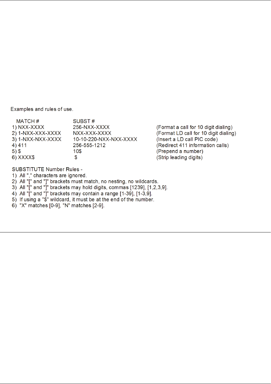
Command Reference Guide Voice Operator Ring Group Command Set
60000CRG0-35E Copyright © 2012 ADTRAN, Inc. 3393
The special characters ( ), -, and + are always ignored in the template. The following are example template
entries using wildcards:
Examples: 1) 555-81xx matches 555-8100 to 555-8199.
2) 555-812[012] matches 555-8120 to 555-8122.
3) Nxx-xxxx matches 7 digits local.
4) 1-Nxx-Nxx-xxxx matches long distance calls in North America.
Additional wildcards ($ and 0 to 9) can also be used. The command line interface (CLI) also contains
helpful information regarding the construction of the template and can be viewed by entering the match
ani command followed by a question mark. For example, entering the command as follows results in the
template input specifications:
(config)#match ani ?
Usage Examples
The following example specifies that the ANI information from numbers 555-8111 to 555-8115 will be
substituted by 555-8110 for outbound calls:
(config)#voice operator-group
(config-operator-group)#match ani 555-811[125] substitute 555-8110

Command Reference Guide Voice Operator Ring Group Command Set
60000CRG0-35E Copyright © 2012 ADTRAN, Inc. 3394
max-inbound <value>
Use the max-inbound command to define the maximum number of calls that can be inbound at the same
time. Use the no form of this command to return to the default setting.
Syntax Description
<value> Specifies the maximum number of calls that can be inbound at the same
time. Range is 1 to 10 calls.
Default Values
By default, the maximum number of inbound calls is set to 1.
Command History
Release 10.1 Command was introduced.
Usage Examples
The following example sets the maximum number of inbound calls to 3:
(config)#voice operator-group
(config-operator-group)#max-inbound 3

Command Reference Guide Voice Operator Ring Group Command Set
60000CRG0-35E Copyright © 2012 ADTRAN, Inc. 3395
member <number>
Use the member command to create a new member of the operator group. Use the no form of this
command to remove a user’s extension from an operator group.
Syntax Description
<number> Specifies the extension number of the user to be added as an operator
group member.
Default Values
No default values are necessary for this command.
Command History
Release 10.1 Command was introduced.
Functional Notes
A user can log in and out of the operator group using the login-member and no login-member
commands. Refer to login-member <number> on page 3391 for more information.
Usage Examples
The following example adds the user at extension 4422 to the operator ring group:
(config)#voice operator-group
(config-operator-group)#member 4422

Command Reference Guide Voice Operator Ring Group Command Set
60000CRG0-35E Copyright © 2012 ADTRAN, Inc. 3396
num-rings <value>
Use the num-rings command to specify the number of rings for call pickup before the system redirects the
call. Each system mode call coverage action can be configured with a different number of rings based on
preference. Use the no form of this command to return to the default setting. Variations of this command
include:
num-rings <value>
num-rings <system mode> <value>
num-rings override <value>
Syntax Description
<system mode> Optional. Specifies the system mode to configure for call coverage. Choose
from custom1, custom2, custom3, lunch, night, or weekend. Refer to
the Functional Notes of this command for more information on configuring
system modes.
override Ignores the programmed system mode schedule.
<value>
Specifies the number of rings before the next action. Specify 1 through 9
rings.
Default Values
By default, the maximum number of rings allowed at each extension is 2.
Command History
Release 10.1 Command was introduced.
Release A1 Command was updated to include the system mode feature options.
Functional Notes
System mode call coverage provides more diverse functionality for call handling. In previous versions of
AOS (revision 15.1 or earlier), up to five coverage modes were allowed. Calls were processed in the order
in which the coverage options were entered into the system.
With the addition of the system mode options, up to five coverage options per system mode are allowed.
The system modes can be modified using the command voice system-mode on page 1445.
Usage Examples
The following example sets the maximum number of rings for the operator ring group to 6:
(config)#voice operator-group
(config-operator-group)#num-rings 6

Command Reference Guide Voice Operator Ring Group Command Set
60000CRG0-35E Copyright © 2012 ADTRAN, Inc. 3397
prefix
Use the prefix command to turn on the caller ID prefix for this ring group, causing GRP: to display in
front of the caller ID information. Use the no form of this command to turn the prefix off. Variations of
this command include:
prefix
prefix <prefix>
Syntax Description
<prefix> Optional. Specifies an alphanumeric outbound calling name prefix.
Maximum length is 40 characters.
Default Values
By default, no prefixes are enabled.
Command History
Release 10.1 Command was introduced.
Release A2.04 Command was expanded to include the optional <prefix> parameter.
Usage Examples
The following example turns on the caller ID prefix for the operator ring group:
(config)#voice operator-group
(config-operator-group)#prefix

Command Reference Guide Voice Operator Ring Group Command Set
60000CRG0-35E Copyright © 2012 ADTRAN, Inc. 3398
sip-identity
Use the sip-identity command to configure the Session Initiation Protocol (SIP) registration options for
the user. Use the no form of this command to disable the setting. Variations of this command include the
following:
sip-identity <station> <Txx>
sip-identity <station> <Txx> register
sip-identity <station> <Txx> register auth-name <username> password <password>
Syntax Description
<station> Specifies the station to be used for SIP trunk (e.g., station extension).
<Txx> Specifies the SIP trunk through which to register the server. The trunk is
specified in the format Txx (e.g., T01).
register Registers the user to the server.
auth-name <username> Optional. Sets the user name that will be required as authentication for
registration to the SIP server.
password <password> Optional. Sets the password that will be required as authentication for
registration to the SIP server.
Default Values
No default values are necessary for this command.
Command History
Release 12.1 Command was introduced.
Release 13.1 Command functionality was introduced to this section.
Usage Examples
The following example specifies trunk T02 and extension 4400 for SIP identity:
(config)#voice operator-group
(config-operator-group)#sip-identity 4400 t02

Command Reference Guide Voice Operator Ring Group Command Set
60000CRG0-35E Copyright © 2012 ADTRAN, Inc. 3399
type
Use the type command to configure the group type for the operator group. Variations of this command
include:
type all
type executive
type linear
type ucd
Syntax Description
all Configures the group as an all-inclusive operator group. When an operator
group call comes in, all phones ring simultaneously.
executive Configures an executive operator group. Refer to email <address> on page
3414 for more information.
linear Configures the group as a linear hunt operator group. Member phones ring
one at a time until the call is picked up. When the next call comes in, the call
cycle begins again by ringing the first operator group member. Refer to
member <number> on page 3395 for more information.
ucd Configures the group as a uniform call distribution (UCD) operator group.
Member phones ring one at a time until the call is picked up. When the next
call comes in, the system remembers which member extension it last dialed
and then continues the call cycle by ringing the next member in the operator
group.
Default Values
No default values are necessary for this command.
Command History
Release 10.1 Command was introduced.
Usage Examples
The following example configures all phones in the operator ring group to ring each time a call comes in:
(config)#voice operator-group
(config-operator-group)#type all

Command Reference Guide Voice Operator Ring Group Command Set
60000CRG0-35E Copyright © 2012 ADTRAN, Inc. 3400
voicemail
Use the voicemail command to configure the voicemail options for the user. Use the no form of this
command to disable the settings. Variations of this command include the following:
voicemail attachment-level <dB>
voicemail attachment-level disabled
voicemail auth-mode full
voicemail auth-mode password
voicemail auto-play
voicemail cos <name>
voicemail delete-msg-on-email
voicemail envelope-play
voicemail greeting alternate
voicemail greeting default
voicemail greeting standard
voicemail new-user
voicemail notify email attach-message pcm
voicemail notify email attach-message pcm max-size <size>
voicemail notify email text-only
voicemail oper-assist <number>
voicemail password <password>
Syntax Description
attachment-level <dB> Specifies the number of decibels for voicemail attachment files. Valid entries
are -30, -25, -20, -15, or -10 dB.
attachment-level disabled Disables the automatic gain control (AGC) for voicemail attachments.
auth-mode full Specifies that the extension and password are required to access voicemail.
auth-mode password Specifies that the password is required to access voicemail. Only the
password is required if set to password authentication mode.
auto-play Specifies automatic playback of messages when entering the mailbox.
cos <name> Configures the voicemail class of service (CoS) type by entering the name
of the selected CoS.
delete-msg-on-email Enables deletion of stored voicemail on email attachments.
envelope-play Automatically plays message envelopes during message playback.
greeting alternate Specifies the alternate recorded voicemail greeting to be used.
greeting default Specifies the default voicemail greeting to be used.
greeting standard Specifies the user’s standard recorded voicemail greeting to be used.
new-user Executes the new-user wizard for voicemail configuration.
notify email Specifies sending an email notification when a new voicemail is received.
attach-message Sends the voicemail as a WAV file attachment to the specified email. The
email client must be configured for email options to work.

Command Reference Guide Voice Operator Ring Group Command Set
60000CRG0-35E Copyright © 2012 ADTRAN, Inc. 3401
pcm Indicates message sent as email attachment will be in pulse-code
modulation (PCM) format.
max-size <size> Optional. Indicates truncating email attachments at the specified maximum
size in kilobits (kb). Minimum size entry is 10 kb.
text-only Sends only a text message to the specified email address.
oper-assist <number> Directs all operator calls to the specified phone number.
password <password> Creates the password/personal identification number (PIN) that will be
required to access voicemail.
Default Values
No default values are necessary for this command.
Command History
Release 12.1 Command was introduced.
Release 15.1 Command was expanded.
Release A2 Command was expanded to include the notify email parameters.
Release A2.04 Command was expanded to include attachment-level parameters.
Usage Examples
The following example sets the voicemail CoS to class1:
(config)#voice operator-group
(config-operator-group)#voicemail cos class1

Command Reference Guide Voice Paging Group Command Set
60000CRG0-35E Copyright © 2012 ADTRAN, Inc. 3402
VOICE PAGING GROUP COMMAND SET
The voice paging group configures handset paging parameters. Handset paging is a feature that provides
paging to select groups of users through their IP phone handset. Handset paging works through a one-way
audio transmission received as a call on individual IP phones, rather than on an overhead speaker using a
private branch exchange (PBX) as overhead paging does. A handset page is initiated by a member of the
paging group and sent to other members of the group. Voice paging groups are defined and organized
using the commands in this section. For more information on using handset paging, refer to the Handset
Paging for the NetVanta 7000 Series quick configuration guide (article number 3102) available online at
https://supportforums.adtran.com.
To activate the Voice Paging Group Configuration mode, enter the voice paging-group <extension>
command from the Global Configuration mode prompt. For example:
>enable
#configure terminal
(config)#voice paging-group 8956
Configuring new paging group “8956”.
(config-8956)#
The following commands are common to multiple command sets and are covered in a centralized section
of this guide. For more information, refer to the sections listed below:
description <text> on page 70
do on page 71
end on page 72
exit on page 73
shutdown on page 82
All other commands for this command set are described in this section in alphabetical order.
codec on page 3403
include-paging-port on page 3404
member <extension> on page 3405
page-timeout <seconds> on page 3406

Command Reference Guide Voice Paging Group Command Set
60000CRG0-35E Copyright © 2012 ADTRAN, Inc. 3403
codec
Use the codec command to specify the coder-decoder (CODEC) that is used for the audio of the paging
group. Use the no form of this command to return to the default. Variations of this command include:
codec g711alaw
codec g711ulaw
codec g722
codec g729
Syntax Description
g711alaw Specifies the audio of the paging group is set to G.711 A-Law 64 kilobits per
second (Kbps).
g711ulaw Specifies the audio of the paging group is set to G.711 mu-Law 64 Kbps.
g722 Specifies the audio of the paging group is set to G.722 8 Kbps.
g729 Specifies the audio of the paging group is set to G.729 8 Kbps.
Default Values
By default, the CODEC for the paging group is set to G.729.
Command History
Release A2.04 Command was introduced in the Voice Paging Group.
Functional Notes
The default CODEC used by paging groups is G.729, and is recommended for bandwidth optimization.
Other CODECs can be used when a page initiator or recipient does not support G.729.
This codec command is not to be confused with the codec command used when creating CODEC lists
(refer to Voice CODEC List Command Set on page 3803 or codec on page 3804). This command does not
create a list of CODECs, nor can it be entered multiple times. This codec command, used when
configuring the voice paging group, specifies a single CODEC to be used by the paging group. If another
CODEC is entered from the Voice Paging Group Configuration mode prompt, it will override any previous
CODEC entries.
Usage Examples
The following example specifies the paging group using extension 8956 will use CODEC G.722 for audio:
(config)#voice paging-group 8956
(config-8956)#codec g722

Command Reference Guide Voice Paging Group Command Set
60000CRG0-35E Copyright © 2012 ADTRAN, Inc. 3404
include-paging-port
Use the include-paging-port command to enable overhead paging for the paging group. Use the no form
of this command to disable overhead paging for the paging group.
Syntax Description
No subcommands.
Default Values
By default, overhead paging is not enabled in paging groups.
Command History
Release A2.04 Command was introduced.
Functional Notes
Enabling the paging port for a handset paging group allows the page to transmit through IP phone
handsets and an overhead paging system. This option will only function if an overhead paging system is
available.
Usage Examples
The following example enables overhead paging for the paging group using extension 8956:
(config)#voice paging-group 8956
(config-8956)#include-paging-port

Command Reference Guide Voice Paging Group Command Set
60000CRG0-35E Copyright © 2012 ADTRAN, Inc. 3405
member <extension>
Use the member command to add a new member to the paging group. Use the no form of this command to
remove a member from the paging group.
Syntax Description
<extension> Specifies the four-digit extension of the user to add to the paging group.
Default Values
By default, no members are included in a paging group.
Command History
Release A2.04 Command was introduced.
Usage Examples
The following example adds a user at extension 4567 to the paging group using extension 8956:
(config)#voice paging-group 8956
(config-8956)#member 4567

Command Reference Guide Voice Paging Group Command Set
60000CRG0-35E Copyright © 2012 ADTRAN, Inc. 3406
page-timeout <seconds>
Use the page-timeout command to specify the amount of time page group users have to connect to the
page before the call is started. Use the no form of this command to return to the default value.
Syntax Description
<seconds> Specifies the time (in seconds) that users have to connect to a page before
information is transmitted. Range is 1 to 10 seconds.
Default Values
By default, the page timeout is set to 2 seconds.
Command History
Release A2.04 Command was introduced.
Functional Notes
If no connection is made before the timeout period expires, the paging call is terminated.
Usage Examples
The following example sets the page timeout to 5 seconds for the paging group using extension 8956:
(config)#voice paging-group 8956
(config-8956)#page-timeout 5

Command Reference Guide Voice Ring Group Command Set
60000CRG0-35E Copyright © 2012 ADTRAN, Inc. 3407
VOICE RING GROUP COMMAND SET
Voice ring groups define groups of user accounts that can be called in a coordinated way with a single
extension. Ring group members can log in when they want to receive calls from the group, and log out
when they do not want to receive group calls.
There are five ring group types to select from when creating a new ring group. The first of these types is a
linear hunt group. In this type of group, calls are distributed to members in the order in which they were
added to the ring group. The second type is the all ring group. In this type of group, all members of the
group are called, and the first extension to answer receives the call. The third type is the uniform call
distribution (UCD) group. In this group type, calls are distributed to members in the order in which they
were added to the group, but in a uniform, round-robin fashion. The fourth type is an executive ring group.
In this group type, calls are made to both the executive’s and assistant’s extensions, but the calls use the
executive’s call coverage. The last type is the operator ring group. This group type is detailed in the Voice
Operator Ring Group Command Set on page 3384.
Ring group’s extensions must be unique and cannot begin with a 0 or a 9. When configuring a new ring
group, the extension defaults to one greater than the highest number ring group extension currently
configured, or 8001 if no ring groups are configured. For more information about specific ring group
configuration, refer to the NetVanta 7000 Series Ring Groups and Operator Groups quick configuration
guide (article number 1539) available online at https://supportforums.adtran.com.
To activate the Voice Ring Group Configuration mode, enter the voice ring-group command at the Global
Configuration mode prompt. For example:
>enable
#configure terminal
(config)#voice ring-group xxxx*
(config-xxxx)#
*where xxxx = the ring group’s four-digit extension.
The following commands are common to multiple command sets and are covered in a centralized section
of this guide. For more information, refer to the sections listed below:
alias “<text>” on page 66
cross-connect on page 67
description <text> on page 70
do on page 71
exit on page 73
interface on page 74

Command Reference Guide Voice Ring Group Command Set
60000CRG0-35E Copyright © 2012 ADTRAN, Inc. 3408
All other commands for this command set are described in this section in alphabetical order.
assistant-extension <number> on page 3409
cos on page 3410
coverage on page 3411
did <number> on page 3413
email <address> on page 3414
email-secondary <address> on page 3415
executive-extension <number> on page 3416
login-member <number> on page 3417
match ani <template> substitute <template> on page 3418
member <number> on page 3421
num-rings on page 3422
prefix on page 3423
sip-identity on page 3424
type on page 3425
voicemail on page 3426

Command Reference Guide Voice Ring Group Command Set
60000CRG0-35E Copyright © 2012 ADTRAN, Inc. 3409
assistant-extension <number>
Use the assistant-extension command to tie an assistant’s extension to an executive’s extension.
Syntax Description
<number> Specifies the number of the assistant’s extension.
Default Values
No default values are necessary for this command.
Command History
Release 10.1 Command was introduced.
Functional Notes
This command is used in conjunction with the executive-extension command (refer to
executive-extension <number> on page 3416). When the executive’s extension is dialed, both the
assistant’s and the executive’s phones will ring. If neither phone is answered (or both are busy or set to
do-not-disturb (DND)), the call is forwarded through the executive’s call coverage list.
Usage Examples
The following example creates the executive ring group 1234 and causes both the executive (extension
4440) and the assistant (extension 4444) phones to ring when the executive extension is dialed:
(config)#voice ring-group 1234
(config-1234)#type executive
(config-1234)#executive-extension 4440
(config-1234)#assistant-extension 4444
This command only applies to a ring group of type executive. Refer to type on page 3425
for more information.

Command Reference Guide Voice Ring Group Command Set
60000CRG0-35E Copyright © 2012 ADTRAN, Inc. 3410
cos
Use the cos command to set class of service (CoS) mode for the ring group. The CoS can be set to change
for the members of the ring group based on the current system mode by including the system mode
parameter. The CoS defines the types of phone service that will be available to the user during the time
period. Use the no form of this command to disable this feature. Variations of this command include:
cos <name>
cos <system mode> <name>
cos no-access
cos <system mode> no-access
cos override <name>
cos override no-access
Syntax Description
<name> Specifies the predefined CoS.
<system mode> Optional. Specifies the system mode to configure. Choose from custom1,
custom2, custom3, lunch, night, or weekend. Refer to the Functional
Notes of this command for more information on configuring system modes.
no-access Blocks users from placing calls when applied to the CoS.
override Ignores the programmed system mode schedule.
Default Values
By default, CoS is set to no-access.
Command History
Release 9.3 Command was introduced.
Release A1 Command was expanded to include the system mode options.
Functional Notes
Additional functionality for this feature is provided by assigning a CoS to a specific system mode. When the
system mode changes at a trigger point, the ring group’s CoS changes.
For example, a CoS applied to the ring group when the system mode is specified as night can be used to
prevent outbound calls during evening hours. System modes are defined from the Global Configuration
mode using the command voice system-mode on page 1445.
Usage Examples
The following example assigns the CoS Assistant to the ring group 1234:
(config)#voice ring-group 1234
(config-1234)#cos Assistant

Command Reference Guide Voice Ring Group Command Set
60000CRG0-35E Copyright © 2012 ADTRAN, Inc. 3411
coverage
Use the coverage command to configure call coverage parameters for members of this group. The call
coverage setting determines how a call is handled if the party dialed does not answer after a specified
number of rings. Use the no form of this command to remove an individual coverage parameter. Variations
of this command include:
coverage aa
coverage aa <number>
coverage internal <number>
coverage internal <number> num-rings <value>
coverage operator
coverage operator num-rings <value>
coverage override aa
coverage override aa <number>
coverage override external <number>
coverage override internal <number>
coverage override internal <number> num-rings <value>
coverage override operator
coverage override operator num-rings <value>
coverage override vm
coverage override vm <number>
coverage vm
coverage vm <number>
coverage <system mode> aa
coverage <system mode> aa <number>
coverage <system mode> external <number>
coverage <system mode> internal <number>
coverage <system mode> internal <number> num-rings <value>
coverage <system mode> operator
coverage <system mode> operator num-rings <value>
coverage <system mode> vm
coverage <system mode> vm <number>
Syntax Description
<system mode> Optional. Specifies the system mode to configure for call coverage. Choose
from custom1, custom2, custom3, lunch, night, or weekend. Refer to
the Functional Notes of this command for more information on configuring
system modes.
aa Forwards the call to the default auto attendant.
aa <number> Forwards the call to a specific extension programmed for the auto
attendant. If no extension is specified, the phone is forwarded to the default
auto attendant.
external
<number>
Forwards the call to the specified external number. If no number is entered,
the default auto answer is used.

Command Reference Guide Voice Ring Group Command Set
60000CRG0-35E Copyright © 2012 ADTRAN, Inc. 3412
internal
<number>
Forwards the call to the specified internal number.
num-rings
<value>
Optional. Specifies the number of rings for the call before performing the
next action. Valid range is 1 to 9.
operator Forwards the call to the operator.
override Ignores the programmed system mode schedule.
vm Forwards the call to voicemail.
vm <number> Optional. Forwards the phone to the specified mailbox number.
Default Values
By default, no call coverage is specified.
Command History
Release 9.3 Command was introduced.
Release 11.1 Command was updated to include the voicemail and number of rings
options.
Release 12.1 Command was updated to include the auto attendant and operator options.
Release A1 Command was updated to include the system mode feature options.
Functional Notes
System mode call coverage provides more diverse functionality for call handling. In previous versions of
AOS (revision 15.1 or earlier), up to five coverage modes were allowed. Calls were processed in the order
in which the coverage options were entered into the system.
With the addition of the system mode options, up to five coverage options per system mode are allowed.
The system modes can be modified using the command voice system-mode on page 1445.
Usage Examples
The following example specifies that calls to the ring group 1234 be forwarded to the internal extension
8500 when in the night system mode.
(config)#voice ring-group 1234
(config-1234)#coverage night internal 8500

Command Reference Guide Voice Ring Group Command Set
60000CRG0-35E Copyright © 2012 ADTRAN, Inc. 3413
did <number>
Use the did command to configure direct inward dialing (DID) for this group. DID is used if a service
provider is providing digits to the unit on inbound calls or if the unit needs to provide DID information to a
piece of customer premises equipment (CPE). Use the no form of this command to disable this feature.
Syntax Description
<number> Defines the DID number assigned to the ring group.
Default Values
No default values are necessary for this command.
Command History
Release 10.1 Command was introduced.
Usage Examples
The following example assigns DID 44 to the ring group 1234:
(config)#voice ring-group 1234
(config-1234)#did 44

Command Reference Guide Voice Ring Group Command Set
60000CRG0-35E Copyright © 2012 ADTRAN, Inc. 3414
email <address>
Use the email command to enter the email address for this user’s group. Use the no form of this command
to disable this feature.
Syntax Description
<address> Specifies an email address for this group.
Default Values
No default values are necessary for this command.
Command History
Release 13.1 Command was introduced.
Usage Examples
The following example creates an email contact for this group:
(config)#voice ring-group 1234
(config-1234)#email admin@helpdesk.com

Command Reference Guide Voice Ring Group Command Set
60000CRG0-35E Copyright © 2012 ADTRAN, Inc. 3415
email-secondary <address>
Use the email-secondary command to enter a secondary email address for this user’s group. Use the no
form of this command to disable this feature.
Syntax Description
<address> Specifies a contact email address for this group.
Default Values
No default values are necessary for this command.
Command History
Release 13.1 Command was introduced.
Usage Examples
The following example creates a secondary email contact for this group:
(config)#voice ring-group 1234
(config-1234)#email-secondary lead@helpdesk.com

Command Reference Guide Voice Ring Group Command Set
60000CRG0-35E Copyright © 2012 ADTRAN, Inc. 3416
executive-extension <number>
Use the executive-extension command to tie an executive’s extension to an assistant’s extension.
Syntax Description
<number> Specifies the number of the executive’s extension.
Default Values
No default values are necessary for this command.
Command History
Release 10.1 Command was introduced.
Functional Notes
This command is used in conjunction with the assistant-extension command (refer to assistant-extension
<number> on page 3409). When the executive’s extension is dialed, both the assistant’s and the
executive’s phones will ring. If neither phone is answered (or both are busy or set to do-not-disturb (DND)),
the call is forwarded through the executive’s call coverage list.
Usage Examples
The following example creates the executive ring group 1234 and causes both the executive (extension
4440) and the assistant (extension 4444) phones to ring when the executive extension is dialed:
(config)#voice ring-group 1234
(config-1234)#type executive
(config-1234)#executive-extension 4440
(config-1234)#assistant-extension 4444
This command only applies to type executive ring group(s). Refer to type on page 3425 for
more information.

Command Reference Guide Voice Ring Group Command Set
60000CRG0-35E Copyright © 2012 ADTRAN, Inc. 3417
login-member <number>
Use the login-member command to log an existing member of the ring group into the system. You must
first use the member command to create a new group member. Use the no form of this command to disable
this feature. Refer to member <number> on page 3421 for more information.
Syntax Description
<number> Specifies the extension number of the user who is logging in.
Default Values
No default values are necessary for this command.
Command History
Release 10.1 Command was introduced.
Functional Notes
This command allows a user to log in and out of a ring group, letting the system know when a user is
available to accept calls.
Usage Examples
The following example logs in the user at extension 4422:
(config)#voice ring-group 1234
(config-1234)#login-member 4422

Command Reference Guide Voice Ring Group Command Set
60000CRG0-35E Copyright © 2012 ADTRAN, Inc. 3418
match ani <template> substitute <template>
Use the match ani substitute command to configure automatic number identification (ANI) substitution
for outbound voice trunks. Use the no form of this command to remove the substitution. Variations of this
command include:
match ani <template> substitute <template>
match ani <template> substitute <template> name <name>
Syntax Description
ani <template> Specifies the ANI information to be substituted. This information is entered
using wildcards and numerical digits. Refer to the Functional Notes of this
command for available wildcards and proper data entry.
substitute <template> Specifies the ANI information that is substituted for the original ANI
information. This information is entered using wildcards and numerical
digits. Refer to the Functional Notes of this command for available wildcards
and proper data entry.
name <name> Optional. Specifies the name associated with the ANI information. This
option is only available on trunks that support ANI name information
(integrated services digital network (ISDN) trunks, Session Initiation
Protocol (SIP) trunks, T1 loop start (LS) network trunks, and T1 ground start
(GS) network trunks).
Default Values
By default, no ANI substitution is configured.
Command History
Release A2 Command was introduced.
Functional Notes
The convention for ANI templates is very similar to dial plan entries. Wildcards available for this command
are:
0-9 = Match exact digit only.
M = Any digit 1 to 8.
X = Any single digit (0 to 9).
N = Any digit 2 to 9.
[123] = Any digit contained in the bracketed list.
Do not use dashes, commas, spaces, etc., inside the brackets. Commas are implied between
numbers in the brackets.

Command Reference Guide Voice Ring Group Command Set
60000CRG0-35E Copyright © 2012 ADTRAN, Inc. 3419
The special characters ( ), -, and + are always ignored in the template. The following are example template
entries using wildcards:
Examples: 1) 555-81xx matches 555-8100 to 555-8199.
2) 555-812[012] matches 555-8120 to 555-8122.
3) Nxx-xxxx matches 7 digits local.
4) 1-Nxx-Nxx-xxxx matches long distance calls in North America.
Additional wildcards ($ and 0 to 9) can also be used. The command line interface (CLI) also contains
helpful information regarding the construction of the template and can be viewed by entering the match
ani command followed by a question mark. For example, entering the command as follows results in the
template input specifications:
(config)#match ani ?
Usage Examples
The following example specifies that the ANI information from numbers 555-8111 to 555-8115 will be
substituted by 555-8110 for outbound calls for voice ring group 1234:
(config)#voice ring-group 1234
(config-1234)#match ani 555-811[125] substitute 555-8110

Command Reference Guide Voice Ring Group Command Set
60000CRG0-35E Copyright © 2012 ADTRAN, Inc. 3420
max-inbound <value>
Use the max-inbound command to define the maximum number of calls that can be inbound at the same
time. Use the no form of this command to return to the default setting.
Syntax Description
<value> Specifies the maximum number of calls that can be inbound at the same
time. Range is 1 to 10 calls.
Default Values
By default, the maximum number of inbound calls is set to 1.
Command History
Release 10.1 Command was introduced.
Usage Examples
The following example sets the maximum number of inbound calls on ring group 1234 to 3:
(config)#voice ring-group 1234
(config-1234)#max-inbound 3

Command Reference Guide Voice Ring Group Command Set
60000CRG0-35E Copyright © 2012 ADTRAN, Inc. 3421
member <number>
Use the member command to create a new member of the ring group. Use the no form of this command to
remove a user’s extension from a ring group.
Syntax Description
<number> Specifies the extension number of the user you want to add as a ring group
member.
Default Values
No default values are necessary for this command.
Command History
Release 10.1 Command was introduced.
Functional Notes
A user can log in and out of the ring group using the login-member and no login-member commands.
Refer to login-member <number> on page 3417 for more information.
Usage Examples
The following example adds the user at extension 4422 to the ring group 1234:
(config)#voice ring-group 1234
(config-1234)#member 4422

Command Reference Guide Voice Ring Group Command Set
60000CRG0-35E Copyright © 2012 ADTRAN, Inc. 3422
num-rings
Use the num-rings command to specify the number of rings for call pickup before the system redirects the
call. Each system mode call coverage action can be configured with a different number of rings based on
preference. Use the no form of this command to return to the default setting. Variations of this command
include:
num-rings <value>
num-rings <system mode> <value>
num-rings override <value>
Syntax Description
<system mode> Optional. Specifies the system mode to configure for call coverage. Choose
from custom1, custom2, custom3, lunch, night, or weekend. Refer to
the Functional Notes of this command for more information on configuring
system modes.
override Ignores the programmed system mode schedule.
<value>
Specifies the number of rings before the next action. Specify 0 through 9
rings. Entering 0 specifies an unlimited number of rings.
Default Values
By default, the num-rings is set to 4.
Command History
Release 9.3 Command was introduced.
Release A1 Command was updated to include the system mode feature options.
Usage Examples
The following example sets the number of rings for this ring group to 6:
(config)#voice ring-group 1234
(config-1234)#num-rings 6

Command Reference Guide Voice Ring Group Command Set
60000CRG0-35E Copyright © 2012 ADTRAN, Inc. 3423
prefix
Use the prefix command to turn on the caller ID prefix for this ring group, causing GRP: to display in
front of the caller ID information. Use the no form of this command to turn the prefix off. Variations of
this command include:
prefix
prefix <prefix>
Syntax Description
<prefix> Optional. Specifies an alphanumeric outbound calling name prefix.
Maximum length is 40 characters.
Default Values
By default, no prefixes are enabled.
Command History
Release 10.1 Command was introduced.
Release A2.04 Command was expanded to include the optional <prefix> parameter.
Usage Examples
The following example turns on the caller ID prefix for ring group 1234:
(config)#voice ring-group 1234
(config-1234)#prefix

Command Reference Guide Voice Ring Group Command Set
60000CRG0-35E Copyright © 2012 ADTRAN, Inc. 3424
sip-identity
Use the sip-identity command to configure the Session Initiation Protocol (SIP) registration options for
the user. Use the no form of this command to disable the settings. Variations of this command include the
following:
sip-identity <station> <Txx>
sip-identity <station> <Txx> register
sip-identity <station> <Txx> register auth-name <username> password <password>
Syntax Description
<station> Specifies the station to be used for SIP trunk (e.g., station extension).
<Txx> Specifies the SIP trunk through which to register the server. The trunk is
specified in the format Txx (e.g., T01).
register Registers the user to the server.
auth-name <username> Optional. Sets the user name that will be required as authentication for
registration to the SIP server.
password <password> Optional. Sets the password that will be required as authentication for
registration to the SIP server.
Default Values
No default values are necessary for this command.
Command History
Release 12.1 Command was introduced.
Usage Examples
The following example specifies trunk T02 and extension 4400 for SIP identity:
(config)#voice ring-group 1234
(config-1234)#sip-identity 4400 T02

Command Reference Guide Voice Ring Group Command Set
60000CRG0-35E Copyright © 2012 ADTRAN, Inc. 3425
type
Use the type command to configure the group type for the ring group. Variations of this command include:
type all
type executive
type linear
type ucd
Syntax Description
all Configures the group as an all-inclusive ring group. When a ring group call
comes in, all phones ring simultaneously.
executive Configures an executive ring group. Refer to executive-extension
<number> on page 3416 for more information.
linear Configures the group as a linear hunt ring group. Member phones ring one
at a time until the call is picked up. When the next call comes in, the call
cycle begins again by ringing the first ring group member. Refer to member
<number> on page 3421 for more information.
ucd Configures the group as a uniform call distribution (UCD) ring group.
Member phones ring one at a time until the call is picked up. When the next
call comes in, the system remembers which member extension it last dialed
and then continues the call cycle by ringing the next member in the ring
group.
Default Values
No default values are necessary for this command.
Command History
Release 10.1 Command was introduced.
Usage Examples
The following example configures the ring group 1234 to ring all phones in the ring group each time a call
comes in:
(config)#voice ring-group 1234
(config-1234)#type all

Command Reference Guide Voice Ring Group Command Set
60000CRG0-35E Copyright © 2012 ADTRAN, Inc. 3426
voicemail
Use the voicemail command to configure the voicemail options for the user. Use the no form of this
command to disable the settings. Variations of this command include the following:
voicemail attachment-level <dB>
voicemail attachment-level disabled
voicemail auth-mode full
voicemail auth-mode password
voicemail auto-play
voicemail cos <name>
voicemail delete-msg-on-email
voicemail envelope-play
voicemail greeting alternate
voicemail greeting default
voicemail greeting standard
voicemail new-user
voicemail notify email attach-message pcm
voicemail notify email attach-message pcm max-size <size>
voicemail notify email text-only
voicemail oper-assist <number>
voicemail password <password>
Syntax Description
attachment-level <dB> Specifies the number of decibels for voicemail attachment files. Valid entries
are -30, -25, -20, -15, or -10 dB.
attachment-level disabled Disables the automatic gain control (AGC) for voicemail attachments.
auth-mode full Specifies that the extension and password are required to access voicemail.
auth-mode password Specifies that the password is required to access voicemail. Only the
password is required if set to password authentication mode.
auto-play Specifies automatic playback of messages when entering the mailbox.
cos <name> Configures the voicemail class of service (CoS) type by entering the name
of the selected CoS.
delete-msg-on-email Enables deletion of stored voicemail on email attachments.
envelope-play Automatically plays message envelopes during message playback.
greeting alternate Specifies the alternate recorded voicemail greeting to be used.
greeting default Specifies the default voicemail greeting to be used.
greeting standard Specifies the user’s standard recorded voicemail greeting to be used.
new-user Executes the new-user wizard for voicemail configuration.
notify email Specifies sending an email notification when a new voicemail is received.
attach-message Sends the voicemail as a WAV file attachment to the specified email. The
email client must be configured for email options to work.

Command Reference Guide Voice Ring Group Command Set
60000CRG0-35E Copyright © 2012 ADTRAN, Inc. 3427
pcm Indicates message sent as email attachment will be in pulse-code
modulation (PCM) format.
max-size <size> Optional. Indicates truncating email attachments at the specified maximum
size in kilobits (kb). Minimum size entry is 10 kb.
text-only Sends only a text message to the specified email address.
oper-assist <number> Directs all operator calls to the specified phone number.
password <password> Creates the password/personal identification number (PIN) that will be
required to access voicemail.
Default Values
No default values are necessary for this command.
Command History
Release 12.1 Command was introduced.
Release 15.1 Command was expanded.
Release A2 Command was expanded to include the notify email parameters.
Release A2.04 Command was expanded to include attachment-level parameters.
Usage Examples
The following example sets the voicemail CoS for this user to class1:
(config)#voice ring-group 1234
(config-1234)#voicemail cos class1

Command Reference Guide Voice Ring Group Command Set
60000CRG0-35E Copyright © 2012 ADTRAN, Inc. 3428
voice match ani <template> substitute <template>
Use the voice match ani substitute command to configure automatic number identification (ANI)
substitution for inbound voice trunks. Use the no form of this command to remove the substitution.
Variations of this command include:
voice match ani <template> substitute <template>
Syntax Description
ani <template> Specifies the ANI information to be substituted. This information is entered
using wildcards and numerical digits. Refer to the Functional Notes of this
command for available wildcards and proper data entry.
substitute <template> Specifies the ANI information that is substituted for the original ANI
information. This information is entered using wildcards and numerical
digits. Refer to the Functional Notes of this command for available wildcards
and proper data entry.
Default Values
By default, no ANI substitution is configured.
Command History
Release A2 Command was introduced.
Functional Notes
The convention for ANI templates is very similar to dial plan entries. Wildcards available for this command
are:
0-9 = Match exact digit only.
M = Any digit 1 to 8.
X = Any single digit (0 to 9).
N = Any digit 2 to 9.
[123] = Any digit contained in the bracketed list.
Do not use dashes, commas, spaces, etc., inside the brackets. Commas are implied between
numbers in the brackets.
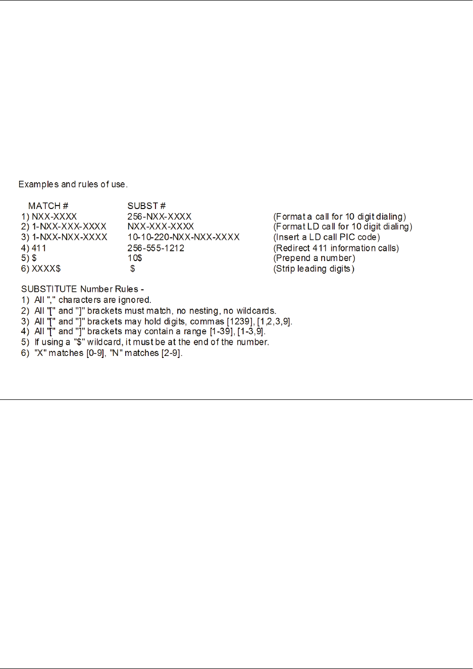
Command Reference Guide Voice Ring Group Command Set
60000CRG0-35E Copyright © 2012 ADTRAN, Inc. 3429
The special characters ( ), -, and + are always ignored in the template. The following are example template
entries using wildcards:
Examples: 1) 555-81xx matches 555-8100 to 555-8199.
2) 555-812[012] matches 555-8120 to 555-8122.
3) Nxx-xxxx matches 7 digits local.
4) 1-Nxx-Nxx-xxxx matches long distance calls in North America.
Additional wildcards ($ and 0 to 9) can also be used. The command line interface (CLI) also contains
helpful information regarding the construction of the template and can be viewed by entering the match
ani command followed by a question mark. For example, entering the command as follows results in the
template input specifications:
(config)#match ani ?
Usage Examples
The following example specifies that the ANI information from numbers 555-8111 to 555-8115 on all
inbound trunks will be substituted by 555-8110:
(config)#voice ring-group 1234
(config)#voice match ani 555-811[125] substitute 555-8110

Command Reference Guide Voice Trunk Group Command Set
60000CRG0-35E Copyright © 2012 ADTRAN, Inc. 3430
VOICE TRUNK GROUP COMMAND SET
Voice trunks are digital or analog subscriber lines delivered by service providers that allow communication
devices to connect to the outside world. Voice trunk groups combine one or more trunk accounts and
assign outbound call characteristics to the group. Individual trunk groups can be created for each trunk
account. The trunk group is assigned outbound call capabilities (local calls, long distance calls, etc.).
Additionally, a cost is assigned to each attribute in the outbound call template.
To create a trunk group, you must first configure individual trunk accounts. For more information on
creating voice trunk accounts, refer to the following sections of this document:
•Voice Analog Trunk Command Set on page 3443
•Voice SIP Trunk Command Set on page 3532
•Voice T1 Trunk Command Set on page 3603
For more information about configuring trunk groups, refer to the NetVanta 7000 Series Trunk Accounts
configuration guide available online at https://supportforums.adtran.com (article number 1541).
To enter the Voice Trunk Group Configuration mode, enter the voice grouped-trunk command at the
Global Configuration mode prompt. For example:
>enable
#configure terminal
(config)#voice grouped-trunk TestGroup
(config-TestGroup)#
The following commands are common to multiple command sets and are covered in a centralized section
of this guide. For more information, refer to the sections listed below:
cross-connect on page 67
description <text> on page 70
do on page 71
exit on page 73
interface on page 74
Integrated services digital network (ISDN) trunk groups are created using the command
isdn-group <number> on page 1227. For more information regarding the creation of
ISDN trunk groups, refer to the Voice ISDN Group Command Set on page 3375.

Command Reference Guide Voice Trunk Group Command Set
60000CRG0-35E Copyright © 2012 ADTRAN, Inc. 3431
All other commands for this command set are described in this section in alphabetical order.
accept <pattern> on page 3432
deny on page 3434
match ani <template> substitute <template> on page 3435
permit on page 3437
reject <pattern> on page 3438
resource-selection on page 3440
trunk <Txx> on page 3441

Command Reference Guide Voice Trunk Group Command Set
60000CRG0-35E Copyright © 2012 ADTRAN, Inc. 3432
accept <pattern>
Use the accept command to specify numbers that users can dial on the trunk. This command controls the
type of outbound calls users can place on the system. Use the no form of this command to remove a
configured dial pattern and return to the default setting. Variations of this command include:
accept <pattern>
accept <pattern> cost <value>
Syntax Description
<pattern> Specifies the patterns users can dial on the trunk. You can enter a complete
phone number or wildcards can be used to help define accepted numbers.
Refer to Functional Notes below for more information on using wildcards.
cost <value> Specifies the cost value for the trunk. This option is used if a call is accepted
by several trunks. The call will be routed to the trunk with the lowest cost
value. The valid range is 0 to 499.
Default Values
By default, the cost value is zero.
Command History
Release 9.3 Command was introduced.
Functional Notes
The available wildcards for this command are:
0-9 = Match exact digit only.
M = Any digit 1 to 8.
X = Any single digit (0 to 9).
N = Any digit 2 to 9.
[123] = Any digit contained in the bracketed list.
The special characters ( ), -, + are always ignored.
Examples:1) 555-81xx matches 555-8100 to 555-8199.
2) 555-812[012] matches 555-8120 to 555-8122.
3) 1-800$ matches any 1-800 calls.
4) Nxx-xxxx matches 7 digit local.
5) 1-Nxx-Nxx-xxxx matches long distance calls in North America.
Do not use dashes, commas, spaces, etc., inside the brackets. Commas are implied between
numbers in the brackets.

Command Reference Guide Voice Trunk Group Command Set
60000CRG0-35E Copyright © 2012 ADTRAN, Inc. 3433
Usage Examples
The following example allows users on the trunk TestGroup to dial any local number:
(config)#voice grouped-trunk TestGroup
(config-TestGroup)#accept Nxxxxxx

Command Reference Guide Voice Trunk Group Command Set
60000CRG0-35E Copyright © 2012 ADTRAN, Inc. 3434
deny
Use the deny command to add a proxy, automatic number identification (ANI) list, or trunk list to a voice
trunk group’s deny policy. Use the no form of this command to remove the proxy, ANI list, or trunk list
from the deny policy. Variations of this command include:
deny list <name>
deny proxy
Syntax Description
list <name> Specifies that either a trunk list or ANI list is added to the trunk group’s deny
policy.
proxy Specifies that the proxy is added to the trunk group’s deny policy.
Default Values
By default, no list or proxy is part of the trunk group’s deny policy.
Command History
Release A2 Command was introduced.
Functional Notes
The trunk and ANI lists are created as part of the Source and ANI Based Routing (SABR) feature on AOS
voice products. For more information about SABR, refer to the SABR in AOS configuration guide available
online at https://supportforums.adtran.com (article number 2510). For more information about creating ANI
or trunk lists, refer to voice ani-list <name> on page 1377 or voice trunk-list <name> on page 1451.
Usage Examples
The following example applies the TEST2 list to the deny policy of trunk group TestGroup:
(config)#voice grouped-trunk TestGroup
(config-TestGroup)#deny list TEST2
Although there is no limit on the number of lists applied to voice trunk groups, it is
important to remember that the more lists that are applied to a trunk group, the more the
runtime performance of call routing will be affected.

Command Reference Guide Voice Trunk Group Command Set
60000CRG0-35E Copyright © 2012 ADTRAN, Inc. 3435
match ani <template> substitute <template>
Use the match ani substitute command to configure automatic number identification (ANI) substitution
for outbound voice trunks. Use the no form of this command to remove the substitution. Variations of this
command include:
match ani <template> substitute <template>
match ani <template> substitute <template> name <name>
Syntax Description
ani <template> Specifies the ANI information to be substituted. This information is entered
using wildcards and numerical digits. Refer to the Functional Notes of this
command for available wildcards and proper data entry.
substitute <template> Specifies the ANI information that is substituted for the original ANI
information. This information is entered using wildcards and numerical
digits. Refer to the Functional Notes of this command for available wildcards
and proper data entry.
name <name> Optional. Specifies the name associated with the ANI information. This
option is only available on trunks that support ANI name information
(integrated services digital network (ISDN) trunks, Session Initiation
Protocol (SIP) trunks, T1 loop start (LS) network trunks, and T1 ground start
(GS) network trunks).
Default Values
By default, no ANI substitution is configured.
Command History
Release A2 Command was introduced.
Functional Notes
The convention for ANI templates is very similar to dial plan entries. Wildcards available for this command
are:
0-9 = Match exact digit only.
M = Any digit 1 to 8.
X = Any single digit (0 to 9).
N = Any digit 2 to 9.
[123] = Any digit contained in the bracketed list.
Do not use dashes, commas, spaces, etc., inside the brackets. Commas are implied between
numbers in the brackets.

Command Reference Guide Voice Trunk Group Command Set
60000CRG0-35E Copyright © 2012 ADTRAN, Inc. 3436
The special characters ( ), -, and + are always ignored in the template. The following are example template
entries using wildcards:
Examples: 1) 555-81xx matches 555-8100 to 555-8199.
2) 555-812[012] matches 555-8120 to 555-8122.
3) Nxx-xxxx matches 7 digits local.
4) 1-Nxx-Nxx-xxxx matches long distance calls in North America.
Additional wildcards ($ and 0 to 9) can also be used. The command line interface (CLI) also contains
helpful information regarding the construction of the template and can be viewed by entering the match
ani command followed by a question mark. For example, entering the command as follows results in the
template input specifications:
(config)#match ani ?
Usage Examples
The following example specifies that the ANI information from numbers 555-8111 to 555-8115 will be
substituted by 555-8110 for outbound calls for trunk group TestGroup:
(config)#voice grouped-trunk TestGroup
(config-TestGroup)#match ani 555-811[125] substitute 555-8110

Command Reference Guide Voice Trunk Group Command Set
60000CRG0-35E Copyright © 2012 ADTRAN, Inc. 3437
permit
Use the permit command to add a proxy, automatic number identification (ANI) list, or trunk list to a
voice trunk group’s permit policy. Use the no form of this command to remove the proxy, ANI list, or
trunk list from the permit policy. Variations of this command include:
permit list <name>
permit proxy
Syntax Description
list <name> Specifies that either a trunk list or ANI list is added to the trunk group’s
permit policy.
proxy Specifies that the proxy is added to the trunk group’s permit policy.
Default Values
By default, no list or proxy is part of the trunk group’s permit policy.
Command History
Release A2 Command was introduced.
Functional Notes
The trunk and ANI lists are created as part of the Source and ANI Based Routing (SABR) feature on AOS
voice products. For more information about SABR, refer to the SABR in AOS configuration guide available
online at https://supportforums.adtran.com (article number 2510). For more information about creating ANI
or trunk lists, refer to voice ani-list <name> on page 1377 or voice trunk-list <name> on page 1451.
Usage Examples
The following example applies the TEST1 list to the permit policy of trunk group TestGroup:
(config)#voice grouped-trunk TestGroup
(config-TestGroup)#permit list TEST1
Although there is no limit on the number of lists applied to voice trunk groups, it is
important to remember that the more lists that are applied to a trunk group, the more the
runtime performance of call routing will be affected.
Command Reference Guide Voice Trunk Group Command Set
60000CRG0-35E Copyright © 2012 ADTRAN, Inc. 3438
reject <pattern>
Use the reject command to specify numbers users cannot dial on the trunk. This feature allows
administrators to restrict callers from unwanted outbound calls, such as international calls and 900
numbers. Use the no form of this command to disable this feature.
Syntax Description
<pattern> Specifies the patterns that users cannot dial on the trunk. You can enter a
complete phone number or wildcards can be used to help define rejected
numbers. Refer to Functional Notes below for more information on using
wildcards. For example, you can enter 900$ to prevent users from dialing all
900 numbers.
Default Values
No default values are necessary for this command.
Command History
Release 9.3 Command was introduced.
Functional Notes
The available wildcards for this command are:
0-9 = Match exact digit only.
M = Any digit 1 to 8.
X = Any single digit (0 to 9).
N = Any digit 2 to 9.
[123] = Any digit contained in the bracketed list.
The special characters ( ), -, + are always ignored.
Examples:1) 555-81xx matches 555-8100 to 555-8199.
2) 555-812[012] matches 555-8120 to 555-8122.
3) 1-800$ matches any 1-800 calls.
4) Nxx-xxxx matches 7 digit local.
5) 1-Nxx-Nxx-xxxx matches long distance calls in North America.
Do not use dashes, commas, spaces, etc., inside the brackets. Commas are implied between
numbers in the brackets.

Command Reference Guide Voice Trunk Group Command Set
60000CRG0-35E Copyright © 2012 ADTRAN, Inc. 3439
Usage Examples
The following example blocks calls to any 900 number on the trunk TestGroup:
(config)#voice grouped-trunk TestGroup
(config-TestGroup)#reject 900$

Command Reference Guide Voice Trunk Group Command Set
60000CRG0-35E Copyright © 2012 ADTRAN, Inc. 3440
resource-selection
Use the resource-selection command to determine how the switchboard uses outbound call resources
contained within a time division multiplexing (TDM) based trunk group. Use the no form of this command
to disable this feature. Variations of this command include:
resource-selection circular
resource-selection circular ascending
resource-selection circular descending
resource-selection linear
resource-selection linear ascending
resource-selection linear descending
Syntax Description
circular Performs call load balancing among available DS0s/B-channels in this
trunk. Subsequent calls will be delivered to the next available
DS0/B-channel in a round-robin fashion.
linear Specifies that a call being delivered to this trunk will be accepted out the first
available DS0/B-channel available at the time the call is received.
ascending Optional. Distributes calls in an order from the lowest to the highest channel
(DS0 1, 2, 3 through 24).
descending Optional. Distributes calls in an order from the highest to the lowest channel
(DS0 24, 23, 22 through 1).
Default Values
By default, resource selection is set to linear.
Command History
Release 9.3 Command was introduced.
Release 13.1 Command was expanded to include the ascending and descending
subcommands.
Usage Examples
The following example specifies circular resource selection on the trunk TestGroup:
(config)#voice grouped-trunk TestGroup
(config-TestGroup)#resource-selection circular

Command Reference Guide Voice Trunk Group Command Set
60000CRG0-35E Copyright © 2012 ADTRAN, Inc. 3441
trunk <Txx>
Use the trunk command to add an existing trunk to the trunk group so outbound calls may be placed out
that particular trunk as well. Use the no form of this command to remove a configured trunk group.
Syntax Description
<Txx> Specifies an ID number for the trunk. The trunk ID is in the format Txx
where xx is the trunk ID number. Enter a trunk ID between 1 and 99. For
example, trunk T02.
Default Values
No default values are necessary for this command.
Command History
Release 9.3 Command was introduced.
Usage Examples
The following example adds trunk T02 to the trunk group TestGroup:
(config)#voice grouped-trunk TestGroup
(config-TestGroup)#trunk t02

Command Reference Guide
60000CRG0-35E Copyright © 2012 ADTRAN, Inc. 3442
VOICE TRUNKS COMMAND SETS
This section includes the following command sets:
•Voice Analog Trunk Command Set on page 3443
•Voice ISDN Trunk Command Set on page 3493
•Voice SIP Trunk Command Set on page 3532
•Voice T1 Trunk Command Set on page 3603

Command Reference Guide Voice Analog Trunk Command Set
60000CRG0-35E Copyright © 2012 ADTRAN, Inc. 3443
VOICE ANALOG TRUNK COMMAND SET
Voice analog trunks are analog subscriber lines delivered by service providers that allow communication
devices to connect to the outside world. To configure analog trunks, you must first configure the foreign
exchange office (FXO) physical interface. By default, FXO interfaces are enabled, but their status must be
verified before creating an analog trunk. For more information on configuring and verifying FXO
interfaces, refer to the FXO Interface Command Set on page 1748.
Once the FXO interface is configured, a trunk account must be created for the analog trunk to make and
receive calls. When creating trunk accounts, you must assign an FXO port to the trunk, and make sure the
analog FXO settings (trunk number, supervision, etc.) match the parameters set by your service provider.
There are three main types of analog trunks supported by AOS. The first type is a dial pulse terminate
(DPT) analog trunk, the second type is a loop start (LS) analog trunk, and the third is a ground start (GS)
analog trunk. Configuration commands for all three analog trunk types are included in this section. For
more information about configuring analog trunks, refer to the NetVanta 7000 Series Trunk Accounts
configuration guide (article number 1541) available online at https://supportforums.adtran.com.
To enter the Voice Analog Trunk DPT Configuration mode, enter the following command at the Global
Configuration mode prompt. For example:
>enable
#configure terminal
(config)#voice trunk t01 type analog supervision dpt
(config-t01)#
To enter the Voice Analog Trunk LS Configuration mode, enter the following command at the Global
Configuration mode prompt. For example:
>enable
#configure terminal
(config)#voice trunk t01 type analog supervision loop-start
(config-t01)#
To enter the Voice Analog Trunk GS Configuration mode, enter the following command at the Global
Configuration mode prompt. For example:
>enable
#configure terminal
(config)#voice trunk t01 type analog supervision ground-start
(config-t01)#
Not all Voice Analog Trunk commands apply to all analog trunk types. Use the ? command
to display a list of valid commands.

Command Reference Guide Voice Analog Trunk Command Set
60000CRG0-35E Copyright © 2012 ADTRAN, Inc. 3444
The following commands are common to multiple command sets and are covered in a centralized section
of this guide. For more information, refer to the sections listed below:
cross-connect on page 67
description <text> on page 70
do on page 71
exit on page 73
interface on page 74
All other commands for this command set are described in this section in alphabetical order.
alc on page 3446
blind-dial on page 3448
busy all on page 3449
busy fxo <slot/port> on page 3450
busy-out monitor track <name> on page 3451
busy range fxo <range> on page 3452
caller-id on page 3453
caller-id-override on page 3454
codec-group <name> on page 3455
connect fxo <slot/port> on page 3456
connect range fxo <range> on page 3457
dialtone timeout <value> on page 3458
did digits-transferred <value> on page 3459
disconnect-supervision tone busy on page 3460
early-cut-through on page 3461
echo-cancellation on page 3462
loop-disconnect time <value> on page 3463
match ani <template> substitute <template> on page 3464
match dnis <template> substitute <template> on page 3466
modem-passthrough on page 3468
plc on page 3469
prefer trunk-routing on page 3470
reject-external on page 3471
resource-selection on page 3472
rtp delay-mode on page 3473
rtp dtmf-relay on page 3474
rtp frame-packetization <value> on page 3475
rtp packet-delay on page 3476
rtp qos dscp <value> on page 3477
rtp rx-gain <value> on page 3478

Command Reference Guide Voice Analog Trunk Command Set
60000CRG0-35E Copyright © 2012 ADTRAN, Inc. 3445
rtp tx-gain <value> on page 3479
trunk-number <number> on page 3480
t38 on page 3481
t38 ced auto-generate on page 3482
t38 ced length <time> on page 3483
t38 error-correction on page 3484
t38 fallback-mode g711 on page 3485
t38 generate-cng on page 3486
t38 max-buffer <value> on page 3487
t38 max-datagram <value> on page 3488
t38 max-rate on page 3489
t38 redundancy on page 3490
t38 v21-preamble-timeout <value> on page 3491
vad on page 3492

Command Reference Guide Voice Analog Trunk Command Set
60000CRG0-35E Copyright © 2012 ADTRAN, Inc. 3446
alc
Use the alc command to enable automatic level control (ALC). ALC reduces Realtime Transport Protocol
(RTP) received signals that are out of specification to the predefined levels. It is not necessary to enable
ALC on those networks that guarantee signal levels to be within specification. Use the no form of this
command to disable this feature. Variations of this command include:
alc
alc level -16
alc level -17
alc level -18
alc level -19
alc level -20
alc level -21
alc level -22
Syntax Description
level -16 Optional. Specifies the ALC attenuation level is -16 dBm0.
level -17 Optional. Specifies the ALC attenuation level is -17 dBm0.
level -18 Optional. Specifies the ALC attenuation level is -18 dBm0.
level -19 Optional. Specifies the ALC attenuation level is -19 dBm0.
level -20 Optional. Specifies the ALC attenuation level is -20 dBm0.
level -21 Optional. Specifies the ALC attenuation level is -21 dBm0.
level -22 Optional. Specifies the ALC attenuation level is -22 dBm0.
Default Values
By default, ALC is disabled.
Command History
Release 14.1 Command was introduced.
Release 15.1 Command was added to the Voice Line Interface.
Release A2 Command was added to the Media Gateway Control Protocol (MGCP)
endpoint configuration.
Release A2.04 Command was expanded to include the level parameters.
Usage Examples
The following example activates ALC on trunk T01:
(config)#voice trunk t01 type analog supervision loop-start
(config-t01)#alc

Command Reference Guide Voice Analog Trunk Command Set
60000CRG0-35E Copyright © 2012 ADTRAN, Inc. 3447
anlp
Use the anlp command to enable advance non-linear processing. Use the no form of this command to
disable blind dialing.
Syntax Description
No subcommands.
Default Values
By default, blind-dial is disabled.
Command History
Release 9.1 Command was introduced.
Usage Examples
The following example enables blind dialing:
(config)#voice trunk t01 type analog supervision loop-start
(config-t01)#blind-dial

Command Reference Guide Voice Analog Trunk Command Set
60000CRG0-35E Copyright © 2012 ADTRAN, Inc. 3448
blind-dial
Use the blind-dial command to allow calls to be placed without the presence of dial tone. Use the no form
of this command to disable blind dialing.
Syntax Description
No subcommands.
Default Values
By default, blind-dial is disabled.
Command History
Release 9.1 Command was introduced.
Usage Examples
The following example enables blind dialing:
(config)#voice trunk t01 type analog supervision loop-start
(config-t01)#blind-dial

Command Reference Guide Voice Analog Trunk Command Set
60000CRG0-35E Copyright © 2012 ADTRAN, Inc. 3449
busy all
Use the busy all command to set all level zero digital signals (DS0s) to busy so that no calls are allowed
inbound or outbound. If any calls are active at the time this command is issued, the calls will stay active
until either party terminates the call. Once terminated, the DS0s are busied out. Use the no form of this
command to return to the default setting. Variations of this command include:
busy all
busy all now
Syntax Description
now Optional. Immediately terminates calls that are active at the time the
command is issued (for example, in the middle of a conversation).
Default Values
No default values are necessary for this command.
Command History
Release 9.3 Command was introduced.
Release 11.1 Command was expanded to include the analog voice trunk.
Usage Examples
The following example sets all DS0s on trunk T01 to busy and terminates calls that are active at the time
the command is issued:
(config)#voice trunk t01 type analog supervision loop-start
(config-t01)#busy all now

Command Reference Guide Voice Analog Trunk Command Set
60000CRG0-35E Copyright © 2012 ADTRAN, Inc. 3450
busy fxo <slot/port>
Use the busy fxo command to set a DS0 to busy so that no calls are allowed inbound or outbound. If a call
is active at the time this command is issued, the call will stay active until either party terminates the call.
Once terminated, the DS0 is set to busy. Use the no form of this command to disable this feature.
Variations of this command include:
busy fxo <slot/port>
busy fxo <slot/port> now
Syntax Description
<slot/port> Specifies the slot/port for the foreign exchange office (FXO).
now Optional. Immediately terminates active call at the time the command is
issued (for example, in the middle of a conversation).
Default Values
No default values are necessary for this command.
Command History
Release 9.3 Command was introduced.
Release 11.1 Command was expanded to include the analog voice trunk.
Usage Examples
The following example sets FXO 0/1 to busy and terminates an active call when the command is issued:
(config)#voice trunk t01 type analog supervision loop-start
(config-t01)#busy fxo 0/1 now

Command Reference Guide Voice Analog Trunk Command Set
60000CRG0-35E Copyright © 2012 ADTRAN, Inc. 3451
busy-out monitor track <name>
Use the busy-out monitor track command to automatically take a voice trunk out of service based on one
or more conditions. The primary application of this feature is to signal to an attached private branch
exchange (PBX) that because calls routed to the integrated access device (IAD) could fail due to loss of
Session Initiation Protocoal (SIP) trunk connectivity, it should attempt to route the call via another
interface. For more information on creating tracks, refer to track <name> on page 1372 and the Network
Monitor Track Command Set on page 2977. Use the no form of this command to remove a track from
busy-out monitoring.
Syntax Description
<name> Specifies the name of the track to monitor.
Default Values
No default values are necessary for this command.
Command History
Release A4.01 Command was introduced.
Usage Examples
The following example shuts down trunk T01 when the on_fail track fails:
(config)#voice trunk t01 type analog supervision loop-start
(config-t01)#busy-out monitor track on_fail

Command Reference Guide Voice Analog Trunk Command Set
60000CRG0-35E Copyright © 2012 ADTRAN, Inc. 3452
busy range fxo <range>
Use the busy range fxo command to set a particular set of level zero digital signals (DS0s) to busy so that
no calls are allowed inbound or outbound. If any calls are active at the time this command is issued, the
calls will stay active until either party terminates the call. Once terminated, the DS0s are set to busy. Use
the no form of this command to return to the default setting. Variations of this command include:
busy range fxo <range>
busy range fxo <range> now
Syntax Description
<range> Specifies a range of ports in the format <slot/begin port range-end port
range> (for example, 0/1-4).
now Optional. Terminates calls that are active at the time the command is issued
(for example, in the middle of a conversation).
Default Values
No default values are necessary for this command.
Command History
Release 11.1 Command was introduced.
Usage Examples
The following example sets DS0s to busy and terminates calls assigned to port range fxo 0/1 through
fxo 0/4 when the command is issued:
(config)#voice trunk t01 type analog supervision loop-start
(config-t01)#busy range fxo 0/1-4 now

Command Reference Guide Voice Analog Trunk Command Set
60000CRG0-35E Copyright © 2012 ADTRAN, Inc. 3453
caller-id
Use the caller-id command to interpret and pass caller identification (ID) on this trunk. This information
usually displays the name, number, time, and date of the calling party. Use the no form of this command to
cancel the setting.
Syntax Description
No subcommands.
Default Values
By default, caller ID is disabled.
Command History
Release 10.1 Command was introduced.
Usage Examples
The following example enables caller ID:
(config)#voice trunk t01 type analog supervision loop-start
(config-t01)#caller-id

Command Reference Guide Voice Analog Trunk Command Set
60000CRG0-35E Copyright © 2012 ADTRAN, Inc. 3454
caller-id-override
Use the caller-id-override command to replace the calling party information for this trunk with a specific
number. This command is used to conceal a user’s name and number or to display a different name and
number for internal or external caller ID. Use the no form of this command to cancel the setting. Variations
of this command include:
caller-id-override emergency-outbound <number>
caller-id-override emergency-outbound match-substitute
caller-id-override number-inbound <number>
caller-id-override number-inbound <number> if-no-cpn
caller-id-override number-inbound <number> <trunk id>
Syntax Description
<number> Specifies the number to display on caller ID.
<trunk id> Optional. Specifies the trunk ID (Txx) for outbound calls.
emergency-outbound Specifies the calling party number on outbound emergency calls.
match-substitute Specifies the configured automatic number identification (ANI) match
substitution for outbound emergency calls.
number-inbound Specifies the calling party number on inbound calls.
if-no-cpn Optional. Specifies caller ID override only if calling party number is not
available in the automatic number identification (ANI).
Default Values
No default values are necessary for this command.
Command History
Release 10.1 Command was introduced.
Release 15.1 Command was expanded.
Release 16.1 Command was expanded to include the if-no-cpn subcommand.
Release A4.01 Command was expanded to include the match-substitute subcommand.
Usage Examples
The following example sets the caller ID override number on the trunk where the command is issued:
(config)#voice trunk t01 type analog supervision loop-start
(config-t01)#caller-id-override number-inbound 555-8000

Command Reference Guide Voice Analog Trunk Command Set
60000CRG0-35E Copyright © 2012 ADTRAN, Inc. 3455
codec-group <name>
Use the codec-group command to specify the coder-decoder (CODEC) list to be used by this account. Use
the no form of this command to remove the CODEC list from the account.
Syntax Description
<name> Specifies the CODEC list to be used for this account.
Default Values
By default, no CODEC lists are assigned.
Command History
Release 9.3 Command was introduced.
Release 11.1 Command was expanded to include the integrated services digital network
(ISDN) trunk.
Release 15.1 Command was added to the Voice Line Configuration command set.
Release A1 Command was included in the Voice Loopback Account Configuration
command set.
Release A2 Command was added to the Media Gateway Control Protocol (MGCP)
Configuration command set.
Functional Notes
The codec-group command applies a previously configured CODEC list to an interface, voice trunk, or
voice account. These lists are lists of CODECs used by the interface, trunk, or account in call negotiation,
and are arranged in preferred order with the first listed CODEC being the most preferred.
CODEC lists are created using the codec command from the Voice CODEC List Configuration mode
prompt. For more information about creating CODEC lists, refer to the Voice CODEC List Command Set
on page 3803.
Usage Examples
The following example applies the CODEC list List1 to the trunk:
(config)#voice trunk t01 type analog supervision loop-start
(config-t01)#codec-group List1

Command Reference Guide Voice Analog Trunk Command Set
60000CRG0-35E Copyright © 2012 ADTRAN, Inc. 3456
connect fxo <slot/port>
Use the connect fxo command to specify the physical interface this trunk will use for voice calls. Use the
no form of this command to remove this association.
Syntax Description
<slot/port> Specifies the slot/port for the foreign exchange office (FXO) trunk.
Default Values
By default, no physical interface is assigned.
Command History
Release 9.3 Command was introduced.
Release 11.1 Command was expanded to include the analog voice trunk.
Usage Examples
The following example specifies this trunk to use port fxo 0/1:
(config)#voice trunk t01 type analog supervision loop-start
(config-t01)#connect fxo 0/1

Command Reference Guide Voice Analog Trunk Command Set
60000CRG0-35E Copyright © 2012 ADTRAN, Inc. 3457
connect range fxo <range>
Use the connect range fxo command to specify the range of physical interfaces for this trunk group usage.
Use the no form of this command to return to the default setting.
Syntax Description
<range> Specifies a range of ports in the format <slot/begin port range-end port
range> (for example, 0/1-4).
Default Values
No default values are necessary for this command.
Command History
Release 11.1 Command was introduced.
Usage Examples
The following example specifies that this analog loop start (LS) trunk will use the contiguous port range
fxo 0/1 through fxo 0/4:
(config)#voice trunk t01 type analog supervision loop-start
(config-t01)#connect range fxo 0/1-4

Command Reference Guide Voice Analog Trunk Command Set
60000CRG0-35E Copyright © 2012 ADTRAN, Inc. 3458
dialtone timeout <value>
Use the dialtone timeout command to specify the dial tone detection timeout period (in milliseconds) for
dial tone detection.
Syntax Description
<value> Specifies the dial tone detection timeout period in milliseconds. Valid rage is
1500 to 60000 milliseconds.
Default Values
By default, the dial tone detection timeout period is 2000 milliseconds for the United States, Puerto Rico,
and Canada and is 4000 milliseconds for all other supported countries.
Command History
Release A4.05 Command was introduced.
Usage Examples
The following example specifies that analog loop start trunk t01 will use a 3000 milliseconds dial tone
detection timeout period:
(config)#voice trunk t01 type analog supervision loop-start
(config-t01)#dialtone timeout 3000

Command Reference Guide Voice Analog Trunk Command Set
60000CRG0-35E Copyright © 2012 ADTRAN, Inc. 3459
did digits-transferred <value>
Use the did digits-transferred command to define how many of the received digits should be sent to the
internal switchboard from an incoming call on a user role trunk. The number of digits transferred are the
least significant digits received. Direct inward dialing (DID) should be used if a Telco provider is
providing digits to the unit on inbound calls or if the unit needs to provide DID information to a piece of
customer premises equipment (CPE). Use the no form of this command to disable this feature. Variations
of this command include:
did digits-transferred <value>
did digits-transferred <value> prefix <number>
Syntax Description
<value> Specifies the number of digits to be transferred. Range is 1 to 16 digits.
prefix <number> Optional. Specifies a sequence of digits to be prepended to the digits that
will be transmitted. For example, if seven digits will be transferred via DID,
then prefix the seven digits with 256. Thus, 555-8000 would be prefixed
with 256, transmitting out the string of digits 256-555-8000.
Default Values
No default values are necessary for this command.
Command History
Release 11.1 Command was introduced.
Functional Notes
User Role Example:
555-1000 is an incoming call on the trunk. With did digits-transferred <value> set to 4, the number 1000
will be sent to the switchboard. On a network role trunk, the did digits-transferred command allows you to
define how many of the digits from the Accept criteria should be sent externally from a call that was routed
by the switchboard. The number of digits transferred are the least significant digits received.
Network Role Example:
555-1000 is accepted on the universal time (UT) interface. With did digits-transferred <value> set to 4,
the number of 1000 will be sent to the device connected to the UT interface. This command cannot be
specified if and when trunk-number is being used. Conversely, if DID is used, trunk-number will not be
allowed.
Usage Examples
The following example transfers the digits 555-8000 and adds the prefix 256:
(config)#voice trunk t01 type analog supervision loop-start
(config-t01)#did digits-transferred 5558000 prefix 256

Command Reference Guide Voice Analog Trunk Command Set
60000CRG0-35E Copyright © 2012 ADTRAN, Inc. 3460
disconnect-supervision tone busy
Use the disconnect-supervision tone busy command to enable disconnect supervision for call progress
tones on the analog voice trunk. Use the no version of this command to disable this feature.
Syntax Description
busy Specifies the voice trunk to be monitored for busy tone. Upon detection of
busy tone, the call will be disconnected after 10 seconds.
Default Values
By default, disconnect-supervision is disabled.
Command History
Release A4.05 Command was introduced.
Functional Notes
Disconnect supervision monitors a foreign exchange office (FXO) port for a specific condition to determine
when the line should be released. Disconnect supervision is used in auto attendant, fax, and modem
applications to ensure that a connection is not maintained indefinitely when a call has ended or could not
be completed.
Usage Examples
The following example enables disconnect supervision for busy tone:
(config)#voice trunk t01 type analog supervision loop-start
(config-t01)#disconnect-supervision tone busy

Command Reference Guide Voice Analog Trunk Command Set
60000CRG0-35E Copyright © 2012 ADTRAN, Inc. 3461
early-cut-through
Use the early-cut-through command to provide the caller with inband ringback and other call progress
signals. This command should not be issued if the connected equipment does not provide inband ringback
and other call progress signals. This option is only valid for voice trunks in the network role. Use the no
form of this command to disable this feature.
Syntax Description
No subcommands.
Default Values
By default, early-cut-through is disabled.
Command History
Release A1 Command was introduced.
Usage Examples
The following example activates early-cut-through:
(config)#voice trunk t01 type analog supervision loop-start
(config-t01)#early-cut-through

Command Reference Guide Voice Analog Trunk Command Set
60000CRG0-35E Copyright © 2012 ADTRAN, Inc. 3462
echo-cancellation
Use the echo-cancellation command to improve voice quality for packetized-based voice calls, such as
Voice over Internet Protocol (VoIP) or Media Gateway Control Protocol (MGCP). Use the no form of this
command to disable this feature.
Syntax Description
No subcommands.
Default Values
By default, echo-cancellation is enabled.
Command History
Release 9.3 Command was introduced.
Usage Examples
The following example activates echo-cancellation:
(config)#voice trunk t01 type analog supervision loop-start
(config-t01)#echo-cancellation

Command Reference Guide Voice Analog Trunk Command Set
60000CRG0-35E Copyright © 2012 ADTRAN, Inc. 3463
loop-disconnect time <value>
Use the loop-disconnect time command to specify the length of time a line must maintain a loop current
feed open (LCFO) state to qualify as a valid disconnection. Use the no form of this command to disable
this feature.
Syntax Description
No subcommands.
Default Values
The default loop-disconnect time is determined using the command voice system-country <name> on
page 1444. The list below shows the default loop disconnect time (in milliseconds) for fully-supported
countries:
Command History
Release A5.01 Command was introduced.
Functional Notes
Loop disconnect time is only configurable on ground start and loop start analog trunks.
Usage Examples
The following example configures the loop disconnect time for loop start trunk T01 as 500 ms:
(config)#voice trunk t01 type analog supervision loop-start
(config-t01)#loop-disconnect time 500
Australia 500 ms Mexico 500 ms
Belgium 200 ms Puerto Rico 500 ms
Canada 500 ms United Arab Emirates 200 ms
ETSI 200 ms United Kingdom 200 ms
Ireland 200 ms United States 500 ms

Command Reference Guide Voice Analog Trunk Command Set
60000CRG0-35E Copyright © 2012 ADTRAN, Inc. 3464
match ani <template> substitute <template>
Use the match ani substitute command to configure automatic number identification (ANI) substitution
for outbound voice trunks. Use the no form of this command to remove the substitution. Variations of this
command include:
match ani <template> substitute <template>
match ani <template> substitute <template> name <name>
Syntax Description
ani <template> Specifies the ANI information to be substituted. This information is entered
using wildcards and numerical digits. Refer to the Functional Notes of this
command for available wildcards and proper data entry.
substitute <template> Specifies the ANI information that is substituted for the original ANI
information. This information is entered using wildcards and numerical
digits. Refer to the Functional Notes of this command for available wildcards
and proper data entry.
name <name> Optional. Specifies the name associated with the ANI information. This
option is only available on trunks that support ANI name information
(integrated services digital network (ISDN) trunks, Session Initiation
Protocol (SIP) trunks, T1 loop start (LS) network trunks, and T1 ground start
(GS) network trunks).
Default Values
By default, no ANI substitution is configured.
Command History
Release A2 Command was introduced.
Functional Notes
The convention for ANI templates is very similar to dial plan entries. Wildcards available for this command
are:
0-9 = Match exact digit only.
M = Any digit 1 to 8.
X = Any single digit (0 to 9).
N = Any digit 2 to 9.
[123] = Any digit contained in the bracketed list.
Do not use dashes, commas, spaces, etc., inside the brackets. Commas are implied between
numbers in the brackets.

Command Reference Guide Voice Analog Trunk Command Set
60000CRG0-35E Copyright © 2012 ADTRAN, Inc. 3465
The special characters ( ), -, and + are always ignored in the template. The following are example template
entries using wildcards:
Examples: 1) 555-81xx matches 555-8100 to 555-8199.
2) 555-812[012] matches 555-8120 to 555-8122.
3) Nxx-xxxx matches 7 digits local.
4) 1-Nxx-Nxx-xxxx matches long distance calls in North America.
Additional wildcards ($ and 0 to 9) can also be used. The command line interface (CLI) also contains
helpful information regarding the construction of the template and can be viewed by entering the match
ani command followed by a question mark. For example, entering the command as follows results in the
template input specifications:
(config)#match ani ?
Usage Examples
The following example specifies that the ANI information from numbers 555-8111 to 555-8115 will be
substituted by 555-8110 for outbound calls on the trunk T03:
(config)#voice trunk t03 type analog supervision loop-start
(config-t03)#match ani 555-811[125] substitute 555-8110

Command Reference Guide Voice Analog Trunk Command Set
60000CRG0-35E Copyright © 2012 ADTRAN, Inc. 3466
match dnis <template> substitute <template>
Use the match dnis substitute command to configure dialed number identification service (DNIS)
substitution for outbound voice trunks. Use the no form of this command to remove the substitution.
Variations of this command include:
match dnis <template> substitute <template>
match dnis <template> substitute <template> name <name>
Syntax Description
dnis <template> Specifies the DNIS information to be substituted. This information is entered
using wildcards and numerical digits. Refer to the Functional Notes of this
command for available wildcards and proper data entry.
substitute <template> Specifies the DNIS information that is substituted for the original DNIS
information. This information is entered using wildcards and numerical
digits. Refer to the Functional Notes of this command for available wildcards
and proper data entry.
name <name> Optional. Specifies the name associated with the DNIS information. This
option is only available on trunks that support DNIS name information
(integrated services digital network (ISDN) trunks, Session Initiation
Protocol (SIP) trunks, T1 loop start (LS) network trunks, and T1 ground start
(GS) network trunks).
Default Values
By default, no DNIS substitution is configured.
Command History
Release A2 Command was introduced.
Functional Notes
The convention for DNIS templates is very similar to dial plan entries. Wildcards available for this
command are:
0-9 = Match exact digit only.
M = Any digit 1 to 8.
X = Any single digit (0 to 9).
N = Any digit 2 to 9.
[123] = Any digit contained in the bracketed list.
Do not use dashes, commas, spaces, etc., inside the brackets. Commas are implied between
numbers in the brackets.

Command Reference Guide Voice Analog Trunk Command Set
60000CRG0-35E Copyright © 2012 ADTRAN, Inc. 3467
The special characters ( ), -, and + are always ignored in the template. The following are example template
entries using wildcards:
Examples: 1) 555-81xx matches 555-8100 to 555-8199.
2) 555-812[012] matches 555-8120 to 555-8122.
3) Nxx-xxxx matches 7 digits local.
4) 1-Nxx-Nxx-xxxx matches long distance calls in North America.
Additional wildcards ($ and 0 to 9) can also be used. The command line interface (CLI) also contains
helpful information regarding the construction of the template and can be viewed by entering the match
dnis command followed by a question mark. For example, entering the command as follows results in the
template input specifications:
(config)#match dnis ?
Usage Examples
The following example specifies that the DNIS information for dialed numbers on trunk T03 that match
1-334-NXX-XXXX are substituted with 1-800-557-4500:
(config)#voice trunk t03 type analog supervision loop-start
(config-t03)#match dnis 1-334-NXX-XXXX substitute 1-800-557-4500

Command Reference Guide Voice Analog Trunk Command Set
60000CRG0-35E Copyright © 2012 ADTRAN, Inc. 3468
modem-passthrough
Use the modem-passthrough command to switch to passthrough mode on fax or modem tone detection.
This command allows modem and fax calls to maintain a connection without altering the signals with the
voice improvement settings, such as echo cancellation and voice activity detection (VAD). Use the no form
of this command to disable this feature. Variations of this command include:
modem-passthrough
modem-passthrough detection-time <value>
Syntax Description
detection-time <value> Optional. Specifies the fax and/or modem detection time length value in
seconds. Range is 0 to 8 seconds.
Default Values
By default, modem-passthrough is enabled.
Command History
Release 11.1 Command was introduced.
Release 12.1 Command was expanded.
Usage Examples
The following example disables modem-passthrough:
(config)#voice trunk t01 type analog supervision loop-start
(config-t01)#no modem-passthrough

Command Reference Guide Voice Analog Trunk Command Set
60000CRG0-35E Copyright © 2012 ADTRAN, Inc. 3469
plc
Use the plc command to enable packet loss concealment (PLC). PLC is used to prevent choppy
connections by concealing a packet loss by replacing the lost packet with another voice packet in the data
stream. Use the no form of this command to disable this feature.
Syntax Description
No subcommands.
Default Values
By default, PLC is enabled on this interface.
Command History
Release 11.1 Command was introduced.
Usage Examples
The following example disables PLC on trunk T01:
(config)#voice trunk t01 type analog supervision loop-start
(config-t01)#no plc

Command Reference Guide Voice Analog Trunk Command Set
60000CRG0-35E Copyright © 2012 ADTRAN, Inc. 3470
prefer trunk-routing
Use the prefer trunk-routing command to add a trunk to a list of trunks that are considered first for call
routing, regardless of system routing mode or locally configured extensions. Use the no form of this
command to remove the trunk from the list.
Syntax Description
No subcommands.
Default Values
By default, prefer trunk-routing is disabled.
Command History
Release A2 Command was introduced.
Functional Notes
Trunk routing can be specified as a preference for specific trunks, allowing the trunk to be considered first
for routing rather than relying on the internal or external nature of the call to dictate whether the trunk or
voice station is the first choice routing path. The prefer trunk-routing command, executed from a specific
trunk’s configuration mode, adds the trunk to a list of trunks that are considered first for routing.
By default, no trunk routing preference is set, so that each trunk operates as dictated by normal call routing
modes. Adding the trunk routing preference only affects how inbound calls from the specific trunk are
handled.
Usage Examples
The following example specifies that trunk routing is preferred on the trunk T01:
(config)#voice trunk t01 type analog supervision loop-start
(config-t01)#prefer trunk-routing

Command Reference Guide Voice Analog Trunk Command Set
60000CRG0-35E Copyright © 2012 ADTRAN, Inc. 3471
reject-external
Use the reject-external command to prevent inbound calls on the trunk from being routed back out of the
same trunk. Use the no form of this command to disable this feature.
Syntax Description
No subcommands.
Default Values
By default, reject-external is enabled on this interface.
Command History
Release 9.3 Command was introduced.
Functional Notes
In general, trunks are assigned to the user role, which means they terminate lines from a Telco provider. If
this is the case, reject-external should be enabled so that inbound calls on the trunk cannot be routed
back out of the same trunk. If the configuration is poor, inbound long distance calls could be routed back
out the same trunk, causing the owner of the unit to be charged for long distance calls without his
knowledge. For network-role trunks and Session Initiation Protocol (SIP) based trunks, this command
should be disabled to allow calls to be properly routed in the unit.
Usage Examples
The following example disables reject-external:
(config)#voice trunk t01 type analog supervision loop-start
(config-t01)#no reject-external

Command Reference Guide Voice Analog Trunk Command Set
60000CRG0-35E Copyright © 2012 ADTRAN, Inc. 3472
resource-selection
Use the resource-selection command to determine how the switchboard uses outbound call resources
contained within a time division multiplexing (TDM) based trunk group. Use the no form of this command
to disable this feature. Variations of this command include:
resource-selection circular
resource-selection circular ascending
resource-selection circular descending
resource-selection linear
resource-selection linear ascending
resource-selection linear descending
Syntax Description
circular Performs call load balancing among available DS0s/B-channels in this
trunk. Subsequent calls will be delivered to the next available
DS0/B-channel in a round-robin fashion.
linear Specifies that a call being delivered to this trunk will be accepted out the first
available DS0/B-channel available at the time the call is received.
ascending Optional. Distributes calls in an order from the lowest to the highest channel
(DS0 1, 2, 3 through 24).
descending Optional. Distributes calls in an order from the highest to the lowest channel
(DS0 24, 23, 22 through 1).
Default Values
By default, resource selection is set to linear.
Command History
Release 9.3 Command was introduced.
Release 13.1 Command was expanded to include the ascending and descending
subcommands.
Usage Examples
The following example specifies circular resource selection:
(config)#voice trunk t01 type analog supervision loop-start
(config-t01)#resource-selection circular

Command Reference Guide Voice Analog Trunk Command Set
60000CRG0-35E Copyright © 2012 ADTRAN, Inc. 3473
rtp delay-mode
Use the rtp delay-mode command to configure the Realtime Transport Protocol (RTP) jitter buffer packet
delay mode settings. RTP is used to prevent static on voice connections by enhancing the quality of the
packet delivery. Use the no form of this command to return to the default setting. Variations of this
command include:
rtp delay-mode adaptive
rtp delay-mode fixed
Syntax Description
adaptive Configures the RTP jitter buffer packet delay to adjust during a call based
on network conditions.
fixed Configures the RTP jitter buffer packet delay to remain constant.
Default Values
By default, the RTP delay mode is set to adaptive. This allows for minimal latency by adjusting the
average packet delay based on the conditions of the network.
Command History
Release 11.1 Command was introduced.
Usage Examples
The following example configures RTP delay mode as fixed:
(config)#voice trunk t01 type analog supervision loop-start
(config-t01)#rtp delay-mode fixed

Command Reference Guide Voice Analog Trunk Command Set
60000CRG0-35E Copyright © 2012 ADTRAN, Inc. 3474
rtp dtmf-relay
Use the rtp dtmf-relay command to configure the method by which Realtime Transport Protocol (RTP)
dual tone multi-frequency (DTMF) events are relayed. The dial digits can be sent inband or out-of-band
(OOB) of the voice stream. Use the no form of this command to return to the default value. Variations of
this command include:
rtp dtmf-relay inband
rtp dtmf-relay nte
<value>
Syntax Description
inband Specifies that RTP DTMF events be relayed inband in the RTP stream.
nte
<value>
Specifies that RTP DTMF events be relayed OOB using named telephone
event (NTE). Enter an NTE value between 96 and 127.
Default Values
By default, the rtp dtmf-relay is set for NTE 101.
Command History
Release 9.3 Command was introduced.
Usage Examples
The following example configures RTP DTMF relay events for inband:
(config)#voice trunk t01 type analog supervision loop-start
(config-t01)#rtp dtmf-relay inband

Command Reference Guide Voice Analog Trunk Command Set
60000CRG0-35E Copyright © 2012 ADTRAN, Inc. 3475
rtp frame-packetization <value>
Use the rtp frame-packetization command to configure the Realtime Transport Protocol (RTP) frame
packetization time in milliseconds for individual trunks and users. Use the no form of this command to
return to the default value.
Syntax Description
<value> Configures the RTP frame packetization time value in milliseconds. Select
from 10, 20, or 30 milliseconds.
Default Values
By default, the rtp frame-packetization time is set to 20 milliseconds on all trunks and users.
Command History
Release 9.3 Command was introduced.
Usage Examples
The following example sets the frame packetization time for trunk T01 to 10 milliseconds:
(config)#voice trunk t01 type analog supervision loop-start
(config-t01)#rtp frame-packetization 10

Command Reference Guide Voice Analog Trunk Command Set
60000CRG0-35E Copyright © 2012 ADTRAN, Inc. 3476
rtp packet-delay
Use the rtp packet-delay command to configure the maximum Realtime Transport Protocol (RTP) packet
delays. This command is used to set the allowable limits of latency on the network. Use the no form of this
command to return to the default value. Variations of this command include:
rtp packet-delay fax <value>
rtp packet-delay maximum <value>
rtp packet-delay nominal <value>
Syntax Description
fax <value> Sets the fax delay time value. Range is 0 to 500 milliseconds.
maximum <value> Sets the maximum delay time value in increments of 10 milliseconds.
Range is 40 to 320 milliseconds.
nominal <value> Sets the nominal delay time value in increments of 10 milliseconds. Range
is 10 to 240 milliseconds.
Default Values
By default, the RTP packet delay for fax is 300, maximum is 100, and nominal is 50.
Command History
Release 11.1 Command was introduced.
Usage Examples
The following example configures the RTP fax delay time on trunk T01 to 200 milliseconds:
(config)#voice trunk t01 type analog supervision loop-start
(config-t01)#rtp packet-delay fax 200

Command Reference Guide Voice Analog Trunk Command Set
60000CRG0-35E Copyright © 2012 ADTRAN, Inc. 3477
rtp qos dscp <value>
Use the rtp qos dscp command to configure the maximum Realtime Transport Protocol (RTP) quality of
service (QoS) parameters for differentiated services code point (DSCP). Use the no form of this command
to return to the default global value.
Syntax Description
<value> Configures the RTP QoS parameter for DSCP. Enter a value between 0 and
63.
Default Values
By setting the rtp qos dscp value on an individual trunk or user, you will override the global rtp qos dscp
setting for RTP packets. The default global DSCP value for RTP is 46.
Command History
Release 9.3 Command was introduced.
Functional Notes
By setting the rtp qos dscp value on an individual trunk or user, you will override the global rtp qos dscp
setting for RTP packets. QoS is set using a DSCP value. Valid DSCP values are 0 to 63, and a higher
DSCP value has a higher priority. The default global DSCP value for RTP is 46. Remember that if you are
using a public IP connection, such as the Internet, for Voice over Internet Protocol (VoIP), end-to-end QoS
may not be guaranteed. The default DSCP value for Session Initiation Protocol (SIP) is 26. To configure
QoS for the RTP traffic that carries the voice conversation, use the command ip rtp qos dscp followed by
the desired DSCP value.
Usage Examples
The following example configures the RTP QoS DSCP for trunk T02 to 60:
(config)#voice trunk t02 type analog supervision loop-start
(config-t02)#rtp qos dscp 60

Command Reference Guide Voice Analog Trunk Command Set
60000CRG0-35E Copyright © 2012 ADTRAN, Inc. 3478
rtp rx-gain <value>
Use the rtp rx-gain command to specify the Realtime Transport Protocol (RTP) receive (RX) gain or
attenuation. RTP is used to prevent static on voice connections by enhancing the quality of the packet
delivery. Using the no form of this command returns the RTP RX gain or attenuation to the default value.
Syntax Description
<value> Specifies the RTP RX gain or attenuation in the RTP to time division
multiplexing (TDM) direction. Range is 6 to -14. Negative values specify
attenuation. Positive values specify gain in decibels (dB).
Default Values
By default, RTP RX gain is set to 0 dB.
Command History
Release A4.01 Command was introduced.
Usage Examples
The following example specifies the RTP RX gain for trunk T01 is 4 dB:
(config)#voice trunk t01 type analog supervision loop-start
(config-t01)#rtp rx-gain 4

Command Reference Guide Voice Analog Trunk Command Set
60000CRG0-35E Copyright © 2012 ADTRAN, Inc. 3479
rtp tx-gain <value>
Use the rtp tx-gain command to specify the Realtime Transport Protocol (RTP) transmit (TX) gain or
attentuation. RTP is used to prevent static on voice connections by enhancing the quality of the packet
delivery. Using the no form of this command returns the RTP TX gain or attenuation to the default value.
Syntax Description
<value> Specifies the RTP TX gain or attenuation in the time division multiplexing
(TDM) to RTP direction. Range is 6 to -14. Negative values specify
attenuation. Positive values specify gain in decibels (dB).
Default Values
By default, RTP TX gain is set to 0 dB.
Command History
Release A4.01 Command was introduced.
Usage Examples
The following example specifies the RTP TX gain for trunk T01 is 4 dB:
(config)#voice trunk t01 type analog supervision loop-start
(config-t01)#rtp tx-gain 4

Command Reference Guide Voice Analog Trunk Command Set
60000CRG0-35E Copyright © 2012 ADTRAN, Inc. 3480
trunk-number <number>
Use the trunk-number command to define the call routing when direct inward dialing (DID) is disabled.
This feature directs incoming calls to the specified number when DID is not present. This command also
allows users to activate different system modes of operation that redirect incoming calls to a different
number depending on the specified mode. Use the no form of this command to disable this feature.
Variations of this command include:
trunk-number <number>
trunk-number no-number
trunk-number <system mode> <number>
trunk-number <system mode> no-number
trunk-number override <number>
trunk-number override no-number
Syntax Description
<number> Specifies the number used for call routing when DID is disabled.
<system mode> Optional. Specifies the system mode to configure. Choose from custom1,
custom2, custom3, lunch, night, or weekend. Refer to the command
voice system-mode on page 1445 for more information on system modes.
no-number Specifies no inbound calls are allowed on this trunk.
override Ignores the programmed system mode schedule.
Default Values
No default values are necessary for this command.
Command History
Release 11.1 Command was introduced.
Release 15.1 Command was added to the feature group D (FGD) trunk options.
Release A1 Command was expanded to include the new subcommands.
Usage Examples
The following example defines call routing on trunk T03:
(config)#voice trunk t03 type t1-rbs supervision fgd role user
(config-t03)#trunk-number 4000

Command Reference Guide Voice Analog Trunk Command Set
60000CRG0-35E Copyright © 2012 ADTRAN, Inc. 3481
t38
Use the t38 command to enable T.38 fax operation. Use the no form of this command to disable this
feature.
Syntax Description
No subcommands.
Default Values
By default, T.38 is disabled.
Command History
Release 16.1 Command was introduced.
Usage Examples
The following example enables T.38 on trunk T01:
(config)#voice trunk t01 type analog supervision loop-start
(config-t01)#t38
Technology Review
T.38 is an International Telecommunication Union (ITU) specification that allows Group-3 Fax (T.30) data to
be transported over the Internet. It is similar to dual tone multi-frequency (DTMF) relay (RFC 2833) in that
the digital signal processor (DSP) decodes tones and demodulated fax data and converts them into
packets. A similar device on the other end takes the packets/tones and remodulates them so that an
analog fax machine on the other end can receive the fax. AOS’s previous support (revisions 12 through 15)
for fax/modem signals was simply detecting a tone and forcing the coder-decoder (CODEC) into G.711 and
disabling/enabling echo cancellers based on the tones detected. When packet loss becomes high, sending
faxes over G.711 becomes problematic, due to dropped messages and timeouts/retrains.
T.38 can be used in conjunction with various call-control schemes, such as H.323, Session Initiation
Protocol (SIP), and Media Gateway Control Protocol (MGCP). AOS only supports SIP as the call-control
method. This is typically referred to T.38/Annex-D. Annex-D describes the Session Initiation
Protocol/Session Description Protocol (SIP/SDP) call establishment procedures.
The command modem-passthrough on page 3468 must be enabled for T.38 operation to
work.

Command Reference Guide Voice Analog Trunk Command Set
60000CRG0-35E Copyright © 2012 ADTRAN, Inc. 3482
t38 ced auto-generate
Use the t38 ced auto-generate command to specify when the digital signal processor (DSP) should
regenerate the called station identifier (CED) signal toward the time division multiplexed (TDM) endpoint.
If auto-generate is enabled, the DSP generates the CED signal only when it does not receive CED indicator
packets from the Voice over IP (VoIP) endpoint. If auto-generate is disabled, the DSP generates the CED
signal only when it does receive CED indicator packets from the VoIP endpoint. Using the no version of
this command disables CED auto-generate.
Syntax Description
No subcommands.
Default Values
By default, CED auto-generate is disabled.
Command History
Release A5.01 Command was introduced.
Functional Notes
This command is only available on AOS voice products that have Freescale DSP. This includes the Total
Access 900(e) Series, the NetVanta 6310/6330 Series, and the NetVanta 7000 Series products.
This command is used to help in troubleshooting T.38 interoperability issues. This command should only
be issued by advanced users or at the direction of ADTRAN technical support.
Usage Examples
The following example enables CED auto-generate for the T.38 session on the trunk:
(config)#voice trunk t01 type analog supervision loop-start
(config-t01)#t38 ced auto-generate

Command Reference Guide Voice Analog Trunk Command Set
60000CRG0-35E Copyright © 2012 ADTRAN, Inc. 3483
t38 ced length <time>
Use the t38 ced length command to set the maximum duration of a regenerated called station identifier
(CED) signal, in milliseconds, from the digital signal processor (DSP) toward the time division
multiplexed (TDM) endpoint when a T.38 session is active. Using the no form of this command returns the
duration to the default value.
Syntax Description
<time> Specifies the maximum duration of a regenerated CED signal in
milliseconds. Valid range is 0 to 4000 ms.
Default Values
By default, the maximum duration of a regenerated CED signal is 3000 ms.
Command History
Release A5.01 Command was introduced.
Functional Notes
This command is only available on AOS voice products that have Freescale DSP. This includes the Total
Access 900(e) Series, the NetVanta 6310/6330 Series, and the NetVanta 7000 Series products.
This command is used to help in troubleshooting T.38 interoperability issues. This command should only
be issued by advanced users or at the direction of ADTRAN technical support.
Setting the maximum duration of a regenerated CED signal to 0 effectively prevents any CED generation.
Usage Examples
The following example decreases the maximum duration of the CED signal to 2000 ms for the T.38
session:
(config)#voice trunk t01 type analog supervision loop-start
(config-t01)#t38 ced length 2000

Command Reference Guide Voice Analog Trunk Command Set
60000CRG0-35E Copyright © 2012 ADTRAN, Inc. 3484
t38 error-correction
Use the t38 error-correction command to specify the type of fax error correction. Use the no form of this
command to disable this feature. Variations of this command include:
t38 error-correction fec
t38 error-correction redundancy
Syntax Description
fec Specifies forward error correction (FEC) as the fax error correction. FEC is
a system of error control where the sender adds redundant data to its
messages, allowing the receiver to detect and correct errors (within certain
bounds) without the need to request additional data from the sender.
redundancy Specifies redundancy as the fax error correction. Redundancy error
correction replicates the payload a user-specified number of times to
determine if errors are present. The number of redundant packets is set
using the command t38 v21-preamble-timeout <value> on page 3491).
Default Values
By default, t38 error-correction is set to fec for the Total Access 900(e) Series, the NetVanta 6310/6330
Series, the NetVanta 6355 Series, and the NetVanta 7000 Series products. The default setting is
redundancy for the NetVanta 6200 Series and the NetVanta 640 Series products.
Command History
Release 16.1 Command was introduced.
Release A5.01 Command default value changed to fec for the Total Access 900(e) Series,
the NetVanta 6310/6330 Series, the NetVanta 6355 Series, and the
NetVanta 7000 Series products.
Usage Examples
The following example sets the t38 error-correction to fec:
(config)#voice trunk t01 type analog supervision loop-start
(config-t01)#t38 error-correction fec

Command Reference Guide Voice Analog Trunk Command Set
60000CRG0-35E Copyright © 2012 ADTRAN, Inc. 3485
t38 fallback-mode g711
Use the t38 fallback-mode command to specify the transmission mode used when T.38 fax relay cannot
be successfully negotiated at the time of the fax transfer. Use the no form of this command to disable this
feature.
Syntax Description
g711 Specifies that fax operation revert back to analog mode (G.711).
Default Values
By default, t38 fallback-mode is to G.711.
Command History
Release 16.1 Command was introduced.
Release A5.01 Command default was changed to G.711.
Usage Examples
The following example enables the t38 fallback-mode on trunk T02:
(config)#voice trunk t01 type analog supervision loop-start
(config-t01)#t38 fallback-mode g711

Command Reference Guide Voice Analog Trunk Command Set
60000CRG0-35E Copyright © 2012 ADTRAN, Inc. 3486
t38 generate-cng
Use the t38 generate-cng command to specify whether the digital signal processor (DSP) will begin a
T.38 session by generating the calling signal (CNG) toward the time division multiplexed (TDM)
endpoint. Using the no version of this command disables CNG generation.
Syntax Description
No subcommands.
Default Values
By default, CNG generation is disabled.
Command History
Release A5.01 Command was introduced.
Functional Notes
This command is only available on AOS voice products that have Freescale DSP. This includes the Total
Access 900(e) Series, the NetVanta 6310/6330 Series, and the NetVanta 7000 Series products.
This command is used to help in troubleshooting T.38 interoperability issues. This command should only
be issued by advanced users or at the direction of ADTRAN technical support.
With the introduction of this command, the CNG generation behavior of the T.38 session is now
configurable. In AOS firmware prior to A5.01, this behavior was not configurable, but rather was set to
always generate this signal.
Usage Examples
The following example enables CNG generation for the T.38 session:
(config)#voice trunk t01 type analog supervision loop-start
(config-t01)#t38 generate-cng

Command Reference Guide Voice Analog Trunk Command Set
60000CRG0-35E Copyright © 2012 ADTRAN, Inc. 3487
t38 max-buffer <value>
Use the t38 max-buffer command to set the maximum buffer size for T.38 fax operation. Use the no form
of this command to return to the default value.
Syntax Description
<value> Specifies the value of the max-buffer attribute in the Session Description
Protocol (SDP) offer when the T.38 session is initiated. Range is 0 to
800 bytes.
Default Values
By default, the maximum buffer size is set to 200.
Command History
Release 16.1 Command was introduced.
Usage Examples
The following example sets the t38 max-buffer to 100:
(config)#voice trunk t01 type analog supervision loop-start
(config-t01)#t38 max-buffer 100

Command Reference Guide Voice Analog Trunk Command Set
60000CRG0-35E Copyright © 2012 ADTRAN, Inc. 3488
t38 max-datagram <value>
Use the t38 max-datagram command to set the maximum datagram value in this unit. Use the no form of
this command to return to the default value.
Syntax Description
<value> Specifies the value of the max-datagram attribute in the Session
Description Protocol (SDP) offer when the T.38 session is initiated. Range is
0 to 300 bytes.
Default Values
By default, the maximum datagram value is set to 72 bytes.
Command History
Release 16.1 Command was introduced.
Release A5.01 Command default was changed to 72 bytes.
Usage Examples
The following example sets the t38 max-datagram to 100:
(config)#voice trunk t01 type analog supervision loop-start
(config-t01)#t38 max-datagram 100

Command Reference Guide Voice Analog Trunk Command Set
60000CRG0-35E Copyright © 2012 ADTRAN, Inc. 3489
t38 max-rate
Use the t38 max-rate command to specify the fax maximum rate. The actual transmission rate could be
lower than specified rate if the receiving end cannot support the maximum rate. Use the no form of this
command to return to the default value. Variations of this command include:
t38 max-rate 14400
t38 max-rate 12000
t38 max-rate 2400
t38 max-rate 4800
t38 max-rate 7200
t38 max-rate 9600
Syntax Description
14400 Specifies 14400 bits per second (bps) as fax maximum rate.
12000 Specifies 12000 bps as fax maximum rate.
2400 Specifies 2400 bps as fax maximum rate.
4800 Specifies 4800 bps as fax maximum rate.
7200 Specifies 7200 bps as fax maximum rate.
9600 Specifies 9600 bps as fax maximum rate.
Default Values
By default, the maximum fax rate is set to 14400 bps.
Command History
Release 16.1 Command was introduced.
Usage Examples
The following example sets the t38 max-rate to 4800 bps:
(config)#voice trunk t01 type analog supervision loop-start
(config-t01)#t38 max-rate 4800

Command Reference Guide Voice Analog Trunk Command Set
60000CRG0-35E Copyright © 2012 ADTRAN, Inc. 3490
t38 redundancy
Use the t38 redundancy command to set the number of redundant packets sent when the t38
error-correction redundancy feature is enabled. Use the no form of this command to return to the default
value. Variations of this command include:
t38 redundancy high-speed <value>
t38 redundancy low-speed <value>
Syntax Description
high-speed <value> Specifies the number of redundant T.38 fax packets to be sent for data
messages (high-speed fax machine image data). Range is 0 (no
redundancy) to 4 packets.
low-speed <value> Specifies the number of redundant T.38 fax packets to be sent for the
signaling messages (low-speed fax machine protocol). Range is 0 (no
redundancy) to 7 packets.
Default Values
By default, high-speed and low-speed redundancy values are set to 0 (no redundancy).
Command History
Release 16.1 Command was introduced.
Usage Examples
The following example enables t38 error-correction redundancy and sets the number of redundant data
messages to 3 on trunk T01:
(config)#voice trunk t01 type analog supervision loop-start
(config-t01)#t38 error-correction redundancy
(config-t01)#t38 redundancy high-speed 3

Command Reference Guide Voice Analog Trunk Command Set
60000CRG0-35E Copyright © 2012 ADTRAN, Inc. 3491
t38 v21-preamble-timeout <value>
Use the t38 v21-preamble-timeout command to set the maximum amount of time that the digital signal
processor (DSP) waits for peer device activity after starting to transmit a V.21 preamble event before
spoofing a response to the time division multiplexed (TDM) endpoint. Using the no version of this
command returns the timeout value to the default setting.
Syntax Description
<value> The time, in milliseconds, that the DSP will wait for peer activity. Valid range
is 1 to 3000 ms.
Default Values
By default, the V.21 preamble timeout is set to 1700 ms.
Command History
Release A5.01 Command was introduced.
Functional Notes
This command is only available on AOS voice products that have Freescale DSP. This includes the Total
Access 900(e) Series, the NetVanta 6310/6330 Series, and the NetVanta 7000 Series products.
This command is used to help in troubleshooting T.38 interoperability issues. This command should only
be issued by advanced users or at the direction of ADTRAN technical support.
Usage Examples
The following example specifies the V.21 preamble timeout value as 2000 ms:
(config)#voice trunk t01 type analog supervision loop-start
(config-t01)#t38 v21-preamble-timeout 2000

Command Reference Guide Voice Analog Trunk Command Set
60000CRG0-35E Copyright © 2012 ADTRAN, Inc. 3492
vad
Use the vad command to enable voice activity detection (VAD). VAD blocks out noise categorized as
silence during a voice connection. The silent voice packets are not transmitted, allowing bandwidth usage
to be reduced. Although VAD saves bandwidth, the quality of the voice call may be compromised. Use the
no form of this command to disable this feature.
Syntax Description
No subcommands.
Default Values
By default, VAD is enabled for all T1 robbed bit signaling (RBS) trunks and users.
Command History
Release 9.3 Command was introduced.
Usage Examples
The following example disables VAD on trunk T01:
(config)#voice trunk t01 type analog supervision loop-start
(config-t01)#no vad

Command Reference Guide Voice ISDN Trunk Command Set
60000CRG0-35E Copyright © 2012 ADTRAN, Inc. 3493
VOICE ISDN TRUNK COMMAND SET
The integrated services digital network (ISDN) primary rate interface (PRI) is a circuit composed of
23 bearer (B) channels and 1 data (D) channel. ISDN PRI is an international standard for digital
communications, allowing a full range of enhanced services supporting voice and data. The 23 B channels
are used to transmit voice or data over an all-digital public switched telephone network (PSTN). The
D channel is used to transmit out-of-band (OOB) signaling for the B channels and controls dialing numbers
and features such as call waiting.
Voice ISDN trunks are digital subscriber lines delivered by service providers that connect communication
devices through the PRI interface to the outside world. In order to configure ISDN trunks, you must
configure a trunk account to make and receive calls. To do this, you create a trunk account (using the
command voice trunk <trunk id> type on page 1452) and assign the PRI interface (using the command
cross-connect on page 67). When you configure the trunk account, make sure the PRI settings (trunk
number, caller ID, etc.) match the parameters set by your service provider. For more information about the
creation and use of ISDN trunks, refer to the Total Access 900 Series ISDN PRI Interface quick
configuration guide (article number 1538) or the NetVanta 7000 Series Trunk Accounts configuration
guide (article number 1541) available online at https://supportforums.adtran.com.
To create an ISDN trunk account and enter the Voice ISDN Trunk Configuration mode, enter voice trunk
<trunk id> type isdn at the Global Configuration mode prompt. For example:
>enable
#configure terminal
(config)#voice trunk t01 type isdn
(config-t01)#
The following commands are common to multiple command sets and are covered in a centralized section
of this guide. For more information, refer to the sections listed below:
cross-connect on page 67
description <text> on page 70
exit on page 73
interface on page 74
All other commands for this command set are described in this section in alphabetical order.
alc on page 3495
caller-id-override on page 3496
codec-group <name> on page 3497
connect isdn-group <number> on page 3498
echo-cancellation on page 3500
match ani <template> substitute <template> on page 3501
match dnis <template> replace ani <number> on page 3503

Command Reference Guide Voice ISDN Trunk Command Set
60000CRG0-35E Copyright © 2012 ADTRAN, Inc. 3494
match dnis <template> substitute <template> on page 3505
modem-passthrough on page 3507
plc on page 3508
prefer trunk-routing on page 3509
reject-external on page 3510
resource-selection on page 3511
rtp delay-mode on page 3512
rtp dtmf-relay on page 3513
rtp frame-packetization <value> on page 3514
rtp packet-delay on page 3515
rtp qos dscp <value> on page 3516
rtp rx-gain <value> on page 3517
rtp tx-gain <value> on page 3518
trunk-number <number> on page 3519
t38 on page 3520
t38 ced auto-generate on page 3521
t38 ced length <time> on page 3522
t38 error-correction on page 3523
t38 fallback-mode g711 on page 3524
t38 generate-cng on page 3525
t38 max-buffer <value> on page 3526
t38 max-datagram <value> on page 3527
t38 max-rate on page 3528
t38 redundancy on page 3529
t38 v21-preamble-timeout <value> on page 3530
vad on page 3531

Command Reference Guide Voice ISDN Trunk Command Set
60000CRG0-35E Copyright © 2012 ADTRAN, Inc. 3495
alc
Use the alc command to enable automatic level control (ALC). ALC reduces Realtime Transport Protocol
(RTP) received signals that are out of specification to the predefined levels. It is not necessary to enable
ALC on those networks that guarantee signal levels to be within specification. Use the no form of this
command to disable this feature. Variations of this command include:
alc
alc level -16
alc level -17
alc level -18
alc level -19
alc level -20
alc level -21
alc level -22
Syntax Description
level -16 Optional. Specifies the ALC attenuation level is -16 dBm0.
level -17 Optional. Specifies the ALC attenuation level is -17 dBm0.
level -18 Optional. Specifies the ALC attenuation level is -18 dBm0.
level -19 Optional. Specifies the ALC attenuation level is -19 dBm0.
level -20 Optional. Specifies the ALC attenuation level is -20 dBm0.
level -21 Optional. Specifies the ALC attenuation level is -21 dBm0.
level -22 Optional. Specifies the ALC attenuation level is -22 dBm0.
Default Values
By default, ALC is disabled.
Command History
Release 14.1 Command was introduced.
Release 15.1 Command was added to the Voice Line Interface.
Release A2 Command was added to the Media Gateway Control Protocol (MGCP)
endpoint configuration.
Release A2.04 Command was expanded to include the level parameters.
Usage Examples
The following example activates the ALC for the trunk:
(config)#voice trunk t01 type isdn
(config-t01)#alc

Command Reference Guide Voice ISDN Trunk Command Set
60000CRG0-35E Copyright © 2012 ADTRAN, Inc. 3496
caller-id-override
Use the caller-id-override command to replace the calling party information for this trunk with a specific
number. This command is used to conceal a user’s name and number or to display a different name and
number for internal or external caller ID. Use the no form of this command to cancel the setting. Variations
of this command include:
caller-id-override emergency-outbound <number>
caller-id-override emergency-outbound match-substitute
caller-id-override number-inbound <number>
caller-id-override number-inbound <number> if-no-cpn
caller-id-override number-inbound <number> <trunk id>
Syntax Description
<number> Specifies the number to display on caller ID.
<trunk id> Optional. Specifies the trunk ID (Txx) for outbound calls.
emergency-outbound Specifies the calling party number on outbound emergency calls.
match-substitute Specifies the configured automatic number identification (ANI) match
substitution for outbound emergency calls.
number-inbound Specifies the calling party number on inbound calls.
if-no-cpn Optional. Specifies caller ID override only if calling party number is not
available in the automatic number identification (ANI).
Default Values
No default values are necessary for this command.
Command History
Release 10.1 Command was introduced.
Release 15.1 Command was expanded.
Release 16.1 Command was expanded to include the if-no-cpn subcommand.
Release A4.01 Command was expanded to include the match-substitute subcommand.
Usage Examples
The following example sets the caller ID override number on the trunk where the command is issued:
(config)#voice trunk t01 type isdn
(config-t01)#caller-id-override number 555-8000

Command Reference Guide Voice ISDN Trunk Command Set
60000CRG0-35E Copyright © 2012 ADTRAN, Inc. 3497
codec-group <name>
Use the codec-group command to specify the coder-decoder (CODEC) list to be used by this account. Use
the no form of this command to remove the CODEC list from the account.
Syntax Description
<name> Specifies the CODEC list to be used for this account.
Default Values
By default, no CODEC lists are assigned.
Command History
Release 9.3 Command was introduced.
Release 11.1 Command was expanded to include the integrated services digital network
(ISDN) trunk.
Release 15.1 Command was added to the Voice Line Configuration command set.
Release A1 Command was included in the Voice Loopback Account Configuration
command set.
Release A2 Command was added to the Media Gateway Control Protocol (MGCP)
Configuration command set.
Functional Notes
The codec-group command applies a previously configured CODEC list to an interface, voice trunk, or
voice account. These lists are lists of CODECs used by the interface, trunk, or account in call negotiation,
and are arranged in preferred order with the first listed CODEC being the most preferred.
CODEC lists are created using the codec command from the Voice CODEC List Configuration mode
prompt. For more information about creating CODEC lists, refer to the Voice CODEC List Command Set
on page 3803.
Usage Examples
The following example applies the CODEC list List1 to the trunk:
(config)#voice trunk t01 type isdn
(config-t01)#codec-group List1

Command Reference Guide Voice ISDN Trunk Command Set
60000CRG0-35E Copyright © 2012 ADTRAN, Inc. 3498
connect isdn-group <number>
Use the connect isdn-group command to associate a trunk with an integrated services digital network
(ISDN) group. The ISDN group number uniquely identifies an ISDN trunk group. Use the no form of this
command to remove this association.
Syntax Description
<number> Specifies the ISDN group number. Range is 1 to 255.
Default Values
By default, no group is defined.
Command History
Release 9.3 Command was introduced.
Release 11.1 Command was expanded to include the ISDN trunk.
Usage Examples
The following example specifies that this trunk will use the ISDN group 1:
(config)#voice trunk t01 type isdn
(config-t01)#connect isdn-group 1

Command Reference Guide Voice ISDN Trunk Command Set
60000CRG0-35E Copyright © 2012 ADTRAN, Inc. 3499
early-cut-through
Use the early-cut-through command to provide the caller with inband ringback and other call progress
signals. This command should not be issued if the connected equipment does not provide inband ringback
and other call progress signals. This option is only valid for voice trunks in the network role. Use the no
form of this command to disable this feature.
Syntax Description
No subcommands.
Default Values
By default, early-cut-through is enabled.
Command History
Release A5.02 Command was introduced.
Usage Examples
The following example disables early-cut-through:
(config)#voice trunk t01 type isdn
(config-t01)#no early-cut-through

Command Reference Guide Voice ISDN Trunk Command Set
60000CRG0-35E Copyright © 2012 ADTRAN, Inc. 3500
echo-cancellation
Use the echo-cancellation command to improve voice quality for packetized-based voice calls, such as
Voice over IP (VoIP) or Media Gateway Control Protocol (MGCP). Enabling this command may
significantly improve the voice quality in calls across the telephone network. Use the no form of this
command to disable this feature.
Syntax Description
No subcommands.
Default Values
By default, echo-cancellation is enabled.
Command History
Release 9.3 Command was introduced.
Release 11.1 Command was expanded to include the integrated services digital network
(ISDN) trunk.
Usage Examples
The following example activates echo-cancellation:
(config)#voice trunk t01 type isdn
(config-t01)#echo-cancellation

Command Reference Guide Voice ISDN Trunk Command Set
60000CRG0-35E Copyright © 2012 ADTRAN, Inc. 3501
match ani <template> substitute <template>
Use the match ani substitute command to configure automatic number identification (ANI) substitution
for outbound voice trunks. Use the no form of this command to remove the substitution. Variations of this
command include:
match ani <template> substitute <template>
match ani <template> substitute <template> name <name>
Syntax Description
ani <template> Specifies the ANI information to be substituted. This information is entered
using wildcards and numerical digits. Refer to the Functional Notes of this
command for available wildcards and proper data entry.
substitute <template> Specifies the ANI information that is substituted for the original ANI
information. This information is entered using wildcards and numerical
digits. Refer to the Functional Notes of this command for available wildcards
and proper data entry.
name <name> Optional. Specifies the name associated with the ANI information. This
option is only available on trunks that support ANI name information
(integrated services digital network (ISDN) trunks, Session Initiation
Protocol (SIP) trunks, T1 loop start (LS) network trunks, and T1 ground start
(GS) network trunks).
Default Values
By default, no ANI substitution is configured.
Command History
Release A2 Command was introduced.
Functional Notes
The convention for ANI templates is very similar to dial plan entries. Wildcards available for this command
are:
0-9 = Match exact digit only.
M = Any digit 1 to 8.
X = Any single digit (0 to 9).
N = Any digit 2 to 9.
[123] = Any digit contained in the bracketed list.
Do not use dashes, commas, spaces, etc., inside the brackets. Commas are implied between
numbers in the brackets.
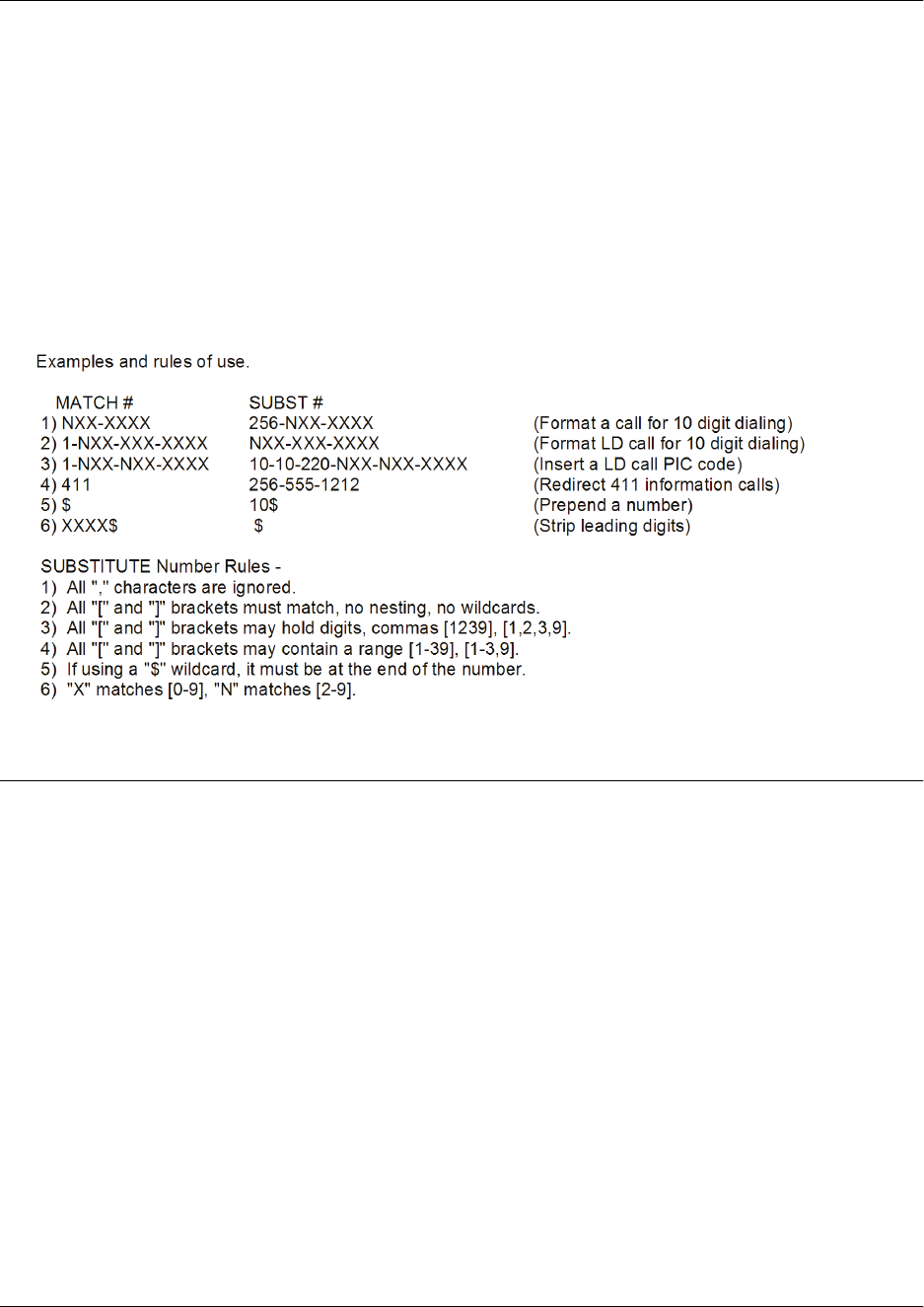
Command Reference Guide Voice ISDN Trunk Command Set
60000CRG0-35E Copyright © 2012 ADTRAN, Inc. 3502
The special characters ( ), -, and + are always ignored in the template. The following are example template
entries using wildcards:
Examples: 1) 555-81xx matches 555-8100 to 555-8199.
2) 555-812[012] matches 555-8120 to 555-8122.
3) Nxx-xxxx matches 7 digits local.
4) 1-Nxx-Nxx-xxxx matches long distance calls in North America.
Additional wildcards ($ and 0 to 9) can also be used. The command line interface (CLI) also contains
helpful information regarding the construction of the template and can be viewed by entering the match
ani command followed by a question mark. For example, entering the command as follows results in the
template input specifications:
(config)#match ani ?
Usage Examples
The following example specifies that the ANI information from numbers 555-8111 to 555-8115 will be
substituted by 555-8110 for outbound calls on the trunk T03:
(config)#voice trunk t03 type isdn
(config-t03)#match ani 555-811[125] substitute 555-8110

Command Reference Guide Voice ISDN Trunk Command Set
60000CRG0-35E Copyright © 2012 ADTRAN, Inc. 3503
match dnis <template> replace ani <number>
Use the match dnis replace ani command to replace dialed number identification service (DNIS)
information with automatic number identification (ANI) information on outbound voice trunks. Use the no
form of this command to remove the replacement. Variations of this command include:
match dnis <template> replace ani <number>
match dnis <template> replace ani <number> name <name>
Syntax Description
dnis <template> Specifies the DNIS information to be replaced. This information is entered
using wildcards and numerical digits. Refer to the Functional Notes of this
command for available wildcards and proper data entry.
replace ani <number> Specifies the ANI information that replaces the original DNIS information.
This information is entered using numerical digits. Enter the number without
punctuation.
name <name> Optional. Specifies the name associated with the ANI information. This
option is only available on trunks that support ANI name information
(integrated services digital network (ISDN) trunks, Session Initiation
Protocol (SIP) trunks, T1 loop start (LS) network trunks, and T1 ground start
(GS) network trunks).
Default Values
By default, no DNIS replacement is configured.
Command History
Release A2 Command was introduced.
Functional Notes
The convention for DNIS templates is very similar to dial plan entries. Wildcards available for this
command are:
0-9 = Match exact digit only.
M = Any digit 1 to 8.
X = Any single digit (0 to 9).
N = Any digit 2 to 9.
[123] = Any digit contained in the bracketed list.
Do not use dashes, commas, spaces, etc., inside the brackets. Commas are implied between
numbers in the brackets.
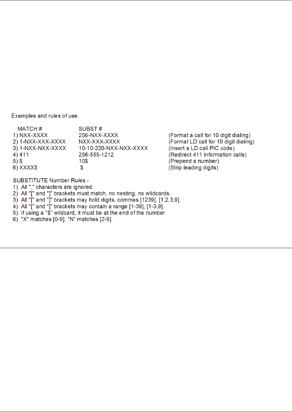
Command Reference Guide Voice ISDN Trunk Command Set
60000CRG0-35E Copyright © 2012 ADTRAN, Inc. 3504
The special characters ( ), -, and + are always ignored in the template. The following are example template
entries using wildcards:
Examples: 1) 555-81xx matches 555-8100 to 555-8199.
2) 555-812[012] matches 555-8120 to 555-8122.
3) Nxx-xxxx matches 7 digits local.
4) 1-Nxx-Nxx-xxxx matches long distance calls in North America.
Additional wildcards ($ and 0 to 9) can also be used. The command line interface (CLI) also contains
helpful information regarding the construction of the template and can be viewed by entering the match
dnis command followed by a question mark. For example, entering the command as follows results in the
template input specifications:
(config)#match dnis ?
Usage Examples
The following example specifies that the DNIS information for dialed numbers on trunk T03 that match
1-256-524-8600 are replaced with 882-6467:
(config)#voice trunk t03 type isdn
(config-t03)#match dnis 1-256-524-8600 replace ani 8826467

Command Reference Guide Voice ISDN Trunk Command Set
60000CRG0-35E Copyright © 2012 ADTRAN, Inc. 3505
match dnis <template> substitute <template>
Use the match dnis substitute command to configure dialed number identification service (DNIS)
substitution for outbound voice trunks. Use the no form of this command to remove the substitution.
Variations of this command include:
match dnis <template> substitute <template>
match dnis <template> substitute <template> name <name>
Syntax Description
dnis <template> Specifies the DNIS information to be substituted. This information is entered
using wildcards and numerical digits. Refer to the Functional Notes of this
command for available wildcards and proper data entry.
substitute <template> Specifies the DNIS information that is substituted for the original DNIS
information. This information is entered using wildcards and numerical
digits. Refer to the Functional Notes of this command for available wildcards
and proper data entry.
name <name> Optional. Specifies the name associated with the DNIS information. This
option is only available on trunks that support DNIS name information
(integrated services digital network (ISDN) trunks, Session Initiation
Protocol (SIP) trunks, T1 loop start (LS) network trunks, and T1 ground start
(GS) network trunks).
Default Values
By default, no DNIS substitution is configured.
Command History
Release A2 Command was introduced.
Functional Notes
The convention for DNIS templates is very similar to dial plan entries. Wildcards available for this
command are:
0-9 = Match exact digit only.
M = Any digit 1 to 8.
X = Any single digit (0 to 9).
N = Any digit 2 to 9.
[123] = Any digit contained in the bracketed list.
Do not use dashes, commas, spaces, etc., inside the brackets. Commas are implied between
numbers in the brackets.

Command Reference Guide Voice ISDN Trunk Command Set
60000CRG0-35E Copyright © 2012 ADTRAN, Inc. 3506
The special characters ( ), -, and + are always ignored in the template. The following are example template
entries using wildcards:
Examples: 1) 555-81xx matches 555-8100 to 555-8199.
2) 555-812[012] matches 555-8120 to 555-8122.
3) Nxx-xxxx matches 7 digits local.
4) 1-Nxx-Nxx-xxxx matches long distance calls in North America.
Additional wildcards ($ and 0 to 9) can also be used. The command line interface (CLI) also contains
helpful information regarding the construction of the template and can be viewed by entering the match
dnis command followed by a question mark. For example, entering the command as follows results in the
template input specifications:
(config)#match dnis ?
Usage Examples
The following example specifies that the DNIS information for dialed numbers on trunk T03 that match
1-334-NXX-XXXX are substituted with 1-800-557-4500:
(config)#voice trunk t03 type isdn
(config-t03)#match dnis 1-334-NXX-XXXX substitute 1-800-557-4500

Command Reference Guide Voice ISDN Trunk Command Set
60000CRG0-35E Copyright © 2012 ADTRAN, Inc. 3507
modem-passthrough
Use the modem-passthrough command to switch to passthrough mode on fax or modem tone detection.
This command allows modem and fax calls to maintain a connection without altering the signals with the
voice improvement settings, such as echo cancellation and voice activity detection (VAD). Use the no form
of this command to disable this feature. Variations of this command include:
modem-passthrough
modem-passthrough detection-time <value>
Syntax Description
detection-time <value> Optional. Specifies the fax and/or modem detection time length value in
seconds. Range is 0 to 8 seconds.
Default Values
By default, modem-passthrough is enabled.
Command History
Release 11.1 Command was introduced.
Release 12.1 Command was expanded.
Usage Examples
The following example enables modem-passthrough:
(config)#voice trunk t01 type isdn
(config-t01)#modem-passthrough

Command Reference Guide Voice ISDN Trunk Command Set
60000CRG0-35E Copyright © 2012 ADTRAN, Inc. 3508
plc
Use the plc command to enable packet loss concealment (PLC). PLC is used to prevent choppy
connections by concealing a packet loss by replacing the lost packet with another voice packet in the data
stream. Use the no form of this command to disable this feature.
Syntax Description
No subcommands.
Default Values
By default, PLC is enabled.
Command History
Release 11.1 Command was introduced.
Usage Examples
The following example enables PLC on trunk T01:
(config)#voice trunk t01 type isdn
(config-t01)#plc

Command Reference Guide Voice ISDN Trunk Command Set
60000CRG0-35E Copyright © 2012 ADTRAN, Inc. 3509
prefer trunk-routing
Use the prefer trunk-routing command to add a trunk to a list of trunks that are considered first for call
routing, regardless of system routing mode or locally configured extensions. Use the no form of this
command to remove the trunk from the list.
Syntax Description
No subcommands.
Default Values
By default, prefer trunk-routing is disabled.
Command History
Release A2 Command was introduced.
Functional Notes
Trunk routing can be specified as a preference for specific trunks, allowing the trunk to be considered first
for routing rather than relying on the internal or external nature of the call to dictate whether the trunk or
voice station is the first choice routing path. The prefer trunk-routing command, executed from a specific
trunk’s configuration mode, adds the trunk to a list of trunks that are considered first for routing.
By default, no trunk routing preference is set, so that each trunk operates as dictated by normal call routing
modes. Adding the trunk routing preference only affects how inbound calls from the specific trunk are
handled.
Usage Examples
The following example specifies that trunk routing is preferred on the trunk T01:
(config)#voice trunk t01 type isdn
(config-t01)#prefer trunk-routing

Command Reference Guide Voice ISDN Trunk Command Set
60000CRG0-35E Copyright © 2012 ADTRAN, Inc. 3510
reject-external
Use the reject-external command to blocked outbound (external) call attempts. Use the no form of this
command to disable this feature.
Syntax Description
No subcommands.
Default Values
By default, this command is enabled.
Command History
Release 11.1 Command was introduced.
Usage Examples
The following example enables packet loss concealment (PLC) on trunk T01:
(config)#voice trunk t01 type isdn
(config-t01)#reject-external

Command Reference Guide Voice ISDN Trunk Command Set
60000CRG0-35E Copyright © 2012 ADTRAN, Inc. 3511
resource-selection
Use the resource-selection command to determine how the switchboard uses outbound call resources
contained within a time division multiplexing (TDM) based trunk group. Use the no form of this command
to disable this feature. Variations of this command include:
resource-selection circular
resource-selection circular ascending
resource-selection circular descending
resource-selection linear
resource-selection linear ascending
resource-selection linear descending
Syntax Description
circular Performs call load balancing among available DS0s/B-channels in this
trunk. Subsequent calls will be delivered to the next available
DS0/B-channel in a round-robin fashion.
linear Specifies that a call being delivered to this trunk will be accepted out the first
available DS0/B-channel available at the time the call is received.
ascending Optional. Distributes calls in an order from the lowest to the highest channel
(DS0 1, 2, 3 through 24).
descending Optional. Distributes calls in an order from the highest to the lowest channel
(DS0 24, 23, 22 through 1).
Default Values
By default, resource selection is set to linear.
Command History
Release 9.3 Command was introduced.
Release 13.1 Command was expanded to include the ascending and descending
subcommands.
Usage Examples
The following example specifies circular resource selection:
(config)#voice trunk t01 type isdn
(config-t01)#resource-selection circular

Command Reference Guide Voice ISDN Trunk Command Set
60000CRG0-35E Copyright © 2012 ADTRAN, Inc. 3512
rtp delay-mode
Use the rtp delay-mode command to configure the Realtime Transport Protocol (RTP) jitter buffer packet
delay mode settings. RTP is used to prevent static on voice connections by enhancing the quality of the
packet delivery. Use the no form of this command to return to the default setting. Variations of this
command include:
rtp delay-mode adaptive
rtp delay-mode fixed
Syntax Description
adaptive Configures RTP jitter buffer packet delay to adjust during a call based on
network conditions.
fixed Configures the RTP jitter buffer packet delay to remain constant.
Default Values
By default, this command is set to adaptive.
Command History
Release 11.1 Command was introduced.
Usage Examples
The following example configures RTP delay mode as fixed:
(config)#voice trunk t01 type isdn
(config-t01)#rtp delay-mode fixed

Command Reference Guide Voice ISDN Trunk Command Set
60000CRG0-35E Copyright © 2012 ADTRAN, Inc. 3513
rtp dtmf-relay
Use the rtp dtmf-relay command to configure the method by which Realtime Transport Protocol (RTP)
dual tone multi-frequency (DTMF) events are relayed, either inband in the RTP stream or out-of-band
(OOB) using named telephone events (NTEs). RTP DTMF relay is used to prevent the tone (dialed digits)
from being corrupted. Use the no form of this command to return to the default value. Variations of this
command include:
rtp dtmf-relay inband
rtp dtmf-relay nte <value>
Syntax Description
inband Configures RTP DTMF relay events for inband.
nte <value> Configures RTP DTMF relay events for NTE. Enter a value between
96 and 127.
Default Values
By default, the rtp dtmf-relay is set for NTE 101.
Command History
Release 9.3 Command was introduced.
Release 11.1 Command was expanded to include the integrated services digital network
(ISDN) trunk.
Usage Examples
The following example configures RTP DTMF relay events for NTE with an event value of 101:
(config)#voice trunk t01 type isdn
(config-t01)#rtp dtmf-relay nte 101

Command Reference Guide Voice ISDN Trunk Command Set
60000CRG0-35E Copyright © 2012 ADTRAN, Inc. 3514
rtp frame-packetization <value>
Use the rtp frame-packetization command to configure the Realtime Transport Protocol (RTP) frame
packetization time in milliseconds for individual trunks and users. Use the no form of this command to
return to the default value.
Syntax Description
<value>
Configures the RTP frame packetization time in milliseconds. Select from
10, 20, or 30 milliseconds.
Default Values
By default, the rtp frame-packetization time is set to 20 milliseconds on all trunks and users.
Command History
Release 9.3 Command was introduced.
Release 11.1 Command was expanded to include the integrated services digital network
(ISDN) trunk.
Usage Examples
The following example sets the frame packetization time for trunk T01 to 20 milliseconds:
(config)#voice trunk t01 type isdn
(config-t01)#rtp frame-packetization 20

Command Reference Guide Voice ISDN Trunk Command Set
60000CRG0-35E Copyright © 2012 ADTRAN, Inc. 3515
rtp packet-delay
Use the rtp packet-delay command to configure the maximum Realtime Transport Protocol (RTP) packet
delays. This command is used to set the allowable limits of latency on the network. Use the no form of this
command to return to the default value. Variations of this command include:
rtp packet-delay fax <value>
rtp packet-delay maximum <value>
rtp packet-delay nominal <value>
Syntax Description
fax <value> Sets the fax delay time in milliseconds. Range is 0 to 500 milliseconds.
maximum <value> Sets the maximum delay time in increments of 10 milliseconds. Range is
40 to 320 milliseconds.
nominal <value> Sets the nominal delay time
in increments of 10 milliseconds. Range is
10 to 240
milliseconds
.
Default Values
No default values are necessary for this command.
Command History
Release 11.1 Command was introduced.
Usage Examples
The following example configures the RTP fax delay time on trunk T01 to 10 milliseconds:
(config)#voice trunk t01 type isdn
(config-t01)#rtp packet-delay fax 10

Command Reference Guide Voice ISDN Trunk Command Set
60000CRG0-35E Copyright © 2012 ADTRAN, Inc. 3516
rtp qos dscp <value>
Use the rtp qos dscp command to configure the maximum Realtime Transport Protocol (RTP) quality of
service (QoS) parameters for differentiated services code point (DSCP).
Syntax Description
<value>
Configures the RTP QoS parameter for DSCP. Enter a value between 10
and 63.
Default Values
By default, no RTP QoS DSCP is configured for this interface.
Command History
Release 9.3 Command was introduced.
Release 11.1 Command was expanded to include the integrated services digital network
(ISDN) trunk.
Functional Notes
By setting the rtp qos dscp value on an individual trunk or user, you will override the global rtp qos dscp
setting for RTP packets. QoS is set using a DSCP value. Valid DSCP values are 10 to 63, and a higher
DSCP value has a higher priority. The default DSCP value for RTP is 46. Remember that if you are using a
public IP connection, such as the Internet, for Voice over Internet Protocol (VoIP), end-to-end QoS may not
be guaranteed. The default DSCP value for Session Initiation Protocol (SIP) is 26. To configure QoS for
the RTP traffic that carries the voice conversation, use the command ip rtp qos dscp followed by the
desired DSCP value.
Usage Examples
By setting the rtp qos dscp value on an individual trunk or user, you will override the global rtp qos dscp
setting for RTP packets. The following example sets the DSCP value for RTP packets that trunk T02
generates to 60.
(config)#voice trunk t02 type isdn
(config-t02)#rtp qos dscp 60

Command Reference Guide Voice ISDN Trunk Command Set
60000CRG0-35E Copyright © 2012 ADTRAN, Inc. 3517
rtp rx-gain <value>
Use the rtp rx-gain command to specify the Realtime Transport Protocol (RTP) receive (RX) gain or
attenuation. RTP is used to prevent static on voice connections by enhancing the quality of the packet
delivery. Using the no form of this command returns the RTP RX gain or attenuation to the default value.
Syntax Description
<value> Specifies the RTP RX gain or attenuation in the RTP to time division
multiplexing (TDM) direction. Range is 6 to -14. Negative values specify
attenuation. Positive values specify gain in decibels (dB).
Default Values
By default, RTP RX gain is set to 0 dB.
Command History
Release A2.04 Command was introduced.
Usage Examples
The following example specifies the RTP RX gain for integrated services digital network (ISDN) trunk T01
is 4 dB:
(config)#voice trunk t01 type isdn
(config-t01)#rtp rx-gain 4

Command Reference Guide Voice ISDN Trunk Command Set
60000CRG0-35E Copyright © 2012 ADTRAN, Inc. 3518
rtp tx-gain <value>
Use the rtp tx-gain command to specify the Realtime Transport Protocol (RTP) transmit (TX) gain or
attentuation. RTP is used to prevent static on voice connections by enhancing the quality of the packet
delivery. Using the no form of this command returns the RTP TX gain or attenuation to the default value.
Syntax Description
<value> Specifies the RTP TX gain or attenuation in the time division multiplexing
(TDM) to RTP direction. Range is 6 to -14. Negative values specify
attenuation. Positive values specify gain in decibels (dB).
Default Values
By default, RTP TX gain is set to 0 dB.
Command History
Release A2.04 Command was introduced.
Usage Examples
The following example specifies the RTP TX gain for integrated services digital network (ISDN) trunk T01
is 4 dB:
(config)#voice trunk t01 type isdn
(config-t01)#rtp tx-gain 4

Command Reference Guide Voice ISDN Trunk Command Set
60000CRG0-35E Copyright © 2012 ADTRAN, Inc. 3519
trunk-number <number>
Use the trunk-number command to define the call routing when direct inward dialing (DID) is disabled.
This feature directs incoming calls to the specified number when DID is not present. This command also
allows users to activate different system modes of operation that redirect incoming calls to a different
number depending on the specified mode. Use the no form of this command to disable this feature.
Variations of this command include:
trunk-number <number>
trunk-number no-number
trunk-number <system mode> <number>
trunk-number <system mode> no-number
trunk-number override <number>
trunk-number override no-number
Syntax Description
<number> Specifies the number used for call routing when DID is disabled.
<system mode> Optional. Specifies the system mode to configure. Choose from custom1,
custom2, custom3, lunch, night, or weekend. Refer to the command
voice system-mode on page 1445 for more information on system modes.
no-number Specifies no inbound calls are allowed on this trunk.
override Ignores the programmed system mode schedule.
Default Values
No default values are necessary for this command.
Command History
Release 11.1 Command was introduced.
Release 15.1 Command was added to the feature group D (FGD) trunk options.
Release A1 Command was expanded to include the new subcommands.
Usage Examples
The following example defines call routing on trunk T02:
(config)#voice trunk t02 type isdn
(config-t02)#trunk-number 4000

Command Reference Guide Voice ISDN Trunk Command Set
60000CRG0-35E Copyright © 2012 ADTRAN, Inc. 3520
t38
Use the t38 command to enable T.38 fax operation. Use the no form of this command to disable this
feature.
Syntax Description
No subcommands.
Default Values
By default, T.38 is disabled.
Command History
Release 16.1 Command was introduced.
Usage Examples
The following example enables T.38:
(config)#voice trunk t02 type isdn
(config-t02)#t38
Technology Review
T.38 is an International Telecommunication Union (ITU) specification that allows Group-3 Fax (T.30) data to
be transported over the Internet. It is similar to dual tone multi-frequency (DTMF) relay (RFC 2833) in that
the digital signal processor (DSP) decodes tones and demodulated fax data and converts them into
packets. A similar device on the other end takes the packets/tones and remodulates them so that an
analog fax machine on the other end can receive the fax. AOS’s previous support (revisions 12 through 15)
for fax/modem signals was simply detecting a tone and forcing the coder-decoder (CODEC) into G.711 and
disabling/enabling echo cancellers based on the tones detected. When packet loss becomes high, sending
faxes over G.711 becomes problematic, due to dropped messages and timeouts/retrains.
T.38 can be used in conjunction with various call-control schemes, such as H.323, Session Initiation
Protocol (SIP), and Media Gateway Control Protocol (MGCP). AOS only supports SIP as the call-control
method. This is typically referred to T.38/Annex-D. Annex-D describes the Session Initiation
Protocol/Session Description Protocol (SIP/SDP) call establishment procedures.
The command modem-passthrough on page 3507 must be enabled for T.38 operation to
work.

Command Reference Guide Voice ISDN Trunk Command Set
60000CRG0-35E Copyright © 2012 ADTRAN, Inc. 3521
t38 ced auto-generate
Use the t38 ced auto-generate command to specify when the digital signal processor (DSP) should
regenerate the called station identifier (CED) signal toward the time division multiplexed (TDM) endpoint.
If auto-generate is enabled, the DSP generates the CED signal only when it does not receive CED indicator
packets from the Voice over IP (VoIP) endpoint. If auto-generate is disabled, the DSP generates the CED
signal only when it does receive CED indicator packets from the VoIP endpoint. Using the no version of
this command disables CED auto-generate.
Syntax Description
No subcommands.
Default Values
By default, CED auto-generate is disabled.
Command History
Release A5.01 Command was introduced.
Functional Notes
This command is only available on AOS voice products that have Freescale DSP. This includes the Total
Access 900(e) Series, the NetVanta 6310/6330 Series, and the NetVanta 7000 Series products.
This command is used to help in troubleshooting T.38 interoperability issues. This command should only
be issued by advanced users or at the direction of ADTRAN technical support.
Usage Examples
The following example enables CED auto-generate for the T.38 session on the trunk:
(config)#voice trunk t02 type isdn
(config-t02)#t38 ced auto-generate

Command Reference Guide Voice ISDN Trunk Command Set
60000CRG0-35E Copyright © 2012 ADTRAN, Inc. 3522
t38 ced length <time>
Use the t38 ced length command to set the maximum duration of a regenerated called station identifier
(CED) signal, in milliseconds, from the digital signal processor (DSP) toward the time division
multiplexed (TDM) endpoint when a T.38 session is active. Using the no form of this command returns the
duration to the default value.
Syntax Description
<time> Specifies the maximum duration of a regenerated CED signal in
milliseconds. Valid range is 0 to 4000 ms.
Default Values
By default, the maximum duration of a regenerated CED signal is 3000 ms.
Command History
Release A5.01 Command was introduced.
Functional Notes
This command is only available on AOS voice products that have Freescale DSP. This includes the Total
Access 900(e) Series, the NetVanta 6310/6330 Series, and the NetVanta 7000 Series products.
This command is used to help in troubleshooting T.38 interoperability issues. This command should only
be issued by advanced users or at the direction of ADTRAN technical support.
Setting the maximum duration of a regenerated CED signal to 0 effectively prevents any CED generation.
Usage Examples
The following example decreases the maximum duration of the CED signal to 2000 ms for the T.38
session:
(config)#voice trunk t02 type isdn
(config-t02)#t38 ced length 2000

Command Reference Guide Voice ISDN Trunk Command Set
60000CRG0-35E Copyright © 2012 ADTRAN, Inc. 3523
t38 error-correction
Use the t38 error-correction command to specify the type of fax error correction. Use the no form of this
command to disable this feature. Variations of this command include:
t38 error-correction fec
t38 error-correction redundancy
Syntax Description
fec Specifies forward error correction (FEC) as the fax error correction. FEC is
a system of error control where the sender adds redundant data to its
messages, allowing the receiver to detect and correct errors (within certain
bounds) without the need to request additional data from the sender.
redundancy Specifies redundancy as the fax error correction. Redundancy error
correction replicates the payload a user-specified number of times to
determine if errors are present. The number of redundant packets is set
using the command t38 redundancy on page 3529).
Default Values
By default, t38 error-correction is set to fec for the Total Access 900(e) Series, the NetVanta 6310/6330
Series, the NetVanta 6355 Series, and the NetVanta 7000 Series products. The default setting is
redundancy for the NetVanta 6200 Series and the NetVanta 640 Series products.
Command History
Release 16.1 Command was introduced.
Release A5.01 Command default value changed to fec for the Total Access 900(e) Series,
the NetVanta 6310/6330 Series, the NetVanta 6355 Series, and the
NetVanta 7000 Series products.
Usage Examples
The following example sets the t38 error-correction to fec:
(config)#voice trunk t02 type isdn
(config-t02)#t38 error-correction fec

Command Reference Guide Voice ISDN Trunk Command Set
60000CRG0-35E Copyright © 2012 ADTRAN, Inc. 3524
t38 fallback-mode g711
Use the t38 fallback-mode command to specify the transmission mode used when T.38 fax relay cannot
be successfully negotiated at the time of the fax transfer. Use the no form of this command to disable this
feature.
Syntax Description
g711 Specifies that fax operation revert back to analog mode (G.711).
Default Values
By default, t38 fallback-mode is to G.711.
Command History
Release 16.1 Command was introduced.
Release A5.01 Command default was changed to G.711.
Usage Examples
The following example enables the t38 fallback-mode on trunk T02:
(config)#voice trunk t02 type isdn
(config-t02)#t38 fallback-mode g711

Command Reference Guide Voice ISDN Trunk Command Set
60000CRG0-35E Copyright © 2012 ADTRAN, Inc. 3525
t38 generate-cng
Use the t38 generate-cng command to specify whether the digital signal processor (DSP) will begin a
T.38 session by generating the calling signal (CNG) toward the time division multiplexed (TDM)
endpoint. Using the no version of this command disables CNG generation.
Syntax Description
No subcommands.
Default Values
By default, CNG generation is disabled.
Command History
Release A5.01 Command was introduced.
Functional Notes
This command is only available on AOS voice products that have Freescale DSP. This includes the Total
Access 900(e) Series, the NetVanta 6310/6330 Series, and the NetVanta 7000 Series products.
This command is used to help in troubleshooting T.38 interoperability issues. This command should only
be issued by advanced users or at the direction of ADTRAN technical support.
With the introduction of this command, the CNG generation behavior of the T.38 session is now
configurable. In AOS firmware prior to A5.01, this behavior was not configurable, but rather was set to
always generate this signal.
Usage Examples
The following example enables CNG generation for the T.38 session:
(config)#voice trunk t02 type isdn
(config-t02)#t38 generate-cng

Command Reference Guide Voice ISDN Trunk Command Set
60000CRG0-35E Copyright © 2012 ADTRAN, Inc. 3526
t38 max-buffer <value>
Use the t38 max-buffer command to set the maximum buffer size for T.38 fax operation. Use the no form
of this command to return to the default value.
Syntax Description
<value> Specifies the value of the max-buffer attribute in the Session Description
Protocol (SDP) offer when the T.38 session is initiated. Range is 0 to
800 bytes.
Default Values
By default, the maximum buffer size is set to 200.
Command History
Release 16.1 Command was introduced.
Usage Examples
The following example sets the t38 max-buffer to 100:
(config)#voice trunk t02 type isdn
(config-t02)#t38 max-buffer 100

Command Reference Guide Voice ISDN Trunk Command Set
60000CRG0-35E Copyright © 2012 ADTRAN, Inc. 3527
t38 max-datagram <value>
Use the t38 max-datagram command to set the maximum datagram value in this unit. Use the no form of
this command to return to the default value.
Syntax Description
<value> Specifies the value of the max-datagram attribute in the Session
Description Protocol (SDP) offer when the T.38 session is initiated. Range is
0 to 300 bytes.
Default Values
By default, the maximum datagram value is set to 72 bytes.
Command History
Release 16.1 Command was introduced.
Release A5.01 Command default was changed to 72 bytes.
Usage Examples
The following example sets the t38 max-datagram to 100:
(config)#voice trunk t02 type isdn
(config-t02)#t38 max-datagram 100

Command Reference Guide Voice ISDN Trunk Command Set
60000CRG0-35E Copyright © 2012 ADTRAN, Inc. 3528
t38 max-rate
Use the t38 max-rate command to specify the fax maximum rate. The actual transmission rate could be
lower than specified rate if the receiving end cannot support the maximum rate. Use the no form of this
command to return to the default value. Variations of this command include:
t38 max-rate 14400
t38 max-rate 12000
t38 max-rate 2400
t38 max-rate 4800
t38 max-rate 7200
t38 max-rate 9600
Syntax Description
14400 Specifies 14400 bits per second (bps) as fax maximum rate.
12000 Specifies 12000 bps as fax maximum rate.
2400 Specifies 2400 bps as fax maximum rate.
4800 Specifies 4800 bps as fax maximum rate.
7200 Specifies 7200 bps as fax maximum rate.
9600 Specifies 9600 bps as fax maximum rate.
Default Values
By default, the maximum fax rate is set to 14400 bps.
Command History
Release 16.1 Command was introduced.
Usage Examples
The following example sets the t38 max-rate to 4800 bps:
(config)#voice trunk t02 type isdn
(config-t02)#t38 max-rate 4800

Command Reference Guide Voice ISDN Trunk Command Set
60000CRG0-35E Copyright © 2012 ADTRAN, Inc. 3529
t38 redundancy
Use the t38 redundancy command to set the number of redundant packets sent when the t38
error-correction redundancy feature is enabled. Use the no form of this command to return to the default
value. Variations of this command include:
t38 redundancy high-speed <value>
t38 redundancy low-speed <value>
Syntax Description
high-speed <value> Specifies the number of redundant T.38 fax packets to be sent for data
messages (high-speed fax machine image data). Range is 0 (no
redundancy) to 4 packets.
low-speed <value> Specifies the number of redundant T.38 fax packets to be sent for the
signaling messages (low-speed fax machine protocol). Range is 0 (no
redundancy) to 7 packets.
Default Values
By default, high-speed and low-speed redundancy values are set to 0 (no redundancy).
Command History
Release 16.1 Command was introduced.
Usage Examples
The following example enables t38 error-correction redundancy and sets the number of redundant data
messages to 3:
(config)#voice trunk t02 type isdn
(config-t02)#t38 error-correction redundancy
(config-t02)#t38 redundancy high-speed 3

Command Reference Guide Voice ISDN Trunk Command Set
60000CRG0-35E Copyright © 2012 ADTRAN, Inc. 3530
t38 v21-preamble-timeout <value>
Use the t38 v21-preamble-timeout command to set the maximum amount of time that the digital signal
processor (DSP) waits for peer device activity after starting to transmit a V.21 preamble event before
spoofing a response to the time division multiplexed (TDM) endpoint. Using the no version of this
command returns the timeout value to the default setting.
Syntax Description
<value> The time, in milliseconds, that the DSP will wait for peer activity. Valid range
is 1 to 3000 ms.
Default Values
By default, the V.21 preamble timeout is set to 1700 ms.
Command History
Release A5.01 Command was introduced.
Functional Notes
This command is only available on AOS voice products that have Freescale DSP. This includes the Total
Access 900(e) Series, the NetVanta 6310/6330 Series, and the NetVanta 7000 Series products.
This command is used to help in troubleshooting T.38 interoperability issues. This command should only
be issued by advanced users or at the direction of ADTRAN technical support.
Usage Examples
The following example specifies the V.21 preamble timeout value as 2000 ms:
(config)#voice trunk t02 type isdn
(config-t02)#t38 v21-preamble-timeout 2000

Command Reference Guide Voice ISDN Trunk Command Set
60000CRG0-35E Copyright © 2012 ADTRAN, Inc. 3531
vad
Use the vad command to enable voice activity detection (VAD). VAD blocks out noise categorized as
silence during a voice connection. The silent voice packets are not transmitted, allowing bandwidth usage
to be reduced. Although VAD saves bandwidth, the quality of the voice call may be compromised. Use the
no form of this command to disable this feature.
Syntax Description
No subcommands.
Default Values
By default, VAD is enabled for all T1 robbed-bit signaling RBS trunks and users.
Command History
Release 9.3 Command was introduced.
Release 11.1 Command was expanded to include the integrated services digital network
(ISDN) trunk.
Usage Examples
The following example enables voice activation detection on trunk T01:
(config)#voice trunk t01 type isdn
(config-t01)#vad

Command Reference Guide Voice SIP Trunk Command Set
60000CRG0-35E Copyright © 2012 ADTRAN, Inc. 3532
VOICE SIP TRUNK COMMAND SET
Session Initiation Protocol (SIP) trunking is a packet-based voice service that routes calls over an IP
network to an IP-compatible private branch exchange (PBX) or voice switch using SIP signaling to place
and receive calls. The typical SIP trunk service provider offers extensive cost savings, compared to
conventional trunk services. The IP connection to the provider carries all traffic, such as local, long
distance, and toll free calls, video, email, Internet, data, and other media over a single circuit. Calls into
public switched telephone networks (PSTNs) are also handled by the SIP service provider by passing the
calls off to a media gateway that connects to the PSTN for users not using Voice over Internet Protocol
(VoIP) service.
SIP trunks are configured over data connections. Thus, they can be configured over an Ethernet connection
or a T1 connection.
To create a SIP trunk and enter the Voice SIP Trunk Configuration mode, enter the voice trunk type sip
command at the Global Configuration mode prompt. For example:
>enable
#configure terminal
(config)#voice trunk t01 type sip
(config-t01)#
The following commands are common to multiple command sets and are covered in a centralized section
of this guide. For more information, refer to the sections listed below:
cross-connect on page 67
description <text> on page 70
do on page 71
exit on page 73
interface on page 74
All other commands for this command set are described in this section in alphabetical order.
alc on page 3535
alert-info on page 3536
authentication username <username> password <password> on page 3537
busy all on page 3538
busy-out monitor track <name> on page 3539
caller-id-override on page 3540
check-supported replaces on page 3541
codec-group <name> on page 3542
conferencing-uri <value> on page 3543
default-ring-cadence on page 3544
dial-string source on page 3545

Command Reference Guide Voice SIP Trunk Command Set
60000CRG0-35E Copyright © 2012 ADTRAN, Inc. 3533
diversion-supported on page 3546
domain <name> on page 3547
grammar alert-info url <url> on page 3548
grammar from on page 3549
grammar p-asserted-identity host on page 3551
grammar proxy-require privacy on page 3552
grammar refer-to on page 3553
grammar request-uri on page 3554
grammar require 100rel on page 3555
grammar supported 100rel on page 3556
grammar to on page 3557
incoming-music-on-hold on page 3558
match ani <template> add diversion <template> on page 3559
match ani <template> add p-asserted-identity <template> on page 3562
match ani <template> replace diversion <template> on page 3564
match ani <template> substitute <template> on page 3567
match dnis <template> replace ani <number> on page 3569
match dnis <template> substitute <template> on page 3571
max-number-calls <value> on page 3573
media-loopback on page 3574
outbound-proxy primary <value> on page 3575
outbound-proxy secondary <value> on page 3576
p-assert-diversion on page 3577
phone-context on page 3578
prefer double-reinvite on page 3582
prefer reinvite-without-sdp on page 3583
prefer trunk-routing on page 3584
register on page 3585
registrar expire-time <value> on page 3587
registrar max-concurrent-reg <value> on page 3588
registrar primary <value> on page 3589
registrar require-expires on page 3590
registrar secondary <value> on page 3591
registrar threshold on page 3592
reject-external on page 3593
sip-keep-alive on page 3594
sip-server primary <value> on page 3595
sip-server rollover on page 3596
sip-server secondary <value> on page 3597


Command Reference Guide Voice SIP Trunk Command Set
60000CRG0-35E Copyright © 2012 ADTRAN, Inc. 3535
alc
Use the alc command to enable automatic level control (ALC). ALC reduces Realtime Transport Protocol
(RTP) received signals that are out of specification to the predefined levels. It is not necessary to enable
ALC on those networks that guarantee signal levels to be within specification. Use the no form of this
command to disable this feature. Variations of this command include:
alc
alc level -16
alc level -17
alc level -18
alc level -19
alc level -20
alc level -21
alc level -22
Syntax Description
level -16 Optional. Specifies the ALC attenuation level is -16 dBm0.
level -17 Optional. Specifies the ALC attenuation level is -17 dBm0.
level -18 Optional. Specifies the ALC attenuation level is -18 dBm0.
level -19 Optional. Specifies the ALC attenuation level is -19 dBm0.
level -20 Optional. Specifies the ALC attenuation level is -20 dBm0.
level -21 Optional. Specifies the ALC attenuation level is -21 dBm0.
level -22 Optional. Specifies the ALC attenuation level is -22 dBm0.
Default Values
By default, ALC is disabled.
Command History
Release 14.1 Command was introduced.
Release 15.1 Command was added to the Voice Line Interface.
Release A2 Command was added to the Media Gateway Control Protocol (MGCP)
endpoint configuration.
Release A2.04 Command was expanded to include the level parameters.
Usage Examples
The following example activates the ALC on trunk T01:
(config)#voice trunk t01 type sip
(config-t01)#alc

Command Reference Guide Voice SIP Trunk Command Set
60000CRG0-35E Copyright © 2012 ADTRAN, Inc. 3536
alert-info
Use the alert-info command to allow the alert information attribute on incoming and/or outgoing auto
answer alert information. Use the no form of this command to cancel the setting. Variations of this
command include:
alert-info incoming auto-answer
alert-info outgoing auto-answer
Syntax Description
incoming auto-answer Specifies processing incoming ALERT-INFO attribute.
outgoing auto-answer Specifies allowing the outgoing ALERT-INFO auto-answer attribute.
Default Values
By default, both incoming and outgoing auto answer alert information is allowed on the NetVanta 7000
Series in the ALERT-INFO messages. However, both are disabled by default in the IP business gateways
(IPBGs) (Total Access 900 Series and NetVanta 1335). The IPBGs will ignore incoming auto answer in the
ALERT-INFO messages, and will not send the information on outgoing trunks.
Command History
Release 16.1 Command was introduced.
Usage Examples
The following example blocks outgoing alert-info auto-answer attribute on trunk T01:
(config)#voice trunk t01 type sip
(config-t01)#alert-info outgoing auto-answer

Command Reference Guide Voice SIP Trunk Command Set
60000CRG0-35E Copyright © 2012 ADTRAN, Inc. 3537
authentication username <username> password <password>
Use the authentication username password command to enable authentication security between the
Session Initiation Protocol (SIP) server and the unit. Each port that registers with the SIP server will use
the defined username and password. Use the no form of this command to return to the default setting.
Syntax Description
username <username> Specifies a string to be sent as the user name in authentication.
password <password> Specifies a string to be sent as the password in authentication.
Default Values
By default, authentication is not enabled.
Command History
Release 9.3 Command was introduced.
Functional Notes
If all users on the trunk use the same user name/password, enter the user name and password for
authentication under the trunk. Otherwise, enter authentication information for each user individually in the
Voice User command set that overrides the setting of this command. Refer to Voice User Account
Command Set on page 3697 for more information.
Usage Examples
The following example configures a user name of iaduser and password of totalaccess at the trunk level:
(config)#voice trunk t01 type sip
(config-t01)#authentication username iaduser password totalaccess

Command Reference Guide Voice SIP Trunk Command Set
60000CRG0-35E Copyright © 2012 ADTRAN, Inc. 3538
busy all
Use the busy all command to set all level zero digital signals (DS0s) to busy so that no calls are allowed
inbound or outbound. If any calls are active at the time this command is issued, the calls will stay active
until either party terminates the call. Once terminated, the DS0s are busied out. Use the no form of this
command to disable this feature. Variations of this command include:
busy all
busy all now
Syntax Description
now Optional. Immediately terminates calls that are active at the time the
command is issued.
Default Values
By default, this command is disabled.
Command History
Release 9.3 Command was introduced.
Release 15.1 Command was added to the Voice Trunk Session Initiation Protocol (SIP)
command set.
Usage Examples
The following example sets all DS0s on trunk T01 to busy and terminates calls that are active at the time
the command is issued:
(config)#voice trunk t01 type sip
(config-t01)#busy all now

Command Reference Guide Voice SIP Trunk Command Set
60000CRG0-35E Copyright © 2012 ADTRAN, Inc. 3539
busy-out monitor track <name>
Use the busy-out monitor track command to automatically take a voice trunk out of service based on one
or more conditions. The primary application of this feature is to signal to an attached private branch
exchange (PBX) that because calls routed to the integrated access device (IAD) could fail due to loss of
Session Initiation Protocoal (SIP) trunk connectivity, it should attempt to route the call via another
interface. For more information on creating tracks, refer to track <name> on page 1372 and the Network
Monitor Track Command Set on page 2977. Use the no form of this command to remove a track from
busy-out monitoring.
Syntax Description
<name> Specifies the name of the track to monitor.
Default Values
No default values are necessary for this command.
Command History
Release A4.01 Command was introduced.
Usage Examples
The following example shuts down trunk T01 when the on_fail track fails:
(config)#voice trunk t01 type sip
(config-t01)#busy-out monitor track on_fail

Command Reference Guide Voice SIP Trunk Command Set
60000CRG0-35E Copyright © 2012 ADTRAN, Inc. 3540
caller-id-override
Use the caller-id-override command to replace the calling party information for this trunk with a specific
number. This command is used to conceal a user’s name and number or to display a different name and
number for internal or external caller ID. Use the no form of this command to cancel the setting. Variations
of this command include:
caller-id-override emergency-outbound <number>
caller-id-override emergency-outbound match-substitute
caller-id-override number-inbound <number>
caller-id-override number-inbound <number> if-no-cpn
caller-id-override number-inbound <number> <trunk id>
Syntax Description
<number> Specifies the number to display on caller ID.
<trunk id> Optional. Specifies the trunk ID (Txx) for outbound calls.
emergency-outbound Specifies the calling party number on outbound emergency calls.
match-substitute Specifies the configured automatic number identification (ANI) match
substitution for outbound emergency calls.
number-inbound Specifies the calling party number on inbound calls.
if-no-cpn Optional. Specifies caller ID override only if calling party number is not
available in the automatic number identification (ANI).
Default Values
No default values are necessary for this command.
Command History
Release 10.1 Command was introduced.
Release 15.1 Command was expanded.
Release 16.1 Command was expanded to include the if-no-cpn subcommand.
Release A4.01 Command was expanded to include the match-substitute subcommand.
Usage Examples
The following example sets the caller ID override number on the trunk where the command is issued:
(config)#voice trunk t01 type sip
(config-t01)#caller-id-override number 555-8000

Command Reference Guide Voice SIP Trunk Command Set
60000CRG0-35E Copyright © 2012 ADTRAN, Inc. 3541
check-supported replaces
Use the check-supported replaces command to check all support extensions on outbound messages and
only send replaces when supported by the far-end device. Otherwise, replaces are automatically sent
regardless of the far-end capabilities. Use the no form of this command to disable this feature.
Syntax Description
No subcommands.
Default Values
By default, this command is disabled.
Command History
Release 15.1 Command was introduced.
Usage Examples
The following example sets all DS0s on trunk T01 to busy and terminates calls that are active at the time
the command is issued:
(config)#voice trunk t01 type sip
(config-t01)#check-supported replaces

Command Reference Guide Voice SIP Trunk Command Set
60000CRG0-35E Copyright © 2012 ADTRAN, Inc. 3542
codec-group <name>
Use the codec-group command to specify the coder-decoder (CODEC) list to be used by this account. Use
the no form of this command to remove the CODEC list from the account.
Syntax Description
<name> Specifies the CODEC list to be used for this account.
Default Values
By default, no CODEC lists are assigned.
Command History
Release 9.3 Command was introduced.
Release 11.1 Command was expanded to include the integrated services digital network
(ISDN) trunk.
Release 15.1 Command was added to the Voice Line Configuration command set.
Release A1 Command was included in the Voice Loopback Account Configuration
command set.
Release A2 Command was added to the Media Gateway Control Protocol (MGCP)
Configuration command set.
Functional Notes
The codec-group command applies a previously configured CODEC list to an interface, voice trunk, or
voice account. These lists are lists of CODECs used by the interface, trunk, or account in call negotiation,
and are arranged in preferred order with the first listed CODEC being the most preferred.
CODEC lists are created using the codec command from the Voice CODEC List Configuration mode
prompt. For more information about creating CODEC lists, refer to the Voice CODEC List Command Set
on page 3803.
Usage Examples
The following example applies the CODEC list List1 to trunk T01:
(config)#voice trunk t01 type sip
(config-t01)#codec-group List1

Command Reference Guide Voice SIP Trunk Command Set
60000CRG0-35E Copyright © 2012 ADTRAN, Inc. 3543
conferencing-uri <value>
Use the conferencing-uri command to configure a conference application server uniform resource
identifier (URI) that controls and uniquely identifies a conference. Use the no form of this command to
return to the default setting.
Syntax Description
<value> Specifies the extension or complete URI of the conference application
server.
Default Values
By default, conferencing-uri is not configured.
Command History
Release 11.1 Command was introduced.
Usage Examples
The following example sets the conferencing-uri to 0606:
(config)#voice trunk t01 type sip
(config-t01)#conferencing-uri 0606

Command Reference Guide Voice SIP Trunk Command Set
60000CRG0-35E Copyright © 2012 ADTRAN, Inc. 3544
default-ring-cadence
Use the default-ring-cadence to set the default ring cadence for incoming Session Initiation Protocol
(SIP) calls that do not contain an Alert-Info header preference. Use the no form of this command to return
to the default setting. Variations of this command include:
default-ring-cadence external
default-ring-cadence internal
Syntax Description
external Sets the default ring cadence for incoming calls to external.
internal Sets the default ring cadence for incoming calls to internal.
Default Values
By default, the inbound ring cadence is set to external.
Command History
Release A5.01 Command was introduced.
Usage Examples
The following example sets the default-ring-cadence to internal:
(config)#voice trunk t01 type sip
(config-t01)#default-ring-cadence internal

Command Reference Guide Voice SIP Trunk Command Set
60000CRG0-35E Copyright © 2012 ADTRAN, Inc. 3545
dial-string source
Use the dial-string source command to set the Session Initiation Protocol (SIP) dialing string field of your
choice. Use the no form of this command to remove the specified setting. Variations of this command
include the following:
dial-string source request-uri
dial-string source to
Syntax Description
request-uri Specifies the Request URI user field as the dialing string source.
to Specifies the To header field as the dialing string source.
Default Values
No default values are necessary for this command.
Command History
Release 13.1 Command was introduced.
Usage Examples
The following example enables the To header user field as the dial-string for this trunk:
(config)#voice trunk t01 type sip
(config-t01)#dial-string source to

Command Reference Guide Voice SIP Trunk Command Set
60000CRG0-35E Copyright © 2012 ADTRAN, Inc. 3546
diversion-supported
Use the diversion-supported command to apply a Session Initiation Protocol (SIP) Diversion header to
redirected calls on the trunk. Use the no form of this command to return to the default setting.
Syntax Description
No subcommands.
Default Values
By default, this feature is disabled on the NetVanta 7000 Series products. By default, this feature is
enabled on the Total Access 900(e) Series products and NetVanta 6000 Series products.
Command History
Release A2.03 Command was introduced.
Functional Notes
This feature retains the originating number when a call is processed through an auto attendant, transferred
from a user extension, or is forwarded by a user phone to an external number. For these calls, the number
included in the From field of the SIP messages are subject to the automatic number identification (ANI)
substitution and a SIP Diversion header is added with the original caller ID number. Calls from internal
extensions are subject to the ANI substitution configured on the trunk without the addition of a SIP
Diversion header.
Usage Examples
The following example enables diversion-supported:
(config)#voice trunk t01 type sip
(config-t01)#diversion-supported

Command Reference Guide Voice SIP Trunk Command Set
60000CRG0-35E Copyright © 2012 ADTRAN, Inc. 3547
domain <name>
Use the domain command to configure the assigned domain name for host messages. The domain is an
unique identifier for the Session Initiation Protocol (SIP) users on the trunk. Use the no form of this
command to disable this feature.
Syntax Description
<name> Specifies the domain name for the SIP trunk commands.
Default Values
By default, no domain is configured.
Command History
Release 11.1 Command was introduced.
Usage Examples
The following example sets the domain name as home.com:
(config)#voice trunk t01 type sip
(config-t01)#domain home.com

Command Reference Guide Voice SIP Trunk Command Set
60000CRG0-35E Copyright © 2012 ADTRAN, Inc. 3548
grammar alert-info url <url>
Use the grammar alert-info url command to specify the Alert-Info header construction for Session
Initiation Protocol (SIP) trunk messages. Use the no form of this command to return to the default setting.
Syntax Description
<url> Specifies the Alert-Info Hypertext Transfer Protocol (HTTP) universal
resource locator (URL) header format.
Default Values
By default, the local loopback address is the host in the Alert-Info header (127.0.0.1).
Command History
Release A2 Command was introduced.
Usage Examples
The following example sets the Alert-Info header to use a specific URL as shown in the sample header
below:
(config)#voice trunk t01 type sip
(config-t01)#grammar alert-info url www.notused.com
Sample header:
Alert-Info:<http://www.notused.com>;info=alert-internal

Command Reference Guide Voice SIP Trunk Command Set
60000CRG0-35E Copyright © 2012 ADTRAN, Inc. 3549
grammar from
Use the grammar from command to configure the From header on Session Initiation Protocol (SIP)
messages. Use the no form of this command to return to the default setting. Variations of this command
include:
grammar from host domain
grammar from host local
grammar from host override registered-users domain
grammar from host override registered-users local
grammar from host override registered-users sip-server
grammar from host sip-server
grammar from user domestic
grammar from user domestic <Txx>
grammar from user international
grammar from user international <Txx>
Syntax Description
host Specifies the Host field formatting for the From header.
domain Specifies the trunk domain setting for formatting the From header.
local Specifies the local IP address for formatting the From header.
override registered-users Overrides the current grammar from host setting for SIP messages
originating from registered users.
sip-server Specifies the SIP server settings for formatting the From header.
user Specifies the User field formatting for the From header.
domestic Specifies domestic formatting for the From user header.
international Specifies international formatting for the From user header.
<Txx> Optional. Indicates a two-digit trunk identifier (for example, T01).
Default Values
By default, the host for formatting messages is sip-server, and the default for the user format is domestic.
Command History
Release A2 Command was introduced.
Release A5.01 Command was expanded to include the override registered-users
parameter.
Release R10.1.0 Command was introduced.
Functional Notes
Omitting the trunk identifier when issuing the grammar from user command specifies the User header
globally.
Command Reference Guide Voice SIP Trunk Command Set
60000CRG0-35E Copyright © 2012 ADTRAN, Inc. 3550
Usage Examples
The following example sets the From header format to use a local IP:
(config)#voice trunk t01 type sip
(config-t01)#grammar from host local
The following example sets the From header format to use calling party format on trunk T02:
(config)#voice trunk t01 type sip
(config-t01)#grammar from user domestic T02
Technology Review
This technology review provides information about the E.164 recommendation for international numbering
plans and telephone number formats.
A fully specified telephone number can have a maximum of 15 digits, including country code, area code,
and the subscriber’s number. These numbers usually consist of a + prefix. E.164 numbers exclude dialing
prefixes. The most familiar prefixes are international direct dialing (IDD) and national direct dialing (NDD).
In countries other than the United States, the IDD and NDD are represented by different numbers.
Additionally, E.123 describes the use of + to indicate a fully specified international number. The + is used in
SIP headers to provide consistency across national and international phone calls.
AOS products provide support for E.164 by being able to specify a country code and an IDD prefix.
Nationally formatted telephone numbers are converted to international format by prefixing them with + and
the country code. On outbound international calls, + is substituted for the IDD. On incoming international
calls, the + is removed. If the country code matches the configured value, it too is removed.
Setting the From header to international will cause phone numbers to be formatted as
indicated by E.164. The country code must be configured, and the number must be of type
national for this feature to work successfully.

Command Reference Guide Voice SIP Trunk Command Set
60000CRG0-35E Copyright © 2012 ADTRAN, Inc. 3551
grammar p-asserted-identity host
Use the grammar p-asserted-identity host command to configure the P-Asserted Identity header host
format for the Session Initiation Protocol (SIP) trunk. Use the no form of this command to return to the
default setting. Variations of this command include:
grammar p-asserted-identity host domain
grammar p-asserted-identity host local
grammar p-asserted-identity host sip-server
Syntax Description
domain Specifies the domain host for formatting the header.
local Specifies the local IP as host for formatting the header.
sip-server Specifies the SIP server as host for formatting the header.
Default Values
By default, the host for formatting messages is sip-server.
Command History
Release A2 Command was introduced.
Usage Examples
The following example sets the p-asserted-identity header host format to use a local IP for constructing the
header:
(config)#voice trunk t01 type sip
(config-t01)#grammar p-asserted-identity host local

Command Reference Guide Voice SIP Trunk Command Set
60000CRG0-35E Copyright © 2012 ADTRAN, Inc. 3552
grammar proxy-require privacy
Use the grammar proxy-require privacy command to add privacy to Proxy-Require header format for
Session Initiation Protocol (SIP) trunk. Use the no form of this command to disable this feature.
Syntax Description
No subcommands.
Default Values
By default, this feature is disabled.
Command History
Release A2 Command was introduced.
Usage Examples
The following example allows a Proxy-Require header to be added to packets containing a privacy header:
(config)#voice trunk t01 type sip
(config-t01)#grammar proxy-require privacy

Command Reference Guide Voice SIP Trunk Command Set
60000CRG0-35E Copyright © 2012 ADTRAN, Inc. 3553
grammar refer-to
Use the grammar refer-to command to configure the Session Initiation Protocol (SIP) Refer-To header on
intratrunk attended transfers. Use the no form of this command to return to the default setting. Variations
of this command include:
grammar refer-to intratrunk-attended-transfer source contact
grammar refer-to intratrunk-attended-transfer source to-from
Syntax Description
intratrunk-attended-transfer source Specifies the source for Refer-To header of an intratrunk attended
transfer.
contact Specifies the Contact header as the source for the Refer-To
header.
to-from Specifies either the To or From header as the source for Refer-To
header.
Default Values
By default, the To or From header is the source for the Refer-To header on intratrunk attended transfers.
Command History
Release A5.01 Command was introduced.
Usage Examples
The following example specifies the Contact header as the source for the Refer-To header of an intratrunk
attended transfer:
(config)#voice trunk t01 type sip
(config-T01)#grammar refer-to intratrunk-attended-transfer source contact

Command Reference Guide Voice SIP Trunk Command Set
60000CRG0-35E Copyright © 2012 ADTRAN, Inc. 3554
grammar request-uri
Use the grammar request-uri command to format the Request uniform resource identifier (URI) for
Session Initiation Protocol (SIP) trunk messages. Use the no form of this command to return to the default
setting. Variations of this command include:
grammar request-uri host domain
grammar request-uri host sip-server
grammar request-uri host-resolve
Syntax Description
host domain Specifies the trunk domain setting for formatting the Request-URI header.
host sip-server Specifies the trunk SIP server setting for formatting the Request-URI
header.
host-resolve Enables the local unit to resolve the domain before constructing the
Request-URI header.
Default Values
By default, the host for formatting messages is sip server, and host-resolve is disabled.
Command History
Release A2 Command was introduced.
Release R10.1.0 Command was added to the VQM Reporter command set.
Usage Examples
The following example enables SIP trunk messages to resolve the Request URI from the host domain:
(config)#voice trunk t01 type sip
(config-t01)#grammar request-uri host domain
The following example enables SIP trunk messages to resolve the Request URI from the local unit:
(config)#voice trunk t01 type sip
(config-t01)#grammar request-uri host-resolve

Command Reference Guide Voice SIP Trunk Command Set
60000CRG0-35E Copyright © 2012 ADTRAN, Inc. 3555
grammar require 100rel
Use the grammar require 100rel command to add 100rel to the Require header format. Use the no form
of this command to return to the default setting.
Syntax Description
No subcommands.
Default Values
By default, grammar require 100rel is disabled.
Command History
Release A2 Command was introduced.
Functional Notes
This command enables or disables the sending of reliable provisional responses to clients that support
100rel. Reliable provisional responses will always be sent to clients that require 100rel even with grammar
require 100rel disabled.
Usage Examples
The following example enables grammar require 100rel:
(config)#voice trunk t01 type sip
(config-t01)#grammar require 100rel
Technology Review
There are two Require headers that may use the 100rel tag, one in the initial request, and one in the
provisional response.
The user agent client (UAC) is used to initiate Session Initiation Protocol (SIP) requests. When the UAC
creates a new request, it can require reliable provisional responses for that request by adding the option
tag 100rel to the Require header of that request.
The user agent server (UAS) contacts the user when SIP requests are received, and returns responses on
behalf of the user, using provisional responses for request progress information. Provisional responses
(100 to 199) are transmitted on a best-effort basis. By using reliable provisional responses, responses are
sent by the UAS until they are acknowledged as received. This is especially beneficial when sending
provisional responses over an unreliable transport, such as User Datagram Protocol (UDP).
The UAS must send any non-100rel provisional responses reliably if the initial request contained a Require
header field with the option tag 100rel. If the UAS is unwilling to do so, it must reject the initial request with
a Bad Extension message and include an Unsupported header field containing the option tag 100rel. If the
client supports 100rel, the UAS has the option of sending provisional responses with or without the
Require 100rel tag as instructed by the grammar require 100rel command.

Command Reference Guide Voice SIP Trunk Command Set
60000CRG0-35E Copyright © 2012 ADTRAN, Inc. 3556
grammar supported 100rel
Use the grammar supported 100rel command to include 100rel in the supported header of the Session
Initiation Protocol (SIP) trunk message. Use the no form of this command to return to the default setting.
Syntax Description
No subcommands.
Default Values
By default, grammar supported 100rel is disabled.
Command History
Release A2 Command was introduced.
Usage Examples
The following example enables grammar supported 100rel:
(config)#voice trunk t01 type sip
(config-t01)#grammar supported 100rel

Command Reference Guide Voice SIP Trunk Command Set
60000CRG0-35E Copyright © 2012 ADTRAN, Inc. 3557
grammar to
Use the grammar to command to configure the To header host format of Session Initiation Protocol (SIP)
trunk messages. Use the no form of this command to return to the default setting. Variations of this
command include:
grammar to host domain
grammar to host sip-server
Syntax Description
host domain Specifies using the trunk domain setting to format the To header.
host sip-server Specifies using the trunk SIP server settings to format the To header.
Default Values
By default, the host for formatting messages is sip server.
Command History
Release A2 Command was introduced.
Release R10.1.0 Command was added to the VQM Reporter command set.
Usage Examples
The following example configures the To header format construction to use the trunk domain:
(config)#voice trunk t01 type sip
(config-t01)#grammar to host domain

Command Reference Guide Voice SIP Trunk Command Set
60000CRG0-35E Copyright © 2012 ADTRAN, Inc. 3558
incoming-music-on-hold
Use the incoming-music-on-hold command to activate music on hold for hold re-invites on Session
Initiation Protocol (SIP) trunk calls. Use the no form of this command to disable this feature.
Syntax Description
No subcommands.
Default Values
By default, this feature is disabled.
Command History
Release A4.01 Command was introduced.
Usage Examples
The following example activates music on hold for hold re-invites on SIP trunk calls:
(config)#voice trunk t01 type sip
(config-t01)#incoming-music-on-hold

Command Reference Guide Voice SIP Trunk Command Set
60000CRG0-35E Copyright © 2012 ADTRAN, Inc. 3559
match ani <template> add diversion <template>
Use the match ani add diversion command to add Session Initiation Protocol (SIP) Diversion headers to
outgoing SIP messages. Use the no form of this command to remove the Diversion header from the SIP
message. Variations of this command include:
match ani <template> add diversion <template>
match ani <template> add diversion <template> <diversion type> <screening type> <privacy setting>
Syntax Description
ani <template> Specifies the source automatic number identification (ANI) information to be
matched. This information is entered using wildcards and numerical digits.
Refer to the Functional Notes of this command for available wildcards and
proper data entry.
add Specifies that when the match source matches the match source template,
SIP Diversion headers are added to the SIP trunk messages.
diversion <template> Specifies the match target and match target template used to execute the
command action when adding SIP Diversion headers to SIP messages.
This information is entered using wildcards and numerical digits. Refer to
the Functional Notes of this command for available wildcards and proper
data entry.
<diversion type> Optional. Specifies the reason for the diversion. If you specify the diversion
type, you must also specify whether or not the diversion is screened by the
network, and whether diversion privacy is used. Diversion reasons include
the following:
away Diverts the message if the receiving SIP agent is away.
deflection Diverts the message if the receiving SIP agent is
deflecting calls.
do-not-disturb Diverts the message if the receiving SIP agent has
do-not-disturb enabled.
follow-me Diverts the message if the receiving SIP agent has
FindMe-FollowMe enabled.
no-answer Diverts the message if the receiving SIP agent does not
answer.
out-of-service Diverts the message if the receiving SIP agent is
out-of-service.
time-of-day Diverts the message if the message is sent at a particular
time of day.
unavailable Diverts the message if the receiving SIP agent is
unavailable.
unconditional Diverts the message on an unconditional basis.
unknown Diverts the message if an unknown error occurs.
user-busy Diverts the message if the receiving SIP agent is busy.

Command Reference Guide Voice SIP Trunk Command Set
60000CRG0-35E Copyright © 2012 ADTRAN, Inc. 3560
<screening type> Optional. Specifies whether the diversion is screened by the network.
Screening types include:
no Specifies that the diversion used is not screened by the
network.
yes Specifies that the diversion used is screened by the
network.
<privacy setting> Optional. Specifies whether privacy is used when SIP Diversion headers
are added to the SIP messages. Privacy settings include:
full Specifies that the diversion uses full privacy.
off Specifies that the diversion does not use privacy.
Default Values
By default, SIP diversions are specified as unconditional (unconditional), do not use network screening
(no), and do not use privacy (off).
Command History
Release A4.01 Command was introduced.
Functional Notes
Both match source and match target templates are defined in the same way as dial plan entries.
Wildcards available for use are as follows:
0-9 = Match exact digit only.
M = Any digit 1 to 8.
X = Any single digit (0 to 9).
N = Any digit 2 to 9.
[123] = Any digit contained in the bracketed list.
The special characters ( ), -, and + are always ignored in the template.
This command can get very lengthy. To shorten the length of the command, you must elect
to use all default values for the diversion options, or you must override all options.
Do not use exclamation points, commas, spaces, etc., inside the brackets. Commas are
implied between numbers in the brackets.
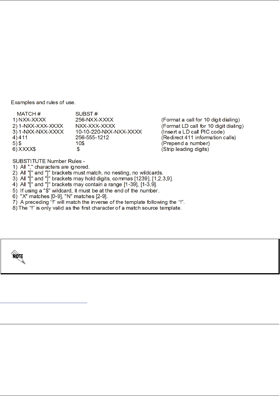
Command Reference Guide Voice SIP Trunk Command Set
60000CRG0-35E Copyright © 2012 ADTRAN, Inc. 3561
The following are example template entries using wildcards:
1. 555-81xx matches 555-8100 to 555-8199.
2. 555-812[012] matches 555-8120 to 555-8122.
3. Nxx-xxxx matches 7 digits local.
4. 1-Nxx-Nxx-xxxx matches long distance calls in North America.
Additional wildcards ($ and 0 to 9) can also be used. The CLI also contains helpful information regarding
the construction of the template and can be viewed by entering the match ani command followed by a
question mark. For example, entering the command as follows results in the template input specifications:
(config)#match ani ?
In the following example command, the match source template is in bold:
match ani !2565558XXX add diversion 2565558000 unconditional yes full
For additional information about configuring SIP Diversion headers in SIP messaging, refer to the quick
configuration guide, Modifying SIP Headers to SIP Trunks in AOS Voice Products available online at
https://supportforums.adtran.com (article number 3506).
Usage Examples
In the following example, the SIP trunk (t01) is configured so that when the ANI source template
(2565558XXX) is matched, an unconditional SIP Diversion header with a target template of 2565558000
and network screening and full privacy are added to the message.
(config)#voice trunk t01
(config-T01)#match ani 2565558XXX add diversion 2565558000 unconditional yes full
In this example, the template includes a ! at the beginning. The ! indicates that the inverse
of the template is matched. Inverse matching can only be used with the match source
template and requires a static target template (the target template cannot contain
wildcards).

Command Reference Guide Voice SIP Trunk Command Set
60000CRG0-35E Copyright © 2012 ADTRAN, Inc. 3562
match ani <template> add p-asserted-identity <template>
Use the match ani add p-asserted-identity command to add a P-Asserted-Identity header to an outgoing
Session Initiation Protocol (SIP) message. Use the no form of this command to remove the
P-Asserted-Identity header.
Syntax Description
ani <template> Specifies the source ANI information to be matched. This information
is entered using wildcards and numerical digits. Refer to the
Functional Notes of this command for available wildcards and proper
data entry.
add Specifies that when the match source matches the match source
template, SIP headers are added to the SIP trunk messages.
p-asserted-identity <template> Specifies that it is a P-Asserted-Identity header that is added to the
SIP message and specifies the match target template. Templates are
entered using wildcards and numerical digits. Refer to the Functional
Notes of this command for available wildcards and proper data entry.
Default Values
By default, P-Asserted-Identity headers are not added to SIP messages.
Command History
Release A4.01 Command was introduced.
Functional Notes
Both match source and match target templates are defined in the same way as dial plan entries.
Wildcards available for use are as follows:
0-9 = Match exact digit only.
M = Any digit 1 to 8.
X = Any single digit (0 to 9).
N = Any digit 2 to 9.
[123] = Any digit contained in the bracketed list.
Do not use exclamation points, commas, spaces, etc., inside the brackets. Commas are
implied between numbers in the brackets.
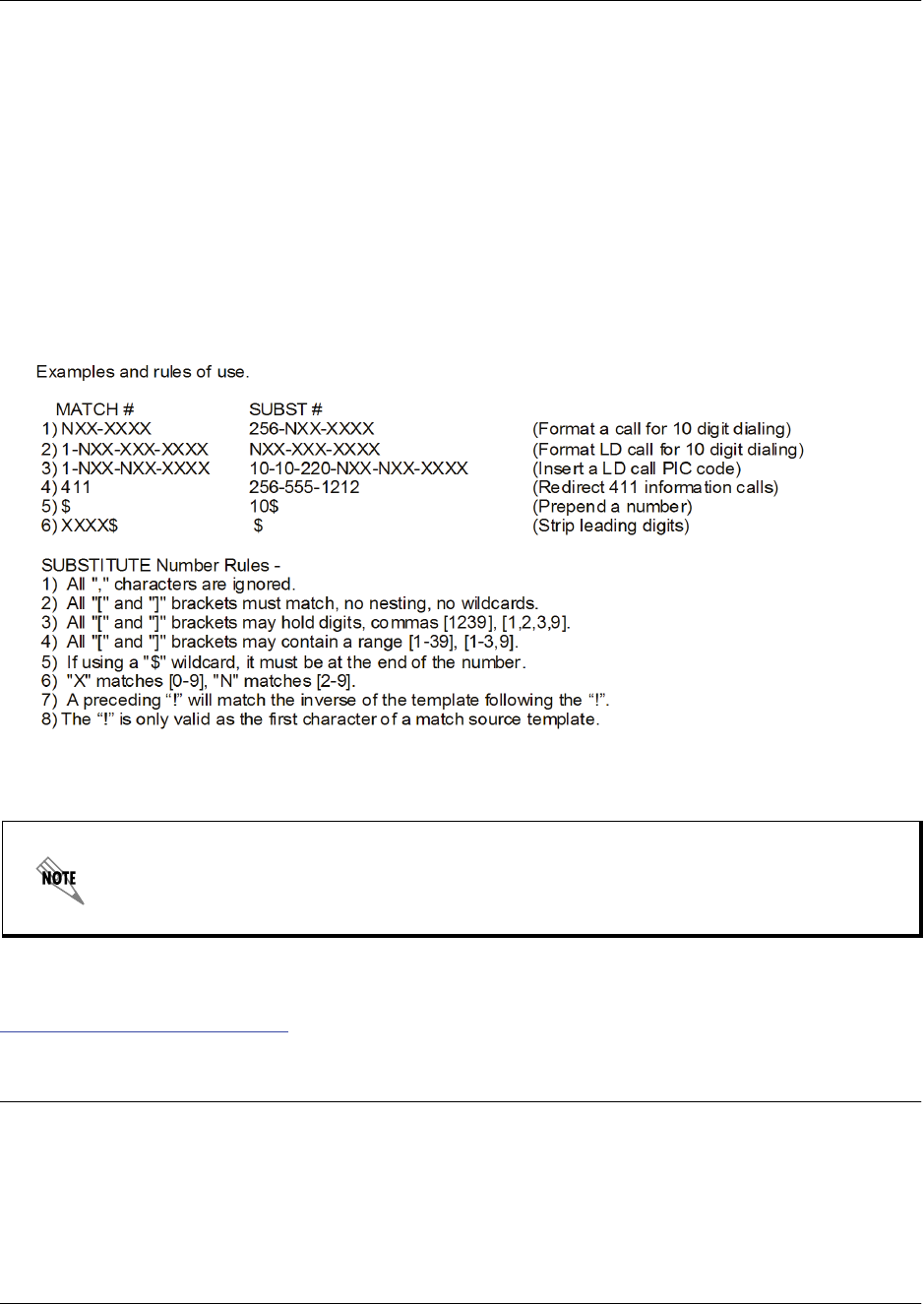
Command Reference Guide Voice SIP Trunk Command Set
60000CRG0-35E Copyright © 2012 ADTRAN, Inc. 3563
The special characters ( ), -, and + are always ignored in the template. The following are example template
entries using wildcards:
1. 555-81xx matches 555-8100 to 555-8199.
2. 555-812[012] matches 555-8120 to 555-8122.
3. Nxx-xxxx matches 7 digits local.
4. 1-Nxx-Nxx-xxxx matches long distance calls in North America.
Additional wildcards ($ and 0 to 9) can also be used. The CLI also contains helpful information regarding
the construction of the template and can be viewed by entering the match ani command followed by a
question mark. For example, entering the command as follows results in the template input specifications:
(config)#match ani ?
In the following example command, the match source template is in bold:
match ani !2565558XXX add diversion 2565558000 unconditional yes full
For additional information about configuring SIP Diversion headers in SIP messaging, refer to the quick
configuration guide, Modifying SIP Headers to SIP Trunks in AOS Voice Products available online at
https://supportforums.adtran.com.
Usage Examples
In the following example, a P-Asserted-Identity header is adding to a SIP message when the ANI source
template of 2565558XXX is matched with the target template of 2565558000:
(config)#voice trunk t01
(config-T01)#match ani 2565558XXX add p-asserted-identity 2565558000
In this example, the template includes a ! at the beginning. The ! indicates that the inverse
of the template is matched. Inverse matching can only be used with the match source
template and requires a static target template (the target template cannot contain
wildcards).

Command Reference Guide Voice SIP Trunk Command Set
60000CRG0-35E Copyright © 2012 ADTRAN, Inc. 3564
match ani <template> replace diversion <template>
Use the match ani replace diversion command to replace Session Initiation Protocol (SIP) Diversion
headers on outgoing SIP messages. Use the no form of this command to revert to the original header on the
SIP message. Variations of this command include:
match ani <template> replace diversion <template>
match ani <template> replace diversion <template> <diversion type> <screening type> <privacy
setting>
Syntax Description
ani <template> Specifies the source automatic number identification (ANI) information to be
matched. This information is entered using wildcards and numerical digits.
Refer to the Functional Notes of this command for available wildcards and
proper data entry.
replace Specifies that when the match source matches the match source template,
SIP Diversion headers are replaced on the SIP trunk messages.
diversion <template> Specifies the match target and match target template used to execute the
command action when replacing SIP Diversion headers in SIP messages.
This information is entered using wildcards and numerical digits. Refer to
the Functional Notes of this command for available wildcards and proper
data entry.
<diversion type> Optional. Specifies the reason for the diversion. If you specify the diversion
type, you must also specify whether or not the diversion is screened by the
network, and whether diversion privacy is used. Diversion reasons include
the following:
away Diverts the message if the receiving SIP agent is away.
deflection Diverts the message if the receiving SIP agent is
deflecting calls.
do-not-disturb Diverts the message if the receiving SIP agent has
do-not-disturb enabled.
follow-me Diverts the message if the receiving SIP agent has
FindMe-FollowMe enabled.
no-answer Diverts the message if the receiving SIP agent does not
answer.
out-of-service Diverts the message if the receiving SIP agent is
out-of-service.
time-of-day Diverts the message if the message is sent at a particular
time of day.
unavailable Diverts the message if the receiving SIP agent is
unavailable.
unconditional Diverts the message on an unconditional basis.
unknown Diverts the message if an unknown error occurs.
user-busy Diverts the message if the receiving SIP agent is busy.
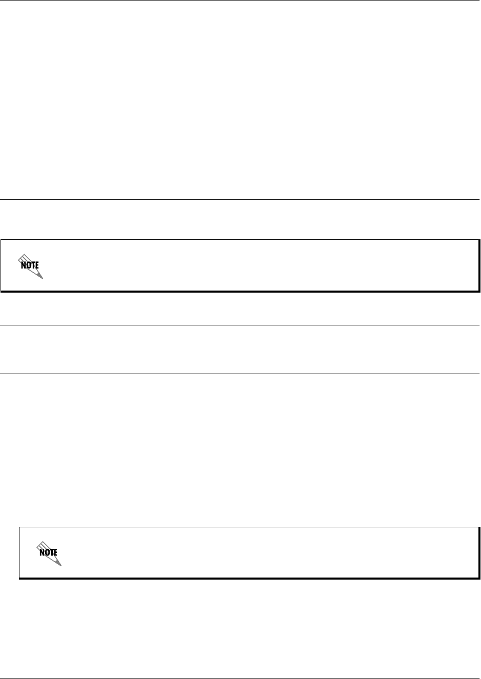
Command Reference Guide Voice SIP Trunk Command Set
60000CRG0-35E Copyright © 2012 ADTRAN, Inc. 3565
<screening type> Optional. Specifies whether the diversion is screened by the network.
Screening types include:
no Specifies that the diversion used is not screened by the
network.
yes Specifies that the diversion used is screened by the
network.
<privacy setting> Optional. Specifies whether privacy is used when SIP Diversion headers
are added to the SIP messages. Privacy settings include:
full Specifies that the diversion uses full privacy.
off Specifies that the diversion does not use privacy.
Default Values
By default, SIP diversions are specified as unconditional (unconditional), do not use network screening
(no), and do not use privacy (off).
Command History
Release A4.05 Command was introduced.
Functional Notes
Both match source and match target templates are defined in the same way as dial plan entries.
Wildcards available for use are as follows:
0-9 = Match exact digit only.
M = Any digit 1 to 8.
X = Any single digit (0 to 9).
N = Any digit 2 to 9.
[123] = Any digit contained in the bracketed list.
The special characters ( ), -, and + are always ignored in the template.
This command can get very lengthy. To shorten the length of the command, you must elect
to use all default values for the diversion options, or you must override all options.
Do not use exclamation points, commas, spaces, etc., inside the brackets. Commas are
implied between numbers in the brackets.
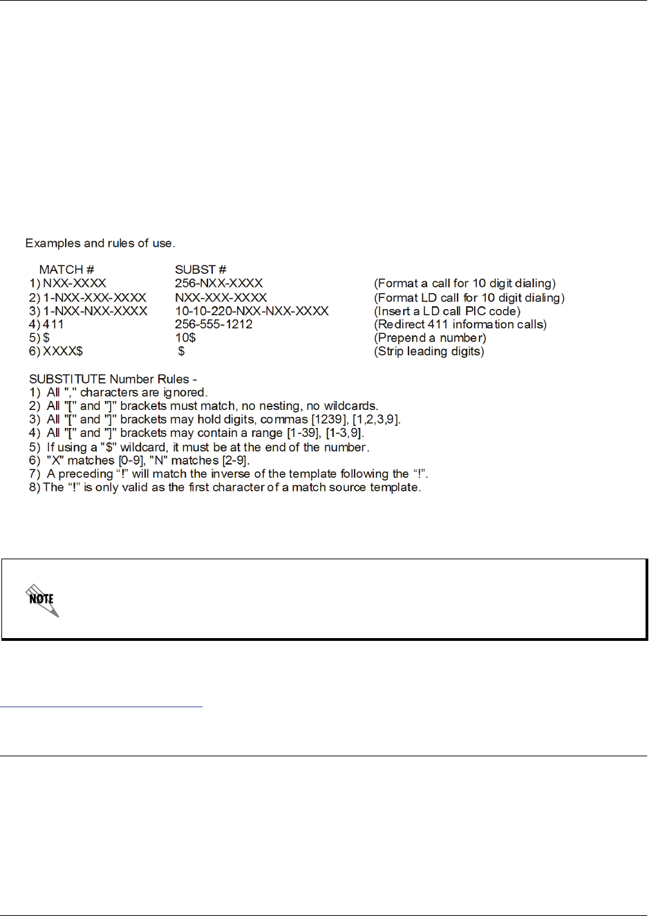
Command Reference Guide Voice SIP Trunk Command Set
60000CRG0-35E Copyright © 2012 ADTRAN, Inc. 3566
The following are example template entries using wildcards:
1. 555-81xx matches 555-8100 to 555-8199.
2. 555-812[012] matches 555-8120 to 555-8122.
3. Nxx-xxxx matches 7 digits local.
4. 1-Nxx-Nxx-xxxx matches long distance calls in North America.
Additional wildcards ($ and 0 to 9) can also be used. The CLI also contains helpful information regarding
the construction of the template and can be viewed by entering the match ani command followed by a
question mark. For example, entering the command as follows results in the template input specifications:
(config)#match ani ?
In the following example command, the match source template is in bold:
match ani !2565558XXX replace diversion 2565558000 unconditional yes full
For additional information about configuring SIP Diversion headers in SIP messaging, refer to the
configuration guide, Modifying SIP Headers on SIP Trunks in AOS Voice Products available online at
https://supportforums.adtran.com (article number 3506).
Usage Examples
In the following example, the SIP trunk (t01) is configured so that when the ANI source template
(2565558XXX) is matched, an unconditional SIP Diversion header with a target template of 2565558000
and network screening and full privacy replaces the original SIP header.
(config)#voice trunk t01
(config-T01)#match ani 2565558XXX replace diversion 2565558000 unconditional yes full
In this example, the template includes a ! at the beginning. The ! indicates that the inverse
of the template is matched. Inverse matching can only be used with the match source
template and requires a static target template (the target template cannot contain
wildcards).

Command Reference Guide Voice SIP Trunk Command Set
60000CRG0-35E Copyright © 2012 ADTRAN, Inc. 3567
match ani <template> substitute <template>
Use the match ani substitute command to configure automatic number identification (ANI) substitution
for outbound voice trunks. Use the no form of this command to remove the substitution. Variations of this
command include:
match ani <template> substitute <template>
match ani <template> substitute <template> name <name>
Syntax Description
ani <template> Specifies the ANI information to be substituted. This information is entered
using wildcards and numerical digits. Refer to the Functional Notes of this
command for available wildcards and proper data entry.
substitute <template> Specifies the ANI information that is substituted for the original ANI
information. This information is entered using wildcards and numerical
digits. Refer to the Functional Notes of this command for available wildcards
and proper data entry.
name <name> Optional. Specifies the name associated with the ANI information. This
option is only available on trunks that support ANI name information
(integrated services digital network (ISDN) trunks, Session Initiation
Protocol (SIP) trunks, T1 loop start (LS) network trunks, and T1 ground start
(GS) network trunks).
Default Values
By default, no ANI substitution is configured.
Command History
Release A2 Command was introduced.
Functional Notes
The convention for ANI templates is very similar to dial plan entries. Wildcards available for this command
are:
0-9 = Match exact digit only.
M = Any digit 1 to 8.
X = Any single digit (0 to 9).
N = Any digit 2 to 9.
[123] = Any digit contained in the bracketed list.
Do not use dashes, commas, spaces, etc., inside the brackets. Commas are implied between
numbers in the brackets.

Command Reference Guide Voice SIP Trunk Command Set
60000CRG0-35E Copyright © 2012 ADTRAN, Inc. 3568
The special characters ( ), -, and + are always ignored in the template. The following are example template
entries using wildcards:
Examples: 1) 555-81xx matches 555-8100 to 555-8199.
2) 555-812[012] matches 555-8120 to 555-8122.
3) Nxx-xxxx matches 7 digits local.
4) 1-Nxx-Nxx-xxxx matches long distance calls in North America.
Additional wildcards ($ and 0 to 9) can also be used. The command line interface (CLI) also contains
helpful information regarding the construction of the template and can be viewed by entering the match
ani command followed by a question mark. For example, entering the command as follows results in the
template input specifications:
(config)#match ani ?
Usage Examples
The following example specifies that the ANI information from numbers 555-8111 to 555-8115 will be
substituted by 555-8110 for outbound calls on the trunk T03:
(config)#voice trunk t03 type sip
(config-t03)#match ani 555-811[125] substitute 555-8110

Command Reference Guide Voice SIP Trunk Command Set
60000CRG0-35E Copyright © 2012 ADTRAN, Inc. 3569
match dnis <template> replace ani <number>
Use the match dnis replace ani command to replace dialed number identification service (DNIS)
information with automatic number identification (ANI) information on outbound voice trunks. Use the no
form of this command to remove the replacement. Variations of this command include:
match dnis <template> replace ani <number>
match dnis <template> replace ani <number> name <name>
Syntax Description
dnis <template> Specifies the DNIS information to be replaced. This information is entered
using wildcards and numerical digits. Refer to the Functional Notes of this
command for available wildcards and proper data entry.
replace ani <number> Specifies the ANI information that replaces the original DNIS information.
This information is entered using numerical digits. Enter the number without
punctuation.
name <name> Optional. Specifies the name associated with the ANI information. This
option is only available on trunks that support ANI name information
(integrated services digital network (ISDN) trunks, Session Initiation
Protocol (SIP) trunks, T1 loop start (LS) network trunks, and T1 ground start
(GS) network trunks).
Default Values
By default, no DNIS replacement is configured.
Command History
Release A2 Command was introduced.
Functional Notes
The convention for DNIS templates is very similar to dial plan entries. Wildcards available for this
command are:
0-9 = Match exact digit only.
M = Any digit 1 to 8.
X = Any single digit (0 to 9).
N = Any digit 2 to 9.
[123] = Any digit contained in the bracketed list.
Do not use dashes, commas, spaces, etc., inside the brackets. Commas are implied between
numbers in the brackets.

Command Reference Guide Voice SIP Trunk Command Set
60000CRG0-35E Copyright © 2012 ADTRAN, Inc. 3570
The special characters ( ), -, and + are always ignored in the template. The following are example template
entries using wildcards:
Examples: 1) 555-81xx matches 555-8100 to 555-8199.
2) 555-812[012] matches 555-8120 to 555-8122.
3) Nxx-xxxx matches 7 digits local.
4) 1-Nxx-Nxx-xxxx matches long distance calls in North America.
Additional wildcards ($ and 0 to 9) can also be used. The command line interface (CLI) also contains
helpful information regarding the construction of the template and can be viewed by entering the match
dnis command followed by a question mark. For example, entering the command as follows results in the
template input specifications:
(config)#match dnis ?
Usage Examples
The following example specifies that the DNIS information for dialed numbers on trunk T03 that match
1-256-524-8600 are replaced with 882-6467:
(config)#voice trunk t03 type sip
(config-t03)#match dnis 1-256-524-8600 replace ani 8826467

Command Reference Guide Voice SIP Trunk Command Set
60000CRG0-35E Copyright © 2012 ADTRAN, Inc. 3571
match dnis <template> substitute <template>
Use the match dnis substitute command to configure dialed number identification service (DNIS)
substitution for outbound voice trunks. Use the no form of this command to remove the substitution.
Variations of this command include:
match dnis <template> substitute <template>
match dnis <template> substitute <template> name <name>
Syntax Description
dnis <template> Specifies the DNIS information to be substituted. This information is entered
using wildcards and numerical digits. Refer to the Functional Notes of this
command for available wildcards and proper data entry.
substitute <template> Specifies the DNIS information that is substituted for the original DNIS
information. This information is entered using wildcards and numerical
digits. Refer to the Functional Notes of this command for available wildcards
and proper data entry.
name <name> Optional. Specifies the name associated with the DNIS information. This
option is only available on trunks that support DNIS name information
(integrated services digital network (ISDN) trunks, Session Initiation
Protocol (SIP) trunks, T1 loop start (LS) network trunks, and T1 ground start
(GS) network trunks).
Default Values
By default, no DNIS substitution is configured.
Command History
Release A2 Command was introduced.
Functional Notes
The convention for DNIS templates is very similar to dial plan entries. Wildcards available for this
command are:
0-9 = Match exact digit only.
M = Any digit 1 to 8.
X = Any single digit (0 to 9).
N = Any digit 2 to 9.
[123] = Any digit contained in the bracketed list.
Do not use dashes, commas, spaces, etc., inside the brackets. Commas are implied between
numbers in the brackets.

Command Reference Guide Voice SIP Trunk Command Set
60000CRG0-35E Copyright © 2012 ADTRAN, Inc. 3572
The special characters ( ), -, and + are always ignored in the template. The following are example template
entries using wildcards:
Examples: 1) 555-81xx matches 555-8100 to 555-8199.
2) 555-812[012] matches 555-8120 to 555-8122.
3) Nxx-xxxx matches 7 digits local.
4) 1-Nxx-Nxx-xxxx matches long distance calls in North America.
Additional wildcards ($ and 0 to 9) can also be used. The command line interface (CLI) also contains
helpful information regarding the construction of the template and can be viewed by entering the match
dnis command followed by a question mark. For example, entering the command as follows results in the
template input specifications:
(config)#match dnis ?
Usage Examples
The following example specifies that the DNIS information for dialed numbers on trunk T03 that match
1-334-NXX-XXXX are substituted with 1-800-557-4500:
(config)#voice trunk t03 type sip
(config-t03)#match dnis 1-334-NXX-XXXX substitute 1-800-557-4500

Command Reference Guide Voice SIP Trunk Command Set
60000CRG0-35E Copyright © 2012 ADTRAN, Inc. 3573
max-number-calls <value>
Use the max-number-calls command to configure the maximum number of calls allowed on this trunk.
This command is useful in controlling the call usage of the trunk. Use the no form of this command to
return to the default setting.
Syntax Description
<value> Specifies the maximum number of calls allowed on this trunk. Range is 1 to
64 calls.
Default Values
By default, no maximum number of calls is specified.
Command History
Release 11.1 Command was introduced.
Usage Examples
The following example sets the maximum number of calls allowed to 25:
(config)#voice trunk t01 type sip
(config-t01)#max-number-calls 25

Command Reference Guide Voice SIP Trunk Command Set
60000CRG0-35E Copyright © 2012 ADTRAN, Inc. 3574
media-loopback
Use the media-loopback command to configure a Session Initiation Protocol (SIP) trunk to allow media
loopback calls to be placed on the trunk. Media loopback enables media sessions to be established where
the media is looped back to the transmitter. This is typically referred to as active monitoring of services.
This command allows media loopback sessions on some SIP trunks while disallowing media-loopback on
others. Use the no form of this command do disable this feature.
Syntax Description
No subcommands.
Default Values
By default, media-loopback is enabled on SIP trunks.
Command History
A4.03 Command was introduced.
Usage Examples
The following example enables media loopback on trunk T01:
(config)#voice trunk t01 type sip
(config-t01)#media-loopback

Command Reference Guide Voice SIP Trunk Command Set
60000CRG0-35E Copyright © 2012 ADTRAN, Inc. 3575
outbound-proxy primary <value>
Use the outbound-proxy primary command to define the primary name/address of the Session Initiation
Protocol (SIP) proxy server to which the trunk will send all SIP messages. Use the no form of this
command to return to the default setting. Variations of this command include:
outbound-proxy primary <value>
outbound-proxy primary <value> tcp
outbound-proxy primary <value> tcp <number>
outbound-proxy primary <value> udp
outbound-proxy primary <value> udp <number>
Syntax Description
<value>
Specifies the fully qualified domain name (FQDN) or IP address of the
outbound proxy server.
<number> Optional. Specifies the port number. Range is 0 to 65535.
tcp Optional. Sets the Transmission Control Protocol (TCP) port of the
outbound proxy server.
udp Optional. Sets the User Datagram Protocol (UDP) port of the outbound
proxy server.
Default Values
By default, the IP address is set to 0.0.0.0 and the UDP port is set to 5060.
Command History
Release 9.3 Command was introduced.
Release 15.1 Command was expanded.
Functional Notes
The configured value must resolve to a valid IP address.
Usage Examples
The following example sets the outbound proxy server to sip-proxy.adtran.com with a UDP port of 2222:
(config)#voice trunk t01 type sip
(config-t01)#outbound-proxy primary sip-proxy.adtran.com udp 2222

Command Reference Guide Voice SIP Trunk Command Set
60000CRG0-35E Copyright © 2012 ADTRAN, Inc. 3576
outbound-proxy secondary <value>
Use the outbound-proxy secondary command to define the secondary name/address of the Session
Initiation Protocol (SIP) proxy server to which the trunk will send all SIP messages. Use the no form of
this command to return to the default setting. Variations of this command include:
outbound-proxy secondary <value>
outbound-proxy secondary <value> tcp
outbound-proxy secondary <value> tcp <number>
outbound-proxy secondary <value> udp
outbound-proxy secondary <value> udp <number>
Syntax Description
<value>
Specifies the fully qualified domain name (FQDN) or IP address of the
outbound proxy server.
<number> Optional. Specifies the port number. Range is 0 to 65535.
tcp Optional. Sets the Transmission Control Protocol (TCP) port of the
outbound proxy server.
udp Optional. Sets the User Datagram Protocol (UDP) port of the outbound
proxy server.
Default Values
By default, the IP address is set to 0.0.0.0 and the UDP port is set to 5060.
Command History
Release 15.1 Command was introduced.
Functional Notes
The configured value must resolve to a valid IP address.
Usage Examples
The following example sets the outbound proxy server to sip-proxy.adtran.com with a UDP port of 2244:
(config)#voice trunk t01 type sip
(config-t01)#outbound-proxy secondary sip-proxy.adtran.com udp 2244

Command Reference Guide Voice SIP Trunk Command Set
60000CRG0-35E Copyright © 2012 ADTRAN, Inc. 3577
p-assert-diversion
Use the p-assert-diversion command to enable sending P-Asserted-Identity in place of the Session
Initiation Protocol (SIP) diversion header. Use the no form of this command to disable this feature.
Syntax Description
No subcommands.
Default Values
By default, this command is disabled.
Command History
Release A4.01 Command was introduced.
Usage Examples
The following example enables P-Asserted-Identity in place of the SIP diversion header:
(config)#voice trunk t01 type sip
(config-t01)#p-assert-diversion

Command Reference Guide Voice SIP Trunk Command Set
60000CRG0-35E Copyright © 2012 ADTRAN, Inc. 3578
phone-context
Use the phone-context command to create an entry in the phone-context map. The phone-context map
allows call context information to be preserved between the Session Initiation Protocol (SIP) server and the
primary rate interface (PRI). Use the no form of this command to delete the configured entry. Variations of
this command include the following:
phone-context <string> plan <indicator> type <number>
phone-context <string> plan <indicator> type abbreviated
phone-context <string> plan <indicator> type international
phone-context <string> plan <indicator> type level0
phone-context <string> plan <indicator> type level1
phone-context <string> plan <indicator> type level2
phone-context <string> plan <indicator> type national
phone-context <string> plan <indicator> type network-specific
phone-context <string> plan <indicator> type subscriber
phone-context <string> plan <indicator> type unknown
phone-context <string> plan e164 type <number>
phone-context <string> plan e164 type abbreviated
phone-context <string> plan e164 type international
phone-context <string> plan e164 type level0
phone-context <string> plan e164 type level1
phone-context <string> plan e164 type level2
phone-context <string> plan e164 type national
phone-context <string> plan e164 type network-specific
phone-context <string> plan e164 type subscriber
phone-context <string> plan e164 type unknown
phone-context <string> plan private type <number>
phone-context <string> plan private type abbreviated
phone-context <string> plan private type international
phone-context <string> plan private type level0
phone-context <string> plan private type level1
phone-context <string> plan private type level2
phone-context <string> plan private type national
phone-context <string> plan private type network-specific
phone-context <string> plan private type subscriber
phone-context <string> plan private type unknown
phone-context <string> plan unknown type <number>
phone-context <string> plan unknown type abbreviated
phone-context <string> plan unknown type international
phone-context <string> plan unknown type level0
phone-context <string> plan unknown type level1
phone-context <string> plan unknown type level2
phone-context <string> plan unknown type national
phone-context <string> plan unknown type network-specific
phone-context <string> plan unknown type subscriber

Command Reference Guide Voice SIP Trunk Command Set
60000CRG0-35E Copyright © 2012 ADTRAN, Inc. 3579
phone-context <string> plan unknown type unknown
Syntax Description
<string> Specifies a string of text for the phone-context map entry. This is used to
convert between phone-context and NPI/TON values.
plan Specifies the NPI to associate with the phone-context map entry.
<number> Specifies the NPI value. Valid range is 0 to 15.
e164 Specifies using the ISDN/telephone numbering plan (E.164) value (0001)
for the NPI bits of the Type-of-Address octet.
private Specifies using the private numbering plan value (1001) for the NPI bits of
the Type-of-Address octet.
unkown Specifies using the unknown numbering plan value (0000) for the NPI bits
of the Type-of-Address octet.
type Specifies the TON to associate with the phone-context map entry.
<number> Specifies the TON value. Valid range is 0 to 7.
abbreviated Specifies using the abbreviated value (110) for the TON bits of the
Type-of-Address octet. Abbreviated is used mainly in private ISDN network
applications and the implementation is network dependent.
international Specifies using the international value (001) for the TON bits of the
Type-of-Address octet. International is used for calls destined outside the
national calling area. International calls have the international direct dialing
(IDD) prefix removed. For example, consider an international call of 011-N$,
where the IDD prefix is 011 and the N$ represents the digits necessary for
routing the call at the destination. When the called party information
element (IE) is created for this call, the prefix is stripped and the N$ digits
are placed in the number digits field.
level0 Specifies using the level 0 local number type in a Private Numbering Plan
(PNP). The value of the TON bits of the Type-of-Address octet is identical to
the subscriber value (100) in E.164 format.
level1 Specifies using the level 1 regional number type in a PNP. The value of the
TON bits of the Type-of-Address octet is identical to the national value
(010) in E.164 format.
level2 Specifies using the level 2 local number type in a PNP. The value of the
TON bits of the Type-of-Address octet is identical to the international value
(001) in E.164 format.
national Specifies using the national value (010) for the TON bits of the
Type-of-Address octet. National is used for calls destined for inside the
national calling area (calls that do not cross into an international local
access and transport area (LATA)). National calls have the direct dialing
prefix removed. For example, consider a national call with a direct dialing
prefix of 1 and NXX-NXX-XXXX to represent the ten-digit number
necessary for routing the call. When the called party IE is created for this
call, the prefix (1) is stripped and the NXX-NXX-XXXX digits are placed in
the number digits field.

Command Reference Guide Voice SIP Trunk Command Set
60000CRG0-35E Copyright © 2012 ADTRAN, Inc. 3580
network-specific Specifies using the network-specific value (011) for the TON bits of the
Type-of-Address octet. Network specific is used for calls that require special
access to a private network, which requires the use of a prefix that should
be stripped once access to the network has been gained. Network-specific
calls have the dialing prefix removed. For example, a call to a private
network with the prefix 700 consists of 700-N$, where 700 is the dialing
prefix and N$ represents the digits necessary for routing the call at the
destination. When the called party IE is created for this call, the prefix is
stripped and the N$ is placed in the Number Digits field.
subscriber Specifies using the subscriber value (100) for the TON bits of the
Type-of-Address octet. Subscriber is used for local calls (not long distance).
Subscriber calls, by default, have the area code removed. For example, a
subscriber call to 916-555-1212 would have the prefix 916 stripped and
555-1212 in the number digits field. For areas with mandatory ten-digit
dialing, a blank prefix should be entered to ensure that all ten digits are
passed to the number digits field.
unknown Specifies using the unknown value (000) for the TON bits of the
Type-of-Address octet. Unknown is used when the number type is not
known. Unknown numbers are presumed to have no prefix, and the entire
dialed number is presented in the number digits field.
Default Values
By default, no phone-context map entries are configured.
Command History
R10.1.0 Command was introduced.

Command Reference Guide Voice SIP Trunk Command Set
60000CRG0-35E Copyright © 2012 ADTRAN, Inc. 3581
Functional Notes
During ISDN call establishment on a PRI, each phone number in the SETUP message is qualified with a
pair of identifiers, TON and NPI, which determine how the phone number is to be treated. The mechanism
by which a SIP server communicates information about phone numbers is the SIP URI phone-context field.
The phone-context command allows a table to be configured that stores associations between the SIP
URI phone-context strings and NPI/TON value pairs. This map allows the SIP trunk to convert between
numerical NPI/TON value pairs and a phone-context text string. Consequently, phone number information
is preserved during interworking between SIP and ISDN PRI.
In the PRI to SIP direction, the received NPI/TON values are passed through the switchboard to the SIP
trunk. The SIP trunk then uses the phone-context table to find the corresponding phone-context text string,
and the string is inserted as a phone-context= parameter into the outgoing SIP URI.
In the SIP to PRI direction, the SIP trunk uses the phone-context table to convert the string received in the
phone-context= parameter to the corresponding NPI/TON values. The values are then passed through
the switchboard to the PRI trunk and on to the connected equipment.
Usage Examples
The following example creates an entry in the phone-context map that associates the phone-context string
phonesystem.adtran.com with the private NPI and level0 TON:
(config)#voice trunk t01 type sip
(config-t01)#phone-context phonesystem.adtran.com plan private type level0
Command Reference Guide Voice SIP Trunk Command Set
60000CRG0-35E Copyright © 2012 ADTRAN, Inc. 3582
prefer double-reinvite
Use the prefer double-reinvite command to specify that Session Initiation Protocol (SIP) double reInvite
messages are included in calls involving the trunk. Calls that typically require a double reInvite are
forwarded calls from call overage and any attended transfer, and when these calls connect, a double
reInvite message is initiated when the feature is enabled. Using the no form of this command indicates that
double reInvites are not preferred on the trunk. Use the command ip sip prefer double-reinvite on page
1127 to specify the global setting for this feature. Variations of this command include:
prefer double-reinvite
prefer double-reinvite system
Syntax Description
system Optional. Specifies that the system double reInvite setting is used. The
system setting is specified using the command prefer double-reinvite on
page 3582.
Default Values
By default, all trunk accounts prefer a double re-Invite.
Command History
Release A5.01 Command was introduced.
Functional Notes
The prefer double-reinvite command is used in the trunk’s configuration to determine whether a double
reInvite is preferred in calls involving the trunk. By default, the system is configured so that double reInvites
are preferred, and all trunk accounts prefer a double reInvite. Double reInvites are used, for example,
when a SIP trunk in local transfer mode is providing ring-back during a blind transfer. In this scenario, a
double reInvite must occur in order to establish a talk path after the transfer target answers.
You can also specify whether Session Description Protocol (SDP) is used in the double reInvite message.
To send a double reInvite without SDP, refer to the command prefer reinvite-without-sdp on page 3583.
This command helps determine which endpoint receives SDP in the double reInvite call flow.
Usage Examples
The following example specifies that SIP double reInvites are not preferred on this trunk:
(config)#voice trunk t01 type sip
(config-t01)#no prefer double-reinvite
This command should only be issued by advanced users or at the direction of ADTRAN
technical support.

Command Reference Guide Voice SIP Trunk Command Set
60000CRG0-35E Copyright © 2012 ADTRAN, Inc. 3583
prefer reinvite-without-sdp
Use the prefer reinvite-without-sdp command to specify that Session Initiation Protocol (SIP) double
reInvite messages are included in calls involving the trunk, but that these messages do not include Session
Description Protocol (SDP). This command helps to determine which endpoint receives the SDP in the
double reInvite call flow. Using the no form of this command indicates that reInvite messages without
SDP are not preferred. Use the command ip sip prefer double-reinvite on page 1127 to specify the global
setting for this feature.
Syntax Description
No subcommands.
Default Values
By default, all trunk accounts prefer a double reInvite with SDP.
Command History
Release A5.01 Command was introduced.
Functional Notes
When a double reInvite is initiated, the first reInvite without SDP is not sent to the account that does not
require it. When both accounts do not require a reInvite with SDP, the target account sends the initial
reInvite message.
You can specify whether a re-Invite is preferred on the trunk using the command prefer double-reinvite on
page 3582. This command is used in the trunk’s configuration to determine whether a double reInvite is
preferred in calls involving the trunk. By default, the system is configured so that double reInvites are
preferred, and all trunk accounts prefer a double reInvite. Double reInvites are used, for example, when a
SIP trunk in local transfer mode is providing ring-back during a blind transfer. In this scenario, a double
reInvite must occur in order to establish a talk path after the transfer target answers.
Usage Examples
The following example specifies that SIP double reInvites with SDP are preferred on this trunk:
(config)#voice trunk t01 type sip
(config-t01)#no prefer reinvite-without-sdp
This command should only be issued by advanced users or at the direction of ADTRAN
technical support.

Command Reference Guide Voice SIP Trunk Command Set
60000CRG0-35E Copyright © 2012 ADTRAN, Inc. 3584
prefer trunk-routing
Use the prefer trunk-routing command to add a trunk to a list of trunks that are considered first for call
routing, regardless of system routing mode or locally configured extensions. Use the no form of this
command to remove the trunk from the list.
Syntax Description
No subcommands.
Default Values
By default, prefer trunk-routing is disabled.
Command History
Release A2 Command was introduced.
Functional Notes
Trunk routing can be specified as a preference for specific trunks, allowing the trunk to be considered first
for routing rather than relying on the internal or external nature of the call to dictate whether the trunk or
voice station is the first choice routing path. The prefer trunk-routing command, executed from a specific
trunk’s configuration mode, adds the trunk to a list of trunks that are considered first for routing.
By default, no trunk routing preference is set, so that each trunk operates as dictated by normal call routing
modes. Adding the trunk routing preference only affects how inbound calls from the specific trunk are
handled.
Usage Examples
The following example specifies that trunk routing is preferred on the trunk T01:
(config)#voice trunk t01 type sip
(config-t01)#prefer trunk-routing
Command Reference Guide Voice SIP Trunk Command Set
60000CRG0-35E Copyright © 2012 ADTRAN, Inc. 3585
register
Use the register command to define the Session Initiation Protocol (SIP) name for registration of the
authorization name(s) and password(s). Use the no form of this command to remove a registration.
Variations of this command include the following:
register <name>
register <name> auth-name <username> password <word>
register range <begin> <end>
register range <begin> <end> auth-name <username> password <word>
register range <begin> <end> auth-name range <begin> <end> password range <begin> <end>
register range <begin> <end> auth-name range <begin> <end> password <word>
Syntax Description
<name> Specifies the name of the SIP trunk to register.
range <begin> <end> Specifies the beginning and ending of the range to register SIP users,
authentication names, and/or passwords.
auth-name <username>
Optional. Specifies the user name for authentication.
password <word>
Optional. Specifies the password for authentication.
Default Values
By default, no registration range is programmed.
Command History
Release 12.1 Command was introduced.
Release 15.1 Command was expanded.
Functional Notes
Using the range option reduces the time required to program individual user registration and
authentication settings. The range configuration option allows multiple users to be configured in one step
for example:
register range 2565553000 2565553100 auth-name range Adtran3000 Adtran3100 password range
adtn3000 adtn3100
In this example, 100 users in the range (256) 555-3000 to (256) 555-3100 are registered with
authentication names ranging from Adtran3000 to Adtran3100 and passwords ranging from adtn3000 to
adtn3100.
When using the range option, there must be the same number of elements in each related
range. In other words, each SIP user in a range must have one authentication name and/or
one password.

Command Reference Guide Voice SIP Trunk Command Set
60000CRG0-35E Copyright © 2012 ADTRAN, Inc. 3586
The user may enter an authentication name range, password range, or both. An error will be returned if the
provided authentication name and/or password range values are not large enough for the SIP identity
range provided (i.e., in the example, if the user had entered Adtran3000 Adtran3099 for the authentication
name range, an error would have been returned because the specified SIP identity range is 100 users (not
99)).
Usage Examples
The following example registers trunk T01 under the name of MainOffice:
(config)#voice trunk t01 type sip
(config-t01)#register MainOffice
The following example sets the authorization name and password range for a group of SIP users:
(config)#voice trunk t01 type sip
(config-t01)#register range 2565554000 2565554100 auth-name range Adtran4000 Adtran4100
password range adtn8000 adtn8100

Command Reference Guide Voice SIP Trunk Command Set
60000CRG0-35E Copyright © 2012 ADTRAN, Inc. 3587
registrar expire-time <value>
Use the registrar expire-time command to define the Session Initiation Protocol (SIP) expiration time for
requested registration. This command specifies the duration of the registration that is requested in the
REGISTER sent to the SIP server. Use the no form of this command to return to the default setting.
Syntax Description
<value>
Specifies expiration time (in seconds) for a registration. Valid range
depends on whether the command registrar threshold on page 3592 is
configured for absolute or percentage. If the threshold is set to
percentage, the range is 0 to 4294967295. If the threshold is set to
absolute, the range is <absolute threshold value> + 6 to 4294967295.
Default Values
By default, this value is set to 3600 seconds.
Command History
Release 12.1 Command was introduced.
Usage Examples
The following example specifies the registration expiration time for the SIP trunk as 1800 seconds:
(config)#voice trunk t01 type sip
(config-t01)#registrar expire-time 1800

Command Reference Guide Voice SIP Trunk Command Set
60000CRG0-35E Copyright © 2012 ADTRAN, Inc. 3588
registrar max-concurrent-reg <value>
Use the registrar max-concurrent-reg command to control the maximum number of simultaneous
registration requests that are allowed for the trunk. This value can be adjusted to help eliminate congestion
caused by too many concurrent registration requests. Use the no form of this command to return to the
default value.
Syntax Description
<value> Specifies the maximum number of concurrent registrations. Valid range
is 1 to 32 registrations.
Default Values
By default, the maximum number of concurrent registrations is set to 32.
Command History
Release 12.1 Command was introduced.
Usage Examples
The following example sets the maximum number on concurrent registrations to 12:
(config)#voice trunk t01 type sip
(config-t01)#registrar max-concurrent-reg 12

Command Reference Guide Voice SIP Trunk Command Set
60000CRG0-35E Copyright © 2012 ADTRAN, Inc. 3589
registrar primary <value>
Use the registrar primary command to define the primary Session Initiation Protocol (SIP) registrar fully
qualified domain name (FQDN) or IP address that is based on the domain naming system (DNS) suffix.
Use the no form of this command to return to the default setting. Variations of this command include:
registrar primary <value>
registrar primary <value> tcp
registrar primary <value> tcp <number>
registrar primary <value> udp
registrar primary <value> udp <number>
Syntax Description
<value>
Specifies the FQDN or IP address of the registrar server. IP addresses
should be expressed in dotted decimal notation (for example, 10.10.10.1).
<number> Optional. Specifies the port number. Range is 0 to 65535.
tcp Optional. Sets the Transmission Control Protocol (TCP) port of the
outbound proxy server.
udp Optional. Sets the User Datagram Protocol (UDP) port of the outbound
proxy server.
Default Values
By default, the IP address is set to 0.0.0.0 and the UDP port is set to 5060.
Command History
Release 9.3 Command was introduced.
Release 15.1 Command was expanded.
Functional Notes
This command specifies which trunk will send SIP register messages. The configured value must resolve
to a valid IP address.
Usage Examples
The following example sets the registrar server to as1.adtran.com with a UDP port of 9060:
(config)#voice trunk t01 type sip
(config-t01)#registrar primary as1.adtran.com udp 9060
A secondary SIP registrar can be set using the command registrar secondary <value> on
page 3591.

Command Reference Guide Voice SIP Trunk Command Set
60000CRG0-35E Copyright © 2012 ADTRAN, Inc. 3590
registrar require-expires
Use the registrar require-expires command to define the Session Initiation Protocol (SIP) expiration time
for registration. A successful response to a register contains an expires header or the response is considered
a failure. When disabled, a successful response does not require an expires header to be considered
successful. Use the no form of this command to return to the default setting.
Syntax Description
<value>
Specifies expiration time (in seconds) for a response to a registration
request.
Default Values
By default, the registration expiration time is enabled.
Command History
Release 15.1 Command was introduced.
Usage Examples
The following example disables registration expiration time for the SIP trunk:
(config)#voice trunk t01 type sip
(config-t01)#no registrar require-expires

Command Reference Guide Voice SIP Trunk Command Set
60000CRG0-35E Copyright © 2012 ADTRAN, Inc. 3591
registrar secondary <value>
Use the registrar secondary command to define the secondary Session Initiation Protocol (SIP) registrar
fully qualified domain name (FQDN) or IP address that is based on the domain naming system (DNS)
suffix. Use the no form of this command to return to the default setting. Variations of this command
include:
registrar secondary <value>
registrar secondary <value> tcp
registrar secondary <value> tcp <number>
registrar secondary <value> udp
registrar secondary <value> udp <number>
Syntax Description
<value>
Specifies the FQDN or IP address of the registrar server. IP addresses
should be expressed in dotted decimal notation (for example, 10.10.10.1).
<number> Optional. Specifies the port number. Range is 0 to 65535.
tcp Optional. Sets the Transmission Control Protocol (TCP) port of the
outbound proxy server.
udp Optional. Sets the User Datagram Protocol (UDP) port of the outbound
proxy server.
Default Values
By default, the IP address is set to 0.0.0.0 and the UDP port is set to 5060.
Command History
Release 15.1 Command was introduced.
Functional Notes
This command specifies which trunk will send SIP register messages. The configured value must resolve
to a valid IP address.
Usage Examples
The following example sets the registrar server to as1.adtran.com with a UDP port of 9060:
(config)#voice trunk t01 type sip
(config-t01)#registrar secondary as1.adtran.com udp 9060

Command Reference Guide Voice SIP Trunk Command Set
60000CRG0-35E Copyright © 2012 ADTRAN, Inc. 3592
registrar threshold
Use the registrar threshold command to specify the Session Initiation Protocol (SIP) trunk registration
renewal threshold. Use the no form of this command to return to the default value. Variations of this
command include:
registrar threshold absolute <value>
registrar threshold percentage <percent>
Syntax Description
absolute <value> Specifies that the registration renewal occurs when the remaining amount of
time on the registration coincides with this value. Valid range is 5 to 604800
seconds (1 week).
percentage <percent> Specifies that the renewal occurs at a certain remaining percentage of the
registration time. Valid range is 1 to 90 percent.
Default Values
By default, the registrar threshold is set at absolute 300 seconds.
Command History
Release 12.1 Command was introduced.
Usage Examples
The following example sets the registrar renewal threshold time at 50 percent of the returned valid
registration time:
(config)#voice trunk t01 type sip
(config-t01)#registrar threshold percentage 50

Command Reference Guide Voice SIP Trunk Command Set
60000CRG0-35E Copyright © 2012 ADTRAN, Inc. 3593
reject-external
Use the reject-external command to prevent inbound calls on the trunk from being routed back out of the
same trunk. Use the no form of this command to return to the default setting.
Syntax Description
No subcommands.
Default Values
No default values are necessary for this command.
Command History
Release 9.3 Command was introduced.
Functional Notes
In general, trunks are assigned to the user role, which means they terminate lines from a Telco provider. If
this is the case, reject-external should be enabled so that inbound calls on the trunk cannot be routed
back out of the same trunk. If the configuration is poor, inbound long distance calls could be routed back
out of the same trunk, causing the owner of the unit to be charged for long distance calls without his
knowledge. For network-role trunks and SIP-based trunks, this command should be disabled to allow calls
to be properly routed in the unit.
Usage Examples
The following example activates reject-external:
(config)#voice trunk t01 type sip
(config-t01)#reject-external

Command Reference Guide Voice SIP Trunk Command Set
60000CRG0-35E Copyright © 2012 ADTRAN, Inc. 3594
sip-keep-alive
Use the sip-keep-alive command to configure the type of keep-alive method for this Session Initiation
Protocol (SIP) trunk. Keep-alive messages must be sent between SIP device and the registrar to keep the
connected channel open for communication. Use the no form of this command to return to disable this
feature. Variations of this command include the following:
sip-keep-alive info
sip-keep-alive info <value>
sip-keep-alive options
sip-keep-alive options <value>
Syntax Description
info Specifies the INFO method to be used for the keep-alives on the trunk.
options Specifies the OPTIONS method to be used for the keep-alives on the trunk.
<value> Optional. Specifies the amount of time in seconds between the type of SIP
keep-alive messages being sent during a call. Range is 30 to
3600 seconds.
Default Values
By default, sip-keep-alive is set to info 60 on NetVanta 7000 Series products. For IP business gateways
(Total Access 900(e) Series and NetVanta 6000 Series) sip-keep-alive is disabled by default.
Command History
Release 13.1 Command was introduced
Release A2.04 Command was added to the Voice Line and Voice User command sets.
Usage Examples
The following example sets the keep-alive method to info:
(config)#voice trunk t01 type sip
(config-t01)#sip-keep-alive info

Command Reference Guide Voice SIP Trunk Command Set
60000CRG0-35E Copyright © 2012 ADTRAN, Inc. 3595
sip-server primary <value>
Use the sip-server primary command to define the primary name/address of the Session Initiation
Protocol (SIP) server to which the trunk will send call-related SIP messages. Use the no form of this
command to return to the default setting. Variations of this command include:
sip-server primary <value>
sip-server primary <value> udp
sip-server primary <value> udp <number>
sip-server primary <value> tcp
sip-server primary <value> tcp <number>
Syntax Description
<value>
Specifies the fully qualified domain name (FQDN) or IP address of the SIP
proxy server. IP addresses should be expressed in dotted decimal notation
(for example, 10.10.10.1).
<number> Optional. Specifies the port number. Range is 0 to 65535.
tcp Optional. Sets the Transmission Control Protocol (TCP) port of the
outbound proxy server.
udp Optional. Sets the User Datagram Protocol (UDP) port of the outbound
proxy server.
Default Values
By default, the IP address is set to 0.0.0.0 and the UDP port is set to 5060.
Command History
Release 9.3 Command was introduced.
Release 15.1 Command was expanded.
Usage Examples
The following example sets the SIP proxy server to as1.adtran.com with a UDP port of 9060:
(config)#voice trunk t01 type sip
(config-t01)#sip-server primary as1.adtran.com udp 9060

Command Reference Guide Voice SIP Trunk Command Set
60000CRG0-35E Copyright © 2012 ADTRAN, Inc. 3596
sip-server rollover
Use the sip-server rollover command to configure the rollover behavior of the Session Initiation Protocol
(SIP) server. Use the no form of this command to return to the default setting. Variations of this command
include:
sip-server rollover service-unavailable-or-timeout
sip-server rollover timeout-only
Syntax Description
service-unavailable-or-timeout Specifies the rollover to the next SIP server to occur after receiving a
503 Service Unavailable message or no response.
timeout-only Specifies the rollover to the next SIP server to occur only after no
response is received.
Default Values
By default, the sip-server rollover is set to timeout-only.
Command History
Release A2.03 Command was introduced.
Usage Examples
The following example sets the SIP server rollover to timeout-only:
(config)#voice trunk t01 type sip
(config-t01)#sip-server rollover timeout-only

Command Reference Guide Voice SIP Trunk Command Set
60000CRG0-35E Copyright © 2012 ADTRAN, Inc. 3597
sip-server secondary <value>
Use the sip-server secondary command to define the secondary name/address of the Session Initiation
Protocol (SIP) server to which the trunk will send call-related SIP messages. Use the no form of this
command to return to the default setting. Variations of this command include:
sip-server secondary <value>
sip-server secondary <value> udp
sip-server secondary <value> udp <number>
sip-server secondary <value> tcp
sip-server secondary <value> tcp <number>
Syntax Description
<value>
Specifies the fully qualified domain name (FQDN) or IP address of the SIP
proxy server. IP addresses should be expressed in dotted decimal notation
(for example, 10.10.10.1).
<number> Optional. Specifies the port number. Range is 0 to 65535.
tcp Optional. Sets the Transmission Control Protocol (TCP) port of the
outbound proxy server.
udp Optional. Sets the User Datagram Protocol (UDP) port of the outbound
proxy server.
Default Values
By default, the IP address is set to 0.0.0.0 and the UDP port is set to 5060.
Command History
Release 9.3 Command was introduced.
Release 15.1 Command was expanded.
Usage Examples
The following example sets the SIP proxy server to as1.adtran.com with a UDP port of 9070:
(config)#voice trunk t01 type sip
(config-t01)#sip-server secondary as1.adtran.com udp 9070

Command Reference Guide Voice SIP Trunk Command Set
60000CRG0-35E Copyright © 2012 ADTRAN, Inc. 3598
sip-server validation register
Use the sip-server validation register command to enable Session Initiation Protocol (SIP) server
validation on the trunk for use in SIP trunk failover. When this feature is enabled, new REGISTER
requests are only sent to valid servers, or the highest priority server to which the SIP trunk can register.
Use the no form of this command to disable the validation feature.
Syntax Description
No subcommands.
Default Values
By default, SIP server validation is disabled.
Command History
Release A5.01 Command was introduced.
Functional Notes
Enabling this feature configures the trunk to use the validated form of SIP trunk failover. This method of
SIP trunk failover works in this manner:
When the AOS unit first boots, it establishes a prioritized list of SIP server addresses, using DNS as
necessary. It uses the highest priority server as the destination of outbound trunk registrations. As long as
these registrations are successful, the unit continues to use that server. If a failover condition occurs (if a
request times out or there is no response from the server), the unit unregisters the specific registration to
that server. The unit then iterates through the prioritized list of servers to find a valid one. A server is valid
if it accepts the trunk registration request. All other trunk registrations remain unchanged. When the
registration expires, the new REGISTER request is always sent to the highest priority server address in the
list.
Usage Examples
The following example enables SIP server validation for the trunk:
(config)#voice trunk t01 type sip
(config-t01)#sip-server validation register

Command Reference Guide Voice SIP Trunk Command Set
60000CRG0-35E Copyright © 2012 ADTRAN, Inc. 3599
snmp trap registration failures <value> interval <value>
Use the snmp trap registration command to specify that Simple Network Management Protocol (SNMP)
traps are enabled for the trunk, and that these traps are sent for Session Initiation Protocol (SIP) registration
events. In addition, this command specifies how many registration failures can occur before an SNMP trap
is sent, and at what interval the traps are sent. Use the no form of this command to disable SNMP traps for
the trunk.
Syntax Description
failures <value> Specifies the number of failures that occur before a trap is sent. Valid range
is 1 to 128 failures.
interval <value> Specifies the time (in seconds) that elapses between traps. Valid range is
30 to 86400 seconds.
Default Values
By default, SNMP traps are disabled on the trunk.
Command History
Release A5.01 Command was introduced.
Usage Examples
The following example enables SNMP traps on the trunk, and specifies that traps are sent for every 3
registration failures and every 3600 seconds:
(config)#voice trunk t01 type sip
(config-t01)#snmp trap registration failures 3 interval 3600

Command Reference Guide Voice SIP Trunk Command Set
60000CRG0-35E Copyright © 2012 ADTRAN, Inc. 3600
transfer-mode
Use the transfer-mode command to specify the behavior of the Session Initiation Protocol (SIP) trunk
when configured in a network with a Netvanta Unified Communications product. This feature determines
whether transferred calls will be controlled by the unit locally, or by the network. Use the no form of this
command to return to the default setting. Variations of this command include:
transfer-mode local
transfer-mode network
Syntax Description
local Specifies that call transferring is controlled locally by the unit.
network Specifies that call transferring is controlled by the network.
Default Values
By default, the network controls call transfers.
Command History
Release A4.05 Command was introduced for the NetVanta 7000 Series products.
Functional Notes
When this command is issued on a specific SIP trunk, it overrides the voice transfer-mode configuration
(if previously set in the Global Configuration mode) but only applies the new configuration setting to the
SIP trunk on which it was issued. Refer to voice transfer-mode on page 1449 for more information on using
the Global command.
Usage Examples
The following example configures the network to handle call transfers:
(config)#voice trunk t01 type sip
(config-t01)#transfer-mode network

Command Reference Guide Voice SIP Trunk Command Set
60000CRG0-35E Copyright © 2012 ADTRAN, Inc. 3601
trust-domain
Use the trust-domain command to add security measures for users’ identity and privacy by connecting the
trunk to a trusted domain. Using the trusted domain adds another level of privacy from participating
service providers. The system supports RFC 3323 and RFC 3325. Use the no form of this command to
return to the default setting. Variations of this command include the following:
trust-domain
trust-domain p-asserted-identity-required
Syntax Description
p-asserted-identity-required Requires the use of P-Asserted-Identity SIP privacy for this trusted
domain.
Default Values
By default, the trust-domain is disabled.
Command History
Release 13.1 Command was introduced.
Usage Examples
The following example enables the trust-domain:
(config)#voice trunk t01 type sip
(config-t01)#trust-domain

Command Reference Guide Voice SIP Trunk Command Set
60000CRG0-35E Copyright © 2012 ADTRAN, Inc. 3602
vm-diversion
Use the vm-diversion command to apply a Session Initiation Protocol (SIP) Diversion header to calls
forwarded to the external voice mail server. Use the no form of this command to return to the default
setting.
Syntax Description
No subcommands.
Default Values
By default, this feature is disabled.
Command History
Release A4.01 Command was introduced.
Usage Examples
The following example enables vm-diversion:
(config)#voice trunk t01 type sip
(config-t01)#vm-diversion

Command Reference Guide Voice T1 Trunk Command Set
60000CRG0-35E Copyright © 2012 ADTRAN, Inc. 3603
VOICE T1 TRUNK COMMAND SET
Voice T1 trunks are trunks that use T1 circuits and robbed-bit signaling (RBS) to connect communication
devices to the outside world. The T1 RBS trunk can terminate a line from the service provider, or be a
termination point acting as the network to a private branch exchange (PBX) or key system requiring a T1
circuit. The term T1 circuit is commonly used to identify a multiplexed 24-channel, 1.544 Mbps digital
data circuit, providing communications between two facilities or from a local service provider. T1 refers to
the transport of a DS1-formatted signal onto a copper, fiber, or wireless medium for deploying voice, data,
or video conferencing services. T1 connections provide up to 24 DSO channels of 64kbps, and use the
RBS scheme to pass call signaling status information.
RBS is the process where the least significant bit in the sixth and twelfth frame (of a superframe (SF) T1)
and the sixteenth and twentieth frame (of an extended superframe (ESF) T1) is robbed for voice A, B, C,
and D signaling bits. These signaling bits indicate on-hook or off-hook conditions, as well as other
signaling states.
Before configuring a T1 voice trunk, the T1 interface must be configured. For more information on
configuring the T1 interface, refer to the T1 Interface Command Set on page 1913. Once the T1 interface is
configured, you must create a T1 trunk account in order to make and receive calls. When creating the T1
trunk account, it is important to make sure the T1 RBS settings (supervision, type, etc.) match the
parameters set by your service providers.
There are six main types of T1 trunks supported by AOS. The first is a T1 trunk without RBS, the second
is a T1 RBS trunk using feature group D (FGD), the third is a T1 RBS trunk using ground start (GS), the
fourth is a T1 RBS trunk using loop start (LS), the fifth is a T1 RBS trunk using wink, and the sixth is a T1
RBS trunk using immediate supervision.
To create a T1 trunk account without RBS and enter the Trunk Account Configuration mode, enter the
following command at the Global Configuration mode prompt. For example:
>enable
#configure terminal
(config)#voice trunk t01
(config-t01)#
To create a T1 RBS trunk account using FGD and enter the Trunk Account Configuration mode, enter the
following command at the Global Configuration mode prompt. For example:
>enable
#configure terminal
(config)#voice trunk t01 type t1-rbs supervision fgd role user
(config-t01)#
Command Reference Guide Voice T1 Trunk Command Set
60000CRG0-35E Copyright © 2012 ADTRAN, Inc. 3604
To create a T1 RBS trunk account using GS and enter the Trunk Account Configuration mode, enter the
following command at the Global Configuration mode prompt. For example:
>enable
#configure terminal
(config)#voice trunk t01 type t1-rbs supervision ground-start role user
(config-t01)#
To create a T1 RBS trunk using LS and enter the Trunk Account Configuration mode, enter the following
command at the Global Configuration mode prompt. For example:
>enable
#configure terminal
(config)#voice trunk t01 type t1-rbs supervision loop-start role user
(config-t01)#
To create a T1 RBS trunk account using wink and enter the Trunk Account Configuration mode, enter the
following command at the Global Configuration mode prompt. For example:
>enable
#configure terminal
(config)#voice trunk t01 type t1-rbs supervision wink role [network | user]
(config-t01)#
To create a T1 RBS trunk using immediate supervision and enter the Trunk Account Configuration mode,
enter the following command at the Global Configuration mode prompt. For example:
>enable
#configure terminal
(config)#voice trunk t01 type t1-rbs supervision immediate role [network | user]
(config-t01)#
The following commands are common to multiple command sets and are covered in a centralized section
of this guide. For more information, refer to the sections listed below:
cross-connect on page 67
description <text> on page 70
do on page 71
exit on page 73
interface on page 74
Not all T1 Trunk commands apply to all T1 trunk types. Use the ? command to display a
list of valid commands.

Command Reference Guide Voice T1 Trunk Command Set
60000CRG0-35E Copyright © 2012 ADTRAN, Inc. 3605
All other commands for this command set are described in this section in alphabetical order.
alc on page 3607
blind-dial on page 3608
busy all on page 3609
busy t1 <slot/port> tdm-group <number> on page 3610
caller-id on page 3611
caller-id-override on page 3612
codec-group <name> on page 3613
connect t1 <slot/port> tdm-group <number> on page 3614
dialtone on page 3615
did digits-transferred on page 3616
dnis-digits <value> prefix <number> on page 3617
early-cut-through on page 3618
echo-cancellation on page 3619
match ani <template> substitute <template> on page 3620
match dnis <template> replace ani <number> on page 3622
match dnis <template> substitute <template> on page 3624
modem-passthrough on page 3626
nls on page 3627
plc on page 3628
prefer trunk-routing on page 3629
reject-external on page 3630
resource-selection on page 3631
rtp delay-mode on page 3632
rtp dtmf-relay on page 3633
rtp frame-packetization <value> on page 3634
rtp packet-delay on page 3635
rtp qos dscp <value> on page 3636
rtp rx-gain <value> on page 3637
rtp tx-gain <value> on page 3638
treat-inbound-as-internal on page 3639
trunk-number <number> on page 3640
t38 on page 3642
t38 ced auto-generate on page 3643
t38 ced length <time> on page 3644
t38 error-correction on page 3645
t38 fallback-mode g711 on page 3646
t38 generate-cng on page 3647

Command Reference Guide Voice T1 Trunk Command Set
60000CRG0-35E Copyright © 2012 ADTRAN, Inc. 3606
t38 max-buffer <value> on page 3648
t38 max-datagram <value> on page 3649
t38 max-rate on page 3650
t38 redundancy on page 3651
t38 v21-preamble-timeout <value> on page 3652
tx-ani on page 3653
vad on page 3654

Command Reference Guide Voice T1 Trunk Command Set
60000CRG0-35E Copyright © 2012 ADTRAN, Inc. 3607
alc
Use the alc command to enable automatic level control (ALC). ALC reduces Realtime Transport Protocol
(RTP) received signals that are out of specification to the predefined levels. It is not necessary to enable
ALC on those networks that guarantee signal levels to be within specification. Use the no form of this
command to disable this feature. Variations of this command include:
alc
alc level -16
alc level -17
alc level -18
alc level -19
alc level -20
alc level -21
alc level -22
Syntax Description
level -16 Optional. Specifies the ALC attenuation level is -16 dBm0.
level -17 Optional. Specifies the ALC attenuation level is -17 dBm0.
level -18 Optional. Specifies the ALC attenuation level is -18 dBm0.
level -19 Optional. Specifies the ALC attenuation level is -19 dBm0.
level -20 Optional. Specifies the ALC attenuation level is -20 dBm0.
level -21 Optional. Specifies the ALC attenuation level is -21 dBm0.
level -22 Optional. Specifies the ALC attenuation level is -22 dBm0.
Default Values
By default, ALC is disabled.
Command History
Release 14.1 Command was introduced.
Release 15.1 Command was added to the Voice Line Interface.
Release A2 Command was added to the Media Gateway Control Protocol (MGCP)
endpoint configuration.
Release A2.04 Command was expanded to include the level parameters.
Usage Examples
The following example activates the ALC on trunk T01:
(config)#voice trunk t01 type t1-rbs supervision loop-start role user
(config-t01)#alc

Command Reference Guide Voice T1 Trunk Command Set
60000CRG0-35E Copyright © 2012 ADTRAN, Inc. 3608
blind-dial
Use the blind-dial command to allow calls to be placed without the presence of dial tone. Use the no form
of this command to disable blind dialing.
Syntax Description
No subcommands.
Default Values
By default, blind-dial is disabled.
Command History
Release 9.1 Command was introduced.
Usage Examples
The following example enables blind dialing:
(config)#voice trunk t01 type t1-rbs supervision loop-start role user
(config-t01)#blind-dial

Command Reference Guide Voice T1 Trunk Command Set
60000CRG0-35E Copyright © 2012 ADTRAN, Inc. 3609
busy all
Use the busy all command to set all level zero digital signals (DS0s) to busy so that no calls are allowed
inbound or outbound. If any calls are active at the time this command is issued, the calls will stay active
until either party terminates the call. Once terminated, the DS0s are busied out. Use the no form of this
command to disable this feature. Variations of this command include:
busy all
busy all now
Syntax Description
now Optional. Immediately terminates calls that are active at the time the
command is issued.
Default Values
No default values are necessary for this command.
Command History
Release 9.3 Command was introduced.
Usage Examples
The following example sets all DS0s on trunk T01 to busy and terminates calls that are active at the time
the command is issued:
(config)#voice trunk t01 type t1-rbs supervision wink role network
(config-t01)#busy all now

Command Reference Guide Voice T1 Trunk Command Set
60000CRG0-35E Copyright © 2012 ADTRAN, Inc. 3610
busy t1 <slot/port> tdm-group <number>
Use the busy t1 tdm-group command to set a particular set of level zero digital signals (DS0s) (defined in
a time division multiplexing (TDM) group) to busy so that no calls are allowed inbound or outbound the
interface. If any calls are active at the time this command is issued, the calls will stay active until either
party terminates the call. Once terminated, the DS0s are set to busy. Use the no form of this command to
disable this feature. Variations of this command include:
busy t1 <slot/port> tdm-group <number>
busy t1 <slot/port> tdm-group <number> now
Syntax Description
<slot/port> Specifies the slot/port for the T1.
<number> Specifies the TDM group ID number.
now Optional. Terminates calls that are active at the time the command is issued
(for example, in the middle of a conversation).
Default Values
No default values are necessary for this command.
Command History
Release 9.3 Command was introduced.
Usage Examples
The following example sets DS0s in TDM group 2 to busy and terminates calls that are active when the
command is issued:
(config)#voice trunk t01 type t1-rbs supervision wink role network
(config-t01)#busy t1 0/1 tdm-group 2 now

Command Reference Guide Voice T1 Trunk Command Set
60000CRG0-35E Copyright © 2012 ADTRAN, Inc. 3611
caller-id
Use the caller-id number command to interpret and pass caller identification (ID) on this trunk. This
information usually displays the name, number, time, and date of the calling party. Use the no form of this
command to cancel the setting.
Syntax Description
No subcommands.
Default Values
By default, caller ID is disabled.
Command History
Release 10.1 Command was introduced.
Usage Examples
The following example enables caller ID:
(config)#voice trunk t01 type t1-rbs supervision fgd role user
(config-t01)#caller-id

Command Reference Guide Voice T1 Trunk Command Set
60000CRG0-35E Copyright © 2012 ADTRAN, Inc. 3612
caller-id-override
Use the caller-id-override command to replace the calling party information for this trunk with a specific
number. This command is used to conceal a user’s name and number or to display a different name and
number for internal or external caller ID. Use the no form of this command to cancel the setting. Variations
of this command include:
caller-id-override emergency-outbound <number>
caller-id-override emergency-outbound match-substitute
caller-id-override number-inbound <number>
caller-id-override number-inbound <number> if-no-cpn
caller-id-override number-inbound <number> <trunk id>
Syntax Description
<number> Specifies the number to display on caller ID.
<trunk id> Optional. Specifies the trunk ID (Txx) for outbound calls.
emergency-outbound Specifies the calling party number on outbound emergency calls.
match-substitute Specifies the configured automatic number identification (ANI) match
substitution for outbound emergency calls.
number-inbound Specifies the calling party number on inbound calls.
if-no-cpn Optional. Specifies caller ID override only if calling party number is not
available in the automatic number identification (ANI).
Default Values
No default values are necessary for this command.
Command History
Release 10.1 Command was introduced.
Release 15.1 Command was expanded.
Release 16.1 Command was expanded to include the if-no-cpn subcommand.
Release A4.01 Command was expanded to include the match-substitute subcommand.
Usage Examples
The following example sets the caller ID override number on the trunk where the command is issued:
(config)#voice trunk t01 type t1-rbs supervision wink role network
(config-t01)#caller-id-override number-inbound 555-8000

Command Reference Guide Voice T1 Trunk Command Set
60000CRG0-35E Copyright © 2012 ADTRAN, Inc. 3613
codec-group <name>
Use the codec-group command to specify the coder-decoder (CODEC) list to be used by this account. Use
the no form of this command to remove the CODEC list from the account.
Syntax Description
<name> Specifies the CODEC list to be used for this account.
Default Values
By default, no CODEC lists are assigned.
Command History
Release 9.3 Command was introduced.
Release 11.1 Command was expanded to include the integrated services digital network
(ISDN) trunk.
Release 15.1 Command was added to the Voice Line Configuration command set.
Release A1 Command was included in the Voice Loopback Account Configuration
command set.
Release A2 Command was added to the Media Gateway Control Protocol (MGCP)
Configuration command set.
Functional Notes
The codec-group command applies a previously configured CODEC list to an interface, voice trunk, or
voice account. These lists are lists of CODECs used by the interface, trunk, or account in call negotiation,
and are arranged in preferred order with the first listed CODEC being the most preferred.
CODEC lists are created using the codec command from the Voice CODEC List Configuration mode
prompt. For more information about creating CODEC lists, refer to the Voice CODEC List Command Set
on page 3803.
Usage Examples
The following example applies the CODEC list List1 to the trunk:
(config)#voice trunk t01 type t1-rbs supervision wink role network
(config-t01)#codec-group List1

Command Reference Guide Voice T1 Trunk Command Set
60000CRG0-35E Copyright © 2012 ADTRAN, Inc. 3614
connect t1 <slot/port> tdm-group <number>
Use the connect t1 tdm-group command to specify the physical interfaces this trunk group will use for
voice connections. Refer to tdm-group <number> on page 1929 for more information on creating time
division multiplexing (TDM) groups. Use the no form of this command to remove this association.
Syntax Description
<slot/port> Specifies the slot/port for the T1.
<number> Specifies the TDM group ID number.
Default Values
By default, no physical interface is assigned.
Command History
Release 9.3 Command was introduced.
Usage Examples
The following example specifies that this trunk will use the level zero digital signals (DS0s) in TDM group 3
(on T1 interface 0/1):
(config)#voice trunk t01 type t1-rbs supervision wink role network
(config-t01)#connect t1 0/1 tdm-group 3

Command Reference Guide Voice T1 Trunk Command Set
60000CRG0-35E Copyright © 2012 ADTRAN, Inc. 3615
dialtone
Use the dialtone command to enable dial tone generation. Use the no form of this command to disable this
feature.
Syntax Description
No subcommands.
Default Values
By default, the dial tone is enabled.
Command History
Release 15.1 Command was introduced.
Usage Examples
The following example disables dial tone on trunk T01:
(config)#voice trunk t01 type t1-rbs supervision wink role network
(config-t01)#no dialtone

Command Reference Guide Voice T1 Trunk Command Set
60000CRG0-35E Copyright © 2012 ADTRAN, Inc. 3616
did digits-transferred
Use the did digits-transferred command to define how many of the received digits should be sent to the
internal switchboard from an incoming call on a user role trunk. The number of digits transferred are the
least significant digits received. Direct inward dialing (DID) should be used if a Telco provider is
providing digits to the unit on inbound calls or if the unit needs to provide DID information to a piece of
customer premises equipment (CPE). Use the no form of this command to disable this feature. Variations
of this command include:
did digits-transferred <value>
did digits-transferred <value> prefix <number>
Syntax Description
<value> Specifies the number of digits to be transferred. Range is 1 to 16 digits.
prefix <number> Optional. Specifies a sequence of digits to be prepended to the digits that
will be transmitted. For example, if seven digits will be transferred via DID,
then prefix the seven digits with 256. Thus, 555-8000 would be prefixed
with 256, transmitting out the string of digits 256-555-8000.
Default Values
No default values are necessary for this command.
Command History
Release 11.1 Command was introduced.
Functional Notes
User Role Example:
555-1000 is an incoming call on the trunk. With did digits-transferred <value> set to 4, the number 1000
will be sent to the switchboard. On a network role trunk, the did digits-transferred command allows you to
define how many of the digits from the Accept criteria should be sent externally from a call that was routed
by the switchboard. The number of digits transferred are the least significant digits received.
Network Role Example:
555-1000 is accepted on the universal time (UT) interface. With did digits-transferred <value> set to 4,
the number of 1000 will be sent to the device connected to the UT interface. This command cannot be
specified if and when trunk-number is being used. Conversely, if DID is used, trunk-number will not be
allowed.
Usage Examples
The following example transfers the digits 555-8000 and adds the prefix 256:
(config)#voice trunk t01 type t1-rbs supervision wink role network
(config-t01)#did digits-transferred 5558000 prefix 256

Command Reference Guide Voice T1 Trunk Command Set
60000CRG0-35E Copyright © 2012 ADTRAN, Inc. 3617
dnis-digits <value> prefix <number>
Use the dnis-digits prefix command to program the number of digits to be transferred inbound on the
specific trunk. Use the no form of this command to cancel the setting.
Syntax Description
<value> Specifies the number of digits to be transferred.
<number> Specifies the number prefix to prepend to the transferred digits.
Default Values
No default values are necessary for this command.
Command History
Release 12.1 Command was introduced.
Usage Examples
The following example sets the number of transferred dialed number identification service (DNIS) digits to
4 on trunk T01 and sets the prefix 555:
(config)#voice trunk t01 type t1-rbs supervision fgd role user
(config-t01)#dnis-digits 4 prefix 555

Command Reference Guide Voice T1 Trunk Command Set
60000CRG0-35E Copyright © 2012 ADTRAN, Inc. 3618
early-cut-through
Use the early-cut-through command to provide the caller with inband ringback and other call progress
signals. This command should not be issued if the connected equipment does not provide inband ringback
and other call progress signals. This option is only valid for voice trunks in the network role. Use the no
form of this command to disable this feature.
Syntax Description
No subcommands.
Default Values
By default, early-cut-through is disabled.
Command History
Release A1 Command was introduced.
Usage Examples
The following example activates early-cut-through:
(config)#voice trunk t01 type t1-rbs supervision wink role network
(config-t01)#early-cut-through

Command Reference Guide Voice T1 Trunk Command Set
60000CRG0-35E Copyright © 2012 ADTRAN, Inc. 3619
echo-cancellation
Use the echo-cancellation command to improve voice quality for packetized-based voice calls, such as
Voice over Internet Protocol (VoIP) or Media Gateway Control Protocol (MGCP). Use the no form of this
command to disable this feature.
Syntax Description
No subcommands.
Default Values
By default, echo-cancellation is enabled.
Command History
Release 9.3 Command was introduced.
Usage Examples
The following example activates echo-cancellation:
(config)#voice trunk t01 type t1-rbs supervision wink role network
(config-t01)#echo-cancellation

Command Reference Guide Voice T1 Trunk Command Set
60000CRG0-35E Copyright © 2012 ADTRAN, Inc. 3620
match ani <template> substitute <template>
Use the match ani substitute command to configure automatic number identification (ANI) substitution
for outbound voice trunks. Use the no form of this command to remove the substitution. Variations of this
command include:
match ani <template> substitute <template>
match ani <template> substitute <template> name <name>
Syntax Description
ani <template> Specifies the ANI information to be substituted. This information is entered
using wildcards and numerical digits. Refer to the Functional Notes of this
command for available wildcards and proper data entry.
substitute <template> Specifies the ANI information that is substituted for the original ANI
information. This information is entered using wildcards and numerical
digits. Refer to the Functional Notes of this command for available wildcards
and proper data entry.
name <name> Optional. Specifies the name associated with the ANI information. This
option is only available on trunks that support ANI name information
(integrated services digital network (ISDN) trunks, Session Initiation
Protocol (SIP) trunks, T1 loop start (LS) network trunks, and T1 ground start
(GS) network trunks).
Default Values
By default, no ANI substitution is configured.
Command History
Release A2 Command was introduced.
Functional Notes
The convention for ANI templates is very similar to dial plan entries. Wildcards available for this command
are:
0-9 = Match exact digit only.
M = Any digit 1 to 8.
X = Any single digit (0 to 9).
N = Any digit 2 to 9.
[123] = Any digit contained in the bracketed list.
Do not use dashes, commas, spaces, etc., inside the brackets. Commas are implied between
numbers in the brackets.

Command Reference Guide Voice T1 Trunk Command Set
60000CRG0-35E Copyright © 2012 ADTRAN, Inc. 3621
The special characters ( ), -, and + are always ignored in the template. The following are example template
entries using wildcards:
Examples: 1) 555-81xx matches 555-8100 to 555-8199.
2) 555-812[012] matches 555-8120 to 555-8122.
3) Nxx-xxxx matches 7 digits local.
4) 1-Nxx-Nxx-xxxx matches long distance calls in North America.
Additional wildcards ($ and 0 to 9) can also be used. The command line interface (CLI) also contains
helpful information regarding the construction of the template and can be viewed by entering the match
ani command followed by a question mark. For example, entering the command as follows results in the
template input specifications:
(config)#match ani ?
Usage Examples
The following example specifies that the ANI information from numbers 555-8111 to 555-8115 will be
substituted by 555-8110 for outbound calls on the trunk T03:
(config)#voice trunk t03 type t1-rbs supervision wink role network
(config-t03)#match ani 555-811[125] substitute 555-8110

Command Reference Guide Voice T1 Trunk Command Set
60000CRG0-35E Copyright © 2012 ADTRAN, Inc. 3622
match dnis <template> replace ani <number>
Use the match dnis replace ani command to replace dialed number identification service (DNIS)
information with automatic number identification (ANI) information on outbound voice trunks. Use the no
form of this command to remove the replacement. Variations of this command include:
match dnis <template> replace ani <number>
match dnis <template> replace ani <number> name <name>
Syntax Description
dnis <template> Specifies the DNIS information to be replaced. This information is entered
using wildcards and numerical digits. Refer to the Functional Notes of this
command for available wildcards and proper data entry.
replace ani <number> Specifies the ANI information that replaces the original DNIS information.
This information is entered using numerical digits. Enter the number without
punctuation.
name <name> Optional. Specifies the name associated with the ANI information. This
option is only available on trunks that support ANI name information
(integrated services digital network (ISDN) trunks, Session Initiation
Protocol (SIP) trunks, T1 loop start (LS) network trunks, and T1 ground start
(GS) network trunks).
Default Values
By default, no DNIS replacement is configured.
Command History
Release A2 Command was introduced.
Functional Notes
The convention for DNIS templates is very similar to dial plan entries. Wildcards available for this
command are:
0-9 = Match exact digit only.
M = Any digit 1 to 8.
X = Any single digit (0 to 9).
N = Any digit 2 to 9.
[123] = Any digit contained in the bracketed list.
Do not use dashes, commas, spaces, etc., inside the brackets. Commas are implied between
numbers in the brackets.

Command Reference Guide Voice T1 Trunk Command Set
60000CRG0-35E Copyright © 2012 ADTRAN, Inc. 3623
The special characters ( ), -, and + are always ignored in the template. The following are example template
entries using wildcards:
Examples: 1) 555-81xx matches 555-8100 to 555-8199.
2) 555-812[012] matches 555-8120 to 555-8122.
3) Nxx-xxxx matches 7 digits local.
4) 1-Nxx-Nxx-xxxx matches long distance calls in North America.
Additional wildcards ($ and 0 to 9) can also be used. The command line interface (CLI) also contains
helpful information regarding the construction of the template and can be viewed by entering the match
dnis command followed by a question mark. For example, entering the command as follows results in the
template input specifications:
(config)#match dnis ?
Usage Examples
The following example specifies that the DNIS information for dialed numbers on trunk T03 that match
1-256-524-8600 are replaced with 882-6467:
(config)#voice trunk t03 type t1-rbs supervision wink role network
(config-t03)#match dnis 1-256-524-8600 replace ani 8826467

Command Reference Guide Voice T1 Trunk Command Set
60000CRG0-35E Copyright © 2012 ADTRAN, Inc. 3624
match dnis <template> substitute <template>
Use the match dnis substitute command to configure dialed number identification service (DNIS)
substitution for outbound voice trunks. Use the no form of this command to remove the substitution.
Variations of this command include:
match dnis <template> substitute <template>
match dnis <template> substitute <template> name <name>
Syntax Description
dnis <template> Specifies the DNIS information to be substituted. This information is entered
using wildcards and numerical digits.Refer to the Functional Notes of this
command for available wildcards and proper data entry.
substitute <template> Specifies the DNIS information that is substituted for the original DNIS
information. This information is entered using wildcards and numerical
digits. Refer to the Functional Notes of this command for available wildcards
and proper data entry.
name <name> Optional. Specifies the name associated with the DNIS information. This
option is only available on trunks that support DNIS name information
(integrated services digital network (ISDN) trunks, Session Initiation
Protocol (SIP) trunks, T1 loop start (LS) network trunks, and T1 ground start
(GS) network trunks).
Default Values
By default, no DNIS substitution is configured.
Command History
Release A2 Command was introduced.
Functional Notes
The convention for DNIS templates is very similar to dial plan entries. Wildcards available for this
command are:
0-9 = Match exact digit only.
M = Any digit 1 to 8.
X = Any single digit (0 to 9).
N = Any digit 2 to 9.
[123] = Any digit contained in the bracketed list.
Do not use dashes, commas, spaces, etc., inside the brackets. Commas are implied between
numbers in the brackets.

Command Reference Guide Voice T1 Trunk Command Set
60000CRG0-35E Copyright © 2012 ADTRAN, Inc. 3625
The special characters ( ), -, and + are always ignored in the template. The following are example template
entries using wildcards:
Example: 1) 555-81xx matches 555-8100 to 555-8199.
2) 555-812[012] matches 555-8120 to 555-8122.
3) Nxx-xxxx matches 7 digits local.
4)1-Nxx-Nxx-xxxx matches long distance calls in North America.
Additional wildcards ($ and 0 to 9) can also be used. The command line interface (CLI) also contains
helpful information regarding the construction of the template and can be viewed by entering the match
dnis command followed by a question mark. For example, entering the command as follows results in the
template input specifications:
(config)#match dnis ?
Usage Examples
The following example specifies that the DNIS information for dialed numbers on trunk T03 that match
1-334-NXX-XXXX are substituted with 1-800-557-4500:
(config)#voice trunk t03 type t1-rbs supervision wink role network
(config-t03)#match dnis 1-334-NXX-XXXX substitute 1-800-557-4500

Command Reference Guide Voice T1 Trunk Command Set
60000CRG0-35E Copyright © 2012 ADTRAN, Inc. 3626
modem-passthrough
Use the modem-passthrough command to switch to passthrough mode on fax or modem tone detection.
This command allows modem and fax calls to maintain a connection without altering the signals with the
voice improvement settings, such as echo cancellation and voice activity detection (VAD). Use the no form
of this command to disable this feature. Variations of this command include:
modem-passthrough
modem-passthrough detection-time <value>
Syntax Description
detection-time <value> Optional. Specifies the fax and/or modem detection time length value in
seconds. Range is 0 to 8 seconds.
Default Values
By default, modem-passthrough is enabled.
Command History
Release 11.1 Command was introduced.
Release 12.1 Command was expanded.
Usage Examples
The following example disables modem-passthrough:
(config)#voice trunk t01 type t1-rbs supervision wink role network
(config-t01)#no modem-passthrough

Command Reference Guide Voice T1 Trunk Command Set
60000CRG0-35E Copyright © 2012 ADTRAN, Inc. 3627
nls
Use the nls command to enable the non-linear suppression (NLS) option for the user. This option sets the
echo canceller to reduce acoustic echo. Use the no form of this command to disable this feature.
Syntax Description
No subcommands.
Default Values
No default values are necessary for this command.
Command History
Release 14.1 Command was introduced.
Release 15.1 Command was added to the Voice Trunk T1 command set.
Usage Examples
The following example enables NLS on trunk T01:
(config)#voice trunk t01 type t1-rbs supervision wink role network
(config-t01)#nls

Command Reference Guide Voice T1 Trunk Command Set
60000CRG0-35E Copyright © 2012 ADTRAN, Inc. 3628
plc
Use the plc command to enable packet loss concealment (PLC). PLC is used to prevent choppy
connections by concealing a packet loss by replacing the lost packet with another voice packet in the data
stream. Use the no form of this command to disable this feature.
Syntax Description
No subcommands.
Default Values
By default, PLC is enabled.
Command History
Release 11.1 Command was introduced.
Usage Examples
The following example disables PLC on trunk T01:
(config)#voice trunk t01 type t1-rbs supervision wink role network
(config-t01)#no plc

Command Reference Guide Voice T1 Trunk Command Set
60000CRG0-35E Copyright © 2012 ADTRAN, Inc. 3629
prefer trunk-routing
Use the prefer trunk-routing command to add a trunk to a list of trunks that are considered first for call
routing, regardless of system routing mode or locally configured extensions. Use the no form of this
command to remove the trunk from the list.
Syntax Description
No subcommands.
Default Values
By default, prefer trunk-routing is disabled.
Command History
Release A2 Command was introduced.
Functional Notes
Trunk routing can be specified as a preference for specific trunks, allowing the trunk to be considered first
for routing rather than relying on the internal or external nature of the call to dictate whether the trunk or
voice station is the first choice routing path. The prefer trunk-routing command, executed from a specific
trunk’s configuration mode, adds the trunk to a list of trunks that are considered first for routing.
By default, no trunk routing preference is set, so that each trunk operates as dictated by normal call routing
modes. Adding the trunk routing preference only affects how inbound calls from the specific trunk are
handled.
Usage Examples
The following example specifies that trunk routing is preferred on the trunk T01:
(config)#voice trunk t01 type t1-rbs supervision wink role network
(config-t01)#prefer trunk-routing

Command Reference Guide Voice T1 Trunk Command Set
60000CRG0-35E Copyright © 2012 ADTRAN, Inc. 3630
reject-external
Use the reject-external command to prevent inbound calls on the trunk from being routed back out of the
same trunk. Use the no form of this command to disable this feature.
Syntax Description
No subcommands.
Default Values
By default, reject-external is enabled on this interface.
Command History
Release 9.3 Command was introduced.
Functional Notes
In general, trunks are assigned to the user role, which means they terminate lines from a Telco provider. If
this is the case, reject-external should be enabled so that inbound calls on the trunk cannot be routed
back out of the same trunk. If the configuration is poor, inbound long distance calls could be routed back
out of the same trunk, causing the owner of the unit to be charged for long distance calls without his
knowledge. For network-role trunks and Session Initiation Protocol (SIP) based trunks, this command
should be disabled to allow calls to be properly routed in the unit.
Usage Examples
The following example disables reject-external:
(config)#voice trunk t01 type t1-rbs supervision wink role network
(config-t01)#no reject-external

Command Reference Guide Voice T1 Trunk Command Set
60000CRG0-35E Copyright © 2012 ADTRAN, Inc. 3631
resource-selection
Use the resource-selection command to determine how the switchboard uses outbound call resources
contained within a time division multiplexing (TDM) based trunk group. Use the no form of this command
to disable this feature. Variations of this command include:
resource-selection circular
resource-selection circular ascending
resource-selection circular descending
resource-selection linear
resource-selection linear ascending
resource-selection linear descending
Syntax Description
circular Performs call load balancing among available DS0s/B-channels in this
trunk. Subsequent calls will be delivered to the next available
DS0/B-channel in a round-robin fashion.
linear Specifies that a call being delivered to this trunk will be accepted out the first
available DS0/B-channel available at the time the call is received.
ascending Optional. Distributes calls in an order from the lowest to the highest channel
(DS0 1, 2, 3 through 24).
descending Optional. Distributes calls in an order from the highest to the lowest channel
(DS0 24, 23, 22 through 1).
Default Values
By default, resource selection is set to linear.
Command History
Release 9.3 Command was introduced.
Release 13.1 Command was expanded to include the ascending and descending
subcommands.
Usage Examples
The following example specifies circular resource selection:
(config)#voice trunk t01 type t1-rbs supervision wink role network
(config-t01)#resource-selection circular

Command Reference Guide Voice T1 Trunk Command Set
60000CRG0-35E Copyright © 2012 ADTRAN, Inc. 3632
rtp delay-mode
Use the rtp delay-mode command to configure the Realtime Transport Protocol (RTP) jitter buffer packet
delay mode settings. RTP is used to prevent static on voice connections by enhancing the quality of the
packet delivery. Use the no form of this command to return to the default setting. Variations of this
command include:
rtp delay-mode adaptive
rtp delay-mode fixed
Syntax Description
adaptive Configures the RTP jitter buffer packet delay to adjust during a call based
on network conditions.
fixed Configures the RTP jitter buffer packet delay to remain constant.
Default Values
By default, the RTP delay mode is set to adaptive.
Command History
Release 11.1 Command was introduced.
Usage Examples
The following example configures RTP delay mode as fixed:
(config)#voice trunk t01 type t1-rbs supervision wink role network
(config-t01)#rtp delay-mode fixed

Command Reference Guide Voice T1 Trunk Command Set
60000CRG0-35E Copyright © 2012 ADTRAN, Inc. 3633
rtp dtmf-relay
Use the rtp dtmf-relay command to configure the method by which Realtime Transport Protocol (RTP)
dual tone multi-frequency (DTMF) events are relayed. The dial digits can be sent inband or out-of-band
(OOB) of the voice stream. Use the no form of this command to return to the default value. Variations of
this command include:
rtp dtmf-relay inband
rtp dtmf-relay nte <value>
Syntax Description
inband Specifies that RTP DTMF events be relayed inband in the RTP stream.
nte <value> Specifies that RTP DTMF events be relayed OOB using named telephone
event (NTE). Enter an NTE value between 96 and 127.
Default Values
By default, the rtp dtmf-relay is set for NTE 101.
Command History
Release 9.3 Command was introduced.
Usage Examples
The following example configures RTP DTMF relay events for inband:
(config)#voice trunk t01 type t1-rbs supervision wink role network
(config-t01)#rtp dtmf-relay inband

Command Reference Guide Voice T1 Trunk Command Set
60000CRG0-35E Copyright © 2012 ADTRAN, Inc. 3634
rtp frame-packetization <value>
Use the rtp frame-packetization command to configure the Realtime Transport Protocol (RTP) frame
packetization time in milliseconds for individual trunks and users. Use the no form of this command to
return to the default value.
Syntax Description
<value> Configures the RTP frame packetization time value in milliseconds. Select
from 10, 20, or 30 milliseconds.
Default Values
By default, the rtp frame-packetization time is set to 20 milliseconds on all trunks and users.
Command History
Release 9.3 Command was introduced.
Usage Examples
The following example sets the frame packetization time for trunk T01 to 10 milliseconds:
(config)#voice trunk t01 type t1-rbs supervision wink role network
(config-t01)#rtp frame-packetization 10

Command Reference Guide Voice T1 Trunk Command Set
60000CRG0-35E Copyright © 2012 ADTRAN, Inc. 3635
rtp packet-delay
Use the rtp packet-delay command to configure the maximum Realtime Transport Protocol (RTP) packet
delays. This command is used to set the allowable limits of latency on the network. Use the no form of this
command to return to the default value. Variations of this command include:
rtp packet-delay fax <value>
rtp packet-delay maximum <value>
rtp packet-delay nominal <value>
Syntax Description
fax <value> Sets the fax delay time value. Range is 0 to 500 milliseconds.
maximum <value> Sets the maximum delay time value in increments of 10 milliseconds.
Range is 40 to 320 milliseconds.
nominal <value> Sets the nominal delay time value in increments of 10 milliseconds. Range
is 10 to 240 milliseconds.
Default Values
By default, the RTP packet delay for fax is 300, maximum is 100, and nominal is 50.
Command History
Release 11.1 Command was introduced.
Usage Examples
The following example configures the RTP fax delay time on trunk T01 to 200 milliseconds:
(config)#voice trunk t01 type t1-rbs supervision wink role network
(config-t01)#rtp packet-delay fax 200

Command Reference Guide Voice T1 Trunk Command Set
60000CRG0-35E Copyright © 2012 ADTRAN, Inc. 3636
rtp qos dscp <value>
Use the rtp qos dscp command to configure the maximum Realtime Transport Protocol (RTP) quality of
service (QoS) parameters for differentiated services code point (DSCP). Use the no form of this command
to return to the default global value.
Syntax Description
<value> Configures the RTP QoS parameter for DSCP. Enter a value between 0 and
63.
Default Values
By setting the rtp qos dscp value on an individual trunk or user, you will override the global rtp qos dscp
setting for RTP packets. QoS is set using a DSCP value. The default global DSCP value for RTP is 46.
Command History
Release 9.3 Command was introduced.
Functional Notes
By setting the rtp qos dscp value on an individual trunk or user, you will override the global rtp qos dscp
setting for RTP packets. QoS is set using a DSCP value. Valid DSCP values are 0 to 63, and a higher
DSCP value has a higher priority. The default global DSCP value for RTP is 46. Remember that if you are
using a public IP connection, such as the Internet, for Voice over Internet Protocol (VoIP), end-to-end QoS
may not be guaranteed. The default DSCP value for Session Initiation Protocol (SIP) is 26. To configure
QoS for the RTP traffic that carries the voice conversation, use the command ip rtp qos dscp followed by
the desired DSCP value.
Usage Examples
The following example configures the RTP QoS DSCP for trunk T01 to 60:
(config)#voice trunk t01 type t1-rbs supervision wink role network
(config-t01)#rtp qos dscp 60

Command Reference Guide Voice T1 Trunk Command Set
60000CRG0-35E Copyright © 2012 ADTRAN, Inc. 3637
rtp rx-gain <value>
Use the rtp rx-gain command to specify the Realtime Transport Protocol (RTP) receive (RX) gain or
attenuation. RTP is used to prevent static on voice connections by enhancing the quality of the packet
delivery. Using the no form of this command returns the RTP RX gain or attenuation to the default value.
Syntax Description
<value> Specifies the RTP RX gain or attenuation in the RTP to time division
multiplexing (TDM) direction. Range is 6 to -14. Negative values specify
attenuation. Positive values specify gain in decibels (dB).
Default Values
By default, RTP RX gain is set to 0 dB.
Command History
Release A2.04 Command was introduced.
Command History
Release A2.04 Command was introduced.
Usage Examples
The following example specifies the RTP RX gain for trunk T01 is 4 dB:
(config)#voice trunk t03 type t1-rbs supervision fgd role user
(config-t01)#rtp rx-gain 4

Command Reference Guide Voice T1 Trunk Command Set
60000CRG0-35E Copyright © 2012 ADTRAN, Inc. 3638
rtp tx-gain <value>
Use the rtp tx-gain command to specify the Realtime Transport Protocol (RTP) transmit (TX) gain or
attentuation. RTP is used to prevent static on voice connections by enhancing the quality of the packet
delivery. Using the no form of this command returns the RTP TX gain or attenuation to the default value.
Syntax Description
<value> Specifies the RTP TX gain or attenuation in the time division multiplexing
(TDM) to RTP direction. Range is 6 to -14. Negative values specify
attenuation. Positive values specify gain in decibels (dB).
Default Values
By default, RTP TX gain is set to 0 dB.
Command History
Release A2.04 Command was introduced.
Usage Examples
The following example specifies the RTP TX gain for trunk T01 is 4 dB:
(config)#voice trunk t03 type t1-rbs supervision fgd role user
(config-t01)#rtp tx-gain 4

Command Reference Guide Voice T1 Trunk Command Set
60000CRG0-35E Copyright © 2012 ADTRAN, Inc. 3639
treat-inbound-as-internal
Use the treat-inbound-as-internal command to make incoming trunk calls appear as internal calls. Use
the no form of this command to cancel the setting.
Syntax Description
No subcommands.
Default Values
No default values are necessary for this command.
Command History
Release 12.1 Command was introduced.
Usage Examples
The following example configures the unit to treat inbound calls on trunk T03 as internal calls:
(config)#voice trunk t03 type t1-rbs supervision fgd role user
(config-t03)#treat-inbound-as-internal

Command Reference Guide Voice T1 Trunk Command Set
60000CRG0-35E Copyright © 2012 ADTRAN, Inc. 3640
trunk-number <number>
Use the trunk-number command to define the call routing when direct inward dialing (DID) is disabled.
This feature directs incoming calls to the specified number when DID is not present. This command also
allows users to activate different system modes of operation that redirect incoming calls to a different
number depending on the specified mode. Use the no form of this command to disable this feature.
Variations of this command include:
trunk-number <number>
trunk-number custom1 <number>
trunk-number custom1 no-number
trunk-number custom2 <number>
trunk-number custom2 no-number
trunk-number custom3 <number>
trunk-number custom3 no-number
trunk-number lunch <number>
trunk-number lunch no-number
trunk-number night <number>
trunk-number night no-number
trunk-number no-number
trunk-number override <number>
trunk-number override no-number
trunk-number weekend <number>
trunk-number weekend no-number
Syntax Description
<number> Specifies the number used for call routing when DID is disabled.
custom1 - custom3 Specifies the custom mode to use.
lunch Specifies the lunch-time mode.
night Specifies the night-time mode.
no-number Specifies no inbound calls are allowed on this trunk.
override Specifies the override mode.
weekend Specifies the weekend mode.
Default Values
No default values are necessary for this command.
Command History
Release 11.1 Command was introduced.
Release 15.1 Command was added to the feature group D (FGD) trunk options.
Release 16.1 Command was expanded to include the new subcommands.

Command Reference Guide Voice T1 Trunk Command Set
60000CRG0-35E Copyright © 2012 ADTRAN, Inc. 3641
Usage Examples
The following example defines call routing on trunk T03:
(config)#voice trunk t03 type t1-rbs supervision fgd role user
(config-t03)#trunk-number 4000

Command Reference Guide Voice T1 Trunk Command Set
60000CRG0-35E Copyright © 2012 ADTRAN, Inc. 3642
t38
Use the t38 command to enable T.38 fax operation. Use the no form of this command to disable this
feature.
Syntax Description
No subcommands.
Default Values
By default, T.38 is disabled.
Command History
Release 16.1 Command was introduced.
Usage Examples
The following example enables T.38 for trunk T03:
(config)#voice trunk t03 type t1-rbs supervision fgd role user
(config-t03)#t38
Technology Review
T.38 is an International Telecommunication Union (ITU) specification that allows Group-3 Fax (T.30) data to
be transported over the Internet. It is similar to dual tone multi-frequency (DTMF) relay (RFC 2833) in that
the digital signal processor (DSP) decodes tones and demodulated fax data and converts them into
packets. A similar device on the other end takes the packets/tones and remodulates them so that an
analog fax machine on the other end can receive the fax. AOS’s previous support (revisions 12 through 15)
for fax/modem signals was simply detecting a tone and forcing the coder-decoder (CODEC) into G.711 and
disabling/enabling echo cancellers based on the tones detected. When packet loss becomes high, sending
faxes over G.711 becomes problematic, due to dropped messages and timeouts/retrains.
T.38 can be used in conjunction with various call-control schemes, such as H.323, Session Initiation
Protocol (SIP), and Media Gateway Control Protocol (MGCP). AOS only supports SIP as the call-control
method. This is typically referred to T.38/Annex-D. Annex-D describes the Session Initiation
Protocol/Session Description Protocol (SIP/SDP) call establishment procedures.
The modem-passthrough command must be enabled for T.38 operation to work. Refer to
modem-passthrough on page 3626.

Command Reference Guide Voice T1 Trunk Command Set
60000CRG0-35E Copyright © 2012 ADTRAN, Inc. 3643
t38 ced auto-generate
Use the t38 ced auto-generate command to specify when the digital signal processor (DSP) should
regenerate the called station identifier (CED) signal toward the time division multiplexed (TDM) endpoint.
If auto-generate is enabled, the DSP generates the CED signal only when it does not receive CED indicator
packets from the Voice over IP (VoIP) endpoint. If auto-generate is disabled, the DSP generates the CED
signal only when it does receive CED indicator packets from the VoIP endpoint. Using the no version of
this command disables CED auto-generate.
Syntax Description
No subcommands.
Default Values
By default, CED auto-generate is disabled.
Command History
Release A5.01 Command was introduced.
Functional Notes
This command is only available on AOS voice products that have Freescale DSP. This includes the Total
Access 900(e) Series, the NetVanta 6310/6330 Series, and the NetVanta 7000 Series products.
This command is used to help in troubleshooting T.38 interoperability issues. This command should only
be issued by advanced users or at the direction of ADTRAN technical support.
Usage Examples
The following example enables CED auto-generate for the T.38 session on the trunk:
(config)#voice trunk t03 type t1-rbs supervision fgd role user
(config-t03)#t38 ced auto-generate

Command Reference Guide Voice T1 Trunk Command Set
60000CRG0-35E Copyright © 2012 ADTRAN, Inc. 3644
t38 ced length <time>
Use the t38 ced length command to set the maximum duration of a regenerated called station identifier
(CED) signal, in milliseconds, from the digital signal processor (DSP) toward the time division
multiplexed (TDM) endpoint when a T.38 session is active. Using the no form of this command returns the
duration to the default value.
Syntax Description
<time> Specifies the maximum duration of a regenerated CED signal in
milliseconds. Valid range is 0 to 4000 ms.
Default Values
By default, the maximum duration of a regenerated CED signal is 3000 ms.
Command History
Release A5.01 Command was introduced.
Functional Notes
This command is only available on AOS voice products that have Freescale DSP. This includes the Total
Access 900(e) Series, the NetVanta 6310/6330 Series, and the NetVanta 7000 Series products.
This command is used to help in troubleshooting T.38 interoperability issues. This command should only
be issued by advanced users or at the direction of ADTRAN technical support.
Setting the maximum duration of a regenerated CED signal to 0 effectively prevents any CED generation.
Usage Examples
The following example decreases the maximum duration of the CED signal to 2000 ms for the T.38
session:
(config)#voice trunk t03 type t1-rbs supervision fgd role user
(config-t03)#t38 ced length 2000

Command Reference Guide Voice T1 Trunk Command Set
60000CRG0-35E Copyright © 2012 ADTRAN, Inc. 3645
t38 error-correction
Use the t38 error-correction command to specify the type of fax error correction. Use the no form of this
command to disable this feature. Variations of this command include:
t38 error-correction fec
t38 error-correction redundancy
Syntax Description
fec Specifies forward error correction (FEC) as the fax error correction. FEC is
a system of error control where the sender adds redundant data to its
messages, allowing the receiver to detect and correct errors (within certain
bounds) without the need to request additional data from the sender.
redundancy Specifies redundancy as the fax error correction. Redundancy error
correction replicates the payload a user-specified number of times to
determine if errors are present. The number of redundant packets is set
using the command t38 v21-preamble-timeout <value> on page 3652).
Default Values
By default, t38 error-correction is set to fec for the Total Access 900(e) Series, the NetVanta 6310/6330
Series, the NetVanta 6355 Series, and the NetVanta 7000 Series products. The default setting is
redundancy for the NetVanta 6200 Series and the NetVanta 640 Series products.
Command History
Release 16.1 Command was introduced.
Release A5.01 Command default value changed to fec for the Total Access 900(e) Series,
the NetVanta 6310/6330 Series, the NetVanta 6355 Series, and the
NetVanta 7000 Series products.
Usage Examples
The following example sets the t38 error-correction to fec:
(config)#voice trunk t03 type t1-rbs supervision fgd role user
(config-t03)#t38 error-correction fec

Command Reference Guide Voice T1 Trunk Command Set
60000CRG0-35E Copyright © 2012 ADTRAN, Inc. 3646
t38 fallback-mode g711
Use the t38 fallback-mode command to specify the transmission mode used when T.38 fax relay cannot
be successfully negotiated at the time of the fax transfer. Use the no form of this command to disable this
feature.
Syntax Description
g711 Specifies that fax operation revert back to analog mode (G.711).
Default Values
By default, t38 fallback-mode is to G.711.
Command History
Release 16.1 Command was introduced.
Release A5.01 Command default was changed to G.711.
Usage Examples
The following example enables the t38 fallback-mode on trunk T02:
(config)#voice trunk t03 type t1-rbs supervision fgd role user
(config-t03)#t38 fallback-mode g711

Command Reference Guide Voice T1 Trunk Command Set
60000CRG0-35E Copyright © 2012 ADTRAN, Inc. 3647
t38 generate-cng
Use the t38 generate-cng command to specify whether the digital signal processor (DSP) will begin a
T.38 session by generating the calling signal (CNG) toward the time division multiplexed (TDM)
endpoint. Using the no version of this command disables CNG generation.
Syntax Description
No subcommands.
Default Values
By default, CNG generation is disabled.
Command History
Release A5.01 Command was introduced.
Functional Notes
This command is only available on AOS voice products that have Freescale DSP. This includes the Total
Access 900(e) Series, the NetVanta 6310/6330 Series, and the NetVanta 7000 Series products.
This command is used to help in troubleshooting T.38 interoperability issues. This command should only
be issued by advanced users or at the direction of ADTRAN technical support.
With the introduction of this command, the CNG generation behavior of the T.38 session is now
configurable. In AOS firmware prior to A5.01, this behavior was not configurable, but rather was set to
always generate this signal.
Usage Examples
The following example enables CNG generation for the T.38 session:
(config)#voice trunk t03 type t1-rbs supervision fgd role user
(config-t03)#t38 generate-cng

Command Reference Guide Voice T1 Trunk Command Set
60000CRG0-35E Copyright © 2012 ADTRAN, Inc. 3648
t38 max-buffer <value>
Use the t38 max-buffer command to set the maximum buffer size for T.38 fax operation. Use the no form
of this command to return to the default value.
Syntax Description
<value> Specifies the value of the max-buffer attribute in the Session Description
Protocol (SDP) offer when the T.38 session is initiated. Range is 0 to
800 bytes.
Default Values
By default, the maximum buffer size is set to 200.
Command History
Release 16.1 Command was introduced.
Usage Examples
The following example sets the t38 max-buffer to 100:
(config)#voice trunk t03 type t1-rbs supervision fgd role user
(config-t03)#t38 max-buffer 100

Command Reference Guide Voice T1 Trunk Command Set
60000CRG0-35E Copyright © 2012 ADTRAN, Inc. 3649
t38 max-datagram <value>
Use the t38 max-datagram command to set the maximum datagram value in this unit. Use the no form of
this command to return to the default value.
Syntax Description
<value> Specifies the value of the max-datagram attribute in the Session
Description Protocol (SDP) offer when the T.38 session is initiated. Range is
0 to 300 bytes.
Default Values
By default, the maximum datagram value is set to 72 bytes.
Command History
Release 16.1 Command was introduced.
Release A5.01 Command default was changed to 72 bytes.
Usage Examples
The following example sets the t38 max-datagram to 100:
(config)#voice trunk t03 type t1-rbs supervision fgd role user
(config-t03)#t38 max-datagram 100

Command Reference Guide Voice T1 Trunk Command Set
60000CRG0-35E Copyright © 2012 ADTRAN, Inc. 3650
t38 max-rate
Use the t38 max-rate command to specify the fax maximum rate. The actual transmission rate could be
lower than specified rate if the receiving end cannot support the maximum rate. Use the no form of this
command to return to the default value. Variations of this command include:
t38 max-rate 14400
t38 max-rate 12000
t38 max-rate 2400
t38 max-rate 4800
t38 max-rate 7200
t38 max-rate 9600
Syntax Description
14400 Specifies 14400 bits per second (bps) as fax maximum rate.
12000 Specifies 12000 bps as fax maximum rate.
2400 Specifies 2400 bps as fax maximum rate.
4800 Specifies 4800 bps as fax maximum rate.
7200 Specifies 7200 bps as fax maximum rate.
9600 Specifies 9600 bps as fax maximum rate.
Default Values
By default, the maximum fax rate is set to 14400 bps.
Command History
Release 16.1 Command was introduced.
Usage Examples
The following example sets the t38 max-rate to 4800 bps:
(config)#voice trunk t03 type t1-rbs supervision fgd role user
(config-t03)#t38 max-rate 4800

Command Reference Guide Voice T1 Trunk Command Set
60000CRG0-35E Copyright © 2012 ADTRAN, Inc. 3651
t38 redundancy
Use the t38 redundancy command to set the number of redundant packets sent when the t38
error-correction redundancy feature is enabled. Use the no form of this command to return to the default
value. Variations of this command include:
t38 redundancy high-speed <value>
t38 redundancy low-speed <value>
Syntax Description
high-speed <value> Specifies the number of redundant T.38 fax packets to be sent for data
messages (high-speed fax machine image data). Range is 0 (no
redundancy) to 4 packets.
low-speed <value> Specifies the number of redundant T.38 fax packets to be sent for the
signaling messages (low-speed fax machine protocol). Range is 0 (no
redundancy) to 7 packets.
Default Values
By default, high-speed and low-speed redundancy values are set to 0 (no redundancy).
Command History
Release 16.1 Command was introduced.
Usage Examples
The following example enables t38 error-correction redundancy and sets the number of redundant data
messages to 3 for trunk T01:
(config)#voice trunk t01 type t1-rbs supervision wink role network
(config-t01)#t38 error-correction redundancy
(config-t01)#t38 redundancy high-speed 3

Command Reference Guide Voice T1 Trunk Command Set
60000CRG0-35E Copyright © 2012 ADTRAN, Inc. 3652
t38 v21-preamble-timeout <value>
Use the t38 v21-preamble-timeout command to set the maximum amount of time that the digital signal
processor (DSP) waits for peer device activity after starting to transmit a V.21 preamble event before
spoofing a response to the time division multiplexed (TDM) endpoint. Using the no version of this
command returns the timeout value to the default setting.
Syntax Description
<value> The time, in milliseconds, that the DSP will wait for peer activity. Valid range
is 1 to 3000 ms.
Default Values
By default, the V.21 preamble timeout is set to 1700 ms.
Command History
Release A5.01 Command was introduced.
Functional Notes
This command is only available on AOS voice products that have Freescale DSP. This includes the Total
Access 900(e) Series, the NetVanta 6310/6330 Series, and the NetVanta 7000 Series products.
This command is used to help in troubleshooting T.38 interoperability issues. This command should only
be issued by advanced users or at the direction of ADTRAN technical support.
Usage Examples
The following example specifies the V.21 preamble timeout value as 2000 ms:
(config)#voice trunk t03 type t1-rbs supervision fgd role user
(config-t03)#t38 v21-preamble-timeout 2000

Command Reference Guide Voice T1 Trunk Command Set
60000CRG0-35E Copyright © 2012 ADTRAN, Inc. 3653
tx-ani
Use the tx-ani command to transmit automatic number identification (ANI) (calling-party number) and
dialed number identification service (DNIS) (called-party number) for outbound feature group D (FGD)
calls. This command is only valid on a trunk configured for FGD supervision. Use the no form of this
command to cancel the setting.
Syntax Description
No subcommands.
Default Values
No default values are necessary for this command.
Command History
Release 12.1 Command was introduced.
Release 15.1 Command was added to the FGD command set.
Usage Examples
The following example configures the system to transmit ANI/DNIS information on the outbound FGD
trunk:
(config)#voice trunk t03 type t1-rbs supervision fgd role user
(config-t03)#tx-ani

Command Reference Guide Voice T1 Trunk Command Set
60000CRG0-35E Copyright © 2012 ADTRAN, Inc. 3654
vad
Use the vad command to enable voice activity detection (VAD). VAD blocks out noise categorized as
silence during a voice connection. The silent voice packets are not transmitted, allowing bandwidth usage
to be reduced. Although VAD saves bandwidth, the quality of the voice call may be compromised. Use the
no form of this command to disable this feature.
Syntax Description
No subcommands.
Default Values
By default, VAD is enabled for all T1 robbed-bit signaling (RBS) trunks and users.
Command History
Release 9.3 Command was introduced.
Usage Examples
The following example disables VAD on trunk T01:
(config)#voice trunk t01 type t1-rbs supervision wink role network
(config-t01)#no vad


Command Reference Guide Voice Line Account Command Set
60000CRG0-35E Copyright © 2012 ADTRAN, Inc. 3656
VOICE LINE ACCOUNT COMMAND SET
The voice line account commands help you to configure the lines used by voice users. These commands
allow you to configure call coverages, call permissions, system activities, and to monitor the quality of the
voice connections. Voice line account configurations work hand-in-hand with other voice features, such as
system modes, shared line accounts (SLAs), and shared call appearances (SCAs). For more information on
system modes, refer to the NetVanta 7000 Series System Modes quick configuration guide available online
at https://supportforums.adtran.com (article number 2313). For more information on SLAs, refer to the
Shared Line Accounts over Analog Trunks configuration guide (article number 2132), and for more
information on SCAs, refer to the NetVanta 7000 Series Shared Call Appearances quick configuration
guide (article number 3101), both available online at https://supportforums.adtran.com.
To create a voice line account and enter the Voice Line Account Configuration mode, enter the voice line
command at the Global Configuration mode prompt. For example:
>enable
#configure terminal
(config)#voice line sales
(config-sales)#
The following commands are common to multiple command sets and are covered in a centralized section
of this guide. For more information, refer to the sections listed below:
description <text> on page 70
do on page 71
exit on page 73
interface on page 74
All other commands for this command set are described in this section in alphabetical order.
accept <pattern> on page 3658
alc on page 3659
codec-group <name> on page 3660
coverage on page 3661
echo-cancellation on page 3663
nls on page 3664
num-rings <value> on page 3665
password <password> on page 3666
plc on page 3667
reject <pattern> on page 3668
rtp delay-mode on page 3670
rtp dtmf-relay on page 3671
rtp frame-packetization <value> on page 3672
rtp packet-delay on page 3673

Command Reference Guide Voice Line Account Command Set
60000CRG0-35E Copyright © 2012 ADTRAN, Inc. 3658
accept <pattern>
Use the accept command to specify numbers that users can dial. This command controls the type of
outbound calls users can place. Use the no form of this command to remove a configured dial pattern and
return to the default setting.
Syntax Description
<pattern> Specifies the patterns users can dial. You can enter a complete phone
number or wildcards can be used to help define accepted numbers. Refer to
Functional Notes below for more information on using wildcards.
Default Values
By default, the cost value is zero.
Command History
Release 9.3 Command was introduced.
Release 15.1 Command was added to the Voice Line Interface.
Functional Notes
The available wildcards for this command are:
0-9 = Match exact digit only.
M = Any digit 1 to 8.
X = Any single digit (0 to 9).
N = Any digit 2 to 9.
[123] = Any digit contained in the bracketed list.
The special characters ( ), -, + are always ignored.
Examples: 1) 555-81xx matches 555-8100 to 555-8199.
2) 555-812[012] matches 555-8120 to 555-8122.
3) 1-800$ matches any 1-800 calls.
4) Nxx-xxxx matches 7 digit local.
5) 1-Nxx-Nxx-xxxx matches long distance calls in North America.
Usage Examples
The following example allows users on the line sales to dial any local number:
(config)#voice line sales
(config-sales)#accept Nxxxxxx
Do not use dashes, commas, spaces, etc., inside the brackets. Commas are implied between
numbers in the brackets.

Command Reference Guide Voice Line Account Command Set
60000CRG0-35E Copyright © 2012 ADTRAN, Inc. 3659
alc
Use the alc command to enable auto level control (ALC). ALC reduces Realtime Transport Protocol (RTP)
received signals that are out of specification to the predefined levels. It is not necessary to enable ALC on
those networks that guarantee signal levels to be within specification. Use the no form of this command to
disable this feature.
Syntax Description
No subcommands.
Default Values
No default values are necessary for this command.
Command History
Release 14.1 Command was introduced.
Release 15.1 Command was added to the Voice Line Interface.
Usage Examples
The following example activates the ALC for line sales:
(config)#voice line sales
(config-sales)#alc

Command Reference Guide Voice Line Account Command Set
60000CRG0-35E Copyright © 2012 ADTRAN, Inc. 3660
codec-group <name>
Use the codec-group command to specify the coder-decoder (CODEC) list to be used by this account. Use
the no form of this command to remove the CODEC list from the account.
Syntax Description
<name> Specifies the CODEC list to be used for this account.
Default Values
By default, no CODEC lists are assigned.
Command History
Release 9.3 Command was introduced.
Release 11.1 Command was expanded to include the integrated services digital network
(ISDN) trunk.
Release 15.1 Command was added to the Voice Line Configuration command set.
Release A1 Command was included in the Voice Loopback Account Configuration
command set.
Release A2 Command was added to the Media Gateway Control Protocol (MGCP)
Configuration command set.
Functional Notes
The codec-group command applies a previously configured CODEC list to an interface, voice trunk, or
voice account. These lists are lists of CODECs used by the interface, trunk, or account in call negotiation,
and are arranged in preferred order with the first listed CODEC being the most preferred.
CODEC lists are created using the codec command from the Voice CODEC List Configuration mode
prompt. For more information about creating CODEC lists, refer to the Voice CODEC List Command Set
on page 3803.
Usage Examples
The following example applies the CODEC list List1 to the voice line sales:
(config)#voice line sales
(config-sales)#codec-group List1

Command Reference Guide Voice Line Account Command Set
60000CRG0-35E Copyright © 2012 ADTRAN, Inc. 3661
coverage
Use the coverage command to configure call coverage parameters for the line. The call coverage setting
determines how a call is handled if the party dialed does not answer after a specified number of rings. Use
the no form of this command to remove an individual coverage parameter. Variations of this command
include:
coverage aa
coverage aa <number>
coverage internal <number> num-rings <value>
coverage operator
coverage operator num-rings <value>
coverage override <value>
coverage vm
coverage vm <number>
coverage <system mode> aa
coverage <system mode> aa <number>
coverage <system mode> external <number>
coverage <system mode> internal <number>
coverage <system mode> internal <number> num-rings <value>
coverage <system mode> operator
coverage <system mode> operator num-rings <value>
coverage <system mode> vm
coverage <system mode> vm <number>
Syntax Description
<system mode> Optional. Specifies the system mode to configure for call coverage. Choose
from custom1, custom2, custom3, lunch, night, or weekend. Refer to
the Functional Notes of this command for more information on configuring
system modes.
aa Forwards the call to the default auto attendant.
aa <number> Forwards the call to a specific extension programmed for the auto
attendant. If no extension is specified, the phone is forwarded to the default
auto attendant.
external
<number>
Forwards the call to the specified external number. If no number is entered,
the default auto answer is used.
internal
<number>
Forwards the call to the specified internal number.
num-rings
<value>
Optional. Specifies the number of rings for the call before performing the
next action. Valid range is 1 to 9.
operator Forwards the call to the operator.
override
<value>
Ignores the programmed system mode schedule.
vm Forwards the call to voicemail.
vm <number> Optional. Forwards the call to the specified mailbox number.

Command Reference Guide Voice Line Account Command Set
60000CRG0-35E Copyright © 2012 ADTRAN, Inc. 3662
Default Values
By default, no call coverage is specified.
Command History
Release 9.3 Command was introduced.
Release 11.1 Command was updated to include the voicemail and number of rings
options.
Release 12.1 Command was updated to include the auto attendant, global, and operator
options.
Release A1 Command was updated to include the system mode feature options.
Functional Notes
System mode call coverage provides more diverse functionality for call handling. In previous versions of
AOS (revision 15.1 or earlier), up to five coverage modes were allowed. Calls were processed in the order
in which the coverage options were entered into the system.
With the addition of the system mode options, up to five coverage options per system mode are allowed.
The system modes can be modified using the command voice system-mode on page 1445.
Usage Examples
The following example specifies that the line be forwarded after 3 rings to the internal extension 8500 when
in the night system mode:
(config)#voice line sales
(config-sales)#coverage night internal 8500 num-rings 3

Command Reference Guide Voice Line Account Command Set
60000CRG0-35E Copyright © 2012 ADTRAN, Inc. 3663
echo-cancellation
Use the echo-cancellation command to improve voice quality for packetized-based voice calls, such as
Voice over Internet Protocol (VoIP) or Media Gateway Control Protocol (MGCP). Use the no form of this
command to disable this feature.
Syntax Description
No subcommands.
Default Values
By default, echo-cancellation is enabled.
Command History
Release 9.3 Command was introduced.
Release 15.1 Command was added to the Voice Line Interface.
Usage Examples
The following example activates echo-cancellation for voice line sales:
(config)#voice line sales
(config-sales)#echo-cancellation

Command Reference Guide Voice Line Account Command Set
60000CRG0-35E Copyright © 2012 ADTRAN, Inc. 3664
nls
Use the nls command to enable the non-linear suppression (NLS) option for the line. This option sets the
echo canceller to reduce acoustic echo. Use the no form of this command to disable this feature.
Syntax Description
No subcommands.
Default Values
No default values are necessary for this command.
Command History
Release 14.1 Command was introduced.
Release 15.1 Command was added to the Voice Line Interface.
Usage Examples
The following example enables NLS for voice line sales:
(config)#voice line sales
(config-sales)#nls

Command Reference Guide Voice Line Account Command Set
60000CRG0-35E Copyright © 2012 ADTRAN, Inc. 3665
num-rings <value>
Use the num-rings command to specify the number of rings for call pickup before the system redirects the
call. Each system mode call coverage action can be configured with a different number of rings based on
preference. Use the no form of this command to return to the default setting. Variations of this command
include:
num-rings <value>
num-rings <system mode> <value>
num-rings override <value>
Syntax Description
<system mode> Optional. Specifies the system mode to configure for call coverage. Choose
from custom1, custom2, custom3, lunch, night, or weekend. Refer to
the Functional Notes of this command for more information on configuring
system modes.
override Ignores the programmed system mode schedule.
<value>
Specifies the number of rings before the next action. The valid range is
1 to 9.
Default Values
By default, num-rings is set to 4.
Command History
Release 9.3 Command was introduced.
Release A1 Command was updated to include the system mode feature options.
Functional Notes
System mode call coverage provides more diverse functionality for call handling. In previous versions of
AOS (revision 15.1 or earlier), up to five coverage modes were allowed. Calls were processed in the order
in which the coverage options were entered into the system.
With the addition of the system mode options, up to five coverage options per system mode are allowed.
The system modes can be modified using the command voice system-mode on page 1445.
Usage Examples
The following example sets the number of rings for voice line sales to 6:
(config)#voice line sales
(config-sales)#num-rings 6

Command Reference Guide Voice Line Account Command Set
60000CRG0-35E Copyright © 2012 ADTRAN, Inc. 3666
password <password>
Use the password command to create a password or personal identification number (PIN) to protect voice
settings and messages. Use the no form of this command to remove a password.
Syntax Description
<password>
Specifies a 4-digit password or PIN.
Default Values
No default values are necessary for this command.
Command History
Release 9.3 Command was introduced.
Release 15.1 Command was added to the Voice Line Interface.
Usage Examples
The following example sets the password for voice line sales to 4321:
(config)#voice line sales
(config-sales)#password 4321
The password configured must be used when configuring the IP phone using the IP Phone
Configs Web-based graphical user interface (GUI) menu.

Command Reference Guide Voice Line Account Command Set
60000CRG0-35E Copyright © 2012 ADTRAN, Inc. 3667
plc
Use the plc command to enable packet loss concealment (PLC). PLC is used to prevent choppy
connections by concealing a packet loss by replacing the lost packet with another voice packet in the data
stream. Use the no form of this command to disable this feature.
Syntax Description
No subcommands.
Default Values
By default, PLC is enabled.
Command History
Release 11.1 Command was introduced.
Release 15.1 Command was added to the Voice Line Interface.
Usage Examples
The following example disables PLC for the voice line sales:
(config)#voice line sales
(config-sales)#no plc
Command Reference Guide Voice Line Account Command Set
60000CRG0-35E Copyright © 2012 ADTRAN, Inc. 3668
reject <pattern>
Use the reject command to specify numbers users cannot dial on the line. This feature allows
administrators to restrict callers from unwanted outbound calls, such as international calls and 900
numbers. Use the no form of this command to disable this feature.
Syntax Description
<pattern> Specifies the patterns that users cannot dial on the line. You can enter a
complete phone number or wildcards can be used to help define rejected
numbers. Refer to Functional Notes below for more information on using
wildcards. For example, you can enter 900$ to prevent users from dialing all
900 numbers.
Default Values
No default values are necessary for this command.
Command History
Release 9.3 Command was introduced.
Release 15.1 Command was added to the Voice Line Interface.
Functional Notes
The available wildcards for this command are:
0-9 = Match exact digit only.
M = Any digit 1 to 8.
X = Any single digit (0 to 9).
N = Any digit 2 to 9.
[123] = Any digit contained in the bracketed list.
The special characters ( ), -, + are always ignored.
Examples: 1) 555-81xx matches 555-8100 to 555-8199.
2) 555-812[012] matches 555-8120 to 555-8122.
3) 1-800$ matches any 1-800 calls.
4) Nxx-xxxx matches 7 digit local.
5) 1-Nxx-Nxx-xxxx matches long distance calls in North America.
Do not use dashes, commas, spaces, etc., inside the brackets. Commas are implied between
numbers in the brackets.

Command Reference Guide Voice Line Account Command Set
60000CRG0-35E Copyright © 2012 ADTRAN, Inc. 3669
Usage Examples
The following example blocks calls to any 900 number on the line sales:
(config)#voice line sales
(config-sales)#reject 1900$

Command Reference Guide Voice Line Account Command Set
60000CRG0-35E Copyright © 2012 ADTRAN, Inc. 3670
rtp delay-mode
Use the rtp delay-mode command to configure the Realtime Transport Protocol (RTP) jitter buffer packet
delay mode settings. RTP is used to prevent static on voice connections by enhancing the quality of the
packet delivery. Use the no form of this command to return to the default setting. Variations of this
command include:
rtp delay-mode adaptive
rtp delay-mode fixed
Syntax Description
adaptive Configures the RTP jitter buffer packet delay to adjust during a call based
on network conditions.
fixed Configures the RTP jitter buffer packet delay to remain constant.
Default Values
By default, the RTP delay mode is set to adaptive. This allows for minimal latency by adjusting the
average packet delay based on the conditions of the network.
Command History
Release 11.1 Command was introduced.
Release 15.1 Command was added to the Voice Line Interface.
Usage Examples
The following example configures RTP delay mode as fixed:
(config)#voice line sales
(config-sales)#rtp delay-mode fixed

Command Reference Guide Voice Line Account Command Set
60000CRG0-35E Copyright © 2012 ADTRAN, Inc. 3671
rtp dtmf-relay
Use the rtp dtmf-relay command to configure the method by which Realtime Transport Protocol (RTP)
dual tone multi-frequency (DTMF) events are relayed. The dial digits can be sent inband or out-of-band
(OOB) of the voice stream. Use the no form of this command to return to the default value. Variations of
this command include:
rtp dtmf-relay inband
rtp dtmf-relay nte
<value>
Syntax Description
inband Specifies that RTP DTMF events be relayed inband in the RTP stream.
nte
<value>
Specifies that RTP DTMF events be relayed OOB using named telephone
events (NTEs). Enter an NTE value between 96 and 127.
Default Values
By default, the rtp dtmf-relay is set for NTE 101.
Command History
Release 9.3 Command was introduced.
Release 15.1 Command was added to the Voice Line Interface.
Usage Examples
The following example configures RTP DTMF relay events for inband:
(config)#voice line sales
(config-sales)#rtp dtmf-relay inband

Command Reference Guide Voice Line Account Command Set
60000CRG0-35E Copyright © 2012 ADTRAN, Inc. 3672
rtp frame-packetization <value>
Use the rtp frame-packetization command to configure the Realtime Transport Protocol (RTP) frame
packetization time in milliseconds for individual trunks and users. Use the no form of this command to
return to the default value.
Syntax Description
<value> Configures the RTP frame packetization time value in milliseconds. Select
from 10, 20, or 30 milliseconds.
Default Values
By default, the rtp frame-packetization time is set to 20 milliseconds on all trunks and users.
Command History
Release 9.3 Command was introduced.
Release 15.1 Command was added to the Voice Line Interface.
Usage Examples
The following example sets the frame packetization time for voice line sales to 10 milliseconds:
(config)#voice line sales
(config-sales)#rtp frame-packetization 10

Command Reference Guide Voice Line Account Command Set
60000CRG0-35E Copyright © 2012 ADTRAN, Inc. 3673
rtp packet-delay
Use the rtp packet-delay command to configure the maximum Realtime Transport Protocol (RTP) packet
delays. This command is used to set the allowable limits of latency on the network. Use the no form of this
command to return to the default value. Variations of this command include:
rtp packet-delay maximum <value>
rtp packet-delay nominal <value>
Syntax Description
maximum <value> Sets the maximum delay time value in increments of 10 milliseconds.
Range is 40 to 320 milliseconds.
nominal <value> Sets the nominal delay time value in increments of 10 milliseconds. Range
is 10 to 240 milliseconds.
Default Values
By default, the RTP packet delay for maximum is 100, and for nominal is 50.
Command History
Release 11.1 Command was introduced.
Release 15.1 Command was added to the Voice Line Interface.
Usage Examples
The following example configures the RTP maximum delay time on voice line sales to 200 milliseconds:
(config)#voice line sales
(config-sales)#rtp packet-delay maximum 200

Command Reference Guide Voice Line Account Command Set
60000CRG0-35E Copyright © 2012 ADTRAN, Inc. 3674
rtp qos dscp <value>
Use the rtp qos dscp command to configure the maximum Realtime Transport Protocol (RTP) quality of
service (QoS) parameters for differentiated services code point (DSCP). Use the no form of this command
to return to the default global value.
Syntax Description
<value> Configures the RTP QoS parameter for DSCP. Enter a value between 0 and
63.
Default Values
By setting the rtp qos dscp value on an individual trunk or user, you will override the global rtp qos dscp
setting for RTP packets. The default global DSCP value for RTP is 46.
Command History
Release 9.3 Command was introduced.
Release 15.1 Command was added to the Voice Line Interface.
Functional Notes
By setting the rtp qos dscp value on an individual trunk or user, you will override the global rtp qos dscp
setting for RTP packets. QoS is set using a DSCP value. Valid DSCP values are 0 to 63, and a higher
DSCP value has a higher priority. The default global DSCP value for RTP is 46. Remember that if you are
using a public IP connection, such as the Internet, for Voice over Internet Protocol (VoIP), end-to-end QoS
may not be guaranteed. The default DSCP value for Session Initiation Protocol (SIP) is 26. To configure
QoS for the RTP traffic that carries the voice conversation, use the command ip rtp qos dscp followed by
the desired DSCP value.
Usage Examples
The following example configures the RTP QoS DSCP for voice line sales to 60:
(config)#voice line sales
(config-sales)#rtp qos dscp 60

Command Reference Guide Voice Line Account Command Set
60000CRG0-35E Copyright © 2012 ADTRAN, Inc. 3675
seize-timeout <seconds>
Use the seize-timeout command to specify the maximum time the trunk will be seized before placing a
call. Use the no form of this command to return to the default timeout interval.
Syntax Description
<seconds> Specifies maximum number of seconds the trunk will be seized before
placing a call. Valid range is 5 to 120 seconds.
Default Values
By default, the seize-timeout period is set to 30 seconds.
Command History
Release 15.1 Command was introduced.
Usage Examples
The following example sets the seize-timeout period to 20 seconds:
(config)#voice line sales
(config-sales)#seize-timeout 20

Command Reference Guide Voice Line Account Command Set
60000CRG0-35E Copyright © 2012 ADTRAN, Inc. 3676
sip-keep-alive
Use the sip-keep-alive command to configure the type of keep-alive method for this Session Initiation
Protocol (SIP) trunk. Keep-alive messages must be sent between SIP device and the registrar to keep the
connected channel open for communication. Use the no form of this command to return to disable this
feature. Variations of this command include the following:
sip-keep-alive info
sip-keep-alive info <value>
sip-keep-alive options
sip-keep-alive options <value>
Syntax Description
info Specifies the INFO method to be used for the keep-alives on the trunk.
options Specifies the OPTIONS method to be used for the keep-alives on the trunk.
<value> Optional. Specifies the amount of time in seconds between the type of SIP
keep-alive messages being sent during a call. Range is 30 to
3600 seconds.
Default Values
By default, sip-keep-alive is set to info 60 on NetVanta 7000 Series products. For IP business gateways
(Total Access 900(e) Series and NetVanta 6000 Series) sip-keep-alive is disabled by default.
Command History
Release 13.1 Command was introduced
Release A2.04 Command was added to the Voice Line and Voice User command sets.
Usage Examples
The following example sets the keep-alive method to info:
(config)#voice line sales
(config-sales)#sip-keep-alive info

Command Reference Guide Voice Line Account Command Set
60000CRG0-35E Copyright © 2012 ADTRAN, Inc. 3677
trunk <Txx>
Use the trunk command to specify the trunk the voice line will use. Use the no form of this command to
remove a configured trunk group.
Syntax Description
<Txx> Specifies an ID number for the trunk. The trunk ID is in the format Txx,
where xx is the trunk ID number. Enter a trunk ID between 1 and 99. For
example, trunk T02.
Default Values
No default values are necessary for this command.
Command History
Release 9.3 Command was introduced.
Release 15.1 Command was added to the Voice Line Interface.
Usage Examples
The following example adds trunk T02 to the voice line sales:
(config)#voice line sales
(config-sales)#trunk t02

Command Reference Guide Voice Line Account Command Set
60000CRG0-35E Copyright © 2012 ADTRAN, Inc. 3678
vad
Use the vad command to enable voice activity detection (VAD). VAD blocks out noise categorized as
silence during a voice connection. The silent voice packets are not transmitted, allowing bandwidth usage
to be reduced. Although VAD saves bandwidth, the quality of the voice call may be compromised. Use the
no form of this command to disable this feature.
Syntax Description
No subcommands.
Default Values
By default, VAD is enabled for all T1 robbed-bit signaling (RBS) trunks and users.
Command History
Release 9.3 Command was introduced.
Release 15.1 Command was added to the Voice Line Interface.
Usage Examples
The following example disables VAD on voice line sales:
(config)#voice line sales
(config-sales)#no vad

Command Reference Guide Voice Loopback Account Command Set
60000CRG0-35E Copyright © 2012 ADTRAN, Inc. 3679
VOICE LOOPBACK ACCOUNT COMMAND SET
A loopback account is an internal account that creates a Realtime Transport Protocol (RTP) loopback.
Loopback calls allow you to actively troubleshoot voice issues. Loopback calls can be originated from the
command line interface (CLI), or the configured loopback extension can automatically answer an
incoming call. During the loopback call, you hear a mirror copy of the transmitted audio path. The
loopback call gives you the ability to verify two-way audio, test latency, and judge call quality. Unlike
normal calls between two endpoints, statistics are not recorded on loopback calls. Since the audio in the
call is simply a retransmission of the RTP stream, the call is not handled by digital signal processor (DSP)
so information on packet loss, delay, and jitter are not available on loopback calls.
In order to place loopback calls, you will need to configure a loopback extension. This is a special type of
user account that the AOS unit will use to place and/or receive the actual loopback call. A loopback
extension has the same basic configurable options that affect call quality as a normal user account.
Loopback accounts also require the same configuration that any other user account would need in order to
properly interact with the Session Initiation Protocol (SIP) server, SIP identity, external caller ID override,
etc. A dial plan must also be configured for the loopback account. The dial plan is needed for the unit to
accept and route the call. The commands in this section are used for creating and configuring a loopback
account. For additional information about configuring loopback accounts, refer to the Using the AOS
Loopback Account common application guide (article number 2363) available online at
https://supportforums.adtran.com.
To create a loopback account and enter the Voice Loopback Account Configuration mode, enter the voice
loopback command at the Global Configuration mode prompt. For example:
>enable
#configure terminal
(config)#voice loopback 5555
(config-LB-5555)#
The following commands are common to multiple command sets and are covered in a centralized section
of this guide. For more information, refer to the sections listed below:
alias “<text>” on page 66
cross-connect on page 67
description <text> on page 70
do on page 71
exit on page 73
interface on page 74

Command Reference Guide Voice Loopback Account Command Set
60000CRG0-35E Copyright © 2012 ADTRAN, Inc. 3680
All other commands for this command set are described in this section in alphabetical order.
alc on page 3681
appearances <value> on page 3682
caller-id on page 3683
codec-group <name> on page 3684
echo-cancellation on page 3685
media-loopback on page 3686
nls on page 3687
num-rings <value> on page 3688
plc on page 3689
rtp delay-mode on page 3690
rtp dtmf-relay on page 3691
rtp frame-packetization <value> on page 3692
rtp packet-delay on page 3693
rtp qos dscp <value> on page 3694
shutdown on page 3695
sip-identity on page 3696

Command Reference Guide Voice Loopback Account Command Set
60000CRG0-35E Copyright © 2012 ADTRAN, Inc. 3681
alc
Use the alc command to enable auto level control (ALC). ALC reduces Realtime Transport Protocol (RTP)
received signals that are out of specification to the predefined levels. It is not necessary to enable ALC on
those networks that guarantee signal levels to be within specification. Use the no form of this command to
disable this feature.
Syntax Description
No subcommands.
Default Values
No default values are necessary for this command.
Command History
Release 14.1 Command was introduced.
Release A1 Command was included in the Voice Loopback Account Configuration
command set.
Usage Examples
The following example activates ALC for loopback 5555:
(config)#voice loopback 5555
(config-LB-5555)#alc

Command Reference Guide Voice Loopback Account Command Set
60000CRG0-35E Copyright © 2012 ADTRAN, Inc. 3682
appearances <value>
Use the appearances command to specify the number of simultaneous loopback calls allowed on the
system. The maximum number of calls allowed is five. Use the no form of this command to reset the
number of call appearances allowed on this account.
Syntax Description
<value> Configures the number of calls. Range is 1 to 5.
Default Values
By default, the call appearances is set to 1.
Command History
Release A1 Command was introduced.
Usage Examples
The following example specifies that 3 simultaneous loopback calls be allowed on the system:
(config)#voice loopback 5555
(config-LB-5555)#appearances 3

Command Reference Guide Voice Loopback Account Command Set
60000CRG0-35E Copyright © 2012 ADTRAN, Inc. 3683
caller-id
Use the caller-id command to specify a name or number to display as the caller ID information. Use the no
form of this command to return to the default value. Variations of this command include:
caller-id name <name>
caller-id number <number>
Syntax Description
name <name> Specifies the name of the loopback account.
number <number> Specifies the number of the loopback account.
Default Values
By default, the caller ID will display the extension number used when creating the loopback account. If no
name or alternate number is specified, the loopback extension number will be displayed.
Command History
Release A1 Command was introduced.
Usage Examples
The following example sets the caller ID information for the loopback account:
(config)#voice loopback 5555
(config-LB-5555)#caller-id name VQMTesting
(config-LB-5555)#caller-id number 372-5555

Command Reference Guide Voice Loopback Account Command Set
60000CRG0-35E Copyright © 2012 ADTRAN, Inc. 3684
codec-group <name>
Use the codec-group command to specify the coder-decoder (CODEC) list to be used by this account. Use
the no form of this command to remove the CODEC list from the account.
Syntax Description
<name> Specifies the CODEC list to be used for this account.
Default Values
By default, no CODEC lists are assigned.
Command History
Release 9.3 Command was introduced.
Release 11.1 Command was expanded to include the integrated services digital network
(ISDN) trunk.
Release 15.1 Command was added to the Voice Line Configuration command set.
Release A1 Command was included in the Voice Loopback Account Configuration
command set.
Release A2 Command was added to the Media Gateway Control Protocol (MGCP)
Configuration command set.
Functional Notes
The codec-group command applies a previously configured CODEC list to an interface, voice trunk, or
voice account. These lists are lists of CODECs used by the interface, trunk, or account in call negotiation,
and are arranged in preferred order with the first listed CODEC being the most preferred.
CODEC lists are created using the codec command from the Voice CODEC List Configuration mode
prompt. For more information about creating CODEC lists, refer to the Voice CODEC List Command Set
on page 3803.
Usage Examples
The following example applies the CODEC list List1 to loopback account 5555:
(config)#voice loopback 5555
(config-LB-5555)#codec-group List1

Command Reference Guide Voice Loopback Account Command Set
60000CRG0-35E Copyright © 2012 ADTRAN, Inc. 3685
echo-cancellation
Use the echo-cancellation command to improve voice quality for packetized-based voice calls, such as
Voice over Internet Protocol (VoIP) or Media Gateway Control Protocol (MGCP). Use the no form of this
command to disable this feature.
Syntax Description
No subcommands.
Default Values
By default, echo-cancellation is enabled.
Command History
Release 9.3 Command was introduced.
Release A1 Command was included in the Voice Loopback Account Configuration
command set.
Usage Examples
The following example activates echo-cancellation for loopback 5555:
(config)#voice loopback 5555
(config-LB-5555)#echo-cancellation

Command Reference Guide Voice Loopback Account Command Set
60000CRG0-35E Copyright © 2012 ADTRAN, Inc. 3686
media-loopback
Use the media-loopback command to designate a voice loopback account to be used for media loopback.
Media loopback enables media sessions to be established where the media is looped back to the
transmitter. This is typically referred to as active monitoring of services. Use the no form of this command
to disable this feature.
Syntax Description
No subcommands.
Default Values
By default, media-loopback is disabled.
Command History
Release A4.03 Command was introduced.
Usage Examples
The following example configures voice loopback account 5555 to be used for media loopback:
(config)#voice loopback 5555
(config-LB-5555)#media-loopback

Command Reference Guide Voice Loopback Account Command Set
60000CRG0-35E Copyright © 2012 ADTRAN, Inc. 3687
nls
Use the nls command to enable the non-linear suppression (NLS) option for the user. This option sets the
echo canceller to reduce acoustic echo. Use the no form of this command to disable this feature.
Syntax Description
No subcommands.
Default Values
No default values are necessary for this command.
Command History
Release 14.1 Command was introduced.
Release A1 Command was included in the Voice Loopback Account Configuration
command set.
Usage Examples
The following example enables NLS for loopback 5555:
(config)#voice loopback 5555
(config-LB-5555)#nls

Command Reference Guide Voice Loopback Account Command Set
60000CRG0-35E Copyright © 2012 ADTRAN, Inc. 3688
num-rings <value>
Use the num-rings command to specify the number of rings before the loopback account answers (when
called). Use the no form of this command to return to the default value.
Syntax Description
<value>
Specifies the number of rings before answering. Specify 0 through 9 rings.
Entering 0 specifies answering the call immediately.
Default Values
By default, num-rings is set to 0.
Command History
Release 9.3 Command was introduced.
Release A1 Command was included in the Voice Loopback Account Configuration
command set.
Usage Examples
The following example sets the number of rings for loopback 5555 to 3:
(config)#voice loopback 5555
(config-LB-5555)#num-rings 3

Command Reference Guide Voice Loopback Account Command Set
60000CRG0-35E Copyright © 2012 ADTRAN, Inc. 3689
plc
Use the plc command to enable packet loss concealment (PLC). PLC is used to prevent choppy
connections by replacing a lost packet with another voice packet in the data stream. Use the no form of this
command to disable this feature.
Syntax Description
No subcommands.
Default Values
By default, PLC is enabled.
Command History
Release 11.1 Command was introduced.
Release A1 Command was included in the Voice Loopback Account Configuration
command set.
Usage Examples
The following example disables PLC for loopback 5555:
(config)#voice loopback 5555
(config-LB-5555)#no plc

Command Reference Guide Voice Loopback Account Command Set
60000CRG0-35E Copyright © 2012 ADTRAN, Inc. 3690
rtp delay-mode
Use the rtp delay-mode command to configure the Realtime Transport Protocol (RTP) jitter buffer packet
delay mode settings. RTP is used to prevent static on voice connections by enhancing the quality of the
packet delivery. Use the no form of this command to return to the default setting. Variations of this
command include:
rtp delay-mode adaptive
rtp delay-mode fixed
Syntax Description
adaptive Configures the RTP jitter buffer packet delay to adjust during a call based
on network conditions.
fixed Configures the RTP jitter buffer packet delay to remain constant.
Default Values
By default, the RTP delay mode is set to adaptive. This allows for minimal latency by adjusting the
average packet delay based on the conditions of the network.
Command History
Release 11.1 Command was introduced.
Release A1 Command was included in the Voice Loopback Account Configuration
command set.
Usage Examples
The following example configures the RTP delay mode as fixed:
(config)#voice loopback 5555
(config-LB-5555)#rtp delay-mode fixed

Command Reference Guide Voice Loopback Account Command Set
60000CRG0-35E Copyright © 2012 ADTRAN, Inc. 3691
rtp dtmf-relay
Use the rtp dtmf-relay command to configure the method by which Realtime Transport Protocol (RTP)
dual tone multi-frequency (DTMF) events are relayed. The dial digits can be sent inband or out-of-band
(OOB) of the voice stream. Use the no form of this command to return to the default value. Variations of
this command include:
rtp dtmf-relay inband
rtp dtmf-relay nte <value>
Syntax Description
inband Specifies that RTP DTMF events be relayed inband in the RTP stream.
nte
<value>
Specifies that RTP DTMF event value be relayed OOB using named
telephone events (NTEs). Enter a named telephone event (NTE) value
between 96 and 127.
Default Values
By default, the rtp dtmf-relay is set for nte 101.
Command History
Release 9.3 Command was introduced.
Release A1 Command was included in the Voice Loopback Account Configuration
command set.
Usage Examples
The following example configures RTP DTMF relay events for inband:
(config)#voice loopback 5555
(config-LB-5555)#rtp dtmf-relay inband

Command Reference Guide Voice Loopback Account Command Set
60000CRG0-35E Copyright © 2012 ADTRAN, Inc. 3692
rtp frame-packetization <value>
Use the rtp frame-packetization command to configure the Realtime Transport Protocol (RTP) frame
packetization time in milliseconds for individual trunks and users. Use the no form of this command to
return to the default value.
Syntax Description
<value>
Configures the RTP frame packetization time value in milliseconds. Select
from 10, 20, or 30 milliseconds.
Default Values
By default, the rtp frame-packetization time is set to 20 milliseconds on all trunks and users.
Command History
Release 9.3 Command was introduced.
Release A1 Command was included in the Voice Loopback Account Configuration
command set.
Usage Examples
The following example sets the frame packetization time for loopback account 5555 to 10 milliseconds:
(config)#voice loopback 5555
(config-LB-5555)#rtp frame-packetization 10

Command Reference Guide Voice Loopback Account Command Set
60000CRG0-35E Copyright © 2012 ADTRAN, Inc. 3693
rtp packet-delay
Use the rtp packet-delay command to configure the maximum Realtime Transport Protocol (RTP) packet
delays. This command is used to set the allowable limits of latency on the network. Use the no form of this
command to return to the default value. Variations of this command include:
rtp packet-delay fax <value>
rtp packet-delay maximum <value>
rtp packet-delay nominal <value>
Syntax Description
fax <value> Sets the fax delay time value in milliseconds. Range is 0 to
500 milliseconds.
maximum <value> Sets the maximum delay time value in increments of 10 milliseconds.
Range is 40 to 320 milliseconds.
nominal <value> Sets the nominal delay time value
in increments of 10 milliseconds. Range is
10 to 240 milliseconds.
Default Values
By default, the RTP packet delays are fax 300, maximum 100, and nominal 50.
Command History
Release 11.1 Command was introduced.
Release A1 Command was included in the Voice Loopback Account Configuration
command set.
Usage Examples
The following example configures the RTP fax delay time for loopback 5555 to 200 milliseconds:
(config)#voice loopback 5555
(config-LB-5555)#rtp packet-delay fax 200

Command Reference Guide Voice Loopback Account Command Set
60000CRG0-35E Copyright © 2012 ADTRAN, Inc. 3694
rtp qos dscp <value>
Use the rtp qos dscp command to configure the Realtime Transport Protocol (RTP) differentiated services
code point (DSCP) value. Use the no form of this command to return to the default global value.
Syntax Description
<value>
Configures the RTP value for DSCP. The DSCP values are 0 to 63.
Default Values
By setting the rtp qos dscp value on an individual trunk or user, you will override the global rtp qos dscp
setting for RTP packets. The default global DSCP value for RTP is 46.
Command History
Release 9.3 Command was introduced.
Release A1 Command was included in the Voice Loopback Account Configuration
command set.
Functional Notes
By setting the rtp qos dscp value on an individual trunk or user, you will override the global rtp qos dscp
setting for RTP packets. QoS is set using a DSCP value. Valid DSCP values are 0 to 63, and a higher
DSCP value has a higher priority. The default global DSCP value for RTP is 46. Remember that if you are
using a public IP connection, such as the Internet, for Voice over Internet Protocol (VoIP), end-to-end QoS
may not be guaranteed. The default DSCP value for Session Initiation Protocol (SIP) is 26. To configure
QoS for the RTP traffic that carries the voice conversation, use the command ip rtp qos dscp followed by
the desired DSCP value.
Usage Examples
The following example sets the RTP quality of service (QoS) DSCP value to 14:
(config)#voice loopback 5555
(config-LB-5555)#rtp qos dscp 14

Command Reference Guide Voice Loopback Account Command Set
60000CRG0-35E Copyright © 2012 ADTRAN, Inc. 3695
shutdown
Use the shutdown command to disable the loopback account and prevent future calls into the account. Use
the no form of this command to reactivate the loopback account.
Syntax Description
No subcommands.
Default Values
By default, no loopback accounts are configured.
Command History
Release A1 Command was included in the Voice Loopback Account Configuration
command set.
Usage Examples
The following example disables the loopback account 5555:
(config)#voice loopback 5555
(config-LB-5555)#shutdown

Command Reference Guide Voice Loopback Account Command Set
60000CRG0-35E Copyright © 2012 ADTRAN, Inc. 3696
sip-identity
Use the sip-identity command to configure the Session Initiation Protocol (SIP) registration options for
the user. Use the no form of this command to disable the setting. Variations of this command include the
following:
sip-identity <station> <Txx>
sip-identity <station> <Txx> register
sip-identity <station> <Txx> register auth-name <username> password <password>
Syntax Description
<station> Specifies the station to be used for SIP trunk (e.g., station extension).
<Txx> Specifies the SIP trunk through which to register the server. The trunk is
specified in the format Txx (e.g., T01).
register Registers the user to the server.
auth-name <username> Optional. Sets the user name that will be required as authentication for
registration to the SIP server.
password <password> Optional. Sets the password that will be required as authentication for
registration to the SIP server.
Default Values
No default values are necessary for this command.
Command History
Release 12.1 Command was introduced.
Release A1 Command was included in the Voice Loopback Account Configuration
command set.
Usage Examples
The following example specifies trunk T02 and extension 4400 for SIP identity on the loopback account:
(config)#voice loopback 5555
(config-LB-5555)#sip-identity 4400 T02

Command Reference Guide Voice User Account Command Set
60000CRG0-35E Copyright © 2012 ADTRAN, Inc. 3697
VOICE USER ACCOUNT COMMAND SET
Voice user accounts are used to define phone users that are registered to an AOS voice product. There are
three different types of user accounts: Session Initiation Protocol (SIP), analog, and virtual. SIP user
accounts are associated with a SIP user agent. Analog user accounts are user accounts that are associated
with a physical foreign exchange station (FXS) interface. Virtual user accounts are not associated with a
physical port. These user types can be used for special applications such as forwarding calls.
The commands in this section describe how to configure voice features for user accounts. For more
information about configuring voice users, refer to the configuration guide Configuring NetVanta 7100
User Accounts on the NetVanta 7000 Series (article number 1896) available online at
https://supportforums.adtran.com.
To create a user account and enter the Voice User Account Configuration mode, enter the voice user
command at the Global Configuration mode prompt. For example:
>enable
#configure terminal
(config)#voice user 4444
(config-4444)#
The following commands are common to multiple command sets and are covered in a centralized section
of this guide. For more information, refer to the sections listed below:
alias “<text>” on page 66
cross-connect on page 67
description <text> on page 70
do on page 71
exit on page 73
interface on page 74
All other commands for this command set are described in this section in alphabetical order.
alc on page 3700
block-caller-id on page 3701
busy-out alert-mode on page 3702
busy-out monitor track <name> on page 3703
caller-id-override on page 3704
call-waiting on page 3705
codec-group <name> on page 3706
connect on page 3707
contact-group <group number> on page 3708
cos on page 3709
coverage on page 3711

Command Reference Guide Voice User Account Command Set
60000CRG0-35E Copyright © 2012 ADTRAN, Inc. 3698
did <number> on page 3714
directory-include on page 3715
dnd on page 3716
dnis-digits <value> on page 3717
door-phone on page 3720
echo-cancellation on page 3721
email <address> on page 3722
email-secondary <address> on page 3723
findme-followme on page 3724
first-name <name> on page 3725
forward <number> on page 3726
forward-disconnect on page 3727
fwd-courtesy on page 3728
group-ring-call-waiting on page 3729
hotel on page 3730
hotline <number> on page 3731
last-name <name> on page 3732
location <text> on page 3733
match ani <template> substitute <template> on page 3734
message-waiting on page 3736
modem-passthrough on page 3737
nls on page 3738
notify email on page 3739
num-rings on page 3740
password <password> on page 3742
plc on page 3743
remote-phone on page 3744
rtp delay-mode on page 3745
rtp dtmf-relay on page 3746
rtp frame-packetization <value> on page 3747
rtp frame-packetization mode on page 3748
rtp packet-delay on page 3749
rtp qos dscp <value> on page 3750
script <name> on page 3751
show voice mail on page 3752
sip-authentication password <password> on page 3754
sip-identity on page 3755
sip-keep-alive on page 3756
sip-register send-unsynced on page 3757

Command Reference Guide Voice User Account Command Set
60000CRG0-35E Copyright © 2012 ADTRAN, Inc. 3699
special-ring-cadences on page 3758
speed-dial <number> on page 3759
station-lock on page 3760
t38 on page 3761
t38 ced auto-generate on page 3762
t38 ced length <time> on page 3763
t38 ced auto-generate on page 3762
t38 fallback-mode g711 on page 3765
t38 generate-cng on page 3766
t38 max-buffer <value> on page 3767
t38 max-datagram <value> on page 3768
t38 max-rate on page 3769
t38 redundancy on page 3770
t38 v21-preamble-timeout <value> on page 3771
vad on page 3772
voicemail on page 3773
voicemail notify schedule on page 3775

Command Reference Guide Voice User Account Command Set
60000CRG0-35E Copyright © 2012 ADTRAN, Inc. 3700
alc
Use the alc command to enable automatic level control (ALC). ALC reduces Realtime Transport Protocol
(RTP) received signals that are out of specification to the predefined levels. It is not necessary to enable
ALC on those networks that guarantee signal levels to be within specification. Use the no form of this
command to disable this feature. Variations of this command include:
alc
alc level -16
alc level -17
alc level -18
alc level -19
alc level -20
alc level -21
alc level -22
Syntax Description
level -16 Optional. Specifies the ALC attenuation level is -16 dBm0.
level -17 Optional. Specifies the ALC attenuation level is -17 dBm0.
level -18 Optional. Specifies the ALC attenuation level is -18 dBm0.
level -19 Optional. Specifies the ALC attenuation level is -19 dBm0.
level -20 Optional. Specifies the ALC attenuation level is -20 dBm0.
level -21 Optional. Specifies the ALC attenuation level is -21 dBm0.
level -22 Optional. Specifies the ALC attenuation level is -22 dBm0.
Default Values
By default, ALC is disabled.
Command History
Release 14.1 Command was introduced.
Release 15.1 Command was added to the Voice Line Interface.
Release A2 Command was added to the Media Gateway Control Protocol (MGCP)
endpoint configuration.
Release A2.04 Command was expanded to include the level parameters.
Usage Examples
The following example activates the ALC for voice user 4444:
(config)#voice user 4444
(config-4444)#alc

Command Reference Guide Voice User Account Command Set
60000CRG0-35E Copyright © 2012 ADTRAN, Inc. 3701
block-caller-id
Use the block-caller-id command to block all inbound caller ID delivery to this user. This command
prevents the selected user from receiving caller ID information. Use the no form of this command to
disable this feature.
Syntax Description
No subcommands.
Default Values
No default values are necessary for this command.
Command History
Release 9.3 Command was introduced.
Usage Examples
The following example activates the block-caller-id command for user 4444:
(config)#voice user 4444
(config-4444)#block-caller-id

Command Reference Guide Voice User Account Command Set
60000CRG0-35E Copyright © 2012 ADTRAN, Inc. 3702
busy-out alert-mode
Use the busy-out alert-mode command to specify the busy-out monitoring alert mode received by the
voice user when attempting to make a call when the voice trunk is in busied out mode. Use the no form of
this command to return to the default busy-out alert mode. Variations of this command include:
busy-out alert-mode fast-busy
busy-out alert-mode no-battery
busy-out alert-mode no-dialtone
Syntax Description
fast-busy Specifies that a fast busy tone is heard on the port when the voice trunk is in
busied out mode.
no-battery Specifies the battery is removed from the port when the voice trunk is in
busied out mode.
no-dialtone Specifies there is no dialtone on the port when the voice trunk is in busied
out mode.
Default Values
By default, the busy-out alert is set to no-dialtone.
Command History
Release R10.1.0 Command was introduced.
Usage Examples
The following example specifies the busy-out alert type as fast-busy for voice user 4444:
(config)#voice user 4444
(config-4444)#busy-out alert-mode fast-busy

Command Reference Guide Voice User Account Command Set
60000CRG0-35E Copyright © 2012 ADTRAN, Inc. 3703
busy-out monitor track <name>
Use the busy-out monitor track command to enable busy-out monitoring on the port used by this voice
user. Use the no version of this command to disable the busy-out monitoring feature.
Syntax Description
<name> Specifies a track to associate with the voice port for busy-out monitoring
use.
Default Values
By default, busy-out monitoring is not enabled on the port.
Command History
Release R10.1.0 Command was introduced.
Usage Examples
The following example enables busy-out monitoring and associates the track TESTTRACK with the port
used by voice user 4444:
(config)#voice user 4444
(config-4444)#busy-out monitor track TESTTRACK

Command Reference Guide Voice User Account Command Set
60000CRG0-35E Copyright © 2012 ADTRAN, Inc. 3704
caller-id-override
Use the caller-id-override command to manipulate caller ID information for the user. This command is
used to conceal user’s name and number or to display a different name and number for internal or external
caller ID. Use the no form of this command to disable this feature. Variations of this command include:
caller-id-override emergency-number <number>
caller-id-override external-number <number>
caller-id-override external-name <name>
caller-id-override external-name empty
caller-id-override internal-name empty
caller-id-override internal-name <name>
caller-id-override internal-number empty
caller-id-override internal-number <number>
Syntax Description
emergency-number <number> Replaces the caller ID number on emergency calls with the specified
number.
external-number <number> Replaces the caller ID number on external calls with the specified
number.
external-name <name> Replaces the caller ID name on external calls with the specified name.
internal-name <name> Replaces the caller ID name on internal calls with the specified name.
internal-number <number> Replaces caller ID number on internal calls with the specified number.
empty Makes the caller ID name or number on internal calls and the caller ID
name on external calls display as blank.
Default Values
No default values are necessary for this command.
Command History
Release 9.3 Command was introduced.
Release A4.01 Command was expanded to include the emergency-number and
external-name parameters.
Usage Examples
The following example activates the caller-id-override command for external numbers for user 4444:
(config)#voice user 4444
(config-4444)#caller-id-override external-number 256-555-8000
This example activates the caller-id-override command for names with internal calls and makes the
display appear blank:
(config)#voice user 4444
(config-4444)#caller-id-override internal-number empty

Command Reference Guide Voice User Account Command Set
60000CRG0-35E Copyright © 2012 ADTRAN, Inc. 3705
call-waiting
Use the call-waiting command to enable call waiting for a user. The selected user will be allowed to
receive caller ID information. Use the no form of this command to disable this feature.
Syntax Description
No subcommands.
Default Values
No default values are necessary for this command.
Command History
Release 9.3 Command was introduced.
Usage Examples
The following example activates the call-waiting command for user 4444:
(config)#voice user 4444
(config-4444)#call-waiting

Command Reference Guide Voice User Account Command Set
60000CRG0-35E Copyright © 2012 ADTRAN, Inc. 3706
codec-group <name>
Use the codec-group command to specify the coder-decoder (CODEC) list to be used by this account. Use
the no form of this command to remove the CODEC list from the account.
Syntax Description
<name> Specifies the CODEC list to be used for this account.
Default Values
By default, no CODEC lists are assigned.
Command History
Release 9.3 Command was introduced.
Release 11.1 Command was expanded to include the integrated services digital network
(ISDN) trunk.
Release 15.1 Command was added to the Voice Line Configuration command set.
Release A1 Command was included in the Voice Loopback Account Configuration
command set.
Release A2 Command was added to the Media Gateway Control Protocol (MGCP)
Configuration command set.
Functional Notes
The codec-group command applies a previously configured CODEC list to an interface, voice trunk, or
voice account. These lists are lists of CODECs used by the interface, trunk, or account in call negotiation,
and are arranged in preferred order with the first listed CODEC being the most preferred.
CODEC lists are created using the codec command from the Voice CODEC List Configuration mode
prompt. For more information about creating CODEC lists, refer to the Voice CODEC List Command Set
on page 3803.
Usage Examples
The following example applies the CODEC list List1 to user 4444:
(config)#voice user 4444
(config-4444)#codec-group List1

Command Reference Guide Voice User Account Command Set
60000CRG0-35E Copyright © 2012 ADTRAN, Inc. 3707
connect
Use the connect command to associate physical ports with the user. This command assigns a specific
station or port type to the user. Use the no form of this command to remove associations. Variations of this
command include:
connect fxs <slot/port>
connect sip
Syntax Description
fxs <slot/port> Specifies that a foreign exchange station (FXS) port is associated with the
user.
sip Specifies that this is a Session Initiation Protocol (SIP) user.
Default Values
By default, users are not associated with physical ports.
Command History
Release 9.3 Command was introduced.
Usage Examples
The following example associates the physical FXS slot 1/port 1 interface with the user 4444:
(config)#voice user 4444
(config-4444)#connect fxs 1/1
The following example associates a SIP port with the user 4444.
(config)#voice user 4444
(config-4444)#connect sip

Command Reference Guide Voice User Account Command Set
60000CRG0-35E Copyright © 2012 ADTRAN, Inc. 3708
contact-group <group number>
Use the contact-group command to create a FindMe-FollowMe contact group for the user and enter the
group’s configuration mode. Using the no form of this command removes the contact group from the
user’s configuration.
Syntax Description
<group number> Specifies the contact group number. Valid range is 1 to 5.
Default Values
By default, no contact groups are configured.
Command History
Release A4.01 Command was introduced.
Functional Notes
FindMe-FollowMe must be enabled on the user account to use configured contact groups.
FindMe-FollowMe is enabled using the command findme-followme on page 3724.
Each contact group is numbered, and group numbers specify which contact group FindMe-FollowMe
searches first. For example, the calling party number will be matched to the permitted calling party number
list in contact group 1 before contact group 2. If a match is found, the actions for contact group 1 are
performed. Otherwise, the next contact group is searched for matches. Each user account can have up to
5 contact groups.
The contact-group command creates a FindMe-FollowMe contact group and enters the group’s
configuration mode. Commands in this configuration mode are detailed in the section FindMe-FollowMe
Contact Group Command Set on page 3852.
Usage Examples
The following example creates contact group 1 for voice user 4444, and enters the group’s configuration
mode:
(config)#voice user 4444
(config-4444)#contact-group 1
(config-4444-cg-1)#

Command Reference Guide Voice User Account Command Set
60000CRG0-35E Copyright © 2012 ADTRAN, Inc. 3709
cos
Use the cos command to set class of service (CoS) mode for the user. The CoS can be set to change for the
user based on the current system mode by including the system mode parameter. The CoS defines the types
of phone service that will be available to the user during the time period. Use the no form of this command
to disable this feature. Variations of this command include:
cos <name>
cos <system mode> <name>
cos no-access
cos <system mode> no-access
cos override <name>
cos override no-access
Syntax Description
<name> Specifies the predefined CoS.
<system mode> Optional. Specifies the system mode to configure. Choose from custom1,
custom2, custom3, lunch, night, or weekend. Refer to the Functional
Notes of this command for more information on configuring system modes.
no-access Blocks users from placing calls when the CoS is applied.
override Ignores the programmed system mode schedule.
Default Values
By default, the CoS is set to no-access.
Command History
Release 9.3 Command was introduced.
Release A1 Command was expanded to include the system mode options.
Functional Notes
Additional functionality for this feature is provided by assigning a CoS to a specific system mode. When the
system mode changes at a trigger point, the user’s CoS changes.
For example, a CoS applied to the user when the system mode is specified as night can be used to
prevent outbound calls during evening hours. System modes are defined from the Global Configuration
mode using the command voice system-mode on page 1445.
Usage Examples
The following example specifies the CoS Assistant for the user 4444.
(config)#voice user 4444
(config-4444)#cos Assistant

Command Reference Guide Voice User Account Command Set
60000CRG0-35E Copyright © 2012 ADTRAN, Inc. 3710
The following example configures the user’s CoS to change to general when the system mode changes to
night.
(config)#voice user 4444
(config-4444)#cos night general

Command Reference Guide Voice User Account Command Set
60000CRG0-35E Copyright © 2012 ADTRAN, Inc. 3711
coverage
Use the coverage command to configure call coverage parameters for the user. The call coverage setting
determines how a call is handled if the dialed party does not answer after a specified number of rings. Use
the no form of this command to remove an individual coverage parameter. Variations of this command
include:
coverage aa
coverage aa <number>
coverage findme-followme
coverage global <name>
coverage internal <number>
coverage internal <number> num-rings <value>
coverage operator
coverage operator num-rings <value>
coverage override external <number>
coverage override global <name>
coverage override internal <number>
coverage override internal <number> num-rings <value>
coverage override operator
coverage override operator num-rings <value>
coverage override vm
coverage override vm <number>
coverage vm
coverage vm <number>
coverage <system mode> aa
coverage <system mode> aa <number>
coverage <system mode> external <number>
coverage <system mode> findme-followme
coverage <system mode> global <name>
coverage <system mode> internal <number>
coverage <system mode> internal <number> num-rings <value>
coverage <system mode> operator
coverage <system mode> operator num-rings <value>
coverage <system mode> vm
coverage <system mode> vm <number>
Syntax Description
<system mode> Optional. Specifies the system mode to configure for call coverage. Choose
from custom1, custom2, custom3, lunch, night, or weekend. Refer to
the Functional Notes of this command for more information on configuring
system modes.
aa Forwards the call to the default auto attendant.
aa <number> Forwards the call to a specific extension programmed for the auto
attendant. If no extension is specified, the phone is forwarded to the default
auto attendant.

Command Reference Guide Voice User Account Command Set
60000CRG0-35E Copyright © 2012 ADTRAN, Inc. 3712
external
<number>
Forwards the call to the specified external number. If no number is entered,
the default auto answer is used.
findme-followme Specifies that FindMe-FollowMe is the preferred coverage type for this user.
global <name> Uses the specified global call coverage list.
internal
<number>
Forwards the call to the specified internal number.
num-rings
<value>
Optional. Specifies the number of rings for the call before performing the
next action. Valid range is 1 to 9.
operator Forwards the call to the operator.
override Ignores the programmed system mode schedule.
vm Forwards the call to voicemail.
vm <number> Optional. Forwards the phone to the specified mailbox number.
Default Values
By default, no system mode call coverage is specified.
Command History
Release 9.3 Command was introduced.
Release 11.1 Command was updated to include the voicemail and num-rings
parameters.
Release 12.1 Command was updated to include the aa, global, and operator
parameters.
Release A1 Command was updated to include the system mode feature options.
Release A4.01 Command was updated to include the findme-followme parameter.
Functional Notes
System mode call coverage provides more diverse functionality for call handling. In previous versions of
AOS (revision 15.1 or earlier), up to five coverage modes were allowed. Calls were processed in the order
in which the coverage options were entered into the system.
With the addition of the system mode options, up to five coverage options per system mode are allowed.
The system modes can be modified using the command voice system-mode on page 1445.
The FindMe-FollowMe feature can be used instead of other call coverages. When FindMe-FollowMe is
enabled as the call coverage mode, incoming callers are directed according to the user’s configuration of
the FindMe-FollowMe feature. For more information about configuring FindMe-FollowMe, refer to the
commands contact-group <group number> on page 3708 and findme-followme on page 3724, as well as
to the command sets FindMe-FollowMe Contact Group Command Set on page 3852 and
FindMe-FollowMe Action Script Command Set on page 3844. If you would like more information about
FindMe-FollowMe, its configuration, and how it relates to call coverage, refer to the Configuring User
Accounts on the NetVanta 7000 Series quick configuration guide available online at
https://supportforums.adtran.com.

Command Reference Guide Voice User Account Command Set
60000CRG0-35E Copyright © 2012 ADTRAN, Inc. 3713
Usage Examples
The following example specifies that the user's phone be forwarded to the internal extension 8500 when in
the night system mode after 3 rings.
(config)#voice user 4444
(config-4444)#coverage night internal 8500 num-rings 3
The following example specifies that incoming calls to the user extension 4444 follow the call coverage
outlined in the user’s FindMe-FollowMe configuration:
(config)#voice user 4444
(config-4444)#coverage findme-followme

Command Reference Guide Voice User Account Command Set
60000CRG0-35E Copyright © 2012 ADTRAN, Inc. 3714
did <number>
Use the did command to configure direct inward dialing (DID) parameters for the extension. DID is used if
a service provider is providing digits to the unit on inbound calls or if the unit needs to provide DID
information to a piece of customer premises equipment (CPE). Use the no form of this command to disable
this feature.
Syntax Description
<number>
Specifies the DID number for the user.
Default Values
No default values are necessary for this command.
Command History
Release 9.3 Command was introduced.
Usage Examples
The following example assigns a did number of 555-4560 to user 4444:
(config)#voice user 4444
(config-4444)#did 5554560

Command Reference Guide Voice User Account Command Set
60000CRG0-35E Copyright © 2012 ADTRAN, Inc. 3715
directory-include
Use the directory-include command to add this user in a dial-by-name (DBN) directory. Adding users to
the directory allows the users to call parties by the voice user’s name stored in the system. Use the no form
of this command to disable this feature. Variations of this command include:
directory-include
directory-include first-name <name>
directory-include first-name <name> last-name <name>
directory-include <directory name>
directory-include <directory name> first-name <name>
directory-include <directory name> first-name <name> last-name <name>
Syntax Description
first-name <name> Optional. Specifies the directory entry of the user’s first name to be included
in the directory.
last-name <name> Optional. Specifies the directory entry of the user’s last name to be included
in the directory.
<directory name> Optional. Specifies the name of a directory.
Default Values
No default values are necessary for this command.
Command History
Release 9.3 Command was introduced.
Release 14.1 Command was expanded.
Functional Notes
Using this command automatically retrieves the values stored in the first-name and last-name for the
DBN directory. If a user also uses an alias, you may add extra entries into the DBN directory by specifying
the first and last names within the directory-include command.
By default, a system directory is always available. All voice users are automatically added as members of
the system directory.
Usage Examples
The following example adds the user 4444 to a DBN directory:
(config)#voice user 4444
(config-4444)#directory-include

Command Reference Guide Voice User Account Command Set
60000CRG0-35E Copyright © 2012 ADTRAN, Inc. 3716
dnd
Use the dnd command to enable the do-not-disturb (DND) option for the user. This setting prevents the
phone extension assigned to the user from ringing. Use the no form of this command to disable this
feature.
Syntax Description
No subcommands.
Default Values
No default values are necessary for this command.
Command History
Release 9.3 Command was introduced.
Usage Examples
The following example enables DND for user 4444:
(config)#voice user 4444
(config-4444)#dnd

Command Reference Guide Voice User Account Command Set
60000CRG0-35E Copyright © 2012 ADTRAN, Inc. 3717
dnis-digits <value>
Use the dnis-digits command to enable the dialed number identification service (DNIS) delay feature and
to specify the number of DNIS dual tone multi-frequency (DTMF) digits that are outpulsed to the terminal
when a call is routed to an automatic call distributor (ACD), such as a fax server, that is connected to a
foreign exchange station (FXS) port. For more information on how this feature works, refer to the
Functional Notes and Technology Review sections below. Use the no form of this command to disable the
DNIS delay feature. Variations of this command include:
dnis-digits <value>
dnis-digits <value> digit-delay <value>
dnis-digits <value> digit-delay <value> cut-through-delay <value>
Syntax Description
dnis-digits <value> Specifies the number of DNIS digits that are to be outpulsed. Range is 1 to
16 digits.
digit-delay <value> Optional. Specifies the delay (in milliseconds) between the terminal going
off-hook and the first DNIS digit outpulse. The delay is specified in 100 ms
increments and the range is 100 to 1000 ms.
cut-through-delay <value> Optional. Specifies the delay (in milliseconds) between the outpulsing of the
final DNIS digit and the start of two-way voice traffic. The delay is specified
in 100 ms increments and the range is 100 to 2000 ms.
Default Values
By default, this feature is disabled and zero DNIS digits are outpulsed. When the shortest version of the
command is used (dnis-digits <value>), the digit delay is set to 200 ms and the cut-through-delay is set to
500 ms by default.
Command History
Release A2.04 Command was introduced.
Functional Notes
The DNIS delay feature is used when an FXS port is connected to an ACD, such as a fax server. When the
switchboard routes a call to the port and the terminal answers, the trailing digits of the called number are
outpulsed to allow the terminal to finish routing the call. The dnis-digits command allows you to configure
how many digits are outpulsed. For more information on how the feature operates, refer to the Technology
Review section of this command.
This feature is available only when the voice user type is specified as FXS.

Command Reference Guide Voice User Account Command Set
60000CRG0-35E Copyright © 2012 ADTRAN, Inc. 3718
Usage Examples
The following example specifies that the voice user’s terminal outpulse 4 DNIS digits and use the delay
default values (200 ms for digit-delay and 500 ms for cut-through-delay):
(config)#voice user 4444
(config-4444)#dnis-digits 4
Technology Review
The following diagram demonstrates the actions taken by the FXS port and the DNIS delay feature:
The diagram shows that the DNIS feature is idle while the FXS port is alerting and waiting for the terminal
to go off-hook. After the terminal is off-hook, the DNIS feature enters the Delay 1 state, specified by the
digit-delay parameter of this command. Entering this state allows sufficient time for any transients audible
on the two-way wire to die away, and for the terminal to attach a digit register. After Delay 1 times out,
DNIS DTMF digits are outpulsed to the terminal. The feature then enters the Delay 2 state, specified by the
cut-through-delay parameter of this command. Entering this state allows for the connected terminal to
finish routing the call. Once the feature enters the Connect state, a two-way voice band connection is
established. Using the dnis-digits command allows you to specify the number of DNIS digits outpulsed
and the duration of both delay periods in this process.
This feature is intended for use with a fax server, where multiple inbound fax numbers are all routed to a
single analog port. To use this feature effectively, follow these steps:
1. Create a voice user account using the command voice user <extension> on page 1455. The extension
number assigned can be arbitrary, or it can be one of the desired inbound fax lines.
2. Connect an analog port using the command connect on page 3707.
3. Assign an alias for each inbound fax line to be steered into the fax server using the command alias
“<text>” on page 66.
4. Set the number of DNIS digits using the dnis-digits command. These digits must be set in conjunction
with the fax server configuration.
FXS status
DNIS delay
status
Idle Alerting Off-hook
Idle Delay 1
(digit-delay)
Outpulse DNIS Delay 2
(cut-through-delay)
Connect

Command Reference Guide Voice User Account Command Set
60000CRG0-35E Copyright © 2012 ADTRAN, Inc. 3719
The configuration of the DNIS digits feature appears as follows:
(config)#voice user 4444
(config-4444)#connect fxs 0/1
(config-4444)#description “fax-server”
(config-4444)#alias 2565552081
(config-4444)#alias 2565552082
(config-4444)#alias 2568882093
(config-4444)#alias 2568882094
(config-4444)#dnis-digits 7
(config-4444)#exit

Command Reference Guide Voice User Account Command Set
60000CRG0-35E Copyright © 2012 ADTRAN, Inc. 3720
door-phone
Use the door-phone command to enable the door phone mode for this extension. Use the no form of this
command to disable the door phone mode for this extension.
Syntax Description
No subcommands.
Default Values
By default, the door phone mode is disabled.
Command History
Release 12.1 Command was introduced.
Usage Examples
The following example makes extension 4444 the door phone extension.
(config)#voice user 4444
(config-4444)#door-phone

Command Reference Guide Voice User Account Command Set
60000CRG0-35E Copyright © 2012 ADTRAN, Inc. 3721
echo-cancellation
Use the echo-cancellation command to improve voice quality for packetized-based voice calls, such as
Voice over Internet Protocol (VoIP) or Media Gateway Control Protocol (MGCP). Use the no form of this
command to disable this feature.
Syntax Description
No subcommands.
Default Values
By default, echo-cancellation is enabled.
Command History
Release 9.3 Command was introduced.
Usage Examples
The following example activates echo-cancellation for user 4444:
(config)#voice user 4444
(config-4444)#echo-cancellation

Command Reference Guide Voice User Account Command Set
60000CRG0-35E Copyright © 2012 ADTRAN, Inc. 3722
email <address>
Use the email command to configure the primary email notification address for this extension. Use the no
form of this command to remove a configured email address.
Syntax Description
<address> Specifies the primary email notification address for this extension.
Default Values
No default values are necessary for this command.
Command History
Release 12.1 Command was introduced.
Usage Examples
The following example configures the primary email notification address for this extension as
first.last@company.com.
(config)#voice user 4444
(config-4444)#email first.last@company.com

Command Reference Guide Voice User Account Command Set
60000CRG0-35E Copyright © 2012 ADTRAN, Inc. 3723
email-secondary <address>
Use the email-secondary command to configure the secondary email notification address for this
extension. The secondary email address will be used based on the email notification schedule. Use the no
form of this command to remove a configured secondary email address.
Syntax Description
<address> Specifies the secondary email notification address for this extension.
Default Values
No default values are necessary for this command.
Command History
Release 12.1 Command was introduced.
Usage Examples
The following example configures the secondary email notification address for this extension as
first.last@company.com.
(config)#voice user 4444
(config-4444)#email-secondary first.last@company.com

Command Reference Guide Voice User Account Command Set
60000CRG0-35E Copyright © 2012 ADTRAN, Inc. 3724
findme-followme
Use the findme-followme command to enable the FindMe-FollowMe feature for the user. Use the no form
of this command to disable the feature. Variations of this command include:
findme-followme
findme-followme enhanced
Syntax Description
enhanced Optional. Specifies that the enhanced version of FindMe-FollowMe is
enabled on the user account.
Default Values
By default, FindMe-FollowMe is disabled.
Command History
Release A4.01 Command was introduced.
Functional Notes
The enhanced version of FindMe-FollowMe allows the AOS device to remain in the talk path only for
external calls with press-to-accept enabled.
This command must be enabled on the user account for additional FindMe-FollowMe configurations. For
more information about configuring the FindMe-FollowMe feature, refer to FindMe-FollowMe Contact
Group Command Set on page 3852 and FindMe-FollowMe Action Script Command Set on page 3844, or
the Configuring User Accounts for the NetVanta 7000 Series quick configuration guide available online at
https://supportforums.adtran.com.
Usage Examples
The following example enables the basic FindMe-FollowMe feature for voice user 4444:
(config)#voice user 4444
(config-4444)#findme-followme
FindMe-FollowMe is a complex feature requiring a large amount of system resources.
Decreasing the amount of enhanced FindMe-FollowMe can reduce the amount of system
resources used by the feature.

Command Reference Guide Voice User Account Command Set
60000CRG0-35E Copyright © 2012 ADTRAN, Inc. 3725
first-name <name>
Use the first-name command to specify the user’s first name. The name will represent the user’s first
name in the system. Use the no form of this command to remove a first name.
Syntax Description
<name>
Specifies the user’s first name.
Default Values
No default values are necessary for this command.
Command History
Release 9.3 Command was introduced.
Usage Examples
The following example specifies the first name of user 4444:
(config)#voice user 4444
(config-4444)#first-name John

Command Reference Guide Voice User Account Command Set
60000CRG0-35E Copyright © 2012 ADTRAN, Inc. 3726
forward <number>
Use the forward command to redirect all calls to this extension to a specified number. Forwarding calls
allows the user to receive incoming calls at a different number. Use the no form of this command to disable
this feature.
Syntax Description
<number> Forwards all calls to the specified number. Do not include dashes or
hyphens in the number.
Default Values
No default values are necessary for this command.
Command History
Release 9.3 Command was introduced.
Usage Examples
The following example forwards all calls to user 4444 to the number 256-555-8000:
(config)#voice user 4444
(config-4444)#forward 2565558000

Command Reference Guide Voice User Account Command Set
60000CRG0-35E Copyright © 2012 ADTRAN, Inc. 3727
forward-disconnect
Use the forward-disconnect command to specify the method of manipulating the polarity to signal a
disconnect of the line. Use the no form of this command to return to the default value. Variations of this
command include:
forward-disconnect battery none
forward-disconnect battery remove
forward-disconnect battery reverse
forward-disconnect delay <value>
Syntax Description
battery none Specifies that the battery will not be removed or reversed upon disconnect.
battery remove Specifies that the battery will be removed upon disconnect.
battery reverse Specifies that the battery will be reversed upon disconnect.
delay
<value>
Sets a forward disconnect delay time value in milliseconds. Specify 250,
500, 750, 1000, or 2000 milliseconds.
Default Values
By default, forward-disconnect battery remove is enabled.
Command History
Release 9.3 Command was introduced.
Release A4.05 Command was expanded to include the battery none parameter.
Usage Examples
The following example removes the battery upon disconnect for user 4444. This command is used most
often with a fax machine that needs to be alerted that a call has ended:
(config)#voice user 4444
(config-4444)#forward-disconnect battery remove

Command Reference Guide Voice User Account Command Set
60000CRG0-35E Copyright © 2012 ADTRAN, Inc. 3728
fwd-courtesy
Use the fwd-courtesy command to enable the courtesy ring feature when a call is forwarded to notify the
user that an incoming call has been re-routed. Use the no form of this command to disable this feature.
Syntax Description
No subcommands.
Default Values
No default values are necessary for this command.
Command History
Release 9.3 Command was introduced.
Usage Examples
The following example sends a courtesy ring when a call is forwarded:
(config)#voice user 4444
(config-4444)#fwd-courtesy

Command Reference Guide Voice User Account Command Set
60000CRG0-35E Copyright © 2012 ADTRAN, Inc. 3729
group-ring-call-waiting
Use the group-ring-call-waiting command to enable the user to receive multiple calls from a ring group.
Use the no form of this command to disable the feature.
Syntax Description
No subcommands.
Default Values
By default, users cannot receive multiple calls from a ring group.
Command History
Release A4.01 Command was introduced.
Usage Examples
The following example enables user 4444 to receive multiple calls from a ring group:
(config)#voice user 4444
(config-4444)#group-ring-call-waiting

Command Reference Guide Voice User Account Command Set
60000CRG0-35E Copyright © 2012 ADTRAN, Inc. 3730
hotel
Use the hotel command to allow extension reassignment to an alternate phone. Use the no form of this
command to deny extension reassignment.
Syntax Description
No subcommands.
Default Values
By default, the hotel feature is disabled.
Command History
Release 10.1 Command was introduced.
Usage Examples
The following example enables the user to assign extension 4444 to an alternate phone:
(config)#voice user 4444
(config-4444)#hotel

Command Reference Guide Voice User Account Command Set
60000CRG0-35E Copyright © 2012 ADTRAN, Inc. 3731
hotline <number>
Use the hotline command to configure the user’s phone as a hotline phone. When the user picks up the
phone, it will automatically ring the extension assigned. Use the no form of this command to disable this
feature.
Syntax Description
<number>
Specifies the hotline number to dial when the phone is off-hook.
Default Values
No default values are necessary for this command.
Command History
Release 9.3 Command was introduced.
Usage Examples
The following example sets up user 4444 as a hotline and specifies that the number 256-555-8000 will be
dialed when user 4444’s phone is off-hook:
(config)#voice user 4444
(config-4444)#hotline 2565558000

Command Reference Guide Voice User Account Command Set
60000CRG0-35E Copyright © 2012 ADTRAN, Inc. 3732
last-name <name>
Use the last-name command to specify the user’s last name. The stored name will appear in the caller ID
information and directory for the user. Use the no form of this command to remove a last name.
Syntax Description
<name>
Specifies the user’s last name.
Default Values
No default values are necessary for this command.
Command History
Release 9.3 Command was introduced.
Usage Examples
The following example specifies the last name of user 4444:
(config)#voice user 4444
(config-4444)#last-name Smith

Command Reference Guide Voice User Account Command Set
60000CRG0-35E Copyright © 2012 ADTRAN, Inc. 3733
location <text>
Use the location command to specify the user’s physcial location within the company’s physical address.
The user’s location is used to enhance emergency call email alert notification with the location of the
caller. Use the no form of this command to remove the user’s location.
Syntax Description
<text>
Specifies the user’s location using no more than 40 characters.
Default Values
No default values are necessary for this command.
Command History
Release A4.03 Command was introduced.
Usage Examples
The following example specifies the location of user 4444:
(config)#voice user 4444
(config-4444)#location 5th floor, room 582

Command Reference Guide Voice User Account Command Set
60000CRG0-35E Copyright © 2012 ADTRAN, Inc. 3734
match ani <template> substitute <template>
Use the match ani substitute command to configure automatic number identification (ANI) substitution
for outbound voice trunks. Use the no form of this command to remove the substitution. Variations of this
command include:
match ani <template> substitute <template>
match ani <template> substitute <template> name <name>
Syntax Description
ani <template> Specifies the ANI information to be substituted. This information is entered
using wildcards and numerical digits. Refer to the Functional Notes of this
command for available wildcards and proper data entry.
substitute <template> Specifies the ANI information that is substituted for the original ANI
information. This information is entered using wildcards and numerical
digits. Refer to the Functional Notes of this command for available wildcards
and proper data entry.
name <name> Optional. Specifies the name associated with the ANI information. This
option is only available on trunks that support ANI name information
(integrated services digital network (ISDN) trunks, Session Initiation
Protocol (SIP) trunks, T1 loop start (LS) network trunks, and T1 ground start
(GS) network trunks).
Default Values
By default, no ANI substitution is configured.
Command History
Release A2 Command was introduced.
Functional Notes
The convention for ANI templates is very similar to dial plan entries. Wildcards available for this command
are:
0-9 = Match exact digit only.
M = Any digit 1 to 8.
X = Any single digit (0 to 9).
N = Any digit 2 to 9.
[123] = Any digit contained in the bracketed list.
Do not use dashes, commas, spaces, etc., inside the brackets. Commas are implied between
numbers in the brackets.

Command Reference Guide Voice User Account Command Set
60000CRG0-35E Copyright © 2012 ADTRAN, Inc. 3735
The special characters ( ), -, and + are always ignored in the template. The following are example template
entries using wildcards:
Examples: 1) 555-81xx matches 555-8100 to 555-8199.
2) 555-812[012] matches 555-8120 to 555-8122.
3) Nxx-xxxx matches 7 digits local.
4) 1-Nxx-Nxx-xxxx matches long distance calls in North America.
Additional wildcards ($ and 0 to 9) can also be used. The command line interface (CLI) also contains
helpful information regarding the construction of the template and can be viewed by entering the match
ani command followed by a question mark. For example, entering the command as follows results in the
template input specifications:
(config)#match ani ?
Usage Examples
The following example specifies that the ANI information from numbers 555-8111 to 555-8115 will be
substituted by 555-8110 for outbound calls for user 4444:
(config)#voice user 4444
(config-4444)#match ani 555-811[125] substitute 555-8110

Command Reference Guide Voice User Account Command Set
60000CRG0-35E Copyright © 2012 ADTRAN, Inc. 3736
message-waiting
Use the message-waiting command to configure message-waiting notification methods. Use this
command to select the phone alert used to notify users of new voicemail. Use the no form of this command
to disable this feature. Variations of this command include:
message-waiting both
message-waiting dialtone-only
message-waiting lamp-only
Syntax Description
both Sets message-waiting notification for both dial tone and lamp.
dialtone-only Sets message-waiting notification for dial tone only.
lamp-only Sets message-waiting notification for lamp-only.
Default Values
No default values are necessary for this command.
Command History
Release 9.3 Command was introduced.
Usage Examples
The following example sets message-waiting notification for user 4444 for both dial tone and lamp:
(config)#voice user 4444
(config-4444)#message-waiting both

Command Reference Guide Voice User Account Command Set
60000CRG0-35E Copyright © 2012 ADTRAN, Inc. 3737
modem-passthrough
Use the modem-passthrough command to switch to passthrough mode on fax or modem tone detection.
This command allows modem and fax calls to maintain a connection without altering the signals with the
voice improvement settings, such as echo cancellation and voice activity detection (VAD). Use the no form
of this command to disable this feature.
Syntax Description
No subcommands.
Default Values
By default, modem-passthrough is enabled.
Command History
Release 11.1 Command was introduced.
Usage Examples
The following example disables modem-passthrough:
(config)#voice user 4444
(config-4444)#no modem-passthrough

Command Reference Guide Voice User Account Command Set
60000CRG0-35E Copyright © 2012 ADTRAN, Inc. 3738
nls
Use the nls command to enable the non-linear suppression (NLS) option for the user. This option sets the
echo canceller to reduce acoustic echo. Use the no form of this command to disable this feature.
Syntax Description
No subcommands.
Default Values
No default values are necessary for this command.
Command History
Release 14.1 Command was introduced.
Usage Examples
The following example enables NLS for user 4444:
(config)#voice user 4444
(config-4444)#nls

Command Reference Guide Voice User Account Command Set
60000CRG0-35E Copyright © 2012 ADTRAN, Inc. 3739
notify email
Use the notify email command to indicate either the primary or secondary email address for voicemail
notification during the voicemail notification schedule. The primary and secondary email addresses must
be configured using the commands email <address> on page 3722 and email-secondary <address> on
page 3723. Use the no form of this command to disable this feature. Variations of this command include
the following:
notify email primary
notify email secondary
Syntax Description
primary Specifies that email notifications for this schedule will be sent to the primary
email address.
secondary Specifies that email notifications for this schedule will be sent to the
secondary email address.
Default Values
No default values are necessary for this command.
Command History
Release 12.1 Command was introduced.
Release 15.1 Command was expanded.
Usage Examples
The following example configures the unit to send email notification for this schedule to the secondary
email address.
(config)#voice user 4444
(config-4444)#voicemail notify schedule monday 06:00 am
Configuring New Schedule “monday 06:00 am”.
(config-4444-mon-06:00am)#notify email secondary

Command Reference Guide Voice User Account Command Set
60000CRG0-35E Copyright © 2012 ADTRAN, Inc. 3740
num-rings
Use the num-rings command to specify the number of rings for call pickup before the system redirects the
call. Each system mode call coverage action can be configured with a different number of rings based on
preference. Use the no form of this command to return to the default setting. Variations of this command
include:
num-rings <value>
num-rings disabled
num-rings <system mode> <value>
num-rings <system mode> disabled
num-rings override <value>
Syntax Description
disabled Optional. Specifies that the extension does not ring. This parameter is used
when the FindMe-FollowMe feature is in call coverage mode and causes
the FindMe-FollowMe actions to begin as soon as the incoming call is
placed.
<system mode> Optional. Specifies the system mode to configure for call coverage. Choose
from custom1, custom2, custom3, lunch, night, or weekend. Refer to
the Functional Notes of this command for more information on configuring
system modes.
override Ignores the programmed system mode schedule.
<value>
Specifies the number of unanswered rings before the next call action
begins. Specify 0 through 9 rings. Entering 0 specifies an unlimited number
of rings.
Default Values
By default, the num-rings is set to 4.
Command History
Release 9.3 Command was introduced.
Release A1 Command was updated to include the system mode feature options.
Release A4.01 Command was expanded to include the disabled parameter.
Functional Notes
System mode call coverage provides more diverse functionality for call handling. In previous versions of
AOS (revision 15.1 or earlier), up to five coverage modes were allowed. Calls were processed in the order
in which the coverage options were entered into the system.
With the addition of the system mode options, up to five coverage options per system mode are allowed.
The system modes can be modified using the command voice system-mode on page 1445.

Command Reference Guide Voice User Account Command Set
60000CRG0-35E Copyright © 2012 ADTRAN, Inc. 3741
The disabled parameter specifies that the extension does not ring. This parameter is useful when the
FindMe-FollowMe feature is enabled on the user account and is set as the preferred call coverage mode.
For more information about configuring FindMe-FollowMe, refer to the Configuring User Accounts on the
NetVanta 7000 Series quick configuration guide available online at https://supportforums.adtran.com.
Usage Examples
The following example allows the extension 4444 to ring 6 times before redirecting the call:
(config)#voice user 4444
(config-4444)#num-rings 6
The following example sets the number of rings to 1 before redirecting the call when the system mode is
set to weekend:
(config)#voice user 4444
(config-4444)#num-rings weekend 1
The following example specifies that extension 4444 will not ring during lunch when the lunch system
mode is enabled:
(config)#voice user 4444
(config-4444)#num-rings lunch disabled

Command Reference Guide Voice User Account Command Set
60000CRG0-35E Copyright © 2012 ADTRAN, Inc. 3742
password <password>
Use the password command to create a password or personal identification number (PIN) to protect voice
settings and messages. Use the no form of this command to remove a password.
Syntax Description
<password>
Specifies a 4-digit password or PIN.
Default Values
No default values are necessary for this command.
Command History
Release 9.3 Command was introduced.
Usage Examples
The following example sets the password for user 4444 to 4321:
(config)#voice user 4444
(config-4444)#password 4321

Command Reference Guide Voice User Account Command Set
60000CRG0-35E Copyright © 2012 ADTRAN, Inc. 3743
plc
Use the plc command to enable packet loss concealment (PLC). PLC is used to prevent choppy
connections by concealing a packet loss by replacing the lost packet with another voice packet in the data
stream. Use the no form of this command to disable this feature.
Syntax Description
No subcommands.
Default Values
By default, PLC is enabled.
Command History
Release 11.1 Command was introduced.
Usage Examples
The following example disables PLC for user 4444:
(config)#voice user 4444
(config-4444)#no plc

Command Reference Guide Voice User Account Command Set
60000CRG0-35E Copyright © 2012 ADTRAN, Inc. 3744
remote-phone
Use the remote-phone command to specify using the source IPv4 address and port for routing rather than
the Contact address specified in the SIP messaging. Enabling this feature also enables media anchoring for
the voice user. Use the no form of this command to disable the settings.
Syntax Description
No subcommands.
Default Values
No default values are necessary for this command.
Command History
Release R10.1.0 Command was introduced.
Usage Examples
The following example configures the voice user for extension 4444 as a remote phone:
(config)#voice user 4444
(config-4444)#remote-phone

Command Reference Guide Voice User Account Command Set
60000CRG0-35E Copyright © 2012 ADTRAN, Inc. 3745
rtp delay-mode
Use the rtp delay-mode command to configure the Realtime Transport Protocol (RTP) jitter buffer packet
delay mode settings. RTP is used to prevent static on voice connections by enhancing the quality of the
packet delivery. Use the no form of this command to return to the default setting. Variations of this
command include:
rtp delay-mode adaptive
rtp delay-mode fixed
Syntax Description
adaptive Configures RTP jitter buffer packet delay to adjust during a call based on
network conditions.
fixed Configures the RTP jitter buffer packet delay to remain constant.
Default Values
By default, the RTP delay mode is set to adaptive. This allows for minimal latency by adjusting the
average packet delay based on the conditions of the network.
Command History
Release 11.1 Command was introduced.
Usage Examples
The following example configures RTP delay mode as fixed:
(config)#voice user 4444
(config-4444)#rtp delay-mode fixed

Command Reference Guide Voice User Account Command Set
60000CRG0-35E Copyright © 2012 ADTRAN, Inc. 3746
rtp dtmf-relay
Use the rtp dtmf-relay command to configure the method by which Realtime Transport Protocol (RTP)
dual tone multi-frequency (DTMF) events are relayed. The dial digits can be sent inband or out-of-band
(OOB) of the voice stream. Use the no form of this command to return to the default value. Variations of
this command include:
rtp dtmf-relay inband
rtp dtmf-relay nte <value>
Syntax Description
inband Specifies that RTP DTMF events be relayed inband in the RTP stream.
nte
<value>
Specifies that RTP DTMF event value be relayed OOB using named
telephone event (NTE). Enter an NTE value between 96 and 127.
Default Values
By default, the rtp dtmf-relay is set for NTE 101.
Command History
Release 9.3 Command was introduced.
Usage Examples
The following example configures RTP DTMF relay events for inband:
(config)#voice user 4444
(config-4444)#rtp dtmf-relay inband

Command Reference Guide Voice User Account Command Set
60000CRG0-35E Copyright © 2012 ADTRAN, Inc. 3747
rtp frame-packetization <value>
Use the rtp frame-packetization command to configure the Realtime Transport Protocol (RTP) frame
packetization time in milliseconds for individual trunks and users. Use the no form of this command to
return to the default value.
Syntax Description
<value>
Configures the RTP frame packetization time value in milliseconds. Select
from 10, 20, or 30 milliseconds.
Default Values
By default, the rtp frame-packetization time is set to 20 milliseconds on all trunks and users.
Command History
Release 9.3 Command was introduced.
Usage Examples
The following example sets the frame packetization time for user 4444 to 10 milliseconds:
(config)#voice user 4444
(config-4444)#rtp frame-packetization 10

Command Reference Guide Voice User Account Command Set
60000CRG0-35E Copyright © 2012 ADTRAN, Inc. 3748
rtp frame-packetization mode
Use the rtp frame-packetization mode command to specify the method for determining the Realtime
Transport Protocol (RTP) frame packetization period on received calls. Use the no form of this command
to return to the default value. Variations of this command include:
rtp frame-packetization mode fixed
rtp frame-packetization mode negotiated
Syntax Description
fixed Specifies that received calls always use the configured packetization period.
This period is set using the command rtp frame-packetization <value> on
page 3747.
negotiated Specifies that the trunks and users use the packetization period specified in
the Session Description Protocol (SDP) offer.
Default Values
By default, the rtp frame-packetization mode is set to negotiated.
Command History
Release A2.04 Command was introduced.
Usage Examples
The following example sets the method for determining the frame packetization mode for user 4444 to
fixed:
(config)#voice user 4444
(config-4444)#rtp frame-packetization mode fixed

Command Reference Guide Voice User Account Command Set
60000CRG0-35E Copyright © 2012 ADTRAN, Inc. 3749
rtp packet-delay
Use the rtp packet-delay command to configure the maximum Realtime Transport Protocol (RTP) packet
delays. This command is used to set the allowable limits of latency on the network. Use the no form of this
command to return to the default value. Variations of this command include:
rtp packet-delay fax <value>
rtp packet-delay maximum <value>
rtp packet-delay nominal <value>
Syntax Description
fax <value> Sets the fax delay time value in milliseconds. Range is 0 to
500 milliseconds.
maximum <value> Sets the maximum delay time value in increments of 10 milliseconds.
Range is 40 to 320 milliseconds.
nominal <value> Sets the nominal delay time value
in increments of 10 milliseconds. Range is
10 to 240 milliseconds.
Default Values
By default, the RTP packet delay for fax is 300, maximum is 100, and nominal is 50.
Command History
Release 11.1 Command was introduced.
Usage Examples
The following example configures the RTP fax delay time for user 4444 to 200 milliseconds:
(config)#voice user 4444
(config-4444)#rtp packet-delay fax 200

Command Reference Guide Voice User Account Command Set
60000CRG0-35E Copyright © 2012 ADTRAN, Inc. 3750
rtp qos dscp <value>
Use the rtp qos dscp command to configure the maximum Realtime Transport Protocol (RTP) quality of
service (QoS) parameters for differentiated services code point (DSCP). Use the no form of this command
to return to the default global value.
Syntax Description
<value>
Configures the RTP QoS parameter for DSCP. Enter a value between 0 and
63.
Default Values
By setting the rtp qos dscp value on an individual trunk or user, you will override the global rtp qos dscp
setting for RTP packets. The default global DSCP value for RTP is 46.
Command History
Release 9.3 Command was introduced.
Functional Notes
By setting the rtp qos dscp value on an individual trunk or user, you will override the global rtp qos dscp
setting for RTP packets. QoS is set using a DSCP value. Valid DSCP values are 0 to 63, and a higher
DSCP value has a higher priority. The default global DSCP value for RTP is 46. Remember that if you are
using a public IP connection, such as the Internet, for Voice over Internet Protocol (VoIP), end-to-end QoS
may not be guaranteed. The default DSCP value for Session Initiation Protocol (SIP) is 26. To configure
QoS for the RTP traffic that carries the voice conversation, use the command ip rtp qos dscp followed by
the desired DSCP value.
Usage Examples
The following example configures the RTP QoS DSCP for user 4444 to 60:
(config)#voice user 4444
(config-4444)#rtp qos dscp 60

Command Reference Guide Voice User Account Command Set
60000CRG0-35E Copyright © 2012 ADTRAN, Inc. 3751
script <name>
Use the script command to create a FindMe-FollowMe action script for the user and to enter the script’s
configuration mode. Use the no form of this command to remove the script from the user’s
FindMe-FollowMe configuration.
Syntax Description
<name> Specifies the name of the action script using no more than 10 characters.
Default Values
By default, no FindMe-FollowMe action scripts are configured.
Command History
Release A4.01 Command was introduced.
Functional Notes
Each FindMe-FollowMe action script is the set of actions taken when FindMe-FollowMe is enabled and set
as the call coverage mode for the user. Action scripts are associated with FindMe-FollowMe contact
groups, and each group has one associated script. When the script command is entered from the user
account’s configuration mode, you will enter the action script configuration mode. Each action script can
hold 10 actions.
For more information about enabling FindMe-FollowMe and specifying it as the call coverage mode for the
user, refer to the commands findme-followme on page 3724 and coverage on page 3711. For more
information about contact group configuration, refer to FindMe-FollowMe Contact Group Command Set on
page 3852. For more information about action script configuration, refer to FindMe-FollowMe Action Script
Command Set on page 3844. For more information about configuring the FindMe-FollowMe feature, refer
to the Configuring User Accounts on the NetVanta 7000 Series quick configuration guide available online
at https://supportforums.adtran.com.
Usage Examples
The following example creates the action script BUSINESS for user 4444, and enters the script’s
configuration mode:
(config)#voice user 4444
(config-4444)#script BUSINESS
(config-4444-sc-BUSINESS)#

Command Reference Guide Voice User Account Command Set
60000CRG0-35E Copyright © 2012 ADTRAN, Inc. 3752
show voice mail
Use the show voice mail command to display a user’s voicemail information. This command can also be
executed from the Enable mode prompt using the syntax explained in show voice mail on page 799.
Variations of this command include:
show voice mail
show voice mail notify-schedule
Syntax Description
notify-schedule Displays the voicemail notification schedule.
Default Values
No default values are necessary for this command.
Command History
Release 12.1 Command was introduced.
Release 17.1 Command was expanded to include the modifiers begin, exclude, and
include.
Usage Examples
The following example shows sample output from the show voice mail command for extension 4444:
(config)#voice user 4444
(config-4444)#show voice mail
Voicemail information for account: 4444
VM Class of Service: normal_voicemail
Standard Greeting (min): 01:00 Total Voicemail Usage (min): 05:00
Alternate Greeting (min): 01:00 Total Voicemail Free (min): 10:00
Recorded Name (min): 00:10
The output of all show commands can be limited by appending the following modifiers to
the end of the command: | begin <text>, | exclude <text>, and | include <text>. The
include modifier limits output to lines that contain the specified text, the exclude modifier
excludes any lines with the specified text, and the begin modifier displays the first line of
output with the specified text and all lines thereafter.
For specific instructions and examples regarding these modifiers, refer to the introduction
of the Enable Mode Command Set on page 83.

Command Reference Guide Voice User Account Command Set
60000CRG0-35E Copyright © 2012 ADTRAN, Inc. 3753
The following is sample output for the show voice mail notify-schedule command for extension 4444:
(config)#voice user 4444
(config-4444)#voicemail notify schedule monday 06:00 am
Configuring New Schedule "monday 06:00 am".
(config-4444-mon-06:00am)#show voice mail notify-schedule
Start End Email 1 Email 2
--------------------------------------------------------------------------------------------
Sun 12:00am Sun 11:59pm --- ---
Mon 12:00am Mon 5:59am --- ---
Mon 6:00am at 11:59pm --- ---

Command Reference Guide Voice User Account Command Set
60000CRG0-35E Copyright © 2012 ADTRAN, Inc. 3754
sip-authentication password <password>
Use the sip-authentication password command to configure the Session Initiation Protocol (SIP)
authentication password for this user. Use the no form of this command to remove the authentication
password.
Syntax Description
<password> Specifies a string to be sent as the password in authentication.
Default Values
By default, no SIP authentication password is configured.
Command History
Release A2.04 Command was introduced.
Usage Examples
The following example specifies that user 4444 will use the password Password for authentication:
(config)#voice user 4444
(config-4444)#sip-authentication password Password

Command Reference Guide Voice User Account Command Set
60000CRG0-35E Copyright © 2012 ADTRAN, Inc. 3755
sip-identity
Use the sip-identity command to configure the Session Initiation Protocol (SIP) registration options for
the user. Use the no form of this command to disable the settings. Variations of this command include the
following:
sip-identity <station> <Txx>
sip-identity <station> <Txx> register
sip-identity <station> <Txx> register auth-name <username> password <password>
Syntax Description
<station> Specifies the station to be used for SIP trunk (e.g., station extension).
<Txx> Specifies the SIP trunk through which to register the server. The trunk is
specified in the format Txx (e.g., T01).
register Registers the user to the server.
auth-name <username> Optional. Sets the user name that will be required as authentication for
registration to the SIP server.
password <password> Optional. Sets the password that will be required as authentication for
registration to the SIP server.
Default Values
No default values are necessary for this command.
Command History
Release 12.1 Command was introduced.
Usage Examples
The following example specifies trunk T02 and extension 4400 for SIP identity:
(config)#voice user 4444
(config-4444)#sip-identity 4400 T02

Command Reference Guide Voice User Account Command Set
60000CRG0-35E Copyright © 2012 ADTRAN, Inc. 3756
sip-keep-alive
Use the sip-keep-alive command to configure the type of keep-alive method for this Session Initiation
Protocol (SIP) trunk. Keep-alive messages must be sent between SIP device and the registrar to keep the
connected channel open for communication. Use the no form of this command to return to disable this
feature. Variations of this command include the following:
sip-keep-alive info
sip-keep-alive info <value>
sip-keep-alive options
sip-keep-alive options <value>
Syntax Description
info Specifies the INFO method to be used for the keep-alives on the trunk.
options Specifies the OPTIONS method to be used for the keep-alives on the trunk.
<value> Optional. Specifies the amount of time in seconds between the type of SIP
keep-alive messages being sent during a call. Range is 30 to
3600 seconds.
Default Values
By default, sip-keep-alive is set to info 60 on NetVanta 7000 Series products. For IP business gateways
(Total Access 900(e) Series and NetVanta 6000 Series) sip-keep-alive is disabled by default.
Command History
Release 13.1 Command was introduced
Release A2.04 Command was added to the Voice Line and Voice User command sets.
Usage Examples
The following example sets the keep-alive method to info:
(config)#voice user 4444
(config-4444)#sip-keep-alive info

Command Reference Guide Voice User Account Command Set
60000CRG0-35E Copyright © 2012 ADTRAN, Inc. 3757
sip-register send-unsynced
Use the sip-register send-unsynced command to disable the Session Initiation Protocol (SIP)
synchronized registration method used for this voice user. When this command is enabled, AOS will
register sip-identities regardless of whether the remote entity is registered. Use the no form of this
command to use the synchronized registration method, in which SIP-identities will not be registered unless
the remote entity is registered.
Syntax Description
No subcommands.
Default Values
No default values are necessary for this command.
Command History
Release R10.1.0 Command was introduced.
Usage Examples
The following example specifies the use of synchronized registration for extension 4444:
(config)#voice user 4444
(config-4444)#no sip-register send-unsynced

Command Reference Guide Voice User Account Command Set
60000CRG0-35E Copyright © 2012 ADTRAN, Inc. 3758
special-ring-cadences
Use the special-ring-cadences command to enable special ring cadences for this user. This command
allows the user to be alerted with a distinctive ring. Use the no form of this command to disable this
feature.
Syntax Description
No subcommands.
Default Values
No default values are necessary for this command.
Command History
Release 9.3 Command was introduced.
Usage Examples
The following example enables special ring cadences for user 4444:
(config)#voice user 4444
(config-4444)#special-ring-cadences

Command Reference Guide Voice User Account Command Set
60000CRG0-35E Copyright © 2012 ADTRAN, Inc. 3759
speed-dial <number>
Use the speed-dial command to assign a number (1 through 20) to the user. The speed dial number allows
the user to call each other by simply dialing 1- or 2-digit numbers. Use the no form of this command to
disable this feature.
Syntax Description
<number>
Specifies the speed dial number for the user. Select from numbers 1
through 20.
Default Values
No default values are necessary for this command.
Command History
Release 9.3 Command was introduced.
Usage Examples
The following example assigns a speed-dial number to user 4444:
(config)#voice user 4444
(config-4444)#speed-dial 2

Command Reference Guide Voice User Account Command Set
60000CRG0-35E Copyright © 2012 ADTRAN, Inc. 3760
station-lock
Use the station-lock command to lock the (station) against inbound or outbound calls. Locking a station
will restrict phone privileges. Use the no form of this command to disable this feature. Variations of this
command include:
station-lock admin
station-lock admin inbound
station-lock admin inbound-outbound
station-lock user
station-lock user inbound
station-lock user inbound-outbound
Syntax Description
admin Allows the administrator to block calls.
user Allows the user to block calls.
inbound Optional. Blocks inbound calls.
inbound-outbound Optional. Blocks both inbound and outbound calls.
Default Values
No default values are necessary for this command.
Command History
Release 9.3 Command was introduced.
Usage Examples
The following example configures an administrator inbound and outbound station lock:
(config)#voice user 4444
(config-4444)#station-lock admin inbound-outbound

Command Reference Guide Voice User Account Command Set
60000CRG0-35E Copyright © 2012 ADTRAN, Inc. 3761
t38
Use the t38 command to enable T.38 fax operation. Use the no form of this command to disable this
feature.
Syntax Description
No subcommands.
Default Values
By default, T.38 is disabled.
Command History
Release 16.1 Command was introduced.
Usage Examples
The following example enables T.38 for user 4444:
(config)#voice user 4444
(config-4444)#t38
Technology Review
T.38 is an International Telecommunication Union (ITU) specification that allows Group-3 Fax (T.30) data to
be transported over the Internet. It is similar to dual tone multi-frequency (DTMF) relay (RFC 2833) in that
the digital signal processor (DSP) decodes tones and demodulated fax data and converts them into
packets. A similar device on the other end takes the packets/tones and remodulates them so that an
analog fax machine on the other end can receive the fax. AOS’s previous support (revisions 12 through 15)
for fax/modem signals was simply detecting a tone and forcing the coder-decoder (CODEC) into G.711 and
disabling/enabling echo cancellers based on the tones detected. When packet loss becomes high, sending
faxes over G.711 becomes problematic, due to dropped messages and timeouts/retrains.
T.38 can be used in conjunction with various call-control schemes, such as H.323, Session Initiation
Protocol (SIP), and Media Gateway Control Protocol (MGCP). AOS only supports SIP as the call-control
method. This is typically referred to T.38/Annex-D. Annex-D describes the Session Initiation
Protocol/Session Description Protocol (SIP/SDP) call establishment procedures.
The command modem-passthrough on page 3737 must be enabled for T.38 operation to
work.

Command Reference Guide Voice User Account Command Set
60000CRG0-35E Copyright © 2012 ADTRAN, Inc. 3762
t38 ced auto-generate
Use the t38 ced auto-generate command to specify when the digital signal processor (DSP) should
regenerate the called station identifier (CED) signal toward the time division multiplexed (TDM) endpoint.
If auto-generate is enabled, the DSP generates the CED signal only when it does not receive CED indicator
packets from the Voice over IP (VoIP) endpoint. If auto-generate is disabled, the DSP generates the CED
signal only when it does receive CED indicator packets from the VoIP endpoint. Using the no version of
this command disables CED auto-generate.
Syntax Description
No subcommands.
Default Values
By default, CED auto-generate is disabled.
Command History
Release A5.01 Command was introduced.
Functional Notes
This command is only available on AOS voice products that have Freescale DSP. This includes the Total
Access 900(e) Series, the NetVanta 6310/6330 Series, and the NetVanta 7000 Series products.
This command is used to help in troubleshooting T.38 interoperability issues. This command should only
be issued by advanced users or at the direction of ADTRAN technical support.
Usage Examples
The following example enables CED auto-generate for the T.38 session for user 4444:
(config)#voice user 4444
(config-4444)#t38 ced auto-generate

Command Reference Guide Voice User Account Command Set
60000CRG0-35E Copyright © 2012 ADTRAN, Inc. 3763
t38 ced length <time>
Use the t38 ced length command to set the maximum duration of a regenerated called station identifier
(CED) signal, in milliseconds, from the digital signal processor (DSP) toward the time division
multiplexed (TDM) endpoint when a T.38 session is active. Using the no form of this command returns the
duration to the default value.
Syntax Description
<time> Specifies the maximum duration of a regenerated CED signal in
milliseconds. Valid range is 0 to 4000 ms.
Default Values
By default, the maximum duration of a regenerated CED signal is 3000 ms.
Command History
Release A5.01 Command was introduced.
Functional Notes
This command is only available on AOS voice products that have Freescale DSP. This includes the Total
Access 900(e) Series, the NetVanta 6310/6330 Series, and the NetVanta 7000 Series products.
This command is used to help in troubleshooting T.38 interoperability issues. This command should only
be issued by advanced users or at the direction of ADTRAN technical support.
Setting the maximum duration of a regenerated CED signal to 0 effectively prevents any CED generation.
Usage Examples
The following example decreases the maximum duration of the CED signal to 2000 ms for the T.38 session
for user 4444:
(config)#voice user 4444
(config-4444)#t38 ced length 2000

Command Reference Guide Voice User Account Command Set
60000CRG0-35E Copyright © 2012 ADTRAN, Inc. 3764
t38 error-correction
Use the t38 error-correction command to specify the type of fax error correction. Use the no form of this
command to disable this feature. Variations of this command include:
t38 error-correction fec
t38 error-correction redundancy
Syntax Description
fec Specifies forward error correction (FEC) as the fax error correction. FEC is
a system of error control where the sender adds redundant data to its
messages, allowing the receiver to detect and correct errors (within certain
bounds) without the need to request additional data from the sender.
redundancy Specifies redundancy as the fax error correction. Redundancy error
correction replicates the payload a user-specified number of times to
determine if errors are present. The number of redundant packets is set
using the command t38 v21-preamble-timeout <value> on page 3771).
Default Values
By default, t38 error-correction is set to fec for the Total Access 900(e) Series, the NetVanta 6310/6330
Series, the NetVanta 6355 Series, and the NetVanta 7000 Series products. The default setting is
redundancy for the NetVanta 6200 Series and the NetVanta 640 Series products.
Command History
Release 16.1 Command was introduced.
Release A5.01 Command default value changed to fec for the Total Access 900(e) Series,
the NetVanta 6310/6330 Series, the NetVanta 6355 Series, and the
NetVanta 7000 Series products.
Usage Examples
The following example sets the t38 error-correction to fec for user 4444:
(config)#voice user 4444
(config-4444)#t38 error-correction fec

Command Reference Guide Voice User Account Command Set
60000CRG0-35E Copyright © 2012 ADTRAN, Inc. 3765
t38 fallback-mode g711
Use the t38 fallback-mode command to specify the transmission mode used when T.38 fax relay cannot
be successfully negotiated at the time of the fax transfer. Use the no form of this command to disable this
feature.
Syntax Description
g711 Specifies that fax operation revert back to analog mode (G.711).
Default Values
By default, t38 fallback-mode is to G.711.
Command History
Release 16.1 Command was introduced.
Release A5.01 Command default was changed to G.711.
Usage Examples
The following example enables the t38 fallback-mode for user 4444:
(config)#voice user 4444
(config-4444)#t38 fallback-mode g711

Command Reference Guide Voice User Account Command Set
60000CRG0-35E Copyright © 2012 ADTRAN, Inc. 3766
t38 generate-cng
Use the t38 generate-cng command to specify whether the digital signal processor (DSP) will begin a
T.38 session by generating the calling signal (CNG) toward the time division multiplexed (TDM)
endpoint. Using the no version of this command disables CNG generation.
Syntax Description
No subcommands.
Default Values
By default, CNG generation is disabled.
Command History
Release A5.01 Command was introduced.
Functional Notes
This command is only available on AOS voice products that have Freescale DSP. This includes the Total
Access 900(e) Series, the NetVanta 6310/6330 Series, and the NetVanta 7000 Series products.
This command is used to help in troubleshooting T.38 interoperability issues. This command should only
be issued by advanced users or at the direction of ADTRAN technical support.
With the introduction of this command, the CNG generation behavior of the T.38 session is now
configurable. In AOS firmware prior to A5.01, this behavior was not configurable, but rather was set to
always generate this signal.
Usage Examples
The following example enables CNG generation for the T.38 session for user 4444:
(config)#voice user 4444
(config-4444)#t38 generate-cng

Command Reference Guide Voice User Account Command Set
60000CRG0-35E Copyright © 2012 ADTRAN, Inc. 3767
t38 max-buffer <value>
Use the t38 max-buffer command to set the maximum buffer size for T.38 fax operation. Use the no form
of this command to return to the default value.
Syntax Description
<value> Specifies the value of the max-buffer attribute in the Session Description
Protocol (SDP) offer when the T.38 session is initiated. Range is 0 to
800 bytes.
Default Values
By default, the maximum buffer size is set to 200.
Command History
Release 16.1 Command was introduced.
Usage Examples
The following example sets the t38 max-buffer to 100 for user 4444:
(config)#voice user 4444
(config-4444)#t38 max-buffer 100

Command Reference Guide Voice User Account Command Set
60000CRG0-35E Copyright © 2012 ADTRAN, Inc. 3768
t38 max-datagram <value>
Use the t38 max-datagram command to set the maximum datagram value in this unit. Use the no form of
this command to return to the default value.
Syntax Description
<value> Specifies the value of the max-datagram attribute in the Session
Description Protocol (SDP) offer when the T.38 session is initiated. Range is
0 to 300 bytes.
Default Values
By default, the maximum datagram value is set to 72 bytes.
Command History
Release 16.1 Command was introduced.
Release A5.01 Command default was changed to 72 bytes.
Usage Examples
The following example sets the t38 max-datagram to 100 for user 4444:
(config)#voice user 4444
(config-4444)#t38 max-datagram 100

Command Reference Guide Voice User Account Command Set
60000CRG0-35E Copyright © 2012 ADTRAN, Inc. 3769
t38 max-rate
Use the t38 max-rate command to specify the fax maximum rate. The actual transmission rate could be
lower than specified rate if the receiving end cannot support the maximum rate. Use the no form of this
command to return to the default value. Variations of this command include:
t38 max-rate 14400
t38 max-rate 12000
t38 max-rate 2400
t38 max-rate 4800
t38 max-rate 7200
t38 max-rate 9600
Syntax Description
14400 Specifies 14400 bits per second (bps) as fax maximum rate.
12000 Specifies 12000 bps as fax maximum rate.
2400 Specifies 2400 bps as fax maximum rate.
4800 Specifies 4800 bps as fax maximum rate.
7200 Specifies 7200 bps as fax maximum rate.
9600 Specifies 9600 bps as fax maximum rate.
Default Values
By default, the maximum fax rate is set to 14400 bps.
Command History
Release 16.1 Command was introduced.
Usage Examples
The following example sets the t38 max-rate to 4800 bps for user 4444:
(config)#voice user 4444
(config-4444)#t38 max-rate 4800

Command Reference Guide Voice User Account Command Set
60000CRG0-35E Copyright © 2012 ADTRAN, Inc. 3770
t38 redundancy
Use the t38 redundancy command to set the number of redundant packets sent when the t38
error-correction redundancy feature is enabled. Use the no form of this command to return to the default
value. Variations of this command include:
t38 redundancy high-speed <value>
t38 redundancy low-speed <value>
Syntax Description
high-speed <value> Specifies the number of redundant T.38 fax packets to be sent for data
messages (high-speed fax machine image data). Range is 0 (no
redundancy) to 4 packets.
low-speed <value> Specifies the number of redundant T.38 fax packets to be sent for the
signaling messages (low-speed fax machine protocol). Range is 0 (no
redundancy) to 7 packets.
Default Values
By default, high-speed and low-speed redundancy values are set to 0 (no redundancy).
Command History
Release 16.1 Command was introduced.
Usage Examples
The following example enables t38 error-correction redundancy and sets the number of redundant data
messages to 3 for user 4444:
(config)#voice user 4444
(config-4444)#t38 error-correction redundancy
(config-4444)#t38 redundancy high-speed 3

Command Reference Guide Voice User Account Command Set
60000CRG0-35E Copyright © 2012 ADTRAN, Inc. 3771
t38 v21-preamble-timeout <value>
Use the t38 v21-preamble-timeout command to set the maximum amount of time that the digital signal
processor (DSP) waits for peer device activity after starting to transmit a V.21 preamble event before
spoofing a response to the time division multiplexed (TDM) endpoint. Using the no version of this
command returns the timeout value to the default setting.
Syntax Description
<value> The time, in milliseconds, that the DSP will wait for peer activity. Valid range
is 1 to 3000 ms.
Default Values
By default, the V.21 preamble timeout is set to 1700 ms.
Command History
Release A5.01 Command was introduced.
Functional Notes
This command is only available on AOS voice products that have Freescale DSP. This includes the Total
Access 900(e) Series, the NetVanta 6310/6330 Series, and the NetVanta 7000 Series products.
This command is used to help in troubleshooting T.38 interoperability issues. This command should only
be issued by advanced users or at the direction of ADTRAN technical support.
Usage Examples
The following example specifies the V.21 preamble timeout value as 2000 ms for voice user 4444:
(config)#voice user 4444
(config-4444)#t38 v21-preamble-timeout 2000

Command Reference Guide Voice User Account Command Set
60000CRG0-35E Copyright © 2012 ADTRAN, Inc. 3772
vad
Use the vad command to enable voice activity detection (VAD). VAD blocks out noise categorized as
silence during a voice connection. The silent voice packets are not transmitted, allowing bandwidth usage
to be reduced. Although VAD saves bandwidth, the quality of the voice call may be compromised. Use the
no form of this command to disable this feature.
Syntax Description
No subcommands.
Default Values
By default, VAD is enabled for all voice trunks and users.
Command History
Release 9.3 Command was introduced.
Usage Examples
The following example disables VAD for user 4444:
(config)#voice user 4444
(config-4444)#no vad

Command Reference Guide Voice User Account Command Set
60000CRG0-35E Copyright © 2012 ADTRAN, Inc. 3773
voicemail
Use the voicemail command to configure the voicemail options for the user. Use the no form of this
command to disable the settings. Variations of this command include the following:
voicemail attachment-level <dB>
voicemail attachment-level disabled
voicemail auth-mode full
voicemail auth-mode none
voicemail auth-mode password
voicemail auto-play
voicemail cos <name>
voicemail delete-msg-on-email
voicemail envelope-play
voicemail greeting alternate
voicemail greeting default
voicemail greeting standard
voicemail language-preference English
voicemail language-preference FrenchCanadian
voicemail language-preference LatinAmSpanish
voicemail new-user
voicemail notify email
voicemail notify email-secondary
voicemail notify email attach-message pcm
voicemail notify email attach-message pcm max-size <size>
voicemail notify email text-only
voicemail oper-assist <number>
voicemail password <password>
Syntax Description
attachment-level <dB> Specifies the number of decibels for voicemail attachment files. Valid entries
are -30, -25, -20, -15, or -10 dB.
attachment-level disabled Disables the automatic gain control (AGC) for voicemail attachments.
auth-mode full Specifies that the extension and password are required to access voicemail.
auth-mode none Specifies that voicemail authentication is disabled.
auth-mode password Specifies that the password is required to access voicemail. Only the
password is required if set to password authentication mode.
auto-play Specifies automatic playback of messages when entering the mailbox.
cos <name> Configures the voicemail class of service (CoS) type by entering the name
of the selected CoS.
delete-msg-on-email Enables deletion of stored voicemail on email attachments.
envelope-play Automatically plays message envelopes during message playback.
greeting alternate Specifies the alternate recorded voicemail greeting to be used.
greeting default Specifies the default voicemail greeting to be used.

Command Reference Guide Voice User Account Command Set
60000CRG0-35E Copyright © 2012 ADTRAN, Inc. 3774
greeting standard Specifies the user’s standard recorded voicemail greeting to be used.
language-preference Specifies the language of the user’s voicemail audio prompts.
English Specifies English as the language of the user’s voicemail audio prompts.
FrenchCanadian Specifies French Canadian as the language of the user’s voicemail audio
prompts.
LatinAmSpanish Specifies Latin American Spanish as the language of the user’s voicemail
audio prompts.
new-user Executes the new-user wizard for voicemail configuration.
notify email Specifies sending an email notification when a new voicemail is received.
This email is sent to the user’s primary email address specified by the
command email <address> on page 3722.
secondary Specifies that the email notification is sent to the user’s secondary email
address. This address is specified by the command email-secondary
<address> on page 3723.
attach-message Sends the voicemail as a WAV file attachment to the specified email. The
email client must be configured for email options to work.
pcm Indicates message sent as email attachment will be in pulse-code
modulation (PCM) format.
max-size <size> Optional. Indicates truncating email attachments at the specified maximum
size in kilobits (kb). Minimum size entry is 10 kb.
text-only Sends only a text message to the specified email address.
oper-assist <number> Directs all operator calls to the specified phone number.
password <password> Creates the password/personal identification number (PIN) that will be
required to access voicemail.
Default Values
No default values are necessary for this command.
Command History
Release 12.1 Command was introduced.
Release 15.1 Command was expanded.
Release A2 Command was expanded to include the notify email parameters.
Release A2.04 Command was expanded to include attachment-level parameters.
Release A4.01 Command was expanded to include auth-mode none parameters.
Release A4.03 Command was expanded to include the language-preference parameter.
Usage Examples
The following example sets the voicemail CoS for this user to class1:
(config)#voice user 4444
(config-4444)#voicemail cos class1

Command Reference Guide Voice User Account Command Set
60000CRG0-35E Copyright © 2012 ADTRAN, Inc. 3775
voicemail notify schedule
Use the voicemail notify schedule command to create a notification schedule for the user’s voicemail
message notification. When you create a notification schedule, you also enter the schedule’s configuration
mode. Using the no form of this command removes the notification schedule from the user’s configuration.
Variations of this command include:
voicemail notify schedule <day> <HH:MM> am
voicemail notify schedule <day> <HH:MM> pm
Once you have entered the voicemail notify schedule command, you are in the notification schedule
configuration mode. From this mode you can enter the notify email command to specify whether
notifications are sent to the primary or secondary user email address. Use the no form of this command to
disable email notification. Variations of this command include:
notify email primary
notify email secondary
Syntax Description
<day> Specifies the day of the week for the voicemail notification. Options include:
Monday, Tuesday, Wednesday, Thursday, Friday, Saturday, and
Sunday.
<HH:MM> Specifies the time of day voicemail notifications are sent in the HH:MM
format. For example, to send a notification at 5:00, enter 05:00.
am Specifies the voicemail notification time is in the a.m.
pm Specifies the voicemail notification time is in the p.m.
primary Specifies the email notification is sent to the user’s primary email address.
This address is specified using the command email <address> on page
3722.
secondary Specifies the email notification is sent to the user’s secondary email
address. This address is specified using the command email-secondary
<address> on page 3723.
Default Values
By default, no voicemail notification schedule is configured.
Command History
Release 12.1 Command was introduced.
Release 15.1 Command was expanded to include the secondary email address.

Command Reference Guide Voice User Account Command Set
60000CRG0-35E Copyright © 2012 ADTRAN, Inc. 3776
Usage Examples
The following example configures a voicemail notification schedule for user 4444. This user is scheduled to
receive voicemail notifications on Monday at 3:00 pm by an email sent to the primary email address:
(config)#voice user 4444
(config-4444)#voicemail notify schedule monday 03:00 pm
Configuring New Schedule “monday 03:00 pm”.
(config-4444-mon-03:00pm)#notify email primary

Command Reference Guide
60000CRG0-35E Copyright © 2012 ADTRAN, Inc. 3777
VOICE SERVICES COMMAND SETS
This section includes the following command sets:
•Voice Auto Attendant Command Set on page 3778
•Voice Call Queuing Command Set on page 3781
•Voice Coverage Command Set on page 3799
•Voice CODEC List Command Set on page 3803
•Voice CoS Command Set on page 3807
•FindMe-FollowMe Action Script Command Set on page 3844
•FindMe-FollowMe Contact Group Command Set on page 3852
•Voice Music on Hold Command Set on page 3862
•Proxy User Template Command Set on page 3865
•Voicemail CoS Command Set on page 3876
•VQM Reporter Command Set on page 3885

Command Reference Guide Voice Auto Attendant Command Set
60000CRG0-35E Copyright © 2012 ADTRAN, Inc. 3778
VOICE AUTO ATTENDANT COMMAND SET
Auto attendant is a voice feature that allows callers to be automatically transferred to an extension without
any operator action. The commands in this section allow you to configure an auto attendant and to specify
which files the auto attendant will use, as well as to configure Session Initiation Protocol (SIP) parameters
so the auto attendant can be used in conjunction with system modes. For more information on configuring
the voice auto attendant, refer to the Configuring the Auto Attendant common application guide (article
number 1822) available online at https://supportforums.adtran.com.
To create an auto attendant and enter the Voice Auto Attendant Configuration mode, enter the voice
autoattendant <name> <extension> command at the Global Configuration mode prompt. For example:
>enable
#configure terminal
(config)#voice autoattendant Example 1212
(config-aa1212)#
The following commands are common to multiple command sets and are covered in a centralized section
of this guide. For more information, refer to the sections listed below:
alias “<text>” on page 66
cross-connect on page 67
description <text> on page 70
do on page 71
end on page 72
exit on page 73
interface on page 74
shutdown on page 82
All other commands for this command set are described in this section in alphabetical order.
entry-filename <name> on page 3779
sip-identity on page 3780

Command Reference Guide Voice Auto Attendant Command Set
60000CRG0-35E Copyright © 2012 ADTRAN, Inc. 3779
entry-filename <name>
Use the entry-filename command to enter the extensible markup language (XML) file to use for this auto
attendant. Use the no form of this command to disable the setting.
Syntax Description
<name> Specifies the name of the XML file name to use for this auto attendant.
Default Values
No default values are necessary for this command.
Command History
Release 13.1 Command was introduced.
Usage Examples
The following example shows the entry-filename command being executed to select the XML file to use
for this auto attendant:
(config)#voice autoattendant Example 1212
(config-aa1212)#entry-filename Operaa

Command Reference Guide Voice Auto Attendant Command Set
60000CRG0-35E Copyright © 2012 ADTRAN, Inc. 3780
sip-identity
Use the sip-identity command to configure Session Initiation Protocol (SIP) registration options for the
user. Use the no form of this command to disable the setting. Variations of this command include the
following:
sip-identity <station> <Txx>
sip-identity <station> <Txx> register
sip-identity <station> <Txx> register auth-name <username> password <password>
Syntax Description
<station> Specifies the station to be used for SIP trunk (e.g., station extension).
<Txx> Specifies the SIP trunk through which to register the server. The trunk is
specified in the format Txx (e.g., T01).
register Registers the user to the server.
auth-name <username> Sets the user name that will be required as authentication for registration to
the SIP server.
password <password> Sets the password that will be required as authentication for registration to
the SIP server.
Default Values
No default values are necessary for this command.
Command History
Release 12.1 Command was introduced.
Usage Examples
The following example configures the auto attendant to use extension 5000 as its identity on trunk T02:
(config)#voice autoattendant Example 1212
(config-aa1212)#sip-identity 5000 T02

Command Reference Guide Voice Call Queuing Command Set
60000CRG0-35E Copyright © 2012 ADTRAN, Inc. 3781
VOICE CALL QUEUING COMMAND SET
Call queuing is a voice feature that pools multiple incoming calls into a single call queue that can be
answered by members of the queue. The call queuing feature can be configured to play on-hold music and
user-customized messages that inform callers of the status of their call.
For more information about configuring call queuing, refer to the quick configuration guide Configuring
Call Queuing on the NetVanta 7000 Series (article number 3417) available online at
https://supportforums.adtran.com.
To create a call queue and enter the Voice Call Queuing Configuration mode, enter the voice queue
<extension> command at the Global Configuration mode prompt. For example:
>enable
#configure terminal
(config)#voice queue 6407
(config-6407)#
The following commands are common to multiple command sets and are covered in a centralized section
of this guide. For more information, refer to the section listed below:
cross-connect on page 67
exit on page 73
shutdown on page 82
All other commands for this command set are described in this section in alphabetical order:
call-distribution on page 3782
deliver-member <extension> on page 3783
dequeue-extension on page 3784
description <text> on page 3785
digit-action dial-extension <extension> on page 3786
greeting on page 3787
lock on page 3788
login-member <extension> on page 3789
max-number-calls <number> on page 3790
max-wait-time <seconds> on page 3791
member <extension> on page 3792
name <queue> on page 3793
overflow-extension <extension> on page 3794
prefix <characters> on page 3795
rest-period <seconds> on page 3796
ringback-only on page 3797
ring-time on page 3798

Command Reference Guide Voice Call Queuing Command Set
60000CRG0-35E Copyright © 2012 ADTRAN, Inc. 3782
call-distribution
Use the call-distribution command to specify the manner in which queued calls are distributed to
members of the call queue. Use the no version of this command to restore the default.
Syntax Description
linear-hunt Specifies that members of the call queue will be called in a linear,
progressive fashion based on the foreign exchange service (fxs) port to
which the queue member is connected.
most-idle-agent Specifies that the member of the call queue who has not been on a call
queue phone call for the longest duration of time will be called. Calls that
end before the call queue greeting is played are not count as calls for the
distribution list.
ring-all Specifies that all members of the call queue will be called simultaneously.
Default Values
By default, all members of the call queue will be called simultaneously.
Command History
Release A5.01 Command was introduced.
Usage Examples
The following example configures the call-distrubtion as most-idle-agent:
(config)# voice queue 6407
(config-6407)# call-distribution most-idle-agent

Command Reference Guide Voice Call Queuing Command Set
60000CRG0-35E Copyright © 2012 ADTRAN, Inc. 3783
deliver-member <extension>
Use the deliver-member command to send a call to a member extension even though that member is
currently on the phone. Use the no version of this command to disable this feature.
Syntax Description
<extension> Specifies the member extension.
Default Values
No default values are necessary for this command.
Command History
Release A4.01 Command was introduced.
Usage Examples
The following example sends a call to the member at extension 6535:
(config)# voice queue 6407
(config-6407)# deliver-member 6535

Command Reference Guide Voice Call Queuing Command Set
60000CRG0-35E Copyright © 2012 ADTRAN, Inc. 3784
dequeue-extension
Use the dequeue-extension command to set the dequeue extension for a call queue. People who are not
members of the queue can call the dequeue extension to answer queued calls. Use the no version of this
command to remove the dequeue extension.
Syntax Description
<extension> Specifies the extension to be used as the dequeue extension.
Default Values
By default, no dequeue-extension is specified.
Command History
Release A4.01 Command was introduced.
Usage Examples
The following example sets the dequeue extension of the call queue to 7900:
(config)# voice queue 6407
(config-6407)#dequeue-extension 7900

Command Reference Guide Voice Call Queuing Command Set
60000CRG0-35E Copyright © 2012 ADTRAN, Inc. 3785
description <text>
Use the description command to define a description for the call queue. Use the no version of this
command to remove the description.
Syntax Description
<text> Describes the call queue.
Default Values
No default values are necessary for this command.
Command History
Release A4.01 Command was introduced.
Usage Examples
The following example sets the call queue’s description to tech support queue:
(config)# voice queue 6407
(config-6407)#description tech support queue

Command Reference Guide Voice Call Queuing Command Set
60000CRG0-35E Copyright © 2012 ADTRAN, Inc. 3786
digit-action dial-extension <extension>
Use the digit-action dial-extension command to define the extension to which a queued caller will be
forwarded if they press any digit on their phone while waiting in the queue. Use the no version of this
command to disable this feature.
Syntax Description
<extension> Specifies the extension to which callers will be forwarded.
Default Values
No default values are necessary for this command.
Command History
Release A4.01 Command was introduced.
Usage Examples
The following example sets the digit-action dial-extension for the call queue to 5150:
(config)# voice queue 6407
(config-6407)#digit-action dial-extension 5150

Command Reference Guide Voice Call Queuing Command Set
60000CRG0-35E Copyright © 2012 ADTRAN, Inc. 3787
greeting
Use the greeting command to configure all greeting types associated with the call queuing feature to use a
greeting other than the system default. Use the no version of this command to restore the system
defaults.Variations of this command include:
greeting periodic <number> <file>
greeting periodic <number> <file> time <seconds>
greeting periodic disabled
greeting pickup <file>
greeting pickup disabled
greeting welcome <file>
greeting welcome disabled
Syntax Description
<number> Specifies the index of the greeting to be configured.
<file> Specifies the file name to be used as the greeting.
disabled Disables the greeting type.
periodic Configures a call queue periodic greeting.
pickup Configures a call queue pickup greeting.
time <seconds> Specifies the number of seconds between periodic greetings. The valid
range is 0 to 3600 seconds.
welcome Configures a call queue welcome greeting.
Default Values
By default, AOS uses system default periodic, pickup, and welcome greetings.
Command History
Release A4.01 Command was introduced.
Usage Examples
The following example sets the first periodic greeting for a call queue to file1:
(config)# voice queue 6407
(config-6407)#greeting periodic 1 file1

Command Reference Guide Voice Call Queuing Command Set
60000CRG0-35E Copyright © 2012 ADTRAN, Inc. 3788
lock
Use the lock command to prevent new calls from entering the call queue. Use the no version of this
command to unlock the call queue.
Syntax Description
No subcommands.
Default Values
No default values are necessary for this command.
Command History
Release A4.01 Command was introduced.
Usage Examples
The following example locks the call queue:
(config)# voice queue 6407
(config-6407)#lock

Command Reference Guide Voice Call Queuing Command Set
60000CRG0-35E Copyright © 2012 ADTRAN, Inc. 3789
login-member <extension>
Use the login-member command to log an existing queue member into the call queue. Use the no version
of this command to log a member out of the call queue.
Syntax Description
<extension> Specifies the extension of the call queue member.
Default Values
By default, members are logged out of the call queue.
Command History
Release A4.01 Command was introduced.
Usage Examples
The following example logs existing queue member 6535 into the call queue:
(config)# voice queue 6407
(config-6407)# login-member 6535

Command Reference Guide Voice Call Queuing Command Set
60000CRG0-35E Copyright © 2012 ADTRAN, Inc. 3790
max-number-calls <number>
Use the max-number-calls command to define the maximum number of calls allowed in the call queue.
Use the no version of this command to restore the system default.
Syntax Description
<number> Specifies the maximum number of calls allowed in the call queue. The
range for this command is dependent upon the NetVanta unit and will be
reflected in an error message if the range is exceeded.
Default Values
By default, 16 calls are allowed in the call queue.
Command History
Release A4.01 Command was introduced.
Usage Examples
The following example sets the maximum number of calls allowed in the queue to 10:
(config)# voice queue 6407
(config-6407)#max-number-calls 10

Command Reference Guide Voice Call Queuing Command Set
60000CRG0-35E Copyright © 2012 ADTRAN, Inc. 3791
max-wait-time <seconds>
Use the max-wait-time command to define the maximum amount of time a call can wait in the queue
before being sent to the overflow extension. If no overflow extension is set, the call will remain in the
queue until it is answered or the caller hangs up. Use the no version of this command to restore the default
value.
Syntax Description
<seconds> Indicates the maximum wait time in seconds, with a range from 30 to 6400.
Default Values
By default, the max-wait-time is 3600 seconds.
Command History
Release A4.01 Command was introduced.
Usage Examples
The following example sets the call queue’s maximum wait time to 900 seconds:
(config)# voice queue 6407
(config-6407)#max-wait-time 900

Command Reference Guide Voice Call Queuing Command Set
60000CRG0-35E Copyright © 2012 ADTRAN, Inc. 3792
member <extension>
Use the member command to add members to a call queue. Use the no version of this command to remove
the member from the queue.
Syntax Description
<extension> Specifies the extension of the member to be added.
Default Values
No default values are necessary for this command.
Command History
Release A4.01 Command was introduced.
Usage Examples
The following example adds extension 6535 as a member of the call queue:
(config)# voice queue 6407
(config-6407)#member 6535

Command Reference Guide Voice Call Queuing Command Set
60000CRG0-35E Copyright © 2012 ADTRAN, Inc. 3793
name <queue>
Use the name command to define the name of a call queue. Use the no version of this command to remove
the name of the queue.
Syntax Description
<queue> Specifies the name of the call queue.
Default Values
No default values are necessary for this command.
Command History
Release A4.01 Command was introduced.
Usage Examples
The following example defines the name of the call queue on extension 6407 as TSQueue:
(config)# voice queue 6407
(config-6407)#name TSQueue

Command Reference Guide Voice Call Queuing Command Set
60000CRG0-35E Copyright © 2012 ADTRAN, Inc. 3794
overflow-extension <extension>
Use the overflow-extension command to define the extension to which a queued caller will be forwarded
if the call queue is not available. This includes when the queue is locked, shutdown, at maximum capacity,
or the call has been in queue past the maximum wait time. Use the no version of this command to remove
the overflow extension.
Syntax Description
<extension> Specifies the extension to which callers will be forwarded.
Default Values
By default, if no overflow extension is specified, queued calls will be dropped.
Command History
Release A4.01 Command was introduced.
Usage Examples
The following example sets the overflow extension for the call queue to 5309:
(config)# voice queue 6407
(config-6407)#overflow-extension 5309
(config-6407)#

Command Reference Guide Voice Call Queuing Command Set
60000CRG0-35E Copyright © 2012 ADTRAN, Inc. 3795
prefix <characters>
Use the prefix command to define the characters that are pre-pended to calls coming into the call queue.
The prefix is displayed along with the calling number in the call queue member’s caller ID. Use the no
version of this command to restore the system default.
Syntax Description
<characters> Specifies the characters to be prepended to queued calls.
Default Values
By default, AOS pre-pends CQ_ to all calls entering the call queue.
Command History
Release A4.01 Command was introduced.
Usage Examples
The following example sets the prefix for the call queue to TSQ:
(config)# voice queue 6407
(config-6407)#prefix TSQ

Command Reference Guide Voice Call Queuing Command Set
60000CRG0-35E Copyright © 2012 ADTRAN, Inc. 3796
rest-period <seconds>
Use the rest-period command to set the rest period for a call queue. The rest period is the amount of time
after hanging up before another queued call can be sent to the member extension. Use the no version of this
command to restore the system default.
Syntax Description
<seconds> Specifies the length of the rest period, from 0 to 600 seconds.
Default Values
By default, the rest period is 120 seconds.
Command History
Release A4.01 Command was introduced.
Usage Examples
The following example sets the call queue’s rest period to 60 seconds:
(config)# voice queue 6407
(config-6407)#rest-period 60

Command Reference Guide Voice Call Queuing Command Set
60000CRG0-35E Copyright © 2012 ADTRAN, Inc. 3797
ringback-only
Use the ringback-only command to set the call queue to ringback-only mode. Queued calls will hear only
ringback instead of hold music and greetings, conserving system resources. Use the no version of this
command to disable this feature.
Syntax Description
No subcommands.
Default Values
By default, the ringback-only mode is disabled and the full-featured queue is available.
Command History
Release A4.01 Command was introduced.
Usage Examples
The following example sets the call queue to ringback only mode:
(config)# voice queue 6407
(config-6407)#ringback-only

Command Reference Guide Voice Call Queuing Command Set
60000CRG0-35E Copyright © 2012 ADTRAN, Inc. 3798
ring-time
Use the ring-time command to define the time (in seconds) that outbound calls from the call queue are
allowed to ring logged-in members. Use the no version of this command to restore the system default.
Syntax Description
<seconds> Specifies the ring-time, from 0 (unlimited) to 60 seconds..
Default Values
By default, the ring-time is 30 seconds.
Command History
Release A4.01 Command was introduced.
Usage Examples
The following example sets the ring time for the call queue to 60 seconds:
(config)# voice queue 6407
(config-6407)#ring-time 60

Command Reference Guide Voice Coverage Command Set
60000CRG0-35E Copyright © 2012 ADTRAN, Inc. 3799
VOICE COVERAGE COMMAND SET
The Voice Coverage Command Set covers the commands used to configure the global call coverage list
used on the AOS product. The call coverage list is used to control call routing when a voice user’s phone is
not answered. Call coverage can also be set on a per-user basis using the command coverage on page 3711
from the user account configuration mode.
To create a global call coverage list and enter the list’s configuration mode, enter the voice coverage
command from the Global Configuration mode prompt as follows:
>enable
#configure terminal
(config)#voice coverage Evening
Configuring New Global Call Handling List “Evening”.
(config-gch)#
The following commands are common to multiple command sets and are covered in a centralized section
of this guide. For more information, refer to the sections listed below:
do on page 71
exit on page 73
All other commands for this command set are described in this section in alphabetical order.
coverage on page 3800
default on page 3802

Command Reference Guide Voice Coverage Command Set
60000CRG0-35E Copyright © 2012 ADTRAN, Inc. 3800
coverage
Use the coverage command to configure global call coverage parameters for the AOS unit. The call
coverage setting determines how a call is handled if the dialed party does not answer after a specified
number of rings. Use the no form of this command to remove an individual coverage parameter. Variations
of this command include:
coverage aa
coverage aa <number>
coverage internal <number>
coverage internal <number> num-rings <value>
coverage operator
coverage operator num-rings <value>
coverage override external <number>
coverage override global <name>
coverage override internal <number>
coverage override internal <number> num-rings <value>
coverage override operator
coverage override operator num-rings <value>
coverage override vm
coverage override vm <number>
coverage vm
coverage vm <number>
coverage <system mode> aa
coverage <system mode> aa <number>
coverage <system mode> external <number>
coverage <system mode> internal <number>
coverage <system mode> internal <number> num-rings <value>
coverage <system mode> operator
coverage <system mode> operator num-rings <value>
coverage <system mode> vm
coverage <system mode> vm <number>
Syntax Description
<system mode> Optional. Specifies the system mode to configure for call coverage. Choose
from custom1, custom2, custom3, lunch, night, or weekend. Refer to
the Functional Notes of this command for more information on configuring
system modes.
aa Forwards the call to the default auto attendant.
aa <number> Forwards the call to a specific extension programmed for the auto
attendant. If no extension is specified, the phone is forwarded to the default
auto attendant.
external
<number>
Forwards the call to the specified external number. If no number is entered,
the default auto answer is used.
internal
<number>
Forwards the call to the specified internal number.

Command Reference Guide Voice Coverage Command Set
60000CRG0-35E Copyright © 2012 ADTRAN, Inc. 3801
num-rings
<value>
Optional. Specifies the number of rings for the call before performing the
next action. Valid range is 1 to 9.
operator Forwards the call to the operator.
override Ignores the programmed system mode schedule.
vm Forwards the call to voicemail.
vm <number> Optional. Forwards the phone to the specified mailbox number.
Default Values
By default, no system mode call coverage is specified.
Command History
Release 9.3 Command was introduced.
Release 11.1 Command was updated to include the voicemail and number of rings
options.
Release 12.1 Command was updated to include the auto attendant, global, and operator
options.
Release A1 Command was updated to include the system mode feature options.
Functional Notes
System mode call coverage provides more diverse functionality for call handling. In previous versions of
AOS (revision 15.1 or earlier), up to five coverage modes were allowed. Calls were processed in the order
in which the coverage options were entered into the system.
With the addition of the system mode options, up to five coverage options per system mode are allowed.
The system modes can be modified using the command voice system-mode on page 1445.
Usage Examples
The following example specifies that the user's phone be forwarded to the internal extension 8500 when in
the night system mode after 3 rings.
(config)#voice coverage Evening
(config-gch)#coverage night internal 8500 num-rings 3

Command Reference Guide Voice Coverage Command Set
60000CRG0-35E Copyright © 2012 ADTRAN, Inc. 3802
default
Use the default command to specify the global call coverage list as the default list for the AOS unit. Use
the no form of this command to remove the list as the default list.
Syntax Description
No subcommands.
Default Values
By default, no global call coverage list is configured.
Command History
Release 9.3 Command was introduced.
Usage Examples
The following example specifies that the global call coverage list Evening is the default coverage list and is
used for all new users unless coverage is configured on a per-user basis:
(config)#voice coverage Evening
(config-gch)#default

Command Reference Guide Voice CODEC List Command Set
60000CRG0-35E Copyright © 2012 ADTRAN, Inc. 3803
VOICE CODEC LIST COMMAND SET
Voice coder-decoder (CODEC) lists are lists of CODECs arranged in preferred order with the first listed
CODEC being the most preferred for call negotiation.
The primary reason to create and assign voice CODEC lists is to save time. CODEC lists are created,
listing CODECs in the order of preference, and then lists are applied to interfaces using the codec-group
command (refer to the specific interface configuration command set for more information). Configuring a
CODEC list allows the list to be applied to multiple interfaces, such as Media Gateway Control Protocol
(MGCP) interfaces, voice trunks, voice accounts, and voice users without having to define the order of
CODECs individually. The order of preference is used primarily to conserve bandwidth on wide area
network (WAN)-based interfaces.
For example, when a user makes an outbound call from a foreign exchange station (FXS) port to a Session
Initiation Protocol (SIP) trunk, the trunk will look at its CODEC list and query the user making the call as
to which CODEC is to be used according to its CODEC list. It will query with the first CODEC (for
example, G.729). If this CODEC is listed in the CODEC list that is applied to the user (no matter the
CODEC preference on the user interface), then G.729 is agreed upon and the call will be converted and
sent out the trunk. This is the most bandwidth conservative CODEC in this case.
To activate the Voice CODEC List Configuration mode, enter the voice codec-list trunk command at the
Global Configuration mode prompt. For example:
>enable
#configure terminal
(config)#voice codec-list List1
(config-codec)#
The following commands are common to multiple command sets and are covered in a centralized section
of this guide. For more information, refer to the sections listed below:
cross-connect on page 67
description <text> on page 70
do on page 71
exit on page 73
interface on page 74
All other commands for this command set are described in this section in alphabetical order.
codec on page 3804
default on page 3806

Command Reference Guide Voice CODEC List Command Set
60000CRG0-35E Copyright © 2012 ADTRAN, Inc. 3804
codec
Use the codec command to specify the order of preference for coder-decoders (CODECs) used by the
CODEC list. Use the no form of this command to remove a CODEC from the CODEC list. Variations of
this command include:
codec g711alaw
codec g711ulaw
codec g722
codec g729
Syntax Description
g711alaw Assigns the G.711 A-Law CODEC (64000 bps) as the preferred CODEC for
negotiation.
g711ulaw Assigns the G.711 Mu-Law CODEC (64000 bps) as the preferred CODEC
for negotiation.
g722 Assigns the G.722 CODEC as the preferred CODEC for negotiation.
g729 Assigns the G.729 CODEC (8000 bps) as the preferred CODEC for
negotiation.
Default Values
By default, no CODEC lists are created.
Command History
Release 9.3 Command was introduced.
Release 15.1 Command was expanded to include the g711alaw parameter.
Release A2.04 Command was expanded to include the g722 parameter.
Functional Notes
You can enter as many CODECs in the list as necessary by repeating the codec command while in the
Voice CODEC List Configuration mode (refer to the Usage Examples section of this command).
Order is important when creating a CODEC list. The interface attempts to use the first CODEC in the list to
negotiate a call. If the first CODEC negotiation is unsuccessful, the interface uses the second CODEC in
the list and so on. If this process is unsuccessful, the call will fail.
CODEC lists do not take any action until they are applied to an interface. For information on applying
CODEC lists, refer to the codec-group <name> command in the command section of the interface to
which you want to apply the list.

Command Reference Guide Voice CODEC List Command Set
60000CRG0-35E Copyright © 2012 ADTRAN, Inc. 3805
Usage Examples
The following example creates a CODEC list, List1, and specifies that the interface to which this list is
applied will use g729 first, g711ulaw second, and g722 third as it negotiates the call:
(config)#voice codec-list List1
(config-codec)#codec g729
(config-codec)#codec g711ulaw
(config-codec)#codec g722

Command Reference Guide Voice CODEC List Command Set
60000CRG0-35E Copyright © 2012 ADTRAN, Inc. 3806
default
Use the default command to set the coder-decoder (CODEC) list as the default list for call negotiation on
the interface to which it is applied. Use the no form of this command to remove the CODEC list as the
default.
Syntax Description
No subcommands.
Default Values
No default values are necessary for this command.
Command History
Release 9.3 Command was introduced.
Usage Examples
The following example specifies the CODEC list List1 is used as the default list for call negotiation on the
interfaces to which the list is applied:
(config)#voice codec-list List1
(config-codec)#default

Command Reference Guide Voice CoS Command Set
60000CRG0-35E Copyright © 2012 ADTRAN, Inc. 3807
VOICE COS COMMAND SET
Class of service (CoS) defines the permissions available to a system user for making voice calls, and it is
necessary to configure CoS before calls can be made (other than to the operator and 911). Voice CoS
permissions include the types of calls and actions a user can perform. There are three default classes of
voice CoS: normal users, executive users, and public phones, but you can also create your own class. A
maximum of 10 voice CoS types can be defined. The commands in this section help you to define voice
CoS classes so they can be applied to voice users. Voice CoS classes created with these commands are
applied to users using the cos command, detailed in the Voice User Account Command Set on page 3697.
For more information on configuring voice CoS, refer to the NetVanta 7000 Series Classes of Service
quick configuration guide (article number 2197) available online at https://supportforums.adtran.com.
To create a voice CoS and enter the Voice CoS Configuration mode, enter the voice class-of-service
command at the Global Configuration mode prompt. For example:
>enable
#configure terminal
(config)#voice class-of-service set1
Configuring Existing Level “set1”.
(config-cos-set1)#
The following commands are common to multiple command sets and are covered in a centralized section
of this guide. For more information, refer to the sections listed below:
cross-connect on page 67
do on page 71
exit on page 73
interface on page 74
All other commands for this command set are described in this section in alphabetical order.
aa-initiate-permit <template> on page 3809
billing-codes on page 3810
block-caller-id on page 3811
call-privilege on page 3812
camp-on on page 3814
conference on page 3815
default-level on page 3816
deny-template <template> on page 3817
disable-callwaiting on page 3818
dnd on page 3819
door-phone on page 3820
external-fwd on page 3821
forward on page 3822

Command Reference Guide Voice CoS Command Set
60000CRG0-35E Copyright © 2012 ADTRAN, Inc. 3808
hold on page 3823
hotel on page 3824
logout-group on page 3825
message-waiting on page 3826
overhead-paging on page 3827
override-passcode <passcode> on page 3828
park on page 3829
permit template <number> on page 3830
pickup on page 3831
program-user-speed on page 3832
redial on page 3833
remote-fwd on page 3834
rename <name> on page 3835
retrieve-park on page 3836
return-last-call on page 3837
station-lock on page 3838
system-mode on page 3839
system-speed on page 3840
transfer on page 3841
unlock-door on page 3842
user-speed on page 3843

Command Reference Guide Voice CoS Command Set
60000CRG0-35E Copyright © 2012 ADTRAN, Inc. 3809
aa-initiate-permit <template>
Use the aa-initiate-permit command to enable the handsfree auto answer feature. Handsfree voice
communication (similar to using a speakerphone or intercom) will be available for the programmed
number template. When using aa-initiate-permit, the receiving party’s phone automatically answers the
phone. Use the no form of this command to disable this feature.
Syntax Description
<template> Allows users with the specified number template to initiate auto answer
calls.
Default Values
By default, aa-initiate-permit is disabled.
Command History
Release 13.1 Command was introduced.
Functional Notes
In order to place an auto answer call, you must dial ** prior to the number. Users can also program ** as a
soft key to dial ** separately before dialing the number to call. Users must dial *971 to block auto answer
calls and *970 to reactivate the feature.
Usage Examples
The following example enables the handsfree auto answer for users with the extension range of 4200 to
4299:
(config)#voice class-of-service set1
Configuring Existing Level “set1”.
(config-cos-set1)#aa-initiate-permit 42xx

Command Reference Guide Voice CoS Command Set
60000CRG0-35E Copyright © 2012 ADTRAN, Inc. 3810
billing-codes
Use the billing-codes command to enable a billing account code collection. If enabled, users must enter a
billing code prior to dialing a number. This feature is useful for controlling access to the long distance
privileges. Use the no form of this command to disable account code collection.
Syntax Description
No subcommands.
Default Values
By default, billing codes are disabled.
Command History
Release 10.1 Command was introduced.
Usage Examples
The following example enables account code collection in rule set set1:
(config)#voice class-of-service set1
Configuring Existing Level “set1”.
(config-cos-set1)#billing-codes

Command Reference Guide Voice CoS Command Set
60000CRG0-35E Copyright © 2012 ADTRAN, Inc. 3811
block-caller-id
Use the block-caller-id command to conceal caller ID information for outbound calls. Use the no form of
this command to allow caller ID for outbound calls.
Syntax Description
No subcommands.
Default Values
By default, the block-caller-id feature is disabled.
Command History
Release 10.1 Command was introduced.
Usage Examples
The following example blocks caller ID for outbound calls in rule set set1:
(config)#voice class-of-service set1
Configuring Existing Level “set1”.
(config-cos-set1)#block-caller-id

Command Reference Guide Voice CoS Command Set
60000CRG0-35E Copyright © 2012 ADTRAN, Inc. 3812
call-privilege
Use the call-privilege command to assign general call privileges for outbound access. This determines
what type of calls a user is permitted to make as a member of this class of service (CoS). Use the no form
of this command to remove general call privileges for outbound access. Variations of this command
include:
call-privilege 900-number
call-privilege all
call-privilege extensions
call-privilege international
call-privilege local
call-privilege long-distance
call-privilege operator-assisted
call-privilege specify-carrier
call-privilege toll-free
call-privilege [user1 | user2 | user3]
Syntax Description
900-number Permits 900 calls in the form 1-900-NXX-XXXX and 976-XXXX.
all Permits all calls.
extensions Permits internal calls.
international Permits international calls in the form 011-number.
local Permits local calls in the form NXX-XXXX.
long-distance Permits long distance calls in the form 1-NXX-NXX-XXXX.
operator-assisted Permits operator-assisted calls.
specify-carrier Permits calls that specify carrier.
toll-free Permits toll free calls.
user1 Permits calls that match the first user-defined template.
user2 Permits calls that match the second user-defined template.
user3 Permits calls that match the third user-defined template.
Valid characters include:
0-9 - Any single digit.
X - Any single digit 0 through 9.
N - Any single digit 2 through 9.
Default Values
By default, no call privileges are enabled.
Command History
Release 10.1 Command was introduced.

Command Reference Guide Voice CoS Command Set
60000CRG0-35E Copyright © 2012 ADTRAN, Inc. 3813
Usage Examples
The following example permits long distance calls in rule set set1:
(config)#voice class-of-service set1
Configuring Existing Level “set1”.
(config-cos-set1)#call-privilege long-distance

Command Reference Guide Voice CoS Command Set
60000CRG0-35E Copyright © 2012 ADTRAN, Inc. 3814
camp-on
Use the camp-on command to allow automatic retry of a busy extension. This feature enables a user to
reach the busy party as soon as the line is available. Use the no form of this command to disable automatic
retry.
Syntax Description
No subcommands.
Default Values
By default, the camp-on feature is disabled.
Command History
Release 10.1 Command was introduced.
Usage Examples
The following example enables automatic retry of a busy extension in rule set set1:
(config)#voice class-of-service set1
Configuring Existing Level “set1”.
(config-cos-set1)#camp-on

Command Reference Guide Voice CoS Command Set
60000CRG0-35E Copyright © 2012 ADTRAN, Inc. 3815
conference
Use the conference command to allow the initiation of three-way conference calls. This feature allows
multiple parties to communicate at the same time on the same line. Use the no form of this command to
return to the default setting.
Syntax Description
No subcommands.
Default Values
By default, the three-way conference call feature is disabled.
Command History
Release 10.1 Command was introduced.
Usage Examples
The following example allows the initiation of three-way conference calls in rule set set1:
(config)#voice class-of-service set1
Configuring Existing Level “set1”.
(config-cos-set1)#conference

Command Reference Guide Voice CoS Command Set
60000CRG0-35E Copyright © 2012 ADTRAN, Inc. 3816
default-level
Use the default-level command to set this class of service (CoS) level as the default. When enabled, new
users that are added to the system are assigned this CoS by default. To change the default from this CoS
level, use the no form of this command.
Syntax Description
No subcommands.
Default Values
No default values are necessary for this command.
Command History
Release 10.1 Command was introduced.
Usage Examples
The following example sets the rule set set1 as the default CoS level:
(config)#voice class-of-service set1
Configuring Existing Level “set1”.
(config-cos-set1)#default-level

Command Reference Guide Voice CoS Command Set
60000CRG0-35E Copyright © 2012 ADTRAN, Inc. 3817
deny-template <template>
Use the deny-template command to configure a number template that specifies the types of calls that users
in this class of service (CoS) are not allowed to make. Use the no form of this command to remove a deny
template.
Syntax Description
<template> Specifies a number template. All calls matching this pattern will be denied.
Valid characters include:
0-9 - Any single digit.
X - Any single digit 0 through 9.
N - Any single digit 2 through 9.
M - Any single digit 2 through 8.
[ ] - Any single digit of those within the brackets.
-(), - Punctuation characters that are ignored.
For example: 555-81XX matches 555-8100 through 555-8199 and
555-812[0,1,2] matches 555-8120 through 555-8122.
Default Values
No default values are necessary for this command.
Command History
Release 10.1 Command was introduced.
Usage Examples
The following example denies users in rule set set1 the ability to make any call beginning with 555:
(config)#voice class-of-service set1
Configuring Existing Level “set1”.
(config-cos-set1)#deny-template 555-xxxx

Command Reference Guide Voice CoS Command Set
60000CRG0-35E Copyright © 2012 ADTRAN, Inc. 3818
disable-callwaiting
Use the disable-callwaiting command to allow users to control the call waiting feature. Disabling call
waiting will block the alert of an incoming call while the user is on the phone. Use the no form of this
command to enable call waiting.
Syntax Description
No subcommands.
Default Values
By default, call waiting is enabled.
Command History
Release 10.1 Command was introduced.
Usage Examples
The following example allows users in rule set set1 to disable call waiting:
(config)#voice class-of-service set1
Configuring Existing Level “set1”.
(config-cos-set1)#disable-callwaiting

Command Reference Guide Voice CoS Command Set
60000CRG0-35E Copyright © 2012 ADTRAN, Inc. 3819
dnd
Use the dnd command to enable do-not-disturb (DND). Do-not-disturb makes the line appear busy to
incoming calls. Use the no form of this command to return to the default setting.
Syntax Description
No subcommands.
Default Values
By default, the do-not-disturb feature is disabled.
Command History
Release 10.1 Command was introduced.
Usage Examples
The following example enables the do-not-disturb feature in rule set set1:
(config)#voice class-of-service set1
Configuring Existing Level “set1”.
(config-cos-set1)#dnd

Command Reference Guide Voice CoS Command Set
60000CRG0-35E Copyright © 2012 ADTRAN, Inc. 3820
door-phone
Use the door-phone command to allow the user to call the door phone using a special prefix (SPRE) code.
Use the no form of this command to deny door phone access.
Syntax Description
No subcommands.
Default Values
By default, door phone access is denied.
Command History
Release 12.1 Command was introduced.
Usage Examples
The following example allows door phone access in voice class of service (CoS) rule set named set1:
(config)#voice class-of-service set1
Configuring Existing Level “set1”.
(config-cos-set1)#door-phone

Command Reference Guide Voice CoS Command Set
60000CRG0-35E Copyright © 2012 ADTRAN, Inc. 3821
external-fwd
Use the external-fwd command to allow forwarding of calls to an external number. When enabled, the
users can forward their phones to lines outside the system, such as their home numbers. Use the no form of
this command to disable external call forwarding.
Syntax Description
No subcommands.
Default Values
By default, forwarding calls to an external number is disabled.
Command History
Release 10.1 Command was introduced.
Usage Examples
The following example allows users in rule set set1 to forward calls to an external number:
(config)#voice class-of-service set1
Configuring Existing Level “set1”.
(config-cos-set1)#external-fwd

Command Reference Guide Voice CoS Command Set
60000CRG0-35E Copyright © 2012 ADTRAN, Inc. 3822
forward
Use the forward command to allow users to forward calls to another extension. Forwarding calls allows
the user to receive incoming calls at a different number. Use the no form of this command to end call
forwarding.
Syntax Description
No subcommands.
Default Values
By default, internal call forwarding is disabled.
Command History
Release 10.1 Command was introduced.
Usage Examples
The following example allows users in rule set set1 to forward calls:
(config)#voice class-of-service set1
Configuring Existing Level “set1”.
(config-cos-set1)#forward

Command Reference Guide Voice CoS Command Set
60000CRG0-35E Copyright © 2012 ADTRAN, Inc. 3823
hold
Use the hold command to allow users to place calls on standby. Use the no form of this command to
disable the call hold option.
Syntax Description
No subcommands.
Default Values
By default, the call hold option is disabled.
Command History
Release 10.1 Command was introduced.
Usage Examples
The following example enables users in rule set set1 to place a call on hold:
(config)#voice class-of-service set1
Configuring Existing Level “set1”.
(config-cos-set1)#hold

Command Reference Guide Voice CoS Command Set
60000CRG0-35E Copyright © 2012 ADTRAN, Inc. 3824
hotel
Use the hotel command to allow extension reassignment to an alternate phone. Use the no form of this
command to disable extension reassignment.
Syntax Description
No subcommands.
Default Values
By default, the hotel feature is disabled.
Command History
Release 10.1 Command was introduced.
Usage Examples
The following example enables users in rule set set1 to reassign an extension to an alternate phone:
(config)#voice class-of-service set1
Configuring Existing Level “set1”.
(config-cos-set1)#hotel

Command Reference Guide Voice CoS Command Set
60000CRG0-35E Copyright © 2012 ADTRAN, Inc. 3825
logout-group
Use the logout-group command to allow a user to issue a special prefix (SPRE) command to log out of a
user group. Use the no form of this command to deny the ability to log out of a user group.
Syntax Description
No subcommands.
Default Values
By default, the ability to log out of a user group is denied.
Command History
Release 12.1 Command was introduced.
Usage Examples
The following example allows the user in rule set set1 to log out of a user group:
(config)#voice class-of-service set1
Configuring Existing Level “set1”.
(config-cos-set1)#logout-group

Command Reference Guide Voice CoS Command Set
60000CRG0-35E Copyright © 2012 ADTRAN, Inc. 3826
message-waiting
Use the message-waiting command to allow message waiting indicator control. This allows users to
change the manner in which message notification takes place. Use the no form of this command to disable
message waiting indicator control.
Syntax Description
No subcommands.
Default Values
By default, control of the message waiting indicator is disabled.
Command History
Release 10.1 Command was introduced.
Usage Examples
The following example allows users in rule set set1 to manage message waiting indicators:
(config)#voice class-of-service set1
Configuring Existing Level “set1”.
(config-cos-set1)#message-waiting

Command Reference Guide Voice CoS Command Set
60000CRG0-35E Copyright © 2012 ADTRAN, Inc. 3827
overhead-paging
Use the overhead-paging command to allow the user to connect to overhead paging using a special prefix
(SPRE) code. Use the no form of this command to deny the ability to connect to overhead paging.
Syntax Description
No subcommands.
Default Values
By default, the ability to connect to overhead paging is denied.
Command History
Release 12.1 Command was introduced.
Usage Examples
The following example allows the user in rule set set1 to connect to overhead paging:
(config)#voice class-of-service set1
Configuring Existing Level “set1”.
(config-cos-set1)#overhead-paging

Command Reference Guide Voice CoS Command Set
60000CRG0-35E Copyright © 2012 ADTRAN, Inc. 3828
override-passcode <passcode>
Use the override-passcode command to assign an override passcode. This four-digit code is used in
conjunction with the class of service (CoS) override feature and enables a user to override an extension’s
configured CoS with the new CoS as defined by the passcode. Use the no form of this command to remove
an override passcode.
Syntax Description
<passcode> Specifies a four-digit numerical passcode.
Default Values
No default values are necessary for this command.
Command History
Release 10.1 Command was introduced.
Usage Examples
The following example sets the override passcode to 1234 in rule set set1:
(config)#voice class-of-service set1
Configuring Existing Level “set1”.
(config-cos-set1)#override-passcode 1234

Command Reference Guide Voice CoS Command Set
60000CRG0-35E Copyright © 2012 ADTRAN, Inc. 3829
park
Use the park command to allow users to park calls on the system. Use the no form of this command to
disable the call parking feature.
Syntax Description
No subcommands.
Default Values
By default, the parking feature is enabled.
Command History
Release 11.1 Command was introduced.
Usage Examples
The following example allows users to park calls in rule set set1:
(config)#voice class-of-service set1
Configuring Existing Level “set1”.
(config-cos-set1)#park

Command Reference Guide Voice CoS Command Set
60000CRG0-35E Copyright © 2012 ADTRAN, Inc. 3830
permit template <number>
Use the permit template command to configure call privilege additions that are permitted access only.
This specifically allows an otherwise restricted number to be dialed. Use the no form of this command to
remove the template.
Syntax Description
<number> Specifies the number that may be dialed. The number is in the form
NXX-XXXX, where N is 2 to 9 and X is 0 to 9.
Default Values
No default values are necessary for this command.
Command History
Release 12.1 Command was introduced.
Usage Examples
The following example allows the number 325-1234 to be dialed in rule set set1:
(config)#voice class-of-service set1
Configuring Existing Level “set1”.
(config-cos-set1)#permit template 325-1234

Command Reference Guide Voice CoS Command Set
60000CRG0-35E Copyright © 2012 ADTRAN, Inc. 3831
pickup
Use the pickup command to enable the call pickup feature. If enabled, users with this voice class of service
(CoS) applied can enter a special prefix (SPRE) code or group extension to answer calls ringing on another
phone. Using the no form of this command disabled the call pickup feature on the CoS.
Syntax Description
No subcommands.
Default Values
By default, call pickup is disabled.
Command History
Release A4.01 Command was introduced.
Functional Notes
There are two types of call pickup available: directed call pickup and call pickup groups. Directed call
pickup allows a user to answer a ringing phone by dialing a SPRE code in addition to the phone’s
extension. For example, using directed call pickup, a user would dial *528509 where *52 is the call pickup
SPRE code and 8509 is the ringing phone’s extension. Call pickup groups allow the user to dial the group
extension to answer the ringing phone. For more information about configuring call pickup, refer to the
Configuring the Call Pickup Feature on AOS Voice Products quick configuration guide available online at
https://supportforums.adtran.com.
Usage Examples
The following example enables the call pickup feature in the CoS set1:
(config)#voice class-of-service set1
Configuring Existing Level “set1”.
(config-cos-set1)#pickup

Command Reference Guide Voice CoS Command Set
60000CRG0-35E Copyright © 2012 ADTRAN, Inc. 3832
program-user-speed
Use the program-user-speed command to allow users to access speed dial functionality through the
system. Use the no form of this command to disable the speed dialing feature.
Syntax Description
No subcommands.
Default Values
By default, the speed dial feature is disabled.
Command History
Release 11.1 Command was introduced.
Usage Examples
The following example enables the speed dial feature for users in rule set set1:
(config)#voice class-of-service set1
Configuring Existing Level “set1”.
(config-cos-set1)#program-user-speed

Command Reference Guide Voice CoS Command Set
60000CRG0-35E Copyright © 2012 ADTRAN, Inc. 3833
redial
Use the redial command to grant users access to the redial functionality, which redials the last outgoing
number. Use the no form of this command to disable last number redial.
Syntax Description
No subcommands.
Default Values
By default, the last number redial feature is disabled.
Command History
Release 10.1 Command was introduced.
Usage Examples
The following example enables the last number redial feature in rule set set1:
(config)#voice class-of-service set1
Configuring Existing Level “set1”.
(config-cos-set1)#redial

Command Reference Guide Voice CoS Command Set
60000CRG0-35E Copyright © 2012 ADTRAN, Inc. 3834
remote-fwd
Use the remote-fwd command to allow a user to control call forwarding from a remote location. Use the
no form of this command to disable remote forwarding.
Syntax Description
No subcommands.
Default Values
By default, remote forwarding feature is disabled.
Command History
Release 10.1 Command was introduced.
Usage Examples
The following example allows users in rule set set1 to enable call forwarding from a remote location:
(config)#voice class-of-service set1
Configuring Existing Level “set1”.
(config-cos-set1)#remote-fwd

Command Reference Guide Voice CoS Command Set
60000CRG0-35E Copyright © 2012 ADTRAN, Inc. 3835
rename <name>
Use the rename command to assign a new name to the class of service (CoS) rule set.
Syntax Description
<name> Specifies the new name of the CoS rule set.
Default Values
No default values are necessary for this command.
Command History
Release 10.1 Command was introduced.
Usage Examples
The following example changed the name of rule set set1 to accounting:
(config)#voice class-of-service set1
Configuring Existing Level “set1”.
(config-cos-set1)#rename accounting
(config-cos-accounting)#

Command Reference Guide Voice CoS Command Set
60000CRG0-35E Copyright © 2012 ADTRAN, Inc. 3836
retrieve-park
Use the retrieve-park command to allow the retrieval of parked calls. Use the no form of this command to
disable the retrieve parked calls feature.
Syntax Description
No subcommands.
Default Values
By default, the retrieve parked calls feature is disabled.
Command History
Release 11.1 Command was introduced.
Usage Examples
The following example enables retrieval of parked calls in rule set set1:
(config)#voice class-of-service set1
Configuring Existing Level “set1”.
(config-cos-set1)#retrieve-park

Command Reference Guide Voice CoS Command Set
60000CRG0-35E Copyright © 2012 ADTRAN, Inc. 3837
return-last-call
Use the return-last-call command to allow users to return the last call received. Use the no form of this
command to disable the return last call received feature.
Syntax Description
No subcommands.
Default Values
By default, the return-last-call feature is disabled.
Command History
Release 10.1 Command was introduced.
Usage Examples
The following example allows users in rule set set1 to return the last call received:
(config)#voice class-of-service set1
Configuring Existing Level “set1”.
(config-cos-set1)#return-last-call

Command Reference Guide Voice CoS Command Set
60000CRG0-35E Copyright © 2012 ADTRAN, Inc. 3838
station-lock
Use the station-lock command to allow users to lock an extension, preventing it from making outbound
calls. Use the no form of this command to revoke user’s ability to disable outbound calling capabilities.
Syntax Description
No subcommands.
Default Values
By default, the station-lock feature is disabled. Users are not allowed to block their extension’s capability
to place outbound calls.
Command History
Release 10.1 Command was introduced.
Usage Examples
The following example enables the station-lock feature in rule set set1:
(config)#voice class-of-service set1
Configuring Existing Level “set1”.
(config-cos-set1)#station-lock

Command Reference Guide Voice CoS Command Set
60000CRG0-35E Copyright © 2012 ADTRAN, Inc. 3839
system-mode
Use the system-mode command to enable the system mode feature for this class of service (CoS). Once
enabled, users to whom this CoS is applied can activate different system modes on the unit via the
command line interface (CLI), special prefix (SPRE) codes, auto attendant, or the Web-based graphical
user interface (GUI). Use the no form of this command to disable this feature.
Syntax Description
No subcommands.
Default Values
By default, this command is disabled.
Command History
Release A1 Command was introduced.
Usage Examples
The following example enables the system mode feature for users with the applied CoS set1:
(config)#voice class-of-service set1
Configuring Existing Level “set1”.
(config-cos-set1)#system-mode

Command Reference Guide Voice CoS Command Set
60000CRG0-35E Copyright © 2012 ADTRAN, Inc. 3840
system-speed
Use the system-speed command to enable system speed dial usage for the system. Use the no form of this
command to disable the system speed setting.
Syntax Description
No subcommands.
Default Values
By default, system-speed is enabled.
Command History
Release 11.1 Command was introduced.
Usage Examples
The following example enables configuration of the system speed in rule set set1:
(config)#voice class-of-service set1
Configuring Existing Level “set1”.
(config-cos-set1)#system-speed

Command Reference Guide Voice CoS Command Set
60000CRG0-35E Copyright © 2012 ADTRAN, Inc. 3841
transfer
Use the transfer command to allow users to perform call transfers. Use the no form of this command to
disable call transfers.
Syntax Description
No subcommands.
Default Values
By default, the call transfer feature is disabled.
Command History
Release 11.1 Command was introduced.
Usage Examples
The following example allows users in rule set set1 to perform call transfers:
(config)#voice class-of-service set1
Configuring Existing Level “set1”.
(config-cos-set1)#transfer

Command Reference Guide Voice CoS Command Set
60000CRG0-35E Copyright © 2012 ADTRAN, Inc. 3842
unlock-door
Use the unlock-door command to enable the user to use a special prefix (SPRE) code to control the door
contact. Use the no form of this command to disable door contact operation.
Syntax Description
No subcommands.
Default Values
By default, door contact operation is disabled.
Command History
Release 12.1 Command was introduced.
Usage Examples
The following example enables door contact operation in rule set set1:
(config)#voice class-of-service set1
Configuring Existing Level “set1”.
(config-cos-set1)#unlock-door

Command Reference Guide Voice CoS Command Set
60000CRG0-35E Copyright © 2012 ADTRAN, Inc. 3843
user-speed
Use the user-speed command to allow users to program speed dial numbers. Use the no form of this
command to deny this privilege.
Syntax Description
No subcommands.
Default Values
By default, user speed dial programming is not allowed.
Command History
Release 11.1 Command was introduced.
Usage Examples
The following example allows users in rule set set1 to program speed dial numbers:
(config)#voice class-of-service set1
Configuring Existing Level “set1”.
(config-cos-set1)#user-speed

Command Reference Guide FindMe-FollowMe Action Script Command Set
60000CRG0-35E Copyright © 2012 ADTRAN, Inc. 3844
FINDME-FOLLOWME ACTION SCRIPT COMMAND SET
FindMe-FollowMe is a feature supported by AOS that enables calls to be redirected based on who is
calling and the availability of the called party. When the FindMe-FollowMe feature is enabled and
configured, an incoming call rings the called party’s extension for the amount of time specified by the
number of rings, and then is redirected based on the configuration of the FindMe-FollowMe feature.
Configuring FindMe-FollowMe revolves around two main actions: configuring the user’s contact
group(s), and configuring the scripts used to determine which numbers are dialed in the FindMe-FollowMe
call sequence. Contact groups are the groups of callers the user anticipates permitting to use the
FindMe-FollowMe feature. For more information about configuring contact groups, refer to
FindMe-FollowMe Contact Group Command Set on page 3852.
The second part of configuring FindMe-FollowMe is to specify the actions taken when an incoming call is
received. The configurable actions include: calling the user extension, calling an internal extension, calling
an external number, forwarding the call to an auto attendant, forwarding the call to voicemail, or sending
an email to the called party. FindMe-FollowMe actions do not, however, include calling ring groups. Each
of these actions that places a call can be configured for a specific timeout in which to stop the call, as well
as prompt the called party for dual tone multi-frequency (DTMF) digits to manage the call. Each
FindMe-FollowMe contact group can have 1 action script associated with it, and each script can have up to
10 actions, each of which can place up to 4 calls. Actions are numbered in the order you want them to be
performed, but they can be entered in the command line interface (CLI) in any order. If you are working
with actions in parallel, rather than sequence, configuring different ring times for different actions causes
FindMe-FollowMe to delay the next action until the maximum ring time expires for the first action. This
command set outlines the available commands for configuring FindMe-FollowMe action scripts.
For more information about configuring the FindMe-FollowMe feature, refer to the Configuring User
Accounts on the NetVanta 7000 Series quick configuration guide available online at
https://supportforums.adtran.com.
To create a FindMe-FollowMe action script for a voice user, enter the script command at the voice user
configuration mode prompt. For example:
>enable
#configure terminal
(config)#voice user 4444
(config-4444)#script Business
(config-4444-sc-Business)#
The following commands are common to multiple command sets and are covered in a centralized section
of this guide. For more information, refer to the sections listed below:
cross-connect on page 67
do on page 71

Command Reference Guide FindMe-FollowMe Action Script Command Set
60000CRG0-35E Copyright © 2012 ADTRAN, Inc. 3845
All other commands for this command set are described in this section in alphabetical order.
action <number> email on page 3846
action <number> external <phone number> on page 3847
action <number> internal <extension> on page 3848
action <number> refer <extension> on page 3849
action <number> vm on page 3850
description <“text”> on page 3851

Command Reference Guide FindMe-FollowMe Action Script Command Set
60000CRG0-35E Copyright © 2012 ADTRAN, Inc. 3846
action <number> email
Use the action <number> email command to specify that FindMe-FollowMe sends the called party an
email notification of the call. Use the no form of this command to remove email notification from the
action list. Variations of this command include:
action <number> email primary
action <number> email secondary
Syntax Description
<number> Specifies the order number for the action. Valid range is 1 to 10.
primary Specifies that the email is sent to the user’s primary email address.
secondary Specifies that the email is sent to the user’s secondary email address.
Default Values
By default, no action lists are configured.
Command History
Release A4.01 Command was introduced.
Functional Notes
This action sends an email to the called party’s primary or secondary email address. These addresses are
specified in the user account configuration mode using the commands email <address> on page 3722 and
email-secondary <address> on page 3723.
Usage Examples
The following example specifies that the first action for the action script Business, in user 4444’s
FindMe-FollowMe configuration, is to send a notification email to the user’s primary email address:
(config)#voice user 4444
(config-4444)#script Business
(config-4444-sc-Business)#action 1 email primary

Command Reference Guide FindMe-FollowMe Action Script Command Set
60000CRG0-35E Copyright © 2012 ADTRAN, Inc. 3847
action <number> external <phone number>
Use the action <number> external command to specify that FindMe-FollowMe rings an external phone
number to locate the called party. Use the no form of this command to remove this action from the action
script. Variations of this command include:
action <number> external <phone number> press-to-accept
action <number> external <phone number> no-press-to-accept
action <number> external <phone number> press-to-accept ring-time <seconds>
action <number> external <phone number> no press-to-accept ring-time <seconds>
Syntax Description
<number> Specifies the order number for the action. Valid range is 1 to 10.
<phone number> Specifies the external number to ring.
press-to-accept Specifies that the called party is prompted to enter a digit to answer the call,
generally selecting 1 to accept the call.
no-press-to-accept Specifies that the called party is not prompted to enter a digit to answer the
call.
ring-time <seconds> Optional. Specifies the time (in seconds) that FindMe-FollowMe rings the
external number before moving on to the next action in the list. Range is 1
to 60 seconds.
Default Values
By default, no external numbers are specified and the ring time is set to 24 seconds.
Command History
Release A4.01 Command was introduced.
Usage Examples
The following example specifies that the first action for the action script Business, in user 4444’s
FindMe-FollowMe configuration, is to ring the external number of 12565550980. For this action, the called
party presses a digit to answer the call, and the ring time is specified at 30 seconds:
(config)#voice user 4444
(config-4444)#script Business
(config-4444-sc-Business)#action 1 external 12565550980 press-to-accept ring-time 30

Command Reference Guide FindMe-FollowMe Action Script Command Set
60000CRG0-35E Copyright © 2012 ADTRAN, Inc. 3848
action <number> internal <extension>
Use the action <number> internal command to specify that FindMe-FollowMe rings an internal
extension to locate the called party. Use the no form of this command to remove this action from the action
script. Variations of this command include:
action <number> internal <extension> press-to-accept
action <number> internal <extension> no-press-to-accept
action <number> internal <extension> press-to-accept ring-time <seconds>
action <number> internal <extension> no-press-to-accept ring-time <seconds>
Syntax Description
<number> Specifies the order number for the action. Valid range is 1 to 10.
<extension> Specifies the internal extension to ring.
press-to-accept Specifies that the called party is prompted to enter a digit to answer the call,
generally selecting 1 to accept the call.
no-press-to-accept Specifies that the called party is not prompted to enter a digit to answer the
call.
ring-time <seconds> Optional. Specifies the time (in seconds) that FindMe-FollowMe rings the
external number before moving on to the next action in the list. Range is 1
to 60 seconds.
Default Values
By default, no internal numbers are specified and the ring time is set to 24 seconds.
Command History
Release A4.01 Command was introduced.
Usage Examples
The following example specifies that the first action for the action script Business, in user 4444’s
FindMe-FollowMe configuration, is to ring the internal extension of 8989. For this action, the called party
presses a digit to answer the call, and the ring time is specified at 30 seconds:
(config)#voice user 4444
(config-4444)#script Business
(config-4444-sc-Business)#action 1 internal 8989 press-to-accept ring-time 30

Command Reference Guide FindMe-FollowMe Action Script Command Set
60000CRG0-35E Copyright © 2012 ADTRAN, Inc. 3849
action <number> refer <extension>
Use the action <number> refer command to specify that FindMe-FollowMe refers an incoming call to
another user. Use the no form of this command to remove the action from the action script.
Syntax Description
<number> Specifies the order number for the action. Valid range is 1 to 10.
<extension> Specifies the user extension to which the call is referred.
Default Values
By default, no action scripts are configured.
Command History
Release A4.01 Command was introduced.
Functional Notes
When a refer action is added to the action script, no other actions are performed after the refer. When a
FindMe-FollowMe call is referred to another user, the call no longer uses the FindMe-FollowMe action
script, but rather uses the call coverage configured for the user to which the call was referred.
Usage Examples
The following example specifies that the fifth and final action for the action script Business, in user 4444’s
FindMe-FollowMe configuration, is to refer the call to user 1234. When the call is accepted by extension
1234, the call follows the call coverage configured for that user.
(config)#voice user 4444
(config-4444)#script Business
(config-4444-sc-Business)#action 5 refer 1234

Command Reference Guide FindMe-FollowMe Action Script Command Set
60000CRG0-35E Copyright © 2012 ADTRAN, Inc. 3850
action <number> vm
Use the action <number> vm command to specify that FindMe-FollowMe sends the caller to voicemail.
Use the no form of this command to remove the action from the action script. Variations of this command
include:
action <number> vm
action <number> vm <mailbox>
Syntax Description
<number> Specifies the order number for the action. Valid range is 1 to 10.
<mailbox> Optional. Sends the caller to a specific voice mailbox, rather than the user’s
mailbox.
Default Values
By default, the call is sent to the user’s voice mailbox unless another mailbox is specified.
Command History
Release A4.01 Command was introduced.
Usage Examples
The following example specifies that the fourth action for the action script Business, in user 4444’s
FindMe-FollowMe configuration, is to send the call to the user’s voice mailbox:
(config)#voice user 4444
(config-4444)#script Business
(config-4444-sc-Business)#action 4 vm

Command Reference Guide FindMe-FollowMe Action Script Command Set
60000CRG0-35E Copyright © 2012 ADTRAN, Inc. 3851
description <“text”>
Use the description command to enter a short description of the action script. This description can be
useful when you have multiple scripts and contact groups configured. Use the no form of this command to
remove the description.
Syntax Description
<“text”> Describes the action script. The text should be enclosed in quotation marks.
Default Values
By default, no action scripts are configured.
Command History
Release A4.01 Command was introduced.
Usage Examples
The following example creates a description (New Business Contacts) for the action script Business (in
user 4444’s FindMe-FollowMe configuration):
(config)#voice user 4444
(config-4444)#script Business
(config-4444-sc-Business)#description “New Business Contacts”

Command Reference Guide FindMe-FollowMe Contact Group Command Set
60000CRG0-35E Copyright © 2012 ADTRAN, Inc. 3852
FINDME-FOLLOWME CONTACT GROUP COMMAND SET
FindMe-FollowMe is a feature supported by AOS that enable calls to be redirected based on who is
calling. When the FindMe-FollowMe feature is enabled and configured, an incoming call rings the called
party’s extension for a specified number of rings, and then is redirected based on the configuration of the
FindMe-FollowMe feature.
Configuring FindMe-FollowMe revolves around two main actions: configuring the user’s contact
group(s), and configuring the scripts used to determine which numbers are dialed in the FindMe-FollowMe
sequence. Contact groups are the groups of callers the user anticipates permitting to use the
FindMe-FollowMe feature. For example, a user might have a contact group for family and one for business
partners. New contact groups can be added or removed at any time, and each user can have up to 5 contact
groups. In addition, contact groups can be configured to play a courtesy greeting, prompt the caller for
their name, enable callers to leave a voicemail, provide ringback to the inbound caller, and add or remove
group members based on their calling number. This command set outlines the available commands for
configuring FindMe-FollowMe contact groups.
For more information about configuring action scripts, refer to FindMe-FollowMe Action Script Command
Set on page 3844. For more information about configuring the FindMe-FollowMe feature, refer to the
Configuring User Accounts on the NetVanta 7000 Series quick configuration guide available online at
https://supportforums.adtran.com.
To create a FindMe-FollowMe contact group for a voice user, enter the contact-group command at the
voice user configuration mode prompt. For example:
>enable
#configure terminal
(config)#voice user 4444
(config-4444)#contact-group 1
(config-4444-cg-1)#
The following commands are common to multiple command sets and are covered in a centralized section
of this guide. For more information, refer to the sections listed below:
cross-connect on page 67
do on page 71
All other commands for this command set are described in this section in alphabetical order.
courtesy-greeting on page 3854
digit-prompt on page 3855
group-description <“text”> on page 3856
implicitly-allow on page 3857
permit-caller-id number <number> on page 3858
presence available script <name> on page 3859
record-calling-name on page 3860


Command Reference Guide FindMe-FollowMe Contact Group Command Set
60000CRG0-35E Copyright © 2012 ADTRAN, Inc. 3854
courtesy-greeting
Use the courtesy-greeting command to enable a courtesy greeting for the inbound caller while
FindMe-FollowMe performs actions to locate the called party. The courtesy greeting provided by AOS
tells callers to “Please wait while I locate your party.” Using the no form of this command disables the
courtesy greeting.
Syntax Description
No subcommands.
Default Values
By default, the courtesy greeting is enabled.
Command History
Release A4.01 Command was introduced.
Functional Notes
If ringback is enabled in the FindMe-FollowMe contact group, then all prompts and greetings are ignored.
Usage Examples
The following example disables the courtesy greeting for contact group 2 in voice user 4444’s
FindMe-FollowMe configuration:
(config)#voice user 4444
(config-4444)#contact-group 2
(config-4444-cg-2)#no courtesy-greeting

Command Reference Guide FindMe-FollowMe Contact Group Command Set
60000CRG0-35E Copyright © 2012 ADTRAN, Inc. 3855
digit-prompt
Use the digit-prompt command to enable dual tone multi-frequency (DTMF) digit prompting for the
FindMe-FollowMe contact group. When DTMF digit prompting is enabled, inbound callers can control the
incoming call using DTMF tones. When callers hear the prompt “To leave a voicemail at any time, press
1,” they can then press 1 to leave a voicemail message. Using the no form of this command disables
DTMF digit prompting for the contact group.
Syntax Description
No subcommands.
Default Values
By default, DTMF digit prompting is disabled in FindMe-FollowMe.
Command History
Release A4.01 Command was introduced.
Functional Notes
To use DTMF digit prompting, enhanced FindMe-FollowMe must be enabled on the user account. Refer to
the command findme-followme on page 3724 for more information.
Usage Examples
The following example enables DTMF digit prompting for contact group 2 in voice user 4444’s
FindMe-FollowMe configuration:
(config)#voice user 4444
(config-4444)#contact-group 2
(config-4444-cg-2)#digit-prompt

Command Reference Guide FindMe-FollowMe Contact Group Command Set
60000CRG0-35E Copyright © 2012 ADTRAN, Inc. 3856
group-description <“text”>
Use the group-description command to enter a short description for the contact group. Using the no form
of this command removes the group description.
Syntax Description
<“text”> Describes the contact group. Enter the descriptions in quotation marks.
Default Values
By default, no group description exists.
Command History
Release A4.01 Command was introduced.
Usage Examples
The following example describes contact group 2 in voice user 4444’s FindMe-FollowMe configuration as
Business Contacts:
(config)#voice user 4444
(config-4444)#contact-group 2
(config-4444-cg-2)#group-description “Business Contacts”

Command Reference Guide FindMe-FollowMe Contact Group Command Set
60000CRG0-35E Copyright © 2012 ADTRAN, Inc. 3857
implicitly-allow
Use the implicitly-allow command to specify the callers that are implicitly allowed into the user’s
FindMe-FollowMe contact group. Using the no form of this command removes implicit users from the
contact group. Variations of this command include:
implicitly-allow all
implicitly-allow external
implicitly-allow internal
Syntax Description
all Specifies that all callers are implicitly included in the contact group.
external Specifies that only external callers are implicitly included in the contact
group.
internal Specifies that only internal callers are implicitly included in the contact
group.
Default Values
By default, no users are included implicitly in a contact group.
Command History
Release A4.01 Command was introduced.
Usage Examples
In the following example, external callers are implicitly included in contact group 2 for voice user 4444’s
FindMe-FollowMe configuration:
(config)#voice user 4444
(config-4444)#contact-group 2
(config-4444-cg-2)#implicitly-allow external

Command Reference Guide FindMe-FollowMe Contact Group Command Set
60000CRG0-35E Copyright © 2012 ADTRAN, Inc. 3858
permit-caller-id number <number>
Use the permit-caller-id number command to add explicitly known numbers to the contact group and
make them members of the group. Using the no form of this command removes the member from the
group. Variations of this command include:
permit-caller-id number <number>
permit-caller-id number <number> <“description”>
Syntax Description
<number> Specifies the calling number of the known member to add to the contact
group.
<“description”> Optional. Specifies a short description of the member to add to the group.
Descriptions should be in quotation marks.
Default Values
By default, no members are explicitly included in the contact group.
Command History
Release A4.01 Command was introduced.
Usage Examples
The following example adds the member Company A VIP (who calls from number 12565557890) to
contact group 2 of voice user 4444’s FindMe-FollowMe configuration:
(config)#voice user 4444
(config-4444)#contact-group 2
(config-4444-cg-2)#permit-caller-id number 12565557890 “Company A VIP”

Command Reference Guide FindMe-FollowMe Contact Group Command Set
60000CRG0-35E Copyright © 2012 ADTRAN, Inc. 3859
presence available script <name>
Use the presence available script command to associate previously configured action scripts with a user’s
FindMe-FollowMe contact group. Using the no form of this command removes the script from the contact
group.
Syntax Description
<name> Specifies which action script is associated with the contact group.
Default Values
By default, no action scripts are associated with the contact group.
Command History
Release A4.01 Command was introduced.
Functional Notes
FindMe-FollowMe works by executing actions to locate the called party. These actions are determined by
configuring action scripts for each contact group. Each contact group can have 1 action script associated
with it, and each action script can support up to 10 actions. For more information about configuring
FindMe-FollowMe action scripts, refer to FindMe-FollowMe Action Script Command Set on page 3844.
Usage Examples
In the following example, the action script Business is associated with contact group 2 in voice user
4444’s FindMe-FollowMe configuration:
(config)#voice user 4444
(config-4444)#contact-group 2
(config-4444-cg-2)#presence available script Business

Command Reference Guide FindMe-FollowMe Contact Group Command Set
60000CRG0-35E Copyright © 2012 ADTRAN, Inc. 3860
record-calling-name
Use the record-calling-name command to enable a prompt that asks incoming callers to record their
names. When the name recording option is enabled, the system records 3 seconds of audio before moving
on to other scripts or actions. Using the no form of this command disables the name recording feature.
Syntax Description
No subcommands.
Default Values
By default, callers are not prompted to record their names.
Command History
Release A4.01 Command was introduced.
Functional Notes
When ringback is enabled for the contact group, all prompts and greetings are ignored.
Usage Examples
The following example enables caller name recording in contact group 2 of voice user 4444’s
FindMe-FollowMe configuration:
(config)#voice user 4444
(config-4444)#contact-group 2
(config-4444-cg-2)#record-calling-name

Command Reference Guide FindMe-FollowMe Contact Group Command Set
60000CRG0-35E Copyright © 2012 ADTRAN, Inc. 3861
ringback
Use the ringback command to enable ringback for the contact group. When ringback is enabled, inbound
FindMe-FollowMe calls are only answered when an outbound call is answered or if one of the
FindMe-FollowMe actions requires the call to be answered (for example, voicemail). If ringback is
disabled, then the call is answered immediately, any configured greetings are played, and music on hold is
eventually played while the called party is located. Using the no form of this command disables ringback.
Syntax Description
No subcommands.
Default Values
By default, ringback is disabled.
Command History
Release A4.01 Command was introduced.
Functional Notes
Ringback must be disabled for any contact group configured prompts or greetings to be played. However,
using the prompts and greetings can drain system resources. ADTRAN recommends you use ringback as
much as possible to save these resources.
Usage Examples
The following example enables ringback for contact group 2 in voice user 4444’s FindMe-FollowMe
configuration:
(config)#voice user 4444
(config-4444)#contact-group 2
(config-4444-cg-2)#ringback

Command Reference Guide Voice Music on Hold Command Set
60000CRG0-35E Copyright © 2012 ADTRAN, Inc. 3862
VOICE MUSIC ON HOLD COMMAND SET
Music on hold (MOH) is a feature that allows the user to play hold music internally from a NetVanta 7000
Series unit rather than using an external music player. This feature replaces the CD player or other
hardware that would normally be required to generate hold music. The MOH feature can be used for hold
music, as well as for call queues and FindMe-FollowMe.
For more information about configuring MOH, refer to the quick configuration guide Configuring Music
on Hold on the NetVanta 7000 Series (article number 3418) available online at
https://supportforums.adtran.com.
To specify a MOH player and enter the Voice Music on Hold Configuration mode, enter the voice
music-on-hold player <name> command at the Global Configuration mode prompt. For example:
>enable
#configure terminal
(config)#voice music-on-hold player moh1
(config-moh1)#
The following commands are common to multiple command sets and are covered in a centralized section
of this guide. For more information, refer to the section listed below:
cross-connect on page 67
exit on page 73
All other commands for this command set are described in this section in alphabetical order:
default on page 3863
file <filename> on page 3864

Command Reference Guide Voice Music on Hold Command Set
60000CRG0-35E Copyright © 2012 ADTRAN, Inc. 3863
default
Use the default command to set the current music on hold (MOH) player as the default player. Use the no
version of this command to restore the system default.
Default Values
By default, the system player is set as the default player.
Command History
Release A4.01 Command was introduced.
Usage Examples
The following example sets the player moh1 as the default MOH player:
(config)#voice music-on-hold player moh1
(config-moh1)#default

Command Reference Guide Voice Music on Hold Command Set
60000CRG0-35E Copyright © 2012 ADTRAN, Inc. 3864
file <filename>
Use the file command to add music files to a music on hold (MOH) player. Use the no version of this
command to remove the file from the MOH player.
Syntax Description
<filename> Specifies the name of the music file to be added to the MOH player.
Default Values
No default values are necessary for this command.
Command History
Release A4.01 Command was introduced.
Usage Examples
The following example adds the file named holdmusic1.wav to the MOH player:
(config)#voice music-on-hold player moh1
(config-moh1)#file holdmusic1.wav

Command Reference Guide Proxy User Template Command Set
60000CRG0-35E Copyright © 2012 ADTRAN, Inc. 3865
PROXY USER TEMPLATE COMMAND SET
The proxy user template is an expanded function of the Session Initiation Protocol (SIP) Proxy feature on
ADTRAN Operating System (AOS) products. By creating a proxy user template on the AOS device
serving as a SIP Proxy, calls are allowed to route to a private branch exchange (PBX) even if the SIP Proxy
has not received a REGISTER request from that user on the PBX. Users are dynamically added to the
proxy user database when an INVITE or SUBSCRIBE message is received from the user, allowing SIP
messages to be routed for the identified user. The user template makes it possible to route traffic for users
not already known by the SIP Proxy. This feature can also direct certain calls to local external public
switch telephone network (PSTN) gateways.
The commands in this section help you to create and define a template, as well as explain how calls
received by the SIP Proxy respond to these configuration parameters. For more information about SIP
Proxy configuration, refer to the configuration guide Configuring SIP Proxy in AOS (article number 2183)
available online at https://supportforums.adtran.com.
To create a proxy user template and enter the proxy user template configuration mode, enter the ip sip
proxy user-template command at the Global Configuration mode prompt. For example:
>enable
#configure terminal
(config)#ip sip proxy user-template Set1
(config-template-Set1)#
The following commands are common to multiple command sets and are covered in a centralized section
of this guide. For more information, refer to the sections listed below:
do on page 71
exit on page 73
interface on page 74
All other commands for this command set are described in this section in alphabetical order.
accept <template> on page 3866
expire-time <seconds> on page 3868
ipv6 policy-class <ipv6 acp name> max-sessions <number> on page 3869
match on page 3870
proxy-mode on page 3871
reject <template> on page 3872
routeback-rejection on page 3874
target <host> on page 3875

Command Reference Guide Proxy User Template Command Set
60000CRG0-35E Copyright © 2012 ADTRAN, Inc. 3866
accept <template>
Use the accept command to specify a number pattern to match to a user ID and add the user to the Session
Initiation Protocol (SIP) Proxy user database. Once the accept entry is added to the proxy user template,
SIP messages are permitted and routed on the proxy server for the identified user. Use the no form of this
command to remove a configured template entry from the proxy user template.
Syntax Description
<template> Specifies the patterns to match to a proxy user and allow the user as an
entry to the SIP Proxy user database. You can enter a complete phone
number, or use wildcards to define accepted numbers. Refer to Functional
Notes below for more information on using wildcards.
Default Values
No default values are necessary for this command.
Command History
Release A4.01 Command was introduced.
Functional Notes
The available wildcards for this command are:
0-9 = Match exact digit only.
X = Match any single digit 0 through 9.
N = Match any single digit 2 through 9.
M = Match any single digit 1 through 8.
$ = Match any number string dialed.
[ ] = Match any digit contained in the bracketed list (for example: [146] will match 1, 4, or 6).
Rules:
The following rules apply to the number templates.
1. Any open bracket must have a corresponding closing bracket to complete the statement.
2. Use only numbers inside brackets. Do not use dashes, spaces, wildcards, or other special characters
inside the brackets. Commas can be used in the brackets but are ignored.
3. Bracketed lists cannot be nested.
4. The $ wildcard can only be used as the last character in a template.
AOS will process the reject patterns before the accept patterns, regardless of the order they
appear in the configuration of the proxy user template. Refer to reject <template> on page
3872 for additional information.

Command Reference Guide Proxy User Template Command Set
60000CRG0-35E Copyright © 2012 ADTRAN, Inc. 3867
Examples:
1) 1234 matches 1234 exactly.
2) 555-81XX matches 555-8100 to 555-8199.
3) 555-812[012] matches 555-8120 to 555-8122.
4) 1-800$ matches any 1-800 numbers.
5) NXX-XXXX matches 7 digit numbers beginning with 2 through 9.
6) 1-NXX-NXX-XXXX matches long distance calls in North America.
7) [78]$ matches any length number starting with 7 or 8.
Usage Examples
The following example configures the Set1 proxy user template to permit SIP messages for users with the
256-555 exchange in their ID:
(config)#ip sip proxy user-template Set1
(config-template-Set1)#accept 256555XXXX

Command Reference Guide Proxy User Template Command Set
60000CRG0-35E Copyright © 2012 ADTRAN, Inc. 3868
expire-time <seconds>
Use the expire-time command to set the number of seconds before a proxy user entry is removed from the
SIP proxy user database. In the Proxy User Template command set, this command applies to a user entry
created as a result of matching the specified proxy user template. Use the no form of this command to
return to the default value of 3600 seconds.
Syntax Description
<seconds> Specifies the number of seconds until the user entry expires. Valid range is
30 to 86400 seconds. A value of 0 means the entry will never expire.
Default Values
By default, the expiration time is set to 3600, which means the user entry will be removed from the
database after 1 hour.
Command History
Release A4.01 Command was introduced.
Usage Examples
The following example sets the expiration time to 7200 seconds (or 2 hours) for the Set1 proxy user
template:
(config)#ip sip proxy user-template Set1
(config-template-Set1)#expire-time 7200

Command Reference Guide Proxy User Template Command Set
60000CRG0-35E Copyright © 2012 ADTRAN, Inc. 3869
ipv6 policy-class <ipv6 acp name> max-sessions <number>
Use the ipv6 policy-class max-sessions command to specify the maximum number of allowed Internet
Protocol version 6 (IPv6) policy sessions on a specific IPv6 access control policy (ACP). For more details
on IPv6 ACP functionality in AOS, refer to the IPv6 Access Control Policy Command Set on page 3192.
Use the no form of this command to return to the default value.
Syntax Description
<ipv6 acp name> Identifies the configured IPv6 ACP to which the max-session limit is applied.
Use an alphanumeric descriptor (maximum of 50 characters). All ACP
descriptors are case sensitive.
<number> Specifies the maximum number of allowed IPv6 policy sessions. Valid range
is 1 up to a value based on the amount of RAM in the AOS unit (refer to
Default Values below).
Default Values
By default, the maximum IPv6 ACP sessions allowed are based on the amount of RAM in the AOS unit.
The following table outlines the default values based on RAM:
Command History
Release 18.1 Command was introduced.
Functional Notes
To set the system-wide maximum limit for ACP sessions (both IPv4 and IPv6), use the command
policy-class max-sessions <number> on page 1282.
Usage Examples
The following example allows no more than 100 policy sessions on the IPv6 ACP named PRIVATEv6:
(config)#ip sip proxy user-template Set1
(config-template-Set1)#ipv6 policy-class PRIVATEv6 max-sessions 100
RAM Amount Default Max Sessions
64 MB 10000
128 MB 30000
256 MB 80000
512 MB 200000
768 MB 300000
1 GB 450000

Command Reference Guide Proxy User Template Command Set
60000CRG0-35E Copyright © 2012 ADTRAN, Inc. 3870
match
Use the match command to configure the proxy user template match settings for specific traffic patterns.
Use the no form of this command to disable a match setting. Variations of this command include:
match inbound
match outbound
match outbound source contact
match outbound source from
match outbound source from enable-alternate-identity
Syntax Description
inbound Specifies that this proxy user template should be used to match against
inbound traffic.
outbound Specifies that this proxy user template should be used to match against
outbound traffic.
source Specifies the Session Initiation Protocol (SIP) header type(s) to use when
matching the proxy user template against outbound traffic.
contact Specifies that the Contact header should be used when matching the
proxy user template against outbound traffic.
from Specifies that the From header should be used when matching the proxy
user template against outbound traffic.
enable-alternate-identity Specifies that the P-Preferred-Indentity, P-Asserted-Identity or
Remote-Party-ID header, if present, should be used in place of the From
header when matching the proxy user template against outbound traffic.
Default Values
By default, the Contact header is used when matching the proxy user template agains outbound traffic.
Command History
Release A5.01 Command was introduced.
Functional Notes
For more information on the operation and configuration of SIP proxy, refer to the configuration guide
Configuring SIP Proxy in AOS (article number 2183) available online at https://supportforums.adtran.com.
Usage Examples
The following example specifies that the Set1 proxy user template should be used to match against
outbound traffic and that the From header should be used:
(config)#ip sip proxy user-template Set1
(config-template-Set1)#match outbound source from

Command Reference Guide Proxy User Template Command Set
60000CRG0-35E Copyright © 2012 ADTRAN, Inc. 3871
proxy-mode
Use the proxy-mode command to enable the appropriate Session Initiation Protocol (SIP) proxy operation
mode for users added to the SIP proxy user database by the specified proxy user template. Use the no form
of this command to return to the default setting. Variations of this command include:
proxy-mode auto
proxy-mode outbound-proxy
proxy-mode stateful
proxy-mode transparent
Syntax Description
auto Detects the correct proxy mode automatically.
outbound-proxy Specifies using outbound proxy mode.
stateful Specifies using stateful proxy mode.
transparent Specifies using transparent proxy mode.
Default Values
By default, this feature is set to auto. The auto setting detects the correct proxy mode for outbound
requests based upon how the INVITE is addressed. The correct proxy mode for inbound requests cannot
be initially detected until the proxy server has trained using an outbound message from the user.
Therefore, in situations where it is essential to correctly identify the proxy mode for inbound messages, it is
suggested to specifically configure the proxy-mode for outbound-proxy, stateful, or transparent,
whichever is most appropriate for your situation.
Command History
Release A4.01 Command was introduced.
Functional Notes
For more information on the operation and configuration of SIP proxy, refer to the configuration guide
Configuring SIP Proxy in AOS (article number 2183) available online at https://supportforums.adtran.com.
Usage Examples
The following example enables transparent proxy mode operation for users added by the Set1 proxy user
template:
(config)#ip sip proxy user-template Set1
(config-template-Set1)#proxy-mode transparent

Command Reference Guide Proxy User Template Command Set
60000CRG0-35E Copyright © 2012 ADTRAN, Inc. 3872
reject <template>
Use the reject command to specify a number pattern to match to a user ID for rejection from the SIP Proxy
user database. If a match is successful, SIP messages are rejected for the matching user. Use the no form of
this command to remove a configured template entry from the proxy user template.
Syntax Description
<template> Specifies the patterns to match a proxy user and reject the user as an entry
to the SIP proxy user database. You can enter a complete phone number,
or wildcards can be used to help define rejected numbers. Refer to
Functional Notes below for more information on using wildcards.
Default Values
No default values are necessary for this command.
Command History
Release A4.01 Command was introduced.
Functional Notes
The available wildcards for this command are:
0-9 = Match exact digit only.
X = Match any single digit 0 through 9.
N = Match any single digit 2 through 9.
M = Match any single digit 1 through 8.
$ = Match any number string dialed.
[ ] = Match any digit contained in the bracketed list (for example: [146] will match 1, 4, or 6).
Rules:
The following rules apply to the number templates.
1. Any open bracket must have a corresponding closing bracket to complete the statement.
2. Use only numbers inside brackets. Do not use dashes, spaces, wildcards, or other special characters
inside the brackets. Commas can be used in the brackets but are ignored.
3. Bracketed lists cannot be nested.
4. The $ wildcard can only be used as the last character in a template.
Examples:
1) 1234 matches 1234 exactly.
2) 555-81XX matches 555-8100 to 555-8199.
3) 555-812[012] matches 555-8120 to 555-8122.
AOS will process the reject patterns before the accept patterns, regardless of the order they
appear in the configuration of the proxy user template. Refer to accept <template> on
page 3866 for additional information.

Command Reference Guide Proxy User Template Command Set
60000CRG0-35E Copyright © 2012 ADTRAN, Inc. 3873
4) 1-800$ matches any 1-800 numbers.
5) NXX-XXXX matches 7 digit numbers beginning with 2 through 9.
6) 1-NXX-NXX-XXXX matches long distance calls in North America.
7) [78]$ matches any length number starting with 7 or 8.
Usage Examples
The following example configures the Set1 proxy user template to reject the user matching ID 2565556031
as an entry to the SIP proxy user database:
(config)#ip sip proxy user-template Set1
(config-template-Set1)#reject 2565556031

Command Reference Guide Proxy User Template Command Set
60000CRG0-35E Copyright © 2012 ADTRAN, Inc. 3874
routeback-rejection
Use the routeback-rejection command to specify that during failover the proxy user template should not be
used if the Contact header matches the template’s target. Use the no form of this command to disable
routeback rejection.
Syntax Description
No subcommands.
Default Values
By default, routeback-rejection is disabled.
Command History
Release A5.01 Command was introduced.
Usage Examples
The following example enables routeback rejection for proxy user template Set1:
(config)#ip sip proxy user-template Set1
(config-template-Set1)#routeback-rejection

Command Reference Guide Proxy User Template Command Set
60000CRG0-35E Copyright © 2012 ADTRAN, Inc. 3875
target <host>
Use the target command to specify the proxy user’s location. This command indicates the host name or IP
address, protocol, and port number to use in locating the proxy user. Use the no form of this command to
remove the target configuration. Variations of this command include:
target <host>
target <host> tcp
target <host> tcp <port>
target <host> udp
target <host> udp <port>
Syntax Description
<host> Specifies the fully qualified domain name (FQDN) or IP address of the
target server. IP addresses should be expressed in dotted decimal notation
(for example, 208.61.209.1).
tcp Optional. Specifies using Transmission Control Protocol (TCP).
udp Optional. Specifies using User Datagram Protocol (UDP).
<port> Optional. Specifies the TCP or UDP port used by the target host. Range is 1
to 65535.
Default Values
By default, no target server is configured. If a target is configured with no protocol or port specified, the
proxy server operates using UDP on port 5060. If a protocol is specified, but no port is specified, the proxy
server uses port 5060.
Command History
Release A4.01 Command was introduced.
Usage Examples
The following example specifies the users matching the proxy user template Set1 are located at IP
address 10.10.10.3 and to use UDP port 5061:
(config)#ip sip proxy user-template Set1
(config-template-Set1)#target 10.10.10.3 udp 5061

Command Reference Guide Voicemail CoS Command Set
60000CRG0-35E Copyright © 2012 ADTRAN, Inc. 3876
VOICEMAIL COS COMMAND SET
Class of service (CoS) defines the permissions available to a system user, and in this case defines
permissions as they relate to user voicemail. By default, users are not assigned a voicemail CoS. When a
user’s account does not have an assigned voicemail CoS, the user will not have access to a voice mailbox.
The commands in this section help you to create a CoS specifically for voice mailboxes. The classes
created with these commands are then applied to users using the command voicemail on page 3773. For
more information about configuring voicemail CoS and voicemail in general, refer to the NetVanta 7000
Series Voicemail quick configuration guide (article number 2198) available online at
https://supportforums.adtran.com.
To create a voicemail CoS and enter the Voicemail CoS Configuration mode, enter the voice mail
class-of-service command at the Global Configuration mode prompt. For example:
>enable
#configure terminal
(config)#voice mail class-of-service class1
Configuring Existing Level “class1”.
(config-vm-class1)#
The following commands are common to multiple command sets and are covered in a centralized section
of this guide. For more information, refer to the sections listed below:
do on page 71
exit on page 73
interface on page 74
All other commands for this command set are described in this section in alphabetical order.
default-level on page 3877
expire-time <days> on page 3878
greeting-length-max <time> on page 3879
greeting-quota <time> on page 3880
message-length-max <time> on page 3881
message-quota <time> on page 3882
prompt-delete on page 3883
rename <name> on page 3884

Command Reference Guide Voicemail CoS Command Set
60000CRG0-35E Copyright © 2012 ADTRAN, Inc. 3877
default-level
Use the default-level command to set the current voicemail class of service (CoS) level as the default
level. Use the no form of this command to disable this feature.
Syntax Description
No subcommands.
Default Values
No default values are necessary for this command.
Command History
Release A4.01 Command was introduced.
Usage Examples
The following example configures the voicemail CoS class1 as the default CoS:
(config)#voice mail class-of-service class1
Configuring Existing Level "class1".
(config-vm-class1)#default-level

Command Reference Guide Voicemail CoS Command Set
60000CRG0-35E Copyright © 2012 ADTRAN, Inc. 3878
expire-time <days>
Use the expire-time command to set the number of days before a voicemail message expires. Use the no
form of this command to return to the default value.
Syntax Description
<days> Specifies the number of days until a message expires. Valid range is 5 to
60 days. A value of 0 means messages will never expire.
Default Values
By default, the number of days is set to 0, which means messages will never expire.
Command History
Release 12.1 Command was introduced.
Usage Examples
The following example configures the voicemail class of service (CoS) class1 to delete voicemail
messages after 14 days:
(config)#voice mail class-of-service class1
Configuring Existing Level "class1".
(config-vm-class1)#expire-time 14

Command Reference Guide Voicemail CoS Command Set
60000CRG0-35E Copyright © 2012 ADTRAN, Inc. 3879
greeting-length-max <time>
Use the greeting-length-max command to set the maximum length (in seconds) for a voicemail greeting.
Use the no form of this command to return to the default value.
Syntax Description
<time> Specifies the length in seconds for a voicemail greeting. Valid range is 20 to
120 seconds.
Default Values
By default, the maximum voicemail greeting time is set to 60 seconds.
Command History
Release 12.1 Command was introduced.
Usage Examples
The following example configures the maximum length for a voicemail greeting in rule set class1 to
60 seconds:
(config)#voice mail class-of-service class1
Configuring Existing Level "class1".
(config-vm-class1)#greeting-length-max 60

Command Reference Guide Voicemail CoS Command Set
60000CRG0-35E Copyright © 2012 ADTRAN, Inc. 3880
greeting-quota <time>
Use the greeting-quota command to set the maximum storage time (in minutes) of all greeting messages.
Use the no form of this command to return to the default value.
Syntax Description
<time> Specifies the maximum storage time (in minutes) for the storage of all
greeting messages. Valid range is 1 to 9 minutes.
Default Values
By default, the maximum storage time for all greeting messages is 3 minutes.
Command History
Release 12.1 Command was introduced.
Usage Examples
The following example configures the maximum storage time for all greeting messages in rule set class1
to 5 minutes:
(config)#voice mail class-of-service class1
Configuring Existing Level "class1".
(config-vm-class1)#greeting-quota 5

Command Reference Guide Voicemail CoS Command Set
60000CRG0-35E Copyright © 2012 ADTRAN, Inc. 3881
message-length-max <time>
Use the message-length-max command to set the maximum length (in seconds) for a voicemail message.
Use the no form of this command to return to the default value.
Syntax Description
<time> Specifies the maximum length (in seconds) for a voicemail message. Valid
range is 30 to 600 seconds.
Default Values
By default, the maximum length for a voicemail message is 120 seconds.
Command History
Release 12.1 Command was introduced.
Usage Examples
The following example sets the maximum length a voicemail message in rule set class1 to 300 seconds:
(config)#voice mail class-of-service class1
Configuring Existing Level "class1".
(config-vm-class1)#message-length-max 300

Command Reference Guide Voicemail CoS Command Set
60000CRG0-35E Copyright © 2012 ADTRAN, Inc. 3882
message-quota <time>
Use the message-quota command to set the maximum storage time (in minutes) of all voicemail
messages. Use the no form of this command to return to the default value.
Syntax Description
<time> Specifies the maximum storage time (in minutes) of all voicemail messages.
Valid range is 1 to 180 minutes.
Default Values
By default, the maximum storage time of all voicemail messages is 10 minutes.
Command History
Release 12.1 Command was introduced.
Usage Examples
The following example sets the maximum storage time of all voicemail messages in rule set class1 to
120 minutes:
(config)#voice mail class-of-service class1
Configuring Existing Level "class1".
(config-vm-class1)#message-quota 120

Command Reference Guide Voicemail CoS Command Set
60000CRG0-35E Copyright © 2012 ADTRAN, Inc. 3883
prompt-delete
Use the prompt-delete command to configure the unit to prompt the user before deleting messages. Use
the no form of this command to disable the prompt before deleting messages.
Syntax Description
No subcommands.
Default Values
By default, the prompt before deleting messages is disabled.
Command History
Release 12.1 Command was introduced.
Usage Examples
The following example configures the unit to prompt the user before deleting voicemail messages:
(config)#voice mail class-of-service class1
Configuring Existing Level "class1".
(config-vm-class1)#prompt-delete

Command Reference Guide Voicemail CoS Command Set
60000CRG0-35E Copyright © 2012 ADTRAN, Inc. 3884
rename <name>
Use the rename command to rename the voicemail class of service (CoS) rule set. Use the no form of this
command to return to the previous name.
Syntax Description
<name> Specifies the new name of the CoS rule set.
Default Values
No default values are necessary for this command.
Command History
Release 12.1 Command was introduced.
Usage Examples
The following example assigns a new name (class2) to the current CoS rule set class1:
(config)#voice mail class-of-service class1
Configuring Existing Level "class1".
(config-vm-class1)#rename class2

Command Reference Guide VQM Reporter Command Set
60000CRG0-35E Copyright © 2012 ADTRAN, Inc. 3885
VQM REPORTER COMMAND SET
Voice quality monitoring (VQM) allows real time passive Voice over IP (VoIP) quality measurements to
be taken on all Realtime Transport Protocol (RTP) voice streams transmitted through an AOS device. The
VQM reporter is a feature supported by AOS devices that allows the gathered VQM statistics to be
aggregated by third-party collectors, such as the n-Command® managed service provider (MSP) server.
Allowing aggregation by the n-Command MSP server provides more flexibility in monitoring voice
networks.
VQM should be enabled and configured on the AOS device before configuring the VQM reporter. For
information on configuring VQM, refer to the Voice Quality Monitoring configuration guide available on
the CD shipped with your product or online at https://supportforums.adtran.com (article number 2262).
VQM commands are also detailed in the Global Configuration Mode Command Set on page 852 beginning
with the command ip rtp quality-monitoring on page 1084.
To create a VQM reporter and enter the reporter’s configuration mode, enter the ip rtp
quality-monitoring reporter <name> command from the Global Configuration mode prompt. For
example:
>enable
#configure terminal
(config)#ip rtp quality-monitoring reporter Reporter1
(config-rtp-reporter-Reporter1)#
The following commands are common to multiple command sets and are covered in a centralized section
of this guide. For more information, refer to the section listed below:
cross-connect on page 67
description <text> on page 70
do on page 71
exit on page 73
shutdown on page 82
All other commands in this command set are described in this section in alphabetical order:
collector on page 3886
domain <name> on page 3888
grammar from on page 3889
grammar request-uri on page 3890
grammar to on page 3892
ipv6 policy-class <ipv6 acp name> max-sessions <number> on page 3893
max-queue-depth <value> on page 3894
max-retries <value> on page 3895
outbound-proxy on page 3896

Command Reference Guide VQM Reporter Command Set
60000CRG0-35E Copyright © 2012 ADTRAN, Inc. 3886
collector
Use the collector command to specify the IP address or host name of the server that will be receiving
information from the voice quality monitoring (VQM) reporter. Use the no form of this command to
remove the server from the reporter’s configuration. Variations of this command include:
collector primary <hostname | ip address>
collector primary <hostname | ip address> tcp
collector primary <hostname | ip address> tcp <port>
collector primary <hostname | ip address> udp
collector primary <hostname | ip address> udp <port>
collector secondary <hostname | ip address>
collector secondary <hostname | ip address> tcp
collector secondary <hostname | ip address> tcp <port>
collector secondary <hostname | ip address> udp
collector secondary <hostname | ip address> udp <port>
Syntax Description
primary Specifies that the server is the primary contact server for the VQM reporter.
secondary Specifies that the server is the secondary contact server for the VQM
reporter.
<hostname | ip address> Specifies the host name or IP address of the server. IP addresses should be
expressed in the decimal dotted notation (for example, 10.10.10.1).
tcp Optional. Specifies that the reporter and server communicate using
Transmission Control Protocol (TCP).
udp Optional. Specifies that the reporter and server communicate using User
Datagram Protocol (UDP).
<port> Optional. Specifies the TCP or UDP port used for communication between
the reporter and the server. Range is 0 to 65535.
Default Values
By default, no server is configured.
Command History
Release 17.6 Command was introduced.

Command Reference Guide VQM Reporter Command Set
60000CRG0-35E Copyright © 2012 ADTRAN, Inc. 3887
Usage Examples
The following example specifies that the VQM reporter uses the server with the IP address of 172.5.67.99
as its primary server:
(config)#ip rtp quality-monitoring reporter Reporter1
(config-rtp-reporter-Reporter1)#collector primary 172.5.67.99

Command Reference Guide VQM Reporter Command Set
60000CRG0-35E Copyright © 2012 ADTRAN, Inc. 3888
domain <name>
Use the domain command to configure the assigned fully qualified domain name (FQDN) for host
messages. The domain is a unique identifier for the Session Initiation Protocol (SIP) messages sent by the
VQM reporter. Use the no form of this command to disable this feature.
Syntax Description
<name> Specifies the FQDN for the SIP messages sent by the VQM reporter.
Default Values
By default, no FQDN is configured.
Command History
Release R10.1.0 Command was introduced.
Usage Examples
The following example sets the domain name as home.com:
(config)#ip rtp quality-monitoring reporter Reporter1
(config-rtp-reporter-Reporter1)#domain home.com

Command Reference Guide VQM Reporter Command Set
60000CRG0-35E Copyright © 2012 ADTRAN, Inc. 3889
grammar from
Use the grammar from command to configure the From header on Session Initiation Protocol (SIP)
messages from the VQM reporter. Use the no form of this command to return to the default setting.
Variations of this command include:
grammar from host collector
grammar from host domain
grammar from host local
grammar from user <username>
grammar from user none
Syntax Description
host Specifies the Host field formatting for the From header.
collector Specifies the collector’s host setting for formatting the Host field of the From
header.
domain Specifies the user defined domain name for formatting the Host field of the
From header. The domain name is configure using the command domain
<name> on page 3888.
local Specifies the local IP address for formatting the Host field of the From
header.
user Specifies the User field formatting for the From header.
<username> Specifies the user name used to format the User field of the From header.
none Specifies that the user is not include in the User field of the From header.
Default Values
By default, the host for formatting messages is local, and <username> is set to the unit’s serial number.
Command History
Release A2 Command was introduced.
Release R10.1.0 Command was added to the VQM Reporter command set.
Usage Examples
The following example sets the From header format to use the user defined domain name:
(config)#ip rtp quality-monitoring reporter Reporter1
(config-rtp-reporter-Reporter1)#grammar from host domain
The following example specifies that the user is not included in the User field of the From header:
(config)#ip rtp quality-monitoring reporter Reporter1
(config-rtp-reporter-Reporter1)#grammar from user none

Command Reference Guide VQM Reporter Command Set
60000CRG0-35E Copyright © 2012 ADTRAN, Inc. 3890
grammar request-uri
Use the grammar request-uri command to format the Request uniform resource identifier (URI) for
Session Initiation Protocol (SIP) messages from the VQM reporter. Use the no form of this command to
return to the default setting. Variations of this command include:
grammar request-uri host collector
grammar request-uri host domain
grammar request-uri host-resolve
grammar request-uri user follow-to
grammar request-uri user none
Syntax Description
host Specifies the Host field formatting for the Request-URI header.
collector Specifies the collector’s host setting for formatting the Host field of the
Request-URI header.
domain Specifies the user defined domain name for formatting the Host field of the
Request-URI header. The domain name is configure using the command
domain <name> on page 3888.
host-resolve Enables the local unit to resolve the domain before resolving the Host field
of the Request URI.
user Specifies the User field formatting for the Request-URI header.
follow-to Specifies that the current To header user values should be used for
formatting the User field formatting of the Request-URI header.
none Specifies that the user is not included in the Request-URI header.
Default Values
By default, the host for formatting messages is collector, host-resolve is disabled, and the User field
formatting uses the current To header (follow-to) user values.
Command History
Release A2 Command was introduced.
Release R10.1.0 Command was added to the VQM Reporter command set.
Usage Examples
The following example enables VQM reporter SIP messages to resolve the Request URI from the host
domain:
(config)#ip rtp quality-monitoring reporter Reporter1
(config-rtp-reporter-Reporter1)#grammar request-uri host domain
The following example specifies that the user is not included in the User field of the Request URI header:
(config)#ip rtp quality-monitoring reporter Reporter1

Command Reference Guide VQM Reporter Command Set
60000CRG0-35E Copyright © 2012 ADTRAN, Inc. 3891
(config-rtp-reporter-Reporter1)#grammar request-uri user none

Command Reference Guide VQM Reporter Command Set
60000CRG0-35E Copyright © 2012 ADTRAN, Inc. 3892
grammar to
Use the grammar to command to configure the To header on Session Initiation Protocol (SIP) messages
from the VQM reporter. Use the no form of this command to return to the default setting. Variations of this
command include:
grammar to host collector
grammar to host domain
grammar to user <username>
grammar to user none
Syntax Description
host Specifies the Host field formatting for the To header.
collector Specifies the collector’s host setting for formatting the Host field of the To
header.
domain Specifies the user defined domain name for formatting the Host field of the
To header. The domain name is configure using the command domain
<name> on page 3888.
user Specifies the User field formatting for the Host field of the To header.
<username> Specifies the user name used to format the User field of the To header.
none Specifies that the user is not include in the Host field of the To header.
Default Values
By default, the host for formatting messages is collector, and the <username> is collector.
Command History
Release A2 Command was introduced.
Release R10.1.0 Command was added to the VQM Reporter command set.
Usage Examples
The following example sets the To header format to use the user defined domain name for formatting the
To header:
(config)#ip rtp quality-monitoring reporter Reporter1
(config-rtp-reporter-Reporter1)#grammar to host domain
The following example specifies that the user is not included in the User field of the To header:
(config)#ip rtp quality-monitoring reporter Reporter1
(config-rtp-reporter-Reporter1)#grammar to user none

Command Reference Guide VQM Reporter Command Set
60000CRG0-35E Copyright © 2012 ADTRAN, Inc. 3893
ipv6 policy-class <ipv6 acp name> max-sessions <number>
Use the ipv6 policy-class max-sessions command to specify the maximum number of allowed Internet
Protocol version 6 (IPv6) policy sessions on a specific IPv6 access control policy (ACP). For more details
on IPv6 ACP functionality in AOS, refer to the IPv6 Access Control Policy Command Set on page 3192.
Use the no form of this command to return to the default value.
Syntax Description
<ipv6 acp name> Identifies the configured IPv6 ACP to which the max-session limit is applied.
Use an alphanumeric descriptor (maximum of 50 characters). All ACP
descriptors are case sensitive.
<number> Specifies the maximum number of allowed IPv6 policy sessions. Valid range
is 1 up to a value based on the amount of RAM in the AOS unit (refer to
Default Values below).
Default Values
By default, the maximum IPv6 ACP sessions allowed are based on the amount of RAM in the AOS unit.
The following table outlines the default values based on RAM:
Command History
Release 18.1 Command was introduced.
Functional Notes
To set the system-wide maximum limit for ACP sessions (both IPv4 and IPv6), use the command
policy-class max-sessions <number> on page 1282.
Usage Examples
The following example allows no more than 100 policy sessions on the IPv6 ACP named PRIVATEv6:
(config)#ip rtp quality-monitoring reporter Reporter1
(config-rtp-reporter-Reporter1)#ipv6 policy-class PRIVATEv6 max-sessions 100
RAM Amount Default Max Sessions
64 MB 10000
128 MB 30000
256 MB 80000
512 MB 200000
768 MB 300000
1 GB 450000

Command Reference Guide VQM Reporter Command Set
60000CRG0-35E Copyright © 2012 ADTRAN, Inc. 3894
max-queue-depth <value>
Use the max-queue-depth command to specify the number of reports held in queue that are waiting to
send requests or receive responses. Use the no form of this command to return the queue depth to the
default value.
Syntax Description
<value> Specifies the number of reports held in queue. Range is 0 to 2000.
Default Values
By default, the reporter is configured to hold 512 reports in queue.
Command History
Release 17.6 Command was introduced.
Usage Examples
The following example sets the reporter to hold 700 reports in its queue:
(config)#ip rtp quality-monitoring reporter Reporter1
(config-rtp-reporter-Reporter1)#max-queue-depth 700

Command Reference Guide VQM Reporter Command Set
60000CRG0-35E Copyright © 2012 ADTRAN, Inc. 3895
max-retries <value>
Use the max-retries command to specify the number of times the reporter will attempt to contact the
server. Use the no form of this command to return the number of attempts to the default value.
Syntax Description
<value> Specifies the number of connection attempts. Range is 0 to 5.
Default Values
By default, the voice quality monitoring (VQM) reporter is set to attempt to connect to the server 3 times.
Command History
Release 17.6 Command was introduced.
Functional Notes
After the reporter has attempted the maximum number of times to contact the server, the reports sent to
the server are discarded. You can see how many reports have been discarded by using the command
debug ip rtp quality-monitoring reporter on page 313.
Usage Examples
The following example sets the number of connection attempts to 4:
(config)#ip rtp quality-monitoring reporter Reporter1
(config-rtp-reporter-Reporter1)#max-retries 4

Command Reference Guide VQM Reporter Command Set
60000CRG0-35E Copyright © 2012 ADTRAN, Inc. 3896
outbound-proxy
Use the outbound-proxy command to specify the IP address or host name of the device receiving
information from the voice quality monitoring (VQM) reporter before the information is sent to the
collector. This command allows you to configure additional devices to receive VQM reporters in addition
to a single collector. Using the no form of this command removes the outbound proxy server from the
VQM reporter configuration. Variations of this command include:
outbound-proxy primary <hostname | ip address>
outbound-proxy primary <hostname | ip address> tcp
outbound-proxy primary <hostname | ip address> tcp <port>
outbound-proxy primary <hostname | ip address> udp
outbound-proxy primary <hostname | ip address> udp <port>
outbound-proxy secondary <hostname | ip address>
outbound-proxy secondary <hostname | ip address> tcp
outbound-proxy secondary <hostname | ip address> tcp <port>
outbound-proxy secondary <hostname | ip address> udp
outbound-proxy secondary <hostname | ip address> udp <port>
Syntax Description
primary Specifies this outbound proxy server as the primary contact server for the
VQM reporter.
secondary Specifies this outbound proxy server as the secondary contact server for the
VQM reporter.
<hostname | ip address> Specifies the host name or IP address of the outbound proxy. IP addresses
should be expressed in the decimal dotted notation (for example,
10.10.10.1).
tcp Optional. Specifies that the reporter and outbound proxy server
communicate using Transmission Control Protocol (TCP).
udp Optional. Specifies that the reporter and outbound proxy server
communicate using User Datagram Protocol (UDP).
<port> Optional. Specifies the TCP or UDP port used for communication between
the reporter and the outbound proxy server. Range is 0 to 65535.
Default Values
By default, no server is configured. By default, the port used by both TCP and UDP is 5060.
Command History
Release A4.03 Command was introduced.

Command Reference Guide VQM Reporter Command Set
60000CRG0-35E Copyright © 2012 ADTRAN, Inc. 3897
Usage Examples
The following example specifies that the VQM reporter uses the outbound proxy server with the IP address
of 172.5.67.99 as its primary server:
(config)#ip rtp quality-monitoring reporter Reporter1
(config-rtp-reporter-Reporter1)#outbound-proxy primary 172.5.67.99

Command Reference Guide
60000CRG0-35E Copyright © 2012 ADTRAN, Inc. 3898
VPN PARAMETER COMMAND SETS
This section includes the following command sets:
•CA Profile Command Set on page 3899
•Certificate Command Set on page 3911
•Crypto Map IKE Command Set on page 3916
•Crypto Map Manual Command Set on page 3933
•IKE Client Command Set on page 3943
•IKE Policy Attributes Command Set on page 3948
•IKE Policy Command Set on page 3955

Command Reference Guide CA Profile Command Set
60000CRG0-35E Copyright © 2012 ADTRAN, Inc. 3899
CA PROFILE COMMAND SET
To activate the Certificate Authority (CA) Profile Configuration mode, enter the crypto ca profile
command at the Global Configuration mode prompt. For example:
>enable
#configure terminal
(config)#crypto ca profile MyProfile
Configuring New CA Profile MyProfile
(ca-profile)#
The following commands are common to multiple command sets and are covered in a centralized section
of this guide. For more information, refer to the sections listed below:
cross-connect on page 67
do on page 71
end on page 72
exit on page 73
interface on page 74
All other commands for this command set are described in this section in alphabetical order.
crl optional on page 3900
email address <address> on page 3901
enrollment retry on page 3902
enrollment terminal on page 3903
enrollment url <url> on page 3904
fqdn <name> on page 3905
ip-address <ipv4 address> on page 3906
ipv6 policy-class <ipv6 acp name> max-sessions <number> on page 3907
password <password> on page 3908
serial-number on page 3909
subject-name <name> on page 3910

Command Reference Guide CA Profile Command Set
60000CRG0-35E Copyright © 2012 ADTRAN, Inc. 3900
crl optional
Use the crl optional command to make certificate revocation list (CRL) verification optional.
Syntax Description
No subcommands.
Default Values
By default, CRL optional is enabled.
Command History
Release 5.1 Command was introduced.
Functional Notes
If enabled, AOS is able to accept certificates even if no CRL is loaded into the configuration. Currently, this
is the only mode supported by AOS for CRL negotiations.
Usage Examples
The following example sets CRL verification as optional:
(config)#crypto ca profile MyProfile
Configuring New CA Profile MyProfile
(ca-profile)#crl optional

Command Reference Guide CA Profile Command Set
60000CRG0-35E Copyright © 2012 ADTRAN, Inc. 3901
email address <address>
Use the email address command to specify that an email address should be included in the certificate
request. Use the no form of this command to remove an email address.
Syntax Description
<address> Specifies the complete email address to use when sending certificate
requests. This field allows up to 51 characters.
Default Values
No default values are necessary for this command.
Command History
Release 5.1 Command was introduced.
Functional Notes
Configuring this setting simplifies the crypto ca enroll dialog, allowing you to enter the email address only
once rather than every time you go through the enrollment process. Refer to crypto ca enroll <name> on
page 916.
Usage Examples
The following example specifies joesmith@company.com as the email address to be sent in certificate
requests:
(config)#crypto ca profile MyProfile
Configuring New CA Profile MyProfile
(ca-profile)#email address joesmith@company.com

Command Reference Guide CA Profile Command Set
60000CRG0-35E Copyright © 2012 ADTRAN, Inc. 3902
enrollment retry
Use the enrollment retry command to determine how AOS handles certificate requests. Use the no form
of this command to return to the default setting. Variations of this command include:
enrollment retry count
<number>
enrollment retry period
<value>
Syntax Description
count
<number>
Specifies the number of times AOS re-sends a certificate request when it
does not receive a response from the previous request. Range is 1 to 100.
period
<value>
Specifies the time period between certificate request retries. The default is
1 minute between retries. Range is 1 to 60 minutes.
Default Values
By default, period is set to 5 minutes, and count is set to 12 retries.
Command History
Release 5.1 Command was introduced.
Usage Examples
The following example configures AOS to send certificate requests every 2 minutes, stopping after
50 retries (if no response is received):
(config)#crypto ca profile MyProfile
Configuring New CA Profile MyProfile
(ca-profile)#enrollment retry count 50
(ca-profile)#enrollment retry period 2

Command Reference Guide CA Profile Command Set
60000CRG0-35E Copyright © 2012 ADTRAN, Inc. 3903
enrollment terminal
Use the enrollment terminal command to specify manual (i.e., cut-and-paste) certificate enrollment. Use
the no form of this command to disable this feature.
Syntax Description
No subcommands.
Default Values
By default, this command is enabled.
Command History
Release 5.1 Command was introduced.
Functional Notes
This mode is overridden if the enrollment url command specifies the certificate authority (CA) to which
automatic certificate requests are to be sent via Simple Certificate Exchange Protocol (SCEP). Issuing an
enrollment terminal command after using the enrollment url command deletes the uniform resource
locator (URL) and forces the unit to use manual enrollment. Refer to enrollment url <url> on page 3904 for
more information.
Usage Examples
The following example configures AOS to accept manual certificate enrollment input:
(config)#crypto ca profile MyProfile
Configuring New CA Profile MyProfile
(ca-profile)#enrollment terminal

Command Reference Guide CA Profile Command Set
60000CRG0-35E Copyright © 2012 ADTRAN, Inc. 3904
enrollment url <url>
Use the enrollment url command to specify the uniform resource locator (URL) of the certificate
authority (CA) to which AOS should send certificate requests. Use the no form of this command to remove
a URL.
Syntax Description
<url> Specifies the certificate authority’s URL (for example,
http://10.10.10.1:400/abcdefg/pkiclient.exe).
Default Values
No default values are necessary for this command.
Command History
Release 5.1 Command was introduced.
Functional Notes
When entering the URL, http:// is required followed by the IP address or domain naming system (DNS) of
the CA. If the port number is something other than 80, include it after the IP address or DNS name
separated with a colon (:).
The CA may have other necessary information to include in the common gateway interface (CGI) path
before ending with the actual CGI program. An example template to follow is
http://hostname:port/path/to/program.exe.
Use the default program pkiclient.exe without specifying it, end the URL with a slash (/). Otherwise, you
must enter the program name to use. For example, http://10.10.10.1:400/abcdefg/ will assume
pkiclient.exe as the program (but not including the terminating slash is a configuration error).
Specifying this command will override the enrollment terminal setting as described previously (refer to
enrollment terminal on page 3903).
Usage Examples
The following example specifies http://CAserver/certsrv/mscep/mscep.dll as the URL to which AOS will
send certificate requests:
(config)#crypto ca profile MyProfile
Configuring New CA Profile MyProfile
(ca-profile)#enrollment url http://CAserver/certsrv/mscep/mscep.dll

Command Reference Guide CA Profile Command Set
60000CRG0-35E Copyright © 2012 ADTRAN, Inc. 3905
fqdn <name>
Use the fqdn command to specify a fully qualified domain name (FQDN) to be included in the certificate
requests. Use the no form of this command to remove an FQDN.
Syntax Description
<name> Specifies the FQDN (e.g., company.com) to be included in requests.
Default Values
No default values are necessary for this command.
Command History
Release 5.1 Command was introduced.
Functional Notes
Configuring this setting simplifies the crypto ca enroll dialog, allowing you to enter the FQDN only once
rather than every time you go through the enrollment process. Refer to crypto ca enroll <name> on page
916.
Usage Examples
The following example specifies company.com as the FQDN to be sent in certificate requests:
(config)#crypto ca profile MyProfile
Configuring New CA Profile MyProfile
(ca-profile)#fqdn company.com

Command Reference Guide CA Profile Command Set
60000CRG0-35E Copyright © 2012 ADTRAN, Inc. 3906
ip-address <ipv4 address>
Use the ip-address command to specify an Internet Protocol version 4 (IPv4) address to be included in the
certificate requests. Use the no form of this command to remove a defined IPv4 address.
Syntax Description
<ipv4 address> Specifies a valid IPv4 address. IPv4 addresses should be expressed in
dotted decimal notation (for example, 10.10.10.1).
Default Values
No default values are necessary for this command.
Command History
Release 5.1 Command was introduced.
Functional Notes
Configuring this setting simplifies the crypto ca enroll dialog, allowing you to enter the IPv4 address only
once rather than every time you go through the enrollment process. Refer to crypto ca enroll <name> on
page 916.
Usage Examples
The following example specifies 66.203.52.193 as the IPv4 address to be sent in certificate requests:
(config)#crypto ca profile MyProfile
Configuring New CA Profile MyProfile
(ca-profile)#ip-address 66.203.52.193

Command Reference Guide CA Profile Command Set
60000CRG0-35E Copyright © 2012 ADTRAN, Inc. 3907
ipv6 policy-class <ipv6 acp name> max-sessions <number>
Use the ipv6 policy-class max-sessions command to specify the maximum number of allowed Internet
Protocol version 6 (IPv6) policy sessions on a specific IPv6 access control policy (ACP). For more details
on IPv6 ACP functionality in AOS, refer to the IPv6 Access Control Policy Command Set on page 3192.
Use the no form of this command to return to the default value.
Syntax Description
<ipv6 acp name> Identifies the configured IPv6 ACP to which the max-session limit is applied.
Use an alphanumeric descriptor (maximum of 50 characters). All ACP
descriptors are case sensitive.
<number> Specifies the maximum number of allowed IPv6 policy sessions. Valid range
is 1 up to a value based on the amount of RAM in the AOS unit (refer to
Default Values below).
Default Values
By default, the maximum IPv6 ACP sessions allowed are based on the amount of RAM in the AOS unit.
The following table outlines the default values based on RAM:
Command History
Release 18.1 Command was introduced.
Functional Notes
To set the system-wide maximum limit for ACP sessions (both IPv4 and IPv6), use the command
policy-class max-sessions <number> on page 1282.
Usage Examples
The following example allows no more than 100 policy sessions on the IPv6 ACP named PRIVATEv6:
(config)#crypto ca profile MyProfile
Configuring New CA Profile MyProfile
(ca-profile)#ipv6 policy-class PRIVATEv6 max-sessions 100
RAM Amount Default Max Sessions
64 MB 10000
128 MB 30000
256 MB 80000
512 MB 200000
768 MB 300000
1 GB 450000

Command Reference Guide CA Profile Command Set
60000CRG0-35E Copyright © 2012 ADTRAN, Inc. 3908
password <password>
Use the password command to specify the challenge password for Simple Certificate Exchange Protocol
(SCEP). Use the no form of this command to allow certificate authority (CA) requests to be sent
automatically (using SCEP) without requiring a password.
Syntax Description
<password> Specifies the SCEP password (up to 80 characters).
Default Values
By default, no password is required.
Command History
Release 5.1 Command was introduced.
Functional Notes
There are two places for configuring a SCEP password:
• At the (ca-profile)# prompt.
• If it is not configured at the (ca-profile)# prompt, you are prompted to enter one when going through the
certificate enrollment process.
The password is sent to the CA from which you are requesting a certificate. The CA may then ask for the
password later before a certificate can be revoked. Refer to crypto ca enroll <name> on page 916.
Usage Examples
The following example sets the SCEP challenge password to adtran:
(config)#crypto ca profile MyProfile
Configuring New CA Profile MyProfile
(ca-profile)#password adtran

Command Reference Guide CA Profile Command Set
60000CRG0-35E Copyright © 2012 ADTRAN, Inc. 3909
serial-number
Use the serial-number command to specify that a serial number will be included in the certificate request.
Use the no form of this command to prevent a serial number from being included in the certificate request.
Syntax Description
No subcommands.
Default Values
By default, this command is disabled.
Command History
Release 5.1 Command was introduced.
Functional Notes
By default, this command is set to no serial-number, which means that the serial number is not included
in the certificate requests.
Usage Examples
The following example configures AOS to include a serial number in the certificate request:
(config)#crypto ca profile MyProfile
Configuring New CA Profile MyProfile
(ca-profile)#serial-number

Command Reference Guide CA Profile Command Set
60000CRG0-35E Copyright © 2012 ADTRAN, Inc. 3910
subject-name <name>
Use the subject-name command to specify the subject name used in the certificate request. Use the no
form of this command to remove a configured subject name.
Syntax Description
<name> Specifies a subject name string using up to 256 characters entered in X.500
Lightweight Directory Access Protocol (LDAP) format.
Default Values
By default, there is no subject name configured.
Command History
Release 5.1 Command was introduced.
Functional Notes
Configuring this setting simplifies the crypto ca enroll dialog, allowing you to enter the subject name only
once rather than every time you go through the enrollment process. Refer to crypto ca enroll <name> on
page 916.
Usage Examples
The following example assigns a subject name of Adtran-cert to certificate requests:
(config)#crypto ca profile MyProfile
Configuring New CA Profile MyProfile
(ca-profile)#subject-name Adtran-cert

Command Reference Guide Certificate Command Set
60000CRG0-35E Copyright © 2012 ADTRAN, Inc. 3911
CERTIFICATE COMMAND SET
To activate the Certificate Configuration mode, enter the crypto ca certificate chain command at the
Global Configuration mode prompt. For example:
>enable
#configure terminal
(config)#crypto ca certificate chain MyProfile
(config-cert-chain)#
The following commands are common to multiple command sets and are covered in a centralized section
of this guide. For more information, refer to the sections listed below:
cross-connect on page 67
do on page 71
end on page 72
exit on page 73
interface on page 74
All other commands for this command set are described in this section in alphabetical order.
certificate <serial number> on page 3912
certificate ca <serial number> on page 3913
crl on page 3914
ipv6 policy-class <ipv6 acp name> max-sessions <number> on page 3915

Command Reference Guide Certificate Command Set
60000CRG0-35E Copyright © 2012 ADTRAN, Inc. 3912
certificate <serial number>
Use the certificate command to restore a certificate. Use the no form of this command to remove a specific
certificate from the certificate chain.
Syntax Description
<serial number> Specifies the certificate’s serial number (up to 51 characters). This value
can be found for existing certificates by using the show run command.
Default Values
No default values are necessary for this command.
Command History
Release 5.1 Command was introduced.
Functional Notes
The user typically does not enter this command. It is primarily used to restore certificates from the startup
configuration when the product is powered up.
Usage Examples
The following example removes the certificate with the serial number
73f0bfe5ed8391a54d1214390a36cee7:
(config)#crypto ca certificate chain MyProfile
(config-cert-chain)#no certificate 73f0bfe5ed8391a54d1214390a36cee7

Command Reference Guide Certificate Command Set
60000CRG0-35E Copyright © 2012 ADTRAN, Inc. 3913
certificate ca <serial number>
Use the certificate ca command to restore a certificate authority (CA) certificate. Use the no form of this
command to remove a specific certificate from the certificate chain for a CA.
Syntax Description
<serial number> Specifies the certificate’s serial number (up to 51 characters). This value
can be found for existing certificates by using the show run command.
Default Values
No default values are necessary for this command.
Command History
Release 5.1 Command was introduced.
Functional Notes
The user typically does not enter this command. It is primarily used to restore certificates from the startup
configuration when the product is powered up.
Usage Examples
The following example removes the CA certificate with the serial number 0712:
(config)#crypto ca certificate chain MyProfile
(config-cert-chain)#no certificate ca 0712

Command Reference Guide Certificate Command Set
60000CRG0-35E Copyright © 2012 ADTRAN, Inc. 3914
crl
Use the crl command to restore a certificate revocation list (CRL). Use the no form of this command to
remove the CRL for the specific certificate authority (CA).
Syntax Description
No subcommands.
Default Values
No default values are necessary for this command.
Command History
Release 5.1 Command was introduced.
Functional Notes
The user typically does not enter this command. It is primarily used to restore CRLs from the startup
configuration when the product is powered up.
Usage Examples
The following example removes the CRL for the current CA:
(config)#crypto ca certificate chain MyProfile
(config-cert-chain)#no crl

Command Reference Guide Certificate Command Set
60000CRG0-35E Copyright © 2012 ADTRAN, Inc. 3915
ipv6 policy-class <ipv6 acp name> max-sessions <number>
Use the ipv6 policy-class max-sessions command to specify the maximum number of allowed Internet
Protocol version 6 (IPv6) policy sessions on a specific IPv6 access control policy (ACP). For more details
on IPv6 ACP functionality in AOS, refer to the IPv6 Access Control Policy Command Set on page 3192.
Use the no form of this command to return to the default value.
Syntax Description
<ipv6 acp name> Identifies the configured IPv6 ACP to which the max-session limit is applied.
Use an alphanumeric descriptor (maximum of 50 characters). All ACP
descriptors are case sensitive.
<number> Specifies the maximum number of allowed IPv6 policy sessions. Valid range
is 1 up to a value based on the amount of RAM in the AOS unit (refer to
Default Values below).
Default Values
By default, the maximum IPv6 ACP sessions allowed are based on the amount of RAM in the AOS unit.
The following table outlines the default values based on RAM:
Command History
Release 18.1 Command was introduced.
Functional Notes
To set the system-wide maximum limit for ACP sessions (both IPv4 and IPv6), use the command
policy-class max-sessions <number> on page 1282.
Usage Examples
The following example allows no more than 100 policy sessions on the IPv6 ACP named PRIVATEv6:
(config)#crypto ca certificate chain MyProfile
(config-cert-chain)#ipv6 policy-class PRIVATEv6 max-sessions 100
RAM Amount Default Max Sessions
64 MB 10000
128 MB 30000
256 MB 80000
512 MB 200000
768 MB 300000
1 GB 450000

Command Reference Guide Crypto Map IKE Command Set
60000CRG0-35E Copyright © 2012 ADTRAN, Inc. 3916
CRYPTO MAP IKE COMMAND SET
To activate the Crypto Map Internet Key Exchange (IKE) mode, enter a valid version of the crypto map
ipsec-ike command at the Global Configuration mode prompt. For example:
>enable
#
configure terminal
(config)#
crypto map MyMap 100 ipsec-ike
(config-crypto-map)#
The following commands are common to multiple command sets and are covered in a centralized section
of this guide. For more information, refer to the sections listed below:
cross-connect on page 67
description <text> on page 70
do on page 71
end on page 72
exit on page 73
interface on page 74
All other commands for this command set are described in this section in alphabetical order.
antireplay on page 3917
commit-bit on page 3918
ike-policy <number> on page 3920
(config-crypto-map)#ike-policy 100 on page 3920
match address <name> on page 3921
match track <name> on page 3923
reverse-route on page 3925
set peer on page 3927
set pfs on page 3929
set security-association idle-time <value> on page 3930
set security-association lifetime on page 3931
set transform-set on page 3932
For virtual private network (VPN) configuration example scripts, refer to the Virtual
Private Network configuration guide available on the AOS Documentation CD provided
with your unit, or online at https://supportforums.adtran.com (article number 1616).

Command Reference Guide Crypto Map IKE Command Set
60000CRG0-35E Copyright © 2012 ADTRAN, Inc. 3917
antireplay
Use the antireplay command to enable anti-replay sequence number checking for all security associations
(SAs) created on this crypto map. Use the no form of this command to disable this feature. Variations of
this command include:
antireplay
antireplay <value>
Syntax Description
<value> Optional. Specifies the anti-replay window size in bytes. Select from 64,128,
256, 512, or 1024 bytes.
Default Values
By default, the window size is set to 64 bytes.
Command History
Release 7.1 Command was introduced.
Usage Examples
The following example enables anti-replay sequence checking on crypto map VPN 100:
(config)#crypto map MyMap 100 ipsec-ike
(config-crypto-map)#antireplay

Command Reference Guide Crypto Map IKE Command Set
60000CRG0-35E Copyright © 2012 ADTRAN, Inc. 3918
commit-bit
Use the commit-bit command to set the commit-bit in the Internet Security Association and Key
Management Protocol (ISAKMP) header when sending the second message of quick mode on an IPSec
tunnel negotiation. Use the no form of this command to disable this feature.
Syntax Description
No subcommands.
Default Values
By default, the commit-bit will be used.
Command History
Release 12.1 Command was introduced.
Functional Notes
As an extra security measure, the commit-bit can be set by the responder of a quick mode negotiation to
force the initiator to wait for the fourth message of quick mode before bringing up its IPSec security
associations (SAs). By default, this feature is enabled on all AOS products with virtual private network
(VPN) capabilities. Some vendors, however, may have incorrect implementations of the commit-bit that do
not interoperate well with AOS products. In that case, the commit-bit should be disabled on all crypto maps
that have a peer that does not support the commit-bit.
Usage Examples
The following example disables the use of commit-bit:
(config)#crypto map MyMap 100 ipsec-ike
(config-crypto-map)#no commit-bit
The following example displays a configuration with the commit-bit disabled:
ip crypto
!
crypto ike-policy 100
initiate main
respond main
local-id address 10.10.10.1
peer 192.168.1.1
attribute 2
encryption aes-256-cbc
authentication pre-share
lifetime 3600
!

Command Reference Guide Crypto Map IKE Command Set
60000CRG0-35E Copyright © 2012 ADTRAN, Inc. 3919
crypto ike remote-id address 10.10.10.1 preshared-key adtran ike-policy 100 crypto map VPN 10
no-mode-config no-xauth
!
crypto ipsec transform-set esp-aes-256-cbc-esp-sha-hmac esp-aes-256-cbc esp-sha-hmac mode tunnel
!
crypto map VPN 10 ipsec-ike
description VPN to Main Site
match address VPN-10-vpn-selectors
set peer 192.168.1.1
set transform-set esp-aes-256-cbc-esp-sha-hmac
set security-association lifetime seconds 3600
no commit-bit
ike-policy 100

Command Reference Guide Crypto Map IKE Command Set
60000CRG0-35E Copyright © 2012 ADTRAN, Inc. 3920
ike-policy <number>
Use the ike-policy command to ensure that only a specified Internet key exchange (IKE) policy is used to
establish the IPSec tunnel. This prevents any mobile virtual private network (VPN) policies from using
IPSec policies that are configured for static VPN peer policies. Use the no form of this command to
remove a configured policy.
Syntax Description
<number> Specifies the policy number of the policy to assign to this crypto map.
Default Values
No default values are necessary for this command.
Command History
Release 6.1 Command was introduced.
Usage Examples
The following example sets the IKE policy 100 for crypto map MyMap:
(config)#crypto map MyMap 100 ipsec-ike
(config-crypto-map)#ike-policy 100
Command Reference Guide Crypto Map IKE Command Set
60000CRG0-35E Copyright © 2012 ADTRAN, Inc. 3921
match address <name>
Use the match address command to assign an IP access control list (ACL) to a crypto map definition. The
ACL designates the IP packets to be encrypted by this crypto map. Use the no form of this command to
delete an IP ACL. Refer to ip access-list extended <ipv4 acl name> on page 982 for more information on
creating ACLs.
Syntax Description
<name> Specifies the name of the ACL you wish to assign to this crypto map.
Default Values
By default, no IP ACLs are defined.
Command History
Release 4.1 Command was introduced.
Functional Notes
Crypto map entries do not directly contain the selectors used to determine which data to secure. Instead,
the crypto map entry refers to an ACL. An ACL is assigned to the crypto map using the match address
command. If no ACL is configured for a crypto map, then the entry is incomplete and will have no effect on
the system.
The entries of the ACL used in a crypto map should be created with respect to traffic sent by the ADTRAN
product. The source information must be the local ADTRAN product and the destination must be the peer.
Only extended ACLs can be used in crypto maps.
Usage Examples
The following example shows setting up an ACL (called NewList) and then assigning the new list to a
crypto map (called NewMap):
(config)#ip access-list extended NewList
Configuring New Extended ACL “NewList”
(config-ext-nacl)#exit
(config)#crypto map NewMap 10 ipsec-ike
(config-crypto-map)#match address NewList
For a complete list of all extended ACL configuration commands, refer to the IPv4 Access
Control List Command Set on page 3126.

Command Reference Guide Crypto Map IKE Command Set
60000CRG0-35E Copyright © 2012 ADTRAN, Inc. 3922
Technology Review
A crypto map entry is a single policy that describes how certain traffic is to be secured. There are two types
of crypto map entries: ipsec-manual and ipsec-ike. Each entry is given an index, which is used to sort the
ordered list.
When a nonsecured packet arrives on an interface, the crypto map set associated with that interface is
processed in order. If a crypto map entry matches the nonsecured traffic, the traffic is discarded.
When a packet is to be transmitted on an interface, the crypto map set associated with that interface is
processed in order. The first crypto map entry that matches the packet will be used to secure the packet. If
a suitable security association (SA) exists, that is used for transmission. Otherwise, an SA is established
based on the manual key configuration.
When a secured packet arrives on an interface, its security parameter index (SPI) is used to look up an SA.
If an SA does not exist, or if the packet fails any of the security checks (bad authentication, traffic does not
match SA selectors, etc.), it is discarded. If all checks pass, the packet is forwarded normally.

Command Reference Guide Crypto Map IKE Command Set
60000CRG0-35E Copyright © 2012 ADTRAN, Inc. 3923
match track <name>
Use the match track command to assign a network monitoring track to enable or disable the indicated
crypto map policy. Use the no form of this command to remove this capability. Refer to track <name> on
page 1372 and Network Monitor Track Command Set on page 2977 for more information on creating and
using tracks.
Syntax Description
<name> Specifies the name of the network monitoring track to assign to this crypto
map.
Default Values
By default, there are no network monitoring tracks assigned.
Command History
Release 14.1 Command was introduced.
Functional Notes
To increase availability of a network with two virtual private network (VPN) gateways, a track can be
assigned to a primary crypto map policy. This track will ensure connectivity to the primary VPN gateway. If
the track detects connectivity problems on this gateway, the primary crypto map policy is disabled. Network
traffic is then allowed to flow over the backup VPN gateway using the backup crypto map policy (which
would have a similar match address access control list (ACL) as the primary crypto map policy). Once the
track detects connectivity with the primary VPN gateway again, it will re-enable the primary crypto map
policy.
Network monitoring tracks must be created first with the track command executed from the Global
Configuration mode command prompt. Once created, further configuration is accomplished through the
commands available in the Network Monitor Track Command Set on page 2977.
Usage Examples
The following example shows the preliminary steps necessary before assigning a track to a crypto map
policy, as well as configuring the track to disable the primary VPN gateway if connectivity issues are
detected.
Define a probe named primaryping to ping the primary VPN gateway (10.22.156.251):
(config)#probe primaryping icmp-echo
(config-probe-primaryping)#destination 10.22.156.251
(config-probe-primaryping)#period 10
(config-probe-primaryping)#tolerance consecutive fail 3
(config-probe-primaryping)#no shutdown

Command Reference Guide Crypto Map IKE Command Set
60000CRG0-35E Copyright © 2012 ADTRAN, Inc. 3924
Create a track named track1 to test the probe defined above:
(config)#track track1
(config-track-track1)#test probe primaryping
(config-track-track1)#no shutdown
(config-track-track1)#exit
Configure the crypto map (NewMap) to create a VPN tunnel to the primary VPN gateway (10.22.156.251):
(config)#crypto map NewMap 10 ipsec-ike
(config-crypto-map)#description Primary VPN policy
(config-crypto-map)#match track track1
(config-crypto-map)#match address VPN-selectors
(config-crypto-map)#set peer 10.22.156.251
Configure the crypto map (NewMap) to create a VPN tunnel to the backup VPN gateway (10.22.156.240):
(config)#crypto map NewMap 20 ipsec-ike
(config-crypto-map)#description Backup VPN policy
(config-crypto-map)#match address VPN-selectors
(config-crypto-map)#set peer 10.22.156.240

Command Reference Guide Crypto Map IKE Command Set
60000CRG0-35E Copyright © 2012 ADTRAN, Inc. 3925
reverse-route
Use the reverse-route command to enable virtual private network (VPN) reverse route injection for a
particular crypto map. Use the no form of this command to disable reverse route injection. Variations of
this command include the following:
reverse-route
reverse-route <number>
reverse-route <number> tag <value>
reverse-route tag <value>
Syntax Description
<number> Optional. Specifies the administrative distance for the static route. Range is
1 to 255.
tag <value> Optional. Specifies that a tag will be added to the static route in the route
table. Range from 1 to 65535.
Default Values
By default, reverse routing is disabled.
Command History
Release 15.1 Command was introduced.
Functional Notes
Reverse route injection automatically inserts a static route to a peer’s remote network into the route table
of a VPN gateway.
The tags used in reverse route injection allow the routes to be individuated from other static routes.
Usage Examples
The following example enables reverse route injection for crypto map MyMap with an administrative
distance of 20 and a tag value of 10:
(config)#crypto map MyMap 100 ispec-ike
(config-crypto-map)#reverse-route 20 tag 10

Command Reference Guide Crypto Map IKE Command Set
60000CRG0-35E Copyright © 2012 ADTRAN, Inc. 3926
Technology Review
The reverse route injection allows a crypto IPSec policy to inject static routes to a remote network into its
own route table, leaving it to the configuration of routing protocols to propagate the routes within the
network. Reverse route injection serves as a method of updating routing tables when using a backup VPN
server. In case one VPN is taken down or is unreachable, the VPN peer’s route is removed out of the VPN
gateway’s route table and other route tables within the network.
Administrative distance is a feature that routers employ in order to select the most reliable path when there
are two or more routes to the same destination from two different routing protocols. Administrative distance
defines the reliability of a routing protocol by assigning a value (the smaller the value, the more trustworthy
the protocol) that is then used by the router to organize routing protocols according to reliability.

Command Reference Guide Crypto Map IKE Command Set
60000CRG0-35E Copyright © 2012 ADTRAN, Inc. 3927
set peer
Use the set peer command to set the IP address or host name of the peer device. Use the no form of this
command to remove a peer device. Variations of this command include:
set peer hostname <hostname>
set peer <ip address>
Syntax Description
hostname <hostname> Specifies the host name of the peer device expressed in the format
<host.example.com> (for example, vpn.somecompany.com).
<ip address> Specifies the IP address of the peer device. If this is not configured, it
implies responder only to any peer. IP addresses should be expressed in
dotted decimal notation (for example, 10.10.10.1).
Default Values
No default values are necessary for this command.
Command History
Release 4.1 Command was introduced.
Release 16.1 Command was expanded to include the host name parameters.
Functional Notes
If no peer IP address or host name is configured, the entry will only be used to respond to IPSec requests;
it cannot initiate the requests (since it doesn't know which IP address to which to send the packet). When a
peer IP address is configured, the crypto map entry can be used to both initiate and respond to security
associations (SAs). The peer address or host name is not checked when a tunnel is initiated from a remote
unit; this address only serves as the virtual private network (VPN) peer to which to initiate a tunnel.
The peer IP address is the public IP address of the device that will terminate the IPSec tunnel. If the peer
IP address is not static, or the peer’s address cannot be attained through the domain naming system
(DNS) host name, the ADTRAN product cannot initiate the VPN tunnel. There are many Dynamic DNS
services that can serve DNS for hosts that are dynamically addressed. By setting no peer IP address, the
ADTRAN product can respond to an IPSec tunnel request.
Only one peer IP address or host name can be set.
When using DNS host names for peer IP addresses, the crypto map is not able to initiate a tunnel until the
DNS host name resolves. This DNS host name is checked every 10 minutes.

Command Reference Guide Crypto Map IKE Command Set
60000CRG0-35E Copyright © 2012 ADTRAN, Inc. 3928
Usage Examples
The following example sets the peer IP address of 10.100.23.64:
(config)#crypto map MyMap 100 ipsec-ike
(config-crypto-map)#set peer 10.100.23.64
The following example sets the peer host name to vpn.examplehost.com:
(config)#crypto map MyMap 100 ipsec-ike
(config-crypto-map)#set peer hostname vpn.examplehost.com

Command Reference Guide Crypto Map IKE Command Set
60000CRG0-35E Copyright © 2012 ADTRAN, Inc. 3929
set pfs
Use the set pfs command to choose the type of perfect forward secrecy (PFS), if any, that will be required
during the IPsec negotiation of security associations (SAs) for this crypto map. Use the no form of this
command to return to the default setting. Variations of this command include:
set pfs group1
set pfs group2
set pfs group5
set pfs group1 legacy-peer
set pfs group2 legacy-peer
set pfs group5 legacy-peer
Syntax Description
group1 Requires IPSec to use Diffie-Hellman Group 1 (768-bit modulus) exchange
during IPSec security association (SA) key generation.
group2 Requires IPSec to use Diffie-Hellman Group 2 (1024-bit modulus)
exchange during IPSec SA key generation.
group5 Requires IPSec to use Diffie-Hellman Group 5 (1536-bit modulus)
exchange during IPSec SA key generation.
legacy-peer Optional. Specifies using the Diffie-Hellman secret generation for legacy
peers (running AOS versions prior to A1.08 for voice products or 17.6.1 for
data products).
Default Values
By default, no PFS will be used during IPsec SA key generation.
Command History
Release 4.1 Command was introduced.
Release 15.1 Command was expanded to include the group5 parameter.
Release 17.6/A2.04 Command was expanded to include legacy-peer option.
Functional Notes
If left at the default setting, no PFS will be used during IPSec SA key generation. If PFS is specified, then
the specified Diffie-Hellman Group exchange will be used for the initial and all subsequent key generation,
thus providing no data linkage between prior keys and future keys.
Usage Examples
The following example specifies use of the Diffie-Hellman Group 1 exchange during IPSec SA key
generation:
(config)#crypto map MyMap 100 ipsec-ike
(config-crypto-map)#set pfs group1

Command Reference Guide Crypto Map IKE Command Set
60000CRG0-35E Copyright © 2012 ADTRAN, Inc. 3930
set security-association idle-time <value>
Use the set security-association idle-time command to set the receive idle timeout in seconds. This is the
maximum amount of time for which the current virtual private network (VPN) peer can be idle. Once the
timeout has occurred, the VPN tunnel will be brought down. Use the no form of this command to disable
the timeout feature.
Syntax Description
<value> Specifies the idle timeout in seconds. Valid range is 1 to 4294967294.
Default Values
By default, the idle timeout is not defined.
Command History
Release 15.1 Command was introduced.
Usage Examples
The following example sets the receive idle timeout to 60 seconds:
(config)#crypto map MyMap 100 ipsec-ike
(config-crypto-map)#set security-association idle-time 60

Command Reference Guide Crypto Map IKE Command Set
60000CRG0-35E Copyright © 2012 ADTRAN, Inc. 3931
set security-association lifetime
Use the set security-association lifetime command to define the lifetime (in kilobytes and/or seconds) of
the IPSec security associations (SAs) created by this crypto map. Use the no form of this command to
return to the default setting. Variations of this command include:
set security-association lifetime kilobytes <value>
set security-association lifetime seconds <value>
Syntax Description
kilobytes <value> Specifies the SA lifetime limit in kilobytes.
seconds <value> Specifies the SA lifetime limit in seconds.
Default Values
By default, the security-association lifetime is set to 28800 seconds, and there is no default for the
kilobytes’ lifetime.
Command History
Release 4.1 Command was introduced.
Functional Notes
Values can be entered for this command in both kilobytes and seconds. Whichever limit is reached first will
end the SA.
Usage Examples
The following example sets the SA lifetime to 300 kilobytes and 2 hours (7200 seconds):
(config)#crypto map MyMap 100 ipsec-ike
(config-crypto-map)#set security-association lifetime kilobytes 300
(config-crypto-map)#set security-association lifetime seconds 7200

Command Reference Guide Crypto Map IKE Command Set
60000CRG0-35E Copyright © 2012 ADTRAN, Inc. 3932
set transform-set
Use the set transform-set command to assign up to six transform sets to a crypto map. Use the no form of
this command to return to the default setting. Refer to crypto ipsec transform-set <name> <parameters>
on page 927 for information on defining transform sets. Variations of this command include:
set transform-set <name>
set transform-set <name> <name>
set transform-set <name> <name> <name>
set transform-set <name> <name> <name> <name>
set transform-set <name> <name> <name> <name> <name>
set transform-set <name> <name> <name> <name> <name> <name>
Syntax Description
<name> Assigns up to six transform sets to this crypto map by listing the set names,
separated by a space.
Default Values
By default, there is no transform set assigned to the crypto map.
Command History
Release 4.1 Command was introduced.
Functional Notes
Crypto map entries do not directly contain the transform configuration for securing data. Instead, the crypto
map is associated with transform sets that contain specific security algorithms (refer to crypto ipsec
transform-set <name> <parameters> on page 927).
If no transform set is configured for a crypto map, then the entry is incomplete and will have no effect on
the system.
Usage Examples
The following example first creates a transform set (Set1) consisting of two security algorithms (up to three
may be defined), and then assigns the transform set to a crypto map (MyMap):
(config)#crypto ipsec transform-set Set1 esp-3des esp-sha-hmac
(cfg-crypto-trans)#exit
(config)#crypto map MyMap 100 ipsec-ike
(config-crypto-map)#set transform-set Set1

Command Reference Guide Crypto Map Manual Command Set
60000CRG0-35E Copyright © 2012 ADTRAN, Inc. 3933
CRYPTO MAP MANUAL COMMAND SET
To activate the Crypto Map Manual mode, enter a valid version of the crypto map ipsec-manual
command at the Global Configuration mode prompt. For example:
>enable
#configure terminal
(config)#crypto map Map-Name 10 ipsec-manual
(config-crypto-map)#
The following commands are common to multiple command sets and are covered in a centralized section
of this guide. For more information, refer to the sections listed below:
description <text> on page 70
cross-connect on page 67
do on page 71
end on page 72
exit on page 73
interface on page 74
All other commands for this command set are described in this section in alphabetical order.
antireplay on page 3934
match address <name> on page 3935
set peer <ip address> on page 3937
set session-key on page 3938
set transform-set <name> on page 3942
For virtual private network (VPN) configuration example scripts, refer to the VPN
configuration guide located on the AOS Documentation CD provided with your unit.

Command Reference Guide Crypto Map Manual Command Set
60000CRG0-35E Copyright © 2012 ADTRAN, Inc. 3934
antireplay
Use the antireplay command to enable anti-replay sequence number checking for all security associations
(SAs) created on this crypto map. Use the no form of this command to disable this feature. Variations of
this command include:
antireplay
antireplay <value>
Syntax Description
<value> Optional. Specifies the anti-replay window size in bytes. Select from 64,
128, 256, 512, or 1024 bytes.
Default Values
By default, the window size is set to 64 bytes.
Command History
Release 7.1 Command was introduced.
Usage Examples
The following example enables anti-replay sequence checking on crypto map VPN 100:
(config)#crypto map VPN 100 ipsec-manual
(config-crypto-map)#antireplay

Command Reference Guide Crypto Map Manual Command Set
60000CRG0-35E Copyright © 2012 ADTRAN, Inc. 3935
match address <name>
Use the match address command to assign an IP access control list (ACL) to a crypto map definition. The
ACL designates the IP packets to be encrypted by this crypto map. Use the no form of this command to
remove a defined IP ACL. Refer to ip access-list extended <ipv4 acl name> on page 982 for more
information on creating ACLs.
Syntax Description
<name> Specifies the name of the ACL you wish to assign to this crypto map.
Default Values
By default, no IP ACLs are defined.
Command History
Release 4.1 Command was introduced.
Functional Notes
Crypto map entries do not directly contain the selectors used to determine which data to secure. Instead,
the crypto map entry refers to an ACL. An ACL is assigned to the crypto map using the match address
command. If no ACL is configured for a crypto map, then the entry is incomplete and will have no effect on
the system.
The entries of the ACL used in a crypto map should be created with respect to traffic sent by the ADTRAN
product. The source information must be the local ADTRAN product, and the destination must be the peer.
Only extended ACLs can be used in crypto maps.
Usage Examples
The following example shows setting up an ACL (called NewList) and then assigning the new list to a
crypto map (called NewMap):
(config)#ip access-list extended NewList
Configuring New Extended ACL "NewList"
(config-ext-nacl)#exit
(config)#crypto map NewMap 10 ipsec-manual
(config-crypto-map)#match address NewList
For a complete list of all extended ACL configuration commands, refer to the IPv4 Access
Control List Command Set on page 3126.

Command Reference Guide Crypto Map Manual Command Set
60000CRG0-35E Copyright © 2012 ADTRAN, Inc. 3936
Technology Review
A crypto map entry is a single policy that describes how certain traffic is to be secured. There are two types
of crypto map entries: ipsec-manual and ipsec-ike. Each entry is given an index, which is used to sort the
ordered list.
When a nonsecured packet arrives on an interface, the crypto map set associated with that interface is
processed in order. If a crypto map entry matches the nonsecured traffic, the traffic is discarded.
When a packet is to be transmitted on an interface, the crypto map set associated with that interface is
processed in order. The first crypto map entry that matches the packet will be used to secure the packet. If
a suitable security association (SA) exists, that is used for transmission. Otherwise, an SA is established
based on the manual key configuration.
When a secured packet arrives on an interface, its security parameter index (SPI) is used to look up an SA.
If an SA does not exist, or if the packet fails any of the security checks (bad authentication, traffic does not
match SA selectors, etc.), it is discarded. If all checks pass, the packet is forwarded normally.

Command Reference Guide Crypto Map Manual Command Set
60000CRG0-35E Copyright © 2012 ADTRAN, Inc. 3937
set peer <ip address>
Use the set peer command to set the IP address of the peer device. Use the no form of this command to
remove a peer device.
Syntax Description
<ip address> Specifies the IP address of the peer device. IP addresses should be
expressed in dotted decimal notation (for example, 10.10.10.1).
Default Values
No default values are necessary for this command.
Command History
Release 4.1 Command was introduced.
Functional Notes
If no peer IP address is configured, the manual crypto map is not valid and not complete. A peer IP
address is required for manual crypto maps. To change the peer IP address, the no set peer command
must be issued first; then the new peer IP address can be configured.
Usage Examples
The following example sets the peer IP address of 10.100.23.64:
(config-crypto-map)#set peer 10.100.23.64

Command Reference Guide Crypto Map Manual Command Set
60000CRG0-35E Copyright © 2012 ADTRAN, Inc. 3938
set session-key
Use the set session-key command to define the encryption and authentication keys for this crypto map.
Use the no form of this command to remove defined encryption and authentication keys. Variations of this
command include the following:
set session-key inbound ah <SPI> <key>
set session-key inbound esp <SPI> authenticator <key>
set session-key inbound esp <SPI> cipher <key>
set session-key inbound esp <SPI> cipher <key> authenticator <key>
set session-key outbound ah <SPI> <key>
set session-key outbound esp <SPI> authenticator <key>
set session-key outbound esp <SPI> cipher <key>
set session-key outbound esp <SPI> cipher <key> authenticator <key>
Syntax Description
inbound Defines encryption keys for inbound traffic.
outbound Defines encryption keys for outbound traffic.
ah <SPI> Specifies Authentication Header (AH) Protocol and security parameter
index (SPI).
esp <SPI> Specifies Encapsulating Security Payload (ESP) Protocol and SPI.
cipher <key> Optional. Specifies encryption/decryption key.
authenticator <key> Optional. Specifies authentication key.
Default Values
No default values are necessary for this command.
Command History
Release 4.1 Command was introduced.
Functional Notes
The inbound local SPI must equal the outbound remote SPI. The outbound local SPI must equal the
inbound remote SPI. The key values are the hexadecimal representations of the keys. They are not true
ASCII strings. Therefore, a key of 3031323334353637 represents 01234567.

Command Reference Guide Crypto Map Manual Command Set
60000CRG0-35E Copyright © 2012 ADTRAN, Inc. 3939
Refer to the following list for key length requirements.
Algorithm: Minimum key length required:
DES 64 bits in length; 8 hexadecimal bytes
3DES 192 bits in length; 24 hexadecimal bytes
AES-128-CBC 128 bits in length; 16 hexadecimal bytes
AES-192-CBC 192 bits in length; 24 hexadecimal bytes
AES-256-CBC 256 bits in length; 32 hexadecimal bytes
MD5 128 bits in length; 16 hexadecimal bytes
SHA1 160 bits in length; 20 hexadecimal bytes
Usage Examples
The following example configures an AOS product for virtual private network (VPN) using IPSec manual
keys. This example assumes that the AOS product has been configured with a wide area network (WAN)
IP address of 63.97.45.57 on interface ppp 1 and a local area network (LAN) IP address of 10.10.10.254
on interface ethernet 0/1. The peer private IP subnet is 10.10.20.0.
For more detailed information on VPN configuration, refer to the VPN configuration guide located on the
AOS Documentation CD provided with your unit.
Step 1:
Enter the Global Configuration mode (i.e., config terminal mode).
>enable
#configure terminal
Step 2:
Enable VPN support using the ip crypto command. This command allows crypto maps to be applied to
interfaces, and enables the Internet key exchange (IKE) server to listen for IKE negotiation sessions on
User Datagram Protocol (UDP) port 500.
(config)#ip crypto
Step 3:
Define the transform set. A transform set defines the encryption and/or authentication algorithms to be
used to secure the data transmitted over the VPN tunnel. Multiple transform sets may be defined in a
system. Once a transform set is defined, many different crypto maps within the system can reference it. In
this example, a transform set named highly_secure has been created. This transform set defines ESP
with authentication implemented using 3DES encryption and SHA1 authentication.
(config)#crypto ipsec transform-set highly_secure esp-3des esp-sha-hmac
(cfg-crypto-trans)#mode tunnel

Command Reference Guide Crypto Map Manual Command Set
60000CRG0-35E Copyright © 2012 ADTRAN, Inc. 3940
Step 4:
Define an IP access control list (ACL). An extended ACL is used to specify which traffic needs to be sent
securely over the VPN tunnel. The entries in the list are defined with respect to the local system. The
source IP address will be the source of the traffic to be encrypted. The destination IP address will be the
receiver of the data on the other side of the VPN tunnel.
(config)#ip access-list extended corporate_traffic
(config-ext-nacl)#permit ip 10.10.10.0 0.0.0.255 10.10.20.0 0.0.0.255 log
deny ip any any
Step 5:
Create crypto map and define manual keys. A crypto map is used to define a set of encryption schemes to
be used for a given interface. A crypto map entry has a unique index within the crypto map set. The crypto
map entry will specify whether IKE is used to generate encryption keys, or if manually specified keys will
be used. The crypto map entry will also specify who will be terminating the VPN tunnel, as well as which
transform set or sets will be used to encrypt and/or authenticate the traffic on that VPN tunnel. It also
specifies the lifetime of all created IPSec security associations (SAs).
The keys for the algorithms defined in the transform set associated with the crypto map will be defined by
using the set session-key command. A separate key is needed for both inbound and outbound traffic. The
key format consists of a string of hexadecimal values without the leading 0x for each character. For
example, a cipher key of this is my cipher key would be entered as:
74686973206973206D7920636970686572206B6579.
A unique SPI is needed for both inbound and outbound traffic. The local system's inbound SPI and keys
will be the peer's outbound SPI and keys. The local system's outbound SPI and keys will be the peer's
inbound SPI and keys. In this example, the following keys and SPIs are used:
Inbound cipher SPI: 300 Inbound cipher key: "2te$#g89jnr(j!@4rvnfhg5e"
Outbound cipher SPI: 400 Outbound cipher key: "8564hgjelrign*&(gnb#1$d3"
Inbound authenticator key:"r5%^ughembkdhj34$x.<"
Outbound authenticator key:"io78*7gner#4(mgnsd!3"
(config)#crypto map corporate_vpn 1 ipsec-ike
(config-crypto-map)#match address corporate_traffic
(config-crypto-map)#set peer 63.105.15.129
(config-crypto-map)#set transform-set highly_secure
(config-crypto-map)#set session-key inbound esp 300 cipher
32746524236738396A6E72286A21403472766E6668673565 authenticator
7235255E756768656D626B64686A333424782E3C
(config-crypto-map)#set session-key outbound esp 400 cipher
3835363468676A656C7269676E2A2628676E622331246433 authenticator
696F37382A37676E65722334286D676E73642133

Command Reference Guide Crypto Map Manual Command Set
60000CRG0-35E Copyright © 2012 ADTRAN, Inc. 3941
Step 6:
Configure public interface. This process includes configuring the IP address for the interface and applying
the appropriate crypto map to the interface. Crypto maps are applied to the interface on which encrypted
traffic will be transmitted.
(config)#interface ppp 1
(config-ppp 1)#ip address 63.97.45.57 255.255.255.248
(config-ppp 1)#crypto map corporate_vpn
(config-ppp 1)#no shutdown
Step 7:
Configure private interface to allow all traffic destined for the VPN tunnel to be routed to the appropriate
gateway.
(config)#interface ethernet 0/1
(config-eth 0/1)#ip address 10.10.10.254 255.255.255.0
(config-eth 0/1)#no shutdown
(config-eth 0/1)#exit

Command Reference Guide Crypto Map Manual Command Set
60000CRG0-35E Copyright © 2012 ADTRAN, Inc. 3942
set transform-set <name>
Use the set transform-set command to assign a transform set to a crypto map. Use the no form of this
command to remove assigned transform sets. Refer to crypto ipsec transform-set <name> <parameters>
on page 927 for information on defining transform sets.
Syntax Description
<name> Assigns a transform set to this crypto map by entering the set name.
Default Values
By default, no transform set is assigned to the crypto map.
Command History
Release 4.1 Command was introduced.
Functional Notes
Crypto map entries do not directly contain the transform configuration for securing data. Instead, the crypto
map is associated with transform sets that contain specific security algorithms (refer to crypto ipsec
transform-set <name> <parameters> on page 927).
If no transform set is configured for a crypto map, then the entry is incomplete and will have no effect on
the system. For manual key crypto maps, only one transform set can be specified.
Usage Examples
The following example first creates a transform set (Set1) consisting of two security algorithms (up to three
may be defined), and then assigns the transform set to a crypto map (Map1):
(config)#crypto ipsec transform-set Set1 esp-3des esp-sha-hmac
(cfg-crypto-trans)#exit
(config)#crypto map Map1 1 ipsec-manual
(config-crypto-map)#set transform-set Set1
Command Reference Guide IKE Client Command Set
60000CRG0-35E Copyright © 2012 ADTRAN, Inc. 3943
IKE CLIENT COMMAND SET
To activate the Internet Key Exchange (IKE) Client mode, enter the crypto ike client command at the
Global Configuration mode prompt. For example:
>enable
#configure terminal
(config)#crypto ike client configuration pool ConfigPool1
(config-ike-client-pool)#
The following commands are common to multiple command sets and are covered in a centralized section
of this guide. For more information, refer to the sections listed below:
cross-connect on page 67
do on page 71
end on page 72
exit on page 73
interface on page 74
All other commands for this command set are described in this section in alphabetical order.
dns-server on page 3944
ip-range <start ip address> <end ip address> on page 3945
ipv6 policy-class <ipv6 acp name> max-sessions <number> on page 3946
netbios-name-server <ip address> <secondary> on page 3947
For virtual private network (VPN) configuration example scripts, refer to the VPN
configuration guide located on the AOS Documentation CD provided with your unit.

Command Reference Guide IKE Client Command Set
60000CRG0-35E Copyright © 2012 ADTRAN, Inc. 3944
dns-server
Use the dns-server command to specify the default primary and secondary domain naming system (DNS)
servers to use for the Dynamic Host Configuration Protocol (DHCP) client. Use the no form of this
command to remove the configured DNS server. Variations of this command include:
dns-server <ip address>
dns-server <ip address> <secondary>
Syntax Description
<ip address> Specifies the IP address of the preferred DNS server on the network.
<secondary> Optional. Specifies the IP address of the second preferred DNS server on
the network.
IP addresses should be expressed in dotted decimal notation (for example,
10.10.10.1).
Default Values
By default, there are no specified default DNS servers.
Command History
Release 2.1 Command was introduced.
Release 4.1 Command was expanded to include the Internet key exchange (IKE) client
configuration pool.
Usage Examples
The following example specifies a default DNS server with address 192.72.3.254 and a secondary DNS
server with address 192.100.4.253:
(config)#crypto ike client configuration pool ConfigPool1
(config-ike-client-pool)#dns-server 192.72.3.254 192.100.4.253

Command Reference Guide IKE Client Command Set
60000CRG0-35E Copyright © 2012 ADTRAN, Inc. 3945
ip-range <start ip address> <end ip address>
Use the ip-range command to specify the range of addresses from which the router draws when assigning
an IP address to a client. Use the no form of this command to remove defined IP ranges.
Syntax Description
<start ip address> Specifies the first IP address in the range for this pool.
<end ip address> Specifies the last IP address in the range for this pool.
IP addresses should be expressed in dotted decimal notation (for example,
10.10.10.1).
Default Values
By default, no IP address range is defined.
Command History
Release 4.1 Command was introduced.
Usage Examples
The following example defines an IP address range for this configuration pool:
(config)#crypto ike client configuration pool ConfigPool1
(config-ike-client-pool)#ip-range 172.1.1.1 172.1.1.25

Command Reference Guide IKE Client Command Set
60000CRG0-35E Copyright © 2012 ADTRAN, Inc. 3946
ipv6 policy-class <ipv6 acp name> max-sessions <number>
Use the ipv6 policy-class max-sessions command to specify the maximum number of allowed Internet
Protocol version 6 (IPv6) policy sessions on a specific IPv6 access control policy (ACP). For more details
on IPv6 ACP functionality in AOS, refer to the IPv6 Access Control Policy Command Set on page 3192.
Use the no form of this command to return to the default value.
Syntax Description
<ipv6 acp name> Identifies the configured IPv6 ACP to which the max-session limit is applied.
Use an alphanumeric descriptor (maximum of 50 characters). All ACP
descriptors are case sensitive.
<number> Specifies the maximum number of allowed IPv6 policy sessions. Valid range
is 1 up to a value based on the amount of RAM in the AOS unit (refer to
Default Values below).
Default Values
By default, the maximum IPv6 ACP sessions allowed are based on the amount of RAM in the AOS unit.
The following table outlines the default values based on RAM:
Command History
Release 18.1 Command was introduced.
Functional Notes
To set the system-wide maximum limit for ACP sessions (both IPv4 and IPv6), use the command
policy-class max-sessions <number> on page 1282.
Usage Examples
The following example allows no more than 100 policy sessions on the IPv6 ACP named PRIVATEv6:
(config)#crypto ike client configuration pool ConfigPool1
(config-ike-client-pool)#ipv6 policy-class PRIVATEv6 max-sessions 100
RAM Amount Default Max Sessions
64 MB 10000
128 MB 30000
256 MB 80000
512 MB 200000
768 MB 300000
1 GB 450000

Command Reference Guide IKE Client Command Set
60000CRG0-35E Copyright © 2012 ADTRAN, Inc. 3947
netbios-name-server <ip address> <secondary>
Use the netbios-name-server command to specify the network basic input/output system (NetBIOS)
Windows Internet Naming Service (WINS) name servers to assign to a client. Use the no form of this
command to remove assigned name servers. Variations of this command include:
netbios-name-server <ip address>
netbios-name-server <ip address> <secondary>
Syntax Description
<ip address> Specifies the primary WINS server IP address to assign.
<secondary> Optional. Specifies the secondary WINS server IP address to assign.
Default Values
By default, no WINS server address is defined.
Command History
Release 4.1 Command was introduced.
Usage Examples
The following example defines two WINS server addresses for this configuration pool:
(config)#crypto ike client configuration pool ConfigPool1
(config-ike-client-pool)#netbios-name-server 172.1.17.1 172.1.17.25

Command Reference Guide IKE Policy Attributes Command Set
60000CRG0-35E Copyright © 2012 ADTRAN, Inc. 3948
IKE POLICY ATTRIBUTES COMMAND SET
To activate the Internet Key Exchange (IKE) Policy Attributes mode, enter the attribute command at the
IKE Policy prompt. For example:
>enable
#configure terminal
(config)#crypto ike policy 1
(config-ike)#attribute 10
(config-ike-attribute)#
The following commands are common to multiple command sets and are covered in a centralized section
of this guide. For more information, refer to the sections listed below:
cross-connect on page 67
do on page 71
end on page 72
exit on page 73
interface on page 74
All other commands for this command set are described in this section in alphabetical order.
authentication on page 3949
encryption on page 3950
group on page 3951
hash on page 3952
ipv6 policy-class <ipv6 acp name> max-sessions <number> on page 3953
lifetime <value> on page 3954
For virtual private network (VPN) configuration example scripts, refer to the VPN
configuration guide located on the AOS Documentation CD provided with your unit.

Command Reference Guide IKE Policy Attributes Command Set
60000CRG0-35E Copyright © 2012 ADTRAN, Inc. 3949
authentication
Use the authentication command to configure this Internet key exchange (IKE) policy’s use of preshared
secrets and signed certificates during IKE negotiation. Use the no form of this command to disable this
feature. Variations of this command include:
authentication dss-sig
authentication pre-share
authentication rsa-sig
Syntax Description
dss-sig Specifies to use DSS-signed certificates during IKE negotiation to validate
the peer.
pre-share Specifies the use of preshared secrets during IKE negotiation to validate the
peer.
rsa-sig Specifies to use RSA-signed certificates during IKE negotiation to validate
the peer.
Default Values
By default, authentication is set to pre-share.
Command History
Release 4.1 Command was introduced.
Release 5.1 Command was expanded to include the signed certificates.
Functional Notes
Both sides must share the same preshared secret in order for the negotiation to be successful.
Usage Examples
The following example enables preshared secrets for this IKE policy:
(config-ike)#attribute 10
(config-ike-attribute)#authentication pre-share

Command Reference Guide IKE Policy Attributes Command Set
60000CRG0-35E Copyright © 2012 ADTRAN, Inc. 3950
encryption
Use the encryption command to specify which encryption algorithm this Internet key exchange (IKE)
policy will use to transmit data over the IKE-generated security association (SA). Use the no form of this
command to return to the default value. Variations of this command include:
encryption aes-128-cbc
encryption aes-192-cbc
encryption aes-256-cbc
encryption des
encryption 3des
Syntax Description
aes-128-cbc Specifies the AES-128-CBC encryption algorithm.
aes-192-cbc Specifies the AES-192-CBC encryption algorithm.
aes-256-cbc Specifies the AES-256-CBC encryption algorithm.
des Specifies the DES encryption algorithm.
3des Specifies the 3DES encryption algorithm.
Default Values
By default, encryption is set to DES.
Command History
Release 4.1 Command was introduced.
Usage Examples
The following example selects 3DES as the encryption algorithm for this IKE policy:
(config-ike)#attribute 10
(config-ike-attribute)#encryption 3des

Command Reference Guide IKE Policy Attributes Command Set
60000CRG0-35E Copyright © 2012 ADTRAN, Inc. 3951
group
Use the group command to specify the Diffie-Hellman Group (1, 2, or 5) to be used by this Internet key
exchange (IKE) policy to generate the keys (which are then used to create the IPSec security association
(SA)). Use the no form of this command to return to the default setting. Variations of this command
include:
group 1
group 2
group 5
Syntax Description
1Requires the IKE policy to use Diffie-Hellman Group 1 (768-bit modulus)
exchange during IPSec SA key generation.
2Requires the IKE policy to use Diffie-Hellman Group 2 (1024-bit modulus)
exchange during IPSec SA key generation.
5Requires the IKE policy to use Diffie-Hellman Group 5 (1536-bit modulus)
exchange during IPSec SA key generation.
Default Values
By default, group is set to 1.
Command History
Release 4.1 Command was introduced.
Release 15.1 Command was expanded to include the group 5 parameter.
Functional Notes
The local IKE policy and the peer IKE policy must have matching group settings in order for negotiation to
be successful.
Usage Examples
The following example sets this IKE policy to use Diffie-Hellman Group 2:
(config-ike)#attribute 10
(config-ike-attribute)#group 2

Command Reference Guide IKE Policy Attributes Command Set
60000CRG0-35E Copyright © 2012 ADTRAN, Inc. 3952
hash
Use the hash command to specify the hash algorithm to be used to authenticate the data transmitted over
the Internet key exchange (IKE) security association (SA). Use the no form of this command to return to
the default setting. Variations of this command include:
hash md5
hash sha
Syntax Description
md5 Choose the message digest 5 (MD5) hash algorithm.
sha Choose the SHA hash algorithm.
Default Values
By default, hash is set to sha.
Command History
Release 4.1 Command was introduced.
Usage Examples
The following example specifies md5 as the hash algorithm:
(config-ike)#attribute 10
(config-ike-attribute)#hash md5

Command Reference Guide IKE Policy Attributes Command Set
60000CRG0-35E Copyright © 2012 ADTRAN, Inc. 3953
ipv6 policy-class <ipv6 acp name> max-sessions <number>
Use the ipv6 policy-class max-sessions command to specify the maximum number of allowed Internet
Protocol version 6 (IPv6) policy sessions on a specific IPv6 access control policy (ACP). For more details
on IPv6 ACP functionality in AOS, refer to the IPv6 Access Control Policy Command Set on page 3192.
Use the no form of this command to return to the default value.
Syntax Description
<ipv6 acp name> Identifies the configured IPv6 ACP to which the max-session limit is applied.
Use an alphanumeric descriptor (maximum of 50 characters). All ACP
descriptors are case sensitive.
<number> Specifies the maximum number of allowed IPv6 policy sessions. Valid range
is 1 up to a value based on the amount of RAM in the AOS unit (refer to
Default Values below).
Default Values
By default, the maximum IPv6 ACP sessions allowed are based on the amount of RAM in the AOS unit.
The following table outlines the default values based on RAM:
Command History
Release 18.1 Command was introduced.
Functional Notes
To set the system-wide maximum limit for ACP sessions (both IPv4 and IPv6), use the command
policy-class max-sessions <number> on page 1282.
Usage Examples
The following example allows no more than 100 policy sessions on the IPv6 ACP named PRIVATEv6:
(config-ike)#attribute 10
(config-ike-attribute)#ipv6 policy-class PRIVATEv6 max-sessions 100
RAM Amount Default Max Sessions
64 MB 10000
128 MB 30000
256 MB 80000
512 MB 200000
768 MB 300000
1 GB 450000

Command Reference Guide IKE Policy Attributes Command Set
60000CRG0-35E Copyright © 2012 ADTRAN, Inc. 3954
lifetime <value>
Use the lifetime command to specify how long an Internet key exchange (IKE) security association (SA) is
valid before expiring. Use the no form of this command to return to the default setting.
Syntax Description
<value> Specify how many seconds an IKE SA will last before expiring. The valid
range is 60 to 1209600.
Default Values
By default, lifetime is set to 28800 seconds.
Command History
Release 4.1 Command was introduced.
Usage Examples
The following example sets a lifetime of two hours:
(config-ike)#attribute 10
(config-ike-attribute)#lifetime 7200

Command Reference Guide IKE Policy Command Set
60000CRG0-35E Copyright © 2012 ADTRAN, Inc. 3955
IKE POLICY COMMAND SET
To activate the Internet Key Exchange (IKE) Policy mode, enter the crypto ike policy command at the
Global Configuration mode prompt. For example:
>enable
#configure terminal
(config)#crypto ike policy 1
(config-ike)#
The following commands are common to multiple command sets and are covered in a centralized section
of this guide. For more information, refer to the sections listed below:
cross-connect on page 67
do on page 71
end on page 72
exit on page 73
interface on page 74
All other commands for this command set are described in this section in alphabetical order.
attribute <number> on page 3956
client authentication host on page 3957
client authentication host xauth-type on page 3958
client authentication server list <listname> on page 3959
client configuration pool <name> on page 3960
initiate on page 3961
local-id on page 3963
nat-traversal on page 3965
peer on page 3966
respond on page 3968
For virtual private network (VPN) configuration example scripts, refer to the VPN
configuration guide located on the AOS Documentation CD provided with your unit.

Command Reference Guide IKE Policy Command Set
60000CRG0-35E Copyright © 2012 ADTRAN, Inc. 3956
attribute <number>
Use the attribute command to define attributes for the associated Internet key exchange (IKE) policy.
Multiple attributes can be created for a single IKE policy. Once you enter this command, you are in the
IKE Policy Attribute mode. Refer to IKE Policy Attributes Command Set on page 3948 for more
information. Use the no form of this command to remove a defined attribute.
Syntax Description
<number> Assigns a number (range: 1 to 65535) to the attribute policy. The number is
the attribute's priority number and specifies the order in which the resulting
virtual private network (VPN) proposals get sent to the far end.
This command takes you to the (config-ike-attribute)# prompt. From here,
you can configure the settings for the attribute as outlined in the section IKE
Policy Attributes Command Set on page 3948.
Default Values
By default, no attribute is defined.
Command History
Release 4.1 Command was introduced.
Functional Notes
Multiple attributes on an IKE policy are ordered by number (with the lowest number representing the
highest priority).
Usage Examples
The following example defines a policy attribute (10) and takes you into the IKE policy attributes:
(config)#crypto ike policy 1
(config-ike)#attribute 10
(config-ike-attribute)#

Command Reference Guide IKE Policy Command Set
60000CRG0-35E Copyright © 2012 ADTRAN, Inc. 3957
client authentication host
Use the client authentication host command to enable the unit to act as an Xauth host when this Internet
key exchange (IKE) policy is negotiated with a peer. Use the no form of this command to disable this
feature. Variations of this command include the following:
client authentication host username <username>
client authentication host username <username> password <password>
client authentication host username <username> password <password> passphrase <phrase>
Syntax Description
password <password> Specifies the value sent via Xauth as the password.
username <username> Specifies the value sent via Xauth as the user name.
passphrase <phrase> Optional. Specifies the value sent via Xauth as the passphrase. This is only
used with authentication type
one time password (
OT
P).
Default Values
By default, if this command is not present in the IKE policy, the unit does not act as an Xauth host.
Command History
Release 5.1 Command was introduced.
Functional Notes
The specified credentials are programmed into the unit, and there is no prompt for entering values real
time. Therefore, schemes requiring real-time input or additional responses (e.g., SecureID) are not
supported. The client authentication host and the client authentication server commands are mutually
exclusive. Refer to client authentication server list <listname> on page 3959 for more information.
Usage Examples
The following example specifies the login credentials to be sent:
(config)#crypto ike policy 1
(config-ike)#client authentication host username jsmith password password1 passphrase phrase

Command Reference Guide IKE Policy Command Set
60000CRG0-35E Copyright © 2012 ADTRAN, Inc. 3958
client authentication host xauth-type
Use the client authentication host xauth-type command to allow the user to specify the Xauth
authentication type if a type other than generic is desired. Use the no form of this command to return to the
default setting. Variations of this command include:
client authentication host xauth-type generic
client authentication host xauth-type otp
client authentication host xauth-type radius
Syntax Description
generic Specifies generic authentication type.
otp Specifies one time password (OTP) authentication type.
radius Specifies remote authentication dial-in user service (RADIUS)
authentication type.
Default Values
By default, authentication is set to generic.
Command History
Release 5.1 Command was introduced.
Functional Notes
This command is used along with the client authentication host username. Refer to client configuration
pool <name> on page 3960 for more information. When acting as an Xauth host, this command allows the
user to specify the Xauth authentication type if a type other than generic is desired.
Usage Examples
The following example sets the Xauth type to radius:
(config)#crypto ike policy 1
(config-ike)#client authentication host xauth-type radius

Command Reference Guide IKE Policy Command Set
60000CRG0-35E Copyright © 2012 ADTRAN, Inc. 3959
client authentication server list <listname>
Use the client authentication server list command to specify an authentication, authorization, and
accounting (AAA) authentication method list to be used in the Internet key exchange (IKE) policy. AAA
must be enabled to use this command (refer to the command aaa on on page 889). Use the no form of this
command to remove the authentication list from the policy. Variations of this command include:
client authentication server list default
client authentication server list <listname>
Syntax Description
default Specifies the default AAA authentication method list is applied in the IKE
policy.
<listname> Specifies the named AAA authentication method list is applied in the IKE
policy.
Default Values
By default, no AAA authentication method list is applied to the IKE policy and extended authentication is
not performed.
Command History
Release 5.1 Command was introduced.
Functional Notes
When this IKE policy is negotiated and the peer has indicated Xauth via the IKE authentication method
and/or the Xauth vendor ID, this command allows the unit to perform as an Xauth server (edge device).
The specified AAA authentication method list is used to identify the location of the user authentication
database.
The AAA authentication method list used by the IKE policy is most often the AAA login authentication
method list. For more information about configuring these lists, refer to the command aaa authentication
login on page 871.
For more information about configuring AAA in your network, refer to the configuration guide Configuring
AAA in AOS available online at https://supportforums.adtran.com.
Usage Examples
The following example specifies that the AAA authentication method list AuthList1 is used in the IKE
policy for extended authentication:
(config)#crypto ike policy 1
(config-ike)#client authentication server list AuthList1

Command Reference Guide IKE Policy Command Set
60000CRG0-35E Copyright © 2012 ADTRAN, Inc. 3960
client configuration pool <name>
Use the client configuration pool command to configure AOS to perform as mode-config server (edge
device) when an Internet key exchange (IKE) policy is negotiated. Use the no form of this command to
return to the default setting. Variations of this command include the following:
client configuration pool <name>
client configuration pool <name> initiate
client configuration pool <name> initiate respond
client configuration pool <name> respond
client configuration pool <name> respond initiate
Syntax Description
<name> Specifies the pool from which to obtain parameters to assign to the client.
initiate Enables set/ack (push) mode.
respond Enables request/response mode.
Default Values
By default, if this command is not present in the IKE policy, the ADTRAN device allocates mode-config IP
addresses, domain naming system (DNS) server addresses, and network basic input/output system
(NetBIOS) name server addresses, and mode-config is not performed.
Command History
Release 4.1 Command was introduced.
Functional Notes
This command ties an existing client configuration pool to an IKE policy.
By using the initiate and respond commands, you can configure the IKE policy to initiate and respond,
initiate only, or respond only. It is an error if you have both initiate and respond disabled.
Usage Examples
The following example ties the ConfigPool1 configuration pool to this IKE policy:
(config)#crypto ike policy 1
(config-ike)#client configuration pool ConfigPool1

Command Reference Guide IKE Policy Command Set
60000CRG0-35E Copyright © 2012 ADTRAN, Inc. 3961
initiate
Use the initiate command to allow the Internet key exchange (IKE) policy to initiate negotiation (in main
mode or aggressive mode) with peers. Use the no form of this command to allow the policy to respond
only. Variations of this command include:
initiate aggressive
initiate main
Syntax Description
aggressive Specifies to initiate using aggressive mode. Aggressive mode can be used
when one end of the virtual private network (VPN) tunnel has a dynamically
assigned address. The side with the dynamic address must be the initiator
of the traffic and tunnel. The side with the static address must be the
responder.
main Specifies to initiate using main mode. Main mode requires that each end of
the VPN tunnel has a static wide area network (WAN) IP address. Main
mode is more secure than aggressive mode because more of the main
mode negotiations are encrypted.
Default Values
By default, the main initiation mode is enabled.
Command History
Release 4.1 Command was introduced.
Functional Notes
By using the initiate and respond commands, you can configure the IKE policy to initiate and respond,
initiate only, or respond only. It is an error if you have both initiate and respond disabled.
Usage Examples
The following example enables the AOS device to initiate IKE negotiation in main mode:
(config)#crypto ike policy 1
(config-ike)#initiate main

Command Reference Guide IKE Policy Command Set
60000CRG0-35E Copyright © 2012 ADTRAN, Inc. 3962
ipv6 policy-class <ipv6 acp name> max-sessions <number>
Use the ipv6 policy-class max-sessions command to specify the maximum number of allowed Internet
Protocol version 6 (IPv6) policy sessions on a specific IPv6 access control policy (ACP). For more details
on IPv6 ACP functionality in AOS, refer to the IPv6 Access Control Policy Command Set on page 3192.
Use the no form of this command to return to the default value.
Syntax Description
<ipv6 acp name> Identifies the configured IPv6 ACP to which the max-session limit is applied.
Use an alphanumeric descriptor (maximum of 50 characters). All ACP
descriptors are case sensitive.
<number> Specifies the maximum number of allowed IPv6 policy sessions. Valid range
is 1 up to a value based on the amount of RAM in the AOS unit (refer to
Default Values below).
Default Values
By default, the maximum IPv6 ACP sessions allowed are based on the amount of RAM in the AOS unit.
The following table outlines the default values based on RAM:
Command History
Release 18.1 Command was introduced.
Functional Notes
To set the system-wide maximum limit for ACP sessions (both IPv4 and IPv6), use the command
policy-class max-sessions <number> on page 1282.
Usage Examples
The following example allows no more than 100 policy sessions on the IPv6 ACP named PRIVATEv6:
(config)#crypto ike policy 1
(config-ike)#ipv6 policy-class PRIVATEv6 max-sessions 100
RAM Amount Default Max Sessions
64 MB 10000
128 MB 30000
256 MB 80000
512 MB 200000
768 MB 300000
1 GB 450000

Command Reference Guide IKE Policy Command Set
60000CRG0-35E Copyright © 2012 ADTRAN, Inc. 3963
local-id
Use the local-id command to set the local ID for the Internet key exchange (IKE) policy. This setting
overrides the system local ID setting (set in the Global Configuration mode using the crypto ike local-id
address command). Use the no form of this command to remove a local ID. Variations of this command
include:
local-id address <ip address>
local-id asn1-dn <name>
local-id fqdn <name>
local-id user-fqdn <name>
Syntax Description
address <ip address> Specifies a remote IP address. IP addresses should be expressed in dotted
decimal notation (for example, 10.10.10.1).
asn1-dn <name> Specifies an abstract syntax notation distinguished name as the remote ID
(enter this value in Lightweight Directory Access Protocol (LDAP) format).
fqdn <name> Specifies a fully qualified domain name (FQDN) (e.g., adtran.com) as the
remote ID.
user-fqdn <name> Specifies a user FQDN or email address (e.g., user1@adtran.com) as the
remote ID.
Default Values
By default, the local ID is not defined.
Command History
Release 4.1 Command was introduced.
Functional Notes
The local ID for a particular IKE policy can be set in two ways. The first (default) method is done in the
Global Configuration mode:
(config)#crypto ike local-id address
This command, which by default is executed on startup, makes the local ID of an IKE policy equal to the
IPv4 address of the interface on which an IKE negotiation is occurring. This is particularly useful for
products that could have multiple public interfaces.
The second method is to use the IKE policy command:
(config)#crypto ike policy 1
(config-ike)#local-id [address | asn1-dn | fqdn | user-fqdn]
<ip address or name>

Command Reference Guide IKE Policy Command Set
60000CRG0-35E Copyright © 2012 ADTRAN, Inc. 3964
This policy-specific command allows you to manually set the local ID for an IKE policy on a per-policy
basis. You can use both methods simultaneously in the product. Several IKE policies can be created, some
of which use the default system setting of the IPv4 address of the public interface. Others can be set to
override this system setting and manually configure a local ID specific to those policies. When a new IKE
policy is created, they default to no local-id. This allows the system local ID setting to be applied to the
policy.
Usage Examples
The following example sets the local ID of this IKE policy to the IPv4 address 63.97.45.57:
(config)#crypto ike policy 1
(config-ike)#local-id address 63.97.45.57

Command Reference Guide IKE Policy Command Set
60000CRG0-35E Copyright © 2012 ADTRAN, Inc. 3965
nat-traversal
Use the nat-traversal command to allow, force, or disable network address translation (NAT) traversal
versions 1 and 2 on a specific Internet key exchange (IKE) policy. Use the no form of this command to
disable this feature. Variations of this command include:
nat-traversal v1 allow
nat-traversal v1 disable
nat-traversal v1 force
nat-traversal v2 allow
nat-traversal v2 disable
nat-traversal v2 force
Syntax Description
v1 Specifies NAT traversal version 1.
v2 Specifies NAT traversal version 2.
allow Sets the IKE policy to allow the specified NAT traversal version.
disable Sets the IKE policy to disable the specified NAT traversal version.
force Sets the IKE policy to force the specified NAT traversal version.
Default Values
The default values for this command are
nat-traversal v1 allow
and
nat-traversal v2 allow.
Command History
Release 7.1 Command was introduced.
Usage Examples
The following example disables version 2 on IKE policy 1:
(config)#crypto ike policy 1
(config-ike)#nat-traversal v2 disable

Command Reference Guide IKE Policy Command Set
60000CRG0-35E Copyright © 2012 ADTRAN, Inc. 3966
peer
Use the peer command to enter the IP address of the peer device. Repeat this command for multiple peers.
Use the any keyword if you want to set up a policy that will initiate or respond to any peer. Use the no
form of this command to remove a peer device. Variations of this command include:
peer <ip address>
peer any
Syntax Description
<ip address> Specifies a peer IP address. IP addresses should be expressed in dotted
decimal notation (for example, 10.10.10.1).
any Allows any peer to connect to this Internet key exchange (IKE) policy.
Default Values
No default values are necessary for this command.
Command History
Release 4.1 Command was introduced.
Functional Notes
An IKE policy is incomplete unless one of the peer commands is specified. Only one IKE policy can be
configured with peer any.
Usage Examples
The following example sets multiple peers on an IKE policy for an initiate-and-respond policy using
preshared secret, DES, message digest 5(MD5), and Diffie-Hellman Group 1:
(config)#crypto ike policy 1
(config-ike)#peer 63.97.45.57
(config-ike)#peer 63.105.15.129
(config-ike)#peer 192.168.1.3
(config-ike)#respond anymode
(config-ike)#initiate main
The following example sets up a policy allowing any peer to initiate using preshared secret, DES, MD5,
and Diffie-Hellman Group 1.
(config)#crypto ike policy 1
(config-ike)#peer any
(config-ike)#respond anymode
(config-ike)#initiate main

Command Reference Guide IKE Policy Command Set
60000CRG0-35E Copyright © 2012 ADTRAN, Inc. 3967
Technology Review
IKE policies must have a peer address associated with them to allow certain peers to negotiate with the
ADTRAN product. This is a problem when you have roaming users (those who obtain their IP address
using Dynamic Host Configuration Protocol (DHCP) or some other dynamic means). To allow for roaming
users, the IKE policy can be set up with peer any to allow any peer to negotiate with the ADTRAN product.
There can only be one peer any policy in the running configuration.

Command Reference Guide IKE Policy Command Set
60000CRG0-35E Copyright © 2012 ADTRAN, Inc. 3968
respond
Use the respond command to allow the Internet key exchange (IKE) policy to respond to negotiations by a
peer. Use the no form of this command to allow the policy to only initiate negotiations. Variations of this
command include:
respond aggressive
respond anymode
respond main
Syntax Description
aggressive Specifies to respond only to aggressive mode.
anymode Specifies to respond to any mode.
main Specifies to respond only to main mode.
Default Values
By default, respond to any mode is enabled.
Command History
Release 4.1 Command was introduced.
Functional Notes
By using the initiate and respond commands, you can configure the IKE policy to initiate and respond,
initiate only, or respond only. It is an error if you have both initiate and respond disabled.
Usage Examples
The following example configures the router to initiate and respond to IKE negotiations:
(config)#crypto ike policy 1
(config-ike)#respond anymode
