Apollo Lake Platform Intel® Trusted Execution Engine (Intel® TXE) Firmware Bring Up Guide APL_Intel(R) TXE FW_Bringup Guide_V1_1 APL Intel(R) FW Bringup V1 1
User Manual: APL_Intel(R) TXE FW_Bringup Guide_V1_1
Open the PDF directly: View PDF ![]() .
.
Page Count: 34
- 1 Introduction
- 2 Image Creation/Flashing Procedure
- 2.1 Prerequisites
- 2.2 Flashing the ROM Bypass
- 2.3 Start FIT
- 2.4 Creating the Binary Image
- 2.5 Coinless Platform Configuration
- 2.6 Voltage Regulator Configurations
- 2.7 IFWI Flashing Procedure
- 2.8 Flashing Procedure for an SPI Based Platform
- 2.9 Windows Drivers Installation
- 3 Appendix A: ROM Bypass
- 4 Appendix B: Phone Flash Tool DnX Commands
- 5 Appendix C: Enabling Quad Mode on SPI Part

Apollo Lake Platform - Intel®
Trusted Execution Engine (Intel®
TXE) Firmware Bring-Up Guide
User Guide
August 2016
Revision 1.1
Intel Confidential

2 Intel Confidential Bring up Guide
You may not use or facilitate the use of this document in connection with any infringement or other legal analysis concerning
Intel products described herein. You agree to grant Intel a non-exclusive, royalty-free license to any patent claim thereafter
drafted which includes subject matter disclosed herein.
No license (express or implied, by estoppel or otherwise) to any intellectual property rights is granted by this document.
Intel technologies’ features and benefits depend on system configuration and may require enabled hardware, software or service
activation. Performance varies depending on system configuration. No computer system can be absolutely secure. Check
with your system manufacturer or retailer or learn more at intel.com.
Intel technologies may require enabled hardware, specific software, or services activation. Check with your system manufacturer
or retailer.
The products described may contain design defects or errors known as errata which may cause the product to deviate from
published specifications. Current characterized errata are available on request.
Intel disclaims all express and implied warranties, including without limitation, the implied warranties of merchantability, fitness
for a particular purpose, and non-infringement, as well as any warranty arising from course of performance, course of dealing, or
usage in trade.
All information provided here is subject to change without notice. Contact your Intel representative to obtain the latest Intel
product specifications and roadmaps.
Copies of documents which have an order number and are referenced in this document may be obtained by calling 1-800-548-
4725 or visit www.intel.com/design/literature.htm.
Intel, the Intel logo, Intel® TXE, Intel® FIT, Intel® ISS, Intel® PTT, are trademarks of Intel Corporation in the U.S. and/or other
countries.
*Other names and brands may be claimed as the property of others.
© 2016 Intel Corporation. All rights reserved.

Bring up Guide Intel Confidential 3
Contents
1 Introduction .................................................................................................... 7
1.1 Terminology ......................................................................................... 7
2 Image Creation/Flashing Procedure .................................................................... 8
2.1 Prerequisites ........................................................................................ 8
2.1.1 IFWI Image Components, Tools and Drivers ................................. 8
2.1.2 MEU Configurations .................................................................. 9
2.1.2.1 Configuring MEU Signing Settings ................................ 9
2.2 Flashing the ROM Bypass ...................................................................... 10
2.3 Start FIT ............................................................................................ 10
2.4 Creating the Binary Image .................................................................... 10
2.4.1 Configuring and Building the Image .......................................... 10
2.4.1.1 Flash Layout Configurations: ..................................... 10
2.4.1.2 Flash Settings Configurations: ................................... 12
2.4.1.3 Platform SMIP Configurations .................................... 14
2.5 Coinless Platform Configuration ............................................................. 17
2.6 Voltage Regulator Configurations ........................................................... 17
2.6.1.2 Platform Protection Configurations ............................. 18
2.6.1.3 Intel® Integrated Sensor Solution Configurations .......... 20
2.6.1.4 DnX Configurations .................................................. 21
2.6.2 Configuring Intel® FIT build settings .......................................... 22
2.6.3 Save/Load Intel® FIT XML configuration ..................................... 23
2.6.3.1 Building the Firmware Flash Image ............................. 24
2.7 IFWI Flashing Procedure ....................................................................... 24
2.7.1 Prerequisites ......................................................................... 24
2.8 Flashing Procedure for an SPI Based Platform .......................................... 25
2.8.1 Flashing an Image Using the FPT Tool ....................................... 25
2.8.2 Flashing the Image Using Dediprog ........................................... 25
2.9 Windows Drivers Installation ................................................................. 27
3 Appendix A: ROM Bypass ................................................................................ 28
3.1 Flashing the ROM bypass ...................................................................... 28
4 Appendix B: Phone Flash Tool DnX Commands ................................................... 31
5 Appendix C: Enabling Quad Mode on SPI Part .................................................... 33
5.1 Setting the Quad Enabled Bit Using Dediprog .......................................... 33
Figures
Figure 1 - MEU Configurations Example ................................................................................... 9
Figure 2. Intel® TXE and BIOS Region Configurations Example ................................................. 11
Figure 3 - SMIP Configurations Example ................................................................................ 11
Figure 4 - iUnit, PMC, uCode Configuration Example ............................................................... 12
Figure 5. SPI flash setting configuration example ................................................................... 13

4 Intel Confidential Bring up Guide
Figure 6 - APL RVP Flash Configuration Example ..................................................................... 14
Figure 7 - Configuration example according to APL Intel (R) RVP VR ......................................... 16
Figure 8 - Mod-Phy Lane Ownership FIT Configuration ............................................................ 16
Figure 9 - APL Intel® RVP Root Port Configuration example ..................................................... 18
Figure 11 - Platform Integrity and Boot Guard Configurations example ...................................... 19
Figure 12 - TPM Configuration Example ................................................................................. 20
Figure 13. ISS Configurations example ................................................................................. 21
Figure 14 - USB Descriptor configuration example .................................................................. 21
Figure 15 - Build configuration settings example .................................................................... 23
Figure 16 - saving/loading Intel® FIT Configurations ............................................................... 23
Figure 17 - Selecting the SPI Component .............................................................................. 25
Figure 18 - Set VCC Voltage ................................................................................................ 26
Figure 19 - Main Window after the Configurations ................................................................... 26
Figure 20 - Load File Settings .............................................................................................. 26
Figure 21 - Flashing Procedure Expected Result ..................................................................... 27
Figure 22 - Selecting the SPI Component .............................................................................. 28
Figure 23 - Set VCC Voltage ................................................................................................ 29
Figure 24 - Main Window after the Configurations ................................................................... 29
Figure 25 - Load File Settings .............................................................................................. 29
Figure 26 - Flashing Procedure Expected Result ..................................................................... 30
Figure 27 - the Quad Enable information from the “MX25U6435FM2I-10G" SPI Spec ................... 33
Figure 28 - Writing the Quad Enable bit to the Flash ............................................................... 33
Figure 29 - verifying the register new value ........................................................................... 34

Bring up Guide Intel Confidential 5
Revision History
Revision
Number Description Revision Date
0.5 • Initial release September 2015
0.6
• Consolidated the two image creation procedure
(SPI/eMMC) into one chapter.
• MEU configuration was moved to the prerequisites
section.
• Update the DnX tool name to “dnxFwDownloader”
and add the procedure to clear GPP4 prior to the
image flashing.
• Added a procedure to flash IFWI image onto SPI
based platform using FPT.
• Aligned to the latest FIT GUI.
• Added SMIP configurations for SPI based platforms.
• Added a section to set the platform SMIP according to
the VR and Mod-Phy lanes.
• Added Data clear security policy configurations.
• Added Boot Guard 2.0 and TPM related
configurations.
• Added the IFP Emulation configurations.
• Added the procedure the manually edit the platform
SMIP according to the board configurations.
• Added the phone flash tool DnX related command list
in appendix C.
• Added the procedure to set the “Quad enable” bit for
SPI based platform in appendix D.
November 2015
0.7
• Updated the screenshot according to the latest tools
UI.
• Updated the “Flash Layout” configurations.
• Added Platform SMIP default configurations for Intel®
APL RVP.
• In the platform protection configuration section, a
procedure was added to create the necessary files for
each boot guard profile.
December 2015
0.8
• Modified the SMIP configuration sections
• Updated the guide according to the latest tool UI.
• Updated the Boot Guard section, instructing the user
to sign each of the components when choosing any
profile.
• Updated the pre-requisite image components table,
removing the Intel TXE and PMC SMIPs.
• Removed the appendixes for manually configuring the
SMIP files, and boot guard legacy settings.
February 2016
0.85 • Add support for no-signing.
• UI fixes. March 2016

6 Intel Confidential Bring up Guide
• Removed ‘SPI Soft Strap Emulation’ IFP emulation
from debug tab.
0.9
• UI update.
• Add the configuration for flexible BIOS data size and
extended OBB. May 2016
1.0
• UI fixes.
• Remove BXT references.
• Remove eMMC based platform configurations. June 2016
1.1
• Removed Data clear security policy configurations
• Added section 2.5 “Coinless Platform Configuration”
• Removed reference to SPI read/write frequency
recommendation
August 2016
§

Introduction
Bring up Guide Intel Confidential 7
1 Introduction
This document covers the Apollo Lake Platform Intel® Trusted Execution Engine
(Intel® TXE) Firmware bring-up procedure.
Please notes that this guide only contains the SMIP configuration procedure for the
critical boot settings, for the complete guide for the platform SMIP configurations
please refer to “Broxton/Apollo Lake SoC SPI and SMIP programming guide (doc
#559702).
1.1 Terminology
Term Definition
APL Apollo Lake. Braswell next generation platform
Intel® FIT Intel® Flash Image Tool
MEU Manifest Extension Utility
DnX Download And Execute
SMIP Signed Master Image Profile
ROT Root Of Trust
ISS Intel® Integrated Sensor Solution
GPIO General Purpose Input/output
Intel® PTT Intel® Platform Trusted Technology
IFWI Integrated Firmware Image. The new Firmware image layout used in APL/BXT
platforms
SPD Storage Proxy Driver.
VR Voltage Regulator.

Image Creation/Flashing Procedure
8 Intel Confidential Bring up Guide
2 Image Creation/Flashing
Procedure
2.1 Prerequisites
2.1.1 IFWI Image Components, Tools and Drivers
In order to build the image the following image components are required:
Requirements Require tool/component Description
Tools FIT Flash image tool that is used
to create the image.
MEU Manifest Extension Utility
that is used to create
manifests.
OpenSSL Freeware. Used to sign the
manifests.
Image
components
(critical for
platform boot)
IAFW (BIOS) SMIP Binary Available in the BKC.
PMC binary Available in the PMC FW Kit.
uCode patch 1 Available in the BKC.
uCode patch 2 Available in the BKC.
TXE FW binary Available in TXE FW kit.
ROT Key manifest Available in TXE FW kit.
OEM Key Manifest Available in TXE FW kit or
created using MEU
Full IAFW(BIOS) binary Generated by OEM/Available
in the BKC.
Additional Image
Components iUnit binary Available in the BKC.
ISS image Available in ISS Kit.
ISS PDT File Available in ISS Kit.

Image Creation/Flashing Procedure
Bring up Guide Intel Confidential 9
Requirements Require tool/component Description
Signing keys Private key for SMIP
signing OEM generated, for more
details please refer to the
“BXT and APL Signing and
Manifesting Guide” which is
part of the TXE FW Kit.
Private key for DnX signing
Drivers TXEI, SPD Available in TXE FW kit.
2.1.2 MEU Configurations
2.1.2.1 Configuring MEU Signing Settings
FIT will use MEU in order to create the SMIP and DnX manifests (as part of the image
creation process).Therefore, the signing settings will have to be configure in MEU prior
to building the image.
Generate the MEU configuration file:
1. Run: MEU -gen meu_config
Edit the MEU configuration xml (meu_config.xml) which was created in the previous
step, and set the following:
“SigningToolPath” - path to the signing tool (the OpenSSL tool)
“PrivatekeyPath” - path to the private key that used to sign the SMIP/DnX.
Figure 1 - MEU Configurations Example

Image Creation/Flashing Procedure
10 Intel Confidential Bring up Guide
2.2 Flashing the ROM Bypass
For Broxton platform the ROM bypass needs to be flashed prior to the bring-up
process, Please follow “Appendix A: ROM Bypass” to flash the ROM bypass image,
before the image creation procedure.
2.3 Start FIT
Start the FIT tool by navigating to: \\Tools\FIT folder and running fit.exe
2.4 Creating the Binary Image
2.4.1 Configuring and Building the Image
Please follow the procedure below in order to configure and build the IFWI image.
2.4.1.1 Flash Layout Configurations:
In the flash layout section in FIT, the following regions will be defined: TXE, BIOS,
SMIP, iUnit, PMC, uCode.
Please note that the first region that needs to be configured is the TXE region since
loading it will reset the existing image configurations.
1. Configure Intel TXE region:
• On the left panel select the Flash layout tab
• In the “Intel ® TXE Sub-Partition” set the following:
“Intel ® TXE Binary file”
2. Configure the BIOS region:
• in Flash Layout tab, IA/BIOS Sub-Partition, configure:
“BIOS Binary File”
“Enable Split OBB” - enable this to extend the OBB into the LBP2
in order to accommodate for a larger OBB.
“BIOS Data Size” - configure the BIOS data size, this can be
configured to ‘0’, ‘128KB’, ‘256KB’, ‘384KB’, 512KB’, this
configuration will affect the maximum size of the OBB.
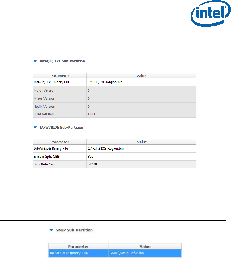
Image Creation/Flashing Procedure
Bring up Guide Intel Confidential 11
Figure 2. Intel® TXE and BIOS Region Configurations Example
3. Configuring the SMIP region:
• In the flash layout tab, SMIP Sub-partition, configure:
IAFW SMIP binary file (the BIOS SMIP).
Figure 3 - SMIP Configurations Example
4. Configuring the PMC and uCode regions:
• in the Flash layout tab, PMC Sub-Partition, select:
PMC Binary file.
• In the Flash layout tab, uCode Sub-Partition, select:
uCode patch 1 Input file.
uCode patch 2 Input file.
5. Configuring the iUnit (optional)
• In the Flash layout tab, iUnit Sub-Partition, select:
iUnit Binary File.
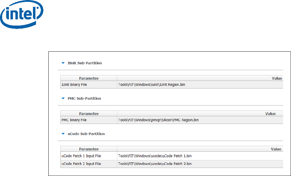
Image Creation/Flashing Procedure
12 Intel Confidential Bring up Guide
Figure 4 - iUnit, PMC, uCode Configuration Example
2.4.1.2 Flash Settings Configurations:
In this section, the bootable device setting will be configured.
2.4.1.2.1 SPI Based Platform Configurations
Under “Flash Setting” tab, “flash component” section set the following:
• “Number of Flash Components”: should be configured to “1”.
• Flash Component 1 size: should be configured to “8MB”.
• BIOS region overlap: should be configured to “False”.
Under “Flash Setting” tab, “Boot Source Selection” section, set the following:
• “SPI Boot Source Enable/Disable”: should be set to “Enabled”.
• “UFS Boot Source Enable/Disable”: should be set to “Disabled”.
• “eMMc Boot Source Enable/Disable”: should be set to “Disabled”.
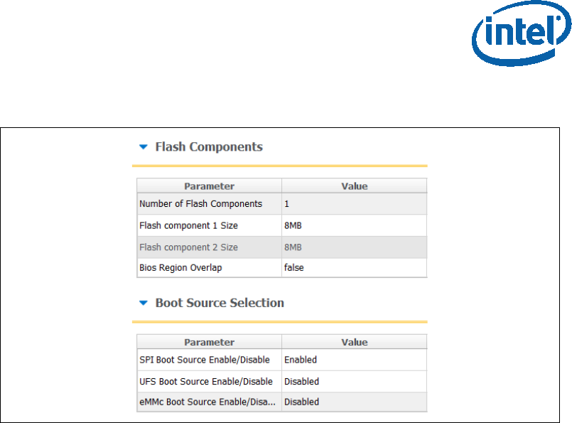
Image Creation/Flashing Procedure
Bring up Guide Intel Confidential 13
Figure 5. SPI flash setting configuration example
Under “Flash Setting” tab, “Flash Configuration” section set the following
according to the SPI flash part support:
• Boot Block Size - Enable per Top Swap usage on platform.
• Dual I/O Read Enabled
• Dual Output Fast Read Support
• Dual Output Read Enabled
• Fast Read Clock Frequency
• Fast Read Supported
• Quad I/O Read Enabled - please refer to the note below.
• Quad Output Read Enabled - please refer to the note below.
• Read ID and Read Status Clock Frequency
• Write and Erase Clock Frequency
Note: when setting “Quad I/O Read Enabled” or “Quad Output Read Enabled” to
“Yes”, the “Quad Enabled” bit need to be set in the SPI, without it the platform will
NOT BOOT, please refer to “Appendix C: Enabling Quad mode on SPI Part” for the
procedure.
Note: for detailed description of each configuration please refer to the “Apollo Lake
SoC SPI and SMIP programming guide (doc #559702).
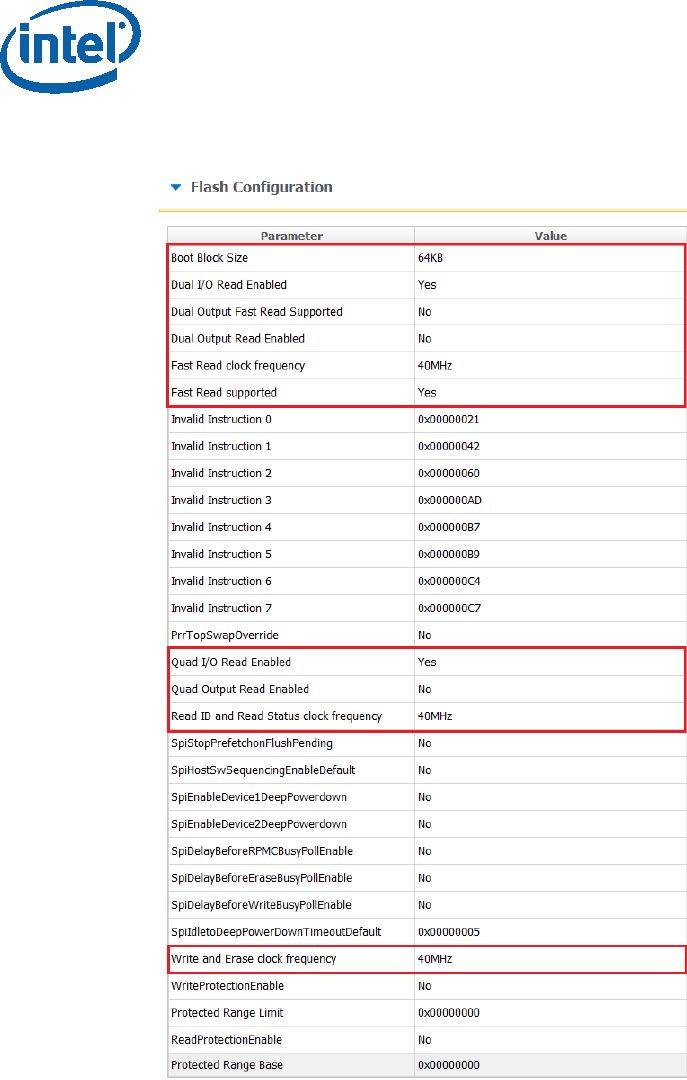
Image Creation/Flashing Procedure
14 Intel Confidential Bring up Guide
Figure 6 - APL RVP Flash Configuration Example
2.4.1.3 Platform SMIP Configurations
2.4.1.3.1 Voltage Regulator Depended SMIP Configurations
The following configurations needs to be set according to the VR of the board, for
more information please refer to the “Broxton/Apollo Lake SoC SPI and SMIP
programming guide (doc #559702).

Image Creation/Flashing Procedure
Bring up Guide Intel Confidential 15
In the “CPU Straps” tab, under “PUNIT” configure the following according to the
board VR:
Rail 0 Alert polling enable:
o “Enabled” = SVID OR Whiskey Cove PMIC VR Type
o “Disabled” = I2C VR Type
Rail 0 SVID ID:
o 0x0 = SVID OR I2C VR Type
o 0x5 = Whiskey Cove PMIC VR Type
Rail 1 Alert polling enable:
o “Enabled” = SVID OR Whiskey Cove PMIC VR Type
o “Disabled” = I2C VR Type
Rail 1 SVID ID:
o 0x0 = I2C VR Type
o 0x1 = Whiskey Cove PMIC VR Type
o 0x2 = SVID VR Type
Rail 2 Alert polling enable:
o “Enabled” = Whiskey Cove PMIC VR Type
o “Disabled” = SVID OR I2C VR Type
Rail 2 SVID ID:
o 0x0 = SVID OR I2C VR Type
o 0x2 = Whiskey Cove PMIC VR Type
Rail 3 Alert polling enable:
o “Enabled” = Whiskey Cove PMIC VR Type
o “Disabled” = SVID OR I2C VR Type
Rail 3 SVID ID:
o 0x0 = I2C VR Type
o 0x1 = SVID VR Type
o 0x6 = Whiskey Cove PMIC VR Type
Note: Please refer to the example below for the APL Intel ® RVP configuration
example.
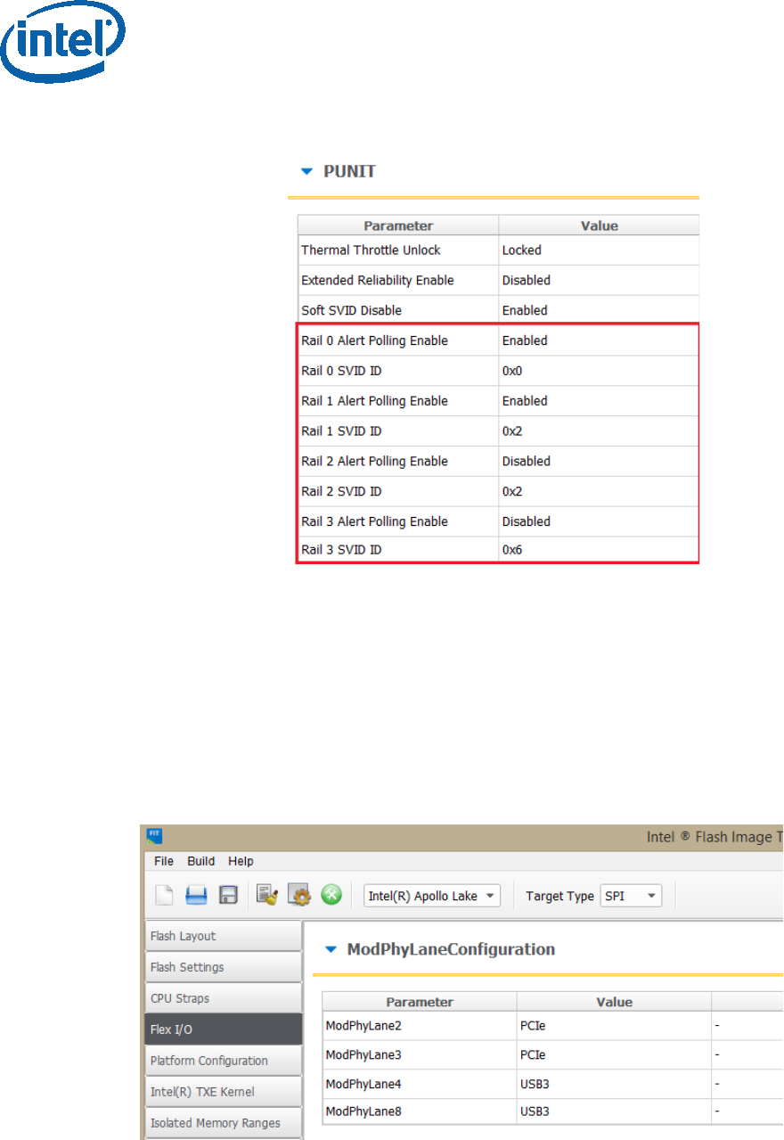
Image Creation/Flashing Procedure
16 Intel Confidential Bring up Guide
Figure 7 - Configuration example according to APL Intel (R) RVP VR
2.4.1.3.2 Mod-Phy lane Depended SMIP Configurations
The following configurations needs to be set according to the platform SMIP Mod-Phy
lane configurations. Platform SMIP are fully configurable via FIT UI (XML or GUI).
Refer to the relevant FIT tab/section for configuring SMIP. SPI and SMIP programming
guide (part of TXE kit) has further details of each SMIP configuration.
Configure the Platform SMIP via FIT of the platform Mod-Phy configurations according
to the screenshot below.
Figure 8 - Mod-Phy Lane Ownership FIT Configuration
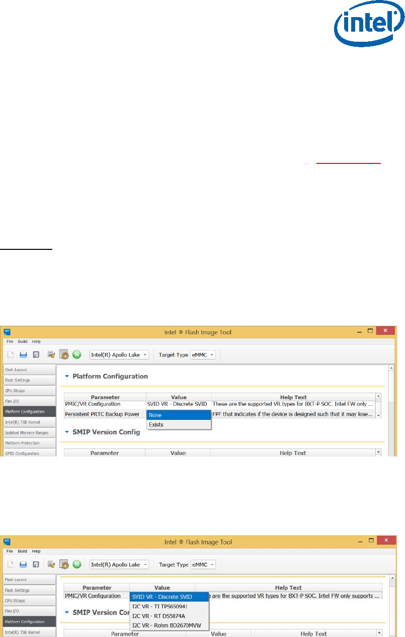
Image Creation/Flashing Procedure
Bring up Guide Intel Confidential 17
2.5 Coinless Platform Configuration
If your product design does not have Persistent RTC power (i.e. no coin battery), you
may set the below configuration of “Persistent PRTC Backup Power” to “None” (Default
is “Exists” = Coin Battery exists). Note that this configuration will be permanently
set in FPF fuses and cannot be reversed. Setting this option, your system will lose
some TXE features that depend on PRTC; like Anti-Replay Protection, PTT-Anti
Hammering (PTT-AH), and DAL persistent time.
You may design your system in such a way to always guarantee power to RTC. See
Apollo Lake Platform Design Guide (PDG) for more details.
Important: With “Persistent PRTC Backup Power = Exists”, RTC power must not lose
power 10 times in the lifetime of the product. PTT-AH feature uses RTC to detect
physical attacks. PTT-AH counts RTC power loss in FPF to detect this. Once PTT-AH
FPFs reach count 10, user will be locked out for 120 minutes when it boots. Every
subsequent RTC power loss, user will also be locked out for 120 minutes. If you think
your system, according to its design, will lose RTC power more than 10 times in its
lifetime, then select “Persistent PRTC Backup Power = None” to avoid this lock out.
2.6 Voltage Regulator Configurations
When configuring customer platform with PMIC/VR setup (discrete SVIT/Rohm/RT/
TI), please use the below dropdown to make the selection:
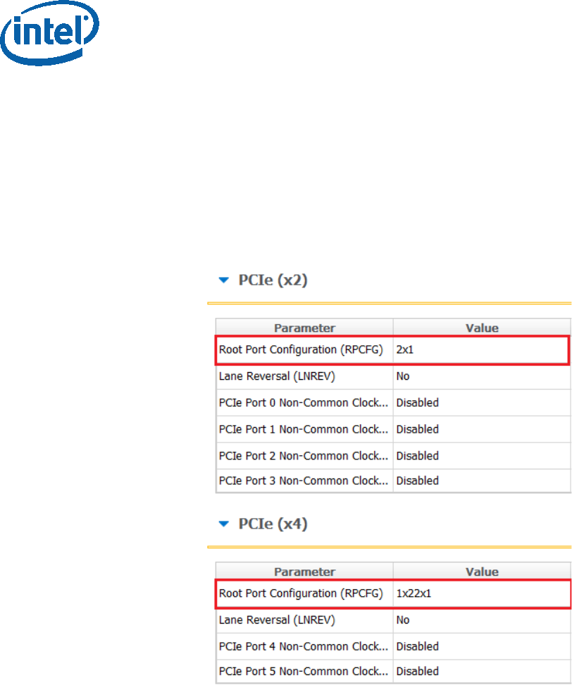
Image Creation/Flashing Procedure
18 Intel Confidential Bring up Guide
2.6.1.1.1 PCIe SMIP Configurations
The Root Port Configurations needs to be set according to the platform schematics, for
more information please refer to “Broxton/Apollo Lake SoC SPI and SMIP
programming guide” (doc #559702).
In the “Flex I/O” tab under “PCIe (x2)” and PCIE (x4) sections set the “Root Port
Configuration (RPCFG)” according to the platform schematics.
Figure 9 - APL Intel® RVP Root Port Configuration example
2.6.1.2 Platform Protection Configurations
2.6.1.2.1 Platform Integrity and Boot Guard Configurations
In this section the configurations that are related to the boot guard authentication
flow will be set, these settings need to be aligned with the OEM Key manifest settings.
There are 3 available Boot Guard profiles:
Boot Guard Profile 0 - Legacy: in this profile Boot Guard boot block
verifications and measurement protection is off.
Boot Guard Profile 1 - V: Strict Verification Enforcement. Prevents unverified
bios components from running.
Boot Guard Profile 1 - VM: Strict Verification and Measurement enforcement.
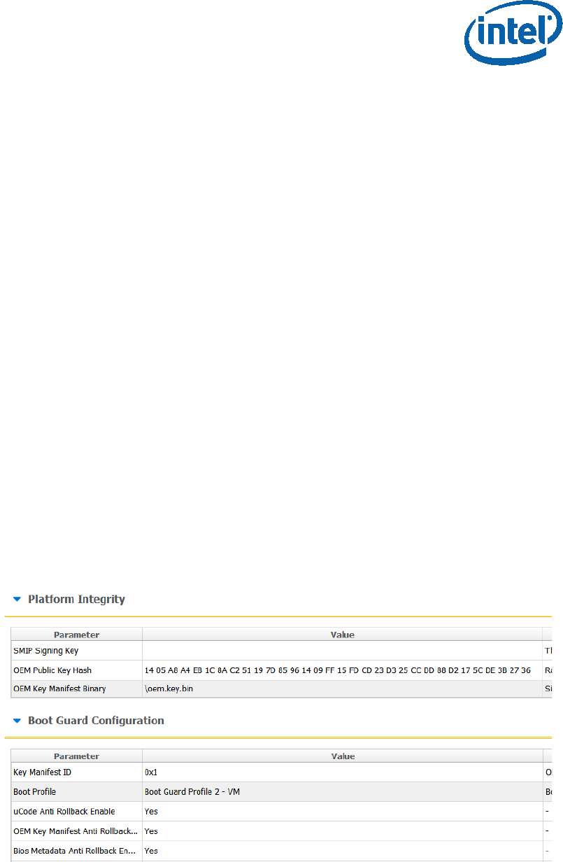
Image Creation/Flashing Procedure
Bring up Guide Intel Confidential 19
Prevents unverified Bios components from running.
When using the other Boot Guard profiles (Legacy/V/VM), and for complete
information about signing and manifesting, please refer to the “BXT and APL Signing
and Manifesting Guide” which is part of the FW Kit, please note that even when using
“Boot Guard Profile 0 - Legacy” each component still needs to be manifested and
signed.
Note: when building an image for Intel® RVP, the required files for each of the boot
guard profiles can be found in the TXE FW kit.
Once the necessary files were created according to the Boot Guard profile, in the
“platform protection” tab, under “Platform Integrity” set:
• “SMIP Signing Key” - this will be the private key that will be used to sign the
SMIP manifest, please note that as part of the OEM key manifest procedure,
the SMIP public key (which is paired with this private key) will need to be
configured for the SMIP manifest authentication.
• “OEM Public key Hash” - the hash of the public key that is used to
authenticate the OEM key manifest.
• “OEM Key Manifest Binary” - the OEM Key manifest binary that was created
using the MEU tool.
• “Key Manifest ID” - needs to be set according to the KMID in the OEM Key
Manifest.
• “Boot Profile” - set to according to the boot guard profile.
When choosing not to sign the image, the above files does not need to be set, and
‘Boot Profile’ should be set to ‘Boot Guard profile 0 - legacy’.
Figure 10 - Platform Integrity and Boot Guard Configurations example

Image Creation/Flashing Procedure
20 Intel Confidential Bring up Guide
2.6.1.2.2 Intel® PTT and TPM Configurations
This settings needs to be set according to the TPM devices that is used on the
platform.
When using fTPM the following configurations needs to be set:
• In the platform protection tab, under Intel ® PTT configurations, set:
o Intel PTT initial power-up state to “Enable”.
o Intel PTT Supported to “Yes”.
o Intel PTT Supported [FPF] to “Yes”.
• In the platform protection tab, under TPM Over SPI Bus Configurations,
set:
o Discrete TPM Location to “None”.
When using a dTPM the following configurations needs to be set:
• In the platform protection tab, under TPM Over SPI Bus Configurations,
set:
o Discrete TPM location according to board configurations to SPI/LPC.
Figure 11 - TPM Configuration Example
2.6.1.3 Intel® Integrated Sensor Solution Configurations
To enable Intel® Integrated Sensor Solution, the following configurations needs to be
set in the “Integrated Sensor Hub” tab:
Under “integrated Sensor Hub” section, set “Integrated Sensor Hub
Supported” as “Yes”.
Under “ISH Image” section, select the ISH binary location in “InputFile” field.
Under “ISH Data” section, select the PDT file location in “PDT Binary File” field.
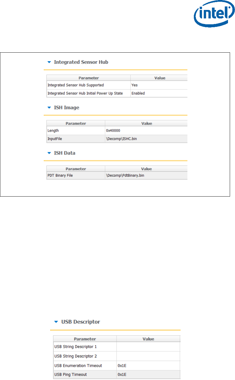
Image Creation/Flashing Procedure
Bring up Guide Intel Confidential 21
Figure 12. ISS Configurations example
2.6.1.4 DnX Configurations
In this section the DnX (Download and Execute) settings will be configured,
DnX is used to push tokens to the platforms.
For SPI based platform set:
Under the “USB Descriptor” section configure:
o USB Enumeration Time-out - Time-out in SECONDS Used by ROM DnX
logic to wait for enumeration from host before timing out. Default value is
“0x1E” (30 seconds time out), to disable cable detection set this field to
“0”.
o USB Ping Time-out - Time-out in SECONDS Used by ROM DnX logic to
wait for ping from host before timing out. Default value is “0x1E” (30
seconds time out), to disable cable detection set this field to “0”.
Figure 13 - USB Descriptor configuration example
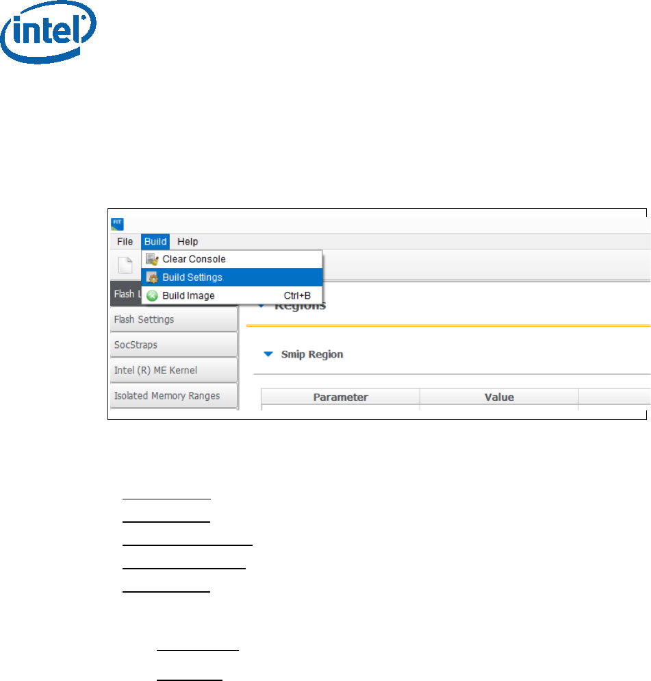
Image Creation/Flashing Procedure
22 Intel Confidential Bring up Guide
2.6.2 Configuring Intel® FIT build settings
In the main menu select Build Build settings
Edit your configuration as shown below.
Image build setting:
• Output path: the location and name of the image that will be created.
• Target Type: the bootable device type SPI/eMMC/UFS.
• Manifest tool path: the path to the MEU tool.
• Signing tool path: the path to the signing tool.
• Signing tool: the signing tool that is going to be used.
Environment Variables: (optional)
• $SourceDir: The location where FIT will look for binary images during the
image creation process.
• $DestDir: The location where FIT will save the binary image.
Image Creation/Flashing Procedure
Bring up Guide Intel Confidential 23
Figure 14 - Build configuration settings example
2.6.3 Save/Load Intel® FIT XML configuration
Once the IFWI setting have been configured, it’s highly recommended to save these
setting into a FIT xml, these settings can be loaded to simplify future image creations.
To save/load FIT configurations xml, from the FIT menu select: File
“open”/”save”/”save as”.
Figure 15 - saving/loading Intel® FIT Configurations
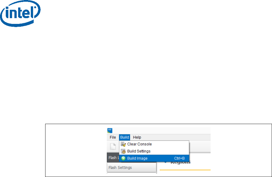
Image Creation/Flashing Procedure
24 Intel Confidential Bring up Guide
2.6.3.1 Building the Firmware Flash Image
Note: before building the FW image please make sure that the MEU setting are
configured (procedure in the prerequisites section), without this the image creation,
the process will FAIL.
After the IFWI configurations and the Build setting are set, build the image: FIT
setting select build “Build image”.
The output will be the two images, one for DnX flashing (on eMMC based platform),
and the other for external programmer/FPT flashing.
Figure 9 - Saving/Loading FIT Configurations
2.7 IFWI Flashing Procedure
2.7.1 Prerequisites
The following equipment and setup is required in order to complete IFWI flashing with
DnX:
• Management console (a.k.a Recovery host). Can be any PC, running Windows
7/8.1 OS
• Recovery host should be connected to the target device (device being flashed)
with a micro USB cable.
• Phone Flash Tool (PFT) should be installed on the recovery host. (Link to PFT
location available in TXE kit Release Notes)
• DnX module (can be found in TXE kit) and the recovery image should be
downloaded to the recovery host.
• eMMC needs to be selected as the boot source for the platform, on APL RVP
set jumper J6E7 to 2-3.
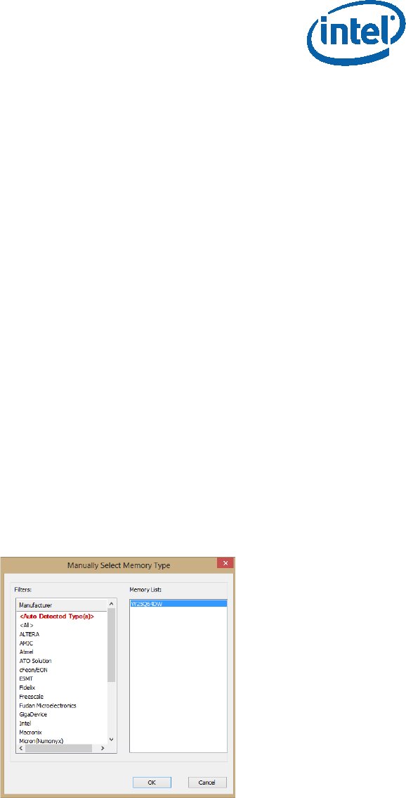
Image Creation/Flashing Procedure
Bring up Guide Intel Confidential 25
2.8 Flashing Procedure for an SPI Based Platform
Please note that on APL Intel the boot source needs to be set as SPI, to do so set
jumper J6E6 to 2-3.
2.8.1 Flashing an Image Using the FPT Tool
Flashing the SPI image can be done on the target platform from OS/EFI Shell using
the Flash Programing Tool, the tool is located in the FW Kit under
tools\Flash_Programming_tool.
To flash the image:
• Copy the FPT tool and the SPI image to the target platform
• From the FPT tool run: FPT -f “image_name.bin”
The expected output from the flashing procedure is “FPT Operation Passed”.
2.8.2 Flashing the Image Using Dediprog
• Connect the Dediprog to the platform and run the Dediprog software.
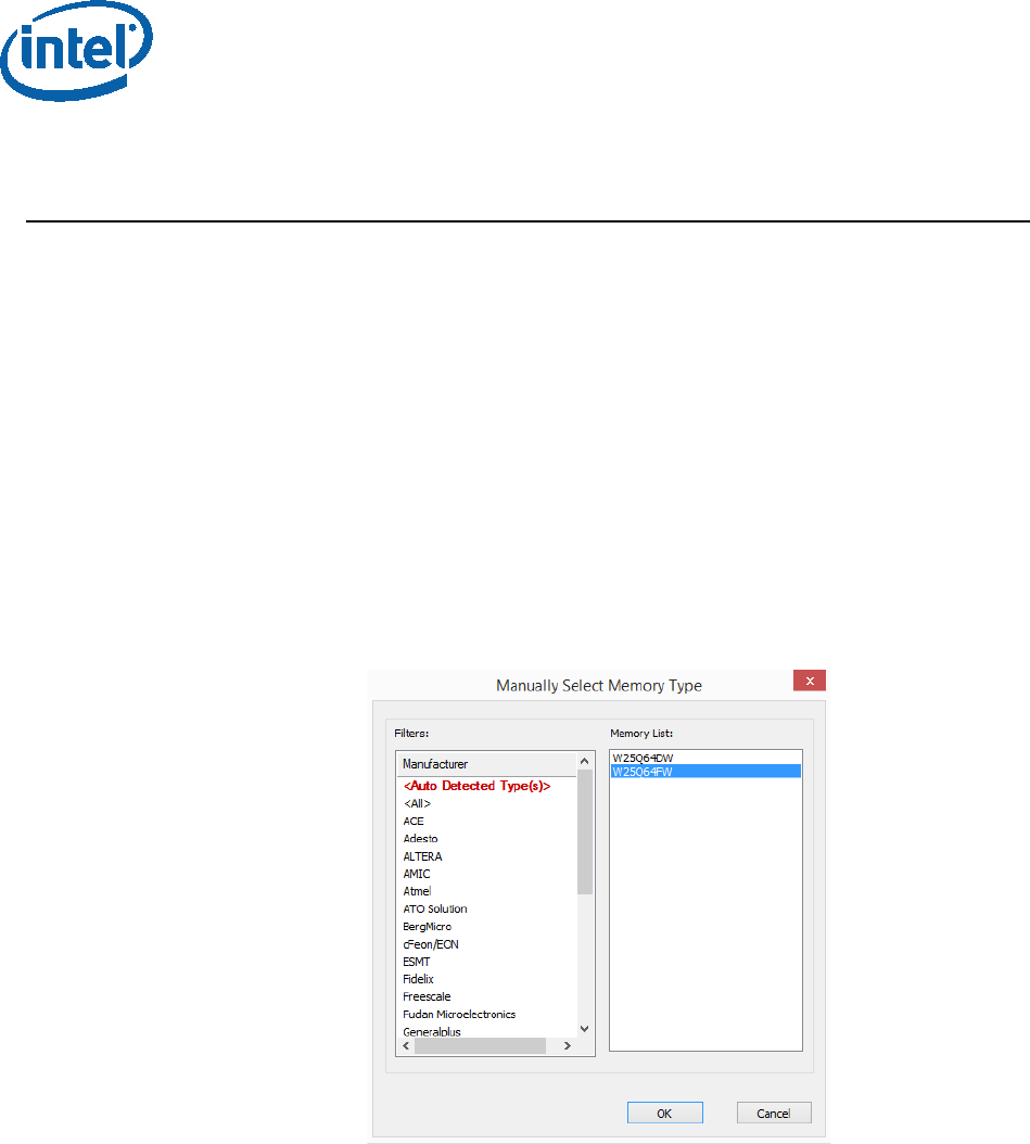
• Click “Detect”.
• Under “Manually Select Memory Type” window, select the SPI flash and click OK
Figure 16 - Selecting the SPI Component
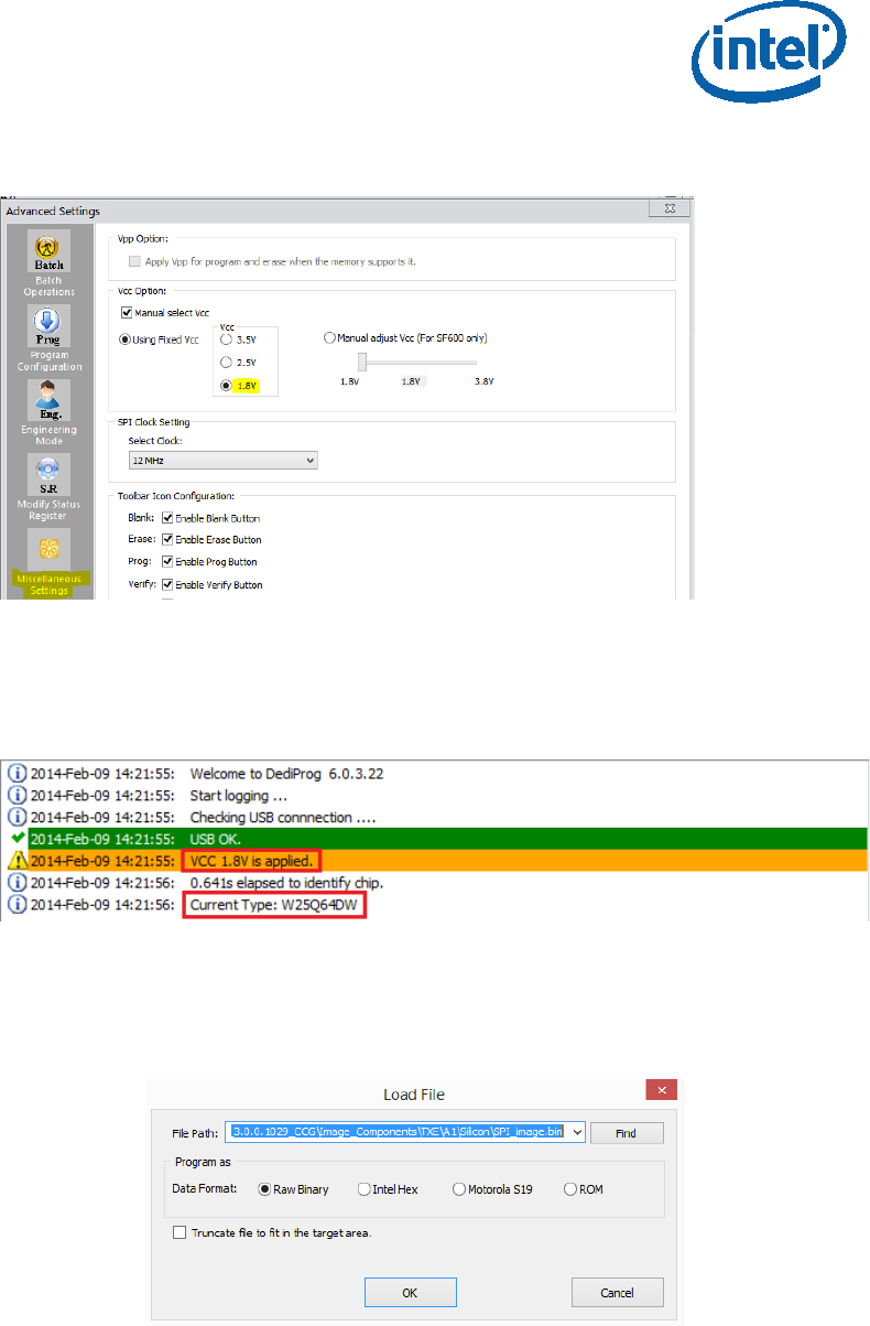
• Click: Config Miscellaneous Settings, under “Vcc Option”, configure Vcc voltage
to 1.8V.
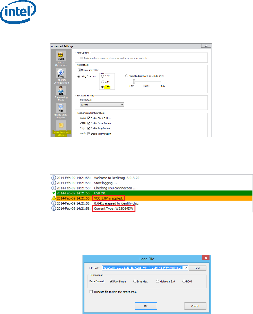
Image Creation/Flashing Procedure
26 Intel Confidential Bring up Guide
Figure 17 - Set VCC Voltage
• Under DediProg main window, the VCC voltage will be set to 1.8V, and the SPI
component will be selected.
Figure 18 - Main Window after the Configurations
• Click “File”, select the SPI image that was built in section 2.4, “Creating the Binary
Imag”.
• Under “Program as”, set data format as “Raw binary”.
Figure 19 - Load File Settings
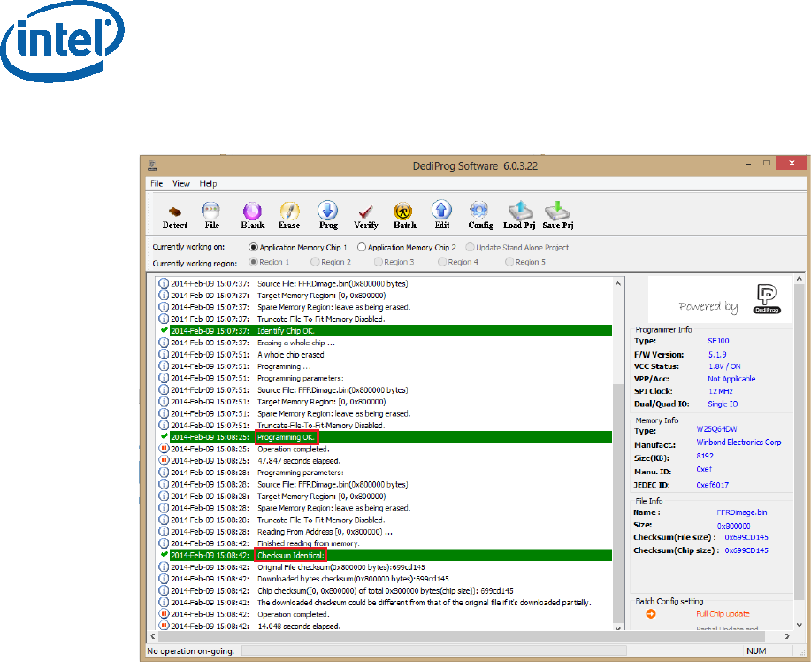
• Click “Batch” to flash the file. When the procedure is over, click “Verify” to verify
that the flashing was performed correctly.
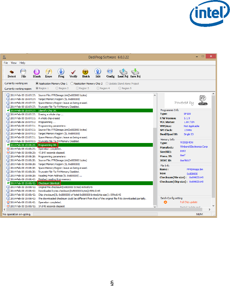
Image Creation/Flashing Procedure
Bring up Guide Intel Confidential 27
Figure 20 - Flashing Procedure Expected Result
2.9 Windows Drivers Installation
Once the platform boots up to OS, install the TXEI and SPD using the SetupTXE.exe
file that can be located in the kit under the “Installers” folder.
Note: the TXEI and SPD standalone drivers can be found under the same folder.
Appendix A: ROM Bypass
28 Intel Confidential Bring up Guide
3 Appendix A: ROM Bypass
For BXT based platform ROM bypass needs to be flashed to the platform prior to the
bring-up procedure.
The ROM bypass SPI image can be found in the TXE FW kit, under
“Image_Components\TXE”
3.1 Flashing the ROM bypass
• Connect the Dediprog to the platform and run the Dediprog software.
• Click “Detect”.
• In the “Manually Select Memory Type” window, select the SPI flash and click OK
Note: on Intel RVP choose: “W25Q64FW”
Figure 21 - Selecting the SPI Component
• Click: Config Miscellaneous Settings, under “Vcc Option” configure Vcc voltage
to 1.8V.
Appendix A: ROM Bypass
Bring up Guide Intel Confidential 29
Figure 22 - Set VCC Voltage
• In the DediProg main window the VCC voltage will be set to 1.8V, and the SPI
component will be selected.
Figure 23 - Main Window after the Configurations
• Click “File”, select the SPI image that was built in section 2.4, “Creating the Binary
Imag”. Under “Program as”, set data format as “Raw binary”.
Figure 24 - Load File Settings
• Click “Batch” to flash the file, when the procedure is over, click “Verify” to verify
that the flashing was performed correctly.
Appendix A: ROM Bypass
30 Intel Confidential Bring up Guide
Figure 25 - Flashing Procedure Expected Result
§

Appendix B: Phone Flash Tool DnX Commands
Bring up Guide Intel Confidential 31
4 Appendix B: Phone Flash Tool
DnX Commands
Please refer to the table below for the Phone Flash Tool DnX related commands,
please note that this commands needs to be run from a CLI.
Description CLI command
Flashing IFWI image dnxFwDownloader.exe --command downloadfwos --
fw_dnx DNXP_0x1.bin --fw_image
<IFWI_DnX_Image> --flags 0
Clear GPP4/RPMB dnxFwDownloader.exe --command clearrpmb --
fw_dnx DNXP_0x1.bin --device 2 --idx 0
Configure the GPPs on an
eMMC based platform
dnxFwDownloader .exe --command configpart --
fw_dnx DNXP_0x1.bin --path cfgpart.xml --device 2 --
idx 0
Read token dnxFwDownloader .exe --command readtoken --
fw_dnx DNXP_0x1.bin --path read.bin --slot 0
Write token dnxFwDownloader .exe --command writetoken --
fw_dnx DNXP_0x1.bin --token test_token.bin --slot
0
Erase token dnxFwDownloader .exe --command erasetoken --
fw_dnx DNXP_0x1.bin --slot 0
Read boot media contents -
EMMC BP1
dnxFwDownloader .exe --command readbootmedia -
-fw_dnx DNXP_0x1.bin --path boot1.bin --device 2 -
-idx 0 --start 0 --blocks 4096 --part 0
Read boot media contents -
EMMC BP2
dnxFwDownloader .exe --command readbootmedia -
-fw_dnx DNXP_0x1.bin --path boot2.bin --device 2 -
-idx 0 --start 0 --blocks 4096 --part 1

Appendix B: Phone Flash Tool DnX Commands
32 Intel Confidential Bring up Guide
§
Read boot media contents -
EMMC GPP4
dnxFwDownloader .exe --command readbootmedia -
-fw_dnx DNXP_0x1.bin --path gpp4.bin --device 2 --
idx 0 --start 0 --blocks 4096 --part 35
Read boot media contents -
EMMC RPMB
dnxFwDownloader .exe --command readbootmedia -
-fw_dnx DNXP_0x1.bin --path rpmb.bin --device 2 --
idx 0 --start 0 --blocks 4096 --part 16
Read boot media contents -
UFS BP1
dnxFwDownloader .exe --command readbootmedia -
-fw_dnx DNXP_0x1.bin --path boot1.bin --device 3 -
-idx 0 --start 0 --blocks 4096 --part 0
Read boot media contents -
UFS BP2
dnxFwDownloader .exe --command readbootmedia -
-fw_dnx DNXP_0x1.bin --path boot2.bin --device 3 -
-idx 0 --start 0 --blocks 4096 --part 1
Read boot media contents -
UFS GPP4
dnxFwDownloader .exe --command readbootmedia -
-fw_dnx DNXP_0x1.bin --path gpp4.bin --device 3 --
idx 0 --start 0 --blocks 4096 --part 22
Read boot media contents -
UFS RPMB
dnxFwDownloader .exe --command readbootmedia -
-fw_dnx DNXP_0x1.bin --path rpmb.bin --device 3 --
idx 0 --start 0 --blocks 4096 --part 48
Appendix C: Enabling Quad Mode on SPI Part
Bring up Guide Intel Confidential 33
5 Appendix C: Enabling Quad
Mode on SPI Part
When enabling quad operations in the soft steps the Quad enable bit needs to be set
accordingly within the SPI part, if not the platform will not boot.
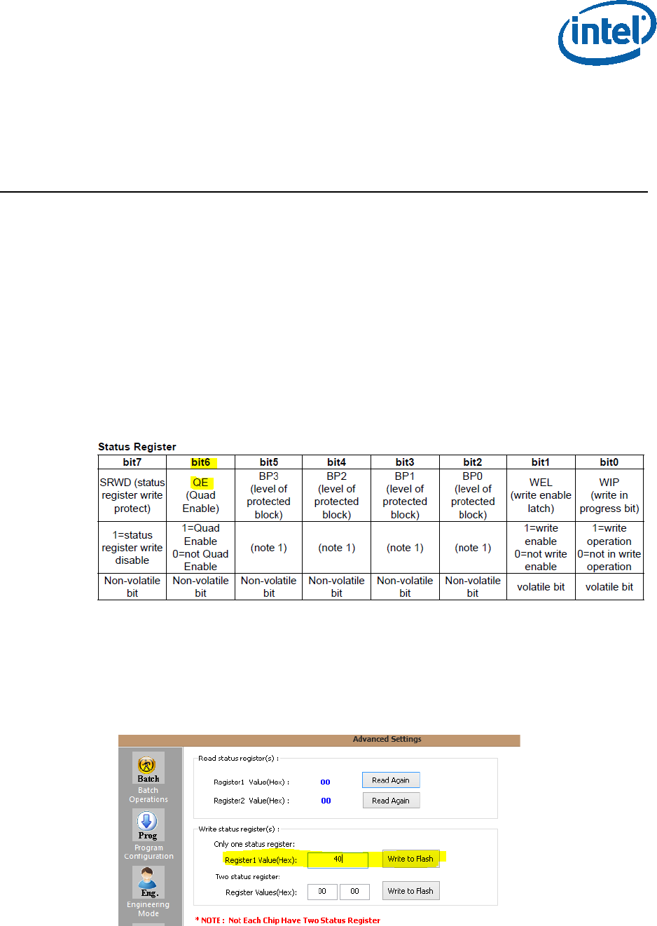
The Quad Enable bit location is different for each SPI vendor model, please refer to
the SPI Spec in order to get the Quad Enabled bit location for your SPI device.
5.1 Setting the Quad Enabled Bit Using Dediprog
The following procedure uses the SPI part “MX25U6435FM2I-10G” as an example,
please follow the procedure below with the settings that corresponds to the SPI device
that is used on your platform.
Figure 26 - the Quad Enable information from the “MX25U6435FM2I-10G" SPI Spec
To set the Quad enable bit:
• Attached Dediprog to SPI device & open Dediprog Software
• Go to Config S.R. Modify Status Register
• Under “Write Status register(s)”, write “0x40” to “Register1 Value(Hex)” as shown
below
Figure 27 - Writing the Quad Enable bit to the Flash
Appendix C: Enabling Quad Mode on SPI Part
34 Intel Confidential Bring up Guide
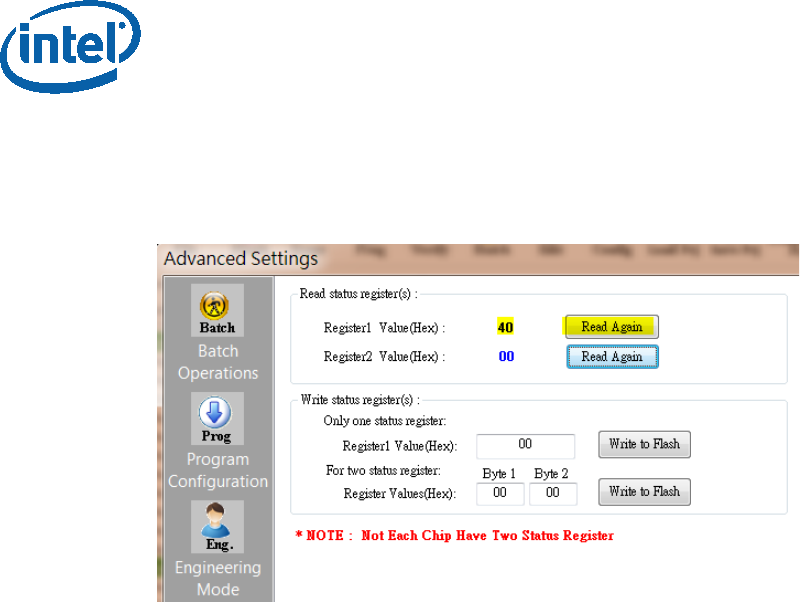
• Verify Register 1 has the value “40” as shown below
Figure 28 - verifying the register new value
§
