System Tools For Broxton APL_System_Tools_User_Guide_TXE 3_0_Rev 1.0 APL User Guide TXE 3 0 Rev
User Manual: APL_System_Tools_User_Guide_TXE 3_0_Rev 1.0
Open the PDF directly: View PDF ![]() .
.
Page Count: 90

System Tools for Apollo Lake:
Intel® Trusted Execution
Environment 3.0
User Guide
June 2016
Revision: 1.0 Release
Intel Confidential

2 Intel Confidential
You may not use or facilitate the use of this document in connection with any infringement or other legal analysis concerning
Intel products described herein. You agree to grant Intel a non-exclusive, royalty-free license to any patent claim thereafter
drafted which includes subject matter disclosed herein.
No license (express or implied, by estoppel or otherwise) to any intellectual property rights is granted by this document.
Intel technologies’ features and benefits depend on system configuration and may require enabled hardware, software or service
activation. Learn more at Intel.com, or from the OEM or retailer.
No computer system can be absolutely secure. Intel does not assume any liability for lost or stolen data or systems or any
damages resulting from such losses.
The products described may contain design defects or errors known as errata which may cause the product to deviate from
published specifications. Current characterized errata are available on request.
Intel disclaims all express and implied warranties, including without limitation, the implied warranties of merchantability, fitness
for a particular purpose, and non-infringement, as well as any warranty arising from course of performance, course of dealing, or
usage in trade.
Intel technologies’ features and benefits depend on system configuration and may require enabled hardware, software or service
activation. Learn more at intel.com, or from the OEM or retailer.
All information provided here is subject to change without notice. Contact your Intel representative to obtain the latest Intel
product specifications and roadmaps.
Copies of documents which have an order number and are referenced in this document may be obtained by calling 1-800-548-
4725 or visit www.intel.com/design/literature.htm.
By using this document, in addition to any agreements you have with Intel, you accept the terms set forth below.
Contact your local Intel sales office or your distributor to obtain the latest specifications and before placing your product order.
Intel, vPro and the Intel logo are trademarks of Intel Corporation in the U.S. and other countries.
*Other names and brands may be claimed as the property of others.
Copyright © 2016, Intel Corporation. All rights reserved.

Intel Confidential 3
Contents
1 Introduction ...................................................................................................... 8
1.1 Terminology ........................................................................................... 8
1.2 Reference Documents ............................................................................ 11
2 Preface ........................................................................................................... 12
2.1 Overview ............................................................................................. 12
2.2 Image Editing Tools .............................................................................. 12
2.3 Manufacturing Line Validation Tool .......................................................... 12
2.4 Intel® TXE Setting Checker Tool ............................................................. 13
2.5 Operating System Support ..................................................................... 13
Windows* 10 DT 32-bit will be supported post TTM.... Error! Bookmark not defined.
2.6 Generic System Requirements ................................................................ 13
2.7 Error Return ......................................................................................... 14
2.8 Usage of the Double-Quote Character (") ................................................. 14
2.9 PMX Driver Limitation ............................................................................ 14
3 Intel® Flash Image Tool (Intel® FIT) ................................................................... 16
3.1 System Requirements ........................................................................... 16
3.2 Required Files ....................................................................................... 16
3.3 Intel® FIT ............................................................................................ 16
3.3.1 Configuration Files ................................................................... 17
3.3.2 Creating a New Configuration .................................................... 17
3.3.3 Opening an Existing Configuration ............................................. 17
3.3.4 Saving a Configuration ............................................................. 17
3.3.5 Environment Variables ............................................................. 17
3.3.6 Image Build Settings ................................................................ 20
3.3.7 DnX Build Settings ................................................................... 21
3.3.8 Target Platform and Flash Settings ............................................ 22
3.3.9 Flash Layout Tab ..................................................................... 22
3.3.10 Flash Settings Tab ................................................................... 23
3.3.11 Platform Protection .................................................................. 25
3.3.12 Integrated Sensor Hub ............................................................. 26
3.3.13 Download and Execute ............................................................. 26
3.3.14 GPIO Profiles ........................................................................... 26
3.3.15 End Of Manufacturing State ...................................................... 27
3.3.16 Platform Configuration Tab ....................................................... 27
3.3.17 Other Configuration Tabs .......................................................... 27
3.3.18 Building a Flash Image ............................................................. 27
3.3.19 Decomposing an Existing Flash Image ........................................ 28
3.3.20 Command Line Interface .......................................................... 28
3.3.21 Example – Decomposing an Image and Extracting Parameters ...... 30
4 Flash Programming Tool ................................................................................... 32
4.1 System Requirements ........................................................................... 32
4.2 Microsoft Windows* Required Files .......................................................... 32
4.3 EFI Required Files ................................................................................. 33
4.4 Programming the Flash Device ............................................................... 33
4.5 Programming CVARS ............................................................................. 34
4.6 Usage .................................................................................................. 34

4 Intel Confidential
4.7 Fparts.txt File ....................................................................................... 38
4.8 Examples ............................................................................................. 39
4.8.1 Complete SPI Flash Device Burn with Binary File ......................... 39
4.8.2 Dump full image ...................................................................... 39
4.8.3 Display SPI Information ............................................................ 39
4.8.4 Verify Image with Errors ........................................................... 39
4.8.5 Verify Image Successfully ......................................................... 40
4.8.6 Get Intel® TXE settings ............................................................ 40
4.8.7 Compare Intel® TXE Settings .................................................... 40
4.8.8 CVAR Configuration File Generation (-cfggen) ............................. 40
5 Intel® TXEManuf and TXEManufWin .................................................................... 42
5.1 Windows* PE Requirements ................................................................... 42
5.2 How to Use Intel® TXEManuf .................................................................. 42
5.3 Usage .................................................................................................. 43
5.3.1 Host-based Tests ..................................................................... 44
5.4 Intel® TXEManuf –EOL Check ................................................................. 44
5.4.1 TXEManuf.cfg File .................................................................... 44
5.4.2 TXEManuf –EOL Variable Check ................................................. 44
5.4.3 TXEManuf –EOL Config Check .................................................... 45
5.4.4 Output/Result ......................................................................... 45
5.5 Examples ............................................................................................. 45
5.5.1 Example for Consumer Intel® TXE FW SKU ................................. 45
6 Intel® TXEInfo ................................................................................................. 47
6.1 Windows* PE Requirements ................................................................... 47
6.2 Usage .................................................................................................. 47
6.3 Examples ............................................................................................. 51
6.3.1 Intel® TXE FW SKU .................................................................. 51
6.3.2 Retrieve the Current Value of the Flash Version ........................... 52
7 Intel® Platform Flash Tool ................................................................................. 53
8 Intel® Manifest Extension Utility (MEU) ............................................................... 54
8.1 Introduction ......................................................................................... 54
8.2 Intel MEU XML ...................................................................................... 54
8.3 Intel MEU Configuration ......................................................................... 55
8.3.1 Signing Tool Configuration ........................................................ 55
8.3.2 LZMA Compression Tool ........................................................... 56
8.3.3 User Path Variables .................................................................. 56
8.4 Supported Binary Formats ..................................................................... 57
8.4.1 Binary Types ........................................................................... 57
8.4.2 Example: OEM Key Manifest Creation ......................................... 58
8.5 Creating a Public Key Hash: ................................................................... 58
8.5.1 Example: Key Hash Generation ................................................. 59
8.6 Decomposing a Binary ........................................................................... 59
8.7 Resigning a Binary ................................................................................ 60
8.8 Exporting a Manifest ............................................................................. 61
8.9 Importing a Manifest ............................................................................. 61
8.10 Command Line Options .......................................................................... 62
9 Widevine* KeyBox Provisioning Procedure .......................................................... 63
Appendix A Intel® TXE CVARs ............................................................................................ 65

Intel Confidential 5
Appendix B Tool Detail Error Codes ..................................................................................... 69
B.1 Common Error Code for All Tools ....................................................................... 69
B.2 Firmware Update Errors .................................................................................... 75
B.3 Intel® TXEManuf Errors .................................................................................... 76
B.4 Intel® TXEINFO Errors ...................................................................................... 80
B.5 FPT Errors ....................................................................................................... 81
B.6 MEU Errors ..................................................................................................... 83
Appendix C Tool Option Dependency on BIOS/Intel® TXE Status ............................................ 85
Appendix D : Using Local Android* Intel® TXE System Tools ................................................. 86
D.1 Using Android* System Tools ............................................................................ 86
D.2 Setup & Install ADB and Fastboot ...................................................................... 86
D.3 Using Fastboot ................................................................................................ 86
D.4 How to Push & Use the Intel® TXE System Tools ................................................. 86
Appendix E : Google* Widevine for Intel® TXE .................................................................... 88
E.1 Creating Widevine* CEK (Customer Encryption Key) ............................................ 88
E.1.1 FITC CEK File Creation Procedure....................................................................... 88
E.1.1.1 Cleartext CEK .................................................................................................. 88
E.1.1.2 Ciphertext CEK ................................................................................................ 89
E.2 Constructing Widevine* Provisioning KeyBox File ................................................. 90
E.2.1 KeyBox Creation Procedure ............................................................................... 90
Figures
Figure 3-1. Environment Variables in Build Settings Dialog ................................... 18
Figure 3-2. Image Build Settings in Build Settings Dialog ...................................... 21
Figure 3-3. DnX Build Settings in Build Settings Dialog Error! Bookmark not defined.
Figure 3-4. Flash Layout Tab ............................................................................. 23
Figure 3-5. Add VSCC Table Entry Dialog ............................................................ 24
Figure 3-6. Deleting VSCC Table Entry Dialog ...................................................... 25
Figure 3-7. Platform Protection Tab .................................................................... 26
Tables
Table 2-1: OS Support for Tools ........................................................................ 13
Table 3-1. Environment Variables Options........................................................... 18
Table 3-2: Build Settings Dialog Options ............................................................. 20
Table 3-3: DnX Build Settings Dialog Options ...................................................... 21
Table 3-4: Target Platform and Flash Options ...................................................... 22

6 Intel Confidential
Table 3-5. Key Platform Protection Fields ............................................................ 25
Table 3-6. DnX Fields ....................................................................................... 26
Table 3-7. Intel FIT Command Line Options ........................................................ 28
Table 4-1: FPT OS Requirements ....................................................................... 33
Table 4-2. Named Variables Options .................................................................. 34
Table 4-3. Command Line Options for fpt.efi, fpt.exe and fptw.exe ........................ 34
Table 4-4. FPT –closemnf Behavior .................................................................... 38
Table 5-1: Options for the Tool .......................................................................... 43
Table 5-2: TXEManuf - EOL Config Tests ............................................................. 45
Table 6-1. Intel® TXEInfo Command Line Options ................................................ 47
Table 6-2. List of Components that Intel® TXEINFO Displays ................................. 48

Intel Confidential 7
Revision History
Revision Number
Description
Revision Date
0.3
Pre-Alpha Release
September 2015
0.4
Updated OS matrix with Linux library support
0.6
Alpha version release
0.7
Updated OS matrix with Win10 32-bit support
Added details to MEU on key hash generation
October 2015
0.8
Updated OS matrix
Updated MEU error codes, and additional functionality
November 2015
0.81
Removed CommitFPF command, updated details of –
TXE flag, updated details of –CLOSEMNF flag
Windows 10 DT 32-bit will be supported post-TTM
Updated FIT settings location, based on Beta build
locations. Added note about Disable Boot Source FPFs.
Multiple minor clarfications and corrections
January 2016
0.85
Added Appendix on using Local Android* Intel® System
Tools
Added chapter and Appendix on Google Widevine
provisioning and processes
Added usage of –ISH –fwstat combination flag in Intel®
TXEInfo
Removal of Win10 32-bit OS support from all tools,
impacting Win10 PE 32-bit and EFI Shell 32 bit as well
Removed NFC flags from tools
April 2016
1.0
Removed all mention of Broxton
July 2016
§ §

Introduction
8 Intel Confidential
1 Introduction
The purpose of this document is to describe the tools that are used in the platform
design, manufacturing, testing, and validation process.
1.1 Terminology
Acronym/Term
Definition
AC
Alternating Current
Agent
Software that runs on a client PC with OS running
API
Application Programming Interface
BIN
Binary file
BIOS
Basic Input Output System
BIOS-FW
Basic Input Output System Firmware
BIST
Built In Self-Test
CLI
Command Line Interface
CRB
Customer Reference Board
CVAR
Changeable Variable
DLL
Dynamic Link Library
DNS
Domain Naming System
DnX
Download and Execute Technology
EC
Embedded Controller
EFI
Extensible Firmware Interface
EHCI
Enhanced Host Controller Interface
End User
The person who uses the computer (either Desktop or Mobile). The
user usually may not have administrator privileges.
EOP
End Of Post
Intel® FIT
Intel® Flash Image Tool
FLOCKDN
Flash Configuration Lock-Down
FOV
Fixed Offset Variable
Intel® FPT
Intel® Flash Programming Tool
FQDN
Fully Qualified Domain Name
FW
Firmware
G3
A system state of Mechanical Off where all power is disconnected from
the system. A G3 power state does not necessarily indicate that RTC
power is removed.
GPIO
General Purpose Input/output

Introduction
Intel Confidential 9
Acronym/Term
Definition
GUI
Graphical User Interface
GUID
Globally Unique Identifier
HECI
(deprecated)
Host Embedded Controller Interface
Host or Host CPU
The processor running the operating system. This is different than the
processor running the Intel® TXE FW.
Host Service/
Application
An application running on the host CPU
HW
Hardware
IBV
Independent BIOS Vendor
ICC
Integrated Clock Configuration
ID
Identification
INF
An information file (.inf) used by Microsoft operating systems that
support the Plug & Play feature. When installing a driver, this file
provides the OS with the necessary information about driver filenames,
driver components, and supported hardware.
Intel® DAL
Intel® Dynamic Application Loader (Intel® DAL)
Intel® TXE
Intel® Trusted Execution Engine. The embedded processor residing in
the chipset MCH.
Intel® TXEI driver
Intel® TXE host driver that runs on the host and interfaces between
ISV Agent and the Intel® TXE HW.
ISV
Independent Software Vendor
IT User
Information Technology User. Typically very technical and uses a
management console to ensure multiple PCs on a network function.
LAN
Local Area Network
LED
Light Emitting Diode
LPC
Low Pin Count Bus
CM0
Intel® TXE power state where all HW power planes are activated. Host
power state is S0.
CM1
Intel® TXE power state where all HW power planes are activated but
the host power state is different than S0. (Some host power planes are
not activated.) The Host PCI-E* interface is unavailable to the host SW.
This power state is not available in Cougar Point.
CM3
Intel® TXE power state where all HW power planes are activated but
the host power state is different than S0. (Some host power planes are
not activated.) The Host PCI-E* interface is unavailable to the host SW.
The main memory is not available for Intel® TXE use.
CM-Off
No power is applied to the processor subsystem. Intel® TXE is shut
down.
MAC address
Media Access Control address
MCP
Multi-Chip Package (Central Processing Unit / Platform Controller Hub)

Introduction
10 Intel Confidential
Acronym/Term
Definition
NM
Number of Masters
NVM
Non-Volatile Memory
NVRAM
Non-Volatile Random Access Memory
ODM
Original Device Manufacturer
OEM
Original Equipment Manufacturer
OEM ID
Original Equipment Manufacturer Identification
OS
Operating System
OS Hibernate
OS state where the OS state is saved on the hard drive.
OS not
Functional
The Host OS is considered non-functional in Sx power state in any one
of the following cases when the system is in S0 power state:
OS is hung
After PCI reset
OS watch dog expires
OS is not present
PAVP
Protected Video and Audio Path
PC
Personal Computer
PCI
Peripheral Component Interconnect
PCIe
Peripheral Component Interconnect Express
PHY
Physical Layer
PID
Provisioning ID
PKI
Public Key Infrastructure
PM
Power Management
ROM
Read Only Memory
RSA
A public key encryption method
RTC
Real Time Clock
S0
A system state where power is applied to all HW devices and the
system is running normally.
S1, S2, S3
A system state where the host CPU is not running but power is
connected to the memory system (memory is in self refresh).
S4
A system states where the host CPU and memory are not active.
S5
A system state where all power to the host system is off but the power
cord is still connected.
SDK
Software Development Kit
SHA
Secure Hash Algorithm
SMBus
System Management Bus
SPI
Serial Peripheral Interface
SPI Flash
Serial Peripheral Interface Flash

Introduction
Intel Confidential 11
Acronym/Term
Definition
Sx
All S states which are different than S0
SW
Software
System States
Operating System power states such as S0, S1, S2, S3, S4, and S5.
UI
User Interface
UMA
Unified Memory Access
Un-configured
state
The state of the Intel® TXE FW when it leaves the OEM factory. At this
stage the Intel® TXE FW is not functional and must be configured.
USB
Universal Serial Bus
VSCC
Vendor Specific Component Capabilities
Windows* PE
Windows* Pre installation Environment
XML
Extensible Markup Language.
1.2 Reference Documents
Document
Document No./Location
Apollo Lake- Intel®Trusted Execution
Engine (Intel®TXE) Firmware Bring-Up
Guide
Release kit
EDS
CDI
Apollo Lake Soc SPI and Signed Master
Image Profile(SMIP) Programming Guide
Release kit
Apollo Lake Signing and Manifesting
Guide
Release kit
§ §

Preface
12 Intel Confidential
2 Preface
2.1 Overview
This document covers the system tools used for creating, modifying, and writing
binary image files, manufacturing testing, Intel® TXE setting information gathering,
and Intel® TXE FW updating. The tools are located in Kit directory\Tools\System
tools. For information about other tools, see the tool's user guides in the other
directories in the FW release.
The system tools described in this document are platform specific in the following
ways:
Apollo Lake (APL) platforms – All tools in the Apollo Lake FW release kit are
designed for Apollo Lake platforms only. These tools do not work properly on any
other legacy platforms. Tools designed for other platforms also do not work
properly on the Apollo Lake platforms.
Intel® TXE Firmware 3.0 SKU – The tools are provided for the Intel® TXE FW 3.0
SKUs.
2.2 Image Editing Tools
The following tools create and write flash images:
Intel® FIT:
Combines the BIOS, Intel® TXE FW and other binaries into one image.
Configures SMIPs and CVARs for Intel® TXE settings that can be
programmed by a flash programming device or the FPT Tool.
FPT:
Programs the SPI flash memory of individual regions or the entire SPI
flash device.
Modifies some Intel® TXE settings (CVAR) after Intel® TXE is flashed on
the flash memory part.
Platform Flash Tool (using DnX)
2.3 Manufacturing Line Validation Tool
The manufacturing line validation tool (Intel® TXEManuf) allows the Intel® TXE
functionality to be tested immediately after the chipset is generated. This tool is
designed to be able to run quickly. It can run on simple operating systems, such as
EFI, Windows* 98. The Windows* version is written to run on Windows* 7, Windows*
8.1 and Win* PE 32 and 64. This tool is mostly run on the manufacturing line to do
manufacturing testing.

Preface
Intel Confidential 13
2.4 Intel® TXE Setting Checker Tool
The Intel® TXE setting checker tool (Intel® TXEInfo) retrieves and displays information
about some of the Intel® TXE settings, the Intel® TXE FW version, and the FW
capability on the platform.
2.5 Operating System Support
Table 2-1: OS Support for Tools
Intel® TXE and
Manufacturing
Tools
EFI Shell 64 bit
Windows * 7 SP1 32bit
Windows* 7 SP1 64bit
Windows* PE 3.1 64bit
Windows* 8.1 32bit
Windows 8.1 64bit
Windows* PE 5.1 64bit
Windows* 10 DT 64bit
Windows * 10 PE 64bit
Windows 10 Mobile
Android M Dessert 64 bit (both user and
kernel 64 bit)
Fedora /RedHat * Linux (Glibc 2.19, Kernel
3.18.20) 64bit
Intel® Flash Image Tool
X
X
X
X
X
Intel® Flash
Programming Tool
X
X
X
X
X
X
X
X
X
Intel® TXEManuf Tool
X
X
X
X
X
X
X
X
X
Intel® TXE Info Tool
X
X
X
X
X
X
X
X
X
Manifest Extension Tool
X
X
X
X
X
Platform Flash Tool and
Token Manager Tool
X
X
X
X
X
2.6 Generic System Requirements
The installation of the following driver is required by integration validation tools that
run locally on the system under test with the Intel® TXE:
Intel® TXEI driver.
See the description of each tool for its exact requirements.

Preface
14 Intel Confidential
2.7 Error Return
Intel® FIT and Intel® MEU return a non-0 number on an error, and the final error code
is printed.
Other tools return 0/1/2 for the error level (0 = success, 1= error, 2 = Success with
warning). A detailed error code is displayed on the screen and stored on an error.log
file in the same directory as the tools. (See Appendix B for a list of these error codes.)
2.8 Usage of the Double-Quote Character (")
The EFI version of the tools handle multi-word argument is different than the
DOS/Windows* version. If there is a single argument that consists of multiple words
delimitated by spaces, the argument needs to be entered as following:
FPT.efi –f “” arguments ””.
The command shell used to invoke the tools in EFI and Windows* has a built-in CLI.
The command shell was intended to be used for invoking applications as well as
running in batch mode and performing basic system and file operations. For this
reason, the CLI has special characters that perform additional processing upon
command.
The double-quote is the only character which needs special consideration as input. The
various quoting mechanisms are the backslash escape character (/), single-quotes ('),
and double-quotes ("). A common issue encountered with this is the need to have a
double-quote as part of the input string rather than using a double-quote to define the
beginning and end of a string with spaces.
For example, the user may want these words – one two – to be entered as a single
string for a vector instead of dividing it into two strings ("one", "two"). In that case,
the entry – including the space between the words – must begin and end with double-
quotes ("one two") in order to define this as a single string.
When double-quotes are used in this way in the CLI, they define the string to be
passed to a vector, but are NOT included as part of the vector. The issue encountered
with this is how to have the double-quote character included as part of the vector as
well as bypassed during the initial processing of the string by the CLI. This can be
resolved by preceding the double-quote character with a backslash (\").
For example, if the user wants these words to be input – input"string – the command
line is: input\"string.
2.9 PMX Driver Limitation
Several tools (Intel® TXEInfo, Intel® TXEInfo, and Intel® FPT) use the PMX library to
get access to the PCI device. Only one tool can get access to the PMX library at a time
because of library limitation. Therefore, running multiple tools to get access to PMX
library will result in an error (failure to load driver).
The PMX driver is not designed to work with the latest Windows* driver model (it does
not conform to the new driver's API architecture).

Preface
Intel Confidential 15
In Windows* 7 (and higher), the verifier sits in kernel mode, performing continual
checks or making calls to selected driver APIs with simulations of well-known driver
related issues.
Warning: Running the PMX driver with the Windows* 7 (and higher) driver verifier turned on
causes the OS to crash. Do not include PMX as part of the verifier driver list if the user
is running Windows* 7 (and higher) with the driver verifier turned on.
§ §

Intel® Flash Image Tool (Intel® FIT)
16 Intel Confidential
3 Intel® Flash Image Tool (Intel®
FIT)
The Intel® Flash Image Tool (Intel® FIT) creates and configures a complete SPI, eMMc
or UFS flash image file for Apollo Lake platforms in the following way:
1. Intel FIT creates and allows configuration of the SPI Flash Descriptor Region,
which contains configuration information for platform hardware and FW (SPI
images only)
2. Intel FIT assembles the following into a single firmware image:
BIOS
IUnit
PMC
uCode
Intel® TXE
SMIP configuration settings
Manifest files
SPI Flash Descriptor Region (SPI images only)
3. The user can manipulate the firmware image before its generation via a GUI or
xml file and change the various chipset parameters to match the target hardware.
Various configurations can be saved to independent files, so the user does not
have to recreate a new image each time.
Intel FIT supports a set of command line parameters that can be used to build an
image from the CLI or from a makefile. When a previously stored configuration is used
to define the image layout, the user does not have to interact with the GUI.
Note: Intel FIT just generates a complete firmware image file; it does not program the flash
device. This complete firmware image must be programmed into the flash with Intel®
FPT, DnX, any third-party flash burning tool, or some other flash burner device.
3.1 System Requirements
Intel® FIT runs on the OSs described in section 2.5. The tool does not have to run on
an Intel® TXE-enabled system.
3.2 Required Files
The Intel FIT main executable is FIT.exe. The following files must be in the same
directory as FIT.exe:
vsccommn.bin
3.3 Intel® FIT
See the following for further information:

Intel® Flash Image Tool (Intel® FIT)
Intel Confidential 17
General configuration information – See the FW Bring Up Guide from the
appropriate Intel® TXE FW kit.
Detailed information on how to configure SPI descriptor and SMIPs – See Apollo
Lake Soc SPI and Signed Master Image Profile(SMIP) Programming Guide.
3.3.1 Configuration Files
The flash image can be configured in many different ways, depending on the target
hardware and the required FW options. Intel FIT lets the user change this
configuration in a graphical manner (via the GUI). Each configuration can be saved to
an XML file. These XML files can be loaded at a later time and used to build
subsequent flash images.
3.3.2 Creating a New Configuration
Intel FIT provides a XML configuration file template that will help the user can use to
create their own configuration XML. This template configuration XML file can be
created by clicking File > New and then save. It can also be created from the
command line using –save option.
3.3.3 Opening an Existing Configuration
To open an existing configuration file:
1. Choose File > Open; the Open File dialog appears.
2. Select the XML file to load
3. Click Open.
Note: The user can also open a file by dragging and dropping a configuration file into the
main window of the application.
3.3.4 Saving a Configuration
To save the current configuration in an XML file:
Choose File > Save or File > Save As; the Save File dialog appears if the
configuration has not been given a name or if File > Save As was chosen.
1. Select the path and enter the file name for the configuration.
2. Click Save.
3.3.5 Environment Variables
A set of environment variables is provided to make the image configuration files more
portable. The configuration is not tied to a particular root directory structure because
all of the paths in the configuration are relative to environment variables. The user
can set the environment variables appropriate for the platform being used, or override
the variables with command line options.
It is recommended that the environment variables be the first thing that the user sets
when working with a new configuration. This ensures that Intel FIT can properly
substitute environment variables into paths to keep them relative. Doing this also
speeds up configuration because many of the Open File dialogs default to particular
environment variable paths.
Intel® Flash Image Tool (Intel® FIT)
18 Intel Confidential
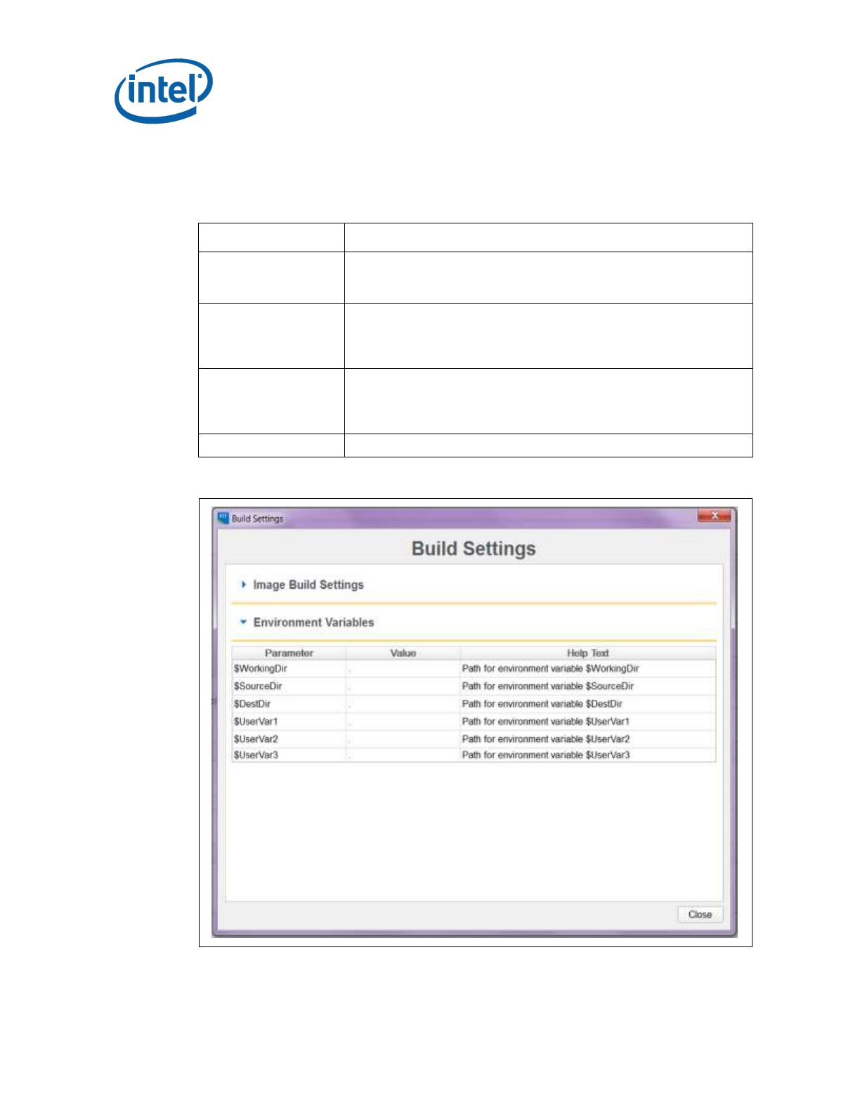
To modify the environment variables:
1. Choose Build > Build Settings; a dialog appears displaying the current working
directory on top, followed by the current values of all the environment variables:
Table 3-1. Environment Variables Options
Option
Description
$WorkingDir
the directory functions as a basic path variable when modified in the
GUI. If $WorkingDir CLI flag is used when launching FIT GUI, then
the fit.log will be created in $WorkingDir directory.
$SourceDir
the directory that contains the base image binary files from which a
complete flash image is prepared. Usually these base image binary
files are obtained from Intel® VIP on the Web, a BIOS programming
resource, or another source.
$DestDir
the directory in which the final combined image is saved, as well as
intermediate files generated during the build. Also the directory
where the components of an image are stored when an image is
decomposed.
$UserVar1-3
used when the above variables are not populated
Figure 3-1. Environment Variables in Build Settings Dialog

Intel® Flash Image Tool (Intel® FIT)
Intel Confidential 19
2. Click the button next to an environment variable and select the directory
where that variable's files will be stored; the name and relative path of that
directory appears in the field next to the variable's name.
3. Repeat Step 2 until the directories of all relevant environment variables have been
defined.
4. Click OK.
5. The environment variables are saved in the XML file. They can be overridden on
the command line if using the XML file on multiple systems.

Intel® Flash Image Tool (Intel® FIT)
20 Intel Confidential
3.3.6 Image Build Settings
Intel FIT lets the user set several options that control how the image is built. The
options that can be modified are described in Table 3-2.
To modify the build setting:
1. Choose Build > Build Settings; a dialog appears showing the current build
settings.
2. Modify the relevant settings in the Build Settings dialog.
3. Click OK; the modified build settings are saved in the XML configuration file.
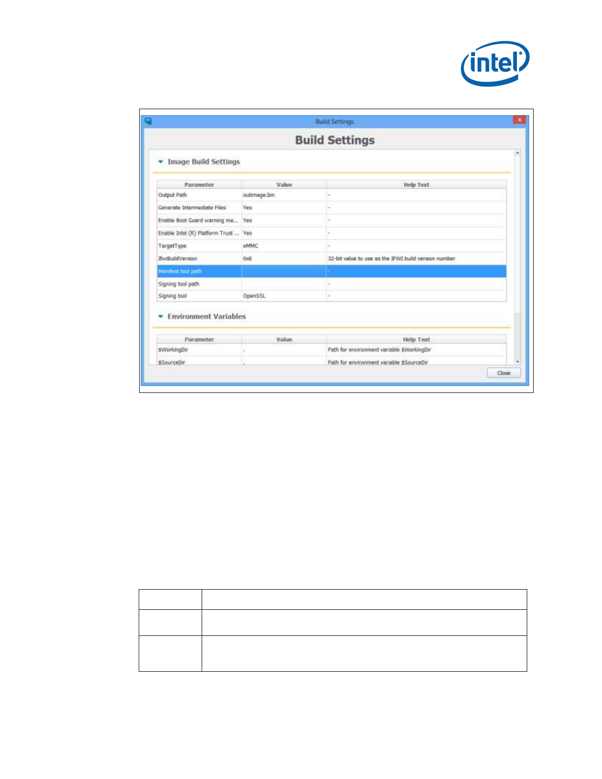
Table 3-2: Build Settings Dialog Options
Option
Description
Output filename
The path and filename where the final image should be saved
after it is built. (Note: Using the $DestDir environment
variable makes the configuration more portable.)
Generate intermediate build
files
Causes the application to generate separate (intermediate)
binary files, in addition to the final image file. These files are
located in the specified output folder's INT subfolder.
Enable Boot Guard Warning
message at build time
Enables Boot Guard warning messages at build time
Enable Intel® Platform Trust
Technology messages at
build time
Enables Intel® Platform Trust Technology warning messages at
build time
Target Type
If building an SPI/eMMc/UFS image
IFWI Build Version
32-bit value to use as the IFWI build version number
Manifest Extension Utility
Path
Path to the Intel MEU application, which creates and adds a
manifest to the SMIP data
Signing Tool Path
Path to the signing tool (normally OpenSSL), to sign the SMIP
data
Signing Tool
Name of the signing tool (normally OpenSSL) to sign the SMIP
data
Intel® Flash Image Tool (Intel® FIT)
Intel Confidential 21
Figure 3-2. Image Build Settings in Build Settings Dialog
3.3.7 DnX Build Settings
Intel FIT lets the user set several options that control if and how a DnX image is built.
The options that can be modified are described in Table 3-2.
NOTE: In early versions of the tool, these settings are visible in the DnX tab of the
tool, and not the Build Settings Dialog.
To modify the build setting:
1. Choose Build > Build Settings; a dialog appears showing the current build
settings.
2. Modify the relevant settings in the Build Settings dialog.
3. Click OK; the modified build settings are saved in the XML configuration file.
Table 3-3: DnX Build Settings Dialog Options
Option
Description
Build DnX
image
Should Intel FIT build a DnX image
DnX Output
Filename
The path and filename where the final DnX image should be saved after it is
built. (Note: Using the $DestDir environment variable makes the configuration
more portable.)
Intel® Flash Image Tool (Intel® FIT)
22 Intel Confidential
Option
Description
Signing Key
Private key for signing the DnX image. Must be the same private key used to
sign the OEM Key Manifest, and whose public key hash is entered into OEM
Public Key Hash field in Platform Protection tab, and which gets burned to an
FPF.
Platform ID
Platform ID that DnX uses to verify the image is suitable for the platform.
OEM ID
OEM ID that DnX uses to verify the image is suitable for the platform.
3.3.8 Target Platform and Flash Settings
Intel FIT lets the user define the target platform and flash type of the final image.
These options are displayed in drop-down combo boxes on the toolbar.
NOTE: In early versions of the tool, the Flash Type setting is visible in the Build
Settings Dialog.
Table 3-4: Target Platform and Flash Options
Combo
Options
Target Platform
Apollo Lake
Flash Type
eMMc / UFS / SPI
3.3.9 Flash Layout Tab
The Flash Layout tab contains information about the various binaries that need to be
stitched together in the final image. It allows uploading the paths of these binaries
that need to be present on the same system as Intel FIT. During image compilation,
these binary files are stitched into the image.
Intel® Flash Image Tool (Intel® FIT)
Intel Confidential 23
Figure 3-3. Flash Layout Tab
3.3.10 Flash Settings Tab
The Flash Settings tab contains information about the flash image and the target
hardware. It is important for this region to be configured correctly or the target
computer may not function as expected. This region also needs to be configured
correctly in order to ensure that the system is secure. Most of the settings here are
relevant only to SPI images, but there are also some settings relevant to eMMc or
UFS. Based on the selections in the Target Platform and Flash combo boxes, only
relevant fields will be editable.
There is a section in this tab called “Boot Source Selection” which enables the setting
of FPFs to disable boot sources that the platform will not support. Note that while
setting these FPFs can speed platform boot, since they are burned to fuses at End of
Manufacture, the system can then never be changed to boot from a different boot
source.
3.3.10.1 SPI Region Access Control
Regions of the SPI flash can be protected from read or write access by setting a
protection parameter in the Descriptor Region. The Descriptor Region must be locked
before Intel® TXE devices are shipped. If the Descriptor Region is not locked, the
Intel® TXE device is vulnerable to security attacks. The level of read/write access
provided is at the discretion of the OEM/ODM. Intel FIT gives 3 options for access
control
full access, which is suitable for pre-production images
Intel recommended settings, which lock the regions based on the
recommendations in the APL SPI and SMIP Programming Guide, allowing host
OS access to the PDR region.
Intel recommended settings, which lock the regions based on the
recommendations in the APL SPI and SMIP Programming Guide, forbidding
host OS access to the PDR region.
Intel® Flash Image Tool (Intel® FIT)
24 Intel Confidential
3.3.10.2 SPI VSCC Table
This section is used to store information to setup SPI flash access for Intel® TXE. This
does not have any effect on the usage of the FPT. If the information in this section
is incorrect, Intel® TXE FW may not communicate with the flash device. The
information provided is dependent on the flash device used on the system. (For more
information, see the Apollo Lake Soc SPI and Signed Master Image Profile(SMIP)
Programming Guide, Section 6.4.)
VSCC Table can be accessed:
1. Select Flash Settings Tab on the left pan
2. Expand VSCC Entries on the right pan as shown in Figure 9 below:
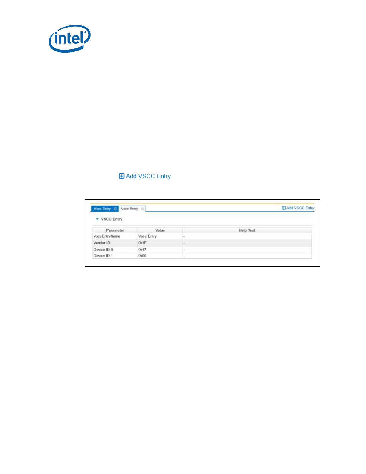
3.3.10.3 Adding a New Table
To add a new table:
1. Choose on top left > VSCC Entry.
Figure 3-4. Add VSCC Table Entry Dialog
2. Enter a name into the Entry Name field. (Note: To avoid confusion it is
recommended that each table entry name be unique. There is no checking
mechanism in Intel FIT to prevent table entries that have the same name and no
error message is displayed in such cases.)
3. User can enter into the values for the flash device.
NOTES: The VSCC register value will be automatically populated by Intel FIT using the
vsccommn.bin file the appropriate information for the Vendor and Device ID.
NOTES: If the descriptor region is being built manually the user will need to reference the VSCC
table information for the parts being supported from the manufacturers’ serial flash data
sheet. The Apollo Lake SPI Programming Guide should be used to calculate the VSSC
values.
3.3.10.4 Removing an Existing VSCC Table
To remove an existing table:
1. Click on the name of the table in the top tab that the user wants to remove as
shown in Figure 12.
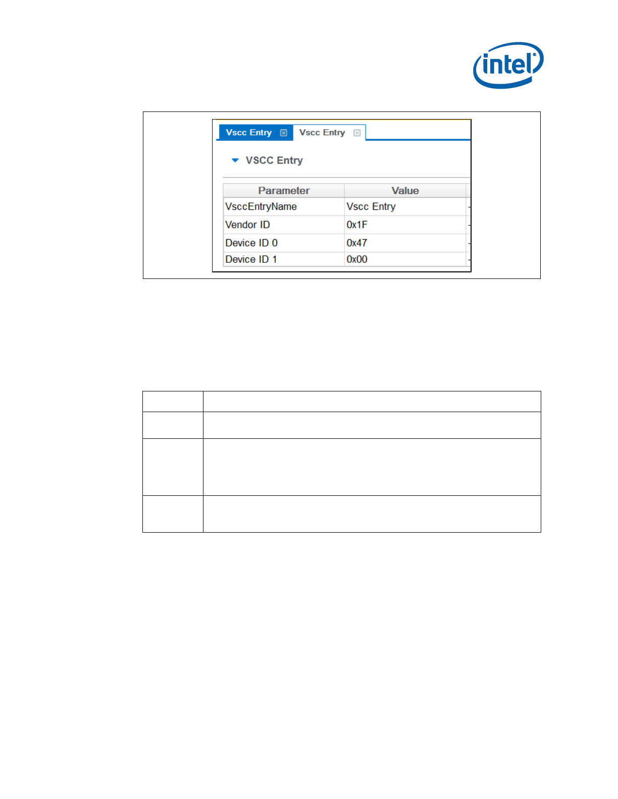
Intel® Flash Image Tool (Intel® FIT)
Intel Confidential 25
Figure 3-5. Deleting VSCC Table Entry Dialog
2. Click close; the table and all of the information will be removed.
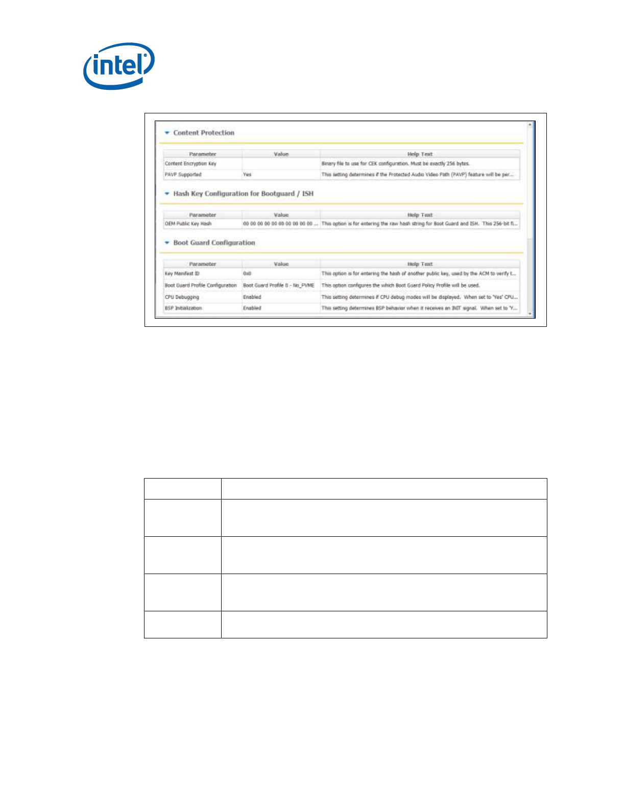
3.3.11 Platform Protection
This tab includes many settings relating to the protection of the platform, and its
integrity. In particular, it includes
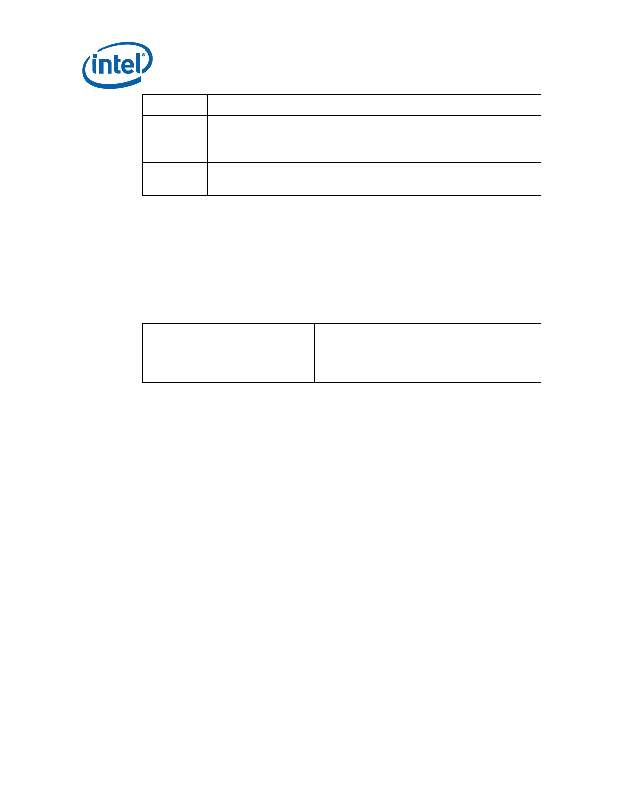
Table 3-5. Key Platform Protection Fields
Option
Description
SMIP
signing key
This is the path to the private key used to sign the SMIP, while public key hash
of it is included in the OEM hash manifest.
OEM Public
Key Hash
This option is for entering the raw hash string or certificate file for the SHA-256
hash of the OEM public key corresponding to the private key used to sign the
OEM Key hash manifest. When manufacture is completed, this hash value is
burned into an FPF. This value is used to verify the OEM Key hash, and also
DnX images
OEM Key
Manifest
Binary
Signed manifest file (created by Intel MEU) containing hashes of keys used for
signing components of image
There are also fields for configuring Boot Guard and Intel® PTT.
Intel® Flash Image Tool (Intel® FIT)
26 Intel Confidential
Figure 3-6. Platform Protection Tab
3.3.12 Integrated Sensor Hub
This tab allows the enabling of Integrated Sensor Hub (ISH) in the image, and
inclusion of a binary file for it.
3.3.13 Download and Execute
This tab allows the configuration of settings related to Download and Execute (DnX).
Table 3-6. DnX Fields
Option
Description
DnX Enabled
Permanently enable/disable DnX on the platform. This variable gets burned
into a fuse (FPF) at close of manufacture, and can never be changed after
that.
Platform ID
Platform ID that DnX uses to verify the image is suitable for the platform.
This variable gets burned into a fuse (FPF) at close of manufacture, and
can never be changed after that.
OEM ID
OEM ID that DnX uses to verify the image is suitable for the platform. This
variable gets burned into a fuse (FPF) at close of manufacture, and can
never be changed after that.
USB
configurations
Series of settings for USB for DnX
3.3.14 GPIO Profiles
Intel FIT supports the configuration of up to 5 sets of GPIO profiles, as defined in the
SPI and SMIP programming guide. By default, Intel FIT creates a single profile, further
ones can be added, and extra ones removed, in the same method as VSCC tables are

Intel® Flash Image Tool (Intel® FIT)
Intel Confidential 27
added and removed (see section 3.3.10.2). When building the image, only the first
profile is compiled into the IFWI image. All of the profiles are built as binary files, and
placed in the build output directory. They can be used later by Intel® FPT to update
the profile in the image to one of the other profiles defined within FIT.
3.3.15 End Of Manufacturing State
In SPI platforms, End of Manufacturing state is implicitly set in the image if the SPI
regions are locked with the flash settings. If the regions are not locked, End of
Manufacturing state can be set during manufacturing using the FPT tool.
On eMMc and UFS platforms, which do not have region locking, End of Manufacturing
state can be explicitly set in the Intel FIT image using a dedicated setting.
This field is un the Intel® TXE Kernel tab, in the ‘Manufacturing Settings’ section, and
is called ‘End of Manufacturing Enable’.
3.3.16 Platform Configuration Tab
The PMIC/VR Configuration option in the Platform Configuration tab is new in APL
platforms. This allows users to select from a dropdown with 4 voltage regulator (VR)
options for the Power Management IC (PMIC) supported on the platform. Selecting the
correct option is critical – the platform will not boot if the wrong one is selected.
3.3.17 Other Configuration Tabs
Intel FIT has multiple other tabs of settings that can be configured. Each one should
be opened, and the settings changed where relevant. In many cases, default values
are provided which can be retained. Each field includes help text clarifying its
meaning.
3.3.18 Building a Flash Image
The flash image can be built with the Intel FIT GUI interface.
To build a flash image with the currently loaded configuration:
Choose Build > Build Image.
– OR –
Specify an XML file with the /b option in the command line.
Intel FIT uses an XML configuration file and the corresponding binary files to build the
SPI flash image. The following is produced when an image is built:
Binary file representing the image
Text file detailing the various regions in the image
Optional set of intermediate files (see Section 5).
Multiple binary files containing the image broken up according to the flash
component sizes (Note: These files are only created if two flash components are
specified.)

Intel® Flash Image Tool (Intel® FIT)
28 Intel Confidential
The individual binary files can be used to manually program independent flash devices
using a flash programmer. However, the user should select the single larger binary file
when using Intel FPT.
3.3.19 Decomposing an Existing Flash Image
Intel FIT is capable of taking an existing flash image and decomposing it in order to
create the corresponding configuration. This configuration can be edited in the GUI
like any other configuration (see below). A new image can be built from this
configuration that is almost identical to the original, except for the changes made to
it.
To decompose an image:
1. Chose File > Open.
2. Change the file type filter to the appropriate file type.
3. Select the required file and click Open; the image is automatically decomposed,
the GUI is updated to reflect the new configuration, and a folder is created with
each of the components in a separate binary file.
Note: It is also possible to decompose an image by simply dragging and dropping the file
into the main window. When decomposing an image, there are some CVARs which will
not be able to be decomposed by Intel FIT. Intel FIT will use Intel default value
instead. User might want to check the log file to find out which CVARs were not
parsed.
Note: The TXE region binary contained in INT folder after image generation only contains the
firmware default base settings for TXE region no Intel FIT customization is applied.
Note: Rebuilding an image requires access to some of the private keys used for SMIP signing
in its initial creation.
3.3.20 Command Line Interface
Intel FIT supports command line options.
To view all of the supported options: Run the application with the -? option.
The command line syntax for Intel FIT is:
fit.exe [-exp] [-h|?] [-version|ver] [-b] [-o] [-f] [-me] [-bios]
[-pdr] [-bios_overlap] [-pmcp] [-ucode1] [-ucode2]
[-iunit] [-ufs_phy] [-sd_token] [-iafw_smip] [-pmc_smip]
[-smip_key] [-meu_path] [-st_path] [-st] [-w] [-s] [-d] [-u1] [-u2] [-u3]
[-i] [-flashcount] [-flashsize1] [-flashsize2] [-save]
Table 3-7. Intel FIT Command Line Options
Option
Description
-exp
Displays example usage of the tool
-H or -?
Displays the command line options.

Intel® Flash Image Tool (Intel® FIT)
Intel Confidential 29
Option
Description
-B
Automatically builds the flash image. The GUI does not
appear if this flag is specified. This option causes the program
to run in auto-build mode. If there is an error, a valid
message is displayed and the image is not built.
If a BIN file is included in the command line, this option
decomposes it.
-O <file>
Path and filename where the image is saved. This command
overrides the output file path in the XML file.
-f <file>
Specifies input file. XML, full image binary, or ME only binary.
-TXE <file>
Overrides the binary source file for the Intel® TXE Region with
the specified binary file.
-BIOS <file>
Overrides the binary source file for the BIOS Region with the
specified binary file.
-pdr
Overrides the binary source file for the PDR region
bios_overlap<true|false>
Overrides the Bios region overlap setting in the XML file.
-pmcp<file>
Overrides the binary source file for the PMCP region
-ucode1<file>
Overrides the binary source file for the uCode1 patch
-ucode2<file>
Overrides the binary source file for the uCode2 patch
-iunit<file>
Overrides the binary source file for the iUnit region
-ufs_phy<file>
Overrides the binary source file for the UFS PHY
-sd_token<file>
Overrides the binary source file for the Secure Debug Token
-iafw_smip<file>
Overrides the binary source file for the IAFW SMIP
-pmc_smip<file>
Overrides the binary source file for the PMC SMIP
-smip_key<file>
Overrides Key used to sign SMIP sub partition
-meu_path<path>
Overrides path to Manifest Extension Utility
-st_path<path>
Overrides path to Signing tool.
-st<OpenSSL |
MobileSigningUtil>
Overrides signing tool setting
-W <path>
Overrides the working directory environment variable
$WorkingDir. It is recommended that the user set these
environmental variables first. (Suggested values can be found
in the OEM Bringup Guide.)
-S <path>
Overrides the source file directory environment variable
$SourceDir. It is recommended that the user set these
environmental variables before starting a project.
-D <path>
Overrides the destination directory environment variable
$DestDir. It is recommended that the user set these
environmental variables before starting a project.
-U1 <value>
Overrides the $UserVar1 environment variable with the value
specified. Can be any value required.
-U2 <value>
Overrides the $UserVar2 environment variable with the value
specified. Can be any value required.

Intel® Flash Image Tool (Intel® FIT)
30 Intel Confidential
Option
Description
-U3 <value>
Overrides the $UserVar3 environment variable with the value
specified. Can be any value required.
-I <enable|disable>
Enables or disables intermediate file generation.
-FLASHCOUNT <0, 1 or 2>
Overrides the number of flash components in the Descriptor
Region. If this value is zero, only the Intel® TXE Region is
built.
-FLASHSIZE1 <0, 1, 2, 3, 4,
5, 6 or 7>
Overrides the size of the first flash component with the size of
the option selected as follows:
0 = 512KB
1 = 1MB
2 = 2MB
3 = 4MB
4 = 8MB
5 = 16MB
6 = 32MB
7 = 64MB
-FLASHSIZE2 <0, 1, 2, 3, 4,
5, 6 or 7>
Overrides the size of the first flash component with the size of
the option selected as follows:
0 = 512KB
1 = 1MB
2 = 2MB
3 = 4MB
4 = 8MB
5 = 16MB
6 = 32MB
7 = 64MB
-Save <file>
Saves the XML file.
3.3.21 Example – Decomposing an Image and Extracting
Parameters
The CVARS variables and the current value parameters of an image can be viewed by
dragging and dropping the image into the main window, which then displays the
current values of the image's parameters.
An image's parameters can also be extracted by entering the following commands into
the command line:
fit.exe -f output.bin -save output.xml
This command would create a folder named "output". The folder contains the
individual region binaries and the Map file.
The xml file contains the current Intel® TXE parameters.
The Map file contains the start, end, and length of each region.

Intel® Flash Image Tool (Intel® FIT)
Intel Confidential 31
Note: If using paths defined in the kit, be sure to put "" around the path as the spaces cause
issues.
Note: The TXE override option changes the TXE base used on command line but still uses
the values from the xml or binary passed in.
§ §

Flash Programming Tool
32 Intel Confidential
4 Flash Programming Tool
The FPT is used to program a complete SPI image into the SPI flash device(s).
On SPI flash only, FPT can program each region individually or it can program all of
the regions with a single command. The user can also use FPT to perform various
functions such as:
View the contents of the flash on the screen.
Write the contents of the flash to a log file.
Perform a binary file to flash comparison.
Write to a specific address block.
Note: For proper function in a Multi-SPI configuration the Block Erase, Block Erase
Command and Chip Erase must all match.
On all flash types, the user can also use FPT to Program Named variables.
4.1 System Requirements
The EFI versions of FPT (fpt.efi) run on a 32-bit or 64-bit EFI environment. Ensure to
take the respective binary from within the kit.
The Windows* versions (fptw.exe and fptw64.exe) run on a 32-bit or 64-bit EFI
environment. The Windows* 64 bit version (fptw64.exe) is designed for running in
native 64 bit OS environment which does not have 32 bit compatible mode available
for example Windows*PE 64. Both versions require administrator privileges to run
under Windows* OS. The user needs to use the Run as Administrator option to
open the CLI.
FPT requires that the platform is bootable (i.e. working BIOS) and an operating
system to run on. It is designed to deliver a custom image to a computer that is
already able to boot and is not a means to get a blank system up and running. FPT
must be run on the system with the flash memory to be programmed.
One possible workflow for using FPT is:
1. A pre-programmed flash with a bootable BIOS image is plugged into a new
computer.
2. The computer boots.
3. FPT is run and a new IFWI image is written to flash.
4. The computer powers down.
5. The computer powers up, boots, and is able to access its Intel® TXE capabilities as
well as any new custom BIOS features.
4.2 Microsoft Windows* Required Files
The Microsoft Windows* version of the FPT executable is fptw.exe. The following files
must be in the same directory as fptw.exe:

Flash Programming Tool
Intel Confidential 33
fparts.txt – contains a comma-separated list of attributes for supported flash
devices. The text in the file explains each field. An additional entry may be
required in this file to describe the flash part which is on the target system.
Examine the target board before adding the appropriate attribute values. The
supplied file is already populated with default values for SPI devices used with
Intel CRBs.
fptw.exe – the executable used to program the final image file into the flash.
pmxdll.dll
idrvdll.dll
In order for tools to work under the Windows* PE environment, you must manually
load the driver with the .inf file in the Intel® TXE driver installation files. Once you
locate the .inf file you must use the Windows* PE cmd drvload HECI.inf to load it
into the running system each time Windows* PE reboots. Failure to do so causes
errors for some features.
Table 4-1: FPT OS Requirements
FPT version
Target OS
Support Drivers
FPTw.EXE
Windows* 32 / 64 bit w/WOW64
idrvdll.dll, pmxdll.dll
FPTW64.EXE
Windows* Native 64 bit
idrvdll32e.dll, pmxdll32e.dll
Note: In the Windows* environment for operations involving global reset you should add a
pause or delay when running FPTW using a batch or script file.
4.3 EFI Required Files
The EFI version of the FPT executable is fpt.efi. The following files must be in the
same directory as fpt.efi:
fparts.txt – contains a comma-separated list of attributes for supported flash
devices. The text in the file explains each field. An additional entry may be
required in this file to describe the flash part which is on the target system.
Examine the target board before adding the appropriate attribute values. The
supplied file is already populated with default values for SPI devices used with
Intel CRBs.
fpt.efi – the executable used to program the final image file into the flash. Before
running fpt.efi, all the required files must be placed at root directory of the disk
otherwise errors like “FPT is unable to find FPARTS.TXT “might be displayed.
4.4 Programming the Flash Device
Once the Intel® TXE is programmed, it runs at all times. Intel® TXE is capable of
writing to the flash device at any time, even when the management mode is set to
none and it may appear that no writing would occur.

Flash Programming Tool
34 Intel Confidential
4.5 Programming CVARS
FPT can program the CVARS and change the default values of the parameters. The
modified parameters are used by the Intel® TXE FW after a global reset (Intel® TXE +
HOST reset) or upon returning from a G3 state. CVARS can be programmed using
getfile/setfile/CommitFiles APIs.
The variables can be modified individually or all at once via a text file.
Note: After setting CVARs, you need to call the –commit command to ensure they are
committed. This is different to previous platforms.
Table 4-2. Named Variables Options
Option
Description
fpt.exe –CVARS
Displays a list of the supported manufacturing configurable named
variables (CVARs).
fpt.exe –cfggen
Creates a list of blank CVARs in a text file that lets the user update
multiple line configurable CVARS. The variables have the following format
in the text file:
CVAR name = value which will be used by setfile.
fpt.exe –U –N
<CVAR name>
Accept the CVAR name
fpt.exe –IN
<Text file>
Accepts cfggen file with values set and will use setfile to update
See Appendix A for a description of all the CVAR parameters.
4.6 Usage
The EFI and Windows* versions of the FPT can run with command line options.
To view all of the supported commands: Run the application with the -? option.
The commands in EFI and Windows* versions have the same syntax. The command
line syntax for fpt.efi, fpt.exe and fptw.exe is:
FPT.exe [-H|?] [-VER] [-EXP] [-VERBOSE] [-Y] [-P] [-LIST] [-I] [-F]
[-ERASE] [-VERIFY][-NOVERIFY] [-D] [-DESC] [-BIOS] [-TXE] [-PDR]
[-B] [-E][REWRITE] [-ADDRESS|A] [-LENGTH|L]
[-CVARS] [-CFGGEN] [-U] [-O] [-IN] [-N][-V] [-CLOSEMNF] [-GRESET] [-PAGE]
[-SPIBAR] [-R] [-VARS] [-COMMIT] [-HASHED] [-FPFS] [-COMMITFPFS][-RPBIND]
[-GETPID]
Table 4-3. Command Line Options for fpt.efi, fpt.exe and fptw.exe
Option
Description
Help (-H, -?)
Displays the list of command line options supported by FPT tool.
-VER
Shows the version of the tools.
-EXP
Shows examples of how to use the tools.

Flash Programming Tool
Intel Confidential 35
Option
Description
-VERBOSE [<file>]
Displays the tool's debug information or stores it in a log file.
-Y
Bypasses Prompt. FPT does not prompt user for input. This
confirmation will automatically be answered with "y".
-P <file>
Flash parts file. Specifies the alternate flash definition file which
contains the flash parts description that FPT has to read. By
default, FPT reads the flash parts definitions from fparts.txt.
-LIST
Supported Flash Parts. Displays all supported flash parts. This
option reads the contents of the flash parts definition file and
displays the contents on the screen.
-I
Info. Displays information about the image currently used in the
flash.
-F <file>
<NOVERIFY>
Flash. Programs a binary file into an SPI flash. The user needs to
specify the binary file to be flashed. FPT reads the binary, and then
programs the binary into the flash. After a successful flash, FPT
verifies that the SPI flash matches the provided image. Without
specify the length with –L option, FPT will use the total SPI size
instead of an image size.
The NOVERFY sub-option *must* follow the file name. This will
allow flashing the SPI without verifying the programming was done
correctly. The user will be prompted before proceeding unless ‘-y’
is used.
-ERASE:
Block Erase. Erases all the blocks in a flash. This option does not
use the chip erase command but instead erases the SPI flash block
by block. This option can be used with a specific region argument
to erase that region. This option cannot be used with the –f, -b, -c,
-d or –verify options.
-VERIFY <file>:
Verify. Compares a binary to the SPI flash. The image file name
has to be passed as a command line argument if this flag is
specified.
-D <file> :
Dump. Reads the SPI flash and dumps the flash contents to a file
or to the screen using the STDOUT option. The flash device must
be written in 4KB sections. The total size of the flash device must
also be in increments of 4KB.
-DESC:
Read/Write Descriptor region. Specifies that the Descriptor region
is to be read, written, or verified. The start address is the
beginning of the region.
-BIOS:
Read/Write BIOS region. Specifies that the BIOS region is to be
read, written, or verified. Start address is the beginning of the
region.
Note that in APL platforms, the entire IFWI image resides in the
BIOS region.
-TXE:
Read/Write Intel® TXE region. Specifies that the Intel® TXE region
is to be read, written, or verified. The start address is the
beginning of the region.
Note that in APL platforms, the entire IFWI image resides in the
BIOS region, and the TXE region in SPI is only used for TXE ROM
Bypass code.

Flash Programming Tool
36 Intel Confidential
Option
Description
-PDR:
Read/Write PDR region. Specifies that the PDR region is to be read,
written, or verified. The start address is the beginning of the
region.
-B:
Blank Check. Checks whether the SPI flash is erased. If the SPI
flash is not empty, the application halts as soon as contents are
detected. The tool reports the address at which data was found.
-E:
Skip Erase. Does not erase blocks before writing. This option skips
the erase operation before writing and should be used if the part
being flashed is a blank SPI flash device.
-A<value>, -ADDRESS
<value>
Write/Read Address. Specifies the start address at which a read,
verify, or write operation must be performed. The user needs to
provide an address. This option is not used when providing a
region since the region dictates the start address.
-L <value>, LENGTH
<value>
Write/Read Length. Specifies the length of data to be read, written,
or verified. The user needs to provide the length. This option is not
used when providing a region since the region/file length
determines this.
-CVARS:
Lists all the current manufacturing line configurable variables.
-U:
Update. Updates the CVARs in the flash. The user can update the
multiple FOVs by specifying their names and values in the
parameter file. The parameter file must be in an INI file format
(the same format generated by the –cfggen command). The -in
<file> option is used to specify the input file.
-O <file>
Output File. The file used by FPT to output CVAR information.
-IN <file>
Input File. The file used by FPT for CVAR input. This option flag
must be followed by a text file (i.e., fpt –u –in FPT.cfg). The tool
updates the CVARs contained in the text file with the values
provided in the input file.
User can also use FPT –cfggen to generate this file.
-N <value>
Name. Specifies the name of the CVAR that the user wants to
update in the image file or flash. The name flag must be used with
Value (-v).
-V <value>
Value. Specifies the value for the CVAR variable. The name of
variable is specified in the Name flag. The Value flag must follow
the Name flag.
-CLOSEMNF <NO>
<PDR>:
End of Manufacturing. This option is executed at the end of
manufacturing phase. This option does the following:
CloseMnf does the following:
Commits all FPFs (if firmware is PV), even if CommitFPF was not
called
Does RPMB binding
Sets SOC Config lock
Sets all ‘Return to Factory Defaults’ to default values
Creates eMMc/UFS data partitions
Sets the Intel® TXE manufacturing mode done bit (Global Locked
bit).

Flash Programming Tool
Intel Confidential 37
Option
Description
Verifies that the Intel® TXE manufacturing mode done bit (Global
Locked) is set.
For SPI, sets the master region access permission in the Descriptor
region to its Intel-recommended value, and verifies that flash
regions are locked.
If the image was properly set before running this option, FPT skips
all of the above and reports PASS. If anything was changed, FPT
automatically forces a global reset through the CF9GR mechanism.
The user can use the no reset option to bypass the reset. If
nothing was changed, based on the current setting, the tool
reports PASS without any reset.
The "NO" addition will prevent the system from doing a global reset
following a successful update of the TXE Manufacturing Mode Done,
the Region Access permissions, or both.
The "PDR" addition will allow CPU\BIOS Read & Write access to the
PDR region of flash.
Note: In order to allow FPT to perform a global reset, BIOS should
not lock CF9GR when Intel® TXE is in manufacturing mode. This
step is highly recommended to the manufacturing process. Without
doing proper end of manufacturing process would lead to ship
platform with potential security/privacy risk.
Important:
Before using this option with Production MCP / FW verify that the
values for the PTT and Anchor Cove are correct in your image.
Once this setting is used it will permanently commit values into the
Field Programmable Fuses and cannot be undone.
-GRESET <NO> :
Global Reset. FPT performs a global reset. On mobile platforms this
includes driving GPIO30 low. Mobile platforms require a SUS Well
power-down acknowledge-driven low before the global reset occurs
or the platform may not boot up from the reset.
The "NO" afterwards disables the driving of GPIO30 for mobile
SKUs.
-CFGGEN
CVAR Input file generation option. This creates a file which can be
used to update the line configurable CVARS.
-SPIBAR:
Display SPI BAR. FPT uses this option to display the SPI Base
Address Register.
-R <name>
CVAR or FPF Read. FPT uses this option to retrieve value for a
specific CVAR or FPF file name. The value of the variable is
displayed. By default, all non- secure variables are displayed in
clear-text and secure CVAR will be displayed in HASH. The -hashed
option can be used to display the hash of a value instead of the
clear-text value.
-VARS:
Display Supported Variables. FPT uses this option to display all
variables supported for the -R and -COMPARE commands.
-COMMIT:
Commit. FPT uses this option to commit all setfile commands
CVARs changes to CVAR and cause relevant reset accordingly If no
pending variable changes are present, Intel® TXE does not reset
and the tool displays the status of the commit operation.
-COMMITFPF
Commits CVAR values to FPF via firmware and prevents further
modification of FPFs

Flash Programming Tool
38 Intel Confidential
Option
Description
-PAGE
Pauses the screen when a page of text has been reached. Hit any
key to continue.
-HASHED:
Hash Variable Output. FPT uses this option to distinguish whether
the displayed output is hashed by the FW. For variables that can
only be returned in hashed form this option has no effect – the
data displayed is hashed regardless.
-FPFS
Displays a list of the FPFs
-COMMITFPFS<name>
Commit the FPFs permanently into the MCP.
-REWRITE
Allows to rewrite the SPI with file data even if flash is identical.
-RPBIND
Bind RP
-GETPID
Retrieve the part id into a file
Table 4-4. FPT –closemnf Behavior
Condition before FPT -
closemnf
Condition after FPT -closemnf
Other FPT
Action
Intel
TXE
Mfg
Done
bit set
Flash
Access set
to Intel
rec values
Intel TXE
Mfg Mode
Intel
TXE
Mfg
Done
bit set
Flash
Access set
to Intel rec
values?
Intel TXE
Mfg Mode
FPT
return
value
**
Global
Reset
No
No
Enabled
Yes
Yes
Disabled
0
Yes
No
Yes
Enabled
No
Yes
Enabled
1
No
Yes
No
Enabled
Yes
Yes
Disabled
0
Yes
Yes
Yes
Disabled
Yes
Yes
Disabled
0
No
** Return value 0 indicates successful completion. In the second case, FPT –closemnf returns 1
(= error) because it is unable to set the Intel TXE Mfg Done bit, because flash permissions are
already set to Intel recommended values (host cannot access Intel TXE Region).
4.7 Fparts.txt File
The fparts.txt file contains a list of all SPI flash devices that are supported by FPT.
The flash devices listed in this file must contain a 4KB erase block size. If the flash
device is not listed, the user will receive the following error:
Intel (R) Flash Programming Tool. Version: x.x.x.xxxx
Copyright (c) 2007-2014, Intel Corporation. All rights reserved.
Platform: Intel(R) Qxx Express Chipset
Error 75: “fparts.txt” file not found.
If the SPI flash device is not located in fparts.txt, the user is expected to provide
information about the device, inserting the values into fparts.txt in same format as is
used for the rest of the devices. Detailed information on how to derive the values in
fparts.txt is found in the Apollo Lake SPI Programming Guide. The device must have
a 4KB erase sector and the total size of the SPI Flash device must be a multiple of
4KB. The values are listed in columns in the following order:

Flash Programming Tool
Intel Confidential 39
Display name
Device ID (2 or 3 bytes)
Device Size (in bits)
Block Erase Size (in bytes - 256, 4K, 64K)
Block Erase Command
Write Granularity (1 or 64)
Unused
4.8 Examples
The following examples illustrate the usage of the EFI version of the tool (fpt.efi). The
Windows* version of the tool (Fptw.exe) behaves in the same manner apart from
running in a Windows* environment.
4.8.1 Complete SPI Flash Device Burn with Binary File
C:\ fpt.exe –f spi.bin
EFI:
>fpt.efi –f spi.bin or fs0:\>fpt.efi –f spi.bin
This command writes the data in the spi.bin file into a whole SPI flash from address
0x0
4.8.2 Dump full image
fpt.exe –d imagedump.bin
This command dumps the full image into the imagedump.bin file.
4.8.3 Display SPI Information
fptw.exe –I
This command displays information about the flash devices present in the computer.
The base address refers to the start location of that region and the limit address refers
to the end of the region. If the flash device is not specified in fparts.txt, FPT returns
the error message "There is no supported SPI flash device installed".
4.8.4 Verify Image with Errors
fpt.exe -verify outimage.bin

Flash Programming Tool
40 Intel Confidential
This command compares the Intel® TXE region programmed on the flash with the
specified FW image file outimage.bin. If the -y option is not used; the user is
notified that the file is smaller than the binary image. This is due to extra padding that
is added during the program process. The padding can be ignored when performing a
comparison. The -y option proceeds with the comparison without warning.
4.8.5 Verify Image Successfully
fpt.exe -verify outimage.bin
This command compares image.bin with the contents of the flash. Comparing an
image should be done immediately after programming the flash device. Verifying the
contents of the flash device after a system reset results in a mismatch because Intel®
TXE changes some data in the flash after a reset.
4.8.6 Get Intel® TXE settings
fpt.exe –r “Privacy/SecurityLevel”
Please note that only –r (get command) supports the –hashed optional command
argument. When –hashed is used, variable value will be returned in hashed format,
otherwise it will be returned in clear txt. There are a few exceptions in the case of
variables PID and PPS, their value will be always returned in hashed format regardless
–hashed is used or not. This is primarily because of security concern.
4.8.7 Compare Intel® TXE Settings
FPT –verbose –compare vars.txt compares variables with suggested values in vars.txt,
and report result on the screen. Vars.txt can have the following data with verbose
information: FPT –VARS can be used to get the VAR list for the platform and get the
value/format from Intel FIT advanced mode. There are settings in the Intel® TXE
which are stored encrypted. Users will not be able to compare them using clear text
values. Please use FPT –R option to read the hash value of those settings and use
them as baseline for the expected value.
4.8.8 CVAR Configuration File Generation (-cfggen)
It creates an input file which can be used to update CVARs. The file includes all the
current CVAR. When creating the file, it extracts the fixed offset variables from flash.
Note, the file generated will change every time the list of CVAR changes.
fpt.exe –cfggen [ -o <Output Text File> ][ options ]
-o <Output File Name>
The desired name of the file
generated. If none is provided the
default, fpt.cfg, will be used.
-p < file name >
Alternate SPI Flash Parts list file.

Flash Programming Tool
Intel Confidential 41
-page
Pauses at screen / page / window
boundaries. Hit any key to continue.
-Verbose [<file name>]
Displays more information.
-y
Will not pause to user input to
continue
§ §

Intel® TXEManuf and TXEManufWin
42 Intel Confidential
5 Intel® TXEManuf and
TXEManufWin
Intel® TXEManuf validates Intel® TXE functionality on the manufacturing line. It
verifies that these components have been assembled together correctly.
The Windows* version of Intel® TXEManufWin (Intel® TXEManufWin) requires
administrator privileges to run under Windows* OS. The user needs to use the Run
as Administrator option to open the CLI.
Intel® TXEManuf validates all components and flows that need to be tested according
to the FW installed on the platform in order to ensure the functionality of Intel® TXE
applications: BIOS-FW, Flash, etc. This tool is meant to be run on the manufacturing
line.
5.1 Windows* PE Requirements
In order for tools to work under the Windows* PE environment, you must manually
load the driver with the .inf file in the Intel® TXEI driver installation files. Once you
locate the .inf file you must use the Windows* PE cmd drvload HECI.inf to load it
into the running system each time Windows* PE reboots. Failure to do so causes
errors for some features.
5.2 How to Use Intel® TXEManuf
Intel® TXEManuf checks the FW SKU and runs the proper tests accordingly unless an
option to select tests is specified.
Intel® TXEManuf is intelligent enough to know if it should run the test or report a
result. If there is no test result available for an Intel® TXE enabled platform,
TXEManuf calls the test. Otherwise, it reports the result or the failure message from
the previous test.
Intel® TXEManuf tools report the result or cause a reboot. If there is a reboot, Intel®
TXEManuf should be run again.
VSCCCOMMN.bin is required to verify the VSCC entry on the platform. This file must
be in same folder as the TXEManuf executable or TXEManuf reports an error.

Intel® TXEManuf and TXEManufWin
Intel Confidential 43
5.3 Usage
The DOS version of the tool can be operated using the same syntax as the Windows*
version. The Windows* version of the tool can be executed by:
TXEManuf [-EXP] [-H|?] [-VER] [-TEST] [-S0]
[-BISTRESULT] [-EOL] [-CFGGEN] [-F] [-VERBOSE] [-PAGE]
[-ERRLIST] [-ALL][-NOISH] [-ISH]
Table 5-1: Options for the Tool
Option
Description
No option
Test result will be reported back right after the test is done and cleared.
If BIST test result isn’t displayed after BIST test is done, the tool needs
to be run again (with or without any BIST related argument
combinations) to retrieve the result, once test result is displayed, it will
be cleared.
Tool is capable of remembering whether/what tests (including host based
tests) have been run from previous invocation. Host based tests will be
run for all cases (whether it’s retrieving test result or run the actual
BIST).
-EXP
Shows examples of how to use the tools.
-H or -?
Displays the help screen.
-VER
Shows the version of the tools.
-TEST
Run full test
-S0
Run BIST test that does not require power cycle
-BISTRESULT
Returns last BIST results
-EOL
<Var|Config> -
F <filename>
This option runs several checks for the use of OEMs to ensure that all
settings and configurations have been made according to Intel
requirements before the system leaves the manufacturing process. The
check can be configured by the customer to select which test items to run
and their expected value (only applicable for Variable Values, FW Version,
BIOS Version). The sub option config or var is optional. Using -EOL
without a sub option is equivalent to the –EOL config.
When –f flag is used along with a file name, the tool will load the file as
the configuration file, instead of using TXEManuf.cfg.
-CFGGEN
<filename>
Use this option along with a filename to generate a default configuration
file. This file (with or without modification) can be used for the -EOL
option. Rename it TXEManuf.cfg before using it. It is highly
recommended to use this option to generate a new TXEManuf.cfg with an
up-to-date variable names list before using the Intel® TXEManuf End-Of-
Line check feature.
-F <filename>
Load customer defined .cfg file
-VERBOSE
<file>
Displays the debug information of the tool or stores it in a log file.
–PAGE
When it takes more than one screen to display all the information, this
option lets the user pause the display and then press any key to continue
on to the next screen.

Intel® TXEManuf and TXEManufWin
44 Intel Confidential
Option
Description
-ERRLIST <test
name>
Return a list of available codes
-NOISH
This option will skip ISH tests
-ISH
This option will force ISH tests
5.3.1 Host-based Tests
1. TXE/BIOS VSCC validation, Intel® TXEManuf verifies that flash SPI ID on the
system is described in VSCC table. If found, VSCC entry for relevant SPI part
should match the known good values that pre-populated in the file.
2. Intel® TXE state check, Intel® TXEManuf verifies Intel® TXE is in normal state.
This is done by checking the value of 4 fields (initialization state, mode of
operation, current operation state, and error state) in FW status register1. If
any of these fields indicates Intel® TXE is in abnormal state, Intel® TXEManuf
will report error without running BIST test.
5.4 Intel® TXEManuf –EOL Check
TXEManuf –EOL check is used to give customers the ability to check Intel® TXE-
related configuration before shipping. There are two sets of tests that can be run:
variable check and configuration check. Variable check is very similar as FPT –
compare option. Please refer that section.
5.4.1 TXEManuf.cfg File
The TXEManuf.cfg file includes all the test configurations for TXEManuf –EOL check. It
needs to be at the same folder that TXEManuf is run. If there is no TXEManuf.cfg file
on that folder, TXEManuf –EOL config runs the Intel recommended default check
only.
The default xml configuration file can be created by running the –CFGGEN command.
Lines which start with // are comments. They are also used to inform users of the
available test group names and the names of specific checks that are included in each
test that Intel® TXEManuf recognizes.
To select which test items to run: Create a line that begins with
SubTestName="<specific sub test name>".
5.4.2 TXEManuf –EOL Variable Check
TXEManuf –EOL variable check is designed to check the Intel® TXE settings on the
platform before shipping. To minimize the security risk in exposing this in an end-user
environment, this test is only available in Intel® TXE manufacturing mode or No EOP
Message Sent.
NOTES: -EOL Variable check. The system must be in Intel® TXE manufacturing mode when
-EOL Variable check is run or No EOP Message Sent.

Intel® TXEManuf and TXEManufWin
Intel Confidential 45
5.4.3 TXEManuf –EOL Config Check
TXEManuf –EOL Config check is designed to check the Intel® TXE-related
configuration before shipping. Running Intel-recommended tests before shipping is
highly recommended.
Table 5-2: TXEManuf - EOL Config Tests
Test
Expected Configuration
EOP status check
Enabled
Intel® TXE VSCC check
Set according to the Intel-recommended value
BIOS VSCC check
Set according to the Intel-recommended value
Intel® TXE Manufacturing Mode status
Disabled
Flash Region Access Permissions
Set according to the Intel-recommended value
Note: –EOL Config check. If the system is in Intel® TXE manufacturing mode when
–EOL Config check is run there will be an error report or No EOP Message Sent.
5.4.4 Output/Result
The following test results can be displayed at the end-of-line checking:
Pass – all tests passed
Pass with warning – all tests passed except the tests that were modified by the
customer to give a warning on failure. (This modification does not apply to Intel-
recommended tests
Fail with warning - all tests passed except some Intel-recommended tests that
were modified by the customer to give a warning on failure.
Fail - any customer-defined error occurred in the test.
5.5 Examples
5.5.1 Example for Consumer Intel® TXE FW SKU
TXEManuf –verbose
Intel(R) TXEManuf Version: 3.0.0.1044
Copyright(C) 2005 - 2015, Intel Corporation. All rights reserved.
FW Status Register1: 0x82000255
FW Status Register2: 0x80100000
FW Status Register3: 0x30550607
FW Status Register4: 0x00080000
FW Status Register5: 0x80018001
FW Status Register6: 0x00000000

Intel® TXEManuf and TXEManufWin
46 Intel Confidential
CurrentState: Normal
ManufacturingMode: Enabled
FlashPartition: Valid
OperationalState: CM0 with UMA
InitComplete: Complete
BUPLoadState: Success
ErrorCode: No Error
ModeOfOperation: Normal
SPI Flash Log: Not Present
Phase: Maestro
TXE File System Corrupted: No
FPF and TXE Config Status: Not committed
FW Capabilities value is 0xFBA200
Feature enablement is 0xFBA200
Platform type is 0x2000441
Feature enablement is 0x71101840
TXE initialization state valid
TXE operation mode valid
Current operation state valid
TXE error state valid
MFS is not corrupted
PCH SKU Emulation is correct
Request Intel(R) TXE BIST status command... done
Get Intel(R) TXE test data command... done
Get Intel(R) TXE test data command... done
Total of 7 Intel(R) TXE test result retrieved
Policy Kernel - Boot Guard : Self Test - Passed
Policy Kernel - Embedded Controller : Power source type - Passed
MCA - MCA Tests : Blob - Passed
MCA - MCA Tests : MCA Manuf - Passed
VDM - General : VDM engine - Passed
Policy Kernel - ME Password : Validate MEBx password - Passed
Clear Intel(R) TXE test data command... done
TXEManuf Operation Passed

Intel® TXEInfo
Intel Confidential 47
6 Intel® TXEInfo
TXEInfoWin and Intel® TXEInfo provide a simple test to check whether the Intel® TXE
FW is alive. Both tools perform the same test; query the Intel® TXE FW– and retrieve
data.
Table 18 contains a list of the data that each tool returns.
The Windows* version of TXEInfo (TXEInfoWin) requires administrator privileges to
run under Windows* OS. The user needs to use the Run as Administrator option to
open the CLI.
6.1 Windows* PE Requirements
In order for tools to work under the Windows* PE environment, you must manually
load the driver with the .inf file in the Intel® TXEI driver installation files. Once you
locate the .inf file you must use the Windows* PE cmd drvload HECI.inf to load it
into the running system each time Windows* PE reboots. Failure to do so causes
errors for some features.
6.2 Usage
The executable can be invoked by:
TXEInfo.exe [-EXP] [-H|?] [-VER] [-FITVER] [-FEAT]
[-VALUE] [-FWSTS] [-VERBOSE] [-PAGE] [-NOISH] [-ISH]
Table 6-1. Intel® TXEInfo Command Line Options
Option
Description
-FEAT < name>
-VALUE <value>
Compares the value of the given feature name with the value in the
command line. If the feature name or value is more than one word,
the entire name or value must be enclosed in quotation marks. If
the values are identical, a message indicating success appears. If
the values are not identical, the actual value of the feature is
returned. Only one feature may be requested in a command line.
-FITVER
Displays Intel FIT version information
-FEAT <name>
Retrieves the current value for the specified feature. If the feature
name is more than one word, the entire feature name must be
enclosed in quotation marks. The feature name entered must be
the same as the feature name displayed by Intel® TXEINFO.
Intel® TXEINFO can retrieve all of the information detailed below.
However, depending on the SKU selected, some information may
not appear.
Note: For the EFI shell version you need to add additional “^” to
enclose the text string in order for it to be properly parsed.
Example: TXEINFO.efi –feat “^”BIOS boot state”^”

Intel® TXEInfo
48 Intel Confidential
Option
Description
–FWSTS
Decodes the Intel® TXE FW status register value field and breaks it
down into the following bit definitions for easy readability:
FW Status Register1: 0x1E000255
FW Status Register2: 0x69000006
CurrentState: Normal
ManufacturingMode: Enabled
FlashPartition: Valid
OperationalState: CM0 with UMA
InitComplete: Complete
BUPLoadState: Success
ErrorCode: No Error
ModeOfOperation: Normal
-VERBOSE <filename>
Turns on additional information about the operation for debugging
purposes. This option has to be used together with the above
mentioned option(s). Failure to do so generates the error: "Error
9254: Invalid command line option".
This option works with no option and -feat.
-H or -?:
Displays the list of command line options supported by the Intel®
TXEINFO tool.
-VER
Shows the version of the tools.
- PAGE
When it takes more than one screen to display all the information,
this option lets the user pause the display and then press any key
to continue on to the next screen.
-EXP
Shows examples about how to use the tools.
-ISH
This shows ISH information
Using the combination flags –ISH –fwstat you can retrieve the ISH
firmware status
-NOISH
Do not display any information related to ISH
No option:
If the tool is invoked without parameters, it reports information for
all components listed in Table 6-2 below for full SKU FW.
Table 6-2. List of Components that Intel® TXEINFO Displays
Feature
Name
Feature Data
Source (Intel®
TXE
Kernel/SW/
Other)
Specific
Feature
Dependency
Field Value
Tools Version
SW (Intel®
TXEInfo)
N/A
Version string
Example:
11.x.y.ZZZZ; where x=minor,
y = HF/MR, ZZZZ = Build
Number.
VendorID
Intel® TXE Kernel
N/A
A number (in Hex)
PCH Version
Intel® TXE Kernel
N/A
A version string

Intel® TXEInfo
Intel Confidential 49
Feature
Name
Feature Data
Source (Intel®
TXE
Kernel/SW/
Other)
Specific
Feature
Dependency
Field Value
FW Version
Intel® TXE Kernel
N/A
Version string
11.x.y.ZZZZ; where x=minor,
y = HF/MR, ZZZZ = Build
Number.
Intel® TXE
Driver version*
Other (Reading
Windows* registry
entries
Only when
Windows* Intel®
TXE driver is
installed
A version string
IFWI Module
Version
Intel® TXE Kernel
N/A
A version string
Number of
IFWI Modules
Intel® TXE Kernel
N/A
A number
IFWI Module
Name
Intel® TXE Kernel
N/A
A string
FW Capabilities
Intel® TXE Kernel
N/A
Combination of feature name
list breakdown (with a
Hexadecimal value)
*This is a display of the Feature
State for the Intel® TXE. Is
enabled / disabled on the
system. Each bit in the value
represents a feature state.
Last Intel® TXE
Reset Reason
Intel® TXE Kernel
N/A
Power up/
Firmware reset/
Global system reset/
Unknown
BIOS Lock
Other (Directly
reading from SPI)
N/A
Enabled/Disabled/
Unknown
If shown as enabled, both
FLOCKDN for BIOS are set.
If shown as disabled, either/all
FLOCKDN for BIOS are not set.
Host Read
Access to
Intel® TXE
Other (Directly
reading from SPI)
N/A
Enabled/Disabled/
Unknown
Host Write
Access to
Intel® TXE
Other (Directly
reading from SPI)
N/A
Enabled/Disabled/
Unknown
SPI Flash ID
Other (Directly
reading from SPI)
Only when there
are SPI flash
parts HW
installed
A JEDEC ID number (in Hex)
TXE/BIOS
VSCC register
values
Other (Directly
reading from SPI)
Only when there
are flash parts
HW installed
A 32bit VSCC number (in Hex)

Intel® TXEInfo
50 Intel Confidential
Feature
Name
Feature Data
Source (Intel®
TXE
Kernel/SW/
Other)
Specific
Feature
Dependency
Field Value
BIOS Boot
State
Intel® TXE Kernel
N/A
Pre Boot/
In Boot/
Post Boot
Capability
Licensing
Service
Intel® TXE Kernel
Not shown unless
Fw feature
capability
supports it
Enabled/Disabled
OEM Tag
Intel® TXE Kernel
N/A
A 32bit Hexadecimal number
Report on
Revenue
Sharing ID
Fields
Intel® TXE Kernel
Firmware Host
Interface
N/A
3 slot of 32-bit integer values
(in Hex)
FWSTS
Intel® TXE Kernel
N/A
Two 32bit Hexadecimal
numbers and their bit definition
breakdown
OEM Public Key
Hash FPF
Intel® TXE Kernel
BIOS
Yes / No
OEM Public Key
Hash TXE
Intel® TXE Kernel
BIOS
SHA-256bit Hash entry
ACM SVN FPF
Intel® TXE Kernel
BIOS
KM SVN FPF
Intel® TXE Kernel
BIOS
BSMM SVN FPF
Intel® TXE Kernel
BIOS
GuC Encryption
Key TXE
Intel® TXE Kernel
BIOS
256-bit string
Protect BIOS
Environment
Intel® TXE Kernel
BIOS
Yes / No
CPU Debugging
Intel® TXE Kernel
BIOS
Enabled / Disabled
BSP
Initialization
Intel® TXE Kernel
BIOS
Enabled / Disabled
Measured Boot
Intel® TXE Kernel
BIOS
Yes / No
Verified Boot
Intel® TXE Kernel
BIOS
Yes / No
Key Manifest ID
Intel® TXE Kernel
BIOS
Hash of Public Key to verify
Boot Policy Manifest
PTT
Intel® TXE Kernel
BIOS
Enabled / Disabled
EK Revoke
Intel® TXE Kernel
BIOS
Revoked / Not Revoked
Integrated
Sensor Solution
FW State
ISH
ISH Firmware
Responding / Not Responding
FW Status
ISH
ISH Firmware
Sensors Apps Responding /
Sensor Apps Not Responding

Intel® TXEInfo
Intel Confidential 51
Feature
Name
Feature Data
Source (Intel®
TXE
Kernel/SW/
Other)
Specific
Feature
Dependency
Field Value
Integrated
Sensor Solution
FW Version
ISH
ISH Firmware
Version string
Module Status
ISH
ISH Firmware
Module x Status: Loaded / Not
Loaded
Extended
Modules FW
Status
ISH
ISH Firmware
Version string
Extended
Modules FW
Versions
ISH
ISH Firmware
Version string
HECI Driver
Version
ISH
ISH Firmware
Version string
PCI Bus Driver
Version
ISH
ISH Firmware
Version string
Integrated
Sensor Solution
Driver Version
ISH
ISH Firmware
Version string
Sensors
Information
ISH
ISH Firmware
Information on the various
Sensors configured on the
platform.
6.3 Examples
This is a simple test that indicates whether the FW is alive. If the FW is alive, the test
returns device-specific parameters. The output is from the Windows* version.
6.3.1 Intel® TXE FW SKU
TXEINFOWIN.exe
Intel(R) TXEInfo Version: 3.0.0.1044
Copyright(C) 2005 - 2015, Intel Corporation. All rights reserved.
Intel(R) TXE code versions:
BIOS Version APLK_IFWI_X64_R_2015_39_4_00
Vendor ID 8086
PCH Version 3
FW Version 3.0.0.1044 Unknown
TXEI Driver Version 3.0.0.1044
IFWI Module Version 3.0.0.1044
Number of IFWI Modules 0
IFWI Module Name
FW Capabilities 0x71101840

Intel® TXEInfo
52 Intel Confidential
Intel(R) Capability Licensing Service - PRESENT/ENABLED
Protect Audio Video Path - PRESENT/ENABLED
Intel(R) Dynamic Application Loader - PRESENT/ENABLED
Service Advertisement & Discovery - PRESENT/ENABLED
Intel(R) Platform Trust Technology - PRESENT/ENABLED
TLS Disabled
Last TXE reset reason Power up
BIOS Config Lock Disabled
Host Read Access to TXE Enabled
Host Write Access to TXE Enabled
Host Read Access to EC Disabled
Host Write Access to EC Disabled
SPI Flash ID 1 EF6018
SPI Flash ID 2 Unknown
BIOS boot State Post Boot
Capability Licensing Service Enabled
OEM Tag 0x00000000
Slot 1 Board Manufacturer 0x00000000
Slot 2 System Assembler 0x00000000
Slot 3 Reserved 0x00000000
M3 Autotest Disabled
EPID Group ID 0x4DC
Replay Protection Not Supported
Replay Protection Counters 0
Storage Device Type SPI
OEM Public Key Hash FPF Not set
OEM Public Key Hash TXE Not set
ACM SVN FPF Not set
KM SVN FPF Not set
BSMM SVN FPF Not set
GuC Encryption Key FPF Not set
GuC Encryption Key TXE Not set
FPF TXE
--- --
Protect BIOS Environment Not set Not set
CPU Debugging Not set Not set
BSP Initialization Not set Not set
Measured Boot Not set Not set
Verified Boot Not set Not set
Key Manifest ID Not set Not set
Enforcement Policy Not set Not set
PTT Not set Not set
EK Revoke State Not set
6.3.2 Retrieve the Current Value of the Flash Version
C:\ TXEINFO.exe -feat "BIOS boot state"
Intel(R) TXEInfo Version: 3.0.0.1044
Copyright(C) 2005 - 2015, Intel Corporation. All rights reserved.
BIOS boot State: Post Boot
§ §

Intel® Platform Flash Tool
Intel Confidential 53
7 Intel® Platform Flash Tool
The Platform Flash Tool is included with a dedicated installer in the firmware kit. It
includes its own documentation, covering usage of DnX to flash firmware on eMMC
and UFS flash devices, as well as secure token creation.
§ §

Intel® Manifest Extension Utility (MEU)
54 Intel Confidential
8 Intel® Manifest Extension
Utility (MEU)
8.1 Introduction
This chapter covers in detail the usage of the Intel Manifest Extension Utility (MEU).
Intel MEU is a tool used to generate various binaries containing manifests which will
be validated by the TXE FW. Intel MEU can call an external signing tool, such as
OpenSSL, to sign the manifests in the final binary.
Depending on the binary type being generated, the contents may be stitched into an
IFWI image using the Intel Flash Image Tool (Intel FIT), or the contents may be
passed to the TXE FW at runtime by a driver. Intel FIT may also call Intel MEU to add
a signed manifest to a binary it is generating.
The usage flow of the Intel MEU to add manifests, sign binaries, and build images for
the Apollo Lake platforms is explained in the Apollo Lake Signing and Manifesting
Guide.
8.2 Intel MEU XML
When generating a binary, Intel MEU consumes two XML files. One is for tool
configuration, the other is used to configure the binary being generated.
This section describes the requirements associated with these XML files.
Each XML file has a root node which tells the tool what type of XML file this is. For
example, the Intel MEU configuration XML contains MeuConfig as the root node:
<?xml version="1.0" encoding="utf-8"?>
<MeuConfig version="2.3">
...
</MeuConfig>
The root node also contains a version attribute. Intel MEU will use the value to
detect if the XML was generated with an older and incompatible version of MEU.
Underneath the root node, there will be config nodes, these may be grouped into
sections, for example:
<VersionExtraction>

Intel® Manifest Extension Utility (MEU)
Intel Confidential 55
<Enabled value="false" value_list="true,,false" help_text="If
enabled, the version details will be extracted from the InputFile
binary at the offsets specified. If disabled, the version must be
specified manually.">
<InputFile value="" help_text="Binary file from which to
extract the version details.">
...
</VersionExtraction>
The config nodes may have multiple attributes, in general only the value attribute is
looked at by the tool, while the other attributes are for the user’s information:
value - Used to configure a value for the given setting. If the setting is an enum,
the value must match one of the values in value_list. If the setting is a number
the value may be entered in decimal (256) or by hex using a 0x prefix (0x100).
value_list - Contains a double-comma separated list of valid values.
help_text - Contains details for the user regarding how to configure the setting.
8.3 Intel MEU Configuration
Intel MEU uses XML configuration file that is used to configure the signing and
compression utilities as well as some user variables. The config file is not visible upon
installation, but needs to be generated by the user. The config file template,
meu_config.xml, can be generated by the tool with the following command:
C:\meu\meu.exe -gen meu_config
By default, the tool will look for meu_config.xml in the same folder as the meu.exe
executable, but this can be overridden using a command line option.
8.3.1 Signing Tool Configuration
The following XML block is used in the meu_config.xml to configure the signing utility:
<SigningConfig>
<SigningTool value="OpenSSL"
value_list="Disabled,,OpenSSL,,MobileSigningUtil">
<SigningToolPath value="$UserVar1/openssl/openssl.exe">
<PrivateKeyPath value="$SourceDir/keys/dbg_priv_key.pem">
<SigningToolXmlPath value="">
<SigningToolExecPath value="">
</SigningConfig>

Intel® Manifest Extension Utility (MEU)
56 Intel Confidential
SigningTool - Select the tool to use for signing. Currently, Intel MEU only
supports OpenSSL.
SigningToolPath - The path to the signing tool binary file.
PrivateKeyPath - The path to the private key file (in PEM format) to use for
signing.
SigningToolXmlPath Leave blank.
SigningToolExecPath Configures the path to execute the signing tool from. If
left blank, the current working directory will be used. This can be useful if relative
paths are used in the Signing Tool XML file.
Intel MEU does not come with the OpenSSL command line utility, and it must be
installed separately. One source for OpenSSL binaries is Shining Light Productions,
the "Light" version is sufficient.
8.3.2 LZMA Compression Tool
TXE FW supports handling of compressed modules. This functionality is currently
available for the Integrated Sensor Hub Code Partition (ISH). The manifest tool must
be configured with the path to the compression utility, which is usually distributed
with the tool. If LZMA compression is not needed, this path can be left blank.
<CompressionConfig label="Compression Configuration">
<LzmaToolPath value="$UserVar1/ftool/lzma.exe" label="LZMA
Tool Path">
</CompressionConfig>
8.3.3 User Path Variables
Intel MEU allows the use of User Path Variables to allow the XML to be more flexible.
These variables can be configured in the meu_config.xml or by using command line
options.
<PathVars label="Path Variables">
<WorkingDir value="./" label="$WorkingDir" help_text="Path
for environment variable $WorkingDir">
<SourceDir value="./" label="$SourceDir" help_text="Path for
environment variable $SourceDir">
<DestDir value="./" label="$DestDir" help_text="Path for
environment variable $DestDir">
<UserVar1 value="./" label="$UserVar1" help_text="Path for
environment variable $UserVar1">
<UserVar2 value="./" label="$UserVar2" help_text="Path for
environment variable $UserVar2">

Intel® Manifest Extension Utility (MEU)
Intel Confidential 57
<UserVar3 value="./" label="$UserVar3" help_text="Path for
environment variable $UserVar3">
</PathVars>
These variables can be substituted in a configuration xml node's value and will be
replaced by the variable's value at build time. For example when configuring the
OpenSSL path, we can use $UserVar1:
<SigningToolPath value="$UserVar1\openssl.exe">
And, then if the tool is run with the -u1 switch:
C:\meu\meu.exe -f <input xml> -u1 "c:\openssl\bin"
Intel MEU will look for OpenSSL at the path "c:\openssl\bin\openssl.exe".
Although some of these variables are named (i.e. SourceDir), the tool will not actually
search in this path, for a given source/input file, unless "$SourceDir" is contained in
the corresponding xml configuration xml node's value.
8.4 Supported Binary Formats
This section describes the binary formats supported by Intel MEU.
8.4.1 Binary Types
Intel MEU generates template XML configuration files for each binary format. To get a
complete list of templates Intel MEU can generate, use the following command:
C:\meu\meu.exe -binlist
To generate an XML template use the following command:
C:\meu\meu.exe -gen <Binary Type> -o <output.xml>
This is the table of supported binaries for OEM usage:
Binary Type
Usage
CodePartition
ISH
CodePartitionMeta
iUnit, Audio (aDSP)
Bios
IAFW (BIOS) Image
OEMKeyManifest
OEM Key Manifest Extension
DnxRecoveryImage
DnX IFWI Image
OEMUnlockToken
OEM Unlock Token

Intel® Manifest Extension Utility (MEU)
58 Intel Confidential
8.4.2 Example: OEM Key Manifest Creation
To Generate the OEM Key Manifest XML template, run the following command:
C:\meu>meu -gen OEMKeyManifest -o OEMKeyManifest.xml
=================================================================
Intel(R) Manifest Extension Utility. Version: 3.0.0.1029
Copyright (c) 2013 - 2015, Intel Corporation. All rights
reserved.
8/12/2015 - 3:58:35 pm
=================================================================
Command Line: meu -gen OEMKeyManifest -o OEMKeyManifest.xml
Saving XML ...
XML file written to OEMKeyManifest.xml
To build the OEM Key manifest, edit the XML configuration file generated in the
previous step to ensure all of its fields include correct data
C:\meu\meu.exe -f M:/fw/build/meu/OEMKeyManifest.xml \
-o M:/fw/bin /OEMKeyManifest.bin \
-s M:/fw/build \
-mnver 3.0.0.7005 \
-u1 M:/fw/tools
8.5 Creating a Public Key Hash:
Intel MEU supports creation of a public key hash, which is a binary file containing the
hash of the public key’s modulus and exponent in little endian format, in one of 3
different ways:
1. Extraction from an already signed binary:
# meu.exe -keyhash <output hashfile> -f <input.bin>
2. Extraction from a public or private key in PEM format
# meu.exe -keyhash <output hashfile> -key <inputkey.pem>

Intel® Manifest Extension Utility (MEU)
Intel Confidential 59
3. Creation when building or signing a binary
# meu.exe -keyhash <output hashfile> -f <input.xml> -o <output.bin>
The public key hash is a readable string, and can be copied and pasted from the text
file as needed.
8.5.1 Example: Key Hash Generation
To generate a public key hash from a signed binary:
# meu.exe -keyhash temp/hash -f iunp.bin
=========================================================================
Intel(R) Manifest Extension Utility. Version: 3.0.0.1048
Copyright (c) 2013 - 2015, Intel Corporation. All rights reserved.
10/29/2015 - 10:10:24 am
=========================================================================
Command Line: meu -keyhash temp/hash -f iunp.bin
Log file written to meu.log
Loading XML file: C:/Users/meu_config.xml
Public Key Hash Value:
14 05 A8 A4 EB 1C 8A C2 51 19 7D 85 96 14 09 FF 15 FD CD 23 D3 25 CC DD
88 D2 17 5C DE 3B 27 36
Public Key Hash Saved to:
temp\hash.bin
temp\hash.txt
Program terminated.
8.6 Decomposing a Binary
Intel® MEU is able to decompose a manifested and signed binary, to return it to the
original state it was in before Intel MEU added a manifest and/or signature, together
with an xml detailing the decomposition. This xml can later be used as input to Intel®

Intel® Manifest Extension Utility (MEU)
60 Intel Confidential
MEU to recreate the full binary with manifest and signature. The –decomp command
also requires the binary type as its first parameter. So, for example, to decompose a
BIOS binary, you can call:
# meu -decomp BIOS -f <input.bin> –save <decomp.xml>
8.7 Resigning a Binary
Intel® MEU is able to resign a binary that has already been signed. This is very useful
when changing the signing keys – the relevant binary files just need to be resigned.
# meu.exe –resign -f <input.bin> –o <output.bin> -key <privatekey.pem>
It is only necessary to override the private key for signing (as in the example) if the
key is different to that defined in the default Intel® MEU configuration xml.
Some binaries – such as full IFWI images, include multiple manifests. When calling the
–resign option on such binaries, you need to include the index of the manifest to be
resigned, or ‘all’ if all are to be resigned (using the new key). If the index, or ‘all’ is
not included, Intel® MEU will show a full list of the manifests included in the binary:
More than one manifest was found in this file. Please provide a comma-
separated list of the manifest indices you want to resign. (ex. -resign
"0,3,5") or specify "all" (ex. -resign all)
The following manifests were detected:
Index | Offset | Size | Name (if available)
-----------------------------------------------
0 | 0x000002058 | 0x000000378 | SMIP.man
1 | 0x000006058 | 0x000000378 | RBEP.man
2 | 0x00000E088 | 0x0000003E0 | PMCP.man
3 | 0x00001C130 | 0x000000D6C | FTPR.man
4 | 0x00006F000 | 0x0000002EC | rot.key
5 | 0x000072CD0 | 0x0000003B8 | oem.key
6 | 0x000077070 | 0x0000002EC | IBBP.man
7 | 0x0000D1058 | 0x000000378 | ISHC.man
8 | 0x0001116E8 | 0x0000011B0 | NFTP.man
9 | 0x0005C2070 | 0x000000378 | IUNP.man
The Intel® MEU can then be called again, including the index desired. Following the
above example, if the SMIP is to be resigned, call:
# meu.exe –resign 0 -f <input.bin> –o <output.bin> -key <privatekey.pem>

Intel® Manifest Extension Utility (MEU)
Intel Confidential 61
8.8 Exporting a Manifest
Intel® supports exporting the manifest(s) from a binary. This can be useful if a user
wishes to sign them using a different application (i.e. not OpenSSL), or send them to
a signing server to be signed.
Use the MEU –export function to export the manifest. The manifest is exported to a
directory.
# meu -export -f <binary.bin> -o <directory_containing_manifests>
If the binary includes multiple manifests, you need to give the index of the desired
manifest, e.g.
# meu -export 0 -f <binary.bin> -o <directory_containing_manifests>
If you do not supply an index, or include all with the –export flag, Intel® will output a
list of all the manifests, including their indices:
More than one manifest was found in this file. Please provide a comma-
separated list of the manifest indices you want to export. (ex. -export
"0,3,5") or specify "all" (ex. -export "all")
The following manifests were detected:
Index | Offset | Size | Name (if available)
-----------------------------------------------
0 | 0x000001130 | 0x000000D9C | FTPR.man
1 | 0x000053000 | 0x000000330 | rot.key
2 | 0x000094058 | 0x000000378 | RBEP.man
3 | 0x0000A1748 | 0x000001280 | NFTP.man
4 | 0x0001A2058 | 0x000000378 | DNXP.man
Error 26: Failed to export manifest(s). Missing manifest indices list.
8.9 Importing a Manifest
Use the MEU –import function to import the signed manifest back into the binary. The
signed manifest must be in a separate directory, which is passed as an input
parameter. If the binary supports multiple manifests (e.g. a full IFWI binary), and the
folder has multiple manifests, the command will be able to import them all back into
the binary.
# meu.exe -import <directory_containing_manifests> -f <input_binary.bin>
-o <output_binary.bin>

Intel® Manifest Extension Utility (MEU)
62 Intel Confidential
8.10 Command Line Options
Command Line Option
Description
exp
Display example usage of this tool.
h | ?
Display help screen.
version | ver
Display version of the tool.
verbose | v
Log verbose messages.
binlist
Displays a list of supported binary types
o
Overrides the output file path.
f
Specifies input file. XML, full image binary, or ME only binary.
gen
Specifies the type of XML template to generate.
cfg
Overrides the path to the tool config XML file.
decomp
Specifies the binary type to use for decomposition.
save
Overrides the output XML path
w
Overrides the $WorkingDir environment variable.
s
Overrides the $SourceDir environment variable.
d
Overrides the $DestDir environment variable.
u1
Overrides the $UserVar1 environment variable.
u2
Overrides the $UserVar2 environment variable.
u3
Overrides the $UserVar3 environment variable.
mnver
Overrides the version of the output binary.
mndebug
Overrides the debug flag in the output binary’s manifest(s)
st
Overrides SigningTool in the tool config XML file
stp
Overrides SigningToolPath in the tool config XML file
key
Overrides the signing key in the XML file.
noverify
Skips verification of generated manifest signature
keyhash
Exports the public key hash to a directory
resign
Resigns manifest(s) in a binary
export
Exports manifest(s) from a binary
import
Imports manifest(s) into a binary
§ §
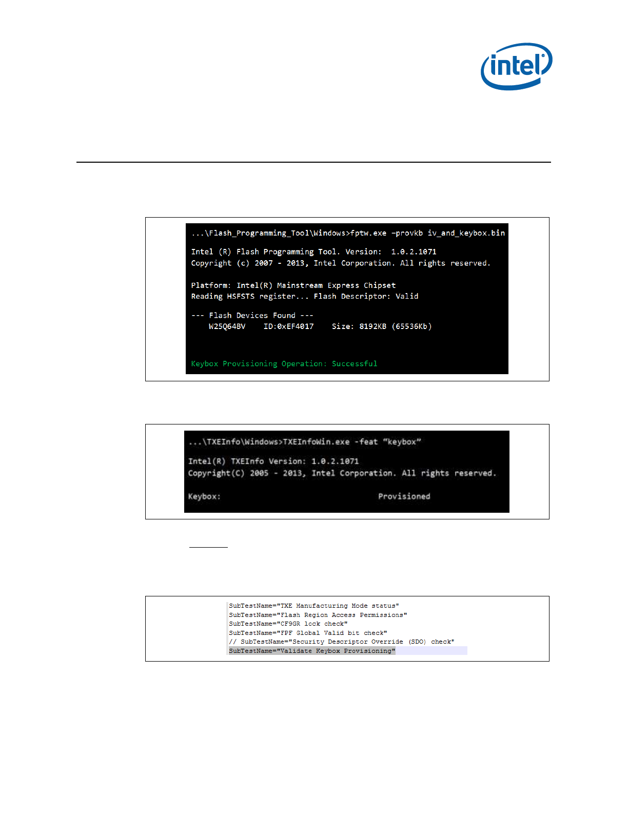
Widevine* KeyBox Provisioning Procedure
Intel Confidential 63
9 Widevine* KeyBox Provisioning
Procedure
1. Provision Widevine using IV (Initialization Vector) and encrypted KeyBox file (refer
to Chapter 8 - Error! Reference source not found., for files creation procedure)
Run FPT –provkb <iv_and_keybox.bin>
2. Optional: Verify that the Widevine device has been properly provisioned
Run: TXEInfo –feat “keybox”
3. After properly closing manufacturing (using FPT-closemnf), run TXEManuf EOL
Testing.
Edit TXEManuf.cfg file in EOL section
Uncomment "SubTestName "Validate Keybox Provisioning"" test in order to
include WV Provisioning Test check
Run TXEManuf –EOL

Widevine* KeyBox Provisioning Procedure
64 Intel Confidential
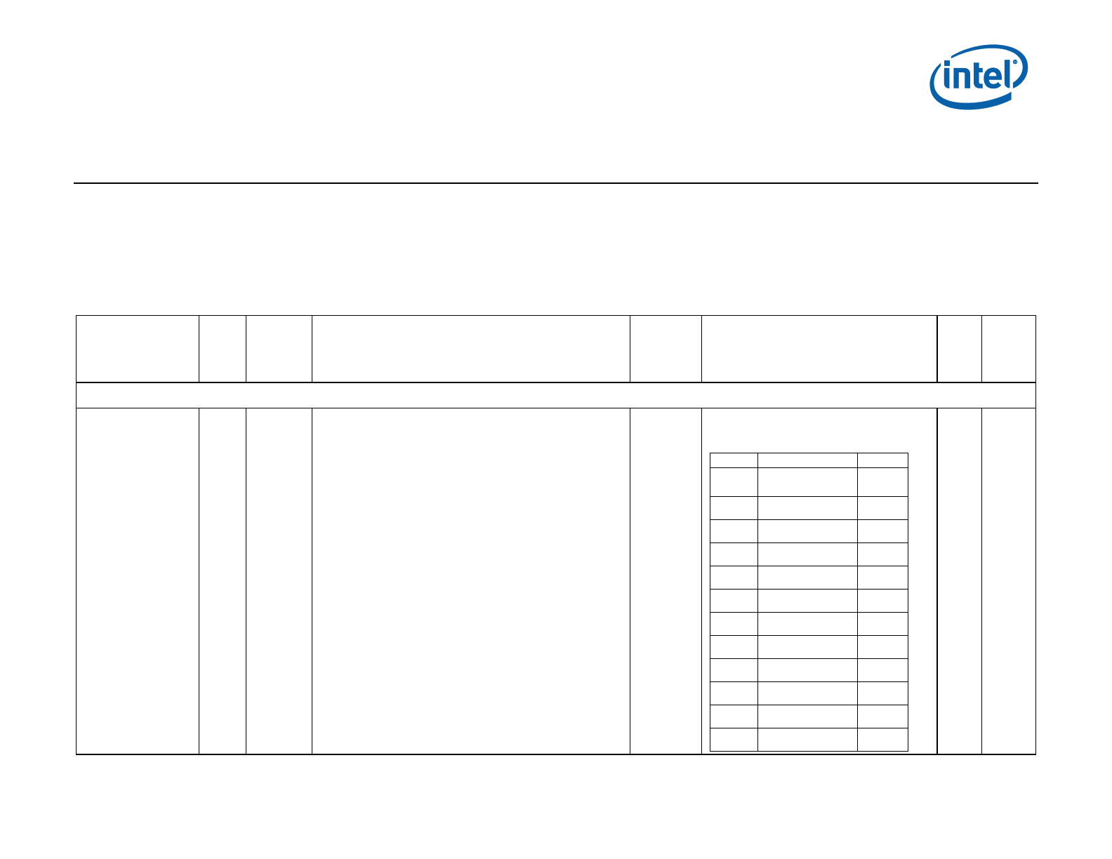
Intel® TXE CVARs
Intel Confidential 65
Appendix A Intel® TXE CVARs
This appendix only covers fixed offset variables that are directly available to FPT and FPTW. A complete list of CVARs can be found in the Firmware
Variable Structures for Intel® Management Engine. All of the fixed offset variables have an ID and a name. The -CVAR option displays a list of the IDs
and their respective names. The variable name must be entered exactly as displayed below.
This table is for reference use only and will be updated later.
Table 20: CVARs Descriptions
Fixed Offset
Name
FPT
ID
Fixed
Offset
ID
Description
Data
Length
(in
Bytes)
Expected Value
Secure
Reset
Type
Non-Application Specific Fixed Offset Item Descriptions
OEMSkuRule
7
0x000A
UINT32 (little endian) value. This controls what features are
permanently disabled by OEM.
Notes:
There are reserved bits that the must not be changed
for proper platform operation. The user should only
modify the bit(s) for the feature(s) they wish to
change. There is NO ability to change features one at
a time. This CVAR sets OEM Permanent Disable for
ALL features. In addition prior updating or changing
any of available settings it is highly recommended
that the user first retrieves the current OEM Sku Rule
and toggling only the desired bits, and then resave
them.
This will not enable functionality that is not capable of
working in the target hardware SKU. Please see the
respective Firmware Bring-up Guide for a list of what
features are capable with what firmware bundle and
Hardware SKU of Intel 9 Series Chipset.
4
Feature Capable: 1
Feature Permanently disabled: 0
Bit
Description
Notes
31
Near Field
Communication
1
30
Reserved
29:22
Reserved
21
TLS
20
DAL
19
Reserved
18
Reserved
17
Reserved
16
Reserved
15:13
Reserved
12
PAVP
11:6
Reserved
No
Global
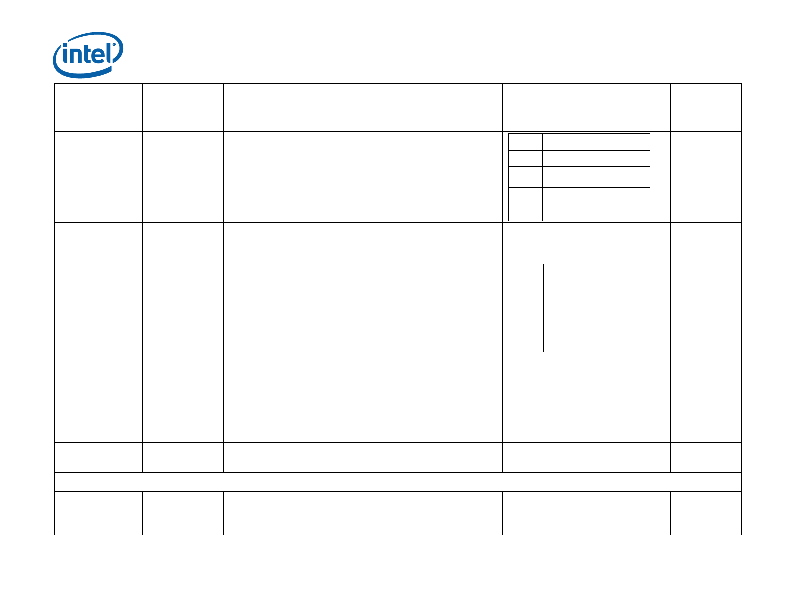
Intel® TXE CVARs
66 Intel Confidential
Fixed Offset
Name
FPT
ID
Fixed
Offset
ID
Description
Data
Length
(in
Bytes)
Expected Value
Secure
Reset
Type
5
Reserved
4:3
Reserved
2
Security
Application
1
Reserved
0
Reserved
Feature Shipment
Time State
8
0x000B
UINT32 (little endian) value. This controls what features are
enabled or disabled. This setting is only relevant for
features NOT permanently disabled by the OEM Permanent
Disable.
This will not enable functionality that is not capable of
working in the target hardware SKU. Please see the
respective Firmware Bring-up Guide for a list of what
features are capable with what firmware bundle and
Hardware SKU
Notes:
There are reserved bits that the must not be changed
for proper platform operation. The user should only
modify the bit(s) for the feature(s) they wish to
change. There is NO ability to change features one at
a time. This CVAR sets OEM Permanent Disable for
ALL features. In addition prior updating or changing
any of available settings it is highly recommended
that the user first retrieves the current Feature
Shipment Time State and toggling only the desired
bits, and then resave them.
4
Feature Enabled: 1
Feature Disabled: 0
Bit
Description
Notes
31:30
Reserved
29
Reserved
28:3
Reserved
2
Reserved
1:0
Reserved
No
Global
OEM_TAG
34
0x000F
A human readable 32-bit number to describe the
flash image represented by value
4
Readable 32 bit hex value identifying the
image. Can be empty (Null).
No
TXE
Revenue Sharing Related CVAR Item Descriptions
ODM_ID
0x5003
CVAR used for setting the ODM ID Used by Intel ® Services
Note: This value can only be programmed into FW
once.
4
32-bit value
Value 0x00000000 < n < 0xFFFFFFFF
Yes
TXE

Intel® TXE CVARs
Intel Confidential 67
Fixed Offset
Name
FPT
ID
Fixed
Offset
ID
Description
Data
Length
(in
Bytes)
Expected Value
Secure
Reset
Type
SystemIntegratorID
0x5004
Used for setting the System Integrator ID used by Intel ®
Services
Note: This value can only be programmed into FW
once.
4
32-bit value
Value 0x00000000 < n < 0xFFFFFFFF
Yes
TXE
ReservedID
0x5005
Used for setting the "Reserved" ID used by Intel ® Services
Note: This value can only be programmed into FW
once.
4
32-bit value
Value 0x00000000 < n < 0xFFFFFFFF
Yes
TXE
Field Programmable Fuses
PTT Enable
0x7001
Enables / Disables the fTPM / PTT FPFs
1
0 = Disabled
1 = Enabled
Note: Setting the value to ‘0’ will
permanently disable Intel® PTT in the
chipset.
No
TXE
FPT CVAR Retrieve command:
fpt.exe –r <name> | all [-f <file>] [options]
Required Parameters
<name> Name of CVAR OR All retrieves all the CVARs
Manufacturing Configurable CVARs
Named Variables (CVARs)
OEMSkuRule
FeatureShipState
OEM_TAG
ODM ID used by Intel (R) Services
System Integrator ID used by Intel (R) Services
Reserved ID used by Intel (R) Services

Intel® TXE CVARs
68 Intel Confidential
Manufacturing Configurable CVARs
Named Variables (CVARs)
Flash Protection Override Policy Hard
Flash Protection Override Policy Soft
§ §

Appendix B Tool Detail Error
Codes
B.1 Common Error Code for All Tools
Note that FIT and MEU have different error codes, as mentioned in section 2.7.
Error
Code
Error Message
Response
0
Success
1
Memory allocation error occurred
Make sure there is enough
memory in the system
2
Invalid descriptor region
Check descriptor region
3
Region does not exist
Check region to be
programmed
4
Failure. Unexpected error occurred
Contact Intel
5
Invalid data for Read ID command
Contact Intel
6
Error occurred while communicating with SPI
device
Check SPI device
7
Hardware sequencing failed. Make sure that
access permissions are correct for the target flash
area
Check descriptor region access
settings
8
Software sequencing failed. Make sure that access
permissions are correct for the target flash area
Check descriptor region access
settings
9
Unrecognized value in the HSFSTS register
Unrecognized value in the
HSFSTS register
10
Hardware Timeout occurred in SPI device
Hardware Timeout occurred in
SPI device
11
AEL is not equal to zero
AEL is not equal to zero
12
FCERR is not equal to zero
FCERR is not equal to zero
25
The host CPU does not have writes access to the
target flash area. To enable write access for this
operation the user needs to modify the descriptor
settings to give host access to this region.
Check descriptor region access
settings
26
The host CPU does not have read access to the
target flash area. To enable read access for this
operation the user needs to modify the descriptor
settings to give host access to this region.
Check descriptor region access
settings

Widevine* KeyBox Provisioning Procedure
70 Intel Confidential
Error
Code
Error Message
Response
27
The host CPU does not have erase access to the
target flash area. To enable erase access for this
operation the user needs to modify the descriptor
settings to give host access to this region.
Check descriptor region access
settings
28
Protected Range Registers are currently set by
BIOS, preventing flash access.
Contact the target system BIOS vendor for an
option to disable Protected Range Registers.
Assert Flash Descriptor
Override Strap (GPIO33) to
Low, Power Cycle, and Retry.
If Protected Range Registers
(memory location: SPIBAR +
74h -> 8Fh) are still set,
contact the target BIOS
vendor.
50
General Erase failure
Attempt the command again. If
it fails again, contact Intel.
51
An attempt was made to read beyond the end of
flash memory
Check address
52
An attempt was made to write beyond the end of
flash memory
Check address
53
An attempt was made to erase beyond the end of
flash memory
Check address
54
The address <address> of the block to erase is
not aligned correctly
Check address
55
Internal Error
Contact Intel
56
The supplied zero-based index of the SPI Device is
out of range.
The supplied zero-based index
of the SPI Device is out of
range.
57
AEL or FCERR is not equal to zero for Software
Sequencing
AEL or FCERR is not equal to
zero for Software Sequencing
75
File not found
Check file location
76
Access was denied opening the file
Check file location
77
An unknown error occurred while opening the file
Verify the file is not corrupt
78
Failed to allocate memory for the flash part
definition file
Check system memory
Verify the file is not corrupt
79
Failed to read the entire file into memory
Check system memory
Verify the file is not corrupt
80
Parsing of file failed
Check system memory
Verify the file is not corrupt
100
This error can occur if both Software and
Hardware sequencing are not available and the
SPI Flash configuration registers are write
protected by the Flash Configuration Lock-Down
bit (FLOCKDN).
Contact the BIOS vendor to unlock this bit or
enable hardware sequencing in descriptor mode.
Check with BIOS vendor or SPI
programming Guide

Widevine* KeyBox Provisioning Procedure
Intel Confidential 71
Error
Code
Error Message
Response
101
No SPI flash device could be identified. Please
verify if Fparts.txt has support for this part
Verify Fparts.txt contains
device supported.
102
Failed to read the device ID from the SPI flash
part
Verify Fparts.txt has correct
values
103
There are no supported SPI flash devices
installed. Check connectivity and orientation of
SPI flash device
Verify Fparts.txt has correct
values. Check SPI Device
104
The two SPI flash devices do not have compatible
command sets
Verify both SPI devices on the
system are compatible
105
An error occurred while writing to the write status
register of the SPI flash device. This program will
not be able to modify the SPI flash
Check SPI Device
202
Confirmation is not received from the user to
perform operation.
203
Flash is not blank
204
Data verify mismatch found
205
Unexpected failure occurred
207
Invalid parameter value specified by user. The
option specified cannot be run on a platform with
Intel® TXE Ignition FW
208
Intel® TXE is disabled
209
Intel® TXE failed to reset
210
Requesting Intel® TXE FW Reset failure.
211
Communications error between FPT and the Intel®
TXE.
212
The request to disable the Intel® TXE failed.
213
Intel® TXE disable is not required
214
Intel® TXE is already disabled
215
The attempt to commit the CVARs has failed.
216
The Close Manufacturing process failed.
217
Setting Global Reset Failed
240
Access was denied opening the file
241
Access was denied creating the file
242
An unknown error occurred while opening the file
243
An unknown error occurred while creating
244
Not a valid file
245
File not found error
246
Failed to read the entire file into memory
247
Failed to write the entire flash contents to file

Widevine* KeyBox Provisioning Procedure
72 Intel Confidential
Error
Code
Error Message
Response
248
File already exists
249
The file is longer than the flash area to write.
250
The file is smaller than the flash area to write.
251
Length of image file extends past the flash area.
252
Image file not found.
253
File does not exist
254
Not able to open the file
255
Error occurred while reading the file
256
Error occurred while writing to the file
280
Failed to disable write protection for the BIOS
space
281
The Enable bit in the LPC RCBA register is not set.
The value of this register cannot be used as the
SPI BIOS base address.
282
Failed to get information about the installed flash
devices
283
Unable to write data to flash.
284
Fail to load driver (PCI access for Windows*). The
tool needs to run with an administrator privilege
account.
320
FPT General failure error
321
The address is outside the boundaries of the flash
area.
360
Invalid Block Erase Size value in
361
Invalid Write Granularity value in
362
Invalid Enable Write Status Register Command
value
363
Invalid Chip Erase Timeout value
360
Invalid Block Erase Size value in
361
Invalid Write Granularity value in
362
Invalid Enable Write Status Register Command
value
363
Invalid Chip Erase Timeout value
360
Invalid Block Erase Size value in
361
Invalid Write Granularity value in
362
Invalid Enable Write Status Register Command
value
363
Invalid Chip Erase Timeout value
440
Invalid Fixed Offset variable name

Widevine* KeyBox Provisioning Procedure
Intel Confidential 73
Error
Code
Error Message
Response
441
CVAR invalid variable ID
442
Param file is already opened
443
CVAR exists already
444
Invalid name or Id of CVAR
445
Invalid length of CVAR value. Check CVAR
configuration file for correct length
446
Password does not match the criteria.
447
Error occurred while reading CVAR configuration
file
448
Invalid hash certificate file
449
Valid PID/PPS/Password records are not found in
450
Invalid Intel® TXE Manufacturing Mode Done
value entered
451
Unable to get master base address from the
descriptor.
452
Verification of End Of Manufacturing settings
failed
453
End Of Manufacturing Operation failure -
Verification failure on Intel® TXE Manufacturing
Mode Done settings
454
End Of Manufacturing Operation failure -
Verification failure on Intel® TXE Manuf counter.
455
End Of Manufacturing Operation failure -
Verification failure on Descriptor Lock settings.
456
Invalid hexadecimal value entered for the CVAR
457
Parsing of file failed
481
The setup file version is unsupported
483
The given buffer length is invalid
484
the record chunk count cannot contain all of the
setup file record data
485
the setup file header indicates that there are no
valid records (RecordsConsumed >=
RecordCount)
486
the given buffer is invalid
487
A record entry with an invalid Module ID was
encountered.
488
A record was encountered with an invalid record
number.
489
The setup file header contains an invalid module
ID list.

Widevine* KeyBox Provisioning Procedure
74 Intel Confidential
Error
Code
Error Message
Response
490
The setup file header contains an invalid byte
count.
491
The setup file record id is not found
492
The list of data record entries is invalid.
495
The PID is invalid.
496
The PPS is invalid.
497
The PID checksum failed.
498
The PPS checksum failed.
501
The data record is missing a PID entry.
502
The data record is missing a PPS entry.
503
The header chunk count cannot contain all of the
setup file header data.
504
The requested index is invalid.
505
Failed to write to the given file.
506
Failed to read from the given file.
507
Failed to create random numbers.
508
The data record is missing a PKI DNS Suffix entry.
509
The data record is missing a Config Server FQDN
entry.
511
The data record is missing a Pre-Installed
Certificate enabled entry.
512
The data record is missing a User defined
certificate config entry.
513
The data record is missing a User defined
certificate Add entry.
515
OEM Firmware Update Qualifier data missing in
USB file.
1000
Invalid command line option(s)
1001
Unsupported OS
8192
General error
8193
Cannot locate Intel® TXE device
8194
Memory access failure
8195
Write register failure
8196
OS failed to allocate memory
8197
Circular buffer overflow
8198
Not enough memory in circular buffer
8199
Communication error between application and
Intel® TXE <HECI command name>
Contact Intel

Widevine* KeyBox Provisioning Procedure
Intel Confidential 75
Error
Code
Error Message
Response
8200
Unsupported HECI bus message protocol version
8201
Unexpected interrupt reason
8203
Unexpected result in command response <HECI
command name>
Contact Intel
8204
Unsupported message type
8205
Cannot find host client
8206
Cannot find Intel® TXE client
8207
Client already connected
8208
No free connection available
8209
Illegal parameter
8210
Flow control error
8211
No message
8212
Requesting HECI receive buffer size is too large
8213
Application or driver internal error
8214
Circular buffer not empty
B.2 Firmware Update Errors
Error
Code
Error Message
0
Success
8193
Intel® TXE Interface : Cannot locate Intel® TXE device driver
8704
Firmware update operation not initiated due to a SKU mismatch
8705
Firmware update not initiated due to version mismatch
8706
Firmware update not initiated due to integrity failure or invalid FW image
8707
Firmware update failed due to an internal error
8708
Firmware Update operation not initiated because a firmware update is already in
progress
8710
Firmware update tool failed due to insufficient memory
8713
Firmware update not initiated due to an invalid FW image header
8714
Firmware update not initiated due to file open or read failure
8716
Invalid usage
8718
Update operation timed-out; cannot determine if the operation succeeded
8719
Firmware update cannot be initiated because Local Firmware update is disabled
8722
Intel® TXE Interface : Unsupported message type
8723
No Firmware update is happening

Widevine* KeyBox Provisioning Procedure
76 Intel Confidential
Error
Code
Error Message
8724
Platform did not respond to update request.
8725
Failed to receive last update status from the firmware
8727
Firmware update tool failed to get the firmware parameters
8728
This version of the Intel l® FW Update Tool is not compatible with the current
platform.
8741
FW Update Failed.
8743
Unknown or unsupported Platform.
8744
OEM ID verification failed.
8745
Firmware update cannot be initiated because the OEM ID provided is incorrect
8746
Firmware update not initiated due to invalid image length
8747
Firmware update not initiated due to an unavailable global buffer
8748
Firmware update not initiated due to invalid firmware parameters
8754
Encountered error writing to file.
8757
Display FW Version failed.
8758
The image provided is not supported by the platform.
8759
Internal Error.
8760
Update downgrade vetoed.
8761
Firmware write file failure.
8762
Firmware read file failure.
8763
Firmware delete file failure.
8764
Partition layout NOT compatible.
8765
Downgrade NOT allowed, data mismatched.
8766
Password did not match.
8768
Password Not provided when required.
8769
Polling for FW Update Failed.
8772
Invalid usage, -allowsv switch required to update the same version firmware
8778
Unable to read FW version from file. Please verify the update image used.
8787
Password exceeded maximum number of retries.
B.3 Intel® TXEManuf Errors
Error
Codes
Error Messages
9248
Intel® TXE internal communication error (BIST)
9249
Intel® TXE internal communication error (FW)
9250
Used by IBX, not used by CPT, TXE8

Widevine* KeyBox Provisioning Procedure
Intel Confidential 77
Error
Codes
Error Messages
9251
Fail to create verbose log file %s.
Where %s is the log file name user specified.
9252
Used by IBX, not used by CPT, TXE8
9254
Used by IBX, not used by CPT, TXE8
9255
Internal error
9256
Communication error between host application and Intel® TXE FW
9261
Hibernation isn't supported by the OS, Intel® TXE test cannot run
9262
Used by IBX, not used by CPT, TXE8
9263
Used by IBX, not used by CPT, TXE8
9264
Used by IBX, not used by CPT, TXE8
9265
Used by IBX, not used by CPT, TXE8
9266
Used by IBX, not used by CPT, TXE8
9267
Fail to establish a communication with SPI flash interface
9268
Fail to load vsccommn.bin
9269
Zero flash device found for VSCC check
9270
Fail to load driver (PCI access for Windows*)
Tool needs to run with an administrator priviledge account.
9271
Flash ID 0x%06X Intel® TXE VSCC mismatch
Programmed value of 0x%X doesn't match the recommended value of
0x%X
See PCH SPI programming Guide for more details
9272
No recommended TXE VSCC value found for flash ID 0x%06X
9273
Intel® VE is disabled by PCH SoftStrap, not used by TXE8
9275
Used by IBX, not used by CPT
9276
Fail to read FW Status Register value 0x%X
9277
Intel® VE internal error, not used by TXE8
9278
Cannot locate hardware platform identification
This program cannot be run on the current platform.
Unknown or unsupported hardware platform
or
A %s hardware platform is detected
This program cannot be run on the current platform.
Unknown or unsupported hardware platform
Where %s is the official name of the hardware platform
9279
SPI flash Intel® TXE region is not locked

Widevine* KeyBox Provisioning Procedure
78 Intel Confidential
Error
Codes
Error Messages
9280
Intel® Gbe/TXE has read or write access to BIOS region
9281
SPI flash descriptor region is not locked
9282
BIOS has granted Intel® Gbe and/or Intel® TXE access to its region
9283
Region access permissions don't match Intel recommended values
9284
Read firmware flash master region permission failure
9285
Used by IBX, not used by CPT, TXE8
9286
Used by IBX, not used by CPT, TXE8
9287
Used by IBX, not used by CPT, TXE8
9288
Used by IBX, not used by CPT, TXE8
9289
Used by IBX, not used by CPT, TXE8
9290
Used by IBX, not used by CPT, TXE8
9291
Used by IBX, not used by CPT, TXE8
9295
Used by IBX, not used by CPT, TXE8
9296
TXEINFO Test Failed
Or
TXEINFO End-Of-Line Test Failed
Or
TXEINFO Operation Failed
9297
Intel® NAND needs to be enabled to perform the test, not used by TXE8
9298
Used by IBX, not used by CPT
9299
Single flash part found, Flash Partition Boundary Address must be zero
9300
Flash Partition Boundary Address should be in between flash parts
9301
The two flash parts on this platform require different BIOS VSCC values
9302
Intel® NAND module test failed (feature not enabled), not used by TXE8
9303
Memory allocation failed for checking variable “<Variable Name>”
9304
Variable “<Variable Name>” mismatch, actual value is - <Variable Value>
9305
Intel® TXE firmware version mismatch, actual value is - <Version String>
Intel® Gbe version mismatch, actual value is - <Version String>
BIOS version mismatch, actual value is - <Version String>
9307
Intel® Wired/Wireless LAN MAC address mismatch, feature is not supported
Intel® Wired/Wireless LAN MAC address mismatch, actual value is - <MAC
Address>
9308
Security Descriptor Override Strap (SDO) is enabled
9309
End-Of-Post message is not sent
9310
Unable to determine Intel® TXE Manufacturing Mode status
Intel® TXE is still in Manufacturing Mode
9311
Intel® TXE test failed to start, error 0x%X returned

Widevine* KeyBox Provisioning Procedure
Intel Confidential 79
Error
Codes
Error Messages
9312
Intel® TXE test timeout (exceeded 30 seconds)
9313
No Intel® TXE test result to retrieve, not used by TXE8
9314
Intel® TXE test result reports error(s), not used by TXE8
9315
Intel® TXE test is currently running, try again
9316
Intel® TXE cannot run Full BIST. Possible Causes: (1) Power package 2 not
supported, (2) This is a mobile system with DC power
9317
No valid OEM ICC data programmed
9318
TXEINFO End-Of-Line Test config file generation failed
9319
CIRA service button is broken, not used by TXE8
9320
Internal error
9321
TXEINFO End-Of-Line Test Failed
9322
TXEINFO Operation Failed
9324
CM3 results are not available from SPI. Please run –test option to perform
the BIST test
9325
Failed to delete CM3 results from SPI
9326
CM3 test failed
9327
CM3 test failed
9328
Internal error
9329
Internal error
9330
Internal error
9331
SMBus hardware is not ready
9332
Internal error
9333
SMBus encountered time-out
9334
Failed to retrieve password from SPI
9335
Internal error
9336
Internal error
9337
Internal error
9338
Failed to retrieve test result from SPI
9339
Failed to retrieve power rule from SPI
9340
Failed to retrieve power source
9341
Failed to retrieve PROC_MISSING_CVAR setting
9342
PROC_MISSING_CVAR setting is set incorrectly
9343
Internal error
9344
Failed to retrieve power package setting
9345
Failed to retrieve CM3 Power Rails Availability setting
9346
CM3 Power Rails Availability setting is set incorrectly

Widevine* KeyBox Provisioning Procedure
80 Intel Confidential
Error
Codes
Error Messages
9347
Power source is not AC
9348
Internal error
9349
Internal error
9350
Internal error
9351
Length of OEM Customizable Certificate Friendly Name setting is set
incorrectly
9352
OEM Customizable Certificate Stream setting is set incorrectly
9353
OEM Customizable Certificate Hash Algorithm setting is set incorrectly
9354
Length of OEM Customizable Certificate Stream is set incorrectly
9358
LAN power well setting is set incorrectly
9359
Power Pkg 2 Supported is set incorrectly
9360
USBr EHCI 1 Enabled and/or USBr EHCI 2 Enabled setting is set incorrectly
9362
Internal error
9363
Internal error
9364
The compressed data is incorrect
9365
Intel integrated LAN setting is set incorrectly
9366
Intel LAN connected Device (PHY) physical connectivity error with TXE
9367
Firmware is in recovery mode
9368
SMBus address is not configured correctly
9369
Could not register for SMBus alert
9370
Communication interference
9371
SMBUS connection failed. Check connection or SMBUS address
9372
GPIO connection failed. Check connection or GPIO configuration
9373
NFC Radio – Unknown error
9374
NFC RF Test – Error returned from radio
9375
NFC RF Test – Communication interference or bad response returned from
radio
9376
NFC RF Test – Timeout
B.4 Intel® TXEINFO Errors
Error
Code
Error Messages
9452
Communication error between application and Intel® TXE module (iCLS client)
9455
Failed to read FW Status Register value 0x%X
9457
Failed to create verbose log file %s:
Where %s is the log file name user specified
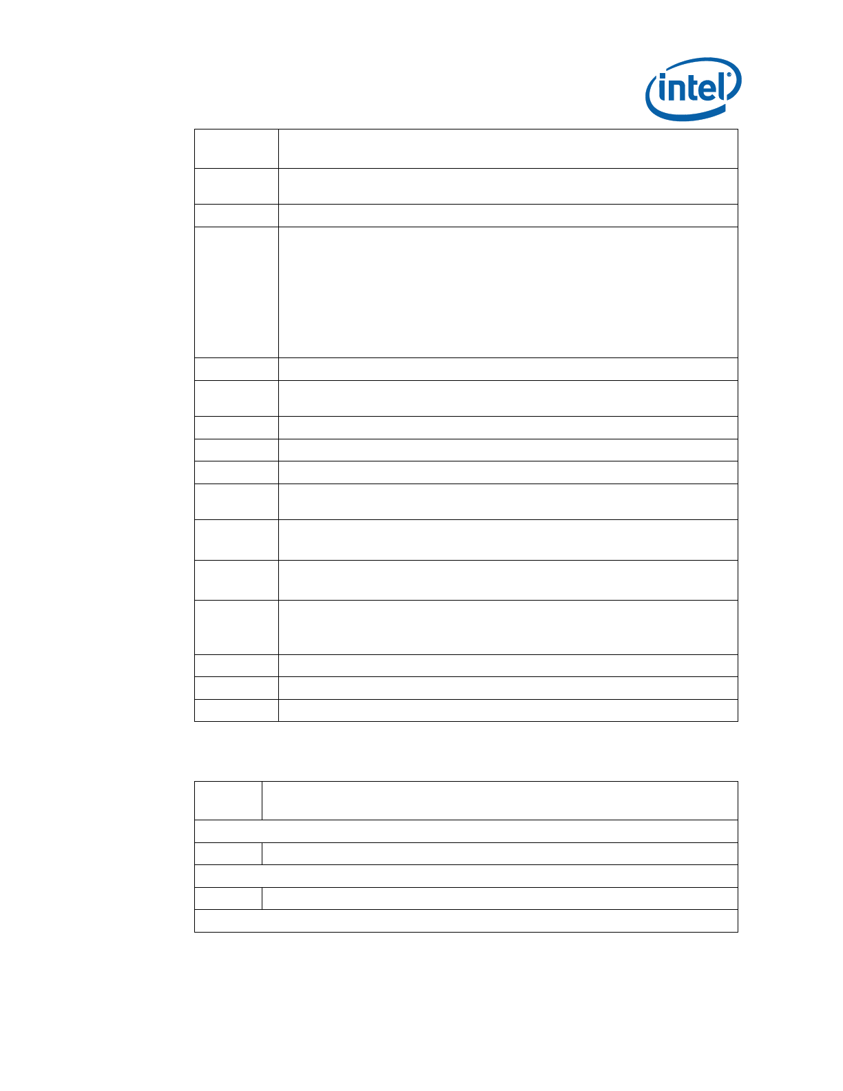
Widevine* KeyBox Provisioning Procedure
Intel Confidential 81
Error
Code
Error Messages
9458
Communication error between application and Intel® TXE module (FW Update
client)
9459
Internal error (Could not determine FW features information)
9460
Cannot locate hardware platform identification
This program cannot be run on the current platform.
Unknown or unsupported hardware platform
Or
A %s hardware platform is detected
This program cannot be run on the current platform.
Unknown or unsupported hardware platform
Where %s is the official name of the hardware platform
9461
Communication error between application and Intel® TXE module (HCI client)
9462
Communication error between application and Intel® TXE module (Kernel
Client)
9467
Cannot use zero as SPI Flash ID index number
9468
Couldn't find a matching SPI Flash ID
9469
Access to SPI Flash device(s) failed
9470
Failed to load driver (PCI access for Windows*)
Tool needs to run with an administrator privilege account.
9471
Invalid feature name XXXXX:
Where XXXXX is the feature name
9472
XXXXX feature was not available:
Where XXXXX is the feature name
9473
XXXXX actual value is – YYYYY:
Where XXXXX is the feature name
Where YYYY is the feature value
9474
Error reporting revenue share information – Invalid index used
9475
Error reporting revenue share information – Index already in use
9476
Error reporting revenue share information – Slot is empty
B.5 FPT Errors
Error
Code
Error
Invalid Parameters
200
Invalid parameter value specified by the user. Use -? Option to see help.
Invalid Verbose File
254
Not able to open the file <FILENATXE>.
Unsupported Platform

Widevine* KeyBox Provisioning Procedure
82 Intel Confidential
Error
Code
Error
201
<EXENATXE> cannot be run on the current platform.
Please contact your vendor.
Unsupported OS
9254
Unsupported OS
Commit CVARs Operation
517
Get CVAR - Read Failed
518
Get CVAR - Invalid CVAR specified
519
Get CVAR - Out of Memory
520
Get CVAR - Blob Integrity Failed
8193
Intel® TXE Interface : Cannot locate Intel® TXE device driver
8199
Intel® TXE Interface : Intel® TXE Device not ready for data transmission
8204
Intel® TXE Interface : Unsupported message type
8213
Intel® TXE Interface : Buffer too small
Compare CVAR(s) Operation
518
Get CVAR - Invalid CVAR specified
519
Get CVAR - Out of Memory
520
Get CVAR - Blob Integrity Failed
8193
Intel® TXE Interface : Cannot locate Intel® TXE device driver
8199
Intel® TXE Interface : Intel® TXE Device not ready for data transmission
8204
Intel® TXE Interface : Unsupported message type
8213
Intel® TXE Interface : Buffer too small
Retrieve CVAR Operation
518
Get CVAR - Invalid CVAR specified
519
Get CVAR - Out of Memory
520
Get CVAR - Blob Integrity Failed
8193
Intel® TXE Interface : Cannot locate Intel® TXE device driver
8199
Intel® TXE Interface : Intel® TXE Device not ready for data transmission
8204
Intel® TXE Interface : Unsupported message type
8213
Intel® TXE Interface : Buffer too small
Updating Parameters Operations
506
Failed to read from the given file.
3003
Error occurred while opening image file
3004
Parsing of image file failed
3005
Heci communication failed
3006
File does not exist

Widevine* KeyBox Provisioning Procedure
Intel Confidential 83
Error
Code
Error
3007
Operating system is not supported
3009
User defined certificate hash table is full
3010
Unable to start HECI
3011
Invalid input file name
3012
Chipset not supported by the tool
3013
PID value is NULL
3014
PPS value is NULL
3015
Configuration Server FQDN value is NULL
3016
PKI DNS Suffix value is NULL
3017
Host Name value is NULL
3018
Domain Name value is NULL
3054
Unable to create Logfile
3055
System failed to retrieve current firmware feature state.
3056
Unable to Save updated parameter as factory defaults on FW image.
3057
Unable to complete CVAR commit option.
B.6 MEU Errors
Error
Code
Error
1
Failed to initialize tool
2
Failed to process input XML
3
Invalid command line options
4
Failed to build
5
Failed to save XML
6
File not found
7
Unknown root node found in XML
8
Invalid XML template option specified
9
Invalid Manifest Version specified on CLI
10
Unable to load tool config xml
11
Unsupported signing tool specified
12
Invalid signing tool configuration
13
Error setting the log file
14
Invalid decomp binary type specified
15
Invalid input file type
16
File is not a valid XML file

Widevine* KeyBox Provisioning Procedure
84 Intel Confidential
Error
Code
Error
17
Invalid manifest index value
18
Error finding manifests in file
19
Failed to write file
20
Path provided is not a valid directory
21
Unable to find files
22
Unable to read file
23
Failed to import manifest(s)
24
Failed to resign manifest(s)
25
Failed to generate public key hash
26
Failed to export manifest(s)
27
Failed to decompose
§ §

Widevine* KeyBox Provisioning Procedure
Intel Confidential 85
Appendix C Tool Option
Dependency on BIOS/Intel®
TXE Status
Tools' Options
Intel® TXE End-of-
Manufacturing CVAR
End of post
Set
Not Set
Yes
No
FPT -Greset
Not related
Not related
Not related
N/A Not related
FPT –R
Depends on End
of post status
Work
Depends on Intel® TXE
manufacturing mode done bit status
Work
Intel® TXEINFO –
EOL config
Depends on End
of post status
Work
Depends on Intel® TXE
manufacturing mode done bit status
Work
§ §
§ §

: Using Local Android* Intel® TXE System Tools
86 Intel Confidential
Appendix D : Using Local
Android* Intel® TXE System
Tools
D.1 Using Android* System Tools
In order to use Intel® TXE System tools locally on SUT, you must push the tools using
ADB (Android Debug Bridge) to a directory that can be accessed using Terminal
Emulator OR using ABD itself.
D.2 Setup & Install ADB and Fastboot
Obtain ADB and Fastboot tool (comes as part of the Phone Flash Tool installation,
which is part of the Intel TXE FW Kit). There are Linux* and Windows versions of the
tool. Usage of this tool will be the same with respect to Intel TXE System tools.
D.3 Using Fastboot
To use Fastboot:
1. Connect a MicroUSB OTG cable between the platform USB OTG port and the host
System
2. From the host system, navigate to the Fastboot path, and open CMD/Shell
3. Run Fastboot –devices
The output should be the device name on the devices list
4. For more information about Fastboot commands run: Fastboot -?
D.4 How to Push & Use the Intel® TXE System Tools
1. Connecting SUT to console can be done in two ways:
Connect a MicroUSB OTG cable between the platform USB OTG port and the
host system
Or using network connection:
1. Place both SUT & Console on same IP network
2. Use “ADB Connect <IP_Address_Of_SUT>”
2. Push the Intel TXE FW tools & their components, example below:
\platform-tools>adb.exe push FPT /data/local
1862 KB/s (357043 bytes in 0.187s)
\platform-tools>adb.exe push TXEInfo /data/local
1986 KB/s (222110 bytes in 0.109s)

: Using Local Android* Intel® TXE System Tools
Intel Confidential 87
\platform-tools>adb.exe push TXEManuf /data/local
1914 KB/s (305893 bytes in 0.156s)
\platform-tools>adb.exe push TXEManuf.cfg /data/local
377 KB/s (6023 bytes in 0.015s)
\platform-tools>adb.exe push fparts.txt /data/local
7 KB/s (8057 bytes in 1.000s)
\platform-tools>adb.exe push vsccommn.bin /data/local
133 KB/s (2132 bytes in 0.015s)
\platform-tools>adb.exe push FpfConfigFile.txt /data/local
26 KB/s (431 bytes in 0.015s)
3. Run the Intel® TXE System tools using ADB or local Terminal Emulator
Using ABD Example:
. \platform-tools>adb.exe shell
. root@android:/ # su
. 127|root@android:/ # cd data/local
. root@android:/data/local # chmod 777 FPT TXEInfo TXEManuf
. Verify execution rights have been given via “ls -l”
. While in “data/local” directory run: “./TXEInfo” / “./FPT”
“./TXEManuf”
4. Running local Terminal Emulator or Serial connection will be the same usage of
the Intel® TXE System tools. For Serial connection:
Connect microUSB to Console COM port.
Using Terminal client (e.g. PuTTY) configure connection to be serial with
speed of 115200.
When connection is successful, change to Android directory where tools have
been pushed (i.e. /data/local per above example).
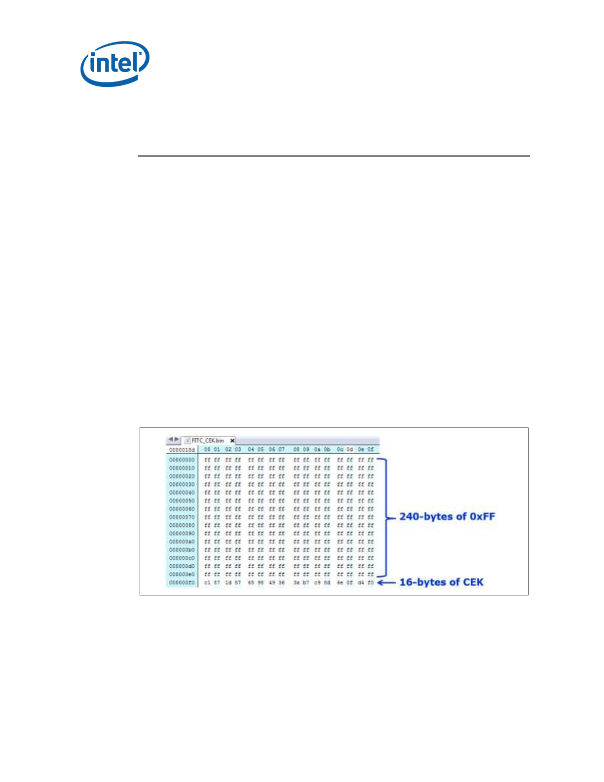
: Google* Widevine for Intel® TXE
88 Intel Confidential
Appendix E : Google* Widevine
for Intel® TXE
E.1 Creating Widevine* CEK (Customer
Encryption Key)
The CEK is responsible for encrypting Widevine Keybox in Android devices and not
accessible by the host. The CEK is a global key used among the same models of
devices for a single Customer.
Note: The below key files are for demonstration purposes only and are not actual keys.
E.1.1 FITC CEK File Creation Procedure
E.1.1.1 Cleartext CEK
1. Generate a 16-byte Hex random number (unique per OEM) which is called CEK.
2. Combine 240 bytes of 0xFF (upper) with 16-byte CEK (lower) into 256 bytes
FITC_CEK.bin
3. Insert FITC_CEK.bin into flash image with FITC tool (refer to section Error!
Reference source not found., steps 2-5).
FITC CEK File Map Example
When building the image, add FITC_CEK.bin file (Flash Image -> TXE Region -
> Configuration -> TXE -> CEK Configuration)
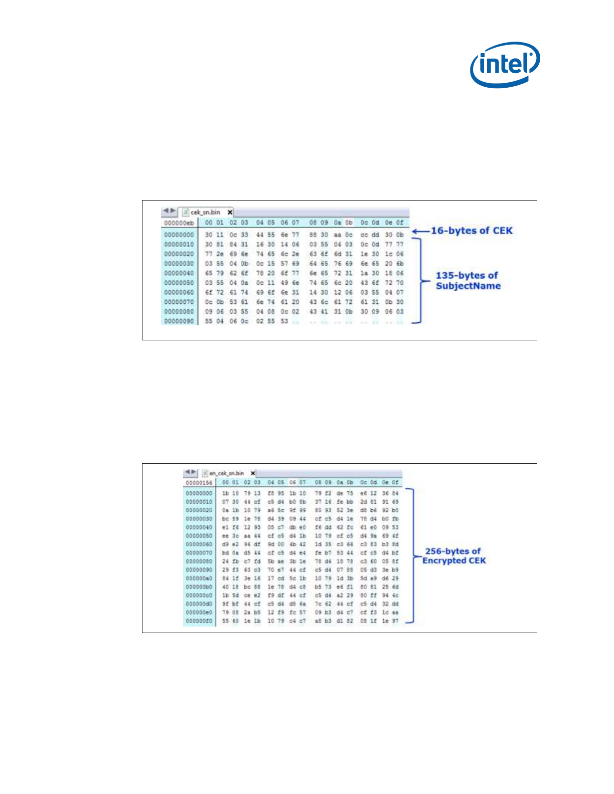
: Google* Widevine for Intel® TXE
Intel Confidential 89
E.1.1.2 Ciphertext CEK
Note: Customer should scope relevant Google* documentation and decide on CEK insertion
method. Intel recommended method is ciphertext
1. Generate a 16-byte Hex random number (unique per OEM) which is called CEK.
2. Create concatenated CEK||subjectname into one file (cek_sn.bin)
a. SubjectName can be found under \\System
Tools\Certificates\TXE1SubjectName.bin
3. Use openssl tool (open source tool) to convert the CEK certificate to *.pem format
a. CEK certificate can be found under \\System Tools\Certificates\
TXE1DrmCekKeyProvPreProduction.cer
b. Run openssl.exe x509 -inTXE1DrmCekKeyProvPreProduction.cer -inform
DER -out <TXE1DrmCekKeyProvPreProduction_CEK.pem> -outform PEM
4. Encrypt CEK:
a. Run: openssl.exe rsautl -encrypt -inkey
<TXE1DrmCekKeyProvPreProduction_CEK.pem> -certin -pkcs -in
cek_sn.bin -out en_cek_sn.bin
5. Insert en_cek_sn.bin into flash image with FITC tool (refer to section Error!
Reference source not found., steps 2-5)
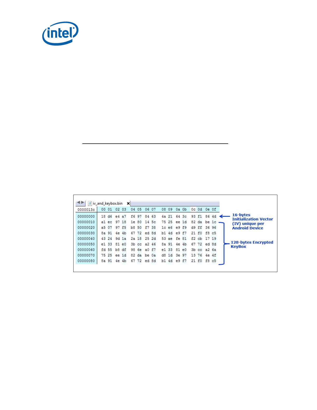
: Google* Widevine for Intel® TXE
90 Intel Confidential
E.2 Constructing Widevine* Provisioning
KeyBox File
To support Security Level 1 playback of protected content on Android devices,
Widevine Keybox must be provisioned by Customer in factory. This keybox contains a
device ID that is unique for each Android device and is the license that establishes a
root of trust between Widevine DRM servers and the Android device.
E.2.1 KeyBox Creation Procedure
1. Request KeyBox directly from Google.
2. Create appropriate unique 16-byte IV (Initialization Vector) for respective Android
device.
3. Encrypt keybox by global CEK and IV via AES-CBC encryption.
Example of encrypting KB with IV & CEK using AES-CBC:
openssl aes-128-cbc -nopad -K <16-byte-CEK> -iv <16-byte-IV> -in
GoogleKeyBox.bin -out EncryptedKB.bin
4. Write 16 bytes of IV, 128 bytes of encrypted keybox using FPT (refer to Widevine*
KeyBox Provisioning Procedure, Chapter 7)
FPT KeyBox Provisioning File Map Example
