APX7000_APX7000XE_BSM_frontCover APX Series/APX7000 Top Display Basic Service Manual 6875962M01 H APX7000
User Manual: -APX Series/APX7000 Top Display Basic Service Manual 6875962M01-H
Open the PDF directly: View PDF ![]() .
.
Page Count: 316 [warning: Documents this large are best viewed by clicking the View PDF Link!]

APX™ TWO-WAY RADIOS
APX 7000
APX 7000XE
BASIC SERVICE
MANUAL

Foreword
This manual covers all models of the ASTRO® APX™ 7000/ APX™ 7000XE digital portable radio, unless otherwise
specified. It includes all the information necessary to maintain peak product performance and maximum working time,
using levels 1 and 2 maintenance procedures. This level of service goes down to the board replacement level and is typical
of some local service centers, self-maintained customers, and distributors.
For details on radio operation or component-level troubleshooting, refer to the applicable manuals available separately. A
list of related publications is provided in the section, “ Related Publications” on page 1:v and page 2:v.
Product Safety and RF Exposure Compliance
For a list of Motorola-approved antennas, batteries, and other accessories, visit the following web site:
http://www.motorolasolutions.com
Manual Revisions
Changes which occur after this manual is printed are described in FMRs (Florida Manual Revisions). These FMRs provide
complete replacement pages for all added, changed, and deleted items, including pertinent parts list data, schematics, and
component layout diagrams. To obtain FMRs, contact the Customer Care and Services Division (refer to “Appendix B
Replacement Parts Ordering”).
Computer Software Copyrights
The Motorola products described in this manual may include copyrighted Motorola computer programs stored in
semiconductor memories or other media. Laws in the United States and other countries preserve for Motorola certain
exclusive rights for copyrighted computer programs, including, but not limited to, the exclusive right to copy or reproduce in
any form the copyrighted computer program. Accordingly, any copyrighted Motorola computer programs contained in the
Motorola products described in this manual may not be copied, reproduced, modified, reverse-engineered, or distributed in
any manner without the express written permission of Motorola. Furthermore, the purchase of Motorola products shall not
be deemed to grant either directly or by implication, estoppel, or otherwise, any license under the copyrights, patents or
patent applications of Motorola, except for the normal non-exclusive license to use that arises by operation of law in the
sale of a product.
Document Copyrights
No duplication or distribution of this document or any portion thereof shall take place without the express written permission
of Motorola. No part of this manual may be reproduced, distributed, or transmitted in any form or by any means, electronic
or mechanical, for any purpose without the express written permission of Motorola.
Disclaimer
The information in this document is carefully examined, and is believed to be entirely reliable. However, no responsibility is
assumed for inaccuracies. Furthermore, Motorola reserves the right to make changes to any products herein to improve
readability, function, or design. Motorola does not assume any liability arising out of the applications or use of any product
or circuit described herein; nor does it cover any license under its patent rights nor the rights of others.
Trademarks
MOTOROLA, MOTO, MOTOROLA SOLUTIONS and the Stylized M logo are trademarks or registered trademarks of
Motorola Trademark Holdings, LLC and are used under license. All other trademarks are the property of their respective
owners. © 2010–2013 Motorola Solutions, Inc. All rights reserved.
ATTENTION! Before using this radio, read the guide enclosed with your
radio which contains important operating instructions for
safe usage and RF energy awareness and control for
compliance with applicable standards and regulations.


iv Document History
Document History
The following major changes have been implemented in this manual since the previous edition:
Edition Description Date
6875962M01-A Initial edition Apr. 2009
6875962M01-B Added APX 7000: UHF1/700-800 and UHF1/VHF bands Nov. 2009
6875962M01-C Revert Accessory list back to Rev A. Nov. 2009
6875962M01-D Added APX 7000: UHF2/700-800 and UHF2/VHF bands Jun. 2010
6875962M01-E APX 7000: Updated Displays and Control Top parts lists.
Added Band specific RF Boards reference into Exploded
View parts list.
APX 7000XE: Initial edition for APX 7000XE (top display
model)
Feb. 2011
6875962M01-F APX 7000: Added UHF1/UHF2 info Nov. 2011
6875962M01-G APX 7000XE: Added UHF1/UHF2 info
APX 7000XE: Added dual display models
APX 7000 and APX 7000XE: Modification on specs and
model charts
May. 2012
6875962M01-H • Added Bluetooth Option Board info into Model Charts,
Basic Theory of Operations and Disassembly/
Reassembly Chapters
• Updated Model Charts (Item number changed from
01009304019 to 01009304024)
• Updated Compatibility table for APX 7000 and
APX 7000 XE.
June 2013
Commercial Warranty v
Commercial Warranty
Limited Warranty
MOTOROLA COMMUNICATION PRODUCTS
I. What This Warranty Covers And For How Long
MOTOROLA SOLUTIONS INC. (“MOTOROLA”) warrants the MOTOROLA manufactured
Communication Products listed below (“Product”) against defects in material and workmanship
under normal use and service for a period of time from the date of purchase as scheduled below:
Motorola, at its option, will at no charge either repair the Product (with new or reconditioned parts),
replace it (with a new or reconditioned Product), or refund the purchase price of the Product during
the warranty period provided it is returned in accordance with the terms of this warranty. Replaced
parts or boards are warranted for the balance of the original applicable warranty period. All replaced
parts of Product shall become the property of MOTOROLA.
This express limited warranty is extended by MOTOROLA to the original end user purchaser only
and is not assignable or transferable to any other party. This is the complete warranty for the Product
manufactured by MOTOROLA. MOTOROLA assumes no obligations or liability for additions or
modifications to this warranty unless made in writing and signed by an officer of MOTOROLA.
Unless made in a separate agreement between MOTOROLA and the original end user purchaser,
MOTOROLA does not warrant the installation, maintenance or service of the Product.
MOTOROLA cannot be responsible in any way for any ancillary equipment not furnished by
MOTOROLA which is attached to or used in connection with the Product, or for operation of the
Product with any ancillary equipment, and all such equipment is expressly excluded from this
warranty. Because each system which may use the Product is unique, MOTOROLA disclaims
liability for range, coverage, or operation of the system as a whole under this warranty.
II. General Provisions
This warranty sets forth the full extent of MOTOROLA'S responsibilities regarding the Product.
Repair, replacement or refund of the purchase price, at MOTOROLA's option, is the exclusive
remedy. THIS WARRANTY IS GIVEN IN LIEU OF ALL OTHER EXPRESS WARRANTIES. IMPLIED
WARRANTIES, INCLUDING WITHOUT LIMITATION, IMPLIED WARRANTIES OF
MERCHANTABILITY AND FITNESS FOR A PARTICULAR PURPOSE, ARE LIMITED TO THE
DURATION OF THIS LIMITED WARRANTY. IN NO EVENT SHALL MOTOROLA BE LIABLE FOR
DAMAGES IN EXCESS OF THE PURCHASE PRICE OF THE PRODUCT, FOR ANY LOSS OF
USE, LOSS OF TIME, INCONVENIENCE, COMMERCIAL LOSS, LOST PROFITS OR SAVINGS
OR OTHER INCIDENTAL, SPECIAL OR CONSEQUENTIAL DAMAGES ARISING OUT OF THE
USE OR INABILITY TO USE SUCH PRODUCT, TO THE FULL EXTENT SUCH MAY BE
DISCLAIMED BY LAW.
ASTRO APX 7000/ APX 7000XE Digital Portable Units One (1) Year
Product Accessories One (1) Year

vi Commercial Warranty
III. State Law Rights
SOME STATES DO NOT ALLOW THE EXCLUSION OR LIMITATION OF INCIDENTAL OR
CONSEQUENTIAL DAMAGES OR LIMITATION ON HOW LONG AN IMPLIED WARRANTY
LASTS, SO THE ABOVE LIMITATION OR EXCLUSIONS MAY NOT APPLY.
This warranty gives specific legal rights, and there may be other rights which may vary from state to
state.
IV. How To Get Warranty Service
You must provide proof of purchase (bearing the date of purchase and Product item serial number)
in order to receive warranty service and, also, deliver or send the Product item, transportation and
insurance prepaid, to an authorized warranty service location. Warranty service will be provided by
Motorola through one of its authorized warranty service locations. If you first contact the company
which sold you the Product, it can facilitate your obtaining warranty service. You can also call
Motorola at 1-888-567-7347 US/Canada.
V. What This Warranty Does Not Cover
A. Defects or damage resulting from use of the Product in other than its normal and customary
manner.
B. Defects or damage from misuse, accident, water, or neglect.
C. Defects or damage from improper testing, operation, maintenance, installation, alteration,
modification, or adjustment.
D. Breakage or damage to antennas unless caused directly by defects in material workmanship.
E. A Product subjected to unauthorized Product modifications, disassemblies or repairs
(including, without limitation, the addition to the Product of non-Motorola supplied equipment)
which adversely affect performance of the Product or interfere with Motorola's normal
warranty inspection and testing of the Product to verify any warranty claim.
F. Product which has had the serial number removed or made illegible.
G. Rechargeable batteries if:
H. any of the seals on the battery enclosure of cells are broken or show evidence of
tampering.
I. the damage or defect is caused by charging or using the battery in equipment or service
other than the Product for which it is specified.
J. Freight costs to the repair depot.
K. A Product which, due to illegal or unauthorized alteration of the software/firmware in the
Product, does not function in accordance with MOTOROLA's published specifications or the
FCC certification labeling in effect for the Product at the time the Product was initially
distributed from MOTOROLA.
L. Scratches or other cosmetic damage to Product surfaces that does not affect the operation of
the Product.
M. Normal and customary wear and tear.

Commercial Warranty vii
VI. Patent And Software Provisions
MOTOROLA will defend, at its own expense, any suit brought against the end user purchaser to the
extent that it is based on a claim that the Product or parts infringe a United States patent, and
MOTOROLA will pay those costs and damages finally awarded against the end user purchaser in
any such suit which are attributable to any such claim, but such defense and payments are
conditioned on the following:
A. that MOTOROLA will be notified promptly in writing by such purchaser of any notice of such
claim;
B. that MOTOROLA will have sole control of the defense of such suit and all negotiations for its
settlement or compromise; and
C. should the Product or parts become, or in MOTOROLA's opinion be likely to become, the
subject of a claim of infringement of a United States patent, that such purchaser will permit
MOTOROLA, at its option and expense, either to procure for such purchaser the right to
continue using the Product or parts or to replace or modify the same so that it becomes
noninfringing or to grant such purchaser a credit for the Product or parts as depreciated and
accept its return. The depreciation will be an equal amount per year over the lifetime of the
Product or parts as established by MOTOROLA.
MOTOROLA will have no liability with respect to any claim of patent infringement which is based
upon the combination of the Product or parts furnished hereunder with software, apparatus or
devices not furnished by MOTOROLA, nor will MOTOROLA have any liability for the use of ancillary
equipment or software not furnished by MOTOROLA which is attached to or used in connection with
the Product. The foregoing states the entire liability of MOTOROLA with respect to infringement of
patents by the Product or any parts thereof.
Laws in the United States and other countries preserve for MOTOROLA certain exclusive rights for
copyrighted MOTOROLA software such as the exclusive rights to reproduce in copies and distribute
copies of such Motorola software. MOTOROLA software may be used in only the Product in which
the software was originally embodied and such software in such Product may not be replaced,
copied, distributed, modified in any way, or used to produce any derivative thereof. No other use
including, without limitation, alteration, modification, reproduction, distribution, or reverse
engineering of such MOTOROLA software or exercise of rights in such MOTOROLA software is
permitted. No license is granted by implication, estoppel or otherwise under MOTOROLA patent
rights or copyrights.
VII. Governing Law
This Warranty is governed by the laws of the State of Illinois, USA.

viii Commercial Warranty
Notes

ASTRO APX 7000/ APX 7000XE
Digital Portable Radios
Section 1
APX 7000

Notes

Table of Contents Sec 1: iii
Table of Contents
Model Numbering, Charts, and Specifications....................................... 1:ix
Portable Radio Model Numbering System ..............................................................................................1:ix
ASTRO APX 7000 700–800 MHz and VHF Model Chart.........................................................................1:x
ASTRO APX 7000 700–800 MHz and UHF1 Model Chart......................................................................1:xi
ASTRO APX 7000 UHF1 and VHF Model Chart.................................................................................... 1:xii
ASTRO APX 7000 UHF1 and UHF2 Model Chart................................................................................. 1:xiii
ASTRO APX 7000 700–800 MHz and UHF2 Model Chart.................................................................... 1:xiv
ASTRO APX 7000 UHF2 and VHF Model Chart....................................................................................1:xv
Specifications for VHF Radios............................................................................................................... 1:xvi
Specifications for 700–800 MHz Radios............................................................................................... 1:xvii
Specifications for UHF1 Radios........................................................................................................... 1:xviii
Specifications for UHF2 Radios............................................................................................................. 1:xix
Chapter 1 Introduction ...................................................................... 1:1-1
1.1 Manual Contents......................................................................................................................... 1:1-1
1.2 Notations Used in This Manual................................................................................................... 1:1-1
1.3 Radio Description ....................................................................................................................... 1:1-2
1.4 FLASHport®................................................................................................................................1:1-2
Chapter 2 Basic Maintenance........................................................... 1:2-1
2.1 General Maintenance ................................................................................................................. 1:2-1
2.2 Handling Precautions.................................................................................................................. 1:2-1
Chapter 3 Basic Theory of Operation .............................................. 1:3-1
3.1 Major Assemblies ....................................................................................................................... 1:3-1
3.2 Analog Mode of Operation.......................................................................................................... 1:3-3
3.3 Digital (ASTRO) Mode of Operation ......................................................................................... 1:3-11
3.4 Controller Section ..................................................................................................................... 1:3-12
Chapter 4 Recommended Test Equipment and Service Aids ....... 1:4-1
4.1 Recommended Test Equipment ................................................................................................. 1:4-1
4.2 Service Aids................................................................................................................................ 1:4-2
4.3 Field Programming ..................................................................................................................... 1:4-3
Chapter 5 Performance Checks ....................................................... 1:5-1
5.1 Test Equipment Setup ................................................................................................................ 1:5-1
5.2 Display Radio Test Mode (Dual-Display Version)....................................................................... 1:5-3
5.3 Top-Display Version Radio Test Mode ....................................................................................... 1:5-7
5.4 Receiver Performance Checks ................................................................................................... 1:5-9
5.5 Transmitter Performance Checks ............................................................................................. 1:5-10

Sec 1: iv Table of Contents
Chapter 6 Radio Alignment Procedures.......................................... 1:6-1
6.1 Test Setup................................................................................................................................... 1:6-1
6.2 Tuner Main Menu........................................................................................................................ 1:6-2
6.3 Softpot......................................................................................................................................... 1:6-2
6.4 Radio Information........................................................................................................................ 1:6-4
6.5 Transmitter Alignments ............................................................................................................... 1:6-4
6.6 Front End Filter Alignment ........................................................................................................ 1:6-22
6.7 Performance Testing................................................................................................................. 1:6-24
Chapter 7 Encryption ........................................................................ 1:7-1
7.1 Load an Encryption Key.............................................................................................................. 1:7-1
7.2 Multikey Feature ......................................................................................................................... 1:7-1
7.3 Select an Encryption Key............................................................................................................ 1:7-2
7.4 Select an Encryption Index ......................................................................................................... 1:7-3
7.5 Erase an Encryption Key ............................................................................................................ 1:7-3
Chapter 8 Disassembly/Reassembly Procedures .......................... 1:8-1
8.1 APX 7000 Exploded View (Main Subassemblies) ...................................................................... 1:8-1
8.2 Required Tools and Supplies...................................................................................................... 1:8-5
8.3 Fastener Torque Chart................................................................................................................ 1:8-5
8.4 Antenna....................................................................................................................................... 1:8-6
8.5 Battery......................................................................................................................................... 1:8-7
8.6 Universal Connector Cover....................................................................................................... 1:8-10
8.7 Radio Disassembly ................................................................................................................... 1:8-12
8.8 Serviceable Components of the Main Sub-Assemblies ............................................................ 1:8-20
8.9 Radio Reassembly.................................................................................................................... 1:8-31
8.10 Ensuring Radio Submergibility.................................................................................................. 1:8-39
Chapter 9 Basic Troubleshooting .................................................... 1:9-1
9.1 Power-Up Error Codes................................................................................................................ 1:9-1
9.2 Operational Error Codes ............................................................................................................. 1:9-2
9.3 Receiver Troubleshooting ........................................................................................................... 1:9-2
9.4 Transmitter Troubleshooting ....................................................................................................... 1:9-3
9.5 Encryption Troubleshooting ........................................................................................................ 1:9-4
9.6 Bluetooth Option / Expansion Board Troubleshooting ................................................................ 1:9-4
9.7 Bluetooth Troubleshooting .......................................................................................................... 1:9-5
Chapter 10 Exploded Views and Parts Lists................................... 1:10-1
10.1 APX 7000 Dual Display Exploded View.................................................................................... 1:10-2
10.2 APX 7000 Dual Display Exploded View Parts List.................................................................... 1:10-3
10.3 APX 7000 Top Display Exploded View ..................................................................................... 1:10-4
10.4 APX 7000 Top Display Exploded View Parts List ..................................................................... 1:10-5
Index..................................................................................................1:Index-1

List of Tables Sec 1: v
List of Tables
Table 1-1. ASTRO APX 7000 Basic Features .................................................................................... 1:1-2
Table 4-1. Recommended Test Equipment......................................................................................... 1:4-1
Table 4-2. Service Aids....................................................................................................................... 1:4-2
Table 5-1. Initial Equipment Control Settings...................................................................................... 1:5-2
Table 5-2. Test-Mode Displays............................................................................................................ 1:5-3
Table 5-3. Test Frequencies (MHz)..................................................................................................... 1:5-5
Table 5-4. Test Environments ............................................................................................................. 1:5-5
Table 5-5. Receiver Performance Checks .......................................................................................... 1:5-9
Table 5-6. Receiver Tests for ASTRO Conventional Channels* ......................................................... 1:5-9
Table 5-7. Transmitter Performance Checks .................................................................................... 1:5-10
Table 5-8. Transmitter Tests for ASTRO Conventional Channels* ................................................... 1:5-11
Table 6-1. Reference Oscillator Alignment ......................................................................................... 1:6-6
Table 7-1. Encryption Key Zeroization Options................................................................................... 1:7-4
Table 8-1. APX 7000 Partial Exploded View Parts List....................................................................... 1:8-4
Table 8-2. Required Tools and Supplies ............................................................................................. 1:8-5
Table 8-3. Required Tools and Supplies ............................................................................................. 1:8-5
Table 9-1. Power-Up Error Code Displays..........................................................................................1:9-1
Table 9-2. Operational Error Code Displays .......................................................................................1:9-2
Table 9-3. Receiver Troubleshooting Chart ........................................................................................1:9-2
Table 9-4. Transmitter Troubleshooting Chart .................................................................................... 1:9-3
Table 9-5. Encryption Troubleshooting Chart ..................................................................................... 1:9-4
Table 9-6. Bluetooth Option/Expansion Board Troubleshooting Chart ............................................... 1:9-4
Table 9-7. Bluetooth Troubleshooting Chart .......................................................................................1:9-5
Table 10-1. APX 7000 Exploded Views .............................................................................................1:10-1
Table 10-2. Compatibility Table........................................................................................................... 1:10-6
Related Publications
APX 7000 Digital Portable Radios Full Feature User Guide ..................................................... 6875945M01
APX 7000 Digital Portable Radios Half Feature User Guide..................................................... 6875952M01
APX 7000 Digital Portable Radios Detailed Service Manual..................................................... 6875961M01
APX 7000 Digital Portable Radios User Guide (CD): VHF/700–800 MHz ................................. PMLN5335_
APX 7000 Digital Portable Radios User Guide (CD): UHF1/700–800 MHz ............................... PMLN5335_
APX 7000 Digital Portable Radios User Guide (CD): UHF1/VHF .............................................. PMLN5335_
APX 7000 Digital Portable Radios User Guide (CD): UHF2/700–800 MHz ............................... PMLN5335_
APX 7000 Digital Portable Radios User Guide (CD): UHF2/VHF .............................................. PMLN5335_
APX 7000 Digital Portable Radios User Guide (CD): UHF1/UHF2 ............................................ PMLN5335_

Sec 1: vi List of Figures
List of Figures
Figure 3-1. APX 7000 Overall Block Diagram (VOCON Board MNCN6200/ MNCN6201) .................. 1:3-2
Figure 3-2. APX 7000 Overall Block Diagram (VOCON Board MNCN6202/ MNCN6203) .................. 1:3-2
Figure 3-3. Receiver Block Diagram (VHF and 700–800 MHz)............................................................ 1:3-3
Figure 3-4. Receiver Block Diagram (UHF1 and 700–800 MHz) ......................................................... 1:3-3
Figure 3-5. Receiver Block Diagram (UHF1 and VHF)......................................................................... 1:3-4
Figure 3-6. Receiver Block Diagram (UHF1 and UHF2) ...................................................................... 1:3-4
Figure 3-7. Receiver Block Diagram (UHF2 and 700–800 MHz) ......................................................... 1:3-5
Figure 3-8. Receiver Block Diagram (UHF2 and VHF)......................................................................... 1:3-5
Figure 3-9. GPS Diagram ..................................................................................................................... 1:3-6
Figure 3-10. Transceiver (VHF and 700–800 MHz) Block Diagram ....................................................... 1:3-8
Figure 3-11. Transceiver (UHF1 and 700–800 MHz) Block Diagram ..................................................... 1:3-8
Figure 3-12. Transceiver (VHF and UHF1) Block Diagram .................................................................... 1:3-9
Figure 3-13. Transceiver (UHF1 and UHF2) Block Diagram.................................................................. 1:3-9
Figure 3-14. Transceiver (UHF2 and 700–800 MHz) Block Diagram ................................................... 1:3-10
Figure 3-15. Transceiver (VHF and UHF2) Block Diagram .................................................................. 1:3-10
Figure 3-16. Controller Block Diagram ................................................................................................. 1:3-12
Figure 5-1. Performance Checks Test Setup........................................................................................1:5-1
Figure 6-1. Radio Alignment Test Setup............................................................................................... 1:6-1
Figure 6-2. Tuner Software Main Menu................................................................................................ 1:6-2
Figure 6-3. Typical Softpot Screen ....................................................................................................... 1:6-3
Figure 6-4. Radio Information Screen .................................................................................................. 1:6-4
Figure 6-5. Reference Oscillator Alignment Screen (VHF and 700–800 MHz,
UHF1 and 700–800 MHz, and UHF2 and 700–800 MHz)...................................................................... 1:6-5
Figure 6-6. Reference Oscillator Alignment Screen (UHF1 and VHF, and UHF1 and UHF2).............. 1:6-5
Figure 6-7. Reference Oscillator Alignment Screen (UHF2 and VHF) ................................................. 1:6-6
Figure 6-8. Transmit Power Characterization Points Alignment Screen (VHF and 700–800 MHz)...... 1:6-7
Figure 6-9. Transmit Power Characterization Points Alignment Screen (UHF1 and 700–800 MHz) ... 1:6-8
Figure 6-10. Transmit Power Characterization Points Alignment Screen (UHF1 and VHF)................... 1:6-8
Figure 6-11. Transmit Power Characterization Points Alignment Screen (UHF1 and UHF2) ................ 1:6-9
Figure 6-12. Transmit Power Characterization Points Alignment Screen (UHF2 and 700–800 MHz) ... 1:6-9
Figure 6-13. Transmit Power Characterization Points Alignment Screen (UHF2 and VHF)................. 1:6-10
Figure 6-14. Transmit Power Characterization Alignment Screen (VHF and 700–800 MHz) .............. 1:6-11
Figure 6-15. Transmit Power Characterization Alignment Screen (UHF1 and 700–800 MHz) ............ 1:6-11
Figure 6-16. Transmit Power Characterization Alignment Screen (UHF1 and VHF) ........................... 1:6-12
Figure 6-17. Transmit Power Characterization Alignment Screen (UHF1 and UHF2) ......................... 1:6-12
Figure 6-18. Transmit Power Characterization Alignment Screen (UHF2 and 700–800 MHz) ............ 1:6-13
Figure 6-19. Transmit Power Characterization Alignment Screen (UHF2 and VHF) ........................... 1:6-13
Figure 6-20. PA Saturation Referencing Alignment Screen (VHF and 700–800 MHz) ........................ 1:6-14
Figure 6-21. PA Saturation Referencing Alignment Screen (UHF1 and 700–800 MHz) ...................... 1:6-15
Figure 6-22. PA Saturation Referencing Alignment Screen (UHF1 and VHF) ..................................... 1:6-15
Figure 6-23. PA Saturation Referencing Alignment Screen (UHF1 and UHF2) ................................... 1:6-16
Figure 6-24. PA Saturation Referencing Alignment Screen (UHF2 and 700–800 MHz) ...................... 1:6-16
Figure 6-25. PA Saturation Referencing Alignment Screen (UHF2 and VHF) ..................................... 1:6-17
Figure 6-26. Transmit Deviation Balance Alignment Screen (VHF and 700–800 MHz)....................... 1:6-18
Figure 6-27. Transmit Deviation Balance Alignment Screen (UHF1 and 700–800 MHz)..................... 1:6-19
Figure 6-28. Transmit Deviation Balance Alignment Screen (UHF1 and VHF).................................... 1:6-19
Figure 6-29. Transmit Deviation Balance Alignment Screen (UHF1 and UHF2).................................. 1:6-20
Figure 6-30. Transmit Deviation Balance Alignment Screen (UHF2 and 700–800 MHz)..................... 1:6-20
Figure 6-31. Transmit Deviation Balance Alignment Screen (UHF2 and VHF).................................... 1:6-21
Figure 6-32. Front End Filter Alignment Screen (UHF1) ...................................................................... 1:6-22

List of Figures Sec 1: vii
Figure 6-33. Front End Filter Alignment Screen (UHF2) ...................................................................... 1:6-23
Figure 6-34. Bit Error Rate Screen....................................................................................................... 1:6-25
Figure 6-35. Transmitter Test Pattern Screen ...................................................................................... 1:6-26
Figure 8-1. APX 7000 Dual Display Partial Exploded View.................................................................. 1:8-2
Figure 8-2. APX 7000 Top Display Partial Exploded View ................................................................... 1:8-3
Figure 8-3. Attaching the Antenna........................................................................................................ 1:8-6
Figure 8-4. Removing the Antenna ...................................................................................................... 1:8-6
Figure 8-5. Attaching Battery – Battery Seal ........................................................................................ 1:8-7
Figure 8-6. Attaching Battery – Memory Door......................................................................................1:8-8
Figure 8-7. Attaching Battery – Slide into Position ............................................................................... 1:8-8
Figure 8-8. Squeezing the Release Latches ........................................................................................1:8-9
Figure 8-9. Removing the Battery ........................................................................................................ 1:8-9
Figure 8-10. Removing the Thumb Screw............................................................................................1:8-10
Figure 8-11. Engaging Hook and Seating Cover.................................................................................. 1:8-11
Figure 8-12. Securing the Cover .......................................................................................................... 1:8-11
Figure 8-13. Remove Center Screws ................................................................................................... 1:8-12
Figure 8-14. Remove Bottom Screws .................................................................................................. 1:8-12
Figure 8-15. Remove Top Screws ........................................................................................................ 1:8-13
Figure 8-16. Remove Speaker Module ................................................................................................ 1:8-13
Figure 8-17. Remove Flex Connectors and Expansion Board Assembly ............................................ 1:8-14
Figure 8-18. Unlock Levers .................................................................................................................. 1:8-14
Figure 8-19. Remove Bluetooth Option Board ..................................................................................... 1:8-14
Figure 8-20. Remove Antenna Coax Cable Connector........................................................................ 1:8-15
Figure 8-21. Remove Housing ............................................................................................................. 1:8-15
Figure 8-22. Remove Back Chassis Assembly from Main Chassis Assembly..................................... 1:8-16
Figure 8-23. Remove RF Board Assembly........................................................................................... 1:8-17
Figure 8-24. Remove VOCON Board Assembly .................................................................................. 1:8-18
Figure 8-25. Remove Knobs and Fastener Hardware.......................................................................... 1:8-19
Figure 8-26. Remove Control Top Bezel Assembly.............................................................................. 1:8-19
Figure 8-27. Remove Control Top Assembly (9) .................................................................................. 1:8-19
Figure 8-28. Serviceable Components – Main Chassis Assembly....................................................... 1:8-20
Figure 8-29. Remove Chassis Ground Contact ................................................................................... 1:8-22
Figure 8-30. Control Top Assembly and Control Top Seal ................................................................... 1:8-22
Figure 8-31. Top Bezel Assembly......................................................................................................... 1:8-23
Figure 8-32. VOCON Board Assembly................................................................................................. 1:8-23
Figure 8-33. RF Board Assembly ......................................................................................................... 1:8-24
Figure 8-34. Expansion Board Assembly ............................................................................................. 1:8-25
Figure 8-35. Back Chassis Assembly (Dual Display Version) .............................................................. 1:8-25
Figure 8-36. Back Chassis Assembly (Top Display Version)................................................................ 1:8-27
Figure 8-37. Main Housing Assembly (Dual Display Version).............................................................. 1:8-27
Figure 8-38. Main Housing Assembly (Top Display Version) ............................................................... 1:8-28
Figure 8-39. Speaker Module............................................................................................................... 1:8-29
Figure 8-40. Speaker Grille Assembly.................................................................................................. 1:8-30
Figure 8-41. Control Top Bezel Assembly ............................................................................................ 1:8-31
Figure 8-42. Top Bezel Assembly......................................................................................................... 1:8-31
Figure 8-43. Inspect Pads .................................................................................................................... 1:8-32
Figure 8-44. Insert VOCON Board ....................................................................................................... 1:8-33
Figure 8-45. Connect RF Board to VOCON Board .............................................................................. 1:8-33
Figure 8-46. Place Back Chassis ......................................................................................................... 1:8-34
Figure 8-47. Place Housing into Main Chassis .................................................................................... 1:8-34
Figure 8-48. Assemble Expansion Board Assembly ............................................................................ 1:8-35
Figure 8-49. Insert Flex Connectors..................................................................................................... 1:8-35
Figure 8-50. Assemble Bluetooth Option Board................................................................................... 1:8-36
Figure 8-51. Lock Levers...................................................................................................................... 1:8-36

Sec 1: viii List of Figures
Figure 8-52. Lubricate Main Chassis.................................................................................................... 1:8-36
Figure 8-53. Insert Speaker Module ..................................................................................................... 1:8-37
Figure 8-54. Insert Top Screws ............................................................................................................ 1:8-37
Figure 8-55. Remove Center Screws ................................................................................................... 1:8-38
Figure 8-56. Insert Center Screws ....................................................................................................... 1:8-38
Figure 8-57. Insert Bottom Screws ....................................................................................................... 1:8-38
Figure 8-58. Attaching Grille Eliminator................................................................................................ 1:8-41
Figure 10-1. APX 7000 Dual Display Exploded View........................................................................... 1:10-2
Figure 10-2. APX 7000 Top Display Exploded View ............................................................................ 1:10-4

Model Numbering, Charts, and Specifications
Portable Radio Model Numbering System
Position 1 – Type of Unit
H = Hand-Held Portable
Positions 2 & 3 – Model Series
Position 4 - Frequency Band
Less than 29.7MHz
29.7 to 35.99MHz
36 to 41.99MHz
42 to 50MHz
66 to 80MHz
74 to 90MHz
Product Specific
136 to 162MHz
146 to 178MHz
174 to 210MHz
190 to 235MHz
336 to 410MHz
380 to 470MHz
438 to 482MHz
470 to 520MHz
Dual Band Capable
764 to 870MHz
825 to 870MHz
896 to 941MHz
1.0 to 1.6GHz
1.5 to 2.0GHz
Values given represent range only; they are
not absolute.
Position 5 – Power Level
0 to 0.7 Watts
0.7 to 0.9 Watts
1.0 to 3.9 Watts
4.0 to 5.0 Watts
5.1 to 6.0 Watts
6.1 to 10 Watts
0 to 6 Watts
Position 6 – Physical Packages
RF Modem Operation
Receiver Only
Standard Control; No Display
Standard Control; With Display
Limited Keypad; No Display
Limited Keypad; With Display
Full Keypad; No Display
Full Keypad; With Display
Limited Controls; No Display
Limited Controls; Basic Display
Limited Controls; Limited Display
Rotary Controls; Standard Display
Enhanced Controls; Enhanced Display
Low Profile; No Display
Low Profile; Basic Display
Low Profile; Basic Display, Full Keypad
Position 7 – Channel Spacing
1 = 5kHz
2 = 6.25kHz
3 = 10kHz
4 = 12.5kHz
5 = 15kHz
6 = 20/25kHz
7 = 30kHz
9 = Variable/Programmable
Typical Model Number:
Position:
Position 8 – Primary Operation
Conventional/Simplex
Conventional/Duplex
Trunked Twin Type
Dual Mode Trunked
Dual Mode Trunked/Duplex
Trunked Type I
Trunked Type II
FDMA* Digital Dual Mode
TDMA** Digital Dual Mode
Single Sideband
Global Positioning Satellite Capable
Amplitude Companded Sideband (ACSB)
Programmable
* FDMA = Frequency Division Multiple Access
** TDMA = Time Division Multiple Access
Position 9 – Primary System Type
Conventional
Privacy Plus
Clear SMARTNET
Advanced Conventional Stat-Alert
Enhanced Privacy Plus
Nauganet 888 Series
Japan Specialized Mobile Radio (JSMR)
Multi-Channel Access (MCA)
CoveragePLUS
MPT1327* – Public
MPT1327* – Private
Radiocom
Tone Signalling
Binary Signalling
Phonenet
Programmable
Secure Conventional
Secure SMARTNET
* MPT = Ministry of Posts and Telecommunications
Position 10 – Feature Level
1 = Basic
2 = Limited Package
3 = Limited Plus
4 = Intermediate
5 = Standard Package
6 = Standard Plus
7 = Expanded Package
8 = Expanded Plus
9 = Full Feature/
Programmable
Position 11 – Version
Version Letter (Alpha) – Major Change
Position 12 –
Unique Model Variations
C = Cenelec
N = Standard Package
Positions 13 – 16
SP Model Suffix
123 4 5 6 7 8 910111213141516
H97 T GD 9 P W 1 A N S P 0 1
97 = APX 7000
A
B
C
D
F
G
H
J
K
L
M
=
=
=
=
=
=
=
=
=
=
=
P
Q
R
S
T
U
V
W
Y
Z
=
=
=
=
=
=
=
=
=
=
A
B
C
D
E
F
G
=
=
=
=
=
=
=
A
B
C
D
E
F
G
H
J
K
L
M
N
P
Q
R
=
=
=
=
=
=
=
=
=
=
=
=
=
=
=
=
A
B
C
D
E
F
G
H
J
K
L
M
P
=
=
=
=
=
=
=
=
=
=
=
=
=
A
B
C
D
E
F
G
H
J
K
L
M
N
P
Q
W
X
Y
=
=
=
=
=
=
=
=
=
=
=
=
=
=
=
=
=
=

Sec 1: x ASTRO APX 7000 700–800 MHz and VHF Model Chart
ASTRO APX 7000 700–800 MHz and VHF Model Chart
MODEL NUMBER:
FCC ID:
H97TGD9PW1_N
AZ489FT7036
MODEL DESCRIPTION: 700–800 / VHF, APX 7000
Top Display Model
Dual Display Model
ITEM NUMBER DESCRIPTION
XX01009304001 Sub-Assembly, Main Chassis
X01009304024 Display, Color
●●01009304004 Grille, Speaker, Black
●●01009304005 Grille, Speaker, Safety Yellow
●●01009304006 Grille, Speaker, Impact Green
XX0375962B01 Screw, Chassis (M2.5 x 0.45 x 31mm)
XX0375962B02 Screw, Chassis (M2.5 x 0.45 x 25mm)
XX0375962B03 Screw, Chassis (M2.5 x 0.45 x 7.3mm)
XX1110027B23 Grease, Fluorocarbon Lubricant
XX1375044C02 Assembly, Control Top
XX1375579B03 Bezel, Outer Top
XX1575250H01 Cover, Universal Connector
X1575356H01 Cover, Belt Clip, Top Display
XX32009064001 Plug, Controls Flex Support
XX3271829H01 Seal, Battery Connector
XX3275623B02 Pad, Thermal, Outer
XX3275882B01 Seal, Memory Card Portal
XX3371896H01 Label, Grille Top APX 7000
X3385836D09 Label, Blank, Top Display
XX3875126H01 Cap, Chassis Screw Boss
XX75009299001 Pad, Thermal, Inner
XX7575218H01 Pad, Thermal, Expansion / VOCON
XXMHLN6977_/ MHLN7035_*Assembly, Expansion Board
XMNCN6200_/ MNCN6202_** Assembly, VOCON Board, Dual Display
XMNCN6201_/ MNCN6203_** Assembly, VOCON Board, Top Display
X01009304011 Assembly, Main Housing, Dual Display, Black
●01009304007 Assembly, Main Housing, Dual Display, Safety Yellow
●01009304008 Assembly, Main Housing, Dual Display, Impact Green
●01009304015 Assembly, Main Housing, Top Display, Black
●01009304009 Assembly, Main Housing, Top Display, Safety Yellow
●01009304010 Assembly, Main Housing, Top Display, Impact Green
XXNHN7002_ Assembly, Speaker Module
XNHN7017_ Sub-Assembly, Back Chassis, Dual Display
XNHN7004_ Sub-Assembly, Back Chassis, Top Display
XXMNUR4001_ Assembly, RF Board
ooNNTN8160_ Bluetooth Upgrade Kit
∆∆NUUK6000_ Assembly Bluetooth Option Board
XXPMLN5335_ User Guide CD, APX 7000/ APX 7000XE
Note:
X= Item Included.
●= Option available.
o= Optional.
∆= Comes with unit equipped with Bluetooth Option Board
•Refer Appendix A for antennas, batteries and other applicable accessories.
*With TI Chipset.
** With PCN Display Vocon.

ASTRO APX 7000 700–800 MHz and UHF1 Model Chart Sec 1: xi
ASTRO APX 7000 700–800 MHz and UHF1 Model Chart
MODEL NUMBER:
FCC ID:
H97TGD9PW1_N
AZ489FT7040
MODEL DESCRIPTION: 700–800 / UHF1, APX 7000
Top Display Model
Dual Display Model
ITEM NUMBER DESCRIPTION
XX01009304001 Sub-Assembly, Main Chassis
X01009304024 Display, Color
●●01009304004 Grille, Speaker, Black
●●01009304005 Grille, Speaker, Safety Yellow
●●01009304006 Grille, Speaker, Impact Green
XX0375962B01 Screw, Chassis (M2.5 x 0.45 x 31mm)
XX0375962B02 Screw, Chassis (M2.5 x 0.45 x 25mm)
XX0375962B03 Screw, Chassis (M2.5 x 0.45 x 7.3mm)
XX1110027B23 Grease, Fluorocarbon Lubricant
XX1375044C02 Assembly, Control Top
XX1375579B03 Bezel, Outer Top
XX1575250H01 Cover, Universal Connector
X1575356H01 Cover, Belt Clip, Top Display
XX32009064001 Plug, Controls Flex Support
XX3271829H01 Seal, Battery Connector
XX3275623B02 Pad, Thermal, Outer
XX3275882B01 Seal, Memory Card Portal
XX3371896H01 Label, Grille Top APX 7000
X3385836D09 Label, Blank, Top Display
XX3875126H01 Cap, Chassis Screw Boss
XX75009299001 Pad, Thermal, Inner
XX7575218H01 Pad, Thermal, Expansion / VOCON
XXMHLN6977_/ MHLN7035_*Assembly, Expansion Board
XMNCN6200_/ MNCN6202_** Assembly, VOCON Board, Dual Display
XMNCN6201_/ MNCN6203_** Assembly, VOCON Board, Top Display
●01009304011 Assembly, Main Housing, Dual Display, Black
●01009304007 Assembly, Main Housing, Dual Display, Safety Yellow
●01009304008 Assembly, Main Housing, Dual Display, Impact Green
●01009304015 Assembly, Main Housing, Top Display, Black
●01009304009 Assembly, Main Housing, Top Display, Safety Yellow
●01009304010 Assembly, Main Housing, Top Display, Impact Green
XXNHN7002_ Assembly, Speaker Module
XNHN7017_ Sub-Assembly, Back Chassis, Dual Display
XNHN7004_ Sub-Assembly, Back Chassis, Top Display
XXMNUS4000_ Assembly, RF Board
ooNNTN8160_ Bluetooth Upgrade Kit
∆∆NUUK6000_ Assembly Bluetooth Option Board
XXPMLN5335_ User Guide CD, APX 7000/ APX 7000XE
Note:
X= Item Included.
●= Option available.
o= Optional.
∆= Comes with unit equipped with Bluetooth Option Board
•Refer Appendix A for antennas, batteries and other applicable accessories.
*With TI Chipset.
** With PCN Display Vocon.

Sec 1: xii ASTRO APX 7000 UHF1 and VHF Model Chart
ASTRO APX 7000 UHF1 and VHF Model Chart
MODEL NUMBER:
FCC ID:
H97TGD9PW1_N
AZ489FT4886
MODEL DESCRIPTION: UHF1 / VHF, APX 7000
Top Display Model
Dual Display Model
ITEM NUMBER DESCRIPTION
XX01009304001 Sub-Assembly, Main Chassis
X01009304024 Display, Color
●●01009304004 Grille, Speaker, Black
●●01009304005 Grille, Speaker, Safety Yellow
●●01009304006 Grille, Speaker, Impact Green
XX0375962B01 Screw, Chassis (M2.5 x 0.45 x 31mm)
XX0375962B02 Screw, Chassis (M2.5 x 0.45 x 25mm)
XX0375962B03 Screw, Chassis (M2.5 x 0.45 x 7.3mm)
XX1110027B23 Grease, Fluorocarbon Lubricant
XX1375044C02 Assembly, Control Top
XX1375579B03 Bezel, Outer Top
XX1575250H01 Cover, Universal Connector
X1575356H01 Cover, Belt Clip, Top Display
XX32009064001 Plug, Controls Flex Support
XX3271829H01 Seal, Battery Connector
XX3275623B02 Pad, Thermal, Outer
XX3275882B01 Seal, Memory Card Portal
XX3371896H01 Label, Grille Top APX 7000
X3385836D09 Label, Blank, Top Display
XX3875126H01 Cap, Chassis Screw Boss
XX75009299001 Pad, Thermal, Inner
XX7575218H01 Pad, Thermal, Expansion / VOCON
XXMHLN6977_/ MHLN7035_*Assembly, Expansion Board
XMNCN6200_/ MNCN6202_** Assembly, VOCON Board, Dual Display
XMNCN6201_/ MNCN6203_** Assembly, VOCON Board, Top Display
●01009304011 Assembly, Main Housing, Dual Display, Black
●01009304007 Assembly, Main Housing, Dual Display, Safety Yellow
●01009304008 Assembly, Main Housing, Dual Display, Impact Green
●01009304015 Assembly, Main Housing, Top Display, Black
●01009304009 Assembly, Main Housing, Top Display, Safety Yellow
●01009304010 Assembly, Main Housing, Top Display, Impact Green
XXNHN7002_ Assembly, Speaker Module
XNHN7017_ Sub-Assembly, Back Chassis, Dual Display
XNHN7004_ Sub-Assembly, Back Chassis, Top Display
XXMNUT4000_ Assembly, RF Board
ooNNTN8160_ Bluetooth Upgrade Kit
∆∆NUUK6000_ Assembly Bluetooth Option Board
XXPMLN5335_ User Guide CD, APX 7000/ APX 7000XE
Note:
X= Item Included.
●= Option available.
o= Optional.
∆= Comes with unit equipped with Bluetooth Option Board
•Refer Appendix A for antennas, batteries and other applicable accessories.
*With TI Chipset.
** With PCN Display Vocon.

ASTRO APX 7000 UHF1 and UHF2 Model Chart Sec 1: xiii
ASTRO APX 7000 UHF1 and UHF2 Model Chart
MODEL NUMBER:
FCC ID:
H97TGD9PW1_N
AZ489FT4906
MODEL DESCRIPTION: UHF1 / UHF2, APX 7000
Top Display Model
Dual Display Model
ITEM NUMBER DESCRIPTION
XX01009304001 Sub-Assembly, Main Chassis
X01009304024 Display, Color
●●01009304004 Grille, Speaker, Black
●●01009304005 Grille, Speaker, Safety Yellow
●●01009304006 Grille, Speaker, Impact Green
XX0375962B01 Screw, Chassis (M2.5 x 0.45 x 31mm)
XX0375962B02 Screw, Chassis (M2.5 x 0.45 x 25mm)
XX0375962B03 Screw, Chassis (M2.5 x 0.45 x 7.3mm)
XX1110027B23 Grease, Fluorocarbon Lubricant
XX1375044C02 Assembly, Control Top
XX1375579B03 Bezel, Outer Top
XX1575250H01 Cover, Universal Connector
X1575356H01 Cover, Belt Clip, Top Display
XX32009064001 Plug, Controls Flex Support
XX3271829H01 Seal, Battery Connector
XX3275623B02 Pad, Thermal, Outer
XX3275882B01 Seal, Memory Card Portal
XX3371896H01 Label, Grille Top APX 7000
X3385836D09 Label, Blank, Top Display
XX3875126H01 Cap, Chassis Screw Boss
XX75009299001 Pad, Thermal, Inner
XX7575218H01 Pad, Thermal, Expansion / VOCON
XXMHLN6977_/ MHLN7035_*Assembly, Expansion Board
XMNCN6200_/ MNCN6202_** Assembly, VOCON Board, Dual Display
XMNCN6201_/ MNCN6203_** Assembly, VOCON Board, Top Display
●01009304011 Assembly, Main Housing, Dual Display, Black
●01009304007 Assembly, Main Housing, Dual Display, Safety Yellow
●01009304008 Assembly, Main Housing, Dual Display, Impact Green
●01009304015 Assembly, Main Housing, Top Display, Black
●01009304009 Assembly, Main Housing, Top Display, Safety Yellow
●01009304010 Assembly, Main Housing, Top Display, Impact Green
XXNHN7002_ Assembly, Speaker Module
XNHN7017_ Sub-Assembly, Back Chassis, Dual Display
XNHN7004_ Sub-Assembly, Back Chassis, Top Display
XXMNUE7367_ Assembly, RF Board
ooNNTN8160_ Bluetooth Upgrade Kit
∆∆NUUK6000_ Assembly Bluetooth Option Board
XXPMLN5335_ User Guide CD, APX 7000/ APX 7000XE
Note:
X= Item Included.
●= Option available.
o= Optional.
∆= Comes with unit equipped with Bluetooth Option Board
•Refer Appendix A for antennas, batteries and other applicable accessories.
*With TI Chipset.
** With PCN Display Vocon.

Sec 1: xiv ASTRO APX 7000 700–800 MHz and UHF2 Model Chart
ASTRO APX 7000 700–800 MHz and UHF2 Model Chart
MODEL NUMBER:
FCC ID:
H97TGD9PW1_N
AZ489FT7042
MODEL DESCRIPTION: 700–800 / UHF2, APX 7000
Top Display Model
Dual Display Model
ITEM NUMBER DESCRIPTION
XX01009304001 Sub-Assembly, Main Chassis
X01009304024 Display, Color
●●01009304004 Grille, Speaker, Black
●●01009304005 Grille, Speaker, Safety Yellow
●●01009304006 Grille, Speaker, Impact Green
XX0375962B01 Screw, Chassis (M2.5 x 0.45 x 31mm)
XX0375962B02 Screw, Chassis (M2.5 x 0.45 x 25mm)
XX0375962B03 Screw, Chassis (M2.5 x 0.45 x 7.3mm)
XX1110027B23 Grease, Fluorocarbon Lubricant
XX1375044C02 Assembly, Control Top
XX1375579B03 Bezel, Outer Top
XX1575250H01 Cover, Universal Connector
X1575356H01 Cover, Belt Clip, Top Display
XX32009064001 Plug, Controls Flex Support
XX3271829H01 Seal, Battery Connector
XX3275623B02 Pad, Thermal, Outer
XX3275882B01 Seal, Memory Card Portal
XX3371896H01 Label, Grille Top APX 7000
X3385836D09 Label, Blank, Top Display
XX3875126H01 Cap, Chassis Screw Boss
XX75009299001 Pad, Thermal, Inner
XX7575218H01 Pad, Thermal, Expansion / VOCON
XXMHLN6977_/ MHLN7035_*Assembly, Expansion Board
XMNCN6200_/ MNCN6202_** Assembly, VOCON Board, Dual Display
XMNCN6201_/ MNCN6203_** Assembly, VOCON Board, Top Display
●01009304011 Assembly, Main Housing, Dual Display, Black
●01009304007 Assembly, Main Housing, Dual Display, Safety Yellow
●01009304008 Assembly, Main Housing, Dual Display, Impact Green
●01009304015 Assembly, Main Housing, Top Display, Black
●01009304009 Assembly, Main Housing, Top Display, Safety Yellow
●01009304010 Assembly, Main Housing, Top Display, Impact Green
XXNHN7002_ Assembly, Speaker Module
XNHN7017_ Sub-Assembly, Back Chassis, Dual Display
XNHN7004_ Sub-Assembly, Back Chassis, Top Display
XXMNUS4002_ Assembly, RF Board
ooNNTN8160_ Bluetooth Upgrade Kit
∆∆NUUK6000_ Assembly Bluetooth Option Board
XXPMLN5335_ User Guide CD, APX 7000/ APX 7000XE
Note:
X= Item Included.
●= Option available.
o= Optional.
∆= Comes with unit equipped with Bluetooth Option Board
•Refer Appendix A for antennas, batteries and other applicable accessories.
*With TI Chipset.
** With PCN Display Vocon.

ASTRO APX 7000 UHF2 and VHF Model Chart Sec 1: xv
ASTRO APX 7000 UHF2 and VHF Model Chart
MODEL NUMBER:
FCC ID:
H97TGD9PW1_N
AZ489FT4893
MODEL DESCRIPTION: UHF2 / VHF, APX 7000
Top Display Model
Dual Display Model
ITEM NUMBER DESCRIPTION
XX01009304001 Sub-Assembly, Main Chassis
X01009304024 Display, Color
●●01009304004 Grille, Speaker, Black
●●01009304005 Grille, Speaker, Safety Yellow
●●01009304006 Grille, Speaker, Impact Green
XX0375962B01 Screw, Chassis (M2.5 x 0.45 x 31mm)
XX0375962B02 Screw, Chassis (M2.5 x 0.45 x 25mm)
XX0375962B03 Screw, Chassis (M2.5 x 0.45 x 7.3mm)
XX1110027B23 Grease, Fluorocarbon Lubricant
XX1375044C02 Assembly, Control Top
XX1375579B03 Bezel, Outer Top
XX1575250H01 Cover, Universal Connector
X1575356H01 Cover, Belt Clip, Top Display
XX32009064001 Plug, Controls Flex Support
XX3271829H01 Seal, Battery Connector
XX3275623B02 Pad, Thermal, Outer
XX3275882B01 Seal, Memory Card Portal
XX3371896H01 Label, Grille Top APX 7000
X3385836D09 Label, Blank, Top Display
XX3875126H01 Cap, Chassis Screw Boss
XX75009299001 Pad, Thermal, Inner
XX7575218H01 Pad, Thermal, Expansion / VOCON
XXMHLN6977_/ MHLN7035_*Assembly, Expansion Board
XMNCN6200_/ MNCN6202_** Assembly, VOCON Board, Dual Display
XMNCN6201_/ MNCN6203_** Assembly, VOCON Board, Top Display
●01009304011 Assembly, Main Housing, Dual Display, Black
●01009304007 Assembly, Main Housing, Dual Display, Safety Yellow
●01009304008 Assembly, Main Housing, Dual Display, Impact Green
●01009304015 Assembly, Main Housing, Top Display, Black
●01009304009 Assembly, Main Housing, Top Display, Safety Yellow
●01009304010 Assembly, Main Housing, Top Display, Impact Green
XXNHN7002_ Assembly, Speaker Module
XNHN7017_ Sub-Assembly, Back Chassis, Dual Display
XNHN7004_ Sub-Assembly, Back Chassis, Top Display
XXMNUT4004_ Assembly, RF Board
ooNNTN8160_ Bluetooth Upgrade Kit
∆∆NUUK6000_ Assembly Bluetooth Option Board
XXPMLN5335_ User Guide CD, APX 7000/ APX 7000XE
Note:
X= Item Included.
●= Option available.
o= Optional.
∆= Comes with unit equipped with Bluetooth Option Board
•Refer Appendix A for antennas, batteries and other applicable accessories.
*With TI Chipset.
** With PCN Display Vocon.

Sec 1: xvi Specifications for VHF Radios
Specifications for VHF Radios
All specifications are per Telecommunications Industries Association TIA-603 unless otherwise
noted.
GENERAL RECEIVER TRANSMITTER
Temperature Range:
Operating: -30°C to +60°C
Storage: -40°C to +85°C
Power Supply:
Nickel-Metal-Hydride Battery (NiMH)
or Lithium-Ion Battery (Li-Ion)
Battery Voltage:
Nominal: 7.5 Vdc
Range: 6 to 9 Vdc
Transmit Current Drain (Typical): 2398 mA
Receive Current Drain (Rated Audio): 273 mA
Standby Current Drain: 142 mA
Recommended IMPRES Battery:
Li-Ion (2900mAh, IP67): NNTN7038_1
or Li-Ion (2150mAh, Slim, IP67): PMNN4403_
or Li-Ion (4200mAh, Rugged): NNTN7034_
or Li-Ion (4100mAh, Rugged)2:NNTN7033_
or NiMH (2100mAh, IP67): NNTN7037_
or NiMH (2100mAh, Rugged): NNTN7573_
or NiMH (2000mAh, IP67)2:NNTN7036_
or Li-Ion (2300mAh, Rugged)2:NNTN8092_
or NiMH (2000mAh, Rugged)2:NNTN7035_
Dimensions3:
Without Battery (Radio Only):
H = 6.29" (159.7 mm)
W4 = 2.98" (75.6 mm) / 2.31" (58.6 mm)
D5 = 1.25" (31.7 mm) / 1.40" (35.6 mm)
With Li-Ion Battery6:
H = 6.55" (166.3 mm)
W4 = 2.98" (75.6 mm) / 2.31" (58.6 mm)
D5 = 1.65" (41.8 mm) / 1.40" (35.6 mm)
With NiMH Battery7:
H = 8.55" (217.1 mm)
W4 = 2.98" (75.6 mm) / 2.31" (58.6 mm)
D5= 1.65" (41.8 mm) / 1.40" (35.6 mm)
Weight: (w/o Antenna):
Less Battery: 12.2 oz (346 g)
With Li-Ion6:18.7 oz (530 g)
With Li-Ion Ultra High Cap8:22.9 oz (648 g)
With NiMH7:24.0 oz (681 g)
Frequency Range: 136–174 MHz
Bandwidth: 38 MHz
Analog Sensitivity (typical)
(12 dB SINAD): 0.216 µV
Digital Sensitivity (typical)
(1% BER): 0.277 µV
(5% BER): 0.188 µV
Intermodulation Rejection (typical): 80.5 dB
Selectivity9 (typical):
(25 kHz Channel): 79.3 dB
(12.5 kHz Channel): 70 dB
Spurious Rejection (typical): 93.2 dB
Frequency Stability
(-30+60°C; 25°C reference): ±0.0001%
Rated Audio:
Internal Speaker: 1 W
External Speaker: 500 mW
FM Hum and Noise (typical):
25 kHz -53.8 dB
12.5 kHz -48 dB
Distortion (typical): 1.2%
Channel Spacing: 12.5/20/25 kHz
Frequency Range: 136–174 MHz
RF Power:
136–174 MHz: 1–6 Watts
Frequency Stability
(-30 to +60°C; 25°C ref.): ±0.0001%
Emission
(typical conducted): -75 dBc
FM Hum and Noise (typical):
25 kHz -47 dB
12.5 kHz -45 dB
Distortion (typical): 0.50%
Modulation Limiting: 25 kHz chnls ±5.0 kHz
20 kHz chnls ±4.0 kHz
12.5 kHz chnls ±2.5 kHz
ACPR (typical): 25 kHz -78 dBc
12.5 kHz -68 dBc
Emissions Designators:
11K0F3E, 16K0F3E, 8K10F1D, 8K10F1E,
8K10F1W, 20K0F1E
Note:
1. Default APX 7000 Battery
2. Intrinsically Safe.
3. H = Height; W = Width; D = Depth.
4. W = (Width @ Top) / (Width @ PTT).
5. D = (Depth @ Bottom) / (Depth @ PTT).
6. Measured with NNTN7038_.
7. Measured with NNTN7035_.
8. Measured with NNTN7033_.
9. Single tone test.
Specifications subject to change without notice.

Specifications for 700–800 MHz Radios Sec 1: xvii
Specifications for 700–800 MHz Radios
All specifications are per Telecommunications Industries Association TIA-603 unless otherwise
noted.
GENERAL RECEIVER TRANSMITTER
Temperature Range:
Operating: -30°C to +60°C
Storage: -40°C to +85°C
Power Supply:
Nickel-Metal-Hydride Battery (NiMH)
or Lithium-Ion Battery (Li-Ion)
Battery Voltage:
Nominal: 7.5 Vdc
Range: 6 to 9 Vdc
Transmit Current Drain (Typical): 1499 mA
Receive Current Drain (Rated Audio): 278 mA
Standby Current Drain: 148 mA
Recommended IMPRES Battery:
Li-Ion (2900mAh, IP67): NNTN7038_1
or Li-Ion (2150mAh, Slim, IP67): PMNN4403_
or Li-Ion (4200mAh, Rugged): NNTN7034_
or Li-Ion (4100mAh, Rugged)2:NNTN7033_
or NiMH (2100mAh, IP67): NNTN7037_
or NiMH (2100mAh, Rugged): NNTN7573_
or NiMH (2000mAh, IP67)2:NNTN7036_
or Li-Ion (2300mAh, Rugged)2:NNTN8092_
or NiMH (2000mAh, Rugged)2:NNTN7035_
Dimensions3:
Without Battery (Radio Only):
H = 6.29" (159.7 mm)
W4 = 2.98" (75.6 mm) / 2.31" (58.6 mm)
D5 = 1.25" (31.7 mm) / 1.40" (35.6 mm)
With Li-Ion Battery6:
H = 6.55" (166.3 mm)
W4 = 2.98" (75.6 mm) / 2.31" (58.6 mm)
D5 = 1.65" (41.8 mm) / 1.40" (35.6 mm)
With NiMH Battery7:
H = 8.55" (217.1 mm)
W4 = 2.98" (75.6 mm) / 2.31" (58.6 mm)
D5= 1.65" (41.8 mm) / 1.40" (35.6 mm)
Weight: (w/o Antenna):
Less Battery: 12.2 oz (346 g)
With Li-Ion6:18.7 oz (530 g)
With Li-Ion Ultra High Cap8:22.9 oz (648 g)
With NiMH7:24.0 oz (681 g)
Frequency Range:
700 MHz: 763–776 MHz
800 MHz: 851–870 MHz
Bandwidth:
700 MHz: 13 MHz
800 MHz: 19 MHz
Analog Sensitivity (typical)
(12 dB SINAD): 0.25 µV
Digital Sensitivity (typical)
(1% BER: 700/ 800 MHz): 0.347/ 0.333 µV
(5% BER): 0.251 µV
Intermodulation Rejection (typical): 80 dB
Selectivity9 (typical):
(25 kHz Channel): 75.7 dB
(12.5 kHz Channel): 67.5 dB
Spurious Rejection (typical): 76.6 dB
Frequency Stability
(-30+60°C; 25°C reference): ±0.0001%
Rated Audio:
Internal Speaker: 1 W
External Speaker: 500 mW
FM Hum and Noise (typical):
25 kHz -54 dB
12.5 kHz -48 dB
Distortion (typical): 0.9%
Channel Spacing: 12.5/20/25 kHz
Frequency Range:
700 MHz: 763–776; 793–806 MHz
800 MHz: 806–825; 851–870 MHz
RF Power:
700 MHz: 1–2.7 Watts
800 MHz: 1–3 Watts
Frequency Stability
(-30 to +60°C; 25°C ref.):
700 MHz: ±0.0001%
800 MHz: ±0.0001%
Emission
(typical conducted)): -75 dBc
FM Hum and Noise (typical)
25 kHz chnls (700/ 800 MHz): -48 / -47 dB
12.5 kHz chnls (700/ 800 MHz): -46 / -45 dB
Distortion (typical):
700 MHz: 0.60%
800 MHz: 1%
Modulation Limiting: 25 kHz chnls ±5.0 kHz
20 kHz chnls ±4.0 kHz
12.5 kHz chnls ±2.5 kHz
ACPR (typical): 25 kHz -78 dBc
12.5 kHz -68 dBc
Emissions Designators:
11K0F3E, 16K0F3E, 8K10F1D, 8K10F1E,
8K10F1W, 20K0F1E
Note:
1. Default APX 7000 Battery
2. Intrinsically Safe.
3. H = Height; W = Width; D = Depth.
4. W = (Width @ Top) / (Width @ PTT).
5. D = (Depth @ Bottom) / (Depth @ PTT).
6. Measured with NNTN7038_.
7. Measured with NNTN7035_.
8. Measured with NNTN7033_.
9. Single tone test.
Specifications subject to change without notice.

Sec 1: xviii Specifications for UHF1 Radios
Specifications for UHF1 Radios
All specifications are per Telecommunications Industries Association TIA-603 unless otherwise
noted.
NOTE: Per the FCC Narrowbanding rules, new products (APX7000 UHF1 / UHF2) submitted for FCC
certification after January 1, 2011 are restricted from being granted certification at 25 kHz for
United States – State and Local Markets only.
GENERAL RECEIVER TRANSMITTER
Temperature Range:
Operating: -30°C to +60°C
Storage: -40°C to +85°C
Power Supply:
Nickel-Metal-Hydride Battery (NiMH)
or Lithium-Ion Battery (Li-Ion)
Battery Voltage:
Nominal: 7.5 Vdc
Range: 6 to 9 Vdc
Transmit Current Drain (Typical): 2060 mA
Receive Current Drain (Rated Audio): 273 mA
Standby Current Drain: 142 mA
Recommended IMPRES Battery:
Li-Ion (2900mAh, IP67): NNTN7038_1
or Li-Ion (2150mAh, Slim, IP67): PMNN4403_
or Li-Ion (4200mAh, Rugged): NNTN7034_
or Li-Ion (4100mAh, Rugged)2:NNTN7033_
or NiMH (2100mAh, IP67): NNTN7037_
or NiMH (2100mAh, Rugged): NNTN7573_
or NiMH (2000mAh, IP67)2:NNTN7036_
or Li-Ion (2300mAh, Rugged)2:NNTN8092_
or NiMH (2000mAh, Rugged)2:NNTN7035_
Dimensions3:
Without Battery (Radio Only):
H = 6.29" (159.7 mm)
W4 = 2.98" (75.6 mm) / 2.31" (58.6 mm)
D5 = 1.25" (31.7 mm) / 1.40" (35.6 mm)
With Li-Ion Battery6:
H = 6.55" (166.3 mm)
W4 = 2.98" (75.6 mm) / 2.31" (58.6 mm)
D5 = 1.65" (41.8 mm) / 1.40" (35.6 mm)
With NiMH Battery7:
H = 8.55" (217.1 mm)
W4 = 2.98" (75.6 mm) / 2.31" (58.6 mm)
D5= 1.65" (41.8 mm) / 1.40" (35.6 mm)
Weight: (w/o Antenna):
Less Battery: 12.2 oz (346 g)
With Li-Ion6:18.7 oz (530 g)
With Li-Ion Ultra High Cap8:22.9 oz (648 g)
With NiMH7:24.0 oz (681 g)
Frequency Range: 380–470 MHz
Bandwidth: 90 MHz
Analog Sensitivity (typical)
(12 dB SINAD): 0.234 µV
Digital Sensitivity (typical)
(1% BER): 0.307 µV
(5% BER): 0.207 µV
Intermodulation Rejection (typical): 80.2 dB
Selectivity9 (typical):
(25 kHz Channel): 78.3 dB
(12.5 kHz Channel): 68.1 dB
Spurious Rejection (typical): 80.3 dB
Frequency Stability
(-30+60°C; 25°C reference): ±0.0001%
Rated Audio:
Internal Speaker: 1 W
External Speaker: 500 mW
FM Hum and Noise (typical):
25 kHz -53.5 dB
12.5 kHz -47.4 dB
Distortion (typical): 0.91 %
Channel Spacing: 12.5/20/25 kHz
Frequency Range: 380–470 MHz
RF Power:
380–470 MHz: 1–5 Watts
Frequency Stability
(-30 to +60°C; 25°C ref.): ±0.0001%
Emission
(typical conducted)): -75 dBc
FM Hum and Noise (typical):
25 kHz -47 dB
12.5 kHz -45 dB
Distortion (typical): 0.50%
Modulation Limiting: 25 kHz chnls ±5.0 kHz
20 kHz chnls ±4.0 kHz
12.5 kHz chnls ±2.5 kHz
ACPR (typical): 25 kHz -75 dBc
12.5 kHz -68 dBc
Emissions Designators:
11K0F3E, 16K0F3E, 8K10F1D, 8K10F1E,
8K10F1W, 20K0F1E
Note:
1. Default APX 7000 Battery
2. Intrinsically Safe.
3. H = Height; W = Width; D = Depth.
4. W = (Width @ Top) / (Width @ PTT).
5. D = (Depth @ Bottom) / (Depth @ PTT).
6. Measured with NNTN7038_.
7. Measured with NNTN7035_.
8. Measured with NNTN7033_.
9. Single tone test.
Specifications subject to change without notice.

Specifications for UHF2 Radios Sec 1: xix
Specifications for UHF2 Radios
All specifications are per Telecommunications Industries Association TIA-603 unless otherwise
noted.
NOTE: Per the FCC Narrowbanding rules, new products (APX7000 UHF1 / UHF2) submitted for FCC
certification after January 1, 2011 are restricted from being granted certification at 25 kHz for
United States – State and Local Markets only
GENERAL RECEIVER TRANSMITTER
Temperature Range:
Operating: -30°C to +60°C
Storage: -40°C to +85°C
Power Supply:
Nickel-Metal-Hydride Battery (NiMH)
or Lithium-Ion Battery (Li-Ion)
Battery Voltage:
Nominal: 7.5 Vdc
Range: 6 to 9 Vdc
Transmit Current Drain (Typical): 2100 mA
Receive Current Drain (Rated Audio): 268 mA
Standby Current Drain: 137 mA
Recommended IMPRES Battery:
Li-Ion (2900mAh, IP67): NNTN7038_1
or Li-Ion (2150mAh, Slim, IP67): PMNN4403_
or Li-Ion (4200mAh, Rugged): NNTN7034_
or Li-Ion (4100mAh, Rugged)2:NNTN7033_
or NiMH (2100mAh, IP67): NNTN7037_
or NiMH (2100mAh, Rugged): NNTN7573_
or NiMH (2000mAh, IP67)2:NNTN7036_
or Li-Ion (2300mAh, Rugged)2:NNTN8092_
or NiMH (2000mAh, Rugged)2:NNTN7035_
Dimensions3:
Without Battery (Radio Only):
H = 6.29" (159.7 mm)
W4 = 2.98" (75.6 mm) / 2.31" (58.6 mm)
D5 = 1.25" (31.7 mm) / 1.40" (35.6 mm)
With Li-Ion Battery6:
H = 6.55" (166.3 mm)
W4 = 2.98" (75.6 mm) / 2.31" (58.6 mm)
D5 = 1.65" (41.8 mm) / 1.40" (35.6 mm)
With NiMH Battery7:
H = 8.55" (217.1 mm)
W4 = 2.98" (75.6 mm) / 2.31" (58.6 mm)
D5= 1.65" (41.8 mm) / 1.40" (35.6 mm)
Weight: (w/o Antenna):
Less Battery: 12.2 oz (346 g)
With Li-Ion6:18.7 oz (530 g)
With Li-Ion Ultra High Cap8:22.9 oz (648 g)
With NiMH7:24.0 oz (681 g)
Frequency Range: 450–520 MHz
Bandwidth: 70 MHz
Analog Sensitivity (typical)
(12 dB SINAD): 0.234 µV
Digital Sensitivity (typical)
(1% BER): 0.307 µV
(5% BER): 0.207 µV
Intermodulation Rejection (typical): 80.2 dB
Selectivity9 (typical):
(25 kHz Channel): 78.3 dB
(12.5 kHz Channel): 67.5 dB
Spurious Rejection (typical): 80.3 dB
Frequency Stability
(-30+60°C; 25°C reference): ±0.0001%
Rated Audio:
Internal Speaker: 1 W
External Speaker: 500 mW
FM Hum and Noise (typical):
25 kHz -53.5 dB
12.5 kHz -47.4 dB
Distortion (typical): 0.91 %
Channel Spacing: 12.5/20/25 kHz
Frequency Range: 450–520 MHz
RF Power:
450–520 MHz: 1–5 Watts
Frequency Stability
(-30 to +60°C; 25°C ref.): ±0.0001%
Emission (
typical conducted)): -75 dBc
FM Hum and Noise (typical):
25 kHz -47 dB
12.5 kHz -45 dB
Distortion (typical): 0.50%
Modulation Limiting: 25 kHz chnls ±5.0 kHz
20 kHz chnls ±4.0 kHz
12.5 kHz chnls ±2.5 kHz
ACPR (typical): 25 kHz -75 dBc
12.5 kHz -68 dBc
Emissions Designators:
11K0F3E, 16K0F3E, 8K10F1D, 8K10F1E,
8K10F1W, 20K0F1E
Note:
1. Default APX 7000 Battery
2. Intrinsically Safe.
3. H = Height; W = Width; D = Depth.
4. W = (Width @ Top) / (Width @ PTT).
5. D = (Depth @ Bottom) / (Depth @ PTT).
6. Measured with NNTN7038_.
7. Measured with NNTN7035_.
8. Measured with NNTN7033_.
9. Single tone test.
Specifications subject to change without notice.

Sec 1: xx Specifications for UHF2 Radios
Notes
Chapter 1 Introduction
This manual contains information needed for Levels One and Two radio servicing. Level One
servicing consists of radio programming, radio alignment, knobs replacement, and installation and
removal of the antenna, belt clip, battery, and universal connector cover. Level Two servicing covers
disassembly and reassembly of the radio to replace circuit boards.
1.1 Manual Contents
Included in this manual are radio specifications for the VHF(136–174 MHz), UHF1 (380–470 MHz),
UHF2 (450–520 MHz) and 764–870 MHz frequency bands, a general description of
ASTRO APX 7000 models, recommended test equipment, service aids, radio alignment procedures,
general maintenance recommendations, procedures for assembly and disassembly, and exploded
views and parts lists.
1.2 Notations Used in This Manual
Throughout the text in this publication, you will notice the use of note, caution, warning, and danger
notations. These notations are used to emphasize that safety hazards exist, and due care must be
taken and observed.
NOTE: An operational procedure, practice, or condition that is essential to emphasize.
CAUTION indicates a potentially hazardous situation which, if
not avoided, might result in equipment damage.
WARNING indicates a potentially hazardous situation
which, if not avoided, could result in death or injury.
DANGER indicates an imminently hazardous
situation which, if not avoided, will result in death or
injury.

Sec 1: 1-2 Introduction: Radio Description
1.3 Radio Description
The ASTRO APX 7000 radios are among the most sophisticated two-way radios available. These
dual band radios are capable of operating in both VHF (136–174 MHz) and 764–870 MHz frequency
bands, UHF1 (380–470 MHz) and 764–870 MHz frequency bands, VHF (136–174 MHz) and UHF1
(380–470 MHz) frequency bands, UHF1 (380–450 MHz) and UHF2 (450–520 MHz) frequency
bands, UHF2 (450–520 MHz) and 764–870 MHz frequency bands, and, VHF (136–174 MHz) and
UHF2 (450–520 MHz) frequency bands.
The ASTRO APX 7000 radio provides improved voice quality across more coverage area. The digital
process, called embedded signaling, intermixes system signaling information with digital voice,
resulting in improved system reliability and the capability of supporting a multitude of advanced
features.
ASTRO APX 7000 radios are available in two configurations – Top Display and Dual Display.
Table 1-1 describes their basic features.
1.4 FLASHport®
The ASTRO APX 7000 radio utilizes Motorola’s FLASHport technology. FLASHport makes it
possible to add software that drives the radio’s capabilities both at the time of purchase and later on.
Previously, changing a radio’s features and capabilities meant significant modifications or buying a
new radio. But now, similar to how a computer can be loaded with different software, the radio’s
features and capabilities can be upgraded with FLASHport software.
Table 1-1. ASTRO APX 7000 Basic Features
Feature Top-Display Dual-Display
Display LCD (monochrome)
Fully bit-mapped
Top Display:
• 1 line of text (8 characters per line)
• 1 line of icons
LCD
• Top Display – monochrome
• Front Display – color
Fully bit-mapped
Top Display:
• 1 line of text (8 characters per line)
• 1 line of icons
Front Display:
Dispatch Mode:
• 5 lines of text (14 characters per line)
List Feature Mode:
• 8 lines of text (14 characters per line)
• 2 lines of icons
Keypad None 3 x 2 Menu Buttons
(with 4-way Navigation button),
3 x 4 Alphanumeric Keypad
Channel Capability 96 (Basic Zone Bank)
1200 (Enhanced Zone Bank)
2000
Dialing from Prestored List No Yes
Programmable Softkeys No Yes

Chapter 2 Basic Maintenance
This chapter describes preventive maintenance and handling precautions. Each of these topics
provides information vital to the successful operation and maintenance of your radio.
2.1 General Maintenance
In order to avoid operating outside the limits set by the FCC, we recommend that you align the
ASTRO APX 7000 radio’s reference oscillator every time the radio is taken apart, or once per year,
whichever comes first. Checking this parameter when the product is placed in service is especially
important if the product has been in storage for a significant period of time (6 months or more)
between being shipped from the factory and commissioned for service. (See Section “6.5.1
Reference Oscillator Alignment” on page 1:6-4). Periodic visual inspection and cleaning is also
recommended.
For APX 7000 R (Ruggedized) Radios – Radio submergibility should be checked annually by
qualified service technicians.
2.1.1 Inspection
Check that the external surfaces of the radio are clean and that all external controls and switches are
functional. A detailed inspection of the interior electronic circuitry is not needed.
2.1.2 Cleaning
The following procedures describe the recommended cleaning agents and the methods to be used
when cleaning the external surfaces of the radio. External surfaces include the housing assembly
and battery case. These surfaces should be cleaned whenever a periodic visual inspection reveals
the presence of smudges, grease, and/or grime.
The only recommended agent for cleaning the external radio surfaces is a 0.5% solution of a mild
dishwashing detergent in water.
The detergent-water solution should be applied sparingly with a stiff, non-metallic, short-bristled
brush to work all loose dirt away from the radio. A soft, absorbent, lintless cloth or tissue should be
used to remove the solution and dry the radio. Make sure that no water remains entrapped near the
connectors, cracks, or crevices.
Use all chemicals as prescribed by the manufacturer. Be sure to follow all
safety precautions as defined on the label or material safety data sheet.
The effects of certain chemicals and their vapors can have harmful results
on certain plastics. Aerosol sprays, tuner cleaners, and other chemicals
should be avoided.

Sec 1: 2-2 Basic Maintenance: Handling Precautions
2.2 Handling Precautions
Complementary metal-oxide semiconductor (CMOS) devices, and other high-technology devices,
are used in this family of radios. While the attributes of these devices are many, their characteristics
make them susceptible to damage by electrostatic discharge (ESD) or high-voltage charges.
Damage can be latent, resulting in failures occurring weeks or months later. Therefore, special
precautions must be taken to prevent device damage during disassembly, troubleshooting, and
repair. Handling precautions are mandatory for this radio, and are especially important in low-
humidity conditions.
2.2.1 APX 7000 R Radios Only
If the radio battery contact area has been submerged in water, dry and clean the radio battery
contacts before attaching a battery to the radio. Otherwise, the water could short-circuit the radio.
If the radio has been submerged in water, shake the radio briskly so that any water that is trapped
inside the speaker grille and microphone port can be removed. Otherwise, the water will decrease
the audio quality of the radio.
• The APX 7000 radio has a vent port that allows for pressure equalization
in the radio. Never poke this vent with any objects, such as needles,
tweezers, or screwdrivers. This could create a leak path into the radio and,
in the case of APX 7000 R radios, the radio’s submergibility will be lost.
• The pressure equalization vent is located under the main speaker grille
near the top left side. Never obstruct or cover the small opening on the top
left with any object, including a label. Ensure that no oily substances come
in contact with this vent.
•(APX 7000 R Radios Only) The APX 7000 R radio is designed to be
submerged to a maximum depth of six (6) feet, with a maximum
submersion time of 2 hours per U.S. MIL-STD. Exceeding either
maximum limit may result in damage to the radio. For specific U.S.
MIL-STD details, see Section “8.10 Ensuring Radio Submergibility” on
page 1:8-39.

Chapter 3 Basic Theory of Operation
This chapter discusses the basic operational theory of the ASTRO APX 7000 radio, which is a
wideband, synthesized radio available in the VHF (136–174 MHz), UHF1 (380–470 MHz),
UHF2 (450–520 MHz), 764 to 870 MHz, VHF/764 to 870 MHz, UHF1/764 to 870 MHz, VHF/UHF1,
UHF1/UHF2, UHF2/764 to 870 MHz and VHF/UHF2, frequency bands.
All ASTRO APX 7000 radios are capable of both analog operation (12.5 kHz or 25 kHz bandwidths),
ASTRO mode (digital) operation (12.5 kHz only) and X2-TDMA mode (25 kHz only).
3.1 Major Assemblies
The ASTRO APX 7000 radio includes the following major assemblies (see Figure 3-1):
•VOCON Board – contains a dual-core processor which includes both the microcontroller unit
(MCU) and a digital signal processor (DSP) core, the processor's memory devices, an audio
and power supply support integrated circuit (IC), a digital support IC, external audio power
amplifier, and Type III secure IC.
•Transceiver (XCVR) Board – contains all transmit, receive, and frequency generation circuitry,
including the digital receiver back-end IC and the reference oscillator.
•Expander Board – contains the internal audio power amplifier circuitry and the Global
Positioning System (GPS) IC and support circuitry.
•Bluetooth Board – contains a microprocessor and memory, Bluetooth circuitry, MPP (Motorola
Proximity Pairing) circuitry, and an accelerometer.
•Top Display – 112 pixels x 32 pixels, transflective monochrome liquid crystal display (LCD).
•Control Top – contains five switches: On/Off & Volume Knob, a 16 position Channel/Frequency
Knob with concentric 2 position switch (for Secure Enable/Disable operation), a 3 position
toggle switch for Zone Selection, and a push button switch used for Emergency calling. The
control top also includes an TX/RX LED that is solid amber upon receive, red on PTT, and
blinks amber on secure TX/RX.
•Front Display (Dual-Display Version only) – 320 pixels x 240 pixels, transflective color LCD.
•Keypad (Dual-Display Version Only) – Dual-Display version has a 3 x 2 Menu keypad with
4-way navigation button, and a 3 x 4 alphanumeric keypad.
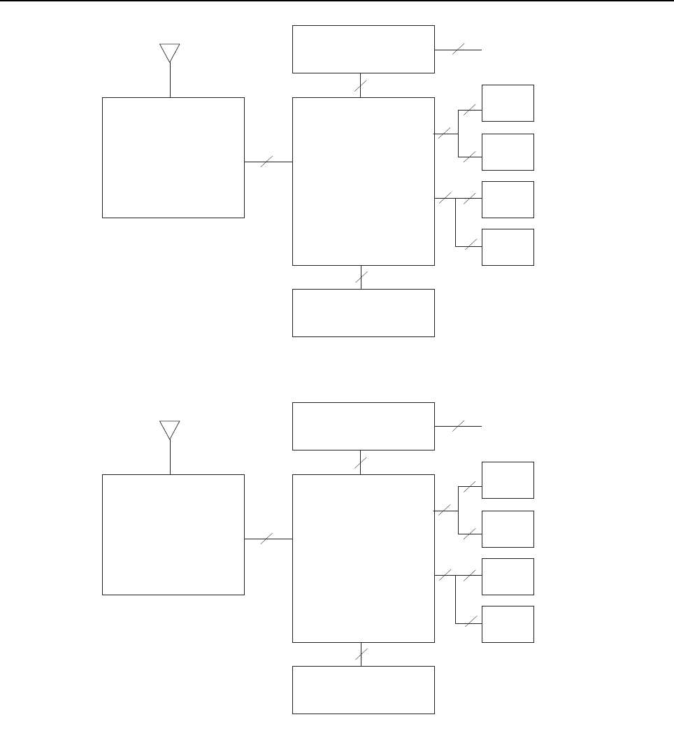
Sec 1: 3-2 Basic Theory of Operation: Major Assemblies
Figure 3-1. APX 7000 Overall Block Diagram (VOCON Board MNCN6200/ MNCN6201)
Figure 3-2. APX 7000 Overall Block Diagram (VOCON Board MNCN6202/ MNCN6203)
Expander External accessory connector
Board External antenna
Front display*
Transceiver VoCon
Keypad**
Board Board
Top display
Note:
* Applicable to model with Front Display and
VOCON Board MNCN6200.
** Applicable to model with Front Display.
Controls top
Option
Board
40
60
14
60
40
20
50 20
30
60
Antenna
Expander External accessory connector
Board External antenna
Front display*
Transceiver VoCon Keypad**
Board Board
Top display
Controls top
Option
Board
40
60
14
80
50
30
50 20
30
60
Antenna
Note:
* Applicable to model with Front Display and
VOCON Board MNCN6202.
** Applicable to model with Front Display.
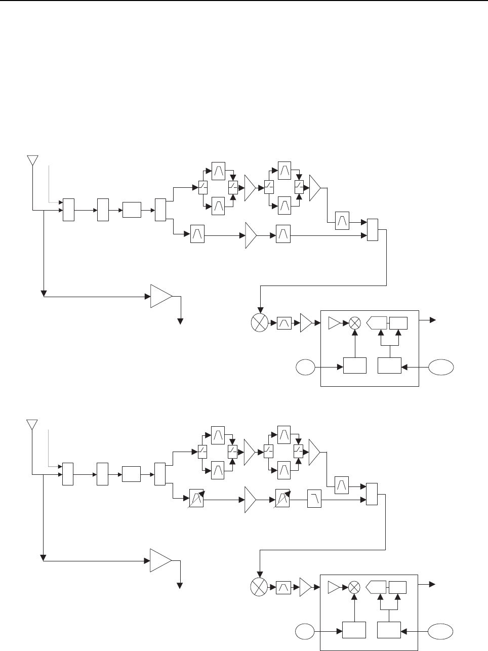
Basic Theory of Operation: Analog Mode of Operation Sec 1: 3-3
3.2 Analog Mode of Operation
This section provides an overview of the analog mode receive and transmit theory of operation.
3.2.1 Receiving
The RF signal is received at the antenna and is routed through the Auxiliary and Multi Switch (SP3T)
ICs. The latter contains a switchable attenuator that is enabled at predetermined RF power
thresholds present at the antenna port. The output of the Multi-switch IC is applied to the first SPST
band select switch to select either VHF or 700–800 bands (see Figure 3-3), UHF1 or 700–800 bands
(see Figure 3-4), VHF or UHF1 bands (see Figure 3-5), UHF1 or UHF2 bands (see Figure 3-6),
UHF2 or 700–800 bands (see Figure 3-7) and VHF or UHF2 bands (see Figure 3-8).
Figure 3-3. Receiver Block Diagram (VHF and 700–800 MHz)
Figure 3-4. Receiver Block Diagram (UHF1 and 700–800 MHz)
SW
2:1
700/800
VHF
Abacus III
2nd
LO
18Mhz
CLK
CLK
Dec.
Filter
LO
ADC
ΣΔ
SW
2:1
PER
SP3T
AUX
DPLXR
To
RF/Vocon
Connector
SSI
RMT Port
SW
2:1
700/800
UHF1
Abacus III
2nd
LO
18Mhz
CLK
CLK
Dec.
Filter
LO
ADC
ΣΔ
SW
2:1
PER
SP3T
AUX
DPLXR
To
RF/Vocon
Connector
SSI
RMT Port

Sec 1: 3-4 Basic Theory of Operation: Analog Mode of Operation
Figure 3-5. Receiver Block Diagram (UHF1 and VHF)
Figure 3-6. Receiver Block Diagram (UHF1 and UHF2)
SW
2:1
VHF
UHF1
Abacus III
2nd
LO
18Mhz
CLK
CLK
Dec.
Filter
LO
ADC
ΣΔ
SW
2:1
PER
SP3T
AUX
DPLXR
To
RF/Vocon
Connector
SSI
RMT Port
SW
2:1
UHF2
UHF1
Abacus III
2nd
LO
18Mhz
CLK
CLK
Dec.
Filter
LO
ADC
ΣΔ
SW
2:1
PER
SP3T
AUX
DPLXR
To
RF/Vocon
Connector
SSI
RMT Port
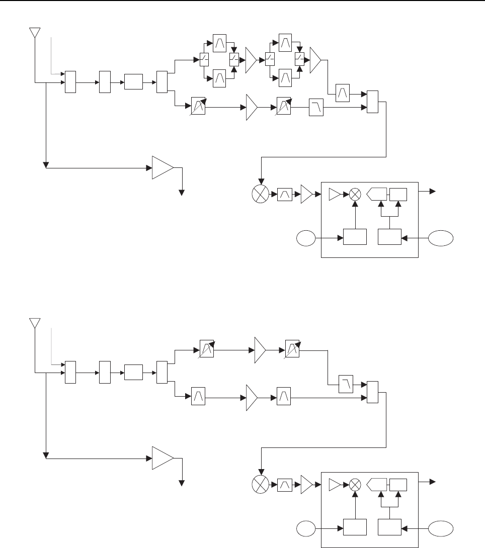
Basic Theory of Operation: Analog Mode of Operation Sec 1: 3-5
Figure 3-7. Receiver Block Diagram (UHF2 and 700–800 MHz)
Figure 3-8. Receiver Block Diagram (UHF2 and VHF)
SW
2:1
700/800
UHF2
Abacus III
2nd
LO
18Mhz
CLK
CLK
Dec.
Filter
LO
ADC
ΣΔ
SW
2:1
PER
SP3T
AUX
DPLXR
To
RF/Vocon
Connector
SSI
RMT Port
SW
2:1
VHF
UHF2
Abacus III
2nd
LO
18Mhz
CLK
CLK
Dec.
Filter
LO
ADC
ΣΔ
SW
2:1
PER
SP3T
AUX
DPLXR
To
RF/Vocon
Connector
SSI
RMT Port

Sec 1: 3-6 Basic Theory of Operation: Analog Mode of Operation
3.2.1.1 GPS
The GPS architecture employs a single chip GPS receiver which decodes GPS signals at
1575.42 MHz. It is capable of producing a final position solution including full tracking and data
decode capability. The GPS receiver will operate in the autonomous mode only.
The GPS signal is tapped at the antenna port via a series resonant network which provides a very
low capacitive load to the transceiver. The signal is routed though a GPS LNA and its output is
applied to the RF-Controller interface connector where it is eventually routed to the expansion board
for processing by the GPS IC.
The GPS receiver is setup in an autonomous one track always (OTA) mode, also known as
continuous navigation. This means the GPS will continuously track satellites for as long as the radio
is powered to ensure the best possible accuracy. In the event the radio loses visibility of the satellites
due to terrain or environmental factors such as driving through a tunnel or entering a building, the
GPS will temporarily lose its position fix. A power savings algorithm will then cycle the GPS in and
out of a sleep mode at approximately 90 second intervals until the radio has moved back into an
environment where GPS signals are present.
The user will be able to view the current latitude, longitude, and time/date stamp on the radio’s
display. The radio can also be configured to send its location to the system at predetermined
intervals (LRRP). Depending on system options, the user may be able to enable/disable the GPS
receiver.
Figure 3-9. GPS Diagram
3.2.1.2 VHF Front-End
From the first band select switch, a VHF signal is routed to the first pre-selector filter followed by an
LNA and a second pre-selector filter. Both filters are discrete and fixed designs and are used to band
limit the incoming energy and suppress known spurious responses such as Image and the ½ IF spur.
The output of the second pre-selector filter is applied to the RF port of the Mixer IC via a second
VHF/700,800 or VHF/UHF1, or VHF/UHF2 band select switch. The Mixer IC is also excited by a
Local Oscillator (LO) signal at the LO port to down-convert the RF signal to a 109.65 MHz
intermediate frequency (IF). The down converted IF signal is passed through a crystal filter and IF
amplifier which drives the input of the Abacus 3 Analog to Digital Converter IC (AD9864).
GPS IC
GPS Receiver Circuit
Antenna
OMAP
Processor

Basic Theory of Operation: Analog Mode of Operation Sec 1: 3-7
3.2.1.3 700/800 MHz Front-End
From the first band select switch, a 700 MHz or 800 MHz band signal is routed to a second band
SPST switch which selects the 700 or the 800 band signal and routes it to the appropriate first
pre-selector filter. A third band select switch selects the output of the appropriate filter and applies it
to an LNA followed by a similar pre-selector filter/ band-select switch circuit. The signal is then routed
to second LNA whose output is applied to a discrete image filter. Both preselector filters are Surface
Acoustic Wave designs used to band limit the received energy and suppress known spurious
responses such as Image and the ½ IF spur. The output of the discrete image filter is applied to the
RF port of the Mixer IC via a second VHF/700,800 or UHF1/700,800 or UHF2/700,800 band select
switch. The Mixer IC is also excited by a Local Oscillator (LO) signal at the LO port to down-convert
the RF signal to a 109.65 MHz intermediate frequency (IF). The down converted IF signal is passed
through a crystal filter and IF amplifier which drives the input of the Abacus 3 Analog to Digital
Converter IC (AD9864).
3.2.1.4 UHF1 Front-End
From the first band select switch, a UHF1 signal is routed to the first pre-selector filter followed by an
LNA and a second pre-selector filter. Both filters are discrete and tunable designs and are used to
band limit the incoming energy and suppress known spurious responses such as Image spur. The
output of the second pre-selector filter is applied to the RF port of the Mixer IC via a second
UHF1/700,800 or UHF1/VHF or UHF1/UHF2 band select switch. The Mixer IC is also excited by a
Local Oscillator (LO) signal at the LO port to down-convert the RF signal to a 109.65 MHz
intermediate frequency (IF). The down converted IF signal is passed through a crystal filter and IF
amplifier which drives the input of the Abacus 3 Analog to Digital Converter IC (AD9864).
3.2.1.5 UHF2 Front-End
From the first band select switch, a UHF2 signal is routed to the first pre-selector filter followed by a
Low Noise Amplifier (LNA) and a second pre-selector filter. Both filters are discrete and tunable
designs and are used to band limit the incoming energy and suppress known spurious responses
such as Image spur. The output of the second pre-selector filter is applied to a discrete Low Pass
Filter (LPF). The output of the LPF is applied to the RF port of the Mixer IC via a second
UHF2/700,800 or UHF1/UHF2 or VHF/UHF2 band select switch. The Mixer IC, is driven by a Local
Oscillator (LO) signal generated by the Trident synthesizer IC, at the LO port to down-convert the RF
signal to a 109.65 MHz intermediate frequency (IF). It is a passive, high linearity design with
balanced inputs at the RF and IF ports and internal LO buffer. The down converted IF signal is
passed through a 3-pole crystal filter, and an IF amplifier, which drives the input of the Analog to
Digital Converter IC.
3.2.1.6 Analog To Digital Converter
The ADC IC's front end down converts the first IF to a second IF, a 2.25 MHz signal. The second IF
is sampled at 18 MHz, a signal generated by an integrated clock synthesizer. The sampled signal is
decimated by a factor of 900 to 20 kHz and converted to SSI format at the ADC's output. The Serial
Synchronous Interface (SSI) serial data waveform is composed of a 16 bit in-phase word (I) followed
by a 16 bit Quadrature word (Q). A 20 kHz Frame Synch and a 1.2 MHz clock waveform are used to
synchronize the SSI IQ data transfer to the Digital Signal Processor IC (OMAP) for post-processing
and demodulation.

Sec 1: 3-8 Basic Theory of Operation: Analog Mode of Operation
3.2.2 Transmitting
When the radio is transmitting, microphone audio is digitized and then processed by the DSP and
sent to the Trident IC (see Figure 3-10 to Figure 3-15) via the SSI interface. The Trident IC
processes the SSI data for application to the voltage controlled oscillator as a modulation signal.
Figure 3-10. Transceiver (VHF and 700–800 MHz) Block Diagram
Figure 3-11. Transceiver (UHF1 and 700–800 MHz) Block Diagram
To Antenna
To RMT Port
To RX
Log amp Power Detector
Digital RF Attenuator
FET 700/800
Driver Amplifier
FET VHF
VCO Module
VCO Module
VCO Module
Trident IC
SP3T RF Switch
Switch
TX SSI from Vocon
TX Buffer Amp
RF Switch
Harmonic Filters
Loop Filter
Ref. Oscillator
Coupler
Rev Power Detection
RF Switch Matrix
SP2T RF Switch
To Antenna
To RMT Port
To RX
Log amp Power Detector
Digital RF Attenuator
FET 700/800
Driver Amplifier
FET UHF1
VCO Module
VCO Module
VCO Module
VCO Module
Trident IC
SP3T RF Switch
Switch
TX SSI from Vocon
TX Buffer Amp
RF Switch
Harmonic Filters
Loop Filter
Ref. Oscillator
Coupler
VCO
Rev Power Detection
RF Switch Matrix
SP2T RF Switch

Basic Theory of Operation: Analog Mode of Operation Sec 1: 3-9
Figure 3-12. Transceiver (VHF and UHF1) Block Diagram
Figure 3-13. Transceiver (UHF1 and UHF2) Block Diagram
To Antenna
To RMT Port
To RX
Log amp Power Detector
Digital RF Attenuator
FET UHF1
Driver Amplifier
FET VHF
VCO Module
VCO Module
VCO Module
Trident IC
SP3T RF Switch
Switch
TX SSI from Vocon
TX Buffer Amp
RF Switch
Harmonic Filters
Loop Filter
Ref. Oscillator
Coupler
VCO
Rev Power Detection
RF Switch Matrix
SP2T RF Switch
To Antenna
To RMT Port
To RX
Log amp Power Detector
Digital RF Attenuator
FET UHF2
Driver Amplifier
FET UHF1
VCO Module
VCO Module
Trident IC
SP3T RF Switch
Switch
TX SSI from Vocon
TX Buffer Amp
RF Switch
Harmonic Filters
Loop Filter
Ref. Oscillator
Coupler
VCO
Rev Power Detection
RF Switch Matrix
SP2T RF Switch
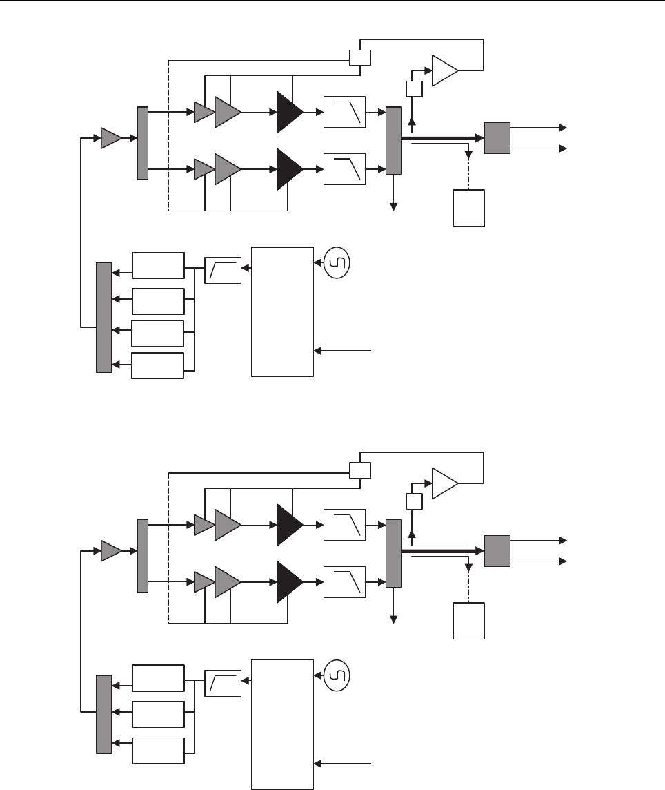
Sec 1: 3-10 Basic Theory of Operation: Analog Mode of Operation
Figure 3-14. Transceiver (UHF2 and 700–800 MHz) Block Diagram
Figure 3-15. Transceiver (VHF and UHF2) Block Diagram
To Antenna
To RMT Port
To RX
Log amp Power Detector
Digital RF Attenuator
FET 700/800
Driver Amplifier
FET UHF2
VCO Module
VCO Module
VCO Module
VCO Module
Trident IC
SP3T RF Switch
Switch
TX SSI from Vocon
TX Buffer Amp
RF Switch
Harmonic Filters
Loop Filter
Ref. Oscillator
Coupler
VCO
Rev Power Detection
RF Switch Matrix
SP2T RF Switch
To Antenna
To RMT Port
To RX
Log amp Power Detector
Digital RF Attenuator
FET UHF2
Driver Amplifier
FET VHF
VCO Module
VCO Module
VCO Module
Trident IC
SP3T RF Switch
Switch
TX SSI from Vocon
TX Buffer Amp
RF Switch
Harmonic Filters
Loop Filter
Ref. Oscillator
Coupler
VCO
Rev Power Detection
RF Switch Matrix
SP2T RF Switch

Basic Theory of Operation: Digital (ASTRO) Mode of Operation Sec 1: 3-11
3.2.2.1 VHF Transmit
Once a VHF frequency for transmit has been selected, the Trident IC and its accompanying logic
circuitry enable the correct voltage controlled oscillator which then generates the desired transmit
frequency. This transmit signal is then routed to the TX buffer amplifier which amplifies the signal. An
RF switch then routes the signal to the VHF Driver amplifier and then to the discrete final stage. The
signal is then filtered by a harmonic filter and passed through a RF switch into a directional coupler.
The Log Amp power detector monitors the output of the directional coupler and adjusts the control
voltages to the driver amplifier and the discrete final. Finally, the RF signal comes to a Single Pole
DoubleThrow (SP2T) RF switch which can route the power to the main antenna or to the Universal
Connector port of the radio.
3.2.2.2 700/800 MHz Transmit
Once a 700/800 MHz frequency for transmit has been selected, the Trident IC and its accompanying
logic circuitry enable the correct voltage controlled oscillator which then generates the desired
transmit frequency. This transmit signal is then routed to the TX buffer amplifier which amplifies the
signal. An RF switch then routes the signal to the 700/800 MHz Driver amplifier and then to the
discrete final stage. The signal is then filtered by a harmonic filter and passed through a RF switch
into a directional coupler. The Log Amp power detector monitors the output of the directional coupler
and adjusts the control voltages to the driver amplifier and the discrete final. Finally, the RF signal
comes to a Single Pole Double Throw (SP2T) RF switch which can route the power to the main
antenna or to the Universal Connector port of the radio.
3.2.2.3 UHF1 Transmit
Once a UHF frequency for transmit has been selected, the Trident IC and its accompanying logic
circuitry enable the correct voltage controlled oscillator which then generates the desired transmit
frequency. This transmit signal is then routed to the TX buffer amplifier which amplifies the signal. An
RF switch then routes the signal to the UHF1 Driver amplifier and then to the discrete final stage.
The signal is then filtered by a harmonic filter and passed through a RF switch into a directional
coupler. The Log Amp power detector monitors the output of the directional coupler and adjusts the
control voltages to the driver amplifier and the discrete final. Finally, the RF signal comes to a Single
Pole DoubleThrow (SP2T) RF switch which can route the power to the main antenna or to the
Universal Connector port of the radio.
3.2.2.4 UHF2 Transmit
Once a UHF frequency for transmit has been selected, the Trident IC and its accompanying logic
circuitry enable the correct voltage controlled oscillator which then generates the desired transmit
frequency. This transmit signal is then routed to the TX buffer amplifier which amplifies the signal. An
RF switch then routes the signal to the UHF2 Driver amplifier and then to the discrete final stage.
The signal is then filtered by a harmonic filter and passed through a RF switch into a directional
coupler. The Log Amp power detector monitors the output of the directional coupler and adjusts the
control voltages to the driver amplifier and the discrete final. Finally, the RF signal comes to a Single
Pole DoubleThrow (SP2T) RF switch which can route the power to the main antenna or to the
Universal Connector port of the radio.
3.3 Digital (ASTRO) Mode of Operation
In the ASTRO (digital) mode of operation, the transmitted or received signal is limited to a discrete
set of frequency deviation levels. The receiver handles an ASTRO-mode signal identically to an
analog-mode signal, up to the point where the DSP decodes the received data. In the ASTRO
receive mode, the DSP uses a different algorithm to recover data.
In the ASTRO transmit mode, microphone audio is processed identically to an analog mode, with the
exception of the algorithm the DSP uses to encode the information. Using this algorithm, transmitter
FM deviation is limited to discrete levels.
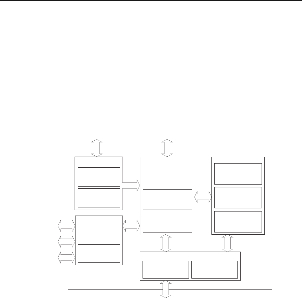
Sec 1: 3-12 Basic Theory of Operation: Controller Section
3.4 Controller Section
The controller section (see Figure 3-16) comprises of five functional sections that are split among
three boards, which are the VOCON, EXPANSION and BLUETHOOTH OPTION boards. The main
functional section consists of a dual core ARM and DSP controller, an encryption processor (MACE),
Flash memory, and a Double Data Rate Synchronous Dynamic Random Access Memory (DDR
SDRAM). The Power and Clocks section includes a power management IC (MAKO) and various
external switching regulators, and two clock sources (12 MHz and 24.576 MHz) from which all other
controller digital clocks are derived. The Audio section has a CODEC and a class-D audio power
amplifier that provides the radio with a multiple microphone, multiple speaker design. The User
Interface section provides communication and control to the top and main Liquid Crystal Displays
(LCD) on the radio, as well as a keypad and a side connector interface conforming to Universal
Connector specifications. The Expansion Memory, GPS and Bluetooth section comprises of a Micro
SD memory interface, Global Positioning Satellite (GPS) processor, and an Option Board for radio
feature upgrades.
Figure 3-16. Controller Block Diagram
The ARM controller core of the OMAP processor handles the power up sequence of all devices,
including firmware upgrades, and all operating system tasks that are associated with FLASH and
SDRAM memories and user interface communication. The FLASH memory (64 MB) is required to
store the firmware, tuning, and Codeplug settings, which upon initialization get read and stored into
SDRAM (32 MB) for execution. The ARM and DSP core jointly control and configure audio, wireless
and RF devices linked to the Serial Peripheral Interface (SPI) and Synchronous Serial Interface
(SSI) buses to enable radio FM and optional wireless communication protocols. For encryption, a
separate ARM processor is used (MACE) to encode and decode encryption packets coming in from
the main OMAP processor through the SSI interface. Its firmware is flashed via the main processor
during an upgrade request to its internal FLASH memory.
USER INTERFACE
Top Display
Data Display
KeyPad
Expansion Board:
Side Connector
POWER & CLOCKS
Clocks Sources:
12 Mhz
24.576 Mhz
CONTROLLERS & MEMORY
ARM Processor
Digital Signal Processor
Flash Memory
DDR Memory
Encryption Processor
EXPANSION MEMORY, GPS & OPTIONS
Option Board
Expansion Board:
SD Card
GPS
Voltage Regulators
AUDIO
Expansion Board Audio:
Main Amplifier / Speaker
Main Microphone
Data Speaker
Data Microphone
Acc. Speaker
Acc. Microphone
Micro SD
Interface
RF Interface
Battery Supply
Top Display
Interface
Data Display &
KeyPad
Side
Connector

Basic Theory of Operation: Controller Section Sec 1: 3-13
The power and most clocks to the controller devices are provided by the MAKO IC and external
switching and linear regulators on board. A Complex Programmable Logic Array (CPLD) IC divides
the 24.576 MHz clock from MAKO to source OMAP's 32 kHz Real Time Clock, and MACE's 4 MHz
main clock. OMAP's main clock is supplied externally from an on board 12 MHz crystal.
The radio has two internal microphones and two internal speakers, as well as available microphone
and speaker connections for external accessories. The main external speaker is located opposite to
the main display and keypad of the radio. It can deliver a rated power of 1W on a ~4 Ohms speaker,
while the smaller "data" speaker can only deliver 0.5 W of power on a load of 16 Ohms. Both internal
and external microphones use the CODEC's AD to deliver digital audio samples to the DSP
controller. The main speaker is driven by the class D PA on the expansion board, while the data and
external speakers are driven by the AB type PA on MAKO. Both speaker paths use the CODEC for
volume control and to convert audio from digital to analog.
The user interface block consists of a top and main or "data side" display, a keypad, top controls and
the accessory side connector. The side connector (Universal Connector) provides audio, USB,
RS232 and RF communication for accessories. All signals to and from the connector go through the
internal expansion board before reaching the microcontroller and other devices on the main board.
The radio also has an expansion bay for a Micro SD memory card, a Global Positioning System
(GPS) interface, and an bluetooth slot for radio feature upgrades. The memory card can be inserted
on the bay near the battery connector of the radio. The bluetooth slot of the radio is available
internally to the radio, and it is not hot swappable by the user. The bluetooth slot is available through
a connector directly linked to the main controller board.

Sec 1: 3-14 Basic Theory of Operation: Controller Section
Notes

Chapter 4 Recommended Test Equipment and Service
Aids
This chapter provides lists of recommended test equipment and service aids, as well as information
on field programming equipment that can be used in servicing and programming ASTRO APX 7000
radios.
4.1 Recommended Test Equipment
The list of equipment contained in Table 4-1 includes all of the standard test equipment required for
servicing two-way portable radios, as well as several unique items designed specifically for servicing
this family of radios. The “Characteristics” column is included so that equivalent equipment may be
substituted; however, when no information is provided in this column, the specific Motorola model
listed is either a unique item or no substitution is recommended.
Table 4-1. Recommended Test Equipment
Equipment Characteristics Example Application
Service
Monitor
Can be used as a substitute for
items marked with an asterisk
(*)
Aeroflex 3920
(www.aeroflex.com),
R-2670 Communication
Analyzer,
8901_ Modulation Analyzer
(www.agilent.com) or
equivalent
Frequency/deviation meter and
signal generator for wide-range
troubleshooting and alignment
Digital RMS
Multimeter *
100 µV to 300 V
5 Hz to 1 MHz
10 Mega Ohm Impedance
Fluke 179 or equivalent
(www.fluke.com)
AC/DC voltage and current
measurements. Audio voltage
measurements
RF Signal
Generator *
100 MHz to 1 GHz
-130 dBm to +10 dBm
FM Modulation 0 kHz to 10 kHz
Audio Frequency 100 Hz to
10 kHz
Agilent N5181A
(www.agilent.com),
Ramsey RSG1000B
(www.ramseyelectronics.com,
or equivalent
Receiver measurements
Oscilloscope * 2 Channel
50 MHz Bandwidth
5 mV/div to 20 V/div
Leader LS8050
(www.leaderusa.com),
Tektronix TDS1001b
(www.tektronix.com),
or equivalent
Waveform measurements
RF Millivolt
Meter
100 mV to 3 V RF
10 kHz to 1 GHz
Boonton 9240
(www.boonton.com) or
equivalent
Waveform measurements
Power Supply 0 V to 32 V
0 A to 20 A
B&K Precision 1790
(www.bkprecision.com)
or equivalent
Voltage supply

Sec 1: 4-2 Recommended Test Equipment and Service Aids: Service Aids
4.2 Service Aids
Refer to Table 4-2 for a listing and description of the service aids designed specifically for servicing
this family of radios. These kits and/or parts are available from the Radio Products and Solutions
Organization offices listed in “Appendix B. Replacement Parts Ordering” on page B-1. While all of
these items are available from Motorola, most are standard shop equipment items, and any
equivalent item capable of the same performance may be substituted for the item listed.
Table 4-2. Service Aids
Motorola Part
Number Description Application
1110027B23 Speaker Module Seal
Lubricant
Used to ensure good sealing of the Speaker Module to the
Main Chassis.
5880384G68 SMA to BNC Adapter Adapts radio’s antenna port to BNC cabling of test equipment.
66009254001 APX 7000/ APX 7000XE
Battery Eliminator
Used in place of battery to connect radio to an external power
supply.
66009255001 Grille Eliminator Special tool used when pressure testing the radio. Replaces
the radio grille to seal the port vent.
66009256001 Volume Potentiometer Outer
Spanner Bit
Used to assemble and disassemble the spanner nut on the
volume potentiometer.
66009258001 Antenna Spanner Bit Used to assemble and disassemble the spanner nut on the
antenna bushing.
66009259001 Vacuum Adapter Submersible radios only. Connects the vacuum/pressure hose
to the radio.
66009260001
66009260003
Board Analysis Fixture
(APX 7000)
Board Analysis Fixture
(APX 7000XE and
future APX 7000)
Special fixture that allows radio’s internal board to be mounted
externally. Provides easy access to electronic circuits,
required for board-level troubleshooting.
NOTE: Contact Motorola Solutions Radio Products and
Solutions Organization (1-800-927-2744) to
determine which version of fixture is required for
your APX 7000 radio.
NLN9839_ Vacuum Pump Kit Submersible radios only. Vacuum pump with gauge and
vacuum hose. Requires 66009259001 Adapter Kit.
NTN4265_ Pressure Pump Kit Submersible radios only. Pressure pump with gauge and
pressure hose. Requires 66009259001 Adapter Kit.
RVN5224_ Customer Programming
Software (CPS) and Tuner
Software
CPS allows customer-specific programming of modes and
features. Tuner software required to perform alignment of
radio parameters.
PMKN4012_ Programming Cable Used to program the radio through Customer
Programming Software and Tuner Software.
PMKN4013_ Programming/Service Cable Used to program and service the radio through Customer
Programming Software and Tuner Software.
RLN4460_ Portable Test Set Used for radio performance checks. Connects to radio’s
universal connector and allows remote switching and signal
injection/outputs for test equipment measurements.

Recommended Test Equipment and Service Aids: Field Programming Sec 1: 4-3
4.3 Field Programming
This family of radios can be aligned and programmed in the field. This requires specific equipment
and special instructions. Refer to the online help in the Customer Programming Software (CPS) for
complete field programming information.

Sec 1: 4-4 Recommended Test Equipment and Service Aids: Field Programming
Notes

Chapter 5 Performance Checks
This chapter covers performance checks used to ensure that the ASTRO APX 7000 radio meets
published specifications. The recommended test equipment listed in the previous section
approaches the accuracy of the manufacturing equipment, with a few exceptions. Accuracy of the
test equipment must be maintained in compliance with the manufacturer’s recommended calibration
schedule. Checks should be performed if radio performance degradation is suspected.
5.1 Test Equipment Setup
Supply voltage can be connected from the battery eliminator. The equipment required for the
performance checks is connected as shown in Figure 5-1.
Figure 5-1. Performance Checks Test Setup
BNC
USB END IS NOT USED
AUDIO GENERATOR
SINAD METER
AC VOLTMETER
TX
RX
30 dB PAD
30 dB PAD
RF GENERATOR
MODULATION ANALYZER
OR
SERVICE MONITOR
AEROFLEX
SERVICE MONITOR
UNIVERSAL
BATTERY
ELIMINATOR
66009254001
(7.5V AT BATTERY
ELIMINATOR
TERMINALS)
TRANSMIT
RECEIVE
DC POWER SUPPLY RADIO
PROGRAM/TEST CABLE
PMKN4013_
AUDIO IN
SET TO APPROX. 8mV FOR Tx
MEASURE 3.74Vrms FOR Rx
SMA-BNC
5880384G68
TEST SET
RLN4460_

Sec 1: 5-2 Performance Checks: Test Equipment Setup
Initial equipment control settings should be as indicated in Table 5-1 and should be the same for all
performance checks and alignment procedures, except as noted.
Table 5-1. Initial Equipment Control Settings
System Analyzer Test Set Power Supply
Monitor Mode: Standard* Spkr/Load: Speaker Voltage: 7.5 Vdc
Receiver Checks
RF Control: GEN
Output Level: -47 dBm
Modulation: 1kHz tone
@3 kHz deviation for 25 kHz channel spacing
@1.5 kHz deviation for 12.5 kHz channel spacing
Frequency: Set to selected radio RX frequency
Meter: AC Volts
Transmitter Checks
RF Control: MONITOR
Frequency: Set to selected radio TX frequency
Meter: RF Display
Modulation Type: FM
Attenuation: 20 dB
PTT: OFF (center) DC On/Standby: Standby
Meter Out: RX Volt Range: 10 Vdc
Opt Sel: ON Current: 2.5 Amps
* Use “PROJ 25 STD” if testing ASTRO Conventional channels.

Performance Checks: Display Radio Test Mode (Dual-Display Version) Sec 1: 5-3
5.2 Display Radio Test Mode (Dual-Display Version)
This section provides instructions for performing tests in display radio test mode.
5.2.1 Access the Test Mode
To enter the display radio test mode:
1. Turn the radio on.
2. Within 10 seconds after “SELF TEST” is complete, press Side Button 2 five times in
succession.
The radio shows a series of displays that give information regarding various version numbers
and subscriber specific information. The displays are described in Table 5-2.
Table 5-2. Test-Mode Displays
Name of Display Description Appears
Service The literal string indicates the radio has
entered test mode.
Always
Host version The version of host firmware is displayed. Always
DSP version The version of DSP firmware is displayed. Always
Secure version Version of the encryption software When the radio is secure
equipped
KGI algorithms name
(Encryption Type 1)
Type of encryption being used When the radio is secure
equipped
KG2 algorithms name
(Encryption Type 2)
Type of encryption being used When the radio is secure
equipped and 2 or more
algorithms are loaded
KG3 algorithms name
(Encryption Type 3)
Type of encryption being used When the radio is secure
equipped and 3 or more
algorithms are loaded
KG4 algorithms name
(Encryption Type 4)
Type of encryption being used When the radio is secure
equipped and 4 or more
algorithms are loaded
KG5 algorithms name
(Encryption Type 5)
Type of encryption being used When the radio is secure
equipped and 5 or more
algorithms are loaded
Model number The radio’s model number, as
programmed in the codeplug
Always
Serial number The radio’s serial number, as programmed
in the codeplug
Always
ESN The radio’s unique electronic serial
number
Always
ROM Size The memory capacity of the host FLASH
part
Always

Sec 1: 5-4 Performance Checks: Display Radio Test Mode (Dual-Display Version)
NOTE: All displays are temporary and will expire without any user intervention. If
information is longer than the physical length of the radio’s display, the information
will wrap around to the next display. After the last display, “RF TEST” is displayed.
To freeze any of the displays, press the left arrow on the 4-Way Navigation Button.
To resume automatic scrolling, press the right arrow on the 4-Way Navigation
Button. To rapidly scroll forward through the displays, continue pressing the right
arrow. You cannot scroll backwards.
NOTE: Press the Top side (purple) button to advance the test environments from “RF
TEST”, “CH TEST”, “RGB TEST”, “CID TEST” then press the orange button to
confirm selection. Press any other buttons to advance the test.
Once a test is carried out, restart the radio to proceed to another test.
3. Do one of the following:
•Press the Top Side Button to stop the displays and toggle between RF test mode and the
Control Top and Keypad test mode. The test mode menu “CH TEST” is displayed,
indicating that you have selected the Control Top and Keypad test mode. Go to Section
“5.2.3 Control Top and Keypad Test Mode” on page 1:5-6.
NOTE: Each press of the Top Side Button will toggle between “CH TEST” and “RF TEST”.
•Press the Top Button (Orange button) to stop the displays and put the radio into the RF
test mode. The test mode menu, “1 CSQ”, is displayed, indicating test frequency 1, Carrier
SQuelch mode. Go to Section “5.2.2 RF Test Mode” below.
NOTE: Once your radio is in a particular test mode, you must turn off the radio and turn it
back on again to access the other test mode.
FLASHcode The FLASH codes as programmed in the
codeplug
Always
RF band 1 The radio’s operating frequency Always
RF band 2 The radio’s operating frequency When the radio has more than 1
operating frequency
Tuning ver Version of Tuning codeplug Always
Proc ver Version of Processor Always
Option Board Type Type of Option Board in the radio When the radio is equipped with
an Option Board
Option Board
Bluetooth Addr
Address of the Bluetooth IC When the radio is equipped with
a Bluetooth Option Board
Option Board SW
Version
Version of Option Board software When the radio is equipped with
an Option Board
Table 5-2. Test-Mode Displays (Continued)
Name of Display Description Appears

Performance Checks: Display Radio Test Mode (Dual-Display Version) Sec 1: 5-5
5.2.2 RF Test Mode
When the ASTRO APX 7000 radio is operating in its normal environment, the radio's microcomputer
controls the RF channel selection, transmitter key-up, and receiver muting, according to the
customer codeplug configuration. However, when the unit is on the bench for testing, alignment, or
repair, it must be removed from its normal environment using a special routine, called RF TEST
MODE.
While in RF test mode:
• Each additional press of Side Button 2 advances to the next test channel. (Refer to Table 5-3.)
•Pressing Side Button 1 scrolls through and accesses the test environments shown in
Table 5-4.
NOTE: Transmit into a load when keying a radio under test.
Table 5-3. Test Frequencies (MHz)
Test
Channel
VHF UHF1 UHF2 700–800 MHz
RX TX RX TX RX TX RX TX
F1 136.075 136.025 380.075 380.025 450.075 450.025 764.0625 764.0125
F2 142.075 142.125 390.075 390.025 460.075 460.025 769.0625 769.0125
F3 154.275 154.225 400.075 400.025 471.075 471.025 775.9375 775.9875
F4 160.175 160.125 411.075 411.025 484.925 484.975 851.0625 794.0125
F5 168.125 168.075 424.975 424.925 485.075 485.025 860.0625 809.0125
F6 173.925 173.975 435.075 435.025 495.075 495.025 869.9375 823.9875
F7 – – 444.925 (Tune)
/ 445.075 (Test
Mode)
444.975 (Tune)
/ 444.999995
(Test Mode)
506.075 506.025 851.0625 851.0125
F8 – – 445.075 445.025 (Tune)
/ 445.000005
(Test Mode)
519.925 519.975 860.0625 860.0125
F9 – – 457.075 457.025 – – 869.9375 869.8875
F10 – – 469.975 469.925 – – – –
Table 5-4. Test Environments
Display Description Function
CSQ Carrier
Squelch
RX: unsquelch if carrier detected
TX: mic audio
TPL Tone
Private-Line
RX: unsquelch if carrier and tone (192.8 Hz)
detected
TX: mic audio + tone (192.8 Hz)
SEC Secure** RX: auto-coded clear
TX: with key present–encrypted audio with
key absent–constant unsquelch

Sec 1: 5-6 Performance Checks: Display Radio Test Mode (Dual-Display Version)
5.2.3 Control Top and Keypad Test Mode
This test mode is used to verify proper operation of all radio buttons and switches if a failure is
suspected.
5.2.3.1 Control Top Checks
To perform the control top checks:
1. Press and hold the Top Button (Orange button); the radio icons are displayed, and the LED
lights amber.
2. Release the Top Button; “148/0” appears, which indicates that the Top Button is in the
open position. Your radio is now in the Control Top and Keypad test mode.
3. Press the Top Button again; “148/1” appears, which indicates that the Top Button is in the
closed position.
4. Rotate the 16-Position Select Switch; “4/0” through “4/15” appears, which indicates that
the selector switch is in mode/zone position 1 through 16.
5. Rotate the Two-Position Concentric Switch; “65/0” and “65/1” appear.
6. Cycle through the Three-Position A/B/C Switch; “67/0,” “67/1,” and “67/2” appear.
7. Rotate the Volume Control; “2/0” through “2/255” appear. The display values may vary
slightly at the upper and lower limits.
8. Press the Top Side Button; “96/1” appears; release, “96/0” appears.
9. Press Side Button 1; “97/1” appears; release, “97/0” appears.
10. Press Side Button 2; “98/1” appears; release, “98/0” appears.
11. Press the PTT Button; “1/1” appears; release, “1/0” appears.
5.2.3.2 Keypad Checks:
To continue to the keypad checks:
5.2.3.2.1 Dual-Display Model
-Press
0, “48/1” appears; release, “48/0” appears.
-Press
1, “49/1” appears; release, “49/0” appears.
-Press
2, “50/1” appears; release, “50/0” appears.
-Press
3, “51/1” appears; release, “51/0” appears.
-Press
4, “52/1” appears; release, “52/0” appears.
-Press
5, “53/1” appears; release, “53/0” appears.
AST ASTRO RX: none
TX: Digital Voice***
USQ Carrier
Unsquelch
RX: unsquelch always
TX: mic audio
** On radios equipped with secure option.
***All deviation values are based on deviation tuning of this
mode.
Table 5-4. Test Environments (Continued)
Display Description Function

Performance Checks: Top-Display Version Radio Test Mode Sec 1: 5-7
- Press 6, “54/1” appears; release, “54/0” appears.
- Press 7, “55/1” appears; release, “55/0” appears.
- Press 8, “56/1” appears; release, “56/0” appears.
- Press 9, “57/1” appears; release, “57/0” appears.
- Press *, “58/1” appears; release, “58/0” appears.
- Press #, “59/1” appears; release, “59/0” appears.
- Press <, “128/1” appears; release, “128/0” appears.
- Press H, “129/1” appears; release, “129/0” appears.
- Press >, “130/1” appears; release, “130/0” appears.
- Press {, “131/1” appears; release, “131/0” appears.
- Press |, “132/1” appears; release, “132/0” appears.
- Press }, “133/1” appears; release, “133/0” appears.
- Press P, “134/1” appears; release, “134/0” appears.
- Press U, “135/1” appears; release, “135/0” appears.
- Press D, “136/1” appears; release, “136/0” appears.
5.3 Top-Display Version Radio Test Mode
This section provides instructions for performing tests in non-display radio test mode.
5.3.1 Access the Test Mode
To enter the non-display radio test mode:
1. Turn the radio on.
2. Within 10 seconds after the top red LED turns off, press Side button 2 five times in
succession.
3. Do one of the following:
• Press the Top Side Button to put the radio into the Control Top and Keypad test mode.
Go to “5.3.3 Control Top Test Mode” below.
NOTE: Each press of the Top Side Button toggles between Control Top and Keypad test
mode (non-display radio) and RF test mode (non-display radio).
•Press the Top Button (Orange button) to put the radio into the RF test mode. Go to “5.3.2
RF Test Mode” below.

Sec 1: 5-8 Performance Checks: Top-Display Version Radio Test Mode
5.3.2 RF Test Mode
When the ASTRO APX 7000 radio is operating in its normal environment, the radio's microcomputer
controls the RF channel selection, transmitter key-up, and receiver muting, according to the
customer codeplug configuration. However, when the unit is on the bench for testing, alignment, or
repair, it must be removed from its normal environment via a special routine, called RF TEST MODE.
While in RF test mode:
• Each additional press of Side Button 2 advances to the next test channel. (Refer to Table 5-3
on page 1:5-5) The channel number is represented by the number of tones emitted by the radio
after the button press (for example, five tones indicates channel 5).
•Pressing Side Button 1 scrolls through and accesses test environments shown in Table 5-4 on
page 1:5-5. The test environment is represented by the number of tones emitted by the radio
after the button press (for example, 11 tones indicate AST).
NOTE: Transmit into a load when keying a radio under test.
5.3.3 Control Top Test Mode
This test mode is used to verify proper operation of all radio buttons and switches if a failure is
suspected.
To perform the control top checks:
1. Press and hold the Top Button (Orange button); the LED lights red, and the radio beeps.
2. Release the Top Button; the radio beeps, indicating that the Top Button is in the open
position.
3. Press the Top Button again; the radio beeps, indicating that the Top Button is in the closed
position.
4. Rotate the Two-Position Concentric Switch; the radio beeps in each switch position.
5. Rotate the 16-Position Select Switch; the radio beeps in each switch position.
6. Cycle through the Three-Position A/B/C Switch; the radio beeps in each switch position.
7. Rotate the Volume Control; the radio beeps at each new volume setting.
8. Press the Top Side Button; the radio beeps.
9. Press Side Button 1; the radio beeps.
10. Press Side Button 2; the radio beeps.

Performance Checks: Receiver Performance Checks Sec 1: 5-9
5.4 Receiver Performance Checks
The following tables outline the performance checks for the receiver.
Table 5-5. Receiver Performance Checks
Test Name System Analyzer Radio Test Set Comments
Rated Audio RF Control: Gen
Output Level: -47 dBm
Freq: Selected radio RX
freq.
Mod: 1kHz tone @ 3kHz
dev.
Meter: AC Volts
As above PTT to OFF
(center)
Set volume control to
3.74 Vrms
Distortion As above, except
Meter: Ext Dist.
As above As above Distortion < 3.0%
Sensitivity
(SINAD)
As above, except
Meter: SINAD
As above As above RF input to be < 0.35 µV
Noise Squelch
Threshold
(only radios
with
conventional
system need
to be tested)
Set as for rated audio
check
Out of TEST
MODE; select a
conventional
system
As above Set volume control to
3.74 Vrms.
Set RF level to -130 dBm
and raise until radio
unsquelches.
Unsquelch to occur at
< 0.25 µV. Preferred SINAD
= 6–8 dB.
*See Table 5-4 on page 1:5-5.
Table 5-6. Receiver Tests for ASTRO Conventional Channels*
Test Name System Analyzer Radio Test Set Comments
Bit Error rate
(BER) Floor
Mode: Proj 25 Std
RF Control: Gen
Output Level: -47 dBm
Proj 25 Dev: 2.83 kHz
Code: 1011 Hz PAT
Radio Tuner
Software (Bit Error
Rate screen) is
required
PTT to OFF
(center)
BER < 0.01%
(Use test setup shown in
Figure 6-1 on page 1:6-1)
Reference
Sensitivity
As above; lower the
output level until 5% BER
is obtained
As above As above Output level < 0.35 µV
(-116 dBm)
(Use test setup shown in
Figure 6-1 on page 1:6-1)
Audio Output
Distortion
Mode: Proj 25 Std
RF Control: Gen
Output Level: -47 dBm
Proj 25 Dev: 2.83 kHz
Code: 1011 Hz PAT
Meter: Ext. Distortion
Radio Tuner
Software not
used;
Radio: Out of
TEST MODE;
Select a
conventional
ASTRO channel
PTT to OFF
(center)
Meter selector to
Audio PA
Spkr/Load to
Speaker
Distortion < 3.0%

Sec 1: 5-10 Performance Checks: Transmitter Performance Checks
5.5 Transmitter Performance Checks
The following tables outline the performance checks for the transmitter.
Residual
Audio Noise
Ratio
Mode: Proj 25 Std
RF Control: Gen
Output Level: -47 dBm
Proj 25 Dev: 2.83 kHz
Code:
A) 1011 Hz PAT
B) Silence PAT
Meter: AC Volts
As above As above Residual Audio Noise Ratio
-45 dB
*These tests require a communications system analyzer with the ASTRO 25 test options.
Table 5-7. Transmitter Performance Checks
Test Name System Analyzer Radio Test Set Comments
Reference
Frequency
RF Control: Monitor
Meter: RF Display
Display: Bar Graphs
Freq: Selected radio TX
freq.
TEST MODE CSQ
channel* or
programmed
conventional
channel
PTT to continuous
(during the
performance
check).
VHF: 2.0 ppm
(272–348 Hz)
700/800 MHz: 1.5 ppm
(1.15–1.3 kHz)
UHF1: 2 ppm
(760–940 Hz)
UHF2: 2 ppm
(900–1040 Hz)
RF Power As above As above As above VHF: 1–6 Watts
700/800 MHz:
764–806 MHz: 2.5 Watts
806–870 MHz: 3Watts
UHF1: 1–5 Watts
UHF2: 1–5 Watts
Voice
Modulation
(external)
As above. Set fixed 1 kHz
audio level to
approximately 10 mV.
As above As above Deviation:
(12.5 kHz) ≥2.1 kHz, but
≤2.5 kHz
(25 kHz) ≥4.1 kHz, but
≤5.0 kHz
Voice
Modulation
(internal)
For Modulation Analyzer:
FM measurements
15 kHz LP Filter
As above Remove
modulation input.
PTT to OFF
(center)
Press PTT button on radio.
Say “four” loudly into the
radio mic. Measure
deviation:
(12.5 kHz) ≥2.1 kHz but
≤2.5 kHz
(25 kHz) ≥4.1 kHz but
≤5.0 kHz
Table 5-6. Receiver Tests for ASTRO Conventional Channels* (Continued)
Test Name System Analyzer Radio Test Set Comments

Performance Checks: Transmitter Performance Checks Sec 1: 5-11
PL Modulation
(radios with
conventional,
clear mode,
coded squelch
operation only)
For Modulation Analyzer:
FM measurements
15 kHz LP Filter
Conventional
coded squelch
personality TPL
channel (test
mode*)
PTT to continuous
(during the
performance
check)
Deviation:
(12.5 kHz) ≥375 Hz but
≤500 Hz
(25 kHz) ≥500 Hz but
≤1000 Hz
Secure
Modulation
(radios with
conventional,
secure mode,
talkaround
operation only)
As above Programmed
conventional
channel (secure
mode operation)
Load key into
radio.
As above Deviation:
≥3.7 kHz but ≤4.3 kHz
*See Table 5-4 on page 1:5-5.
Table 5-8. Transmitter Tests for ASTRO Conventional Channels*
Test Name System Analyzer Radio Test Set Comments
RF Power Aeroflex or equivalent
Service Monitor
Select a
Conventional
Channel
PTT to continuous
(during
measurement).
VHF: 1–6 Watts
700/800 MHz:
764–806 MHz: 2.5 Watts
806–870 MHz: 3Watts
UHF1: 1–5 Watts
UHF2: 1–5 Watts
Frequency
Error
As above As above As above Error ≤±1.0 kHz
Frequency
Deviation
As above Radio Tuner
Software
(Transmitter Test
Pattern screen) is
required)
High use: Symbol
Rate PAT
Low use: Low
Symbol Rate P
PTT to OFF
(center)
DHIGH
≥2.543 kHz but
≤3.110 kHz
DLOW
≥0.841 kHz but
≤1.037 kHz
(Use test setup shown in
Figure 6-1 on page 1:6-1)
*These tests require a communications system analyzer with the ASTRO 25 test options.
Table 5-7. Transmitter Performance Checks (Continued)
Test Name System Analyzer Radio Test Set Comments

Sec 1: 5-12 Performance Checks: Transmitter Performance Checks
Notes
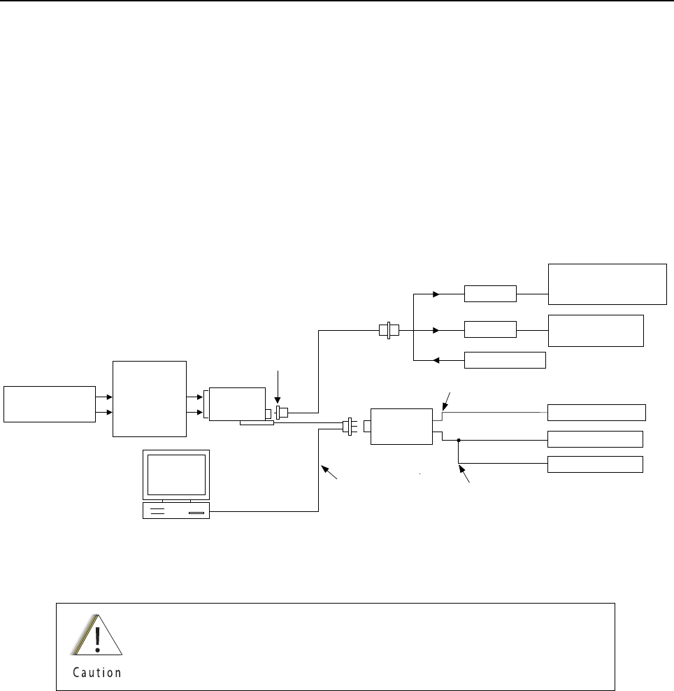
Chapter 6 Radio Alignment Procedures
This chapter describes both receiver and transmitter radio alignment procedures.
6.1 Test Setup
A personal computer (PC) and tuner software are required to align the radio. Refer to the applicable
manual for installation and setup procedures for the software. To perform the alignment procedures,
the radio must be connected to the PC and to a universal test set. The radio alignment test setup is
shown in Figure 6-1.
Figure 6-1. Radio Alignment Test Setup
These radio alignment procedures should only be attempted by qualified
service personnel. Failure to perform alignment procedures properly may
result in seriously degraded radio or system performance.
BNC
COMPUTER
AUDIO GENERATOR
SINAD METER
AC VOLTMETER
TX
RX
30 dB PAD
30 dB PAD
RF GENERATOR
TRANSMIT
RECEIVE
PROGRAM/TEST CABLE
PMKN4013_
AUDIO IN
SMA-BNC
5880384G68
TEST SET
RLN4460_
SET TO APPROX. 8mV FOR Tx
MEASURE 3.74Vrms FOR Rx
MODULATION ANALYZER
OR
SERVICE MONITOR
AEROFLEX
SERVICE MONITOR
USB END IS NOT USED
RADIO
DC POWER SUPPLY
UNIVERSAL
BATTERY
ELIMINATOR
66009254001
(7.5V AT BATTERY
ELIMINATOR
TERMINALS)

Sec 1: 6-2 Radio Alignment Procedures: Tuner Main Menu
6.2 Tuner Main Menu
Select Tuner from the START menu by clicking Start › Program Files › Motorola ›
ASTRO 25 Products › ASTRO 25 Tuner. To read the radio, use the File › Read Device menu or
click on . Figure 6-2 illustrates how the alignment screens are organized. To access a
screen, double-click on the desired screen name in the Tuner menu.
Figure 6-2. Tuner Software Main Menu
IMPORTANT: Tuning should follow the order of the Tuning tree view in descending
order from top to bottom
6.3 Softpot
The alignment screens introduce the concept of the “softpot,” an analog SOFTware-controlled
POTentiometer used for adjusting all transceiver alignment controls.
Each alignment screen provides the ability to increase or decrease the softpot value by using a
slider, or by entering the new value from the keyboard directly into the box. The slider bar indicates
the current softpot value; see Figure 6-3.
DO NOT switch radios in the middle of any alignment
procedure. Always left-click the Close button on the screen to
return to the Main Menu screen before disconnecting the
radio. Improper exits from the alignment screens might leave
the radio in an improperly configured state and result in
seriously degraded radio or system performance.
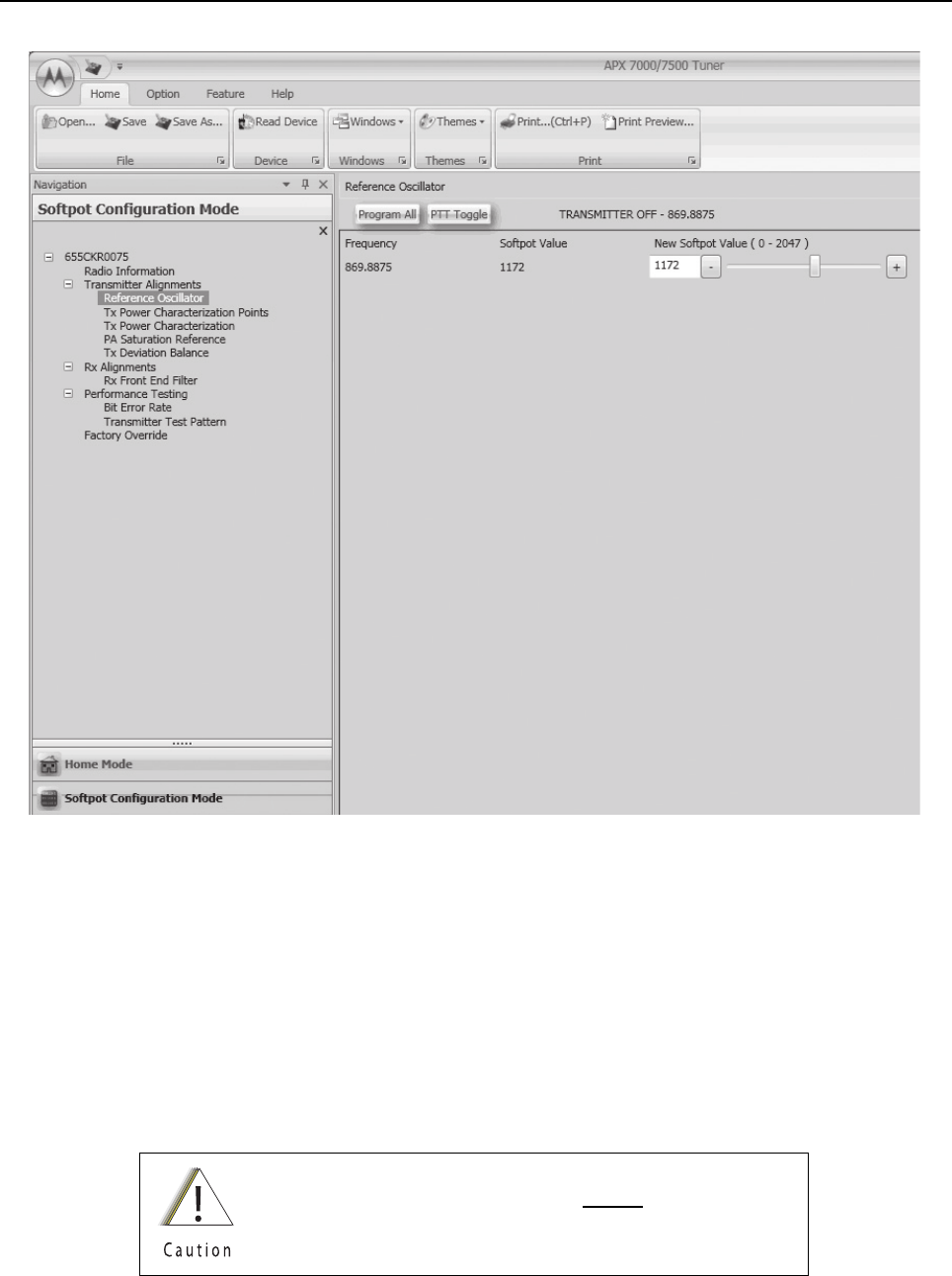
Radio Alignment Procedures: Softpot Sec 1: 6-3
Figure 6-3. Typical Softpot Screen
Adjusting the softpot value sends information to the radio to increase (or decrease) the voltage in the
corresponding circuit. For example, left-clicking the UP spin button in the New Softpot Value scroll
box on the Reference Oscillator screen instructs the radio’s microcomputer to increase the voltage
across a varactor in the reference oscillator, which increases the frequency.
In ALL cases, the softpot value is just a relative number corresponding to a digital-to-analog (D/A)
generated voltage in the radio.
Perform the following procedures in the sequence indicated.
NOTE: Some of the following screens may vary depending upon the radio under test and the version
of tuner software you are using. Refer to the software’s online help.
When keying the radio during a test, always transmit into a
dummy load.

Sec 1: 6-4 Radio Alignment Procedures: Radio Information
6.4 Radio Information
Figure 6-4 shows a typical Radio Information screen. This screen is informational only and cannot be
directly changed.
Figure 6-4. Radio Information Screen
6.5 Transmitter Alignments
6.5.1 Reference Oscillator Alignment
Adjustment of the reference oscillator is critical for proper radio operation. Improper adjustment will
result not only in poor operation, but also in a misaligned radio that will interfere with other users
operating on adjacent channels. For this reason, the reference oscillator should be checked every
time the radio is serviced, or once a year, whichever comes first. The frequency counter used for this
procedure must have a stability of 0.1 ppm (or better). Also, checking this parameter when the
product is placed in service is especially important if the product has been in storage for a significant
period of time (6 months or more) between being shipped from the factory and commissioned for
service.
NOTE: Reference oscillator alignment is required after replacing (or servicing) the transceiver board.
This test can be done with either the R-2670 Communication Analyzer or the 8901_ Modulation
Analyzer.
• Initial setup using the R-2670 Communication Analyzer:
- RF Control: MONITOR
-B/W: WB
- Freq: CPS frequency under test
- Attenuation: 20dB
- Mon RF in: RF I/O
- Meter: RF Display
- Mode: STD
- Input Level: uV or W

Radio Alignment Procedures: Transmitter Alignments Sec 1: 6-5
- Display: Bar Graphs
- Squelch: Mid-range or adjust as necessary
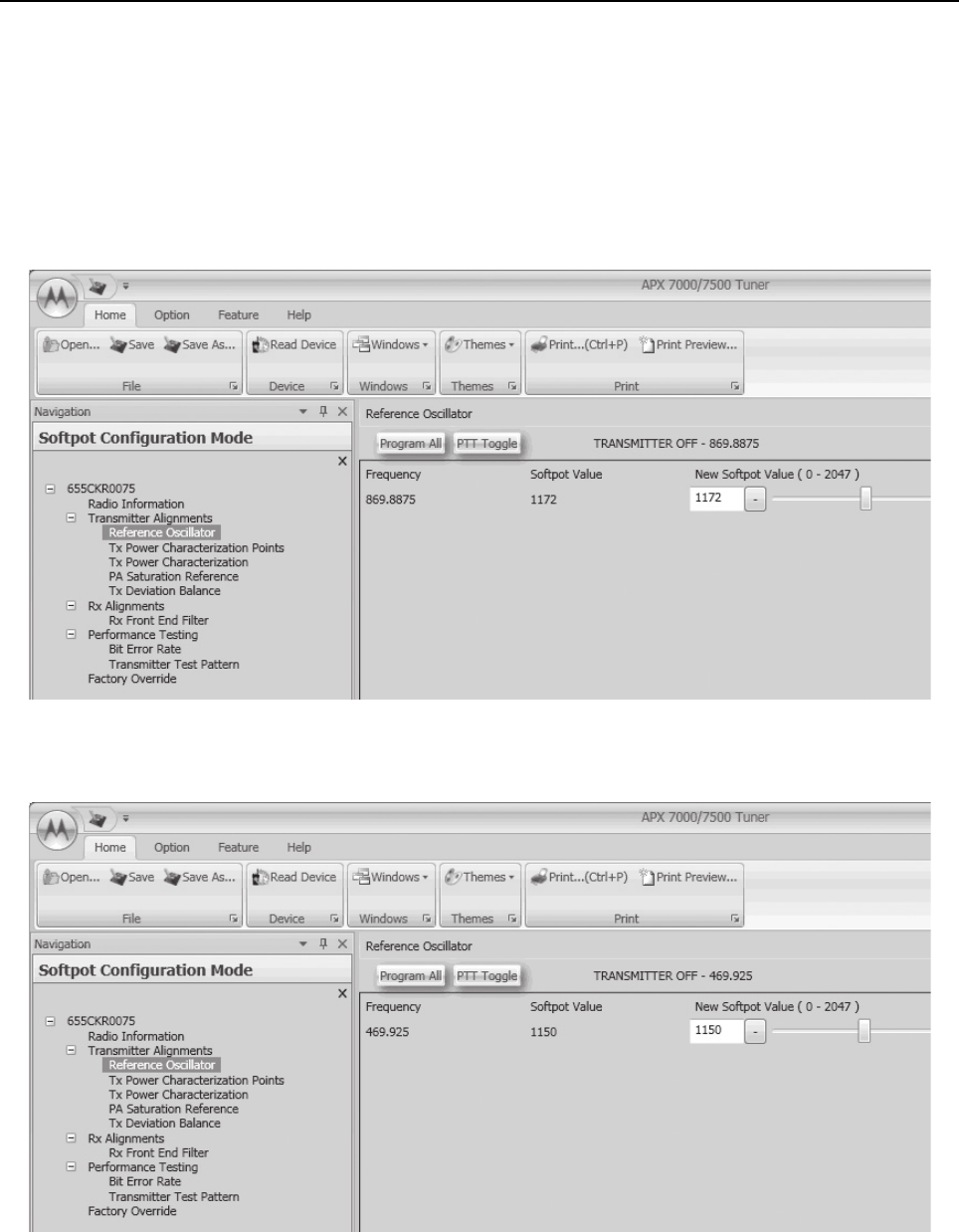
Sec 1: 6-6 Radio Alignment Procedures: Transmitter Alignments
• Initial setup using the 8901_ Series Modulation Analyzer:
- Press the green Automatic Operation button on the analyzer.
-Press the FREQ key.
- Type 7.1 followed by SPCL button to set the 8901B_ modulation analyzer for maximum
accuracy.
To align the reference oscillator:
1. Select the Reference Oscillator alignment screen. See Figure 6-5 to Figure 6-7.
Figure 6-5. Reference Oscillator Alignment Screen (VHF and 700–800 MHz, UHF1 and 700–800 MHz,
and UHF2 and 700–800 MHz)
Figure 6-6. Reference Oscillator Alignment Screen (UHF1 and VHF, and UHF1 and UHF2)

Radio Alignment Procedures: Transmitter Alignments Sec 1: 6-7
Figure 6-7. Reference Oscillator Alignment Screen (UHF2 and VHF)
2. Make sure the Communication Analyzer is in Manual mode.
VHF and 700–800 MHz, UHF1 and 700–800 MHz ,and, UHF2 and 700–800 MHz
• Set the base frequency to 869.8875 MHz
UHF1 and VHF
• Set the base frequency to 469.925 MHz
UHF1 and UHF2
• Set the base frequency to 469.925 MHz
UHF2 and VHF
• Set the base frequency to 519.975 MHz
3. Adjust the reference oscillator’s softpot value with the slider until the measured value is as
close as possible to the frequency shown on the screen. See Table 6-1.
NOTE: Increases the slider decreases the frequency and vice versa.
4. Left-click the Program All button on the screen to dekey the radio and save the tuned values.
5. Left-click the Close button on the screen to return to the Transmitter Alignments menu.
Table 6-1. Reference Oscillator Alignment
Band Target
VHF ±50 Hz
700 MHz/800 MHz ±50 Hz
UHF1 ±50 Hz
UHF2 ±50 Hz

Sec 1: 6-8 Radio Alignment Procedures: Transmitter Alignments
6.5.2 Power Characterization Points
Tuning of the radio is done through Power Characterization Points tuning screen.
1. Select the TX Power Characterization Points alignment screen. See Figure 6-8 to
Figure 6-13.
2. Set power supply voltage and current limit.
3. Adjust softpot value by manipulating the slider bar, incrementing the "New Softpot Value" text
box, or directly entering the desired value into the "New Softpot Value" text box until the rated
power is indicated on the service monitor. For rated power refer to the help text in the Tuner.
4. Repeat the steps 2 and 3 for all frequencies.
5. Left-click the Program All button on the screen to dekey the radio and save the tuned values.
Figure 6-8. Transmit Power Characterization Points Alignment Screen (VHF and 700–800 MHz)

Radio Alignment Procedures: Transmitter Alignments Sec 1: 6-9
Figure 6-9. Transmit Power Characterization Points Alignment Screen (UHF1 and 700–800 MHz)
Figure 6-10. Transmit Power Characterization Points Alignment Screen (UHF1 and VHF)

Sec 1: 6-10 Radio Alignment Procedures: Transmitter Alignments
Figure 6-11. Transmit Power Characterization Points Alignment Screen (UHF1 and UHF2)
Figure 6-12. Transmit Power Characterization Points Alignment Screen (UHF2 and 700–800 MHz)

Radio Alignment Procedures: Transmitter Alignments Sec 1: 6-11
Figure 6-13. Transmit Power Characterization Points Alignment Screen (UHF2 and VHF)
6.5.3 Power Characterization Tuning
Tuning of the radio is done through Power Characterization tuning screen.
IMPORTANT: Power Characterization Tuning Points must be tuned before tuning
Power Characterization Tuning.
NOTE: a.The longer the RF cable, the more the attenuation of the power reading.
b.Use a standard 50 ohm cable
c.Remember to set the Communication Analyzer to baseband power.
1. Select the TX Power Characterization alignment screen. The screen indicates the transmit
power to be used. See Figure 6-14 to Figure 6-19.
2. Left-click the box under “Measure Power 1” for the desired frequency field. (The selected box
is highlighted).
3. Click the PTT Toggle button on the screen to make the radio transmit. The screen indicates
whether the radio is transmitting.
4. Measure the transmit power of the radio with a service monitor.
5. Input the transmit power in watts using two decimal places into the highlighted “Measure
Power 1” box.
6. Left-click the box under “Measure Power 2” box for the same frequency field. (The selected
box is highlighted).
7. Measure the transmit power of the radio with a service monitor.
8. Input the transmit power in watts using two decimal places into the highlighted “Measure
Power 2” box.
9. Repeat steps 2 to 8 for all frequencies.
10. Left-click the Program All button on the screen to dekey the radio and save the tuned values.
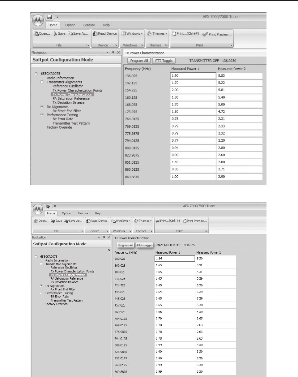
Sec 1: 6-12 Radio Alignment Procedures: Transmitter Alignments
Figure 6-14. Transmit Power Characterization Alignment Screen (VHF and 700–800 MHz)
Figure 6-15. Transmit Power Characterization Alignment Screen (UHF1 and 700–800 MHz)

Radio Alignment Procedures: Transmitter Alignments Sec 1: 6-13
Figure 6-16. Transmit Power Characterization Alignment Screen (UHF1 and VHF)
Figure 6-17. Transmit Power Characterization Alignment Screen (UHF1 and UHF2)
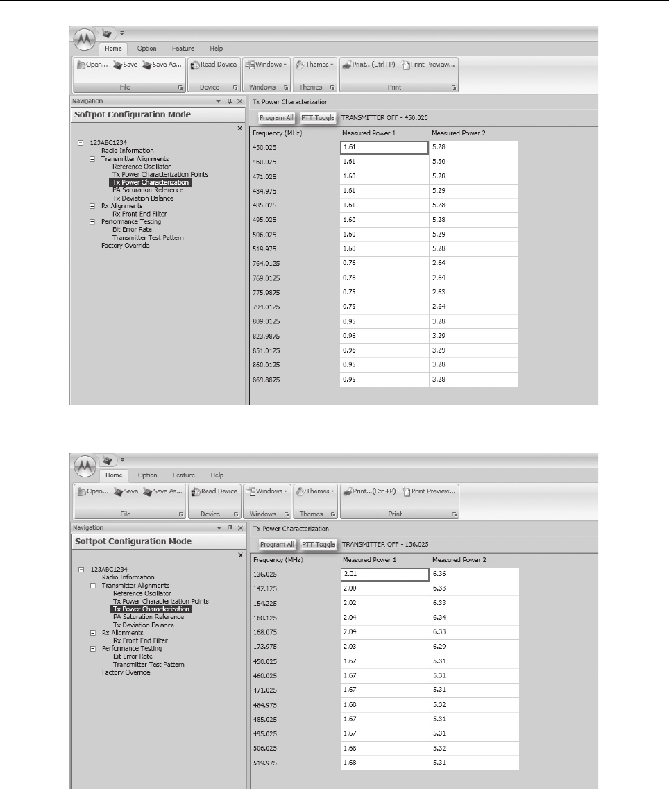
Sec 1: 6-14 Radio Alignment Procedures: Transmitter Alignments
Figure 6-18. Transmit Power Characterization Alignment Screen (UHF2 and 700–800 MHz)
Figure 6-19. Transmit Power Characterization Alignment Screen (UHF2 and VHF)
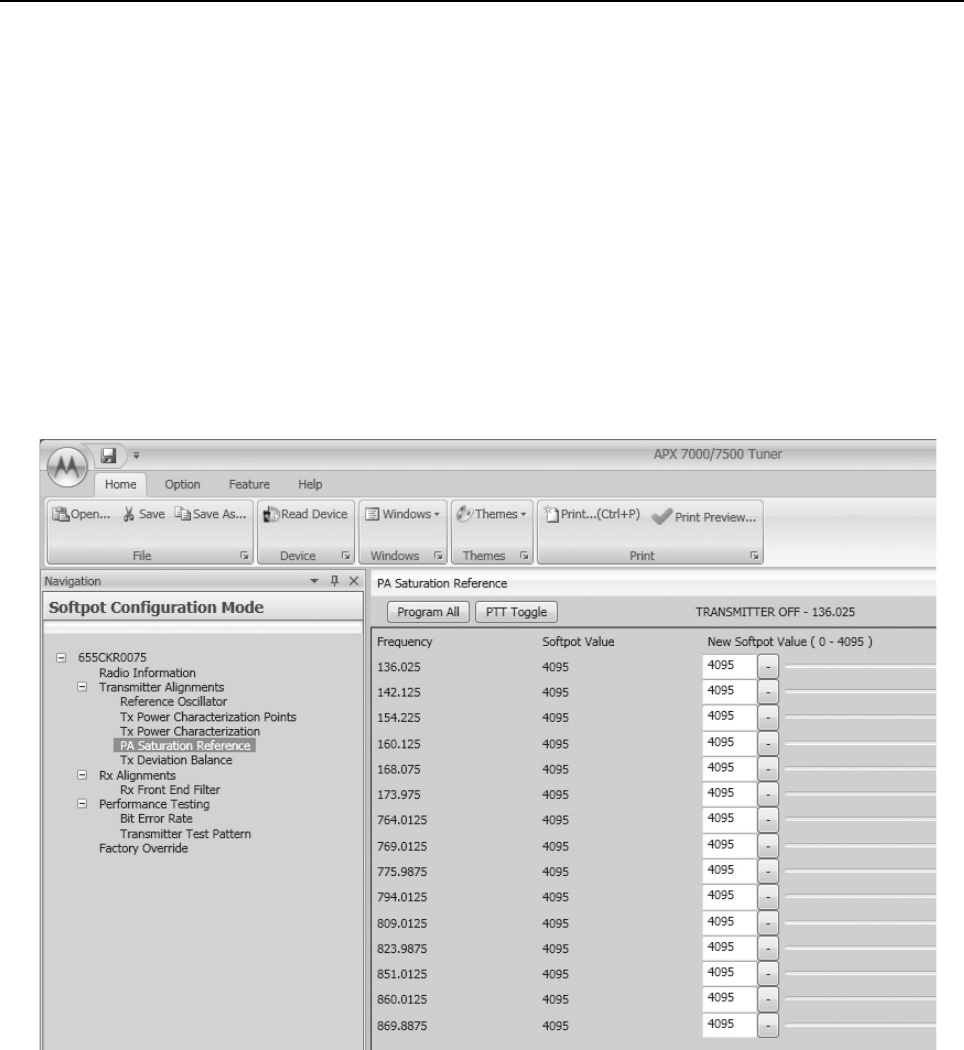
Radio Alignment Procedures: Transmitter Alignments Sec 1: 6-15
6.5.4 PA Saturation Reference Tuning
Tuning is done through PA Saturation Referencing screen.
1. Select the PA Saturation Reference alignment screen. The screen indicates the transmit
frequencies to be used. See Figure 6-20 to Figure 6-25.
2. In Manual Mode, set the service monitor to the desired frequency (as shown in the frequency
list in the PA Saturation Reference alignment screen).
3. Adjust the PA Saturation Reference softpot value with the slider until the radio transmits as
close as possible to the rated power. For rated power refer to the help text in the Tuner.
4. Left-click the slider of the frequency selected (should be the same frequency as step 2).
5. Left-click the PTT Toggle button on the screen to make the radio transmit. The screen
indicates whether the radio is transmitting.
6. Repeat the steps 2 to 5 for all frequencies.
7. Left-click the Program All button on the screen to dekey the radio and save the tuned values.
Figure 6-20. PA Saturation Referencing Alignment Screen (VHF and 700–800 MHz)
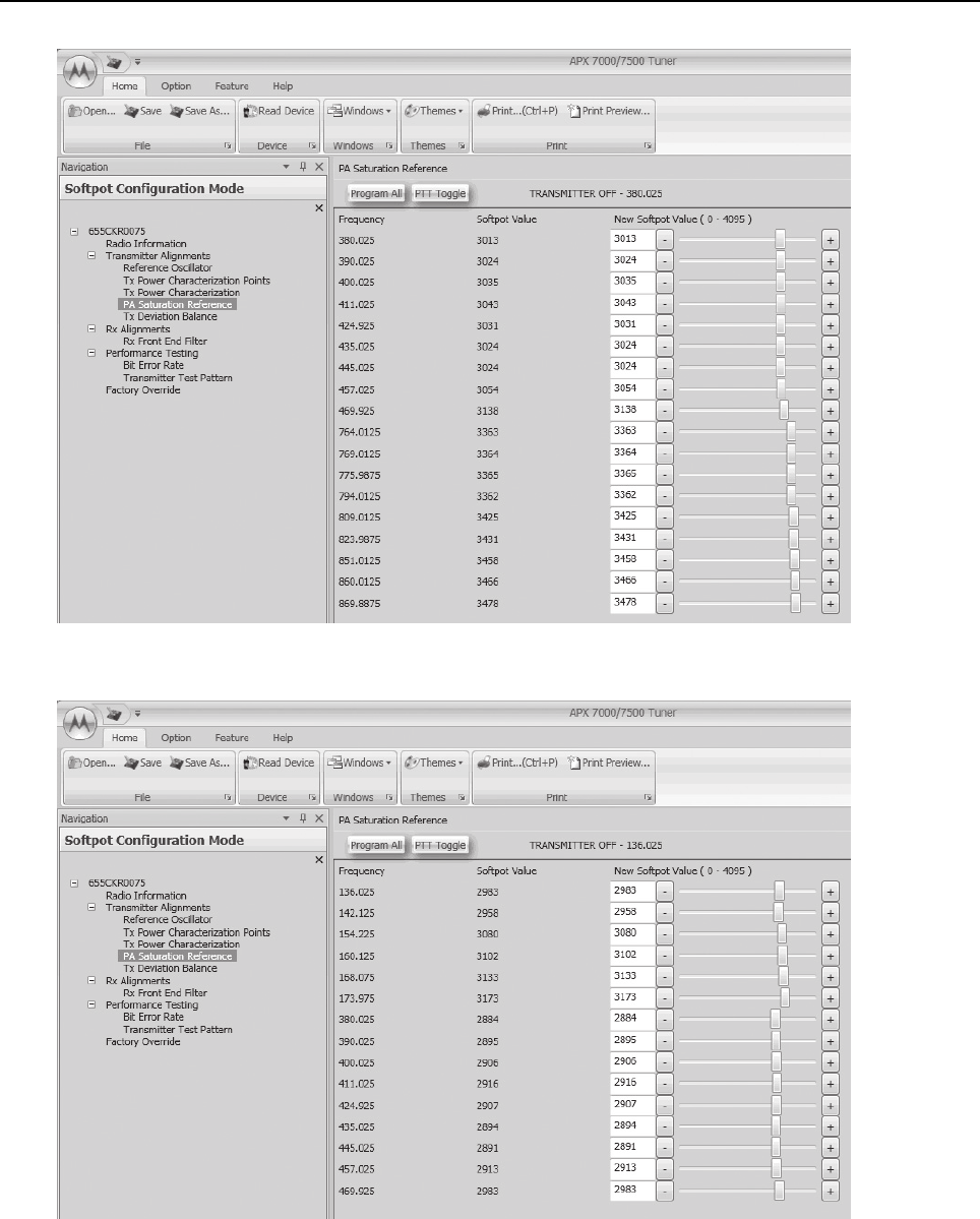
Sec 1: 6-16 Radio Alignment Procedures: Transmitter Alignments
Figure 6-21. PA Saturation Referencing Alignment Screen (UHF1 and 700–800 MHz)
Figure 6-22. PA Saturation Referencing Alignment Screen (UHF1 and VHF)

Radio Alignment Procedures: Transmitter Alignments Sec 1: 6-17
Figure 6-23. PA Saturation Referencing Alignment Screen (UHF1 and UHF2)
Figure 6-24. PA Saturation Referencing Alignment Screen (UHF2 and 700–800 MHz)

Sec 1: 6-18 Radio Alignment Procedures: Transmitter Alignments
Figure 6-25. PA Saturation Referencing Alignment Screen (UHF2 and VHF)
6.5.5 Transmit Deviation Balance Alignment
This alignment procedure balances the modulation contributions of the low- and high-frequency
portions of a baseband signal. Proper alignment is critical to the operation of signalling schemes that
have very low frequency components (for example, DPL) and could result in distorted waveforms if
improperly adjusted.
This procedure needs to be performed at multiple frequencies to allow for proper alignment across
the entire RF band. The RF band is divided into frequency zones with a calibration point (value) in
each zone.
NOTE: This alignment is required after replacing (or servicing) the VOCON board or the transceiver
board.
Proper alignment requires a modulation analyzer or meter with a frequency response to less than
10 Hz modulating frequency. The modulation analyzer settings during this test should be set for
average deviation, a 15 kHz low-pass filter, no de-emphasis, and no high-pass filter, if these settings
are supported.
This alignment can be done with either the R-2670 Communication Analyzer or the 8901_ Series
Modulation Analyzer. The method of choice is the R-2670 analyzer.
1. Initial setup using the R-2670 Communication Analyzer:
- Connect a BNC cable between the “DEMOD OUT” port and the “VERT/SINAD DIST/DMM
COUNTER IN” port on the R-2670.
-Press the SPF key on the R-2670 to display the “SPECIAL FUNCTIONS MENU.” Move the
cursor to “High Pass,” and select 5 Hz on the soft key menu. Select 20 kHz for the “Low
Pass” setting.
- In the “RF Control” section of the R-2670, move the cursor to the “B/W” setting and select
“WIDE +/- 100 kHz” on the soft key menu.
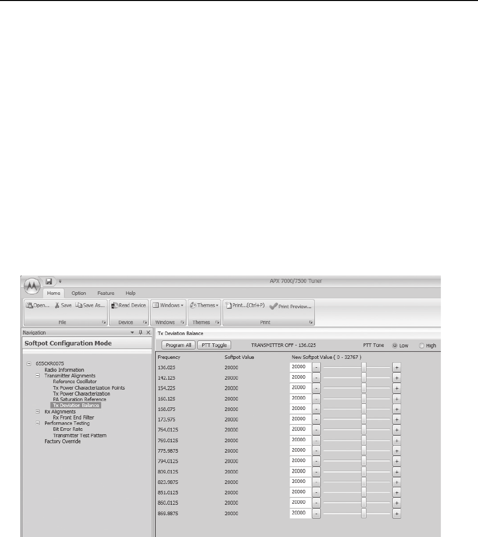
Radio Alignment Procedures: Transmitter Alignments Sec 1: 6-19
- Place the R-2670 cursor in the “Display” zone. Select “AC VOLTS” on the soft key menu.
Move the cursor to the “Range” setting and select “AUTO.”
2. Initial setup using the 8901_ Series Modulation Analyzer:
- Press the FM MEASUREMENT button. (The “Error 03-input level too low” indication is
normal until an input signal is applied.)
- Simultaneously press the Peak – and Peak + buttons. Both LEDs on the buttons should
light.
- Press the 15 kHz LP filter key.
3. Select the TX Deviation Balance alignment screen. The screen indicates the transmit
frequencies to be used. See Figure 6-26 to Figure 6-31.
4. In the "RF Control" section of the R2670, set the service monitor to the desired frequency (as
shown in the frequency list in the TX Deviation Balance alignment screen).
5. Left-click the PTT Tone: Low button.
6. Left-click the slider of the frequency selected (should be the same frequency as step 4).
7. Left-click the PTT Toggle button on the screen to make the radio transmit. The screen
indicates whether the radio is transmitting.
8. Measure and Record the Low Tone Tx Deviation value from the 8901_ Series Analyzer or the
AC voltage value from the R2670.
Figure 6-26. Transmit Deviation Balance Alignment Screen (VHF and 700–800 MHz)

Sec 1: 6-20 Radio Alignment Procedures: Transmitter Alignments
Figure 6-27. Transmit Deviation Balance Alignment Screen (UHF1 and 700–800 MHz)
Figure 6-28. Transmit Deviation Balance Alignment Screen (UHF1 and VHF)

Radio Alignment Procedures: Transmitter Alignments Sec 1: 6-21
Figure 6-29. Transmit Deviation Balance Alignment Screen (UHF1 and UHF2)
Figure 6-30. Transmit Deviation Balance Alignment Screen (UHF2 and 700–800 MHz)

Sec 1: 6-22 Radio Alignment Procedures: Transmitter Alignments
Figure 6-31. Transmit Deviation Balance Alignment Screen (UHF2 and VHF)
9. Left-click the PTT Tone: High button.
10. Adjust the softpot value until the measured deviation/voltage, when using the high tone, is
within +/- 1.5% of the value observed when using the Low Tone.
11. Left-click the PTT Toggle to de-key the radio.
12. Repeat the steps 4 to 10 for all frequencies.
13. Left-click the Program All button on the screen to dekey the radio and save the tuned values.

Radio Alignment Procedures: Front End Filter Alignment Sec 1: 6-23
6.6 Front End Filter Alignment
The alignment procedure adjusts the front end receiver bandpass filters for the best receiver
sensitivity and selectivity. This procedure should be performed for all test frequencies to allow for
proper software interpolation of frequencies between the test frequencies in the band
(see Figure 6-32 and Figure 6-33).
NOTE: Rx Front End Filter Alignment is required after replacing (or servicing) the transceiver board.
6.6.1 Procedure for UHF Range 1 (Auto Tune)
Tuning of the radio is done through Rx Front End Filter tuning screen
1. Select the Rx Front End Filter alignment screen. See Figure 6-32.
2. Click on the slider or the "New Softpot Value" text box to select which frequency to tune.
3. Apply RF test signal input with no modulation at -14 dBm on the Test Signal Frequency
displayed at the top of the screen.
4. Left-click the Autotune button.
5. Repeat the steps 2–4 for all frequencies.
6. Left-click the Program All button on the screen to save the tuned values in the radio.
Figure 6-32. Front End Filter Alignment Screen (UHF1)
This procedure should only be attempted by qualified service
technicians.
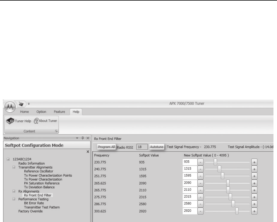
Sec 1: 6-24 Radio Alignment Procedures: Front End Filter Alignment
6.6.2 Procedure for UHF Range 2 (Auto Tune)
Tuning of the radio is done through Rx Front End Filter tuning screen
1. Select the Rx Front End Filter alignment screen. See Figure 6-33.
2. Click on the slider or the "New Softpot Value" text box to select which frequency to tune.
3. Apply RF test signal input with no modulation at -14 dBm on the Test Signal Frequency
displayed at the top of the screen.
4. Left-click the Autotune button.
5. Repeat the steps 2–4 for all frequencies.
6. Left-click the Program All button on the screen to save the tuned values in the radio.
Figure 6-33. Front End Filter Alignment Screen (UHF2)

Radio Alignment Procedures: Performance Testing Sec 1: 6-25
6.7 Performance Testing
6.7.1 Bit Error Rate
This section describes the Bit Error Rate (BER) test of the radio’s receiver at a desired frequency
(see Figure 6-34).
6.7.1.1 Bit Error Rate Fields
Set up the R2670 Communication Analyzer as follows:
1. Connect the RF Input port of the radio under test to the RF IN/OUT port of the R2670 Service
Monitor.
2. Set up the R2670 Service Monitor:
- In the Display Zone, select PROJ 25 STD mode and set the meter to RF DISPLAY.
- In the RF Zone, configure the analyzer as follows:
- In the Audio Zone, select the 1011 Hz PAT code and set the deviation to “PROJ25Dev:
2.83 kHz ~”.
The bit error rate screen contains the following fields:
•Rx Frequency:
This field selects the Receive Frequency directly in MHz.
•Test Pattern:
This field selects the Digital test pattern to be received by the radio. Choices are: Standard
Tone Test Pattern (Framed 1011), F2 1031 and Standard Interface Test Pattern (CCITT V.52).
•Modulation Type:
This field represents the digital modulation type of the incoming signal on which BER is to be
calculated.
•Continuous Operation:
This field allows the user the option to repeat the BER test indefinitely. A selection of Yes will
cause the radio to calculate BER on a continuous basis and update the results on this screen
after each integration time. A selection of No will cause the BER test to execute for only one
sample of the integration time and then update the display.
•Audio:
This field allows the user to select the audio output during a test. Selecting Internal will cause
the radio's built-in speaker to unmute to any signals at the desired frequency which are present
during the test. Selecting External will route the same signal to the radio's accessory connector
audio output. Selecting Mute will disable the audio output.
NOTE: There will be no audio option available for APX 7000 when performing a Bit Error Rate
Tes t .
•BER Integration Time:
BER Integration Time carries with Test Pattern Type.
• Number of Frames
Number of Frames over which bit error result are accumulated to produce the result.
RF Control: Generate
Preset: B/W: NB
Freq: Test frequency (Ex: 851.0625 MHz)
Output Level: -50.0 dBm
Gen RF Out: RF I/O

Sec 1: 6-26 Radio Alignment Procedures: Performance Testing
NOTE: When Continuous Operation = Yes, all fields will be grayed out while the test is in progress.
They will be enabled when the STOP button is pressed.
When Continuous Operation = No, a wait cursor will be displayed while the test is in
progress and return to normal when the test is done.
Figure 6-34. Bit Error Rate Screen
3. Press Start/Stop button to begin or end BER testing.

Radio Alignment Procedures: Performance Testing Sec 1: 6-27
6.7.2 Transmitter Test Pattern
The Transmitter Test Pattern test is used to transmit specific test patterns at a desired frequency so
that the user can perform tests on the radio’s transmitter (see Figure 6-35).
6.7.2.1 Transmitter Test Fields
This screen contains the following fields:
•Tx Frequency:
This field selects the Transmit Frequency directly in MHz.
•Channel Spacing:
This field allows the user to select the desired channel spacing in kHz.
•Test Pattern Type:
This field represents the type of test pattern which will be transmitted by the radio when PTT
TOGGLE button is pressed.
NOTE: Channel Spacing and Test Pattern Type fields will be grayed out while radio is transmitting.
Figure 6-35. Transmitter Test Pattern Screen

Sec 1: 6-28 Radio Alignment Procedures: Performance Testing
Notes

Chapter 7 Encryption
This chapter provides procedures for using the encryption capability of your radio. The following
procedures are outlined:
• Loading an encryption key
• Selecting an encryption key
• Selecting an Index (only applicable to Dual Display configured radios)
• Erasing an encryption key (only applicable to Dual Display configured radios)
7.1 Load an Encryption Key
Keys will be loaded from the KVL to the radio in either clear or encrypted form depending on the
configuration of the CPS parameter "KVL – FIPS Level 3 Approved Mode". If the parameter is
disabled, keys will be sent in clear form; if the parameter is enabled, keys will be sent to the radio in
encrypted form.
NOTE: A KVL4000 or KVL3000 Plus with software version R03.52.45 or greater must be used to load
keys to a radio with "KVL – FIPS Level 3 Approved Mode" enabled.
To load an encryption key:
1. Refer to the key-variable loader (KVL) manual for equipment connections and setup.
2. Attach the KVL to the radio. The top display shows “KEYLOAD” whereas “KEYLOADING” is
shown on the front display of a Dual Display configured radio. All other radio functions, except
for power down, backlight, and volume, are locked out.
3. Refer to the KVL manual for how to load the encryption keys into the radio.
4. When the key is loaded successfully, you will hear:
• On single-key radios – a short tone.
• On multikey radios – an alternating tone.
7.2 Multikey Feature
This feature allows the radio to be equipped with multiple encryption keys. It can support two or more
encryption algorithms simultaneously (e.g., AES and DES-XL).
•Conventional Multikey – The encryption keys can be tied (strapped), on a one-per-channel
basis. In addition, the radio can have operator-selectable keys, operator-selectable indices, and
operator-selectable key erasure. If talkgroups are enabled in conventional, then the encryption
keys are strapped to the talkgroups.
•Trunked Multikey – If the radio is used for both conventional and trunked applications, strap
the encryption keys for trunking on a per- talkgroup or announcement group basis. In addition,
a different key can be strapped to other features; for example, dynamic regrouping, failsoft, or
emergency talkgroup. The radio can have operator-selectable key erasure.

Sec 1: 7-2 Encryption: Select an Encryption Key
7.3 Select an Encryption Key
You can select an encryption key using either the menu or the keypad.
7.3.1 Use the Menu
To select an encryption key using the menu:
1. Press > until the display shows “KEY”.
2. Press {, |, or } directly below “KEY”. The display shows the last user-selected and
-stored encryption key, as well as the available menu selections.
3. Press < or > to scroll through the list of encryption keys.
NOTE: If you select an erased key, the display alternates between showing the encryption
key and “ERASED KEY”.
4. Press {, |, or } directly below the desired menu.
•PSET = selects the preset or default encryption key.
•SEL = saves the newly selected key and returns to the home display.
5. Press H, the PTT button, or {, |, or } directly below the ABRT menu, or turn the
16-Position Select knob to exit this menu.
• If the selected key is erased, the display shows “KEY FAIL” and the radio sounds a
momentary keyfail tone.
• If the selected key is not allowed, the display shows “ILLEGAL KEY” and the radio sounds a
momentary illegal key tone.
7.3.2 Use the Keypad
To select an encryption key using the keypad:
1. Press > until the display shows “KEY”.
2. Press {, |, or }directly below “KEY”. The display shows the last user-selected and
stored encryption key, as well as the available menu selections.
3. Using the keypad, enter the number of the desired key.
NOTE: If you select an erased key, the display alternates between showing the encryption
key and “ERASED KEY”.
4. Press < or > to select from the menu.
•PSET = selects the preset or default encryption key.
•SEL = saves the newly selected key and returns to the home display.
5. Press H, the PTT button, or {, |, or } directly below the ABRT menu, or turn the
16-Position Select knob to exit this menu.
• If the selected key is erased, the display shows “KEY FAIL” and the radio sounds a
momentary keyfail tone.
• If the selected key is not allowed, the display shows “ILLEGAL KEY” and the radio sounds a
momentary illegal key tone.

Encryption: Select an Encryption Index Sec 1: 7-3
7.4 Select an Encryption Index
This feature lets the user select one or more groups of several encryption keys from among the
available keys stored in the radio. For example, the radio could have a group of three keys structured
to one index, and another group of three different keys structured to another index. Changing indices
makes the radio automatically switch from one set of keys to the other. Every channel to which one
of the original keys was tied will now have the equivalent new key instead.
7.4.1 Use the Menu
To select an index using the menu:
1. Press > until the display shows “INDX”.
2. Press {, |, or } directly below “INDX”. The display shows the last user-selected and
-stored index, as well as the available index menu selections.
3. Press {, |, or } directly below the desired index. The display shows the last
user- selected and -stored index, as well as the available index menu selections.
4. Choose one of the following:
a. To save the index, press {, |, or } directly below “SEL”.
b. To exit this menu without changing the index selection, press H or the PTT button, or turn
the 16-Position Select knob.
7.4.2 Use the Keypad
To select an index using the keypad:
1. Press > until the display shows “INDX”.
2. Press {, |, or } directly below “INDX”. The display shows the last user-selected and
-stored index, as well as the available index menu selections.
3. Using the keypad, enter the number of the desired index.
4. Choose one of the following:
a. To save the index, press {, |, or }directly below “SEL”.
b. To exit this menu without changing the index selection, press H or the PTT button, or turn
the 16-Position Select knob.
7.5 Erase an Encryption Key
This section describes two methods for erasing an encryption key.
7.5.1 Method 1 – Key Zeroization (Multikey Only)
To zeroize an encryption key:
1. Press > until the display shows “ERAS”.
2. Press {, |, or } directly below “ERAS”. The display shows the last user-selected and
-stored encryption key, as well as the available menu selections that are listed in Table 7-1.
3. Choose one of the following:
• If you want to erase all the encryption keys at once, go to step 4 below.
• If you want to erase a single encryption key, do one of the following:

Sec 1: 7-4 Encryption: Erase an Encryption Key
–Press < or > to find the desired key. The display shows the selected key and the available
menu selections shown in Table 7-1.
– Using the keypad, enter the location number of the desired key. The display shows the
selected key, as well as the available menu selections shown in Table 7-1.
NOTE: To exit this menu at any time without erasing the key selection, press H or the PTT
button, or turn the 16-Position Select knob.
4. Press {, |, or } directly below the desired menu selection.
5. Press H, the PTT button, or turn the 16-Position Select knob to exit this menu.
7.5.2 Method 2 – All Keys Erased
To erase all encryption keys at one time:
With the radio on, press and hold the Top Side button and, while holding this button down,
press the Top button.
NOTE: DO NOT press the Top button before pressing the Top Side button unless you are
in an emergency situation. This sends an emergency alarm.
Before the keys are erased, the display shows “PLEASE WAIT”.
When all the encryption keys have been erased, the display shows “ALL KEYS ERASED”.
Table 7-1. Encryption Key Zeroization Options
Menu
Selection Action
ALL Erases all the encryption keys in the radio. The display
shows “ERS ALL KEYS” and “YES” and “NO”.
SNGL Selects the displayed encryption key to be erased.The
display shows “ERS SNGL KEY” and “YES” and “NO”.
ABRT Exits this menu and returns to the home display

Chapter 8 Disassembly/Reassembly Procedures
This chapter provides detailed procedures for disassembling/reassembling and ensuring
submergibility of the APX 7000 (R) radios. When performing these procedures, refer to
“Chapter 10. Exploded Views and Parts Lists” on page 1:10-1 and the diagrams that accompany the
text. Items in parentheses ( ) throughout this chapter refer to item numbers in the exploded view
diagrams and their associated parts lists.
This chapter also has procedures for removing and installing the APX 7000 radio’s standard
accessories and changing the Volume and Frequency Knobs.
8.1 APX 7000 Exploded View (Main Subassemblies)
This section contains the APX 7000 radio partially exploded views.
NOTES:
• Refer to Figure 8-1 and Figure 8-2, the Dual Display and Top Display Partial Exploded Views,
and Table 8-1, the Partial Exploded View Parts List.
• Letters in parentheses ( ) refer to item letters in Figure 8-1, Figure 8-2 and Tab l e 8 -1.
When servicing electronics, always ensure that you are
properly grounded with antistatic grounding system approved
for electronics handling.

Sec 1: 8-2 Disassembly/Reassembly Procedures: APX 7000 Exploded View (Main Subassemblies)
Figure 8-1. APX 7000 Dual Display Partial Exploded View
H
A
B
C
D
E
F
G
J
K
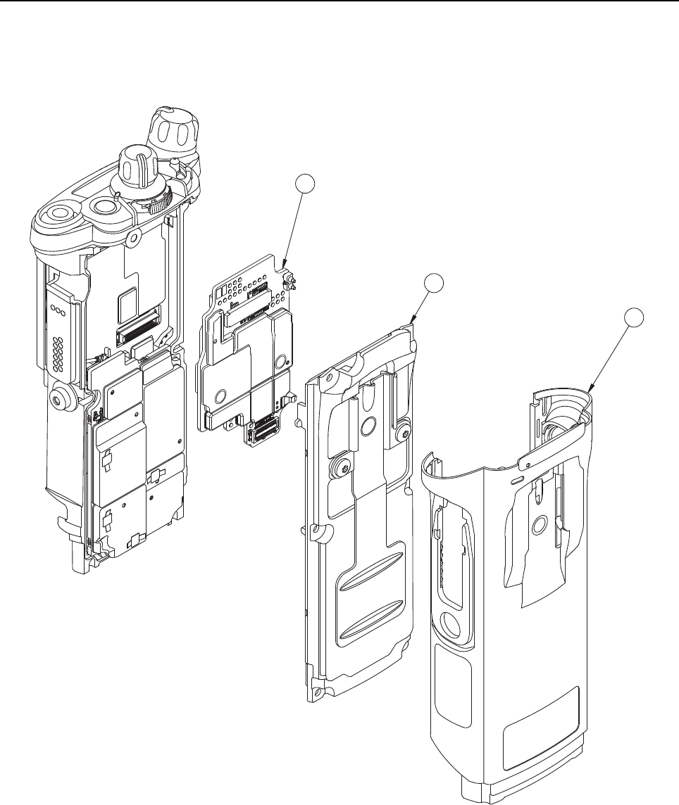
Disassembly/Reassembly Procedures: APX 7000 Exploded View (Main Subassemblies) Sec 1: 8-3
Figure 8-2. APX 7000 Top Display Partial Exploded View
L
M
N
NOTE: All common parts are shown on the APX 7000 Dual Display Partial Exploded View.

Sec 1: 8-4 Disassembly/Reassembly Procedures: APX 7000 Exploded View (Main Subassemblies)
Table 8-1. APX 7000 Partial Exploded View Parts List
Item
Letter Description Exploded View and Parts List
A Speaker Grille Assembly Refer Figure 10-1: "APX 7000 Dual Display
Exploded View" on page 1:10-2.
B Speaker Module Refer Figure 10-1: "APX 7000 Dual Display
Exploded View" on page 1:10-2.
C Expansion Board Assembly Refer Figure 10-1: "APX 7000 Dual Display
Exploded View" on page 1:10-2.
D Main Housing Assembly
(Dual Display)
Refer Figure 10-1: "APX 7000 Dual Display
Exploded View" on page 1:10-2.
E Back Chassis Assembly
(Dual Display)
Refer Figure 10-1: "APX 7000 Dual Display
Exploded View" on page 1:10-2.
F RF Board Assembly Refer Figure 10-1: "APX 7000 Dual Display
Exploded View" on page 1:10-2.
G VOCON Board Assembly
(Dual Display)
Refer Figure 10-1: "APX 7000 Dual Display
Exploded View" on page 1:10-2.
H Knobs & Top Bezel
Assembly
Refer Figure 10-1: "APX 7000 Dual Display
Exploded View" on page 1:10-2.
J Control Top Assembly Refer Figure 10-1: "APX 7000 Dual Display
Exploded View" on page 1:10-2.
K Main Chassis Assembly Refer Figure 10-1: "APX 7000 Dual Display
Exploded View" on page 1:10-2.
L Main Housing Assembly
(Top Display)
Refer Figure 10-2: "APX 7000 Top Display
Exploded View" on page 1:10-4.
M Back Chassis Assembly
(Top Display)
Refer Figure 10-2: "APX 7000 Top Display
Exploded View" on page 1:10-4.
N VOCON Board Assembly
(Top Display)
Refer Figure 10-2: "APX 7000 Top Display
Exploded View" on page 1:10-4.
O Bluetooth Option Board Refer Figure 10-2: "APX 7000 Top Display
Exploded View" on page 1:10-4.

Disassembly/Reassembly Procedures: Required Tools and Supplies Sec 1: 8-5
8.2 Required Tools and Supplies
8.3 Fastener Torque Chart
Table 8-3 lists the various fasteners by part number and description, followed by the torque values
and the location where used. Torque all fasteners to the recommended value when assembling the
radio.
Table 8-2. Required Tools and Supplies
Tools Motorola
Part Number Supplier Supplier
Part Number Remarks
Bit, Torx IP8 – – – Torx T8 may be used, but Torx Plus IP8 is
recommended
Bit, Volume
Spanner Nut
66009256001 Motorola –
Bit, Antenna
Spanner
66009258001 Motorola –
Black Stick – Hexacon
Electric Co.
MA-800G
Seater,
Secure Lever
66009261001 Motorola –
Driver,
Torque
–––
Vacuum
Pump Kit
NLN9839_ Motorola – For Vacuum Test
Grille
Eliminator
66009255001 Motorola – For Vacuum Test and Pressure Test
Vacuum
Adapter
66009259001 Motorola – For Vacuum Test and Pressure Test
Pressure
Pump Kit
NTN4265_ Motorola – For Pressure Test
Table 8-3. Required Tools and Supplies
Motorola
Part Number Description Repair Torque (in-lbs)
0275361H01 Volume Spanner Nut (17) 8
0275891B01 Antenna Spanner Nut (19) 16
0375962B01 Top Screw (28) 10
0375962B02 Center Screw (29) 10
0375962B03 Bottom Screw (30) 10
0375962B04 Control Top Screw (31) 8

Sec 1: 8-6 Disassembly/Reassembly Procedures: Antenna
8.4 Antenna
This section explains how to attach and remove the antenna.
8.4.1 Attach Antenna
To attach the antenna:
With the radio turned off, turn the antenna clockwise to attach it to the radio.
Figure 8-3. Attaching the Antenna
8.4.2 Remove Antenna
To remove the antenna:
With the radio turned off, turn the antenna counter-clockwise to remove it from the radio.
Figure 8-4. Removing the Antenna

Disassembly/Reassembly Procedures: Battery Sec 1: 8-7
8.5 Battery
This section explains how to properly attach and remove the battery.
NOTE: The Motorola-approved battery shipped with the APX 7000 radio is uncharged. Prior to using
a new battery, charge it per the recommended procedure for the battery.
8.5.1 Attach Battery
To attach the battery:
1. With the radio turned off, verify that the battery seal is set properly in its groove as shown in
Figure 8-5.
Figure 8-5. Attaching Battery – Battery Seal
To avoid a possible explosion:
• DO NOT charge, remove, or attach the battery in an area
labeled “hazardous atmosphere.”
• DO NOT discard batteries in a fire.
If the radio is programmed for volatile-key retention,
encryption keys will be retained for approximately 30 seconds
after battery removal.
Battery Seal

Sec 1: 8-8 Disassembly/Reassembly Procedures: Battery
2. Verify that the Memory Door (33) is closed by ensuring the door is fully seated and the catch
feature on the tab is in the main chassis notch.
Figure 8-6. Attaching Battery – Memory Door
3. Set the battery onto the chassis as shown in Figure 8-7. and slide into position. Make sure
both battery latches click into position.
Figure 8-7. Attaching Battery – Slide into Position
Memory Door

Disassembly/Reassembly Procedures: Battery Sec 1: 8-9
8.5.2 Remove Battery
To remove the battery:
1. With the radio turned off, squeeze the two latches located near the bottom, on the sides of the
battery.
Figure 8-8. Squeezing the Release Latches
2. While squeezing the latches, remove the battery by sliding it out as shown.
Figure 8-9. Removing the Battery
Battery Latch
(other one on
opposite side)
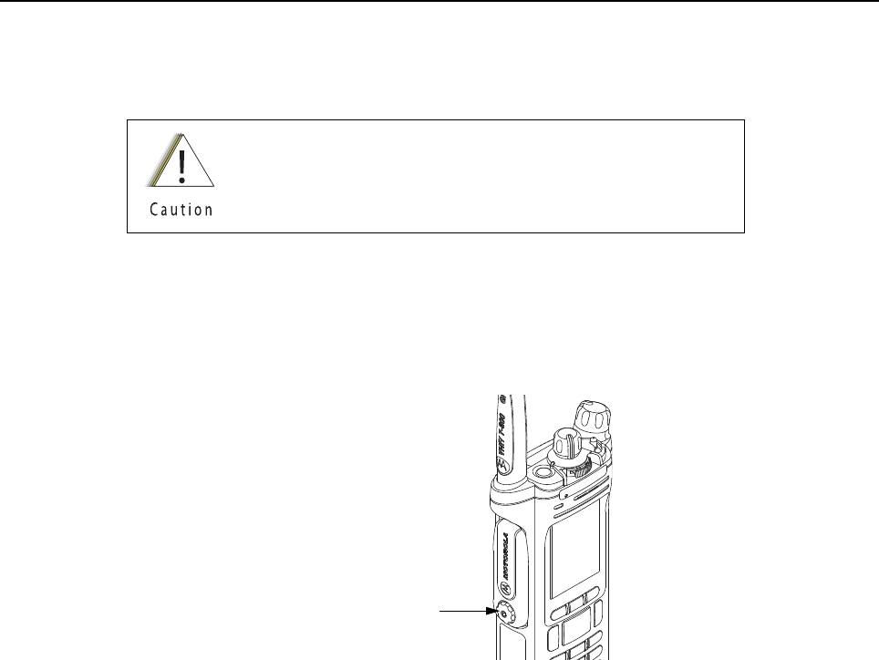
Sec 1: 8-10 Disassembly/Reassembly Procedures: Universal Connector Cover
8.6 Universal Connector Cover
This section explains how to remove and attach the Universal Connector Cover (43).
8.6.1 Remove Universal Connector Cover
To remove the Universal Connector Cover (43):
1. Unscrew the thumb screw. If the screw is too tight a hex driver may be used.
NOTE: Do not remove the screw. It should remain captive in the cover.
Figure 8-10. Removing the Thumb Screw
2. Slightly swing the Universal Connector Cover away from radio before sliding it upward to
disengage the hook feature.
3. Pull the Universal Connector Cover away from the radio.
When the universal connector is not in use, keep it covered
with the Universal Connector Cover.
Thumb Screw with Hex Head Socket

Disassembly/Reassembly Procedures: Universal Connector Cover Sec 1: 8-11
8.6.2 Attach Universal Connector Cover
To attach the Universal Connector Cover:
1. Insert the hooked end of the cover into the pocket. Engage the hook beneath the undercut
and swing the cover down onto the radio. Ensure the cover is seated properly and the screw
is aligned into the threaded hole.
Figure 8-11. Engaging Hook and Seating Cover
2. Hand tighten the thumb screw clockwise until secured.
NOTE: Do not overtighten the screw. The screw should be snugged and not allow the cover
to move.
Figure 8-12. Securing the Cover
Top Hooked End
Thumb Screw
Thumb Screw with Hex Head Socket
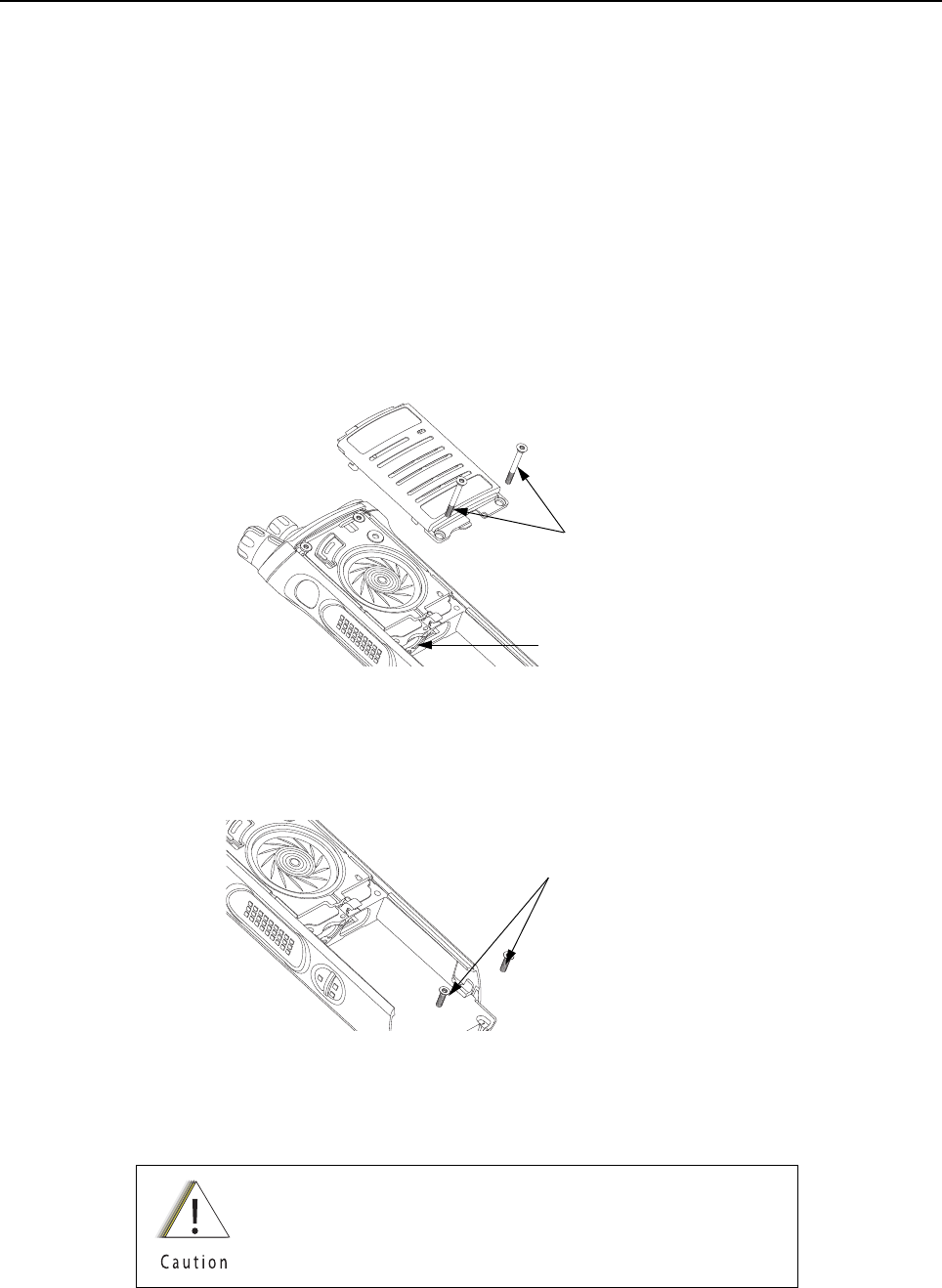
Sec 1: 8-12 Disassembly/Reassembly Procedures: Radio Disassembly
8.7 Radio Disassembly
This section contains instructions for disassembling the radio's main subassemblies.
Prepare the radio for disassembly:
• Turn off the radio by rotating the On/Off/Volume Knob (12) fully counterclockwise until a click is
heard.
• Remove the antenna, the battery, any memory card, Belt Clip Cover (48) (Top Display Only),
the Universal Connector Cover (43) and any other accessory connected to the radio.
8.7.1 Removal of the Speaker Grille Assemblies (A)
1. With the Battery removed and the primary loudspeaker side of the radio facing you, remove
the center two screws (29) and swing out Speaker Grille Assembly (A) as shown in
Figure 8-13.
Figure 8-13. Remove Center Screws
NOTE: Memory Door (33) can be removed with the left center screw removed.
2. Remove the bottom two screws (30) if the Main Housing Assembly (D, L) is to be removed.
Refer Figure 8-14.
Figure 8-14. Remove Bottom Screws
NOTE: Once the screws have been removed, both Thermal Pads (39, 40) should be
replaced.
Do not touch either the speaker cone or the Port Seal (25).
Take extra precaution to make sure neither the speaker nor
the breather pad is damaged.
Center Screws (29)
Memory Door (33)
Bottom Screws (30)
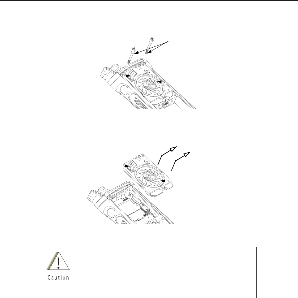
Disassembly/Reassembly Procedures: Radio Disassembly Sec 1: 8-13
8.7.2 Removal of the Speaker Module (B)
1. Remove the top two screws (28) as shown in Figure 8-15.
Figure 8-15. Remove Top Screws
2. Carefully pick out the Speaker Module (23) with the Black Stick and swing it out of the
Main Chassis Assembly (K) as shown in Figure 8-16.
Figure 8-16. Remove Speaker Module
8.7.3 Removal of the Expansion Board Assembly (C)
1. Using the Black Stick, unplug the two flex connectors located on the left and right side of the
Expansion Board Assembly (42). Unfold and straighten the flex located on the right side as
shown in Figure 8-17.
Be careful not to damage the speaker cone or the Port Seal (25)
during the disassembly process.
This Module has lubricant on the seal and can be contaminated
with foreign material. Any foreign material can put the radio's
submergibility at risk.
Top Screws (28)
Speaker Cone
Port Seal (25)
Speaker Cone
Port Seal (25)
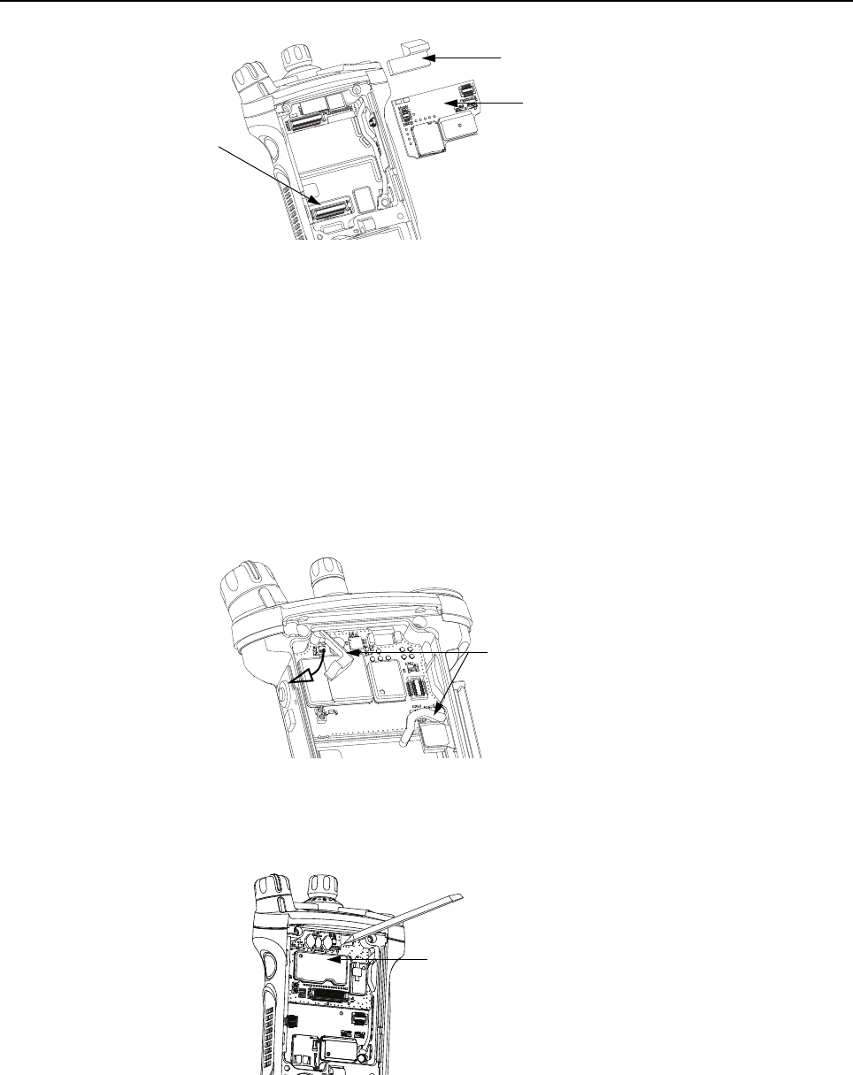
Sec 1: 8-14 Disassembly/Reassembly Procedures: Radio Disassembly
Figure 8-17. Remove Flex Connectors and Expansion Board Assembly
2. Remove the Expansion Board Assembly (C) by gently lifting up the right side of the PCB as
shown in Figure 8-17.
3. If the VOCON Board Assembly (G, O) is to be removed from the Control Top Assembly (J),
then remove the Connector Plug (32) with the Black Stick and unplug the Control Top
Assembly flex as shown in Figure 8-17.
If the radio is equipped with an Bluetooth Option Board Assembly in lieu of the Connector
Plug (32):
i. rotate the Bluetooth Option Board locking levers to unlock the option board and free it
for removal as shown in Figure 8-18.
Figure 8-18. Unlock Levers
ii. unplug the Bluetooth Option Board Assembly from the VOCON Board Assembly by
using the Black Stick as shown in Figure 8-19.
Figure 8-19. Remove Bluetooth Option Board
Flex Connectors
Expansion Board Assembly (42)
Connector Plug (32)
Locking Levers
Bluetooth Option Board
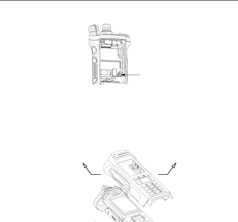
Disassembly/Reassembly Procedures: Radio Disassembly Sec 1: 8-15
4. If the RF Board Assembly (F) is to be removed, use the Black Stick to unplug the antenna
coax cable from the RF Board Assembly as shown in Figure 8-20.
Figure 8-20. Remove Antenna Coax Cable Connector
5. Flip the radio over.
8.7.4 Removal of the Main Housing Assembly (D)
1. Gently stretch both sides of the Main Housing Assembly (1) outwards to clear the radio. Then
lift it over the radio as shown in Figure 8-21.
NOTE: For Top Display version, ensure the Belt Clip Cover (48) has been removed.
Figure 8-21. Remove Housing
Antenna Coax Cable Connector
Stretch Outwards
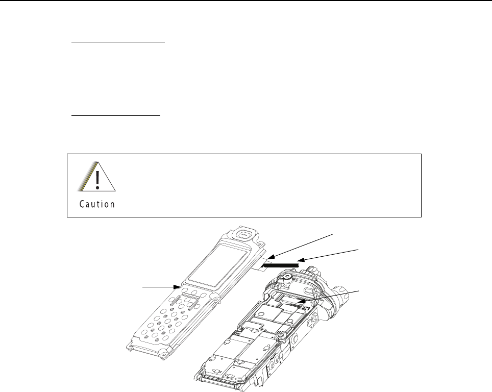
Sec 1: 8-16 Disassembly/Reassembly Procedures: Radio Disassembly
8.7.5 Removal of the Back Chassis Assembly (E, M)
1. Dual Display version:
Gently separate the Back Chassis Assembly (E) from the Main Chassis Assembly (K) to
allow access to disconnect the flex connection between both chassis. This connector is
located near the top of the radio. Use the Black Stick to disconnect the connector as shown in
Figure 8-22.
Top Display version:
Back Chassis Assembly (M) has no connections and can be removed by just separating the
the two chassis apart.
Figure 8-22. Remove Back Chassis Assembly from Main Chassis Assembly
Pull the flex connector vertically upwards by using black stick
through the pull belt to avoid damaging it.
Back Chassis Assembly (20) Connector
Pull Belt
Black Stick
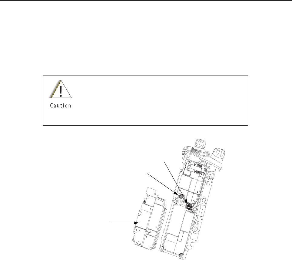
Disassembly/Reassembly Procedures: Radio Disassembly Sec 1: 8-17
8.7.6 Removal of the RF Board Assembly (F)
NOTE: Reconfirm the coax cable connector on the bottom side of the RF Board is
disconnected before removing the RF Board.
1. Unplug the RF Board Assembly (F) from the VOCON Board Assembly (G, O) by using the
Black Stick. Slowly lift the RF Board Assembly enough to allow access to the small coax
cable. Unplug the small coax cable using a Black Stick or a pair of small tweezers.
Figure 8-23. Remove RF Board Assembly
Place the RF Board Assembly in a clean and ESD safe area
to avoid contamination to the Battery Connector Seal (41) and
electrical damage to the electronics respectively.
Replace Thermal Pads (39, 40) whenever RF Board
Assembly is removed.
Connector
RF Board Assembly (38)
Small Coax Cable

Sec 1: 8-18 Disassembly/Reassembly Procedures: Radio Disassembly
8.7.7 Removal of the VOCON Board Assembly (G, O)
NOTE: Reconfirm the Flex connector between the Control Top Assembly (J) and the
VOCON Board Assembly (G, O) or, if so equipped, the Bluetooth Option Board is
disconnected (see step 3 on page 1:8-14). Failure to do so may damage the
connectors or the flex.
1. Gently rotate the VOCON Board Assembly just enough to clear the Main Chassis and
Bluetooth Option Board connector. Slide out the VOCON Board Assembly as shown in
Figure 8-24.
Figure 8-24. Remove VOCON Board Assembly
8.7.8 Removal of the Knobs & Top Bezel Assembly (H)
A. Remove the Frequency Knob
To remove the Frequency Knob (13):
1. Hold the radio in one hand so that the top of the radio faces upward, and the front of the radio
faces you.
2. With the other hand, grasp the Frequency Knob and pull it upward, until it is free from its
shaft.
B. Remove the Volume Knob
To remove the Volume Knob (12):
1. Hold the radio in one hand so that the top of the radio faces upward and the front of the radio
faces you.
2. With the other hand, grasp the Volume Knob and pull it upward.
i. Remove the Torque Adder (15) with the Black Stick.
ii. Unscrew the Volume Spanner Nut (17) using the Volume Spanner Bit with a driver.
Remove the Volume Washer (16) below the nut.
iii. Unscrew the Antenna Spanner Nut (19) with the Antenna Spanner Bit and a driver.
Remove the Antenna Washer (18) below the nut as shown in Figure 8-25.
VOCON Board Assembly (G, O)
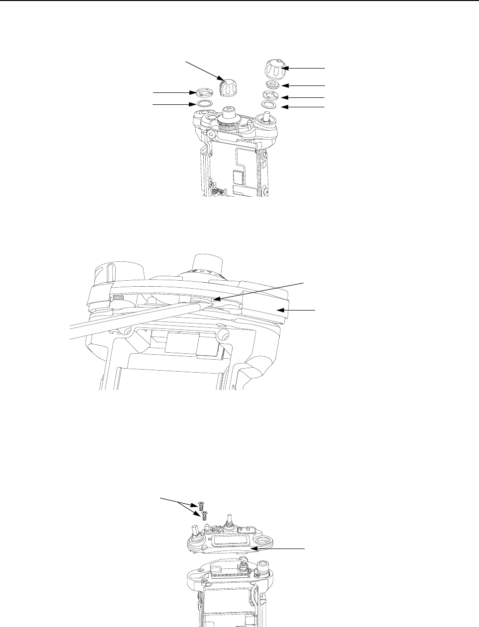
Disassembly/Reassembly Procedures: Radio Disassembly Sec 1: 8-19
Figure 8-25. Remove Knobs and Fastener Hardware
iv. Gently lift the Control Top Bezel Assembly (11) and with the aid of the Black Stick, pop
the Secure Lever (14) off the Frequency shaft as shown in Figure 8-26.
Figure 8-26. Remove Control Top Bezel Assembly
8.7.9 Removal of the Control Top Assembly (J)
i. Use a Torx Plus IP8 bit to remove the two Control Top Screws (31). See Figure 8-27.
NOTE: Ensure the Control Top flex is disconnected from the VOCON Board (G, O) to
prevent damage to the flex or connector.
Figure 8-27. Remove Control Top Assembly (9)
Volume Knob (12)
Torque Adder (15)
Volume Spanner Nut (17)
Frequency Knob (13)
Antenna Spanner Nut (19)
Antenna Washer (18) Volume Washer (16)
Secure Lever (14)
Control Top Bezel Assembly (11)
Control Top Assembly (J)
Control Top Screws (31)
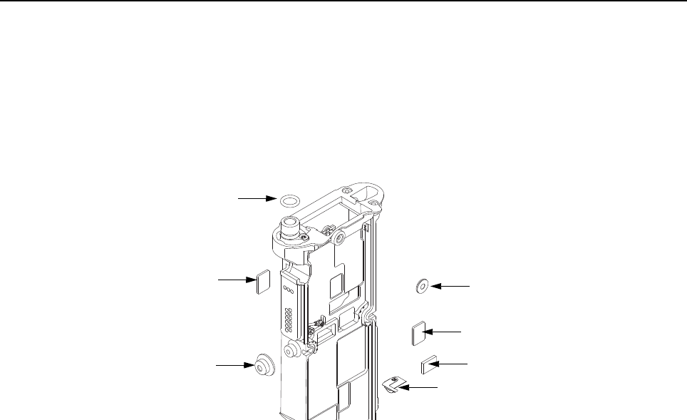
Sec 1: 8-20 Disassembly/Reassembly Procedures: Serviceable Components of the Main Sub-Assemblies
II. Gently separate the Control Top Assembly (J) from the Main Chassis Assembly (K).
NOTE: Place the Control Top Assembly (J) and the remaining Main Chassis Assembly (K)
on an ESD safe surface free from debris.
8.8 Serviceable Components of the Main Sub-Assemblies
8.8.1 Servicing Main Chassis Assembly (K)
Figure 8-28. Serviceable Components – Main Chassis Assembly
8.8.1.1 Servicing Chassis Pads:
1. Complete steps from Section 8.7.1. through Section 8.7.9. of Section “8.7 Radio
Disassembly” on page 1:8-12.
2. Carefully peel off the pad(s) that need replacing (i.e. VOCON Pad (8),
Expansion Board Pad (8) and/or Coin Cell Pad (7) from the chassis.
3. Use the Black Stick to help remove any difficult sections of the pad(s).
4. Clean the area once the pad(s) are removed to ensure it is free of adhesive and debris.
5. Peel the liner off the new pad(s) and place in the respective location.
6. Apply slight pressure to set the adhesive.
8.8.1.2 Servicing Chassis Screw Boss Cap:
1. Complete steps from Section 8.7.1. through Section 8.7.4. of Section “8.7 Radio
Disassembly” on page 1:8-12.
2. Carefully pry off the Universal Connector Boss Cap (34) with the Black Stick from the
Main Chassis Assembly (3) as shown in Figure 8-28.
3. Press the new Cap down onto the boss until it is fully seated.
NOTE: There should be no gap between the chassis boss top face and the corresponding
interior surface of the cap.
Microphone Seal (4)
Thermal Pad (8)
Thermal Pad (8)
Coin Cell Pad (7)
Chassis Ground Contact (6)
Universal Connector
Boss Cap (34)
O-Ring (5)

Disassembly/Reassembly Procedures: Serviceable Components of the Main Sub-Assemblies Sec 1: 8-21
8.8.1.3 Servicing Antenna O-ring:
1. Complete steps from Section 8.7.1. through Section 8.7.9. of Section “8.7 Radio
Disassembly” on page 1:8-12.
2. Remove the O-ring (5) with the Black Stick.
3. Reinstall the O-ring by rolling it over the threaded portion of the antenna hub until it sets in its
groove.
NOTE: Ensure the O-ring is not twisted.
8.8.1.4 Servicing Microphone Membrane
1. Complete steps from Section 8.7.1. through Section 8.7.4. of Section “8.7 Radio
Disassembly” on page 1:8-12.
2. Carefully peel off the Microphone Membrane (4) from the Main Chassis Assembly (3).
3. Clean the area, once the Microphone Membrane is removed, to ensure it is free of adhesive
and debris. Ensure nothing comes in contact with the microphone while cleaning.
4. Remove the backer from the Microphone Membrane.
5. Carefully place the Microphone Membrane centered on the top surface of the microphone
boss area on the Main Chassis. Ensure the membrane is flat with no ripples or folds. Press
down firmly, applying 2-3 lbs. of force.
8.8.1.5 Servicing Chassis Ground Contact:
NOTE: Chassis Ground Contact (6) will be damaged during disassembly.
1. Complete steps from Section 8.7.1. through Section 8.7.9. of Section “8.7 Radio
Disassembly” on page 1:8-12.
2. Slide the Black Stick under the Chassis Ground Contact (6) through the opening on the RF/
VOCON PCB side of the radio to lift off the contact.
3. Clean the area once the Chassis Ground Contact is removed to ensure it is free of adhesive
and debris.
4. Remove the backer of the Chassis Ground Contact and place it in the appropriate location
with a pair of flat tip tweezers by aligning the hole in the Ground Contact with the post located
on the chassis. Ensure the Ground Contact is centered in the opening and the outer surface
of the Ground Contact is parallel to the area adjacent to it in the chassis as shown in
Figure 8-29.
5. Apply pressure to the adhesive to activate it.
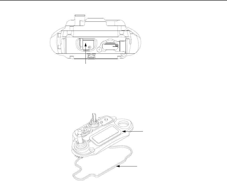
Sec 1: 8-22 Disassembly/Reassembly Procedures: Serviceable Components of the Main Sub-Assemblies
Figure 8-29. Remove Chassis Ground Contact
NOTE: There are no other serviceable components on the Main Chassis Assembly (K).
8.8.2 Servicing Control Top Assembly (J)
Figure 8-30. Control Top Assembly and Control Top Seal
8.8.2.1 Control Top Main Seal
1. Complete steps from Section 8.7.1. through Section 8.7.9. of Section “8.7 Radio
Disassembly” on page 1:8-12.
2. Remove the Control Top Seal (10) with the Black Stick.
3. Replace the new seal into the groove provided in the Control Top Assembly's casting.
4. Ensure that seal is set properly and not stretched.
NOTE: There are no other serviceable components on the Control Top Assembly (J).
Chassis Ground Contact (6)
Control Top Seal (10)
Control Top Assembly (9)

Disassembly/Reassembly Procedures: Serviceable Components of the Main Sub-Assemblies Sec 1: 8-23
8.8.3 Servicing Knobs and Top Bezel Assembly (H)
Figure 8-31. Top Bezel Assembly
8.8.3.1 Secure Lever
1. Complete steps from Section 8.7.8. of Section “8.7 Radio Disassembly” on page 1:8-12.
2. Pull the Secure Lever (14) straight out of Control Top Bezel Assembly (11) as shown in
Figure 8-31.
3. Insert the lever's arm into the bezel's slot.
NOTE: All serviceable components on the Top Bezel Assembly are shown in Figure 8-31.
8.8.4 Servicing VOCON Board Assembly (G, O)
Figure 8-32. VOCON Board Assembly
8.8.4.1 Back up Battery
1. Complete steps from Section 8.7.1. through Section 8.7.7. of Section “8.7 Radio
Disassembly” on page 1:8-12.
2. Remove the battery with the Black Stick.
NOTE: Make sure the positive side is facing upwards.
3. Press the new battery into the battery carrier until it is secured and fully snapped into place.
NOTE: There are no other serviceable components on the VOCON Board Assembly.
Volume Knob (12)
Torque Adder (15)
Volume Spanner Nut (17)
Frequency Knob (13)
Antenna Spanner Nut (19)
Antenna Washer (18)
Volume Washer (16)
Secure Lever (14) Control Top Bezel Assembly (11)
Battery (37)
VOCON Board

Sec 1: 8-24 Disassembly/Reassembly Procedures: Serviceable Components of the Main Sub-Assemblies
8.8.5 Servicing of RF Board Assembly
Complete steps 8.7.1 through 8.7.6 of Section “8.7 Radio Disassembly” on page 1:8-12.
Figure 8-33. RF Board Assembly
8.8.5.1 Battery Seal
1. Slide the Battery Connector Seal (41) from the battery contact header with the Black Stick.
2. Use the Black Stick and push the new Battery Connector Seal until it is properly seated onto
the RF Board surface.
8.8.5.2 Thermal Pads
1. Scrape off both thermal pads (39 and 40) from the amplifiers and / or Main chassis with the
Black Stick.
2. Ensure there are no debris or residue left on the amplifier's surfaces.
3. Replace with new thermal pads.
4. Peel off the back liner from the thermal pads.
5. Insert the Outer Thermal Pad (39) into the shield opening. Make sure the bottom surface of
the pad is mating with the top surface of the amplifiers.
6. Insert the Inner Thermal Pad (40) without compressing or deforming it.
NOTE: There are no other serviceable components on the RF Board Assembly.
Thermal pads should always be replaced when RF Board
assembly is removed.
Battery Connector Seal (41)
RF Board Assembly (F)
Outer Thermal Pad (39)
Inner Thermal Pad (40)

Disassembly/Reassembly Procedures: Serviceable Components of the Main Sub-Assemblies Sec 1: 8-25
8.8.6 Servicing of Expansion Board Assembly
1. Complete steps 8.7.1 through 8.7.3 of Section “8.7 Radio Disassembly” on page 1:8-12.
Figure 8-34. Expansion Board Assembly
NOTE: There are no serviceable components on the Expansion Board Assembly.
8.8.7 Servicing Back Chassis Assembly (E) – Dual Display Version
1. Complete steps 8.7.1 through 8.7.5 of Section “8.7 Radio Disassembly” on page 1:8-12.
Figure 8-35. Back Chassis Assembly (Dual Display Version)
NOTE: Take care not to damage the Color Display during disassembly.
8.8.7.1 Servicing Color Display
1. Disconnect the Back Chassis Flex from the back of the Color Display (35).
2. Gently pry the Color Display out of the Back Chassis Assembly (20) by using the Black Stick
against the white section of the frame (upper left corner at the back of the Color Display).
3. Remove any remnants of the Display's Pad if it does not come off completely with the Color
Display from the back Chassis Assembly.
Take care not to damage the Back Chassis seal while
servicing the Back Chassis.
Expansion Board Assembly (C)
Color Display (35)
Back Chassis Assembly (20)
Speaker Seal (21)
Lens (22)

Sec 1: 8-26 Disassembly/Reassembly Procedures: Serviceable Components of the Main Sub-Assemblies
4. Clean the area to ensure it is free of adhesive and debris once the Display is completely
removed.
5. Ensure there are no foreign material on the new Color Display or the Lens (22).
6. Remove the liner from the new Color Display and seat it into the Back Chassis Assembly.
7. Ensure the Display is oriented correctly and seated properly.
8.8.7.2 Servicing the main Lens
NOTE: Prior to Lens removal, Color Display must be removed (See Section 8.8.7.1 on
page 1:8-25).
1. Remove the main Lens (22) carefully and slowly with the Black Stick.
NOTE: To ease the breaking of the adhesive bond, place Back Chassis in freezer.
2. Clean the area once the Lens is completely removed to ensure it is free of adhesive and
debris.
3. Peel the liner off of the adhesive side of the new Lens and place it centered left to right in the
lens pocket of the back Chassis assembly. Bias it upwards against the horizontal surface.
4. Press the Lens down.
5. Ensure the adhesive shows no sign of air entrapments.
8.8.7.3 Servicing the Speaker Seal
NOTE: Speaker Seal (21) will be damaged during disassembly. Do not reuse.
1. Carefully scrape off the Speaker Seal (21) with the Black Stick without contacting the
Speaker.
2. Clean the area once the Speaker Seal is completely removed, to ensure it is free of adhesive
and debris.
3. Replace with a new Speaker Seal.
4. Peel the liner off and place the new Seal centered to the speaker and press onto the Back
Chassis.
NOTE: There are no other serviceable components on the Back Chassis Assembly.
Over prying may damage the lens.

Disassembly/Reassembly Procedures: Serviceable Components of the Main Sub-Assemblies Sec 1: 8-27
8.8.8 Servicing Back Chassis Assembly (M) – Top Display Version
Figure 8-36. Back Chassis Assembly (Top Display Version)
NOTE: There are No serviceable Components on the Back Chassis Assembly.
8.8.9 Servicing Main Housing (D) – Dual Display Version
Figure 8-37. Main Housing Assembly (Dual Display Version)
8.8.9.1 Top Label
NOTE: There is no need to remove any components in order to service the Top Label (2).
1. Scrape off the Top Label (2) with the Black Stick.
2. Clean the area once the Top Label is completely removed to ensure it is free of adhesive and
debris.
3. Replace with a new Label.
4. Remove the liner and place the label in the recess.
5. Press the label.
Back Chassis Assembly (46)
Top Label (2)
Front Housing Assembly (1)
FM Label (50)
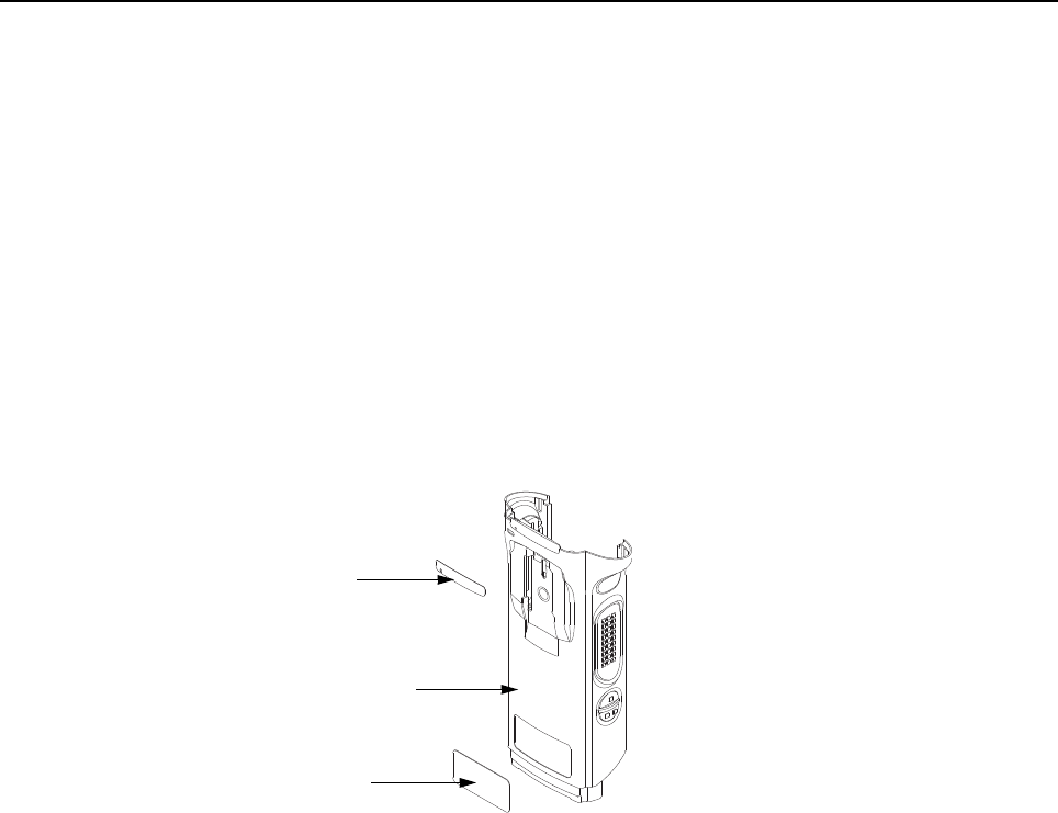
Sec 1: 8-28 Disassembly/Reassembly Procedures: Serviceable Components of the Main Sub-Assemblies
8.8.9.2 FM Label (50)
NOTE: There is no need to remove any components in order to service the
FM Label (50).
1. Scrape off the FM Label (50) with the Black Stick.
2. Clean the area once the FM Label is completely removed to ensure it is free of adhesive and
debris.
3. Replace with a new FM Label.
4. Remove the liner and place the label in the recess.
5. Press the new label.
NOTE: There are No Other serviceable components on the Main Housing Assembly (D).
8.8.10 Servicing Main Housing (L) – Top Display Version
Figure 8-38. Main Housing Assembly (Top Display Version)
8.8.10.1 Top Label
NOTE: There is no need to remove any components in order to service the Top Label (2).
1. Scrape off the Top Label (2) with the Black Stick.
2. Clean the area once the Top Label is completely removed to ensure it is free of adhesive and
debris.
3. Replace with a new Label.
4. Remove the liner and place the label in the recess.
5. Press the label.
8.8.10.2 Blank / FM Label (49)
NOTE: There is no need to remove any components in order to service the
bottom Label (49).
1. Scrape off the bottom Label (49) with the Black Stick.
2. Clean the area once the bottom Label is completely removed to ensure it is free of adhesive
and debris.
3. Replace with a new Label.
Blank / FM Label (49)
Front Housing Assembly (45)
Top Label (2)
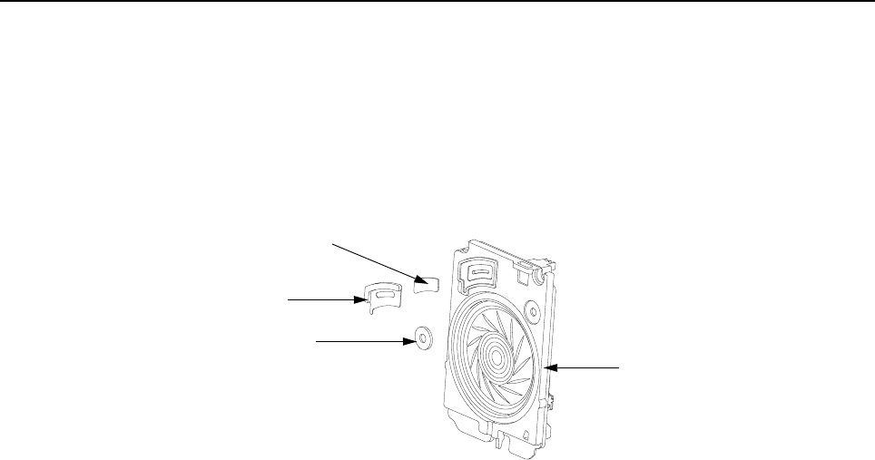
Disassembly/Reassembly Procedures: Serviceable Components of the Main Sub-Assemblies Sec 1: 8-29
4. Remove the liner and place the label in the recess.
5. Press the label.
NOTE: There are No Other serviceable components on the Main Housing Assembly (L).
8.8.11 Servicing Speaker Module (B)
1. Complete steps 8.7.1 through 8.7.2 of Section “8.7 Radio Disassembly” on page 1:8-12.
Figure 8-39. Speaker Module
8.8.11.1 Servicing Port Seal and Port Seal Label
NOTE: Port Seal (25) and Port Seal Label (26) will be damaged during disassembly.
2. Remove the white Port Seal (25) and the black Port Seal Label (26) with the Black Stick.
3. Lift up the Port Seal Label carefully. Do not scratch the mating surface on the
Speaker Module (23).
4. Clean the area once both Seals are removed to ensure it is free of adhesive and debris.
5. Remove the backer of the white Port Seal and place it in the appropriate location on the
Speaker Module with a pair of flat tip tweezers. Ensure the seal is flat with no ripples, folds or
tears.
6. Remove the backer of the black Port Seal Label and place it in the appropriate location on the
Speaker Module with a pair of flat tip tweezers. Ensure the label is flat with no ripples or folds.
8.8.11.2 Servicing Microphone Membrane
NOTE: Disassembly the Microphone Membrane will damage it.
1. Carefully peel off the Microphone Membrane (24) from the Speaker Module (23).
2. Clean the area once the Microphone Membrane is removed to ensure it is free of adhesive or
debris. Ensure nothing comes in contact with the microphone while cleaning.
3. Remove the backer from the Microphone Membrane.
4. Carefully place the Microphone Membrane within the recess area on the Speaker Module.
Ensure the membrane is flat with no ripples or folds.
5. Press down firmly, applying 2-3 lbs. of force.
NOTE: There are No Other serviceable components on the Speaker Module (B).
Microphone Membrane (24)
Port Seal (25)
Port Seal Label (26)
Speaker Module (23)

Sec 1: 8-30 Disassembly/Reassembly Procedures: Serviceable Components of the Main Sub-Assemblies
8.8.12 Servicing Speaker Grille Assembly (A)
Figure 8-40. Speaker Grille Assembly
NOTE: Grille Label will be damaged during disassembly.
8.8.12.1 Servicing Grille Label
NOTE: There is no need to remove any components in order to service the
Speaker Grille Label (44).
NOTE: Grille Label will be damaged during disassembly.
1. Remove the Grille Label by using the Black Stick to lift it. Be careful not to damage the
Speaker Grille Assembly's (27) surface.
2. Clean the area once the Grille Label is removed to ensure it is free of adhesive and debris.
3. Remove the backer of the new Grille Label and place in the appropriate location using a flat
tip tweezer.
NOTE: There are No Other serviceable components on the Speaker Grille Assembly (A).
Speaker Grille
Speaker Grille Label (44)
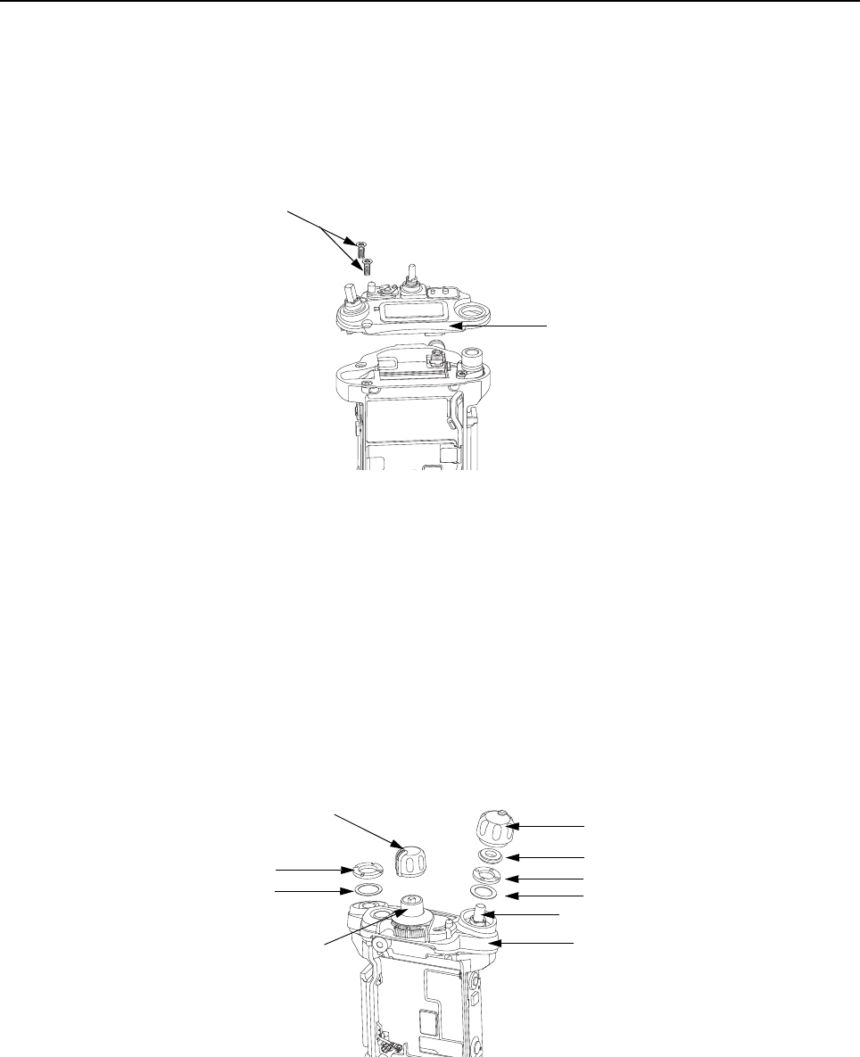
Disassembly/Reassembly Procedures: Radio Reassembly Sec 1: 8-31
8.9 Radio Reassembly
This section contains instructions for reassembling the radio.
8.9.1 Reassemble the Main Sub Assemblies
8.9.1.1 Assemble Control Top Assembly (J) to Main Chassis Assembly (K)
Figure 8-41. Control Top Bezel Assembly
1. Verify there are no surface irregularities such as scratches or indentations on both the Control
Top Seal Grove and the Seal's mating surface on the Main Chassis
Assembly (3). Also ensure that the Control Top Seal (10) and surrounding surfaces are free
of debris and other foreign material.
2. Verify Control Top Seal is properly seated into its groove and place Control Top Assembly
onto Main Chassis Assembly as shown in Figure 8-41.
3. Torque both screws with a Torx IP8 Bit and a torque Driver to 8 in-lbs.
8.9.1.2 Assemble Knobs and Top Bezel Assembly (H)
Figure 8-42. Top Bezel Assembly
1. With the Secure Lever (14) in place, slide the Control Top Bezel onto the Control Top. Ensure
that the Secure Lever is keyed correctly on the Frequency outer shaft. Use the Secure Lever
Setter to fully set the lever into place.
Control Top Assembly (9)
Control Top Screws (31)
Volume Knob (12)
Torque Adder (15)
Volume Spanner Nut (17)
Frequency Knob (13)
Antenna Spanner Nut (19)
Antenna Washer (18) Volume Washer (16)
Control Top Bezel Assembly (11)
Volume Shaft
Frequency Shaft
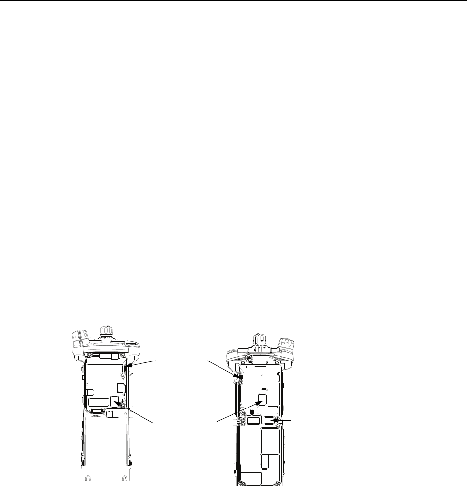
Sec 1: 8-32 Disassembly/Reassembly Procedures: Radio Reassembly
2. While holding down the bezel, place the Volume Washer (16) onto the Volume Shaft. See
Figure 8-42.
3. Tighten the Volume Spanner Nut (17) by hand first to avoid cross threading. Then, torque the
nut with the Volume Spanner Bit at 8 in-lbs.
4. Place the Antenna washer (18) onto the antenna threaded hub as shown in Figure 8-42.
5. Tighten the Antenna Spanner Nut (19) by hand first to avoid cross threading. Then, torque
the nut with the Antenna Spanner Bit at 16 in-lbs.
6. Slide and ensure the Torque Adder (15) is fully seated onto the Volume Potentiometer's Hub.
7. Align the D-shaped part of the Volume Shaft with the D-shape hole in the Volume Knob (12)
and press the Volume Knob into place.
8. Align the D-shaped part of the Frequency Shaft with the D-shape hole in the
Frequency Knob (13) and press the Frequency Knob into place.
8.9.1.3 Assemble VOCON Board Assembly (G, O)
1. Inspect the Main Chassis (3) sealing surfaces to make sure there is no surface irregularities
such as scratches or indentations. Clean any debris or other foreign material.
2. Inspect the two thermal pads (8) on the front and back of the unit along with the
Coin Cell Pad (7) to confirm pads are clean and free of debris as shown in Figure 8-43.
Figure 8-43. Inspect Pads
3. Orient the Main Chassis (3) with the Frequency Knob (13) on top. Insert the
VOCON Board Assembly (36) into the chassis starting at a 45° angle and rotate the board
into place. Ensure the control top flex is located below the PCB, and is not being pinched
between the PCB and the casting. See Figure 8-44.
Thermal Pads (8)
Sealing Surface
Coin Cell Pad (7)
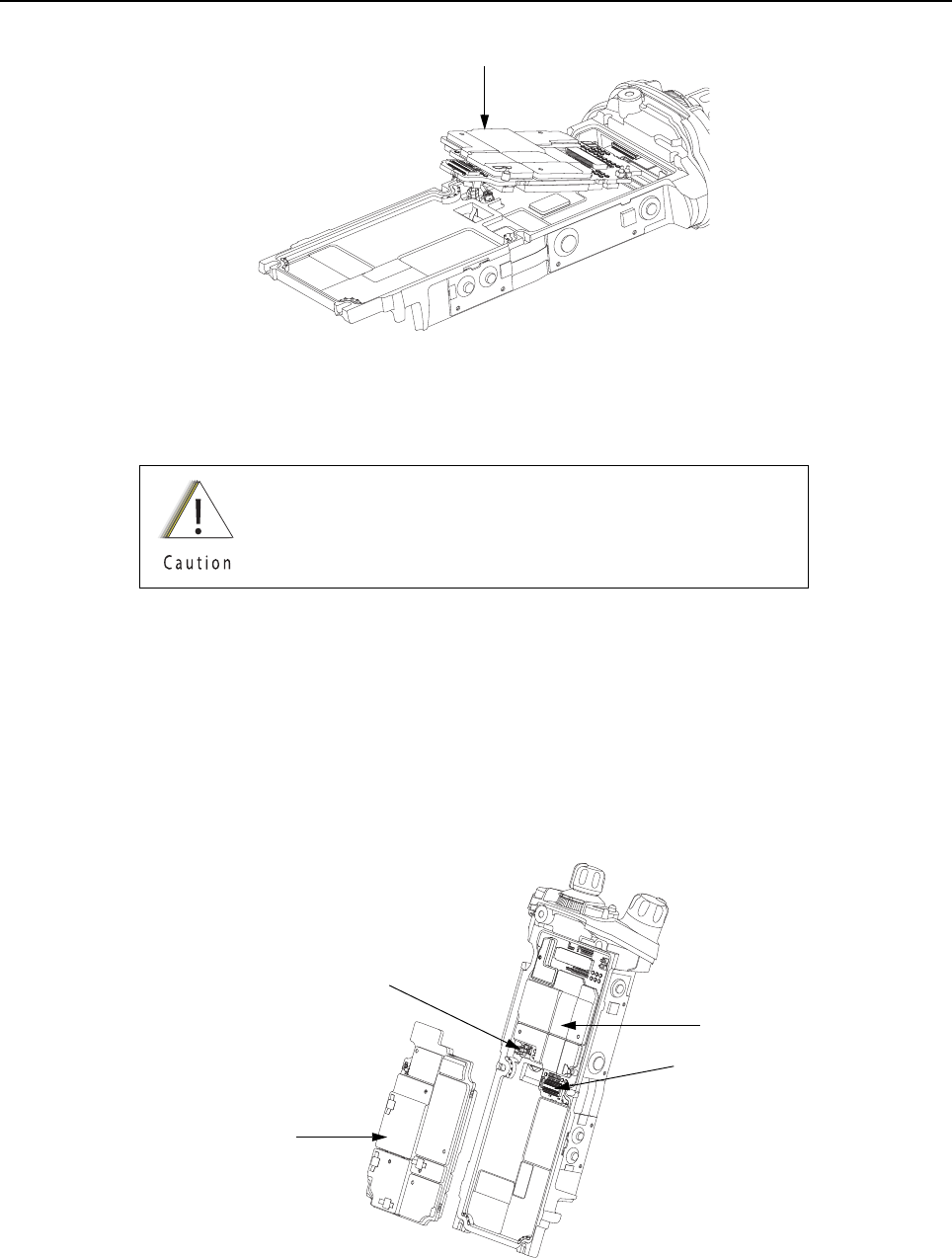
Disassembly/Reassembly Procedures: Radio Reassembly Sec 1: 8-33
Figure 8-44. Insert VOCON Board
8.9.1.4 Assemble RF Board Assembly (F)
1. Inspect the Battery Connector Seal (41) on the RF Board Assembly (F) for any damage or
debris. Replace seal if necessary.
2. Connect the small coaxial cable connector into the RF Board (38).
3. Connect the RF Board (38) to the VOCON Board as shown in Figure 8-45.
NOTE: Do not connect the Antenna coax at this time. Front Housing Assembly (1) must be
snapped in place prior to connecting the coax.
Figure 8-45. Connect RF Board to VOCON Board
Always replace with new thermal pads. See Section “8.8.5.2
Thermal Pads” on page 1:8-24.
VOCON Board Assembly (G, O)
Connector
RF Board Assembly (F)
Small Coax Cable
VOCON Board
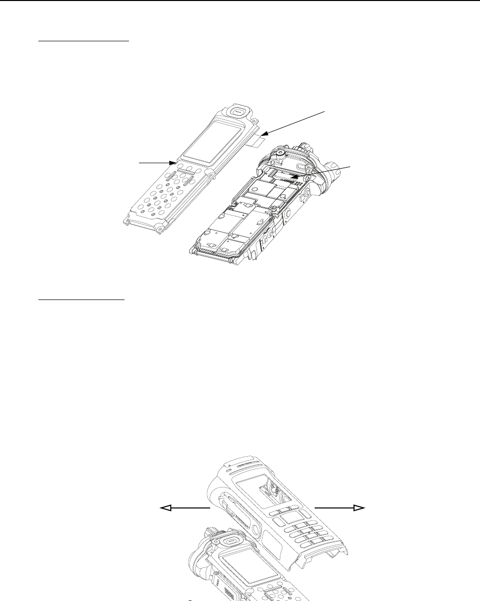
Sec 1: 8-34 Disassembly/Reassembly Procedures: Radio Reassembly
8.9.1.5 Assemble Back Chassis Assembly (E, M)
Dual Display version:
1. Inspect the Back Chassis Assembly seal for any debris or foreign material.
2. Connect the Back Chassis Flex to the VOCON board (G).
3. Set the Back Chassis Assembly (E) onto the Main Chassis Assembly (K).
Figure 8-46. Place Back Chassis
Top Display version:
1. Inspect the Back Chassis Assembly (M) seal for any debris or foreign material.
2. Set the Back Chassis Assembly (M) onto the Main Chassis Assembly (K).
8.9.1.6 Assemble Main Housing Assembly (D, L)
1. Stretch the Main Housing Assembly (D,L) side walls outward with both hands just enough to
clear the Main Chassis (K) and place it onto the radio.
2. Ensure the top edge of the housing and the bottom edge of the control top are aligned as
shown in Figure 8-47.
3. Squeeze the Main Housing Assembly (D,L) and the Main Chassis Assembly (K) in the battery
area until the Main Housing Assembly fully snaps in place onto the Main Chassis Assembly.
Figure 8-47. Place Housing into Main Chassis
Back Chassis Assembly (20) Connector
Pull Belt
Stretch Outwards
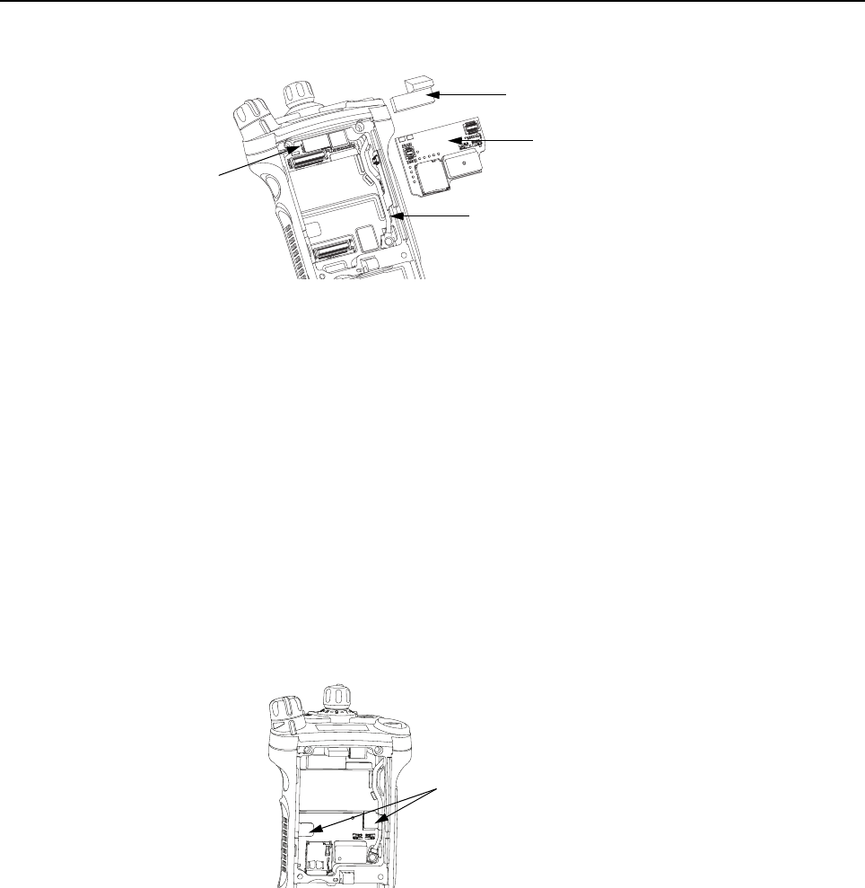
Disassembly/Reassembly Procedures: Radio Reassembly Sec 1: 8-35
8.9.1.7 Assemble Expansion Board Assembly (C)
Figure 8-48. Assemble Expansion Board Assembly
1. If the Control Top Assembly (J) or VOCON Board Assembly (G, O) was NOT removed skip to
step 2.
Connect the Control Top Flex to the VOCON Board Assembly as shown in Figure 8-48.
2. If the RF Board Assembly (38) was NOT removed, skip to step 4.
Carefully align the Antenna Coax Plug to the Coax Receptacle on the RF board Assembly (F)
and slide the plug in using the Black Stick. Ensure the universal connector flex is not caught
under the antenna coax cable.
3. Tuck in the Antenna Coax Cable into its grooves as shown in Figure 8-48.
4. Plug the Expansion Board Assembly (C) to the VOCON Board Assembly (G, O) as shown in
Figure 8-48. Make sure the connector is fully engaged.
5. Connect the two Flex Connectors to their pairing connectors on the right and left sides of the
Expansion Board Assembly as shown in Figure 8-49.
Figure 8-49. Insert Flex Connectors
6. If the radio is equipped with an Bluetooth Option Board Assembly skip this step. Install the
Connector Plug (32) by inserting it onto the Option Board Connector on the VOCON Board
Assembly as shown in Figure 8-48.
Flex Connectors
Expansion Board Assembly (42)
Connector Plug (32)
Antenna Coax Cable
Flex Connectors

Sec 1: 8-36 Disassembly/Reassembly Procedures: Radio Reassembly
8.9.1.8 Assemble Bluetooth Option Board Assembly (if so equipped)
1. Connect the Bluetooth Option Board Assembly to the VOCON Board Assembly. Ensure it is
completely connected as shown in Figure 8-50.
Figure 8-50. Assemble Bluetooth Option Board
2. Rotate the Bluetooth Option Board locking levers till they slide under the chassis feature and
lock the option board in place. Levers should be fully rotated until they rest as shown in
Figure 8-51.
Figure 8-51. Lock Levers
8.9.1.9 Assemble Speaker Module (B)
1. Apply a thin film of Lubricant (Part Number 1110027B23) to the upper two corners of the
Main Chassis (3) in the Speaker Module (23) opening as shown in Figure 8-52. Ensure no
lubricant contaminates the gold pads or the microphone membrane.
Figure 8-52. Lubricate Main Chassis
Do not touch the speaker cone or the Port Seal (25). Take
extra precaution to make sure neither the speaker nor the
breather pad is damaged.
Bluetooth Option Board
Levers at Lock Position
Apply Lubricant
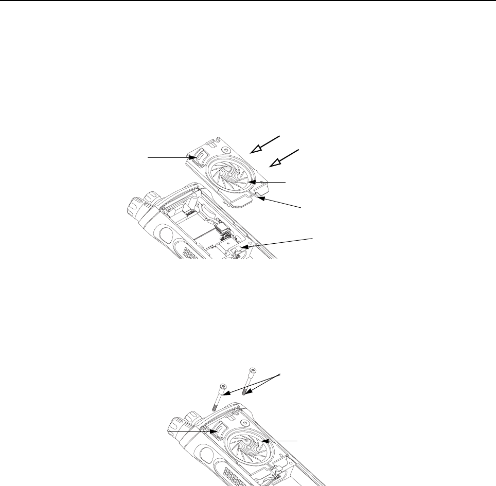
Disassembly/Reassembly Procedures: Radio Reassembly Sec 1: 8-37
NOTE: Avoid any lubricant to come in contact with any internal components.
2. Ensure the Seal is free from any debris or foreign material.
3. Align the Speaker Module's Pin feature located on the bottom edge directly below the
speaker, into the hole on the chassis hook feature.
4. Swing the Speaker Module down and firmly press the top side into the radio as shown in
Figure 8-53.
Figure 8-53. Insert Speaker Module
5. While holding the Speaker Module down, place the two top screws (28) into the their
respective holes and torque the screws to 10 in-lbs with an IP8 Torx Bit in a torque driver.
See Figure 8-54.
IMPORTANT: For proper sealing, Speaker Module (B) must be held down during the
torquing of the screws.
Figure 8-54. Insert Top Screws
Speaker Cone
Port Seal (25)
Pin Feature
Chassis Hook Feature
Top Screws (28)
Speaker Cone
Port Seal (25)

Sec 1: 8-38 Disassembly/Reassembly Procedures: Radio Reassembly
8.9.1.10 Assemble Speaker Grille Assembly (A)
1. Install the Speaker Grille (A) by inserting the top lip under the control top bezel and rotating
the grille into place. See Figure 8-55.
Figure 8-55. Remove Center Screws
NOTE: Ensure the Memory Door (33) is in place and the memory door screw shaft is
aligned with the screw hole.
2. Insert the two center screws (29) and torque to 10 in-lbs. See Figure 8-56.
Figure 8-56. Insert Center Screws
3. If removed, insert the two bottom screws (30) into the screw holes at the bottom of the radio
as shown in Figure 8-57., and torque to 10 in-lbs.
Figure 8-57. Insert Bottom Screws
NOTE: Refer to the appropriate section in this manual for reinstalling the antenna, battery,
or any other accessory that was previously connected or attached to the radio prior
to servicing.
Center Screws (29)
Memory Door (33)
Center Screws (29)
Memory Door (33)
Bottom Screws (30)

Disassembly/Reassembly Procedures: Ensuring Radio Submergibility Sec 1: 8-39
8.10 Ensuring Radio Submergibility
This section discusses radio submergibility concerns, tests, and disassembly and reassembly of
ASTRO APX 7000 R radios.
8.10.1 Standards
ASTRO APX 7000 R radio models meet the stringent requirements of U. S. MIL-STD-810C, Method
512.1, Procedure I; MIL-STD-810D, Method 512.2, Procedure I; MIL-STD-810E, Method 512.3,
Procedure I; and MIL-STD-810F, Method 512.4, Procedure I, which require the radio to maintain
watertight integrity when immersed in six (6) feet of water for two hours.
8.10.2 Servicing
APX 7000 R radios shipped from the Motorola Solutions factory have passed vacuum testing and
should not be disassembled. If disassembly is necessary, refer to qualified service personnel and
service shops capable of restoring the water ight integrity of the radio.
8.10.3 Water Exposure
If the radio is exposed to water, shake the radio to remove the excess water from the speaker grille
and microphone ports areas before operating; otherwise, the sound may be distorted until the water
has evaporated, or is dislodged from these areas.
8.10.4 Specialized Test Equipment
This section summarizes the specialized test equipment necessary for testing the integrity of ASTRO
APX 7000 R radios.
To ensure that the radio is truly a watertight unit, special testing, test procedures, and specialized
test equipment are required. The special testing involves a vacuum check of the radio and pressure
testing (troubleshooting) for water leaks if the vacuum check fails. The specialized test equipment is
needed to perform the vacuum check and pressure testing, if required.
8.10.4.1 Vacuum Pump Kit NLN9839_
The Vacuum Pump Kit includes a Vacuum Pump with gauge and a Vacuum Hose. The Vacuum
Adapter (p/n 66009259001) which connects the vacuum pump to the radio, must be ordered
separately.
8.10.4.2 Pressure Pump Kit NTN4265_
The Pressure Pump Kit includes a Pressure Pump with gauge and a Pressure Hose. As with the
Vacuum Pump Kit above, the Vacuum Adapter connects the pressure pump to the radio.
8.10.5 Disassembly
Disassemble the radio according to Section “8.7 Radio Disassembly” on page 1:8-12.
It is strongly recommended that maintenance of the radio be deferred to
qualified service personnel and service shops. This is of paramount
importance as irreparable damage to the radio can result from service by
unauthorized persons. If disassembly is necessary, unauthorized attempts to
repair the radio may void any existing warranties or extended performance
agreements with Motorola. It is also recommended that submergibility be
checked annually by qualified service personnel.
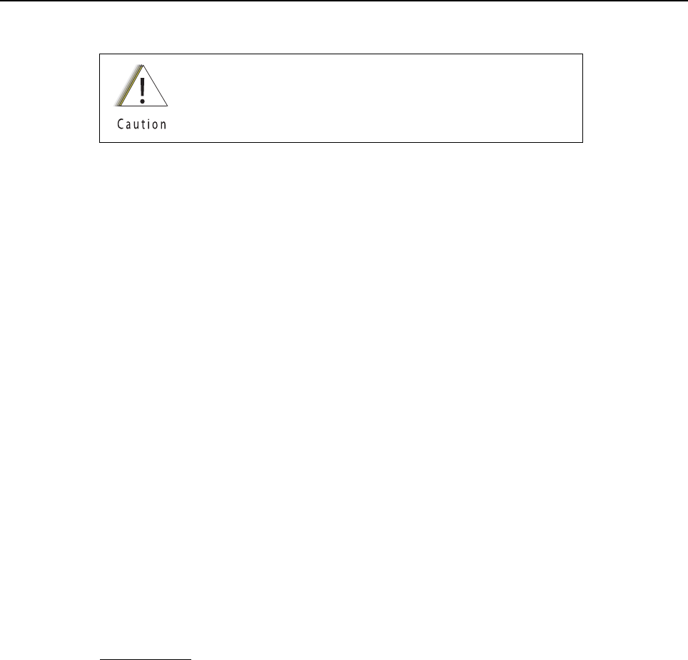
Sec 1: 8-40 Disassembly/Reassembly Procedures: Ensuring Radio Submergibility
8.10.6 Reassembly
To reassemble the radio:
1. Inspect the seal on the Back Chassis Assembly (E, M) for any damage or foreign material.
2. Inspect the seal on the Speaker Module (B) for any damage or foreign material.
3. Inspect the Battery Connector Seal (41) on the RF Board Assembly (G, O) for any damage.
4. Inspect the mating seal surfaces on the Main Chassis (3) for all of the above seals for
damage or foreign material that might prevent the seals from sealing properly.
Continue reassembling the radio according to Section “8.9 Radio Reassembly” on page 1:8-31.
Tighten all hardware that was loosened or removed.
8.10.7 Vacuum Test
The Vacuum Test uses a Vacuum Pump to create a negative pressure condition inside the radio. The
gauge measures this pressure and is used to monitor any pressure changes in the radio. A properly
sealed, watertight radio should have minimal change in pressure during the test.
Before starting the vacuum test:
• Remove the battery and antenna.
• Remove the Universal Connector Cover (43) or any other accessories to expose the universal
connector.
NOTE: Refer to the exploded view diagrams and parts lists found in “Chapter 10. Exploded Views
and Parts Lists” on page 1:10-1.
8.10.7.1 Vacuum Tool Setup
1. Attach one end of the hose to the Vacuum Pump. Attach the other side of the hose to the
Vacuum Adapter.
2. Tool Leak Test:
i. Block the open end of the Vacuum Adapter.
ii. Pull the knob on the Vacuum Pump to create vacuum.
iii. Pump at least 15 inHg.
iv. Watch the gauge for a minute. If there is any loss of vacuum, repair or replace the tool.
3. Ensure that the seal is attached to the Vacuum Adapter.
Do not reassemble the radio without first performing the
following preliminary inspection procedure.

Disassembly/Reassembly Procedures: Ensuring Radio Submergibility Sec 1: 8-41
8.10.7.2 Attaching Grille Eliminator
Figure 8-58. Attaching Grille Eliminator
1. Remove the Speaker Grille (27) by following steps in Section 8.7.1 on page 1:8-12 and
remove the Memory Door (33).
2. Slide the top of the Grille Eliminator under the Control Top Bezel (11) and swing it down
towards the radio. Secure the Grille Eliminator using the two center screws (29) with a torque
of 10 in lbs. See Figure 8-58.
8.10.7.3 Test Procedure
1. Attach the Vacuum Adapter onto the radio in the same manner as a radio battery. Ensure
both latches are clicked into place.
2. Place the radio on a flat surface with the Grille Eliminator facing upward.
3. Pull the knob on the Vacuum Pump to create vacuum. The vacuum test pressure should be
between 5-7 inHg.
4. Observe the gauge for approximately 2 minutes.
• If the needle falls less than 2 inHg, the radio passes the vacuum test.
i. Remove the Grille Eliminator
ii. Visually inspect the Port Seal Label (26) for proper adhesion to the
Speaker Module (23). Make sure there are no wrinkles or cuts to the material that would
cause a leak. Replace seal if damaged. (See appropriate section for servicing the
seals).
iii. If the seal passes this inspection, this radio is approved for submergibility. No additional
testing is required.
iv. Replace the Speaker Grille Assembly (27) and Memory Door (33) as described in the
reassembly procedures.
Ensure that the vacuum pressure NEVER exceeds 7 inHg.
The radio has pressure sensitive components that can be
damaged if the pressure exceeds this limit.
Grille Eliminator
Vacuum Adapter
Screws

Sec 1: 8-42 Disassembly/Reassembly Procedures: Ensuring Radio Submergibility
• If the needle falls more than 2 inHg, the radio fails the vacuum test and the radio might
leak if submerged. Additional troubleshooting of the radio is required.
i. Keep the Grille Eliminator and Vacuum Adapter on but remove the Vacuum Pump from
the Vacuum Adapter.
ii. Goto Section “8.10.8 Pressure Test (using NTN4265_)” on page 1:8-42.
8.10.8 Pressure Test (using NTN4265_)
Pressure testing the radio is necessary only if the radio has failed the vacuum test. Do not perform
the pressure test until the vacuum test has been completed. Pressure testing involves creating a
positive pressure condition inside the radio, submerging the radio in water, and observing the radio
for a stream of bubbles (leak). Since all areas of the radio are being checked, observe the entire unit
carefully for the possibility of multiple leaks before completing this test.
NOTES:When Radio is placed under the water there will be some air trapped which will be released.
This is not a failure.
Refer to the exploded view diagrams and parts lists found in “Chapter 10. Exploded Views
and Parts Lists” on page 1:10-1.
The Grille Eliminator must be used to conduct the pressure test:
If the radio is still set up from vacuum test, skip steps 1 through 4.
To conduct the pressure test:
1. Remove the Speaker Grille (27) by following the steps from Section “8.7.1 Removal of the
Speaker Grille Assemblies (A)” on page 1:8-12 and remove the Memory Door (33).
2. Slide the top of the Grille Eliminator under the Control Top Bezel (11) and swing it down
towards the radio. Secure the Grille Eliminator using the two center screws (29) with a torque
of 10 in lbs. See Figure 8-58.
3. Ensure that an seal is attached to the Vacuum Adapter.
4. Attach the Vacuum Adapter onto the radio in the same manner as a radio battery. Ensure
both the latches are clicked into place.
5. Attach one end of the hose to the Pressure Pump. Attach the other side of the hose to the
Vacuum Adapter.
6. Operate the pump until the gauge reads approximately 1 psig.
7. Maintain the pressure around 1 psig and submerge the radio into a water-filled container.
Pressure must remain between 0.5 psig and 1.5 psig.
Pressure lower then 0.5 psig may allow water into the radio,
which will damage the radio.
Ensure that the pressure NEVER exceeds 1.5 psig. The radio
has pressure sensitive components that can be damaged if
the pressure exceeds this limit.

Disassembly/Reassembly Procedures: Ensuring Radio Submergibility Sec 1: 8-43
8. Watch for any continuous series of bubbles. A steady stream of bubbles indicates a sign of
leakage.
NOTE: Some accumulation of air may be entrapped in the main housing which may cause a false
diagnosis of a leak. Ensure there is a steady stream of bubbles before concluding there is a
leak.
9. Note all of the seal areas that show signs of leakage. Rotate the radio to view all sides to
pinpoint the problem(s) to one (or more) of the following areas:
• Seal Interfaces
• Speaker Assembly
• Battery Connector Seal
• Main Chassis, including the Control Top
• Back Chassis
10. Remove the radio from the water container and dry the radio thoroughly. Be especially careful
to dry the area around the Memory Door (33).
11. With the Radio in an upright position and Control Top up, remove the vacuum adapter by
squeezing the release latches, and pulling the adapter down and away from the radio.
12. Ensure the area around the Memory Door (33) opening is dry
13. Dry the remainder of the radio and remove the Grille Eliminator.
14. See “8.10.9. Troubleshooting Leak Areas” on page 1:8-43.
8.10.9 Troubleshooting Leak Areas
Before repairing any leak, first read all of the steps within the applicable section. This will help to
eliminate unnecessary disassembly and reassembly of a radio with multiple leaks. Troubleshoot only
the faulty seal areas listed in “8.10.8. Pressure Test (using NTN4265_)” on page 1:8-42 and, when
multiple leaks exist, in the order listed.
NOTES:All disassembly and reassembly methods can be found in Section 8.7. and Section 8.9.
If in the field, water is found around the battery leads, the O-ring on the Battery should be
inspected and replaced if needed.
8.10.9.1 Seal Interfaces
• If leak occurs at one or more of the seal interfaces, disassembly of the component(s) and
inspection of the interfaces to determine if there is any damage. If no damage is observed,
re-assemble the radio as directed.
• If damage has occurred, replacement parts will be needed.
8.10.9.2 Speaker Module
• If leak occurs through the Microphone Membrane (24) or the Port Seal (25), replace these
items.
• If leak occurs elsewhere on the Speaker Module (B), the module will need to be replaced.
To avoid equipment damage, keep the area around the
memory card opening dry to prevent water from entering the
radio.

Sec 1: 8-44 Disassembly/Reassembly Procedures: Ensuring Radio Submergibility
8.10.9.3 Battery Contact Seal
• If leak occurs due to damage to the Battery Connector Seal (41), it will need to be replaced.
8.10.9.4 Back Chassis
• If leak occurs through the Color Display Lens (22), replace it.
• If leak occurs elsewhere on the Back Chassis (E/M), it will need to be replaced.
8.10.9.5 Control Top
• If leak occurs through the antenna or the Control Top Seal (10), replace it.
• If leak occurs elsewhere on the Control Top Assembly (J), it will need to be replaced.
8.10.9.6 Main Chassis
• If leak occurs on the Back Chassis (E/M), it will need to be replaced.
Chapter 9 Basic Troubleshooting
This section of the manual contains troubleshooting charts and error codes that will help you to
isolate a problem. Level one and two troubleshooting will support only radio alignment,
programming, battery replacement, and knob replacement, and circuit board replacement.
Component-level service information can be found in the “ASTRO APX 7000/ APX 7000XE Portable
Radios Detailed Service Manual,” Motorola publication number 6875961M01.
9.1 Power-Up Error Codes
When the radio is turned on (power-up), the radio performs self-tests to determine if its basic
electronics and software are in working order. Problems detected during these tests are presented
as error codes on the radio’s display. For non-display radios, the problem will be presented at
power-up by a single, low-frequency tone. The radio should be sent to the depot if cycling power and
reprogramming the code plug do not solve the problem. The presence of an error should prompt the
user that a problem exists and that a service technician should be contacted.
Self-test errors are classified as either fatal or non-fatal. Fatal errors will inhibit user operation;
non-fatal errors will not. Use Table 9-1 to aid in understanding particular power-up error code
displays.
Table 9-1. Power-Up Error Code Displays
Error
Code Description Corrective Action
01/02 FLASH ROM Codeplug Checksum Non-Fatal Error Reprogram the codeplug
01/12 Security Partition Checksum Non-Fatal Error Send radio to depot
01/81 Host ROM Checksum Fatal Error Send radio to depot
01/82 FLASH ROM Codeplug Checksum Fatal Error Reprogram the codeplug
01/84 External EEPROM Blank (or SLIC failure) Fatal Error Send radio to depot
01/88 External RAM Fatal Error – Note: Not a checksum failure Send radio to depot
01/90 General Hardware Failure Fatal Error Turn the radio off, then on
01/92 Security Partition Checksum Fatal Error Send radio to depot
01/93 FLASHport Authentication Code Failure Send radio to depot
01/94 Internal EEPROM Blank Fatal Error. Send radio to depot
01/98 Internal RAM Fail Fatal Error Send radio to depot
01/A0 ABACUS Tune Failure Fatal Error Send radio to depot
01/A2 Tuning Codeplug Checksum Fatal Error Send radio to depot
02/81 DSP ROM Checksum Fatal Error Send radio to depot
02/88 DSP RAM Fatal Error – Note: Not a checksum failure Turn the radio off, then on
Sec 1: 9-2 Basic Troubleshooting: Operational Error Codes
9.2 Operational Error Codes
During radio operation, the radio performs dynamic tests to determine if the radio is working properly.
Problems detected during these tests are presented as error codes on the radio’s display. The
presence of an error code should prompt a user that a problem exists and that a service technician
should be contacted. Use Table 9-2 to aid in understanding particular operational error codes.
9.3 Receiver Troubleshooting
Table 9-3 lists the possible causes of, and corrections for, receiver problems.
02/90 General DSP Hardware Failure (DSP startup message not
received correctly)
Turn the radio off, then on
09/10 Secure Hardware Error Turn the radio off, then on
09/90 Secure Hardware Fatal Error Turn the radio off, then on
Note: If the corrective action does not fix the failure, send the radio to the depot.
Table 9-2. Operational Error Code Displays
Error Code Description Corrective Action
FAIL 001 Synthesizer Out-of-Lock 1. Reprogram external codeplug
2. Send radio to depot
FAIL 002 Selected Mode/Zone Codeplug
Checksum Error
Reprogram external codeplug
Table 9-3. Receiver Troubleshooting Chart
Symptom Possible Cause Correction or Test
(Measurements at Room Temperature)
Radio Dead; Display Does Not
Turn On
1. Dead Battery Replace with charged battery
2. Blown Fuse Send radio to depot
3. On/Off Switch
4. Regulators
Radio Dead; Display
Turns On
1. VOCON Board Send radio to depot
2. RF Board
3. Expander Board
Table 9-1. Power-Up Error Code Displays (Continued)
Error
Code Description Corrective Action
Basic Troubleshooting: Transmitter Troubleshooting Sec 1: 9-3
9.4 Transmitter Troubleshooting
Table 9-4 lists the possible causes of, and corrections for, transmitter problems.
Radio On; Front Display Off High operating
temperature (above
80°C)
Allow radio to return to normal operating
temperature.
No Receive Audio, or Receiver
Does Not Unmute
Programming 1. Check if transmitted signal matches the
receiver configuration (PL, DPL, etc.)
2. Check if radio able to unmute with monitor
function enabled
Audio Distorted or Not Loud
Enough
Synthesizer Not On
Frequency
Check synthesizer frequency by measuring the
transmitter frequency; realign if off by more than
±1000 Hz
RF Sensitivity Poor 1. Synthesizer Not On
Frequency
Check synthesizer frequency by measuring the
transmitter frequency; realign if off by more than
±1000 Hz
2. Antenna Switch/
Connector
Send radio to depot
3. Receiver Front-
End Tuning
Check RF front-end tuning for optimum sensitivity
using the tuner
Radio Will Not Turn Off VOCON Board Send radio to depot
Table 9-4. Transmitter Troubleshooting Chart
Symptom Possible Cause Correction or Test (Measurements
Taken at Room Temperature)
No RF Power Out 1. TX Power Level or Frequency Check TX power level and frequency
programming (from tuner)
2. No Injection To Power
Amplifier
Send radio to depot
3. Antenna Switch/Connector
No Modulation;
Distorted Modulation
1. Programming Check deviation and compensation
settings using the tuner
2. VOCON Board Send radio to depot
Bad Microphone Sensitivity 1. Check Deviation and
Compensation
Realign if necessary
2. Microphone Send radio to depot
Table 9-3. Receiver Troubleshooting Chart (Continued)
Symptom Possible Cause Correction or Test
(Measurements at Room Temperature)
Sec 1: 9-4 Basic Troubleshooting: Encryption Troubleshooting
9.5 Encryption Troubleshooting
Table 9-5 lists the possible causes of, and corrections for, encryption problems.
9.6 Bluetooth Option / Expansion Board Troubleshooting
Table 9-6 lists the possible causes of, and corrections for, Bluetooth Option / Expansion Board
problems.
No/Low signaling
(PL, DPL, MDC)
1. Programming Check programming
2. VOCON Board Send radio to depot
Cannot Set Deviation
Balance
RF Board Send radio to depot
Table 9-5. Encryption Troubleshooting Chart
Symptom Possible Cause Corrective Action
No “KEYLOAD” on Radio Display When
Keyloading Cable is Attached to the Radio
Side Connector
1. Defective Keyload Cable Send radio to depot
2. Defective Radio
Keyloader Displays “FAIL” 1. Wrong Keyloader Type Use correct keyloader
type. Refer to Keyloader
User Guide for more
information
2. Bad Keyloader Try another keyloader
3. Defective Radio Send radio to depot
Table 9-6. Bluetooth Option/Expansion Board Troubleshooting Chart
Message Displayed Possible Cause Corrective Action
Hardware board absent Option / Expansion Board is not present on the
radio and feature is enabled by a code plug.
Send radio to depot
Hardware board mismatch When an option / expansion board feature is
enabled in code plug, but the board (EB or OB)
does not have corresponding capability.
Send radio to depot
Hardware board failed Displayed if the board Deenumerated,
Enumeration timed out, Option board device
initialized with a Fatal Error.
Reset the radio. If this
persists, send radio to the
depot
Table 9-4. Transmitter Troubleshooting Chart (Continued)
Symptom Possible Cause Correction or Test (Measurements
Taken at Room Temperature)

Basic Troubleshooting: Bluetooth Troubleshooting Sec 1: 9-5
9.7 Bluetooth Troubleshooting
Table 9-7 lists the possible causes of, and corrections for, bluetooth problems.
Update failed Please reset Bluetooth Option / Expansion board firmware
update fails.
Reset radio. if this
persists, send radio to the
depot
Table 9-7. Bluetooth Troubleshooting Chart
Message Displayed Possible Cause Corrective Action
Non_Audio dev connect failed /
Audio device connect failed
Displayed when the accessory fails to connect
after pairing.
Clear all pairing
information and try to pair
and connect.
Bluetooth pairing failed Accessory and Radio failed to pair through MPP/
NFC.
Retry pairing accessory
with Radio.
Clear all BT devices failed Radio was unable to clear information of all the
accessories that are paired and/or connected.
Reset the radio.
Bluetooth on failed Bluetooth Option Board is in an unknown state
and is unable to process the request for
Bluetooth ON.
Reset the radio. If this
continues, send radio to
the depot.
Table 9-6. Bluetooth Option/Expansion Board Troubleshooting Chart (Continued)
Message Displayed Possible Cause Corrective Action

Sec 1: 9-6 Basic Troubleshooting: Bluetooth Troubleshooting
Notes

Chapter 10 Exploded Views and Parts Lists
This chapter contains exploded views and associated parts lists for the ASTRO APX 7000 digital portable radios. The following table lists the exploded views for the APX 7000 radio in different configurations:
Table 10-1. APX 7000 Exploded Views
View Page
APX 7000 Dual Display Exploded View 1:10-2
APX 7000 Top Display Exploded View 1:10-4
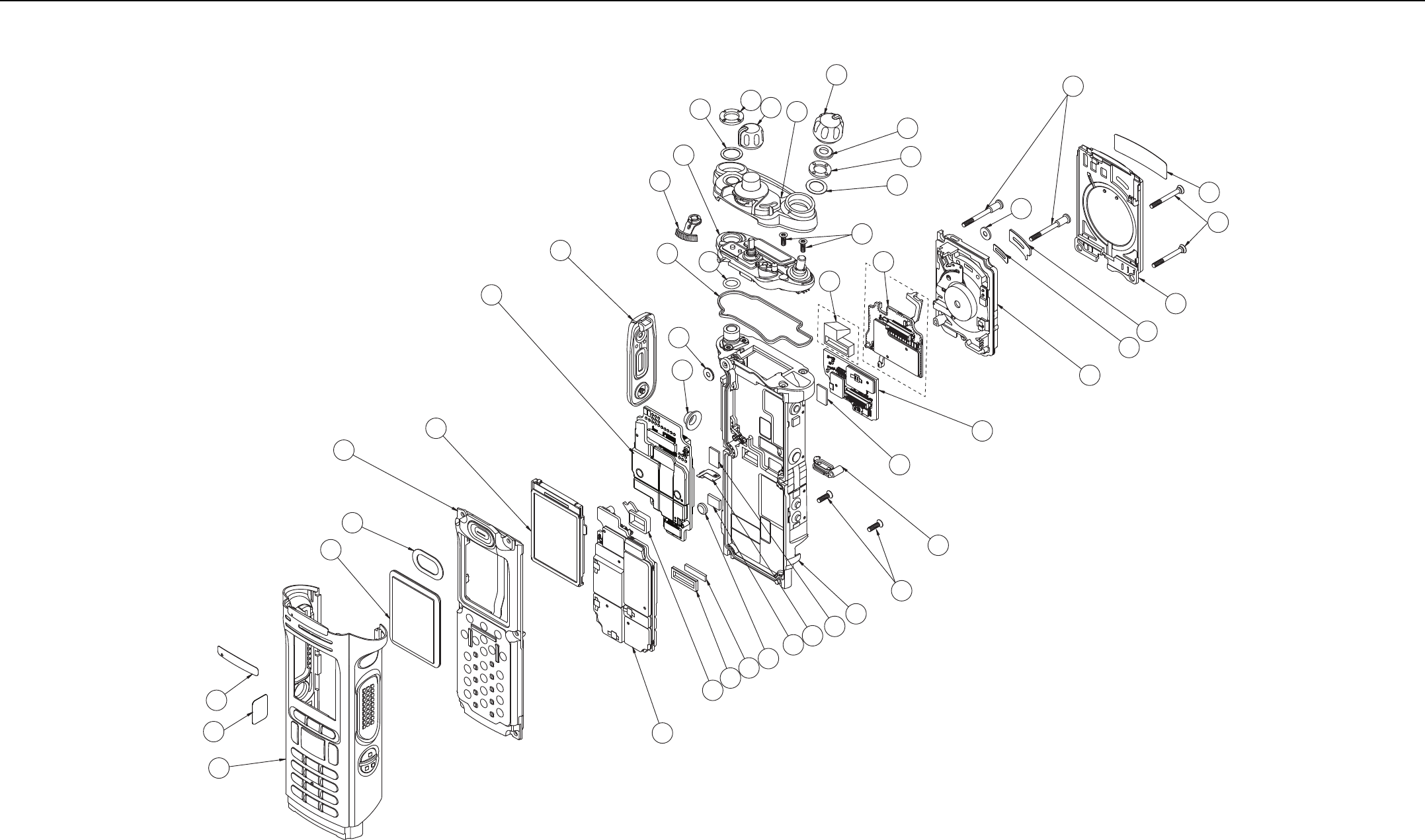
Sec 1: 10-2 Exploded Views and Parts Lists: APX 7000 Dual Display Exploded View
10.1 APX 7000 Dual Display Exploded View
Figure 10-1. APX 7000 Dual Display Exploded View
3
30
33
38
6
7
8
8
41
39
40 37
23
27
28
29
42
44
24
25
26
9
11
12
13
14
15
16
17
18 19
31
32
51
or
1
50
20
35
2
21
22
34
36
43
4
5
10

Exploded Views and Parts Lists: APX 7000 Dual Display Exploded View Parts List Sec 1: 10-3
10.2 APX 7000 Dual Display Exploded View Parts
List
NOTE:
1. HIGH IMPACT GREEN and PUBLIC SAFETY YELLOW Colored Housings can be serviced in
the depot and can be ordered via AAD.
2. See Table 10-2."Compatibility Table” on page 1:10-6.
3. Radios installed with the Option Board Kit NNTN8160_ do not have the connector plug
(32009064001).
4. With TI Chipset.
5. With PCN Display Vocon.
Item
No.
Motorola Part
Number Description
1 NHN7000_
010093040071
010093040081
Assy, Front Housing, Dual Display (Black)
Assy, Front Housing, Dual Display (Yellow)
Assy, Front Housing, Dual Display (Green)
23375622B01 Label, Housing, Dataside
3 01009304001 Assy, Main, Chassis
43275002C02 Seal, Membrane, Microphone
5 3275033C01 O-ring, Antenna, Main
63971892H01 Contact, Chassis Ground
7 7505316J16 Pad, Coin Cell Battery
87575218H01 Pad (x2), Thermal, Exp & VOCON Board
91375044C022Assy, Control Top
10 3275031C01 Seal, Control Cap
11 1371891H02 Bezel, Control Top, Subassembly
12 3675581B01 Knob, Volume
13 3675590B03 Knob, Frequency
14 4575585B01 Lever, Secure
15 3275377H01 Seal, Cap, Torque Adder
16 0405659W01 Washer, Wave, Volume
17 0275361H01 Nut, Spanner, Volume
18 0400129O54 Washer, Lock, Antenna
19 0275891B01 Nut, Spanner, Antenna
20 NHN7017_2Assy, Back Chassis, Dual Display
21 3271816H01 Seal, Speaker, Dataside
22 6175619B02 Lens,Color Display
23 NHN7002_ Module, Speaker
24 3275002C02 Seal, Membrane, Microphone
25 3271819H01 Seal, Port
26 5475160H01 Label, Seal, Port
27 01009304004
01009304005
01009304006
Assy, Grille, Speaker (Black)
Assy, Grille, Speaker (Yellow)
Assy, Grille, Speaker (Green)
28 0375962B01 Screw (x2), M2.5 X 0.45, 30.10 LG
29 0375962B02 Screw (x2), M2.5 X 0.45, 24.45 LG
30 0375962B03 Screw (x2), M2.5 X 0.45, 9.2 LG
31 0375962B04 Screw (x2), M2.5 X 0.45, 7.0 LG
32332009064001 Plug, Support, Connector
33 3275882B01 Door, Seal, Memory
34 3875126H01 Cap, Chassis Boss, Universal Connector
35 010093040242Display, Color, Back
36 MNCN6202_2,5
MNCN6200_2
Assy, VOCON Board, Dual Display
Assy, VOCON Board, Dual Display
37 6003710K08 Battery, Backup, Coincell
38 MNUR4001_
MNUS4000_
MNUT4000_
MNUS4002_
MNUT4004_
MNUE7367_
Assy, Board, RF (VHF / 700–800 MHz)
Assy, Board, RF (UHF1 / 700–800 MHz)
Assy, Board, RF (UHF1 / VHF)
Assy, Board, RF (UHF2 / 7/800 MHz)
Assy, Board, RF (UHF2 / VHF)
Assy, Board, RF (UHF1 / UHF2)
39 3275623B02 Pad, Thermal, Outer
40 75009299001 Pad, Thermal, Inner
41 3271829H01 Seal, Connector, Battery
42 MHLN6977_
MHLN7035_4
Assy, Board, Expansion
Assy, Board, Expansion
43 1575250H01 Cover, Connector, Universal Conncector
44 3371896H01
3371896H02
Label, Grille, Speaker for APX 7000 radios
Label, Grille, Speaker for APX 7000R radios
Item
No.
Motorola Part
Number Description
50 33009274001 Label, Main Housing FM, Dual Displays
513NNTN8160_ Assembly, APX Portable Option Board
Item
No.
Motorola Part
Number Description
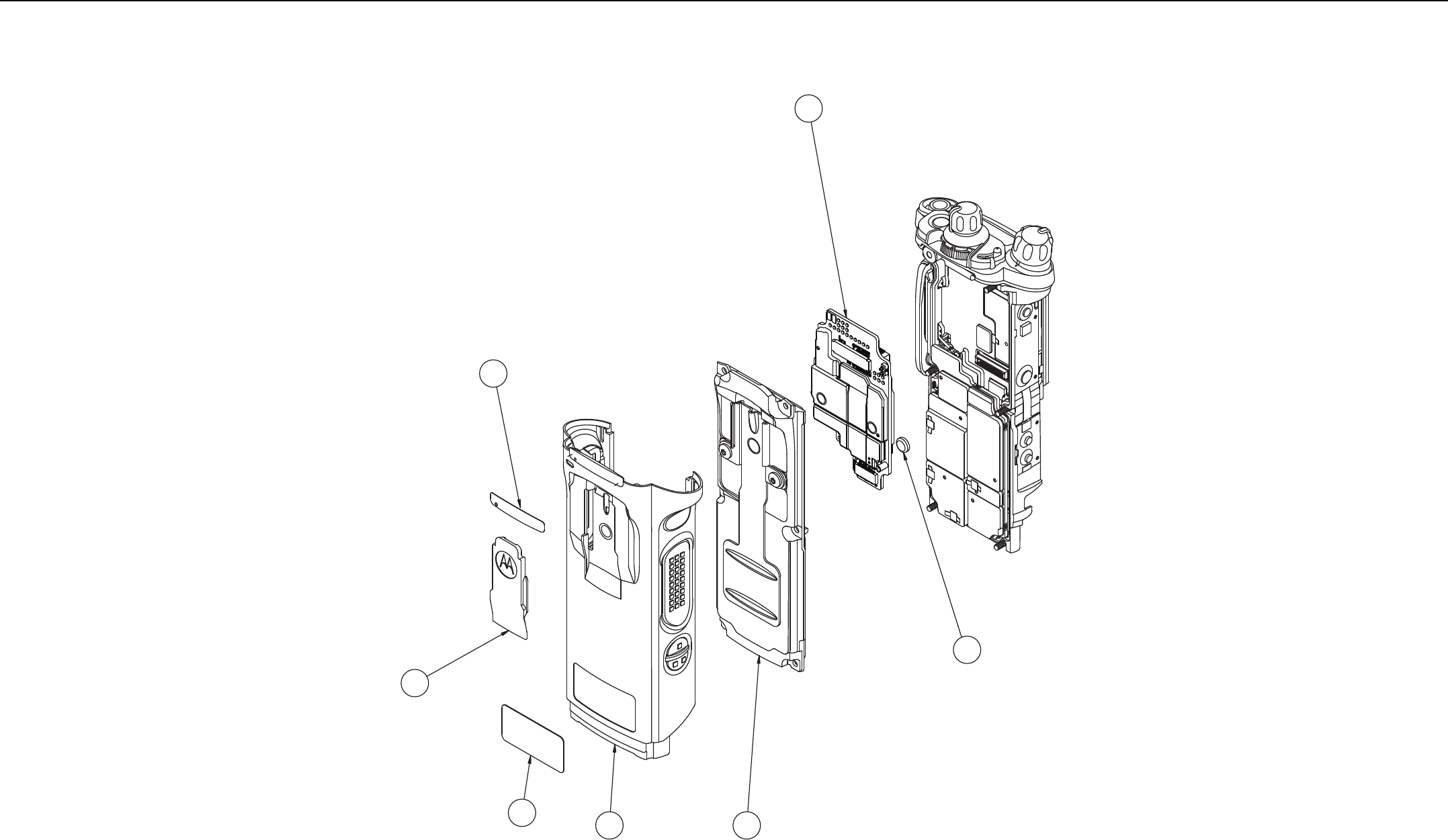
Sec 1: 10-4 Exploded Views and Parts Lists: APX 7000 Top Display Exploded View
10.3 APX 7000 Top Display Exploded View
Figure 10-2. APX 7000 Top Display Exploded View
45 46
47
48
49
2
37
NOTE: Refer to Dual Display view for items not exploded.
Parts shown here are exclusive to Top Display version.

Exploded Views and Parts Lists: APX 7000 Top Display Exploded View Parts List Sec 1: 10-5
10.4 APX 7000 Top Display Exploded View Parts List
Item
No.
Motorola Part
Number Description
45 NHN7001_
01009304009
01009304010
Assy, Front Housing, Top Display (Black)
Assy, Front Housing, Top Display (Yellow)
Assy, Front Housing, Top Display (Green)
23375622B01 Label, Housing, Dataside
46 NHN7004_ Assy, Back Chassis, Top Display
47 MNCN6203_2, 5
MNCN6201_2
Assy, VOCON Board Top Display
Assy, VOCON Board Top Display
37 6003710K08 Battery, Backup, Coincell
48 1575356H01 Cover, Clip, Belt
(See Appendix A"Accessories” on page 3:A-1)
49 3385836D09
3385836D08
Label, Main Housing, Top Display
Label, Main Housing FM, Top Display

Sec 1: 10-6 Exploded Views and Parts Lists: APX 7000 Top Display Exploded View Parts List
Table 10-2. Compatibility Table
Compatibility Table
Assy, Control Top – 1375044C02
Assy, Control Top – 1375044C01
Display, Color, Back – 01009304024
Display, Color, Back – 01009304019
Display, Color, Back – 01009304003
Assy, Back Chassis – Dual Display, NHN7017_
Assy, Back Chassis – Dual Display, NHN7003_
VOCON Board, Top – Display MNCN6203_
VOCON Board, Top – Display MNCN6201_
VOCON Board, Dual – Display MNCN6202_
VOCON Board, Dual – Display MNCN6200_
Assy, Control Top – 1375044C02 ––●●●●●●●●●
Assy, Control Top –1375044C01 ––●●●●●●●●●
Display, Color, Back – 01009304024 ●●–––●x––●x
Display, Color, Back – 01009304019 ●●–––●x––●x
Display, Color, Back – 01009304003 ●●–––x●––x●
Assy, Back Chassis – Dual Display, NHN7017_ ●●●●x––––●x
Assy, Back Chassis – Dual Display, NHN7003_ ●●xx●––––x●
VOCON Board, Top – Display MNCN6203_ ●●–––––––––
VOCON Board, Top – Display MNCN6201_ ●●–––––––––
VOCON Board, Dual – Display MNCN6202_ ●●●●x●x––––
VOCON Board, Dual – Display MNCN6200_ ●●xx●x●––––
Note:
●Compatible
xNot Compatible
– Not Applicable

Index Index
Numerics
700-800 MHz
radio specifications 1:xvii
700-800 MHz and UHF1
model chart 1:xi
700-800 MHz and UHF2
model chart 1:xiv
700-800 MHz and VHF
model chart 1:x
A
alignment, tuner
bit error rate test 1:6-24
introduction 1:6-1
main menu 1:6-2
radio information screen 1:6-4
reference oscillator 1:6-4
softpot use 1:6-2
test setup 1:6-1
transmit deviation balance 1:6-17
transmitter test pattern 1:6-26
analog mode
receiving 1:3-3
transmitting 1:3-8
antenna
attaching 1:8-6
removing 1:8-6
antenna o-ring
servicing 1:8-21
ARM theory of operation 1:3-12
assemble
back chassis assembly 1:8-34
bluetooth option board assembly 1:8-36
expansion board assembly 1:8-35
knobs and top bezel assembly 1:8-31
main housing assembly 1:8-34
RF board assembly 1:8-33
speaker grill assembly 1:8-38
top control assembly 1:8-31
vocon board assembly 1:8-32
ASTRO mode
receiving 1:3-11
transmitting 1:3-11
audio theory of operation 1:3-13
B
back chassis assembly
assemble 1:8-34
dual display
servicing 1:8-25
removing 1:8-16
top display
servicing 1:8-27
battery
attaching 1:8-7
removing 1:8-9
bit error rate test 1:6-24
bluetooth
troubleshooting chart 1:9-5
bluetooth option board assembly
assemble 1:8-36
bluletooth option/expansion board
troubleshooting chart 1:9-4
C
chassis ground contact
servicing 1:8-21
chassis pads
servicing 1:8-20
chassis screw boss cap
servicing 1:8-20
cleaning external plastic surfaces 1:2-1
color display
servicing 1:8-25
control top and keypad test mode, dual-display
version 1:5-6
control top assembly
removing 1:8-19
servicing 1:8-22
control top test mode
top-display version 1:5-8
controller
ARM theory of operation 1:3-12
audio theory of operation 1:3-13
theory of operation 1:3-12
user interface block theory of operation 1:3-13
controller expansion bay & option slot theory of
operation 1:3-13
D
disassembly/reassembly
antenna
attaching 1:8-6
removing 1:8-6
back chassis assembly
removing 1:8-16
battery
attaching 1:8-7
removing 1:8-9
control top assembly
removing 1:8-19
expansion board assembly
removing 1:8-13
housing assembly
reassembling 1:8-31
introduction 1:8-1
knobs and top bezel assembly
removing 1:8-18
main chassis assembly
removing 1:8-20
main housing assembly
removing 1:8-15
RF board assembly
removing 1:8-17
speaker grill assembly
removing 1:8-12
speaker module

Sec 1: Index-2 Index
removing 1:8-13
universal connector cover
attaching 1:8-11
removing 1:8-10
vocon board assembly
removing 1:8-18
display radio
test mode
test environments 1:5-5
test frequencies 1:5-5
dual-display version
control top and keypad test mode 1:5-6
entering test mode 1:5-3
RF test mode 1:5-5
E
encryption
index
selecting with keypad 1:7-3
selecting with menu 1:7-3
key
erasing
all keys 1:7-4
key zeroization 1:7-3
selecting with keypad 1:7-2
selecting with menu 1:7-2
troubleshooting chart 1:9-4
error codes
operational 1:9-2
power-up 1:9-1
expansion bay & option slot theory of operation 1:3-13
expansion board assembly
assemble 1:8-35
removing 1:8-13
servicing 1:8-25
exploded view
complete
dual display version 1:10-2
top display version 1:10-4
partial
dual display 1:8-2
top display 1:8-3
F
field programming equipment 1:4-3
FLASHport 1:1-2
G
grille label
servicing 1:8-30
H
handling precautions
non-ruggedized radios 1:2-1
ruggedized radios 1:2-2
housing assembly
reassembling 1:8-31
I
index, encryption
selecting with keypad 1:7-3
selecting with menu 1:7-3
K
key, encryption
erasing
all keys 1:7-4
key zeroization 1:7-3
loading 1:7-1
selecting with keypad 1:7-2
selecting with menu 1:7-2
knobs and top bezel assembly
assemble 1:8-31
removing 1:8-18
servicing 1:8-23
L
loading an encryption key 1:7-1
M
main chassis assembly
removing 1:8-20
main housing
dual display
servicing 1:8-27
top display
servicing 1:8-28
main housing assembly
assemble 1:8-34
removing 1:8-15
main lens
servicing 1:8-26
maintenance
cleaning 1:2-1
inspection 1:2-1
ruggedized radio submergibility checks 1:2-1
manual
notations 1:1-1
microphone membrane
servicing 1:8-21, 1:8-29
model chart
700-800 MHz and UHF1 1:xi
700-800 MHz and UHF2 1:xiv
700-800 MHz and VHF 1:x
numbering system 1:ix
UHF1 and VHF 1:xii, 1:xiii
UHF2 and VHF 1:xv
model numbering system, radio 1:ix
multikey
conventional 1:7-1
trunked 1:7-1
N
notations
manual 1:1-1

Index Sec 1: Index-3
warning, caution, and danger 1:1-1
P
performance checks
receiver 1:5-9
test setup 1:5-1
transmitter 1:5-10
performance test
tuner 1:6-24
port seal label
servicing 1:8-29
power-up error codes 1:9-1
precautions, handling 1:2-1
R
radio
alignment 1:6-1
basic description 1:1-2
dual-display model
RF test mode 1:5-5
dual-display version
control top and keypad test mode 1:5-6
entering display test mode 1:5-3
exploded view
complete
top display version 1:10-4
complete dual display version 1:10-2
partial
dual display 1:8-2
top display 1:8-3
features 1:1-2
FLASHport feature 1:1-2
information screen 1:6-4
model numbering system 1:ix
models 1:1-2
reassembling
housing assembly 1:8-31
submergible models
disassembling 1:8-39
reassembling 1:8-40
submersibility
specialized test equipment 1:8-39
standards 1:8-39
vacuum test 1:8-40
test environments 1:5-5
test frequencies 1:5-5
test mode
dual-display version 1:5-3
top-display model 1:5-7
top-display version
control top test mode 1:5-8
entering test mode 1:5-7
RF test mode 1:5-8
receiver
ASTRO conventional channel tests 1:5-9
performance checks 1:5-9
troubleshooting 1:9-2
receiving
analog mode 1:3-3
ASTRO mode 1:3-11
reference oscillator alignment 1:6-4
RF board assembly
assemble 1:8-33
removing 1:8-17
servicing 1:8-24
RF test mode
dual-display version 1:5-5
top-display version 1:5-8
ruggedized radios
handling precautions 1:2-2
submergibility checks 1:2-1
S
service aids 1:4-2
servicing
antenna o-ring 1:8-21
back chassis assembly
dual display 1:8-25
top display 1:8-27
chassis ground contact 1:8-21
chassis pads 1:8-20
chassis screw boss cap 1:8-20
color display 1:8-25
control top assembly 1:8-22
expansion board assembly 1:8-25
grille label 1:8-30
knobs and top bezel assembly 1:8-23
main housing
dual display 1:8-27
top display 1:8-28
main lens 1:8-26
microphone membrane 1:8-21, 1:8-29
port seal label 1:8-29
RF board assembly 1:8-24
speaker grille assembly 1:8-30
speaker module 1:8-29
speaker seal 1:8-26
vocon board assembly 1:8-23
softpot 1:6-2
speaker grill assembly
assemble 1:8-38
removing 1:8-12
speaker grille assembly
servicing 1:8-30
speaker module
removing 1:8-13
servicing 1:8-29
speaker seal
servicing 1:8-26
specifications
700-800 MHz radios 1:xvii
UHF1 radios 1:xviii
UHF2 radios 1:xix
VHF radios 1:xvi
standards, radio submersibility 1:8-39
submergibility
radio disassembly 1:8-39
radio reassembly 1:8-40
submersibility
specialized test equipment 1:8-39
standards 1:8-39
vacuum test 1:8-40

Sec 1: Index-4 Index
T
test equipment
recommended 1:4-1
specialized submersibility 1:8-39
test mode, entering
dual-display version 1:5-3
top-display version 1:5-7
test setup
alignment 1:6-1
performance checks 1:5-1
tests
receiver
ASTRO conventional channels 1:5-9
performance checks 1:5-9
transmitter
ASTRO conventional channels 1:5-11
performance checks 1:5-10
theory of operation
analog mode 1:3-3
ASTRO mode 1:3-11
controller 1:3-12
ARM 1:3-12
audio 1:3-13
expansion bay & option slot 1:3-13
user interface block 1:3-13
major assemblies 1:3-1
overview 1:3-1
top control assembly
assemble 1:8-31
top-display version
control top test mode 1:5-8
entering test mode 1:5-7
RF test mode 1:5-8
transmit deviation
balance alignment 1:6-17
transmitter
ASTRO conventional channel tests 1:5-11
performance checks 1:5-10
test pattern 1:6-26
troubleshooting 1:9-3
transmitting
analog mode 1:3-8
ASTRO mode 1:3-11
troubleshooting
bluetooth option/expansion board problems 1:9-4
bluetooth problems 1:9-5
encryption problems 1:9-4
introduction 1:9-1
operational error codes 1:9-2
power-up error codes 1:9-1
receiver problem chart 1:9-2
transmitter problem chart 1:9-3
tuner
bit error rate test 1:6-24
introduction 1:6-1
main menu 1:6-2
performance test 1:6-24
radio information screen 1:6-4
reference oscillator alignment 1:6-4
test setup 1:6-1
transmit deviation balance alignment 1:6-17
transmitter alignment 1:6-4
transmitter test pattern 1:6-26
U
UHF Specifications 1:xvii
UHF1
radio specifications 1:xviii
UHF1 and VHF
model chart 1:xii, 1:xiii
UHF2
radio specifications 1:xix
UHF2 and VHF
model chart 1:xv
universal connector cover
attaching 1:8-11
removing 1:8-10
user interface block theory of operation 1:3-13
V
vacuum test, submersibility 1:8-40
view, exploded
complete
top display version 1:10-4
complete dual display version 1:10-2
partial
dual display 1:8-2
top display 1:8-3
vocon board assembly
assemble 1:8-32
removing 1:8-18
servicing 1:8-23
W
warning, caution, and danger notations 1:1-1

ASTRO APX 7000/ APX 7000XE
Digital Portable Radios
Section 2
APX 7000XE

Notes

Table of Contents Sec 2: iii
Table of Contents
Model Numbering, Charts, and Specifications....................................... 2:ix
ASTRO APX 7000XE 700–800 MHz and VHF Model Chart ....................................................................2:x
ASTRO APX 7000XE 700–800 MHz and UHF1 Model Chart.................................................................2:xi
ASTRO APX 7000XE UHF1 and VHF Model Chart ............................................................................... 2:xii
ASTRO APX 7000XE UHF1 and UHF2 Model Chart............................................................................ 2:xiii
ASTRO APX 7000XE 700–800 MHz and UHF2 Model Chart............................................................... 2:xiv
ASTRO APX 7000XE UHF2 and VHF Model Chart ...............................................................................2:xv
Specifications for VHF Radios............................................................................................................... 2:xvi
Specifications for 700–800 MHz Radios............................................................................................... 2:xvii
Specifications for UHF1 Radios........................................................................................................... 2:xviii
Specifications for UHF2 Radios............................................................................................................. 2:xix
Chapter 1 Introduction ...................................................................... 2:1-1
1.1 Manual Contents......................................................................................................................... 2:1-1
1.2 Notations Used in This Manual................................................................................................... 2:1-1
1.3 Radio Description ....................................................................................................................... 2:1-2
1.4 FLASHport®................................................................................................................................2:1-2
Chapter 2 Basic Maintenance........................................................... 2:2-1
2.1 General Maintenance ................................................................................................................. 2:2-1
2.2 Handling Precautions.................................................................................................................. 2:2-1
Chapter 3 Basic Theory of Operation .............................................. 2:3-1
3.1 Major Assemblies ....................................................................................................................... 2:3-1
3.2 Analog Mode of Operation.......................................................................................................... 2:3-2
3.3 Digital (ASTRO) Mode of Operation ......................................................................................... 2:3-11
3.4 Controller Section ..................................................................................................................... 2:3-12
Chapter 4 Recommended Test Equipment and Service Aids ....... 2:4-1
4.1 Recommended Test Equipment ................................................................................................. 2:4-1
4.2 Service Aids................................................................................................................................ 2:4-2
4.3 Field Programming ..................................................................................................................... 2:4-3
Chapter 5 Performance Checks ....................................................... 2:5-1
5.1 Test Equipment Setup ................................................................................................................ 2:5-1
5.2 Display Radio Test Mode (Dual-Display Version)....................................................................... 2:5-3
5.3 Top-Display Version Radio Test Mode ....................................................................................... 2:5-7
5.4 Receiver Performance Checks ................................................................................................... 2:5-9
5.5 Transmitter Performance Checks ............................................................................................. 2:5-10

Sec 2: iv Table of Contents
Chapter 6 Radio Alignment Procedures.......................................... 2:6-1
6.1 Test Setup................................................................................................................................... 2:6-1
6.2 Tuner Main Menu........................................................................................................................ 2:6-2
6.3 Softpot......................................................................................................................................... 2:6-2
6.4 Radio Information........................................................................................................................ 2:6-4
6.5 Transmitter Alignments ............................................................................................................... 2:6-4
6.6 Front End Filter Alignment ........................................................................................................ 2:6-22
6.7 Performance Testing................................................................................................................. 2:6-24
Chapter 7 Encryption ........................................................................ 2:7-1
7.1 Load an Encryption Key.............................................................................................................. 2:7-1
7.2 Multikey Feature ......................................................................................................................... 2:7-1
7.3 Select an Encryption Key............................................................................................................ 2:7-2
7.4 Select an Encryption Index ......................................................................................................... 2:7-3
7.5 Erase an Encryption Key ............................................................................................................ 2:7-3
Chapter 8 Disassembly/Reassembly Procedures .......................... 2:8-1
8.1 APX 7000XE Exploded View (Main Subassemblies).................................................................. 2:8-1
8.2 Required Tools and Supplies...................................................................................................... 2:8-5
8.3 Fastener Torque Chart................................................................................................................ 2:8-5
8.4 Antenna....................................................................................................................................... 2:8-6
8.5 Battery......................................................................................................................................... 2:8-7
8.6 Universal Connector Cover....................................................................................................... 2:8-10
8.7 Radio Disassembly ................................................................................................................... 2:8-12
8.8 Serviceable Components of the Main Sub-Assemblies ............................................................ 2:8-20
8.9 Radio Reassembly.................................................................................................................... 2:8-29
8.10 Ensuring Radio Submergibility.................................................................................................. 2:8-37
Chapter 9 Basic Troubleshooting .................................................... 2:9-1
9.1 Power-Up Error Codes................................................................................................................ 2:9-1
9.2 Operational Error Codes ............................................................................................................. 2:9-2
9.3 Receiver Troubleshooting ........................................................................................................... 2:9-2
9.4 Transmitter Troubleshooting ....................................................................................................... 2:9-3
9.5 Encryption Troubleshooting ........................................................................................................ 2:9-4
9.6 Bluetooth Option / Expansion Board Troubleshooting ................................................................ 2:9-4
9.7 Bluetooth Troubleshooting .......................................................................................................... 2:9-5
Chapter 10 Exploded Views and Parts Lists................................... 2:10-1
10.1 APX 7000XE Top Display Exploded View ................................................................................ 2:10-2
10.2 APX 7000XE Top Display Exploded View Parts List ................................................................ 2:10-3
10.3 APX 7000XE Dual Display Exploded View ............................................................................... 2:10-4
10.4 APX 7000XE Dual Display Exploded View Parts List ............................................................... 2:10-5
Index..................................................................................................2:Index-1

List of Tables Sec 2: v
List of Tables
Table 1-1. ASTRO APX 7000XE Basic Features................................................................................ 2:1-2
Table 4-1. Recommended Test Equipment......................................................................................... 2:4-1
Table 4-2. Service Aids....................................................................................................................... 2:4-2
Table 5-1. Initial Equipment Control Settings...................................................................................... 2:5-2
Table 5-2. Test-Mode Displays............................................................................................................ 2:5-3
Table 5-3. Test Frequencies (MHz)..................................................................................................... 2:5-5
Table 5-4. Test Environments ............................................................................................................. 2:5-5
Table 5-5. Receiver Performance Checks .......................................................................................... 2:5-9
Table 5-6. Receiver Tests for ASTRO Conventional Channels* ......................................................... 2:5-9
Table 5-7. Transmitter Performance Checks .................................................................................... 2:5-10
Table 5-8. Transmitter Tests for ASTRO Conventional Channels* ................................................... 2:5-11
Table 6-1. Reference Oscillator Alignment ......................................................................................... 2:6-6
Table 7-1. Encryption Key Zeroization Options................................................................................... 2:7-4
Table 8-1. APX 7000XE Partial Exploded View Parts List .................................................................. 2:8-4
Table 8-2. Required Tools and Supplies ............................................................................................. 2:8-5
Table 8-3. Required Tools and Supplies ............................................................................................. 2:8-5
Table 9-1. Power-Up Error Code Displays..........................................................................................2:9-1
Table 9-2. Operational Error Code Displays .......................................................................................2:9-2
Table 9-3. Receiver Troubleshooting Chart ........................................................................................2:9-2
Table 9-4. Transmitter Troubleshooting Chart .................................................................................... 2:9-3
Table 9-5. Encryption Troubleshooting Chart ..................................................................................... 2:9-4
Table 9-6. Bluetooth Option/Expansion Board Troubleshooting Chart ............................................... 2:9-4
Table 9-7. Bluetooth Troubleshooting Chart .......................................................................................2:9-5
Table 10-1. APX 7000XE Exploded Views ........................................................................................ 2:10-1
Table 10-2. Compatibility Table........................................................................................................... 2:10-6
Related Publications
APX 7000XE Digital Portable Radios User Guide.................................................................... 68012002071
APX 7000/ 7000XE Digital Portable Radios Detailed Service Manual ...................................... 6875961M01
APX 7000/ 7000XE Digital Portable Radios User Guide (CD) ................................................... PMLN5335_

Sec 2: vi List of Figures
List of Figures
Figure 3-1. APX 7000XE Overall Block Diagram (VOCON Board MNCN6202/ MNCN6203).............. 2:3-2
Figure 3-2. Receiver Block Diagram (VHF and 700–800 MHz)............................................................ 2:3-3
Figure 3-3. Receiver Block Diagram (UHF1 and 700–800 MHz) ......................................................... 2:3-3
Figure 3-4. Receiver Block Diagram (UHF1 and VHF)......................................................................... 2:3-3
Figure 3-5. Receiver Block Diagram (UHF1 and UHF2) ...................................................................... 2:3-4
Figure 3-6. Receiver Block Diagram (UHF2 and 700–800 MHz) ......................................................... 2:3-4
Figure 3-7. Receiver Block Diagram (UHF2 and VHF)......................................................................... 2:3-5
Figure 3-8. GPS Diagram ..................................................................................................................... 2:3-5
Figure 3-9. Transceiver (VHF and 700–800 MHz) Block Diagram ....................................................... 2:3-7
Figure 3-10. Transceiver (UHF1 and 700–800 MHz) Block Diagram ..................................................... 2:3-8
Figure 3-11. Transceiver (VHF and UHF1) Block Diagram .................................................................... 2:3-8
Figure 3-12. Transceiver (UHF1 and UHF2) Block Diagram.................................................................. 2:3-9
Figure 3-13. Transceiver (UHF2 and 700–800 MHz) Block Diagram ..................................................... 2:3-9
Figure 3-14. Transceiver (VHF and UHF2) Block Diagram .................................................................. 2:3-10
Figure 3-15. Controller Block Diagram ................................................................................................. 2:3-12
Figure 5-1. Performance Checks Test Setup........................................................................................2:5-1
Figure 6-1. Radio Alignment Test Setup............................................................................................... 2:6-1
Figure 6-2. Tuner Software Main Menu................................................................................................ 2:6-2
Figure 6-3. Typical Softpot Screen ....................................................................................................... 2:6-3
Figure 6-4. Radio Information Screen .................................................................................................. 2:6-4
Figure 6-5. Reference Oscillator Alignment Screen (VHF and 700–800 MHz,
UHF1 and 700–800 MHz, and UHF2 and 700–800 MHz)...................................................................... 2:6-5
Figure 6-6. Reference Oscillator Alignment Screen (UHF1 and VHF, and UHF1 and UHF2).............. 2:6-5
Figure 6-7. Reference Oscillator Alignment Screen (UHF2 and VHF) ................................................. 2:6-6
Figure 6-8. Transmit Power Characterization Points Alignment Screen (VHF and 700–800 MHz)...... 2:6-7
Figure 6-9. Transmit Power Characterization Points Alignment Screen (UHF1 and 700–800 MHz) ... 2:6-8
Figure 6-10. Transmit Power Characterization Points Alignment Screen (UHF1 and VHF)................... 2:6-8
Figure 6-11. Transmit Power Characterization Points Alignment Screen (UHF1 and UHF2) ................ 2:6-9
Figure 6-12. Transmit Power Characterization Points Alignment Screen (UHF2 and 700–800 MHz) ... 2:6-9
Figure 6-13. Transmit Power Characterization Points Alignment Screen (UHF2 and VHF)................. 2:6-10
Figure 6-14. Transmit Power Characterization Alignment Screen (VHF and 700–800 MHz) .............. 2:6-11
Figure 6-15. Transmit Power Characterization Alignment Screen (UHF1 and 700–800 MHz) ............ 2:6-11
Figure 6-16. Transmit Power Characterization Alignment Screen (UHF1 and VHF) ........................... 2:6-12
Figure 6-17. Transmit Power Characterization Alignment Screen (UHF1 and UHF2) ......................... 2:6-12
Figure 6-18. Transmit Power Characterization Alignment Screen (UHF2 and 700–800 MHz) ............ 2:6-13
Figure 6-19. Transmit Power Characterization Alignment Screen (UHF2 and VHF) ........................... 2:6-13
Figure 6-20. PA Saturation Referencing Alignment Screen (VHF and 700–800 MHz) ........................ 2:6-14
Figure 6-21. PA Saturation Referencing Alignment Screen (UHF1 and 700–800 MHz) ...................... 2:6-15
Figure 6-22. PA Saturation Referencing Alignment Screen (UHF1 and VHF) ..................................... 2:6-15
Figure 6-23. PA Saturation Referencing Alignment Screen (UHF1 and UHF2) ................................... 2:6-16
Figure 6-24. PA Saturation Referencing Alignment Screen (UHF2 and 700–800 MHz) ...................... 2:6-16
Figure 6-25. PA Saturation Referencing Alignment Screen (UHF2 and VHF) ..................................... 2:6-17
Figure 6-26. Transmit Deviation Balance Alignment Screen (VHF and 700–800 MHz)....................... 2:6-18
Figure 6-27. Transmit Deviation Balance Alignment Screen (UHF1 and 700–800 MHz)..................... 2:6-19
Figure 6-28. Transmit Deviation Balance Alignment Screen (UHF1 and VHF).................................... 2:6-19
Figure 6-29. Transmit Deviation Balance Alignment Screen (UHF1 and UHF2).................................. 2:6-20
Figure 6-30. Transmit Deviation Balance Alignment Screen (UHF2 and 700–800 MHz)..................... 2:6-20
Figure 6-31. Transmit Deviation Balance Alignment Screen (UHF2 and VHF).................................... 2:6-21
Figure 6-32. Front End Filter Alignment Screen (UHF1) ...................................................................... 2:6-22
Figure 6-33. Front End Filter Alignment Screen (UHF2) ...................................................................... 2:6-23

List of Figures Sec 2: vii
Figure 6-34. Bit Error Rate Screen....................................................................................................... 2:6-25
Figure 6-35. Transmitter Test Pattern Screen ...................................................................................... 2:6-26
Figure 8-1. APX 7000XE Top Display Partial Exploded View .............................................................. 2:8-2
Figure 8-2. APX 7000XE Dual Display Partial Exploded View............................................................. 2:8-3
Figure 8-3. Attaching the Antenna........................................................................................................ 2:8-6
Figure 8-4. Removing the Antenna ...................................................................................................... 2:8-6
Figure 8-5. Attaching Battery – Battery Seal ........................................................................................ 2:8-7
Figure 8-6. Attaching Battery – Memory Door......................................................................................2:8-8
Figure 8-7. Attaching Battery – Slide into Position ............................................................................... 2:8-8
Figure 8-8. Squeezing the Release Latches ........................................................................................2:8-9
Figure 8-9. Removing the Battery ........................................................................................................ 2:8-9
Figure 8-10. Removing the Thumb Screw............................................................................................2:8-10
Figure 8-11. Engaging Hook and Seating Cover.................................................................................. 2:8-11
Figure 8-12. Securing the Cover .......................................................................................................... 2:8-11
Figure 8-13. Remove Center Screws ................................................................................................... 2:8-12
Figure 8-14. Remove Bottom Screws .................................................................................................. 2:8-12
Figure 8-15. Remove Top Screws ........................................................................................................ 2:8-13
Figure 8-16. Remove Speaker Module ................................................................................................ 2:8-13
Figure 8-17. Remove Flex Connectors and Expansion Board Assembly ............................................ 2:8-14
Figure 8-18. Unlock Levers .................................................................................................................. 2:8-14
Figure 8-19. Remove Bluetooth Option Board ..................................................................................... 2:8-14
Figure 8-20. Remove Antenna Coax Cable Connector........................................................................ 2:8-15
Figure 8-21. Remove Housing ............................................................................................................. 2:8-15
Figure 8-22. Remove Back Chassis Assembly from Main Chassis Assembly..................................... 2:8-16
Figure 8-23. Remove RF Board Assembly........................................................................................... 2:8-17
Figure 8-24. Remove VOCON Board Assembly .................................................................................. 2:8-18
Figure 8-25. Remove Knobs and Fastener Hardware.......................................................................... 2:8-19
Figure 8-26. Remove Control Top Assembly........................................................................................ 2:8-19
Figure 8-27. Serviceable Components – Main Chassis Assembly....................................................... 2:8-20
Figure 8-28. Remove Chassis Ground Contact ................................................................................... 2:8-21
Figure 8-29. Control Top Assembly and Control Top Seal ................................................................... 2:8-22
Figure 8-30. Frequency and Volume Knobs Assembly ........................................................................ 2:8-22
Figure 8-31. VOCON Board Assembly................................................................................................. 2:8-23
Figure 8-32. RF Board Assembly ......................................................................................................... 2:8-23
Figure 8-33. Expansion Board Assembly ............................................................................................. 2:8-24
Figure 8-34. Back Chassis Assembly (Dual Display Version) .............................................................. 2:8-25
Figure 8-35. Back Chassis Assembly (Top Display Version)................................................................ 2:8-27
Figure 8-36. Main Housing Assembly .................................................................................................. 2:8-27
Figure 8-37. Speaker Module............................................................................................................... 2:8-28
Figure 8-38. Control Top Bezel Assembly ............................................................................................ 2:8-29
Figure 8-39. Knobs Assembly .............................................................................................................. 2:8-29
Figure 8-40. Inspect Pads .................................................................................................................... 2:8-30
Figure 8-41. Insert VOCON Board ....................................................................................................... 2:8-30
Figure 8-42. Connect RF Board to VOCON Board .............................................................................. 2:8-31
Figure 8-43. Place Back Chassis ......................................................................................................... 2:8-32
Figure 8-44. Place Housing into Main Chassis .................................................................................... 2:8-32
Figure 8-45. Assemble Expansion Board Assembly ............................................................................ 2:8-33
Figure 8-46. Insert Flex Connectors..................................................................................................... 2:8-33
Figure 8-47. Assemble Bluetooth Option Board................................................................................... 2:8-34
Figure 8-48. Lock Levers...................................................................................................................... 2:8-34
Figure 8-49. Lubricate Main Chassis.................................................................................................... 2:8-35
Figure 8-50. Insert Speaker Module..................................................................................................... 2:8-35
Figure 8-51. Insert Top Screws ............................................................................................................ 2:8-36
Figure 8-52. Remove Center Screws ................................................................................................... 2:8-36

Sec 2: viii List of Figures
Figure 8-53. Insert Center Screws ....................................................................................................... 2:8-36
Figure 8-54. Insert Bottom Screws ....................................................................................................... 2:8-37
Figure 8-55. Attaching Grille Eliminator................................................................................................ 2:8-39
Figure 10-1. APX 7000XE Top Display Exploded View ....................................................................... 2:10-2
Figure 10-2. APX 7000XE Dual Display Exploded View ...................................................................... 2:10-4

Model Numbering, Charts, and Specifications
Portable Radio Model Numbering System
Position 1 – Type of Unit
H = Hand-Held Portable
Positions 2 & 3 – Model Series
Position 4 - Frequency Band
Less than 29.7MHz
29.7 to 35.99MHz
36 to 41.99MHz
42 to 50MHz
66 to 80MHz
74 to 90MHz
Product Specific
136 to 162MHz
146 to 178MHz
174 to 210MHz
190 to 235MHz
336 to 410MHz
380 to 470MHz
438 to 482MHz
470 to 520MHz
Dual Band Capable
764 to 870MHz
825 to 870MHz
896 to 941MHz
1.0 to 1.6GHz
1.5 to 2.0GHz
Values given represent range only; they are
not absolute.
Position 5 – Power Level
0 to 0.7 Watts
0.7 to 0.9 Watts
1.0 to 3.9 Watts
4.0 to 5.0 Watts
5.1 to 6.0 Watts
6.1 to 10 Watts
0 to 6 Watts
Position 6 – Physical Packages
RF Modem Operation
Receiver Only
Standard Control; No Display
Standard Control; With Display
Limited Keypad; No Display
Limited Keypad; With Display
Full Keypad; No Display
Full Keypad; With Display
Limited Controls; No Display
Limited Controls; Basic Display
Limited Controls; Limited Display
Rotary Controls; Standard Display
Enhanced Controls; Enhanced Display
Low Profile; No Display
Low Profile; Basic Display
Low Profile; Basic Display, Full Keypad
Position 7 – Channel Spacing
1 = 5kHz
2 = 6.25kHz
3 = 10kHz
4 = 12.5kHz
5 = 15kHz
6 = 20/25kHz
7 = 30kHz
9 = Variable/Programmable
Typical Model Number:
Position:
Position 8 – Primary Operation
Conventional/Simplex
Conventional/Duplex
Trunked Twin Type
Dual Mode Trunked
Dual Mode Trunked/Duplex
Trunked Type I
Trunked Type II
FDMA* Digital Dual Mode
TDMA** Digital Dual Mode
Single Sideband
Global Positioning Satellite Capable
Amplitude Companded Sideband (ACSB)
Programmable
* FDMA = Frequency Division Multiple Access
** TDMA = Time Division Multiple Access
Position 9 – Primary System Type
Conventional
Privacy Plus
Clear SMARTNET
Advanced Conventional Stat-Alert
Enhanced Privacy Plus
Nauganet 888 Series
Japan Specialized Mobile Radio (JSMR)
Multi-Channel Access (MCA)
CoveragePLUS
MPT1327* – Public
MPT1327* – Private
Radiocom
Tone Signalling
Binary Signalling
Phonenet
Programmable
Secure Conventional
Secure SMARTNET
* MPT = Ministry of Posts and Telecommunications
Position 10 – Feature Level
1 = Basic
2 = Limited Package
3 = Limited Plus
4 = Intermediate
5 = Standard Package
6 = Standard Plus
7 = Expanded Package
8 = Expanded Plus
9 = Full Feature/
Programmable
Position 11 – Version
Version Letter (Alpha) – Major Change
Position 12 –
Unique Model Variations
C = Cenelec
N = Standard Package
Positions 13 – 16
SP Model Suffix
123 4 5 6 7 8 910111213141516
H49 T GD 9 P W 1 A N
49 = APX 7000XE
A
B
C
D
F
G
H
J
K
L
M
=
=
=
=
=
=
=
=
=
=
=
P
Q
R
S
T
U
V
W
Y
Z
=
=
=
=
=
=
=
=
=
=
A
B
C
D
E
F
G
=
=
=
=
=
=
=
A
B
C
D
E
F
G
H
J
K
L
M
N
P
Q
R
=
=
=
=
=
=
=
=
=
=
=
=
=
=
=
=
A
B
C
D
E
F
G
H
J
K
L
M
P
=
=
=
=
=
=
=
=
=
=
=
=
=
A
B
C
D
E
F
G
H
J
K
L
M
N
P
Q
W
X
Y
=
=
=
=
=
=
=
=
=
=
=
=
=
=
=
=
=
=

Sec 2: x ASTRO APX 7000XE 700–800 MHz and VHF Model Chart
ASTRO APX 7000XE 700–800 MHz and VHF Model Chart
MODEL NUMBER:
FCC ID:
MODEL DESCRIPTION:
H49TGD9PW1_N
AZ489FT7036
700–800 / VHF, APX 7000XE
Top Display Model
Dual Display Model
ITEM NUMBER DESCRIPTION
XX01009304020 Sub-Assembly, Main Chassis
●●NHN7051 Grille, Speaker, Kit_Black
●●NHN7053 Grille, Speaker, Kit_Impact Green
●●NHN7052 Grille, Speaker, Kit_Safety Yellow
●●01009506007 Control Top, Black
●●01009506009 Control Top, Impact Green
●●01009506008 Control Top, Safety Yellow
●15009584001 Housing, Assembly Black
●15009584003 Housing, Assembly Impact Green
●15009584002 Housing, Assembly Safety Yellow
●01009506013 Housing, Assembly Black, Dual Display
●01009506015 Housing, Assembly Impact Green, Dual Display
●01009506014 Housing, Assembly Safety Yellow, Dual Display
XX0375962B01 Screw, Chassis (M2.5 x 0.45 x 31mm)
XX0375962B02 Screw, Chassis (M2.5 x 0.45 x 25mm)
XX0375962B03 Screw, Chassis (M2.5 x 0.45 x 7.3mm)
XX0275891B01 Spanner, Nut, Antenna
XX03009357001 Screw, Control Top (M2.5 x 0.45 x 18)
XX400129054 Washer, Antenna
XX1110027B23 Grease, Fluorocarbon Lubricant
XX1575250H01 Cover, Universal Connector
X1575356H01 Cover, Belt Clip, Top Display
XX32009064001 Plug, Controls, Flex Support
XX3271829H01 Seal, Battery Connector
XX3275623B02 Pad, Thermal, Ring, Outer
XX3275882B01 Seal, Memory Card Portal
XX3385836D09 Label, Blank, Top/ Dual Display
X3385836D08 Label, FM, Top Display
X3385836D11 Label, FM, Dual Display
XX3875126H01 Cap, Chassis Screw Boss
XX75009299001 Pad, Thermal, RF, PA Inner (16.7 x 3.7mm)
XX7575218H01 Pad, Thermal Expansion / VOCON
XXMHLN6977_/ MHLN7035_*Assembly, Expansion Board
XMNCN6203_ Assembly, VOCON Board, Top Display
XMNCN6202_ Assembly, VOCON Board, Dual Display
XXNHN7002_ Assembly, Speaker Module
XNHN7004_ Sub-Assembly, Back Chassis, Top Display
XNHN7017_ Sub-Assembly, Back Chassis, Dual Display
XXMNUR4001_ Assembly, RF Board
X38009295001 Grip, Insert
X7575692B01 Keypad
XX36009258001 Knob, Frequncy
XX36009257001 Knob, Volume
XXNNTN8160_ Bluetooth Upgrade Kit
∆∆NUUK6000_ Assembly Bluetooth Option Board
XXPMLN5335_ User Guide CD, APX 7000/APX 7000XE
Note:
X= Item Included.
●= Option available.
∆= Comes with unit equipped with Bluetooth Option Board
•Refer Appendix A for antennas, batteries and other applicable accessories.
*With TI Chipset.

ASTRO APX 7000XE 700–800 MHz and UHF1 Model Chart Sec 2: xi
ASTRO APX 7000XE 700–800 MHz and UHF1 Model Chart
MODEL NUMBER:
FCC ID:
MODEL DESCRIPTION:
H49TGD9PW1_N
AZ489FT7040
700–800 / UHF1, APX 7000XE
Top Display Model
Dual Display Model
ITEM NUMBER DESCRIPTION
XX01009304020 Sub-Assembly, Main Chassis
●●NHN7051 Grille, Speaker, Kit_Black
●●NHN7053 Grille, Speaker, Kit_Impact Green
●●NHN7052 Grille, Speaker, Kit_Safety Yellow
●●01009506007 Control Top, Black
●●01009506009 Control Top, Impact Green
●●01009506008 Control Top, Safety Yellow
●15009584001 Housing, Assembly Black
●15009584003 Housing, Assembly Impact Green
●15009584002 Housing, Assembly Safety Yellow
●01009506013 Housing, Assembly Black, Dual Display
●01009506015 Housing, Assembly Impact Green, Dual Display
●01009506014 Housing, Assembly Safety Yellow, Dual Display
XX0375962B01 Screw, Chassis (M2.5 x 0.45 x 31mm)
XX0375962B02 Screw, Chassis (M2.5 x 0.45 x 25mm)
XX0375962B03 Screw, Chassis (M2.5 x 0.45 x 7.3mm)
XX0275891B01 Spanner, Nut, Antenna
XX03009357001 Screw, Control Top (M2.5 x 0.45 x 18)
XX400129054 Washer, Antenna
XX1110027B23 Grease, Fluorocarbon Lubricant
XX1575250H01 Cover, Universal Connector
X1575356H01 Cover, Belt Clip, Top Display
XX32009064001 Plug, Controls, Flex Support
XX3271829H01 Seal, Battery Connector
XX3275623B02 Pad, Thermal, Ring, Outer
XX3275882B01 Seal, Memory Card Portal
XX3385836D09 Label, Blank, Top/ Dual Display
X3385836D08 Label, FM, Top Display
X3385836D11 Label, FM, Dual Display
XX3875126H01 Cap, Chassis Screw Boss
XX75009299001 Pad, Thermal, RF, PA Inner (16.7 x 3.7mm)
XX7575218H01 Pad, Thermal Expansion / VOCON
XXMHLN6977_/ MHLN7035_*Assembly, Expansion Board
XMNCN6203_ Assembly, VOCON Board, Top Display
XMNCN6202_ Assembly, VOCON Board, Dual Display
XXNHN7002_ Assembly, Speaker Module
XNHN7004_ Sub-Assembly, Back Chassis, Top Display
XNHN7017_ Sub-Assembly, Back Chassis, Dual Display
XXMNUS4000_ Assembly, RF Board
X38009295001 Grip, Insert
X7575692B01 Keypad
XX36009258001 Knob, Frequncy
XX36009257001 Knob, Volume
XXNNTN8160_ Bluetooth Upgrade Kit
∆∆NUUK6000_ Assembly Bluetooth Option Board
XXPMLN5335_ User Guide CD, APX 7000/APX 7000XE
Note:
X= Item Included.
●= Option available.
∆= Comes with unit equipped with Bluetooth Option Board
•Refer Appendix A for antennas, batteries and other applicable accessories.
*With TI Chipset.

Sec 2: xii ASTRO APX 7000XE UHF1 and VHF Model Chart
ASTRO APX 7000XE UHF1 and VHF Model Chart
MODEL NUMBER:
FCC ID:
MODEL DESCRIPTION:
H49TGD9PW1_N
AZ489FT4886
UHF1 / VHF, APX 7000XE
Top Display Model
Dual Display Model
ITEM NUMBER DESCRIPTION
XX01009304020 Sub-Assembly, Main Chassis
●●NHN7051 Grille, Speaker, Kit_Black
●●NHN7053 Grille, Speaker, Kit_Impact Green
●●NHN7052 Grille, Speaker, Kit_Safety Yellow
●●01009506007 Control Top, Black
●●01009506009 Control Top, Impact Green
●●01009506008 Control Top, Safety Yellow
●15009584001 Housing, Assembly Black
●15009584003 Housing, Assembly Impact Green
●15009584002 Housing, Assembly Safety Yellow
●01009506013 Housing, Assembly Black, Dual Display
●01009506015 Housing, Assembly Impact Green, Dual Display
●01009506014 Housing, Assembly Safety Yellow, Dual Display
XX0375962B01 Screw, Chassis (M2.5 x 0.45 x 31mm)
XX0375962B02 Screw, Chassis (M2.5 x 0.45 x 25mm)
XX0375962B03 Screw, Chassis (M2.5 x 0.45 x 7.3mm)
XX0275891B01 Spanner, Nut, Antenna
XX03009357001 Screw, Control Top (M2.5 x 0.45 x 18)
XX400129054 Washer, Antenna
XX1110027B23 Grease, Fluorocarbon Lubricant
XX1575250H01 Cover, Universal Connector
X1575356H01 Cover, Belt Clip, Top Display
XX32009064001 Plug, Controls, Flex Support
XX3271829H01 Seal, Battery Connector
XX3275623B02 Pad, Thermal, Ring, Outer
XX3275882B01 Seal, Memory Card Portal
XX3385836D09 Label, Blank, Top/ Dual Display
X3385836D08 Label, FM, Top Display
X3385836D11 Label, FM, Dual Display
XX3875126H01 Cap, Chassis Screw Boss
XX75009299001 Pad, Thermal, RF, PA Inner (16.7 x 3.7mm)
XX7575218H01 Pad, Thermal Expansion / VOCON
XXMHLN6977_/ MHLN7035_*Assembly, Expansion Board
XMNCN6203_ Assembly, VOCON Board, Top Display
XMNCN6202_ Assembly, VOCON Board, Dual Display
XXNHN7002_ Assembly, Speaker Module
XNHN7004_ Sub-Assembly, Back Chassis, Top Display
XNHN7017_ Sub-Assembly, Back Chassis, Dual Display
XXMNUT4000_ Assembly, RF Board
X38009295001 Grip, Insert
X7575692B01 Keypad
XX36009258001 Knob, Frequncy
XX36009257001 Knob, Volume
XXNNTN8160_ Bluetooth Upgrade Kit
∆∆NUUK6000_ Assembly Bluetooth Option Board
XXPMLN5335_ User Guide CD, APX 7000/APX 7000XE
Note:
X= Item Included.
●= Option available.
∆= Comes with unit equipped with Bluetooth Option Board
•Refer Appendix A for antennas, batteries and other applicable accessories.
*With TI Chipset.

ASTRO APX 7000XE UHF1 and UHF2 Model Chart Sec 2: xiii
ASTRO APX 7000XE UHF1 and UHF2 Model Chart
MODEL NUMBER:
FCC ID:
MODEL DESCRIPTION:
H49TGD9PW1_N
AZ489FT4906
UHF1 / UHF2, APX 7000XE
Top Display Model
Dual Display Model
ITEM NUMBER DESCRIPTION
XX01009304020 Sub-Assembly, Main Chassis
●●NHN7051 Grille, Speaker, Kit_Black
●●NHN7053 Grille, Speaker, Kit_Impact Green
●●NHN7052 Grille, Speaker, Kit_Safety Yellow
●●01009506007 Control Top, Black
●●01009506009 Control Top, Impact Green
●●01009506008 Control Top, Safety Yellow
●15009584001 Housing, Assembly Black
●15009584003 Housing, Assembly Impact Green
●15009584002 Housing, Assembly Safety Yellow
●01009506013 Housing, Assembly Black, Dual Display
●01009506015 Housing, Assembly Impact Green, Dual Display
●01009506014 Housing, Assembly Safety Yellow, Dual Display
XX0375962B01 Screw, Chassis (M2.5 x 0.45 x 31mm)
XX0375962B02 Screw, Chassis (M2.5 x 0.45 x 25mm)
XX0375962B03 Screw, Chassis (M2.5 x 0.45 x 7.3mm)
XX0275891B01 Spanner, Nut, Antenna
XX03009357001 Screw, Control Top (M2.5 x 0.45 x 18)
XX400129054 Washer, Antenna
XX1110027B23 Grease, Fluorocarbon Lubricant
XX1575250H01 Cover, Universal Connector
X1575356H01 Cover, Belt Clip, Top Display
XX32009064001 Plug, Controls, Flex Support
XX3271829H01 Seal, Battery Connector
XX3275623B02 Pad, Thermal, Ring, Outer
XX3275882B01 Seal, Memory Card Portal
XX3385836D09 Label, Blank, Top/ Dual Display
X3385836D08 Label, FM, Top Display
X3385836D11 Label, FM, Dual Display
XX3875126H01 Cap, Chassis Screw Boss
XX75009299001 Pad, Thermal, RF, PA Inner (16.7 x 3.7mm)
XX7575218H01 Pad, Thermal Expansion / VOCON
XXMHLN6977_/ MHLN7035_*Assembly, Expansion Board
XMNCN6203_ Assembly, VOCON Board, Top Display
XMNCN6202_ Assembly, VOCON Board, Dual Display
XXNHN7002_ Assembly, Speaker Module
XNHN7004_ Sub-Assembly, Back Chassis, Top Display
XNHN7017_ Sub-Assembly, Back Chassis, Dual Display
XXMNUE7367_ Assembly, RF Board
X38009295001 Grip, Insert
X7575692B01 Keypad
XX36009258001 Knob, Frequncy
XX36009257001 Knob, Volume
XXNNTN8160_ Bluetooth Upgrade Kit
∆∆NUUK6000_ Assembly Bluetooth Option Board
XXPMLN5335_ User Guide CD, APX 7000/APX 7000XE
Note:
X= Item Included.
●= Option available.
∆= Comes with unit equipped with Bluetooth Option Board
•Refer Appendix A for antennas, batteries and other applicable accessories.
*With TI Chipset.

Sec 2: xiv ASTRO APX 7000XE 700–800 MHz and UHF2 Model Chart
ASTRO APX 7000XE 700–800 MHz and UHF2 Model Chart
MODEL NUMBER:
FCC ID:
MODEL DESCRIPTION:
H49TGD9PW1_N
AZ489FT7042
700–800/ UHF2, APX 7000XE
Top Display Model
Dual Display Model
ITEM NUMBER DESCRIPTION
XX01009304020 Sub-Assembly, Main Chassis
●●NHN7051 Grille, Speaker, Kit_Black
●●NHN7053 Grille, Speaker, Kit_Impact Green
●●NHN7052 Grille, Speaker, Kit_Safety Yellow
●●01009506007 Control Top, Black
●●01009506009 Control Top, Impact Green
●●01009506008 Control Top, Safety Yellow
●15009584001 Housing, Assembly Black
●15009584003 Housing, Assembly Impact Green
●15009584002 Housing, Assembly Safety Yellow
●01009506013 Housing, Assembly Black, Dual Display
●01009506015 Housing, Assembly Impact Green, Dual Display
●01009506014 Housing, Assembly Safety Yellow, Dual Display
XX0375962B01 Screw, Chassis (M2.5 x 0.45 x 31mm)
XX0375962B02 Screw, Chassis (M2.5 x 0.45 x 25mm)
XX0375962B03 Screw, Chassis (M2.5 x 0.45 x 7.3mm)
XX0275891B01 Spanner, Nut, Antenna
XX03009357001 Screw, Control Top (M2.5 x 0.45 x 18)
XX400129054 Washer, Antenna
XX1110027B23 Grease, Fluorocarbon Lubricant
XX1575250H01 Cover, Universal Connector
X1575356H01 Cover, Belt Clip, Top Display
XX32009064001 Plug, Controls, Flex Support
XX3271829H01 Seal, Battery Connector
XX3275623B02 Pad, Thermal, Ring, Outer
XX3275882B01 Seal, Memory Card Portal
XX3385836D09 Label, Blank, Top/ Dual Display
X3385836D08 Label, FM, Top Display
X3385836D11 Label, FM, Dual Display
XX3875126H01 Cap, Chassis Screw Boss
XX75009299001 Pad, Thermal, RF, PA Inner (16.7 x 3.7mm)
XX7575218H01 Pad, Thermal Expansion / VOCON
XXMHLN6977_/ MHLN7035_*Assembly, Expansion Board
XMNCN6203_ Assembly, VOCON Board, Top Display
XMNCN6202_ Assembly, VOCON Board, Dual Display
XXNHN7002_ Assembly, Speaker Module
XNHN7004_ Sub-Assembly, Back Chassis, Top Display
XNHN7017_ Sub-Assembly, Back Chassis, Dual Display
XXMNUS4002_ Assembly, RF Board
X38009295001 Grip, Insert
X7575692B01 Keypad
XX36009258001 Knob, Frequncy
XX36009257001 Knob, Volume
XXNNTN8160_ Bluetooth Upgrade Kit
∆∆NUUK6000_ Assembly Bluetooth Option Board
XXPMLN5335_ User Guide CD, APX 7000/APX 7000XE
Note:
X= Item Included.
●= Option available.
∆= Comes with unit equipped with Bluetooth Option Board
•Refer Appendix A for antennas, batteries and other applicable accessories.
*With TI Chipset.

ASTRO APX 7000XE UHF2 and VHF Model Chart Sec 2: xv
ASTRO APX 7000XE UHF2 and VHF Model Chart
MODEL NUMBER:
FCC ID:
MODEL DESCRIPTION:
H49TGD9PW1_N
AZ489FT4893
UHF2 / VHF, APX 7000XE
Top Display Model
Dual Display Model
ITEM NUMBER DESCRIPTION
XX01009304020 Sub-Assembly, Main Chassis
●●NHN7051 Grille, Speaker, Kit_Black
●●NHN7053 Grille, Speaker, Kit_Impact Green
●●NHN7052 Grille, Speaker, Kit_Safety Yellow
●●01009506007 Control Top, Black
●●01009506009 Control Top, Impact Green
●●01009506008 Control Top, Safety Yellow
●15009584001 Housing, Assembly Black
●15009584003 Housing, Assembly Impact Green
●15009584002 Housing, Assembly Safety Yellow
●01009506013 Housing, Assembly Black, Dual Display
●01009506015 Housing, Assembly Impact Green, Dual Display
●01009506014 Housing, Assembly Safety Yellow, Dual Display
XX0375962B01 Screw, Chassis (M2.5 x 0.45 x 31mm)
XX0375962B02 Screw, Chassis (M2.5 x 0.45 x 25mm)
XX0375962B03 Screw, Chassis (M2.5 x 0.45 x 7.3mm)
XX0275891B01 Spanner, Nut, Antenna
XX03009357001 Screw, Control Top (M2.5 x 0.45 x 18)
XX400129054 Washer, Antenna
XX1110027B23 Grease, Fluorocarbon Lubricant
XX1575250H01 Cover, Universal Connector
X1575356H01 Cover, Belt Clip, Top Display
XX32009064001 Plug, Controls, Flex Support
XX3271829H01 Seal, Battery Connector
XX3275623B02 Pad, Thermal, Ring, Outer
XX3275882B01 Seal, Memory Card Portal
XX3385836D09 Label, Blank, Top/ Dual Display
X3385836D08 Label, FM, Top Display
X3385836D11 Label, FM, Dual Display
XX3875126H01 Cap, Chassis Screw Boss
XX75009299001 Pad, Thermal, RF, PA Inner (16.7 x 3.7mm)
XX7575218H01 Pad, Thermal Expansion / VOCON
XXMHLN6977_/ MHLN7035_*Assembly, Expansion Board
XMNCN6203_ Assembly, VOCON Board, Top Display
XMNCN6202_ Assembly, VOCON Board, Dual Display
XXNHN7002_ Assembly, Speaker Module
XNHN7004_ Sub-Assembly, Back Chassis, Top Display
XNHN7017_ Sub-Assembly, Back Chassis, Dual Display
XXMNUT4004_ Assembly, RF Board
X38009295001 Grip, Insert
X7575692B01 Keypad
XX36009258001 Knob, Frequncy
XX36009257001 Knob, Volume
XXNNTN8160_ Bluetooth Upgrade Kit
∆∆NUUK6000_ Assembly Bluetooth Option Board
XXPMLN5335_ User Guide CD, APX 7000/APX 7000XE
Note:
X= Item Included.
●= Option available.
∆= Comes with unit equipped with Bluetooth Option Board
•Refer Appendix A for antennas, batteries and other applicable accessories.
*With TI Chipset.

Sec 2: xvi Specifications for VHF Radios
Specifications for VHF Radios
All specifications are per Telecommunications Industries Association TIA-603 unless otherwise
noted.
GENERAL RECEIVER TRANSMITTER
Temperature Range:
Operating: -30°C to +60°C
Storage: -40°C to +85°C
Power Supply:
Nickel-Metal-Hydride Battery (NiMH)
or Lithium-Ion Battery (Li-Ion)
Battery Voltage:
Nominal: 7.5 Vdc
Range: 6 to 9 Vdc
Transmit Current Drain (Typical): 2398 mA
Receive Current Drain (Rated Audio): 273 mA
Standby Current Drain: 142 mA
Recommended IMPRES Battery:
Li-Ion (2150mAh, Slim, IP67): PMNN4403_
or Li-Ion (2900mAh, IP67): NNTN7038_
or Li-Ion (4200mAh, Rugged): NNTN7034_
or Li-Ion (4100mAh, Rugged)2:NNTN7033_
or NiMH (2100mAh, IP67): NNTN7037_
or NiMH (2100mAh, Rugged): NNTN7573_
or NiMH (2000mAh, IP67)2:NNTN7036_
or Li-Ion (2300mAh, Rugged)2:NNTN8092_1
or NiMH (2000mAh, Rugged)2:NNTN7035_
Dimensions3:
Without Battery (Radio Only):
H = 6.94" (176.3 mm)
W4 = 3.32" (84.3 mm) / 2.39" (60.8 mm)
D5 = 1.25" (31.7 mm) / 1.40" (35.6 mm)
With Li-Ion Battery6:
H = 7.20" (182.9 mm)
W4 = 3.32" (84.3 mm) / 2.39" (60.8 mm)
D5 = 1.65" (41.8 mm) / 1.40" (35.6 mm)
With NiMH Battery7:
H = 9.20" (233.7 mm)
W4 = 3.32" (84.3 mm) / 2.39" (60.8 mm)
D5 = 1.64" (41.7 mm) / 1.40" (35.6 mm)
Weight: (w/o Antenna):
Less Battery: 15.4 oz (436 g)
With Li-Ion6:21.9 oz (620 g)
With Li-Ion Ultra High Cap8: 26.7 oz (757 g)
With NiMH7:27.2 oz (771 g)
Frequency Range: 136–174 MHz
Bandwidth: 38 MHz
Analog Sensitivity (typical)
(12 dB SINAD): 0.216 µV
Digital Sensitivity (typical)
(1% BER): 0.277 µV
(5% BER): 0.188 µV
Intermodulation Rejection (typical): 80.5 dB
Selectivity9 (typical):
(25 kHz Channel): 79.3 dB
(12.5 kHz Channel): 70 dB
Spurious Rejection (typical): 93.2 dB
Frequency Stability
(-30+60°C; 25°C reference): ±0.0001%
Rated Audio:
Internal Speaker: 1 W
External Speaker: 500 mW
FM Hum and Noise (typical):
25 kHz -53.8 dB
12.5 kHz -48 dB
Distortion (typical): 1.2%
Channel Spacing: 12.5/20/25 kHz
Frequency Range: 136–174 MHz
RF Power:
136–174 MHz: 1–6 Watts
Frequency Stability
(-30 to +60°C; 25°C ref.): ±0.0001%
Emission
(typical conducted): -75 dBc
FM Hum and Noise (typical):
25 kHz -47 dB
12.5 kHz -45 dB
Distortion (typical): 0.50%
Modulation Limiting: 25 kHz chnls ±5.0 kHz
20 kHz chnls ±4.0 kHz
12.5 kHz chnls ±2.5 kHz
ACPR (typical): 25 kHz -78 dBc
12.5 kHz -68 dBc
Emissions Designators:
11K0F3E, 16K0F3E, 8K10F1D, 8K10F1E,
8K10F1W, 20K0F1E
Note:
1. Default APX 7000XE Battery
2. Intrinsically Safe.
3. H = Height; W = Width; D = Depth.
4. W = (Width @ Top) / (Width @ PTT).
5. D = (Depth @ Bottom) / (Depth @ PTT).
6. Measured with NNTN8092_.
7. Measured with NNTN7035_.
8. Measured with NNTN7033_.
9. Single tone test.
Specifications subject to change without notice.

Specifications for 700–800 MHz Radios Sec 2: xvii
Specifications for 700–800 MHz Radios
All specifications are per Telecommunications Industries Association TIA-603 unless otherwise
noted.
GENERAL RECEIVER TRANSMITTER
Temperature Range:
Operating: -30°C to +60°C
Storage: -40°C to +85°C
Power Supply:
Nickel-Metal-Hydride Battery (NiMH)
or Lithium-Ion Battery (Li-Ion)
Battery Voltage:
Nominal: 7.5 Vdc
Range: 6 to 9 Vdc
Transmit Current Drain (Typical): 1499 mA
Receive Current Drain (Rated Audio): 278 mA
Standby Current Drain: 148 mA
Recommended IMPRES Battery:
Li-Ion (2150mAh, Slim, IP67): PMNN4403_
or Li-Ion (2900mAh, IP67): NNTN7038_
or Li-Ion (4200mAh, Rugged): NNTN7034_
or Li-Ion (4100mAh, Rugged)2:NNTN7033_
or NiMH (2100mAh, IP67): NNTN7037_
or NiMH (2100mAh, Rugged): NNTN7573_
or NiMH (2000mAh, IP67)2:NNTN7036_
or Li-Ion (2300mAh, Rugged)2:NNTN8092_1
or NiMH (2000mAh, Rugged)2:NNTN7035_
Dimensions3:
Without Battery (Radio Only):
H = 6.94" (176.3 mm)
W4 = 3.32" (84.3 mm) / 2.39" (60.8 mm)
D5 = 1.25" (31.7 mm) / 1.40" (35.6 mm)
With Li-Ion Battery6:
H = 7.20" (182.9 mm)
W4 = 3.32" (84.3 mm) / 2.39" (60.8 mm)
D5 = 1.65" (41.8 mm) / 1.40" (35.6 mm)
With NiMH Battery7:
H = 9.20" (233.7 mm)
W4 = 3.32" (84.3 mm) / 2.39" (60.8 mm)
D5 = 1.64" (41.7 mm) / 1.40" (35.6 mm)
Weight: (w/o Antenna):
Less Battery: 15.4 oz (436 g)
With Li-Ion6:21.9 oz (620 g)
With Li-Ion Ultra High Cap8: 26.7 oz (757 g)
With NiMH7:27.2 oz (771 g)
Frequency Range:
700 MHz: 763–776 MHz
800 MHz: 851–870 MHz
Bandwidth:
700 MHz: 13 MHz
800 MHz: 19 MHz
Analog Sensitivity (typical)
(12 dB SINAD): 0.25 µV
Digital Sensitivity (typical)
(1% BER 700 / 800 MHz): 0.347/ 0.333 µV
(5% BER): 0.251 µV
Intermodulation Rejection (typical): 80 dB
Selectivity9 (typical):
(25 kHz Channel): 75.7 dB
(12.5 kHz Channel): 67.5 dB
Spurious Rejection (typical): 76.6 dB
Frequency Stability
(-30+60°C; 25°C reference): ±0.0001%
Rated Audio:
Internal Speaker: 1 W
External Speaker: 500 mW
FM Hum and Noise (typical):
25 kHz -54 dB
12.5 kHz -48 dB
Distortion (typical): 0.9%
Channel Spacing: 12.5/20/25 kHz
Frequency Range:
700 MHz: 763–776; 793–806 MHz
800 MHz: 806–825; 851–870 MHz
RF Power:
700 MHz: 1–2.7 Watts
800 MHz: 1–3 Watts
Frequency Stability
(-30 to +60°C; 25°C ref.):
700 MHz: ±0.0001%
800 MHz: ±0.0001%
Emission
(typical conducted): -75 dBc
FM Hum and Noise (typical):
25 kHz chnls (700/ 800 MHz): -48 / -47 dB
12.5 kHz chnls (700/ 800 MHz): -46 / -45 dB
Distortion (typical):
700 MHz: 0.60%
800 MHz: 1%
Modulation Limiting: 25 kHz chnls ±5.0 kHz
20 kHz chnls ±4.0 kHz
12.5 kHz chnls ±2.5 kHz
ACPR (typical): 25 kHz -78 dBc
12.5 kHz -68 dBc
Emissions Designators:
11K0F3E, 16K0F3E, 8K10F1D, 8K10F1E,
8K10F1W, 20K0F1E
Note:
1. Default APX 7000XE Battery
2. Intrinsically Safe.
3. H = Height; W = Width; D = Depth.
4. W = (Width @ Top) / (Width @ PTT).
5. D = (Depth @ Bottom) / (Depth @ PTT).
6. Measured with NNTN8092_.
7. Measured with NNTN7035_.
8. Measured with NNTN7033_.
9. Single tone test.
Specifications subject to change without notice.

Sec 2: xviii Specifications for UHF1 Radios
Specifications for UHF1 Radios
All specifications are per Telecommunications Industries Association TIA-603 unless otherwise
noted.
NOTE: Per the FCC Narrowbanding rules, new products (APX7000 UHF1/ UHF2) submitted for FCC
certification after January 1, 2011 are restricted from being granted certification at 25 kHz for
United States – State and Local Markets only.
GENERAL RECEIVER TRANSMITTER
Temperature Range:
Operating: -30°C to +60°C
Storage: -40°C to +85°C
Power Supply:
Nickel-Metal-Hydride Battery (NiMH)
or Lithium-Ion Battery (Li-Ion)
Battery Voltage:
Nominal: 7.5 Vdc
Range: 6 to 9 Vdc
Transmit Current Drain (Typical): 2060 mA
Receive Current Drain (Rated Audio): 273 mA
Standby Current Drain: 142 mA
Recommended IMPRES Battery:
Li-Ion (2150mAh, Slim, IP67): PMNN4403_
or Li-Ion (2900mAh, IP67): NNTN7038_
or Li-Ion (4200mAh, Rugged): NNTN7034_
or Li-Ion (4100mAh, Rugged)2:NNTN7033_
or NiMH (2100mAh, IP67): NNTN7037_
or NiMH (2100mAh, Rugged): NNTN7573_
or NiMH (2000mAh, IP67)2:NNTN7036_
or Li-Ion (2300mAh, Rugged)2:NNTN8092_1
or NiMH (2000mAh, Rugged)2:NNTN7035_
Dimensions3:
Without Battery (Radio Only):
H = 6.94" (176.3 mm)
W4 = 3.32" (84.3 mm) / 2.39" (60.8 mm)
D5 = 1.25" (31.7 mm) / 1.40" (35.6 mm)
With Li-Ion Battery6:
H = 7.20" (182.9 mm)
W4 = 3.32" (84.3 mm) / 2.39" (60.8 mm)
D5 = 1.65" (41.8 mm) / 1.40" (35.6 mm)
With NiMH Battery7:
H = 9.20" (233.7 mm)
W4 = 3.32" (84.3 mm) / 2.39" (60.8 mm)
D5 = 1.64" (41.7 mm) / 1.40" (35.6 mm)
Weight: (w/o Antenna):
Less Battery: 15.4 oz (436 g)
With Li-Ion6:21.9 oz (620 g)
With Li-Ion Ultra High Cap8: 26.7 oz (757 g)
With NiMH7:27.2 oz (771 g)
Frequency Range: 380–470 MHz
Bandwidth: 90 MHz
Analog Sensitivity (typical)
(12 dB SINAD): 0.234 µV
Digital Sensitivity (typical)
(1% BER): 0.307 µV
(5% BER): 0.207 µV
Intermodulation Rejection (typical): 80.2 dB
Selectivity9 (typical):
(25 kHz Channel): 78.3 dB
(12.5 kHz Channel): 68.1 dB
Spurious Rejection (typical): 80.3 dB
Frequency Stability
(-30+60°C; 25°C reference): ±0.0001%
Rated Audio:
Internal Speaker: 1 W
External Speaker: 500 mW
FM Hum and Noise (typical):
25 kHz -53.5 dB
12.5 kHz -47.4 dB
Distortion (typical): 0.91 %
Channel Spacing: 12.5/20/25 kHz
Frequency Range: 380–470 MHz
RF Power:
380–470 MHz: 1–5 Watts
Frequency Stability
(-30 to +60°C; 25°C ref.): ±0.0001%
Emission
(typical conducted): -75 dBc
FM Hum and Noise (typical):
25 kHz -47 dB
12.5 kHz -45 dB
Distortion (typical): 0.50%
Modulation Limiting: 25 kHz chnls ±5.0 kHz
20 kHz chnls ±4.0 kHz
12.5 kHz chnls ±2.5 kHz
ACPR (typical): 25 kHz -78 dBc
12.5 kHz -68 dBc
Emissions Designators:
11K0F3E, 16K0F3E, 8K10F1D, 8K10F1E,
8K10F1W, 20K0F1E
Note:
1. Default APX 7000XE Battery
2. Intrinsically Safe.
3. H = Height; W = Width; D = Depth.
4. W = (Width @ Top) / (Width @ PTT).
5. D = (Depth @ Bottom) / (Depth @ PTT).
6. Measured with NNTN8092_.
7. Measured with NNTN7035_.
8. Measured with NNTN7033_.
9. Single tone test.
Specifications subject to change without notice.

Specifications for UHF2 Radios Sec 2: xix
Specifications for UHF2 Radios
All specifications are per Telecommunications Industries Association TIA-603 unless otherwise
noted.
NOTE: Per the FCC Narrowbanding rules, new products (APX7000 UHF1/ UHF2) submitted for FCC
certification after January 1, 2011 are restricted from being granted certification at 25 kHz for
United States – State and Local Markets only.
GENERAL RECEIVER TRANSMITTER
Temperature Range:
Operating: -30°C to +60°C
Storage: -40°C to +85°C
Power Supply:
Nickel-Metal-Hydride Battery (NiMH)
or Lithium-Ion Battery (Li-Ion)
Battery Voltage:
Nominal: 7.5 Vdc
Range: 6 to 9 Vdc
Transmit Current Drain (Typical): 2100 mA
Receive Current Drain (Rated Audio): 268 mA
Standby Current Drain: 137 mA
Recommended IMPRES Battery:
Li-Ion (2150mAh, Slim, IP67): PMNN4403_
or Li-Ion (2900mAh, IP67): NNTN7038_
or Li-Ion (4200mAh, Rugged): NNTN7034_
or Li-Ion (4100mAh, Rugged)2:NNTN7033_
or NiMH (2100mAh, IP67): NNTN7037_
or NiMH (2100mAh, Rugged): NNTN7573_
or NiMH (2000mAh, IP67)2:NNTN7036_
or Li-Ion (2300mAh, Rugged)2:NNTN8092_1or
NiMH (2000mAh, Rugged)2:NNTN7035_
Dimensions3:
Without Battery (Radio Only):
H = 6.94" (176.3 mm)
W4 = 3.32" (84.3 mm) / 2.39" (60.8 mm)
D5 = 1.25" (31.7 mm) / 1.40" (35.6 mm)
With Li-Ion Battery6:
H = 7.20" (182.9 mm)
W4 = 3.32" (84.3 mm) / 2.39" (60.8 mm)
D5 = 1.65" (41.8 mm) / 1.40" (35.6 mm)
With NiMH Battery7:
H = 9.20" (233.7 mm)
W4 = 3.32" (84.3 mm) / 2.39" (60.8 mm)
D5 = 1.64" (41.7 mm) / 1.40" (35.6 mm)
Weight: (w/o Antenna):
Less Battery: 15.4 oz (436 g)
With Li-Ion6:21.9 oz (620 g)
With Li-Ion Ultra High Cap8: 26.7 oz (757 g)
With NiMH7:27.2 oz (771 g)
Frequency Range: 450–520 MHz
Bandwidth: 70 MHz
Analog Sensitivity (typical)
(12 dB SINAD): 0.234 µV
Digital Sensitivity (typical)
(1% BER): 0.307 µV
(5% BER): 0.207 µV
Intermodulation Rejection (typical): 80.2 dB
Selectivity9 (typical):
(25 kHz Channel): 78.3 dB
(12.5 kHz Channel): 67.5 dB
Spurious Rejection (typical): 80.3 dB
Frequency Stability
(-30+60°C; 25°C reference): ±0.0001%
Rated Audio:
Internal Speaker: 1 W
External Speaker: 500 mW
FM Hum and Noise (typical):
25 kHz -53.5 dB
12.5 kHz -47.4 dB
Distortion (typical): 0.91 %
Channel Spacing: 12.5/20/25 kHz
Frequency Range: 450–520 MHz
RF Power:
450–520 MHz: 1–5 Watts
Frequency Stability
(-30 to +60°C; 25°C ref.): ±0.0001%
Emission
(typical conducted): -75 dBc
FM Hum and Noise (typical):
25 kHz -47 dB
12.5 kHz -45 dB
Distortion (typical): 0.50%
Modulation Limiting: 25 kHz chnls ±5.0 kHz
20 kHz chnls ±4.0 kHz
12.5 kHz chnls ±2.5 kHz
ACPR (typical): 25 kHz -78 dBc
12.5 kHz -68 dBc
Emissions Designators:
11K0F3E, 16K0F3E, 8K10F1D, 8K10F1E,
8K10F1W, 20K0F1E
Note:
1. Default APX 7000XE Battery
2. Intrinsically Safe.
3. H = Height; W = Width; D = Depth.
4. W = (Width @ Top) / (Width @ PTT).
5. D = (Depth @ Bottom) / (Depth @ PTT).
6. Measured with NNTN8092_.
7. Measured with NNTN7035_.
8. Measured with NNTN7033_.
9. Single tone test.
Specifications subject to change without notice.

Sec 2: xx Specifications for UHF2 Radios
Notes

Chapter 1 Introduction
This manual contains information needed for Levels One and Two radio servicing. Level One
servicing consists of radio programming, radio alignment, knobs replacement, and installation and
removal of the antenna, belt clip, battery, and universal connector cover. Level Two servicing covers
disassembly and reassembly of the radio to replace circuit boards.
1.1 Manual Contents
Included in this manual are radio specifications for the VHF(136–174 MHz), UHF1 (380–470 MHz),
UHF2 (450–520 MHz) and 764–870 MHz frequency bands, a general description of
ASTRO APX 7000XE models, recommended test equipment, service aids, radio alignment
procedures, general maintenance recommendations, procedures for assembly and disassembly,
and exploded views and parts lists.
1.2 Notations Used in This Manual
Throughout the text in this publication, you will notice the use of note, caution, warning, and danger
notations. These notations are used to emphasize that safety hazards exist, and due care must be
taken and observed.
NOTE: An operational procedure, practice, or condition that is essential to emphasize.
CAUTION indicates a potentially hazardous situation which, if
not avoided, might result in equipment damage.
WARNING indicates a potentially hazardous situation
which, if not avoided, could result in death or injury.
DANGER indicates an imminently hazardous
situation which, if not avoided, will result in death or
injury.

Sec 2: 1-2 Introduction: Radio Description
1.3 Radio Description
The ASTRO APX 7000XE radios are among the most sophisticated two-way radios available. These
dual band radios are capable of operating in both VHF (136–174 MHz) and 764–870 MHz frequency
bands, UHF1 (380–470 MHz) and 764–870 MHz frequency bands, VHF (136–174 MHz) and UHF1
(380–470 MHz) frequency bands, UHF1 (380–450 MHz) and UHF2 (450–520 MHz) frequency
bands, UHF2 (450–520 MHz) and 764–870 MHz frequency bands, and, VHF (136–174 MHz) and
UHF2 (450–520 MHz) frequency bands.
The ASTRO APX 7000XE radio provides improved voice quality across more coverage area. The
digital process, called embedded signaling, intermixes system signaling information with digital
voice, resulting in improved system reliability and the capability of supporting a multitude of
advanced features.
ASTRO APX 7000XE radios are avaiable in two configurations – Top Display and Dual Display.
Table 1-1 describes the basic features.
1.4 FLASHport®
The ASTRO APX 7000XE radio utilizes Motorola’s FLASHport technology. FLASHport makes it
possible to add software that drives the radio’s capabilities both at the time of purchase and later on.
Previously, changing a radio’s features and capabilities meant significant modifications or buying a
new radio. But now, similar to how a computer can be loaded with different software, the radio’s
features and capabilities can be upgraded with FLASHport software.
Table 1-1. ASTRO APX 7000XE Basic Features
Feature Top-Display Dual-Display
Display LCD (monochrome)
Fully bit-mapped
Top Display:
• 1 line of text (8 characters per line)
• 1 line of icons
LCD
• Top Display – monochrome
• Front Display – color
Fully bit-mapped
Top Display:
• 1 line of text (8 characters per line)
• 1 line of icons
Front Display:
Dispatch Mode:
• 5 lines of text (14 characters per line)
List Feature Mode:
• 8 lines of text (14 characters per line)
• 2 lines of icons
Keypad None 3 x 2 Menu Buttons
(with 4-way Navigation button),
3 x 4 Alphanumeric Keypad
Channel Capability 96 (Basic Zone Bank)
1200 (Enhanced Zone Bank)
2000
Dialing from Prestored List No Yes
Programmable Softkeys No Yes

Chapter 2 Basic Maintenance
This chapter describes preventive maintenance and handling precautions. Each of these topics
provides information vital to the successful operation and maintenance of your radio.
2.1 General Maintenance
In order to avoid operating outside the limits set by the FCC, we recommend that you align the
ASTRO APX 7000XE radio’s reference oscillator every time the radio is taken apart, or once per
year, whichever comes first. (See Section “6.5.1 Reference Oscillator Alignment” on page 2:6-4).
Periodic visual inspection and cleaning is also recommended.
For APX 7000XE Radios – Radio submergibility should be checked annually by qualified service
technicians.
2.1.1 Inspection
Check that the external surfaces of the radio are clean and that all external controls and switches are
functional. A detailed inspection of the interior electronic circuitry is not needed.
2.1.2 Cleaning
The following procedures describe the recommended cleaning agents and the methods to be used
when cleaning the external surfaces of the radio. External surfaces include the housing assembly
and battery case. These surfaces should be cleaned whenever a periodic visual inspection reveals
the presence of smudges, grease, and/or grime.
The only recommended agent for cleaning the external radio surfaces is a 0.5% solution of a mild
dishwashing detergent in water.
The detergent-water solution should be applied sparingly with a stiff, non-metallic, short-bristled
brush to work all loose dirt away from the radio. A soft, absorbent, lintless cloth or tissue should be
used to remove the solution and dry the radio. Make sure that no water remains entrapped near the
connectors, cracks, or crevices.
2.2 Handling Precautions
Complementary metal-oxide semiconductor (CMOS) devices, and other high-technology devices,
are used in this family of radios. While the attributes of these devices are many, their characteristics
make them susceptible to damage by electrostatic discharge (ESD) or high-voltage charges.
Damage can be latent, resulting in failures occurring weeks or months later. Therefore, special
precautions must be taken to prevent device damage during disassembly, troubleshooting, and
repair. Handling precautions are mandatory for this radio, and are especially important in low-
humidity conditions.
Use all chemicals as prescribed by the manufacturer. Be sure to follow all
safety precautions as defined on the label or material safety data sheet.
The effects of certain chemicals and their vapors can have harmful results
on certain plastics. Aerosol sprays, tuner cleaners, and other chemicals
should be avoided.

Sec 2: 2-2 Basic Maintenance: Handling Precautions
2.2.1 APX 7000XE Radios Only
If the radio battery contact area has been submerged in water, dry and clean the radio battery
contacts before attaching a battery to the radio. Otherwise, the water could short-circuit the radio.
If the radio has been submerged in water, shake the radio briskly so that any water that is trapped
inside the speaker grille and microphone port can be removed. Otherwise, the water will decrease
the audio quality of the radio.
• The APX 7000XE radio has a vent port that allows for pressure
equalization in the radio. Never poke this vent with any objects, such as
needles, tweezers, or screwdrivers. This could create a leak path into the
radio and, the radio’s submergibility will be lost.
• The pressure equalization vent is located under the main speaker grille
near the top left side. Never obstruct or cover the small opening on the top
left with any object, including a label. Ensure that no oily substances come
in contact with this vent.
• APX 7000XE radio is designed to be submerged to a maximum depth of
six (6) feet, with a maximum submersion time of 2 hours per U.S.
MIL-STD. Exceeding either maximum limit may result in damage to the
radio. For specific U.S.
MIL-STD details, see Section “8.10 Ensuring Radio Submergibility” on
page 2:8-37.

Basic Theory of Operation: Major Assemblies Sec 2: 3-1
Chapter 3 Basic Theory of Operation
This chapter discusses the basic operational theory of the ASTRO APX 7000XE radio, which is a
wideband, synthesized radio available in the VHF (136–174 MHz), UHF1 (380–470 MHz),
UHF2 (450–520 MHz), 764 to 870 MHz, VHF/764 to 870 MHz, UHF1/764 to 870 MHz and
VHF/UHF1, UHF1/UHF2, UHF2/764 to 870 MHz and VHF/UHF2, frequency bands.
All ASTRO APX 7000XE radios are capable of both analog operation (12.5 kHz or 25 kHz
bandwidths), ASTRO mode (digital) operation (12.5 kHz only) and X2-TDMA mode (25 kHz only).
3.1 Major Assemblies
The ASTRO APX 7000XE radio includes the following major assemblies (see Figure 3-1):
•VOCON Board – contains a dual-core processor which includes both the microcontroller unit
(MCU) and a digital signal processor (DSP) core, the processor's memory devices, an audio
and power supply support integrated circuit (IC), a digital support IC, external audio power
amplifier, and Type III secure IC.
•Transceiver (XCVR) Board – contains all transmit, receive, and frequency generation circuitry,
including the digital receiver back-end IC and the reference oscillator.
•Expander Board – contains the internal audio power amplifier circuitry and the Global
Positioning System (GPS) IC and support circuitry.
•Bluetooth Board – contains a microprocessor and memory, Bluetooth circuitry, MPP (Motorola
Proximity Pairing) circuitry, and an accelerometer.
•Top Display – 112 pixels x 32 pixels, transflective monochrome liquid crystal display (LCD).
•Control Top – contains five switches: On/Off & Volume Knob, a 16 position Channel/Frequency
Knob with concentric 2 position switch (for Secure Enable/Disable operation), a 3 position
toggle switch for Zone Selection, and a push button switch used for Emergency calling. The
control top also includes an TX/RX LED that is solid amber upon receive, red on PTT, and
blinks amber on secure TX/RX.
•Front Display (Dual-Display Version only) – 320 pixels x 240 pixels, transflective color LCD.
•Keypad (Dual-Display Version Only) – Dual-Display version has a 3 x 2 Menu keypad with
4-way navigation button, and a 3 x 4 alphanumeric keypad.
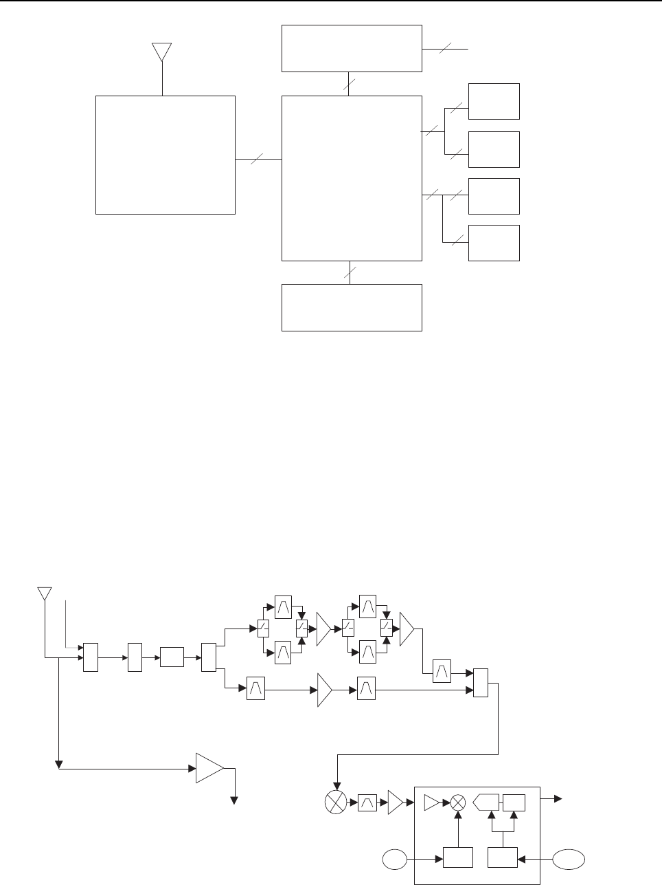
Sec 2: 3-2 Basic Theory of Operation: Analog Mode of Operation
Figure 3-1. APX 7000XE Overall Block Diagram (VOCON Board MNCN6202/ MNCN6203)
3.2 Analog Mode of Operation
This section provides an overview of the analog mode receive and transmit theory of operation.
3.2.1 Receiving
The RF signal is received at the antenna and is routed through the Auxiliary and Multi Switch (SP3T)
ICs. The latter contains a switchable attenuator that is enabled at predetermined RF power
thresholds present at the antenna port. The output of the Multi-switch IC is applied to the first SPST
band select switch to select either VHF or 700,800 bands (see Figure 3-2), UHF1 or 700,800 bands
(see Figure 3-3), VHF or UHF1 bands (see Figure 3-4), UHF1 or UHF2 bands (see Figure 3-5),
UHF2 or 700,800 bands (see Figure 3-6) and VHF or UHF2 bands (see Figure 3-7).
Expander External accessory connector
Board External antenna
Front display*
Transceiver VoCon Keypad**
Board Board
Top display
Controls top
Option
Board
40
60
14
80
50
30
50 20
30
60
Antenna
Note:
* Applicable to model with Front Display and
VOCON Board MNCN6202.
** Applicable to model with Front Display.
SW
2:1
700/800
VHF
Abacus III
2nd
LO
18Mhz
CLK
CLK
Dec.
Filter
LO
ADC
ΣΔ
SW
2:1
PER
SP3T
AUX
DPLXR
To
RF/Vocon
Connector
SSI
RMT Port
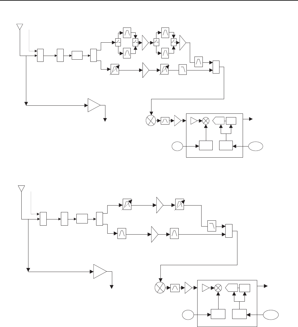
Basic Theory of Operation: Analog Mode of Operation Sec 2: 3-3
Figure 3-2. Receiver Block Diagram (VHF and 700–800 MHz)
Figure 3-3. Receiver Block Diagram (UHF1 and 700–800 MHz)
Figure 3-4. Receiver Block Diagram (UHF1 and VHF)
SW
2:1
700/800
UHF1
Abacus III
2nd
LO
18Mhz
CLK
CLK
Dec.
Filter
LO
ADC
ΣΔ
SW
2:1
PER
SP3T
AUX
DPLXR
To
RF/Vocon
Connector
SSI
RMT Port
SW
2:1
VHF
UHF1
Abacus III
2nd
LO
18Mhz
CLK
CLK
Dec.
Filter
LO
ADC
ΣΔ
SW
2:1
PER
SP3T
AUX
DPLXR
To
RF/Vocon
Connector
SSI
RMT Port
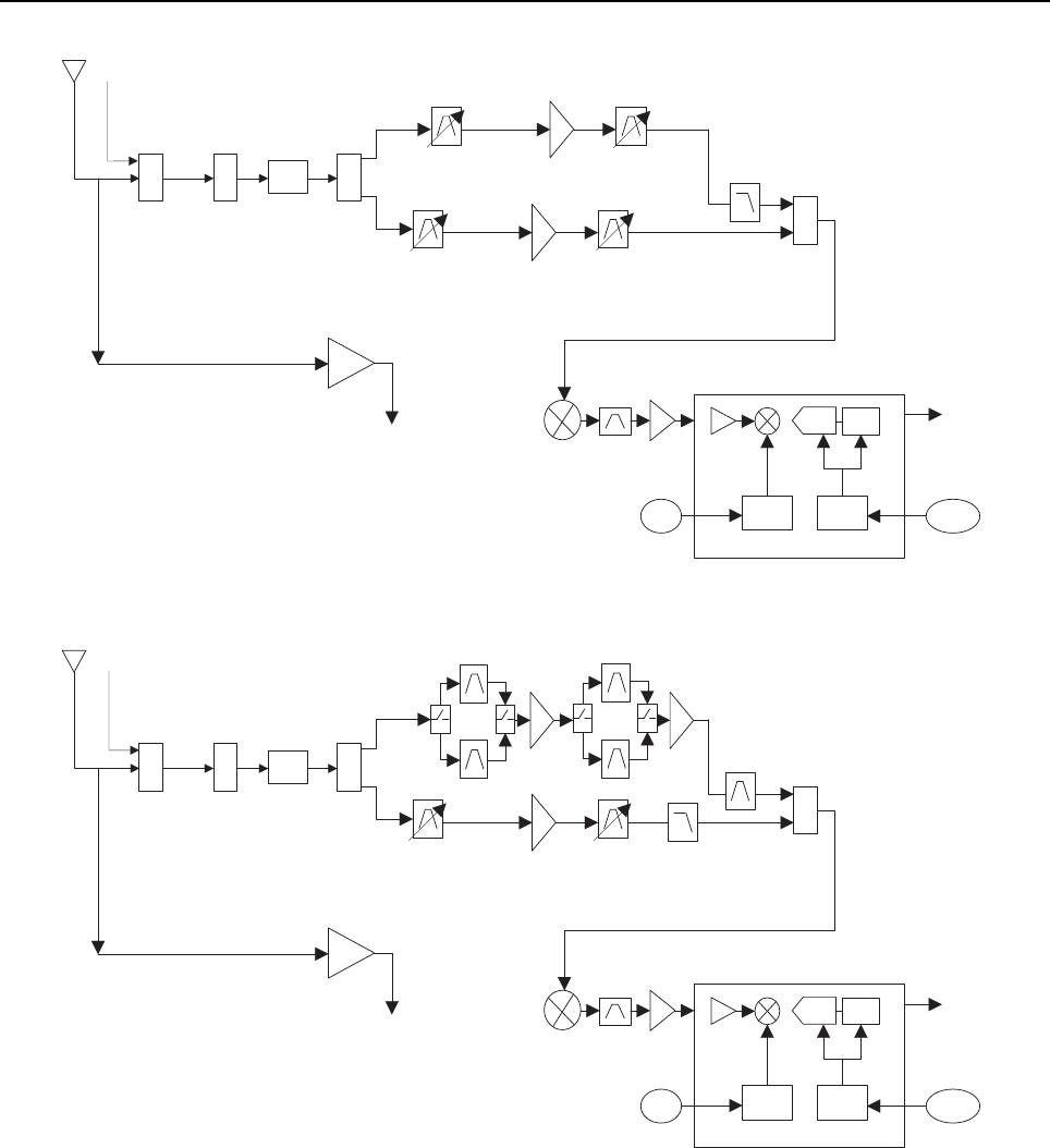
Sec 2: 3-4 Basic Theory of Operation: Analog Mode of Operation
Figure 3-5. Receiver Block Diagram (UHF1 and UHF2)
Figure 3-6. Receiver Block Diagram (UHF2 and 700–800 MHz)
SW
2:1
UHF2
UHF1
Abacus III
2nd
LO
18Mhz
CLK
CLK
Dec.
Filter
LO
ADC
ΣΔ
SW
2:1
PER
SP3T
AUX
DPLXR
To
RF/Vocon
Connector
SSI
RMT Port
SW
2:1
700/800
UHF2
Abacus III
2nd
LO
18Mhz
CLK
CLK
Dec.
Filter
LO
ADC
ΣΔ
SW
2:1
PER
SP3T
AUX
DPLXR
To
RF/Vocon
Connector
SSI
RMT Port
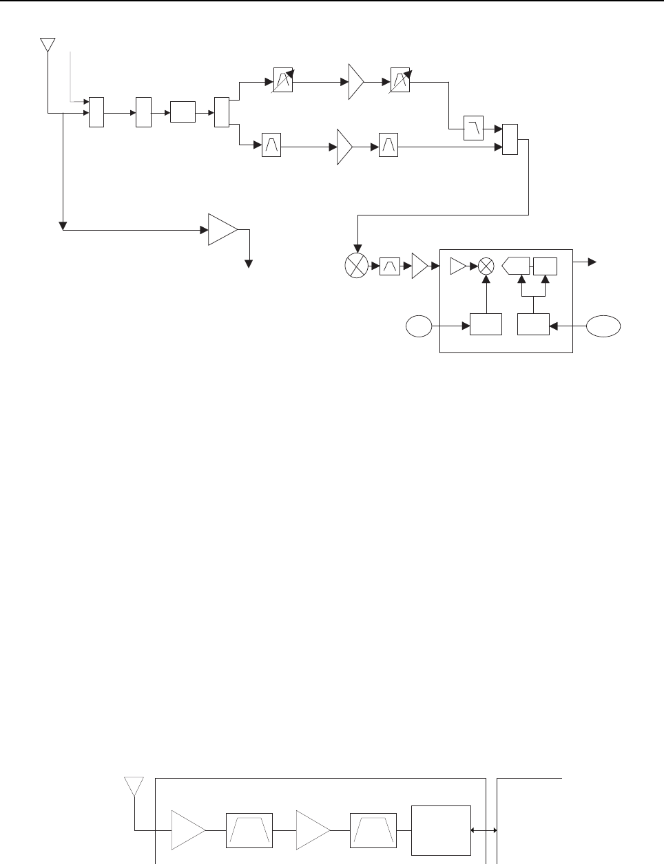
Basic Theory of Operation: Analog Mode of Operation Sec 2: 3-5
Figure 3-7. Receiver Block Diagram (UHF2 and VHF)
3.2.1.1 GPS
The GPS architecture employs a single chip GPS receiver which decodes GPS signals at
1575.42 MHz. It is capable of producing a final position solution including full tracking and data
decode capability. The GPS receiver will operate in the autonomous mode only.
The GPS signal is tapped at the antenna port via a series resonant network which provides a very
low capacitive load to the transceiver. The signal is routed though a GPS LNA and it's output is
applied to the RF-Controller interface connector where it is eventually routed to the expansion board
for processing by the GPS IC.
The GPS receiver is setup in an autonomous one track always (OTA) mode, also known as
continuous navigation. This means the GPS will continuously track satellites for as long as the radio
is powered to ensure the best possible accuracy. In the event the radio loses visibility of the satellites
due to terrain or environmental factors such as driving through a tunnel or entering a building, the
GPS will temporarily lose its position fix. A power savings algorithm will then cycle the GPS in and
out of a sleep mode at approximately 90 second intervals until the radio has moved back into an
environment where GPS signals are present.
The user will be able to view the current latitude, longitude, and time/date stamp on the radio’s
display. The radio can also be configured to send its’ location to the system at predetermined
intervals (LRRP). Depending on system options, the user may be able to enable/disable the GPS
receiver.
Figure 3-8. GPS Diagram
SW
2:1
VHF
UHF2
Abacus III
2nd
LO
18Mhz
CLK
CLK
Dec.
Filter
LO
ADC
ΣΔ
SW
2:1
PER
SP3T
AUX
DPLXR
To
RF/Vocon
Connector
SSI
RMT Port
GPS IC
GPS Receiver Circuit
Antenna
OMAP
Processor

Sec 2: 3-6 Basic Theory of Operation: Analog Mode of Operation
3.2.1.2 VHF Front-End
From the first band select switch, a VHF signal is routed to the first pre-selector filter followed by an
LNA and a second pre-selector filter. Both filters are discrete and fixed designs and are used to band
limit the incoming energy and suppress known spurious responses such as Image and the ½ IF spur.
The output of the second pre-selector filter is applied to the RF port of the Mixer IC via a second
VHF/700,800 or VHF/UHF1 or VHF/UHF2 band select switch. The Mixer IC is also excited by a
Local Oscillator (LO) signal at the LO port to down-convert the RF signal to a 109.65 MHz
intermediate frequency (IF). The down converted IF signal is passed through a crystal filter and IF
amplifier which drives the input of the Abacus 3 Analog to Digital Converter IC (AD9864).
3.2.1.3 700/800 MHz Front-End
From the first band select switch, a 700 MHz or 800 MHz band signal is routed to a second band
SPST switch which selects the 700 or the 800 band signal and routes it to the appropriate first
pre-selector filter. A third band select switch selects the output of the appropriate filter and applies it
to an LNA followed by a similar pre-selector filter/ band-select switch circuit. The signal is then routed
to second LNA whose output is applied to a discrete image filter. Both preselector filters are Surface
Acoustic Wave designs used to band limit the received energy and suppress known spurious
responses such as Image and the ½ IF spur. The output of the discrete image filter is applied to the
RF port of the Mixer IC via a second VHF/700,800 or UHF1/700,800 or UHF2/700,800 band select
switch. The Mixer IC is also excited by a Local Oscillator (LO) signal at the LO port to down-convert
the RF signal to a 109.65 MHz intermediate frequency (IF). The down converted IF signal is passed
through a crystal filter and IF amplifier which drives the input of the Abacus 3 Analog to Digital
Converter IC (AD9864).
3.2.1.4 UHF1 Front-End
From the first band select switch, a UHF1 signal is routed to the first pre-selector filter followed by an
LNA and a second pre-selector filter. Both filters are discrete and tunable designs and are used to
band limit the incoming energy and suppress known spurious responses such as Image spur. The
output of the second pre-selector filter is applied to the RF port of the Mixer IC via a second
UHF1/700,800 or UHF1/VHF or UHF1/UHF2 band select switch. The Mixer IC is also excited by a
Local Oscillator (LO) signal at the LO port to down-convert the RF signal to a 109.65 MHz
intermediate frequency (IF). The down converted IF signal is passed through a crystal filter and IF
amplifier which drives the input of the Abacus 3 Analog to Digital Converter IC (AD9864).
3.2.1.5 UHF2 Front-End
From the first band select switch, a UHF1 signal is routed to the first pre-selector filter followed by a
Low Noise Amplifier (LNA) and a second pre-selector filter. Both filters are discrete and tunable
designs and are used to band limit the incoming energy and suppress known spurious responses
such as Image spur. The output of the second pre-selector filter is applied to a discrete Low Pass
Filter (LPF). The output of the LPF is applied to the RF port of the Mixer IC via a second
UHF2/700,800 or UHF1/UHF2 or VHF/UHF2 band select switch. The Mixer IC, is driven by a Local
Oscillator (LO) signal generated by the Trident synthesizer IC, at the LO port to down-convert the RF
signal to a 109.65 MHz intermediate frequency (IF). It is a passive, high linearity design with
balanced inputs at the RF and IF ports and internal LO buffer. The down converted IF signal is
passed through a 3-pole crystal filter and an IF amplifier, which drives the input of the Analog to
Digital Converter IC.
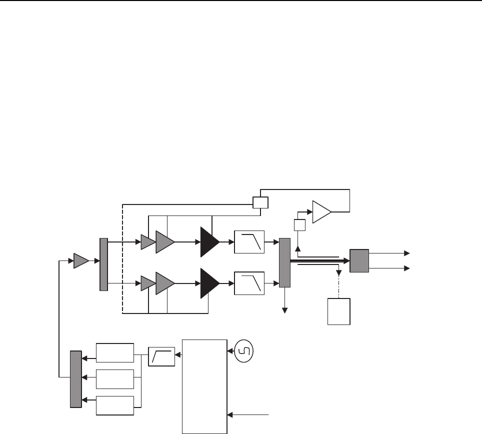
Basic Theory of Operation: Analog Mode of Operation Sec 2: 3-7
3.2.1.6 Analog To Digital Converter
The ADC IC's front end down converts the first IF to a second IF, a 2.25 MHz signal. The second IF
is sampled at 18 MHz, a signal generated by an integrated clock synthesizer. The sampled signal is
decimated by a factor of 900 to 20 kHz and converted to SSI format at the ADC's output. The Serial
Synchronous Interface (SSI) serial data waveform is composed of a 16 bit in-phase word (I) followed
by a 16 bit Quadrature word (Q). A 20 kHz Frame Synch and a 1.2 MHz clock waveform are used to
synchronize the SSI IQ data transfer to the Digital Signal Processor IC (OMAP) for post-processing
and demodulation.
3.2.2 Transmitting
When the radio is transmitting, microphone audio is digitized and then processed by the DSP and
sent to the Trident IC (see Figure 3-9 to Figure 3-14) via the SSI interface. The Trident IC processes
the SSI data for application to the voltage controlled oscillator as a modulation signal.
Figure 3-9. Transceiver (VHF and 700–800 MHz) Block Diagram
To Antenna
To RMT Port
To RX
Log amp Power Detector
Digital RF Attenuator
FET 700/800
Driver Amplifier
FET VHF
VCO Module
VCO Module
VCO Module
Trident IC
SP3T RF Switch
Switch
TX SSI from Vocon
TX Buffer Amp
RF Switch
Harmonic Filters
Loop Filter
Ref. Oscillator
Coupler
Rev Power Detection
RF Switch Matrix
SP2T RF Switch
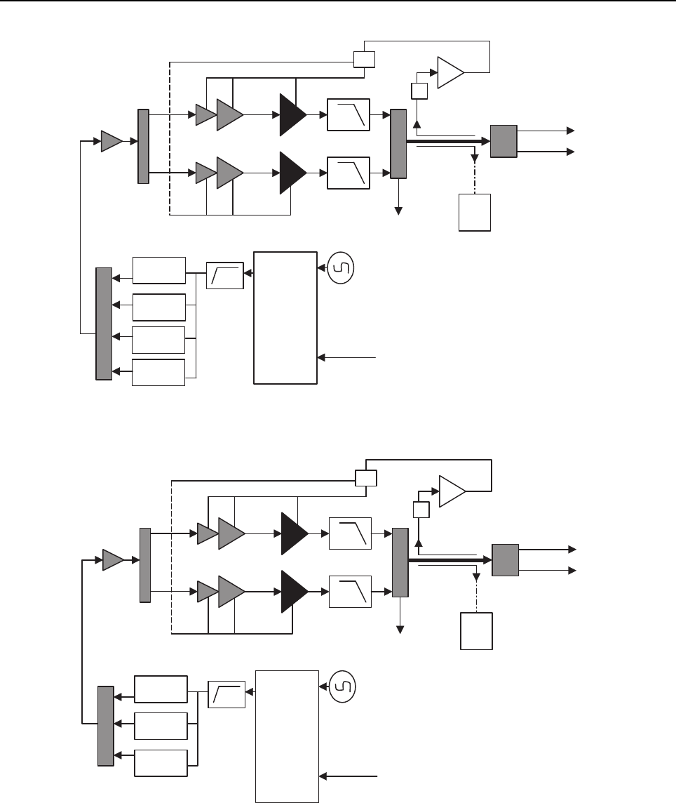
Sec 2: 3-8 Basic Theory of Operation: Analog Mode of Operation
Figure 3-10. Transceiver (UHF1 and 700–800 MHz) Block Diagram
Figure 3-11. Transceiver (VHF and UHF1) Block Diagram
To Antenna
To RMT Port
To RX
Log amp Power Detector
Digital RF Attenuator
FET 700/800
Driver Amplifier
FET UHF1
VCO Module
VCO Module
VCO Module
VCO Module
Trident IC
SP3T RF Switch
Switch
TX SSI from Vocon
TX Buffer Amp
RF Switch
Harmonic Filters
Loop Filter
Ref. Oscillator
Coupler
VCO
Rev Power Detection
RF Switch Matrix
SP2T RF Switch
To Antenna
To RMT Port
To RX
Log amp Power Detector
Digital RF Attenuator
FET UHF1
Driver Amplifier
FET VHF
VCO Module
VCO Module
VCO Module
Trident IC
SP3T RF Switch
Switch
TX SSI from Vocon
TX Buffer Amp
RF Switch
Harmonic Filters
Loop Filter
Ref. Oscillator
Coupler
VCO
Rev Power Detection
RF Switch Matrix
SP2T RF Switch
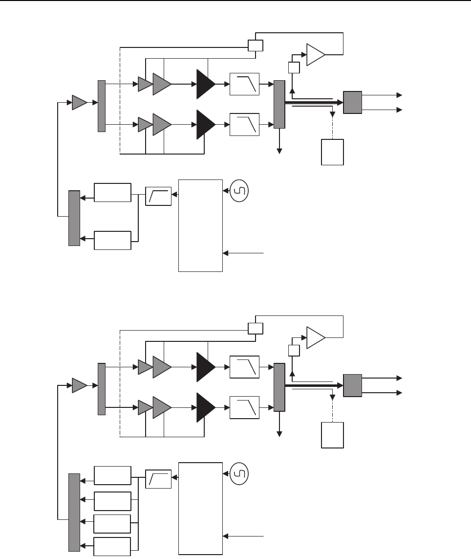
Basic Theory of Operation: Analog Mode of Operation Sec 2: 3-9
Figure 3-12. Transceiver (UHF1 and UHF2) Block Diagram
Figure 3-13. Transceiver (UHF2 and 700–800 MHz) Block Diagram
To Antenna
To RMT Port
To RX
Log amp Power Detector
Digital RF Attenuator
FET UHF2
Driver Amplifier
FET UHF1
VCO Module
VCO Module
Trident IC
SP3T RF Switch
Switch
TX SSI from Vocon
TX Buffer Amp
RF Switch
Harmonic Filters
Loop Filter
Ref. Oscillator
Coupler
VCO
Rev Power Detection
RF Switch Matrix
SP2T RF Switch
To Antenna
To RMT Port
To RX
Log amp Power Detector
Digital RF Attenuator
FET 700/800
Driver Amplifier
FET UHF2
VCO Module
VCO Module
VCO Module
VCO Module
Trident IC
SP3T RF Switch
Switch
TX SSI from Vocon
TX Buffer Amp
RF Switch
Harmonic Filters
Loop Filter
Ref. Oscillator
Coupler
VCO
Rev Power Detection
RF Switch Matrix
SP2T RF Switch
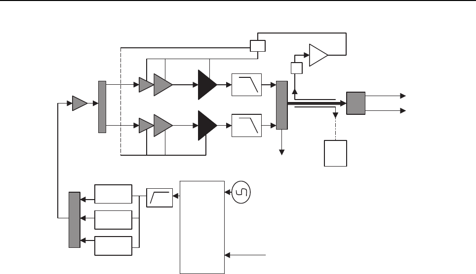
Sec 2: 3-10 Basic Theory of Operation: Analog Mode of Operation
Figure 3-14. Transceiver (VHF and UHF2) Block Diagram
3.2.2.1 VHF Transmit
Once a VHF frequency for transmit has been selected, the Trident IC and its accompanying logic
circuitry enable the correct voltage controlled oscillator which then generates the desired transmit
frequency. This transmit signal is then routed to the TX buffer amplifier which amplifies the signal. An
RF switch then routes the signal to the VHF Driver amplifier and then to the discrete final stage. The
signal is then filtered by a harmonic filter and passed through a RF switch into a directional coupler.
The Log Amp power detector monitors the output of the directional coupler and adjusts the control
voltages to the driver amplifier and the discrete final. Finally, the RF signal comes to a Single Pole
Double Throw (SP2T) RF switch which can route the power to the main antenna or to the Universal
Connector port of the radio.
3.2.2.2 700/800 MHz Transmit
Once a 700/800 MHz frequency for transmit has been selected, the Trident IC and its accompanying
logic circuitry enable the correct voltage controlled oscillator which then generates the desired
transmit frequency. This transmit signal is then routed to the TX buffer amplifier which amplifies the
signal. An RF switch then routes the signal to the 700/800 MHz Driver amplifier and then to the
discrete final stage. The signal is then filtered by a harmonic filter and passed through a RF switch
into a directional coupler. The Log Amp power detector monitors the output of the directional coupler
and adjusts the control voltages to the driver amplifier and the discrete final. Finally, the RF signal
comes to a Single Pole Double Throw (SP2T) RF switch which can route the power to the main
antenna or to the Universal Connector port of the radio.
To Antenna
To RMT Port
To RX
Log amp Power Detector
Digital RF Attenuator
FET UHF2
Driver Amplifier
FET VHF
VCO Module
VCO Module
VCO Module
Trident IC
SP3T RF Switch
Switch
TX SSI from Vocon
TX Buffer Amp
RF Switch
Harmonic Filters
Loop Filter
Ref. Oscillator
Coupler
VCO
Rev Power Detection
RF Switch Matrix
SP2T RF Switch

Basic Theory of Operation: Digital (ASTRO) Mode of Operation Sec 2: 3-11
3.2.2.3 UHF1 Transmit
Once a UHF frequency for transmit has been selected, the Trident IC and its accompanying logic
circuitry enable the correct voltage controlled oscillator which then generates the desired transmit
frequency. This transmit signal is then routed to the TX buffer amplifier which amplifies the signal. An
RF switch then routes the signal to the UHF1 Driver amplifier and then to the discrete final stage.
The signal is then filtered by a harmonic filter and passed through a RF switch into a directional
coupler. The Log Amp power detector monitors the output of the directional coupler and adjusts the
control voltages to the driver amplifier and the discrete final. Finally, the RF signal comes to a Single
Pole Double Throw (SP2T) RF switch which can route the power to the main antenna or to the
Universal Connector port of the radio.
3.2.2.4 UHF2 Transmit
Once a UHF frequency for transmit has been selected, the Trident IC and its accompanying logic
circuitry enable the correct voltage controlled oscillator which then generates the desired transmit
frequency. This transmit signal is then routed to the TX buffer amplifier which amplifies the signal. An
RF switch then routes the signal to the UHF2 Driver amplifier and then to the discrete final stage.
The signal is then filtered by a harmonic filter and passed through a RF switch into a directional
coupler. The Log Amp power detector monitors the output of the directional coupler and adjusts the
control voltages to the driver amplifier and the discrete final. Finally, the RF signal comes to a Single
Pole Double Throw (SP2T) RF switch which can route the power to the main antenna or to the
Universal Connector port of the radio.
3.3 Digital (ASTRO) Mode of Operation
In the ASTRO (digital) mode of operation, the transmitted or received signal is limited to a discrete
set of frequency deviation levels. The receiver handles an ASTRO-mode signal identically to an
analog-mode signal, up to the point where the DSP decodes the received data. In the ASTRO
receive mode, the DSP uses a different algorithm to recover data.
In the ASTRO transmit mode, microphone audio is processed identically to an analog mode, with the
exception of the algorithm the DSP uses to encode the information. Using this algorithm, transmitter
FM deviation is limited to discrete levels.

Sec 2: 3-12 Basic Theory of Operation: Controller Section
3.4 Controller Section
The controller section (see Figure 3-15) comprises of five functional sections that are split among
three boards, which are the VOCON, EXPANSION and BLUETHOOTH OPTION boards. The main
functional section consists of a dual core ARM and DSP controller, an encryption processor (MACE),
Flash memory, and a Double Data Rate Synchronous Dynamic Random Access Memory (DDR
SDRAM). The Power and Clocks section includes a power management IC (MAKO) and various
external switching regulators, and two clock sources (12 MHz and 24.576 MHz) from which all other
controller digital clocks are derived. The Audio section has a CODEC and a class-D audio power
amplifier that provides the radio with a multiple microphone, multiple speaker design. The User
Interface section provides communication and control to the top and main Liquid Crystal Displays
(LCD) on the radio, as well as a keypad and a side connector interface conforming to Universal
Connector specifications. The Expansion Memory, GPS and Bluetooth section comprises of a Micro
SD memory interface, Global Positioning Satellite (GPS) processor, and an Option Board for radio
feature upgrades.
Figure 3-15. Controller Block Diagram
The ARM controller core of the OMAP processor handles the power up sequence of all devices,
including firmware upgrades, and all operating system tasks that are associated with FLASH and
SDRAM memories and user interface communication. The FLASH memory (64 MB) is required to
store the firmware, tuning, and Codeplug settings, which upon initialization get read and stored into
SDRAM (32 MB) for execution. The ARM and DSP core jointly control and configure audio, wireless
and RF devices linked to the Serial Peripheral Interface (SPI) and Synchronous Serial Interface
(SSI) buses to enable radio FM and optional wireless communication protocols. For encryption, a
separate ARM processor is used (MACE) to encode and decode encryption packets coming in from
the main OMAP processor through the SSI interface. Its firmware is flashed via the main processor
during an upgrade request to its internal FLASH memory.
USER INTERFACE
Top Display
Data Display
KeyPad
Expansion Board:
Side Connector
POWER & CLOCKS
Clocks Sources:
12 Mhz
24.576 Mhz
CONTROLLERS & MEMORY
ARM Processor
Digital Signal Processor
Flash Memory
DDR Memory
Encryption Processor
EXPANSION MEMORY, GPS & OPTIONS
Option Board
Expansion Board:
SD Card
GPS
Voltage Regulators
AUDIO
Expansion Board Audio:
Main Amplifier / Speaker
Main Microphone
Data Speaker
Data Microphone
Acc. Speaker
Acc. Microphone
Micro SD
Interface
RF Interface
Battery Supply
Top Display
Interface
Data Display &
KeyPad
Side
Connector

Basic Theory of Operation: Controller Section Sec 2: 3-13
The power and most clocks to the controller devices are provided by the MAKO IC and external
switching and linear regulators on board. A Complex Programmable Logic Array (CPLD) IC divides
the 24.576 MHz clock from MAKO to source OMAP's 32 kHz Real Time Clock, and MACE's 4 MHz
main clock. OMAP's main clock is supplied externally from an on board 12 MHz crystal.
The radio has two internal microphones and two internal speakers, as well as available microphone
and speaker connections for external accessories. The main external speaker is located opposite to
the main display and keypad of the radio. It can deliver a rated power of 1W on a ~4 Ohms speaker,
while the smaller "data" speaker can only deliver 0.5 W of power on a load of 16 Ohms. Both internal
and external microphones use the CODEC's AD to deliver digital audio samples to the DSP
controller. The main speaker is driven by the class D PA on the expansion board, while the data and
external speakers are driven by the AB type PA on MAKO. Both speaker paths use the CODEC for
volume control and to convert audio from digital to analog.
The user interface block consists of a top and main or "data side" display, a keypad, top controls and
the accessory side connector. The side connector (Universal Connector) provides audio, USB,
RS232 and RF communication for accessories. All signals to and from the connector go through the
internal expansion board before reaching the microcontroller and other devices on the main board.
The radio also has an expansion bay for a Micro SD memory card, a Global Positioning System
(GPS) interface, and an bluetooth slot for radio feature upgrades. The memory card can be inserted
on the bay near the battery connector of the radio. The bluetooth slot of the radio is available
internally to the radio, and it is not hot swappable by the user. The bluetooth slot is available through
a connector directly linked to the main controller board.

Sec 2: 3-14 Basic Theory of Operation: Controller Section
Notes

Chapter 4 Recommended Test Equipment and Service
Aids
This chapter provides lists of recommended test equipment and service aids, as well as information
on field programming equipment that can be used in servicing and programming
ASTRO APX 7000XE radios.
4.1 Recommended Test Equipment
The list of equipment contained in Table 4-1 includes all of the standard test equipment required for
servicing two-way portable radios, as well as several unique items designed specifically for servicing
this family of radios. The “Characteristics” column is included so that equivalent equipment may be
substituted; however, when no information is provided in this column, the specific Motorola model
listed is either a unique item or no substitution is recommended.
Table 4-1. Recommended Test Equipment
Equipment Characteristics Example Application
Service
Monitor
Can be used as a substitute for
items marked with an asterisk
(*)
Aeroflex 3920
(www.aeroflex.com) or
R-2670 Communication
Analyzer,
8901_ Modulation Analyzer
(www.agilent.com) or
equivalent
Frequency/deviation meter and
signal generator for wide-range
troubleshooting and alignment
Digital RMS
Multimeter *
100 µV to 300 V
5 Hz to 1 MHz
10 Mega Ohm Impedance
Fluke 179 or equivalent
(www.fluke.com)
AC/DC voltage and current
measurements. Audio voltage
measurements
RF Signal
Generator *
100 MHz to 1 GHz
-130 dBm to +10 dBm
FM Modulation 0 kHz to 10 kHz
Audio Frequency 100 Hz to
10 kHz
Agilent N5181A
(www.agilent.com),
Ramsey RSG1000B
(www.ramseyelectronics.com,
or equivalent
Receiver measurements
Oscilloscope * 2 Channel
50 MHz Bandwidth
5 mV/div to 20 V/div
Leader LS8050
(www.leaderusa.com),
Tektronix TDS1001b
(www.tektronix.com),
or equivalent
Waveform measurements
RF Millivolt
Meter
100 mV to 3 V RF
10 kHz to 1 GHz
Boonton 9240
(www.boonton.com) or
equivalent
Waveform measurements
Power Supply 0 V to 32 V
0 A to 20 A
B&K Precision 1790
(www.bkprecision.com)
or equivalent
Voltage supply

Sec 2: 4-2 Recommended Test Equipment and Service Aids: Service Aids
4.2 Service Aids
Refer to Table 4-2 for a listing and description of the service aids designed specifically for servicing
this family of radios. These kits and/or parts are available from the Radio Products and Solutions
Organization offices listed in “Appendix B. Replacement Parts Ordering” on page B-1. While all of
these items are available from Motorola, most are standard shop equipment items, and any
equivalent item capable of the same performance may be substituted for the item listed.
Table 4-2. Service Aids
Motorola Part
Number Description Application
1110027B23 Speaker Module Seal
Lubricant
Used to ensure good sealing of the Speaker Module to the
Main Chassis.
5880384G68 SMA to BNC Adapter Adapts radio’s antenna port to BNC cabling of test equipment.
66009254001 APX 7000/ APX 7000XE
Battery Eliminator
Used in place of battery to connect radio to an external power
supply.
66009275001 Grille Eliminator Special tool used when pressure testing the radio. Replaces
the radio grille to seal the port vent.
66009256001 Volume Potentiometer Outer
Spanner Bit
Used to assemble and disassemble the spanner nut on the
volume potentiometer.
66009258001 Antenna Spanner Bit Used to assemble and disassemble the spanner nut on the
antenna bushing.
66009259001 Vacuum Adapter Submersible radios only. Connects the vacuum/pressure hose
to the radio.
66009260001
66009260003
Board Analysis Fixture
(APX 7000)
Board Analysis Fixture
(APX 7000XE and
future APX 7000)
Special fixture that allows radio’s internal board to be mounted
externally. Provides easy access to electronic circuits,
required for board-level troubleshooting.
NOTE: Contact Motorola Solutions Radio Products and
Solutions Organization (1-800-927-2744) to
determine which version of fixture is required for
your APX 7000XE radio.
NLN9839_ Vacuum Pump Kit Submersible radios only. Vacuum pump with gauge and
vacuum hose. Requires 66009259001 Adapter Kit.
NTN4265_ Pressure Pump Kit Submersible radios only. Pressure pump with gauge and
pressure hose. Requires 66009259001 Adapter Kit.
RVN5224_ Customer Programming
Software (CPS) and Tuner
Software
CPS allows customer-specific programming of modes and
features. Tuner software required to perform alignment of
radio parameters.
PMKN4012_ Programming Cable Used to program the radio through Customer
Programming Software and Tuner Software.
PMKN4013_ Programming/Service Cable Used to program and service the radio through Customer
Programming Software and Tuner Software.
RLN4460_ Portable Test Set Used for radio performance checks. Connects to radio’s
universal connector and allows remote switching and signal
injection/outputs for test equipment measurements.

Recommended Test Equipment and Service Aids: Field Programming Sec 2: 4-3
4.3 Field Programming
This family of radios can be aligned and programmed in the field. This requires specific equipment
and special instructions. Refer to the online help in the Customer Programming Software (CPS) for
complete field programming information.

Sec 2: 4-4 Recommended Test Equipment and Service Aids: Field Programming
Notes
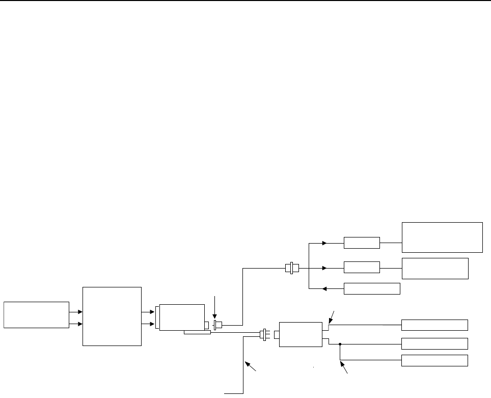
Chapter 5 Performance Checks
This chapter covers performance checks used to ensure that the ASTRO APX 7000XE radio meets
published specifications. The recommended test equipment listed in the previous section
approaches the accuracy of the manufacturing equipment, with a few exceptions. Accuracy of the
test equipment must be maintained in compliance with the manufacturer’s recommended calibration
schedule. Checks should be performed if radio performance degradation is suspected.
5.1 Test Equipment Setup
Supply voltage can be connected from the battery eliminator. The equipment required for the
performance checks is connected as shown in Figure 5-1.
Figure 5-1. Performance Checks Test Setup
BNC
USB END IS NOT USED
AUDIO GENERATOR
SINAD METER
AC VOLTMETER
TX
RX
30 dB PAD
30 dB PAD
RF GENERATOR
MODULATION ANALYZER
OR
SERVICE MONITOR
AEROFLEX
SERVICE MONITOR
UNIVERSAL
BATTERY
ELIMINATOR
66009254001
(7.5V AT BATTERY
ELIMINATOR
TERMINALS)
TRANSMIT
RECEIVE
DC POWER SUPPLY RADIO
PROGRAM/TEST CABLE
PMKN4013_
AUDIO IN
SET TO APPROX. 8mV FOR Tx
MEASURE 3.74Vrms FOR Rx
SMA-BNC
5880384G68
TEST SET
RLN4460_
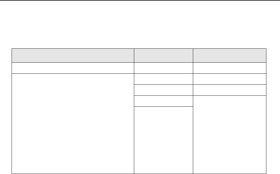
Sec 2: 5-2 Performance Checks: Test Equipment Setup
Initial equipment control settings should be as indicated in Table 5-1 and should be the same for all
performance checks and alignment procedures, except as noted.
Table 5-1. Initial Equipment Control Settings
System Analyzer Test Set Power Supply
Monitor Mode: Standard* Spkr/Load: Speaker Voltage: 7.5 Vdc
Receiver Checks
RF Control: GEN
Output Level: -47 dBm
Modulation: 1kHz tone
@3 kHz deviation for 25 kHz channel spacing
@1.5 kHz deviation for 12.5 kHz channel spacing
Frequency: Set to selected radio RX frequency
Meter: AC Volts
Transmitter Checks
RF Control: MONITOR
Frequency: Set to selected radio TX frequency
Meter: RF Display
Modulation Type: FM
Attenuation: 20 dB
PTT: OFF (center) DC On/Standby: Standby
Meter Out: RX Volt Range: 10 Vdc
Opt Sel: ON Current: 2.5 Amps
* Use “PROJ 25 STD” if testing ASTRO Conventional channels.

Performance Checks: Display Radio Test Mode (Dual-Display Version) Sec 2: 5-3
5.2 Display Radio Test Mode (Dual-Display Version)
This section provides instructions for performing tests in display radio test mode.
5.2.1 Access the Test Mode
To enter the display radio test mode:
1. Turn the radio on.
2. Within 10 seconds after “SELF TEST” is complete, press Side Button 2 five times in
succession.
The radio shows a series of displays that give information regarding various version numbers
and subscriber specific information. The displays are described in Table 5-2.
Table 5-2. Test-Mode Displays
Name of Display Description Appears
Service The literal string indicates the radio has
entered test mode.
Always
Host version The version of host firmware is displayed. Always
DSP version The version of DSP firmware is displayed. Always
Secure version Version of the encryption software When the radio is secure
equipped
KGI algorithms name
(Encryption Type 1)
Type of encryption being used When the radio is secure
equipped
KG2 algorithms name
(Encryption Type 2)
Type of encryption being used When the radio is secure
equipped and 2 or more
algorithms are loaded
KG3 algorithms name
(Encryption Type 3)
Type of encryption being used When the radio is secure
equipped and 3 or more
algorithms are loaded
KG4 algorithms name
(Encryption Type 4)
Type of encryption being used When the radio is secure
equipped and 4 or more
algorithms are loaded
KG5 algorithms name
(Encryption Type 5)
Type of encryption being used When the radio is secure
equipped and 5 or more
algorithms are loaded
Model number The radio’s model number, as
programmed in the codeplug
Always
Serial number The radio’s serial number, as programmed
in the codeplug
Always
ESN The radio’s unique electronic serial
number
Always
ROM Size The memory capacity of the host FLASH
part
Always
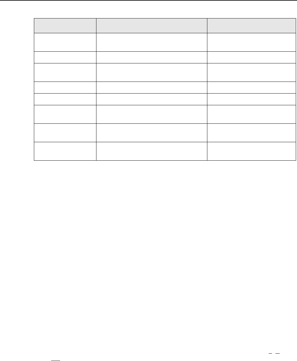
Sec 2: 5-4 Performance Checks: Display Radio Test Mode (Dual-Display Version)
NOTE: All displays are temporary and will expire without any user intervention. If
information is longer than the physical length of the radio’s display, the information
will wrap around to the next display. After the last display, “RF TEST” is displayed.
To freeze any of the displays, press the left arrow on the 4-Way Navigation Button.
To resume automatic scrolling, press the right arrow on the 4-Way Navigation
Button. To rapidly scroll forward through the displays, continue pressing the right
arrow. You cannot scroll backwards.
NOTE: Press the Top side (purple) button to advance the test environments from “RF
TEST”, “CH TEST”, “RGB TEST”, “CID TEST” then press the orange button to
confirm selection. Press any other buttons to advance the test.
Once a test is carried out, restart the radio to proceed to another test.
3. Do one of the following:
•Press the Top Side Button to stop the displays and toggle between RF test mode and the
Control Top and Keypad test mode. The test mode menu “CH TEST” is displayed,
indicating that you have selected the Control Top and Keypad test mode. Go to Section
“5.2.3 Control Top and Keypad Test Mode” on page 2:5-6.
NOTE: Each press of the Top Side Button will toggle between “CH TEST” and “RF TEST”.
•Press the Top Button (Orange button) to stop the displays and put the radio into the RF
test mode. The test mode menu, “1 CSQ”, is displayed, indicating test frequency 1, Carrier
SQuelch mode. Go to Section “5.2.2 RF Test Mode” below.
NOTE: Once your radio is in a particular test mode, you must turn off the radio and turn it
back on again to access the other test mode.
FLASHcode The FLASH codes as programmed in the
codeplug
Always
RF band 1 The radio’s operating frequency Always
RF band 2 The radio’s operating frequency When the radio has more than 1
operating frequency
Tuning ver Version of Tuning codeplug Always
Proc ver Version of Processor Always
Option Board Type Type of Option Board in the radio When the radio is equipped with
an Option Board
Option Board
Bluetooth Addr
Address of the Bluetooth IC When the radio is equipped with
a Bluetooth Option Board
Option Board SW
Version
Version of Option Board software When the radio is equipped with
an Option Board
Table 5-2. Test-Mode Displays (Continued)
Name of Display Description Appears
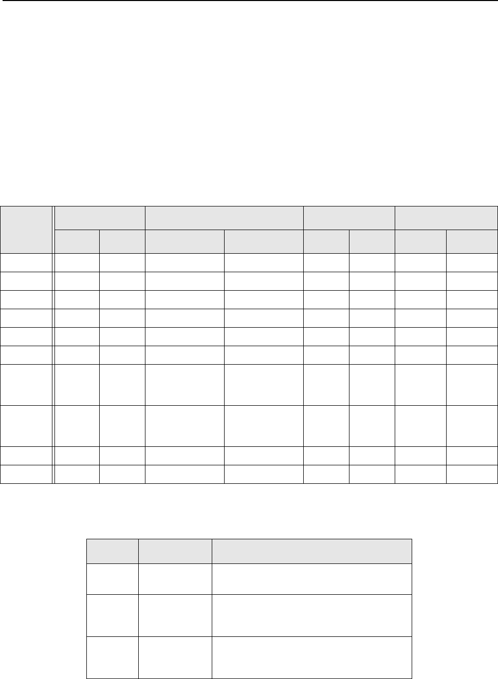
Performance Checks: Display Radio Test Mode (Dual-Display Version) Sec 2: 5-5
5.2.2 RF Test Mode
When the ASTRO APX 7000XE radio is operating in its normal environment, the radio's
microcomputer controls the RF channel selection, transmitter key-up, and receiver muting, according
to the customer codeplug configuration. However, when the unit is on the bench for testing,
alignment, or repair, it must be removed from its normal environment using a special routine, called
RF TEST MODE.
While in RF test mode:
• Each additional press of Side Button 2 advances to the next test channel. (Refer to Table 5-3.)
•Pressing Side Button 1 scrolls through and accesses the test environments shown in
Table 5-4.
NOTE: Transmit into a load when keying a radio under test.
Table 5-3. Test Frequencies (MHz)
Test
Channel
VHF UHF1 UHF2 700–800 MHz
RX TX RX TX RX TX RX TX
F1 136.075 136.025 380.075 380.025 450.075 450.025 764.0625 764.0125
F2 142.075 142.125 390.075 390.025 460.075 460.025 769.0625 769.0125
F3 154.275 154.225 400.075 400.025 471.075 471.025 775.9375 775.9875
F4 160.175 160.125 411.075 411.025 484.925 484.975 851.0625 794.0125
F5 168.125 168.075 424.975 424.925 485.075 485.025 860.0625 809.0125
F6 173.925 173.975 435.075 435.025 495.075 495.025 869.9375 823.9875
F7 – – 444.925 (Tune)
/ 445.075 (Test
Mode)
444.975 (Tune)
/ 444.999995
(Test Mode)
506.075 506.025 851.0625 851.0125
F8 – – 445.075 445.025 (Tune)
/ 445.000005
(Test Mode)
519.925 519.975 860.0625 860.0125
F9 – – 457.075 457.025 – – 869.9375 869.8875
F10 – – 469.975 469.925 – – – –
Table 5-4. Test Environments
Display Description Function
CSQ Carrier
Squelch
RX: unsquelch if carrier detected
TX: mic audio
TPL Tone
Private-Line
RX: unsquelch if carrier and tone (192.8 Hz)
detected
TX: mic audio + tone (192.8 Hz)
SEC Secure** RX: auto-coded clear
TX: with key present–encrypted audio with
key absent–constant unsquelch

Sec 2: 5-6 Performance Checks: Display Radio Test Mode (Dual-Display Version)
5.2.3 Control Top and Keypad Test Mode
This test mode is used to verify proper operation of all radio buttons and switches if a failure is
suspected.
5.2.3.1 Control Top Checks
To perform the control top checks:
1. Press and hold the Top Button (Orange button); the radio icons are displayed, and the LED
lights amber.
2. Release the Top Button; “148/0” appears, which indicates that the Top Button is in the
open position. Your radio is now in the Control Top and Keypad test mode.
3. Press the Top Button again; “148/1” appears, which indicates that the Top Button is in the
closed position.
4. Rotate the 16-Position Select Switch; “4/0” through “4/15” appears, which indicates that
the selector switch is in mode/zone position 1 through 16.
5. Rotate the Two-Position Concentric Switch; “65/0” and “65/1” appear.
6. Cycle through the Three-Position A/B/C Switch; “67/0,” “67/1,” and “67/2” appear.
7. Rotate the Volume Control; “2/0” through “2/255” appear. The display values may vary
slightly at the upper and lower limits.
8. Press the Top Side Button; “96/1” appears; release, “96/0” appears.
9. Press Side Button 1; “97/1” appears; release, “97/0” appears.
10. Press Side Button 2; “98/1” appears; release, “98/0” appears.
11. Press the PTT Button; “1/1” appears; release, “1/0” appears.
5.2.3.2 Keypad Checks:
To continue to the keypad checks:
5.2.3.2.1 Dual-Display Model
-Press
0, “48/1” appears; release, “48/0” appears.
-Press
1, “49/1” appears; release, “49/0” appears.
-Press
2, “50/1” appears; release, “50/0” appears.
-Press
3, “51/1” appears; release, “51/0” appears.
-Press
4, “52/1” appears; release, “52/0” appears.
-Press
5, “53/1” appears; release, “53/0” appears.
AST ASTRO RX: none
TX: Digital Voice***
USQ Carrier
Unsquelch
RX: unsquelch always
TX: mic audio
** On radios equipped with secure option.
***All deviation values are based on deviation tuning of this
mode.
Table 5-4. Test Environments (Continued)
Display Description Function

Performance Checks: Top-Display Version Radio Test Mode Sec 2: 5-7
- Press 6, “54/1” appears; release, “54/0” appears.
- Press 7, “55/1” appears; release, “55/0” appears.
- Press 8, “56/1” appears; release, “56/0” appears.
- Press 9, “57/1” appears; release, “57/0” appears.
- Press *, “58/1” appears; release, “58/0” appears.
- Press #, “59/1” appears; release, “59/0” appears.
- Press <, “128/1” appears; release, “128/0” appears.
- Press H, “129/1” appears; release, “129/0” appears.
- Press >, “130/1” appears; release, “130/0” appears.
- Press {, “131/1” appears; release, “131/0” appears.
- Press |, “132/1” appears; release, “132/0” appears.
- Press }, “133/1” appears; release, “133/0” appears.
- Press P, “134/1” appears; release, “134/0” appears.
- Press U, “135/1” appears; release, “135/0” appears.
- Press D, “136/1” appears; release, “136/0” appears.
5.3 Top-Display Version Radio Test Mode
This section provides instructions for performing tests in non-display radio test mode.
5.3.1 Access the Test Mode
To enter the non-display radio test mode:
1. Turn the radio on.
2. Within 10 seconds after the top red LED turns off, press Side button 2 five times in
succession.
3. Do one of the following:
• Press the Top Side Button to put the radio into the Control Top and Keypad test mode.
Go to “5.3.3 Control Top Test Mode” below.
NOTE: Each press of the Top Side Button toggles between Control Top and Keypad test
mode (non-display radio) and RF test mode (non-display radio).
•Press the Top Button (Orange button) to put the radio into the RF test mode. Go to “5.3.2
RF Test Mode” below.
5.3.2 RF Test Mode
When the ASTRO APX 7000XE radio is operating in its normal environment, the radio's
microcomputer controls the RF channel selection, transmitter key-up, and receiver muting, according
to the customer codeplug configuration. However, when the unit is on the bench for testing,
alignment, or repair, it must be removed from its normal environment via a special routine, called RF
TEST MODE.
While in RF test mode:
• Each additional press of Side Button 2 advances to the next test channel. (Refer to Tabl e 5-3
on page 2:5-5) The channel number is represented by the number of tones emitted by the radio
after the button press (for example, five tones indicates channel 5).

Sec 2: 5-8 Performance Checks: Top-Display Version Radio Test Mode
•Pressing Side Button 1 scrolls through and accesses test environments shown in Table 5-4 on
page 2:5-5. The test environment is represented by the number of tones emitted by the radio
after the button press (for example, 11 tones indicate AST).
5.3.3 Control Top Test Mode
This test mode is used to verify proper operation of all radio buttons and switches if a failure is
suspected.
To perform the control top checks:
1. Press and hold the Top Button (Orange button); the LED lights red, and the radio beeps.
2. Release the Top Button; the radio beeps, indicating that the Top Button is in the open
position.
3. Press the Top Button again; the radio beeps, indicating that the Top Button is in the closed
position.
4. Rotate the Two-Position Concentric Switch; the radio beeps in each switch position.
5. Rotate the 16-Position Select Switch; the radio beeps in each switch position.
6. Cycle through the Three-Position A/B/C Switch; the radio beeps in each switch position.
7. Rotate the Volume Control; the radio beeps at each new volume setting.
8. Press the Top Side Button; the radio beeps.
9. Press Side Button 1; the radio beeps.
10. Press Side Button 2; the radio beeps.

Performance Checks: Receiver Performance Checks Sec 2: 5-9
5.4 Receiver Performance Checks
The following tables outline the performance checks for the receiver.
Table 5-5. Receiver Performance Checks
Test Name System Analyzer Radio Test Set Comments
Rated Audio RF Control: Gen
Output Level: -47 dBm
Freq: Selected radio RX
freq.
Mod: 1kHz tone @ 3kHz
dev.
Meter: AC Volts
As above PTT to OFF
(center)
Set volume control to
3.74 Vrms
Distortion As above, except
Meter: Ext Dist.
As above As above Distortion < 3.0%
Sensitivity
(SINAD)
As above, except
Meter: SINAD
As above As above RF input to be < 0.35 µV
Noise Squelch
Threshold
(only radios
with
conventional
system need
to be tested)
Set as for rated audio
check
Out of TEST
MODE; select a
conventional
system
As above Set volume control to
3.74 Vrms.
Set RF level to -130 dBm
and raise until radio
unsquelches.
Unsquelch to occur at
< 0.25 µV. Preferred SINAD
= 6–8 dB.
*See Table 5-4 on page 2:5-5.
Table 5-6. Receiver Tests for ASTRO Conventional Channels*
Test Name System Analyzer Radio Test Set Comments
Bit Error rate
(BER) Floor
Mode: Proj 25 Std
RF Control: Gen
Output Level: -47 dBm
Proj 25 Dev: 2.83 kHz
Code: 1011 Hz PAT
Radio Tuner
Software (Bit Error
Rate screen) is
required
PTT to OFF
(center)
BER < 0.01%
(Use test setup shown in
Figure 6-1 on page 2:6-1)
Reference
Sensitivity
As above; lower the
output level until 5% BER
is obtained
As above As above Output level < 0.35 µV
(-116 dBm)
(Use test setup shown in
Figure 6-1 on page 2:6-1)
Audio Output
Distortion
Mode: Proj 25 Std
RF Control: Gen
Output Level: -47 dBm
Proj 25 Dev: 2.83 kHz
Code: 1011 Hz PAT
Meter: Ext. Distortion
Radio Tuner
Software not
used;
Radio: Out of
TEST MODE;
Select a
conventional
ASTRO channel
PTT to OFF
(center)
Meter selector to
Audio PA
Spkr/Load to
Speaker
Distortion < 3.0%

Sec 2: 5-10 Performance Checks: Transmitter Performance Checks
5.5 Transmitter Performance Checks
The following tables outline the performance checks for the transmitter.
Residual
Audio Noise
Ratio
Mode: Proj 25 Std
RF Control: Gen
Output Level: -47 dBm
Proj 25 Dev: 2.83 kHz
Code:
A) 1011 Hz PAT
B) Silence PAT
Meter: AC Volts
As above As above Residual Audio Noise Ratio
-45 dB
*These tests require a communications system analyzer with the ASTRO 25 test options.
Table 5-7. Transmitter Performance Checks
Test Name System Analyzer Radio Test Set Comments
Reference
Frequency
RF Control: Monitor
Meter: RF Display
Display: Bar Graphs
Freq: Selected radio TX
freq.
TEST MODE CSQ
channel* or
programmed
conventional
channel
PTT to continuous
(during the
performance
check).
VHF: 2.0 ppm
(272–348 Hz)
700/800 MHz: 1.5 ppm
(1.15–1.3 kHz)
UHF1: 2 ppm
(760–940 Hz)
UHF2: 2 ppm
(900–1040 Hz)
RF Power As above As above As above VHF: 1–6 Watts
700/800 MHz:
764–806 MHz: 2.5 Watts
806–870 MHz: 3Watts
UHF1: 1–5 Watts
UHF2: 1–5 Watts
Voice
Modulation
(external)
As above. Set fixed 1 kHz
audio level to
approximately 10 mV.
As above As above Deviation:
(12.5 kHz) ≥2.1 kHz, but
≤2.5 kHz
(25 kHz) ≥4.1 kHz, but
≤5.0 kHz
Voice
Modulation
(internal)
For Modulation Analyzer:
FM measurements
15 kHz LP Filter
As above Remove
modulation input.
PTT to OFF
(center)
Press PTT button on radio.
Say “four” loudly into the
radio mic. Measure
deviation:
(12.5 kHz) ≥2.1 kHz but
≤2.5 kHz
(25 kHz) ≥4.1 kHz but
≤5.0 kHz
Table 5-6. Receiver Tests for ASTRO Conventional Channels* (Continued)
Test Name System Analyzer Radio Test Set Comments

Performance Checks: Transmitter Performance Checks Sec 2: 5-11
PL Modulation
(radios with
conventional,
clear mode,
coded squelch
operation only)
For Modulation Analyzer:
FM measurements
15 kHz LP Filter
Conventional
coded squelch
personality TPL
channel (test
mode*)
PTT to continuous
(during the
performance
check)
Deviation:
(12.5 kHz) ≥375 Hz but
≤500 Hz
(25 kHz) ≥500 Hz but
≤1000 Hz
Secure
Modulation
(radios with
conventional,
secure mode,
talkaround
operation only)
As above Programmed
conventional
channel (secure
mode operation)
Load key into
radio.
As above Deviation:
≥3.7 kHz but ≤4.3 kHz
*See Table 5-5 on page 2:5-9.
Table 5-8. Transmitter Tests for ASTRO Conventional Channels*
Test Name System Analyzer Radio Test Set Comments
RF Power Aeroflex or equivalent
Service Monitor
Select a
Conventional
Channel
PTT to continuous
(during
measurement).
VHF: 1–6 Watts
700/800 MHz:
764–806 MHz: 2.5 Watts
806–870 MHz: 3Watts
UHF1: 1–5 Watts
UHF2: 1–5 Watts
Frequency
Error
As above As above As above Error ≤±1.0 kHz
Frequency
Deviation
As above Radio Tuner
Software
(Transmitter Test
Pattern screen) is
required)
High use: Symbol
Rate PAT
Low use: Low
Symbol Rate P
PTT to OFF
(center)
DHIGH
≥2.543 kHz but
≤3.110 kHz
DLOW
≥0.841 kHz but
≤1.037 kHz
(Use test setup shown in
Figure 6-1 on page 2:6-1)
*These tests require a communications system analyzer with the ASTRO 25 test options.
Table 5-7. Transmitter Performance Checks (Continued)
Test Name System Analyzer Radio Test Set Comments

Sec 2: 5-12 Performance Checks: Transmitter Performance Checks
Notes
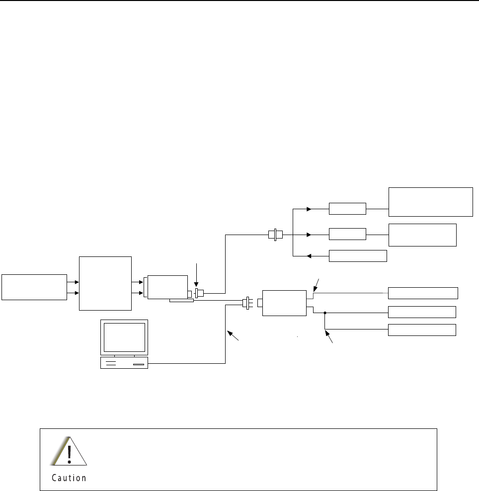
Chapter 6 Radio Alignment Procedures
This chapter describes both receiver and transmitter radio alignment procedures.
6.1 Test Setup
A personal computer (PC) and tuner software are required to align the radio. Refer to the applicable
manual for installation and setup procedures for the software. To perform the alignment procedures,
the radio must be connected to the PC and to a universal test set. The radio alignment test setup is
shown in Figure 6-1.
Figure 6-1. Radio Alignment Test Setup
These radio alignment procedures should only be attempted by qualified
service personnel. Failure to perform alignment procedures properly may
result in seriously degraded radio or system performance.
BNC
COMPUTER
AUDIO GENERATOR
SINAD METER
AC VOLTMETER
TX
RX
30 dB PAD
30 dB PAD
RF GENERATOR
TRANSMIT
RECEIVE
PROGRAM/TEST CABLE
PMKN4013_
AUDIO IN
SMA-BNC
5880384G68
TEST SET
RLN4460_
SET TO APPROX. 8mV FOR Tx
MEASURE 3.74Vrms FOR Rx
MODULATION ANALYZER
OR
SERVICE MONITOR
AEROFLEX
SERVICE MONITOR
USB END IS NOT USED
RADIO
DC POWER SUPPLY
UNIVERSAL
BATTERY
ELIMINATOR
66009254001
(7.5V AT BATTERY
ELIMINATOR
TERMINALS)
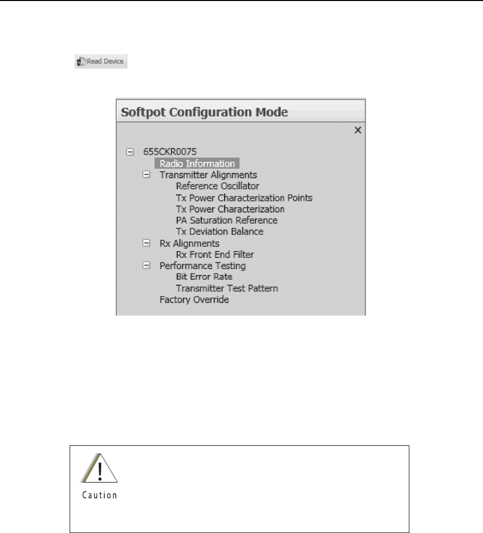
Sec 2: 6-2 Radio Alignment Procedures: Tuner Main Menu
6.2 Tuner Main Menu
Select Tuner from the START menu by clicking Start › Program Files › Motorola ›
ASTRO 25 Products › ASTRO 25 Tuner. To read the radio, use the File › Read Device menu or
click on . Figure 6-2 illustrates how the alignment screens are organized. To access a
screen, double-click on the desired screen name in the Tuner menu.
Figure 6-2. Tuner Software Main Menu
IMPORTANT: Tuning should follow the order of the Tuning tree view in descending
order from top to bottom
6.3 Softpot
The alignment screens introduce the concept of the “softpot,” an analog SOFTware-controlled
POTentiometer used for adjusting all transceiver alignment controls.
Each alignment screen provides the ability to increase or decrease the softpot value by using a
slider, or by entering the new value from the keyboard directly into the box. The slider bar indicates
the current softpot value; see Figure 6-3.
DO NOT switch radios in the middle of any alignment
procedure. Always left-click the Close button on the screen to
return to the Main Menu screen before disconnecting the
radio. Improper exits from the alignment screens might leave
the radio in an improperly configured state and result in
seriously degraded radio or system performance.

Radio Alignment Procedures: Softpot Sec 2: 6-3
Figure 6-3. Typical Softpot Screen
Adjusting the softpot value sends information to the radio to increase (or decrease) the voltage in the
corresponding circuit. For example, left-clicking the UP spin button in the New Softpot Value scroll
box on the Reference Oscillator screen instructs the radio’s microcomputer to increase the voltage
across a varactor in the reference oscillator, which increases the frequency.
In ALL cases, the softpot value is just a relative number corresponding to a digital-to-analog (D/A)
generated voltage in the radio.
Perform the following procedures in the sequence indicated.
NOTE: Some of the following screens may vary depending upon the radio under test and the version
of tuner software you are using. Refer to the software’s online help.
When keying the radio during a test, always transmit into a
dummy load.
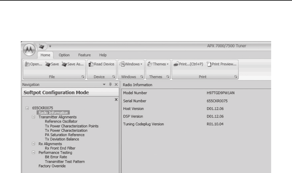
Sec 2: 6-4 Radio Alignment Procedures: Radio Information
6.4 Radio Information
Figure 6-4 shows a typical Radio Information screen. This screen is informational only and cannot be
directly changed.
Figure 6-4. Radio Information Screen
6.5 Transmitter Alignments
6.5.1 Reference Oscillator Alignment
Adjustment of the reference oscillator is critical for proper radio operation. Improper adjustment will
result not only in poor operation, but also in a misaligned radio that will interfere with other users
operating on adjacent channels. For this reason, the reference oscillator should be checked every
time the radio is serviced, or once a year, whichever comes first. The frequency counter used for this
procedure must have a stability of 0.1 ppm (or better).
NOTE: Reference oscillator alignment is required after replacing (or servicing) the transceiver board.
This test can be done with either the R-2670 Communication Analyzer or the 8901_ Modulation
Analyzer.
• Initial setup using the R-2670 Communication Analyzer:
- RF Control: MONITOR
-B/W: WB
- Freq: CPS frequency under test
- Attenuation: 20dB
- Mon RF in: RF I/O
- Meter: RF Display
- Mode: STD
- Input Level: uV or W
- Display: Bar Graphs
- Squelch: Mid-range or adjust as necessary

Radio Alignment Procedures: Transmitter Alignments Sec 2: 6-5
• Initial setup using the 8901_ Series Modulation Analyzer:
- Press the green Automatic Operation button on the analyzer.
- Press the FREQ key.
- Type 7.1 followed by SPCL button to set the 8901B_ modulation analyzer for maximum
accuracy.
To align the reference oscillator:
1. Select the Reference Oscillator alignment screen. See Figure 6-5, Figure 6-6 and
Figure 6-7.
Figure 6-5. Reference Oscillator Alignment Screen (VHF and 700–800 MHz, UHF1 and 700–800 MHz,
and UHF2 and 700–800 MHz)
Figure 6-6. Reference Oscillator Alignment Screen (UHF1 and VHF, and UHF1 and UHF2)
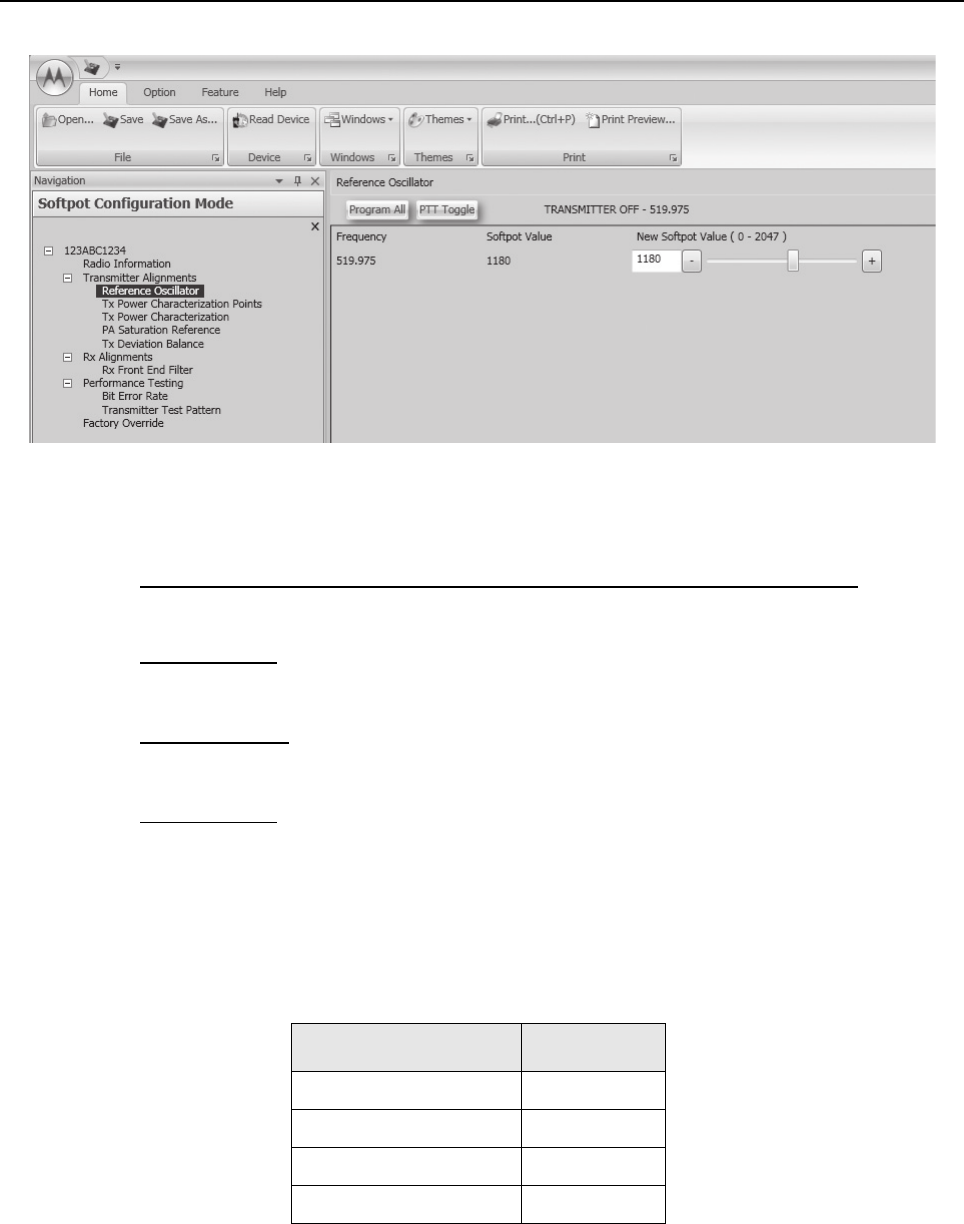
Sec 2: 6-6 Radio Alignment Procedures: Transmitter Alignments
Figure 6-7. Reference Oscillator Alignment Screen (UHF2 and VHF)
2. Make sure the Communication Analyzer is in Manual mode.
VHF and 700–800 MHz, UHF1 and 700–800 MHz ,and, UHF2 and 700–800 MHz
• Set the base frequency to 869.8875 MHz
UHF1 and VHF
• Set the base frequency to 469.925 MHz
UHF1 and UHF2
• Set the base frequency to 469.925 MHz
UHF2 and VHF
• Set the base frequency to 519.975 MHz
3. Adjust the reference oscillator’s softpot value with the slider until the measured value is as
close as possible to the frequency shown on the screen. See Table 6-1.
NOTE: Increases the slider decreases the frequency and vice versa.
4. Left-click the Program All button on the screen to dekey the radio and save the tuned values.
5. Left-click the Close button on the screen to return to the Transmitter Alignments menu.
Table 6-1. Reference Oscillator Alignment
Band Target
VHF ±50 Hz
700 MHz/800 MHz ±50 Hz
UHF1 ±50 Hz
UHF2 ±50 Hz
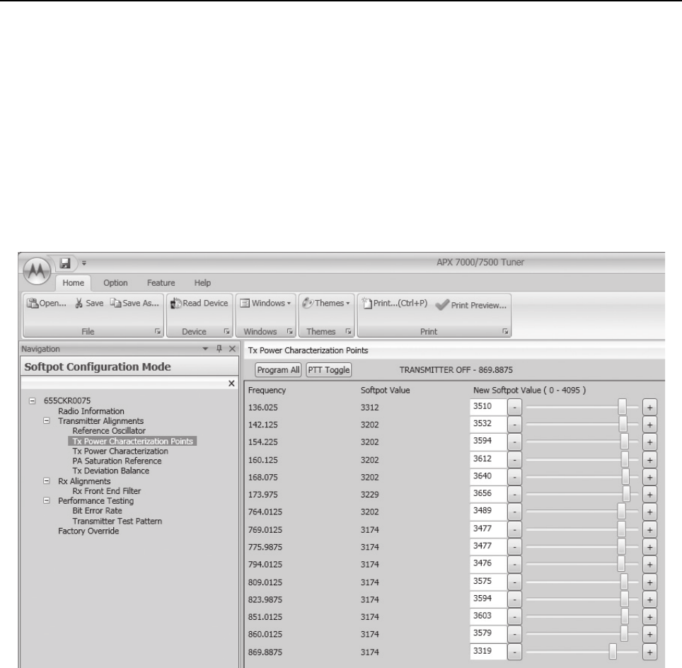
Radio Alignment Procedures: Transmitter Alignments Sec 2: 6-7
6.5.2 Power Characterization Points
Tuning of the radio is done through Power Characterization Points tuning screen.
1. Select the TX Power Characterization Points alignment screen.
See Figure 6-8 to Figure 6-13.
2. Set power supply voltage and current limit.
3. Adjust softpot value by manipulating the slider bar, incrementing the "New Softpot Value" text
box, or directly entering the desired value into the "New Softpot Value" text box until the rated
power is indicated on the service monitor. For rated power refer to the help text in the Tuner.
4. Repeat the steps 2 and 3 for all frequencies.
5. Left-click the Program All button on the screen to dekey the radio and save the tuned values.
Figure 6-8. Transmit Power Characterization Points Alignment Screen (VHF and 700–800 MHz)
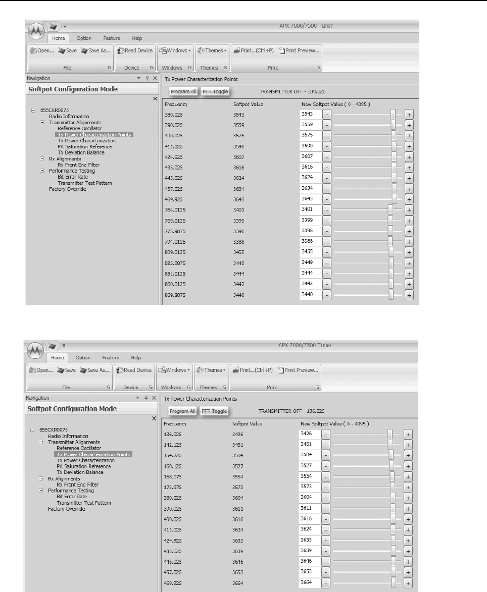
Sec 2: 6-8 Radio Alignment Procedures: Transmitter Alignments
Figure 6-9. Transmit Power Characterization Points Alignment Screen (UHF1 and 700–800 MHz)
Figure 6-10. Transmit Power Characterization Points Alignment Screen (UHF1 and VHF)
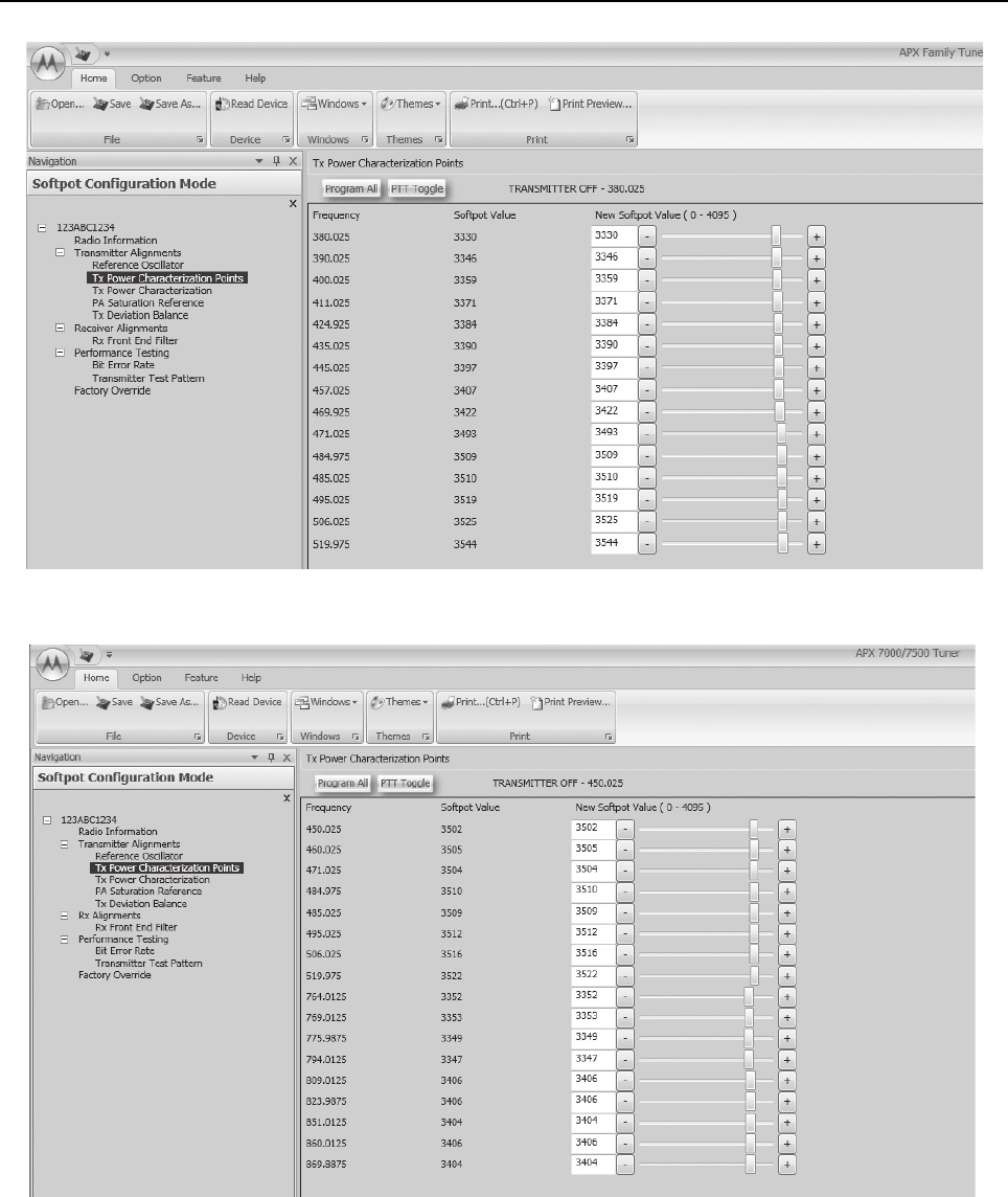
Radio Alignment Procedures: Transmitter Alignments Sec 2: 6-9
Figure 6-11. Transmit Power Characterization Points Alignment Screen (UHF1 and UHF2)
Figure 6-12. Transmit Power Characterization Points Alignment Screen (UHF2 and 700–800 MHz)

Sec 2: 6-10 Radio Alignment Procedures: Transmitter Alignments
Figure 6-13. Transmit Power Characterization Points Alignment Screen (UHF2 and VHF)
6.5.3 Power Characterization Tuning
Tuning of the radio is done through Power Characterization tuning screen.
IMPORTANT: Power Characterization Tuning Points must be tuned before tuning
Power Characterization Tuning.
NOTE: a.The longer the RF cable, the more the attenuation of the power reading.
b.Use a standard 50 ohm cable
c.Remember to set the Communication Analyzer to baseband power.
1. Select the TX Power Characterization alignment screen. The screen indicates the transmit
power to be used. See Figure 6-14 to Figure 6-19.
2. Left-click the box under “Measure Power 1” for the desired frequency field. (The selected box
is highlighted).
3. Click the PTT Toggle button on the screen to make the radio transmit. The screen indicates
whether the radio is transmitting.
4. Measure the transmit power of the radio with a service monitor.
5. Input the transmit power in watts using two decimal places into the highlighted “Measure
Power 1” box.
6. Left-click the box under “Measure Power 2” box for the same frequency field. (The selected
box is highlighted).
7. Measure the transmit power of the radio with a service monitor.
8. Input the transmit power in watts using two decimal places into the highlighted “Measure
Power 2” box.
9. Repeat steps 2 to 8 for all frequencies.
10. Left-click the Program All button on the screen to dekey the radio and save the tuned values.
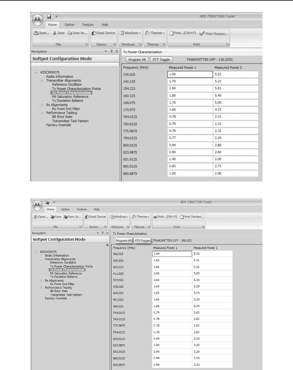
Radio Alignment Procedures: Transmitter Alignments Sec 2: 6-11
Figure 6-14. Transmit Power Characterization Alignment Screen (VHF and 700–800 MHz)
Figure 6-15. Transmit Power Characterization Alignment Screen (UHF1 and 700–800 MHz)
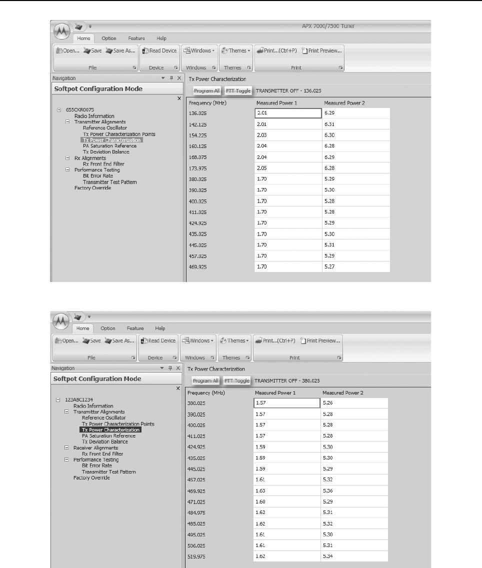
Sec 2: 6-12 Radio Alignment Procedures: Transmitter Alignments
Figure 6-16. Transmit Power Characterization Alignment Screen (UHF1 and VHF)
Figure 6-17. Transmit Power Characterization Alignment Screen (UHF1 and UHF2)

Radio Alignment Procedures: Transmitter Alignments Sec 2: 6-13
Figure 6-18. Transmit Power Characterization Alignment Screen (UHF2 and 700–800 MHz)
Figure 6-19. Transmit Power Characterization Alignment Screen (UHF2 and VHF)

Sec 2: 6-14 Radio Alignment Procedures: Transmitter Alignments
6.5.4 PA Saturation Reference Tuning
Tuning is done through PA Saturation Referencing screen.
1. Select the PA Saturation Reference alignment screen. The screen indicates the transmit
frequencies to be used. See Figure 6-20 to Figure 6-25.
2. In Manual Mode, set the service monitor to the desired frequency (as shown in the frequency
list in the PA Saturation Reference alignment screen).
3. Adjust the PA Saturation Reference softpot value with the slider until the radio transmits as
close as possible to the rated power. For rated power refer to the help text in the Tuner.
4. Left-click the slider of the frequency selected (should be the same frequency as step 2).
5. Left-click the PTT Toggle button on the screen to make the radio transmit. The screen
indicates whether the radio is transmitting.
6. Repeat the steps 2 to 5 for all frequencies.
7. Left-click the Program All button on the screen to dekey the radio and save the tuned values.
Figure 6-20. PA Saturation Referencing Alignment Screen (VHF and 700–800 MHz)
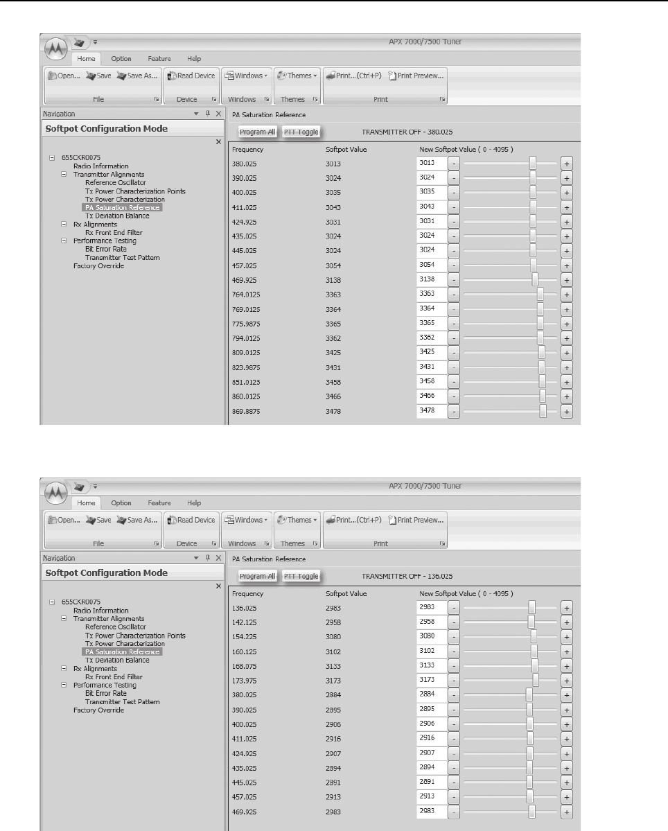
Radio Alignment Procedures: Transmitter Alignments Sec 2: 6-15
Figure 6-21. PA Saturation Referencing Alignment Screen (UHF1 and 700–800 MHz)
Figure 6-22. PA Saturation Referencing Alignment Screen (UHF1 and VHF)
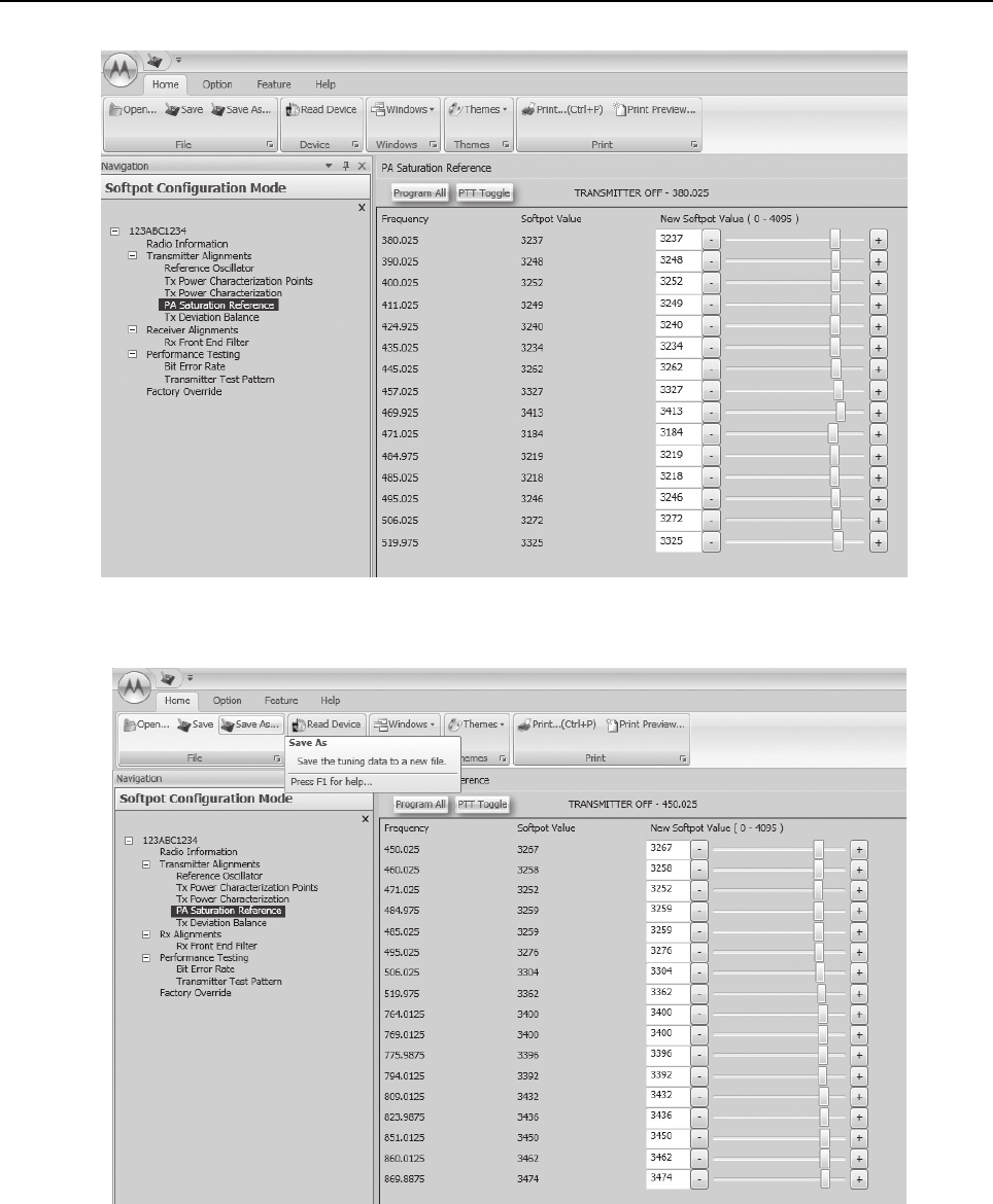
Sec 2: 6-16 Radio Alignment Procedures: Transmitter Alignments
Figure 6-23. PA Saturation Referencing Alignment Screen (UHF1 and UHF2)
Figure 6-24. PA Saturation Referencing Alignment Screen (UHF2 and 700–800 MHz)
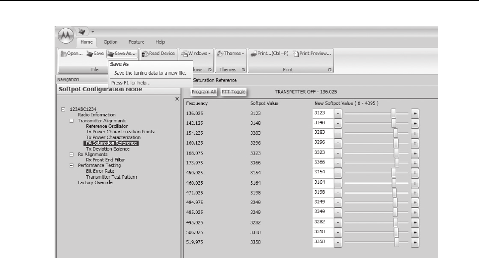
Radio Alignment Procedures: Transmitter Alignments Sec 2: 6-17
Figure 6-25. PA Saturation Referencing Alignment Screen (UHF2 and VHF)
6.5.5 Transmit Deviation Balance Alignment
This alignment procedure balances the modulation contributions of the low- and high-frequency
portions of a baseband signal. Proper alignment is critical to the operation of signalling schemes that
have very low frequency components (for example, DPL) and could result in distorted waveforms if
improperly adjusted.
This procedure needs to be performed at multiple frequencies to allow for proper alignment across
the entire RF band. The RF band is divided into frequency zones with a calibration point (value) in
each zone.
NOTE: This alignment is required after replacing (or servicing) the VOCON board or the transceiver
board.
Proper alignment requires a modulation analyzer or meter with a frequency response to less than
10 Hz modulating frequency. The modulation analyzer settings during this test should be set for
average deviation, a 15 kHz low-pass filter, no de-emphasis, and no high-pass filter, if these settings
are supported.
This alignment can be done with either the R-2670 Communication Analyzer or the 8901_ Series
Modulation Analyzer. The method of choice is the R-2670 analyzer.
1. Initial setup using the R-2670 Communication Analyzer:
- Connect a BNC cable between the “DEMOD OUT” port and the “VERT/SINAD DIST/DMM
COUNTER IN” port on the R-2670.
-Press the SPF key on the R-2670 to display the “SPECIAL FUNCTIONS MENU.” Move the
cursor to “High Pass,” and select 5 Hz on the soft key menu. Select 20 kHz for the “Low
Pass” setting.
- In the “RF Control” section of the R-2670, move the cursor to the “B/W” setting and select
“WIDE +/- 100 kHz” on the soft key menu.
- Place the R-2670 cursor in the “Display” zone. Select “AC VOLTS” on the soft key menu.
Move the cursor to the “Range” setting and select “AUTO.”
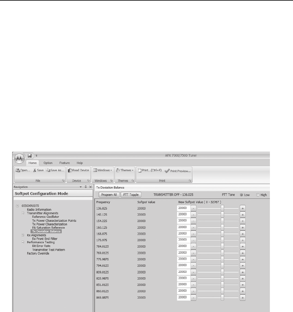
Sec 2: 6-18 Radio Alignment Procedures: Transmitter Alignments
2. Initial setup using the 8901_ Series Modulation Analyzer:
-Press the FM MEASUREMENT button. (The “Error 03-input level too low” indication is
normal until an input signal is applied.)
- Simultaneously press the Peak – and Peak + buttons. Both LEDs on the buttons should
light.
- Press the 15 kHz LP filter key.
3. Select the TX Deviation Balance alignment screen. The screen indicates the transmit
frequencies to be used. See Figure 6-26 to Figure 6-31.
4. In the "RF Control" section of the R2670, set the service monitor to the desired frequency (as
shown in the frequency list in the TX Deviation Balance alignment screen).
5. Left-click the PTT Tone: Low button.
6. Left-click the slider of the frequency selected (should be the same frequency as step 4).
7. Left-click the PTT Toggle button on the screen to make the radio transmit. The screen
indicates whether the radio is transmitting.
8. Measure and Record the Low Tone Tx Deviation value from the 8901_ Series Analyzer or the
AC voltage value from the R2670.
Figure 6-26. Transmit Deviation Balance Alignment Screen (VHF and 700–800 MHz)
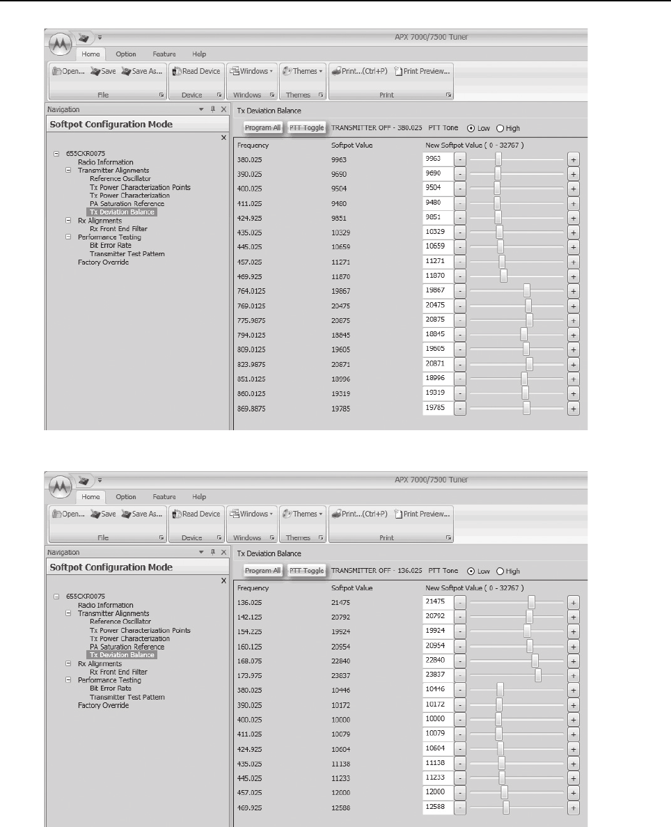
Radio Alignment Procedures: Transmitter Alignments Sec 2: 6-19
Figure 6-27. Transmit Deviation Balance Alignment Screen (UHF1 and 700–800 MHz)
Figure 6-28. Transmit Deviation Balance Alignment Screen (UHF1 and VHF)
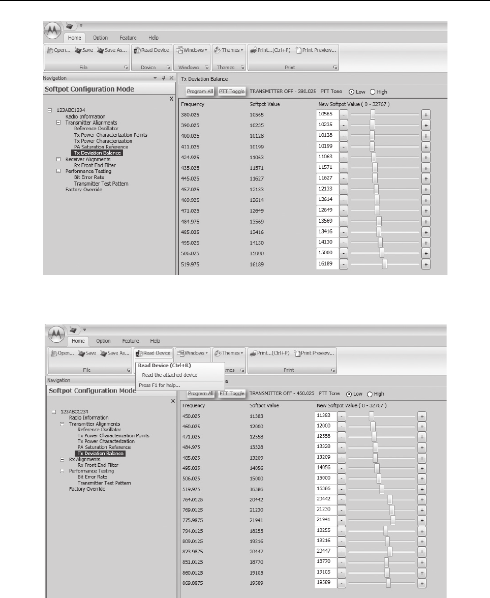
Sec 2: 6-20 Radio Alignment Procedures: Transmitter Alignments
Figure 6-29. Transmit Deviation Balance Alignment Screen (UHF1 and UHF2)
Figure 6-30. Transmit Deviation Balance Alignment Screen (UHF2 and 700–800 MHz)
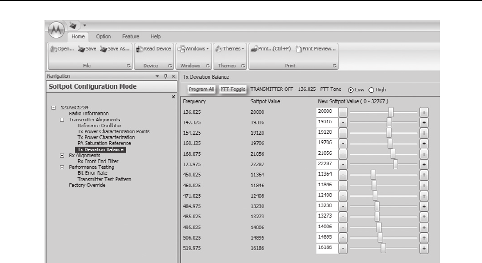
Radio Alignment Procedures: Transmitter Alignments Sec 2: 6-21
Figure 6-31. Transmit Deviation Balance Alignment Screen (UHF2 and VHF)
9. Left-click the PTT Tone: High button.
10. Adjust the softpot value until the measured deviation/voltage, when using the high tone, is
within +/- 1.5% of the value observed when using the Low Tone.
11. Left-click the PTT Toggle to de-key the radio.
12. Repeat the steps 4 to 10 for all frequencies.
13. Left-click the Program All button on the screen to dekey the radio and save the tuned values.
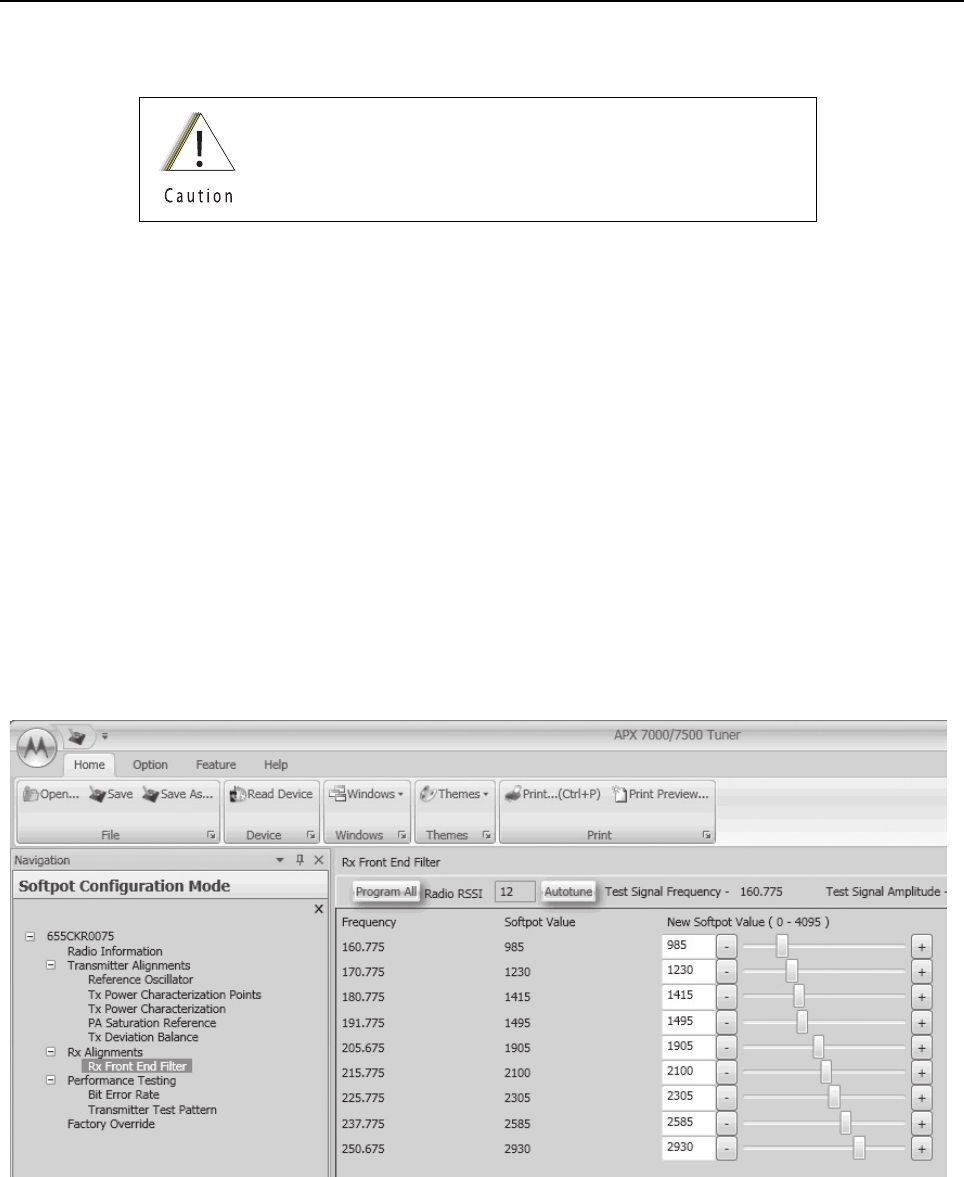
Sec 2: 6-22 Radio Alignment Procedures: Front End Filter Alignment
6.6 Front End Filter Alignment
The alignment procedure adjusts the front end receiver bandpass filters for the best receiver
sensitivity and selectivity. This procedure should be performed for all test frequencies to allow for
proper software interpolation of frequencies between the test frequencies in the band
(see Figure 6-32 and Figure 6-33).
NOTE: Rx Front End Filter Alignment is required after replacing (or servicing) the transceiver board.
6.6.1 Procedure for UHF Range 1 (Auto Tune)
Tuning of the radio is done through Rx Front End Filter tuning screen
1. Select the Rx Front End Filter alignment screen. See Figure 6-32.
2. Click on the slider or the "New Softpot Value" text box to select which frequency to tune.
3. Apply RF test signal input with no modulation at -14 dBm on the Test Signal Frequency
displayed at the top of the screen.
4. Left-click the Autotune button.
5. Repeat the steps 2–4 for all frequencies.
6. Left-click the Program All button on the screen to save the tuned values in the radio.
Figure 6-32. Front End Filter Alignment Screen (UHF1)
This procedure should only be attempted by qualified service
technicians.
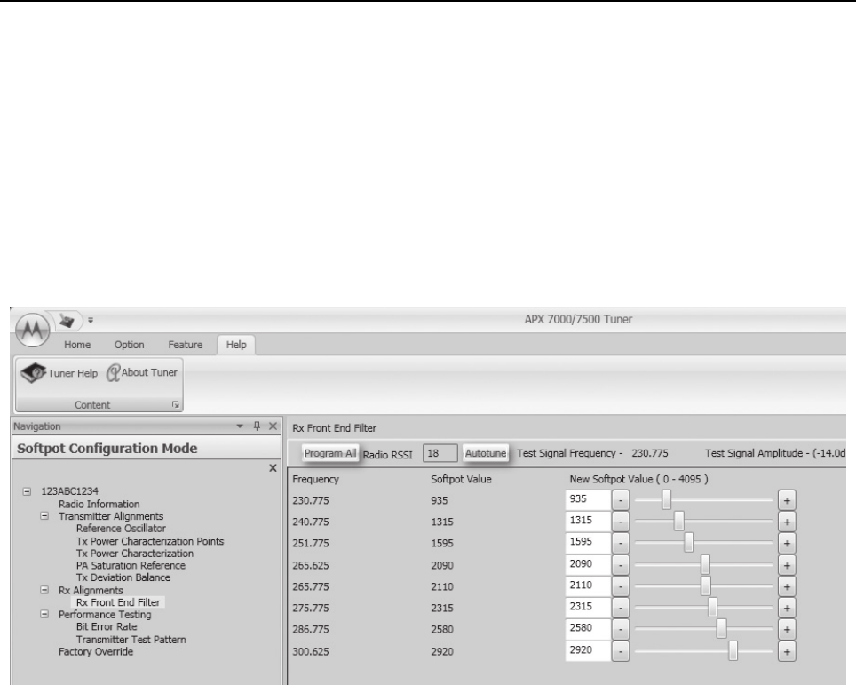
Radio Alignment Procedures: Front End Filter Alignment Sec 2: 6-23
6.6.2 Procedure for UHF Range 2 (Auto Tune)
Tuning of the radio is done through Rx Front End Filter tuning screen
1. Select the Rx Front End Filter alignment screen. See Figure 6-33.
2. Click on the slider or the "New Softpot Value" text box to select which frequency to tune.
3. Apply RF test signal input with no modulation at -14 dBm on the Test Signal Frequency
displayed at the top of the screen.
4. Left-click the Autotune button.
5. Repeat the steps 2–4 for all frequencies.
6. Left-click the Program All button on the screen to save the tuned values in the radio.
Figure 6-33. Front End Filter Alignment Screen (UHF2)

Sec 2: 6-24 Radio Alignment Procedures: Performance Testing
6.7 Performance Testing
6.7.1 Bit Error Rate
This section describes the Bit Error Rate (BER) test of the radio’s receiver at a desired frequency
(see Figure 6-34).
6.7.1.1 Bit Error Rate Fields
Set up the R2670 Communication Analyzer as follows:
1. Connect the RF Input port of the radio under test to the RF IN/OUT port of the R2670 Service
Monitor.
2. Set up the R2670 Service Monitor:
- In the Display Zone, select PROJ 25 STD mode and set the meter to RF DISPLAY.
- In the RF Zone, configure the analyzer as follows:
- In the Audio Zone, select the 1011 Hz PAT code and set the deviation to “PROJ25Dev:
2.83 kHz ~”.
The bit error rate screen contains the following fields:
•Rx Frequency:
This field selects the Receive Frequency directly in MHz.
•Test Pattern:
This field selects the Digital test pattern to be received by the radio. Choices are: Standard
Tone Test Pattern (Framed 1011), F2 1031 and Standard Interface Test Pattern (CCITT V.52).
•Modulation Type:
This field represents the digital modulation type of the incoming signal on which BER is to be
calculated.
•Continuous Operation:
This field allows the user the option to repeat the BER test indefinitely. A selection of Yes will
cause the radio to calculate BER on a continuous basis and update the results on this screen
after each integration time. A selection of No will cause the BER test to execute for only one
sample of the integration time and then update the display.
•Audio:
This field allows the user to select the audio output during a test. Selecting Internal will cause
the radio's built-in speaker to unmute to any signals at the desired frequency which are present
during the test. Selecting External will route the same signal to the radio's accessory connector
audio output. Selecting Mute will disable the audio output.
NOTE: There will be no audio option available for APX 7000XE when performing a Bit Error Rate
Test.
•BER Integration Time:
BER Integration Time carries with Test Pattern Type.
• Number of Frames
Number of Frames over which bit error result are accumulated to produce the result.
RF Control: Generate
Preset: B/W: NB
Freq: Test frequency (Ex: 851.0625 MHz)
Output Level: -50.0 dBm
Gen RF Out: RF I/O
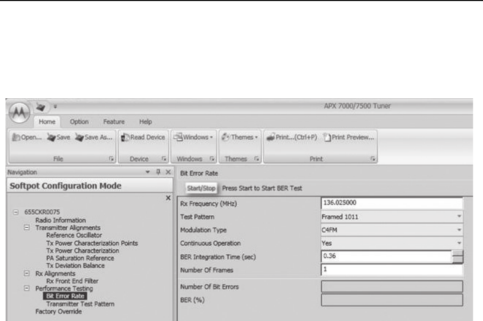
Radio Alignment Procedures: Performance Testing Sec 2: 6-25
NOTE: When Continuous Operation = Yes, all fields will be grayed out while the test is in progress.
They will be enabled when the STOP button is pressed.
When Continuous Operation = No, a wait cursor will be displayed while the test is in
progress and return to normal when the test is done.
Figure 6-34. Bit Error Rate Screen
3. Press Start/Stop button to begin or end BER testing.
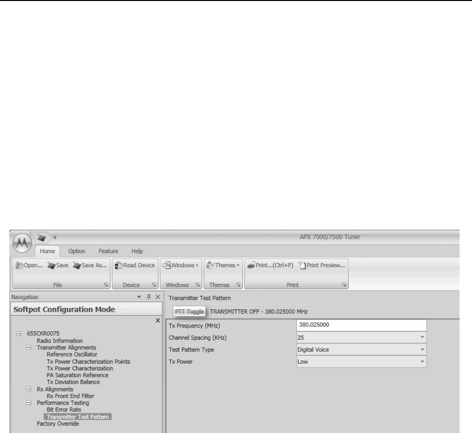
Sec 2: 6-26 Radio Alignment Procedures: Performance Testing
6.7.2 Transmitter Test Pattern
The Transmitter Test Pattern test is used to transmit specific test patterns at a desired frequency so
that the user can perform tests on the radio’s transmitter (see Figure 6-35).
6.7.2.1 Transmitter Test Fields
This screen contains the following fields:
•Tx Frequency:
This field selects the Transmit Frequency directly in MHz.
•Channel Spacing:
This field allows the user to select the desired channel spacing in kHz.
•Test Pattern Type:
This field represents the type of test pattern which will be transmitted by the radio when PTT
TOGGLE button is pressed.
NOTE: Channel Spacing and Test Pattern Type fields will be grayed out while radio is transmitting.
Figure 6-35. Transmitter Test Pattern Screen

Chapter 7 Encryption
This chapter provides procedures for using the encryption capability of your radio. The following
procedures are outlined:
• Loading an encryption key
• Selecting an encryption key
• Selecting an Index (only applicable to Dual Display configured radios)
• Erasing an encryption key (only applicable to Dual Display configured radios)
7.1 Load an Encryption Key
Keys will be loaded from the KVL to the radio in either clear or encrypted form depending on the
configuration of the CPS parameter "KVL – FIPS Level 3 Approved Mode". If the parameter is
disabled, keys will be sent in clear form; if the parameter is enabled, keys will be sent to the radio in
encrypted form.
NOTE: A KVL4000 or KVL3000 Plus with software version R03.52.45 or greater must be used to load
keys to a radio with "KVL – FIPS Level 3 Approved Mode" enabled.
To load an encryption key:
1. Refer to the key-variable loader (KVL) manual for equipment connections and setup.
2. Attach the KVL to the radio. The top display shows “KEYLOAD” whereas “KEYLOADING” is
shown on the front display of a Dual Display configured radio. All other radio functions, except
for power down, backlight, and volume, are locked out.
3. Refer to the KVL manual for how to load the encryption keys into the radio.
4. When the key is loaded successfully, you will hear:
• On single-key radios – a short tone.
• On multikey radios – an alternating tone.
7.2 Multikey Feature
This feature allows the radio to be equipped with multiple encryption keys. It can support two or more
encryption algorithms simultaneously (e.g., AES and DES-XL).
•Conventional Multikey – The encryption keys can be tied (strapped), on a one-per-channel
basis. In addition, the radio can have operator-selectable keys, operator-selectable indices, and
operator-selectable key erasure. If talkgroups are enabled in conventional, then the encryption
keys are strapped to the talkgroups.
•Trunked Multikey – If the radio is used for both conventional and trunked applications, strap
the encryption keys for trunking on a per- talkgroup or announcement group basis. In addition,
a different key can be strapped to other features; for example, dynamic regrouping, failsoft, or
emergency talkgroup. The radio can have operator-selectable key erasure.

Sec 2: 7-2 Encryption: Select an Encryption Key
7.3 Select an Encryption Key
You can select an encryption key using either the menu or the keypad.
7.3.1 Use the Menu
To select an encryption key using the menu:
1. Press > until the display shows “KEY”.
2. Press {, |, or } directly below “KEY”. The display shows the last user-selected and
-stored encryption key, as well as the available menu selections.
3. Press < or > to scroll through the list of encryption keys.
NOTE: If you select an erased key, the display alternates between showing the encryption
key and “ERASED KEY”.
4. Press {, |, or } directly below the desired menu.
•PSET = selects the preset or default encryption key.
•SEL = saves the newly selected key and returns to the home display.
5. Press H, the PTT button, or {, |, or } directly below the ABRT menu, or turn the
16-Position Select knob to exit this menu.
• If the selected key is erased, the display shows “KEY FAIL” and the radio sounds a
momentary keyfail tone.
• If the selected key is not allowed, the display shows “ILLEGAL KEY” and the radio sounds a
momentary illegal key tone.
7.3.2 Use the Keypad
To select an encryption key using the keypad:
1. Press > until the display shows “KEY”.
2. Press {, |, or }directly below “KEY”. The display shows the last user-selected and
stored encryption key, as well as the available menu selections.
3. Using the keypad, enter the number of the desired key.
NOTE: If you select an erased key, the display alternates between showing the encryption
key and “ERASED KEY”.
4. Press < or > to select from the menu.
•PSET = selects the preset or default encryption key.
•SEL = saves the newly selected key and returns to the home display.
5. Press H, the PTT button, or {, |, or } directly below the ABRT menu, or turn the
16-Position Select knob to exit this menu.
• If the selected key is erased, the display shows “KEY FAIL” and the radio sounds a
momentary keyfail tone.
• If the selected key is not allowed, the display shows “ILLEGAL KEY” and the radio sounds a
momentary illegal key tone.

Encryption: Select an Encryption Index Sec 2: 7-3
7.4 Select an Encryption Index
This feature lets the user select one or more groups of several encryption keys from among the
available keys stored in the radio. For example, the radio could have a group of three keys structured
to one index, and another group of three different keys structured to another index. Changing indices
makes the radio automatically switch from one set of keys to the other. Every channel to which one
of the original keys was tied will now have the equivalent new key instead.
7.4.1 Use the Menu
To select an index using the menu:
1. Press > until the display shows “INDX”.
2. Press {, |, or } directly below “INDX”. The display shows the last user-selected and
-stored index, as well as the available index menu selections.
3. Press {, |, or } directly below the desired index. The display shows the last
user- selected and -stored index, as well as the available index menu selections.
4. Choose one of the following:
a. To save the index, press {, |, or } directly below “SEL”.
b. To exit this menu without changing the index selection, press H or the PTT button, or turn
the 16-Position Select knob.
7.4.2 Use the Keypad
To select an index using the keypad:
1. Press > until the display shows “INDX”.
2. Press {, |, or } directly below “INDX”. The display shows the last user-selected and
-stored index, as well as the available index menu selections.
3. Using the keypad, enter the number of the desired index.
4. Choose one of the following:
a. To save the index, press {, |, or }directly below “SEL”.
b. To exit this menu without changing the index selection, press H or the PTT button, or turn
the 16-Position Select knob.
7.5 Erase an Encryption Key
This section describes two methods for erasing an encryption key.
7.5.1 Method 1 – Key Zeroization (Multikey Only)
To zeroize an encryption key:
1. Press > until the display shows “ERAS”.
2. Press {, |, or } directly below “ERAS”. The display shows the last user-selected and
-stored encryption key, as well as the available menu selections that are listed in Table 7-1.
3. Choose one of the following:
• If you want to erase all the encryption keys at once, go to step 4 below.
• If you want to erase a single encryption key, do one of the following:

Sec 2: 7-4 Encryption: Erase an Encryption Key
–Press < or > to find the desired key. The display shows the selected key and the available
menu selections shown in Table 7-1.
– Using the keypad, enter the location number of the desired key. The display shows the
selected key, as well as the available menu selections shown in Table 7-1.
NOTE: To exit this menu at any time without erasing the key selection, press H or the PTT
button, or turn the 16-Position Select knob.
4. Press {, |, or } directly below the desired menu selection.
5. Press H, the PTT button, or turn the 16-Position Select knob to exit this menu.
7.5.2 Method 2 – All Keys Erased
To erase all encryption keys at one time:
With the radio on, press and hold the Top Side button and, while holding this button down,
press the Top button.
NOTE: DO NOT press the Top button before pressing the Top Side button unless you are
in an emergency situation. This sends an emergency alarm.
Before the keys are erased, the display shows “PLEASE WAIT”.
When all the encryption keys have been erased, the display shows “ALL KEYS ERASED”.
Table 7-1. Encryption Key Zeroization Options
Menu
Selection Action
ALL Erases all the encryption keys in the radio. The display
shows “ERS ALL KEYS” and “YES” and “NO”.
SNGL Selects the displayed encryption key to be erased.The
display shows “ERS SNGL KEY” and “YES” and “NO”.
ABRT Exits this menu and returns to the home display

Chapter 8 Disassembly/Reassembly Procedures
This chapter provides detailed procedures for disassembling/reassembling and ensuring
submergibility of the APX 7000XE radios. When performing these procedures, refer to
“Chapter 10: Exploded Views and Parts Lists” on page 2:10-1 and the diagrams that accompany the
text. Items in parentheses ( ) throughout this chapter refer to item numbers in the exploded view
diagrams and their associated parts lists.
This chapter also has procedures for removing and installing the APX 7000XE radio’s standard
accessories and changing the Volume and Frequency Knobs.
8.1 APX 7000XE Exploded View (Main Subassemblies)
This section contains the APX 7000XE radio partially exploded views.
NOTES:
• Refer to Figure 8-1 and Figure 8-2, the Top Display and Dual Display Partial Exploded Views,
and Table 8-1, the Partial Exploded View Parts List.
• Letters in parentheses ( ) refer to item letters in Figure 8-1, Figure 8-2 and Tab l e 8 -1.
When servicing electronics, always ensure that you are
properly grounded with antistatic grounding system approved
for electronics handling.
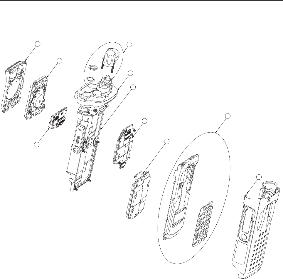
Sec 2: 8-2 Disassembly/Reassembly Procedures: APX 7000XE Exploded View (Main Subassemblies)
Figure 8-1. APX 7000XE Top Display Partial Exploded View
A
B
H
J
C
K
G
F
E
D
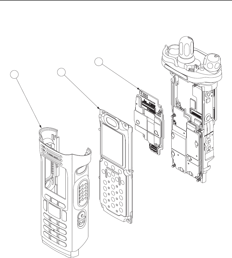
Disassembly/Reassembly Procedures: APX 7000XE Exploded View (Main Subassemblies) Sec 2: 8-3
Figure 8-2. APX 7000XE Dual Display Partial Exploded View
LM
N
NOTE: All common parts are shown on the APX 7000XE Top Display Partial Exploded View.

Sec 2: 8-4 Disassembly/Reassembly Procedures: APX 7000XE Exploded View (Main Subassemblies)
Table 8-1. APX 7000XE Partial Exploded View Parts List
Item
Letter Description Exploded View and Parts List
A Speaker Grille Assembly Refer Figure 10-1: "APX 7000XE Top Display
Exploded View" on page 2:10-2.
B Speaker Module Refer Figure 10-1: "APX 7000XE Top Display
Exploded View" on page 2:10-2.
C Expansion Board Assembly Refer Figure 10-1: "APX 7000XE Top Display
Exploded View" on page 2:10-2.
D Main Housing Assembly
(Top Display)
Refer Figure 10-1: "APX 7000XE Top Display
Exploded View" on page 2:10-2.
E Back Chassis Assembly
(Top Display)
Refer Figure 10-1: "APX 7000XE Top Display
Exploded View" on page 2:10-2.
F RF Board Assembly Refer Figure 10-1: "APX 7000XE Top Display
Exploded View" on page 2:10-2.
G VOCON Board Assembly
(Top Display)
Refer Figure 10-1: "APX 7000XE Top Display
Exploded View" on page 2:10-2.
H Frequency and Volume
Knobs Assembly
Refer Figure 10-1: "APX 7000XE Top Display
Exploded View" on page 2:10-2.
J Control Top Assembly Refer Figure 10-1: "APX 7000XE Top Display
Exploded View" on page 2:10-2.
K Main Chassis Assembly Refer Figure 10-1: "APX 7000XE Top Display
Exploded View" on page 2:10-2.
L Main Housing Assembly
(Dual Display)
Refer Figure 10-2: "APX 7000XE Dual Display
Exploded View" on page 2:10-4.
M Back Chassis Assembly
(Dual Display)
Refer Figure 10-2: "APX 7000XE Dual Display
Exploded View" on page 2:10-4.
N VOCON Board Assembly
(Dual Display)
Refer Figure 10-2: "APX 7000XE Dual Display
Exploded View" on page 2:10-4.
O Bluetooth Option Board Refer Figure 10-1: "APX 7000XE Top Display
Exploded View" on page 2:10-2.
Disassembly/Reassembly Procedures: Required Tools and Supplies Sec 2: 8-5
8.2 Required Tools and Supplies
8.3 Fastener Torque Chart
Table 8-3 lists the various fasteners by part number and description, followed by the torque values
and the location where used. Torque all fasteners to the recommended value when assembling the
radio.
Table 8-2. Required Tools and Supplies
Tools Motorola
Part Number Supplier Supplier
Part Number Remarks
Bit, Torx IP8 – – – Torx T8 may be used, but Torx Plus IP8 is
recommended
Bit, Antenna
Spanner
66009258001 Motorola –
Black Stick – Hexacon
Electric Co.
MA-800G
Driver,
Torque
–––
Vacuum
Pump Kit
NLN9839_ Motorola – For Vacuum Test
Grille
Eliminator
66009275001 Motorola – For Vacuum Test and Pressure Test
Vacuum
Adapter
66009259001 Motorola – For Vacuum Test and Pressure Test
Pressure
Pump Kit
NTN4265_ Motorola – For Pressure Test
Table 8-3. Required Tools and Supplies
Motorola
Part Number Description Repair Torque (in-lbs)
0275891B01 Antenna Spanner Nut (16) 16
0375962B01 Top Screw (23) 10
0375962B02 Center Screw (24) 10
0375962B03 Bottom Screw (25) 10
03009357001 Control Top Screw (26) 7
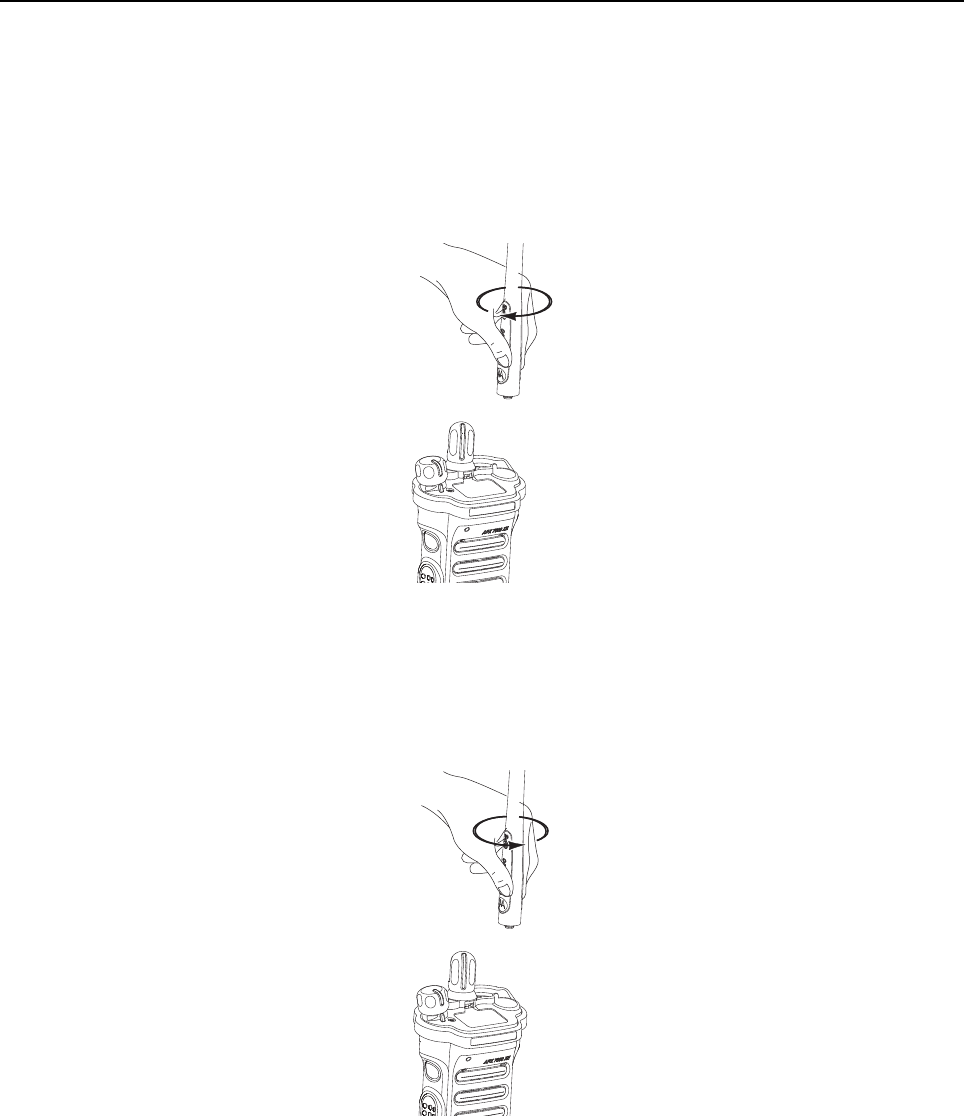
Sec 2: 8-6 Disassembly/Reassembly Procedures: Antenna
8.4 Antenna
This section explains how to attach and remove the antenna.
8.4.1 Attach Antenna
To attach the antenna:
With the radio turned off, turn the antenna clockwise to attach it to the radio.
Figure 8-3. Attaching the Antenna
8.4.2 Remove Antenna
To remove the antenna:
With the radio turned off, turn the antenna counter-clockwise to remove it from the radio.
Figure 8-4. Removing the Antenna
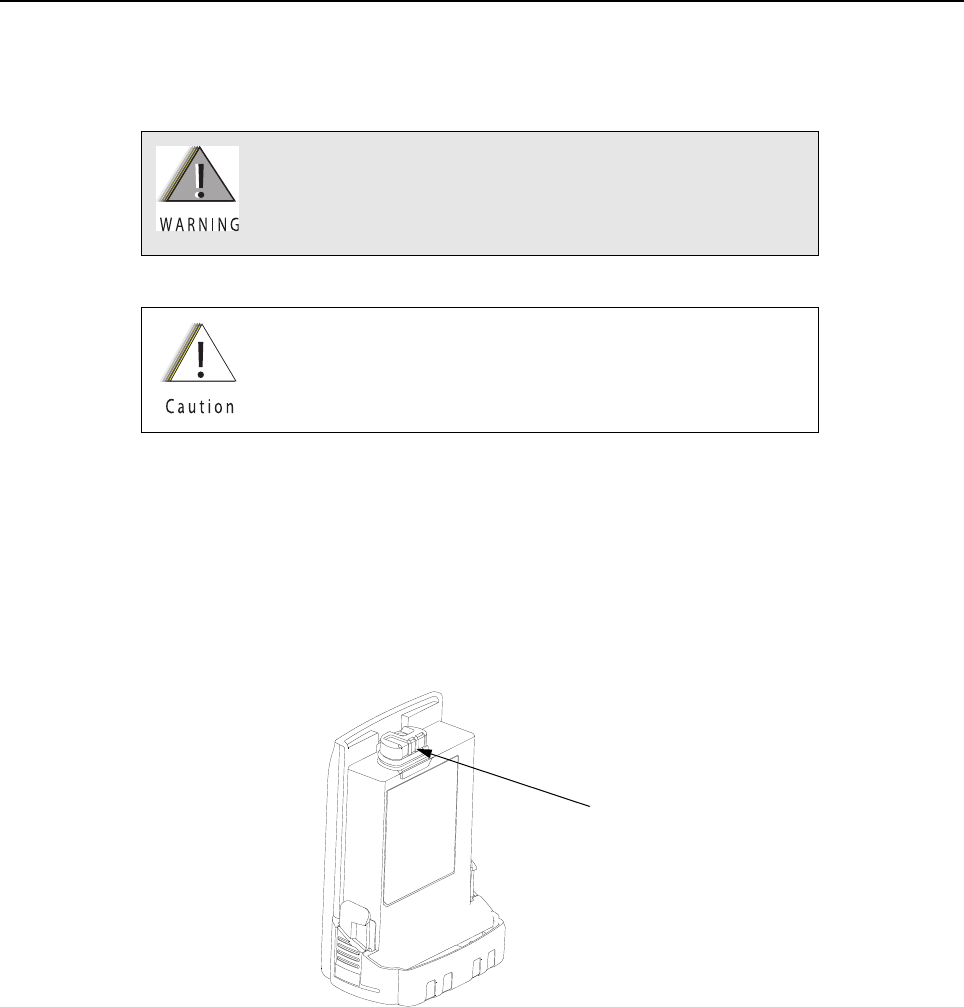
Disassembly/Reassembly Procedures: Battery Sec 2: 8-7
8.5 Battery
This section explains how to properly attach and remove the battery.
NOTE: The Motorola-approved battery shipped with the APX 7000XE radio is uncharged. Prior to
using a new battery, charge it per the recommended procedure for the battery.
8.5.1 Attach Battery
To attach the battery:
1. With the radio turned off, verify that the battery seal is set properly in its groove as shown in
Figure 8-5.
Figure 8-5. Attaching Battery – Battery Seal
To avoid a possible explosion:
• DO NOT charge, remove, or attach the battery in an area
labeled “hazardous atmosphere.”
• DO NOT discard batteries in a fire.
If the radio is programmed for volatile-key retention,
encryption keys will be retained for approximately 30 seconds
after battery removal.
Battery Seal
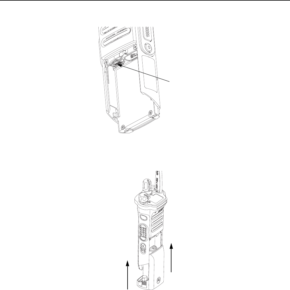
Sec 2: 8-8 Disassembly/Reassembly Procedures: Battery
2. Verify that the Memory Door (28) is closed by ensuring the door is fully seated and the catch
feature on the tab is in the main chassis notch.
Figure 8-6. Attaching Battery – Memory Door
3. Set the battery onto the chassis as shown in Figure 8-7. and slide into position. Make sure
both battery latches click into position.
Figure 8-7. Attaching Battery – Slide into Position
Memory Door (28)
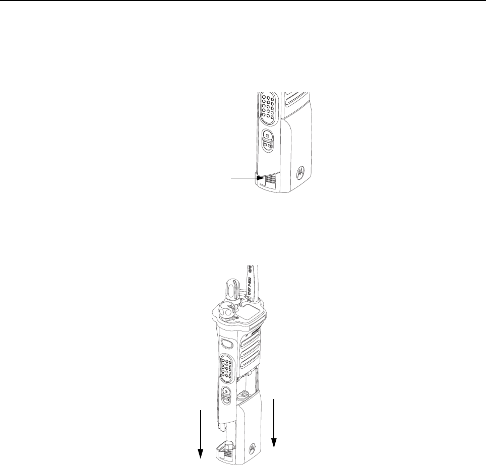
Disassembly/Reassembly Procedures: Battery Sec 2: 8-9
8.5.2 Remove Battery
To remove the battery:
1. With the radio turned off, squeeze the two latches located near the bottom, on the sides of the
battery.
Figure 8-8. Squeezing the Release Latches
2. While squeezing the latches, remove the battery by sliding it out as shown.
Figure 8-9. Removing the Battery
Battery Latch
(other one on
opposite side)
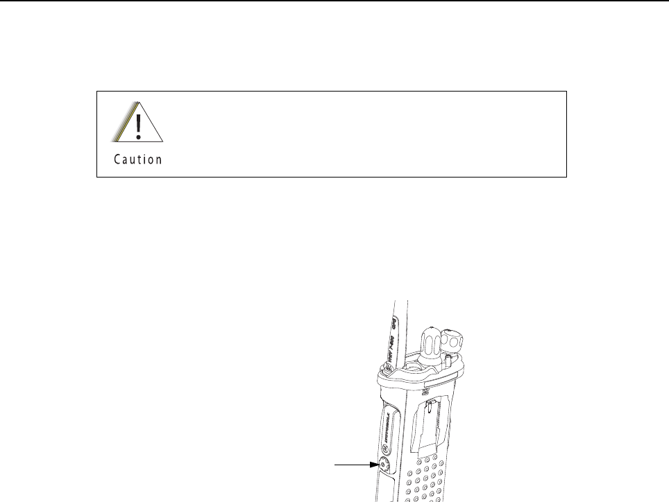
Sec 2: 8-10 Disassembly/Reassembly Procedures: Universal Connector Cover
8.6 Universal Connector Cover
This section explains how to remove and attach the Universal Connector Cover (38).
8.6.1 Remove Universal Connector Cover
To remove the Universal Connector Cover (38):
1. Unscrew the thumb screw. If the screw is too tight a hex driver may be used.
NOTE: Do not remove the screw. It should remain captive in the cover.
Figure 8-10. Removing the Thumb Screw
2. Slightly swing the Universal Connector Cover away from radio before sliding it upward to
disengage the hook feature.
3. Pull the Universal Connector Cover away from the radio.
When the universal connector is not in use, keep it covered
with the Universal Connector Cover.
Thumb Screw with Hex Head Socket
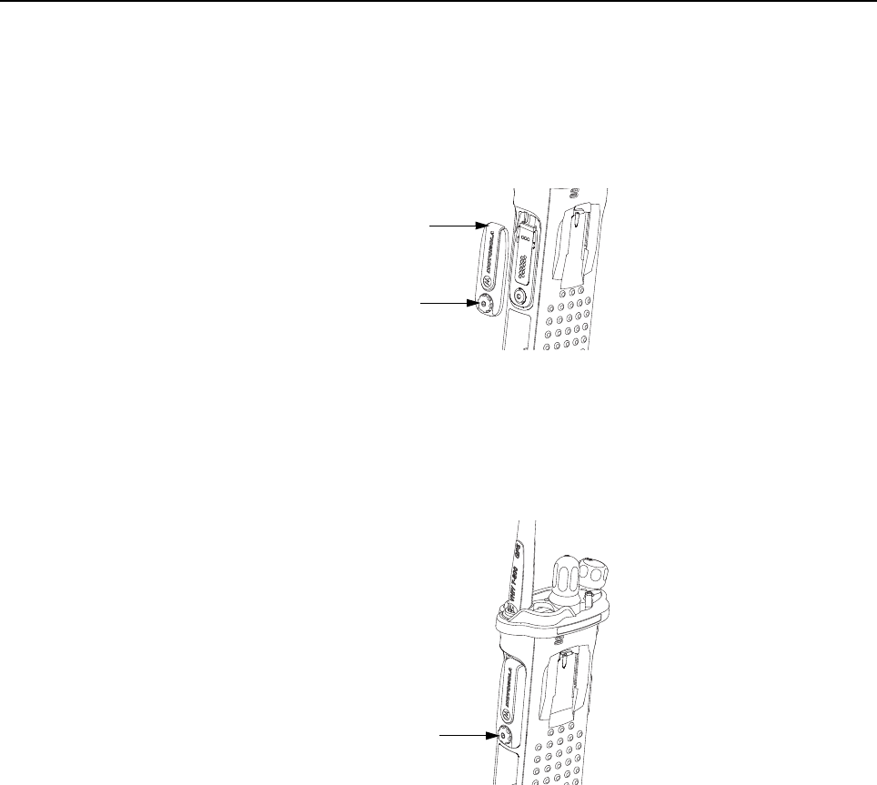
Disassembly/Reassembly Procedures: Universal Connector Cover Sec 2: 8-11
8.6.2 Attach Universal Connector Cover
To attach the Universal Connector Cover:
1. Insert the hooked end of the cover into the pocket. Engage the hook beneath the undercut
and swing the cover down onto the radio. Ensure the cover is seated properly and the screw
is aligned into the threaded hole.
Figure 8-11. Engaging Hook and Seating Cover
2. Hand tighten the thumb screw clockwise until secured.
NOTE: Do not overtighten the screw. The screw should be snugged and not allow the cover
to move.
Figure 8-12. Securing the Cover
Top Hooked End
Thumb Screw
Thumb Screw with Hex Head Socket

Sec 2: 8-12 Disassembly/Reassembly Procedures: Radio Disassembly
8.7 Radio Disassembly
This section contains instructions for disassembling the radio's main subassemblies.
Prepare the radio for disassembly:
• Turn off the radio by rotating the On/Off/Volume Knob (12) fully counterclockwise until a click is
heard.
• Remove the antenna, the battery, any memory card, Belt Clip Cover (39), the Universal
Connector Cover (38) and any other accessory connected to the radio.
8.7.1 Removal of the Speaker Grille Assemblies (A)
1. With the Battery removed and the primary loudspeaker side of the radio facing you, remove
the center two screws (24) and swing out Speaker Grille Assembly (A) as shown in
Figure 8-13.
Figure 8-13. Remove Center Screws
NOTE: Memory Door (28) can be removed with the left center screw removed.
2. Remove the bottom two screws (25) if the Main Housing Assembly (D, L) is to be removed.
Refer Figure 8-14.
Figure 8-14. Remove Bottom Screws
NOTE: Once the screws have been removed, both Thermal Pads (33, 34) should be
replaced.
Do not touch either the speaker cone or the Port Seal (20).
Take extra precaution to make sure neither the speaker nor
the breather pad is damaged.
Center Screws (24)
Memory Door (28)
Bottom Screws (25)

Disassembly/Reassembly Procedures: Radio Disassembly Sec 2: 8-13
8.7.2 Removal of the Speaker Module (B)
1. Remove the top two screws (23) as shown in Figure 8-15.
Figure 8-15. Remove Top Screws
2. Carefully pick out the Speaker Module (18) with the Black Stick and swing it out of the
Main Chassis Assembly (N) as shown in Figure 8-16.
Figure 8-16. Remove Speaker Module
Be careful not to damage the speaker cone or the Port Seal (20)
during the disassembly process.
This Module has lubricant on the seal and can be contaminated
with foreign material. Any foreign material can put the radio's
submergibility at risk.
Top Screws (23)
Port Seal (20)
Speaker Cone
Speaker Cone
Port Seal (20) Black Stick

Sec 2: 8-14 Disassembly/Reassembly Procedures: Radio Disassembly
8.7.3 Removal of the Expansion Board Assembly (C)
1. Using the Black Stick, unplug the two flex connectors located on the left and right side of the
Expansion Board Assembly (36). Unfold and straighten the flex located on the right side as
shown in Figure 8-17.
Figure 8-17. Remove Flex Connectors and Expansion Board Assembly
2. Remove the Expansion Board Assembly (C) by gently lifting up the right side of the PCB as
shown in Figure 8-17.
3. If the VOCON Board Assembly (G, N) is to be removed from the Control Top Assembly (J),
then remove the Connector Plug (27) with the Black Stick and unplug the Control Top
Assembly flex as shown in Figure 8-17.
If the radio is equipped with an Bluetooth Option Board Assembly in lieu of the Connector
Plug (27):
i. rotate the Bluetooth Option Board locking levers to unlock the option board and free it
for removal as shown in Figure 8-18.
Figure 8-18. Unlock Levers
ii. unplug the Bluetooth Option Board Assembly from the VOCON Board Assembly by
using the Black Stick as shown in Figure 8-19.
Figure 8-19. Remove Bluetooth Option Board
Flex Connectors
Expansion Board Assembly (36)
Connector Plug (27)
Locking Levers
Bluetooth Option Board
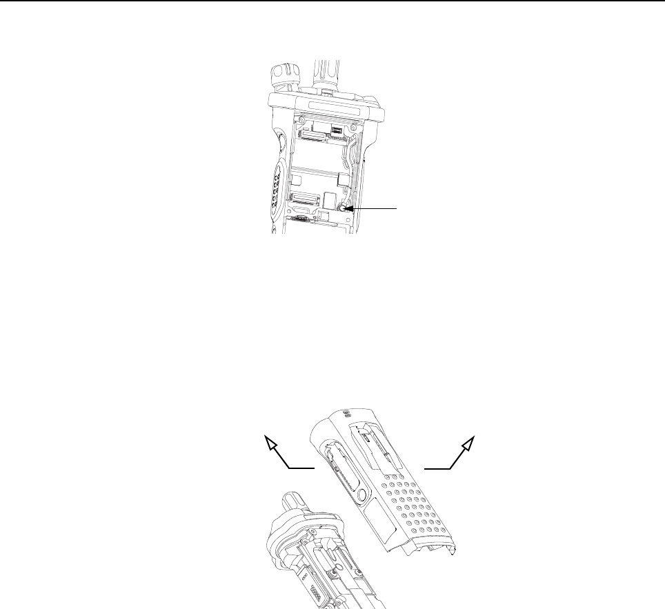
Disassembly/Reassembly Procedures: Radio Disassembly Sec 2: 8-15
4. If the RF Board Assembly (F) is to be removed, use the Black Stick to unplug the antenna
coax cable from the RF Board Assembly as shown in Figure 8-20.
Figure 8-20. Remove Antenna Coax Cable Connector
5. Flip the radio over.
8.7.4 Removal of the Main Housing Assembly (D)
• Gently stretch both sides of the Main Housing Assembly (1) outwards to clear the radio.
Then, lift it over the radio as shown in Figure 8-21.
NOTE: For Top Display version, ensure the Belt Clip Cover (39) has been removed.
Figure 8-21. Remove Housing
Antenna Coax Cable Connector
Stretch Outwards
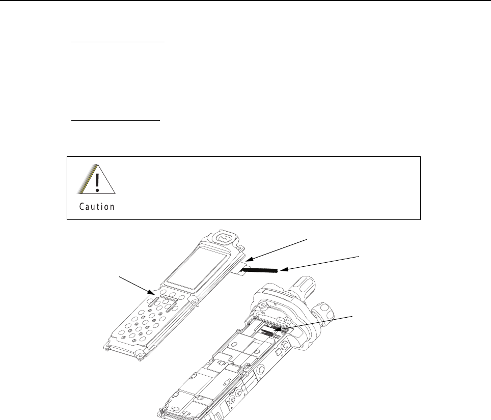
Sec 2: 8-16 Disassembly/Reassembly Procedures: Radio Disassembly
8.7.5 Removal of the Back Chassis Assembly (E, M)
1. Dual Display version:
Gently separate the Back Chassis Assembly (M) from the Main Chassis Assembly (K) to
allow access to disconnect the flex connection between both chassis. This connector is
located near the top of the radio. Use the Black Stick to disconnect the connector as shown in
Figure 8-22.
Top Display version:
Back Chassis Assembly (E) has no connections and can be removed by just separating the
the two chassis apart.
Figure 8-22. Remove Back Chassis Assembly from Main Chassis Assembly
Pull the flex connector vertically upwards by using black stick
through the pull belt to avoid damaging it.
Back Chassis Assembly (41)
Connector
Pull Belt
Black Stick
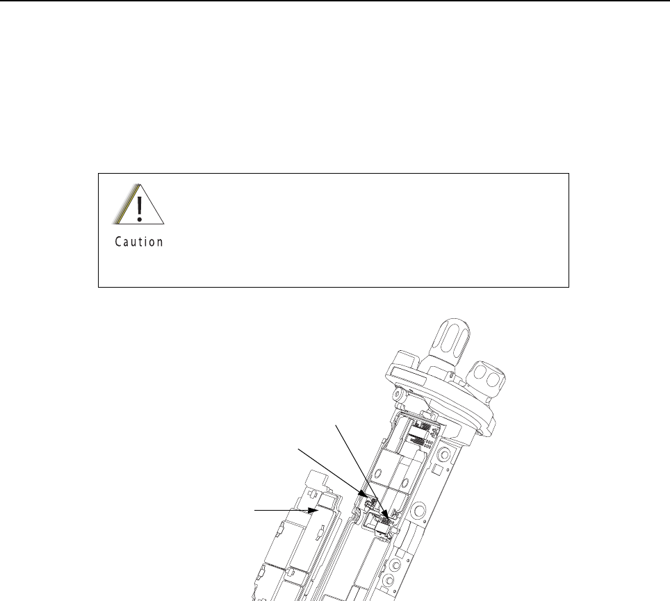
Disassembly/Reassembly Procedures: Radio Disassembly Sec 2: 8-17
8.7.6 Removal of the RF Board Assembly (F)
NOTE: Reconfirm the coax cable connector on the bottom side of the RF Board is
disconnected before removing the RF Board.
1. Unplug the RF Board Assembly (F) from the VOCON Board Assembly (G, N) by using the
Black Stick. Slowly lift the RF Board Assembly enough to allow access to the small coax
cable. Unplug the small coax cable using a Black Stick or a pair of small tweezers.
Figure 8-23. Remove RF Board Assembly
Place the RF Board Assembly in a clean and ESD safe area
to avoid contamination to the Battery Connector Seal (35) and
electrical damage to the electronics respectively.
Replace Thermal Pads (33, 34) whenever RF Board
Assembly is removed.
Connector
RF Board Assembly (32)
Small Coax Cable

Sec 2: 8-18 Disassembly/Reassembly Procedures: Radio Disassembly
8.7.7 Removal of the VOCON Board Assembly (G,M)
NOTE: Reconfirm the Flex connector between the Control Top Assembly (J) and the
VOCON Board Assembly (G, N) or, if so equipped, the Bluetooth Option Board is
disconnected (see step 2 on page 2:8-34). Failure to do so may damage the
connectors or the flex.
1. Gently rotate the VOCON Board Assembly just enough to clear the Main Chassis and
Bluetooth Option Board connector. Slide out the VOCON Board Assembly as shown in
Figure 8-24.
Figure 8-24. Remove VOCON Board Assembly
8.7.8 Removal of the Knobs
A. Remove the Frequency Knob
To remove the Frequency Knob (13):
1. Hold the radio in one hand so that the top of the radio faces upward, and the front of the radio
faces you.
2. With a pair of pliers, grasp the Frequency Knob and pull it upward, until it is free from its shaft.
B. Remove the Volume Knob
To remove the Volume Knob (12):
1. Hold the radio in one hand so that the top of the radio faces upward and the front of the radio
faces you.
2. With a pair of pliers, grasp the Volume Knob and pull it upward.
VOCON Board Assembly (G, N)
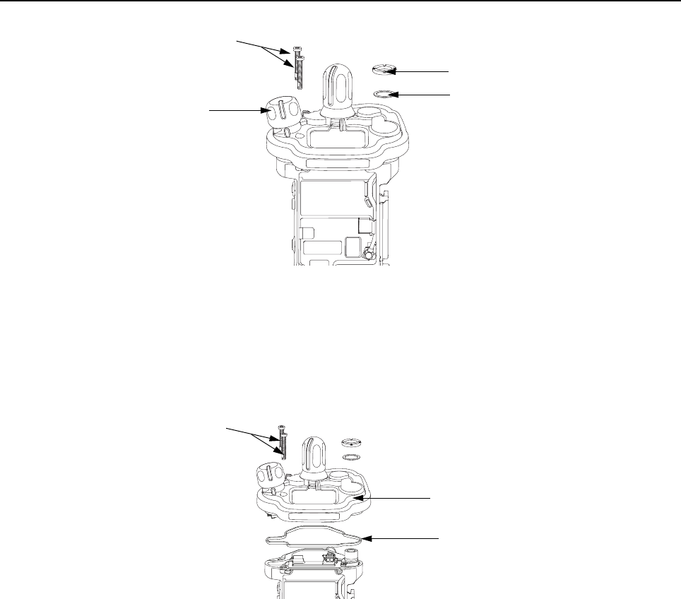
Disassembly/Reassembly Procedures: Radio Disassembly Sec 2: 8-19
Figure 8-25. Remove Knobs and Fastener Hardware
8.7.9 Removal of the Control Top Assembly (J)
i. Use a Torx Plus IP8 bit to remove the two Control Top Screws (26). See Figure 8-26.
NOTE: Ensure the Control Top flex is disconnected from the VOCON Board (G, N) to
prevent damage to the flex or connector.
Figure 8-26. Remove Control Top Assembly
II. Gently separate the Control Top Assembly (J) from the Main Chassis Assembly (K).
NOTE: Place the Control Top Assembly (J) and the remaining Main Chassis Assembly (K)
on an ESD safe surface free from debris.
Antenna Spanner Nut (16)
Antenna Washer (15)
Control Top Screws (26)
Volume Knob (12)
Control Top Assembly (J)
Control Top Screws (26)
Control Top Seal (14)
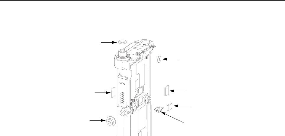
Sec 2: 8-20 Disassembly/Reassembly Procedures: Serviceable Components of the Main Sub-Assemblies
8.8 Serviceable Components of the Main Sub-Assemblies
8.8.1 Servicing Main Chassis Assembly (K)
Figure 8-27. Serviceable Components – Main Chassis Assembly
8.8.1.1 Servicing Chassis Pads:
1. Complete steps from Section 8.7.1. through Section 8.7.9. of Section “8.7 Radio
Disassembly” on page 2:8-12.
2. Carefully peel off the pad(s) that need replacing (i.e. VOCON Pad (9),
Expansion Board Pad (9) and/or Coin Cell Pad (8) from the chassis.
3. Use the Black Stick to help remove any difficult sections of the pad(s).
4. Clean the area once the pad(s) are removed to ensure it is free of adhesive and debris.
5. Peel the liner off the new pad(s) and place in the respective location.
6. Apply slight pressure to set the adhesive.
8.8.1.2 Servicing Chassis Screw Boss Cap:
1. Complete steps from Section 8.7.1. through Section 8.7.4. of Section “8.7 Radio
Disassembly” on page 2:8-12.
2. Carefully pry off the Universal Connector Cover (38) with the Black Stick from the
Main Chassis Assembly (4) as shown in Figure 8-27.
3. Press the new Cap down onto the boss until it is fully seated.
NOTE: There should be no gap between the chassis boss top face and the corresponding
interior surface of the cap.
8.8.1.3 Servicing Antenna O-ring:
1. Complete steps from Section 8.7.1. through Section 8.7.9. of Section “8.7 Radio
Disassembly” on page 2:8-12.
2. Remove the O-ring (6) with the Black Stick.
3. Reinstall the O-ring by rolling it over the threaded portion of the antenna hub until it sets in its
groove.
NOTE: Ensure the O-ring is not twisted.
Microphone Seal (19)
Thermal Pad (9) Thermal Pad (9)
Coin Cell Pad (8)
Chassis Ground Contact (7)
Universal Connector Cap (29)
O Ring (6)

Disassembly/Reassembly Procedures: Serviceable Components of the Main Sub-Assemblies Sec 2: 8-21
8.8.1.4 Servicing Microphone Membrane
1. Complete steps from Section 8.7.1. through Section 8.7.4. of Section “8.7 Radio
Disassembly” on page 2:8-12.
2. Carefully peel off the Microphone Membrane (19) from the Main Chassis Assembly (4).
3. Clean the area, once the Microphone Membrane is removed, to ensure it is free of adhesive
and debris. Ensure nothing comes in contact with the microphone while cleaning.
4. Remove the backer from the Microphone Membrane.
5. Carefully place the Microphone Membrane centered on the top surface of the microphone
boss area on the Main Chassis. Ensure the membrane is flat with no ripples or folds. Press
down firmly, applying 2-3 lbs. of force.
8.8.1.5 Servicing Chassis Ground Contact:
NOTE: Chassis Ground Contact (7) will be damaged during disassembly.
1. Complete steps from Section 8.7.1. through Section 8.7.9. of Section “8.7 Radio
Disassembly” on page 2:8-12.
2. Slide the Black Stick under the Chassis Ground Contact (7) through the opening on the RF/
VOCON PCB side of the radio to lift off the contact.
3. Clean the area once the Chassis Ground Contact is removed to ensure it is free of adhesive
and debris.
4. Remove the backer of the Chassis Ground Contact and place it in the appropriate location
with a pair of flat tip tweezers by aligning the hole in the Ground Contact with the post located
on the chassis. Ensure the Ground Contact is centered in the opening and the outer surface
of the Ground Contact is parallel to the area adjacent to it in the chassis as shown in
Figure 8-28.
5. Apply pressure to the adhesive to activate it.
Figure 8-28. Remove Chassis Ground Contact
NOTE: There are no other serviceable components on the Main Chassis Assembly (N).
Chassis Ground Contact (7)
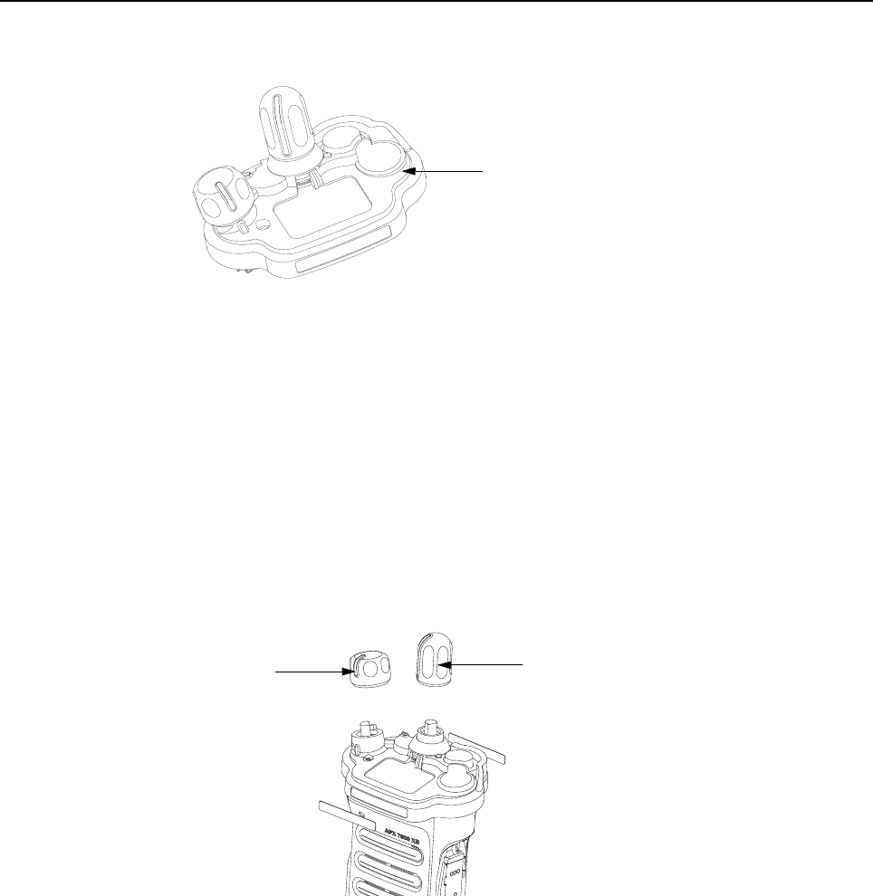
Sec 2: 8-22 Disassembly/Reassembly Procedures: Serviceable Components of the Main Sub-Assemblies
8.8.2 Servicing Control Top Assembly (J)
Figure 8-29. Control Top Assembly and Control Top Seal
8.8.2.1 Control Top Main Seal
1. Complete steps from Section 8.7.1. through Section 8.7.9. of Section “8.7 Radio
Disassembly” on page 2:8-12.
2. Remove the Control Top Seal (14) with the Black Stick.
3. Replace the new seal into the groove provided in the Control Top Assembly's casting.
4. Ensure that seal is set properly and not stretched.
NOTE: There are no other serviceable components on the Control Top Assembly (J).
8.8.3 Servicing Knobs and Top Bezel Assembly (H)
Figure 8-30. Frequency and Volume Knobs Assembly
Knobs should be removed when damaged. To remove knobs:
• Firmly hold the radio in one hand and use a pair of pliers to grip the knob.
NOTE: The knobs are designed to be difficult to remove, however, it will come off. If the
metal D clip sticks to the knob post, remove the D clip prior to putting on the new
knob.
Control Top Assembly (10)
Frequency Knob (13)
Volume Knob (12)

Disassembly/Reassembly Procedures: Serviceable Components of the Main Sub-Assemblies Sec 2: 8-23
8.8.4 Servicing VOCON Board Assembly (G, N)
Figure 8-31. VOCON Board Assembly
8.8.4.1 Back up Battery
1. Complete steps from Section 8.7.1. through Section 8.7.7. of Section “8.7 Radio
Disassembly” on page 2:8-12.
2. Remove the battery with the Black Stick.
NOTE: Make sure the positive side is facing upwards.
3. Press the new battery into the battery carrier until it is secured and fully snapped into place.
NOTE: There are no other serviceable components on the VOCON Board Assembly.
8.8.5 Servicing of RF Board Assembly
Complete steps 8.7.1 through 8.7.6 of Section “8.7 Radio Disassembly” on page 2:8-12.
Figure 8-32. RF Board Assembly
8.8.5.1 Battery Seal
1. Slide the Battery Connector Seal (35) from the battery contact header with the Black Stick.
2. Use the Black Stick and push the new Battery Connector Seal until it is properly seated onto
the RF Board surface.
Battery (31)
VOCON Board
Battery Connector Seal (35)
RF Board Assembly (F)
Outer Thermal Pad (33)
Inner Thermal Pad (34)

Sec 2: 8-24 Disassembly/Reassembly Procedures: Serviceable Components of the Main Sub-Assemblies
8.8.5.2 Thermal Pads
1. Scrape off both thermal pads (33, 34) from the amplifiers and/or Main chassis with the Black
Stick.
2. Ensure there are no debris or residue left on the amplifier's surfaces.
3. Replace with new thermal pads.
4. Peel off the back liner from the thermal pads.
5. Insert the Outer Thermal Pad (33) into the shield opening. Make sure the bottom surface of
the pad is mating with the top surface of the amplifiers.
6. Insert the Inner Thermal Pad (34) without compressing or deforming it.
NOTE: There are no other serviceable components on the RF Board Assembly.
8.8.6 Servicing of Expansion Board Assembly
1. Complete steps 8.7.1 through 8.7.3 of Section “8.7 Radio Disassembly” on page 2:8-12.
Figure 8-33. Expansion Board Assembly
NOTE: There are no serviceable components on the Expansion Board Assembly.
Thermal pads should always be replaced when RF Board
assembly is removed.
Expansion Board Assembly (C)
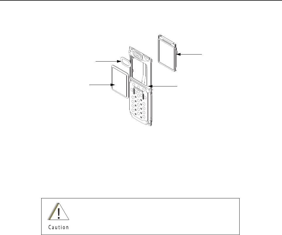
Disassembly/Reassembly Procedures: Serviceable Components of the Main Sub-Assemblies Sec 2: 8-25
8.8.7 Servicing Back Chassis Assembly (M) – Dual Display Version
Complete steps 8.7.1 through 8.7.5 of Section “8.7 Radio Disassembly” on page 2:8-12
Figure 8-34. Back Chassis Assembly (Dual Display Version)
NOTE: Take care not to damage the Color Display during disassembly.
8.8.7.1 Servicing Color Display
1. Disconnect the Back Chassis Flex from the back of the Color Display (44).
2. Gently pry the Color Display out of the Back Chassis Assembly (41) by using the Black Stick
against the white section of the frame (upper left corner at the back of the Color Display).
3. Remove any remnants of the Display's Pad if it does not come off completely with the Color
Display from the back Chassis Assembly.
4. Clean the area to ensure it is free of adhesive and debris once the Display is completely
removed.
5. Ensure there are no foreign material on the new Color Display or the Lens (42).
6. Remove the liner from the new Color Display and seat it into the Back Chassis Assembly.
7. Ensure the Display is oriented correctly and seated properly.
Take care not to damage the Back Chassis seal while
servicing the Back Chassis.
Color Display (44)
Back Chassis Assembly (41)
Speaker Seal (43)
Lens (42)

Sec 2: 8-26 Disassembly/Reassembly Procedures: Serviceable Components of the Main Sub-Assemblies
8.8.7.2 Servicing the main Lens
NOTE: Prior to Lens removal, Color Display must be removed (See Section 8.8.7.1 on
page 2:8-25).
1. Remove the main Lens (42) carefully and slowly with the Black Stick.
NOTE: To ease the breaking of the adhesive bond, place Back Chassis in freezer.
2. Clean the area once the Lens is completely removed to ensure it is free of adhesive and
debris.
3. Peel the liner off of the adhesive side of the new Lens and place it centered left to right in the
lens pocket of the back Chassis assembly. Bias it upwards against the horizontal surface.
4. Press the Lens down.
5. Ensure the adhesive shows no sign of air entrapments.
8.8.7.3 Servicing the Speaker Seal
NOTE: Speaker Seal (43) will be damaged during disassembly. Do not reuse.
1. Carefully scrape off the Speaker Seal (43) with the Black Stick without contacting the
Speaker.
2. Clean the area once the Speaker Seal is completely removed, to ensure it is free of adhesive
and debris.
3. Replace with a new Speaker Seal.
4. Peel the liner off and place the new Seal centered to the speaker and press onto the Back
Chassis.
NOTE: There are no other serviceable components on the Back Chassis Assembly.
Over prying may damage the lens.
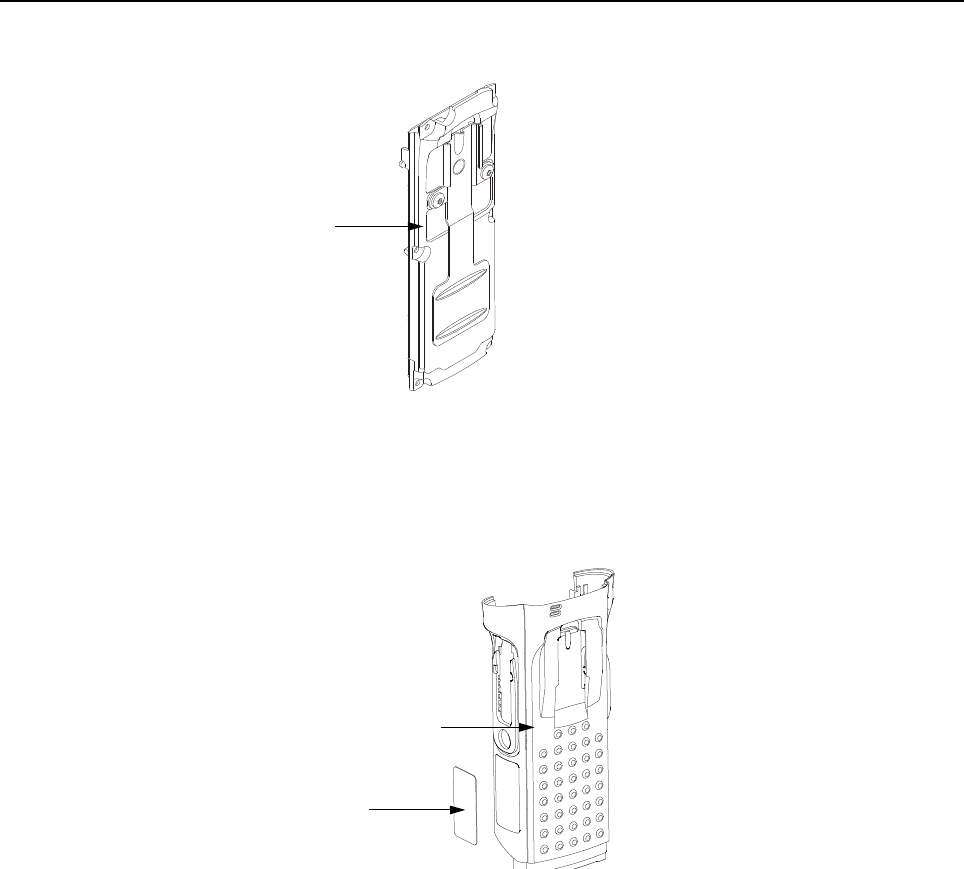
Disassembly/Reassembly Procedures: Serviceable Components of the Main Sub-Assemblies Sec 2: 8-27
8.8.8 Servicing Back Chassis Assembly (E) – Top Display Version
Figure 8-35. Back Chassis Assembly (Top Display Version)
NOTE: There are No serviceable Components on the Back Chassis Assembly.
8.8.9 Servicing Main Housing (D)/ Main Housing (L)
Figure 8-36. Main Housing Assembly
8.8.9.1 Blank/FM Label (2)
NOTE: There is no need to remove any components in order to service the Blank/FM Label
(2) or FM Label Label (46).
1. Scrape off the Blank/FM Label (2) or FM Label Label (46) with the Black Stick.
2. Clean the area once the label is completely removed to ensure it is free of adhesive and
debris.
3. Replace with a new label.
4. Remove the liner and place the label in the recess.
5. Press the label.
NOTE: There are No Other serviceable components on the Main Housing Assembly (D)/
Main Housing Assembly (L).
Back Chassis Assembly (17)
Blank/ FM Label (2)
Main Housing Assembly (1)
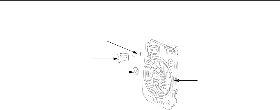
Sec 2: 8-28 Disassembly/Reassembly Procedures: Serviceable Components of the Main Sub-Assemblies
8.8.10 Servicing Speaker Module (B)
1. Complete steps 8.7.1 through 8.7.2 of Section “8.7 Radio Disassembly” on page 2:8-12.
Figure 8-37. Speaker Module
8.8.10.1 Servicing Port Seal and Port Seal Label
NOTE: Port Seal (20) and Port Seal Label (21) will be damaged during disassembly.
2. Remove the white Port Seal (20) and the black Port Seal Label (21) with the Black Stick.
3. Lift up the Port Seal Label carefully. Do not scratch the mating surface on the
Speaker Module (18).
4. Clean the area once both Seals are removed to ensure it is free of adhesive and debris.
5. Remove the backer of the white Port Seal and place it in the appropriate location on the
Speaker Module with a pair of flat tip tweezers. Ensure the seal is flat with no ripples, folds or
tears.
6. Remove the backer of the black Port Seal Label and place it in the appropriate location on the
Speaker Module with a pair of flat tip tweezers. Ensure the label is flat with no ripples or folds.
8.8.10.2 Servicing Microphone Membrane
NOTE: Disassembly the Microphone Membrane will damage it.
2. Carefully peel off the Microphone Membrane (19) from the Speaker Module (18).
3. Clean the area once the Microphone Membrane is removed to ensure it is free of adhesive or
debris. Ensure nothing comes in contact with the microphone while cleaning.
4. Remove the backer from the Microphone Membrane.
5. Carefully place the Microphone Membrane within the recess area on the Speaker Module.
Ensure the membrane is flat with no ripples or folds.
6. Press down firmly, applying 2-3 lbs. of force.
NOTE: There are No Other serviceable components on the Speaker Module (B).
Microphone Membrane (19)
Port Seal (20)
Port Seal Label (21)
Speaker Module (18)
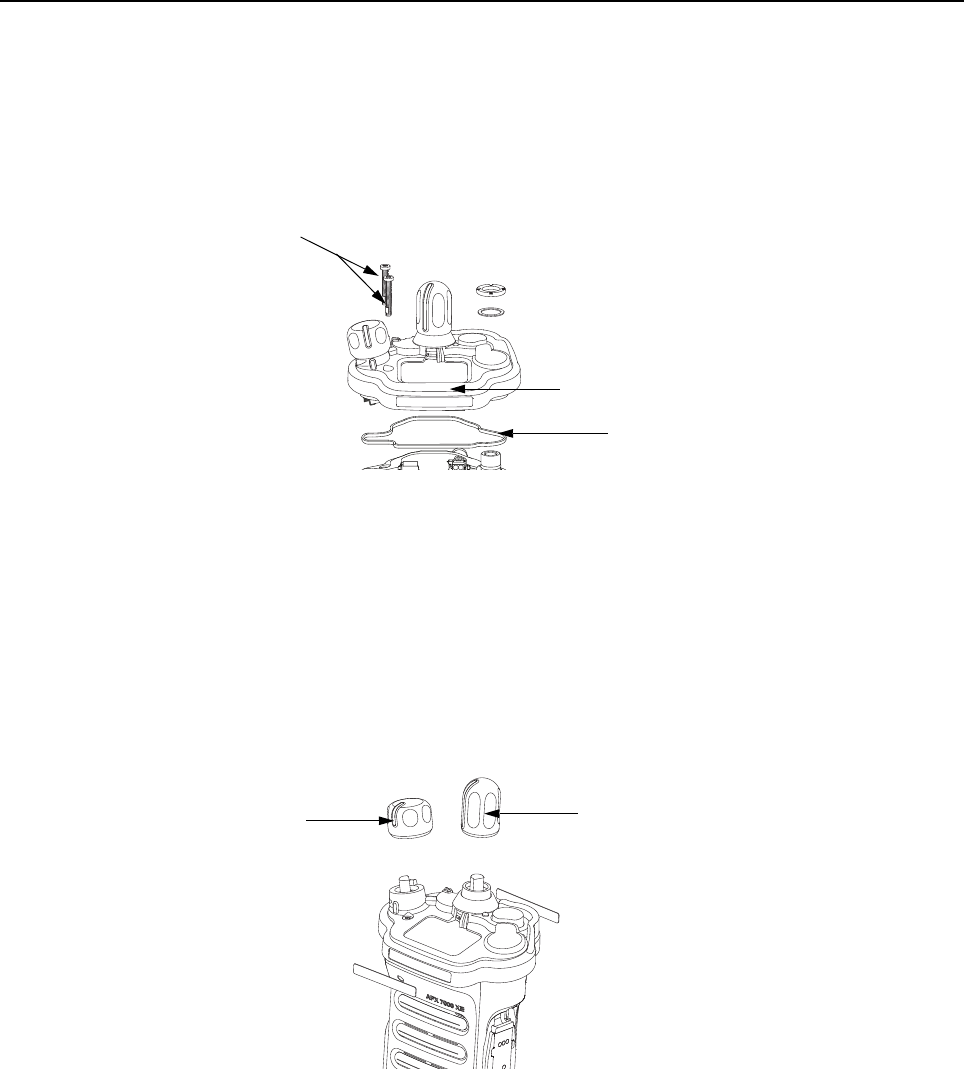
Disassembly/Reassembly Procedures: Radio Reassembly Sec 2: 8-29
8.9 Radio Reassembly
This section contains instructions for reassembling the radio.
8.9.1 Reassemble the Main Sub Assemblies
8.9.1.1 Assemble Top Control Assembly (J) to Main Chassis Assembly (N)
Figure 8-38. Control Top Bezel Assembly
1. Verify there are no surface irregularities such as scratches or indentations on both the Control
Top Main Seal Grove and the Seal's mating surface on the Main Chassis
Assembly (4). Also ensure that the Control Top Seal (14) and surrounding surfaces are free
of debris and other foreign material.
2. Verify Control Top Seal is properly seated into its groove and place Control Top Assembly
onto Main Chassis Assembly as shown in Figure 8-38.
3. Torque both screws with a Torx IP8 Bit and a torque Driver to 8 in-lbs.
8.9.1.2 Assemble Frequency and Volume Knobs Assembly (H)
Figure 8-39. Knobs Assembly
1. Align the D-shaped part of the Volume Shaft with the D-shape hole in the Volume Knob and
press the Volume Knob (12) into place.
Control Top Assembly (10)
Control Top Screws (26)
Control Top Seal (14)
Frequency Knob (13)
Volume Knob (12)
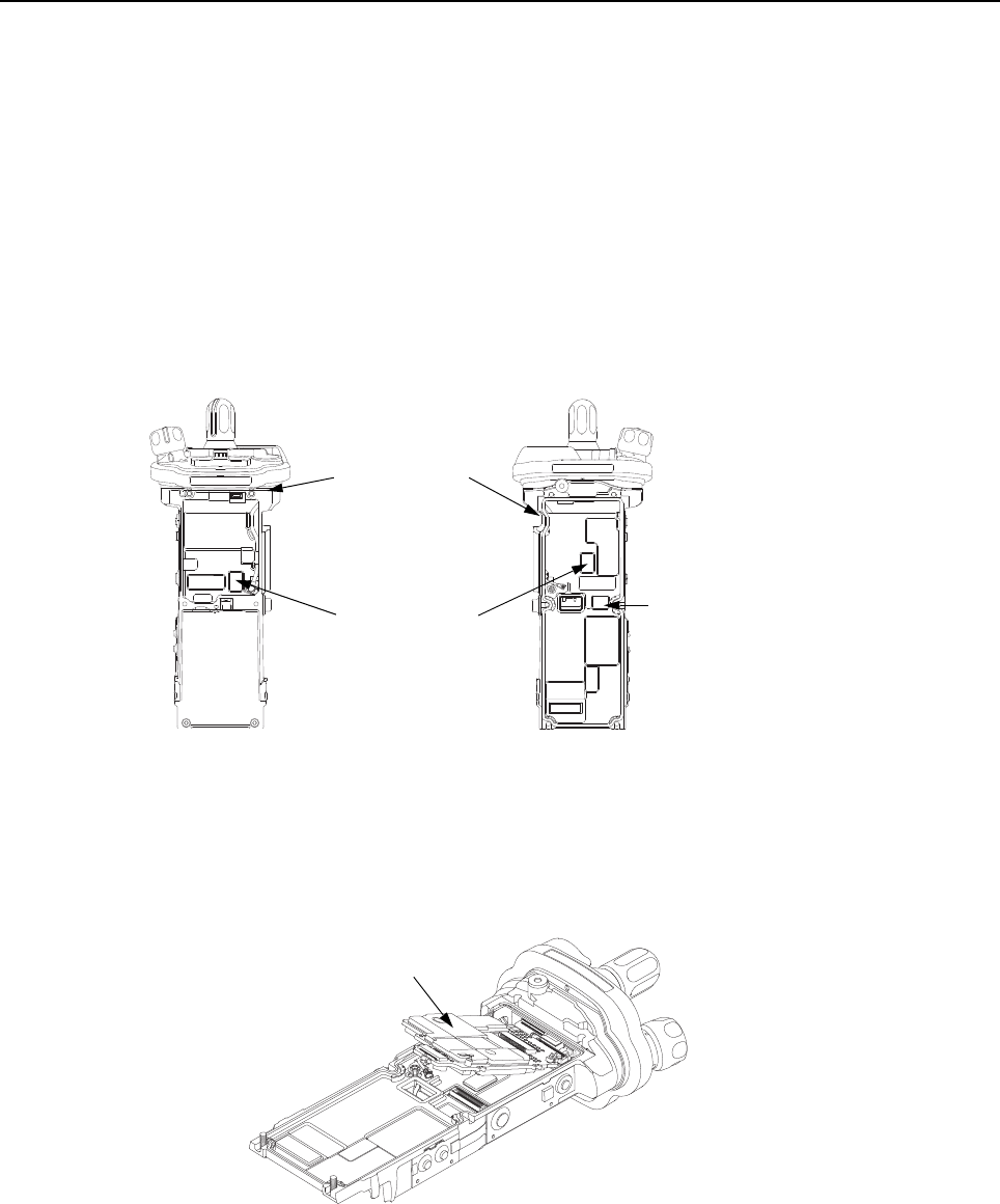
Sec 2: 8-30 Disassembly/Reassembly Procedures: Radio Reassembly
2. Align the D-shaped part of the Frequency Shaft with the D-shape hole in the
Frequency Knob (13) and press the Frequency Knob into place.
NOTE: Considerable force is needed to press the knobs into place. The use of a solid
surface may be required. If used, the surface should be covered with a rubbery
covering to prevent markings on the knobs.
8.9.1.3 Assemble VOCON Board Assembly (G, N)
1. Inspect the Main Chassis (4) sealing surfaces to make sure there is no surface irregularities
such as scratches or indentations. Clean any debris or other foreign material.
2. Inspect the two thermal pads (9) on the front and back of the unit along with the
Coin Cell Pad (8) to confirm pads are clean and free of debris as shown in Figure 8-40.
Figure 8-40. Inspect Pads
3. Orient the Main Chassis (4) with the Frequency Knob (13) on top. Insert the
VOCON Board Assembly (30/ 45) into the chassis starting at a 45° angle and rotate the board
into place. Ensure the control top flex is located below the PCB, and is not being pinched
between the PCB and the casting. See Figure 8-41.
Figure 8-41. Insert VOCON Board
Thermal Pads (9)
Sealing Surface
Coin Cell Pad (8)
VOCON Board Assembly (G, N)
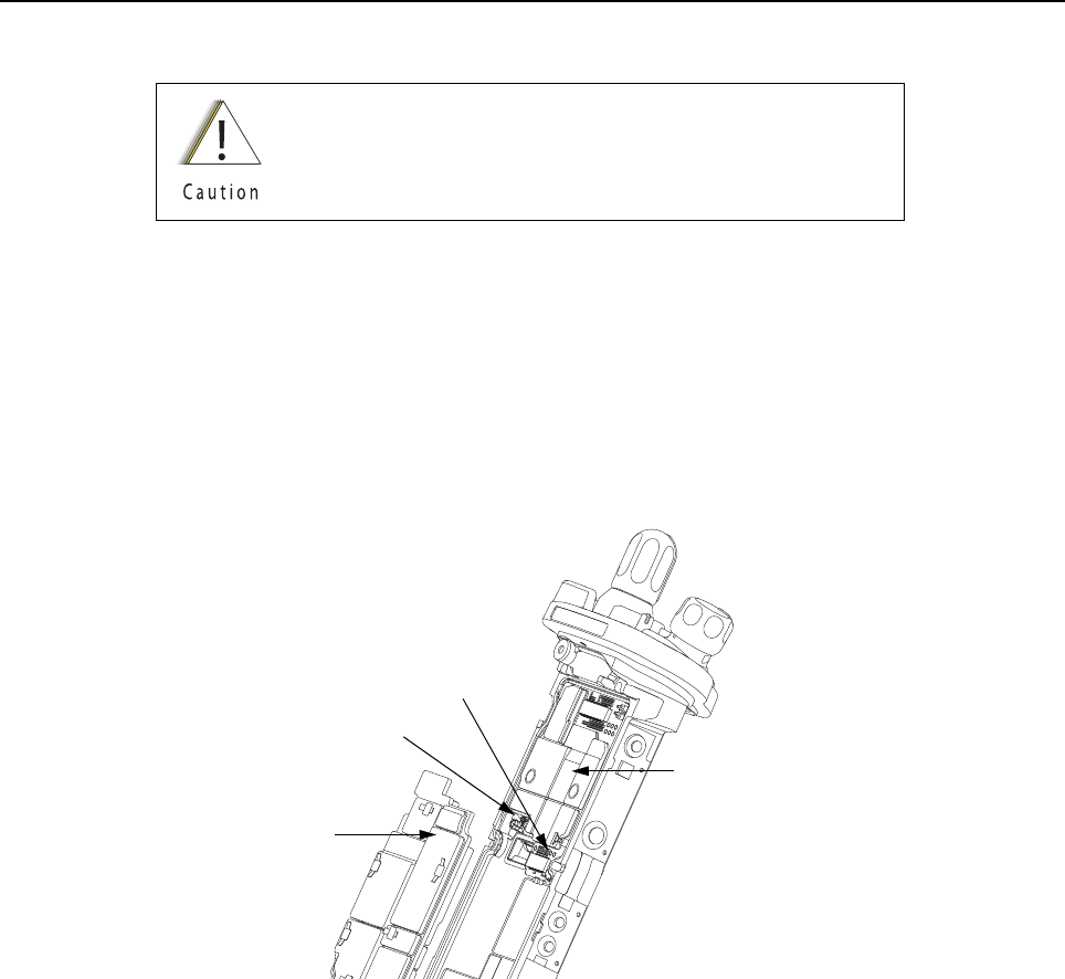
Disassembly/Reassembly Procedures: Radio Reassembly Sec 2: 8-31
8.9.1.4 Assemble RF Board Assembly (F)
1. Inspect the Battery Connector Seal (35) on the RF Board Assembly (F) for any damage or
debris. Replace seal if necessary.
2. Connect the small coaxial cable connector into the RF Board (32).
3. Connect the RF Board to the VOCON Board as shown in Figure 8-42.
NOTE: Do not connect the Antenna coax at this time. Front Housing Assembly (1) must be
snapped in place prior to connecting the coax.
Figure 8-42. Connect RF Board to VOCON Board
Always replace with new thermal pads. See Section “8.8.5.2
Thermal Pads” on page 2:8-24.
Connector
RF Board Assembly (32)
Small Coax Cable
VOCON Board
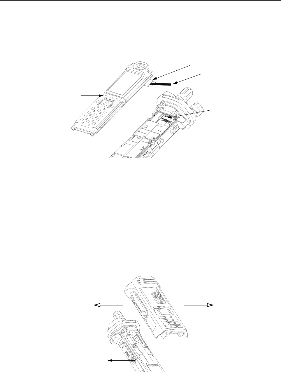
Sec 2: 8-32 Disassembly/Reassembly Procedures: Radio Reassembly
8.9.1.5 Assemble Back Chassis Assembly (E, M)
Dual Display version:
1. Inspect the Back Chassis Assembly seal for any debris or foreign material.
2. Connect the Back Chassis Flex to the VOCON board (N).
3. Set the Back Chassis Assembly (M) onto the Main Chassis Assembly (K).
Figure 8-43. Place Back Chassis
Top Display version:
1. Inspect the Back Chassis Assembly seal for any debris or foreign material.
2. Set the Back Chassis Assembly (E) onto the Main Chassis Assembly (K).
8.9.1.6 Assemble Main Housing Assembly (D, L)
1. Stretch the Main Housing Assembly (D, L) side walls outward with both hands just enough to
clear the Main Chassis (K) and place it onto the radio.
2. Ensure the top edge of the housing and the bottom edge of the control top are aligned as
shown in Figure 8-44.
3. Squeeze the Main Housing Assembly (D, L) and the Main Chassis Assembly (K) in the
battery area until the Main Housing Assembly fully snaps in place onto the Main Chassis
Assembly.
Figure 8-44. Place Housing into Main Chassis
Back Chassis Assembly (41)
Connector
Pull Belt
Black Stick
Stretch Outwards
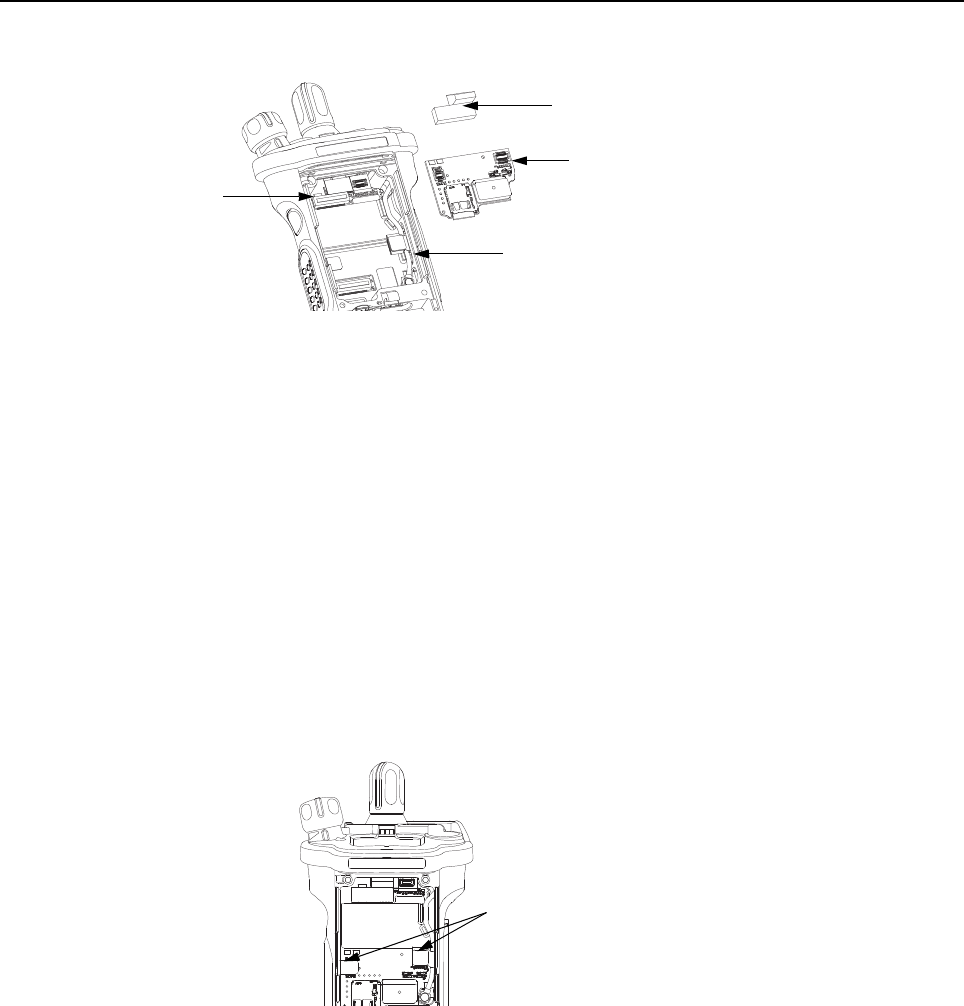
Disassembly/Reassembly Procedures: Radio Reassembly Sec 2: 8-33
8.9.1.7 Assemble Expansion Board Assembly (C)
Figure 8-45. Assemble Expansion Board Assembly
1. If the Control Top Assembly (J) or VOCON Board Assembly (G, N) was NOT removed skip to
step 2.
Connect the Control Top Flex to the VOCON Board Assembly as shown in Figure 8-45.
2. If the RF Board Assembly (F) was NOT removed, skip to step 4.
Carefully align the Antenna Coax Plug to the Coax Receptacle on the RF board Assembly (F)
and slide the plug in using the Black Stick. Ensure the universal connector flex is not caught
under the antenna coax cable.
3. Tuck in the Antenna Coax Cable into its grooves as shown in Figure 8-45.
4. Plug the Expansion Board Assembly (C) to the VOCON Board Assembly (G, N) as shown in
Figure 8-45. Make sure the connector is fully engaged.
5. Connect the two Flex Connectors to their pairing connectors on the right and left sides of the
Expansion Board Assembly as shown in Figure 8-46.
Figure 8-46. Insert Flex Connectors
6. If the radio is equipped with an Bluetooth Option Board Assembly skip this step. Install the
Connector Plug (27) by inserting it onto the Option Board Connector on the VOCON Board
Assembly as shown in Figure 8-45.
Flex Connectors
Expansion Board Assembly (36)
Connector Plug (27)
Antenna Coax Cable
Flex Connectors
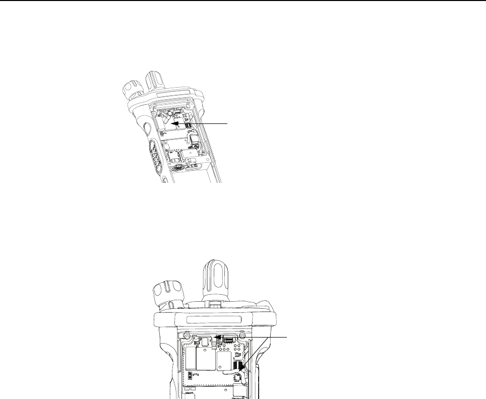
Sec 2: 8-34 Disassembly/Reassembly Procedures: Radio Reassembly
8.9.1.8 Assemble Bluetooth Option Board Assembly (if so equipped)
1. Connect the Bluetooth Option Board Assembly to the VOCON Board Assembly. Ensure it is
completely connected as shown in Figure 8-47.
Figure 8-47. Assemble Bluetooth Option Board
2. Rotate the Bluetooth Option Board locking levers till they slide under the chassis feature and
lock the option board in place. Levers should be fully rotated until they rest as shown in
Figure 8-48.
Figure 8-48. Lock Levers
Bluetooth Option Board
Levers at Lock Position

Disassembly/Reassembly Procedures: Radio Reassembly Sec 2: 8-35
8.9.1.9 Assemble Speaker Module (B)
1. Apply a thin film of Lubricant (Part Number 1110027B23) to the upper two corners of the
Main Chassis (4) in the Speaker Module (18) opening as shown in Figure 8-49. Ensure no
lubricant contaminates the gold pads or the microphone membrane (19).
Figure 8-49. Lubricate Main Chassis
NOTE: Avoid any lubricant to come in contact with any internal components.
2. Ensure the Seal is free from any debris or foreign material.
3. Align the Speaker Module's Pin feature located on the bottom edge directly below the
speaker, into the hole on the chassis hook feature.
4. Swing the Speaker Module down and firmly press the top side into the radio as shown in
Figure 8-50.
Figure 8-50. Insert Speaker Module
5. While holding the Speaker Module down, place the two top screws (23) into the their
respective holes and torque the screws to 10 in-lbs with an IP8 Torx Bit in a torque driver.
See Figure 8-51.
Do not touch the speaker cone or the Port Seal (20). Take
extra precaution to make sure neither the speaker nor the
breather pad is damaged.
Apply Lubricant
Speaker Cone
Port Seal (20)
Pin Feature
Chassis Hook Feature
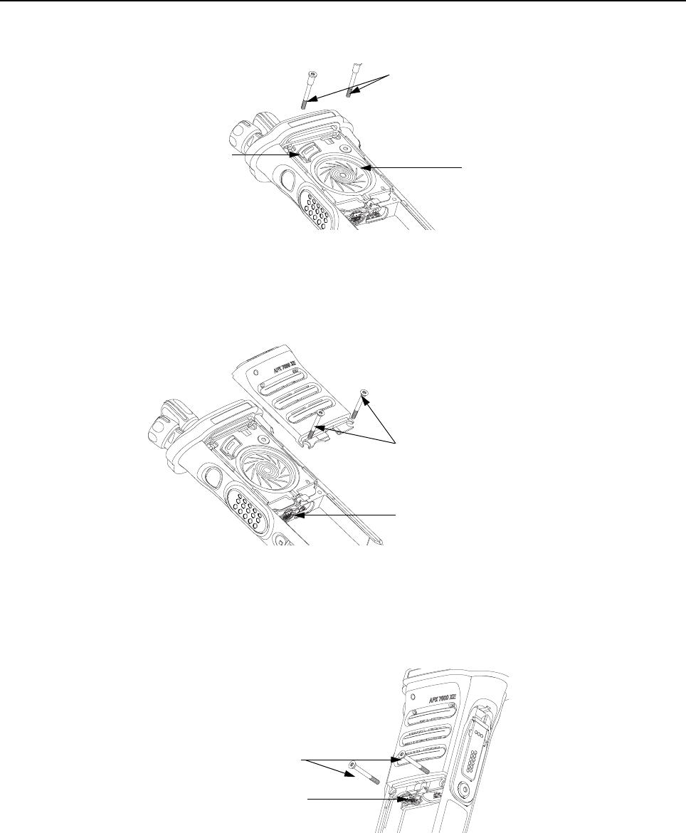
Sec 2: 8-36 Disassembly/Reassembly Procedures: Radio Reassembly
IMPORTANT: For proper sealing, Speaker Module (B) must be held down during the
torquing of the screws.
Figure 8-51. Insert Top Screws
8.9.1.10 Assemble Speaker Grille Assembly (A)
1. Install the Speaker Grille (A) by inserting the top lip under the control top bezel and rotating
the grille into place. See Figure 8-52.
Figure 8-52. Remove Center Screws
NOTE: Ensure the Memory Door (28) is in place and the memory door screw shaft is
aligned with the screw hole.
2. Insert the two center screws (24) and torque to 10 in-lbs. See Figure 8-53.
Figure 8-53. Insert Center Screws
Top Screws (23)
Port Seal (20)
Speaker Cone
Center Screws (24)
Memory Door (28)
Center Screws (24)
Memory Door (28)
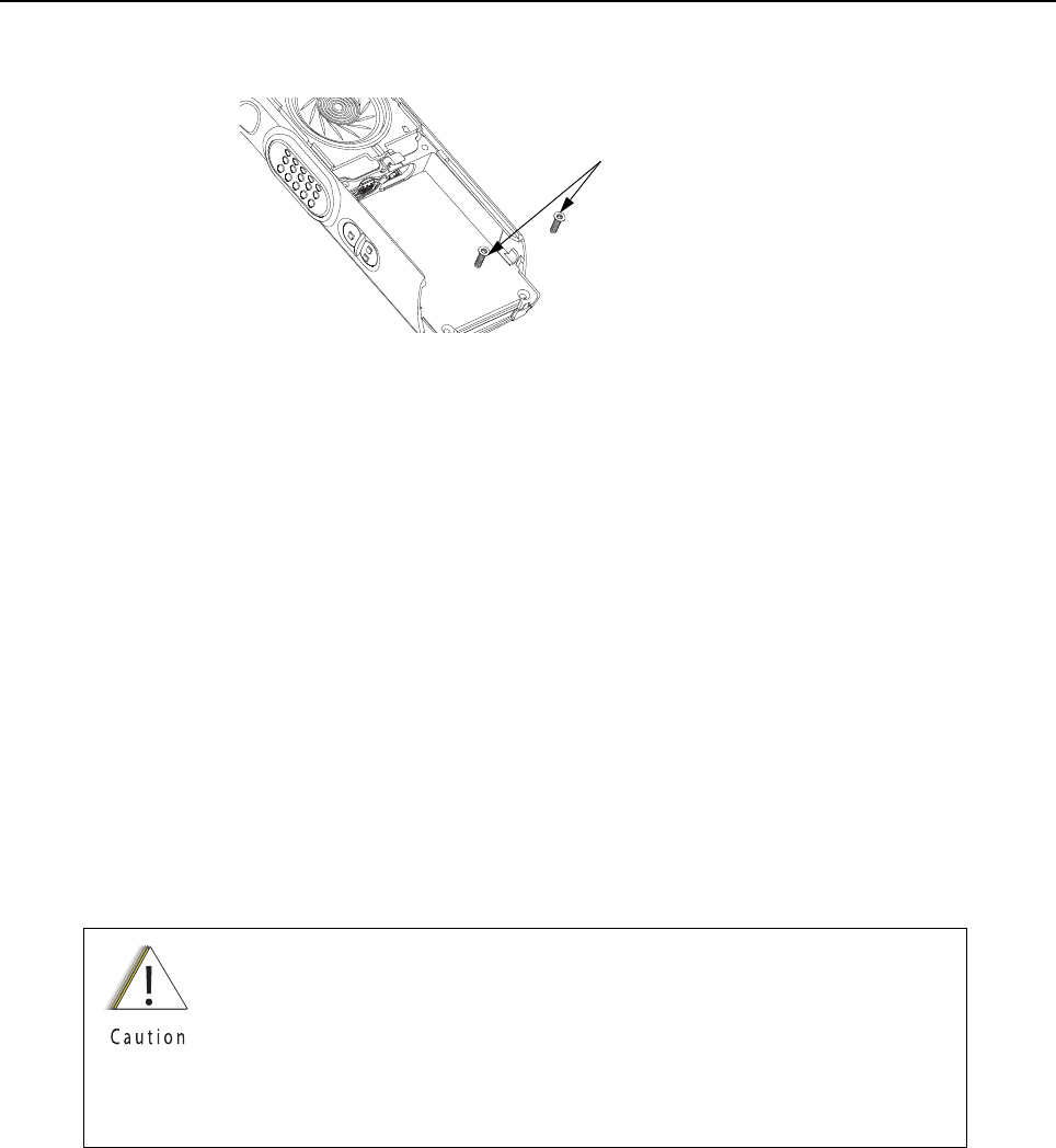
Disassembly/Reassembly Procedures: Ensuring Radio Submergibility Sec 2: 8-37
3. If removed, insert the two bottom screws (25) into the screw holes at the bottom of the radio
as shown in Figure 8-54., and torque to 10 in-lbs.
Figure 8-54. Insert Bottom Screws
NOTE: Refer to the appropriate section in this manual for reinstalling the antenna, battery,
or any other accessory that was previously connected or attached to the radio prior
to servicing.
8.10 Ensuring Radio Submergibility
This section discusses radio submergibility concerns, tests, and disassembly and reassembly of
ASTRO APX 7000XE radios.
8.10.1 Standards
ASTRO APX 7000XE radio models meet the stringent requirements of U. S. MIL-STD-810C, Method
512.1, Procedure I; MIL-STD-810D, Method 512.2, Procedure I; MIL-STD-810E, Method 512.3,
Procedure I; and MIL-STD-810F, Method 512.4, Procedure I, which require the radio to maintain
watertight integrity when immersed in six (6) feet of water for two hours.
8.10.2 Servicing
APX 7000XE radios shipped from the Motorola Solutions factory have passed vacuum testing and
should not be disassembled. If disassembly is necessary, refer to qualified service personnel and
service shops capable of restoring the watertight integrity of the radio.
8.10.3 Water Exposure
If the radio is exposed to water, shake the radio to remove the excess water from the speaker grille
and microphone ports areas before operating; otherwise, the sound may be distorted until the water
has evaporated, or is dislodged from these areas.
It is strongly recommended that maintenance of the radio be deferred to
qualified service personnel and service shops. This is of paramount
importance as irreparable damage to the radio can result from service by
unauthorized persons. If disassembly is necessary, unauthorized attempts to
repair the radio may void any existing warranties or extended performance
agreements with Motorola. It is also recommended that submergibility be
checked annually by qualified service personnel.
Bottom Screws (25)
Sec 2: 8-38 Disassembly/Reassembly Procedures: Ensuring Radio Submergibility
8.10.4 Specialized Test Equipment
This section summarizes the specialized test equipment necessary for testing the integrity of ASTRO
APX 7000XE radios.
To ensure that the radio is truly a watertight unit, special testing, test procedures, and specialized
test equipment are required. The special testing involves a vacuum check of the radio and pressure
testing (troubleshooting) for water leaks if the vacuum check fails. The specialized test equipment is
needed to perform the vacuum check and pressure testing, if required.
8.10.4.1 Vacuum Pump Kit NLN9839_
The Vacuum Pump Kit includes a Vacuum Pump with gauge and a Vacuum Hose. The Vacuum
Adapter (p/n 66009259001) which connects the vacuum pump to the radio, must be ordered
separately.
8.10.4.2 Pressure Pump Kit NTN4265_
The Pressure Pump Kit includes a Pressure Pump with gauge and a Pressure Hose. As with the
Vacuum Pump Kit above, the Vacuum Adapter connects the pressure pump to the radio.
8.10.5 Disassembly
Disassemble the radio according to Section “8.7 Radio Disassembly” on page 2:8-12.
8.10.6 Reassembly
To reassemble the radio:
1. Inspect the seal on the Back Chassis Assembly (E, M) for any damage or foreign material.
2. Inspect the seal on the Speaker Module (B) for any damage or foreign material.
3. Inspect the Battery Connector Seal (35) on the RF Board Assembly (F) for any damage.
4. Inspect the mating seal surfaces on the Main Chassis (4) for all of the above seals for
damage or foreign material that might prevent the seals from sealing properly.
Continue reassembling the radio according to Section “8.9 Radio Reassembly” on page 2:8-29.
Tighten all hardware that was loosened or removed.
8.10.7 Vacuum Test
The Vacuum Test uses a Vacuum Pump to create a negative pressure condition inside the radio. The
gauge measures this pressure and is used to monitor any pressure changes in the radio. A properly
sealed, watertight radio should have minimal change in pressure during the test.
Before starting the vacuum test:
• Remove the battery and antenna.
• Remove the Universal Connector Cover (38) or any other accessories to expose the universal
connector.
NOTE: Refer to the exploded view diagrams and parts lists found in “Chapter 10: Exploded Views
and Parts Lists” on page 2:10-1.
Do not reassemble the radio without first performing the
following preliminary inspection procedure.
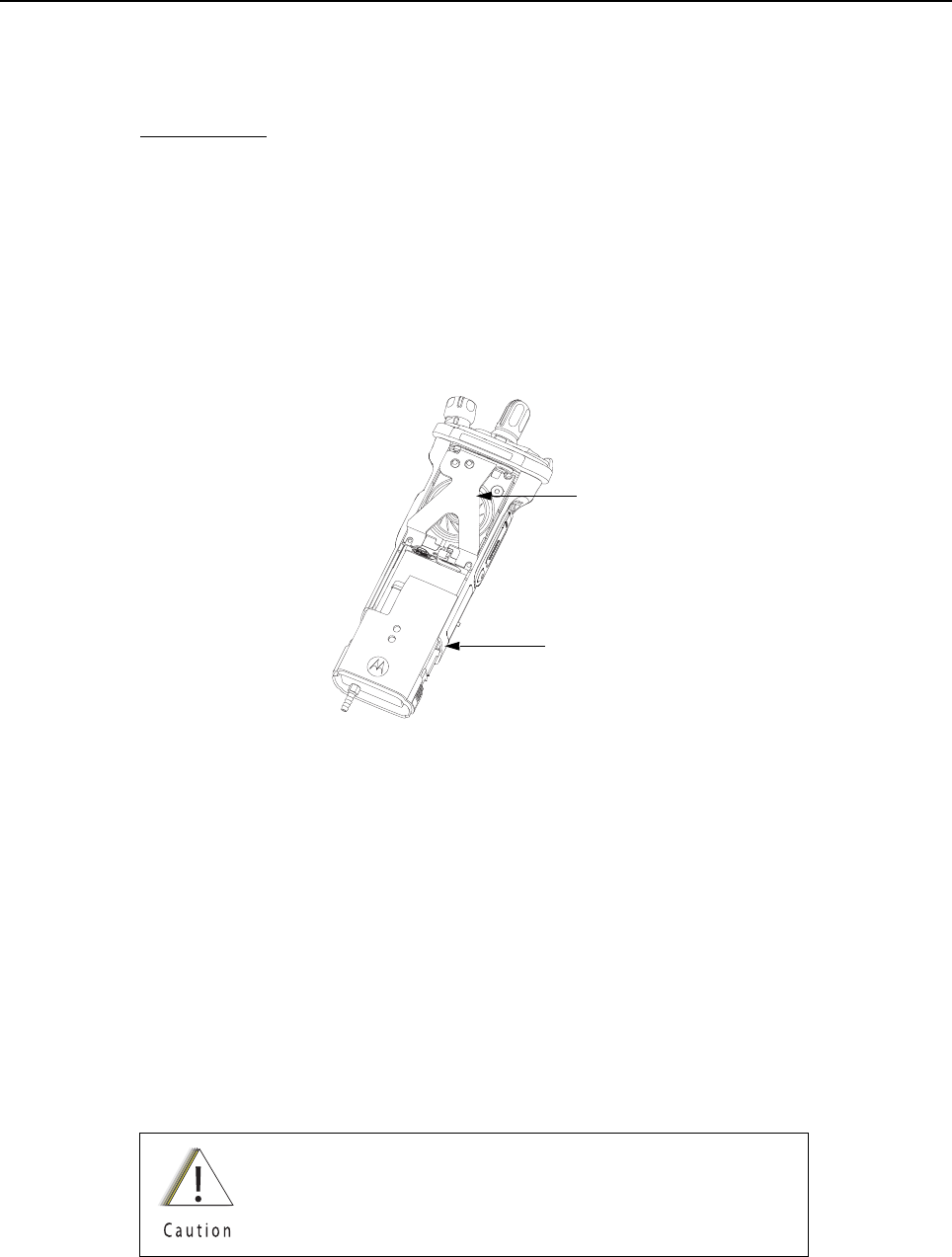
Disassembly/Reassembly Procedures: Ensuring Radio Submergibility Sec 2: 8-39
8.10.7.1 Vacuum Tool Setup
1. Attach one end of the hose to the Vacuum Pump. Attach the other side of the hose to the
Vacuum Adapter.
2. Tool Leak Test:
i. Block the open end of the Vacuum Adapter.
ii. Pull the knob on the Vacuum Pump to create vacuum.
iii. Pump at least 15 inHg.
iv. Watch the gauge for a minute. If there is any loss of vacuum, repair or replace the tool.
3. Ensure that the seal is attached to the Vacuum Adapter.
8.10.7.2 Attaching Grille Eliminator
Figure 8-55. Attaching Grille Eliminator
1. Remove the Speaker Grille (22) by following steps in Section 8.7.1 on page 2:8-12 and
remove the Memory Door (28).
2. Slide the top of the Grille Eliminator under the Control Top Bezel (10) and swing it down
towards the radio. Secure the Grille Eliminator using the two center screws (24) with a torque
of 10 in lbs. See Figure 8-55.
8.10.7.3 Test Procedure
1. Attach the Vacuum Adapter onto the radio in the same manner as a radio battery. Ensure
both latches are clicked into place.
2. Place the radio on a flat surface with the Grille Eliminator facing upward.
3. Pull the knob on the Vacuum Pump to create vacuum. The vacuum test pressure should be
between 5–7 inHg.
Ensure that the vacuum pressure NEVER exceeds 7 inHg.
The radio has pressure sensitive components that can be
damaged if the pressure exceeds this limit.
Grille Eliminator
Vacuum Adapter

Sec 2: 8-40 Disassembly/Reassembly Procedures: Ensuring Radio Submergibility
4. Observe the gauge for approximately 2 minutes.
• If the needle falls less than 2 inHg, the radio passes the vacuum test.
i. Remove the Grille Eliminator
ii. Visually inspect the Port Seal Label (21) for proper adhesion to the
Speaker Module (18). Make sure there are no wrinkles or cuts to the material that would
cause a leak. Replace seal if damaged. (See appropriate section for servicing the
seals).
iii. If the seal passes this inspection, this radio is approved for submergibility. No additional
testing is required.
iv. Replace the Speaker Grille Assembly (22) and Memory Door (28) as described in the
reassembly procedures.
• If the needle falls more than 2 inHg, the radio fails the vacuum test and the radio might
leak if submerged. Additional troubleshooting of the radio is required.
i. Keep the Grille Eliminator and Vacuum Adapter on but remove the Vacuum Pump from
the Vacuum Adapter.
ii. Goto Section “8.10.8 Pressure Test (using NTN4265_)” on page 2:8-40.
8.10.8 Pressure Test (using NTN4265_)
Pressure testing the radio is necessary only if the radio has failed the vacuum test. Do not perform
the pressure test until the vacuum test has been completed. Pressure testing involves creating a
positive pressure condition inside the radio, submerging the radio in water, and observing the radio
for a stream of bubbles (leak). Since all areas of the radio are being checked, observe the entire unit
carefully for the possibility of multiple leaks before completing this test.
NOTES:When Radio is placed under the water there will be some air trapped which will be released.
This is not a failure.
Refer to the exploded view diagrams and parts lists found in “Chapter 10: Exploded Views
and Parts Lists” on page 2:10-1.
The Grille Eliminator must be used to conduct the pressure test:
If the radio is still set up from vacuum test, skip steps 1 through 4.
To conduct the pressure test:
1. Remove the Speaker Grille (22) by following the steps from Section “8.7.1 Removal of the
Speaker Grille Assemblies (A)” on page 2:8-12 and remove the Memory Door (28).
2. Slide the top of the Grille Eliminator under the Control Top Bezel (10) and swing it down
towards the radio. Secure the Grille Eliminator using the two center screws (24) with a torque
of 10 in lbs. See Figure 8-55.
3. Ensure that an seal is attached to the Vacuum Adapter.
4. Attach the Vacuum Adapter onto the radio in the same manner as a radio battery. Ensure
both the latches are clicked into place.
5. Attach one end of the hose to the Pressure Pump. Attach the other side of the hose to the
Vacuum Adapter.
Disassembly/Reassembly Procedures: Ensuring Radio Submergibility Sec 2: 8-41
6. Operate the pump until the gauge reads approximately 1 psig.
7. Maintain the pressure around 1 psig and submerge the radio into a water-filled container.
8. Watch for any continuous series of bubbles. A steady stream of bubbles indicates a sign of
leakage.
NOTE: Some accumulation of air may be entrapped in the main housing which may cause a false
diagnosis of a leak. Ensure there is a steady stream of bubbles before concluding there is a
leak.
9. Note all of the seal areas that show signs of leakage. Rotate the radio to view all sides to
pinpoint the problem(s) to one (or more) of the following areas:
• Seal Interfaces
• Speaker Assembly
• Battery Connector Seal
• Main Chassis, including the Control Top
• Back Chassis
10. Remove the radio from the water container and dry the radio thoroughly. Be especially careful
to dry the area around the Memory Door (28).
11. With the Radio in an upright position and Control Top up, remove the vacuum adapter by
squeezing the release latches, and pulling the adapter down and away from the radio.
12. Ensure the area around the Memory Door (28) opening is dry.
13. Dry the remainder of the radio and remove the Grille Eliminator.
14. See “8.10.9: Troubleshooting Leak Areas” on page 2:8-42.
Pressure must remain between 0.5 psig and 1.5 psig.
Pressure lower then 0.5 psig may allow water into the radio,
which will damage the radio.
Ensure that the pressure NEVER exceeds 1.5 psig. The radio
has pressure sensitive components that can be damaged if
the pressure exceeds this limit.
To avoid equipment damage, keep the area around the
memory card opening dry to prevent water from entering the
radio.

Sec 2: 8-42 Disassembly/Reassembly Procedures: Ensuring Radio Submergibility
8.10.9 Troubleshooting Leak Areas
Before repairing any leak, first read all of the steps within the applicable section. This will help to
eliminate unnecessary disassembly and reassembly of a radio with multiple leaks. Troubleshoot only
the faulty seal areas listed in “8.10.8: Pressure Test (using NTN4265_)” on page 2:8-40 and, when
multiple leaks exist, in the order listed.
NOTES:All disassembly and reassembly methods can be found in Section 8.7. and Section 8.9.
If in the field, water is found around the battery leads, the O-ring on the Battery should be
inspected and replaced if needed.
8.10.9.1 Seal Interfaces
• If leak occurs at one or more of the seal interfaces, disassembly of the component(s) and
inspection of the interfaces to determine if there is any damage. If no damage is observed,
re-assemble the radio as directed.
• If damage has occurred, replacement parts will be needed.
8.10.9.2 Speaker Module
• If leak occurs through the Microphone Membrane (19) or the Port Seal (20), replace these
items.
• If leak occurs elsewhere on the Speaker Module (B), the module will need to be replaced.
8.10.9.3 Battery Contact Seal
• If leak occurs due to damage to the Battery Connector Seal (35), it will need to be replaced.
8.10.9.4 Back Chassis
• If leak occurs elsewhere on the Back Chassis (E/M), it will need to be replaced.
8.10.9.5 Control Top
• If leak occurs through the antenna or the Control Top Seal (14), replace it.
• If leak occurs elsewhere on the Control Top Assembly (J), it will need to be replaced.
8.10.9.6 Main Chassis
• If leak occurs on the Back Chassis (E/M), it will need to be replaced.

Chapter 9 Basic Troubleshooting
This section of the manual contains troubleshooting charts and error codes that will help you to
isolate a problem. Level one and two troubleshooting will support only radio alignment,
programming, battery replacement, and knob replacement, and circuit board replacement.
Component-level service information can be found in the “ASTRO APX 7000/ APX 7000XE Portable
Radios Detailed Service Manual,” Motorola publication number 6875961M01.
9.1 Power-Up Error Codes
When the radio is turned on (power-up), the radio performs self-tests to determine if its basic
electronics and software are in working order. Problems detected during these tests are presented
as error codes on the radio’s display. For non-display radios, the problem will be presented at
power-up by a single, low-frequency tone. The radio should be sent to the depot if cycling power and
reprogramming the code plug do not solve the problem. The presence of an error should prompt the
user that a problem exists and that a service technician should be contacted.
Self-test errors are classified as either fatal or non-fatal. Fatal errors will inhibit user operation;
non-fatal errors will not. Use Table 9-1 to aid in understanding particular power-up error code
displays.
Table 9-1. Power-Up Error Code Displays
Error
Code Description Corrective Action
01/02 FLASH ROM Codeplug Checksum Non-Fatal Error Reprogram the codeplug
01/12 Security Partition Checksum Non-Fatal Error Send radio to depot
01/81 Host ROM Checksum Fatal Error Send radio to depot
01/82 FLASH ROM Codeplug Checksum Fatal Error Reprogram the codeplug
01/84 External EEPROM Blank (or SLIC failure) Fatal Error Send radio to depot
01/88 External RAM Fatal Error – Note: Not a checksum failure Send radio to depot
01/90 General Hardware Failure Fatal Error Turn the radio off, then on
01/92 Security Partition Checksum Fatal Error Send radio to depot
01/93 FLASHport Authentication Code Failure Send radio to depot
01/94 Internal EEPROM Blank Fatal Error. Send radio to depot
01/98 Internal RAM Fail Fatal Error Send radio to depot
01/A0 ABACUS Tune Failure Fatal Error Send radio to depot
01/A2 Tuning Codeplug Checksum Fatal Error Send radio to depot
02/81 DSP ROM Checksum Fatal Error Send radio to depot
02/88 DSP RAM Fatal Error – Note: Not a checksum failure Turn the radio off, then on

Sec 2: 9-2 Basic Troubleshooting: Operational Error Codes
9.2 Operational Error Codes
During radio operation, the radio performs dynamic tests to determine if the radio is working properly.
Problems detected during these tests are presented as error codes on the radio’s display. The
presence of an error code should prompt a user that a problem exists and that a service technician
should be contacted. Use Table 9-2 to aid in understanding particular operational error codes.
9.3 Receiver Troubleshooting
Table 9-3 lists the possible causes of, and corrections for, receiver problems.
02/90 General DSP Hardware Failure (DSP startup message not
received correctly)
Turn the radio off, then on
09/10 Secure Hardware Error Turn the radio off, then on
09/90 Secure Hardware Fatal Error Turn the radio off, then on
Note: If the corrective action does not fix the failure, send the radio to the depot.
Table 9-2. Operational Error Code Displays
Error Code Description Corrective Action
FAIL 001 Synthesizer Out-of-Lock 1. Reprogram external codeplug
2. Send radio to depot
FAIL 002 Selected Mode/Zone Codeplug
Checksum Error
Reprogram external codeplug
Table 9-3. Receiver Troubleshooting Chart
Symptom Possible Cause Correction or Test
(Measurements at Room Temperature)
Radio Dead; Display Does Not
Turn On
1. Dead Battery Replace with charged battery
2. Blown Fuse Send radio to depot
3. On/Off Switch
4. Regulators
Radio Dead; Display
Turns On
1. VOCON Board Send radio to depot
2. RF Board
3. Expander Board
Table 9-1. Power-Up Error Code Displays (Continued)
Error
Code Description Corrective Action

Basic Troubleshooting: Transmitter Troubleshooting Sec 2: 9-3
9.4 Transmitter Troubleshooting
Table 9-4 lists the possible causes of, and corrections for, transmitter problems.
Radio On; Front Display Off High operating
temperature (above
80°C)
Allow radio to return to normal operating
temperature.
No Receive Audio, or Receiver
Does Not Unmute
Programming 1. Check if transmitted signal matches the
receiver configuration (PL, DPL, etc.)
2. Check if radio able to unmute with monitor
function enabled
Audio Distorted or Not Loud
Enough
Synthesizer Not On
Frequency
Check synthesizer frequency by measuring the
transmitter frequency; realign if off by more than
±1000 Hz
RF Sensitivity Poor 1. Synthesizer Not On
Frequency
Check synthesizer frequency by measuring the
transmitter frequency; realign if off by more than
±1000 Hz
2. Antenna Switch/
Connector
Send radio to depot
3. Receiver Front-
End Tuning
Check RF front-end tuning for optimum sensitivity
using the tuner
Radio Will Not Turn Off VOCON Board Send radio to depot
Table 9-4. Transmitter Troubleshooting Chart
Symptom Possible Cause Correction or Test (Measurements
Taken at Room Temperature)
No RF Power Out 1. TX Power Level or Frequency Check TX power level and frequency
programming (from tuner)
2. No Injection To Power
Amplifier
Send radio to depot
3. Antenna Switch/Connector
No Modulation;
Distorted Modulation
1. Programming Check deviation and compensation
settings using the tuner
2. VOCON Board Send radio to depot
Bad Microphone Sensitivity 1. Check Deviation and
Compensation
Realign if necessary
2. Microphone Send radio to depot
Table 9-3. Receiver Troubleshooting Chart (Continued)
Symptom Possible Cause Correction or Test
(Measurements at Room Temperature)
Sec 2: 9-4 Basic Troubleshooting: Encryption Troubleshooting
9.5 Encryption Troubleshooting
Table 9-5 lists the possible causes of, and corrections for, encryption problems.
9.6 Bluetooth Option / Expansion Board Troubleshooting
Table 9-6 lists the possible causes of, and corrections for, Bluetooth Option / Expansion Board
problems.
No/Low signaling
(PL, DPL, MDC)
1. Programming Check programming
2. VOCON Board Send radio to depot
Cannot Set Deviation
Balance
RF Board Send radio to depot
Table 9-5. Encryption Troubleshooting Chart
Symptom Possible Cause Corrective Action
No “KEYLOAD” on Radio Display When
Keyloading Cable is Attached to the Radio
Side Connector
1. Defective Keyload Cable Send radio to depot
2. Defective Radio
Keyloader Displays “FAIL” 1. Wrong Keyloader Type Use correct keyloader
type. Refer to Keyloader
User Guide for more
information
2. Bad Keyloader Try another keyloader
3. Defective Radio Send radio to depot
Table 9-6. Bluetooth Option/Expansion Board Troubleshooting Chart
Message Displayed Possible Cause Corrective Action
Hardware board absent Bluetooth Option / Expansion Board is not
present on the radio and feature is enabled by a
code plug.
Send radio to depot
Hardware board mismatch When an option / expansion board feature is
enabled in code plug, but the board (EB or OB)
does not have corresponding capability.
Send radio to depot
Hardware board failed Displayed if the board Deenumerated,
Enumeration timed out, Option board device
initialized with a Fatal Error.
Reset the radio. If this
persists, send radio to the
depot
Table 9-4. Transmitter Troubleshooting Chart (Continued)
Symptom Possible Cause Correction or Test (Measurements
Taken at Room Temperature)

Basic Troubleshooting: Bluetooth Troubleshooting Sec 2: 9-5
9.7 Bluetooth Troubleshooting
Table 9-7 lists the possible causes of, and corrections for, bluetooth problems.
Update failed Please reset Bluetooth Option / Expansion board firmware
update fails.
Reset radio. if this
persists, send radio to the
depot
Table 9-7. Bluetooth Troubleshooting Chart
Message Displayed Possible Cause Corrective Action
Non_Audio dev connect failed /
Audio device connect failed
Displayed when the accessory fails to connect
after pairing.
Clear all pairing
information and try to pair
and connect.
Bluetooth pairing failed Accessory and Radio failed to pair through MPP/
NFC.
Retry pairing accessory
with Radio.
Clear all BT devices failed Radio was unable to clear information of all the
accessories that are paired and/or connected.
Reset the radio.
Bluetooth on failed Option Board is in an unknown state and is
unable to process the request for Bluetooth ON.
Reset the radio. If this
continues, send radio to
the depot.
Table 9-6. Bluetooth Option/Expansion Board Troubleshooting Chart (Continued)
Message Displayed Possible Cause Corrective Action

Sec 2: 9-6 Basic Troubleshooting: Bluetooth Troubleshooting
Notes

Exploded Views and Parts Lists: Sec 2: 10-1
Chapter 10 Exploded Views and Parts Lists
This chapter contains exploded views and associated parts lists for the ASTRO APX 7000XE digital portable radios. The following table lists the exploded views for the APX 7000XE radio in different configurations:
Table 10-1. APX 7000XE Exploded Views
View Page
APX 7000XE Top Display Exploded View 2:10-2
APX 7000XE Dual Display Exploded View 2:10-4

Sec 2: 10-2 Exploded Views and Parts Lists: APX 7000XE Top Display Exploded View
10.1 APX 7000XE Top Display Exploded View
Figure 10-1. APX 7000XE Top Display Exploded View
1
2
3
8
33 34
7
99
28
25
4
5
38
30
35
31
32
17
39
11 6
14
10
13
15
16
26
12
11
27
37
23
18 19
20
36
21
24
22
29
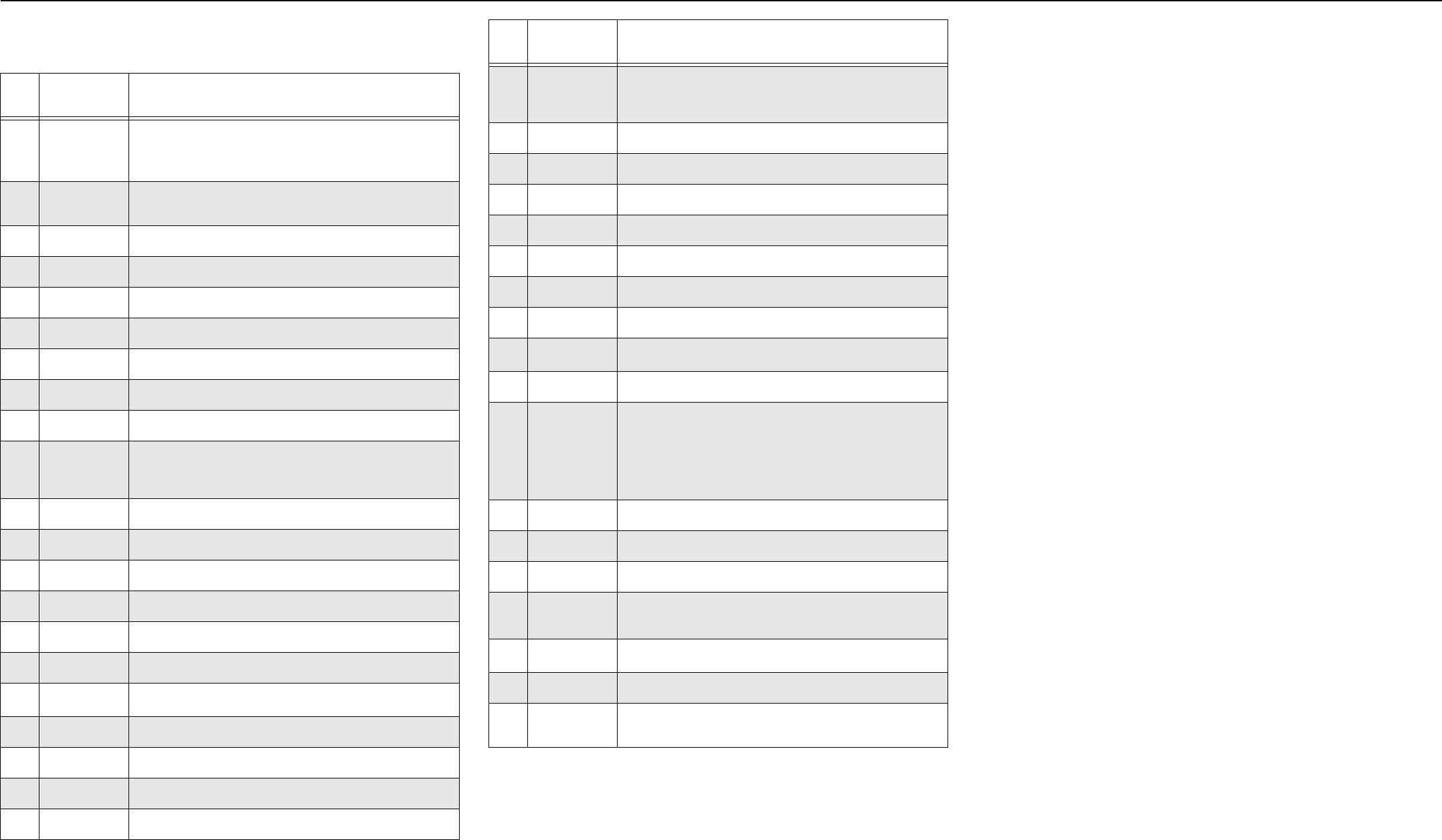
Exploded Views and Parts Lists: APX 7000XE Top Display Exploded View Parts List Sec 2: 10-3
10.2 APX 7000XE Top Display Exploded View Parts
List
NOTE:
1. HIGH IMPACT GREEN and PUBLIC SAFETY YELLOW Colored Housings can be serviced in
the depot and can be ordered via AAD.
2. See Table 10-2."Compatibility Table” on page 2:10-6
3. Radios installed with the Option Board Kit NNTN8160_ do not have the connector plug
(32009064001).
4. With TI Chipset.
Item
No.
Motorola Part
Number Description
1 15009584001
150095840031
150095840021
Housing, Assembly Black
Housing, Assembly Impact Green
Housing, Assembly Safety Yellow
23385836D09
3385836D08
Label, Blank, Top Display
Label, FM, Top Display (where applicable)
3 38009295002 Grip, Rubber, Insert
401009304020 Assy, Main, Chassis
5 3275002C02 Seal, Membrane, Microphone
63275033C01 O-ring, Antenna Main
7 39711892H01 Contact, Chassis Ground
8 7505316J16 Pad, Coin Cell Battery
9 7575218H01 Pad (x2), Thermal, Exp & VOCON Board
10 01009506007
01009506008
01009506009
Control Top, Black
Control Top, Safety Yellow
Control Top, Impact Green
11 33009276001 Label, Control Top (x2)
12 36009258001 Knob, Volume
13 36009257001 Knob, Frequency
14 3275377H01 Seal, Control Top
15 0400129054 Washer, Lock Antenna
16 0275891B01 Nut, Spanner, Antenna
17 NHN7004_2Sub-Assembly, Back Chassis, Top Display
18 NHN7002_ Module, Speaker
19 3275002C02 Seal, Membrane, Microphone
20 3271819H01 Seal, Port
21 5475160H01 Label, Seal, Port
22 NHN7051_
NHN7052_
NHN7053_
Grille, Speaker Kit, Impact Green
Grille, Speaker Kit, Safety Yellow
Grille, Speaker Kit, Black
23 0375962B01 Screw (x2) M2.5 x 0.45, 30.10 LG
24 0375962B02 Screw (x2) M2.5 x 0.45, 24.45 LG
25 0375962B03 Screw (x2) M2.5 x 0.45, 9.2 LG
26 03009357001 Screw, Control Top (M2.5 x 0.45 x 18 )
27 32009064001 Plug, Support, Connector
28 3275882B01 Door, Seal, Memory
29 3875126H01 Cap, Chassis Boss, Universal Connector
30 MNCN6203_2Assy, VOCON Board, Top Display
31 6003710K08 Battery, Backup, Coincell
32 MNUR4001_
MNUS4000_
MNUT4000_
MNUS4002_
MNUT4004_
MNUE7367_
Assembly, RF Board (7–800/VHF)
Assembly, RF Board (7–800/UHF1)
Assembly, RF Board (UHF1/VHF)
Assembly, RF Board (7–800/UHF2)
Assembly, RF Board (UHF2/VHF)
Assembly, RF Board (UHF1/UHF2)
33 3275623B02 Pad, Thermal, Outer
34 75009299001 Pad, Thermal, Inner
35 3271829H01 Seal, Connector, Battery
36 MHLN6977_
MHLN7035_4
Assy, Board, Expansion
373NNTN8160_ Bluetooth Upgrade Kit (where applicable)
38 1575250H01 Cover, Connector, Universal Connector
39 1575356H01 Cover, Clip, Belt
(See Appendix A"Accessories” on page 3:A-1)
Item
No.
Motorola Part
Number Description
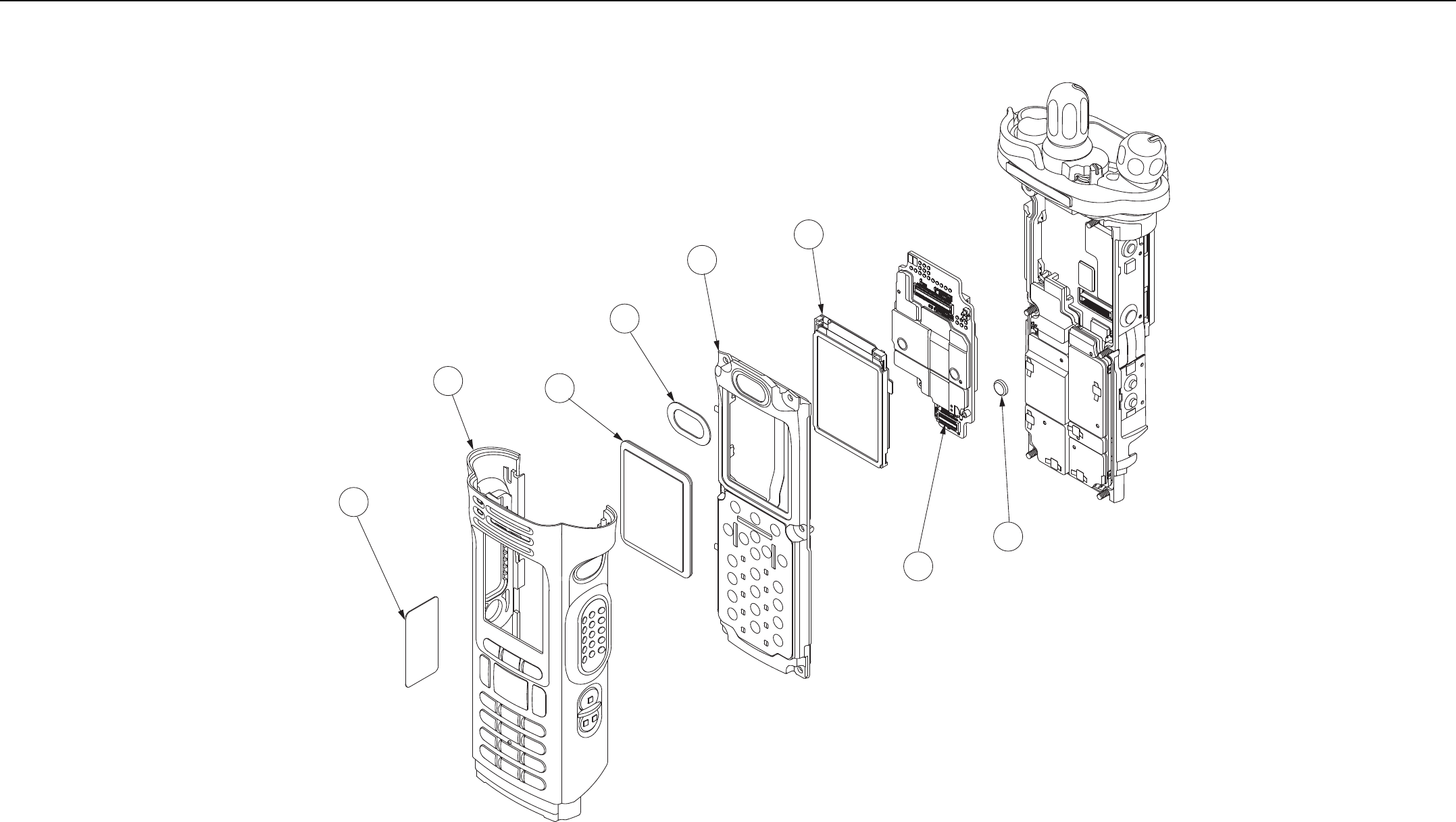
Sec 2: 10-4 Exploded Views and Parts Lists: APX 7000XE Dual Display Exploded View
10.3 APX 7000XE Dual Display Exploded View
Figure 10-2. APX 7000XE Dual Display Exploded View
46
40 42
43
41
44
31
45
NOTE: Refer to Top Display view for items not exploded. Parts
shown here are exclusive to Dual Display version.

Exploded Views and Parts Lists: APX 7000XE Dual Display Exploded View Parts List Sec 2: 10-5
10.4 APX 7000XE Dual Display Exploded View
Parts List
Item
No.
Motorola Part
Number Description
40 01009506013
01009506014
01009506015
Assy, Front Housing, Dual Display (Black)
Assy, Front Housing, Dual Display (Yellow)
Assy, Front Housing, Dual Display (Green)
41 NHN7017_2Assy, Back Chassis, Dual Display
42 6175619B02 Lens, Color Display
43 3271816H01 Seal, Speaker, Dataside
44 010093040242Display, Color, Back
45 MNCN6202_2Assy, VOCON Board Dual Display
31 6003710K08 Battery, Backup, Coincell
46 3385836D11 Label, Main Housing FM, Dual Display (where applicable)

Sec 2: 10-6 Exploded Views and Parts Lists: APX 7000XE Dual Display Exploded View Parts List
Table 10-2. Compatibility Table
Compatibility Table
Display, Color Back – 01009304024
Display, Color Back – 01009304019
Display, Color Back – 01009304003
Assy, Back Chassis – Top Display, NHN7004_
Assy, Back Chassis – Dual Display, NHN7017_
VOCON Board, MNCN6203_
VOCON Board, MNCN6202_
VOCON Board, MNCN6201_
VOCON Board, MNCN6200_
Display, Color Back – 01009304024 –––x●x●xx
Display, Color Back – 01009304019 –––x●x●xx
Display, Color Back – 01009304003 –––x●x●xx
Assy, Back Chassis –Top Display, NHN7004_ xxx––●x●x
Assy, Back Chassis – Dual Display, NHN7017_ ●●●––x●xx
VOCON Board, MNCN6203_ xxx●x––––
VOCON Board, MNCN6202_ ●●●x●––––
VOCON Board, MNCN6201_ xxxxx––––
VOCON Board, MNCN6200_ xxxxx––––
Note:
●Compatible
xNot Compatible
– Not Applicable

Index Index
Numerics
700–800 MHz
radio specifications 2:ivii
700–800 MHz and UHF1
model chart 2:ii
700–800 MHz and UHF2
model chart 2:iiv
700–800 MHz and VHF
model chart 2:i
A
alignment, tuner
bit error rate test 2:6-24
introduction 2:6-1
main menu 2:6-2
radio information screen 2:6-4
reference oscillator 2:6-4
softpot use 2:6-2
test setup 2:6-1
transmit deviation balance 2:6-17
transmitter test pattern 2:6-26
analog mode
receiving 2:3-2
transmitting 2:3-7
antenna
attaching 2:8-6
removing 2:8-6
antenna o-ring
servicing 2:8-20
ARM theory of operation 2:3-12
assemble
back chassis assembly 2:8-32
bluetooth option board assembly 2:8-34
expansion board assembly 2:8-33
frequency and volume knobs assembly 2:8-29
main housing assembly 2:8-32
RF board assembly 2:8-31
speaker grill assembly 2:8-36
top control assembly 2:8-29
vocon board assembly 2:8-30
ASTRO mode
receiving 2:3-11
transmitting 2:3-11
audio theory of operation 2:3-13
B
back chassis assembly
assemble 2:8-32
removing 2:8-16
top display
servicing 2:8-25, 2:8-27
battery
attaching 2:8-7
removing 2:8-9
bit error rate test 2:6-24
bluetooth
troubleshooting chart 2:9-5
bluetooth option board assembly
assemble 2:8-34
bluetooth option/expansion board
troubleshooting chart 2:9-4
C
chassis ground contact
servicing 2:8-21
chassis pads
servicing 2:8-20
chassis screw boss cap
servicing 2:8-20
cleaning external plastic surfaces 2:2-1
color display
servicing 2:8-25
control top and keypad test mode, dual-display
version 2:5-6
control top assembly
removing 2:8-19
servicing 2:8-22
control top test mode
top-display version 2:5-8
controller
ARM theory of operation 2:3-12
audio theory of operation 2:3-13
theory of operation 2:3-12
user interface block theory of operation 2:3-13
controller expansion bay & option slot theory of
operation 2:3-13
D
disassembly/reassembly
antenna
attaching 2:8-6
removing 2:8-6
back chassis assembly
removing 2:8-16
battery
attaching 2:8-7
removing 2:8-9
control top assembly
removing 2:8-19
expansion board assembly
removing 2:8-14
housing assembly
reassembling 2:8-29
introduction 2:8-1
knobs and top bezel assembly
removing 2:8-18
main chassis assembly
removing 2:8-20
main housing assembly
removing 2:8-15
RF board assembly
removing 2:8-17
speaker grill assembly
removing 2:8-12
speaker module
removing 2:8-13
universal connector cover

Sec 2: Index-2 Index
attaching 2:8-11
removing 2:8-10
vocon board assembly
removing 2:8-18
display radio
test mode
test environments 2:5-5
test frequencies 2:5-5
dual-display version
control top and keypad test mode 2:5-6
entering test mode 2:5-3
RF test mode 2:5-5
E
encryption
index
selecting with keypad 2:7-3
selecting with menu 2:7-3
key
erasing
all keys 2:7-4
key zeroization 2:7-3
selecting with keypad 2:7-2
selecting with menu 2:7-2
troubleshooting chart 2:9-4
error codes
operational 2:9-2
power-up 2:9-1
expansion bay & option slot theory of operation 2:3-13
expansion board assembly
assemble 2:8-33
removing 2:8-14
servicing 2:8-24
exploded view
complete
dual display version 2:10-4
top display version 2:10-2
partial
dual display 2:8-3
top display 2:8-2
F
field programming equipment 2:4-3
FLASHport 2:1-2
frequency and volume knobs assembly
assemble 2:8-29
H
handling precautions
non-ruggedized radios 2:2-1
XE radios 2:2-2
housing assembly
reassembling 2:8-29
I
index, encryption
selecting with keypad 2:7-3
selecting with menu 2:7-3
K
key, encryption
erasing
all keys 2:7-4
key zeroization 2:7-3
loading 2:7-1
selecting with keypad 2:7-2
selecting with menu 2:7-2
knobs and top bezel assembly
removing 2:8-18
servicing 2:8-22
L
loading an encryption key 2:7-1
M
main chassis assembly
removing 2:8-20
main housing assembly
assemble 2:8-32
removing 2:8-15
main lens
servicing 2:8-26
maintenance
cleaning 2:2-1
inspection 2:2-1
ruggedized radio submergibility checks 2:2-1
manual
notations 2:1-1
microphone membrane
servicing 2:8-21, 2:8-28
model chart
700–800 MHz and UHF1 2:ii
700–800 MHz and UHF2 2:iiv
700–800 MHz and VHF 2:i
numbering system 2:ix
UHF1 and UHF2 2:iiii
UHF1 and VHF 2:iii
UHF2 and VHF 2:iv
model numbering system, radio 2:ix
multikey
conventional 2:7-1
trunked 2:7-1
N
notations
manual 2:1-1
warning, caution, and danger 2:1-1
P
performance checks
receiver 2:5-9
test setup 2:5-1
transmitter 2:5-10
performance test
tuner 2:6-24
port seal label

Index Sec 2: Index-3
servicing 2:8-28
power-up error codes 2:9-1
precautions, handling 2:2-1
R
radio
alignment 2:6-1
basic description 2:1-2
dual-display model
RF test mode 2:5-5
dual-display version
control top and keypad test mode 2:5-6
entering display test mode 2:5-3
exploded view
complete dual display version 2:10-4
complete top display version 2:10-2
partial
dual display 2:8-3
top display 2:8-2
features 2:1-2
FLASHport feature 2:1-2
information screen 2:6-4
model numbering system 2:ix
models 2:1-2
reassembling
housing assembly 2:8-29
submergible models
disassembling 2:8-38
reassembling 2:8-38
submersibility
specialized test equipment 2:8-38
standards 2:8-37
vacuum test 2:8-38
test environments 2:5-5
test frequencies 2:5-5
test mode
dual-display version 2:5-3
top-display model 2:5-7
top-display version
control top test mode 2:5-8
entering test mode 2:5-7
RF test mode 2:5-7
receiver
ASTRO conventional channel tests 2:5-9
performance checks 2:5-9
troubleshooting 2:9-2
receiving
analog mode 2:3-2
ASTRO mode 2:3-11
reference oscillator alignment 2:6-4
RF board assembly
assemble 2:8-31
removing 2:8-17
servicing 2:8-23
RF test mode
dual-display version 2:5-5
top-display version 2:5-7
ruggedized radios
submergibility checks 2:2-1
S
service aids 2:4-2
servicing
antenna o-ring 2:8-20
back chassis assembly
top display 2:8-25, 2:8-27
chassis ground contact 2:8-21
chassis pads 2:8-20
chassis screw boss cap 2:8-20
color display 2:8-25
control top assembly 2:8-22
expansion board assembly 2:8-24
knobs and top bezel assembly 2:8-22
main lens 2:8-26
microphone membrane 2:8-21, 2:8-28
port seal label 2:8-28
RF board assembly 2:8-23
speaker module 2:8-28
speaker seal 2:8-26
vocon board assembly 2:8-23
softpot 2:6-2
speaker grill assembly
assemble 2:8-36
removing 2:8-12
speaker module
removing 2:8-13
servicing 2:8-28
speaker seal
servicing 2:8-26
specifications
700–800 MHz radios 2:ivii
UHF1 radios 2:iviii
UHF2 radios 2:iix
VHF radios 2:ivi
standards, radio submersibility 2:8-37
submergibility
radio disassembly 2:8-38
radio reassembly 2:8-38
submersibility
specialized test equipment 2:8-38
standards 2:8-37
vacuum test 2:8-38
T
test equipment
recommended 2:4-1
specialized submersibility 2:8-38
test mode, entering
dual-display version 2:5-3
top-display version 2:5-7
test setup
alignment 2:6-1
performance checks 2:5-1
tests
receiver
ASTRO conventional channels 2:5-9
performance checks 2:5-9
transmitter
ASTRO conventional channels 2:5-11
performance checks 2:5-10
theory of operation
analog mode 2:3-2

Sec 2: Index-4 Index
ASTRO mode 2:3-11
controller 2:3-12
ARM 2:3-12
audio 2:3-13
expansion bay & option slot 2:3-13
user interface block 2:3-13
major assemblies 2:3-1
overview 2:3-1
top control assembly
assemble 2:8-29
top-display version
control top test mode 2:5-8
entering test mode 2:5-7
RF test mode 2:5-7
transmit deviation
balance alignment 2:6-17
transmitter
ASTRO conventional channel tests 2:5-11
performance checks 2:5-10
test pattern 2:6-26
troubleshooting 2:9-3
transmitting
analog mode 2:3-7
ASTRO mode 2:3-11
troubleshooting
bluetooth option/expansion board problems 2:9-4
bluetooth problems 2:9-5
encryption problems 2:9-4
introduction 2:9-1
operational error codes 2:9-2
power-up error codes 2:9-1
receiver problem chart 2:9-2
transmitter problem chart 2:9-3
tuner
bit error rate test 2:6-24
introduction 2:6-1
main menu 2:6-2
performance test 2:6-24
radio information screen 2:6-4
reference oscillator alignment 2:6-4
test setup 2:6-1
transmit deviation balance alignment 2:6-17
transmitter alignment 2:6-4
transmitter test pattern 2:6-26
U
UHF Specifications 2:ivii
UHF1
radio specifications 2:iviii
UHF1 and UHF2
model chart 2:iiii
UHF1 and VHF
model chart 2:iii
UHF2
radio specifications 2:iix
UHF2 and VHF
model chart 2:iv
universal connector cover
attaching 2:8-11
removing 2:8-10
user interface block theory of operation 2:3-13
V
vacuum test, submersibility 2:8-38
view, exploded
complete dual display version 2:10-4
complete top display version 2:10-2
partial
dual display 2:8-3
top display 2:8-2
vocon board assembly
assemble 2:8-30
removing 2:8-18
servicing 2:8-23
W
warning, caution, and danger notations 2:1-1
X
XE radios
handling precautions 2:2-2

ASTRO APX 7000/ APX 7000XE
Digital Portable Radios
Section 3
Appendices

Notes

Appendix A Accessories
Motorola Solutions provides the following approved optional accessories to improve the productivity
of the APX 7000/ APX 7000XE portable radio.
For a complete list of Motorola-approved antennas, batteries, and other accessories,
visit the following web site:
http://www.motorolasolutions.com/APX

Section 3: A-2 Accessories
Notes

Appendix B Replacement Parts Ordering
B.1 Basic Ordering Information
When ordering replacement parts or equipment information, the complete identification number
should be included. This applies to all components, kits, and chassis. If the component part number
is not known, the order should include the number of the chassis or kit of which it is a part, and
sufficient description of the desired component to identify it.
B.2 Transceiver Board, VOCON Board and Expander Board Ordering
Information
When ordering a replacement Transceiver Board, VOCON Board or Expander Board, refer to the
applicable Model Chart in the front of this manual. Read the Transceiver Board, VOCON Board, or
Expander Board note, and include the proper information with your order.
B.3 Motorola Online
Motorola Online users can access our online catalog at
http://www.motorola.com/businessonline
To register for online access, please call 1-800-422-4210 (for U.S. and Canada Service Centers
only). International customers can obtain assistance at http://www.motorola.com/businessonline
B.4 Mail Orders
Mail orders are only accepted by the US Federal Government Markets Division (USFGMD).
Motorola
7031 Columbia Gateway Drive
3rd Floor – Order Processing
Columbia, MD 21046
U.S.A.

Section 3: B-2 Replacement Parts Ordering: Telephone Orders
B.5 Telephone Orders
Radio Products and Solutions Organization*
(United States and Canada)
7:00 AM to 7:00 PM (Central Standard Time)
Monday through Friday (Chicago, U.S.A.)
1-800-422-4210
1-847-538-8023 (United States and Canada)
U.S. Federal Government Markets Division (USFGMD)
1-877-873-4668
8:30 AM to 5:00 PM (Eastern Standard Time)
B.6 Fax Orders
Radio Products and Solutions Organization*
(United States and Canada)
1-800-622-6210
1-847-576-3023 (United States and Canada)
USFGMD
(Federal Government Orders)
1-800-526-8641 (For Parts and Equipment Purchase Orders)
B.7 Parts Identification
Radio Products and Solutions Organization*
(United States and Canada)
1-800-422-4210
B.8 Product Customer Service
Radio Products and Solutions Organization (United States and Canada)
1-800-927-2744
* The Radio Products and Solutions Organization (RPSO) was formerly known as the Radio
Products Services Division (RPSD) and/or the Accessories and Aftermarket Division (AAD).

Glossary Glossary
This glossary contains an alphabetical listing of terms and their definitions that are applicable to
ASTRO portable and mobile subscriber radio products.
Term Definition
A/D See analog-to-digital conversion.
Abacus IC A custom integrated circuit providing a digital receiver intermediate
frequency (IF) backend.
active channel A channel that has traffic on it.
ACK Acknowledgment of communication.
ADC See analog-to-digital converter.
ADDAG See Analog-to-Digital, Digital-to-Analog and Glue.
analog Refers to a continuously variable signal or a circuit or device designed
to handle such signals. See also digital.
Analog-to-Digital,
Digital-to-Analog
and Glue
An integrated circuit designed to be an interface between the radio’s
DSP, which is digital, and the analog transmitter and receiver ICs.
analog-to-digital
conversion
Conversion of an instantaneous dc voltage level to a corresponding
digital value. See also D/A.
analog-to-digital
converter
A device that converts analog signals into digital data. See also DAC.
ASTRO 25 trunking Motorola standard for wireless digital trunked communications.
ASTRO conventional Motorola standard for wireless analog or digital conventional
communications.
automatic level
control
A circuit in the transmit RF path that controls RF power amplifier output,
provides leveling over frequency and voltage, and protects against high
VSWR.
autoscan A feature that allows the radio to automatically scan the members of a
scan list.
band Frequencies allowed for a specific purpose.
BGA See ball grid array.
ball grid array A type of IC package characterized by solder balls arranged in a grid
that are located on the underside of the package.
Call Alert Privately paging an individual by sending an audible tone.

Section 3: Glossary-2 Glossary
carrier squelch Feature that responds to the presence of an RF carrier by opening or
unmuting (turning on) a receiver's audio circuit. A squelch circuit
silences the radio when no signal is being received so that the user
does not have to listen to “noise.”
central controller A software-controlled, computer-driven device that receives and
generates data for the trunked radios assigned to it. It monitors and
directs the operations of the trunked repeaters.
channel A group of characteristics, such as transmit/receive frequency pairs,
radio parameters, and encryption encoding.
CODEC See coder/decoder.
coded squelch Used on conventional channels to ensure that the receiver hears only
those communications intended for the receiver.
codeplug Firmware that contains the unique personality for a system or device. A
codeplug is programmable and allows changes to system and unit
parameters. See also firmware.
coder/decoder A device that encodes or decodes a signal.
control channel In a trunking system, one of the channels that is used to provide a
continuous, two-way/data-communications path between the central
controller and all radios on the system.
conventional Typically refers to radio-to-radio communications, sometimes through a
repeater. Frequencies are shared with other users without the aid of a
central controller to assign communications channels. See also
trunking.
conventional scan
list
A scan list that includes only conventional channels.
CPS See Customer Programming Software.
cursor A visual tracking marker (a blinking line) that indicates a location on a
display.
Customer
Programming
Software
Software with a graphical user interface containing the feature set of an
ASTRO radio. See also RSS.
D/A See digital-to-analog conversion.
DAC See digital-to-analog converter.
deadlock Displayed by the radio after three failed attempts to unlock the radio.The
radio must be powered off and on prior to another attempt.
default A pre-defined set of parameters.
Term Definition

Glossary Section 3: Glossary-3
digital Refers to data that is stored or transmitted as a sequence of discrete
symbols from a finite set; most commonly this means binary data
represented using electronic or electromagnetic signals. See also
analog.
digital-to-analog
conversion
Conversion of a digital signal to a voltage that is proportional to the input
value. See also A/D.
digital-to-analog
converter
A device that converts digital data into analog signals. See also ADC.
Digital Private Line A type of digital communications that utilizes privacy call, as well as
memory channel and busy channel lock out to enhance communication
efficiency.
digital signal
processor
A microcontroller specifically designed for performing the mathematics
involved in manipulating analog information, such as sound, that has
been converted into a digital form. DSP also implies the use of a data
compression technique.
digital signal
processor code
Object code executed by the Digital Signal Processor in an ASTRO
subscriber radio. The DSP is responsible for computation-intensive
tasks, such as decoding ASTRO signaling.
dispatcher An individual who has radio-system management duties and
responsibilities.
DPL See Digital Private Line. See also PL.
DSP See digital signal processor.
DSP code See digital signal processor code.
dynamic regrouping A feature that allows the dispatcher to temporarily reassign selected
radios to a single special channel so they can communicate with each
other.
EEPOT Electrically Programmable Digital Potentiometer.
EEPROM See Electrically Erasable Programmable Read-Only Memory.
Electrically Erasable
Programmable
Read-Only Memory
A special type of PROM that can be erased by exposing it to an
electrical charge. An EEPROM retains its contents even when the
power is turned off.
Failsoft A backup system that allows communication in a non-trunked,
conventional mode if the trunked system fails.
FCC Federal Communications Commission.
Term Definition

Section 3: Glossary-4 Glossary
firmware Code executed by an embedded processor such as the Host or DSP in
a subscriber radio. This type of code is typically resident in non-volatile
memory and as such is more difficult to change than code executed
from RAM.
FGU See frequency generation unit.
flash A non-volatile memory device similar to an EEPROM. Flash memory
can be erased and reprogrammed in blocks instead of one byte at a
time.
FLASHcode A 13-digit code which uniquely identifies the System Software Package
and Software Revenue Options that are enabled in a particular
subscriber radio. FLASHcodes are only applicable for radios which are
upgradeable through the FLASHport process.
FLASHport A Motorola term that describes the ability of a radio to change memory.
Every FLASHport radio contains a FLASHport EEPROM memory chip
that can be software written and rewritten to, again and again.
FMR See Florida Manual Revision.
Florida Manual
Revision
A publication that provides supplemental information for its parent
publication before it is revised and reissued.
frequency Number of times a complete electromagnetic-wave cycle occurs in a
fixed unit of time (usually one second).
frequency
generation unit
This unit generates ultra-stable, low-phase noise master clock and other
derived synchronization clocks that are distributed throughout the
communication network.
General-Purpose
Input/Output
Pins whose function is programmable.
GPIO See General-Purpose Input/Output.
hang up Disconnect.
home display The first information display shown after a radio completes its self test.
host code Object code executed by the host processor in an ASTRO subscriber
radio. The host is responsible for control-oriented tasks such as
decoding and responding to user inputs.
IC See integrated circuit.
IF Intermediate Frequency.
IMBE A sub-band, voice-encoding algorithm used in ASTRO digital voice.
inbound signaling
word
Data transmitted on the control channel from a subscriber unit to the
central control unit.
Term Definition

Glossary Section 3: Glossary-5
integrated circuit An assembly of interconnected components on a small semiconductor
chip, usually made of silicon. One chip can contain millions of
microscopic components and perform many functions.
ISW See inbound signaling word.
key-variable loader A device used to load encryption keys into a radio.
kHz See kilohertz.
kilohertz One thousand cycles per second. Used especially as a radio-frequency
unit.
KVL See key-variable loader.
LCD See liquid-crystal display.
LED See LED.
light emitting diode An electronic device that lights up when electricity is passed through it.
liquid-crystal display An LCD uses two sheets of polarizing material with a liquid-crystal
solution between them. An electric current passed through the liquid
causes the crystals to align so that light cannot pass through them.
LO Local oscillator.
low-speed
handshake
150-baud digital data sent to the radio during trunked operation while
receiving audio.
LSH See low-speed handshake.
Master In Slave Out SPI data line from a peripheral to the MCU.
Master Out Slave In SPI data line from the MCU to a peripheral.
MCU See microcontroller unit.
MDC Motorola Digital Communications.
menu entry A software-activated feature shown at the bottom of the display.
Selection of a feature is controlled by the programming of the buttons on
the side of the radio.
MHz See Megahertz.
Megahertz One million cycles per second. Used especially as a radio-frequency
unit.
microcontroller unit Also written as µC. A microprocessor that contains RAM and ROM
components, as well as communications and programming components
and peripherals.
MISO See Master In Slave Out.
Term Definition

Section 3: Glossary-6 Glossary
mode A programmed combination of operating parameters; for example, a
channel or talkgroup.
mode slaving A radio programmed to automatically provide the proper operation for a
given selected mode.
monitoring Used in conventional operation where the programmed monitor button
is pressed to listen to another user who is active on a channel. This
prevents one user from interfering with another user’s conversation.
MOSI See Master Out Slave In.
multiplexer An electronic device that combines several signals for transmission on
some shared medium (e.g., a telephone wire).
MUX See multiplexer.
Network Access
Code
Network Access Code (NAC) operates on digital channels to reduce
voice channel interference between adjacent systems and sites.
NiCd Nickel-cadmium.
NiMH Nickel-metal-hydride.
non-tactical/revert The user will talk on a preprogrammed emergency channel. The
emergency alarm is sent out on this same channel.
OMPAC See over-molded pad-array carrier.
open architecture A controller configuration that utilizes a microprocessor with extended
ROM, RAM, and EEPROM.
oscillator An electronic device that produces alternating electric current and
commonly employs tuned circuits and amplifying components.
OSW See outbound signaling word.
OTAR See over-the-air rekeying.
outbound signaling
word
Data transmitted on the control channel from the central controller to the
subscriber unit.
over-molded pad-
array carrier
A Motorola custom IC package, distinguished by the presence of solder
balls on the bottom pads.
over-the-air rekeying Allows the dispatcher to remotely reprogram the encryption keys in the
radio.
PA Power amplifier.
page A one-way alert with audio and/or display messages.
paging One-way communication that alerts the receiver to retrieve a message.
PC Board Printed Circuit Board. Also referred to as a PCB.
Term Definition

Glossary Section 3: Glossary-7
personality A set of unique features specific to a radio.
phase-locked loop A circuit in which an oscillator is kept in phase with a reference, usually
after passing through a frequency divider.
PL See private-line tone squelch.
PLL See phase-locked loop.
preprogrammed A software feature that has been activated by a qualified radio
technician.
Private
(Conversatiion) Call
A feature that lets you have a private conversation with another radio
user in the group.
private-line tone
squelch
A continuous sub-audible tone that is transmitted along with the carrier.
See also DPL.
programmable A radio control that can have a radio feature assigned to it.
Programmable
Read-Only Memory
A memory chip on which data can be written only once. Once data has
been written onto a PROM, it remains there forever.
PROM See Programmable Read-Only Memory.
PTT See Push-to-Talk.
Push-to-Talk The switch or button usually located on the left side of the radio which,
when pressed, causes the radio to transmit. When the PTT is released,
the unit returns to receive operation.
radio frequency The portion of the electromagnetic spectrum between audio sound and
infrared light (approximately 10 kHz to 10 GHz).
radio frequency
power amplifier
Amplifier having one or more active devices to amplify radio signals.
Radio Interface Box A service aid used to enable communications between a radio and the
programming software.
Radio Service
Software
DOS-based software containing the feature set of an ASTRO radio. See
also CPS.
random access
memory
A type of computer memory that can be accessed randomly; that is, any
byte of memory can be accessed without touching the preceding bytes.
RAM See random access memory.
read-only memory A type of computer memory on which data has been prerecorded. Once
data has been written onto a ROM chip, it cannot be removed and can
only be read.
real-time clock A module that keeps track of elapsed time even when a computer is
turned off.
Term Definition

Section 3: Glossary-8 Glossary
receiver Electronic device that amplifies RF signals. A receiver separates the
audio signal from the RF carrier, amplifies it, and converts it back to the
original sound waves.
registers Short-term data-storage circuits within the microcontroller unit or
programmable logic IC.
repeater Remote transmit/receive facility that re-transmits received signals in
order to improve communications range and coverage (conventional
operation).
repeater/talkaround A conventional radio feature that permits communication through a
receive/transmit facility, which re-transmits received signals in order to
improve communication range and coverage.
RESET Reset line: an input to the microcontroller that restarts execution.
RF See radio frequency.
RF PA See radio frequency power amplifier.
RIB See Radio Interface Box.
ROM See read-only memory.
RPCIC Regulator/power control IC.
RPT/TA See repeater/talkaround.
RSS See Radio Service Software.
RSSI Received Signal Strength Indicator.
RTC See real-time clock.
RX Receive.
RX DATA Recovered digital data line.
SAP See Serial Audio CODEC Port.
SCI IN Serial Communications Interface Input line.
selective call A feature that allows you to call a selected individual, intended to
provide privacy and to eliminate the annoyance of having to listen to
conversations of no interest to you.
selective switch Any digital P25 traffic having the correct Network Access Code and the
correct talkgroup.
Serial Audio CODEC
Port
SSI to and from the GCAP II IC CODEC used to transfer transmit and
receive audio data.
Term Definition

Glossary Section 3: Glossary-9
Serial
Communication
Interface Input Line
A full-duplex (receiver/transmitter) asynchronous serial interface.
SCI IN See Serial Communication Interface Input Line.
Serial Peripheral
Interface
How the microcontroller communicates to modules and ICs through the
CLOCK and DATA lines.
signal An electrically transmitted electromagnetic wave.
Signal Qualifier
mode
An operating mode in which the radio is muted, but still continues to
analyze receive data to determine RX signal type.
softpot See software potentiometer.
software Computer programs, procedures, rules, documentation, and data
pertaining to the operation of a system.
software
potentiometer
A computer-adjustable electronic attenuator.
spectrum Frequency range within which radiation has specific characteristics.
SPI See Serial Peripheral Interface.
squelch Muting of audio circuits when received signal levels fall below a pre-
determined value. With carrier squelch, all channel activity that exceeds
the radio’s preset squelch level can be heard.
SRAM See static RAM.
SRIB Smart Radio Interface Box. See RIB.
SSI See Synchronous Serial Interface.
Standby mode An operating mode in which the radio is muted but still continues to
monitor data.
static RAM A type of memory used for volatile, program/data memory that does not
need to be refreshed.
status calls Pre-defined text messages that allow the user to send a conditional
message without talking.
Synchronous Serial
Interface
DSP interface to peripherals that consists of a clock signal line, a frame
synchronization signal line, and a data line.
system central
controllers
Main control unit of the trunked dispatch system; handles ISW and
OSW messages to and from subscriber units (See ISW and OSW).
system select The act of selecting the desired operating system with the system-select
switch (also, the name given to this switch).
Term Definition

Section 3: Glossary-10 Glossary
tactical/non-revert The user will talk on the channel that was selected before the radio
entered the emergency state.
TalkAround Bypassing a repeater and talking directly to another unit for local unit-to-
unit communications.
talkgroup An organization or group of radio users who communicate with each
other using the same communications path.
talkgroup scan list A scan list that can include both talkgroups (trunked) and channels
(conventional).
thin small-outline
package
A type of dynamic random-access memory (DRAM) package that is
commonly used in memory applications.
time-out timer A timer that limits the length of a transmission.
tone A continuous, sub-audible tone transmitted with the carrier.
TOT See time-out timer.
transceiver Transmitter-receiver. A device that both transmits and receives analog
or digital signals. Also abbreviated as XCVR.
transmitter Electronic equipment that generates and amplifies an RF carrier signal,
modulates the signal, and then radiates it into space.
trunking The automatic sharing of communications paths between a large
number of users. Allows users to share a smaller number of frequencies
because a repeater or communications path is assigned to a talkgroup
for the duration of a conversation. See also conventional.
trunking priority
monitor scan list
A scan list that includes talkgroups that are all from the same trunking
system.
TSOP See thin small-outline package.
TX Transmit.
UART See also Universal Asynchronous Receiver Transmitter.
UHF Ultra-High Frequency.
USK Unique shadow key.
Universal
Asynchronous
Receiver Transmitter
A microchip with programming that controls a computer's interface to its
attached serial devices.
Universal Connector Interface point for all accessories to the radio.
Universal Serial Bus An external bus standard that supports data transfer rates of 12 Mbps.
USB See Universal Connector.
Term Definition

Glossary Section 3: Glossary-11
VCO See voltage-controlled oscillator.
vector sum excited
linear predictive
coding
A voice-encoding technique used in ASTRO digital voice.
VHF Very-High Frequency.
VOCON See vocoder/controller.
vocoder An electronic device for synthesizing speech by implementing a
compression algorithm particular to voice. See also voice encoder.
vocoder/controller A PC board that contains an ASTRO radio’s microcontroller, DSP,
memory, audio and power functions, and interface support circuitry.
voice encoder The DSP-based system for digitally processing analog signals, and
includes the capabilities of performing voice compression algorithms or
voice encoding. See also vocoder.
voltage-controlled
oscillator
An oscillator in which the frequency of oscillation can be varied by
changing a control voltage.
Term Definition

Section 3: Glossary-12 Glossary
Notes

Motorola Solutions, Inc.
1303 East Algonquin Road
Schaumburg, Illinois 60196 U.S.A.
MOTOROLA, MOTO, MOTOROLA SOLUTIONS and
the Stylized M logo are trademarks or registered trademarks
of Motorola Trademark Holdings, LLC and are used under license.
All other trademarks are the property of their respective owners.
© 2009 – 2013 Motorola Solutions, Inc. All rights reserved.
June 2013.
*6875962M01*
6875962M01-H
