ARC EM Starter Kit User Guide
User Manual:
Open the PDF directly: View PDF ![]() .
.
Page Count: 131 [warning: Documents this large are best viewed by clicking the View PDF Link!]
- Contents
- List of Figures
- List of Tables
- 1 Preface
- 2 Introduction
- 3 Getting Started
- 4 Working with ARC EM Starter Kit
- 5 About the Demo Packages
- 6 Building and Running Applications
- Building, Running, and Debugging Projects Using the MetaWare IDE
- Building and Running Applications Using make
- Building and Running Projects Using the ARC GNU IDE
- 7 Creating Applications Using the MetaWare Tools
- 8 Running Applications in Self-Boot Mode
- Appendix: A Hardware Functional Description
- Board Overview
- FPGA Design Overview
- External Hardware Interfaces
- Pmod Pin Configuration
- Headers J10, J11, J12
- Peripheral Controllers
- On-Board Devices
- Appendix: B ARC EM Configurations
- Appendix: C FPGA Image Recovery
- Appendix: D Using a JTAG Debugger
- Glossary and References

ARC EM Starter Kit
User Guide
Version 6280-009 March 2015

1
Synopsys, Inc. Version 6280-009
March 2015
Copyright Notice and Proprietary Information Notice
Copyright © 2015 Synopsys, Inc. All rights reserved. This software and documentation contain confidential and proprietary information
that is the property of Synopsys, Inc. The software and documentation are furnished under a license agreement and may be used or
copied only in accordance with the terms of the license agreement. No part of the software and documentation may be reproduced,
transmitted, or translated, in any form or by any means, electronic, mechanical, manual, optical, or otherwise, without prior written
permission of Synopsys, Inc., or as expressly provided by the license agreement.
Destination Control Statement
All technical data contained in this publication is subject to the export control laws of the United States of America. Disclosure to
nationals of other countries contrary to United States law is prohibited. It is the reader's responsibility to determine the applicable
regulations and to comply with them.
Disclaimer
SYNOPSYS, INC., AND ITS LICENSORS MAKE NO WARRANTY OF ANY KIND, EXPRESS OR IMPLIED, WITH REGARD TO THIS
MATERIAL, INCLUDING, BUT NOT LIMITED TO, THE IMPLIED WARRANTIES OF MERCHANTABILITY AND FITNESS FOR A
PARTICULAR PURPOSE.
Trademarks
Synopsys and certain Synopsys product names are trademarks of Synopsys, as set forth at
http://www.synopsys.com/Company/Pages/Trademarks.aspx.
All other product or company names may be trademarks of their respective owners.
Synopsys, Inc.
690 E. Middlefield Road
Mountain View, CA 94043
www.synopsys.com

2
Version 6280-009 Synopsys, Inc.
March 2015
Contents
1 Preface ............................................................................................................................................... 9
Document Structure .......................................................................................................................... 9
2 Introduction ...................................................................................................................................... 10
About the ARC EM Starter Kit ......................................................................................................... 10
Target Applications ......................................................................................................................... 10
Tool Requirements .......................................................................................................................... 11
Platform Requirements ................................................................................................................... 11
Development Process ..................................................................................................................... 11
3 Getting Started ................................................................................................................................. 13
Package Contents ........................................................................................................................... 13
Set up the ARC EM Starter Kit ........................................................................................................ 14
Default Board Settings ................................................................................................................. 14
Board Jumper Settings ................................................................................................................ 14
Select the Default ARC EM Configuration ................................................................................... 14
Connect the USB Cable .................................................................................................................. 16
USB Driver Installation ................................................................................................................. 16
Connect the Power Supply ............................................................................................................. 16
Run the Self-Test ............................................................................................................................ 17
Self-Test and Bootloader ............................................................................................................. 17
View Self-Test Output on PuTTY Console ................................................................................... 18
4 Working with ARC EM Starter Kit ..................................................................................................... 22
Selecting ARC EM Configurations .................................................................................................. 22
Connecting External Interfaces to the ARC EM Starter Kit ............................................................. 24
Connecting the PMODAD2 Extension Module ................................................................................ 25
5 About the Demo Packages ............................................................................................................... 26
About the Bare-Metal Demo Package ............................................................................................. 26
Supported ARC EM Starter Kit Hardware .................................................................................... 27
Directory Structure ....................................................................................................................... 28
Compatibility ................................................................................................................................ 29
About the MQX Demo Package ...................................................................................................... 30
Overview ...................................................................................................................................... 30

3
Contents ARC EM Starter Kit
Synopsys, Inc. Version 6280-009
March 2015
Directory Structure ....................................................................................................................... 31
6 Building and Running Applications ................................................................................................... 33
Building, Running, and Debugging Projects Using the MetaWare IDE ........................................... 33
Download and Install MetaWare .................................................................................................. 33
Licenses ....................................................................................................................................... 34
Download MetaWare Lite ............................................................................................................. 34
Install MetaWare Lite ................................................................................................................... 34
Hardware Connections between MetaWare and ARC EM Starter Kit .......................................... 34
Run Applications using the MetaWare IDE .................................................................................. 35
Building and Running Applications Using make .............................................................................. 44
Building and Running Projects Using the ARC GNU IDE ............................................................... 48
7 Creating Applications Using the MetaWare Tools ............................................................................ 58
Creating an Application Using the Command Line Tools ................................................................ 58
Debugging Applications Using the MetaWare Debugger ................................................................ 59
Creating Application Using the MetaWare IDE ............................................................................... 60
Create a New Project in the MetaWare IDE ................................................................................. 60
Invoking the Debugger and Running the Executable ................................................................... 65
8 Running Applications in Self-Boot Mode .......................................................................................... 69
Self-Boot Application Concept ........................................................................................................ 69
Building a Self-Boot Application ...................................................................................................... 69
Write the Self-Boot Application Image to SPI Flash ........................................................................ 70
Writing .......................................................................................................................................... 70
Reading ....................................................................................................................................... 72
Running the Self-Boot Application .................................................................................................. 72
SPI Flash Memory Structure ........................................................................................................... 73
Appendix: A Hardware Functional Description ............................................................................... 75
Board Overview .............................................................................................................................. 75
FPGA Design Overview .................................................................................................................. 77
External Hardware Interfaces .......................................................................................................... 78
Connecting Peripheral Controllers ............................................................................................... 79
Pmod Pin Configuration .................................................................................................................. 80
PMOD_MUX_CTRL Register ...................................................................................................... 80
Pmod1 Configuration ................................................................................................................... 81

4
ARC EM Starter Kit Contents
Version 6280-009 Synopsys, Inc.
March 2015
UART_MAP_CTRL Register ........................................................................................................ 81
Pmod2 Configuration ................................................................................................................... 83
Pmod3 Configuration ................................................................................................................... 83
Pmod4 Configuration ................................................................................................................... 85
Pmod5 Configuration ................................................................................................................... 85
Pmod6 Configuration ................................................................................................................... 86
Pmod7 Configuration ................................................................................................................... 88
Pmods Configuration summary .................................................................................................... 89
Headers J10, J11, J12 .................................................................................................................... 91
Peripheral Controllers ..................................................................................................................... 93
GPIO ............................................................................................................................................ 93
I2C ............................................................................................................................................... 94
SPI Master ................................................................................................................................... 95
SPI Slave ..................................................................................................................................... 97
UART ........................................................................................................................................... 98
Pin Mux Controller ..................................................................................................................... 100
Peripheral Memory Mapping ...................................................................................................... 101
Interrupts Connections ............................................................................................................... 101
On-Board Devices ......................................................................................................................... 102
JTAG Connector ........................................................................................................................ 102
USB ........................................................................................................................................... 102
SD Card ..................................................................................................................................... 102
Man-Machine Interface .............................................................................................................. 102
Power Supply ............................................................................................................................. 104
Appendix: B ARC EM Configurations ........................................................................................... 105
Programmer’s Model ..................................................................................................................... 105
Core Configurations and Memory Mapping .................................................................................. 105
ARC_EM5D and ARC_EM4 Configurations .............................................................................. 105
ARC_EM7DARC_EM7DFPU, ARC_EM6 and ARC_EM6FPU Configurations .......................... 107
Detailed Core Configurations ........................................................................................................ 109
Troubleshooting ......................................................................................................................... 112
Appendix: C FPGA Image Recovery ............................................................................................ 113
Board Jumper Settings .............................................................................................................. 113

5
Contents ARC EM Starter Kit
Synopsys, Inc. Version 6280-009
March 2015
Xilinx Lab Tools Installation .......................................................................................................... 114
Connecting the FPGA Programming Cable .................................................................................. 115
FPGA Programming Sequence ..................................................................................................... 116
SPI Flash-Programming Sequence ............................................................................................... 120
Appendix: D Using a JTAG Debugger .......................................................................................... 125
Ashling Opella-XD Debugger ........................................................................................................ 125
Lauterbach TRACE32 Debugger .................................................................................................. 127
Lauterbach TRACE32 Tool Installation ......................................................................................... 128
Glossary and References ................................................................................................................. 129
Glossary ........................................................................................................................................ 129
References.................................................................................................................................... 130

6
Version 6280-009 Synopsys, Inc.
March 2015
List of Figures
Figure 1 Board Jumper and Switch Locations ..................................................................................... 14
Figure 2 SW1 Switch .......................................................................................................................... 15
Figure 3 Power Supply and USB Cable Connection to the Board ....................................................... 17
Figure 4 COM6 Port ............................................................................................................................ 19
Figure 5 PuTTY Configuration Window ............................................................................................... 20
Figure 6 Self-test Results in a Terminal Window, ARC_EM5D ........................................................... 21
Figure 7 SW1 DIP Switch.................................................................................................................... 23
Figure 8 Peripheral device connected using Pmod ............................................................................. 24
Figure 9 PmodAD2 Connection to Pmod2 .......................................................................................... 25
Figure 10 MIDE Directory .................................................................................................................... 35
Figure 11 Selecting a Workspace ....................................................................................................... 35
Figure 12 MetaWare IDE — Select Workspace Directory ................................................................... 36
Figure 13 MetaWare IDE — Select an Import Source ........................................................................ 37
Figure 14 MetaWare IDE — Select Projects for Import ....................................................................... 38
Figure 15 MetaWare IDE - Demo Projects in the Workspace ............................................................. 39
Figure 16 MetaWare IDE - Set Active Build Configurations ................................................................ 39
Figure 17 MetaWare IDE – Build Results in Console Window ............................................................ 40
Figure 18 MetaWare IDE – Selecting the Debug Configuration from the Run Menu .......................... 40
Figure 19 MetaWare IDE – Creating the new Debug Configuration .................................................... 41
Figure 20 MetaWare IDE – Selecting a Name for the New Debug Configuration ............................... 42
Figure 21 MetaWare IDE – Selecting the Debugger Target ................................................................ 43
Figure 22 MetaWare IDE – Debug Window ........................................................................................ 43
Figure 23 ARC GNU IDE - Select Workspace Directory ..................................................................... 48
Figure 24 ARC GNU IDE - Import Existing Projects into Workspace (First Step) ............................... 49
Figure 25 ARC GNU IDE - Import Existing Projects into Workspace (Second step) ........................... 50
Figure 26 ARC GNU IDE - List of Demo Projects in the Workspace ................................................... 50
Figure 27 ARC GNU IDE - Set Active Build Configurations ................................................................ 51
Figure 28 ARC GNU IDE - Build Results in Console Window ............................................................. 52
Figure 29 ARC GNU IDE - Creating a Debug Configuration ............................................................... 53
Figure 30 ARC GNU IDE – Program Selection ................................................................................... 54
Figure 31 ARC GNU IDE - Commands Initialization from the Debugger ............................................ 55
Figure 32 ARC GNU IDE – Debug Window ........................................................................................ 56
Figure 33 ARC GNU IDE – Stepping Toolbar ..................................................................................... 56
Figure 34 ARC GNU IDE – Stepping Toolbar ..................................................................................... 57
Figure 35 ARC GNU IDE – Stepping Toolbar ..................................................................................... 57
Figure 36 MetaWare Settings Required to Use ARC JTAG through USB .......................................... 60
Figure 37 MetaWare IDE - Creating a New Project ............................................................................ 61
Figure 38 MetaWare IDE - Select Project Configurations ................................................................... 62
Figure 39 MetaWare IDE - Select TCF File ......................................................................................... 63
Figure 40 MetaWare IDE - Create New Source File ........................................................................... 63
Figure 41 MetaWare IDE - Console Output for Test Project ............................................................... 64
Figure 42 MetaWare IDE - Creating New Debug Configuration .......................................................... 65
Figure 43 MetaWare IDE - Configure Debugger ................................................................................. 66
Figure 44 MetaWare IDE - Debug Perspective ................................................................................... 67

7
List of Figures ARC EM Starter Kit
Synopsys, Inc. Version 6280-009
March 2015
Figure 45 MetaWare IDE - Console window ....................................................................................... 68
Figure 46 Output of spi_rw .................................................................................................................. 71
Figure 47 Typical Flash Memory Structure ......................................................................................... 74
Figure 48 FGPA Design Block Diagram .............................................................................................. 77
Figure 49 Pmod Pin Numbering .......................................................................................................... 80
Figure 50 Pin Positions at Headers J10, J11, and J12 ....................................................................... 91
Figure 51 DW I2C Connection ............................................................................................................ 94
Figure 52 DW SPI Master Connection ................................................................................................ 96
Figure 53 DW UART Components Connection ................................................................................... 98
Figure 54 Memory Map of ARC_EM5D Configuration ...................................................................... 106
Figure 55 Memory Map of ARC_EM7D and ARC_EM7DFPU Configurations .................................. 108
Figure 56 Welcome Dialog ................................................................................................................ 114
Figure 57 Product Registration Dialog .............................................................................................. 115
Figure 58 USB FPGA Programming Cable Connection to the Board ............................................... 116
Figure 59 iMPACT Tool – Main Window View .................................................................................. 117
Figure 60 iMPACT Tool – Initialize Chain Menu Option .................................................................... 118
Figure 61 iMPACT Tool – Assign New Configuration File Dialog Box .............................................. 119
Figure 62 iMPACT View of the Successful FPGA Programming ...................................................... 120
Figure 63 iMPACT Tool – select SPI device ..................................................................................... 121
Figure 64 iMPACT Tool – Add PROM File Dialog Box ..................................................................... 122
Figure 65 iMPACT Tool – Select Attached SPI/BPI Dialog Box ........................................................ 123
Figure 66 iMPACT View of the Successful SPI ROM Programming ................................................. 124
Figure 67 Ashling XD Pod with Debug Cable .................................................................................... 125
Figure 68 Jumper J8 Set ................................................................................................................... 126
Figure 69 ARC JTAG Connection to the Board ................................................................................. 127
Figure 70 Lauterbach TRACE32 with Debug Cable .......................................................................... 127

8
Version 6280-009 Synopsys, Inc.
March 2015
List of Tables
Table 1 Predefined ARC Сonfigurations ............................................................................................. 15
Table 2 Predefined ARC Configurations ............................................................................................. 22
Table 3 Selecting the Configuration .................................................................................................... 23
Table 4 Directory Structure of the Bare-Metal Demo Package ........................................................... 28
Table 5 Availability of Bare-Metal demo Applications for Different Tools ............................................ 29
Table 6 Core Configuration Supported for MetaWare and ARC GNU ................................................ 29
Table 7 MQX Environment Variables .................................................................................................. 30
Table 8 Folder Structure of the MQX Demo Package ......................................................................... 31
Table 9 Peripheral Devices Connection to Pmods .............................................................................. 78
Table 10 Board Connections Overview of Peripheral Controllers ....................................................... 79
Table 11 Pin Assignment of Pmod1 (J1) Upper Row Depending on PM1[0] ...................................... 81
Table 12 Pin Assignment of Pmod1 (J1) Lower Row depending on PM1[2] ....................................... 82
Table 13 Pin Assignment of Pmod2 (J2) Depending on PM2[0] ......................................................... 83
Table 14 Pin Assignment of Pmod3 (J3) Depending on PM3[0] ......................................................... 84
Table 15 Pin Assignment of Pmod4 (J4) Depending on PM4[0] ......................................................... 85
Table 16 Pin Assignment of Pmod5 (J5) Upper Row Depending on PM5[0] ...................................... 86
Table 17 Pin Assignment of Pmod5 (J5) Lower Row Depending on PM5[2] ...................................... 86
Table 18 Pin Assignment of Pmod6 (J6) Upper Row Depending on PM6[0] ...................................... 87
Table 19 Pin Assignment of Pmod6 (J6) Lower Row Depending on PM6[2] ...................................... 87
Table 20 Pin Assignment of Pmod7 (J7) Depending on PM7[0] ......................................................... 88
Table 21 Pmods configuration summary ............................................................................................. 89
Table 22 Pin Assignment of the Header J10 Depending on PM2[0] ................................................... 91
Table 23 Pin Assignment of the Header J11 Depending on PM3[0] ................................................... 92
Table 24 Pin Assignment of the Header J12 Depending on PM4[0] ................................................... 92
Table 25 SPI Master Signals Usage ................................................................................................... 96
Table 26 Register File Mapping ........................................................................................................ 100
Table 27 Peripheral Memory Mapping .............................................................................................. 101
Table 28 Interrupts Connections ....................................................................................................... 101
Table 29 Configuration Details .......................................................................................................... 109
Table 30 Board Jumper Settings ....................................................................................................... 113
Table 31 ARC EM Starter Kit JTAG Connector Pin-out .................................................................... 126

9
Synopsys, Inc. Version 6280-009
March 2015
1
Preface
This chapter outlines the document structure and provides a brief chapter overview. Addi-
tionally, it contains a list of available resources and other supporting documents.
Document Structure
This document consists of the following chapters:
Preface – Overview of the available documentation and its organization.
Introduction – Overview of the ARC EM Starter Kit, target applications, and the tool
requirements.
Getting Started – Software required for the ARC EM Starter Kit and step-by-step
guide on how to connect it to a power supply and to a debugger.
Working with ARC EM Starter Kit – Procedures about how to configure the ARC EM
Starter Kit.
About the Demo Packages – This section describes the demo packages used for
ARC EM Starter Kit.
Building and Running Applications – Procedures about how to build, run, and debug
applications using the MetaWare Development Toolkit and ARC GNU.
Creating Applications Using the MetaWare Tools – Procedures to create and debug
software applications using the MetaWare Tools.
Running Applications in Self-Boot Mode – Procedures to run applications in self-boot
mode.
Hardware Functional Description – Information about the hardware used in the ARC
EM Starter Kit.
ARC EM Configurations – Information about the ARC EM configurations packaged
with the ARC EM Starter Kit.
FPGA Image Recovery – Information about how to program the FPGA.
Using a JTAG Debugger – Information about using a JTAG debugger.
Glossary and References – List of abbreviations, terms, and external references.

10
Version 6280-009 Synopsys, Inc.
March 2015
2
Introduction
This document describes the ARC EM Starter Kit and procedures to build and run applica-
tions on the ARC EM Starter Kit.
About the ARC EM Starter Kit
The DesignWare® ARC® EM Starter Kit enables rapid software development, code porting,
software debugging, and profiling for ARC EM5D and ARC EM7D processors.
The ARC EM Starter Kit consists of a hardware platform, including pre-installed FPGA
images of ARC EM5D, ARC EM7D, and ARC EM7DFPU configurations with peripherals,
and a software package. The ARC EM4 processor is a subset of ARC EM5D processor, and
ARC EM6 processor is a subset of ARC EM7D processor. So software may be built for ARC
EM4 or ARC EM6 processors but then run on the ARC EM5D or ARC EM7D processor
configurations on the starter kit.
The development board is based on a Xilinx Spartan®-6 LX150 FPGA and supports
hardware extensions using six 2x6 connectors supporting a total of 48 user I/O pins (plus
power and ground pins) that can be used to connect components such as sensors,
actuators, memories, displays, buttons, switches, and communication devices. A Digilent
Pmod™ compatible extension board containing a four-channel 12-bit A/D converter with an
I2C interface and an AC power adapter is included in the package.
Target Applications
The ARC EM Starter Kit is targeted at the following applications:
Evaluation of ARC EM processors
Performance analysis of ARC EM processors

11
Tool Requirements ARC EM Starter Kit
Synopsys, Inc. Version 6280-009
March 2015
You can connect the following end-devices to the ARC EM Starter Kit:
Sensors
Actuators
Displays
Buttons
Switches
Communication devices
Tool Requirements
The ARC EM Starter Kit requires the following tools to be installed on your host:
Digilent Adept software — Software driver for the Digilent JTAG-USB cable.
Note
Make sure that you are using latest version of Adept driver. For minimal version of
Adept software, see DesignWare ARC EM Starter Kit 2.1 Release Notes.
MetaWare Development Toolkit — DesignWare ARC tools to run and debug
applications on the DesignWare ARC processors.
ARC GNU — an open-source development environment to run and debug
applications for the DesignWare ARC processors. For more details, see ARC GNU
documentation.
Platform Requirements
For a list of platforms supported by ARC EM Starter Kit, see DesignWare ARC EM Starter
Kit 2.1 Release Notes.
Development Process
The ARC EM Starter Kit allows you to develop software applications using the following
software tools:
MetaWare Lite — A free downloadable version of the MetaWare Development Toolkit.
MetaWare Lite has the following restrictions:
o Supports only the Windows platform.
o The code size is restricted to 32K or less.

12
Development Process ARC EM Starter Kit
Version 6280-009 Synopsys, Inc.
March 2015
For more information about downloading and installing MetaWare Lite, see Download
MetaWare Lite.
MetaWare Development Toolkit — A software development toolchain that supports the
development, debugging, and tuning of embedded applications for the DesignWare ARC
processors.
The toolchain includes a compiler and debugger. MetaWare Development Toolkit is a
licensed product from Synopsys. This MetaWare Development Toolkit must be
separately licensed from the ARC EM Starter Kit.
For more information see Building, Running, and Debugging projects using the Meta-
Ware IDE.ARC GNU — ARC GNU is an open source development environment for ARC
processors. The tools include the GCC compiler and GDB debugger as well a number of
utilities and libraries that make up a complete software tool chain. For more information
see, Building and running projects using the ARC GNU IDE.

13
Version 6280-009 Synopsys, Inc.
March 2015
3
Getting Started
This chapter describes the software required for the ARC EM Starter Kit. It also contains a
step-by-step guide on how to connect the ARC EM Starter Kit to a power supply and to a
debugger.
Use the following procedure to set up the ARC EM Starter Kit and perform the self-test
1. Unpack the Package Contents
2. Setting up the ARC EM Starter Kit
3. Connecting the USB
4. Connecting the Power Supply
5. Running Self-Test
Package Contents
The ARC EM Starter Kit package contains the following items:
FPGA module with Xilinx Spartan-6 FPGA device mounted on base board with extension
connectors and peripherals
4-channel 12-bit A/D converter extension module
100-240V AC power adapter
USB cable
Note
Software examples and ARC GNU software tools are available from the ARC EM Starter Kit
Downloads Web page: http://www.synopsys.com/cgi-bin/dwarcsw/arcemsk/menu.cgi.
Typically a password is provided by email when you register to order the kit. If you do not
have a password, submit this form:
http://www.synopsys.com/cgi-bin/dwarcsw/req1.cgi?id=arcemsk.
Next Steps:
Setting up the ARC EM Starter Kit.
14
ARC EM Starter Kit Set up the ARC EM Starter Kit
Version 6280-009 Synopsys, Inc.
March 2015
Set up the ARC EM Starter Kit
The following sections explain the procedures to connect the ARC EM Starter Kit to your
host.
Default Board Settings
This section describes default settings for links and switches on the board.
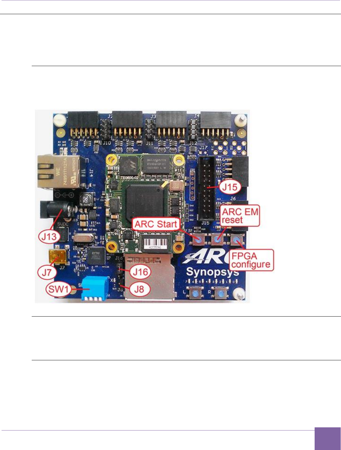
Figure 1 Board Jumper and Switch Locations
Board Jumper Settings
The ARC EM Starter Kit hardware contains pre-installed FPGA configurations that are ready
for use.
Select the Default ARC EM Configuration
The FPGA board includes an SPI flash storage device pre-programmed with four FPGA
images containing different configurations of DesignWare® ARC EM cores. ARC_EM5D is
the default processor configuration.
15
Set up the ARC EM Starter Kit ARC EM Starter Kit
Synopsys, Inc. Version 6280-009
March 2015
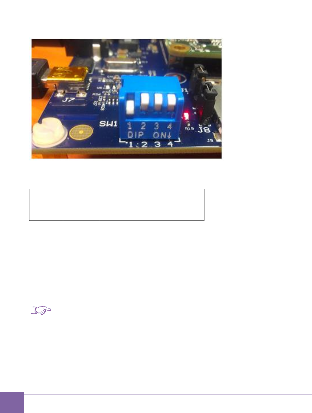
The FPGA image can be selected using the pins 1 and 2 of the SW1 switch on the board:
Figure 2 SW1 Switch
The default configuration parameters of bit 1 and bit 2 are provided in Table 1.
Table 1 Predefined ARC Сonfigurations
Bit 1
Bit 2
Configuration
OFF
OFF
ARC_EM5D
The selected configuration is downloaded from the on-board SPI flash device automatically
after the board is powered up or after you press the FPGA configure button located above
the letter “C” of the ARC logo.
Bits 3 and 4 the SW1 switch must be in the OFF position to perform a self-test.
The configuration loading process might take up to twenty seconds after the board is
powered on. The green LED on the FPGA module is on during this period. After the
configuration is loaded, the ARC EM processor performs a self-test as described in the
Running Self-Test section.
Note
After FPGA configuration, the SW1 switch is available for user applications.
Next Steps:
Connect the USB Cable.

16
ARC EM Starter Kit Connect the USB Cable
Version 6280-009 Synopsys, Inc.
March 2015
Connect the USB Cable
A single USB cable provides a communication channel between the debugger and the
ARC EM Starter Kit board:
A USB-JTAG interface
A USB-UART debug console
If you have not installed the MetaWare Development Toolkit, you can alternatively use the
USB-UART channel to establish communication between the ARC EM core and another
serial console such as PuTTY.
USB Driver Installation
In order to use JTAG-USB and JTAG-UART interfaces, a driver is required on the host on
which you run the MetaWare debugger or another serial debug console such as PuTTY.
The driver is a part of the Digilent Adept System tool and can be downloaded from the
Digilent web site at www.digilentinc.com.
Follow the installation instructions provided by Digilent.
USB Connections
Use the USB cable delivered as part of the ARC EM Starter kit.
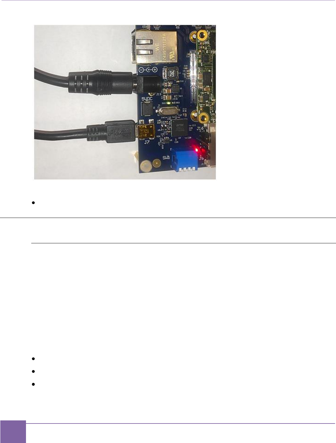
1. Connect the mini-USB plug to the connector J7 on the board as shown on Figure 3.
2. Connect the other end of the cable to the host running the debugger.
Note
The J8 header needs to be open (jumper removed) to enable communication with the debug-
ger via the USB-JTAG channel. This is the factory default setting. The USB-UART channel for
a serial console is always enabled.
Connect the Power Supply
Use the universal switching power adapter (110-240 Volts AC to 5 Volts DC) provided in the
package. Connect the appropriate AC plug for your AC power outlet. Connect the DC plug
to the connector J13 “5V DC” on the board as shown on Figure 3. Finally, connect the AC
plug to your AC power outlet.
Note
The ARC EM Starter Kit board operates on 5V DC. It does not have any user-
accessible means to change power-supply settings.
17
Run the Self-Test ARC EM Starter Kit
Synopsys, Inc. Version 6280-009
March 2015
Figure 3 Power Supply and USB Cable Connection to the Board
Next Steps:
Running Self-Test.
Run the Self-Test
Self-Test and Bootloader
After the FPGA image is loaded from the SPI-flash memory, the ICCM of the ARC
processor contains a pre-programmed image of the self-test application that is executed
after a CPU reset.
The self-test application behavior depends on bit 3 of the on-board DIP switch SW1.
Bit 3 – skip self-test app. When this bit is on, the self-test application does not perform any
tests and does not send any messages to the console. However, in any position of Bit 3, the
startup code enables LED7 to indicate the CPU start.
To run self-test application the Bit 3 switch should be off.
The Self-test application indicates the core configuration loaded into FPGA as follows:
LED0 – ARC_EM5D
LED1 – ARC_EM7D
LED2 – ARC_EM7DFPU
The Self-test application performs the following actions:

18
ARC EM Starter Kit Run the Self-Test
Version 6280-009 Synopsys, Inc.
March 2015
1. Runs the startup code, which initializes program counter and stack pointer.
2. Checks the ARC EM IDENTITY register.
3. Initializes and test peripheral controllers.
4. Flashes LEDs.
5. Tests SPI flash.
6. Prints the following information to the console:
o Version of self-test application
o ARC EM configuration number
o ARC processor ID
o Type of SPI flash
View Self-Test Output on PuTTY Console
PuTTY is a simple debug console that you can use when the MetaWare Development
Toolkit is not installed.
Prerequisites
USB cable is connected to your host and the USB drivers are installed.
Board is powered up.
Procedure
1. Click Start > Control Panel > Device Manager.
2. In the Device Manager window, double-click Ports (COM & LPT).
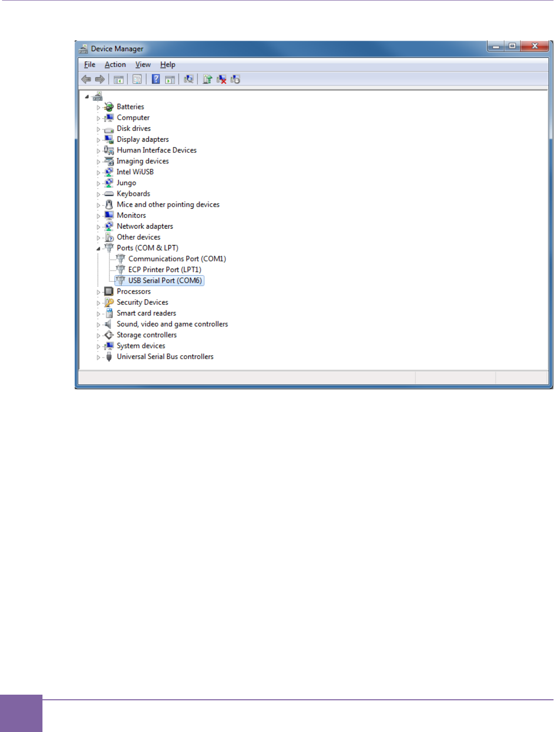
3. Select USB Serial Port and take note of the COM port assigned to the USB Serial
Port
Example: Figure 4 shows the port COM6 being used.
19
Run the Self-Test ARC EM Starter Kit
Synopsys, Inc. Version 6280-009
March 2015
Figure 4 COM6 Port
4. Download putty.exe from http://www.putty.org.
5. Double-click the downloaded putty.exe file.
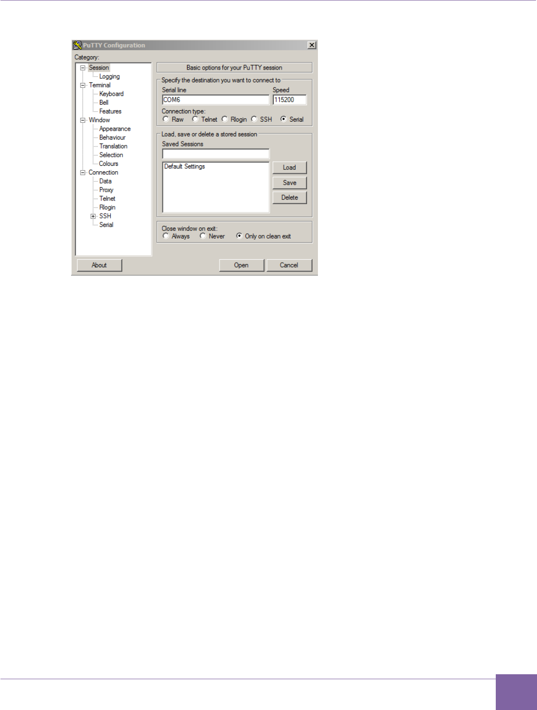
The PuTTY Configuration window appears.
6. Select Serial connection type.
7. Enter the COM port name from Step 2 in the Serial line field and set the Speed
field to 115200 as shown in Figure 5.
20
ARC EM Starter Kit Run the Self-Test
Version 6280-009 Synopsys, Inc.
March 2015
Figure 5 PuTTY Configuration Window
8. Click the Open button to launch the PuTTY terminal.
9. Press the ARC EM Reset button after launching PuTTY.
10. The self-test is performed.
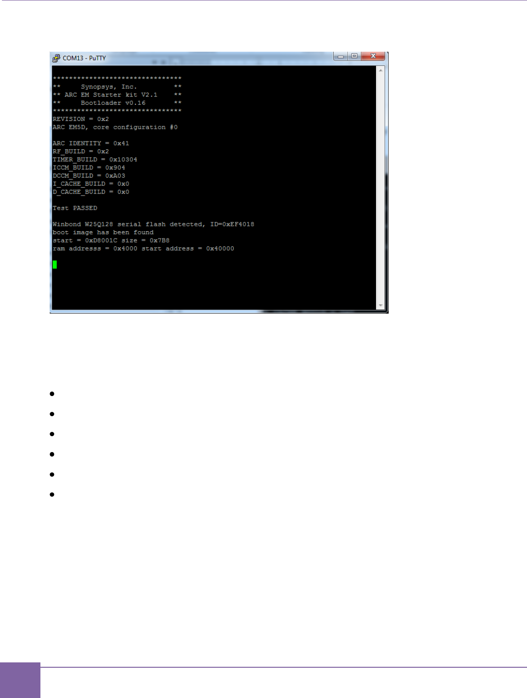
Figure 6 on page 21 shows the console output after completion of self-test application. This
example uses the ARC_EM5D configuration (SW1 bits 1 and 2 both off).
21
Run the Self-Test ARC EM Starter Kit
Synopsys, Inc. Version 6280-009
March 2015
Figure 6 Self-test Results in a Terminal Window, ARC_EM5D
Next Steps:
After you have successfully completed the self-test of the ARC EM Starter Kit, you can start
working with the ARC EM Starter Kit.
The following chapters explain some of the tasks you can do with the ARC EM Starter Kit:
Building, Running, and Debugging Projects Using the MetaWare IDE
Building and Running Projects Using the ARC GNU IDE
Selecting ARC EM Configurations
Connecting External Interfaces to the ARC EM Starter Kit
Connecting the PMODAD2 Extension Module
Creating Applications Using the MetaWare Tools

22
Synopsys, Inc. Version 6280-009
March 2015
4
Working with ARC EM Starter Kit
Selecting ARC EM Configurations
This section describes the usage of the preloaded FPGA images that are stored in the on-
board SPI Flash device.
Spartan-6 FPGAs include a capability called MultiBoot that allows the FPGA to selectively
reprogram and reload its bitstream from an attached external memory. The MultiBoot
feature allows the FPGA application to load different FPGA bitstreams under the control of
the FPGA application.
The FPGA board includes an SPI flash storage device that is pre-programmed with FPGA
images with different configurations of DesignWare® ARC EM cores: ARC_EM5D,
ARC_EM7D, and ARC_EM7DFPU.
Table 2 describes the main parameters of each configuration.
Table 2 Predefined ARC Configurations
Parameters
Configurations
ARC_EM5D
ARC_EM7D
ARC_EM7DFPU
ICCM
128 KB
32 KB
32 KB
DCCM
256 KB
32 KB
32 KB
Instruction Cache
-
16KB
16KB
Data cache
-
16KB
16KB
Timers
2
2
2
Core
Registers
32
32
32
Address Width
32
32
32
Note:
The EM4 processor is a subset of EM5D, and EM6 is a subset of EM7D. So software may be built for EM4
or EM6 but then run on EM5D or EM7D respectively.
23
Selecting ARC EM Configurations ARC EM Starter Kit
Synopsys, Inc. Version 6280-009
March 2015
For a detailed description of the predefined configurations, see Appendix A, Detailed Core
Configurations.
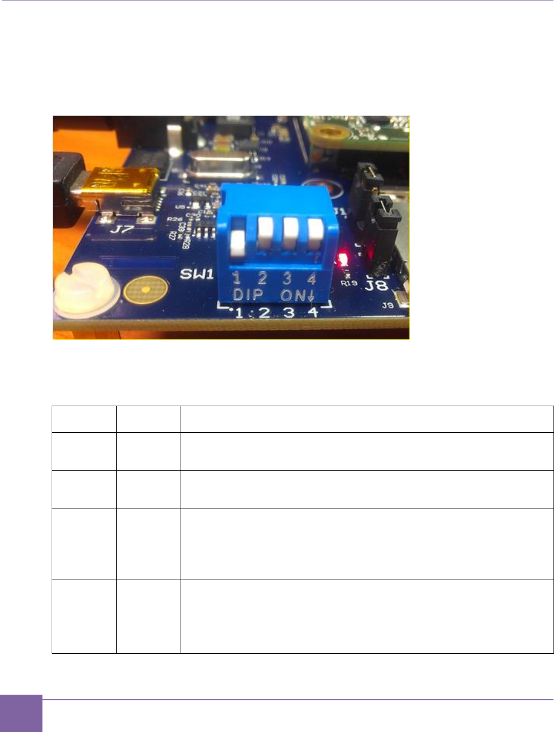
The FPGA image can be selected with pins 1 and 2 of the SW1 DIP switch on the base-
board as shown in Figure 7.
Figure 7 SW1 DIP Switch
The definitions of bits 1 and 2 are described in the Table 3.
Table 3 Selecting the Configuration
Bit 1
Bit 2
Configuration
OFF
OFF
ARC_EM5D (and ARC_EM4)
ON
OFF
ARC_EM7D (and ARC_EM6)
OFF
ON
ARC_EM7DFPU (and ARC_EM6PFU)
This is ARC_EM7D with Floating Point Unit
ON
ON
Reserved
24
ARC EM Starter Kit Connecting External Interfaces to the ARC EM Starter Kit
Version 6280-009 Synopsys, Inc.
March 2015
The selected configuration is downloaded from the on-board SPI flash device automatically
after power on or after you press the FPGA configure button located above the letter ‘C‘ of
the ARC logo on the baseboard. The loading process takes up to 20 seconds, and a green
LED on the FPGA module is on during this period. After that, the ARC EM processor
optionally performs a self-test and/or starts a user application. This action depends on the
position of bits 3 and 4 of SW1 as described in the section below.
Note
After the FPGA is programmed, the DIP switches are available for user applications. They
must be switched back to the position for the desired predefined FPGA image, before you
press the FPGA Configure button and power the board up.
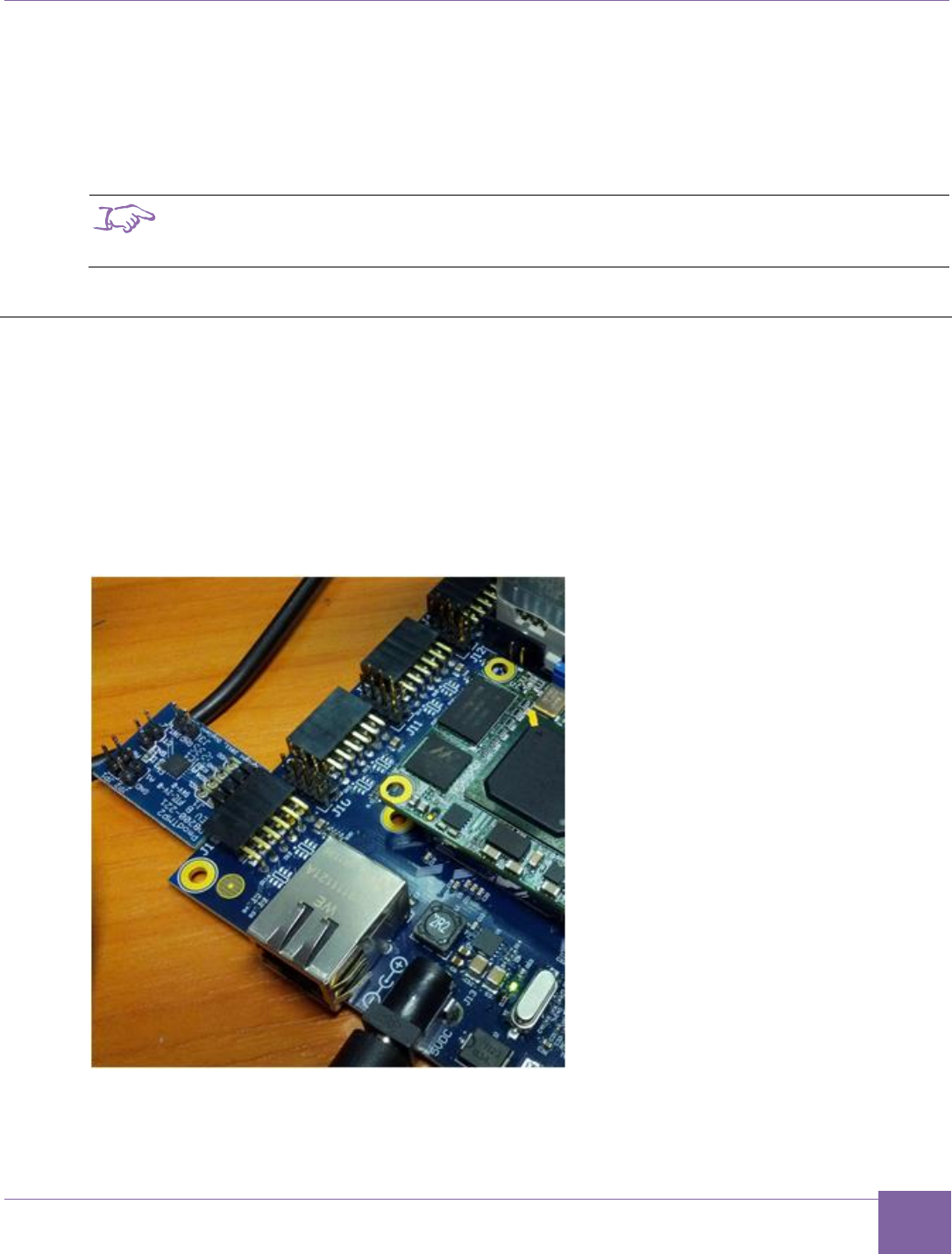
Connecting External Interfaces to the ARC EM Starter Kit
This section describes the connection of peripheral devices using Pmod connectors on the
baseboard.
The baseboard has several unified connectors that can be used to connect peripheral
devices. These connectors comply with the Pmod™ Interface Specification by Digilent Inc.
Refer to the Digilent Pmod Interface Specification for more details.
Figure 8 Peripheral device connected using Pmod
25
Connecting the PMODAD2 Extension Module ARC EM Starter Kit
Synopsys, Inc. Version 6280-009
March 2015
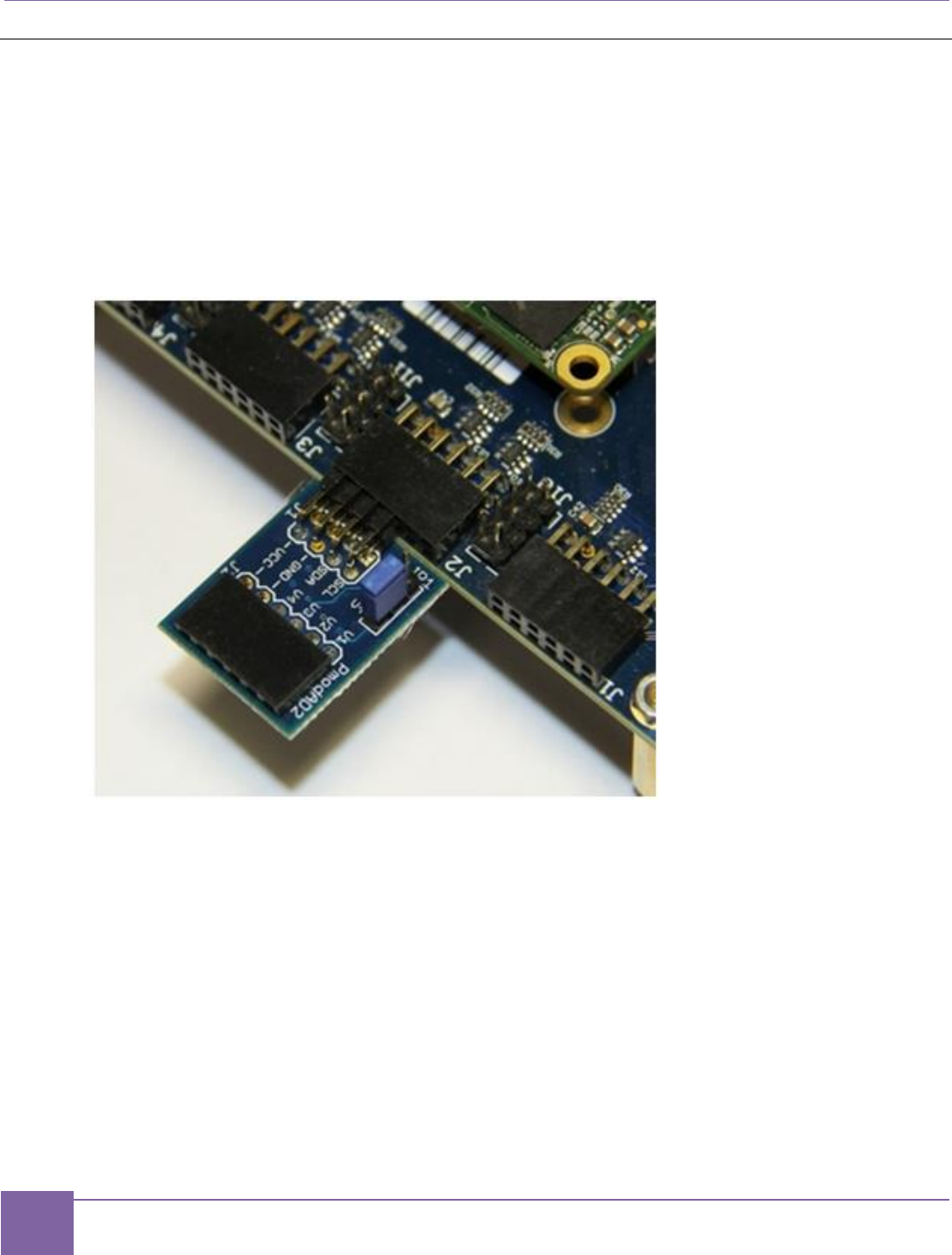
Connecting the PMODAD2 Extension Module
A PmodAD2 module is included in the ARC EM Starter Kit. This is a four-channel 12-bit A/D
converter with a Pmod I2C interface.
The module has a 2x4-pin Pmod connector. Insert the module on the left side of connector
J2, J3, or J4 using pins 3, 4, 5, 6, 9, 10, 11, 12.
As an example, Figure 9 shows how the PmodAD2 can be connected to Pmod2.
Figure 9 PmodAD2 Connection to Pmod2
For information on how to configure and use Pmod connectors, see section Pmod Pin
Configuration in page 80.

26
Synopsys, Inc. Version 6280-009
March 2015
5
About the Demo Packages
This section describes the demo packages used for ARC EM Starter Kit.
About the Bare-Metal Demo Package
The bare-metal demo applications contain sample code to illustrate how to build a simple
applications and communicate with peripheral devices available on the board. The following
applications are included in the bare-metal demo package, which can be downloaded from
the ARC EM Starter Kit download page.
hello
This application prints “Hello world” in the debug console over the JTAG connection.
Note: This application is available for the MetaWare Development toolkit only.
hello_uart
This application prints “Hello world” in the UART console.
leds
This application demonstrates how to configure and use LED indicators connected to
the GPIO controller.
leds_spi
This application demonstrates how to build an application running in self-boot mode.
It includes the necessary startup and make files .The functionality of this application
is the same as in leds demo. See details in readme.txt.
fibonacci
This application is a simple math example. It calculates the Fibonacci sequence and
returns 0 if the result of the calculation is correct, or 1 otherwise.
spi_rw
This application lets you write and read a binary image to/from the on-board SPI
Flash memory.
adc
This application demonstrates reading data from an external ADC module PmodAD2
connected to the extension port Pmod2.
temp_sensor
This application demonstrates reading data from an external temperature sensor
module PmodTMP2 connected to the extension port Pmod2 and prints the current
temperature on an external LCD display PmodCLS connected to Pmod6 and Pmod7.
27
About the Bare-Metal Demo Package ARC EM Starter Kit
Synopsys, Inc. Version 6280-009
March 2015
Note
This application requires additional Pmod extension boards not included in the ARC EM
Starter Kit package.
All demo applications use peripheral controllers to indicate status by LEDs, send information
to a UART, or read data from a device connected to a PMOD connector. To support
peripheral devices, the bare-metal package includes an IO library. The IO library provides a
simple low-level IP for peripheral controllers: I2C, SPI, UART and GPIO.
The following IO modules are included:
GPIO – GPIO driver includes simple functions for reading the status of onboard
buttons, switches, LEDs, and programming the LEDs.
I2C – polling-mode driver includes functions for initializing the I2C controller, reading,
and writing data from I2C slave device. The I2C driver supports only I2C slave mode.
mux – multiplexer driver defines and functions to configure PMOD multiplexer and
select routing modes for communication interfaces: SPI, UART.
SPI – low-level functions to work with the SPI interface.
UART – a few simple functions for printing to the UART.
Flash – SPI flash driver. The driver provides functions for reading, writing, and eras-
ing of onboard SPI flash memory.
LCD – PmodCLS LCD display driver supports two-string text LCD display connected
using SPI.
Supported ARC EM Starter Kit Hardware
The bare-metal demo applications are configured by default to support the latest version of
the ARC EM Starter kit hardware (FPGA image). The version of the FPGA image used in
the board is part of the service information printed on the console during the self-test
execution as follows:
To support older versions of ARC EM Starter Kit, open file options.mk from the
/options folder and set PRODUCT variable to your version of the hardware as shown be-
low:
# emsk_1.1
# emsk_2.0
# emsk_2.1
#
PRODUCT = emsk_2.1

28
ARC EM Starter Kit About the Bare-Metal Demo Package
Version 6280-009 Synopsys, Inc.
March 2015
Directory Structure
Table 4 represents the directory structure of the bare-metal demo package:
Table 4 Directory Structure of the Bare-Metal Demo Package
Directory
Description
apps/
Example applications in subfolders. It contains sources,
configurations, and makefiles.
/adc
Example application for reading the data from the AD convert-
er PmodAD2: application sources and makefile
/fibonacci
A simple math application
/hello
“Hello world” application sources and makefile
/hello_uart
UART version of “Hello world” application sources and
makefile
/leds
Flashing LEDs application sources and makefile
/leds_spi
Self-boot version of flashing LEDs application
/spi_flash
Example application for reading and writing SPI flash: applica-
tion sources and makefile
board/
Configuration files and header files for specific boards
boot/
Bootloader source code and makefile
common/
Common C, assembly, and header files for all applications
io/
Source files and makefiles for the peripheral controllers library
/flash
Source files of SPI FLASH module (required SPI controller
module)
/gpio
Source files of GPIO controller module (access to onboard
LED, DIP-switch, and buttons)
/i2c
Source files of I2C controller module
/lcd
Source files of character-based LCD controller
/mux
Source files of PMOD multiplexer
/spi
Source files of SPI controller module
/timers
Source files of the timer module
/uart
Source files of UART controller module
/wdt
Source files of Watchdog timer module

29
About the Bare-Metal Demo Package ARC EM Starter Kit
Synopsys, Inc. Version 6280-009
March 2015
Directory
Description
options/
Configuration files for building demo applications
project_arcgnu/
IDE projects for ARC GNU toolchain
project_arcmw/
IDE projects for MetaWare
Compatibility
The bare-metal applications are provided with a rich build environment for the MetaWare
Development Toolkit and the ARC GNU toolchain supporting command-line and IDE
projects. Table 5 lists the availability of the demo applications for the different tools.
Table 5 Availability of Bare-Metal demo Applications for Different Tools
Application
Command Line
IDE
MetaWare
ARC GNU
MetaWare
ARC GNU
adc
Yes
Yes
Yes
Yes
fibonacci
Yes
Yes
Yes
Yes
hello
Yes
No
Yes
No
hello_uart
Yes
Yes
Yes
Yes
leds
Yes
Yes
Yes
Yes
spi_rw
Yes
No
Yes
No
temp_sensor
Yes
No
Yes
No
Table 6 lists the core configurations that are supported by the software development tools.
Table 6 Core Configuration Supported for MetaWare and ARC GNU
CPU Configuration
Target Name for Bare-Metal Software
MetaWare
ARC GNU
ARC_EM5D
em5d
Yes
Yes
ARC_EM7D
em7d
Yes
Yes
ARC_EM7DFPU
em7dfpu
Yes
Yes
ARC_EM4
em4
Yes
Yes
ARC_EM6
em6
Yes
Yes
ARC_EM6FPU
em6fpu
Yes
Yes

30
ARC EM Starter Kit About the MQX Demo Package
Version 6280-009 Synopsys, Inc.
March 2015
About the MQX Demo Package
Overview
The MQX demo package contains the following:
Binary version of the MQX operating system (source files are not included) prebuilt for
use with the EM Starter Kit board.
Example MQX applications with source code that demonstrate how to build a simple
MQX application and work with the peripheral device drivers.
You can download the software package including MQX demo from the ARC EM Starter Kit
download page. You receive the corresponding URL after ordering the product.
Unzip the software package on a Windows machine, open the MQX folder, and follow the
instructions inside the README.txt file to install and configure MQX.
You can copy the MQX RTOS Evaluation Kit to any directory location on your machine. If
you want to use MQX RTOS with the MetaWare IDE, the MetaWare IDE assumes that the
MQX RTOS is installed at the default location:
C:\ARC\software\mqx2.61c
If you install the MQX RTOS in a different location, you must change the environment varia-
bles in the MetaWare IDE. Click Window > Preferences > C/C++ > Build > Environment,
and edit the environment variables. Table 7 lists the MQX environment variables.
Table 7 MQX Environment Variables
Environment Variable
Default Value
MQX_COMPILER_ROOT
C:\ARC\MetaWare\arc
MQX_ROOT
C:\ARC\software\mqx2.61c
MQX_CONFIG
%MQX_ROOT%\build\config.mk
MQX_PSP_LIB_DIR
%MQX_ROOT%\build\mqx.a config_dir
where mqx.a config_dir> can be one of the following
choices:
arcv2em_0.met - corresponds to config0
arcv2em_1.met - corresponds to config1
arcv2em_2.met - corresponds to config2
The MQX demo package for ARC EM Starter kit includes the following applications:
dw_apb_led
This application demonstrates how to configure and use LED indicators connected
to the GPIO controller.

31
About the MQX Demo Package ARC EM Starter Kit
Synopsys, Inc. Version 6280-009
March 2015
dw_apb_button_led
This application demonstrates how to control LED indicators using push buttons
connected to GPIO pins.
dw_apb_switch_led
This application demonstrates how to control LED indicators using switches
connected to GPIO pins.
dw_apb_uart
This application demonstrates how to configure the DW APB UART for different
parameters, such as baud rate, start bit, and stop bits.
dw_spi_sd_card
This application demonstrates the following features
o Setting the SD card in the SPI mode
o Checking the supported voltage ranges of an SD card
o Starting and finishing the initialization process
o Determining the capacity of the SD card (SDSD, SDHC)
o Getting the CID and CSD of the SD card
o Performing a sector write of 512 bytes
o Performing a sector read of 512 bytes
i2c_adc
This application demonstrates reading ADC data from the PmodAD2 extension
board, included in the ARC EM Starter Kit, using an I2C interface. The internal
dw_apb_i2c is programmed to operate in I2C master mode. The PmodAD2 device
is an I2C slave.
Directory Structure
Table 8 describes the folder structure of the MQX demo package.
Table 8 Folder Structure of the MQX Demo Package
Directory
Description
examples/starterkit/
Demo applications subfolders
examples/starterkit/
dw_apb_led
Application sources and makefile for the GPIO
demo using LEDs
examples/starterkit/
dw_apb_button_led
Application sources and makefile for the GPIO
demo controlling LEDs by push buttons

32
ARC EM Starter Kit About the MQX Demo Package
Version 6280-009 Synopsys, Inc.
March 2015
Directory
Description
examples/starterkit/
dw_apb_switch_led
Application sources and makefile for the GPIO
demo controlling LEDs by DIP switches
examples/starterkit/
dw_apb_uart
Application sources and makefile for the UART
demo
examples/starterkit/
dw_spi_sd_card
Application sources and makefile for the SD card
demo
examples/starterkit/i2c_adc
Application sources and makefile for the I2C ADC
demo
build/starterkit
Configuration files for building applications for the
different core configurations that are included in the
ARC EM Starter Kit
library/
MQX libraries
doc/
MQX documentation including the MQX user guide
for DW peripheral device drivers

33
Version 6280-009 Synopsys, Inc.
March 2015
6
Building and Running Applications
The ARC EM Starter Kit allows you to develop software applications using the following
software tools:
MetaWare Lite — A free downloadable version of the MetaWare Development Toolkit.
MetaWare Lite has the following restrictions:
o Supports only the Windows platform.
o The code size is restricted to 32K or less.
o Supports the ARC EM family of processors only.
For more information about downloading and installing MetaWare Lite, Building,
Running, and Debugging projects using the MetaWare IDE.
MetaWare Development Toolkit — A software development toolchain that supports the
development, debugging, and tuning of embedded applications for the DesignWare ARC
processors. The toolchain includes a compiler and debugger. The MetaWare
Development Toolkit must be separately licensed. For more information, see Building,
Running, and Debugging projects using the MetaWare IDE.
ARC GNU — ARC GNU is an open source development environment for ARC
processors. The tools include the GCC compiler and GDB debugger as well a number of
utilities and libraries that make up a complete software tool chain. For more information,
see Building and running projects using the ARC GNU IDE.
All software tools support both GUI and command line build approaches. The command
line approach similar for MetaWare and ARC GNU. For more information on how build
applications and run applications in this mode, see Building and Running Applications
Using gmake.
Building, Running, and Debugging Projects Using the
MetaWare IDE
You can use the MetaWare Development Toolkit or MetaWare Lite.
Download and Install MetaWare
The MetaWare toolkit is required for embedded software development on ARC processors.
This software toolkit is not included in the ARC EM Starter Kit download. Follow the
instructions listed below to download and install MetaWare Development Toolkit.

34
ARC EM Starter Kit Building, Running, and Debugging Projects Using the MetaWare IDE
Version 6280-009 Synopsys, Inc.
March 2015
Downloading MetaWare
1. Go to https://www.synopsys.com/dw/dwdl.php?id=arc_MWDT_ARC
2. Select and download the appropriate platform specific download image:
mw_devkit_arc_<revision>_win_install.exe for Windows
Installation on Windows
1. Double click the mw_devkit_arc_<revision>_win_install.exe file from a
Windows Explorer window to run the installer, and follow the on-screen instructions.
Licenses
The DesignWare® MetaWare® Development Toolkit for ARC requires a license from
Synopsys.
Follow instructions provided with DesignWare® MetaWare® Development Toolkit to set up
a license.
Download MetaWare Lite
1. You must register at the following website to download MetaWare Lite:
http://www.synopsys.com/cgi-bin/arcmwtk_lite/reg1.cgi
2. Complete the registration form to receive the download link.
3. Click Continue.
A download link with the activation key is sent to the registered email address.
4. Click the download link in the welcome mail to download the software.
Install MetaWare Lite
Note
Ensure you have the following information before proceeding with the installation:
Email address registered with Synopsys Inc. to download MetaWare Lite.
Activation key — you can find this information in the confirmation email from
Synopsys Inc.
1. Double-click the DW_ARC_MetaWare_Lite_J_2014_12_win.exe file.
2. Follow the on-screen instructions to complete the installation process.
Hardware Connections between MetaWare and ARC EM Starter Kit
Connect the board to the computer using the Digilent USB cable.
35
Building, Running, and Debugging Projects Using the MetaWare IDE ARC EM Starter Kit
Synopsys, Inc. Version 6280-009
March 2015
Run Applications using the MetaWare IDE
This section describes how to set up a project in the Eclipse-based MetaWare IDE.
Setting up a Workspace
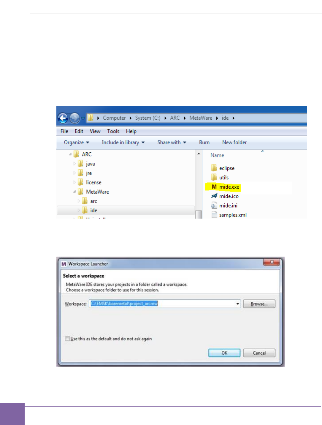
1. Start the MetaWare IDE by double-clicking mide.exe in the directory
/MetaWare/ide of the directory in which the MetaWare toolkit is installed. (Other
startup options are possible depending on the options selected during installation of
the MetaWare toolkit.)
Figure 10 MIDE Directory
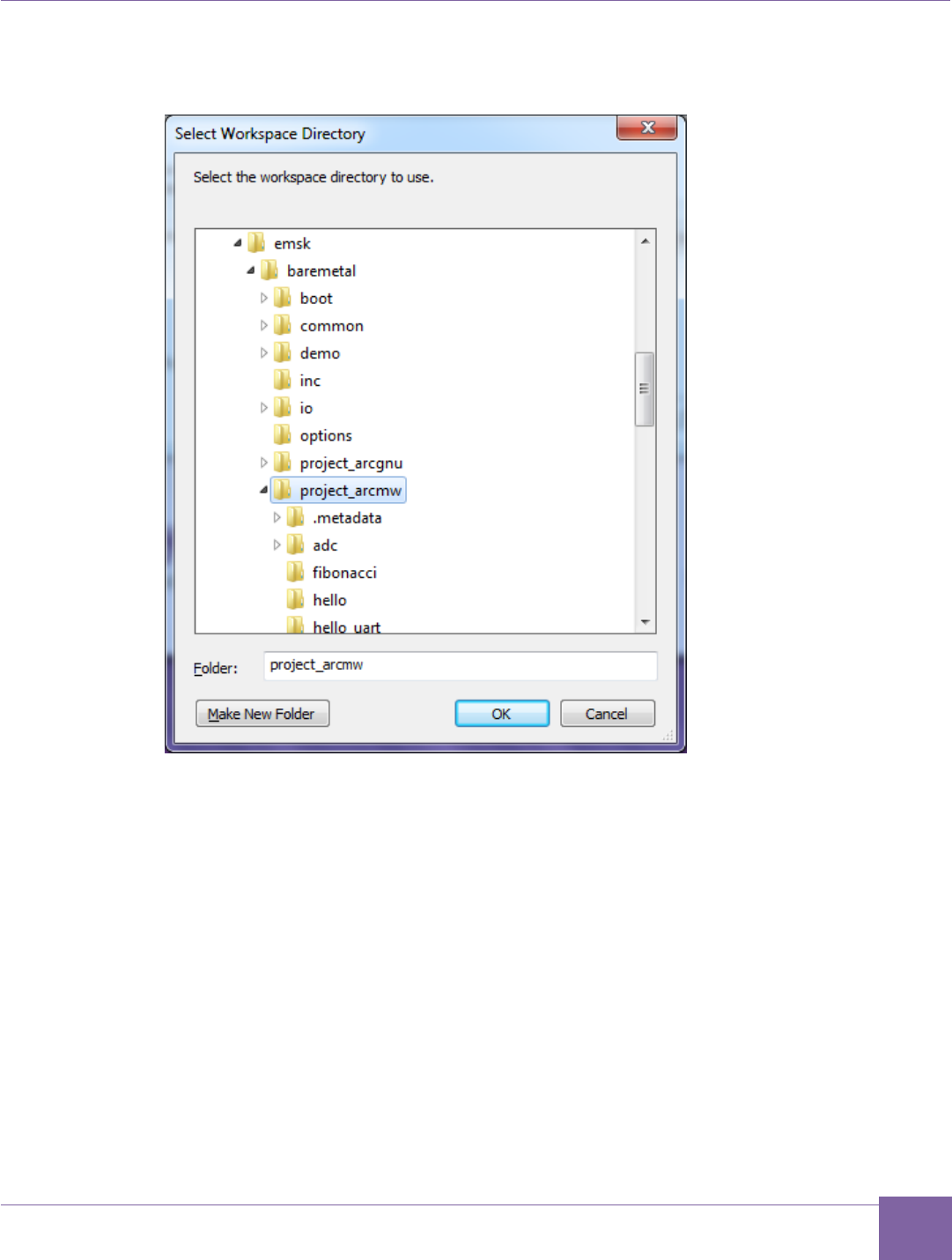
2. In the pop-up screen, select baremetal/project_arcmw as the current work-
space and click OK.
Figure 11 Selecting a Workspace
The files belonging to the demo projects have to be installed in the Eclipse IDE
workspace.
37
Building, Running, and Debugging Projects Using the MetaWare IDE ARC EM Starter Kit
Synopsys, Inc. Version 6280-009
March 2015
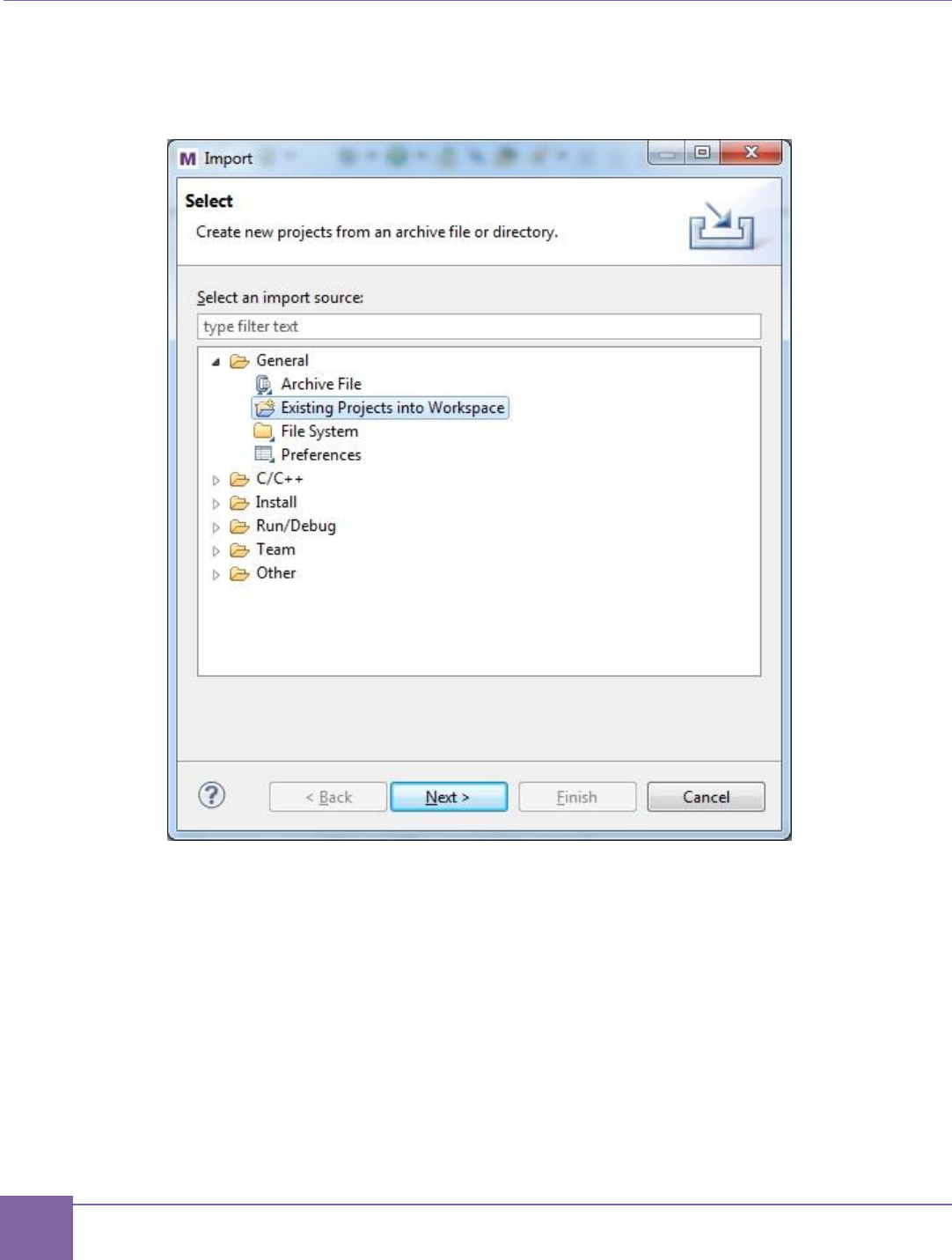
4. Click File > Import from the top menu of the MetaWare IDE. Then select Existing
Projects into Workspace and click the Next button.
Figure 13 MetaWare IDE — Select an Import Source
38
ARC EM Starter Kit Building, Running, and Debugging Projects Using the MetaWare IDE
Version 6280-009 Synopsys, Inc.
March 2015
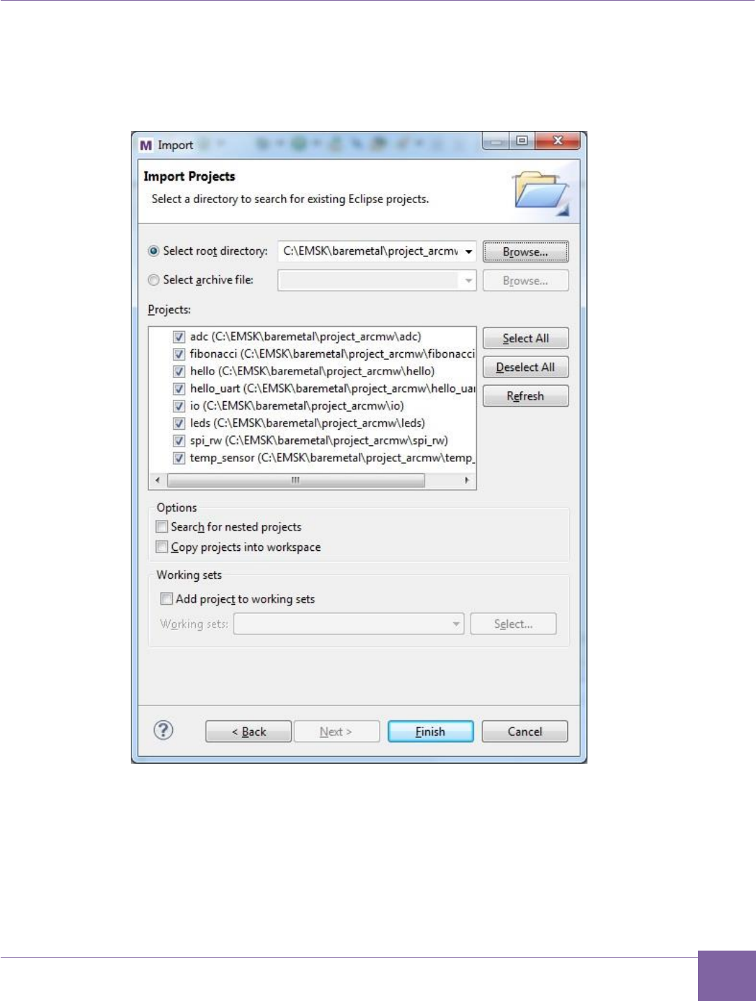
6. Select your baremetal/project_arcmw folder as the root directory and select all
projects available there for import. Then click the Finish button to import the demo
projects into your workspace.
Figure 14 MetaWare IDE — Select Projects for Import
39
Building, Running, and Debugging Projects Using the MetaWare IDE ARC EM Starter Kit
Synopsys, Inc. Version 6280-009
March 2015
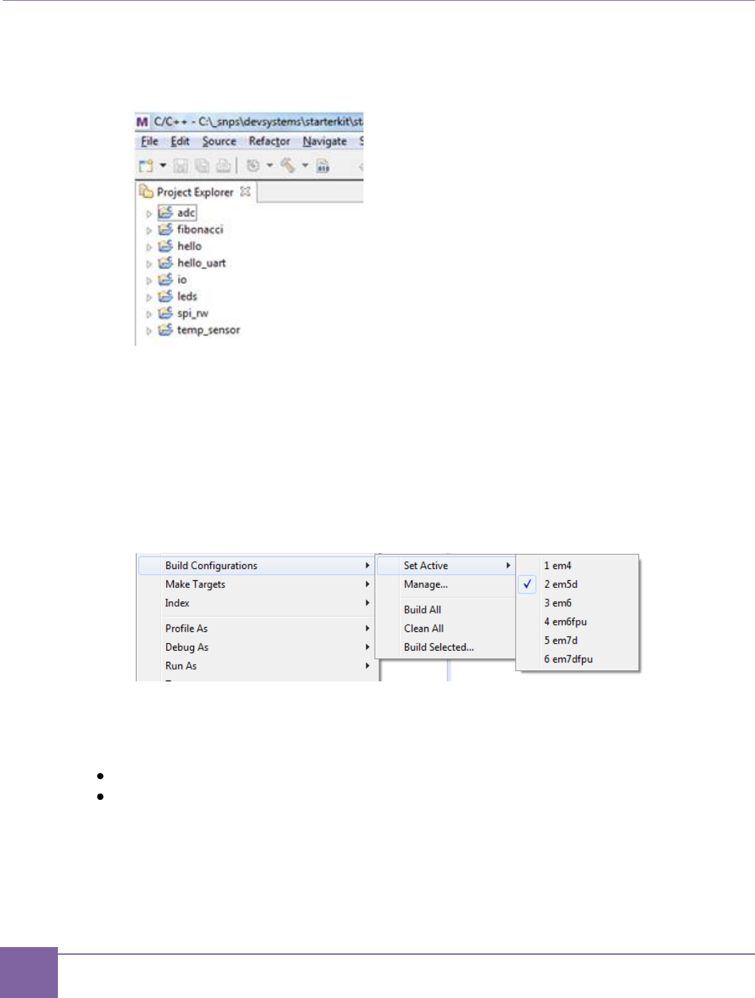
7. The MetaWare IDE loads and displays the demo projects in your workspace as
shown in Figure 15.
Figure 15 MetaWare IDE - Demo Projects in the Workspace
Building a Project Using the MetaWare IDE
1. Build the I/O library before the demo applications. To build the I/O library, right click
on an I/O project and select Build Project from the context menu.
2. Right-click one of the application projects.
3. Select Build Configurations > Set Active and select your build target, for example
em5d.
Figure 16 MetaWare IDE - Set Active Build Configurations
This step selects the em5d configuration of the project for building. You can choose an-
other option to match your debug target.
4. Rebuild the project using either of the following methods:
Right-click the project and select Build Project from the context menu.
Press CTRL-B.
40
ARC EM Starter Kit Building, Running, and Debugging Projects Using the MetaWare IDE
Version 6280-009 Synopsys, Inc.
March 2015
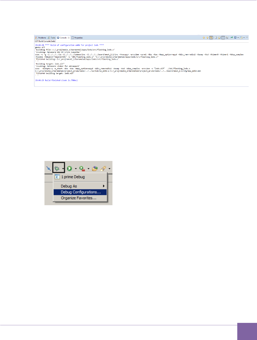
You can see the build results in the Console window. An example is shown in
Figure 17.
Figure 17 MetaWare IDE – Build Results in Console Window
Debugging a Project Using the MetaWare IDE
After the C Project is successfully compiled, you can debug the resulting executable on the
ARC EM Starter Kit board. This section provides short instructions how to configure and run
a debug session in the MetaWare IDE.
To debug the project, create a new debug configuration:
1. Select Debug Configurations from the Run menu or click the down arrow next to
the bug icon:
Figure 18 MetaWare IDE – Selecting the Debug Configuration from the Run Menu
41
Building, Running, and Debugging Projects Using the MetaWare IDE ARC EM Starter Kit
Synopsys, Inc. Version 6280-009
March 2015
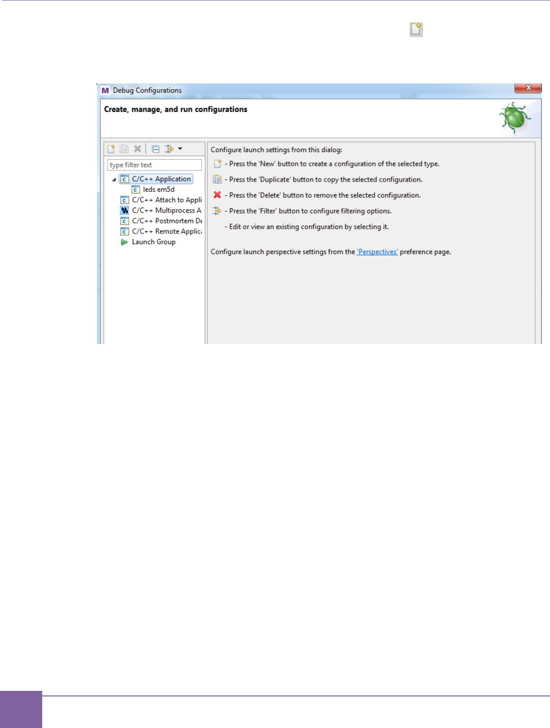
2. Double click C/C++ Application or click the top left icon to create a new debug
configuration for the project.
Figure 19 MetaWare IDE – Creating the new Debug Configuration
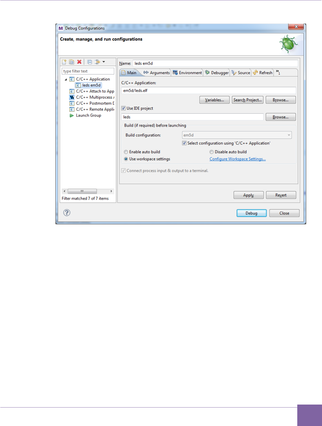
3. Optionally select a name for the new debug configuration (by default, it equals the
project name followed by the selected build target).
42
ARC EM Starter Kit Building, Running, and Debugging Projects Using the MetaWare IDE
Version 6280-009 Synopsys, Inc.
March 2015
Figure 20 MetaWare IDE – Selecting a Name for the New Debug Configuration
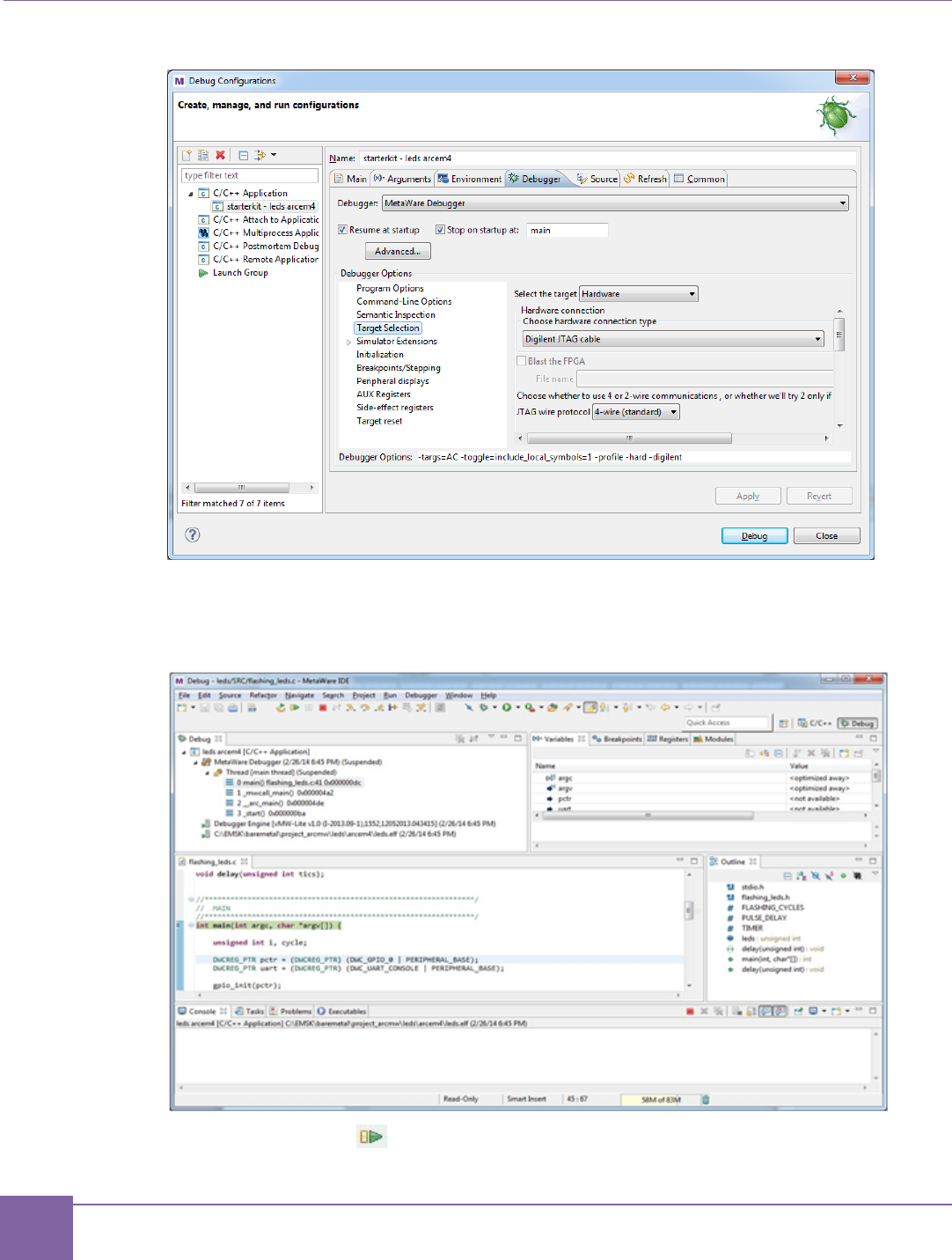
4. Click the Debugger tab, Target Selection and configure the target to use
Hardware.
5. Select Digilent JTAG cable as the hardware connection type.
43
Building, Running, and Debugging Projects Using the MetaWare IDE ARC EM Starter Kit
Synopsys, Inc. Version 6280-009
March 2015
Figure 21 MetaWare IDE – Selecting the Debugger Target
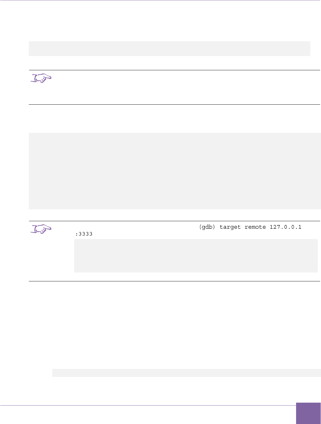
6. Click the Debug button in the Debug configurations dialog to initiate a debug
session and switch the IDE to the Debug perspective:
Figure 22 MetaWare IDE – Debug Window
7. Click the run button in the toolbar at the top of MetaWare IDE window to run the
application.

44
ARC EM Starter Kit Building and Running Applications Using make
Version 6280-009 Synopsys, Inc.
March 2015
8. When done, click the Terminate button on the toolbar to close the debug session.
9. Click the C/C++ button to display the Project Explorer.
Building and Running Applications Using make
Bare-metal demo applications use the GNU gmake utility to build. The build environment
provided with the bare-metal applications supports the MetaWare Development Toolkit and
the ARC GNU toolchain.
Build Environment
Each demo project has an individual makefile, but uses common configuration options that
are located in the options folder:
options.mk
Common options file with default settings for all applications. It sets the default core
configuration, default board settings, and the toolchain version and includes other
configuration files depending on the parameter settings.
rules.mk
This file defines rules for building source and object files and common targets for the
build.
Tool specific settings are located in /options/tools subfolder
toolchain_gnu.mk, toolchain_mw.mk
These files define toolchain-specific parameters (compiler, linker, and so on).
Board and core specific configuration files are located in the
/board/emsk_2.1/cfg folder
core_xx.mk
defines configuration-specific command line parameters (such core options, CPU
CLOCK, and so on).
board.mk
defines board specific settings like supported cores, JTAG settings, common defines,
and so on…
emxx.tcf
provides configuration options for ARC tools
link_emxx.ln
is a memory map file for ARC GNU linker
map_emxx.met
is a memory map file for MetaWare linker
To build a demo application, perform the following actions, illustrated here for the leds
demo application:
1. Open options/options.mk and set up the core configuration and toolchain by
setting the CURRENT_CORE and TOOLCHAIN variables. Set CURRENT_CORE =
em5d and TOOLCHAIN = mw.

45
Building and Running Applications Using make ARC EM Starter Kit
Synopsys, Inc. Version 6280-009
March 2015
2. Open a command window.
3. Navigate to the leds application folder:
cd C:/EMSK/baremetal/apps/leds/
4. Type the following command:
gmake all
The command above builds the demo application.
By default, the makefiles of the bare-metal demo applications support the following targets:
clean
Clean all object and temporary files in the application folder and in the I/O folders of
the I/O components linked to the project.
all
Compile and link the application. Object and ELF files are placed in the project
folder.
build
Clean and build application using the targets described above.
For a detailed description of configuration options and information on using particular
applications, refer to the readme.txt file in the corresponding application folder.
Running an Application Using MetaWare
All demo applications are compatible with the MetaWare development tools. The demo
applications can be configured for all processor configurations available in the ARC EM
Starter Kit board.
The MetaWare build environment provides additional makefile targets for running
applications using the MetaWare debugger or in batch mode:
run
Load and execute the application using the MetaWare debugger in command-line
mode.
gui
Load the application on the ARC EM core and execute the MetaWare debugger in
GUI mode. You can set breakpoints, run the program step by step, watch variables,
and perform other actions.
Running an Application Using ARC GNU Tools
The following list of demo applications can be built using the ARC GNU toolchain:
adc
hello_uart
fibonacci
leds
46
ARC EM Starter Kit Building and Running Applications Using make
Version 6280-009 Synopsys, Inc.
March 2015
The other demo applications use the MetaWare hostlink interface, which is not supported by
the ARC GNU toolchain. Before running application on ARC EM Starter kit board open a
windows console and type the following command for running OpenOCD:
openocd -f ../share/openocd/scripts/target/snps_starter_kit_arc-em.cfg
-c init -c halt -c "reset halt"
Note
ARC GNU IDE 2014.08 includes a version of the OpenOCD configuration file incompatible
with EMSK 2.x. Use the snps_em_sk-2.0.cfg” file from the
baremetal/project_arcgnu folder instead.
Then open one more Windows console, load and run your application by using GDB in
command-line mode:
arc-elf32-gdb --quiet leds.elf
(gdb) target remote 127.0.0.1 :3333
(gdb) set remotetimeout 15
(gdb) load
(gdb) break main
(gdb) continue
(gdb) step
(gdb) next
(gdb) break exit
(gdb) continue
Note
You might see the following message after the
command:
Remote debugging using 127.0.0.1 :3333
exit (code=0) at /bld/arc/unisrc-
4.8win/newlib/libc/stdlib/exit.c:61
61 /bld/arc/unisrc-4.8win/newlib/libc/stdlib/exit.c: No such
file or directory.
It is not an error. It might occur because ARC GNU sources are not supplied by this tool.
Detailed information on how to load and debug applications for ARC processors using the
ARC GNU debugger is provided in the ARC GDB Getting Started document.
Building MQX Applications Using gmake
In order to build an MQX demo application perform the following actions:
1. Open a command window.
2. Navigate to the application folder, dw_apb_led demo is used below as an exam-
ple:
C:\ARC\software\mqx2.61c\examples\starterkit\dw_apb_led\

47
Building and Running Applications Using make ARC EM Starter Kit
Synopsys, Inc. Version 6280-009
March 2015
3. Type one of the following commands, depending on the core configuration you are
using:
ARC_EM5D
gmake MQX_CONFIG= C:\ARC\software\mqx2.61c
\build\starterkit\config0.mk
ARC_EM7D
gmake MQX_CONFIG= C:\ARC\software\mqx2.61c
\build\starterkit\config1.mk
ARC_EM7DFPU
gmake MQX_CONFIG= C:\ARC\software\mqx2.61c
\build\starterkit\config2.mk
These commands build the demo application for a respective target processor.
Use the following command to run a demo application:
mdb –OS=MQX-run -digilent <application
dir>/arcv2em_<core_config_#>.met/<elf-filename>.elf
For example, to run the dw_apb_led demo on an ARC_EM5D configuration, use the
following command:
mdb –OS=MQX-run -digilent
C:\ARC\software\mqx2.61c\examples\starterkit\dw_apb_led\arcv2em_0.me
t\dw_apb_led.elf
For a detailed description of configuration options and information on using particular
applications, refer to the readme.txt file in the corresponding application folder and
consult the driver documentation in the doc/ folder.
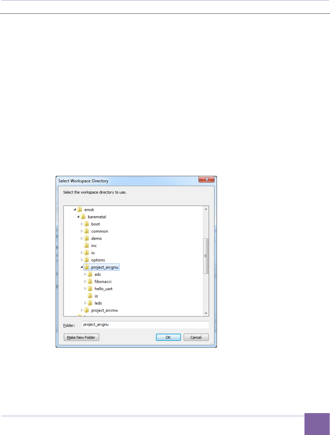
48
ARC EM Starter Kit Building and Running Projects Using the ARC GNU IDE
Version 6280-009 Synopsys, Inc.
March 2015
Building and Running Projects Using the ARC GNU IDE
Obtaining the ARC GNU Toolchain
Prebuilt versions of the ARC GNU tools are available from the GitHub website:
https://github.com/foss-for-synopsys-dwc-arc-processors/arc_gnu_eclipse/releases
The ARC GNU Toolchain is also made available as source code, allowing it to be built and
installed on any supported platform. The main git repository for the ARC GNU tool chain is
https://github.com/foss-for-synopsys-dwc-arc-processors/toolchain
Using the IDE Workspace
The files belonging to the demo projects have to be installed in the Eclipse IDE workspace.
The instructions below illustrate this process step-by-step:
1. Run the ARC GNU IDE and select baremetal/project_arcgnu as the current
workspace.
Figure 23 ARC GNU IDE - Select Workspace Directory
2. Close the Welcome view to see your workspace.
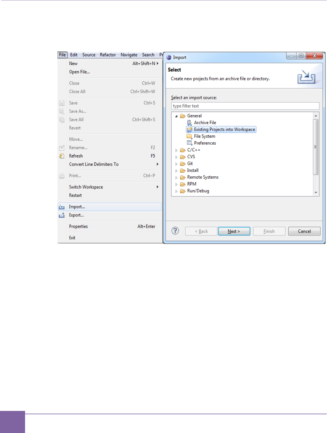
49
Building and Running Projects Using the ARC GNU IDE ARC EM Starter Kit
Synopsys, Inc. Version 6280-009
March 2015
3. Select File > import in the top menu, then select General > Existing Projects into
Workspace and click the Next button.
Figure 24 ARC GNU IDE - Import Existing Projects into Workspace (First Step)
4. Select your baremetal/project_gnu folder as the root directory and select all
projects available there for import. Then click the Finish button to import the demo
projects into your workspace. See Figure 25 for more details.
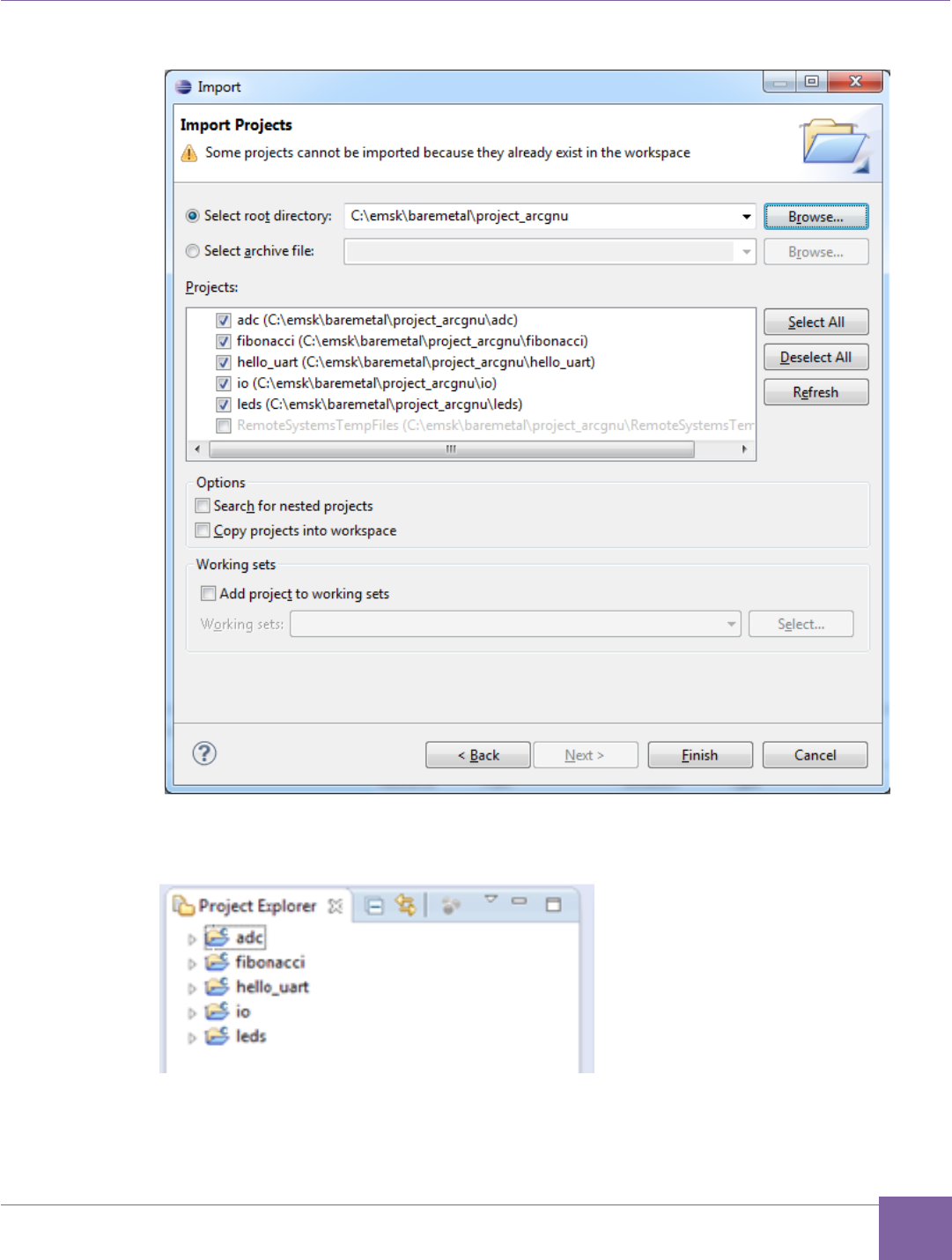
50
ARC EM Starter Kit Building and Running Projects Using the ARC GNU IDE
Version 6280-009 Synopsys, Inc.
March 2015
Figure 25 ARC GNU IDE - Import Existing Projects into Workspace (Second step)
The IDE loads and displays the demo projects in your workspace as shown in Figure 26.
Figure 26 ARC GNU IDE - List of Demo Projects in the Workspace
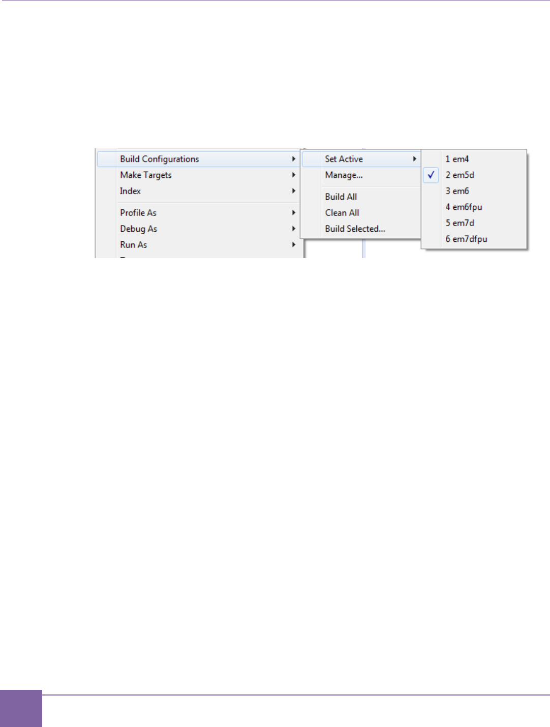
51
Building and Running Projects Using the ARC GNU IDE ARC EM Starter Kit
Synopsys, Inc. Version 6280-009
March 2015
Building a Project Using the ARC GNU IDE
1. The I/O library must be built before any demo applications can be built. To build the
I/O library, right-click on the I/O project and select Build Project in the context
menu.
2. Right-click one of the application projects and select Build Configurations > Set
Active and select your build target, for example em5d as shown in Figure 27.
Figure 27 ARC GNU IDE - Set Active Build Configurations
This step selects an ARC_EM5D configuration of the project for building. You can
choose another option to match your debug target. A full list of available targets and
corresponding core configurations are described in Compatibility section of this
document.
3. Rebuild the project using any of the following methods:
o Right-click the project again and select Build Project.
o Press CTRL-B.
You can see the build results in the console window.
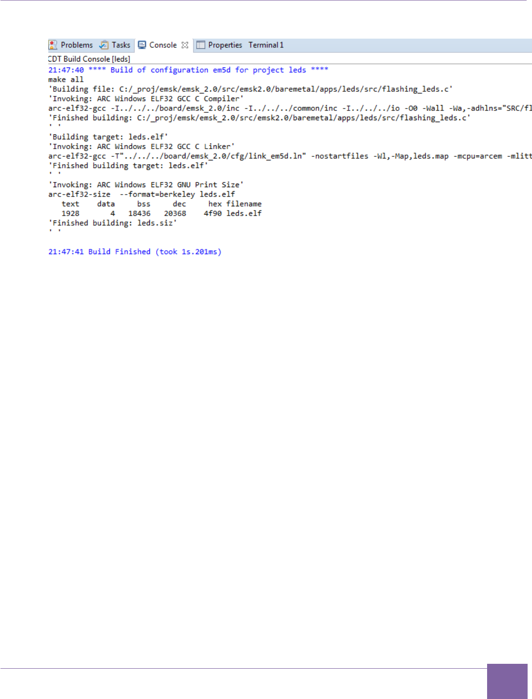
52
ARC EM Starter Kit Building and Running Projects Using the ARC GNU IDE
Version 6280-009 Synopsys, Inc.
March 2015
Figure 28 ARC GNU IDE - Build Results in Console Window
Debugging a Project Using the ARC GNU IDE
After the project is successfully compiled by ARC GCC, you can debug the resulting
executable on the ARC EM Starter Kit board.
This section provides short instructions on how to configure and run a debug session in the
ARC GNU toolchain IDE. The full documentation of the debugger features is available in the
ARC_GNU_IDE_GettingStarted.pdf provided with the ARC GNU Toolchain.
To debug the project, create a new debug configuration using arc-elf32-gdb.
1. Select Debug Configurations from the Run menu.
2. Double click ARC C/C++ or click the top left icon to create a new debug
configuration for the project:
3. Select a name for the new debug configuration (by default, it equals the project
name followed by the selected build target).
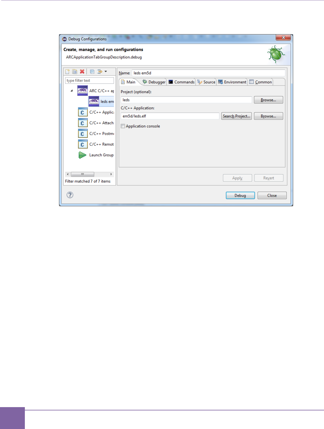
53
Building and Running Projects Using the ARC GNU IDE ARC EM Starter Kit
Synopsys, Inc. Version 6280-009
March 2015
Figure 29 ARC GNU IDE - Creating a Debug Configuration
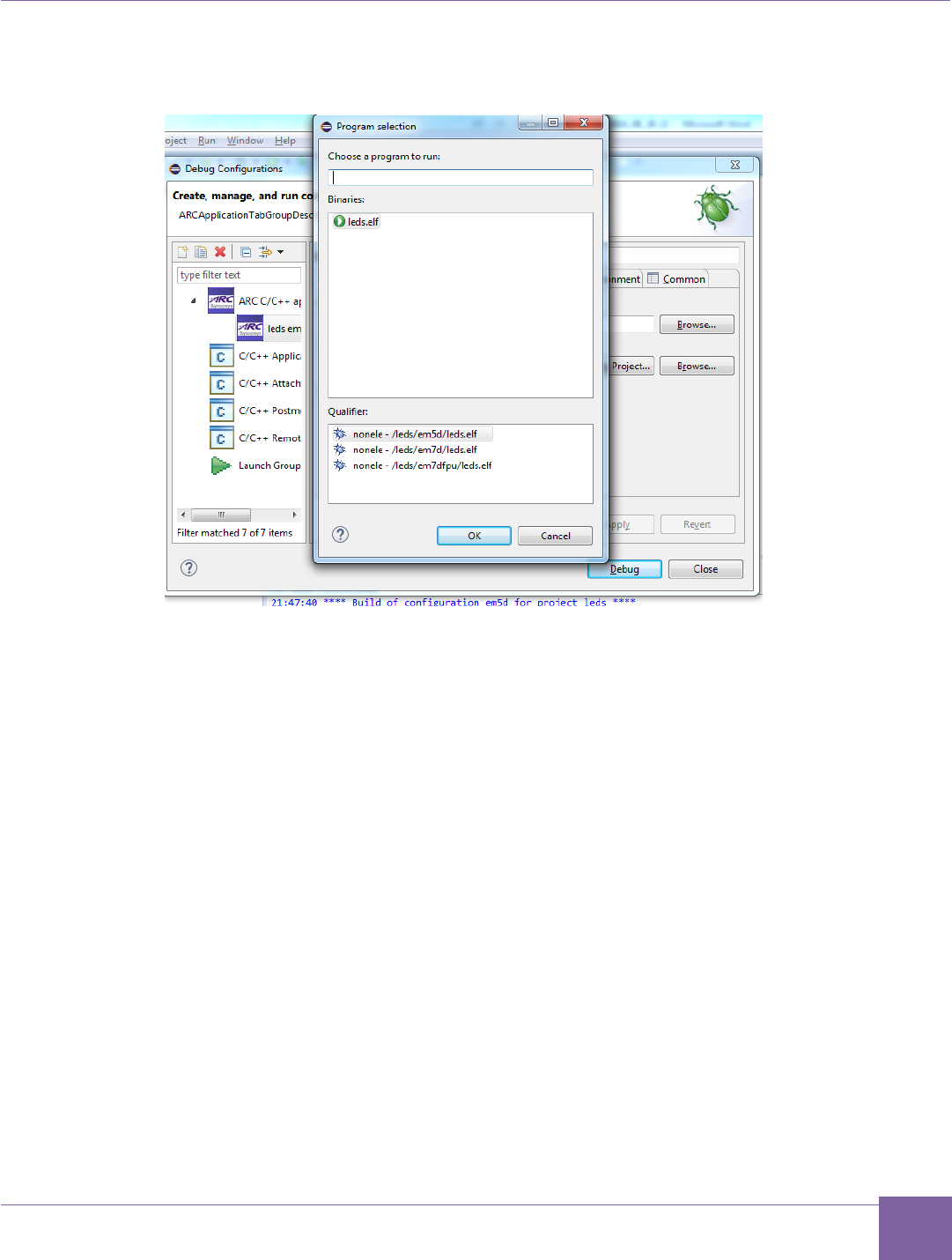
54
ARC EM Starter Kit Building and Running Projects Using the ARC GNU IDE
Version 6280-009 Synopsys, Inc.
March 2015
4. Click the Search Project and select the required program.
Figure 30 ARC GNU IDE – Program Selection
Note that if you are building an application only for one configuration, the ARC GNU
IDE automatically selects it.
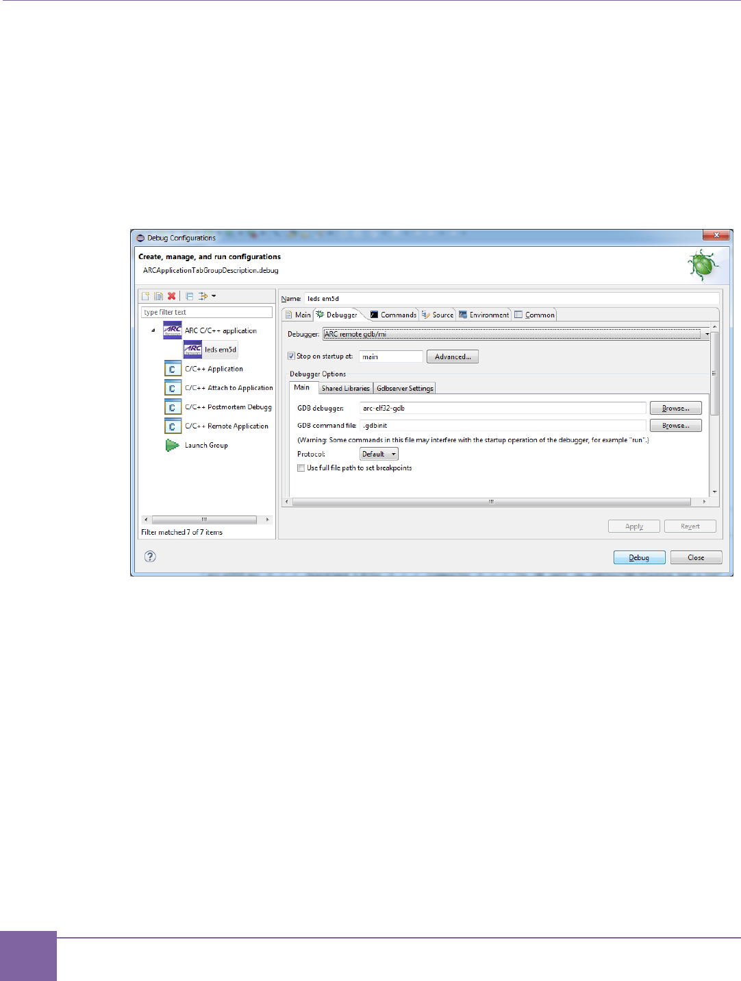
55
Building and Running Projects Using the ARC GNU IDE ARC EM Starter Kit
Synopsys, Inc. Version 6280-009
March 2015
5. Navigate to the Debugger tab and select “ARC remote gdb/mi” from the Debugger
drop down menu.
In the Debugger Options select Gdbserver Settings sub-tab. The ARC GDB Serv-
er JTAG via OpenOCD and the COM port can be selected from here.
In JTAG via OpenOCD section map OpenOCD PATH to the board configuration
file baremetal/project_arcgnu/snps_em_sk-2.0.cfg
Figure 31 ARC GNU IDE - Commands Initialization from the Debugger
Note that there might be a problem with OpenOCD not binding to the
localhost. If it happens, the Host Address at Gdbserver Settings sub-tab should
be changed to real IP. Otherwise, the debug session would not start.
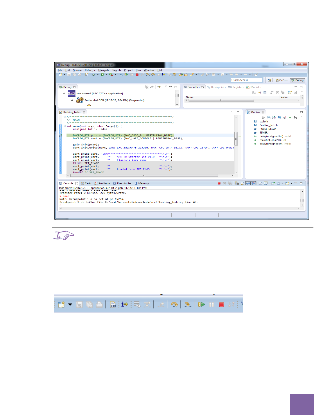
56
ARC EM Starter Kit Building and Running Projects Using the ARC GNU IDE
Version 6280-009 Synopsys, Inc.
March 2015
6. Click the Debug button in the Debug configurations dialog to initiate the debug
session. This action automatically launches the PuTTY and OpenOCD applications
in the background and connects to the UART on the ARC EM Starter Kit board.
OpenOCD startup log messages appear on the console.
Figure 32 ARC GNU IDE – Debug Window
Note
If a serial terminal is already open before debugging, close it to
avoid contention between the GNU tool and the standalone serial
console
7. Step through each line by using F5 (step into), or F6 (step over).
Figure 33 ARC GNU IDE – Stepping Toolbar
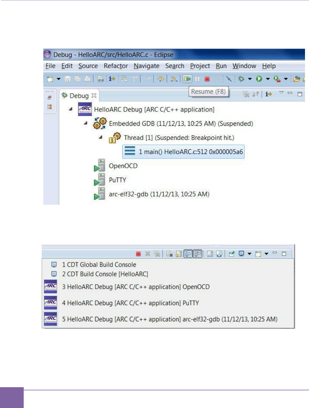
57
Building and Running Projects Using the ARC GNU IDE ARC EM Starter Kit
Synopsys, Inc. Version 6280-009
March 2015
8. Toggle a breakpoint at the last line of main(), which is "}", and then click Resume or
press F8.
Figure 34 ARC GNU IDE – Stepping Toolbar
9. Terminate all external tools like a PuTTY before you quit current debugging
process.
Figure 35 ARC GNU IDE – Stepping Toolbar

58
Version 6280-009 Synopsys, Inc.
March 2015
7
Creating Applications Using the MetaWare Tools
This chapter describes how to create and run a simple application using the MetaWare tools
in IDE and command-line modes.
Creating an Application Using the Command Line Tools
The following procedure describes the process of building a simple “Hello world” application
for the ARC EM Starter Kit. This application can be used as a starting point for creating your
own applications to run on the Starter Kit.
Prerequisites:
Ensure that you have downloaded and installed the MetaWare Development Toolkit.
See Download and Install MetaWare.
Ensure that you have connected the ARC EM Starter Kit to the host. See Quick Con-
nection Guide.
Perform the following steps in order to create an application:
1. Create a simple C program that prints “Hello world” string to the default stdout de-
vice. For example:
#include "stdio.h"
int main(void) {
printf("Hello world");
return 0;
}
2. Save the code above as myhello.c

59
Debugging Applications Using the MetaWare Debugger ARC EM Starter Kit
Synopsys, Inc. Version 6280-009
March 2015
3. Build your application running the MetaWare compiler in command line mode:
ccac myhello.c -av2em -core1 -Os -Hpfnoflt -Hldopt=
-Bbase=0x100 -o myhello.elf
This command compiles and links myhello.elf for ARC EM core version 1. The
myhello.elf file is created in the same folder as the source file. Ensure that the
base address points to the right memory region for ARC_EM5 and ARC_EM7D con-
figurations. You also can use a linker script to manage memory allocation for your
application; example memory linker scripts are available in
/baremetal/board/emsk_2.1/cfg folder:
map_em5d.met – for ARC_EM5D configuration
map_em7d.met – for ARC_EM7D and ARC_EM7DFPUconfiguration
map_em7dfpu.met – for ARC_EM7DFPUconfiguration
There are also available met-files for the em4, em6 and em6fpu configurations.
The command line below illustrates how to build the application using a linker script
for ARC_EM5D configuration:
ccac myhello.c -av2em -core1 -Os -Hpfnoflt -Hldopt=
-Bbase=0x100 -o myhello.elf map_em5d.met
Debugging Applications Using the MetaWare Debugger
1. Use the following command to launch your application in the MetaWare GUI de-
bugger in an interactive mode:
mdb -digilent myhello.elf
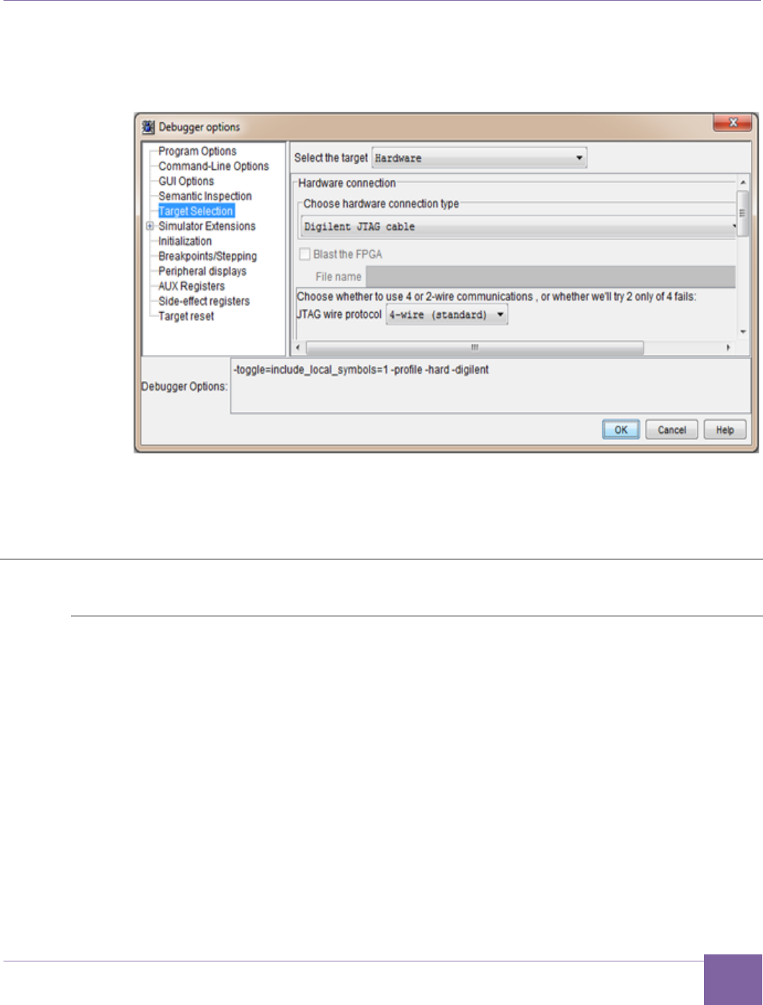
60
ARC EM Starter Kit Creating Application Using the MetaWare IDE
Version 6280-009 Synopsys, Inc.
March 2015
2. In the Debug a process or processes dialog, click Debugger Options and set the
debugger options as shown in Figure 36.
Figure 36 MetaWare Settings Required to Use ARC JTAG through USB
3. Click OK.
“Hello world” output appears on the command line.
Creating Application Using the MetaWare IDE
Create a New Project in the MetaWare IDE
1. Launch the MetaWare IDE.
2. Select Create a New Project.
3. From the Select a wizard dialog box that results, select C/C++-> C Project and
click Next.
4. Add a Project Name (for example: Lab1).
5. To create an Empty Project with an ARC EM Generic executable, select the
appropriate options as shown in Figure 37, and then click Next.
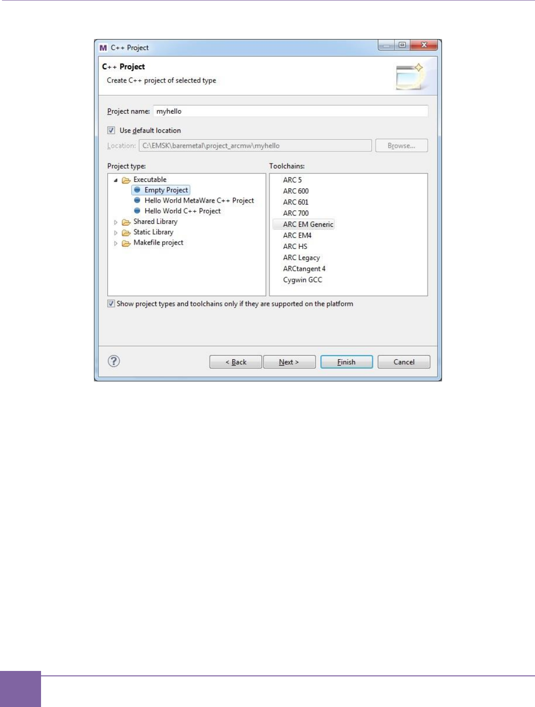
61
Creating Application Using the MetaWare IDE ARC EM Starter Kit
Synopsys, Inc. Version 6280-009
March 2015
Figure 37 MetaWare IDE - Creating a New Project
6. Click Next again to create both Debug and Release configurations.
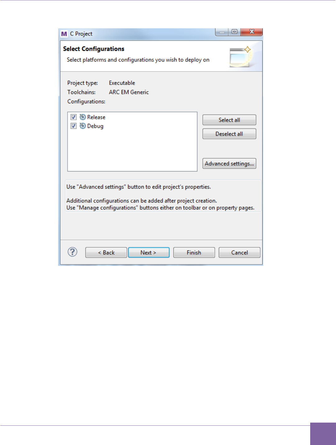
62
ARC EM Starter Kit Creating Application Using the MetaWare IDE
Version 6280-009 Synopsys, Inc.
March 2015
Figure 38 MetaWare IDE - Select Project Configurations
7. Click the Next button to proceed selecting a Tool Configuration File (TCF); this step
presets the IDE with the right compile options and memory mapping.
a. In the board/emsk_2.1/cfg folder, select Browse to a TCF file and
select the TCF file corresponds to your ARC EM configuration. (The EM4
processor is a subset of EM5D, and EM6 is a subset of EM7D. So soft-
ware may be built for EM4 but then run on EM5D or built for EM6 but then
run on EM7D)
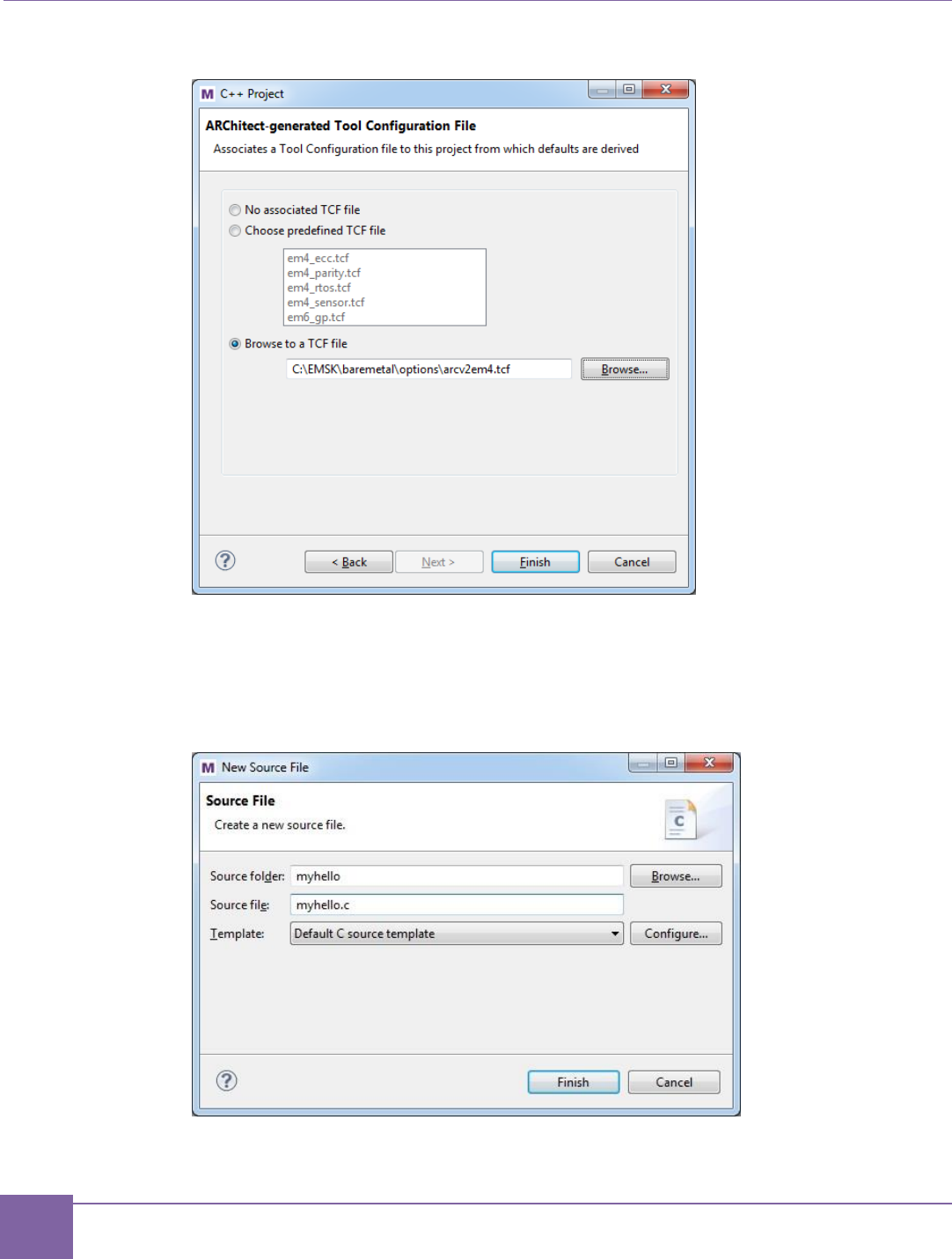
63
Creating Application Using the MetaWare IDE ARC EM Starter Kit
Synopsys, Inc. Version 6280-009
March 2015
Figure 39 MetaWare IDE - Select TCF File
8. Click Finish to create the project.
9. Select File > New > Source File and, create a new source file for your project. For
example myhello.c
Figure 40 MetaWare IDE - Create New Source File
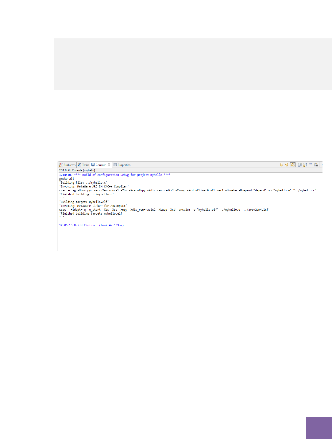
64
ARC EM Starter Kit Creating Application Using the MetaWare IDE
Version 6280-009 Synopsys, Inc.
March 2015
Create a simple C program that prints “Hello world” to the default stdout device. For
example:
#include "stdio.h"
int main(void) {
printf("Hello world");
return 0;
}
10. Save your file.
11. To create the executable, select Build Project under the Project main menu, or
mouse over the myhello project, right-click, and select Build Project.
12. Review the messages in the Problems and Console panes at the bottom of the
window to verify a successful build.
Figure 41 MetaWare IDE - Console Output for Test Project
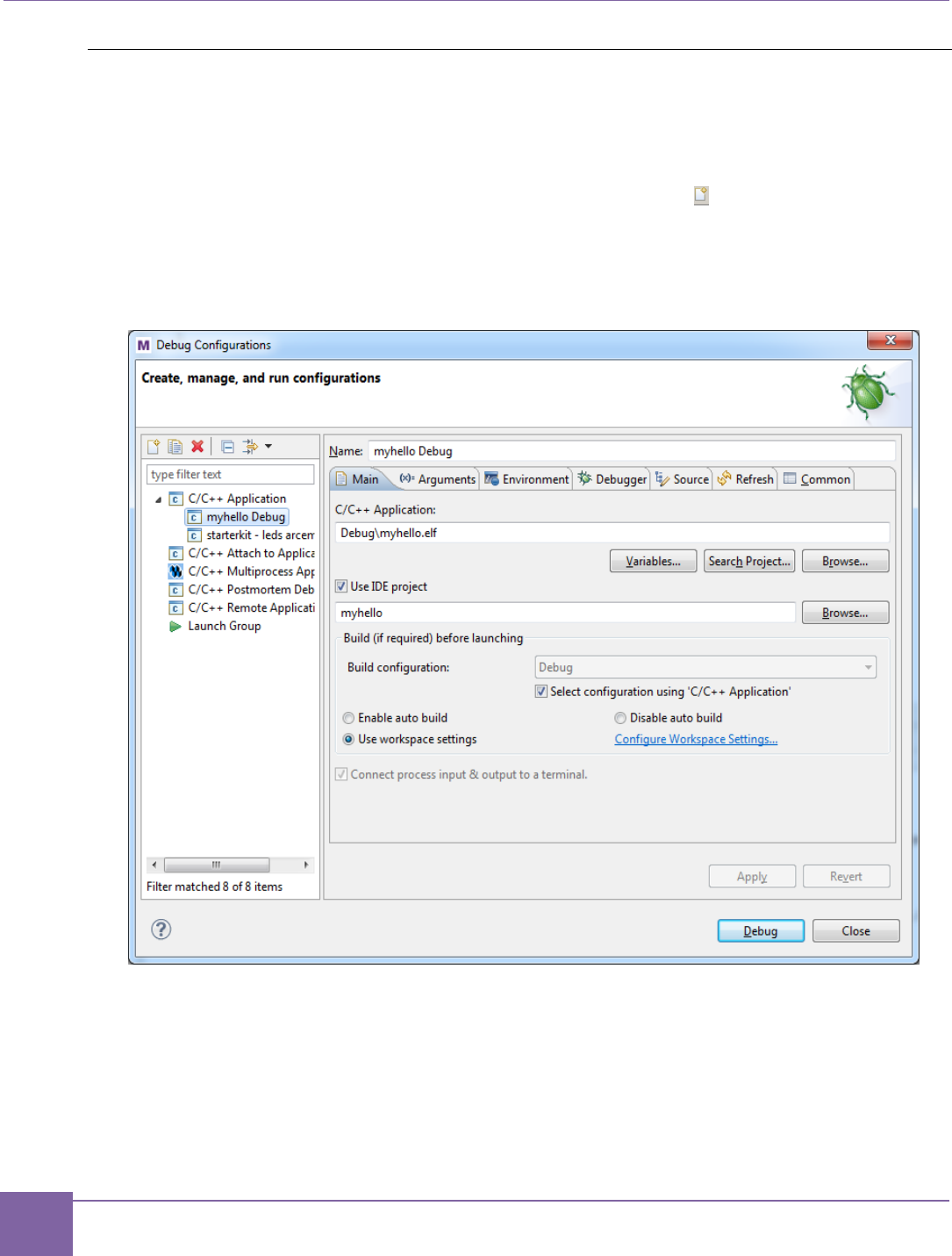
65
Creating Application Using the MetaWare IDE ARC EM Starter Kit
Synopsys, Inc. Version 6280-009
March 2015
Invoking the Debugger and Running the Executable
Make sure that the ARC EM Starter kit board is connected to your computer by USB cable.
1. Select Run > Debug Configurations or right-click myhello and select Debug As >
Debug Configurations.
2. Double click the C/C++ Application, or click New icon ( ) with C/C++ Application
selected
The IDE displays a window similar to Figure 42. The Main tab is selected by default.
Figure 42 MetaWare IDE - Creating New Debug Configuration
3. Click the Debugger tab and set up the debugger to run the application on an ARC
EM Starter Kit board.
4. Click the Target Selection menu in the Debugger Options field.
a. On the right side of Debugger Options field, in the Select the target field,
select Hardware.
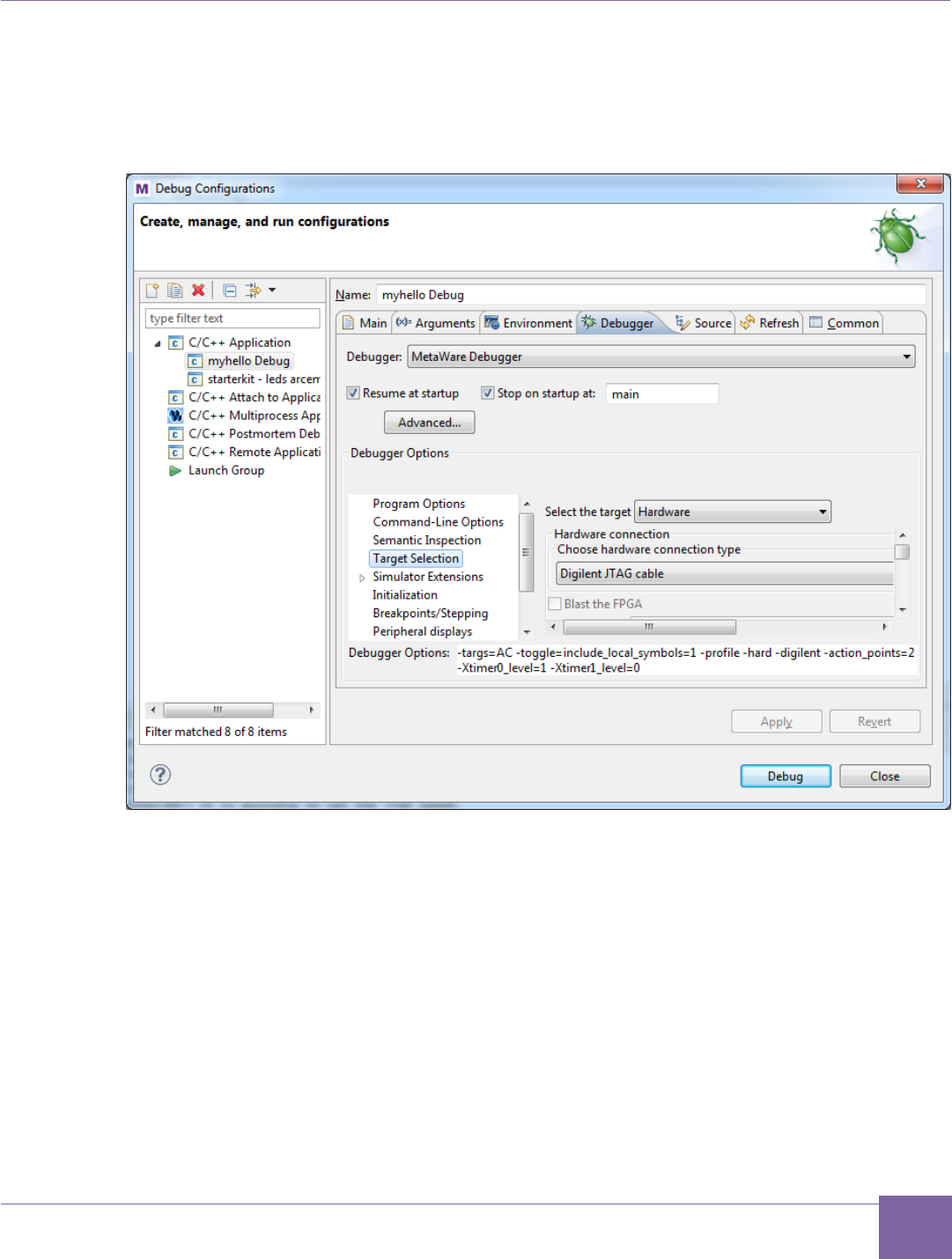
66
ARC EM Starter Kit Creating Application Using the MetaWare IDE
Version 6280-009 Synopsys, Inc.
March 2015
b. In the Hardware connection field, choose the Digilent JTAG cable from
the Choose hardware connection type drop-down menu. Keep the de-
faults for all other settings.
Figure 43 MetaWare IDE - Configure Debugger
5. Click Debug and confirm the perspective switch by selecting yes in the pop-up win-
dow. The Debug perspective opens as shown in Figure 44.
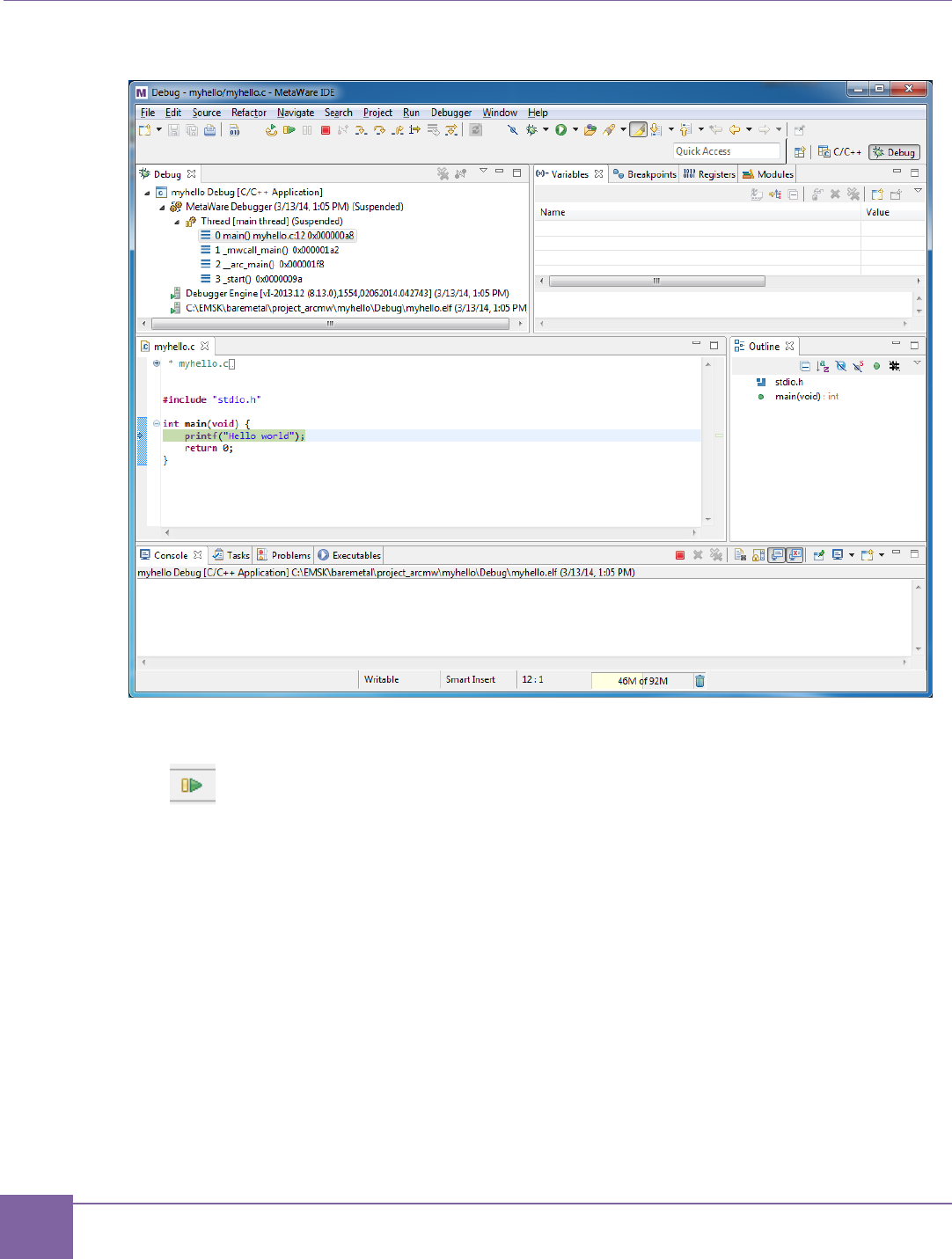
67
Creating Application Using the MetaWare IDE ARC EM Starter Kit
Synopsys, Inc. Version 6280-009
March 2015
Figure 44 MetaWare IDE - Debug Perspective
6. Click the Resume/Run button:

68
ARC EM Starter Kit Creating Application Using the MetaWare IDE
Version 6280-009 Synopsys, Inc.
March 2015
7. The application prints “Hello world” in the Console window.
Figure 45 MetaWare IDE - Console window

69
Version 6280-009 Synopsys, Inc.
March 2015
8
Running Applications in Self-Boot Mode
This chapter describes how to build a self-booting application, write it into SPI memory, and
run it after the board power up or reset.
Self-Boot Application Concept
ARC EM Starter kit provides an ability to store a customer application in SPI flash memory
and run it after power up. That application is called a self-boot application in this chapter.
The following are the basic stages in preparing and using self-boot applications:
1. Build the self-boot application
2. Write the self-boot application to SPI memory
3. Run the self-boot application
Running the application is a process executed by ARC EM Starterkit board. Preparing
application for running in self-boot mode requires connecting the ARC EM Starter Kit to a
host with Windows OS and installed MetaWare or MetaWare Lite tools.
Building a Self-Boot Application
The following requirements exist for an application built for running in self-boot mode:
The application can be built for a target CPU configuration. There are some
differences between four configurations of cores supported by ARC EM Starter Kit,
and an application built for ARC EM5D might not work properly on an ARC EM7D.
Make sure that you build your application using the correct core configuration.
The application must be linked to use a valid memory segment and cannot use the
memory space from 0x0000_0000 to 0x0000_4000, which is reserved for the
bootloader. A valid memory segment means that the memory used by your
application must be available for a target core configuration. An application mapped
in non-existent memory region does not work.
The led_spi application from baremetal/apps is an example of a self-boot application.

70
ARC EM Starter Kit Write the Self-Boot Application Image to SPI Flash
Version 6280-009 Synopsys, Inc.
March 2015
Write the Self-Boot Application Image to SPI Flash
The SPI interface on the ARC EM Starter Kit board does not connect directly to JTAG and
not available through any PMOD. An application image can be written to the flash memory
by using the spi_rw application from the demo package.
The spi_rw is an application for the ARC EM cores. It communicates with the file system of
a host computer using the JTAG interface to read/write file from the host computer and
store/load data on the on-board SPI flash memory chip.
The spi_rw application supports write and read commands:
Writing
The w command writes a binary image to the on-board SPI flash memory.
The spi_rw application expects a few parameters to write and configure self-boot
application, such as:
gmake run CMD_LINE="-w <file> <ram_address> <start_address>"
-w switches spi_rw to write mode.
<file> is path to self-boot application image, for example:
C:\EMSK\baremetal\apps\leds_spi\leds_spi.img.
<ram_address> defines the RAM start address for loading an application image.
<start_address> defines the address from which the bootloader starts the
execution of the loaded image.
The spi_rw is an ARC processor application; run it on the ARC processor. To run the
application in command line mode do the following steps:
1. Open a command-line console on your host.
2. Navigate to the spi_rw application folder.
3. Type the following command in the command-line console:
gmake run CMD_LINE="<cmd line parameters>"
With <cmd line parameters> as described above.
The following instructions illustrate how to write the leds_spi.img application to be
loaded in ICCM memory with the start address 0x4000.
1. Open a command -line console on your host.
2. Navigate to baremetal/apps/leds_spi.
3. Build leds_spi.img using the command gmake build.
4. Navigate to baremetal/apps/spi_rw.
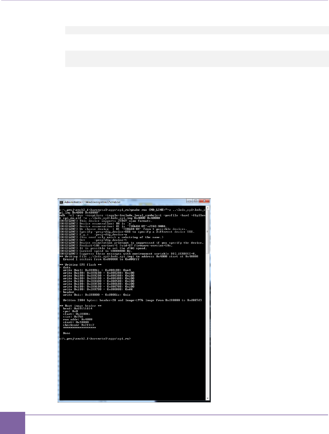
71
Write the Self-Boot Application Image to SPI Flash ARC EM Starter Kit
Synopsys, Inc. Version 6280-009
March 2015
5. Build spi_rw by running the following command:
gmake
6. Write leds_spi to SPI flash by running the following command:
gmake run CMD_LINE="-w ../leds_spi/leds_spi.img 0x4000
0x4000"
This command does the following:
1. It runs mdb debugger in command-line mode and loads the spi_rw application in
the ARC EM Starter Kit.
2. Starts debugger execution of spi_rw on the ARC processor with the specified
command line parameters. The spi_rw application reads the self-boot image form
the host though the JTAG port and writes it into SPI memory.
3. After the self-boot image is written into the SPI memory, the spi_rw application
creates a header with the parameters needed for running the self-boot image and
writes this header into SPI memory.
4. After completion all SPI programming operations the spi_rw application prints sta-
tus information in the console as shown in Figure 46.
Figure 46 Output of spi_rw

72
ARC EM Starter Kit Running the Self-Boot Application
Version 6280-009 Synopsys, Inc.
March 2015
Reading
The spi_rw application also provides an ability to read binary image from SPI flash in a file
on a host computer by using the follow command:
gmake run CMD_LINE="-r <file>”
-r switches spi_rw to read mode.
<file> is name of the file to read binary data from SPI.
To use the read command to do the following steps:
1. Open command-prompt console.
2. Navigate to baremetal/apps/spi_rw
3. Build spi_rw by running the following command
gmake
4. Write leds_spi to SPI flash by running the following command:
gmake run CMD_LINE="-r read.img”
5. The spi_rw application creates the read.img file in the current folder. This file
contains the self-boot image read from SPI flash.
Note
The spi_rw applications are only compatible with the MetaWare toolkit.
Running the Self-Boot Application
After the board is powered up, the ICCM memory has a predefined application that includes
self-tests and bootloader parts. After completion of self-tests, this application checks state of
on-board DIP switch SW1. If bit 4 of SW1 is ON, the bootloader is starting. The bootloader
checks SPI flash memory for a data structure with the self-boot image parameters. This
structure includes the following information:
typedef struct {
unsigned int head; // 0x68656164 ='head'
unsigned int cpu_type; // = 0 - all images
unsigned int start; // start address of application image in spi flash
unsigned int size; // size of image in bytes
unsigned int ramaddr; // address of ram for loading image
unsigned int ramstart; // start address of application in RAM !!!!
unsigned int checksum; // sum of all bytes in image
} image_t;

73
SPI Flash Memory Structure ARC EM Starter Kit
Synopsys, Inc. Version 6280-009
March 2015
The bootloader looks for a head signature in SPI flash memory at address 0xD80000. After
the signature is found, the bootloader reads the image parameters from the header and
starts loading procedure:
1. The bootloader starts copying the application image from address start in SPI-
flash to address ramaddr in the processor memory. The number of bytes for
copying is declared in the size parameter of self-boot header. The ramaddr can
point to a DDR, ICC or DCCM memory space, except the space 0x00000000 –
0x00004000, which is reserved for the bootloader.
2. After copying the data, the bootloader compares the checksum of the application
image with the checksum from self-boot header, and if they are equal the
bootloader start executing the application from the address specified by the
ramaddr parameter of self-boot header.
Position Bit3 of on-board DIP switch SW1 affects the console output of the bootloader.
Setting Bit 3 to the ‘On’ position suppresses console output. When Bit 3 is on the ‘Off’
position the bootloader prints the parameters of the self-boot image and indicates the status
of the loading process.
Note
The bootloader does not check the compatibility of application stored in SPI flash memory
with selected core configuration. Make sure that you run your application on the right core
configuration.
SPI Flash Memory Structure
The flash memory is divided in two sections: FPGA image and Application. The Application
section contains the main code for the application and header, and the FPGA section con-
tains the default core configurations for FPGA.
The header contains the following information:
Application image size
RAM destination address
Checksum
Start address from which the CPU starts code execution after loading
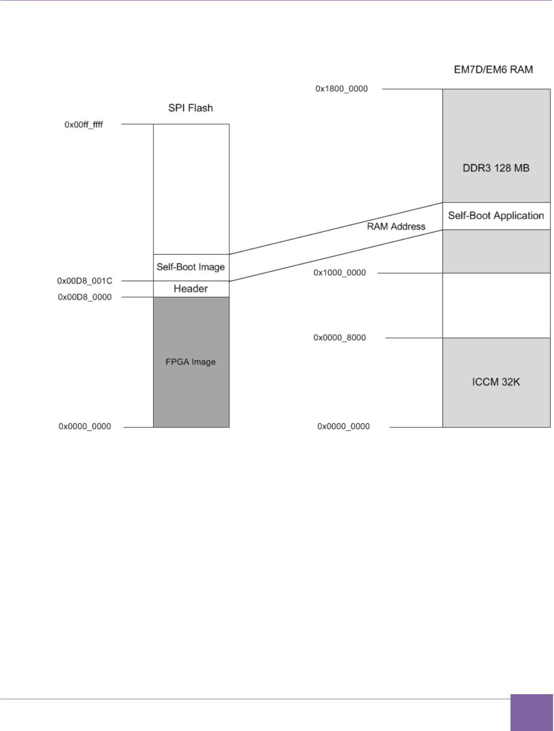

75
Version 6280-009 Synopsys, Inc.
March 2015
Appendix: A
Hardware Functional Description
This appendix provides information about the hardware used in the ARC EM Starter Kit.
Board Overview
The ARC EM Starter Kit consists of two boards:
FPGA module with a Xilinx Spartan-6 XC6SLX150-3FGG484C FPGA device.
Base board with extension connectors and peripherals.
The kit has the following on-board peripheral devices:
2×16-bit wide 1 Gbit (128 MB) DDR3 SDRAM
128 Mbit (16 MB) SPI Flash memory (Winbond W25Q128BV [19])
SD card reader
LEDs
Push-buttons
DIP switches
Seven Pmod connectors
On-board clock oscillator
The SPI flash contains three pre-programmed FPGA images. One image is loaded after
board power up, depending on DIP switch position. Refer to Selecting ARC EM
Configurations section for more information.
Every FPGA image includes an ARC EM core and a set of DesignWare peripheral
controllers connected to the on-board devices and external interfaces via pin-sharing logic.
This allows sharing of 52 I/O pins between GPIO, SPI, I2C and UART devices. The
customer application can configure the external connectors as needed (refer to External
Hardware Interfaces section for more information).
The ARC_EM5D core runs at 35 MHz clock, ARC_EM7D runs at 30 MHz clock and
ARC_EM7DFPU runs at 20 MHz clock.

76
ARC EM Starter Kit Board Overview
Version 6280-009 Synopsys, Inc.
March 2015
Depending on the selected configuration, the ARC core supports the following features:
Different internal memory (SRAM) or external DDR3 memory with different cache
parameters
Floating Point Unit
The basic peripheral set includes the following items:
GPIO
Four ports connected to LEDs, buttons, on-board switch, and external connectors
DW UART
Three separate ports.
UART0 is connected to the external interfaces using pin-sharing logic. It can
optionally be accessed at the Pmod1 connector.
UART1 is internally connected to an on-board UART-to-USB converter and used
as default console for demo applications.
UART2 is connected to the external interfaces using the pin-sharing logic. It can
optionally be accessed at the Pmod5 connector.
DW SPI master
SPI master controller. It is connected to on-board devices (SPI flash and SD
card) and to external interfaces via pin-sharing logic and can optionally be
accessed at the connectors Pmod5 or Pmod6. It can also address the SPI slave
interface for loop-back testing.
DW SPI slave
SPI slave controller. It is connected to the external interface using pin-sharing
logic and can optionally be accessed at the Pmod1 connector.
DW I2C
Two separate ports.
I2C_0 controller is connected to the external interfaces using pin-sharing logic
and can optionally be accessed at the connectors Pmod2 or Pmod3.
I2C_1 controller is connected to the external interfaces using the pin-sharing
logic and can optionally be accessed at the connector Pmod4.
The PmodAD2 extension board, provided with the ARC EM Starter kit, connects
to the main board using the I2C interface.
DW Timers
Two separate timers.
DW WDT
WDT Controller.
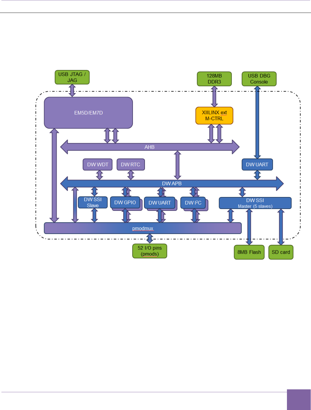

78
External Hardware Interfaces ARC EM Starter Kit
Synopsys, Inc. Version 6280-009
March 2015
External Hardware Interfaces
This section describes the external hardware interface devices that can be used with ARC
EM Starter Kit.
External hardware interface devices can be connected to the ARC EM Starter Kit using
Pmod connectors. Table 9 provides an overview of possible peripheral combinations for
each Pmod connector.
Table 9 Peripheral Devices Connection to Pmods
Pmod
Pmod
connector
Peripherals
MUX option 0
MUX option 1
Pmod1
J1
GPIOs
External SPI master + UART0
Pmod2
J2
GPIOs
ARC EM control/status signals + I2C_0
Pmod3
J3
GPIOs
GPIO + I2C_0
Pmod4
J4
GPIOs
GPIO + I2C_1
Pmod5
J5
GPIOs
External SPI slave 1 + UART2
Pmod6
J6
GPIOs
External SPI slave 0 and CS outputs
for all other SPI slaves + ARC EM con-
trol/status signals
Pmod7
J20
GPIOs
ARC EM control/status signals
The functionality of the Pmod connectors is programmable. Each connector can operate
either as a GPIO or as a dedicated peripheral device. Several connectors provide access to
ARC EM status and control pins.
The GPIO ports are configured as inputs or outputs using the GPIO driver.
A PmodAD2 module is included in the ARC EM Starter kit. This is a 4-channel 12-bit A/D
converter with a Pmod I2C interface. It can be connected to any of the connectors J2, J3 or
J4. Refer to Connecting the PMODAD2 Extension Module section for more details.
The sections below provide information about register programming, possible connections,
and other details.
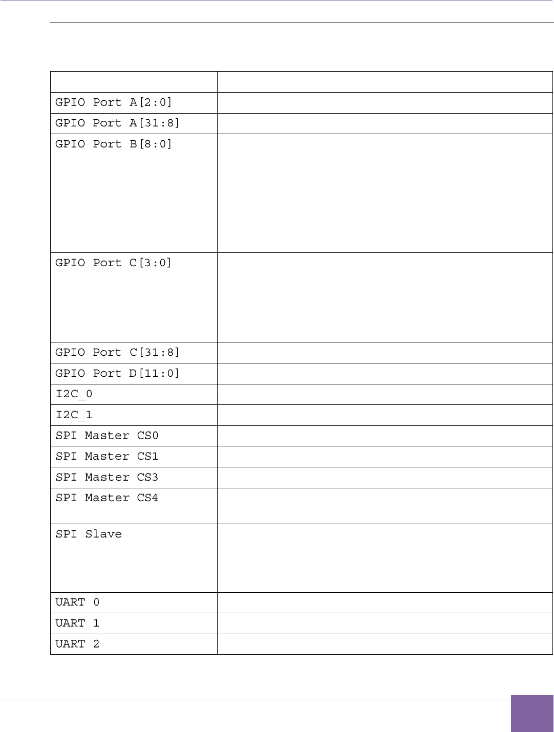
79
ARC EM Starter Kit External Hardware Interfaces
Version 6280-009 Synopsys, Inc.
March 2015
Connecting Peripheral Controllers
Table 10 Board Connections Overview of Peripheral Controllers
Peripherals
Board connection
Buttons: (Above letter 'A' in ARC logo, L, R)
Pmods (J1, J2, J3, J4, J5, J6) pins [10:7]
LEDs [8:0]
Port B[0] controls LED0
Port B[1] controls LED1
...
Port B[8] controls LED8
The LED is on if its corresponding control bit is pro-
grammed to 0.
DIP Switch SW1
SW1 switch 1 connected to Port C[0]
SW1 switch 2 connected to Port C[1]
SW1 switch 3 connected to Port C[2]
SW1 switch 4 connected to Port C[3]
Pmods (J1, J2, J3, J4, J5, J6) pins [4:1]
Pmods (J3, J4, J20)
Pmods (J2, J3)
Pmod J4
Pmod J6 pins [4:1]
Pmod J5 pins [4:1]
SD Card
Internal loopback to SPI Slave when register
SPI_MAP_CTRL[0]=1 (for test purposes).
Pmod J1 [10:7] pins when SPI_MAP_CTRL[0]=0
Internal loopback to SPI Master when
SPI_MAP_CTRL[0]=1 (for test purposes). Refer to the SPI
Slave section for more details.
Pmod J1 pins [4:1]
USB UART (debug console)
Pmod J5 pins [10:7]
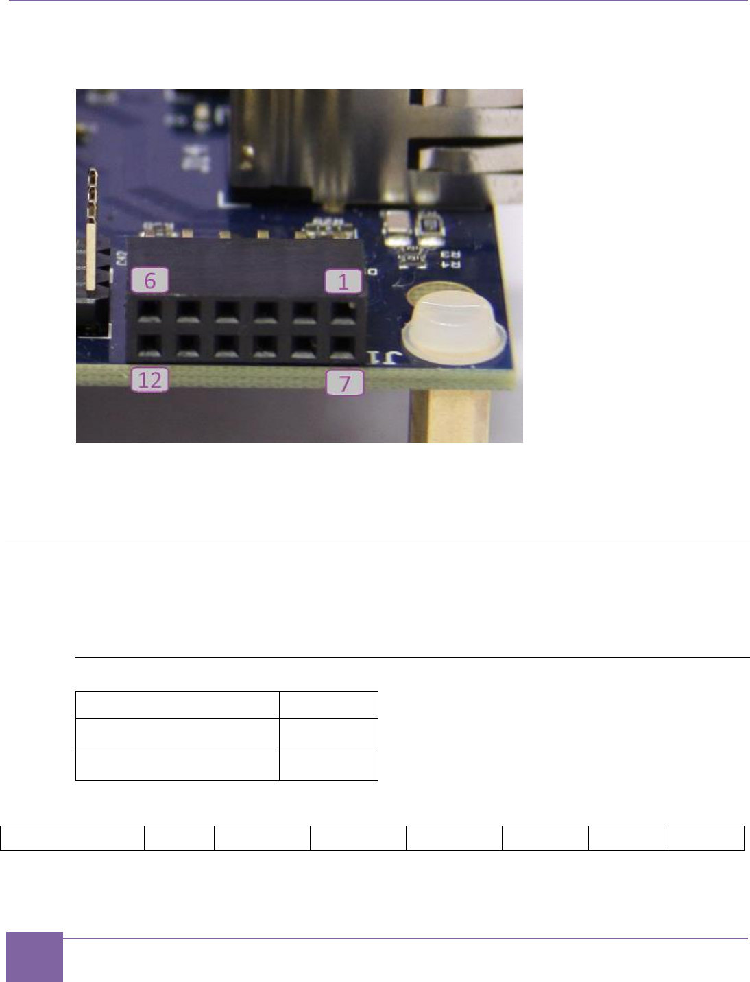
80
Pmod Pin Configuration ARC EM Starter Kit
Synopsys, Inc. Version 6280-009
March 2015
Figure 49 shows the location of the Pmod pins on the board connectors.
Figure 49 Pmod Pin Numbering
Pmod bits 5 and 11 are connected to GND for all PMOD connectors.
Pmod bits 6 and 12 are connected to 3.3 V for all PMOD connectors.
Pmod Pin Configuration
Pmod pins are configured by the Pin Mux Controller using the PMOD_MUX_CTRL register. This register
is mapped to the peripheral register file (refer to Table 26).
PMOD_MUX_CTRL Register
Default
0x0
Peripheral memory offset
0x0
Access
Read/Write
31
30
29
28
27
26
25
24
23
22
21
20
19
18
17
16
15
14
13
12
11
10
9
8
7
6
5
4
3
2
1
0
Reserved
PM7[1:0]
PM6[3:0]
PM5[3:0]
PM4[3:0]
PM3[3:0]
PM2[3:0]
PM1[3:0]

81
Pmod Pin Configuration ARC EM Starter Kit
Synopsys, Inc. Version 6280-009
March 2015
Pmod1 Configuration
PM1[3:0] – select signals connected to Pmod1 at the J1 connector
Pins 1, 2, 3, 4, and 7 of Pmod1 (J1) are pulled up irrespective of the setting of PM1.
Note: PM1[1] and PM1[3] are reserved.
Using Pmod1 (J1) As a GPIO Port
This is the default setting after a reset.
Set PM1[0] = 0 – Pmod1[4:1] are connected to DW GPIO Port C[11:8].
Set PM1[2] = 0 – Pmod1[10:7] are connected to DW GPIO Port A[11:8].
See Table 11 and Table 12 for the detailed pin assignment.
Using Pmod1 (J1) Upper Row As a UART
Set PM1[0] = 1 – Pmod1[4:1] are connected to the DW UART0 signals.
The UART signal mapping to the Pmod1[4:1] port is controlled by the UART_MAP_CTRL reg-
ister.
This register is mapped to the peripheral register file (refer to Table 26).
UART_MAP_CTRL Register
Default
0xE4
Peripheral memory offset
0xC
Access
UART_MAP_CTRL[7:0] bits have R/W access
31
...
8
7
6
5
4
3
2
1
0
Reserved
UM4[1:0]
UM3[1:0]
UM2[1:0]
UM1[1:0]
Table 11 Pin Assignment of Pmod1 (J1) Upper Row Depending on PM1[0]
Pmod1 Pins (J1)
PM1[0]=0
PM1[0]=1
GPIO Signal
UART Signal
4
Port C[11]
RTS_N if UM4="11" (default)
RXD if UM4="10"
TXD if UM4="01"
CTS_N if UM4="00"
3
Port C[10]
RTS_N if UM3="11"
RXD if UM3="10" (default)
TXD if UM3="01"
CTS_N if UM3="00"

82
ARC EM Starter Kit Pmod Pin Configuration
Version 6280-009 Synopsys, Inc.
March 2015
2
Port C[9]
RTS_N if UM2="11"
RXD if UM2="10"
TXD if UM2="01" (default)
CTS_N if UM2="00"
1
Port C[8]
RTS_N if UM1="11"
RXD if UM1="10"
TXD if UM1="01"
CTS_N if UM1="00" (default)
UART mapping examples:
Pmod Interface Type 4 UART
Set UART_MAP_CTRL=0xE4 (Binary: 11 10 01 00)
UM1 = "00": Pmod1[1] connected to CTS_N
UM2 = "01": Pmod1[2] connected to TXD
UM3 = "01": Pmod1[3] connected to RXD
UM4 = "11": Pmod1[4] connected to RTS_N
Pmod Interface Type 3 UART
Set UART_MAP_CTRL=0x6C (Binary: 01 10 11 00)
UM1 = "00": Pmod1[1] connected to CTS_N
UM2 = "11": Pmod1[2] connected to RTS_N
UM3 = "10": Pmod1[3] connected to RXD
UM4 = "01": Pmod1[4] connected to TXD
Using Pmod1 (J1) Lower Row As an SPI Slave
Set PM1[2] = 1 – Pmod1[10:7] are connected to DW SPI Slave signals.
Table 12 Pin Assignment of Pmod1 (J1) Lower Row depending on PM1[2]
Pmod1 Pins (J1)
PM1[2]=0
PM1[2]=1
GPIO Signals
SPI signals
10
Port A[11]
SPI SLV SCLK
9
Port A[10]
SPI SLV MISO
8
Port A[9]
SPI SLV MOSI
7
Port A[8]
SPI SLV CS_N

83
Pmod Pin Configuration ARC EM Starter Kit
Synopsys, Inc. Version 6280-009
March 2015
Pmod2 Configuration
PM2[3:0] – select signals connected to Pmod2 at the J2 connector.
Pins 3 and 4 are pulled up, while pins 1 and 7 are pulled down irrespective of the setting of
PM2.
Note: PM2[3:1] are reserved.
Using Pmod2 (J2) as a GPIO Port
This is the default setting after a reset.
Set PM2[0] = 0 – Pmod2[4:1] are connected to DW GPIO Port C[15:12].
Pmod2[10:7] are connected to DW GPIO Port A[15:12].
Using Pmod2 (J2) as an I2C port and to access the ARC EM halt/run interface
Set PM2[0] = 1 – Pmod2[4:3] are connected to DW I2C_0 signals,
Pmod2[2:1] and Pmod2[8:7] are connected to the ARC EM halt/run
interface.
In this mode the ARC EM halt/run interface is mapped to Pmod2 next to the I2C signals.
The halt/run interface signals can be conveniently accessed at the header J10 (see the
section Headers J10, J11, J12).
Table 13 Pin Assignment of Pmod2 (J2) Depending on PM2[0]
Pmod2 Pins (J2)
PM2[0]=0
PM2[0]=1
GPIO Signals
Signals
10
Port A[15]
N/C
9
Port A[14]
N/C
8
Port A[13]
halt_ack
7
Port A[12]
halt_req
4
Port C[15]
I2C_0 SDA
3
Port C[14]
I2C_0 SCL
2
Port C[13]
run_ack
1
Port C[12]
run_req
Pmod3 Configuration
PM3[3:0] – select signals connected to Pmod3 at the J3 connector.
Pins 1, 2, 3, 4, 5, and 6 are pulled up irrespective of the PM3[0] setting.

84
ARC EM Starter Kit Pmod Pin Configuration
Version 6280-009 Synopsys, Inc.
March 2015
PM3[3:1] are reserved.
Using Pmod3 (J3) As a GPIO Port
This is the default setting after reset.
Set PM3[0] = 0 – Pmod3[4:1] are connected to DW GPIO Port C[19:16].
Pmod3[10:7] are connected to DW GPIO Port A[19:16].
Using Pmod3 (J3) As an I2C Interface
Set PM3[0] = 1 – Pmod3[4:3] are connected to DW I2C_0 signals
Pmod3[2:1] are connected to DW GPIO Port D[1:0].
Pmod3[8:7] are connected to DW GPIO Port D[3:2].
In this mode a few GPIO signals are mapped to Pmod3 next to the I2C signals. These GPIO
signals can be conveniently accessed at the header J11 (see the section Headers J10, J11,
J12).
Table 14 Pin Assignment of Pmod3 (J3) Depending on PM3[0]
Pmod3 Pins (J3)
PM3[0]=0
PM3[0]=1
GPIO Signals
Signals
10
Port A[19]
N/C
9
Port A[18]
N/C
8
Port A[17]
Port D[3]
7
Port A[16]
Port D[2]
4
Port C[19]
I2C_0 SDA
3
Port C[18]
I2C_0 SCL
2
Port C[17]
Port D[1]
1
Port C[16]
Port D[0]

85
ARC EM Starter Kit Pmod Pin Configuration
Version 6280-009 Synopsys, Inc.
March 2015
Pmod4 Configuration
PM4[3:0] – select signals connected to Pmod4 at the J4 connector.
Pins 1, 2, 3, 4, 5, and 6 are pulled up irrespective of the setting of PM4[0].
Note: PM4[3:1] are reserved.
Using Pmod4 (J4) as a GPIO Port
This is the default setting after a reset.
Set PM4[0] = 0 – Pmod4[4:1] are connected to DW GPIO Port C[23:20].
Pmod4[10:7] are connected to DW GPIO Port A[23:20].
Using Pmod4 (J4) as an I2C Interface
Set PM4[0] = 1 – Pmod4[4:3] are connected to DW I2C_1 signals,
Pmod4[2:1] are connected to DW GPIO Port D[5:4].
Pmod4[8:7] are connected to DW GPIO Port D[7:6].
In this mode, a few GPIO signals are mapped to Pmod4 next to the I2C signals. These
GPIO signals can be conveniently accessed at the header J12 (see the section Headers
J10, J11, J12).
Table 15 Pin Assignment of Pmod4 (J4) Depending on PM4[0]
Pmod4 pins (J4)
PM4[0]=0
PM4[0]=1
GPIO Signals
Signals
10
Port A[23]
N/C
9
Port A[22]
N/C
8
Port A[21]
Port D[7]
7
Port A[20]
Port D[6]
4
Port C[23]
I2C_1 SDA
3
Port C[22]
I2C_1 SCL
2
Port C[21]
Port D[5]
1
Port C[20]
Port D[4]
Pmod5 Configuration
PM5[3:0] – select signals connected to Pmod5 at the J5 connector.
Pins 3, 7 and 9 are pulled up irrespective of the setting of PM5.
Note: PM5[1] and PM5[3] are reserved.

86
ARC EM Starter Kit Pmod Pin Configuration
Version 6280-009 Synopsys, Inc.
March 2015
Using Pmod5 (J5) As a GPIO Port
This is the default setting after a reset.
Set PM5[0] = 0 – Pmod5[4:1] are connected to DW GPIO Port C[27:24].
Set PM5[2] = 0 – Pmod5[10:7] are connected to DW GPIO Port A[27:24].
Using Pmod5 (J5) As an SPI Master (Four-Pin Interfaces Using CS1_N)
Set PM5[0] = 1 – Pmod5[4:1] are connected to DW SPI Master signals using CS1_N.
This allows you to connect an SPI slave to the DW SPI Master. Additional SPI slaves can be
connected to the same DW SPI Master at Pmod6.
Using Pmod5 (J5) As a UART
Set PM5[2] = 1 – Pmod5[10:7] are connected to the DW UART2 signals.
Table 16 Pin Assignment of Pmod5 (J5) Upper Row Depending on PM5[0]
Pmod5 Pins (J5)
PM5[0]=0
PM5[0]=1
GPIO Signals
SPI Signals
4
Port C[27]
SPI MST SCLK
3
Port C[26]
SPI MST MISO
2
Port C[25]
SPI MST MOSI
1
Port C[24]
SPI MST CS1_N
Table 17 Pin Assignment of Pmod5 (J5) Lower Row Depending on PM5[2]
Pmod5 Pins (J5)
PM5[2]=0
PM5[2]=1
GPIO Signals
UART Signals
10
Port A[27]
UART2 RTS_N
9
Port A[26]
UART2 RXD
8
Port A[25]
UART2 TXD
7
Port A[24]
UART2 CTS_N
Pmod6 Configuration
PM6[3:0] – select signals connected to Pmod6 at J6 connector.
Pin 3 is pulled up irrespective of the setting of PM6.
Note: PM6[1] and PM6[3] are reserved.

87
Pmod Pin Configuration ARC EM Starter Kit
Synopsys, Inc. Version 6280-009
March 2015
Using Pmod6 (J6) As a GPIO Port
Set PM6[0] = 0 – Pmod6[4:1] are connected to DW GPIO Port C[31:28].
Set PM6[2] = 0 – Pmod6[10:7] are connected to DW GPIO Port A[31:28].
Using Pmod6 (J6) As an SPI Master (Four-Pin Interface with One Chip Select CS0_N)
Set PM6[0] = 1 – Pmod6[4:1] are connected to DW SPI Master signals using CS0_N.
This allows you to connect an SPI slave to the DW SPI Master. Additional SPI slave can be
connected to the same DW SPI Master at Pmod5. Alternatively, two additional chip select
signals can be made available at the lower row of Pmod6.
Using Pmod6 (J6) As an SPI Master (Seven-Pin Interface with Three Chip Selects)
Set PM6[0] = 1 – Pmod6[4:1] are connected to DW SPI Master signals using CS0_N.
Set PM6[2] = 1 – Pmod6[8:7] are connected to the DW SPI Master chip select signals
CS1_N and CS2_N
Pmod6[6:5] are connected to the ARC EM halt and sleep status signals
This allows connecting three SPI slaves to the DW SPI Master. In this case do not use
Pmod5 as an SPI Master, because it uses the same chip-select signals.
Using Pmod6 (J6) to Monitor the ARC EM Halt and Sleep Status Signals
Set PM6[2] = 1 – Pmod6[8:7] are connected to the DW SPI Master chip select signals
CS1_N and CS2_N
Pmod6[6:5] are connected to the ARC EM halt and sleep status signals
Table 18 Pin Assignment of Pmod6 (J6) Upper Row Depending on PM6[0]
Pmod6 Pins (J6)
PM6[0]=0
PM6[0]=1
GPIO Signals
SPI signals
4
Port C[31]
SPI MST SCLK
3
Port C[30]
SPI MST MISO
2
Port C[29]
SPI MST MOSI
1
Port C[28]
SPI MST CS0_N
Table 19 Pin Assignment of Pmod6 (J6) Lower Row Depending on PM6[2]
Pmod6 Pins (J6)
PM6[2]=0
PM6[2]=1
GPIO Signals
Signals
10
Port A[31]
sleep
9
Port A[30]
halt

88
ARC EM Starter Kit Pmod Pin Configuration
Version 6280-009 Synopsys, Inc.
March 2015
Pmod6 Pins (J6)
PM6[2]=0
PM6[2]=1
GPIO Signals
Signals
8
Port A[29]
SPI MST CS2_N
7
Port A[28]
SPI MST CS1_N
Pmod7 Configuration
PM7[1:0] – select signals connected to Pmod7 at J20 connector.
Note: PM7[1] is reserved.
Using Pmod7 (J20) As a GPIO Port
Set PM7[0] = 0 – Pmod7[4:1] are connected to DW GPIO Port D[11:8].
Using Pmod7 (J20) to Monitor the ARC EM Sleep Status Signals
Set PM7[0] = 1 - Pmod7[4:1] are connected to the ARC EM sleep status signals.
Table 20 Pin Assignment of Pmod7 (J7) Depending on PM7[0]
Pmod7 Pins (J20)
PM7[0]=0
PM7[0]=1
GPIO Signals
Signals
4
Port D[11]
sleep
3
Port D[10]
sleep_mode[2]
2
Port D[9]
sleep_mode[1]
1
Port D[8]
sleep_mode[0]
Note
Pmod7 is implemented using staggered drill-holes. You can plug a standard six-pin Pmod
cable into the drill-holes using the six-pin header and gender changer that is typically
provided with the Pmod cable. The staggering of the drill-holes ensures a tight and reliable
connection. If desired you can also solder a 1x6 header or a 1x6 female connector.
An example for programming the Pmod pin configuration can be found in the bare-metal
demo application.

89
Pmod Pin Configuration ARC EM Starter Kit
Synopsys, Inc. Version 6280-009
March 2015
Pmods Configuration summary
Table 21 Pmods configuration summary
Pmod1 Pins (J1)
PM1[2]=0
PM1[2]=1
10
Port A[11]
SPI SLV SCLK
9
Port A[10]
SPI SLV MISO
8
Port A[9]
SPI SLV MOSI
7
Port A[8]
SPI SLV CS_N
Pmod1 Pins (J1)
PM1[0]=0
PM1[0]=1
4
Port C[11]
UART0 (Table 11)
3
Port C[10]
UART0 (Table 11)
2
Port C[9]
UART0 (Table 11)
1
Port C[8]
UART0 (Table 11)
Pmod2 Pins (J2)
PM2[0]=0
PM2[0]=1
10
Port A[15]
N/C
9
Port A[14]
N/C
8
Port A[13]
halt_ack
7
Port A[12]
halt_req
4
Port C[15]
I2C_0 SDA
3
Port C[14]
I2C_0 SCL
2
Port C[13]
run_ack
1
Port C[12]
run_req
Pmod3 Pins (J3)
PM3[0]=0
PM3[0]=1
10
Port A[19]
N/C
9
Port A[18]
N/C
8
Port A[17]
Port D[3]
7
Port A[16]
Port D[2]
4
Port C[19]
I2C_0 SDA
3
Port C[18]
I2C_0 SCL
2
Port C[17]
Port D[1]
1
Port C[16]
Port D[0]
Pmod4 pins (J4)
PM4[0]=0
PM4[0]=1

90
ARC EM Starter Kit Pmod Pin Configuration
Version 6280-009 Synopsys, Inc.
March 2015
10
Port A[23]
N/C
9
Port A[22]
N/C
8
Port A[21]
Port D[7]
7
Port A[20]
Port D[6]
4
Port C[23]
I2C_1 SDA
3
Port C[22]
I2C_1 SCL
2
Port C[21]
Port D[5]
1
Port C[20]
Port D[4]
Pmod5 Pins (J5)
PM5[2]=0
PM5[2]=1
10
Port A[27]
UART2 RTS_N
9
Port A[26]
UART2 RXD
8
Port A[25]
UART2 TXD
7
Port A[24]
UART2 CTS_N
Pmod5 Pins (J5)
PM5[0]=0
PM5[0]=1
4
Port C[27]
SPI MST SCLK
3
Port C[26]
SPI MST MISO
2
Port C[25]
SPI MST MOSI
1
Port C[24]
SPI MST CS1_N
Pmod6 Pins (J6)
PM6[2]=0
PM6[2]=1
10
Port A[31]
sleep
9
Port A[30]
halt
8
Port A[29]
SPI MST CS2_N
7
Port A[28]
SPI MST CS1_N
Pmod6 Pins (J6)
PM6[0]=0
PM6[0]=1
4
Port C[31]
SPI MST SCLK
3
Port C[30]
SPI MST MISO
2
Port C[29]
SPI MST MOSI
1
Port C[28]
SPI MST CS0_N
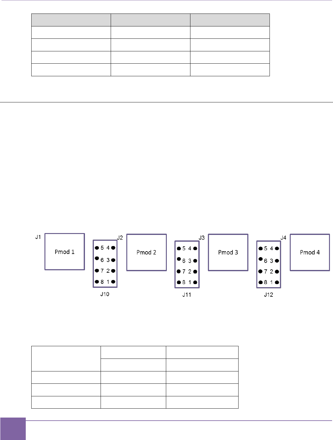
91
Headers J10, J11, J12 ARC EM Starter Kit
Synopsys, Inc. Version 6280-009
March 2015
Pmod7 Pins (J20)
PM7[0]=0
PM7[0]=1
4
Port D[11]
sleep
3
Port D[10]
sleep_mode[2]
2
Port D[9]
sleep_mode[1]
1
Port D[8]
sleep_mode[0]
Headers J10, J11, J12
The Pmod connectors J2, J3 and J4 can be used to plug in peripheral modules with a Pmod
I2C interface, which uses only eight out of 12 available Pmod pins.
According to the Pmod signal mapping described in the Pmod Pin Configuration section,
four pins that are not used for the I2C interface are available for other purposes, such as
GPIO or ARC EM control signals. However, when an I2C Pmod module is inserted into the
Pmod connector on the board, physical access to the other four Pmod pins might be difficult,
depending on the design of the I2C module. To facilitate access to these signals, they are
also connected to separate headers J10, J11, and J12.
The pins 5, 6, 7, 8 of J10, J11, and J12 are connected to the ground. Therefore, you can put
jumpers in place to tie any signals on pins 1, 2, 3, or 4 to the ground.
Figure 50 Pin Positions at Headers J10, J11, and J12
Table 22 lists the pin assignment at the header J10 depending on bit PM2[0] of the
PMOD_MUX_CTRL register.
Table 22 Pin Assignment of the Header J10 Depending on PM2[0]
J10
PM2[0]=0
PM2[0]=1
GPIO Signals
ARC EM Signals
1
Port C[12]
run_req
2
Port A[12]
halt_req
3
Port A[13]
halt_ack

92
ARC EM Starter Kit Headers J10, J11, J12
Version 6280-009 Synopsys, Inc.
March 2015
4
Port C[13]
run_ack
5
GND
6
7
8
9
The following pin assignment is used at the header J11 depending on bit PM3 of the
PMOD_MUX_CTRL Register:
Table 23 Pin Assignment of the Header J11 Depending on PM3[0]
J11
PM3[0]=0
PM3[0]=1
GPIO Signals
GPIO Signals
1
Port C[16]
Port D[0]
2
Port A[16]
Port D[2]
3
Port A[17]
Port D[3]
4
Port C[17]
Port D[1]
5
GND
6
7
8
The following pin assignment is used at the header J12 depending on bit PM4 of the
PMOD_MUX_CTRL Register.
Table 24 Pin Assignment of the Header J12 Depending on PM4[0]
J12
PM4[0]=0
PM4[0]=1
GPIO Signals
GPIO Signals
1
Port C[20]
Port D[4]
2
Port A[20]
Port D[6]
3
Port A[21]
Port D[7]
4
Port C[21]
Port D[5]
5
GND
6

93
Peripheral Controllers ARC EM Starter Kit
Synopsys, Inc. Version 6280-009
March 2015
7
8
Peripheral Controllers
This section describes peripheral devices included in the FPGA project of the ARC EM
Starter Kit.
The following peripheral devices are available:
SPI master
SPI slave
I2C
UART
GPIO
WDT
Timers
The following DesignWare IP components were used to implement the peripherals:
DW_apb_uart – Universal Asynchronous Receiver/Transmitter
DW_apb_gpio – General Purpose Programmable I/O
DW_apb_ssi – Synchronous Serial Interface (SPI)
DW_apb_i2c – I2C interface
DW_apb_wdt – WDT
DW_apb_timers – Timers
General information about DesignWare components can be found at
http://www.synopsys.com/IP/Pages/default.aspx
GPIO
Basic GPIO functionality is provided with the Synopsys DesignWare GPIO IP
(DW_apb_gpio) [4].
This IP controls push buttons, LEDs, and DIP switches and provides the GPIO functionality
of Pmod connectors.
The Pmod connectivity is defined by control register settings described in the Connecting
Peripheral Controllers section.
The DW_apb_gpio is configured to have the following 4 ports:
Port A width is 32 bits
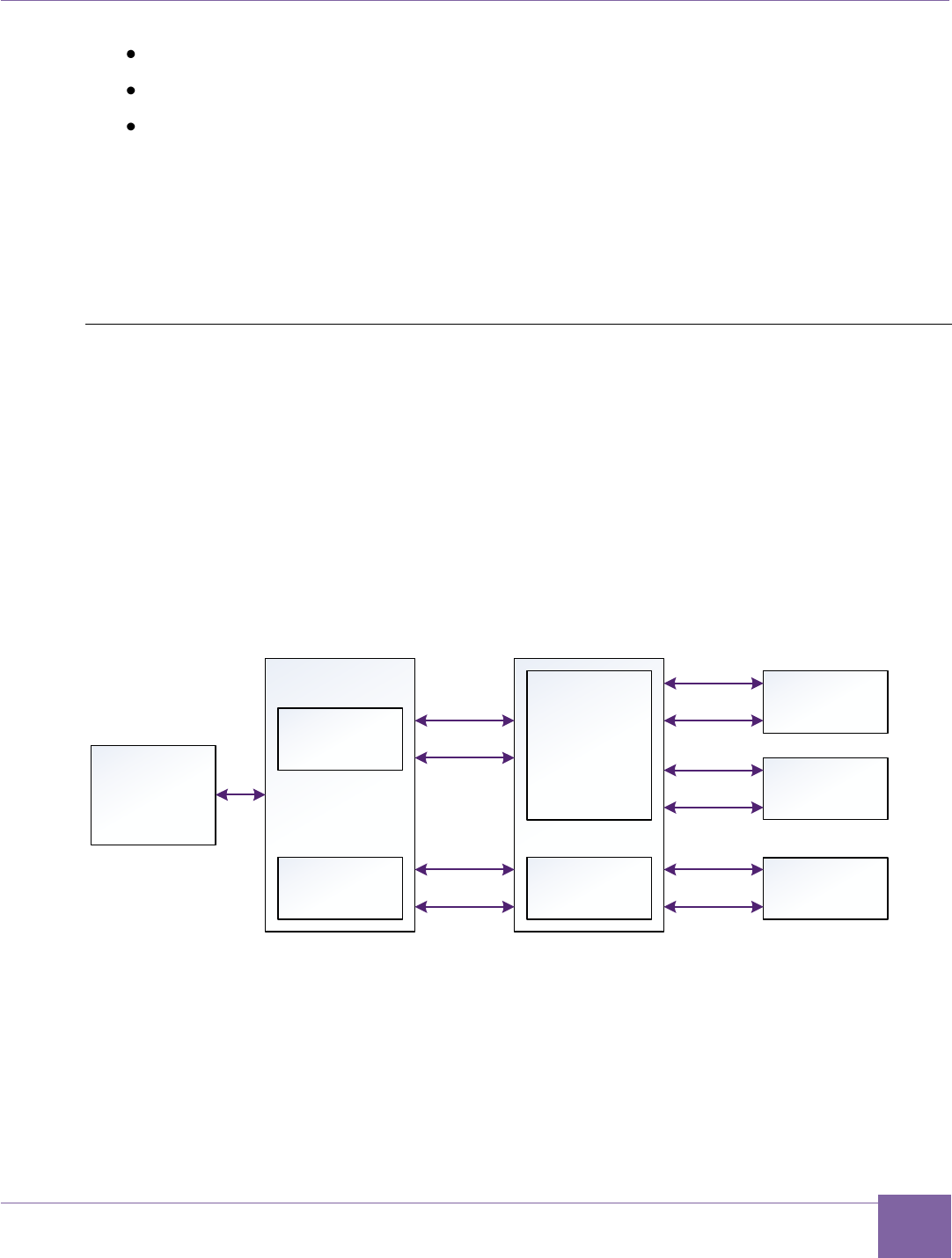
94
ARC EM Starter Kit Peripheral Controllers
Version 6280-009 Synopsys, Inc.
March 2015
Port B width is 9 bits
Port C width is 32 bits
Port D width is 12 bits
Port A includes debounce logic and supports interrupt processing. It generates a single,
combined interrupt connected to the ARC EM interrupt controller port irq_18.
A detailed description of the peripheral can be found in the DesignWare DW_apb_gpio
Databook [4].
GPIO Controller registers are mapped to the peripheral memory (see Table 27).
I2C
Two instances of an I2C peripheral is available. It can be programmed at run time either as
a master or slave device. It supports I2C standard and fast mode (up to 400 kHz).
Master mode allows multiple I2C slaves to be connected. Three PMOD connectors (Pmod 2,
Pmod3, or Pmod4) are available for direct connection of up to three I2C slaves to the I2C
masters; the Pmod connectivity is defined with the control register settings as described in
the Connecting Peripheral Controllers section. If needed, additional slaves can be
connected using external breadboards that support the necessary wiring to hook up multiple
slaves to a single Pmod interface. Figure 51 shows the interconnection between
dw_apb_i2c and the Pmod connectors.
Figure 51 DW I2C Connection
Signals of I2C 0 controller may be mapped to Pmod2 and Pmod3, signals of I2C 1 controller
may be mapped to Pmod4. Signals of I2C 0 device are connected as wired AND. When
some Pmod connector is not selected by the pin mux controller, the corresponding signals
are connected to high level.
In slave mode, I2C slave address is programmable at run-time. The default I2C slave
address is 0x55.
ARC
Core
Pmod2
DW I2C 1
Pin MUX
Pin MUX
Pmod3
DW I2C 0
Pmod4
SCL
SDA
SCL
SDA
SCL
SDA
SCL
SDA
SCL
SDA

95
Peripheral Controllers ARC EM Starter Kit
Synopsys, Inc. Version 6280-009
March 2015
The ARC EM Starter Kit includes a driver for the I2C peripheral. The I2C functionality is
based on the Synopsys DesignWare I2C IP (DW_apb_i2c). A detailed description can be
found in the DesignWare DW_apb_i2c Databook [5].
I2C Controller registers are mapped to the peripheral memory (refer to Table 27)
SPI Master
The SPI Master has six chip-select outputs. Therefore, it can control up to six SPI devices:
On-board SPI flash memory
On-board SD Card
Internal SPI Slave
Up to three SPI peripherals connected to Pmod connectors
The SPI Master is implemented using the Synopsys DesignWare DW_apb_ssi IP
component. Its detailed description can be found in the DW_apb_ssi Databook [6].
The SPI Master uses a system clock (pclk) and an additional peripheral clock (ssi_clk)
for the SPI interface. The system clock is 35 MHz in ARC_EM5D, 30 MHz in ARC_EM7D
and 20 MHz in ARC_EM7DFPU. The peripheral clock is always 50 MHz.
The SPI Master control registers are mapped to the peripheral memory (refer to Table 27)
Note
The DW_apb_ssi IP supports other serial protocols too. However, the IP configuration
selected for the ARC EM Starter Kit supports SPI mode only.
The IP contains separate receive and transmit FIFOs, which have a depth of 32 words each.
The width of both transmit and receive FIFO buffers is fixed at 16 bits due to the serial
specifications, which state that a serial transfer (data frame) can be from four to 16 bits in
length.
Data frames that are less than 16 bits in length must be right-justified when written into the
transmit FIFO buffer. The shift control logic automatically right-justifies received data in the
receive FIFO buffer. The device supports all four SPI modes (clock polarity and clock
phase), which can be programmed at run-time.
The maximum achievable SPI clock frequency is 25 MHz.
The ARC EM Starter Kit includes a driver for the SPI master peripheral. Refer to the DW
APB SPI Master Controller User Manual for information on how to control the peripheral.
The chip-select assignment of the SPI Master is described in Table 25.
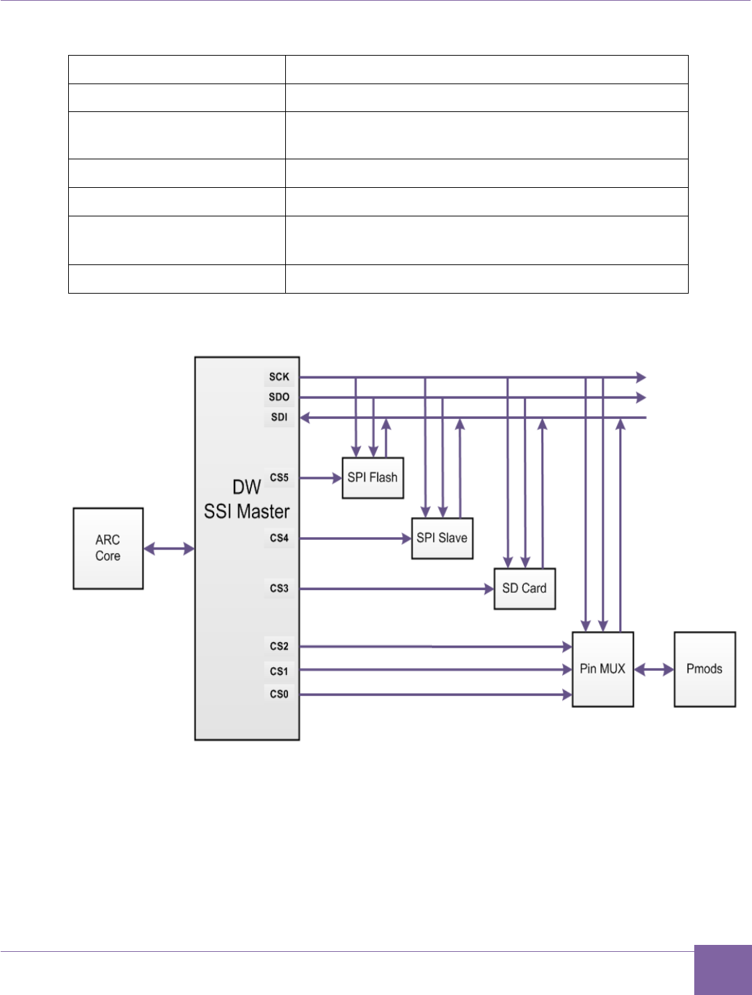
96
ARC EM Starter Kit Peripheral Controllers
Version 6280-009 Synopsys, Inc.
March 2015
Table 25 SPI Master Signals Usage
Chip Select Name
Devices
CS0
Pmod 6 pin 1 (connector J6)
CS1
Pmod 5 pin 1 (connector J5), or
Pmod 6 pin 7(connector J6)
CS2
Pmod 6 pin 8 (connector J6)
CS3
On-board SD card
CS4
Internal SPI Slave
(when register SPI_MAP_CTRL[0]=1)
CS5
On-board SPI Flash memory
Figure 52 DW SPI Master Connection
The Pmod multiplexer allows using the SPI master in two different ways: multiple Pmod SPI
mode and pin-count optimized mode.
Multiple Pmod SPI Mode
Each SPI slave has its own Pmod SPI compliant interface with individual clock, data, and
chip-select signals. The SPI master generates a single clock and a single data output.
These signals are branched to multiple Pmod connectors. The data inputs from the slaves

97
Peripheral Controllers ARC EM Starter Kit
Synopsys, Inc. Version 6280-009
March 2015
are multiplexed into one signal. This mode is controlled by the chip-select outputs of the
master.
Use this mode if you want to connect one or several Pmod-compliant SPI modules in a
convenient way. You can directly connect the Pmod SPI modules to the Pmod connectors
on the board.
To select this mode, go to the register PMOD_MUX_CTRL and set PM6[0]=1, PM5[0]=1
and/or PM5[2]=1 depending on the desired number and location of SPI interfaces.
Pin-Count Optimized Mode
All SPI slaves share the clock and data signals. However, they have individual chip-select
signals. All SPI signals are located in a single Pmod connector, namely Pmod6 at connector
J6.
Use this mode if you want to connect extension boards with multiple SPI slaves. This is
typically done using wires as this is not a standard Pmod SPI interface.
To select this mode, go to register PMOD_MUX_CTRL and set PM6[0]=1 and PM6[2]=1.
Note
For more information on the location of individual SPI signals on the Pmod connectors,
refer to the Pmod Pin Configuration section.
SPI Slave
The SPI Slave is implemented using the Synopsys DesignWare DW_apb_ssi IP component.
Refer to the DW_apb_ssi Databook [6] for a detailed description.
The SPI slave uses a system clock (pclk) and a peripheral clock (ssi_clk) for the SPI
interface. The system clock is 35 MHz in ARC_EM5D, 30 MHz in ARC_EM7D and 20 MHz
in ARC_EM7DFPU and the peripheral clock is 50 MHz.
The SPI Slave control registers are mapped to the peripheral memory (refer to Table 27).
Note
The DW_apb_ssi IP supports other serial protocols. However, the configuration selected
for the ARC EM Starter Kit supports SPI mode only.
The IP contains separate receive and transmit FIFOs, which have a depth of 32 words each.
The width of both transmits and receives FIFO buffers is fixed at 16 bits due to the serial
specifications, which state that a serial transfer (data frame) can be four to 16 bits in length.
Data frames that are less than 16 bits in length must be right-justified when written into the
transmit FIFO buffer. The shift-control logic automatically right-justifies receive data in the
receive FIFO buffer. The device supports all four SPI modes (clock polarity and clock
phase), which can be programmed at run-time.
If the SPI slave is in transmit only mode, the maximum achievable SPI clock frequency is
6.25 MHz.

98
ARC EM Starter Kit Peripheral Controllers
Version 6280-009 Synopsys, Inc.
March 2015
If the SPI slave is in transmit and receive mode, the maximum achievable SPI clock
frequency is 5 MHz.
The ARC EM Starter Kit includes the driver for the SPI slave peripheral. Refer to the DW
APB SPI Master Controller User Manual for information on how to control the peripheral.
UART
The UART is implemented using the Synopsys DesignWare UART IP (DW_apb_uart). Refer
to Synopsys DesignWare DW_apb_uart Databook [8] for more information (including a
register description).
The UART Controller uses a system clock (pclk) and a peripheral clock (sclk) for the
UART interface. The system clock is 35 MHz in ARC_EM5D, 30 MHz in ARC_EM7D and 20
MHz in ARC_EM7DFPU. The peripheral clock is always 50 MHz.
UART Controller registers are mapped to the peripheral memory (refer to Table 27).
The IP contains FIFOs, which have a depth of 32 words. The device supports auto flow
control.
The FPGA design includes three UART instances; one of them is connected to the USB
Debug Console as shown in the Figure 48 FGPA Design Block Diagram. The corresponding
USB / UART Interfaces are located on the board.
Figure 53 DW UART Components Connection
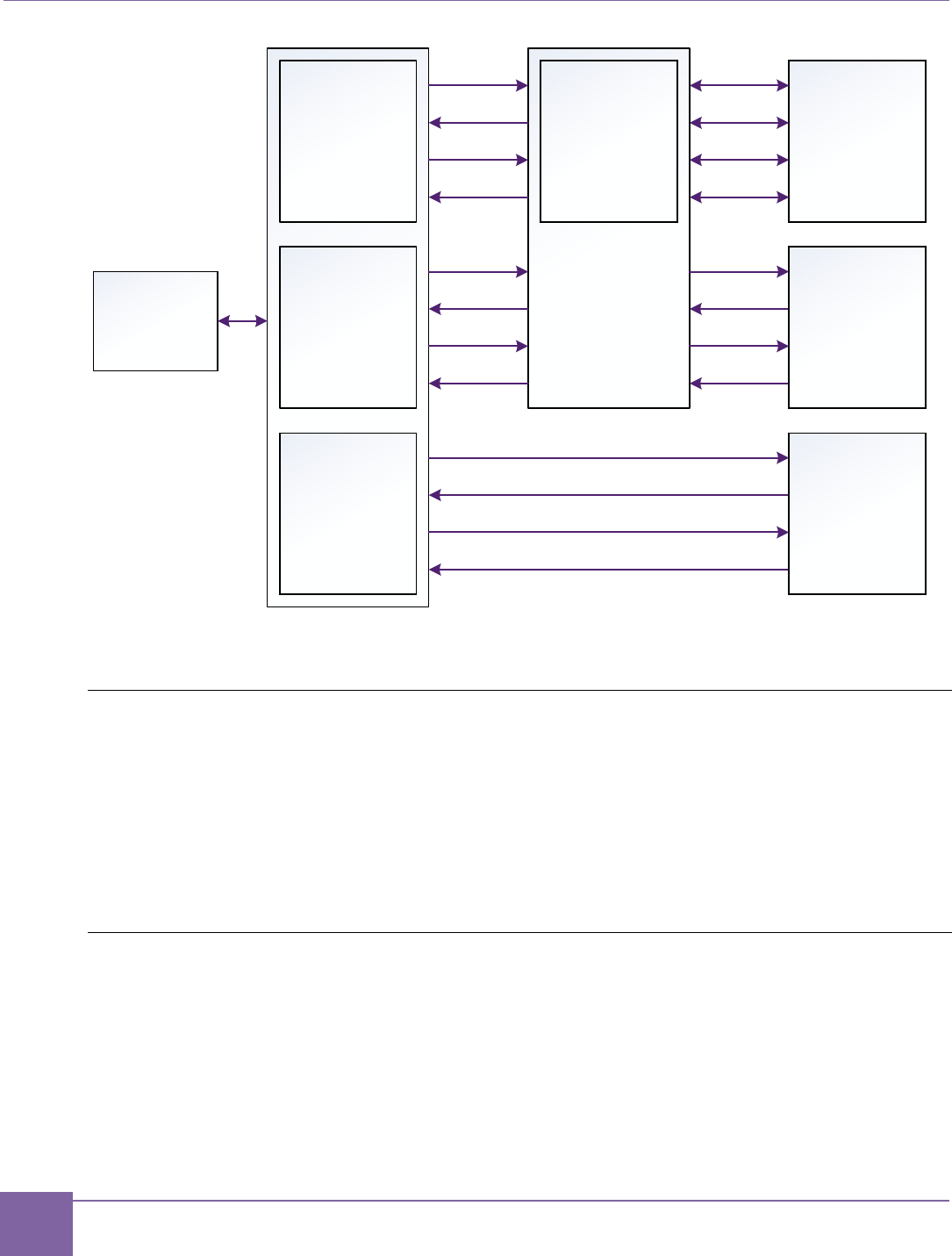
99
Peripheral Controllers ARC EM Starter Kit
Synopsys, Inc. Version 6280-009
March 2015
The ARC EM Starter Kit includes a driver for the UART peripheral. Refer to the DW APB
ARC EM Starter Kit UART User Manual for information on how to control the peripheral.
Timers
The Timers are implemented using the Synopsys DesignWare Timers IP (DW_apb_timers).
Refer to Synopsys DesignWare DW_apb_timers Databook [7] for more information
(including a register description).
The Timers Controller uses a system clock (pclk). The system clock is 35 MHz in
ARC_EM5D, 30 MHz in ARC_EM7D and 20 MHz in ARC_EM7DFPU.
Timers controller registers are mapped to the peripheral memory (refer to Table 27).
WDT
The WDT is implemented using the Synopsys DesignWare WDT IP (DW_apb_wdt). Refer
to Synopsys DesignWare DW_apb_wdt Databook [9] for more information (including a
register description).
The WDT controller uses a system clock (pclk) and a peripheral clock (tclk) as watchdog
timer clock. The system clock is 35 MHz in ARC_EM5D, 30 MHz in ARC_EM7D and 20
MHz in ARC_EM7DFPU. The peripheral clock is always 50 MHz.
The WDT controller registers are mapped to the peripheral memory (refer to Table 27).
DW UART 2
DW UART 0
RTS
CTS
TXD
RXD
RTS
CTS
TXD
RXD
DW UART 1
RTS
CTS
TXD
RXD
UART MUX
Pin MUX
Pmod 1
RTS
CTS
TXD
RXD
Pmod 5
USB UART
ARC
Core

100
Peripheral Controllers ARC EM Starter Kit
Synopsys, Inc. Version 6280-009
March 2015
Pin Mux Controller
The pin mux controller connects the peripheral controllers to external hardware interfaces
and to each other. The Pin Mux Controller registers are mapped to the peripheral memory
starting from the pin mux controller base address (refer to Table 27). Registers are listed in
Table 26.
Table 26 Register File Mapping
Offset
Register Name
Default
Value
Description
0x0
PMOD_MUX_CTRL
0x0
This register controls mapping of the peripheral de-
vice signals on Pmod connectors. Refer to the
Pmod Pin Configuration section for more details.
0x4
I2C_MAP_CTRL
0x0
Reserved for future extensions
0x8
SPI_MAP_CTRL
0x0
SPI_MAP_CTRL[0] selects the mode of operation
of the SPI Slave:
Normal operation, SPI_MAP_CTRL[0]=0:
SPI Slave is connected to Pmod1 at connector J1.
Loop-back mode, SPI_MAP_CTRL[0]=1:
SPI Slave is connected to the SPI Master inside the
FPGA using CS4. This mode is for test purposes
only.
0xC
UART_MAP_CTRL
0xE4
This register controls mapping of the UART signals
on the Pmod1 connector. Refer to the Pmod Pin
Configuration section for more details.
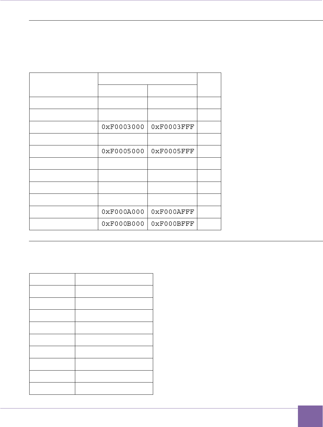
101
ARC EM Starter Kit Peripheral Controllers
Version 6280-009 Synopsys, Inc.
March 2015
Peripheral Memory Mapping
The peripheral memory mapping depends on the AHB address width. The configurations
use an address width of 32 bits.
Table 27 Peripheral Memory Mapping
Name
Address width: 32 bits
Size
Start
End
Pin Mux Controller
0xF0000000
0xF0000FFF
4KB
GPIO
0xF0002000
0xF0002FFF
4KB
Timers
4KB
I2C_0
0xF0004000
0xF0004FFF
4KB
I2C_1
4KB
SPI Master
0xF0006000
0xF0006FFF
4KB
SPI Slave
0xF0007000
0xF0007FFF
4KB
UART0
0xF0008000
0xF0008FFF
4KB
UART1
0xF0009000
0xF0009FFF
4KB
UART2
4KB
WDT
4KB
Interrupts Connections
Table 28 Interrupts Connections
Interrupt
Component
irq_18
GPIO controller
irq_19
I2C_0 controller
irq_20
I2C_1 controller
irq_21
SPI Master controller
irq_22
SPI Slave controller
irq_23
UART0
irq_24
UART1
irq_25
UART2
irq_26
WDT

102
ARC EM Starter Kit On-Board Devices
Version 6280-009 Synopsys, Inc.
March 2015
irq_27
DW Timer 0
irq_28
DW Timer 1
On-Board Devices
JTAG Connector
It is recommended to use the USB interface for JTAG debugging. Alternatively, it is possible
to use industry-standard debug probes connected to the 20-pin JTAG connector J15.
The ARC EM Starter Kit supports a standard four-wire JTAG interface. The two-wire IEEE
1149.7 C JTAG is not supported.
Refer to the Appendix C for examples of using JTAG debuggers.
USB
The mini-USB port can be used for several purposes:
ARC JTAG debugging port
UART debug console
FPGA bitfile programming
Put jumper J8 in place for FPGA programming and remove it when the USB port is used for
ARC JTAG or as a UART debug console.
Refer to FPGA Programming for details on how to install and use the Digilent Adept and
Xilinx iMPACT software.
SD Card
The SD card interface works in SPI mode. It is connected to channel 3 of the SPI Master.
The ARC EM Starter Kit includes an MQX application that supports SD cards in raw mode.
Refer to the About the MQX Demo Package section for more details.
Man-Machine Interface
The following components are available on the ARC EM Starter Kit board:
Push buttons
DIP-switches
Jumpers
LEDs

103
ARC EM Starter Kit On-Board Devices
Version 6280-009 Synopsys, Inc.
March 2015
Push Buttons
Name
Location
Description
A
Above letter “A”
of the ARC logo
ARC start button when processor is halted. Additionally, this
button is connected to DW GPIO Port A[2]. Debouncing is
implemented inside the DW GPIO IP.
Note that when the processor is halted (for example, for
debugging), pressing this button continues execution; pay
special attention to this button in debug mode; in general
mode it may be used by the user application same way as
the 'L' and 'R' buttons.
Reset
Above letter “R”
of the ARC logo
ARC reset
C
Above letter “C”
of the ARC logo
Configure button. Pushing this button has the same effect as
a power-on reset and triggers the FPGA to re-load the bitfile
from the serial flash memory.
L
Marked 'L'
User button. This button is connected to DW GPIO Port A[0].
Debouncing is implemented inside the GPIO IP.
R
Marked 'R'
User button. This button is connected to DW GPIO Port A[1].
Debouncing is implemented inside the GPIO IP.
Note: three push buttons (A, L, R) are available for user purposes.
DIP-Switches
The four-bit DIP-switch SW1 is used for the following purposes:
1. Controlling input ports for user GPIOs
Switch 1 is connected to GPIO Port C[0].
Switch 2 is connected to GPIO Port C[1].
Switch 3 is connected to GPIO Port C[2].
Switch 4 is connected to GPIO Port C[3].
2. Selection of the predefined FPGA image to be loaded at power-on or after pressing
the configuration button ‘C‘ (Switch 1 and Switch 2) as described in the section
Select ARC EM Configurations .
3. Enabling a Self-test application (Switch 3) as described in the section Self-Test and
Bootloader
4. Running user applications from SPI flash (Switch 4) as described in the section
Running Applications in Self-Boot Mode.
Note
If switches 1 or 2 are used for user applications, ensure that they are switched to a proper
position for the predefined FPGA image, before board power on or before the configuration
button ’C’ is pressed.

104
ARC EM Starter Kit On-Board Devices
Version 6280-009 Synopsys, Inc.
March 2015
Jumpers
Refer to ARC EM Starter Kit Getting Started for more information.
LEDs
Nine LEDs can be used as output ports for user GPIOs. The LEDs LED0 to LED8 are
located below the ARC Synopsys logo on the board. LED8 is located next to the DIP switch
SW1.
LED GPIO mapping:
GPIO Port B[0] controls LED0
GPIO Port B[1] controls LED1
GPIO Port B[8] controls LED8
If the LED is on, its corresponding control bit is programmed to 0.
After a reset, the LEDs indicate the selected ARC EM configuration and display the result of
a self-test.
Power Supply
Use a universal power adapter (110-240 Volts AC to 5 Volts DC) from the package. Connect
the appropriate AC plug for your AC power outlet. Connect the DC plug to the connector
J13 “5V DC” on the board as shown on Figure 4. Finally, connect the AC plug to your AC
power outlet.

105
Version 6280-009 Synopsys, Inc.
March 2015
Appendix: B
ARC EM Configurations
This chapter is intended for programmers of the ARC EM Starter Kit. It includes an overview
of the demo applications provided with the ARC EM Starter Kit and explains how to use the
ARC EM Starter Kit software development
Programmer’s Model
The ARC EM Starter Kit provides three different ARC EM core configurations that can be
used for running applications on a 35 MHz CPU clock for ARC_EM5D configuration, 30
MHz clock for ARC_EM7D and 20 MHz for ARC_EM7DFPU.
The detailed configurations of the four cores are described in Detailed Core Configurations.
For information about the ARC EM architecture, refer to the ARCv2 ISA Programmer's
Reference [12].
For information about building and running applications on the target platform, refer to the
C/C++ Programmer's Guide for the MetaWare Compiler [13].
Core Configurations and Memory Mapping
From a programmer’s point of view, the ARC EM Starter kit provides two different memory
maps:
ARC_EM5D and ARC_EM4 configurations
ARC_EM7D, ARC_EM7DFPU, ARC_EM6 and ARC_EM6FPU configurations
ARC_EM5D and ARC_EM4 Configurations
This is an ARC EM core with 32 bits of address space, 128 KB of code memory (ICCM) and
256 KB of data memory (DCCM).
Corresponding MetaWare compiler options for this configuration are:
-arcv2em -core1 -HL -Xcode_density -Xswap -Xnorm -Xmpy16
-Xmpy -Xmpyd -Xshift_assist -Xbarrel_shifter -Xdsp_complex
-Xtimer0 -Xtimer1
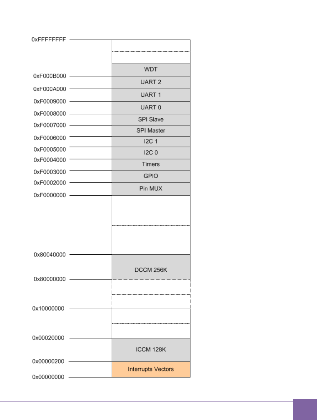

107
Core Configurations and Memory Mapping ARC EM Starter Kit
Synopsys, Inc. Version 6280-009
March 2015
ARC_EM7DARC_EM7DFPU, ARC_EM6 and ARC_EM6FPU Configurations
This is an ARC EM core with 32 bits of address space, 32 KB of code memory (ICCM) and
32 KB of data memory (DCCM). The corresponding MetaWare compiler options for this con-
figuration are:
ARC_EM7D:
-arcv2em -core1 -HL -Xcode_density -Xswap -Xnorm -Xmpy16 -Xmpy
-Xmpyd -Xshift_assist -Xbarrel_shifter -Xdsp_complex
-Xtimer0 -Xtimer1
ARC_EM7DFPU:
-arcv2em -core1 -HL -Xcode_density -Xswap -Xnorm -Xmpy16 -Xmpy
-Xmpyd -Xshift_assist -Xbarrel_shifter -Xdsp_complex -Xfpus_div
-Xfpu_mac -Xfpuda -Xtimer0 -Xtimer1
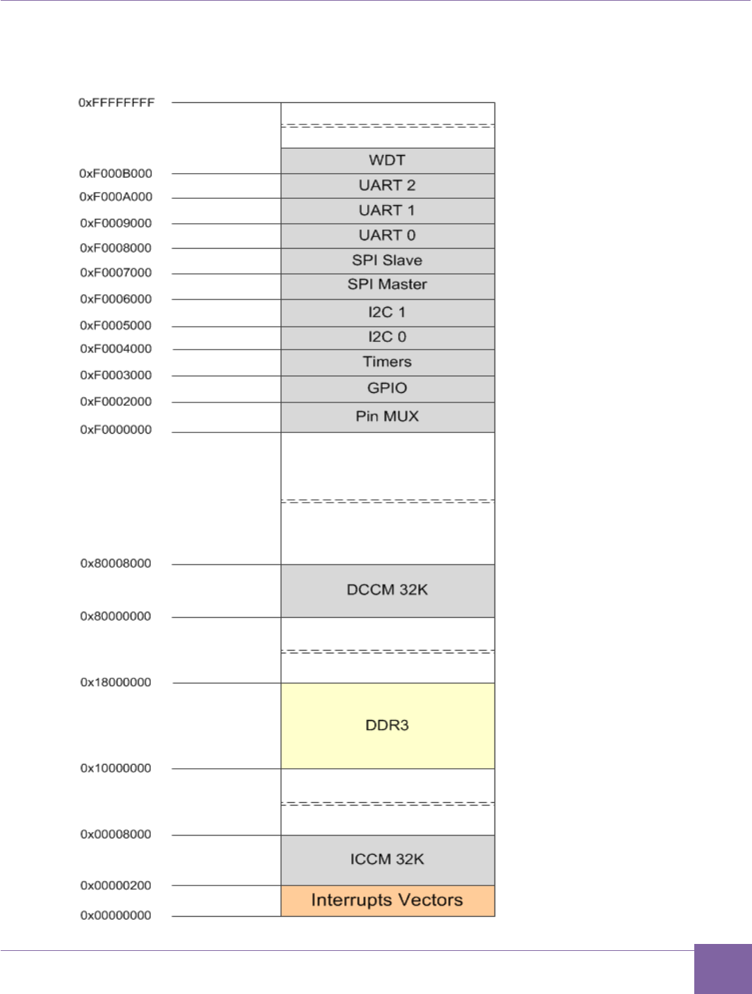

109
Detailed Core Configurations ARC EM Starter Kit
Synopsys, Inc. Version 6280-009
March 2015
Detailed Core Configurations
Table 29 describes the ARC_EM5D, ARC_EM7D and ARC_EM7DFPU configurations.
Table 29 Configuration Details
Configuration Option
Description
ARC_EM5D
ARC_EM7D
ARC_EM7D
FPU
instances
The number of in-
stantiations of this
core
1
1
1
dsp_impl
Infer DSP data path
elements from Veri-
log operators or use
optimized versions
Inferred
inferred
inferred
dsp_complex
Enable support for
16b+16b complex
datatype operations:
CMAC, CMACC,
CBFLY
True
true
true
fpu_dp_assist
Enables double-
precision accelera-
tion instructions
-
-
True
fpu_fma_option
Enables the fused
multiply-add & mul-
tiply-subtract in-
structions
-
-
True
fpu_mas_cycles
The number of
mul/add/sub cycles
-
-
2
fpu_div_option
Enables divide &
square-root accel-
eration
-
-
True
fpu_div_cycles
Controls div/sqrt
implementation
-
-
17
code_density_opt
ion
Code Density ISA
extension.
True
True
True
bitscan_option
Bit-Scan ISA
extension.
True
True
True
number_of_interr
upts
The total number of
interrupts
13
13
13

110
ARC EM Starter Kit Detailed Core Configurations
Version 6280-009 Synopsys, Inc.
March 2015
Configuration Option
Description
ARC_EM5D
ARC_EM7D
ARC_EM7D
FPU
external_interru
pts
Number of external
interrupt pins.
11
11
11
intvbase_preset
Interrupt vector
base.
0
0
0
rgf_num_regs
Number of core
registers.
32
32
32
rgf_wr_ports
Register file: num-
ber of write ports.
1
1
1
byte_order
Endianness.
Little
Little
Little
shift_option
Shift option.
3
3
3
swap_option
SWAP instruction.
True
True
True
div_rem_option
DIV/REM option.
radix2
radix2
radix2
mpy_option
Multiplier ISA
option.
None
None
None
stack_checking
Include logic for val-
idating stack ac-
cesses. Stack ac-
cess violations are
subject to privilege
violation exceptions.
False
False
False
code_protection
Disables any load or
store to the corre-
sponding region
False
False
False
timer_0_int_leve
l
Timer 0 interrupt
level.
1
1
1
timer_1_int_leve
l
Timer 1 interrupt
level.
0
0
0
dccm_size
Size of the Data
Closely Coupled
Memory (DCCM) in
bytes.
262144
32768
32768
dccm_dmi
DCCM has DMI
port.
False
false
false
iccm0_size
Defines the size of
ICCM0 in bytes.
This ICCM has 0
131072
32768
32768

111
Detailed Core Configurations ARC EM Starter Kit
Synopsys, Inc. Version 6280-009
March 2015
Configuration Option
Description
ARC_EM5D
ARC_EM7D
ARC_EM7D
FPU
wait states.
iccm0_base
Sets the initial
memory region as-
signment for
ICCM0.
0
0
0
iccm0_dmi
ICCM0 has DMI
port.
False
False
False
rgf_num_banks
Two register banks
are needed for fast
IRQ, but may be se-
lected even without.
1
1
1
rgf_banked_regs
Number of banked
registers.
32
32
32
number_of_levels
Number of interrupt
levels.
2
2
2
firq_option
Fast IRQ enabled.
false
false
false
num_actionpoints
Number of trigger
events available.
2
2
2
aps_feature
Selects Actionpoint
feature set.
min
min
min
smart_stack_entr
ies
Specifies the num-
ber of entries in the
trace buffer.
8
8
8
pct_counters
The number of Per-
formance Monitor
counters
8
8
8
dc_size
D-cache size.
-
16384
16384
dc_ways
D-cache ways.
-
2
2
dc_bsize
D-cache line length.
-
32
32
dc_feature_level
D-cache feature
level.
-
2
2
dc_uncached_regi
on
D-cache uncached
region.
-
false
false
ic_size
I-cache size.
-
16384
16384

112
ARC EM Starter Kit Detailed Core Configurations
Version 6280-009 Synopsys, Inc.
March 2015
Configuration Option
Description
ARC_EM5D
ARC_EM7D
ARC_EM7D
FPU
ic_ways
I-cache ways.
-
2
2
ic_bsize
I-cache line length.
-
32
32
ic_pwr_opt_level
I-cache dynamic
power optimization.
-
1
1
ic_feature_level
I-cache feature
level.
-
2
2
ic_disable_on_re
set
Disable I-cache on
reset.
False
False
Troubleshooting
The following message may appear when you try to connect using the MetaWare debugger:
[DIGILENT] Device enumeration: #0 is `TE0604-02'=JTAG-ONB4.
[DIGILENT] We choose device : #0 `TE0604-02' from 1 possible
devices.
[DIGILENT] Product=508 variant=1 fwid=57 firmware-version=108.
[DIGILENT] It is possible to set the JTAG speed.
[DIGILENT] Current speed is 10000000 Hz.
[JTAG] ARC 1 does not exist; the chain has 0 ARCs.
Download failed (2).
No process.
Exiting due to error and because exit_on_error=1.
C:\ARC\MetaWare\arc/bin/cld: Permission denied
This means that the J8 jumper was left after programming the FPGA. Remove it to eliminate
this message.
1. Make sure that you are using the correct console settings for the dw_apb_uart
application:
Baudrate=115200 Kb/s
Bits=8
Parity=None
Stop=1
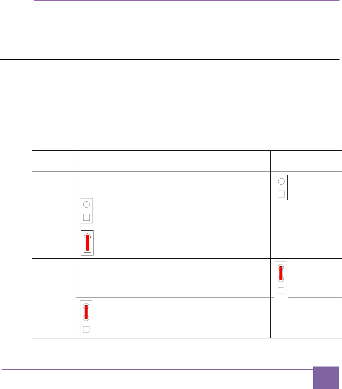
113
Version 6280-009 Synopsys, Inc.
March 2015
Appendix: C
FPGA Image Recovery
ARC EM Starter Kit has pre-programmed configurations stored in SPI flash. However, it is
possible to do firmware updates using Xilinx tools.
This section describes software and hardware tools required for FPGA image programming
and the actions required to perform it.
Board Jumper Settings
The ARC EM Starter Kit hardware contains pre-installed FPGA configurations. Therefore, it
is ready to use with no extra actions needed.
Table 30 describes the board jumper settings. Changing jumper positions is only needed for
reprogramming the FPGA or the serial flash memory.
Jumper J8 has two pins. J16 has three pins; pin 1 is at the bottom and it is the closest one
to J8.
Table 30 Board Jumper Settings
Reference
Description
Default Jumper
Setting
J8
This jumper selects the JTAG target.
Select the ARC EM processor
Leave the pins open when using the Meta-
Ware Debugger
Select the FPGA
Put a jumper in place during FPGA configura-
tion, for example for programming the bitfile.
J16
This jumper selects the SDIO mode.
Warning:
Do not alter
this setting.
normal SDIO mode
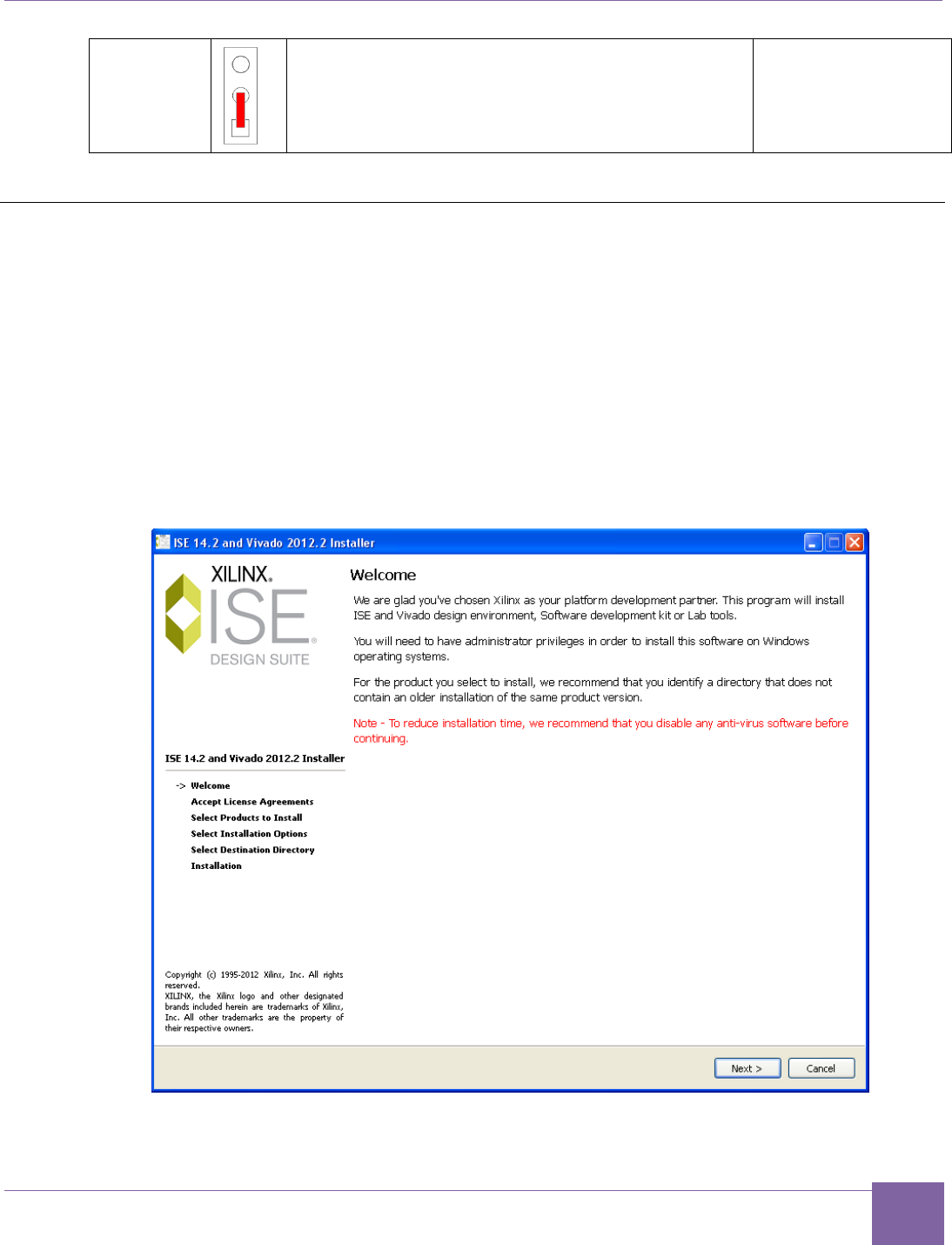
114
ARC EM Starter Kit Xilinx Lab Tools Installation
Version 6280-009 Synopsys, Inc.
March 2015
reserved
Xilinx Lab Tools Installation
The Xilinx Lab Tools utility is optional. This toolset includes the iMPACT tool, which can be
used to configure the FPGA with bitfiles that may become available on the ARC EM Starter
Kit download site. The Xilinx Lab Tools can be downloaded from the following address:
http://www.xilinx.com/support/download/index.htm.
To install Xilinx Lab tools, perform the following steps:
1. Unzip the Lab Tool package and execute the xsetup.exe.
This starts the installation:
Figure 56 Welcome Dialog
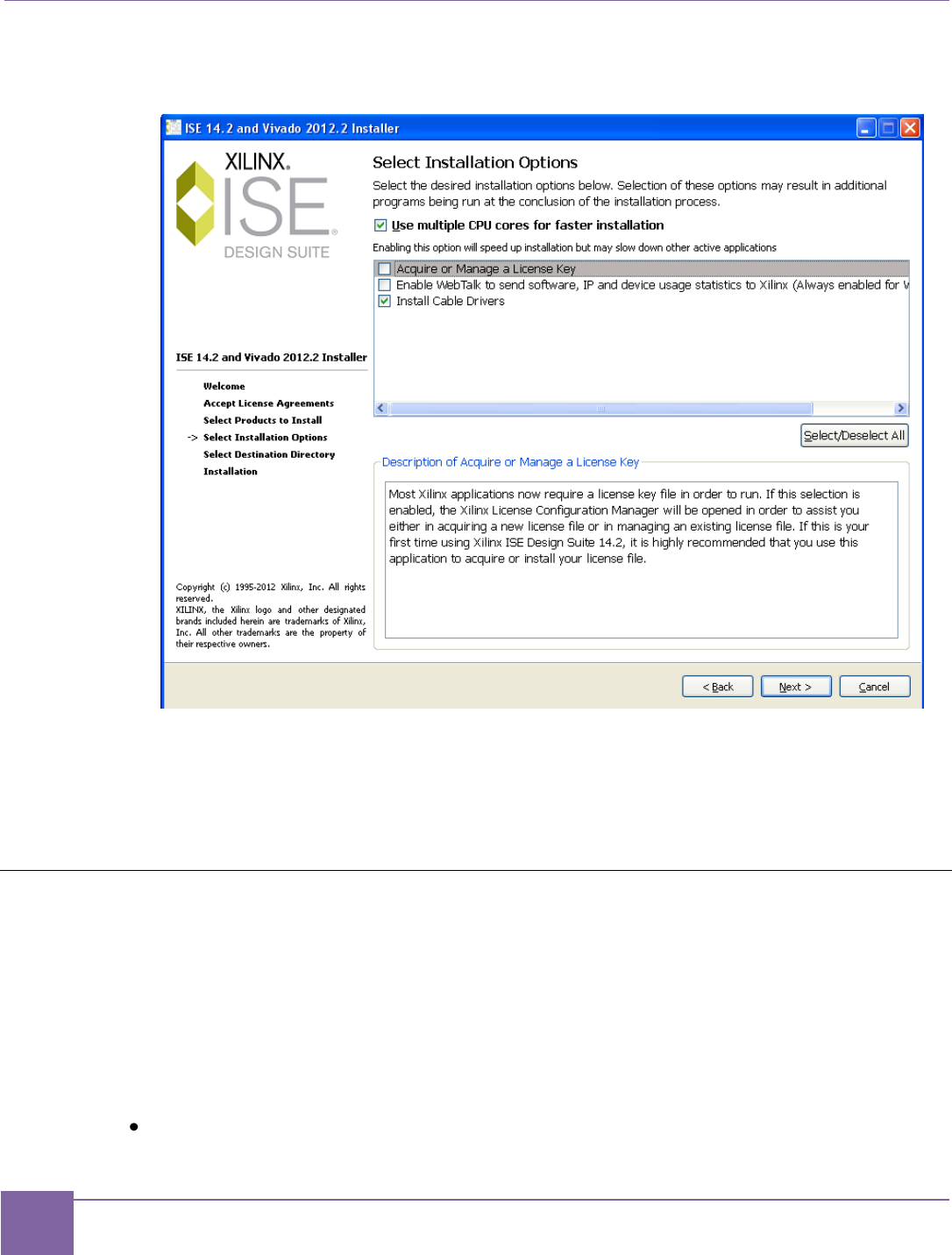
115
Connecting the FPGA Programming Cable ARC EM Starter Kit
Synopsys, Inc. Version 6280-009
March 2015
2. In the next dialog, choose the following tick-boxes and click Next:
Figure 57 Product Registration Dialog
3. Proceed with the installation and wait until it is finished.
The program is now installed.
Connecting the FPGA Programming Cable
Programming of an FPGA bitfile is normally not required, because pre-programmed images
are available in the SPI Flash memory. Refer to the Select ARC EM Configurations section
for more details.
Cabling is required if you wish to program other bitfiles that may become available on the
ARC EM Starter Kit web site.
The following cabling is required for programming the board with an FPGA bitfile:
USB cable with mini-USB connector
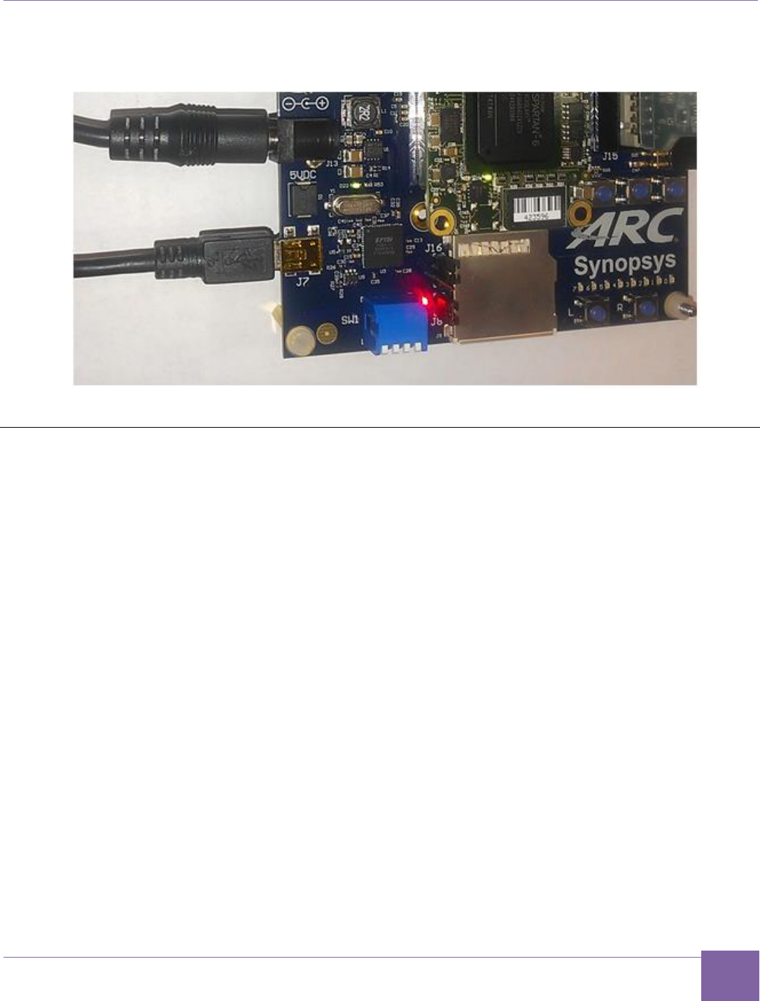
116
ARC EM Starter Kit FPGA Programming Sequence
Version 6280-009 Synopsys, Inc.
March 2015
Connect this cable to the connector J7 on the board and to your computer.
Figure 58 USB FPGA Programming Cable Connection to the Board
FPGA Programming Sequence
This section describes the process of programming the Xilinx FPGA in the ARC EM Starter
Kit with bitfiles using the iMPACT tool.
It is assumed that the USB programming cable is attached to the appropriate connector on
the board according to the Connecting the FPGA Programming Cable section.
To perform FPGA programming, perform the following steps:
1. Put a jumper in place at header J8.
2. Run the Xilinx iMPACT tool:
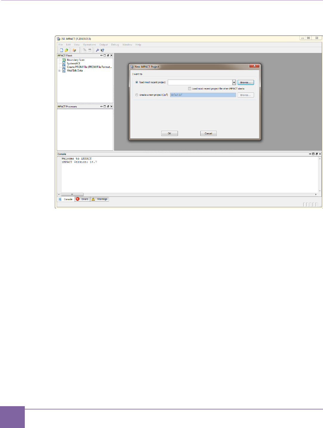
117
FPGA Programming Sequence ARC EM Starter Kit
Synopsys, Inc. Version 6280-009
March 2015
Figure 59 iMPACT Tool – Main Window View
3. Cancel the iMPACT Project selection dialog.
4. Select the Boundary Scan option from the Flows toolbar, situated in the upper left
corner of the application.
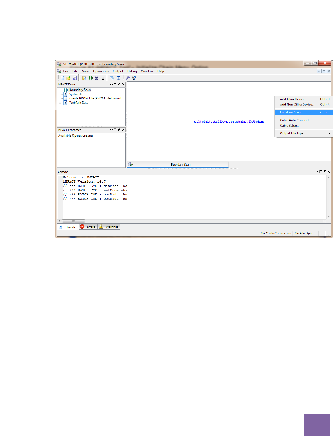
118
ARC EM Starter Kit FPGA Programming Sequence
Version 6280-009 Synopsys, Inc.
March 2015
5. When the Boundary Scan window appears, right click on it and select Initialize
Chain option.
Figure 60 iMPACT Tool – Initialize Chain Menu Option
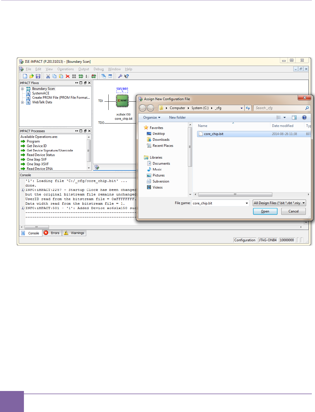
119
FPGA Programming Sequence ARC EM Starter Kit
Synopsys, Inc. Version 6280-009
March 2015
Select the FPGA XC6SLX150 in the sequence of detected devices. Double-click on
it and point to the location of an FPGA image *.bit file.
Figure 61 iMPACT Tool – Assign New Configuration File Dialog Box
6. If no SPI flash programming is required, select "No" in the window appeared.
7. Right-click on the FPGA device and select "Program".
8. A screenshot of the iMPACT tool after successful programming is shown in Figure
62.
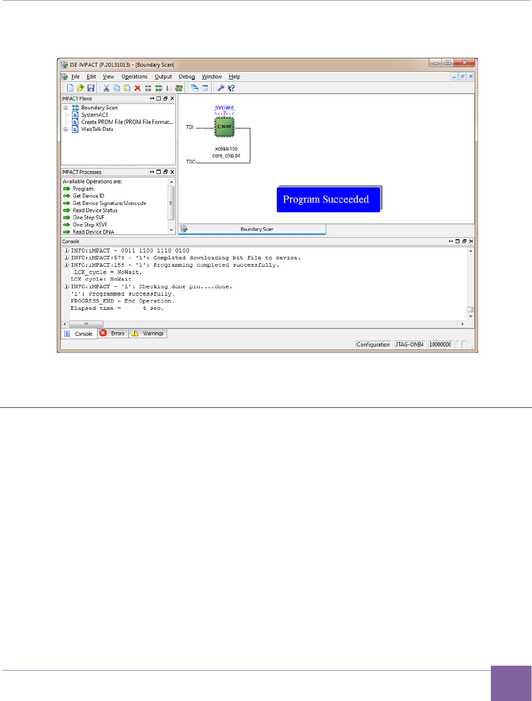
120
ARC EM Starter Kit SPI Flash-Programming Sequence
Version 6280-009 Synopsys, Inc.
March 2015
Figure 62 iMPACT View of the Successful FPGA Programming
9. Remove the jumper from header J8.
SPI Flash-Programming Sequence
This section describes the process of programming the SPI Flash in the ARC EM Starter Kit
with MCS files using the iMPACT tool.
It is assumed that the USB programming cable is attached to the appropriate connector on
the board according to the Connecting the FPGA Programming Cable section.
In order to perform SPI flash programming, perform the following steps:
1. Put a jumper in place at header J8.
2. Run the Xilinx iMPACT tool.
3. Cancel the project selection dialog box.
4. Select the Boundary Scan option from the Flows toolbar, situated in the upper left
corner of the application.
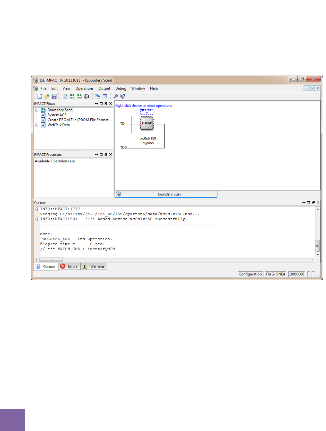
121
SPI Flash-Programming Sequence ARC EM Starter Kit
Synopsys, Inc. Version 6280-009
March 2015
5. When the Boundary Scan window appears, right click on it and select Initialize
Chain option.
6. Select the SPI/BPI dashed frame above FPGA icon in the sequence of detected de-
vices. Double-click it and point to the location of a flash image *.mcs file.
Figure 63 iMPACT Tool – select SPI device
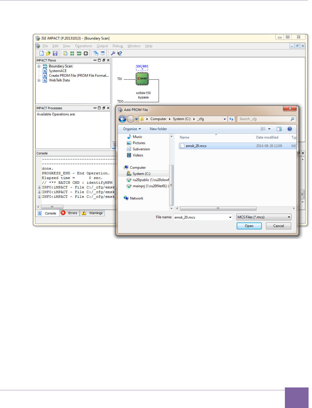
122
ARC EM Starter Kit SPI Flash-Programming Sequence
Version 6280-009 Synopsys, Inc.
March 2015
Figure 64 iMPACT Tool – Add PROM File Dialog Box
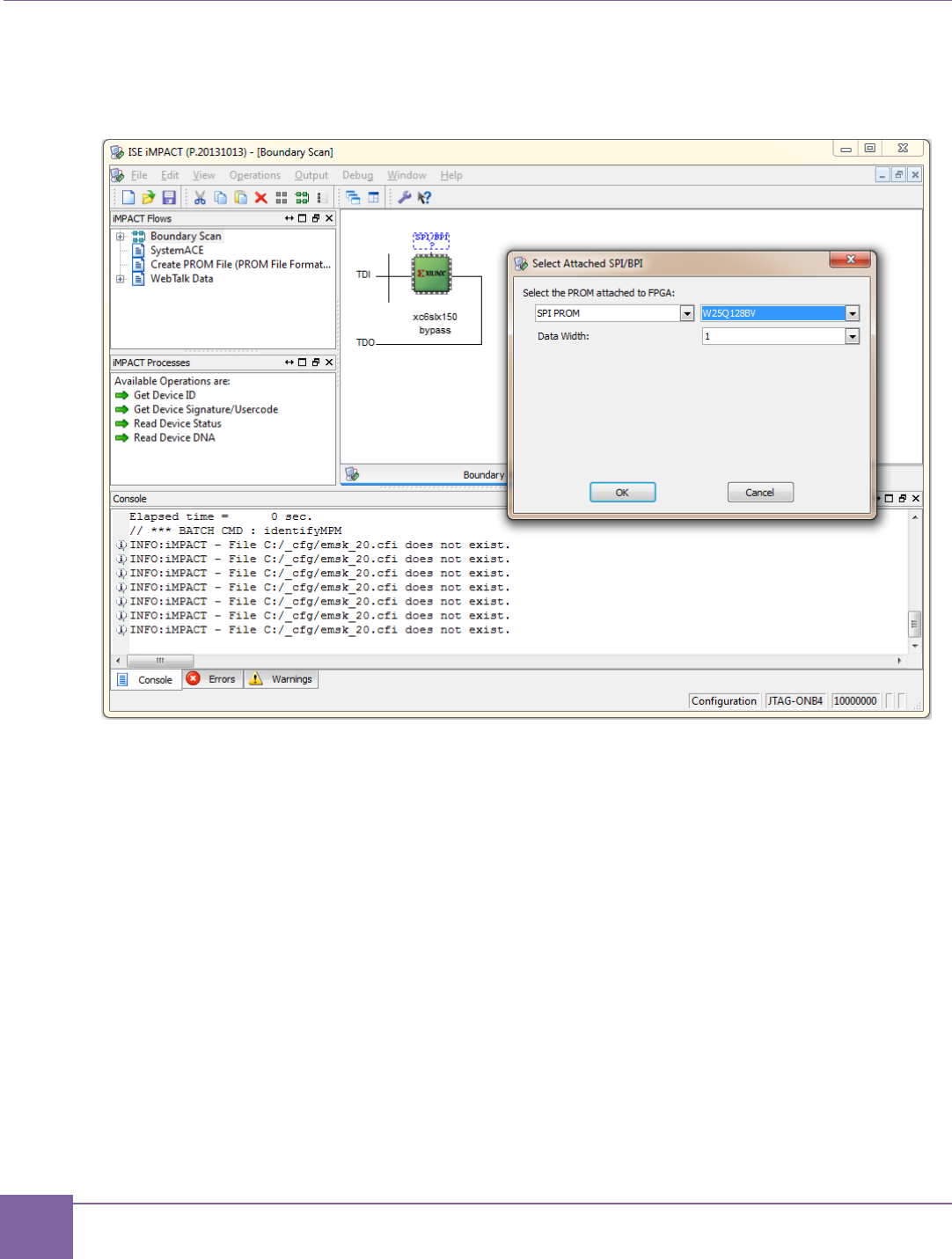
123
SPI Flash-Programming Sequence ARC EM Starter Kit
Synopsys, Inc. Version 6280-009
March 2015
7. Select SPI PROM W25Q128BV flash type, data with data width 1.
Figure 65 iMPACT Tool – Select Attached SPI/BPI Dialog Box
8. Right-click on the Flash device and select Program.
9. Accept the default programming options.
10. Flash programming takes approximately four minutes.
11. A screen shot of the iMPACT tool after successful programming is shown in Figure 66.
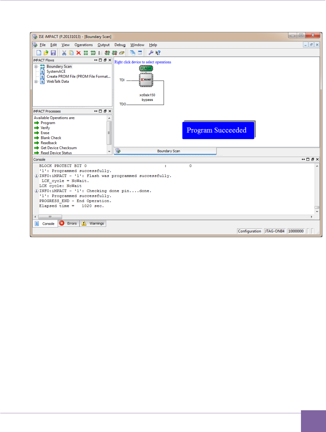
124
ARC EM Starter Kit SPI Flash-Programming Sequence
Version 6280-009 Synopsys, Inc.
March 2015
Figure 66 iMPACT View of the Successful SPI ROM Programming
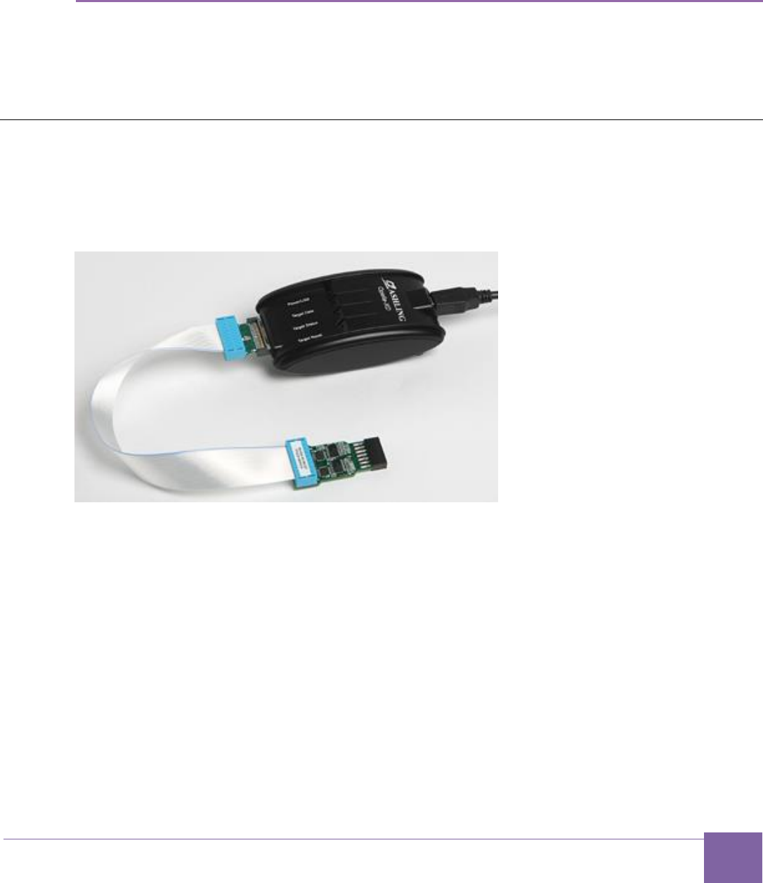
125
Version 6280-009 Synopsys, Inc.
March 2015
Appendix: D
Using a JTAG Debugger
It is best to use the on-board USB port to connect your debugger. If you wish to use a JTAG
debug cable instead, you can connect it to the JTAG debugging port at the J15 connector.
This section describes software and hardware tools for using example JTAG debuggers.
Ashling Opella-XD Debugger
The Ashling Opella-XD debugger has two components: The Opella-XD for ARC Debug
Probe and the 20-way JTAG Debug cable TPAOP-ARC20. They are shown in Figure 67.
Figure 67 Ashling XD Pod with Debug Cable
For more details, refer to http://www.ashling.com/.
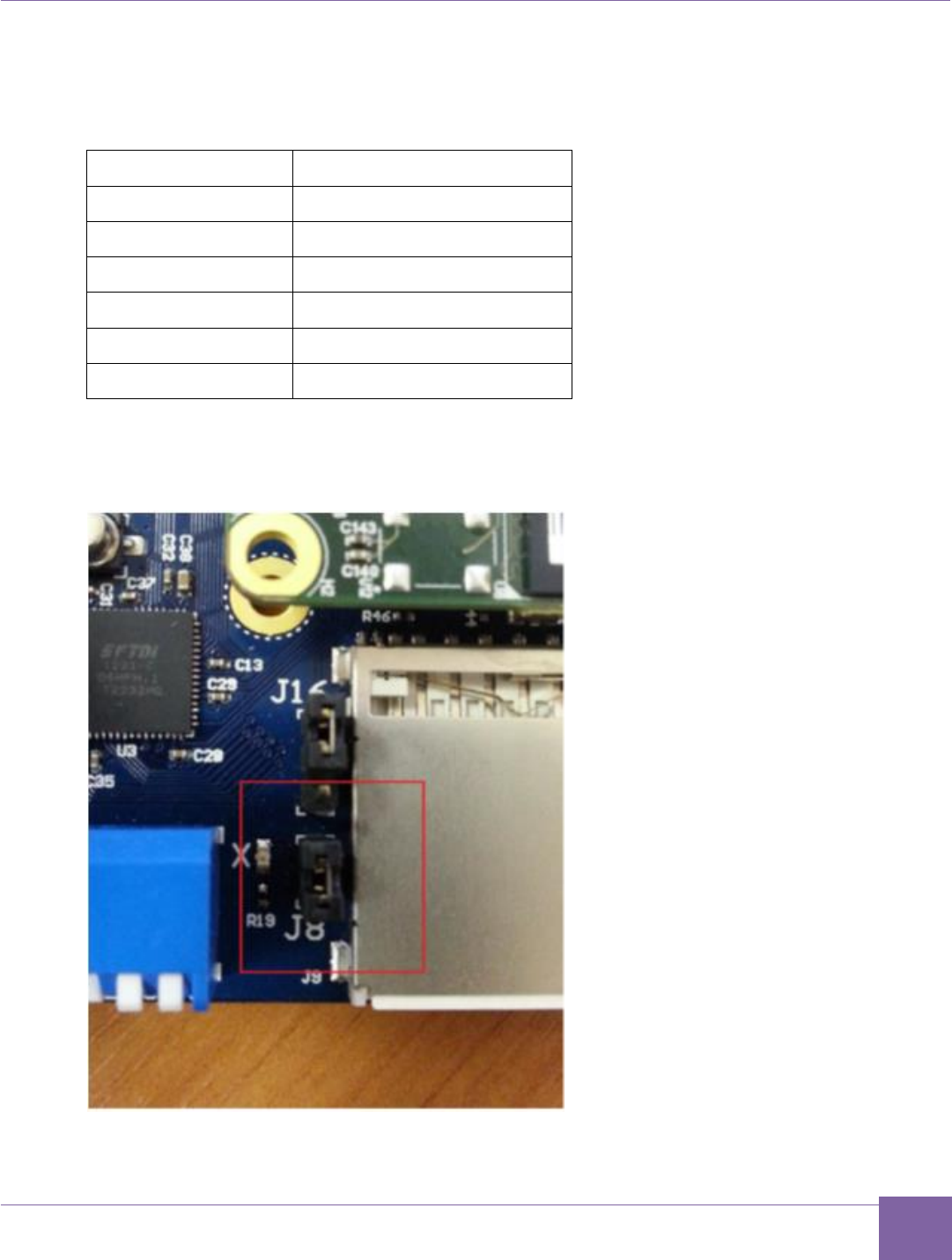
126
ARC EM Starter Kit Ashling Opella-XD Debugger
Version 6280-009 Synopsys, Inc.
March 2015
Connect the JTAG debug cable connect to the J15 connector on the baseboard. Match the
signal names on the cable and the connector according to Table 31.
Table 31 ARC EM Starter Kit JTAG Connector Pin-out
J15 pin number
JTAG signal
1
V_REF
4
GND
5
TDI
7
TMS
9
TCK
13
TDO
To use the JTAG connected to J15 make sure that the J8 jumper has been set.
Figure 68 Jumper J8 Set
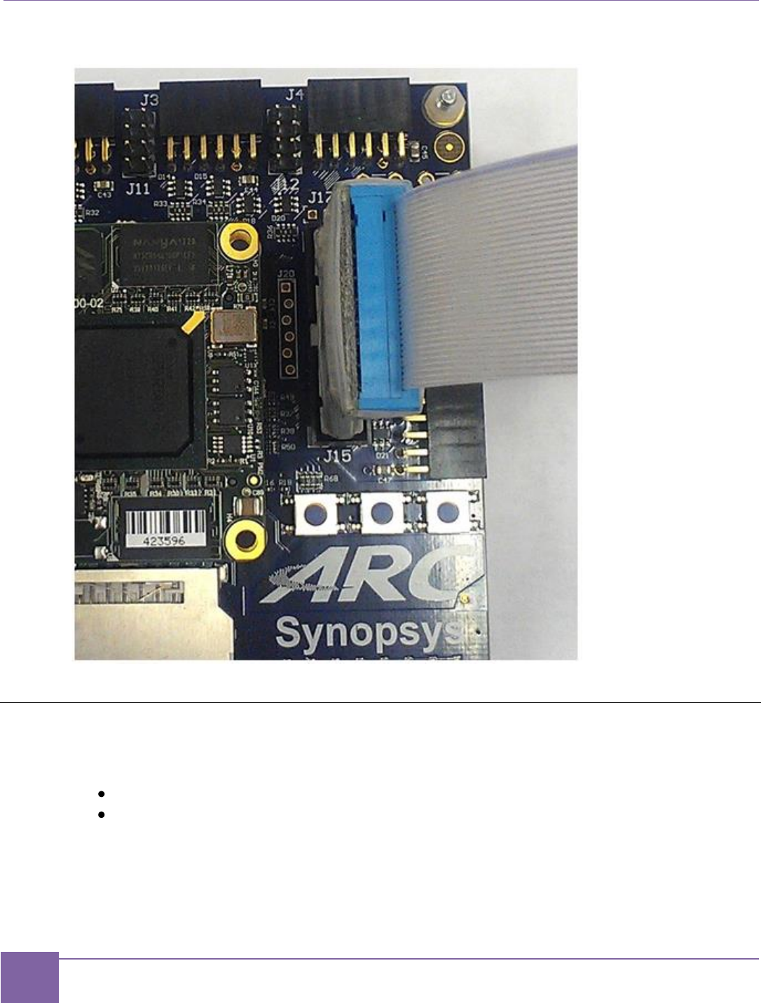
127
Lauterbach TRACE32 Debugger ARC EM Starter Kit
Synopsys, Inc. Version 6280-009
March 2015
Figure 69 ARC JTAG Connection to the Board
Lauterbach TRACE32 Debugger
The Lauterbach TRACE32 debugger for ARC cores has two components:
Power debug module
JTAG debugger for ARC
These components are shown in Figure 70.
Figure 70 Lauterbach TRACE32 with Debug Cable

128
ARC EM Starter Kit Lauterbach TRACE32 Tool Installation
Version 6280-009 Synopsys, Inc.
March 2015
For more information, refer to http://www.lauterbach.com/frames.html?bdmarc.html.
Connect the debugger to the J15 connector on the baseboard. The JTAG pin assignment is
the same as for the Ashling debugger. Refer to Table 31 for more information.
Lauterbach TRACE32 Tool Installation
This tool is required if the Lauterbach TRACE32 debugger is used for JTAG communication
with an ARC EM core.
The software can be downloaded from the Lauterbach Download Center web page at
http://www.lauterbach.com/frames.html?downloadcenter.html.

129
Version 6280-009 Synopsys, Inc.
March 2015
Glossary and References
This chapter contains a list of specific terms used in this document and references for
further reading.
Glossary
APB
AMBA Advanced Peripheral Bus
AHB
AMBA Advanced High Performance Bus
DCCM
Data Closely Coupled Memory
DMP
Data Memory Pipeline (ARC proprietary bus)
DW
Synopsys DesignWare IP solutions
GPIO
General Purpose Input/Output pins
ICCM
Instruction Closely Coupled Memory
Pmod
Digilent Pmod™ socket connector

130
ARC EM Starter Kit References
Version 6280-009 Synopsys, Inc.
March 2015
References
[1] ARC EM Starter Kit Getting Started
http://www.synopsys.com/dw/ipdir.php?ds=arc_em_starter_kit
[2] AMBA Specification (http://www.arm.com)
[3] AMBA APB3 Specification (http://www.arm.com)
[4] Synopsys DesignWare DW_apb_gpio Databook, version 2.10a, June 2014
[5] Synopsys DesignWare DW_apb_i2c Databook, version 1.22a, June 2014
[6] Synopsys DesignWare DW_apb_ssi Databook, version 3.23a, June 2014
[7] Synopsys DesignWare DW_apb_timers Databook, version 2.09a, June 2014
[8] Synopsys DesignWare DW_apb_uart Databook, version 3.15a, June 2014
[9] Synopsys DesignWare DW_apb_wdt Databook, version 1.08a, June 2014
[10] Synopsys DesignWare DW_apb Databook, version 2.03a, June 2014
[11] Xilinx UG380: Spartan-6 FPGA Configuration User Guide
(http://www.xilinx.com/support/documentation/user_guides/ug380.pdf)
[12] ARCv2 ISA Programmer's Reference
[13] C/C++ Programmer's Guide for the MetaWare Compiler
[14] Xilinx XAPP496
(http://www.xilinx.com/support/documentation/application_notes/xapp496.pdf)
[15] Maxim DS2502-E48 product overview
(http://www.maxim-ic.com/datasheet/index.mvp/id/3748)
[16] Maxim DS2432 product page
(http://www.maximintegrated.com/datasheet/index.mvp/id/2914)
[17] Xilinx DS160: Spartan-6 Family Overview
(http://www.xilinx.com/support/documentation/data_sheets/ds160.pdf)
[18] Xilinx DS162: Spartan-6 FPGA Data Sheet: DC and Switching
(http://www.xilinx.com/support/documentation/data_sheets/ds162.pdf)
[19] Winbond W25Q128BV product overview
(http://www.winbond.com/hq/enu/ProductAndSales/ProductLines/FlashMemory/SerialF
lash/W25Q128BV.htm)
[20] DesignWare ARB SPI Master Controller User Manual
