ARFX4
User Manual: ARFX4
Open the PDF directly: View PDF ![]() .
.
Page Count: 74

CONTENTS
Parts marked with “ ” are important for maintaining the safety of the set. Be sure to replace these parts with
specified ones for maintaining the safety and performance of the set.
SHARP CORPORATION This document has been published to be used
for after sales service only.
The contents are subject to change without notice.
SERVICE MANUAL
CODE: 00ZARFX4//A1E
DIGITAL LASER COPIER/
PRINTER OPTION
FAX EXPANSION KIT
(For U.S.A./Canada)
MODEL AR-FX4
EXPANSION MEMORY
2MB: AR-MM5
4MB: AR-MM6
8MB: AR-MM7
[1] OUTLINE . . . . . . . . . . . . . . . . . . . . . . . . . . . . . . . . . . . . . . . . . . . . 1-1
[2] SPECIFICATIONS . . . . . . . . . . . . . . . . . . . . . . . . . . . . . . . . . . . . . 1-1
[3] INSTALLATION PROCEDURE . . . . . . . . . . . . . . . . . . . . . . . . . . . 3-1
[4] ADJUSTMENTS . . . . . . . . . . . . . . . . . . . . . . . . . . . . . . . . . . . . . . . 4-1
[5] SIMULATION . . . . . . . . . . . . . . . . . . . . . . . . . . . . . . . . . . . . . . . . . 5-1
[6] SOFT SWITCH DESCRIPTIONS . . . . . . . . . . . . . . . . . . . . . . . . . . 6-1
[7] KEY OPERATOR PROGRAM . . . . . . . . . . . . . . . . . . . . . . . . . . . . 7-1
[8] FLASH ROM VERSION UP PROCEDURE . . . . . . . . . . . . . . . . . . 8-1
[9] TROUBLE CODE LIST. . . . . . . . . . . . . . . . . . . . . . . . . . . . . . . . . . 9-1
[10] ELECTRICAL SECTION. . . . . . . . . . . . . . . . . . . . . . . . . . . . . . . . 10-1
CONTENTS
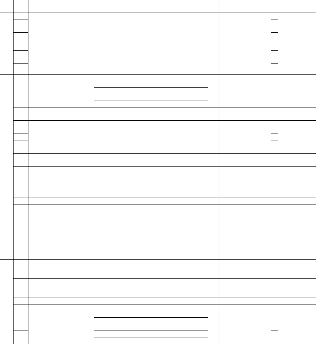
[1] OUTLINE . . . . . . . . . . . . . . . . . . . . . . . . . . . . . . . . . . . . . . . . . 1-1
[2] SPECIFICATIONS
1. Communication system . . . . . . . . . . . . . . . . . . . . . . . . . . . 1-1
2. Scanning system . . . . . . . . . . . . . . . . . . . . . . . . . . . . . . . . 1-1
3. Image process system . . . . . . . . . . . . . . . . . . . . . . . . . . . . 1-2
4. Print system . . . . . . . . . . . . . . . . . . . . . . . . . . . . . . . . . . . . 1-2
5. Transmission function system. . . . . . . . . . . . . . . . . . . . . . . 1-2
6. Reception function system . . . . . . . . . . . . . . . . . . . . . . . . . 1-3
7. Registration system . . . . . . . . . . . . . . . . . . . . . . . . . . . . . . 1-3
8. Telephone function system. . . . . . . . . . . . . . . . . . . . . . . . . 1-4
9. Memory system . . . . . . . . . . . . . . . . . . . . . . . . . . . . . . . . . 1-4
10. Additional information function for transmission . . . . . . . . . 1-4
11. Additional print function when receiving . . . . . . . . . . . . . . . 1-4
12. Recording table system . . . . . . . . . . . . . . . . . . . . . . . . . . . 1-5
13. Others . . . . . . . . . . . . . . . . . . . . . . . . . . . . . . . . . . . . . . . . . 1-5
[3] INSTALLATION PROCEDURE
1. Install of expansion kit . . . . . . . . . . . . . . . . . . . . . . . . . . . . 3-1
A. Parts included. . . . . . . . . . . . . . . . . . . . . . . . . . . . . . . . . 3-1
B. Installation . . . . . . . . . . . . . . . . . . . . . . . . . . . . . . . . . . . 3-1
2. Mounting of additional memory (AR-MM5, MM6, MM7) . . . 3-3
[4] ADJUSTMENTS
1. Density section . . . . . . . . . . . . . . . . . . . . . . . . . . . . . . . . . . 4-1
A. FAX mode density adjustment (Overall mode) (<FAX
mode> SIM 46-12) . . . . . . . . . . . . . . . . . . . . . . . . . . . . . 4-1
B. FAX mode density adjustment (Individual mode) (<FAX
mode> SIM 46-13 – 16) . . . . . . . . . . . . . . . . . . . . . . . . . 4-1
2. Communication section . . . . . . . . . . . . . . . . . . . . . . . . . . . 4-2
A. Dial test (<FAX mode> SIM 66-13) . . . . . . . . . . . . . . . . 4-2
[5] SIMULATION
1. Entering the simulation mode/cancel of simulation mode . 5-1
2. Simulation code list . . . . . . . . . . . . . . . . . . . . . . . . . . . . . . 5-1
3. Details . . . . . . . . . . . . . . . . . . . . . . . . . . . . . . . . . . . . . . . . 5-1
[6] SOFT SWITCH DESCRIPTIONS
1. Quick reference of FAX soft SW setup change . . . . . . . . . 6-1
2. Soft switch list . . . . . . . . . . . . . . . . . . . . . . . . . . . . . . . . . . 6-2
3. Soft switch descriptions . . . . . . . . . . . . . . . . . . . . . . . . . . 6-19
[7] KEY OPERATOR PROGRAM
1. List . . . . . . . . . . . . . . . . . . . . . . . . . . . . . . . . . . . . . . . . . . . 7-1
2. Operating procedure . . . . . . . . . . . . . . . . . . . . . . . . . . . . . 7-2
A. Common procedures. . . . . . . . . . . . . . . . . . . . . . . . . . . 7-2
B. List output . . . . . . . . . . . . . . . . . . . . . . . . . . . . . . . . . . . 7-3
[8] FLASH ROM VERSION UP PROCEDURE
1. Program download procedure (Main body program, FAX
program) . . . . . . . . . . . . . . . . . . . . . . . . . . . . . . . . . . . . . . . 8-1
2. Others (Error list) . . . . . . . . . . . . . . . . . . . . . . . . . . . . . . . . 8-2
[9] TROUBLE CODE LIST
1. Machine trouble codes . . . . . . . . . . . . . . . . . . . . . . . . . . . 9-1
2. Communication result code . . . . . . . . . . . . . . . . . . . . . . . . 9-2
A. Composition of communication report code . . . . . . . . . 9-2
3. List of buzzer sounds in case of FAX abnormality . . . . . . . 9-4
[10] ELECTRICAL SECTION
1. Block diagram . . . . . . . . . . . . . . . . . . . . . . . . . . . . . . . . . 10-1
A. Main block diagram . . . . . . . . . . . . . . . . . . . . . . . . . . . 10-1
B. TEL/LIU PWB block diagram. . . . . . . . . . . . . . . . . . . . 10-2
2. Circuit diagram. . . . . . . . . . . . . . . . . . . . . . . . . . . . . . . . . 10-3
A. FAX MAIN PWB . . . . . . . . . . . . . . . . . . . . . . . . . . . . . 10-3
B. TEL/LIU PWB . . . . . . . . . . . . . . . . . . . . . . . . . . . . . . 10-13
AR-FX4 OUTLINE/SPECIFICATIONS - 1
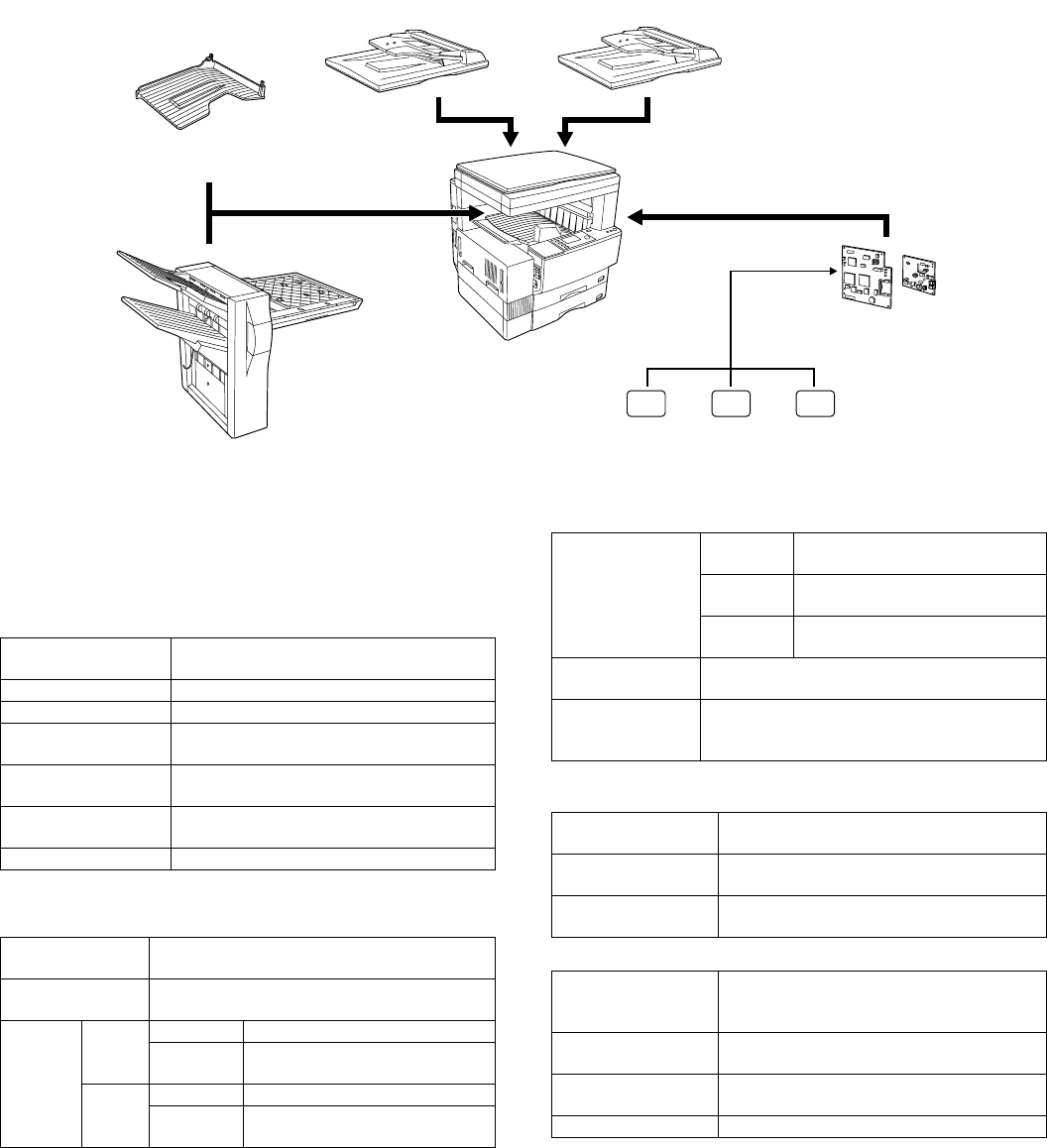
[1] OUTLINE
This unit is a fax expansion kit which provides facsimile functions by
attaching to the digital machine AR-235/275 series.
To expand facsimile functions, use of SPF/RSPF is recommendable.
By attaching a job separator/finisher, copy output and fax output can
be separately discharged to different trays.
The fax board of the fax expansion kit is provided with 2MB flash mem-
ory (standard). An expansion memory of one of 2MB/4MB/8MB can be
added. (2MB expansion memory for fax, AR-MM5; 4MB expansion
memory for fax, AR-MM6; 8MB expansion memory for fax, AR-MM7)
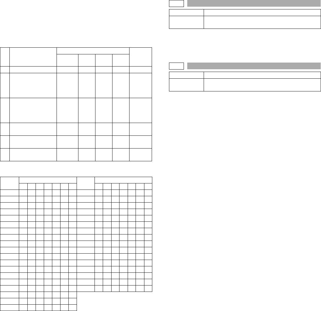
[2] SPECIFICATIONS
1. Communication system
(1) Electronic transmission system
2. Scanning system
(1) Document size
(2) Transmission mode document load quantity scan
cycle (SPF/RSPF capacity)
(3) Half-tone reproduction density adjustment
RSPF (AR-RP3) SPF (AR-SP4)
Job separator
(AR-TR3)
Finisher
(AR-FN5)
Expansion memory (One of them is attached to.)
2MB
AR-MM5 AR-MM6 AR-MM7
4MB 8MB
FAX expansion kit
(AR-FX4)
Transmission time About 3 sec (Super G3/33660bps)
About 6sec (G3 ECM/14400bps)
Compression system MH, MR, MMR, JBIG
Modem speed 33600bps → 2400 auto fall back
Mutual
communication
Super G3/G3
Employed line Public Switched Telephone Network
(PSTN), Private Branch Exchange (PBX)
Number of employed
lines
One line (no additional line allowed)
ECM YES
Max. document
width
297mm (11.7")
Unscanable area Lead edge 5mm or less, rear edge 5mm or less
left & right edges 6mm or less
Auto
detection
size
OC AB series A3/B4/A4/A4R/A5
Inch series 11 x 17/8.5 x 14/8.5 x 11/
8.5 x 11R/5.5 x 8.5
SPF/
RSPF
AB series A3/B4/A4/A4R/A5
Inch series 11 x 17/8.5 x 14/8.5 x 11/
8.5 x 11R/5.5 x 8.5
Document size
specified
AB series A3/B4/A4/A4R/A5/8.5 x 11/
8.5 x 11R
Inch series 11 x 17/8.5 x 14/8.5 x 11/
8.5 x 11R/5.5 x 8.5/A4/A4R
AB series
+ foolscap
A3/B4/A4/A4R/A5/8.5 x 11/
8.5 x 11R/8.5 x 13
Duplex document
specified
YES
Long document Max. 1000mm,.depending on the document
width and resolution
Differs in single/duplex.
SPF/OC
transmission select
NO (Selection inhibited during scanning of a
document)
Continuous auto
paper feed
YES
Document load
capacity
30 sheets
Document scan cycle About 40 pages/min (Normal, A4R memory
transmission, guaranteed scan pages = 30
pages)
Document scan
speed
About 1.5sec/page (Normal, A4R memory
transmission)
Half-tone (Photo
mode)
Equivalent to 256 gradations (Combination
of fine/super fine/ultra fine is possible.)
Density selection Auto/manual in 5 steps
AR-FX4 OUTLINE/SPECIFICATIONS - 2
3. Image process system
(1) Image selection
(2) Print resolution
4. Print system
(1) Recording size
(2) Recording paper
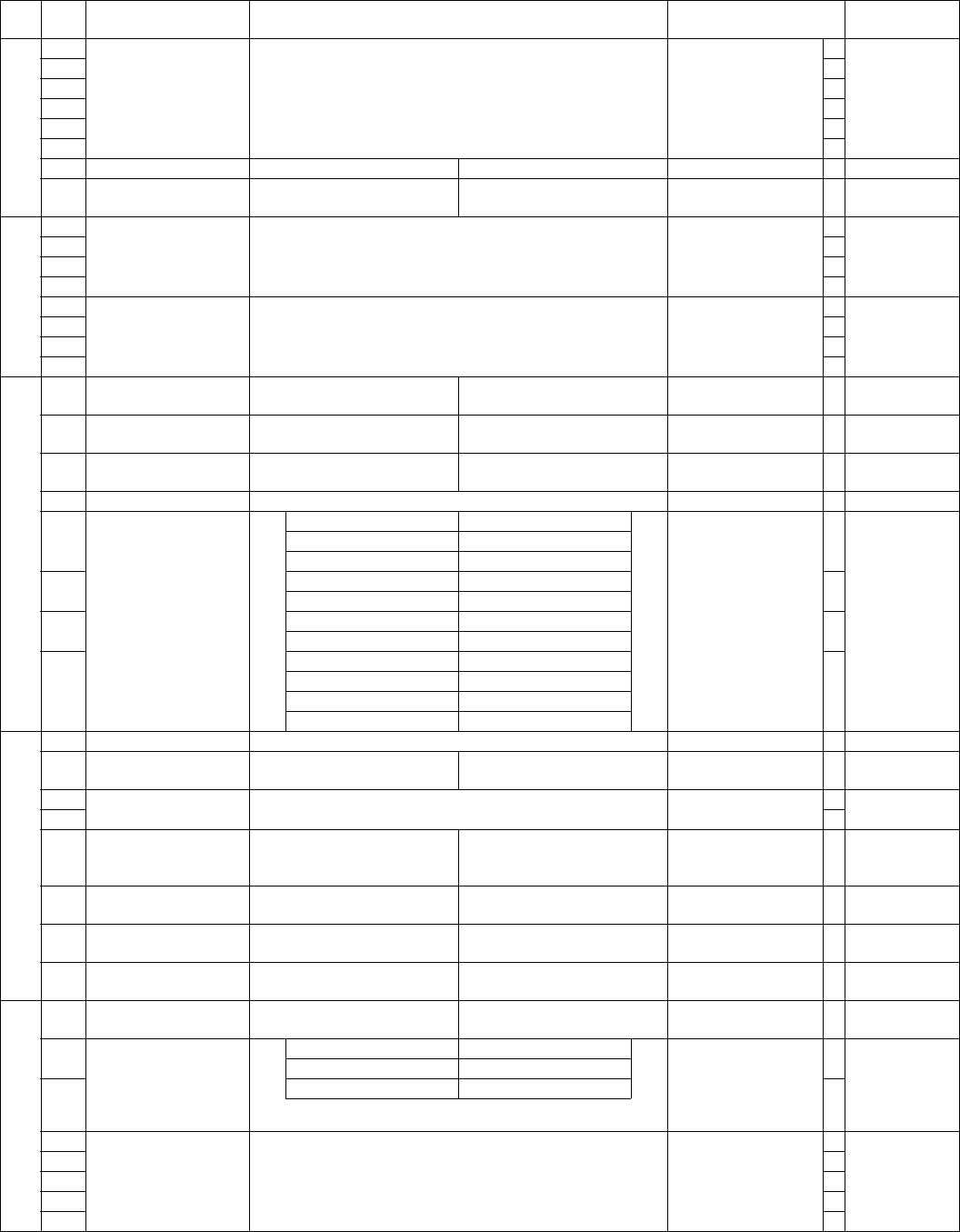
5. Transmission function system
(1) Simplified dialing function
(2) F-code communication
(3) Time specification
(4) Recall mode
(5) Automatic reduction transmission
(6) Memory transmission/direct transmission
(7) Broadcast function
(8) Confidential function
(9) Scan specification
(10) Priority function
(11) Serial transmission function
(12) Rotation transmission
(13) Book document transmission
Normal 8dot/mm x 3.85line/mm
Fine 8dot/mm x 7.7line/mm
Super fine 8dot/mm x 15.4line/mm
Ultra fine 16dot/mm x 15.4line/mm: ITU-T conforming
(reception impossible without additional
memory. Receives in super fine mode.)
600dpi (with resolution correction)
Max. record width 293mm (11.5")
Recording paper
size detection
YES (All sizes except for multi paper feed. →
Recognition of the set size. The tray has no
function to detect the actual paper size.)
Recording paper
size
AB
series
A3/B4/A4/A4R/A5/8.5 x 11/8.5 x 11R
Inch
series
11 x 17/8.5 x 14/8.5 x 11/8.5 x 11R/
5.5 x 8.5/A4/A4R
Cassette capacity Machine: 500 x 1 or 500 x 2
Option: 500 x 1 or 500 x 2
Recording paper
empty detection
YES
Paper feed All installed trays except for multi-manual tray.
Rapid key dialing 50 items
Speed dialing 300 items
Group dialing 50 items (including rapid key dialing)
Telephone
directory
transmission
Any of other parties registered to speed dialing,
rapid key dialing, and group dialing can be
searched for using the first 10 letters.
Chain dialing YES
Redialing The preceding number is saved, and is not
cleared even with CLEAR ALL key.
Program 9 items
Mode recall NO
Sub address YES (Max. 20 digits)
Password YES (Max. 20 digits)
Time specification:
Transmission/polling
Time is specified in transmission/polling.
Auto recall mode
when other party
is busy.
Interval 1min to 15min, default 3min
Number of
times
0 to 14 times / 0: No resend
Default 2 times
Auto recall mode
when in a
communication
error
Interval 1min to 15min / 0: Resend
immediately after disconnection of
the line
Default 1min
Number of
times
1 time only / 0: No resend
Default 1 times
Send page After the error page
Number of transmissions
counted in recall mode
simultaneously.
Max. 50 items
Message is reduced according
to the receiver’s machine.
YES (ON/OFF by key operator
program)
Memory
transmission
Memory
transmission
YES
Number of
transmission
reservation to
be set
Max. 50 items
Process in
memory full
Transmission cancel or only
scanned data transmission
Quick online transmission YES (Enable/Disable setup by key
operator program)
Direct transmission YES (30 pages from SPF, only 1
page from OC)
Default setup Set by key operator program
Broadcast
transmission
Number of
destinations
200 destinations (When group
dialing is used, the number of other
parties registered to group dialing is
added.)
Transmission
method
Broadcast key, group key
Usable dial 10-key entry, rapid key dialing,
speed dialing.
However, those of which sub
address is registered cannot be
used.
Group dialing Transmitted by group dialing
registered to rapid key dialing
Relay
broadcast
transmission
Instructing
station
Only from the machine having Sharp
relay broadcast instructing
transmission function
Relay station Only from the machine having Sharp
relay broadcast transmission
function
Multiple relay NO
Number of
relay groups
10 groups
Number of
receiving
stations that
may be
specified per
group
120 items in rapid key dialing, 240
items in speed dialing
Confidential
transmission
Other station Only Sharp machine having
confidential function
Page division YES (Allowed only from OC)
Page coupling NO
Transmission reservation
interrupt
YES (by direct transmission)
Broadcast interrupt YES (by direct transmission)
Serial transmission NO
Paper size AB series A4 → A4R, 8.5 x 11 → 8.5 x 11R
Inch series 8.5 x 11 → 8.5 x 11R, A4 → A4R,
Transmission method By OC mode
Page division YES

AR-FX4 OUTLINE/SPECIFICATIONS - 3
(14) Finish stamp
(15) Bulletin board, polling transmission functions
6. Reception function system
(1) Reception mode
(2) Zoom reception
(3) Memory reception function
(4) Received data override output
(5) Transfer
(6) Specified number reception
(7) Confidential function
(8) Rotation reception
(9) Division reception
(10) Duplex reception
(11) 2 in 1 reception
(12) Polling (send request)
(13) Turn around transmission
7. Registration system
(1) Number registration
NO
Bulletin board Bulletin board YES
Protection
function
Check by other party’s number YES
Check by matching of system number (user’s
own machine), ID number (other party’s
machine) (between Sharp machines only)
YES
Default setup Automatic reception (Reception
state switchable)
Automatic
reception
Automatic
reception setup
YES
Number of calls 0 to 9 times (Factory setup 2
times, variable)
Automatic
switching of
Telephone/Fax
NO
Non-call reception Allowed by setting the number of
calls to 0.
Manual
reception
Manual reception
setup
YES
Setup for switching
to automatic
reception
NO
Number of calls to
switch to automatic
reception in
manual reception
mode
NO
Dial-in NO
Answering
machine
connection
Answering
connection
NO
Reception mode time switch NO
Reduction Reduction to
regular size
YES (ON/OFF by key operator
program)
Reduction between
regular sizes
YES (by print condition setup of
key operator program)
Enlargement NO
Proxy reception Only when output is disabled.
Compulsory memory reception NO
YES
Transfer destination registration YES (Registered by key operator
program)
Transfer procedure YES (Operated with function
menu)
Reception of only specified numbers allowed NO
Reception of specified numbers inhibited YES
Confidential
reception
Sender Sharp machine having
confidential function only
Confidential box Registered up to 10 boxes
Confidential box
name
36 letters
Confidential ID
code
May be set per confidential box
Paper is outputted by rotating 90 degrees to the set direction of
paper in cassette
Division size When no paper for reception of long
document
Division reception setup YES (by print condition setup of key
operator program)
NO
NO
Polling YES
Resolution at send
request
Variable by soft SW.
Default: fine
NO
Speed
dialing
Number of items 300 items
Number of digits of
other party’s
number
40 digits
Registered name 36 letters
Searched letters Up to 10 letters
User tag
classification
NO
International
communication
mode setup
YES
Transmission
method
Speed dialing key + (000 to 299) +
Start key
Rapid key
dialing
Number of items 50 items
Number of digits of
other party’s
number
40 digits
Registered name 36 letters
Searched letters Up to half-size 10 letters
User tag
classification
NO
International
communication
mode setup
YES
Transmission
method
Rapid dialing key (01 – 50)
Group
dialing
Registered key Rapid dialing key
Max. number of
registration per
group dialing
100 items (The total number of
registration is 150 items.)
Registerable
number
Numbers registered to speed
dialing, rapid dialing, and numbers
entered with 10-key
Registered name 36 letters
Searched letters Up to 10 letters
User tag
classification
NO
Transmission
method
Rapid dialing key

AR-FX4 OUTLINE/SPECIFICATIONS - 4
(2) Sender registration
(3) Polling (send request), bulletin board (remote
transmission) allow number registration)
(4) Letter input
(5) Registered data write
(6) Date/time adjustment
(7) Backup
8. Telephone function system
9. Memory system
10. Additional information function for transmission
11. Additional print function when receiving
Program Number of items 9 items
Registerable item All items that can be set in
transmission, except for time
setup
Registered name 36 letters
Call method By pressing program key
Change in setup
after calling
YES
Sender’s name 36 letters, registered with key operator program
Sender’s number 20 digits, registered with key operator program
Send
request allow
number
Registration of
other party to
which send
request is made
10 digits, 20 digits, registered by
key operator program
System
number
System number
registration
Up to 1 number, registered in key
operator program
ID number ID number
registration
Up to 10 items in 4 digits.
Registered by key operator
program.
Input method Key entry YES
Letters allowed
for input
Half-size
characters
Alphabet, Numerical figures,
Special characters, Codes
YES (Service tool. Dial registration can be made with PC.)
Registered by key operator program.
Backup of registration in power
failure
SRAM used, by built-in battery
Handset NO
On-hook function YES
Reserve NO
Pause YES (1 to 15sec: Default 2sec, set
by key operator program)
Telephone transmission in
power failure
No (However, external telephone
transmission is allowed.)
Sound
volume
adjustment
Call sound
volume
YES (Set by key operator program to
Large/Medium/Small/No sound.)
Line monitor
sound
YES (Set by key operator program to
Large/Medium/Small/No sound.)
On-hook sound YES (Set by key operator program to
Large/Medium/Small.)
Scan end
sound
YES (Set by soft switch to Large/
Medium/Small/No sound.)
Communication
end sound
YES (Set by soft switch to Large/
Medium/Small/No sound.)
Tone pulse switch PULSE/TONE selection with key
operator program.
External telephone
connection
YES
Remote
reception
switch
YES (Switch number is in 1 digit + ∗∗)
5∗∗
Memory capacity Standard 2MB
Option Up to 8MB (+2MB/+4MB/+8MB)
Memory content
(transmission
reservation)
confirmation
LCD display YES
Printout YES
Memory use status YES (% display)
Document data memory backup
in power failure
YES (Flash memory)
Page counter YES
Date printing YES (Year/month/day, Year
in 4 digits)
Date/ display
sequential switch
NO
Cover paper
function
Cover
paper
item
Date YES
Receiver’s
name
YES
Receiver’s
number
YES
Sender’s
name
YES
Sender’s
number
YES
Display of
number of
documents
transmitted
YES
Transmission
message
YES
Print paper
size
A4 (AB series)
8.5 x 11 (Inch series)
Transmission
message
Regular message CONFIDENTIAL/PLS.
DISTRIBUTE/URGENT/
PLS.
CALL BACK/IMPORTANT
User message NO
Sender print
function
Sender’s number 20 digits, registered with
key operator program
Sender’s name 36 letters
Index print YES (Set by key operator program)
AR-FX4 OUTLINE/SPECIFICATIONS - 5
12. Recording table system
(1) Communication record function
(2) Communication result report function
(3) Report function
(4) Other report list
13. Others
Communication record table size AB series A4 (Not output when
paper greater than
A4 is not set.)
Inch
series
Letter (not output if
size setting is not
Letter or larger)
Communication record memory
capacity
50 items in total of transmission
and reception
Communication
record table
Number of
items
Max. 50 items for each of
transmission and reception
(Total of transmission and
reception is up to 50 items.)
Record table is outputted
separately. If registration
exceeds 50, the oldest one is
deleted.
Time-specified
output
YES (2 times per day)
Output when
recording
memory full
Soft SW provided
Output of
individual
department
YES (Communication time of
each department is outputted as
department management record
table.)
Time-specified communication
table
Common with transmission
record table
Confidential reception check
table
YES
Communication
result table
(transmission)
YES (Select Always print/in failure of
transmission/no print. With key operator
program)
Broadcast
communication
report
YES (Select Always print/in failure of
transmission/no print. With key operator
program)
Communication
result table
(reception)
YES (Select Always print/in failure of
transmission/no print. With key operator
program)
Communication
result table
(confidential
reception)
YES (Select Always print no print. With key
operator program)
Document content
print in transmission
error
YES (Some part of the first page is printed:
ON/OFF setup by key operator program.
Confidential transmission data are never
printed.)
Rapid key dialing
table
YES (Rapid key table)
Speed dialing table YES (Speed dialing table)
Group table YES (Group number table
Telephone number
table
YES (Table of searched letters in rapid key
dialing, speed dialing, and group dialing in
alphabetical order)
Transmission
message list
NO
ID/Senders list YES
Confidential ID
table
YES
Soft switch list YES
Memory image
deletion table
NO
CSI transmission
function
CSI transmission YES
Department
management
Limitation on users
in each department
YES
Number of
departments
registered
20 items
Charge
management
function for each
department
NO
Operation panel
display
LCD 19 letters x 5 lines
Automatic booting mode NO
AR-FX4 INSTALLATION PROCEDURE - 1
[3] INSTALLATION PROCEDURE
1. Install of expansion kit
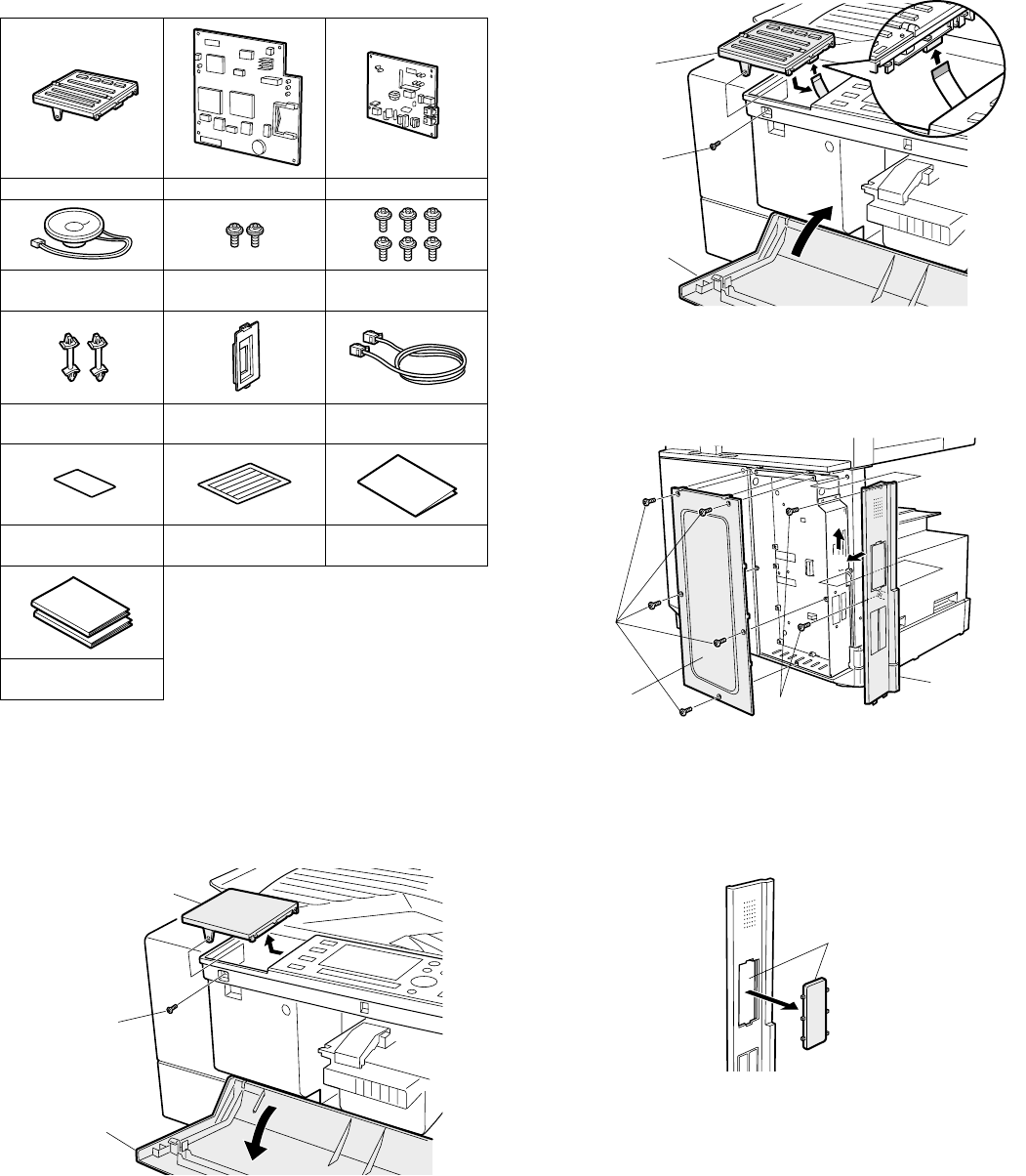
A. Parts included
B. Installation
Turn off the main switch of the copier and then remove the
power plug of the copier from the outlet.
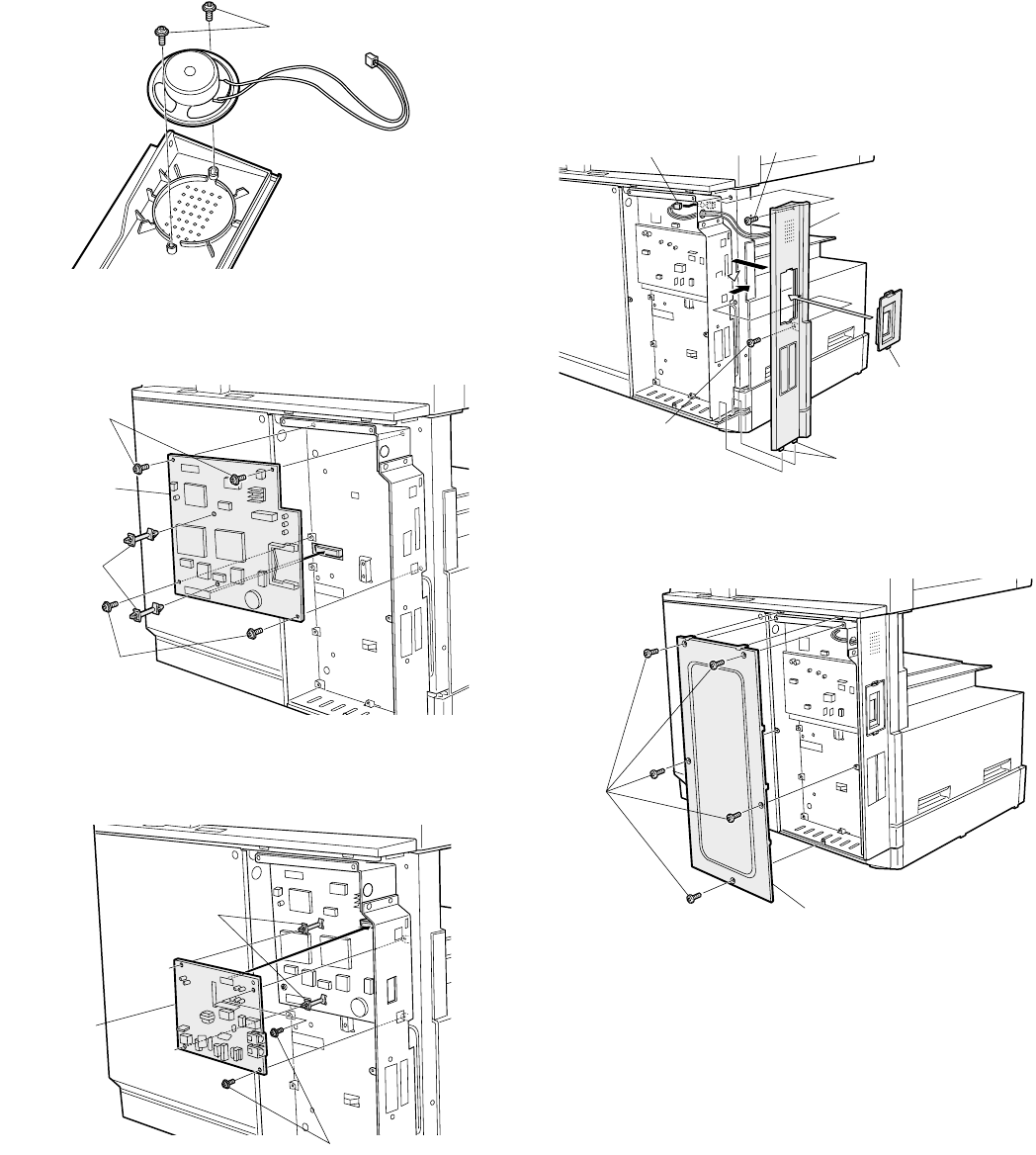
1) Remove the fax dummy cover.
Open the front cover of the copier, remove the screw that fixes the
fax dummy cover, and remove the fax dummy cover.
2) Attach the fax key unit.
Connect the flat cable to the fax key unit, attach the fax key unit to
the operation panel, and use the screw to fix it.
Close the front cover of the copier.
3) Remove the shielding plate and the left rear cabinet.
Remove the 5 fixing screws on the shilding plate and take off the
shilding plate with inserting the flatblade screwdriver, etc.
Next, remove the 5 fixing screws on the left rear cabinet, and slide
it backward to remove.
4) Work the left rear cabinet.
Cut and remove the cut-out portion from the left rear cabinet using
a tool such as nippers.
Be careful about the direction of the tool so that the cut surface is
flat.
Fax key unit: Fax PWB TEL/LIU PWB
Speaker unit: M3 golden screws:
2 pcs.
M3 screws with
washer: 6 pcs.
PWB spacers: 2 pcs. Fax connector cover:
1 pcs.
Line cable: 1 pcs.
Supplied label:
1 sheet
Writing label: 1 sheet Installation manual:
1 sheet
Operation manuals:
2 pcs.
Fax dummy cover
Screw
Front cover
Fax key unit
Screw
Front cover
(1)
(2)
Screws
Screws Left rear cabinet
Shielding plate
Cut-out portion
AR-FX4 INSTALLATION PROCEDURE - 2
5) Attach the speaker.
Attach the speaker to the left rear cabinet using supplied two
golden screws (M3).
6) Attach the fax PWB.
Mount the two spacers on the fax PWB.
Next, insert the fax PWB connector into the connector on the
expansion PWB, install with 4 M3 screws with washer.
7) Attach the TEL/LIU PWB.
Insert the TEL/LIU PWB connector into the fax PWB connector,
attach 2 spacers on the TEL/LIU PWB, and attach the TEL/LIU
PWB with 2 M3 screws with washer.
8) Reattach the left rear cabinet.
1. Pass the speaker harness through the hole of the frame of the
fax expansion PWB and connect it to the connector of the fax
PWB.
2. Fit the pawls of the left rear cabinet to the mounting portions of
the main unit. Slide the cabinet toward the front of the main unit
to attach it.
3. Fix the left rear cabinet with 2 screws.
4. Attach the supplied fax connector cover.
9) Reattach the shielding plate.
Fit the pawls of the shielding plate to the main unit and secure the
plate using five screws.
Insert the power plug of the copier to the outlet and turn
on the main switch. Then, carry out the following
procedure.
10) Date/time setting
Press [SPECIAL FUNCTION] key on the operation panel, select
[KEY OPERATOR PROGRAM]. Input 5-digit Key Operator Code
with 10-key, and select [FAX] in Mode Select.
Select [DEFAULT SETTING], [DATE/TIME SETTING], and input
month/day/year in this order, and press [OK] to set.
Input hour/minute in this order, and press [OK] to set.
M3 golden screws
Spacers
Fax PWB
M3 screws with
washer
M3 screws with
washer
M3 screws with washer
TEL/LIU PWB
Spacers
1
2
3
4
3
Screw
Screw
Speaker harness
Left rear cabinet
Pawls
Fax connector cover
Screws
Shielding plate
AR-FX4 INSTALLATION PROCEDURE - 3
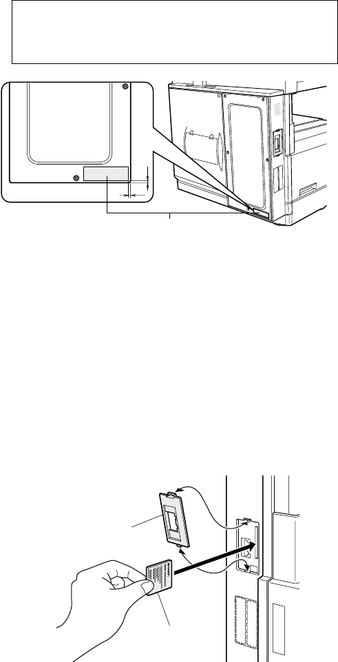
11) Paste the label on the left rear cabinet of the copier.
Paste the FCC label to the position shown in the illustration.
2. Mounting of additional memory
(AR-MM5, MM6, MM7)
• When mounting memory, turn off the main unit.
1) Remove the fax connector cover using a flatblade screwdriver or
the like.
2) Insert the memory card securely so that the model name is on the
rear side.
3) Reattach the fax connector cover.
• Turn on the main unit.
(When turning on the main unit just after expansion, the system
check time will become longer due to memory initialization.)
4) Make certain that the memory was expanded by displaying SW list
with SIM 66-21.
In order to manifest the compliance with FCC Part 68 and IC CS-03, it is
required to provide the machine with the FCC Registration Number (USA),
Ringer Equivalence (USA) and Ringer Equivalence (Canada).
After installing the FAX expansion kit in the machine, please put the
registration label, packed with the kit, on the prescribed location.
FCC label
3
3
Fax connector cover
Memory card
1)
1)
2)
3)
3)
AR-FX4 ADJUSTMENTS - 1
[4] ADJUSTMENTS
1. Density section
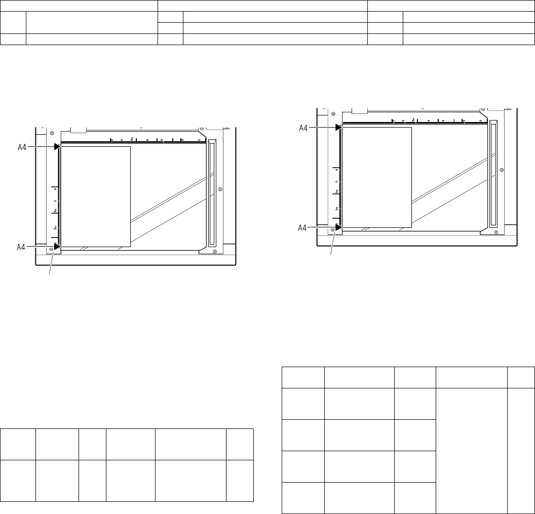
A. FAX mode density adjustment (Overall mode)
(<FAX mode> SIM 46-12)
1) Set the test chart (TPAP-2109SCZZ <CCITT #3 chart>) on the OC
table as shown below, and close the OC cover.
2) Switch to the FAX mode and execute SIM 46-12.
3) After warming up, shading is performed and the current density
level is displayed on the lower two digits of the display section in
standard and auto density mode.
4) Enter the set value with the 10-key to adjust the FAX image den-
sity.
5) Make a copy, and adjust so that the following adjustment specifica-
tion is satisfied.
∗When an adjustment is made in this mode, the exposure level for
each communication mode and each density mode are automatically
adjusted accordingly.
<Adjustment specifications>
B. FAX mode density adjustment (Individual mode)
(<FAX mode> SIM 46-13 – 16)
1) Set the test chart (TPAP-2109SCZZ <CCITT #3 chart>) on the OC
table as shown below, and close the OC cover.
2) Switch to the FAX mode and execute SIM 46-13 to 46-16 depend-
ing on the adjustment mode.
3) After warming up, shading is performed and the current density
level is displayed on the lower two digits of the display section.
4) Enter the set value with the 10-key to adjust the FAX image den-
sity.
5) Make a copy, and adjust the density with the copy as a reference.
<Adjustment specifications>
Section Adjustment items Adjustment procedures
1 Density section A FAX mode density adjustment (Overall mode) <FAX mode> SIM 46-12
B FAX mode density adjustment (Individual mode) <FAX mode> SIM 46-13 – 46-16
2 Communication section A Dial test <FAX mode> SIM 66-13
Density
mode
Resolution
mode SIM
CCITT #3
chart output
result
Set value Set
range
Auto Standard FAX
mode
46-12
“3” is slightly
copied.
The greater the
set value is, the
greater the density
is, and vice versa.
0 – 99
Glass holding plate
Resolution
mode
Density
changeover SIM Set value Set
range
Standard Switched with the
density select
key.
FAX
mode 46-
13
The greater the
set value is, the
greater the density
is, and vice versa.
0 – 99
Fine Switched with the
density select
key.
FAX
mode 46-
14
Super fine Switched with the
density select
key.
FAX
mode 46-
15
Ultra fine Switched with the
density select
key.
FAX
mode 46-
16
Glass holding plate
AR-FX4 ADJUSTMENTS - 2
2. Communication section
Note: These items are factory adjusted when shipping according to
FCC standards. Therefore, do not change the setting in the mar-
ket.
A. Dial test (<FAX mode> SIM 66-13)
(1) Dial pulse transmission test
1) Execute SIM 66-13 in FAX mode.
2) Execute the dial pulse mode according to the instructions on the
LCD display.
3) Select the dial pulse.
4) Set the make time.
5) Select the dial to be transmitted.
Default: 0123456789∗#
(After deleting with the clear key, it can be set to any desired
value.)
6) Transmission is started from the line.
(2) DTMF signal transmission level adjustment
1) Execute SIM 66-13 in the FAX mode.
2) Execute the DTMF mode according to the instructions on the LCD
display.
3) Select the signal transmission level.
The signal transmission level is classified into two groups: the high
group, and the low group.
Transmission can be made with either of default and the soft SW
set value.
4) The transmission level can be set when the following menu is dis-
played on the LCD. (et value 1 = 0.5dB change)
(This value is returned to the original value when the simulation
mode is canceled.)
5) Select the dial signal to be transmitted.
Default: 0123456789∗#
(After deleting with the clear key, it can be set to any desired
value.)
6) Start transmission from the line.
SELECT SIGNAL
1:PULSE 2:DTMF
SELECT PULSE
1:10PPS 2:20PPS
INPUT MAKE TIME
(0-15) _
SEND yyPPS xxm s
1:YES 2:NO
SENDING yyPPS xxm s
SIM Soft
SW
Initial
value Set value
Dial
pulse
make
time
10
PPS
FAX
mode
66-13
SW 67-
1 – 4
40ms
(14)
SW set value: 0 – 15
Make time: 26 – 41ms
1ms step
(Binary
input)
20
PPS
SW 67-
5 – 8
0ms 0 fixed
SELECT SIGNAL
1:PULSE 2:DTMF
SELECT HIGH LEVEL
1:DEFAULT 2:SOFT SW.
SELECT LOW LEVEL
1:DEFAULT 2:SOFT SW.
INPUT VALUE
(0-15) _
H:xx L:yy
1:YES 2:NO
xx: High group soft SW set value
yy: Low group soft SW set value
SENDING DTMF
SIM Soft
SW
Initial
value Set value
DTMF
trans-
mission
level
High
group
(FAX
mode) 66-
13
(Test only)
SW 53-
1 – 4
3.5dB
(7)
SW set value:
0 – 15
Transmission
level: 0 – 7.5dB
0.5ms
step
(Binary
input)
Low
group
SW 53-
5 – 8
3.5dB
(7)
AR-FX4 SIMULATION - 1
[5] SIMULATION
1. Entering the simulation mode/cancel of
simulation mode
• Selection of the main code and the sub code is set with the [START]
key.
• There are two or more screens, the adjustment "Current page/Max.
page" is displayed. Press [↑] key (previous page) or [↓] key to select
a screen.
2. Simulation code list
3. Details
Operation/procedure
Enter the adjustment value and press the [OK] key, and output opera-
tion is performed for 30sec.
The minimum increment is 2V.
The result of (Set value – 199) / 2 is stored in the EEPROM.
When reading a value from the EEPROM, the value of (EEP value *2)
+ 200 is used as the set value.
Therefore, the set value entered must be an even number. If an odd
number is entered the entered odd number + 1 is displayed after
pressing [OK] key.
Operation/procedure
Enter the adjustment value and press the [OK] key, and output opera-
tion is performed for 30sec.
The input value is in the increment of –25V.
Procedure Key operation
1 Simulation mode selection
2 Main code selection
3 Sub code selection
4Selection of the mode and
item
5 Start simulation operation
6
Returns to the sub code
selection.
Simulation mode clear
Code Function
Main Sub
8 13 Used to check and adjust the operation of the
developing bias voltage in FAX mode and the
control circuit.
14 Used to check and adjust the operation of the main
charger grid voltage (high mode) in FAX mode and
the control circuit.
15 Used to check and adjust the operation of the main
charger grid voltage (low mode) in FAX mode and
the control circuit.
22 11 FAX related counter display
24 10 FAX related counter clear
26 1 Used to set options. (This simulation is used to
make option setting when an option is installed.)
60 Used to set enable/disable of the FAX mode key
when FAX is not installed. (When FAX is installed,
the FAX mode is enabled regardless of this setup.)
46 12 FAX exposure level adjustment (batch)
13 to
16
FAX exposure level adjustment (individual)
48 8 FAX magnification ratio adjustment (read)
9 FAX magnification ratio adjustment (print)
10 FAX auto reduction magnification ratio (print).
50 8 FAX lead edge adjustment (read)
9 FAX lead edge adjustment (print)
66 1 FAX related soft SW setting
2 Initial set for the value of the FAX soft SW
3 FAX PWB memory check
4 Signal send mode
6 Printing the confidential password
7 Image data print
10 Image data memory clear
11 300bps signals send
13 Send test and adjustment of the dial pulse and
DTMF signal.
17 DTMF signal send
21 FAX information print
30 TEL/LIU state change recognition
32 Receive data check
34 Communication time measurement display
#→C
INTERRUPT
→ →
INTERRUPT
10-key
(Input main code)
→START
10-key
(Input sub code)
→START
10-key
and
↑ ↓
START
OK
or
INTERRUPT
CA
66
37 Speaker sound volume adjustment
38 Time setting/check
50 The FAST area of SRAM is cleared.
8
8-13
Purpose Adjustment/Operation test/check
Function
(Purpose)
Used to check and adjust the operation of the
developing bias voltage in FAX mode and the control
circuit.
Section Image process (Photoconductor/Developping/
Transfer/Cleaning)
Developer/Toner hopper
(Initial screen) (Executing screen)
Setting range 200-550
Default 426
8-14
Purpose Adjustment/Operation test/check
Function
(Purpose)
Used to check and adjust the operation of the main
charger grid voltage (high mode) in FAX mode and the
control circuit.
Section Image process (Photoconductor/Developping/
Transfer/Cleaning)
Photo conductor
(Initial screen) (Executing screen)
Setting range 1-8
Default 5
Code Function
Main Sub
Sim8-13 DV BIAS FAX
FAX 426
EXEC [200-550] 4260
Sim8-13 DV BIAS FAX
FAX 426
EXEC [200-550] 426
Sim8-14 MHV(H) FAX
FAX 5
EXEC [ 1- 8] 5
Sim8-14 MHV(H) FAX
FAX 5
EXEC [ 1- 8] 5
AR-FX4 SIMULATION - 2
*1. The negative value of the set value corresponds to the grid high
output voltage.
*2. The set values can be selected from the above 8 patterns only.
*3. The selected pattern determines the grid high voltage and the grid
low voltage.
If, for example, the grid high voltage is set to –480V (pattern 1), the
grid low voltage is –350V.
Operation/procedure
Enter the adjustment value and press the [OK] key, and output opera-
tion is performed for 30sec.
*1. The negative value of the set value corresponds to the grid high
output voltage.
*2. The set values can be selected from the above 8 patterns only.
*3. The selected pattern determines the grid high voltage and the grid
low voltage.
If, for example, the grid high voltage is set to –480V (pattern 1), the
grid low voltage is –350V.
Operation/procedure
The current counter value (number of send/receive pages) of the FAX
send/receive counter and the accumulated reception time and the print
counter are displayed.
Note: Executable only when the FAX is installed.
Operation/procedure
The current counter value (number of send/receive pages) of the FAX
send/receive counter and the accumulated reception time and the print
counter are cleared to 0.
Note: Executable only when the FAX is installed.
Operation/procedure
Set the job separator.
Operation/procedure
Input the set value with the 10-key and press the [OK] key.
This setup varies in connection with SIM 26-6 (Destination setup).
NO. Set value Grid High Grid Low
1 480 –480V –350V
2 505 –505V –375V
3 530 –530V –400V
4 555 –555V –425V
5 580 –580V –450V
6 605 –605V –475V
7 630 –630V –500V
8 655 –655V –525V
8-15
Purpose Adjustment/Operation test/check
Function
(Purpose)
Used to check and adjust the operation of the main
charger grid voltage (low mode) in FAX mode and the
control circuit.
Section Image process (Photoconductor/Developping/
Transfer/Cleaning)
Photo conductor
(Initial screen) (Executing screen)
Setting range 1-8
Default 5
NO. Set value Grid High Grid Low
1 480 –480V –350V
2 505 –505V –375V
3 530 –530V –400V
4 555 –555V –425V
5 580 –580V –450V
6 605 –605V –475V
7 630 –630V –500V
8 655 –655V –525V
22
22-11
Purpose Adjustment/Setting/Check
Function
(Purpose)
FAX related counter display
Sim8-15 MHV(L) FAX
FAX 5
EXEC [ 1- 8] 5
Sim8-15 MHV(L) FAX
FAX 5
EXEC [ 1- 8] 5
24
24-10
Purpose Adjustment/Setting/Check
Function
(Purpose)
FAX related counter clear
26
26-1
Purpose Setting
Function
(Purpose)
Used to set options. (This simulation is used to make
option setting when an option is installed.)
Item Specifications Option
Set value Connection option
0 None (default)
1 Job separator provided.
26-60
Purpose Setting
Function
(Purpose)
Used to set enable/disable of the FAX mode key when
FAX is not installed. (When FAX is installed, the FAX
mode is enabled regardless of this setup.)
Item Operation
Display
items Content Setting
range
Default
JAPAN,
SEC, SECL,
SUK, SCA
Others
0:ON
Effective (The
message with FAX
uninstalled is
displayed.)
0-1 0 1
1:OFF
Disable (Error Beep)
Sim26-1 OPTION SET.
JOB SEPARATOR 0
(0:NONE
1:JOB SEPARATOR)
[ 0- 1] 0
Sim26-60 FAX KEY
FAX KEY SETTING 0
(0:ON 1:OFF)
[ 0- 1] 0
AR-FX4 SIMULATION - 3
Operation/procedure
Shading is performed to turn on the copy LED.
The current exposure value of "Normal character, Auto exposure"
mode is displayed.
Enter an adjustment value of 2 digits with the 10-key and press the
START key, and the entered value will be set to all the modes and the
self print will be made in the normal size.
Exposure adjustment value table
When initializing each data: 50
Note: Executable only when the FAX is installed.
Operation/procedure
The FAX exposure level can be adjusted separately for each mode by
specifying a sub code. Since selection of Auto/Manual and Photo ON/
OFF is allowed separately for each mode, adjustments of 14 patterns
in total can be made.
(Refer to 46-12, "Exposure adjustment table".)
Shading is performed to turn on the copy LED.
The current exposure value of the selected mode is displayed.
Enter the 2-digit adjustment value with the 10-key pad and push
START key. The entered value is set for the specified mode, and the
self print is made with the same magnification ratio for the mode.
Note: Executable only when the FAX is installed.
Operation/procedure
Adjust and set FAX document read magnification ratio, read and print
the document.
Note: Executable only when the FAX is installed.
Operation/procedure
After the adjustment/setting of FAX print magnification ratio, read and
print the document.
Note: Executable only when the FAX is installed.
Operation/procedure
Set the FAX auto reduction magnification ratio (0 to 15%).
Note:Executable only when the FAX is installed.
Operation/procedure
Adjust and set FAX document read lead edge position, read and print
the document.
46
46-12
Purpose Adjustment
Function
(Purpose)
FAX exposure level adjustment (batch)
Mode AE Photo Exposure adjustment
STD
(Standard
character)
Auto ON –
Manual
Auto OFF
Individual adjustment
enable
(46-13 to 16)
Manual
Fine
(Small
character)
Auto ON
Manual
Auto OFF
Manual
S-fine
(Fine)
Auto ON
Manual
Auto OFF
Manual
U-fine
(Super fine)
Auto ON
Manual
Auto OFF
Manual
46-13 to 16
Purpose Adjustment
Function
(Purpose)
FAX exposure level adjustment (individual)
Sub code Mode
13 STD (normal character)
14 Fine (small character)
15 S-fine (super fine)
16 U-fine (super fine)
48
48-8
Purpose Adjustment
Function
(Purpose)
FAX magnification ratio adjustment (read)
Related soft
SW
SW76-1 to 8, SW77-1 to 8
Adjustment magnification ratio Adjustment
range
Adjustment
unit
OC read main scanning
magnification ratio
1 – 128 –
255%
0.1%
increment
OC read sub scanning
magnification ratio
SPF read main scanning
magnification ratio
SPF read sub scanning
magnification ratio
48-9
Purpose Adjustment
Function
(Purpose)
FAX magnification ratio adjustment (print)
Related soft SW SW78-1 to 8, SW79-1 to 8
Adjustment magnification ratio Adjustment
range
Adjustment
unit
Main scanning magnification ratio 1 – 128 –
255%
0.1%
increment
Sub scanning magnification ratio
48-10
Purpose Adjustment
Function
(Purpose)
FAX auto reduction magnification ratio (print).
Related soft SW SW25-1 to 4
50
50-8
The adjustments on the machine side must have been normally
completed.
Purpose Adjustment
Function
(Purpose)
FAX lead edge adjustment (read)
Related soft SW SW44-1 to 4, SW44-5 to 8
SW45-1 to 4, SW45-5 to 8
AR-FX4 SIMULATION - 4
Note: Executable only when the FAX is installed.
Operation/procedure
After the adjustment/setting of FAX print lead edge position, read and
print the document.
Note: Executable only when the FAX is installed.
Operation/procedure
Display FAX software SW on LCD, and set/change those with 10-key.
Note: Executable only when the FAX is installed.
Operation/procedure
Used to clear the FAX-related soft switches except for the line signal
adjustment value and the machine adjustment value and to set default
values (which differ depending on the country code separately
entered.)
Note: Executable only when the FAX is installed.
Operation/procedure
Read/write can be checked for FAX PWB memory.
The check result is displayed separately for each memory.
1. Memory to be checked
2. Detailed procedure
Interruption cannot be made during operation.
Note: Executable only when the FAX is installed.
Operation/procedure
By setting the message No., the signal is sent to the line and the
speaker of the body. (The signal is continuously sent until the interrup-
tion command is provided by pressing the [BACK] key.)
The signal send level can be selected from 0dB or the soft SW set
value. However, the level setup is not required for 01, 31 - 35, the
selection may does not appear. After completion of the mode, the sig-
nal send level is returned to the soft SW set value before execution of
the mode.
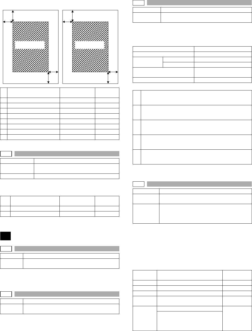
Adjustment position Adjustment range Adjustment
unit
A OC read lead edge position 43 – 50 – 57 lines 8 lines
B OC read left edge position 43 – 50 – 57 dots 8 dots
C OC read rear edge position 43 – 50 – 57 lines 8 lines
D OC read right edge position 43 – 50 – 57 dots 8 dots
E SPF read lead edge position 43 – 50 – 57 lines 8 lines
F SPF read left edge position 43 – 50 – 57 dots 8 dots
G SPF read rear edge position 43 – 50 – 57 lines 8 lines
H SPF read right edge position 43 – 50 – 57 dots 8 dots
50-9
Purpose Adjustment
Function
(Purpose)
FAX lead edge adjustment (print)
Related soft SW SW74-1 to 4, SW75-5 to 8
Adjustment position Adjustment range Adjustment
unit
A Lead edge position 43 – 50 – 57 lines 16 lines
B Left edge position 43 – 50 – 57 dots 16 dots
66
66-1
Purpose Adjustment/Setting/Check
Function
(Purpose)
FAX related soft SW setting
66-2
Purpose Adjustment/Setting/Check
Function
(Purpose)
Initial set for the value of the FAX soft SW
OC read SPF read
Read area Read area
A
B
E
F
D
C
H
G
66-3
Purpose Adjustment/Setting/Check
Function
(Purpose)
FAX PWB memory check
DRAM
SRAM
Flash ROM Program area SUM check only
Memory area
Option memory The memory size follows the
automatically detected value.
PAGE
1 "55H" is written to all the addresses of each memory, and the
address data are read in sequence to check that they were
properly written.
2 "AAH" is written to all the addresses of each memory, and the
address data are read in sequence to check that they were
properly written.
3 "00H" is written to all the addresses of each memory, and the
address data are read in sequence to check that they were
properly written.
4 Perform checks 1 - 3 sequentially. If there is no abnormality, it is
"OK." If there is any abnormality, "NG" is notified to the error
address.
5 After completion of check, the memory is returned to the initial
state.
(CPU is not reset)
66-4
Purpose Adjustment/Setting/Check
Function
(Purpose)
Signal send mode
Related soft
SW
SW5-5 to 8 (signals send level)
SW23-1 to 4 (RBT ON time)
SW23-5 to 8 (RBT OFF time)
SW43-1 to 5 (DTMF signal send time)
Signal
number Send signal Send level
Selection menu
01 Signal not send None
26 7EH Flag signal Yes
27, 28, 30 Tone signal Yes
31 Pseudo-ringer sound
([ON HOOK] key ON)
None
32 Voice message (no sound) None
Under the state where the ring back
tone can be sent to the line, keep
the sound composition IC volume to
0.

AR-FX4 SIMULATION - 5
Note: Executable only when the FAX is installed.
Operation/procedure
The confidential ID table (confidential BOX numbers, confidential BOX
names, and confidential password) is printed.
The confidential data of My company mode is printed separately.
Note: Executable only when the FAX is installed.
Operation/procedure
Used to input all image data (including confidential reception data,
remote send image, not-sent image) stored in image memory of the
FAX section.
The output image is remained even after outputting.
Note: Executable only when the FAX is installed.
Operation/procedure
Used to clear all image data (including confidential reception data)
stored in image memory of the FAX section.
The management table is also cleared (initialized) at the same time.
Note: Executable only when the FAX is installed.
Operation/procedure
By setting the signal number, the specified signal is delivered to the
line at the speed of 300bps. (The signal is continuously sent until the
interruption command is provided by pressing the [BACK] key.)
The signal send level can be selected from 0dB or the soft SW set
value.
The signal send level is returned to the soft SW set value before exe-
cution of the mode after completion of the mode.
Note: Executable only when the FAX is installed.
Operation/procedure
The send test of dial pulse and DTMF signal is performed and the
make time adjustment of dial pulse and the DTMF signal send level
adjustment are performed if necessary.
•Used to set the make time. By performing the test, the registered
dial pulse of max. 100 digits can be sent from the line.
•When "*" and "#" are included in the registered dial number, they are
disregarded and the number is not processed as a dial.
•The make time set in the dial test is written into the corresponding
soft SW.
•Default: 1 2 3 4 5 6 7 8 9 0
Operate the [ ← ] [ → ] key in DP dial selection menu to switch.
(Time before pulse delivery can be changed as 2sec → 4sec →
8sec.)
•Set the signal send level to 0dB or the soft SW set value.
Used to set the high level group and the low level group of DTMF
signal send level. By executing the test, DTMF signal is sent from
the line to a recorded dial number of max. 100 digits.
•The high group/low group value of the DTMF signal send level set in
the dial test is written into the corresponding soft SW.
•Default: 1 2 3 4 5 6 7 8 9 * 0 #
In the PB dial select menu, press [←][→] keys to select.
Pressing the [CLEAR] key during the operation clears the input
value and returns to the value input menu.
•Max. 100 digits can be assigned to each dial (0 - 9, *, #). While the
default value is displayed at first, a desired value can be entered and
the entered value is stored on the FAX side until the menu is can-
celed.
•After completion of the mode, the signal send level is returned to the
soft SW set value before execution of the mode.
Note: Executable only when the FAX is installed.
33 Ring back tone (no sound) None
Under the state where the ring back
tone can be sent to the line, keep
the G/A volume to 0.
34 Dial pulse (make) 1: 0dB
2: Soft SW
Maintain the make state with
keeping the condition to be able to
send to the dial pulse line.
35 Dial pulse (break) 1: 0dB
2: Soft SW
Maintain the break state with
keeping the condition to be able to
send to the dial pulse line.
Other than
the above
FFH Yes
66-6
Purpose Adjustment/Setting/Check
Function
(Purpose)
Printing the confidential password
66-7
Purpose Adjustment/Setting/Check
Function
(Purpose)
Print the screen memory contents
66-10
Purpose Adjustment/Setting/Check
Function
(Purpose)
Image data memory clear
66-11
Purpose Adjustment/Setting/Check
Function
(Purpose)
300bps signals send
Signal
number Send signal Send level
Selection menu
Number Signal Number Signal
1 No signal (CML ON) 4 00000
2 11111 5 010101
3 11110 6 00001
66-13
Purpose Adjustment/Setting/Check
Function
(Purpose)
Send test and adjustment of the dial pulse and
DTMF signal.
Related soft SW SW53-1 to 4 (DTMF high group end level)
SW53-5 to 8 (DTMF low group send level)
SW67-1 to 4 (DP 10PPS make time)
SW67-5 to 8 (DP 10PPS make time)
1. Dial pulse (10pps) send test
2. Dial pulse (20pps) send test
3. DTMF signal send test
Make time 1ms for input value of 1. Adjust so that the dial pulse
make rate is within 33±3%. (For North America,
40±3%.)
Dial pulse make rate =
Make time / (Make time + Break time)
Break time It is obtained from the formula below and
automatically set.
PPS = 1000 / (make time + break time)
DTMF signal
adjustment
The signal send levels are classified into the high
group and the low group. The send level is 0.5dB for
each 1 of input value.

AR-FX4 SIMULATION - 6
Operation/procedure
Set the signal send level to 0dB or the soft SW set value, and specify
one dial to be delivered to.
The DTMF signal of the specified dial number is delivered until the
interruption command is provided by pressing the [BACK] key.) When
another dial number is specified during delivery of the signal, the new
dial number is delivered.
The signal send level is returned to the soft SW set value before exe-
cution of the mode after completion of the mode.
Note: Executable only when the FAX is installed.
Operation/procedure
The following FAX information is printed.
Note: Executable only when the FAX is installed.
Operation/procedure
When the relay state of the polarity reverse relay, the external tele-
phone hook switch is changed, the content of change is displayed
regardless of the soft SW setup. The display of change is kept until an
interruption command is supplied by pressing the [BACK] key.
Note: Executable only when the FAX is installed.
Operation/procedure
The data received from the line are checked to insure that the following
reception data are identical to the judgment data. If identical, "OK" is
notified. If not, "NG."
A judgment is made according to the reception start data. Continuous
coincidence is required.
Note: Executable only when the FAX is installed.
Operation/procedure
The send/receive test is performed, and the time required for send/
receive of the image data in the test is measured and displayed.
When there are two or more send/receive operations of image data in
one communication, only the time of the last send/receive data near
the end is measured.
Note: Executable only when the FAX is installed.
66-17
Purpose Adjustment/Setting/Check
Function
(Purpose)
DTMF signal send
Related soft SW SW53-1 to 4 (DTMF high group end level)
SW53-5 to 8 (DTMF low group send level)
66-21
Purpose Adjustment/Setting/Check
Function
(Purpose)
FAX information print
Print information Details
1 User switch list
2 Soft SW list
3 Dump list
4 System error Used to print the system error log (error
number and time). For this operation, the
system error log is always stored as the
ring buffer in the SRAM 256byte area.
5 Protocol monitor Regardless of soft SW19-1 status, the
protocol monitor of the preceding
communication is printed. (Printing is
allowed at any time before starting the
next communication.) For this operation,
the protocol monitor of one
communication is always buffered.
66-30
Purpose Adjustment/Setting/Check
Function
(Purpose)
Recognize TEL/LIU state change.
Check signal Notification contents
Signal low Signal high
HS2 ——
HS1 ——
RHS ON OFF
EXHS ON OFF
66-32
Purpose Adjustment/Setting/Check
Function
(Purpose)
Receive data check
Receive speed 300bps
Receive data 00
Number of judgment data 100
66-34
Purpose Adjustment/Setting/Check
Function
(Purpose)
Communication time measurement display
Related soft SW SW10-1
Setup on the user
side when executing
communication
Communication
means
Picture quality
Density
ECM
Sender information
: Memory send
: Normal Character
: Lighter
:ON
:OFF
Measuring
range
Send From flag reception before sending of
image data until sending of RCP frame
Receive From flag reception before reception of
image data until reception of RCP frame
Mode when measuring
Used to make communication not in a
simulation process but in the normal screen
and measure the time.
How to check the time
Enter the simulation for communication time
check and check the time.
Measuring unit
msec
66-37
Purpose Adjustment/Setting/Check
Function
(Purpose)
Speaker sound volume adjustment
Related soft SW SW 86-1, 2 (call sound)
SW 85-1, 2 (line monitor sound)
SW 84-1, 2 (on hook)
SW 88-1, 2 (read end sound)
SW 89-1, 2 (communication end sound)
SW 87-1, 2 (DTMF send sound)
SW75-1, 2 (send end sound length)
SW75-3, 4 (receive end sound length)
AR-FX4 SIMULATION - 7
Operation/procedure
The following test sound is delivered to the line and the speaker to
adjust the sound kind and volume.
The send level to the line is the set value of soft SW.
The set values of the selected sound kind and volume are written to
each soft SW.
1. Sound kinds pattern
NS=No Sound S=Small M=Medium L=Large
2. Sound volume pattern
S=Small M=Medium L=Large
Note: Executable only when the FAX is installed.
Operation/procedure
Read/write the time (year, month, day, min., sec.) on RTC of FAX
PWB.
Note: Executable only when the FAX is installed.
Operation/procedure
Only the SRAM area where data related to FAST are stored is cleared.
Note: Executable only when the FAX is installed.
Sound kinds
(Test sound)
Sound volume set value Sound
volume
Pattern
0 123
1 Call sound NS S M L 01 to 35
2 Lline monitor sound
(Test sound :
Communication
signal sound)
NS S M L 01 to 35
3 On hook
(Test sound :
Communication
signal sound)
Setting
Disable
S M L 01 to 35
4 Read complete
sound
NS S M L 01 to 35
5 Communication
end sound
NS S M L 01 to 35
6 DTMF signal send
sound
NS S M L 01 to 35
Sound
volume
VR set value Sound
volume
VR set value
1234567 1234567
01 S M L 20 S M L
02 S M L 21 S M L
03 S M L 22 S M L
04 S M L 23 S M L
05 S M L 24 S M L
06 S M L 25 S M L
07 S M L 26 S M L
08 S M L 27 S M L
09 S M L 28 S M L
10 S M L 29 S M L
11 S M L 30 S M L
12 S M L 31 S M L
13 S M L 32 S M L
14 S M L 33 S M L
15 S M L 34 S M L
16 S M L 35 S M L
17 S M L
18 S M L
19 S M L
66-38
Purpose Adjustment/Setting/Check
Function
(Purpose)
Time setting/check
66-50
Purpose Adjustment/Setting/Check
Function
(Purpose)
The FAST area of SRAM is cleared.

AR-FX4 SOFT SWITCH DESCRIPTIONS - 1
[6] SOFT SWITCH DESCRIPTIONS
1. Quick reference of FAX soft SW setup change
Large item Medium item Switch content Key operator Soft SW No. Purpose of use
Dial (calling) Remote party
calling inhibited
Pause time Initial setup SW 38-1 – 4 When dial inhibited/erroneous dial
Dial calling signal Initial setup SW 41-1, 2 When dial inhibited
DTMF related items NO SW 53-1 – 4 When dial inhibited in PB (PBX/FAX
service, etc.)
NO SW 53-5 – 8 When dial inhibited in PB (PBX/FAX
service, etc.)
NO SW 43-1 – 5 When dial inhibited in PB (PBX/FAX
service, etc.)
Pulse (10PPS) NO SW 67-1 – 4 When dial inhibited with pulse
Signal detection Busy tone detection NO SW 7-3 When busy tone detection inhibited
Busy tone detection NO SW 15-1 – 3 When busy tone detection error
Dial tone detection NO SW 7-4
Redialing When error Recall interval Send function setup SW 4-1 – 4 When transmission errors occur frequently
When error Number of times of recall Send function setup SW 40-1 – 4
When busy Recall interval Send function setup SW 4-5 – 8 When line is busy frequently
When busy Number of times of recall Send function setup SW 40-5 – 8
Reception
(receiving call)
When CI
detection inhibited
CI detection NO SW 12-6, 7 No reception
CI signal OFF detection
time
NO SW 55-1 – 7 No reception
External
telephone
Setup of external
telephone
YES/NO Initial setup SW 16-2 When connecting external telephone
Remote switch
number
Input of 2-digit number Initial setup SW 2-5 – 8 When remote switch is erroneously
detected
Remote switch
setup
YES/NO NO SW 8-5 When remote switch is erroneously
detected
Communication General Transmission level NO SW 5-5 – 8 When remote machine cannot receive
signals at a proper level.
JBIG mode NO SW 10-8 When an error occurs in JBIG mode
SG3 V34 mode function setup NO SW 52-7 When SG3 communication errors occur
frequently
V34 symbol rate NO SW 58-1 – 6 When SG3 communication errors occur
frequently
Transmission G3/SG3 DIS reception
confirmation
Rapid key/speed dial, etc. SW 6-8 When an error occurs in phase B
Line equalizer NO SW 5-1, 2 It is set depending on the distance with the
station when a communication error occurs.
SG3 V34 transmission speed Rapid key/speed dial, etc. When an error occurs in SG3
communication.
Manual transmission V34 NO SW 52-6 When SG3 communication error occurs in
FAX service, etc.
G3 V29 no-modulation
carrier
NO SW 6-5 When V29 communication error occurs.
Modem transmission
speed
Rapid/speed dial, etc. SW 15-5 – 8 For certain/uncertain destinations
RTN reception error NO SW 52-5 When the result is OK though RTN is
received.
Reception G3/SG3 CSI transmission NO
Max. reception length NO When receiving a document of 1m or more
length
Proxy reception NO
Prevention against EQM
dissipation
NO When line is in bad condition and errors
occur frequently.
SG3 V34 reception speed NO When fall-down frequently occurs in SG3
communication.
G3 Countermeasure for
echo in reception
NO When an error occurs in phase B of
reception.
Reception modem speed NO SW 7-7, 8 When line is in bad condition and fall-back
or errors occur frequently.
EYE-Q check only NO SW 72-1 Change in detection method of training
error

AR-FX4 SOFT SWITCH DESCRIPTIONS - 2
2. Soft switch list
∗When outside the set range, the default value is automatically set.
∗Never change the soft switch setup which are inhibited to use.
Reception print Paper selection Sub scan length
judgment
NO When print is not made on selected paper.
Output condition setup Reception function setup To make divided print instead of reduction
print
Automatic reduction print Reception function setup When reduction print is not made.
Magnification ratio in
automatic reduction
NO When reduction print is not made on a fixed
size paper.
Rotation reception print NO When rotation print is not made.
Reception size setup Reception function setup Reception capacity is indicated on the
transmission machine.
Index Index print setup Reception function setup When an index is added to received data.
Large item Medium item Switch content Key operator Soft SW No. Purpose of use
SW
NO.
Data
No. Item Switch selection and contents of functions Initial value Remark
S
W
1
1 Size specification Bit No. 1 2
Conforms to the
machine information.
0
When set to
conformity to the
machine
information, if
machine
information is
uncertain, set to
centimeter size.
Centimeter size 0 0
Inch size 1 0
2 Conforms to the machine
information.
01
1
Conforms to the machine
information.
11
3 Inhibited to use 0
4 Auto/Manual default
setup
1: Manual reception 0: Automatic reception
Automatic reception 0
Manual
reception can be
set only when
external
telephone is
connected.
5 Send request protection 1: Not protected 0: Protected Protected 0
6 Reduction send mode 1: Normal 0: Reduction Reduction 0
7 Contents of send
document are printed in
memory send error
1: Not print 0: Print
Print 0
8 Inhibited to use 0
S
W
2
1 Inhibited to use 0
2 0
3 0
4 0
5 Remote selection
number setup
Binary input
5
0 When a value
outside the set
range is set, the
initial value is
set.
6 Bit No.
Set range
5678
0 to 9
1
7 0
81
S
W
3
1 Density default setup Bit No. 1 2 3 4 5
Auto
0
Auto 00000
2 Light 1 0 0 0 0 0
Slightly light 0 1 0 0 0
3 Medium 00100 0
Slightly dark 0 0 0 1 0
4 Dark 00001 0
5 0
6 Image quality priority
selection
Bit No. 6 7 8
Normal
0Normal 0 0 0
Fine 0 0 1
7 Super fine 0 1 0
0Ultra fine 0 1 1
Not used 1 0 0
8 Fine + half-tone 1 0 1
0Super fine + half-tone 1 1 0
Ultra fine + half-tone 1 1 1
AR-FX4 SOFT SWITCH DESCRIPTIONS - 3
S
W
4
1 Recall interval in
communication error
Binary input
1min
0
2 Bit No.
Set range
1234
0 to 15min
0: Immediate recall after
disconnection of line
0
3 0
41
5 Recall interval in busy Binary input
3min
0 When a value
outside the set
range is set, the
initial value is
set.
6 Bit No.
Set range
5678
1 to 15min
0
7 1
81
S
W
5
1 Line equivalent unit [km] Bit No. 1 2
No Filter
0
When a value
outside the set
range is set, the
initial value is
set.
No Filter 0 0
1.8km 0 1
23.6km10 0
7.2km 1 1
3 Inhibited to use 0
4 1
5 Signal send level Binary input
–12dBm
0
6 Bit No.
Set range
5678
–5 to –20dBm
1
7 1
8 1
S
W
6
1 ECM 1: YES 0: NO YES 1
2 CED signal send 1: YES 0: NO YES 1
3 CSI transmission 1: YES 0: NO YES 1
4 DIS reception
confirmation in G3 send
1: 2 times 0: Once in NFS reception
2 times in DIS reception
Once in NFS
reception, 2 times in
DIS reception
0
5 Non-modulation carrier
in V.29 send
1: YES 0: NO NO 0
6 EOL detection timer 1: 25sec 0: 13sec 13sec 0
7 Countermeasure for
echo in reception
(CED tone send
interval)
1: 500ms 0: 75ms
75ms 0
8 Countermeasure for
echo in transmission
(After reception of DIS,
hold time up to signal
send is set.)
1: 500ms 0: 200ms
200ms 0
S
W
7
1 MH fixed 1: YES 0: NO (depending on the other
party’s machine) NO 0
2 Dial tone detection 1: YES 0: NO NO 0
3 Busy tone detection 1: YES 0: NO YES 1
4 Dial tone monitoring
time
1: 10sec 0: 5sec 5sec 0
5 Inhibited to use 0
6 Max. length of reception 1: No limit 0: 1.5m 1.5m 0
7 Modem speed in
reception fixed
Bit No. 7 8
No fixing
0No fixing 0 0
V.29-9600BPS 0 1
8 V.27ter-4800BPS 1 0 0
V.17-14400BPS 1 1
SW
NO.
Data
No. Item Switch selection and contents of functions Initial value Remark

AR-FX4 SOFT SWITCH DESCRIPTIONS - 4
S
W
8
1 Memory transmission/
direct transmission
default setup
1: Direct transmission 0: Memory transmission
Memory transmission 0
2 Proxy reception 1: YES 0: NO YES 1
3 Printing the content of
transmitted document in
normal memory
transmission
1: Not print 0: Print
Not print 1
4 Judgment of system No.
in bulletin transmission
1: Allow 0: Inhibit Inhibit 0
5 Remote reception
indication
1: YES 0: NO YES 1
6 Inhibited to use 0
7 1
8 0
S
W
9
1 Print of total
communication time
and total pages
1: YES 0: NO
YES 1
2 Inhibited to use 1
3 Quick memory
transmission
1: Allow 0: Inhibit Allow 1
4 Yes/No of SUB capacity
in reception
1: NO 0: YES YES 0
5 F-code relay broadcast
function
1: Inhibit 0: Allow Allow 0
6 F-code confidential
reception function
1: Inhibit 0: Allow Allow 0
7 Yes/No of SEP capacity
in reception
1: NO 0: YES YES 0
8 Yes/No of reception
PWD capacity
1: Send without password 0: Disconnection of line with
DCN
Disconnection of line
with DCN 0
S
W
10
1 Measurement of
communication time
(image)
1: YES 0: NO
YES 1
2 Sender’s telephone
number registration
1: Inhibit 0: Allow Allow 0
3 Yes/No of reception SID
capacity
1: Send without password 0: Disconnection of line with
DCN
Disconnection of line
with DCN 0
4 SDT signal detection 1: YES 0: NO NO 0
5 Inhibited to use 0
6 0
7 ECM MMR mode 1: YES 0: NO YES 1
8 ECM JBIG mode 1: YES 0: NO YES 1
S
W
11
1 Inhibited to use 0
2 0
3 0
4 0
5 0
6 0
7 0
8 0
S
W
12
1 Inhibited to use 0
2 0
3 0
4 0
5 0
6 CI detection Bit No. 6 7
4 sine wave
0
When a value
outside the set
range is set, the
initial value is
set.
4 sine wave 0 0
3 sine wave 1 0
7 2 sine wave 0 1 0
11
8 Inhibited to use 0
SW
NO.
Data
No. Item Switch selection and contents of functions Initial value Remark
AR-FX4 SOFT SWITCH DESCRIPTIONS - 5
S
W
13
1 Inhibited to use 0
2 0
3 0
4 0
5 0
6 0
7 Relay data output 1: YES 0: NO YES 1
8 Relay broadcast
function
1: Allow 0: Inhibit Allow 1
S
W
14
1 V.34 mode sending
speed
Binary input
33600bps
1
2 Bit No. 1 2 3 4 1
3 Sending speed =
2400(bps) x N
When N=0, 2400bps.
When N=15, 33600bps.
1
4 0
5 V.34 mode reception
speed
Binary input
33600bps
1
6 Bit No. 5 6 7 8 1
7 Reception speed =
2400(bps) x N
When N=0, 2400bps.
When N=15, 33600bps.
1
8 0
S
W
15
1 Lower limit of speaker
sound detection time
1: 350ms 0: 250ms 250ms 0
2 Upper limit of speaker
sound detection time
1: 650ms 0: 750ms 750ms 0
3 Lower limit 2 of speaker
sound detection time
1: 150ms 0: Follows SW15-1. Follows SW15-1. 0
4 Inhibited to use 0
5 Modem speed
(V.33 mode or below)
Bit No. 5678
V.17 14.4kbps
1V.27 2400bps 0 0 0 0
V.29 9600bps 0 0 0 1
6 V.27 4800bps 0 0 1 0 0
V.29 7200bps 0 0 1 1
7 V.33 14.4kbps 0 1 0 0 0
V.33 12.0kbps 0 1 1 0
8 V.17 9600bps 1 0 0 1
0
V.17 12.0kbps 1 0 1 0
V.17 7200bps 1 0 1 1
V.17 14.4kbps Others
S
W
16
1 Inhibited to use 0
2 External telephone
connection
1: YES 0: NO YES 1
3 Inhibited to use 0
4 0
5 Rotation transmission
selection
(11 x 8.5 → 8.5 x 11)
1: YES 0: NO
YES 1
6 Rotation transmission
selection (A4 → A4R)
1: YES 0: NO YES 1
7 Rotation transmission
selection (B5R → B5)
1: YES 0: NO YES 1
8 Rotation transmission
selection (A5 → A5R)
1: YES 0: NO YES 1
S
W
17
1 Paper selection priority
sequence
1: Width priority 0: Area priority Area priority 0
2 Output condition setup Bit No. 2 3
Reduction allowed
0When a value
outside the set
range is set, the
initial value is
set.
Reduction allowed 0 0
3 Division allowed 1 0 0
4 Inhibited to use 0
5 1
6 1
7 1
8 1
SW
NO.
Data
No. Item Switch selection and contents of functions Initial value Remark
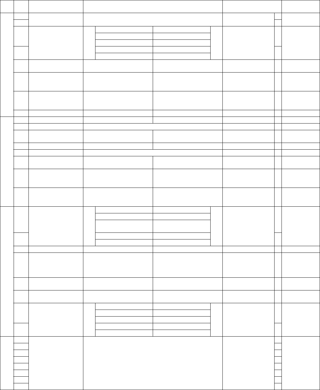
AR-FX4 SOFT SWITCH DESCRIPTIONS - 6
S
W
18
1 Inhibited to use 1
2 0
3 Reception size
specification
(Indicates reception
capacity.)
Bit No. 3 4
By the attached
cassette
0By the attached cassette 0 0
B4 (A4/B4) 0 1
4A410 0
A3 (A4/B4/A3) 1 1
5 11 inch reception
capacity setup
1: 255mm or 215mm 0: 303mm or 255mm or
215mm
303mm or 255mm or
215mm 0
6 Output method in A3
width reception (Inch
series)
1: 297mm width 0: 11 inch width
11 inch width 0
7 Output method in A4
width reception (Inch
series)
1: Data of 8.5 inch width is
printed
0: Data of 210mm width is
printed 8.5 inch width print 1
8 Override print setup 1: Override print allowed 0: Override print inhibited Override print allowed 1
S
W
19
1Protocol monitor 1: YES 0: NO NO 0
2 Inhibited to use 0
3 Output only in protocol
monitor error
1: YES 0: NO NO 0
4 Protocol monitor save 1: Save 0: Disable Save 1
5 Inhibited to use 0
6 Recording table
automatic print
1: YES 0: NO YES 1
7 Time specification 1 of
communication record
table
1: Allow 0: Inhibit
Inhibit 0
8 Time specification 2 of
communication record
table
1: Allow 0: Inhibit
Inhibit 0
S
W
20
1 Line sound monitor
range
Bit No. 1 2
Up to NSF signal send/
receive
0
When a value
outside the set
range is set, the
initial value is
set.
OFF 0 0
Up to NSF signal send/
receive
01
2All10 1
11
3 Line monitor display 1: YES 0: NO NO 0
4 Data output
specification in
communication error
during reception
1: Not output 0: Output
Output 0
5 Receivable memory
capacity
1: 64Kbyte 0: 128Kbyte 128Kbyte 0
6 Memory over during
reception
1: Output 0: Not output Output 1
7 Flag-adrs timer setup
(V.21-FSK)
Bit No. 7 8
6sec
06sec 0 0
15sec 0 1
8 30sec 1 0 0
120sec 1 1
S
W
21
1 Interval between
completion of
communication and the
next call
Binary input
1sec
0
2 Bit No.
Set range
12345678
0 to 255sec
0
3 0
4 0
5 0
6 0
7 0
8 1
SW
NO.
Data
No. Item Switch selection and contents of functions Initial value Remark

AR-FX4 SOFT SWITCH DESCRIPTIONS - 7
S
W
22
1 Inhibited to use 0
2 0
3 0
4 0
5 0
6 0
7 0
8 0
S
W
23
1 Inhibited to use 0
2 0
3 0
4 0
5 0
6 0
7 0
8 0
S
W
24
1 Image capacity at send
request
Bit No. 1 2
Ultra fine
0Ultra fine 0 0
Super fine 0 1
2Fine10 0
Normal 1 1
3 Specified number
reception
1: Refuge specified number
reception
0: Ignore specified number
reception
Ignore specified
number reception 0
4 Specified number
reception when manual
reception
1: Refuge specified number
reception
0: Ignore specified number
reception Ignore specified
number reception 0
5 Inhibited to use 0
6 Document output setup
in reception
1: Collective output after
completion of reception.
0: Output after reception of
every page
Output after reception
of every page 0
7 Inhibited to use 0
8 Automatic reduction
print
1: Allow 0: Inhibit Allow 1
S
W
25
1 Automatic reduction
rate setup
Binary input
6%
0
2 Bit No.
Set range
1234
0 to 15%
1
3 1
4 0
5 Inhibited to use 0
6 0
7 0
8 0
S
W
26
1 Inhibited to use 0
2 0
3 0
4 0
5 1
6 0
7 1
8 0
S
W
27
1 Inhibited to use 0
2 Recording paper tray
selection
(Tray 1)
1: ON 0: OFF
ON 1
3 Recording paper tray
selection
(Tray 2)
1: ON 0: OFF
ON 1
4 Recording paper tray
selection
(Tray 3)
1: ON 0: OFF
ON 1
5 Recording paper tray
selection
(Tray 4)
1: ON 0: OFF
ON 1
6 Inhibited to use 0
7 0
8 0
SW
NO.
Data
No. Item Switch selection and contents of functions Initial value Remark

AR-FX4 SOFT SWITCH DESCRIPTIONS - 8
S
W
28
1 Inhibited to use 1
2 0
3 0
4 0
5 0
6 0
7 0
8 0
S
W
29
1 Inhibited to use 0
2 0
3 0
4 0
5 Setup of number of
times of call rings
Binary input
2 times
0
6 Bit No.
Set range
5678
0 to 9 times
0
7 1
8 0
S
W
30
1 Report output when
canceling
1: Output 0: Not output Not output 0
2 Inhibited to use 1
3 Rotation print 1: Allow 0: Inhibit Allow 1
4 Department
management
1: Allow 0: Inhibit Inhibit 0
5 Default data, sender
print
1: ON 0: OFF ON 1
6 Department name
notification
1: ON 0: OFF OFF 0
7 Date/sender print
position setup
1: Inside of document 0: Outside of document Outside of document 0
8 Report output (in
confidential reception)
1: Print 0: Not print Print 1
S
W
31
1 Report output (in
transmission)
Bit No. 1 2
Only when
transmission is failed.
1Print inhibited 0 0
All print 0 1
2 Only when transmission
is failed.
10
0
11
3 Report output
(In broadcast,
sequential send
request, and relay
broadcast)
Bit No. 3 4
All print
0Print inhibited 0 0
All print 0 1
4 Only the address to
which transmission is
failed
10
1
11
5 Report output (in
reception)
Bit No. 5 6
Print inhibited
0Print inhibited 0 0
All print 0 1
6 Only in error 1 0 0
11
7 Inhibited to use 1
8 0
S
W
32
1 Distinctive ring Bit No. 1 2 3 4
OFF
0Other than
U.S.A., Canda,:
OFF (fixed)
Australia: ON/
OFF only
OFF 0000
2 Standard/ON 0 0 0 1 0
Pattern1 1 0 0 0
3 Pattern2 0 1 0 0 0
Pattern3 1 1 0 0
4 Pattern4 0 0 1 0 0
Pattern5 1 0 1 0
5 Inhibited to use 0
6 Index print setup 1: Print 0: Not print Not print 0
7 Inhibited to use 0
8 0
SW
NO.
Data
No. Item Switch selection and contents of functions Initial value Remark
AR-FX4 SOFT SWITCH DESCRIPTIONS - 9
S
W
33
1 Page number print
setup
1: YES 0: NO YES 1
2 Inhibited to use 0
3 0
4 0
5 0
6 0
7 0
8 0
S
W
34
1 Inhibited to use 0
2 0
3 0
4 0
5 0
6 0
7 0
8 0
S
W
35
1 Cover function default
setup
1: YES 0: NO NO 0
2 Inhibited to use 0
3 CI delete max. OFF
time
Bit No. 3 4
10sec
05sec 0 0
10sec 0 1
4 15sec 1 0 1
20sec 1 1
5 Inhibited to use 1
6 0
7 1
8 0
S
W
36
1 Inhibited to use 0
2 1
3 0
4 1
5 0
6 0
7 0
8 0
S
W
37
1 Inhibited to use 0
2 0
3 0
4 0
5 0
6 1
7 0
8 1
S
W
38
1 Pause time setup Binary input
2sec
0 When a value
outside the set
range is set, the
initial value is
set.
2 Bit No.
Set range
1234
1 to 15sec
0
3 1
40
5 Inhibited to use 0
6 0
7 Transfer function 1: Allow 0: Inhibit Inhibit 0
8 Inhibited to use 0
S
W
39
1 Call time setup in
automatic transmission
(T0 timer setup)
Binary input
45sec
0 When a value
outside the set
range is set, the
initial value is
set.
2 Bit No.
Set range
123
30 to 60sec
5sec unit
1
31
4 Inhibited to use 1
5 0
6 0
7 0
8 0
SW
NO.
Data
No. Item Switch selection and contents of functions Initial value Remark
AR-FX4 SOFT SWITCH DESCRIPTIONS - 10
S
W
40
1 Number of times of
recall in error
Binary input
1 times
0 When a value
outside the set
range is set, the
initial value is
set.
2 Bit No.
Set range
1234
0 to 1 times
0
3 0
41
5 Number of times of
recall in busy
Binary input
2 times
0 When a value
outside the set
range is set, the
initial value is
set.
6 Bit No.
Set range
5678
0 to 14 times
0
7 1
80
S
W
41
1 Tone/Pulse default
setup
Bit No. 1 2
TONE
1
When a value
outside the set
range is set, the
initial value is
set.
10PPS 0 0
20PPS 0 1
2TONE10 0
11
3Telephone line menu 1: Inhibit 0: Allow
Allow 0 Japan, U.S.A.,
Canada: Fixed
to “Allow”
4 Maintenance system 0
5 F.A.S.T mode 1: YES 0: NO
NO 0
Fixed to NO for
other than
U.S.A. and
Canada.
6 Sequence of year/
month/day in LCD,
report, and sender
record
Bit No. 6 7
Month/Day/Year
0
When a value
outside the set
range is set, the
initial value is
set.
Year/Month/Day 0 0
Month/Day/Year 0 1
7 Day/Month/Year 1 0 1
11
8 Time display format 1: am/pm 0: 24H am/pm 1
S
W
42
1Direct send recall Allow/
Inhibit
1: Allow 0: Inhibit Allow 1
2 Inhibited to use 0
3 0
4 Manual/Auto reception
auto swiching
1: Allow 0: Inhibit Inhibit 0
5 Number of auto switch
calls of manual
reception → auto
reception
Binary input
9 times
1 When a value
outside the set
range is set, the
initial value is
set.
6 Bit No.
Set range
5678
1 to 9
0
7 0
81
S
W
43
1 DTMF signal send time Binary input
110ms
0 When a value
outside the set
range is set, the
initial value is
set.
2 Bit No.
Set range
12345
60 to 310ms
10ms unit
1
3 0
4 1
5 1
6 Maintenance cycle Bit No. 6 7 8
50K
0
50K 0 0 1
7 25K 0 1 0 0
12.5K 0 1 1
85K100 1
Others FREE
S
W
44
1 Scan effective image
area (OC)
Main scan
Left edge image loss
1: – 0: + + 0
2 Binary input
+0 dot
0
3 Bit No.
Set range
234
0 to ±56 dots
8 dot interval
0
40
5 Scan effective image
area (SPF)
Main scan
Left edge image loss
1: – 0: + + 0
6 Binary input
+0 dot
0
7 Bit No.
Set range
678
0 to ±56 dots
8 dot interval
0
80
SW
NO.
Data
No. Item Switch selection and contents of functions Initial value Remark

AR-FX4 SOFT SWITCH DESCRIPTIONS - 11
S
W
45
1 Scan effective image
area (OC)
Main scan
Right edge image loss
1: – 0: + + 0
2 Binary input
+0 dot
0
3 Bit No.
Set range
234
0 to ±56 dots
8 dot interval
0
40
5 Scan effective image
area (SPF)
Main scan
Right edge image loss
1: – 0: + + 0
6 Binary input
+0 dot
0
7 Bit No.
Set range
678
0 to ±56 dots
8 dot interval
0
80
S
W
46
1 Inhibited to use 1
2 1
3 Priority in the day of
week
1: YES 0: NO NO 0
4 Inhibited to use 0
5 Daylight saving tive 1: Allow 0: Inhibit Inhibit 0
6 Inhibited to use 0
7 0
8 0
S
W
47
1 Time specification print
1 (O’clock) in the
communication report
table
Binary input
0 o’clock
0 When a value
outside the set
range is set, the
initial value is
set.
2 Bit No.
Set range
12345
00 to 23 o’clock
0
3 0
4 0
5 0
6 Inhibited to use 0
7 0
8 0
S
W
48
1 Time specification print
1 (min) in the
communication report
table
Binary input
0 min
0 When a value
outside the set
range is set, the
initial value is
set.
2 Bit No.
Set range
123456
00 to 59min
0
3 0
4 0
5 0
6 0
7 Inhibited to use 0
8 0
S
W
49
1 Time specification print
2 (O’clock) in the
communication report
table
Binary input
0 o’clock
0 When a value
outside the set
range is set, the
initial value is
set.
2 Bit No.
Set range
12345
00 to 23 o’clock
0
3 0
4 0
5 0
6 Inhibited to use 0
7 0
8 0
S
W
50
1 Time specification print
2 (min) in the
communication report
table
Binary input
0 min
0 When a value
outside the set
range is set, the
initial value is
set.
2 Bit No.
Set range
123456
00 to 59min
0
3 0
4 0
5 0
6 0
7 Inhibited to use 0
8 0
S
W
51
1 Inhibited to use 0
2 0
3 0
4 0
5 0
6 CED detection time 1: 500ms 0: 1000ms 1000ms 0
7 Busy tone detection
cycle
Bit No. 7 8
2puls
02puls 0 0
4puls 0 1
8 6puls 1 0 0
10puls 1 1
SW
NO.
Data
No. Item Switch selection and contents of functions Initial value Remark

AR-FX4 SOFT SWITCH DESCRIPTIONS - 12
S
W
52
1 Busy tone detection
level
Bit No. 1 2
–43dB
0–43dB 0 0
–35dB 0 1
2 –33dB 1 0 0
–30dB 1 1
3 ERR frame reception
operation
1: Continues process. 0: Not continue process.
(Error)
Not continue process.
(Error) 0
4 Inhibited to use 0
5 Error process in RTN
reception
1: Not error 0: Error Error 0
6 V.34 mode function in
manual communication
1: ON 0: OFF ON 1
7 V.34 mode function 1: ON 0: OFF ON 1
8 V.34 control channel
communication speed
1: 2400bps 0: 1200bps 1200bps 0
S
W
53
1 DTMF send level
(High group) setup
Binary input
3.5db
0
2 Bit No.
Set range
1234
0 to 7.5db
0.5dB interval
1
3 1
4 1
5 DTMF send level
(Low group) setup
Binary input
3.5db
0
6 Bit No.
Set range
5678
0 to 7.5db
0.5dB interval
1
7 1
8 1
S
W
54
1 Scan effective image
area (OC)
Sub scan
lead edge image loss
1: – 0: + + 0
2 Binary input
+0 line
0
3 Bit No.
Set range
234
0 to ±56 line
8 line interval
0
40
5 Scan effective image
area (SPF)
Sub scan
lead edge image loss
1: – 0: + + 0
6 Binary input
+0 line
0
7 Bit No.
Set range
678
0 to ±56 line
8 line interval
0
80
S
W
55
1 CI signal OFF detection
enable time
Binary input
1200ms
1
2 Bit No.
Set range
1234567
0 to 1270ms
10ms unit
1
3 1
4 1
5 0
6 0
7 0
8 EQM judgment
threshold value
1: Loose 0: Tight
Tight 0
Disable when
EQM Judge
Value is SRAM
S
W
56
1 Inhibited to use 0
2 0
3 0
4 0
5 0
6 0
7 0
8 0
S
W
57
1 Inhibited to use 0
2 1
3 0
4 0
5 0
6 0
7 0
8 0
SW
NO.
Data
No. Item Switch selection and contents of functions Initial value Remark

AR-FX4 SOFT SWITCH DESCRIPTIONS - 13
S
W
58
1 V.34 3429 (baud)
Rate Mask
1: supported 0: not supported supported 1
2 V.34 3200 (baud)
Rate Mask
1: supported 0: not supported supported 1
3 V.34 3000 (baud)
Rate Mask
1: supported 0: not supported supported 1
4 V.34 2800 (baud)
Rate Mask
1: supported 0: not supported supported 1
5 Inhibited to use 0
6 V.34 2400 (baud)
Rate Mask
1: supported 0: not supported supported 1
7 Inhibited to use 0
8 0
S
W
59
1 Inhibited to use 0
2 0
3 0
4 0
5 0
6 0
7 0
8 0
S
W
60
1 Inhibited to use 1
2 1
3 1
4 1
5 Countermeasures
against V.34
communication error
(reception)
(Phase 2 error retry
setup)
1: YES 0: NO
NO 0
6 Countermeasures
against V.34
communication error
(transmission)
(Phase 2 error retry
setup)
1: YES 0: NO
NO 0
7 Inhibited to use 0
8 0
S
W
61
1 Inhibited to use 0
2 0
3 1
4 1
5 0
6 0
7 0
8 0
S
W
62
1 Inhibited to use 0
2 0
3 0
4 0
5 1
6 0
7 1
8 1
S
W
63
1 Inhibited to use 1
2 0
3 0
4 1
5 0
6 1
7 0
8 1
SW
NO.
Data
No. Item Switch selection and contents of functions Initial value Remark

AR-FX4 SOFT SWITCH DESCRIPTIONS - 14
S
W
64
1 Inhibited to use 0
2 1
3 0
4 0
5 0
6 1
7 1
8 0
S
W
65
1 Inhibited to use 0
2 0
3 1
4 0
5 0
6 0
7 0
8 1
S
W
66
1 Inhibited to use 0
2 0
3 1
4 0
5 0
6 0
7 0
8 1
S
W
67
1 Setup of make rate
(10PPS)
Binary input
40ms
1
2 Bit No.
Set range
1234
26 to 41ms
1ms interval
1
3 1
4 0
5 Inhibited to use 0
6 0
7 0
8 0
S
W
68
1 Inhibited to use 0
2 0
3 1
4 0
5 T1 timer setup Binary input
40sec
0
6 Bit No.
Set range
5678
15 to 90sec
5sec interval
1
7 0
8 1
S
W
69
1 Inhibited to use 0
2 0
3 0
4 0
5 0
6 0
7 0
8 0
S
W
70
1 Inhibited to use 0
2 0
3 0
4 0
5 0
6 1
7 0
8 0
SW
NO.
Data
No. Item Switch selection and contents of functions Initial value Remark
AR-FX4 SOFT SWITCH DESCRIPTIONS - 15
S
W
71
1 Dial ringing wait time Bit No. 1 2
3.5sec
03.5sec 0 0
4sec 0 1
2 5sec 1 0 0
6sec 1 1
3 Inhibited to use 1
4 0
5 1
6 1
7 Silent detection level Bit No. 7 8
–43dBm 0
When outside
the set range,
the initial value
is set.
–43dBm 0 0
–40dBm 0 1
8 –39dBm 1 0 0
S
W
72
1 EYE-Q check 1: EYE-Q check only 0: 0 reception & EYE-Q check 0 reception & EYE-Q
check 0
2 Inhibited to use 0
3 0
4 0
5 1
6 0
7 0
8 0
S
W
73
1 Inhibited to use 0
2 0
3 0
4 0
5 0
6 0
7 DIS reception process
selection in reception
Bit No. 7 8
Command resend by
judging that echo has
been received
0Command resend by judging that echo has been received 0 0
Line disconnection by judging as improper DIS 0 1
8 Polled send when there is polled document with DIS
reception. In other cases, command resend by judging
that echo has been received.
10
0
Polled send when there is polled document with DIS
reception, command resend when judgement that
transmitter has received echo, in other cases, shut down
the line as ellegal DIS.
11
S
W
74
1 Print lead edge
adjustment (Lead edge
adjustment)
1: – 0: + + 0
2 Binary input
48 line
0
3 Bit No.
Set range
234
0 to ±112 line
16 line interval
1
41
5 Print lead edge
adjustment (Rear edge
adjustment)
1: – 0: + + 0
6 Binary input
48 line
0
7 Bit No.
Set range
678
0 to ±112 line
16 line interval
1
81
S
W
75
1 Transmission end
sound
(Buzzer sound length)
setup
Bit No. 1 2
3sec
0
Communi-cation
error sound is
generated even
in silent setup
3sec 0 0
1sec 0 1
2 Silent 1 0 0
11
3 Reception end sound
(Buzzer sound length)
setup
Bit No. 3 4
3sec
0
Communi-cation
error sound is
generated even
in silent setup
3sec 0 0
1sec 0 1
4 Silent 1 0 0
11
5 Print lead edge
adjustment (Left edge)
1: – 0: + + 0
6 Binary input
48 line
0
7 Bit No.
Set range
678
0 to ±112 line
16 line interval
1
81
SW
NO.
Data
No. Item Switch selection and contents of functions Initial value Remark

AR-FX4 SOFT SWITCH DESCRIPTIONS - 16
S
W
76
1 Scan magnification ratio
adjustment OC
(main scan)
1: – 0: + + 0
2 Binary input
0%
0
3 Bit No.
Set range
2345678
0 to ±12.7%
0.1% interval
0
4 0
5 0
6 0
7 0
8 0
S
W
77
1 Scan magnification ratio
adjustment OC
(sub scan)
1: – 0: + + 0
2 Binary input
0%
0
3 Bit No.
Set range
2345678
0 to ±12.7%
0.1% interval
0
4 0
5 0
6 0
7 0
8 0
S
W
78
1 Print magnification
ration adjustment (main
scan)
1: – 0: + + 0
2 Binary input
0%
0
3 Bit No.
Set range
2345678
0 to ±12.7%
0.1% interval
0
4 0
5 0
6 0
7 0
8 0
S
W
79
1 Print magnification
ration adjustment (sub
scan)
1: – 0: + + 0
2 Binary input
0%
0
3 Bit No.
Set range
2345678
0 to ±12.7%
0.1% interval
0
4 0
5 0
6 0
7 0
8 0
S
W
80
1 Scan effective image
area (OC)
Sub scan
Rear edge image loss
1: – 0: + + 0
2 Binary input
+0 line
0
3 Bit No.
Set range
234
0 to ±56 line
8 line interval
0
40
5 Scan effective image
area (SPF)
Sub scan
Rear edge image loss
1: – 0: + + 0
6 Binary input
+14 line
0
7 Bit No.
Set range
678
0 to 28 line
2 line interval
0 = 14 line
0
8
0
S
W
81
1 Destination information Binary input
U.S.A.: 0 0 0 1
Canada: 0 0 1 0
0
2 Bit No. 1 2 3 4
1: U.S.A.
2: Canada
0
3 0
4 1
5 Language information Binary input
English: 0 0 0 1
0 For English, the
proper character
is determined by
destination
information.
6 Bit No. 5 6 7 8
1: English
0
7 0
81
S
W
82
1 Scan magnification ratio
adjustment SPF
(main scan)
1: – 0: + + 0
2 Binary input
0%
0
3 Bit No.
Set range
2345678
0 to ±12.7%
0.1% interval
0
4 0
5 0
6 0
7 0
8 0
SW
NO.
Data
No. Item Switch selection and contents of functions Initial value Remark
AR-FX4 SOFT SWITCH DESCRIPTIONS - 17
S
W
83
1 Scan magnification ratio
adjustment SPF
(sub scan)
1: – 0: + + 0
2 Binary input
0%
0
3 Bit No.
Set range
2345678
0 to ±12.7%
0.1% interval
0
4 0
5 0
6 0
7 0
8 0
S
W
84
1 On-hook speaker
volume
Bit No. 1 2
Medium
1Not used 0 0
Small 0 1
2Medium10 0
Large 1 1
3 On-hook pattern
number
Binary input
21
0
4 Bit No.
Set range
345678
Pattern number 1 to 35
1
5 0
6 1
7 0
8 1
S
W
85
1 Line monitor speaker
volume
Bit No. 1 2
Medium
1Silent 0 0
Small 0 1
2Medium10 0
Large 1 1
3 Line monitor pattern
number
Binary input
21
0
4 Bit No.
Set range
345678
Pattern number 1 to 35
1
5 0
6 1
7 0
8 1
S
W
86
1 Ringing volume Bit No. 1 2
Medium
1Silent 0 0
Small 0 1
2Medium10 0
Large 1 1
3 Ringing pattern number Binary input
21
0
4 Bit No.
Set range
345678
Pattern number 1 to 35
1
5 0
6 1
7 0
8 1
S
W
87
1 Speaker volume in
DTMF send
Bit No. 1 2
Medium
1Silent 0 0
Small 0 1
2Medium10 0
Large 1 1
3 Pattern number in
DTMF send
Binary input
21
0
4 Bit No.
Set range
345678
Pattern number 1 to 35
1
5 0
6 1
7 0
8 1
S
W
88
1 Speaker volume at
scanner scan end
Bit No. 1 2
Medium
1Silent 0 0
Small 0 1
2Medium10 0
Large 1 1
3 Pattern number in
scanner scanning
Binary input
21
0
4 Bit No.
Set range
345678
Pattern number 1 to 35
1
5 0
6 1
7 0
8 1
SW
NO.
Data
No. Item Switch selection and contents of functions Initial value Remark

AR-FX4 SOFT SWITCH DESCRIPTIONS - 18
S
W
89
1 Speaker volume of
communication end
sound
Bit No. 1 2
Medium
1Silent 0 0
Small 0 1
2Medium10 0
Large 1 1
3 Pattern number of
communication end
sound
Binary input
21
0
4 Bit No.
Set range
345678
Pattern number 1 to 35
1
5 0
6 1
7 0
8 1
S
W
90
1 Inhibited to use 0
2 0
3 0
4 1
5 1
6 0
7 0
8 0
S
W
91
1 Inhibited to use 0
2 0
3 0
4 0
5 0
6 0
7 0
8 0
S
W
92
1 Inhibited to use 0
2 0
3 0
4 0
5 0
6 0
7 0
8 0
S
W
93
1 Inhibited to use 0
2 0
3 0
4 0
5 0
6 0
7 0
8 0
S
W
94
1 Inhibited to use 0
2 0
3 0
4 0
5 0
6 0
7 0
8 0
S
W
95
1 Inhibited to use 1
2 1
3 0
4 0
5 0
6 1
7 0
8 0
SW
NO.
Data
No. Item Switch selection and contents of functions Initial value Remark

AR-FX4 SOFT SWITCH DESCRIPTIONS - 19
3. Soft switch descriptions
SW1 No.1, No.2 Size specification
Used to set inch series or AB series for recording paper when printing
received documents.
There is normally no need to change from "Depends on the machine
information."
SW1 No.3 Inhibited to use
SW1 No.4 Auto/Manual default setup
Used to select Auto/Manual reception mode when turning on the
power. (When no external telephone is connected, do not select Man-
ual. However, setup is possible and reception can be made by on-
hook.)
When set to 1, manual reception.
When set to 0, auto reception.
Default: 0 (auto reception)
SW1 No.5 Send request protection
Used to set YES/NO of the confidential protection function (inhibition of
transmission to an erroneous party). Confidential protection is per-
formed by collating the number registered in this machine and that in
the other party’s machine. (Sender’s telephone number ←→ Send
request allow number, System number ←→ ID number)
When set to 1, protection is not made.
When set to 0, protection is made.
Default: 0 (protection enable)
SW1 No.6 Reduction send mode
Used to set whether the transmitted document is received in reduction
size or both ends of recording paper are cut when the transmitted doc-
ument width is greater than the recording paper width.
When set to 1, both ends are cut without reduction and transmitted.
When set to 0, it is reduced and transmitted.
Default: 0 (Reduction transmission)
SW1 No.7 Contents of send document are printed in
memory send error
Used to set Print/Not print part of the sent document in the transmis-
sion result table in case of a memory transmission error.
When set to 1, the transmitted document is not printed on the transmis-
sion result table.
When set to 0, the transmitted document is printed on the transmission
result table.
Default: 0 (Print transmitted documents)
SW1 No.8 Inhibited to use
SW2 No.1 – No.4 Inhibited to use
SW2 No.5 – No.8 Remote selection number setup
Used to set the number by binary input for remote switch reception
from an external telephone. "**" in a remote switch number (X**) is
fixed.
When 10 or greater value is entered, the operations will be the same
as setup of 5.
Default: Setup of 5 as 0101
SW3 No.1 – No.5 Density default setup
Used to set the default setup of density of the operation panel.
SW3 No.6 – No.8 Image quality priority selection
Used to set the initial value of image selection when scanning a docu-
ment.
When set to 100, the operations are the same as the normal mode.
Default: 000 (Normal mode)
SW4 No.1 – No.4 Recall interval in communication error
Used to set recall interval after disconnection of communication due to
a communication error in memory transmission.
The set range is 0 to 15 min in the increment of 1 min by binary input.
When set to 0, recall is made immediately after disconnection.
However, the time interval set by SW21 (Interval between the end of a
communication and the next call) is taken.
Default: 0001 (1 min)
SW4 No.5 – No.8 Recall interval in busy
Used to set recall interval after disconnection of communication due to
the busy state of the other party or no response.
Can be set in the range of 1 – 15min by increment of 1min by binary
input.
When set to 0 min, it is the same as setup of 3 min.
Default: 0 0 1 1 (3 min)
SW5 No.1, No.2 Line equivalent unit [km]
Used to set the modem filter coefficient.
SW5 No.3, No.4 Inhibited to use
SW5 No.5 – No.8 Signal send level
Used to set the attenuation quantity of signal send level from the
modem. The actual output level to the line pin is further attenuated by
8dBm. (When set to 2, the actual level on the line is about –10dBm.)
Default: 0 1 1 1 (–12dBm)
S
W
96
1 Inhibited to use 0
2 1
3 0
4 0
5 1
6 0
7 0
8 0
S
W
97
1 Inhibited to use 0
2 1
3 1
4 0
5 1
6 0
7 0
8 0
SW
NO.
Data
No. Item Switch selection and contents of functions Initial value Remark
AR-FX4 SOFT SWITCH DESCRIPTIONS - 20
SW6 No.1 ECM
Used to set whether ECM (Error Correction Mode) is performed or not.
When, however, SW52-7 (V.34 mode function) is set to OFF, or when
SW52-7 (V.34 mode function is set to ON and the transmission is not
the super G3 transmission, ECM Disable setup is effective. This is
because the ECM function is indispensable in a transmission other
than super G3 transmission in V.34 mode and the other party machine
may perform checking. With SW52-7 (V.34 mode function) is ON and
this reception function is disabled.
When set to 1, ECM is enabled.
When set to 0, ECM is disabled.
Default: 1 (ECM enabled)
SW6 No.2 CED signal send
Used to set whether CED signal is sent or not. This setup is effective
only when SW52-7 (V.34 mode function) is off. This is because V.34
mode requires sending of ANSam signal.
When set to 1, CED (ANSam) signal is sent.
When set to 0, CED (ANSam) signal is not sent.
Default: 1, CED (ANSam) signal is sent.
SW6 No.3 CSI transmission
CSI signal includes the telephone number registered as sender’s num-
ber. Used to set whether this signal is sent or not.
When set to 1, CSI signal is sent.
When set to 0, CSI signal is not sent.
Default: 1 (CSI signal is sent.)
SW6 No.4 DIS reception confirmation in G3 send
Used to set whether DIS reception is checked or not in G3 mode.
When set to 1, DIS reception is always checked twice.
When set to 0, NSF/DIS reception is checked once, or DIS reception
without NSF is checked twice.
Default: 0 (NSF reception is checked once, DIS without NSF is
checked twice.)
SW6 No.5 Non-modulation carrier in V.29 send
Used to set whether non-modulation carriers are sent or not in V.29
transmission.
When set to 1, non-modulated carrier is sent.
When set to 0, non-modulated carrier is not sent.
Default: 0 (Non-modulated carrier is not sent.)
SW6 No.6 EOL detection timer
Used to set the detection timer of EOL (End Of Life) when Phase-C
reception.
When set to 1, the timer is set to 25sec.
When set to 0, the timer is set to 13sec.
Default: 0 (13sec)
SW6 No.7 Countermeasures for echo in reception (CED
tone send interval)
Used to select ON/OFF of countermeasures against echo.
An interval of 500ms is inserted before DIS transmission.
Default: 0 (75ms)
SW6 No.8 Countermeasure for echo in transmission
(After reception of DIS, hold time up to signal send is set.)
An interval of 500ms is inserted before DCS transmission.
Default: 0 (200ms)
SW7 No.1 MH fixed
Used to fix the image data compression method in communication.
Normal setting
When set to 0, automatic selection of MH/MR/MMR is performed
according to the other party machine’s capacity.
When set to 1, MH fixed. This is effective when communication is
made only with MH machine or when images are disturbed due to poor
conditions of the line.
When SW52-7 (V.34 mode function) is OFF or when SW52-7 (V.34
mode function) is ON in transmission, MH fixing is enabled.
This is because the MMR function is indispensable in V.34 mode and
the other party machine checks that. When SW52-7 (V.34 mode func-
tion) is ON in reception, this function is disabled.
SW7 No.2 Dial tone detection
Used to set whether dial tone detection is performed or not in auto dial
ringing.
"1": YES
"0": NO
When set to YES and dial tone is not detected, dial is not performed.
Default: 0 (NO)
SW7 No.3 Busy tone detection
Used to set whether busy tone signal is detected or not in ringing.
When set to 1, busy tone is detected.
When set to 0, busy tone is not detected.
Default: 1 (Busy tone is detected.)
SW7 No.4 Dial tone monitoring time
Used to set dial tone monitoring time when detecting dial tone.
"1": 10sec
"0": 5sec
Default: 0 (5 sec)
SW7 No.5 Inhibited to use
SW7 No.6 Max. length of reception
Used to set the length of reception when long document is sent from
the other party.
When set to 1, reception is made without limitations.
When set to 0, reception is terminated after 1.5m reception.
Default: 0 (Reception is terminated after receiving 1.5m.)
SW7 No.7, No.8 Modem speed in reception fixed
Used to set the start speed of reception procedure when receiving from
an other party other than V.34.
When set to "no fixing," the operations are the same as V.17-
14400BPS.
The above four setups are possible. The reception procedure is started
at the set communication speed.
Default: 0 0 (no fixing) Reception is made at the proper communica-
tion speed.
SW8 No.1 Memory transmission/direct transmission
default setup
Used to select memory transmission or direct transmission when the
power is turned on and when time out is cleared.
When set to 1, direct transmission is selected when the power is turned
on and the time out is cleared.
When set to 0, memory transmission is selected when the power is
turned on and the time out is cleared.
Default: 0 (Memory transmission)
SW8 No.2 Proxy reception
When set to 1, auto reception is accepted under the following condi-
tions to perform proxy reception.
(1) No recording paper or jam
(2) Remaining image memory capacity is 128KB or 64KB or above.
(3) The number of memory reception (max. 50 items) and the number
of pages do not exceed the limit.
When set to 0, automatic reception is not allowed without recording
paper or in case of a jam.
Default: 1 (YES)
bit 7 8
0 0 : No fixing
0 1 : V.29-9600BPS
1 0 : V.27ter-4800BPS
1 1 : V.17-14400BPS
AR-FX4 SOFT SWITCH DESCRIPTIONS - 21
SW8 No.3 Printing the content of transmitted document in
normal memory transmission
Used to set whether transmitted images are printed on the communica-
tion result table or not when the communication result table is printed
after normal completion of memory transmission.
"1": The transmitted document is not printed.
"0": The transmitted document is printed.
Default: 1 (Not printed.)
SW8 No.4 Judgment of system No. in bulletin
transmission
Used to set whether the condition of coincidence between the system
number of this machine and that of the other party machine is
employed as a criterion to judge whether to allow bulletin transmission
by receiving polling transmission from the other party machine made
by our company.
"1": When the system number of the other party machine made by our
company coincide with the system number of this machine, polling is
allowed.
"0": Though the system number of the other party machine made by
our company coincide with the system number of this machine, polling
is not allowed.
Default: 0 (Inhibited)
SW8 No.5 Remote reception indication
Used to set whether remote select function is used or not.
When set to 1, the function is allowed.
When set to 0, inhibited.
Default: 1 (Allowed)
SW8 No.6 – No.8 Inhibited to use
SW9 No.1 Print of total communication time and total
pages
Used to set whether total communication time and total number of
sheets are recorded or not on the communication record table.
When set to 1, the total communication time and the total number of
pages are printed on the communication record table.
When set to 0, they are not printed on the communication record table.
Default: 1 (YES)
SW9 No.2 Inhibited to use
SW9 No.3 Quick memory transmission
Used to set whether quick memory transmission (transmission of ring-
ing before completion of scanning) is performed or not. Linked with the
key operator program menu.
Default: 1 (Allow)
SW9 No.4 Yes/No of SUB capacity in reception
Used to set notification of YES/NO of DIS signal Bit 49 SUB capacity.
"0": YES
"1": NO
Default: 0 (YES)
When notified 0 and NO, the F code transmission from the other party
can be inhibited.
SW9 No.5 F-code relay broadcast function
Used to set whether F code relay broadcast instruction from the other
party is received and relay broadcast transmission is performed or F
code relay broadcast instruction is not received (though the relay box
number by SUB coincides with) from the other party. Though this func-
tion is set to disable, F code instruction can be transmitted.
Default: 0 (Allow)
SW9 No.6 F-code confidential reception function
Used to set whether F code confidential reception from the other party
is made or not (though the confidential box number by SUM coincides
with).
Though this function is set to disable, F code transmission can be
made.
Default: 0 (Allow)
SW9 No.7 Yes/No of SEP capacity in reception
Used to set notification of YES/NO of DIS signal Bit 47 SEP capacity.
"0": YES
"1": NO
Default: 0 (YES)
When set to 1 (NO), F code polling is inhibited.
SW9 No.8 Yes/No of reception PWD capacity
Used to set whether password function is judged or not for F code bul-
letin board polling.
"0": Password is judged. If password is not acceptable, communica-
tion is cut off.
"1": Password is not judged. Password is disregarded and communi-
cation is allowed.
Default: 0 (Password is judged.)
SW10 No.1 Measurement of communication time (image)
Used to set YES/NO of measurement.
Used to measure the communication time in phase C. However, it is
the communication time in the latest phase C. (Unit: msec)
Default: 1 (YES)
SW10 No.2 Sender’s telephone number registration
Used to set Enable/Disable of registered transmitter telephone number
change.
When set to 1, sender’s TEL No. cannot be registered and changed.
To prevent sender’s TEL No. from being changed erroneously, this is
set to 1.
Default: 0 (Allow)
SW10 No.3 Yes/No of reception SID capacity
Used to set whether password is judged or nor in F code reception.
"0": Password is judged. If password is not acceptable, communica-
tion is cut off.
"1": Password is not judged. Password is disregarded and communi-
cation is allowed.
Default: 0 (Password is judged.)
SW10 No.4 SDT signal detection
Used to set whether SDT signal which is the second dial tone when
transmitting to F net is detected or not.
When SDT signal is not detected, dialing is performed normally even
after "16X."
When set to 1, the signal is detected.
When set to 0, the signal is not detected.
Default: 0 (Not detected)
SW10 No.5, No.6 Inhibited to use
SW10 No.7 ECM MMR mode
Used to set whether MMR coding system is used or not.
"1": MMR is used.
"0": MMR is not used.
Default: 1 (MMR communication is made.)
SW10 No.8 ECM JBIG mode
Used to set whether JBIG communication is used or not.
"1": JBIG communication is used.
"0": JBIG communication is not used.
Default: 1 (JBIG communication is used.)
SW11 No.1 – No.8 Inhibited to use
AR-FX4 SOFT SWITCH DESCRIPTIONS - 22
SW12 No.1 – No.5 Inhibited to use
SW12 No.6, No.7 CI detection
Used to set the frequency to detect CI signal which is the calling signal
as follows:
Default: 0 0 (4 sine wave)
SW12 No.8 Inhibited to use
SW13 No.1 – No.6 Inhibited to use
SW13 No.7 Relay data output
Used to set whether the received document is outputted from the relay
direction station when relay broadcasting direction is received.
When set to 1, the document received from the relay instruction station
is printed.
When set to 0, the document received from the relay instruction station
is not printed.
Default: 1 (Printed)
SW13 No.8 Relay broadcast function
Used to set whether relay broadcasting transmission is performed
when receiving the relay broadcasting direction from the other party or
the relay broadcasting direction is not received from the other party.
When set to 1, the relay broadcast instruction from the allowed party is
received.
When set to 0, the relay broadcast instruction is not received even from
the allowed party.
Default: 1 (The relay broadcast instruction is received.)
When this function is set to disable, relay broadcast instruction can be
transmitted.
SW14 No.1 – No.4 V.34 mode sending speed
Used to set the transmission speed when starting communication in
V.34 mode.
Setting can be made by binary input of N in "2400 (bps) x N" in the
range of 2400bps – 33600bps.
N can be set in the range of 0 – 15. When it is set to 0, 2400bps; when
set to 15, 33600bps.
Default: N = 14 (Transmission is started from 33600bps.)
SW14 No.5 – No.8 V.34 mode reception speed
Used to set the reception speed when starting reception in V.34 mode.
Setting can be made by binary input of N in "2400 (bps) x N" in the
range of 2400bps – 33600bps.
N can be set in the range of 0 – 15. When it is set to 0, 2400bps; when
set to 15, 33600bps.
Default: N = 14 (Reception is started from 33600bps.)
SW15 No.1 Lower limit of speaker sound detection time
Lower limit of speaker sound detection time
1: 350ms 0: 250ms
Default: 0 (250ms)
SW15 No.2 Upper limit of speaker sound detection time
Upper limit of speaker sound detection time
1: 650ms 0: 750ms
Default: 0 (750ms)
SW15 No.3 Lower limit 2 of speaker sound detection time
Lower limit 2 of speaker sound detection time
1: 150ms 0: Follows SW15-1.
Default: 0 (Follows SW15-1.)
SW15 No.4 Inhibited to use
SW15 No.5 – No.8 Modem speed (V.33 mode or less)
Used to set the speed to start communication. When communication
troubles occur frequently, the speed may be reduced to solve the trou-
bles.
Default: 1 0 0 0 (V.17 14.4kbps)
SW16 No.1 Inhibited to use
SW16 No.2 External telephone connection
When this switch is not set to YES, an external telephone cannot be
used.
Default: 1 (YES)
SW16 No.3, No.4 Inhibited to use
SW16 No.5 Rotation transmission selection (11 x 8.5 →
8.5 x 11)
Used to set whether letter R document is transmitted as A3 width or
the scanned image is rotated and transmitted as A4R width.
Default: 1 (YES)
SW16 No.6 Rotation transmission selection (A4 → A4R)
Used to set whether A4 document is transmitted as A4 or the scanned
image is rotated and transmitted as A4R.
When set to 1, the document is transmitted as A4 width.
When set to 0, the document is transmitted as A3 width.
Default: 1 (Transmitted as A4 width.)
SW16 No.7 Rotation transmission selection (B5R → B5)
Used to set whether B5R document is transmitted as B5R or the
scanned image is rotated and transmitted as B5.
When set to 1, the document is transmitted as B4 width.
When set to 0, the document is transmitted as A4 width.
Default: 1 (Transmitted as B4 width.)
SW16 No.8 Rotation transmission selection (A5 → A5R)
Used to set whether A5R document is transmitted as A5R or the
scanned image is rotated and transmitted as A5.
When set to 1, the document is transmitted as A4 width.
When set to 0, the document is transmitted as A5R.
(However, the transmission width is A4.)
Default: 1 (Transmitted as A4 width.)
SW17 No.1 Paper selection priority sequence
Used to set whether the FAX reception paper is selected by data width
priority or data area priority.
"0": Area priority
"1": Width priority
Default: 0 (Area priority)
SW17 No.2, No.3 Output condition setup
Used to set whether the received data are reduced or divided to print
when a document is received and there is no suitable size paper.
Default: 0 0 (Reduction print)
SW17 No.4 – No.8 Inhibited to use
SW18 No.1, No.2 Inhibited to use
bit 6 7
0 0 : 4 sine wave (280ms)
1 0 : 3 sine wave (190ms)
0 1 : 2 sine wave (130ms)
1 1 : Similar to 4 sine wave (280mm).
bit 2 3
0 0 : Reduction allowed
1 0 : Division allowed

AR-FX4 SOFT SWITCH DESCRIPTIONS - 23
SW18 No.3, No.4 Reception size specification (Indicates
reception capacity.)
Used to set the receivable document width which is informed the other
party when receiving a communication.
The setup items are as follows:
Default: 0 0 (Varies depending on the installed cassette.)
Max. allowed reception width selection
Max. allowed reception width is determined by Table 1 and Table 2.
This determines the transmitted size from the other party.
When set to A3 with SW18-No. 3/No. 4 only with B5 cassette, proxy
reception is always performed. Do not use this combination.
(Because division process in the main scanning direction is not per-
formed.)
When set to A4 with SW18-No. 3/No. 4, A3 document from the
other party is not divided into A4 paper but reduction to A4width is
requested to the other party.
• Max. allowed reception width setup
• Max. allowable reception width by installed cassette
SW18 No.5 11 inch reception capacity setup
When SW18-3 – 4 is set to "Depends on installed cassette," the max.
allowable reception width by 8.5 x 11" cassette is set.
When set to 0, the reception allowable width is A3.
When set to 1, the reception allowable width is B4.
Default: 0 (Reception allowable width is A3)
SW18 No.6 Output method when A3 width reception (Inch
series)
Used to set whether an image of 297mm width is reduced and printed
or an image of 11" width is printed without reduction on paper of 11"
width when an image of A3 width is received.
When set to 0, printing is made on paper of 11" width.
When set to 1, printing is made on paper of 297mm width.
Default: 0 (Printed on paper of 11" width.)
SW18 No.7 Output method when A4 width reception (Inch
series)
Used to set whether printing is made on paper of 8.5" width or of
210mm width when an image of A4 width is received.
When set to 0, printing is made on paper of 210mm width.
When set to 1, printing is made on paper of 8.5" width.
Default: 1 (Printing is made on paper of 8.5" width.)
SW18 No.8 Override print setup
Used to set whether the latter print job is performed or not when the
former print job is suspended at the first page due to printable paper
empty.
When set to 0, override print is not allowed.
When set to 1, override print is allowed.
Default: 1 (Override print allowed)
SW19 No.1 Protocol monitor
Used to set whether communication protocol result is printed after
completion of communication or not.
Used for communication test.
Default: 0 (NO)
SW19 No.2 Inhibited to use
SW19 No.3 Output only in protocol monitor error
Used to set whether protocol monitor is outputted only when a commu-
nication error occurs or every time when communication is completed.
Effective when SW19 No. 1 (Protocol monitor) is set to YES. However,
only when SW19 No. 1 is set to 1 (YES), protocol monitor is outputted
in case of a communication error.
Default: 0 (NO)
SW19 No.4 Protocol monitor save
Used to set whether the protocol monitor of the final communication is
saved or not.
When set to "Saved," the preceding protocol monitor can be printed
with SIM 66-21.
Default: The protocol monitor is saved.
SW19 No.5 Inhibited to use
SW19 No.6 Recording table automatic print
Used to set whether the communication record table is printed auto-
matically when each of transmission/reception data of communication
record table reaches 50 items.
When set to 1, the table is automatically printed.
When set to 0, the table is not printed though the data reaches 50
items.
Default: 1 (Printed)
SW19 No.7 Time specification 1 of communication record
table
Used to set whether time No. 1 is enabled or not in the output function
of communication result table at the specified time.
Linked with the key operator program.
Default: 0 (Inhibit)
SW19 No.8 Time specification 2 of communication record
table
Used to set whether time No. 2 is enabled or not in the output function
of communication result table at the specified time.
Linked with the key operator program.
Default: 0 (Inhibit)
SW20 No.1, No.2 Line sound monitor range
Used to set the line sound monitor range when the line monitor func-
tion is used.
Used to set to monitor NSF signal send/receive until NSF signal is
sent/received.
When set to ALL, all procedures up to line disconnection are moni-
tored.
The setup items are as follows:
Default: 0 1 (Up to NSF signal send/receive)
bit 3 4
0 0 : By the attached cassette
0 1 : B4 (A4/B4) width
1 0 : A4 width
1 1 : A3 (A4/B4/A3) width
SW18 Size specification Reception allowable
width
No.3 No.4
0 0 Depends on the
installed cassette.
Varies according to the
table below.
0 1 B4 A4 & B4 width
1 0 A4 A4 width
1 1 A3 A4 & B4 & A3 width
[Max. paper size of installed
cassette with FAX function] →[Sampled paper size
(Data width)]
A5 →A4
B5 →B4
A4 →A3
B4 →B4
A3 →A3
No cassette with FAX function →A3
bit 1 2
0 0 : Not used. (Same as 0.1)
0 1 : Up to NSF signal send/receive
10 :All
1 1 : Not used. (Same as 0.1)
AR-FX4 SOFT SWITCH DESCRIPTIONS - 24
SW20 No.3 Line monitor display
Used to set whether the communication speed and the reception level
are displayed on the LCD or not.
Displayed on the communication status screen by pressing the job sta-
tus key.
When set to 1, displayed on LCD.
When set to 0, not displayed on LCD.
Default: 0 (Not displayed)
SW20 No.4 Data output specification in communication
error during reception
Used to set whether the image on the page where a communication
error occurred during image reception is printed or not.
"0": Setup to print
"1": Setup not to print
Default: 0 (Output)
However, “Output setting” is effective only when SW24-6 is set to "Out-
put for every page reception."
SW20 No.5 Receivable memory capacity
Used to set the remaining memory capacity for acceptance of call.
When set to 1, ringing is made until the remaining memory capacity is
64KB or less.
When set to 0, ringing is made until the remaining memory capacity is
128KB or less.
Default: 0 (Ringing is made until the remaining is 128KB or less.)
SW20 No.6 Memory over during reception
Used to set whether the received data are output or destroyed when
memory is over during reception.
When set to 1, received data are output.
When set to 0, received data are disposed without output.
Default: 1 (Received data are output)
SW20 No.7, No.8 Flag-adrs timer setup (V.21-FSK)
Used to set the time between Flag-adrs during FSk signal reception in
a communication other than V.34 mode.
FSK signal reception in V.34 does not conform to this soft switch.
Default: 0 0 (6sec)
SW21 No.1 – No.8 Inhibited to use
Used to set the time interval between the end of a communication and
a call for the next communication.
The actual interval is the setup value + 3.5sec.
Setup is made by binary input in the interval of 0 – 255sec.
The initial setup is to ring in the interval of 1sec.
SW22 No.1 – No.8 Inhibited to use
SW23 No.1 – No.8 Inhibited to use
SW24 No.1, No.2 Image capacity at send request
Used to set the image capacity of the machine when send request
(polling).
Reflected on DTC.
Default: 0 0 (Ultra fine)
SW24 No.3 Specified number reception
Used to set ON/OFF of the function to reject FAX reception from a reg-
istered number.
Default: 0 (Ignore specified number reception)
SW24 No.4 Specified number reception when manual
reception
Used to set whether reception from manual reception is rejected or not
when reception function by specifying the number is ON.
Default: 0 (Ignore specified number reception)
SW24 No.5 Inhibited to use
SW24 No.6 Document output setup in reception
Used to set whether all received documents are outputted at a time
after completion of reception or each document is outputted every time
when it is received.
When set to 1, all are outputted collectively after completion of recep-
tion.
When set to 0, output is made after reception of every page.
Default: 0 (Output after reception of every page)
SW24 No.7 Inhibited to use
SW24 No.8 Automatic reduction print
Used to set whether the received document is automatically reduced
and printed so that the print-out is fit in a fixed size when the document
size is longer than the fixed sizes but smaller than the max. length of
automatic reduction ratio.
When set to 1, the document is automatically reduced and printed.
When set to 0, the document is printed without reduction.
Default: 1 (Automatic reduction print enable)
SW25 No.1 – No.4 Automatic reduction rate setup
Used to set the auto reduction ratio when "Auto reduction print" is set
to Enable.
Setup is made in the range of 0 – 15% by binary input of N in "100% –
N x 1%."
Default: 94% (Reduce 6%)
SW25 No.5 – No.8 Inhibited to use
SW26 No.1 – No.8 Inhibited to use
SW27 No.1 Inhibited to use
SW27 No.2 – No.5 Recording paper tray selection
(Tray 1 – 4)
Used to select the tray for output of the received documents.
Tray 1 to Tray 4 can be set to ON/OFF individually. When set to OFF,
the tray does not output received documents.
Setup is made by selecting bit 2 – bit 5. Each bit is selected in the
sequence of tray 1 – tray 4.
When bit 1 is selected, output is made by using that tray.
When bit 0 is selected, output is made by using that tray.
Default: Tray 1 – tray 4 are used.
SW27 No.6 – No.8 Inhibited to use
SW28 No.1 – No.8 Inhibited to use
SW29 No.1 – No.4 Inhibited to use
SW29 No.5 – No.8 Setup of number of times of call rings
Used to set the number of call rings until reception is started in auto
reception mode.
The set range is 0 to 9 times by binary input.
When set to 0, no ring is made.
Default: 2 times
SW30 No.1 Report output when canceling
Used to set whether the communication report table is outputted or not
when canceling transmission during document transmission.
When set to 1, the communication report table is printed.
When set to 0, the communication report table is not printed.
Default: 0 (Not printed)
SW30 No.2 Inhibited to use
bit 2 : Tray 1
bit 3 : Tray 2
bit 4 : Tray 3
bit 5 : Tray 4
AR-FX4 SOFT SWITCH DESCRIPTIONS - 25
SW30 No.3 Rotation print
Used to set Enable/Disable of rotation print when the received docu-
ment can be printed by rotation.
When set to 1, the received document is rotated and printed.
When set to 0, the received document is not rotated.
Default: 1 (The received document is rotated and printed.)
SW30 No.4 Department management
Used to set Enable/Disable of FAX using dept. management by the
use of the dept. management function.
When set to 1, the department management function is used.
When set to 0, the department management function is not used.
Default: 0 (The department management function is not used.)
SW30 No.5 Default data, sender print
Used to set whether the registered sender information and date and
time of transmission are printed at the top of the transmission docu-
ment when a document is transmitted through the second line.
When set to 1, date and sender are printed.
When set to 0, date and sender are not printed.
Default: 1 (Date and sender are printed.)
SW30 No.6 Department name notification
Used to set whether the department name is transmitted as sender
information when the department management function is enabled.
Default: 0 (OFF)
SW30 No.7 Date/sender print position setup
Used to set the print position of date and transmitter information on the
transmitted documents.
When set to 1, printed at the top of the document.
When set to 0, added outside the document.
Default: 0 (Added outside the document.)
SW30 No.8 Report output (in confidential reception)
Used to set whether the communication report table is outputted or not
when a confidential reception is made.
When set to 1, the communication report table is printed.
When set to 0, the communication report table is not printed.
Default: 1 (Printed)
SW31 No.1, No.2 Report output (in transmission)
Used to set whether the communication report is outputted or not after
completion of transmission (excluding sequential broadcasting,
sequential send request, and relay broadcasting).
Setup is selected from "print inhibition," "all output," and "only when
transmission is failed" as follows:
Default: 1 0 (Outputted only when transmission is failed.)
SW31 No.3, No.4 Report output (In broadcast, sequential
send request, and relay broadcast)
Used to set whether the communication report table is outputted or not
after completion of transmission (sequential broadcasting, sequential
send request, and relay broadcasting).
Setup is selected from "print inhibition," "all output," and "only the
address to which transmission is failed" as follows:
Default: 0 1 (All are printed.)
SW31 No. 5, No.6 Report output (in reception)
Used to set whether the communication report table is outputted or not
when a reception (excluding confidential reception) is made.
Setup is selected from "print inhibition," "all output," and "only in error"
as follows:
Default: 0 0 (Print inhibited)
SW31 No.7, No.8 Inhibited to use
SW32 No.1 – No.4 Distinctive ring
The function judges TEL or FAX by CI ringing.
Default: 0 0 0 0 (OFF)
SW32 No.5 Inhibited to use
SW32 No.6 Index print setup
Used to set whether the index is printed or not when outputting
received documents.
When set to 1, the index is printed on the received document.
When set to 0, the index is not printed.
Default: 0 (The index is not printed.)
SW32 No.7, No.8 Inhibited to use
SW33 No.1 Page number print setup
Used to set whether the page number is added to the position where
date and transmitter information are printed. (In memory transmission,
paper number/total number of pages)
When set to 1, the page number is printed.
When set to 0, the page number is not printed.
Default: 1 (The page number is printed.)
SW33 No.2 – No.8 Inhibited to use
SW34 No.1 – No.8 Inhibited to use
SW35 No.1 Cover function default setup
Used to set whether the cover is added or not when transmitting.
When set to 1, the cover is added.
When set to 0, the cover is not added.
Default: 0 (The cover is not added.)
SW35 No.2 Inhibited to use
SW35 No.3, No.4 CI delete max. OFF time
Used to set the max. wait time from detection of CI signal pulse (num-
ber of times) to the next CI signal pulse detection. If next Ci signal
pulse is not detected within this time, the number of calls up to now is
cleared.
The setup items are as follows:
Default: 0 1 (10sec)
SW35 No.5 – No.8 Inhibited to use
SW36 No.1 – No.8 Inhibited to use
SW37 No.1 – No.8 Inhibited to use
SW38 No.1 – No.4 Pause time setup
Used to set the pause time.
The set range is 1 sec to 15 sec by binary input.
When set to 0, it is the same as 2 sec.
Default: 2sec
bit 1 2
0 0 : Print inhibited
0 1 : All are printed.
1 0 : Only when transmission is failed.
1 1 : Not used (Same as "Only when transmission is failed.")
bit 3 4
0 0 : Print inhibited
0 1 : All are printed.
1 0 : Only the address to which transmission is failed.
1 1 : Not used (Same as "Only the address to which
transmission is failed")
bit 5 6
0 0 : Print inhibited
0 1 : All are printed.
1 0 : Only in error
1 1 : Same as "print inhibited."
bit 3 4
00 :5sec
0 1 : 10sec
1 0 : 15sec
1 1 : 20sec
AR-FX4 SOFT SWITCH DESCRIPTIONS - 26
SW38 No.5, No.6 Inhibited to use
SW38 No.7 Transfer function
Used to set Enable/Disable the transfer function.
Default: 0 (Inhibit)
SW38 No.8 Inhibited to use
SW39 No.1 – No.3 Call time setup in automatic
transmission (T0 timer setup)
Used to set the call time when call does not reach the other party in
auto send mode.
The set range is 30 to 60 sec in the increment of 5 sec by binary input
of "(5 sec x N) + 30 sec)".
"N" can be set in the range of 0 to 7. When set to 7 (65 sec), it is the
same as setup of 45 sec.
Default: 45sec (N=3)
SW39 No.4 – No.8 Inhibited to use
SW40 No.1 – No.4 Number of times of recall in error
Used to set the number of recall times in case of a communication
error.
Setup is made in the range of 0 – 1 times by binary input.
When set to 0, recall is not made.
Default: 1 time of recall
SW40 No.5 – No.8 Number of times of recall in busy
Used to set the number of recall times in case of busy state of the other
party or when call does not reach the other party.
Setup is made in the range of 0 – 14 times by binary input.
When set to 0, recall is not made.
Default: 2 times of recall
SW41 No.1, No.2 Tone/Pulse default setup
Employed line setup (Dial setup)
Selection of 10PPS, 20PPS, and TONE is allowed.
The setup items are as follows:
Default: 1 0 (TONE)
SW41 No.3 Telephone line menu
Used to set whether Tone/Pulse setup is displayed on the menu or not.
Default: 0 (Fixed to “Allow”)
SW41 No.4 Maintenance system
Setup of the model for judgment of consumable parts system when
using the F.A.S.T. function.
SW41 No.5 F.A.S.T mode
Used to set Enable/Disable of FAST operation.
To enable FAST operation, the serviceman must change this SW
setup.
Default: 0 (NO)
SW41 No.6, No.7 Sequence of year/month/day in LCD,
report, and sender record
Used to set the sequence of year, month, and day in the display,
report, and sender record.
SW41 No.8 Time display format
Used to set the sequence of year, month, and day in the LCD display,
report, and sender record.
When set to 0, time is indicated in 24H format.
When set to 1, time is indicated in AM/PM format.
Default: 1 (AM/PM)
SW42 No.1 Direct send recall Allow/Inhibit
Used to set allow/inhibit of wait for recall in direct send.
Default: 1 (Allow)
SW42 No.2, No.3 Inhibited to use
SW42 No.4 Manual/Auto reception auto swiching
Used to set whether automatic reception is made or not when ringing is
made the number of auto switch call times in manual reception.
Default: 0 (Inhibit)
SW42 No.5 – No.8 Number of auto switch calls of manual
reception → auto reception
When the above setup is allowed, automatic reception is made at the
set number of times.
The set range is 1 to 9 times.
Default: 9 times
SW43 No.1 – No.5 DTMF signal send time
Used to set the send time when sending DTMF signal.
Setup is made in the range of 60 – 310ms by binary input of N in
"10(ms) x N" in the increment of 10ms.
N is set in the range of 0 – 31.
When N is set to 0, it is the same as 110ms (N=11).
Default: 110ms
SW43 No.6 – No.8 Maintenance cycle
Setup for judgment of consumable parts notification when using the
F.A.S.T. function. This setup should be the same as SIM21-2 setup.
Default: 0 0 1 (50K)
SW44 No.1 – No.4 Scan effective image area (OC) Main
scan Left edge image loss
Used to set the left edge image loss of main scan in OC scan of FAX.
The set value of SIM 50-8 is reflected.
SW44 No.5 – No.8 Scan effective image area (SPF) Main
scan Left edge image loss
Used to set the left edge image loss of main scan in SPF scan of FAX.
The set value of SIM 50-8 is reflected.
SW45 No.1 – No.4 Scan effective image area (OC) Main
scan Right edge image loss
Used to set the right edge image loss of main scan in OC scan of FAX.
The set value of SIM 50-8 is reflected.
SW45 No.5 – No.8 Scan effective image area (SPF) Main
scan Right edge image loss
Used to set the right edge image loss of main scan in SPF scan of
FAX.
The set value of SIM 50-8 is reflected.
SW46 No.1, No.2 Inhibited to use
SW46 No.3 Priority in the day of week
Used to set the recording sequence of the day of month and the day of
week if the date is in the sequence of day, month, and year.
Default: 0 (NO)
SW46 No.4 Inhibited to use
SW46 No.5 Daylight saving tive
Used to set Enable/Disable of Daylight saving time.
Default: 0 (Inhibit)
SW46 No.6 – No.8 Inhibited to use
SW47 No.1 – No.5 Time specification print 1 (O’clock) in
the communication report table
Used to set "o’clock" of the time (o’clock, min) when specifying the time
in the communication report table.
Setup is in the range of 0 – 23 (o’clock) by binary input.
When set to 24 – 31, the time is set to 0 o’clock.
Default: 0 o’clock
bit 1 2
0 0 : 10PPS
0 1 : 20PPS
10 :TONE
1 1 : Similar to TONE.
AR-FX4 SOFT SWITCH DESCRIPTIONS - 27
SW47 No.6 – No.8 Inhibited to use
SW48 No.1 – No.6 Time specification print 1 (min) in the
communication report table
Used to set "min" of the time (o’clock, min) when specifying the time in
the communication report table.
Setup is in the range of 0 – 59 (min) by binary input.
When set to 60 – 63, the time is set to 0 min.
Default: 0 min
SW48 No.7, No.8 Inhibited to use
SW49 No.1 – No.5 Time specification print 2 (O’clock) in
the communication report table
Used to set "o’clock" of the time (o’clock, min) when specifying the time
in the communication report table.
Setup is in the range of 0 – 23 (o’clock) by binary input.
When set to 24 – 31, the time is set to 0 o’clock.
Default: 0 o’clock
SW49 No.6 – No.8 Inhibited to use
SW50 No.1 – No.6 Time specification print 2 (min) in the
communication report table
Used to set "min" of the time (o’clock, min) when specifying the time in
the communication report table.
Setup is in the range of 0 – 59 (min) by binary input.
When set to 60 – 63, the time is set to 0 min.
Default: 0 min
SW50 No.7, No.8 Inhibited to use
SW51 No.1 – No.5 Inhibited to use
SW51 No.6 CED detection time
Used to set CED/ANSam signal detection time. When the CED/
ANSam signal is detected for duration of the set time, it is recognized.
When set to 1, if a signal is detected for 500ms or more, it is recog-
nized.
When set to 0, if a signal is detected for 1000ms or more, it is recog-
nized.
Default: 0 (1000ms or more)
SW51 No.7, No.8 Busy tone detection cycle
Used to set the number of pulses of busy tone detected to recognize
as busy tone.
When set to 0 0, 2 pulses are detected.
When set to 0 1, 4 pulses are detected.
When set to 1 0, 6 pulses are detected.
When set to 1 1, 10 pulses are detected.
Default: 0 0 (2 pulses are detected for recognition of busy tone.)
SW52 No.1, No.2 Busy tone detection level
Used to set the lowest detection level when detecting busy tone.
When set to 0 0, busy tone of –43dB is detected.
When set to 0 1, busy tone of –35dB is detected.
When set to 1 0, busy tone of –33dB is detected.
When set to 1 1, busy tone of –30dB is detected.
Used to set for erroneous detection of busy tone.
Default is 0 0 (–43dB).
SW52 No.3 ERR frame reception operation
Used to set the operation when image data with error frame is
received.
"0": Not continue process. (Error)
"1": Continues process.
Default: 0 (Not continue process. (Error))
SW52 No.4 Inhibited to use
SW52 No.5 Error process in RTN reception
Used to set whether RTN reception is treated as a communication
error or not.
When set to 1, it is not judged as an error when RTN is received.
When set to 0, it is judged as an error when RTN is received.
Default: 0 (Judged as an error.)
SW52 No.6 V.34 mode function in manual communication
Used to set whether V.34 mode function is enabled or not in manual
transmission.
When set to 1, V.34 mode function is enabled.
When set to 0, V.34 mode function is disabled.
Default: 1 (V.34 mode function is enabled.)
SW52 No.7 V.34 mode function
Used to set whether V.34 mode is used for send/receive with the other
party machine is provided with V.34 mode.
When set to 1, send/receive is made by using V.34 mode.
When set to 0, send/receive is made without using V.34 mode.
Default: 1 (V.34 mode function is enabled.)
SW52 No.8 V.34 control channel communication speed
Used to set V.34 mode communication speed of the control channel.
When set to 1, the communication speed of control channel is
2400bps.
When set to 0, the communication speed of control channel is
1200bps.
Default: 0 (1200bps)
SW53 No.1 – No.4 DTMF send level (High group) setup
Used to set the DTMF signal send level (high group).
The set range is 0 to 7.5 with binary input in the increment of 0.5dB.
Default: 3.5
Send level = – (set value + 12)/2 [dB]
SW53 No.5 – No.8 DTMF send level (Low group) setup
Used to set the DTMF signal send level (low group).
The set range is 0 to 7.5 with binary input in the increment of 0.5dB.
Default: 3.5
Send level = – (set value + 12)/2 [dB]
SW54 No.1 – No.4 Scan effective image area (OC) Sub
scan lead edge image loss
Setup of image loss in OC scan image area
The quantity of image loss at the lead edge in sub scan direction can
be adjusted. When the set value is increased, the lead edge image
loss quantity is increased.
The set value of SIM 50-8 is reflected.
SW54 No.5 – No.8 Scan effective image area (SPF) Sub
scan lead edge image loss
Used to set image loss in SPF scan image area.
The quantity of image loss at the lead edge in sub scan direction can
be adjusted. When the set value is increased, the lead edge image
loss quantity is increased.
The set value of SIM 50-8 is reflected.
SW55 No.1 – No.7 CI signal OFF detection enable time
Used to set the min. OFF time for judgment of CI pulse (16Hz call sig-
nal). When OFF time continues for more than the set time, it is judged
as 1 pulse of CI.
Setup is made in the range of 0 – 1270 by binary input. Set value x
10ms.
Default is 1200ms.
AR-FX4 SOFT SWITCH DESCRIPTIONS - 28
SW55 No.8 EQM judgment threshold value
Used to set whether the threshold value, FTT, for EQM judgment is
severely adjusted or loosely adjusted when confirming TCF reception.
When it is loosely adjusted, TCF is easy to return CFR, however, it is
apt to cause an error in PIX (Phase-C).
SW56 No.1 – No.8 Inhibited to use
SW57 No.1 – No.8 Inhibited to use
SW58 No.1 V.34 3429 (baud) Rate Mask
Used to set whether 3429 is supported as the symbol rate in V.34 com-
munication or not.
SW58 No.2 V.34 3200 (baud) Rate Mask
Used to set whether 3200 is supported as the symbol rate in V.34 com-
munication or not.
SW58 No.3 V.34 3000 (baud) Rate Mask
Used to set whether 3000 is supported as the symbol rate in V.34 com-
munication or not.
SW58 No.4 V.34 2800 (baud) Rate Mask
Used to set whether 2800 is supported as the symbol rate in V.34 com-
munication or not.
SW58 No.5 Inhibited to use
SW58 No.6 V.34 2400 (baud) Rate Mask
Used to set whether 2400 is supported as the symbol rate in V.34 com-
munication or not.
SW58 No.7, No.8 Inhibited to use
SW59 No.1 – No.8 Inhibited to use
SW60 No.1 – No.4 Inhibited to use
SW60 No.5 Countermeasures against V.34
communication error (reception) (Phase 2 error retry
setup)
Improves and controls error retry in phase 2 of V.34 reception.
Default: 0 (NO)
SW60 No.6 Countermeasures against V.34
communication error (transmission) (Phase 2 error retry
setup)
Improves and controls error retry in phase 2 of V.34 transmission.
Default: 0 (NO)
SW60 No.7, No.8 Inhibited to use
SW61 No.1 – No.8 Inhibited to use
SW62 No.1 – No.8 Inhibited to use
SW63 No.1 – No.8 Inhibited to use
SW64 No.1 – No.8 Inhibited to use
SW65 No.1 – No.8 Inhibited to use
SW66 No.1 – No.8 Inhibited to use
SW67 No.1 – No.4 Setup of make rate (10PPS)
Used to set the make rate when dialing at 10PPS.
The set range of N is 0 to 15 in binary input for the make rate of (N +26
ms), which ranges from 26 to 41 ms.
Default: 40 ms
SW67 No.5 – No.8 Inhibited to use
SW68 No.1 – No.4 Inhibited to use
SW68 No.5 – No.8 T1 timer setup
Used to set time-out time from phase B to detection of signal.
T1 time-out time is set in the range of 30 – 105sec (in the increment of
5sec).
Default is 40sec.
SW69 No.1 – No.8 Inhibited to use
SW70 No.1 – No.8 Inhibited to use
SW71 No.1, No.2 Dial ringing wait time
Used to set wait time from connection of the line to start of dial ringing.
When ringing is made without detecting dial tone, ringing is made after
setting this time.
When set to 0 0, ringing is made after 3.5sec.
When set to 0 1, ringing is made after 4sec.
When set to 1 0, ringing is made after 5sec.
When set to 1 1, ringing is made after 6sec.
Default: 0 0 (Ringing after 3.5sec)
SW71 No.3 – No.6 Inhibited to use
SW71 No.7, No.8 Silent detection level
Used to set the judgment level of silence.
When set to 0 0, –43dBm or less is judged as silence.
When set to 0 1, –40dBm or less is judged as silence.
When set to 1 0, –39dBm or less is judged as silence.
Default: 0 0 (–43dBm or less is judged as silence.)
SW72 No.1 EYE-Q check
Used to set whether TCF is checked or not in TCF reception.
When set to 1, check is made only with EQM value. Therefore, TCF
check becomes loose.
When set to 0, check is made both with received data and EQM value.
Default: 0 (check is made both with received data and EQM value. )
SW72 No.2 – No.8 Inhibited to use
SW73 No.1 – No.6 Inhibited to use
SW73 No.7, No.8 DIS reception process selection in
reception
Used to set the process when DIS is received.
When set to 0 0, it is judged as reception of echo and the command is
sent again.
When set to 0 1, the line is disconnected as improper DIS.
When set to 1 0, if DIS is the receiver machine and there are some
accumulated documents, bulletin transmission is made. In other cases,
it is judged as reception of echo and the command is sent again.
When set to 1 1, if DIS is the receiver machine and there are some
accumulated documents, bulletin board is transmitted. If DIS is the
transmitter machine, it is judged as reception of echo and the com-
mand is sent again. In the other cases, it is judged as improper DIS
and the line is disconnected.
Default: 0 0 (Judged as reception of echo, and the command is sent
again.)
SW74 No.1 – No.4 Print lead edge adjustment (Lead edge
adjustment)
Setup of print image area void
The quantity of lead edge void in sub scan direction can be adjusted.
When the set value is increased, the lead edge void is increased.
Setup of SIM 50-9 is reflected.
SW74 No.5 – No.8 Print lead edge adjustment (Rear edge
adjustment)
Setup of print image area void
The quantity of lead edge void in sub scan direction can be adjusted.
When the set value is increased, the lead edge void is increased.
Setup of SIM 50-9 is reflected.
AR-FX4 SOFT SWITCH DESCRIPTIONS - 29
SW75 No.1, No.2 Transmission end sound (Buzzer sound
length) setup
Setup of the length of buzzer sound indicating the completion of trans-
mission.
Setup is selected from 3sec, 1sec, and silent as follows:
Default: 0 0 (3sec)
SW75 No.3, No.4 Reception end sound (Buzzer sound
length) setup
Setup of the length of buzzer sound indicating the completion of trans-
mission.
Setup is selected from 3sec, 1sec, and silent as follows:
Default: 0 0 (3sec)
SW75 No.5 – No.8 Print lead edge adjustment (Left edge)
Setup of print image area void
The quantity of left edge void in main scan direction can be adjusted.
When the set value is increased, the image void becomes greater.
Setup of SIM 50-9 is reflected.
SW76 No.1 – No.8 Scan magnification ratio adjustment
OC (main scan)
The magnification ratio in main scan direction of OC scan is adjusted.
Setup of SIM 48-8 is reflected.
SW77 No.1 – No.8 Scan magnification ratio adjustment
OC (sub scan)
The magnification ratio in sub scan direction of OC scan is adjusted.
Setup of SIM 48-8 is reflected.
SW78 No.1 – No.8 Print magnification ration adjustment
(main scan)
The magnification ratio in main scan direction when printing is
adjusted.
Setup of SIM 48-9 is reflected.
SW79 No.1 – No.8 Print magnification ration adjustment
(sub scan)
The magnification ratio in sub scan direction when printing is adjusted.
Setup of SIM 48-9 is reflected.
SW80 No.1 – No.4 Scan effective image area (OC) Sub
scan Rear edge image loss
Setup of image loss in OC scan image area
The quantity of image loss at the rear edge in sub scan direction can
be adjusted. When the set value is increased, the image loss quantity
at the rear edge is increased.
The set value of SIM 50-8 is reflected.
SW80 No.5 – No.8 Scan effective image area (SPF) Sub
scan Rear edge image loss
Used to set image loss in SPF scan image area.
The quantity of image loss at the rear edge in sub scan direction can
be adjusted. When the set value is increased, the image loss quantity
at the rear edge is increased.
The set value of SIM 50-8 is reflected.
SW81 No.1 – No.4 Destination information
Destination setup
SW81 No.5 – No.8 Language information
Language setup
SW82 No.1 – No.8 Scan magnification ratio adjustment
SPF (main scan)
SPF scan main scan magnification ratio setup
Setup of SIM 48-8 is reflected.
SW83 No.1 – No.8 Scan magnification ratio adjustment
SPF (sub scan)
SPF scan sub scan magnification ratio setup
Setup of SIM 48-8 is reflected.
SW84 No.1, No.2 On-hook speaker volume
The speaker volume is set when on-hook.
SW84 No.3 – No.8 On-hook pattern number
Pattern of sound volume (Large/Medium/Small) when on-hook.
Refer to SIM 66-37.
SW85 No.1, No.2 Line monitor speaker volume
Used to set the line sound volume from the speaker in FAX transmis-
sion.
SW85 No.3 – No.8 Line monitor pattern number
Pattern of line monitor sound volume (Large/Medium/Small)
SW86 No.1, No.2 Ringing volume
Used to set the ringing sound volume.
SW86 No.3 – No.8 Ringing pattern number
Pattern of ringing sound volume (Large/Medium/Small)
SW87 No.1, No.2 Speaker volume in DTFM send
Used to set the volume of transmission sound and DTMF sound from
speaker when pressing on-hook button.
SW87 No.3 – No.8 Pattern number in DTFM send
Pattern of sound volume (Large/Medium/Small) when sending DTMF
SW88 No.1, No.2 Speaker volume at scanner scan end
Used to set the volume of scan end sound from the speaker when scan
is completed.
SW88 No.3 – No.8 Pattern number in scanner scanning
Pattern of sound volume (Large/Medium/Small) when scan is com-
pleted.
SW89 No.1, No.2 Speaker volume of communication end
sound
Used to set the volume of communication end sound from the speaker
when communication is completed.
SW89 No.3 – No.8 Pattern number of communication end
sound
Pattern of sound volume (Large/Medium/Small) of communication end
SW90 No.1 – No.8 Inhibited to use
SW91 No.1 – No.8 Inhibited to use
SW92 No.1 – No.8 Inhibited to use
SW93 No.1 – No.8 Inhibited to use
SW94 No.1 – No.8 Inhibited to use
SW95 No.1 – No.8 Inhibited to use
SW96 No.1 – No.8 Inhibited to use
SW97 No.1 – No.8 Inhibited to use
bit 1 2
00 :3sec
01 :1sec
1 0 : Silent
1 1 : Similar to the setup of 3sec.
bit 3 4
00 :3sec
01 :1sec
1 0 : Silent
1 1 : Similar to the setup of 3sec.

AR-FX4 KEY OPERATOR PROGRAM - 1
[7] KEY OPERATOR PROGRAM
1. List
Function setup Program name Soft SW
setup Program function (Outline)
List output,
setup
List output No Key operator list, confidential ID list, reception rejection number list, F code setup
check list, department code table, and department management record table are
printed.
Communication result table
print
SW30-8
SW31-1 – 8
This setup is made to print the communication result (normal completion or
communication error) after completion of communication (normal transmission,
broadcasting, reception, confidential reception).
The content of document is
printed in case of a
communication error.
SW1-7 This setup is made to print data (which were tried to be sent) under the result table
in case of a communication error.
Recording table print SW47-1 – 5
SW48-1 – 6
SW49-1 – 5
SW50-1 – 6
SW19-7, 8
This setup is made to print all the previous communication data at the specified
time.
Initial setup Dial ring signal setup SW41-1, 2 Used to set the kind of telephone line connected to this machine.
Pause time SW38-1 – 4 Used to set the pause time between destination numbers.
Sender registration SW10-2 Used to register the telephone number and the sender’s name to use this
machine.
Sound volume SW84-1, 2
SW85-1, 2
SW86-1, 2
Used to set when on-hook volume, ringing volume, and line monitor volume are
adjusted.
External telephone
connection
SW16-2 Used to set connection of external telephone.
Remote switch number SW2-1 – 8
SW8-5
Used to set when remote switch number is changed in order to enter FAX
reception mode from external telephone mode.
Department management SW30-4 Used to set department management.
Department number No Used to register department codes and department names in department
management.
Date, time No Used to set date and time of the clock built in the machine.
Distinctive ring SW32-1 – 4 The function judges TEL or FAX by CI ringing.
Daylight saving tive SW46-5 Used to set Enable/Disable of Daylight saving time.
Send function
setup
Send image quality, density SW3-1 – 5 Used to set image quality and density under the standard state of FAX mode.
Automatic reduction
transmission
SW1-6 Used to set to reduce document images according to the recording paper size of
the other party.
Rotation transmission SW16-5, 6 Used to set whether document placed longitudinally is transmitted laterally or
transmitted by rotating reversely. (Rotation transmission setup is available for
letter size, not available for B5R/A5R.)
Page number print SW33-1 Used to set to print page number on the top of paper in the other party.
Default transmission setup SW8-1 Used to set the transmission mode under the standard state to memory send or
direct send.
Quick online SW9-3 Used to set memory send or quick online send when transmission mode is
memory send.
Date/sender print position SW30-7 Used to set print position of date and sender at the top of recording paper of the
other party.
Department name notification SW30-6 Used to set whether document placed longitudinally is transmitted laterally or
transmitted by rotating reversely.
Recall when the other party is
busy.
SW4-5 – 8
SW40-5 – 8
Used to set the recall interval and the number of times of recalls when the line is
busy.
Recall in case of a
transmission error
SW4-1 – 4
SW40-1 – 4
Used to set resend interval and the number of times of resending when a
communication error occurs during transmission.
Call time in automatic send SW39-1 – 3 Used to set the time up to disconnection of line when the other party does not
respond to calling made by automatic dialing of registered number in this machine.
Cover function default setup SW35-1 Used to set whether the cover is added or not when transmitting.
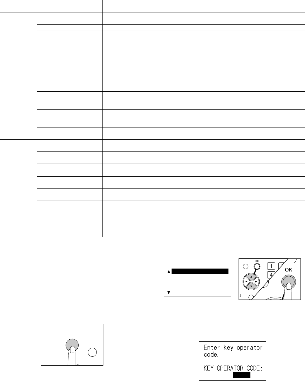
AR-FX4 KEY OPERATOR PROGRAM - 2
2. Operating procedure
The key operator program can be set from all the modes (copy, FAX,
printer, scanner). When setup is completed, the mode returns to the
original mode.
Note:
• When the key operator program is used, send/receive of FAX cannot
be made.
• The key operator program cannot be used during send/receive of
FAX or during communication.
A. Common procedures
1) Press [SPECIAL FUNCTION] key.
2) Select the key operator program with [UP] [DOWN] keys, and
press [OK] key.
3) Enter the key operator code.
• Enter a code of 5 digits and go to step 4).
• When a code is entered, "-" is changed to "*."
• When an erroneous key is pressed, press [CLEAR] key and
enter the correct entry again.
Reception
function setup
Number of times of automatic
reception call
SW29-5 – 8 Used to set the number of times of calls until reception is started in automatic
reception state.
Reception data print tray SW27-2 – 5 Used to set recording paper tray for printing reception data]
Reception data print
condition
SW17-2 – 3 Used to set whether reduction print is made or divided print is made when there is
no paper of the same size as the received image.
Automatic reduction print in a
fixed size
SW24-8 Used to set whether reduction print is made or not according to the size of paper
set in the tray when data of greater size than the size of paper set in the tray.
Reception data transfer SW38-7 Used to set data transfer to the telephone number registered in this program when
image data received in the memory of this machine cannot be outputted.
Registration of telephone
number to transfer reception
data
No The FAX number to be transferred is registered.
Index print SW32-6 Used to set whether a black mark (index) is printed at the top of recording paper.
Reception data override SW18-8 Used to set to print the latter data prior to the former data when printing of the
former data is in standby state due to recording paper empty, etc. and the latter
data are ready to print.
Output method when A3
width reception (Inch series)
SW18-6 Used to set whether an image of 297mm width is reduced and printed or an image
of 11" width is printed without reduction on paper of 11" width when an image of
A3 width is received.
Specified number reception SW24-3 Used to set ON/OFF of the function to reject FAX reception from a registered
number.
Special
function setup
Polling protection SW1-5 Used to set the protection function when transmission is made by receiving
polling.
Registration of polling allow
number
No Used to register or delete the other party’s number for transmission by polling.
ID number registration No Used to set the system number of the other party’s machine.
System number registration No Used to set for registration of the system number of this machine.
Relay ID code registration SW13-8 Used to set for registration of the relay broadcast transmission allow number from
the transmission station.
Confidential box registration No Used to set for registration of the confidential box number and password of
confidential reception.
F code confidential box
registration
No Used to set for registration of memory box for F code confidential reception.
Registration of F code relay
group
No Used to set for registration of memory box for F code relay reception.
Registration of F code bulletin
board
No Used to set for registration of memory box for F code bulletin board transmission.
Function setup Program name Soft SW
setup Program function (Outline)
SPECIAL FUNCTION
SPECIAL FUNCTION
CONFIGURATION
PAPER SIZE SET
DISPLAY CONTRAST
KEY OPERATOR PRG.
BACK
SPECIAL FUNCT
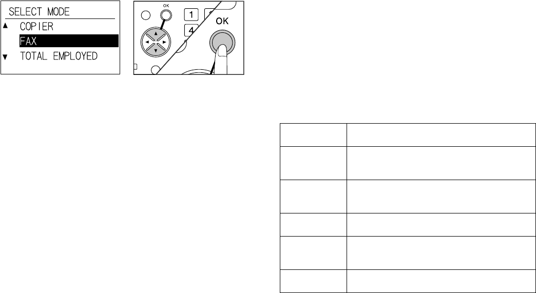
AR-FX4 KEY OPERATOR PROGRAM - 3
4) Select FAX with [UP] [DOWN] keys, and press [OK] key.
•Select COPY, and the key operator program in the copy mode
can be set.
5) Perform setup of each program according to the description in the
following pages.
•Set and register the program for setup of the following functions.
List output/setup, initial setup, transmission function setup,
reception function setup, special function setup
6) When setup is completed, press [CA] (Clear All) key.
•Terminate the key operator program.
Press [BACK] key to return to the previous screen.
To terminate each program, press [CA] (Clear All) key.
B. List output
1) Perform common operating procedures up to step 4).
2) Select "List output/Setup" with [UP] [DOWN] keys and press [OK]
key.
3) Select "List output" with [UP] [DOWN] keys and press [OK] key.
4) Select a list name to output with [UP] [DOWN] keys and press [OK]
key.
•Select among Key operator table, Confidential ID table, F code
setup check table, Department code table, and Department man-
agement record table *.
•When the key operator program is terminated, print is started.
* This item is displayed on the list only when department manage-
ment is set to ON (Effective) in the initial setup of the key opera-
tor program.
(3) Print method of record table
1) Press [SPECIAL FUNCTION] key in the FAX mode.
2) Select "PRINT" with [UP] [DOWN] keys, and press [OK] key.
3) Select "Record table" with [UP] [DOWN] keys, and press [OK] key.
4) Select a record table name to be printed with [UP] [DOWN] keys,
and press [OK] key.
•Print reservation is made and print is made automatically.
•Printable record table
Communication record table, communication reservation table,
document load check table, speed dial table, rapid dial table,
group table, telephone number table, program table, relay group
table, ID sender table, confidential reception check table
When [CA] key is pressed in the record table selection screen, the dis-
play returns to the initial screen. When [BACK] key is pressed, the dis-
play returns to the print selection screen of step 3).
The communication record table can be automatically printed by speci-
fying time to print. Specification of print time can be set by the key
operator program up to 2 times per day.
BACK
SPECIAL FUNCTI
Key operator
list
Used to print the current setup conditions of key
operator program.
Confidential ID
table
Used to print the contents of confidential box
registration (confidential box number, confidential
box name, ID number).
F code setup
check table
Used to print the contents of F code confidential
box registration, F code relay group registration,
and F code bulletin board registration.
Department
code table
Used to print registered numbers, department
names, and department numbers.
Department
management
record table
Used to print communication time and
communication pages in each department.
Anti Junk list The reception rejection telephone number list is
printed.
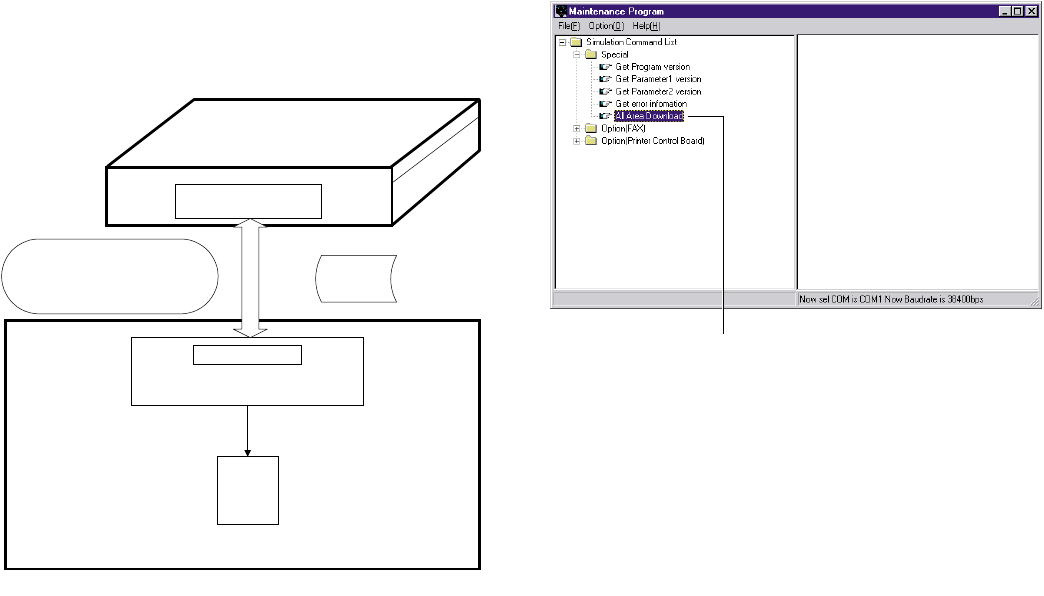
AR-FX4 FLASH ROM VERSION UP PROCEDURE - 1
[8] FLASH ROM VERSION UP
PROCEDURE
(Items necessary for upgrade)
APersonal computer
BRS232C Cross cable (D-sub 9pin to D-sub 9pin, or D-sub 25pin to
D-sub 9pin)
CSoftware for upgrade
(Type of ROM)
Flash ROM is directly attached to each PWB
(Targeted PWBs)
1MCU-PWB
2FAX-PWB
Diagrammatic sketch for upgrade method
(Files necessary for download)
• Maintenance program: mainte.exe
• Loader files
• IMC loader file: imcbios.cvt
• FAX loader file: faxbios.cvt
The maintenance program performs downloading of the following pro-
gram:
• FAX program download
Note: The downloaded files such as Printer Control Board file should
be copied in the same folder as that of the maintenance pro-
gram.
1. Program download procedure (Main
body program, FAX program)
Follow the procedure below to download the main body program and
the FAX program:
1) Preliminary procedure: Connect PC and the main body with the
download cable (RS-232C cable).
2) PC side: Boot the maintenance program.
3) Main body side: Turn on the power of LEOPARD, and it enters the
download mode.
4) PC side: Check that the tree structure is displayed on the mainte-
nance program.
∗Be sure to perform step 2) before turning on the power.
When the tree is displayed, downloading can be performed.
(Double-click to perform.)
5) PC side: Double-click Special in the main tree items to extend the
sub tree items, then double-click All Area Download.
6) PC side: The maintenance program asks the file name. Specify a
download file (*.dat).
Download file:
• leopXXXX.dat: File for collective download (IMC, FAX)
XXXX: Release version (Leop0114.dat, etc.)
7) PC side: When a download file is specified, the downloading pro-
cedure advances automatically.
Time required for downloading is as follows:
8) PC side: When the message below is displayed, downloading is
completed.
End message: Download Complete
9) After-process: Terminate the maintenance program, and turn off
and on the power of the main body.
With the above procedures, downloading is completed.
(Personal computer)
(AR-235/275)
RS232C connector
(9pin or 25pin)
MCU-PWB
I/F Circuit (9pin)
RS232C Cross cable
(D-sub 9pin to D-sub 9pin)
or
(D-sub 25pin to D-sub 9pin)
Download
data
A
C
B
1
FAX-PWB
2
•Main body program download time: About 5 min
•FAX program download time: About 5 min

AR-FX4 FLASH ROM VERSION UP PROCEDURE - 2
2. Others (Error list)
The list below describes errors occurring during download and countermeasures.
No Error message Descriptions
01 COM Port Open Error ! This error message is displayed when a COM port which is disabled is selected or when there is an abnormal
COM port.
[Countermeasures]
Select another COM port which is enable. Check if there is any software which is using the COM port.
02 TimeOut Error ! This error message is displayed when no response is sent back from the remote party for 10 sec.
[Countermeasures]
Once reset the maintenance software and the machine, then download again.
03 Receive Error ! This error message is displayed when data received from the remote party are abnormal.
[Countermeasures]
Once reset the maintenance software and the machine, then download again.
04 Panel Size Error ! This error message is displayed when the download file size is specified to 8MB though the machine panel is of
4MB size.
[Countermeasures]
Specify a download size suitable for the machine panel size, and download again.
05 Destination Error ! This error message is displayed when the destination of the machine panel does not coincide with that of the
download file.
[Countermeasures]
Specify the download file suitable for the destination of the machine panel, and download again.
06 Printer Control Board
FirmWare Download
Send Error !
This error message is displayed when an error occurs during downloading of the printer control board firmware.
[Countermeasures]
Execute SIM 67-14 on the machine panel to check that "Please Send Data" is displayed, and download again.

AR-FX4 TROUBLE CODE LIST - 1
[9] TROUBLE CODE LIST
1. Machine trouble codes
Trouble code
Details of trouble
Main
code
Sub
code
F6 00 Content F6-**: MCU-FAX communication trouble
Detail Communication setup error/framing/parity/
protocol error
Cause FAX control PWB connector disconnection
Defective harness between FAX control
PWB and MCU PWB
Motherboard connector pin breakage
FAX control PWB ROM error/Data error
Check
and
remedy
Check connector/harness of FAX control
PWB and MCU PWB.
Check the grounding of the copier.
Check FAX control PWB ROM.
10 Content FAX control PWB trouble
Detail Communication trouble between MCU and
FAX control PWB
Cause FAX control PWB connector disconnection
Defective harness between FAX control
PWB and MCU PWB
Motherboard connector pin breakage
FAX control PWB ROM error/Data error
Check
and
remedy
Check connector/harness of FAX control
PWB and MCU PWB.
Check the grounding of the copier.
Check FAX control PWB ROM.
80 Content FAX control PWB communication trouble
(Protocol)
Detail Communication trouble between MCU and
FAX control PWB (Protocol error)
Cause FAX control PWB connector disconnection
Defective harness between FAX control
PWB and MCU PWB
Motherboard connector pin breakage
FAX control PWB ROM error/Data error
Check
and
remedy
Check connector/harness of FAX control
PWB and MCU PWB.
Check the grounding of the copier.
Check FAX control PWB ROM.
81 Content FAX control PWB communication trouble
(Parity)
Detail Communication trouble between MCU and
FAX control PWB (Parity error)
Cause FAX control PWB connector disconnection
Defective harness between FAX control
PWB and MCU PWB
Motherboard connector pin breakage
FAX control PWB ROM error/Data error
Check
and
remedy
Check connector/harness of FAX control
PWB and MCU PWB.
Check the grounding of the copier.
Check FAX control PWB ROM.
F6 82 Content FAX control PWB communication trouble
(Over-run)
Detail Communication trouble between MCU and
FAX control PWB (Overrun error)
Cause FAX control PWB connector disconnection
Defective harness between FAX control
PWB and MCU PWB
Motherboard connector pin breakage
FAX control PWB ROM error/Data error
Check
and
remedy
Check connector/harness of FAX control
PWB and MCU PWB.
Check the grounding of the copier.
Check FAX control PWB ROM.
84 Content FAX control PWB communication trouble
(Framing)
Detail Communication trouble between MCU and
FAX control PWB (Framing error)
Cause FAX control PWB connector disconnection
Defective harness between FAX control
PWB and MCU PWB
Motherboard connector pin breakage
FAX control PWB ROM error/Data error
Check
and
remedy
Check connector/harness of FAX control
PWB and MCU PWB.
Check the grounding of the copier.
Check FAX control PWB ROM.
88 Content FAX control PWB communication trouble
(Timeout)
Detail Communication trouble between MCU and
FAX control PWB (Timeout error)
Cause FAX control PWB connector disconnection
Defective harness between FAX control
PWB and MCU PWB
Motherboard connector pin breakage
FAX control PWB ROM error/Data error
Check
and
remedy
Check connector/harness of FAX control
PWB and MCU PWB.
Check the grounding of the copier.
Check FAX control PWB ROM.
99 Content Machine-FAX board language error
Detail The machine language setup does not
coincide with the FAX board language setup.
Cause FAX board correction error
SIM setup error
Check
and
remedy
Check the firmware of the FAX board and
the combination of the panel screen data,
and download the correct version, if
necessary.
Check the machine language information.
(Machine language setup:SIM 26-22)
Trouble code
Details of trouble
Main
code
Sub
code

AR-FX4 TROUBLE CODE LIST - 2
2. Communication result code
Described on the communication report table, the communication man-
agement table, and the protocol communication report table when
communication is completed.
A. Composition of communication report code
Communication result X X (X X X X)
Upper 2 digits of a communication result code: Communication report
code of 00 - 90 (Refer to the list of communication report codes.)
Lower 4 digits of a communication result code: Codes used by service-
man.
Note) Communication report sub code 1 and sub code 2 are in hexa-
decimal. (The others are in decimal.)
<Communication result code list>
(Note) For result codes 16 - 31, V.34 mode communication.
For 32 or later, refer to the table below.
<Communication result code list>
Top 2 digits Communication report sub code 1 (Refer to
the list of communication sub code 1.)
Bottom 2 digits Communication report sub code 2 (Refer to
the list of communication sub code 2.)
Result
code
Final reception signal
(Transmitting side)
Final reception signal
(Receiving side)
0 Abnormal signal Abnormal signal
1 NSF, DIS (SID), (SUB), NSS, DCS
2 CFR (PWD), (SEP), NSC, DTC
3 FTT EOP
4MCF EOM
5 PIP, PIN MPS
6 RTN, RTP PRI-Q
7 No signal, DCN DCN
8 PPR PPS-EOP
9PPS-EOM
10 PPS-MPS, PPS-NULL
11 RNR RR
12 CTR CTC
13 ERR EOR-Q
14 PPS-PRI-Q
15
16 Abnormal signal Abnormal signal
17 NSF, DIS SID, SUB, NSS, DCS
18 CFR PWD, SEP, NSC, DTC
19 FTT PPS-EOP
20 MCF PPS-EOM
21 PIP, PIN PPS-MPS, PPS-NULL
22 RTN, RTP PRI-Q
23 No signal, DCN DCN
24 PPR
25 RNR RR
26 CTR CTC
27 ERR EOR-Q
28 PPS-PRI-Q
29 V.8 Phase-1 V.8 Phase-1
30 V.8 Phase-2 V.8 Phase-2
31 V.8 Phase-3 V.8 Phase-3
Result code
(Communication
result)
Communication
report result
column
Communication interruption
content
0 – 31 Refer to the
previous table.
Depends on the
communication disconnection
position. For 16 or later, V.34
mode communication.
33 Busy The calling side cannot
connect the line with the other
party.
34 Cancel When a communication
interruption command is
delivered during transmission
or reception, <Send/Receive/
Poll/Bulletin>
When the operation is
interrupted by the stop key.
35 Power OFF When the power is cur off
during sending or receiving,
<Send/Receive/Poll/Bulletin>
38 Reception
memory over
When memory is over during
reception, <Receive/Poll>.
When printing cannot be
performed during reception
due to inhibition of proxy
reception, <Receive/Poll>
42 Reception
length over
When the received data length
of one page exceeds the range
during reception, <Receive/
Poll>
44 Document error When a document jam occurs
during direct transmission,
<Send>
46 No response
from the other
party
When the FAX signal from the
other party is not detected
within T1 time, <Send/Poll>
48 OK Communication normal end
49 The other party
has no polling
function.
When the called side has no
polling function in polling
reception, <Poll>
When the called side has no
transmission data, <Bulletin>
50 Polling is not
accepted.
When DCN is received for
DTC in polling reception,
<Poll>
When there is no transmission
data in polling transmission,
<Bulletin>
51 Polling allow
number
discrepancy
When the allow number does
not coincide in polling
transmission, <Bulletin>
When the system number does
not coincide in polling
transmission, <Bulletin>
56 Interface not
accepted
1) When DCN is received for
NSS in transmission of the
relay instruction, <Send>
2) When a receiving station
number that is not
registered is instructed in
reception of the relay
instruction, <Receive>
3) When F code relay
instruction is received
during F code relay
broadcasting, <Receive>

AR-FX4 TROUBLE CODE LIST - 3
• When communication result is OK, the communication result sub
code 1 and sub code 2 are 0000.
• < > indicates the communication means. <Send>, send; <Receive>,
receive; <Poll>, polling; <Bulletin>, bulletin board
The status code from the modem in V.34 mode is indicated with the
communication result sub code 1 (top 2 digits). However, the commu-
nication sub code 1 is 00 in communication other than V.34 mode.
<Communication result sub code list 1>
59 The other party
has no function
of F code
bulletin board.
When the other party machine
does not have DIS bit 47
(Selective polling function) in F
code polling (ringing), <Poll>
60 F code polling
is not accepted.
When DCN is received for SEP
in F code polling (ringing),
<Poll>
When there is no transmission
data for SEP in bulletin board,
<Bulletin>
61 F code bulletin
board number
discrepancy
When the sub address (bulletin
board number (SEP)) does not
coincide in bulletin board,
<Bulletin>
62 F code bulletin
board password
discrepancy
When the pass code (PWD)
does not coincide in bulletin
board, <Bulletin>
63 The other party
has no function
of F code.
When the other party machine
does not have DIS bit 49 (sub
address capacity) in F code
transmission, <Send>. Check
that the other party machine
conforms to F code.
64 F code is not
accepted.
When F code is transmitted,
<Send>
1) When DCN is received for
SUB, check the BOX
number.
2) When DCN is received for
SID, check BOX number
and the pass code.
When F code is received,
<Receive>
When the F code relay
broadcast function or the F
code confidential reception
function is inhibited with soft
switches.
67 F code
password
discrepancy
When the pass code (SID)
does not coincide in F code
reception, <Receive>
68 BOX NO. NG When a BOX number that is
not registered is instructed
(SUB discrepancy) in F code
reception, <Receive>
Result code
(Communication
result)
Communication
report result
column
Communication interruption
content Code
(Hexadecimal) Descriptions
21 Phase 2 Timeout standby for INFO0
22 Check sum error in INFO0
23 Timeout standby for tone A or B
24 Timeout standby for the first phase
reversion
25 Timeout standby for cut off tone
probing
26 Timeout standby for the second
phase reversion
27 Timeout standby for probing end
28 Timeout standby for the third phase
reversion
29 Timeout standby for INFO1
2A Check sum error in INFO1
2B Tone found before INFO1
2C Unexpected INFO0 found
31 Timeout standby for turning off the
reception control channel
91 Control
channel
Error in the first CC train
92 Timeout standby for PPh
93 Tone A/B detected in CC retrain
94 Timeout standby for ALT
95 Ach found
97 Timeout standby for turning off CC
98 FED OFF with CC data
A1 A trouble which cannot be solved in
phase 2. Retrain is forcibly made.
B0 Primary
channel
resync
Trouble in S sequence of HDX-
resync
B1 FED OFF in S sequence of HDX-
resync
B2 Unexpected completion of S
sequence in HDX-resync
B3 Timeout standby for S-Sbar in
HDX-resync
B4 Timeout standby for S-Sbar in
HDX-resync
B5 Timeout standby for S in HDX-
resync
B6 Timeout for sync with PP
C0 Phase 3 Trouble in S sequence of phase 3
C1 FED OFF in S sequence of phase 3
C2 Unexpected completion of S
sequence
C3 Timeout standby for S-Sbar of
phase 3
C4 Timeout standby for S-Sbar of
phase 3
C5 Timeout standby for S of phase 3
C7 Training due to TRN failure
D0 Phase 4 Trouble in S sequence of phase 4
D1 FED OFF in S sequence of phase 4
D2 Unexpected completion of S
sequence
D3 Timeout standby for S-Sbar of
phase 4
D4 Timeout standby for S-Sbar of
phase 4
D5 Timeout standby for S of phase 4
D6 Timeout standby for MP
D8 Timeout standby for E
DA Timeout at renegotiation of the
transmitter rate
DB Timeout at MPh of the transmitter
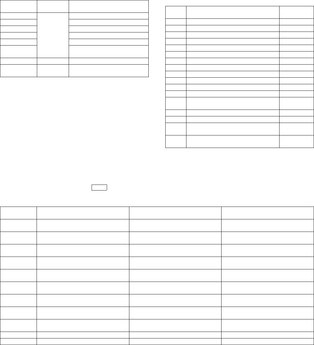
AR-FX4 TROUBLE CODE LIST - 4
<Communication result sub code 2>
3. List of buzzer sounds in case of FAX abnormality
E2 Retrain Retrain detected in phase 2
E3 Retrain detected in phase 3
E4 Retrain detected in phase 4
FE DTR OFF in retrain
FF TX setup port flag
71 Writing is not made to the first
mapping frame.
96 Clear down PSTN clear down request is made.
61 HDLC The transmitter sends HDLC abort
in underflow state.
Code
(Hexadecimal) Descriptions Result
code 2 Communication interruption content Transmission/
Reception
02 EOL time over Reception
03 Carrier detection time over Reception
05 Time-up in phase C (8min) Transmission
06 Memory image decoding error Reception
07 Memory image decoding error Transmission
11 Polarity reversion detection Reception
12 Invalid command reception Reception
13 Time over (1min timer/6sec timer) Reception
14 PUT error Reception
20 Polarity reversion detection Transmission
21 Invalid command reception Transmission
22 Fall back retry number over Transmission
23 Resend over of the number of times of
command retry
Transmission
24 Time over (T5 timer) Transmission
25 Time over (T5 timer) in V.34 mode Transmission
26 Time over occurrence during shift from
Primary to Control in V.34 mode
Transmission
28 Modem chip answering NG Transmission/
Reception
– : Long sound • : Single sound 3: Pause
Example: In case of TEL/LIU connection abnormality
{{– • • • • •} repeats {Pee • pi • pause • pi • pi • pi • pi}.
Beep sound
pattern Information content Detail Trouble content
– • • • Expanded memory connection
abnormality
Expanded memory insertion abnormality Expanded memory reinsertion
– • • • • Internal DMA transfer abnormality Internal DMA transfer operation
abnormality
PWB solder trouble, PWB parts trouble
– • • • • • TEL/LIU PWB connection abnormality TEL/LIU PWB is not connected to the
main PWB.
– • • • Program ROM (main section) writing not
completed
Program ROM (main section) data
abnormality
Download retry
– • • • • Program ROM (font section) writing not
completed
Program ROM (font section) data
abnormality
Download retry
– • • • • Work DRAM (IC13, 14) abnormality Work DRAM abnormality IC13, 14: PWB solder trouble, PWB parts
trouble
– • • • • • SRAM (IC41) abnormality 1 IC41: PWB solder trouble, PWB parts
trouble
– • • • • • • SRAM (IC41) abnormality 2 IC41: PWB solder trouble, PWB parts
trouble
– • – – MCU upload no responding MCU PWB does not respond. MCU PWB - main PWB connection
– • • – System abnormality 1 Various internal operation abnormality PWB solder trouble, PWB parts trouble
– • • • – System abnormality 2 Various internal operation abnormality PWB solder trouble, PWB parts trouble
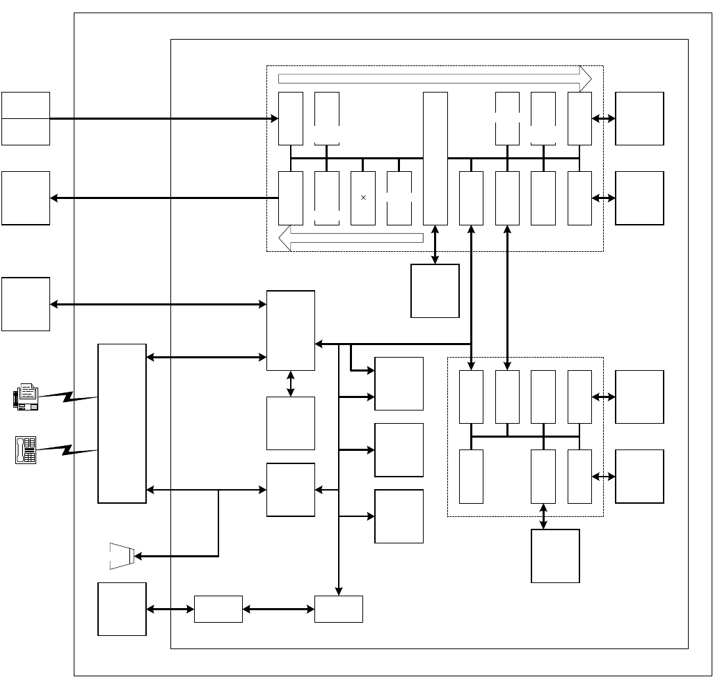
AR-FX4 ELECTRICAL SECTION - 1
[10] ELECTRICAL SECTION
1. Block diagram
A. Main block diagram
COPIER
SCANNER
S (1)
SCAN
I/F
PAGE MEMORY
SDRAM
128Mbit
IMAGE
PROCESS
MEMORY
SRAM
1Mbit
P (3)
33
COPIER
PRINTER
P (5)
PRINT
I/F
CPU
(SH7709A)
COPIER CPU
S (3)
SDRAM
CON-
TROL
P (1)
SDRAM
CON-
TROL
SRAM
CON-
TROL
MODEM
FM336
RTC
WORK
MEMORY
SDRAM
16Mbit
IMAGE
MEMORY
(STANDARD)
FLASH ROM
16Mbit
IMAGE
MEMORY
(EXPANDED)
FLASH ROM
2MB/4MB/8MB
EXPANSION
CONNECTOR
TEL/LIU
PWB
REGIS-
TRATION
MEMORY
SRAM
2Mbit
EXTERNAL
TELEPHONE
LINE
FAX UNIT
FAX MAIN PWB
IMAGE PROCESS GA
S (5)
MN860
65
I/F
DMAC
CON-
TROL
CPU
I/F
FAX
GA
I/F
CODE/
DECODE
MN86065
CPU
I/F
IMAGE
GA
I/F
DMAC
CON-
TROL
MN860
65
I/F
CODE/
DECODE
MN86065
IMAGE
PROCESS
MEMORY
SRAM
1Mbit
SRAM
CON-
TROL
RTC
I/F
PROGRAM
FLASH ROM
16Mb
BUS
BUFFER
PCL
FAX PROCESS GA
SCAN PROCESS FLOW
PRINT PROCESS FLOW
SPEAKER
MODEM
CON-
TROL
S (4)
SUB
SCAN
1/2
MULTI-
PLICATION
S (3)
ROTATION
SCAN
P (2)
ROTATION
PRINT
P (4)
RESO-
LUTION
CON-
VERSION
S (2)
SUB
SCAN
2/3
MULTI-
PLICATION
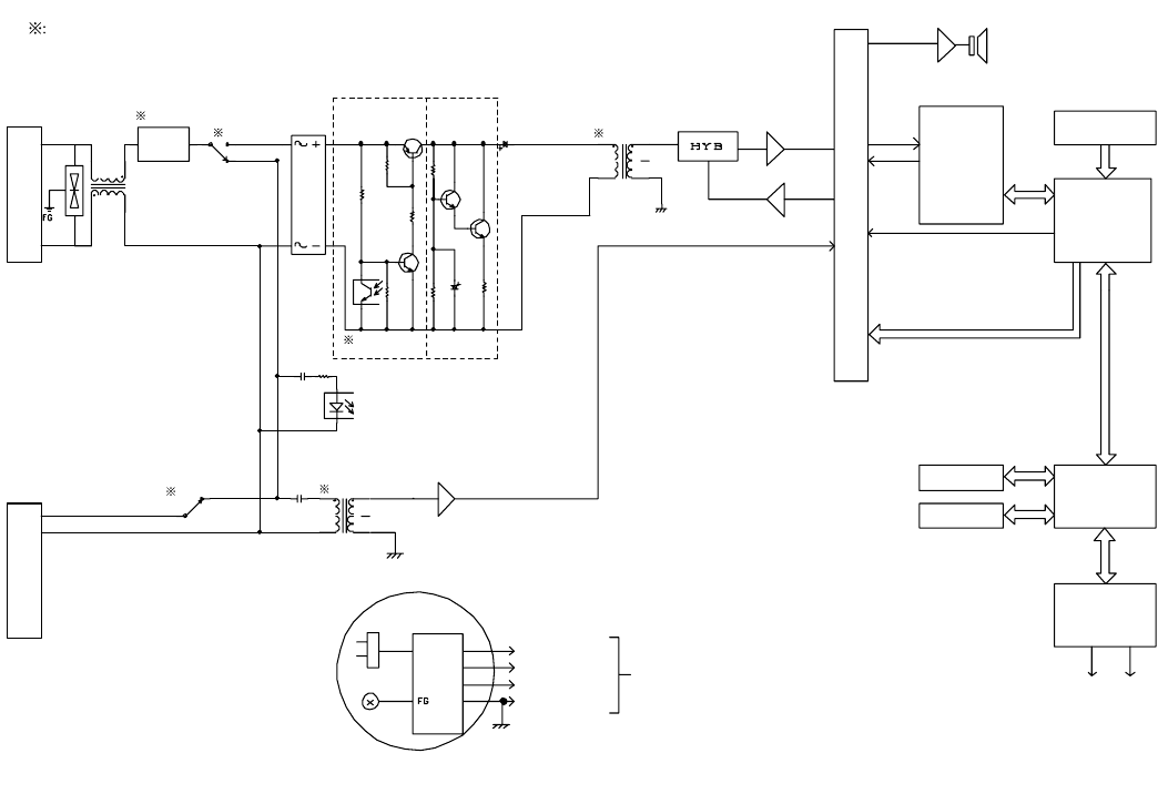
AR-FX4 ELECTRICAL SECTION - 2
B. TEL/LIU PWB block diagram
POWER SUPPLY LINE
CONNECTION JACK
EXTERNAL
TELEPHONE
JACK
CURRENT DETECT SECTION
DC SEPARATE
PHOTO
COUPLER
SWITCH CIRCUIT
SECTION
SP
MODEM
33600bps
V.34
ATT (0 – 15db)
PB SIGNAL
GENERATE
SECTION
FAX CONTROL
SECTION
(CPU, GATE ARRAY)
PSEUDO RBT SOUND
GENERATE SECTION
PROGRAM
CONTROL ROM
READ SECTION
POWER SOURCE RECIVE CONDITION
TO EACH SECTION
EARTH
AC120V
DC24V
DC5V
DC3.3V
GND
CENTRONICS I/F
LAN (10/100BASE-1)
COPY
CONTROL
SECTION
PRINTER I/F
(OPTION)
PRINT SECTION
ON HOOK
DP TRANSMISSION
CIRCUIT
LINE
CLOSE/
INTERFACE
CIRCUIT
CML RELAY
CI DETECT
S RELAY TRANSFORMER
TRANSFORMER
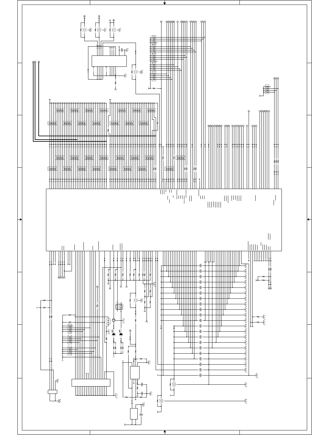
AR-FX4 ELECTRICAL SECTION - 3
CPU_TDO VOL[A]
PCRXD
PCTXD
AUDCK
CPU_TCK
WE0-
A13
A17
A14
A7
A25
D24
A15
A23
A12
A8
D21
A4
A21
D2
D17
A16
A19
A6
A0
A10
A22
A3
D3
A20
A1
A24
A11
A2
D23
A18
A5
A9
IRQ2-
DRAK[0]
CS0-
WE1-
AUDSYNC-
ASMD0-
CS4-
DREQ[1]-
CS3-
CS5-
LED
CPU_TDI
BS-
DRAK[1]
CS2-
AUDATA3
AUDATA2
CS6-
WAIT-
D29
D28
D16
D20
D22
D7
D30
D18
D31
D5
D26
D27
D25
D6
D19
D9
SRAMCLR-
TUIKA1
RD-
RD/WR-
DREQ[0]-
IRQ1-
IRQ0-
D8
D10
D11
D4
D15
D1
D0
D13
D12
D14
AUDATA1
CPU_TMS
AUDATA0
TRST-
ASEBRKRK-
MD3
CPURES-
FAXSRDY-
L_BT
FAXCRDY-
FAXSTS
FAXCMD
BS-
CASL-
RD/WR-
VOLCNT[B]
MPXA
RD-
SPMUTE
WE0-
WAIT-
EC
VOL[A]
RAS3L-
CKE
VRSEL[2]-
VOL[B]
VOLCNT[A]
VRSEL[1]-
CML
C_BT
WE1-
S
DPON-
TELMUTE
TXSEL[B]
TXSEL[A]
CI-
VOL[C]
VRSEL[3]-
RCVMUTE
RHS-
EXHS-
HS[1]-
LIUID
HS[2]-
FNETD
PWOFF-
VOL[A]
CS0-
CS3-
CS4-
CS6-
IRQ0-
IRQ1-
IRQ2-
CS5-
D[16:31]
A[1:25]
CPU_CKIO
DRAK[1]
DREQ[1]-
DREQ[0]-
DRAK[0]
DPMUTE
150VON
CION
CPU_CKIO
CKIO_GA1
CKIO_GA2
CKIO_SDRAM
DQMUL
DQMUU
D[0:15]
+1.8V
+3.3V
+5V
+3.3V
+3.3V
+3.3V
+3.3V
+3.3V
+3.3V
+3.3V
+3.3V +3.3V
+3.3V
+1.8V
+3.3V
+3.3V
+3.3V TP728
FB2
MEM2012(NM)
TP427
TP1128
TP703
TP630
TP91
TP83
C12
F0.1u/16
TP1079
R21 R(NM)
R273
10K
TP696
TP109
TP682
TP737
TP157
TP1069
R33 R(NM)
TP730
BR34
MNR14 10K
1
2
3
4 5
6
7
8
TP627
TP1067
C17
F0.1u/16
R23 10K
BR33
MNR14 10K
1
2
3
4 5
6
7
8
TP710
TP738
TP714
TP1093
R36 R(NM)
BR4
MNR14 (NM)
1
2
3
4 5
6
7
8
TP631
BR21
MNR14 (NM)
1
2
3
4 5
6
7
8
TP107
TP1074
FB13
MEM2012(NM)
TP81
TP111
TP747
BR11
MNR14 (NM)
1
2
3
4 5
6
7
8
TP126
TP655
TP698
TP651
FB5
MEM2012(NM)
TP131
TP95
R10 6.8K
TP663
TP665
TP713
TP681
BR8
MNR14 4.7K
1
2
3
4 5
6
7
8
C242F0.1u/16
TP424
TP740
TP672
C10
F0.1u/16
BR6
MNR14 (NM)
1
2
3
4 5
6
7
8
TP646
TP103
TP92
TP89
C18
F0.1u/16
TP658
TP660
TP726
TP1090
TP101
TP93
C5
B470/50
R37 10K
TP1071
TP136
TP110
FB1
MEM2012(NM)
JP3
SD00415-52
1 2
TP122
C23
F0.1u/16
BR15
MNR14 (NM)
1
2
3
4 5
6
7
8
C21
F0.1u/16
TP744
TP1070
BR30
MNR14 33
1
2
3
4 5
6
7
8
TP624
TP1084
TP712
TP675
LED1 LT1P67A
TP1080
TP635
TP695
BR2
MNR14 (NM)
1
2
3
4 5
6
7
8
R7 33
TP741
TP671
TP1130 JP2
SD00415-52
1 2
TP1044
BR13
MNR14 (NM)
1
2
3
4 5
6
7
8
TP720
FB6
MEM2012(NM)
TP733
BR20
MNR14 33
1
2
3
4 5
6
7
8
BR31
MNR14 (NM)
1
2
3
4 5
6
7
8
R49
10K
BR37
MNR14 33
1
2
3
4 5
6
7
8
TP662
TP657
BR12
MNR14 33
1
2
3
4 5
6
7
8
TP137
R32 10K
TP112
TP1076
BR17
MNR14 (NM)
1
2
3
4 5
6
7
8
FB4
MEM2012(NM)
TP724
TP82
R34 10K
TP1092
R24 10K
TP652
R43 10K
TP120
TP296
TP1083
TP739
C6
B470/50
C9
F0.1u/16
TP124
BR19
MNR14 (NM)
1
2
3
4 5
6
7
8
TP641
TP911
BR1
MNR14 33
1
2
3
4 5
6
7
8
TP699
R26
R(NM)
TP415
R50
10K
R20 10K
TP74
TP88
TP736
TP1077
TP706
C22
F0.1u/16
TP425
TP130
TP725
TP85
R5
3.3K
BR3
MNR14 33
1
2
3
4 5
6
7
8
TP135
BR35
MNR14 10K
1
2
3
4 5
6
7
8
TP623
TP912
TP729
R230 0
R219 33
TP668
TP119
IC3
FS781
2
3
1
6
7
8
4 5
XOUT
S1
XIN
FSOUT
S0
VDD
LF VSS
TP90
TP98
TP100
R40
10K
BR32
MNR14 10K
1
2
3
4 5
6
7
8
TP645
TP129
TP84
BR14
MNR14 33
1
2
3
4 5
6
7
8
TP123
TP913
TP104
TP694
TP709
R45 33
TP674
TP417
BR25
MNR14 (NM)
1
2
3
4 5
6
7
8
TP80
TP1072
R35 10K
TP653
TP1129
TP742
TP715
BR16
MNR14 33
1
2
3
4 5
6
7
8
TP118
TP86
R12 33
R46 33
TP1087
TP14
TP642
C8
F0.1u/16
R28 10K
TP216
TP1043
BR18
MNR14 33
1
2
3
4 5
6
7
8
TP632
R16 0 TP686
C7
F0.1u/16
TP1085
TP708
TP426
TP700
TP625
TP75
R22 0
TP670
TP117
TP743
TP705
TP1078
R3 100
TP1081
TP15
TP643
TP673
R14 820
TP732
BR22
MNR14 33
1
2
3
4 5
6
7
8
IC2
74LCX244WM
218
416
614
812
11 9
13 7
15 5
17 3
1
19
20
10
1A1 1Y1
1A2 1Y2
1A3 1Y3
1A4 1Y4
2A1 2Y1
2A2 2Y2
2A3 2Y3
2A4 2Y4
1G
2G
VCC
GND
R4 100
R19 10K
TP633
C2
B2200/50
BR23
MNR14 (NM)
1
2
3
4 5
6
7
8
TP1042
TP683
TP707
R30 10K
TP134
R17 820
TP1086
TP735
TP654
TP1127
C1
F0.1u/16
TP692
TP693
R39 R(NM)
TP105
TP664
R38 33
TP8
TP717
TP644
C3
C(NM)
TP73
BR24
MNR14 33
1
2
3
4 5
6
7
8
R1
4.7K
R29 R(NM)
TP1066
TP99
C16
F0.1u/16
TP666
TP659
TP423
TP649
X1
SG-8002JCPC(39.3216MHz)
4
31
2
VDD
OUTOE
GND
TP676
TP76
C15
F0.1u/16
TP113
R42 R(NM)
C11
F0.1u/16
BR39
MNR14 10K
1
2
3
4 5
6
7
8
TP636
BR27
MNR14 (NM)
1
2
3
4 5
6
7
8
R18 820
TP1094
R41 33
TP634
TP121
R25
0
LED2 LT1P67A
TP689 R47 33
TP661
TP656
TP7
TP94
TP731
TP96
TP677
TP1088
TP722
TP718
C19
F0.1u/16
TP648
R44 33
TP638
TP114
TP678
TP78
BR28
MNR14 33
1
2
3
4 5
6
7
8
TP679 BR26
MNR14 33
1
2
3
4 5
6
7
8
BR36
MNR14 10K
1
2
3
4 5
6
7
8
TP628
TP128
CN1
S4B-PH-SM3-TB
1
2
3
4
TP1068
BR5
MNR14 33
1
2
3
4 5
6
7
8
CN2
NCS036-014-DS(NM)
12 34 56 78 910 1112 1314 1516 1718 1920 2122 2324 2526 2728 2930 3132 3334 3536
12 34 56 78 910 1112 1314 1516 1718 1920 2122 2324 2526 2728 2930 3132 3334 3536
TP527
TP639
BR9
MNR14 4.7K
1
2
3
4 5
6
7
8
R2
4.7K
TP108
TP680
C20
F0.1u/16
R13 820
TP125
TP667
R15 10K
TP650
FB3
MEM2012(NM)
JP1
SD00415-52(NM)
1 2
TP97
TP115
TP704 R51 33
R53 33
R48 33
TP77
TP719
TP409
TP629
R231 0
R11 10K
R9 0
TP102
TP158
TP685
R54 33
TP528
TP640
TP687
R8 33
TP1065
BR38
MNR14 33
1
2
3
4 5
6
7
8
TP1073
BR29
MNR14 (NM)
1
2
3
4 5
6
7
8
R274
10K
TP1082
TP647
R31 10K
TP734
TP1075
BR10
MNR14 33
1
2
3
4 5
6
7
8
TP116
IC1 SH7709A
158
157
13
14
15
16
17
18
20
22
23
24
25
26
28
30
31
32
34
36
37
38
39
40
41
42
43
44
46
48
49
50
51
52
53
54
55
56
58
60
61
62
63
64
65
66
67
68
70
72
73
74
75
76
77
78
80
82
84
86
184
6
19
33
45
57
69
83
95
109
161
181
27
79
132
152
153
173
147
148
198
208
3
21
35
47
59
71
85
97
111
163
183
29
81
134
154
175
145
150
205
155
156
4
5
146
149
193
124
122
121
144
1
2
195
196
197
194
171
164
165
172
166
167
174
168
169
170
176
135
133
131
130
94
139
137
136
138
128
151
143
142
141
140
11
7
162
96
102
87
106
107
118
119
116
117
108
110
112
113
89
90
91
92
93
88
105
123
191
114
189
192
115
190
104
103
126
125
182
12
129
127
207
206
204
203
202
201
200
199
101
100
99
98
160
10
9
8
188
187
186
185
180
179
178
177
120
159
STATUS1/PTJ(7)
STATUS0/PTJ(6)
D31/PTB(7)
D30/PTB(6)
D29/PTB(5)
D28/PTB(4)
D27/PTB(3)
D26/PTB(2)
D25/PTB(1)
D24/PTB(0)
D23/PTA(7)
D22/PTA(6)
D21/PTA(5)
D20/PTA(4)
D19/PTA(3)
D18/PTA(2)
D17/PTA(1)
D16/PTA(0)
D15
D14
D13
D12
D11
D10
D9
D8
D7
D6
D5
D4
D3
D2
D1
D0
A0
A1
A2
A3
A4
A5
A6
A7
A8
A9
A10
A11
A12
A13
A14
A15
A16
A17
A18
A19
A20
A21
A22
A23
A24
A25
RESETOUT/PTD(2)
Vss(RTC)
VssQ
VssQ
VssQ
VssQ
VssQ
VssQ
VssQ
VssQ
VssQ
VssQ
Vss
Vss
Vss
Vss
Vss
Vss
Vss-PLL1
Vss-PLL2
AVss
AVss
Vcc(RTC)
VccQ
VccQ
VccQ
VccQ
VccQ
VccQ
VccQ
VccQ
VccQ
VccQ
Vcc
Vcc
Vcc
Vcc
Vcc
Vcc-PLL1
Vcc-PLL2
AVcc(3.3V)
XTAL
EXTAL
XTAL2
EXTAL2
CAP1
CAP2
RESETP
RESETM
BREQ
BACK
MD0
MD1
MD2
MD3
MD4
MD5
CA
RxD0/SCPT(0)
TxD0/SCPT(0)
SOK0/SCPT(1)
RxD1/SCPT(2)
TxD1/SCPT(2)
SCK1/SCPT(3)
RxD2/SCPT(4)
TxD2/SCPT(4)
SCK2/SCPT(5)
RTS2/SCPT(6)
CTS2/IRQ5/SCP(7)
AUDATA(0)/PTG(0)
AUDATA(1)/PTG(1)
AUDATA(2)/PTG(2)
AUDATA(3)/PTG(3)
AUDSYNC/PTE(7)
TCK/PTF(4)/PINT(12)
TMS/PTF(6)/PINT(14)
TRST/PTF(7)/PINT(15)
TDI/PTF(5)/PINT(13)
ASEBRKAK/PTG(5)
AUDCK/PTH(6)
IRLS(0)/PTF(0)/PINT(8)
IRLS(1)/PTF(1)/PINT(9)
IRLS(2)/PTF(2)/PINT(10)
IRLS(3)/PTF(3)/PINT(11)
IRQ3/IRL3/PTH(3)
NMI
CKIO
CS0/MCS(0)
CS6/CE1B
BS/PTK(4)
RAS3L/PTJ(0)
RAS2L/PTJ(1)
RAS3U/PTE(2)
RAS2U/PTE(1)
CAS2L/PTE(6)
CAS2H/PTE(3)
CASLL/CASL/PTJ(2)
CASLH/CASU/PTJ(3)
CASHL/PTJ(4)
CASHH/PTJ(5)
WE0/DQMLL
WE1/DQMLU/WE
WE2/DQMUL/ICIORD/PTK(6)
WE3/DQMUL/ICIOWR/PTK(7)
RD/WR
RD
CKE/PTK(5)
WAIT
DREQ0/PTD(4)
DACK0/PTD(5)
DRAK0/PTD(1)
DREQ1/PTD(6)
DACK1/PTD(7)
DRAK1/PTD(0)
CE2B/PTE(5)
CE2A/PTE(4)
IOIS16/PTG(7)
ADTRG/PTH(5)
WAKEUP/PTD(3)
IRQ4/PTH(4)
PTG(4)
ASMD0/PTG(6)
AN(7)/DA(0)/PTL(7)
AN(6)/DA(1)/PTL(6)
AN(5)/PTL(5)
AN(4)/PTL(4)
AN(3)/PTL(3)
AN(2)/PTL(2)
AN(1)/PTL(1)
AN(0)/PTL(0)
CS5/CE1A/PTK(3)
CS4/PTK(2)
CS3/PTK(1)
CS2/PTK(0)
IRQOUT
IRQ2/IRL2/PTH(2)
IRQ1/IRL1/PTH(1)
IRQ0/IRL0/PTH(0)
MCS(0)/PTC(0)/PINT(0)
MCS(1)/PTC(1)/PINT(1)
MCS(2)/PTC(2)/PINT(2)
MCS(3)/PTC(3)/PINT(3)
MCS(4)/PTC4)/PINT(4)
MCS(5)/PTC(5)/PINT(5)
MCS(6)/PTC(6)/PINT(6)
MCS(7)/PTC(7)/PINT(7)
TDO/PTE(0)
TCLK/PTH(7)
R55 33
TP702
R6
4.7K
TP1089
TP727
C24
F0.1u/16
TP723
TP637
TP716 R52 33
TP79
C13
F0.1u/16
TP697
TP106
Q1 DTC363EKA
B
E
C
TP669
TP721
TP133
BR7
MNR14 4.7K
1
2
3
4 5
6
7
8
TP162
C4
F0.1u/16
TP127
TP688
C14
F0.1u/16
TP1091
TP701
TP626
TP87
TP711R27
3.3K
TP132
FAX MAIN PWB (CPU) 1/10
2. Circuit diagram
A. FAX MAIN PWB
8 7 6 5 432 1
87 6 5 432 1
D
C
B
A
D
C
B
A
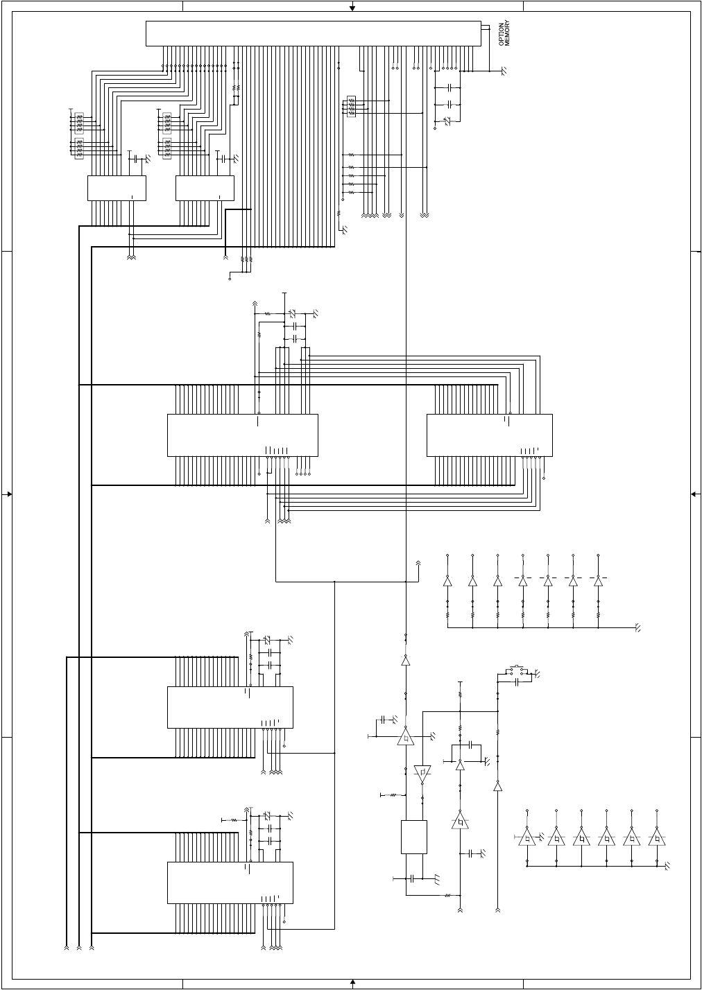
AR-FX4 ELECTRICAL SECTION - 4
D28
D17
D22
D24
D30
D25
D19
D21
D20
D31
D16
D27
D23
D26
D18
D29
A2
A3
A18
A14
A13
A4
A11
A17
A20
A10
A8
A9
A6
A7
A19
A21
A5
A15
A12
A16 D9
D10
A7
A15
A6
A8
A12
D5
A9
A20
D11
A18
D3
A5
A17
D1
D13
A13
D0
A1
A4
A3
A14
D2
D4
D15
A10
D8
D12
A19
D6
D7
A2
A11
D14
A16
D9
D11
D0
D8
D4
A1
A9
D10
A7
D12
A14
A17
ROMOBNK1
D14
D7
A8
D15
A4
A5
A6
A11
A16
D3
D2
A13
A15
A18
D5
A20
D1
D6
A2
A10
A19
D13
A3
A12
ROMOBNK2
ROMOBNK0
D1
D7
D11
D4
D9
D14
D10
D8
D15
D0
D2
D13
D6
D5
D3
D12
A9
A4
A11
A3
A17
A8
A18
A16
A10
A15
A1
A19
A20
A12
A2
A13
A7
A6
A5
A14
D12
D15
A13
D1
A5
A11
A15 D9
A16
D11
A2
D3
A4
A9
A12
A20
A7
A14
D6
D4
D0
A8
A10
D8
D14
A19
D2
A3
A17
A18
D13
D5
A21
D7
D10
A6
ROMPCE-
ROMPOE-
ROMPWE-
ROMPWP-
A[1:25]
D[0:15]
D[16:31]
MANRES-
FRESET
RES-
ROMPWP-
ROMPOE-
ROMPWE-
ROMPCE-
ROMPRY ROMPRY
ROMNWP-
ROMNWE-
ROMNOE-
ROMNCE-
ROMNRY
ROMOCID0
ROMOWE-
ROMOCE-
ROMOWP-
ROMORY
ROMOOE-
BFDIR
ROMOBNK[0:2]
ROMOCD1
ROMOCD0
BFOE-
ROMOCID1
+3.3V +3.3V
+3.3V
+3.3V
+3.3V
+3.3V
+5V
+3.3V
+5V
+5V
+5V
+3.3V
+5V
+3.3V
+3.3V
+3.3V
+3.3V
R229 100K
TP154
R64
0
R222 1K
TP396
TP1032
TP273
TP391
IC11A
74LCX06M
1 2
147
C25
F0.1u/16
C35
F0.1u/16
TP269
TP141
TP1022
TP388
IC9A
74LCX14M
1 2
147
R62
10K
TP270
IC20C
74LCX04M
5 6
147
C29
F0.1u/16
IC11B
74LCX06M
3 4
TP272
SW1 SKHU(NM)
C38
A33u/10
R227 100K
C31
F0.1u/16
R59 10K
TP1036
TP390
TP1033
TP387
TP268
C34
F0.1u/16
TP146
TP1024
IC9C
74LCX14M
56
IC24F
74LCX14M (NM)
13 12
R61 1K
TP1064
R249 0
IC9D
74LCX14M
9 8
R225 4.7K
IC4
74LCX245M
218
317
416
515
614
713
812
911
19
120
10
A1 B1
A2 B2
A3 B3
A4 B4
A5 B5
A6 B6
A7 B7
A8 B8
G
DIR VCC
GND
BR42
MNR14 10K
1
2
3
4 5
6
7
8
C36
F0.1u/16
TP1035
BR40
MNR14 10K
1
2
3
4 5
6
7
8
TP1034
R220 1K
TP143
IC6
MBM29LV160BE
9
16
17
48
1
2
3
4
5
6
7
8
18
19
20
21
22
23
24
25
45
43
41
39
36
34
32
30
44
42
40
38
35
33
31
29
26
28
11
14
15
13
47
12 37
27
46
10
A19
A18
A17
A16
A15
A14
A13
A12
A11
A10
A9
A8
A7
A6
A5
A4
A3
A2
A1
A0
DQ15
DQ14
DQ13
DQ12
DQ11
DQ10
DQ9
DQ8
DQ7
DQ6
DQ5
DQ4
DQ3
DQ2
DQ1
DQ0
CE
OE
WE
WP
RY/BY
VPP
BYTE
RP VCC
GND
GND
NC
IC10
PST591IMT
3
4
1
2
VCC
GND
OUT
RES
TP1027
TP1037
R221 1K
R224 4.7K
IC24B
74LCX14M (NM)
3 4
R58
10K
IC11D
74LCX06M
9 8
147
TP1021
TP892
TP1041
IC11E
74LCX06M
11 10
147
R253 0
TP751
C43
B2200/50
R63
10K
R66
0
TP1040
R254 0
IC11F
74LCX06M
13 12
147
R57
10K
BR41
MNR14 10K
1
2
3
4 5
6
7
8
C33
A33u/10
TP145
TP147
TP1026
TP1030
TP405
IC20D
74LCX04M
9 8
147
R255 0
TP422
TP753
BR43
MNR14 10K
1
2
3
4 5
6
7
8
TP894
TP140
C41
C(NM)
TP754
IC20E
74LCX04M
11 10
147
TP1038
TP1020
R65 10K
TP142
R60
1K
IC20F
74LCX04M
13 12
147
TP752
TP1031
TP1039
TP383
C26
F0.1u/16
R250 0
TP144
IC8
74LCX245M
218
317
416
515
614
713
812
911
19
120
10
A1 B1
A2 B2
A3 B3
A4 B4
A5 B5
A6 B6
A7 B7
A8 B8
G
DIR VCC
GND
R223 4.7K
IC24C
74LCX14M (NM)
5 6
C30
F0.1u/16
TP407
R251 0
TP1023
TP1028
TP153
TP394
IC24D
74LCX14M (NM)
9 8
C42
F0.1u/16
C37
F0.1u/16
C40
F0.1u/16
TP406
TP385
IC24E
74LCX14M (NM)
11 10
TP893
R228 100K
TP397
TP150
IC5
MBM29LV160BE
9
16
17
48
1
2
3
4
5
6
7
8
18
19
20
21
22
23
24
25
45
43
41
39
36
34
32
30
44
42
40
38
35
33
31
29
26
28
11
14
15
13
47
12 37
27
46
10
A19
A18
A17
A16
A15
A14
A13
A12
A11
A10
A9
A8
A7
A6
A5
A4
A3
A2
A1
A0
DQ15
DQ14
DQ13
DQ12
DQ11
DQ10
DQ9
DQ8
DQ7
DQ6
DQ5
DQ4
DQ3
DQ2
DQ1
DQ0
CE
OE
WE
WP
RY/BY
VPP
BYTE
RP VCC
GND
GND
NC
TP1019
TP393
IC11C
74LCX06M
5 6
147
TP408
IC7
LH28F160S3T-L10A(NM)
5
6
7
8
10
11
12
13
17
18
19
20
22
23
24
25
26
27
28
32
52
50
47
45
41
39
36
34
51
49
46
44
40
38
35
33
14
54
55
56
15
31
16 9
21
42
1
4
2
53
3
29
30
37
43
48
A19
A18
A17
A16
A15
A14
A13
A12
A11
A10
A9
A8
A7
A6
A5
A4
A3
A2
A1
A0
DQ15
DQ14
DQ13
DQ12
DQ11
DQ10
DQ9
DQ8
DQ7
DQ6
DQ5
DQ4
DQ3
DQ2
DQ1
DQ0
CE0
OE
WE
WP
VPP
BYTE
RP VCC
GND
GND
NC
A20
CE1
STS
NC
NC
NC
VCC
VCC
GND
TP148
TP149
TP1029
R56
1K
R226 100K
R252 0
TP404
C27
A33u/10
C28
A33u/10
TP749
CN3
ICM-MB68H-S153-400N
1
2
3
4
5
6
7
9
15
16
30
31
32
33
34
35
36
37
38
39
40
41
42
43
44
45
57
58
59
60
61
62
63
64
65
66
67
68
56
55
54
53
50
49
48
47
46
19
20
14
13
21
10
8
11
12
22
23
24
25
26
27
28
29
17
51
18
52
GND
D3
D4
D5
D6
D7
CE1-
OE-
WE-
READY
D0
D1
D2
WP
GND
GND
CD1-
D11
D12
D13
D14
D15
CE2-
NC
CS1
CS2
NC
RESET
WAIT-
NC
REG-
BVD2
BVD1
D8
D9
D10
CD2-
GND
NC
NC
NC
A22
A21
A20
A19
A18
A17
A16
A15
A14
A13
A12
A11
A10
A9
A8
A7
A6
A5
A4
A3
A2
A1
A0
VCC
VCC
NC
NC
TP392
TP895
TP1025
IC24A
74LCX14M (NM)
1 2
147
IC70
MBM29LV160BE-
9
16
17
48
1
2
3
4
5
6
7
8
18
19
20
21
22
23
24
25
45
43
41
39
36
34
32
30
44
42
40
38
35
33
31
29
26
28
11
14
15
13
47
12 37
27
46
10
A19
A18
A17
A16
A15
A14
A13
A12
A11
A10
A9
A8
A7
A6
A5
A4
A3
A2
A1
A0
DQ15
DQ14
DQ13
DQ12
DQ11
DQ10
DQ9
DQ8
DQ7
DQ6
DQ5
DQ4
DQ3
DQ2
DQ1
DQ0
CE
OE
WE
WP
RY/BY
VPP
BYTE
RP VCC
GND
GND
NC
TP271
TP750
TP389
C32
F0.1u/16
C39
F0.1u/16
TP274
BR46
MNR14 100K
1
2
3
4 5
6
7
8
FAX MAIN PWB (FLASH) 2/10
1234
D
C
B
A
D
C
B
A
1234
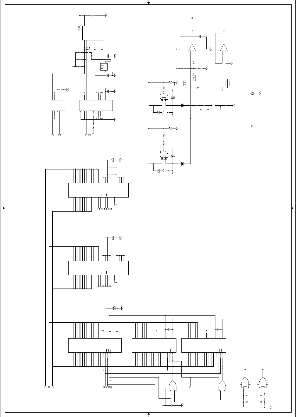
AR-FX4 ELECTRICAL SECTION - 5
L_BT
C_BT
D5
D3
D7
D4
D1
D9
D2
D13
D11
D6
D15
D14
D0
D12
D10
D8
A15
A14
A3
A7
A5
A1
A12
A4
A10
A9
A6
A13
A8
A16
A2
A11
A17 D15
D2
D13
D1
D11
D9
D7
D6
D5
D12
D8
D0
D4
D3
D10
D14
A7
A11
A8
A9
A4
A3
A12
A5
A6
A2
A10
A13 A12
A6
A4
A11
A13
A5
A7
A10
A9
A2
A3
A8
D18
D19
D17
D25
D26
D16
D24
D23
D22
D30
D28
D20
D27
D29
D21
D31
D5
D6
D10
D13
D8
D11
D1
D3
D14
D15
D0
D9
D7
D12
D2
D4
A10
A15
A9
A12
A2
A8
A14
A17
A16
A4
A7
A13
A1
A3
A11
A6
A5
A5
A3
A16
A2
A12
A11
A1
A4
A17
A9
A8
A14
A6
A13
A7
A15
A10
RAMCE-
RAMOE-
RAMWE-
RAMUB-
RAMLB-
CKIO_SDRAM
WE0-
RD/WR-
CS3-
WE1-
CASL-
RAS3L-
A[1:25]
D[0:15]
D[16:31]
CKE
RTCDT
RTCIO
RTCCK
RTCCE
RTC125G-
RTC125DIR
L_BT
C_BT
RD/WR-
CKE
DQMUU
DQMUL
CKIO_SDRAM
CS3-
CASL-
RAS3L-
RES-
VBT3.3
+5V
+5V+5V
VBT5
+12V
VBT5
+5V
+3.3V
VBT3.3
+5V
+3.3V
+5V
+5V
+5V
+3.3V
+3.3V
+5V+3.3V
TP1010
D2
DAP202U
A
K2
K1
C44
F0.1u/16
TP888
IC13
W981616AH
2
21
3
22
5
23
6
24
8
27
9
28
11
29
12
30
31
32
20
19
17
16
18
14
15
1
4
39
40
42
43
45
46
48
49
36
35
34
7
13
25
38
10
26
47
50
41
44
33
37
I/O0
A0
I/O1
A1
I/O2
A2
I/O3
A3
I/O4
A4
I/O5
A5
I/O6
A6
I/O7
A7
A8
A9
A10
A11
RAS
CAS
CS
LDQM
WE
VCC
GND
I/O8
I/O9
I/O10
I/O11
I/O12
I/O13
I/O14
I/O15
UDQM
CLK
CKE
VCC
VCC
VCC
VCC
GND
GND
GND
GND
GND
VCC
NC
NC
TP379
C52
A10u/16
TP419
TP889
TP1135
C53
A10u/16
JP4
SD00415-52
1 2
TP1114
TP401
IC73
IS62LV1024LL-70T
20
19
18
17
16
30
21
22
23
25
8
26
27
5
15
14
13
3
9
12
1
31
2
24
6
32
4
11
7
10 29
28
A0
A1
A2
A3
A4
CE1
I/O0
I/O1
I/O2
I/O3
VCC
I/O4
I/O5
WE
A5
A6
A7
A8
NC
A12
A11
A10
A9
VSS
CE2
OE
A13
A14
A15
A16 I/O7
I/O6
TP1012
C54
A10u/16
C50
F0.1u/16
TP1100
R78
1.6K
R69
12K
TP1134
TP403
R74
1.6K
R257 0
TP1008
TP1007
TP381
TP402
Q2
DTC363EKA
B
E
C
C48
F0.1u/16
IC17
DM74ALS244AWM
218
416
614
812
11 9
13 7
15 5
17 3
1
19
20
10
1A1 1Y1
1A2 1Y2
1A3 1Y3
1A4 1Y4
2A1 2Y1
2A2 2Y2
2A3 2Y3
2A4 2Y4
1G
2G
VCC
GND
IC72A
74LCX32M
1
23
147
TP1013
R70
1K
C47
F0.1u/16
R258 0
IC16A
LM393
3
21
84
TP1136
TP1015
C51
F0.1u/16
X2
DMX-38(32.768KHz)
R76
1K
TP1014
C49
A10u/16
R80
0
R259 0
IC72D
74LCX32M
12
13 11
147
JP5
SD00415-52
1 2
TP1101
IC18
NJU6356EM
7
1
6
5
2
3
8
4
DATA
I/O-
CLK
CE
XT
XT-
VDD
VSS
IC72B
74LCX32M
4
56
147
TP1123
TP1117
IC12
IS62LV12816LL-70T (NM)
5
4
3
2
1
6
7
8
9
10
11
12
13
14
15
16
17
44
43
42
27
23
28
22
24
25
26 29
30
31
32
33
34
35
36
37
38
39
40
41
21
20
19
18
A0
A1
A2
A3
A4
CE
I/O0
I/O1
I/O2
I/O3
VCC
VSS
I/O4
I/O5
I/O6
I/O7
WE
A5
A6
A7
A8
NC
NC
A12
A11
A10
A9 I/O8
I/O9
I/O10
I/O11
VCC
VSS
I/O12
I/O13
I/O14
I/O15
LB
UB
OE
A13
A14
A15
A16
C61
C10/50
R68
27
R79 10K TP1018
IC15
TC7WH245FK
1
7
2 6
3 5
8
4
DIR
G
A1 B1
A2 B2
VCC
GND
TP399
C62
C10/50
D1
DAP202U
A
K2
K1
TP1113
TP380
R77 4.7K
IC14
W981616AH
2
21
3
22
5
23
6
24
8
27
9
28
11
29
12
30
31
32
20
19
17
16
18
14
15
1
4
39
40
42
43
45
46
48
49
36
35
34
7
13
25
38
10
26
47
50
41
44
33
37
I/O0
A0
I/O1
A1
I/O2
A2
I/O3
A3
I/O4
A4
I/O5
A5
I/O6
A6
I/O7
A7
A8
A9
A10
A11
RAS
CAS
CS
LDQM
WE
VCC
GND
I/O8
I/O9
I/O10
I/O11
I/O12
I/O13
I/O14
I/O15
UDQM
CLK
CKE
VCC
VCC
VCC
VCC
GND
GND
GND
GND
GND
VCC
NC
NC
TP1017
R75
82K
TP1118
D9
RB751V-40
BT1
CR2477-H01
12
C46
A10u/16
C241
F0.1u/16
C59
F0.1u/16
R256 0
D4
1SS355
TP1016
TP1120
R67
27
IC72C
74LCX32M
9
10 8
147
C45
F0.1u/16
TP1122TP267
TP400
TP1009
JP6
SD00415-52
1 2
TP1112
TP421
TP1121
TP398
R71
10K
D3
1SS355
TP382
TP1115
R72
10K
TP266
-
+
IC16B
LM393
5
67
TP420
TP1119
C55
A10u/16
TP378
TP891
TP1116
C60
F0.1u/16
R73
10K
C58
F0.1u/16
IC71
IS62LV1024LL-70T
20
19
18
17
16
30
21
22
23
25
8
26
27
5
15
14
13
3
9
12
1
31
2
24
6
32
4
11
7
10 29
28
A0
A1
A2
A3
A4
CE1
I/O0
I/O1
I/O2
I/O3
VCC
I/O4
I/O5
WE
A5
A6
A7
A8
NC
A12
A11
A10
A9
VSS
CE2
OE
A13
A14
A15
A16 I/O7
I/O6
TP890
C56
A10u/35
C57
F0.1u/16
D10
RB751V-40
FAX MAIN PWB (SRAM) 3/10
B
A
A B
BA
A
B
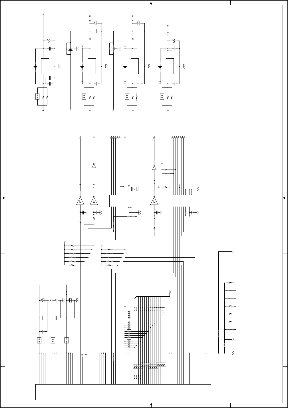
AR-FX4 ELECTRICAL SECTION - 6
FAXACK1P-
FAXCS1P-
GDATA12
FRESET-
GDATA6
GDATA14
GDATA10
GDATA15
GDATA8
GDATA2
GDATA3
GDATA7
GDATA9
GDATA5
GDATA1
GDATA4
GDATA11
GDATA0
GDATA13
FRESET
PWOFF-
PRLINE-
SCLINE-
HSYNC-
READY-
FAXPAGE-
FAXCMD
FAXSTS
FAXCRDY-
FAXSRDY-
FAXPRD-
GDATA[0:15]
FAXREQ0P-
FAXACK0P-
FAXCS0P-
+24V
+5V
+3.3V
AGAG
+3.3V
+3.3V
+24V
+12V +5VA
AGAG
+12V
AGAG
MDM3.3V+5V
+3.3V +1.8V
+3.3V
+3.3V
+3.3V
+3.3V
+3.3V
AGAG
+5V
AGAG
+3.3V
R240 R(NM)
TP1209 C79
F0.1u/16
TP1131
BR48
MNR14 10K
1
2
3
4 5
6
7
8
TP413
JP12
SD00415-52
1 2
BR49
MNR14 10K
1
2
3
4 5
6
7
8
IC26
74LCX244WM
218 416 614 812 119137155173
1
19
20
10
1A11Y1 1A21Y2 1A31Y3 1A41Y4 2A12Y1 2A22Y2 2A32Y3 2A42Y4
1G
2G
VCC
GND
C78
A33u/10
IC21 NJM78M05DLA
1
2
3
IN
GND
OUT
IC23 LM1117MPX-3.3
3
1
2
4
IN
GND
OUT1
OUT2
R285 0
TP1200
D6 1SS355
BR50
MNR14 10K
1
2
3
4 5
6
7
8
TP1210 R262 0
R242 10K
R266
0
IC20B
74LCX04M
3 4
147
R260 0
C84
F0.1u/16
JP7
SD00415-52
1 2
R247 10K
TP1211
TP384
R84 R(NM)
FB15
MEM2012(NM)
R248 10K
FB14
RB551V-30
C68
F0.01u/50
JP13
SD00415-52
1 2
TP1055
C74
A33u/10
IC22
74LCX244WM
218
416
614
812
11 9
13 7
15 5
17 3
1
19 20
10
1A1 1Y1
1A2 1Y2
1A3 1Y3
1A4 1Y4
2A1 2Y1
2A2 2Y2
2A3 2Y3
2A4 2Y4
1G
2G VCC
GND
D8 1SS355
IC9B
74LCX14M
3 4
TP1049
TP1103
R85
10K
R234 10K
R267
0
TP1212
TP1205
R264
0
C82
A33u/10
R235 10K
R236 10K
TP1231
IC9F
74LCX14M
13 12
C69
F0.1u/16
C71
A33u/10
R232 R(NM)
TP160
R237 10K
R239 0
JP10
SD00415-52
1 2
TP1203
C83
F0.1u/16
R238 10K
TP161
CN4
TX24-60R-12ST-H1
1
2
3
4
5
6
7
8
9
10
11
12
13
14
15
16
17
18
19
20
21
22
23
24
25
26
27
28
29
30
31
32
33
34
35
36
37
38
39
40
41
42
43
44
45
46
47
48
49
50
51
52
53
54
55
56
57
58
59
60
+24V
+24V
+5V
+5V
+3.3V
+3.3V
RESET-
PWOFF-
PRLINE-
HSYNC-
GND
GND
FAXPAGE-
FAXCMD
FAXCRDY-
GND
GDATA0
GDATA2
GDATA4
GDATA6
GDATA8
GDATA10
GDATA12
GDATA14
GND
FAXPRD-
FAXACK1P-
GND
FAXACK0P-
GND
+24V
+24V
+5V
+5V
+3.3V
+3.3V
NC
NC
SCLINE-
READY-
GND
GND
FAXDET-
FAXSTS
FAXSRDY-
GND
GDATA1
GDATA3
GDATA5
GDATA7
GDATA9
GDATA11
GDATA13
GDATA15
GND
FAXREQ1P-
FAXCS1P-
FAXREQ0P-
FAXCS0P-
GND
R81 0
TP1201
TP138 TP1102
R261 0
R268
0
TP1230
TP1206
TP410
JP11
SD00415-52
1 2
IC20A
74LCX04M
1 2
147
TP897
C63
F0.01u/50
C81
C(NM)
C77
F0.1u/16
TP745
TP1207
TP1213
TP139
IC9E
74LCX14M
11 10
R245 10K
TP1216
TP1215
R286 0
R86 0
TP1204
TP746
TP1232
R90 0
C73
C(NM)
C72
C(NM)
D7 1SS355
IC25 LM1117MPX-1.8
3
1
2
4
IN
GND
OUT1
OUT2
BR104
MNR14 33
1
2
3
4 5
6
7
8
R263 0
C244
F0.01u/50
TP1214
TP748
TP1219
BR105
MNR14 33
1
2
3
4 5
6
7
8
R269
0
C243
F0.01u/50
BR106
MNR14 33
1
2
3
4 5
6
7
8
R88 0
C67
A47u/25
BR107
MNR14 33
1
2
3
4 5
6
7
8
JP8
SD00415-52
1 2
TP1217
TP1208
C85
F0.1u/16
D5 1SS355
R243 10K
C80
F0.1u/16
R87
240F
R83 0
TP1132
C75
F0.1u/16
R241 10K
R246 0
TP395
C64
A10u/35
TP1202
JP9
SD00415-52
1 2
TP1218
R270
0
R244 10K
TP1124
R89 0
R284 0
IC19 NJM7812
IN
GND
OUT
IN
GND
OUT
C65
F0.1u/16
TP386
C70
F0.1u/16
R82 0
R265
0
C76
F0.1u/16
C66
A33u/10
R233 10K
BR47
MNR14 10K
1
2
3
4 5
6
7
8
FAX MAIN PWB (MCU I/F) 4/10
8 7 6 5 4321
87 6 5 4321
D
C
B
A
D
C
B
A
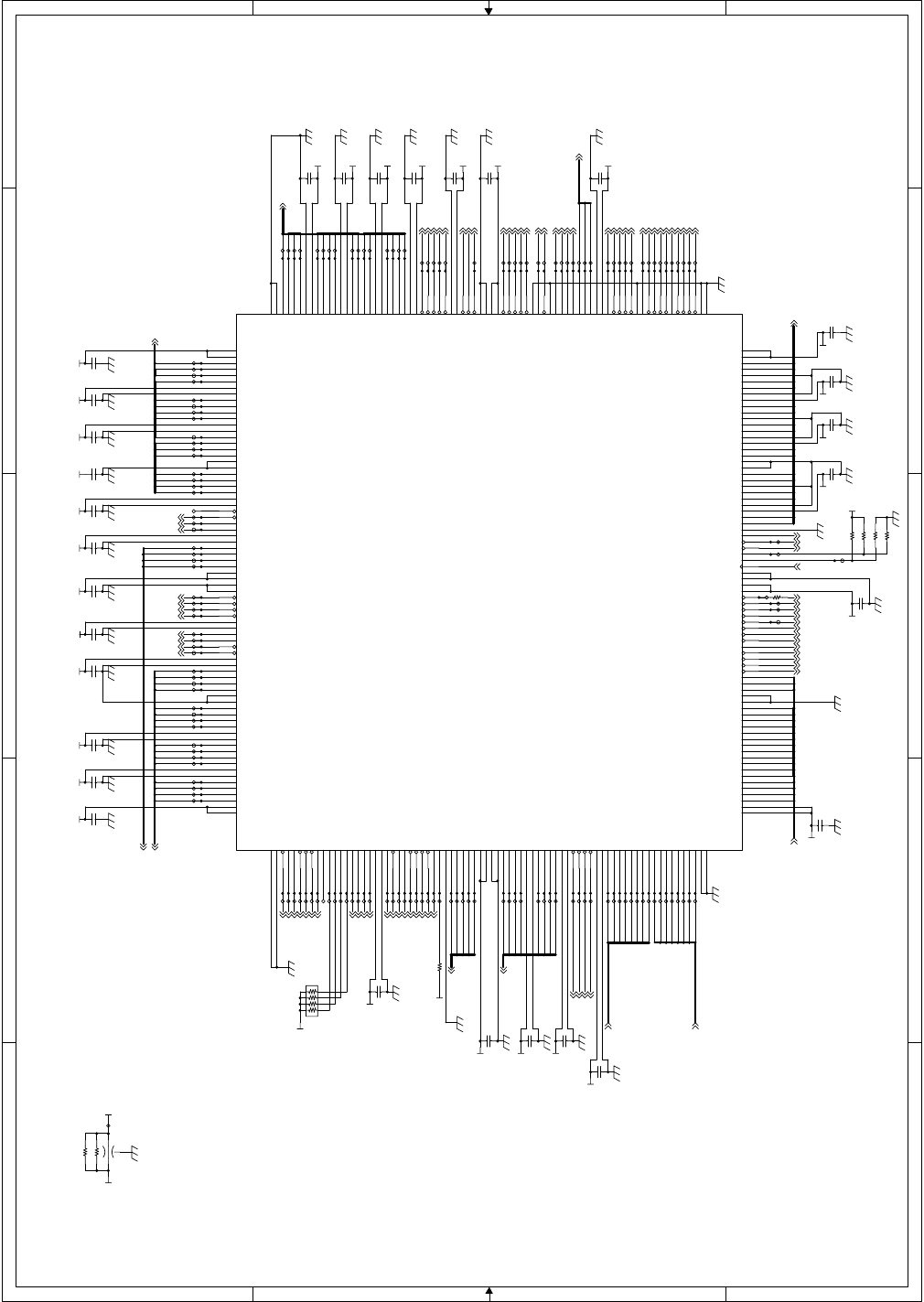
AR-FX4 ELECTRICAL SECTION - 7
EDCBA
EDCBA
4
3
2
1
4
3
2
1
CD1D7
M1D7
G1D2
CD1D6
A15
G1D0
D11
D0
M1A4
A5
CD1A0
G1D5
G1D1
D12
M1D12
M1D10
CD1D4
MDMA1
CD1D13
CD1D1
M1D4
D13
CD1D11
D2
A12
M1D14
M1D15
A10
M1A2
M1A3
CD1D8
D10
M1D11
D15
G1D4
D6
CD1D14
CD1D12
D14
D4
MDMA2
A7
A6
M1D6
CD1D5
A14
D1
MDMA3
A16
A13
D3
M1A11
G1D3
M1D8
G1D6
G1D7
D7
A8
M1D13
M1D2
CD1D9
M1D5
MDMA4
CD1D2
CD1D15
M1D9
CD1D3
A11
M1D1
D8
CD1D10
M1D3
D9
M1A9
A9
CD1D0
M1D0
D5
M1A12
M1A5
M1A8
M1A0
M1A1
M1A14
M1A6
M1A10
M1A15
M1A7
M1A13
MDMA0
ROMOBNK0
ROMOBNK1
ROMOBNK2
MDMD7
MDMD1
MDMD6
MDMD2
MDMD5
MDMD4
MDMD0
MDMD3
A4
A3
A1
A2
A22
A21
A20
CD1A2
CD1A1
CD1A3
G2D0
G2D1
G2D2
G2D3
G2D4
G2D5
G2D6
G2D7
DRAK[1]
ROMORY
G2ACK-
BS-
ROMNWP-
BFDIR
VOST-
CD1WR-
CD1ACKD0-
ROMOWE-
VOCH-
ROMOCID0
MDMCS-
CPURES-
ROMNCE-
ROMOCD0
DRAK[0]
BFOE-
CD1ACKC0-
ROMOCE-
M1LB-
RAMOE-
RTC125G-
RAMUB-
VOBUSY-
MDMRES-
RAMWE-
DREQ[1]-
ROMNWE-
CD1CS-
RD/WR-
RD-
CS4-
BT
CS6-
MDMIRQ
RTCCE
CD1REQC0
RES-
G2REQ-
ROMOOE-
MD3
MDMWR-
CD1RD-
CD1CLK
IRQ1-
IRQ0-
MANRES-
BZ
CD1UBE-
CD1REQD0
ROMOCD1
WE1-
RTCIO
VOSD
M1CE-
VORES-
RAMLB-
M1WE-
M1OE-
MDMRD-
RTCCK
DREQ[0]-
VOSI
CS0-
ROMOCID1
G1ACK-
WE0-
M1UB-
ROMOWP-
RTC125DIR
RTCDT
VONAR
ROMNRY
RAMCE-
CD1IRQ-
ROMNOE-
G1REQ-
A[1:25]
M1A[0:15]
M1D[0:15]
CD1D[0:15]
MDMA[0:4]
D[0:15]
MDMD[0:7]
G1D[0:7]
ROMPRY
ROMPCE-
ROMPWP-
ROMPWE-
ROMPOE-
CD1RES-
CKIO_GA1
CD1A[0:3]
ROMOBNK[0:2]
WAIT-
G2D[0:7]
+3.3V 3.3VGA1
3.3VGA1
3.3VGA1
3.3VGA1
3.3VGA1
3.3VGA1
3.3VGA1
3.3VGA1
3.3VGA1
3.3VGA1 3.3VGA1
3.3VGA1 3.3VGA1 3.3VGA1 3.3VGA1
3.3VGA1
3.3VGA1
3.3VGA1
3.3VGA1
3.3VGA1
3.3VGA1
3.3VGA1
3.3VGA1 3.3VGA13.3VGA13.3VGA13.3VGA13.3VGA13.3VGA13.3VGA13.3VGA13.3VGA13.3VGA13.3VGA1
TP986
TP861
C107
F0.1u/16
TP935
TP361
R91 0
TP612
TP982
TP300
TP920
R93 4.7K
TP582
TP428
TP691
TP1000
TP584
TP922
R96 0
TP993
TP595
TP611
TP956
C109
F0.1u/16
C97
F0.1u/16
C92
F0.1u/16
TP921
R95 R(NM)
TP873
TP51
C103
F0.1u/16
TP878
TP364
TP860
TP997
TP975
C93
F0.1u/16
TP690
TP868
TP923
R97 0
C108
F0.1u/16
TP1099 TP980
TP871
TP953
TP985
TP919
TP971
C87
F0.1u/16
TP943
TP586
FB7
MEM2012(NM)
TP1060
TP1006
TP590
BR51
MNR14 4.7K
1
2
3
4 5
6
7
8
TP947
TP924
TP297
TP916
TP305
TP1001
C104
F0.1u/16
TP918
TP946
TP957
TP1059
TP915
TP927
TP306
TP589
TP865
TP875
TP917
TP872
C96
F0.1u/16
TP1005
TP983
TP944
TP583
TP994
TP926
C95
F0.1u/16
TP962
TP374
TP974
C98
F0.1u/16
TP307
TP988
TP862
TP299
TP940
TP948
TP939
TP371
TP870
C106
F0.1u/16
TP1002
C91
F0.1u/16
TP684
TP934
TP587
TP375
TP304
TP593
TP958
TP298
TP950
TP1004
TP945
C101
F0.1u/16
C90
F0.1u/16
C100
F0.1u/16
TP876
TP869
TP978
TP928
TP863
R212
0
TP961
TP363
TP303
TP866
TP302
TP301
TP613
TP941
TP925
IC27
uPD65948GL-114
304
228
303
77
302
227
301
1
300
226
299
78
298
225
297
296
224
295
79
294
223
293
2
292
222
291
80
290
221
289
288
220
287
81
286
219
285
3
284
218
283
82
282
217
281
216
280
83
279
215
278
4
277
214
276
84
275
213
274
273
212
272
85
271
211
270
5
269
210
268
86
267
209
266
265
208
264
87
263
207
262
6
261
206
260
88
259
205
258
204
257
89
256
203
255
7
254
202
253
90
252
201
251
250
200
249
91
248
199
247
8
246
198
245
92
244
197
243
242
196
241
93
240
195
239
9
238
194
237
94
236
193
235
234
192
233
95
232
191
231
10
230
190
229
96
189
188
97
187
11
186
98
185
184
99
183
12
182
100
181
180
101
179
13
178
102
177
176
103
175
14
174
104
173
172
105
171
15
170
106
169
168
107
167
16
166
108
165
164
109
163
17
162
110
161
160
111
159
18
158
112
157
156
113
155
19
154
114
153
115
20
116
117
21
118
119
22
120
121
23
122
123
24
124
125
25
126
127
26
128
129
27
130
131
28
132
133
29
134
135
30
136
137
31
138
139
32
140
141
33
142
143
34
144
145
35
146
147
36
148
149
37
150
151
38
152
39
40
41
42
43
44
45
46
47
48
49
50
51
52
53
54
55
56
57
58
59
60
61
62
63
64
65
66
67
68
69
70
71
72
73
74
75
76
VDD-304
GND-228
VDD-303
VDD-77
CDD[15]
GND-227
CDD[14]
GND-1
CDD[13]
MA[15]
CDD[12]
VDD-78
GND-298
MA[14]
VDD-297
CDD[11]
MA[13]
CDD[10]
A[1]
CDD[9]
MA[12]
CDD[8]
GND-2
GND-292
GND-222
VDD-291
A[2]
CDD[7]
VDD-221
CDD[6]
CDD[5]
MA[11]
CDD[4]
A[3]
GND-286
MA[10]
GND-285
VORES_N
CDD[3]
MA[9]
CDD[2]
A[4]
CDD[1]
MA[8]
CDD[0]
GND-216
GND-280
A[5]
VDD-279
VDD-215
CDACKD_N
VOSD
CDACKC_N
MA[7]
CDREQD
A[6]
CDREQC
MA[6]
GND-274
VDD-273
MA[5]
CDUBE_N
A[7]
CDWR_N
MA[4]
CDRD_N
VOSI
CDCS_N
GND-210
GND-268
A[8]
GND-267
VDD-209
VDD-266
VDD-265
MA[3]
CDA[3]
A[9]
CDA[2]
MA[2]
CDA[1]
VOST_N
CDA[0]
MA[1]
GND-260
A[10]
VDD-259
MA[0]
CDIRQ
GND-204
CDCLK
A[11]
CDRES_N
VDD-203
TRES_N
VOCH_N
GND-254
MUB_N
VDD-253
A[12]
MD[15]
MLB_N
MD[14]
MD[13]
MWE_N
MD[12]
A[13]
GND-248
MOE_N
GND-247
VOBUSY_N
MD[11]
MCE_N
MD[10]
A[14]
MD[9]
GND-197
MD[8]
GND-242
VDD-196
VDD-241
A[15]
MD[7]
RES_N
MD[6]
VONAR
MD[5]
CPURES_N
MD[4]
A[16]
GND-236
MANRES_N
VDD-235
MD[3]
GND-192
MD[2]
GND-95
MD[1]
GND-191
MD[0]
NC
VDD-230
VDD-190
VDD-229
GND-96
VDD-189
RAMUB_N
A[20]
RAMLB_N
TCK
RAMWE_N
A[21]
RAMOE_N
RAMCE_N
A[22]
GND-183
TDI
BFDIR
CS0_N
BFOE_N
GND-180
CS4_N
ROMOCID[1]
TRST
ROMOCID[0]
CS6_N
ROMOCD[1]
ROMOCD[0]
BS_N
ROMBNK[2]
TDO
ROMBNK[1]
RW (RD/WR-)
ROMBNK[0]
GND-172
RD_N
VDD-171
RTCDT
ROMRY
WE0_N
ROMOWP_N
ROMOWE_N
WE1_N
ROMOOE_N
RTCCK
ROMOCE_N
DREQ[0]_N
GND-165
ROMNRY
DREQ[1]_N
ROMNWP_N
RTCCE
ROMNWE_N
DRAK[0]_N
ROMNOE_N
ROMNCE_N
DRAK[1]_N
ROMPRY
RTCIO
ROMWP_N
WAIT_N
ROMPWE_N
ROMPOE_N
VDD-113
ROMPCE_N
VDD-19
GND-154
VDD-114
GND-153
GND-115
GND-20
GND-116
CLK
RTC245DIR
BSSEL[0]
BSSEL[1]
RTC245OE_N
IRQ[0]_N
IRQ[1]_N
BZ
MODE3
GND-123
BT
D[0]
D[1]
MDMRES_N
VDD-126
GND-127
MDMCS_N
D[2]
D[3]
MDMRD_N
GND-130
D[4]
MDMWR_N
D[5]
GND-133
MDMIRQ
GND-134
D[6]
TMS
D[7]
VDD-137
GND-31
GND-138
D[8]
MDMA[0]
D[9]
GND-141
MDMA[1]
D[10]
D[11]
MDMA[2]
VDD-144
GND-145
MDMA[3]
D[12]
D[13]
MDMA[4]
GND-148
D[14]
VDD-37
D[15]
VDD-151
VDD-38
VDD-152
GND-39
GND-40
MDMD[0]
MDMD[1]
MDMD[2]
MDMD[3]
VDD-45
GND-46
MDMD[4]
MDMD[5]
MDMD[6]
MDMD[7]
VDD-51
GND-52
G1REQ_N
G1ACK_N
G2REQ_N
G2ACK_N
VDD-57
GND-58
G1D[0]
G1D[1]
G1D[2]
G1D[3]
G1D[4]
G1D[5]
G1D[6]
G1D[7]
G2D[0]
G2D[1]
G2D[2]
G2D[3]
G2D[4]
G2D[5]
G2D[6]
G2D[7]
GND-75
GND-76
TP874
C89
F0.1u/16
TP929
TP976
R94 R(NM)
TP513
TP995
R271 0
TP1058
TP990
TP591
TP999
TP936
TP951
TP1003
TP987
TP594
TP616
C111
F0.1u/16
TP992
TP981
TP933
C102
F0.1u/16
C88
F0.1u/16
TP955
TP1
TP960
TP864
TP1057
TP991
TP979
C114
F0.1u/16
TP877
TP942
C94
F0.1u/16
TP585
TP588
TP867
TP617
TP931
C86
F0.1u/16
TP596
TP1061
TP949
TP972
C113
F0.1u/16
TP1098
TP937
TP359
TP614
TP984
TP996
TP930
C110
F0.1u/16
TP580
TP1062
TP973
C115
F0.1u/16
TP989
TP959
TP998
TP592
TP914
TP970
TP938
TP360
C112
F0.1u/16
TP615
C105
F0.1u/16
TP954
TP932
TP859
C99
F0.1u/16
TP416
TP952
TP977
TP581
TP372
FAX MAIN PWB (GA1) 5/10
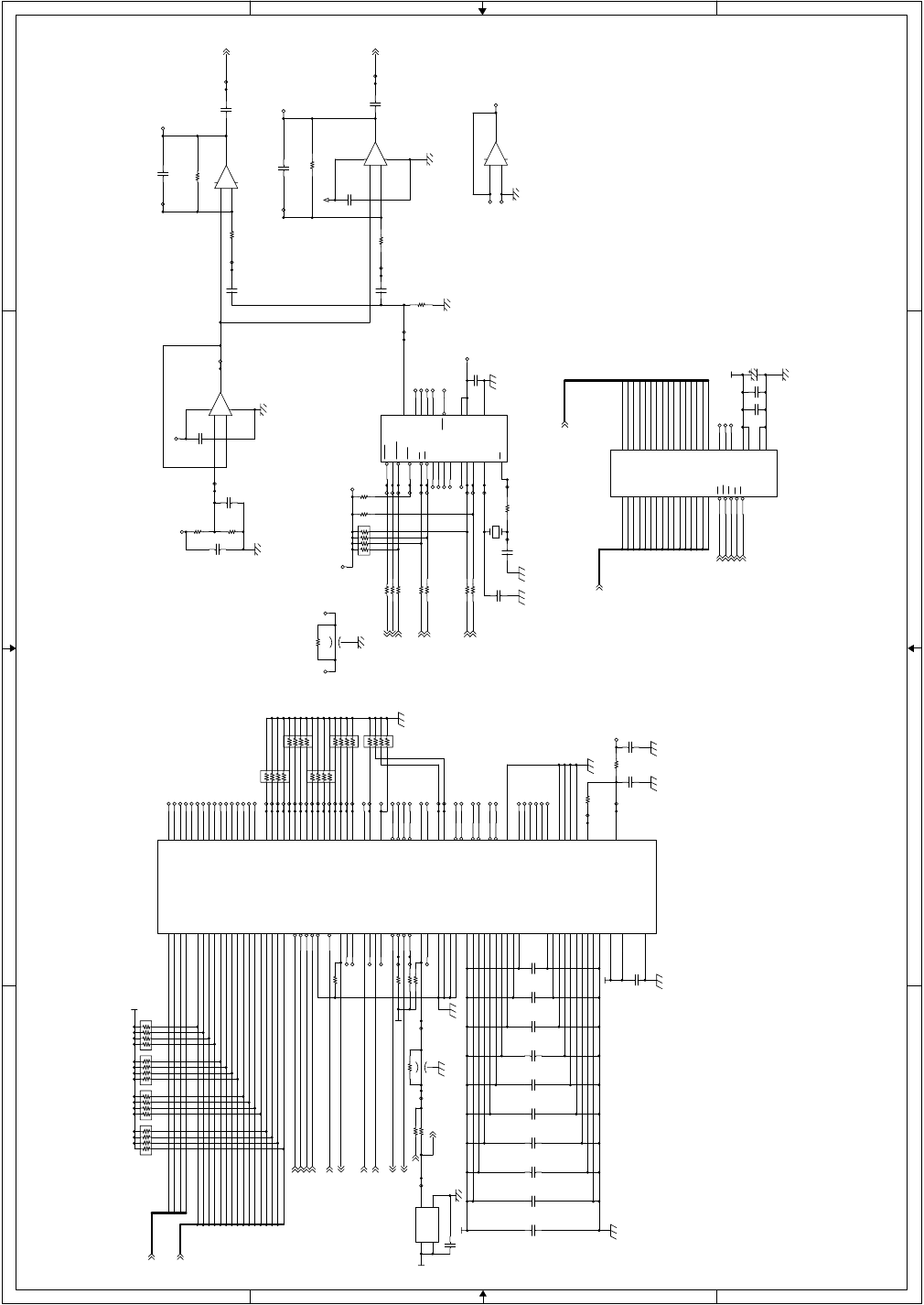
AR-FX4 ELECTRICAL SECTION - 8
(JATE‘Ή )
CD1A1
CD1D15
CD1D10
CD1D1
CD1D5
CD1D7
CD1D2
CD1D0
CD1A0
CD1A2
CD1A3
CD1D14
CD1D13
CD1D12
CD1D11
CD1D9
CD1D8
CD1D6
CD1D4
CD1D3
AOUT1
M1D13
M1A15
M1A13
M1D6
M1A9
M1D7
M1A6
M1D8
M1A7
M1D14
M1A4
M1A12
M1D10
M1A2
M1A14
M1D0
M1D15
M1A11
M1D5
M1D9
M1A0
M1D11
M1A3
M1A10
M1D12
M1A1
M1D4
M1D1
M1D3
M1A8
M1A5
M1D2
CD1A[0:3]
CD1D[0:15]
CD1UBE-
CD1RD-
CD1WR-
CD1CS-
CD1RES-
CD1IRQ-
CD1REQC0
CD1ACKC0- VOBUSY-
VOST-
VOSD
VOCH-
VOSI
VORES-
VONAR
M1LB-
M1UB-
M1OE-
M1WE-
M1CE-
M1A[0:15]
M1D[0:15]
CD1REQD0
CD1ACKD0-
AOUT
AOUT(SIG)
CD1CLK
CLK16M
+3.3V
+3.3V
AGAG
AG
+12V
+12V
AGAG
AGAG
+12V
MSM5V
MSM5V
+3.3V
+3.3V
+3.3V
+3.3V
+5VA MSM5V
AGAG
AGAG
C127
C18/50
TP969
BR62 MNR14 10K
1
2
3
4 5
6
7
8
+
-
IC29B
NJM2904M
5
67
TP1011
TP342
TP607
TP332
TP376
TP357
BR64 MNR14 10K
1
2
3
4 5
6
7
8C123
F0.1u/16
TP414
TP621
TP358
TP373
BR63
MNR14 10K
1
2
3
4 5
6
7
8
TP347
C142
A33u/10
TP610
TP68
C245F0.1u/16 TP354
R114 R(NM)
TP344
C124
F0.1u/16
TP333
TP346
TP352
TP362
TP64
TP63
R99 10.0KF
C125
F0.1u/16
TP355
TP310
TP608
R117
100K
TP343
TP620
C126
F0.1u/16
IC31, X4, IC29, IC30
QS51 MSM6653A
QS52~ Not Mount
TP334
TP967
C141
F0.1u/16
C120
F0.1u/16
TP366
TP350
IC28
MN86065
30
8
2
32
38
20
21
22
23
26
27
28
29
42
43
44
3
10
6
128
127
126
125
75
76
77
78
79
82
83
84
85
86
87
88
89
90
1
59
9
24
36
11
25
37
124
56
7
13
14
15
16
17
18
19
12
45
31
4
5
33
34
35
39
40
41
93
94
95
96
97
98
99
100
101
104
105
106
107
108
109
110
111
112
46
47
60
50
51
49
48
64
63
58
57
52
53
54
65
80
91
102
113
123
114
103
92
81
66
55
62
61
67
68
69
70
71
72
73
74
115
116
117
118 119
120
121
122
CS-
WR-
HEX-
REQC0
ACKC0-
D7
D6
D5
D4
D3
D2
D1
D0
A3
A2
A1
INTR0
CLKOUT
CLKIN
TEST0
TEST1
TEST2
TEST3
IA15
IA14
IA13
IA12
IA11
IA10
IA9
IA8
IA7
IA6
IA5
IA4
IA3
IA2
RESET-
IMUE-
VDD1
VDD2
VDD3
VSS1
VSS2
VSS3
VSS10
IREADY
RD-
D14
D13
D12
D11
D10
D9
D8
D15
A0
UBE-
INTR1
INTR2
REQC1
REQD0
REQD1
ACKC1-
ACKD0-
ACKD1-
IA1
IA0
ID15
ID14
ID13
ID12
ID11
ID10
ID9
ID8
ID7
ID6
ID5
ID4
ID3
ID2
ID1
ID0
IHREQ
IHACK
IMLE-
IMR-
IMW-
DREQ0
DREQ1
DACK0-
DACK1-
DCMP0-
DCMP1-
IOR-
IOW-
VDD4
VDD5
VDD6
VDD7
VDD8
VDD9
VDD10
VSS9
VSS8
VSS7
VSS6
VSS5
VSS4
EXA0
EXA1
NC67
NC68
NC69
NC70
NC71
NC72
MINTC
MINTIN
VREF5
MINTEST
SCANEN
AVDD VCOI
PCO
AVSS
PLLOFF TP70
TP370
TP345
C121
F0.1u/16
TP336
TP69
TP1051
R103 1K
R108 100
TP329
TP53
TP1125
TP418
TP318
TP516
TP368
R109
10K R110 100
TP1126
TP348
TP326
R113 R(NM)
C119
F0.1u/16
TP54
+
-
IC30B
NJM4558M
5
67
TP335
TP324
TP369
R115 0 TP1053
R122 2K
BR65
MNR14 10K
1
2
3
4 5
6
7
8
R116 100
TP308
TP353
TP314
TP325
TP61
FB12
MEM2012(NM)
TP968
R106 10K
TP71
TP367
TP966
R105
10K
R118 100
TP337
TP1056
TP62
TP377
TP313
X3
SG-8002JCPC(16.000MHz)
4
31
2
VDD
OUTOE
GND
TP320
TP322
TP67
TP72
FB8
MEM2012(NM)
TP356
X4
SMD-49(4.096MHz)
TP65
BR57
MNR14 (NM)
1
2
3
4 5
6
7
8
R119 100
TP60
R102 33KFTP338
C140
F0.01u/50
BR58
MNR14 (NM)
1
2
3
4 5
6
7
8
R120 100
TP327C137
F0.1u/16
C117
F0.1u/16
C135
F0.1u/16
TP609
BR66 MNR14 10K
1
2
3
4 5
6
7
8
TP618
C139
B2200/50
TP323
BR60
MNR14 (NM)
1
2
3
4 5
6
7
8
TP316
C136
F0.1u/16
IC32
IS61LV6416-12T
44
43
42
27
26
6
7
8
9
10
11
12
13
14
15
16
17
25
24
21
20
22
23
28
4
5
18
19 29
30
31
32
33
34
35
36
37
38
39
40
41
3
2
1
A0
A1
A2
A3
A4
CE
I/O0
I/O1
I/O2
I/O3
VCC
VSS
I/O4
I/O5
I/O6
I/O7
WE
A5
A6
A7
A8
NC
NC
NC
A12
A11
A10
A9 I/O8
I/O9
I/O10
I/O11
VCC
VSS
I/O12
I/O13
I/O14
I/O15
LB
UB
OE
A13
A14
A15
TP964
C133
F0.1u/16
R101 24KF
TP963
R123 100
TP349
BR59
MNR14 (NM)
1
2
3
4 5
6
7
8
TP312
C122
B470/50
R98
33K
TP340
TP59
TP309
C131
F0.1u/16
+
-
IC29A
NJM2904M
3
21
84
TP1052
TP328
C143
F0.1u/16
C116
B470/50
TP622
C134
F0.1u/16
C144
F0.1u/16
R121 100
TP965 TP58
R104
10K
TP317
TP331
C132
F0.1u/16 TP319
C128
C18/50
TP339
R112
10K
TP57
C129
F0.1u/16
+
-IC30A
NJM4558M
3
21
84
C118
F0.1u/16
TP351
TP321
TP315
R107 100
C130
F0.1u/16
C138
F0.1u/16
TP56
TP311
R213 0
TP341
R100
33K
TP330
TP365
IC31
MSM6653A-583GS-K
2
23
7
1
24
3
4
5
6
8
9
10
11
12
13
14
15
16
17
18
19
20
21
22
XT
AOUT
PRG
VDD
GND
XT
NC
CMD
NC
ST
I1
I2
I2/PORT0
I3/PORT1
I4
I5/SI
I6/SD
CH
RESET
VPP
NC
BUSY
NC
NAR
TP66
BR61
MNR14 10K
1
2
3
4 5
6
7
8
R111 0
TP619
TP55
FAX MAIN PWB (GA1-CODEC) 6/10
1234
D
C
B
A
D
C
B
A
1234
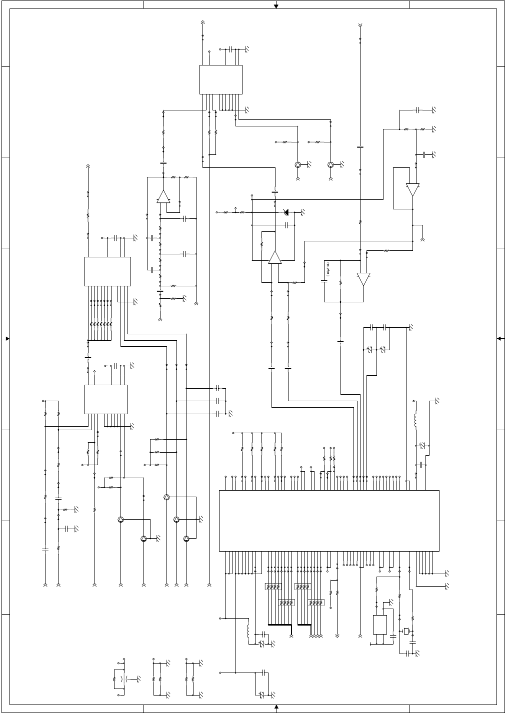
AR-FX4 ELECTRICAL SECTION - 9
SPOUT
SIGRX
MDMD3
MDMA2
MDMD6
MDMD0
MDMA3
MDMA0
MDMD2
MDMA1
MDMD4
MDMA4
MDMD5
MDMD1
MDMD7
MDMRD-
MDMWR-
MDMCS-
MDMRES-
SIGRX
BZ
AOUT
VOLCNT[A]
VOLCNT[B]
VOL[A]
VOL[B]
VOL[C]
BT
TXSEL[A]
TXSEL[B]
SIGTX
AOUT(SIG)
SPOUT
SIGRX
MDMIRQ
MDMD[0:7]
MDMA[0:4]
VREF
VREF
AGAG
AGAG AGAG
AGAG AGAG
AGAG
AGAG AGAG
MAG
AGAG AGAG
AGAG
AGAG
+12V +12V
+12V
MDM5V
AGAG
AGAG AGAG
AGAG
+12V
+12V
MDG
MDM5V
MDG
MDM3.3V
+5VA MDM5V
MDG
MDM3.3V
MDG
MDG
MDM3.3V
AGAG MAG
MAG
MDM3.3V
MDG
+5VA
+5VA
+12V
+12V
+12V
AGAG
AGAG
AGAG
MDG
AGAG
TP555
R169 0
BR74
MNR14 100
1
2
3
4 5
6
7
8
TP48
C177
F0.1u/16
X6
SMD-49(28.224MHz) (NM)
TP598
TP3
TP575
C151
F0.1u/16
TP22
TP38
Q4
DTC363EKA
B
E
C
TP1224
TP602
IC35
NJM4052BM
1312
3
14
15
11
1
5
2
4
6
10
9 8
7
16
XX0
Y
X1
X2
X3
Y0
Y1
Y2
Y3
INH
A
B VSS
VEE
VDD
R143 0
TP562
R126 10K
TP9
R159 44.2KF
TP37
TP514
TP2
TP6
TP1225
TP572
C169
F0.1u/16
TP558
TP11
TP1220
TP1050
R155
47
TP541
R154 10K
C171
F0.1u/16
TP509
TP31
TP34 Q9
DTC363EKA
B
E
C
TP30
TP533
TP538
C248
B0.01u/25
C168
A10u/16
TP13
TP504
R156 10K
TP24
TP412
TP539
TP540
TP573
-
+
IC37A
NJM2058M
3
21
411
TP550
TP605
TP503
R134 10K TP17
R283
43K
TP1097
R137 33K
IC34
NJM4051BM
13
14
15
12
1
5
2
4
6
11
10
9
3
16
7
8
X0
X1
X2
X3
X4
X5
X6
X7
INH
A
B
C
X
VDD
VEE
VSS
TP517
TP544
TP599
TP502
TP568
TP519
TP604
TP512
TP1227
R138 62K
R175
0
C247
B0.01u/25
C146
F0.1u/16
-
+
IC37B
NJM2058M
5
6
7
R164
44.2KF
R139 200K
C167
F0.1u/16
TP1222
TP505
TP577
R216
47
C163
F0.1u/16
TP29
TP10
TP571
R160 10K
L1 10uH 10%
TP19
TP1047
R142 360K
R215 0
C162
F0.1u/16
TP518
R280
30K
C161
F0.1u/16
TP20
R275
5.1K
TP557
TP526
R281
10K
R124 0
TP547
C147
B4700/25
R178 100
TP1048
R282
18K
TP43
TP569
R161 10K
TP521
TP600
R152 33K
R144 0
C160
F0.1u/16
TP543
TP523
TP1133
TP524
R153 100K
C145
F0.1u/16
TP1223
TP42
TP542
TP26
C158
A33u/10
C250
B0.01u/25
-
+
IC37D
NJM2058M
12
13 14
TP570
R173 137KF
C154
C(NM)
TP603
C176
A10u/16
TP565
-
+
IC37C
NJM2058M
10
9
8
TP515
R128 56K
C159
F0.1u/16
C165
B470/50
C156
F0.1u/16
C150
F0.1u/16
R179
33K
C153
C(NM)
TP553
R129
1K
TP551
TP567
IC36
FM336
95
94
93
91
90
89
88
87
4
96
7
6
5
79
34
18
85
86
37
76
77
11
67
78
12
9
68
75
64
10
8
23
24
29
28
35
30
31
25
13
38
16
52
3
2
97
14
15
17
19
20
21
22
26
27
32
33
36
39
40
41
42
43
44
4546
47
48
49
50
51
53
54
55
56
57
1
58
59
60
61
62
63
65
66
69
70
71
72
73
74
80
81
82
83
84
92
98
99
100
D7
D6
D5
D4
D3
D2
D1
D0
RS4
RS0
/READ
/WRITE
/CS
IRQ
POR
/RESET
XTALI
XTALO
TALK
RI
RINGD
TXD
RXD
RTS
CTS
RLSD
DTR
DSR
XTCLK
TDCLK
RDCLK
EYESYNC
EYECLK
TXA2
TXA1
RIN
VREF
VC
MAVSS
VDD1
VDD
VSS
VSUB
RS3
RS2
RS1
XYCNT
PF6
NC
SR4OUT
NC
SR4IN
CLK_OUT
MAVDD
SPKR
MICROPHONE
MAVSS
MIC_BIAS
NC
MIC_EN
NC
M_CNTRL_SIN
M_CLKIN
M_TXSIN
M_SCKM_RXOUT
M_STROBE
NC
OH
VDD
SET3V_BAR2
VSS
NC
NC
SLEEP
VDD1
PF7
CSP
TESTP
NC
SR1IO
VCORE
VDD1
VSS
A4
VDD1
IA_SLEEP
VGG
YCLK
XCLK
EYEXY
VSS
GPO0
DSPWTP
DSPRDP
VDD1
VDD1
PLL_VDD
VSS
PLL_GND
TP510
TP507
TP36
R163 44.2KF
R177
33K
TP511
R278
3K
C170
A10u/16
TP25
TP552
R165
10K
FB9
MEM2012(NM)
R162
10K
TP597
TP40
R131 6.2K
TP549
R176 R(NM)
Q7
DTC363EKA
B
E
C
TP530
TP560
Q8
DTC363EKA
B
E
C
TP1054
C246F0.1u/16
R214 0
TP46
C172
C27/50
TP1226
TP39
TP32
R277
43K
R133 10K
C249
F0.1u/16
TP548
TP525
TP1221
TP49
R145
10K
TP508
TP606
TP563
C149
F0.1u/16
C175
F0.1u/16
TP23
TP33
C164
F0.1u/16
C173
C27/50
C174
F0.1u/16
Q6
DTC363EKA
B
E
C
C251
B0.01u/25
TP45
BR71
MNR14 100
1
2
3
4 5
6
7
8
R174 0
Q3
DTC363EKA
B
E
C
TP411
R157 10K
TP546
TP44
R140
10K
R146
10K
C155
C(NM)
TP21
C166
F0.1u/16
TP35
TP578
TP564
C157
A33u/10
R149 3K
R170 10
C148
F0.1u/16
TP554
TP520
TP506
TP529
R276
12K
R150 0
TP579
TP574
L2
NL322522T-8R2J
Q5
DTC363EKA
B
E
C
TP47
BR72
MNR14 100
1
2
3
4 5
6
7
8
R135 56K
TP556
R158 44.2KF
TP16
TP601
TP561
ZD1
UDZ10B
R125 56K
TP522
R166 0
TP12
TP501
TP52
BR73
MNR14 100
1
2
3
4 5
6
7
8
R136 18K
R167 4.7K
X5
SG-8002JCPC(28.224MHz)
4
31
2
VDD
OUTOE
GND
TP545
TP50
TP41
TP576
R141
10K
R168 0
R147
10K
R127 3K
R171 68.1KF
R130 56K IC33
NJM4052BM
13
3
12
14
15
11
1
5
2
4
6
10
9 8
7
16
X
Y
X0
X1
X2
X3
Y0
Y1
Y2
Y3
INH
A
B VSS
VEE
VDD
TP566
TP5
TP559
R132 5.1K
R279
20K
FAX MAIN PWB (FM336) 7/10
8 7 6 5 4321
87 6 5 4321
D
C
B
A
D
C
B
A
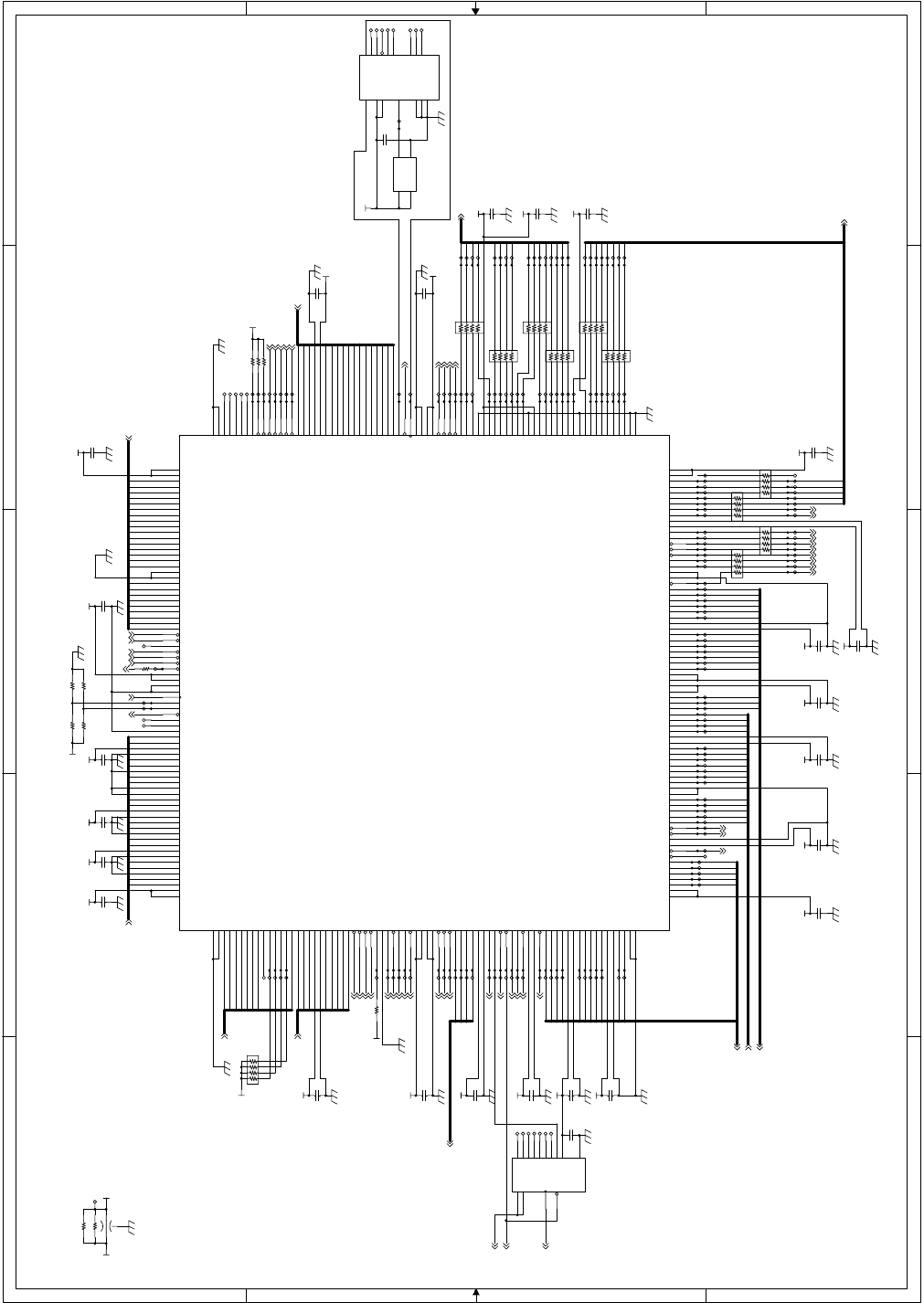
AR-FX4 ELECTRICAL SECTION - 10
CD2A0
D0
CD2A2
CD2A1
CD2A3
G2D5
G2D1
G2D7
G2D2
G2D4
G2D6
G1D7
CD2D0
CD2D9
CD2D2
CD2D1
CD2D8
CD2D4
CD2D5
CD2D6
CD2D7
CD2D10
CD2D3
CD2D15
CD2D13
CD2D14
CD2D12
CD2D11
M2A0
M2A3
M2A1
M2A2
M2A4
M2A5
M2A6
M2A7
M2A8
M2A9
M2A10
M2A11
M2A12
M2A15
M2A13
M2A14
M2D7
M2D0
M2D8
M2D11
M2D1
M2D9
M2D12
M2D2
M2D10
M2D13
M2D3
M2D4
M2D14
M2D5
M2D15
M2D6
SDRAM_A3
SDRAM_A1
SDRAM_A9
SDRAM_A12
SDRAM_A2
SDRAM_A8
SDRAM_A11
SDRAM_A0
SDRAM_A4
SDRAM_A10
SDRAM_A6
SDRAM_A7
SDRAM_A5
SDRAM_D1
SDRAM_D0
SDRAM_D2
SDRAM_D4
SDRAM_D3
SDRAM_D7
SDRAM_D5
SDRAM_D6
SDRAM_D10
SDRAM_D9
SDRAM_D8
SDRAM_D11
SDRAM_D13
SDRAM_D12
SDRAM_D14
SDRAM_D15
TR
GDATA11
GDATA13
GDATA7
GDATA1
GDATA9
GDATA0
GDATA8
GDATA2
GDATA6
GDATA12
GDATA14
GDATA4
GDATA3
GDATA5
GDATA10
A23
A22
A17
A4
A14
A13
A9
A7
A1
A24
A25
A20
A6
A12
A2
A3
A11
A18
A8
A16
A19
A21
A15
A10
D1
D2
D3
D4
D5
D7
D6
D8
D9
D10
D11
D13
D12
D14
D15
GDATA15
A5
G1D2
G1D5
G1D0
G2D3
G2D0
G1D4
G1D6
G1D1
G1D3
CD2ACKC0-
CD2IRQ0
CD2RES-
FAXREQ0P-
CD2CLK
CD2ACKC1-
CD2ACKD0-
CD2ACKD1-
G1REQ-
CD2RD-
CD2REQD0
CD2IRQ1
CD2WR-
CD2CS- FAXPRD-
CD2UBE-
CD2REQD1
G2ACK-
CD2REQC1
G2REQ-
WAIT-
CD2REQC0
G1ACK-
M2A[0:15]
M2D[0:15]
SDRAM_A[0:12]
A[1:25]
G1D[0:7]
IRQ2-
CD2D[0:15]
SDRAM_DQM1
SDRAM_CKE
SDRAM_DQM0
SDRAM_RAS-
SDRAM_CAS-
SDRAM_CS-
SDRAM_WR-
SDRAM_CLK
SDRAM_BA1
SDRAM_BA0
SDRAM_D[0:15]
GDATA[0:15]
FAXPAGE-
READY-
SCLINE-
PRLINE-
RES-
HSYNC-
CS5-
BS-
RD-
CKIO_GA2
WE0-
WE1-
D[0:15]
M2CE-
M2OE-
M2WE-
CD2A[0:3]
G2D[0:7]
FAXACK0P-
FAXCS0P-
CD2CLKIN
+5V
3.3VGA2
3.3VGA2
+3.3V
3.3VGA2
3.3VGA2
3.3VGA2
3.3VGA2
3.3VGA2
3.3VGA2
3.3VGA2
3.3VGA2 3.3VGA2 3.3VGA2 3.3VGA2 3.3VGA2
3.3VGA2
3.3VGA2
3.3VGA2
3.3VGA2
3.3VGA2
3.3VGA2
3.3VGA2
3.3VGA2
3.3VGA2
3.3VGA2
3.3VGA2
3.3VGA23.3VGA23.3VGA23.3VGA2
TP810
TP759
C187
F0.1u/16
TP804
TP851
R186 4.7K
TP196
TP847
TP769
TP818
TP794
TP816
TP829
C193
F0.1u/16
TP215
TP880
BR83
MNR14 33
1
2
3
4 5
6
7
8
TP780
TP813
TP187
TP211
TP767
TP195
TP901
BR80
MNR14 33
1
2
3
4 5
6
7
8
BR81
MNR14 33
1
2
3
4 5
6
7
8
R184 0
TP840
BR82
MNR14 33
1
2
3
4 5
6
7
8
TP209
TP771
TP852
TP896
TP814
TP781
TP778
TP760
TP295
TP194
TP902
C240
F0.1u/16
TP817
TP826
TP207
TP763
TP213
TP846
TP182
TP206
BR85
MNR14 33
1
2
3
4 5
6
7
8
C179
F0.1u/16
TP830
TP879
TP214
TP805
TP833
TP799
TP164
TP837
TP192
TP858
TP193
TP292
TP821
TP850
TP802
TP773
TP165
TP807
TP796
X7
SG-8002JCPH(28.16301MHz)
4
31
2
VDD
OUTOE
GND
TP881
TP775
TP188
TP765
TP159
TP842
TP212
TP205
FB10
MEM2012(NM)
TP887
TP815
TP190
TP163
TP173
R188 4.7K
TP1063
TP883
TP844
C194
F0.1u/16
TP828
TP762
C191
F0.1u/16
C181
F0.1u/16
TP1107 BR79
MNR14 33
1
2
3
4 5
6
7
8
BR76
MNR14 33
1
2
3
4 5
6
7
8
TP885
TP179
C185
F0.1u/16
R185 4.7K
TP855
TP824
TP1106
TP181
TP908
TP882
R181 0
TP822
TP834
TP808
TP169
TP886
TP756
TP777 C190
F0.1u/16
TP903
TP1105
TP841
C201
F0.1u/16
TP839
BR78
MNR14 33
1
2
3
4 5
6
7
8
C196
F0.1u/16
TP170
TP856
TP768
TP202
TP884
TP770
TP812
TP784
TP904
BR77
MNR14 33
1
2
3
4 5
6
7
8
TP210
TP1111
TP806
TP800
IC39
M66235FP
3
9
2
1
6
4
7
10
1113
158
14
12
16
5TEST2
CNTCK
TEST1
CLKIN
/CKO/2
PULSE
CKO/2
/CKO
CKOTR
TEST3GND
GND
VCC
VCC
GND
TP831
TP845
TP786
TP797
TP909
TP204
TP857
TP200
TP287
TP1110
TP787
TP189
R217
0
TP208
C199
F0.1u/16
TP906
R180 R(NM)
TP785
TP766
TP1109
TP854
TP178
BR75
MNR14 4.7K
1
2
3
4 5
6
7
8
TP201
TP288
TP820
TP152
R182 R(NM)
TP907
TP827
TP791
TP835
TP180
TP177
TP171
C195
F0.1u/16
TP809
R183 0
C192
F0.1u/16
TP168
C180
F0.1u/16
TP789
R187 4.7K
C178
F0.1u/16
C183
F0.1u/16
TP905
TP1108
TP761
R272 0
TP811 TP184
TP774
C189
F0.1u/16
C182
F0.1u/16
TP183
TP151
TP199
TP289
TP823
TP167
BR84
MNR14 33
1
2
3
4 5
6
7
8
TP788
IC38
uPD65954GL-061
304
228
303
77
302
227
301
1
300
226
299
78
298
225
297
296
224
295
79
294
223
293
2
292
222
291
80
290
221
289
3
288
220
287
81
286
219
285
284
218
283
82
282
217
281
4
280
216
279
83
278
215
277
276
214
275
84
274
213
273
5
272
212
271
85
270
211
269
6
268
210
267
86
266
209
265
264
208
263
87
262
207
261
7
260
206
259
88
258
205
257
204
256
89
255
203
254
8
253
202
252
90
251
201
250
249
200
248
91
247
199
246
9
245
198
244
92
243
197
242
10
241
196
240
93
239
195
238
237
194
236
94
235
193
234
11
233
192
232
95
231
191
230
229
190
96
189
12
188
97
187
13
186
98
185
184
99
183
14
182
100
181
101
180
15
179
102
178
177
103
176
16
175
104
174
17
173
105
172
171
106
170
18
169
107
168
167
108
166
19
165
109
164
20
163
110
162
161
111
160
21
159
112
158
157
113
156
22
155
114
154
153
115
23
116
24
117
118
25
119
120
26
121
27
122
123
28
124
29
125
126
30
127
128
31
129
32
130
131
33
132
133
34
134
135
35
136
36
137
138
37
139
140
38
141
39
142
143
40
144
145
41
146
147
42
148
43
149
150
44
151
152
45
46
47
48
49
50
51
52
53
54
55
56
57
58
59
60
61
62
63
64
65
66
67
68
69
70
71
72
73
74
75
76
VDD-304
GND-228
VDD-303
VDD-77
D[15]
GND-227
D[14]
GND-1
GND-300
TOUT5
D[13]
VDD-78
D[12]
TOUT4
GND-297
VDD-296
TOUT3
D[11]
CDD[11]
D[10]
TOUT2
GND-293
GND-2
D[9]
TOUT1
D[8]
CDD[12]
GND-290
TIN
VDD-289
G2D[7]
D[7]
TEB_N
D[6]
CDD[13]
GND-286
TMOD1_N
GND-285
D[5]
READY_N
D[4]
CDD[14]
GND-282
FAXPAGE_N
D[3]
G2D[6]
D[2]
PRLINE_N
GND-279
CDD[15]
VDD-278
SCLINE_N
D[1]
D[0]
HSYNC_N
GND-275
TRES_N
NC[3]
GDATA[15]
NC[2]
G2D[5]
IRQ[2]_N
GDATA[14]
BSSEL[1]
MCE_N
BSSEL[0]
GDATA[13]
CLK_SYS
G2D[4]
GND-268
GND-210
GND-267
VDD-86
VDD-266
VDD-209
VDD-265
WAIT_N
GDATA[12]
WE1_N
GND-87
WE0_N
GDATA[11]
RD_N
G2D[3]
NC[1]
GDATA[10]
BS_N
MOE_N
CS5_N
GDATA[9]
A[25]
GDATA[8]
A[24]
MWE_N
A[23]
GDATA[7]
A[22]
G2D[2]
A[21]
GDATA[6]
A[20]
MA[0]
A[19]
GDATA[5]
A[18]
A[17]
GDATA[4]
GND-248
MA[1]
GND-247
GDATA[3]
A[16]
G2D[1]
A[15]
GDATA[2]
A[14]
MA[2]
A[13]
GDATA[1]
A[12]
NC[0]
A[11]
GDATA[0]
A[10]
MA[3]
A[9]
TR
A[8]
A[7]
RES_N
A[6]
MA[4]
A[5]
CLK_VID
A[4]
TCK
A[3]
GND-192
A[2]
GND-95
A[1]
GND-191
VDD-230
VDD-229
VDD-190
GND-96
VDD-189
TDI
FAXPRD_N
MA[5]
FAXREQOP_N
TRST
FAXACKOP_N
MA[6]
FAXCSOP_N
SDRAM_D[15]
MA[7]
SDRAM_D[14]
TDO
SDRAM_D[13]
MA[8]
GND-181
MA[9]
VDD-180
G2D[0]
SDRAM_D[12]
MA[10]
SDRAM_D[11]
SDRAM_D[10]
MA[11]
SDRAM_D[9]
G1D[7]
SDRAM_D[8]
VDD-104
SDRAM_D[7]
G1D[6]
SDRAM_D[6]
GND-105
GND-172
VDD-171
MA[12]
SDRAM_D[5]
G1D[5]
SDRAM_D[4]
MA[13]
SDRAM_D[3]
SDRAM_D[2]
MA[14]
SDRAM_D[1]
VDD-19
SDRAM_D[0]
MA[15]
SDRAM_A[12]
GND-20
GND-163
MD[0]
VDD-162
SDRAM_A[11]
MD[1]
SDRAM_A[10]
G1D[4]
SDRAM_A[9]
MD[2]
SDRAM_A[8]
SDRAM_A[7]
VDD-113
SDRAM_A[6]
G1D[3]
SDRAM_A[5]
VDD-114
GND-154
GND-153
GND-115
G1D[2]
GND-116
G1D[1]
MD[3]
MD[4]
G1D[0]
MD[5]
MD[6]
G2ACK_N
MD[7]
G2REQ_N
MD[8]
MD[9]
G1ACK_N
VDD-124
G1REQ_N
GND-125
MD[10]
TMS
MD[11]
MD[12]
GND-31
MD[13]
CDCLK
MD[14]
MD[15]
CDRES_N
SDRAM_CS_N
GND-133
CDIRQ0
GND-134
SDRAM_CLK
CDIRQ1
SDRAM_CKE
CDUBE_N
SDRAM_RAS_N
SDRAM_CAS_N
VDD-37
SDRAM_WR_N
SDRAM_DQM0
VDD-38
SDRAM_DQM1
GND-39
VDD-142
GND-143
GND-40
SDRAM_BA[0]
SDRAM_BA[1]
CDCS_N
SDRAM_A[0]
SDRAM_A[1]
CDRD_N
SDRAM_A[2]
CDWR_N
SDRAM_A[3]
SDRAM_A[4]
CDA[0]
VDD-151
VDD-152
CDA[1]
CDA[2]
CDA[3]
VDD-48
GND-49
CDREQC0
CDREQC1
CDACKC0_N
CDACKC1_N
CDREQD0
CDREQD1
CDACKD0_N
VDD-57
GND-58
CDACKD1_N
CDD[0]
CDD[1]
CDD[2]
CDD[3]
VDD-64
GND-65
CDD[4]
CDD[5]
CDD[6]
CDD[7]
CDD[8]
VDD-71
GND-72
CDD[9]
CDD[10]
GND-75
GND-76
TP910
TP838
TP757
C184
F0.1u/16
TP772
TP174
TP764
TP790
C198
F0.1u/16 C200
F0.1u/16
TP779
TP848
TP758
TP172
TP755
TP198
TP290
TP843
TP175
TP783
TP155
TP819
TP776
TP832
TP1104
TP176
TP782
TP798
TP257
C202
F0.1u/16
IC74
74VHC164M
1
2
8
9
3
4
5
6
10
11
12
13
14
7
A
B
CLK
CLR
QA
QB
QC
QD
QE
QF
QG
QH
VCC
GND
TP203
TP801
C197
F0.1u/16
TP186
TP156
TP197
TP293
TP825
TP166
TP258
TP793
TP191
TP185
TP853
TP836
TP1046
TP849
TP792
TP795
C186
F0.1u/16
C188
F0.1u/16
EDCBA
EDCBA
4
3
2
1
4
3
2
1
FAX MAIN PWB (GA2) 8/10
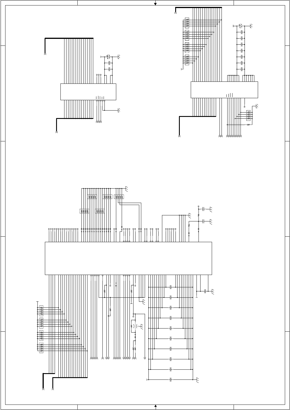
AR-FX4 ELECTRICAL SECTION - 11
M2A2
M2A10
M2A3
M2D8
M2A6 M2D5M2A5 M2D4
M2A7
M2A9
M2A11
M2A14
M2D12
M2A0
M2D14
M2D10
M2D9
M2D3
M2A4
M2A13
CD2A0
CD2A2
M2A15
M2A8
CD2D2
CD2D0
M2D11
CD2D1
CD2A3
M2D0
M2A1
CD2A1
M2D15
M2A12
SDRAM_A12
SDRAM_A6
SDRAM_A9
SDRAM_A1
SDRAM_A7
SDRAM_A8
SDRAM_A5
SDRAM_A0
SDRAM_A11
SDRAM_A10
SDRAM_A4
SDRAM_A2
SDRAM_A3
SDRAM_D7
SDRAM_D9
SDRAM_D4
SDRAM_D0
SDRAM_D3
SDRAM_D14
SDRAM_D12
SDRAM_D11
SDRAM_D2
SDRAM_D1
SDRAM_D8
SDRAM_D13
SDRAM_D6
SDRAM_D10
SDRAM_D15
SDRAM_D5
M2D1
M2D2
M2D6
M2D7
M2D13
CD2D14
CD2D7
CD2D9
CD2D13
CD2D5
CD2D3
CD2D11
CD2D12
CD2D6
CD2D8
CD2D10
CD2D15
CD2D4
M2CE-
CD2WR-
CD2CS-
M2OE-
CD2UBE-
M2A[0:15]
CD2A[0:3]
CD2IRQ0
CD2D[0:15]
CD2RD-
CD2RES-
M2D[0:15]
CD2REQC0
CD2ACKC0-
M2WE-
SDRAM_CLK
SDRAM_WR-
SDRAM_A[0:12]
SDRAM_RAS-
SDRAM_CAS-
SDRAM_CS-
SDRAM_D[0:15]
SDRAM_DQM0
SDRAM_DQM1
SDRAM_BA0
SDRAM_CKE
SDRAM_BA1
CD2REQD0
CD2ACKD0-
CD2IRQ1
CD2REQD1
CD2REQC1
CD2ACKD1-
CD2ACKC1-
CD2CLK
CLK16M
CD2CLKIN
+3.3V
+3.3V
+3.3V
+3.3V
+3.3V
+3.3V
+3.3V
C211
F0.1u/16
TP283
TP246
C217
F0.01u/50
TP1095
TP252
BR103
MNR14 4.7K
1
2
3
4 5
6
7
8
TP249
C223
F0.1u/16
TP235
TP256
R193 R(NM)
BR100
MNR14 (NM)
1
2
3
4 5
6
7
8
R218
4.7K
TP900
TP898
TP282
C222
F0.1u/16
BR96 MNR14 10K
1
2
3
4 5
6
7
8
BR99
MNR14 (NM)
1
2
3
4 5
6
7
8
IC41
IS61LV6416-12T
44
43
42
27
26
6
7
8
9
10
11
12
13
14
15
16
17
25
24
21
20
22
23
28
4
5
18
19 29
30
31
32
33
34
35
36
37
38
39
40
41
3
2
1
A0
A1
A2
A3
A4
CE
I/O0
I/O1
I/O2
I/O3
VCC
VSS
I/O4
I/O5
I/O6
I/O7
WE
A5
A6
A7
A8
NC
NC
NC
A12
A11
A10
A9 I/O8
I/O9
I/O10
I/O11
VCC
VSS
I/O12
I/O13
I/O14
I/O15
LB
UB
OE
A13
A14
A15
TP232
R192 0
R197 100
C221
F0.1u/16
TP239
TP279
TP229
C215
F0.1u/16
TP263
TP234
TP284
TP1045
IC40
MN86065
30
8
2
32
38
20
21
22
23
26
27
28
29
42
43
44
3
10
6
128
127
126
125
75
76
77
78
79
82
83
84
85
86
87
88
89
90
1
59
9
24
36
11
25
37
124
56
7
13
14
15
16
17
18
19
12
45
31
4
5
33
34
35
39
40
41
93
94
95
96
97
98
99
100
101
104
105
106
107
108
109
110
111
112
46
47
60
50
51
49
48
64
63
58
57
52
53
54
65
80
91
102
113
123
114
103
92
81
66
55
62
61
67
68
69
70
71
72
73
74
115
116
117
118 119
120
121
122
CS-
WR-
HEX-
REQC0
ACKC0-
D7
D6
D5
D4
D3
D2
D1
D0
A3
A2
A1
INTR0
CLKOUT
CLKIN
TEST0
TEST1
TEST2
TEST3
IA15
IA14
IA13
IA12
IA11
IA10
IA9
IA8
IA7
IA6
IA5
IA4
IA3
IA2
RESET-
IMUE-
VDD1
VDD2
VDD3
VSS1
VSS2
VSS3
VSS10
IREADY
RD-
D14
D13
D12
D11
D10
D9
D8
D15
A0
UBE-
INTR1
INTR2
REQC1
REQD0
REQD1
ACKC1-
ACKD0-
ACKD1-
IA1
IA0
ID15
ID14
ID13
ID12
ID11
ID10
ID9
ID8
ID7
ID6
ID5
ID4
ID3
ID2
ID1
ID0
IHREQ
IHACK
IMLE-
IMR-
IMW-
DREQ0
DREQ1
DACK0-
DACK1-
DCMP0-
DCMP1-
IOR-
IOW-
VDD4
VDD5
VDD6
VDD7
VDD8
VDD9
VDD10
VSS9
VSS8
VSS7
VSS6
VSS5
VSS4
EXA0
EXA1
NC67
NC68
NC69
NC70
NC71
NC72
MINTC
MINTIN
VREF5
MINTEST
SCANEN
AVDD VCOI
PCO
AVSS
PLLOFF
TP278
C203
A33u/10
TP231
TP227
TP899
TP236
TP251
C208
F0.1u/16
TP217
BR89
MNR14 (NM)
1
2
3
4 5
6
7
8
BR98 MNR14 10K
1
2
3
4 5
6
7
8
C212
F0.1u/16
TP291
TP276
TP225
TP803
TP248
C205
F0.1u/16
TP277
TP223
BR95 MNR14 10K
1
2
3
4 5
6
7
8
R196 2K
C220
F0.1u/16
TP255
C218
F0.1u/16
C207
F0.1u/16
TP254
TP221
TP242
TP230
TP241
TP285
R190 1K
TP224
TP226
C209
F0.1u/16
IC42
W981216BH
223 424 525 726 829 1030 1131 1332
33
34
22
35
36
18
17
19
15
16 1
6
42
44
45
47
48
50
51
53
39
38
37
20
21
3
9
14
27
12
28
46
52
54
41
43
49
40
I/O0A0 I/O1A1 I/O2A2 I/O3A3 I/O4A4 I/O5A5 I/O6A6 I/O7A7
A8
A9
A10
A11
A12
RAS
CAS
CS
DQML
WE VCC
GND
I/O8
I/O9
I/O10
I/O11
I/O12
I/O13
I/O14
I/O15
DQMU
CLK
CKE
BA0
BA1
VCC
VCC
VCC
VCC
GND
GND
GND
GND
GND
GND
VCC
VCC
NC
TP253
TP222
TP244
TP218
BR94 MNR14 10K
1
2
3
4 5
6
7
8
C213
F0.1u/16
C219
A33u/10
TP243
TP281
BR88
MNR14 (NM)
1
2
3
4 5
6
7
8
TP245
TP275
TP265
TP247
C206
F0.1u/16
FB11
MEM2012(NM)
TP240
TP233
C224
F0.1u/16
TP220
TP228
C216
B2200/50
C210
F0.1u/16
TP280
TP237
TP286
C204
F0.1u/16
R191 1K
BR101
MNR14 (NM)
1
2
3
4 5
6
7
8
TP261
TP294
R195 0 TP264
TP238
TP219
BR102
MNR14 (NM)
1
2
3
4 5
6
7
8
TP250
C226
F0.1u/16
TP260
BR87
MNR14 (NM)
1
2
3
4 5
6
7
8
C214
F0.1u/16
C225
F0.1u/16
TP262
BR86
MNR14 (NM)
1
2
3
4 5
6
7
8
TP259
BR97 MNR14 10K
1
2
3
4 5
6
7
8
R194 R(NM)
FAX MAIN PWB (GA2-CODEC) 9/10
12345
12345
D
C
B
A
D
C
B
A
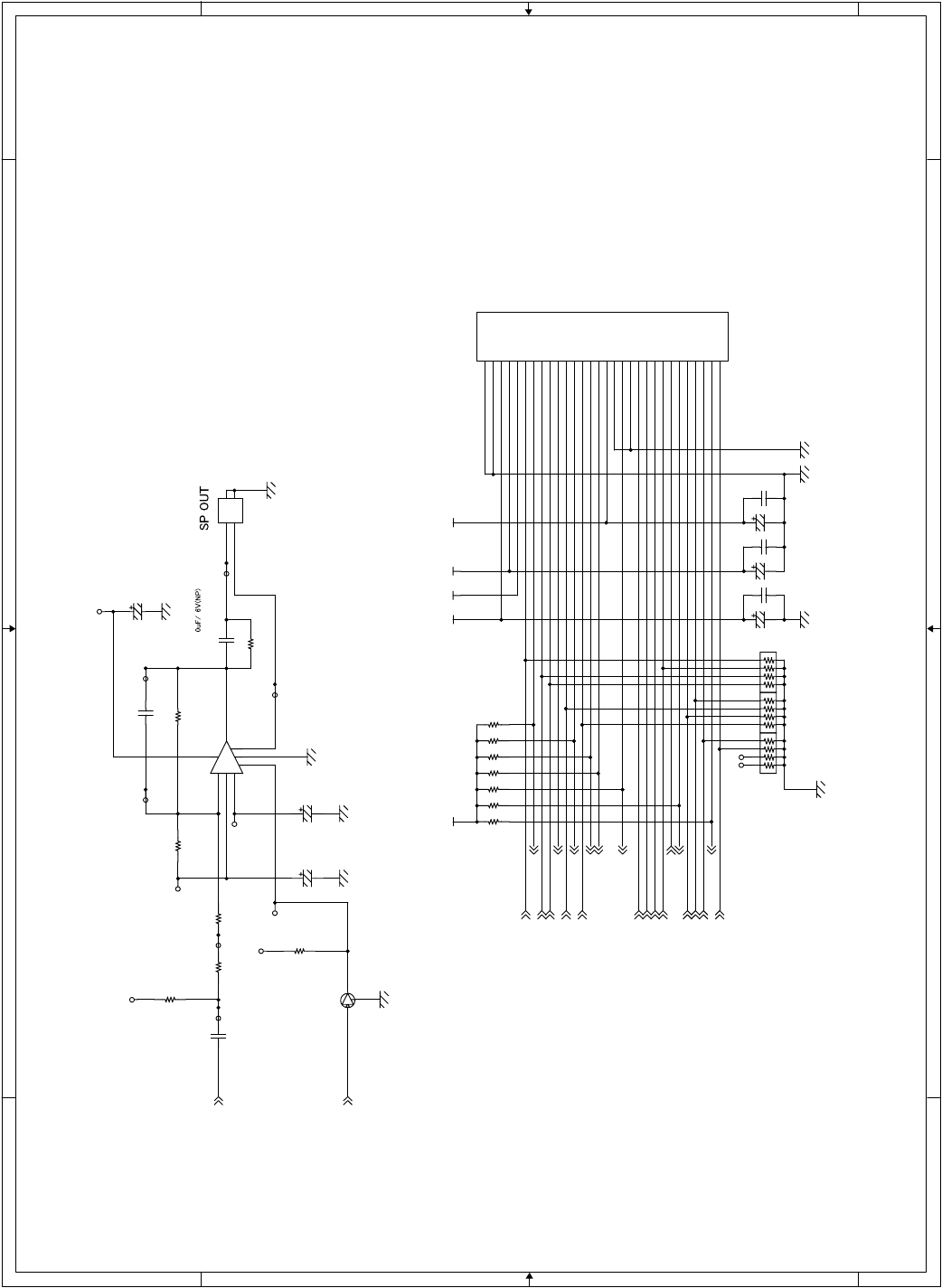
AR-FX4 ELECTRICAL SECTION - 12
MUTE
SP+
SP-
RHS-
LIUID
SIGRX
FNETD
SIGTX
EXHS-
CI-
HS[1]-
SPOUT
SPMUTE
HS[2]-
CML
EC
150VON
VRSEL[3]-
S
RCVMUTE
VRSEL[2]-
TELMUTE
DPON-
DPMUTE
VRSEL[1]-
MPXA
CION
+12V
+5V
+12V
AGAG
+5V
+5V
+3.3V
AGAG
+24V
+5V
R203 0
TP1228
R201 0
BR110
MNR14 3K
1
2
3
4 5
6
7
8
BR109
MNR14 3K
1
2
3
4 5
6
7
8
C235
A47u/25
R202
3.3K
Q10
DTC363EKA
B
E
C
CN5
S2B-PH-SM3-TB
1
21
2
R208
10K
TP27
TP531
R199 100K
C234
A47u/25
R209
10K R210
10K
C227
A4.7u/50
CN6
TX25-30P-6ST-H1
1
2
3
4
5
6
7
8
9
10
11
12
13
14
15
16
17
18
19
20
21
22
23
24
25
26
27
28
29
30
DG
DG
+12VA
+12V
+24V
MPXA
HS1-
TELMUTE
RCVMUTE
SIGRX
EXMSG
CI-
S
HS2-
LIUID
+5V
AG
FNETD
AG
VRSEL1
VRSEL2
VRSEL3
CION
SIGTX
RHS-
DP
CML
EC
EXHS-
150VON
TP535
C232
A4.7u/50
R211
10K
C231
A4.7u/50
BR108
MNR14 3K
1
2
3
4 5
6
7
8
C239
F0.1u/16
R205
10K
C236
A33u/10
R206
10K
R198
R(NM)
TP532
TP536
C229
F0.1u/16
TP534
R204
22K
TP1229
IC43
NJM2113M
4
3
7
8
5
1
2
6
C230
C(NM)
C228
B1000/50
TP1096
R207
10K
TP537
C238
F0.1u/16
R200 75K
C237
F0.1u/16
TP28
FAX MAIN PWB (TEL/LIU IF) 10/10
1234
D
C
B
A
D
C
B
A
1234
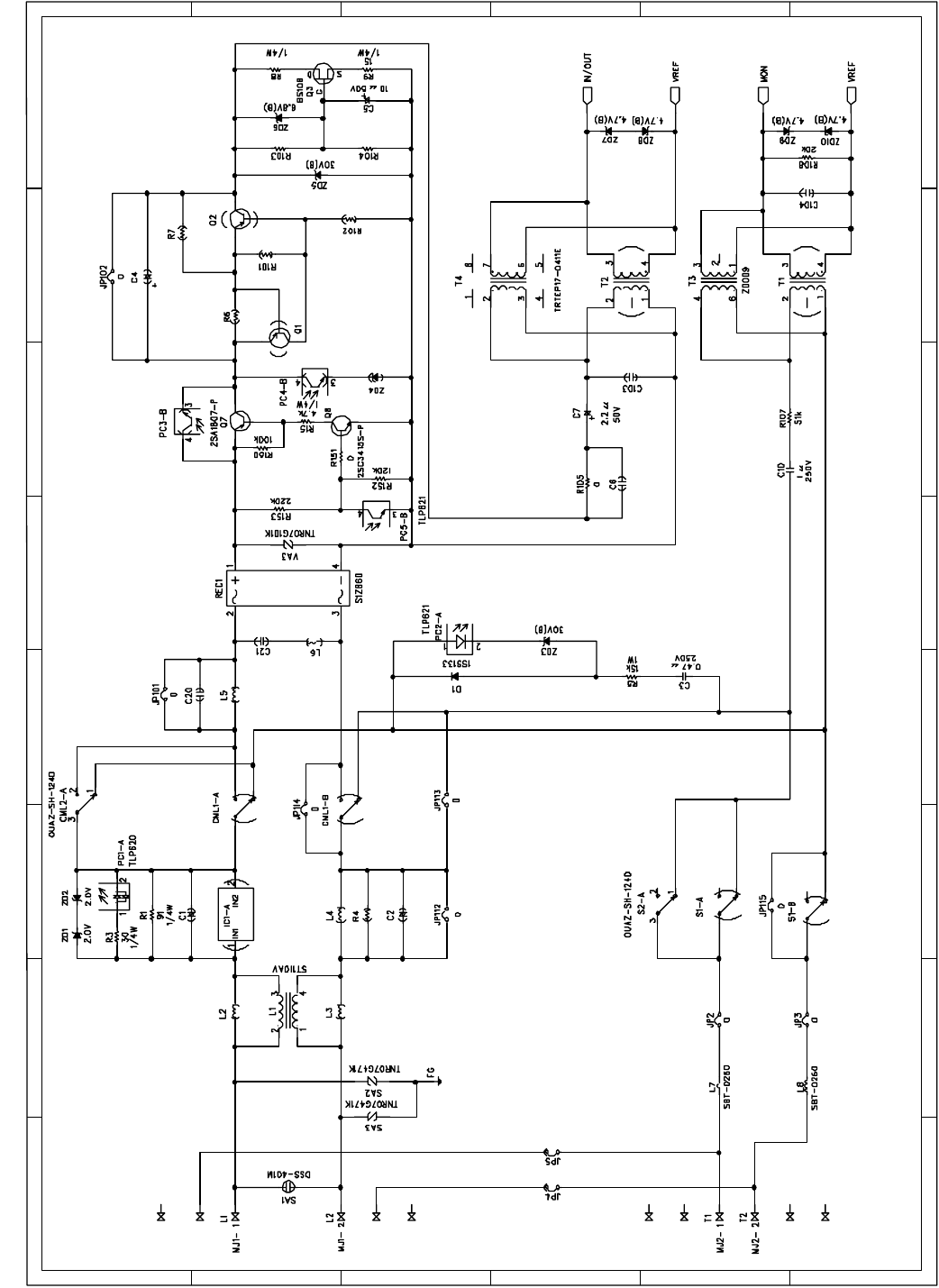
AR-FX4 ELECTRICAL SECTION - 13
ABCDEFGH
ABCDEFGH
1
2
3
4
5
6
1
2
3
4
5
6
TEL/LIU PWB 1/3
B. TEL/LIU PWB
Capacitors are of 50V unless otherwise specified.
Resistors are of 1/16W unless otherwise specified.
7.5k
6.8k
10k
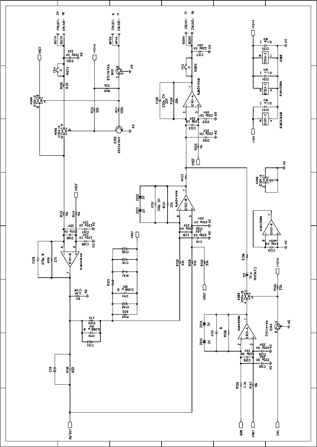
AR-FX4 ELECTRICAL SECTION - 14
ABCDEFGH
ABCDEFGH
1
2
3
4
5
6
1
2
3
4
5
6
TEL/LIU PWB 2/3
Capacitors are of 50V unless otherwise specified.
Resistors are of 1/16W unless otherwise specified.
18k
1800p
100k
27k
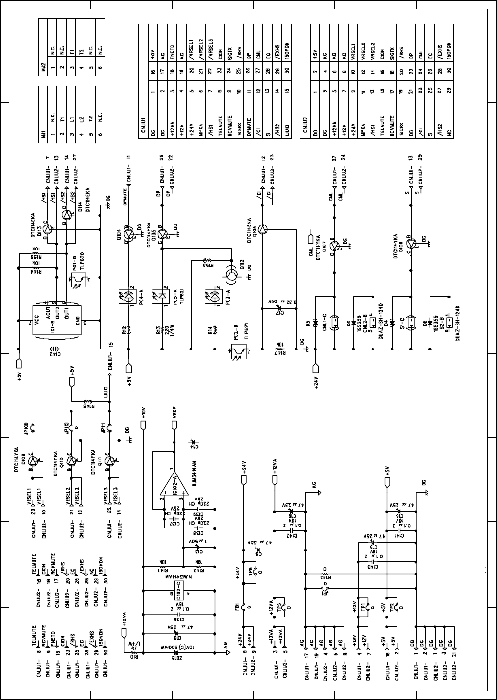
AR-FX4 ELECTRICAL SECTION - 15
ABCDEFGH
ABCDEFGH
1
2
3
4
5
6
1
2
3
4
5
6
TEL/LIU PWB 3/3
Capacitors are of 50V unless otherwise specified.
Resistors are of 1/16W unless otherwise specified.
47 µ 35V
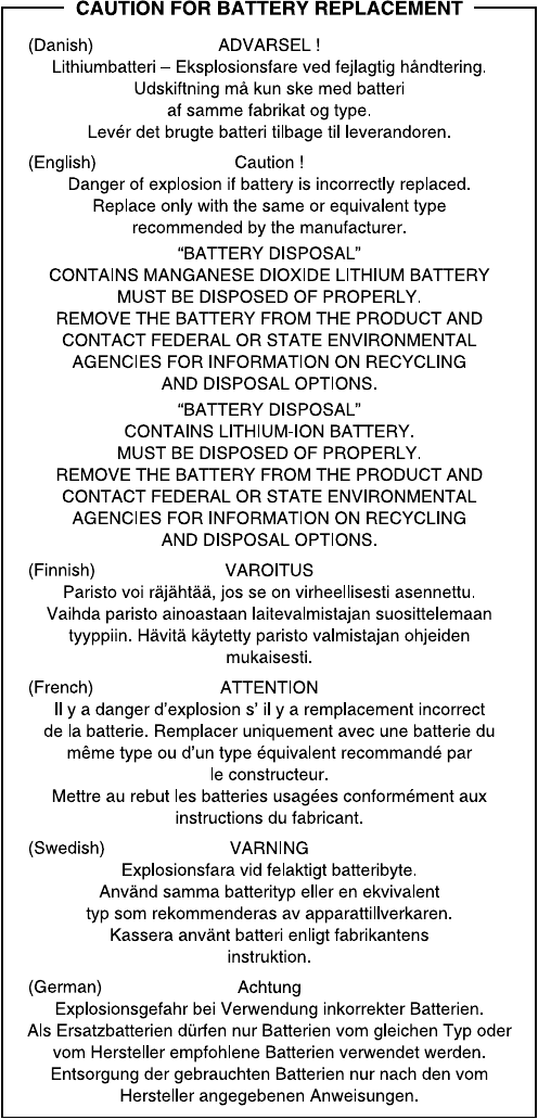

All rights reserved.
Printed.
No part of this publication may be reproduced,
stored in a retrieval system, or transmitted,
in any form or by any means,
electronic; mechanical; photocopying; recording or otherwise
without prior written permission of the publisher.
Trademark Acknowledgments
Microsoft Windows, MS-DOS, Windows NT, Windows 2000 are trademarks of Microsoft
Corporation in the U. S. A. and other countries.
Macintosh, Power Macintosh, Mac OS, LaserWriter, and AppleTalk are registered trademarks of
Apple Computer, Inc.
IBM, PC/ AT, and PowerPC are trademarks of International Business Machines Corporation.
Pentium is a registered trademark of Intel Corporation.
PCL is a trademark of the Hewlett- Packard Company.
PostScript is a registered trademark of Adobe Systems Incorporated.
NetWare is a registered trademark of Novell, Inc.
All other trademarks and copyrights are the property of their respective owners.
Digital Document Systems Group
Quality & Reliability Control Center
Yamatokoriyama, Nara 639-1186, Japan
2001 June Printed
