ARPI600 User Manual
User Manual:
Open the PDF directly: View PDF ![]() .
.
Page Count: 19
- ARPI600 User Manual

ARPI600 User Manual Waveshare
1
ARPI600
User Manual
Overview
Arduino is a massive ecosystem, if there's a way for the Raspberry Pi GPIO interface to
adapt to Arduino pinouts, it is possible to use the Pi together with vast Arduino shields
and hardware/software resources. The ARPI600 is just intended for this.
What's more, the ARPI600 also support XBee modules, make it easy to add wireless
feature to your great project.
Features
- Compatible with Arduino UNO, Leonardo, easy to connect with various Arduino
shields
- XBee connector for connecting various XBee modules
- Sensor interface for connecting various sensors
- Onboard USB TO UART for serial port debugging, also can be configured as XBee
USB adapter
- Onboard ADC, 10 bit, 38KSPS, 11 channels (6 channels for Arduino interface, 5
channels for sensors)
- Onboard RTC
ARPI600 User Manual Waveshare
2
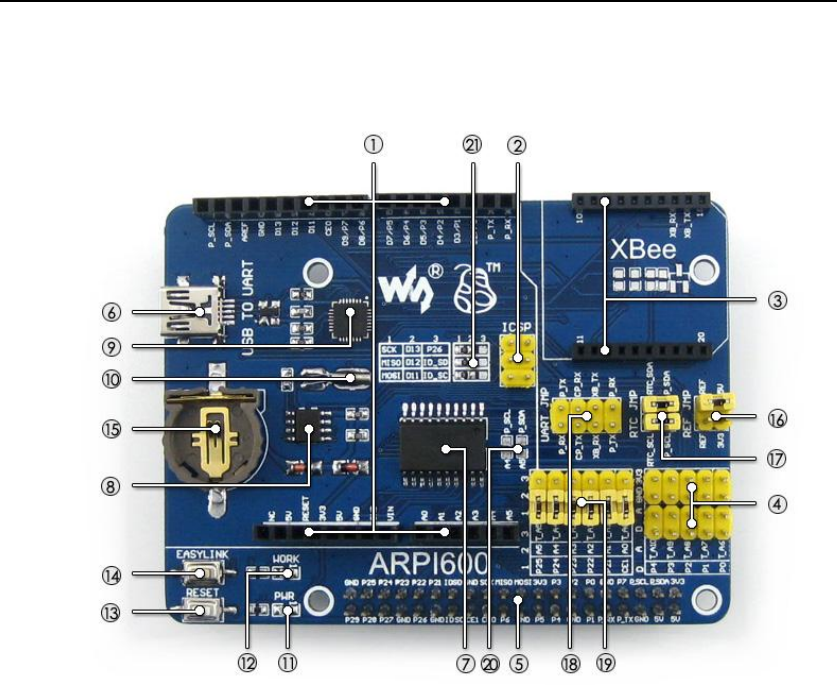
What's on the ARPI600
Figure 1: Onboard device
- Arduino connector : for connecting Arduino shields
- ICSP interface : Arduino ICSP
- XBee connector : for connecting XBee communication modules
- Sensor interface : for connecting sensors
- Raspberry Pi connector : for connecting Raspberry Pi
- USB TO UART
- TLC1543 : AD converter
- PCF8563 : RTC
- CP2102
- 32.768KHz crystal : for RTC
- Power indicator
- XBee state LED
- XBee and Arduino interface RESET button
- XBee EASYLINK button
- RTC battery holder : for CR1220 button battery
- TLC1543 reference voltage configuration jumper
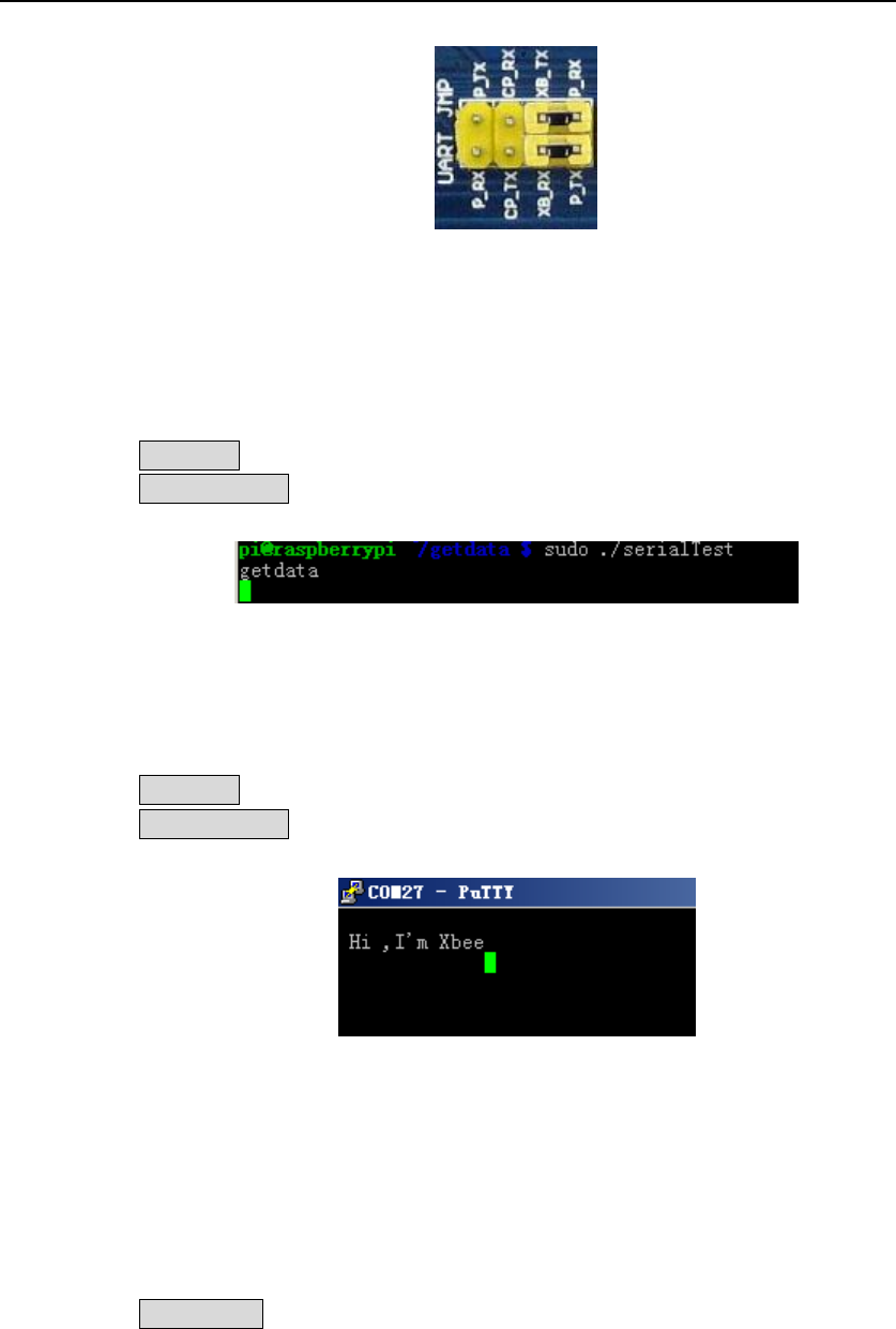
- RTC jumper
- UART jumper
when connecting P_RX and CP_TX, P_TX and CP_RX respectively, USB TO UART is
connected to Raspberry Pi serial port
when connecting XB_RX and CP_TX, XB_TX and CP_RX respectively, USB TO UART is
connected to XBee serial port

ARPI600 User Manual Waveshare
3
when connecting XB_RX and P_TX, XB_TX and P_RX respectively, Raspberry Pi serial port is
connected to XBee serial port
- Arduino AD selection jumper
short 2 and 3 : Arduino A0-A5 as AD input
short 1 and 2 : Arduino A0-A5 as digital control
- Arduino I2C selection jumper
short the jumper : Arduino A4-A5 as I2C control (the A4-A5 of Arduino AD selection
jumper should be opened)
- Arduino SPI selection jumper
short 1 and 2 : Arduino D11-D13 as SPI control (default)
short 2 and 3 : Arduino D11-D13 as digital control

ARPI600 User Manual Waveshare
4
Content
ARPI600 User Manual ............................................................................................................... 1
Overview .......................................................................................................................... 1
Features ........................................................................................................................... 1
What's on the ARPI600 ...................................................................................................... 2
1 How to start up serial debugging function ................................................................... 5
2 How to control peripherals by Raspberry Pi ................................................................. 7
2.1 System serial port configuration ...................................................................... 7
2.2 Install relative libraries .................................................................................... 7
2.3 Serial data display ........................................................................................... 8
3 Building a wireless network with two XBee modules.................................................... 8
3.1 Preparations ................................................................................................... 8
3.2 Installing X-CTU tool........................................................................................ 8
3.3 Testing the connection between PC and XBee .................................................. 9
3.4 Configuring XBee-A module........................................................................... 10
3.5 Configuring XBee-B module ........................................................................... 12
4 How to perform wireless transmission with XBee ...................................................... 13
4.1 Configuring the module ................................................................................ 13
5 RTC clock ................................................................................................................. 14
6 AD conversion (ARPI600 on-board chip TLC1543) ...................................................... 15
6.1 Configuring Pin A0 to Pin AD ......................................................................... 15
6.2 Configuring as other AD pins ......................................................................... 16
7 Interface description ................................................................................................ 16
ARPI600 User Manual Waveshare
5
1 How to enable serial debugging function
1) Please install a USB to UART driver (cp2102 driver) before applying Raspberry Pi board.
After the installation, please open Device Manager to check whether the PC can
identify the USB to UART driver.
2) After connecting ARPI600 to Raspberry Pi board, you should power up the Raspberry Pi
board and then connect ARPI600 to the USB port on your PC. It is not recommended to
connect ARPI600 to the USB port on PC before powering up Raspberry Pi board or for
power supply, since the power supply capability of the USB port on PC is not
powerful enough to support Raspberry Pi board and ARPI600 expansion board at a
same time.
3) The Raspbian system is set to serial debugging output by default, so you should
configure the jumpers on the ARPI600 in order to start up the serial debugging function
for PC.
- Connect CP_RX to P_TX
- Connect CP_TX to P_RX
Figure 2: Starting up serial debugging function
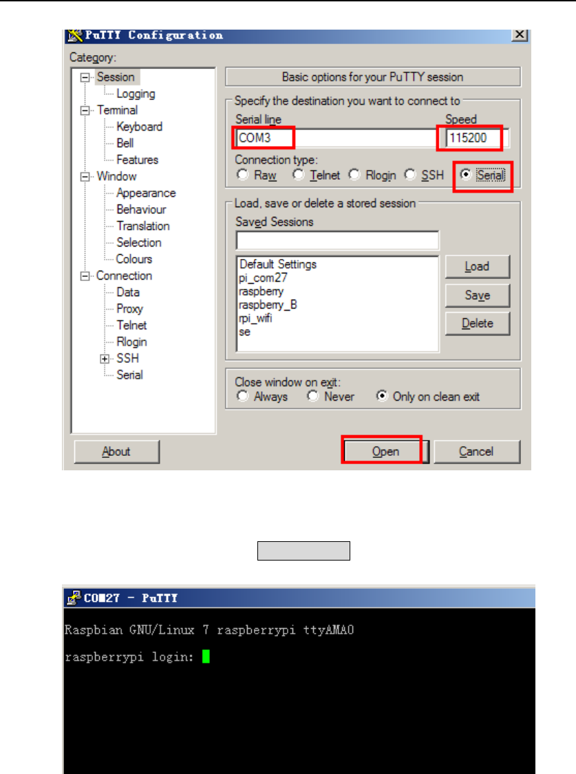
4) Start software/putty.exe, and configure the following parameters marked with red
boxes shown in Figure 3。
Parameter descriptions:
- Serial line: it is used to select corresponding serial port. In this example, the serial
port is COM3, please configure this option based on the actual situation (The serial
port in used can be check by Device Manager).
- Speed: it is used to set the Baud rate: 115200.
- Connection type: this option should be set to Serial.
And then, click the button Open.
ARPI600 User Manual Waveshare
6
Figure 3: PuTTY settings
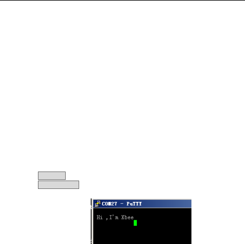
5) Then, you will see a window popped up as Figure 4 shows (If there is nothing shown in
the window, please press the key Return Carriage, then you can see the information
displayed as Figure 4 shows).
Figure 4: Connecting PuTTY to Raspberry Pi board
In this window, you should input following information:
User name: pi
Password: raspberry
Then, you can enter the serial terminal.
ARPI600 User Manual Waveshare
7
2 How to control peripherals by Raspberry Pi
2.1 System serial port configuration
1) Enter the terminal of Raspberry Pi, and input:
sudo nano /boot/cmdline.txt
Then, you should modify the following lines:
wc_otg.lpm_enable=0 console=ttyAMA0,115200 kgdboc=ttyAMA0,115200
console=tty1 root=/dev/mmcblk0p2 rootfstype=ext4 elevator=deadline rootwait
into:
dwc_otg.lpm_enable=0 console=tty1 root=/dev/mmcblk0p2 rootfstype=ext4
elevator=deadline rootwait
Press the keys Ctrl+X, and select the option Y to save the modification.
2) Input the code:
sudo nano /etc/inittab
And modify the following lines:
#Spawn a getty on Raspberry Pi serial line
T0:23:respawn:/sbin/getty -L ttyAMA0 115200 vt100
into:
#Spawn a getty on Raspberry Pi serial line
#T0:23:respawn:/sbin/getty -L ttyAMA0 115200 vt100
Press the keys Ctrl+X, and select the option Y to save the modification.
3) Input the code:
sudo reboot
After completing the modifications described above and restarting the Raspberry
Pi board, the serial debugging function is started up. In this mode, you cannot
enter the terminal of the Pi via the serial port any more, but can control the serial
output by the software (If you want to reset the serial port to the serial debugging
output, please restore the factory settings and restart the Raspberry Pi. Therefore,
it is recommended to backup the Raspbian before making any modification).
2.2 Install relative libraries
1) Copy the library file software/wiringPi.tar.gz into Raspberry Pi (you can perform it
by a U disk), and enter the terminal of Raspberry Pi to input the following code:
sudo tar xvf wiringPi.tar.gz
cd wiringPi/
chmod 777 build
./build
2) After installing the library, input the following code:
gpio -v
ARPI600 User Manual Waveshare
8
Now, you can check whether the installation is successful.
2.3 Serial data display
1) The Raspbian system is set to serial debugging output by default, so you should
configure the jumpers on the ARPI600 in order to start up the serial debugging
function for PC.
- Connect CP_RX to P_TX
- Connect CP_TX to P_RX
2) Start the PuTTY serial debugging software to configure following parameters:
- Serial line: it is used to select corresponding serial port.
- Speed: it is used to set the Baud rate: 9600 (Notices: the parameter Speed in
here is set to 9600, differently from the configuration shown in Figure 3).
- Connection type: this option should be set to Serial.
3) Copy the file program/Xbee/send into the Raspbian, and enter the folder send,
then, execute the following code:
sudo make
sudo ./serialTest
The terminal will display the data as Figure 5 shows:
Figure 5: Data displayed in the terminal
3 Building a wireless network with two XBee modules
3.1 Preparations
1) Two XBee modules
2) Two ARPI600 modules
3) Twp Raspberry Pi boards
- In this document, we will divided the device above into two groups: Group A
and Group B, of which Group A contains XBee-A, Raspberry Pi board-A and
ARPI600-A, and Group B contains XBee-B Raspberry Pi board-B and ARPI600-B.
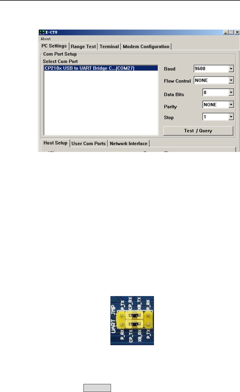
3.2 Installing X-CTU tool
1) Double click the file software/X-CTU V5.2.8.6.exe on your PC to start installing
ARPI600 User Manual Waveshare
9
X-CTU tool. After a successful installation, you can open the X-CTU tool as Figure 6
shows.
Figure 6: X-CTU setting
2) Configure the XBee module. The default setting of XBee is as followed:
- Baud: 9600
- Data Bite: 8
- Parity: NONE
- Stop: 1
3.3 Testing the connection between PC and XBee
1) Connect XBee-A to ARPI600-A, and XBee-B to ARPI600-B, respectively.
2) Set the jumpers on ARPI600 to start up the serial debugging function for the XBee,
as Figure 7 shows.
- Connect XB_RX to CP_RX
- Connect CP_TX to XB_TX
Figure 7: Jumpers setting for serial debugging function between the Pi and the XBee
3) Power up Raspberry Pi board (For more detailed information, please refer to the
step 2 of Section 1. How to enable serial debugging function).
4) Click the button Test/Query to check whether the connection between the
ARPI600 and the XBee is established successfully.

ARPI600 User Manual Waveshare
10
Figure 8: Testing the connection between the board and the XBee
5) For a successful connection, you can see the dialog box as Figure 9 shows.
Figure 9: Successful connection
3.4 Configuring XBee-A module
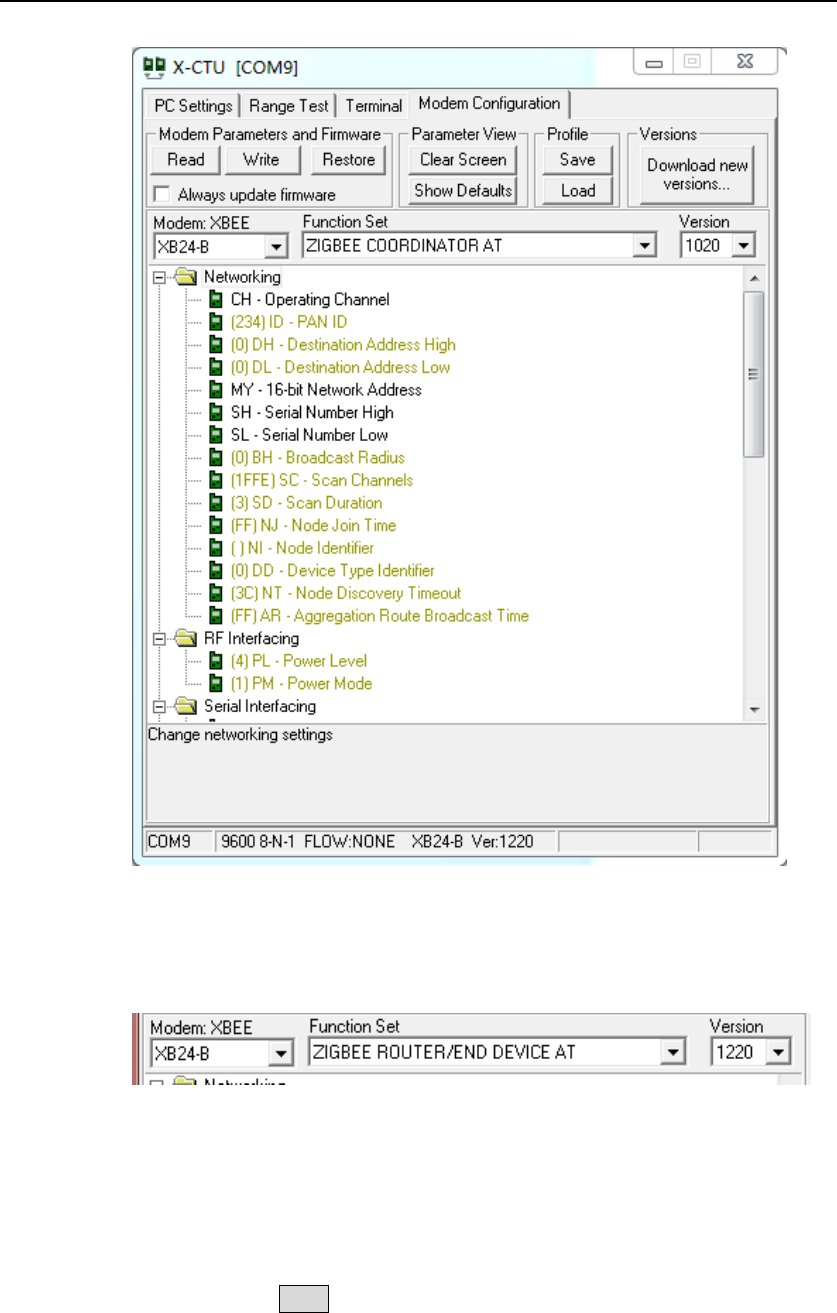
1) Select the option Modem Configuration, and click the button Read to read out the
current parameters of XBee.
ARPI600 User Manual Waveshare
11
Figure 10: Reading out current parameters
2) Select the option ZIBGEE ROUTER/END DEVICE AT under the pull-down menu
Function Set:
Figure 11: Selecting the option ZIBGEE ROUTER/END DEVICE AT under Function Set
3) Set the read Networking parameters:
- ID: 234
- DH: 0
- DL: 0
4) Click the button Write to download the configured parameters into the XBee-A
module.

ARPI600 User Manual Waveshare
12
3.5 Configuring XBee-B module
1) Configure XBee-B module according to the processes described in the Section 3.1
and the Section . However, there is something different. In configuring XBee-B,
you should select the option ZIBGEE COORDINATOR AT under the pull-down menu
Function Set:
Figure 12: Selecting the option ZIBGEE COORDINATOR AT under Function Set
2) Set the read Networking parameters:
- ID: 234
- DH: 0
- DL: ffff
3) Click the button Write to download the configured parameters into the XBee-B
module.
4) In order to implement a simple P2P network, please configure XBee-A and XBee-B
according to the processes described above. Start two X-CTU tools, and select
different COM interfaces in the option PC Settings to control Group A and Group B
respectively.
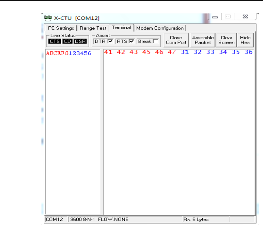
5) Input the data to be transmitted in the X-CTU Terminal of XBee-A, then, you can
find that the inputted data will be sent to XBee-B automatically, and displayed in
the X-CTU Terminal of XBee-B. In the X-CTU, data in blue is the data to be sent,
and data in red is the received data.
ARPI600 User Manual Waveshare
13
Figure 13: Data transmission and receive
6) Figure 13 shows the normal operating state of XBee module.
4 How to perform wireless transmission with XBee
Before performing the wireless transmission with XBee, please make sure the wireless
network built by two XBee modules is work properly. For more information about how
to build the wireless network, please refer to Section 3.
4.1 Configuring the module
1) Set the jumpers on ARPI600:
Here, we should use two Raspberry Pi boards: Raspberry Pi-A and Raspberry Pi-B,
of which Raspberry Pi-A is used for transmitting data and Raspberry Pi-B is used
for receiving data.
Connect Raspberry Pi-A to the serial port of XBee-A and Raspberry Pi-B toXBee-B,
respectively. And then, set the jumpers on ARPI600, as Figure 14 shows.
- Connect XB_RX to P_TX
- Connect XB_TX to P_RX
ARPI600 User Manual Waveshare
14
Figure 14: Setting jumpers on ARPI600
2) Testing the serial port:
Copy the file program/Xbee/getdata to the Raspberry Pi-B, and enter the folder
getdata.
Then, execute the code:
sudo make
sudo ./serialTest
The relative data will be displayed as followed.
Figure 15: Displaying the message getdata
Run the code for transmitting data on Raspberry Pi-A. Then, copy
program/Xbee/send into the Raspbian, and enter the folder send to execute the
following code:
sudo make
sudo ./serialTest
You will see the following message displayed in the PuTTY of Raspberry Pi-B.
Figure 16: Message received by Raspberry Pi-B
5 RTC clock
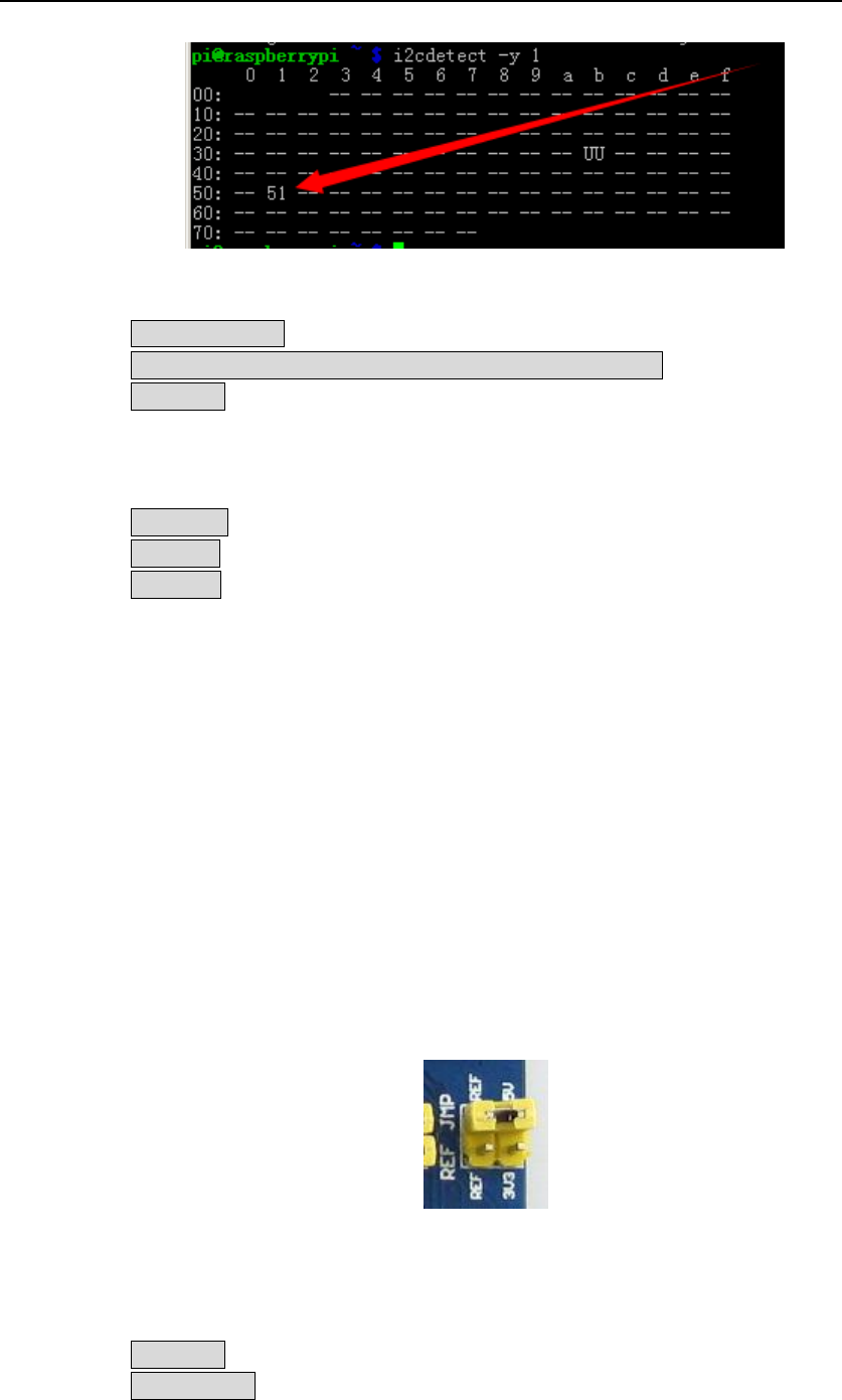
1) Set the jumpers on RTC JMP of the ARPI600.
2) Open the LXTerminal on the desktop of Raspbian, and input the code:
i2cdetect -y 1
3) Then, you will see the device address of PCF8563 connected to Raspberry Pi. Here,
the device address of PCF8563 is 51, which means the PCF8563 is identified by
Raspberry Pi.
ARPI600 User Manual Waveshare
15
Figure 17: The device address of PCF8563 connected to Raspberry Pi
4) Enter LXTerminal, and input:
modprobei2c-dev
echo pcf8563 0x51 > /sys/class/i2c-adapter/i2c-1/new_device
hwclock –r (Read out the time of the connected RTC based on I2C)
LXTerminal will display the time clocked by PCF8563 which may be different from
the Raspbian)
5) Enter LXTerminal, and input:
hwclock -w (Write the time of the Raspbian into PCF8563)
hwclock -r (Synchronize the time of Raspbian to PCF8563)
hwclock -s (Synchronize the time of Raspbian with hardware RCT)
6 AD conversion (ARPI600 on-board chip TLC1543)
6.1 Configuring Pin A0 as Pin AD
1) Please make sure you have installed relative libraries (refer to the Section 2.2:
Installing relative libraries).
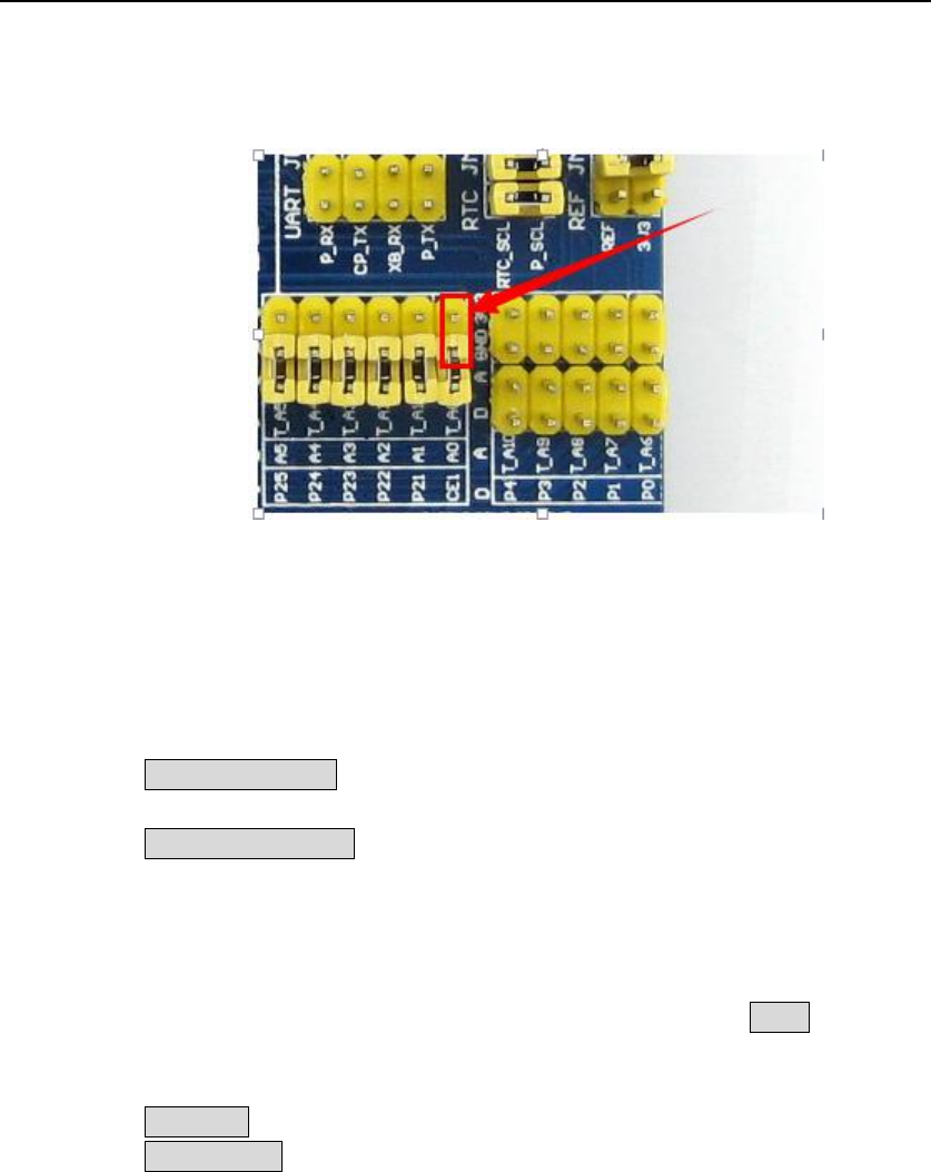
2) Set the jumpers to select reference voltage:
- Connect REF to 5V, which means the AD conversion reference voltage is 5V
(connecting to 5V is a default setting).
- Connect REF to 3V3, which means the AD conversion reference voltage is
3.3V.
Notices: REF can only be connected to one reference voltage at a time.
Figure 18: Setting AD reference voltage
3) Copy the file program/AD_TLC1543 in to Raspbian. Then, enter the folder
AD_TLC1543, and execute the following code under the terminal:
sudo make
sudo ./tlc1543
4) Terminal will display relative AD conversion value. By default, the displayed
ARPI600 User Manual Waveshare
16
conversion value is come from Pin AD0 on TLC1543 (Pin T_A0 on ARPI600).
5) Connect the jumpers T_A0 to A0, then the Pin A0 on Arduino interface can sever
as an AD conversion pin, as shows.
Figure 19: connecting Pin T_A0 to Pin A0
6.2 Configuring as other AD pins
1) If you want to display the conversion value from other AD pins on TLC1543, please
enter the terminal and edit the file tlc1543.c:
sudo nano tlc1543.c
Find out the following line:
re=ADCSelChannel(0);
Modify the “0” in the line into the number corresponding to other AD pin (For
example, modify to “1” for testing the conversion value from Pin AD1 (Pin T_A1),
and modify to “2” for testing the conversion value from Pin AD2 (Pin T_A2), and so
on, until to “10” for testing the conversion value from Pin AD10 (T_A10)).
After completing the operation described above, press the keys Ctrl+X, and select
the option Y to save the modification.
2) Execute the following code under the terminal:
sudo make
sudo ./tlc1543
Now, the modification is in effect.
7 Interface description
1) The default relationship between Arduino digital control pins and Raspberry Pi IOs
is shown in Table 1.
ARPI600 User Manual Waveshare
17
APRI600
IO of Raspberry Pi B+
D0
P_RX
D1
P_TX
D2
P0
D3
P1
D4
P2
D5
P3
D6
P4
D7
P5
D8
P6
D9
P7
D10
CE0
D11
MOSI
D12
MISO
D13
SCK
Table 1: The relationship between Arduino digital control pins and Raspberry Pi IOs
2) The jumper pins D11, D12 and D13 on the module are used for configuring the
ARPI600. And these pins should be shorted by the 0Ω resistances, as Figure 20
shows.
Figure 20: Configuring the jumpers D11, D12 and D13
In factory settings, the jumpers are set as followed:
- Connect SCK to D13
- Connect MISO to D12
- Connect MOSI to D11
The following settings are connecting pins D11, D12 and D13 to the general IO
control pins of Raspberry Pi board.
- Connect D13 to P26
- Connect D12 to IO_SD
- Connect D11 to IO_SC
Notices: Users can modify the settings of these jumpers as required. In this
operation, welding is required. Any changes under no guidance from Waveshare
will be considered as a waiver of warranty.
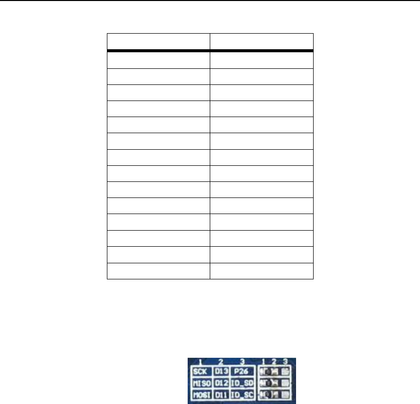
3) The pins A0-A5 of ARPI600 can also be configured as IO pins or ADC pins.

ARPI600 User Manual Waveshare
19
APRI600
IO of Raspberry Pi B+
A0
CE1
A1
P21
A2
P22
A3
P23
A4
P24
A5
P25
Table 2: The relationship between the pins A0-A5 and the pins of Raspberry Pi board
b) When the pins A0-A5 are connected to 3, they will sever as ADC pins.
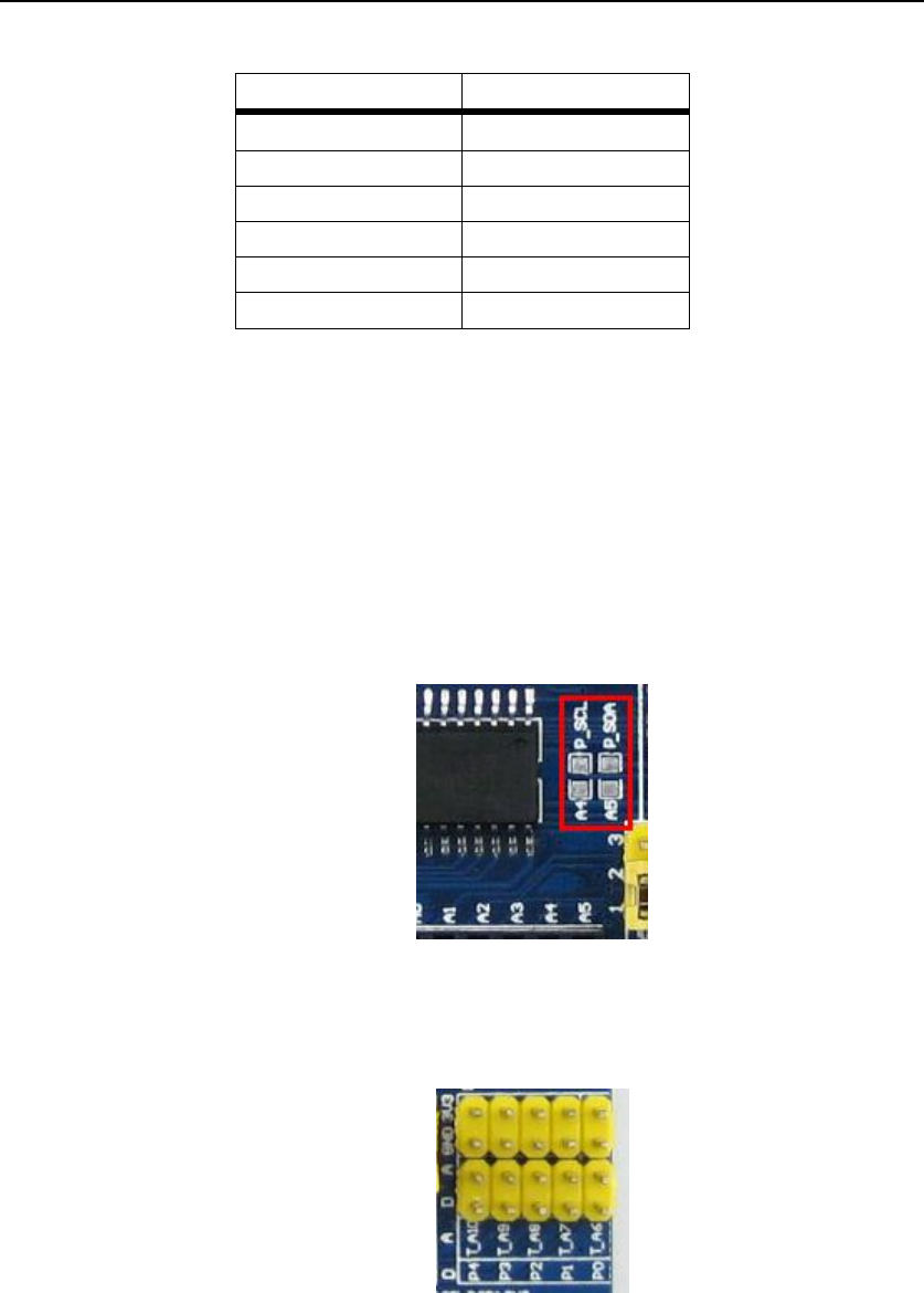
4) You can also connect the pin A4 to P_SCL, and the pin A5 to P_SDA (as Figure 22
shows), to making them sever as I2C control pins of Raspberry Pi board. However,
in default settings, the pins A4 and P_SCL are disconnected, and so do the pins A5
and P_SDA.
Notices: Users can modify the settings of these jumpers as required. In this
operation, welding is required. Any changes under no guidance from Waveshare
will be considered as a waiver of warranty.
Figure 22: Setting the pins A4 and A5 as I2C control pins
5) ARPI600 provides sensor interfaces 4P. Figure 23 shows the jumper settings for
sensor interface 4P.
Figure 23: Sensor interface 4P
In which:
- The pins on A are connected to the ADC pins A6-A10 of TLC1543;
- The pins on D are connected to the IO control pins P0-P4 of Raspberry Pi
board.
Users can apply different sensors via the sensor interface.
