ARRIFLEX 416 Manual, English Instruction Manual UG EN
ARRIFLEX 416 416_manual
c82b2d87-26ab-47e1-b044-55037d388955 ARRI Film Camera 416 User Guide |
User Manual: ARRIFLEX 416 - Instruction Manual User Guide for Arri Camcorder and Action Cam, Free Instruction Manual
Open the PDF directly: View PDF ![]() .
.
Page Count: 240 [warning: Documents this large are best viewed by clicking the View PDF Link!]
- 1. Contents
- 2. Safety Instructions and Legal Disclaimer
- 3. General Description of the ARRIFLEX 416
- 4. Installation of the Camera
- 5. Power Supply
- 6. Magazines
- 7. Camera Body
- 8. Optics
- 9. Camera Operation
- 9.1 Main Camera Switch
- 9.2 Running and Stopping the Camera
- 9.3 Displaying and Setting Operational Parameters
- Overview of Display Modes
- Overview of Display Symbols
- Film Counter
- Frame Rates
- Shifting phase
- Displaying Power Supply Voltage (Mode 3)
- Displaying On-board Battery information (Mode 3)
- Setting the Low Battery warning level (Mode 3)
- Displaying the Timecode Time and Frame Rate (Mode 4)
- Turning Timecode Recording On and Off (Mode 4)
- Displaying and Setting the Timecode User Bits (Mode 5)
- Setting the brightness of the button illumination (Mode 6)
- Switching the Beeper On and Off (Mode 6)
- Setting the Volume of the Warning Signal (Mode 6)
- Selecting a Preset ARRIGLOW Color (Mode 7)
- Setting a User-Adjustable ARRIGLOW Color (Mode 7)
- 10. Video Assist System
- 10.1 General Description of the IVS
- 10.2 Setup
- 10.3 Standard Video Controls
- 10.3.1 Switch On, Off and Check/Hide Menu
- 10.3.2 Mechanical Iris
- 10.3.3 Alignment of the image position (X, Y and Rotation) and focus
- 10.3.4 White Balance (WB)
- 10.3.5 Gain Control
- 10.3.6 Flicker free on/off
- 10.3.7 Changing Format marking number
- 10.3.8 Storing a video image
- 10.3.9 Wrong Cable Warning LED
- 10.4 Inserter Facilities
- 10.4.1 Setting the On-Screen Displays
- 10.4.2 Main Menu
- 10.4.3 Load/Store Menu
- 10.4.4 White Balance (WB), Manual Gain Control (MGC) and Bars Menu
- 10.4.5 Video and Text Adjustment Menu
- 10.4.6 Format Marking Menu
- 10.4.7 Compare/Store Menu
- 10.4.8 System, LDS and Status Menu
- 10.4.9 User Text Menu
- 10.4.10 Timecode Menu
- 10.4.11 USER BITS Menu
- 10.4.12 Pull-Down Menu
- 10.4.13 VITC Line Menu
- 10.4.14 White Line Menu
- 11. Timecode
- 12. ARRIFLEX 416 Plus
- 13. Accessories
- 14. Maintenance
- 15. Appendix
- 16. Technical Data
- 17. Order Numbers
- 18. ARRI Service
- 19. Index

Instruction Manual
As of: Dezember 2006
All Artwork, pictures And texts Are covered by our copyright.
they must not be copied (e.g. on cd-rom, disks or internet-sites) or used in their entire form or in excerpts without our previous written Agreement.
if you Are downloAding pdf-files from our internet homepAge for your personAl use, mAke sure to check for updAted versions.
we cAnnot tAke Any liAbility whAtsoever for downloAded files, As technicAl dAtA Are subject to chAnge without notice.
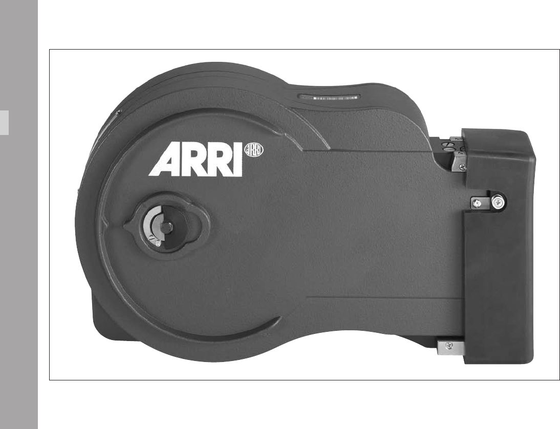
ARRIFLEX 416
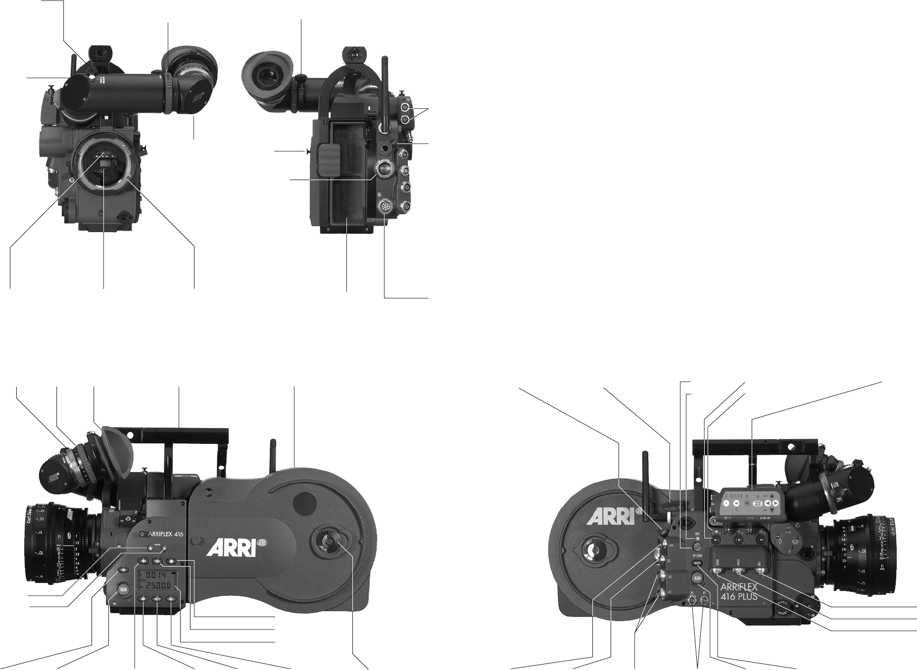
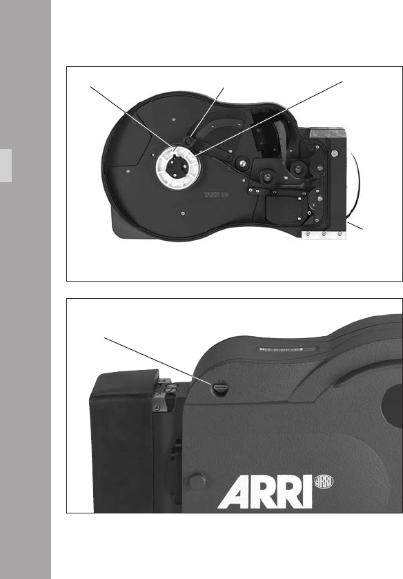
release button
for on board
battery
remote-socketcover on magazine opening
tape
hook
power supply
socket
mini monitor
sockets
PL-mountadjustable mirror shutterbre screen
nder arm
friction adjustment
for nder arm
lock for telecoping
nder arm
adjustment knob for
manual image
compensation
locking button for
manual image
compensation
eyepiece lock eyepiece eyecup standard camera handle SCH-2 shoulder magazine
RUN-buttonPHASE-button magazine door lock
dimmer - button
dimmer + button
MODE-button SEL-button SET-button
LOCK-button
PS/CCU-button
display
NORM-button
Integrated Video Assist IVS
LCS-socketsTCC-socketLDD-socket
battery release button
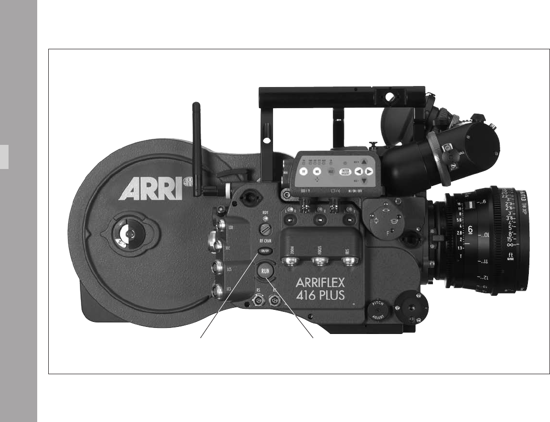
RS-sockets RUN-button camera power ON/OFF
magazine release button RF-channel
RDY LED
lens motor direction switch
lens motor status LED
IRIS-socket
FOCUS socket
ZOOM-socket

1.Content
Content
1. Contents ............................................................3
2. Safety Instructions and Legal Disclaimer ...............7
2.1 Safety Instructions .............................................7
Warning signs ..................................................7
General safety instructions ................................7
Specic safety instructions .................................9
2.2 Disclaimer .....................................................10
3. General Description of the ARRIFLEX 416 ...13
4. Installation of the Camera ..........................15
4.1 Packing and Transport ....................................15
4.2 Tripod & Remote Heads ..................................15
4.3 Split Bridge Plates BP-10 & BP-11 ....................16
Attaching the Bridge Plate to the Camera .........16
Removing the Split Bridge Plate
from the Base Plate .........................................18
Removing the Camera from the Tripod
for Hand-held Operation ................................18
4.4 Accessory Carrier ..........................................19
The 416 Shoulder Pad - SP-2 ..........................19
The 416 Left Rod Bracket – LRB-2 .....................20
4.5 Lens Support ..................................................21
4.6 Grip System ...................................................22
416 Standard Camera Handle SCH-2 ..............22
416 Riser .......................................................23
Low Mode Support Set LMS-2 .........................24
416 Lightweight Support LWS-5 ......................26
4.7 Operation from the Shoulder ...........................27
5. Power Supply ................................................28
5.1 Battery NC 24/7 R .........................................29
5.2 Charger NCL 24 R .........................................29
5.3 Mains Units NG 12/24 R and NG 12/26 R ....30
5.4 On-board Battery OBB-2 ................................30
Mounting the OBB-2 .......................................31
Removing the OBB-2 ......................................31
Charging the OBB-2 .......................................32
5.5 Accessory Power Supply .................................33
24 V Accessories ............................................33
Overload .......................................................33
6. Magazines ......................................................35
6.1 Loading the 416 Magazine .............................35
6.2 Checking the Loop Size ...................................39
6.3 Removing Exposed Film ..................................40
6.4 Transport and Storage ....................................41

Content
7. Camera Body .................................................43
7.1 Mechanically Adjustable Mirror Shutter ............43
Setting the Mirror Shutter Angle .......................43
Shutter Angle Measurement .............................44
Filming with HMI Light ....................................45
7.2 Exchanging the Fibre Screen ...........................46
7.4 Attaching the Magazine .................................47
7.5 Removing the Magazine .................................48
8. Optics ..............................................................49
8.1 Lenses ...........................................................49
Attaching Lenses .............................................49
8.2 Viewnder System ..........................................50
The Eyepiece ..................................................50
Adjusting the Viewnder .................................51
9. Camera Operation ........................................55
9.1 Main Camera Switch ......................................55
9.2 Running and Stopping the Camera ..................55
Running the Camera ........................................56
Stopping the Camera ......................................56
Inching ..........................................................57
9.3 Displaying and Setting Operational Parameters ...57
Overview of Display Modes ............................58
Overview of Display Symbols ..........................59
Film Counter ..................................................60
Frame Rates ...................................................62
Shifting phase ................................................64
Displaying Power Supply Voltage
(Mode 3) .......................................................64
Displaying On-board Battery information
(Mode 3) .......................................................65
Setting the Low Battery warning level
(Mode 3) .......................................................66
Displaying the Timecode Time and Frame Rate
(Mode 4) .......................................................67
Turning Timecode Recording On and Off
(Mode 4) .......................................................67
Displaying and Setting the Timecode User Bits
(Mode 5) .......................................................68
Setting the brightness of the button illumination
(Mode 6) .......................................................68
Switching the Beeper On and Off
(Mode 6) .......................................................69
Setting the Volume of the Warning Signal
(Mode 6) .......................................................69
Selecting a Preset ARRIGLOW Color
(Mode 7) .......................................................70
Setting a User-Adjustable ARRIGLOW Color
(Mode 7) .......................................................71

Content
10. Video Assist System ...................................73
10.1 General Description of the IVS .......................73
New Features ..................................................73
Main Features .................................................74
10.2 Setup ...........................................................76
10.2.1 Installation ..........................................76
10.2.2 Cabling ..............................................78
10.3 Standard Video Controls ...............................85
10.3.1 Switch On, Off and Check/Hide Menu ..85
10.3.2 Mechanical Iris ....................................86
10.3.3 Alignment of the image position
(X, Y and Rotation) and focus ...............87
10.3.4 White Balance (WB) ............................88
10.3.5 Gain Control .......................................94
10.3.6 Flicker free on/off ...............................97
10.3.7 Changing Format marking number .......99
10.3.8 Storing a video image .......................101
10.3.9 Wrong Cable Warning LED ...............103
10.4 Inserter Facilities .........................................105
10.4.1 Setting the On-Screen Displays ...........106
10.4.2 Main Menu .......................................107
10.4.3 Load/Store Menu ..............................108
10.4.4 White Balance (WB), Manual Gain Control
(MGC) and Bars Menu .......................112
10.4.5 Video and Text Adjustment Menu ........120
10.4.6 Format Marking Menu .......................128
10.4.7 Compare/Store Menu ........................133
10.4.8 System, LDS and Status Menu .............136
10.4.9 User Text Menu ..................................144
10.4.10 Timecode Menu ...............................150
10.4.11 USER BITS Menu ..............................156
10.4.12 Pull-Down Menu ..............................160
10.4.13 VITC Line Menu ...............................165
10.4.14 White Line Menu .............................168
11. Timecode .....................................................173
TC-Input .......................................................173
Increased accuracy of the TC Generator .........174
TC Output ....................................................175
Timecode and ESU-1 ....................................175
Using Timecode ..................................................176
Turning on and off the TC Recording ..............176
Indicating Timecode or User Bits ....................177
Overview of the Display Indications
used in Timecode Operation ..........................178

Content
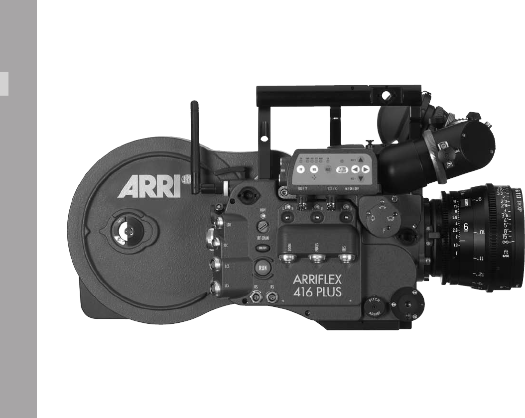
12. ARRIFLEX 416 Plus ....................................185
12.1 General Description ....................................185
12.2 Radio system ..............................................186
12.3 Wireless Remote System .............................188
Lens Motors .................................................188
WMU-3, WBU-3, WFU-3 and CLM-2 Motors ..190
2 x WMU-3, WBU-3, WFU-3
and CLM-2 Motors .......................................191
ZMU-3, WMU-3, WBU-3, WFU-3
and CLM-2 Motors .......................................192
ZMU-3, WZB-3, WBU-3, WMU-3 and WFU-3
with CLM-2 Motors .......................................193
WHA-2, WFU-3, WZB-3, ZMU-3
and CLM-2 Motors .......................................194
ZMU-3, WZB-3, WBU-3, WMU-3, LDD-FP,
WEB-3, WFU-3 and CLM-2 Motors ...............195
12.4 Camera Remote Control ..............................196
WRC-1 via wireless remote control ................197
WRC-1 with WHA-2 via cable ......................198
WRC-1 with WHA-1 ....................................199
RCU-1 .........................................................200
12.5 Lens Data Display .......................................201
Compatibility ...............................................201
Lens Data Archive ........................................201
13. Accessories .................................................203
Accessory Mounting Points ............................203
Work Light WL-3 ..........................................204
Heated Eyecup HE-4 & HE-5 .........................204
Remote “RUN” Switch RS-4 ...........................205
External Synchronization Unit ESU-1 ..............206
Remote Control Unit RCU-1 ...........................207
Wireless Remote Control WRC-1 ...................208
14. Maintenance ..............................................211
Camera .......................................................212
Magazine ....................................................214
15. Appendix ....................................................217
Fuses ...........................................................217
16. Technical Data ............................................223
17. Order Numbers .........................................225
18. ARRI Service ...............................................227
19. Index ...........................................................229
2. Safety Instructions and Legal Disclaimer
General safety instructions
Read and understand all safety and operating
instructions before you operate or install the system.
Retain all safety and operating instructions for
future reference.
Heed all warnings on the system and in the safety
and operating instructions before you operate or
install the system. Follow all installation and
operating instructions.
Do not use accessories or attachments that are
not recommended by ARRI, as they may cause
hazards and invalidate the warranty.
Do not attempt to repair any part of the system.
Repairs must only be carried out by authorized
ARRI Service Centres.
Do not remove any safety measures of the system.
2.1 Safety Instructions
Always follow these instructions to ensure
against injury to yourself and damage to the
system or other objects.
This safety information is in addition to the
product specic operating instructions in general
and must be strictly observed for safety reasons.
Warning signs
Possible risk of injury or damage to equipment.
This symbol indicates the risk of electric shock
or re danger that could result in injury or
equipment damage.
SafetyIntruction

Do not operate the system in high humidity
areas or expose it to water or moisture.
Do not place the system on an unstable trolley,
stand, tripod, bracket, or table. The system may
fall, causing serious personal injury and
damage to the system or other objects.
Operate the system using only the type of
power source indicated in the manual. Unplug
the power cable by gripping the power plug,
not the cable.
Never insert objects of any kind into any part
of the system through openings, as the objects
may touch dangerous voltage points or short
out parts. This could cause re or electrical
shock.
Unplug the system from the power outlet before
opening any part of the system or before
making any changes to the system, especially
the attaching or removing of cables.
Do not use solvents to clean.
Clean optical surfaces only with a lens brush or
a clean lens cloth! In case of solid dirt moisten
a lens cloth with pure alcohol.
Discard contaminated lens cloth after use.
Do not use it to clean lens.
Do not loosen any screws which are painted
over!
SafetyIntruction

Specic safety instructions
Never run the camera without a lens or a
protective cap in the lens mount receptacle!
Never operate the magazine release mechanism
while the camera is running!
As the iris ring end-stops of the ARRIMACRO
lenses move when the lens is focussed,
the ARRIMACRO lenses must not be used with
the ARRI Wireless Remote System (WRS) or the
Lens Control System (LCS).
There is danger of injury with rotating drive
gears on the lens barrel, or when switching the
operating direction of the 416 PLUS, UMC-1
and UMC-3 motor drives!
Any violation of these safety instructions or the non-
observance of personal care could cause serious injuries
(including death) and damage to the system or other
objects.
Note: Notes are used to indicate further information
or information from other instruction manuals.
aphoto indicates objects, which are shown in the
illustration.
Product Identication
When ordering parts or accessories, or if any questions
should arise, please advise the model type and serial
number of the product in question.
SafetyIntruction

1010
2.2 Disclaimer
Before using the products described in this manual be
sure to read and understand all respective instructions.
The ARRIFLEX 416 and 416 PLUS is only available for
commercial customers. The customer grants by utilization,
that the ARRIFLEX 416/PLUS or other components of the
system are only deployed for commercial use. Otherwise
the customer has the obligation to contact ARRI preceding
the utilization.
While ARRI endeavours to enhance the quality, reliability and
safety of their products, customers agree and acknowledge
that the possibility of defects thereof cannot be eliminated
entirely. To minimize risks of damage to property or injury
(including death) to persons arising from defects in the
products, customers must incorporate sufcient safety
measures in their work with the system and have to heed
the statuted canonic use.
No part of this document may be copied or reproduced
in any form or by any means without prior written consent
of ARRI. ARRI assumes no responsibility for any errors that
may appear in this document. The information is subject
to change without notice.
For product specication changes since this manual was
published, refer to the latest publications of ARRI data sheets
or data books, etc., for the most up-to-date specications.
Not all products and/or types are available in every
country. Please check with an ARRI sales representative
for availability and additional information.
Neither ARRI nor its subsidiaries assume any liability for
infringement of patents, copyrights or other intellectual
property rights of third parties by or arising from the use
of ARRI products or any other liability arising from the use
of such products. No license, express, implied or otherwise,
is granted under any patents, copyrights or other intellectual
property rights of ARRI or others.
ARRI or its subsidiaries expressly exclude any liability,
warranty, demand or other obligation for any claim,
representation, or cause, or action, or whatsoever, express
or implied, whether in contract or tort, including negligence,
or incorporated in terms and conditions, whether by statue,
law or otherwise. In no event shall ARRI or its subsidiaries
be liable for or have a remedy for recovery of any
special, direct, indirect, incidental, or consequential
damages, including but not limited to lost prots, lost
savings, lost revenues or economic loss of any kind or for
Diclaimer

1111
any claim by third party, downtime, good-will, damage to
or replacement of equipment or property, any costs or
recovering of any material or goods associated with the
assembly or use of our products, or any other damages
or injury of persons and so on or under any other legal
theory.
In the case one or all of the forgoing clauses are not
allowed by applicable law, the fullest extent permissible
clauses by applicable law are validated.
ARRI is a registered trademark of Arnold & Richter Cine
Technik GmbH & Co Betriebs KG.
Note:
This product and the accessories recommended by the
manufacturer full the specications of the EU-Guideline
89/336/EWG.
Diclaimer
11
GeneralDecription

11
.GeneralDecriptionoftheARRIFLEX1
The ARRIFLEX 416 is a lightweight, modern Super 16 lm
camera with a 35-style viewnder and a very low sound
level. A completely new lightweight ergonomic design,
integrated electronic accessories and compatibility with the
same lenses and accessories used by its 35 mm siblings
make the 416 a powerful, exible and portable Super 16
camera.
There are two models: the ARRIFLEX 416 Plus and the 416.
The 416 Plus has built-in lens motor drivers and radio
modem for wireless lens and camera control. This
eliminates add-on boxes and untidy cables.
• A sound level of less than 20dBA makes the 416 the
quietest 16 mm camera available.
• The ARRIFLEX 416 is equipped with a low-maintenance,
silent precision movement with single pull down claw
and registration pin. Pull down is pitch-adjustable for
quietest running.
• The viewnder can be rotated in two axes and can be
used on either side of the camera with full image
orientation compensation. Its optics are bright and
have a high contrast and high resolution.
The viewnder arm can be extended laterally for left
eye operation.
• The high quality IVS video assist is integrated into the
camera body.
• Speed ranges from 1 – 75 fps, forward only.
• The mirror shutter is manually adjustable to 180°,
172.8°, 150°, 144°, 135°, 90° and 45°.
• The 416‘s low prole design is substantially smaller
and lighter than its predecessors.
A comprehensive range of optical, mechanical and
electronic accessories further expands the operational
possibilities of the camera.
GeneralDecription
11
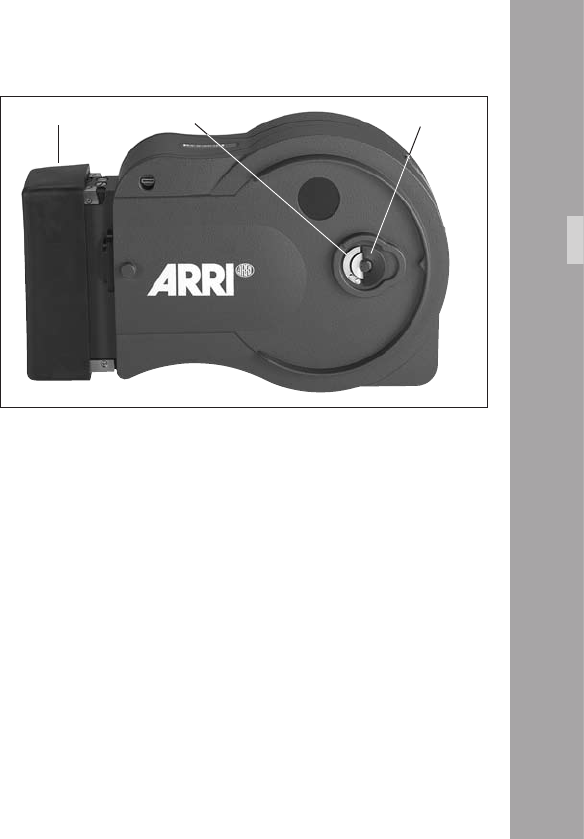
magazine opening cover loop protector
Intallation

11
.IntallationoftheCamera
4.1 Packing and Transport
In order to prevent damage to the mirror
shutter, a protective cap must be in the lens
mount receptacle at all times.
When the ARRIFLEX 416 is transported or
stored without a magazine, the magazine
opening cover aphoto should be in place.
Loaded or empty magazines should only be
transported or stored with the loop protector
aphoto attached to avoid damage to the lm
stock and the magazine throat assembly.
4.2 Tripod & Remote Heads
The following tripod heads are suitable for use with the
ARRIFLEX 416:
• ARRIHEAD
• ARRIHEAD 2
• ARRIHEAD 2 with integrated encoders
• ARRI uid heads
• Sachtler Studio 7, 150 H
• Mitchell head
• OConnor 1030/2060/2575
• Moy head
• Ronford Mini 7/F7/2003/2015/Atlas 30/Atlas
• A&C Pee Pod 500, 1000 & 1600/Power Pod
2000 & Classic
• Hot Head
• Cam-Remote head
• Worall head
In applications where the camera mount is subject
to high forces (e.g. helicopter mounts) the camera
must be additionally secured with retaining cords.
All fastening screws must be tightened rmly with
an appropriate screwdriver (not with the commonly
used coin!).
Intallation
11
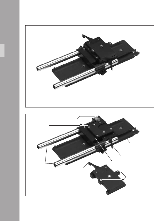
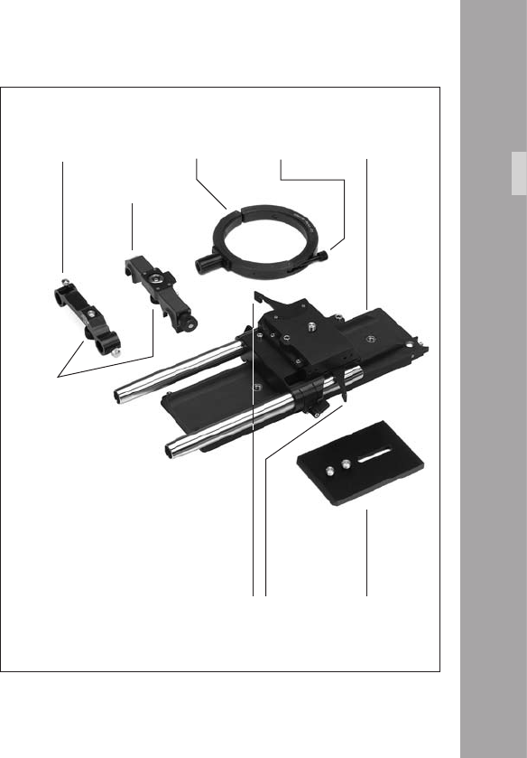
4.3 Split Bridge Plates BP-10 & BP-11
The Split Bridge Plates facilitate balancing of the camera on
the tripod and elevate the 416 to proper height for the
mounting of accessories. They separate into two pieces to
allow you to quickly change between tripod and hand-held
operation. The BP-10 aphoto is designed for 19 mm
support rods, the BP-11 for 15 mm support rods. The
bridge plates consist of the Accessory Carrier, the Sled,
the Base Plate and a pair of 240 mm long Support Rods
19 mm Support rods with lengths of 165 mm, 185 mm,
340 mm and 440 mm or 15 mm diameter support rods
with lengths of 340 mm and 440 mm are available
separately as options.
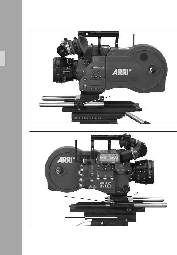
Attaching the Bridge Plate to the Camera
• Separate the Accessory Carrier from the Sled
aphoto.
• Engage the two cylindrical pins on the Accessory
Carrier with the corresponding holes in the camera
base then fasten it aphoto with the slotted screw to
the 3/8-16 threaded hole in the camera base. The
clamping lever of the Accessory Carrier will be on the
camera right side.
• Screw the Wedge Plate for Base Plate onto the Base
Plate of the tripod and lock onto the tripod head.
base plate
support rods sled
Intallation
accessory carrier
clamping lever
spring loaded catch spring loaded pin
cylindrical pins
clamping lever
dove tail guide
11
• Slide the Sled into the dovetail-guide of the Base Plate
until the spring-loaded stop pin aphoto snaps back
audibly. The Sled‘s position can then be xed with the
clamping lever.
• Fit the camera onto the short dovetail-guide on the
Sled. Slide it forward until the spring-loaded catch
aphoto locks it in place.
• Tighten the clamping lever of the Accessory Carrier
aphoto.
• Slide the support rods into the guides and clamp.
• Equip the camera with the required accessories to
determine the centre of gravity. Loosen the sled
clamping lever, and by sliding the camera on the base
plate nd the optimum balance position. Then retighten
the clamping lever.
The accessory carrier has the same dovetail as
the bridge plate so it can be mounted to the
base plate.
If the Lightweight Support is used and
accessories are mounted to the Lightweight
Support rods these accesories will collide with
the base plate. In this conguration the
accessory carrier can not be mounted to the
base plate.
cylindrical pins
Intallation
11
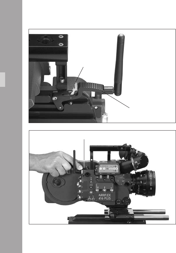
Removing the Split Bridge Plate
from the Base Plate
• Before removing the camera, make sure that all cables
are disconnected and that the eyepiece levelling rod is
detached.
• For fast removal of the bridge plate from the base
plate, loosen the sled clamping lever aphoto, push in
the stop pin aphoto and then pull the camera with
the Sled aphoto from the base plate.
sled
release catch
Intallation
accessory carrier
clamping lever
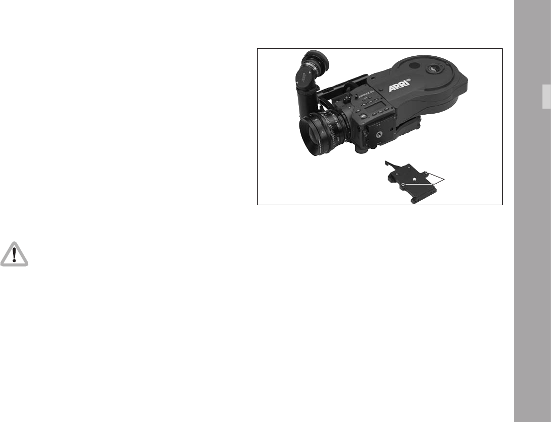
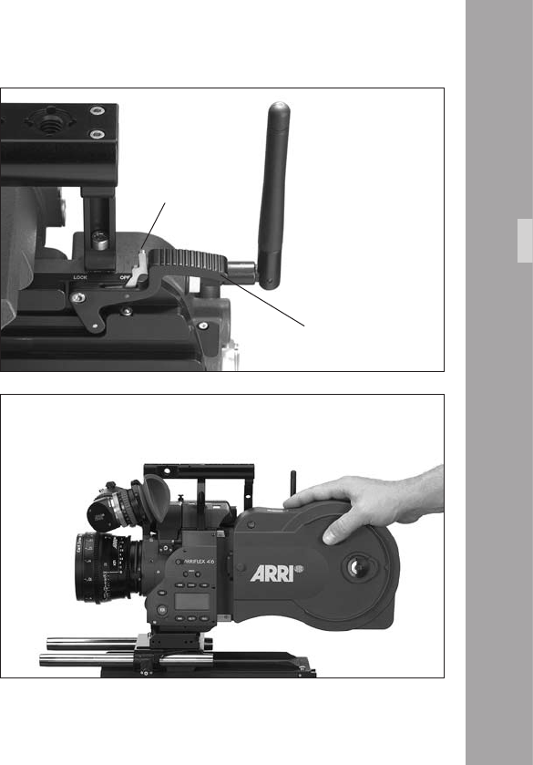
Removing the Camera from the Tripod
for Hand-held Operation
• Before removing the camera, make sure that all cables
are disconnected and that the eyepiece levelling rod is
detached.
• For fast removal of the camera from the tripod for
hand-held operation, loosen the accessory carrier
clamping lever aphoto, push in the release catch
aphoto and then pull the camera with the Accessory
Carrier aphoto away from the Sled.
stop pin
sled clamping lever
11
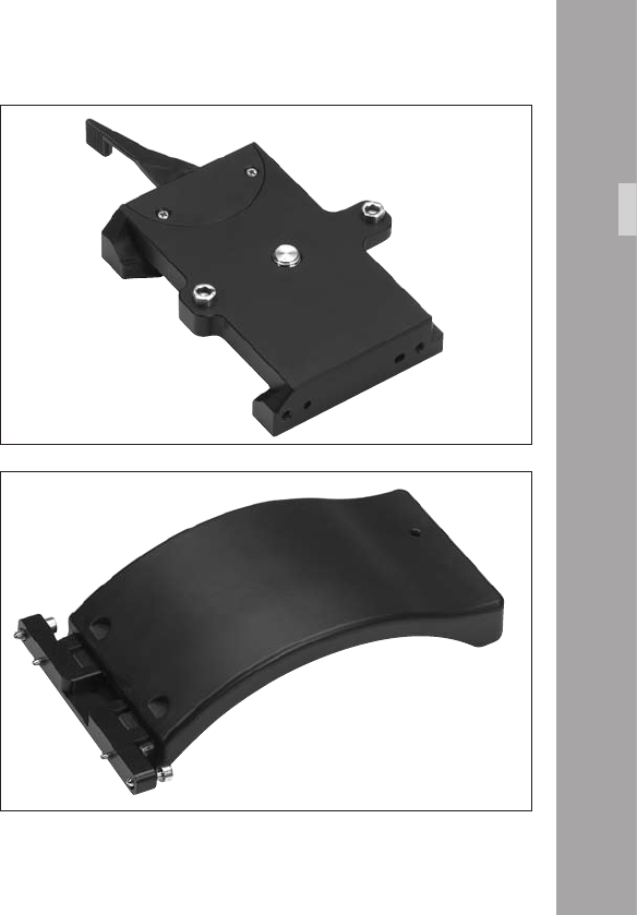
4.4 Accessory Carrier
The Accessory Carrier is a part of the BP-10 & BP-11
Split Bridge Plates. It must be tted to the camera to work
with a split bridge plate but, as its name suggests, it is
also needed for mounting the following accessories:
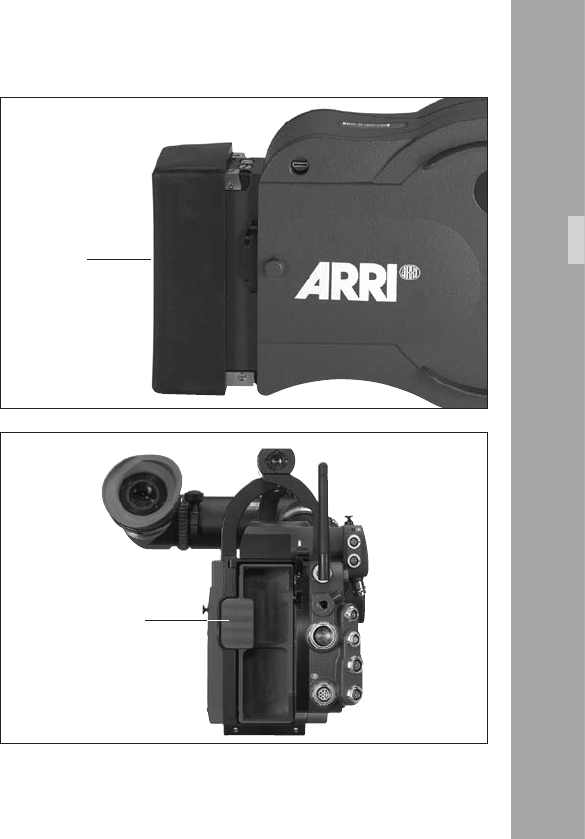
The 416 Shoulder Pad - SP-2
The SP-2 shoulder pad aphoto is a comfortable
sculpted pad for hand-held operation. It hinges at its front
edge to allow it to be pushed down to facilitate the
mounting and removal of magazines.
accessory carrier
Intallation
shoulder pad SP-2
00
The 416 Left Rod Bracket – LRB-2
aphoto attaches to the left side of the Accessory Carrier
to allow the mounting of single 19 mm support rod. It is
also tted with an Accessory Rosette.
left rod bracket LRB-2
Intallation
11
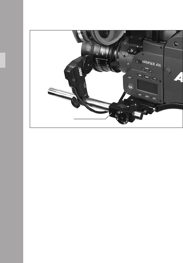
4.5 Lens Support
Heavy or long lenses require support to avoid overstressing
the camera‘s lens mount. Supporting a lens is achieved
by using either the Lens Support LS-9 (snapped onto 19
mm support rods) aphoto or the Lens Support LS-10
(pushed onto 15 mm support rods) in conjunction with a
lens support ring aphoto attached to the lens in use.
They meet and screw together at a standard height.
• Mount the LS-9 lens support onto the support rods from
above and let it click into place by applying slight pressure
or push the LS-10 onto the support rods from the front.
• Fit the appropriate support ring aphoto loosely onto
the lens. Do not tighten.
• Then slide the lens into the lens mount receptacle and
lock. It is essential that you take the weight of the lens
until the Lens Support is under the support column of
the lens support ring.
• Connect the support ring to the lens support and
tighten the knurled screw aphoto as well as the
clamping lever aphoto.
• Complete the process by tightening the clamp screw
aphoto on the support ring.
Note: Mounting the support ring on the relevant lens
is usually carried out only once. The support
ring can then remain in position on the lens.
Intallation
base platelens support
LS-10
lens support ring clamp screw
wedge plate
knurled screw
lens support
LS-9
clamping lever
4.6 Grip System
The multipurpose grip system on the ARRIFLEX 416
guarantees high stability through its xed connection to
the camera body and provides numerous possibilities for
attaching accessories. 3/8-16 inner threads allow attach-
ment in various positions.
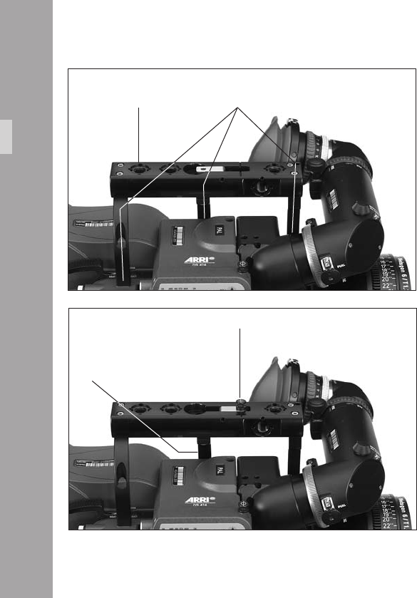
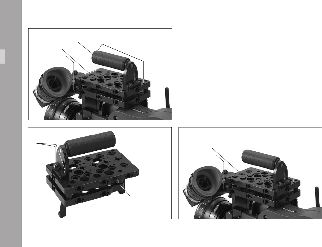
416 Standard Camera Handle SCH-2
The 416 Standard Camera Handle is a dual post handle.
A third post can be added for extra stability when mounting
the camera in an under-slung fashion. It is mounted on
the camera using 2 (or 3) hexagonal screws aphoto.
The 416 Standard Camera Handle includes a ip-out tape
hook that can be folded away to leave a at top surface to
allow the camera to be under-slung and comfortably carried.
Various accessories can be attached using the 3/8-16 holes.
third post
Intallation
standard camera handle SCH-2 screws
ip out tape hook
The 416 Standard Camera Handle can be extended with
the Handle Extension Block HEB-1 aphoto. The Handle
Extension Block can be mounted to any of the 3/8-16 holes
by rst placing the 2 pins aphoto into the corresponding
pin holes on the handle and then fastening the extension
block screw aphoto inside the extension block by using
a long 5mm Allen key. Note that the viewnder cannot be
swung over to the camera right side when the Handle
Extension Block is attached to the front of the 416
Standard Camera Handle.
Note: The 416 Standard Camera Handle is positioned
in the centre of gravity for a typical conguration.
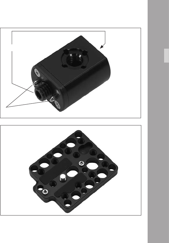
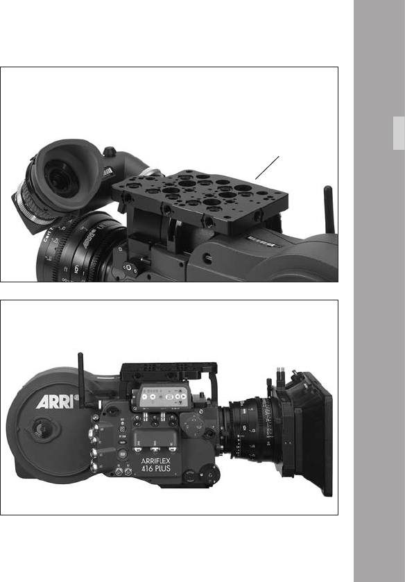
416 Riser
A at base with diverse attachment points for use when
attaching the 416 to a Steadicam plate or other at surface.
Useful when working with Lightweight Support LWS-5, in
order to have LWS-5 clear the mounting surface. Useful
since 416 bottom threads are not compatible with some
Steadicam plates. Also useful in situations requiring
additional mounting security.
Intallation
handle extension block HEB-1
block screw
pins
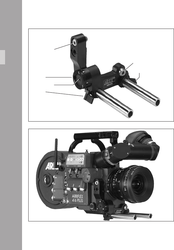
Low Mode Support Set LMS-2
The Low Mode Support Set LMS-2 aphoto is a sturdy
triple post camera handle with integrated Steadicam low
mode plate that attaches to the 416 camera body.
It consists of the Low Mode Bracket aphoto, the Low
Mode Support Handle aphoto and Low Mode Riser
aphoto. The Low Mode Bracket is mounted with 3
hexagonal screws aphoto to the 416 camera body.
The Low-Mode Handle can be attached on both the basic
Low-Mode Bracket and the Low-Mode Riser. There are three
mounting positions on the plates, one at the rear of the plate
low mode handlescrews
Intallation
tape hook
low mode riser
low mode bracket
low mode support handle
low mode riser
low mode bracket
access holes for mounting screws
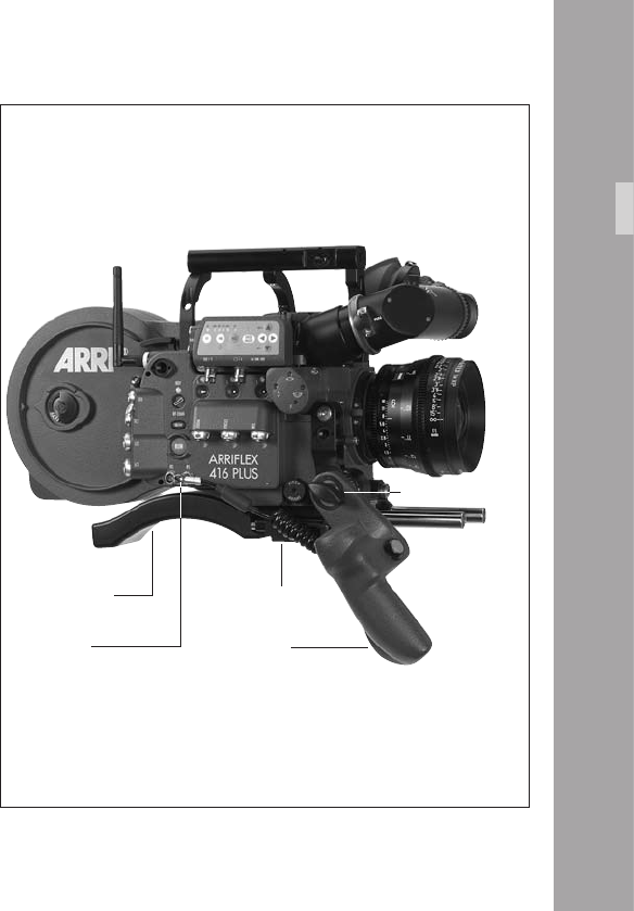
aphoto, one position approximately 50 mm (2“) forwards
and a third approximately 100 mm (4“) forwards. The handle
can be mounted in any of the positions facing forwards or
backwards; in this way, the grip balance can be adapted
to best t the lens in use.
The Low-Mode Bracket aphoto alone offers the lowest
prole and smallest plate-to-lens distance, optimal for Steadicam
applications. It can be attached with the viewnder on the
camera; however, since the Low-Mode Bracket remains under
the level of the viewnder itself, removal of the viewnder
will be necessary in applications requiring the attachment
of a longer plate onto the Low-Mode Bracket.
With the Low-Mode Riser tted, the plate to lens distance
is increased so that a longer plate attached to the Riser
will not collide with the viewnder. This is especially useful
in the situation where rapid switching between operation
in low-mode and operation with viewnder is necessary.
A tape hook is located camera right on the Low-Mode Riser,
and both the Low-Mode Bracket and Low-Mode Riser offer
diverse attachment points for additional accessories.
low mode bracket
Intallation
416 Lightweight Support LWS-5
The 416 Lightweight Support LWS-5 is a sturdy, three point
bracket for mounting 15 mm lightweight support rods. The
LWS-5 is tted with an Accessory Rosette to replace the
camera‘s rosette which is covered when the LWS-5 is
tted aphoto.
• Fit the LWS-5 to the camera by rst engaging the two
guide pins of the upper 3/8-16 screw on the camera
right side aphoto. This will position the LWS-5 so
that the 3/8-16 screw on the front of the bracket lines
up with the threaded hole In the camera. Engage this
screw by a few threads but leave it loose aphoto.
• Tighten the two screws on the camera right side – the
lower one is accessed through a hole in the Accessory
Rosette teeth aphoto.
• Tighten the front screw.
• Slide the support rods into the guides and clamp.
Note: Due to the camera‘s small dimensions and because
the distance from the lens to the support rods is
xed, the rod clamps of the LWS-5 project below
the camera base. To mount the camera with the
LWS-5 tted on a support system such as the Steadi-
cam, it is necessary to t the 416 Riser. This
presents a at base, clear of the support rods,
with selection of threaded holes.
LWS-5
Intallation
upper screw
rosette
clamp
front screw
clamp
lower screw
4.7 Operation from the Shoulder
• Fit the Accessory Carrier to the camera base.
• Attach the Shoulder Pad to the rear of the Accessory
Carrier aphoto.
• Position the handgrip on the rosette and fasten with the
fastening screw aphoto.
• Plug the cable for starting and stopping the camera
into the RS socket.
accessory carrier
handgripRS socket
shoulder pad
rosette screw
Intallation
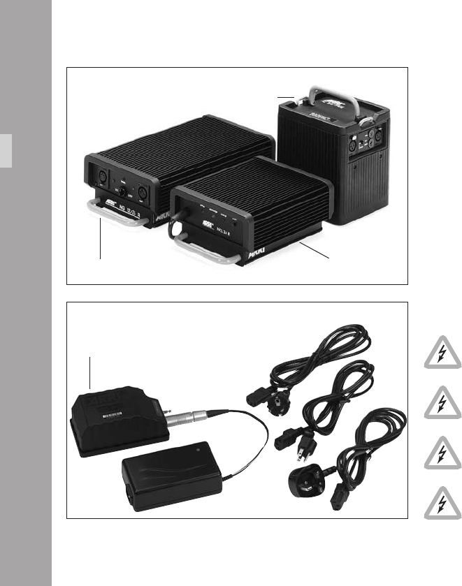
.PowerSupply
The acceptable voltage range to power the camera is from
20.6 to 35 V DC. The power supply cable is attached to
the power supply socket on the camera. Available are:
• the battery NC 24/7 R with charger NCL 24 R
• the mains unit NG 12/24 R.
• the mains unit NG 12/26 R aphoto.
• the on-board battery OBB-2 with charger aphoto.
• First switch on the mains unit (if used).
• Connect the camera to the mains unit or to the battery.
• Switch on the main switch of the camera.
Do not open the batteries!
Charge batteries only with the proper ARRI
chargers!
Do not bypass the fuse or temperature switch!
Do not heat NC-batteries!
Do not short-circuit NC-batteries!
PowerSupply
battery NC 24/7R
NCL 24 RNC 12/26
OBB-2 with charger

5.1 Battery NC 24/7 R
The battery NC 24/7 R has a capacity of 7 ampere-hours.
• Ensure that the main switch on the camera is off.
• Plug the battery cable KC-20-S or the spiral battery
cable KC-29-S into the power supply socket on the
camera and into the battery socket.
Note: If the battery voltage is too low, the “bat”
symbol will show in the camera display.
5.2 Charger NCL 24 R
Charge the NC 24/7 R battery with this charger.
• First check whether the correct mains voltage is set on
the charger.
• Connect the charger to the mains supply.
• Plug the charger cable into the battery socket.
• Press the start button.
Indication of the LEDs
LED Indication
yellow discharging (1A)
red charging
green charger connected to the mains
PowerSupply

00
5.3 Mains Units NG 12/24 R and
NG 12/26 R
Use of a mains unit is recommended for lming in the studio
and when using electronic accessories with high power
consumption.
• First check that the correct mains voltage is set on the
mains unit.
• Ensure that the camera power is turned off.
• Set the voltage switch on the mains unit to 24/26 V.
• Plug the battery cable KC-20-S or the coiled battery
cable KC-29-S into the power supply socket on the
camera and into the 24/26 V socket on the mains unit.
Note: The NG 12/24 R was the original design that
provided 12 & 24 volts out – this was superseded
by the NG 12/26 R which outputs 12 & 26 volts.
The NG 12/24 R can easily be upgraded to
NG 12/26 R specication at an ARRI Service
Centre.
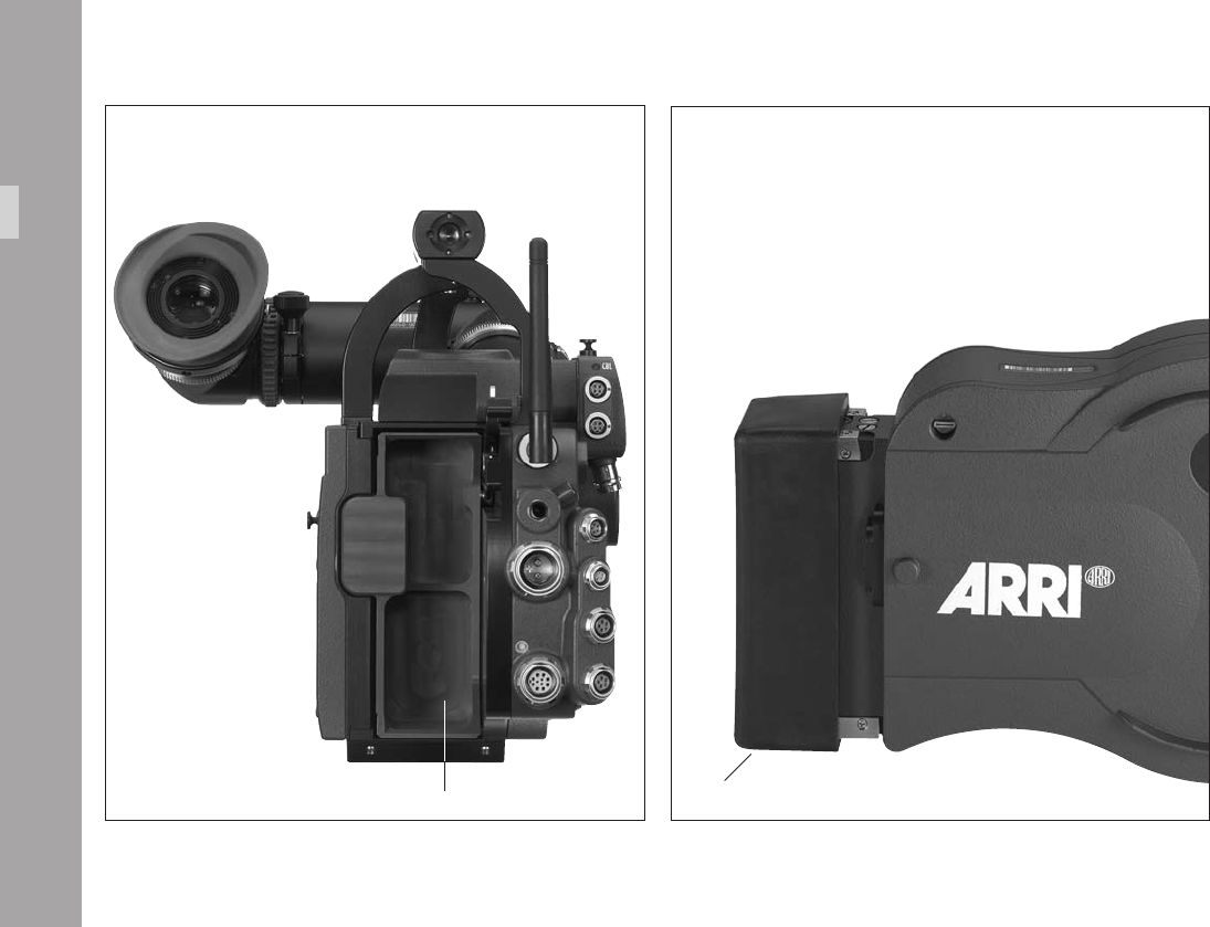
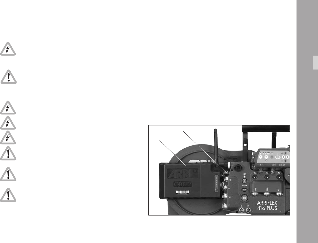
5.4 On-board Battery OBB-2
The OBB-2 On-Board Battery attaches directly to the camera
body by means of a quick change mechanism that can be
easily operated with one hand. The OBB-2 incorporates a
built-in power meter to indicate the state of charge, while
an extra contact in the power connector communicates this
and other information to the camera. When an OBB-2 is
connected, display Mode 3 offers the choice of showing
battery voltage (as normal) or battery capacity (in percent)
or an estimation of how many more magazines the remaining
charge can run. The OBB-2 is an intelligent 29.6 volt
Lithium-Ion battery with a capacity of 80 Watt/hours. A
fully charged OBB-2 will typically run seven magazines
and last about four hours in Standby. Although the 416
power connector has an additional contact it remains
compatible with standard ARRI 24 volt power cables.
The OBB-2 is for use with ARRIFLEX 416
cameras only.
Do not use with an extension cable as this will
prevent communication between the OBB-2 and
416. The 416 monitors the OBB-2 and prevents
it going into deep discharge.
PowerSupply
11
The OBB-2 contains Lithium-Ion cells. The
equivalent Lithium content is less than 8 grams.
Tested according to UN manual of test and
criteria chapter 38.3.
To reduce the risk of re burns do not
disassemble, crush, puncture or short external
contacts.
Do not dispose of in re or water.
Do not expose to temperatures above 60°C.
Use specied charger only.
Charge: 0°C to 40°C.
Discharge: -20° to +50°C.
Remove from camera when discharged, during
transport and in storage.
Check the current regulations regarding trans-
portation of Lithium-Ion batteries with your carrier.
Mounting the OBB-2
• Fit the power plug of the OBB-2 into the camera power
connector and slide the battery forward aphoto.
Removing the OBB-2
• Hold the OBB-2 and press the on-board battery
release button aphoto.
• Pull the battery backwards until the power connectors
disengage.
OBB-2
release button
PowerSupply
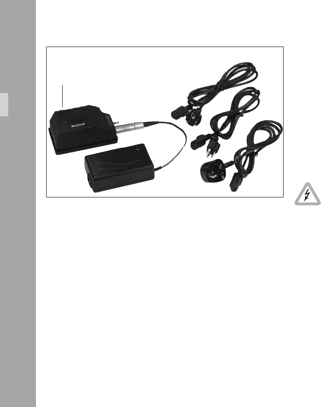
Charging the OBB-2
• Connect the battery to the charger aphoto.
• Connect the mains supply.
• The LED on the charger glows orange when the battery
is empty
• The LED on the charger glows yellow when the battery
is partly full
• The LED on the charger glows green when the battery
is fully charged
Do not charge below 0°C.
PowerSupply
OBB-2 with charger
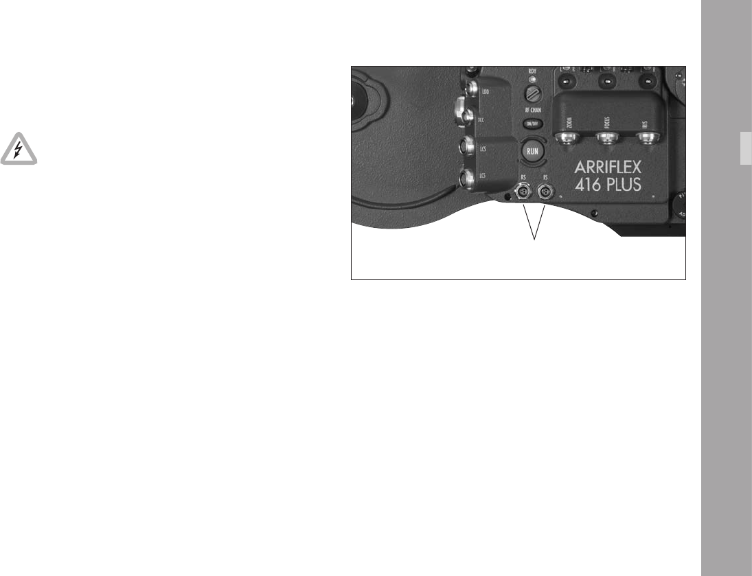
5.5 Accessory Power Supply
24 V Accessories
The RS sockets supply the same voltage as the
camera power supply.
Ensure that the accessories to be used are
suited to the available voltage!
24 V accessories are normally attached to the RS sockets
aphoto. 24 V can also be drawn from the “REMOTE“
connector. At 24 V, the maximum continuous current for both
types of socket together is 2 A, with a peak load of 4 A.
Overload
If the current drawn at the accessory sockets exceeds the
allowable maximum, a self-resetting safety circuit
interrupts the power supply. If this happens, turn the
camera off, unplug all accessories from the camera, wait
for one minute and turn the camera back on.
RS sockets
PowerSupply
Magazine
.Magazine
Only the SHM-3 416 Shoulder Magazine 120/400 can
be used with the ARRIFLEX 416. Magazines from the
16 SR 1, 2 & 3 cameras are not compatible.
6.1 Loading the 416 Magazine
Loading the magazine should be practised in daylight with
a piece of waste lm until the procedure can be carried out
condently in a darkroom or lm changing tent.
Cutting the lm through the middle of the perforation holes
simplies the loading process considerably. The lm head
of a fresh roll of lm is normally cut in this way.
Step 1: The Feed Side
Load the lm into the feed side in absolute darkness
(darkroom or lm changing tent).
• Remove the loop protector and lay the magazine on a
at surface with its feed side door facing upwards.
• To open the door, ip up the locking grip, depress the
safety catch and turn it counter-clockwise aphoto.
• Lift up the magazine cover and remove it by pulling the
cover to the right.
locking grip
Magazine
safety catchloop protector
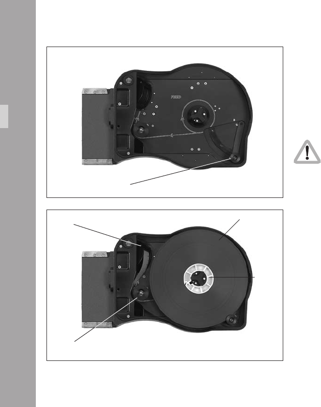
• Swing the footage counter roller arm aphoto away
from the feed side core holder until it locks in place.
• Remove the lm from the lm can and black bag.
• Remove the tape from the lm head. Ensure that the
tape is completely removed and secured out of the way.
• Place the lm roll on the core holder so that it unwinds
in the direction shown aphoto. Press it down fully.
When placing the lm on the core holder, do
not push on the lm itself as it could become
conical. Push on the lm core instead.
• Hold the lm roll still and turn the core holder until the
core holder key clicks into the key slot of the lm core.
Make sure the core holder cannot turn any further.
• Release the footage counter roller arm gently so the roller
rests on the outer surface of the lm roll. The sides of
the roller should overlap the lm roll edges aphoto.
• Push approximately 15 cm (6“) of lm into the slit at
the top of the angled transfer roller. Then thread the
lm around the guide roller.
• Hold the lm still where it enters the transfer roller and
gently back-tension the lm roll to remove any slack.
• Replace and lock the feed side magazine door, being
careful not to trap any lm in the process.
• Check if the door is properly closed before removing
the magazine from the changing tent or dark room.
footage counter roller arm
lm core
lm roll
Magazine
transfer roller
guide roller
loop mark
transfer roller
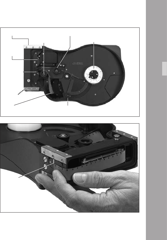
Step 2: The Take-up Side
The following procedures may be carried out in the light.
• Flip the magazine over so that the take-up door is
uppermost and the top of the magazine is facing you.
The ARRI on the door will be upside down.
• Open the take-up side magazine door and latch back
the lay-on roller arm. Fit an empty lm core to the
take-up core holder making sure that the core holder
key is engaged in the key slot of the lm core.
• The lm head should be protruding from the transfer
roller aphoto. Check that it is cut squarely through a
perforation.
• Thread the lm head around the forward guide roller
as indicated inside the magazine. Without touching the
lm core, push the lm head into the upper sprocket roller
until its teeth engage in the lm perforations aphoto.
• Once the sprocket teeth have engaged in the lm
perforations, turn the lm core until the lm head
emerges from the magazine throat.
• Set the loop length by pulling the lm head away from
you and align it with the loop mark on the bottom of
the magazine aphoto. Adjust the loop length by
turning the take-up lm core.
• Now take your hand off the lm core – there is enough
inertia in the sprockets to maintain the loop length.
footage counter roller
lm coreforward guide roller
upper
sprocket roller
Magazine
lower
sprocket roller
rear guide rollerloop length mark
• Hold the lm between thumb and middle nger of your
left hand, while using your index nger to push the lm
head into the lower magazine throat slot. The angle at
which the lm enters is not as critical as it is on the old
SR magazines.
• Keep pushing the lm in with your index nger until
you see the sprockets rotate aphoto. Now take hold
of the lm core again and rotate it counter-clockwise.
This will pull the lm from the throat into the take-up
chamber.
• Thread the lm around the rear guide roller following
the path indicated in the magazine.
• Insert the lm head into the lm core and manually
wind the core holder two or three turns until the lm
winds tightly onto the core.
• Unlatch the lay-on roller arm.
• Close and lock the take-up side door.
• If using timecode, set the sensitivity switch according to
the table In the Timecode section of this manual. The
switch is located at the top left corner of the feed side
door aphoto.
lm core
lower
magazine
throat
lm core slit lay-on roller arm
Timecode sensitivity switch
Magazine
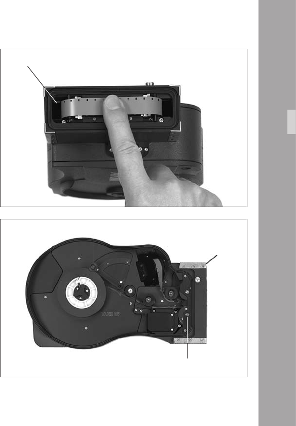
6.2 Checking the Loop Size
• Turn the magazine so the throat is pointing upwards
with the feed side facing you.
• Push the loop to the left so all the slack is below the
pressure plate.
• The end of the loop must fall within the white line
marked in the lower throat chamber aphoto.
• If the loop length is not correct push down the button in
the midlle of the lower sprocket and turn the sprockets
against each other to alter the loop length. Make sure
the sprocket engages properly again after changing
the loop size. Check loop length again.
white line
lay-on roller arm
Magazine
sprocket adjusting button
00
Magazine
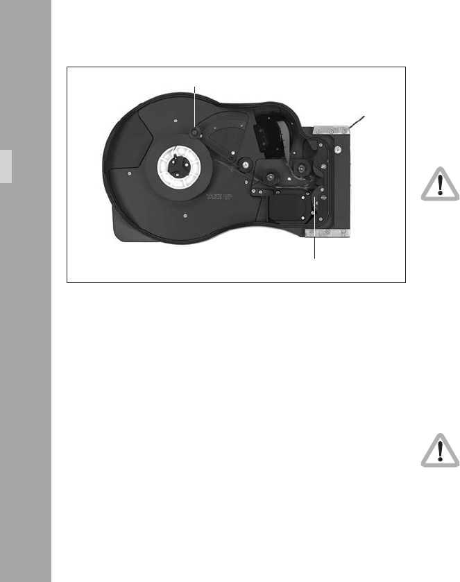
lay-on roller arm 6.3 Removing Exposed Film
If only part of the lm roll has been exposed and you intend
leaving a ‘short end‘ in the magazine, cut the lm loop
squarely through a perforation.
The following steps should be carried out in
total darkness in a darkroom or changing tent!
• Open the take-up side door by ipping the locking
grip upwards and turning the grip counter-clock-wise.
• Lift up the door and remove it by pulling it to the left.
• Manually wind the lm roll counter-clockwise until the
lm tail comes free from the lower sprocket roller.
• Swing the lay-on roller arm aphoto away from the
winding shaft until it locks in place.
• Pull the lm roll upwards and off.
Note: When pulling the lm roll off the shaft, grip the
roll rmly to prevent the middle of the lm roll
from sagging down.
The lm tail should never be pulled to tighten the
roll. This causes scratches and static discharging.
lower sprocket roller
11
Magazine
6.4 Transport and Storage
Loaded or empty magazines should only be transported
or stored with the loop protector aphoto attached to
avoid damage to the lm stock and the magazine throat
assembly.
It is recommended that when the ARRIFLEX 416 is
transported without a magazine the magazine opening
cover should be attached aphoto.
loop protector
magazine opening cover

Magazine
.CameraBody
7.1 Mechanically Adjustable
Mirror Shutter
The mirror shutter on the ARRIFLEX 416 can be mechanically
adjusted while the camera is switched off. The shutter angle
can be adjusted from 180° to 45°. The shutter locks in the
following positions: 180°, 172.8°, 150°, 144°, 135°, 90°
and 45°.
Setting the Mirror Shutter Angle
• Switch off the camera and disconnect the camera from
the power supply!
• Remove the lens or the protective cap from the lens
mount receptacle.
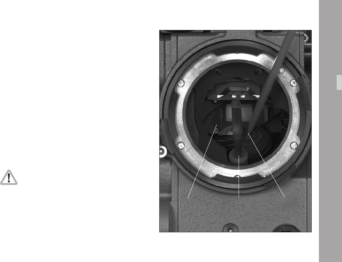
Do not touch the reective surface of the mirror.
• Prevent the shutter from rotating by inserting the at tip
of the red plastic lm track cleaning rod from the
camera’s tool kit into the slot at the mirror shutter
centre aphoto.
• Insert the shutter tool carefully into the adjustment
recess aphoto.
CameraBody
mirror shutter tool lm track cleaning tool
• Turn the shutter tool to set the shutter to the desired
shutter opening. The shutter is held in its preset
positions by a sprung-ball, which can be felt as the
shutter is adjusted. Make sure the shutter registers
properly at the set opening.
• Remove the shutter tool and lm track cleaning rod
Operation of the camera when the mirror
shutter is not correctly locked in position may
cause incorrect exposure!
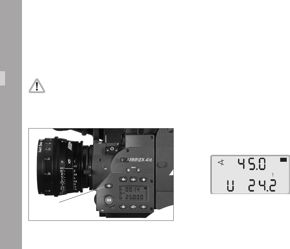
Shutter Angle Measurement
• Holding the “PHASE” button pressed in Standby will
make the camera inch forward.
• During this the display shows the measured shutter
angle in the upper line. The lower line displays the
voltage of the power supply or the percentage of
remaining battery capacity or the number of magazine
rolls left.
phase button
CameraBody
Filming with HMI Light
When lighting scenes with HMI/CID discharge lamps, the
intensity of the light will pulse with the power supply frequency
unless a icker-free ballast is used. To achieve constant
exposure, the camera’s frame rate, the supply frequency
of the lighting and the angle of the mirror shutter must all
relate to each other. As the camera frame rate and the supply
frequency of the lighting are normally xed, compensation
is achieved by adjusting the angle of the mirror shutter.
The following table indicates the mirror shutter angle that
needs to be set:
Supply frequency 50 Hz 60 Hz
Frame rate 25 fps 24 fps 25 fps 24 fps
Shutter angle Any angle 172.8° 150° Any angle
CameraBody
Make sure you compensate exposure for any
change in mirror shutter angle!
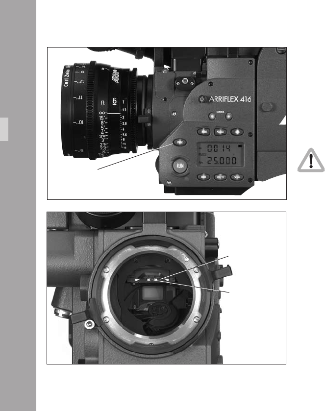
7.2 Exchanging the Fibre Screen
• In Standby, briey press the “PHASE” button to position
the shutter so the mirror surface is protected from
damage as far as possible aphoto.
• Before exchanging the bre screen, switch the camera’s
main switch off and disconnect the camera from the
power supply!
• Remove the lens or the protective cap.
Do not touch the mirror surface!
• Using the special forceps (Hirschmann Clamp) from the
camera‘s toolkit, pull the bre screen aphoto out of
the holder by its tongue aphoto.
• Check that both the bre screen to be inserted and its
frame are completely clean.
• With the special forceps, push the chosen bre screen
into the holder as far as it will go. A sprung-ball catch
xes the bre screen exactly in the right position.
• Check that the bre screen is correctly locked in place.
Note: Cleaning or exchanging the eld lens is
covered in Chapter 14 Maintenance, Cleaning
the Field Lens.
CameraBody
phase button
tongue
bre screen
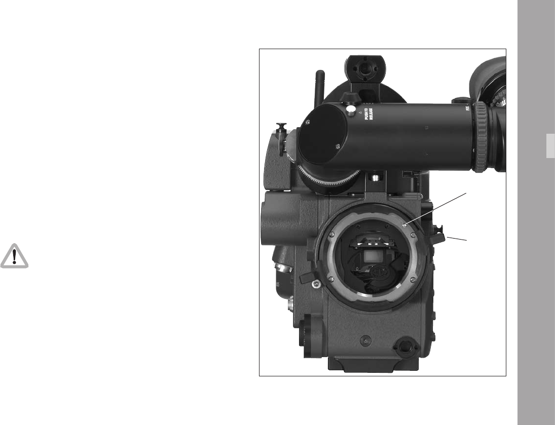
7.4 Attaching the Magazine
• Move the magazine release lever safety catch to the
open position aphoto.
• Press down the magazine release lever aphoto and
remove the magazine opening cover.
• Remove the loop protector from the magazine.
• Place the magazine’s throat in the camera opening and
slide the magazine forward into the camera until it latches.
• Flip the magazine release lever safety catch forward to
prevent accidental release of the magazine.
• Press the “PHASE” button for a couple of seconds to
inch the lm.
Note: After a new magazine has been attached or after
camera power has been turned on, you should
always push the “PHASE” button to perform a loop
check (the display shows “LooP“). This takes about
2 seconds and will engage the pull down claw,
check loop size and centre the loop properly.
Note: If the loop check nds that the loop is too short for
safe camera performance the message “Error
LooP.S“ will show in the camera display. The camera
is not ready and will not run. If the loop check
nds that the loop is too long for safe camera
performance the message “Error LooP.L“ will show
in the camera display. The camera is not ready
and will not run.
CameraBody
release lever
release lever
safety catch
7.5 Removing the Magazine
• Stop the camera if it is running!
• Move the magazine release lever safety catch to the
open position aphoto.
• Push the magazine release lever down aphoto and
pull the magazine back and out of the camera.
• Fit a loop protector to the magazine.
• Replace the cover in the camera opening or mount
another magazine immediately.
release lever
release lever
safety catch
release lever
CameraBody
Optic
.Optic
8.1 Lenses
All ARRIFLEX lenses with a PL-mount can be used. Lenses
with a Ø 41 mm standard or bayonet mount can be used
with a suitable adapter. Heavy and long lenses, such as
zoom lenses, must be supported at all times.
Attaching Lenses
• Remove the protective cap from the lens mount receptacle
by turning the lens lock ring aphoto counter-clockwise
(as viewed from in front of the camera) as far as it will
go and then pulling out the protective cap.
Never put your ngers into the lens mount
receptacle.
• Push the lens into the lens mount receptacle without
catching it at the edges. One of the four slots on the
lens mount must t over the index pin aphoto.
• Press the lens at onto the lens mount receptacle and
turn the lens lock ring clockwise to tighten.
Note: The camera is permanently set in Super 16
conguration.
index pin
lens ring
00
8.2 Viewnder System
The viewnder system on the ARRIFLEX 416 can be
swivelled in two axes. The viewnder image is always
upright and correct left-to-right when the viewnder is
swivelled within the main axes aphoto.
An 80/20 beamsplitter for the video assist is integrated
into the camera body. The viewnder and the video assist
can be used independently of each other.
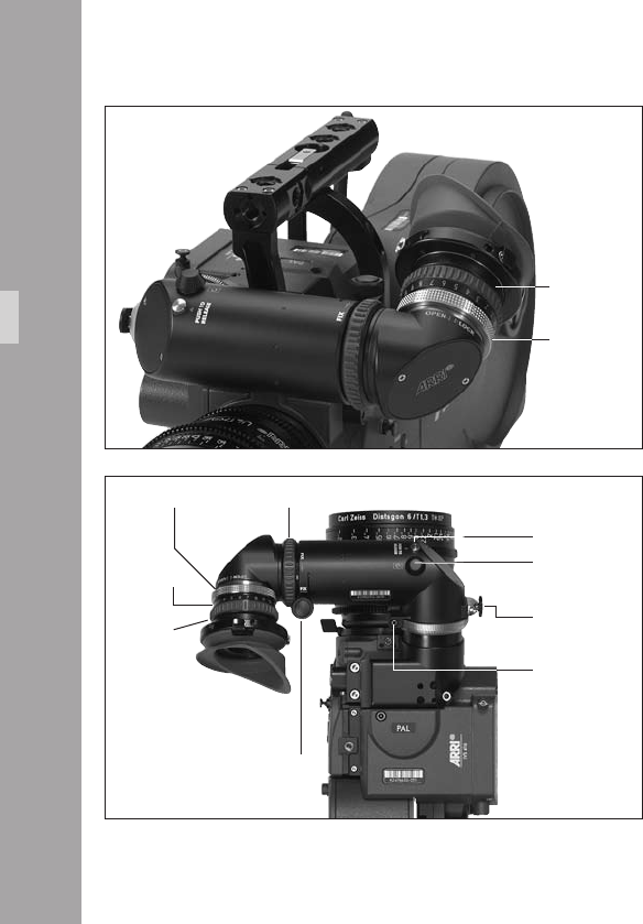
The Eyepiece
Removing the Eyepiece
• Hold the eyepiece with one hand and with the other
turn the knurled ring (eyepiece) aphoto in the
“OPEN” direction until it unscrews from the eyepiece.
• Remove the eyepiece aphoto.
Attaching the Eyepiece
• Position the eyepiece on the viewnder.
• Move the knurled ring (eyepiece) toward the eyepiece
aphoto and turn the ring in the “LOCK” direction until
it tightens.
• Check that the eyepiece is correctly seated.
Optic
eyepiece
knurled ring
knurled ring (eyepiece)
diopter scale
eyepiece
knurled ring
knurled knob
locking button
adjustment knob
allen screw
unlocking key
11
Adjusting the Dioptre
The dioptre compensation is tted with a scale aphoto
of 1 to 12. Position “6” is normal focus.
• To adjust, turn the ring right/left until the bre screen
markings are totally in focus.
Adjusting the Viewnder
Turning the Eyepiece
The eyepiece can be rotated 360° around the viewnder
arm. The eyepiece is held in position by friction.
• To set friction, turn the knurled knob aphoto right/left
until the desired friction has been reached.
Swivelling the Viewnder Arm
The viewnder arm can be swivelled through 360° left to
right. The viewnder arm can be locked into the horizontal
position. The viewnder arm friction can be altered if
necessary by turning the Allen screw aphoto.
• To adjust the viewnder arm, release the locking
mechanism by pulling the unlocking key aphoto.
• Turn the viewnder arm to the desired position.
Note: The unlocking key can be xed in its open position
by turning it.
Optic
unlocking key
unlocking key
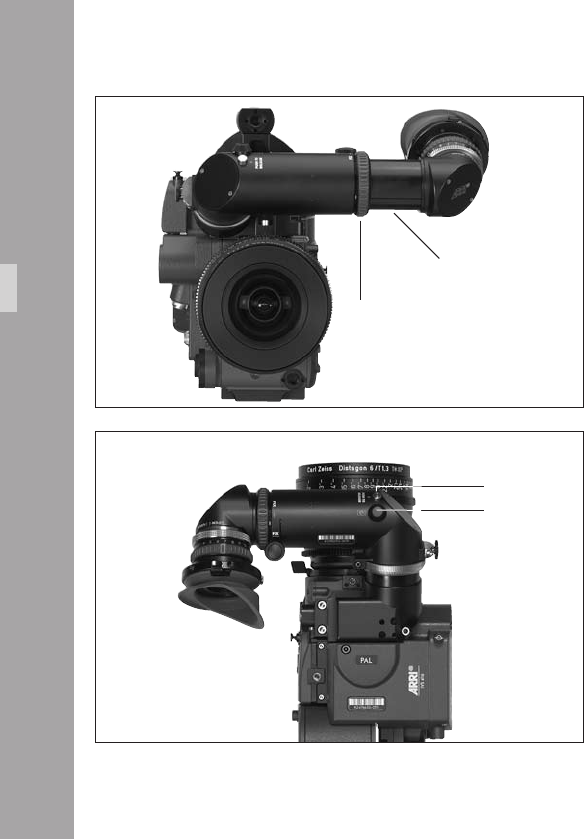
Extending the Viewnder Arm
The viewnder arm can be telescoped continuously by
approx. 40 mm.
• Turn the knurled ring aphoto towards the “LOOSE”
position.
• Pull the viewnder arm aphoto out to the desired
length.
• Retighten the knurled ring.
Image Orientation Compensation
The viewnder system is tted with an automatic image
orientation compensation mechanism.
To enable setting a different image position in certain
situations, the viewnder system is additionally equipped
with a manually adjustable image orientation mechanism.
Manually Adjusting Image Compensation
• Press the locking key aphoto and hold pressed.
• Turn the adjustment knob aphoto until the viewnder
image is in the desired position.
Reactivating Image Compensation
• Turn the adjustment knob aphoto until it locks in
position. Do not press the locking key.
Optic
locking button
adjustment knob
viewnder arm
knurled ring
Note: The automatic image compensation locks in two
positions 180° apart. This allows the image
compensation to be set to provide an upright
image when using a nder extension.
If the viewnder image is inverted without the nder
extension, the image compensation must be adjusted to
the opposite locking position.
Inverting the Image
• Press the locking button aphoto and keep pressed.
• Turn the adjustment knob aphoto.
• Release the locking button aphoto.
• Keep turning the adjustment knob aphoto until the
locking button pops up and the adjustment knob locks
in position.
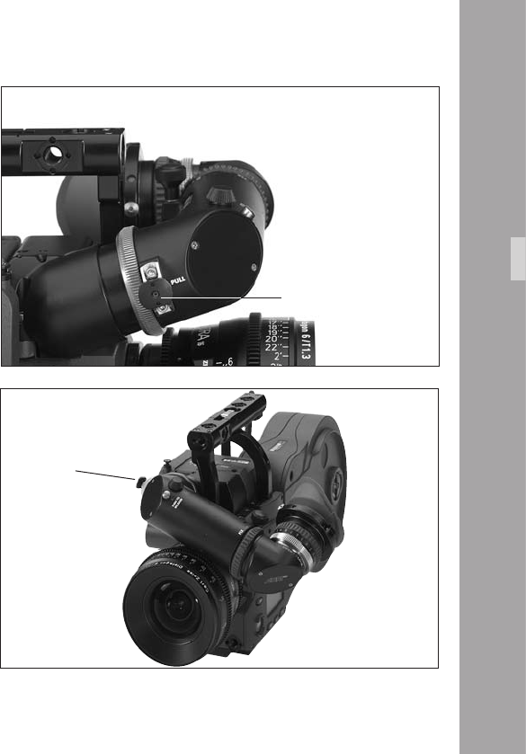
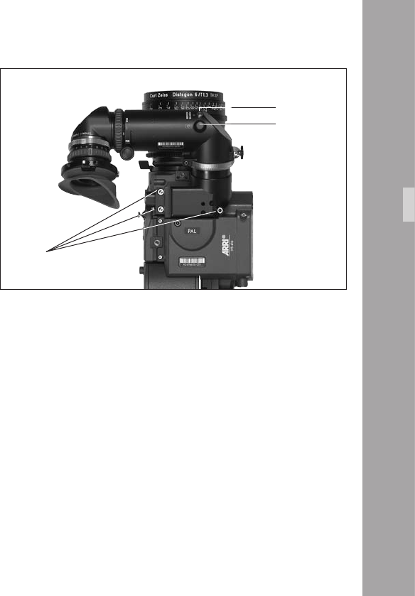
Removing the Viewnder System
Before removing the viewnder system, the viewnder
arm should be brought back to its normal position.
• Loosen the three fastening screws aphoto.
• Pull the viewnder system up and off the camera body.
• If the camera is to be used without the viewnder, t
the cover to protect the beamsplitter prism.
Attaching the Viewnder System
• Position the viewnder system on the camera body
from above.
• Tighten the fastening screws.
Viewnder Warnings
A LED glows when the camera is not running at the set
speed (ASY). This LED blinks when the battery voltage is
low (BAT).
Optic
screws
locking button
adjustment knob
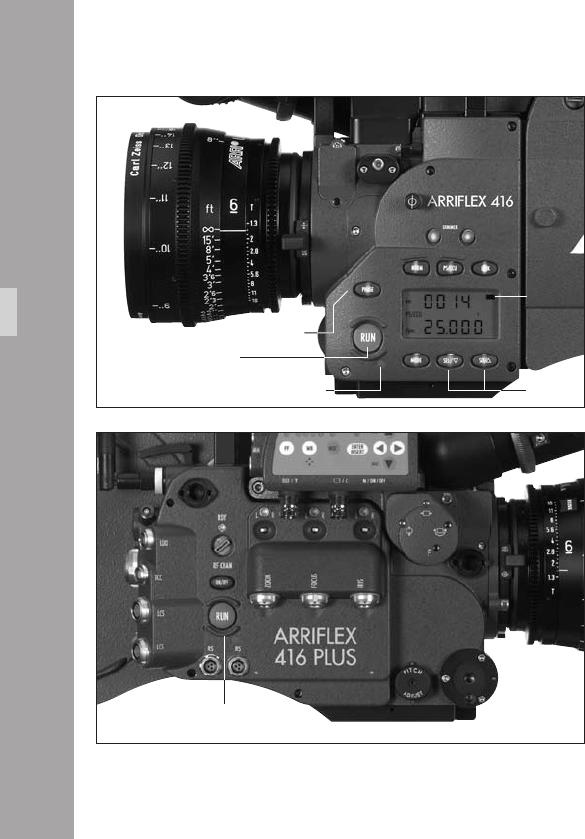
ON/OFF button RUN button
CameraOperation
.CameraOperation
9.1 Main Camera Switch
• If using a mains unit, switch it on.
• Connect the camera to the mains unit or battery.
• Push the “ON/OFF” button aphoto to turn the
camera on. Push the “ON/OFF” button for approx. 3
seconds to turn the camera off again.
Note: If the camera power supply is interrupted, the
camera remembers whether it was on or off
before the interruption and returns to that state
when power is restored. This is useful if the
camera is rigged in a situation where access is
difcult as the battery can be changed without
having to press the “ON/OFF“ button.
CameraOperation
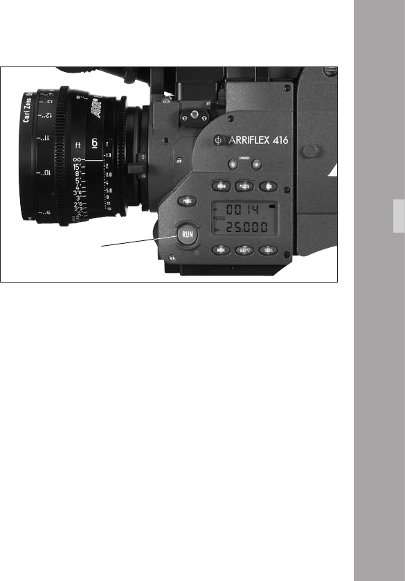
RUN button
9.2 Running and Stopping the
Camera
A “RUN” button is located on both sides of the camera
aphoto.
Running the Camera
If the operation control indicator glows red while in Standby,
the camera is not ready and will not run (see “Overview
of Display Symbols”).
• Briey press the “RUN” button. While the camera is
running up to speed, the operation control indicator
aphoto glows red. Once the set frame rate has been
reached, the operation control indicator turns green.
Note: If the “PHASE” button has not been pushed after
power on or after a new magazine has been
attached, the rst time “RUN” is pressed the camera
performs a 2 second loop check before running.
Stopping the Camera
• Press the “RUN” button again aphoto briey. While
the camera is slowing down the operation control
indicator glows red. The mirror shutter automatically stops
in a position that enables unrestricted viewing through
the viewnder. On reaching this position, the operation
control indicator ashes green before going out.
CameraOperation
RUN button
RUN button
phase button
SEL/SET
buttons
operational control indicator
black bar
to indicate
Mode 1

Inching
The camera can be inched by pressing the “PHASE” button
while the camera is in Standby. If the “PHASE” button is only
pressed briey, the mirror shutter rotates a part revolution
to enable an unrestricted view of the lm gate (e.g. for
checking the gate). If the “PHASE” button is held pressed
longer, the camera will inch forward at approximately 1 fps.
During inching the upper line of the display indicates the
measured shutter angle, the lower line the measured
voltage of the power supply.
While inching, the camera speed is not exactly
controlled. As this can cause faulty exposures,
do not lm while inching.
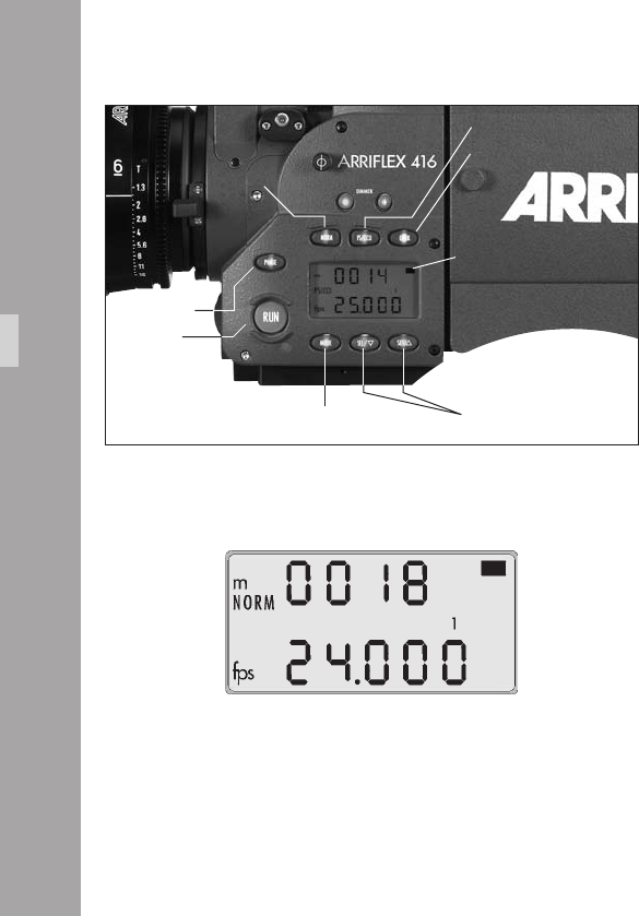
9.3 Displaying and Setting
Operational Parameters
The currently set operational parameters on the ARRIFLEX 416
are displayed on the camera display aphoto in various
modes. The desired mode is selected via the “MODE” button.
In each mode the corresponding operational parameters
can be set using the “SEL” and “SET” buttons aphoto.
Note: The Mode numbers are shown in the display
between the upper and the lower line. Mode 1
is also indicated aphoto in the display by a
black horizontal bar.
To prevent an unintentional alteration of the operational
parameters the buttons “SEL”, “SET”, and “PHASE” can be
locked using the “LOCK” button. If a button is pressed when
the display is locked, the display will show the “OFF” sign.
If the display is locked, this is indicated by the “LOCK”
symbol in the display.
Note: Locking the “PHASE” button has no inuence
on the inching function.
Locking the “SEL” and “SET” buttons has no
inuence on accessories such as the RCU-1.
CameraOperation

Overview of Display Modes
Mode 1 is displayed:
after switching on the camera,
after pressing the “RUN” button
or 30 seconds after the last operation.
1st Display Line 2nd Display Line Adjustment Possibility
Mode 1 total exposed lm counter (m/ft) or frame rate (fps) or setting/re-setting of total exposed lm counter
take counter (m/ft) ESU in standby and selection of a standard frame rate
frame rate (fps) while running
(external control connected)
Mode 2 programmed frame rate (PS) programmed frame rate (fps) programmed frame rate
ESU – external control connected
Mode 3 total exposed lm counter (m/ft) or power supply voltage (V), or (with unit of measurement (m/ft)
take-counter (m/ft) OBB-2 tted) capacity in percent conguration of the lm counter
or remaining magazines press SET to set battery warning level
Mode 4 timecode hours:minutes timecode seconds:frame rate press and hold SET for 3 seconds to turn TC on/off
press SEL to show TC error codes press SEL to show TCS settings press and hold SEL and then
and activity of clock adjustment press and hold SET for 3 seconds to reset clock
adjustment to default
Mode 5 timecode user bits (1st 4 digits) timecode user bits (2nd 4 digits) setting of user bits (0-9, A-F)
Mode 6 sequence and volume of the acoustic brightness of the keypad beep at start, stop, neither or both
warning signal beeper volume
keypad backlight brightness
Mode 7 GLo – RGB ARRIGLOW ARRIGLOW color preset colors 1-8 and User adjustable color
r, G & B values (0-16) for User color r, G & B values (0-16) for User color
CameraOperation
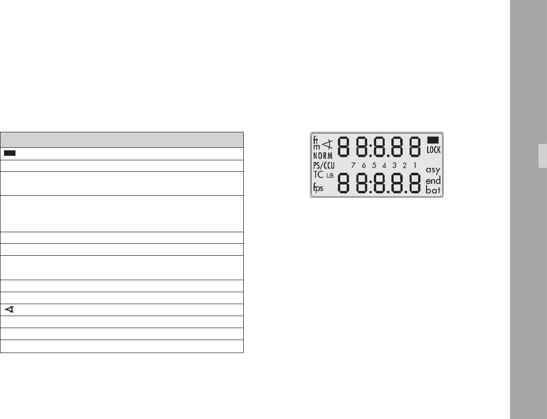
Overview of Display Symbols
Symbol Meaning
glows The display is in Mode 1.
bat glows Battery voltage too low
asy glows Asynchronous operation
(camera is not running at set frame rate)
fps glows display shows current frame rate
blinks ESU is connected
and no sync-frequency is available
7 6 5.. glows Mode number
NORM glows camera will run the set NORM speed
PS/CCU glows camera will run the set PS speed or
the speed set by an accessory
LOCK glows parameter change buttons are locked
m ft glows unit of measurement used by lm counters
glows display shows the current shutter angle
TC glows display shows timecode
UB glows display shows Userbits
end glows lm end
CameraOperation
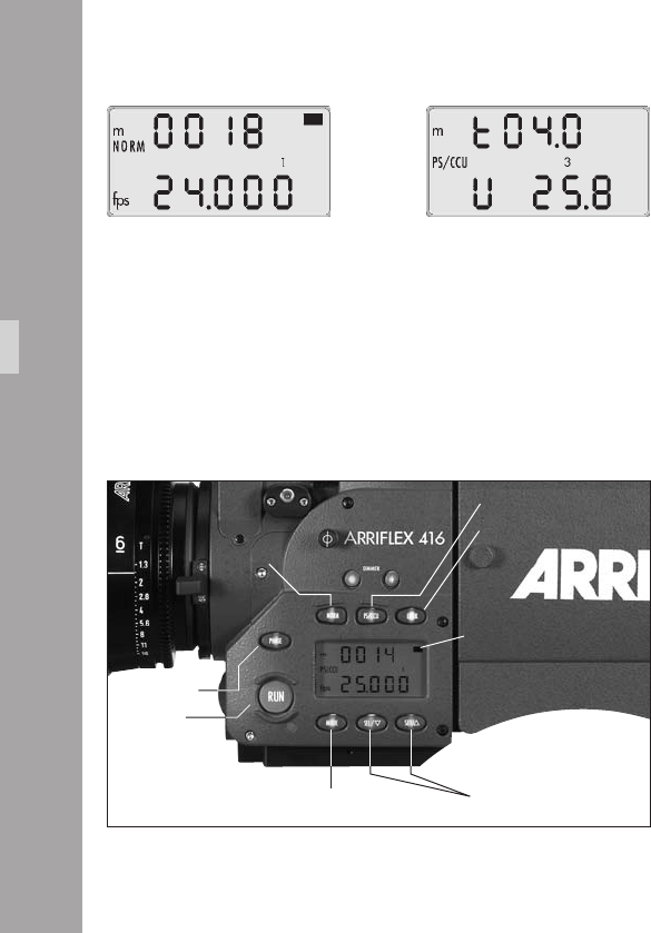
0
Mode 1
total exposed lm or takelength
Mode 3
take length or total exposed lm
0
Film Counter
Displaying the Film Counting Values (Modes 1 and 3)
Film counting values are shown in Modes 1 and 3.
Two different counting values are shown respectively:
• the total amount of exposed lm or
• the take length (amount of lm used in an individual take)
A “t” in the rst digit of the upper display line indicates
the display of take length.
Setting the Film Counter Conguration (Mode 3)
The display conguration can be set individually.
The two shown combinations are possible:
The desired display conguration is set in Mode 3:
• Change from Mode 1 to Mode 3 by pressing the
“MODE” button twice.
• Press the “SEL” button twice; the rst digit in the upper
display line blinks.
• Within three seconds, press the “SET” button.
• The currently set counting value of Mode 3 is displayed.
The corresponding counting value in Mode 1 is
automatically altered.
RUN button
black bar to indicate Mode 1
PHASE button
CameraOperation
MODE button SEL / SET buttons
NORM button
PS/CCU button
LOCK button

11
Resetting the Film Counter (Modes 1 and 3)
• Change to the mode which shows the total exposed
lm counter (“MODE” button).
• The total exposed lm counter can be set to zero by
pressing the “SET” button (for at least 1.5 seconds)
while in Standby.
• The take length counter is automatically reset each time
the camera is started.
Setting the Total Exposed Film Counter (Mode 1)
• The Total Exposed Film Counter can only be set in
Mode 1 (see Setting the Film Counter Conguration
above).
• Use the “SEL“ button to select the total exposed lm
counter digit you wish to change, which will start to
ash.
• Use the “SET“ button to change the value of the
ashing digit.
Changing the Unit of Measurement (Meters/Feet) (Mode 3)
• Change from Mode 1 to Mode 3 by pressing the
“MODE” button twice.
• Press the “SEL” button once; the symbol m/ft blinks.
• Press the “SET” button within three seconds to change
the unit of measurement.
Displaying the Angle of the Mirror Shutter (Mode 1)
• Press and hold the “PHASE” button while in Standby.
The set angle of the mirror shutter appears in the upper
display line.
The camera runs at inching speed.
Setting the shutter angle: see Chapter 7.
CameraOperation
Frame Rates
The ARRIFLEX 416 offers the possibility to set and store
two frame rates. It is possible to select and store:
• a standard frame rate (23.976, 24, 25, 29.97 and 30 fps)
• and a freely programmed frame rate between 1 and
75 fps in increments of 0.001 fps.
The frame rate is activated via the “NORM“ and “PS/CCU”
buttons aphoto on the left of the camera. The “NORM”
setting corresponds to the standard frame rate, the “PS/CCU”
position to the freely programmed frame rate.
Selecting a Standard Frame Rate (Mode 1)
Standby Operation
• The camera must be in Mode 1 and the camera must
be set to “NORM”.
• Press the “SEL” button repeatedly until the desired
frame rate is selected. Within 3 seconds, conrm this
choice by pressing the “SET” button, otherwise the
initial setting is retained.
Note: If the total exposed lm counter is displayed in
Mode 1, pressing “SEL“ rst steps through the
digits of the total exposed lm counter before
the choice of frame rate is offered.
CameraOperation
RUN button
black bar to indicate Mode 1
PHASE button
MODE button SEL / SET buttons
NORM button
PS/CCU button
LOCK button

Setting a Programmed Frame Rate (Mode 2)
Standby Operation
• Change from Mode 1 to Mode 2 by pressing the
“MODE” button once.
• Press the “SEL” button repeatedly until the digit to be
set blinks.
• Press the “SET” button repeatedly until the desired
value is reached.
• Repeat this procedure until all digits are set to the
desired values. A nal conrmation of the set frame
rate is not necessary.
Note: The frame rate can be set between 1 and 75
fps forward only.
Note: The programmed frame rate is stored in non-
volatile memory (which means it is retained
even when the camera is without power).
Changing the Frame Rate while the Camera is running
By means of the “NORM” and “PS/CCU” buttons it is
possible to switch between the standard frame rate
(“NORM”) and the programmed frame rate (“PS/CCU”)
while the camera is running.
Fine Tuning the Programmed Frame Rate (PS Mode)
Fine tuning of the programmed frame rate can be carried
out while the camera is running by means of the buttons
“SEL” (slower) and “SET” (faster). The setting can be
adjusted in increments of 0.001 fps.
• Ensure the camera is in “PS/CCU” mode.
• Run the camera.
• Press the “MODE” button once to change to Mode 2.
• With the buttons “SEL” (slower) and “SET” (faster)
change the frame rate.
CameraOperation
Shifting phase
After the camera has run up, the frame rate can be
temporarily increased by 0.2 fps while the button the
“PHASE” is held pressed aphoto. This is normally used
when synchronizing to an interlaced video signal – look
through the viewnder and hold the “PHASE“ button
pressed until the bar in the video picture is no longer visible
on the monitor. Always conrm results with a lm test.
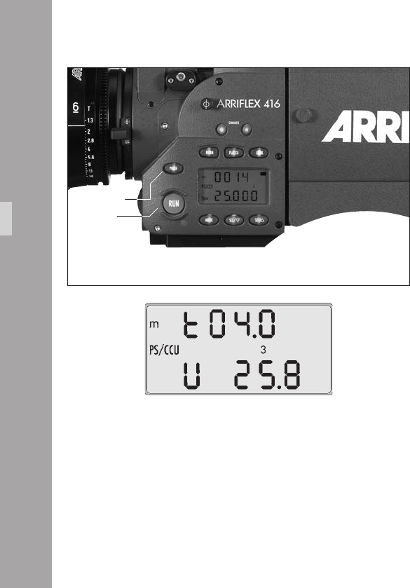
Displaying Power Supply Voltage (Mode 3)
CameraOperation
RUN button
PHASE button
• Change from Mode 1 to Mode 3 by pressing the
“MODE” button twice. The power supply voltage is
shown in the lower line of the display.
Note: If the camera has an OBB-2 attached, the
options of battery capacity (in percent) or
remaining magazines can be displayed instead
of voltage.
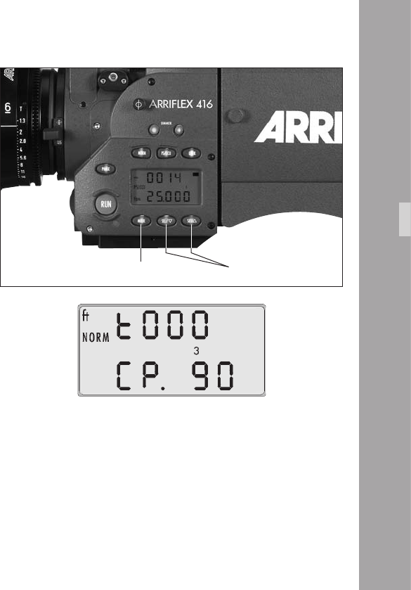
Displaying On-board Battery information
(Mode 3)
The options in this section are only available when an
OBB-2 on-board battery is attached.
• Change from Mode 1 to Mode 3 by pressing the “MODE”
button twice. The display shows the battery voltage.
• Press the “SEL” button three and the display changes to
capacity, shown as e.g. “CP. 72“.“CP“ blinks. This
example would mean the attached OBB-2 battery has
a remaining capacity of 72%.
• Press the “SEL“ button once and the display indicates
the remaining number of magazines the battery can
run. The display might show “CAS.4“, meaning 4
complete magazines (or ‚cassettes‘ in German) can still
be run. “CAS“ blinks.
• Press “SEL“ once more and the display returns to
showing supply voltage.
• Press “SET“ while the selection you want is blinking to
chose that option.
Note: When an OBB-2 is attached to the camera, the
low battery warning is derived from the
battery‘s capacity.
CameraOperation
MODE button SEL / SET buttons

Setting the Low Battery warning level (Mode 3)
When the 416 is not powered by an OBB-2, it is possible
to set the threshold at which the Low Battery warning is
triggered. It can be set anywhere between 20.0 and 29.9
volts.
• Change from Mode 1 to Mode 3 by pressing the
“MODE” button twice.
• Press the “SET“ button. The currently set Low Battery
warning level is displayed for 3 seconds.
• To change the level, press the “SEL“ button 3 times to
select the 2nd voltage digit or 4 times to select the 3rd
voltage digit. The selected digit will blink.
• Adjust the blinking digit with the “SET“ button.
• Once the 2nd and 3rd voltage digits are set as
required, press the “SEL“ button once to exit the
adjustment mode.
CameraOperation
MODE button SEL / SET buttons
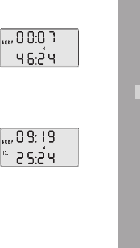
Displaying the Timecode Time and Frame Rate
(Mode 4)
• Press the “MODE“ button until the display shows Mode 4.
The display shows the current timecode value.
The top line shows “Hours:Minutes“. The bottom line
shows “Seconds:TC generator frame rate“.
Note: The timecode generator frame rate matches the
camera‘s frame rate.
Turning Timecode Recording On and Off
(Mode 4)
Timecode recording is only possible at the Standard
Speeds of 23.976, 24.00, 25.00, 29.97 & 30.00 fps.
• Press the “MODE“ button until the display shows Mode 4.
• Press and hold the “SET” button until the “TC“ symbol
appears (ON) or disappears (OFF).
Note: For timecode recording a Timecode Module
must be tted to the magazines.
Note: Timecode recording is also turned on when the
camera receives a valid timecode signal into
the “TCC“ connector.
CameraOperation
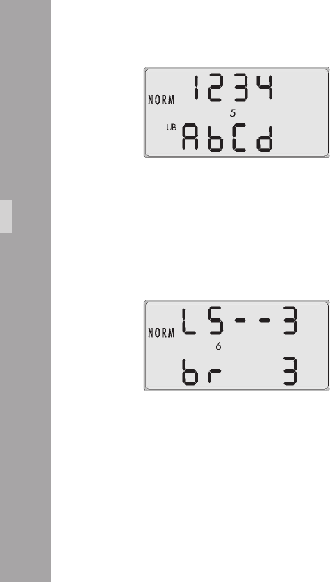
Displaying and Setting the Timecode User Bits
(Mode 5)
User Bits are automatically input with the timecode signal
but they may also be set manually in Mode 5.
• Press the “MODE“ button until the display shows Mode 5.
• Use the “SEL” button to select the digit you wish to change.
The selected digit will ash.
• The “SET” button changes the value of the ashing digit.
• Repeat the last two steps for all the digits that need to
be changed.
Note: User Bits are hexadecimal so only values
between 0 - 9 and A - F are available.
CameraOperation
Setting the brightness of the button illumination
(Mode 6)
• Change from Mode 1 to Mode 4 by pressing the
“MODE” button ve times.
• Press the “SEL” button three times to activate the
display for setting the button illumination.
• Select the desired brightness using the “SET” button.
0…off
3…maximum brightness
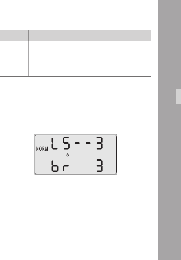
Display Beep on start Beep on stop
LS _ _ off off
LS – _ on off
LS _ – off on
LS – – on on
Switching the Beeper On and Off (Mode 6)
Standby Operation
• Press the “MODE“ button until the display shows Mode 6.
• By pressing the “SEL” button once, activate the display
for setting the Beeper.
• Within three seconds, press the “SET” button to select
one of the four settings.
• Pressing the “MODE” button conrms the selection.
Setting the Volume of the Warning Signal
(Mode 6)
• Press the “MODE“ button until the display shows Mode 6.
• Press the “SEL” button two times to activate the display
for setting the Beeper volume.
• Select the desired volume with the “SET” button.
0…off
3…maximum volume
CameraOperation
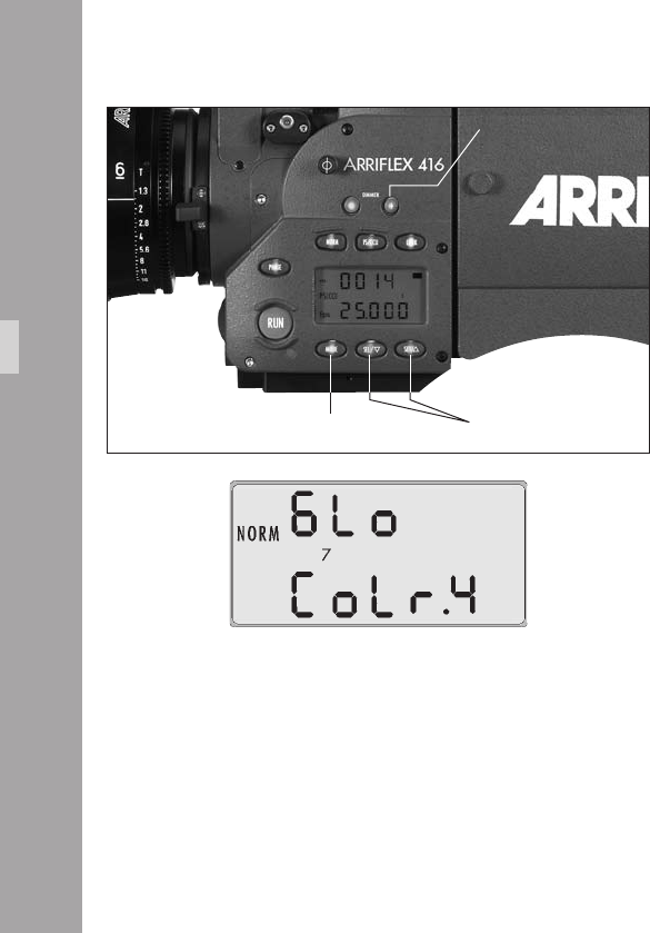
00
Selecting a Preset ARRIGLOW Color (Mode 7)
• Push the “+“ DIMMER button on the camera left side so
you can see the ARRIGLOW in the viewnder.
• Press the “MODE“ button until the display shows Mode 7.
• Press the “SEL” button to make the ARRIGLOW color
number ash.
• Pressing the “SET“ button will cycle through preset color
numbers 1 - 8 and then U, the user-adjustable color.
• Stop at the color you like – no conrmation is necessary.
MODE button SEL / SET buttons
DIMMER + button
CameraOperation
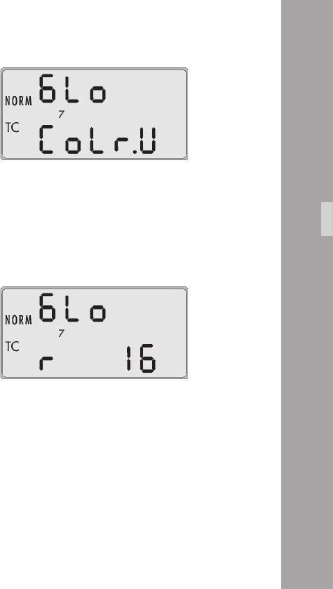
11
Setting a User-Adjustable ARRIGLOW Color
(Mode 7)
• Push the “+“ DIMMER button on the camera left side so
you can see the ARRIGLOW in the viewnder.
• Press the “MODE“ button until the display shows Mode 7.
• Press the “SEL” button to make the ARRIGLOW color
number ash.
• Press the “SET“ button until U appears.
• Pressing the “SEL“ button will cycle through the “r“
(red), “G“ (green) and “B“ (blue) values of the user color.
• Pressing the “SET“ button changes the value from 0 (no
color) up to 16 (maximum color).
• Stop when the color is as you like it – no conrmation
is necessary.
CameraOperation
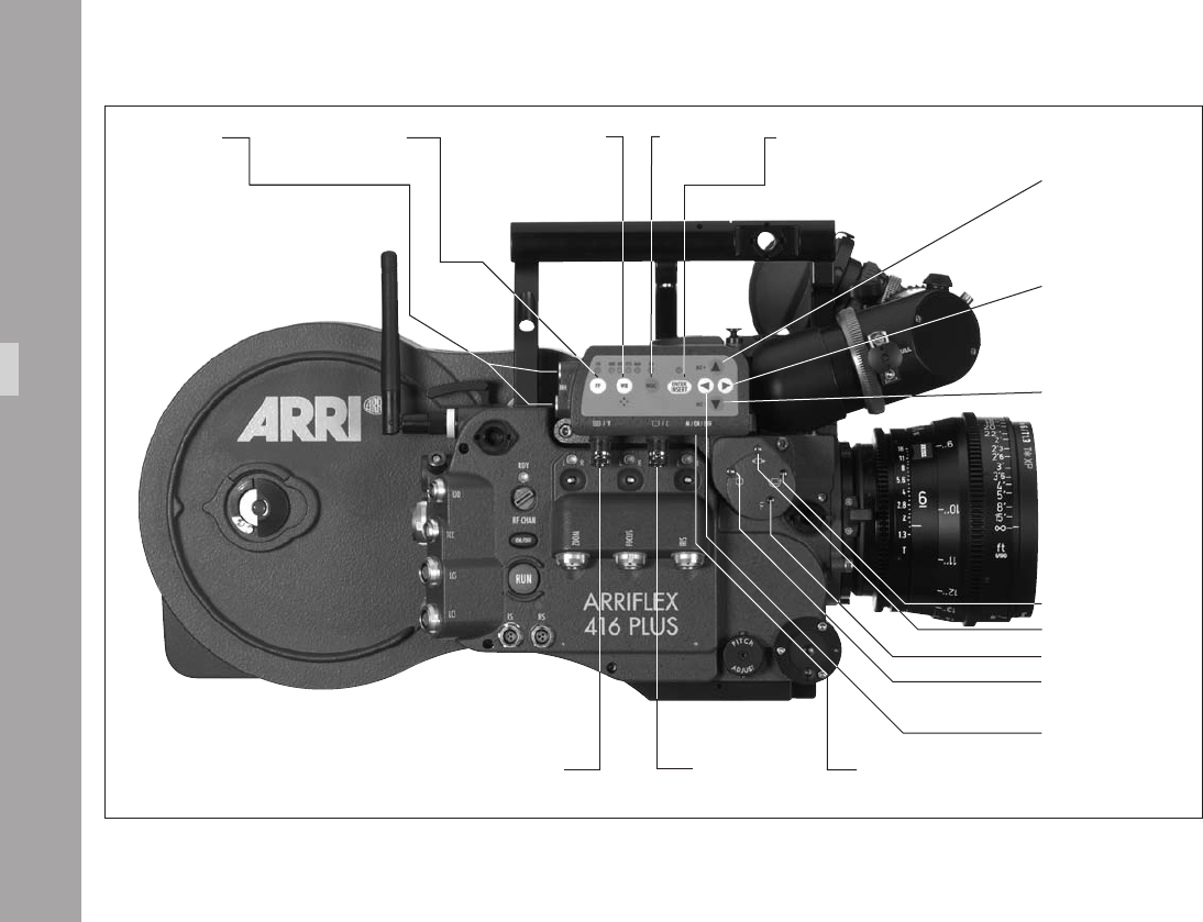
Video-Ait-Sytem
switch check/hide
menu on/off
É/Y
video with data
or Y-Signal
È/C
clean video
or C-signal
mini-monitor
connector
icker-free on/off white balance
automatic, indoor, oudoor,
manual, one-push-white
gain control activate on screen program mode or store position
of inserted windows or store user text
or push for white increase gain or cursor up
or move inserted window
up or increase blue
increase format numbers or
go to submenu or increase
values or increase red
decrease format numbers or
go into submenu or decrease
values or decrease red
decrease gain or cursor down
or move inserted window
down or decrease blue
rotate video image
Y-adjustment
Focus video image
X-adjustment
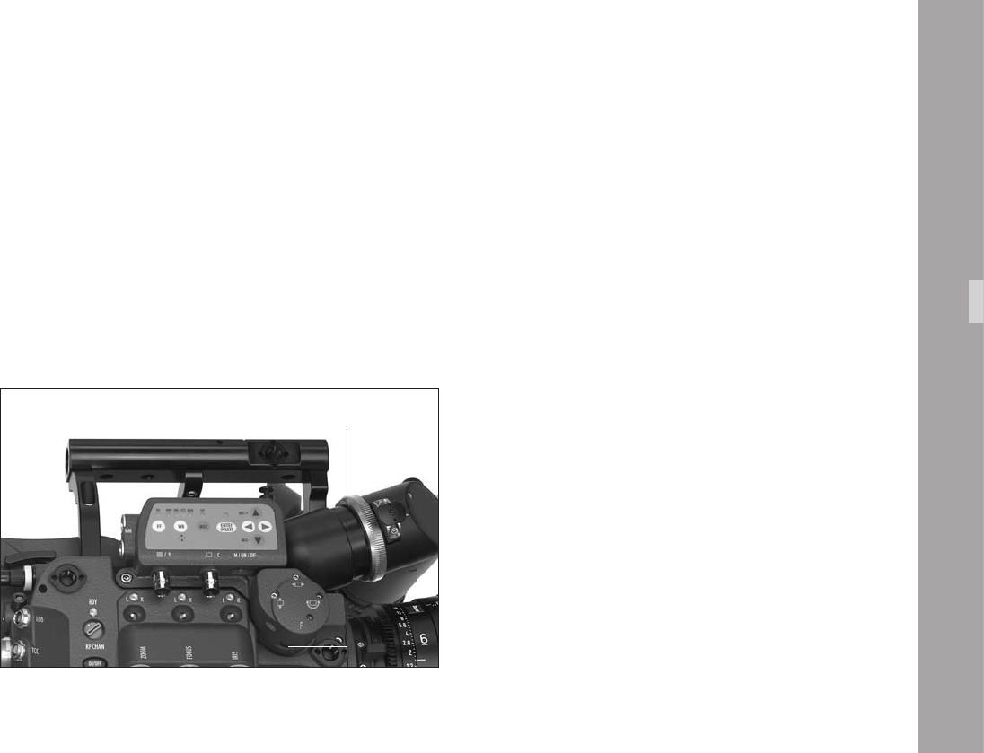
10.VideoAitSytem
10.1 General Description of the IVS
The Integrated Video Assist System (IVS) for the ARRIFLEX
416 brings the highly praised video assist systems from
the ARRIFLEX 435, ARRICAMS and ARRIFLEX 235 to the
ARRIFLEX 416. It resembles the IVS 235 control structure
and of course offers the same unsurpassed image quality
combined with a state-of-the-art inserter to add frame lines,
camera status, LDS information and text to the video image.
Video-Ait-Sytem
New Features
• Electronic image sharpening
The 416 IVS has an electronic sharpness control which
can be adjusted to optimize the look of the video
output.
• Color Bar Generator
A new menu option allows the user to generate color
bars so that monitors being fed from the IVS can be
adjusted correctly.
• One Push White
Automatic white adjustment by pointing the lens at a
white surface and pressing the One Push White Key
• 2 x Mini Monitor connectors
The IVS offers two Mini-Monitor connectors for use
with a 12 V LCD monitor and a wireless video
transmitter. The Mini-Monitor connectors have a
combined output power of up to 36 W (output current
3 A).
• Wrong Cable Warning
An LED illuminates to indicate a bridge between
camera and video grounds. This warning is to prevent
damage to the IVS and/or camera
iris

Main Features
• Integrated into the camera body
Instead of a bulky add-on, the video assist is integrated
into the camera without additional cabling.
• High sensitivity
A high-speed lens with an aperture of 1 : 2.0 and one
of the most sensitive CCD Chips available on the market
combine to provide an excellent color video image in
editing quality even when the lighting is set for high-
speed lm stock that will be pushed during processing.
• High resolution
The design of the new IVS optics was based around
the ARRIFLEX 416 viewnder and results in an image
quality which cannot be attained by add-on solutions.
• Flicker free
An integrated digital frame store enables the video
camera to be synchronized to the lm camera‘s mirror
shutter and provides a icker free video image from 1 fps
(in manual gain control mode) up to maximum speed
because the video image is always taken at the ideal
position of the mirror shutter. Flicker free can be switched
off to bypass the digital frame store and to have
minimal delay in the video system.
• Full white balance control
In addition to the standard indoor white balance setting
of 3200 K, an outdoor setting of 5600 K and an
automatic adjustment, the red and blue channels can
be ne tuned for manual white balance. The 416 IVS
also includes a one push white key.
• Line Interpolation
Resolution is improved in camera “RUN“ mode by using
line interpolation. This results in an image approaching
eld resolution.
• Store and recall settings
All settings can be stored and recalled. This allows you
to adjust all the settings for indoor shooting, store them,
shoot some exterior scenes, then go back indoors and
recall the previous settings.
Up to 6 settings can be stored.
• Integrated frame line inserter
Frame lines can be electronically added to the video
image. This ensures that the lines are visible even in
difcult conditions. The area outside the frame lines
can be darkened electronically in 4 different steps to
emphasize the important image area.
Video-Ait-Sytem

Video-Ait-Sytem
• Camera status display
Camera status information, e.g. camera speed and
lm counter data are passed on a bus interface from
the camera to the video assist and can be displayed in
a camera status line on the monitor.
• Lens Data Information
Lens information, such as lens type, focal distance,
depth of eld, iris and focal length can be
electronically inserted in the video image if they are
available, e.g. from a lens data archive.
• System display
Camera system information is available in the video
assist. Thus, it is possible to see camera warnings such
as low battery on the monitor.
• Integrated text inserter
Additional text such as take numbers or the production
name can be added to the video image by entering the
text on the IVS.
• Y/C Outputs
The usual composite outputs can be switched to an Y/C
output (S VHS) for an even better video image without
annoying color artefacts, with or without data inserted
into the video image. The Y/C output uses two BNC
sockets.
• On-Screen programming
All functions, which do not directly affect the image
appearance, such as frame lines, can be conveniently
programmed with an on-screen programming menu
on the video monitor.
• Dedicated controls
Important image changes, such as gain or white balance,
can be performed in parallel to the on-screen
programming with dedicated keys.
• Image compare function
It is possible to store a chosen image and compare it
against the live input. This clearly shows the difference
between the images, e.g. during stop effect shots.
• Automatic and manual gain control
The gain is controlled automatically to its best value but
can also be set manually.
Note: The IVS package already includes a lens for
Super 16, a 1.5 mm Allen key for image
adjustment and a Y/C (S VHS) cable.
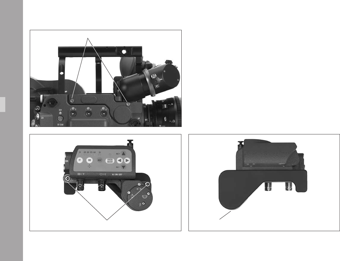
10.2 Setup
10.2.1 Installation
A 3 mm Allen key is used for installation.
• Undo the two screws holding the transport cover
aphoto and remove it.
• Remove the IVS transport cover from the video assist
by undoing the two screws on the IVS aphoto.
Note: It may be useful to screw the camera transport
cover to the IVS transport cover to store them
together as a pair because they are usually
required at the same time.
Video-Ait-Sytem
screws for transport cover
cover on the IVSscrews for cover on the IVS
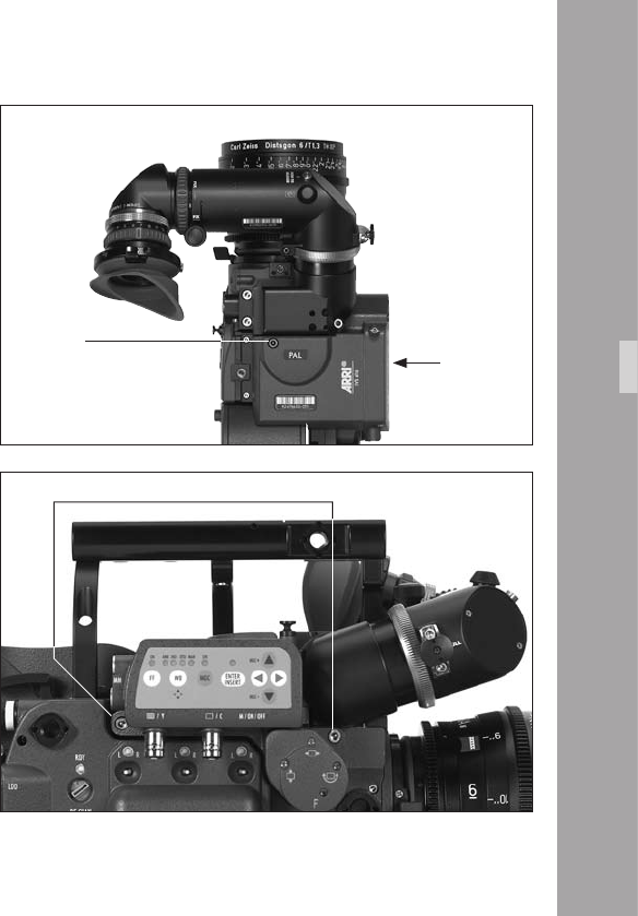
• Attach the video assist to the ARRIFLEX 416 by tting it
to the camera right side in the direction marked
aphoto.
• Tighten the two screws on the camera right side of the
IVS rst aphoto and then tighten the third screw into
the top of the camera aphoto.
Video-Ait-Sytem
screws
3rd screw
t IVS
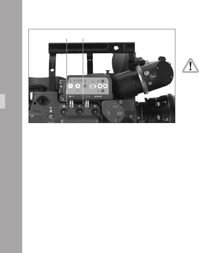
10.2.2 Cabling
Outputs
If it is intended to use composite outputs but it is
not known whether the BNC connectors are
switched to composite or to Y/C, connect the cable
expecting the composite signal to the É/Y
connector rst and check the settings (BNC OUT
VBS or Y/C) in the menu video/text adjust. Please
see next chapter Composite Video Outputs.
The IVS has two BNC sockets, which can be switched to
output two independent composite signals or one Y/C
signal. Additionally, there are two outputs for a mini-
monitor and wireless video transmitter.
Video-Ait-Sytem
È/C
É/Y

Composite Video Outputs
Composite video is only available when the
output is switched to VBS out.
• To switch to composite video (VBS mode), enter the
main menu by pressing the Enter/Insert key Ñ for
more than 3 seconds. Go to sub menu VIDEO/TEXT
ADJUST. The menu line BNC OUT can be switched
between VBS and Y/C. See chapter 10.4 Inserter Facilities
for information on the on-screen program mode.
The difference between the outputs is that there is normal,
clean video on the one connector and video with burnt-in
data on the other.
In the clean video output, marked with the È/C symbol
aphoto, almost no electronic information is inserted.
Only a rolling bar at the button left corner of the video
image indicates a running lm camera.
In the video with data output, marked with the É/Y
symbol aphoto, additional data, such as format marks
or camera status information, can be inserted.
Video-Ait-Sytem
MENU VIDEO/TEXT ADJUST
- FLICKERFREE ON
- LINE INTERP. ON
- SHARPNESS 2
-> - BNC OUT VBS
Y/C DATA
- GENLOCK OFF
- MINI MON DATA OFF
- TXT WHITE LEV. 2
- TXT INVERS OFF
- TXT FINE POS. 2
- EXIT
The outputs are standard BNC sockets for 75 Ω
terminated video signals. Both outputs can be used
simultaneously.

00
Y/C Output
Y/C output offers even better, S VHS quality, compared to
the composite video output. There are also clean video
and video with data signals available in Y/C mode.
Y/C video is only available when the output is
switched to Y/C out.
• Use the on-screen program mode to switch between
composite and Y/C. Enter the main menu by pressing
the Enter/Insert key Ñ for more than 3 seconds.
Go to sub menu VIDEO/TEXT ADJUST. The menu line
BNC OUT can be switched between VBS and Y/C.
See chapter 10.4 Inserter Facilities for information on
the on-screen program mode.
In Y/C, you can choose between the clean video or video
with data signals, which come from the same pair of
connectors.
Video-Ait-Sytem
MENU VIDEO/TEXT ADJUST
- FLICKERFREE ON
- LINE INTERP. ON
- SHARPNESS 2
-> - BNC OUT Y/C
- Y/C DATA OFF
- GENLOCK OFF
- MINI MON DATA ON
- TXT WHITE LEV. 2
- TXT INVERS OFF
- TXT FINE POS. 2
- EXIT
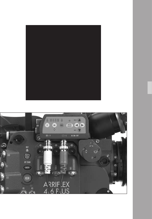
11
• To switch between clean video and video with data,
use the on-screen program mode. Enter the main menu
by pressing the Enter/Insert key Ñ for more than 3
seconds. Go to sub menu VIDEO/TEXT ADJUST. The
menu line Y/C DATA, which can only be reached if
BNC OUT is on Y/C, switches between clean video
and video with data on the Y/C signal. The line displays
Y/C DATA ON or OFF.
See chapter 10.4 Inserter Facilities for information on
the on-screen program mode.
In the clean video output almost no electronic information
is inserted. Only a rolling bar at the lower left corner of
the video image indicates the lm camera is running.
In the video with data output, additional data such as
format marks or camera status information can be inserted.
An adapter cable from the two BNC connectors to a
standard Y/C connector is included in the IVS package
on initial delivery. Connect the red end to the È/C
output and the white end to the É/Y socket aphoto.
Video-Ait-Sytem
MENU VIDEO/TEXT ADJUST
- FLICKERFREE ON
- LINE INTERP. ON
- SHARPNESS 2
- BNC OUT Y/C
-> - Y/C DATA ON
- GENLOCK OFF
- MINI MON DATA ON
- TXT WHITE LEV. 2
- TXT INVERS OFF
- TXT FINE POS. 2
- EXIT

Video-Ait-Sytem
Black and White Output
The Y part of the Y/C output is a standard black and white
signal. To get black and white, use a standard BNC cable
with 75 Ω connected to the É/Y output and switch to Y/C
out.
Black and white or Y signal is only available if
the output is switched to Y/C out.
• Use the on-screen program mode to switch between
composite and Y/C. Enter the main menu by pressing
the Enter/Insert key Ñ for more than 3 seconds. Go
to sub menu VIDEO/TEXT ADJUST. The menu line BNC
OUT can be switched between VBS and Y/C.
See chapter 10.4 Inserter Facilities for information on
the on-screen program mode.
There are clean video and video with data signals
available from the same connector.
MENU VIDEO/TEXT ADJUST
- FLICKERFREE ON
- LINE INTERP. ON
- SHARPNESS 2
-> - BNC OUT Y/C
- Y/C DATA OFF
- GENLOCK OFF
- MINI MON DATA ON
- TXT WHITE LEV. 2
- TXT INVERS OFF
- TXT FINE POS. 2
- EXIT
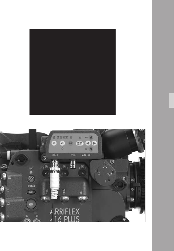
Video-Ait-Sytem
• To switch between clean video and video with data,
use the on-screen program mode. Enter the main menu
by pressing the Enter/Insert key Ñ for more than 3
seconds. Go to sub menu VIDEO/TEXT ADJUST. The
menu point Y/C DATA, which can only be reached if
BNC OUT is on Y/C, switches between normal video
and video with data on the Y/C signal. The line
displays Y/C DATA ON or OFF.
See chapter 10.4 Inserter Facilities for information on
the on-screen program mode.
In the normal video output almost no electronic information
is inserted. Only a rolling bar at the lower left corner of
the video image indicates the lm camera is running.
In the video with data output, additional data such as
format marks or camera status information, can be inserted.
The É/Y socket is standard BNC for 75 Ω video outputs
aphoto.
MENU VIDEO/TEXT ADJUST
- FLICKERFREE ON
- LINE INTERP. ON
- SHARPNESS 2
- BNC OUT Y/C
-> - Y/C DATA ON
- GENLOCK OFF
- MINI MON DATA ON
- TXT WHITE LEV. 2
- TXT INVERS OFF
- TXT FINE POS. 2
- EXIT
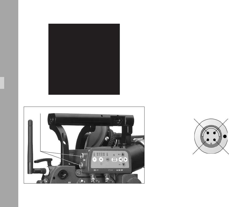
Mini-Monitor Outputs
The IVS has two mini-monitor connectors. Typically one
might be used for a standard mini-monitor and the other
for a video transmitter.
It is possible to switch between normal video and video
with data on the Mini-Monitor output.
• To switch between normal video and video with data
on the mini monitor outputs, use the on-screen
program mode. Enter the main menu by pressing the
Enter/Insert key Ñ for more than 3 seconds. Go to
sub menu VIDEO/TEXT ADJUST. The menu line MINI
MON DATA can be switched OFF and ON.
See chapter 10.4 Inserter Facilities for information on
the on-screen program mode.
Video-Ait-Sytem
Pin-Outs Mini Monitor Connector (seen from outside)
Signal Shield
Pin 2
GND
Pin 1
Composite Video
Pin 3
+12 V
Pin 4
Note: Maximum combined output for the Mini-Monitor
connectors is 3 A (36 W).
mini monitor connectors
MENU VIDEO/TEXT ADJUST
- FLICKERFREE ON
- LINE INTERP. ON
- SHARPNESS 2
- BNC OUT Y/C
- Y/C DATA ON
- GENLOCK OFF
-> - MINI MON DATA ON
- TXT WHITE LEV. 2
- TXT INVERS OFF
- TXT FINE POS. 2
- EXIT
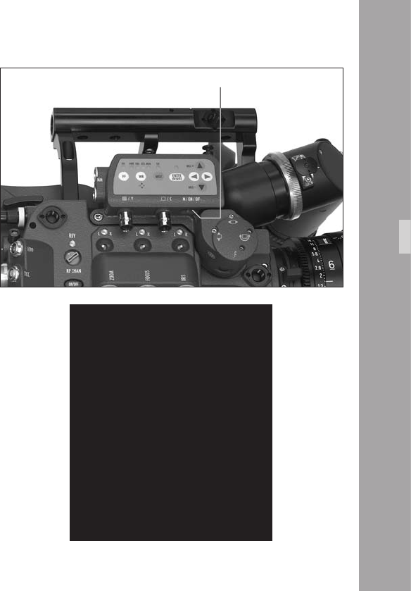
10.3 Standard Video Controls
The IVS can be used as a standard video assist if no
inserter features are used.
Note: All currently used settings are stored even when
the IVS or the camera is switched off. After
restarting the IVS the settings are unchanged,
except for the image stored mode, which will
always come up in live mode and the color
bars, which will always be switched off.
10.3.1 Switch On, Off and Check/Hide Menu
The IVS can be switched on and off independently from
the lm camera, as long as the lm camera is switched
on. Turning off the lm camera will also turn off the IVS.
The Check/Hide Menu position has a spring return so it
will return to the ON position when it is released aphoto.
• The OFF position switches the IVS off without affecting
the lm camera. ON activates the IVS.
Check Menu
If the on-screen program mode is off during normal
operation, the Menu (M) position shows an overview of
the IVS settings aphoto.
Video-Ait-Sytem
CHECK
SETTING
WHITE BALANCE IND
MANUAL GAIN OFF
FLICKERFREE ON
SHARPNESS 8
LINE INTERP. ON
FORMAT 1
VIEW MODE LIVE
USER TEXT LINE ON
SYSTEM LINE OFF
LDS LINE ON
STATUS LINE ON
TIME CODE TIME ON
TIME CODE UB ON
PULL DOWN ON
VITC ON
WHITE LINE ON
switch
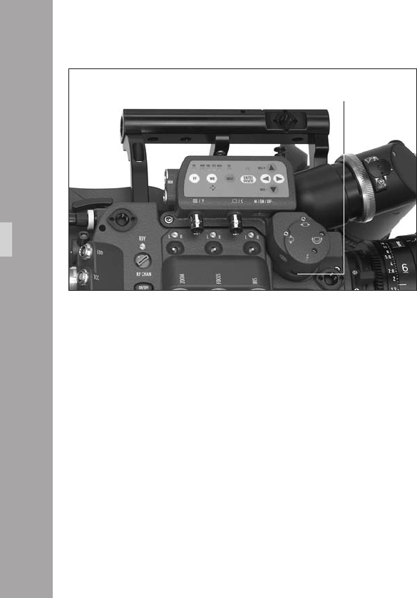
Video-Ait-Sytem
Hide Menu
If the on-screen program mode is on because the settings
are changed, the Menu (M) position clears the screen. For
example, if color is to be changed with the on-screen
program tool, the on-screen program window overlays the
image. To see the image and check its color appearance,
go to M position. The window disappears but the on-screen
program mode is still on. By releasing the switch, the
window will come back in the programming mode.
10.3.2 Mechanical Iris
Only a relatively small portion of the light that passes
through the lm camera’s lens reaches the CCD chip of
the video assist, because the light is shared between the
view nder, the CCD Chip and the lm. Therefore, the IVS
lens is designed for normal use with a totally open iris so
the maximum amount of light falls on the CCD Chip.
Variations in lighting are compensated by the IVS gain
control (automatically or manually).
Under certain conditions, such as when lighting is set for
low sensitivity lm (under 100 ASA), it may be that the
IVS gain range is exceeded. In this case the mechanical
iris of the IVS lens can be closed.
iris
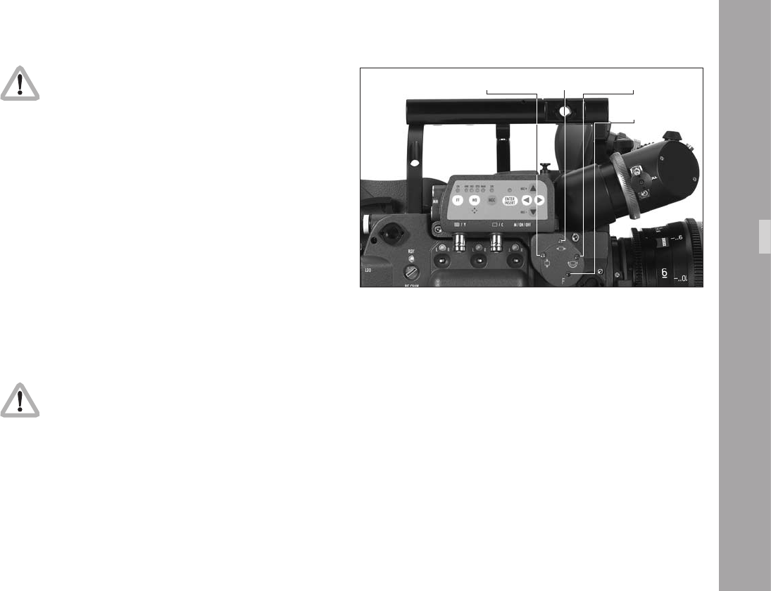
Video-Ait-Sytem
Check all settings on a correctly adjusted monitor.
If the mechanical iris is closed more than necessary, the
IVS will compensate by increasing the gain and restore
the image brightness electronically. This creates additional
electronic noise. To avoid this, open the mechanical iris.
• To change the iris, turn the wheel with the iris symbol Õ.
10.3.3 Alignment of the image position
(X, Y and Rotation) and focus
The position of the image on the CCD Chip and its focus can
vary slightly from camera to camera. The video image on the
monitor may appear off-centre, not levelled or out of focus.
All adjustments can be made by using a 1,5 mm Allen key,
which is delivered with the IVS.
Do not use force!
• Image position adjustments in x and y direction can be
made with the adjustment screws marked x and y aphoto.
• The screw marked Ò moves the video image horizontally
on the monitor. The screw marked Ó moves it vertically.
Note: Design restrictions imposed by the IVS‘ small
size mean that the direction of movement
imparted by the x and y adjustment screws
might be not precisely in the x and y directions.
• Image rotation can be adjusted by the screw marked
with the Ô symbol aphoto.
• The image can be focussed using the screw which is
marked with the F symbol aphoto.
Ó alignment
Ò alignment Ô alignment
F alignment
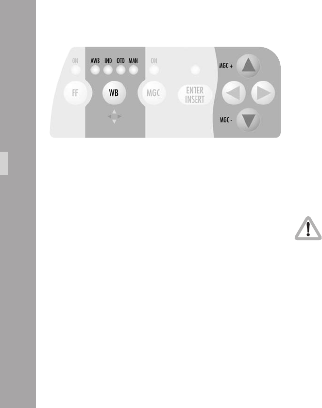
10.3.4 White Balance (WB)
The IVS offers a choice of White Balance methods between
• automatic control (AWB)
• xed setting of indoor (IND)
• xed setting for outdoor (OTD)
• a one push white setting procedure
• and a full manual control of white balance (MAN).
White balance can be manually adjusted in two different
ways: Either with the keypad on the IVS or by using the
on-screen control menu.
Using the Keypad
Check all settings on a correctly adjusted monitor.
Video-Ait-Sytem

Note: With the MAN LED constantly on, no color
settings can be made to avoid accidental
adjustment.
Note: The one push white facility is only available
when the exposure is within the normal range.
If the image is over or underexposed, one push
white will not work.
Note: Changing red, blue and gain will also change
green. The video signal is the addition of red,
green and blue and amplied by the gain.
Decreasing red and blue and lifting gain
increases green.
• By pressing the WB key Ï aphoto, the setting will
be changed from AWB, IND, OTD to MAN. The LED
corresponding to the selected setting will light. After
MAN, the next click on the WB key Ï will cause the
MAN LED to blink.
• It is now possible to manually change the red and blue
channels or to use the one push white facility. To change
manually, make sure that the MAN LED ashes and use
the color coded Ê, Ë, Í and Ì keys. The next click
on the WB key Ï or waiting longer than 5 seconds
without pressing any key will cause the MAN LED to be
constantly on.
For the one push white mode, point the lm camera at
a white surface, e.g. a sheet of paper in front of the
camera, and make sure that the MAN LED and the
Enter Insert LED are ashing. Then press the Ñ key.
Another click on the WB key Ï will lead back to AWB.
An illuminated LED shows the selected mode.
• If Automatic White Balance (AWB) is selected, the IVS
will automatically set the White Balance. No manual
steps are necessary in this mode aphoto.
• If indoor (IND) is selected aphoto white balance is
optimized for tungsten lighting with a color
temperature of 3200 K.
• The outdoor (OTD) setting aphoto optimizes the
white balance for daylight with a color temperature of
5600 K.
Video-Ait-Sytem

00
Video-Ait-Sytem
MENU WB/GAIN/BARS
-> - WHITE BALANCE IND
AUTOADJUST
RED
BLUE
- MANUAL GAIN OFF
VALUE
- COLOR BARS OFF
- EXIT
Using the on-screen menu
Please see chapter 10.4 Inserter Facilities for basics on
the On-screen display.
As well as control by the keypad, white balance can also
be programmed via the on-screen menu.
• Enter the main menu by pressing the Enter/Insert key
Ñ for more than 3 seconds.
Go to sub menu WB/GAIN/BARS.
Move the cursor > with the keys Ê and Ë to the line
– WHITE BALANCE. Pressing the key Í will switch
from Automatic White Balance (AWB), Indoor (IND)
and Outdoor (OTD) to Manual (MAN) and back
Automatic White Balance. The Ì key scrolls through
the options in the opposite direction.
• When white balance is set to manual, the display
changes: Lines to the left of AUTOADJUST, RED and
BLUE appear, indicating that the one push white facility
is available or red and blue saturation of the video
image can now be changed.
MENU WB/GAIN/BARS
-> - WHITE BALANCE MAN
- AUTOADJUST
- RED 30
- BLUE 39
- MANUAL GAIN OFF
VALUE
- COLOR BARS OFF
- EXIT

11
Video-Ait-Sytem
One push white
One push white is only available when white
balance control is set to manual.
If manual white balance is set to MAN, it is possible to
use the one push white facility or to adjust the red and
blue saturation of the video image manually.
• Move the cursor > with the keys Ê and Ë to the line
– AUTOADJUST. Point with the camera to a white
surface. e.g. hold a sheet of paper in front of the
camera. Press the Í key to start the one push white
facility, thus adjusting the white balance to the white in
front of the camera.
The LEDs in the keypad will follow the changes which are
made in this menu and vice versa, if the setting is
changed via the keypad, the on-screen menu will follow.
MENU WB/GAIN/BARS
- WHITE BALANCE MAN
-> - AUTOADJUST
- RED 30
- BLUE 39
- MANUAL GAIN OFF
VALUE
- COLOR BARS OFF
- EXIT

Manual White Balance red increase/decrease
Manual white balance red increase/decrease is
only available if white balance control is set to
manual.
When manual white balance is on MAN, it is possible to
use the one push white facility or to adjust the red and
blue saturation of the video image manually.
• Move the cursor > with the keys Ê and Ë to align
with – RED. Pressing the Í key will increase the red in
the video image; pressing the Ì key will decrease it.
The range for this is from 0 (lowest) to 63 (highest).
• If the key Í or Ì is pressed briey, the value changes
by one step, if the keys are held pressed longer, the
value will continue to change.
The LED in the keypad will follow the changes which are
made in this menu and vice versa, if this setting is changed
via the keypad, the on-screen menu will follow.
Video-Ait-Sytem
MENU WB/GAIN/BARS
- WHITE BALANCE MAN
- AUTOADJUST
-> - RED 30
- BLUE 39
- MANUAL GAIN OFF
VALUE
- COLOR BARS OFF
- EXIT

Manual White Balance blue increase/decrease
Manual white balance blue increase/decrease
is only available if white balance control is on
manual.
If manual white balance is on MAN, it is possible to use
the one push white facility or to adjust the red and blue
saturation of the video image manually.
• Move the cursor > with the keys Ê and Ë to align
with – BLUE. Pressing the Í key will increase the red
in the video image; pressing the Ì key will decrease it.
The range for this is from 0 (lowest) to 63 (highest).
• If the key Í or Ì is pressed briey, the value changes
by one step, if the keys are held pressed longer, the
value will continue to change.
The LED in the keypad will follow the changes which are
made in this menu and vice versa, if this setting is changed
via the keypad, the on-screen menu will follow.
Video-Ait-Sytem
MENU WB/GAIN/BARS
- WHITE BALANCE MAN
- AUTOADJUST
- RED 30
-> - BLUE 39
- MANUAL GAIN OFF
VALUE
- COLOR BARS OFF
- EXIT
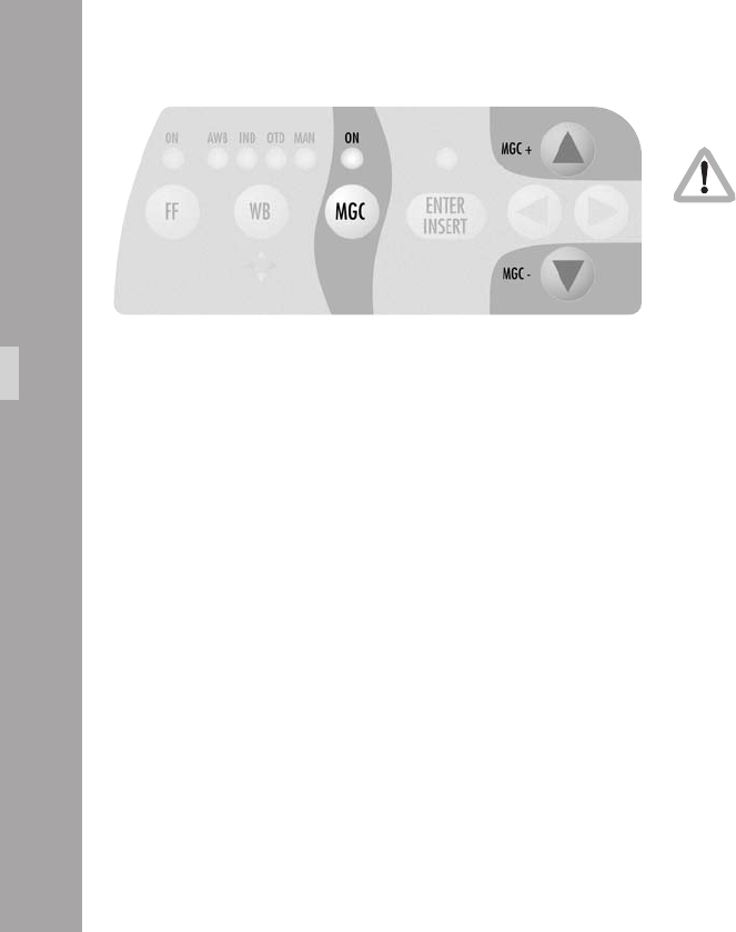
10.3.5 Gain Control
The gain control of the IVS can be set to automatic or
manual. When set to automatic, the brightness of the
video image is adjusted electronically.
If automatic control is selected, the IVS outputs the best
possible image brightness at all times. Light changes in
front of the lm camera are compensated by the IVS and
the brightness appears almost unchanged.
Gain control can be adjusted in two different ways.
It is possible to control it either using the keypad on the
IVS or by using the on-screen control menu.
Using the Keypad
Check all settings on a correctly adjusted monitor.
• By pressing the MGC key Ï the setting alters between
manual and automatic control. An LED above the
MGC key lights when manual gain control (MGC) is
selected aphoto.
• If manual gain control is selected (LED is on), the
brightness of the video image can be manually altered.
By using the Ê or Ë key brightness can be increased
or decreased. The automatic compensation of different
light levels in front of the camera is suppressed.
Video-Ait-Sytem

Using the on-screen menu
Please see chapter 10.4 Inserter Facilities for basics on
the On-Screen display.
The manual gain control can be programmed via the on-
screen menu as well as control via keypad,. Manual gain
control can be switched on or off. If it is on, values can be
set between 0 (low gain) and 63 (high gain).
• Enter the main menu by pressing the Enter/Insert key
Ñ for more than 3 seconds.
Go to sub menu WB/GAIN/COLOR BARS. Move the
cursor > with the keys Ê and Ë to the line –
MANUAL GAIN. Pressing the key Í or Ì will switch
manual gain control off and on. If manual gain control
is on, the display will change. A line symbol – appears
before VALUE indicating that the gain can be changed
manually.
The LED in the keypad will follow the changes which are
made in this menu and vice versa, if this setting is changed
via the keypad, the on-screen menu will follow.
Video-Ait-Sytem
MENU WB/GAIN/BARS
- WHITE BALANCE MAN
- AUTOADJUST
- RED 30
- BLUE 39
-> - MANUAL GAIN OFF
VALUE
- COLOR BARS OFF
- EXIT
MENU WB/GAIN/BARS
- WHITE BALANCE MAN
- AUTOADJUST
- RED 30
- BLUE 39
-> - MANUAL GAIN ON
- VALUE 40
- COLOR BARS OFF
- EXIT

Manual Gain increase/decrease
Manual gain increase/decrease is only available
when manual gain control is on.
• Move the cursor > with the keys Ê and Ë to the line
– VALUE. Pressing the key Í will increase the gain;
the key Ì will decrease it.
The range for this is from 0 (lowest gain) to 63 (highest gain).
• If the key Í or Ì is pressed briey, the value changes
by one step, if the keys are held pressed longer, the
value will continue to change.
The LED in the keypad will follow the changes which are
made in this menu and vice versa, if this setting is
changed via the keypad, the on-screen menu will follow.
Video-Ait-Sytem
MENU WB/GAIN/BARS
- WHITE BALANCE MAN
- AUTOADJUST
- RED 30
- BLUE 39
- MANUAL GAIN ON
-> - VALUE 40
- COLOR BARS OFF
- EXIT

10.3.6 Flicker free on/off
Flicker free can be switched off to bypass the digital frame
store and have the video assist output with no delay.
The typical running speed for the lm camera is different to
that of the video assist. e.g. the lm camera runs at 24 fps
and the video assist at 25 fps for PAL or 30 fps for NTSC.
Without icker processing this speed difference causes
varying brightness between successive individual video
images. To eliminate this so called icker, video images are
stored at the speed of the lm camera into the video frame
storage and recalled in the speed of the video system. This
storage might cause a slight delay, which is not desirable
in some time-crucial conditions, e.g. motion control or
shooting of a pop video. Therefore it is possible to switch
the icker free system off. This will eliminate the delay.
However, icker will occur in this mode.
Using the Keypad
• By pressing the FF key Î the icker free mode alters
between on and off. An LED illuminates to show icker
free (FF) is set to on aphoto.
Video-Ait-Sytem

Using the on-screen menu
Please see chapter 10.4 Inserter Facilities for basics on
the On-Screen display.
Flicker free off can also be programmed via the on-screen
menu as well as via the keypad.
• Enter the main menu by pressing the Enter/Insert key
Ñ for more than 3 seconds. Go to sub menu
VIDEO/TEXT ADJUST. Move the cursor > with the keys
Ê and Ë to the line– FLICKERFREE. Pressing the key
Í or Ì will switch icker free mode off and on.
Note: The lowest camera speed for icker free display
is 5 fps in automatic gain control mode and
1 fps in manual gain control mode.
MENU VIDEO/TEXT ADJUST
-> - FLICKERFREE ON
- LINE INTERP. ON
- SHARPNESS 2
- BNC OUT VBS
Y/C DATA
- GENLOCK OFF
- MINI MON DATA ON
- TXT WHITE LEV. 2
- TXT INVERS OFF
- TXT FINE POS. 2
- EXIT
Video-Ait-Sytem
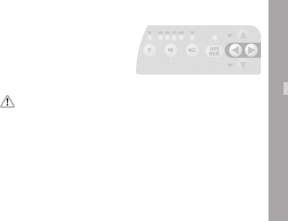
10.3.7 Changing Format marking number
The IVS can insert different format markings. It is possible
to have
• no format marking (OFF),
• format marking number one (1),
• format marking number two (2)
• or both format markings at the same time (1 & 2) on display.
Using the Keypad
The adjustment of the different format markings
can only be done via the on-screen display as
described in chapter 10.4.6 Format Marking
Menu. However, it is possible to select which
format markings are displayed via the keypad.
The format marking selection is only possible when the
White Balance manual mode is not active (when the WB
MAN LED is not ashing). If white balance manual mode
is active, please wait for more than 5 seconds without
pressing any key to leave this mode.
• The key Í will switch from OFF, 1, 2 to 1&2. The key
Ì will switch in the opposite order.
Video-Ait-Sytem

100100
Using the on-screen menu
Please see chapter 10.4 Inserter Facilities for basics on
the On-Screen display.
The format marking number can be programmed via the
on-screen menu as well as via the keypad.
• Enter the main menu by pressing the Enter/Insert key
Ñ for more than 3 seconds.
Go to sub menu FORMAT MARKING. Move the cursor
> with the keys Ê and Ë to the line – FORMAT.
Pressing the key Í will switch from OFF, 1, 2 to 1&2.
The key Ì will switch in the opposite order.
MENU FORMAT MARKING
-> - FORMAT OFF
POSITION 1 Ö
POSITION 1 Ü
POSITION 2 Ö
POSITION 2 Ü
WHITE LEVEL
OUTSIDE
- EXIT
Video-Ait-Sytem

101101
10.3.8 Storing a video image
The IVS can grab and store a selected image, display that
or overlay it against the live image in front of the camera to
compare both images. Although the options to display the
stored image and to compare the stored image against the
live image are only available in the on-screen program
mode, it is possible to store an image any time using the
Enter/Insert key Ñ.
Using the Keypad
• Pressing the Enter/Insert key Ñ briey (less than 1.5
seconds) will store an image in the frame store.
• Every time the Enter/Insert key Ñ is briey pressed,
a new image is stored.
• To view the stored image, or to compare it against a
live image, please enter the on-screen program mode,
as described in chapter 10.4.7 Display mode
Video-Ait-Sytem

1010
Using the on-screen menu
Please see chapter 10.4 Inserter Facilities for basics on
the On-Screen display.
• Enter the main menu by pressing the Enter/Insert key
Ñ for more than 3 seconds.
Go to sub menu COMPARE/STORE. Move the cursor
> with the keys Ê and Ë to the line – STORE IMAGE.
Pressing the key Í or Ì will store the image. The
word DONE will appear for a few seconds to show
that an image was stored.
The stored image is memorized until a new image is stored,
the image is cleared or until the IVS is turned off.
MENU COMPARE/STORE
- VIEW MODE LIVE
-> - STORE IMAGE
- CLEAR IMAGE
- EXIT
Video-Ait-Sytem
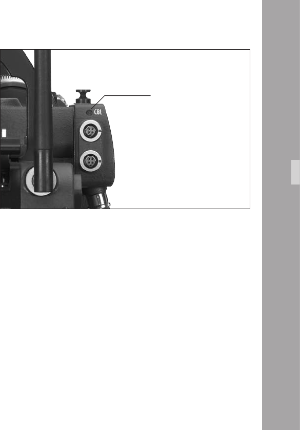
1010
10.3.9 Wrong Cable Warning LED
The main reason for damage to the IVS is incorrectly wired
cables connected to any of the IVS outputs. Even if some
faults do not cause immediate destruction, they put the IVS
at risk and may eventually cause failures of the IVS unit.
Therefore the IVS checks for the following wrong conditions
on the outputs:
• Bridge between camera power supply ground and
video signal ground (e.g. shield of BNC sockets)
• Bridge between positive camera power supply and
video signal ground (e.g. shield of BNC sockets)
• Bridge between positive camera power supply and
housing of the camera and/or IVS
• AC between camera power supply and video signal
ground (e.g. shield of BNC sockets)
• AC between camera power supply and housing of the
camera and/or IVS
• AC between housing of the camera/IVS and video
signal ground (e.g. shield of BNC sockets)
If one of the above described conditions is detected, the
Cable Warning LED (CBL) will light up. Disconnect all cables
form the IVS and/or ARRIFLEX 416 until the warning
disappears. Do not use the faulty cable again.
Note: The above mentioned faults are caused by 3rd
party cables, improper cables, faulty cables or
a fault condition on equipment connected to
these cables. Please report such conditions
immediately to the camera owner.
Video-Ait-Sytem
cable warning LED

1010
Video-Ait-Sytem
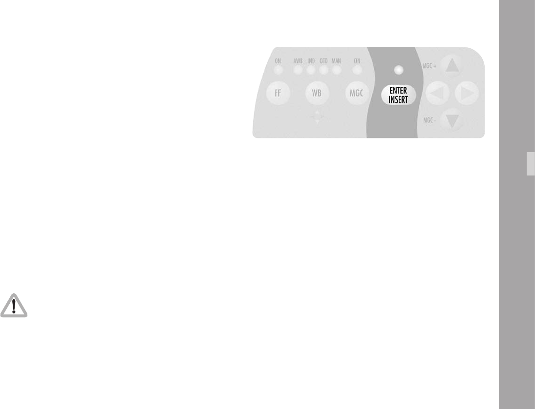
1010
Video-Ait-Sytem
10.4 Inserter Facilities
In addition to the usual video assist functions, the IVS offers
a variety of inserter facilities. They fall into three different
groups of information:
• Format markings
Format markings, which are inserted electronically, are
often more visible than the format markings on the
bre screen.
• Man Readable Information
Camera status
System line
Lens Data Information
Timecode
User Bits
Pull Down Information
Additional text
• Machine Readable Information
VITC
White Line Flag
Inserted data is only available on outputs that
have video with data.
Engravings from the bre screen (e. g. TV Safe
etc.) are visible at all times on all outputs.
Note: All currently used settings are stored even if the IVS
or the camera is switched off or disconnected from
the power supply. After restarting the IVS the
settings remain unchanged, except for the image
stored mode, which will always come up in live
mode and the color bars, which will always be
switched off.

1010
10.4.1 Setting the On-Screen Displays
During programming, inserted data is not fully
updated (e.g. Frame Counter Information). To
get updated information, leave the on-screen
display menu by pressing the Enter/Insert key
Ñ for more than three seconds.
Once the on-screen display is activated by pressing the
Enter/Insert key Ñ for more than three seconds, the
following procedure is used to select and set all functions
within the main menu and the sub menus:
• Pressing the key Ê or Ë will move the cursor > up or
down. Pressing the key Í or Ì activates sub menus.
• Within sub menus the cursor > can be moved up and
down again by pressing the key Ê or Ë. The keys Í
or Ì will now change settings (e. g. switch the insertion
of a user text window on and off), or activates functions
(position mode of a window or EXIT).
• If the windows position mode is activated, the keys Ê or
Ë will move the window across the video image. To leave
the position mode press the Enter/Insert key Ñ briey.
• To go from a sub menu back to the main menu, position
the cursor > by using the keys Ê and Ë on the line
EXIT and press the key Í or Ì.
• Active lines are marked with a dash symbol –.
They can be reached with the cursor > within a menu
using the keys Ê and Ë. Lines may be visible but
without a dash because the currently selected mode
does not use this feature. E.g. when gain is not in
manual control mode, the line value is not active
because value cannot be changed in the automatic
control mode. In this case, no dash symbol – is
displayed and the line cannot be reached with the
cursor >. To activate this line, switch from automatic to
manual gain control mode.
Changes made to settings are immediately activated.
Note: Pressing the Enter/Insert key Ñ for more than
three seconds will cause the system to exit the
on-screen programming mode completely,
regardless of which menu is activated, with the
exception of the positioning mode.
Video-Ait-Sytem
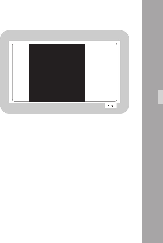
1010
10.4.2 Main Menu
The inserter’s main menu is displayed on the monitor screen
when the on-screen programming is activated by pressing
the Enter/Insert key Ñ aphoto for more than three
seconds. An illuminated LED indicates that the on-screen
programming is activated.
Note: Pressing the Enter/Insert key Ñ for more than
three seconds will cause the system to exit the
on-screen programming mode completely,
regardless of which menu is activated, with the
exception of the positioning mode.
• The keys Ê or Ë move the cursor > up or down.
Pressing the key Í or Ì will lead into a sub menu.
MAIN MENU
-> - LOAD/STORE
- WB/GAIN/BARS
- VIDEO/TEXT ADJ
- FORMAT MARKING
- COMPARE/STORE
- SYSTEM/STATUS
- USER TEXT
- TIME CODE TIME
- TIME CODE UB
- PULL DOWN
- VITC LINE
- WHITE LINE
- EXIT
Video-Ait-Sytem
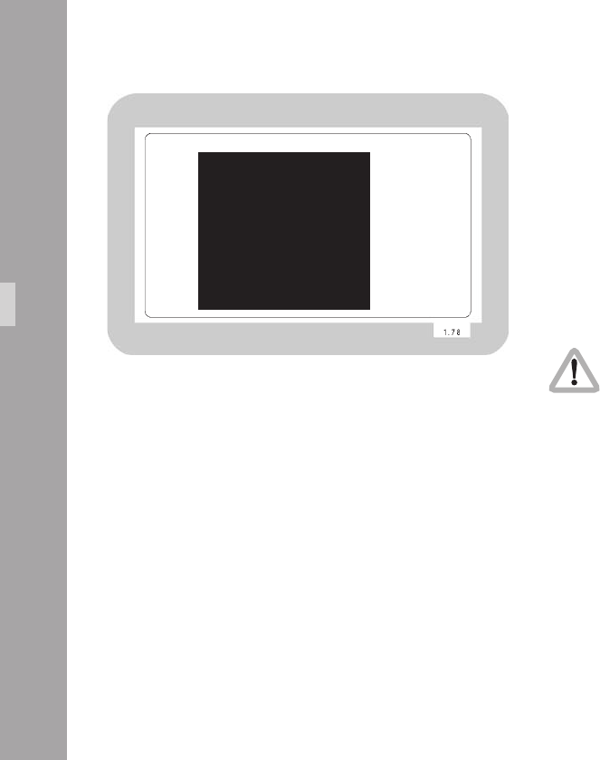
1010
10.4.3 Load/Store Menu
The IVS can store up to 5 sets of settings and recall them. The
default values are a 6th set of settings. Thus it is possible to
make all settings for e.g. indoor shooting and store them as
setting 1. Shooting continues with some exterior scenes and
the operator will make all settings for this and store them as
setting 2. When the work is continued indoors, it is very easy
to recall all the settings stored as setting 1 and get the same
image appearance as before.
MENU LOAD/STORE
-> - STORE SET 1
(CONFIRM BY
ENTER)
- LOAD SET 1
(NO UNDO)
- SET ALL
SETTINGS TO
DEFAULT
- EXIT
Video-Ait-Sytem
A set of settings consists of all set-ups in the IVS. Everything
which can be set electronically, will be stored and recalled.
All video adjustments such as manual gain control, white
balance, icker free, outputs with or without data and line
interpolation as well as all inserter setups, e.g. user text insertion
off or on, frame lines and so on are stored and recalled.
The adjustment of the white level of the inserted data, an
inverse display and a ne adjustment of the vertical position
is described in chapters 10.4.5 White Level, Inverse and
Fine Positioning.
Changes made to settings are immediately activated.
Check all settings on a correctly adjusted monitor.
• Enter the Load/Store submenu from the main menu.
Store Settings
The set of settings, that are currently active, can be stored
as one out of ve settings.
• Move the cursor > with the Ê and Ë keys to the line
– STORE SET. Pressing the Í key will switch from 1 to 2
all the way up to 5 and then back to 1, the Ì key will
step in the opposite direction.

1010
• When the required number is reached, press the
Enter/Insert key Ñ to store this setting under the given
number. The word DONE will appear for 3 seconds
to indicate that the setting was stored. After this, the
display will return to its normal mode.
The new set of settings will immediately replace
the old set of settings. The old settings can not
be recalled.
Load Settings
It is possible to load one out of ve settings. The new settings
will inuence all adjustments that can be made electronically.
The new settings will immediately replace the
previous settings. If the old settings might be
needed again, store them rst as described in
the previous chapter Store Settings.
• Move the cursor > with the Ê and Ë keys to the line
– LOAD SET. Pressing the Í key will switch from 1 to 2
all the way up to 5 and back to 1, the Ì key will switch
in the opposite direction. Pressing either the Í or Ì
keys will immediately load the new settings.
MENU LOAD/STORE
-> - STORE SET 1
(CONFIRM BY
ENTER)
- LOAD SET 1
(NO UNDO)
- SET ALL
SETTINGS TO
DEFAULT
- EXIT
Video-Ait-Sytem
MENU LOAD/STORE
- STORE SET 1
(CONFIRM BY
ENTER)
-> - LOAD SET 1
(NO UNDO)
- SET ALL
SETTINGS TO
DEFAULT
- EXIT

110110
All Settings to Default
When the function set all settings to default is
called, all settings are cleared. They cannot be
recalled.
This menu recalls default setting for all values. This makes
it possible to obtain basic setting throughout the IVS.
• Move the cursor > with the keys Ê and Ë to the line
– SET ALL. Pressing the key Í or Ì recalls the default
values and overwrites all stored settings.
• It is necessary to conrm this procedure, as all settings
will be cleared. This window will appear with the
cursor > in the line NO. Pressing the key Í or Ì will
cancel the procedure.
• To clear everything, move the cursor > with the keys
Ê and Ë to the line – YES. Pressing the key Í or Ì
sets all settings to default.
• If the cursor > is in position EXIT and the key Í or Ì
is pressed, the IVS will return to the Load/Store menu
without setting everything to default.
The default values are:
WB = INDOOR
Manual Gain with GAIN = 0
FLICKER FREE = ON
LINE INTERPOLATION = ON
ARE YOU SURE?
(NO UNDO)
-> - NO
- YES
- EXIT
Video-Ait-Sytem
MENU LOAD/STORE
- STORE SET 1
(CONFIRM BY
ENTER)
- LOAD SET 1
(NO UNDO)
-> - SET ALL
SETTINGS TO
DEFAULT
- EXIT

111111
Y/C data = ON
BNC OUT = VBS
MINI-MONITOR DATA = ON
GENLOCK = OFF
FORMAT 1 = ON
FORMAT 2 = OFF
WHITE LEVEL frame lines = 2
COLOR BARS = OFF
OUTSIDE area = DARK
VIEW MODE = LIVE (Frame store is cleared)
SYSTEM LINE = ON
LDS LINE = OFF
STATUS LINE = ON
TIMECODE TIME window = ON
TIMECODE UB window = OFF
PULL DOWN window = OFF
VITC = OFF
WHITE LINE = OFF
BACKGROUND status/system = BOXED
FILM COUNTER on set to FOOTAGE
USER TEXT LINE = OFF
BACKGROUND User Text line = BOXED
SIZE = SMALL
WHITE LEVEL TEXT = 2
INVERSE = OFF
VERT POS = 5
SHARPNESS = 1
Exit
Use exit to return to the main menu.
• Move the cursor > with the keys Ê and Ë to the line
–EXIT and press the key Í or Ì.
Note: Pressing the Enter/Insert key Ñ for more than
three seconds will cause the system to exit the
on-screen programming mode completely,
regardless of which menu is activated, with the
exception of the positioning mode.
Video-Ait-Sytem
MENU LOAD/STORE
- STORE SET 1
(CONFIRM BY
ENTER)
- LOAD SET 1
(NO UNDO)
- SET ALL
SETTINGS TO
DEFAULT
-> - EXIT
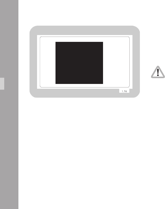
1111
10.4.4 White Balance (WB), Manual Gain Control
(MGC) and Bars Menu
White balance and manual gain control allows the user to
change the color appearance and brightness of the video
image. Color Bars help to set up and test connected monitors.
Changes made to settings are immediately activated.
Check all settings on a correctly adjusted monitor.
• Enter the WB/Gain/Bars submenu from the main menu.
MENU WB/GAIN/BARS
-> - WHITE BALANCE IND
AUTOADJUST
RED
BLUE
- MANUAL GAIN OFF
VALUE
- COLOR BARS OFF
- EXIT
Video-Ait-Sytem

1111
White Balance (Indoor/Outdoor/Automatic/Manual)
White balance can be programmed via the on-screen menu
as well as via the keypad. It toggles through Indoor, Outdoor
and Automatic and Manual.
• Move the cursor > with the keys Ê and Ë to the line
– WHITE BALANCE. Pressing the key Í will switch from
Automatic White Balance (AWB), Indoor (IND) and
Outdoor (OTD) to Manual (MAN) and back to
Automatic White Balance. The key Ì will step in the
opposite direction.
• If white balance is set on manual, the display options will
change: Lines left of AUTOADJUST; RED and BLUE will
appear indicating that the one push white facility is
available or red and blue saturation of the video image
can now be changed.
MENU WB/GAIN/BARS
-> - WHITE BALANCE IND
AUTOADJUST
RED
BLUE
- MANUAL GAIN OFF
VALUE
- COLOR BARS OFF
- EXIT
Video-Ait-Sytem

1111
Video-Ait-Sytem
One push white
One push white is only available when the
white balance control is on manual.
If manual white balance is on MAN, it is possible to use
the one push white facility or to adjust the red and blue
saturation of the video image manually.
• Move the cursor > with the keys Ê and Ë to the line
– AUTOADJUST. Point the camera at a white surface.
e.g. hold a sheet of paper in front of the camera. Press
the key Í to start the one push white facility, thus
adopting the white balance to the sample white in front
of the camera.
The LED in the keypad will follow the changes which are
made in this menu and vice versa, if this setting is changed
via the keypad, the on-screen menu will follow. The auto-
matically derived values are displayed in the RED and
BLUE line.
MENU WB/GAIN/BARS
- WHITE BALANCE MAN
-> - AUTOADJUST
- RED 30
- BLUE 39
- MANUAL GAIN OFF
VALUE
- COLOR BARS OFF
- EXIT

1111
Video-Ait-Sytem
Manual White Balance red increase/decrease
Manual white balance red increase/decrease is
only available if white balance control is on
manual.
If manual white balance is on MAN, it is possible to use
the one push white facility or to adjust the red and blue
saturation of the video image manually.
• Move the cursor > with the keys Ê and Ë to the line
– RED. Pressing the key Í will increase the red in the
video image; the key Ì will decrease it.
The range for this is from 0 (lowest) to 63 (highest).
• If the key Í or Ì is pressed briey, the value is
changes by one step, if the keys are pressed longer,
the value will continue to change.
The LED in the keypad will follow the changes which are
made in this menu and vice versa, if this setting is changed
via the keypad, the on-screen menu will follow.
MENU WB/GAIN/BARS
- WHITE BALANCE MAN
- AUTOADJUST
-> - RED 30
- BLUE 39
- MANUAL GAIN OFF
VALUE
- COLOR BARS OFF
- EXIT

1111
Manual White Balance blue increase/decrease
Manual white balance blue increase/decrease
is only available if white balance control is on
manual.
If manual white balance is on MAN, it is possible to use
the one push white facility or to adjust the red and blue
saturation of the video image manually.
• Move the cursor > with the keys Ê and Ë to the line
– BLUE. Pressing the key Í will increase the blue in the
video image; the key Ì will decrease it.
The range for this is from 0 (lowest) to 63 (highest).
• If the key Í or Ì is pressed briey, the value is changes
by one step, if the keys are pressed longer, the value
will continue to change.
The LED in the keypad will follow the changes which are
made in this menu and vice versa, if this setting is changed
via the keypad, the on-screen menu will follow.
Video-Ait-Sytem
MENU WB/GAIN/BARS
- WHITE BALANCE MAN
- AUTOADJUST
- RED 30
-> - BLUE 39
- MANUAL GAIN OFF
VALUE
- COLOR BARS OFF
- EXIT

1111
Manual Gain Control ON/OFF
The manual gain control can be programmed via the on-
screen menu as well as via the keypad. Manual gain
control can be switched on or off. If it is on, specic
values can be set between 0 (low gain) and 63 (high
gain). If it is off, automatic mode is active.
• Move the cursor > with the keys Ê and Ë to the line
– MANUAL GAIN. Pressing the key Í or Ì will switch
manual gain control off and on. If manual gain control is
on, the display will change. A line symbol – will appear
before VALUE indicating that the gain can be changes
manually.
The LED in the keypad will follow the changes which are
made in this menu and vice versa, if this setting is
changed via the keypad, the on-screen menu will follow.
Video-Ait-Sytem
MENU WB/GAIN/BARS
- WHITE BALANCE MAN
- AUTOADJUST
- RED 30
- BLUE 39
-> - MANUAL GAIN OFF
VALUE
- COLOR BARS OFF
- EXIT
MENU WB/GAIN/BARS
- WHITE BALANCE MAN
- AUTOADJUST
- RED 30
- BLUE 39
-> - MANUAL GAIN ON
- VALUE 40
- COLOR BARS OFF
- EXIT

1111
Manual Gain increase/decrease
Manual gain increase/decrease is only
available when manual gain control is on.
If manual gain is on, it is possible to adjust the gain manually.
• Move the cursor > with the keys Ê and Ë to the line
– VALUE. Pressing the key Í will increase the gain;
the key Ì will decrease it.
The range for this is from 0 (lowest gain) to 63 (highest
gain).
• If the key Í or Ì is pressed briey, the value is changes
by one step, if the keys are pressed longer, the value
will continue to change.
The LED in the keypad will follow the changes which are
made in this menu and vice versa, if this setting is
changed via the keypad, the on-screen menu will follow.
Video-Ait-Sytem
MENU WB/GAIN/BARS
- WHITE BALANCE MAN
- AUTOADJUST
- RED 30
- BLUE 39
- MANUAL GAIN ON
-> - VALUE 40
- COLOR BARS OFF
- EXIT

1111
Color Bars ON/OFF
Color bars can be displayed instead of the video image.
The bars are helpful to set up or check monitors, which
are connected to the IVS.
Note: If the IVS is switched off and on again, it will
always start in the mode COLOR BARS OFF to
avoid accidental use of this mode.
• Move the cursor > with the keys Ê and Ë to the line
– COLOR BARS. Pressing the Í or Ì key will switch
the color bars on and off.
Exit
Use exit to return to the main menu.
• Move the cursor > with the keys Ê and Ë to the line
– EXIT and press the key Í or Ì.
Note: Pressing the Enter/Insert key Ñ for more than
three seconds will cause the system to exit the
on-screen programming mode completely,
regardless of which menu is activated, with the
exception of the positioning mode.
Video-Ait-Sytem
MENU WB/GAIN/BARS
- WHITE BALANCE MAN
- AUTOADJUST
- RED 30
- BLUE 39
- MANUAL GAIN OFF
VALUE
-> - COLOR BARS OFF
- EXIT
MENU WB/GAIN/BARS
- WHITE BALANCE MAN
- AUTOADJUST
- RED 30
- BLUE 39
- MANUAL GAIN OFF
VALUE
- COLOR BARS OFF
-> - EXIT
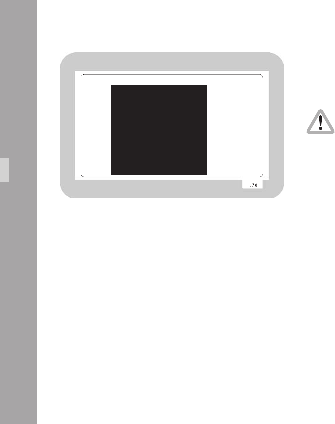
1010
10.4.5 Video and Text Adjustment Menu
This sub menu allows the user to change basic video settings
as well as the appearance of the inserted man readable text.
Changes made to settings are immediately activated.
Check all settings on a correctly adjusted monitor.
• Enter the Video/Text Adjust submenu from the main menu.
MENU VIDEO/TEXT ADJUST
-> - FLICKERFREE ON
- LINE INTERP. ON
- SHARPNESS 2
- BNC OUT VBS
Y/C DATA
- GENLOCK OFF
- MINI MON DATA ON
- TXT WHITE LEV. 2
- TXT INVERS OFF
- TXT FINE POS 2
- EXIT
Video-Ait-Sytem

1111
Flicker free ON/OFF
Flicker free can be switched off to bypass the digital frame
store and have the video assist output with no delay.
The typical running speed for the lm camera is different to
that of the video assist. e.g. the lm camera runs at 24 fps
and the video assist at 25 fps for PAL or 30 fps for NTSC.
Without icker processing this speed difference causes
varying brightness between successive individual video
images. To eliminate this so called icker, video images are
stored at the speed of the lm camera into the video frame
storage and recalled in the speed of the video system. This
storage might cause a slight delay, which is not desirable
in some time-crucial conditions, e.g. motion control or
shooting of a pop video. Therefore it is possible to switch
the icker free system off. This will eliminate the delay.
However, icker will occur in this mode.
In parallel to the control via keypad, the icker free off can
also be programmed via the on-screen menu.
• Move the cursor > with the keys Ê and Ë to the line
– FLICKERFREE. Pressing the key Í or Ì will switch
icker free mode off and on.
MENU VIDEO/TEXT ADJUST
-> - FLICKERFREE ON
- LINE INTERP. ON
- SHARPNESS 2
- BNC OUT VBS
Y/C DATA
- GENLOCK OFF
- MINI MON DATA ON
- TXT WHITE LEV. 2
- TXT INVERS OFF
- TXT FINE POS 2
- EXIT
Video-Ait-Sytem
Note: The lowest camera speed for icker free display
is 5 fps in automatic gain control mode and 1 fps
in manual gain control mode.

11
Line interpolation on/off
Due to the rotating mirror shutter of the lm camera, the
CCD chip of the IVS gets light only for 50 % of the time. All
video assists will therefore have only one true video eld
and the next one will be the repetition of the previous one.
So the repeated video eld does not have new information.
To improve this situation, the video assist can be electronically
enhanced with a feature called line interpolation.
• Move the cursor > with the keys Ê and Ë to the line
– LINE INTERP. Pressing the key Í or Ì will switch the
line interpolation on and off.
Note: This setting only affects the video image while
the lm camera is in run mode.
Sharpness value
The slew rate of the video signal can be electronically
adjusted, thus creating a crisper image. However, this will
lead to more video artefacts so the best image is a balance
between sharpness and video artefacts.
• Move the cursor > with the keys Ê and Ë to the line
– SHARPNESS. Pressing the key Í will switch the
sharpness from 0 to 3 and back to 0. The Ì key will
give the opposite direction.
Video-Ait-Sytem
MENU VIDEO/TEXT ADJUST
- FLICKERFREE ON
-> - LINE INTERP. ON
- SHARPNESS 2
- BNC OUT VBS
Y/C DATA
- GENLOCK OFF
- MINI MON DATA ON
- TXT WHITE LEV. 2
- TXT INVERS OFF
- TXT FINE POS 2
- EXIT
MENU VIDEO/TEXT ADJUST
- FLICKERFREE ON
- LINE INTERP. ON
-> - SHARPNESS 2
- BNC OUT VBS
Y/C DATA
- GENLOCK OFF
- MINI MON DATA ON
- TXT WHITE LEV. 2
- TXT INVERS OFF
- TXT FINE POS 2
- EXIT

11
Note: Sharpness 1 corresponds to the settings of older
IVS types e.g. the IVS 235.
Composite or Y/C signal at the BNC Connectors
The IVS has two BNC sockets which can be switched to
output two independent composite signals or one Y/C signal.
If selected, the Y/C signal comes from the same BNC
connectors on which the composite signal is output.
• Move the cursor > with the keys Ê and Ë to the line
– BNC OUT. Pressing the keys Í or Ì will switch the
output signal on the BNC connector between composite
(VBS) and Y/C
• If Y/C is selected a line symbol – will appear before
Y/C DATA indicating that the Y/C output can now be
switched between clean video and video with data.
Y/C signal with or without data
The Y/C signal can be switched between clean video and
video with data signals. Whichever option is selected the
Y/C signal is output from the same pair of connectors
• Move the cursor > with the keys Ê and Ë to the line
– Y/C DATA. Pressing the key Í or Ì will switch between
normal video and video with data in the Y/C signal.
The line displays Y/C DATA ON or OFF.
Video-Ait-Sytem
MENU VIDEO/TEXT ADJUST
- FLICKERFREE ON
- LINE INTERP. ON
- SHARPNESS 2
-> - BNC OUT Y/C
- Y/C DATA ON
- GENLOCK OFF
- MINI MON DATA ON
- TXT WHITE LEV. 2
- TXT INVERS OFF
- TXT FINE POS 2
- EXIT
MENU VIDEO/TEXT ADJUST
- FLICKERFREE ON
- LINE INTERP. ON
- SHARPNESS 2
- BNC OUT Y/C
-> - Y/C DATA ON
- GENLOCK OFF
- MINI MON DATA ON
- TXT WHITE LEV. 2
- TXT INVERS OFF
- TXT FINE POS 2
- EXIT

11
GENLOCK on/off
It is possible to synchronize the IVS to an external video
signal, thus allowing the user to switch between different
video signals without synchronizing problems.
• Connect a standard video signal of the same type as
the video system (PAL or NTSC) to the Video output
with no data (C-Output).
• Move the cursor > with the keys Ê and Ë to the line
– GENLOCK. Pressing the key Í or Ì will switch
genlock ON or OFF.
The video signal out of the connector for video with
data is now synchronized to the incoming video signal
connected to the other BNC socket.
Note: GENLOCK is only available, if the output is on
VBS mode.
Note: This setting is switched back to GENLOCK off after
the IVS is started (after power down/power up)
to avoid accidental operation.
Video-Ait-Sytem
MENU VIDEO/TEXT ADJUST
- FLICKERFREE ON
- LINE INTERP. ON
- SHARPNESS 2
- BNC OUT VBS
Y/C DATA
-> - GENLOCK ON
- MINI MON DATA ON
- TXT WHITE LEV. 2
- TXT INVERS OFF
- TXT FINE POS 2
- EXIT

11
Mini-Monitor Output as clean video or video with data
The mini monitor output can be programmed to have either
clean video or video with data. Both mini monitor outputs are
in parallel, so there are either no data, or data on both outputs.
If the on-screen menu control is on (red LED next to the
Enter/Insert key Ñ is on), there will always be data in
this output. This is necessary because if the output is
switched to data off, no inserter information is visible and
therefore, it would be impossible to go back into the on-
screen menu to change the settings.
• Move the cursor > with the keys Ê and Ë to the line
– MINI MON DATA. Pressing the key Í or Ì will
switch the insertion of data in the mini monitor
between ON and OFF.
White Level
This line is used to change the brightness of all man readable
windows except the frame lines. Value 0 means dark grey,
value 3 corresponds to bright white characters.
• Move the cursor > with the keys Ê and Ë to the line
– TXT WHITE LEV.. By pressing the key Í the values
for the brightness of the characters will increment from
0 to 3, and after that back to 0. The key Ì will
decrement in the opposite direction.
Video-Ait-Sytem
MENU VIDEO/TEXT ADJUST
- FLICKERFREE ON
- LINE INTERP. ON
- SHARPNESS 2
- BNC OUT Y/C
- Y/C DATA ON
- GENLOCK OFF
-> - MINI MON DATA ON
- TXT WHITE LEV. 2
- TXT INVERS OFF
- TXT FINE POS 2
- EXIT
MENU VIDEO/TEXT ADJUST
- FLICKERFREE ON
- LINE INTERP. ON
- SHARPNESS 2
- BNC OUT VBS
Y/C DATA
- GENLOCK OFF
- MINI MON DATA ON
-> - TXT WHITE LEV. 2
- TXT INVERS OFF
- TXT FINE POS 2
- EXIT

11
Video-Ait-Sytem
Inverse
This menu changes the appearance of all man readable
windows. The format markings are not changed. If inverse
OFF is selected, the characters will appear white. If the
background is BOXED it will appear black in this case. If
inverse ON is selected, the characters will appear black.
If the background is BOXED it will appear white in this case.
• Move the cursor > with the keys Ê and Ë to the line
– INVERSE. The keys Í or Ì will switch between ON
and OFF.
Fine Positioning
By changing the setting in the line Fine Position of this sub-
menu it is possible to simultaneously shift all man readable
windows vertically by one video line (ne adjust). The single
steps are smaller than the steps in the normal position mode.
This will place all windows as far outside the actual image
area as possible. Format markings are not moved.
• Move the cursor > with the keys Ê and Ë to the line
– FINE POS.. By pressing the key Í the value will
increment starting from 0 to 9, after that it will go back
to 0. Higher values will cause the windows to be at a
higher video line. They will therefore appear lower on
the video screen. The key Ì will increment in the
opposite direction.
MENU VIDEO/TEXT ADJUST
- FLICKERFREE ON
- LINE INTERP. ON
- SHARPNESS 2
- BNC OUT VBS
Y/C DATA
- GENLOCK OFF
- MINI MON DATA ON
- TXT WHITE LEV. 2
-> - TXT INVERS OFF
- TXT FINE POS 2
- EXIT
MENU VIDEO/TEXT ADJUST
- FLICKERFREE ON
- LINE INTERP. ON
- SHARPNESS 2
- BNC OUT VBS
Y/C DATA
- GENLOCK OFF
- MINI MON DATA ON
- TXT WHITE LEV. 2
- TXT INVERS OFF
-> - TXT FINE POS 2
- EXIT

11
Video-Ait-Sytem
Exit
Use exit to return to the main menu.
• Move the cursor > with the keys Ê and Ë to the line
–EXIT and press the key Í or Ì.
Note: Pressing the Enter/Insert key Ñ for more than
three seconds will cause the system to exit the
on-screen programming mode completely,
regardless of which menu is activated, with the
exception of the positioning mode.
MENU VIDEO/TEXT ADJUST
- FLICKERFREE ON
- LINE INTERP. ON
- SHARPNESS 2
- BNC OUT VBS
Y/C DATA
- GENLOCK OFF
- MINI MON DATA ON
- TXT WHITE LEV. 2
- TXT INVERS OFF
- TXT FINE POS 2
-> - EXIT

11
10.4.6 Format Marking Menu
The IVS can insert two different format markings electronically
into the video image, either individually or simultaneously.
The position of these format markings can be set anywhere
on the screen, to line up exactly with the bre screen
markings. The brightness is adjustable in four steps and the
area outside of the format markings can be electronically
darkened.
Changes made to settings are immediately activated.
Check all settings on a correctly adjusted monitor.
• Enter the Format Marking submenu from the main menu.
MENU FORMAT MARKING
-> - FORMAT OFF
POSITION 1 Ö
POSITION 1 Ü
POSITION 2 Ö
POSITION 2 Ü
WHITE LEVEL
OUTSIDE
- EXIT
Video-Ait-Sytem

11
Activate Format Markings
If the electronic format markings are not parallel to the bre
screen format markings, readjust the CCD chip with the
rotation alignment screw, as shown in chapter 10.3.3
Alignment of the image position (X-, Y- and Rotation) and
focus.
Note: Only active frame lines can be positioned. If no
frame line is on (FORMAT OFF), no position line
can be reached with the cursor >. If Format 1 is
on, only – POSITION 1 can be reached with
the cursor >. Only if format 1 & 2 is selected,
all - POSITION lines can be accessed.
It is possible to have no format marking (OFF), format
marking number one (1), format marking number two (2)
or both format markings at the same time (1 & 2) on
display.
• Move the cursor > with the keys Ê and Ë to the line
– FORMAT. Pressing the key Í will switch from OFF to
1 to 2 to 1 & 2 and back to OFF, the key Ì will switch
in the opposite direction.
MENU FORMAT MARKING
- FORMAT 1&2
-> - POSITION 1 Ö
- POSITION 1 Ü
- POSITION 2 Ö
- POSITION 2 Ü
- WHITE LEVEL 2
- OUTSIDE LIGHT
- EXIT
Video-Ait-Sytem

1010
Position – Adjusting the position of the Format Markings
The format markings can be adjusted to suit any format. The
format markings on the bre screen serve as a reference.
To align format 1, make sure that FORMAT 1 or FORMAT
1&2 is selected. To align format 2, make sure that
FORMAT 2 or FORMAT 1&2 is selected.
MENU FORMAT MARKING
- FORMAT 1&2
-> - POSITION 1 Ö
- POSITION 1 Ü
- POSITION 2 Ö
- POSITION 2 Ü
- WHITE LEVEL 2
- OUTSIDE LIGHT
- EXIT
Video-Ait-Sytem
To match the electronic format markings with the bre
screen markings proceed as follows:
• Point the lm camera towards a bright object so that the
format markings on the bre screen are clearly visible.
These are best seen if the camera lens is thrown out of focus.
• Move the cursor > with the keys Ê and Ë to the line
– POSITION 1Ö or – POSITION 2Ö, depending on
whether format 1 or format 2 is to be adjusted. The
symbol Ö indicates that the top line and the left line can
be moved. Enter the positioning mode by pressing the
keys Í or Ì.The display will show <>^vE. To move
the top line up and down, use the keys Ê and Ë.
When the desired position has been set, press the key
Ñ to leave the positioning mode. To move the
vertical line left and right, use the keys Í or Ì.
• Move the cursor > with the keys Ê and Ë to the line
– POSITION 1Ü or – POSITION 2Ü, depending on
whether format 1 or format 2 should get adjusted. The
symbol Ü indicates that the lower line can be moved.
Enter the positioning mode by pressing the keys Í or
Ì.The display will show <>^vE. To move the top line
up and down, use the keys Ê and Ë. When the the
desired position has been set, press the key Ñ to
leave the positioning mode. To move the vertical line
left and right, use the keys Í or Ì.

1111
White Level – Setting the Brightness of the Format Markings
The brightness of the format markings can be set to black
(0), dark grey (1), and light grey (2) or white (3).
• Move the cursor > with the keys Ê and Ë to the line
– WHITE LEVEL. Pressing the key Í will switch the
settings from 0 to 1 to 2 to 3 and back to 0, pressing
the key Ì will step through the settings in the opposite
direction.
Outside – Darkening the Area outside of the Format Markings
This function is only available if one or both
format markings is activated.
The brightness of the area outside of one format marking
can be reduced electronically to emphasize the important
image area.
• Move the cursor > with the keys Ê and Ë to the line
– OUTSIDE. Pressing the key Í will switch from no
shading (VID), light shading (LIGHT), dark shading
(DARK) to black (BLACK) and back to VID. Pressing the
key Ì will step through the options in the opposite
direction.
Video-Ait-Sytem
MENU FORMAT MARKING
- FORMAT 1&2
- POSITION 1 Ö
- POSITION 1 Ü
- POSITION 2 Ö
- POSITION 2 Ü
-> - WHITE LEVEL 2
- OUTSIDE LIGHT
- EXIT
MENU FORMAT MARKING
- FORMAT 1&2
- POSITION 1 Ö
- POSITION 1 Ü
- POSITION 2 Ö
- POSITION 2 Ü
- WHITE LEVEL 2
-> - OUTSIDE LIGHT
- EXIT

11
Exit
Use exit to return to the main menu.
• Move the cursor > with the keys Ê and Ë to the line
– EXIT and press the key Í or Ì.
Note: Pressing the Enter/Insert key Ñ for more than
three seconds will cause the system to exit the
on-screen programming mode completely,
regardless of which menu is activated, with the
exception of the positioning mode.
Video-Ait-Sytem
MENU FORMAT MARKING
- FORMAT 1&2
- POSITION 1 Ö
- POSITION 1 Ü
- POSITION 2 Ö
- POSITION 2 Ü
- WHITE LEVEL 2
- OUTSIDE LIGHT
-> - EXIT

11
10.4.7 Compare/Store Menu
The IVS can grab and store a selected image, display it
or overlay it against the live image in front of the camera
to compare both images.
Changes made to settings are immediately activated.
Check all settings on a correctly adjusted monitor.
• Enter the Compare/Store submenu from the main menu.
Display mode
Display mode allows the option of selecting whether a live
image, a stored image or both images in an alternating
display mode are displayed. (Please see next chapter
Store Image how to store an image.)
• Move the cursor > with the keys Ê and Ë to the line
– VIEW MODE. Pressing the key Í will switch from
LIVE to STORD to COMP and back to LIVE. The key Ì
will step through in the opposite direction.
If LIVE is selected, the live IVS image will be displayed. If
STORD is selected, the currently stored image will be
displayed (a black screen means there is no stored image)
and if COMP is selected, the live image and the stored
image will alternate to show the difference of both images.
MENU COMPARE/STORE
-> - VIEW MODE LIVE
- STORE IMAGE
- CLEAR IMAGE
- EXIT
MENU COMPARE/STORE
-> - VIEW MODE LIVE
- STORE IMAGE
- CLEAR IMAGE
- EXIT
The stored image is memorized until it is overwritten by a
new stored image, cleared with the CLEAR IMAGE option
or until the IVS or 416 power is turned off.
Video-Ait-Sytem

11
Store image
The IVS can grab and store a selected image, display it
or overlay it against the live image in front of the camera
to compare both images. Although the options to display
the stored image and to compare the stored image against
the live image are only available in the on-screen program
mode, it is possible to store an image any time using the
Enter/Insert key Ñ. To do so, make sure not to be in a
control menu and press the Enter/Insert key Ñ shortly,
approx. 1.5 seconds. In parallel it is possible to use the
on-screen menu:
• Move the cursor > with the keys Ê and Ë to the line
– STORE IMAGE. Pressing the Í or Ì keys will store
the image. The word DONE will appear for a few
seconds to show that an image was stored.
• The stored image is memorized until a new image is
stored, the image is cleared or until the IVS or 416
power was is turned off.
Clear image
• To clear an image, move the cursor > with the keys Ê
and Ë to the line – CLEAR IMAGE. Pressing the Í or
Ì keys will delete the image. The word DONE will
appear for a few seconds to show that an image was
deleted.
MENU COMPARE/STORE
- VIEW MODE LIVE
-> - STORE IMAGE
- CLEAR IMAGE
- EXIT
MENU COMPARE/STORE
- VIEW MODE LIVE
- STORE IMAGE
-> - CLEAR IMAGE
- EXIT
Video-Ait-Sytem

11
Exit
Use exit to return to the main menu.
• Move the cursor > with the keys Ê and Ë to the line
– EXIT and press the key Í or Ì.
Note: Pressing the Enter/Insert key Ñ for more than
three seconds will cause the system to exit the
on-screen programming mode completely,
regardless of which menu is activated, with the
exception of the positioning mode.
Video-Ait-Sytem
MENU COMPARE/STORE
- VIEW MODE LIVE
- STORE IMAGE
- CLEAR IMAGE
-> - EXIT

11
10.4.8 System, LDS and Status Menu
The IVS can insert the camera system, lens data and status
into the video image.
The System line inserts information from the lm camera
such as:
• Async
• Inching
• Low Battery
• Magazine Film Loop Too Long
• Magazine Film Loop Too Short
When the System line is switched on, an additional line of
information will appear when required, similar to this:
MAGAZINE FILM LOOP TOO LONG
The Lens Data line contains information about the Lens
and Lens settings such as:
• Lens Type
• Actual focal length
• Actual Iris
• Actual focus
• Depth of eld (near point, far point)
When the LDS line is switched on, an additional line of
information will appear, similar to this:
UP65 65MM 11+9/10 7.17M( 4.20M- 22.10M)
Additionally, the Status Line makes it possible to insert
camera status information in a separate line, such as:
• Actual voltage of the power supply
• Camera Status (RUN, STANDBY, NOT READY)
• Actual camera speed
• Preset camera speed
• Actual shutter opening
• Film counter information
MENU SYSTEM/LDS/STATUS
-> - SYSTEM LINE ON
- LDS LINE ON
- STATUS LINE ON
- POSITION
- BACKGROUND BOXED
- FILM COUNTER FTGE
- EXIT
MAGAZINE FILM LOOP TOO LONG
UP65 65MM 11+9/10 7.17M( 4.20M- 22.1M)
26.2V RUN FWD 24.000/24.000fps 180.0 F 12OFT
Video-Ait-Sytem
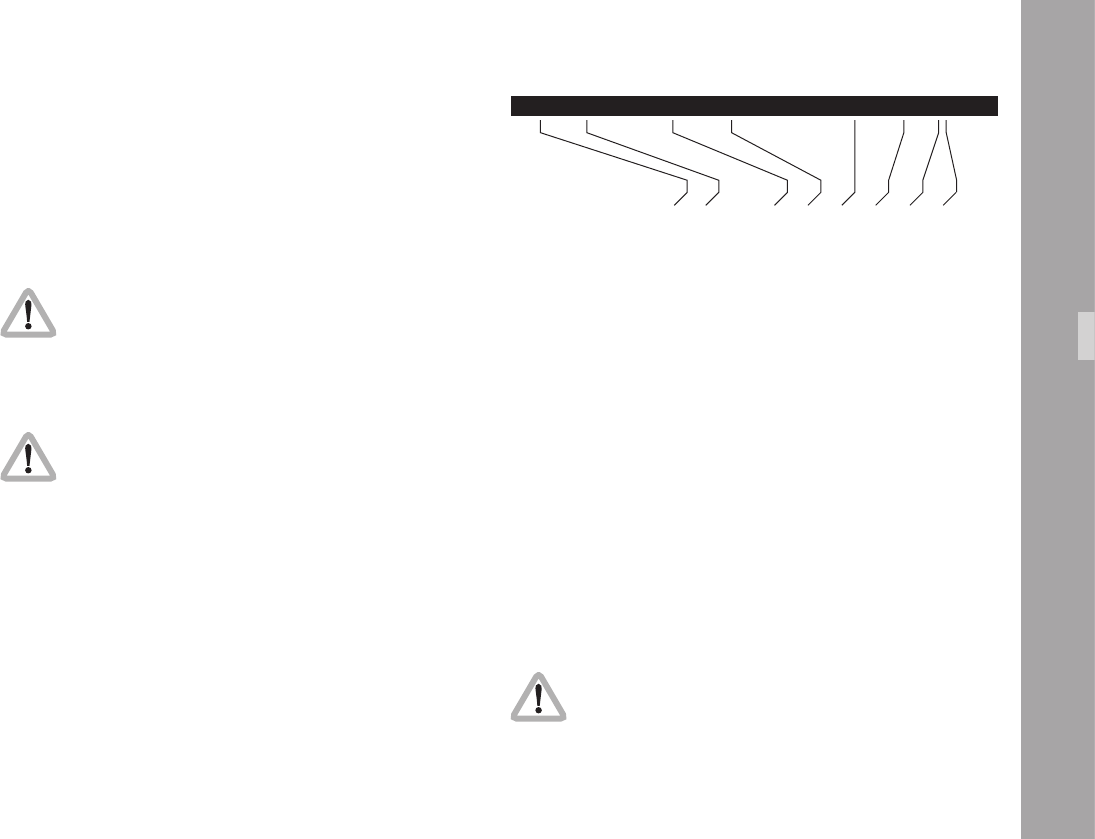
11
26.2V RUN FWD 24.000/24.000fps 180.0 F 120FT
lm camera voltage in
standby (STBY), run (RUN) or not ready (NRDY)
actual lm camera speed in fps
selected lm camra speed in fps
shutter mirror angle (only after camera was running)
counter is take (T) or footage (F) counter
lm counter
counter is meter (M), foot (FT), or seconds (s)
Video-Ait-Sytem
The lm counter gets its data from the lm camera. So the
data on the IVS is identical to the data in the lm camera.
If the lm counter is in the take mode, the data in meters,
feet or seconds of the last take is displayed. In the footage
mode, the total length of the lm run through the camera
is displayed, either in meters or feet.
During on-screen programming inserted data is
not fully updated (e. g. Frame Counter Information).
To update the information, leave the on-screen
display menu by pressing the Enter/Insert key
Ñ for more than three seconds.
When the lm camera is rst switched on, no
mirror shutter angle is displayed. Data only
appears after a few revolutions of the mirror shutter.
The System line, LDS line and Status line live together as a
package. If all lines are on, the upper line will always be
system, the middle line LDS and the lower line status.
Positioning always affects all lines together.
Like all man readable information, the data is inserted as
a window on the monitor image. Each window can be
switched on and off independently. Background and position
can be altered without affecting the settings of other windows.
The adjustment of the white level of the inserted data, an
inverse display and a ne adjustment of the vertical position
is described in chapters 10.4.5 White Level, Inverse and
Fine Positioning.
• Enter the System/LDS/Status submenu from the main menu.
Changes made to settings are immediately activated.
Check all settings on a correctly adjusted monitor.

11
Video-Ait-Sytem
System Line
This sub menu line switches the insertion of camera system
data on (ON) and off (OFF) independently of other inserted
data.
• Move the cursor > with the keys Ê and Ë to the line
– SYSTEM LINE. The keys Í or Ì switch the insertion
on and off.
A line similar to the depicted line will appear:
LOW BATTERY
The menu options Position and Background are
only available if one of the three information
lines is on. The menu option Film Counter is
only available when the Status Line is on.
To clear this message, eliminate the cause of the problem.
In this example, change the battery for a fully charged one.
MENU SYSTEM/LDS/STATUS
-> - SYSTEM LINE ON
- LENS DATA LINE ON
- STATUS LINE ON
- POSITION
- BACKGROUND BOXED
- FILM COUNTER FTGE
- EXIT

11
Video-Ait-Sytem
LDS Line
This sub menu line switches the insertion of Lens Data
(LDS) information on (ON) and off (OFF) independently
of other inserted data.
• Move the cursor > with the keys Ê and Ë to the line
– LDS LINE. The keys Í or Ì switch the insertion on
and off.
A line similar to the depicted line will appear:
UP65 65MM 11+9/10 7.17M ( 4.20M- 22.10M)
The menu options Position and Background are
only available if one of the three information
lines is on. The menu option Film Counter is
only available when the Status Line is on.
MENU SYSTEM/LDS/STATUS
- SYSTEM LINE ON
-> - LENS DATA LINE ON
- STATUS LINE ON
- POSITION
- BACKGROUND BOXED
- FILM COUNTER FTGE
- EXIT
1010
Video-Ait-Sytem
Status Line
This sub menu line switches the insertion of camera status
data on (ON) and off (OFF) independently of other
inserted data.
• Move the cursor > with the keys Ê and Ë to the line
– STATUS LINE. The keys Í or Ì switch the insertion
on and off.
A line similar to the depicted line will appear:
26.2V RUN FWD 24.000/24.000fps 180.0 F 120FT
The menu options Position and Background are
only available if one of the three information lines
is on. The menu option Film Counter is only
available when the Status Line is on.
MENU SYSTEM/LDS/STATUS
- SYSTEM LINE ON
- LENS DATA LINE ON
-> - STATUS LINE ON
- POSITION
- BACKGROUND BOXED
- FILM COUNTER FTGE
- EXIT

1111
Video-Ait-Sytem
Position
The window can be positioned anywhere on the monitor
screen.
The menu option Position is only available if at
least one of the three information lines is on.
• Move the cursor > with the keys Ê and Ë to the line
– POSITION. Enter the positioning mode with the Í or
Ì. keys The following menu is displayed on the screen:
-> - POSITION ^v E
• The Ê and Ë keys move the window up and down.
When the desired position has been set, conrm by
pressing the Enter/Insert key Ñ.
MENU SYSTEM/LDS/STATUS
- SYSTEM LINE ON
- LENS DATA LINE ON
- STATUS LINE ON
-> - POSITION
- BACKGROUND BOXED
- FILM COUNTER FTGE
- EXIT

11
Video-Ait-Sytem
Background
The background of the window can be set electronically to
black in normal display mode or to white in inverse mode
(BOXED) to improve the readability. If this is not activated,
the area around the text is the normal video image (VIDEO).
The menu option Background is only available
if at least one of the three information lines is on.
• Move the cursor > with the Ê and Ë keys to the line
– BACKGROUND. The Í or Ì key switches between
BOXED and VIDEO.
Film Counter
The lm counter is slaved to the footage counter of the lm
camera. It always displays the values, which are in the
camera. Therefore there is no set or reset of lm counter
data on the IVS.
The menu options Position and and Background
are only available if one of the three
information lines is on. The menu option Film
Counter is only available if the Status line is on.
MENU SYSTEM/LDS/STATUS
- SYSTEM LINE ON
- LENS DATA LINE ON
- STATUS LINE ON
- POSITION
-> - BACKGROUND BOXED
- FILM COUNTER FTGE
- EXIT
MENU SYSTEM/LDS/STATUS
- SYSTEM LINE ON
- LENS DATA LINE ON
- STATUS LINE ON
- POSITION
- BACKGROUND BOXED
-> - FILM COUNTER TAKE
(SEC)
- EXIT

11
• Move the cursor > with the Ê and Ë keys to the line
– FILM COUNTER. The Í key will switch from TAKE (M/FT),
TAKE (SEC) to FTGE and back to TAKE (M/FT). The Ì
key will step through the options in the reverse order.
Note: The unit of measurement meters or feet is taken
from the setting of the camera. If the unit of
measurement on the 416 is set to meters, the
data on the IVS is also displayed in meters.
Exit
Use exit to return to the main menu.
• Move the cursor > with the keys Ê and Ë to the line
– EXIT and press the key Í or Ì.
Note: Pressing the Enter/Insert key Ñ for more than
three seconds will cause the system to exit the on-
screen programming mode completely, regardless
of which menu is activated, with the exception of
the positioning mode.
Video-Ait-Sytem
MENU SYSTEM/LDS/STATUS
- SYSTEM LINE ON
- LENS DATA LINE ON
- STATUS LINE ON
- POSITION
- BACKGROUND BOXED
- FILM COUNTER FTGE
-> - EXIT

11
10.4.9 User Text Menu
The IVS can insert additional text into the video image, e.g.
the production name or a scene number. The text can be
entered on the IVS using the text edit facility or the ARRI
software User Text Line IVS (downloadable from the ARRI
website).
If information is stored in the text memory, it will remain
there until the memory is cleared or new text overwrites the
old. The text memory is retained even if the IVS or the
camera is switched off and disconnected from the power
supply. This enables, for example, a camera rental house to
store information, which is then available to the production
team. e.g. the production name.
Like all man readable information, the data is inserted as a
window on the monitor image. The window can be switched
on and off independently. Background, position and character
format can be altered without affecting the settings of
other windows.
This additional line shows the text information, similar to this:
PROD. NAME UNIT A TAKE 35 SCENE 11/III
MENU USER TEXT
-> - USER TEXT LINE ON
- EDIT TEXT
- CLEAR TEXT
(NO UNDO)
- POSITION
- SIZE SMALL
- BACKGROUND BOXED
- EXIT
PROD. NAME UNIT A TAKE 35 SCENE 11/III
Video-Ait-Sytem

11
MENU USER TEXT
-> - USER TEXT LINE ON
- EDIT TEXT
- CLEAR TEXT
(NO UNDO)
- POSITION
- SIZE SMALL
- BACKGROUND BOXED
- EXIT
The adjustment of the white level of the inserted data, an
inverse display and a ne adjustment of the vertical position
is described in chapters 10.4.5 White Level, Inverse and
Fine Positioning.
• Enter the User Text submenu from the main menu.
Changes made to settings are immediately activated.
Check all settings on a correctly adjusted monitor.
User Text Line
This sub menu line switches the insertion of User Text on
(ON) and off (OFF) independently of other inserted data.
• Move the cursor > with the Ê and Ë keys to the line
– USER TEXT LINE. The Í or Ì keys switch the insertion
on and off.
The default text is all characters dotted.
Edit Text using the internal text editing facility
The text can be edited on the IVS without the need for
additional devices.
• Move the cursor > with the Ê and Ë keys to the line
– EDIT TEXT. Activate the edit menu with the Í or Ì keys.
• This will lead into the editing submenu.
Video-Ait-Sytem
MENU USER TEXT
- USER TEXT LINE ON
-> - EDIT TEXT
- CLEAR TEXT
(NO UNDO)
- POSITION
- SIZE SMALL
- BACKGROUND BOXED
- EXIT
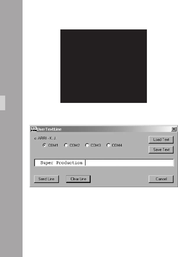
11
The menu EDIT TEXT is displayed on the screen:
• The X Symbol shows the position in the user text line that
is to be changed. Move this text inserter cursor X left and
right with the Í and Ì keys to the desired position.
• Change the character to be inserted with the Ê and
Ë keys.
• Once the desired character is selected, move the text
inserter cursor X to the next position.
• To leave the text edit mode, press the Enter/Insert key
Ñ. This will lead back to the user text menu.
MENU EDIT TEXT
(.................)
>X <
(.................)
> <
(.................)
> <
MOVE THE CURSOR X <>
CHANGE CHARACTER ^v
EXIT PRESS E
Video-Ait-Sytem
Edit Text using the ARRI software User Text Line IVS
• Connect a computer to the ARRIFLEX 416 camera using
a cable KC 89-S (K2.65002.0). Connect the cable
between the REMOTE connector on the camera side and
the serial port on the computer. Computers with no serial
interface, such as new laptops, can use an USB to serial
adapter, which is available in computer hardware shops.
• Select the output channel on your computer (COM 1 to
COM 4).
• Make sure that the USER TEXT LINE is switched on
• Type the necessary information into the editing line.
Click the Send Line button to send the text the IVS.
• Save Text allows you to store a text line, Load Text
loads a text line from the hard disc into the editing line.

11
Clear Text using the internal text editing facility
The user text line can be cleared on the IVS without an
external device. When the text is cleared, the default line,
a dotted line will appear.
Text cleared from the IVS is lost
and cannot be recalled.
• Move the cursor > with the Ê and Ë keys to the line
– CLEAR TEXT. Press the Í or Ì keys to clear the line.
Position
The window can be positioned anywhere on the monitor
screen.
• Move the cursor > with the Ê and Ë keys to the line
– POSITION. Activate the positioning mode with the Í
or Ì keys. The following menu is displayed on the screen:
-> - POSITION ^v E
• The Ê and Ë keys move the window up and down.
When the desired position has been set, conrm by
pressing the Enter/Insert key Ñ.
Video-Ait-Sytem
MENU USER TEXT
- USER TEXT LINE ON
- EDIT TEXT
-> - CLEAR TEXT
(NO UNDO)
- POSITION
- SIZE SMALL
- BACKGROUND BOXED
- EXIT
MENU USER TEXT
- USER TEXT LINE ON
- EDIT TEXT
- CLEAR TEXT
(NO UNDO)
-> - POSITION
- SIZE SMALL
- BACKGROUND BOXED
- EXIT

11
Size
The size of the window can be changed independently
from other inserts.
• Move the cursor > with the Ê and Ë keys to the line
– SIZE. The key Í will switch from SMALL, WIDE, HIGH
to BIG and back to SMALL. The Ì key will switch in
opposite direction.
Video-Ait-Sytem
Background
The background of the window can be set electronically
to black in normal display mode or to white in inverse
mode (BOXED) to improve the readability. If this is not
activated, the area around the text is the normal video
image (VIDEO).
• Move the cursor > with the Ê and Ë keys to the line
– BACKGROUND. The Í or Ì keys switch between
BOXED and VIDEO.
MENU USER TEXT
- USER TEXT LINE ON
- EDIT TEXT
- CLEAR TEXT
(NO UNDO)
- POSITION
-> - SIZE SMALL
- BACKGROUND BOXED
- EXIT
MENU USER TEXT
- USER TEXT LINE ON
- EDIT TEXT
- CLEAR TEXT
(NO UNDO)
- POSITION
- SIZE SMALL
-> - BACKGROUND BOXED
- EXIT

11
Exit
Use exit to return to the main menu.
• Move the cursor > with the Ê and Ë keys to the line
– EXIT and press the Í or Ì keys.
Note: Pressing the Enter/Insert key Ñ for more than
three seconds will cause the system to exit the on-
screen programming mode completely, regardless
of which menu is activated, with the exception
of the positioning mode.
Video-Ait-Sytem
MENU USER TEXT
- USER TEXT LINE ON
- EDIT TEXT
- CLEAR TEXT
(NO UNDO)
- POSITION
- SIZE SMALL
- BACKGROUND BOXED
-> - EXIT

10
10.4.10 Timecode Menu
The IVS can burn the lm camera‘s timecode into the video
assist image to create a direct link to the post production.
It is possible to insert either timecode, which is related to
the lm camera speed, e.g. 24 fps or a timecode which
counts according to the type of video assist (25 full video
frames per second with PAL or 30 full video frames per
second with NTSC).
Like all man readable information, the data is inserted as
a window on the monitor image. The window can be
switched on and off independently. Background, position
and character format can be altered without affecting the
settings of other windows.
The adjustment of the white level of the inserted data, an
inverse display and a ne adjustment of the vertical
position is described in chapter 10.4.5
This additional line shows the TC information:
11:24:30/03
11:24:30/03
MENU TIME CODE TIME
-> - TIME CODE TIME ON
- POSITION
- SIZE SMALL
- BACKGROUND BOXED
- FRAME COUNTER VIDEO
- EXIT
Video-Ait-Sytem

11
Note: The frame information (the last two digits of the
timecode display) is only active if timecode is
actually recorded on lm. If there is no time-
code recording on lm, because for example
the camera is not running at a timecode speed,
only the symbol ** is displayed in that position.
• Enter the Timecode Menu from the Main Menu.
Changes made to settings are immediately activated.
Check all settings on a correctly adjusted monitor.
TC Time
This sub menu line switches the insertion of timecode data
on (ON) and off (OFF) independently of other inserted
data.
• Move the cursor > with the Ê and Ë keys to the line
– TIMECODE TIME. The Í or Ì keys switch the
insertion on and off.
MENU TIME CODE TIME
-> - TIME CODE TIME ON
- POSITION
- SIZE SMALL
- BACKGROUND BOXED
- FRAME COUNTER VIDEO
- EXIT
Video-Ait-Sytem

1
Position
The window can be positioned anywhere on the monitor
screen.
• Move the cursor > with the Ê and Ë keys to the line
– POSITION. Activate the positioning mode with the Í
or Ì keys. The following menu is displayed on the
screen:
-> - POSITION <>^v E
• The Ê and Ë keys move the window up and down.
The Ì and Í keys move it left and right. When the
desired position has been set, conrm by pressing the
Enter/Insert key Ñ.
Size
The size of the window can be changed independently
from other inserts.
• Move the cursor > with the Ê and Ë keys to the line
– SIZE. The Í key will switch from SMALL, WIDE,
HIGH to BIG and back to SMALL. The Ì key will
switch in opposite direction.
Video-Ait-Sytem
MENU TIME CODE TIME
- TIME CODE TIME ON
-> - POSITION
- SIZE SMALL
- BACKGROUND BOXED
- FRAME COUNTER VIDEO
- EXIT
MENU TIME CODE TIME
- TIME CODE TIME ON
- POSITION
-> - SIZE SMALL
- BACKGROUND BOXED
- FRAME COUNTER VIDEO
- EXIT

1
Background
The background of the window can be set electronically
to black in normal display mode or to white in inverse
mode (BOXED) to improve the readability. If this is not
activated, the area around the text is the normal video
image (VIDEO).
• Move the cursor > with the Ê and Ë keys to the line
– BACKGROUND. The Í or Ì keys switch between
BOXED and VIDEO.
Frame Counter
It is recommended the camera user checks the
requirements of all parties involved in post-
production prior to shooting.
Frequently the camera is set to run at a different speed from
that of the video system. In areas with NTSC video system
for example, the lm camera might run at 24 fps whereas
the video system works with 30 full video frames per second.
In order to adapt to these specic needs there are two
different timecode formats possible.
Video-Ait-Sytem
MENU TIME CODE TIME
- TIME CODE TIME ON
- POSITION
- SIZE SMALL
-> - BACKGROUND BOXED
- FRAME COUNTER VIDEO
- EXIT
MENU TIME CODE TIME
- TIME CODE TIME ON
- POSITION
- SIZE SMALL
- BACKGROUND BOXED
-> - FRAME COUNTER VIDEO
- EXIT

1
To have the timecode count related to the lm camera, select
the mode “Frame counter Film“ which is often referred to
as “lm related timecode“. In this mode, the frame counter
of the timecode (the last two digits of the timecode display)
is increased by 1 if the lm is advanced by one frame e.g.
24 times a second at 24 fps. This way it is easy to identify
one particular lm frame by looking at the video image.
On the other hand, this mode will create an unusual time-
code count because some video images are repeated to
cope with the different frame rates of the video and the lm
camera. These repeated images will get duplicated time-
code words which will create error messages on some
timecode readers.
To relate the timecode count to the video system, select
“Frame counter Video“. This is often referred to as “video
related timecode“. Every full video frame will advance the
timecode by 1 e.g. 25 times a second in PAL or 30 times
a second in NTSC. In this mode the IVS creates a standard
timecode. On the other hand, it is more difcult to restore
the link back to the timecode, which was recorded on lm.
To get a reliable relation, it is necessary to utilize the Pull-
Down (refer to chapter 6.8) or White Line Flag
information (refer to chapter 6.11).
At every full second, both time counts are identical.
In case of “Frame counter Film“ there will be a / before the
frame count (the last two digits of the timecode display), in
case of “Frame counter Video“ there will be a : aphoto.
11:24:30/03
11:24:30:03
11:24:30/**
The Frame count is only active if timecode is
actually recorded on Film. In all other cases a
** aphoto symbol will appear in place of the
frame count.
Timecode is only recorded on lm at standard
speeds. These are 23.976 fps, 24 fps, 25 fps,
29.97 fps and 30 fps. At all other speeds, time-
code is displayed on the video assist without the
frame count and it is not recorded on lm.
Timecode is only valid when Flicker Free is on.
• Move the cursor > with the Ê and Ë keys to the line
– FRAME COUNTER. The Í or Ì keys switch the
frame counter mode between “FILM“ and “VIDEO“.
Video-Ait-Sytem

1
Exit
Return to the main menu using Exit.
• Move the cursor > with the keys Ê and Ë to the line
– EXIT and press the key Í or Ì.
Note: Pressing the Enter/Insert key Ñ for more than
three seconds will cause the system to exit the
on-screen programming mode completely,
regardless of which menu is activated, with the
exception of the positioning mode.
Video-Ait-Sytem
MENU TIME CODE TIME
- TIME CODE TIME ON
- POSITION
- SIZE SMALL
- BACKGROUND BOXED
- FRAME COUNTER VIDEO
-> - EXIT
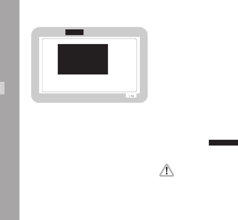
1
10.4.11 USER BITS Menu
The IVS can insert the User Bits of the lm camera’s timecode
into the video assist image to create a direct link to the
post production.
Like all man readable information, the data is inserted as
a window on the monitor image. The window can be
switched on and off independently. Background, position
and character format can be altered without affecting the
settings of other windows.
The adjustment of the white level of the inserted data, an
inverse display and a ne adjustment of the vertical
position is described in chapter 10.4.5
This additional line shows the User Bit information:
100279C1
• Enter the User Bits Menu from the Main Menu.
Changes made to settings are immediately activated.
Check all settings on a correctly adjusted monitor.
MENU TIME CODE UB
-> - TIME CODE UB ON
- POSITION
- SIZE SMALL
- BACKGROUND BOXED
- EXIT
100297C1
Video-Ait-Sytem

1
TC Ubit
This sub menu line switches the insertion of User Bit data
on (ON) and off (OFF) independently of other inserted data.
• Move the cursor > with the Ê and Ë keys to the line
– TC UBIT. The Í or Ì keys switch the insertion on
and off.
MENU TIME CODE UB
-> - TIME CODE UB ON
- POSITION
- SIZE SMALL
- BACKGROUND BOXED
- EXIT
Position
The window can be positioned anywhere on the monitor
screen.
• Move the cursor > with the Ê and Ë keys to the line
– POSITION. Activate the positioning mode with the Í
or Ì keys. The following menu is displayed on the
screen:
-> - POSITION <>^v E
• The Ê and Ë keys move the window up and down.
The Ì and Í keys move it left and right. When the
desired position has been set, conrm by pressing the
Enter/Insert key Ñ.
Video-Ait-Sytem
MENU TIME CODE UB
- TIME CODE UB ON
-> - POSITION
- SIZE SMALL
- BACKGROUND BOXED
- EXIT

1
Size
The size of the window can be changed independently from
other inserts.
• Move the cursor > with the keys Ê and Ë keys to the
line – SIZE. The Í key will switch from SMALL, WIDE,
HIGH to BIG and back to SMALL. The Ì key will
switch in opposite direction.
Background
The background of the window can be set electronically
to black in normal display mode or to white in inverse
mode (BOXED) to improve the readability. If this is not
activated, the area around the text is the normal video
image (VIDEO).
• Move the cursor > with the Ê and Ë keys to the line
– BACKGROUND. The Í or Ì keys switch between
BOXED and VIDEO.
Video-Ait-Sytem
MENU TIME CODE UB
- TIME CODE UB ON
- POSITION
-> - SIZE SMALL
- BACKGROUND BOXED
- EXIT
MENU TIME CODE UB
- TIME CODE UB ON
- POSITION
- SIZE SMALL
-> - BACKGROUND BOXED
- EXIT

1
Exit
Return to the main menu using Exit.
• Move the cursor > with the Ê and Ë keys to the line
– EXIT and press the Í or Ì keys.
Note: Pressing the Enter/Insert key Ñ for more than
three seconds will cause the system to exit the
on-screen programming mode completely,
regardless of which menu is activated, with the
exception of the positioning mode.
Video-Ait-Sytem
MENU TIME CODE UB
- TIME CODE UB ON
- POSITION
- SIZE SMALL
- BACKGROUND BOXED
-> - EXIT
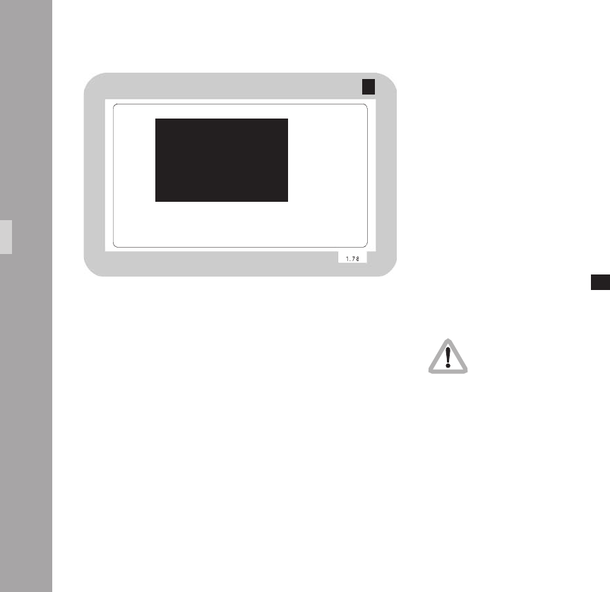
10
10.4.12 Pull-Down Menu
The IVS can generate information on whether the current
video image corresponds to a new lm frame or whether
it is a repeated video image. The Pull-Down information
displays that in man readable form.
The adjustment of the white level of the inserted data, an
inverse display and a ne adjustment of the vertical
position is described in chapter 10.4.5
This additional window shows the pull-down information:
A1
• Enter the Pull-Down Menu from the Main Menu.
Changes made to settings are immediately activated.
Check all settings on a correctly adjusted monitor.
All video assists are based either on PAL or NTSC video
systems, with a xed video frequency of either 25 full video
frames per second with PAL or 29.97 full video frames per
second with NTSC. The speed of the lm camera on the other
hand can be selected over a wide range. At every lm speed
which is different from the video frequency, the IVS has to add
repeated video elds to compensate for the different frame
rates.
MENU PULL DOWN
-> - PULL DOWN ON
- POSITION
- SIZE SMALL
- BACKGROUND BOXED
- EXIT
A1
Video-Ait-Sytem
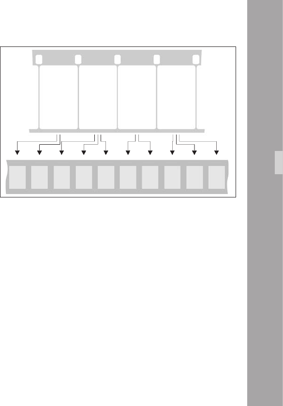
11
In practice the most important case is a lm camera speed
of 23.976 fps and a NTSC video assist.
This creates the situation described in the drawing.
From the rst lm frame, two video elds are derived, the
second lm frame, three video elds are derived, from the
next lm frame, two video elds and so on.
The Pull-Down information is created as follows:
Every time, the video eld corresponds to a new lm frame,
the letter will change either from A to B or B to A and the
number will be set to 1. As long as no new lm frame is
taken, the video elds are counted, beginning from 1.
Consequently A2 is the rst repetition of A1. B2 would be
the rst repetition of B1, B3 would be the second repetition.
In spite of the fact that the name Pull-Down comes from the
working practice in the NTSC systems, where on a telecine
the lm is running on 23.976 fps and gets converted to
29.97 fps, the denition of Pull-Down information on the
IVS can also be applied to PAL and to lm speeds other
than 23.976 fps.
Film
1
Film
2
Film
3
Film
4
A1 A2 B1 B2 B3 A1 A2 B1 B2 B3
Like all man readable information, the data is inserted as
a window on the monitor image. The window can be
switched on and off independently. Background, position
and character format can be altered without affecting the
settings of other windows.
Note: Pull-Down information is only inserted when
timecode is actually recorded on lm. If there is
no timecode recording, for example because
the camera is not running on a timecode speed,
only A1 will be displayed.
Video-Ait-Sytem

1
Pull-Down
This sub menu line switches the insertion of pull down
information on (ON) and off (OFF) independently of other
inserted data.
• Move the cursor > with the Ê and Ë keys to the line
– PULL DOWN. The Í or Ì keys switch the insertion
on and off.
MENU PULL DOWN
-> - PULL DOWN ON
- POSITION
- SIZE SMALL
- BACKGROUND BOXED
- EXIT
Position
The window can be positioned anywhere on the monitor
screen.
• Move the cursor > with the Ê and Ë keys to the line
– POSITION. Activate the positioning mode with the Í
or Ì keys. The following menu is displayed on the
screen:
-> - POSITION <>^v E
• The Ê and Ë keys move the window up and down.
The Ì and Í keys move it left and right. When the
desired position has been set, conrm by pressing the
Enter/Insert key Ñ.
Video-Ait-Sytem
MENU PULL DOWN
- PULL DOWN ON
-> - POSITION
- SIZE SMALL
- BACKGROUND BOXED
- EXIT

1
Size
The size of the window can be changed independently
from other inserts.
• Move the cursor > with the Ê and Ë keys to the line
– SIZE. The Í key will switch from SMALL, WIDE,
HIGH to BIG and back to SMALL. The Ì key will
switch in the opposite direction.
Background
The background of the window can be set electronically
to black in normal display mode or to white in inverse
mode (BOXED) to improve the readability. If this is not
activated, the area around the text is the normal video
image (VIDEO).
• Move the cursor > with the Ê and Ë keys to the line
– BACKGROUND. The Í or Ì keys switch between
BOXED and VIDEO.
Video-Ait-Sytem
MENU PULL DOWN
- PULL DOWN ON
- POSITION
-> - SIZE SMALL
- BACKGROUND BOXED
- EXIT
MENU PULL DOWN
- PULL DOWN ON
- POSITION
- SIZE SMALL
-> - BACKGROUND BOXED
- EXIT

1
Exit
Return to the main menu using Exit.
• Move the cursor > with the Ê and Ë keys to the line
– EXIT and press the Í or Ì keys.
Note: Pressing the Enter/Insert key Ñ for more than
three seconds will cause the system to exit the
on-screen programming mode completely,
regardless of which menu is activated, with the
exception of the positioning mode.
Video-Ait-Sytem
MENU PULL DOWN
- PULL DOWN ON
- POSITION
- SIZE SMALL
- BACKGROUND BOXED
-> - EXIT

1
10.4.13 VITC Line Menu
The IVS can convert the timecode, which can also be
displayed man-readable in the video image, into machine
readable VITC (Vertical Interval Time-Code) and place it
in non visible video lines.
Note: The timecode count that is used (“lm related“ or
“video related timecode“) depends on the
settings of the line “Frame Counter“ in the sub
menu “Timecode“ (see chapter 10.4.10).
Note: VITC is only output if timecode is actually
recorded on lm. If no timecode is recorded on
lm for example because the camera is not
running at a timecode speed, no VITC is available.
Note: The White Line has priority over VITC lines. If
the same line is selected for White Line as well
as for VITC, White Line will appear.
• Enter the VITC Line Menu from the Main Menu.
Changes made to settings are immediately activated.
Check all settings on a correctly adjusted monitor.
MENU VITC LINE
-> - VITC LINE ON
- POSITION 1 10
- POSITION 2 12
- EXIT
A1
Video-Ait-Sytem

1
VITC
This sub menu line switches the insertion of VITC on (ON)
and off (OFF).
• Move the cursor > with the Ê and Ë keys to the line
– VITC. The Í and Ì keys switch the insertion on and off.
Position 1
The insertion of VITC can be on single or multiple lines
between lines 6 and 22. If the same line number is
selected on both position 1 and position 2, the insertion
will be single line; otherwise it will be multiple lines. The
value of position 1 can be higher or lower than that of
position 2.
• Move the cursor > with the Ê and Ë keys to the line
– POSITION 1. By pressing the Í key the value will be
increased until line 22 is selected. By pressing the Ì
key the value will be decreased until line 6 is reached.
MENU VITC LINE
-> - VITC LINE ON
- POSITION 1 10
- POSITION 2 12
- EXIT
Video-Ait-Sytem
MENU VITC LINE
- VITC LINE ON
-> - POSITION 1 10
- POSITION 2 12
- EXIT

1
Position 2
The insertion of VITC can be on single or multiple lines
between lines 6 and 22. If the same line number is
selected on both position 1 and position 2, the insertion
will be single line; otherwise it will be multiple lines. The
value of position 1 can be higher or lower than that of
position 2.
• Move the cursor > with the Ê and Ë keys to the line
– POSITION 2. By pressing the Í key the value will be
increased until line 22 is selected. By pressing the Ì
key the value will be decreased until line 6 is reached.
Exit
Return to the main menu using Exit.
• Move the cursor > with the Ê and Ë keys to the line
– EXIT and press the Í or Ì keys.
Note: Pressing the Enter/Insert key Ñ for more than
three seconds will cause the system to exit the
on-screen programming mode completely,
regardless of which menu is activated, with the
exception of the positioning mode.
Video-Ait-Sytem
MENU VITC LINE
- VITC LINE ON
- POSITION 1 10
-> - POSITION 2 12
- EXIT
MENU VITC LINE
- VITC LINE ON
- POSITION 1 10
- POSITION 2 12
-> - EXIT
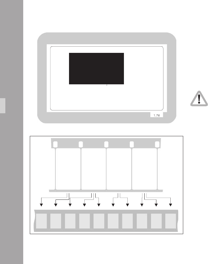
1
10.4.14 White Line Menu
The IVS can generate information on whether the current
video image corresponds to a new lm frame or whether
it is a repeated video image. The White Line ag displays
this in machine readable form.
• Enter the White Line Menu from the Main Menu.
Changes made to settings are immediately activated.
Check all settings on a correctly adjusted monitor.
All video assists are based either on PAL or NTSC video
systems, with a xed video frequency of either 25 full
video frames per second with PAL or 29.97 full video
frames per second with NTSC. The speed of the lm
camera on the other hand can be selected over a wide
range. At every lm speed which is different from the
video frequency, the IVS has to add repeated video elds
to compensate for the different frame rates.
In practice the most important case is a lm camera speed
of 23.976 fps and a NTSC video assist.
This creates a situation described in the drawing.
MENU WHITE LINE
-> - WHITE LINE ON
- POSITION 10
- EXIT
Film
1
Film
2
Film
3
Film
4
A1 A2 B1 B2 B3 A1 A2 B1 B2 B3
Video-Ait-Sytem

1
From the rst lm frame, two video elds are derived, the
second lm frame, three video elds are derived, from the
next lm frame, two video elds and so on.
The White Line ag works as follows:
Every time, the video eld corresponds to a new lm frame,
the letter will change either from A to B or B to A and the
number will be set to 1. As long as no new lm frame is
taken, the video elds are counted, beginning from 1.
Consequently A2 is the rst repetition of A1. B2 would be
the rst repetition of B1, B3 would be the second
repetition. On every A1 or B1, the selected video line will
get set to video signal white, indicating that only these
video frames correlate one-to-one to lm frames. The
duplicated video elds are not marked.
In spite of the fact that the name Pull-Down comes from
the working practice in the NTSC systems, where on a
telecine the lm is running on 23.976 fps and gets
converted to 29.97 fps, the denition of Pull-Down
information on the IVS can also be applied to PAL and to
lm speeds other than 23.976 fps.
Note: The insertion of White Line ags is only done,
when timecode is actually recorded on lm. If
there is no timecode recording, for example
because the camera is not running on a time-
code speed, no White Line ag is sent out.
Note: The White Line has priority over VITC lines. If
the same line is selected for White Line as well
as for VITC, White Line will appear.
Video-Ait-Sytem

10
White Line
This sub menu line switches the insertion of White Lines
on (ON) and off (OFF).
• Move the cursor > with the Ê and Ë keys to the line
– WHITE LINE. The Í and Ì keys switch the insertion on
and off.
Position
The insertion of White Lines can be between line 6 and 22.
• Move the cursor > with the Ê and Ë keys to the line
– POSITION. By pressing the Í key the value will be
increased until line 22 is selected. By pressing the Ì key
the value will be decreased until line 6 is reached.
MENU WHITE LINE
-> - WHITE INE ON
- POSITION 11
- EXIT
Video-Ait-Sytem
MENU WHITE LINE
- WHITE INE ON
-> - POSITION 11
- EXIT

11
Exit
Return to the main menu using Exit.
• Move the cursor > with the Ê and Ë keys to the line
– EXIT and press the Í or Ì keys.
Note: Pressing the Enter/Insert key Ñ for more than
three seconds will cause the system to exit the
on-screen programming mode completely,
regardless of which menu is activated, with the
exception of the positioning mode.
Video-Ait-Sytem
MENU WHITE LINE
- WHITE INE ON
- POSITION 11
-> - EXIT

1
Video-Ait-Sytem

1
11.Timecode
The ARRIFLEX 416 is equipped with a TC generator which
produces 80bit Timecode with a data structure conforming
to SMPTE RP136, Format Type C. The TC generator is set
using a master clock. The precision of the TC generator
ensures that for 8 hours after the synchronization (at 0°C
- 50°C) the difference remains less than one frame, if the
time code generator of the audio machine is precise, too.
Every frame is therefore clearly identiable for synchro-
nization or editing lists.
A new feature on the 416 further improves the accuracy
of the synchronization between the 416 TC generator and
the master clock. To exploit this feature the camera must
be connected to an Ambient Clockit as the master clock.
Timecode is recorded in the magazine, its position on lm
conforming to SMPTE RP114, at standard speeds of
23.976, 24.00, 25.00, 29.97 and 30.00 fps.
The TC information also includes speed of recording
which is described in connection with Timecode as frame
rate. For the ARRIFLEX 416 the valid frame rate is always
the most recently set standard speed.
For Timecode operation, please make sure that
the magazine is equipped with a Timecode
exposure module K2.55034.0.
TC-Input
The TC generator integrated in the ARRIFLEX 416 can be
synchronized to other equipment with a TC generator. A
LTC signal (Longitudinal TimeCode) from any TC generator
is plugged into the “TCC“ socket. The signal level must be
higher than 500 mV p-p. The camera automatically takes
on TC time and TC User Bits. If the LTC signal is correctly
transferred the TC recording will be automatically
switched on.
Timecode
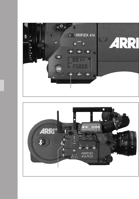
1
• Using the “MODE“ key aphoto switch to Mode 4
(Timecode time)
• Plug the cable with the TC signal into the “TCC“ socket
aphoto. The last two entries on the indicator show a
blinking “EC“ (external code). If the LTC signal is
correctly transferred the indication “CC“ (correct code)
appears for approx. 10 second before the indicator on
the generator frame rate switches back.
Note: The CCU is no longer supported and cannot be
used for setting Timecode.
Increased accuracy of the TC Generator
The ARRIFLEX 416 TC generator has a new feature to extend
the time period required between synchronizations. The
camera must be connected to an Ambient Clockit as the
master clock. The Ambient Clockit measures the frequency
of the 416 TC output, calculates the difference to its own
internal clock and puts out an adjustment value to the 416
TC generator.
Timecode
MODE button
TCC socket

1
TC Output
TC information is constantly available as 80bit LTC on the
“TCC“ socket. Output signal is in the LTC format.
From the TC output TC compatible equipment can be
synchronized on the set once (for 8 hours) on the camera’s
Timecode or constantly supplied with Timecode by the
camera. The camera then takes on the master clock function.
The 416 TC Generator is not able to adjust the clock of an
external device to its own clock frequency. When using the
416 TC Generator as a master clock the adaptation to the
master clock has to be done by the slave itself. No
functionality is provided by the 416 in this respect.
Timecode
Timecode and ESU-1
When using the external synchronization unit ESU-1 for
synchronizing the camera to other equipment, Timecode
can still be recorded. The difference between the external
synchronization and the TC frame rate must be less than
1%. If the difference exceeds 1% the TC recording
switches off and the “TC“ symbol in the display goes off.
If the speed comes back to within 1% of the TC frame
rate, TC recording switches on again and the “TC“
symbol appears again on the display. Even if an external
synchronization unit is used, it is necessary to set the
expected frame rate on the camera, before attaching the
ESU-1.
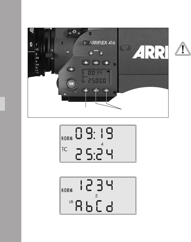
1
Using Timecode
For Timecode operation, please make sure that
the magazine is equipped with a Timecode
exposure module K2.55034.0.
Turning on and off the TC Recording
• Using the “MODE“ key aphoto, switch to Mode 4
(Timecode time).
• Depress the “SET“ key aphoto for approx. 3 s until
the “TC“ symbol appears or disappears on the display.
When the camera is rst turned on without a previously set
valid Timecode remaining in the buffer, the Timecode clock
starts running from time 00:00:00:00, with the User Bits set
to 00000000. This happens regardless of whether TC is
turned on or not. TC time can only be set by the master clock.
User Bits can be set either by the master clock or entered
manually with the camera display. If TC is turned on but not
set by external synchronization, a warning will be displayed.
If a speed is set on the camera which does not correspond
to TC, the TC generator retains the most recently set frame
rate. While Timecode is in use and the speed is changed
from one to another valid Timecode speed, the “TC“ symbol
on the display goes off for approx. 1 s and reappears once
the TC generator is ready.
MODE button SEL / SET buttons
Timecode

1
When TC is set at a Real Time frame rate (24 fps, 25 fps
& 30 fps) and the camera speed is changed to a Non
Real Time Frame rate (23.976 fps & 29.97 fps), a
warning will be indicated after the camera has stopped.
The same warning comes up if you set a TC at Non Real
Time frame rate and switch to Real Time frame rate
afterwards. Setting the TC at the used frame rate (Non
Real Time or Real Time) has to be done to clear this error.
While TC recording is switched on and the camera is
running, there is a delay of approx. 24 frames before the
camera stops after the “RUN” button is pressed to stop
the camera.
Entering User Bits with the Camera Display
• Using the “MODE“ key aphoto switch to Mode 5
(Timecode User Bits).
• Use the “SEL“ key aphoto to select the digit you wish
to change. The selected digit will ash.
• Use the “SET“ key aphoto to change the value of the
selected digit.
Note: User Bit values are hexadecimal so only values
from 0 - 9 and A - F are available.
Indicating Timecode or User Bits
• Using the “MODE“ key switch to Mode 4 (Timecode
time) or Mode 5 (Timecode User Bits).
The Timecode time indicator will indicate “hours:minutes“
in the upper line and “seconds:frame rate“ in the lower
line. In the case of frame rate, only positions before the
comma will be shown:
23 23,976 fps
24 24,000 fps
25 25,000 fps
29 29,970 fps
30 30,000 fps
At speeds of 29,970 fps and 23,976 fps the frame rate in
the “Nondrop-Frame“ mode count in accordance with
SMPTE RP136-1990, 5.2.1, to correspond to NTSC video
with 59,940 Hz. The “Nondrop-Frame“ mode results in a
time difference to real time of exactly 0,1%.
Timecode
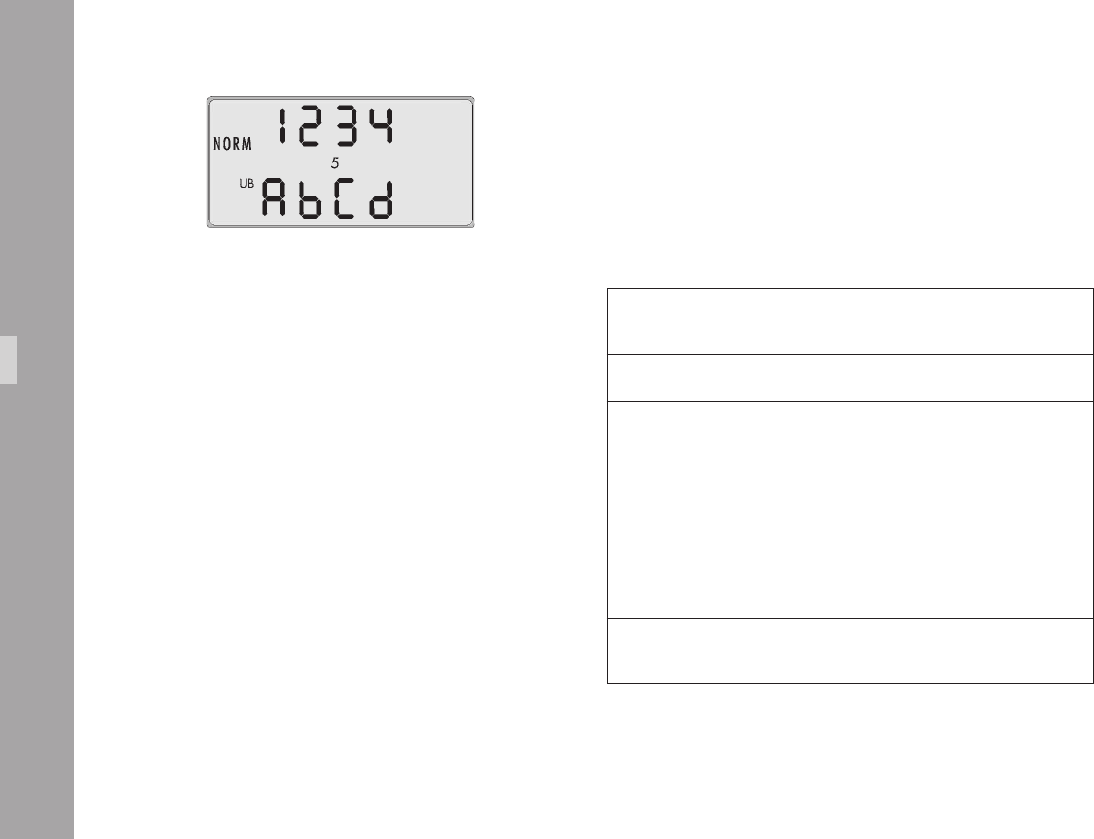
1
Overview of the Display Indications
used in Timecode Operation
TC-Indication on the Display
The “TC“ symbol has the following meanings:
Timecode symbol (TC) solid Timecode is set and will be recorded
when the camera is running
No timecode symbol (TC) Timecode recording is turned off
Timecode symbol (TC) Any TC Warning (see next section)
blinks in Standby (e.g. Timecode was last set or
external synchronization was last performed
over 8 hours ago)
Note:
If the last setting or synchronization
was over 8 hours ago timecode can
still be recorded for test purposes
Timecode symbol (TC) blinks Timecode is not being recorded on the lm
while the camera is running because of a functional disturbance
Timecode

1
TC Warnings
A TC warning is displayed rstly as a blinking “TC“ symbol
in the camera display. If the beeper volume is set to 1 or
higher, a warning beep will sound in time with the blinking
of the “TC“ symbol when the camera is in Standby. The
acoustic warning can be silenced by doing one of the
following:
• Remedy the cause of the warning.
• Switch off timecode.
• Set the beeper volume to 0 (see under Switching the
Beeper On and Off, Chapter 9.3).
• By briey pressing the “SET“ button in Mode 1 of the
display. This will suppress the acoustic warning for 15
minutes.
• Running the camera. The acoustic warning will not sound
while the camera is running. After stopping the camera
the warning will begin to sound again approximately
3 seconds after the camera enters Standby.
The camera can also display more detailed warnings in
hexadecimal form. To see these, change the display to
Mode 4 (Timecode time) using the “MODE“ button and
then press the “SEL“ button.
The four digits in the upper line display hexadecimal
values (0 - 9 & A - F). Their meaning can be looked up in
the following tables. There is no warning if the upper line
displays 00:00. An example of an error warning is
00:03, which indicates two warnings:
• error in external synchronization and
• TC is switched on but not set
In this case both errors can be remedied by external
synchronization.
Timecode
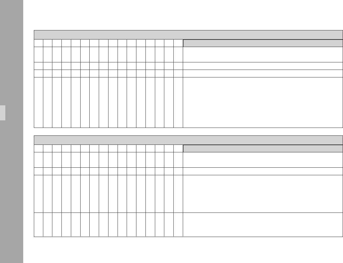
10
Upper Line 1st Digit for TC Warnings
0 1 2 3 4 5 6 7 8 9 A b C d E F Warning Remedy
• • • • • • • • no valid TC frame rate set correct TC frame rate
or switch off TC
• • • • • • • • no meaning on 416 N/A
• • • • • • • • no meaning on 416 N/A
• • • • • • • • the last take has no briey depress the „PHASE“-button,
or intermittent TC or reshoot
Upper Line 2nd Digit for TC Warnings
0 1 2 3 4 5 6 7 8 9 A b C d E F Warning Remedy
• • • • • • • • more than 8 hours reset TC
since TC was last set
• • • • • • • • TCS values not valid reset TCS value
• • • • • • • • ESU frame rate check ESU frame rate
outside TC range (display Mode 1)
and TC generator frame rate
(Mode 4);
max. allowable difference is 1 %
• • • • • • • • no TC with variable speed switch off variable speed accessory
or TC as TC-operation with variable
speed is not possible
Timecode
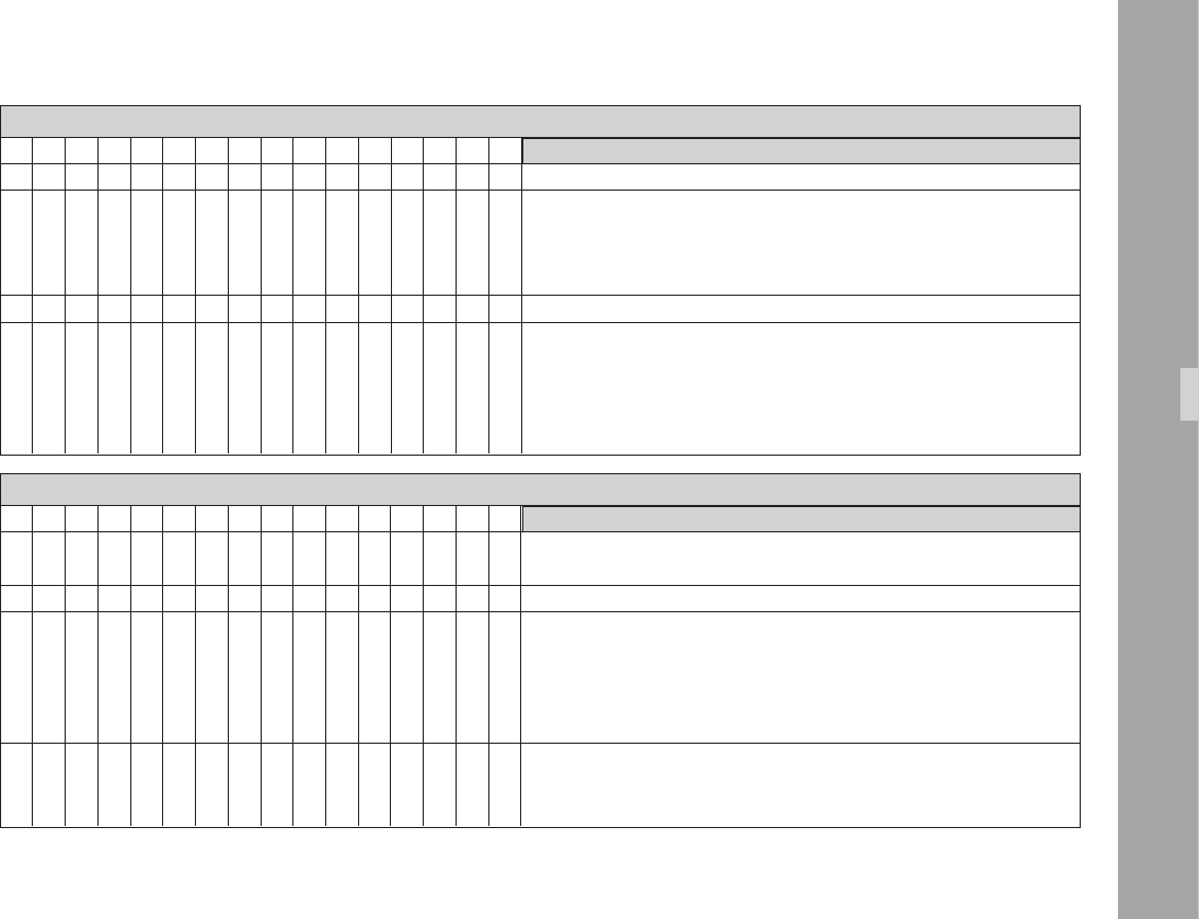
11
Upper Line 3rd Digit for TC Warnings
0 1 2 3 4 5 6 7 8 9 A b C d E F Warning Remedy
• • • • • • • • no meaning on 416 N/A
• • • • • • • • TC not set to NDF/RT reset TC at current frame rate
and swiched to RT/NDF RT (Real Time) is 24, 25, 30 fps
NDF (Nondrop Frame)
is 23,976 and 29,97 fps
• • • • • • • • TC LED not recognized t or check TC module
• • • • • • • • TC not buffered reset TC;
either the TC buffer capacitor
was not (yet) charged or the
power supply was insufcient
or interrupted
Upper Line 4th Digit for TC Warnings
0 1 2 3 4 5 6 7 8 9 A b C d E F Warning Remedy
• • • • • • • • error in external synchronization resynchronize
or check LTC-signal
• • • • • • • • TC switched on but not set set TC
• • • • • • • • TC not ready functional error
have the camera checked
at an authorised ARRI Service Centre
Timecode

1
Film Sensitivity (TCS Value)
The intensity of the TC recording must be adjusted to suit
the sensitivity of different lm stocks. The switch for setting
the TCS level (Timecode sensitivity) is on the feed side on
the magazine. The knob can be turned by hand if the
magazine door is open or with a small screwdriver if the
magazine door is closed.
“0“ means no recording, “1“-“9“ stand for the various
intensity levels. The higher the TCS level, the higher the
intensity of the recording. The difference in intensity of the
successive TCS levels corresponds to one aperture stop.
The currently set level can also be seen in Mode 4 on the
display by pressing the “SEL“ key.
The TCS levels of the most frequently used lm types are
listed in the table or are availabe from the ARRI website.
Film stock Type TCS Value
Fuji 8622 (Color Negative) 6
Fuji 8632 (Color Negative) 6
Fuji 8652 (Color Negative) 5
Fuji 8653 (Color Negative) 6
Fuji 8662 (Color Negative) 4
Fuji 8663 (Color Negative) 5
Fuji 8672 (Color Negative) 4
Fuji 8673 (Color Negative) 5
Fuji 8682 (Color Negative) 6
Fuji 8683 (Color Negative) 6
Fuji 8692 (Color Negative) 4
Kodak 7201 (Color Negative) 7
Kodak 7205 (Color Negative) 6
Kodak 7212 (Color Negative) 6
Kodak 7217 (Color Negative) 6
Kodak 7218 (Color Negative) 5
Kodak 7222 (B/W Negative) 8
Kodak 7229 (Color Negative) 5
Kodak 7231 (B/W Negative) 8
Timecode
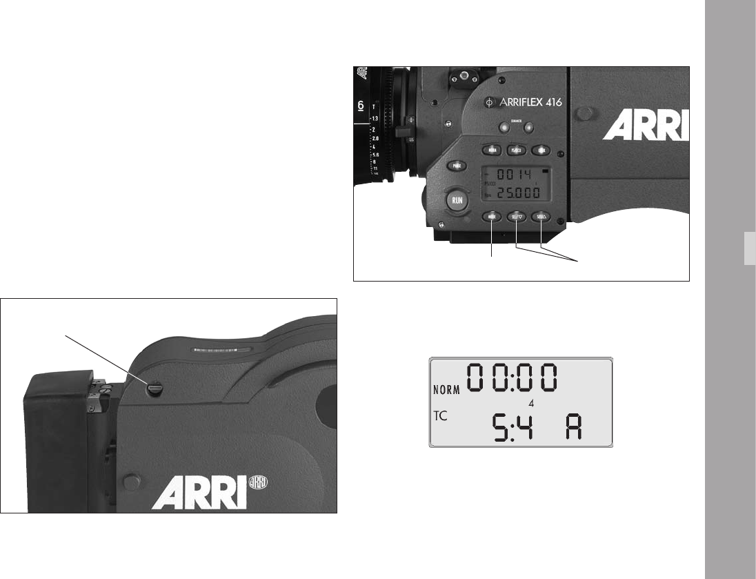
1
Indicating Clock Adjustment
If the 416 TC generator has been adjusted to an Ambient
Clockit the capital letter “A” is displayed next to the TCS
value in the second line of Mode 4 by pressing the “SEL“ key.
A manual reset to default clock can be initiated by
• Using the “MODE“ key, switch to Mode 4 (Timecode
time).
• Depress and hold the “SEL“ key.
• Depress the “SET“ key for approx. 3 sec. until the letter
“A“ disappears on the display. MODE button SEL / SET buttons
TCS switch
Timecode

1
TC Buffer
The ARRIFLEX 416 ensures not only high accuracy of the
Timecode but also allows the TC clock to continue running
while the camera is switched off as long as the camera is
connected to a power supply. The TC generator needs a
power supply of 10mA when the camera is switched off.
To allow the camera battery to be changed, a short-term
buffer of one minute is provided by charge stored in a
capacitor. In order for this buffer to function however it is
necessary that the camera be connected to a power
supply for at least 10 minutes to allow the capacitor to
charge prior to a battery change. Have a fresh battery
ready before disconnecting the old one.
To enable the camera to be used while mobile without
losing TC time, the use of an on-board battery is
recommended. An on-board battery can power the TC
buffer for more than 100 hours. To reduce power
consumption while working with the battery, the battery
should be removed during lengthy breaks in lming
(longer than a day). Before recommencing lming, TC
synchronization will need to be carried out again.
Timecode
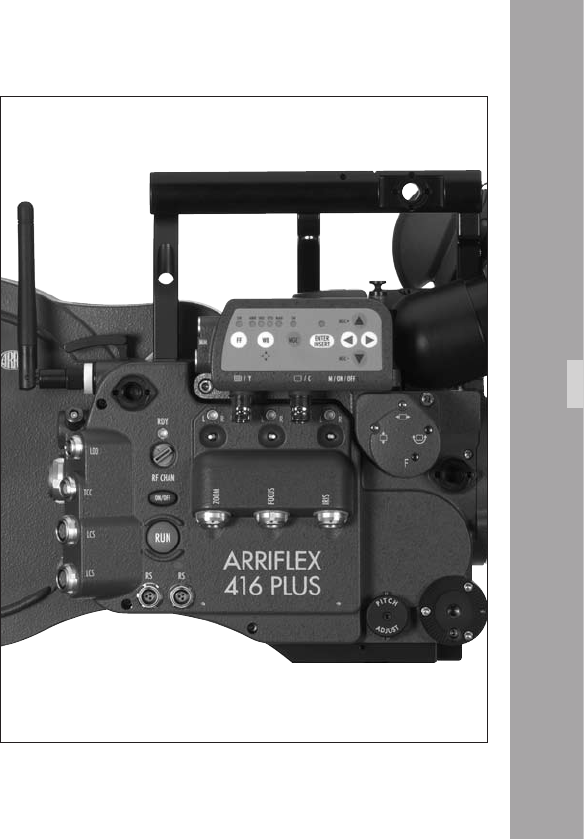
1
1.ARRIFLEX1Plu
12.1 General Description
The ARRIFLEX 416 Plus has an extended electronic side
cover that offers the following additional functions over
the standard ARRIFLEX 416:
• Built-in radio modem for wireless remote control of lens
and camera.
• Motor drivers for up to three CLM-2 motors.
• Two LCS bus interfaces for CLM-1, WHA-2 and ZMU-3.
• LDD (Lens Data Display) interface.
• A second “RS” socket.
The ARRIFLEX 416 electronic side cover is easily exchanged
with the extended version to convert it into an ARRIFLEX 416
Plus and vice versa. This is a workshop procedure and
should be carried out at your rental facility or local ARRI
Service Centre.
ARRIFLEX1Plu
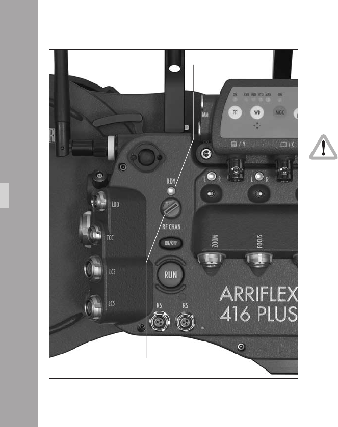
1
12.2 Radio system
A radio is incorporated into the 416 Plus extended
electronics. This enables wireless communication of lens
control and lens data information as well as remote control
of the camera functions.
The 416 Plus uses the latest ARRI WRS protocol
which is denoted be a yellow rubber washer on
the antenna aphoto. All ARRI WRS products
can be upgraded to the new protocol – consult
your local ARRI Service Centre.
The 416 Plus has a channel selection switch and a status
LED aphoto for the radio modem. The channel selection
switch on the camera should be set to the same number
as that of the WMU-2/3 used on the controlling handset.
It is not possible to control more than one 416 Plus, URM,
UMC-3 or LDB with one Wireless Main Unit simultaneously.
Yellow washer wireless protocol uses a specic scheme of
changing frequencies to make the connection between the
handset and camera modems more robust. The channels
of the selection switch are allocated as follows:
status LEDyellow rubber washer
RF channel switch
ARRIFLEX1Plu
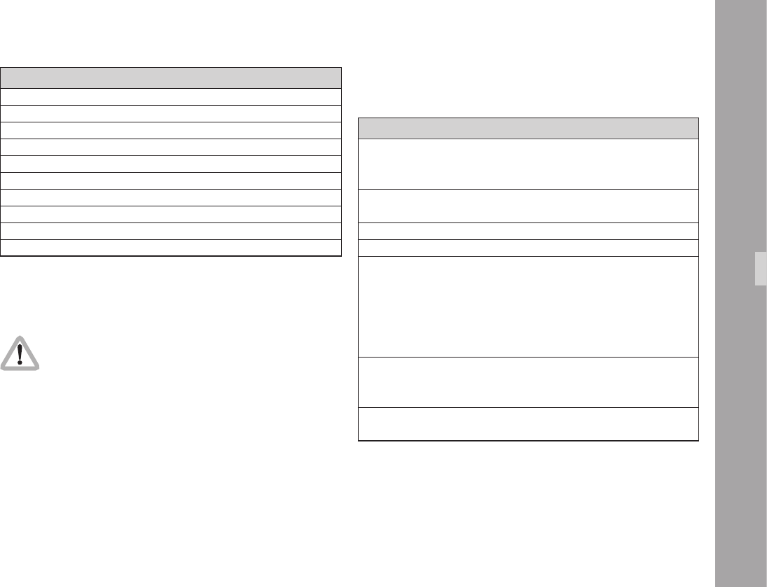
1
Channel Use
0 2444 - 2472 MHz
1 2406 - 2435 MHz
2 2444 - 2472 MHz
3 2406 - 2435 MHz
4 2444 - 2472 MHz
5 2406 - 2435 MHz
6 2444 - 2472 MHz
7 2406 - 2435 MHz
8 Not used
9 Radio device deactivated
• Set the channel selection switch on the camera to the new
channel – the RF LED goes red. Then turn the camera
off and back on again after approximately 5 seconds.
LED Color Status
Off Wireless deactivated (channel 9 selected)
or camera deactivated
or camera has no power
Alternating Radio modem is being initialised.
red/green Do not activate the WMU yet.
Green blinking Radio modem is ready, activate the WMU
Green Wireless remote control OK
Red Channel selection switch has been changed.
Wireless remote control will continue to function but the
channel will be changed the next time it is switched on.
-> Reset to the previously selected channel if the change
was unintentional, or turn module off and on again
to change channel.
Red blinking Hardware error in radio module.
If this error persists after restarting the camera,
send the camera for service.
Red blinking rapidly Radio fault: another ARRI wireless system
is on the same channel nearby. Select another channel.
Note: If two yellow washer remote systems are on the
same set, it is recommended to set one system to
an even channel and the other to an odd channel.
Only odd numbered channels are legally
permitted for use in France
To change the radio channel:
• With the camera off, set the channel and then turn the
camera on. Or,
• Move the channel selection switch to 9 (deactivated) and
then turn it to the required channel within half a second.
Or,
The RDY LED of the radio system aphoto indicates the
status of the radio as follows:
ARRIFLEX1Plu
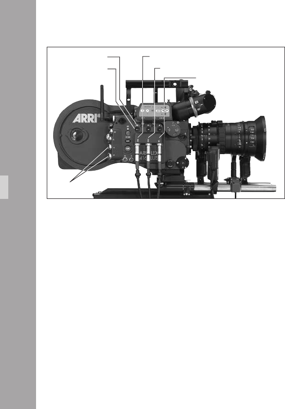
1
12.3 Wireless Remote System
Lens Motors
Both CLM-1 and CLM-2 motors can be used with the
ARRIFLEX 416 Plus.
• CLM-1 motors should be daisy-chained in series with one
of the end motors connected to either (but not both) of
the 416 Plus LCS bus connectors aphoto.
• CLM-2 motors should be connected, according to their
position on the lens, to the Zoom, Focus and Iris
connectors of the 416 Plus aphoto.
• CLM-1 and CLM-2 motors may be used simultaneously
but only on different lens axes.
In the situation where a CLM-1 is assigned to Focus and a
CLM-2 is simultaneously plugged into the Focus connector,
the CLM-1 will have priority and the CLM-2 connection will
be deactivated. The same applies to the Zoom and Iris axes.
Each CLM-2 motor connection has a direction switch
aphoto and a status LED aphoto.
• Use the direction switch to change the direction of
rotation of the attached motor.
LCS bus connectors
status LED
direction switch
Zoom
Focus
Iris
ARRIFLEX1Plu

1
The status LEDs indicate the following:
Color Status
Off no motor connected
Red motor connected but no control unit found
Green motor OK
Green blinking motor OK but at an end stop
Red blinking motor conict: CLM-1 assigned to same function
Red/green alternating calibrating
The following pages show some possible setups of the
LCS and WRS systems. These are only examples and
further variations are possible. See the Lens Control
System Instruction Manual for more details.
Cable Appearance
LC-M1 Coiled, 1 m long outstretched
LC-M2 Straight, 0.5 m long
LC-Z1 Straight, 3.5 m long
LC-Z2 Straight, 7 m long
Cables LC-M1, LC-M2, LC-Z1 and LC-Z2 are inter-
changeable and differ only in appearance and length.
ARRIFLEX1Plu
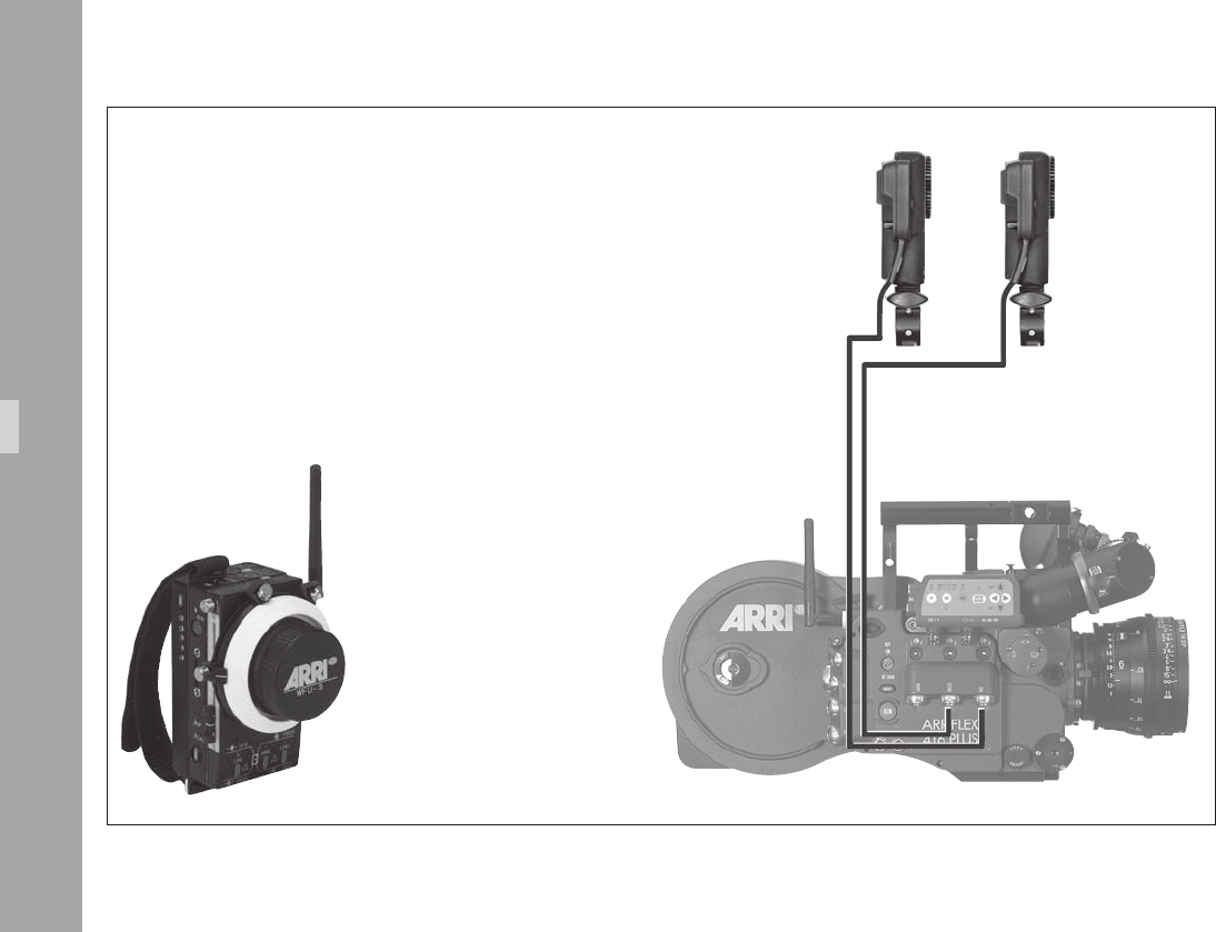
10
WMU-3, WBU-3, WFU-3 and CLM-2 Motors
CLM-2 Iris
WBU-3 + WMU-3 + WFU-3 – Iris & Focus
LC-F1
CLM-2 Focus
ARRIFLEX1Plu
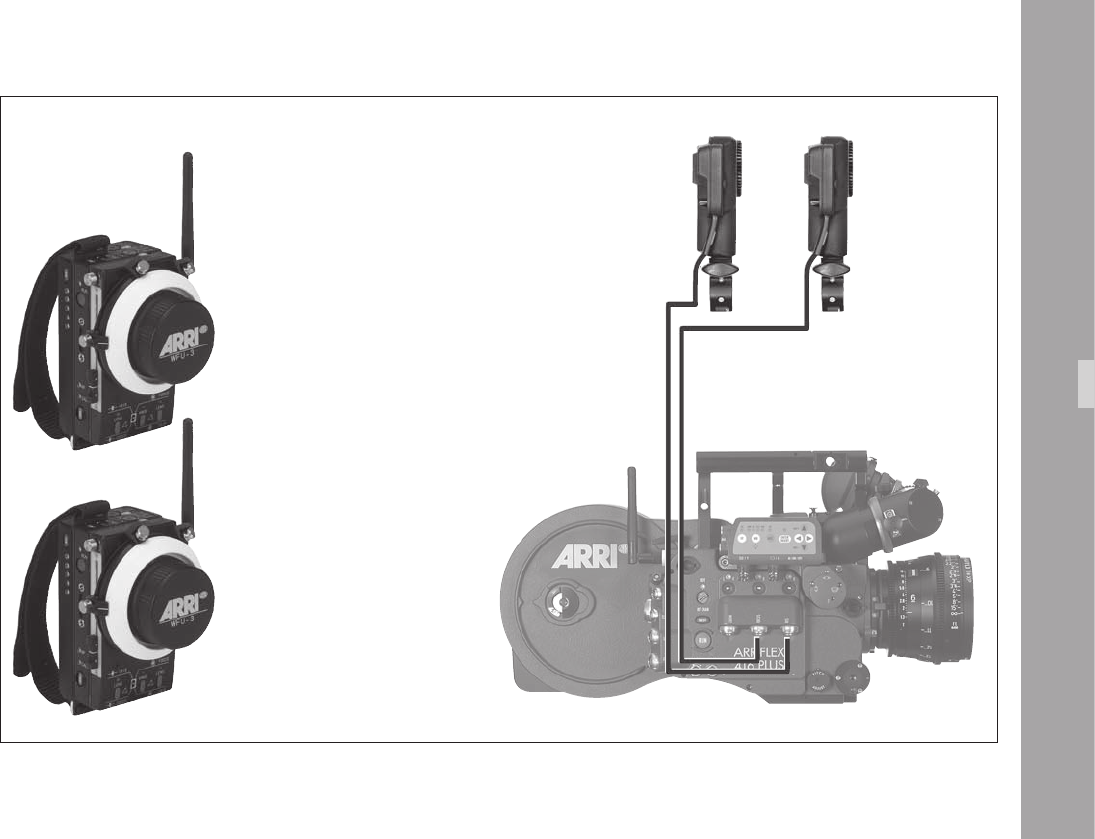
11
2 x WMU-3, WBU-3, WFU-3 and CLM-2 Motors
CLM-2 Iris
LC-F1
CLM-2 Focus
ARRIFLEX1Plu
WBU-3 + WMU-3 + WFU-3 – Focus
WBU-3 + WMU-3 + WFU-3 – Iris
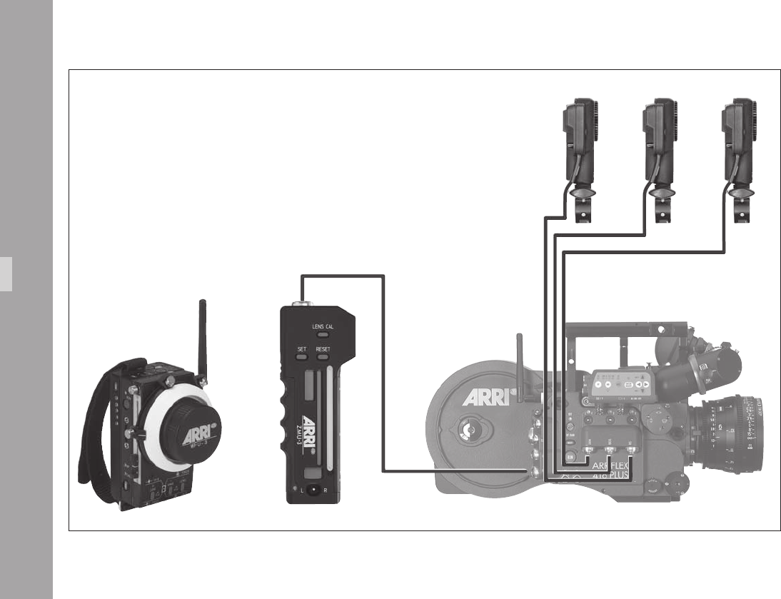
1
CLM-2 Iris CLM-2 ZoomCLM-2 Focus
ZMU-3, WMU-3, WBU-3, WFU-3
and CLM-2 Motors
ARRIFLEX1Plu
WBU-3 + WMU-3 + WFU-3
Focus & Iris
ZMU-3
Zoom
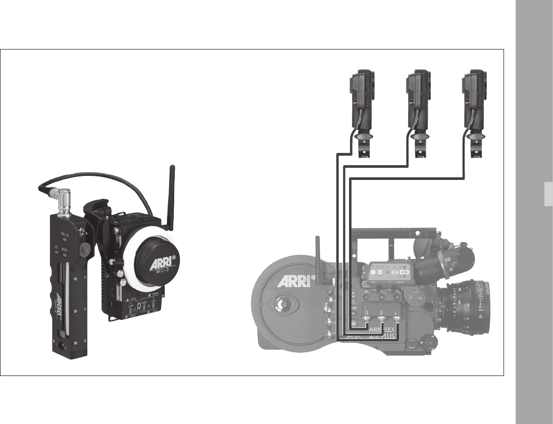
1
CLM-2 Iris CLM-2 Zoom
CLM-2 Focus
ZMU-3, WZB-3, WBU-3, WMU-3 and WFU-3
with CLM-2 Motors
ARRIFLEX1Plu
ZMU-3, WZB-3, WBU-3 + WMU-3 + WFU-3
Zoom, Focus & Iris
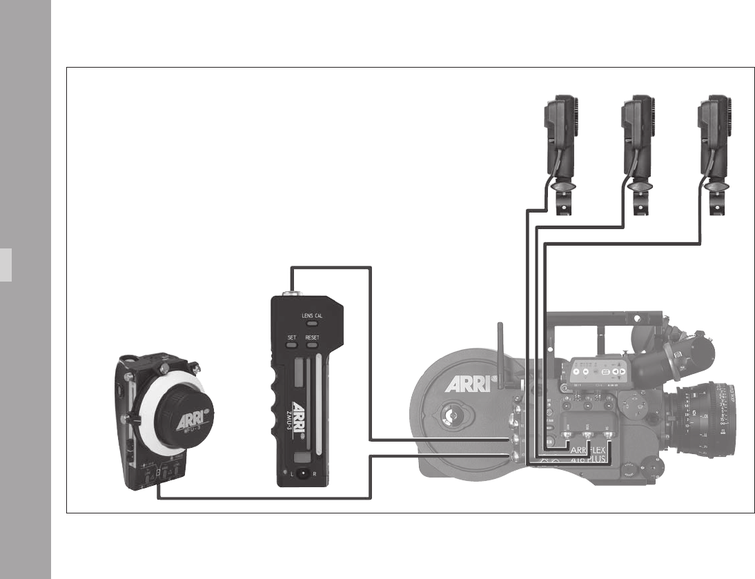
1
WHA-2, WFU-3, WZB-3, ZMU-3
and CLM-2 Motors
ARRIFLEX1Plu
CLM-2 Iris CLM-2 ZoomCLM-2 Focus
WHA-2 + WFU-3
Focus & Iris
ZMU-3
Zoom
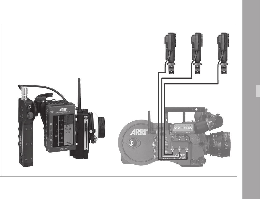
1
ZMU-3, WZB-3, WBU-3, WMU-3, LDD-FP,
WEB-3, WFU-3 and CLM-2 Motors
ARRIFLEX1Plu
CLM-2 Iris CLM-2 Zoom
CLM-2 Focus
ZMU-3, WZB-3, WBU-3, WMU-3, LDD-FP, WEB-3, WFU-3
Zoom, Focus, Iris and LDD-FP

1
12.4 Camera Remote Control
Note: For details of how to use the RCU-1, WRC-1
and ESU-1, please see the instruction manuals
supplied with these units.
The 416 Plus can be remotely controlled by cable and via
wireless remote control.
Only one camera control unit may be used with the 416
Plus at any one time. More than one WMU-3 can be used
in parallel.
If the WRC-1 is used to control the camera either wireless
(with WMU-2/3) or with a cable to the LCS bus (with
WHA-2/3), the CCU LED turns from green to red to
indicate that the REMOTE connector is not available.
The following pages show some examples of remote
control setups:
If RCU/WRC and ESU are used in parallel they can be
connected to the “REMOTE” socket via the splitter cable
KC-88-5.
ARRIFLEX1Plu
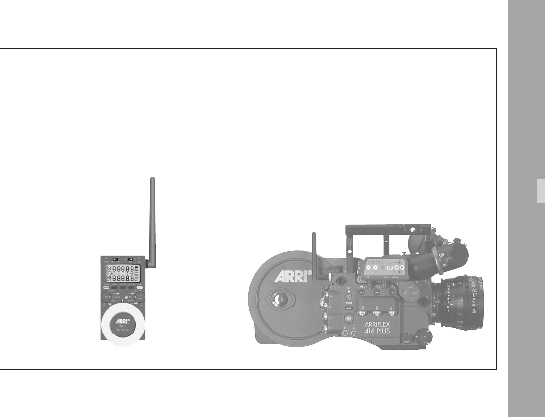
1
ARRIFLEX1Plu
WRC-1 + WMU-3
WRC-1 via wireless remote control
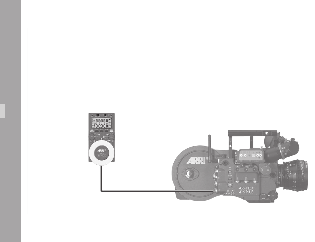
1
WRC-1 + WHA-2
LC-M1
WRC-1 with WHA-2 via cable
ARRIFLEX1Plu
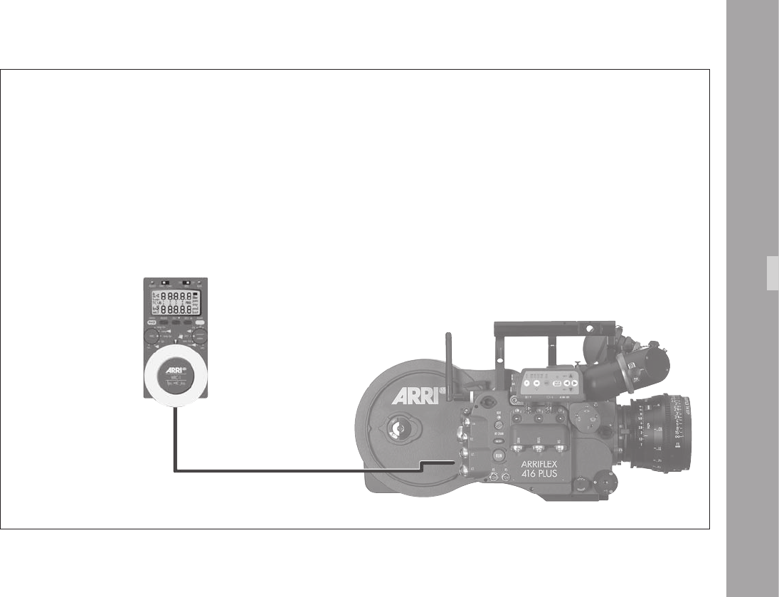
1
ARRIFLEX1Plu
WRC-1 + WHA-1
WRC-1 with WHA-1
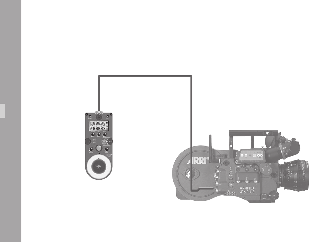
00
RCU-1
KC39
RCU-1
ARRIFLEX1Plu

01
ARRIFLEX1Plu
12.5 Lens Data Display
Compatibility
The ARRIFLEX 416 Plus can be used with the Lens Data
Display for Focus Puller (LDD-FP) to display lens information
using the Lens Data Archive. LDS contacts are not tted to
the camera‘s lens port so LDS lenses and the LDS Data Mount
are not supported.
The ARRIFLEX 416 Plus is only compatible with
the Lens Data Display for Focus Puller (LDD-FP).
The Lens Data Display Classic (LDD) is not
supported.
The LDD-FP can be operated with the 416 Plus in either of
the following congurations:
• Cable LDDFP-RDO (K2.54172.0) between the LDD
connector on the camera and the LDD-FP for cable
operation.
Or
• Wireless, mounted on the WMU-3.
Lens Data Archive
The Lens Data Archive provides the key LDS features for
any camera with any lens, as long as the LDD-FP, UMC-3
or 416 Plus and CLM-1 or CLM-2 lens motors are used –
manual follow focus is not supported. After each lens change,
the lens type is selected from a pre-programmed menu on
the LDD-FP.
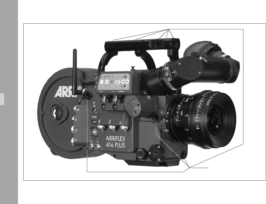
00
accessory mounting points
Acceorie
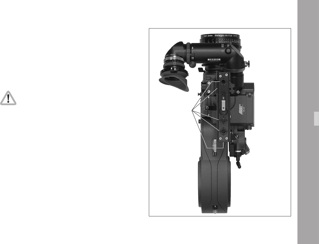
00
1.Acceorie
Acceorie
Accessory Mounting Points
On the camera body and on the electronic cover there
are accessory mounting points. Various accessories can
be mounted to them by using 3/8-16 screws.
Check that the screws do not reach more than
9mm into the camera body from the contact
surface aphoto, otherwise the camera may
be damaged.
accessory mounting points
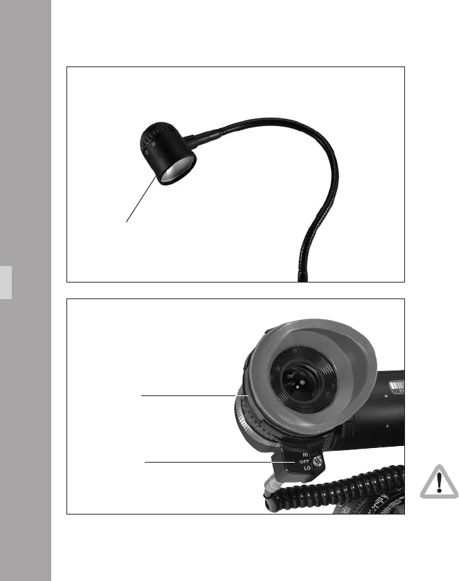
00
Work Light WL-3
• Screw the work light into the Accessory Rosette.
• Connect the plug to an “RS” socket.
• Bend the exible arm, to bring the work light into the
desired position. The work light can be turned on and
off with the ring on the lamp head aphoto. The
brightness of the work light can be adjusted with the
mechanical shutter.
HE-4
WL-3
Acceorie
Heated Eyecup HE-4 & HE-5
The heated eyecup prevents the eyepiece aphoto from
misting-up, e.g. when lming outdoors in cold weather.
• Pull the normal eyecup off the eyepiece and replace it
with the heated eyecup.
• Connect the heated eyecup to the heated eyepiece
outlet with cable KC-63.
• Set the heating level with the toggle switch aphoto:
“LO”: low heat output
“HI”: higher heat output.
If the camera and accessories are powered by
battery, switching off the eyecup during extended
breaks in lming will help conserve power.
switch
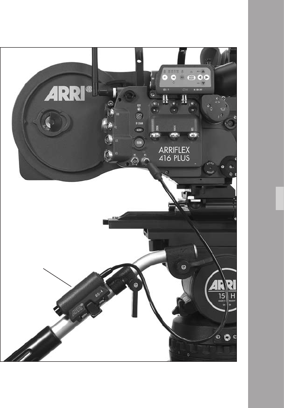
00
Remote “RUN” Switch RS-4
• Attach the remote “RUN” switch with the spring clamp
aphoto (e.g. to the pan handle).
• Plug the RS-4 plug into an “RS” socket.
The RS-4 cable can be extended by 3m/9ft by use of the
KC-40 Extension Cable (K2.47207.0)
Acceorie
RS-4
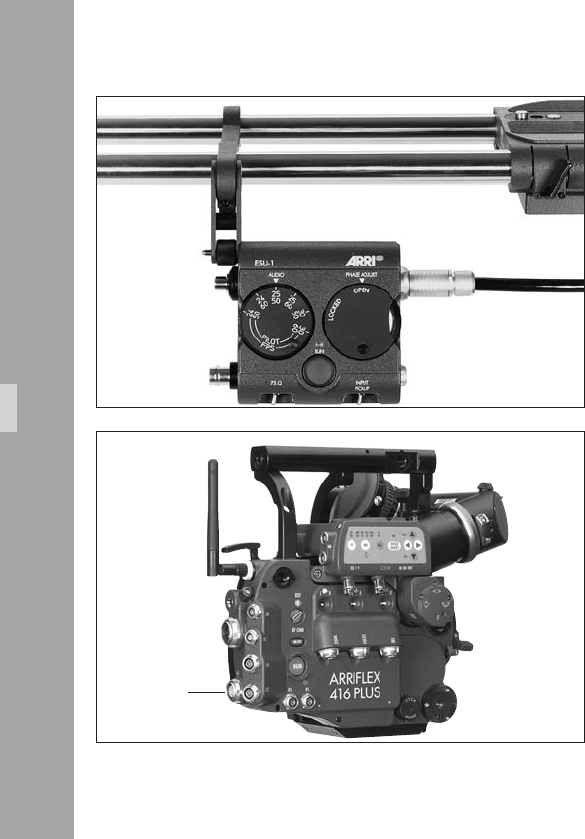
00
External Synchronization Unit ESU-1
The external synchronization unit ESU-1 aphoto can be
used with the ARRIFLEX 416 as well as with the 235, the
435 models, 535, 535B and 16SR 3/Advanced. It allows
the camera to be synchronised to other equipment such as
TV monitors. By means of a BNC-socket, it is possible to
synchronize to an external standard video signal (50/60 Hz)
or, through an inductive pickup, to a CRT type monitor.
The camera display shows “ESU” in the upper line. The
ESU-1 can be used for frame rates from 3 to 60 fps.
The frame rate is indicated on the camera display in Mode 2.
A phase shifter and a pilot tone generator have also been
integrated into the external synchronization unit. The phase
relationship of the synchronization is retained even when
the camera is switched off.
See TECHN. INFORMATION “External Synchronization
Unit ESU-1”.
• To connect the ESU cable to the camera, the 235/416
Accessory Expansion Cable KC-88-s has to be connected
to the camera’s “REMOTE“ socket. The ESU cable is then
connected to the accessory expansion cable. The RCU-1
can be connected to the other socket of the accessory
expansion cable.
Acceorie
REMOTE socket

00
Remote Control Unit RCU-1
The RCU-1 aphoto is a practical remote control unit for
use with all of the latest generation ARRIFLEX camera models.
It can be used in all applications that call for an uncompli-
cated, quick, sturdy and yet still comprehensive remote control.
Complete programs can easily be created to control changing
of frame rate over a certain period of time. These programs
are repeatable and can be recalled as necessary.
The RCU-1 automatically calculates the actual screen-time
for the programmed speed ramps. running values can be
regulated with the large hand wheel.
The free programming of individually dened minimum
and maximum values as end stops is particularly useful.
The illuminated LCD quickly, precisely and comprehensively
shows all set values as well as the status of the camera, or
the RCU-1 respectively, including all warning signals.
• The RCU cable is connected to the “REMOTE“ socket
aphoto on the camera.
For further information see the RCU-1 instruction manual.
Note: CCU, RU and LCC are not supported and could
cause malfunction if connected.
Acceorie
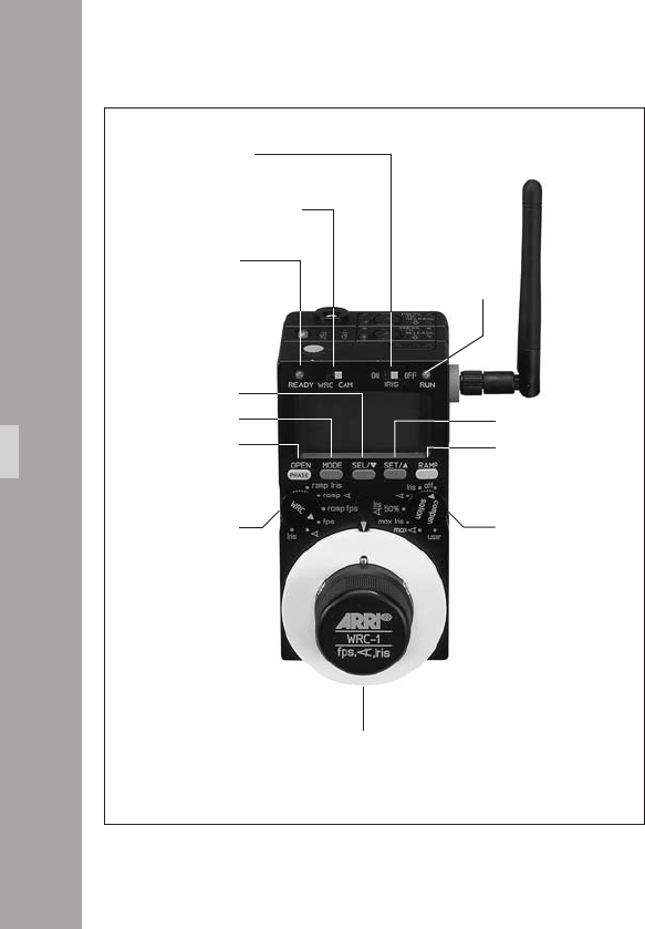
00
Wireless Remote Control WRC-1
The Wireless Remote Control WRC-1 is a handy remote
control unit for use with all of the latest generation of
ARRIFLEX camera models: ARRIFLEX 16SR 3/Advanced,
16SR 3 HS/Advanced, 535, 535B, 235, 435ES, 435
Advanced, 435 Xtreme and the ARRIFLEX 416.
On the ARRIFLEX 416 it enables the user to remotely control:
• the camera speed,
• the aperture of the lens (iris),
providing constant exposure compensation for speed
ramps.
The range of functions offered by the WRC-1 is automatically
adapted to the limits of the camera and the lens control
motor which it is controlling. The large hand wheel permits
sensitive adjustment of operational values, and easy
programming of end-stops for user-dened minimum and
maximum values.
The illuminated LCD provides quick, precise and compre-
hensive information about all the settings, the status of the
camera and the WRC-1, including all warnings.
Acceorie
WRC/CAM sliding switch
WRC
rotary switch
IRIS sliding switch
SEL button
MODE button
OPEN/PHASE
button
handwheel
READY-LED
COMPENSATION
rotary switch
RUN-LED
SET button
RAMP button
WRC-1 with WMU-3

00
The WRC-1 is the perfect addition to the ARRI Wireless
Remote System. Connected to the Wireless Main Unit
(WMU-2, WMU-3) it enables all functions to be remotely
controlled. The WRC-1 can also be connected to the camera
via cable using the Wireless Handgrip Attachment WHA-2.
However, the lens remote control functions are not
available in this conguration.
Acceorie

1010
Acceorie

1111
1.Maintenance
When maintaining and cleaning the camera and
accessories, pay careful attention to the following notes
and tips:
• Always disconnect the camera from the power supply.
• Clean the camera and accessories only on a clean and
at surface which is covered with foam material or a
clean, lint-free cloth.
• Under no circumstances use acetone or nitro-thinner.
These chemicals dissolve the paint and can damage
highly-polished surfaces and plastic parts.
• For cleaning, the use of soft, lint-free cloths and swabs
is recommended. Also suitable are special cleaning
tissues and small sponges as used in cleaning
computers and video equipment.
• When cleaning the lm movement, do not exert too
much pressure. Use only the prescribed special tools.
Use only good quality screwdrivers of the correct size.
• From time to time – at the very least after the
occurrence of a lm jam – it is recommended to clean
the entire interior of the camera and also the magazine
throat and the lm gate with a brush. In most cases it is
sufcient to vacuum out dust and lm chips from the
camera and the magazine interiors. A small battery-
powered vacuum cleaner, as used in cleaning
computers, is suitable for this task.
Maintenance
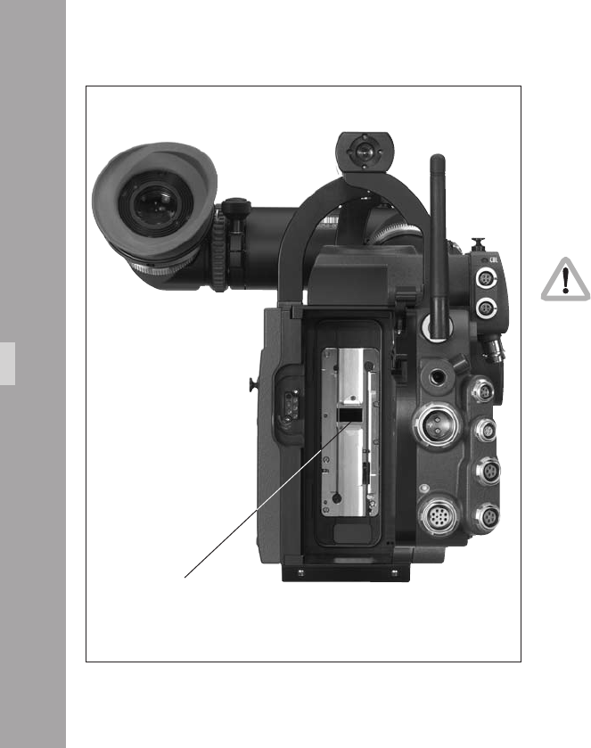
11
Camera
Cleaning the Film Gate
Loose dust or dirt leads to a layer of emulsion forming on
the lm gate. This can cause scratches on the lm and can
also lead to a change in the lm’s coefcient of friction.
Attention!
Keep ngers out of the lm gate opening as this
may damage the mirror shutter.
To clean the lm gate
• Remove the layer of emulsion from the lm gate with a
plastic rod (e.g. the ARRI lm gate cleaner). Under no
circumstances use hard or metal objects.
• When cleaning, pay particular attention to the area of
the lm gate opposite the magazine pressure plate if
lm stock with a strong tendency to build up emulsion
(e.g. b/w stock) is being used.
Maintenance
lm gate
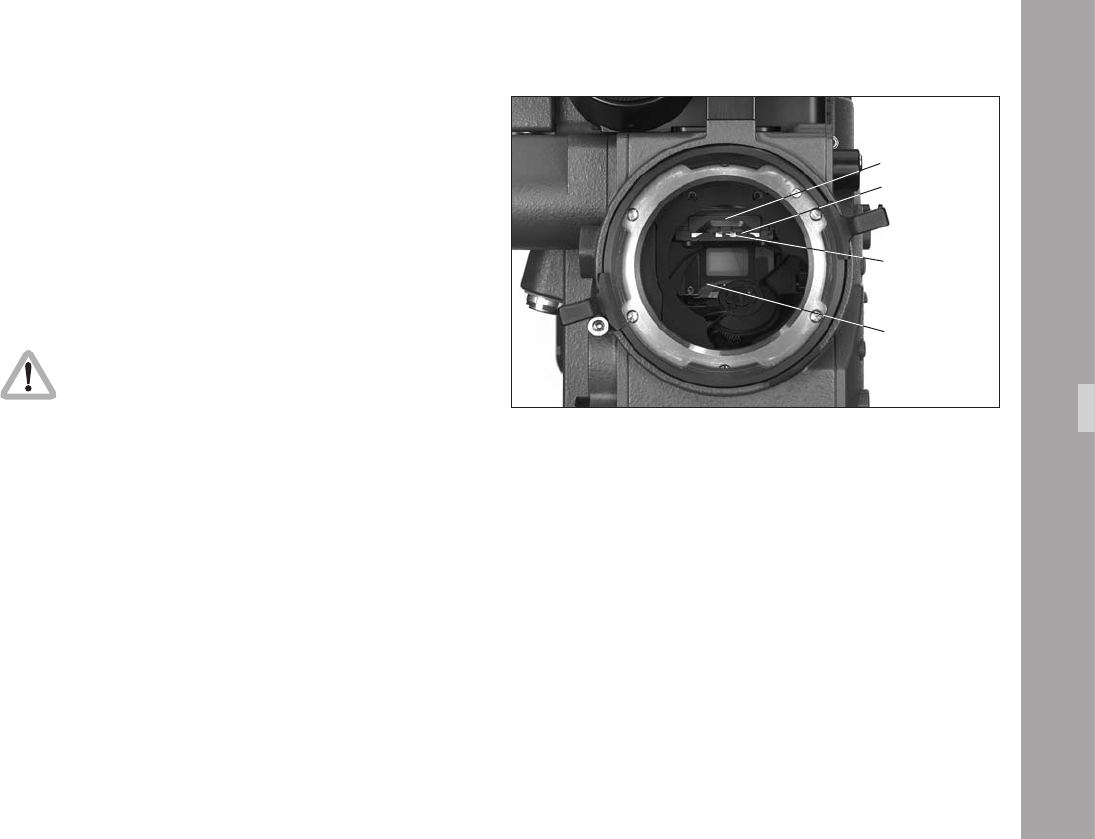
11
Cleaning the Field Lens
• Briey press the “PHASE” button, to position the shutter
to protect the mirror surface from damage as far as
possible.
• Before cleaning the eld lens, switch the camera’s main
switch off and disconnect from the power supply!
• Remove the lens or the protective cap from the
camera‘s lens port.
Do not touch the mirror surface!
• Pull the bre screen aphoto out of the holder by its
tongue aphoto using the special forceps.
• Pull the eld lens aphoto out of the holder by its
tongue aphoto using the special forceps.
• Clean the eld lens with a dry, lint-free cloth.
• Make sure that the frame is completely clean.
• Using the special forceps, push the eld lens as far as
it will go into the holder. A sprung-ball catch xes the
eld lens in the correct position.
• Check that the bre optic screen and its frame are
completely clean.
• Using the special forceps, push the bre optic screen
into the holder as far as it will go. A sprung-ball catch
xes the bre optic screen in the correct position.
Maintenance
tongue
bre screen
eld lens
mirror
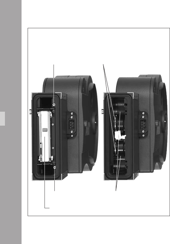
11
Magazine
Cleaning the Throat Assembly
The magazine throat assembly aphoto can be
disassembled for cleaning.
• Remove the two screws beside the top and bottom
corners of the pressure plate aphoto.
• Open the take-up side door and fully loosen the screw
between the two sprocket rollers aphoto.
• Flip the magazine over so the screw drops out of
engagement with the pressure plate assembly. The
screw is captive so it will not fall out and get lost
aphoto.
• Pull out the pressure plate assembly aphoto.
• Clean the lm running surfaces aphoto and guide
rollers aphoto with a brush.
• Put the pressure plate assembly back in place. (It ts
accurately on dowel pins).
• Ret and tighten the two screws.
Maintenance
screw
screw
sprockets
running surfaces
pressure plate assembly
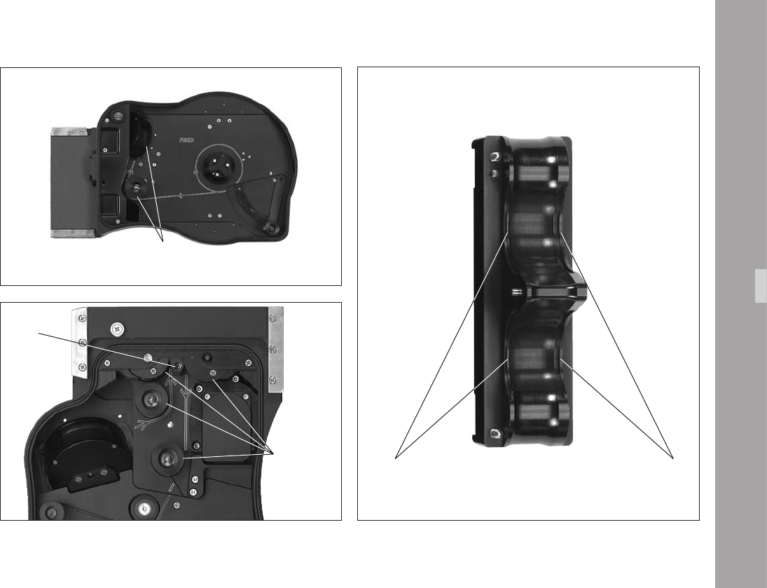
11
Maintenance
pressure plate assembly
from the back
lm running surfaces
guide rollers in magazine
screw
guide rollers
in magazine lm running surfaces
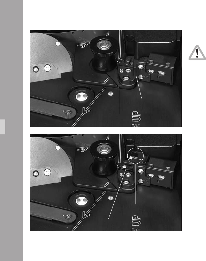
11
Maintenance
Timecode Exposure Module
For Timecode operation, make sure that the lens
of the exposure mode is clean.
• To clean the lens, swing it out as shown aphoto and
clean it.
• Make sure that there are no foreign objects, e.g. lm
dust beneath the ap aphoto.
time code exposure module
ap
open ap
lens

11
1.Appendix
The frame rate of the camera is constantly monitored while
it is running. If the actual frame rate deviates from the set
frame rate, the operation control indicator glows red, a
red LED is seen in the viewnder and the camera display
shows the warning for asynchronous running (“asy”).
Fuses
The ARRIFLEX 416 is equipped with self-resetting
automatic fuses. There are no conventional fuses to blow.
If one of the self resetting fuses blows, turn the camera off,
unplug all accessories from the camera, wait for one
minute, and turn the camera back on.
Appendix

11
Error text in display Error text in IVS Problem
Error LooP.S Magazine lm loop too short magazine lm loop too short
Error LooP.L Magazine lm loop too long magazine lm loop too long
Error CntL Controller Error internal controller limits have been exceeded,
check if camera is jammed
Error CASS Magazine error
Updt PC software update in progress camera software and rmware is updated
Updt Int software update in progress camera software and rmware is updated
Async camera speed is not the chosen speed actual camera speed is not the intended speed
end lm end detected no more raw stock
bat camera supply voltage too low, change battery battery voltage is too low
Appendix

11
Problem Cause Remedy
Scratches on the emulsion side of the negative
In the image area, Dirty or damaged cross bars Clean or, if defective, replace the lm gate
over several frames on the lm gate
In the image area, Upper or lower lm loop too long, Check the loop length of the magazine
short and periodically recurring lm touches inside of magazine throat
(above and below)
Outside the image area Dirty or damaged longitudinal bars Carefully clean lm gate and magazine throat
on the lm gate or,
or lm running surfaces in the magazine throat if defective, replace
Scratches on the glossy side of the negative
In the image area Dirty or damaged lm track Clean lm track and pressure plate
or pressure plate or, if defective, replace
Outside the image area Dirty or damaged longitudinal bars Carefully clean longitudinal bars and magazine throat
on the lm track or,
or lm running surfaces in the magazine throat if defective, replace
Scratching in general Strong tendency of raw lm stock to build up Notify the manufacturer of the lm stock,
emulsion, dust on raw stock from perforation use different lm stock
process, extreme temperatures,
scratched raw stock
Appendix

00
Problem Cause Remedy
Unsteady Image
Vertical Heavy emulsion build-up in the lm gate area, Clean lm gate area, use different lm stock
damaged lm perforation,
very poor gliding ability
of the raw lm stock,
lm stock with positive perforation,
dimensions of raw stock out of tolerance
Horizontal Heavy emulsion build-up in the lm gate area, Clean lm gate area,
lm edge is not straight use different lm stock
Pressure exposures around perforation holes Mechanical stress on the perforation holes Pressure exposures do not affect
the image steadiness
Image Problems
Blurred image Flange focal distance is set incorrectly, When cleaning the lm gate
lens is set incorrectly, ensure that the surfaces are absolutely clean,
poor quality or defective lens, check the lens and the ange focal distance
magazine pressure plate set incorrectly Take magazine to ARRI Service Centre
(image problem conned to one magazine)
Appendix

11
Problem Cause Remedy
Problems at extremely low temperatures
Damage to the lm Greatly reduced tensile strength and increased The camera, battery and particularly the lm stock
brittleness of raw stock In temperatures must be protected from extreme cold.
under -15°C (5° F) especially, When a cold camera is brought into a warmer and
a change in the lm’s friction properties occurs. humid room, condensation builds up
This can be largely prevented by placing the cold
equipment into a sealed plastic bag before moving it
into the warmer environment. Remove it from the bag
once the temperature has equalised.
The camera does not reach Capacity or voltage of the battery Check the battery charge following the directions
the selected frame rate is insufcient in the instruction manual.
Magazine tension is too high Check that the magazine turns easily.
Problems in extremely high temperatures
Increased emulsion build-up The mechanical properties of the lm change Protect the camera and the lm stock from
considerably at temperatures of over 30°C (86°F). extreme heat, e. g. by shading or white covering etc.
The lm becomes soft and easily deformed.
The friction coefcient changes and the lm
builds up more emulsion.
Appendix

Appendix

1.TechnicalData
Film Format
Super 16 mm, conforming to DIN 15602 and ISO-5768-1998
Magazine
416 Shoulder Magazine 120/400 (SHM-3) forward only, up to 75 fps
Lens Mount
54mm PL-mount (positive locking)
Flange Focal Distance
52.0 -0.01mm
Mirror Shutter
Manually adjustable from 45° to 180°.
Movement
Silent precision movement,
single pull down claw,
single registration pin.
Pull down pitch adjustable
Speed Range
1-75 fps forwards only (quartz stabilized)
adjustable to 0.001 fps
Viewnder
Adjustable in two axes with automatic image orientation compensation
and additional manual image compensation.
Fibre screens
Interchangeable for various lming formats,
same bre screens as Arriex SR16 3 Advanced.
Fibre screens from the SR16 1, 2 & 3 may also be used
but they incorporate a scale for a light meter which is not tted to the 416.
TechnicalData

Operating Temperature Range
-20°C to +50°C (-4°F to +122°F)
Power Supply
24 V DC
Acceptable voltage range: ....................................................... 20.6…35 V DC
Viewnder Warning Indicators
Low power supply voltage (BAT)
Asynchronous running (ASY)
IVS
Weight ....................................................................................approx. 0.49 kg
Power Consumption.....................................................................approx. 4.8W
Inputs ......................................................................................................None
Outputs: ................................ 2 BNC outputs for composite video or alternatively
Y - C (S-video) over 2 BNC connectors
& 2 Mini-Monitor outputs
Optic.............................................................................covers Super 16 format
Optic Alignment: ............................................................X, Y, rotation and focus
Dimensions
Length with magazine & viewnder, without lens: ........................405mm (16”)
Width with viewnder on the left:
(w/o handgrip) .........................................................220mm (8 5/8”)
(with handgrip) .......................................................282mm (11 1/8”)
with viewnder on the right: ............................................254mm (10“)
Height with grip: .........................................................................230mm (9”)
without grip: .............................................................180mm (7 1/8“)
Weight
ARRIFLEX 416 Plus camera body
with loaded magazine, viewnder, eyepiece, IVS but no lens: ..... 5.5 kg (12.1 lbs)
TechnicalData

1.OrderNumber
ARRIFLEX 416 Camera Body & SV-2 viewnder ................................ K0.60038.0
ARRIFLEX 416 Plus Camera Body & SV-2 viewnder ..........................K0.60037.0
ARRIFLEX 416 Camera Body only ..................................................... K1.66000.0
ARRIFLEX 416 Plus Camera Body only ..............................................K1.66001.0
ARRIFLEX 416 Universal Viewnder set (SV-2) ...................................K2.55025.0
Installation of the Camera
ARRIHEAD 2 ...................................................................................K2.43670.0
ARRIHEAD 2 with Encoders..............................................................K2.52090.0
Wedge plate for Sled ....................................................................... K2.47092.0
Lens support LS-7, ø 19mm .............................................................. K2.42538.0
Lens support LS-8, ø 15mm .............................................................. K2.49012.0
416 Shoulder Pad (SP-2) ................................................................. K2.55030.0
Camera Handgrip, Right with On/Off Switch .................................... K2.45886.0
416 Riser ........................................................................................K2.35035.0
416 Split Bridge plate BP-10, ø 19mm ..............................................K0.60035.0
416 Split Bridge plate BP-11, ø 15mm ..............................................K0.60036.0
Support rods 240mm, ø 19mm ........................................................ K2.43046.0
Support rods 240mm, ø 15mm ........................................................ K2.21958.0
Support rods 340mm, ø 19mm ........................................................ K2.47347.0
Support rods 340mm, ø 15mm ........................................................ K2.47348.0
416 Standard Camera Handle ......................................................... K2.55027.0
Handle Extension Block ....................................................................K4.65107.0
416 Low Mode Support (LMS-1) .......................................................K2.55029.0
Power Supply
416 On Board Battery (OBB-2) ........................................................ K2.66000.0
416 On Board Battery Charger ........................................................ K2.66004.0
Battery NC 24/7 R ..........................................................................K2.41950.0
Battery cable KC 20S ...................................................................... K2.41966.0
Charger NCL 24 R ..........................................................................K2.42010.0
Mains unit NG 12/24 R ..................................................................K2.44481.A
Mains unit NG 12/26 (4-pin 12v) ....................................................K2.47352.0
Mains unit NG 12/26 (5-pin 12v) ....................................................K2.47351.0
Spiral battery cable KC 29S .............................................................K2.44693.0
OrderNumber

Magazines
416 Shoulder Magazine 120/400 (SHM-3) ...................................... K2.55026.0
Timecode exposure module .............................................................. K2.55034.0
Optical Accessories
4“ x 4“ light-weight matte box LMB-3 ............................................... K2.44471.0
6.6“ x 6.6“ light-weight matte box LMB-4a .......................................K2.47633.0
4”x5,65” light-weight matte box LMB-5 ............................................ K2.47239.0
4“ x 4“ production matte box MB-16 .............................................. *K2.44472.0
4“ x 4“ production matte box MB-17B ............................................ *K2.47247.0
4“ x 5.65“ production matte box MB-18 ......................................... *K2.47178.0
4“ x 5.65“ production matte box MB-19 ......................................... *K2.47099.0
5.65“ x 5.65“ production matte box MB-20 .................................... *K0.60024.0
6.6“ x 6.6“ production matte box MB-14 ........................................ *K0.59971.0
Heated eyecup HE-4 ........................................................................K2.47527.0
Cable KC-42 (for RS socket) .............................................................K4.47473.0
Medium Eyepiece Extension .............................................................K2.55000.0
Long Eyepiece Extension .................................................................. K2.55012.0
* These order numbers refer to matte boxes for ø 19mm support rods
Accessories
Accessory Power Box APB ...............................................................K2.54177.0
External Display EXD-1 ....................................................................K2.55013.0
External synchronization unit ESU-1 .................................................K2.46006.0
Remote switch RS-4 ......................................................................... K2.46942.0
Remote control unit RCU-1 ...............................................................K2.47197.0
Work light WL-2 ............................................................................. K2.43197.0
Videoassist
416 Integrated Videoassist PAL .........................................................K2.47663.0
416 Integrated Videoassist NTSC .....................................................K2.47664.0
OrderNumber

1.ARRIService
Germany ......... Arnold & Richter
Cine Technik
Türkenstraße 89
D-80799 München
phone: +49 (089) 3809-0
fax: +49 (089) 3809-1244
E-mail: webmaster@arri.de
USA ................ ARRI Inc.
(East Coast)
617, Route 303
Blauvelt, New York 10913
phone: (914) 353 14 00
fax: (914) 425 12 50
E-mail: arriex@arri.com
(West Coast)
600 North Victory Blvd.
Burbank, California 91502
phone: (818) 841 70 70
fax: (818) 848 40 28
E-mail: arriex@arri.com
GB ................. ARRI (GB) Ltd.
2 Highbridge
Oxford Road
Uxbridge
Middlesex, UB8 1LX
phone: (0) 1895 457 000
fax: (0) 1895 457 001
E-mail: sales@arri-gb.com
Italy ............... ARRI ITALIA S.r.l.
Viale Edison 318
20099 Sesto S. Giovanni (Milano)
phone: (02) 26 22 71 75
fax: (02) 242 16 92
E-mail: info@arri.it
Via Placanica, 97
00040 Morena (Roma)
phone: (06) 79 89 02 1
fax: (06) 79 89 02 206
Canada .......... ARRI Canada Ltd.
415 Horner Avenue, Unit 11
Etobicoke, Ontario
Canada M8W 4W3
phone: (416) 255 33 35
fax: (416) 255 33 99
E-mail: service@arrican.com
ARRIService

Index

1.Index
Index
24 V accessories .................................................... 33
416 riser ......................................................... 23, 26
50 Hz ................................................................... 45
60 Hz ................................................................... 45
A
accessories .......................................................... 203
24 V .................................................................. 33
accessory carrier .............................................. 16, 19
accessory mounting points .................................... 203
accessory power supply .......................................... 33
accessory rosette .................................................... 26
Ambient Clockit .................................................... 174
appendix ............................................................. 217
ARRIFLEX 416 Plus ............................................... 185
ARRIGLOW ........................................................... 58
color ............................................................ 70, 71
ARRIHEAD ............................................................. 15
ARRIMACRO lenses.................................................. 9
ASY ................................................................ 53, 59
AUTOADJUST ................................................ 91, 114
AWB ............................................................. 88, 113
B
BACKGROUND ................................................... 153
ballast ................................................................... 45
bars, color ........................................................... 119
BAT ........................................................... 29, 53, 59
battery ...................................................... 28, 29, 30
cable .................................................................. 30
low level warning ................................................ 66
warning level setting ............................................ 58
bayonet mount ....................................................... 49
beamsplitter ........................................................... 50
beeper
beep on start ...................................................... 69
beep on stop ....................................................... 69
switching on / off ................................................ 69
black and white output ........................................... 82
BLUE ............................................................. 90, 114
BNC sockets........................................................... 78
BOXED ................................................................ 153
BP-10 .................................................................... 16
BP-11 .................................................................... 16
bracket .................................................................. 24
button illumination
brightness ........................................................... 68

00
Index
C
cable warning ...................................................... 103
camera
running .............................................................. 55
stopping ............................................................. 55
camera body ......................................................... 43
camera operation ................................................... 55
camera remote control .......................................... 196
camera switch ........................................................ 55
CAS ...................................................................... 65
charger ........................................................... 28, 29
check/hide menu ................................................... 85
check menu ........................................................... 85
CID light ................................................................ 45
cleaning .............................................................. 211
cleaning the eld lens ........................................ 213
cleaning the lm gate ........................................ 212
CLM-1 ................................................................. 188
CLM-2 ......................................................... 188, 190
color bars ............................................................ 119
color bar generator ............................................. 73
COMP ................................................................. 133
composite video outputs .......................................... 79
CP......................................................................... 65
D
DIMMER .......................................................... 70, 71
dioptre
adjusting ............................................................ 51
discharge lamps ..................................................... 45
display
display modes ..................................................... 58
display symbols ................................................... 59
rst display line ................................................... 58
Mode 1 .............................................................. 58
Mode 2 .............................................................. 58
Mode 3 .............................................................. 58
Mode 4 .............................................................. 58
Mode 5 .............................................................. 58
second display line .............................................. 58
E
EDIT TEXT ............................................................ 145
end ....................................................................... 59
ESU-1 ........................................... 58, 175, 196, 206
exposed lm
removing ............................................................ 40
external synchronization unit ................................. 206
eyecup HE-4 & HE-5 ............................................ 204
eyepiece ................................................................ 50

11
Index
F
feed side ............................................................... 35
bre screen .......................................................... 213
exchanging ......................................................... 46
eld lens cleaning ................................................ 213
lm core ................................................................ 36
lm core slit ........................................................... 38
lm counter .................................................... 58, 142
conguration ................................................ 58, 60
measurement units ............................................... 61
modes ................................................................ 60
resetting ............................................................. 61
total exposed lm ................................................ 61
values ................................................................. 60
lm gate cleaning ................................................. 212
lm sensitivity ....................................................... 182
lm track cleaning rod ............................................ 43
icker free ............................................................. 45
on / off ...................................................... 97, 121
uid heads ............................................................. 15
footage counter roller ....................................... 36, 37
format marking
activate ............................................................ 129
changing ............................................................ 99
format marking menu ........................................... 128
FORMAT OFF ...................................................... 129
forward guide roller ............................................... 37
fps ........................................................................ 59
frame counter ...................................................... 153
lm .................................................................. 154
video ................................................................ 154
frame rate ....................................................... 62, 67
standard ............................................................. 62
frequency .............................................................. 45
fuses ................................................................... 217
G
gain control ........................................................... 94
manual ..................................................... 117, 118
general description ................................................. 13
GENLOCK ........................................................... 124
grip system ............................................................ 22
guide roller ............................................................ 36
H
handle extension block ........................................... 23
HE-4 ................................................................... 204
HE-5 ................................................................... 204
heated eyecup HE-4 & HE-5 ................................. 204
HEB-1 ................................................................... 23
hide menu ............................................................. 86
HMI light ............................................................... 45

Index
I
image
inverting ............................................................. 53
image orientation compensation .............................. 52
manually ............................................................ 52
reactivating ......................................................... 52
inching .................................................................. 57
IND ....................................................................... 88
indoor ................................................................... 89
inserter
inserter facilities ................................................ 105
inserting data in video ......................................... 81
load/store menu ............................................... 108
main menu ....................................................... 107
installation ............................................................. 15
interpolation ........................................................ 122
inverse ................................................................ 126
inverting the image ................................................ 53
iris ........................................................................ 86
IVS ........................................................................ 73
cabling ............................................................... 78
default values .................................................... 110
installation .......................................................... 76
transport cover .................................................... 76
K
KC-20-S .......................................................... 29, 30
KC-29-S .......................................................... 29, 30
keypad
brightness ........................................................... 58
L
lay-on roller arm .................................................... 38
LDB ..................................................................... 186
LDD ..................................................................... 201
LDD-FP ................................................................ 195
LDS ..................................................................... 136
LDS line ............................................................ 139
LED ....................................................................... 53
LED indication ..................................................... 29
left rod bracket ....................................................... 20
legal disclaimer .................................................. 7, 10
Lens Data Archive ................................................ 201
lens data display .................................................. 201
lens data line ....................................................... 136
lenses .................................................................... 49
attaching ............................................................ 49
lens motors .......................................................... 188
lens mount receptacle ............................................. 49
lens support ........................................................... 21
lightweight support ........................................... 23, 26

Index
lightweight support rods ......................................... 26
line interpolation .................................................. 122
LMS-2 ................................................................... 24
load/store menu .................................................. 108
LOAD SET ........................................................... 109
load settings ........................................................ 109
LOCK .............................................................. 57, 59
locking grip ........................................................... 35
LooP ...................................................................... 47
loop check ............................................................. 47
loop length ............................................................ 37
loop length mark .................................................... 37
loop protector ............................................ 35, 41, 47
loop size
checking ............................................................. 39
low mode bracket ................................................... 24
low mode riser ....................................................... 24
low mode support handle ....................................... 24
low mode support set ............................................. 24
LS-10 .................................................................... 21
LS-9 ...................................................................... 21
LWS-5 ............................................................. 23, 26
M
magazine ...................................................... 35, 214
attaching ............................................................ 47
cover .................................................................. 35
feed side............................................................. 35
loading .............................................................. 35
opening cover ..................................................... 41
release lever ....................................................... 47
removing ............................................................ 48
storage ............................................................... 41
take-up side ........................................................ 37
transport ............................................................. 41
main camera switch ............................................... 55
main menu .......................................................... 107
mains unit ........................................................ 28, 30
maintenance ........................................................ 211
MAN ............................................................ 88, 113
manual gain ................................................ 117, 118
control ...................................................... 112, 117
MGC ........................................................... 112, 117
mini-monitor output ........................................ 84, 125
MINI MON DATA ................................................. 125
mini monitor connectors .......................................... 73
mirror shutter ......................................................... 43
angle measurement ............................................. 61
mode 1 ........................................................... 58, 62

Index
mode 2 ........................................................... 58, 63
mode 3 ........................................................... 64, 65
mode 4 ........................................................... 58, 67
mode 5 ........................................................... 58, 68
mode 6 ........................................................... 68, 69
mode 7 ........................................................... 70, 71
motors ................................................................. 188
mounting points ................................................... 203
N
NC 24/7 R ...................................................... 28, 29
NCL 24 R ........................................................ 28, 29
NG 12/24 R ................................................... 28, 30
NG 12/26 R ................................................... 28, 30
NORM ...................................................... 59, 62, 63
O
OBB-2 ............................................................. 28, 65
charging ............................................................. 32
mounting ............................................................ 31
removing ............................................................ 31
on-board battery .............................................. 28, 30
displaying information ......................................... 65
release button ..................................................... 31
on-screen display ................................................. 106
main menu ....................................................... 107
ON/OFF button ..................................................... 55
one push white ................................................. 73, 91
operation............................................................... 55
operational parameters
displaying ........................................................... 57
setting ................................................................ 57
optics .................................................................... 49
OTD .............................................................. 88, 113
outdoor ................................................................. 89
OUTSIDE ............................................................. 131
overload ................................................................ 33
P
packing ................................................................. 15
parameters
displaying ........................................................... 57
setting ................................................................ 57
PHASE ................................................ 47, 56, 57, 64
phase shifting ........................................................ 64
PL-mount ............................................................... 49
plate ..................................................................... 23
POSITION ........................................................... 129
post ....................................................................... 22
power supply ......................................................... 28
accessory ........................................................... 33
displaying voltage ............................................... 64
frequency ........................................................... 45
product identication ................................................ 9

Index
PS/CCU .......................................................... 59, 63
PS mode ................................................................ 63
pull-down menu ................................................... 160
R
radio channel ...................................................... 187
radio system ........................................................ 186
RCU-1 ................................................. 196, 200, 207
rear guide roller ..................................................... 37
RED ............................................................... 90, 114
REMOTE .............................................................. 196
connector ........................................................... 33
remote control ...................................................... 196
remote control unit ............................................ 207
remote heads ......................................................... 15
riser .......................................................... 23, 24, 26
rod bracket ............................................................ 20
rosette ................................................................... 26
RS-4 .................................................................... 205
RS sockets .............................................................. 33
RUN ...................................................................... 55
running camera ..................................................... 55
RUN switch RS-4 .................................................. 205
S
safety catch............................................................ 35
safety instructions ..................................................... 7
SCH-2 ................................................................... 22
SEL ............................................................ 57, 62, 63
sensitivity setting ................................................... 182
sensitivity switch ..................................................... 38
SET ........................................................... 57, 62, 63
settings to default ................................................. 110
sharpness value ................................................... 122
shoulder operation ................................................. 27
shoulder pad ......................................................... 19
shutter ................................................................... 43
shutter angle .......................................................... 43
locking positions.................................................. 43
measurement ...................................................... 44
setting ................................................................ 43
shutter tool ............................................................. 43
sled ....................................................................... 16
SMPTE RP136 ...................................................... 173
SP-2 ...................................................................... 19
split bridge plates ................................................... 16
standard camera handle ......................................... 22
status line ............................................................ 140
Steadicam ............................................................. 26
Steadicam plate ..................................................... 23

Index
stopping camera .................................................... 55
STORD ................................................................ 133
STORE SET .......................................................... 108
Super 16 ............................................................... 49
support handle ....................................................... 24
support rods .......................................................... 26
S VHS ................................................................... 80
system line ........................................................... 138
T
tape hook .............................................................. 22
TC ......................................................................... 59
TC-indication on the display ............................... 178
TC-Input ........................................................... 173
TC buffer .......................................................... 184
TC generator ..................................................... 173
TC output .......................................................... 175
TC recording
turning on/off ................................................... 176
TCS value ............................................................ 182
TC time ................................................................ 151
TC Ubit ................................................................ 157
TC warnings ........................................................ 179
throat assembly cleaning ...................................... 214
timecode ............................................................. 173
user bits .............................................................. 68
timecode and ESU-1 ............................................. 175
timecode exposure module .................................... 226
cleaning ........................................................... 216
timecode menu ..................................................... 150
timecode recording
switching on off ................................................... 67
turning on/off ................................................... 176
timecode sensitivity switch ....................................... 38
TIMECODE TIME .................................................. 151
timecode time ........................................................ 67
transfer roller ................................................... 36, 37
transport................................................................ 15
tripods ................................................................... 15
U
UB ........................................................................ 59
UMC-3 ................................................................ 186
unit of measurement ............................................... 58
User Bits .............................................................. 177
user bits menu ...................................................... 156
user text line ........................................................ 145
user text menu ...................................................... 144

Index
V
VBS mode ............................................................. 79
VBS out ................................................................. 79
video ................................................................... 153
adjustment ........................................................ 120
aligning image .................................................... 87
background for additional lines .......................... 142
clean .................................................................. 79
clearing images ................................................ 134
compare ........................................................... 133
composite ......................................................... 123
data insertion .................................................... 123
default values .................................................... 110
ne positioning ................................................. 126
focus .................................................................. 87
format markings ................................................ 129
format markings, darkening outside .................... 131
format markings, white level ............................... 131
gain control ........................................................ 94
GENLOCK ........................................................ 124
inverse ............................................................. 126
iris ..................................................................... 86
LDS line ............................................................ 136
line interpolation ............................................... 122
lines positioning ................................................ 126
one push white .................................................. 114
positioning additional info lines .......................... 141
sharpening ....................................................... 122
standard controls ................................................ 85
status line ......................................................... 136
store ................................................................. 133
storing images .................................................. 134
switching on / off ................................................ 85
system line ........................................................ 136
text adjustment .................................................. 120
user text background ......................................... 148
user text clearing ............................................... 147
user text menu ................................................... 144
user text positioning ........................................... 147
user text size ..................................................... 148
with data ............................................ 79, 123, 125
without data.............................................. 123, 125
X, Y, Z adjustment ............................................... 87
Y/C ................................................................. 123
Y/C data insertion ............................................ 123
VIDEO/TEXT ADJUST ............................................. 81
video assist ............................................................ 73
cabling ............................................................... 78
installation .......................................................... 76
video image
storing .............................................................. 101
video signal ........................................................... 64
interlaced ........................................................... 64

Index
viewnder
adjusting ............................................................ 51
viewnder arm ....................................................... 51
extending ........................................................... 52
swivelling............................................................ 51
viewnder system ................................................... 50
removing ............................................................ 53
viewnder warnings ............................................... 53
VIEW MODE ....................................................... 133
VITC .................................................................... 165
VITC line menu ..................................................... 165
W
warning signal
setting the volume ................................................ 69
warning signs .......................................................... 7
WB ............................................................... 88, 112
WB/GAIN/BARS ................................................... 90
WBU-3 ........................................ 190, 192, 193, 195
WEB-3 ................................................................ 195
WFU-3 ................................ 190, 192, 193, 194, 195
WHA-1 ............................................................... 199
WHA-2 ....................................................... 194, 198
white balance .................................. 88, 90, 112, 113
automatic ................................................... 89, 113
indoor ........................................................ 89, 113
manual ............................................................. 113
manual, blue ............................................... 93, 116
manual, red ................................................ 92, 115
one push white ............................................ 91, 114
outdoor ...................................................... 89, 113
white level ................................................... 125, 131
white line menu .................................................... 168
Wireless Main Unit ............................................... 186
wireless remote control ......................................... 208
wireless remote system .......................................... 188
WL-3 .................................................................. 204
WMU-2 ............................................................... 196
WMU-3 ....................... 190, 192, 193, 195, 196, 197
work light ............................................................ 204
WRC-1 ................................ 196, 197, 198, 199, 208
WRS ................................................................... 186
WZB-3 ................................................ 193, 194, 195
Y
Y/C DATA ............................................................. 83
Y/C output ............................................................ 80
Y/C signal ............................................................. 78
Z
ZMU-3 ........................................ 192, 193, 194, 195
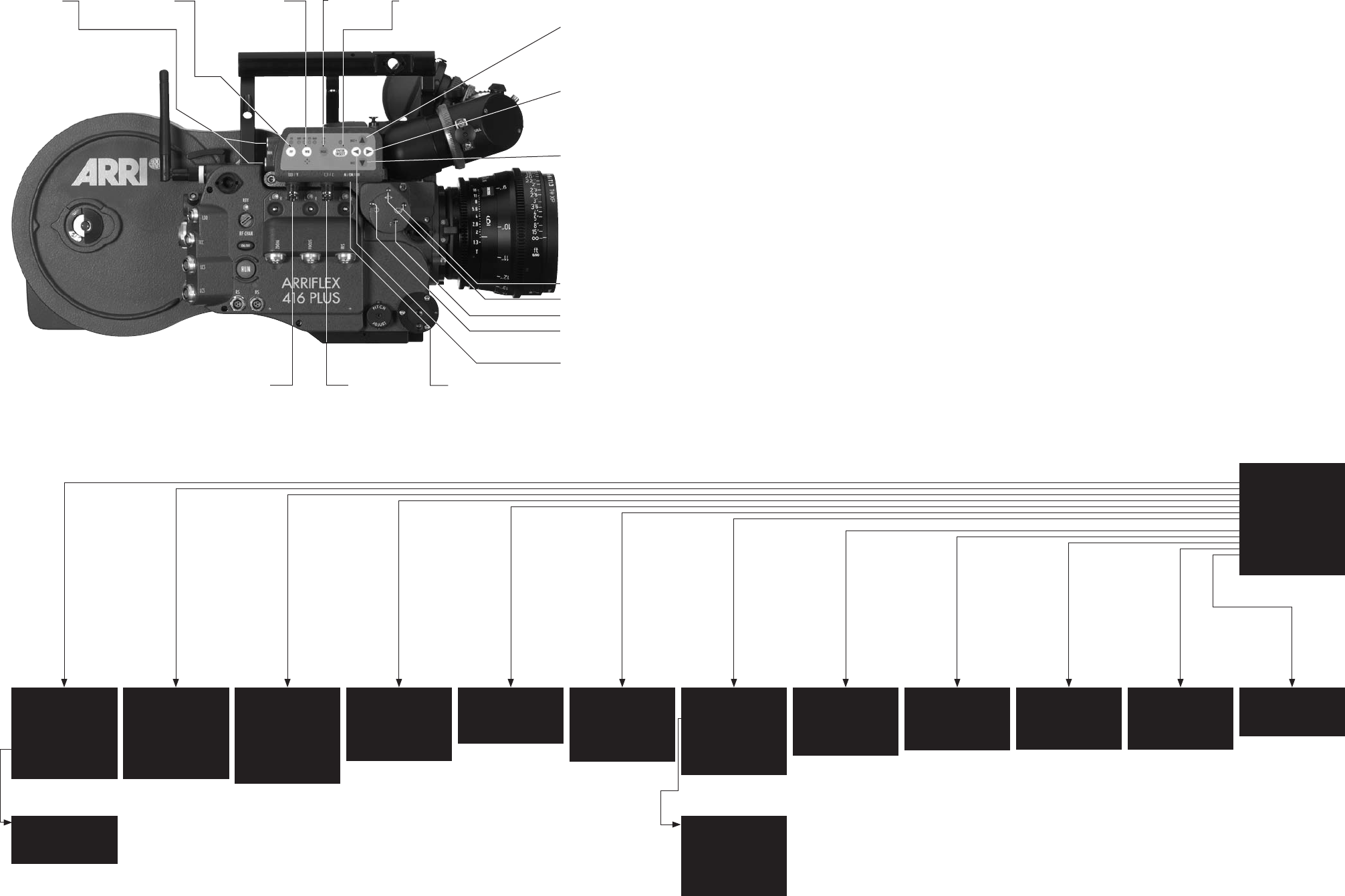
MAIN MENU
-> - LOAD/STORE
- WB/GAIN/BARS
- VIDEO/TEXT ADJ
- FORMAT MARKING
- COMPARE/STORE
- SYSTEM/STATUS
- USER TEXT
- TIME CODE TIME
- TIME CODE UB
- PULL DOWN
- VITC LINE
- WHITE LINE
- EXIT
ARE YOU SURE?
(NO UNDO)
-> - NO
- YES
- EXIT
MENU LOAD/STORE
-> - STORE SET 1
(CONFIRM BY
ENTER)
- LOAD SET 1
(NO UNDO)
- SET ALL
SETTINGS TO
DEFAULT
- EXIT
MENU WB/GAIN/BARS
-> - WHITE BALANCE IND
AUTOADJUST
RED
BLUE
- MANUAL GAIN OFF
VALUE
- COLOR BARS OFF
- EXIT
MENU VIDEO/TEXT ADJUST
-> - FLICKERFREE ON
- LINE INTERP. ON
- SHARPNESS 2
- BNC OUT VBS
Y/C DATA
- GENLOCK OFF
- MINI MON DATA ON
- TXT WHITE LEV. 2
- TXT INVERS ON
- TXT FINE POS 2
- EXIT
MENU FORMAT MARKING
-> - FORMAT 1&2
- POSITION 1 Ö
- POSITION 1 Ü
- POSITION 2 Ö
- POSITION 2 Ü
- WHITE LEVEL 2
- OUTSIDE LIGHT
- EXIT
MENU COMPARE/STORE
-> - VIEW MODE LIVE
- STORE IMAGE
- CLEAR IMAGE
- EXIT
MENU SYSTEM/LDS/STATUS
-> - SYSTEM LINE OFF
- LDS LINE OFF
- STATUS LINE OFF
POSITION
BACKGROUND
FILM COUNTER
- EXIT
MENU USER TEXT
-> - USER TEXT LINE ON
- EDIT TEXT
- CLEAR TEXT
(NO UNDO)
- POSITION
- SIZE SMALL
- BACKGROUND BOXED
- EXIT
MENU EDIT TEXT
(.................)
>X <
(.................)
> <
(.................)
> <
MOVE THE CURSOR X <>
CHANGE CHARACTER ^v
EXIT PRESS E
IVS Quick Reference
MENU TIME CODE UB
-> - TIME CODE UB ON
- POSITION
- SIZE SMALL
- BACKGROUND BOXED
- EXIT
MENU PULL DOWN
-> - PULL DOWN ON
- POSITION
- SIZE SMALL
- BACKGROUND BOXED
- EXIT
MENU VITC LINE
-> - VITC LINE ON
- POSITION 1 10
- POSITION 2 12
- EXIT
MENU WHITE LINE
-> - WHITE LINE ON
- POSITION 11
- EXIT
MENU TIME CODE TIME
-> - TIME CODE TIME ON
- POSITION
- SIZE SMALL
- BACKGROUND BOXED
- FRAME COUNTER FILM
- EXIT
switch check/hide
menu on/off
É/Y
video with data
or Y-Signal
È/C
clean video
or C-signal
mini-monitor
connector
icker-free on/off white balance
outdoor/indoor
outdoor/manual
gain control activate on screen program mode or store position
of inserted window or store user text
increase gain or cursor up
or move inserted window
up or increase blue
increase format numbers or
go to submenu or increase
values or increase red
decrease format numbers or
go into submenu or decrease
values or decrease red
decrease gain or cursor down
or move inserted window
down or decrease blue
Rotate video image
Y-adjustment
Focus video image
X-adjustment

technical data are subject to change without notice
© ARRI 2006
Ident-No. K5.66324.0
available languages:
English
ARNOLD & RICHTER CINE TECHNIK Türkenstr. 89 • D-80799 München
Phone +49 – 089 – 38 09 – 0 • Fax +49 – 089 – 38 09 – 12 44
www.arri.com
