ART 26 & 27 L&M Flow Data
User Manual: ART 26 & 27 L&M flow data
Open the PDF directly: View PDF ![]() .
.
Page Count: 20
ART 26 + 27
Issue 1
This data sheet is designed as a guide and should not be regarded as wholly accurate in every detail. We reserve the right to amend the specification of any product without notice
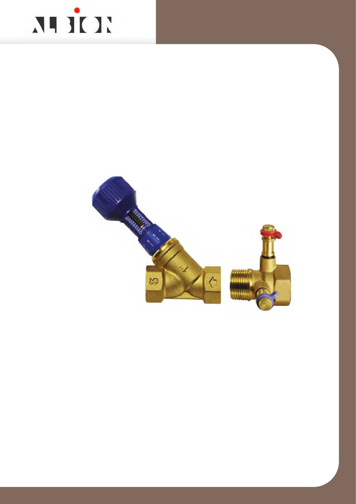
DZR Commissioning Set
Flow Data
and
Installation Instructions
Flow Data
and
Installation Instructions

ART 27
Issue
This data sheet is designed as a guide and should not be regarded as wholly accurate in every detail. We reserve the right to amend the specification of any product without notice
Technical Data
Flow Coefficient
The flow rate can be calculated using the Kvvalue and a measured signal.
Kv= Q*36 Kvs = Q*36
√∆P √∆Ps
where Kv&Kvs = flow coefficient (m3/hr at 1 bar differential)
Q = flow rate (l/s)
∆P = headloss attributable to valve (kPa)
∆Ps = differential pressure across tappings (signal) (kPa)
Kvs Values
Size ½” ¾” 1” 1¼” 1½” 2”
Kvs 1.8 4.1 7.5 16.6 23.0 47.4
Pressure Loss
The pressure loss across a metering station is less than signal differential pressure
indicated on the flow charts. The pressure loss is obtained by multiplying the
pressure signal by the pressure recovery factors given in the table.
This applies to when the metering station is used in a stand alone application or
close coupled to a double regulating valve.
Pressure Recovery Factors
The Albion ART 27 is a fixed orifice metering station used to measure the flow
passing through it, which can be used close coupled to an ART 26 double
regulating valve to form a commissioning set.
Size ½” ¾” 1” 1¼” 1½” 2”
Factor 0.67 0.5 0.5 0.5 0.5 0.4
Size ½”UUL ½”UL ½”L ½”M
Kvs 0.103 0.234 0.473 0.976
Size ½”UUL ½”UL ½”L ½”M
Factor 1.00 0.97 0.87 0.83
ART 26 + 27
Issue 1
This data sheet is designed as a guide and should not be regarded as wholly accurate in every detail. We reserve the right to amend the specification of any product without notice
Technical Data
Sizing
Once the required flow rate has been calculated, the size of the metering station
can be determined based on the following:
The minimum signal at the design flow rate of 1 kPa.
For minimum pressure loss, a maximum signal of 4.7 kPa, which corresponds
to the maximum differential pressure range of a fluorocarbon manometer.
Pressure Equipment Directive
Under the Pressure Equipment Directive (PED) these metering stations and double
regulating valves have been specified for Group 2 Liquids i.e. non-hazardous
Sizes ½” to 2” are classified as SEP (Sound Engineering Practice)
5D 2D
Pressure Loss
The pressure losses for the ART 26 double regulating valves are given on the
individual flow charts along with the corresponding Kv values at the various
positions open.
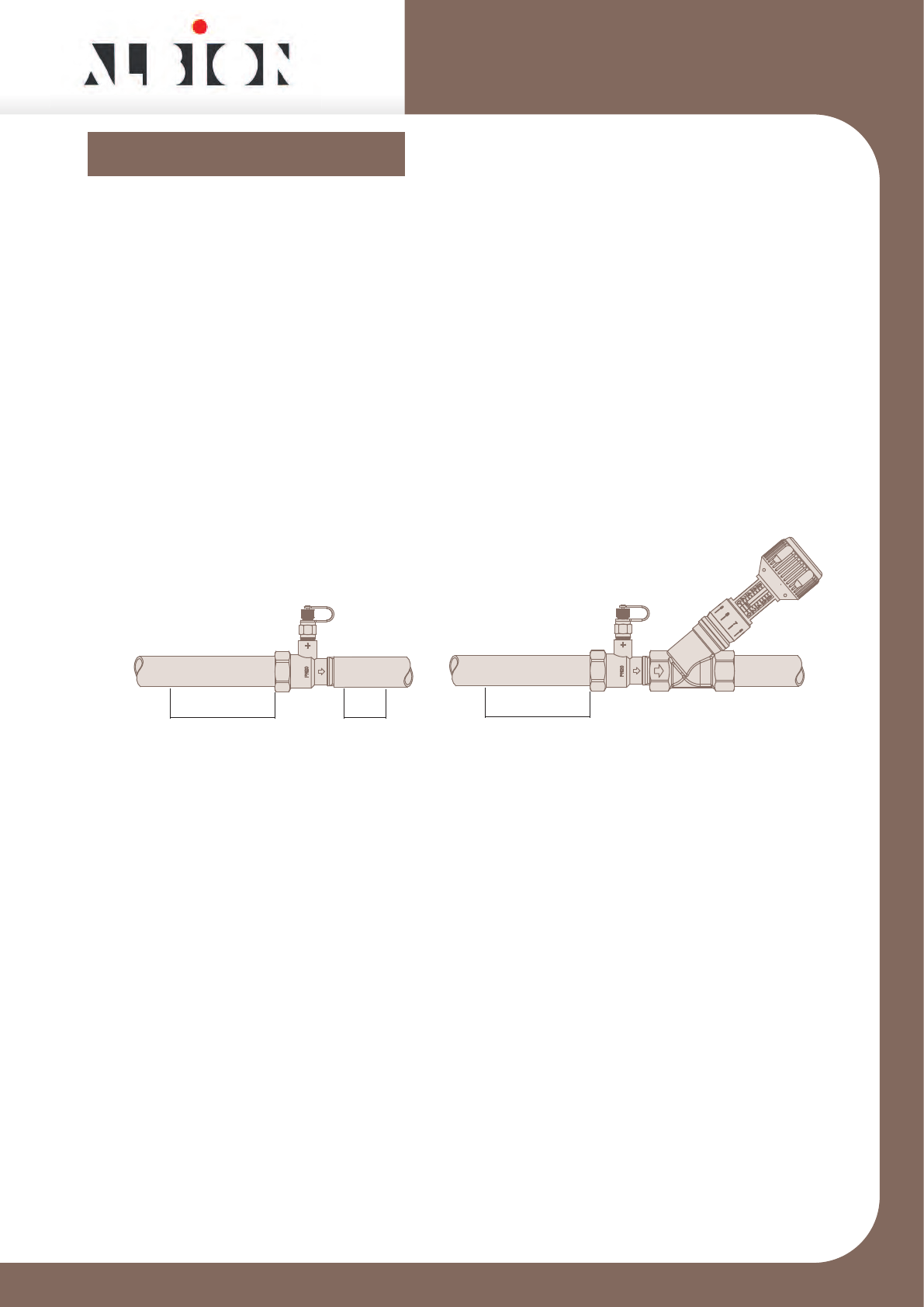
Installation
Metering stations must always be installed with a minimum of 5 pipe diameters of
straight pipe, without intrusion, upstream of the metering station.
Downstream of the metering station a minimum of 2 pipe diameters of straight
pipe are required.
When close coupled to an Albion ART 26 double regulating valves only the
straight pipe upstream of the metering station is required.
5D

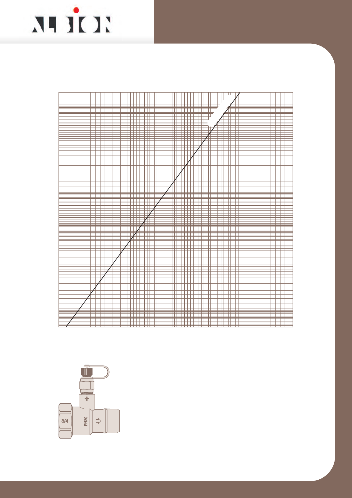
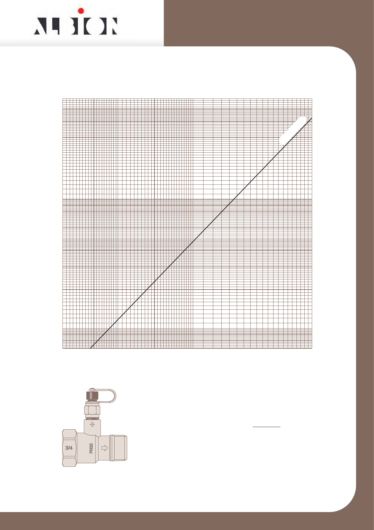
ART 27UUL
1/2” ART 27UUL DZR Metering Station
Issue 1
This data sheet is designed as a guide and should not be regarded as wholly accurate in every detail. We reserve the right to amend the specification of any product without notice.
Signal / Flowrate
Chart used to determine flowrate
from signal measured across orifice
Q = Kvs √ ∆p
36
Where
Q = Flowrate l/s
∆p = Signal kPa
Kvs = Signal Co-efficient
0.002 0.003 0.004 0.006 0.008 0.01 0.02 0.03
1
10
60
50
30
20
40
2
3
4
0.7
5
Flowrate l/s
Signal kPa
6
8
K
vs
=0.103

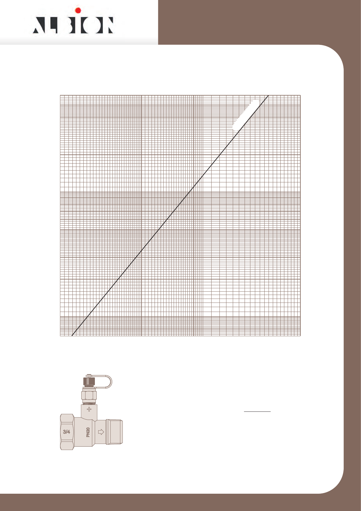
ART 27UL
1/2” ART 27UL DZR Metering Station
Issue 1
This data sheet is designed as a guide and should not be regarded as wholly accurate in every detail. We reserve the right to amend the specification of any product without notice.
Signal / Flowrate
Chart used to determine flowrate
from signal measured across orifice
Q = Kvs √ ∆p
36
Where
Q = Flowrate l/s
∆p = Signal kPa
Kvs = Signal Co-efficient
0.004 0.006 0.008 0.01 0.02 0.03 0.04 0.05 0.06
1
10
60
50
30
20
40
2
3
4
0.7
5
Flowrate l/s
Signal kPa
K
vs
=0.234
6
8
ART 27L
1/2” ART 27L DZR Metering Station
Issue 1
This data sheet is designed as a guide and should not be regarded as wholly accurate in every detail. We reserve the right to amend the specification of any product without notice.
Signal / Flowrate
Chart used to determine flowrate
from signal measured across orifice
Q = Kvs √ ∆p
36
Where
Q = Flowrate l/s
∆p = Signal kPa
Kvs = Signal Co-efficient
0.01 0.02 0.03 0.04 0.06 0.08 0.1 0.2
1
10
60
50
30
20
40
2
3
4
0.7
5
Flowrate l/s
Signal kPa
6
8
K
vs
=0.473
ART 27M
1/2” ART 27M DZR Metering Station
Issue 1
This data sheet is designed as a guide and should not be regarded as wholly accurate in every detail. We reserve the right to amend the specification of any product without notice.
Signal / Flowrate
Chart used to determine flowrate
from signal measured across orifice
Q = Kvs √ ∆p
36
Where
Q = Flowrate l/s
∆p = Signal kPa
Kvs = Signal Co-efficient
0.02 0.03 0.04 0.05 0.06 0.08 0.1 0.2 0.3
1
10
60
50
30
20
40
2
3
4
0.7
5
Flowrate l/s
Signal kPa
6
8
K
vs
=0.976
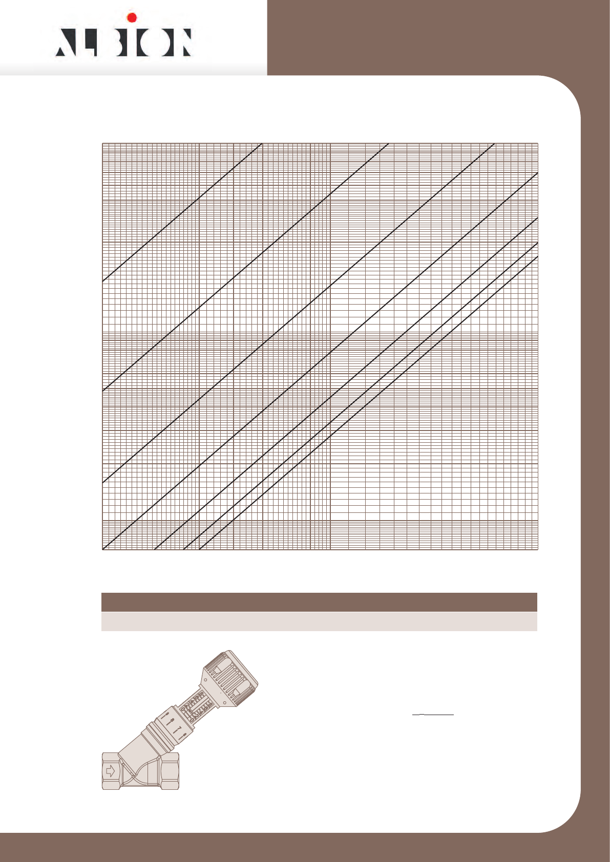
ART 26L
1/2” ART 26L DZR Double Regulating Valve
Issue 1
This data sheet is designed as a guide and should not be regarded as wholly accurate in every detail. We reserve the right to amend the specification of any product without notice
Pressure Loss / Flowrate
Chart used to determine flowrate
from signal measured across orifice
Q = Kv √ ∆p
36
Where
Q = Flowrate l/s
∆p = Pressure Loss kPa
Kv = Pressure Loss Co-efficient
Position 2 3 4 5 6 7 8
Kv0.15 0.22 0.31 0.52 0.83 1.13 1.28
0.004 0.006 0.008 0.01 0.02 0.03 0.04 0.06 0.08 0.1 0.2
0.7
1
10
100
2
3
4
5
20
30
50
40
Flowrate l/s
Pressure Loss kPa
6
8
60
80
234
6
7
8
5
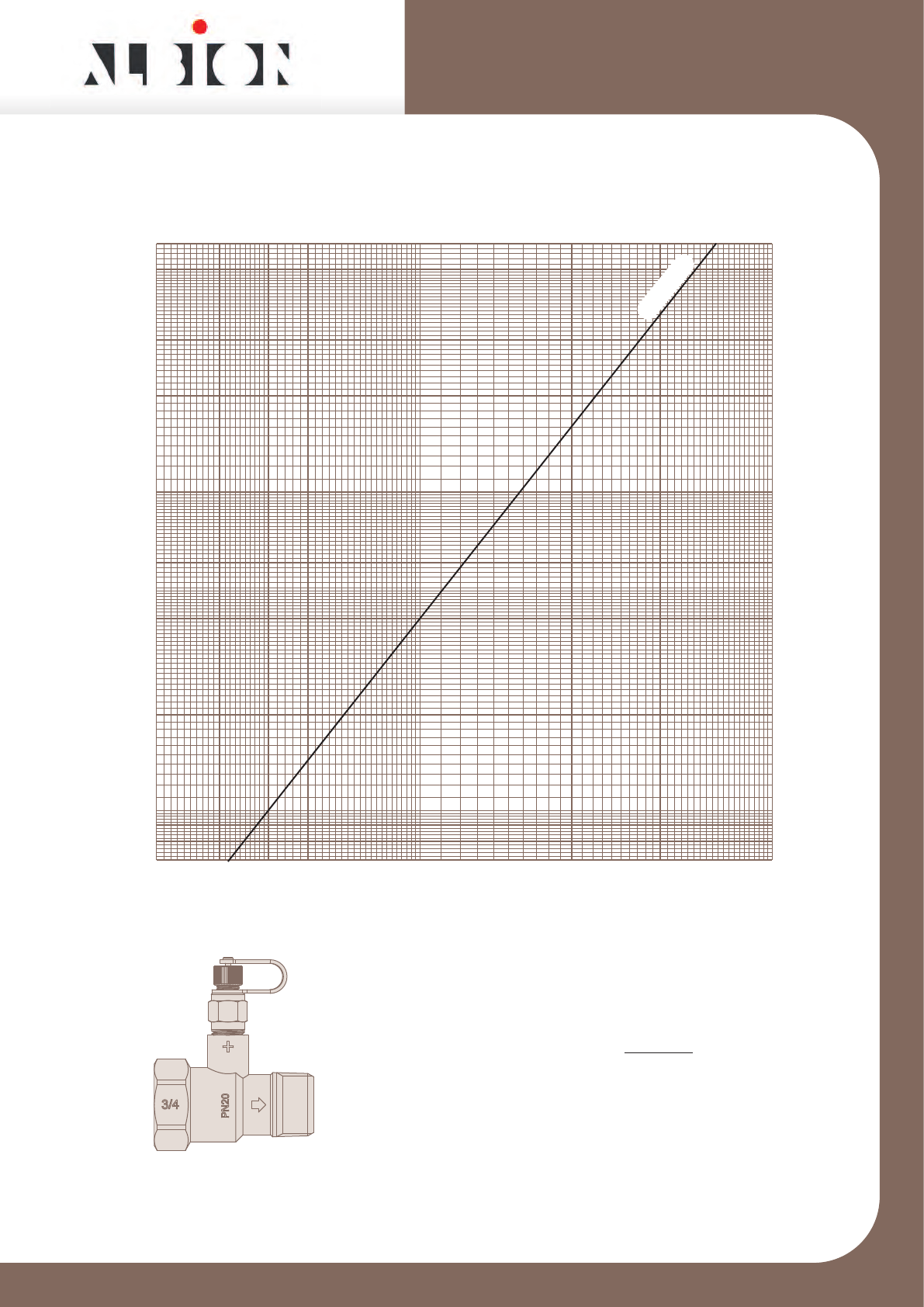
ART 27
1/2” ART 27 DZR Metering Station
Issue 1
This data sheet is designed as a guide and should not be regarded as wholly accurate in every detail. We reserve the right to amend the specification of any product without notice.
Signal / Flowrate
Chart used to determine flowrate
from signal measured across orifice
Q = Kvs √ ∆p
36
Where
Q = Flowrate l/s
∆p = Signal kPa
Kvs = Signal Co-efficient
0.03 0.04 0.05 0.07 0.1 0.2 0.3 0.4 0.5
1
10
60
50
30
20
40
2
3
4
0.7
5
Flowrate l/s
Signal kPa
K
vs
=1.8
6
8
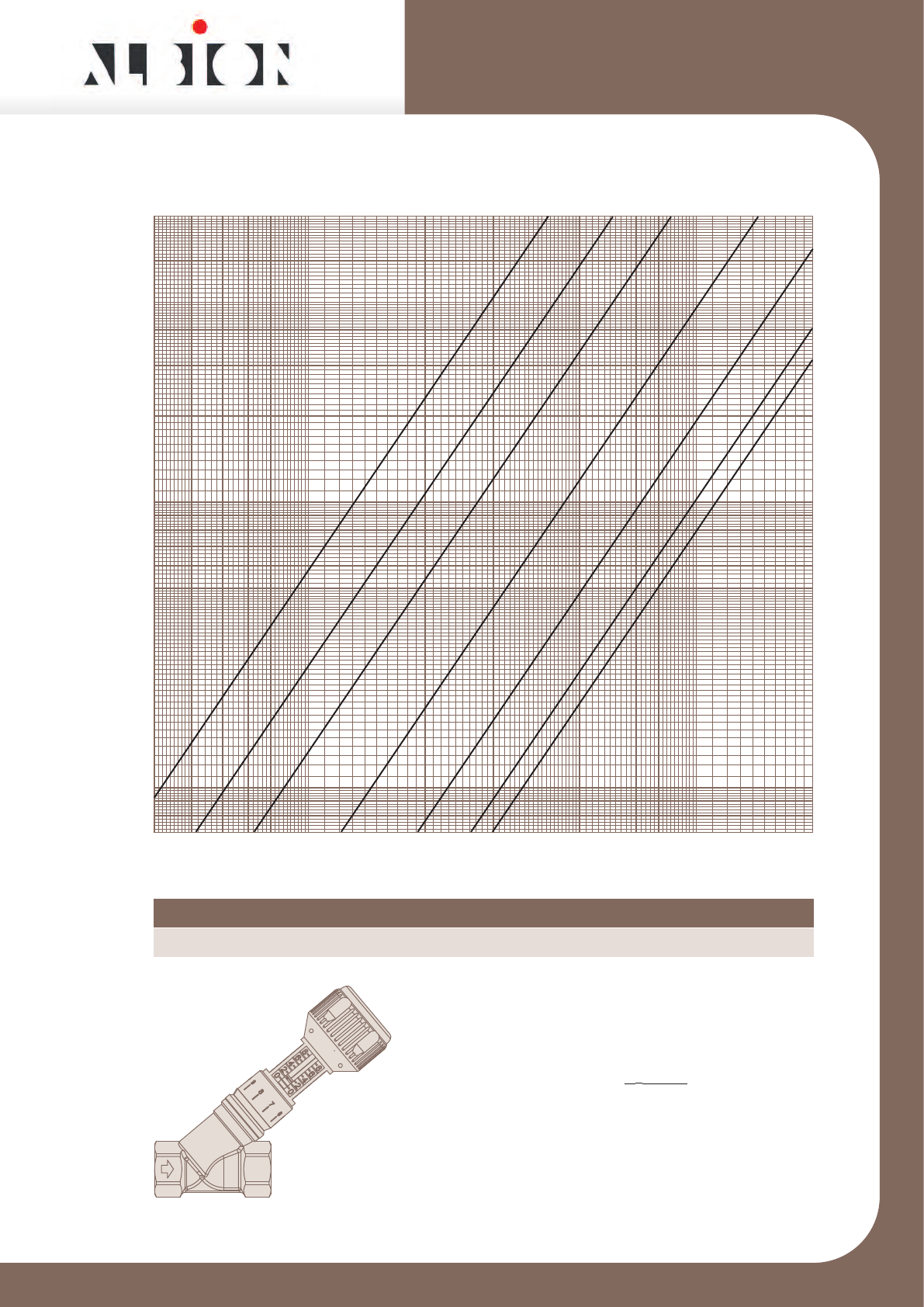
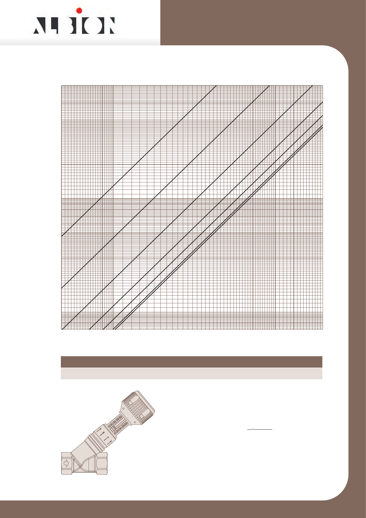
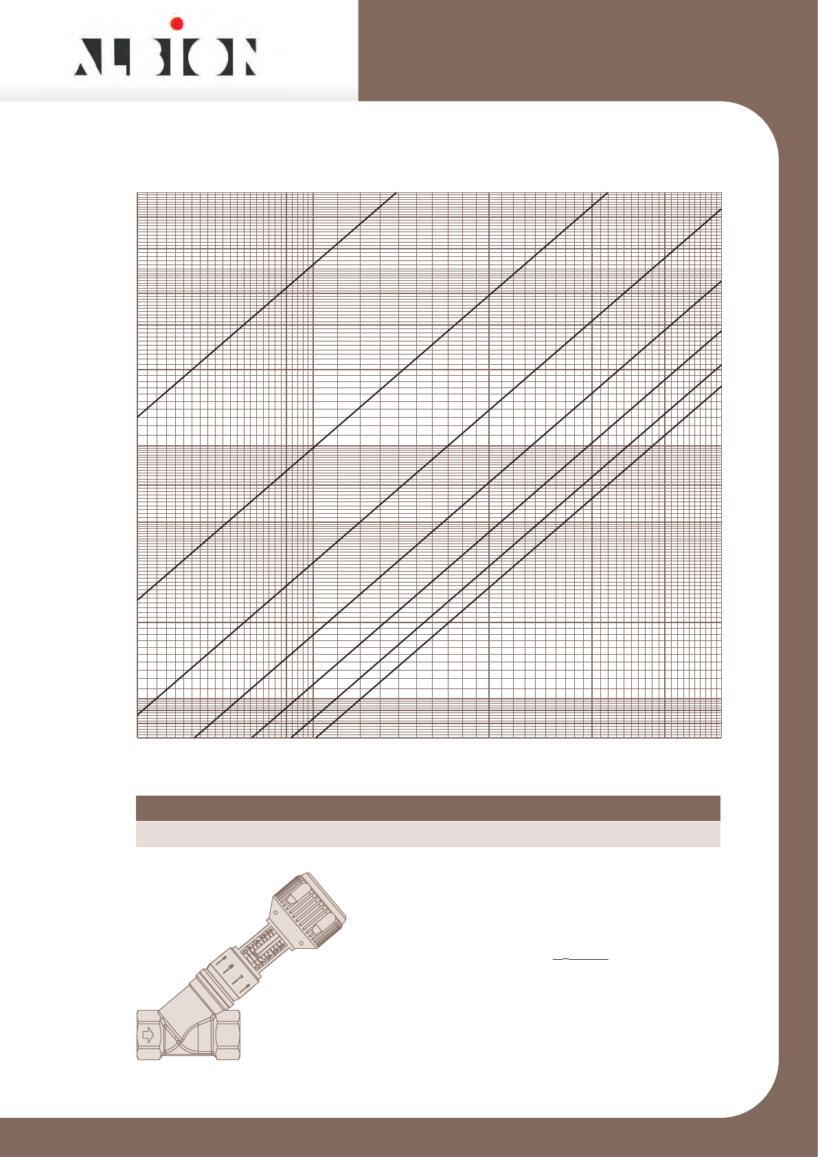
ART 26
1/2” ART 26 DZR Double Regulating Valve
Issue 1
This data sheet is designed as a guide and should not be regarded as wholly accurate in every detail. We reserve the right to amend the specification of any product without notice
Pressure Loss / Flowrate
Chart used to determine flowrate
from signal measured across orifice
Q = Kv √ ∆p
36
Where
Q = Flowrate l/s
∆p = Pressure Loss kPa
Kv = Pressure Loss Co-efficient
Position 2 3 4 5 6 7 8
Kv0.69 0.99 1.3 1.5 1.7 1.8 1.9
0.7
1
100
2
3
4
5
20
30
50
40
Flowrate l/s
10
0.03 0.04 0.05 0.06 0.08 0.1 0.2 0.3 0.4
Pressure Loss kPa
6
8
60
80
234
5
6
7
8
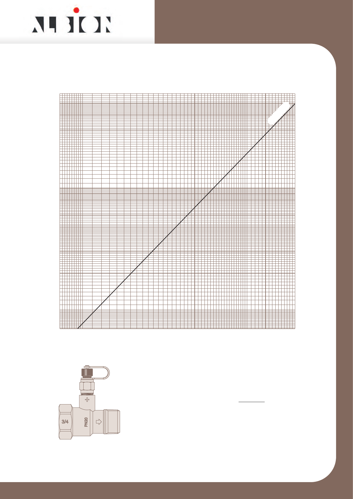
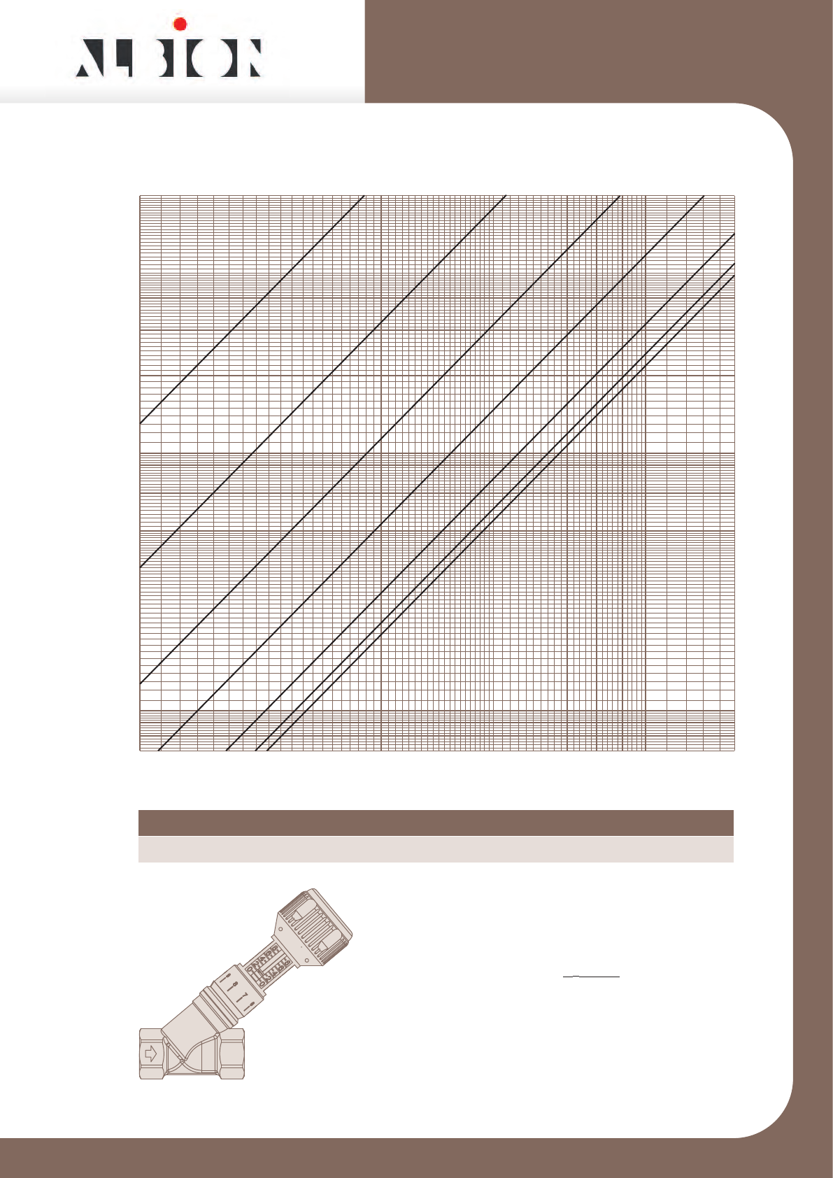
ART 27
3/4” ART 27 DZR Metering Station
Issue 1
This data sheet is designed as a guide and should not be regarded as wholly accurate in every detail. We reserve the right to amend the specification of any product without notice.
Signal / Flowrate
Chart used to determine flowrate
from signal measured across orifice
Q = Kvs √ ∆p
36
Where
Q = Flowrate l/s
∆p = Signal kPa
Kvs = Signal Co-efficient
0.08 0.1 0.2 0.3 0.4 0.5 0.6 0.8
1
10
60
50
30
20
40
2
3
4
0.7
5
Flowrate l/s
Signal kPa
K
vs
=4.1
6
8
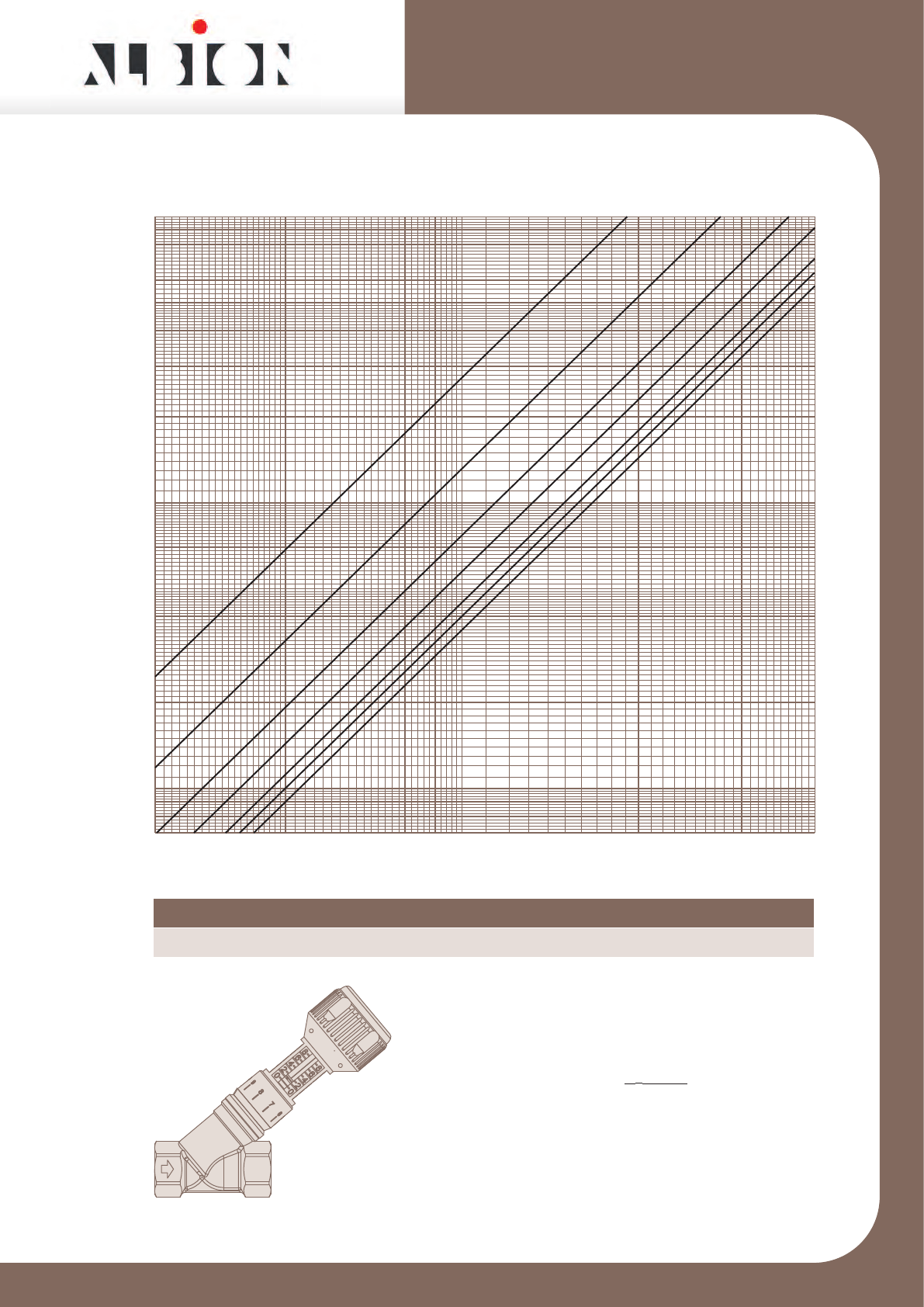
ART 26
3/4” ART 26 DZR Double Regulating Valve
Issue 1
This data sheet is designed as a guide and should not be regarded as wholly accurate in every detail. We reserve the right to amend the specification of any product without notice
Pressure Loss / Flowrate
Chart used to determine flowrate
from signal measured across orifice
Q = Kv √ ∆p
36
Where
Q = Flowrate l/s
∆p = Pressure Loss kPa
Kv = Pressure Loss Co-efficient
Position 2 3 4 5 6 7 8
Kv1.0 1.7 2.6 3.4 3.9 4.3 4.4
0.7
1
100
2
3
4
5
20
30
50
40
Flowrate l/s
0.06 0.08 0.1 0.2 0.3 0.4 0.5 0.6 0.8
10
Pressure Loss kPa
6
8
60
80
234
5
6
7
8

ART 27
1” ART 27 DZR Metering Station
Issue 1
This data sheet is designed as a guide and should not be regarded as wholly accurate in every detail. We reserve the right to amend the specification of any product without notice.
Signal / Flowrate
Chart used to determine flowrate
from signal measured across orifice
Q = Kvs √ ∆p
36
Where
Q = Flowrate l/s
∆p = Signal kPa
Kvs = Signal Co-efficient
0.15 0.2 0.3 0.4 0.5 0.6 0.8 1.0 1.5
1
10
60
50
30
20
40
2
3
4
0.7
5
Flowrate l/s
Signal kPa
K
vs
=7.5
6
8
ART 26
1” ART 26 DZR Double Regulating Valve
Issue 1
This data sheet is designed as a guide and should not be regarded as wholly accurate in every detail. We reserve the right to amend the specification of any product without notice
Pressure Loss / Flowrate
Chart used to determine flowrate
from signal measured across orifice
Q = Kv √ ∆p
36
Where
Q = Flowrate l/s
∆p = Pressure Loss kPa
Kv = Pressure Loss Co-efficient
Position 2 3 4 5 6 7 8
Kv1.0 1.9 3.2 4.7 6.4 7.3 7.7
0.7
1
100
2
3
4
5
20
30
50
40
Flowrate l/s
10
0.1 0.2 0.3 0.4 0.5 0.6 0.8 1.0 1.5
Pressure Loss kPa
6
8
60
80
234
5
6
7
8
ART 27
11/4” ART 27 DZR Metering Station
Issue 1
This data sheet is designed as a guide and should not be regarded as wholly accurate in every detail. We reserve the right to amend the specification of any product without notice.
Signal / Flowrate
Chart used to determine flowrate
from signal measured across orifice
Q = Kvs √ ∆p
36
Where
Q = Flowrate l/s
∆p = Signal kPa
Kvs = Signal Co-efficient
0.3 0.4 0.5 0.6 0.8 1 2 3
1
10
60
50
30
20
40
2
3
4
0.7
5
Flowrate l/s
Signal kPa
6
8
K
vs
=16.6
ART 26
11/4” ART 26 DZR Double Regulating Valve
Issue 1
This data sheet is designed as a guide and should not be regarded as wholly accurate in every detail. We reserve the right to amend the specification of any product without notice
Pressure Loss / Flowrate
Chart used to determine flowrate
from signal measured across orifice
Q = Kv √ ∆p
36
Where
Q = Flowrate l/s
∆p = Pressure Loss kPa
Kv = Pressure Loss Co-efficient
Position 2 3 4 5 6 7 8
Kv2.2 4.7 7.7 10.8 13.5 15.4 16.6
0.2 0.3 0.4 0.5 0.6 0.8 1.0 2.0 2.5
0.7
1
10
100
2
3
4
5
20
30
50
40
Flowrate l/s
Pressure Loss kPa
6
8
60
80
234
5
6
7
8

ART 27
11/2” ART 27 DZR Metering Station
Issue 1
This data sheet is designed as a guide and should not be regarded as wholly accurate in every detail. We reserve the right to amend the specification of any product without notice.
Signal / Flowrate
Chart used to determine flowrate
from signal measured across orifice
Q = Kvs √ ∆p
36
Where
Q = Flowrate l/s
∆p = Signal kPa
Kvs = Signal Co-efficient
0.4 05 0.6 0.8 1 2 3 4
1
10
60
50
30
20
40
2
3
4
0.7
5
Flowrate l/s
Signal kPa
6
8
K
vs
=23.0
ART 26
11/2” ART 26 DZR Double Regulating Valve
Issue 1
This data sheet is designed as a guide and should not be regarded as wholly accurate in every detail. We reserve the right to amend the specification of any product without notice
Pressure Loss / Flowrate
Chart used to determine flowrate
from signal measured across orifice
Q = Kv √ ∆p
36
Where
Q = Flowrate l/s
∆p = Pressure Loss kPa
Kv = Pressure Loss Co-efficient
Position 2 3 4 5 6 7 8
Kv2.5 4.9 8.6 12.9 17.0 19.8 21.5
0.3 0.4 0.5 0.6 0.8 1.0 2.0 3.0
0.7
1
10
100
2
3
4
5
20
30
50
40
Flowrate l/s
Pressure Loss kPa
6
8
60
80
234
5
6
7
8

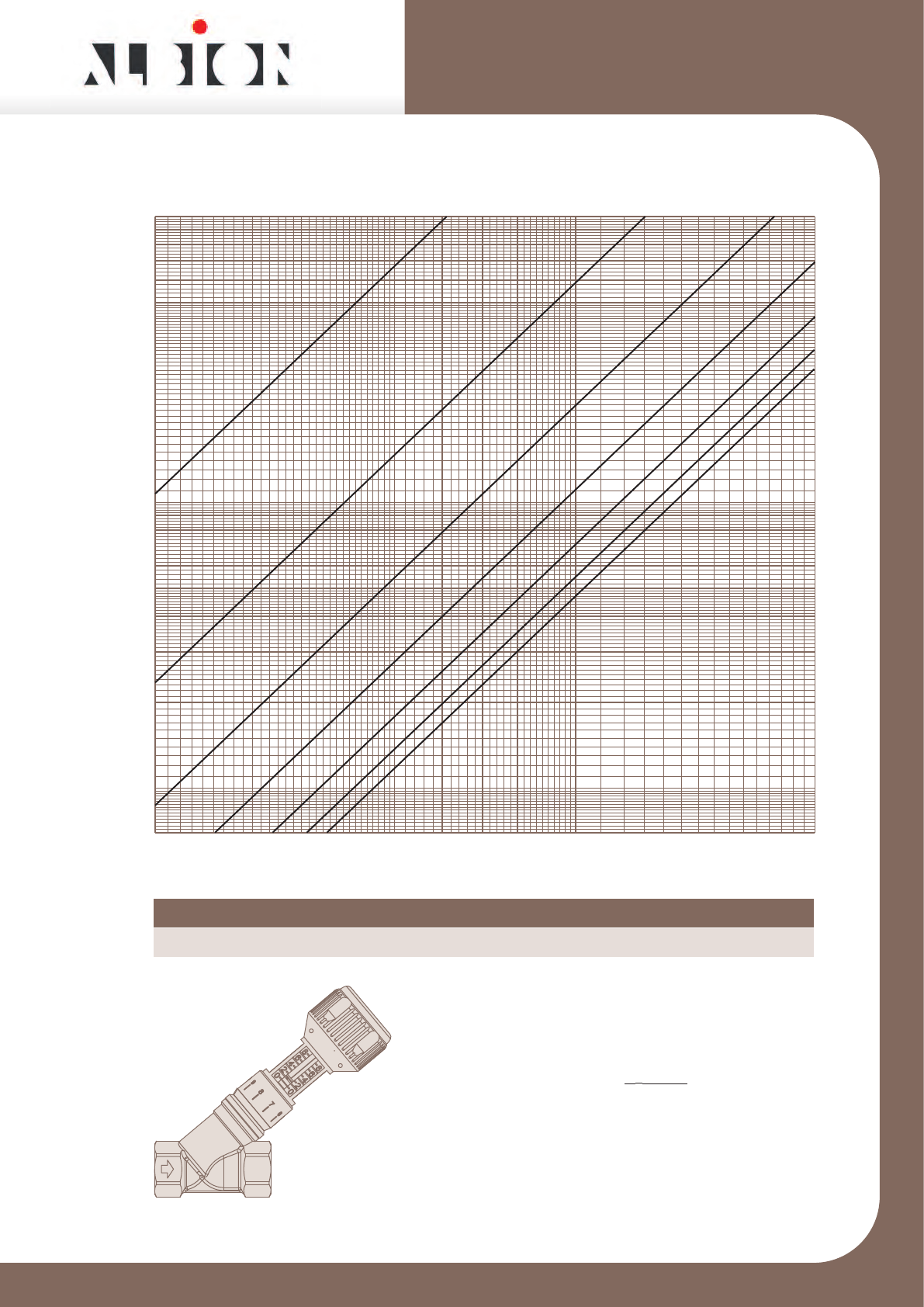
ART 27
2” ART 27 DZR Metering Station
Issue 1
This data sheet is designed as a guide and should not be regarded as wholly accurate in every detail. We reserve the right to amend the specification of any product without notice.
Signal / Flowrate
Chart used to determine flowrate
from signal measured across orifice
Q = Kvs √ ∆p
36
Where
Q = Flowrate l/s
∆p = Signal kPa
Kvs = Signal Co-efficient
0.8 1 2 3 4 5 6 8
1
10
60
50
30
20
40
2
3
4
0.7
5
Flowrate l/s
Signal kPa
6
8
K
vs
=47.4
ART 26
2” ART 26 DZR Double Regulating Valve
Issue 1
This data sheet is designed as a guide and should not be regarded as wholly accurate in every detail. We reserve the right to amend the specification of any product without notice
Pressure Loss / Flowrate
Chart used to determine flowrate
from signal measured across orifice
Q = Kv √ ∆p
36
Where
Q = Flowrate l/s
∆p = Pressure Loss kPa
Kv = Pressure Loss Co-efficient
Position 2 3 4 5 6 7 8
Kv5.0 11.5 19.4 26.9 33.7 39.5 43.6
0.7
1
100
2
3
4
5
20
30
50
40
Flowrate l/s
0.5 0.6 0.8 1.0 2.0 3.0 4.0 5.0
10
Pressure Loss kPa
6
8
60
80
23
4
5
6
7
8
