DTrack2 User Manual V2.12.0 ART DTrack 2.12
User Manual: ART DTrack User Manual 2.12
Open the PDF directly: View PDF ![]() .
.
Page Count: 224 [warning: Documents this large are best viewed by clicking the View PDF Link!]
- Terms and definitions
- Safety
- Introduction
- Markers and targets (rigid bodies)
- System setup
- The tracking cameras of ART
- The Controllers of ART
- Installation of the ART Controller (DTrack2 since v2.10)
- Installation of the ARTTRACK Controller (discontinued)
- Installation of the TRACKPACK Controller (discontinued)
- Setting a static IP address without the DTrack2 Frontend (available from controller software version v2.2)
- The setup file
- The information file
- Wake On LAN
- Remote command strings
- Setting up cascaded systems
- Setting up the Hybrid Motion Capture System
- DTrack2 frontend software
- Interaction devices
- Frequently asked questions (FAQ)
- General Information
- Technical specifications
- Technical Appendix
- Definition of Coordinates and Rotations
- Room Calibration
- Body Calibration
- Definition of the Coordinates by the Body itself
- Definition of the Coordinates by the Room Coordinate System, with Origin in the Center of the Markers
- Definition of the Coordinates by the Room Coordinate System, with Origin in a Marker
- Coordinate System Definition for 5DOF Targets (with and without cylinder markers)
- Coordinate System Definition for two 5DOF Targets with cylinder markers
- 6DOF Results
- 3DOF Data
- Flystick devices
- Measurement Tools
- Fingertracking
- Output of Measurement Data via Ethernet
- Definition of Coordinates and Rotations
- List of Figures
- List of Tables
- Index

version 2.12
April 2016
c
2016 A.R.T. GmbH
Contents are subject to
change without notice
weisser Text als Fake ...
System user manual
ARTtrack R
, TRACKPACK & DTrack R
dasbetrifft die gesamte seitenbreite der seite des dokumentes etetcetcetcetcetcetcetc etcetcetcetc
Trademarks
The following overview shows the registered trademarks of A.R.T. GmbH (Advanced Re-
altime Tracking GmbH):
trademarks illustrated as in Germany in the EU in the USA
A.R.T. R
ART ×××
ARTtrack R
ARTTRACK ×××
DTrack R
DTrack2 ×
smARTtrack R
SMARTTRACK ×××
×××
Microsoft R
and Windows R
are trademarks registered in the United States and
other countries by the Microsoft Corporation.
The company names and product names written in this manual are trademarks
or registered trademarks of the respective companies.
License agreement
The license provider guarantees the license holder a personal right to use the
DTrack2 software. A single license entitles the license holder to use the
software on all computers and networks of the license holder’s
branch/subsidiary office.
In no event shall ART GmbH be liable for any incidental, indirect, or
consequential damages whatsoever (including, without limitation, damages for
loss of business profits, business interruption, loss of business information, or
any other pecuniary loss) arising out of the use of or inability to use the software
or hardware.
c
1999 - 2016 by ART GmbH
Am Öferl 6
D-82362 Weilheim i. OB
Germany
T+49 (0)881-92530-00
v+49 (0)881-92530-01
http://www.ar-tracking.de
What’s new in version v2.12?
Following, a short overview of the main new features in DTrack2 version v2.12:
•Easier addition of cameras: To add a camera, simply re-calibrate the room with-
out losing the origin and orientation of the original coordinate system and continue
tracking. A similar procedure applies when removing cameras from the system.
•Integration of ’COOTrans’, our co-ordinate adjustment utility. This means that the
room adjustment can now be used to transform the tracking coordinate system
into the coordinate system of specific 3rd party objects, provided that the reference
points are known and can be measured (license-based)
•Support of bodies with up to 30 markers each
•Support of bodies with visibility restrictions including display of emission cones
within ’Body Adjustment’
•Additional information dialog regarding cylindrical markers within ’Body Calibration
Result Dialog’
•New function to remove unused markers from a rigid body within ’Body Adjustment’
•Radio channel settings are saved persistently when choosing a specific channel
number
What’s new in version v2.11?
Following, a short overview of the main new features in DTrack2 version v2.11:
•Support of new TRACKPACK/E cameras with Controllers including Synccard3 (see
e.g. chapter 4.1.3 on page 31)
•Support of new ARTTRACK5/C cameras for cave installations with Controllers in-
cluding Synccard3 (see e.g. chapter 4.1.2 on page 28)
•Improvements of usability of Hybrid Motion Capture (see chapter 4.4 on page 63)
What’s new in version v2.10?
Following, a short overview of the main new features in DTrack2 version v2.10:
•Support of ARTTRACK5 cameras with Controllers including Synccard3 (see e.g.
chapter 4.1.1 on page 25)
•Support of external sync source ’TTL signal, both edges’ (see e.g. chapter 4.5.6.3
on page 101)
•New license model. (see e.g. table 4.3 on page 76)
Contents
Termsanddefinitions ................................. 9
1 Safety 11
1.1 Symbols and their meaning . . . . . . . . . . . . . . . . . . . . . . . . . . . 11
1.2 Safetywarnings ................................. 11
2 Introduction 14
3 Markers and targets (rigid bodies) 16
3.1 Passivemarkers ................................. 16
3.2 Activemarkers .................................. 17
3.3 Standardtargets ................................. 20
4 System setup 25
4.1 The tracking cameras of ART .......................... 25
4.1.1 ARTTRACK5 .............................. 25
4.1.2 ARTTRACK5/C ............................. 28
4.1.3 TRACKPACK/E ............................. 31
4.1.4 ARTTRACK2 (discontinued) ...................... 33
4.1.5 ARTTRACK3 (discontinued) ...................... 35
4.1.6 TRACKPACK (discontinued) ...................... 38
4.1.7 TRACKPACK/C (discontinued)..................... 40
4.2 The Controllers of ART ............................. 43
4.2.1 Installation of the ART Controller (DTrack2 since v2.10) . . . . . . . 44
4.2.2 Installation of the ARTTRACK Controller (discontinued) . . . . . . . 48
4.2.3 Installation of the TRACKPACK Controller (discontinued) . . . . . . 52
4.2.4 Setting a static IP address without the DTrack2 Frontend (available
from controller software version v2.2) . . . . . . . . . . . . . . . . . 54
4.2.5 Thesetupfile............................... 55
4.2.6 The information file . . . . . . . . . . . . . . . . . . . . . . . . . . . . 56
4.2.7 WakeOnLAN .............................. 56
4.2.8 Remote command strings . . . . . . . . . . . . . . . . . . . . . . . . 58
4.3 Setting up cascaded systems . . . . . . . . . . . . . . . . . . . . . . . . . . 58
4.4 Setting up the Hybrid Motion Capture System . . . . . . . . . . . . . . . . 63
4.5 DTrack2 frontendsoftware ........................... 70
4.5.1 Gettingstarted .............................. 70
4.5.1.1 Installation guide (Windows) . . . . . . . . . . . . . . . . . 70
4.5.1.2 Installation guide (Linux) . . . . . . . . . . . . . . . . . . . 71
4.5.1.3 Software update . . . . . . . . . . . . . . . . . . . . . . . . 72
4.5.1.4 Start DTrack2 frontend software . . . . . . . . . . . . . . . 72
5
4.5.1.5 Connecting to the controller . . . . . . . . . . . . . . . . . . 72
4.5.1.6 Adjustment of the cameras . . . . . . . . . . . . . . . . . . 74
4.5.1.7 Localizing and removing of disturbing reflections . . . . . . 76
4.5.2 Roomcalibration............................. 77
4.5.2.1 Room re-calibration . . . . . . . . . . . . . . . . . . . . . . 82
4.5.3 Bodycalibration ............................. 84
4.5.3.1 Selecting the coordinate system for 6DOF targets . . . . . 85
4.5.3.2 Calibration with a calibration file . . . . . . . . . . . . . . . 87
4.5.3.3 Body re-calibration . . . . . . . . . . . . . . . . . . . . . . 88
4.5.3.4 Target Library . . . . . . . . . . . . . . . . . . . . . . . . . 89
4.5.4 Bodyadjustment............................. 90
4.5.5 Filtering options in DTrack2 ...................... 91
4.5.6 Menustructure.............................. 93
4.5.6.1 Overview............................ 93
4.5.6.2 MenuDTrack2 ......................... 94
4.5.6.3 Menu Settings . . . . . . . . . . . . . . . . . . . . . . . . . 97
4.5.6.4 Menu Calibration . . . . . . . . . . . . . . . . . . . . . . . . 111
4.5.6.5 Menu Display . . . . . . . . . . . . . . . . . . . . . . . . . 120
4.5.6.6 MenuTools...........................124
4.5.6.7 MenuAbout ..........................124
5 Interaction devices 126
5.1 Flystick2......................................126
5.2 Flystick3......................................132
5.3 Fingertracking ..................................137
5.4 MeasurementTool ................................144
6 Frequently asked questions (FAQ) 147
6.1 Backup ......................................147
6.2 Cameras .....................................147
6.3 Controller .....................................150
6.4 Synchronization .................................150
6.5 DTrack2 andshutterglasses ..........................157
6.6 DTrack2 andinterfaces .............................157
6.7 Software DTrack2 ................................158
6.8 Calibration ....................................161
6.9 Tracking......................................166
6.10Flystick ......................................167
6.11Fingertracking ..................................169
6.12MeasurementTool ................................171
6.13ActiveTargets...................................171
6.14 ART trackingand3DTVs ............................172
6.15 Radio transceivers used in ART products ...................172
7 General Information 173
7.1 Service ......................................173
7.2 Cleaning of the equipment . . . . . . . . . . . . . . . . . . . . . . . . . . . . 173
7.3 Warranty and liability . . . . . . . . . . . . . . . . . . . . . . . . . . . . . . 173
7.4 Declaration of conformity . . . . . . . . . . . . . . . . . . . . . . . . . . . . 175
A Technical specifications 190
A.1 Cameras .....................................190
A.1.1 ARTTRACK5 ..............................190
A.1.2 ARTTRACK5/C .............................191
A.1.3 TRACKPACK/E .............................192
A.1.4 ARTTRACK cameras (discontinued) . . . . . . . . . . . . . . . . . . 193
A.1.5 TRACKPACK cameras (discontinued) . . . . . . . . . . . . . . . . . 194
A.2 Flysticks......................................195
A.3 Fingertracking ..................................196
A.4 ARTController ..................................196
A.5 Overallsystem ..................................197
A.6 Systemlatency..................................199
B Technical Appendix 203
B.1 Definition of Coordinates and Rotations . . . . . . . . . . . . . . . . . . . . 203
B.1.1 RoomCalibration.............................203
B.1.1.1 Room Adjustment . . . . . . . . . . . . . . . . . . . . . . . 203
B.1.2 BodyCalibration .............................204
B.1.2.1 Definition of the Coordinates by the Body itself . . . . . . . 204
B.1.2.2 Definition of the Coordinates by the Room Coordinate Sys-
tem, with Origin in the Center of the Markers . . . . . . . . 204
B.1.2.3 Definition of the Coordinates by the Room Coordinate Sys-
tem, with Origin in a Marker . . . . . . . . . . . . . . . . . . 204
B.1.2.4 Coordinate System Definition for 5DOF Targets (with and
without cylinder markers) . . . . . . . . . . . . . . . . . . . 205
B.1.2.5 Coordinate System Definition for two 5DOF Targets with
cylindermarkers........................205
B.1.3 6DOFResults ..............................205
B.1.4 3DOFData ................................206
B.1.5 Flystickdevices..............................206
B.1.5.1 Flystick1 ............................206
B.1.5.2 Flystick2 ............................207
B.1.5.3 Flystick3 ............................208
B.1.6 Measurement Tools . . . . . . . . . . . . . . . . . . . . . . . . . . . 208
B.1.6.1 Orientation of a Measurement Tool . . . . . . . . . . . . . 208
B.1.6.2 Using a reference body . . . . . . . . . . . . . . . . . . . . 208
B.1.7 Fingertracking ..............................209
B.2 Output of Measurement Data via Ethernet . . . . . . . . . . . . . . . . . . . 210
B.2.1 FrameCounter..............................211
B.2.2 Timestamp ................................211
B.2.3 Standard 6DOF Bodies . . . . . . . . . . . . . . . . . . . . . . . . . 211
B.2.4 Standard 6DOF Bodies (extended format) . . . . . . . . . . . . . . . 212
B.2.5 Flysticks..................................213
B.2.6 Flysticks (Old Format) . . . . . . . . . . . . . . . . . . . . . . . . . . 214
B.2.7 Measurement Tools with sphere tip . . . . . . . . . . . . . . . . . . . 215
B.2.8 Measurement Tool references . . . . . . . . . . . . . . . . . . . . . . 216
B.2.9 Measurement Tools (Old Format) . . . . . . . . . . . . . . . . . . . . 216
B.2.10Fingertracking ..............................217
B.2.11 Additional 3DOF Markers . . . . . . . . . . . . . . . . . . . . . . . . 218
B.2.12 Additional Informations . . . . . . . . . . . . . . . . . . . . . . . . . 218
List of Figures 220
List of Tables 222
Index 223
8

Chapter 0
Terms and definitions
term definition
3DOF three degrees of freedom (i.e. only position)
6DOF six degrees of freedom (i.e. position and orientation)
5DOF five degrees of freedom (i.e. one degree less in orientation)
ART Controller calculates tracking data and generates the data output stream
(compatible to ARTTRACK2 ,ARTTRACK3 ,ARTTRACK5 ,
ARTTRACK5/C ,TRACKPACK/E )
ARTTRACK Controller (discontin-
ued)
calculates tracking data and generates the data output stream
(compatible to ARTTRACK1 ,ARTTRACK2 ,ARTTRACK3 )
ARTTRACK 2 & 3 (discontinued) infrared camera
ARTTRACK5 infrared camera
ARTTRACK5/C infrared camera dedicated for multi-sided projections
body calibration teach the system the geometry of a rigid body
body, rigid body rigid arrangement of several single markers (see also "target")
calibration angle (410mm or 710mm) belongs to the room calibration set and defines origin and orien-
tation of the room coordinate system
ceiling suspension equipment to mount an infrared camera to the ceiling
DTrack2
backend software Linux-based software which does all necessary calculations
frontend software graphical user interface to control the controller
Field of View (FoV) is the area of interest captured on the cameraâ ˘
A´
Zs imager
finger thimble a fixture for the finger tip to hold the active marker(s)
Fingertracking tracks the orientation of the hand and the position of the fingers
Flystick wireless interaction device for virtual reality (VR) applications
hand geometry describes the dimensions of your hand and fingers
hybrid tracking fusion of optical and inertial data into one consolidated output
inertial sensor an inertial measurement unit simultaneously measures 9 phys-
ical properties, namely angular rates, linear accelerations, and
magnetic field components (not used) along all 3 axes. This is
achieved using solid state gyroscopes for measurement of roll,
pitch and yaw and accelerometers for drift correction.
infrared optical tracking position measurement of bodies (subjects or objects) based
upon infrared light and optical measurement procedures
license code (license key) software key to unlock certain capabilities of the tracking system
marker object either made of retro reflective material or LED for position
tracking (3DOF)
Measurement Tool a pointing device which allows to measure the position of the
tool’s tip with high accuracy
measurement volume defines the volume where optical tracking is possible
modulated flash infrared signal which is used for wireless synchronization
motion capture track movements of a human body
mutual blinding one camera sees disturbing reflections caused by the infrared
flashes of another one
prediction predicts output for the specified time in the future to compensate
tracking and rendering latency
room calibration teach the system the position of each camera and define origin
and orientation of the room coordinate system
room calibration set consists of angle and wand
syncgroup cameras being in one syncgroup receive the sync signal at the
same time. Syncgroups are distinguished by a short time delay
between their sync signals (i.e. mutual blinding may be avoided).
synccard (Synccard2/3 or Sync-
cardTP)
plug-in card for the controller which serves for synchronizing the
cameras
9

term definition
Tactile Feedback system for finger-based interactions in immersive virtual reality
applications (wires touch the inside of the finger tips and provide
an impression when they are shortened)
target rigid arrangement of several single markers ( = rigid body)
tracking position measurement of bodies that move in a defined space
TRACKPACK (discontinued) infrared camera
TRACKPACK/C (discontinued) infrared camera dedicated for multi-sided projections
TRACKPACK/E infrared camera
TRACKPACK Controller (discontin-
ued)
calculates tracking data and generates the data output stream
(compatible to TRACKPACK and TRACKPACK/C )
USB radio transceiver (RT2, RT3) exchange data with Flystick or Tactile Feedback
virtual point cloud used for calculating the relative positions of the IR cameras
wand precalibrated stick carrying two markers. The wand belongs to
the room calibration set and is used to generate a virtual point
cloud and to scale the system
10
Chapter 1
1 Safety
1.1 Symbols and their meaning
You can find the following symbols and their signification on the equipment or in the man-
ual:
iUseful and important notes.
ZImportant notes, which may lead to system malfunction or to the
loss of warranty by non-observance.
Important safety warning to assure operation safety.
These warnings have to be considered, otherwise user
and equipment could be endangered, the equipment could be
damaged or the function of the equipment is not warranted.
Safety warning for infrared radiation.
These warnings have to be considered, otherwise users eyes
could be endangered.
Table 1.1: Symbols and their meaning
1.2 Safety warnings
ZSafe operation of the equipment is only warranted if the warnings in
this manual and on the equipment are observed.
•Never use the equipment if any part looks damaged.
•Safe operation is not possible, if
–the housing is damaged,
–any fluid attains in the housing,
–objects attain inside the equipment,
–the equipment shows any visible faults (smoke, sparks, fire, smells, etc.) or
–the power cord is damaged.
•In any of the cases mentioned above (or similar) pull the power cord out of the power
11
1 Safety
socket immediately. Otherwise, users or environment are endangered. Please con-
tact the ART service.
•Never change or alter the equipment, neither mechanically nor electrically. Only the
components described by ART shall be used. The conformity and the warranty of
the producer (ART ) expire by non-compliance.
•Never open the equipment! Only personnel authorized by ART is allowed to open
the equipment. Inside of the equipment there are various hazards like high voltage,
electric shocks - even if the equipment is disconnected - which can lead to death on
contact. In case of malfunction of the equipment please contact the ART service.
•Only peripheral devices which meet the safety requirements of EN/IEC 60950 for
extra low voltage may be attached on Ethernet-, BNC- and the DC-circuit of the
equipment.
•The cameras emit infrared light. Keep a distance of min. 20 cm when operating the
cameras. All cameras are assigned to the Exempt Group according to IEC62471-1
and therefore pose no risk or hazard to the human eye or skin at this distance.
•Be sure that the cameras are firmly mounted in the correct position.
•Do not touch the front pane of the cameras, since the acrylic pane and the lens are
highly sensitive surfaces. Be careful to avoid permanent damages (e.g. scratches).
Only touch the housings of the cameras.
•The ventilation holes of the ARTTRACK2 camera must not be covered. Air circu-
lation is necessary to prevent the cameras from overheating. If the air circulation
is restricted overheating will damage the cameras. The minimum distance between
equipment and environmental objects has to be greater than 3 cm.
•The equipment has to be attached to a power socket with grounding. If the ground-
ing wire is defective the requirement of the safety and the electromagnetic compat-
ibility (EMC) are not guaranteed. To check the function of the grounding wire ask
your regional located electrician.
•Before switching on any device, verify that voltage and frequency of your electric
installation are within the allowed ranges of the equipment. The characteristics of
the equipment can be found on the appliance rating plate or in chapter A on page
190. The appliance rating plates are on the equipment’s housing (ARTTRACK1 on
the lower side of the housing; ARTTRACK2 /ARTTRACK3 on external power sup-
ply, ARTTRACK5 &ARTTRACK5/C /TRACKPACK/E on camera housing, all con-
trollers on the backside of the housing).
•The power switch on the backside does not completely separate the devices from
the electricity network. To completely separate the equipment from the electricity
network the power plug must be disconnected from the power socket. The power
plug has to be accessible freely. The power socket must be close to the equipment.
12

Chapter 1
1.2 Safety warnings
•Please install the cables such that
–no one can stumble over the cords,
–the cords cannot be damaged,
–the cords cannot damage the cameras due to mechanical strain,
–the line of sight of the cameras is not obstructed.
Install a strain relief!
•Only use original ART (or ART authorized) components and accessories. Using
non-original components or accessories may damage the equipment, cause mal-
functions or may void operation safety. The provided components and original
accessories can be found in chapters 4 on page 25 and 5 on page 126. Only
use the originally provided external power supply for operating the camera ART-
TRACK2 and ARTTRACK3 and, if applicable, only the provided PoE+ switch for
ARTTRACK5 &ARTTRACK5/C .
•The equipment must not be dropped and/or knocked.
•Do not use any solvents or water to clean the cameras. For more information about
cleaning the cameras please read chapter 7.2 on page 173.
•Never expose the equipment to high levels of humidity or condensating humidity.
Protect the cameras against water and chemicals.
•The equipment must not be operated in environments with intensive formation of
dust or hot environments where temperatures rise above 40◦C (100◦F).
ZART explicitly denies any liability or warranty if the product is modified
in any way or not used according to this manual and the specification
labels on the equipment.
13
2 Introduction
ART tracking systems are infrared (IR) optical tracking systems. In this user manual we
are going to perceive "tracking" as measurement of the position of objects or subjects that
move in a defined space. These objects or subjects to be tracked have to be equipped
with single markers or rigid arrangements of markers (= rigid body or target).
Position and/or orientation of those rigid bodies can be measured. If only the spatial po-
sition (X, Y, Z) is measured we call this "three degrees of freedom" (3DOF) tracking. The
simultaneous measurement of position and orientation (three independent angular coor-
dinates) is called "six degrees of freedom" (6DOF) tracking.
Single markers are sufficient if only 3DOF coordinates are needed. For 6DOF tracking, a
rigid body is mandatory.
Passive markers are covered with retro reflective material - they act as light reflectors.
Active light emitters (i.e. based on infrared LEDs) are called active markers (see chapter
3 on page 16).
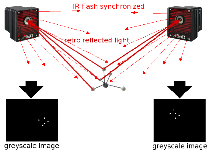
Figure 2.1: Principle of optical tracking (stereo vision)
Figure 2.1 shows the principle of infrared optical tracking with a two-camera system and
a standard target.
14

Chapter 2
The cameras are sending out synchronized IR flashes which are reflected towards the
lens by the retro reflective material which is covering the markers of the target. Intelligent
tracking cameras, that are scanning a certain volume, detect the IR radiation that is re-
flected by the markers and create a greyscale image based on the received IR radiation.
During the preprocessing the camera calculates the 2D marker positions with high accu-
racy using pattern recognition. A mean 2D-accuracy of 0.04 pixels (0.1 pixels maximum
2D-deviation) is standard in ART tracking cameras. Then, the 2D data are being sent to
the Controller via Ethernet.
Now, the controller has to calculate 3DOF or 6DOF data. The base for this calculation
is that the cameras’ field of views are overlapping. DTrack2 calculates the path of the
optical rays from the cameras to the markers and delivers the ray intersections in three-
dimensional coordinates. These intersections are the positions of the markers.
The position and orientation of the cameras are known from the room calibration. During
body calibration, DTrack2 identifies certain marker arrangements as rigid bodies. Based
upon this, DTrack2 is able to calculate 6DOF data and, finally, knows position and orien-
tation of the target and, therefore, of the object or subject to be tracked.
In optical tracking systems you have to be aware that tracking is only possible as long as
the target is positioned in tracking range of the cameras and is not occluded by any other
objects or the object to be tracked. More in detail, at least four markers of a target have
to be visible for a minimum of two cameras to enable tracking.
15
3 Markers and targets (rigid bodies)
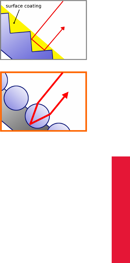
3.1 Passive markers
The passive markers used in ART tracking systems are retro reflectors. These markers
reflect the incoming IR radiation into the direction of the incoming light. More precise: the
IR radiation is reflected into a narrow range of angles around the (opposite) direction of
the incoming light. Passive markers can be either
1. spherical markers:
+ excellent visibility from any perspective,
- expensive fabrication,
- sensitive surface,
- target requires larger volume →danger of mechanical damage.
2. flat markers:
+ cheap,
+ flat targets possible,
+ robust surface because cover may be applied,
- the angular range of visibility is limited to approx. ±45◦.
3. ring markers:
+ cheap,
+ cylindrically shaped targets possible,
+ robust surface,
- the angular range of visibility is limited to approx. ±45◦.
Passive markers are mostly spheres covered with retro reflecting foils. However, they can
also be stickers made from retro reflecting material.
Retro reflecting sheets or foils available on the market can be based on two different op-
tical principles:
16
Chapter 3
3.2 Active markers
1. Triple mirrors, which are arranged such that their planes
form angles of 90◦by pairs, are reflecting light in the de-
scribed way. Mostly foils with arrangements of many very
small mirrors in a plane are used.
2. Glass spheres (with a proper refraction index) are fo-
cussing incoming light approximately to the opposite sur-
face of the ball. A layer of microscopic glass spheres, car-
ried by a reflecting material, acts as a retro reflector. These
foils can be fabricated on a flexible carrier material, thus
they are widely used for equipping spherical markers with
retro reflecting surfaces.
iART spherical markers are covered with retro reflecting foils, based on
the glass spheres principle.
ZThe quality of the markers decreases when they are in contact with
dust, dirt, fat, liquids, glue or comparable contaminants. Please make
sure that the markers are not touched or damaged.
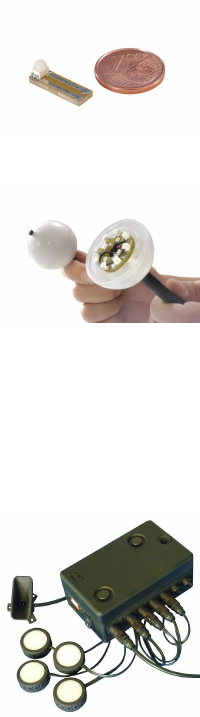
3.2 Active markers
Basics Active markers are light (i.e. infrared light) emitting elements, mostly LEDs.
In ART tracking systems four types of LED-based active markers may be used, depend-
ing on the application:
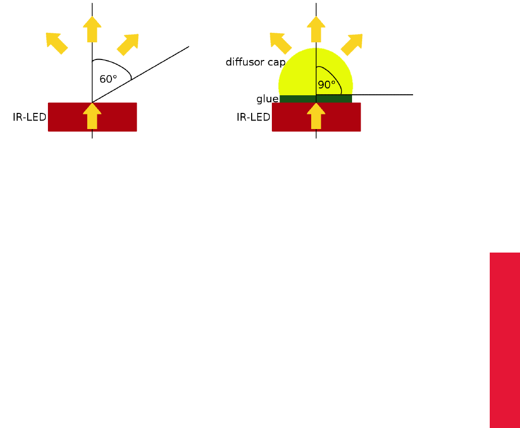
1. Single LEDs without diffusor sphere:
+ can be covered with acrylic protection film,
+ results in simple and robust markers providing visibility up
to high distances (up to 10m),
- the angular range of visibility is limited to approx. ±60◦.
17
3 Markers and targets (rigid bodies)
2. Single LEDs with diffusor sphere:
+ for optimum angular range of visibility,
- distance between marker and tracking camera is limited to
a short distance (up to 4.5m).
3. Big active spherical markers:
+ several single LEDs per marker, covered with light scatter-
ing spheres,
+ provide visibility from all sides and up to very high distances
(approx. 20m),
+ suitable for outdoor tracking,
- diameter: 50mm,
- weight: 50g.
4. Big active flat markers:
+ several single LEDs per marker, covered with light scatter-
ing surface,
+ tracking up to very high distances (approx. 20m),
+ suitable for outdoor tracking,
+ magnetic base for easy positioning on metal surfaces,
- the angular range of visibility is limited to less than 180◦,
- diameter: 30mm.
All active markers provided by ART are controlled by a special PC board and need power
supply.
Synchronization of active markers Active markers could in principle be activated in
CW mode (i.e. continuous light emission). However, this would not be very clever be-
cause tracking cameras have a very narrow time slot of sensitivity, i.e. most of the light
emitted by the markers would be useless for tracking. As a consequence, maximum dis-
tance between cameras and marker would be very short due to an upper limit of power
dissipation allowed for each single LED. Therefore, all active markers provided by ART are
emitting radiation only when the tracking cameras are sensitive, thus having to be syn-
chronized with the cameras.
Synchronization can be done by a wired connection between the tracking system and the
pc-board controlling the active markers, but can also be done in a wireless way.
18
Chapter 3
3.2 Active markers
(a) Single LED (b) Single LED with diffusor sphere
Figure 3.1: Angular range of visibility
For wireless synchronization a coded IR flash is being sent out by a tracking camera. The
active marker’s PC board recognizes the coded flash and activates the LEDs.
19
3 Markers and targets (rigid bodies)
3.3 Standard targets
Type Description Weight approx. Dimension Marker
size
Hand target The hand target is designed for hand track-
ing in usability and assembly studies re-
spectively. It is also frequently used as a
small general-purpose target. Due to the
small size this target is easily occluded by
the hand carrying it. Therefore, proper ar-
rangement of tracking cameras has to be
used in order to avoid occlusions.
25g / 0.9oz (110 ×80 ×28)mm 12mm
Large hand target This hand target is designed for hand track-
ing in a two camera tracking system. Its
large size allows to move the hand in al-
most all directions, without losing tracking.
30g / 1.1oz (170 ×120 ×35)mm 12mm
Claw target The claw target looks just the same as the
hand target. But it comes in a bigger size
and is equipped with bigger markers.
35g / 1.2oz (160 ×110 ×30)mm 16mm
20
Chapter 3
3.3 Standard targets
Type Description Weight approx. Dimension Marker
size
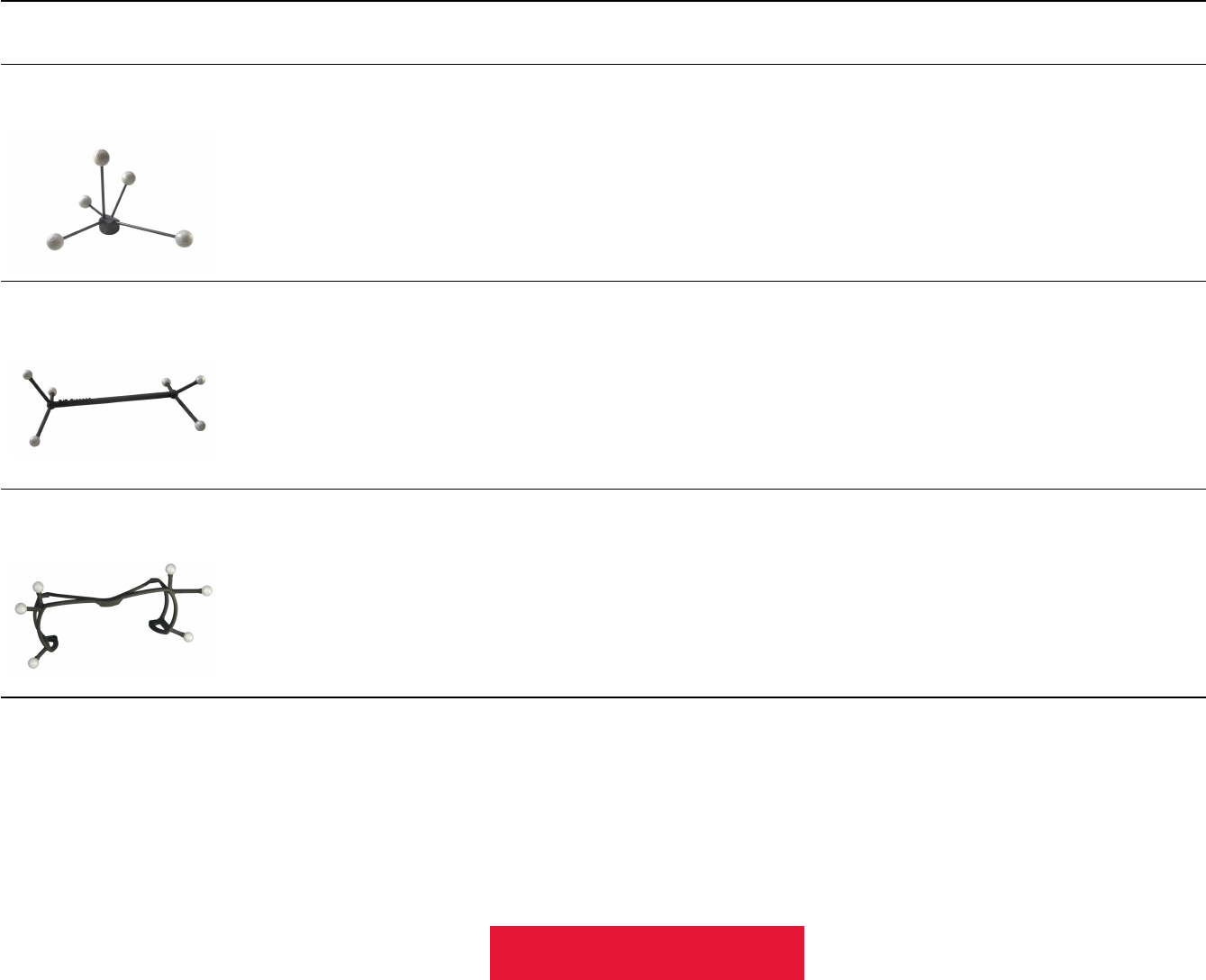
Tree target Originally designed for tracking HMDs, the
tree target is a general-purpose target
for tracking from longer distances. It is
equipped with 20mm markers.
75g / 2.65oz (195 ×170 ×120)mm 20mm
Generic glasses target For head tracking mostly in passive stereo
systems, tracking targets must be fixed to
the stereo glasses. ART offers several
light-weight standard targets for this pur-
pose.
min:
14g / 0.5oz
max:
22g / 0.7oz
(270 ×120 ×35)mm 12mm
INFITEC PREMIUM target Target tailored to the INFITEC PREMIUM
passive stereo glasses.
26g / 0.9oz (225 ×85 ×80)mm 12mm
21
3 Markers and targets (rigid bodies)
Type Description Weight approx. Dimension Marker
size
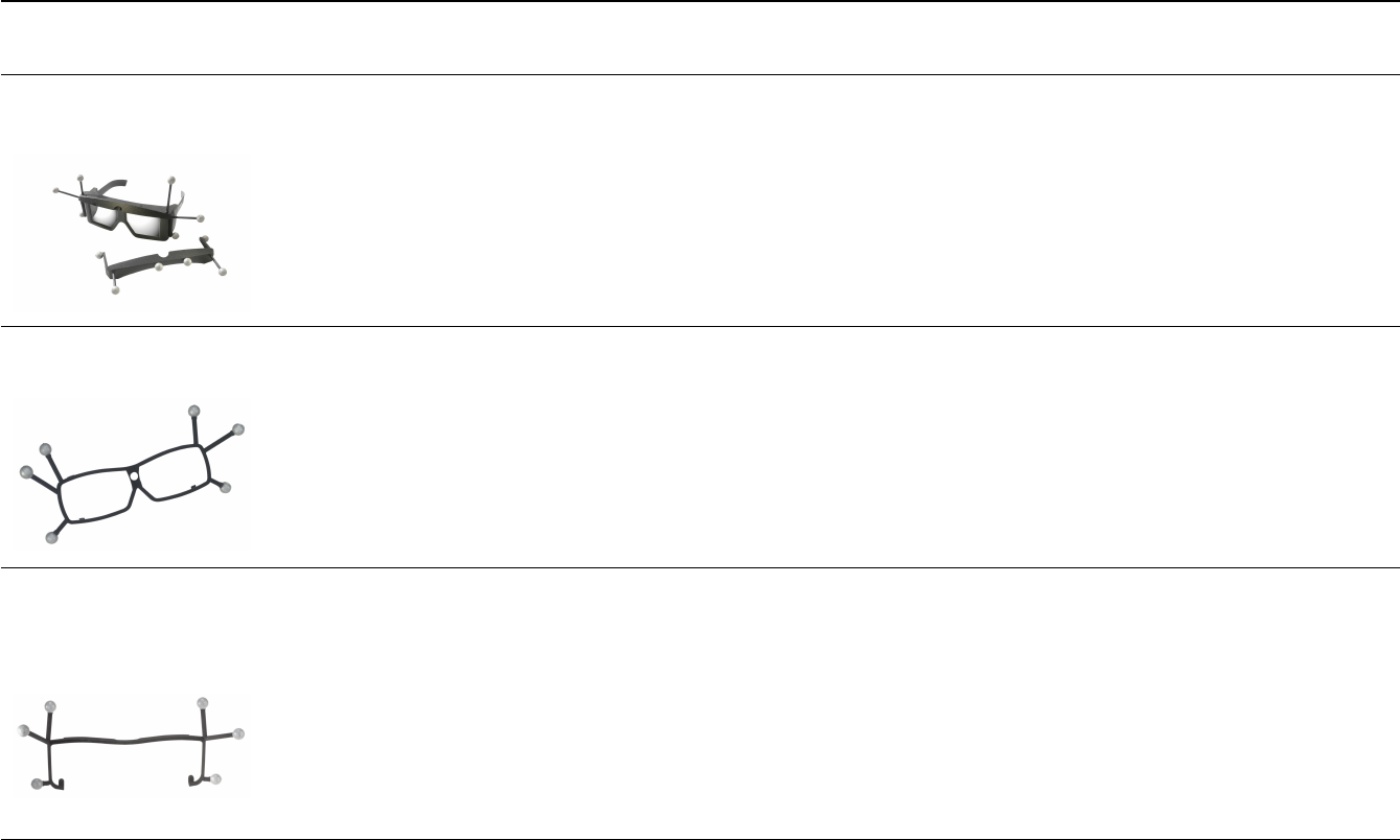
CrystalEyes R
2/3 target Target tailored to the shutter glasses of the
StereoGraphics active stereo system. It fits
to both CrystalEyes R
2 and 3.
28g / 1oz (215 ×120 ×60)mm 12mm
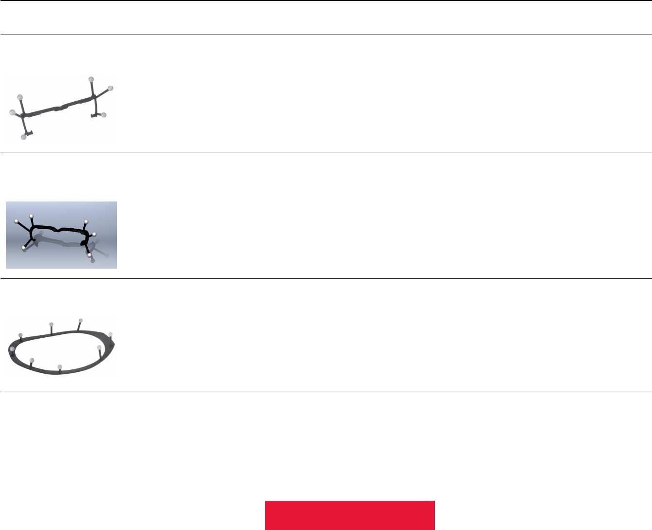
CrystalEyes R
5 target Target tailored to the shutter glasses of the
StereoGraphics active stereo system. It fits
to the CrystalEyes R
5.
19g / 0.7oz (195 ×105 ×40)mm 12mm
NuVision APG6000
and APG6100 target
Target tailored to the NuVision APG6000
and APG6100 shutter glasses.
17g / 0.6 oz (220 ×125 ×75)mm 12mm
22
Chapter 3
3.3 Standard targets
Type Description Weight approx. Dimension Marker
size
Volfoni EDGE R
target Target tailored to the Volfoni EDGE R
shut-
ter glasses.
23g / 0.7 oz (230 ×95 ×60)mm 12mm
NVIDIA 3D Vision R
Pro
target
Target tailored to the NVidia 3D Vision Pro
shutter glasses.
25g / 0.9 oz (225 ×100 ×60)mm 12mm
NVisor SX 60 target Target tailored to the NVisor SX 60 head
mounted display.
55g / 1.94oz (300 ×215 ×35)mm 12mm
23
3 Markers and targets (rigid bodies)
Type Description Weight approx. Dimension Marker
size
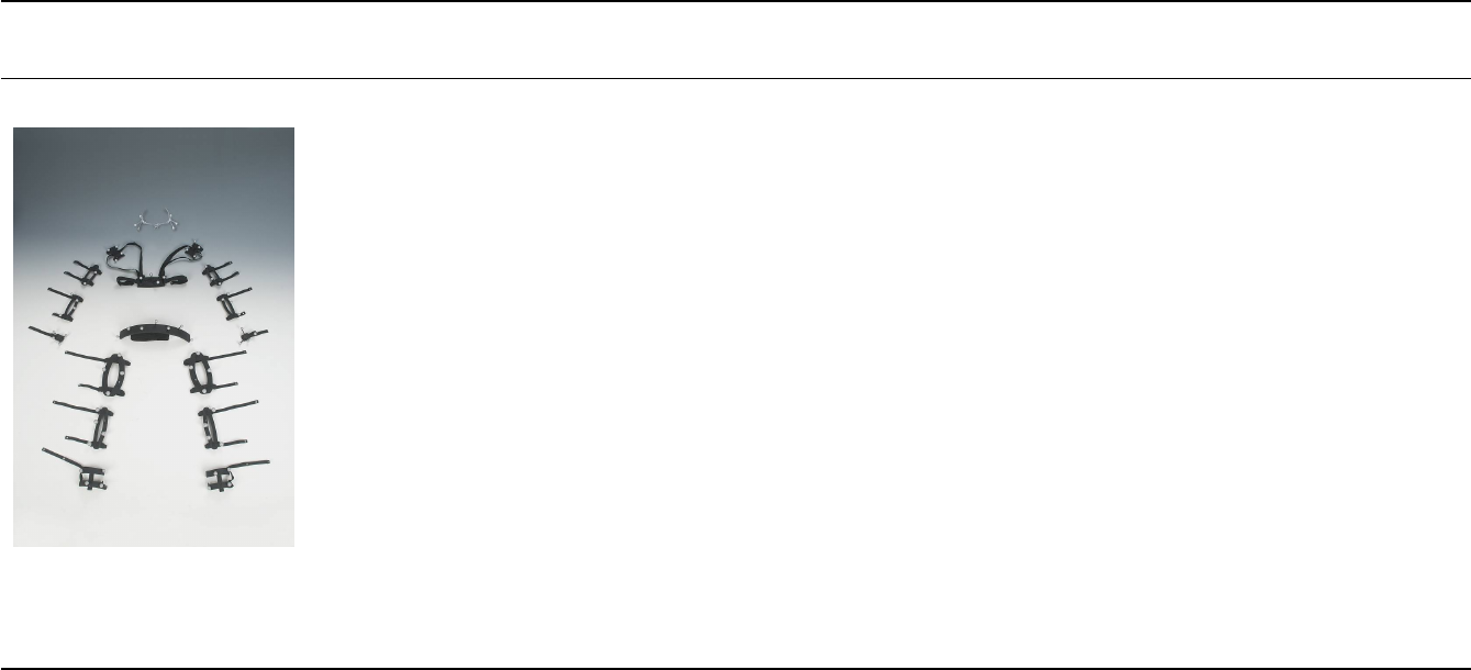
Motion capture targets ART provides a complete set of targets for
motion capture purposes. All targets are
6DOF targets and can be identified by the
tracking system. A full ART MoCap target
set consists of (subsets can be generated):
1 Glasses target (AGT4) 28g / 1.0oz (225 ×180 ×95)mm 12mm
2 Shoulder targets (UT) 44g / 1.55oz (90 ×75 ×35)mm 12mm
1 Dorsal target (DT) 84g / 2.96oz (150 ×65 ×35)mm 12mm
2 Upper arm targets (HBT) 52g / 1.83oz (150 ×70 ×35)mm 12mm
2 Forearm targets (UBT) 50g / 1.76oz (150 ×65 ×35)mm 12mm
2 Hand targets (HT) 25g / 0.9oz (110 ×80 ×28)mm 12mm
1 Waist target (WT, one-piece) 195g / 6.9oz (390 ×140 ×50)mm 14mm
1 Waist target (WT, multi-part), each 30g / 1.1oz (90 ×60 ×50)mm 16mm
2 Upper leg targets (FBT) 99g / 3.49oz (220 ×120 ×40)mm 16mm
2 Lower leg targets (TBT) 58g / 2.05oz (205 ×70 ×35)mm 16mm
2 Foot targets (FT) 65g / 2.29oz (95 ×105 ×70)mm 16mm
Table 3.3: Standard targets overview
24
Chapter 4
4 System setup
4.1 The tracking cameras of ART
4.1.1 ARTTRACK5
Keep a distance of min. 20 cm when operating the camera ! The
camera is assigned to the Exempt Group according to IEC62471-1 and
therefore poses no risk or hazard to the human eye or skin at this dis-
tance.
Description The ARTTRACK5 infrared camera is intended for working environments
with distances between camera and markers of up to 7.5 metres. By default the ART-
TRACK5 is equipped with a 3.5 mm lens. Depending on the application and the setup the
ARTTRACK5 can be equipped with other lenses (i.e. with different focal lengths). Refer
to A.1 on page 190 for a list of available focal lengths and the respective FoV.
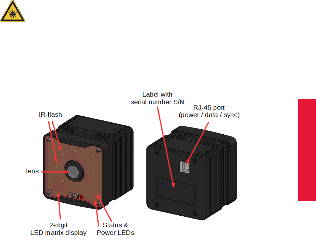
Figure 4.1: Camera ARTTRACK5
Mounting The ARTTRACK5 cameras are optimized for a predefined range of measure-
ment volumes. System operation in smaller or bigger measurement volumes can lead
25
4 System setup
to reduced accuracy or other malfunctions. The measurement volume can be adjusted
within certain limits simply by changing the flash intensity of the ART infrared cameras
(see chapter 4.5.6.3 on page 97).
iThe flash intensities should not be too high. In general, a flash inten-
sity of 50-60 might be sufficient.
Major changes of the measurement volume may require different lenses and thus a new
determination of camera parameters. These changes have to be done at the ART labs.
Be aware that a tracking system is very sensitive to camera movements. Therefore, the
cameras have to be mounted in a way that reduces camera movements (especially vibra-
tions) as much as possible.
iMounting on tripods may be sufficient for presentations and prelimi-
nary installations, but is not recommended as a final solution!
If you want to mount the camera on a tripod there’s no carrier needed.
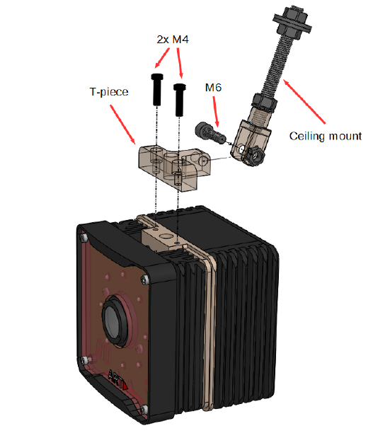
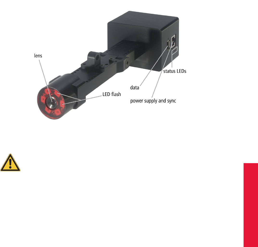
Otherwise the carrier for the ARTTRACK5 can be attached on both bottom and top side
of the camera. Attach the carrier with the T-piece pointing to the back of the camera as
shown in figure 4.2 on page 26. Note, the ceiling suspension is already connected to the
carrier in figure 4.2.
Figure 4.2: Attaching the ceiling mount to the ARTTRACK5 camera
26
Chapter 4
4.1 The tracking cameras of ART
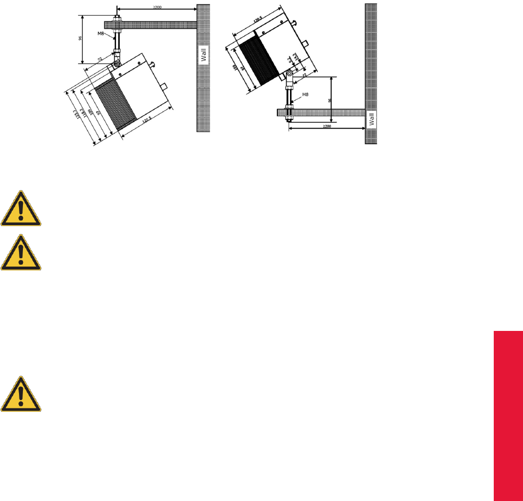
Figure 4.3: Mounting a camera to a wall or a ceiling (e.g. ARTTRACK2 camera)
Only use screws supplied with the ceiling mount for mounting it.
Also, use all the parts supplied with the ceiling mount - especially the
toothed washer is quite important.
You shall never open other screws on the cameras (see chapter 1.2
on page 11). Otherwise, the camera may be damaged and liability and
warranty is void.
Feel free to contact ART in case you want to realise a more complex installation. We will
assist you in your planning.
Make sure to install the system in a way that you can easily access the cameras and
its cables. Be especially careful to mount the cameras firmly so they cannot fall down.
Unsecured cameras may pose a serious hazard to health and safety.
Avoid hard shocks at all times! A new camera calibration at the ART fa-
cilities might become necessary in that case.
Figure 4.3 on page 27 shows the correct mounting for a camera to a wall with a carrier
using the example of an ARTTRACK2 camera. Make sure to not fall below minimal
distance to the wall so enough room is left for the cables and to allow readjustment of the
camera angles and maintenance.
Use strong dowels and screws for mounting the cameras to walls or ceilings (see figure
4.3 on page 27).
If in doubt, ask a skilled craftsman for assistance. Use massive and long enough angle
irons to provide the required stiffness and stability.
To avoid measurement problems, no light sources or highly reflecting areas should be
visible to the camera. Especially strong point light sources like e.g. halogen lamps and
direct or reflected sunlight may imply problems for the measurement (fluorescent lamps
are ok).
Please install the cables such that
•no one can stumble over the cords,
27

4 System setup
•the cords cannot be damaged,
•the cords cannot damage the cameras due to mechanical strain,
•the line of sight of the cameras is not obstructed.
Inappropriate cabling may pose a serious hazard to health and safety.
Cable ducts or fixings should be used and a strain relief should be
installed!
Please refer to chapter 4.2.2 on page 48 for more information.
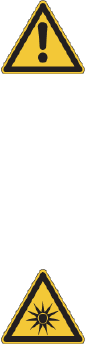
4.1.2 ARTTRACK5/C
Keep a distance of min. 20 cm when operating the camera ! The
camera is assigned to the Exempt Group according to IEC62471-1 and
therefore poses no risk or hazard to the human eye or skin at this dis-
tance.
Description The ARTTRACK5 or TRACKPACK/E system may be combined with the
ARTTRACK5/C camera in order to realize tracking in multi-sided projection environments
(e.g. CAVE R
, I-Space). In such an environment it is necessary to drill holes into the pro-
jections’ corners as the camera cannot see through the screen. The ARTTRACK5/C cam-
era has been designed to easily fit into such holes by separating the lens from the elec-
tronics part (see figure 4.4). With its 4.0 mm lens a large field of view (FoV) is covered.
Refer to A.1 on page 190 for more information.
Figure 4.4: Camera ARTTRACK5/C
The 26-pin D-Sub connector between ARTTRACK5/C remote camera
head and camera body employs proprietary design. Do not try to con-
nect the remote head to any other port (e.g. COM port) !!!
28
Chapter 4
4.1 The tracking cameras of ART
The ARTTRACK5/C system either consists of ARTTRACK5/C cameras only or it can be
mixed with standard ARTTRACK5 or TRACKPACK/E cameras - both variants are limited
to a total number of 50 cameras per system.
Mounting The ARTTRACK5/C cameras are optimized for a predefined range of mea-
surement volumes. System operation in smaller or bigger measurement volumes can lead
to reduced accuracy or other malfunctions. The measurement volume can be adjusted
within certain limits simply by changing the flash intensity of the ART infrared cameras
(see chapter 4.5.6.3 on page 97).
iThe flash intensities should not be too high. In general, a flash inten-
sity of 50-60 might be sufficient.
Major changes of the measurement volume may require different lenses and thus a new
determination of camera parameters. These changes have to be done at the ART labs.
Be aware that a tracking system is very sensitive to camera movements. Therefore, the
cameras have to be mounted in a way that reduces camera movements (especially vibra-
tions) as much as possible.
iMounting on tripods may be sufficient for presentations and prelimi-
nary installations, but is not recommended as a final solution!
If you want to mount the camera on a tripod just mount the carrier on any side of the
camera body and then the remote camera head on the opposite side using a ceiling
mount.
Otherwise the carrier for the ARTTRACK5/C can be attached on all 4 sides of the camera
body. Attach the carrier with the T-piece pointing to the back of the camera in a similar
way to figure 4.2 on page 26. Note, the ceiling suspension is already connected to the
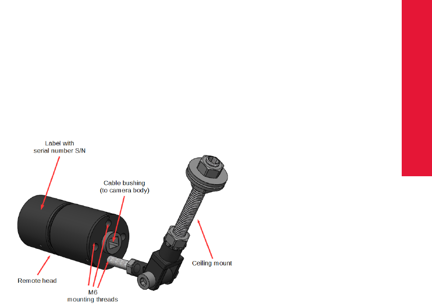
carrier in figure 4.2. The ARTTRACK5/C remote camera head should be installed using
the M6 mounting threads on its back as shown in figure 4.5 on page 29.
Figure 4.5: Camera ARTTRACK5/C remote head (back)
29

4 System setup
ZThe ARTTRACK5/C remote head has to be connected to its corre-
sponding camera body. During mounting please ensure matching se-
rial numbers for both parts !
Only use screws supplied with the ceiling mount for mounting it. Do
not use standard screws for connection of the remote camera head
due to limited space between thread and cable. Also, use all the parts
supplied with the ceiling mount - especially the toothed washer is quite
important.
You shall never open other screws on the cameras (see chapter 1.2
on page 11). Otherwise, the camera may be damaged and liability and
warranty is void.
Feel free to contact ART in case you want to realise a more complex installation. We will
assist you in your planning.
Make sure to install the system in a way that you can easily access the cameras and
its cables. Be especially careful to mount the cameras firmly so they cannot fall down.
Unsecured cameras may pose a serious hazard to health and safety.
Avoid hard shocks at all times! A new camera calibration at the ART fa-
cilities might become necessary in that case.
Figure 4.3 on page 27 shows the correct mounting for a camera to a wall with a carrier
using the example of an ARTTRACK2 camera. Make sure to not fall below minimal
distance to the wall so enough room is left for the cables and to allow readjustment of the
camera angles and maintenance.
Use strong dowels and screws for mounting the cameras to walls or ceilings (see figure
4.3 on page 27).
If in doubt, ask a skilled craftsman for assistance. Use massive and long enough angle
irons to provide the required stiffness and stability.
To avoid measurement problems, no light sources or highly reflecting areas should be
visible to the camera. Especially strong point light sources like e.g. halogen lamps and
direct or reflected sunlight may imply problems for the measurement (fluorescent lamps
are ok).
Please install the cables such that
•no one can stumble over the cords,
•the cords cannot be damaged,
•the cords cannot damage the cameras due to mechanical strain,
•the line of sight of the cameras is not obstructed.
Inappropriate cabling may pose a serious hazard to health and safety.
Cable ducts or fixings should be used and a strain relief should be
installed!
30
Chapter 4
4.1 The tracking cameras of ART
Please refer to chapter 4.2.2 on page 48 for more information.
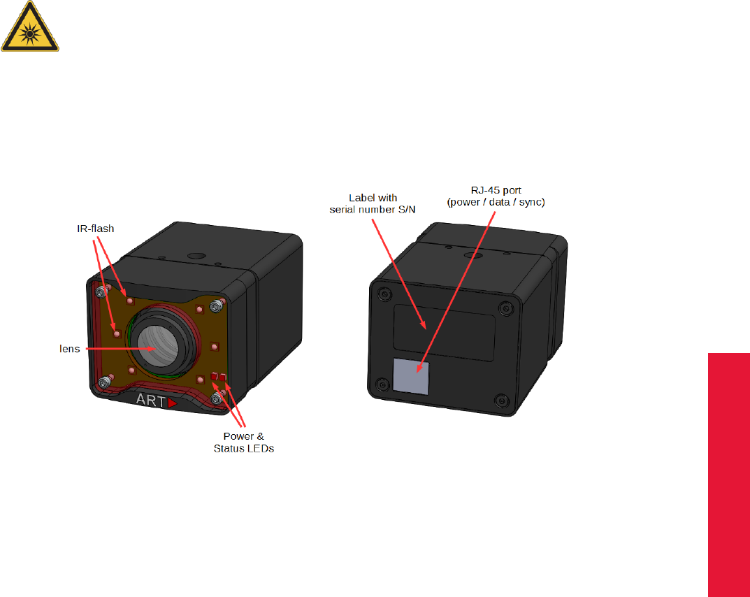
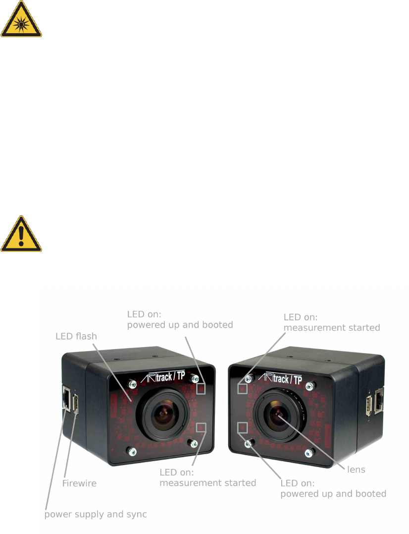
4.1.3 TRACKPACK/E
Keep a distance of min. 20 cm when operating the camera ! The
camera is assigned to the Exempt Group according to IEC62471-1 and
therefore poses no risk or hazard to the human eye or skin at this dis-
tance.
Description The TRACKPACK/E infrared camera is intended for working environments
with distances between camera and markers of up to 4.5 metres. With its 3.5 mm lens a
large field of view (FoV) is covered. Refer to A.1 on page 190 for the respective FoV.
Figure 4.6: Camera TRACKPACK/E
Mounting The TRACKPACK/E cameras are optimized for a predefined range of mea-
surement volumes. System operation in smaller or bigger measurement volumes can lead
to reduced accuracy or other malfunctions. The measurement volume can be adjusted
within certain limits simply by changing the flash intensity of the ART infrared cameras
(see chapter 4.5.6.3 on page 97).
iThe flash intensities should not be too high. In general, a flash inten-
sity of 50-60 might be sufficient.
Major changes of the measurement volume may require different lenses and thus a new
determination of camera parameters. These changes have to be done at the ART labs.
Be aware that a tracking system is very sensitive to camera movements. Therefore, the
cameras have to be mounted in a way that reduces camera movements (especially vibra-
31

4 System setup
tions) as much as possible.
iMounting on tripods may be sufficient for presentations and prelimi-
nary installations, but is not recommended as a final solution!
If you want to mount the camera on a tripod there’s no carrier needed.
Otherwise the carrier for the TRACKPACK/E can be attached on both bottom and top
side of the camera. Attach the carrier with the T-piece pointing to the back of the camera
in a similar way to figure 4.2 on page 26. Note, the ceiling suspension is already con-
nected to the carrier in figure 4.2.
Only use screws supplied with the ceiling mount for mounting it.
Also, use all the parts supplied with the ceiling mount - especially the
toothed washer is quite important.
You shall never open other screws on the cameras (see chapter 1.2
on page 11). Otherwise, the camera may be damaged and liability and
warranty is void.
Feel free to contact ART in case you want to realise a more complex installation. We will
assist you in your planning.
Make sure to install the system in a way that you can easily access the cameras and
its cables. Be especially careful to mount the cameras firmly so they cannot fall down.
Unsecured cameras may pose a serious hazard to health and safety.
Avoid hard shocks at all times! A new camera calibration at the ART fa-
cilities might become necessary in that case.
Figure 4.3 on page 27 shows the correct mounting for a camera to a wall with a carrier
using the example of an ARTTRACK2 camera. Make sure to not fall below minimal
distance to the wall so enough room is left for the cables and to allow readjustment of the
camera angles and maintenance.
Use strong dowels and screws for mounting the cameras to walls or ceilings (see figure
4.3 on page 27).
If in doubt, ask a skilled craftsman for assistance. Use massive and long enough angle
irons to provide the required stiffness and stability.
To avoid measurement problems, no light sources or highly reflecting areas should be
visible to the camera. Especially strong point light sources like e.g. halogen lamps and
direct or reflected sunlight may imply problems for the measurement (fluorescent lamps
are ok).
Please install the cables such that
•no one can stumble over the cords,
•the cords cannot be damaged,
•the cords cannot damage the cameras due to mechanical strain,
32
Chapter 4
4.1 The tracking cameras of ART
•the line of sight of the cameras is not obstructed.
Inappropriate cabling may pose a serious hazard to health and safety.
Cable ducts or fixings should be used and a strain relief should be
installed!
Please refer to chapter 4.2.2 on page 48 for more information.
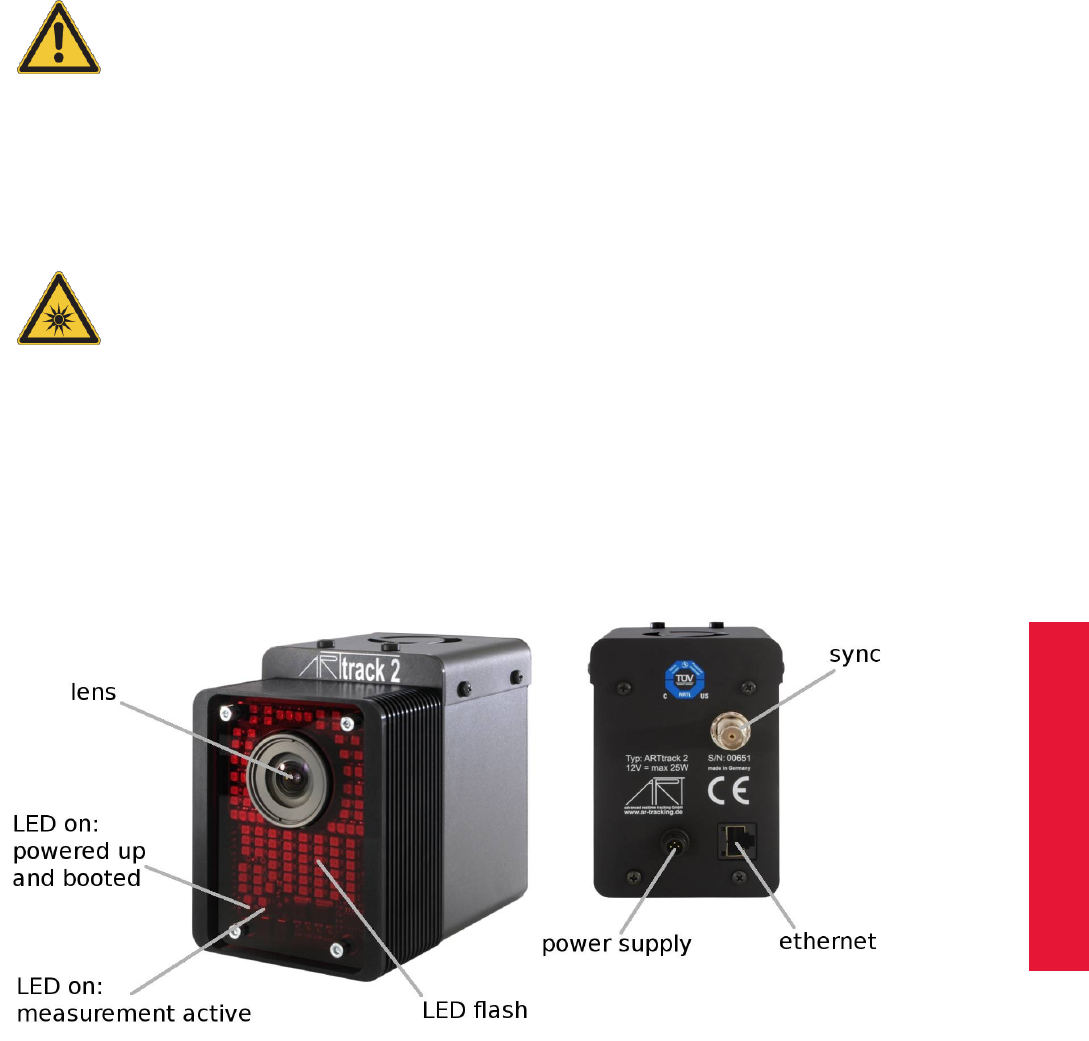
4.1.4 ARTTRACK2 (discontinued)
Keep a distance of min. 20 cm when operating the camera ! The
camera is assigned to the Exempt Group according to IEC62471-1 and
therefore poses no risk or hazard to the human eye or skin at this dis-
tance.
Description The ARTTRACK2 infrared camera is intended for working environments
with distances between camera and markers of up to 4 metres. By default the ART-
TRACK2 is equipped with a 3.5 mm lens. Depending on the application and the setup the
ARTTRACK2 can be equipped with other lenses (i.e. with different focal lengths). Refer
to A.1 on page 190 for a list of available focal lengths and the respective FoV.
Figure 4.7: Camera ARTTRACK2
Mounting The ARTTRACK2 cameras are optimized for a predefined range of measure-
ment volumes. System operation in smaller or bigger measurement volumes can lead
to reduced accuracy or other malfunctions. The measurement volume can be adjusted
within certain limits simply by changing the flash intensity of the ART infrared cameras
33

4 System setup
(see chapter 4.5.6.3 on page 97).
iThe flash intensities should not be too high. In general, a flash inten-
sity of 3-4 might be sufficient.
Major changes of the measurement volume may require different lenses and thus a new
determination of camera parameters. These changes have to be done at the ART labs.
Be aware that a tracking system is very sensitive to camera movements. Therefore, the
cameras have to be mounted in a way that reduces camera movements (especially vibra-
tions) as much as possible.
iMounting on tripods may be sufficient for presentations and prelimi-
nary installations, but is not recommended as a final solution!
If you want to mount the camera on a tripod just mount the carrier on the bottom of the
camera.
Otherwise the carrier for the ARTTRACK2 can be attached on both bottom and top side
of the camera. To attach the carrier remove the screws from the holes 1 and 2 and attach
the carrier with the T-piece pointing to the back of the camera in a similar way to figure 4.2
on page 26. Note, the ceiling suspension is already connected to the carrier in figure 4.2.
Only use screws supplied with the ceiling mount for mounting it. The
screws used for sealing the housings are not sufficiently long for fixing
the carrier. Also, use all the parts supplied with the ceiling mount -
especially the toothed washer is quite important.
You shall never open other screws on the cameras (see chapter 1.2
on page 11). Otherwise, the camera may be damaged and liability and
warranty is void.
Feel free to contact ART in case you want to realise a more complex installation. We will
assist you in your planning.
It is recommended to install the power supply for the cameras in a way that enables the
switching of all cameras by one main switch. If this is done, the system can be easily
turned off and on without changing camera positions.
Make sure to install the system in a way that you can easily access the cameras and
its cables. Be especially careful to mount the cameras firmly so they cannot fall down.
Unsecured cameras may pose a serious hazard to health and safety.
Avoid hard shocks at all times! A new camera calibration at the ART fa-
cilities might become necessary in that case.
Figure 4.3 on page 27 shows the correct mounting for a camera to a wall with a carrier
using the example of an ARTTRACK2 camera. Make sure to not fall below minimal
distance to the wall so enough room is left for the cables and to allow readjustment of the
camera angles and maintenance.
Use strong dowels and screws for mounting the cameras to walls or ceilings (see figure
34

Chapter 4
4.1 The tracking cameras of ART
4.3 on page 27).
If in doubt, ask a skilled craftsman for assistance. Use massive and long enough angle
irons to provide the required stiffness and stability.
To avoid measurement problems, no light sources or highly reflecting areas should be
visible to the camera. Especially strong point light sources like e.g. halogen lamps and
direct or reflected sunlight may imply problems for the measurement (fluorescent lamps
are ok).
Furthermore, please make sure the ventilator holes are not covered. For thermal rea-
sons the ventilator always has to be on the upper side of the ARTTRACK2 camera. That
means, if the camera is to be mounted hanging the carrier must be mounted on top (ven-
tilator side). If it is to be mounted standing the carrier has to be on the bottom side of the
housing.
Please install the cables such that
•no one can stumble over the cords,
•the cords cannot be damaged,
•the cords cannot damage the cameras due to mechanical strain,
•the line of sight of the cameras is not obstructed.
Inappropriate cabling may pose a serious hazard to health and safety.
Cable ducts or fixings should be used and a strain relief should be
installed!
Please refer to chapter 4.2.2 on page 48 for more information.
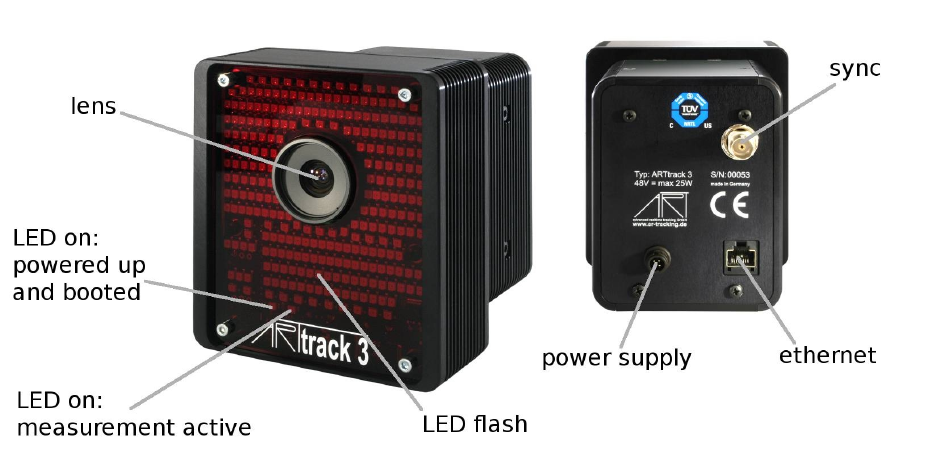
4.1.5 ARTTRACK3 (discontinued)
Keep a distance of min. 20 cm when operating the camera ! The
camera is assigned to the Exempt Group according to IEC62471-1 and
therefore poses no risk or hazard to the human eye or skin at this dis-
tance.
Description The ARTTRACK3 camera is the successor of ARTTRACK1 which is no
longer produced. Due to its larger IR flash it can be used for measurements in higher
distances (up to 6 metres). And, because of its passive cooling system (i.e. without fan),
the ARTTRACK3 is also suitable for dirty or noise sensitive environments.
By default the ARTTRACK5/C is equipped with a 4.5 mm lens. Depending on the ap-
plication and the setup the ARTTRACK3 can be equipped with other lenses (i.e. with
different focal lengths). Refer to A.1 on page 190 for a list of available focal lengths and
the respective FoV.
35
4 System setup
Figure 4.8: Camera ARTTRACK3
Mounting The ARTTRACK3 cameras are optimized for a predefined range of measure-
ment volumes. System operation in smaller or bigger measurement volumes can lead
to reduced accuracy or other malfunctions. The measurement volume can be adjusted
within certain limits simply by changing the flash intensity of the ART infrared cameras
(see chapter 4.5.6.3 on page 97).
iThe flash intensities should not be too high. In general, a flash inten-
sity of 3-4 might be sufficient.
Major changes of the measurement volume may require different lenses and thus a new
determination of camera parameters. These changes have to be done at the ART labs.
Be aware that a tracking system is very sensitive to camera movements. Therefore, the
cameras have to be mounted in a way that reduces camera movements (especially vibra-
tions) as much as possible.
iMounting on tripods may be sufficient for presentations and prelimi-
nary installations, but is not recommended as a final solution!
If you want to mount the camera on a tripod just mount the carrier on the bottom of the
camera.
Otherwise the carrier for the ARTTRACK3 can be attached on both bottom and top side
of the camera. Attach the carrier with the T-piece pointing to the back of the camera in a
similar way to figure 4.2 on page 26. Note, the ceiling suspension is already connected to
the carrier in figure 4.2.
36
Chapter 4
4.1 The tracking cameras of ART
Only use screws supplied with the ceiling mount for mounting it. The
screws used for sealing the housings are not sufficiently long for fixing
the carrier. Also, use all the parts supplied with the ceiling mount -
especially the toothed washer is quite important.
You shall never open other screws on the cameras (see chapter 1.2
on page 11). Otherwise, the camera may be damaged and liability and
warranty is void.
Feel free to contact ART in case you want to realise a more complex installation. We will
assist you in your planning.
It is recommended to install the power supply for the cameras in a way that enables the
switching of all cameras by one main switch. If this is done, the system can be easily
turned off and on without changing camera positions.
Make sure to install the system in a way that you can easily access the cameras and
its cables. Be especially careful to mount the cameras firmly so they cannot fall down.
Unsecured cameras may pose a serious hazard to health and safety.
Avoid hard shocks at all times! A new camera calibration at the ART fa-
cilities might become necessary in that case.
Figure 4.3 on page 27 shows the correct mounting for a camera to a wall with a carrier
using the example of an ARTTRACK2 camera. Make sure to not fall below minimal
distance to the wall so enough room is left for the cables and to allow readjustment of the
camera angles and maintenance.
Use strong dowels and screws for mounting the cameras to walls or ceilings (see figure
4.3 on page 27).
If in doubt, ask a skilled craftsman for assistance. Use massive and long enough angle
irons to provide the required stiffness and stability.
To avoid measurement problems, no light sources or highly reflecting areas should be
visible to the camera. Especially strong point light sources like e.g. halogen lamps and
direct or reflected sunlight may imply problems for the measurement (fluorescent lamps
are ok).
Please install the cables such that
•no one can stumble over the cords,
•the cords cannot be damaged,
•the cords cannot damage the cameras due to mechanical strain,
•the line of sight of the cameras is not obstructed.
Inappropriate cabling may pose a serious hazard to health and safety.
Cable ducts or fixings should be used and a strain relief should be
installed!
37
4 System setup
Please refer to chapter 4.2.2 on page 48 for more information.
4.1.6 TRACKPACK (discontinued)
Keep a distance of min. 20 cm when operating the camera ! The
camera is assigned to the Exempt Group according to IEC62471-1 and
therefore poses no risk or hazard to the human eye or skin at this dis-
tance.
Description The TRACKPACK is a two or four camera infrared optical tracking system
for use in medium-sized working volumes. It is the best solution for Head- and Flystick-
tracking in multi-sided projection environments (max. 3 m x 3 m x 2 m), or in front of
medium-sized projection screens (up to 4.5 m wide). The system consists of two or four
TRACKPACK cameras and a TRACKPACK Controller.
By default the TRACKPACK is equipped with a 3.5 mm lens. Depending on the applica-
tion and the setup the TRACKPACK camera can be equipped with other lenses (i.e. with
different focal lengths). Refer to A.1 on page 190 for a list of available focal lengths and
the respective FoV.
The RJ45 connection between TRACKPACK camera and controller is
used for power supply and synchronization signal. It is not a standard
Ethernet connection! That is why connecting the RJ45 connector to
any other than the equivalent port of the controller may damage the
camera or the connected partner.
Figure 4.9: Camera TRACKPACK
38

Chapter 4
4.1 The tracking cameras of ART
Mounting The TRACKPACK cameras are optimized for a predefined range of measure-
ment volumes. System operation in smaller or bigger measurement volumes can lead
to reduced accuracy or other malfunctions. The measurement volume can be adjusted
within certain limits simply by changing the flash intensity of the ART infrared cameras
(see chapter 4.5.6.3 on page 97).
iThe flash intensities should not be too high. In general, a flash inten-
sity of 3-4 might be sufficient.
Major changes of the measurement volume may require different lenses and thus a new
determination of camera parameters. These changes have to be done at the ART labs.
Be aware that a tracking system is very sensitive to camera movements. Therefore, the
cameras have to be mounted in a way that reduces camera movements (especially vibra-
tions) as much as possible.
iMounting on tripods may be sufficient for presentations and prelimi-
nary installations, but is not recommended as a final solution!
If you want to mount the camera on a tripod just mount the carrier on the bottom of the
camera.
Otherwise the carrier for the TRACKPACK can be attached on both bottom and top side
of the camera. Attach the carrier with the T-piece pointing to the back of the camera in a
similar way to figure 4.2 on page 26. Note, the ceiling suspension is already connected to
the carrier in figure 4.2.
Only use screws supplied with the ceiling mount for mounting it. The
screws used for sealing the housings are not sufficiently long for fixing
the carrier. Also, use all the parts supplied with the ceiling mount -
especially the toothed washer is quite important.
You shall never open other screws on the cameras (see chapter 1.2
on page 11). Otherwise, the camera may be damaged and liability and
warranty is void.
Please keep the distance between the cameras in a range of 1 to 2 metres. Depending
on the lens and the focal length it may be possible to achieve other range values. Please
contact ART for more information.
Make sure to install the system in a way that you can easily access the cameras and
its cables. Be especially careful to mount the cameras firmly so they cannot fall down.
Unsecured cameras may pose a serious hazard to health and safety.
Avoid hard shocks at all times! A new camera calibration at the ART fa-
cilities might become necessary in that case.
Figure 4.3 on page 27 shows the correct mounting for a camera to a wall with a carrier
using the example of an ARTTRACK2 camera. Make sure to not fall below minimal
distance to the wall so enough room is left for the cables and to allow readjustment of the
39
4 System setup
camera angles and maintenance.
Use strong dowels and screws for mounting the cameras to walls or ceilings (see figure
4.3 on page 27).
If in doubt, ask a skilled craftsman for assistance. Use massive and long enough angle
irons to provide the required stiffness and stability.
To avoid measurement problems, no light sources or highly reflecting areas should be
visible to the camera. Especially strong point light sources like e.g. halogen lamps and
direct or reflected sunlight may imply problems for the measurement (fluorescent lamps
are ok).
Please install the cables such that
•no one can stumble over the cords,
•the cords cannot be damaged,
•the cords cannot damage the cameras due to mechanical strain,
•the line of sight of the cameras is not obstructed.
Inappropriate cabling may pose a serious hazard to health and safety.
Cable ducts or fixings should be used and a strain relief should be
installed!
Please refer to chapter 4.2.3 on page 52 for more information.
4.1.7 TRACKPACK/C (discontinued)
Keep a distance of min. 20 cm when operating the camera ! The
camera is assigned to the Exempt Group according to IEC62471-1 and
therefore poses no risk or hazard to the human eye or skin at this dis-
tance.
Description The TRACKPACK system may also be combined with the TRACKPACK/C cam-
era in order to realize tracking in multi-sided projection environments (e.g. CAVE R
, I-
Space). In such an environment it is necessary to drill holes into the projections’ corners
as the camera cannot see through the screen. The TRACKPACK/C camera has been
designed to easily fit into such holes by separating the lens from the electronics part (see
figure 4.10).
With its 3.5 mm lens a large field of view (FoV) is covered. Refer to A.1 on page 190 for
the respective FoV.
The TRACKPACK system either consists of TRACKPACK/C cameras or it can be mixed
with standard TRACKPACK cameras - both variants are limited to a total number of four
cameras per system and come with a TRACKPACK Controller.
40
Chapter 4
4.1 The tracking cameras of ART
Figure 4.10: Camera TRACKPACK/C
The RJ45 connection between TRACKPACK/C camera and controller is
used for power supply and synchronization signal. It is not a standard
Ethernet connection! That is why connecting the RJ45 connector to
any other than the equivalent port of the controller may damage the
camera or the connected partner.
Mounting The TRACKPACK/C cameras are optimized for a predefined range of mea-
surement volumes. System operation in smaller or bigger measurement volumes can lead
to reduced accuracy or other malfunctions. The measurement volume can be adjusted
within certain limits simply by changing the flash intensity of the ART infrared cameras
(see chapter 4.5.6.3 on page 97).
iThe flash intensities should not be too high. In general, a flash inten-
sity of 3-4 might be sufficient.
Major changes of the measurement volume may require different lenses and thus a new
determination of camera parameters. These changes have to be done at the ART labs.
Be aware that a tracking system is very sensitive to camera movements. Therefore, the
cameras have to be mounted in a way that reduces camera movements (especially vibra-
tions) as much as possible.
iMounting on tripods may be sufficient for presentations and prelimi-
nary installations, but is not recommended as a final solution!
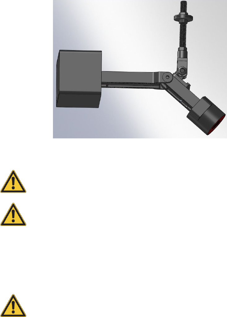
Otherwise the carrier for the TRACKPACK/C can be attached to the camera as shown in
41
4 System setup
figure 4.11.
Figure 4.11: Camera TRACKPACK/C with attached carrier
Only use screws supplied with the ceiling mount for mounting it. The
screws used for sealing the housings are not sufficiently long for fixing
the carrier. Also, use all the parts supplied with the ceiling mount -
especially the toothed washer is quite important.
You shall never open other screws on the cameras (see chapter 1.2
on page 11). Otherwise, the camera may be damaged and liability and
warranty is void.
Please keep the distance between the cameras in a range of 2 to 3 metres. Please con-
tact ART for more information.
Make sure to install the system in a way that you can easily access the cameras and
its cables. Be especially careful to mount the cameras firmly so they cannot fall down.
Unsecured cameras may pose a serious hazard to health and safety.
Avoid hard shocks at all times! A new camera calibration at the ART fa-
cilities might become necessary in that case.
Use strong dowels and screws for mounting the cameras to walls or ceilings (see figure
4.3 on page 27).
If in doubt, ask a skilled craftsman for assistance. Use massive and long enough angle
irons to provide the required stiffness and stability.
To avoid measurement problems, no light sources or highly reflecting areas should be
visible to the camera. Especially strong point light sources like e.g. halogen lamps and
direct or reflected sunlight may imply problems for the measurement (fluorescent lamps
42

Chapter 4
4.2 The Controllers of ART
are ok).
Please install the cables such that
•no one can stumble over the cords,
•the cords cannot be damaged,
•the cords cannot damage the cameras due to mechanical strain,
•the line of sight of the cameras is not obstructed.
Inappropriate cabling may pose a serious hazard to health and safety.
Cable ducts or fixings should be used and a strain relief should be
installed!
Please refer to chapter 4.2.3 on page 52 for more information.
4.2 The Controllers of ART
With the introduction of DTrack2 a new principle of controlling the tracking system is im-
plemented. The tracking system itself consists of cameras, interaction devices (optional),
targets and the ART Controller, the ARTTRACK Controller (discontinued) or TRACK-
PACK Controller (discontinued) respectively.
The software DTrack2 consists of frontend and backend software. The frontend software
is installed on a remote PC which is connected to the controller via Ethernet. A GUI for
easy handling enables the user to control the tracking system completely from the remote
PC. The benefit is that the system becomes more flexible, i.e. different users can con-
trol the tracking system at any one time (but not simultaneously!) from different working
places.
Furthermore, DTrack2 provides the possibility to control its functions via Ethernet (i.e.
without the DTrack2 frontend software). This is done by establishing a TCP/IP connec-
tion with the controller and exchanging short command strings (refer to chapter 4.2.8 on
page 58). Please contact ART if you are interested in using this feature.
The backend software runs on the controller - all necessary calculations (3DOF, 6DOF
data, ...) are done by the controller. The data and control commands are interchanged
via a TCP/IP connection between the controller and the DTrack2 frontend software on the
remote PC. Data output to the application or graphics workstation is done via a UDP con-
nection. The cameras (refer to chapter 4.1 on page 25) and the interaction devices (refer
to chapter 5 on page 126) have to be connected to the respective ports of the controller.
43

4 System setup
ART
Controller
ARTTRACK
Controller
TRACKPACK
Controller
DTrack2 1
ARTTRACK1 × × ×
ARTTRACK2 × × ×
ARTTRACK3 × × ×
ARTTRACK5 × × (from v2.10)
ARTTRACK5/C × × (from v2.11)
TRACKPACK × ×
TRACKPACK/C × × (from v2.5)
TRACKPACK/E × × (from v2.11)
Flystick1 × × × ×
Flystick2 × × × ×
Flystick3 × × × × (from v2.2)
Fingertracking 2× × × ×
Measurement Tool × × × × (from v2.2)
1an appropriate license may be necessary (refer to table 4.3)
2for Fingertracking it is recommended to use six cameras for ideal operation
Table 4.1: Compatibility of the ART cameras and interaction devices
4.2.1 Installation of the ART Controller (DTrack2 since v2.10)
The ART Controller (DTrack2 since v2.10) comes in a 19" inch housing compatible for
rack mounting, see fig. 4.12 on page 44.
To turn on the controller flip the power switch to I, for restart from standby mode press
the button "soft power on". The USB ports can be used for plugging in the USB radio
transceiver for the Flystick2/3 (refer to chapter 5.1 on page 128 or chapter 5.2 on page
134).
ZPlease ensure unblocked airflow at all times for optimal operation of
the ART Controller !
Figure 4.12: ART Controller front view
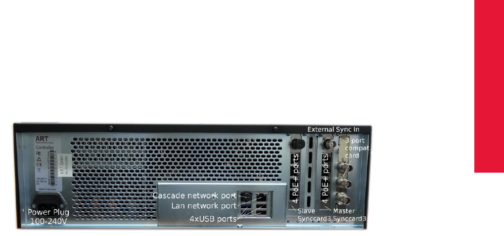
The following list introduces the ports of the ART Controller (see fig. 4.13 on 45):
•ART Synccard3 (master & slave) :
44
Chapter 4
4.2 The Controllers of ART
–ExtIn:
Please plug in the external source (TTL or video signal) for synchronization
here. Please use the accessible port without protective cap only. In cascaded
systems please connect the external source to the master controller only. The
slave controller is then synchronized by the master.
–PoE+ ports:
All ARTTRACK1 ,ARTTRACK2 ,ARTTRACK3 ,ARTTRACK5 ,ARTTRACK5/C
and TRACKPACK/E cameras have to be plugged in here. In larger systems (>
8ARTTRACK5 and ARTTRACK5/C cameras only), please connect the exter-
nal PoE+ switch to any of these ports.
–OUT1-3 (optional):
For cascaded systems please connect OUT1 to ExtIn of a slave controller (see
chapter 4.3 on page 58). For backwards compatibility, please connect ART-
TRACK1 –ARTTRACK3 cameras here. Please refer to chapter 4.2.2 on page
48 for more detailed information.
∗OUT1:
Defines syncgroup # 1. The three different syncgroups are characterized
by their time delay related to syncgroup # 1. When using ARTTRACK1 –
ARTTRACK3 cameras at least one camera has to be connected here if you
are using active targets (e.g. Fingertracking, Flystick3). Refer to chapter
5.3 on page 137 for more information.
∗OUT2:
Defines syncgroup # 2. The default time delay related to syncgroup # 1 is
480µs.
∗OUT3:
Defines syncgroup # 3. The default time delay related to syncgroup # 1 is
960µs.
Figure 4.13: ART Controller back view
•USB port:
Please plug in the USB radio transceiver for the Flystick2/3 here (refer to chapter
5.1 on page 128 or chapter 5.2 on page 134).
45
4 System setup
•LAN network port:
Please connect the ART Controller to your local network using an RJ45 cable.
•Cascaded network port:
For cascaded systems please connect a slave controller to the ART Controller (mas-
ter). Please refer to chapter 4.3 on page 58 for more detailed information.
•Power inlet:
Please connect to mains (100 - 240V).
iThe power inlet is fuse-protected (2x4A, anti-surge type T) and features
a line filter for EMV protection.
IP addresses are predefined in ARTTRACK and TRACKPACK/E cameras - changes by
the user are not possible!
i
The camera network ports are configured using:
•IP address: 172.28.0.X
•subnet mask: 255.255.0.0
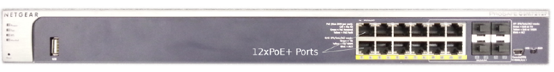
In larger systems (> 8 ARTTRACK5 and ARTTRACK5/C cameras only), please use the
Netgear Prosafe GSM7212P PoE+ switch authorized by ART . It features 12 PoE+ Ports
for connection to ARTTRACK5 and ARTTRACK5/C cameras. Please use the accessible
ports without protective caps only (see fig. 4.14 on page 46). To turn on the PoE+ switch,
please connect it to mains.
ZPlease allow min. 3 minutes for booting prior to starting the ART Con-
troller !
Figure 4.14: ART PoE+ switch front view
Mount the cameras at the desired position before connecting the cables.
The ARTTRACK5 ,ARTTRACK5/C and TRACKPACK/E cameras have to be connected
via twisted pair cables (min. Cat.5, max. length 100 m) to the internal ART Synccard3
of the ART Controller or to an external PoE+ switch for systems > 8 cameras (only ART-
TRACK5 and ARTTRACK5/C ). The external PoE+ switch itself has to be connected to
the Synccard3.
The ART Synccard3 is designed as a single cable solution and is therefore used both for
power and synchronization of the IR cameras.
Connection of ARTTRACK1 ,ARTTRACK2 or ARTTRACK3 cameras (backwards
compatible systems) When connecting the synchronization cables it is important to
46

Chapter 4
4.2 The Controllers of ART
correctly chain the cameras on the sync cable (see chapter 6.4 on page 150). There
must be one continuous signal line from the BNC connector of the synccard to the 75Ω
terminating resistor, with the cameras inserted to the line by T-junctions. It is neither al-
lowed to extend the connection between the T-piece and the camera, nor to branch the
signal line.
Usually, all cameras are connected with the sync output no. 1 ("OUT1") of the synccard
like a chain that is finished by a 75Ωterminating resistor. If the cameras have to be
grouped into different syncgroups, in order to avoid blinding, two or three BNC chains
are used at the sync outputs no. 1 and 2 or 1, 2 and 3, respectively, of the synccard3.
The settings are defined by software DTrack2 . All sync signals are transferred via BNC
connections.
Z
ARTTRACK2 and ARTTRACK3 cameras have to be connected via any
external Ethernet switch or the ART PoE+ switch and may not be con-
nected directly to the PoE+ ports of the ART Synccard3. Please refer
to chapter 4.2.2 on page 48 for more detailed information.
Furthermore, the controller uses the "LAN" ethernet plug (1000 Base-TX) for data output
to the remote PC or to any PC within the local network. Figure 4.15 on page 50 shows
two possibilities of connecting the controller to a local network. You may either use the
controller as a DHCP client within your network (figure 4.15(a)), i.e. the tracking data is
transmitted directly via your local network. Or, if due to your company security guidelines
it is not allowed to connect the controller directly to your network, you may install two
network cards in your remote PC - one is connected to the controller and the other one is
connected to your local network (figure 4.15(b)). In this case, the DTrack2 Frontend will
act as a router for the tracking data.
The controller is controlled by a remote PC via DTrack2 frontend software. When deliv-
ered, the controller is set up to support DHCP. Therefore, it will acquire an IP address
automatically given that a DHCP server is running.
Double-check if the cameras are connected properly to the controller and verify that the
cameras are running. Connect the Ethernet cable to your local network and connect the
power plug of the ART Controller to a power socket. If you want to set a specific static IP
address before booting the controller please refer to chapter 4.2.4 on page 54 for more
information.
Press the power switch on the front of the controller. If the controller is booting without
connected Ethernet cable it will use its fall-back IP address.
iThe fall-back IP address of the controller is 192.168.0.1 (subnet mask
255.255.255.0)!
You may configure another static IP address as follows:
•select Settings →Controller
•untick the checkbox DHCP client
•enter IP address and subnet mask
47

4 System setup
•optionally, enter gateway and nameserver
•reboot the controller for the changes to take effect
Z
Please note that these settings are not part of your personal configura-
tion. Changes in this menu will affect all users of your controller! Your
controller may become unreachable with wrong IP settings! Refer to
chapter 4.2.4 on page 54).
Finally, start the DTrack2 frontend software on the remote PC. Please refer to chapter 4.5
on page 70 for more details.
External synchronization An ART Controller can be synchronized with an external
source. On the back of the controller there is a BNC plug ("ExtIn") which serves as input
for the external synchronization signal. The sync signal may be of type TTL or video (see
also chapter 4.5.6.3 on page 101).
Typically, external synchronization has to be used when other systems inside the tracking
system are also using infrared signals for controlling their equipment (e.g. if IR-controlled
shutter glasses are used). The goal is to reduce or eliminate interference. The ART track-
ing system follows the external synchronization signal and chooses time slots when it is
safe to emit infrared radiation without causing interference. The effect is, for example, that
active shutter glasses are not flickering but offer a stable picture for the user.
Z
The external sync input is not internally terminated.
When synchronizing with a video input, a T-piece with an external 75
Ωterminating resistor should be used if the signal line ends at the
controller.
When using a TTL-signal you should not use a terminating resistor.
However, you should use a shielded cable for the synchronization with
a TTL-signal.
4.2.2 Installation of the ARTTRACK Controller (discontinued)
The following list introduces the ports of the ARTTRACK Controller with Synccard2:
•internal Ethernet switch:
the cameras have to be plugged in here. In larger systems, please connect the
external switch to any of these ports.
•external Ethernet switch:
the Allied Telesis AT-FS708 is an eco friendly switch which is designed to minimize
power consumption (typical 3.5W) through the use of a high efficiency power supply
and a low power chipset. It features an overnight mode (i.e. reduction in power
during after-work hours) as well as other power saving features.
Please refer to the Allied Telesis Installation Guide before connecting the power
source.
•ART Synccard2 :
48

Chapter 4
4.2 The Controllers of ART
–ExtIn:
Please plug in the external source for synchronization here.
–Out1:
Defines syncgroup # 1. The three different syncgroups are characterized by
their time delay related to syncgroup # 1. At least one camera has to be con-
nected here if you are using active targets (e.g. Fingertracking, Flystick3).
Refer to chapter 5.3 on page 137 for more information.
–Out2:
Defines syncgroup # 2. The time delay related to syncgroup # 1 is 480µs.
–Out3:
Defines syncgroup # 3. The time delay related to syncgroup # 1 is 960µs.
•USB port:
Please plug in the USB radio transceiver for the Flystick2/3 here (refer to chapter
5.1 on page 128 or chapter 5.2 on page 134).
•Ethernet port:
Please connect the controller to your local network using an RJ45 cable.
Mount the cameras at the desired position before connecting the cables. The ART-
TRACK cameras have to be connected via twisted pair cables either to the internal Eth-
ernet switch of the controller or to an external Ethernet switch. The external switch itself
has to be connected to the controller.
iOlder switches sometimes do have uplink ports which are not suitable
for connecting to the camera. Only use the normal ports of the switch.
The controller is equipped with an internal switch (100 Base-TX) which serves for the
connection to the cameras (suitable for small systems, i.e. ≤4 cameras). Larger systems
(i.e. >4 cameras) have to be equipped with an external switch which must be connected
to any port (except for the uplink port) of the internal switch of the controller.
i
The camera network is configured using:
•IP address: 172.28.0.1
•subnet mask: 255.255.0.0
IP addresses are predefined in ARTTRACK cameras - changes by the user are not pos-
sible!
The controller is equipped with a PCI card for synchronization of the IR cameras (ART Sync-
card2). When connecting the synchronization cables it is important to correctly chain the
cameras on the sync cable (see chapter 6.4 on page 150). There must be one continuous
signal line from the BNC connector of the synccard to the 75Ωterminating resistor, with
the cameras inserted to the line by T-junctions. It is neither allowed to extend the connec-
tion between the T-piece and the camera, nor to branch the signal line.
49
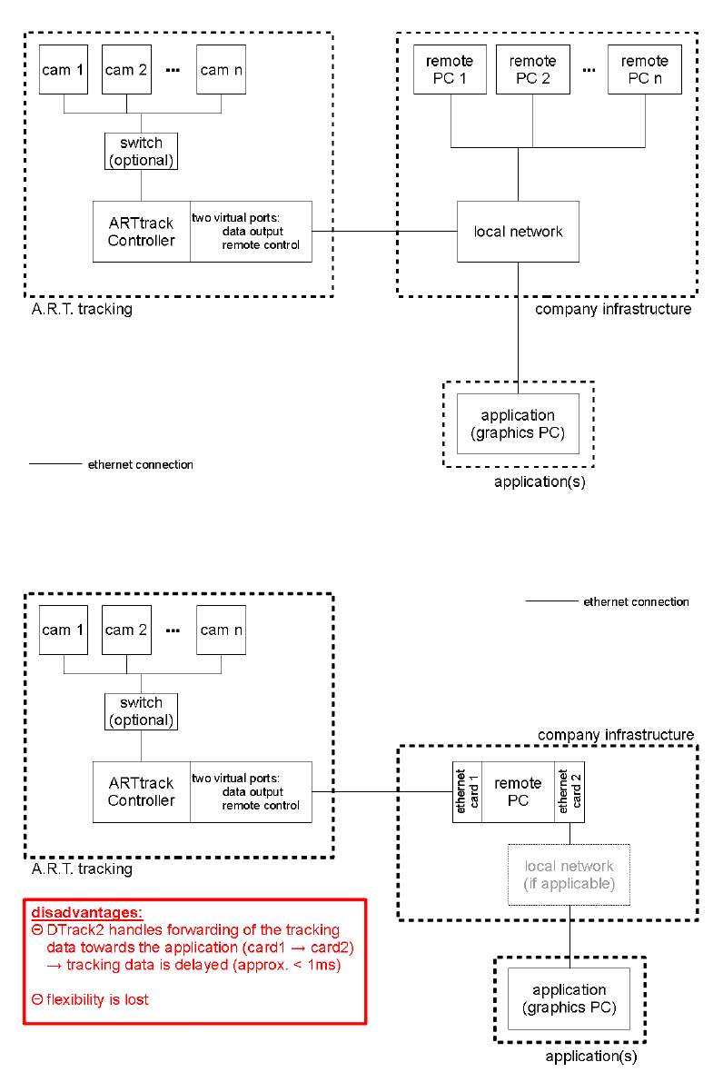
4 System setup
(a) standard connection
(b) indirect connection
Figure 4.15: Connecting the ARTTRACK Controller to a local network
50

Chapter 4
4.2 The Controllers of ART
Usually, all cameras are connected with the sync output no. 1 ("OUT1") of the synccard
like a chain that is finished by a 75Ωterminating resistor. If the cameras have to be
grouped into different syncgroups, in order to avoid blinding, two or three BNC chains are
used at the sync outputs no. 1 and 2 or 1, 2 and 3, respectively, of the synccard. The set-
tings of the Synccard2 are defined by software DTrack2 . All sync signals are transferred
via BNC connections.
Furthermore, the controller uses the single Ethernet plug (100 Base-TX) for data output
to the remote PC or to any PC within the local network. Figure 4.15 on page 50 shows
two possibilities of connecting the controller to a local network. You may either use the
controller as a DHCP client within your network (figure 4.15(a)), i.e. the tracking data is
transmitted directly via your local network. Or, if due to your company security guidelines
it is not allowed to connect the controller directly to your network, you may install two
network cards in your remote PC - one is connected to the controller and the other one is
connected to your local network (figure 4.15(b)). In this case, the DTrack2 Frontend will
act as a router for the tracking data.
The controller is controlled by a remote PC via DTrack2 frontend software. When deliv-
ered, the controller is set up to support DHCP. Therefore, it will acquire an IP address
automatically given that a DHCP server is running.
Double-check if the cameras are connected properly to the controller. Verify that power
supplies are switched on and the cameras are running. Connect the Ethernet cable to
your local network and connect the power plug of the ARTTRACK Controller to a power
socket. If you want to set a specific static IP address before booting the controller please
refer to chapter 4.2.4 on page 54 for more information.
Press the switch next to the power plug to start the controller. If the controller is booting
without connected Ethernet cable it will use its fall-back IP address.
iThe fall-back IP address of the controller is 192.168.0.1 (subnet mask
255.255.255.0)!
You may configure another static IP address as follows:
•select Settings →Controller
•untick the checkbox DHCP client
•enter IP address and subnet mask
•optionally, enter gateway and nameserver
•reboot the controller for the changes to take effect
Z
Please note that these settings are not part of your personal configura-
tion. Changes in this menu will affect all users of your controller! Your
controller may become unreachable with wrong IP settings! Refer to
chapter 4.2.4 on page 54).
51

4 System setup
Finally, start the DTrack2 frontend software on the remote PC. Please refer to chapter 4.5
on page 70 for more details.
External synchronization Any ARTTRACK system controller can be synchronized with
an external source. On the back of the controller there is a BNC plug ("ExtIn") which
serves as input for the external synchronization signal. The sync signal may be of type
TTL or video (see also chapter 4.5.6.3 on page 101).
Typically, external synchronization has to be used when other systems inside the tracking
system are also using infrared signals for controlling their equipment (e.g. if IR-controlled
shutter glasses are used). The goal is to reduce or eliminate interference. The ART track-
ing system follows the external synchronization signal and chooses time slots when it is
safe to emit infrared radiation without causing interference. The effect is, for example, that
active shutter glasses are not flickering but offer a stable picture for the user.
Z
The external sync input is not internally terminated.
When synchronizing with a video input, a T-piece with an external 75
Ωterminating resistor should be used if the signal line ends at the
controller.
When using a TTL-signal you should not use a terminating resistor.
However, you should use a shielded cable for the synchronization with
a TTL-signal.
4.2.3 Installation of the TRACKPACK Controller (discontinued)
The following list introduces the ports of the TRACKPACK Controller:
•ART SynccardTP :
The syncgroups for TRACKPACK systems can be configured in the DTrack2 fron-
tend software. Please refer to chapter 4.5.6.3 on page 97.
–ExtIn:
Please plug in the external source for synchronization here.
–Output:
The cameras have to be plugged in to the RJ45 connectors. Synchronization
and power is supplied with this connection.
•Firewire:
Please connect the TRACKPACK cameras with the controller using the delivered
Firewire cables.
•USB port:
Please plug in the USB radio transceiver for the Flystick2/3 here (refer to chapter
5.1 on page 128 or chapter 5.2 on page 134).
•Ethernet port:
Please connect the controller to your local network using an RJ45 cable.
52

Chapter 4
4.2 The Controllers of ART
For connecting the TRACKPACK controller to your local network, please refer to figure
4.15 on page 50. You may either use the controller as a DHCP client within your network
(figure 4.15(a)), i.e. the tracking data is transmitted directly via your local network. If, due
to your company security guidelines, it is not allowed to connect the controller directly to
your network, you may install two network cards in your remote PC - one is connected to
the controller and the other one is connected to your local network (figure 4.15(b)). In that
case, the DTrack2 Frontend will act as a router for the tracking data.
The controller is controlled by a remote PC via DTrack2 frontend software. When deliv-
ered, the controller is set up to support DHCP. Connect the Ethernet cable to your local
network and connect the power plug to a power socket. If you want to set a specific static
IP address before booting the controller please refer to chapter 4.2.4 on page 54 for more
information.
Press the switch next to the power plug to start the controller. If the controller is booting
without connected Ethernet cable it will use its standard IP address.
iThe fall-back IP address of the controller is 192.168.0.1 (subnet mask
255.255.255.0)!
You may configure another static IP address as follows:
•select Settings →Controller
•untick the checkbox DHCP client
•enter IP address and subnet mask
•optionally, enter gateway and nameserver
•reboot the controller for the changes to take effect
Z
Please note that these settings are not part of your personal configura-
tion. Changes in this menu will affect all users of your controller! Your
controller may become unreachable with wrong IP settings! Refer to
chapter 4.2.4 on page 54).
Finally, start the DTrack2 frontend software on the remote PC. Please refer to chapter 4.5
on page 70 for more details.
External synchronization The TRACKPACK system and therefore the TRACKPACK con-
troller can be synchronized with an external source. On the back of the controller there is
a BNC plug ("ExtIn") which serves as input for the external synchronization signal. The
sync signal may be of type TTL or video (see also chapter 4.5.6.3 on pag 101).
Typically, external synchronization has to be used when other systems inside the tracking
system are also using infrared signals for controlling their equipment (e.g. if IR-controlled
shutter glasses are used). The goal is to reduce or eliminate interference. The TRACK-
PACK tracking system follows the external synchronization signal and chooses time slots
when it is safe to emit infrared radiation without causing interference. The effect is, for ex-
ample, that active shutter glasses are not flickering but offer a stable picture for the user.
53
4 System setup
Z
The external sync input is not internally terminated.
When synchronizing with a video input, a T-piece with an external 75Ω
terminating resistor should be used if the signal line ends at the con-
troller.
When using a TTL-signal you should not use a terminating resistor.
However, you should use a shielded cable for the synchronization with
a TTL-signal.
Be aware of the following specialty of the TrackPack system:
The TRACKPACK cameras get power supply and sync via the RJ45
cable!
Therefore, the status of the synchronization is indicated with two LEDs (orange and green)
located on the synccard of the controller. Depending on the operating condition of the
ART tracking system the LEDs are triggered respectively. Table 4.2 shows how the LEDs
are triggered according to the type of synchronization.
two LEDs (on each port of the camera network card)
↓ ↓
orange green
↓ ↓ ↓ ↓
ON OFF ON OFF
↓ ↓ ↓ ↓ ↓
flashing permanently
lit
measurement
inactive
controller
switched ON
controller
switched OFF
↓ ↓
master (sync
source)
slave (sync
drain)
Status
Table 4.2: Description of the LEDs on the back of the TRACKPACK Controller
4.2.4 Setting a static IP address without the DTrack2 Frontend
(available from controller software version v2.2)
It is possible to configure the IP address of the controller without the DTrack2 frontend
software. You only need a standard USB stick (FAT32 formatted) on which you save a
setup file (format see below).
•Plug in the USB stick to the controller. It doesn’t matter if the controller is running or
not.
•If necessary start up the controller.
•Wait some time (approx. 20-30 seconds, until announced by two beeps) for the
controller to write the two files onto the USB stick.
54

Chapter 4
4.2 The Controllers of ART
•Unplug the USB stick.
•Now, you may view the information file or edit the setup file with any editor (instruc-
tions given in the setup file).
•In case you changed the setup file, please plug in the USB stick to the controller
again.
•Wait some time (approx. 20-30 seconds, until announced by three beeps) for the
controller to read the setup file.
•Reboot the controller for the changes to take effect.
Now, your controller is configured according to your requirements.
4.2.5 The setup file
This file is used to configure the controller without using the DTrack2 frontend software
regarding three parameters, which are:
•configuring the controller to be a DHCP client,
•setting a static IP address and
•carrying out a factory reset.
Carrying out a factory reset will result in the loss of all your settings!
Following, a description of the file (e.g. ARTtrackController00117_setup.txt) format:
1# ARTtrack Controller Setup:
2
3
4# ethernet settings:
5# - uncomment just one of the lines starting with ’SETNET’
6
7# ethernet settings: DHCP
8# - uncomment the following line to activate DHCP
9#SETNET="dhcp"
10
11# ethernet settings: fix IP address and subnet mask
12# - uncomment the following line to set a fix IP address and subnet mask
13#SETNET="ip 192.168.0.1 255.255.255.0"
14
15# name settings: host name
16# - uncomment the following line to set the host name
55
4 System setup
17#SETHOSTNAME="atc"
18
19# name settings: domain name
20# - uncomment the following line to set the domain name
21#SETDOMAINNAME="art.site"
22
23# name settings: domain name server
24# - uncomment one of the following lines to set (or clear) a domain name server
25#SETNAMESERVER="192.168.0.254" # set DNS (IP or hostname)
26#SETNAMESERVER="-" # clear DNS
27
28# factory reset of all other settings:
29# - CAUTION: use with care, all your settings will be lost!
30# - uncomment the following line to reset all other Controller settings
31#RESETSETTINGS="yes"
Example:
If you wanted to setup a static IP you would have to remove the ’#’ sign and enter the
desired IP address, here for example: 123.123.0.1
before:
13#SETNET="ip 192.168.0.1 255.255.255.0"
after:
13 SETNET="ip 123.123.0.1 255.255.255.0"
4.2.6 The information file
This file contains the current settings of the controller. Following, a description of the file
format (e.g. ARTtrackController00150_info.txt):
ARTtrack Controller Information:
Name : atc-150
Serial Number : 00150
Ethernet (LAN) : dhcp
Ethernet IP (LAN) : 10.10.5.22 255.255.0.0 10.10.0.253
Ethernet MAC (LAN): 00:24:1D:00:C3:B3
Domain Name Server:
4.2.7 Wake On LAN
The controller is capable of Wake On LAN (WOL) if it has been forced into standby mode
before by the user (DTrack2 →Controller standby).
56
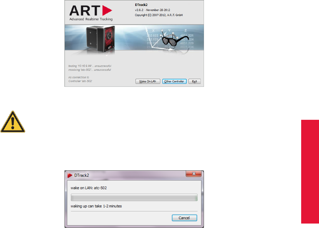
Chapter 4
4.2 The Controllers of ART
There are two options for waking up the controller remotely:
1. you may use DTrack2 or
2. use a separate tool (Windows: WOL program; Linux: console-based command).
Option 1 - WOL via DTrack2 Start the DTrack2 frontend software as usual. The ’Con-
nect’ button will change its name into ’Wake On LAN’ (refer to figure 4.16).
Figure 4.16: Welcome screen of DTrack2 with Wake On LAN option
Please make sure that the controller is still connected to the local net-
work! DTrack2 cannot wake up the controller if no physical connection
between remote PC and controller is established!
Press the ’Wake On LAN’ button and DTrack2 is trying to wake up the controller - this
may take up to two minutes as the controller has to boot up (see figure 4.17).
Figure 4.17: Wake On LAN progress bar
If Wake On LAN was successful DTrack2 will automatically establish the connection with
this controller and start the frontend software.
Option 2 - WOL via separate tool You will need the hostname of the controller as well
as its MAC address. To get this information, please press Settings →Controller and re-
member the ’hostname’ and its MAC address (’ethernet-MAC LAN’).
57

4 System setup
If you are a Windows user you need a separate WOL program to use this feature. Please
refer to the manual of the WOL program you are using to find out how to configure the
WOL function.
When using Linux you only need to switch to the console and type in the following com-
mand and your controller restarts:
for Linux openSUSE:
$ wol <MAC address of your ATC>
e.g.: $ wol 00:1D:92:3A:58:5F
for Ubuntu:
$ wakeonlan <MAC address of your ATC>
e.g.: $ wakeonlan 00:1D:92:3A:58:5F
4.2.8 Remote command strings
The following commands may be used in combination with the DTrack2 SDK to control
the tracking system remotely (e.g. with your media control) and without the DTrack2 fron-
tend. The DTrack2 SDK is available from ART upon request.
Command string (always preceded by "dtrack2") Description
tracking start Start the measurement
tracking stop Stop the measurement
set config active_config <name> Change the configuration to <name>
set output net <channel id> udp <host> <port> Configure where the data has to be sent to
example: dtrack2 set output net ch02 udp 231.231.0.1 5003
set output net <channel id> multicast <host> <port> Configure where the data has to be sent to
example: dtrack2 set output net ch02 multicast 231.231.0.1 5003
set output active <channel id> <output type> <yes/no> Activate or deactivate the data output and specify
the data to be transmitted
example: dtrack2 set output active ch02 all yes
system shutdown Force the controller to go into standby
system reboot Shut down the controller and reboot automati-
cally afterwards
4.3 Setting up cascaded systems
Cascading means that two or more stand-alone tracking systems are combined to one
large system in order to have only one consolidated data output. It is possible to cas-
cade TRACKPACK/E systems with or without ARTTRACK5 and ARTTRACK5/C and to
build cascades out of ARTTRACK (discontinued) with TRACKPACK systems (discon-
tinued). Therefore, the system is subdivided into one master and up to eight slaves.
However, the total number of cameras in the cascaded system cannot exceed 16 for
TRACKPACK/E only systems and 50 for combined ARTTRACK5 &ARTTRACK5/C and
58

Chapter 4
4.3 Setting up cascaded systems
TRACKPACK/E systems respectively.
The task of the master is to gather all single data outputs from all slaves and to merge
them into one single data output. The DTrack2 frontend connects to the master only and
allows to configure (e.g. cameras, output, tracking, etc.) the entire tracking system as
usual.
Z
The master has to be an ARTTRACK Controller with "full-featured" li-
cense (< DTrack2 2.10) and a Synccard2.
Starting with DTrack2 version v2.10 a new license model has been es-
tablished. The master controller needs to have a dedicated "cascaded
systems" license as well as a sufficient license for ALL cameras in the
cascade, e.g. 4 ARTTRACK5 + 4 TRACKPACK/E cameras = license for
8 cameras.
Depending on your setup there are different options how to connect the single tracking
systems within a cascade.
Option 1 - master: all ART and ARTTRACK Controllers, slave(s): ART Controllers
with TRACKPACK/E or TRACKPACK controllers (discontinued) Connect the data
output of the slave controller(s) and the one of the master to the same local area network
LAN (e.g. application network, see option 1 in fig. 4.18 on page 60 and fig. 4.19 on page
61).
Option 2 - master: ART Controllers (DTrack2 => v2.11), slave(s): ART Controllers
with TRACKPACK/E or TRACKPACK controllers (discontinued) Connect the data
output of the slave controller(s) to the cascaded network port of the master (see option 2
in fig. 4.18 on page 60). Please use a switch for two or more TRACKPACK slaves.
Option 3 - master: ARTTRACK controllers (discontinued), slave(s): TRACKPACK con-
trollers (discontinued) Connect the data output of the slave controller(s) to the camera
network of the master (see option 3 in fig. 4.19 on page 61).
59
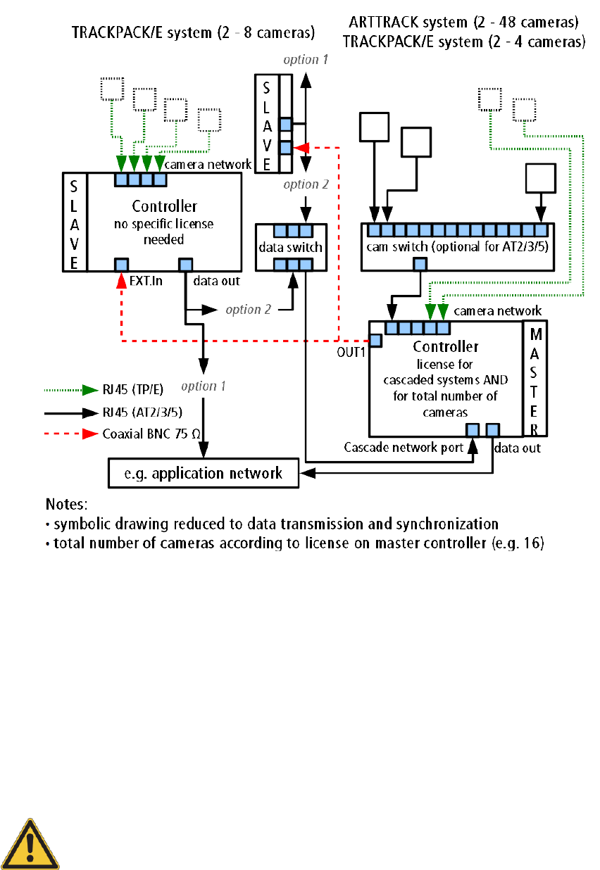
4 System setup
Figure 4.18: Principle of cascading using the LAN (option 1) or the cascaded network port
(option 2 - master ART Controller & DTrack2 => v2.11)
Additionally to the aforementioned figures, please proceed according to the following de-
scription:
1. mount the cameras as usual at the defined positions
2. connect all cameras to their corresponding controller as usual
3. establish a BNC connection between the master’s OUT1 connector and the EXT.In
of the slave(s) for synchronisation of cascade
The USB Radio Transceiver2 for Flystick2 and Flystick3 has to be con-
nected to the master controller.
Double-check if the cameras are connected properly to every controller. If applicable ver-
ify that all power supplies are switched on and the cameras are running (indicated by two
LEDs at the front side of the cameras).
60
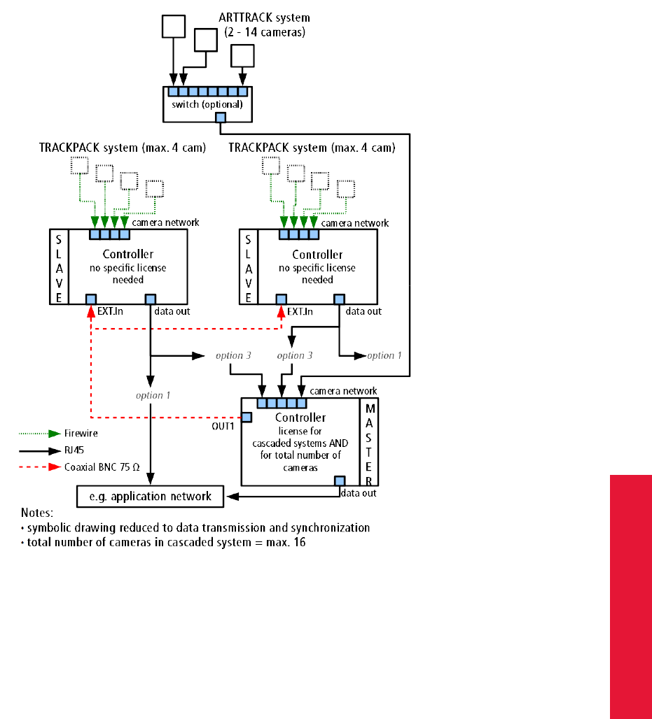
Chapter 4
4.3 Setting up cascaded systems
Figure 4.19: Principle of cascading using the LAN (option 1) or the internal camera net-
work (option 3 - master ARTTRACK controller (discontinued))
The master controller is controlled by a remote PC via DTrack2 frontend software. When
delivered, controllers are set up to support DHCP. When building cascades via LAN (op-
tion 1, see 4.18 on page 60) they will acquire an IP address automatically given that a
DHCP server is running. If you want to set a specific static IP address before booting the
controllers please refer to chapter 4.2.4 on page 54 for more information.
i
If the cascade is connected via the cascaded network port of the
ART Controller (option 2, see 4.18 on page 60), all slave controllers
must be set to a specific static IP address in the subnet 172.29.xxx.xxx
with subnet mask 255.255.0.0 !
In case of using the internal camera network (option 3, see 4.19 on page 61), all slave
controllers will acquire their IP addresses automatically.
Press the power switches (next to the power plug or on the front) to start the master and
the slave controller(s). Make sure the controllers are booted up with all necessary ether-
61
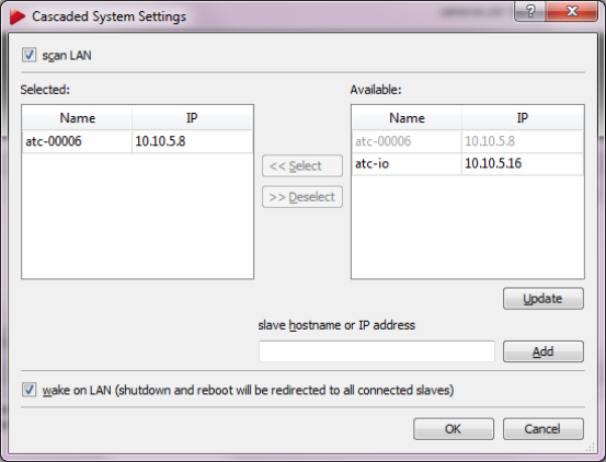
4 System setup
net connections, otherwise the fall-back IP address is applied.
iThe fall-back IP address of the controller is 192.168.0.1 (subnet mask
255.255.255.0)!
Finally, start the DTrack2 frontend software on the remote PC and establish a connection
to the master.
iWe recommend creating a new configuration for all cascaded systems:
DTrack2 →Configurations →’New’
Now, go to Settings →Cascaded System and the main setup dialogue for the cascade
will open up. Basically, you have the possibility to select single tracking systems to join in
the cascade. When using Option 1 (Connection via LAN), you can tick the checkbox ’scan
LAN’ and DTrack2 will search automatically whether controllers are available to become
slaves. They will be listed in the table on the right-hand side of the dialogue (refer to figure
4.20).
Figure 4.20: Cascaded System Settings
Click on the desired Controller and press ’Select’ in order to add it to the cascade. Repeat
these steps if you want to add more single controllers to the cascade.
Make sure that the checkbox ’wake on LAN’ is ticked. This option will enable synchronized
starting and shutting down of the master and all slave controllers. Starting of the cascade
will take 3-4 minutes as the master has to boot up first and then wake up the slave(s). If
the option ’wake on LAN’ is not ticked, the slave(s) WILL NOT be started or shut down
automatically.
The changes will be accepted by the system if you press ’OK ’. Settings (e.g. flash in-
tensity, sync groups) of all cameras inside the cascade can now be edited through the
Settings →Cameras dialogue. The next time you start the measurement all cameras
62

Chapter 4
4.4 Setting up the Hybrid Motion Capture System
inside the cascade can be viewed through the Monitor 2DOF display.
Before continuing, please double-check whether a BNC connection
for synchronization has been established between master (OUT1) and
slave(s) (EXT.In).
Now, you can proceed with calibrating the room as usual. Please refer to chapter 4.5.2
on page 77 where room calibration is explained.
4.4 Setting up the Hybrid Motion Capture System
With the introduction of v2.9.0 DTrack2 supports inertial sensors which are distributed
with our Hybrid Motion Capture suit. The main advantage of hybrid targets is that inertial
sensors still deliver information through the rotation of the target, even when the optical
target may not be tracked any longer due to viewing limitations or occlusions. On the
other hand, drift correction of the inertial sensors is achieved by fusing their output with
position measurements calculated from the optical tracking system. Inertial sensors are
communicating with the DTrack2 system via a 2.4 GHz ISM radio connection.
Connecting the wireless transceivers The wireless antenna comes pre-assembled
with two transceivers (’Dongles’) for communication with the inertial sensors. First con-
nect the USB plugs of these dongles to any free USB port of the controller using the
supplied extension cables. The dongles are activated after rebooting the controller or
calling DTrack2 →Search hardware.
Be sure just to use active (USB 2.0) extension cables (like the supplied
’ATEN UE250’) to connect transceivers (’Dongles’) to an ART Con-
troller. Otherwise proper function of the transceivers cannot be guar-
anteed.
Now within DTrack2 go to Settings →Inertial Sensors and check that all attached dongles
have been found with correct device ID, model, name, firmware version and channel (see
figure 4.21 on page 64). Please also check the frequency the sensors are operating at
(default: 100 Hz).
At this point only dongles and no wireless sensors should be listed. Otherwise continue
reading in chapter 4.4 on page 66.
Z
The default channels for all dongles and sensors are 35 and 55 (out of
80). In case these frequencies are already occupied by other devices
in range (e.g. WLAN), connection problems may occur. ART recom-
mends to scan for available channels and to select free channels ac-
cordingly. Keep a minimum distance of 10 channels between dongles
or from otherwise unavailable channels for optimum connectivity.
Next scan the available radio channels by pressing Scan available channels. After com-
pletion the drop-down menu in the column Channel will show a list of all available chan-
nels for each dongle. The currently used channels are marked in bold digits, while all not
63
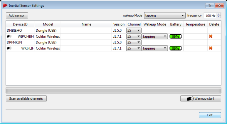
4 System setup
Figure 4.21: Inertial Sensor Settings
recommended channels are greyed out. If the current channel of a dongle is not suitable,
DTrack2 recommends another one (marked green).
Please select an appropriate channel for each dongle. The selected dongle will change
its channel accordingly, like for all assigned sensors. Do not set both dongles to the same
channel or on occupied frequencies from other devices in range.
Adding the inertial sensors to the configuration in DTrack2 This needs to be done
initially - in case the sensors are already connected please skip this step.
Please ensure that all sensors have been charged or alternatively attach the sensors to
the supplied charging hub prior to the following steps.
In the menu Settings →Inertial Sensors, press Add sensor to identify and connect all
inertial sensors in range.
In the appearing dialogue (see figure 4.22 on 65) you should find the Scan mode being
’default’. In this mode DTrack2 will search for the sensors on default channels 35 and
55, even if the dongles / sensors have been set to different channels manually. In this
case, please change the scan mode to ’single’ and select the corresponding channel in
the adjacent selection box. If you don’t know the current radio channel of your sensors,
choose ’all’ (takes some time). With ’USB’ you can identify sensors that are connected to
the ART Controller via a USB charging cable.
Press Scan and the system will identify all sensors in range. Expect 15 inertial sensors
for a complete ART Hybrid Motion Capture suit. Tick the checkboxes of all sensors to be
added to the configuration in the column Accept or add all sensors by ticking ’accept all’.
Then press Apply and exit this dialogue.
64
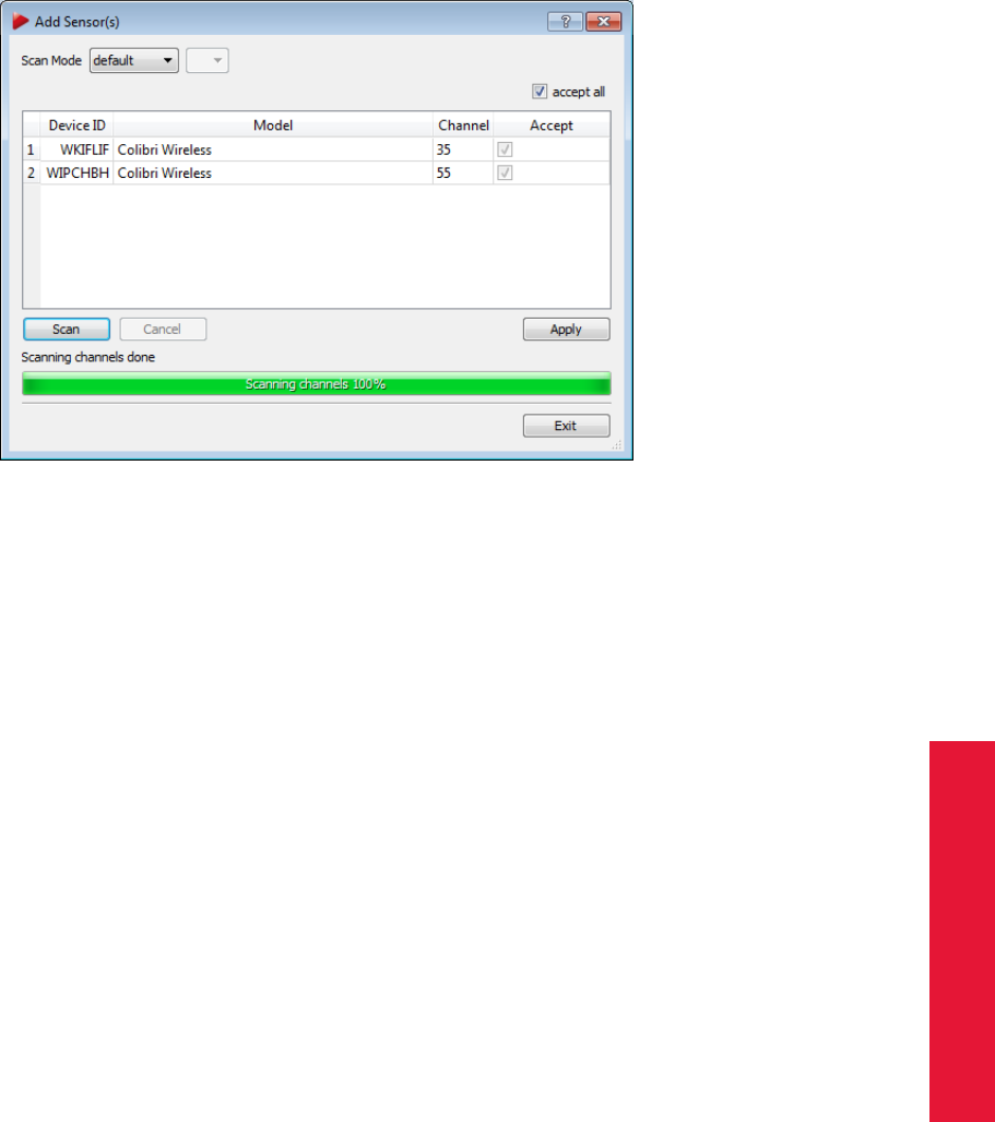
Chapter 4
4.4 Setting up the Hybrid Motion Capture System
Figure 4.22: Add Sensors
i
ART delivers a pre-calibrated hybrid motion capture suit, i.e. both the
optical target geometry as well as the HBC result are stored directly
on the sensor. Unless the hybrid target is disassembled or becomes
damaged, it is sufficient to identify and add all sensors using the menu
Settings →Inertial Sensors →Add Sensors. There is no need to cali-
brate the targets manually.
The dialogue Inertial Sensor Settings (see figure 4.21 on 64) now shows all available
dongles and sensors with the following properties:
•Device ID + wireless icon
•Model (e.g. Colibri Wireless)
•Name (targets from Hybrid Motion Capture suit or user-defined)
•Firmware Version
•Currently used channel (default: 35 / 55); with this menu you can also change the
radio channel of a single sensor
•Wake-up mode (radio, tapping, USB/button)
•Battery level
•Temperature (only during measurement)
Z
Take care that all inertial sensors use a radio channel of one of the
dongles; otherwise this sensor won’t be used during measurement.
Also take care that (approximately) the same number of sensors are
assigned to each dongle.
65
4 System setup
i
The temperature values between single inertial sensors may vary. The
operating temperature is reached as soon as there are no more tem-
perature changes inside the sensors indicated by a green status bar. It
is not dependent on the absolute temperature value.
For warming up the sensors to operating temperature press the button Warmup start.
All inertial sensors are turned to stand-by mode after a pre-defined idle time, which cor-
responds to the selected wake-up mode.
via: radio (idle time: 1 min.), i.e the sensors are switched on as soon as they are ad-
dressed by the controller.
via: tapping (idle time: 3 min., older sensors only), i.e. the sensors are switched on by
tapping on the sensors with your fingertip or tapping the sensors on a hard surface
(e.g. table).
via: USB/button (idle time: 10 min.), i.e. the sensors are switched on by pressing the
button on the sensor for 3-4 seconds or by connecting them to the supplied charging
hub.
ZFor optimal battery life, ART recommends to switch all sensors to
wake-up mode "USB/button" when not in use for a longer period of
time.
Calibration of Hybrid Bodies As requirement for the following steps it is necessary to
warm-up the sensors to operating temperatures and to maintain a constant temperature
during the calibration. Otherwise the measured data and thus the calibration will have
poor quality. Additionally please double-check that all sensors have been charged to at
least 30 % before you continue.
You can simply use the button Warmup start in the dialogue Inertial Sensor Settings (see
figure 4.21 on 64) or in DTrack2 frontend (top right) and leave the process running for
about 5-10 minutes. The progress bar will stop at 100% (progress bar turns green) even
though the warming up of the sensors continues. This shall guarantee that the sensors
work continuously until the calibration and the actual measurement take place. Otherwise
they would cool down again.
Administration of the bodies Within DTrack2 go to Settings →Body Administration (see
figure 4.46 on page 105). All ART pre-calibrated targets have their corresponding optical
target geometries stored inside the inertial sensor. Thus when adding the recognized
inertial sensors, all corresponding target geometries are also added to the tab ’standard
bodies’ in the Body Administration (F8). Unknown or custom hybrid targets, however, will
show up as ’not calibrated’ in the column Calibration. At this point the desired optical
target and the corresponding inertial sensor have to be matched according to their body
ID and device ID.
For new hybrid targets, a three-step calibration procedure has to be performed:
66
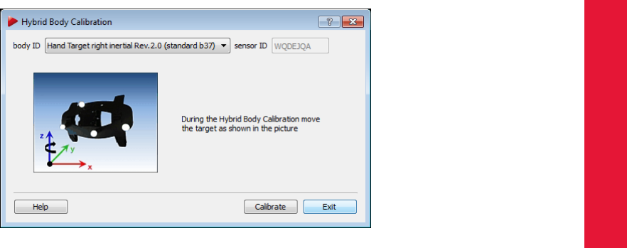
Chapter 4
4.4 Setting up the Hybrid Motion Capture System
1. A standard optical body calibration needs to be carried out. Just press Calibration
and move around the target in front of the cameras. Please refer to 4.5.3 on 84.
2. A hand-eye calibration has to be performed to combine an inertial sensor with its
corresponding optical target. During this Hybrid Body Calibration process (HBC)
the relative rotation of the two sensors is determined.
3. Drift correction for the inertial sensors needs to be measured and applied. Optical
tracking data of the corresponding target allows for correction of residual drift of the
inertial sensor.
ZPlease perform all inertial sensor calibrations with warmed-up sensors
in a constant temperature environment for optimum tracking perfor-
mance.
Hybrid Body Calibration Select the sensor to be calibrated and press Hybrid Body Cali-
bration (see figure 4.23 on page 67). During this calibration the target has to be moved
with moderate speed in any spatial direction of the inertial sensor (please refer to the an-
imation in the HBC dialogue). Select the desired target from the drop-down menu ’Body
ID’ and check the ’sensor ID’ of the inertial sensor for correspondence with the selected
optical target. Then press Calibrate. The appearing dialogue will show the status of the
calibration via a progress bar.
Figure 4.23: Hybrid Body Calibration
As a result you will receive a value for the residual of the calibration. This residual is a
representation of how well the rotational data from the inertial sensor matches the optical
tracking data. Thus it is a measure of the accuracy of the HBC. Values ranging from 1◦to
2◦are ideal. Anything less than 3◦is still acceptable. Please refer to figure 4.24 on page
68
In case the values are acceptable you can assign the calibration and return to the Body
Administration. Now, the sensor should show ’full’ in the column Calibration. Repeat this
procedure for each sensor.
67
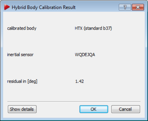
4 System setup
Figure 4.24: Hybrid Body Calibration Result
ZPlease perform all inertial sensor calibrations with warmed-up sensors
in a constant temperature environment for optimum tracking perfor-
mance indicated by a green temperature bar.
Inertial Sensor Calibration After successful calibration of all hybrid bodies, a drift correc-
tion for all inertial sensors should be measured and applied. To this end, please select
Calibration →Inertial Sensor Calibration (see figure 4.25 on page 69). Put all sensors in
the tracking volume (pre-condition: a successful Hybrid Body Calibration for each inertial
sensor) or put them anywhere on a level surface. Do not move or touch them during
the following calibration. Tick the checkboxes in the column Calibrate of all sensors to
be calibrated and press Calibrate. Values around 0.1◦are ideal and still acceptable up to
0.2 ◦, values indicate possible movement during the calibration. When the calibration is
done, you can apply the drift correction either to single sensors by ticking the appropriate
checkboxes in the column Accept or by ticking ’accept all’ for all sensors in range. Press
Apply and exit the dialogue.
iAfter the Inertial Sensor Calibration has been performed and applied
its result is stored directly on the sensor for future use.
68
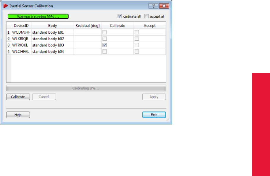
Chapter 4
4.4 Setting up the Hybrid Motion Capture System
Figure 4.25: Inertial Sensor Calibration
69
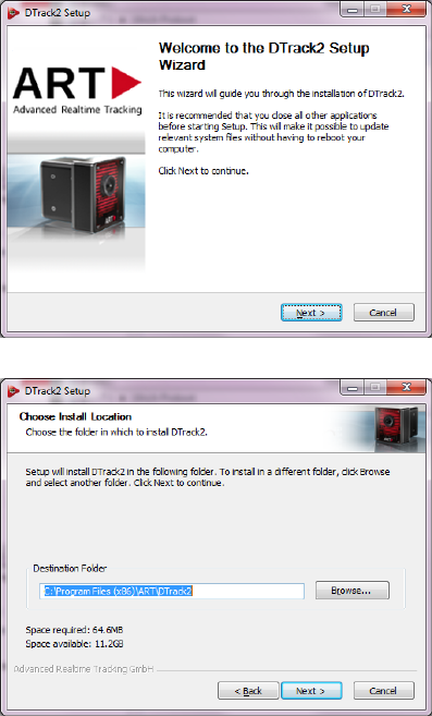
4 System setup
4.5 DTrack2 frontend software
The software DTrack2 is intended to run on a remote PC (Windows or Linux). The Con-
troller can be controlled remotely via Ethernet. The software DTrack2 itself is delivered
via USB pen-drive or can be downloaded in the latest version from our Download Center
at http://www.ar-tracking.com/support/.
4.5.1 Getting started
Please refer to chapter A.5 on page 197 for more information on supported operating
systems.
4.5.1.1 Installation guide (Windows)
Run the installation executable "DTrack2_v2.x.x_win32_install.exe" and the installation
wizard of DTrack2 starts.
Click Next to continue and to start the installation
process for ART DTrack2 software. Administra-
tor rights are not necessary.
Now, please choose the destination folder in
which you want to install DTrack2 .
70
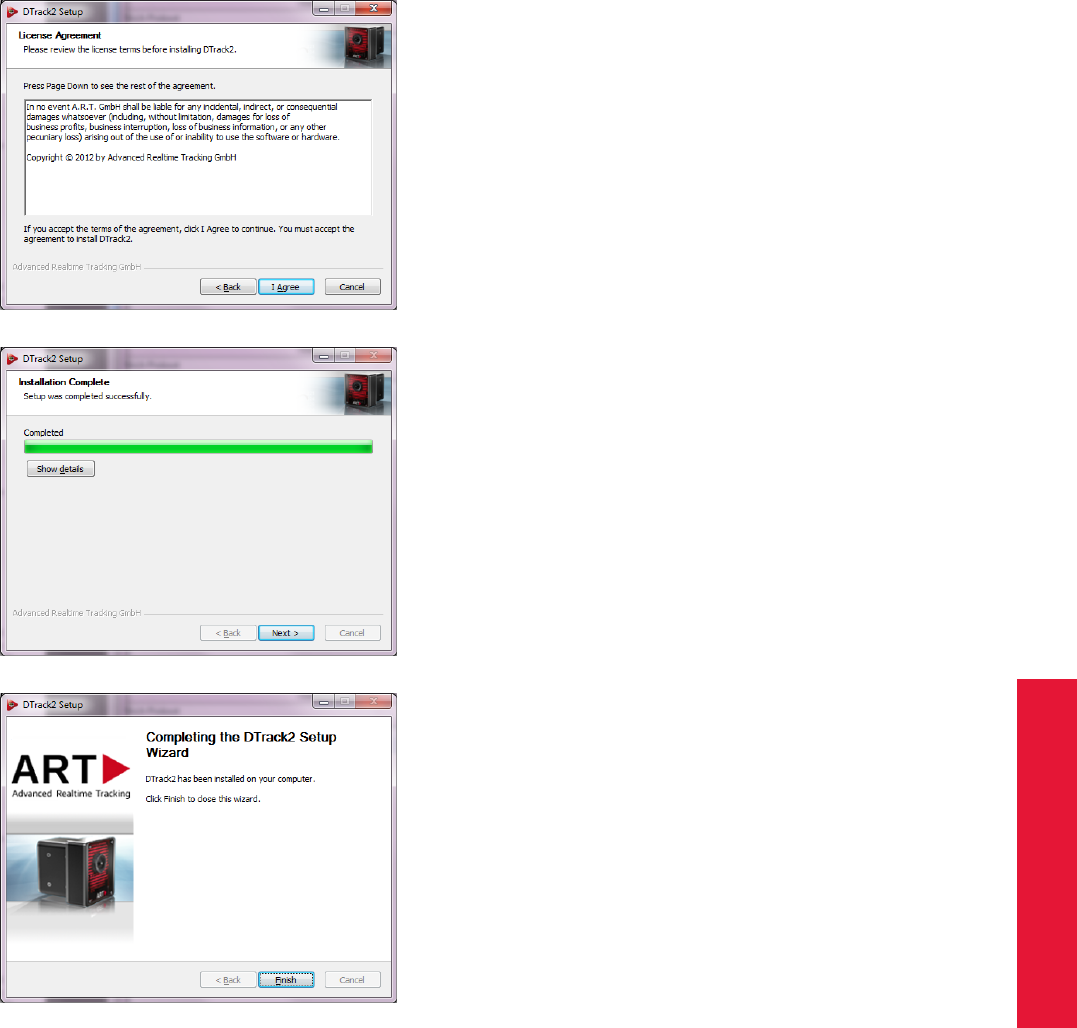
Chapter 4
4.5 DTrack2 frontend software
Please read the license terms carefully and
press I Agree if you agree indeed. A new win-
dow shows the installation progress.
The installation of the DTrack2 software is com-
plete now. DTrack2 has been installed on your
computer. Click Next.
Press Finish to complete the DTrack2 setup wiz-
ard. Now, you can use DTrack2 .
4.5.1.2 Installation guide (Linux)
The software (32-bit and 64-bit package available) is packed in an archive.
(DTrack2_v2.x.x_linux32.tar.gz) You do not need to have administrator rights to extract
all files to a user-defined folder. In a shell, change to the user-defined folder and type in
the command tar xvf DTrack2_v2.x.x_linux32.tar.gz in order to extract the files. For
ease of use, you may create a shortcut on the desktop.
DTrack2 can be started with the command ./DTrack2.
71
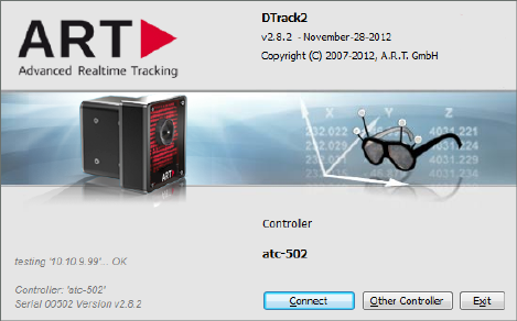
4 System setup
4.5.1.3 Software update
The latest DTrack2 software is always available from our Download Center at http://www.ar-
tracking.com/support/. For the installation of the update, please proceed as mentioned
before in chapters 4.5.1.1 and 4.5.1.2.
After installing DTrack2 on the host PC the Controller can be updated after establishing
a connection to the Controller with the new Frontend.
4.5.1.4 Start DTrack2 frontend software
When you start DTrack2 on the remote PC you will see the following start window (see
figure 4.26).
Figure 4.26: Welcome screen of DTrack2
4.5.1.5 Connecting to the controller
The first time you start DTrack2 , no default controller will be found and another window
will be opened automatically (see figure 4.27). The radio button at position Specific Con-
troller will be ticked.
If you know the name (typically like "atc-00069") or IP address of your controller you may
enter it in line hostname or IP address and press Connect.
Otherwise, you can select Scan, if you don’t know the hostname or the IP address of your
controller. You will see a list of the available controllers in your network.
In column Name every controller in your network will be listed. If no controller or not the
desired controller is listed there please press Update list. Now, the list should contain
your desired controller. If not, please refer to chapter 6 on page 147.
You can identify the correct controller by comparing the serial number on the label on
the back of the controller with the serial number listed in this window (column Serial).
Controllers set in grey are used by other PCs in the network (→IP address listed at the
bottom of the welcome screen). It is only possible to connect to controllers set in black.
72
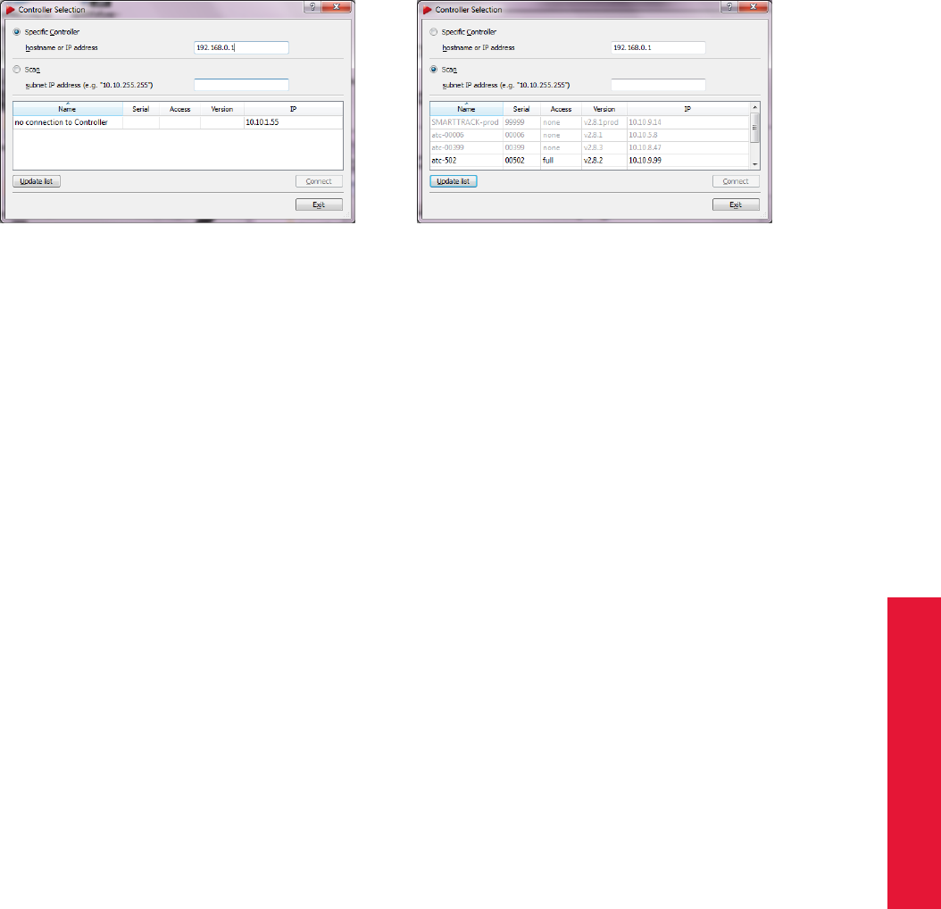
Chapter 4
4.5 DTrack2 frontend software
(a) specific controller (b) scan the network
Figure 4.27: Controller Selection
Select the entry which fits to your desired controller and press Connect.
The next time you start DTrack2 your controller is still known by the software and DTrack2 au-
tomatically searches for it. The welcome screen shows the name of your controller. If this
is the one you want to connect to, just press Connect.
The graphical user interface The graphical user interface of DTrack2 offers different
views which can be switched on and off by the user:
1. Monitor 2DOF Graphical display of markers seen/tracked by the cameras.
Colour code signifies the circularity or the size of the mark-
ers, respectively.
2. Event Display Displays DTrack2 events (e.g. "no valid room calibration")
3. Data Display Displays measurement results (6DOF and/or 3DOF)
4. Fingertracking Shows the measurement results of the hands
5. Flystick Shows the measurement results (6DOF) and the operation
of the buttons and the joystick
6. Measurement Tool Shows the measurement results of the Measurement
Tool and, if assigned, the reference body
By default the first three are shown (see figure 4.28).
In the status bar, a button for starting and stopping of the measurement is integrated.
Additionally, you may retrieve information regarding the cameras connected, the synchro-
nization frequency, the number of bodies tracked and the number of single markers seen.
The synchronization frequency field is changing its colour to yellow, orange and red in
case the effective frequency is decreasing (see figure 4.29):
•grey: max. 5 frames per minute lost (i.e. 3600 frames per minute are transmitted)
•yellow: 5 - 10 frames per minute lost
•orange: 10 - 15 frames per minute lost
73
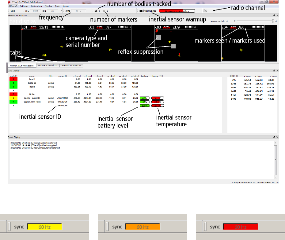
4 System setup
•red: > 15 frames per minute lost
Figure 4.28: Graphical user interface of DTrack2
(a) yellow: 5 - 10 frames per
minute lost
(b) orange: 10 - 15 frames per
minute lost
(c) red: > 15 frames per minute
lost
Figure 4.29: Visualization of the synchronization frequency decrease
4.5.1.6 Adjustment of the cameras
So far, the cameras have been mounted and connected to the controller. The next step
is to adjust the orientation of each camera such that the measurement volume can be
tracked completely. It is especially important that blinding of one camera by another one
is excluded. Therefore, DTrack2 provides the Monitor 2DOF display that essentially is a
graphical display of the field of view of the IR cameras and of the markers that are seen
by the cameras (presented two-dimensional).
Monitor 2DOF display The Monitor 2DOF view shows a black window for each IR cam-
era (equivalent to the field of view) with a schematic display of positions and sizes of all
recognized markers. A simple colour code signifies the size and the circularity of the
74
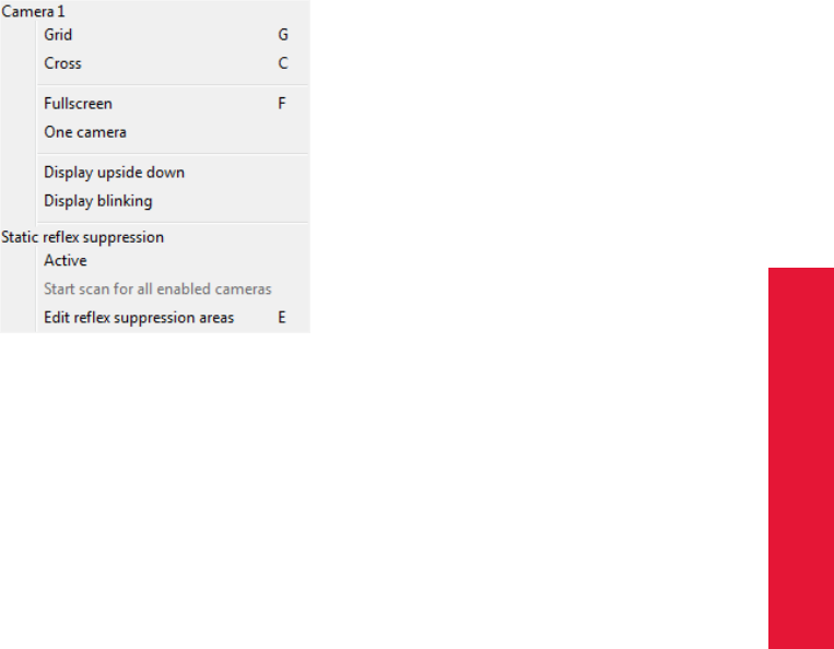
Chapter 4
4.5 DTrack2 frontend software
markers (green = very good quality, yellow = good quality, red = bad quality). As a rule
of thumb, for measurement applications with high accuracy requirements the markers
should be displayed in green; for VR applications yellow markers are always ok. The
Monitor 2DOF display is particularly useful for the final adjustment (especially orientation
adjustments) of the IR cameras.
Additionally, the intensity of the brightest pixel in the field of view is shown using a bar dis-
play for ARTTRACK2 ,ARTTRACK3 ,ARTTRACK5 and TRACKPACK cameras (refer
to figure 4.28). When using an ARTTRACK1 you’ll find the bar display integrated in the
camera on the front side.
A click with the right mouse button into one of the windows opens a menu (see figure
4.30) with settings for the respective camera.
Figure 4.30: Monitor 2DOF view menu (e.g. camera 1)
By clicking and holding the left mouse button on one of the camera displays, its position
can be moved within Monitor 2DOF view.
A more detailed description of the features of the Monitor 2DOF view can be found in
chapter 4.5.6.5 on page 120.
Adjustment of the cameras During this adjustment the user should take care to avoid
mutual blinding of the cameras. If the IR flash of one camera is inside the field of view
of another camera, this situation can, but has not necessarily to be visible in the Monitor
2DOF view. Blinding is often indicated by the observation that the LED bar shows high
intensity, but no markers are inside the measurement volume and the camera does also
not recognize any markers (no marker displayed in Monitor 2DOF view). If this is the
case, it will severely affect tracking in the involved image areas. If these situations cannot
be avoided by proper adjustment of the cameras (i.e. position and orientation), they can
be arranged in different flash groups, thus separating the IR flash of one camera from the
image recording of the other camera on a time scale.
75

4 System setup
On the one hand, camera mounting has to ensure that tracking is possible over the entire
measurement volume. On the other hand, attention has to be paid to the fact that at least
two cameras have to see the calibration angle (for room calibration) completely. Moreover,
the fields of view of the single cameras have to overlap sufficiently, in order to enable the
photogrammetric orientation of all cameras in a common coordinate system; especially if
not all IR cameras are able to see the calibration angle.
License overview Up to DTrack2 v2.10 different license models were available for ART-
TRACK and TRACKPACK systems:
•ARTTRACK systems →extended and full-featured licenses
•TRACKPACK systems →basic, extended and full-featured licenses
Starting with DTrack2 version v2.10 a new license model has been established.
You may use 2, 4, 8, 16 or up to 50 cameras in any combination with 4, 10, 30 or up to 50
targets depending on the license purchased.
Please refer to table 4.3 for a detailed overview.
Feature denotation Values Possible license status
Cascaded supported / not supported
Fingertracking supported / not supported
Measurement Tool supported / not supported
DTrack2 cameras not supported
DTrack2 max. Ccameras 1C= 2, 4, 8, 16 supported
DTrack2 all cameras supported
DTrack2 max. Bbodies B= 4, 10, 30 supported
DTrack2 all bodies supported
1Max. 4 TRACKPACK (discontinued) or 8 TRACKPACK/E cameras without cascaded
system.
Table 4.3: Licenses overview
iThe maximum number of bodies that may be used in the ARTTRACK or
TRACKPACK system includes the calibrated interaction devices (Fin-
gertracking, Flystick, Measurement Tool )!
4.5.1.7 Localizing and removing of disturbing reflections
Reflections may be detected when starting the Monitor 2DOF view in DTrack2 . They are
illustrated the same way as single markers, i.e. with small coloured crosses. But, there
may also be reflections that are not illustrated in the Monitor 2DOF view when mutual
blinding of cameras occurs. Then, you can only tell from the bar display which is indicat-
ing (high) radiation intensities.
This is a known behaviour which, in case of ARTTRACK2 , can be solved easily with
an update of the cameras’s firmware. Please contact ART in case you experience alike
76

Chapter 4
4.5 DTrack2 frontend software
problems.
Sources of disturbing reflections may be diverse. Typically, however, the reflections are
produced from one (or more) of the following:
•strong infrared radiation sources (e.g. sunlight or sunrays, halogen lamps, ...),
•mutual blinding of infrared cameras,
•active or passive targets, that are still in tracking range of the cameras,
•any kind of reflecting material on clothes or shoes,
•blank metal surfaces, especially curved surfaces and surfaces with 90◦angles,
•some types of packaging foils.
For removing disturbing reflections there are different approaches:
•reduce the flash intensity of all cameras to "0":
remaining reflections are originating from infrared radiation sources (e.g. sunlight,
halogen lamps, ...). Try to localize and remove them.
•reduce the flash intensity for one camera after the other to "0":
remaining reflections are caused by mutual blinding of the cameras. Turn the cam-
era until the bar displays’ segments of the Monitor 2d display do not indicate radia-
tion any more. You may also introduce new syncgroups in order to eliminate mutual
blinding.
•try to localize the reflection by moving a target towards the origin of the reflection
(use the Monitor 2DOF display) and proceed as mentioned above.
If reflections cannot be eliminated you may use the reflex suppression tools of DTrack2 (please
refer to 4.5.6.3 on page 98):
1. static reflex scan:
reflexes will be suppressed automatically by DTrack2 upon detection
2. suppress static reflexes manually :
areas to be suppressed may be defined manually
4.5.2 Room calibration
Before you can start tracking, a room calibration has to be carried out. During that cali-
bration, the system identifies the position of the cameras inside the measurement volume
and determines the three-dimensional coordinate system. Carrying out a room calibration
always is the first step. Without it, body calibration and tracking will not be possible.
iThe Show details option offers information about the date of the last
room calibration.
Room calibration has to be carried out
77
4 System setup
•after the first system setup,
•after any changes of IR camera positions (→Room re-calibration),
•after any changes to the number of cameras,
•before a body calibration (when system has been setup initially).
In principle, it is recommended to always perform a room calibration after a certain oper-
ating time of the system, especially if the system setup does not exclude camera move-
ments over time (these camera movements may also be thermal drifts!).
Z
If a camera with 4.5mm lenses (standard for ARTTRACK3 ) is rotated
by one tenth of a degree it will cause aberrations of the optical rays
that are as high as 5 millimetres in 3 metres distance from the camera.
That means for the DTrack2 software (standard settings) that the ob-
servations of this camera are excluded from the calculation of target
positions because these observations would generate unacceptable
errors in the results of measurement. I.e., a camera that is rotated by
one tenth of a degree does not contribute to tracking any more!
For that reason, a room calibration should be carried out whenever any uncertainty re-
garding the mechanical stability or the thermal behaviour of the setup occurs.
For room calibration, the calibration angle of the "room calibration set" is inserted into the
field of view of the IR cameras. The position of the calibration angle defines the room
coordinates. At least two IR cameras have to see all markers of the calibration angle.
Therefore, DTrack2 ’s Monitor 2DOF display is started in the background when selecting
Calibration →Room. Here you can verify that all markers of the angle are seen by the
cameras.
iThe longer arm of the angle defines the X axis (refer to figure 4.32); the
shorter one the Y axis. The center of marker #1 defines the origin of
the room coordinate system (at a height of 43mm).
The pre-calibrated stick carrying two markers is called the "wand". Its function is to create
a virtual "point cloud" in the measurement volume that is used for calculating the relative
positions of the IR cameras with high accuracy. Furthermore, the wand is scaling the
system. That’s why damages of the wand (loose markers, bent poles, etc.) lead to mis-
calculations of the measurement volume.
To choose the marker distances of the calibration angle three predefined settings are pos-
sible, representing the common ART Room Calibration Sets.
Marker distances of the calibration angle can also be set manually using the setting ex-
pert. The numbering of the markers is as seen in figure 4.32.
The wand length has to be set manually in this dialogue - it is written on the label of the
wand.
78
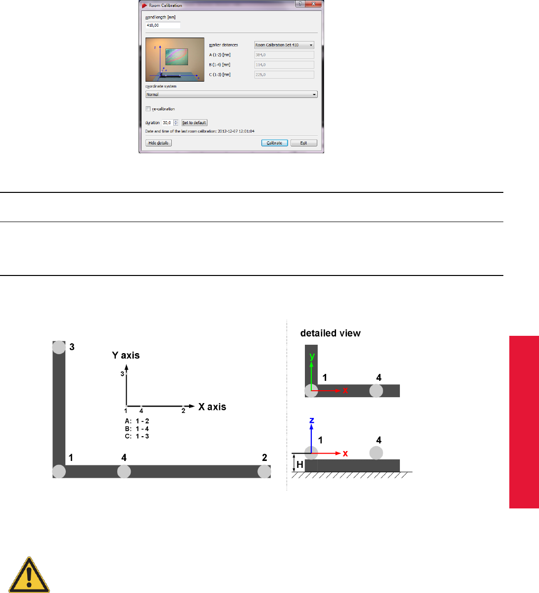
Chapter 4
4.5 DTrack2 frontend software
Figure 4.31: Room calibration settings (e.g. RCS 410)
wand length marker height H TRACKPACK ARTTRACK2 ARTTRACK3 ARTTRACK5
diameter (see Fig. 4.32)
RCS TP 410.0mm 20mm 58mm ×
RCS 410 410.0mm 20mm 43mm ×××
RCS 710 710.0mm 20mm 43mm ×××
RCS 720 720.0mm 30mm 48mm ×××
Table 4.4: Overview of the ART Room Calibration Sets (RCS)
Figure 4.32: Marker distances (including numbering) on the angle and definition of room
coordinate system
Incorrect input data for this dialogue will lead to a poor room calibra-
tion, to wrong system scaling, or to an abortion of the whole room
calibration process.
With the select list at the bottom you may define how the coordinate system of the room
is created relative to the calibration angle (refer to table 4.5).
After pressing Calibrate, the room calibration is started with five seconds delay.
79
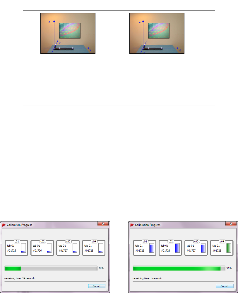
4 System setup
Standard Powerwall
In the Standard setting the
angle defines the X/Y plane (X
at the long, Y at the short
beam) and Z upward.
With the Powerwall setting the
X/Y plane is in the screen and
the Z axis pointing out of the
screen. This is the standard
screen coordinate system of
many VR systems (e.g.
OpenGL, TrackD, etc.).
Table 4.5: Options for coordinate system definition
A window showing the progress of the room calibration appears (see figure 4.33(a)). The
progress is shown for each camera which is especially helpful for big systems. As soon
as the display for a camera changes its colour to green (see 4.33(b)) enough data for
calculation of the camera position has been collected for this camera.
ARTTRACK5 only: This progress is also displayed individually on each cameras corre-
sponding 2-digit LED matrix. After collection of sufficient data the LED matrix changes
back to its defined setting. Please refer to chapter 4.5.6.3 on page 97 for detailed infor-
mation.
(a) (b)
Figure 4.33: Room calibration progress
If necessary, you may adjust the ’duration’ of the room calibration (→Show details) in
a range of 10s - 100s. Resetting the value to default is achieved by pressing the Set to
default button (default = 30s).
Z
Changing the duration of the room calibration, especially towards
shorter durations, may lead to bad room calibration results! Please
make sure that you are always able to cover two thirds of the tracking
volume within the set time.
80
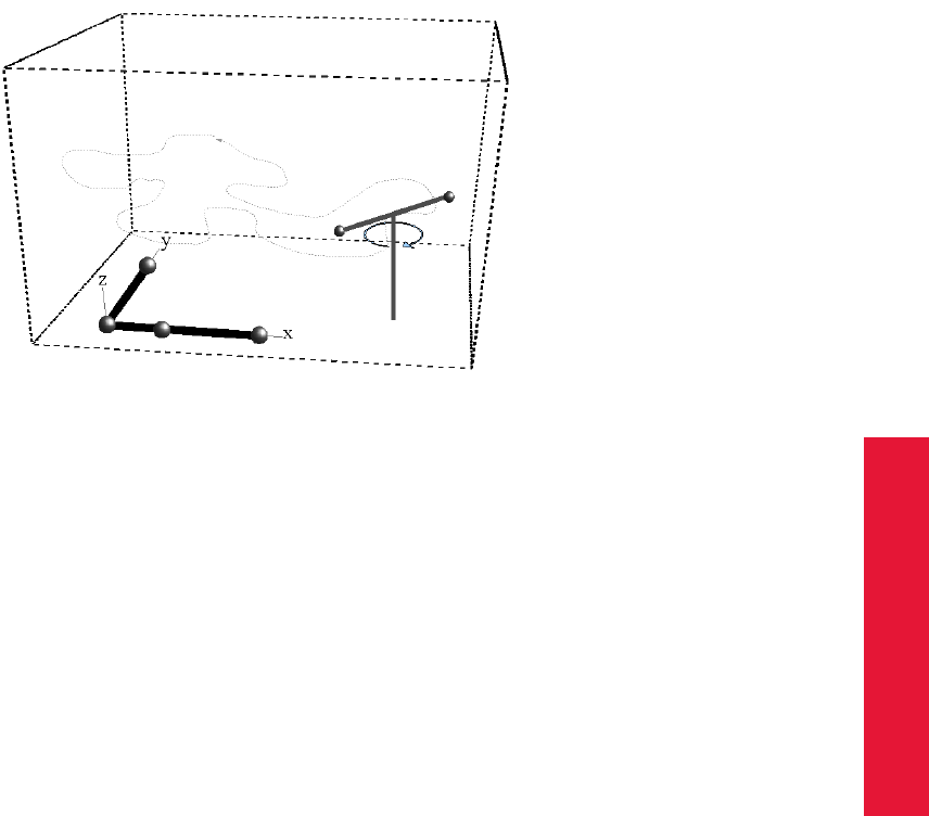
Chapter 4
4.5 DTrack2 frontend software
Move the wand gently within the measurement volume, in order to generate a virtual point
cloud. This point cloud should fill at least about two thirds of the measurement volume. It
is used for calculation of IR cameras positions, so moving the wand in only a very small
volume will result in reduced accuracy of calibration. Here, a compromise has to be found
between (1) too wide movements that often cause the failing of room calibration, and (2)
sparse movements that lead to a valid, but inaccurate room calibration. Avoid rapid and
hectic movement (see figure 4.34).
Figure 4.34: Room calibration process
During calibration, the two markers of the wand should be visible to all IR cameras as
good as possible. If, in a system setup, no sufficient part of the measurement volume is
seen by all IR cameras simultaneously, the point cloud created by the wand movement
has to connect all cameras in a way that ensures the arrangement of all cameras in a
common room coordinate system. More concrete, cameras that see the calibration an-
gle are oriented first. Then, every additional camera has to be connected by a sufficient
volume with at least two already oriented cameras. In this way, the calibration is stepping
forward from camera to camera. (e.g.: cameras 1 and 2 are seeing the angle - camera 3
overviews a certain volume together with cameras 1 and 2 - camera 4, finally overviews
a volume together with cameras 1 and 3).
Calibrating cameras which do not observe the angle directly is called "chain calibration".
Chain calibrated cameras propagate inaccuracies from the previously calibrated cameras.
It is recommended to place the calibration angle in a point where as many cameras as
possible can see the angle.
After a successful room calibration, the DTrack2 info window with the calibration results is
displayed. This window shows the mean residuals for the single cameras (here: ’Residual’
= mean residual of rays during marker detection), as well as the mean deviation (’wand
residual’) and the maximum deviation (’wand range’) of wand length during the calibration
process. These values depend on the system geometry and can give information about
the quality of calibration only to an experienced user. The value ’Used Frames’ represents
81
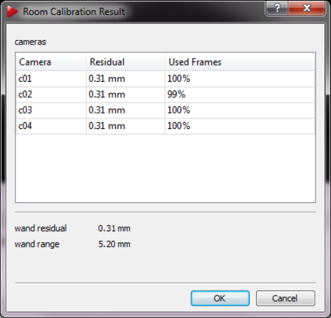
4 System setup
the percentage of valid (i.e., used for room calibration) data for each camera. It should
be as high as possible for all cameras. Values under 50% indicate poor room calibration
quality. The number of valid frames should be greater than 70% for each camera. The
room calibration is confirmed (i.e., the data are stored) by pressing the button OK .
ZPlease note that percentages of more than 70% may not be reached in
large and complicated measurement volumes.
Figure 4.35: Room calibration result
4.5.2.1 Room re-calibration
IR camera setups may change after a certain operation time; if e.g. movement of single
cameras due to mechanical instabilities cannot be excluded or thermal drifts occur. In
this case it is necessary to perform room calibrations periodically. DTrack2 provides a
simplified room calibration to revise an existing room calibration without need of an angle
tool, called room re-calibration.
Check the corresponding field in the room calibration dialogue (see figure 4.36) to activate
re-calibration. Most settings have to be the same as during the previous standard room
calibration, therefore most values of the dialogue cannot be changed - settings regarding
the wand may be modified. If camera positions changed you would have to mark them
in the room calibration dialogue as ’moved’. Re-calibration is possible as long as camera
movements are not too large.
It will fail, e.g. if the mounting of cameras was changed. To perform a re-calibration, no
angle tool has to be present in the measurement volume; only the wand has to be moved
82
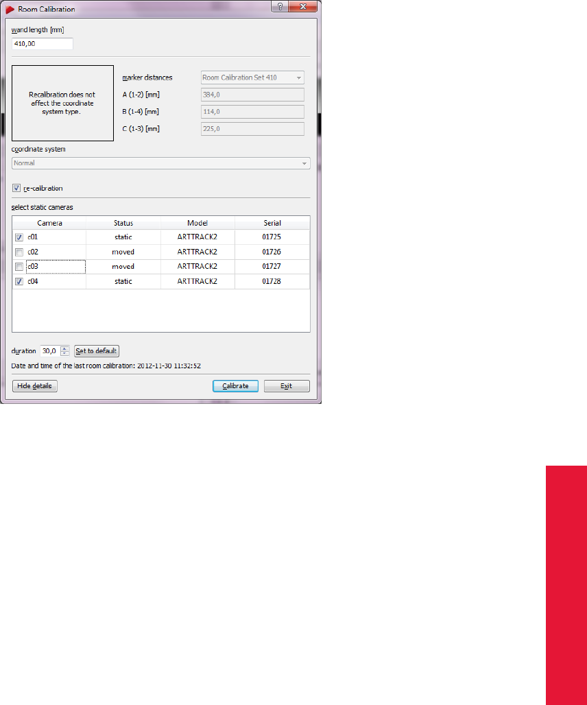
Chapter 4
4.5 DTrack2 frontend software
Figure 4.36: Room re-calibration dialogue
within the measurement volume in the same way as for a standard room calibration.
The main advantage of a room re-calibration is that DTrack2 preserves the origin of your
coordinate system and therefore, the orientation of the coordinate system as well.
Adding a camera to calibrated setup In order to add a camera to already calibrated
setup and preserve the origin of the room calibration, you proceed as follows:
•connect new camera to controller;
•wait until the camera is booted;
•within DTrack2 press ’F2’ in order to perform a search for new hardware;
•check if the camera has been recognized successfully (e.g., by opening camera
settings ’F7’);
•when starting measurement you must see the red message “(re-)calibration re-
quired!” on the Monitor 2DOF of corresponding uncalibrated camera (see sec-
tion 4.5.6.5 on page on page 120 for details);
•perform room re-calibration 4.5.2.1, new camera is automatically marked as “moved”
in the room re-calibration dialogue.
83
4 System setup
4.5.3 Body calibration
The process of teaching a target’s geometry to the tracking system is called body calibra-
tion. For a body calibration, the target (= rigid body) to be calibrated has to be in the field
of view of the IR cameras. The number of bodies to be tracked has to be configured in
Settings →Body Administration.
After pressing Calibrate, the body calibration is started within five seconds delay. The
body can be moved during body calibration, always considering that the cameras should
see each marker of the body at the best.
If the body is not moved during the body calibration it should be considered that each
marker of the target has to be seen by at least two cameras and should be seen by
as many cameras as possible. If two markers, seen from one camera’s point of view,
are merging to one reflex, body calibration may be affected. These "merging marker
situations" should be avoided during body calibration, i.e. the target should be oriented
in a way that reduces merging markers to a minimum. The target orientation can be
checked before starting the body calibration, using DTrack2 ’s Monitor 2DOF display,
which is opened automatically in the background after selecting Calibration →Body. The
following figure 4.37 shows a rigid body with five markers that are all correctly seen by the
IR camera.
Figure 4.37: Recognized target in DTrack2 Monitor 2DOF display
Furthermore, the absence of any additional markers in the measurement volume has to
be ensured for body calibration. If additional markers that are not part of the target to be
calibrated are in the field of view of the IR cameras during body calibration, these mark-
ers will be assigned to the target. That means, the target is not correctly calibrated and,
therefore, tracking problems may occur.
First, the target that shall be calibrated has to be selected in the select list Body. By de-
fault the ’type’ is set to standard which allows for calibrating a 6DOF target with spherical,
84
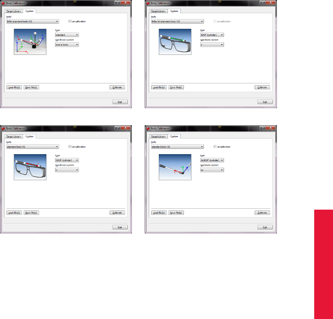
Chapter 4
4.5 DTrack2 frontend software
(a) Target type "standard" (b) Target type "5DOF"
(c) Target type "5DOF (cylinder)" (d) Target type "2x 5DOF (cylinder)"
Figure 4.38: Body calibration dialogue
flat or active markers. When you are using a target made of ring markers you would select
the ’type’ according to the geometry of the target:
•’5DOF ’ .. a target made of spherical markers which are aligned along one main
axis. The rotation around that axis cannot be detected by the system - you loose
one dimension of freedom. Therefore, we call it 5DOF target.
•’5DOF (cylinder)’ .. a target made of ring markers which are aligned along one main
axis.
•’2x 5DOF (cylinder)’ .. an L-shaped target made of ring markers which delivers
6DOF data.
4.5.3.1 Selecting the coordinate system for 6DOF targets
The type of body calibration can be set as ’due to body’, ’due to room’ or ’due to room
(zero in marker)’. The difference between these calibration types is to be found in the
85
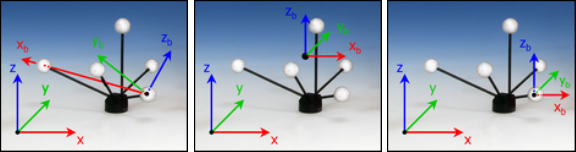
4 System setup
orientation of the body coordinate system relative to the body. During body calibration,
DTrack2 defines a local coordinate system (body coordinate system) for each target.
Body calibration setting due to body The body coordinate system is fixed by the markers of
the rigid body according to a set of rules:
1. Search the biggest distance between two markers of the rigid body. These two
markers (# 1 and # 2) will define the X axis.
2. Search for a third marker (# 3) that has the smallest distance to one of the two
markers # 1 and # 2. The marker that has smallest distance to marker # 3 becomes
marker # 1. It will define the coordinate origin. The other marker will be # 2. The
positive X axis is directed from marker # 1 to marker # 2.
3. Marker # 3 defines the X/Y plane, together with markers # 1 and # 2. Marker # 3
has a positive Y coordinate.
4. The Z axis is already defined by these rules, resulting in a right-handed coordinate
system.
(a) Body calibration
"due to body"
(b) Body calibration
"due to room"
(c) Body calibration
"due to room (zero in
marker)"
Figure 4.39: Defining the target coordinate system
Body calibration setting due to room The origin of the body coordinate system is set to the
center (center of gravity) of all markers building the rigid body. The axes of the body co-
ordinate system are parallel to the axes of the room coordinate system in the beginning
of the body calibration. I.e., the result of a body calibration will depend on the angular po-
sition of the target during calibration. A 6DOF measurement, following calibration without
having moved the body, will give the angular coordinates 0◦/ 0◦/ 0◦.
If the target was moved during calibration, the angular position of the target at the begin-
ning of the calibration will be taken.
Body calibration setting due to room (zero in marker) A combination of the first two methods.
The direction of the axes of the body coordinate system will be set parallel to the room
coordinate system in the moment of body calibration - like done with setting due to room.
The origin of the body coordinate system is given by one marker of the body, according
to the rules given for setting due to body.
86

Chapter 4
4.5 DTrack2 frontend software
Selecting the coordinate system for 5DOF targets Analogue to the settings for the
standard targets it is also necessary to define the body’s coordinate system in case of
5DOF targets. The approach is a bit different but also straight forward.
Coordinate system setting for type ’5DOF’ and ’5DOF (cylinder)’In the body coordinate system
all markers of the target are on the selected axis. The origin is in the middle between the
two markers with the largest distance to each other. The orientation is defined by the
marker with the smallest distance to the origin. Its position has a negative sign. The other
two directions are undetermined due to the one degree of freedom.
Coordinate system setting for type ’2x 5DOF (cylinder)’The body is expected to consist of two
connected 5DOF targets with a roughly perpendicular and constant angle in between.
These are placed on the two axes. The origin is placed at the position where the two
5DOF targets intersect. The first axis is assigned to the 5DOF target which includes the
marker with the largest distance to the origin. The other 5DOF target is placed in the
plane created by the two axes.
A click-type torque wrench is one the most prominent members of this class of bodies.
Due to the engineering backlash and other high mechanical tolerances in these devices
often times the resulting body calibrations are error-prone.
ZPlease double-check whether all markers of the rigid body have been
recognized.
Then, confirm the result with OK . If this is done, the geometry data of the calibrated target
will be stored in the Backend.
iAfter a new room calibration or room re-calibration it is not necessary
to perform a new body calibration. Only if the body itself changes you
have to calibrate the body again.
ZThe previous body calibration will be lost if you carry out a new body
calibration. If you want to save the previous body calibration please
use the ’Save file(s)’ option in the Body calibration dialogue.
4.5.3.2 Calibration with a calibration file
After successfully calibrating a body the information (i.e. geometry) is stored inside the
ART Controller in your personal configuration (see also 4.5.6.2 on 95). To easily create
backups of calibrated bodies, calibration files can be saved at a desired location on the
remote PC. These files contain the dimensions of the target and the distances between
all markers. Each file is specific for just one type of target.
Press ’Save file(s)’ option in the Body calibration dialogue to store the calibration file(s) of
the currently used bodies.
Optionally a restricted visibility can be defined for each marker of a body. This is per-
formed setting up so called “emission cones”; a 2DOF observation from a camera has to
be inside this cone to be used later for pose estimation. Currently the only way to equip
87
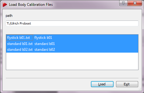
4 System setup
markers with emission cones is to import an appropriate calibration file; those are avail-
able on request. These files are created at ART on site performing a body calibration in a
defined environment or measurement volume respectively.
Press Load file(s) (see figure 4.40) and choose the calibration file(s) for your targets. The
format of the file name has to be according to "standard b01.txt" - the identifier "b01"
refers to the ID of the target. DTrack2 automatically assigns the calibration file to the
respective target by using the identifier in the file name. Press ’Load’ again to confirm the
import of the body calibration files.
Figure 4.40: Import of calibration files
ZThe previous body calibrations will be lost if you load new calibration
files.
iInvalid or corrupt files are not loaded by DTrack2 . This is indicated by
an error message in the confirmation dialogue.
In the upcoming window (see figure 4.41) the coordinates of all identified markers are
listed together with the body’s label as well as the number of markers.
Figure 4.41: Body Calibration Result
By clicking Show details additional information can be displayed.
•’Distances’ shows all possible combinations of distances for all markers (min. dis-
tances are important for customer-specific geometries, call ART for further informa-
tion)
•’Emissions’ shows normalised emission vectors x, y, z and emission aperture for
bodies with restrictions of visibility (calibration files available on request by ART )
•’Cylinder’ shows coordinates and radii for bodies with (cylindrical) ring markers
4.5.3.3 Body re-calibration
DTrack2 provides a possibility to re-calibrate a rigid body in case its geometry is affected
due to e.g. mechanical impact. Tick the checkbox re-calibation and perform a routine
88
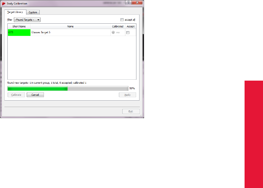
Chapter 4
4.5 DTrack2 frontend software
body calibration as described in 4.5.3 on page 84.
iOnly during a re-calibration the origin and orientation of the initial co-
ordinate system, as well as specific information (predefined emission
vectors, cylindrical marker) are preserved.
4.5.3.4 Target Library
With the introduction of DTrack2 v2.8.1 it is possible to make use of an integrated library
that contains calibration data for most ART standard targets (e.g. Motion Capture, glasses
targets, etc.). When you go to Calibration →Body choose ’Target Library’ (refer to figure
4.42). The filter is set to ’Found Targets’ by default whereas the other options may be
used in case only targets of this type are to be calibrated (e.g. Motion Capture).
Figure 4.42: Calibrate bodies with the target library
With the ’Found Targets’ filter all targets presented, i.e. shown to the system, will be
found. In the unlikely case that a target is not found by the system it needs to be cal-
ibrated using the standard body calibration. The calibrations for all found targets only
need to be accepted either by ticking the checkbox ’accept all’ or one at a time. Finalize
the assignment of the targets by pressing ’Apply’.
Z
DTrack2 compares the geometry of the physical target with the calibra-
tion data of the target library. In some cases a re-calibration might be
necessary, e.g. when a clip-on target is applied to the glasses bending
is possible.
If you haven’t increased the number of targets before the system will ask you if this number
should be adjusted automatically. Press ’OK ’ if you want the system to do so.
Typical usecase: Motion Capture targets without Inertial sensors For this descrip-
tion we’re assuming that a room calibration for eight cameras has already been carried
89
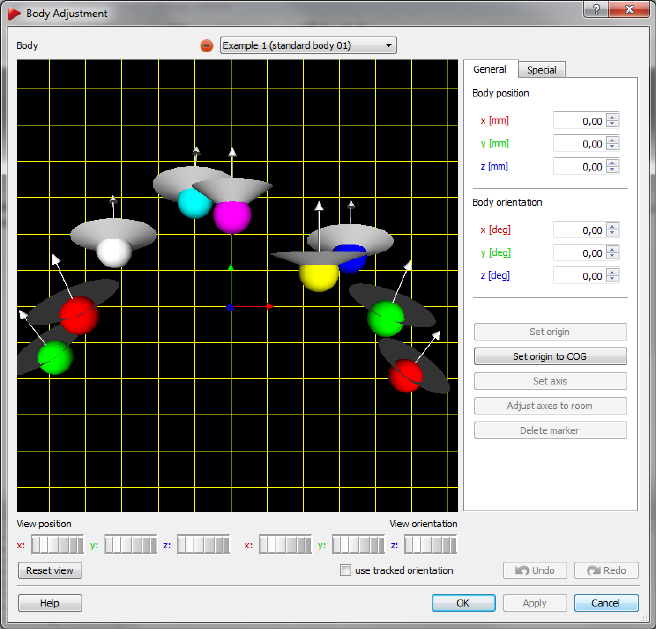
4 System setup
out and that the "full-featured" or "max. 8 cameras" license is available.
First, fit the targets to the test person and make sure that the person is in the calibrated
volume. Then, start the calibration (Calibration →Body →’Target Library’→’Calibrate’)
and allow the test person to move around. While this movement the targets must be visi-
ble for the tracking system.
Finally, one after the other target should be recognized and appear in the display. Tick the
checkbox ’accept all’ and start the measurement in order for your application to receive
tracking data.
In case you need to adjust the order of the targets please go to Settings →Body Admin-
istration (F8).
4.5.4 Body adjustment
The Body adjustment function (see figure 4.43) is a tool to visualise and manipulate cal-
ibration data of rigid bodies, i.e. the body coordinate system may be changed relative to
the markers of the body.
iBody adjustment is not available for 5DOF targets or measurement
tools.
Figure 4.43: Body Adjustment
The main features of Body adjustment are:
90

Chapter 4
4.5 DTrack2 frontend software
•adjust the body coordinate system of each target within the DTrack2 frontend,
•online mode (i.e. the 3D-representation of the target in the ’Graphic view’ is depict-
ing movements / rotation of the target in the "real world"),
•visualise (optionally) predefined emission cones due to restrictions of visibility (di-
rectional and angular dependence) for all markers
•aligning the axes of body and room coordinate system without changing the origin,
•use predefined body coordinate systems,
•move the origin of the body coordinate system,
•set the origin of the body coordinate system in a selected marker,
•delete selected markers from the target geometry.
For detailed information please refer to chapter 4.5.6.4 on page 117.
4.5.5 Filtering options in DTrack2
With the DTrack2 release v2.9.0 we introduce highly improved filtering options which
allow for ideal settings according to the requirement for the tracking performance. For
example in applications where reference targets are used to get the position of a seating
buck it is now possible to apply a strong filter for this specific target which results in abso-
lutely static tracking data.
Using three main settings for defining a filter, i.e. strength, prediction and mode, it is
possible to customize the tracking behaviour in general or for single targets according to
the requirements. Following, a description of these settings.
91

4 System setup
Setting Description Usage
Strength Sets the strength of the filter. Low values
mean less filtering with faster reaction but
higher jitter. High values mean stronger fil-
tering with smoother output but slower re-
action.
a strong filter may be ideal for
tracking seating bucks
Prediction Predicts output for the specified time in the
future to compensate tracking and render-
ing latency. Note that too high positive
values can increase jitter and reduce pre-
cision. Negative values can be used for
smoothing the output at the cost of higher
latency.
a "negative" prediction may be
ideal for recording data as la-
tency doesn’t matter so much
Mode Specifies the elementary behavior of the fil-
ter. Several options are available.
−
’Adaptive fast’ Automatically adapts to the observed mo-
tion.
Moving targets that change be-
tween fast and slow motions,
such as Flysticks.
’Adaptive slow’ Automatically adapts to the observed mo-
tion, with stronger filtering of fast motions.
Moving targets with slow and
medium motions
’Fast’ Optimized for fast motions without special
filtering of slower motions.
Targets where quick reaction is
important, such as HMDs.
’Slow’ Optimized for medium motions without spe-
cial filtering of slow motions.
Targets where quick reaction is
important, but motions are slow.
’Static’ Optimized for targets that are known not to
move at all.
Reference targets attached to
non-moving objects
’Reference target’ Optimized for generally static objects, with
automatic detection of occasional motions.
Reference targets attached to
occasionally moving objects.
92

Chapter 4
4.5 DTrack2 frontend software
4.5.6 Menu structure
4.5.6.1 Overview
DTrack2 Shortcut page 94
Licenses License overview →Licenses can be added by entering
a license key (for Fingertracking, for the Measurement
Tool or for Cascaded Systems)
Configurations Create and save different configurations, lock the used
configuration and save its settings
Start/Stop M Start/Stop measurement
Search hardware F2 Search for newly added hardware
Controller standby Force the controller to go into standby mode
Controller reboot Reboot the controller
Quit Q Quit DTrack2
Settings Shortcut page 97
Cameras F7 Camera settings
Synccard Synccard settings
Inertial Sensor Settings for intertial sensors
ART Radio Info Opens a dialogue where you can see available
transceivers and devices within your setup
Tracking General settings
Body Administration F8 General settings for all targets and interaction devices
Output F9 Set output channels and configure the data to be trans-
mitted
Fingertracking Configure your Fingertracking or Tactile Feedback de-
vice
Flystick Configure your Flystick
Measurement Tool Configure your Measurement Tool
Controller Configure the controller for your local network
Cascaded System Configure a Cascaded System with available con-
trollers
Calibration Shortcut page 111
Start static reflex scan for all
enabled cameras
Starts the static reflex scan
Inertial Sensor Calibration Re-calibrate the internal sensors of the inertial sensor
Room F5 Room calibration
Room adjustment Shift + F5 Adjust room coordinate system
Body F6 Body calibration
Body adjustment Shift + F6 Adjust body coordinate system
Hybrid Body Determine the relative rotation between optical and in-
ertial sensor
Fingertracking Start calibration process for Fingertracking (i.e. hand
geometry)
Measurement Tool Start tip calibration process for the Measurement Tool
93
4 System setup
Display Shortcut page 120
Monitor 2DOF Graphical display of markers recognized by the cam-
eras (monitor 2DOF view)
Data F10 Display measurement results (6DOF and/or 3DOF)
Fingertracking Display Fingertracking measurement data
Flystick Display Flystick measurement data
Measurement Tool Display Measurement Tool data
Events Display event messages generated by DTrack2
Set to default Reset the shown displays to default
Tools Shortcut page 124
Controller Update Start the assistant for the controller update
Measurement Tool demo Provides a convenient way to perform measurements,
either by pressing a button or by performing a gesture
with the Measurement Tool
About Shortcut page 124
DTrack2 Frontend software version
Controller Backend software version
What’s new? Overview of the new features
What’s this? Shift + F1 Help
Table 4.7: DTrack2 menu structure overview
4.5.6.2 Menu DTrack2
DTrack2 Shortcut
Licenses
Configurations
Start/Stop M
Search hardware F2
Controller standby
Controller reboot
Quit Q
Table 4.8: Menu DTrack2
Licenses The capability of the tracking system is defined by licenses which can be
managed here. You can add functionality for Fingertracking, the Measurement Tool or
Cascaded Systems by simply entering a license code which can be provided by ART (see
figure 4.44).
If you want to add Fingertracking, for example, go ahead as follows:
94
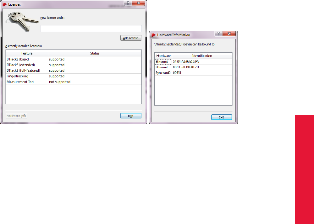
Chapter 4
4.5 DTrack2 frontend software
•Select the feature Fingertracking.
•Click on Hardware Info.
•Contact ART and communicate the serial number of the synccard or the MAC ad-
dress of the Ethernet port (=Identification) in order to receive a license code.
•Enter the license code you received from ART in the field new license code.
•Click on Add license.
(a) Licenses overview (b) Hardware information
Figure 4.44: Managing the licenses
The process is the same for other modules.
Configurations It is possible to create different configurations, e.g. with different tar-
gets or flash settings. These are related to the name of the user and, thus, are easily
accessible.
When creating a new configuration you need to describe your configuration in a few words
(→’description’) and enter your name (→’owner’). The configuration can be changed
later on with Edit (see also figure 4.45).
Your personal configuration is created using the values of the current configuration (→
’clone current configuration’) or default values (→’create with default values’), respec-
tively:
•’clone current configuration’:
all existing calibrations (room and body calibration) and flash settings are inherited.
•’create with default values’:
the system will start from scratch - i.e. as manufactured. That means, you will not
have a room calibration or any body calibrations.
95
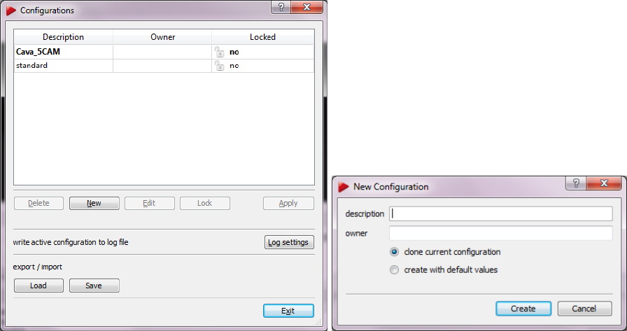
4 System setup
(a) Main window (b) Create a new configuration
Figure 4.45: Managing the configurations
Just press Create and the configuration is saved on the controller.
It is possible to protect the used configuration by pressing the button Lock . Then, you will
be forced to enter a new password and your configuration is locked.
ZPlease do not forget this password!
Existing configurations may be used by selecting the corresponding entry and clicking
Apply. Quit this dialogue by pressing Exit - the configuration is loaded.
Existing configurations can be deleted if not in use any more. Select the entry to be
deleted and click Delete.
Log settings saves the selected configuration in a text file which can be saved on the
remote PC. This function is mainly intended for supplying information to ART in case a
problem arises.
From DTrack2 v2.8.1 it is possible to export and import configurations. ’Save’ will export
the complete active configuration. ’Load’ imports previously saved configurations. The
imported configuration will automatically become the active configuration. It’s possible to
import several configurations at a time.
Please refer to chapter 6.1 on page 147 for detailed information.
96

Chapter 4
4.5 DTrack2 frontend software
When you export a configuration please make sure that you rename it
before exporting, for example by adding the exporting date (e.g. "Stan-
dard 07122012"). Configurations with the same name (e.g. "Standard")
will be overwritten.
Start/Stop Start/Stop measurement.
Search hardware Search for newly added hardware and continue with the system setup
without the need of restarting the controller.
Controller standby Force the controller to go into standby mode with this command.
You can restart the controller by using Wake On LAN. Please refer to chapter 4.2.7 on
page 56 for more details.
Controller reboot Reboot the controller with this command.
Quit Quit DTrack2 frontend software - the active measurement doesn’t have to be
stopped.
4.5.6.3 Menu Settings
Settings Shortcut
Cameras F7
Synccard
Inertial Sensor
ART Radio Info
Tracking
Body Administration F8
Output F9
Fingertracking
Flystick
Measurement Tool
Controller
Cascaded System
Table 4.9: Menu Settings
Cameras This dialogue shows the information about the cameras connected to the sys-
tem and recognized by the software. It allows changes of flash intensity and camera
orientation, as well as settings for modulated flash - either globally for all cameras or
individually. The modulated flash may only be used with active targets. It is used to syn-
chronize an active target.
Changes to the following settings can be made either for all cameras at once, or for each
camera separately. Each camera is represented by a single tab within this window.
97
4 System setup
Room calibration In tab “All Cameras” the “Room cal” column shows which cameras were
used during the room calibration. The ‘yes’ value means that in the latest room calibration
the coordinates of this camera are known. If the camera was not present during the latest
room calibration, this value is ‘no’ and this camera must be re-calibrated to contribute to
the tracking (see section 4.5.2.1 on page 83 on how to add a new camera).
It can also happen that the camera was present during the room calibration, but is not
present anymore (e.g., due to disconnected cable). Such cameras are greyed out and
the only data available are camera type and serial number.
Z
DTrack2 is able to operate although cameras are missing or need to
be (re-)calibrated; for best performance it is highly recommended to
resolve any issues that prevent all available cameras contributing to
the tracking.
Reflex suppression DTrack2 is capable of suppressing reflexes (e.g. sunrays on the floor)
in a static way. However, reflex suppression should always be the last option to be con-
sidered. If possible try adjusting the cameras in order to minimize reflexes. Please refer
to chapter 4.5.1.7 on page 76 for more details.
ZYou should always be aware that reflex suppression results in remov-
ing of the area, in which the reflex originated, from the tracking volume.
There are two possibilities to carry out a reflex suppression:
1. Mark the checkboxes for each camera when you want to suppress reflexes. Af-
terwards, select Calibration →Start Static Reflex Scan for all enabled cameras to
make sure that static reflexes will be suppressed.
2. While measurement is running you may define the areas to be suppressed manu-
ally. In the Monitor 2DOF display, right-click on the respective camera window and
enable ’Edit reflex suppression areas’. Alternatively, you may use the shortcut (’E’)
to enable this mode (shown in figure 4.46(a) on page 99).
Within the edit mode you may (also refer to figure 4.46(b) on page 99)
•create new areas,
•delete areas,
•clear regions,
•resize areas and
•move areas.
Reflex suppression areas are enabled when you leave the edit mode (by disabling
’Edit reflex suppression areas’) and accept the changes. The single areas defined
are stored in the controller and can be edited each time you enter this mode.
98
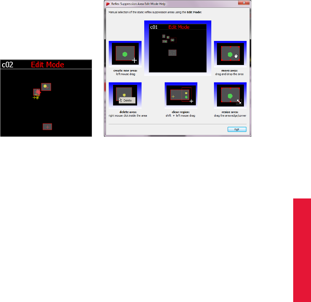
Chapter 4
4.5 DTrack2 frontend software
(a) Reflex suppression edit mode (b) Reflex suppression edit mode help
If you want to disable all reflex suppression areas for a camera at the same time,
just right-click on the respective camera and deactivate the option ’Active’.
Flash settings The flash intensity may be changed within an interval of
•0 .. 6 for ARTTRACK1 ,
•0 .. 8 for ARTTRACK2 /ARTTRACK3 ,
•0 .. 100 for ARTTRACK5 ,ARTTRACK5/C and TRACKPACK/E
•0 .. 7 for TRACKPACK .
i
When using ARTTRACK2/C cameras, it is not possible to adjust the
flash intensity of the respective external flashes with the DTrack2 fron-
tend software!
Please contact ART in case you need to adjust the flash intensity of
the external flashes.
These settings strongly depend on the working area and range. If you have a small work-
ing area where you are close to the cameras small flash intensities may be sufficient.
Otherwise, if your working area is far away from the cameras (but still within tracking
range of the cameras) it may be necessary to change to greater flash intensities.
Generally speaking, you should adjust the flash settings in a way that the recognized
markers are coloured in green or yellow.
99

4 System setup
Keep a distance of min. 20 cm when operating the cameras ! All cam-
eras are assigned to the Exempt Group according to IEC62471-1 and
therefore pose no risk or hazard to the human eye or skin at this dis-
tance.
To be on the safe side, always double-check if the markers of the target are seen properly
by the cameras. Therefore, please use the Monitor 2DOF view:
•markers coloured in red are characterized by bad circularity, small size or low inten-
sity; this may result in poor tracking quality
•markers coloured in yellow offer a good tracking quality
•markers coloured in green offer a very good tracking quality
Increase the flash intensity until all markers are yellow or green (recommended).
Syncgroup For ARTTRACK5 ,ARTTRACK5/C and TRACKPACK systems it is possible
to configure the syncgroups via software. You may change the syncgroups either on the
All Cameras tab or on the one of the respective camera. Possible values are ’Channel 1’,
’Channel 2’ or ’Channel 3’. These settings correspond to the three syncgroups which can
be setup via hardware (daisy-chain cabling) for ARTTRACK systems.
Global camera mode (ARTTRACK5 ,ARTTRACK5/C and TRACKPACK/E only) To switch the cam-
era mode, select the appropriate entry e.g. 1.3 Mpix, max. 150 Hz. Dependent on your
application needs, this function can give you access to:
•higher frame-rates
•lower latencies, i.e delay times (approx. 5 ms @ 0.5 Mpix) Please refer to chapter
A.6 on page 199 for more details.
by selecting smaller field of views.
Be aware, that higher frame-rates come at the cost of the cameras’ reduced field of view
as well as a limited amount of targets that can be tracked simultaneously (lesser amount
of targets @ 300 Hz). The max. frame-rate is defined by the camera with the largest
field of view respectively the max. frame-rate of that individual camera. In mixed systems
ARTTRACK2 or ARTTRACK3 &ARTTRACK5 the max. possible frame-rate is always
limited to 60 Hz.
Global display intensity (ARTTRACK5 only) If necessary the brightness of the status LEDs
and the 2-digit LED matrix display can be dimmed from 0...100%, e.g. when used in
light-sensitive environments (global setting or individually).
Global display mode (ARTTRACK5 only) By default the status LEDs are activated, while the
2-digit LED matrix display shows the currently assigned camera ID. Alternatively select
number of markers / camera ID to display the number of markers in the camera’s field of
view during measurements. The 2-digit LED matrix display can also be deactivated by
selecting only status LEDs (global setting or individually).
100

Chapter 4
4.5 DTrack2 frontend software
Modulated flash The ART tracking system can be used with active markers, i.e. mark-
ers consisting of infrared LEDs instead of retro reflective material (e.g. Fingertracking,
see chapter 5.3 on page 137). This allows both, more robust and longer ranging targets.
These LEDs do not light continuously but also emit light flashes like the camera flash and
thus have to be synchronized with the camera’s timing. This can either be achieved by a
synchronization cable or by using a modulation on the flash.
The option modulated flash, which only appears on the All Cameras tab, allows selecting
one of the cameras to emit the coded flash that triggers active targets. Only one camera
can emit the modulated flash. The modulation reduces the flash intensity in lower flash
settings, so it might be necessary to increase the flash intensity. In higher settings the
reduction is insignificant.
Z
The camera which emits the modulated flash has to be in syncgroup
# 1 ! For ARTTRACK systems this means that the camera has to be
connected to the OUT1 output of the Synccard2. TRACKPACK systems
may be configured via software (refer to chapter Syncgroup above).
Display upside down The checkbox display upside down specifies how the ART camera is
mounted (upright or upside down). This setting does not have any influence on the correct
working of the tracking system because the orientations of the cameras are correctly
determined by the photogrammetric algorithms in any case.
Details Here, it is possible to change the settings concerning markers:
Description
’global marker mode’ configure the marker detection
’global maximum number of markers’ maximum number of markers that a camera is allowed
to see
’global maximum size of markers’ maximum display size of a marker on the sensor
’global minimum size of markers’ minimum display size of a marker on the sensor
Synccard This dialogue shows the model and the serial number of the synccard. Fur-
thermore, it offers a dropdown list to select the mode of synchronization.
Basically, you can select between internal and external synchronization. The further dif-
ferentiation is shown in table 4.10.
101

4 System setup
supported synccard mode field of application
internal generated signal (50 up to 300Hz ARTTRACK5 )
external video signal active-stereo projection with an
analogue video sync signal (=VGA)
external video signal, for validated shutter glasses 1
external video signal, for validated shutter glasses, divisor 2 2
external TTL signal active-stereo projection with a TTL
sync signal
external TTL signal, for validated shutter glasses 1
external TTL signal both edges 3
external TTL signal both edges, for validated shutter glasses 1 3
direct settings advanced custom settings
1predefined settings that should be used with the shutter glasses mentioned in table 4.11
2if, additionally, the frequency of the external synchronization signal is greater than 60Hz, this mode
should be used
3available only for Synccard3
Table 4.10: Overview of the supported synccard modes
If you select ’direct settings’ you may use advanced options for configuring the synccard:
Option Description
source configure the type of synchronization to be ’internal’, ’video’,
’ttl’, ’ttlinv’ or ’ttlboth’
frequency [Hz] change the frequency in an interval of 10 Hz up to 300 Hz
(only for internal synchronization and dependent on camera
mode when using ARTTRACK5 or TRACKPACK/E !
divisor for external signal reduce the tracking frequency (only for external synchroniza-
tion!)
Delay [us] configure the delay between the syncgroups
Brand Type
RealD CrystalEyes 1, 2, 3, 5
NuVision APG6000, APG6100
XPand X101, X103 (with NuVision Long-Range Emitter), X104LX
NVidia 3D Vision Pro (RF sync’ed)
Volfoni EDGE (with Volfoni or NuVision LR Emitter)
Virtalis ActiveWorks 500
Table 4.11: Overview of validated shutter glasses
Inertial Sensor In this dialogue all available wireless transceivers (dongles) are shown.
Furthermore, it is possible to set the frequency the sensors are operating at (default: 100
Hz). Additionally all inertial sensors that have been previously added to the DTrack2 con-
figuration are listed with the following properties:
•Device ID + wireless icon
•Model (e.g. Colibri Wireless)
102

Chapter 4
4.5 DTrack2 frontend software
•Name (targets from Hybrid Motion Capture suit or user-defined)
•Firmware Version
•Currently used channel (default: 35 / 55)
•Wake-up mode (radio, tapping, USB/button)
•Battery level
•Temperature (only during measurement)
Z
The default channels for all dongles and sensors are 35 and 55. In
case these WLAN frequencies are already occupied by other devices
in range, connection problems may occur. ART recommends to scan
for available channels and to select free channels accordingly. Keep a
minimum distance of 10 channels between dongles or from otherwise
unavailable channels for optimum connectivity.
ZFor optimal battery life, ART recommends to switch all sensors to
wake-up mode "USB/button" when not in use for a longer period of
time.
For more information, please refer to chapter 4.4 on page 63.
ART Radio Info When you are using a Flystick, for example, you will get information
about the used transceiver and the Flystick device itself. The following information is
offered:
Description
’Model’ the model of the transceiver or the device respectively
’Serial’ the serial number
’Version’ the firmware version
’Is free (only for Devices)’ the device is not free (= ’no’) if it is assigned to an interaction
device ID
’Is present’ the device or the transceiver is present in the tracking volume
By clicking the button Show details the current channel of the radio transceiver is shown.
By default the radio transceiver is automatically selecting a radio channel during booting.
You may also select an appropriate channel manually using the drop-down menu ’set
channel number’. The setting is saved persistently.
Tracking In this dialogue you can configure whether 3DOF markers are calculated or
not and you can enable or disable the ’automatic start of measurement after booting’.
Also, you can globally define the ’central axis’ for all 5DOF targets. For these the rotation
around the body axis cannot be measured by the tracking system. This rotation is there-
fore set to a certain value by the system. Thus, the 5DOF central axis is only important if
you intend to use the rotation around the body axis. The most important properties are:
103
4 System setup
•If the 5DOF body is positioned parallel to the 5DOF central axis the rotation around
the body axis remains undetermined.
•The rotation around the body axis is reduced to a minimum.
We recommend that you choose the 5DOF central axis as the direction which is the least
often parallel to the tracked body axis (e.g. floor to celling for glasses targets).
iThe best choice for the 5DOF ’central axis’ may be found when using
the tracking data in your appplication.
Details of the definition:
In addition to the 5DOF central axis the system selects an axis for each body in the body
coordinate system (i.e. "pulled axis"). The rotation around the body axis is set to the value
minimizing the angle between the pulled axis and the 5DOF central axis. The pulled axis
is always perpendicular to the body axis. In addition the following criteria are used:
•If the 5DOF central axis is not the body axis the pulled axis is the axis minimizing
the angle to the 5DOF central axis.
•If the 5DOF central axis is the body axis the pulled axis has a random direction in
the plain.
The ’automatic restart of measurement after loss of sync signal’ option is set to ’active’
by default and therefore, it is not shown anymore (from DTrack2 v2.8.1).
Body Administration The menu allows for administering all targets (e.g. Standard,
Flystick, etc.) in the system (refer to figure 4.46).
The number of 6DOF bodies represents the number of targets that should be tracked. In
this context, the number of targets does not include the interaction devices (e.g. Flystick,
Fingertracking or Measurement Tool ). These are completely configurable in separate
tabs.
iHowever, the maximum total number of bodies that may be used in
ART systems includes the calibrated interaction devices (Fingertrack-
ing, Flystick, Measurement Tool )!
Here, you can activate, delete or reset target calibrations and change the order of the
single targets. Additionally, you get the information by which means the target has been
calibrated:
•’Custom’ means that the standard body calibration has been used.
•’Target Library’ means that the predefined calibration file from the system has been
used.
For a detailed description of the single actions please refer to table 4.12.
104
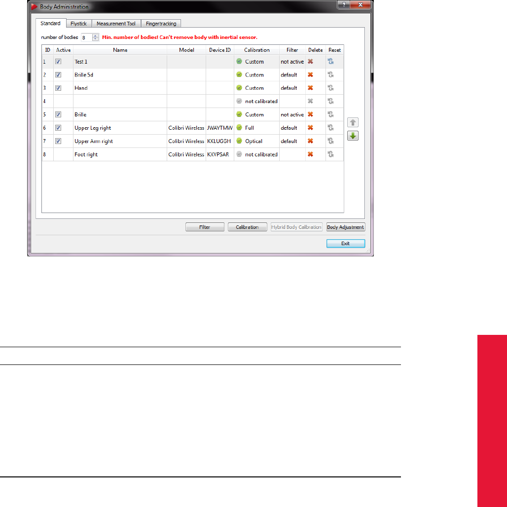
Chapter 4
4.5 DTrack2 frontend software
Figure 4.46: Flexible Body Administration (from DTrack2 v2.9.0)
Action Description
’Active’ Activate or deactivate a target. Data of deactivated targets will not be
transmitted in the data stream. The target order will not be affected.
’Delete’ Deletes the calibration of a target - effective immediately after confirm-
ing the security query. The target order will not be affected.
’Reset’ In case the target has been calibrated initially with the ’Target Library’
and re-calibrated later by the user, it is possible to reset the calibration
to ’Target Library ’.
’Change order’ With the arrows on the right-hand side of the window you may change
the order of the targets. The data output will change accordingly.
Table 4.12: Body Administration - Detailed description of the actions
As mentioned before you can administer interaction devices as well. Therefore, you may
use the tabs Flystick,Measurement Tool and Fingertracking.
In the bottom right of the dialogue you will find four buttons:
105
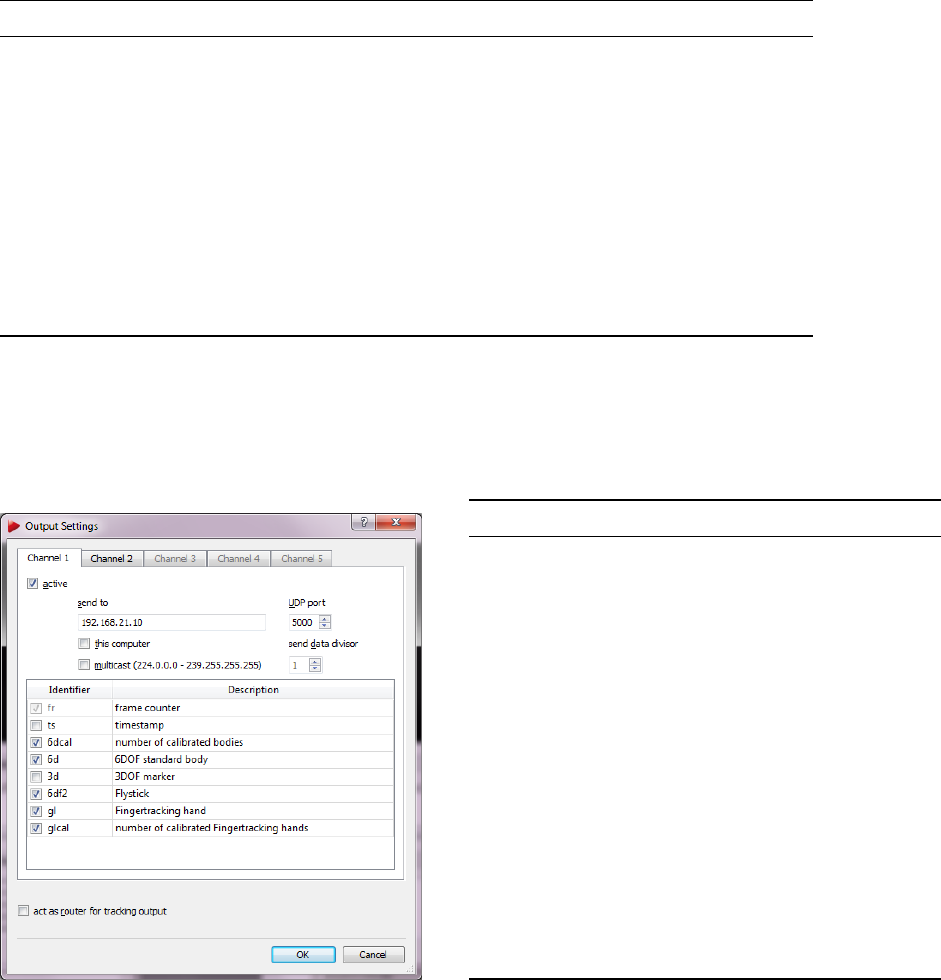
4 System setup
Button Description
’Filter’ Activate or deactivate the filter for each target. You can either use de-
fined presets or customize it to your requirements. A detailed descrip-
tion of the filtering options can be found in chapter 4.5.5 on page 91.
’Calibration’ Directly access the Body Calibration dialogue and perform the calibra-
tion for the selected target. A detailed description for body calibration
can be found in chapter 4.5.3 on page 84.
’Hybrid Body
Calibration’
Directly access the Hybrid Body Calibration dialogue and perform the
calibration for the selected hybrid target. A detailed description for hy-
brid body calibration can be found in chapter 4.4 on page 66.
’Body Adjust-
ment’
Directly access the Body Adjustment dialogue and perform the neces-
sary adjustment for the selected target. A detailed description for body
adjustment can be found in chapter 4.5.4 on page 90.
Output The dialogue Output determines the settings of data output via Ethernet. Data
output will be enabled when you tick the checkbox active.
Figure 4.47: Output settings
Identifier Description
fr frame counter
ts timestamp
6dcal number of adjusted bodies
6d 6DOF standard body
3d 3DOF marker
6df2 Flystick
6dmt Measurement Tool
6dmtr Measurement Tool reference
6dmt2 Measurement Tool (also for ball
probes)
gl Fingertracking hand
glcal number of calibrated Fingertracking
hands
6di 6D inertial body
6df Flystick (old)
only available if activated in Flystick
settings (→checkbox ’use old output
format’)
Table 4.13: Output identifiers
ZWhen using the ’timestamp’ please note the remarks on accuracy in
chapter B.2.2 on page 211.
In total, up to 5 UDP channels for DTrack2 data output can be configured. Tick the check-
box this computer to send data to the remote PC you are currently working at. If you want
to send data to any computer within your local network just enter the IP address of the re-
ceiver and a port number. In addition, it is possible to define a multicast output. By ticking
this checkbox the UDP data is sent to a group of addresses in the range of 224.0.1.0 to
239.255.255.255.
106
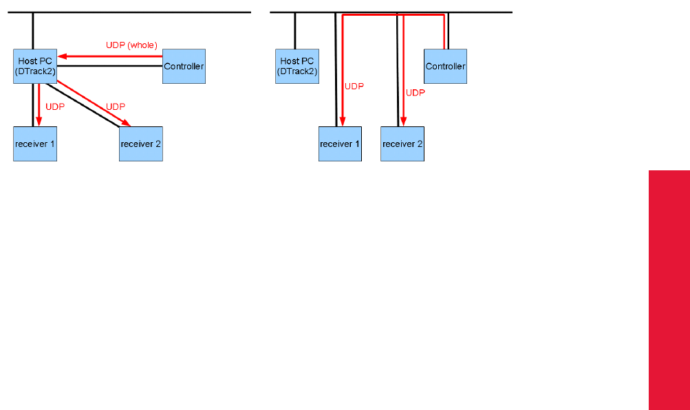
Chapter 4
4.5 DTrack2 frontend software
In order to reduce the data of the UDP output data stream you may set the ’send data
divisor’ to values from 1 to 10. The numbers have the following meaning:
•1 .. every frame is transmitted,
•2 .. every second frame is transmitted,
•...
•10 .. every tenth frame is transmitted.
The UDP output data may be routed by DTrack2 by ticking the checkbox act as router
for tracking output. This functionality is especially important for customers where it is not
allowed to connect the controller to their local network due to security reasons.
(a) act as router enabled (b) act as router disabled
The mandatory requirement to use this function is that the PC, where DTrack2 is installed,
needs to have two separate Ethernet plugs: one for connecting to the controller and one
for the respective local network. The DTrack2 frontend reads the data from the controller
and routes it to the local network where the application PC is connected to.
iUsing this function will cause a short delay during forwarding of the
data.
ZDo not use this function if the application PC and the controller are in
the same network!
Please refer to chapter B on page 203 for the format of the data output.
Fingertracking Here, you can define the number of hands to be used (values: 0 ..
4). Based upon this value, the correct number of selected hands is shown. By default,
the hand geometry is ’none’ and the field Simulate 5 Fingers is empty until you carried
out a calibration of the fingers (→hand geometry). Then, the hand geometry will change
into the name you defined during calibration of the fingers. If you are using a three finger
thimble set but want to get output data for five fingers you may tick the checkbox 3 ->5.
The software DTrack2 will move the two missing fingers parallel to the third finger.
107

4 System setup
It is possible to save several hand geometries in DTrack2 - these will appear in available
hand geometries. So you can use your Fingertracking set with different people and, most
important, you need to calibrate the Fingertracking set only once for each person.
From DTrack2 v2.8.1 on it is possible to export (’Save’), import (’Load’) and remove
(’Delete’) available hand geometries. Just press ’Save’ and select the hand geometries
you want to export and save them at your desired location.
For importing a stored hand geometrie just press ’Load’ and change to the respective di-
rectory, select the appropriate file and press ’OK ’. The hand geometrie may now be used
as follows.
Now, just assign the desired hand geometry to the respective hand ID and use Finger-
tracking. Therefore,
•mark the respective hand ID,
•mark the desired hand geometry and
•press Select.
Repeat the steps if you want to use another hand.
Please refer to chapter 5.3 on page 137 to learn how to install Fingertracking.
Flystick In the Flystick Settings you can define the number of Flysticks to be used (max.
20).
Checkbox Description
’use old output format’ Use the output format of the old Flystick1 (see chap-
ter B on page 203)
’activate MultiUser function’ Refer to page 130 in chapter 5.1 for more informa-
tion.
’use head targets’ The data pair (Flystick and head target) of one user
is made available as output data (if MultiUser func-
tion is activated).
Table 4.14: Flystick settings - Description of the checkboxes
Below, there are two more properties which can be configured for Flystick3:
•sync groups:
Configure your active(!) Flystick3 to send out IR flashes for one or more syncgroups
(syncgroup #1, syncgroups #1 and #2, . . . ; default = syncgroup #1).
•flash intensity:
Set the flash intensity of the active target of the Flystick3 (default = 3) by moving the
slider.
108

Chapter 4
4.5 DTrack2 frontend software
If you change the number of Flysticks you will immediately recognize entries in the se-
lected Flysticks field. The fields Model,Serial and Port are empty by default.
Make sure that your Flystick is in the available Flysticks list - if necessary, compare the
serial number listed here to the one printed on the battery compartment of the Flystick2 or
on the back cover of the Flystick3. Now, you have to assign your Flystick to the respective
Flystick ID.
Therefore,
•mark the respective Flystick ID,
•mark the desired available Flystick and
•press Select.
Repeat these steps if you want to use another Flystick. Please refer to chapter 5.1 on
page 126 to learn how to install the Flystick2 and refer to chapter 5.2 on page 132 for the
Flystick3.
There are one or two Flystick1 entries in the list available Flysticks, even if no Flystick1
is present in the volume. This is due to the fact that the Flystick1 connects via serial
COMport which cannot be polled automatically. If you are using a Flystick1 please refer
to the Flystick1 manual.
Measurement Tool Within the Measurement Tool dialogue you may define the number
of Measurement Tools and the number of references. It is limited to a total number of
four each.
Below, there are several fields where you may change the default values within the allowed
ranges to suit your application.
Control Description
’number of Measurement Tools ’ configure the number of devices to be used
’number of references’ configure the number of reference bodies to be used
’measurement duration [s]’ configure the time to perform a measurement with
the Measurement Tool (valid range: 0.2 - 10.0 sec)
’tool tip tolerance [mm]’ specify the range within which the tip is assumed to
be static (valid range: 0.1 - 5.0 mm)
’activate measurement start simula-
tion’
activate the start button simulation and enable the
respective controls
’minimal angular variation [deg]’ specify the minimum angle that the Measurement
Tool has to be tilted over to start a measurement
(valid range: 10◦- 120◦)
’maximum lead time for this angular
variation [s]’
waiting time before the measurement start by the
start button simulation
Table 4.15: Measurement Tool settings
If you are working with a reference body you may assign it to a specific ’Measurement
Tool ID’:
109
4 System setup
•mark the respective Measurement Tool ,
•mark the reference body and
•press Select.
Repeat these steps if you want to assign references to other Measurement Tools .
Please refer to chapter 5.4 on page 144 to learn how to install the Measurement Tool .
Controller The menu for the Advanced Controller Settings is divided into two tabs - Net-
work and Time.
On the Network tab you may change the hostname (not recommended!) and the domain
according to your network guidelines. When the network cable has been plugged into the
controller while booting, the controller is a DHCP client and the checkbox is ticked. If the
network cable is unplugged while booting the controller uses its default IP address (i.e.
192.168.0.1).
You may also specify IP address,subnet mask,gateway and nameserver as desired.
The MAC address of the controller is printed in the last line for your information (ethernet-
MAC LAN).
On the Time tab you can set the UTC time of the controller. Furthermore, you can syn-
chronize the UTC (=Universal Time Coordinated) time using NTP (=Network Time Proto-
col). NTP is a protocol designed to synchronize the clocks of computers over a network.
Tick the checkbox activate NTP and enter hostname or IP address of your server.
If NTP is activated the controller is trying to connect to the NTP server repeatedly in or-
der to update its clock. The values for ’reachability’ range between 0% - 100% (typically).
They are a measure for the quality of the reachability of the NTP server. Only NTP servers
which are contacted over the internet may provoke some problems. The quality of the syn-
chronization of the clocks is indicated with ’estimitated precision’ in the unit milliseconds
(=ms).
iSynchronizing with NTP takes quite a long time. Active measurements
won’t be disturbed.
Cascaded System Cascading means that two or more stand-alone tracking systems
are combined to one large system in order to have only one consolidated data out-
put. It is possible to cascade TRACKPACK/E systems with or without ARTTRACK5 and
ARTTRACK5/C and to build cascades out of ARTTRACK (discontinued) with TRACK-
PACK systems (discontinued). Therefore, the system is subdivided into one master and
up to eight slaves. However, the total number of cameras in the cascaded system cannot
exceed 16 for TRACKPACK/E only systems and 50 for combined ARTTRACK5 &ART-
TRACK5/C and TRACKPACK/E systems respectively.
The task of the master is to gather all single data outputs from all slaves and to merge
them into one single data output. The DTrack2 frontend connects to the master only and
allows to configure (e.g. cameras, output, tracking, etc.) the entire tracking system as
110

Chapter 4
4.5 DTrack2 frontend software
usual.
Z
The master has to be an ARTTRACK Controller with "full-featured" li-
cense (< DTrack2 2.10) and a Synccard2.
Starting with DTrack2 version v2.10 a new license model has been es-
tablished. The master controller needs to have a dedicated "cascaded
systems" license as well as a sufficient license for ALL cameras in the
cascade, e.g. 4 ARTTRACK5 + 4 TRACKPACK/E cameras = license for
8 cameras.
In order to configure the cascaded system you have to start the DTrack2 frontend soft-
ware and establish a connection to the master.
Go to Settings →Cascaded System to enter the configuration dialogue for the cascaded
system. Basically, you have the choice between ’scan LAN’ or entering a ’slave host-
name or IP address’ directly. For the latter one, you need to know the hostname or the
IP address of your slave(s) when using DHCP or in case you have set a specific static IP
address. The button ’Update’ refreshes the list.
On the right-hand side of the dialogue you will be presented a list of ’Available’ controllers
(i.e. which can become a slave in the cascaded system). Mark the desired controller
and press the button ’Select’ to assign this controller to the cascaded system. It will then
appear on the left-hand side of the dialogue in the list of the ’Selected’ controllers.
Mark controllers in the list of the ’Selected’ controllers to remove them from the cascaded
system by clicking the button ’Deselect’.
If the checkbox ’wake on LAN’ is ticked, all connected slaves will go to standby mode or
reboot if the master goes to standby mode or reboots.
Refer to chapter 4.3 on page 58 for more information on the cascaded system.
4.5.6.4 Menu Calibration
Calibration Shortcut
Start static reflex scan for all en-
abled cameras
Inertial Sensor Calibration
Room F5
Room adjustment Shift + F5
Body F6
Body adjustment Shift + F6
Fingertracking
Measurement Tool
Table 4.16: Menu Calibration
Start static reflex scan for all enabled cameras All ART cameras are able to sup-
press all reflexes in certain areas of the image sensor. This is especially important for
111
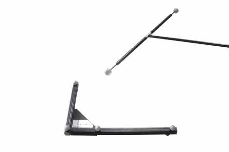
4 System setup
setups in multisided projections: these cameras are mounted in the corners of the multi-
sided projection and usually get a lot of unwanted reflexes from the nearby walls. To gain
good tracking results, these reflexes should be suppressed. The feature can be enabled
or disabled either globally for all cameras or individually for each camera in the camera
settings. Scanning for static reflexes allows searching the measurement volume for un-
wanted reflexes. Areas are defined around the visible reflexes, where all reflexes should
be suppressed later during measurements.
ZBe sure to remove all targets from the measurement volume before
starting the scan.
Inertial Sensor Calibration This function carries out a drift correction for all inertial
sensors. Please refer to chapter 4.4 on page 63 for more information.
Room Use the room calibration menu to configure your room calibration set concerning
wand length and marker distances. The wand length is printed on a label on the wand -
please enter the value here.
Figure 4.48: A room calibration set consisting of angle and wand
Marker distances defines the type of room calibration set - it can either be Room Cali-
bration Set TP,Room Calibration Set 410 or Room Calibration Set 710. When choosing
expert the angle of the room calibration set may be defined by the user. Then, the dis-
tances between the markers on the angle have to be configured.
Define the coordinate system as ’normal’ or ’powerwall’. The layout of the coordinate
system is shown in the 4.49 on page 113. You may adjust the ’duration’ of the room
calibration (→Show details) in a range of 10s - 100s. Resetting the value to default is
achieved by pressing the Set to default button (default = 30s).
Z
Changing the duration of the room calibration, especially towards
shorter durations, may lead to bad room calibration results! Please
make sure that you are always able to cover two thirds of the tracking
volume within the set time.
112
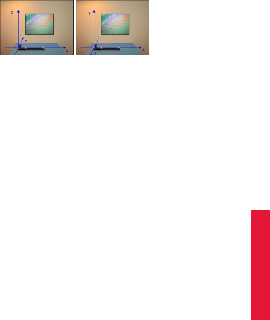
Chapter 4
4.5 DTrack2 frontend software
(a) ’normal’ (b) ’powerwall’
Figure 4.49: Defining the coordinate system for the room calibration
If you are re-calibrating your room use the checkbox re-calibration in the bottom left cor-
ner to indicate it to the tracking system. For more information about room re-calibration
please refer to page 82.
Please refer to chapter 4.5.2 on page 77 for the details on how to perform a room calibra-
tion.
Room adjustment During a room calibration origin and orientation of the room coordi-
nate system are located by the position of the calibration angle; e.g. the reflective marker
in the angle’s vertex (marker #1) defines the origin of the coordinate system. Oftentimes
it might be more suitable to set the coordinate system in respect to well-known points in
space.
Possible scenarios for the application of the Room adjustment functionality are:
•adjust the origin to the center of a screen
•align the coordinate system colinear / parallel to a screen (even very small angular
deviations might lead to substantial misalignment over the full width of the projection
0.1◦on 5m length equals 8.7 mm deviation)
•shift and / or rotate the camera coordinate system to match a reference coordinate
system, e.g. from CAD models
•maintaining a specific coordinate system / orientation when using mobile installa-
tions of cameras, i.e. frequently changing the camera setup locations (suitable ref-
erence points provided)
In all these cases the coordinate system must be altered after calibration.
Z
If you press Enter or click OK , all changes which have been done so far
will be confirmed (changes are sent to the controller) and the dialogue
closes. Pressing Apply accepts the current changes, but the dialogue
is left open. Discard all changes by pressing Cancel.
Coarse The Coarse tab offers a simple way to manipulate the orientation of the room
coordinate system with just one click (see figure 4.50 on page 114. You can define the
orientation of two axes using the drop-down menus - the third one will be oriented auto-
113
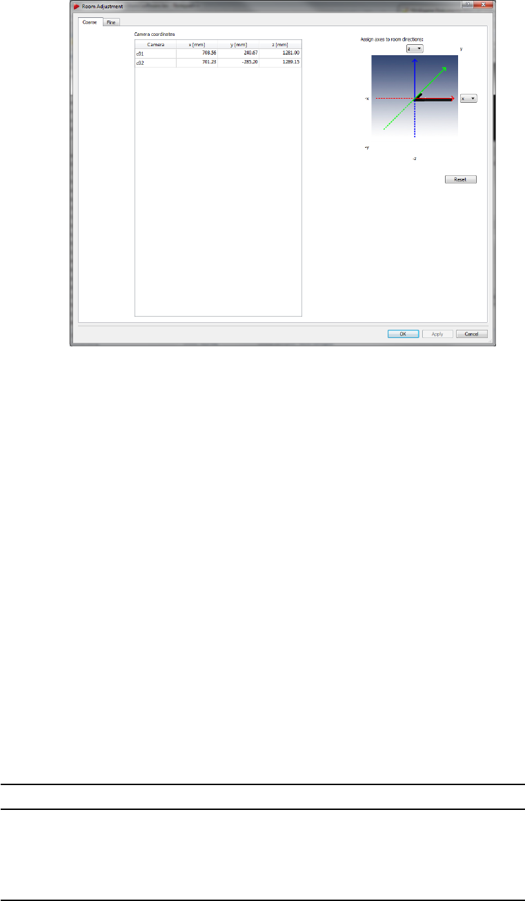
4 System setup
matically according to the right-hand rule. Press Reset to switch back to the unmodified
state.
Figure 4.50: Room adjustment dialogue (coarse)
Fine More detailed options to adjust the room coordinate system are given in the Fine
tab (see figure 4.51 on page 115). By default a cartesian coordinate system is displayed
on the left side of the window. The room coordinate system is shown as a triplet of arrows
with a defined color-coding (x-axis: red, y-axis: green, z-axis: blue), while the xy-plane is
shown as a yellow grid. The current and the transformed room coordinate systems are
marked with (’O’) and (’T’) respectively.
The View position and View orientation may be moved along and / or rotated around all
axes in two different ways:
1. hold down the "Ctrl" key and the left / right mouse button to change the position /
orientation
2. hold down the "Ctrl" key and use the mouse wheel to zoom
3. use the six control dials (below the graphical view) to adjust position and orientation
To center the current room coordinate system, press ’Adjust view’. To restore the default
view (shift and orientation), press ’Reset view’. The visualisation itself can be changed
by clicking the right mouse button to open a menu with the following options. (De-)select
the appropriate ones by (un-)ticking.
Option Description
’Long axes’ extends the coordinate axes of the body coordinate system by
infinite dashed lines
’Show XY plane’ shows the XY plane (yellow grid)
’Show YZ plane’ shows the YZ plane (cyan grid)
’Show XZ plane’ shows the XZ plane (magenta grid)
114
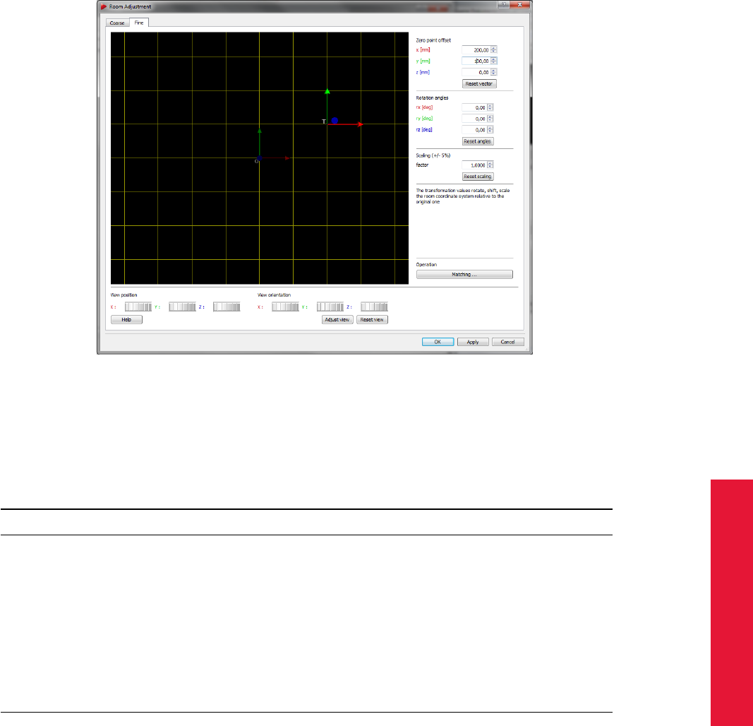
Chapter 4
4.5 DTrack2 frontend software
Figure 4.51: Room adjustment dialogue (fine)
On the right side of the window the room coordinate system may be customized freely,
i.e. user-specific.
Action Description
Zero point offset [mm] translate the room coordinate system along its axes in steps of 1mm
Reset vector reset the zero point offset to the unmodified state (0.00 mm)
Rotation angles [deg] rotate the room coordinate system around its axes (from -180 to +180
◦)
Reset angles reset the rotation angles to the unmodified state (0.00 ◦)
Scaling factor enlarge / shrink the room coordinate system uniformly up to a factor of
+/-5 percent
Reset scaling reset the scaling factor to the unmodified state (1.0000)
Matching start up a module for transforming and matching to a reference coordi-
nate system (Measurement Tool & license provided)
All entered transformation values are given in the original room coordinate system.
Example: let’s assume a standard room coordinate system (xy plane on the ground, z
axis facing upwards) that was calibrated using a “Room Calibration Set” RCS 410. So the
current origin is located 43 mm above the ground (refer to chapter 4.5.2 on page 77 about
details). If the new desired origin should be placed 1 m above the ground, then the Zero
point offset for z must be 957 mm (1000 mm - 43 mm).
Transform Press Matching in the Fine tab to open the room matching dialogue (see
figure 4.52 on page 117). This functionality depends on the Measurement Tool license.
115
4 System setup
iIf the Measurement Tool is not tracked (calibration provided) matching
cannot be performed. Use an authorised Measurement Tool by ART for
best results.
ZDeselect any previously assigned Measurement Tool References prior
to matching of the coordinate systems. Otherwise matching results
will be erroneous.
The purpose of the coordinate transformation is to convert the origin and orientation of the
initial camera coordinate system (indicated with ’O’) into a reference coordinate system
(indicated with ’T’), e.g. given by a certain object or CAD model. All measurement data
will be transformed with respect to the reference coordinate system (’T’). To this end a
three-step calibration procedure has to be performed:
1. Add measurement data from the reference coordinate system (’T’) by manually en-
tering the coordinates into the table reference points using the button Add. A mini-
mum of three (3) data points is necessary for calculations. Delete single data points
by selecting the corresponding row and press Remove. Alternatively load the coor-
dinates from a text file (ASCII) using the button Load. The text file must comply to
the following format:
1 1.00 20.00 300.00 <CRLF>
2 4.00 50.00 600.00 <CRLF>
3 7.00 80.00 900.00 <CRLF>
# x y z <CRLF>
The import strictly follows the sequence from the ASCII text file. The current set of
reference points can be saved by pressing Save.
2. Select a calibrated and tracked Measurement Tool from the drop-down menu and
measure all points (e.g. on the corresponding object) which directly relate to the
reference points (e.g. from a CAD model) defined in step 1.
Each measurement can be started by:
•clicking the button Measure
•clicking the start button on the Measurement Tool (if applicable)
•using the “measurement start simulation” of the Measurement Tool (refer to 5.4
on page 144)
•clicking a button of an assigned Flystick
The following calculations try to correct the order of the measured points, if they
don’t correspond to the order of the reference points. Sometimes this does not
produce the correct result, especially if the points are located too symmetrically
toward each other. In this case toggle the tickbox preserve order of points to lock
the order between reference points and measured points.
ZFor proper matching it is essential to ensure the correct correspon-
dence between reference points and measured points.
116
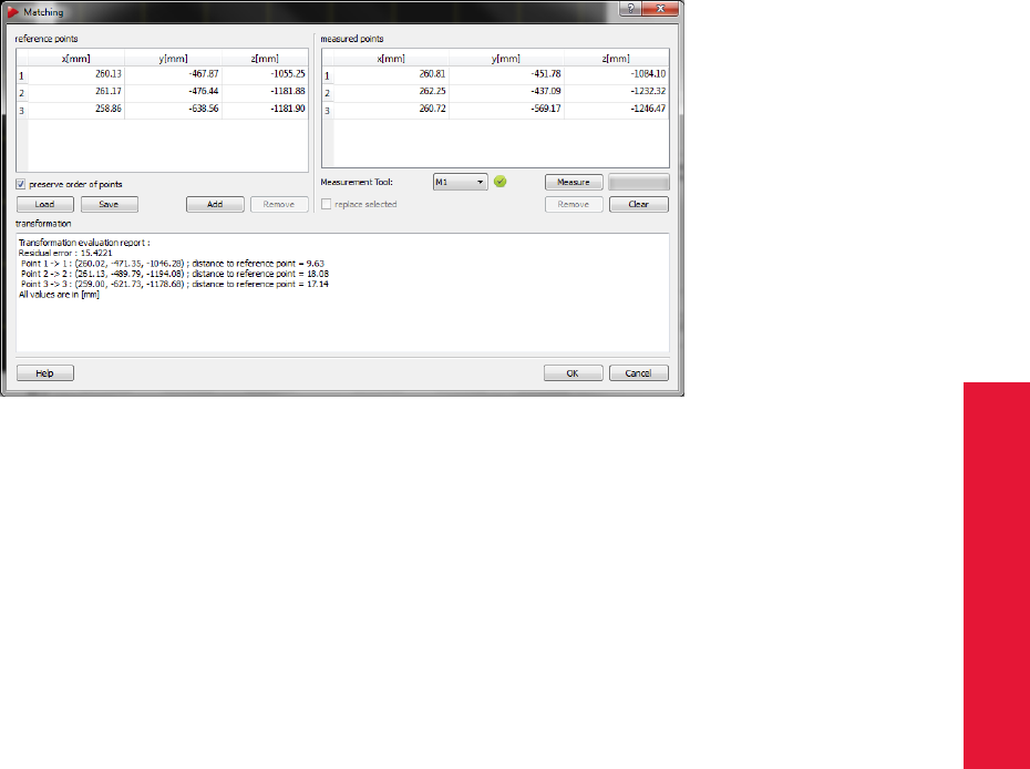
Chapter 4
4.5 DTrack2 frontend software
3. After having measured all corresponding points the calculation is started automati-
cally and the result of the transformation is displayed in the textbox transformation.
Double-check that all measured data points correspond to the correct reference data
points. Delete single data points by selecting the corresponding row and press Re-
move or delete all data points to start all over by pressing Clear . The residual error
(standard deviation) is a measure of the transformation quality, i.e. how well the
measured data fit the corresponding reference points. It can be influenced mostly
by the quality of data acquisition and by differences in scale of the camera and refer-
ence coordinate systems. Pressing OK accepts this transformation and closes the
dialogue box.
Figure 4.52: Room matching dialogue
The calculated transformation is applied on both zero point offset as well as rotation
angles in Fine tab. Do not further manipulate the values manually. Press Enter or click OK
to confirm the resulting transformation and to close the dialogue. Pressing Apply accepts
the current changes and leaves the dialogue open. Discard all changes by pressing
Cancel.
Body Select the body you want to calibrate and tick the checkbox if you want to perform
a re-calibration. Define the type and the coordinate system which should be used for the
calibration.
If you want to use body calibration files for calibrating your target, just click Load file(s)
and select the appropriate calibration file(s). By clicking on Save file(s) you can save your
body calibrations in separate text files.
Please refer to chapter 4.5.3 on page 84 for the details on how to perform a body calibra-
tion.
Body adjustment Use this menu (see figure 4.43 on 90) to visualise and manipulate
calibration data of rigid bodies. Just select the desired body from the drop-down list at the
117
4 System setup
top of the window. By default a cartesian coordinate system is displayed on the left side
of the window depicting the selected rigid body’s geometry (’Graphic view’).
The body coordinate system is shown as a triplet of arrows with a defined color-coding
(x-axis: red, y-axis: green, z-axis: blue), while the xy-plane is shown as a yellow grid. All
markers, however, are visualised by sequentially colored spheres (RGB) for better iden-
tification. In case the selected rigid body features visibility restrictions, emission cones
may have been predefined. Direction of visibility (emission vector) is depicted as an ar-
row (white) for each marker, while the angular restriction (emission aperture) is shown as
a cone (grey).
The View position and View orientation may be moved along and/or rotated around all
axes in two different ways:
1. hold down the "Ctrl" key and the left / right mouse button to change the position /
orientation
2. hold down the "Ctrl" key and use the mouse wheel to zoom
3. use the six control dials (below ’Graphic view’) to adjust position and orientation
To restore the default view, just press ’Reset view’. Tick the ’use tracked orientation’
checkbox to switch to online mode (i.e. the 3D-representation of the target in the ’Graphic
view’ is depicting movements / rotation of the target in the "real world").
The visualisation can be changed by clicking the right mouse button to open a menu with
the following options. (De-)select the appropriate ones by (un-)ticking.
Option Description
’Small markers’ reduces the size of the markers
’Colored markers’ shows the markers in different colors (untick: greyish)
’Emissions’ shows predefined direction (arrows) and angular restriction
(cones) of visibility (if applicable)
’Long axes’ extends the coordinate axes of the body coordinate system by
infinite dashed lines
’Show COG’ shows the body’s center of gravity (white square)
’Show XY plane’ shows the XY plane (yellow grid)
’Show YZ plane’ shows the YZ plane (cyan grid)
’Show XZ plane’ shows the XZ plane (magenta grid)
’Show room orientation’ shows the room coordinate system (only available when check-
box ’use tracked orientation’ is ticked)
’Add line between markers’ adds a line between two selected markers (option greyed out until
two markers are selected)
’Delete line between markers’ removes a line between two selected markers (option greyed out
until line is selected)
’Data view’ switches to the data view
For manipulating the body geometry you have the choice between general or special
options:
General The body coordinate system may be customized freely, i.e. user-specific.
118

Chapter 4
4.5 DTrack2 frontend software
Action Description
Body position [mm] translate the body coordinate system along its axes in steps of 1mm
Body orientation [deg] rotate the body coordinate system around its axes
Set origin activate a marker in the ’Graphic view’ by left-clicking with the mouse.
The marker is highlighted and the button Set origin is activated. Press-
ing this button translates the origin of the body coordinate system into
the center of the selected marker.
Set origin to COG translate the origin of the body coordinate system into the target’s center
of gravity
Set axis activate two markers sequentially in the ’Graphic view’ by left-clicking
with the mouse. The first one is highlighted in white, the second one in
grey. Additionally, the button Set axis is activated. Pressing this button
opens a dialogue to configure the transformation.
Adjust axes to room pressing this button aligns the body coordinate system collinear to the
room coordinate system
Delete marker activate a marker in the ’Graphic view’ by left-clicking with the mouse.
The marker is highlighted and the button Delete marker is activated.
Pressing this button removes the selected marker from the target ge-
ometry.
Special Choose from the following predefined transformations:
•due to body
The body coordinate system is completely defined by the target geometry (see page
86).
•due to room (origin in COG)
The coordinate system is rotated and aligned collinear to the room coordinate sys-
tem with the origin set in the center of gravity (COG) (see page 86). In order to use
this function, the checkbox ’use tracked orientation’ has to be ticked.
•due to room (origin in marker)
The coordinate system is rotated and aligned collinear to the room coordinate sys-
tem with the origin set in one specific marker (see page 86). In order to use this
function, the checkbox ’use tracked orientation’ has to be ticked.
iPredefined visibility restrictions (emission vectors and angles of aper-
ture) are retained along all body transformations.
Z
If you press Enter or click OK , all changes which have been done for
all bodies will be confirmed (changes are sent to the controller) and
the dialogue closes.
Pressing Apply only results in changes of the currently selected body
- the body will be redrawn afterwards.
Z
If the MultiUser function for Flysticks is enabled the Body Adjustment
module will only load standard bodies. If you want to adjust the body
calibration data of your Flystick, please make sure that the MultiUser
function is disabled (Settings →Flystick) - a label ’MultiUser function
should be disabled!’ will appear at the bottom of the dialogue.
119

4 System setup
Hybrid Body This function performs a hand-eye calibration to combine an inertial sen-
sor with its corresponding optical target. Please refer to chapter 4.4 on page 66 for more
information.
Fingertracking Define a new or select an existing ’hand geometry name’. Configure
handedness as being ’left’ or ’right’. Select the type of fingerset.
When clicking on the button Help a pop-up window appears where the calibration process
is explained and visualized.
Please refer to chapter 5.3 on page 142 for more information.
Measurement Tool Perform a tip calibration for the Measurement Tool that is currently
inside the tracking volume. DTrack2 automatically detects the ID of the Measurement
Tool and assigns the tip calibration. Just press Calibrate to start the calibration process.
During calibration please move the Measurement Tool while keeping the tip still at exactly
one position.
ZNote that the progress bar is not continuing if the pointing device is
not moved sufficiently.
Please refer to chapter 5.4 on page 145 for more information.
4.5.6.5 Menu Display
Display Shortcut
Monitor 2DOF
Data F10
Fingertracking
Flystick
Measurement Tool
Events
Set to default
Table 4.17: Menu Display
Monitor 2DOF The Monitor 2DOF display essentially is a graphical display of the field
of view of the IR cameras and of the markers that are seen by the cameras. The Monitor
2DOF display shows a black window for each IR camera (equivalent to the field of view),
with a schematic display of positions and sizes of all recognized markers.
In case, several ARTTRACK cameras are being used in one system, it will be helpful
that the number of cameras shown in the Monitor 2DOF display can be adjusted. From
DTrack2 v2.8.1 you may use the slider ’cameras per tab’ in order to achieve clear ar-
rangement. Tabs containing the remaining cameras will be added to the Monitor 2DOF
display.
120

Chapter 4
4.5 DTrack2 frontend software
The special tab ’most active cameras’ contains these cameras which see the markers of
the targets most of the time.
Example: consider a four camera system with camera01 thru camera04 and you have
set the number of ’cameras per tab’ to two. Now, if you move a target in front of camera02
and camera03 most of the time, these two cameras will then be shown in the ’most active
cameras’ tab.
A simple color code signifies the size and the circularity of the markers (green = very
good quality, yellow = good quality, red = poor quality). Each marker is either displayed
as a circle or as a cross. This indicates the projected size of the marker on the CCD chip
inside the camera (i.e. circle = big marker and cross = small marker).
As a rule of thumb: for measurement applications with high accuracy requirements the
markers should be displayed in green; for VR applications yellow markers are sufficient.
The Monitor 2DOF display is particularly useful for the final adjustment (especially for ori-
entation adjustments) of the IR cameras.
If current room calibration information does not contain some of the currently connected
cameras, on their corresponding monitors a red text “(re-)calibration required!” appears.
On the other hand, if the room calibration does not have some cameras which were
present when calibrating the room, corresponding camera monitors are disabled (crossed
out).
In the Monitor 2DOF display it is possible to interact with your mouse as certain functions
are assigned to the mouse buttons.
•left mouse button:
Click and hold down to move a camera display within the Monitor 2DOF view.
•middle mouse button:
Click to hide all camera displays except for the one you pointed at. Click once again
and all camera displays are shown.
•right mouse button:
A menu is opened; see table 4.18 for more details.
Data On the left hand side, the Data display shows the 6DOF measurement results of
the position and orientation of the body relative to the room coordinate system. The rota-
tion angles are rotations around the X, Y and Z axis. The mathematical definition can be
found in chapter B on page 203. A simple colour code indicates if the body is tracked or
not:
green ... body is being tracked; tracking data is displayed
yellow ... body is being tracked only by the means of the intertial sensor
(only rotational data!)
red ... body is not being tracked; instead of tracking data dashes are
displayed
white ... body is not calibrated; columns are left blank
121

4 System setup
Function Shortcut
Grid G Shows a grid in the camera display.
Cross C Shows a cross in the camera display.
Fullscreen F Resizes Monitor 2DOF view to full
screen and back.
One Camera Only show the view of the selected
camera.
Display upside down Changes display orientation. ’UD’ is
displayed in the camera display.
Display blinking ARTTRACK5 only : Activates / deacti-
vates blinking of 2-digit LED matrix and
status LEDs for easy identification of
camera.
Static Reflex Suppression
Active Enable static suppression of reflexes.
’SR’ is displayed in the camera display.
Start scan for all enabled cameras Initiates a scan for static reflexes. En-
abled only if Active is ticked.
Edit reflex suppression areas E Enter the reflex suppression area edit
mode in order to interactively suppress
unwanted reflexes.
Table 4.18: Features of the Monitor 2DOF view
On the right hand side, the 3DOF calculation for single markers or uncalibrated targets
is shown. All recognized single markers that are have not been assigned to a calibrated
6DOF body are shown here.
Note that the calculation of 3DOF markers has to be activated in Settings →Tracking by
ticking the checkbox. Otherwise, the positions will not be calculated.
Additional information for inertial sensors In the Data Display additional information is pro-
vided for the inertial sensor:
•sensor ID
•battery level
•temperature in ◦C
i
The temperature values between single inertial sensors may vary. The
operating temperature is reached as soon as there are no more tem-
perature changes inside the sensors indicated by a green status bar. It
is not dependent on the absolute temperature value.
Fingertracking The Fingertracking display shows the measurement results of the hands
- i.e. of each finger (thumb, index, middle, ...) - that are available in the measurement vol-
ume. A simple colour code shows the status of the Fingertracking:
122

Chapter 4
4.5 DTrack2 frontend software
green ... Fingertracking device is being tracked; tracking data is displayed
red ... Fingertracking device is not being tracked; instead of tracking
data dashes are displayed
white ... Fingertracking device is not calibrated; columns are left blank
The coordinate system of the measurement data may be switched by using the radio
buttons hand and room. You can distinguish between the hands either by the hand ID or
by the name of the hand geometry.
Flystick The Flystick display shows the measurement results of the position and orien-
tation of the Flystick. Additionally, the operation of the Flystick buttons and of the joystick
are shown. A simple colour code shows the status of the Flystick:
green ... Flystick is being tracked; tracking data is displayed
red ... Flystick is not being tracked; instead of tracking data dashes are
displayed
blue ... button is being pressed
white ... Flystick is not calibrated; columns are left blank
Measurement Tool The Measurement Tool display is split into two parts:
1. position and orientation of the Measurement Tool ’s tip and the respective reference
body
2. position and orientation of the reference body
A simple colour code indicates if the Measurement Tool or the reference body, respec-
tively, are tracked:
green ... tool is being tracked; tracking data is displayed
red ... tool is not being tracked; instead of tracking data dashes are dis-
played
blue ... measurement is being performed
white ... tool is not calibrated; columns are left blank
ZA Measurement Tool , which a reference body has been assigned to,
can only be tracked if the reference body is tracked as well.
Events The Event display presents the status of the tracking system. It offers feedback
of the operational state concerning errors or warnings. Furthermore, it informs the user
about successful room or body calibrations. Each entry is associated with a timestamp
and date.
Set to default If, for some reason, the appearance of the DTrack2 Frontend got messed
up you may reset all views and the size of the window back to default values. This means
that only the Monitor 2DOF , the Data and the Events displays are shown (refer to figure
4.28 on page 74).
123

4 System setup
4.5.6.6 Menu Tools
Tools Shortcut
Controller Update
Measurement Tool Demo
Table 4.19: Menu Tools
Controller Update If you update your DTrack2 frontend software it is mandatory that
you also update the software of the Controller and – maybe – of ARTTRACK5 or ART-
TRACK5/C cameras. An assistant will guide you through the process of the software
update. In case you abort the update of the Controller software (not recommended!) dur-
ing this process you can carry it out later. Just click Tools →Controller update and follow
the instructions of the assistant given during this process.
It is necessary to restart the Controller when the assistant is finished.
iPersonal settings and configurations (e.g. room and body calibration,
output settings, etc.) will be preserved during update!
Measurement Tool Demo This demo provides a convenient way to do measurements
with the Measurement Tool . Points may be collected by using up to four Measurement
Tools . The distances between adjacent points are computed automatically. You may add
or delete points from the list and, if wanted, you may save it to a file.
Control Description
’Measure point’ Place the Measurement Tool at the position you
want to measure and press this button.
’Insert point’ Add an additional point to the list (above the se-
lected point).
’Delete point’ Remove the selected point from the list.
’Save list’ Export the list of points to a file (e.g. may be im-
ported to a spreadsheet program).
’Clear list’ Delete the entries of the list.
The measurement of a point is started either by pressing the button Measure point or
by tilting over the Measurement Tool as defined in Settings. An active measurement is
indicated by a blue rectangle in the Measurement Tool display.
iIf the Measurement Tool is not tracked a measurement cannot be per-
formed!
4.5.6.7 Menu About
DTrack2 Offers information about the software version and release date of the DTrack2 fron-
tend software. By clicking on the button Show details you receive a list of every single
software module with the respective software version.
124

Chapter 4
4.5 DTrack2 frontend software
About Shortcut
DTrack2
Controller
What’s new?
What’s this? Shift + F1
Table 4.20: Menu About
Controller Offers information about the software version and release date of the DTrack2 back-
end software. Additionally, name and serial number of the controller are shown.
What’s new? Provides information about the new features that have been released
with the respective version. By clicking on ’Show more’ you can access the history of
introduced features during the last versions.
What’s this? By clicking What’s this, you may use our context-sensitive help function
within DTrack2 frontend software. Just use the mouse cursor to point on any feature of
the DTrack2 GUI and you will receive an information with a click on the left mouse button.
125

5 Interaction devices
5.1 Flystick2
The batteries must be removed before shipping the Flystick2, other-
wise the radio transmitter could be started by shock or vibration.
Description The Flystick2 is a wireless input device for ART infrared optical tracking
systems.
Figure 5.1: Flystick2
The Flystick2 has a trigger, four buttons and an analogue joystick with an additional button
functionality. All interactions are transmitted wirelessly via a 2.4 GHz ISM radio connec-
tion. The software DTrack2 takes up the Flystick2 button & joystick events and correlates
them with the 6DOF output data. Tracking and interaction data are then transmitted to the
application via Ethernet.
i
The Flystick2 has no power switch. It is activated automatically within
a few seconds after any button event and is deactivated after several
minutes without usage.
The Flystick2 is tracked via passive markers which are covered by an
acrylic housing. This means that 6DOF tracking is still valid when the
Flystick2 electronics is off.
126
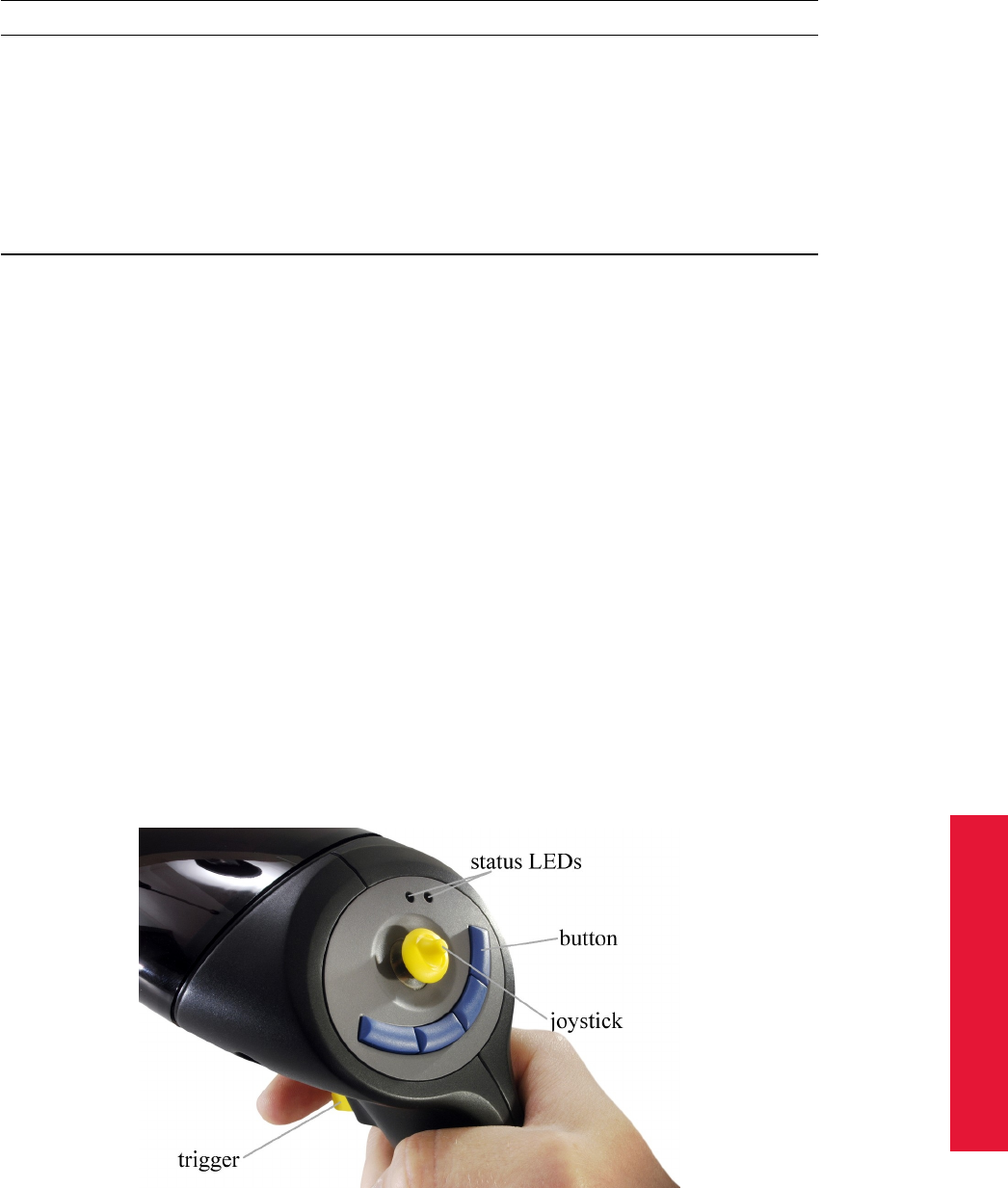
Chapter 5
5.1 Flystick2
Top view
status LEDs green pulse →button pressed or joystick position suc-
cessfully transmitted
yellow pulse →button pressed or joystick position could
not be transmitted
yellow flash-
ing
→low battery, recharge soon
trigger, button
and joystick
press the trigger or any button to invoke an interaction which can
be defined in the user application (e.g. drag objects while button
trigger pressed, open a menu dialogue, . . . )
Table 5.1: Description of the Flystick2
The output data consists of:
•position and orientation of the Flystick,
•status of buttons and joystick,
•number of used Flysticks.
Please refer to chapter B for more information about the format of the output data.
Control elements The numbering sequence of the buttons is as follows:
•# 1 trigger
•# 2 - # 4 blue buttons, right to left
•# 5 pressing the joystick
Figure 5.2: Flystick2 control elements
In neutral position the joystick transmits x=0, y=0.
127

5 Interaction devices
•Moving left creates negative x values, moving right positive x values.
•Moving down creates negative y values, moving up positive y values.
•Full extension into any direction creates values of 1.0 or -1.0.
The Flystick2 device provides all functions (buttons, trigger and joystick) simultaneously.
In case you need to carry out a factory reset for the Flystick2 you just have to plugin the
charger into the charging jack.
Radio module The Flystick2 uses a radio module in the 2.4GHz band. This band is
standardized internationally and can be used without a license. Range with line of sight
is more than 7m but can be reduced when passing material, e.g. projection screens.
Radio Transceiver The USB Radio Transceiver has to be plugged in to any free USB
port of the controller. In case this is done after the controller is switched on it is necessary
to press "F2" in order to search for new hardware. The Radio Transceiver should then be
recognized by the system.
Please make sure that either the old radio transceiver (connected via
the camera network) or the new USB radio transceiver is connected
to the controller. Connecting both radio transceivers to one controller
would lead to malfunction of the Flystick2 or Flystick3.
Switch on the controller. LED (2) which is framed by a circle (see figure 5.3) lights con-
tinuously while controller is booting. When DTrack2 is started, LED (1) which is framed
by a square (see figure 5.3) is switched on and indicates that the radio transceiver was
correctly initialized; LED (2) extinguishes.
During measurement, LED (1) is flashing whenever data is received from or transmitted
to the Flystick. In case of unsuccessful data transmission to the Flystick, LED (2) starts
flashing.
128
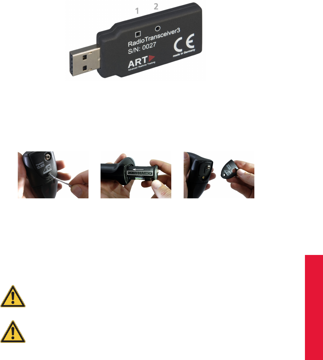
Chapter 5
5.1 Flystick2
Figure 5.3: USB Radio Transceiver3
Battery pack The battery compartment is at the lower end of the handle. It is fixed with
a single screw which can be opened with the supplied 2mm hexagon key. Remove the
screw and take off the cover of the battery compartment.
(a) Step 1 (b) Step 2 (c) Step 3
Figure 5.4: Flystick2 - inserting the battery pack
Insert the battery pack taking care of the polarity - also note the imprinting "<<INSERT<<"
on the battery pack. Apply the cover of the battery compartment again and fix the screw.
iThe battery pack includes 3 standard AAA rechargeable batteries.
The polarity of the batteries is indicated inside the battery pack. The
rechargeable batteries must be inserted into the battery pack in the in-
dicated polarity.
Dispose used batteries according to governmental regulations (life cy-
cle approximately 2 years).
Risk of explosion if battery is replaced by an incorrect type!
Charging jack The charging jack is at the bottom of the handle and has to be connected
with the supplied battery charger.
By connecting the battery charger the Flystick2 electronics are disconnected to prevent
damage. Thus the Flystick2 cannot be used during the the charging process.
129
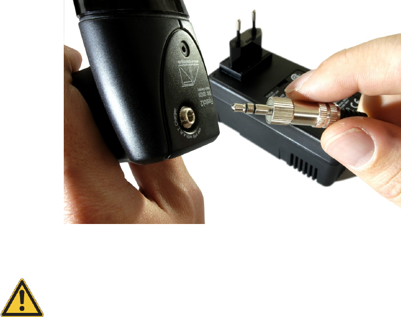
5 Interaction devices
Figure 5.5: Charging the battery of the Flystick2
The rechargeable batteries may only be charged with the supplied
charger. To ensure long battery life, do not let the batteries become
discharged completely. Recharge whenever convenient. Do not charge
for > 24 h.
Battery charger A battery charger is supplied with the delivered Flystick2 and must be
used for charging the batteries. For your convenience, the battery pack may remain inside
the Flystick2 for charging. However, during the charging process the Flystick2 cannot be
used.
As soon as the battery pack is connected to the charger the initialisation starts (status
LED: Yellow). After a few seconds the charger switches to the fast-charge mode (status
LED: Orange).
Once the battery pack is fully charged (approx. 1 h) the charger switches to the top-off
charge mode to balance the cells inside the battery pack (status LED: Green with inter-
mittent yellow flash). This helps to extend battery life. Hereafter the charger goes into
trickle charge mode automatically (status LED: Green). Now, the battery pack may be
used again.
Please also refer to table 5.2 for an overview of the status LEDs on the battery charger.
MultiUser option The MultiUser option is an enhancement especially for VR/AR appli-
cations when working with more than one Flystick2. Up to ten users can be equipped with
a Flystick2 and a head target (usually mounted on glasses). The software DTrack2 is able
to track them all but only the data pair (Flystick2 and head target) of one user is available
as output data. Switching between the single users can be done by just pressing one of
130

Chapter 5
5.1 Flystick2
status LED colour Description
Yellow No battery pack connected or initialisation
Orange Fast charge
Green with Yellow flash Top-off charge (balancing)
Green Trickle charge (charging completed)
Flickering Orange - Green Error (disconnect !)
Table 5.2: Status LEDs quick reference
the Flystick buttons.
Depending on how many Flysticks you are using, you have to configure the number of
Flysticks (max. 10) in Settings →Flystick. Tick the checkbox ’activate MultiUser function’.
If you want to use a Flystick2 and a head target as data pair then you have to tick the
checkbox ’use head targets’ as well. Please refer to chapter B on page 203 for more
details on the output format.
Body calibration First, configure the number of Flystick2 you are using: select Settings
→Flystick and configure the number of Flysticks. You have to assign your Flystick2 to a
’Flystick ID’ by selecting, for example, ’F1’ and selecting your Flystick2 out of the ’avail-
able Flysticks’ list.
Now, press Select to finalize the assignment.
iIf the ’available Flysticks’ list doesn’t contain your Flystick2 although
it is already present, just press any button of the Flystick2 to register
it at the radio transceiver.
Then, select Calibration →Body calibration.
In the appearing dialogue the body to be selected is named ’Flystick body 01’. Please
define the orientation of the body coordinate system relative to the body (default setting is
’due to body’). Make sure that all markers of the Flystick2 are seen by the cameras using
the Monitor 2DOF display which appears in the background.
Press Calibrate and the calibration starts within 5 seconds. Please refer to page 84 for
more information concerning body calibration.
Output settings Please define where the Flystick data has to be sent to. In DTrack2 fron-
tend software, select Settings →Output. You can either select this computer (= remote
PC) or enter an IP address of another computer you want to send data to. By ticking the
checkbox ’6df2’ you can define the Flystick data to be transmitted.
Please refer to chapter 4.5.6.3 on page 106 for more details.
Press Start to start the measurement. In order to see the tracking data you have to enable
the Flystick display by clicking Display →Flystick.
131
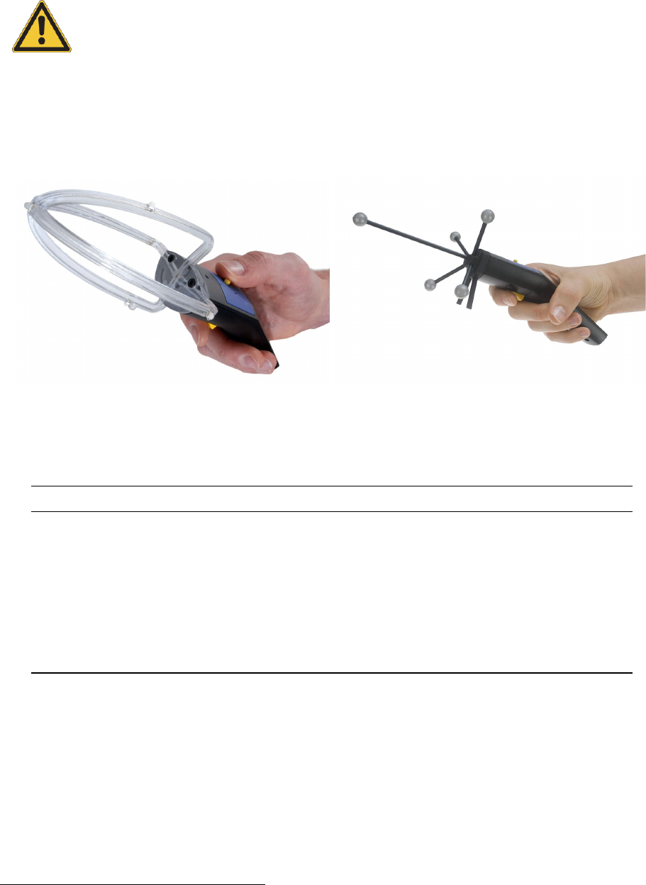
5 Interaction devices
5.2 Flystick3
The batteries must be removed before shipping the Flystick3, other-
wise the radio transmitter could be started by shock or vibration.
Description The Flystick3 is a lightweight input device for ART infrared optical tracking
systems.
(a) active target (discontinued) (b) passive target (standard)
Figure 5.6: Flystick3
Top view
status LEDs green pulse →button pressed or joystick position suc-
cessfully transmitted
yellow pulse →button pressed or joystick position could
not be transmitted
yellow flash-
ing
→low battery, recharge soon
trigger, button
and joystick
press the trigger or any button to invoke an interaction which can
be defined in the user application (e.g. drag objects while button
trigger pressed, open a menu dialogue, . . . )
Table 5.3: Description of the Flystick3
It is equipped with an active1or passive target, a trigger, three buttons and an analogue
joystick for wireless interaction in a virtual environment. Like with the Flystick2, all inter-
actions are transmitted wirelessly via a 2.4 GHz ISM radio connection. Synchronization
of the Flystick3 is provided wirelessly with a modulated flash by one camera.
The software DTrack2 takes up the Flystick3 button and joystick events and correlates
them with the 6DOF output data. Tracking and interaction data are then transmitted to the
1discontinued in December 2011
132
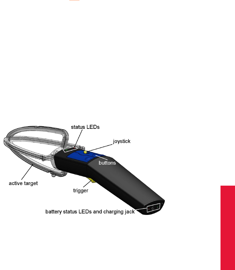
Chapter 5
5.2 Flystick3
application via Ethernet.
ZThe radio transmission and the active target are switched off after 15
minutes without usage. Press any button to reactivate the Flystick3
and, therefore, tracking.
The output data consists of:
•position and orientation of the Flystick,
•status of buttons and joystick,
•number of used Flysticks.
Please refer to chapter B on page 203 for more information about the format of the output
data.
Control elements The numbering sequence of the buttons is as follows:
•# 1 trigger
•# 2 - # 4 blue buttons, right to left
Figure 5.7: Flystick3 control elements
In neutral position the joystick transmits x=0, y=0.
•Moving left creates negative x values, moving right positive x values.
•Moving down creates negative y values, moving up positive y values.
•Full extension into any direction creates values of 1.0 or -1.0.
The Flystick3 device provides all functions (buttons, trigger and joystick) simultaneously.
In case you need to carry out a factory reset for the Flystick3 you will find the reset button
just on top of the charging jack. You may use a paper clip to press the reset button.
133

5 Interaction devices
Radio Transceiver The USB Radio Transceiver has to be plugged in to any free USB
port of the controller. In case this is done after the controller is switched on it is necessary
to press "F2" in order to search for new hardware. The Radio Transceiver should then be
recognized by the system.
Please make sure that either the old radio transceiver (connected via
the camera network) or the new USB radio transceiver is connected
to the controller. Connecting both radio transceivers to one con-
troller would lead to malfunction of the Flystick2 or Flystick3.
Switch on the controller. LED (2) which is framed by a circle (see figure 5.3) lights contin-
uously while the controller is booting. When DTrack2 is started, LED (1) which is framed
by a square (see figure 5.3) is switched on and indicates that the radio transceiver was
correctly initialized; LED (2) extinguishes.
During measurement, LED (1) is flashing whenever data is received from or transmitted
to the Flystick. In case of unsuccessful data transmission to the Flystick, LED (2) starts
flashing.
Battery charger A battery charger is supplied with the delivered Flystick3 and must be
used for charging the batteries. For your convenience, the battery pack may remain in-
side the Flystick3 for charging. During the charging process you may continue using your
Flystick3.
As soon as the battery pack is connected to the charger, the red LED ("Charge") is
switched on. Once the battery pack is fully charged the charger switches off the "Charge"
LED, the green "Ready" LED is switched on. Now, the battery pack may be used again.
The rechargeable batteries may only be charged with the supplied
charger.
An error during charging occured, in case the green LED is switched on permanently and
the red LED is flashing at the same time. This indicates for example that either the battery
isn’t inserted correctly or it is defective.
Inserting the battery For inserting the battery into the Flystick3, you have to take off
the back cover completely.
Risk of explosion if battery is replaced by an incorrect type!
Dispose used batteries according to governmental regulations.
134
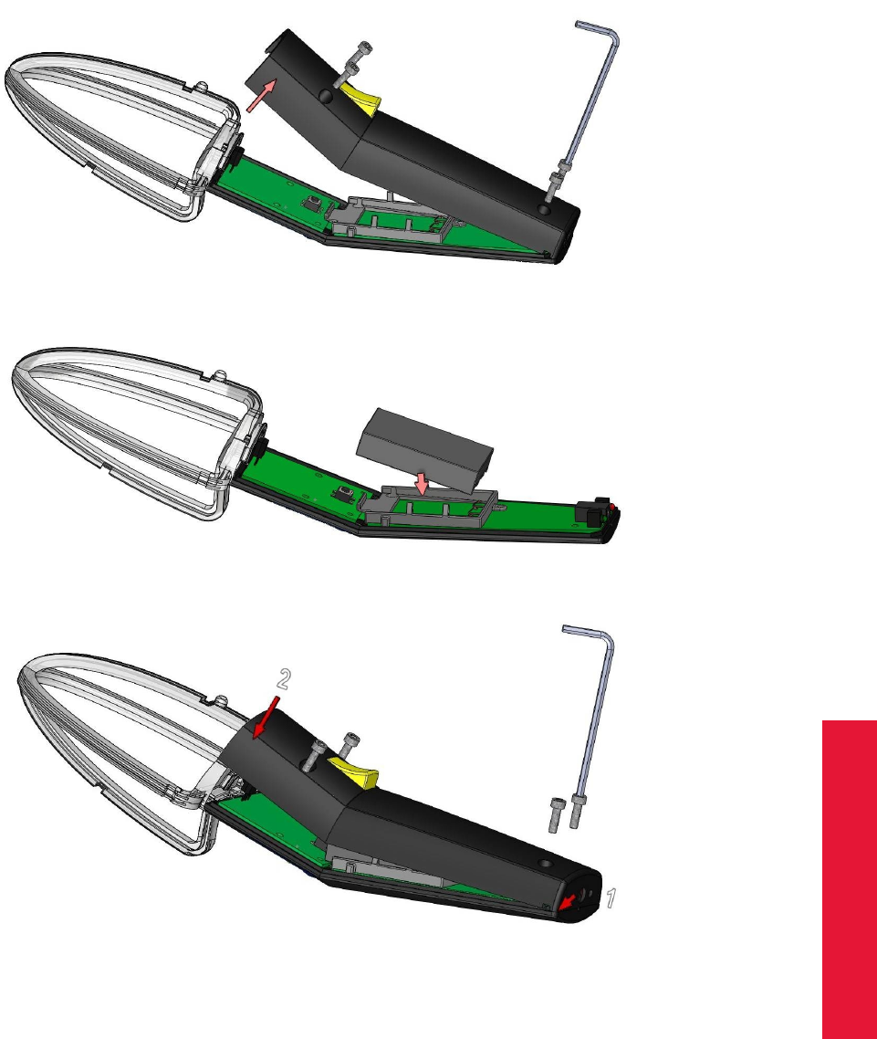
Chapter 5
5.2 Flystick3
Therefore, loosen the four screws using the 2.5mm hexagon key and remove the back
cover.
Place the battery correctly within the cut-out.
Apply the back cover again and tighten the screws carefully.
Wireless synchronization (only for active variant) The receiver for the modulated in-
frared signal which is used for synchronization is located in the middle of the joint between
transparent target and handpiece (see figure 5.7). This coded signal can be generated
by all ART tracking cameras, except for ARTTRACK1 and older ARTTRACK2 (up to SN
320) cameras.
135
5 Interaction devices
Z
Active targets need synchronization in order to make sure that the IR
LEDs are flashing at the proper time. To ensure wireless synchroniza-
tion the following points should be observed:
•The camera which emits the modulated flash has to be in sync-
group # 1 ! For ARTTRACK systems this means that the cam-
era has to be connected to the OUT1 output of the Synccard2.
TRACKPACK systems may be configured via software (refer to
chapter Syncgroup on page 100).
•Note that the synchronization will not work near plasma screens.
•If two or more tracking systems using wireless synchronization
are in the same room, then external synchronization of the sys-
tems might be necessary (e.g. at tradeshows).
The modulated flash is adjustable in Settings →Cameras. Just tick the checkbox ’mod-
ulated flash’ and select one camera (which is in syncgroup # 1) from the dropdown list.
Press OK to apply the changed settings.
However, the Flystick3 may also be used with tracking systems where older ARTTRACK2 (<
SN 320) or ARTTRACK1 cameras are used (DTrack2 is required). For this purpose an
additional external flash can be purchased from ART .
i
If your system is configured with more than one syncgroup it is nec-
essary to configure the Flystick3 as follows. Go to Settings →Flystick
and increase the number of ’syncgroups’ according to the number of
syncgroups used to set up the system.
MultiUser option The MultiUser option is an enhancement especially for VR/AR appli-
cations when working with more than one Flystick. Up to ten users can be equipped with
a Flystick and a head target (usually mounted on glasses). The software DTrack2 is able
to track them all but only the data pair (Flystick and head target) of one user is available
as output data. Switching between the single users can be done by just pressing one of
the Flystick buttons.
Depending on how many Flysticks you are using, you have to configure the number of
Flysticks (max. 10) in Settings →Flystick. Tick the checkbox ’activate MultiUser function’.
If you want to use a Flystick and a head target as data pair then you have to tick the
checkbox ’use head targets’ as well. Please refer to chapter B for more details on the
output format.
Body calibration First, configure the number of Flystick3 you are using: select Settings
→Flystick and configure the number of Flysticks. You have to assign your Flystick3 to a
’Flystick ID’ by selecting, for example, ’F1’ and selecting your Flystick3 out of the ’avail-
able Flysticks’ list.
136

Chapter 5
5.3 Fingertracking
Now, press Select to finalize the assignment.
iIf the ’available Flysticks’ list doesn’t contain your Flystick3 although
it is already present, just press any button of the Flystick3 to register
it at the radio transceiver.
Then, select Calibration →Body calibration.
In the appearing dialogue the body to be selected is named ’Flystick body 01’. Please
define the orientation of the body coordinate system relative to the body (default setting is
’due to body’). Make sure that all markers of the Flystick3 are seen by the cameras using
the Monitor 2DOF display which appears in the background.
Press Calibrate and the calibration starts within 5 seconds. Please refer to page 84 for
more information concerning body calibration.
Output settings Please define where the Flystick data has to be sent to. In DTrack2 fron-
tend software, select Settings →Output. You can either select this computer (= remote
PC) or enter an IP address of another computer you want to send data to. By ticking the
checkbox ’6df2’ you can define the Flystick data to be transmitted.
Please refer to chapter 4.5.6.3 on page 106 for more details.
Press Start to start the measurement. In order to see the tracking data you have to enable
the Flystick display by clicking Display →Flystick.
5.3 Fingertracking
Description The Fingertracking device is an add-on to the ART tracking system which
allows to track the orientation of the hand and the position of the fingers, if necessary for
both hands.
It is integrated into DTrack2 by entering a license code, which can be supplied by ART .
For the creation of the license code we need the serial number of the synccard. Click
DTrack2 →Licenses and Hardware Info to find out the serial number. Go back to license
overview and add the license key delivered by ART for your Fingertracking device (refer
to chapter 4.5.6.2 on page 94).
The Fingertracking device consists of:
•an active hand target for fixing on the back of the hand (see figure 5.9 and table 5.4).
Letters (L and R) indicate whether the hand target is dedicated for the right or left
hand. Wireless synchronization is provided with a modulated flash. The low voltage
power is provided with a rechargeable battery.
•three or five active finger markers, each consisting of an IR LED with diffusing
sphere, a fixture for the finger tip and flexible wires. These active markers are time
sequentially addressed and controlled by the active hand target unit.
The output data consists of:
137

5 Interaction devices
(a) Fingertracking device
with three active finger
markers
(b) Fingertracking device
with five active finger
markers
Figure 5.8: The Fingertracking device
Figure 5.9: Fingertracking hand target
•position and orientation of the back of the hand,
•number of tracked fingers as well as a value to distinguish right and left hands,
•position and orientation of the outermost phalanx, given in the hand coordinate sys-
tem; together with a radius, position and orientation of the finger tip can be identified,
•angles between the single phalanxes as well as their lengths. These values are
calculated using tracked markers and empirical data.
ZThe data shown in the Fingertracking display is NOT the position of the
finger tip! For calculating the finger tip position you need to consider
radius R like shown in figure 5.10.
138

Chapter 5
5.3 Fingertracking
Top view
status LEDs green LED continuously →synchronization received
red LED continuously →no synchronization received
red and green LED flashing →battery low or discharged
infrared LEDs LEDs activate the flashes
power switch activate or deactivate the Fingertracking hand target
configuration dial select the LED brightness and the number of fingers
infrared sync receiver receiver for the modulated infrared synchronization signal
Table 5.4: Description of the Fingertracking
Figure 5.10: Model of a human hand
Please refer to chapter B on page 203 for more information about the format of the output
data.
Principle The finger movement is limited by the structure of the finger bones and ten-
dons. Medical studies of the human hand have proven that without external forces the
movement of the fingers can be derived from palm and finger tip position. Therefore only
the palm and the finger tips have to be tracked.
The active markers for the finger tip are sequentially addressed to allow the tracking sys-
tem to discriminate between the single fingers. Therefore, the update rate of the fingers
is only one-third or one-fifth of the update rate for the hand, e.g. 20 Hz for a 60 Hz mea-
surement with three fingers or 12 Hz for a 60 Hz measurement with five fingers.
Up to four hands with three or five fingers each can be tracked simultaneously provided a
certain minimal distance (approx. 20cm) between the hands.
The finger thimble sets Fingertracking can be ordered as a 3-finger VR, a 3-finger AR
or a 5-finger VR version. The difference between the AR and VR versions can be found
139
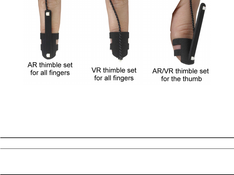
5 Interaction devices
in the position of the LED on the finger thimble: for the VR version the LED is placed on
the tip of the thimble, whilst for the AR version it is placed on top of the thimble (see figure
5.11).
Figure 5.11: Comparison of the finger thimble sets (AR and VR) for Fingertracking
For the ordered version three pairs of different sizes of thimble sets are delivered with the
Fingertracking package (see table 5.5).
Finger size Scope of delivery
Small-sized fingers Diameters of 16mm (thumb) and 12-14mm (other fingers)
Medium-sized fingers Diameters of 18mm (thumb) and 14-16mm (other fingers)
Large-sized fingers Diameters of 20mm (thumb) and 16-18mm (other fingers)
Table 5.5: Description of the finger markers
Battery charger A battery charger is supplied with the delivered Fingertracking and
must be used for charging the batteries.
When you connect the battery charger to a power plug, the red LED ("Status") is switched
on and the green LED ("Charge") starts flashing. As soon as you place the battery cor-
rectly in the charger, the "Charge" LED changes its colour to red and stops flashing.
Once the battery is fully charged the "Charge" LED changes its colour to green again.
Now, the battery may be used.
Inserting the battery The Fingertracking hardware uses standard CAN NB-4L batter-
ies. Two batteries and a charger are provided with each Fingertracking set.
Squeeze the battery in with the contact side first and then gently press the battery into
the compartment until it snaps in.
Wireless synchronization The black sphere on top of the Fingertracking hand target is
a receiver for the modulated infrared signal which is used for synchronization (see figure
140
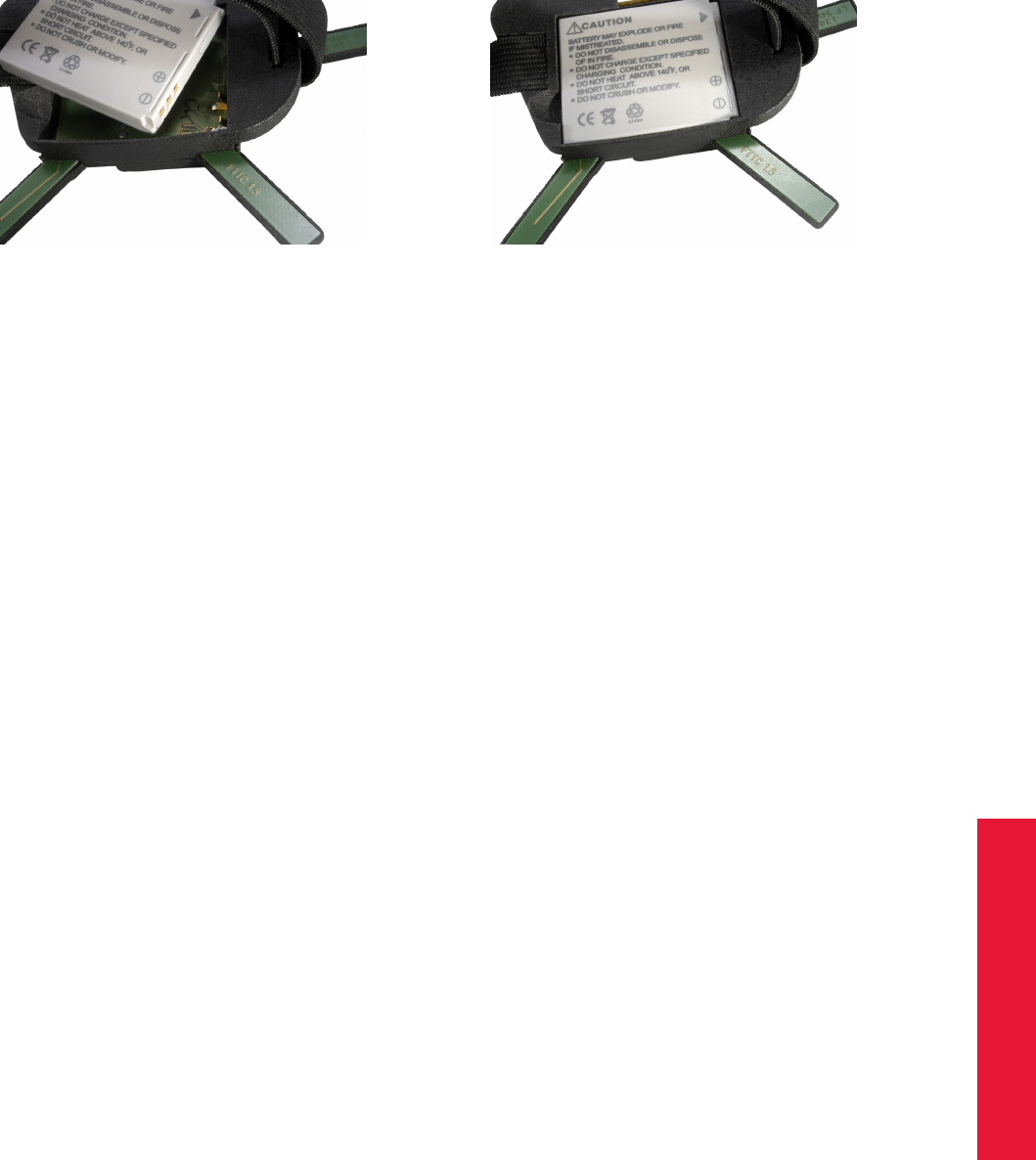
Chapter 5
5.3 Fingertracking
(a) Step1 (b) Step2
Figure 5.12: Inserting the battery
5.9). This coded signal can be generated by all ART tracking cameras, except for ART-
TRACK1 and older ARTTRACK2 (up to SN 320) cameras.
Z
Active targets need synchronization in order to make sure that the IR
LEDs are flashing at the proper time. To ensure wireless synchroniza-
tion the following points should be observed:
•The camera which emits the modulated flash has to be in sync-
group # 1 ! For ARTTRACK systems this means that the cam-
era has to be connected to the OUT1 output of the Synccard2.
TRACKPACK systems may be configured via software (refer to
chapter Syncgroup on page 100).
•Note that the synchronization will not work near plasma screens.
•If two or more tracking systems using wireless synchronization
are in the same room, then external synchronization of the sys-
tems might be necessary (e.g. at tradeshows).
However, Fingertracking may also be used with tracking systems where older ARTTRACK2 (<
SN 320) or ARTTRACK1 cameras are used. For this purpose an additional external flash
can be purchased from ART .
The modulated flash is adjustable in Settings →Cameras. Just tick the checkbox ’mod-
ulated flash’ and select one camera (which is in syncgroup # 1) from the dropdown list.
Press OK to apply the changed settings.
On/off button The small black button next to the configuration switch activates or deac-
tivates the target (please refer to figure 5.9). When deactivated, all IR LEDs are switched
off and the microcontroller is put into sleep mode. A certain minimal power consumption
is inevitable. So, when the Fingertracking is not used for a longer period of time (more
than a week) the batteries should be removed to prevent deep discharge which could
destroy the battery.
141
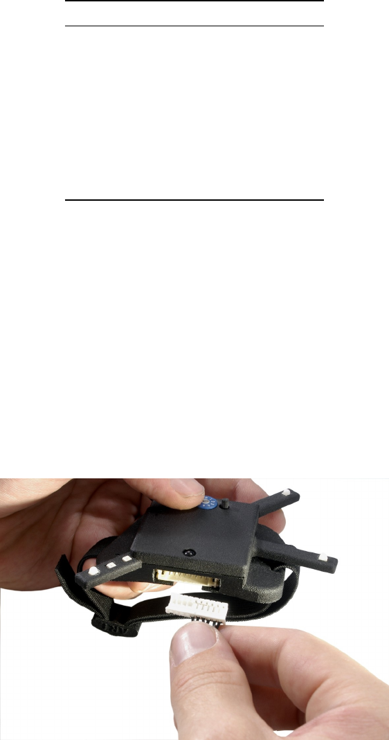
5 Interaction devices
Configuration dial The configuration dial is used to select the LED brightness and the
number of fingers used in the setup (please refer to figure 5.9).
ID no. of sync finger Flash time [µs]
0 3 25
1 3 50
2 3 75
3 3 100
4 5 25
5 5 50
6 5 75
7 5 100
8 - -
9 - -
Table 5.6: Description of the configuration dial
A detailed description of the configuration dial may be found in table 5.6.
Hand target calibration First, configure the number of hands you are using: select
Settings →Fingertracking and configure the number of hands. Then, a standard body
calibration of the hand target has to be carried out. The process of calibrating a 6DOF
body is described in chapter 4.5.3 on page 84. Select the body names hand H1 and hand
H2 for the hand targets.
Connecting the finger thimble set with the hand target Just plug in the connector of
the finger thimble sets into the hand target as shown in figure 5.13.
Figure 5.13: Connecting the finger LED connector with the hand target
Then, apply the finger thimbles to your thumb and fingers.
iPlease observe the order shown in figure 5.14 when using the 5-finger
AR set.
142
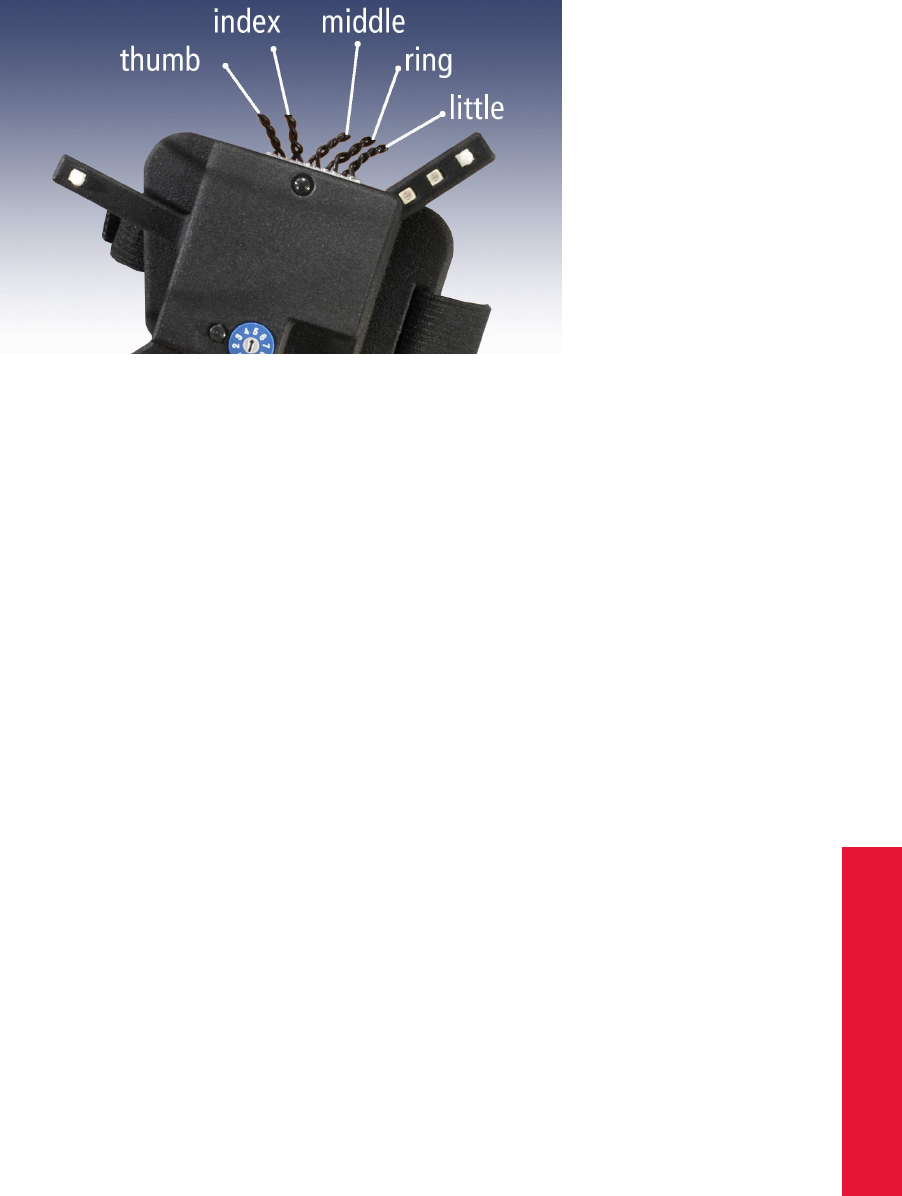
Chapter 5
5.3 Fingertracking
Figure 5.14: Using the 5-finger AR finger thimble set
Finger calibration Select Calibration →Fingertracking to open the calibration menu.
It is important that the hand is completely within the tracking volume and all markers are
visible for at least two cameras when starting the calibration process.
After pressing Calibrate, the countdown for the first step of calibration begins. In this
phase all fingers have to be stretched and must not be spread. Only the thumb has to be
spread. Take care, that there is no space between the fingers.
Neither the fingers nor the thumb should be moved. A progress bar shows the progress
of the calibration.
After step 1 has been completed, the countdown for step 2 is started. During step 2 of the
calibration, the fingers still have to be stretched and not spread. Gently move all of your
fingers up and down at the same time until calibration process is finished. As a rule of
thumb, you should keep the angle between starting and ending position at approximately
60◦. Take care that you do not bend or cross your fingers. The thumb is still spread and
does not move during this phase.
The configuration program indicates data collection while it is active. After data collection,
a calculation process is started which calculates the finger sizes from the movement of
the finger tips. The length of the thumb is derived by the finger lengths. If the calcu-
lation was successful, it is automatically activated in the Fingertracking settings menu.
If the calculation terminates with an error message, the calibration has to be repeated.
Sometimes, it may be necessary to repeat the calibration of the hand target as well.
Output settings Please define where the Fingertracking data has to be sent to. In
DTrack2 frontend software, select Settings →Output. You can either select this com-
puter (= remote PC) or enter an IP address of another computer you want to send data
to. By ticking the checkboxes ’gl’ and ’glcal’ you can define the Fingertracking data to be
transmitted. Please refer to chapter 4.5.6.3 on page 106 for more details.
143
5 Interaction devices
Press Start to start the measurement. In order to see the tracking data you have to enable
the Fingertracking display by clicking Display →Fingertracking.
Resetting finger tip sequence The Fingertracking hardware will compensate short
sync losses internally, but in rare cases the sequence of the fingers can be lost after
sync problems. To regain the correct sequence, the hand must be kept still with all fingers
stretched and the thumb pointing to the side. The system then automatically resets the
correct finger tip order.
When using two hands, both hands have to be separated by at least 50 cm.
This procedure also should be used when the Fingertracking tool has been removed from
the hand and is being reused again by the same user.
Display tool Fingertracking Viewer The Fingertracking Viewer is a small graphical
tool, which shows the hand and finger position. It can be installed on the PC that receives
DTrack2 data.
After starting the viewer, click the Go Online button and specify on which data port the
viewer has to listen, then click OK to connect the viewer to DTrack2 .
Afterwards choose the Hand ID you want to display. If this ID is tracked or not is shown
by the light right next to the Hand-ID setting (green=tracked, red=not tracked). Then click
on one of the hand signs to see your tracked fingers.
To start a small demo showing the handling of a virtual object press the Demos button,
this opens the demos menu. You have a small number of simple demos available, e.g.
you can handle a virtual sphere or cube. To insert the virtual object in the tracking volume,
place the tracked hand at a convenient position and press the Grab object button.
The Fingertracking Viewer is only for demonstration and testing purposes and is only
available as a 2D Viewer.
5.4 Measurement Tool
Introduction The ART Measurement Tool is a pointing device for measurement or med-
ical applications. In this specialized field it is very important to measure positions of points
in high accuracy. For that reason the Measurement Tool is equipped with a measurement
tip. The position of the tip can be measured with the optical tracking system.
Description The Measurement Tool is an add-on to the ART tracking system and is
integrated into DTrack2 by entering a license code, which can be supplied by ART . For
the creation of the license code we need the serial number of the synccard. Click DTrack2
→Licenses and Hardware Info to find out the serial number. Go back to license overview
and add the license key delivered by ART for your Measurement Tool (refer to chapter
4.5.6.2 on page 94).
The pointing device carries a target that was developed to get optimal tracking quality
for the use with two IR cameras. You will get the best measurement results, when the
144

Chapter 5
5.4 Measurement Tool
Figure 5.15: Measurement Tool
pointing device is facing the cameras as shown in figure 5.15 (i.e. markers have to be
oriented towards the cameras). Typically, the position of the tool’s tip is measured in the
DTrack2 room coordinate system which was fixed during room calibration.
Optionally, the ART Measurement Tool can calculate the position relative to a "reference
body". Then, the Measurement Tool is measuring distances to the origin of the reference
body coordinate system, and not to the origin which was defined during room calibration.
The output data consists of:
•position and orientation of the tool’s tip,
•number of the Measurement Tool ,
•rotation matrix of the target.
Please refer to chapter B on page 203 for more information about the format of the output
data.
Body calibration The calibration of the Measurement Tool is separated into two steps:
1. body calibration of the Measurement Tool and
2. calibration of the tip.
First of all, you have to define how many Measurement Tools you want to use. Therefore,
please select Settings →Measurement Tool and define the ’number of Measurement
Tools ’.
Now, please calibrate the Measurement Tool with a standard body calibration (see chap-
ter 4.5.3 on page 84): select Calibration →Body. In the appearing dialogue the body
145

5 Interaction devices
to be selected is named ’Measurement Tool body 01’. Please define the orientation of
the body coordinate system relative to the body (default setting is due to body). Make
sure that all markers of the Measurement Tool are seen by the cameras using the Monitor
2DOF display which appears in the background.
If you are working with a reference body you would have to calibrate it as well. This is
done by a standard body calibration. Just select the body named ’Measurement Tool ref-
erence body 01’.
Press "Calibrate" and the calibration starts within 5 seconds.
Tip calibration After successful body calibration, you have to calibrate the tip of the
Measurement Tool : select Calibration →Measurement Tool .
Place the Measurement Tool in front of the cameras with the tip fixed at exactly one position.
Press Calibrate to start the calibration process. Gently move the Measurement Tool while
keeping the tip still at exactly one position (i.e. tilt around its tip).
DTrack2 is calculating the position of the tip relative to the markers of the Measurement
Tool , i.e. the origin of the body coordinate system is tranformed into the Measurement
Tool ’s tip.
ZNote that the progress bar is not continuing if the pointing device is
not moved sufficiently.
If the tip calibration has been successful the result is presented in the dialogue Mea-
surement Tool Tip Calibration Result. Please check the information displayed and either
’Accept’ or ’Cancel’ the tip calibration.
Output settings Please define where the Measurement Tool data has to be sent to.
In DTrack2 frontend software, select Settings →Output. You can either select this com-
puter (= remote PC) or enter an IP address of another computer you want to send data to.
By ticking the checkboxes ’6dmt’ and ’6dmtr ’ you can define the Measurement Tool data
to be transmitted. Please refer to chapter 4.5.6.3 on pag 106 for more details.
Press Start to start the measurement. In order to see the tracking data you have to enable
the Measurement Tool display by clicking Display →Measurement Tool.
146

Chapter 6
6 Frequently asked questions (FAQ)
Within this FAQ chapter we are offering solutions for easy-to-solve questions that our sup-
port encounters from time to time. The questions are grouped into specific topics to make
it more convenient for you to find a solution.
In case you do not find a proper solution for your specific problem, please do not hesitate
to contact us.
Our goal is to offer the best support possible. Therefore, we ask you to have the system
running and that you have internet access when you call us. Sometimes, it might be
possible to locate your problem if you deliver the following files:
•the configuration export file:
Go to DTrack2 →Configurations and press ’log settings’. Save this file to a location
of your choice and mail it to us.
•the event log file:
–Windows:
Go to "C:\Documents and Settings\username\.ART\DTrack2\version\" and
mail the file "events-yyyy-mm-dd_controllername.log" to us.
–Linux:
In your home directory, go to ".ART/DTrack2/version/ " and mail the file "events-
yyyy-mm-dd_controllername.log" to us.
6.1 Backup
How do I create a backup of important configurations?
From DTrack2 v2.8.1 it is possible to export and import configurations. DTrack2 →Con-
figurations →’Save’ will export the complete active configuration. In case of an accidental
deleting of a configuration it will be possible to restore the configuration presuming that
an export has been carried out before. Then, it could even be a replacement Controller to
’Load’ the exported configuration on.
Please note that a room calibration might be necessary especially in case the number of
cameras or the cameras themselves have changed.
6.2 Cameras
DTrack2 doesn’t recognize the correct number of cameras connected. What can
I do?
•First of all, please check whether cabling is correct.
147
6 Frequently asked questions (FAQ)
•Please make sure for all cameras that the LED, to indicate that the camera is pow-
ered up, is switched on.
•Within DTrack2 press ’F2’ in order to perform a search for new hardware. The
cameras should be detected now.
•In case of ARTTRACK2 (discontinued): please make sure that the camera’s fan
is working. If the fan stops, rising temperatures inside the camera will cause an
emergency shutdown of the internal PC.
•If you are using an external switch, please make sure that no camera is connected
to the uplink port and if applicable, the switch is powered.
•Finally, reboot the cameras, the external switch and the controller.
What is the meaning of the red LEDs at the front of the camera?
They are indicating the status of the camera:
•ARTTRACK2 /ARTTRACK3 (discontinued): The left LED shows that the camera
is powered up and booted. Whereas, the right LED indicates that the measurement
is active. In case of an error (e.g. sync loss), the left LED extinguishes and the right
LED starts flashing. Please refer to figures 4.7 and 4.8 on pages 33 and 36 for the
visualization of the cameras.
•ARTTRACK5 : The lower LED shows that the camera is powered up and booted.
Whereas, the upper LED indicates that the measurement is active. In addition to
the two status LEDs the 2-digit LED-matrix on the left displays the assigned camera
ID (default) and the number of markers in the camera’s corresponding field of view
(when activated under camera settings). Please refer to figure 4.1 on page 25 for
the visualization of the camera.
•ARTTRACK5/C : The red LED on the camera body shows that the camera is pow-
ered up and booted. Please refer to figures 4.4 on page 28 for the visualization of
the cameras.
•TRACKPACK/E : The lower left LED show that the camera is powered up and
booted. Measurement active is indicated by the lower right LED. Please refer to
figure 4.6 on page 31 for a visualization of the camera.
•TRACKPACK (discontinued): The lower left LED show that the camera is powered
up and booted. Measurement active is indicated by the lower right LED. Please refer
to figure 4.9 on page 38 for a visualization of the camera.
One of my cameras recognizes a reflection which I can’t eliminate. What can I
do?
You may enable the suppression of static reflexes within DTrack2 . But carefully read the
notes on page 98.
148

Chapter 6
6.2 Cameras
How many cameras may be connected to the tracking system?
The number of cameras depends on the used license and the tracking system itself:
max. number of
bodies cameras
ARTTRACK system
Extended 4 2
Full-featured 50 50
TRACKPACK system
Basic 4 2
Extended 4 4
Full-featured 50 4
Starting with DTrack2 version v2.10 a new license model has been established.
You may use 2, 4, 8, 16 or up to 50 cameras in any combination with 4, 10, 30 or up to 50
targets depending on the license purchased.
Please refer to table 4.3 on page 76 for a complete license overview.
I’d like to expand my system. Is it possible?
Tracking systems with ARTTRACK cameras are expandable up to a total number of
50 cameras (from DTrack2 v2.8.1). It (i.e. a tracking system with ARTTRACK1 -ART-
TRACK5 ) can be expanded by simply adding additional ARTTRACK cameras, given that
the license allows to do so. In some cases, it might be necessary to purchase a license
for more cameras (e.g. 8 or 16) and an additional PoE+ switch.
TRACKPACK/E systems can be expanded up to 16 cameras through means of cascading
2 separate systems. One ART Controller will function as master, while the other works in
slave mode. The master controller needs to have a dedicated "cascaded systems" license
as well as a sufficient license for ALL cameras inside the cascade, i.e. 16 cameras.
The TRACKPACK system (discontinued) can also be extended up to 16 cameras, how-
ever more equipment is needed in this case. One separate ARTTRACK Controller with a
license for cascaded systems is needed to merge the data output streams of the separate
stand-alone TRACKPACK systems into one single stream.
Please refer to chapter 4.3 on page 58 for more information.
Which upgrade possibilities do I have?
Please refer to table 4.1 on page 44.
149
6 Frequently asked questions (FAQ)
6.3 Controller
What are the possibilities to start the controller?
The controller is equipped with a switch that you have to press for the initial start-up. If
you want to power up your controller remotely, you may either use Wake On LAN (WOL)
or wake-on-power (WOP).
Please refer to chapter 4.2 on page 43 for more information.
I cannot find my controller. What can I do?
•Please make sure that the controller is connected properly to the Ethernet network.
•Switch on the controller.
•It is possible that your controller has become unreachable due to wrong IP settings
(wrong IP address or IP address area, etc.). Please refer to chapter 4.2.4 on page
54.
•In case you are using a firewall, please do not block DTrack2 communication.
For more information, please also refer to chapter 4.2.2 (page 48) or chapter 4.2.3 (page
52).
What is the IP address of my controller?
You may use a standard USB stick and plug it in to the controller at any time. If not running
yet, please switch on the controller. Its settings (IP address, etc.) will be saved to a setup
file on the USB stick. This file may be opened and modified in any editor.
Please refer to chapter 4.2.4 on page 54 for more information.
How can I assign a specific IP address to my controller?
There are two options to do this:
1. Modify the setup file (i.e. enter the IP address), save it to a USB stick and plug it in
the controller. Please refer to chapter 4.2.4 on page 54 for more information.
2. Within DTrack2 go to Settings →Controller. On the General tab, untick the check-
box ’DHCP client’ and enter the desired ’IP address’ and ’subnet mask’. Please
refer to chapter 4.5.6.3 on page 110 for more information.
6.4 Synchronization
Synchronization failed in ARTTRACK5 systems
If you have connected ARTTRACK5 or ARTTRACK5/C cameras via a PoE+ switch,
please check the model of the switch. Some acquirable PoE+ switch models might
not be suitable for usage with ART cameras. Use the recommended ’Netgear Prosafe
150

Chapter 6
6.4 Synchronization
GSM7212P’ or – if not possible – contact ART support.
Synchronization failed in ARTTRACK5 &TRACKPACK/E systems
Due to the single cable solution, the camera is both powered and synchronized over Eth-
ernet. There is no need to guide or check additional cables dedicated to synchronisation
of the cameras. Still hardware issues regarding the controller can arise when using ex-
ternal trigger units, e.g. projectors or graphics cards.
1. Check the cabling (hardware issue):
•Please make sure that the coaxial cables are not damaged.
•Take care of using the correct ports:
–EXT.In: input of the external synchronization
•Active stereo: when using external synchronization (video) the correct cabling
would look as follows:
•Active stereo: when using external synchronization (TTL) the correct cabling
would look as follows:
2. Check the synchronization settings (software issue):
•Go to Settings →Synccard and double-check the settings (external video sig-
nal or TTL) for the Synccard.
•In case of external synchronization, please make sure that the synchronization
signal is being sent by the external source.
Synchronization failed in cascaded systems
Cascading means that two or more stand-alone tracking systems are combined to one
large system in order to have only one consolidated data output. Therefore, the system
is subdivided into one master and up to eight slaves.
The task of the master is to synchronize all slave controllers attached and gather all single
151
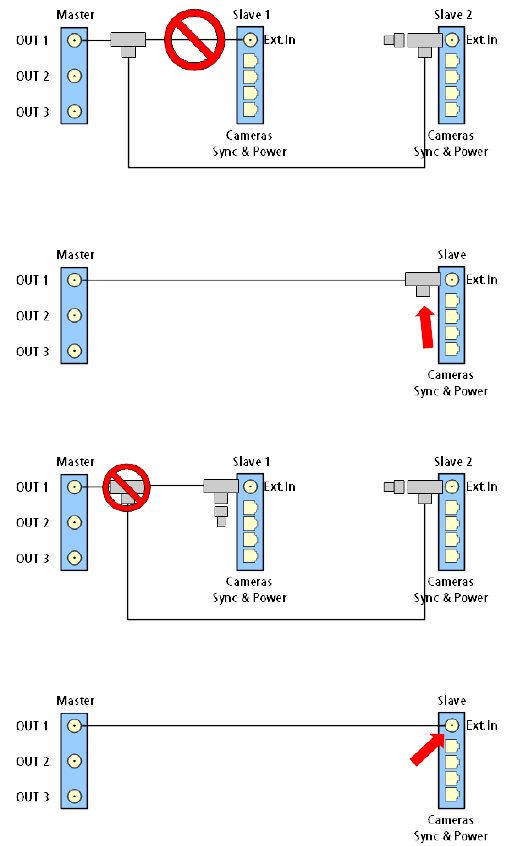
6 Frequently asked questions (FAQ)
data outputs from all slaves and to merge them into one single data output.
Please refer to chapter 4.3 on page 58.
1. Check the cabling (hardware issue):
•Please make sure that the coaxial cables are not damaged.
•Take care of using the correct ports:
–EXT.In: input of the external synchronization (slaves)
–OUT1: output for synchronization of slave controllers (Do not use OUT2 or
OUT3 !)
•Double-check if no extensions between slave controller and terminating resistor
have been made.
•Double-check if the terminating resistor is missing at the end of the signal line.
•Splitting of the synchronization line is not allowed.
•Do not connect the cable directly to the slave controller.
2. Check the cascade settings (software issue):
•Go to Settings →Cascaded System and double-check the attached slave con-
trollers. Please refer to chapter 4.3 on page 58.
152
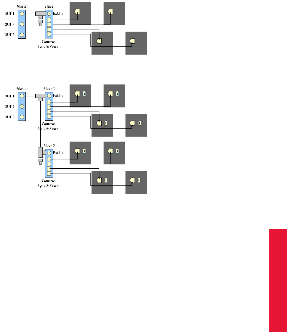
Chapter 6
6.4 Synchronization
•In case of simultaneous external synchronization, please install the synchro-
nization on the master controller according to the instructions for ARTTRACK5 and
TRACKPACK/E systems. Please refer to chapter 6.4 on page 150.
How do I guide the synchronization cables correctly in cascaded systems ?
•When using one TRACKPACK/E master and one TRACKPACK/E slave controller
the correct cabling would look as follows:
•When using one ART Controller as master and two TRACKPACK slave controller
the correct cabling would look as follows:
Synchronization failed in ARTTRACK 2 & 3 systems (discontinued)
Here we have to distinguish between hardware issues (camera and external synchroniza-
tion) and software issues:
1. Check the cabling (hardware issue):
•Please make sure that the cables themselves are not damaged.
•Take care of using the correct ports:
–OUT1 to OUT3: synchronization of the cameras
–EXT.In: input of the external synchronization
•Double-check if no extensions between camera and terminating resistor have
been made.
153
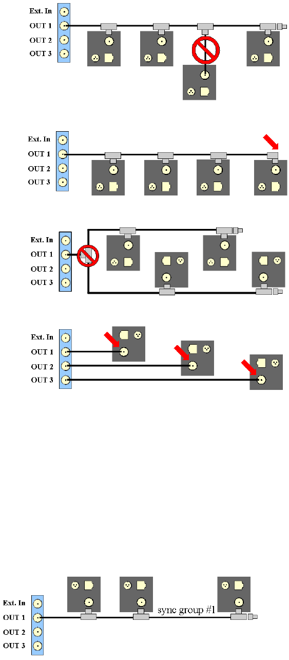
6 Frequently asked questions (FAQ)
•double-check if the terminating resistor is missing at the end of the signal line.
•Splitting of the synchronization line is not allowed.
•Do not connect the cable directly to the camera.
2. Check the synchronization settings (software issue):
•Go to Settings →Synccard and double-check the settings (internal or external
synchronization) for the synccard.
•In case of external synchronization, please make sure that the synchronization
signal is being sent by the external source.
How do I guide the synchronization cables correctly in ARTTRACK 2&3
systems (discontinued)?
•When using only one syncgroup the correct cabling would look as follows:
•When using two syncgroups the correct cabling would look as follows:
154
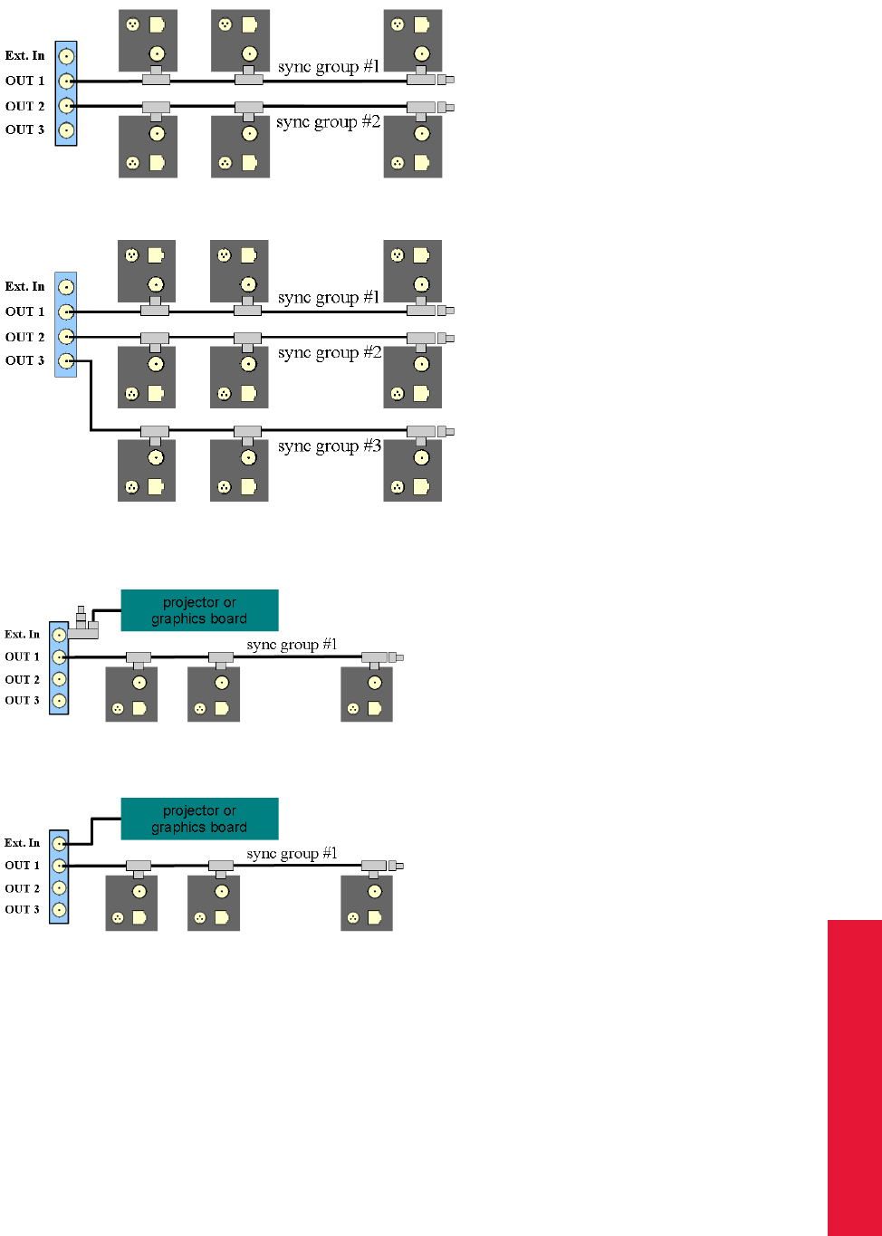
Chapter 6
6.4 Synchronization
•When using three syncgroups the correct cabling would look as follows:
•Active stereo: when using external synchronization (video) the correct cabling
would look as follows:
•Active stereo: when using external synchronization (TTL) the correct cabling would
look as follows:
Synchronization failed in TRACKPACK systems (discontinued)
Here we have to distinguish between hardware and software issues:
1. Check the cabling (hardware issue):
•Please double-check whether the cables are connected correctly and that they
are not loose.
•Please make sure that the cables themselves are not damaged.
•Take care of using the correct ports:
155
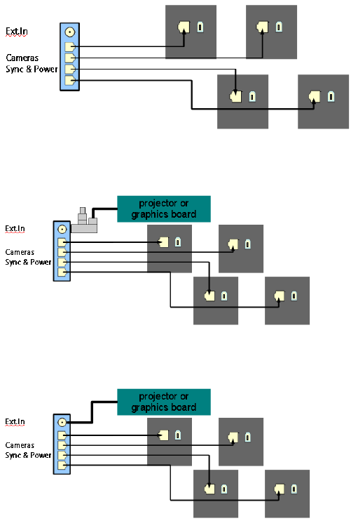
6 Frequently asked questions (FAQ)
–the RJ45 plugs below the BNC plug must be used for connecting the cam-
eras
–EXT.In: input of the external synchronization
2. Check the synchronization settings (software issue):
•Go to Settings →Synccard and double-check the settings (internal or external
synchronization) for the synccard.
•In case of external synchronization, please make sure that the synchronization
signal is being sent by the external source.
How do I guide the synchronization cables correctly in TRACKPACK systems
(discontinued) ?
TRACKPACK systems do not have hardware-based syncgroups. Up to three syncgroups
may be defined within the DTrack2 software: Settings →Cameras →’syncgroup’
•The cables should be guided according to the following sketch:
•Active stereo: when using external synchronization (video) the correct cabling
would look as follows:
•Active stereo: when using external synchronization (TTL) the correct cabling would
look as follows:
156

Chapter 6
6.5 DTrack2 and shutter glasses
6.5 DTrack2 and shutter glasses
What types of shutter glasses can be used with the ART tracking system
•RealD CrystalEyes 1, 2, 3 and 5
•NuVision APG6000 and APG6100
•XPand X101, X103 (with NuVision Long-Range Emitter), X104LX
•NVidia 3D Vision Pro (RF sync’ed)
•Volfoni EDGE (with Volfoni or NuVision LR Emitter)
•Virtalis ActiveWorks 500
When I start tracking, the shutter glasses don’t work correctly.
Most shutter glasses use infrared signals to synchronize the glasses with the image. The
tracking cameras produce a strong infrared flash, which interferes with this communica-
tion. By synchronizing both systems, the cameras emit their flash in a way that does not
interfere.
Please refer to chapter 4.2.2 on page 48 or chapter 4.2.3 on page 52.
When I connect the "ExtIn", the shutter emitters stop working.
Some projectors create only a weak sync signal (TTL), which is not strong enough to
drive the Synccard2. Please contact ART to get a special high-impedance version or
synchronize against the video signal (if available).
Tracking stops when no stereo image is displayed
Some graphics adapters only create the shutter image when a stereo image is displayed.
If available, use video synchronization. Known behavior for NVidia adapters.
6.6 DTrack2 and interfaces
I’m using VRPN. Which output identifiers have to be activated?
It is absolutely mandatory that you activate at least the ’6d’ and ’6dcal’ output identifiers
(refer to table 4.13 on page 106). Activate other output identifiers depending on your
application (e.g. if you’re using a Flystick you have to activate ’6df2’).
I’m using VRPN and TrackD but I only succeed in receiving data via just one of
them.
Please make sure that you are using two separate output channels with different port
numbers.
157
6 Frequently asked questions (FAQ)
I’m having problems with the Flystick2 or Flystick3 data transmission via TrackD.
Please make sure that you are using the latest version of the TrackD module - ART will
provide information upon request. Versions of trackd 5.5 which are older than February
2007 do not support data transmission for Flystick2 or Flystick3.
If you don’t want to change the module you may also use the ’old output format’ in Settings
→Flystick.
6.7 Software DTrack2
Where do I get the software DTrack2 from?
The software DTrack2 is delivered on a USB flash drive with the tracking system. Fur-
thermore, you may register for the ART Download Center
(http://www.ar-tracking.com/support/) in order to always have access to the latest
release of DTrack2 .
Why is my frontend not starting up?
•Please refer to chapter A.5 on page 197 for a list of supported operating systems.
•If using Windows XP: please check, that you have installed Service Pack 3 (SP3).
•If using Linux: some newer Linux distributions don’t install the library libpng12.so.0
as default, although it’s part of the distribution. Please install it using an appropriate
package installer.
•If using 64-bit Linux: please be sure, that you have installed the 64-bit DTrack2 pack-
age. To run 32-bit DTrack2 on 64-bit Linux, you might have to install the 32-bit
version of several libraries (depending on your Linux distribution).
Some of my menu items are missing. What can I do?
•Please check if the latest updates for your operating system are installed.
•Please refer to chapter A.5 on page 197 for a list of supported operating systems.
Where is the Monitor 2DOF display?
•Please check if the latest updates for your operating system are installed.
•Please make sure that your firewall is not blocking DTrack2 , even partly.
•Please refer to chapter A.5 on page 197 for a list of supported operating systems.
158

Chapter 6
6.7 Software DTrack2
Why is the Monitor 2DOF display crossed out for some cameras?
•Please check if all the cameras used during room calibration are connected.
•Please refer to section 6.2 on page 147 for the common reasons of disconnected
cameras.
•Please refer to section 4.5.6.5 on page 120 for more information about Monitor
2DOF.
Why does the “(re-)calibration required” message appear in Monitor 2DOF?
•Please make sure you have performed a correct room calibration using all con-
nected cameras.
•Please refer to section 4.5.6.5 on page 120 for more information about Monitor
2DOF.
My target is not visualized within the Monitor 2DOF display.
•Please make sure that the target is inside the tracking volume and within tracking
range of the cameras.
•Double-check the settings for the flash intensities of the cameras (refer to chapter
4.5.6.3 on page 97).
•In case you are using active targets, please make sure that you have activated the
modulated flash. The camera to emit the modulated flash has to be on syncgroup
#1. When using a Flystick3 you have to doublecheck additionally how many sync-
groups are activated for the Flystick3 active target (Settings →Flystick).
How do I define the number of targets to be tracked?
Go to Settings →Body Administration and change the ’number of 6DOF bodies’.
What is the maximum number of targets?
The maximum number of targets (including Flysticks and Fingertracking hand devices) is
depending on the license type:
•Basic and Extended license: 4
•Full-featured license: 50
Starting with DTrack2 version v2.10 a new license model has been established.
You may activate and calibrate 4, 10, 30 or up to 50 targets depending on the license
purchased.
Please refer to table 4.3 on page 76 for a complete license overview.
159
6 Frequently asked questions (FAQ)
Where do I get a license code from?
You may purchase additional licenses for your system. Please contact us in case you
need consultation.
For creating a new license code we will need some information from you:
Go to DTrack2 →Licenses, select the license you want to add and click on Hardware Info.
Contact ART and tell us the synccard number. If you are using a TRACKPACK system
(discontinued) please tell us the MAC address of the Ethernet adapter.
Where do I enter a new license code?
Go to DTrack2 →Licenses and enter the code in line ’new license code’.
Where do I get a software update from?
The latest release of DTrack2 is always available at the ART Download Center
(http://www.ar-tracking.com/support/).
I want to run a software update. How do I preserve my data and my
configurations?
Your data and your configurations are automatically preserved when running a software
update. But it is recommended to regularly create backups of your configuration(s).
How do I run a software update?
Please contact ART to receive the latest software release and follow the instructions in
chapter 4.5.1.3 on page 72.
Do I have to update the DTrack2 frontend software and the software of the
controller at the same time?
We recommend to do so.
My specific settings have been lost.
Please check if the correct configuration is selected:
go to DTrack2 →Configurations and select the correct configuration.
Is it possible to automatically start the measurement after booting the
controller?
Yes, go to Settings →Tracking and tick the checkbox ’automatic start of measurement
after booting’.
160

Chapter 6
6.8 Calibration
May I close the DTrack2 frontend software window after starting the
measurement?
Yes, the measurement continues even if the DTrack2 frontend software is not active.
What’s the version of my DTrack2 software?
Go to About →DTrack2 to find out the version of your DTrack2 frontend software. The
software version of your controller is shown when you select Controller .
There are greyish areas in my Monitor 2DOF display. What do they indicate?
The static reflex suppression is currently active. This is indicated with these greyish ar-
eas. Markers in these areas will not contribute to tracking.
Please refer to chapter 4.5.6.3 on page 98 for more information.
What do the abbreviations "SR", "DR" and "UD" mean?
SR . . . static reflex suppression active
DR . . . dynamic reflex suppression active
UD . . . display orientation is upside down
Please refer to chapter 4.5.6.5 on page 120 for more information.
The display bar in the Monitor 2DOF display is indicating very high radiation
intensities, although no markers are illustrated. Where’s the radiation coming
from?
Please check that the cameras are not in the field of view of each other to avoid mutual
blinding. Furthermore, remove other strong IR radiation sources from the tracking volume
or, at least, prevent them from interfering with the tracking system.
Monitor 2DOF and/or Data Display are ‘freezing’ after some time, although
tracking didn’t stop.
This can be caused by a firewall that is running on the DTrack2 PC and blocking (UDP)
output data.
Please check your firewall settings and ensure that it is not blocking DTrack2 application,
even partly.
6.8 Calibration
How can I find out when the room has been calibrated last time?
Please go to Calibration →Room and click Show details. The date of the last room
calibration is shown.
161
6 Frequently asked questions (FAQ)
How do I define position and orientation of the room coordinate system?
The calibration angle defines position and orientation of the room coordinate system de-
pending on how you place it within the tracking volume. Please refer to table 4.5 on page
80.
DTrack2 offers the possibility to adjust the room coordinate system after the room cali-
bration. Please refer to chapter 4.5.6.4 on page 113 for more information.
How do I have to move the wand?
Move the wand gently within the measurement volume, in order to generate a virtual point
cloud. This point cloud should fill at least about two thirds of the measurement volume.
Please refer to chapter 4.5.2 on page 77 for more information.
I do not succeed in performing a room calibration.
•Please make sure that the calibration angle is placed within the measurement vol-
ume such that it is seen completely by at least two cameras (→verify with Monitor
2DOF display). If not all cameras see the angle be sure that a sufficient volume
connects each camera to the others. No other marker except for the ones belonging
to the calibration angle should be visible.
•Please make sure that the correct calibration set (’Room Calibration Set TP’, ’Room
Calibration Set 410’ or ’Room Calibration Set 710’) is selected in the settings for
room calibration.
•Please make sure that no reflections are seen by the cameras. If it is not possible
to eliminate the reflections you may use static suppression of reflections to remove
them.
•Please make sure that the markers positioned on the calibration angle are not dam-
aged or misarranged.
•Increase the flash intensities of the cameras until all markers are of good quality (i.e.
at least yellow).
Restart the room calibration. Use the wand to create the virtual point cloud within the
measurement volume. Avoid rapid and hectic movement.
I cannot cover two thirds of the measurement volume within the set time for the
room calibration. How do I extend the time for the calibration process?
Please open the dialogue room calibration from the Calibration menu and press the button
Show Details. There you can extend the time for the calibration process.
162

Chapter 6
6.8 Calibration
How shall I evaluate the room calibration results?
The value ’Used Frames’ represents the percentage of valid (i.e., used for room calibra-
tion) data for each camera. It should be as high as possible for all cameras. Values under
50% indicate poor room calibration quality. The number of valid frames should be greater
than 70% for each camera.
Please note that percentages of more than 70% may not be possible when chain calibra-
tion is executed.
DTrack2 reports the error message "no angle tool detected". What went wrong?
First of all, please double-check if all markers are visible and that there are no disturbing
reflexes. Sometimes, it might help to move the calibration angle a little bit.
Please always verify the settings for the room calibration before repeating:
•wand length is printed on a label on the wand;
•select the correct calibration set.
The progress bar of the room calibration stopped.
Please double-check in the Monitor 2DOF display whether the calibration wand is recog-
nized by the cameras during its movement.
What is a "re-calibration" and when do I have to perform one?
DTrack2 provides simplified room and body calibrations, called room and body re-calibration.
The main advantage of a re-calibration is that DTrack2 preserves the origin and the ori-
entation of your coordinate system as well as specific information (predefined emission
vectors, cylindrical marker).
You may perform a room re-calibration from time to time or if a camera moved slightly
(e.g. due to mechanical instabilities). If your body fell down or if the structure is bent you
should carry out a body re-calibration.
Please refer to chapter 4.5.2.1 on page 82 and chapter 4.5.3.3 on page 88 for more
information.
What does ’scaling factor’ mean?
Performing a room calibration results in a certain scaling error. This might be a problem
when applications do have very high accuracy requirements (e.g. when performing mea-
surements with the Measurement Tool ).
The scaling error can be determined, for instance, by measuring points on a defined
scale (e.g. tape measure). The determined scaling error can thus be adjusted with the
163
6 Frequently asked questions (FAQ)
DTrack2 ’scaling factor’ (refer to chapter B.1.1.1).
Please contact ART if you require further information.
I cannot calibrate my target.
•Please check if the markers of the target are seen by the cameras in good quality
(i.e. at least yellow) - a slight change of the target position might help. If necessary
increase the flash intensities of the cameras. Therefore, go to Settings →Cameras.
•Make sure that when starting the body calibration every marker of the target is visible
to the cameras.
•A body calibration can be carried out only if a valid room calibration has been carried
out before. Otherwise, the button Calibrate is grey and cannot be clicked. Check in
the Event Display if there is a warning saying "no valid room calibration".
In that case, please carry out a new room calibration.
•Please make sure using the Monitor 2DOF display that no marker is overlapped
(i.e. merged) by another one. If necessary rearrange the target and restart the body
calibration.
•Try to carry out the body calibration with a moving target. Therefore, shift the starting
position of the target for calibration (often a shift of 10 or 20cm is enough to enable
calibration again).
•Make sure that no other markers or targets but the one you want to calibrate, are
inside the tracking volume.
•Please carry out a new room calibration.
I’d like to save all my body files for backup reasons but I receive less files than
configured bodies.
DTrack2 only creates body files for calibrated bodies. For example: if you configured 15
targets for tracking but only 4 of them are calibrated, you will only receive 4 calibration
files.
I’d like to calibrate a body but the body calibration dialogue is greyed out.
Please ensure that you have performed and accepted a valid room calibration prior to
body calibration.
You may only calibrate bodies if you have the "Extended" or the "Full-featured" license.
With a "Basic" license you are only able to calibrate bodies using a calibration file.
Starting with DTrack2 version v2.10 a new license model has been established. Thus you
are always allowed to manually calibrate up to 4 bodies at least.
Go to DTrack2 →Licenses to see which license you have.
164

Chapter 6
6.8 Calibration
What is the difference between ’due to body’ and ’due to room’?
When selecting ’due to body’, the body coordinate system is fixed by the markers of the
rigid body. The origin of the body coordinate system is set to the center of gravity of all
markers building the rigid body when ’due to room’ is used.
Please refer to chapter 4.5.3 on page 84 for more information.
Do I have to move the target while performing a body calibration?
If possible we recommend to perform moderate movements because accuracy can be
improved doing so. However, the body has to be visible to the cameras all the time.
May I change the position and the orientation of the body coordinate system
later on?
Yes, you may use the dialogue Body adjustment to alter position and orientation of the
body coordinate system. Please refer to chapter 4.5.6.4 on page 117 for more information.
How do I define a name for a target?
Go to Settings →Body Administration (F8). Double-click into the name field and enter a
name for the respective body.
I cannot increase the number of targets anymore.
The maximum number of targets (including Flysticks and Fingertracking hand device) to
be tracked depends on the license code that is installed. With the "Basic" and the "Ex-
tended" license you may only use 4 targets at the same time - the "Full-featured" license
supports 50 targets.
Starting with DTrack2 version v2.10 a new license model has been established. You may
activate and calibrate 4, 10, 30 or up to 50 targets depending on the license purchased.
Please refer to table 4.3 on page 76 for more information.
How shall I evaluate the body calibration results?
Verify that all markers of the target have been recognized during the DTrack2 body cali-
bration. Further, you may check if the single distances between the markers are correct
(refer to chapter 4.5.3 on page 84).
As a special service you may send us the calibration file and we are going to check it.
165
6 Frequently asked questions (FAQ)
6.9 Tracking
My target (active or passive) is not recognized sporadically or only partly or
even not at all.
•Go to Settings →Cameras and tick the checkbox ’modulated flash’. The camera
that sends out the modulated flash has to be on syncgroup # 1.
•Also, take into account that the distance between active target and cameras should
not exceed 4.5m.
•Deactivate the dynamic reflex suppression. Go to Settings →Cameras and untick
the checkbox ’dynamic reflex suppression’.
•Active targets cannot be used near or in front of plasma screens. The IR emission
of the plasma screen overdrives the IR receiver in the active target.
•Please perform a new room calibration.
•Double-check if the marker surface is not dirty or dusty and that it doesn’t appear to
be worn out.
Tracking does not work.
•Please make sure that the measurement has been started and that the target is
within tracking range of the cameras.
•If marker recognition is poor then increase the flash intensity.
•Check number of markers that are used for calculation. If all markers of the target
are seen by the cameras, but partly not used for calculation, then execute a new
room calibration.
•Go to Settings →Output. Define a receiver for the tracking data and configure the
type of data to be transmitted.
•Activate the tracking functionality within your graphics application.
I’m having too many heavy reflections.
•Please double-check that the flash intensities of the cameras are not too high. In
general, a flash intensity of 3-4 might be sufficient.
•Make sure that no other strong infrared radiation sources (e.g. sunrays or halogen
lamps) are present in the tracking volume. If they cannot be removed you may use
the reflex suppression feature of DTrack2 .
•If mutual blinding is possible please either try to adjust the cameras differently or try
to arrange them in different syncgroups.
166

Chapter 6
6.10 Flystick
Does DTrack2 send data if no target is being tracked?
No tracking data is sent except for the frame number (’fr’).
The application PC does not receive tracking data.
•Go to Settings →Output. Define a receiver for the tracking data and configure the
type of data to be transmitted.
•Check the network connection physically and try to address the controller with a
’Ping’.
•Double-check with a UDP receiver if data is being sent by the controller.
•Activate the tracking functionality within your graphics application.
May I use passive and active targets at the same time?
Yes, of course, there are no restrictions on using passive and active targets simultane-
ously. But you will need an external modulated flash if you are using ARTTRACK1 (dis-
continued) or ARTTRACK2 (SN < 320, (discontinued). Please contact ART in that case.
I am moving my target upwards but within the Monitor 2DOF display it moves
downwards.
The camera is set to display data upside down. In the Monitor 2DOF display, right-click
on the respective camera window and disable Display upside down.
6.10 Flystick
The ART radio transceiver cannot be found.
Please make sure that the ART radio transceiver is plugged in. Then, simply press ’F2’
in order to perform a search for new hardware. The radio transceiver should be detected
now.
My Flystick is not presented within the available Flysticks list.
•Make sure that the battery is charged. Press any button of the Flystick and the
orange status LED should be switched on.
•Go to Settings →ART Radio Info to see if the ART radio transceiver has been
recognized.
•Go to Settings →ART Radio Info →Show details and set the channel number
manually.
167
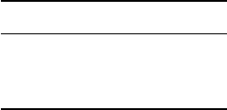
6 Frequently asked questions (FAQ)
Why is the pressing of the Flystick buttons not recognized (within DTrack2 )?
•Make sure that the battery is charged. Press any button of the Flystick and the
orange status LED should be switched on.
•Double-check whether the button pressed events are recognized by DTrack2 . There-
fore:
–enable the Flystick Display (Display →Flystick)
–blue rectangles should light up on each button pressed event in the Flystick
Display.
•Go to Settings →ART Radio Info to see if the ART radio transceiver has been
recognized.
•Go to Settings →ART Radio Info →Show details and set the channel number
manually.
•Go to Settings →Flystick and assign your Flystick (to be found in the available
Flysticks list) to any ’Flystick ID’.
Why is the pressing of the Flystick buttons not recognized (within the graphics
application)?
•Make sure that the battery is charged. Press any button of the Flystick and the
orange status LED should be switched on.
•Go to Settings →Flystick and assign your Flystick (to be found in the available
Flysticks list) to any ’Flystick ID’.
•Go to Settings →Output and check if the data output is configured correctly:
–data receiver defined (’send to’),
–identifier ’6df2’ selected,
–if you are using the old output format: identifier ’6df ’ selected.
What is the maximum number of Flysticks to be used simultaneously?
type max. number
Flystick1 3
Flystick2 5
Flystick3 2
Please double-check that the targets of the Flysticks, that are used simultaneously, are
not identical. If doubts remain please contact ART .
168

Chapter 6
6.11 Fingertracking
What is the MultiUser option for Flysticks?
The MultiUser option is an enhancement especially for VR/AR applications when working
with more than one Flystick.
Please refer to chapter 5.1 on page 130 for more information.
The Flystick output data is not transmitted.
Go to Settings →Output and check if the data output is configured correctly:
•data receiver defined (’send to’),
•identifier ’6df2’ selected,
•if you are using the old output format: identifier ’6df ’ selected.
6.11 Fingertracking
The Fingertracking hand target is not recognized sporadically or even not at all.
•Make sure that the battery is charged and the hand target is switched on.
•Go to Settings →Cameras and tick the checkbox ’modulated flash’. The camera
that sends out the modulated flash has to be on syncgroup # 1.
•The configuration dial has to be turned to the proper position:
for serial numbers ≥100 for serial numbers <100
ID no. of fingers flash time [µs] no. of syncgroups flash time [µs]
0 3 25 1 25
1 3 50 1 50
2 3 75 1 100
3 3 100 1 200
4 5 25 3 25
5 5 50 3 50
6 5 75 3 75
7 5 100 3 100
8 - - - -
9 - - - -
When using Fingertracking, there are always some markers that are flashing
alternately in the Monitor 2DOF display.
This is not bug, but rather it is due to the sequential activation of the finger thimble markers
in order to achieve a separation of the fingers.
169
6 Frequently asked questions (FAQ)
What’s the meaning of the status LEDs on the Fingertracking hand target?
The green LED indicates that the synchronization has been received, whereas the red
LED indicates missing synchronization. If both LEDs are flashing you need to recharge
the battery.
What is being configured when turning the configuration dial?
•for serial numbers <100:
The configuration dial is used to configure the LED brightness and the number of
flash groups used in the system:
–one syncgroup: position 0 to 3,
–three syncgroups: position 4 to 7,
–unused: position 8 to 9.
•for serial numbers ≥100:
The configuration dial is used to select the LED brightness and the number of fingers
used in the setup (refer to table 5.6 on page 142).
What’s the maximum number of hands to be used?
You may use two Fingertracking sets (i.e. four hands) in your tracking system at the same
time. However, the targets of the hand devices should be different.
How do I assign a hand geometry to a hand ID?
Go to Settings →Fingertracking. Select a hand geometry and the hand ID you want to
assign it to and press ’Select’.
The finger calibration fails. What do I do wrong?
•The configuration dial has to be turned to the proper position:
– for serial numbers <100:
∗one syncgroup: position 0 to 3,
∗three syncgroups: position 4 to 7,
∗unused: position 8 to 9.
– for serial numbers ≥100:
∗3-finger version: position 0 to 3,
∗5-finger version: position 4 to 7.
•Go to Settings →Cameras and tick the checkbox ’modulated flash’. The camera
that sends out the modulated flash has to be on syncgroup # 1.
•Please observe the calibration rules defined in chapter 5.3 on page 143:
170

Chapter 6
6.12 Measurement Tool
–the marker on the thumb has to be visible to the cameras,
–do not bend, stretch or cross your fingers,
–do not move your thumb.
•Make sure that you selected the correct handedness and type of fingerset (3-finger
vs. 5-finger) in Calibration →Fingertracking.
•Double-check that the diffusor spheres are not broken or missing.
The Fingertracking output data is not transmitted.
Go to Settings →Output and check if the data output is configured correctly:
•data receiver defined (’send to’),
•identifiers ’gl’ and ’glcal’ selected.
Is it possible to upgrade to the 3-finger or the 5-finger version?
Yes, if you are currently using the 3-finger version you may also use 5-finger thimble sets
and vice versa. Please contact ART to receive more information.
6.12 Measurement Tool
I’m using the Measurement Tool demo but I cannot measure any points.
Please check whether both, the Measurement Tool and the Measurement Tool reference
body (if assigned), are tracked.
It is not possible to perform a tip calibration.
Please check whether both, the Measurement Tool and the Measurement Tool reference
body (if assigned), are tracked.
Then, try to keep the tip in the same position while doing the tip calibration. Therefore, tilt
the Measurement Tool in both room directions, not only in one direction (i.e. left and right,
as well as back and forth). When rotating around one axis only, a tip position cannot be
defined.
6.13 Active Targets
Operation near plasma screen
A plasma screen is a very strong IR source which overdrives the IR receiver in the active
target (e.g. Flystick3, Fingertracking). Thus, active targets may not work properly near
plasma screens. If possible use passive targets as alternative.
171
6 Frequently asked questions (FAQ)
6.14 ART tracking and 3D TVs
Synchronization
3D TVs are primarily consumer products which have not been designed to fulfill the re-
quirements of professional users. In fact, this especially applies when it comes to synchro-
nizing the 3D TV and the tracking system. Typically, there’s no defined synchronization
output which could be used easily. In some rare cases, ART might be able to assist.
Shutter glasses
IR synchronized shutter glasses might not work with ART tracking systems. Due to the
increasing variety, ART only validated a few of these shutter glasses. However, we may
support customers who are performing tests with not validated shutter glasses.
Please contact us to receive information on this issue.
6.15 Radio transceivers used in ART products
Can ART radio transceivers pose any security issue ?
Radio transceivers for Flysticks, Measurement Tool or Tactile Feedback use a protocol
based on IEEE 802.15.4 which was developed in-house at ART specifically for these
devices. There are no other devices which can understand this protocol. The design of
the ATC ensures that use of this protocol is limited to transfering measurement data (like
button-pressed events) and configuring devices.
172
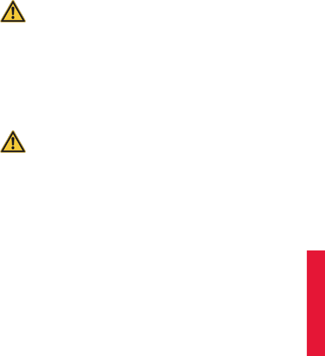
Chapter 7
7 General Information
7.1 Service
It is recommended to maintain the equipment every three years. If you experience any
problems please do not hesitate to contact our support.
Never try to repair anything yourself!!
Opening the equipment implies risks for health and environment as well as loss of war-
ranty and liability.
7.2 Cleaning of the equipment
Only the housing of the cameras may be cleaned. Before cleaning shut down the system
and disconnect the power cords.
Never use water or any chemicals. Just use a dry, lint-free and antistatic tissue like lens-
cleaners for optical equipment.
Do not open the housings!
Opening the housings implies risk for health and environment, as well as loss of warranty
and liability.
7.3 Warranty and liability
Hardware ART warrants the hardware to be free from defects in workmanship and ma-
terial under normal use and service and in its original, unmodified condition, for a period
of 24 months from the time of purchase. The time of purchase is defined as the day when
the end-user takes possession of the equipment. If ART or any company authorized by
ART installs the system, the time of purchase is the time of the first installation.
In case of defects during the warranty period, ART will repair or replace any defective
parts. Replaced parts become property of ART .
Software Software supplied either on the tracking-PC or in cameras is furnished on a
tested "As Is" basis. ART explicitly does not warrant that the software is error (bug) free.
173
7 General Information
If the users detect bugs, ART will provide a workaround or bug fix as soon as possible
after the notification.
Liability ART products are not authorized for use in any circumstances where human
life might be endangered by malfunction, measurement errors or interrupted operation of
the system without written approval of a managing director of ART .
It is the user’s sole responsibility to check the results of the measurement data and to
protect any consecutive system against malfunction, measurement errors or interrupted
operation of the systems supplied by ART . Under no circumstances ART can be held
liable for consequential damages or incidental costs, including production downtimes,
whether arising from measurement errors, interrupted operation or any other malfunction
of the system.
Warranty restrictions All warranty and liability is void, if the system
•is not operated according to the manual,
•shows damages or signs of abuse,
•has been opened by non-authorized people (non-members of ART and companies
not authorized by ART ),
•has been modified by the user or any third party,
•has not been used according to the specifications of this manual.
174
Chapter 7
7.4 Declaration of conformity
7.4 Declaration of conformity
175
7 General Information
176

Chapter 7
7.4 Declaration of conformity
177

7 General Information
178
Chapter 7
7.4 Declaration of conformity
179

7 General Information
Advanced Realtime Tracking GmbH Am Öferl 6 82362 Weilheim i. OB Germany
E
UROPEAN
D
ECLARATION OF
C
ONFORMITY
S
TATEMENT
Advanced Realtime Tracking GmbH
declares under its sole responsibility that the product
ARTTRACK5
to which this declaration relates is in conformity to the following standard(s) or other normative
document(s)
2014/35/EC (Low Voltage Directive):
EN 60950-1:2006 +
A11:2009 + A1:2010 +
A12:2011 + A2:2013
2014/30/EC (EMC Directive):
EN 55022:2010
EN 55024:2010
2011/65/EC (RoHS Directive):
EN 50581:2012
Weilheim i. OB, 20.04.2016
Dr.
A
.
Weiss
(Managing Director)
180

Chapter 7
7.4 Declaration of conformity
Advanced Realtime Tracking GmbH Am Öferl 6 82362 Weilheim i. OB Germany
M
ANUFACTURER
’
S
F
EDERAL
C
OMMUNICATION
C
OMMISSION
D
ECLARATION OF
C
ONFORMITY
S
TATEMENT
Advanced Realtime Tracking GmbH
declares under its sole responsibility that the product
ARTTRACK5
to which this declaration relates is in conformity to the following standard:
FCC 47 CFR Part 15, Subpart B
Class B digital device
Operation is subject to the following two conditions:
(1) this device may not cause harmful interference, and
(2) this device must accept any interference received, including interference that may cause
undesired operation.
Weilheim i. OB, 14.11.2014
Dr.
A
.
Weiss
(Managing Director)
181

7 General Information
Advanced Realtime Tracking GmbH Am Öferl 6 82362 Weilheim i. OB Germany
E
UROPEAN
D
ECLARATION OF
C
ONFORMITY
S
TATEMENT
Advanced Realtime Tracking GmbH
declares under its sole responsibility that the product
ARTTRACK5/C
to which this declaration relates is in conformity to the following standard(s) or other normative
document(s)
2014/35/EC (Low Voltage Directive):
EN 60950-1:2006 +
A11:2009 + A1:2010 +
A12:2011 + A2:2013
2014/30/EC (EMC Directive):
EN 55022:2010
EN 55024:2010
2011/65/EC (RoHS Directive):
EN 50581:2012
This is a class A product. In a domestic environment this product may cause
radio interference in which case the user may be required to take adequate
measures.
Weilheim i. OB, 20.04.2016
Dr.
A
.
Weiss
(Managing Director)
182

Chapter 7
7.4 Declaration of conformity
Advanced Realtime Tracking GmbH Am Öferl 6 82362 Weilheim i. OB Germany
M
ANUFACTURER
’
S
F
EDERAL
C
OMMUNICATION
C
OMMISSION
D
ECLARATION OF
C
ONFORMITY
S
TATEMENT
Advanced Realtime Tracking GmbH
declares under its sole responsibility that the product
ARTTRACK5/C
to which this declaration relates is in conformity to the following standard:
FCC 47 CFR Part 15, Subpart B
Class A digital device
Operation is subject to the following two conditions:
(1) this device may not cause harmful interference, and
(2) this device must accept any interference received, including interference that may cause
undesired operation.
This is a class A product. In a domestic environment this product may cause
radio interference in which case the user may be required to take adequate
measures.
Weilheim i. OB, 28.10.2015
Dr.
A
.
Weiss
(Managing Director)
183

7 General Information
Advanced Realtime Tracking GmbH Am Öferl 6 82362 Weilheim i. OB Germany
E
UROPEAN
D
ECLARATION OF
C
ONFORMITY
S
TATEMENT
Advanced Realtime Tracking GmbH
declares under its sole responsibility that the product
TRACKPACK/E
to which this declaration relates is in conformity to the following standard(s) or other normative
document(s)
2014/35/EC (Low Voltage Directive):
EN 60950-1:2006 +
A11:2009 + A1:2010 +
A12:2011 + A2:2013
2014/30/EC (EMC Directive):
EN 55022:2010
EN 55024:2010
2011/65/EC (RoHS Directive):
EN 50581:2012
Weilheim i. OB, 20.04.2016
Dr.
A
.
Weiss
(Managing Director)
184

Chapter 7
7.4 Declaration of conformity
Advanced Realtime Tracking GmbH Am Öferl 6 82362 Weilheim i. OB Germany
M
ANUFACTURER
’
S
F
EDERAL
C
OMMUNICATION
C
OMMISSION
D
ECLARATION OF
C
ONFORMITY
S
TATEMENT
Advanced Realtime Tracking GmbH
declares under its sole responsibility that the product
TRACKPACK/ E
to which this declaration relates is in conformity to the following standard:
FCC 47 CFR Part 15, Subpart B
Class B digital device
Operation is subject to the following two conditions:
(1) this device may not cause harmful interference, and
(2) this device must accept any interference received, including interference that may cause
undesired operation.
Weilheim i. OB, 11.12.2014
Dr.
A
.
Weiss
(Managing Director)
185

7 General Information
Advanced Realtime Tracking GmbH Am Öferl 6 82362 Weilheim i. OB Germany
E
UROPEAN
D
ECLARATION OF
C
ONFORMITY
S
TATEMENT
Advanced Realtime Tracking GmbH
declares under its sole responsibility that the product
ART Controller
to which this declaration relates is in conformity to the following standard(s) or other normative
document(s)
2014/35/EC (Low Voltage Directive):
EN 60950-1:2006 +
A11:2009 + A1:2010 +
A12:2011
2014/30/EC (EMC Directive):
EN 55022:2010
EN 55024:2010
EN 61000-3-2:2006 +
A1:2009 + A2:2009
EN 61000-3-3:2008
2011/65/EC (RoHS Directive):
EN 50581:2012
Weilheim i. OB, 20.04.2016
Dr.
A
.
Weiss
(Managing Director)
186

Chapter 7
7.4 Declaration of conformity
Advanced Realtime Tracking GmbH Am Öferl 6 82362 Weilheim i. OB Germany
M
ANUFACTURER
’
S
F
EDERAL
C
OMMUNICATION
C
OMMISSION
D
ECLARATION OF
C
ONFORMITY
S
TATEMENT
Advanced Realtime Tracking GmbH
declares under its sole responsibility that the product
ART Controller
to which this declaration relates is in conformity to the following standard:
FCC 47 CFR Part 15, Subpart B
Class B digital device
Operation is subject to the following two conditions:
(1) this device may not cause harmful interference, and
(2) this device must accept any interference received, including interference that may cause
undesired operation.
Weilheim i. OB, 14.11.2014
Dr.
A
.
Weiss
(Managing Director)
187
7 General Information
188

Chapter 7
7.4 Declaration of conformity
189
A Technical specifications
ZThe specifications are subject to change without notice.
A.1 Cameras
A.1.1 ARTTRACK5
IR Source
invisible IR 850nm
flash intensity adjustable in 100 steps
Performance
Sensor resolution 1.3 MPixels
Frame rate up to 300 Hz
Field of view (FoV)
Lens Camera mode
Resolution Medium Speed
1.3 MPix 0.8 MPix 0.5 MPix
150 Hz 240 Hz 300 Hz
F = 3.5mm FoV (horizontal x vertical) 98◦×77◦77◦×57◦60◦×44◦
Max. tracking range
(12mm markers)
5.5m 5.5m 5.5m
F = 4.5mm FoV (horizontal x vertical) 75◦×60◦60◦×45◦47◦×35◦
Max. tracking range
(12mm markers)
6.3m 6.3m 6.3m
F = 6.0mm FoV (horizontal x vertical) 54◦×44◦44◦×33◦34◦×26◦
Max. tracking range
(12mm markers)
7.5m 7.5m 7.5m
Connectivity & Power Supply
single cable solution via Gigabit Ethernet, RJ45, PoE+ (IEEE 802.3at Standard)
max. cable length 100m
Voltage 44 - 57 V (defined by the Standard)
max. power consumption 17 W
Protection category III
Interface connectors RJ45 (hosts data, synchronization and power)
Operating conditions
Temperature 0 .. 38◦C
190

Appendix A
A.1 Cameras
Relative humidity 5 .. 50% (non-condensing)
Cooling system passive
Dimensions
Length 92mm
Width 100mm
Height 100mm
Weight 0.96 kg
A.1.2 ARTTRACK5/C
IR Source
invisible IR 850nm
flash intensity adjustable in 100 steps
Performance
Sensor resolution 1.3 MPixels
Frame rate up to 300 Hz
Field of view (FoV)
Lens Camera mode
Resolution Medium Speed
1.3 MPix 0.8 MPix 0.5 MPix
150 Hz 240 Hz 300 Hz
F = 4.0mm FoV (horizontal x vertical) 89◦×71◦71◦×52◦56◦×42◦
Max. tracking range
(12mm markers)
4.5m 4.0m 3.5m
Connectivity & Power Supply
single cable solution via Gigabit Ethernet, RJ45, PoE+ (IEEE 802.3at Standard)
max. cable length 100m
cable length to remote
camera head
60cm
Voltage 44 - 57 V (defined by the Standard)
max. power consumption 12 W
Protection category III
Interface connectors RJ45 (hosts data, synchronization and power)
Operating conditions
Temperature 0 .. 38◦C
Relative humidity 5 .. 50% (non-condensing)
Cooling system passive
Dimensions remote camera head
Diameter 37mm
Length 73mm
Weight 160g
Dimensions camera body
191
A Technical specifications
Length 55mm
Width 100mm
Height 100mm
Weight 540g
A.1.3 TRACKPACK/E
IR Source
invisible IR 850nm
flash intensity adjustable in 100 steps
Performance
Sensor resolution 1.1 MPixels
Frame rate up to 120 Hz
Field of view (FoV)
Lens Camera mode
Resolution Medium Speed
1.1 MPix 0.7 MPix 0.5 MPix
60 Hz 90 Hz 120 Hz
F = 3.5mm FoV (horizontal x vertical) 97◦×79◦97◦×51◦97◦×36◦
Max. tracking range
(12mm markers)
4.5m 4.5m 4.5m
Connectivity & Power Supply
single cable solution via Gigabit Ethernet, RJ45, PoE (IEEE 802.3af Standard)
max. cable length 100m
Voltage 44 - 57 V (defined by the Standard)
max. power consumption 5 W
Protection category III
Interface connectors RJ45 (hosts data, synchronization and power)
Operating conditions
Temperature 0 .. 38◦C
Relative humidity 5 .. 50% (non-condensing)
Cooling system passive
Dimensions
Length 103 mm
Width 70 mm
Height 59 mm
Weight 0.51 kg
192

Appendix A
A.1 Cameras
A.1.4 ARTTRACK cameras (discontinued)
ARTTRACK2.2 ARTTRACK3.2 ARTTRACK2 ARTTRACK3
from S/N #1800 from S/N #400
IR flash 880nm 850nm 880nm 850nm
Power supply
Nominal voltage 12V 48V 12V 48V
Maximal current 2A 1.4A 2A 1.4A
Maximal power 25W 35W 25W 35W
Ext. power supply 12.2V / 3A / 40W 48V / 0.8A / 40W 12.2V / 3A / 40W 48V / 0.8A / 40W
12.5V / 3A / 40W 48.2V / 0.8A / 40W 12.5V / 3A / 40W 48.2V / 0.8A / 40W
Protection category
Ext. power supply I I I I
Camera III III III III
Interface connectors
data RJ45 RJ45 RJ45 RJ45
synchronization BNC BNC BNC BNC
power external external external external
Operating conditions
Temperature 0 .. 38◦C 0 .. 38◦C 0 .. 38◦C 0 .. 38◦C
Relative humidity 5 .. 50% 5 .. 50% 5 .. 50% 5 .. 50%
non-condensing non-condensing non-condensing non-condensing
Cooling system active (fan)
→noise level of
the fan: 16.5dB(A)
passive active (fan)
→noise level of
the fan: 16.5dB(A)
passive
Dimensions
Length 140mm 140mm 140mm 140mm
Width 78mm 106mm 78mm 106mm
Height 109mm 120mm 109mm 120mm
Weight 0.96kg 1.45kg 0.96kg 1.45kg
‘Performance
Frame rate max. 60fps max. 60fps max. 60fps max. 60fps
(adjustable) (adjustable) (adjustable) (adjustable)
Max. working distance with 12mm passive markers (F .. focal length in mm).
Greater distances achievable with bigger passive markers (e.g. 30mm) or active markers.
@ F = 2.6mm 4.5m 4.5m 4.5m 4.5m
@ F = 3.5mm 4.5m 4.5m 4.5m 4.5m
@ F = 4.5mm 4.5m 6m 4.5m 6m
@ F = 6.0mm 4.5m 7m 4.5m 7m
Maximum number of 6DOF targets (simultaneously)
@ 60fps 50 50 50 50
Field of view (FoV, horizontal ×vertical)
@ F = 2.6mm 88◦×58◦88◦×58◦- -
@ F = 3.5mm 67◦×45◦67◦×45◦72.8◦×58.2◦72.8◦×58.2◦
193

A Technical specifications
ARTTRACK2.2 ARTTRACK3.2 ARTTRACK2 ARTTRACK3
from S/N #1800 from S/N #400
IR flash 880nm 850nm 880nm 850nm
@ F = 4.5mm - 52◦×35◦57.9◦×45.3◦57.9◦×45.3◦
@ F = 6.0mm - - 42.9◦×33.0◦42.9◦×33.0◦
other focal lengths on request
A.1.5 TRACKPACK cameras (discontinued)
TRACKPACK TRACKPACK/C
IR flash 850nm 850nm
Power supply
Nominal voltage 12V 12V
Maximal current 0.5A 0.5A
Maximal power 6W 6W
Ext. power supply - -
- -
Protection category
Ext. power supply - -
Camera III III
Interface connectors
data IEEE1394 IEEE1394
synchronization RJ45 RJ45
power RJ45 RJ45
Operating conditions
Temperature 0 .. 38◦C 0 .. 38◦C
Relative humidity 5 .. 50% 5 .. 50%
non-condensing non-condensing
Cooling system passive passive
Dimensions
Length 77.8mm 228mm
Width 76.9mm 76.9mm
Height 60mm 58mm
Weight 0.45kg 0.45kg
Performance
Frame rate max. 60fps max. 60fps
(adjustable) (adjustable)
Max. working distance with 12mm passive markers (F .. focal length in mm).
Greater distances achievable with bigger passive markers (e.g. 30mm) or active markers.
@ F = 2.6mm 2.5m -
@ F = 3.5mm 3.5m 3.5m
@ F = 4.5mm 3.5m -
@ F = 6.0mm 3.5m -
Maximum number of 6DOF targets (simultaneously)
@ 60fps 4 - 50 4 - 50
194

Appendix A
A.2 Flysticks
TRACKPACK TRACKPACK/C
IR flash 850nm 850nm
Field of view (FoV, horizontal ×vertical)
@ F = 2.6mm 93.5◦×77.2◦-
@ F = 3.5mm 72.8◦×58.2◦72.8◦×58.2◦
@ F = 4.5mm 57.9◦×45.3◦-
@ F = 6.0mm 42.9◦×33.0◦-
other focal lengths on request
A.2 Flysticks
Flystick2 Flystick3
Power supply
Rechargeable battery 13 standard AAA batteries lithium battery (850mAh / 3.7V)
integrated in the handheld
Continuous operation2at least 10 hours at least 8 hours
Battery charging duration
Operation possible with con-
nected charger
no yes
USB transmitter
Connection to the PC USB USB
Radio range
(depending on setup location,
e.g. walls)
at least 7m at least 7m
Radio module
Type ID IEEE 802.15.4 IEEE 802.15.4
Frequency 2.4 GHz 2.4 GHz
Transmission power 1 1
Operating conditions
Operating temperature 0 .. 40◦C 0 .. 38◦C
Relative humidity 5 .. 50%, non-condensing 5 .. 50%, non-condensing
General features
Target type passive markers passive or active markers
(IR-LEDs @ 880nm)
Tracking range
(@ 3.5mm focal length)
approx. 4m approx. 4.5m
Weight 250g 120g
Size 220mm x 180mm x 100mm 245m x 90mm x 75mm
1replacement after a period of 2 years is recommended
2only valid for new batteries
195

A Technical specifications
A.3 Fingertracking
Function
Synchronization via modulated IR flash
Battery NB-4L Li-Ion battery, 3.7V, 700 mAh
Battery charger
Input 12V, 500mA
Power supply 230V, 50Hz, 12W
Continuous operation 1approx. 10 hours
Weight (incl. power supply) 380g
Operating conditions
Operating temperature 0 .. 38◦C
Relative humidity 5 .. 50%, non-condensing
Dimensions
Thimble set available in 3 different sizes (small, medium, large)
Weight 60g
Performance
Frame rate (handtarget) 60Hz
Frame rate (thimbles, 3-finger version) 20Hz
Frame rate (thimbles, 5-finger version) 12Hz
Tracking range 4m (depending on focal length of the cameras)
1only valid for new batteries
A.4 ART Controller
Dimensions
Rackmount (19")
Size 480mm ×345mm ×135mm
Weight 9.75 kg
Power Supply
Voltage 110 - 240 V
max. power consumption 360 W
Connectors
Synchronization in 1, BNC: Video Signal (75Ω), TTL, LVTTL
Camera ports 8, Ethernet 1 GBit/s, PoE+
Data out 1, Ethernet 1 GBit/s
USB 6
Operating conditions
Operating temperature 0 .. 38◦C
Relative humidity 5 .. 50%, non-condensing
196
Appendix A
A.5 Overall system
Hazard notes for service personnel:
Risk of explosion if the mainboard battery is incorrectly replaced. Re-
place only with the same or from manufacturer recommended similar
type.
In order to replace a main fuse of the ART Controller always unplug the
power cord. Two main fuses are existing since two power supplies are
installed. So the device is possibly still under power although a fuse
has blown.
A.5 Overall system
System parameters
number of cameras 2 - 50 (max. 16 for TRACKPACK/E and TRACKPACK systems
(discontinued)
max. number of targets 50
max. number of hands 4
max. number of Flysticks
- Flystick2 5
- Flystick3 1
Scalability ARTTRACK system: fully scalable (2 - 50 cameras)
TRACKPACK/E and TRACKPACK systems (discontinued):
cascadable up to 16 cameras (additional controller necessary)
Accuracy
- of the timestamp with a Synccard2/3: ∆terr ∼ ±0.1ms
with a SynccardTP: ∆terr ∼ ±10ms
Operating conditions
Temperature 0 .. 38◦C
Relative humidity 5 .. 50%, non-condensing
Compatible shutter glasses
NuVision APG6000 ×
NuVision APG6100 ×
NVidia 3D Vision Pro ×, radio synchronization
RealD CE1 ×
RealD CE2 ×
RealD CE3 ×
RealD CE4 -
RealD CE5 ×
Volfoni EDGE ×, with Volfoni or NuVision Long-Range Emitter
XPand X103 ×, with NuVision Long-Range Emitter
XPand X101 ×
XPand X104LX ×
Virtalis ActiveWorks 500 ×
DTrack2 frontend software
197

A Technical specifications
System requirements
- Free disk space ≥200MB
- Processor Intel: ≥P4 2GHz
AMD: ≥K6 1.6Ghz
- RAM ≥1GB
Operating systems Windows XP 32/64 Bit, with Service Pack 3 (SP3)
Windows 7 32/64 Bit
Windows 8/8.1 32/64 Bit
Linux openSUSE ≥12.3 32/64 Bit
Linux Ubuntu ≥10.04 32/64 Bit
Linux CentOS ≥6.6 32/64 Bit
Settings firewall (remote PC)
- used ports 50105 (for UDP & TCP)
50110 (for UDP)
198
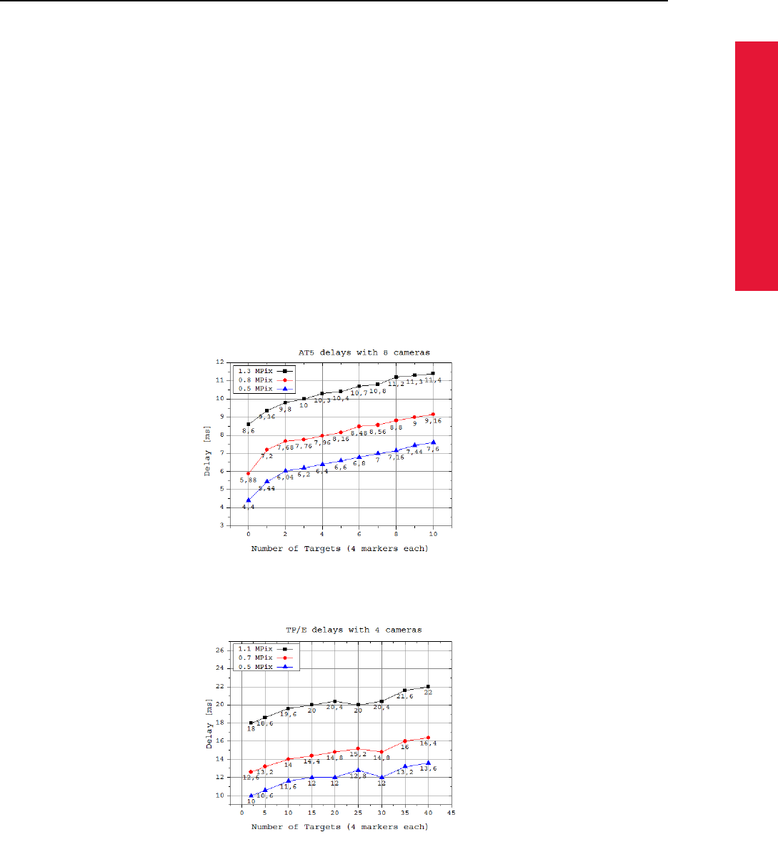
Appendix A
A.6 System latency
A.6 System latency
System Latency
Definition of the system latency:
The system latency is defined as the time delay between sending out the IR
flash by the cameras and the availability of the tracking data at the Controller’s
Ethernet output. The latency is a function of the number of cameras, the number
of targets, enabled or disabled 3DOF tracking and additional reflexes (e.g.
single markers). Another dependency, which is quite important, can be found in
the software version of DTrack2 being used (here: v2.8.6). We recommend to
always use the latest version in order to have the most recent features.
For ARTTRACK5 ,ARTTRACK5/C and TRACKPACK/E : The ATC is trig-
gered externally with an arbitrary function generator at 20 Hz. The output
network card on the ATC is set-up with 10 MBit (ethtool -s eth0 speed 10 duplex
full), so that the network package with the tracking results can be triggered with
an oscilloscope.
ARTTRACK5 + ARTTRACK5/C
TRACKPACK/E 4 Camera System
TRACKPACK/E 8 Camera System
199
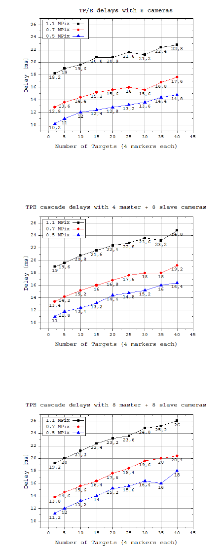
A Technical specifications
TRACKPACK/E 12 Camera Cascade (4 Master + 8 Slaves)
TRACKPACK/E 16 Camera Cascade (8 Master + 8 Slaves)
200

Appendix A
A.6 System latency
ARTTRACK2 (discontinued)
ARTTRACK3 (discontinued)
TRACKPACK (discontinued)
201
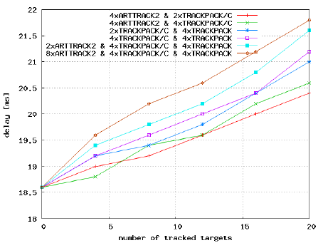
A Technical specifications
TRACKPACK Cascade (discontinued)
202

Appendix B
B Technical Appendix
B.1 Definition of Coordinates and Rotations
B.1.1 Room Calibration
The calibration angle defines origin and axes of the coordinate system. This can be done in two
different ways:
Type longer arm shorter arm
’normal’ +X axis +Y axis
’powerwall’ +X axis -Z axis
For example, a room calibration of type ’normal’ would result in a coordinate system like the
following:
1. The marker located in the crossing point of the two arms is defining the origin of the coordi-
nate system.
2. The longer arm of the calibration tool defines the +X axis.
3. The shorter arm of the calibration tool defines the +Y axis. (i.e., the tool markers define the
X/Y plane.)
4. The Z axis is added in order to give a right-handed coordinate system.
B.1.1.1 Room Adjustment
DTrack2 allows to modify the room coordinate system by specifying these seven values:
•lx,ly,lzfor a translational offset (denoted x, y, z in the GUI),
•η,θ,φfor a rotation (denoted rx, ry, rz in the GUI).
•sfor a scaling factor.
These offsets are defined as a shift and/or rotation and/or scaling of the room coordinate system
relative to the original one. Mathematically a point ~xorig in the original room is transformed into a
point ~xmod in the modified room coordinate system by:
~xmod = (RT·~xorig −~
l)·s
where the rotation matrix Ris calculated from η,θand φlike defined in section B.1.3.
203
B Technical Appendix
B.1.2 Body Calibration
During the body calibration DTrack2 is fixing a local coordinate system (body coordinate system)
for each rigid body. Both coordinate systems define the later 6DOF output (see chapter B.1.3
on page 205). The calibration can be done in three different ways (to be selected in the menu
Calibrate / Body of the body calibration):
B.1.2.1 Definition of the Coordinates by the Body itself
Body calibration setting due to body:
The body coordinate system is fixed by the markers of the rigid body according to a set of rules:
1. Search the biggest distance between two markers of the rigid body. These two markers (#1
and #2) will define the X axis.
2. Search for a third marker (#3) that has the smallest distance to one of the two markers #1
and #2. The marker that has smallest distance to marker #3 becomes marker #1. It will
define the coordinate origin. The other marker will be #2. The positive X axis is directed
from marker #1 to marker #2.
3. Marker #3 defines the X/Y plane, together with markers #1 and #2. Marker #3 has a positive
Y coordinate.
4. The Z axis is already defined by these rules, resulting in a right-handed coordinate system.
B.1.2.2 Definition of the Coordinates by the Room Coordinate System, with Origin
in the Center of the Markers
Body calibration setting due to room:
The origin of the body coordinate system is set to the center (center of gravity) of all markers
building the rigid body. The axes of the body coordinate system are parallel to the axes of the
room coordinate system in the beginning of the body calibration.
I.e., the result of a body calibration will depend on the angular position of the target during cali-
bration. A 6DOF measurement, following calibration without having moved the body, will give the
angular coordinates 0◦/ 0◦/ 0◦.
If the target was moved during calibration, the angular position of the target at the beginning of the
calibration will be taken.
B.1.2.3 Definition of the Coordinates by the Room Coordinate System, with Origin
in a Marker
Body calibration setting due to room (zero in marker):
A combination of the first two methods. The direction of the axes of the body coordinate system
will be set parallel to the room coordinate system in the moment of body calibration - like done
with setting due to room. The origin of the body coordinate system is given by one marker of the
body, according to the rules given for setting due to body.
204

Appendix B
B.1 Definition of Coordinates and Rotations
B.1.2.4 Coordinate System Definition for 5DOF Targets (with and without cylinder
markers)
Body calibration setting x/y/z:
In the body coordinate system all markers of the target are on the selected axis. The origin is in
the middle between the two markers with the largest distance to each other. The orientation is
defined by the marker with the smallest distance to the origin. Its position has a negative sign.
The other two directions are undetermined due to the one degree of freedom.
B.1.2.5 Coordinate System Definition for two 5DOF Targets with cylinder markers
Body calibration setting xy/yx/yz/zy/zx/xz:
The body is expected to consist of two about perpendicularly connected 5DOF targets. These are
placed on the two axes. The origin is placed at the position where the two 5DOF targets intersect.
The first axis is assigned to the 5DOF target which includes the marker with the largest distance
to the origin. The other 5DOF target is placed in the plane created by the two axes.
B.1.3 6DOF Results
Position and Orientation
Position and orientation of a target are expressed by an affine transformation (~s,R) that transforms
a vector ~x from the body coordinate system to the room coordinate system:
~xroom =R·~xbody +~s
I.e., the coordinates ~s give the position of the origin of the body coordinate system (marker #1 or
center of gravity, as described above), measured in room coordinates.
The 3×3rotation matrix Rdescribes the rotation part of the transformation. The columns of the
matrix Rare the axes (X, Y, Z) of the body coordinate system, expressed in room coordinates.
Description by Rotation Angles
The rotation matrix can be replaced by three consecutive rotations Ri(χ)(rotation angle χ, rotation
axis i). The angles, as given in the DTrack2 data output, are defined by the equation:
R=Rx(η)·Ry(θ)·Rz(φ)
Expressed in trigonometric functions, that means:
R=
cos φcos θ−sin φcos θsin θ
sin φcos η+ cos φsin θsin ηcos φcos η−sin φsin θsin η−cos θsin η
sin φsin η−cos φsin θcos ηcos φsin η+ sin φsin θcos ηcos θcos η
Note that per definitionem the angles can only have the values:
−180◦≤φ≤180◦,−90◦≤θ≤90◦,−180◦≤η≤180◦
205

B Technical Appendix
ZNote: rotation angles can show strange behaviour at certain orientations. In
particular, for orientations close to θ=±90◦the other two angles can experi-
ence large odd-looking changes (so called “Gimbal Lock”).
When connecting DTrack2 to an application, often problems appear caused by different definitions
of rotation angles. To avoid that, we recommend to use rotation matrices.
B.1.4 3DOF Data
Besides the tracking of 6DOF bodies, DTrack2 is able to calculate the coordinates of single mark-
ers, i.e. markers that can not be recognized as part of a rigid body. The output values are the
coordinates of these markers, measured in room coordinates.
In some situations, a rigid body within the measurement volume is (temporarily) not correctly
recognized by the software. In these cases, its markers appear as 3DOF objects.
3DOF markers are tracked (as long as possible) and labeled with an ID number. When a 3DOF
marker vanishes (or is recognized as part of a 6DOF body), its ID number will not be used any
more, as long as the tracking is active.
B.1.5 Flystick devices
DTrack2 is supporting the following input devices:
•Flystick1,
•Flystick2 and
•Flystick3.
Each of the afore mentioned devices is equipped with buttons (4 - 8) and a small joystick. Input
transactions are transmitted wirelessly to the controller and added to the 6DOF tracking result of
the Flystick body.
There are two types of output formats available, called 6df and 6df2 (details see chapter B.2.5 on
page 213 and chapter B.2.6 on page 214); they differ in the number of carried input controls. Only
the newer 6df2 format is capable of processing analogue values (or controllers) as produced by a
joystick. Both formats use the same order of buttons (details see below):
Output Format Number of Buttons Order of Buttons Number of Controllers
6df 8 (fix) “right to left” —
6df2 device dependent “right to left” device dependent
B.1.5.1 Flystick1
The Flystick1 carries eight switches (buttons); four of them form the so-called hat switch. When
using output format 6df2, hat switch actions are transferred into two analogue controller values
(getting the values −1.0,0.0and 1.0). The following table shows, how each input action appears
in the output data:
206

Appendix B
B.1 Definition of Coordinates and Rotations
Switch 6df Output 6df2 Output
front switch (red) code 01 (hex) button code 01 (hex)
right switch on backside (red) code 02 (hex) button code 02 (hex)
center switch on backside (red) code 04 (hex) button code 04 (hex)
left switch on backside (red) code 08 (hex) button code 08 (hex)
hat switch (black) to the left code 20 (hex) first controller 1.0
hat switch (black) to the right code 80 (hex) first controller −1.0
hat switch (black) up code 40 (hex) second controller 1.0
hat switch (black) down code 10 (hex) second controller −1.0
B.1.5.2 Flystick2
Each Flystick2 is equipped with six switches (buttons) and a small joystick, that produces two
analogue values, one for horizontal and one for vertical movement. When using the old output
format 6df, the joystick values are transferred into hat switch actions; two of the buttons cannot be
accessed.
Switch labelled as 6df Output 6df2 Output
(in figure B.1)
front switch (yellow) id 0 code 01 (hex) button code 01 (hex)
outer right switch on backside (blue) id 1 code 02 (hex) button code 02 (hex)
inner right switch on backside (blue) id 2 code 04 (hex) button code 04 (hex)
inner left switch on backside (blue) id 3 code 08 (hex) button code 08 (hex)
outer left switch on backside (blue) id 4 – button code 10 (hex)
switch on joystick (yellow) id 5 – button code 20 (hex)
joystick (yellow) to the left – code 20 (hex) first controller up to 1.0
joystick (yellow) to the right – code 80 (hex) first controller up to −1.0
joystick (yellow) up – code 40 (hex) second controller up to 1.0
joystick (yellow) down – code 10 (hex) second controller up to −1.0
(a) Flystick2 (b) Flystick3
Figure B.1: Allocation of ID number to the Flystick buttons
207
B Technical Appendix
B.1.5.3 Flystick3
Each Flystick3 is equipped with four switches (buttons) and a small joystick, that produces two
analogue values, one for horizontal and one for vertical movement. When using the old output
format 6df, the joystick values are transferred into hat switch actions.
Switch labelled as 6df Output 6df2 Output
(in figure B.1)
bottom switch (yellow) id 0 code 01 (hex) button code 01 (hex)
top right switch (blue) id 1 code 02 (hex) button code 02 (hex)
top middle switch (blue) id 2 code 04 (hex) button code 04 (hex)
top left switch (blue) id 3 code 08 (hex) button code 08 (hex)
joystick (yellow) to the left – code 20 (hex) first controller up to 1.0
joystick (yellow) to the right – code 80 (hex) first controller up to −1.0
joystick (yellow) up – code 40 (hex) second controller up to 1.0
joystick (yellow) down – code 10 (hex) second controller up to −1.0
B.1.6 Measurement Tools
iOnly available, if the Measurement Tool license is present for DTrack2 (avail-
able since version v2.2.0)
The Measurement Tool license allows the use of Measurement Tools , i.e. pointing devices with a
special target geometry. While tracking, the module calculates position and orientation of the tip
of the tool. It is necessary to perform an additional calibration procedure (called tip calibration) to
provide the module with information about the tip.
B.1.6.1 Orientation of a Measurement Tool
The module modifies the local coordinate system (i.e. the body coordinate system) of the tool’s
body as follows:
1. The tip becomes the origin of the coordinate system.
2. The marker with the largest distance to the tip defines the +Z axis.
3. The marker, that is closest to the tip, defines the Y/Z plane.
This definition shall ease the use of the tip orientation. For instance, the orientation of all ART Mea-
surement Tools is approximately along the -Z axis.
B.1.6.2 Using a reference body
When using a reference body for a Measurement Tool , the module calculates the position of the
tip ~xS
ref within the local coordinate system of the reference body:
~xS
room =Rref ·~xS
ref +~sref
where ~xS
room is the position of the tip in room coordinates, and (~sref , Rref )position and orientation
(see B.1.3) of the reference body. The orientation of the Measurement Tool is transformed in an
analogous way.
208
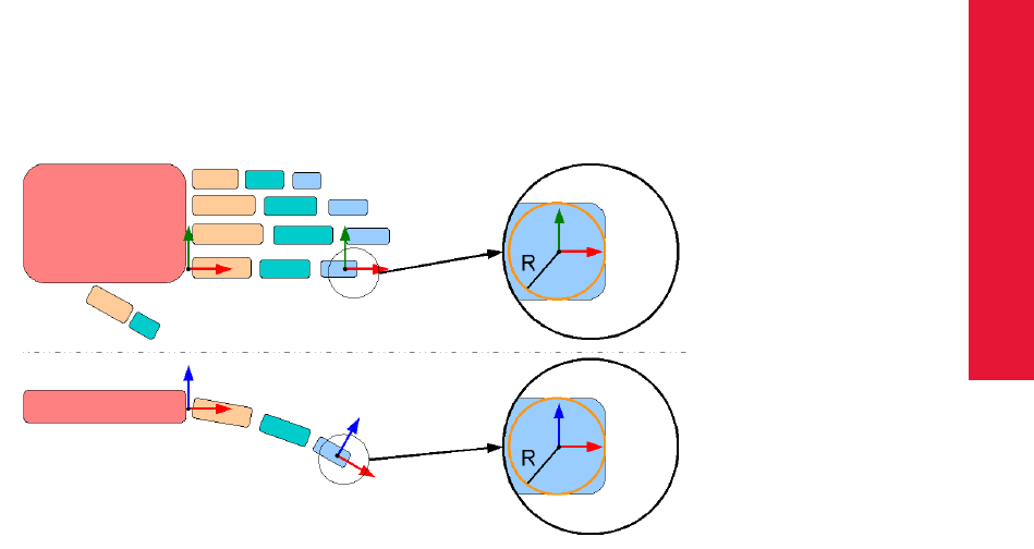
Appendix B
B.1 Definition of Coordinates and Rotations
B.1.7 Fingertracking
The Fingertracking device allows to track a human’s entire hand, including fingers. It provides all
necessary information to describe the tracked hand. In detail:
•position and orientation of the back of the hand (given in room coordinate system).
•number of the device’s fingers (3or 5) as well as a value to distinguish between right and
left hand.
•position and orientation of the outermost phalanxes, given in the hand coordinate system
(see below); with the radius of the finger tip, the position and orientation (more exactly the
surface) of the finger tip can be identified.
•angles between the single phalanxes as well as their lengths. These values are calculated
using tracked markers and empirical data.
The hand coordinate system is defined as follows (see figures B.2 and B.3 on page 209f.):
Figure B.2: Model of a human left hand
•the origin is in the joint, where the index finger is connected to the back of the hand.
•the +X axis is oriented in direction of the outstretched index finger.
•the +Y axis is defined parallel to the back of the hand, indicating towards the ring finger.
•the +Z axis is defined with these specifications, resulting in a right-handed coordinate sys-
tem.
ZPlease note that the +Z axis points up towards the back of the hand for a left
hand, but down for a right hand!
The finger coordinate system (used to measure the orientation of the outermost phalanx relative
to the hand coordinate system) is defined by these rules (see figures B.2 and B.3 on page 209f.):
•origin is the center of the (partial) sphere that forms the finger tip,
209
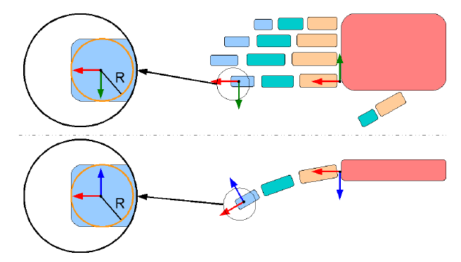
B Technical Appendix
Figure B.3: Model of a human right hand
•the +X axis is oriented in direction of the outstretched finger,
•the +Z axis is defined to form a normal on the finger nail, pointing upwards,
•the +Y axis is defined with these specifications, resulting in a right-handed coordinate sys-
tem.
Given the length of each phalanx and the angles between them, it’s possible to reconstruct the
entire finger.
ZNote that the joint between innermost phalanxes and back of the hand can
move! This corresponds to a bending of the hand’s back.
B.2 Output of Measurement Data via Ethernet
DTrack2 uses ethernet (UDP/IP datagrams) to send measurement data to other applications. The
IP address and the port of the application (and the computer it runs on) can be configured in
Settings →Output.
Each datagram carries all the results of a single measurement, coded in ASCII format. One data-
gram is sent after each measurement of the cameras, i.e. following the synchronization frequency.
The ’send data divisor’ in Settings →Output offers the possibility to decrease the data output
frequency (foutput =fsync/ddivisor).
iAll data are given in units millimeter (mm) or angular degree (deg /◦).
ART provides free sample source code (‘DTrackSDK’, in C++) to receive and parse the output
data. Please contact ART to get it.
A UDP datagram in ASCII format contains several lines separated by CR/LF (hex 0D 0A). Each
line carries data of a specific type and starts with an identifier. In Settings →Output you may
configure which lines or data types should be included in the output:
210

Appendix B
B.2 Output of Measurement Data via Ethernet
Identifier Type of data enable/disable in
fr frame counter always enabled
ts timestamp Settings →Output (’ts’)
6dcal additional informations Settings →Output (’6dcal’)
6d/6di standard bodies (6DOF) Settings →Output (’6d / 6di’)
3d additional markers (3DOF) Settings →Output (’3d’)
6df/6df2 Flysticks (6DOF + buttons) Settings →Output (’6df / 6df2’)
6dmt Measurement Tools (6DOF + tip trafo) Settings →Output (’6dmt’)
6dmtr Measurement Tool references (6DOF) Settings →Output (’6dmtr’)
6dmt2 Measurement Tool with sphere tip (6DOF + tip trafo
+ sphere radius)
Settings →Output (’6dmt2’)
gl/glcal Fingertracking hands (6DOF + fingers) Settings →Output (’gl / glcal’)
B.2.1 Frame Counter
Identifier fr.
This line is always the first one. It carries a frame counter (counting with synchronization fre-
quency).
Example:
fr 21753
B.2.2 Timestamp
Identifier ts.
A timestamp can be added to each datagram. It shows the time at the measurement of this frame,
i.e. the time when the infrared flash of the cameras is fired. The timestamp uses the internal clock
of the controller, giving back the seconds (with an accuracy of 1µs) since 00:00 UTC1(midnight).
This implies that the timestamp value is reset to zero when passing midnight (UTC)!
iThe timestamp typically shows an accuracy of better than ∆terr ∼ ±0.01ms
with a Synccard2 (used in ARTTRACK systems). With a SynccardTP (used in
TRACKPACK systems) one can only expect an accuracy of ∆terr ∼ ±0.5ms.
Example:
ts 39596.024831
B.2.3 Standard 6DOF Bodies
Identifier 6d.
Measurement data of all tracked standard 6DOF bodies (i.e. all 6DOF bodies except Flysticks,
Measurement Tools . . . ). Bodies, that are not tracked by the system at that moment, don’t appear
in the output.
•The first number gives the number of tracked bodies (less or equal to the number of cali-
brated bodies).
1Coordinated Universal Time = Greenwich Mean Time
211
B Technical Appendix
•The data of each tracked body show up in blocks (three consecutive []) like:
[id qu][sxsyszη θ φ][b0b1b2b3b4b5b6b7b8]
They contain:
1. ID number (id, starting with 0), quality value (qu, unused),
2. Position (si), orientation angles (η θ φ) and
3. Rotation matrix (bi) of the Body’s orientation.
All numbers are separated by spaces (hex 20). Nine values b0. . . b8form the rotation matrix
R:
R=
b0b3b6
b1b4b7
b2b5b8
To avoid problems with different definitions of the angles, we recommend to only use rotation
matrices.
Example (one line):
6d 1 [0 1.000][326.848 -187.216 109.503 -160.4704 -3.6963
-7.0913][-0.940508 -0.339238 -0.019025 0.333599 -0.932599 0.137735
-0.064467 0.123194 0.990286]
B.2.4 Standard 6DOF Bodies (extended format)
Identifier 6di.
Measurement data of all tracked standard 6DOF bodies (i.e. all 6DOF bodies except Flysticks,
Measurement Tools . . . ) and all hybrid bodies. The output data contain values especially for
hybrid bodies (tracking status, drift error), but can be used for any standard 6DOF body. Bodies,
that are not tracked by the system at that moment, do appear in the output.
•The first number gives the number of tracked bodies.
•The data of each tracked body show up in blocks (three consecutive []) like:
[id st er][sxsysz][b0b1b2b3b4b5b6b7b8]
They contain:
1. ID number (id, starting with 0), status of the tracking (st,0: not tracked, 1: inertial
tracking, 2: optical tracking, 3: inertial and optical tracking), drift error estimate (er,10
degree per minute when tracking inertially)
2. Position (si) and
3. Rotation matrix (bi) of the Body’s orientation.
212

Appendix B
B.2 Output of Measurement Data via Ethernet
All numbers are separated by spaces (hex 20). Nine values b0. . . b8form the rotation matrix
R:
R=
b0b3b6
b1b4b7
b2b5b8
To avoid problems with different definitions of the angles, we recommend to only use rotation
matrices.
Example (one line):
6di 2 [0 1 2.135][326.848 -187.216 109.503][-0.940508 -0.339238
-0.019025 0.333599 -0.932599 0.137735 -0.064467 0.123194 0.990286] [1 0
0.000][0.000 0.000 0.000][0.000000 0.000000 0.000000 0.000000 0.000000
0.000000 0.000000 0.000000 0.000000]
B.2.5 Flysticks
Identifier 6df2.
ZNote: this format version replaces the older 6df format (see B.2.6). Use it
whenever possible.
The newer format for Flysticks is quite similar to the format of standard 6DOF bodies. It provides
tracking data for all Flysticks and other ART radio devices (see B.1.5):
•The first number after the identifier 6df2 gives the number of defined (i.e. calibrated) Fly-
sticks.
•The second number gives the number of Flystick data, that are following in the line.
•The data of each Flystick show up in blocks (four consecutive []), like:
[id qu nbt nct][sxsysz][b0b1b2b3b4b5b6b7b8][bt0... ct0ct1...]
The four blocks contain:
1. ID number (id, starting with 0), quality value (qu, see below) and the number of avail-
able buttons and controllers (nbt and nct).
2. Position of the Flystick (si).
3. Orientation of the Flystick, given as rotation matrix (bi, like standard bodies).
4. Status of buttons (bti, see below) and controllers (cti, see below).
•The quality (qu) can (so far) just get the values 1.000 or −1.000.−1.000 means that the
target of the Flystick is not visible at the moment. Even in that case a Flystick appears in the
output data. Then dummy values are used for position (zero) and orientation (zero matrix!).
Informations about buttons and controllers are valid as long as the wireless transmission is
active.
•When buttons of the Flysticks are pressed the (decimal) numbers btichange. They are
213
B Technical Appendix
coded binary (i.e. switch 1 activated = bit 0 set, switch 2 activated = bit 1 set, . . . ) with a
maximum of 32 buttons per btinumber.
ZNote that the number of btinumbers in the block can vary with different
Flystick hardware! If the device isn’t equipped with buttons, the output
won’t contain any btinumber!
•Controller elements are transferred into floating point numbers cti, reaching from −1.00 to
1.00. In the output line they follow the button informations (one number for each controller).
ZNote that the number of ctinumbers in the block can vary with different
Flystick hardware! If the device isn’t equipped with controller elements,
the output won’t contain any ctinumber!
Example (one line) for two devices, one Flystick2 (ID 0) and one Flystick1 (ID 1):
6df2 2 2 [0 1.000 6 2][-228.992 270.818 92.561][0.758006 -0.652230 0.004807 -0.651759
-0.757133 0.044271 -0.025236 -0.036691 -0.999008][5 0.13 -1.00] [1 -1.000 4 2][0.000
0.000 0.000][0.000000 0.000000 0.000000 0.000000 0.000000 0.000000 0.000000 0.000000
0.000000][1 1.00 0.00]
B.2.6 Flysticks (Old Format)
Identifier 6df.
ZNote: supported just for compatibility. It is recommended to use the newer
Flystick format 6df2 (see chapter B.2.5 on page 213) whenever possible.
iRefer to chapter B.1.5.2 on page 207 to find out which buttons of the Flystick2
are NOT transmitted when using the old output format 6df.
This older format for Flysticks is quite similar to the format of standard 6DOF bodies:
•The first number gives the number of defined Flysticks.
•The data of each Flystick show up in blocks (three consecutive []) like:
[id qu bt][sxsyszη θ φ][b0b1b2b3b4b5b6b7b8]
They contain:
1. ID number (id, starting with 0), quality value (qu, see below) and button information
(bt, see below),
2. Position (si) and orientation angles (η θ φ) and
3. Orientation (bi) of the Flystick.
•The quality (qu) can (so far) just get the values 1.000 or −1.000.−1.000 means that the
target of the Flystick is not visible at the moment. Even in that case a Flystick appears in the
output data. Then dummy values are used for position (zero) and orientation (zero matrix!).
Informations about buttons are valid as long as the wireless transmission is active.
214

Appendix B
B.2 Output of Measurement Data via Ethernet
•When buttons of the Flysticks are pressed the (decimal) number bt changes. It is coded
binary (i.e. switch 1 activated = bit 0 set, switch 2 activated = bit 1 set, . . . ).
Example (one line):
6df 1 [0 1.000 2][261.103 116.520 41.085 19.6522 -57.3530 116.5992]
[-0.241543 0.968868 -0.054332 -0.482366 -0.168461 -0.859619
-0.842010 -0.181427 0.508039]
B.2.7 Measurement Tools with sphere tip
Identifier 6dmt2.
ZNote: this format version replaces the older 6dmt format (see B.2.9). Use it
whenever possible.
iOnly available, if the Measurement Tool license is present for DTrack2 (avail-
able since version v2.9.1).
The output for Measurement Tool with sphere tip is defined as follows:
•The first number gives the number of calibrated Measurement Tools .
•The second number gives the number the following target data.
•The data of each tool show up in blocks (five consecutive []), like:
[id qu nbt rd][sxsysz][b0b1b2b3b4b5b6b7b8][bt][c11 c12 c13 c22 c23 c33]
They contain:
1. ID number (id, starting with 0), quality value (qu, see below) number of buttons (nbt)
and the radius of the Measurement Tool tip sphere (rd).
2. Measured position (si) of the tip
3. Rotation matrix (bi) of the tip orientation.
4. Button (bt), binary coded (0x01 measurement of a point is active; 0x02,0x04, . . . designate
buttons of the Measurement Tool)
5. Covarianz matrix (cij ) of the position of the tool tip (in mm2)
•The quality (qu) can (so far) just get the values 1.0and −1.0.−1.0means that the target of
the Measurement Tool is not visible at the moment.
•b0. . . b8form a rotation matrix according to the scheme described in chapter B.2.3 on page
211.
•The protocol is prepared for the future when the covariance matrix of the measurement tool
tip is calculated. Until then cij is set to zero.
Example (one line):
6dmt2 1 1 [0 1.000 4 2.000][326.848 -187.216 109.503][0.911812 -0.038421
0.408806 0.095040 0.988324 -0.119094 -0.399457 0.147444 0.904817][0]
[0.000e-00 0.000e-00 0.000e-00 0.000e-00 0.000e-00 0.000e-00]
215
B Technical Appendix
B.2.8 Measurement Tool references
Identifier 6dmtr.
iOnly available, if the Measurement Tool license is present for DTrack2 (avail-
able since version v2.2.0)
The output for Measurement Tool references is defined as follows:
•The first number gives the number of defined Measurement Tool references.
•The second number gives the number of tracked Measurement Tool references.
•The data of each tracked reference show up in blocks (three consecutive []), like:
[id qu][sxsysz][b0b1b2b3b4b5b6b7b8]
They contain:
1. ID number (id, starting with 0), quality value (qu, see below),
2. Measured position (si) of the Measurement Tool reference,
3. Rotation matrix (bi) of the Measurement Tool reference.
•The quality (qu) can (so far) just get the values 1.0and −1.0.−1.0means that the Measure-
ment Tool reference is not visible at the moment.
•b0. . . b8form a rotation matrix Raccording to the scheme described in chapter B.2.3 on
page 211.
Example (one line):
6dmtr 1 1 [0 1.000][-485.245 -67.217 -38.328][0.681257 -0.315034
0.660790 -0.477531 -0.875410 0.074967 0.554845 -0.366620 -0.746817]
B.2.9 Measurement Tools (Old Format)
Identifier 6dmt.
ZNote: supported just for compatibility. It is recommended to use the newer
Measurement Tool format 6dmt2 (see chapter B.2.7 on page 215) whenever
possible.
iOnly available, if the Measurement Tool license is present for DTrack2 (avail-
able since version v2.2.0)
The output for Measurement Tools is similar to the format for Flysticks:
•The first number gives the number of defined Measurement Tools .
•The data of each tool show up in blocks (three consecutive []), like:
[id qu bt][sxsysz][b0b1b2b3b4b5b6b7b8]
They contain:
216

Appendix B
B.2 Output of Measurement Data via Ethernet
1. ID number (id, starting with 0), quality value (qu, see below) and button information
(bt, unused),
2. Measured position (si) of the tip,
3. Rotation matrix (bi) of the tip’s orientation.
•The quality (qu) can (so far) just get the values 1.0and −1.0.−1.0means that the target of
the Measurement Tool is not visible at the moment.
•The protocol is prepared for future Measurement Tools equipped with buttons (like Flysticks).
Until then bt is set to zero.
•b0. . . b8form a rotation matrix Raccording to the scheme described in chapter B.2.3 on
page 211.
Example (one line):
6dmt 1 [0 1.000 0][326.848 -187.216 109.503][0.911812 -0.038421
0.408806 0.095040 0.988324 -0.119094 -0.399457 0.147444 0.904817]
B.2.10 Fingertracking
Identifier gl and glcal.
The output data include all necessary data to reconstruct the hand with all fingers and phalanxes.
The output format in detail:
•The first number gives the number of tracked hands
•The data for each hand show up in blocks (several consecutive []) like:
[id qu lr nf][sxsysz][b0b1b2b3b4b5b6b7b8] [sf
xsf
ysf
z][bf
0bf
1bf
2bf
3bf
4bf
5
bf
6bf
7bf
8] [rf
olf
oαf
om lf
mαf
mi lf
i]...
They contain:
1. ID number (id, starting with 0), a quality value (qu, unused), a number to distinguish
left and right hands (lr,0to denote a left, 1a right hand) and the number of tracked
fingers (nf, always 3or 5with current hardware),
2. Position of the back of the hand (si),
3. Orientation of the back of the hand, given as rotation matrix (bi, like standard bodies),
4. For each finger (starting with the thumb):
a) Position of the tip of the finger (sf
i), given in the hand’s coordinate system,
b) Orientation of the outermost phalanx (bf
i, like standard bodies), given in the hand’s
coordinate system,
c) Radius of the tip of the finger (rf
o), lengths of the phalanxes from the outermost
(lf
o) to the innermost (lf
i) phalanx; angles between the outermost and the middle
phalanx (αf
om) as well as between the middle and the innermost phalanx (αf
mi).
217
B Technical Appendix
ZNote that the number of blocks vary because of the variable number of sup-
ported fingers per hand.
Example (one line):
gl 1 [0 1.000 1 5][-25.835 -221.498 135.999][0.603034 0.783519 0.149826 -0.729406
0.617627 -0.294114 -0.322981 0.068077 0.943954][1.4 -42.4 46.7][0.6110 0.3126 0.7273
-0.5609 -0.4773 0.6764 0.5586 -0.8212 -0.1163][11.6 23.7 -42.9 39.6 -22.6 59.4][36.4
-12.8 56.0][-0.4019 -0.0429 0.9147 -0.1640 -0.9794 -0.1180 0.9009 -0.1975 0.3865][9.2
18.2 -24.5 27.6 -73.2 46.0][39.1 14.8 58.1][-0.6598 -0.1451 0.7373 0.0650 -0.9885
-0.1364 0.7487 -0.0421 0.6616][10.4 20.7 -46.2 31.3 -74.7 52.2][36.3 31.3 55.9][-0.6461
-0.0294 0.7627 0.0779 0.9915 0.1042 -0.7593 0.1268 -0.6383][9.2 18.5 52.0 27.8 65.0
46.3][30.1 52.2 39.9][-0.4985 -0.0406 0.8659 0.1099 0.9879 0.1096 -0.8599 0.1499
-0.4880][6.7 13.4 50.7 20.1 63.3 33.6]
Additional Informations
An optional extra output line (with own identifier) carries the number of defined hands.
Example (one line):
glcal 1
B.2.11 Additional 3DOF Markers
Identifier 3d.
The format of additional markers (all markers that don’t belong to a 6DOF object) looks like a
reduced format of standard bodies:
•The first number is the number of tracked additional markers.
•Blocks (two consecutive []) follow for each marker:
[id qu][sxsysz]
They contain ID number (id, starting with 1) and a quality value (qu, still unused), and the
position (si).
Example (one line):
3d 6 [79 1.000][210.730 -90.669 -108.554] [83 1.000][61.235 -165.625
3.217] [87 1.000][123.633 -107.836 0.110] [88 1.000][212.383 -133.640
77.199] [90 1.000][326.455 -187.055 109.589] [91 1.000][303.185
-239.771 114.861]
B.2.12 Additional Informations
Identifier 6dcal.
Optionally, the number of the adjusted bodies (not only of the tracked ones) can be included in a
data set. This is done within an additional line like:
218

Appendix B
B.2 Output of Measurement Data via Ethernet
6dcal 3
ZNote that this number does not include all calibrated bodies. In particular, it
counts the calibrated bodies that show up in the output lines 6d,6df and 6dmt.
219
List of Figures
2.1 Principle of optical tracking (stereo vision) . . . . . . . . . . . . . . . . . . . 14
3.1 Angular range of visibility . . . . . . . . . . . . . . . . . . . . . . . . . . . . 19
4.1 Camera ARTTRACK5 .............................. 25
4.2 Attaching the ceiling mount to the ARTTRACK5 camera . . . . . . . . . . 26
4.3 Mounting a camera to a wall or a ceiling (e.g. ARTTRACK2 camera) . . . . 27
4.4 Camera ARTTRACK5/C ............................ 28
4.5 Camera ARTTRACK5/C remote head (back) . . . . . . . . . . . . . . . . . 29
4.6 Camera TRACKPACK/E ............................ 31
4.7 Camera ARTTRACK2 .............................. 33
4.8 Camera ARTTRACK3 .............................. 36
4.9 Camera TRACKPACK ............................. 38
4.10 Camera TRACKPACK/C ............................ 41
4.11 Camera TRACKPACK/C with attached carrier . . . . . . . . . . . . . . . . . 42
4.12 ART Controllerfrontview ............................ 44
4.13 ART Controllerbackview ............................ 45
4.14 ART PoE+switchfrontview........................... 46
4.15 Connecting the ARTTRACK Controller to a local network . . . . . . . . . . 50
4.16 Welcome screen of DTrack2 with Wake On LAN option . . . . . . . . . . . 57
4.17 Wake On LAN progress bar . . . . . . . . . . . . . . . . . . . . . . . . . . . 57
4.18 Principle of cascading using the LAN (option 1) or the cascaded network
port (option 2 - master ART Controller & DTrack2 => v2.11) . . . . . . . . . 60
4.19 Principle of cascading using the LAN (option 1) or the internal camera net-
work (option 3 - master ARTTRACK controller (discontinued)) . . . . . . . . 61
4.20 Cascaded System Settings . . . . . . . . . . . . . . . . . . . . . . . . . . . 62
4.21 Inertial Sensor Settings . . . . . . . . . . . . . . . . . . . . . . . . . . . . . 64
4.22AddSensors ................................... 65
4.23 Hybrid Body Calibration . . . . . . . . . . . . . . . . . . . . . . . . . . . . . 67
4.24 Hybrid Body Calibration Result . . . . . . . . . . . . . . . . . . . . . . . . . 68
4.25 Inertial Sensor Calibration . . . . . . . . . . . . . . . . . . . . . . . . . . . . 69
4.26 Welcome screen of DTrack2 .......................... 72
4.27ControllerSelection ............................... 73
4.28 Graphical user interface of DTrack2 ...................... 74
4.29 Visualization of the synchronization frequency decrease . . . . . . . . . . . 74
4.30 Monitor 2DOF view menu (e.g. camera 1) . . . . . . . . . . . . . . . . . . . 75
4.31 Room calibration settings (e.g. RCS 410) . . . . . . . . . . . . . . . . . . . 79
4.32 Marker distances (including numbering) on the angle and definition of room
coordinatesystem ................................ 79
220

Appendix B
List of Figures
4.33 Room calibration progress . . . . . . . . . . . . . . . . . . . . . . . . . . . . 80
4.34 Room calibration process . . . . . . . . . . . . . . . . . . . . . . . . . . . . 81
4.35 Room calibration result . . . . . . . . . . . . . . . . . . . . . . . . . . . . . 82
4.36 Room re-calibration dialogue . . . . . . . . . . . . . . . . . . . . . . . . . . 83
4.37 Recognized target in DTrack2 Monitor 2DOF display ............. 84
4.38 Body calibration dialogue . . . . . . . . . . . . . . . . . . . . . . . . . . . . 85
4.39 Defining the target coordinate system . . . . . . . . . . . . . . . . . . . . . 86
4.40 Import of calibration files . . . . . . . . . . . . . . . . . . . . . . . . . . . . . 88
4.41 Body Calibration Result . . . . . . . . . . . . . . . . . . . . . . . . . . . . . 88
4.42 Calibrate bodies with the target library . . . . . . . . . . . . . . . . . . . . . 89
4.43BodyAdjustment................................. 90
4.44Managingthelicenses.............................. 95
4.45 Managing the configurations . . . . . . . . . . . . . . . . . . . . . . . . . . 96
4.46 Flexible Body Administration (from DTrack2 v2.9.0) . . . . . . . . . . . . . . 105
4.47Outputsettings..................................106
4.48 A room calibration set consisting of angle and wand . . . . . . . . . . . . . 112
4.49 Defining the coordinate system for the room calibration . . . . . . . . . . . . 113
4.50 Room adjustment dialogue (coarse) . . . . . . . . . . . . . . . . . . . . . . 114
4.51 Room adjustment dialogue (fine) . . . . . . . . . . . . . . . . . . . . . . . . 115
4.52 Room matching dialogue . . . . . . . . . . . . . . . . . . . . . . . . . . . . 117
5.1 Flystick2......................................126
5.2 Flystick2 control elements . . . . . . . . . . . . . . . . . . . . . . . . . . . . 127
5.3 USB Radio Transceiver3 . . . . . . . . . . . . . . . . . . . . . . . . . . . . . 129
5.4 Flystick2 - inserting the battery pack . . . . . . . . . . . . . . . . . . . . . . 129
5.5 Charging the battery of the Flystick2 . . . . . . . . . . . . . . . . . . . . . . 130
5.6 Flystick3......................................132
5.7 Flystick3 control elements . . . . . . . . . . . . . . . . . . . . . . . . . . . . 133
5.8 The Fingertracking device . . . . . . . . . . . . . . . . . . . . . . . . . . . . 138
5.9 Fingertracking hand target . . . . . . . . . . . . . . . . . . . . . . . . . . . . 138
5.10Modelofahumanhand .............................139
5.11 Comparison of the finger thimble sets (AR and VR) for Fingertracking . . . 140
5.12Insertingthebattery ...............................141
5.13 Connecting the finger LED connector with the hand target . . . . . . . . . . 142
5.14 Using the 5-finger AR finger thimble set . . . . . . . . . . . . . . . . . . . . 143
5.15MeasurementTool ................................145
B.1 Allocation of ID number to the Flystick buttons . . . . . . . . . . . . . . . . . 207
B.2 Model of a human left hand . . . . . . . . . . . . . . . . . . . . . . . . . . . 209
B.3 Model of a human right hand . . . . . . . . . . . . . . . . . . . . . . . . . . 210
221
List of Tables
1.1 Symbols and their meaning . . . . . . . . . . . . . . . . . . . . . . . . . . . 11
3.3 Standard targets overview . . . . . . . . . . . . . . . . . . . . . . . . . . . . 24
4.1 Compatibility of the ART cameras and interaction devices . . . . . . . . . . 44
4.2 Description of the LEDs on the back of the TRACKPACK Controller . . . . 54
4.3 Licensesoverview ................................ 76
4.4 Overview of the ART Room Calibration Sets (RCS) . . . . . . . . . . . . . . 79
4.5 Options for coordinate system definition . . . . . . . . . . . . . . . . . . . . 80
4.7 DTrack2 menu structure overview . . . . . . . . . . . . . . . . . . . . . . . 94
4.8 Menu DTrack2 .................................. 94
4.9 Menu Settings .................................. 97
4.10 Overview of the supported synccard modes . . . . . . . . . . . . . . . . . . 102
4.11 Overview of validated shutter glasses . . . . . . . . . . . . . . . . . . . . . 102
4.12 Body Administration - Detailed description of the actions . . . . . . . . . . . 105
4.13Outputidentifiers.................................106
4.14 Flystick settings - Description of the checkboxes . . . . . . . . . . . . . . . 108
4.15 Measurement Tool settings . . . . . . . . . . . . . . . . . . . . . . . . . . . 109
4.16 Menu Calibration .................................111
4.17 Menu Display ...................................120
4.18 Features of the Monitor 2DOF view .......................122
4.19 Menu Tools ....................................124
4.20 Menu About ....................................125
5.1 Description of the Flystick2 . . . . . . . . . . . . . . . . . . . . . . . . . . . 127
5.2 Status LEDs quick reference . . . . . . . . . . . . . . . . . . . . . . . . . . 131
5.3 Description of the Flystick3 . . . . . . . . . . . . . . . . . . . . . . . . . . . 132
5.4 Description of the Fingertracking . . . . . . . . . . . . . . . . . . . . . . . . 139
5.5 Description of the finger markers . . . . . . . . . . . . . . . . . . . . . . . . 140
5.6 Description of the configuration dial . . . . . . . . . . . . . . . . . . . . . . . 142
222

Appendix B
Index
active stereo, 151, 155, 156
body adjustment, 117
calibration
adding a camera, 83
body calibration, 84, 89, 117
body re-calibration, 88
calibration angle, 76
calibration file, 87, 117
room calibration, 77, 112
room re-calibration, 82
camera adjustment, 75
Cascaded System, 58, 110
ceiling mount D2, 26
center of gravity, 119
coded flash, 19
configuration management, 95
controller
ART Controller, 44
ARTTRACK Controller, 43, 48, 110
TRACKPACK Controller, 43, 52, 110
coordinate system, 113
Data Display, 73
data output, 106
declaration of conformity, 175
DHCP, 110
Event Display, 73
external flash, 141
field of view (FoV), 74, 193,195
finger thimble set, 139
flash intensity, 99
hand geometry, 107
infrared camera
ARTTRACK2, 33
ARTTRACK3, 35
ARTTRACK5, 25
ARTTRACK5 /C, 29
TRACKPACK, 38
TRACKPACK /C, 40
TRACKPACK/E, 31
infrared optical tracking system, 14
interaction device
Fingertracking, 107, 120, 137
Flystick2, 108, 126
Flystick3, 108, 132
Measurement tool, 109, 120, 144
IP address, 54, 62
liability, 173
license code, 94
line of sight, 128
MAC address, 57, 110
marker
active marker, 17
big active flat marker, 18
big active spherical marker, 18
passive marker, 16
measurement volume, 81
modulated flash, 101, 137
Monitor 2DOF, 73, 120
motion capture, 24
MultiUser option, 130, 136
mutual blinding, 75
radio module, 128
reflex suppression
automatic, 98
manual, 98
remote PC, 70
retro reflector, 17
rigid body, 20
room adjustment, 113
223
Index
room calibration set, 78
send data divisor, 107
sensor fusion, 63
service and support, 173
Settings, 97
shutter glasses (validated), 102
software
DTrack2, 70, 94
standby mode, 97
static reflex scan, 111
synccard
Synccard2, 48, 101
Synccard3, 44, 101, 102
SynccardTP, 52, 101
syncgroup, 9, 45, 49
for TRACKPACK , 100
for ARTtrack, 154
synchronization
active marker synchronization, 18
external synchronization, 101
internal synchronization, 101
wireless synchronization, 140
targets, 20
timestamp, 106, 197, 211
tip calibration, 208
tracking, 103
trademarks, 2
USB radio transceiver, 128, 134
virtual point cloud, 81
Wake On LAN (WOL), 56, 150
wake-on-power (WOP), 150
wand, 78, 112
warranty, 173
224
